Embed Size (px)
Citation preview

Seediscussions,stats,andauthorprofilesforthispublicationat:https://www.researchgate.net/publication/229005509
PreparationofthePVA/HAPcompositepolymermembraneforalkalineDMFCapplication
ARTICLEinDESALINATION·AUGUST2007
ImpactFactor:3.76·DOI:10.1016/j.desal.2007.09.036
CITATIONS
43
READS
115
3AUTHORS,INCLUDING:
Chun-ChenYang
MingchiUniversityofTechnology
85PUBLICATIONS1,831CITATIONS
SEEPROFILE
Availablefrom:Chun-ChenYang
Retrievedon:09February2016

Preparation of the PVA/HAP composite polymer
membrane for alkaline DMFC application
Chun-Chen Yang*, Che-Tseng Lin, Shwu-Jer Chiu
Department of Chemical Engineering, Mingchi University of Technology,
Taipei Hsien 243, Taiwan, ROC
Tel. þ886-290 89899; Fax þ886-290 41914; email: [email protected]
Received 10 July 2007; accepted revised 29 September 2007
Abstract
A novel polyvinyl alcohol/hydroxyapatite (PVA/HAP) composite polymer membrane was prepared by thedirect blend process and solution casting method. Glutaraldehyde (GA) was used as a crosslinker for the com-posite polymer membrane in order to enhance the chemical, thermal and mechanical stabilities and to reducethe swelling ratio. The characteristic properties of the PVA/HAP composite polymer membranes were exam-ined by thermal gravimetric analysis (TGA), X-ray diffraction (XRD), scanning electron microscopy (SEM),micro-Raman spectroscopy and AC impedance method. Alkaline DMFC, consisting of an air cathode electrodewith MnO2 carbon inks, an anode electrode with PtRu black inks on Ti-mesh matrix and the PVA/HAP com-posite polymer membrane, was assembled and investigated. It was found that the alkaline DMFC using a novelcheap PVA/HAP composite polymer membrane showed good electrochemical performance at ambienttemperature and pressure.
Keywords: PVA/HAP; Composite polymer membrane; Direct methanol fuel cell (DMFC); Alkaline; MnO2
1. Introduction
Direct methanol fuel cells (DMFCs) [1–13]
have recently received a lot of attentions due
to these power sources presenting a high-energy
efficiency and low emission of pollutants. The
DMFC has attracted much attention because
of using liquid methanol fuel, which is easy to
deliver and store. More importantly, liquid fuel
can use at ambient temperature and pressure,
which makes the DMFC easily be applied on
the portable 3C electronic devices. However, the
development of acidic DMFC has faced several
serious problems: (i) slow methanol oxidation
kinetics, (ii) the poisoning of CO intermediate on
the Pt surface, (iii) the high methanol crossover*Corresponding author.
Presented at the Fourth Conference of Aseanian Membrane Society (AMS 4), 16–18 August 2007, Taipei,
Taiwan.
0011-9164/08/$– See front matter # 2008 Elsevier B.V. All rights reserved.
doi:10.1016/j.desal.0000.00.000
Desalination 233 (2008) 137–146

through the polymer membrane, (iv) the high costs
of the Nafion membrane and Pt catalyst. Presently,
the perfluorosulfonate ionomer membranes,
such as Nafion membrane (Dupont), are the pri-
mary polymer membranes used on the DMFC.
However, the commercial Nafion polymer
membranes showed serious methanol crossover
problem [2,4], which methanol permeates from
the anode to the cathode. The methanol permea-
tion not only causes a loss of fuel but also forms
a mixed potential at the cathode and leading to a
lower electrochemical performance of the
DMFC. Thus, for the liquid methanol fuel cell,
it is imperative that the most important charac-
teristic properties of a solid polymer membrane
on the DMFC must have a lower methanol
permeation of liquid fuel.
Alkaline polymer electrolytes based on PVA
have been studied for application on Ni–MH
[14], Zn–air [15], and DMFC cells [16,17]. They
reported the alkaline PVA–KOH polymer elec-
trolyte exhibiting the ionic conductivity around
10�2–10�1 S cm�1 at room temperature. Recently,
Yang [17] synthesized the alkaline crosslinked
PVA/TiO2 composite polymer membranes applied
on the DMFC.
Hydroxyapatite (Ca10(PO4)6(OH)2, HAP) has
long been used as an implant material due to
excellent biocompatibility, bioactivity and che-
mical stability. The addition of hydroxyapatite
(HAP) ceramic filler into polymer matrix is allow
to reduce the glass transition temperature (Tg)
and the crystallinity of the PVA polymer, and
also allow the increase the amorphous phases
of polymer matrix, then increase the ionic con-
ductivity. There are various ceramic fillers, such
as Al2O3, TiO2 [2], SiO2 [3], have been exten-
sively studied. As we know, when the HAP filler
used as a stiffer material added into the PVA
matrix, the swelling ratio of PVA/HAP composite
polymer membrane is effectively reduced. The
thermal property, dimension stability and swelling
ratio are at the same time improved.
Experimental results indicated improvements
in the ionic conductivity, thermal property, and
dimension stability as different amounts of the
ceramic fillers were added into the solid
polymer electrolyte (SPE). The reason for the
increase in the ionic conductivity of composite
polymer electrolyte was explained that the cera-
mic particle fillers in the polymer matrix created
some defects at interface of the ceramic particles
and the polymer chain. In this work, we
attempted to disperse these HAP ceramic fillers
into the PVA matrix act as a solid plasticizer
capable of enhancing chemical, thermal and
mechanical stabilities for the PVA composite
polymer membrane.
TGA was used to analyze the thermal stab-
ility properties of the PVA/HAP composite
polymer membrane. XRD was used to examine
the crystallinity of the PVA/HAP polymer mem-
brane. SEM was used to examine the surface
morphology of the composite polymer film.
Micro-Raman spectroscopy was applied to
examine the composition of the PVA/HAP poly-
mer membrane. The ionic conductivity of alka-
line PVA/HAP composite polymer electrolytes
was measured by AC impedance spectroscopy.
The characteristic properties of the crosslinked
PVA/HAP polymer membranes with different
weight percents of HAP fillers (2.5–10 wt.%)
were examined and discussed in detail.
In this work, the alkaline DMFC, composed
of the air cathode electrode loaded with MnO2/
BP2000 carbon inks, the PtRu black anode elec-
trode (4.00 mg cm�2) and the PVA/HAP com-
posite polymer membrane, was assembled and
investigated. The PVA/HAP composite polymer
membrane was first prepared through directing
blend PVA with HAP fillers under ultrasonic
condition. The composite polymer membrane
was then further immersed in 5 wt.% glutaralde-
hyde (GA) solution for a crosslinking treatment.
For anodic methanol electro-oxidation reaction,
cathodic oxygen reduction reaction (ORR) and
138 C.-C. Yang et al. / Desalination 233 (2008) 137–146

the overall reaction of the DMFC in alkaline
media can be described as follows:
Anodic reaction:
CH3OHþ 6OH� ! CO2 þ 5H2Oþ 6e�;
E�a ¼ �0:810 V ðvs: SHEÞ
Cathodic reaction:
1:5O2 þ 3H2Oþ 6e� ! 6OH�;
E�c ¼ 0:402 V ðvs: SHEÞ
Overall reaction:
CH3OHþ 1:5O2 ! CO2 þ 2H2O;
E�cell ¼ 1:21 V
The electrochemical characteristics of the
DMFCs employing alkaline PVA/HAP compo-
site polymer membranes were investigated by
the linear polarization and the potentiostatic
method; especially, for the peak power density
of the DMFC.
2. Experimental
2.1. Preparation of the PVA/HAP composite
polymer membranes
PVA (Aldrich), HAP ceramic fillers (Aldrich),
and KOH (Merck) were used as received with-
out further purification. Degree of polymeriza-
tion and saponification of PVA were 1700 and
98–99%, respectively. The PVA/HAP compo-
site polymer membranes were prepared by a
solution casting method. The appropriate weight
ratios of PVA:HAP ¼ 1:2.5–10 wt.% were dis-
solved in distilled water under stirring, respec-
tively. The above resulting solution was stirred
continuously until the solution mixture became
a homogeneous viscous appearance at 90�C for
2 h. The addition sequence of powders and the
time of blending in the beaker were well controlled.
The resulting mixture solution was poured out
into a Petri dish. The thickness of wet composite
polymer membrane is between 0.20 and 0.40
mm. The Petri dish with viscous PVA/HAP
composite polymer sample was weighed again
and then the excess water was allowed to evapo-
rate slowly at 25�C with a relative humidity of
30%. After water solvent evaporation, the Petri
dish with the composite polymer membrane was
weighed again. The composition of the PVA/HAP
composite polymer membrane was determined
from the mass balance. The thickness of the
composite polymer membrane was controlled
at between 0.15 and 0.30 mm.
2.2. Crystal structure, morphology, and
thermal analyses
TGA thermal analysis was carried out using a
METTLER TOLEDO TGA/ SDTA 815e sys-
tem. Measurements were carried out by heating
from 25 to 600�C, under N2 atmosphere at a
heating rate of 10�C min�1 with about 10 mg
sample. The crystal structures of all PVA/HAP
composite polymer membranes were examined
using a Philips X’Pert X-ray diffractometer
(XRD) with Cu Ka radiation of wavelength
� ¼ 1.54056 A for 2� angles between 10 and
90�. The surface morphology and microstructure
of all PVA/HAP composite polymer membranes
were investigated by a Hitachi S-2600H scan-
ning electron microscope (SEM).
2.3. Ionic conductivity measurements
Conductivity measurements were made for
alkaline PVA/HAP composite polymer mem-
brane by an AC impedance method. The PVA/
HAP composite samples were immersed in
8 M KOH solutions for at least 24 h before test-
ing. The alkaline PVA/HAP composite polymer
membranes were sandwiched between SS304
stainless steel, ion-blocking electrodes, each of
surface area 1.32 cm2, in a spring-loaded glass
holder. A thermocouple was kept in close to the
composite polymer membrane for temperature
C.-C. Yang et al. / Desalination 233 (2008) 137–146 139

measurement. Each sample was equilibrated at
the experimental temperature for at least 60 min
before measurement. AC impedance measurements
were carried out using an Autolab PGSTAT-30
equipment (Eco Chemie B.V., Netherlands). The
AC frequency range from 10 kHz to 10 Hz at
an excitation signal of 5 mV was recorded. The
impedance of the composite polymer membrane
was recorded at a temperature range between
30 and 70�C. Experimental temperatures were
maintained within +0.5�C by a convection oven.
All alkaline PVA/HAP composite polymer
membranes were examined at least three times.
2.4. Micro-Raman spectroscopy analyses
Raman spectrum is a unique tool to charac-
terize the PVA/HAP blend polymer membrane.
The Raman spectroscopy analysis was carried
out by a Renishaw confocal microscopy Raman
spectroscopy system with a microscope equipped
with 5�, 20�, and 50� objectives, and a charge
coupled device (CCD) detector. Raman excita-
tion source was provided by 633 nm laser beam,
which had the beam power 25 mW and was
focused on the sample with a spot size of about
1 mm in diameter.
2.5. Preparation of the anode and
cathode electrodes
The preparation of the catalyst slurry ink for
the anode electrode was prepared by mixing
90 wt.% PtRu black inks (Alfa, HiSPEC 6000,
PtRu black with Pt:Ru ¼ 1:1 molar ratio),
10 wt.% PTFE binder solution (Dupont, 60 wt.%
base solution), and a suitable amount of distilled
water and alcohol. The resulting PtRu black
mixtures were ultrasonicated for 2 h. The PtRu
black inks were loaded onto the Ti-mesh (Delker,
USA) by a paintbrush method to achieve a
loading of PtRu black of 4.0 mg cm�2. The
as-prepared PtRu anode electrode was dried in
a vacuum oven at 365�C for 1 h.
The carbon slurry for the gas diffusion layer
of the air cathode was prepared with a mixture of
70 wt.% Shawinigan acetylene black (AB50)
with specific surface area of 80 m2 g�1 and
40 wt.% PTFE (Teflon-30J suspension) as a
wet-proofing agent and binder. The carbon slurry
was coated on the Ni-foam as a current collector
and then pressed at a pressure of 120 kgf cm�2.
The gas diffusion layer was then sintered at
temperature of 370�C, 60 min. The catalyst
layer of the air electrode was then prepared
by spraying a mixture of a 36 wt.% of PTFE
solution binder and 64 wt.% of mixed powders
consisting of �-MnO2 (electrolytic manganese
oxide, EMD) catalyst supported on BP2000
carbon black. The Ni-foam current collector
was cut from 1 � 1 cm2. The preparation meth-
ods of the air cathode electrodes have been
reported in detail [18].
2.6. Electrochemical measurements
The PVA/HAP composite polymer membrane
was sandwiched between the sheets of the anode
electrode and the cathode electrode, and then
hot-pressed at 60�C for 120 kgf cm�2 for 5 min
to obtain a membrane electrode assembly (MEA).
The electrode area of the MEA was about 1 cm2.
The electrochemical measurements were car-
ried out in a two-electrode system. The i–t and
the power density curves of the DMFC using alka-
line PVA/HAP composite polymer membrane
were recorded at the potentials of 0.2–0.40 V,
respectively. All electrochemical measurements
were performed on an Autolab PGSTAT-30
electrochemical system with GPES 4.8 package
software (Eco Chemie, The Netherland). The
electrochemical performances of the DMFC
with the alkaline PVA/HAP composite polymer
membrane and the cathode electrode open to the
atmospheric air were studied in 8 M KOHþ 2 M
CH3OH solutions at ambient temperatures and
air. The construction of test cell for alkaline
DMFC was also described in detail [17].
140 C.-C. Yang et al. / Desalination 233 (2008) 137–146
3. Results and discussion
3.1. TGA thermal analysis
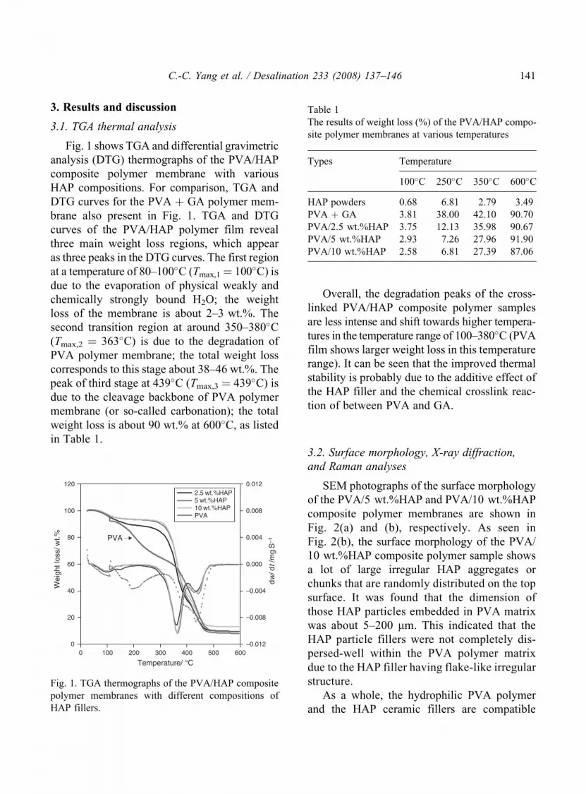
Fig. 1 shows TGA and differential gravimetric
analysis (DTG) thermographs of the PVA/HAP
composite polymer membrane with various
HAP compositions. For comparison, TGA and
DTG curves for the PVA þ GA polymer mem-
brane also present in Fig. 1. TGA and DTG
curves of the PVA/HAP polymer film reveal
three main weight loss regions, which appear
as three peaks in the DTG curves. The first region
at a temperature of 80–100�C (Tmax,1¼ 100�C) is
due to the evaporation of physical weakly and
chemically strongly bound H2O; the weight
loss of the membrane is about 2–3 wt.%. The
second transition region at around 350–380�C(Tmax,2 ¼ 363�C) is due to the degradation of
PVA polymer membrane; the total weight loss
corresponds to this stage about 38–46 wt.%. The
peak of third stage at 439�C (Tmax,3 ¼ 439�C) is
due to the cleavage backbone of PVA polymer
membrane (or so-called carbonation); the total
weight loss is about 90 wt.% at 600�C, as listed
in Table 1.
Overall, the degradation peaks of the cross-
linked PVA/HAP composite polymer samples
are less intense and shift towards higher tempera-
tures in the temperature range of 100–380�C (PVA
film shows larger weight loss in this temperature
range). It can be seen that the improved thermal
stability is probably due to the additive effect of
the HAP filler and the chemical crosslink reac-
tion of between PVA and GA.
3.2. Surface morphology, X-ray diffraction,
and Raman analyses
SEM photographs of the surface morphology
of the PVA/5 wt.%HAP and PVA/10 wt.%HAP
composite polymer membranes are shown in
Fig. 2(a) and (b), respectively. As seen in
Fig. 2(b), the surface morphology of the PVA/
10 wt.%HAP composite polymer sample shows
a lot of large irregular HAP aggregates or
chunks that are randomly distributed on the top
surface. It was found that the dimension of
those HAP particles embedded in PVA matrix
was about 5–200 mm. This indicated that the
HAP particle fillers were not completely dis-
persed-well within the PVA polymer matrix
due to the HAP filler having flake-like irregular
structure.
As a whole, the hydrophilic PVA polymer
and the HAP ceramic fillers are compatible
Temperature/ °C0 100 200 300 400 500 600
Wei
ght l
oss/
wt.%
0
20
40
60
80
100
120
dw/ d
t /m
g S
–1
–0.012
–0.008
–0.004
0.000
0.004
0.008
0.0122.5 wt.%HAP5 wt.%HAP10 wt.%HAPPVA
PVA
Fig. 1. TGA thermographs of the PVA/HAP composite
polymer membranes with different compositions of
HAP fillers.
Table 1
The results of weight loss (%) of the PVA/HAP compo-
site polymer membranes at various temperatures
Types Temperature
100�C 250�C 350�C 600�C
HAP powders 0.68 6.81 2.79 3.49
PVA þ GA 3.81 38.00 42.10 90.70
PVA/2.5 wt.%HAP 3.75 12.13 35.98 90.67
PVA/5 wt.%HAP 2.93 7.26 27.96 91.90
PVA/10 wt.%HAP 2.58 6.81 27.39 87.06
C.-C. Yang et al. / Desalination 233 (2008) 137–146 141

when the content of HAP ceramic fillers is less
than 10 wt.%.
The X-ray diffraction measurement was per-
formed to examine the crystallinity of the PVA/
HAP composite polymer membrane. Fig. 3
shows the diffraction pattern of the PVA/HAP
composite polymer membranes that were pre-
pared by a blending process with different HAP
compositions. It is well known that the PVA
polymer exhibits a semi-crystalline structure
with a large peak at a 2� angle of 19–20� and
a small peak of 39–40� [14–17]. As can be seen
clearly in Fig. 3, a large peak at 2� of 20� for
the PVA/2.5–10 wt.%HAP composite polymer
membranes was seen. But, it was clearly seen
that the peak intensity of XRD for the PVA/HAP
composite polymer films greatly reduced when
the amount of added HAP fillers increased.
It was indicated that the amorphous domain in
the PVA/HAP composite polymer membrane
markedly augmented (i.e. the degree of crystal-
linity decreased). Experimental result indicates
that the PVA/HAP composite polymer mem-
brane with the HAP filler becomes more
amorphous.
Fig. 4(a) shows the micro-Raman spectra for
the PVA powders and PVA polymer membranes,
respectively. Fig. 4(b) shows the micro-Raman
spectra for the PVA/HAP composite polymer
membranes at different compositions of HAP
fillers. It can be seen clearly from micro-Raman
spectra that the strong characteristic scattering
peak of HAP fillers at 958 cm�1 is for –PO3�4 ;
it was due to the P–O stretching. By contrast, the
strong peak for the PVA polymer at 1438 cm�1
is due to the C–H bending and O–H bending.
Moreover, the two weak vibrational peaks for
the PVA polymer at 912 and 851 cm�1 are due
(a)
(b)
Fig. 2. SEM photographs for (a) PVA/5wt.%HAP
composite polymer membrane at 4.5 kx; (b) PVA/
10wt.%HAP composite polymer membrane at 1 kx.
2θ/ deg.10 20 30 40 50 60 70 80 90
Inte
nsity
/ a.u
.
(1) PVA film(2) PVA/2.5%HAP(3) PVA/5%HAP(4) PVA/10%HAP
10%HAP
5%HAP
2.5%HAP
PVA
Fig. 3. XRD spectra for the PVA/HAP composite
polymer membranes at different HAP compositions.
142 C.-C. Yang et al. / Desalination 233 (2008) 137–146

to the C–C stretching. Additionally, there are
several weak scattering peaks at 1145, 1088 cm�1;
they may be due to the C–C stretching and C–O
stretching, as displayed in Fig. 4(a). Most
importantly, it can be seen that the intensities
of those characteristic vibrational peaks for those
PVA/HAP composite polymer membranes are
decreased; it indicates that the amorphous
regions in the PVA/HAP composite polymer
membranes are augmented.
3.3. Ionic conductivity measurements
The typical AC impedance spectra of alka-
line PVA/HAP composite polymer membrane
by a direct blending PVA polymer with HAP
fillers (5 wt.%) at different temperatures are
shown in Fig. 5. The AC spectra are typically
non-vertical spikes for stainless steel (SS) block-
ing electrodes, i.e., SSjPVA/HAP SPEjSS cell.
Analysis of the spectra yields information about
the properties of the PVA/HAP polymer electro-
lyte, such as bulk resistance, Rb. Taking into
account the thickness of the composite electro-
lyte films, the Rb value was converted into the
ionic conductivity value, �, according to the
equation: � ¼ L/Rb � A, where L is the thickness
(cm) of the PVA/HAP polymer membrane, A is
the area of the blocking electrode (cm2), and Rb
is the bulk resistance (ohm) for alkaline compo-
site polymer membrane.
Typically, the Rb values of the PVA/HAP
composite polymer membranes are of the order
1–2 ohm and are dependent on the contents of
HAP fillers and KOH in the film. Note that the
composite polymer membrane was immersed in
800 900 1000 1100 1200 1300 1400 1500 1600
Cou
nts
0
5000
10,000
15,000
20,000
25,000
30,000
35,000
40,000(1) PVA powders(2) PVA membrane
(1)
(2)14
40
1145
926
852
(a)
Raman shift/cm–1
Raman shift/cm–1
800 1000 1200 1400 1600
Inte
nsity
/a.u
.
0
(1) HAP powders(2) PVA/2.5%HAP(3) PVA/5%HAP(4) PVA/10%HAP
(1)
(4)
(2)
(3)
958 (*HAP)
*
*
*
1438
(P
VA
)
912
(PV
A)
851
(PV
A)
(b)
Fig. 4. Micro-Raman spectra for the PVA/HAP
composite polymer membranes with different composi-
tions of HAP fillers.
Z' /ohm
0 2 4 6 8 10 12 14
–Z" /
ohm
0
5
10
15
20
25
30
35
40
30°C40°C50°C60°C70°C
Fig. 5. AC spectra for the PVA/10wt.%HAP com-
posite polymer membrane (in 8 M KOH) at different
temperatures.
C.-C. Yang et al. / Desalination 233 (2008) 137–146 143

8 M KOH solutions for at least 24 h before mea-
surement. Table 2 shows the ionic conductivity
values of the alkaline PVA/2.5–10 wt.%HAP
composite polymer membranes at different
temperatures. As a result, the ionic conductiv-
ity value for the alkaline PVA/2.5 wt.%HAP
composite polymer membranes is about
0.0182 S cm�1 at 30�C.
Comparatively, the ionic conductivity values
for the alkaline PVA/HAP composite polymer
membrane with 5 and 10 wt.% HAP fillers are
about 0.0251 and 0.0442 S cm�1 at 30�C,
respectively. It was found that the highest ionic
conductivity value of the alkaline PVA/HAP
composite polymer membrane is 10 wt.% HAP
fillers (about 0.0442 S cm�1 at ambient tem-
perature). According to the above results, it can
be concluded that the ionic conductivity of the
PVA/HAP composite polymer membranes
increases when the content of added HAP cera-
mic fillers increases.
Generally, the HAP fillers are added into the
PVA polymer membrane, it shows more accessi-
ble free volumes (or more defect sites and voids)
to retain the KOH electrolyte; therefore, the
ionic conductivity is in the order of 10�2 S cm�1
at ambient temperature. The temperature depen-
dence of the ionic conductivity is of the Arrhe-
nius type: � ¼ �0 exp � Ea
RT
� �, where �0 is a
pre-exponential factor, Ea is the activation
energy, and T is the temperature in Kelvin. The
log10(�) vs. 1/T plots, as shown in Fig. 6, obtains
the activation energy (Ea) of the PVA/
10 wt.%HAP composite SPE, which is depen-
dent on the content of HAP fillers. The Ea value
of alkaline PVA/10 wt.%HAP composite polymer
membrane is about 9.71 kJ mol�1, normally the
crosslinked SPE shows Ea value over 15 kJ mol�1.
As we know, when the HAP ceramic filler used
as a stiffer material is added into the PVA
matrix, the swelling ratio of PVA polymer mem-
branes can be effectively reduced from 90.7 to
54.7% as the content of HAP fillers is increased
from 2.5 to 10 wt.%. Experimental results found
that the film dimension stability and ionic
conductivity are at the same time improved.
3.4. Electrochemical measurements
Fig. 7 shows the i–t curves of alkaline DMFC
consisting of the PtRu black anode Ti-electrode
with a loading of PtRu black of 4.0 mg cm�2,
the cathode electrode with MnO2/BP2000
carbon inks of 3.63 mg cm�2 and the PVA/
10 wt.%HAP composite polymer membrane in
Table 2
The ionic conductivities of the PVA/HAP composite
polymer membranes with different compositions HAP
fillers at different temperatures
T (�C) � (S cm�1)
2.5 wt.%HAP 5 wt.%HAP 10 wt.%HAP
30 0.0182 0.0251 0.0442
40 0.0212 0.0272 0.0465
50 0.0263 0.0295 0.0483
60 0.0314 0.0315 0.0514
70 0.0378 0.0335 0.0542
1/T *1000
2.8 2.9 3.0 3.1 3.2 3.3 3.4
log(
σ)/ S
cm
–1
–1.46
–1.44
–1.42
–1.40
–1.38
–1.36
–1.34
–1.32
–1.30
–1.28
–1.26
–1.24
Intercept = 0.0588244251Slope = –0.4551877425r = 0.9983741117Ea = 9.71 kJ/mol
Fig. 6. Arrhenius plot of alkaline PVA/10 wt.%HAP
composite polymer membrane in 8 M KOH.
144 C.-C. Yang et al. / Desalination 233 (2008) 137–146

8 M KOHþ 2 M CH3OH solutions at 0.40, 0.30,
and 0.20 V, respectively. The average current
densities of the DMFC utilizing the PtRu anode
based on Ti-mesh are 18.59, 33.84, and 52.96
mA cm�2, respectively. In spite of a tendency
to drop at the beginning of the test, the discharge
current densities are also stabilized and remain
constant during the 600 min test; it shows good
electrochemical stability of the DMFC. In fact,
the results indicate that the peak power density
of the DMFC in 8 M KOH þ 2 M CH3OH
solutions at 0.40 V was about 10.59 mW cm�2
(0.20 V� 52.96 ¼ 10.59 mW cm�2) at 25�C.
Fig. 8 shows the potential-current density
and the power density–current density curves
for the air-breathing DMFC in 8 M KOH þ 2 M
CH3OH solution at 25�C. Clearly, the maximum
power density of 11.48 mW cm�2 for the alka-
line DMFC using Ti-based anode with 4 mg cm�2
PtRu black was achieved at Ep,max¼ 0.22 V with
a peak current density (ip,max) of 52.20 mA cm�2.
On the other hand, the maximum power den-
sity of the DMFC using a ELAT anode with
4 mg cm�2 PtRu/C was only 5.81 mW cm�2
at Ep,max ¼ 0.190 V with a peak current density
of 30.58 mA cm�2 at 25�C. It was demonstrated
that alkaline DMFC system exhibits some
advantages over than that of the acidic DMFC
system. In particular, alkaline DMFC consists
of the air electrode using non-precious metal
catalyst (i.e., use MnO2/BP2000 catalyst inks
instead of with Pt/C inks) and the low-cost
PVA/HAP composite polymer membrane (i.e.,
a cheap non-perfluorosulfonated polymer mem-
brane instead of expensive Nafion membrane).
4. Conclusions
The composite polymer membrane based on
PVA/HAP was obtained by a solution casting
method. Alkaline air-breathing direct methanol
fuel cell (DMFC) utilizing the PVA/HAP com-
posite polymer membrane was assembled and
systematically examined. The DMFC is com-
prised of the air cathode electrode with MnO2/
BP2000 catalyst inks, the PtRu black Ti-anode
Time/ min
0 100 200 300 400 500 600
i/ m
A c
m–2
0
10
20
30
40
50
60
70
80
90
(1) 0.2 V(2) 0.3 V(3) 0.4 V
(1)
(2)
(3)
Fig. 7. The i–t curves for the DMFC employing the
PVA/10 wt.%HAP composite polymer membrane in
8 M KOH þ 2 M CH3OH at 25�C and ambient air.
i/ mA cm–2
0 10 20 30 40 50 60 70 80 90 100 110
Cel
l pot
entia
l/ V
0.0
0.2
0.4
0.6
0.8
1.0
P.D
./ m
W c
m–2
0
2
4
6
8
10
12
14
(1)
(2)
(3)
(4)
Fig. 8. The IV and P.D. curves for the DMFC using the
PVA/10 wt.%HAP composite polymer membrane in
8 M KOH þ 2 CH3OH at 25�C; (1) IV curve for ELAT
E-TEK anode; (2) IV curve for Ti-based anode;
(3) P.D. curve for ELAT anode; (4) P.D. curve for
Ti-based anode.
C.-C. Yang et al. / Desalination 233 (2008) 137–146 145

electrode and the PVA/HAP composite polymer
membrane. It was demonstrated that the alkaline
DMFC with the PVA/HAP composite polymer
membrane shows good electrochemical perfor-
mances at ambient temperatures and pressure.
The maximum peak power density of the
alkaline DMFC is 11.48 mW cm�2 at 25�C.
From the application point of view, the PVA/
HAP composite polymer membranes can easily
be prepared and controlled. These composite
polymer membranes show a high potential for
future alkaline DMFC applications.
Acknowledgement
Financial support from the National Science
Council, Taiwan (Project No. NSC-95-2221-
E131-032) is gratefully acknowledged.
References
[1] N. Nakagawa and Y. Xiu, Performance of a direct
methanol fuel cell operated at atmospheric
pressure, J. Power Sources, 118 (2003) 248.
[2] V. Baglio, A.S. Arico, A.D. Blasi, V. Antonucci,
P.L. Antonucci, S. Licoccia, E. Traversa and
F.S. Fiory, Nifion–TiO2 composite DMFC mem-
branes: physico-chemical properties of the filler
versus electrochemical performance, Electrochim.
Acta, 50 (2005) 1241.
[3] S. Panero, P. Fiorenza, M.A. Navarra,
J. Romanowska and B. Scrosati, Silica-added,
composite poly(vinyl alcohol) membranes for fuel
cell application, J. Electrochem. Soc., 152 (12)
(2005) A2400.
[4] J.H. Choi, Y.M. Kim, J.S. Lee, K.Y. Cho,
H.Y. Jung, J.K. Park, I.S. Park and Y.E. Sung,
A polyaniline supported PtRu nanocomposite
anode and a Pd-impregnated nanocomposite
Nafion membrane for DMFCs, Solid State Ionics,
176 (2005) 3031.
[5] V.S. Silva, S. Weisshaar, R. Reissner, B. Ruffmann,
S. Vetter, A. Mendes, L.M. Madeirs and S. Nunes,
Performance and efficiency of a DMFC using
non-flourinated composite membranes operating
at low/medium temperatures, J. Power Sources,
145 (2005) 485.
[6] E. Antolini, Formation of carbon-supported PtM
alloys for low temperature fuel cells: a review,
Mater. Chem. Phys., 78 (2003) 563.
[7] G.Q. Lu and C.Y. Wang, Development of micro
direct methanol fuel cells for high power applica-
tions, J. Power Sources, 144 (2005) 141.
[8] C.Y. Chen and P. Yang, Performance of an air-
breathing direct methanol fuel cell, J. Power
Sources, 123 (2003) 37.
[9] T. Shimizu, T. Momma, M. Mohamedi, T. Osaka
and S. Sarangapani, Design and fabrication of pump-
less small direct methanol fuel cells for portable
applications, J. Power Sources, 137 (2004) 277.
[10] K. Kordesch, V. Hacker and U. Bachhiesl, Direct
methanol-air fuel cells with membranes plus
circulating electrolyte, J. Power Sources, 96
(2001) 200.
[11] J.G. Liu, T.S. Zhao, R. Chen and C.W. Wong, The
effect of methanol concentration on the perfor-
mance of a passive DMFC, Electrochem. Com-
mun., 7 (2005) 288.
[12] B.K. Kho, I.H. Oh, S.A. Hong and H.Y. Ha,
The effect of pretreatment methods on the perfor-
mance of passive DMFCs, Electrochim. Acta, 50
(2004) 781.
[13] H. Chang, J.R. Kim, J.H. Cho, H.K. Kim and
K.H. Choi, Materials and processes for small fuel
cells, Solid State Ionics, 148 (2002) 601.
[14] C.C. Yang, Polymer Ni–MH battery based on
PEO–PVA–KOH polymer electrolyte, J. Power
Sources, 109 (2002) 22.
[15] C.C. Yang and S.J. Lin, Alkaline composite
PEO–PVA-glass-fiber-mat polymer electrolyte for
Zn-air battery, J. Power Sources, 112 (2002) 497.
[16] C.C. Yang, Synthesis and characterization of
the crosslinked PVA/TiO2 composite polymer
membrane for alkaline DMFC, J. Membr. Sci.,
288 (2006).
[17] C.C. Yang, S.J. Chiu and W.C. Chien, Develop-
ment of alkaline direct methanol fuel cells based
on crosslinked PVA polymer membranes, J. Power
Sources, 162 (2002) 21.
[18] C.C. Yang, S.T. Hsu, W.C. Chien, M.C. Shih,
S.J. Chiu, K.T. Lee and C.L. Wang, Electrochemi-
cal properties of air electrodes based on MnO2
catalysts supported on binary carbons, Int.
J. Hydrogen Energy, 31 (2006) 2076.
146 C.-C. Yang et al. / Desalination 233 (2008) 137–146


