Embed Size (px)
Citation preview

Prismatic Rail
www.rollon.com
FrontespizioPrismaticRail.indd 1 28/09/2018 13:33:02

We design and produce in order to support you
LOGISTICS
ROBOTICS
INDUSTRIAL MACHINERY
RAILWAY
V a l u e s
An international groupfor technology,
a local support for service
Over 40 years of know how in design and production
Appl ica t ions

INTERIORS AND ARCHITECTURE
MEDICAL
SPECIAL VEHICLES
AERONAUTICS
From a full range of standardproducts to fit-to-customersolutions for best perfomances
S o l u t i o n s
Collaboration
High level technical consulting
Cross competences in several industrial sectors for an effective problem-solving

A complete range for linear motion which reaches every customer
Telescopic Line
Telescopic guides with ball bearings,with hardened raceways, high load capacities, and low bending, resistant to shocks and vibrations. For partial, total or extended extraction up to 200% of the length of the guide.
A global provider
of solutions
for applications
for linear motion
Linear Line
Linear and curved guides with ball and roller bearings,with hardened raceways, high load capacities, self-alignment and capable of working in dirty environments.
with hardened raceways, high load capacities, and low bending, resistant to shocks and vibrations. For partial, total or extended extraction up to 200% of the length of

Actuator System LineIntegrated actuators for industrial automation,they fi nd applications in numerous industrial sectors: from machinery ser-vo systems to high precision assembly systems, packaging lines and high speed production lines. It has evolved from Actuator Line series in order to meet the most demanding needs of our customers.
Actuator Line
Linear actuators with different guide confi gurations and drives,available with belt, screw or rack and pinion drives according to different needs in terms of precision and speed. Guides with bearings or ball recircu-lating systems for different load capacities and critical environments.
A global provider
of solutions
for applications
for linear motion

Prismatic Rail1 Product explanation
Prismatic Rail: with cylindrical or V-shaped rollers PR-2
2 Technical dataPerformance characteristics and Notes PR-4
3 Product dimensionsSteel V-shaped rails, Machining: drilled guide rails with straight cut PR-5Machining: drilled guide rails with 1 bevel and 1 slanting cut,Machining: drilled guide rails with 2 slanting cuts PR-6Roller slides, Tilting roller slides with 4 rollers Ø30 for V-shaped guide rails 28.6x11 PR-73-Roller slides Ø 40 for V-shaped guide rails 35x16Tilting roller slides with 4 rollers Ø40 for V-shaped guide rails 35x16 PR-8Fixed 4-roller slide Ø40 for V-shaped guide rails V 35x16 PR-9E type roller slides (roller Ø52) and F type (roller Ø62) for V-shaped guide rails 55x25 PR-10Type G roller slides (roller Ø52) and H type (roller Ø62) for V-shaped guide rails 55x25,I-type roller slides (roller Ø52) and L-type (roller Ø62) for V-shaped guide rails V 55x25 PR-11P-type roller slides (rollers Ø52) and Q-type (rollers Ø62) for V-shaped guide rails 55x25 PR-12
4 AccessoriesV-shaped rollers (Guide Rails 28.6 x 11) anti-oxidized version,V-shaped rollers [rails 35 x 16] integrale PR-13Spare roller with stud PR-14Assembly Studs, Type 0 assembly pins suitable for roller slide Ø30 and Ø40 PR-15Type 7 assembly pins suitable for roller slide E-F,Assembly pins type 8 suitable for carriage E-F PR-16Type 9 assembly pins suitable for tilting roller slides G-H / I-L,Type 10-11-12 assembly pins suitable for tilting roller slides P-Q PR-17V-shaped guide rail assembly inserts PR-18
5 Technical instructionsRollers and V-shaped guide rails 28.6x11 and 35x16,Application diagram common to 2-roller slides, Application diagram common to 3-roller slides PR-19
Ordering keyOrdering key with explanations PR-20Assembly of standard carriages / K version carriages PR-20
Prismatic Rail
www.rollon.com
FrontespizioPrismaticRail.indd 1 28/09/2018 13:33:02
FrontespizioCurviline.indd 1 28/09/2018 13:14:54

Reference
SectionShape of
railHardenedraceways
Self-alignment
Slider
Anticorrosion Size
Max. load capacity per slider
[N] Dynamic coefficient [N]
C 100
Max. momentcapacity
[Nm]
Max. rail length
[mm]
Max. speed*
[m/s]
Max.acceleration
[m/s² ]
Operatingtemperature
Product Family Product Balls Rollers Co rad Co ax Mx My Mz
Speedy Rail
SR35 √ ++ 35 400 400 - - - - 6500*2 8 8 - 30° C / + 80° C
SRC48 √ + 48 540 400 - - - - 7500*2 8 8 - 30° C / + 80° C
SR √ +++60-90-120-
180-25014482 14482 - - - 7500*2 15 10 - 30° C / + 80° C
X-Rail
TEXTESUEXUES
+++ 20-26-30-40-45 1740 935 **** 4000 1.5 2
-20°C/+100°C TEX-UEX
-20°C/+120°C TES-UES
Easyslide
SN √ ++ **** 22-28-35-43-63
122000 85400 122000 1120,7 8682 12403 1970 0,8 -20°C/+130°C
SNK √ + **** 43 10858 7600 10858 105 182 261 2000*2 1,5 -20°C/+70°C
Compact RailTLCKLCULC
√ +++**** 18-28-35
-43-6315000 10000 36600 350 689 1830 4080*2 9 20 -20°C/+120°C
Curviline
CKRCVR
CKRHCVRHCKRXCVRX
√ + **** 16,5-23 2475 1459 **** 3240 1,5 2 -20°C/+80°C
Reported data must be verified according to the application.
*1 The maximum value is defined by the application.
*2 A longer stroke is available for jointed versions.
*** C50
****For more information, please contact our technical department.
Available in stainless steel
Available in stainless steel
Mono Rail
MR √ -15-20-25-30-35-
45-55249000 155000*** 5800 6000 6000 4000*2 3,5 20 -10°C/+60°C
MMR √ - **** 7-9-12-15 8385 5065 171,7 45,7 45,7 1000*2 3 250 -20°C/+80°C
Prismatic Rail P √ +++
28-35-55 15000 15000 - - - - 7500*2 7 20 -10°C/+80°C
Technical features overview

CR
XR
ES
CL
PR
SR
MR
Reference
SectionShape of
railHardenedraceways
Self-alignment
Slider
Anticorrosion Size
Max. load capacity per slider
[N] Dynamic coeffi cient [N]
C 100
Max. momentcapacity
[Nm]
Max. rail length
[mm]
Max. speed*
[m/s]
Max.acceleration
[m/s² ]
Operatingtemperature
Product Family Product Balls Rollers Co rad Co ax Mx My Mz
Speedy Rail
SR35 √ ++ 35 400 400 - - - - 6500*2 8 8 - 30° C / + 80° C
SRC48 √ + 48 540 400 - - - - 7500*2 8 8 - 30° C / + 80° C
SR √ +++60-90-120-
180-25014482 14482 - - - 7500*2 15 10 - 30° C / + 80° C
X-Rail
TEXTESUEXUES
+++ 20-26-30-40-45 1740 935 **** 4000 1.5 2
-20°C/+100°C TEX-UEX
-20°C/+120°C TES-UES
Easyslide
SN √ ++ **** 22-28-35-43-63
122000 85400 122000 1120,7 8682 12403 1970 0,8 -20°C/+130°C
SNK √ + **** 43 10858 7600 10858 105 182 261 2000*2 1,5 -20°C/+70°C
Compact RailTLCKLCULC
√ +++**** 18-28-35
-43-6315000 10000 36600 350 689 1830 4080*2 9 20 -20°C/+120°C
Curviline
CKRCVR
CKRHCVRHCKRXCVRX
√ + **** 16,5-23 2475 1459 **** 3240 1,5 2 -20°C/+80°C
Mono Rail
MR √ -15-20-25-30-35-
45-55249000 155000*** 5800 6000 6000 4000*2 3,5 20 -10°C/+60°C
MMR √ - **** 7-9-12-15 8385 5065 171,7 45,7 45,7 1000*2 3 250 -20°C/+80°C
COrad
My
MzsMzdMx
COax
Prismatic Rail P √ +++
28-35-55 15000 15000 - - - - 7500*2 7 20 -10°C/+80°C

Prismatic Rail: with cylindrical or V-shaped rollers
The Prismatic Rail product family is composed of roller sliders sliding on
V-shaped rails made of hardened steel. These linear guides also have high
self-alignment properties.
V-shaped rails are induction hardened and polished, available in three
sizes: 28, 35 and 55 mm. Rails can be machined with two straight cuts,
one straight and one slanting cut or two slanting cuts. These options allow
to create joinable versions, and thus obtaining longer strokes.
The aluminium slider can be configured with a variable number of rollers
with steel pins, ranging from 3 to 6. Rollers are in turn available in two
variants, cylindrical or V-shaped, with variable diameter from Ø30 a Ø62
depending on rail size.
The most important characteristics:
■ Long life thanks to hardened raceways
■ Optimal reliability in dirty environments
■ Self-aligning system
■ Simple mounting
■ High dynamics
Preferred areas of application:
■ Robot and handling systems
■ Industrial automation
■ Logistics
■ Packaging machines
Fig. 1
Product explanation
2 Product explanation
PR-2

PR
Fig. 2
Fig. 3
Fig. 4
Fig. 5
Fig. 6
Fig. 7
Drilled guide rails with straight cut:
Machining provided for guide rails with no joint.
Sliders with rollers Ø30 - Ø40:
Floating and fixed sliders with rollers Ø30 (guide size 28) and Ø40 (guide
size 35).
Sliders with rollers Ø52- Ø62:
Floating and fixed sliders with rollers Ø52 and Ø62 (guide size 55).
Drilled guide rails with 2 slanting cuts:
Machining provided for the intermediate crop down sizes of guide rail
ends with multiple joints.
Assembly pins:
Steel pins.
Drilled guide rails with one straight and one slanting cut:
Machining provided for the crop down sizes of guide rail ends with joints.
PR-3
Prismatic Rail

Performance characteristics:
■ Sizes available: 28,35 and 55 mm.
■ Rollers dimensions: Ø30 - Ø40 - Ø52 - Ø62.
■ V-shaped rollers in hardened C45 steel available for sizes 28 and 35.
■ Aluminum sliders, fl oating and fi xed, with 3, 4 or 6 rollers.
■ Max. speed: 7 m/s (depending on application).
■ Max. acceleration: 20 m/s² (depending on application).
■ Max. radial load capacity: 15000 (per slider).
■ Max. axial load capacity: 15000 (per slider).
■ Operating temperature: from -10°C to +80°C.
■ Induction hardened and polished rails.
■ Max. rail length: 4100 mm.
■ Steel assembly pins.
Notes:
■ V-shaped roller with plastic compound shell are available upon request.
■ Stainless steel pins and special variants are available upon request.
■ Longer stroke achievable with joinable versions.
■ V-shaped rails available in drilled or non-drilled versions.
■ Please follow the diagrams in every slider section to ensure correct
assembly.
■ For applications with high projecting loads, the sliders’ rollers must
be adjusted so that the load is supported by the maximum possible
number of them.
2 Technical data
Fig. 8
Technical data
PR-4

PR
Steel V-shaped rails
Machining: drilled guide rails with straight cut
Material: high-performance alloy steel: R > 900 MPa
Hardened and tempered: core hardness 240 HB.
Features Moment of inertia Ix[mm4]
Moment of inertia Iy[mm4]
Weight[Kg/m]
28,6x11 2148 14490 2
35x16 7932 36405 3,5
55x25 41906 194636 7,8
Size Treatment L. max[mm]
P[mm]
I[mm]
A[mm]
B[mm]
C[mm]
Code
28,6x11 hardened anti-oxidation 3980 150 40 11 7 5 P28...
35x16 Induction-hardened 4100 100 50 11 7 7,5 P35...
55x25 Induction-hardened 4100 150 25 18 11 11,5 P55...
3.2
16
23,5
8
x
y
4,2
25
35
20
55 90°
x
y
35 90°
0
+0.
05 0
.1
+0.
05 0
.1
3.2
11
18,5
8
x
y
28,6
90°
0+0.
05 0
.1
V-shaped guide rail 35x16
V-shaped guide rail 55x25
V-shaped guide rail 28.6x11
I P P I
L
ØA
ØB
C
P_ _ -.....F V-shaped guide rails, length L, drilled
Fig. 9 Fig. 10
Fig. 11 Fig. 12
Tab. 1
Tab. 2
Induction-hardened and polished. Track hardness > 58 HRC
Guide rail 28.6x11 code 203.0012 has anti-oxidation coating.
Product dimensions
PR-5
Prismatic Rail

3 Product dimensions
Machining: drilled guide rails with 1 straight and 1 slanting cut
Machining: drilled guide rails with 2 slanting cuts
Size Treatment L. max[mm]
P[mm]
Y[mm]
I[mm]
A[mm]
B[mm]
C[mm]
Code
28,6x11 hardened anti-oxidation 3700 150 50 50 11 7 5 P28...
35x16 Induction-hardened 4000 100 50 50 11 7 7,5 P35...
55x25 Induction-hardened 3950 150 25 25 18 11 11,5 P55...
Size Treatment L. max[mm]
P[mm]
Y[mm]
A[mm]
B[mm]
C[mm]
Code
28,6x11 hardened anti-oxidation 3700 150 50 11 7 5 P28...
35x16 Induction-hardened 3900 100 50 11 7 7,5 P35...
55x25 Induction-hardened 3950 150 25 17 11 11,5 P55...
P_ _ -.....FXX V-shaped guide rails with 2 slanting cuts, length L, drilled
P_ _ -.....FX V-shaped guide rails with 1 slanting cut, length L, drilled
Y P P I
L
ØA
ØB
C
X
20°
Y P P Y
L*
ØA
ØB
C
X
20°
*in order to maintain a constant hole pitch, arrange the guide rails so that the length “L” is equal to: n•P + 2•Y
Fig. 13
Fig. 15 Fig. 16
Fig. 14
Tab. 3
Tab. 4
PR-6

PR
Roller slides
Tilting roller slides with 4 rollers Ø30 for V-shaped guide rails 28.6x11
Ø40 roller slides with 3 rollers, aluminium alloy castings (Rs=280 N/
mm2). Ø30, Ø40, Ø52 and Ø62 roller slides with 4 or 6 rollers, extruded
aluminium alloy (Rs=310 N/mm2). Alloy steel pins (Rs=800 N/mm2)
Rollers with double rows of angular contact ball bearings, long-life.
A[mm]
Load capacity
[N]
Weight[Kg]
Code
Roller slide with concentric pin
75 3818 1,8 204.0052
Roller slide with excentric pin (±1 mm)
75 3818 1,8 204.0053
Roller slide with concentric pin
50 3818 1,4 204.0054
Roller slide with excentric pin (±1 mm)
50 3818 1,4 204.0055
Spare parts A[mm]
Code
Complete body with rollers 204.0050
Concentric pin 75 236.0010
Excentric pin (±1 mm) 75 236.0011
Concentric pin 50 236.0014
Excentric pin (±1 mm) 50 236.0015
Use the roller slide eccentric pin to adjust the backlash along the plane
between the guide rails.
Fixed 3-roller slide
Fixed 4-roller slide Ø30 and Ø40
Roller slides Ø40 (V-shaped 35x16) - Ø30 (guide rail 28.6x11)
Fixed 4-roller slide
Fixed 4-roller slide
Tilting roller slide with 4 rollers
Tilting roller slide with 6 rollers
Fixed 6-roller slide
Fixed 4-roller slide
Roller slides Ø52 and Ø62 (V-shaped 55x25)
Tilting 4-roller slide
Roller slidesØ30 (rails 28.6x11) A 18
Ø30
H8
Ø4 0
Ø50
11086
4 438 1,51,5
56 A 18
39,7
1 Ø 5
0Ø
30 H
8± 1,5Sliding washer
Important: remove the space washers to enable self-alignment of the roller slide
Fig. 17
Fig. 18 Fig. 19
Tab. 5
Tab. 6
PR-7
Prismatic Rail

140
35
1515
120
8,5
287
60
35
1515
Ø6
50 ca.47
2851
,8
44,8
with excentric pin.register ± 0.75 mm
Tilting roller slides with 4 rollers Ø40 for V-shaped guide rails 35x16
3-Roller slides Ø 40 for V-shaped guide rails 35x16
Rollers side 1 Rollers side 2 Specification Load capacity[N]
Weight[Kg]
Code
1 concentric 2 concentric 3-rollers carriage Ø40 - concentric 3535 1,3 204.1579
1 eccentric 2 concentric 3-rollers carriage Ø40 - 1 exc. side 1 3535 1,3 204.0474
2 concentric 1 concentric 3-rollers carriage Ø40 - concentric 3535 1,3 204.2302
2 concentric 1 eccentric 3-rollers carriage Ø40 - 1 exc. side 2 3535 1,3 204.0475
Use the roller slide eccentric pin to adjust the backlash along the plane
between the guide rails.tino.
Please follow the diagrams below to ensure correct assembly. To make
up for tolerances in the profile shapes, use pins to lock carriages with
3 Product dimensions
eccentric rollers after placing them in the appropriate position. (With the
eccentric pins in the neutral position).
Side 1
Side 2
Ø38±0,02
Ø6H7Ø45
Ø30H8
4 4160
76
381,5 1,5
55,5 A 18
ø30
H8
ø40
ø50
51,7
8
guide rails 35x16 6
± 1,5
120
Detail of plate guide rails 35x16 machining
A[mm]
Load capacity
[N]
Weight[Kg]
Code
Slide with eccentric pin (±1 mm)
75 7071 2,2 204.0016
Slide with eccentric pin (±1 mm)
50 7071 1,8 204.0033
Spare parts A[mm]
Code
Complete body with rollers 204.0052
Eccentric pin (±1 mm) 75 204.0053
Eccentric pin (±1 mm) 75 204.0054
Important: remove the spacer washers to enable self-alignment of the roller slide
All pins are eccentric, but are made concentric by inserting the pin in the
specific hole on the plate, in order to determine the required preload.
Fig. 20 Fig. 21
Fig. 22
Tab. 7
Tab. 8Tab. 9
PR-8

PR
Fixed 4-roller slide Ø40 for V-shaped guide rails V 35x16Use the roller slide eccentric pin to adjust the backlash along the plane
between the guide rails.
Important: remove the space washers to enable self-alignment of the roller slide sliding washers
Important: machine the pin clamping plate as shown in Fig. A
4 B 4
C
DE
381,5 1,5
55,5 A 18
ø30
H8
ø40
ø50
51,7
8
V-shaped 35x16 6
± 1,5
2 1
perni conc.
perni ecc.
5
12
Ø30
H8
Ø40
Fig. A
Sliding washer
Ø38±0,02
Ø6H7Ø45
Ø30H8Detail of platemachining
Fig. 23
A[mm]
Load capacity[N]
Code
R. slide L=370 complete with exc. pin (± 1 mm) 75 7071 204.0018
R. slide L=600 complete with exc. pin (± 1 mm) 75 7071 204.0028
R. slide L=370 complete with exc. pin (± 1 mm) 50 7071 204.0031
R. slide L=600 complete with exc. pin (± 1 mm) 50 7071 204.0035
R. slide spare parts (2)
B[mm]
C[mm]
D[mm]
E[mm]
Code
Roller slide L= 370 370 320 276 180 204.0002
Roller slide L= 600 600 550 506 410 204.0026
Pin spare parts (1) A[mm]
Weight[Kg]
Codice
Eccentric pin (± 1 mm) 75 4.1 204.0011
Eccentric pin (± 1 mm) 50 3.5 204.0015
Tab. 10
Tab. 11 Tab. 12
PR-9
Prismatic Rail

Ø Rollers A
Rollers Ø52 71,75
Rollers Ø62 78,85
Technicalcaracteristics
Ø52 Ø62
Load capacity [N] 12021 14991
N° rollers 4 4
Weight [Kg] 4,6 5,2
Spare parts code 204.1518 204.1519
E type roller slides (roller Ø52) and F type (roller Ø62) for V-shaped guide rails 55x254-Stiff Rollers slide. Suitable for mounting pin: Type 7-8
Use the roller slide eccentric pin to adjust the backlash along the plane
between the guide rails.
Important: machine the pin clamping plate as shown in Fig. A
435
6
107
180
ø25
scraper
7610
7
52/6
2A
perni conc.
perni ecc.
5
12
Ø30
H8
Ø40
K versioninverted roller position
Fig. A
3 Product dimensions
Tab. 13
Tab. 14
Fig. 24
Fig. 25
PR-10

PR
Ø Rollers A
Rollers Ø52 71,75
Rollers Ø62 78,85
Type G roller slides (roller Ø52) and H type (roller Ø62) for V-shaped guide rails 55x25
I-type roller slides (roller Ø52) and L-type (roller Ø62) for V-shaped guide rails V 55x25
Tilting 4-roller slides Suitable for assembly pins: Type 9
Use the roller slide eccentric pin to adjust the backlash along the plane
between the guide rails.
Tilting 4-roller slides Suitable for assembly pins: Type 9
Use the roller slide eccentric pin to adjust the backlash along the plane
between the guide rails.
Rif.
A
423
617
0
25
ø34
scraper
25
scraper
436
6
65
ø34
170
65
Rif.
A
Tab. 15
Tab. 16
Fig. 26
Fig. 27
Technicalcaracteristics
Ø52 Ø62
Load capacity [N] 12021 14991
N° roller 4 4
Weight [Kg] 3,2 3,8
Spare parts code 204.1520 204.1521
PR-11
Prismatic Rail

Ø Roller A
Roller Ø52 71,75
Roller Ø62 78,85
K versioninverted roller position
P-type roller slides (rollers Ø52) and Q-type (rollers Ø62) for V-shaped guide rails 55x25Fixed 6-roller slides Suitable for assembly pins: Type 10-11-12
Use the roller slide eccentric pin to adjust the backlash along the plane
between the guide rails.
scraper
460
025
380
ø30
106
274
2510
6
ecc.
±1
A
K Versioninverted roller position
3 Product dimensions
Tab. 17
Tab. 18
Tab. 19
Fig. 28
Fig. 29
Fig. 30
Technical caracteristics
Ø52 Ø62
Load capacity [N] 12021 14991
N° rollers 6 6
Weight [Kg] 4,9 5,9
Spare parts code 204.1522 204.1523
Technical caracteristics
Ø52 Ø62
Load capacity [N] 12021 14991
N° rollers 6 6
Weight [Kg] 4,9 5,9
Spare parts code 204.2086 204.2283
PR-12

PR
Shaped rollers with radial bearings with 2RS sealing (medium version).
Shaped rollers with two rows of angular contact ball bearings. With bila-
teral sliding sealing rings. Accuracy class P6.
They support loads along the axis of the pin provided Pa eff < 0.4 Pr eff.
V-shaped rollers (Guide Rails 28.6 x 11) anti-oxidized version
V-shaped rollers [rails 35 x 16] integral
* IMPORTANT: upon request, spacers can be supplied to increase the centre-distance between the guide rail and the roller supporting surface. In addition to theroller code, please indicate the required centre-distance (L). e.g. 205.0013.L
* IMPORTANT: upon request, spacers can be supplied to increase the centre-distance between the guide rail and the roller supporting surface. In addition to the roller code, please indicate the required centre-distance (L). e.g. 205.0011.L
76 31
30
15
CH 30 (ecc.)
M10
Ø63
16
ecc.
1,5 CH 19
9
Ø24
g6/
H7
28,6x11
37
n° 4 holes M6x90°
15
Ø59
g7/H
8
Ø48
Ø60
31
L(2,5)
Ø38
5filo piastra
Version Type Bearing C(1cusc.)
Cw(2cusc.)
COw(2cusc.)
PR[N]
PA[N]
Speed[mm/s]
Weight[Kg]
Code
Medium Conc. radial bearing 7800 9600 4800 1400 600 2500 0,8 205.0013
Medium Exc. radial bearing 7800 9600 4800 1400 600 2500 0,8 205.0014
n° 4 holes M6x90°
15
Ø59
g7/H
8
Ø48
Ø60
31
L(2,5)
Ø38
5filo piastra
89,531
36
14 min.25 max.
CH 30 (ecc.)
M16
ø75
13
ecc.
1,5 CH 19
13
35x16
45,5
Ø24
g6/
H7
(* upon request)Rails 35x16
Tab. 20
Fig. 31
Fig. 33
Fig. 32
Fig. 34
Accessories
Tab. 21
Type Bearing C COw(2cusc.)
PR[N]
PA[N]
Speed[mm/s]
Weight[Kg]
Code
Conc. angular contact 21000 13900 4500 1800 2500 1 205.0011
Exc. angular contact 21000 13900 4500 1800 2500 1 205.0012
PR-13
Prismatic Rail

4 Accessories
Make sure that all the components are locked in place with the
appropriate screws. The recommended tightening torque for pin locking
screws and nuts is 50 Nm.
Spare roller with pin
Tab. 22
Roller Cw[N]
COw[N]
Fr amm.[N]
Vmax.
Ø30 5,100 3,100 1,350 7 m/s
Ø40 10,000 7,000 2,500 7 m/s
Ø52 16,700 12,300 4,250 6 m/s
Ø62 21,500 14,500 5,300 5 m/s
Spare roller with pin Weight[Kg]
Code
Ø30 Concentric 0,02 406.0056
Ø40 Concentric 0,22 205.0464
Ø40 Excentric (± 0.75 mm) 0,25 205.0163
Ø52 Concentric 0,4 205.0163
Ø62 Concentric 0,55 205.0165
Max. load factors for induction-hardened guides
Tab. 23
Fig. 35
PR-14

PR
Ø38±0,02
Ø6H7Ø45
Ø30H8
Material: burnished steel (Rs=800 N/mm2). Special variants upon request.
AISI 303 stainless steel versions are available upon request. Types 0-7-
Assembly Pins
Type 0 assembly pins suitable for roller slide Ø30 and Ø40
* Important: machine the pin clamping plate as shown in Fig. A
8-9 are complete with self-lubricating bushings to make roller slide self-
adjustments easier.
Pin type 0
Pin type 7
Pin type 8
Pin type 9
Pin type 10-11-12
perni conc.
perni ecc.
5
12
Ø30
H8
Ø40
Fig. A
55,5A18
ø25M16
1,5 1,5
n˚3 ø8
ø50
ø40
ø30
6
±1,5
38
Dett. “1”
Technical caracteristics
A[mm]
Weight [Kg] 1,1 approx.
Eccentric code (±0,75 mm) 75 236.0011
Eccentric code (±0,75 mm) 50 236.0015
Important: remove the spacer washers to enable self-alignment of the roller slide
Fig. 36
Fig. 37
Fig. 38
Tab. 24
PR-15
Prismatic Rail

Type 7 assembly pins suitable for roller slide E-F
Assembly pins type 8 suitable for carriage E-F
* Important: machine the pin clamping plate as shown in Fig. A
Technical caracteristics
Weight [Kg] 1,1 circa
Eccentric code (± 1 mm) 236.1689
Technical caracteristics
Weight [Kg] 1,8 approx.
Excentric code (±1 mm) 236.1691
Important: remove the spacer washers to enable self-alignment of the roller slide
Important: remove the spacer washers to enable self-alignment of the roller slide
perni conc.
perni ecc.
5
12Ø
30 H
8Ø
40
Fig. A
62,56818
ø25M16
1,5 1,5
n˚3 ø8
ø50
ø40
ø30
6
±1,5
Dett. “1”
Ø38±0,02
Ø6H7Ø45
Ø30H8
42,59518ø2
5M16
1,5 1,5
n˚3 ø8
ø50
ø40
ø30
6
±1,5
perni conc.
perni ecc.
5
12
Ø30
H8
Ø40
Fig. A
Ø38±0,02
Ø6H7Ø45
Ø30H8
Dett. “1”
4 Accessories
Fig. 39
Fig. 40
Fig. 41
Fig. 42
Tab. 25
Tab. 26
PR-16

PR
Type 9 assembly pins suitable for tilting roller slides G-H / I-L
Type 10-11-12 assembly pins suitable for tilting roller slides P-Q
Technical caracteristics
Weight [Kg] 2 circa
Concentric code 236.2076
Excentric code (± 1,5 mm) 236.2079
Type A[mm]
B[mm]
C[mm]
Weight[Kg]
Exc.code
(±1,5 mm)
10 95 73 35 2 236.2083
11 87 65 27 1,8 236.2089
Important: remove the spacer washers to enable self-alignment of the roller slide
6295
ø34CH24
2 2
ø59H8
±2
29.6
ø46
35,2
M10
CH32
62A
Ø30CH24
ø59H8
29,6
ø46
35,2
M10
CH32
B
C
Fig. 43
Fig. 45
Fig. 44
Fig. 46
Tab. 27
Tab. 28
PR-17
Prismatic Rail

V-shaped guide rail assembly inserts
Guide rails Slot side Screw Code
A 35x16/28x11 8 M6x20 209.0298
B 35x16 12,5 M6x25 209.1855
C* 55x25 8 M8x30 209.0479
D 55x25 12,5 M10x30 209.0480
4 Accessories
Material: C40 galvanized steel.
A and C: suitable for medium profiles
B and D: suitable for load-bearing profiles
209.0479
8
12,5
30
20
4
812,5
M6
30
20
208,
7
20
30
7,2
8
3
30
20
10
8
M6
6,5
A B C* D
209.0480
* Special drilling for M8 screws instead of M10 is required.
Fig. 47 Fig. 48
Tab. 29
PR-18

PR
Material: Hardened and burnished C45 steel covering; burnished steel pins
and bolts. Rollers with shaped plastic cover are available upon request.
Rollers with longer centre-distance L can be supplied.
Rollers and V-shaped guide rails 28.6x11 and 35x16
Application diagram common to 2-roller slides
Application diagram common to 3-roller slides
33 Y
G
X
A
PA1PR
PA2
PR
R1
PA1
PR2PA2
33
Y
G
X
33
PA1 PA2
YW
A
G
PA1
PR
PA2
PR
G • Y PA1 = –––––– = PA2 X PR1 = G + PA1
PR2 = PA2 X = A + 20 mm
G • Y PA1 = –––––– X
PA2 = PA1 + G
X = A + 20 mm
G • Y PA1 = –––––– W + Y
PA2 = G - PA1 X = A + 20 mm
MZ
204.2072
204.2072
204.2071
204.0004
Fz
204.2072 204.0004
204.2072
204.0004
Mx
Horizontal sliding - vertical carriage Vertical sliding
Fz
204.0474204.1579
MZ
204.2302
204.1579 204.0474
204.0475
Fz
204.2302 204.0475
204.1579
204.0475
Mx
Horizontal slidingVertical carriage or asymmetric load
Vertical slidingHorizontal slidingSymmetric load
Horizontal slidingInverted load
Fig. 49
Fig. 50
Fig. 51
Technical instructions
PR-19
Prismatic Rail

Assembly of standard carriages / K version carriages
Ordering key
IMPORTANT: for applications with high projecting loads, the rollers
of the slides must be adjusted so that the load is supported by the
maximum possible number of rollers. If this means arranging the rollers
symmetrically with respect to the standard roller slide version, please add
the letter K at the end of the code when filling in the order form. However,
the roller assembly can also be inverted at a later date, by disassembling
the pins and rollers and then reassembling them in the opposite way.
Fy
Mx
Fy
MxPin type 10 con.
Perno tipo 10 con.
4 rollers
Roller slide 204.2084.K(P-type)
204.2096.K 204.2106.K
204.2096
204.2106.K
Perno tipo 10 ecc.
Cursore 204.2086.K(tipo P)
4 rollers
4 rollers
4 rollerRoller slide 204.2084
(P-type)
Pin type 10 con.
Roller slides 204.2086.K(P-type)
Example:
Identification codes for Prismatic Rail guideP 35
28
35
55
- 1100 F XX
X = Single slanting cut
XX w= Double slanting cut
Drilled
Length
Size
Linear guides series Prismatic Rail
Fig. 52
Ordering key
PR-20

PR
Notes
PR-21
Prismatic Rail


Railway
Medical
Logistics
Guides suitable for all applications

Aerospace
Special Vehicles
Industrial
MR-52
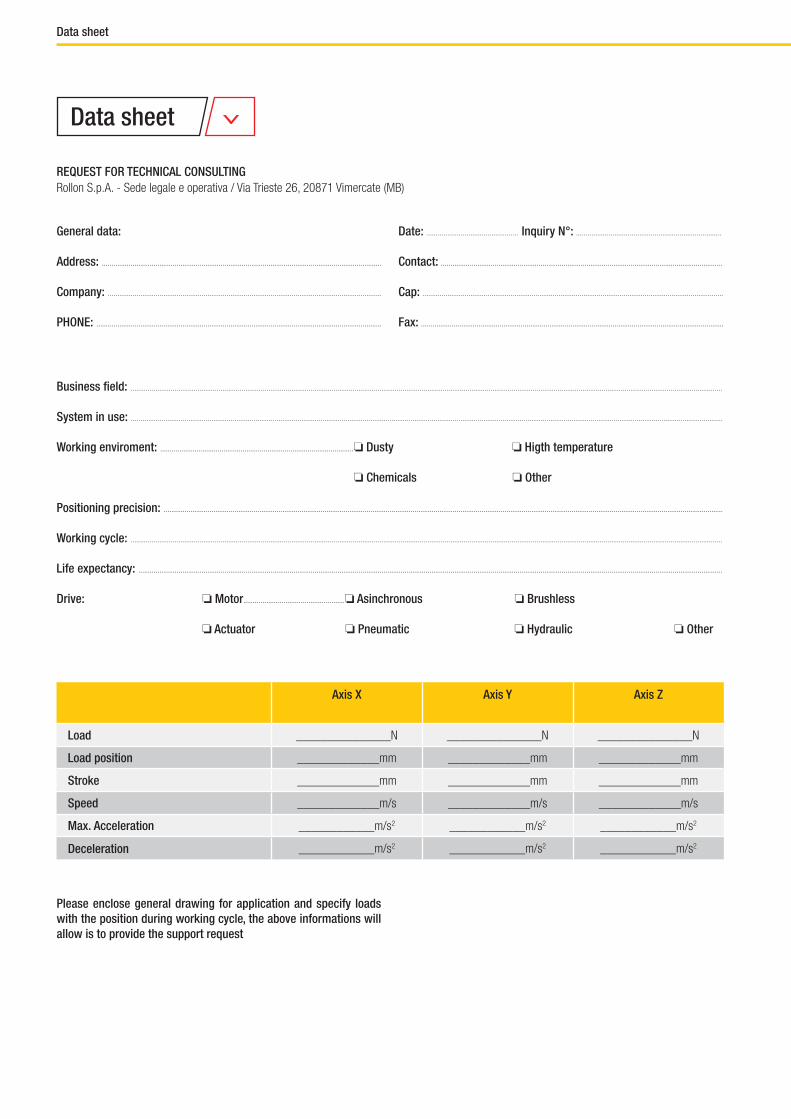
Please enclose general drawing for application and specify loads with the position during working cycle, the above informations will allow is to provide the support request
General data: Date: ................................................ Inquiry N°: ............................................................................
Address: .................................................................................................................................................. Contact: ...................................................................................................................................................
Company: ............................................................................................................................................... Cap: .............................................................................................................................................................
PHONE: ..................................................................................................................................................... Fax: ..............................................................................................................................................................
Business field: .....................................................................................................................................................................................................................................................................................................................
System in use: .....................................................................................................................................................................................................................................................................................................................
Working enviroment: .....................................................................................................❏ Dusty ❏ Higth temperature
❏ Chemicals ❏ Other
Positioning precision: ....................................................................................................................................................................................................................................................................................................
Working cycle: .....................................................................................................................................................................................................................................................................................................................
Life expectancy: .................................................................................................................................................................................................................................................................................................................
Drive: ❏ Motor.....................................................❏ Asinchronous ❏ Brushless
❏ Actuator ❏ Pneumatic ❏ Hydraulic ❏ Other
Axis X Axis Y Axis Z
Load _______________N _______________N _______________N
Load position _____________mm _____________mm _____________mm
Stroke _____________mm _____________mm _____________mm
Speed _____________m/s _____________m/s _____________m/s
Max. Acceleration ____________m/s2 ____________m/s2 ____________m/s2
Deceleration ____________m/s2 ____________m/s2 ____________m/s2
Data sheet
REQUEST FOR TECHNICAL CONSULTINGRollon S.p.A. - Sede legale e operativa / Via Trieste 26, 20871 Vimercate (MB)
Data sheet


LL_GC_EN_09/18
All addresses of our global sales partners can also be found at www.rollon.comThe content of this document and its use are subject to the general terms of sale of ROLLON available on the web site www.rollon.comChanges and errors expected. The text and images may be used only with our permission.
DistributorConsult the other ranges of products
Rollon Branches & Rep. OfficesDistributors
3F Shiodome Building, 1-2-20 Kaigan, Minato-ku,Tokyo 105-0022 JapanPhone +81 3 6721 8487www.rollon.jp - [email protected]
ROLLON - JAPAN
Via Trieste 26I-20871 Vimercate (MB)Phone: (+39) 039 62 59 1www.rollon.it - [email protected]
ROLLON S.p.A. - ITALY (Headquarters)
Bonner Strasse 317-319D-40589 DüsseldorfPhone: (+49) 211 95 747 0www.rollon.de - [email protected]
ROLLON GmbH - GERMANY
Ringbaan Zuid 86905 DB ZevenaarPhone: (+31) 316 581 999www.rollon.nl - [email protected]
ROLLON B.V. - NETHERLANDS
101 Bilby Road. Suite BHackettstown, NJ 07840Phone: (+1) 973 300 5492www.rolloncorp.com - [email protected]
ROLLON Corporation - USA
Les Jardins d‘Eole, 2 allée des SéquoiasF-69760 LimonestPhone: (+33) (0) 4 74 71 93 30www.rollon.fr - [email protected]
ROLLON S.A.R.L. - FRANCE
R. Joaquim Floriano, 397, 2o. andarItaim Bibi - 04534-011, São Paulo, BRASILPhone: +55 (11) 3198 3645www.rollonbrasil.com.br - [email protected]
ROLLON - SOUTH AMERICA (Rep. Office)
1st floor, Regus Gem Business Centre, 26/1 Hosur Road, Bommanahalli, Bangalore 560068Phone: (+91) 80 67027066www.rollonindia.in - [email protected]
ROLLON India Pvt. Ltd. - INDIA
117105, Moscow, Varshavskoyeshosse 17, building 1Phone: +7 (495) 508-10-70 www.rollon.ru - [email protected]
ROLLON S.p.A. - RUSSIA (Rep. Office)
No. 1155 Pang Jin Road, China, Suzhou, 215200Phone: +86 0512 6392 1625 www.rollon.cn.com - [email protected]
ROLLON Ltd - CHINA
The Works 6 West Street OlneyBuckinghamshire, United Kingdom, MK46 5 HRPhone: +44 (0) 1234964024www.rollon.uk.com - [email protected]
ROLLON Ltd - UK (Rep. Office)
ASIA
AMERICA
EUROPE
Linear Line
www.rollon.com
COVER_Linear.indd 1 28/09/2018 13:25:04
Telescopic Line
www.rollon.com
COVER_TELESCOPIC.indd 1 28/09/2018 13:25:34
Actuator System Line
www.rollon.com
COVE_ActuatorSystemLine.indd 1 28/09/2018 13:23:35
Actuator Line
www.rollon.com
COVER_Attuatori.indd 1 28/09/2018 13:24:25
BIBUS Otomasyon San ve Tic. Ltd. Sti.İkitelli OSB Bedrettin Dalan Bulvarı VIP Plaza Kat: 43- 4434490 Başakşehir - İstanbul / TURKEY
+90 444 20 38 - Tel+90 212 249 88 34 - Fax


