Embed Size (px)
Citation preview

Prepared by:
0 Issued for Approval
REV DESCRIPTION PREP’D CHECK’D APPROV’D DATE
CUSTOMER :PROJECT :DOCUMENT : FACTORY ACCEPTANCE TEST
PROCEDURE FOR CONTROL VALVECUST. DOC NO. : -PTCS DOC NO. : FCS-SOP-001. REV 01SHEET : 1 OF 10

Page 1 of 10
TABLE OF CONTENTS
Table of Contents ....................................................................................................................................1
SECTION – 1. INTRODUCTION ...............................................................................................................2
1 – 1. Introduction and System Overview ..............................................................................................2
1 – 2. Reference Documents ...................................................................................................................2
1 – 3. Test Equipment .............................................................................................................................2
1 – 4. Orientation of Witnesses ..............................................................................................................3
1 – 5. Punch List ......................................................................................................................................3
SECTION – 2. OPERATIONAL TEST .........................................................................................................4
2 – 1. Operational Test for Hydro Static Test ..........................................................................................4
A. Purpose ...........................................................................................................4
B. Scope ........................................................................................................................4
C. Equipment and Material ..........................................................................................4
D. Procedure ........................................................................................................5
2 – 2. Operational Test for Seat Leak Test...............................................................................................6
A. Purpose ............................................................................................................6
B. Scope .........................................................................................................................6
C. Equipment and Material ...........................................................................................6
D. Procedure.........................................................................................................7
2 – 3. Operational Test for Stroke Test....................................................................................................8
A. Purpose ............................................................................................................8
B. Scope .........................................................................................................................8
C. Equipment and Material ...........................................................................................8
D. Procedure.........................................................................................................9
Annexure 1 Punch List .................................................................................................................10

Page 2 of 10
SECTION 1 – INTRODUCTION
1.1 INTRODUCTION
This document defines the Factory Acceptance Test (FAT) procedure to be carried out for UnitControl valve.
Factory Acceptance Test (FAT) is categorized onto three activities:
1. Hydro test2. Seat leak test3. Stroke test
The purpose of carrying out the FAT is to check functionality of each instrument and packageas per agreed and approved documents
The PCV System Specification as per datasheet:
1. Tag No. : Manufacture : Fisher Control Valve Actuator Model : Supply actuator : Body Model : Size Valve Model : Positioner Model :
Input Signal :
Access :
1.2 REFERENCE DOCUMENTS
The lists of applicable documents are enclosed along with this FAT procedure. This FATProcedure is provided as information and reference customer before conduct the FAT

Page 3 of 10
1.3 TEST EQUIPMENT
The following is a list of test equipment used for Functional the field instruments. If required,other instruments will be used.
Loop calibrator Hart Communicator (375 or 475) Compressor for Air Instrument Rotameter Pressure Gauge Block/Needle Valve Flange Tubing and fitting Hydro pump Barton Recorder (optional)
1.4 ORIENTATION OF WITNESSES
All representatives shall be briefed on the operating principles of the PCV package beforecommencing the FAT. The exact FAT schedule shall also be explained to the representativesduring this briefing.
1.5 PUNCH LIST
Any discrepancies noted during the tests shall be defined, agreed and recorded in the PunchList Section. For punch list format refer to Annexure-1

Page 4 of 10
SECTION 2 – 1. OPERATIONAL TEST FOR HYDROSTATIC TEST
A. Purpose
This document describes the method of procedure test for confirming mechanical structuralintegrity and liquid, the test shall show no leakage, no wetting of the external surfaces and nopermanent distortion under the full test pressure.
B. Scope
The hydrostatic test for valve test specification referenced on API 598
C. Equipment and Materials
- Hydrotest pump with capacity 100 MPA
- Air Instrument
- Flange
- Connector
- Tubing SS
- Test Fluid; water-soluable oil or inhibitor corrosion
Page 5 of 10
D. Procedure Operational
- Adjust Regulator for Supply Pressure to POSITIONER
- After filling a valve with suitable liquid the valve shall be pressurized
- Closed Block valve for feed liquid into the test valve
- Input pressure from Hydrotest Pump as per Ansi class req
- The duration of test pressure shall not be less than 3 minutes before start of inspection
- The temperature of test liquid shall not exceed 100° F
- After the pressure has reached the specified target, the Valve body must no allowable
leackage
- Open Block valve for Release pressure on the valve

Page 6 of 10
SECTION 2 – 2. OPERATIONAL TEST FOR SEAT LEAK TEST
A. Purpose
This document describes the method of Procedure test for the Quantity of fluid passing
through a valve, when the valve is in the fully Closed position with differential pressure and
temperature (ANSI Leak Class)
B. Scope
Seat leak test for valve test specification referenced on ANSI B16.104
C. Equipment and Materials
- Air Compressor for Press 50 Psig
- Air instrument to control valve
- Block / Needle valve
- Flange
- Connector
- Union Tee
- Tubing and ferrule sets
- Rotameter

Page 7 of 10
D. Procedure Operational
- Prior to testing, the valve shall be completely assembled, and all instrument and accessories
mounted according to the requisition or assembly processing document.
- Verify the valve in Fully Closed position
- Verify Inlet pressure must not exceed maximum Inlet body valve.
- Slightly Open block valve to the inlet body valve 50 psig ( referenced ANSI B16.104
- Check Rotameter for actual leak, leakage must not exceed the Maximum allowable Leak on
datasheet
SECTION 2– 3. OPERATIONAL TEST FOR STROKE TEST
A. Purpose
This document describes the method for demonstrating that the actuator has adequate force to
open and close the valve. The procedure shall demonstrate that no mechanical damage or
permanent deformation of valve components will occur and that accessories function properly
B. Scope
testing valve travels from a normal position to a predetermined final position as a fully opened or closed
end position in a certain operating situation.
C. Equipment and Materials
- Air Instrument
- Loop Calibrator ( 4 - 20 mA)
- Connector
- Tubing and ferrule sets

Page 8 of 10
D. Procedure Operational
- Apply Air Instrument for Supply pressure to Regulator 67 CFRS
- Adjust Regulator 67CFRS until pressure as per datasheet for Supply Pressure to
POSITIONER
- Set Loop Calibrator to provide current Input Signal (4-20mA) to POSITIONER
- Verify Current Input Signal to Stroke test ( Low Travel – Mid Travel - High Travel )
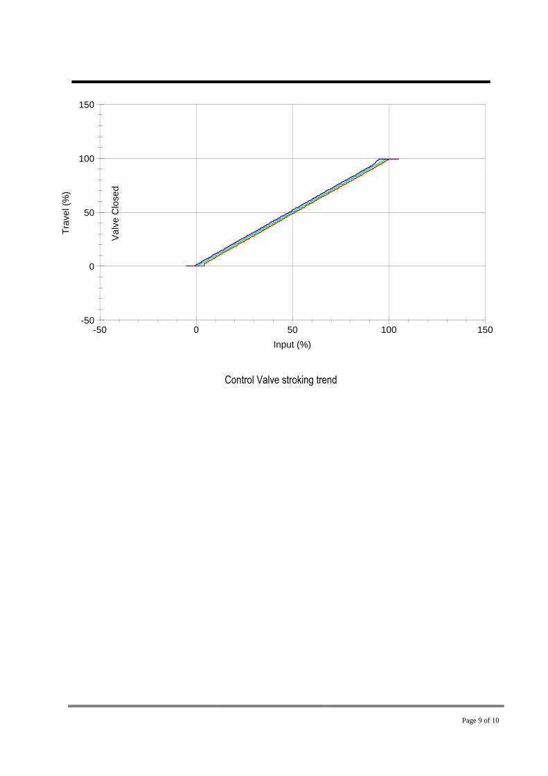
- See Percentage of Actual Travel (0-100%) to match with Current input Signal
(4-20mA) based on table bellow
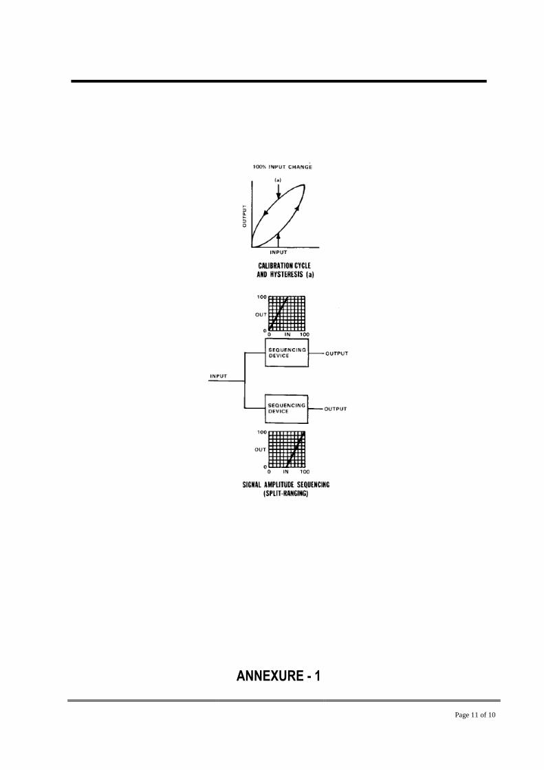
- Hysterisis test will perform by AMS Valvelink software with total scan mode (Min
Requirment Positioner DVC6200 Tier AD or PD, if tier below AD will perform by one step
upgrade)
Hysteresis test (as per purchaser required); Compared the maximum difference in output value
for any single input value during calibration cycle, excluding error due to dead band.
Page 9 of 10
-50 0 50 100 150-50
0
50
100
150
Input (%)
Tra
ve
l(%
)
Va
lve
Clo
se
d
Control Valve stroking trend

Page 10 of 10
Control Valve Step Respon Trend
Page 11 of 10
ANNEXURE - 1

Page 12 of 10
Punch List Date -No Description Action By


