Embed Size (px)
Citation preview

PRODUCT CATALOG 60TH EDITIONMiTek
® USP® Structural Connectors

ENGINEERED PRODUCTS
Our products save on labor and installation costs and
help provide code compliant and safe, resilient homes.
SOFTWARE
We’re optimizing the workflow of your business, improving
accuracy and reducing waste with our software solutions.
MiTek-US.com/Products
MiTek-US.com/Software
MITEK IS MORE THAN JUST ENGINEERED PRODUCTS
WE’RE WORKING TO BE YOUR HOLISTIC BUILDING SOLUTIONS PARTNERSEE MORE OF OUR SOLUTIONS ON THE INSIDE-FRONT COVER >
MITEK IS MORE THAN JUST ENGINEERED PRODUCTS
WE’RE WORKING TO BE YOUR HOLISTIC BUILDING SOLUTIONS PARTNER< SEE MORE OF OUR SOLUTIONS ON THE INSIDE-FRONT COVER
MiTek® Product Catalog
Copy
righ
t © 2
020
MiT
ek In
dust
ries
, Inc
. Al
l Rig
hts
Rese
rved
3
What's New at MiTek?
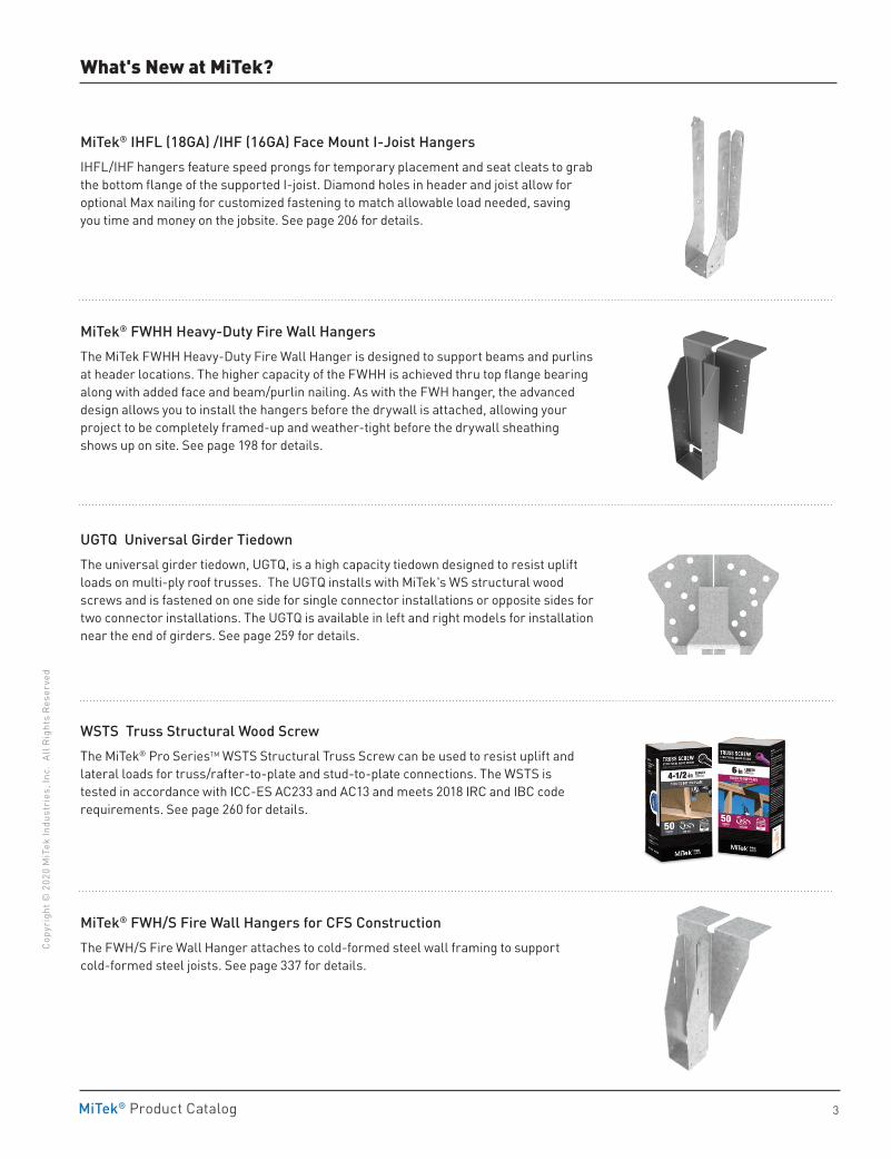
MiTek® IHFL (18GA) /IHF (16GA) Face Mount I-Joist HangersIHFL/IHF hangers feature speed prongs for temporary placement and seat cleats to grab the bottom flange of the supported I-joist. Diamond holes in header and joist allow for optional Max nailing for customized fastening to match allowable load needed, saving you time and money on the jobsite. See page 206 for details.
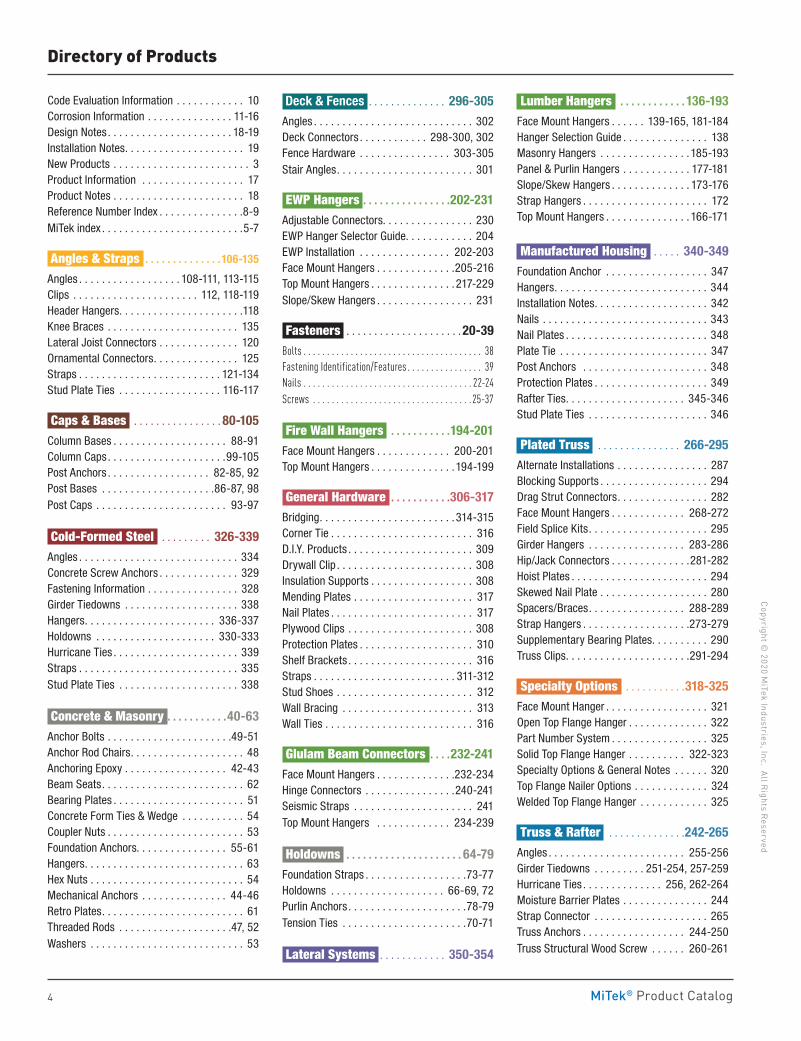
MiTek® FWHH Heavy-Duty Fire Wall HangersThe MiTek FWHH Heavy-Duty Fire Wall Hanger is designed to support beams and purlins at header locations. The higher capacity of the FWHH is achieved thru top flange bearing along with added face and beam/purlin nailing. As with the FWH hanger, the advanced design allows you to install the hangers before the drywall is attached, allowing your project to be completely framed-up and weather-tight before the drywall sheathing shows up on site. See page 198 for details.
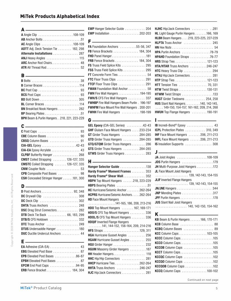
UGTQ Universal Girder Tiedown The universal girder tiedown, UGTQ, is a high capacity tiedown designed to resist uplift loads on multi-ply roof trusses. The UGTQ installs with MiTek's WS structural wood screws and is fastened on one side for single connector installations or opposite sides for two connector installations. The UGTQ is available in left and right models for installation near the end of girders. See page 259 for details.
WSTS Truss Structural Wood Screw The MiTek® Pro SeriesTM WSTS Structural Truss Screw can be used to resist uplift and lateral loads for truss/rafter-to-plate and stud-to-plate connections. The WSTS is tested in accordance with ICC-ES AC233 and AC13 and meets 2018 IRC and IBC code requirements. See page 260 for details.
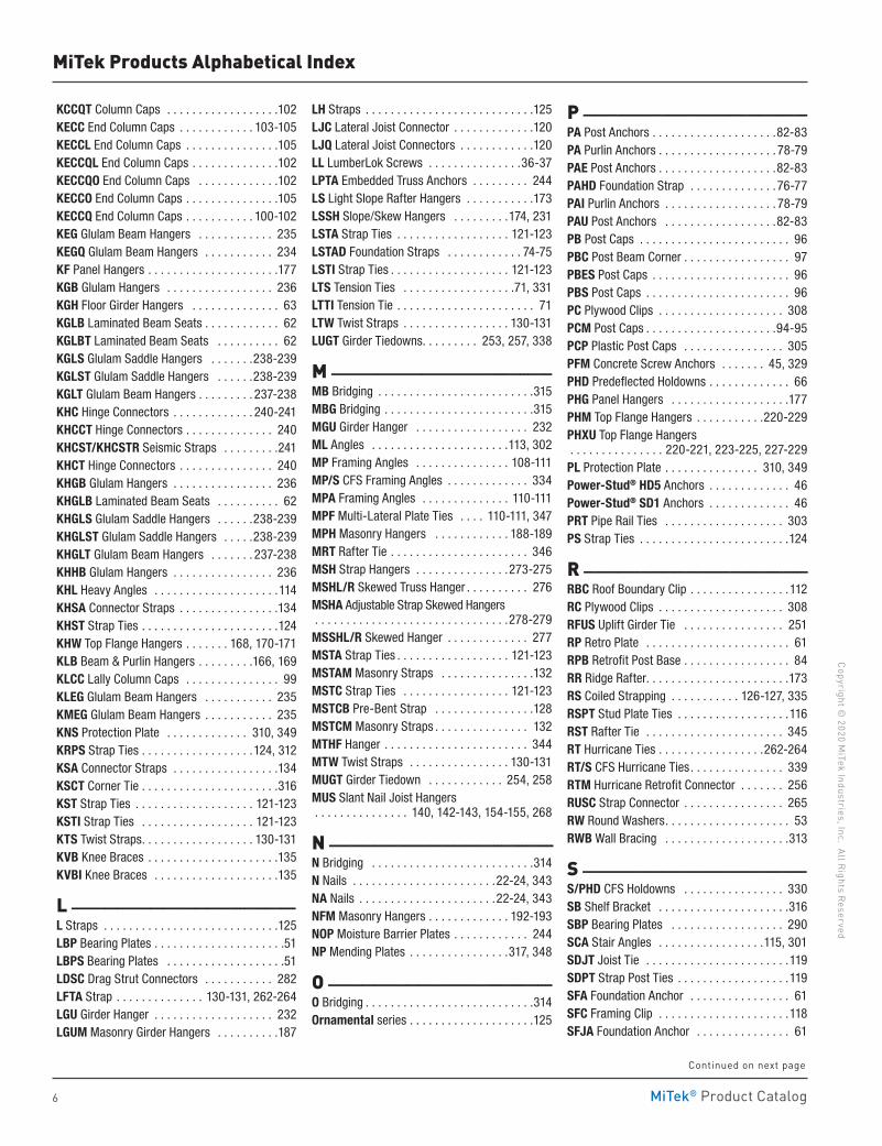
MiTek® FWH/S Fire Wall Hangers for CFS ConstructionThe FWH/S Fire Wall Hanger attaches to cold-formed steel wall framing to support cold-formed steel joists. See page 337 for details.
MiTek® Product Catalog
Copyright © 2020 M
iTek Industries, Inc. All Rights Reserved
4
Directory of Products
Code Evaluation Information . . . . . . . . . . . . 10 Corrosion Information . . . . . . . . . . . . . . . 11-16Design Notes . . . . . . . . . . . . . . . . . . . . . . 18-19Installation Notes . . . . . . . . . . . . . . . . . . . . . 19 New Products . . . . . . . . . . . . . . . . . . . . . . . . 3 Product Information . . . . . . . . . . . . . . . . . . 17Product Notes . . . . . . . . . . . . . . . . . . . . . . . 18Reference Number Index . . . . . . . . . . . . . . .8-9MiTek index . . . . . . . . . . . . . . . . . . . . . . . . .5-7
Angles & Straps . . . . . . . . . . . . . .106-135
Angles . . . . . . . . . . . . . . . . . . 108-111, 113-115 Clips . . . . . . . . . . . . . . . . . . . . . . 112, 118-119Header Hangers . . . . . . . . . . . . . . . . . . . . . .118Knee Braces . . . . . . . . . . . . . . . . . . . . . . . 135 Lateral Joist Connectors . . . . . . . . . . . . . . 120 Ornamental Connectors . . . . . . . . . . . . . . . 125 Straps . . . . . . . . . . . . . . . . . . . . . . . . . 121-134 Stud Plate Ties . . . . . . . . . . . . . . . . . . 116-117
Caps & Bases . . . . . . . . . . . . . . . . 80-105
Column Bases . . . . . . . . . . . . . . . . . . . . 88-91 Column Caps . . . . . . . . . . . . . . . . . . . . .99-105 Post Anchors . . . . . . . . . . . . . . . . . . 82-85, 92Post Bases . . . . . . . . . . . . . . . . . . . .86-87, 98Post Caps . . . . . . . . . . . . . . . . . . . . . . . 93-97
Cold-Formed Steel . . . . . . . . . 326-339
Angles . . . . . . . . . . . . . . . . . . . . . . . . . . . . 334Concrete Screw Anchors . . . . . . . . . . . . . . 329Fastening Information . . . . . . . . . . . . . . . . 328 Girder Tiedowns . . . . . . . . . . . . . . . . . . . . 338Hangers . . . . . . . . . . . . . . . . . . . . . . . 336-337Holdowns . . . . . . . . . . . . . . . . . . . . . 330-333Hurricane Ties . . . . . . . . . . . . . . . . . . . . . . 339Straps . . . . . . . . . . . . . . . . . . . . . . . . . . . . 335Stud Plate Ties . . . . . . . . . . . . . . . . . . . . . 338
Concrete & Masonry . . . . . . . . . . .40-63
Anchor Bolts . . . . . . . . . . . . . . . . . . . . . .49-51Anchor Rod Chairs . . . . . . . . . . . . . . . . . . . . 48 Anchoring Epoxy . . . . . . . . . . . . . . . . . . 42-43 Beam Seats . . . . . . . . . . . . . . . . . . . . . . . . . 62 Bearing Plates . . . . . . . . . . . . . . . . . . . . . . . 51 Concrete Form Ties & Wedge . . . . . . . . . . . 54 Coupler Nuts . . . . . . . . . . . . . . . . . . . . . . . . 53 Foundation Anchors . . . . . . . . . . . . . . . . 55-61Hangers . . . . . . . . . . . . . . . . . . . . . . . . . . . . 63 Hex Nuts . . . . . . . . . . . . . . . . . . . . . . . . . . . 54 Mechanical Anchors . . . . . . . . . . . . . . . 44-46Retro Plates . . . . . . . . . . . . . . . . . . . . . . . . . 61Threaded Rods . . . . . . . . . . . . . . . . . . . .47, 52Washers . . . . . . . . . . . . . . . . . . . . . . . . . . . 53
Deck & Fences . . . . . . . . . . . . . . 296-305
Angles . . . . . . . . . . . . . . . . . . . . . . . . . . . . 302Deck Connectors . . . . . . . . . . . . 298-300, 302 Fence Hardware . . . . . . . . . . . . . . . . 303-305Stair Angles . . . . . . . . . . . . . . . . . . . . . . . . 301
EWP Hangers . . . . . . . . . . . . . . . .202-231
Adjustable Connectors . . . . . . . . . . . . . . . . 230EWP Hanger Selector Guide . . . . . . . . . . . . 204 EWP Installation . . . . . . . . . . . . . . . . 202-203Face Mount Hangers . . . . . . . . . . . . . .205-216Top Mount Hangers . . . . . . . . . . . . . . .217-229Slope/Skew Hangers . . . . . . . . . . . . . . . . . 231
Fasteners . . . . . . . . . . . . . . . . . . . . . 20-39
Bolts . . . . . . . . . . . . . . . . . . . . . . . . . . . . . . . . . . . . . . 38Fastening Identification/Features . . . . . . . . . . . . . . . . 39 Nails . . . . . . . . . . . . . . . . . . . . . . . . . . . . . . . . . . . . 22-24Screws . . . . . . . . . . . . . . . . . . . . . . . . . . . . . . . . . .25-37
Fire Wall Hangers . . . . . . . . . . .194-201
Face Mount Hangers . . . . . . . . . . . . . 200-201Top Mount Hangers . . . . . . . . . . . . . . .194-199
General Hardware . . . . . . . . . . .306-317
Bridging . . . . . . . . . . . . . . . . . . . . . . . .314-315 Corner Tie . . . . . . . . . . . . . . . . . . . . . . . . . 316 D .I .Y . Products . . . . . . . . . . . . . . . . . . . . . . 309 Drywall Clip . . . . . . . . . . . . . . . . . . . . . . . . 308 Insulation Supports . . . . . . . . . . . . . . . . . . 308Mending Plates . . . . . . . . . . . . . . . . . . . . . 317 Nail Plates . . . . . . . . . . . . . . . . . . . . . . . . . 317 Plywood Clips . . . . . . . . . . . . . . . . . . . . . . 308Protection Plates . . . . . . . . . . . . . . . . . . . . 310Shelf Brackets . . . . . . . . . . . . . . . . . . . . . . 316Straps . . . . . . . . . . . . . . . . . . . . . . . . . 311-312 Stud Shoes . . . . . . . . . . . . . . . . . . . . . . . . 312Wall Bracing . . . . . . . . . . . . . . . . . . . . . . . 313Wall Ties . . . . . . . . . . . . . . . . . . . . . . . . . . 316
Glulam Beam Connectors . . . .232-241
Face Mount Hangers . . . . . . . . . . . . . .232-234 Hinge Connectors . . . . . . . . . . . . . . . .240-241Seismic Straps . . . . . . . . . . . . . . . . . . . . . 241Top Mount Hangers . . . . . . . . . . . . . 234-239
Holdowns . . . . . . . . . . . . . . . . . . . . . 64-79
Foundation Straps . . . . . . . . . . . . . . . . . .73-77Holdowns . . . . . . . . . . . . . . . . . . . . 66-69, 72Purlin Anchors . . . . . . . . . . . . . . . . . . . . .78-79 Tension Ties . . . . . . . . . . . . . . . . . . . . . .70-71
Lateral Systems . . . . . . . . . . . . 350-354
Lumber Hangers . . . . . . . . . . . . 136-193
Face Mount Hangers . . . . . . 139-165, 181-184Hanger Selection Guide . . . . . . . . . . . . . . . 138Masonry Hangers . . . . . . . . . . . . . . . .185-193Panel & Purlin Hangers . . . . . . . . . . . . 177-181Slope/Skew Hangers . . . . . . . . . . . . . . 173-176Strap Hangers . . . . . . . . . . . . . . . . . . . . . . 172 Top Mount Hangers . . . . . . . . . . . . . . . 166-171
Manufactured Housing . . . . . 340-349
Foundation Anchor . . . . . . . . . . . . . . . . . . 347Hangers . . . . . . . . . . . . . . . . . . . . . . . . . . . 344Installation Notes . . . . . . . . . . . . . . . . . . . . 342Nails . . . . . . . . . . . . . . . . . . . . . . . . . . . . . 343Nail Plates . . . . . . . . . . . . . . . . . . . . . . . . . 348Plate Tie . . . . . . . . . . . . . . . . . . . . . . . . . . 347Post Anchors . . . . . . . . . . . . . . . . . . . . . . 348Protection Plates . . . . . . . . . . . . . . . . . . . . 349 Rafter Ties . . . . . . . . . . . . . . . . . . . . . 345-346Stud Plate Ties . . . . . . . . . . . . . . . . . . . . . 346
Plated Truss . . . . . . . . . . . . . . . 266-295
Alternate Installations . . . . . . . . . . . . . . . . 287Blocking Supports . . . . . . . . . . . . . . . . . . . 294Drag Strut Connectors . . . . . . . . . . . . . . . . 282 Face Mount Hangers . . . . . . . . . . . . . 268-272 Field Splice Kits . . . . . . . . . . . . . . . . . . . . . 295 Girder Hangers . . . . . . . . . . . . . . . . . 283-286Hip/Jack Connectors . . . . . . . . . . . . . .281-282 Hoist Plates . . . . . . . . . . . . . . . . . . . . . . . . 294 Skewed Nail Plate . . . . . . . . . . . . . . . . . . . 280 Spacers/Braces . . . . . . . . . . . . . . . . . 288-289Strap Hangers . . . . . . . . . . . . . . . . . . .273-279 Supplementary Bearing Plates . . . . . . . . . . 290Truss Clips . . . . . . . . . . . . . . . . . . . . . .291-294
Specialty Options . . . . . . . . . . .318-325
Face Mount Hanger . . . . . . . . . . . . . . . . . . 321Open Top Flange Hanger . . . . . . . . . . . . . . 322Part Number System . . . . . . . . . . . . . . . . . 325Solid Top Flange Hanger . . . . . . . . . . 322-323Specialty Options & General Notes . . . . . . 320Top Flange Nailer Options . . . . . . . . . . . . . 324Welded Top Flange Hanger . . . . . . . . . . . . 325
Truss & Rafter . . . . . . . . . . . . . .242-265
Angles . . . . . . . . . . . . . . . . . . . . . . . . 255-256 Girder Tiedowns . . . . . . . . . 251-254, 257-259 Hurricane Ties . . . . . . . . . . . . . . 256, 262-264 Moisture Barrier Plates . . . . . . . . . . . . . . . 244 Strap Connector . . . . . . . . . . . . . . . . . . . . 265Truss Anchors . . . . . . . . . . . . . . . . . . 244-250 Truss Structural Wood Screw . . . . . . 260-261
MiTek® Product Catalog
Copy
righ
t © 2
020
MiT
ek In
dust
ries
, Inc
. Al
l Rig
hts
Rese
rved
5
A ——————————————-------------------A Angle Clip . . . . . . . . . . . . . . . . . . . . . 108-109AB Anchor Bolts . . . . . . . . . . . . . . . . . . . . . . .51AC Angle Clips . . . . . . . . . . . . . . . . . . . 108-109ADTT Adj . Deck Tension Tie . . . . . . . . 182, 298Alternate Installations . . . . . . . . . . . . . . . 287ANJ Heavy Angles . . . . . . . . . . . . . . . . . . . .115ARC Anchor Rod Chairs . . . . . . . . . . . . . . . . . 48ATR All Thread Rod . . . . . . . . . . . . . . . . . . . . 52
B ——————————————-------------------B Bolts . . . . . . . . . . . . . . . . . . . . . . . . . . . . . 38B Corner Braces . . . . . . . . . . . . . . . . . . . . . .114BC Post Cap . . . . . . . . . . . . . . . . . . . . . . . . . 93BCS Post Caps . . . . . . . . . . . . . . . . . . . . . . . 93BD Bolt Down . . . . . . . . . . . . . . . . . . . . . . . 305BL Corner Braces . . . . . . . . . . . . . . . . . . . . .114BN Breakfast Nook Hangers . . . . . . . . . . . . 282BP Bearing Plates . . . . . . . . . . . . . . . . . . . . . .51BPH Beam & Purlin Hangers . . 218, 221, 223-229
C ——————————————-------------------C Post Caps . . . . . . . . . . . . . . . . . . . . . . . . . 93CBE Column Bases . . . . . . . . . . . . . . . . . . . . 90CBSQ Column Bases . . . . . . . . . . . . . . . . . . 91CIA-GEL Epoxy . . . . . . . . . . . . . . . . . . . . .42-43 CIA-EA Epoxy Acrylate . . . . . . . . . . . . . . . . . 43 CLPBF Butterfly Hanger . . . . . . . . . . . . . . . 268CMST Coiled Strapping . . . . . . . . 126-127, 335CMSTC Coiled Strapping . . . . . . . 126-127, 335CNW Coupler Nuts . . . . . . . . . . . . . . . . . . . . 53CPB Composite Post Bases . . . . . . . . . . . . . 98CSH Concealed Stringer Hanger . . . . . .181, 300
D ——————————————-------------------D Post Anchors . . . . . . . . . . . . . . . . . . . 92, 348DC Drywall Clip . . . . . . . . . . . . . . . . . . . . . 308DC Deck Clip . . . . . . . . . . . . . . . . . . . . . . . 302DHTA Truss Anchors . . . . . . . . . . . . . . . . . 248DSC Drag Strut Connectors . . . . . . . . . . . . . 282DTB Deck Tie Back . . . . . . . . . . . 66, 183, 299DTB/S CFS Holdown . . . . . . . . . . . . . . . . . 332DTC Truss Anchor . . . . . . . . . . . . . . . . . . . 249DTUS Undersaddle Hanger . . . . . . . . . . . . . .180DUC Ductile Undercut Anchors . . . . . . . . . . . 44
E ——————————————-------------------EA Adhesive (CIA-EA) . . . . . . . . . . . . . . . . . . 43EBG Elevated Post Base . . . . . . . . . . . . . . . . 87EPB Elevated Post Bases . . . . . . . . . . . . .86-87EPBH Elevated Post Bases . . . . . . . . . . . . . . 87EPCM End Post Caps . . . . . . . . . . . . . . . .94-95ERB Fence Bracket . . . . . . . . . . . . . . . 184, 304
EWP Hanger Selector Guide . . . . . . . . . . . . 204EWP Installation . . . . . . . . . . . . . . . . . .202-203
F ——————————————-------------------FA Foundation Anchors . . . . . . . . . .55-56, 347FB Fence Brackets . . . . . . . . . . . . . . . 184, 304FHD Panel Hanger . . . . . . . . . . . . . . . . . . . . .181FRB Fence Brackets . . . . . . . . . . . . . . 184, 304FS Truss Field Splice Kits . . . . . . . . . . . . . . 295FSS Truss Field Splice Kits . . . . . . . . . . . . . 295FT Concrete Form Ties . . . . . . . . . . . . . . . . . 54FTC Floor Truss Clips . . . . . . . . . . . . . . . . . 291FTCF Floor Truss Clips . . . . . . . . . . . . . . . . 291FWAN Foundation Wall Anchor . . . . . . . . . . . 58FWH Fire Wall Hangers . . . . . . . . . . . . . 194-195FWH/S CFS Fire Wall Hangers . . . . . . . . . . 337FWHBP Fire Wall Hangers Beam Purlin . 196-197 FWHFM Face Mount Fire Wall Hangers . 200-201FWHH Fire Wall Hangers . . . . . . . . . . . 198-199
G ——————————————-------------------GEL Epoxy (CIA-GEL Series) . . . . . . . . . .42-43GHF Glulam Face Mount Hangers . . . . .233-234GT Girder Truss Hangers . . . . . . . . . . .284-285GTD Girder Truss Hangers . . . . . . . . . .284-285GTQ/GTQM Girder Truss Hangers . . . . . . . . 286 GTS Girder Truss Hangers . . . . . . . . . .284-285GTWS Girder Truss Hangers . . . . . . . . . . . . 283
H ——————————————-------------------Hanger Selector Guide . . . . . . . . . . . . . . . .138Hardy Frame® Moment Frames . . . . . . . . 353Hardy Frame® Shear Wall . . . . . . . . . . . . . 352HBPH Top Mount Hangers . . . . . .218, 223-229HBPS Bearing Plates . . . . . . . . . . . . . . . . . . .51HC Hurricane/Seismic Anchor . . . . . . . .262-264HCPRS Hurricane/Seismic Anchors . . . . .262-264HD Face Mount Hangers . . . . . . . . . . . . . . . . .141-165, 186, 208, 213-216HDO Top Mount Hangers . . . . . . . 167, 169-171HDO/S CFS Top Mount Hangers . . . . . . . . . 336HDOL/S CFS Top Mount Hangers . . . . . . . . 336HDQIF Inverted Flange Hangers . . . . . . . . 141, 144-152, 156-164, 209, 214-216HFS Straps . . . . . . . . . . . . . . . . . . . . . .129, 311 HGA Hurricane Gusset Angles . . . . . . . . . . 256HGAM Hurricane Gusset Angles . . . . . . . . . 255HGU Girder Hanger . . . . . . . . . . . . . . . . . . . 232HGUM Masonry Girder Hangers . . . . . . . . . .187HH Header Hangers . . . . . . . . . . . . . . . . . . . 118HHC Hip/Hip Connectors . . . . . . . . . . . . . . 281HHCP Hurricane Ties . . . . . . . . . . . . . . .262-264HHTA Truss Anchors . . . . . . . . . . . . . . 246-247HJC Hip/Jack Connectors . . . . . . . . . . . . . . 281
HJHC Hip/Jack Connectors . . . . . . . . . . . .281 HL Light Gauge Purlin Hangers . . . . . . .166, 169HLBH Beam Hangers . . . . 219, 223-225, 227-229HLPTA Truss Anchor . . . . . . . . . . . . . . . . . 245HN Hex Nuts . . . . . . . . . . . . . . . . . . . . . . . . . 54HPA Purlin Anchors . . . . . . . . . . . . . . . . . 78-79HPAHD Foundation Straps . . . . . . . . . . . .76-77HRS Strap Ties . . . . . . . . . . . . . . . . . . . 121-123HTA/HTAR Truss Anchors . . . . . . . . . . 246-247HTC Heavy Truss Clip . . . . . . . . . . . . . . . . . 294HTHJ Hip/Jack Connectors . . . . . . . . . . . . . 281HTP Strap Ties . . . . . . . . . . . . . . . . . . . 121-123HTT Tension Ties . . . . . . . . . . . . . . . . . 70, 331HTW Twist Straps . . . . . . . . . . . . . . . . . 130-131HTWM Twist Straps . . . . . . . . . . . . . . . . . . .133HUGT Girder Tiedowns . . . . . . . . . . . . 254, 258HUS Slant Nail Hangers . . . . . . . . . 140, 142-145, . . . . . 149-150, 154-157, 161-162, 209, 214, 268HWUH Top Flange Hangers . . . . . . . . . 190-191
I ——————————————-------------------IB Incredi-Bond® Epoxy . . . . . . . . . . . . . . . . 43ICPL Protection Plates . . . . . . . . . . . . 310, 349IHF Face Mount Hangers . . . . . . . 206, 211-213IHFL Face Mount Hangers . . . . . . 206, 211-213IS Insulation Supports . . . . . . . . . . . . . . . . 308
J ——————————————-------------------JA Joist Angles . . . . . . . . . . . . . . . . . . 108-109JDS Purlin Hangers . . . . . . . . . . . . . . . . . . .179JH Multi-Purpose Joist Hangers . . . . . . . . . .172JL Face Mount Joist Hangers . . . . . . . . . . . . . . . . . . . . . 139, 142-143, 154-155JLIF Inverted Flange Hangers . . . . . . . . . . . . . . . . . . . . . 139, 142-143, 154-155 JN/JNE Hangers . . . . . . . . . . . . . . . . . . . . . 344JNP Mending Plates . . . . . . . . . . . . . . . . . . .317JPF Purlin Hangers . . . . . . . . . . . . . . . . . . . .178JUS Slant Nail Joist Hangers . . . . . . . . . . . . . . . . . . . 140, 142-150, 154-162
K ——————————————-------------------KB Beam & Purlin Hangers . . . . . . 166, 170-171KCB Column Base . . . . . . . . . . . . . . . . . . . . 88KCBQ Column Bases . . . . . . . . . . . . . . . . . . 89KCC Column Caps . . . . . . . . . . . . . . . . . 103-105KCCC Column Caps . . . . . . . . . . . . . . . . . . . .105KCCO Column Caps . . . . . . . . . . . . . . . . . . . .105KCCOB Column Caps . . . . . . . . . . . . . . . . . .105KCCT Column Caps . . . . . . . . . . . . . . . . . . . .105KCCQC Column Caps . . . . . . . . . . . . . . . . . .102KCCQO Column Caps . . . . . . . . . . . . . . . . . .102KCCQOB Column Caps . . . . . . . . . . . . . . . . .102KCCQ Column Caps . . . . . . . . . . . . . . . 100-102
MiTek Products Alphabetical Index
Continued on next page
MiTek® Product Catalog
Copyright © 2020 M
iTek Industries, Inc. All Rights Reserved
6
KCCQT Column Caps . . . . . . . . . . . . . . . . . .102KECC End Column Caps . . . . . . . . . . . . 103-105 KECCL End Column Caps . . . . . . . . . . . . . . .105KECCQL End Column Caps . . . . . . . . . . . . . .102KECCQO End Column Caps . . . . . . . . . . . . .102KECCO End Column Caps . . . . . . . . . . . . . . .105KECCQ End Column Caps . . . . . . . . . . . 100-102KEG Glulam Beam Hangers . . . . . . . . . . . . 235KEGQ Glulam Beam Hangers . . . . . . . . . . . 234KF Panel Hangers . . . . . . . . . . . . . . . . . . . . .177KGB Glulam Hangers . . . . . . . . . . . . . . . . . 236KGH Floor Girder Hangers . . . . . . . . . . . . . . 63KGLB Laminated Beam Seats . . . . . . . . . . . . 62KGLBT Laminated Beam Seats . . . . . . . . . . 62KGLS Glulam Saddle Hangers . . . . . . .238-239KGLST Glulam Saddle Hangers . . . . . .238-239KGLT Glulam Beam Hangers . . . . . . . . . 237-238KHC Hinge Connectors . . . . . . . . . . . . . 240-241KHCCT Hinge Connectors . . . . . . . . . . . . . . 240KHCST/KHCSTR Seismic Straps . . . . . . . . .241KHCT Hinge Connectors . . . . . . . . . . . . . . . 240KHGB Glulam Hangers . . . . . . . . . . . . . . . . 236KHGLB Laminated Beam Seats . . . . . . . . . . 62KHGLS Glulam Saddle Hangers . . . . . .238-239KHGLST Glulam Saddle Hangers . . . . .238-239KHGLT Glulam Beam Hangers . . . . . . . 237-238KHHB Glulam Hangers . . . . . . . . . . . . . . . . 236KHL Heavy Angles . . . . . . . . . . . . . . . . . . . .114KHSA Connector Straps . . . . . . . . . . . . . . . .134KHST Strap Ties . . . . . . . . . . . . . . . . . . . . . .124KHW Top Flange Hangers . . . . . . . 168, 170-171KLB Beam & Purlin Hangers . . . . . . . . .166, 169KLCC Lally Column Caps . . . . . . . . . . . . . . . 99KLEG Glulam Beam Hangers . . . . . . . . . . . 235KMEG Glulam Beam Hangers . . . . . . . . . . . 235KNS Protection Plate . . . . . . . . . . . . . 310, 349KRPS Strap Ties . . . . . . . . . . . . . . . . . .124, 312KSA Connector Straps . . . . . . . . . . . . . . . . .134KSCT Corner Tie . . . . . . . . . . . . . . . . . . . . . .316KST Strap Ties . . . . . . . . . . . . . . . . . . . 121-123KSTI Strap Ties . . . . . . . . . . . . . . . . . . 121-123KTS Twist Straps . . . . . . . . . . . . . . . . . . 130-131KVB Knee Braces . . . . . . . . . . . . . . . . . . . . .135KVBI Knee Braces . . . . . . . . . . . . . . . . . . . .135
L ——————————————-------------------L Straps . . . . . . . . . . . . . . . . . . . . . . . . . . . .125LBP Bearing Plates . . . . . . . . . . . . . . . . . . . . .51LBPS Bearing Plates . . . . . . . . . . . . . . . . . . .51LDSC Drag Strut Connectors . . . . . . . . . . . 282LFTA Strap . . . . . . . . . . . . . . 130-131, 262-264LGU Girder Hanger . . . . . . . . . . . . . . . . . . . 232LGUM Masonry Girder Hangers . . . . . . . . . .187
LH Straps . . . . . . . . . . . . . . . . . . . . . . . . . . .125LJC Lateral Joist Connector . . . . . . . . . . . . .120LJQ Lateral Joist Connectors . . . . . . . . . . . .120LL LumberLok Screws . . . . . . . . . . . . . . .36-37 LPTA Embedded Truss Anchors . . . . . . . . . 244LS Light Slope Rafter Hangers . . . . . . . . . . .173LSSH Slope/Skew Hangers . . . . . . . . .174, 231LSTA Strap Ties . . . . . . . . . . . . . . . . . . 121-123LSTAD Foundation Straps . . . . . . . . . . . . 74-75LSTI Strap Ties . . . . . . . . . . . . . . . . . . . 121-123LTS Tension Ties . . . . . . . . . . . . . . . . . .71, 331LTTI Tension Tie . . . . . . . . . . . . . . . . . . . . . . 71LTW Twist Straps . . . . . . . . . . . . . . . . . 130-131LUGT Girder Tiedowns . . . . . . . . . 253, 257, 338
M ——————————————------------------MB Bridging . . . . . . . . . . . . . . . . . . . . . . . . .315MBG Bridging . . . . . . . . . . . . . . . . . . . . . . . .315MGU Girder Hanger . . . . . . . . . . . . . . . . . . 232ML Angles . . . . . . . . . . . . . . . . . . . . . .113, 302MP Framing Angles . . . . . . . . . . . . . . . 108-111MP/S CFS Framing Angles . . . . . . . . . . . . . 334MPA Framing Angles . . . . . . . . . . . . . . 110-111 MPF Multi-Lateral Plate Ties . . . . 110-111, 347MPH Masonry Hangers . . . . . . . . . . . . 188-189MRT Rafter Tie . . . . . . . . . . . . . . . . . . . . . . 346 MSH Strap Hangers . . . . . . . . . . . . . . .273-275MSHL/R Skewed Truss Hanger . . . . . . . . . . 276MSHA Adjustable Strap Skewed Hangers . . . . . . . . . . . . . . . . . . . . . . . . . . . . . . .278-279MSSHL/R Skewed Hanger . . . . . . . . . . . . . 277MSTA Strap Ties . . . . . . . . . . . . . . . . . . 121-123MSTAM Masonry Straps . . . . . . . . . . . . . . .132MSTC Strap Ties . . . . . . . . . . . . . . . . . 121-123MSTCB Pre-Bent Strap . . . . . . . . . . . . . . . .128MSTCM Masonry Straps . . . . . . . . . . . . . . . 132MTHF Hanger . . . . . . . . . . . . . . . . . . . . . . . 344MTW Twist Straps . . . . . . . . . . . . . . . . 130-131MUGT Girder Tiedown . . . . . . . . . . . . 254, 258MUS Slant Nail Joist Hangers . . . . . . . . . . . . . . . 140, 142-143, 154-155, 268
N ——————————————-------------------N Bridging . . . . . . . . . . . . . . . . . . . . . . . . . .314N Nails . . . . . . . . . . . . . . . . . . . . . . .22-24, 343NA Nails . . . . . . . . . . . . . . . . . . . . . .22-24, 343NFM Masonry Hangers . . . . . . . . . . . . . 192-193NOP Moisture Barrier Plates . . . . . . . . . . . . 244NP Mending Plates . . . . . . . . . . . . . . . .317, 348
O ——————————————-------------------O Bridging . . . . . . . . . . . . . . . . . . . . . . . . . . .314Ornamental series . . . . . . . . . . . . . . . . . . . .125
P ——————————————-------------------PA Post Anchors . . . . . . . . . . . . . . . . . . . .82-83PA Purlin Anchors . . . . . . . . . . . . . . . . . . . 78-79PAE Post Anchors . . . . . . . . . . . . . . . . . . .82-83PAHD Foundation Strap . . . . . . . . . . . . . .76-77PAI Purlin Anchors . . . . . . . . . . . . . . . . . . 78-79PAU Post Anchors . . . . . . . . . . . . . . . . . .82-83PB Post Caps . . . . . . . . . . . . . . . . . . . . . . . . 96PBC Post Beam Corner . . . . . . . . . . . . . . . . . 97PBES Post Caps . . . . . . . . . . . . . . . . . . . . . . 96PBS Post Caps . . . . . . . . . . . . . . . . . . . . . . . 96PC Plywood Clips . . . . . . . . . . . . . . . . . . . . 308PCM Post Caps . . . . . . . . . . . . . . . . . . . . .94-95PCP Plastic Post Caps . . . . . . . . . . . . . . . . 305PFM Concrete Screw Anchors . . . . . . . 45, 329PHD Predeflected Holdowns . . . . . . . . . . . . . 66PHG Panel Hangers . . . . . . . . . . . . . . . . . . .177PHM Top Flange Hangers . . . . . . . . . . .220-229PHXU Top Flange Hangers . . . . . . . . . . . . . . . 220-221, 223-225, 227-229PL Protection Plate . . . . . . . . . . . . . . . 310, 349Power-Stud® HD5 Anchors . . . . . . . . . . . . . 46Power-Stud® SD1 Anchors . . . . . . . . . . . . . 46PRT Pipe Rail Ties . . . . . . . . . . . . . . . . . . . 303PS Strap Ties . . . . . . . . . . . . . . . . . . . . . . . .124
R ——————————————-------------------RBC Roof Boundary Clip . . . . . . . . . . . . . . . .112RC Plywood Clips . . . . . . . . . . . . . . . . . . . . 308RFUS Uplift Girder Tie . . . . . . . . . . . . . . . . 251RP Retro Plate . . . . . . . . . . . . . . . . . . . . . . . 61RPB Retrofit Post Base . . . . . . . . . . . . . . . . . 84RR Ridge Rafter . . . . . . . . . . . . . . . . . . . . . . .173RS Coiled Strapping . . . . . . . . . . . 126-127, 335RSPT Stud Plate Ties . . . . . . . . . . . . . . . . . .116RST Rafter Tie . . . . . . . . . . . . . . . . . . . . . . 345RT Hurricane Ties . . . . . . . . . . . . . . . . .262-264RT/S CFS Hurricane Ties . . . . . . . . . . . . . . . 339RTM Hurricane Retrofit Connector . . . . . . . 256RUSC Strap Connector . . . . . . . . . . . . . . . . 265RW Round Washers . . . . . . . . . . . . . . . . . . . . 53RWB Wall Bracing . . . . . . . . . . . . . . . . . . . .313
S ——————————————-------------------S/PHD CFS Holdowns . . . . . . . . . . . . . . . . 330SB Shelf Bracket . . . . . . . . . . . . . . . . . . . . .316SBP Bearing Plates . . . . . . . . . . . . . . . . . . 290SCA Stair Angles . . . . . . . . . . . . . . . . .115, 301SDJT Joist Tie . . . . . . . . . . . . . . . . . . . . . . .119SDPT Strap Post Ties . . . . . . . . . . . . . . . . . .119SFA Foundation Anchor . . . . . . . . . . . . . . . . 61SFC Framing Clip . . . . . . . . . . . . . . . . . . . . .118SFJA Foundation Anchor . . . . . . . . . . . . . . . 61
MiTek Products Alphabetical Index
Continued on next page
MiTek® Product Catalog
Copy
righ
t © 2
020
MiT
ek In
dust
ries
, Inc
. Al
l Rig
hts
Rese
rved
7
SFP Fence Post Connectors . . . . . . . . . . . . 305SHA Masonry Uplift Connectors . . . . . . . . . 255SKH Skewed 45° Hangers . . . . . . . . . . 175-176SKHH Skewed 45° Hangers . . . . . . . . . 175-176SMP Fence Post Connectors . . . . . . . . . . . 305SNP Skewed Nail Plate . . . . . . . . . . . . . . . . 280Specialty Options . . . . . . . . . . . . . . . .320-325SPT Stud Plate Ties . . . . . . . . . . . 116-117, 338SPTH Stud Plate Ties . . . . . . . . . . . . . . . . . .117SPTHW Stud Plate Ties . . . . . . . . . . . . . 117, 346SRCP Sill Retrofit Connector Plate . . . . . . . . 59SRC Sill Retro Connector . . . . . . . . . . . . . . . 60ST Foundation Anchors . . . . . . . . . . . . . . . . 57ST Strap Ties . . . . . . . . . . . . . . . . . . . . 121-123Stabilizer . . . . . . . . . . . . . . . . . . . . . . . . . . 288STAD Foundation Straps . . . . . . . . . . . . . 74-75STB Anchor Bolts . . . . . . . . . . . . . . . . . . .49-50STBL Anchor Bolts . . . . . . . . . . . . . . . . . .49-50STC Scissor Truss Clips . . . . . . . . . . . . . . . 293STS Stud Shoes . . . . . . . . . . . . . . . . . . . . . .312SUH Joist Hangers .139, 142-151, 153-163, 165SW Top Flange Hangers . . . . . . . . . . . . 168-170SWH Top Flange Hangers . . . . . . . . . . . 168-171
T ——————————————-------------------T Hoist Plates . . . . . . . . . . . . . . . . . . . . . . . 294T Straps . . . . . . . . . . . . . . . . . . . . . . . . . . . .125TA Foundation Straps . . . . . . . . . . . . . . . . . . 73TA Truss Anchors . . . . . . . . . . . . . . . . . . . . 250TAR Truss Anchors . . . . . . . . . . . . . . . . . . . 250TD Holdowns . . . . . . . . . . . . . . . . . . . . . .68-69TDL Concrete Angles . . . . . . . . . . . . . . . . . .113TDS CFS Holdowns . . . . . . . . . . . . . . . . . . 333TDX Holdowns . . . . . . . . . . . . . . . . . . . . .68-69TFI Top Mount Hangers . . . . . 217, 222, 224-225TFL Top Mount Hangers . . . . . . . . 217, 221-222TH Straps . . . . . . . . . . . . . . . . . . . . . . . . . . .125THD Face Mount Truss Hangers . . . . . . . . . . . . . . . . . . . . . . . 210, 215-216, 269THDH Face Mount Hangers . . . . . . . . . . . . . . . . . . . 210, 214-216, 270-271THDHQ Girder Truss Hangers . . . . . . . . . . . 272THF Face Mount Hangers . . . . . . . . . . .207, 213THFI Face Mount Hangers . . . . . . . . . . 205, 212
THO Top Mount Hangers . . . . . . . . 217, 221-226THR Threaded Rods . . . . . . . . . . . . . . . . . . . .47TMP Rafter-To-Plate Connectors . . . . . . . . 230TMPH Rafter-To-Plate Connectors . . . . . . . 230TPP Mending Plates . . . . . . . . . . . . . . . . . . .317TR Roof Truss Ties . . . . . . . . . . . . . . . . . . . 293TS Truss Spacer . . . . . . . . . . . . . . . . . . . . . 289TSP Stud Plate Tie . . . . . . . . . . . . 116, 262-264TSX Truss Spacers . . . . . . . . . . . . . . . . . . . 289TT D .I .Y . Products . . . . . . . . . . . . . . . . . . . . 309 TTA Corner Bracket . . . . . . . . . . . . . . . . . . . 309TTB Bracket . . . . . . . . . . . . . . . . . . . . . . . . 309TTC Corner Tie . . . . . . . . . . . . . . . . . . . . . . 309TTF Bracket . . . . . . . . . . . . . . . . . . . . . . . . 309TTR Clip . . . . . . . . . . . . . . . . . . . . . . . . . . . 309TTU Clip . . . . . . . . . . . . . . . . . . . . . . . . . . . 309TUS Undersaddle Hanger . . . . . . . . . . . . . . .180
U ——————————————-------------------UGTS Uplift Girder Ties . . . . . . . . . . . . . . . . 252UGTQ Girder Tiedown . . . . . . . . . . . . . . . . . 259UMH Universal Masonry Hangers . . . . . . . . .185 UPHD Holdowns . . . . . . . . . . . . . . . . . . . . . . 67USC Uplift Girder Ties . . . . . . . . . . . . . . . . . 252
V ——————————————-------------------VTT Valley Truss Tie . . . . . . . . . . . . . . . . . . 292
W ——————————————------------------WAS Wet Post Anchors . . . . . . . . . . . . . . . . 85WB Wall Bracing . . . . . . . . . . . . . . . . . . . . . .313WBC Wall Bracing . . . . . . . . . . . . . . . . . . . .313WBT Wall Bracing . . . . . . . . . . . . . . . . . . . . .313WE Wet Post Anchors . . . . . . . . . . . . . . . . . . 85WG Concrete Form Wedge . . . . . . . . . . . . . . 54WS Hex Head Screws . . . . . . . . . . . . 25, 32, 34WSBH Bugle Head Screws . . . . . . . . . . . . . . 35WSTS Truss Screws . . . . . . . . . . . . . .260-261WSWH Washer Head Screws . . . . 26-31, 33-34WT Wall Ties . . . . . . . . . . . . . . . . . . . . . . . .316
Z ——————————————-------------------Z4™ Tie-Down Systems . . . . . . . . . . . . . . . . 354 ZC Blocking Supports . . . . . . . . . . . . . . . . . 294
MiTek Products Alphabetical Index
WARRANTYMiTek USA, Inc . (“MiTek”) warrants its MiTek catalog Products to be free from material defects in manufacture and design, and further warrants that they will perform within the design limitations of its published building code approvals for the applications described, when properly installed and maintained . These warranties do not cover Product deterioration due to environmental conditions, Products that have been modified or damaged, improperly installed or used outside of published design limitations or for other applications . In the event any Product is shown to not conform to these warranties, MiTek’s sole obligation, and Customer’s sole and exclusive remedy, shall be, at MiTek’s option, to replace the non-conforming product or refund the full purchase price paid by Customer to MiTek therefor . MITEK MAKES NO OTHER PRODUCT WARRANTIES,
EXPRESS OR IMPLIED, OF ANY KIND, AND PARTICULARLY EXCLUDES ANY IMPLIED WARRANTY OR MERCHANTABILITY OR FITNESS FOR A PARTICULAR PURPOSE . IN NO EVENT SHALL MITEK BE LIABLE FOR INCIDENTAL, CONSEQUENTIAL OR SPECIAL DAMAGES, REGARDLESS OF THE LEGAL THEORY OF RECOVERY, EVEN IF IT WAS AWARE OF THE POSSIBILITY OF SUCH DAMAGES . IN ANY CASE, MITEK’S MAXIMUM LIABILITY SHALL NOT EXCEED THE PURCHASE PRICE PAID BY CUSTOMER FOR THE NON-CONFORMING PRODUCT . Some states restrict consequential or other liability damage limitations, so some of the above limitations may not apply to you . MiTek reserves the right to change this warranty periodically . Consult MiTek’s website MiTek-US .com or contact MiTek for a current warranty statement .
MiTek® Product Catalog
Copyright © 2020 M
iTek Industries, Inc. All Rights Reserved
8
Reference Number Index
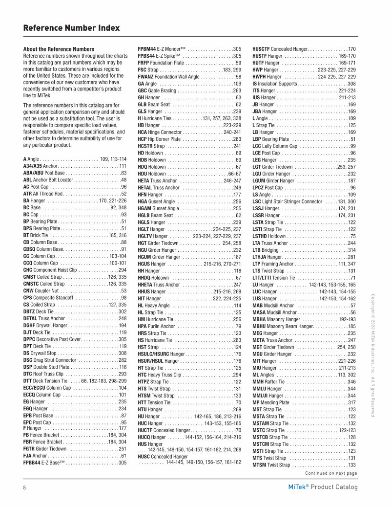
About the Reference NumbersReference numbers shown throughout the charts in this catalog are part numbers which may be more familiar to customers in various regions of the United States . These are included for the convenience of our new customers who have recently switched from a competitor’s product line to MiTek .
The reference numbers in this catalog are for general application comparison only and should not be used as a substitution tool . The user is responsible to compare specific load values, fastener schedules, material specifications, and other factors to determine suitability of use for any particular product .
A Angle . . . . . . . . . . . . . . . . . . . . . . . 109, 113-114A34/A35 Anchor . . . . . . . . . . . . . . . . . . . . . . . . 111ABA/ABU Post Base . . . . . . . . . . . . . . . . . . . . . .83ABL Anchor Bolt Locator . . . . . . . . . . . . . . . . . . .48AC Post Cap . . . . . . . . . . . . . . . . . . . . . . . . . . . .96ATR All Thread Rod . . . . . . . . . . . . . . . . . . . . . . .52 BA Hanger . . . . . . . . . . . . . . . . . . . . 170, 221-226BC Base . . . . . . . . . . . . . . . . . . . . . . . . . . 92, 348BC Cap . . . . . . . . . . . . . . . . . . . . . . . . . . . . . . . .93BP Bearing Plate . . . . . . . . . . . . . . . . . . . . . . . . .51BPS Bearing Plate . . . . . . . . . . . . . . . . . . . . . . . .51BT Brick Tie . . . . . . . . . . . . . . . . . . . . . . .185, 316CB Column Base . . . . . . . . . . . . . . . . . . . . . . . . .88CBSQ Column Base . . . . . . . . . . . . . . . . . . . . . . .91CC Column Cap . . . . . . . . . . . . . . . . . . . . . 103-104CCQ Column Cap . . . . . . . . . . . . . . . . . . . 100-101CHC Component Hoist Clip . . . . . . . . . . . . . . . .294CMST Coiled Strap . . . . . . . . . . . . . . . . . .126, 335CMSTC Coiled Strap . . . . . . . . . . . . . . . .126, 335CNW Coupler Nut . . . . . . . . . . . . . . . . . . . . . . . .53CPS Composite Standoff . . . . . . . . . . . . . . . . . .98CS Coiled Strap . . . . . . . . . . . . . . . . . . . . 127, 335DBTZ Deck Tie . . . . . . . . . . . . . . . . . . . . . . . . .302DETAL Truss Anchor . . . . . . . . . . . . . . . . . . . .248DGHF Drywall Hanger . . . . . . . . . . . . . . . . . . . .194DJT Deck Tie . . . . . . . . . . . . . . . . . . . . . . . . . . 119DPPC Decorative Post Cover . . . . . . . . . . . . . . .305DPT Deck Tie . . . . . . . . . . . . . . . . . . . . . . . . . . 119DS Drywall Stop . . . . . . . . . . . . . . . . . . . . . . . .308DSC Drag Strut Connector . . . . . . . . . . . . . . . .282DSP Double Stud Plate . . . . . . . . . . . . . . . . . . . 116DTC Roof Truss Clip . . . . . . . . . . . . . . . . . . . . .293DTT Deck Tension Tie . . . . 66, 182-183, 298-299ECC/ECCU Column Cap . . . . . . . . . . . . . . . . . .104ECCQ Column Cap . . . . . . . . . . . . . . . . . . . . . .101EG Hanger . . . . . . . . . . . . . . . . . . . . . . . . . . . .235EGQ Hanger . . . . . . . . . . . . . . . . . . . . . . . . . . .234EPB Post Base . . . . . . . . . . . . . . . . . . . . . . . . . .87EPC Post Cap . . . . . . . . . . . . . . . . . . . . . . . . . . .95 F Hanger . . . . . . . . . . . . . . . . . . . . . . . . . . . . .177FB Fence Bracket . . . . . . . . . . . . . . . . . . .184, 304FBR Fence Bracket . . . . . . . . . . . . . . . . . .184, 304FGTR Girder Tiedown . . . . . . . . . . . . . . . . . . . .251FJA Anchor . . . . . . . . . . . . . . . . . . . . . . . . . . . . .61FPBB44 E-Z Base™ . . . . . . . . . . . . . . . . . . . . .305
FPBM44 E-Z Mender™ . . . . . . . . . . . . . . . . . .305FPBS44 E-Z Spike™ . . . . . . . . . . . . . . . . . . . .305FRFP Foundation Plate . . . . . . . . . . . . . . . . . . . .59FSC Strap . . . . . . . . . . . . . . . . . . . . . . . . .183, 299FWANZ Foundation Wall Angle . . . . . . . . . . . . . .58GA Angle . . . . . . . . . . . . . . . . . . . . . . . . . . . . .109GBC Gable Bracing . . . . . . . . . . . . . . . . . . . . . .263GH Hanger . . . . . . . . . . . . . . . . . . . . . . . . . . . . .63GLB Beam Seat . . . . . . . . . . . . . . . . . . . . . . . . .62GLS Hanger . . . . . . . . . . . . . . . . . . . . . . . . . . .239H Hurricane Ties . . . . . . . . . . . .131, 257, 263, 338HB Hanger . . . . . . . . . . . . . . . . . . . . . . . . 223-229HCA Hinge Connector . . . . . . . . . . . . . . . . 240-241HCP Hip Corner Plate . . . . . . . . . . . . . . . . . . . .263HCSTR Strap . . . . . . . . . . . . . . . . . . . . . . . . . .241HD Holdown . . . . . . . . . . . . . . . . . . . . . . . . . . . .69HDB Holdown . . . . . . . . . . . . . . . . . . . . . . . . . . .69HDQ Holdown . . . . . . . . . . . . . . . . . . . . . . . . . . .67HDU Holdown . . . . . . . . . . . . . . . . . . . . . . . .66-67HETA Truss Anchor . . . . . . . . . . . . . . . . . 246-247HETAL Truss Anchor . . . . . . . . . . . . . . . . . . . .249HFN Hanger . . . . . . . . . . . . . . . . . . . . . . . . . . .177 HGA Gusset Angle . . . . . . . . . . . . . . . . . . . . . .256HGAM Gusset Angle . . . . . . . . . . . . . . . . . . . . .255HGLB Beam Seat . . . . . . . . . . . . . . . . . . . . . . . .62HGLS Hanger . . . . . . . . . . . . . . . . . . . . . . . . . .239HGLT Hanger . . . . . . . . . . . . . . . . . . 224-225, 237HGLTV Hanger . . . . . . . . 223-224, 227-229, 237HGT Girder Tiedown . . . . . . . . . . . . . . . . 254, 258HGU Girder Hanger . . . . . . . . . . . . . . . . . . . . . .232HGUM Girder Hanger . . . . . . . . . . . . . . . . . . . .187HGUS Hanger . . . . . . . . . . . . . . 215-216, 270-271HH Hanger . . . . . . . . . . . . . . . . . . . . . . . . . . . . 118HHDQ Holdown . . . . . . . . . . . . . . . . . . . . . . . . .67HHETA Truss Anchor . . . . . . . . . . . . . . . . . . . .247 HHUS Hanger . . . . . . . . . . . . . . . . . . 215-216, 269HIT Hanger . . . . . . . . . . . . . . . . . . . .222, 224-225HL Heavy Angle . . . . . . . . . . . . . . . . . . . . . . . . 114HL Strap Tie . . . . . . . . . . . . . . . . . . . . . . . . . . .125HM Hurricane Tie . . . . . . . . . . . . . . . . . . . . . . .256HPA Purlin Anchor . . . . . . . . . . . . . . . . . . . . . . .79HRS Strap Tie . . . . . . . . . . . . . . . . . . . . . . . . . .123HS Hurricane Tie . . . . . . . . . . . . . . . . . . . . . . .263HST Strap . . . . . . . . . . . . . . . . . . . . . . . . . . . . 124HSULC/HSURC Hanger . . . . . . . . . . . . . . . . . . .176HSUR/HSUL Hanger . . . . . . . . . . . . . . . . . . . . .176HT Strap Tie . . . . . . . . . . . . . . . . . . . . . . . . . . .125HTC Heavy Truss Clip . . . . . . . . . . . . . . . . . . . .294HTPZ Strap Tie . . . . . . . . . . . . . . . . . . . . . . . . .122HTS Twist Strap . . . . . . . . . . . . . . . . . . . . . . . . 131HTSM Twist Strap . . . . . . . . . . . . . . . . . . . . . .133HTT Tension Tie . . . . . . . . . . . . . . . . . . . . . . . . .70HTU Hanger . . . . . . . . . . . . . . . . . . . . . . . . . . .269HU Hanger . . . . . . . . . . . . 142-165, 186, 213-216HUC Hanger . . . . . . . . . . . . . . . 143-153, 155-165HUCTF Concealed Hanger . . . . . . . . . . . . . . . . .170HUCQ Hanger . . . . . . .144-152, 156-164, 214-216 HUS Hanger . . . 142-145, 149-150, 154-157, 161-162, 214, 268HUSC Concealed Hanger . . . . . . . . . . 144-145, 149-150, 156-157, 161-162
HUSCTF Concealed Hanger . . . . . . . . . . . . . . . .170 HUSTF Hanger . . . . . . . . . . . . . . . . . . . . . 169-170HUTF Hanger . . . . . . . . . . . . . . . . . . . . . . 169-171HWP Hanger . . . . . . . . . . . . . . . 223-225, 227-229HWPH Hanger . . . . . . . . . . . . . 224-225, 227-229IS Insulation Supports . . . . . . . . . . . . . . . . . . . .308ITS Hanger . . . . . . . . . . . . . . . . . . . . . . . . 221-224IUS Hanger . . . . . . . . . . . . . . . . . . . . . . . . 211-213JB Hanger . . . . . . . . . . . . . . . . . . . . . . . . . . . .169JBA Hanger . . . . . . . . . . . . . . . . . . . . . . . . . . .169L Angle . . . . . . . . . . . . . . . . . . . . . . . . . . . . . . .109L Strap Tie . . . . . . . . . . . . . . . . . . . . . . . . . . . .125LB Hanger . . . . . . . . . . . . . . . . . . . . . . . . . . . .169LBP Bearing Plate . . . . . . . . . . . . . . . . . . . . . . .51LCC Lally Column Cap . . . . . . . . . . . . . . . . . . . .99LCE Post Cap . . . . . . . . . . . . . . . . . . . . . . . . . . .96LEG Hanger . . . . . . . . . . . . . . . . . . . . . . . . . . .235LGT Girder Tiedown . . . . . . . . . . . . . . . . .253, 257LGU Girder Hanger . . . . . . . . . . . . . . . . . . . . . .232LGUM Girder Hanger . . . . . . . . . . . . . . . . . . . .187LPCZ Post Cap . . . . . . . . . . . . . . . . . . . . . . . . . .96LS Angle . . . . . . . . . . . . . . . . . . . . . . . . . . . . . .109LSC Light Stair Stringer Connector . . . . .181, 300LSSJ Hanger . . . . . . . . . . . . . . . . . . . . . . 174, 231LSSR Hanger . . . . . . . . . . . . . . . . . . . . . . 174, 231 LSTA Strap Tie . . . . . . . . . . . . . . . . . . . . . . . . .122LSTI Strap Tie . . . . . . . . . . . . . . . . . . . . . . . . .122LSTHD Holdown . . . . . . . . . . . . . . . . . . . . . . . . .75LTA Truss Anchor . . . . . . . . . . . . . . . . . . . . . . .244LTB Bridging . . . . . . . . . . . . . . . . . . . . . . . . . .314LTHJA Hanger . . . . . . . . . . . . . . . . . . . . . . . . . .281LTP Framing Anchor . . . . . . . . . . . . . . . . . 111, 347LTS Twist Strap . . . . . . . . . . . . . . . . . . . . . . . . 131LTT/LTTI Tension Tie . . . . . . . . . . . . . . . . . . . . .71LU Hanger . . . . . . . . . . . . 142-143, 153-155, 165LUC Hanger . . . . . . . . . . . . . . . 142-143, 154-155LUS Hanger . . . . . . . . . . . . . . . .142-150, 154-162MAB Mudsill Anchor . . . . . . . . . . . . . . . . . . . . .57MASA Mudsill Anchor . . . . . . . . . . . . . . . . . . . . .56MBHA Masonry Hanger . . . . . . . . . . . . . . 192-193MBHU Masonry Beam Hanger . . . . . . . . . . . . . .185MEG Hanger . . . . . . . . . . . . . . . . . . . . . . . . . . .235META Truss Anchor . . . . . . . . . . . . . . . . . . . . .247MGT Girder Tiedown . . . . . . . . . . . . . . . 254, 258MGU Girder Hanger . . . . . . . . . . . . . . . . . . . . .232MIT Hanger . . . . . . . . . . . . . . . . . . . . . . . 221-226MIU Hanger . . . . . . . . . . . . . . . . . . . . . . . 211-213ML Angles . . . . . . . . . . . . . . . . . . . . . . . . 113, 302MMH Rafter Tie . . . . . . . . . . . . . . . . . . . . . . . .346MMLU Hanger . . . . . . . . . . . . . . . . . . . . . . . . .344MMLUI Hanger . . . . . . . . . . . . . . . . . . . . . . . . .344MP Mending Plate . . . . . . . . . . . . . . . . . . . . . . 317MST Strap Tie . . . . . . . . . . . . . . . . . . . . . . . . .123MSTA Strap Tie . . . . . . . . . . . . . . . . . . . . . . . .122MSTAM Strap Tie . . . . . . . . . . . . . . . . . . . . . . .132MSTC Strap Tie . . . . . . . . . . . . . . . . . . . . 122-123MSTCB Strap Tie . . . . . . . . . . . . . . . . . . . . . . .128MSTCM Strap Tie . . . . . . . . . . . . . . . . . . . . . . .132MSTI Strap Tie . . . . . . . . . . . . . . . . . . . . . . . . .123MTS Twist Strap . . . . . . . . . . . . . . . . . . . . . . . 131MTSM Twist Strap . . . . . . . . . . . . . . . . . . . . . .133
Continued on next page
MiTek® Product Catalog
Copy
righ
t © 2
020
MiT
ek In
dust
ries
, Inc
. Al
l Rig
hts
Rese
rved
9
Reference Number Index
MUS Hanger . . . . . . . . . . . 142-143, 154-155, 268Nails . . . . . . . . . . . . . . . . . . . . . . . . . . 23-24, 343NCA Nailless Bridging . . . . . . . . . . . . . . . . . . . 315NS Nail Stopper . . . . . . . . . . . . . . . . . . . .310, 349NUT . . . . . . . . . . . . . . . . . . . . . . . . . . . . . . . . . .54OHA Hanger . . . . . . . . . . . . . . . . . . . . . . . . . . .125OL/OT/OHL/OHT Hangers . . . . . . . . . . . . . . . .125OS/OHS Hangers . . . . . . . . . . . . . . . . . . . . . . .125PA Holdown . . . . . . . . . . . . . . . . . . . . . . . . . . . .73PA Purlin Anchor . . . . . . . . . . . . . . . . . . . . . . . .79PAI Purlin Anchor . . . . . . . . . . . . . . . . . . . . . . . .79PB/PBS Post Base . . . . . . . . . . . . . . . . . . . . . . .85PC Post Cap . . . . . . . . . . . . . . . . . . . . . . . . . 94-95PF Hanger . . . . . . . . . . . . . . . . . . . . . . . . 178-179PFB/PFDB Hanger . . . . . . . . . . . . . . . . . . . . . .179PFDS Hanger . . . . . . . . . . . . . . . . . . . . . . . . . . .181PGT Pipe GripTie . . . . . . . . . . . . . . . . . . . . . . .303PGTIC Pipe GripTie . . . . . . . . . . . . . . . . . . . . . .303PS Strap . . . . . . . . . . . . . . . . . . . . . . . . . . . . . . 124PSCA Sheathing Clip . . . . . . . . . . . . . . . . . . . .308 PSCL Sheathing Clip . . . . . . . . . . . . . . . . . . . .308PSPNZ Protective Plate . . . . . . . . . . . . . .310, 349RBC Roof Boundary Clip . . . . . . . . . . . . . . . . . . 112RCWB Wall Bracing . . . . . . . . . . . . . . . . . . . . . . 313RFB Retrofit Bolt . . . . . . . . . . . . . . . . . . . . . . . . .47RP Retro Plate . . . . . . . . . . . . . . . . . . . . . . . . . .61RPBZ Retrofit Post Base . . . . . . . . . . . . . . . . . .84RPS Strap Tie . . . . . . . . . . . . . . . . . . . . . . 124, 312RR Connector . . . . . . . . . . . . . . . . . . . . . . . . . .173RSP Stud Plate Tie . . . . . . . . . . . . . . . . . . . . . . 116RST Rafter Tie . . . . . . . . . . . . . . . . . . . . . . . . .345RTA/RTB/RTC/RTF/RTR/RTU Rigid Tie® . . . . 309S/B Hanger . . . . . . . . . . . . . . . . . . . . . . . . . . . .336S/DTT Holdown . . . . . . . . . . . . . . . . . . . . . . . . .332S/H Hurricane Tie . . . . . . . . . . . . . . . . . . . . . . .339S/HD Holdown . . . . . . . . . . . . . . . . . . . . . . . . .333S/HDU Holdown . . . . . . . . . . . . . . . . . . . . . . . .330S/HTT Holdown . . . . . . . . . . . . . . . . . . . . . . . . .331S/LBV Hanger . . . . . . . . . . . . . . . . . . . . . . . . . .336S/LS Angle . . . . . . . . . . . . . . . . . . . . . . . . . . . .334S/LTT Holdown . . . . . . . . . . . . . . . . . . . . . . . . .331 SA Strap Connector . . . . . . . . . . . . . . . . . . . . .134SBV Shelf Bracket . . . . . . . . . . . . . . . . . . . . . .316SD Connector Screw . . . . . . . . . . . . . . . . . . . . .36SDS Heavy-Duty Connector Screw . . . . . . . .25, 32SDW Multi-Ply Wood Screw . . . . . . . . . . . . .26, 33 SDWC Screw . . . . . . . . . . . . . . . . . . . . . . . . . . .261SP Stud Plate Tie . . . . . . . . . . . . . . . 116-117, 338SPECANGLE . . . . . . . . . . . . . . . . . . . . . . . . . . . 114SPH Stud Plate Tie . . . . . . . . . . . . . . 116-117, 346SS Stud Shoe . . . . . . . . . . . . . . . . . . . . . . . . . . 312SSP Single Stud Plate . . . . . . . . . . . . . . . . . . . 116SSTB Anchor Bolt . . . . . . . . . . . . . . . . . . . . . . .50ST Strap Tie . . . . . . . . . . . . . . . . . . . . . . . . . . .122STC Roof Truss Clip . . . . . . . . . . . . . . . . . . . . .293STCT Roof Truss Clip . . . . . . . . . . . . . . . . . . . . .293STHD Holdown . . . . . . . . . . . . . . . . . . . . . . . . . .75SUR/SUL Hanger . . . . . . . . . . . . . . . . . . . 175-176T Strap Tie . . . . . . . . . . . . . . . . . . . . . . . . . . . .125TA Staircase Angle . . . . . . . . . . . . . . . . . . 115, 301TB Tension Bridging . . . . . . . . . . . . . . . . . . . . .314
TBE Truss Enhancer . . . . . . . . . . . . . . . . . . . . .290TBP Truss Seat . . . . . . . . . . . . . . . . . . . . . . . . .244TC Truss Connector . . . . . . . . . . . . . . . . . . . . .293THA Hanger . . . . . . . . . . . . . . . . . . . . . . . 274-275THAC Hanger . . . . . . . . . . . . . . . . . . . . . . 274-275THAI Hanger . . . . . . . . . . . . . . . . . . . . . . 274-275THAL/R Hanger . . . . . . . . . . . . . . . . . . . . . . . .276THASR/L Truss Hanger . . . . . . . . . . . . . . . . . . .279THD Titen HD® Anchor . . . . . . . . . . . . . . . .45, 329THGB/THGBH Hanger . . . . . . . . . . . . . . . .284-285THGQ/THGQH Hanger . . . . . . . . . . . . . . . . . . .286THJA Hanger . . . . . . . . . . . . . . . . . . . . . . . . . .281THJM Hanger . . . . . . . . . . . . . . . . . . . . . . . . . .282THJU Hanger . . . . . . . . . . . . . . . . . . . . . . . . . .281TJC Truss Connector . . . . . . . . . . . . . . . . . . . .280TP Tie Plate . . . . . . . . . . . . . . . . . . . . . . . 317, 348TS Twist Strap . . . . . . . . . . . . . . . . . . . . . . . . . 131TSBR Truss Spacer . . . . . . . . . . . . . . . . . . . . .288TSF Truss Spacer . . . . . . . . . . . . . . . . . . . . . . .289TSP Stud Plate Tie . . . . . . . . . . . . . . . . . .116, 263 TSS Truss Seat . . . . . . . . . . . . . . . . . . . . . . . . .244TWB Wall Bracing . . . . . . . . . . . . . . . . . . . . . . 313U Hanger . . . . . . . . . .142-151, 153-163, 165, 214URFP Foundation Anchor . . . . . . . . . . . . . . . . . .60VB Knee Brace . . . . . . . . . . . . . . . . . . . . . . . . .135VPA Connector . . . . . . . . . . . . . . . . . . . . . . . . .230VTCR Valley Truss Clip . . . . . . . . . . . . . . . . . . .292 W Wedge . . . . . . . . . . . . . . . . . . . . . . . . . . . . . .54WA Wedge-All® Anchor . . . . . . . . . . . . . . . . . . .46WASHER . . . . . . . . . . . . . . . . . . . . . . . . . . . . . . .53WB/WBC Wall Bracing . . . . . . . . . . . . . . . . . . . 313WMU Hanger . . . . . . . . . . . . . . . . . . . . . . 188-189WP Hanger . . . . . . . . . . . . . . . . 169-171, 221-226WT Wedge Form Tie . . . . . . . . . . . . . . . . . . . . . .54Z Clip . . . . . . . . . . . . . . . . . . . . . . . . . . . . . . . .294
MiTek® Product Catalog
Copyright © 2020 M
iTek Industries, Inc. All Rights Reserved
10
Code Evaluation Information
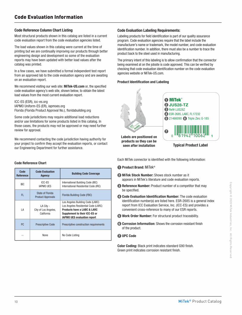
Code Reference Column Chart ListingMost structural products shown in this catalog are listed in a current code evaluation report from the code evaluation agencies listed .
The load values shown in this catalog were current at the time of printing but we are continually improving our products through better engineering design and development so some of the evaluation reports may have been updated with better load values after the catalog was printed .
In a few cases, we have submitted a formal independent test report from an approved lab to the code evaluation agency and are awaiting on an evaluation report .
We recommend visiting our web site: MiTek-US .com or, the specified code evaluation agency’s web site, shown below, to obtain the latest load values from the most current evaluation report .
ICC-ES (ESR), icc-es .org IAPMO Uniform-ES (ER), iapmoes .org Florida (Florida Product Approval No .), floridabuilding .org
Some code jurisdictions may require additional load reductions and/or use limitations for some products listed in this catalog . In those cases, the products may not be approved or may need further review for approval . We recommend contacting the code jurisdiction having authority for your project to confirm they accept the evaluation reports, or contact our Engineering Department for further assistance .
Code Reference Chart
Code Evaluation Labeling Requirements:Labeling products for field identification is part of our quality assurance program . Code evaluation agencies require that the label include the manufacturer’s name or trademark, the model number, and code evaluation identification number . In addition, there must also be a number to trace the product back to the steel used in manufacturing .
The primary intent of this labeling is to allow confirmation that the connector being examined at on the jobsite is code approved . This can be verified by checking that code evaluation identification number on the code evaluation agencies website or MiTek-US .com .
Product Identification and Labeling
Each MiTek connector is identified with the following information:
1 Product Brand: MiTek®
2 MiTek Stock Number: Shows stock number as it appears in MiTek’s literature and code evaluation reports .
3 Reference Number: Product number of a competitor that may be specified .
4 Code Evaluation Identification Number: The code evaluation identification number(s) are listed here . ESR-2685 is a general index report from ICC Evaluation Service, Inc . (ICC-ES) and provides a convenient cross-reference to many of our ESR reports .
5 Work Order Number: For structural product traceability .
6 Corrosion Information: Shows the corrosion resistant finish of the product .
7 UPC Code
Color Coding: Black print indicates standard G90 finish . Green print indicates corrosion resistant finish .
Typical Product Label
JUS28-TZ Ref# LUS28ZESR-2685, LABC, FL17232 21466090 Triple Zinc G-185
MiTek®
Code Reference
Code EvaluationAgency
Building Code Coverage
IBCICC-ES
IAPMO UES International Building Code (IBC) International Residential Code (IRC)
FLState of Florida
Product Approvals Florida Building Code (FBC)
LALA City -
City of Los Angeles, California
Los Angeles Building Code (LABC) Los Angeles Residential Code (LARC) Products have a LABC & LARC Supplement to their ICC-ES or IAPMO UES evaluation report
PC Prescriptive Code Prescriptive construction requirements
-- None No Code Listing
Labels are positioned on products so they can be seen after installation
1
7
2345 6
MiTek® Product Catalog
Copy
righ
t © 2
020
MiT
ek In
dust
ries
, Inc
. Al
l Rig
hts
Rese
rved
11
Corrosion Information
For the majority of applications, metal hangers and connectors are used in interior, above ground, dry service conditions . They are typically not being exposed to corrosive environments which can significantly reduce their strength and longevity .
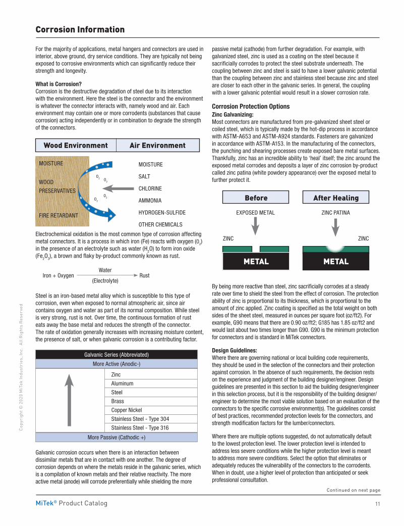
What is Corrosion? Corrosion is the destructive degradation of steel due to its interaction with the environment . Here the steel is the connector and the environment is whatever the connector interacts with, namely wood and air . Each environment may contain one or more corrodents (substances that cause corrosion) acting independently or in combination to degrade the strength of the connectors .
Electrochemical oxidation is the most common type of corrosion affecting metal connectors . It is a process in which iron (Fe) reacts with oxygen (O2) in the presence of an electrolyte such as water (H2O) to form iron oxide (Fe2O3), a brown and flaky by-product commonly known as rust .
Steel is an iron-based metal alloy which is susceptible to this type of corrosion, even when exposed to normal atmospheric air, since air contains oxygen and water as part of its normal composition . While steel is very strong, rust is not . Over time, the continuous formation of rust eats away the base metal and reduces the strength of the connector . The rate of oxidation generally increases with increasing moisture content, the presence of salt, or when galvanic corrosion is a contributing factor .
Galvanic corrosion occurs when there is an interaction between dissimilar metals that are in contact with one another . The degree of corrosion depends on where the metals reside in the galvanic series, which is a compilation of known metals and their relative reactivity . The more active metal (anode) will corrode preferentially while shielding the more
passive metal (cathode) from further degradation . For example, with galvanized steel, zinc is used as a coating on the steel because it sacrificially corrodes to protect the steel substrate underneath . The coupling between zinc and steel is said to have a lower galvanic potential than the coupling between zinc and stainless steel because zinc and steel are closer to each other in the galvanic series . In general, the coupling with a lower galvanic potential would result in a slower corrosion rate .
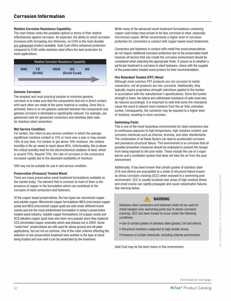
Corrosion Protection OptionsZinc Galvanizing: Most connectors are manufactured from pre-galvanized sheet steel or coiled steel, which is typically made by the hot-dip process in accordance with ASTM-A653 and ASTM-A924 standards . Fasteners are galvanized in accordance with ASTM-A153 . In the manufacturing of the connectors, the punching and shearing processes create exposed bare metal surfaces . Thankfully, zinc has an incredible ability to ‘heal’ itself; the zinc around the exposed metal corrodes and deposits a layer of zinc corrosion by-product called zinc patina (white powdery appearance) over the exposed metal to further protect it .
By being more reactive than steel, zinc sacrificially corrodes at a steady rate over time to shield the steel from the effect of corrosion . The protection ability of zinc is proportional to its thickness, which is proportional to the amount of zinc applied . Zinc coating is specified as the total weight on both sides of the sheet steel, measured in ounces per square foot (oz/ft2) . For example, G90 means that there are 0 .90 oz/ft2; G185 has 1 .85 oz/ft2 and would last about two times longer than G90 . G90 is the minimum protection for connectors and is standard in MiTek connectors .
Design Guidelines: Where there are governing national or local building code requirements, they should be used in the selection of the connectors and their protection against corrosion . In the absence of such requirements, the decision rests on the experience and judgment of the building designer/engineer . Design guidelines are presented in this section to aid the building designer/engineer in this selection process, but it is the responsibility of the building designer/engineer to determine the most viable solution based on an evaluation of the connectors to the specific corrosive environment(s) . The guidelines consist of best practices, recommended protection levels for the connectors, and strength modification factors for the lumber/connectors .
Where there are multiple options suggested, do not automatically default to the lowest protection level . The lower protection level is intended to address less severe conditions while the higher protection level is meant to address more severe conditions . Select the option that eliminates or adequately reduces the vulnerability of the connectors to the corrodents . When in doubt, use a higher level of protection than anticipated or seek professional consultation .
METAL
Before After Healing
METAL
Wood Environment Air Environment
MOISTURE
SALT
CHLORINE
AMMONIA
HYDROGEN-SULFIDE
OTHER CHEMICALS
EXPOSED METAL
ZINC ZINC
ZINC PATINA
O2 O2
O2O2
Iron + Oxygen RustWater
(Electrolyte)
Galvanic Series (Abbreviated)
More Active (Anodic-)
More Passive (Cathodic +)
Zinc
Aluminum
Steel
Brass
Copper Nickel
Stainless Steel - Type 304
Stainless Steel - Type 316
Continued on next page
MOISTURE
WOOD
PRESERVATIVES
FIRE RETARDANT
MiTek® Product Catalog
Copyright © 2020 M
iTek Industries, Inc. All Rights Reserved
12
Corrosion Information
Relative Corrosion Resistance Capability: The chart below ranks the available options in terms of their relative effectiveness against corrosion . As expected, the ability to resist corrosion increases with increasing zinc thickness, so G185 is the most durable pre-galvanized product available . Gold Coat offers enhanced protection compared to G185 while stainless steel offers the best protection for most applications .
Galvanic Corrosion: The simplest and most practical solution to minimize galvanic corrosion is to make sure that the components that are in direct contact with each other are made of the same material or coating . Once this is achieved, there is no net galvanic potential between the components and galvanic corrosion is eliminated or significantly reduced . For example, use galvanized nails for galvanized connectors and stainless steel nails for stainless steel connectors .
Wet Service Condition: For lumber, this refers to any service condition in which the average equilibrium moisture content is 15% or more over a year or may exceed 19% at any time . For lumber to get above 19% moisture, the relative humidity in the air needs to reach above 80% . Unfortunately, this is above the critical humidity level for the electrochemical oxidation of steel, which is around 70% . Beyond 70%, the rate of corrosion in the connectors increases rapidly due to the abundant availability of moisture .
G90 may not be suitable for use in wet service condition .
Preservative (Pressure) Treated Wood: There are many preservative wood treatment formulations available on the market today . The element that is common to most of them is the presence of copper in the formulation which can contribute to the corrosion of steel connectors and fasteners .
Of the copper based preservatives, the two types are micronized copper and soluble copper . Micronized copper formulations MCA (micronized copper azole) and MCQ (micronized copper quat) are sold under different brand names and are the most predominant formulation in today’s preservative treated wood industry . Soluble copper formulations CA (copper azole) and ACQ (alkaline copper quat) have also been very popular since they replaced CCA (chromated copper arsenate) which was phased out in 2004 . Some “metal free” preservatives are still used for above ground and sill plate applications, but are not as common . One of the main criterion affecting the selection of one preservative treatment over another is the type of wood being treated and how well it can be penetrated by the treatment .
While many of the advanced wood treatment formulations containing copper used today have proven to be less corrosive to steel, especially micronized copper, MiTek recommends a higher level of corrosion protection for connectors in contact with copper based wood treatments .
Connectors and fasteners in contact with metal free wood preservatives do not require additional corrosion protection due to the preservative itself, however all factors that can create the corrosive environment should be considered when selecting the appropriate finish . If unsure as to whether a particular treatment is corrosive to steel fasteners, check with the supplier of the preservative treated wood product for their recommendation .
Fire Retardant Treated (FRT) Wood: Although most common FRT products are not corrosive to metal connectors, not all products are non-corrosive . Additionally, they typically require proprietary strength reductions applied to the lumber in accordance with the manufacturer’s specifications . Since the lumber strength is lower, the lateral and withdrawal resistance of nails must also be reduced accordingly . It is important to note that some fire retardants cause the wood to absorb more moisture from the air than untreated lumber . Consequently, the connector may be exposed to a higher level of moisture, resulting in more corrosion .
Swimming Pools: This is one of the most hazardous environments for steel connectors due to continuous exposure to high temperature, high moisture content, and corrosive chemicals such as chlorine, bromine, and other disinfectants . The combination of all these factors can lead to accelerated corrosion and premature structural failure . This environment is so corrosive that all possible preventive measures should be employed to prevent the hanger from being exposed to the pool water . These include the use of a vapor barrier and a ventilation system that does not take the air from the pool environment .
Additionally, it has been known that certain grades of stainless steel (316 and others) are susceptible to a mode of structural failure known as stress corrosion cracking (SCC) when exposed to a swimming pool environment . SCC is usually localized near areas of high residual stress and small cracks can rapidly propagate and cause catastrophic failures . See warning below .
Gold Coat may be the best choice in this environment .
WARNINGStainless steel connectors and fasteners shall not be used for metal hangers over swimming pools due to stress corrosion cracking . SCC has been known to occur under the following conditions:
• Use of certain grades of stainless steel (grades 316 and others) .
• Structural members subjected to high tensile stress .
• Presence of certain chemicals, including chlorine and bromine .
!
Continued on next page
Relative Corrosion Resistance Capability:
G90 TZ HDG GC SS (G185) (Gold Coat)
MiTek® Product Catalog
Copy
righ
t © 2
020
MiT
ek In
dust
ries
, Inc
. Al
l Rig
hts
Rese
rved
13
Corrosion Information
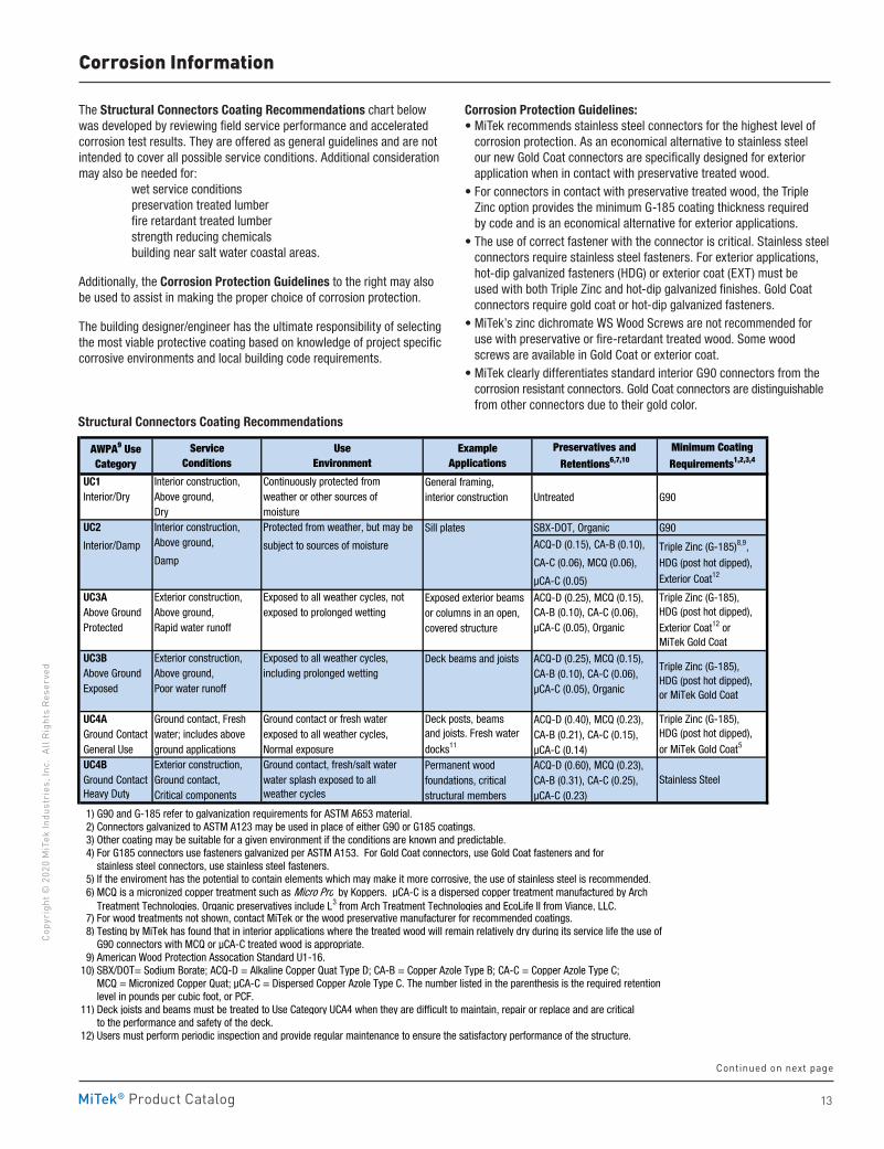
UC1 Interior construction, Continuously protected from General framing, Interior/Dry Above ground, weather or other sources of interior construction Untreated G90
Dry moisture UC2 Interior construction, Protected from weather, but may be Sill plates SBX-DOT, Organic G90
Interior/Damp Above ground, subject to sources of moisture ACQ-D (0.15), CA-B (0.10),
Damp CA-C (0.06), MCQ (0.06),
μCA-C (0.05)
UC3A Exterior construction, Exposed to all weather cycles, not Exposed exterior beams ACQ-D (0.25), MCQ (0.15), Above Ground Above ground, exposed to prolonged wetting or columns in an open, CA-B (0.10), CA-C (0.06), Protected Rapid water runoff covered structure μCA-C (0.05), Organic
UC3B Exterior construction, Exposed to all weather cycles, Deck beams and joists ACQ-D (0.25), MCQ (0.15), Above Ground Above ground, including prolonged wetting CA-B (0.10), CA-C (0.06), Exposed Poor water runoff μCA-C (0.05), Organic
UC4A Ground contact, Fresh Ground contact or fresh water ACQ-D (0.40), MCQ (0.23), Ground Contact water; includes above exposed to all weather cycles, CA-B (0.21), CA-C (0.15), General Use ground applications Normal exposure μCA-C (0.14) UC4B Exterior construction, Ground contact, fresh/salt water Permanent wood ACQ-D (0.60), MCQ (0.23), Ground Contact Ground contact, water splash exposed to all foundations, critical CA-B (0.31), CA-C (0.25), Heavy Duty Critical components weather cycles structural members μCA-C (0.23)
1) G90 and G-185 refer to galvanization requirements for ASTM A653 material. 2) Connectors galvanized to ASTM A123 may be used in place of either G90 or G185 coatings. 3) Other coating may be suitable for a given environment if the conditions are known and predictable. 4) For G185 connectors use fasteners galvanized per ASTM A153. For Gold Coat connectors, use Gold Coat fasteners and for stainless steel connectors, use stainless steel fasteners. 5) If the enviroment has the potential to contain elements which may make it more corrosive, the use of stainless steel is recommended. 6) MCQ is a micronized copper treatment such as Micro Pro by Koppers. μCA-C is a dispersed copper treatment manufactured by Arch Treatment Technologies. Organic preservatives include L3 from Arch Treatment Technologies and EcoLife II from Viance, LLC. 7) For wood treatments not shown, contact MiTek or the wood preservative manufacturer for recommended coatings. 8) Testing by MiTek has found that in interior applications where the treated wood will remain relatively dry during its service life the use of G90 connectors with MCQ or μCA-C treated wood is appropriate. 9) American Wood Protection Assocation Standard U1-16.10) SBX/DOT= Sodium Borate; ACQ-D = Alkaline Copper Quat Type D; CA-B = Copper Azole Type B; CA-C = Copper Azole Type C; MCQ = Micronized Copper Quat; μCA-C = Dispersed Copper Azole Type C. The number listed in the parenthesis is the required retention level in pounds per cubic foot, or PCF.11) Deck joists and beams must be treated to Use Category UCA4 when they are difficult to maintain, repair or replace and are critical to the performance and safety of the deck. 12) Users must perform periodic inspection and provide regular maintenance to ensure the satisfactory performance of the structure.
Stainless Steel
Structural Connectors Coating Recommendations
Triple Zinc (G-185)8,9,
HDG (post hot dipped),
Exterior Coat12
Triple Zinc (G-185),HDG (post hot dipped),
Exterior Coat12 orMiTek Gold Coat
Triple Zinc (G-185),HDG (post hot dipped),or MiTek Gold Coat
Triple Zinc (G-185),HDG (post hot dipped),
or MiTek Gold Coat5
Example Applications
Use Environment
Service Conditions
AWPA9 Use Category
Preservatives and Retentions6,7,10
Minimum Coating Requirements1,2,3,4
Deck posts, beams and joists. Fresh water
docks11
The Structural Connectors Coating Recommendations chart below was developed by reviewing field service performance and accelerated corrosion test results . They are offered as general guidelines and are not intended to cover all possible service conditions . Additional consideration may also be needed for: wet service conditions preservation treated lumber fire retardant treated lumber strength reducing chemicals building near salt water coastal areas .
Additionally, the Corrosion Protection Guidelines to the right may also be used to assist in making the proper choice of corrosion protection .
The building designer/engineer has the ultimate responsibility of selecting the most viable protective coating based on knowledge of project specific corrosive environments and local building code requirements .
Corrosion Protection Guidelines:• MiTek recommends stainless steel connectors for the highest level of
corrosion protection . As an economical alternative to stainless steel our new Gold Coat connectors are specifically designed for exterior application when in contact with preservative treated wood .
• For connectors in contact with preservative treated wood, the Triple Zinc option provides the minimum G-185 coating thickness required by code and is an economical alternative for exterior applications .
• The use of correct fastener with the connector is critical . Stainless steel connectors require stainless steel fasteners . For exterior applications, hot-dip galvanized fasteners (HDG) or exterior coat (EXT) must be used with both Triple Zinc and hot-dip galvanized finishes . Gold Coat connectors require gold coat or hot-dip galvanized fasteners .
• MiTek’s zinc dichromate WS Wood Screws are not recommended for use with preservative or fire-retardant treated wood . Some wood screws are available in Gold Coat or exterior coat .
• MiTek clearly differentiates standard interior G90 connectors from the corrosion resistant connectors . Gold Coat connectors are distinguishable from other connectors due to their gold color .
Continued on next page
Structural Connectors Coating Recommendations
14 MiTek® Product Catalog
Copyright © 2020 M
iTek Industries, Inc. All Rights Reserved
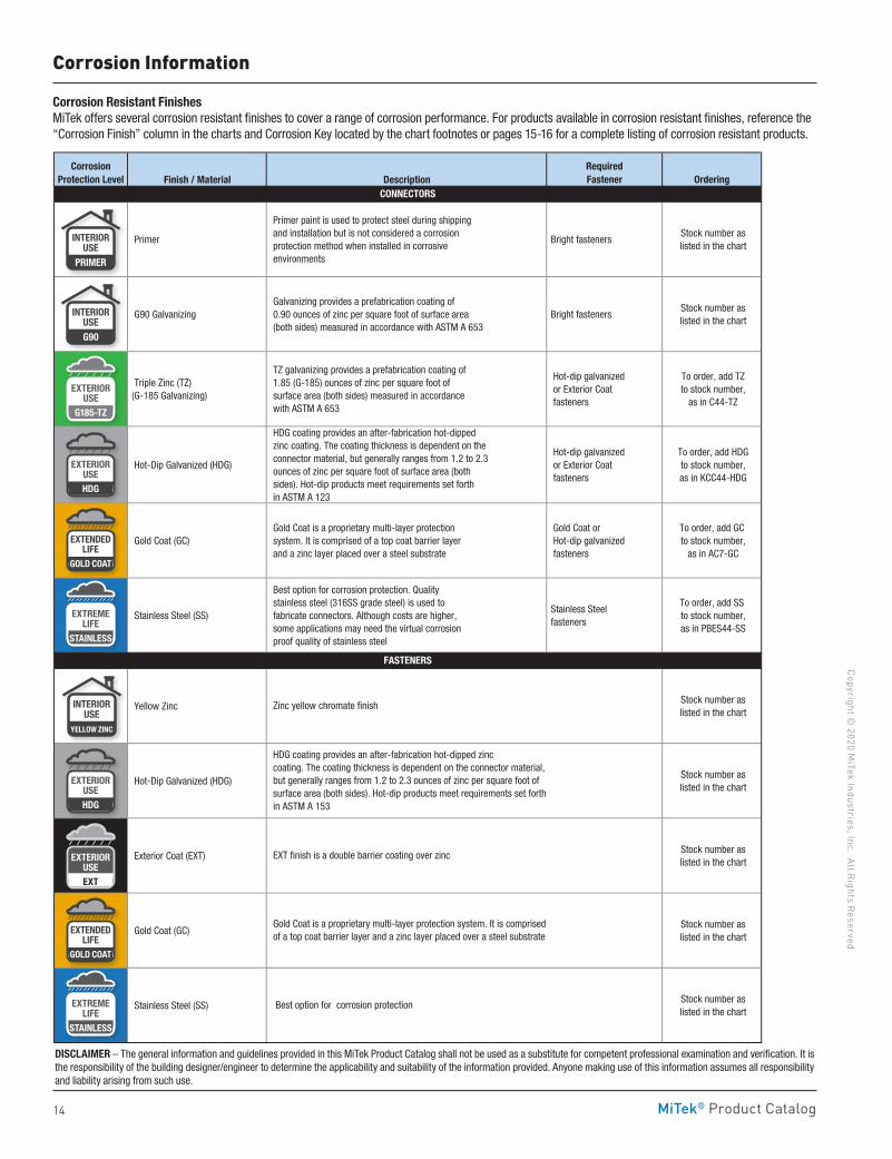
CorrosionProtection Level Finish / Material Description
RequiredFastener Ordering
Primer
Primer paint is used to protect steel during shipping and installation but is not considered a corrosion protection method when installed in corrosive environments
Bright fasteners Stock number as listed in the chart
G90 Galvanizing Galvanizing provides a prefabrication coating of 0.90 ounces of zinc per square foot of surface area (both sides) measured in accordance with ASTM A 653
Bright fasteners Stock number as listed in the chart
Triple Zinc (TZ) (G-185 Galvanizing)
TZ galvanizing provides a prefabrication coating of 1.85 (G-185) ounces of zinc per square foot of surface area (both sides) measured in accordance with ASTM A 653
Hot-dip galvanized or Exterior Coat fasteners
To order, add TZ to stock number,
as in C44-TZ
Hot-Dip Galvanized (HDG)
HDG coating provides an after-fabrication hot-dipped zinc coating. The coating thickness is dependent on the connector material, but generally ranges from 1.2 to 2.3 ounces of zinc per square foot of surface area (both sides). Hot-dip products meet requirements set forth in ASTM A 123
Hot-dip galvanized or Exterior Coat fasteners
To order, add HDG to stock number, as in KCC44-HDG
Gold Coat (GC) Gold Coat is a proprietary multi-layer protection system. It is comprised of a top coat barrier layer and a zinc layer placed over a steel substrate
Gold Coat or Hot-dip galvanized fasteners
To order, add GC to stock number,
as in AC7-GC
Stainless Steel (SS)
Best option for corrosion protection. Quality stainless steel (316SS grade steel) is used to fabricate connectors. Although costs are higher, some applications may need the virtual corrosion proof quality of stainless steel
Stainless Steel fasteners
To order, add SS to stock number, as in PBES44-SS
Yellow Zinc Stock number as listed in the chart
Hot-Dip Galvanized (HDG) Stock number as listed in the chart
Exterior Coat (EXT) Stock number as listed in the chart
Gold Coat (GC) Stock number as listed in the chart
Stainless Steel (SS) Stock number as listed in the chart
CONNECTORS
FASTENERS
HDG coating provides an after-fabrication hot-dipped zinc coating. The coating thickness is dependent on the connector material, but generally ranges from 1.2 to 2.3 ounces of zinc per square foot of surface area (both sides). Hot-dip products meet requirements set forth in ASTM A 153
Gold Coat is a proprietary multi-layer protection system. It is comprised of a top coat barrier layer and a zinc layer placed over a steel substrate
Best option for corrosion protection
Zinc yellow chromate finish
EXT finish is a double barrier coating over zinc
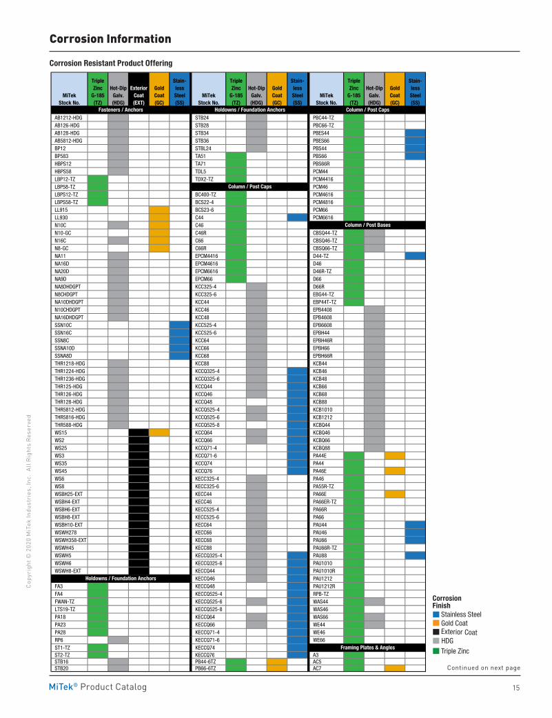
Corrosion Resistant FinishesMiTek offers several corrosion resistant finishes to cover a range of corrosion performance . For products available in corrosion resistant finishes, reference the “Corrosion Finish” column in the charts and Corrosion Key located by the chart footnotes or pages 15-16 for a complete listing of corrosion resistant products .
Corrosion Information
EXTENDEDLIFE
GOLD COAT
EXTENDEDLIFE
GOLD COAT
EXTERIORUSE
G185-TZ
EXTERIORUSE
G185-TZ
EXTERIORUSE
G185-TZ
EXTERIORUSEHDG
EXTERIORUSE
G185-TZ
EXTERIORUSEHDG
INTERIORUSEG90
INTERIORUSE
YELLOW ZINC
INTERIORUSE
PRIMER
EXTREMELIFE
STAINLESS
EXTREMELIFE
STAINLESS
EXTERIORUSE
G185-TZ
EXTERIORUSEEXT
DISCLAIMER – The general information and guidelines provided in this MiTek Product Catalog shall not be used as a substitute for competent professional examination and verification . It is the responsibility of the building designer/engineer to determine the applicability and suitability of the information provided . Anyone making use of this information assumes all responsibility and liability arising from such use .
15MiTek® Product Catalog
Copy
righ
t © 2
020
MiT
ek In
dust
ries
, Inc
. Al
l Rig
hts
Rese
rved
Corrosion Resistant Product Offering
Corrosion Information
MiTekStock No.
TripleZinc
G-185(TZ)
Hot-DipGalv.(HDG)
ExteriorCoat(EXT)
GoldCoat(GC)
Stain-lessSteel(SS)
MiTek Stock No.
TripleZinc
G-185(TZ)
Hot-DipGalv.(HDG)
GoldCoat(GC)
Stain-lessSteel(SS)
MiTekStock No.
TripleZinc
G-185(TZ)
Hot-DipGalv.(HDG)
GoldCoat(GC)
Stain-lessSteel(SS)
AB1212-HDG STB24 PBC44-TZ AB126-HDG STB28 PBC66-TZ AB128-HDG STB34 PBES44 AB5812-HDG STB36 PBES66 BP12 STBL24 PBS44 BP583 TA51 PBS66 HBPS12 TA71 PBS66R HBPS58 TDL5 PCM44 LBP12-TZ TDX2-TZ PCM4416 LBP58-TZ PCM46 LBPS12-TZ BC400-TZ PCM4616 LBPS58-TZ BCS22-4 PCM4816 LL915 BCS23-6 PCM66 LL930 C44 PCM6616 N10C C46 N10-GC C46R CBSQ44-TZ N16C C66 CBSQ46-TZ N8-GC C66R CBSQ66-TZ NA11 EPCM4416 D44-TZ NA16D EPCM4616 D46 NA20D EPCM6616 D46R-TZ NA9D EPCM66 D66 NA8DHDGPT KCC325-4 D66R N8CHDGPT KCC325-6 EBG44-TZ NA10DHDGPT KCC44 EBP44T-TZ N10CHDGPT KCC46 EPB4408 NA16DHDGPT KCC48 EPB4608 SSN10C KCC525-4 EPB6608 SSN16C KCC525-6 EPBH44 SSN8C KCC64 EPBH46R SSNA10D KCC66 EPBH66 SSNA8D KCC68 EPBH66R THR1218-HDG KCC88 KCB44 THR1224-HDG KCCQ325-4 KCB46 THR1236-HDG KCCQ325-6 KCB48 THR125-HDG KCCQ44 KCB66 THR126-HDG KCCQ46 KCB68 THR128-HDG KCCQ48 KCB88 THR5812-HDG KCCQ525-4 KCB1010 THR5816-HDG KCCQ525-6 KCB1212 THR588-HDG KCCQ525-8 KCBQ44 WS15 KCCQ64 KCBQ46 WS2 KCCQ66 KCBQ66 WS25 KCCQ71-4 KCBQ88 WS3 KCCQ71-6 PA44E WS35 KCCQ74 PA44 WS45 KCCQ76 PA46E WS6 KECC325-4 PA46 WS8 KECC325-6 PA55R-TZ WSBH25-EXT KECC44 PA66E WSBH4-EXT KECC46 PA66ER-TZ WSBH6-EXT KECC525-4 PA66R WSBH8-EXT KECC525-6 PA66 WSBH10-EXT KECC64 PAU44 WSWH278 KECC66 PAU46 WSWH358-EXT KECC68 PAU66 WSWH45 KECC88 PAU66R-TZ WSWH5 KECCQ325-4 PAU88 WSWH6 KECCQ325-6 PAU1010 WSWH8-EXT KECCQ44 PAU1010R
KECCQ46 PAU1212 FA3 KECCQ48 PAU1212R FA4 KECCQ525-4 RPB-TZ FWAN-TZ KECCQ525-6 WAS44 LTS19-TZ KECCQ525-8 WAS46 PA18 KECCQ64 WAS66 PA23 KECCQ66 WE44 PA28 KECCQ71-4 WE46 RP6 KECCQ71-6 WE66 ST1-TZ KECCQ74 ST2-TZ KECCQ76 A3 STB16 PB44-6TZ AC5 STB20 PB66-6TZ AC7
Holdowns / Foundation Anchors
Framing Plates & Angles
Column / Post Caps
Fasteners / Anchors Column / Post Caps
Holdowns / Foundation Anchors
Column / Post Bases
Corrosion Finish Stainless Steel Gold Coat Exterior Coat HDG Triple Zinc
Corrosion Finish Stainless Steel Gold Coat Exterior Coat HDG Triple Zinc
Corrosion Finish Stainless Steel Gold Coat Exterior Coat
HDG Triple Zinc
Continued on next page
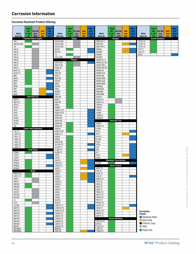
16 MiTek® Product Catalog
Copyright © 2020 M
iTek Industries, Inc. All Rights Reserved
Corrosion Information
MiTekStock No.
TripleZinc
G-185(TZ)
Hot-DipGalv.(HDG)
GoldCoat(GC)
Stain-lessSteel(SS)
MiTekStock No.
TripleZinc
G-185(TZ)
Hot-DipGalv.(HDG)
GoldCoat(GC)
Stain-lessSteel(SS)
MiTekStock No.
TripleZinc
G-185(TZ)
Hot-DipGalv.(HDG)
GoldCoat(GC)
Stain-lessSteel(SS)
MiTekStock No.
TripleZinc
G-185(TZ)
Hot-DipGalv.(HDG)
GoldCoat(GC)
Stain-lessSteel(SS)
AC9 PS218-HDG SKH210L-2 TTC24-TZ ANJ44S-HDG PS418-HDG SKH210R TTC42-TZ JA1 PS720-HDG SKH210R-2 TTF22-TZ KHL33 RS150 SKH26L TTR-TZ KHL35 RS16-R SKH26R TTU2-TZ KHL37 T6 SKH28L WT22 KHL43 TH12-HDG SKH28R KHL46 SKHH210L-2 KHL55 HD210-2IF SKHH210L-2IF KHL57 HD210-3IF SKHH210R-2 KHL76 HD28-2IF SKHH210R-2IF ML24-TZ HD410 SKHH410L ML26-TZ HD410IF SKHH410LIF MP3 HD412 SKHH410R MP34 HD412IF SKHH410RIF MP4F HD44IF SKHH414LIF MP5 HD46 SKHH414RIF MP6F HD46IF SKHH46L MP7 HD48 SKHH46LIF MP9 HD48IF SKHH46R MPA1 HD610 SKHH46RIF
HD610IF SUH210 RSPT6 HD612 SUH210-2 RSPT6-2 HD612IF SUH210-3 SPT22 HD68 THD28-2 SPT24 HD68IF THD410 SPT4 HDQ210-2IF THD46 SPT6 HDQ210-3IF THD48 SPT8 HDQ310IF THDH412 SPTH4 HDQ410IF THDH610 SPTH6 HDQ412IF SPTH8 HDQ610IF HHCP2 TSP HDQ612IF HHCP4-TZ
HUS210 LFTA6 LJC-TZ HUS210-2IF RT10 LJQ15-TZ HUS212-2 RT15 LJQ17-TZ HUS26 RT16-2 LJQ20-TZ HUS28 RT16A LJQ23-TZ HUS28-2IF RT20 LJQ25-TZ JL210IF-TZ RT3A LJQ35-TZ JL24IF-TZ RT4
JL26IF-TZ RT5 HTW20 JL28IF-TZ RT7 LTW12 JPF24 RT7A LTW18 JPF26 RT8A MTW12 JUS210 MTW16 JUS210-2 HTA20 MTW20 JUS210-3 MTW30 JUS24 ADTT-TZ
JUS24-2 CSH-TZ HRS416-TZ JUS26 DC50-TZ HTP37-TZ JUS26-2 DTB-TZ KHST2 JUS28 ERB24-TZ KHST3 JUS28-2 FB14-TZ KRPS22 JUS28-3 FB23-TZ KRPS28 JUS36 FB24-TZ KST227 JUS410 FB26-TZ KST237 JUS44 FRB24-TZ KST248 JUS46 PRT15-TZ KST260 JUS48 PRT2H-TZ L6 KLB210 PRT2-TZ LH12 KLB212 PRTIC2-TZ LSTA36 LSSH15-TZ SCA10-TZ MSTA12 LSSH210-TZ SCA9-TZ MSTA15 LSSH179-TZ SDJT14-TZ MSTA18 LSSH20-TZ SDPT5-TZ MSTA21 LSSH23-TZ SDPT7-TZ MSTA24 LSSH25-TZ MSTA30 LSSH26-TZ ICPL516-TZ MSTA36 LSSH31-TZ ICPL58 MSTA9 LSSH35-TZ TTA12-TZ MSTAM24 MSH422 TTA2-TZ MSTAM36 SKH210L TTB22-TZ
General Hardware
Hurricane Ties
Hangers
Embedded Truss Anchors
Deck & Fences
General HardwareStraps
Hangers
Stud Plate Ties
Lateral Joist Connectors
Twist Straps
Straps
Framing Plates & Angles
Corrosion Resistant Product Offering
Corrosion Finish Stainless Steel Gold Coat Exterior Coat HDG Triple Zinc
Corrosion Finish Stainless Steel Gold Coat Exterior Coat HDG Triple Zinc
Corrosion Finish Stainless Steel Gold Coat Exterior Coat
HDG Triple Zinc
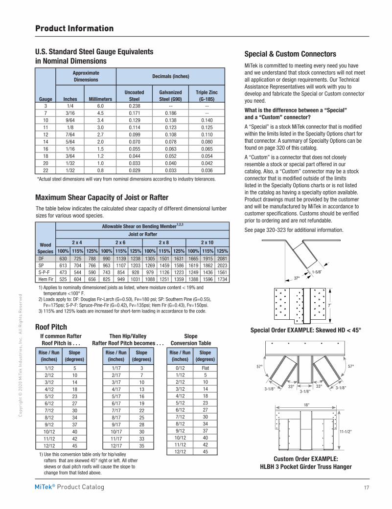
17MiTek® Product Catalog
Copy
righ
t © 2
020
MiT
ek In
dust
ries
, Inc
. Al
l Rig
hts
Rese
rved
1/12 5 1/17 32/12 10 2/17 73/12 14 3/17 104/12 18 4/17 135/12 23 5/17 166/12 27 6/17 197/12 30 7/17 228/12 34 8/17 259/12 37 9/17 2810/12 40 10/17 3011/12 42 11/17 3312/12 45 12/17 35
1) Use this conversion table only for hip/valley rafters that are skewed 45° right or left. All other skews or dual pitch roofs will cause the slope to change from that listed above.
Rise / Run(inches)
Slope(degrees)
Rise / Run(inches)
Slope(degrees)
Product Information
The table below indicates the calculated shear capacity of different dimensional lumber sizes for various wood species .
U .S . Standard Steel Gauge Equivalents in Nominal Dimensions
Maximum Shear Capacity of Joist or Rafter
Roof PitchIf common RafterRoof Pitch is . . .
SlopeConversion Table
Gauge Inches MillimetersUncoated
SteelGalvanized Steel (G90)
Triple Zinc (G-185)
3 1/4 6.0 0.238 -- --7 3/16 4.5 0.171 0.186 --10 9/64 3.4 0.129 0.138 0.14011 1/8 3.0 0.114 0.123 0.12512 7/64 2.7 0.099 0.108 0.11014 5/64 2.0 0.070 0.078 0.08016 1/16 1.5 0.055 0.063 0.06518 3/64 1.2 0.044 0.052 0.05420 1/32 1.0 0.033 0.040 0.04222 1/32 0.8 0.029 0.033 0.036
*Actual steel dimensions will vary from nominal dimensions according to industry tolerances.
Approximate Dimensions
Decimals (inches)
100% 115% 125% 100% 115% 125% 100% 115% 125% 100% 115% 125%
DF 630 725 788 990 1139 1238 1305 1501 1631 1665 1915 2081 SP 613 704 766 963 1107 1203 1269 1459 1586 1619 1862 2023 S-P-F 473 544 590 743 854 928 979 1126 1223 1249 1436 1561 Hem Fir 525 604 656 825 949 1031 1088 1251 1359 1388 1596 1734
1) Applies to nominally dimensioned joists as listed, where moisture content < 19% and temperature <100° F. 2) Loads apply to: DF: Douglas Fir-Larch (G=0.50), Fv=180 psi; SP: Southern Pine (G=0.55), Fv=175psi; S-P-F: Spruce-Pine-Fir (G=0.42), Fv=135psi; Hem Fir (G=0.43), Fv=150psi. 3) 115% and 125% loads are increased for short-term loading in accordance to the code.
Allowable Shear on Bending Member1,2,3
Joist or Rafter
Wood Species
2 x 4 2 x 6 2 x 8 2 x 10
1/12 5 1/17 32/12 10 2/17 73/12 14 3/17 104/12 18 4/17 135/12 23 5/17 166/12 27 6/17 197/12 30 7/17 228/12 34 8/17 259/12 37 9/17 2810/12 40 10/17 3011/12 42 11/17 3312/12 45 12/17 35
1) Use this conversion table only for hip/valley rafters that are skewed 45° right or left. All other skews or dual pitch roofs will cause the slope to change from that listed above.
Rise / Run(inches)
Slope(degrees)
Rise / Run(inches)
Slope(degrees)
0/12 Flat1/12 52/12 103/12 144/12 185/12 236/12 277/12 308/12 349/12 3710/12 4011/12 4212/12 45
Rise / Run(inches)
Slope(degrees)
MiTek is committed to meeting every need you have and we understand that stock connectors will not meet all application or design requirements . Our Technical Assistance Representatives will work with you to develop and fabricate the Special or Custom connector you need .
What is the difference between a “Special” and a “Custom” connector?
A “Special” is a stock MiTek connector that is modified within the limits listed in the Specialty Options chart for that connector . A summary of Specialty Options can be found on page 320 of this catalog .
A “Custom” is a connector that does not closely resemble a stock or special part offered in our catalog . Also, a “Custom” connector may be a stock connector that is modified outside of the limits listed in the Specialty Options charts or is not listed in the catalog as having a specialty option available . Product drawings must be provided by the customer and will be manufactured by MiTek in accordance to customer specifications . Customs should be verified prior to ordering and are not refundable .
See page 320-323 for additional information .
Special & Custom Connectors
37°
1-5/8˝
7˝
37°
1 5/8˝
7˝
Special Order EXAMPLE: Skewed HD < 45°
Custom Order EXAMPLE: HLBH 3 Pocket Girder Truss Hanger
Then Hip/Valley Rafter Roof Pitch becomes . . .
57°
3-1/8"
18"
11-1/2"
3-1/8"3-1/8"
57°
33°33°
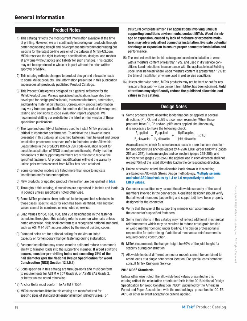
18 MiTek® Product Catalog
Copyright © 2020 M
iTek Industries, Inc. All Rights Reserved
General Information
Product Notes
1) This catalog reflects the most current information available at the time of printing . However, we are continually improving our products through better engineering design and development and recommend visiting our website for the latest on-line version of the catalog at MiTek-US .com . MiTek reserves the right to change specifications, designs, and models at any time without notice and liability for such changes . This catalog may not be reproduced in whole or in part without the prior written approval of MiTek .
2) This catalog reflects changes to product design and allowable loads to some MiTek products . The information presented in this publication supersedes all previously published Product Catalogs .
3) This Product Catalog was designed as a general reference for the MiTek Product Line . Various specialized publications have also been developed for design professionals, truss manufacturers, contractors, and building material distributors . Consequently, product information may vary from one publication to another due to product development testing and revisions to code evaluation report upgrades . We recommend visiting our website for the latest on-line version of these specialized publications .
4) The type and quantity of fasteners used to install MiTek products is critical to connector performance . To achieve the allowable loads presented in this catalog, all specified fasteners must be used and proper installation procedures observed (refer to footnotes under Allowable Loads tables in the product’s ICC-ES ESR code evaluation report for possible substitution of TECO brand pneumatic nails) . Verify that the dimensions of the supporting members are sufficient to receive the specified fasteners . All product modifications will void the warranty unless prior written consent from MiTek has been obtained .
5) Some connector models are listed more than once to indicate installation and/or fastener options .
6) New products or updated product information are designated in blue .
7) Throughout this catalog, dimensions are expressed in inches and loads in pounds unless specifically noted otherwise .
8) Some MiTek products show both nail fastening and bolt schedules . In those cases, specific loads for each has been identified . Nail and bolt values cannot be combined unless noted otherwise .
9) Load values for 8d, 10d, 16d, and 20d designations in the fastener schedules throughout this catalog refer to common wire nails unless noted otherwise . Nails shall conform to a recognized national standard, such as ASTM F1667, as prescribed by the model building codes .
10) Diamond holes are for optional nailing for maximum listed capacity or for temporary hanger fastening during installation .
11) Fastener installation may cause wood to split and reduce a fastener’s ability to transfer loads into the supporting member . If wood splitting occurs, consider pre-drilling holes not exceeding 75% of the nail diameter (per the National Design Specification for Wood Construction (NDS) Section 12 .1 .5 .3) .
12) Bolts specified in this catalog are through-bolts and must conform to requirements for ASTM A 307 Grade A, or ASME SAE Grade 2, or better unless noted otherwise .
13) Anchor Bolts must conform to ASTM F 1554 .
14) MiTek connectors listed in this catalog are manufactured for specific sizes of standard dimensional lumber, plated trusses, or
structural composite lumber . For applications involving unusual supporting conditions environments, contact MiTek . Wood shrink-age or expansion, caused by lack of moisture or excessive mois-ture, may adversely affect connector installation . Evaluate potential shrinkage or expansion to ensure proper connector installation and performance .
15) The load values listed in this catalog are based on installation to wood with a moisture content of less than 19%, and used in dry service con-ditions . Load reductions, in accordance with the applicable local Building Code, shall be taken where wood moisture content is greater than 19% at the time of installation or where used in wet service conditions .
16) Unless otherwise noted, MiTek products may not be bent or cut for any reason unless prior written consent from MiTek has been obtained . Field alterations may significantly reduce the published allowable load values in this catalog .
Design Notes
1) Some products have allowable loads that can be applied in several directions (F1, F2, and uplift is a common example) . When these products have F1, F2 and/or uplift loads applied simultaneously, it is necessary to make the following check:
As an alternative check for simultaneous loads in more than one direction for embedded truss anchors (pages 244-250), LUGT girder tiedowns (pages 253 and 257), hurricane angles and connectors (pages 255-256), and hurricane ties (pages 262-264); the applied load in each direction shall not exceed 75% of the listed allowable load in the corresponding direction .
2) Unless otherwise noted, the allowable loads shown in this catalog are based on Allowable Stress Design methodology . Multiply seismic and wind ASD load values by 1 .4 or 1 .6 respectively to obtain LRFD values .
3) Connector capacities may exceed the allowable capacity of the wood members involved in the connection . A qualified designer should verify that all wood members (supporting and supported) have been properly designed for the connector .
4) Verify that the size of the supporting member can accommodate the connector’s specified fasteners .
5) Some illustrations in this catalog may not reflect additional mechanical reinforcements which may be required to reduce cross grain tension or wood member bending under loading . The design professional is responsible for determining if additional mechanical reinforcement is required during construction .
6) MiTek recommends the hanger height be 60% of the joist height for stability during construction .
7) Allowable loads of different connector models cannot be combined to resist loads at a single connection location . For special considerations, consult MiTek Customer Service
2018 NDS® Standards
Unless otherwise noted, the allowable load values presented in this catalog reflect the calculation criteria set forth in the 2018 National Design Specification for Wood Construction (NDS®) published by the American Forest and Paper Association; with the methodology prescribed in ICC-ES AC13 or other relevant acceptance criteria applied .
F1 applied +
F2 applied +
Uplift applied < 1 .0
F1 allowable F2 allowable Uplift allowable
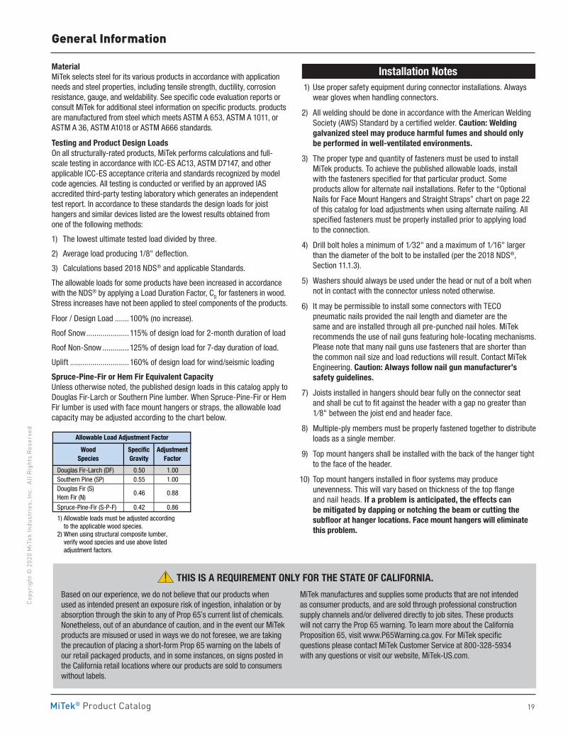
19MiTek® Product Catalog
Copy
righ
t © 2
020
MiT
ek In
dust
ries
, Inc
. Al
l Rig
hts
Rese
rved
General Information
MaterialMiTek selects steel for its various products in accordance with application needs and steel properties, including tensile strength, ductility, corrosion resistance, gauge, and weldability . See specific code evaluation reports or consult MiTek for additional steel information on specific products . products are manufactured from steel which meets ASTM A 653, ASTM A 1011, or ASTM A 36, ASTM A1018 or ASTM A666 standards .
Testing and Product Design LoadsOn all structurally-rated products, MiTek performs calculations and full-scale testing in accordance with ICC-ES AC13, ASTM D7147, and other applicable ICC-ES acceptance criteria and standards recognized by model code agencies . All testing is conducted or verified by an approved IAS accredited third-party testing laboratory which generates an independent test report . In accordance to these standards the design loads for joist hangers and similar devices listed are the lowest results obtained from one of the following methods:
1) The lowest ultimate tested load divided by three .
2) Average load producing 1/8" deflection .
3) Calculations based 2018 NDS® and applicable Standards .
The allowable loads for some products have been increased in accordance with the NDS® by applying a Load Duration Factor, CD for fasteners in wood . Stress increases have not been applied to steel components of the products .
Floor / Design Load . . . . . . .100% (no increase) .
Roof Snow . . . . . . . . . . . . . . . . . . . . .115% of design load for 2-month duration of load
Roof Non-Snow . . . . . . . . . . . . .125% of design load for 7-day duration of load .
Uplift . . . . . . . . . . . . . . . . . . . . . . . . . . . . . 160% of design load for wind/seismic loading
Spruce-Pine-Fir or Hem Fir Equivalent CapacityUnless otherwise noted, the published design loads in this catalog apply to Douglas Fir-Larch or Southern Pine lumber . When Spruce-Pine-Fir or Hem Fir lumber is used with face mount hangers or straps, the allowable load capacity may be adjusted according to the chart below .
Installation Notes 1) Use proper safety equipment during connector installations . Always
wear gloves when handling connectors .
2) All welding should be done in accordance with the American Welding Society (AWS) Standard by a certified welder . Caution: Welding galvanized steel may produce harmful fumes and should only be performed in well-ventilated environments .
3) The proper type and quantity of fasteners must be used to install MiTek products . To achieve the published allowable loads, install with the fasteners specified for that particular product . Some products allow for alternate nail installations . Refer to the “Optional Nails for Face Mount Hangers and Straight Straps” chart on page 22 of this catalog for load adjustments when using alternate nailing . All specified fasteners must be properly installed prior to applying load to the connection .
4) Drill bolt holes a minimum of 1⁄32" and a maximum of 1⁄16" larger than the diameter of the bolt to be installed (per the 2018 NDS®, Section 11 .1 .3) .
5) Washers should always be used under the head or nut of a bolt when not in contact with the connector unless noted otherwise .
6) It may be permissible to install some connectors with TECO pneumatic nails provided the nail length and diameter are the same and are installed through all pre-punched nail holes . MiTek recommends the use of nail guns featuring hole-locating mechanisms . Please note that many nail guns use fasteners that are shorter than the common nail size and load reductions will result . Contact MiTek Engineering . Caution: Always follow nail gun manufacturer’s safety guidelines .
7) Joists installed in hangers should bear fully on the connector seat and shall be cut to fit against the header with a gap no greater than 1⁄8" between the joist end and header face .
8) Multiple-ply members must be properly fastened together to distribute loads as a single member .
9) Top mount hangers shall be installed with the back of the hanger tight to the face of the header .
10) Top mount hangers installed in floor systems may produce unevenness . This will vary based on thickness of the top flange and nail heads . If a problem is anticipated, the effects can be mitigated by dapping or notching the beam or cutting the subfloor at hanger locations . Face mount hangers will eliminate this problem .
Based on our experience, we do not believe that our products when used as intended present an exposure risk of ingestion, inhalation or by absorption through the skin to any of Prop 65’s current list of chemicals . Nonetheless, out of an abundance of caution, and in the event our MiTek products are misused or used in ways we do not foresee, we are taking the precaution of placing a short‐form Prop 65 warning on the labels of our retail packaged products, and in some instances, on signs posted in the California retail locations where our products are sold to consumers without labels .
MiTek manufactures and supplies some products that are not intended as consumer products, and are sold through professional construction supply channels and/or delivered directly to job sites . These products will not carry the Prop 65 warning . To learn more about the California Proposition 65, visit www .P65Warning .ca .gov . For MiTek specific questions please contact MiTek Customer Service at 800‐328‐5934 with any questions or visit our website, MiTek‐US .com .
! THIS IS A REQUIREMENT ONLY FOR THE STATE OF CALIFORNIA .
Douglas Fir-Larch (DF) 0.50 1.00 Southern Pine (SP) 0.55 1.00
Spruce-Pine-Fir (S-P-F) 0.42 0.86
1) Allowable loads must be adjusted according to the applicable wood species. 2) When using structural composite lumber, verify wood species and use above listed adjustment factors.
Douglas Fir (S) Hem Fir (N)
0.46 0.88
Allowable Load Adjustment Factor
WoodSpecies
Specific Gravity
AdjustmentFactor
20
Copyright © 2020 M
iTek Industries, Inc. All Rights Reserved
Fasteners
Fast
ener
s
MiTek® Product Catalog
Fasteners
Bolts 38Fastening Identification / Features 39 Nails 22-24Screws 25-37
pg. 22-39
Fasteners
21
Copy
righ
t © 2
020
MiT
ek In
dust
ries
, Inc
. Al
l Rig
hts
Rese
rved
Fasteners
MiTek® Product Catalog
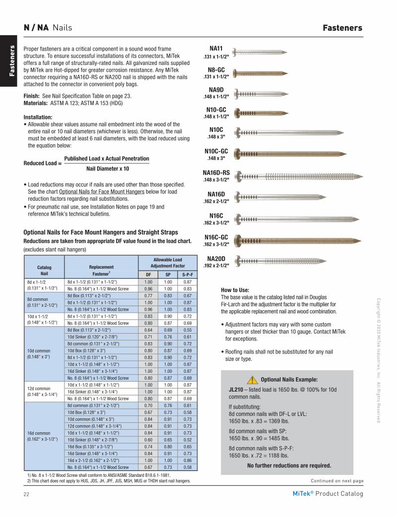
22
Copyright © 2020 M
iTek Industries, Inc. All Rights Reserved
Fasteners
Fast
ener
s
MiTek® Product Catalog
Proper fasteners are a critical component in a sound wood frame structure. To ensure successful installations of its connectors, MiTek offers a full range of structurally-rated nails. All galvanized nails supplied by MiTek are Hot-dipped for greater corrosion resistance. Any MiTek connector requiring a NA16D-RS or NA20D nail is shipped with the nails attached to the connector in convenient poly bags.
Finish: See Nail Specification Table on page 23. Materials: ASTM A 123; ASTM A 153 (HDG)
Installation:• Allowable shear values assume nail embedment into the wood of the
entire nail or 10 nail diameters (whichever is less). Otherwise, the nail must be embedded at least 6 nail diameters, with the load reduced using the equation below:
Reduced Load = Published Load x Actual Penetration
Nail Diameter x 10
• Load reductions may occur if nails are used other than those specified. See the chart Optional Nails for Face Mount Hangers below for load reduction factors regarding nail substitutions.
• For pneumatic nail use, see Installation Notes on page 19 and reference MiTek’s technical bulletins.
N / NA Nails
Continued on next page
NA11
.131 x 1-1/2"
N8-GC .131 x 1-1/2"
NA9D .148 x 1-1/2"
N10-GC .148 x 1-1/2"
N10C .148 x 3"
N10C-GC .148 x 3"
NA16D-RS .148 x 3-1/2"
NA16D .162 x 2-1/2"
N16C .162 x 3-1/2"
N16C-GC .162 x 3-1/2"
NA20D .192 x 2-1/2"
DF SP S-P-F
8d x 1-1/2 (0.131" x 1-1/2") 1.00 1.00 0.87
No. 8 (0.164") x 1-1/2 Wood Screw 0.96 1.00 0.83
8d Box (0.113" x 2-1/2") 0.77 0.83 0.67
8d x 1-1/2 (0.131" x 1-1/2") 1.00 1.00 0.87
No. 8 (0.164") x 1-1/2 Wood Screw 0.96 1.00 0.83
8d x 1-1/2 (0.131" x 1-1/2") 0.83 0.90 0.72
No. 8 (0.164") x 1-1/2 Wood Screw 0.80 0.87 0.69
8d Box (0.113" x 2-1/2") 0.64 0.69 0.55
10d Sinker (0.120" x 2-7/8") 0.71 0.76 0.61
8d common (0.131" x 2-1/2") 0.83 0.90 0.72
10d Box (0.128" x 3") 0.80 0.87 0.69
8d x 1-1/2 (0.131" x 1-1/2") 0.83 0.90 0.72
10d x 1-1/2 (0.148" x 1-1/2") 1.00 1.00 0.87
16d Sinker (0.148" x 3-1/4") 1.00 1.00 0.87
No. 8 (0.164") x 1-1/2 Wood Screw 0.80 0.87 0.69
10d x 1-1/2 (0.148" x 1-1/2") 1.00 1.00 0.87
16d Sinker (0.148" x 3-1/4") 1.00 1.00 0.87
No. 8 (0.164") x 1-1/2 Wood Screw 0.80 0.87 0.69
8d common (0.131" x 2-1/2") 0.70 0.76 0.61
10d Box (0.128" x 3") 0.67 0.73 0.58
10d common (0.148" x 3") 0.84 0.91 0.73
12d common (0.148" x 3-1/4") 0.84 0.91 0.73
10d x 1-1/2 (0.148" x 1-1/2") 0.84 0.91 0.73
10d Sinker (0.148" x 2-7/8") 0.60 0.65 0.52
16d Box (0.135" x 3-1/2") 0.74 0.80 0.65
16d Sinker (0.148" x 3-1/4") 0.84 0.91 0.73
16d x 2-1/2 (0.162" x 2-1/2") 1.00 1.00 0.86
No. 8 (0.164") x 1-1/2 Wood Screw 0.67 0.73 0.58
1) No. 8 x 1-1/2 Wood Screw shall conform to ANSI/ASME Standard B18.6.1-1981. 2) This chart does not apply to HUS, JDS, JH, JPF, JUS, MSH, MUS or THDH slant nail hangers.
Allowable Load Adjustment FactorCatalog
NailReplacement
Fastener1
16d common (0.162" x 3-1/2'')
10d common (0.148" x 3")
12d common (0.148" x 3-1/4")
8d common (0.131" x 2-1/2")
8d x 1-1/2 (0.131" x 1-1/2")
10d x 1-1/2 (0.148" x 1-1/2")
Optional Nails Example:
JL210 – listed load is 1650 lbs. @ 100% for 10d common nails.
If substituting: 8d common nails with DF-L or LVL: 1650 lbs. x .83 = 1369 lbs.
8d common nails with SP: 1650 lbs. x .90 = 1485 lbs.
8d common nails with S-P-F: 1650 lbs. x .72 = 1188 lbs.
No further reductions are required.
!
How to Use: The base value is the catalog listed nail in Douglas Fir-Larch and the adjustment factor is the multiplier for the applicable replacement nail and wood combination.
• Adjustment factors may vary with some custom hangers or steel thicker than 10 gauge. Contact MiTek for exceptions.
• Roofing nails shall not be substituted for any nail size or type.
Optional Nails for Face Mount Hangers and Straight StrapsReductions are taken from appropriate DF value found in the load chart. (excludes slant nail hangers)
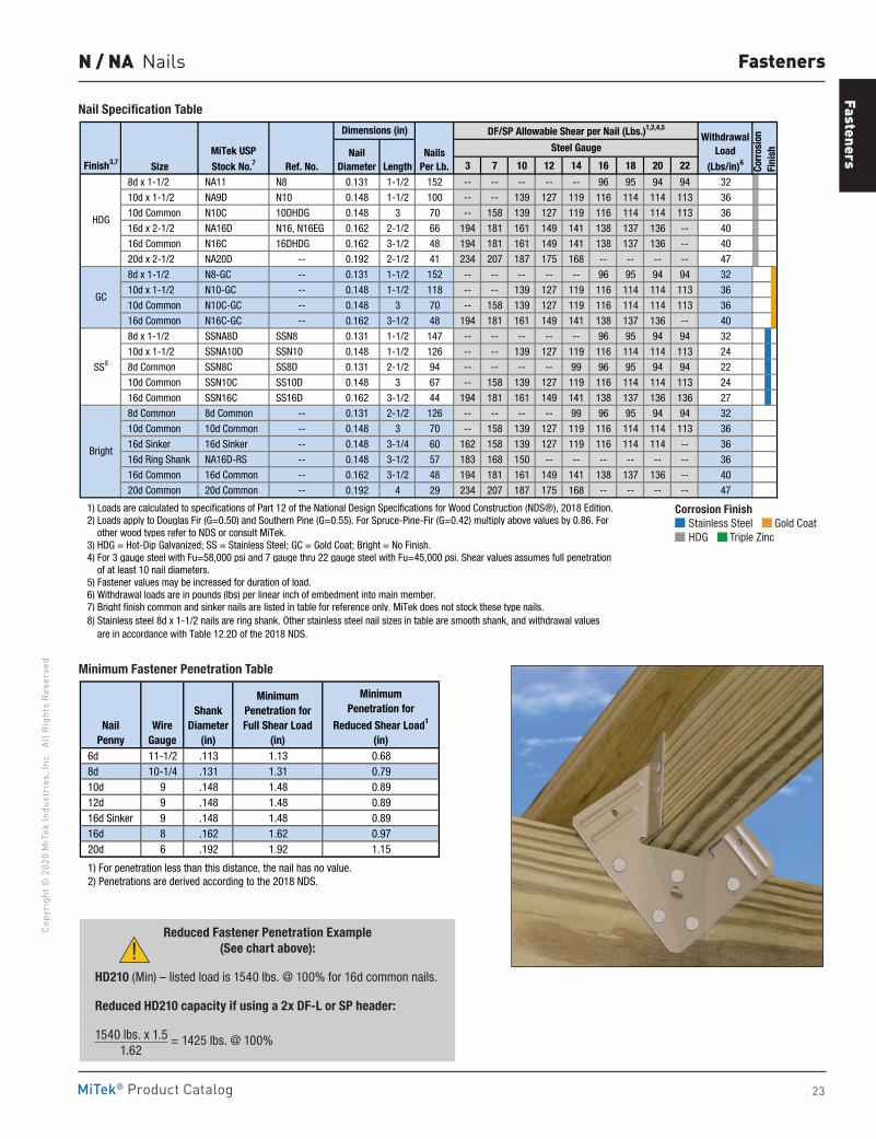
Fasteners
23
Copy
righ
t © 2
020
MiT
ek In
dust
ries
, Inc
. Al
l Rig
hts
Rese
rved
Fasteners
MiTek® Product Catalog
N / NA Nails
Finish3,7 Size Ref. No. Length 3 7 10 12 14 16 18 20 22
8d x 1-1/2 NA11 N8 0.131 1-1/2 152 -- -- -- -- -- 96 95 94 94 32
10d x 1-1/2 NA9D N10 0.148 1-1/2 100 -- -- 139 127 119 116 114 114 113 36
10d Common N10C 10DHDG 0.148 3 70 -- 158 139 127 119 116 114 114 113 36
16d x 2-1/2 NA16D N16, N16EG 0.162 2-1/2 66 194 181 161 149 141 138 137 136 -- 40
16d Common N16C 16DHDG 0.162 3-1/2 48 194 181 161 149 141 138 137 136 -- 40
20d x 2-1/2 NA20D -- 0.192 2-1/2 41 234 207 187 175 168 -- -- -- -- 47
8d x 1-1/2 N8-GC -- 0.131 1-1/2 152 -- -- -- -- -- 96 95 94 94 32
10d x 1-1/2 N10-GC -- 0.148 1-1/2 118 -- -- 139 127 119 116 114 114 113 36
10d Common N10C-GC -- 0.148 3 70 -- 158 139 127 119 116 114 114 113 36
16d Common N16C-GC -- 0.162 3-1/2 48 194 181 161 149 141 138 137 136 -- 40
8d x 1-1/2 SSNA8D SSN8 0.131 1-1/2 147 -- -- -- -- -- 96 95 94 94 32
10d x 1-1/2 SSNA10D SSN10 0.148 1-1/2 126 -- -- 139 127 119 116 114 114 113 24
8d Common SSN8C SS8D 0.131 2-1/2 94 -- -- -- -- 99 96 95 94 94 22
10d Common SSN10C SS10D 0.148 3 67 -- 158 139 127 119 116 114 114 113 24
16d Common SSN16C SS16D 0.162 3-1/2 44 194 181 161 149 141 138 137 136 136 27
8d Common 8d Common -- 0.131 2-1/2 126 -- -- -- -- 99 96 95 94 94 32
10d Common 10d Common -- 0.148 3 70 -- 158 139 127 119 116 114 114 113 36
16d Sinker 16d Sinker -- 0.148 3-1/4 60 162 158 139 127 119 116 114 114 -- 36
16d Ring Shank NA16D-RS -- 0.148 3-1/2 57 183 168 150 -- -- -- -- -- -- 36
16d Common 16d Common -- 0.162 3-1/2 48 194 181 161 149 141 138 137 136 -- 40
20d Common 20d Common -- 0.192 4 29 234 207 187 175 168 -- -- -- -- 47
1) Loads are calculated to specifications of Part 12 of the National Design Specifications for Wood Construction (NDS®), 2018 Edition. 2) Loads apply to Douglas Fir (G=0.50) and Southern Pine (G=0.55). For Spruce-Pine-Fir (G=0.42) multiply above values by 0.86. For other wood types refer to NDS or consult MiTek. 3) HDG = Hot-Dip Galvanized; SS = Stainless Steel; GC = Gold Coat; Bright = No Finish. 4) For 3 gauge steel with Fu=58,000 psi and 7 gauge thru 22 gauge steel with Fu=45,000 psi. Shear values assumes full penetration of at least 10 nail diameters. 5) Fastener values may be increased for duration of load. 6) Withdrawal loads are in pounds (lbs) per linear inch of embedment into main member. 7) Bright finish common and sinker nails are listed in table for reference only. MiTek does not stock these type nails. 8) Stainless steel 8d x 1-1/2 nails are ring shank. Other stainless steel nail sizes in table are smooth shank, and withdrawal values are in accordance with Table 12.2D of the 2018 NDS.
Corr
osio
nFi
nish
HDG
SS8
GC
Bright
MiTek USPStock No.7
NailDiameter
WithdrawalLoad
(Lbs/in)6
Dimensions (in) DF/SP Allowable Shear per Nail (Lbs.)1,2,4,5
Steel GaugeNailsPer Lb.
Nail Specification Table
Corrosion Finish Stainless Steel Gold Coat HDG Triple Zinc
Corrosion Finish Stainless Steel Gold Coat HDG Triple Zinc
Corrosion Finish Stainless Steel Gold Coat HDG Triple Zinc
6d 11-1/2 .113 1.13 0.68 8d 10-1/4 .131 1.31 0.79 10d 9 .148 1.48 0.89 12d 9 .148 1.48 0.89 16d Sinker 9 .148 1.48 0.89 16d 8 .162 1.62 0.97 20d 6 .192 1.92 1.15
1) For penetration less than this distance, the nail has no value. 2) Penetrations are derived according to the 2018 NDS.
MinimumPenetration for
Reduced Shear Load1
(in)
MinimumPenetration for Full Shear Load
(in)Nail
PennyWire
Gauge
ShankDiameter
(in)
Reduced Fastener Penetration Example (See chart above):
HD210 (Min) – listed load is 1540 lbs. @ 100% for 16d common nails.
Reduced HD210 capacity if using a 2x DF-L or SP header:
1540 lbs. x 1.5 = 1425 lbs. @ 100% 1.62
!
Minimum Fastener Penetration Table
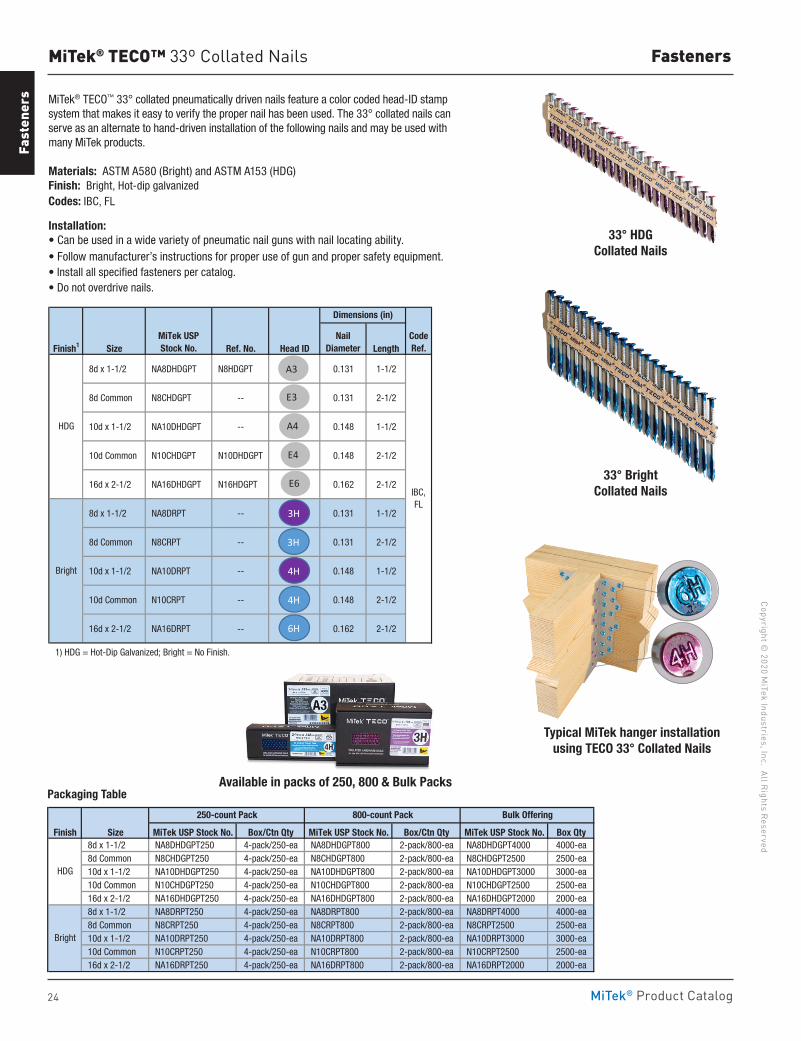
24
Copyright © 2020 M
iTek Industries, Inc. All Rights Reserved
Fasteners
Fast
ener
s
MiTek® Product Catalog
MiTek® TECO™ 33º Collated Nails
MiTek® TECO™ 33° collated pneumatically driven nails feature a color coded head-ID stamp system that makes it easy to verify the proper nail has been used. The 33° collated nails can serve as an alternate to hand-driven installation of the following nails and may be used with many MiTek products.
Materials: ASTM A580 (Bright) and ASTM A153 (HDG)Finish: Bright, Hot-dip galvanizedCodes: IBC, FL
Installation:• Can be used in a wide variety of pneumatic nail guns with nail locating ability. • Follow manufacturer’s instructions for proper use of gun and proper safety equipment. • Install all specified fasteners per catalog.• Do not overdrive nails.
Finish1 Size Ref. No. Head ID Length
8d x 1-1/2 NA8DHDGPT N8HDGPT 0.131 1-1/2
8d Common N8CHDGPT -- 0.131 2-1/2
10d x 1-1/2 NA10DHDGPT -- 0.148 1-1/2
10d Common N10CHDGPT N10DHDGPT 0.148 2-1/2
16d x 2-1/2 NA16DHDGPT N16HDGPT 0.162 2-1/2
8d x 1-1/2 NA8DRPT -- 0.131 1-1/2
8d Common N8CRPT -- 0.131 2-1/2
10d x 1-1/2 NA10DRPT -- 0.148 1-1/2
10d Common N10CRPT -- 0.148 2-1/2
16d x 2-1/2 NA16DRPT -- 0.162 2-1/2
1) HDG = Hot-Dip Galvanized; Bright = No Finish.
Dimensions (in)
MiTek USPStock No.
NailDiameter
Bright
CodeRef.
IBC, FL
HDG
3H
3H
4H
A3
E3
A4
E4
E6
4H
6H
33° HDG Collated Nails
Available in packs of 250, 800 & Bulk Packs
33° Bright Collated Nails
Typical MiTek hanger installation using TECO 33° Collated Nails
Packaging Table
Finish Size MiTek USP Stock No. Box/Ctn Qty MiTek USP Stock No. Box/Ctn Qty MiTek USP Stock No. Box Qty 8d x 1-1/2 NA8DHDGPT250 4-pack/250-ea NA8DHDGPT800 2-pack/800-ea NA8DHDGPT4000 4000-ea 8d Common N8CHDGPT250 4-pack/250-ea N8CHDGPT800 2-pack/800-ea N8CHDGPT2500 2500-ea 10d x 1-1/2 NA10DHDGPT250 4-pack/250-ea NA10DHDGPT800 2-pack/800-ea NA10DHDGPT3000 3000-ea 10d Common N10CHDGPT250 4-pack/250-ea N10CHDGPT800 2-pack/800-ea N10CHDGPT2500 2500-ea 16d x 2-1/2 NA16DHDGPT250 4-pack/250-ea NA16DHDGPT800 2-pack/800-ea NA16DHDGPT2000 2000-ea 8d x 1-1/2 NA8DRPT250 4-pack/250-ea NA8DRPT800 2-pack/800-ea NA8DRPT4000 4000-ea 8d Common N8CRPT250 4-pack/250-ea N8CRPT800 2-pack/800-ea N8CRPT2500 2500-ea 10d x 1-1/2 NA10DRPT250 4-pack/250-ea NA10DRPT800 2-pack/800-ea NA10DRPT3000 3000-ea 10d Common N10CRPT250 4-pack/250-ea N10CRPT800 2-pack/800-ea N10CRPT2500 2500-ea 16d x 2-1/2 NA16DRPT250 4-pack/250-ea NA16DRPT800 2-pack/800-ea NA16DRPT2000 2000-ea
HDG
Bright
Bulk Offering250-count Pack 800-count Pack
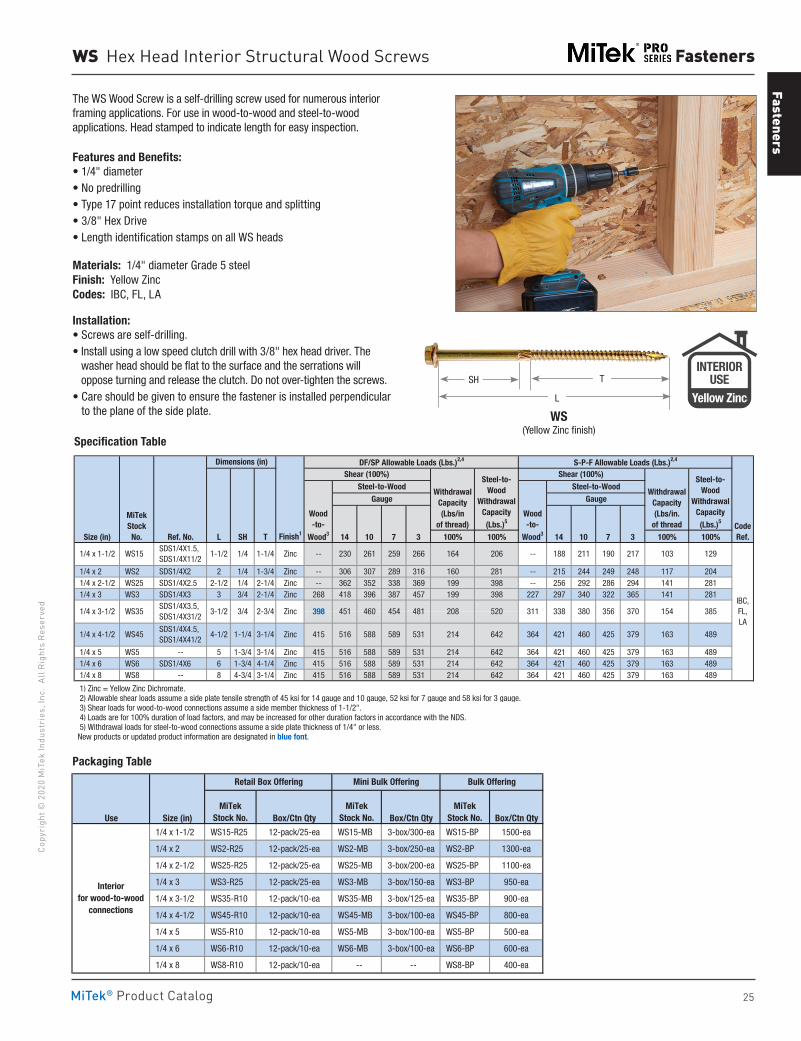
Fasteners
25
Copy
righ
t © 2
020
MiT
ek In
dust
ries
, Inc
. Al
l Rig
hts
Rese
rved
Fasteners
MiTek® Product Catalog
Specification Table
WS Hex Head Interior Structural Wood Screws
The WS Wood Screw is a self-drilling screw used for numerous interior framing applications. For use in wood-to-wood and steel-to-wood applications. Head stamped to indicate length for easy inspection.
Features and Benefits:• 1/4" diameter• No predrilling• Type 17 point reduces installation torque and splitting• 3/8" Hex Drive• Length identification stamps on all WS heads
Materials: 1/4" diameter Grade 5 steelFinish: Yellow ZincCodes: IBC, FL, LA
Installation:• Screws are self-drilling.• Install using a low speed clutch drill with 3/8" hex head driver. The
washer head should be flat to the surface and the serrations will oppose turning and release the clutch. Do not over-tighten the screws.
• Care should be given to ensure the fastener is installed perpendicular to the plane of the side plate.
Size (in) Ref. No. L SH T Finish1 100% 100% 100% 100%
1/4 x 2 WS2 SDS1/4X2 2 1/4 1-3/4 Zinc -- 306 307 289 316 160 281 -- 215 244 249 248 117 204 1/4 x 2-1/2 WS25 SDS1/4X2.5 2-1/2 1/4 2-1/4 Zinc -- 362 352 338 369 199 398 -- 256 292 286 294 141 281 1/4 x 3 WS3 SDS1/4X3 3 3/4 2-1/4 Zinc 268 418 396 387 457 199 398 227 297 340 322 365 141 281
1/4 x 5 WS5 -- 5 1-3/4 3-1/4 Zinc 415 516 588 589 531 214 642 364 421 460 425 379 163 489 1/4 x 6 WS6 SDS1/4X6 6 1-3/4 4-1/4 Zinc 415 516 588 589 531 214 642 364 421 460 425 379 163 489 1/4 x 8 WS8 -- 8 4-3/4 3-1/4 Zinc 415 516 588 589 531 214 642 364 421 460 425 379 163 489
1) Zinc = Yellow Zinc Dichromate. 2) Allowable shear loads assume a side plate tensile strength of 45 ksi for 14 gauge and 10 gauge, 52 ksi for 7 gauge and 58 ksi for 3 gauge. 3) Shear loads for wood-to-wood connections assume a side member thickness of 1-1/2". 4) Loads are for 100% duration of load factors, and may be increased for other duration factors in accordance with the NDS. 5) Withdrawal loads for steel-to-wood connections assume a side plate thickness of 1/4" or less. New products or updated product information are designated in blue font.
MiTek Stock
No.
364 WS45 1/4 x 4-1/2 SDS1/4X4.5, SDS1/4X41/2
4-1/2 1-1/4 3-1/4 Zinc
311208 520
516 588 589 531
385
421 460 425 379 163 489
154338 380 356 370481398
415
451 460 454
-- 188 211
214 642
1/4 x 3-1/2 WS35 3-1/2 3/4 2-3/4 SDS1/4X3.5, SDS1/4X31/2
1/4 x 1-1/2 WS15 1-1/2 1/4 1-1/4 SDS1/4X1.5, SDS1/4X11/2
S-P-F Allowable Loads (Lbs.)2,4
Shear (100%)
WithdrawalCapacity(Lbs/in.
of thread
Steel-to-Wood
WithdrawalCapacity (Lbs.)5
Wood-to-
Wood3 14 10
Steel-to-WoodGauge
IBC,FL,LA
14 10 7 3CodeRef.7 3
259 190 217 103 129266 164 206Zinc -- 230 261
Zinc
Dimensions (in) DF/SP Allowable Loads (Lbs.)2,4
Shear (100%)
WithdrawalCapacity (Lbs/in
of thread)
Steel-to-Wood
Withdrawal Capacity(Lbs.)5
Wood-to-
Wood3
GaugeSteel-to-Wood
WS(Yellow Zinc finish)
T
L
SH
Use Size (in) Box/Ctn Qty Box/Ctn Qty Box/Ctn Qty
1/4 x 1-1/2 WS15-R25 12-pack/25-ea WS15-MB 3-box/300-ea WS15-BP 1500-ea
1/4 x 2 WS2-R25 12-pack/25-ea WS2-MB 3-box/250-ea WS2-BP 1300-ea
1/4 x 2-1/2 WS25-R25 12-pack/25-ea WS25-MB 3-box/200-ea WS25-BP 1100-ea
1/4 x 3 WS3-R25 12-pack/25-ea WS3-MB 3-box/150-ea WS3-BP 950-ea
1/4 x 3-1/2 WS35-R10 12-pack/10-ea WS35-MB 3-box/125-ea WS35-BP 900-ea
1/4 x 4-1/2 WS45-R10 12-pack/10-ea WS45-MB 3-box/100-ea WS45-BP 800-ea
1/4 x 5 WS5-R10 12-pack/10-ea WS5-MB 3-box/100-ea WS5-BP 500-ea
1/4 x 6 WS6-R10 12-pack/10-ea WS6-MB 3-box/100-ea WS6-BP 600-ea
1/4 x 8 WS8-R10 12-pack/10-ea -- -- WS8-BP 400-ea
Bulk OfferingRetail Box Offering Mini Bulk Offering
Interiorfor wood-to-wood
connections
MiTekStock No.
MiTekStock No.
MiTekStock No.
Packaging Table
INTERIORUSE
Yellow Zinc
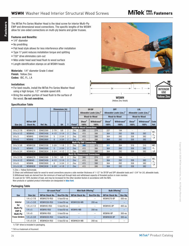
26
Copyright © 2020 M
iTek Industries, Inc. All Rights Reserved
Fasteners
Fast
ener
s
MiTek® Product Catalog
Size (in) L SH T
1/4 x 2-7/8 WSWH278 SDW22300 2-7/8 5/8 2 Zinc 268 274 227 194 -- -- 1/4 x 4-1/2 WSWH45 SDW22458 4-1/2 2-1/4 2 Zinc 415 398 364 282 358 382 1/4 x 5 WSWH5 SDW22500 5 2-3/4 2 Zinc 415 398 364 282 358 382 1/4 x 6 WSWH6 SDW22600 6 3-3/4 2 Zinc 415 398 364 282 358 382
1/4 x 3-3/8 WSWH338 SDW22338 3-3/8 1-1/8 2 Zinc 398 373 311 264 319 310 1/4 x 5 WSWH5 SDW22500 5 2-3/4 2 Zinc 415 398 364 282 358 382 1/4 x 6-3/4 WSWH634 SDW22634 6-3/4 4-1/2 2 Zinc 415 398 364 282 358 382
1/4 x 2-7/8 WSWH278 SDW22300 2-7/8 5/8 2 Zinc 268 274 227 194 -- -- 1/4 x 4-1/2 WSWH45 SDW22458 4-1/2 2-1/4 2 Zinc 415 398 364 282 358 382 1/4 x 6 WSWH6 SDW22600 6 3-3/4 2 Zinc 415 398 364 282 358 382 1/4 x 6-3/8 WSWH638 SDW22638 6-3/8 4-1/8 2 Zinc 415 398 364 282 358 382
1) Zinc = Yellow Dichromate. 2) Shear and withdrawal loads for wood-to-wood connections assume a side member thickness of 1-1/2" for DF/SP and SPF allowable loads and 1-3/4" for LVL allowable loads. 3) Withdrawal loads are derived from the minimum of head pull through tests and withdrawal capacity of threaded portion in main member. 4) Load are for 100% duration of load, and may be increased for the other duration factors in accordance with the NDS. New products or updated product information are designated in blue font.
SPF
Allowable Loads (Lbs.)4
LVL
Allowable Loads (Lbs.)4
Shear2
100%Withdrawal3
100%
Wood-to-Wood
Dimensions (in)
MiTek USPStock No. Ref. No. Finish1
Shear2
100%
DF/SP
Allowable Loads (Lbs.)4
Wood-to-Wood
Multi-Ply Dimensional Connections
IBC,FL,LA
Wood-to-Wood
Shear2
100%Withdrawal3
100%Withdrawal3
100%CodeRef.
Wood-to-Wood Connections
IBC,FL,LA
Multi-Ply EWP ConnectionsIBC,FL,LA
WSWH Washer Head Interior Structural Wood Screws
The MiTek Pro Series Washer Head is the ideal screw for interior Multi-Ply EWP and dimensional wood connections. The specific lengths of the WSWH allow for one-sided connections on multi-ply beams and girder trusses.
Features and Benefits:• 1/4" diameter• No predrilling• Flat head style allows for less interference after installation• Type 17 point reduces installation torque and splitting• T30* drive eliminates cam-out• Nibs under head seat head flush to wood surface• Length identification stamps on all WSWH heads
Materials: 1/4" diameter Grade 5 steelFinish: Yellow ZincCodes: IBC, FL, LA
Installation:• For best results, install the MiTek Pro Series Washer Head
using a high torque, 1/2" variable speed drill.• Bring the washer portion of head flush to the surface of
the wood. Do not overdrive.
Use Size (in) MiTek Stock No. Box/Ctn Qty MiTek Stock No. Box/Ctn Qty MiTek Stock No. Box Qty 1/4 x 2-7/8 WSWH278-R50 5-box/50-ea -- -- WSWH278-BP 500-ea
1/4 x 3-3/8 WSWH338-R50 5-box/50-ea WSWH338-MB 200-ea -- --
1/4 x 4-1/2 WSWH45-R50 5-box/50-ea -- -- WSWH45-BP 400-ea
1/4 x 5 WSWH5-R50 5-box/50-ea WSWH5-MB 200-ea -- --
1/4 x 6 WSWH6-R50 5-box/50-ea -- -- WSWH6-BP 300-ea
1/4 x 6-3/8 WSWH638-R50 5-box/50-ea -- -- WSWH638-BP 300-ea
1/4 x 6-3/4 WSWH634-R50 5-box/50-ea WSWH634-MB 200-ea -- --
1) T30* drive is included in packaging.
Bulk Offering1
Interiorfor
Multi-Ply EWP &
Multi-Ply Truss Girders
50-count Pack1 Mini Bulk Offering1
WSWH (Yellow Zinc finish)
T
L
SH
Packaging Table
Specification Table
INTERIORUSE
Yellow Zinc
* T30 is a trademark of Acument
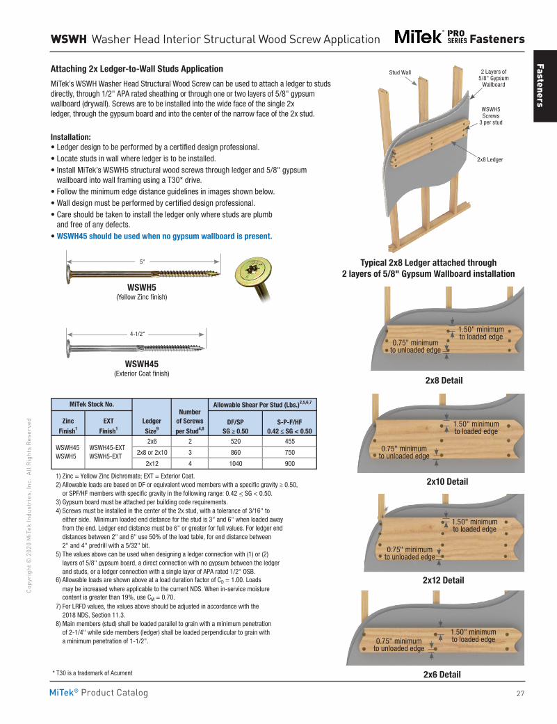
Fasteners
27
Copy
righ
t © 2
020
MiT
ek In
dust
ries
, Inc
. Al
l Rig
hts
Rese
rved
Fasteners
MiTek® Product Catalog
WSWH Washer Head Interior Structural Wood Screw Application
* T30 is a trademark of Acument
1.50" minimum to loaded edge
1.50" minimum to loaded edge
1.50" minimum to loaded edge
0.75" minimum to unloaded edge
0.75" minimum to unloaded edge
0.75" minimum to unloaded edge
2x10 Detail
2x12 Detail
2x6 Detail
0.75" minimum to unloaded edge
2x8 Detail
1.50" minimum to loaded edge
2x6 2 520 455
2x8 or 2x10 3 860 750
2x12 4 1040 900
1) Zinc = Yellow Zinc Dichromate; EXT = Exterior Coat. 2) Allowable loads are based on DF or equivalent wood members with a specific gravity ≥ 0.50, or SPF/HF members with specific gravity in the following range: 0.42 < SG < 0.50. 3) Gypsum board must be attached per building code requirements. 4) Screws must be installed in the center of the 2x stud, with a tolerance of 3/16" to either side. Minimum loaded end distance for the stud is 3" and 6" when loaded away from the end. Ledger end distance must be 6" or greater for full values. For ledger end distances between 2" and 6" use 50% of the load table, for end distance between 2" and 4" predrill with a 5/32" bit. 5) The values above can be used when designing a ledger connection with (1) or (2) layers of 5/8" gypsum board, a direct connection with no gypsum between the ledger and studs, or a ledger connection with a single layer of APA rated 1/2" OSB. 6) Allowable loads are shown above at a load duration factor of CD = 1.00. Loads may be increased where applicable to the current NDS. When in-service moisture content is greater than 19%, use CM = 0.70. 7) For LRFD values, the values above should be adjusted in accordance with the 2018 NDS, Section 11.3. 8) Main members (stud) shall be loaded parallel to grain with a minimum penetration of 2-1/4" while side members (ledger) shall be loaded perpendicular to grain with a minimum penetration of 1-1/2".
WSWH45 WSWH5
EXT
Finish1
WSWH45-EXT WSWH5-EXT
MiTek Stock No. Allowable Shear Per Stud (Lbs.)2,5,6,7
DF/SPSG ≥ 0.50
S-P-F/HF0.42 ≤ SG < 0.50
Ledger
Size9
Number of Screws
per Stud4,8
Zinc
Finish1
Attaching 2x Ledger-to-Wall Studs Application
MiTek’s WSWH Washer Head Structural Wood Screw can be used to attach a ledger to studs directly, through 1/2" APA rated sheathing or through one or two layers of 5/8" gypsum wallboard (drywall). Screws are to be installed into the wide face of the single 2x ledger, through the gypsum board and into the center of the narrow face of the 2x stud.
Installation:• Ledger design to be performed by a certified design professional.• Locate studs in wall where ledger is to be installed.• Install MiTek’s WSWH5 structural wood screws through ledger and 5/8" gypsum
wallboard into wall framing using a T30* drive.• Follow the minimum edge distance guidelines in images shown below.• Wall design must be performed by certified design professional.• Care should be taken to install the ledger only where studs are plumb
and free of any defects.• WSWH45 should be used when no gypsum wallboard is present.
Typical 2x8 Ledger attached through 2 layers of 5/8" Gypsum Wallboard installation
Stud Wall 2 Layers of 5/8" Gypsum
Wallboard
WSWH5 Screws
3 per stud
2x8 Ledger
WSWH5 (Yellow Zinc finish)
WSWH45 (Exterior Coat finish)
5"
4-1/2"
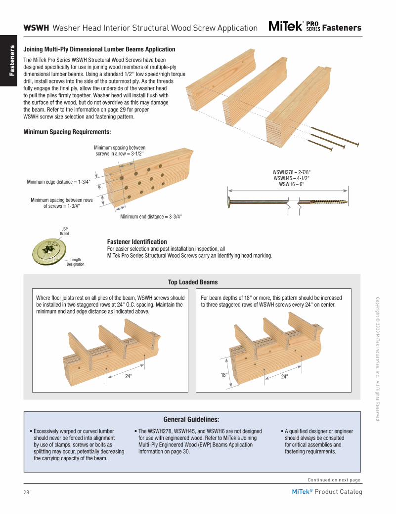
28
Copyright © 2020 M
iTek Industries, Inc. All Rights Reserved
Fasteners
Fast
ener
s
MiTek® Product Catalog
WSWH Washer Head Interior Structural Wood Screw Application
Joining Multi-Ply Dimensional Lumber Beams Application The MiTek Pro Series WSWH Structural Wood Screws have been designed specifically for use in joining wood members of multiple-ply dimensional lumber beams. Using a standard 1/2'' low speed/high torque drill, install screws into the side of the outermost ply. As the threads fully engage the final ply, allow the underside of the washer head to pull the plies firmly together. Washer head will install flush with the surface of the wood, but do not overdrive as this may damage the beam. Refer to the information on page 29 for proper WSWH screw size selection and fastening pattern.
Minimum Spacing Requirements:
Minimum end distance = 3-3/4"
Minimum edge distance = 1-3/4"
Minimum spacing between rows of screws = 1-3/4"
Minimum spacing between screws in a row = 3-1/2"
WSWH278 – 2-7/8" WSWH45 – 4-1/2"
WSWH6 – 6"
• Excessively warped or curved lumber should never be forced into alignment by use of clamps, screws or bolts as splitting may occur, potentially decreasing the carrying capacity of the beam.
• The WSWH278, WSWH45, and WSWH6 are not designed for use with engineered wood. Refer to MiTek’s Joining Multi-Ply Engineered Wood (EWP) Beams Application information on page 30.
• A qualified designer or engineer should always be consulted for critical assemblies and fastening requirements.
General Guidelines:
USP Brand
Length Designation
Fastener IdentificationFor easier selection and post installation inspection, all MiTek Pro Series Structural Wood Screws carry an identifying head marking.
Top Loaded Beams
24" 24" 18"
Where floor joists rest on all plies of the beam, WSWH screws should be installed in two staggered rows at 24" O.C. spacing. Maintain the minimum end and edge distance as indicated above.
For beam depths of 18" or more, this pattern should be increased to three staggered rows of WSWH screws every 24" on center.
Continued on next page
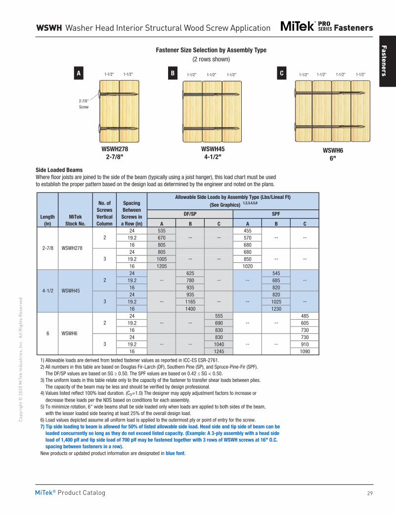
Fasteners
29
Copy
righ
t © 2
020
MiT
ek In
dust
ries
, Inc
. Al
l Rig
hts
Rese
rved
Fasteners
MiTek® Product Catalog
WSWH Washer Head Interior Structural Wood Screw Application
A B
WSWH454-1/2"
1-1/2" 1-1/2" 1-1/2"
WSWH6 6"
1-1/2" 1-1/2" 1-1/2" 1-1/2"
Fastener Size Selection by Assembly Type(2 rows shown)
WSWH2782-7/8"
1-1/2" 1-1/2"
2-7/8"Screw
C
A B C A B C24 535 455
19.2 670 57016 805 68024 805 680
19.2 1005 85016 1205 102024 625 545
19.2 780 68516 935 82024 935 820
19.2 1165 102516 1400 123024 555 485
19.2 690 60516 830 73024 830 730
19.2 1040 91016 1245 1090
1) Allowable loads are derived from tested fastener values as reported in ICC-ES ESR-2761. 2) All numbers in this table are based on Douglas Fir-Larch (DF), Southern Pine (SP), and Spruce-Pine-Fir (SPF). The DF/SP values are based on SG ≥ 0.50. The SPF values are based on 0.42 ≤ SG < 0.50. 3) The uniform loads in this table relate only to the capacity of the fastener to transfer shear loads between plies. The capacity of the beam may be less and should be verified by design professional. 4) Values listed reflect 100% load duration. (CD=1.0) The designer may apply adjustment factors to increase or decrease these loads per the NDS based on conditions for each assembly. 5) To minimize rotation, 6" wide beams shall be side loaded only when loads are applied to both sides of the beam, with the lesser loaded side bearing at least 25% of the overall design load. 6) Load values depicted assume all uniform load is applied to the outermost ply or point of entry for the screw. 7) Tip side loading to beam is allowed for 50% of listed allowable side load. Head side and tip side of beam can be loaded concurrently so long as they do not exceed listed capacity. (Example: A 3-ply assembly with a head side load of 1,400 plf and tip side load of 700 plf may be fastened together with 3 rows of WSWH screws at 16" O.C. spacing between fasteners in a row). New products or updated product information are designated in blue font.
--
-- --
-- --
-- --
--
-- -- -- --
---- ----
6 WSWH6
2
3
No. of Screws VerticalColumn
Length(in)
MiTekStock No.
2-7/8 WSWH278
2
3
SPF
4-1/2 WSWH45
2
3
Spacing Between Screws in a Row (in)
Allowable Side Loads by Assembly Type (Lbs/Lineal Ft) (See Graphics) 1,2,3,4,5,6
DF/SP
-- -- -- --
-- -- -- --
Side Loaded BeamsWhere floor joists are joined to the side of the beam (typically using a joist hanger), this load chart must be used to establish the proper pattern based on the design load as determined by the engineer and noted on the plans.
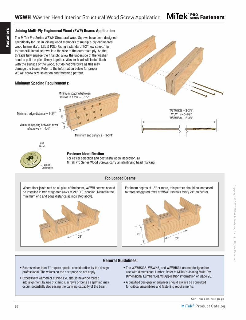
30
Copyright © 2020 M
iTek Industries, Inc. All Rights Reserved
Fasteners
Fast
ener
s
MiTek® Product Catalog
WSWH Washer Head Interior Structural Wood Screw Application
Joining Multi-Ply Engineered Wood (EWP) Beams Application
The MiTek Pro Series WSWH Structural Wood Screws have been designed specifically for use in joining wood members of multiple-ply engineered wood beams (LVL, LSL & PSL). Using a standard 1/2'' low speed/high torque drill, install screws into the side of the outermost ply. As the threads fully engage the final ply, allow the underside of the washer head to pull the plies firmly together. Washer head will install flush with the surface of the wood, but do not overdrive as this may damage the beam. Refer to the information below for proper WSWH screw size selection and fastening pattern.
Minimum Spacing Requirements:
• Beams wider than 7" require special consideration by the design professional. The values on the next page do not apply.
• Excessively warped or curved LVL should never be forced into alignment by use of clamps, screws or bolts as splitting may occur, potentially decreasing the carrying capacity of the beam.
• The WSWH338, WSWH5, and WSWH634 are not designed for use with dimensional lumber. Refer to MiTek’s Joining Multi-Ply Dimensional Lumber Beams Application information on page 28.
• A qualified designer or engineer should always be consulted for critical assemblies and fastening requirements.
General Guidelines:
Top Loaded Beams
Where floor joists rest on all plies of the beam, WSWH screws should be installed in two staggered rows at 24" O.C. spacing. Maintain the minimum end and edge distance as indicated above.
For beam depths of 18" or more, this pattern should be increased to three staggered rows of WSWH screws every 24" on center.
WSWH338 – 3-3/8" WSWH5 – 5-1/2"
WSWH634 – 6-3/4"
Length Designation
Fastener IdentificationFor easier selection and post installation inspection, all MiTek Pro Series Wood Screws carry an identifying head marking.
Minimum end distance = 3-3/4"
Minimum edge distance = 1-3/4"
Minimum spacing between rows of screws = 1-3/4"
Minimum spacing between screws in a row = 3-1/2"
24" 24" 18"
USP Brand
Continued on next page
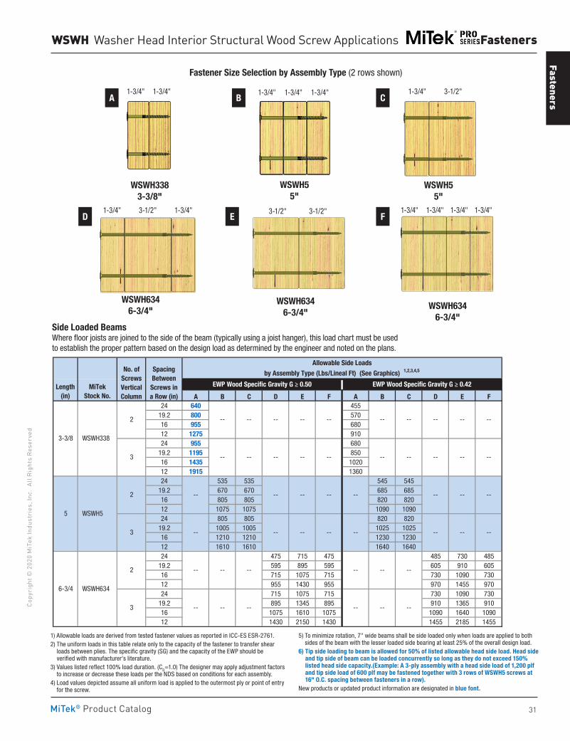
Fasteners
31
Copy
righ
t © 2
020
MiT
ek In
dust
ries
, Inc
. Al
l Rig
hts
Rese
rved
Fasteners
MiTek® Product Catalog
Side Loaded BeamsWhere floor joists are joined to the side of the beam (typically using a joist hanger), this load chart must be used to establish the proper pattern based on the design load as determined by the engineer and noted on the plans.
A B C D E F A B C D E F24 640 455
19.2 800 57016 955 68012 1275 91024 955 680
19.2 1195 85016 1435 102012 1915 136024 535 535 545 545
19.2 670 670 685 68516 805 805 820 82012 1075 1075 1090 109024 805 805 820 820
19.2 1005 1005 1025 102516 1210 1210 1230 123012 1610 1610 1640 164024 475 715 475 485 730 485
19.2 595 895 595 605 910 60516 715 1075 715 730 1090 73012 955 1430 955 970 1455 97024 715 1075 715 730 1090 730
19.2 895 1345 895 910 1365 91016 1075 1610 1075 1090 1640 109012 1430 2150 1430 1455 2185 1455
1) Allowable loads are derived from tested fastener values as reported in ICC-ES ESR-2761. 2) The uniform loads in this table relate only to the capacity of the fastener to transfer shear loads between plies. The specific gravity (SG) and the capacity of the EWP should be verified with manufacturer's literature. 3) Values listed reflect 100% load duration. (CD=1.0) The designer may apply adjustment factors to increase or decrease these loads per the NDS based on conditions for each assembly. 4) Load values depicted assume all uniform load is applied to the outermost ply or point of entry for the screw. 5) To minimize rotation, 7" wide beams shall be side loaded only when loads are applied to both sides of the beam with the lesser loaded side bearing at least 25% of the overall design load. 6) Tip side loading to beam is allowed for 50% of listed allowable head side load. Head side and tip side of beam can be loaded concurrently so long as they do not exceed 150% listed head side capacity.(Example: A 3-ply assembly with a head side load of 1,200 plf and tip side load of 600 plf may be fastened together with 3 rows of WSWH5 screws at 16" O.C. spacing between fasteners in a row). New products or updated product information are designated in blue font.
Length(in)
MiTek Stock No.
EWP Wood Specific Gravity G ≥ 0.50 EWP Wood Specific Gravity G ≥ 0.42
-- -- -- --
Allowable Side Loadsby Assembly Type (Lbs/Lineal Ft) (See Graphics) 1,2,3,4,5
-- --
3
No. of Screws VerticalColumn
Spacing Between Screws in a Row (in)
--
--
3 -- --
--
6-3/4 WSWH634
2
3
--
--
--
-- --
3-3/8 WSWH338
2
2
5 WSWH5
-- -- --
-- -- --
-- -- -- --
-- -- --
-- -- --
--
-- -- --
-- --
-- -- -- --
-- -- -- -- -- --
WSWH Washer Head Interior Structural Wood Screw Applications
WSWH3383-3/8"
1-3/4" 1-3/4"
WSWH5 5"
1-3/4" 1-3/4" 1-3/4"
WSWH55"
1-3/4" 3-1/2"
WSWH6346-3/4"
1-3/4" 1-3/4"3-1/2"
WSWH6346-3/4"
3-1/2" 3-1/2"
WSWH634 6-3/4"
1-3/4" 1-3/4" 1-3/4" 1-3/4"
Fastener Size Selection by Assembly Type (2 rows shown)
A
D
B
E
C
F
1) Allowable loads are derived from tested fastener values as reported in ICC-ES ESR-2761.2) The uniform loads in this table relate only to the capacity of the fastener to transfer shear
loads between plies. The specific gravity (SG) and the capacity of the EWP should be verified with manufacturer's literature.
3) Values listed reflect 100% load duration. (CD=1.0) The designer may apply adjustment factors to increase or decrease these loads per the NDS based on conditions for each assembly.
4) Load values depicted assume all uniform load is applied to the outermost ply or point of entry for the screw.
5) To minimize rotation, 7" wide beams shall be side loaded only when loads are applied to both sides of the beam with the lesser loaded side bearing at least 25% of the overall design load.
6) Tip side loading to beam is allowed for 50% of listed allowable head side load. Head side and tip side of beam can be loaded concurrently so long as they do not exceed 150% listed head side capacity.(Example: A 3-ply assembly with a head side load of 1,200 plf and tip side load of 600 plf may be fastened together with 3 rows of WSWH5 screws at 16" O.C. spacing between fasteners in a row).
New products or updated product information are designated in blue font.
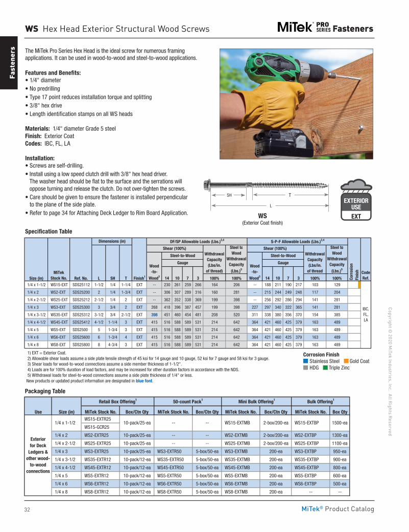
32
Copyright © 2020 M
iTek Industries, Inc. All Rights Reserved
Fasteners
Fast
ener
s
MiTek® Product Catalog
Specification Table
WS Hex Head Exterior Structural Wood Screws
Size (in) Ref. No. L SH T Finish1 100% 100% 100% 100% 1/4 x 1-1/2 WS15-EXT SDS25112 1-1/2 1/4 1-1/4 EXT -- 230 261 259 266 164 206 -- 188 211 190 217 103 129
1/4 x 2 WS2-EXT SDS25200 2 1/4 1-3/4 EXT -- 306 307 289 316 160 281 -- 215 244 249 248 117 204
1/4 x 2-1/2 WS25-EXT SDS25212 2-1/2 1/4 2 EXT -- 362 352 338 369 199 398 -- 256 292 286 294 141 281
1/4 x 3 WS3-EXT SDS25300 3 3/4 2 EXT 268 418 396 387 457 199 398 227 297 340 322 365 141 281
1/4 x 3-1/2 WS35-EXT SDS25312 3-1/2 3/4 2-1/2 EXT 398 451 460 454 481 208 520 311 338 380 356 370 154 385
1/4 x 4-1/2 WS45-EXT SDS25412 4-1/2 1-1/4 3 EXT 415 516 588 589 531 214 642 364 421 460 425 379 163 489
1/4 x 5 WS5-EXT SDS2500 5 1-3/4 3 EXT 415 516 588 589 531 214 642 364 421 460 425 379 163 489
1/4 x 6 WS6-EXT SDS25600 6 1-3/4 4 EXT 415 516 588 589 531 214 642 364 421 460 425 379 163 489
1/4 x 8 WS8-EXT SDS25800 8 4-3/4 3 EXT 415 516 588 589 531 214 642 364 421 460 425 379 163 489
1) EXT = Exterior Coat. 2) Allowable shear loads assume a side plate tensile strength of 45 ksi for 14 gauge and 10 gauge, 52 ksi for 7 gauge and 58 ksi for 3 gauge. 3) Shear loads for wood-to-wood connections assume a side member thickness of 1-1/2". 4) Loads are for 100% duration of load factors, and may be increased for other duration factors in accordance with the NDS. 5) Withdrawal loads for steel-to-wood connections assume a side plate thickness of 1/4" or less. New products or updated product information are designated in blue font.
Steel-to-Wood
Gauge
S-P-F Allowable Loads (Lbs.)2,4
Shear (100%) Withdrawal
Capacity(Lbs/in.
of thread
Steel toWood
WithdrawalCapacity
(Lbs.)5Wood -to-
Wood3
Steel-to-Wood
Gauge
14 10
IBC,FL,LA
MiTekStock No. 14 10 7 3
CodeRef.7 3 Co
rros
ion
Fini
sh
Dimensions (in) DF/SP Allowable Loads (Lbs.)2,4
Shear (100%) Withdrawal
Capacity (Lbs/in.
of thread)
Steel toWood
Withdrawal Capacity
(Lbs.)5Wood -to-
Wood3
WS(Exterior Coat finish)
T
L
SH
The MiTek Pro Series Hex Head is the ideal screw for numerous framingapplications. It can be used in wood-to-wood and steel-to-wood applications.
Features and Benefits:• 1/4" diameter• No predrilling• Type 17 point reduces installation torque and splitting• 3/8" hex drive• Length identification stamps on all WS heads
Materials: 1/4" diameter Grade 5 steelFinish: Exterior CoatCodes: IBC, FL, LA
Installation:• Screws are self-drilling.• Install using a low speed clutch drill with 3/8" hex head driver.
The washer head should be flat to the surface and the serrations will oppose turning and release the clutch. Do not over-tighten the screws.
• Care should be given to ensure the fastener is installed perpendicular to the plane of the side plate.
• Refer to page 34 for Attaching Deck Ledger to Rim Board Application.
Use Size (in) MiTek Stock No. Box/Ctn Qty MiTek Stock No. Box/Ctn Qty MiTek Stock No. Box/Ctn Qty MiTek Stock No. Box Qty WS15-EXTR25
WS15-GCR25
1/4 x 2 WS2-EXTR25 10-pack/25-ea -- -- WS2-EXTMB 2-box/200-ea WS2-EXTBP 1300-ea
1/4 x 2-1/2 WS25-EXTR25 10-pack/25-ea -- -- WS25-EXTMB 2-box/200-ea WS25-EXTBP 1100-ea
1/4 x 3 WS3-EXTR25 10-pack/25-ea WS3-EXTR50 5-box/50-ea WS3-EXTMB 200-ea WS3-EXTBP 950-ea
1/4 x 3-1/2 WS35-EXTR12 10-pack/12-ea WS35-EXTR50 5-box/50-ea WS35-EXTMB 200-ea WS35-EXTBP 900-ea
1/4 x 4-1/2 WS45-EXTR12 10-pack/12-ea WS45-EXTR50 5-box/50-ea WS45-EXTMB 200-ea WS45-EXTBP 800-ea
1/4 x 5 WS5-EXTR12 10-pack/12-ea WS5-EXTR50 5-box/50-ea WS5-EXTMB 200-ea WS5-EXTBP 600-ea
1/4 x 6 WS6-EXTR12 10-pack/12-ea WS6-EXTR50 5-box/50-ea WS6-EXTMB 200-ea WS6-EXTBP 500-ea
1/4 x 8 WS8-EXTR12 10-pack/12-ea WS8-EXTR50 5-box/50-ea WS8-EXTMB 200-ea -- --
Bulk Offering1
Exteriorfor Deck
Ledgers & other wood-
to-wood connections
Retail Box Offering1 50-count Pack1 Mini Bulk Offering1
1/4 x 1-1/2 -- -- WS15-EXTMB 2-box/200-ea WS15-EXTBP 1500-ea10-pack/25-ea
Packaging Table
EXTERIORUSE
G185-TZ
EXTERIORUSEEXT
Corrosion Finish Stainless Steel Gold Coat HDG Triple Zinc
Corrosion Finish Stainless Steel Gold Coat HDG Triple Zinc
Corrosion Finish Stainless Steel Gold Coat HDG Triple Zinc
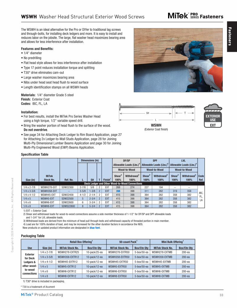
Fasteners
33
Copy
righ
t © 2
020
MiT
ek In
dust
ries
, Inc
. Al
l Rig
hts
Rese
rved
Fasteners
MiTek® Product Catalog
Size (in) L SH T
1/4 x 2-7/8 WSWH278-EXT SDW22300 2-7/8 5/8 2 EXT 268 274 227 194 -- -- 1/4 x 3-5/8 WSWH358-EXT -- 3-5/8 1-3/8 2 EXT 398 398 311 282 319 358 1/4 x 4-1/2 WSWH45-EXT SDW22458 4-1/2 2-1/4 2 EXT 415 398 364 282 358 382 1/4 x 5 WSWH5-EXT SDW22500 5 2-3/4 2 EXT 415 398 364 282 358 382 1/4 x 6 WSWH6-EXT SDW22600 6 3-3/4 2 EXT 415 398 364 282 358 382 1/4 x 8 WSWH8-EXT SDWS22800 8 5-3/4 2 EXT 415 398 364 282 358 382
1) EXT = Exterior Coat. 2) Shear and withdrawal loads for wood-to-wood connections assume a side member thickness of 1-1/2" for DF/SP and SPF allowable loads and 1-3/4" for LVL allowable loads. 3) Withdrawal loads are derived from the minimum of head pull through tests and withdrawal capacity of threaded portion in main member. 4) Load are for 100% duration of load, and may be increased for the other duration factors in accordance the NDS. New products or updated product information are designated in blue font.
Wood-to-Wood
Shear2
100%Withdrawal3
100%
IBC,FL,LA
Deck Ledger and Other Wood-to-Wood Connections
Withdrawal3
100%CodeRef.
Dimensions (in)
MiTekStock No. Ref. No. Finish1
Shear2
100%
DF/SP
Allowable Loads (Lbs.)4
Wood-to-Wood
SPF
Allowable Loads (Lbs.)4
LVL
Allowable Loads (Lbs.)4
Shear2
100%Withdrawal3
100%
Wood-to-Wood
Specification Table
WSWH Washer Head Structural Exterior Wood Screws
The WSWH is an ideal alternative for the Pro or DIYer to traditional lag screws and through-bolts, for installing deck ledgers and more. It is easy to install and reduces labor on the jobsite. The large, flat washer head maximizes bearing area and allows for less interference after installation.
Features and Benefits:• 1/4" diameter• No predrilling• Flat head style allows for less interference after installation• Type 17 point reduces installation torque and splitting• T30* drive eliminates cam-out• Large washer maximizes bearing area• Nibs under head seat head flush to wood surface• Length identification stamps on all WSWH heads
Materials: 1/4" diameter Grade 5 steelFinish: Exterior CoatCodes: IBC, FL, LA
Installation:• For best results, install the MiTek Pro Series Washer Head
using a high torque, 1/2" variable speed drill. • Bring the washer portion of head flush to the surface of the wood.
Do not overdrive. • See page 34 for Attaching Deck Ledger to Rim Board Application, page 27
for Attaching 2x Ledger-to-Wall Studs Application, page 28 for Joining Multi-Ply Dimensional Lumber Beams Application and page 30 for Joining Multi-Ply Engineered Wood (EWP) Beams Application.
Use Size (in) MiTek Stock No. Box/Ctn Qty MiTek Stock No. Box/Ctn Qty MiTek Stock No. Box/Ctn Qty 1/4 x 2-7/8 WSWH278-EXTR25 10-pack/25-ea WSWH278-EXTR50 5-box/50-ea WSWH278-EXTMB 200-ea
1/4 x 3-5/8 WSWH358-EXTR12 10-pack/12-ea WSWH358-EXTR50 5-box/50-ea WSWH358-EXTMB 200-ea
1/4 x 4-1/2 WSWH45-EXTR12 10-pack/12-ea WSWH45-EXTR50 5-box/50-ea WSWH45-EXTMB 200-ea
1/4 x 5 WSWH5-EXTR12 10-pack/12-ea WSWH5-EXTR50 5-box/50-ea WSWH5-EXTMB 200-ea
1/4 x 6 WSWH6-EXTR12 10-pack/12-ea WSWH6-EXTR50 5-box/50-ea WSWH6-EXTMB 200-ea
1/4 x 8 WSWH8-EXTR12 10-pack/12-ea WSWH8-EXTR50 5-box/50-ea WSWH8-EXTMB 200-ea
1) T30* drive is included in packaging.
Exteriorfor Deck
Ledgers & other wood-
to-wood connections
Retail Box Offering1 50-count Pack1 Mini Bulk Offering1
WSWH (Exterior Coat finish)
T
L
SH
Packaging Table
EXTERIORUSE
G185-TZ
EXTERIORUSEEXT
* T30 is a trademark of Acument
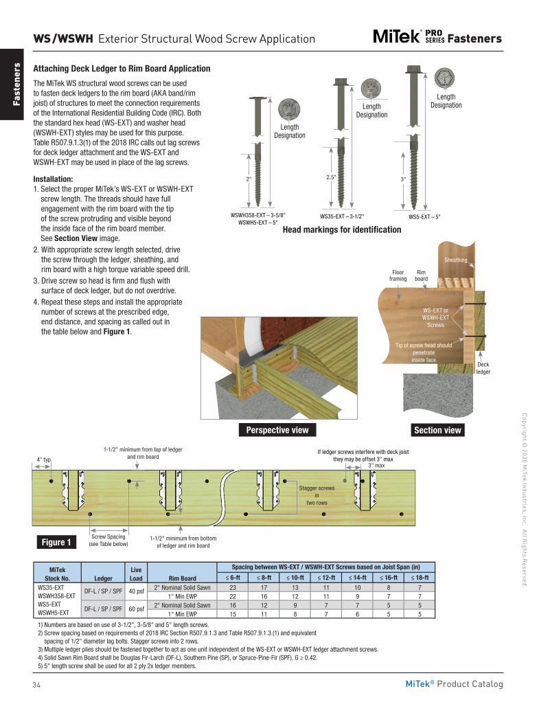
34
Copyright © 2020 M
iTek Industries, Inc. All Rights Reserved
Fasteners
Fast
ener
s
MiTek® Product Catalog
WS / WSWH Exterior Structural Wood Screw Application
Attaching Deck Ledger to Rim Board Application
The MiTek WS structural wood screws can be used to fasten deck ledgers to the rim board (AKA band/rim joist) of structures to meet the connection requirements of the International Residential Building Code (IRC). Both the standard hex head (WS-EXT) and washer head (WSWH-EXT) styles may be used for this purpose. Table R507.9.1.3(1) of the 2018 IRC calls out lag screws for deck ledger attachment and the WS-EXT and WSWH-EXT may be used in place of the lag screws.
Installation:1. Select the proper MiTek’s WS-EXT or WSWH-EXT
screw length. The threads should have full engagement with the rim board with the tip of the screw protruding and visible beyond the inside face of the rim board member. See Section View image.
2. With appropriate screw length selected, drive the screw through the ledger, sheathing, and rim board with a high torque variable speed drill.
3. Drive screw so head is firm and flush with surface of deck ledger, but do not overdrive.
4. Repeat these steps and install the appropriate number of screws at the prescribed edge, end distance, and spacing as called out in the table below and Figure 1.
≤ 6-ft ≤ 8-ft ≤ 10-ft ≤ 12-ft ≤ 14-ft ≤ 16-ft ≤ 18-ft
2" Nominal Solid Sawn 23 17 13 11 10 8 71" Min EWP 22 16 12 11 9 7 7
2" Nominal Solid Sawn 16 12 9 7 7 5 51" Min EWP 15 11 8 7 6 5 5
1) Numbers are based on use of 3-1/2", 3-5/8" and 5" length screws. 2) Screw spacing based on requirements of 2018 IRC Section R507.9.1.3 and Table R507.9.1.3.(1) and equivalent spacing of 1/2" diameter lag bolts. Stagger screws into 2 rows. 3) Multiple ledger plies should be fastened together to act as one unit independent of the WS-EXT or WSWH-EXT ledger attachment screws. 4) Solid Sawn Rim Board shall be Douglas Fir-Larch (DF-L), Southern Pine (SP), or Spruce-Pine-Fir (SPF), G ≥ 0.42. 5) 5" length screw shall be used for all 2 ply 2x ledger members.
MiTek Stock No.
Spacing between WS-EXT / WSWH-EXT Screws based on Joist Span (in)
40 psfDF-L / SP / SPF
60 psfDF-L / SP / SPF
Live LoadLedger Rim Board
WS35-EXT WSWH358-EXT WS5-EXT WSWH5-EXT
Perspective view
Floor framing
Sheathing
Rim board
WS-EXT or WSWH-EXT
Screws
Deck ledger
Tip of screw head should penetrate inside face
Section view
Figure 1
4" typ.
Screw Spacing (see Table below)
1-1/2" minimum from bottom of ledger and rim board
1-1/2" minimum from top of ledger and rim board
3" max
Stagger screws
in two rows
If ledger screws interfere with deck joist they may be offset 3" max
WS35-EXT – 3-1/2" WS5-EXT – 5"WSWH358-EXT – 3-5/8" WSWH5-EXT – 5"
Length DesignationLength
Designation
Length Designation
Head markings for identification
2.5" 3"2"
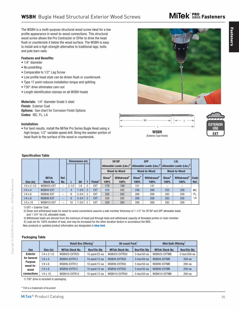
Fasteners
35
Copy
righ
t © 2
020
MiT
ek In
dust
ries
, Inc
. Al
l Rig
hts
Rese
rved
Fasteners
MiTek® Product Catalog
Size (in) L SH T 1/4 x 2-1/2 WSBH25-EXT -- 2-1/2 1/4 2 EXT 179 199 151 141 -- -- 1/4 x 4 WSBH4-EXT -- 4 1-3/4 2 EXT 315 282 246 208 252 339 1/4 x 6 WSBH6-EXT -- 6 3-3/4 2 EXT 328 282 288 208 283 339 1/4 x 8 WSBH8-EXT -- 8 5-3/4 2 EXT 328 282 288 208 283 339 1/4 x 10 WSBH10-EXT -- 10 7-3/4 2 EXT 328 282 288 208 283 339
1) EXT = Exterior Coat. 2) Shear and withdrawal loads for wood-to-wood connections assume a side member thickness of 1-1/2" for DF/SP and SPF allowable loads and 1-3/4" for LVL allowable loads. 3) Withdrawal loads are derived from the minimum of head pull through tests and withdrawal capacity of threaded portion in main member. 4) Load are for 100% duration of load, and may be increased for the other duration factors in accordance the NDS. New products or updated product information are designated in blue font.
Ref. No.
Dimensions (in)
Finish1CodeRef.
MiTekStock No.
IBC,FL,LA
DF/SP
Allowable Loads (Lbs.)4
SPF
Allowable Loads (Lbs.)4
LVL
Allowable Loads (Lbs.)4
Shear2
100%Withdrawal3
100%Shear2
100%Withdrawal3
100%Shear2
100%Withdrawal3
100%
Wood-to-Wood Wood-to-Wood Wood-to-Wood
Specification Table
WSBH Bugle Head Structural Exterior Wood Screws
The WSBH is a multi-purpose structural wood screw ideal for a low profile appearance in wood-to-wood connections. This structural wood screw allows the Pro Contractor or DIYer to drive the head flush or countersink it below the wood surface. The WSBH is easy to install and a high strength alternative to traditional lags, bolts and pole barn nails.
Features and Benefits:• 1/4" diameter• No predrilling• Comparable to 1/2" Lag Screw• Low profile head style can be driven flush or countersunk• Type 17 point reduces installation torque and splitting• T30* drive eliminates cam-out• Length identification stamps on all WSBH heads
Materials: 1/4" diameter Grade 5 steelFinish: Exterior CoatOptions: See chart for Corrosion Finish OptionsCodes: IBC, FL, LA
Installation:• For best results, install the MiTek Pro Series Bugle Head using a
high torque, 1/2" variable speed drill. Bring the washer portion of head flush to the surface of the wood or countersink.
Use Size (in) MiTek Stock No. Box/Ctn Qty MiTek Stock No. Box/Ctn Qty MiTek Stock No. Box/Ctn Qty 1/4 x 2-1/2 WSBH25-EXTR25 10-pack/25-ea WSBH25-EXTR50 5-box/50-ea WSBH25-EXTMB 2-box/200-ea
1/4 x 4 WSBH4-EXTR12 10-pack/12-ea WSBH4-EXTR50 5-box/50-ea WSBH4-EXTMB 200-ea
1/4 x 6 WSBH6-EXTR12 10-pack/12-ea WSBH6-EXTR50 5-box/50-ea WSBH6-EXTMB 200-ea
1/4 x 8 WSBH8-EXTR12 10-pack/12-ea WSBH8-EXTR50 5-box/50-ea WSBH8-EXTMB 200-ea
1/4 x 10 WSBH10-EXTR12 10-pack/12-ea WSBH10-EXTR50 5-box/50-ea WSBH10-EXTMB 200-ea
1) T30* drive is included in packaging.
Exteriorfor General
Purpose wood-to-
wood connections
Retail Box Offering1 50-count Pack1 Mini Bulk Offering1
WSBH (Exterior Coat finish)
T
L
SH
Packaging Table
EXTERIORUSE
G185-TZ
EXTERIORUSEEXT
* T30 is a trademark of Acument
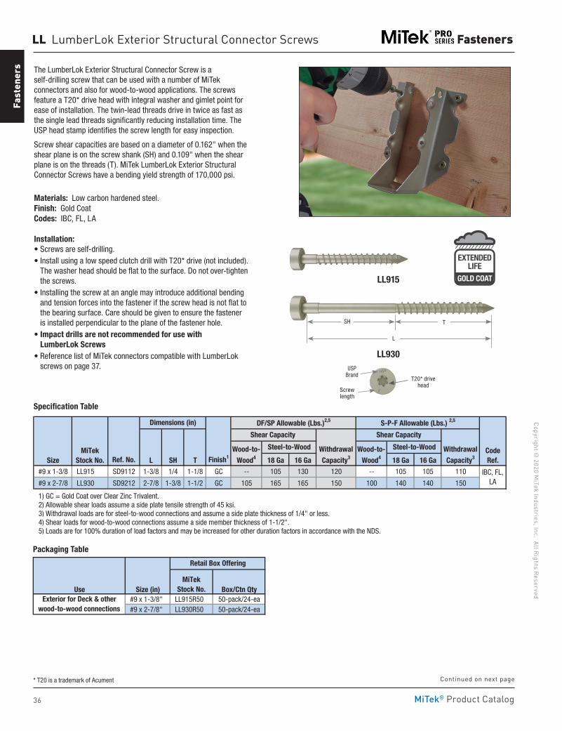
36
Copyright © 2020 M
iTek Industries, Inc. All Rights Reserved
Fasteners
Fast
ener
s
MiTek® Product Catalog
LL LumberLok Exterior Structural Connector Screws
LL915
The LumberLok Exterior Structural Connector Screw is a self-drilling screw that can be used with a number of MiTek connectors and also for wood-to-wood applications. The screws feature a T20* drive head with integral washer and gimlet point for ease of installation. The twin-lead threads drive in twice as fast as the single lead threads significantly reducing installation time. The USP head stamp identifies the screw length for easy inspection.
Screw shear capacities are based on a diameter of 0.162" when the shear plane is on the screw shank (SH) and 0.109" when the shear plane is on the threads (T). MiTek LumberLok Exterior Structural Connector Screws have a bending yield strength of 170,000 psi.
Materials: Low carbon hardened steel.Finish: Gold CoatCodes: IBC, FL, LA
Installation:• Screws are self-drilling.• Install using a low speed clutch drill with T20* drive (not included).
The washer head should be flat to the surface. Do not over-tighten the screws.
• Installing the screw at an angle may introduce additional bending and tension forces into the fastener if the screw head is not flat to the bearing surface. Care should be given to ensure the fastener is installed perpendicular to the plane of the fastener hole.
• Impact drills are not recommended for use with LumberLok Screws
• Reference list of MiTek connectors compatible with LumberLok screws on page 37.
Size Ref. No. L SH T Finish1 18 Ga 16 Ga 18 Ga 16 Ga
#9 x 1-3/8 LL915 SD9112 1-3/8 1/4 1-1/8 GC -- 105 130 120 -- 105 105 110
#9 x 2-7/8 LL930 SD9212 2-7/8 1-3/8 1-1/2 GC 105 165 165 150 100 140 140 150
1) GC = Gold Coat over Clear Zinc Trivalent. 2) Allowable shear loads assume a side plate tensile strength of 45 ksi. 3) Withdrawal loads are for steel-to-wood connections and assume a side plate thickness of 1/4" or less. 4) Shear loads for wood-to-wood connections assume a side member thickness of 1-1/2". 5) Loads are for 100% duration of load factors and may be increased for other duration factors in accordance with the NDS.
IBC, FL, LA
S-P-F Allowable (Lbs.) 2,5
CodeRef.
MiTekStock No.
Dimensions (in) DF/SP Allowable (Lbs.)2,5
Steel-to-WoodWood-to- Wood4
Shear Capacity
WithdrawalCapacity3
Shear Capacity
WithdrawalCapacity3
Wood-to- Wood4
Steel-to-Wood
SH
L
T
LL930
T20* drivehead
Screwlength
Specification Table
Use Size (in) Box/Ctn Qty #9 x 1-3/8" LL915R50 50-pack/24-ea #9 x 2-7/8" LL930R50 50-pack/24-ea
`
Retail Box Offering
Exterior for Deck & other wood-to-wood connections
MiTekStock No.
Packaging Table
EXTENDEDLIFE
GOLD COAT
Continued on next page* T20 is a trademark of Acument
USP Brand
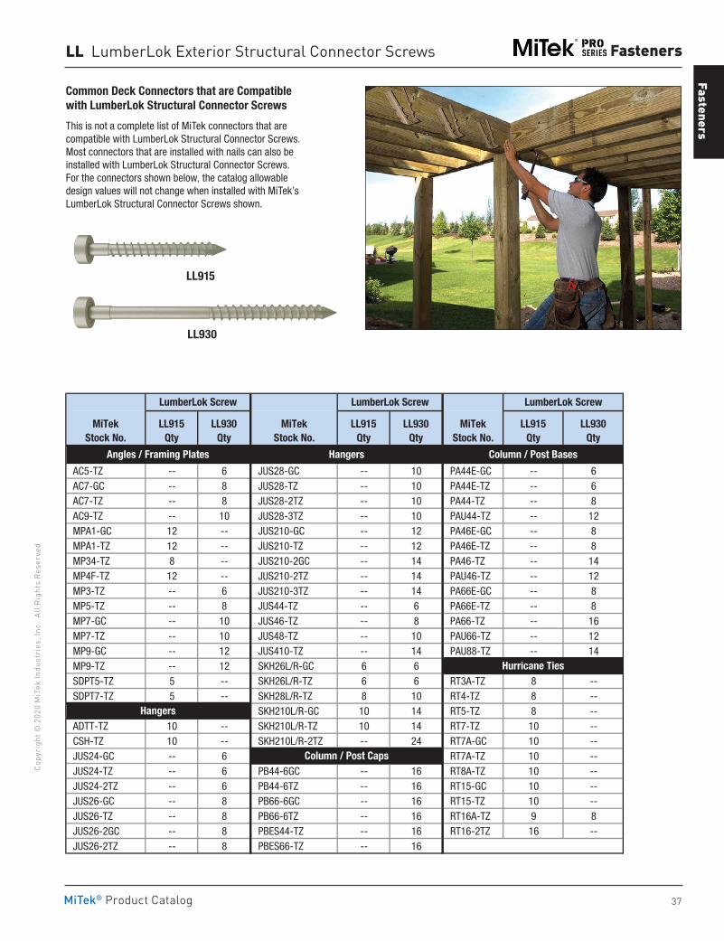
Fasteners
37
Copy
righ
t © 2
020
MiT
ek In
dust
ries
, Inc
. Al
l Rig
hts
Rese
rved
Fasteners
MiTek® Product Catalog
LL915
LL930
LL LumberLok Exterior Structural Connector Screws
Common Deck Connectors that are Compatible with LumberLok Structural Connector Screws
This is not a complete list of MiTek connectors that are compatible with LumberLok Structural Connector Screws. Most connectors that are installed with nails can also be installed with LumberLok Structural Connector Screws. For the connectors shown below, the catalog allowable design values will not change when installed with MiTek’s LumberLok Structural Connector Screws shown.
AC5-TZ -- 6 JUS28-GC -- 10 PA44E-GC -- 6 AC7-GC -- 8 JUS28-TZ -- 10 PA44E-TZ -- 6 AC7-TZ -- 8 JUS28-2TZ -- 10 PA44-TZ -- 8 AC9-TZ -- 10 JUS28-3TZ -- 10 PAU44-TZ -- 12 MPA1-GC 12 -- JUS210-GC -- 12 PA46E-GC -- 8 MPA1-TZ 12 -- JUS210-TZ -- 12 PA46E-TZ -- 8 MP34-TZ 8 -- JUS210-2GC -- 14 PA46-TZ -- 14 MP4F-TZ 12 -- JUS210-2TZ -- 14 PAU46-TZ -- 12 MP3-TZ -- 6 JUS210-3TZ -- 14 PA66E-GC -- 8 MP5-TZ -- 8 JUS44-TZ -- 6 PA66E-TZ -- 8 MP7-GC -- 10 JUS46-TZ -- 8 PA66-TZ -- 16 MP7-TZ -- 10 JUS48-TZ -- 10 PAU66-TZ -- 12 MP9-GC -- 12 JUS410-TZ -- 14 PAU88-TZ -- 14 MP9-TZ -- 12 SKH26L/R-GC 6 6 SDPT5-TZ 5 -- SKH26L/R-TZ 6 6 RT3A-TZ 8 -- SDPT7-TZ 5 -- SKH28L/R-TZ 8 10 RT4-TZ 8 --
SKH210L/R-GC 10 14 RT5-TZ 8 -- ADTT-TZ 10 -- SKH210L/R-TZ 10 14 RT7-TZ 10 -- CSH-TZ 10 -- SKH210L/R-2TZ -- 24 RT7A-GC 10 -- JUS24-GC -- 6 RT7A-TZ 10 -- JUS24-TZ -- 6 PB44-6GC -- 16 RT8A-TZ 10 -- JUS24-2TZ -- 6 PB44-6TZ -- 16 RT15-GC 10 -- JUS26-GC -- 8 PB66-6GC -- 16 RT15-TZ 10 -- JUS26-TZ -- 8 PB66-6TZ -- 16 RT16A-TZ 9 8 JUS26-2GC -- 8 PBES44-TZ -- 16 RT16-2TZ 16 -- JUS26-2TZ -- 8 PBES66-TZ -- 16
Hurricane Ties
Column / Post Caps
Column / Post Bases
MiTekStock No.
LumberLok Screw
LL915Qty
LL930Qty
Hangers
Angles / Framing Plates
LumberLok Screw
LL915Qty
LL930Qty
MiTekStock No.
MiTekStock No.
LL915Qty
LL930Qty
LumberLok Screw
Hangers
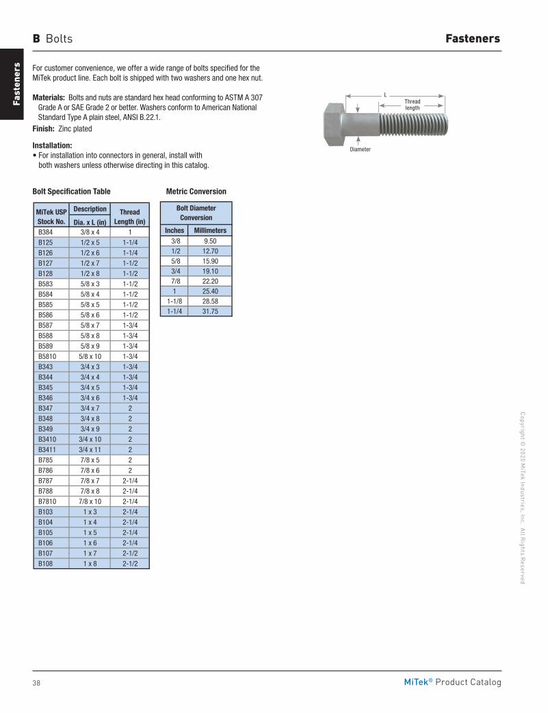
38
Copyright © 2020 M
iTek Industries, Inc. All Rights Reserved
Fasteners
Fast
ener
s
MiTek® Product Catalog
Diameter
L
B Bolts
For customer convenience, we offer a wide range of bolts specified for the MiTek product line. Each bolt is shipped with two washers and one hex nut.
Materials: Bolts and nuts are standard hex head conforming to ASTM A 307 Grade A or SAE Grade 2 or better. Washers conform to American National Standard Type A plain steel, ANSI B.22.1.Finish: Zinc plated
Installation:• For installation into connectors in general, install with
both washers unless otherwise directing in this catalog.
Inches Millimeters3/8 9.501/2 12.705/8 15.903/4 19.107/8 22.201 25.40
1-1/8 28.581-1/4 31.75
Bolt DiameterConversion
Description
Dia. x L (in) B384 3/8 x 4 1 B125 1/2 x 5 1-1/4 B126 1/2 x 6 1-1/4 B127 1/2 x 7 1-1/2 B128 1/2 x 8 1-1/2 B583 5/8 x 3 1-1/2 B584 5/8 x 4 1-1/2 B585 5/8 x 5 1-1/2 B586 5/8 x 6 1-1/2 B587 5/8 x 7 1-3/4 B588 5/8 x 8 1-3/4 B589 5/8 x 9 1-3/4 B5810 5/8 x 10 1-3/4 B343 3/4 x 3 1-3/4 B344 3/4 x 4 1-3/4 B345 3/4 x 5 1-3/4 B346 3/4 x 6 1-3/4 B347 3/4 x 7 2 B348 3/4 x 8 2 B349 3/4 x 9 2 B3410 3/4 x 10 2 B3411 3/4 x 11 2 B785 7/8 x 5 2 B786 7/8 x 6 2 B787 7/8 x 7 2-1/4 B788 7/8 x 8 2-1/4 B7810 7/8 x 10 2-1/4 B103 1 x 3 2-1/4 B104 1 x 4 2-1/4 B105 1 x 5 2-1/4 B106 1 x 6 2-1/4 B107 1 x 7 2-1/2 B108 1 x 8 2-1/2
ThreadLength (in)
MiTek USPStock No.
Metric Conversion Bolt Specification Table
Thread length
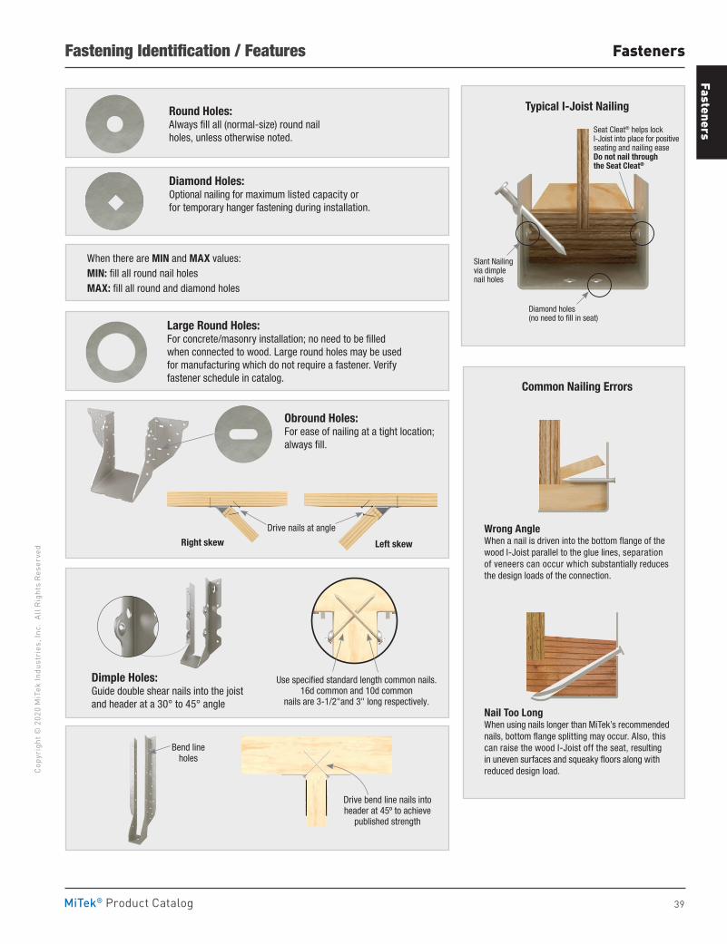
Fasteners
39
Copy
righ
t © 2
020
MiT
ek In
dust
ries
, Inc
. Al
l Rig
hts
Rese
rved
Fasteners
MiTek® Product Catalog
Fastening Identification / Features
Round Holes:Always fill all (normal-size) round nail holes, unless otherwise noted.
Diamond Holes:Optional nailing for maximum listed capacity or for temporary hanger fastening during installation.
When there are MIN and MAX values:MIN: fill all round nail holesMAX: fill all round and diamond holes
Large Round Holes:For concrete/masonry installation; no need to be filled when connected to wood. Large round holes may be used for manufacturing which do not require a fastener. Verify fastener schedule in catalog.
Common Nailing Errors
Wrong AngleWhen a nail is driven into the bottom flange of the wood I-Joist parallel to the glue lines, separation of veneers can occur which substantially reduces the design loads of the connection.
Nail Too LongWhen using nails longer than MiTek’s recommended nails, bottom flange splitting may occur. Also, this can raise the wood I-Joist off the seat, resulting in uneven surfaces and squeaky floors along with reduced design load.
Left skew
Drive nails at angle
Right skew
Obround Holes:For ease of nailing at a tight location; always fill.
Dimple Holes:Guide double shear nails into the joist and header at a 30° to 45° angle
Use specified standard length common nails. 16d common and 10d common
nails are 3-1/2"and 3" long respectively.
Slant Nailingvia dimplenail holes
Seat Cleat® helps lock I-Joist into place for positive seating and nailing easeDo not nail through the Seat Cleat®
Diamond holes(no need to fill in seat)
Typical I-Joist Nailing
Bend lineholes
Drive bend line nails into header at 45º to achieve
published strength
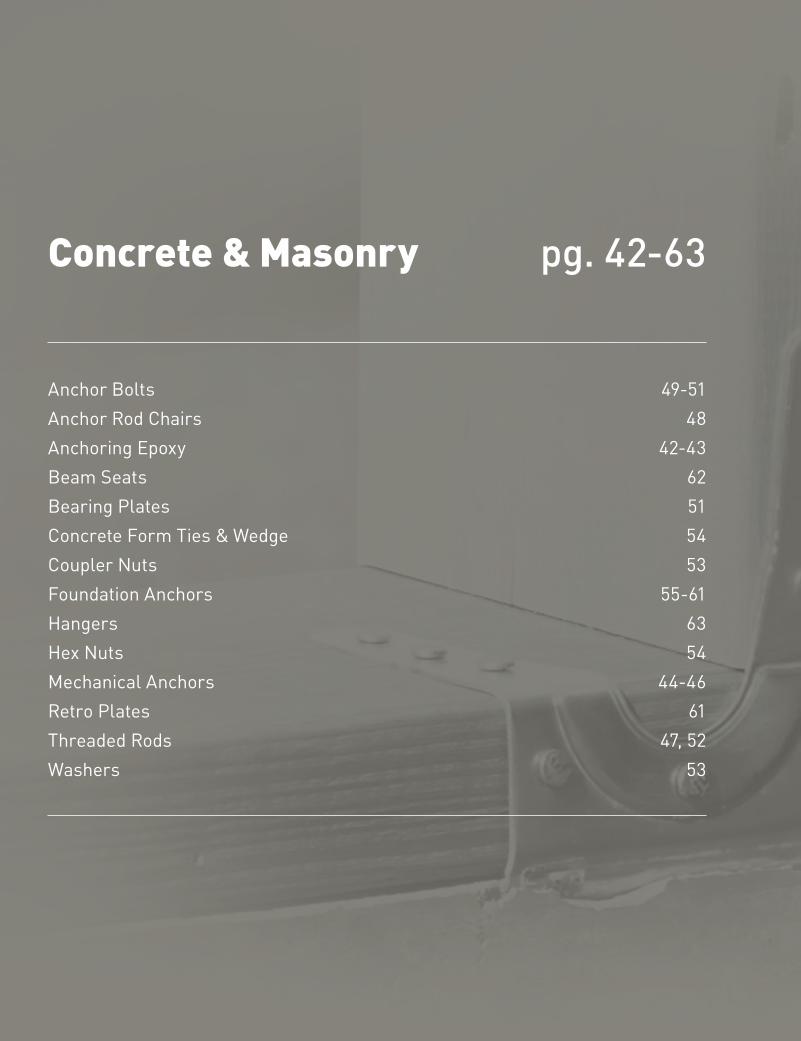
Concrete & Masonry
Anchor Bolts 49-51Anchor Rod Chairs 48Anchoring Epoxy 42-43Beam Seats 62Bearing Plates 51Concrete Form Ties & Wedge 54Coupler Nuts 53Foundation Anchors 55-61Hangers 63 Hex Nuts 54 Mechanical Anchors 44-46Retro Plates 61Threaded Rods 47, 52Washers 53
pg. 42-63
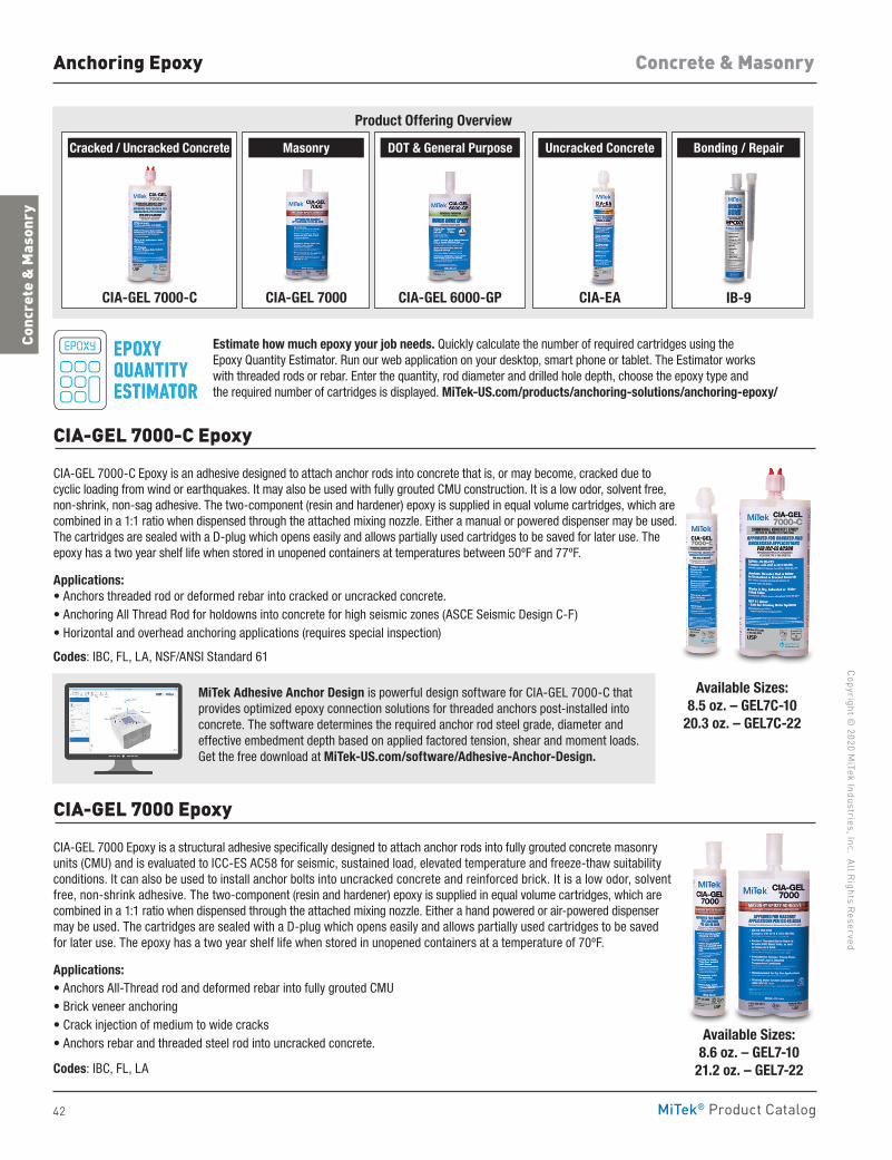
42
Copyright © 2020 M
iTek Industries, Inc. All Rights Reserved
Concrete & Masonry
Conc
rete
& M
ason
ry
MiTek® Product Catalog
Anchoring Epoxy
CIA-GEL 7000-C Epoxy
CIA-GEL 7000-C Epoxy is an adhesive designed to attach anchor rods into concrete that is, or may become, cracked due to cyclic loading from wind or earthquakes. It may also be used with fully grouted CMU construction. It is a low odor, solvent free, non-shrink, non-sag adhesive. The two-component (resin and hardener) epoxy is supplied in equal volume cartridges, which are combined in a 1:1 ratio when dispensed through the attached mixing nozzle. Either a manual or powered dispenser may be used. The cartridges are sealed with a D-plug which opens easily and allows partially used cartridges to be saved for later use. The epoxy has a two year shelf life when stored in unopened containers at temperatures between 50ºF and 77ºF.
Applications:• Anchors threaded rod or deformed rebar into cracked or uncracked concrete.• Anchoring All Thread Rod for holdowns into concrete for high seismic zones (ASCE Seismic Design C-F)• Horizontal and overhead anchoring applications (requires special inspection)
Codes: IBC, FL, LA, NSF/ANSI Standard 61
MiTek Adhesive Anchor Design is powerful design software for CIA-GEL 7000-C that provides optimized epoxy connection solutions for threaded anchors post-installed into concrete. The software determines the required anchor rod steel grade, diameter and effective embedment depth based on applied factored tension, shear and moment loads. Get the free download at MiTek-US.com/software/Adhesive-Anchor-Design.
CIA-GEL 7000 Epoxy
CIA-GEL 7000 Epoxy is a structural adhesive specifically designed to attach anchor rods into fully grouted concrete masonry units (CMU) and is evaluated to ICC-ES AC58 for seismic, sustained load, elevated temperature and freeze-thaw suitability conditions. It can also be used to install anchor bolts into uncracked concrete and reinforced brick. It is a low odor, solvent free, non-shrink adhesive. The two-component (resin and hardener) epoxy is supplied in equal volume cartridges, which are combined in a 1:1 ratio when dispensed through the attached mixing nozzle. Either a hand powered or air-powered dispenser may be used. The cartridges are sealed with a D-plug which opens easily and allows partially used cartridges to be saved for later use. The epoxy has a two year shelf life when stored in unopened containers at a temperature of 70ºF.
Applications: • Anchors All-Thread rod and deformed rebar into fully grouted CMU• Brick veneer anchoring• Crack injection of medium to wide cracks• Anchors rebar and threaded steel rod into uncracked concrete.
Codes: IBC, FL, LA
Available Sizes:8.5 oz. – GEL7C-10
20.3 oz. – GEL7C-22
Available Sizes:8.6 oz. – GEL7-10
21.2 oz. – GEL7-22
Cracked / Uncracked Concrete Bonding / Repair
CIA-GEL 7000-C
Masonry
CIA-GEL 7000
DOT & General Purpose
CIA-GEL 6000-GP
Uncracked Concrete
CIA-EA IB-9
Product Offering Overview
Estimate how much epoxy your job needs. Quickly calculate the number of required cartridges using the Epoxy Quantity Estimator. Run our web application on your desktop, smart phone or tablet. The Estimator works with threaded rods or rebar. Enter the quantity, rod diameter and drilled hole depth, choose the epoxy type and the required number of cartridges is displayed. MiTek-US.com/products/anchoring-solutions/anchoring-epoxy/
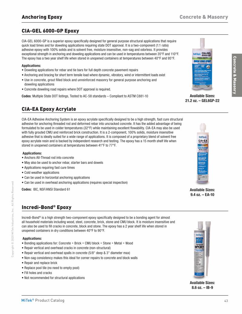
43
Concrete & Masonry
Co
pyri
ght ©
202
0 M
iTek
Indu
stri
es, I
nc.
All R
ight
s Re
serv
ed
Concrete & Masonry
MiTek® Product Catalog
Anchoring Epoxy
CIA-GEL 6000-GP Epoxy
CIA-GEL 6000-GP is a superior epoxy specifically designed for general purpose structural applications that require quick load times and for doweling applications requiring state DOT approval. It is a two-component (1:1 ratio) adhesive epoxy with 100% solids and is solvent free, moisture insensitive, non-sag and odorless. It provides exceptional strength in anchoring and doweling applications and can be used in temperatures between 35°F and 110°F. The epoxy has a two year shelf life when stored in unopened containers at temperatures between 40°F and 95°F.
Applications: • Doweling applications for rebar and tie bars for full depth concrete pavement repairs• Anchoring and bracing for short term tensile load where dynamic, vibratory, wind or intermittent loads exist• Use in concrete, grout filled block and unreinforced masonry for general purpose anchoring and
doweling applications• Concrete doweling road repairs where DOT approval is required.
Codes: Multiple State DOT listings, Tested to AC-58 standards – Compliant to ASTM C881-10
CIA-EA Epoxy Acrylate
CIA-EA Adhesive Anchoring System is an epoxy acrylate specifically designed to be a high strength, fast cure structural adhesive for anchoring threaded rod and deformed rebar into uncracked concrete. It has the added advantage of being formulated to be used in colder temperatures (32°F) while maintaining excellent flowability. CIA-EA may also be used with fully grouted CMU and reinforced brick construction. It is a 2-component, 100% solids, moisture insensitive adhesive that is ideally suited for a wide range of applications. It is composed of a proprietary blend of solvent free epoxy acrylate resin and is backed by independent research and testing. The epoxy has a 15 month shelf life when stored in unopened containers at temperatures between 41°F to 77°F.
Applications: • Anchors All-Thread rod into concrete• May also be used to anchor rebar, starter bars and dowels• Applications requiring fast cure times• Cold weather applications• Can be used in horizontal anchoring applications• Can be used in overhead anchoring applications (requires special inspection)
Codes: IBC, NSF/ANSI Standard 61
Incredi-Bond® Epoxy
Incredi-Bond® is a high strength two-component epoxy specifically designed to be a bonding agent for almost all household materials including wood, steel, concrete, brick, stone and CMU block. It is moisture insensitive and can also be used to fill cracks in concrete, block and stone. The epoxy has a 2 year shelf life when stored in unopened containers in dry conditions between 40°F to 90°F.
Applications: • Bonding applications for: Concrete • Brick • CMU block • Stone • Metal • Wood• Repair vertical and overhead cracks in concrete (non-structural)• Repair vertical and overhead spalls in concrete (5/8" deep & 3" diameter max)• Non-sag consistency makes this ideal for corner repairs to concrete and block walls• Repair and replace brick• Replace pool tile (no need to empty pool)• Fill holes and cracks• Not recommended for structural applications
Available Sizes:9.4 oz. – EA-10
Available Sizes:8.6 oz. – IB-9
Available Sizes:21.2 oz. – GEL6GP-22
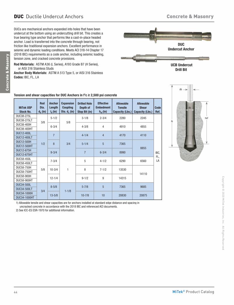
44
Copyright © 2020 M
iTek Industries, Inc. All Rights Reserved
Concrete & Masonry
Conc
rete
& M
ason
ry
MiTek® Product Catalog
DUC Ductile Undercut Anchors
DUCs are mechanical anchors expanded into holes that have been undercut at the bottom using an undercutting drill bit. This creates a true bearing type anchor that performs like a cast-in-place headed anchor. Load is transferred into the concrete through bearing, not friction like traditional expansion anchors. Excellent performance in seismic and dynamic loading conditions. Meets ACI 318-14 Chapter 17 (2018 IBC) requirements as a code anchor, including seismic loading, tension zone, and cracked concrete provisions.
Rod Materials: ASTM A36 (L Series), A193 Grade B7 (H Series), or AISI 316 Stainless StudsAnchor Body Materials: ASTM A 513 Type 5, or AISI 316 StainlessCodes: IBC, FL, LA
DUCUndercut Anchor
UCB Undercut Drill Bit
DUC38-275L DUC38-275LT DUC38-400H DUC38-400HT DUC12-400L DUC12-400LT DUC12-500H DUC12-500HT DUC12-675H DUC12-675HT DUC58-450L DUC58-450LT DUC58-750H DUC58-750HT DUC58-900H DUC58-900HT DUC34-500L DUC34-500LT DUC34-1000H DUC34-1000HT
1) Allowable tensile and shear capacities are for anchors installed at standard edge distance and spacing in uncracked concrete in accordance with the 2018 IBC and referenced ACI documents. 2) See ICC-ES ESR-1970 for additional information.
AllowableShear
Capacity (Lbs.)
Drilled HoleDepth of
Stop Bit (in)
ExpansionCoupling
Dia. dc (in)
AllowableTensile
Capacity (Lbs.)CodeRef.
IBC,FL,LA
7
5/8
3/4
1
1-1/8
5
8
9-1/2
5-7/8
10-7/8
3-1/8
4-3/8
4-1/4
5-1/4
8-5/8
13-5/8
7-3/4
10-3/4
9
5
10
4-1/2
7-1/2
2245
4910 4855
4170 4110
MiTek USPStock No.
2280
6-3/4
7
5-1/23/8
1/2
5/8
3/4
2-3/4
4
4
58
9-3/4 6-3/4
9685
20830 20875
8855
6290 6560
14110
7365
8990
13530
14315
RodDia.
db (in)
AnchorLengthlb (in)
EffectiveEmbedment
hef (in)
12-1/4
7365
lbhef
dc
db
Tension and shear capacities for DUC Anchors in f1c > 2,500 psi concrete
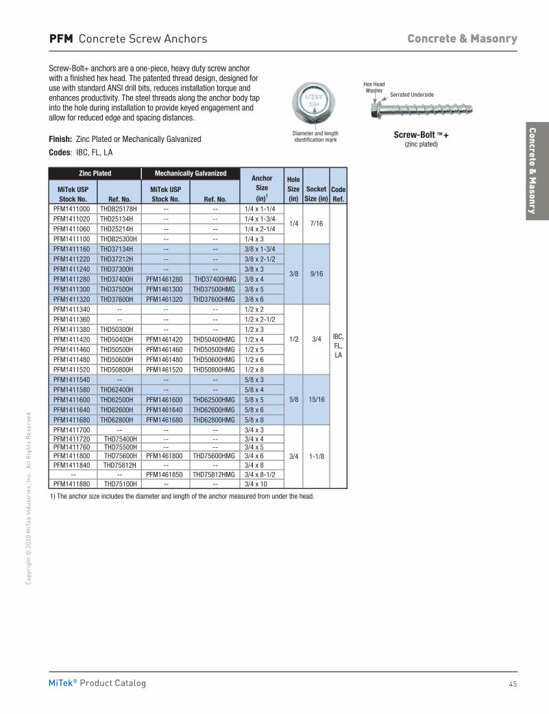
45
Concrete & Masonry
Co
pyri
ght ©
202
0 M
iTek
Indu
stri
es, I
nc.
All R
ight
s Re
serv
ed
Concrete & Masonry
MiTek® Product Catalog
Ref. No. Ref. No. PFM1411000 THDB25178H -- -- 1/4 x 1-1/4 PFM1411020 THD25134H -- -- 1/4 x 1-3/4 PFM1411060 THD25214H -- -- 1/4 x 2-1/4 PFM1411100 THDB25300H -- -- 1/4 x 3 PFM1411160 THD37134H -- -- 3/8 x 1-3/4 PFM1411220 THD37212H -- -- 3/8 x 2-1/2 PFM1411240 THD37300H -- -- 3/8 x 3 PFM1411280 THD37400H PFM1461280 THD37400HMG 3/8 x 4 PFM1411300 THD37500H PFM1461300 THD37500HMG 3/8 x 5 PFM1411320 THD37600H PFM1461320 THD37600HMG 3/8 x 6 PFM1411340 -- -- -- 1/2 x 2 PFM1411360 -- -- -- 1/2 x 2-1/2 PFM1411380 THD50300H -- -- 1/2 x 3 PFM1411420 THD50400H PFM1461420 THD50400HMG 1/2 x 4 PFM1411460 THD50500H PFM1461460 THD50500HMG 1/2 x 5 PFM1411480 THD50600H PFM1461480 THD50600HMG 1/2 x 6 PFM1411520 THD50800H PFM1461520 THD50800HMG 1/2 x 8 PFM1411540 -- -- -- 5/8 x 3 PFM1411580 THD62400H -- -- 5/8 x 4 PFM1411600 THD62500H PFM1461600 THD62500HMG 5/8 x 5 PFM1411640 THD62600H PFM1461640 THD62600HMG 5/8 x 6 PFM1411680 THD62800H PFM1461680 THD62800HMG 5/8 x 8 PFM1411700 -- -- -- 3/4 x 3 PFM1411720 THD75400H -- -- 3/4 x 4 PFM1411760 THD75500H -- -- 3/4 x 5 PFM1411800 THD75600H PFM1461800 THD75600HMG 3/4 x 6 PFM1411840 THD75812H -- -- 3/4 x 8
-- -- PFM1461850 THD75812HMG 3/4 x 8-1/2 PFM1411880 THD75100H -- -- 3/4 x 10
1) The anchor size includes the diameter and length of the anchor measured from under the head.
Zinc Plated Mechanically GalvanizedAnchor
Size
(in)1
HoleSize(in)
MiTek USPStock No.
MiTek USPStock No.
CodeRef.
IBC,FL,LA
3/8 9/16
1/2 3/4
5/8 15/16
1/4 7/16
SocketSize (in)
3/4 1-1/8
PFM Concrete Screw Anchors
Screw-Bolt+ anchors are a one-piece, heavy duty screw anchor with a finished hex head. The patented thread design, designed for use with standard ANSI drill bits, reduces installation torque and enhances productivity. The steel threads along the anchor body tap into the hole during installation to provide keyed engagement and allow for reduced edge and spacing distances.
Finish: Zinc Plated or Mechanically Galvanized
Codes: IBC, FL, LA
Screw-Bolt TM + (zinc plated)
Hex Head Washer
Diameter and length identification mark
Serrated Underside
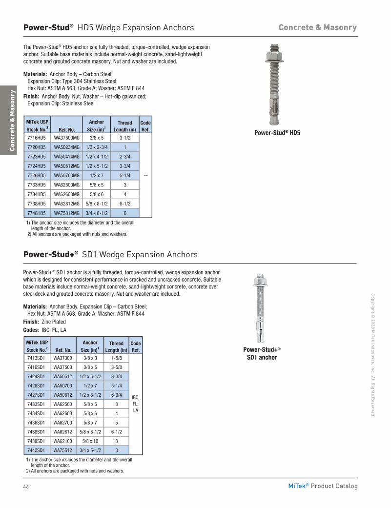
46
Copyright © 2020 M
iTek Industries, Inc. All Rights Reserved
Concrete & Masonry
Conc
rete
& M
ason
ry
MiTek® Product Catalog
Power-Stud® HD5 Wedge Expansion Anchors
Power-Stud® HD5
The Power-Stud® HD5 anchor is a fully threaded, torque-controlled, wedge expansion anchor. Suitable base materials include normal-weight concrete, sand-lightweight concrete and grouted concrete masonry. Nut and washer are included.
Materials: Anchor Body – Carbon Steel; Expansion Clip: Type 304 Stainless Steel; Hex Nut: ASTM A 563, Grade A; Washer: ASTM F 844Finish: Anchor Body, Nut, Washer – Hot-dip galvanized; Expansion Clip: Stainless Steel
Ref. No.
7716HD5 WA37500MG 3/8 x 5 3-1/2
7720HD5 WA50234MG 1/2 x 2-3/4 1
7723HD5 WA50414MG 1/2 x 4-1/2 2-3/4
7724HD5 WA50512MG 1/2 x 5-1/2 3-3/4
7726HD5 WA50700MG 1/2 x 7 5-1/4
7733HD5 WA62500MG 5/8 x 5 3
7734HD5 WA62600MG 5/8 x 6 4
7738HD5 WA62812MG 5/8 x 8-1/2 6-1/2
7748HD5 WA75812MG 3/4 x 8-1/2 6
1) The anchor size includes the diameter and the overall length of the anchor. 2) All anchors are packaged with nuts and washers.
ThreadLength (in)
CodeRef.
--
MiTek USPStock No.2
Anchor Size (in)1
Power-Stud+® SD1 Wedge Expansion Anchors
Power-Stud+® SD1 anchor
Power-Stud+® SD1 anchor is a fully threaded, torque-controlled, wedge expansion anchor which is designed for consistent performance in cracked and uncracked concrete. Suitable base materials include normal-weight concrete, sand-lightweight concrete, concrete over steel deck and grouted concrete masonry. Nut and washer are included.
Materials: Anchor Body, Expansion Clip – Carbon Steel; Hex Nut: ASTM A 563, Grade A; Washer: ASTM F 844Finish: Zinc PlatedCodes: IBC, FL, LA
Ref. No.
7413SD1 WA37300 3/8 x 3 1-5/8
7416SD1 WA37500 3/8 x 5 3-5/8
7424SD1 WA50512 1/2 x 5-1/2 3-3/4
7426SD1 WA50700 1/2 x 7 5-1/4
7427SD1 WA50812 1/2 x 8-1/2 6-3/4
7433SD1 WA62500 5/8 x 5 3
7434SD1 WA62600 5/8 x 6 4
7436SD1 WA62700 5/8 x 7 5
7438SD1 WA62812 5/8 x 8-1/2 6-1/2
7439SD1 WA62100 5/8 x 10 8
7442SD1 WA75512 3/4 x 5-1/2 3
1) The anchor size includes the diameter and the overall length of the anchor. 2) All anchors are packaged with nuts and washers.
IBC,FL,LA
MiTek USPStock No.2
Anchor Size (in)1
ThreadLength (in)
CodeRef.
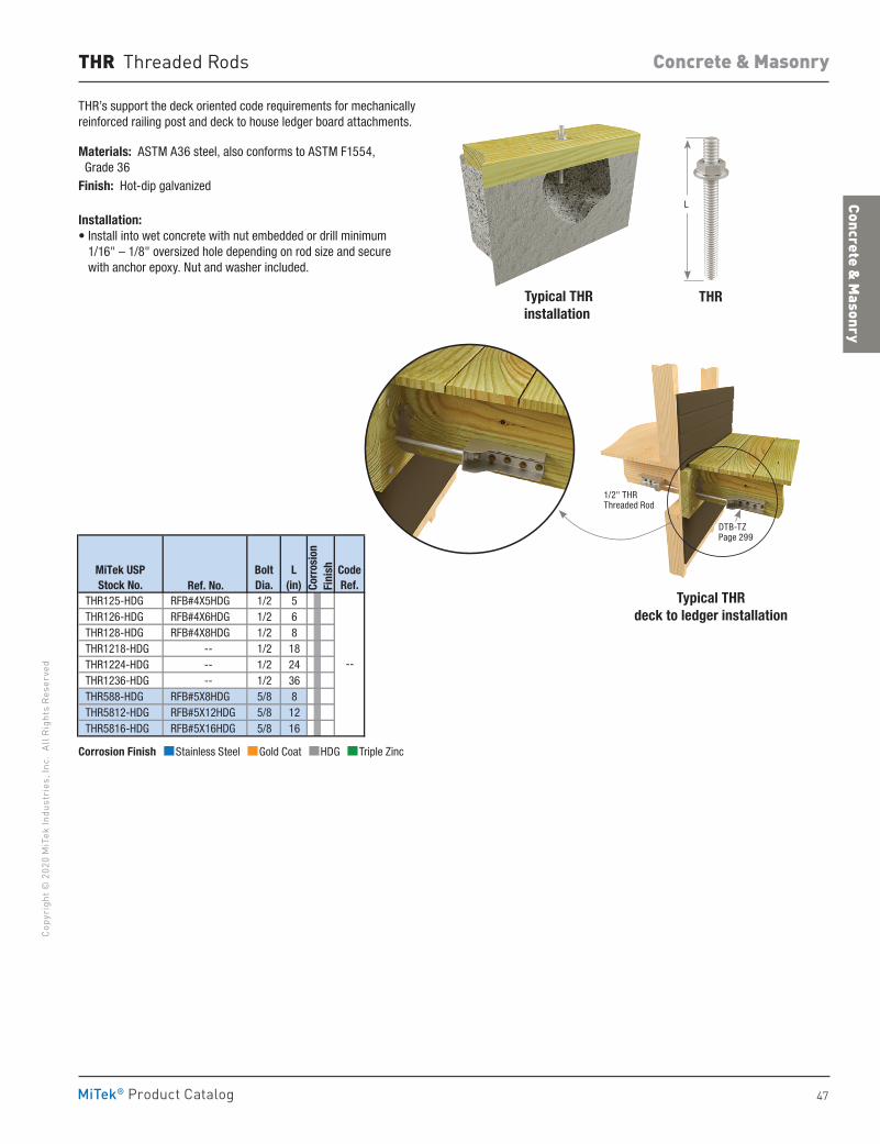
47
Concrete & Masonry
Co
pyri
ght ©
202
0 M
iTek
Indu
stri
es, I
nc.
All R
ight
s Re
serv
ed
Concrete & Masonry
MiTek® Product Catalog
THR Threaded Rods
THR’s support the deck oriented code requirements for mechanically reinforced railing post and deck to house ledger board attachments.
Materials: ASTM A36 steel, also conforms to ASTM F1554, Grade 36Finish: Hot-dip galvanized
Installation:• Install into wet concrete with nut embedded or drill minimum
1/16" – 1/8" oversized hole depending on rod size and secure with anchor epoxy. Nut and washer included.
Typical THR installation
Typical THR deck to ledger installation
Ref. No. THR125-HDG RFB#4X5HDG 1/2 5 THR126-HDG RFB#4X6HDG 1/2 6 THR128-HDG RFB#4X8HDG 1/2 8 THR1218-HDG -- 1/2 18 THR1224-HDG -- 1/2 24 THR1236-HDG -- 1/2 36 THR588-HDG RFB#5X8HDG 5/8 8 THR5812-HDG RFB#5X12HDG 5/8 12 THR5816-HDG RFB#5X16HDG 5/8 16
MiTek USPStock No.
BoltDia.
CodeRef.
--
L(in) Co
rros
ion
Fini
sh
THR
1/2" THR Threaded Rod
L
Corrosion Finish Stainless Steel Gold Coat HDG Triple Zinc
Corrosion Finish Stainless Steel Gold Coat HDG Triple Zinc
Corrosion Finish Stainless Steel Gold Coat HDG Triple Zinc
DTB-TZ Page 299
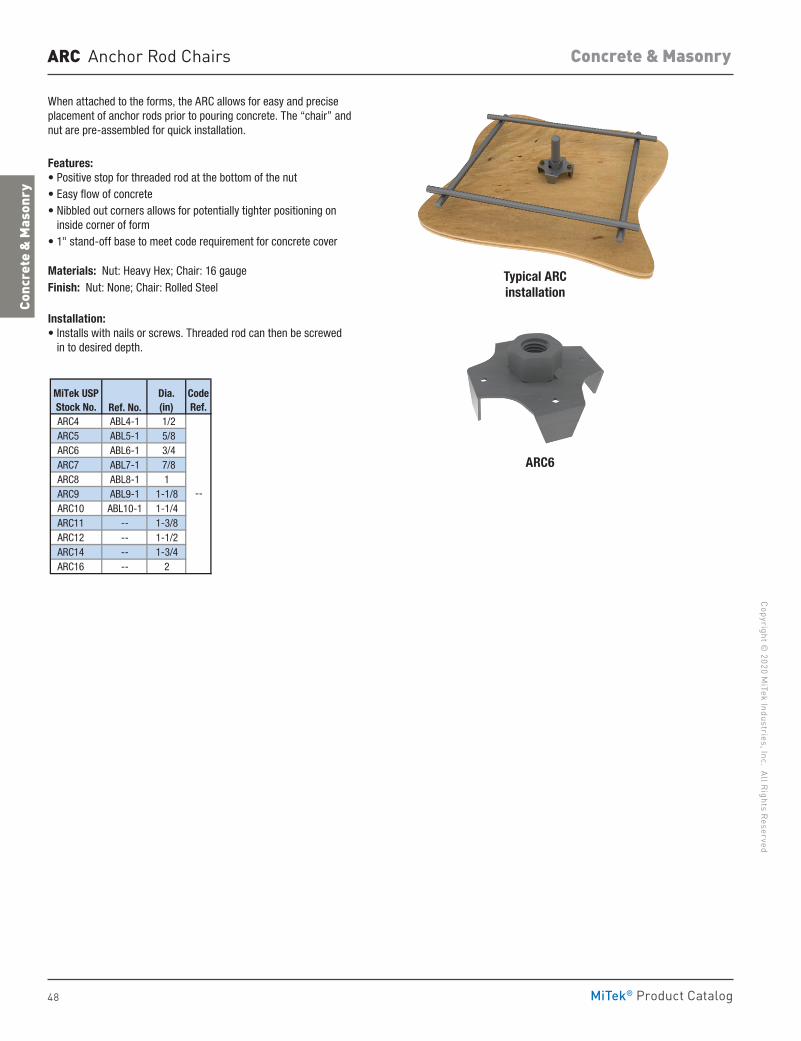
48
Copyright © 2020 M
iTek Industries, Inc. All Rights Reserved
Concrete & Masonry
Conc
rete
& M
ason
ry
MiTek® Product Catalog
When attached to the forms, the ARC allows for easy and precise placement of anchor rods prior to pouring concrete. The “chair” and nut are pre-assembled for quick installation.
Features:• Positive stop for threaded rod at the bottom of the nut• Easy flow of concrete• Nibbled out corners allows for potentially tighter positioning on
inside corner of form• 1" stand-off base to meet code requirement for concrete cover
Materials: Nut: Heavy Hex; Chair: 16 gaugeFinish: Nut: None; Chair: Rolled Steel
Installation:• Installs with nails or screws. Threaded rod can then be screwed
in to desired depth.
ARC6
Typical ARC installation
Ref. No. ARC4 ABL4-1 1/2 ARC5 ABL5-1 5/8 ARC6 ABL6-1 3/4 ARC7 ABL7-1 7/8 ARC8 ABL8-1 1 ARC9 ABL9-1 1-1/8 ARC10 ABL10-1 1-1/4 ARC11 -- 1-3/8 ARC12 -- 1-1/2 ARC14 -- 1-3/4 ARC16 -- 2
--
Dia.(in)
CodeRef.
MiTek USPStock No.
ARC Anchor Rod Chairs
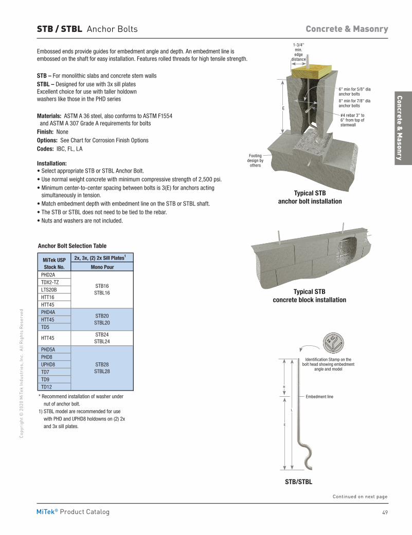
49
Concrete & Masonry
Co
pyri
ght ©
202
0 M
iTek
Indu
stri
es, I
nc.
All R
ight
s Re
serv
ed
Concrete & Masonry
MiTek® Product Catalog
STB / STBL Anchor Bolts
2x, 3x, (2) 2x Sill Plates1
Mono Pour PHD2A TDX2-TZ LTS20B HTT16 HTT45 PHD4A HTT45 TD5
PHD5A PHD8 UPHD8 TD7 TD9 TD12
* Recommend installation of washer under nut of anchor bolt.1) STBL model are recommended for use with PHD and UPHD8 holdowns on (2) 2x and 3x sill plates.
MiTek USPStock No.
STB28STBL28
STB16STBL16
STB24STBL24
STB20STBL20
HTT45
Anchor Bolt Selection Table
Embossed ends provide guides for embedment angle and depth. An embedment line is embossed on the shaft for easy installation. Features rolled threads for high tensile strength.
STB – For monolithic slabs and concrete stem wallsSTBL – Designed for use with 3x sill plates Excellent choice for use with taller holdown washers like those in the PHD series
Materials: ASTM A 36 steel, also conforms to ASTM F1554 and ASTM A 307 Grade A requirements for boltsFinish: NoneOptions: See Chart for Corrosion Finish OptionsCodes: IBC, FL, LA
Installation:• Select appropriate STB or STBL Anchor Bolt.• Use normal weight concrete with minimum compressive strength of 2,500 psi.• Minimum center-to-center spacing between bolts is 3(E) for anchors acting
simultaneously in tension.• Match embedment depth with embedment line on the STB or STBL shaft.• The STB or STBL does not need to be tied to the rebar.• Nuts and washers are not included.
1-3/4" min. edge
distance
Typical STB anchor bolt installation
Typical STB concrete block installation
6" min for 5/8" dia anchor bolts
8" min for 7/8" dia anchor bolts
#4 rebar 3" to 6" from top of stemwall
Footing design by
others
E
STB/STBL
Identification Stamp on the bolt head showing embedment
angle and model
Embedment line
H
L
E
Continued on next page
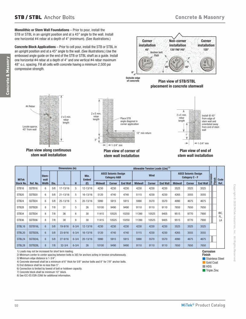
50
Copyright © 2020 M
iTek Industries, Inc. All Rights Reserved
Concrete & Masonry
Conc
rete
& M
ason
ry
MiTek® Product Catalog
STB / STBL Anchor Bolts
Ref. No. Dia. L H Midwall Corner End Wall Midwall Corner End Wall Midwall Corner End Wall
STB16 SSTB16 6 5/8 17-13/16 5 12-13/16 4230 4230 4230 4230 4230 4230 3525 3525 3525
STB20 SSTB20 6 5/8 21-13/16 5 16-13/16 5120 4740 4740 5115 4230 4230 4265 3555 3555
STB24 SSTB24 6 5/8 25-13/16 5 20-13/16 5990 5915 5915 5990 5570 5570 4990 4675 4675
STB28 SSTB28 8 7/8 31 5 26 10100 9490 9490 9110 9110 9110 7650 7650 7650
STB34 SSTB34 8 7/8 36 6 30 11415 10525 10250 11390 10525 9405 9515 8770 7900
STB36 SSTB36 8 7/8 38 8 30 11415 10525 10250 11390 10525 9405 9515 8770 7900
STBL16 SSTB16L 6 5/8 19-9/16 6-3/4 12-13/16 4230 4230 4230 4230 4230 4230 3525 3525 3525
STBL20 SSTB20L 6 5/8 23-9/16 6-3/4 16-13/16 5120 4740 4740 5115 4230 4230 4265 3555 3555
STBL24 SSTB24L 6 5/8 27-9/16 6-3/4 20-13/16 5990 5915 5915 5990 5570 5570 4990 4675 4675
STBL28 SSTB28L 8 7/8 32-3/4 6-3/4 26 10100 9490 9490 9110 9110 9110 7650 7650 7650
1) Loads may not be increased for short term loading. 2) Minimum center to center spacing between bolts is 3(E) for anchors acting in tension simultaneously. 3) Minimum edge distance is 1-3/4". 4) Concrete stemwall shall be a minimum of 6" thick for 5/8" anchor bolts and 8" for 7/8" anchor bolts. 5) End distance shall be no less than 5". 6) Connection is limited by lowest of bolt or holdown capacity. 7) Concrete block shall be minimum 10" block. 8) See ICC-ES ESR-2266 for additional information.
IBC,FL,LA
MiTekStock No.
Stem-wall
Width
Min.Embed
(E) Corr
osio
n Fi
nish
Allowable Tension Loads (Lbs)1,2
CodeRef.
Dimensions (in)
ASCE Seismic Design Category A&B
ASCE Seismic Design Category C - F
Wind
Corrosion Finish Stainless Steel Gold Coat HDG Triple Zinc
Corrosion Finish Stainless Steel Gold Coat HDG Triple Zinc
Corrosion Finish Stainless Steel Gold Coat HDG Triple Zinc
Plan view of STB/STBLplacement in concrete stemwall
Corner installation
45°
45° 45°
Corner installation
135°Anchor bolt
(typ)
Non-corner installation135°/90°/45°
0°
Outside edge of concrete
Plan view along continuous stem wall installation
Plan view of end of stem wall installation
Plan view of corner of stem wall installation
Place STB angle diagonal in corner application
Install @ 45° from edge of stem wall and orientated away from end of stem wall
12" min return
5"
1-3/4" min1-3/4" min
#4 Rebar
Locate approx. 45° from wall
2 x E min. rebar length
2 x E min. rebar length
2 x E min. rebar length
5"
Monolithic or Stem Wall Foundations – Prior to pour, install the STB or STBL in an upright position and at a 45° angle to the wall. Install one horizontal #4 rebar at a depth of 4" (minimum). (See illustrations.)
Concrete Block Applications – Prior to cell pour, install the STB or STBL in an upright position and at a 45° angle to the wall. (See illustrations.) Use the embossed angle guide on the end of the STB or STBL shaft as a guide. Install one horizontal #4 rebar at a depth of 4" and one vertical #4 rebar maximum 48" o.c. spacing. Fill all cells with concrete having a minimum 2,500 psi compressive strength.
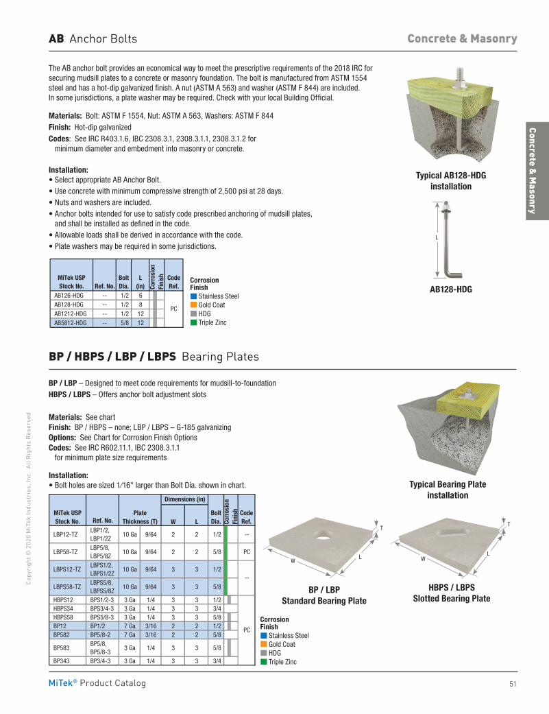
51
Concrete & Masonry
Co
pyri
ght ©
202
0 M
iTek
Indu
stri
es, I
nc.
All R
ight
s Re
serv
ed
Concrete & Masonry
MiTek® Product Catalog
The AB anchor bolt provides an economical way to meet the prescriptive requirements of the 2018 IRC for securing mudsill plates to a concrete or masonry foundation. The bolt is manufactured from ASTM 1554 steel and has a hot-dip galvanized finish. A nut (ASTM A 563) and washer (ASTM F 844) are included. In some jurisdictions, a plate washer may be required. Check with your local Building Official.
Materials: Bolt: ASTM F 1554, Nut: ASTM A 563, Washers: ASTM F 844Finish: Hot-dip galvanizedCodes: See IRC R403.1.6, IBC 2308.3.1, 2308.3.1.1, 2308.3.1.2 for minimum diameter and embedment into masonry or concrete.
Installation:• Select appropriate AB Anchor Bolt.• Use concrete with minimum compressive strength of 2,500 psi at 28 days.• Nuts and washers are included.• Anchor bolts intended for use to satisfy code prescribed anchoring of mudsill plates,
and shall be installed as defined in the code.• Allowable loads shall be derived in accordance with the code.• Plate washers may be required in some jurisdictions.
BP / LBP – Designed to meet code requirements for mudsill-to-foundationHBPS / LBPS – Offers anchor bolt adjustment slots
Materials: See chartFinish: BP / HBPS – none; LBP / LBPS – G-185 galvanizingOptions: See Chart for Corrosion Finish OptionsCodes: See IRC R602.11.1, IBC 2308.3.1.1 for minimum plate size requirements
Installation:• Bolt holes are sized 1⁄16" larger than Bolt Dia. shown in chart.
AB Anchor Bolts
AB126-HDG -- 1/2 6 AB128-HDG -- 1/2 8 AB1212-HDG -- 1/2 12 AB5812-HDG -- 5/8 12
MiTek USPStock No.
BoltDia.
CodeRef.
PC
Ref. No.L
(in) Corr
osio
nFi
nish
Typical AB128-HDGinstallation
Typical Bearing Plateinstallation
HBPS / LBPSSlotted Bearing Plate
AB128-HDG
BP / HBPS / LBP / LBPS Bearing Plates
Ref. No. W L
LBP12-TZ LBP1/2, LBP1/2Z
10 Ga 9/64 2 2 1/2 --
LBP58-TZ LBP5/8, LBP5/8Z
10 Ga 9/64 2 2 5/8 PC
LBPS12-TZ LBPS1/2, LBPS1/2Z
10 Ga 9/64 3 3 1/2
LBPS58-TZ LBPS5/8, LBPS5/8Z
10 Ga 9/64 3 3 5/8
HBPS12 BPS1/2-3 3 Ga 1/4 3 3 1/2 HBPS34 BPS3/4-3 3 Ga 1/4 3 3 3/4 HBPS58 BPS5/8-3 3 Ga 1/4 3 3 5/8 BP12 BP1/2 7 Ga 3/16 2 2 1/2 BP582 BP5/8-2 7 Ga 3/16 2 2 5/8
BP583 BP5/8, BP5/8-3
3 Ga 1/4 3 3 5/8
BP343 BP3/4-3 3 Ga 1/4 3 3 3/4
PC
--
CodeRef.
MiTek USPStock No.
BoltDia.
Dimensions (in)
PlateThickness (T) Co
rros
ion
Fini
sh
Corrosion Finish Stainless Steel Gold Coat HDG Triple Zinc
Corrosion Finish Stainless Steel Gold Coat HDG Triple Zinc
Corrosion Finish Stainless Steel Gold Coat HDG Triple Zinc
Corrosion Finish Stainless Steel Gold Coat HDG Triple Zinc
Corrosion Finish Stainless Steel Gold Coat HDG Triple Zinc
Corrosion Finish Stainless Steel Gold Coat HDG Triple Zinc
BP / LBPStandard Bearing Plate
WL
T
WL
T
L
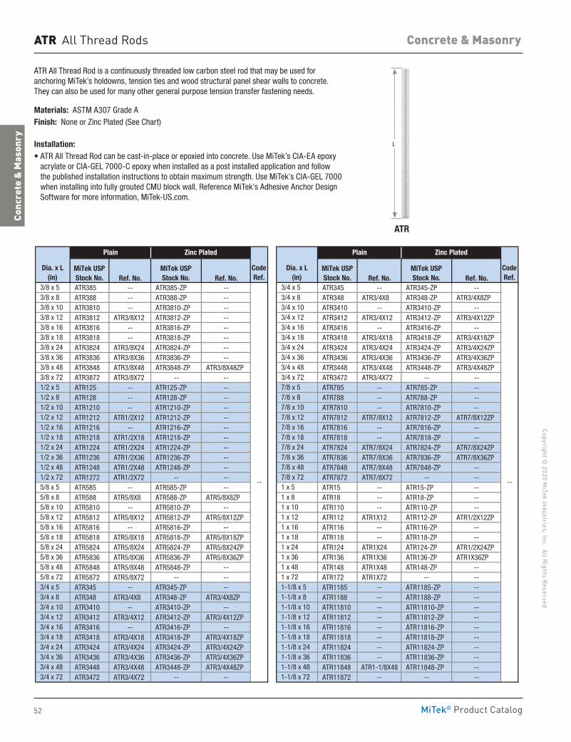
52
Copyright © 2020 M
iTek Industries, Inc. All Rights Reserved
Concrete & Masonry
Conc
rete
& M
ason
ry
MiTek® Product Catalog
ATR
ATR All Thread Rod is a continuously threaded low carbon steel rod that may be used for anchoring MiTek’s holdowns, tension ties and wood structural panel shear walls to concrete. They can also be used for many other general purpose tension transfer fastening needs.
Materials: ASTM A307 Grade A Finish: None or Zinc Plated (See Chart)
Installation: • ATR All Thread Rod can be cast-in-place or epoxied into concrete. Use MiTek’s CIA-EA epoxy
acrylate or CIA-GEL 7000-C epoxy when installed as a post installed application and follow the published installation instructions to obtain maximum strength. Use MiTek’s CIA-GEL 7000 when installing into fully grouted CMU block wall. Reference MiTek's Adhesive Anchor Design Software for more information, MiTek-US.com.
ATR All Thread Rods
Ref. No. Ref. No. Ref. No. Ref. No. 3/8 x 5 ATR385 -- ATR385-ZP -- 3/4 x 5 ATR345 -- ATR345-ZP -- 3/8 x 8 ATR388 -- ATR388-ZP -- 3/4 x 8 ATR348 ATR3/4X8 ATR348-ZP ATR3/4X8ZP 3/8 x 10 ATR3810 -- ATR3810-ZP -- 3/4 x 10 ATR3410 -- ATR3410-ZP -- 3/8 x 12 ATR3812 ATR3/8X12 ATR3812-ZP -- 3/4 x 12 ATR3412 ATR3/4X12 ATR3412-ZP ATR3/4X12ZP 3/8 x 16 ATR3816 -- ATR3816-ZP -- 3/4 x 16 ATR3416 -- ATR3416-ZP -- 3/8 x 18 ATR3818 -- ATR3818-ZP -- 3/4 x 18 ATR3418 ATR3/4X18 ATR3418-ZP ATR3/4X18ZP 3/8 x 24 ATR3824 ATR3/8X24 ATR3824-ZP -- 3/4 x 24 ATR3424 ATR3/4X24 ATR3424-ZP ATR3/4X24ZP 3/8 x 36 ATR3836 ATR3/8X36 ATR3836-ZP -- 3/4 x 36 ATR3436 ATR3/4X36 ATR3436-ZP ATR3/4X36ZP 3/8 x 48 ATR3848 ATR3/8X48 ATR3848-ZP ATR3/8X48ZP 3/4 x 48 ATR3448 ATR3/4X48 ATR3448-ZP ATR3/4X48ZP 3/8 x 72 ATR3872 ATR3/8X72 -- -- 3/4 x 72 ATR3472 ATR3/4X72 -- -- 1/2 x 5 ATR125 -- ATR125-ZP -- 7/8 x 5 ATR785 -- ATR785-ZP -- 1/2 x 8 ATR128 -- ATR128-ZP -- 7/8 x 8 ATR788 -- ATR788-ZP -- 1/2 x 10 ATR1210 -- ATR1210-ZP -- 7/8 x 10 ATR7810 -- ATR7810-ZP -- 1/2 x 12 ATR1212 ATR1/2X12 ATR1212-ZP -- 7/8 x 12 ATR7812 ATR7/8X12 ATR7812-ZP ATR7/8X12ZP 1/2 x 16 ATR1216 -- ATR1216-ZP -- 7/8 x 16 ATR7816 -- ATR7816-ZP -- 1/2 x 18 ATR1218 ATR1/2X18 ATR1218-ZP -- 7/8 x 18 ATR7818 -- ATR7818-ZP -- 1/2 x 24 ATR1224 ATR1/2X24 ATR1224-ZP -- 7/8 x 24 ATR7824 ATR7/8X24 ATR7824-ZP ATR7/8X24ZP 1/2 x 36 ATR1236 ATR1/2X36 ATR1236-ZP -- 7/8 x 36 ATR7836 ATR7/8X36 ATR7836-ZP ATR7/8X36ZP 1/2 x 48 ATR1248 ATR1/2X48 ATR1248-ZP -- 7/8 x 48 ATR7848 ATR7/8X48 ATR7848-ZP -- 1/2 x 72 ATR1272 ATR1/2X72 -- -- 7/8 x 72 ATR7872 ATR7/8X72 -- -- 5/8 x 5 ATR585 -- ATR585-ZP -- 1 x 5 ATR15 -- ATR15-ZP -- 5/8 x 8 ATR588 ATR5/8X8 ATR588-ZP ATR5/8X8ZP 1 x 8 ATR18 -- ATR18-ZP -- 5/8 x 10 ATR5810 -- ATR5810-ZP -- 1 x 10 ATR110 -- ATR110-ZP -- 5/8 x 12 ATR5812 ATR5/8X12 ATR5812-ZP ATR5/8X12ZP 1 x 12 ATR112 ATR1X12 ATR112-ZP ATR1/2X12ZP 5/8 x 16 ATR5816 -- ATR5816-ZP -- 1 x 16 ATR116 -- ATR116-ZP -- 5/8 x 18 ATR5818 ATR5/8X18 ATR5818-ZP ATR5/8X18ZP 1 x 18 ATR118 -- ATR118-ZP -- 5/8 x 24 ATR5824 ATR5/8X24 ATR5824-ZP ATR5/8X24ZP 1 x 24 ATR124 ATR1X24 ATR124-ZP ATR1/2X24ZP 5/8 x 36 ATR5836 ATR5/8X36 ATR5836-ZP ATR5/8X36ZP 1 x 36 ATR136 ATR1X36 ATR136-ZP ATR1X36ZP 5/8 x 48 ATR5848 ATR5/8X48 ATR5848-ZP -- 1 x 48 ATR148 ATR1X48 ATR148-ZP -- 5/8 x 72 ATR5872 ATR5/8X72 -- -- 1 x 72 ATR172 ATR1X72 -- -- 3/4 x 5 ATR345 -- ATR345-ZP -- 1-1/8 x 5 ATR1185 -- ATR1185-ZP -- 3/4 x 8 ATR348 ATR3/4X8 ATR348-ZP ATR3/4X8ZP 1-1/8 x 8 ATR1188 -- ATR1188-ZP -- 3/4 x 10 ATR3410 -- ATR3410-ZP -- 1-1/8 x 10 ATR11810 -- ATR11810-ZP -- 3/4 x 12 ATR3412 ATR3/4X12 ATR3412-ZP ATR3/4X12ZP 1-1/8 x 12 ATR11812 -- ATR11812-ZP -- 3/4 x 16 ATR3416 -- ATR3416-ZP -- 1-1/8 x 16 ATR11816 -- ATR11816-ZP -- 3/4 x 18 ATR3418 ATR3/4X18 ATR3418-ZP ATR3/4X18ZP 1-1/8 x 18 ATR11818 -- ATR11818-ZP -- 3/4 x 24 ATR3424 ATR3/4X24 ATR3424-ZP ATR3/4X24ZP 1-1/8 x 24 ATR11824 -- ATR11824-ZP -- 3/4 x 36 ATR3436 ATR3/4X36 ATR3436-ZP ATR3/4X36ZP 1-1/8 x 36 ATR11836 -- ATR11836-ZP -- 3/4 x 48 ATR3448 ATR3/4X48 ATR3448-ZP ATR3/4X48ZP 1-1/8 x 48 ATR11848 ATR1-1/8X48 ATR11848-ZP -- 3/4 x 72 ATR3472 ATR3/4X72 -- -- 1-1/8 x 72 ATR11872 -- -- --
----
Dia. x L(in)
CodeRef.
Dia. x L(in)
CodeRef.
MiTek USPStock No.
Plain Zinc Plated
MiTek USPStock No.
Plain Zinc Plated
MiTek USPStock No.
MiTek USPStock No.
L
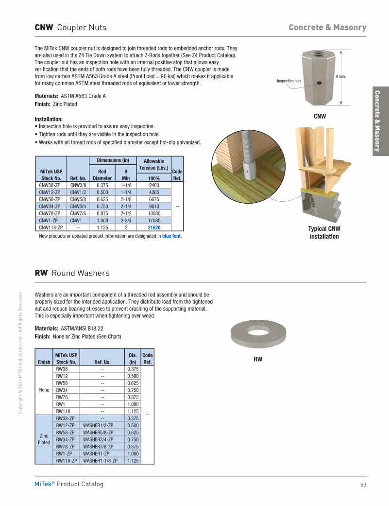
53
Concrete & Masonry
Co
pyri
ght ©
202
0 M
iTek
Indu
stri
es, I
nc.
All R
ight
s Re
serv
ed
Concrete & Masonry
MiTek® Product Catalog
CNW Coupler Nuts
The MiTek CNW coupler nut is designed to join threaded rods to embedded anchor rods. They are also used in the Z4 Tie Down system to attach Z-Rods together (See Z4 Product Catalog). The coupler nut has an inspection hole with an internal positive stop that allows easy verification that the ends of both rods have been fully threaded. The CNW coupler is made from low carbon ASTM A563 Grade A steel (Proof Load = 90 ksi) which makes it applicable for many common ASTM steel threaded rods of equivalent or lower strength.
Materials: ASTM A563 Grade AFinish: Zinc Plated
Installation:• Inspection hole is provided to assure easy inspection.• Tighten rods until they are visible in the inspection hole.• Works with all thread rods of specified diameter except hot-dip galvanized.
Washers are an important component of a threaded rod assembly and should be properly sized for the intended application. They distribute load from the tightened nut and reduce bearing stresses to prevent crushing of the supporting material. This is especially important when tightening over wood.
Materials: ASTM/ANSI B18.22Finish: None or Zinc Plated (See Chart)
RW Round Washers
Finish Ref. No. RW38 -- 0.375 RW12 -- 0.500 RW58 -- 0.625 RW34 -- 0.750 RW78 -- 0.875 RW1 -- 1.000 RW118 -- 1.125 RW38-ZP -- 0.375 RW12-ZP WASHER1/2-ZP 0.500 RW58-ZP WASHER5/8-ZP 0.625 RW34-ZP WASHER3/4-ZP 0.750 RW78-ZP WASHER7/8-ZP 0.875 RW1-ZP WASHER1-ZP 1.000 RW118-ZP WASHER1-1/8-ZP 1.125
ZincPlated
--
Dia.(in)
CodeRef.
MiTek USPStock No.
None
Ref. No. 100% CNW38-ZP CNW3/8 0.375 1-1/8 2400 CNW12-ZP CNW1/2 0.500 1-1/4 4265 CNW58-ZP CNW5/8 0.625 2-1/8 6675 CNW34-ZP CNW3/4 0.750 2-1/4 9610 CNW78-ZP CNW7/8 0.875 2-1/2 13080 CNW1-ZP CNW1 1.000 2-3/4 17080 CNW118-ZP -- 1.125 3 21620
New products or updated product information are designated in blue font.
MiTek USPStock No.
CodeRef.
HMin
Allowable Tension (Lbs.)
--
RodDiameter
Dimensions (in)
RW
CNW
Typical CNWinstallation
H min.Inspection hole
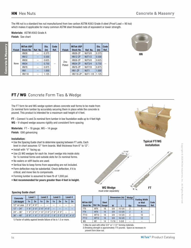
54
Copyright © 2020 M
iTek Industries, Inc. All Rights Reserved
Concrete & Masonry
Conc
rete
& M
ason
ry
MiTek® Product Catalog
The FT form tie and WG wedge system allows concrete wall forms to be made from 2x nominal form lumber by accurately securing them in place while the concrete is poured. This product is intended for a maximum wall height of 4 feet.
FT – Connect 1x and 2x nominal form lumber in low foundation walls up to 4 feet high WG – V-shaped wedge assures rigidity and consistent form spacing
Materials: FT – 18 gauge, WG – 14 gauge
Finish: G90 galvanizing
Installation:• Use the Spacing Guide chart to determine spacing between FT units. Each
level in chart assumes 12" form boards. Wall thickness from 6" to 12".• Install with “V” facing up.• Use (2) WG wedges for each tie. Insert wedge into inside slots
for 1x nominal forms and outside slots for 2x nominal forms.• No walers or stiff-backs are used.• Vertical ties to keep forms from separating are not included.• Form deflection may be substantial. Check deflection, if it is
critical, and move ties to compensate.• Forming lumber is assumed to have fb of 1,000 psi.• Not recommended for pours greater than 4 feet in height.
Spacing Guide chart
Wedge
Ref. No. W L Qty FT6 WT6 18 5/8 10-5/8 2 6 FT8 WT8 18 5/8 12-5/8 2 8 FT10 WT10 18 5/8 14-5/8 2 10 FT12 WT12 18 5/8 16-5/8 2 12 WG W1 14 11/16 3-5/8 -- --
1) May be used with either 3/4" or 1-1/2" forming materials. 2) Breaking strength is approximately 775 pounds. Space as necessary to prevent form blow-out.
1x 2x 1x 2x 1x 2x 1x 2x
12" or Less 2' 6" 4' 0" -- -- -- -- -- -- 12" – 24" 1' 6" 3' 0" 2' 6" 4' 0" -- -- -- -- 24" – 36" 1' 0" 2' 0" 1' 6" 3' 0" 2' 6" 4' 0" -- -- 36" – 48" 0' 9" 1' 6" 1' 0" 2' 0" 1' 6" 3' 0" 2' 6" 4' 0"
1) Factor of safety against tensile failure of tie is 1.5 or more.
Level 1 Level 2 Level 3 Level 4
--
Footing Widthor Wall
Thickness
ConcreteLift Height
Dimensions (in)
MiTek USPStock No.
SteelGauge
CodeRef.
WG Wedgemust order separately
FT
Typical FT/WGinstallation
HN Hex Nuts
The HN nut is a standard hex nut manufactured from low carbon ASTM A563 Grade A steel (Proof Load = 90 ksi) which makes it applicable for many common ASTM steel threaded rods of equivalent or lower strength.
Materials: ASTM A563 Grade AFinish: See chart
Finish Ref. No. Finish Ref. No. HN38 -- 0.375 HN38-ZP NUT3/8 0.375 HN12 -- 0.500 HN12-ZP NUT1/2 0.500 HN58 -- 0.625 HN58-ZP NUT5/8 0.625 HN34 -- 0.750 HN34-ZP NUT3/4 0.750 HN78 -- 0.875 HN78-ZP NUT7/8 0.875 HN1 -- 1.000 HN1-ZP NUT1 1.000 HN118 -- 1.125 HN118-ZP NUT1-1/8 1.125
NoneZinc
Plated
Dia.(in)
CodeRef.
MiTek USPStock No.
----
CodeRef.
MiTek USPStock No.
Dia.(in)
FT / WG Concrete Form Ties & Wedge
L
W
HN
11/16"
3-5/8"
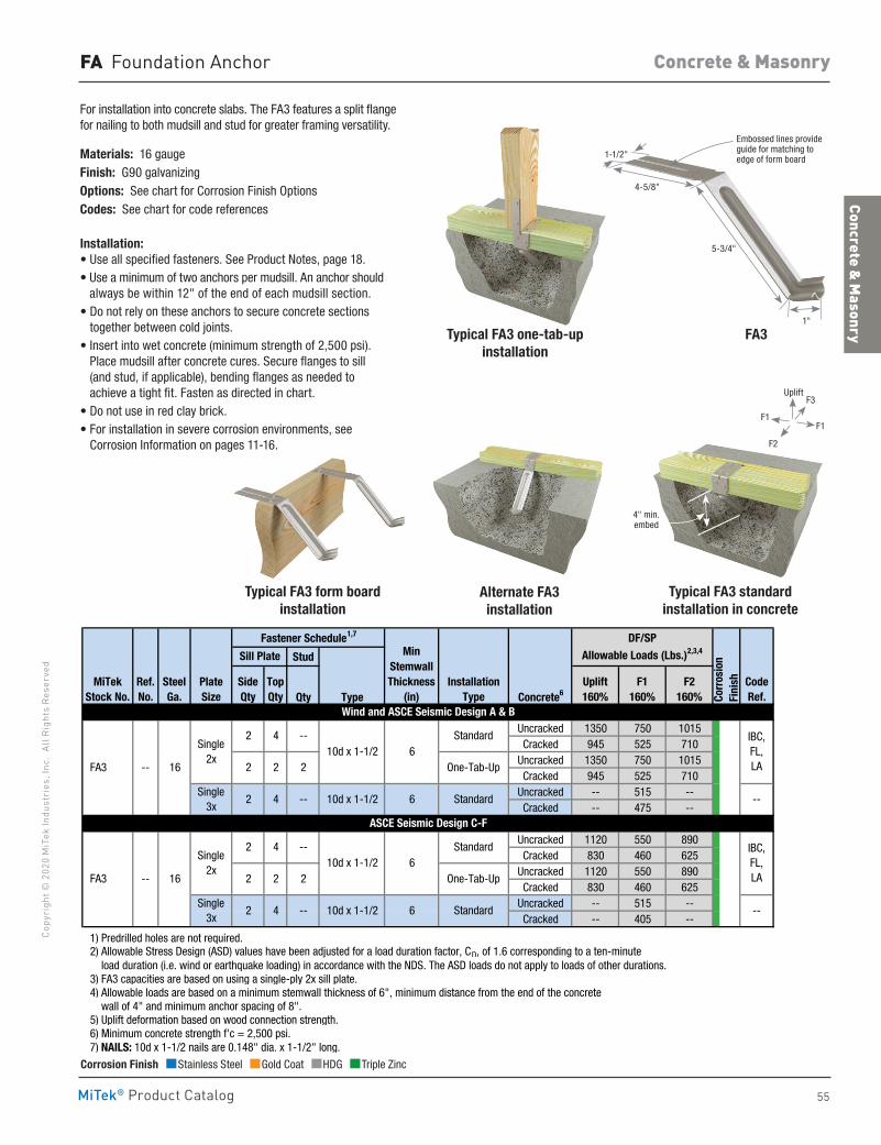
55
Concrete & Masonry
Co
pyri
ght ©
202
0 M
iTek
Indu
stri
es, I
nc.
All R
ight
s Re
serv
ed
Concrete & Masonry
MiTek® Product Catalog
For installation into concrete slabs. The FA3 features a split flange for nailing to both mudsill and stud for greater framing versatility.
Materials: 16 gaugeFinish: G90 galvanizingOptions: See chart for Corrosion Finish OptionsCodes: See chart for code references
Installation:• Use all specified fasteners. See Product Notes, page 18.• Use a minimum of two anchors per mudsill. An anchor should
always be within 12" of the end of each mudsill section.• Do not rely on these anchors to secure concrete sections
together between cold joints.• Insert into wet concrete (minimum strength of 2,500 psi).
Place mudsill after concrete cures. Secure flanges to sill (and stud, if applicable), bending flanges as needed to achieve a tight fit. Fasten as directed in chart.
• Do not use in red clay brick.• For installation in severe corrosion environments, see
Corrosion Information on pages 11-16.
FA Foundation Anchor
Stud
Qty Type Concrete6
Uncracked 1350 750 1015Cracked 945 525 710
Uncracked 1350 750 1015Cracked 945 525 710
Uncracked -- 515 --Cracked -- 475 --
Uncracked 1120 550 890Cracked 830 460 625
Uncracked 1120 550 890Cracked 830 460 625
Uncracked -- 515 --Cracked -- 405 --
1) Predrilled holes are not required. 2) Allowable Stress Design (ASD) values have been adjusted for a load duration factor, CD, of 1.6 corresponding to a ten-minute load duration (i.e. wind or earthquake loading) in accordance with the NDS. The ASD loads do not apply to loads of other durations. 3) FA3 capacities are based on using a single-ply 2x sill plate. 4) Allowable loads are based on a minimum stemwall thickness of 6", minimum distance from the end of the concrete wall of 4" and minimum anchor spacing of 8". 5) Uplift deformation based on wood connection strength. 6) Minimum concrete strength f'c = 2,500 psi. 7) NAILS: 10d x 1-1/2 nails are 0.148" dia. x 1-1/2" long.
MinStemwallThickness
(in)Uplift160%
F1160%
F2160% Co
rros
ion
Fini
sh
DF/SP Allowable Loads (Lbs.)2,3,4Sill Plate
Fastener Schedule1,7
SideQty
TopQty
--10d x 1-1/2 6
Standard
Standard
--
FA3 -- 16 2
Single 3x
ASCE Seismic Design C-F
Standard IBC,FL,LA
2 4 --
2 4 --
One-Tab-Up
StandardSingle
3x--
2 2
PlateSize
Single 2x
10d x 1-1/2 6
10d x 1-1/2 6
Wind and ASCE Seismic Design A & B
SteelGa.
2
MiTekStock No.
16 FA3
InstallationType
CodeRef.
Ref. No.
IBC,FL,LA
6
Single 2x
2 4 -- 10d x 1-1/2
2
One-Tab-Up
4
--
2 2
Corrosion Finish Stainless Steel Gold Coat HDG Triple Zinc
Corrosion Finish Stainless Steel Gold Coat HDG Triple Zinc
Corrosion Finish Stainless Steel Gold Coat HDG Triple Zinc
Typical FA3 form board installation
Alternate FA3 installation
Typical FA3 standard installation in concrete
4" min. embed
FA31"
5-3/4"
4-5/8"
1-1/2"
Embossed lines provide guide for matching to edge of form board
Typical FA3 one-tab-up installation
F1F1
F3
F2
Uplift
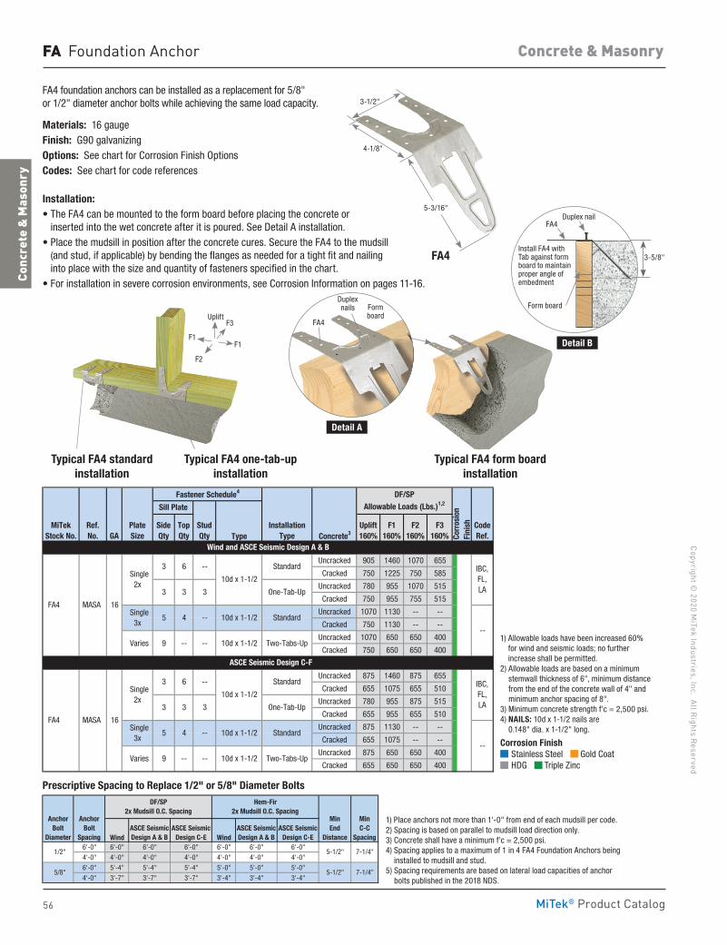
56
Copyright © 2020 M
iTek Industries, Inc. All Rights Reserved
Concrete & Masonry
Conc
rete
& M
ason
ry
MiTek® Product Catalog
FA Foundation Anchor
FA4 foundation anchors can be installed as a replacement for 5/8" or 1/2" diameter anchor bolts while achieving the same load capacity.
Materials: 16 gaugeFinish: G90 galvanizingOptions: See chart for Corrosion Finish OptionsCodes: See chart for code references
Installation:• The FA4 can be mounted to the form board before placing the concrete or
inserted into the wet concrete after it is poured. See Detail A installation.• Place the mudsill in position after the concrete cures. Secure the FA4 to the mudsill
(and stud, if applicable) by bending the flanges as needed for a tight fit and nailing into place with the size and quantity of fasteners specified in the chart.
• For installation in severe corrosion environments, see Corrosion Information on pages 11-16.
Type Concrete3
Uncracked 905 1460 1070 655
Cracked 750 1225 750 585
Uncracked 780 955 1070 515
Cracked 750 955 755 515
Uncracked 1070 1130 -- --
Cracked 750 1130 -- --
Uncracked 1070 650 650 400
Cracked 750 650 650 400
Uncracked 875 1460 875 655
Cracked 655 1075 655 510
Uncracked 780 955 875 515
Cracked 655 955 655 510
Uncracked 875 1130 -- --
Cracked 655 1075 -- --
Uncracked 875 650 650 400
Cracked 655 650 650 400
1) Allowable loads have been increased 60% for wind and seismic loads; no further increase shall be permitted. 2) Allowable loads are based on a minimum stemwall thickness of 6", minimum distance from the end of the concrete wall of 4" and minimum anchor spacing of 8". 3) Minimum concrete strength f'c = 2,500 psi. 4) NAILS: 10d x 1-1/2 nails are 0.148" dia. x 1-1/2" long.
Single 3x
Varies
Wind and ASCE Seismic Design A & B
ASCE Seismic Design C-F
FA4 MASA 16
--
Two-Tabs-Up
Sill Plate
F1160%
F2160%
F3160%
9 -- -- 10d x 1-1/2
--5 4 10d x 1-1/2
3 6
Standard
--
FA4 MASA 16
PlateSize
Single 2x
CodeRef.
Standard
One-Tab-Up
--
10d x 1-1/2
Corr
osio
n Fi
nish
Fastener Schedule4 DF/SP Allowable Loads (Lbs.)1,2
StudQtyGA
MiTekStock No.
3
SideQty
TopQty
Uplift160%
InstallationType
3 3 3
Single 2x
3 3
Single 3x
Varies
5 4 --
----9
Ref. No.
IBC,FL,LA
Standard
One-Tab-Up
--
10d x 1-1/2
3
IBC,FL,LA
Standard10d x 1-1/2
10d x 1-1/2 Two-Tabs-Up
6
Wind Wind6'-0" 6'-0" 6'-0" 6'-0" 6'-0" 6'-0" 6'-0"
4'-0" 4'-0" 4'-0" 4'-0" 4'-0" 4'-0" 4'-0"
6'-0" 5'-4" 5'-4" 5'-4" 5'-0" 5'-0" 5'-0"
4'-0" 3'-7" 3'-7" 3'-7" 3'-4" 3'-4" 3'-4"
1) Place anchors not more than 1'-0" from end of each mudsill per code. 2) Spacing is based on parallel to mudsill load direction only. 3) Concrete shall have a minimum f'c = 2,500 psi. 4) Spacing applies to a maximum of 1 in 4 FA4 Foundation Anchors being installed to mudsill and stud. 5) Spacing requirements are based on lateral load capacities of anchor bolts published in the 2018 NDS.
ASCE Seismic Design C-E
ASCE Seismic Design A & B
ASCE Seismic Design C-E
Prescriptive Spacing To Replace 1/2" or 5/8" Diameter Anchor Bolts
1/2"
5/8"
MinEnd
Distance
MinC-C
Spacing
AnchorBolt
Diameter
AnchorBolt
Spacing
DF/SP 2x Mudsill O.C. Spacing
Hem-Fir 2x Mudsill O.C. Spacing
5-1/2" 7-1/4"
5-1/2" 7-1/4"
ASCE Seismic Design A & B
Corrosion Finish Stainless Steel Gold Coat HDG Triple Zinc
Corrosion Finish Stainless Steel Gold Coat HDG Triple Zinc
Corrosion Finish Stainless Steel Gold Coat HDG Triple Zinc
1) Place anchors not more than 1'-0" from end of each mudsill per code.2) Spacing is based on parallel to mudsill load direction only. 3) Concrete shall have a minimum f'c = 2,500 psi. 4) Spacing applies to a maximum of 1 in 4 FA4 Foundation Anchors being
installed to mudsill and stud.5) Spacing requirements are based on lateral load capacities of anchor
bolts published in the 2018 NDS.
1) Allowable loads have been increased 60% for wind and seismic loads; no further increase shall be permitted.
2) Allowable loads are based on a minimum stemwall thickness of 6", minimum distance from the end of the concrete wall of 4" and minimum anchor spacing of 8".
3) Minimum concrete strength f'c = 2,500 psi.4) NAILS: 10d x 1-1/2 nails are
0.148" dia. x 1-1/2" long.
Typical FA4 one-tab-up installation
Typical FA4 standard installation
Prescriptive Spacing to Replace 1/2" or 5/8" Diameter Bolts
3-1/2"
4-1/8"
FA4
5-3/16"
Typical FA4 form board installation
Detail A
Detail B
Form board
Duplex nails
FA4
Install FA4 with Tab against form board to maintain proper angle of embedment
Form board
FA4
3-5/8"
Duplex nail
F1F1
F3
F2
Uplift
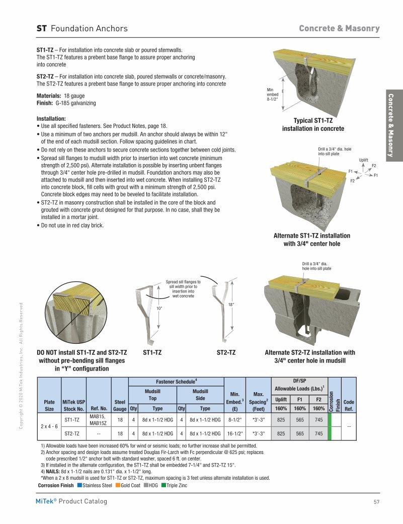
57
Concrete & Masonry
Co
pyri
ght ©
202
0 M
iTek
Indu
stri
es, I
nc.
All R
ight
s Re
serv
ed
Concrete & Masonry
MiTek® Product Catalog
ST Foundation Anchors
ST1-TZ – For installation into concrete slab or poured stemwalls. The ST1-TZ features a prebent base flange to assure proper anchoring into concrete
ST2-TZ – For installation into concrete slab, poured stemwalls or concrete/masonry. The ST2-TZ features a prebent base flange to assure proper anchoring into concrete
Materials: 18 gauge Finish: G-185 galvanizing
Installation:• Use all specified fasteners. See Product Notes, page 18.• Use a minimum of two anchors per mudsill. An anchor should always be within 12"
of the end of each mudsill section. Follow spacing guidelines in chart.• Do not rely on these anchors to secure concrete sections together between cold joints.• Spread sill flanges to mudsill width prior to insertion into wet concrete (minimum
strength of 2,500 psi). Alternate installation is possible by inserting unbent flanges through 3/4" center hole pre-drilled in mudsill. Foundation anchors may also be attached to mudsill and then inserted into wet concrete. When installing ST2-TZ into concrete block, fill cells with grout with a minimum strength of 2,500 psi. Concrete block edges may need to be beveled to facilitate installation.
• ST2-TZ in masonry construction shall be installed in the core of the block and grouted with concrete grout designed for that purpose. In no case, shall they be installed in a mortar joint.
• Do not use in red clay brick.
Uplift F1 F2
Ref. No. Qty Type Qty Type 160% 160% 160%
ST1-TZ MAB15, MAB15Z
18 4 8d x 1-1/2 HDG 4 8d x 1-1/2 HDG 8-1/2" *3'-3" 825 565 745
ST2-TZ -- 18 4 8d x 1-1/2 HDG 4 8d x 1-1/2 HDG 16-1/2" *3'-3" 825 565 745
1) Allowable loads have been increased 60% for wind or seismic loads; no further increase shall be permitted. 2) Anchor spacing and design loads assume treated Douglas Fir-Larch with Fc perpendicular @ 625 psi; replaces code prescribed 1/2" anchor bolt with standard washer, spaced 6 ft. on center. 3) If installed in the alternate configuration, the ST1-TZ shall be embedded 7-1/4" and ST2-TZ 15". 4) NAILS: 8d x 1-1/2 nails are 0.131" dia. x 1-1/2" long. *When a 2 x 8 mudsill is used for ST1-TZ or ST2-TZ, maximum spacing is 3 feet unless alternate installation is used.
--
CodeRef.
Min.Embed.3
(E)
Max.Spacing2
(Feet)
DF/SPAllowable Loads (Lbs.)1
Corr
osio
nFi
nishPlate
Size
Fastener Schedule4
MiTek USPStock No.
2 x 4 - 6
SteelGauge
MudsillTop
MudsillSide
DO NOT install ST1-TZ and ST2-TZwithout pre-bending sill flanges
in “Y” configuration
ST1-TZ ST2-TZ
10"18"
Alternate ST1-TZ installation with 3/4" center hole
Drill a 3/4" dia. hole into sill plate
Alternate ST2-TZ installation with 3/4" center hole in mudsill
Drill a 3/4" dia. hole into sill plate
Corrosion Finish Stainless Steel Gold Coat HDG Triple Zinc
Corrosion Finish Stainless Steel Gold Coat HDG Triple Zinc
Corrosion Finish Stainless Steel Gold Coat HDG Triple Zinc
Typical ST1-TZinstallation in concrete
Min embed 8-1/2"
E
F1F1
F2
UpliftF2
Spread sill flanges to sill width prior to
insertion into wet concrete
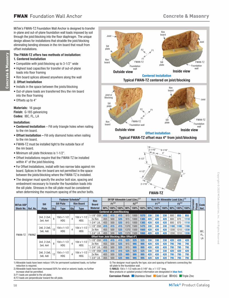
58
Copyright © 2020 M
iTek Industries, Inc. All Rights Reserved
Concrete & Masonry
Conc
rete
& M
ason
ry
MiTek® Product Catalog
FWAN Foundation Wall Anchor
MiTek’s FWAN-TZ Foundation Wall Anchor is designed to transfer in-plane and out-of-plane foundation wall loads imposed by soil through the joist/blocking into the floor diaphragm. The unique design allows for installations that straddle the joist/blocking eliminating bending stresses in the rim board that result from offset installations.
The FWAN-TZ offers two methods of installation: 1. Centered Installation• Compatible with joist/blocking up to 3-1/2" wide• Highest load capacities for transfer of out-of-plane
loads into floor framing • Rim board splices allowed anywhere along the wall2. Offset Installation• Installs in the space between the joists/blocking• Out-of-plane loads are transferred thru the rim board
into the floor framing • Offsets up to 4"
Materials: 16 gaugeFinish: G-185 galvanizingCodes: IBC, FL, LA
Installation:• Centered Installation – Fill only triangle holes when nailing
to the rim board.• Offset Installation – Fill only diamond holes when nailing
to the rim board.• FWAN-TZ must be installed tight to the outside face of
the rim board.• Minimum sill plate thickness is 1-1/2". • Offset Installations require that the FWAN-TZ be installed
within 4" of the joist/blocking.• For Offset Installations, install with two narrow tabs against rim
board. Splices in the rim board are not permitted in the space between the joists/blocking where the FWAN-TZ is installed.
• The designer must specify the anchor bolt size, spacing and embedment necessary to transfer the foundation loads into the sill plate. Stresses in the sill plate must be considered when determining the maximum spacing of the anchor bolts. FWAN-TZ
Sill plate
FWAN-TZ
Sill plate
Sill plate
Sill plate
Joist
Joist
Joist or Blocking
Joist
Rimboard
Rimboard
Rimboard
Rimboard
FWAN-TZ
FWAN-TZFWAN-TZ
Foundation wall
Foundation wall
Foundation wall
Foundation wall
Outside view Inside view
Outside view Inside view
Centered Installation Typical FWAN-TZ centered on joist/blocking
Offset Installation Typical FWAN-TZ offset max 4" from joist/blocking
Sill
Ref. No. Plate Qty Type Qty Type 90% 100% 160% 90% 100% 160% 90% 100% 160% 90% 100% 160%
1-1/8" OSB 415 415 415 915 1000 1070 330 330 330 800 855 8552x Rim 455 500 525 915 1000 1385 420 420 420 800 870 1110
1-3/4" LVL 455 500 525 915 1000 1385 420 420 420 800 870 11101-1/8" OSB 415 415 415 1370 1500 1475 330 330 330 1180 1180 1180
2x Rim 455 500 525 1370 1500 1660 420 420 420 1200 1310 13301-3/4" LVL 455 500 525 1370 1500 1660 420 420 420 1200 1310 1330
1-1/8" OSB 415 415 415 525 525 525 330 330 330 420 420 4202x Rim 455 500 525 915 995 995 420 420 420 795 795 795
1-3/4" LVL 455 500 525 915 995 995 420 420 420 795 795 7951-1/8" OSB 415 415 415 525 525 525 330 330 330 420 420 420
2x Rim 455 500 525 995 995 995 420 420 420 795 795 7951-3/4" LVL 455 500 525 995 995 995 420 420 420 795 795 795
1) Allowable loads have been reduce 10% for permanent sustained loads, no further reduction is required. 2) Allowable loads have been increased 60% for wind or seismic loads; no further increase shall be permitted. 3) F1 loads are parallel to the sill plate. 4) F2 loads are perpendicular toward the sill plate. 5) The designer must specify the type, size and spacing of fasteners connecting the sill plate to the foundation wall. 6) NAILS: 10d x 1-1/2 nails are 0.148" dia. x 1-1/2" long. New products or updated product information are designated in blue font.
410d x 1-1/2
HDG FWAN-TZ FWANZ
Centered on Joist/Blocking
2x6, 2-2x6,3x6, 4x6
1210d x 1-1/2
HDG4
10d x 1-1/2HDG
Offset from Joist Blocking (Max Offset 4")
2x4, 2-2x4,3x4, 4x4
810d x 1-1/2
HDG4
CodeRef.
2x4, 2-2x4,3x4, 4x4
810d x 1-1/2
HDG4
10d x 1-1/2HDG
Corr
osio
nFi
nish
Hem-Fir Allowable Load (Lbs.)1,2
IBC,FL, LA
10d x 1-1/2HDG
2x6, 2-2x6,3x6, 4x6
12
Fastener Schedule6 DF/SP Allowable Load (Lbs.)1,2
10d x 1-1/2HDG
MiTek USPStock No.
F23,4F13,4 F23,4F13,4Sill Plate Rim BoardRim
Board Material
4"
2-1/16"
1"
4"
2-1/16"
4-1/2"
4-1/2"
8-1/16"
Corrosion Finish Stainless Steel Gold Coat HDG Triple Zinc
Corrosion Finish Stainless Steel Gold Coat HDG Triple Zinc
Corrosion Finish Stainless Steel Gold Coat HDG Triple Zinc
F1
F1
F2
F1
F1
F2
1) Allowable loads have been reduce 10% for permanent sustained loads, no further reduction is required.
2) Allowable loads have been increased 60% for wind or seismic loads; no further increase shall be permitted.
3) F1 loads are parallel to the sill plate.4) F2 loads are perpendicular toward the sill plate.
5) The designer must specify the type, size and spacing of fasteners connecting the sill plate to the foundation wall.6) NAILS: 10d x 1-1/2 nails are 0.148" dia. x 1-1/2" long. New products or updated product information are designated in blue font.
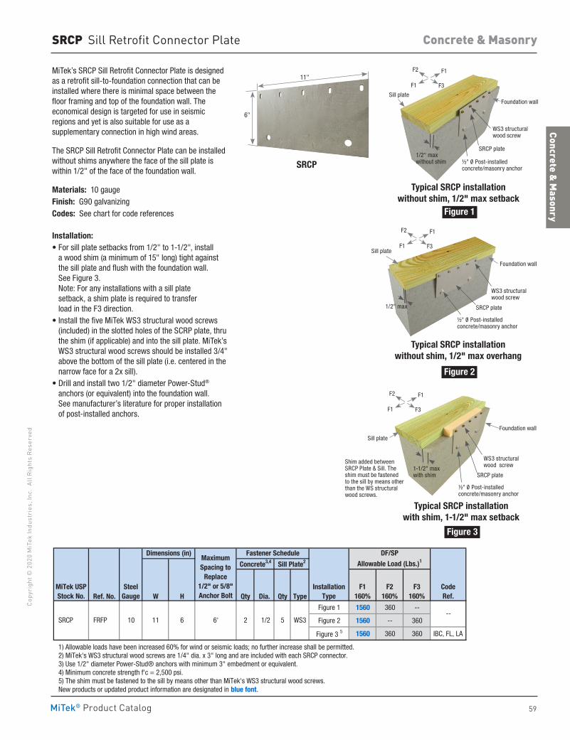
59
Concrete & Masonry
Co
pyri
ght ©
202
0 M
iTek
Indu
stri
es, I
nc.
All R
ight
s Re
serv
ed
Concrete & Masonry
MiTek® Product Catalog
Sill plate
Sill plate
Sill plate
Foundation wall
Foundation wall
Foundation wall
WS3 structural wood screw
WS3 structural wood screw
WS3 structural wood screw
SRCP plate
SRCP plate
SRCP plate
½" 0/ Post-installedconcrete/masonry anchor
½" 0/ Post-installedconcrete/masonry anchor
½" 0/ Post-installedconcrete/masonry anchor
1/2" maxwithout shim
1/2" max
1-1/2" maxwith shim
Typical SRCP installationwithout shim, 1/2" max setback
SRCP Sill Retrofit Connector Plate
MiTek’s SRCP Sill Retrofit Connector Plate is designed as a retrofit sill-to-foundation connection that can be installed where there is minimal space between the floor framing and top of the foundation wall. The economical design is targeted for use in seismic regions and yet is also suitable for use as a supplementary connection in high wind areas.
The SRCP Sill Retrofit Connector Plate can be installed without shims anywhere the face of the sill plate is within 1/2" of the face of the foundation wall.
Materials: 10 gauge Finish: G90 galvanizingCodes: See chart for code references
Installation:• For sill plate setbacks from 1/2" to 1-1/2", install
a wood shim (a minimum of 15" long) tight against the sill plate and flush with the foundation wall. See Figure 3. Note: For any installations with a sill plate setback, a shim plate is required to transfer load in the F3 direction.
• Install the five MiTek WS3 structural wood screws (included) in the slotted holes of the SCRP plate, thru the shim (if applicable) and into the sill plate. MiTek’s WS3 structural wood screws should be installed 3/4" above the bottom of the sill plate (i.e. centered in the narrow face for a 2x sill).
• Drill and install two 1/2" diameter Power-Stud® anchors (or equivalent) into the foundation wall. See manufacturer’s literature for proper installation of post-installed anchors.
Ref. No. W H Qty Dia. Qty Type
Figure 1 1560 360 --
Figure 2 1560 -- 360
Figure 3 5 1560 360 360 IBC, FL, LA
1) Allowable loads have been increased 60% for wind or seismic loads; no further increase shall be permitted. 2) MiTek's WS3 structural wood screws are 1/4" dia. x 3" long and are included with each SRCP connector. 3) Use 1/2" diameter Power-Stud® anchors with minimum 3" embedment or equivalent. 4) Minimum concrete strength f'c = 2,500 psi. 5) The shim must be fastened to the sill by means other than MiTek's WS3 structural wood screws. New products or updated product information are designated in blue font.
6' 2 1/2 5 WS3 SRCP FRFP 10 11 6
DF/SPAllowable Load (Lbs.)1
Steel Gauge
Maximum Spacing to
Replace 1/2" or 5/8"Anchor Bolt
Fastener Schedule
MiTek USPStock No.
Dimensions (in)
Concrete3,4 Sill Plate2
--
F1160%
F2160%
F3160%
InstallationType
CodeRef.
Typical SRCP installationwithout shim, 1/2" max overhang
Shim added between SRCP Plate & Sill. The shim must be fastened to the sill by means other than the WS structural wood screws.
Typical SRCP installationwith shim, 1-1/2" max setback
11"
6"
SRCP
Figure 1
Figure 2
Figure 3
F1
F1
F2
F3
F1
F1
F2
F3
F1
F1
F2
F3
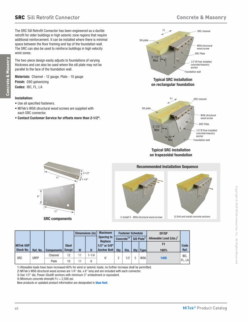
60
Copyright © 2020 M
iTek Industries, Inc. All Rights Reserved
Concrete & Masonry
Conc
rete
& M
ason
ry
MiTek® Product Catalog
SRC Sill Retrofit Connector
The SRC Sill Retrofit Connector has been engineered as a ductile retrofit for older buildings in high seismic zone regions that require additional reinforcement. It can be installed where there is minimal space between the floor framing and top of the foundation wall. The SRC can also be used to reinforce buildings in high velocity wind zones.
The two-piece design easily adjusts to foundations of varying thickness and can also be used where the sill plate may not be parallel to the face of the foundation wall.
Materials: Channel - 12 gauge, Plate - 10 gaugeFinish: G90 galvanizingCodes: IBC, FL, LA
Installation:• Use all specified fasteners. • MiTek’s WS6 structural wood screws are supplied with
each SRC connector.• Contact Customer Service for offsets more than 2-1/2".
F1
Ref. No. Components W H Qty Dia. Qty Type 160%
Channel 12 11 1-1/4
Plate 10 11 6
1) Allowable loads have been increased 60% for wind or seismic loads; no further increase shall be permitted. 2) MiTek's WS6 structural wood screws are 1/4" dia. x 6" long and are included with each connector. 3) Use 1/2" dia. Power-Stud® anchors with minimum 3" embedment or equivalent. 4) Minimum concrete strength f'c = 2,500 psi. New products or updated product information are designated in blue font.
CodeRef.
Sill Plate2
5 WS6 1405IBC,
FL, LA
DF/SP Allowable Load (Lbs.)1
URFP SRC
Steel Gauge
2 1/2
Maximum Spacing to
Replace 1/2" or 5/8"Anchor Bolt
6'
Fastener Schedule
MiTek USPStock No.
Dimensions (in)
Concrete3,4
2) Drill and install concrete anchors 1) Install 5 - WS6 structural wood screws
Recommended Installation Sequence
Typical SRC installationon rectangular foundation
SRC channel
Foundation wall
SRC Plate
1/2"Ø Post-Installedconcrete/masonryanchor
WS6 structural wood screw
Sill plate
F1
2-1/2"Max
SRC components
Typical SRC installationon trapezoidal foundation
SRC channel
Foundation wall
SRC Plate
1/2"Ø Post-Installedconcrete/masonryanchor
2-1/2"Max
WS6 structural wood screw
Sill plate
F1
20°Max
1-1/4"
2-1/2" 11"
11"
6"
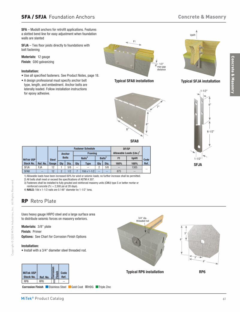
61
Concrete & Masonry
Co
pyri
ght ©
202
0 M
iTek
Indu
stri
es, I
nc.
All R
ight
s Re
serv
ed
Concrete & Masonry
MiTek® Product Catalog
SFA / SFJA Foundation Anchors
SFA – Mudsill anchors for retrofit applications. Features a slotted bend line for easy adjustment when foundation walls are slanted
SFJA – Ties floor joists directly to foundations with bolt fastening
Materials: 12 gaugeFinish: G90 galvanizing
Installation:• Use all specified fasteners. See Product Notes, page 18. • A design professional must specify anchor bolt
type, length, and embedment. Anchor bolts are laterally loaded. Follow installation instructions for epoxy adhesive.
F1 Uplift
Ref. No. Qty Dia. Qty Type Qty Dia. 160% 160% SFJA FJA 12 1 5/8 -- -- 2 5/8 -- 1305 SFA8 -- 12 2 1/2 7 10d x 1-1/2 -- -- 875 --
1) Allowable loads have been increased 60% for wind or seismic loads; no further increase shall be permitted. 2) All bolts shall meet or exceed the specifications of ASTM A 307. 3) Fasteners shall be installed to fully grouted and reinforced masonry units (CMU) type S or better mortar or reinforced concrete (f'c = 2,500 psi at 28 days). 4) NAILS: 10d x 1-1/2 nails are 0.148" diameter by 1-1/2" long.
MiTek USPStock No.
SteelGauge
Nails4 Bolts2
FramingAnchorBolts
Fastener Schedule
CodeRef.
--
DF/SP
Allowable Loads (Lbs.)1
Typical SFA8 installation
SFA8
F1
Typical SFJA installation
Uplift
8"
6"
7"
SFJA
1-1/2"
1-1/2"
6-1/2"
6"
1/2" max gap distance
Typical RP6 installation RP6
Uses heavy gauge HRPO steel and a large surface area to distribute seismic forces on masonry exteriors.
Materials: 3/8" plateFinish: PrimerOptions: See Chart for Corrosion Finish Options
Installation:• Install with a 3/4" diameter steel threaded rod.
Ref. No. RP6 RP6 --
CodeRef.Co
rros
ion
Fini
shMiTek USPStock No.
RP Retro Plate
Corrosion Finish Stainless Steel Gold Coat HDG Triple Zinc
Corrosion Finish Stainless Steel Gold Coat HDG Triple Zinc
Corrosion Finish Stainless Steel Gold Coat HDG Triple Zinc
6"
3"
6"
3"
3/4" dia. threaded rod
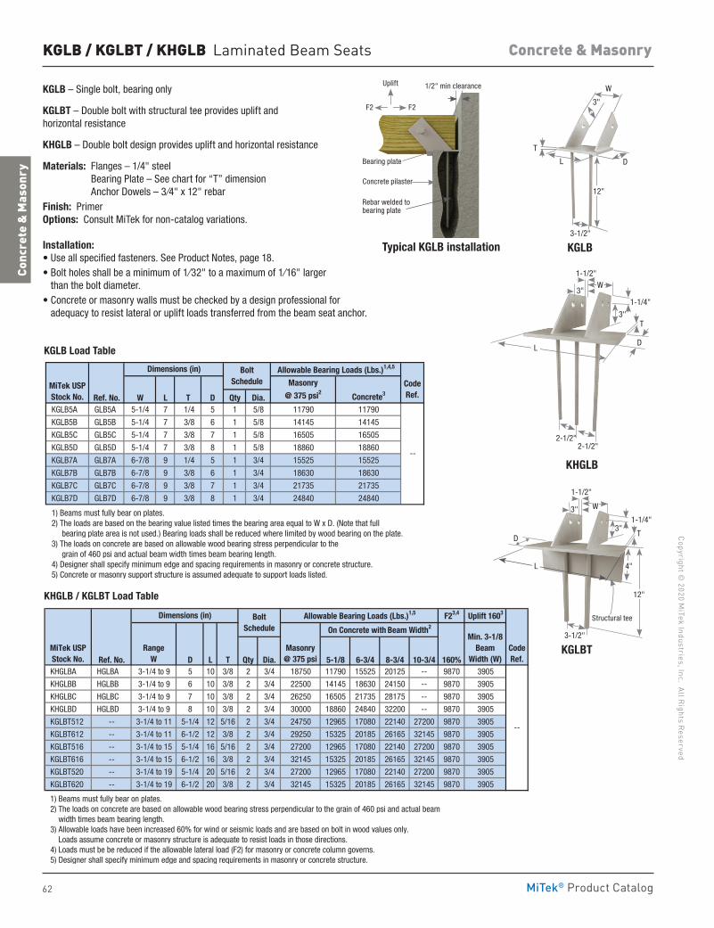
62
Copyright © 2020 M
iTek Industries, Inc. All Rights Reserved
Concrete & Masonry
Conc
rete
& M
ason
ry
MiTek® Product Catalog
KGLBT
Structural tee
12"
4"
3-1/2"
1-1/4"
T3"
L
D
3"
1-1/2"
W
KGLB / KGLBT / KHGLB Laminated Beam Seats
KGLB – Single bolt, bearing only
KGLBT – Double bolt with structural tee provides uplift and horizontal resistance
KHGLB – Double bolt design provides uplift and horizontal resistance
Materials: Flanges – 1/4" steel Bearing Plate – See chart for “T” dimension Anchor Dowels – 3⁄4" x 12" rebar
Finish: Primer Options: Consult MiTek for non-catalog variations.
Installation:• Use all specified fasteners. See Product Notes, page 18.• Bolt holes shall be a minimum of 1⁄32" to a maximum of 1⁄16" larger
than the bolt diameter.• Concrete or masonry walls must be checked by a design professional for
adequacy to resist lateral or uplift loads transferred from the beam seat anchor.
Typical KGLB installation
F23,4 Uplift 1603
Ref. No. D L T Qty Dia. 5-1/8 6-3/4 8-3/4 10-3/4 160% KHGLBA HGLBA 3-1/4 to 9 5 10 3/8 2 3/4 18750 11790 15525 20125 -- 9870 3905
KHGLBB HGLBB 3-1/4 to 9 6 10 3/8 2 3/4 22500 14145 18630 24150 -- 9870 3905
KHGLBC HGLBC 3-1/4 to 9 7 10 3/8 2 3/4 26250 16505 21735 28175 -- 9870 3905
KHGLBD HGLBD 3-1/4 to 9 8 10 3/8 2 3/4 30000 18860 24840 32200 -- 9870 3905
KGLBT512 -- 3-1/4 to 11 5-1/4 12 5/16 2 3/4 24750 12965 17080 22140 27200 9870 3905
KGLBT612 -- 3-1/4 to 11 6-1/2 12 3/8 2 3/4 29250 15325 20185 26165 32145 9870 3905
KGLBT516 -- 3-1/4 to 15 5-1/4 16 5/16 2 3/4 27200 12965 17080 22140 27200 9870 3905
KGLBT616 -- 3-1/4 to 15 6-1/2 16 3/8 2 3/4 32145 15325 20185 26165 32145 9870 3905
KGLBT520 -- 3-1/4 to 19 5-1/4 20 5/16 2 3/4 27200 12965 17080 22140 27200 9870 3905
KGLBT620 -- 3-1/4 to 19 6-1/2 20 3/8 2 3/4 32145 15325 20185 26165 32145 9870 3905
1) Beams must fully bear on plates. 2) The loads on concrete are based on allowable wood bearing stress perpendicular to the grain of 460 psi and actual beam width times beam bearing length. 3) Allowable loads have been increased 60% for wind or seismic loads and are based on bolt in wood values only. Loads assume concrete or masonry structure is adequate to resist loads in those directions. 4) Loads must be be reduced if the allowable lateral load (F2) for masonry or concrete column governs. 5) Designer shall specify minimum edge and spacing requirements in masonry or concrete structure.
--
Allowable Bearing Loads (Lbs.)1,5
On Concrete with Beam Width2
Masonry@ 375 psi
Min. 3-1/8 Beam
Width (W)MiTek USPStock No.
RangeW
Dimensions (in)
CodeRef.
Bolt Schedule
Ref. No. W L T D Qty Dia. Concrete3
KGLB5A GLB5A 5-1/4 7 1/4 5 1 5/8 11790 11790
KGLB5B GLB5B 5-1/4 7 3/8 6 1 5/8 14145 14145
KGLB5C GLB5C 5-1/4 7 3/8 7 1 5/8 16505 16505
KGLB5D GLB5D 5-1/4 7 3/8 8 1 5/8 18860 18860
KGLB7A GLB7A 6-7/8 9 1/4 5 1 3/4 15525 15525
KGLB7B GLB7B 6-7/8 9 3/8 6 1 3/4 18630 18630
KGLB7C GLB7C 6-7/8 9 3/8 7 1 3/4 21735 21735
KGLB7D GLB7D 6-7/8 9 3/8 8 1 3/4 24840 24840
1) Beams must fully bear on plates. 2) The loads are based on the bearing value listed times the bearing area equal to W x D. (Note that full bearing plate area is not used.) Bearing loads shall be reduced where limited by wood bearing on the plate. 3) The loads on concrete are based on allowable wood bearing stress perpendicular to the grain of 460 psi and actual beam width times beam bearing length. 4) Designer shall specify minimum edge and spacing requirements in masonry or concrete structure. 5) Concrete or masonry support structure is assumed adequate to support loads listed.
--
Dimensions (in) Allowable Bearing Loads (Lbs.)1,4,5
MiTek USPStock No.
Masonry
@ 375 psi2CodeRef.
Bolt Schedule
1/2" min clearance
Bearing plate
Concrete pilaster
Rebar welded to bearing plate
KGLB
3" W
D
3-1/2"
L T
12"
KHGLB
3"
3"
1-1/2"
1-1/4"
T
2-1/2" 2-1/2"
L D
W
KGLB Load Table
KHGLB / KGLBT Load Table
Uplift
F2F2
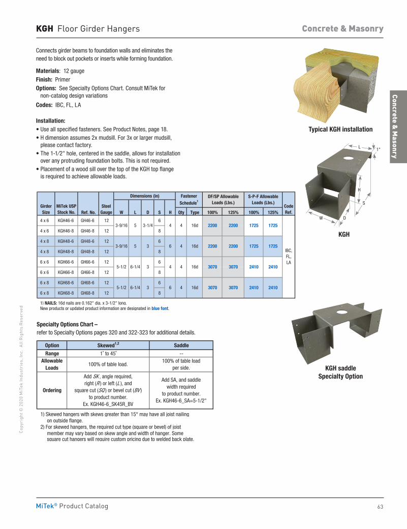
63
Concrete & Masonry
Co
pyri
ght ©
202
0 M
iTek
Indu
stri
es, I
nc.
All R
ight
s Re
serv
ed
Concrete & Masonry
MiTek® Product Catalog
KGH Floor Girder Hangers
Connects girder beams to foundation walls and eliminates the need to block out pockets or inserts while forming foundation.
Materials: 12 gaugeFinish: PrimerOptions: See Specialty Options Chart. Consult MiTek for non-catalog design variations
Codes: IBC, FL, LA
Installation:• Use all specified fasteners. See Product Notes, page 18.• H dimension assumes 2x mudsill. For 3x or larger mudsill,
please contact factory.• The 1-1⁄2" hole, centered in the saddle, allows for installation
over any protruding foundation bolts. This is not required. • Placement of a wood sill over the top of the KGH top flange
is required to achieve allowable loads.
Specialty Options Chart – refer to Specialty Options pages 320 and 322-323 for additional details.
Dimensions (in)
Ref. No. W L D S H Qty Type 100% 125% 100% 125%
4 x 6 KGH46-6 GH46-6 12 6
4 x 6 KGH46-8 GH46-8 12 8
4 x 8 KGH48-6 GH48-6 12 6
4 x 8 KGH48-8 GH48-8 12 8
6 x 6 KGH66-6 GH66-6 12 6
6 x 6 KGH66-8 GH66-8 12 8
6 x 8 KGH68-6 GH68-6 12 6
6 x 8 KGH68-8 GH68-8 12 8
1) NAILS: 16d nails are 0.162" dia. x 3-1/2" long. New products or updated product information are designated in blue font.
2200
3070 3070
3070 3070
2200
4 4 16d
6 4 16d
5-1/2 6-1/4
6-1/45-1/2
3
3
5 3 4 16d6
CodeRef.
IBC,FL,LA
Fastener
Schedule1
GirderSize
MiTek USPStock No.
SteelGauge
DF/SP AllowableLoads (Lbs.)
3-9/16 5 3-1/4 4 4 16d 2200 2200
3-9/16
2410 2410
2410 2410
S-P-F AllowableLoads (Lbs.)
1725 1725
1725 1725
Option Skewed1,2 Saddle
Range 1˚ to 45˚ --
1) Skewed hangers with skews greater than 15° may have all joist nailing on outside flange. 2) For skewed hangers, the required cut type (square or bevel) of joist member may vary based on skew angle and width of hanger. Some square cut hangers will require custom pricing due to welded back plate.
AllowableLoads
Ordering
100% of table load.100% of table load
per side.
Add SA, and saddlewidth required
to product number.Ex. KGH46-6_SA=5-1/2"
Add SK , angle required,right (R ) or left (L ), and
square cut (SQ ) or bevel cut (BV )to product number.
Ex. KGH46-6_SK45R_BV
Typical KGH installation
KGH
S
1"
H
L
W D
KGH saddle Specialty Option
64
Copyright © 2020 M
iTek Industries, Inc. All Rights Reserved
Holdowns
Hold
owns
MiTek® Product Catalog
Holdowns
Foundation Straps 73-77 Holdowns 66-69, 72Purlin Anchors 78-79 Tension Ties 70-71
pg. 66-79
Holdowns
65
Copy
righ
t © 2
020
MiT
ek In
dust
ries
, Inc
. Al
l Rig
hts
Rese
rved
Holdowns
MiTek® Product Catalog
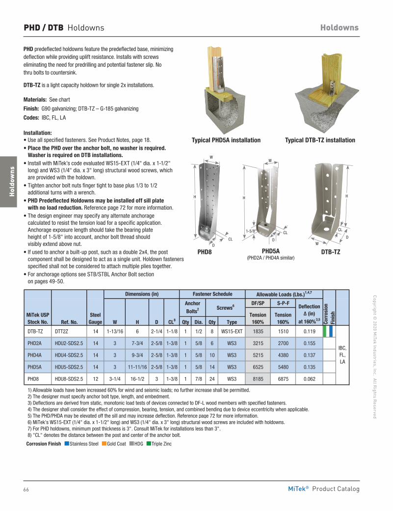
66
Copyright © 2020 M
iTek Industries, Inc. All Rights Reserved
Holdowns
Hold
owns
MiTek® Product Catalog
PHD / DTB Holdowns
PHD predeflected holdowns feature the predeflected base, minimizing deflection while providing uplift resistance. Installs with screws eliminating the need for predrilling and potential fastener slip. No thru bolts to countersink.
DTB-TZ is a light capacity holdown for single 2x installations.
Materials: See chart
Finish: G90 galvanizing; DTB-TZ – G-185 galvanizing
Codes: IBC, FL, LA
Installation:• Use all specified fasteners. See Product Notes, page 18.• Place the PHD over the anchor bolt, no washer is required.
Washer is required on DTB installations.• Install with MiTek’s code evaluated WS15-EXT (1/4" dia. x 1-1/2"
long) and WS3 (1/4" dia. x 3" long) structural wood screws, which are provided with the holdown.
• Tighten anchor bolt nuts finger tight to base plus 1/3 to 1/2 additional turns with a wrench.
• PHD Predeflected Holdowns may be installed off sill plate with no load reduction. Reference page 72 for more information.
• The design engineer may specify any alternate anchorage calculated to resist the tension load for a specific application. Anchorage exposure length should take the bearing plate height of 1-5/8" into account, anchor bolt thread should visibly extend above nut.
• If used to anchor a built-up post, such as a double 2x4, the post component shall be designed to act as a single unit. Holdown fasteners specified shall not be considered to attach multiple plies together.
• For anchorage options see STB/STBL Anchor Bolt section on pages 49-50.
Typical PHD5A installation Typical DTB-TZ installation
PHD8 DTB-TZPHD5A (PHD2A / PHD4A similar)
DF/SP S-P-F
Ref. No. W H D CL8 Qty Dia. Qty Type
DTB-TZ DTT2Z 14 1-13/16 6 2-1/4 1-1/8 1 1/2 8 WS15-EXT 1835 1510 0.119
PHD2A HDU2-SDS2.5 14 3 7-3/4 2-5/8 1-3/8 1 5/8 6 WS3 3215 2700 0.155
PHD4A HDU4-SDS2.5 14 3 9-3/4 2-5/8 1-3/8 1 5/8 10 WS3 5215 4380 0.137
PHD5A HDU5-SDS2.5 14 3 11-11/16 2-5/8 1-3/8 1 5/8 14 WS3 6525 5480 0.135
PHD8 HDU8-SDS2.5 12 3-1/4 16-1/2 3 1-3/8 1 7/8 24 WS3 8185 6875 0.062
1) Allowable loads have been increased 60% for wind and seismic loads; no further increase shall be permitted. 2) The designer must specify anchor bolt type, length, and embedment. 3) Deflections are derived from static, monotonic load tests of devices connected to DF-L wood members with specified fasteners. 4) The designer shall consider the effect of compression, bearing, tension, and combined bending due to device eccentricity when applicable. 5) The PHD/PHDA may be elevated off the sill and may increase deflection. Reference page 72 for more information. 6) MiTek's WS15-EXT (1/4" dia. x 1-1/2" long) and WS3 (1/4" dia. x 3" long) structural wood screws are included with holdowns. 7) For PHD holdowns, minimum post thickness is 3". Consult MiTek for installations less than 3". 8) "CL" denotes the distance between the post and center of the anchor bolt.
Deflection Δ (in)
at 160%3,5
Corr
osio
nFi
nish
IBC,FL,LA
MiTek USPStock No.
SteelGauge
Dimensions (in) Fastener Schedule Allowable Loads (Lbs.)1,4,7
Tension160%
Tension160%
Anchor
Bolts2 Screws6
DD
CL
CL
H
WW
1-5/8"
Corrosion Finish Stainless Steel Gold Coat HDG Triple Zinc
Corrosion Finish Stainless Steel Gold Coat HDG Triple Zinc
Corrosion Finish Stainless Steel Gold Coat HDG Triple Zinc
H
D
CL
W
H
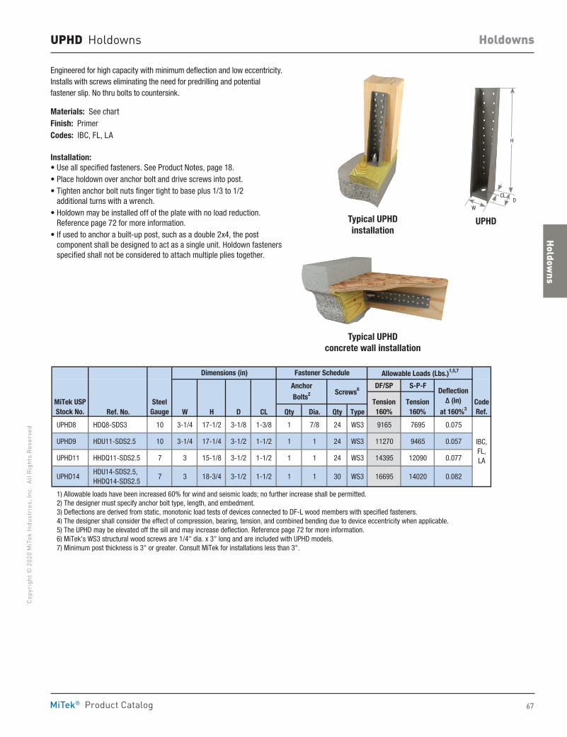
Holdowns
67
Copy
righ
t © 2
020
MiT
ek In
dust
ries
, Inc
. Al
l Rig
hts
Rese
rved
Holdowns
MiTek® Product Catalog
UPHD Holdowns
Engineered for high capacity with minimum deflection and low eccentricity. Installs with screws eliminating the need for predrilling and potential fastener slip. No thru bolts to countersink.
Materials: See chartFinish: PrimerCodes: IBC, FL, LA
Installation:• Use all specified fasteners. See Product Notes, page 18.• Place holdown over anchor bolt and drive screws into post.• Tighten anchor bolt nuts finger tight to base plus 1/3 to 1/2
additional turns with a wrench. • Holdown may be installed off of the plate with no load reduction.
Reference page 72 for more information.• If used to anchor a built-up post, such as a double 2x4, the post
component shall be designed to act as a single unit. Holdown fasteners specified shall not be considered to attach multiple plies together.
DF/SP S-P-F
Ref. No. W H D CL Qty Dia. Qty Type
UPHD8 HDQ8-SDS3 10 3-1/4 17-1/2 3-1/8 1-3/8 1 7/8 24 WS3 9165 7695 0.075
UPHD9 HDU11-SDS2.5 10 3-1/4 17-1/4 3-1/2 1-1/2 1 1 24 WS3 11270 9465 0.057
UPHD11 HHDQ11-SDS2.5 7 3 15-1/8 3-1/2 1-1/2 1 1 24 WS3 14395 12090 0.077
UPHD14 HDU14-SDS2.5, HHDQ14-SDS2.5
7 3 18-3/4 3-1/2 1-1/2 1 1 30 WS3 16695 14020 0.082
1) Allowable loads have been increased 60% for wind and seismic loads; no further increase shall be permitted. 2) The designer must specify anchor bolt type, length, and embedment. 3) Deflections are derived from static, monotonic load tests of devices connected to DF-L wood members with specified fasteners. 4) The designer shall consider the effect of compression, bearing, tension, and combined bending due to device eccentricity when applicable. 5) The UPHD may be elevated off the sill and may increase deflection. Reference page 72 for more information. 6) MiTek's WS3 structural wood screws are 1/4" dia. x 3" long and are included with UPHD models. 7) Minimum post thickness is 3" or greater. Consult MiTek for installations less than 3".
MiTek USPStock No.
SteelGauge
Dimensions (in)
Screws6Anchor
Bolts2
Fastener Schedule
CodeRef.
IBC,FL,LA
Tension160%
Deflection Δ (in)
at 160%3
Allowable Loads (Lbs.)1,5,7
Tension160%
Typical UPHDinstallation
UPHD
Typical UPHDconcrete wall installation
W
H
DCL
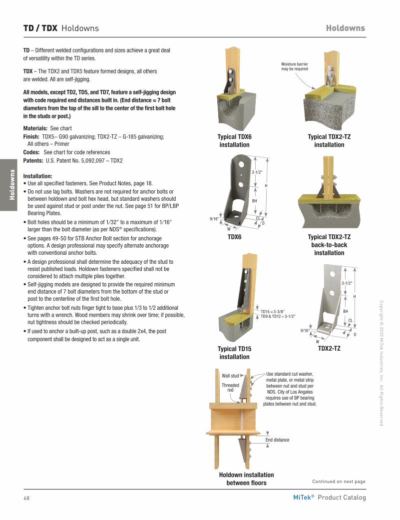
68
Copyright © 2020 M
iTek Industries, Inc. All Rights Reserved
Holdowns
Hold
owns
MiTek® Product Catalog
TD / TDX Holdowns
TD – Different welded configurations and sizes achieve a great deal of versatility within the TD series.
TDX – The TDX2 and TDX5 feature formed designs, all others are welded. All are self-jigging.
All models, except TD2, TD5, and TD7, feature a self-jigging design with code required end distances built in. (End distance = 7 bolt diameters from the top of the sill to the center of the first bolt hole in the studs or post.)
Materials: See chartFinish: TDX5– G90 galvanizing; TDX2-TZ – G-185 galvanizing; All others – PrimerCodes: See chart for code referencesPatents: U.S. Patent No. 5,092,097 – TDX2
Installation:• Use all specified fasteners. See Product Notes, page 18.• Do not use lag bolts. Washers are not required for anchor bolts or
between holdown and bolt hex head, but standard washers should be used against stud or post under the nut. See page 51 for BP/LBP Bearing Plates.
• Bolt holes should be a minimum of 1⁄32" to a maximum of 1⁄16" larger than the bolt diameter (as per NDS® specifications).
• See pages 49-50 for STB Anchor Bolt section for anchorage options. A design professional may specify alternate anchorage with conventional anchor bolts.
• A design professional shall determine the adequacy of the stud to resist published loads. Holdown fasteners specified shall not be considered to attach multiple plies together.
• Self-jigging models are designed to provide the required minimum end distance of 7 bolt diameters from the bottom of the stud or post to the centerline of the first bolt hole.
• Tighten anchor bolt nuts finger tight to base plus 1/3 to 1/2 additional turns with a wrench. Wood members may shrink over time; if possible, nut tightness should be checked periodically.
• If used to anchor a built-up post, such as a double 2x4, the post component shall be designed to act as a single unit.
Typical TDX2-TZinstallation
Holdown installationbetween floors
Typical TDX2-TZ back-to-backinstallation
Typical TD15installation
TDX6
TDX2-TZ
Typical TDX6installation
Moisture barrier may be required
TD15 = 3-3/8" TD9 & TD12 = 3-1/2"
Use standard cut washer, metal plate, or metal strip between nut and stud per NDS. City of Los Angeles
requires use of BP bearing plates between nut and stud.
End distance
Wall stud
Threaded rod
H
DW
CL
3-1/2"
BH
9/16"
H
D
W
CL
3-1/2"
BH
9/16"
Continued on next page
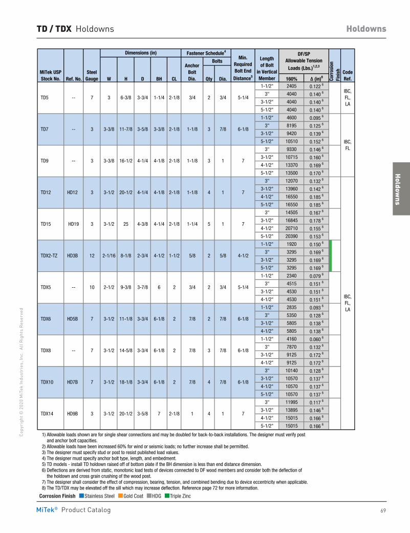
Holdowns
69
Copy
righ
t © 2
020
MiT
ek In
dust
ries
, Inc
. Al
l Rig
hts
Rese
rved
Holdowns
MiTek® Product Catalog
TD / TDX Holdowns
Ref. No. W H D BH CL Qty Dia. 160% Δ (in)8
1-1/2" 2405 0.122 6
3" 4040 0.140 6
3-1/2" 4040 0.140 6
5-1/2" 4040 0.140 6
1-1/2" 4600 0.095 6
3" 8195 0.125 6
3-1/2" 9420 0.139 6
5-1/2" 10510 0.152 6
3" 9330 0.146 6
3-1/2" 10715 0.160 6
4-1/2" 13370 0.169 6
5-1/2" 13500 0.170 6
3" 12070 0.132 6
3-1/2" 13960 0.142 6
4-1/2" 16550 0.185 6
5-1/2" 16550 0.185 6
3" 14505 0.167 6
3-1/2" 16845 0.178 6
4-1/2" 20710 0.155 6
5-1/2" 20390 0.153 6
1-1/2" 1920 0.150 6
3" 3295 0.169 6
3-1/2" 3295 0.169 6
5-1/2" 3295 0.169 6
1-1/2" 2340 0.079 6
3" 4515 0.151 6
3-1/2" 4530 0.151 6
4-1/2" 4530 0.151 6
1-1/2" 2835 0.093 6
3" 5350 0.128 6
3-1/2" 5805 0.138 6
4-1/2" 5805 0.138 6
1-1/2" 4160 0.060 6
3" 7870 0.132 6
3-1/2" 9125 0.172 6
4-1/2" 9125 0.172 6
3" 10140 0.128 6
3-1/2" 10570 0.137 6
4-1/2" 10570 0.137 6
5-1/2" 10570 0.137 6
3" 11995 0.117 6
3-1/2" 13895 0.146 6
4-1/2" 15015 0.166 6
5-1/2" 15015 0.166 6
1) Allowable loads shown are for single shear connections and may be doubled for back-to-back installations. The designer must verify post and anchor bolt capacities. 2) Allowable loads have been increased 60% for wind or seismic loads; no further increase shall be permitted. 3) The designer must specify stud or post to resist published load values. 4) The designer must specify anchor bolt type, length, and embedment. 5) TD models - install TD holdown raised off of bottom plate if the BH dimension is less than end distance dimension. 6) Deflections are derived from static, monotonic load tests of devices connected to DF wood members and consider both the deflection of the holdown and cross grain crushing of the wood post. 7) The designer shall consider the effect of compression, bearing, tension, and combined bending due to device eccentricity when applicable. 8) The TD/TDX may be elevated off the sill which may increase deflection. Reference page 72 for more information.
6-1/8
7
1-1/4
3-3/8
4-1/8
4-1/8
4-1/4
4-1/2
6
6-1/8
6-1/8
IBC,FL
1 1 7
3/4
7/8
7/8
7/8
3/4
7/8
7/8
7/8
5-1/4
6-1/8
6-1/8
6-1/8
1 7
6-1/8
4-1/2
7/8
1 7
1
IBC,FL,LA
3-3/8
3-1/2 20-1/2 3-5/8
2
2
2
2
2-1/8
3-1/2 14-5/8 3-3/4
3-1/2 18-1/8 3-3/4
2-1/2 9-3/8 3-7/8
3-1/2 11-1/8 3-3/4
4-3/8
5/8
7
1-1/8
1-1/8
1-1/4
1-1/8
3
4
3
4
5
2
2
2
4
3/42-1/83-3/4
12
10
7
7
2-1/16 8-1/8 2-3/4
7
1-1/2 5/8
2-1/83-1/2 25
3-1/2 20-1/2 4-1/4 2-1/8
3 2
33
3
3
3
TDX14
--
--
--
HD19
--
--
HD12
HD3B
HD5B
HD7B
HD9B
TDX2-TZ
TDX5
TDX6
TDX8
TDX10
TD5
TD7
3
TD9
TD12
TD15
MiTek USPStock No.
SteelGauge
BoltsAnchor
BoltDia.
CodeRef.
DF/SP Allowable Tension
Loads (Lbs.)1,2,3
Length of Bolt
in VerticalMember
Dimensions (in) Fastener Schedule4
Min.RequiredBolt End
Distance5
5-1/43/46-3/8
3-3/8 11-7/8 3-5/8 2-1/8
16-1/2 4-1/4 2-1/8
7
IBC,FL,LA
Corr
osio
n Fi
nish
Corrosion Finish Stainless Steel Gold Coat HDG Triple Zinc
Corrosion Finish Stainless Steel Gold Coat HDG Triple Zinc
Corrosion Finish Stainless Steel Gold Coat HDG Triple Zinc
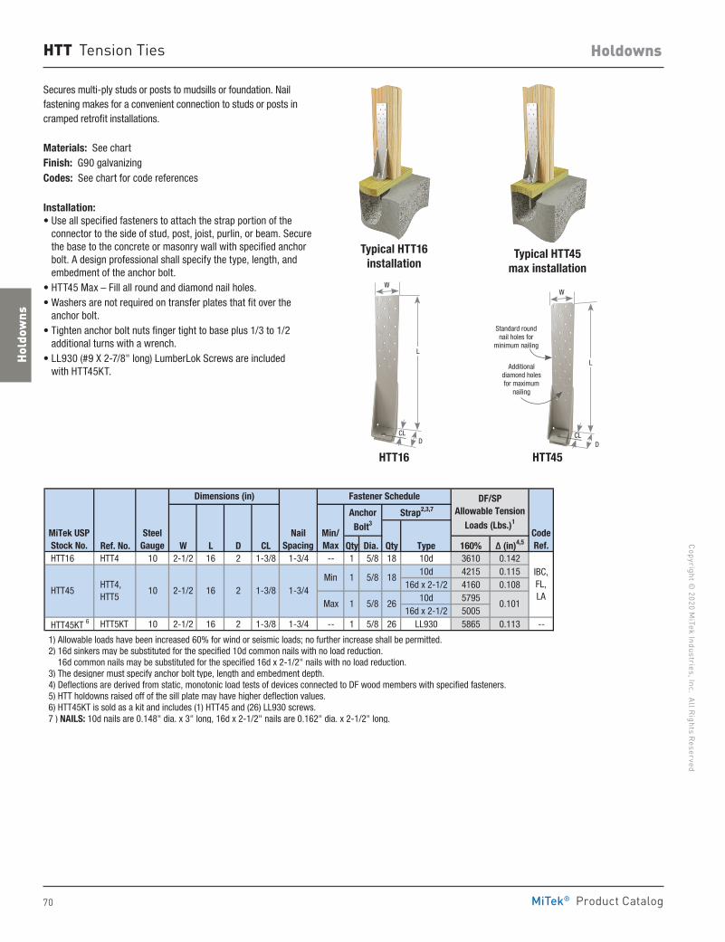
70
Copyright © 2020 M
iTek Industries, Inc. All Rights Reserved
Holdowns
Hold
owns
MiTek® Product Catalog
HTT Tension Ties
Secures multi-ply studs or posts to mudsills or foundation. Nail fastening makes for a convenient connection to studs or posts in cramped retrofit installations.
Materials: See chart Finish: G90 galvanizing Codes: See chart for code references
Installation:• Use all specified fasteners to attach the strap portion of the
connector to the side of stud, post, joist, purlin, or beam. Secure the base to the concrete or masonry wall with specified anchor bolt. A design professional shall specify the type, length, and embedment of the anchor bolt.
• HTT45 Max – Fill all round and diamond nail holes.• Washers are not required on transfer plates that fit over the
anchor bolt.• Tighten anchor bolt nuts finger tight to base plus 1/3 to 1/2
additional turns with a wrench.• LL930 (#9 X 2-7/8" long) LumberLok Screws are included
with HTT45KT.
HTT16 HTT45
Typical HTT45 max installation
Typical HTT16 installation
Ref. No. W L D CL Qty Dia. Qty Type 160% Δ (in)4,5
HTT16 HTT4 10 2-1/2 16 2 1-3/8 1-3/4 -- 1 5/8 18 10d 3610 0.14210d 4215 0.115
16d x 2-1/2 4160 0.10810d 5795
16d x 2-1/2 5005
HTT45KT 6 HTT5KT 10 2-1/2 16 2 1-3/8 1-3/4 -- 1 5/8 26 LL930 5865 0.113 --
1) Allowable loads have been increased 60% for wind or seismic loads; no further increase shall be permitted. 2) 16d sinkers may be substituted for the specified 10d common nails with no load reduction. 16d common nails may be substituted for the specified 16d x 2-1/2" nails with no load reduction. 3) The designer must specify anchor bolt type, length and embedment depth. 4) Deflections are derived from static, monotonic load tests of devices connected to DF wood members with specified fasteners. 5) HTT holdowns raised off of the sill plate may have higher deflection values. 6) HTT45KT is sold as a kit and includes (1) HTT45 and (26) LL930 screws. 7 ) NAILS: 10d nails are 0.148" dia. x 3" long, 16d x 2-1/2" nails are 0.162" dia. x 2-1/2" long.
Min HTT45
1 5/8
1 5/8
HTT4, HTT5
1-3/42-1/2 16 2Max 0.101
SteelGauge
Dimensions (in)
MiTek USPStock No.
CodeRef.
1-3/810
NailSpacing
IBC,FL,LA
AnchorBolt3
Strap2,3,7
18
26
DF/SP Allowable Tension
Loads (Lbs.)1
Fastener Schedule
Min/Max
W
L
DCL
W
L
Standard round nail holes for
minimum nailing
Additional diamond holes for maximum
nailing
DCL
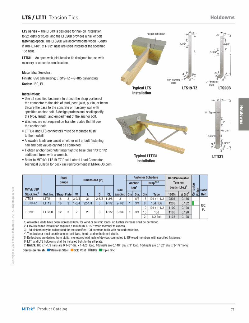
Holdowns
71
Copy
righ
t © 2
020
MiT
ek In
dust
ries
, Inc
. Al
l Rig
hts
Rese
rved
Holdowns
MiTek® Product Catalog
Corrosion Finish Stainless Steel Gold Coat HDG Triple Zinc
Corrosion Finish Stainless Steel Gold Coat HDG Triple Zinc
Corrosion Finish Stainless Steel Gold Coat HDG Triple Zinc
LTS / LTTI Tension Ties
LTS series – The LTS19 is designed for nail-on installation to 2x joists or studs, and the LTS20B provides a nail or bolt fastening option. The LTS20B will accommodate wood I-Joists if 10d (0.148") x 1-1⁄2" nails are used instead of the specified 16d nails.
LTTI31 – An open web joist tension tie designed for use with masonry or concrete construction.
Materials: See chart
Finish: G90 galvanizing; LTS19-TZ – G-185 galvanizing
Codes: IBC, FL
Installation:• Use all specified fasteners to attach the strap portion of
the connector to the side of stud, post, joist, purlin, or beam. Secure the base to the concrete or masonry wall with specified anchor bolt. A design professional shall specify the type, length, and embedment of the anchor bolt.
• Washers are not required on transfer plates that fit over the anchor bolt.
• LTTI31 and LTS connectors must be mounted flush to the mudsill.
• Allowable loads are based on either nail or bolt fastening; nail and bolt values cannot be combined.
• Tighten anchor bolt nuts finger tight to base plus 1/3 to 1/2 additional turns with a wrench.
• Refer to MiTek’s LTS19-TZ Deck Lateral Load Connector Technical Bulletin for deck rail reinforcement at MiTek-US.com.
LTTI31
LTS20BLTS19-TZTypical LTS installation
Typical LTTI31 installation
Ref. No. Strap Plate W L D CL Qty Dia. Qty Type 160% Δ (in)5
LTTI31 LTTI31 18 3 3-3/4 31 2-5/8 1-3/8 3 1 5/8 18 10d x 1-1/2 2805 0.175 LTS19-TZ LTT19 16 3 1-3/4 22-1/4 3 1-1/2 2-1/2 1 3/4 8 10d HDG 1205 0.132
10 10d x 1-1/2 1100 0.12810 16d 1105 0.1282 1/2 Bolt 1175 0.128
1) Allowable loads have been increased 60% for wind or seismic loads; no further increase shall be permitted. 2) LTS20B bolted installation requires a minimum 1-1/2" wood member thickness. 3) 16d sinkers may be substituted for the specified 10d common nails with no load reduction. 4) The designer must specify anchor bolt type, length and embedment depth. 5) Deflections are derived from static, monotonic load tests of devices connected to DF wood members with specified fasteners. 6) LTTI and LTS holdowns shall be installed tight to the sill plate. 7) NAILS: 10d x 1-1/2 nails are 0.148" dia. x 1-1/2" long, 10d nails are 0.148" dia. x 3" long, 16d nails are 0.162" dia. x 3-1/2" long.
SteelGauge
LTS20B LTT20B
MiTek USPStock No.6
CodeRef.
12
Fastener Schedule
NailSpacing
1-1/2 3-3/4 1
Dimensions (in)
3 2 20 3
AnchorBolt4
Strap2,3,7
IBC,FL
3/4
DF/SPAllowable Tension
Loads (Lbs.)1
Corr
osio
n Fi
nish
Hanger not shown
1/4" transfer plate
W
L
DCL
2-1/2"
1/4" transfer plate
W
L
DCL
3-3/4"
6-1/4"
W
L
D
6-3/16"
6"
3/8" Typ.
2-3/8"
11/16"
CL
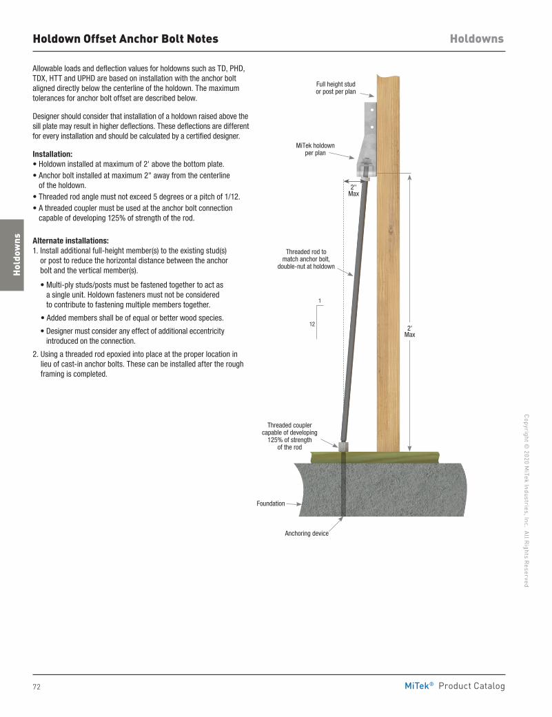
72
Copyright © 2020 M
iTek Industries, Inc. All Rights Reserved
Holdowns
Hold
owns
MiTek® Product Catalog
Allowable loads and deflection values for holdowns such as TD, PHD, TDX, HTT and UPHD are based on installation with the anchor bolt aligned directly below the centerline of the holdown. The maximum tolerances for anchor bolt offset are described below.
Designer should consider that installation of a holdown raised above the sill plate may result in higher deflections. These deflections are different for every installation and should be calculated by a certified designer.
Installation:• Holdown installed at maximum of 2' above the bottom plate.• Anchor bolt installed at maximum 2" away from the centerline
of the holdown.• Threaded rod angle must not exceed 5 degrees or a pitch of 1/12. • A threaded coupler must be used at the anchor bolt connection
capable of developing 125% of strength of the rod.
Alternate installations: 1. Install additional full-height member(s) to the existing stud(s)
or post to reduce the horizontal distance between the anchor bolt and the vertical member(s). • Multi-ply studs/posts must be fastened together to act as
a single unit. Holdown fasteners must not be considered to contribute to fastening multiple members together.
• Added members shall be of equal or better wood species.
• Designer must consider any effect of additional eccentricity introduced on the connection.
2. Using a threaded rod epoxied into place at the proper location in lieu of cast-in anchor bolts. These can be installed after the rough framing is completed.
Holdown Offset Anchor Bolt Notes
Full height stud or post per plan
MiTek holdown per plan
Threaded rod to match anchor bolt,
double-nut at holdown
Threaded coupler capable of developing
125% of strength of the rod
Foundation
Anchoring device
2"Max
2' Max
1
12
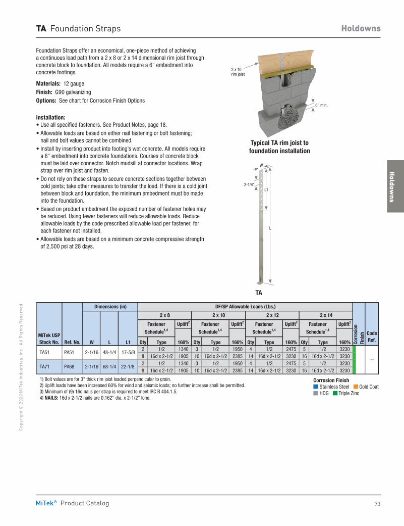
Holdowns
73
Copy
righ
t © 2
020
MiT
ek In
dust
ries
, Inc
. Al
l Rig
hts
Rese
rved
Holdowns
MiTek® Product Catalog
TA Foundation Straps
Foundation Straps offer an economical, one-piece method of achieving a continuous load path from a 2 x 8 or 2 x 14 dimensional rim joist through concrete block to foundation. All models require a 6" embedment into concrete footings.
Materials: 12 gaugeFinish: G90 galvanizingOptions: See chart for Corrosion Finish Options
Installation:• Use all specified fasteners. See Product Notes, page 18.• Allowable loads are based on either nail fastening or bolt fastening;
nail and bolt values cannot be combined.• Install by inserting product into footing’s wet concrete. All models require
a 6" embedment into concrete foundations. Courses of concrete block must be laid over connector. Notch mudsill at connector locations. Wrap strap over rim joist and fasten.
• Do not rely on these straps to secure concrete sections together between cold joints; take other measures to transfer the load. If there is a cold joint between block and foundation, the minimum embedment must be made into the foundation.
• Based on product embedment the exposed number of fastener holes may be reduced. Using fewer fasteners will reduce allowable loads. Reduce allowable loads by the code prescribed allowable load per fastener, for each fastener not installed.
• Allowable loads are based on a minimum concrete compressive strength of 2,500 psi at 28 days.
Typical TA rim joist to foundation installation
6" min.
2 x 10 rim joist
Uplift2 Uplift2 Uplift2 Uplift2
W L L1 Qty Type 160% Qty Type 160% Qty Type 160% Qty Type 160%2 1/2 1340 3 1/2 1950 4 1/2 2475 5 1/2 32308 16d x 2-1/2 1905 10 16d x 2-1/2 2385 14 16d x 2-1/2 3230 16 16d x 2-1/2 32302 1/2 1340 3 1/2 1950 4 1/2 2475 5 1/2 32308 16d x 2-1/2 1905 10 16d x 2-1/2 2385 14 16d x 2-1/2 3230 16 16d x 2-1/2 3230
1) Bolt values are for 3" thick rim joist loaded perpendicular to grain. 2) Uplift loads have been increased 60% for wind and seismic loads; no further increase shall be permitted. 3) Minimum of (9) 16d nails per strap is required to meet IRC R 404.1.5. 4) NAILS: 16d x 2-1/2 nails are 0.162" dia. x 2-1/2" long.
TA71 PA68 2-1/16 68-1/4 22-1/8
TA51 PA51 2-1/16 48-1/4 17-5/8--
Corr
osio
n Fi
nish Code
Ref.
DF/SP Allowable Loads (Lbs.)Dimensions (in)
2 x 142 x 8 2 x 10 2 x 12
Fastener
Schedule1,4
MiTek USPStock No. Ref. No.
Fastener
Schedule1,4
Fastener
Schedule1,4
Fastener
Schedule1,4
TA
Corrosion Finish Stainless Steel Gold Coat HDG Triple Zinc
Corrosion Finish Stainless Steel Gold Coat HDG Triple Zinc
Corrosion Finish Stainless Steel Gold Coat HDG Triple Zinc
L
L1
W
2-1/4"
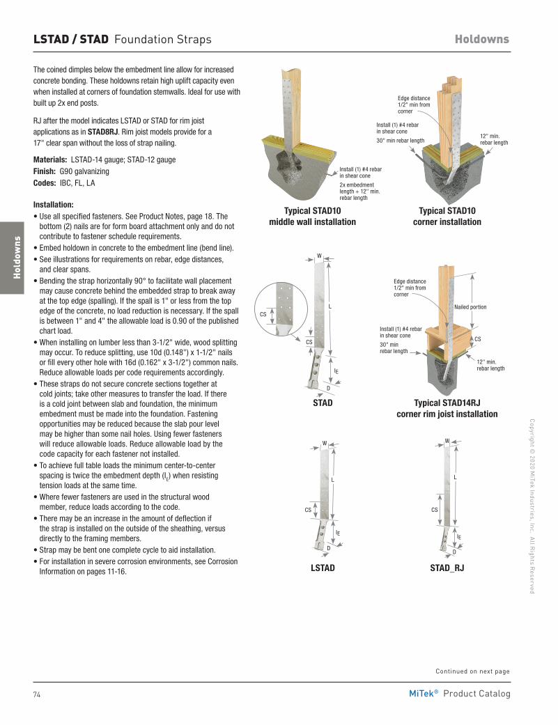
74
Copyright © 2020 M
iTek Industries, Inc. All Rights Reserved
Holdowns
Hold
owns
MiTek® Product Catalog
LSTAD / STAD Foundation Straps
The coined dimples below the embedment line allow for increased concrete bonding. These holdowns retain high uplift capacity even when installed at corners of foundation stemwalls. Ideal for use with built up 2x end posts.
RJ after the model indicates LSTAD or STAD for rim joist applications as in STAD8RJ. Rim joist models provide for a 17" clear span without the loss of strap nailing.
Materials: LSTAD-14 gauge; STAD-12 gaugeFinish: G90 galvanizingCodes: IBC, FL, LA
Installation:• Use all specified fasteners. See Product Notes, page 18. The
bottom (2) nails are for form board attachment only and do not contribute to fastener schedule requirements.
• Embed holdown in concrete to the embedment line (bend line).• See illustrations for requirements on rebar, edge distances,
and clear spans.• Bending the strap horizontally 90° to facilitate wall placement
may cause concrete behind the embedded strap to break away at the top edge (spalling). If the spall is 1" or less from the top edge of the concrete, no load reduction is necessary. If the spall is between 1" and 4" the allowable load is 0.90 of the published chart load.
• When installing on lumber less than 3-1/2" wide, wood splitting may occur. To reduce splitting, use 10d (0.148") x 1-1/2" nails or fill every other hole with 16d (0.162" x 3-1/2") common nails. Reduce allowable loads per code requirements accordingly.
• These straps do not secure concrete sections together at cold joints; take other measures to transfer the load. If there is a cold joint between slab and foundation, the minimum embedment must be made into the foundation. Fastening opportunities may be reduced because the slab pour level may be higher than some nail holes. Using fewer fasteners will reduce allowable loads. Reduce allowable load by the code capacity for each fastener not installed.
• To achieve full table loads the minimum center-to-center spacing is twice the embedment depth (IE) when resisting tension loads at the same time.
• Where fewer fasteners are used in the structural wood member, reduce loads according to the code.
• There may be an increase in the amount of deflection if the strap is installed on the outside of the sheathing, versus directly to the framing members.
• Strap may be bent one complete cycle to aid installation.• For installation in severe corrosion environments, see Corrosion
Information on pages 11-16.
Typical STAD10 middle wall installation
Typical STAD10corner installation
LSTAD
STAD
STAD_RJ
Typical STAD14RJcorner rim joist installation
L
CS
W
D
IE
Install (1) #4 rebar in shear cone
2x embedment length + 12" min. rebar length
L
CS
W
D
IE
L
CS
W
D
IE
CS
Edge distance 1/2" min from corner
Install (1) #4 rebar in shear cone
30" min rebar length12" min. rebar length
Edge distance 1/2" min from corner
Nailed portion
CS
Install (1) #4 rebar in shear cone
30" min rebar length
12" min. rebar length
Continued on next page
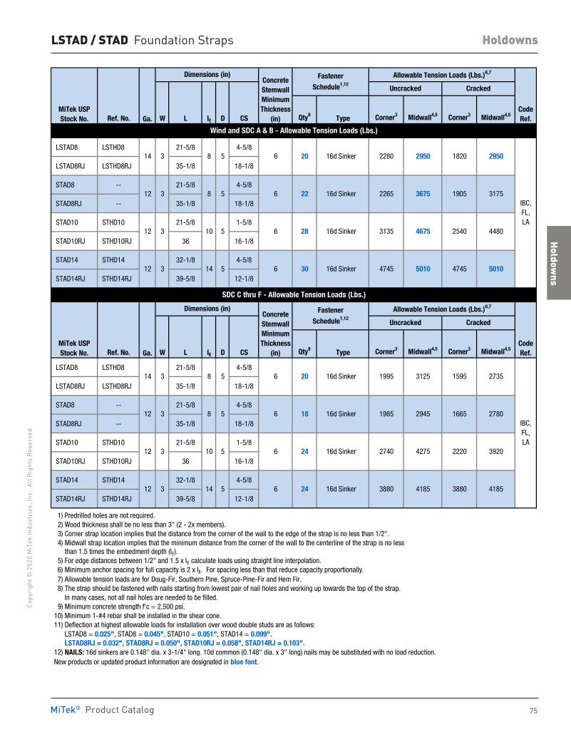
Holdowns
75
Copy
righ
t © 2
020
MiT
ek In
dust
ries
, Inc
. Al
l Rig
hts
Rese
rved
Holdowns
MiTek® Product Catalog
LSTAD / STAD Foundation Straps
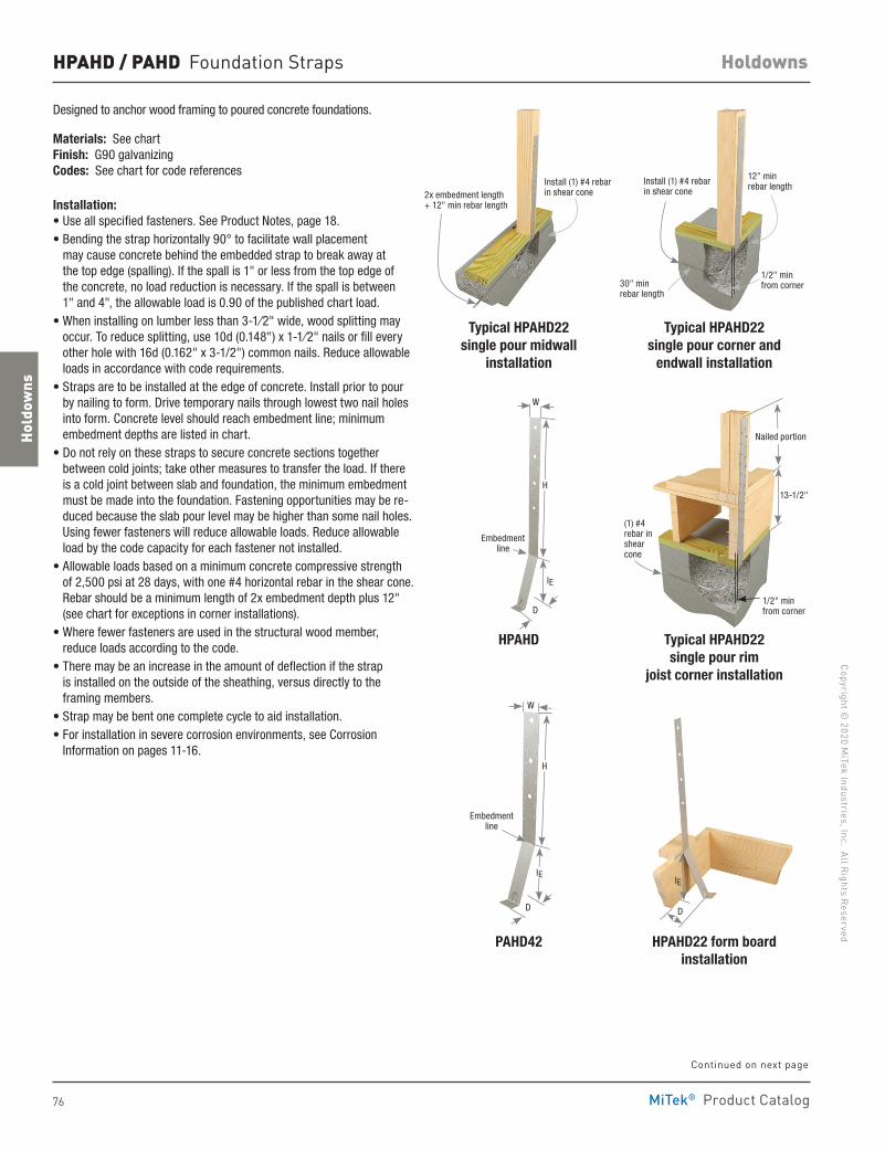
76
Copyright © 2020 M
iTek Industries, Inc. All Rights Reserved
Holdowns
Hold
owns
MiTek® Product Catalog
HPAHD / PAHD Foundation Straps
Designed to anchor wood framing to poured concrete foundations.
Materials: See chart Finish: G90 galvanizing Codes: See chart for code references
Installation:• Use all specified fasteners. See Product Notes, page 18 .• Bending the strap horizontally 90° to facilitate wall placement
may cause concrete behind the embedded strap to break away at the top edge (spalling). If the spall is 1" or less from the top edge of the concrete, no load reduction is necessary. If the spall is between 1" and 4", the allowable load is 0.90 of the published chart load.
• When installing on lumber less than 3-1⁄2" wide, wood splitting may occur. To reduce splitting, use 10d (0.148") x 1-1⁄2" nails or fill every other hole with 16d (0.162" x 3-1/2") common nails. Reduce allowable loads in accordance with code requirements.
• Straps are to be installed at the edge of concrete. Install prior to pour by nailing to form. Drive temporary nails through lowest two nail holes into form. Concrete level should reach embedment line; minimum embedment depths are listed in chart.
• Do not rely on these straps to secure concrete sections together between cold joints; take other measures to transfer the load. If there is a cold joint between slab and foundation, the minimum embedment must be made into the foundation. Fastening opportunities may be re-duced because the slab pour level may be higher than some nail holes. Using fewer fasteners will reduce allowable loads. Reduce allowable load by the code capacity for each fastener not installed.
• Allowable loads based on a minimum concrete compressive strength of 2,500 psi at 28 days, with one #4 horizontal rebar in the shear cone. Rebar should be a minimum length of 2x embedment depth plus 12" (see chart for exceptions in corner installations).
• Where fewer fasteners are used in the structural wood member, reduce loads according to the code.
• There may be an increase in the amount of deflection if the strap is installed on the outside of the sheathing, versus directly to the framing members.
• Strap may be bent one complete cycle to aid installation.• For installation in severe corrosion environments, see Corrosion
Information on pages 11-16.
Typical HPAHD22single pour midwall
installation
Typical HPAHD22single pour corner and
endwall installation
Typical HPAHD22single pour rim
joist corner installation
HPAHD
PAHD42 HPAHD22 form boardinstallation
2x embedment length + 12" min rebar length
Install (1) #4 rebar in shear cone
1/2" min from corner
(1) #4 rebar in shear cone
Nailed portion
13-1/2"
12" min rebar length
1/2" min from corner30" min
rebar length
Install (1) #4 rebar in shear cone
H
W
D
Embedment line
IE
W
Embedment line
H
D
IE
D
IE
Continued on next page
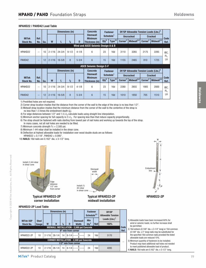
Holdowns
77
Copy
righ
t © 2
020
MiT
ek In
dust
ries
, Inc
. Al
l Rig
hts
Rese
rved
Holdowns
MiTek® Product Catalog
HPAHD / PAHD Foundation Straps
Typical HPAHD22-2Pcorner installation
Typical HPAHD22-2Pmidwall installation
HPAHD22-2P
W L IE D Qty6 Type10 Corner2 Midwall3,4 Corner2 Midwall3,4
W L IE D Qty6 Type10 Corner2 Midwall3,4 Corner2 Midwall3,4
1) Predrilled holes are not required. 2) Corner strap location implies that the distance from the corner of the wall to the edge of the strap is no less than 1/2". 3) Midwall strap location implies that the minimum distance from the corner of the wall to the centerline of the strap is no less than 1.5 times the embedment depth (lE). 4) For edge distances between 1/2" and 1.5 x lE calculate loads using straight line interpolation. 5) Minimum anchor spacing for full capacity is 2 x lE. For spacing less than that reduce capacity proportionally. 6) The strap should be fastened with nails starting from lowest pair of nail holes and working up towards the top of the strap. In many cases, not all nail holes are needed to be filled. 7) Minimum concrete strength f'c = 2,500 psi. 8) Minimum 1-#4 rebar shall be installed in the shear cone. 9) Deflection at highest allowable loads for installation over wood double studs are as follows: HPAHD22 = 0.118", PAHD42 = 0.095".10) NAILS: 16d nails are 0.162" dia. x 3-1/2" long.
1850 705 15105-3/4 6 15 16d 1010
2855 1905 2000 IBC,FL,LA PAHD42 -- 12 2-1/16 16-5/8 8
4-1/8 6 23 16d 2280 HPAHD22 -- 10 2-1/16 24-3/4 9-1/2
PAHD42 --
2-1/16 24-3/4
2-1/16 16-5/8
MiTekStock No. Ga.
Dimensions (in) ConcreteStemwallMinimum
Thickness (in)
FastenerSchedule1
HPAHD22 -- 10 23 16d4-1/89-1/2 6
8 5-3/4
DF/SP Allowable Tension Loads (Lbs.)5
CodeRef.
Uncracked Cracked
IBC,FL,LA6
3110 3265 2175 2285
1155 2465 810 1725
Ref. No.
Ref. No.
CodeRef.
Uncracked Cracked
Wind and ASCE Seismic Design A & B
ASCE Seismic Design C-F
MiTekStock No. Ga.
Dimensions (in) ConcreteStemwallMinimum
Thickness (in)
FastenerSchedule1
DF/SP Allowable Tension Loads (Lbs.)5
12 15 16d
W H IE D Nail 160%
68
68
1) Allowable loads have been increased 60% for wind or seismic loads; no further increase shall be permitted. 2) 16d sinkers (0.148" dia. x 3-1/4" long) or 10d common (0.148" dia. x 3" long) nails may be substituted for the specified 16d common nails provided the listed alowable loads are reduced 15%. 3) Minimum quantity of fasteners to be installed. Product may have additional nail holes not needed to meet published allowable load of product. 4) NAILS: 16d nails are 0.162" dia. x 3-1/2" long.
14 6-1/4 HPAHD22-2P
10 2-1/16
Dimensions (in)
StemwallWidth
FastenerSchedule2,5
CodeRef.
DF/SP Allowable Tension
Loads (Lbs.)1
8" min from corner
MiTek USPStock No.
SteelGauge
MinQty4
MIDWALL INSTALLATION - 2,500 psi Concrete
--
26-1/4 14
16d
16d
4095
1/2" min from corner
6-1/4 HPAHD22-2P 24
CORNER INSTALLATION - 2,500 psi Concrete
2410 2-1/16
5170
26-1/4
1) Allowable loads have been increased 60% for wind or seismic loads; no further increase shall be permitted.
2) 16d sinkers (0.148" dia. x 3-1/4" long) or 10d common (0.148" dia. x 3" long) nails may be substituted for the specified 16d common nails provided the listed allowable loads are reduced 15%.
3) Minimum quantity of fasteners to be installed. Product may have additional nail holes not needed to meet published allowable load of product.
4) NAILS: 16d nails are 0.162" dia. x 3-1/2" long.
Stemwall width
Install (1) #4 rebar in shear cone
Embedment line
H
W
D
IEEdge distance 1/2" min from corner
Install (1) #4 rebar in shear cone
HPAHD22 / PAHD42 Load Table
HPAHD22-2P Load Table
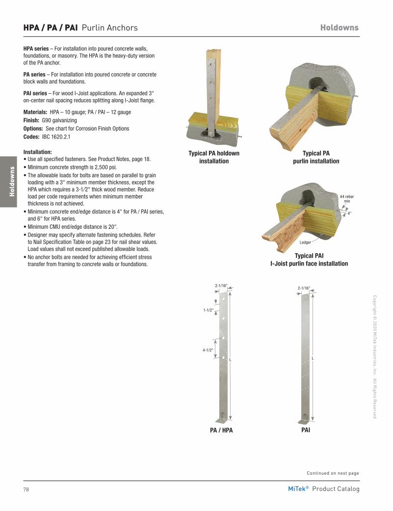
78
Copyright © 2020 M
iTek Industries, Inc. All Rights Reserved
Holdowns
Hold
owns
MiTek® Product Catalog
HPA / PA / PAI Purlin Anchors
HPA series – For installation into poured concrete walls, foundations, or masonry. The HPA is the heavy-duty version of the PA anchor.
PA series – For installation into poured concrete or concrete block walls and foundations.
PAI series – For wood I-Joist applications. An expanded 3" on-center nail spacing reduces splitting along I-Joist flange.
Materials: HPA – 10 gauge; PA / PAI – 12 gaugeFinish: G90 galvanizingOptions: See chart for Corrosion Finish OptionsCodes: IBC 1620.2.1
Installation:• Use all specified fasteners. See Product Notes, page 18.• Minimum concrete strength is 2,500 psi.• The allowable loads for bolts are based on parallel to grain
loading with a 3" minimum member thickness, except the HPA which requires a 3-1⁄2" thick wood member. Reduce load per code requirements when minimum member thickness is not achieved.
• Minimum concrete end/edge distance is 4" for PA / PAI series, and 6" for HPA series.
• Minimum CMU end/edge distance is 20".• Designer may specify alternate fastening schedules. Refer
to Nail Specification Table on page 23 for nail shear values. Load values shall not exceed published allowable loads.
• No anchor bolts are needed for achieving efficient stress transfer from framing to concrete walls or foundations.
Typical PA holdown installation
Typical PA purlin installation
Typical PAI I-Joist purlin face installation
Ledger
#4 rebar min
4"
PA / HPA
L
2-1/16"
1-1/2"
4-1/2"
PAI
L
2-1/16"
Continued on next page
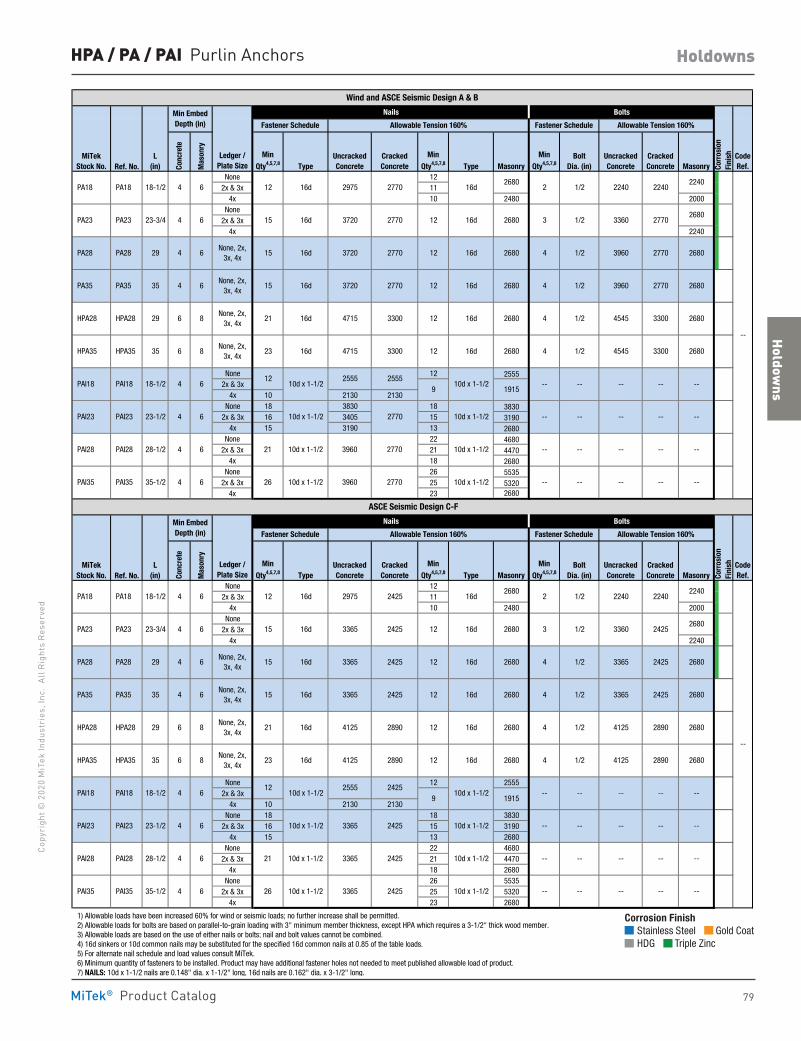
Holdowns
79
Copy
righ
t © 2
020
MiT
ek In
dust
ries
, Inc
. Al
l Rig
hts
Rese
rved
Holdowns
MiTek® Product Catalog
Ref. No.None 12
2x & 3x 114x 10 2480 2000
None2x & 3x
4x 2240
None 12 25552x & 3x
4x 10 2130 2130None 18 3830 18 3830
2x & 3x 16 3405 15 31904x 15 3190 13 2680
None 22 46802x & 3x 21 4470
4x 18 2680None 26 5535
2x & 3x 25 53204x 23 2680
Ref. No.None 12
2x & 3x 114x 10 2480 2000
None2x & 3x
4x 2240
None 12 25552x & 3x
4x 10 2130 2130None 18 18 3830
2x & 3x 16 15 31904x 15 13 2680
None 22 46802x & 3x 21 4470
4x 18 2680None 26 5535
2x & 3x 25 53204x 23 2680
1) Allowable loads have been increased 60% for wind or seismic loads; no further increase shall be permitted. 2) Allowable loads for bolts are based on parallel-to-grain loading with 3" minimum member thickness, except HPA which requires a 3-1/2" thick wood member. 3) Allowable loads are based on the use of either nails or bolts; nail and bolt values cannot be combined. 4) 16d sinkers or 10d common nails may be substituted for the specified 16d common nails at 0.85 of the table loads. 5) For alternate nail schedule and load values consult MiTek. 6) Minimum quantity of fasteners to be installed. Product may have additional fastener holes not needed to meet published allowable load of product. 7) NAILS: 10d x 1-1/2 nails are 0.148" dia. x 1-1/2" long, 16d nails are 0.162" dia. x 3-1/2" long.
2680
10d x 1-1/212
10d x 1-1/22555 2425
9 1915
10d x 1-1/2 3365 2425 10d x 1-1/2
2680
2680
--
--
3365 2425
3365 2425
3365 2425
2680
2680
2770
3960 2770
4545 3300
4545 3300
-- --
--
--
--
--
--
CodeRef.
2680
2680
Corr
osio
nFi
nishMin
Qty4,5,7,8Bolt
Dia. (in)UncrackedConcrete
CrackedConcrete Masonry
2890
2425
2890
2425
24253 1/2 336012 16d
12 16d
12 16d
MiTekStock No.
L(in)
Min
Qty4,5,7,8 TypeUncrackedConcrete
CrackedConcrete
Min
Qty4,5,7,8 Type
15 PA23 PA23 23-3/4 4 6 16d
PA18 PA18
10d x 1-1/2 2770
16d
16d
16d
16d
16d
Min
Qty4,5,7,8UncrackedConcrete
CrackedConcreteType
Min
Qty4,5,7,8 Type
3720 2770
3720
12 16d 2975 2770
10d x 1-1/2
12
10d x 1-1/2
10d x 1-1/2 3960 2770
Min
Qty4,5,7,8Bolt
Dia. (in)Masonry Masonry
2680
Min EmbedDepth (in)
Nails Bolts
Allowable Tension 160% Fastener Schedule Allowable Tension 160%
2 1/2
--
2680
2680
2680
2680
2240 2240
3360
CrackedConcrete
--
None, 2x,3x, 4x
None, 2x,3x, 4x
None, 2x,3x, 4x
None, 2x,3x, 4x
12
12
12
12
12 4 1/2
1/2
2555 2555
2770
10d x 1-1/2
10d x 1-1/2
1915910d x 1-1/2
10d x 1-1/2
2770
39602770
3720 2770
4715 3300
ASCE Seismic Design C-F
2680
2680
2680
2680
--
--
--
-- --
--
--
--
--
--3960
--
--
--
4715 3300
PAI35 PAI35 35-1/2 4 6 --
PAI23 PAI23 23-1/2 4 6
4
15 PA35 PA35 35 4 6 4
18-1/2 4 6
-- -- --3365 242526 10d x 1-1/2
10d x 1-1/2
10d x 1-1/2
-- -- --
PAI28 PAI28 28-1/2 4 6 -- -- -- --3365 242521 10d x 1-1/2
--
None, 2x,3x, 4x
4125 2890 268023 12 16d HPA35 HPA35 35 6 8 4 1/216d 4125
1/216d 4125
PAI18 PAI18 18-1/2 4 6 -- --
None, 2x,3x, 4x
4125 2890 268021 12 16d HPA28 HPA28 29 6 8
1/216d 3365None, 2x,
3x, 4x
PA28 PA28 29 4 6 4 1/216d 3365None, 2x,
3x, 4x15
2680
2 1/2 2240 2240
Min EmbedDepth (in) Fastener Schedule
Nails Bolts
Ledger /Plate Size
Allowable Tension 160% Fastener Schedule Allowable Tension 160%
Conc
rete
Mas
onry
2975 242512 16d 16d2680 2240
Masonry
Wind and ASCE Seismic Design A & B
Ledger /Plate Size
CodeRef.
16d
--
1/2
16d
16d
3
6
15 4
--
16d
1/2
--
15 416d 1/2
21 4
23
UncrackedConcrete
--
L(in)
PAI23 PAI23 23-1/2 4
6
PAI28 PAI28 28-1/2 4
PAI35 PAI35 35-1/2
6
4
6
6
8
6
6
4
PA28 PA28
26
8
HPA35 HPA35 35 6
PAI18 PAI18 18-1/2 4
21
HPA28 HPA28 29 6
29 4
35 4
PA18 18-1/2 PA18
PA23 PA23 23-3/4
PA35 PA35
6 15
4
Corr
osio
nFi
nish
Fastener Schedule
268016d
2240
2680
MiTekStock No. Co
ncre
te
Mas
onry
HPA / PA / PAI Purlin Anchors
Corrosion Finish Stainless Steel Gold Coat HDG Triple Zinc
Corrosion Finish Stainless Steel Gold Coat HDG Triple Zinc
Corrosion Finish Stainless Steel Gold Coat HDG Triple Zinc
80
Copyright © 2020 M
iTek Industries, Inc. All Rights Reserved
Caps & Bases
Caps
& B
ases
MiTek® Product Catalog
Caps & Bases
Column Bases 88-91 Column Caps 99-105 Post Anchors 82-85, 92Post Bases 86-87, 98Post Caps 93-97
pg. 82-105
Caps & Bases
81
Copy
righ
t © 2
020
MiT
ek In
dust
ries
, Inc
. Al
l Rig
hts
Rese
rved
Caps & Bases
MiTek® Product Catalog
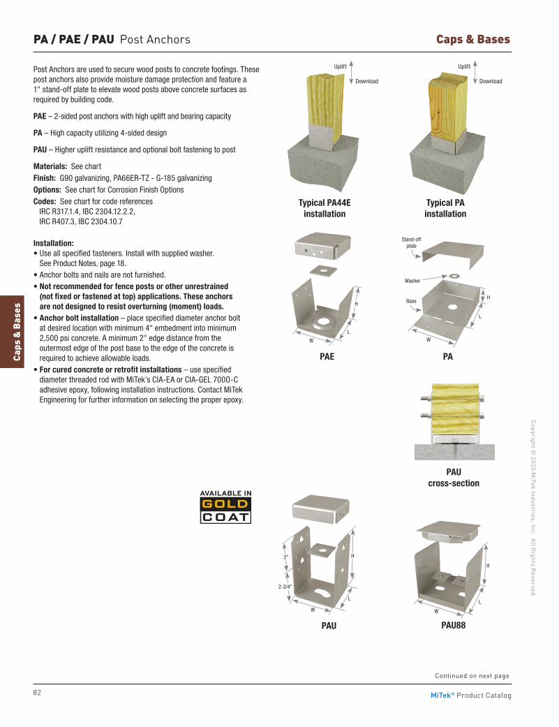
82
Copyright © 2020 M
iTek Industries, Inc. All Rights Reserved
Caps & Bases
Caps
& B
ases
MiTek® Product Catalog
PA / PAE / PAU Post Anchors
Post Anchors are used to secure wood posts to concrete footings. These post anchors also provide moisture damage protection and feature a 1" stand-off plate to elevate wood posts above concrete surfaces as required by building code.
PAE – 2-sided post anchors with high uplift and bearing capacity
PA – High capacity utilizing 4-sided design
PAU – Higher uplift resistance and optional bolt fastening to post
Materials: See chartFinish: G90 galvanizing, PA66ER-TZ - G-185 galvanizingOptions: See chart for Corrosion Finish OptionsCodes: See chart for code references IRC R317.1.4, IBC 2304.12.2.2,
IRC R407.3, IBC 2304.10.7
Installation: • Use all specified fasteners. Install with supplied washer.
See Product Notes, page 18.• Anchor bolts and nails are not furnished.• Not recommended for fence posts or other unrestrained
(not fixed or fastened at top) applications. These anchors are not designed to resist overturning (moment) loads.
• Anchor bolt installation – place specified diameter anchor bolt at desired location with minimum 4" embedment into minimum 2,500 psi concrete. A minimum 2" edge distance from the outermost edge of the post base to the edge of the concrete is required to achieve allowable loads.
• For cured concrete or retrofit installations – use specified diameter threaded rod with MiTek’s CIA-EA or CIA-GEL 700O-C adhesive epoxy, following installation instructions. Contact MiTek Engineering for further information on selecting the proper epoxy.
Typical PA44Einstallation
PAU88
PAUcross-section
Typical PAinstallation
PAU
W W
L
H
L
H
Uplift Uplift
Download Download
PAPAE
W W
L
H
L
Base
Washer
Stand-off plate
H
2-3/4"
2"
Continued on next page
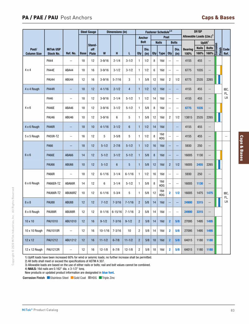
Caps & Bases
83
Copy
righ
t © 2
020
MiT
ek In
dust
ries
, Inc
. Al
l Rig
hts
Rese
rved
Caps & Bases
MiTek® Product Catalog
PA / PAE / PAU Post Anchors
Nails Bolts
Ref. No. Base W H L Qty Qty Type Qty 160% 160%
PA44 -- 18 12 3-9/16 2-1/4 3-1/2 1 1/2 8 16d -- -- 4155 455 --
PA44E ABA44 18 16 3-9/16 3-1/2 3-1/2 1 1/2 6 16d -- -- 6775 1035 --
PAU44 ABU44 12 16 3-9/16 5-7/16 3 1 5/8 12 16d 2 1/2 6775 2535 2265
4 x 4 Rough PA44R -- 18 12 4-1/16 2-1/2 4 1 1/2 12 16d -- -- 4155 455 --
PA46 -- 18 12 3-9/16 2-1/4 5-1/2 1 1/2 14 16d -- -- 4155 455 --
PA46E ABA46 18 12 3-9/16 3-1/2 5-1/2 1 5/8 8 16d -- -- 6775 1035 --
PAU46 ABU46 10 12 3-9/16 6 5 1 5/8 12 16d 2 1/2 13815 2535 2265
4 x 6 Rough PA46R -- 18 10 4-1/16 3-1/2 6 1 1/2 14 16d -- 4155 455 --
5 x 5 Rough PA55R-TZ -- 16 12 5 3-5/8 5 1 1/2 816d HDG
-- -- 4155 455 -- --
PA66 -- 18 12 5-1/2 2-7/8 5-1/2 1 1/2 16 16d -- -- 5930 250 --
PA66E ABA66 14 12 5-1/2 3-1/2 5-1/2 1 5/8 8 16d -- -- 16005 1130 --
PAU66 ABU66 10 12 5-1/2 6 5 1 5/8 12 16d 2 1/2 16005 2455 2265
PA66R -- 18 12 6-1/16 3-1/4 6-1/16 1 1/2 16 16d -- -- 5930 250 --
PA66ER-TZ ABA66R 14 12 6 3-1/4 5-1/2 1 5/8 816d HDG
-- -- 16005 1130 --
PAU66R-TZ ABU66RZ 10 12 6-1/16 5-3/4 5 1 5/8 1216d HDG
2 1/2 16005 1475 1475
8 x 8 PAU88 ABU88 12 12 7-1/2 7-3/16 7-1/16 2 5/8 14 16d -- -- 24900 3315 --
8 x 8 Rough PAU88R ABU88R 12 12 8-1/16 6-15/16 7-1/16 2 5/8 14 16d -- -- 24900 3315 --
10 x 10 PAU1010 ABU1010 12 16 9-1/2 7-3/16 9-1/2 2 5/8 14 16d 2 5/8 27095 1495 1495
10 x 10 Rough PAU1010R -- 12 16 10-1/16 7-3/16 10 2 5/8 14 16d 2 5/8 27095 1495 1495
12 x 12 PAU1212 ABU1212 12 16 11-1/2 6-7/8 11-1/2 2 5/8 18 16d 2 5/8 64015 1180 1180
12 x 12 Rough PAU1212R -- 12 16 12-1/8 6-7/8 12-1/8 2 5/8 18 16d 2 5/8 64015 1180 1180
1) Uplift loads have been increased 60% for wind or seismic loads; no further increase shall be permitted. 2) All bolts shall meet or exceed the specifications of ASTM A 307. 3) Allowable loads are based on the use of either nails or bolts; nail and bolt values cannot be combined. 4) NAILS: 16d nails are 0.162" dia. x 3-1/2" long. New products or updated product information are designated in blue font.
Dia.(in)
Post/Column Size
CodeRef.
Nails Bolts
MiTek USPStock No.
AnchorBolt
Corr
osio
nFi
nish
Dimensions (in) Fastener Schedule2,4
Bearing100%
Steel Gauge
Stand-off
Plate
Uplift1
Post
DF/SPAllowable Loads (Lbs.)3
Dia.(in)
6 x 6 Rough
4 x 4
4 x 6
6 x 6
IBC,FL,LA
IBC,FL,LA
Corrosion Finish Stainless Steel Gold Coat HDG Triple Zinc
Corrosion Finish Stainless Steel Gold Coat HDG Triple Zinc
Corrosion Finish Stainless Steel Gold Coat HDG Triple Zinc
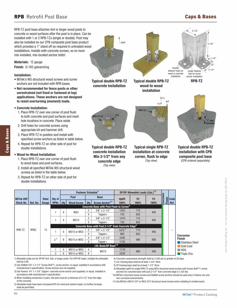
84
Copyright © 2020 M
iTek Industries, Inc. All Rights Reserved
Caps & Bases
Caps
& B
ases
MiTek® Product Catalog
RPB Retrofit Post Base
RPB-TZ post base attaches 4x4 or larger wood posts to concrete or wood surfaces after the post is in place. Can be installed with 1 or 2 RPB-TZs (single or double). Post may also be installed on our CPB composite post base product which provides a 1" stand off as required in untreated wood installations. Installs with concrete screws, so no more mis-installed, mis-located anchor bolts!
Materials: 12 gaugeFinish: G-185 galvanizing
Installation: • MiTek’s WS structural wood screws and screw
anchors are not included with RPB bases. • Not recommended for fence posts or other
unrestrained (not fixed or fastened at top) applications. These anchors are not designed to resist overturning (moment) loads.
• Concrete Installation: 1. Place RPB-TZ over one corner of post flush
to both concrete and post surfaces and mark hole locations in concrete. Place aside.
2. Drill holes for concrete screws using appropriate bit and hammer drill.
3. Place RPB-TZ in position and install with specified screw anchors as listed in table below.
4. Repeat for RPB-TZ on other side of post for double installations.
• Wood-to-Wood Installation: 1. Place RPB-TZ over one corner of post flush
to wood base and post surfaces. 2. Install all specified MiTek WS structural wood
screws as listed in the table below. 3. Repeat for RPB-TZ on other side of post for
double installations.
Ref. No. Qty Wood Screw Qty Screw Anchor2,3
2 3/8" x 2-1/2" 1525 7104 Tapper+ 735 6552 3/8" x 2-1/2" 1470 7104 Tapper+ 735 655
2 3/8" x 2-1/2" 1470 9 7104 Tapper+ 865 6554 3/8" x 2-1/2" 22958 Tapper+ 1735
1 4 WS15 or WS3 4 11102 8 WS15 or WS3 8 2220
1) Allowable loads are for DF/SP 4x4, 6x6, or larger posts. For SPF/HF loads, multiply the allowable load by 0.86. 2) Use DeWalt 3/8" x 2-1/2" Screw-BoltTM+ screw anchor; or equal, installed in accordance with manufacturer's specification. Screw anchors are not supplied. 3) Use Powers 1/4" x 1-3/4" Tapper+ concrete screw anchor (not supplied); or equal, installed in accordance with manufacturer's specification. 4) When installing connectors in pairs, the post must be a minimum of 2-1/2" from the edge of the concrete. 5) Allowable loads have been increased 60% for wind and seiesmic loads; no futher increase shall be permitted. 6) Concrete compressive strength shall be 2,500 psi or greater at 28 days. 7) LVL framing base shall be at least 1-3/4" thick. 8) SP framing base shall be at least 1-1/2" thick. 9) Allowable uplift for single RPB-TZ using WS3 structural wood screws with Screw-BoltTM+ screw anchors for concrete base with post 2-1/2" from concrete edge is 1,525 lbs.10) MiTek's structural wood screws and DeWalt screw anchors should be used only in interior-dry and non-corrosive environments.11) Use MiTek's WS15-EXT or WS3-EXT structural wood screws when installing to treated wood.
495
495
495
495
990990
1 4 WS15
Post Base
RPB-TZ RPBZ 12
Uplift160%
Concrete Base with Post 2-1/2" from Concrete Edge4
MiTek USPStock No.
SteelGauge
1 4 WS15 or WS3
2 5 8 WS15 or WS3
WS15 960
F2160%
CodeRef.
--
Corr
osio
nFi
nish
LVL Base/SP Base7,8
Concrete Base with Post Flush to Corner6
1 4 WS3
DF/SP Allowable Loads (Lbs.)1,5
Qty of RPBs
Fastener Schedule4
F3160%
Typical double RPB-TZ installation with CPB composite post base
(CPB ordered separately)
Typical double RPB-TZ wood-to wood
installation
Typical double RPB-TZconcrete installation Min 2-1/2" from any
concrete edge (Top view)
Typical single RPB-TZ installation at concrete
corner, flush to edge (Top view)
RPB-TZ
1) Allowable loads are for DF/SP 4x4, 6x6, or larger posts. For SPF/HF loads, multiply the allowable load by 0.86.
2) Use DeWalt 3/8" x 2-1/2" Screw-BoltTM+ screw anchor; or equal, installed in accordance with manufacturer's specification. Screw anchors are not supplied.
3) Use Powers 1/4" x 1-3/4" Tapper+ concrete screw anchor (not supplied); or equal, installed in accordance with manufacturer's specification.
4) When installing connectors in pairs, the post must be a minimum of 2-1/2" from the edge of the concrete.
5) Allowable loads have been increased 60% for wind and seismic loads; no further increase shall be permitted.
6) Concrete compressive strength shall be 2,500 psi or greater at 28 days. 7) LVL framing base shall be at least 1-3/4" thick. 8) SP framing base shall be at least 1-1/2" thick. 9) Allowable uplift for single RPB-TZ using WS3 structural wood screws with Screw-BoltTM+ screw
anchors for concrete base with post 2-1/2" from concrete edge is 1,525 lbs.10) MiTek's structural wood screws and DeWalt screw anchors should be used only in interior-dry and
non-corrosive environments.11) Use MiTek's WS15-EXT or WS3-EXT structural wood screws when installing to treated wood.
2-1/2"
2-1/4"
1-1/2"
5-1/8"
Typical double RPB-TZconcrete installation
Uplift
RPB-TZ (2) 4x4
RPB-TZ
4x4F3
F2
Corrosion Finish Stainless Steel Gold Coat HDG Triple Zinc
Corrosion Finish Stainless Steel Gold Coat HDG Triple Zinc
Corrosion Finish Stainless Steel Gold Coat HDG Triple Zinc
1" gapallowed
Smaller fastener holes for wood or concrete
installation
Larger fastener hole for screw
anchor installation
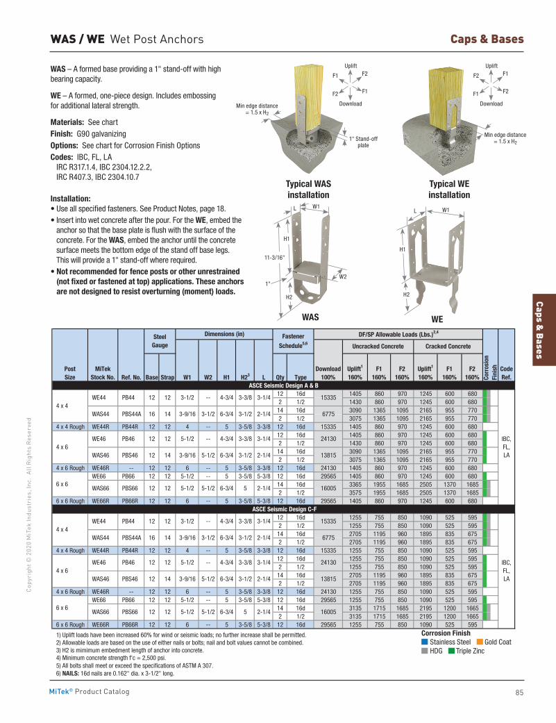
Caps & Bases
85
Copy
righ
t © 2
020
MiT
ek In
dust
ries
, Inc
. Al
l Rig
hts
Rese
rved
Caps & Bases
MiTek® Product Catalog
Ref. No. Base Strap W1 W2 H1 H23 L Qty Type
12 16d 1405 860 970 1245 600 6802 1/2 1430 860 970 1245 600 680
14 16d 3090 1365 1095 2165 955 7702 1/2 3075 1365 1095 2165 955 770
4 x 4 Rough WE44R PB44R 12 12 4 -- 5 3-5/8 3-3/8 12 16d 15335 1405 860 970 1245 600 68012 16d 1405 860 970 1245 600 6802 1/2 1430 860 970 1245 600 680
14 16d 3090 1365 1095 2165 955 7702 1/2 3075 1365 1095 2165 955 770
4 x 6 Rough WE46R -- 12 12 6 -- 5 3-5/8 3-3/8 12 16d 24130 1405 860 970 1245 600 680 WE66 PB66 12 12 5-1/2 -- 5 3-5/8 5-3/8 12 16d 29565 1405 860 970 1245 600 680
14 16d 3365 1955 1685 2505 1370 16852 1/2 3575 1955 1685 2505 1370 1685
6 x 6 Rough WE66R PB66R 12 12 6 -- 5 3-5/8 5-3/8 12 16d 29565 1405 860 970 1245 600 680
12 16d 1255 755 850 1090 525 5952 1/2 1255 755 850 1090 525 595
14 16d 2705 1195 960 1895 835 6752 1/2 2705 1195 960 1895 835 675
4 x 4 Rough WE44R PB44R 12 12 4 -- 5 3-5/8 3-3/8 12 16d 15335 1255 755 850 1090 525 59512 16d 1255 755 850 1090 525 5952 1/2 1255 755 850 1090 525 595
14 16d 2705 1195 960 1895 835 6752 1/2 2705 1195 960 1895 835 675
4 x 6 Rough WE46R -- 12 12 6 -- 5 3-5/8 3-3/8 12 16d 24130 1255 755 850 1090 525 595 WE66 PB66 12 12 5-1/2 -- 5 3-5/8 5-3/8 12 16d 29565 1255 755 850 1090 525 595
14 16d 3135 1715 1685 2195 1200 16652 1/2 3135 1715 1685 2195 1200 1665
6 x 6 Rough WE66R PB66R 12 12 6 -- 5 3-5/8 5-3/8 12 16d 29565 1255 755 850 1090 525 595
1) Uplift loads have been increased 60% for wind or seismic loads; no further increase shall be permitted. 2) Allowable loads are based on the use of either nails or bolts; nail and bolt values cannot be combined. 3) H2 is mimimum embedment length of anchor into concrete. 4) Minimum concrete strength f'c = 2,500 psi. 5) All bolts shall meet or exceed the specifications of ASTM A 307. 6) NAILS: 16d nails are 0.162" dia. x 3-1/2" long.
Dimensions (in)
16005
15335
24130
15335
24130
6775
6775
13815
13815
16005
5 2-1/4
3-1/2 2-1/4
3-1/4
3-9/16 2-1/4
4 x 6
6 x 65-1/2 5-1/2 6-3/4
5-1/2 -- 4-3/4
12
WAS66 PBS66 12 12
3-9/16 5-1/2 6-3/4 WAS46 PBS46 12 14
3-3/8 3-1/4 IBC,FL,LA
WAS44 PBS44A 16 14 3-9/16 3-1/2 6-3/4 3-1/2 2-1/4
WE46 PB46 12 12
3-1/2 -- 4-3/4 3-3/8 WE44 PB44 12
ASCE Seismic Design C-F
12 12 3-1/45-1/2 --
5-1/2
3-9/16 2-1/4
3-3/8 4 x 6
6 x 6
4 x 4
4-3/4
PBS46
PBS66
14
12
WAS44
WAS46
WAS66
FastenerSchedule5,6
IBC,FL,LA12
12
DF/SP Allowable Loads (Lbs.)2,4
3-1/43-1/2 4-3/4 3-3/8--
SteelGauge
2-1/45
3-1/2
5-1/2
5-1/2
6-3/4
6-3/4
6-3/4
3-1/2
3-1/2
4 x 4
ASCE Seismic Design A & B
WE44
WE46
CodeRef.
MiTekStock No.
PostSize
PB44 12 12
PB46
16 14 PBS44A
Corr
osio
nFi
nish
Cracked ConcreteUncracked Concrete
Download100%
Uplift1
160%F1
160%F2
160%Uplift1
160%F1
160%F2
160%
WAS / WE Wet Post Anchors
WAS – A formed base providing a 1" stand-off with high bearing capacity.
WE – A formed, one-piece design. Includes embossing for additional lateral strength.
Materials: See chartFinish: G90 galvanizingOptions: See chart for Corrosion Finish OptionsCodes: IBC, FL, LA IRC R317.1.4, IBC 2304.12.2.2,
IRC R407.3, IBC 2304.10.7
Installation:• Use all specified fasteners. See Product Notes, page 18. • Insert into wet concrete after the pour. For the WE, embed the
anchor so that the base plate is flush with the surface of the concrete. For the WAS, embed the anchor until the concrete surface meets the bottom edge of the stand off base legs. This will provide a 1" stand-off where required.
• Not recommended for fence posts or other unrestrained (not fixed or fastened at top) applications. These anchors are not designed to resist overturning (moment) loads.
Typical WAS installation
Typical WE installation
WAS WE
W1
1" Stand-off plate
Min edge distance = 1.5 x H2
Min edge distance = 1.5 x H2
LL
H1
H2
11-3/16"
1"W2
H1
H2
W1
Corrosion Finish Stainless Steel Gold Coat HDG Triple Zinc
Corrosion Finish Stainless Steel Gold Coat HDG Triple Zinc
Corrosion Finish Stainless Steel Gold Coat HDG Triple Zinc
F1
F1
F2
F2
Uplift
Download
F2
F2
F1
F1
Uplift
Download
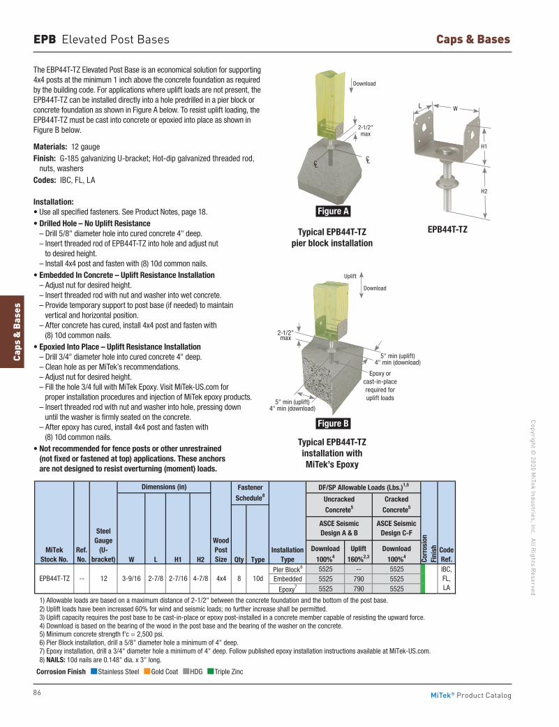
86
Copyright © 2020 M
iTek Industries, Inc. All Rights Reserved
Caps & Bases
Caps
& B
ases
MiTek® Product Catalog
W L H1 H2 Qty TypePier Block6 5525 -- 5525Embedded 5525 790 5525
Epoxy7 5525 790 5525
1) Allowable loads are based on a maximum distance of 2-1/2" between the concrete foundation and the bottom of the post base. 2) Uplift loads have been increased 60% for wind and seismic loads; no further increase shall be permitted. 3) Uplift capacity requires the post base to be cast-in-place or epoxy post-installed in a concrete member capable of resisting the upward force. 4) Download is based on the bearing of the wood in the post base and the bearing of the washer on the concrete. 5) Minimum concrete strength f'c = 2,500 psi. 6) Pier Block installation, drill a 5/8" diameter hole a minimum of 4" deep. 7) Epoxy installation, drill a 3/4" diameter hole a minimum of 4" deep. Follow published epoxy installation instructions available at MiTek-US.com. 8) NAILS: 10d nails are 0.148" dia. x 3" long.
UncrackedConcrete5
ASCE SeismicDesign A & B
Download 100%4
Download 100%4
Fastener Schedule8
DF/SP Allowable Loads (Lbs.)1,5
IBC,FL,LA
InstallationType
8 10d12 3-9/16 2-7/162-7/8 4-7/8
CodeRef.
Uplift 160%2,3 Co
rros
ion
Fini
sh
WoodPostSize
SteelGauge
(U-bracket)
Dimensions (in)
CrackedConcrete5
MiTekStock No.
EPB44T-TZ -- 4x4
Ref. No.
ASCE SeismicDesign C-F
Typical EPB44T-TZ pier block installation
EPB44T-TZ
Typical EPB44T-TZ installation with MiTek’s Epoxy
The EBP44T-TZ Elevated Post Base is an economical solution for supporting 4x4 posts at the minimum 1 inch above the concrete foundation as required by the building code. For applications where uplift loads are not present, the EPB44T-TZ can be installed directly into a hole predrilled in a pier block or concrete foundation as shown in Figure A below. To resist uplift loading, the EPB44T-TZ must be cast into concrete or epoxied into place as shown in Figure B below.
Materials: 12 gaugeFinish: G-185 galvanizing U-bracket; Hot-dip galvanized threaded rod, nuts, washersCodes: IBC, FL, LA
Installation:• Use all specified fasteners. See Product Notes, page 18. • Drilled Hole – No Uplift Resistance
– Drill 5/8" diameter hole into cured concrete 4" deep. – Insert threaded rod of EPB44T-TZ into hole and adjust nut to desired height. – Install 4x4 post and fasten with (8) 10d common nails.
• Embedded In Concrete – Uplift Resistance Installation – Adjust nut for desired height. – Insert threaded rod with nut and washer into wet concrete. – Provide temporary support to post base (if needed) to maintain vertical and horizontal position. – After concrete has cured, install 4x4 post and fasten with (8) 10d common nails.
• Epoxied Into Place – Uplift Resistance Installation – Drill 3/4" diameter hole into cured concrete 4" deep. – Clean hole as per MiTek’s recommendations. – Adjust nut for desired height. – Fill the hole 3/4 full with MiTek Epoxy. Visit MiTek-US.com for proper installation procedures and injection of MiTek epoxy products. – Insert threaded rod with nut and washer into hole, pressing down until the washer is firmly seated on the concrete. – After epoxy has cured, install 4x4 post and fasten with (8) 10d common nails.
• Not recommended for fence posts or other unrestrained (not fixed or fastened at top) applications. These anchors are not designed to resist overturning (moment) loads.
EPB Elevated Post Bases
Corrosion Finish Stainless Steel Gold Coat HDG Triple Zinc
Corrosion Finish Stainless Steel Gold Coat HDG Triple Zinc
Corrosion Finish Stainless Steel Gold Coat HDG Triple Zinc
L
H1
H2
W
Figure A
Figure B
CL
2-1/2" max
CL
2-1/2" max
5" min (uplift) 4" min (download)
Epoxy or cast-in-place required for uplift loads
Download
Download
Uplift
5" min (uplift) 4" min (download)
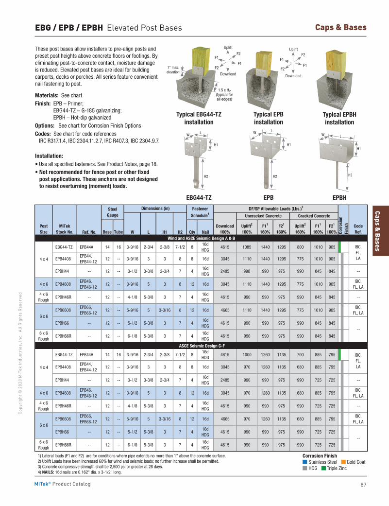
Caps & Bases
87
Copy
righ
t © 2
020
MiT
ek In
dust
ries
, Inc
. Al
l Rig
hts
Rese
rved
Caps & Bases
MiTek® Product Catalog
EBG / EPB / EPBH Elevated Post Bases
These post bases allow installers to pre-align posts and preset post heights above concrete floors or footings. By eliminating post-to-concrete contact, moisture damage is reduced. Elevated post bases are ideal for building carports, decks or porches. All series feature convenient nail fastening to post.
Materials: See chartFinish: EPB – Primer;
EBG44-TZ – G-185 galvanizing; EPBH – Hot-dip galvanized
Options: See chart for Corrosion Finish OptionsCodes: See chart for code references IRC R317.1.4, IBC 2304.11.2.7, IRC R407.3, IBC 2304.9.7.
Installation:• Use all specified fasteners. See Product Notes, page 18. • Not recommended for fence post or other fixed
post applications. These anchors are not designed to resist overturning (moment) loads.
Ref. No. W L H1 H2 Qty Nail
EBG44-TZ EPB44A 14 16 3-9/16 2-3/4 2-3/8 7-1/2 816dHDG
4615 1085 1440 1295 800 1010 905
EPB4408 EPB44, EPB44-12
12 -- 3-9/16 3 3 8 8 16d 3045 1110 1440 1295 775 1010 905
EPBH44 -- 12 -- 3-1/2 3-3/8 2-3/4 7 416dHDG
2485 990 990 975 990 845 845 --
4 x 6 EPB4608 EPB46, EPB46-12
12 -- 3-9/16 5 3 8 12 16d 3045 1110 1440 1295 775 1010 905IBC,
FL, LA
4 x 6Rough
EPBH46R -- 12 -- 4-1/8 5-3/8 3 7 416dHDG
4615 990 990 975 990 845 845 --
EPB6608 EPB66, EPB66-12
12 -- 5-9/16 5 3-3/16 8 12 16d 4665 1110 1440 1295 775 1010 905IBC,
FL, LA
EPBH66 -- 12 -- 5-1/2 5-3/8 3 7 416dHDG
4615 990 990 975 990 845 845
6 x 6Rough
EPBH66R -- 12 -- 6-1/8 5-3/8 3 7 416dHDG
4615 990 990 975 990 845 845
EBG44-TZ EPB44A 14 16 3-9/16 2-3/4 2-3/8 7-1/2 816dHDG
4615 1000 1260 1135 700 885 795
EPB4408 EPB44, EPB44-12
12 -- 3-9/16 3 3 8 8 16d 3045 970 1260 1135 680 885 795
EPBH44 -- 12 -- 3-1/2 3-3/8 2-3/4 7 416dHDG
2485 990 990 975 990 725 725 --
4 x 6 EPB4608 EPB46, EPB46-12
12 -- 3-9/16 5 3 8 12 16d 3045 970 1260 1135 680 885 795IBC,
FL, LA
4 x 6Rough
EPBH46R -- 12 -- 4-1/8 5-3/8 3 7 416dHDG
4615 990 990 975 990 725 725 --
EPB6608 EPB66, EPB66-12
12 -- 5-9/16 5 3-3/16 8 12 16d 4665 970 1260 1135 680 885 795IBC,
FL, LA
EPBH66 -- 12 -- 5-1/2 5-3/8 3 7 416dHDG
4615 990 990 975 990 725 725
6 x 6Rough
EPBH66R -- 12 -- 6-1/8 5-3/8 3 7 416dHDG
4615 990 990 975 990 725 725
1) Lateral loads (F1 and F2) are for conditions where pipe extends no more than 1" above the concrete surface. 2) Uplift Loads have been increased 60% for wind and seismic loads; no further increase shall be permitted. 3) Concrete compressive strength shall be 2,500 psi or greater at 28 days. 4) NAILS: 16d nails are 0.162" dia. x 3-1/2" long.
Dimensions (in) DF/SP Allowable Loads (Lbs.)3
TubeWind and ASCE Seismic Design A & B
Corr
osio
nFi
nishPost
SizeCodeRef.
MiTekStock No.
Fastener
Schedule4 Uncracked Concrete
Base
Steel Gauge Cracked Concrete
Download100%
Uplift2
160%F11
160%F21
160%Uplift2
160%F11
160%F21
160%
6 x 6
4 x 4
6 x 6
4 x 4
ASCE Seismic Design C-F
IBC,FL,LA
IBC,FL,LA
--
--
EPBHEBG44-TZ
Typical EPBH installation
Typical EBG44-TZ installation
EPB
Typical EPB installation
Corrosion Finish Stainless Steel Gold Coat HDG Triple Zinc
Corrosion Finish Stainless Steel Gold Coat HDG Triple Zinc
Corrosion Finish Stainless Steel Gold Coat HDG Triple Zinc
W
H1
L
H2
W
H1
L
H2
W
H1
L
H2
1" max. elevation
1.5 x H2 (typical for all edges)
F1
F1
F2
F2
Uplift
Download
F1
F1
F2
F2
Uplift
Download
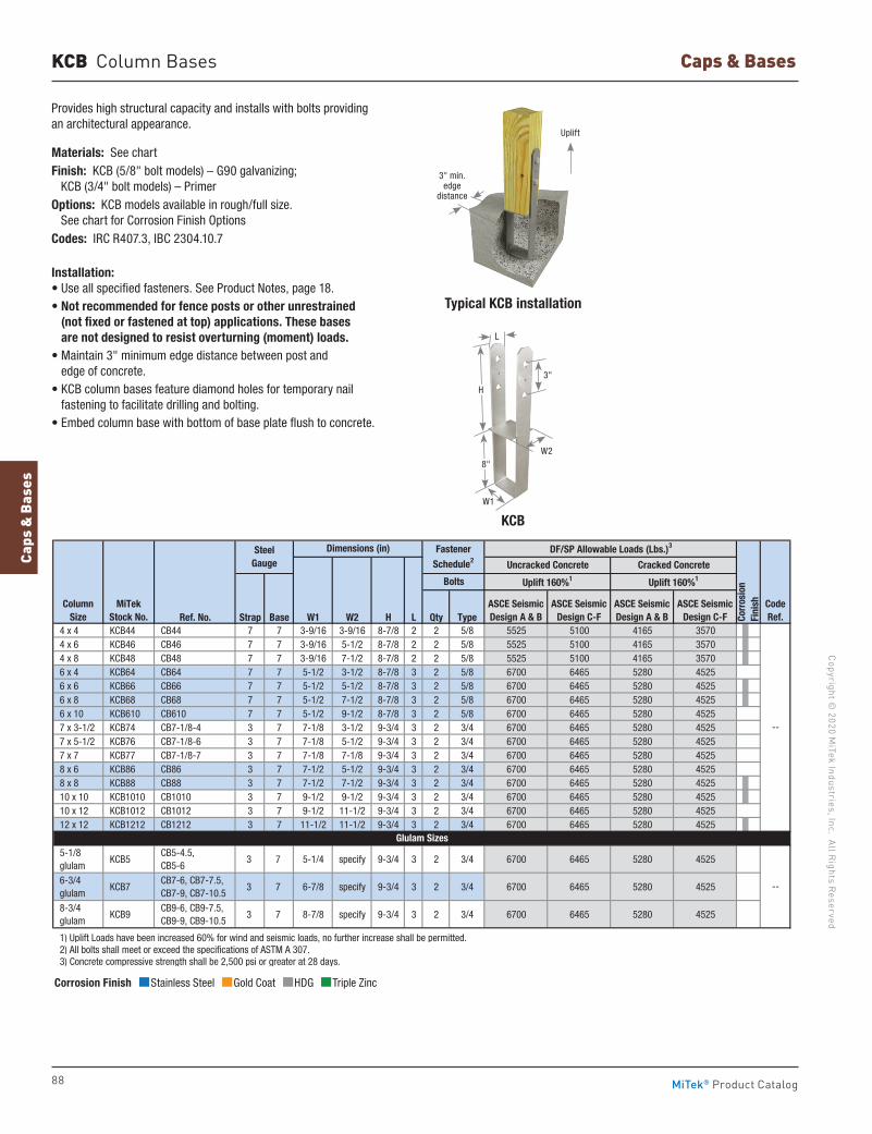
88
Copyright © 2020 M
iTek Industries, Inc. All Rights Reserved
Caps & Bases
Caps
& B
ases
MiTek® Product Catalog
KCB Column Bases
Provides high structural capacity and installs with bolts providing an architectural appearance.
Materials: See chartFinish: KCB (5/8" bolt models) – G90 galvanizing; KCB (3/4" bolt models) – PrimerOptions: KCB models available in rough/full size. See chart for Corrosion Finish OptionsCodes: IRC R407.3, IBC 2304.10.7
Installation:• Use all specified fasteners. See Product Notes, page 18.• Not recommended for fence posts or other unrestrained
(not fixed or fastened at top) applications. These bases are not designed to resist overturning (moment) loads.
• Maintain 3" minimum edge distance between post and edge of concrete.
• KCB column bases feature diamond holes for temporary nail fastening to facilitate drilling and bolting.
• Embed column base with bottom of base plate flush to concrete.
Ref. No. Strap Base W1 W2 H L Qty Type 4 x 4 KCB44 CB44 7 7 3-9/16 3-9/16 8-7/8 2 2 5/8 5525 5100 4165 3570 4 x 6 KCB46 CB46 7 7 3-9/16 5-1/2 8-7/8 2 2 5/8 5525 5100 4165 3570 4 x 8 KCB48 CB48 7 7 3-9/16 7-1/2 8-7/8 2 2 5/8 5525 5100 4165 3570 6 x 4 KCB64 CB64 7 7 5-1/2 3-1/2 8-7/8 3 2 5/8 6700 6465 5280 4525 6 x 6 KCB66 CB66 7 7 5-1/2 5-1/2 8-7/8 3 2 5/8 6700 6465 5280 4525 6 x 8 KCB68 CB68 7 7 5-1/2 7-1/2 8-7/8 3 2 5/8 6700 6465 5280 4525 6 x 10 KCB610 CB610 7 7 5-1/2 9-1/2 8-7/8 3 2 5/8 6700 6465 5280 4525 7 x 3-1/2 KCB74 CB7-1/8-4 3 7 7-1/8 3-1/2 9-3/4 3 2 3/4 6700 6465 5280 4525 7 x 5-1/2 KCB76 CB7-1/8-6 3 7 7-1/8 5-1/2 9-3/4 3 2 3/4 6700 6465 5280 4525 7 x 7 KCB77 CB7-1/8-7 3 7 7-1/8 7-1/8 9-3/4 3 2 3/4 6700 6465 5280 4525 8 x 6 KCB86 CB86 3 7 7-1/2 5-1/2 9-3/4 3 2 3/4 6700 6465 5280 4525 8 x 8 KCB88 CB88 3 7 7-1/2 7-1/2 9-3/4 3 2 3/4 6700 6465 5280 4525 10 x 10 KCB1010 CB1010 3 7 9-1/2 9-1/2 9-3/4 3 2 3/4 6700 6465 5280 4525 10 x 12 KCB1012 CB1012 3 7 9-1/2 11-1/2 9-3/4 3 2 3/4 6700 6465 5280 4525 12 x 12 KCB1212 CB1212 3 7 11-1/2 11-1/2 9-3/4 3 2 3/4 6700 6465 5280 4525
5-1/8 glulam
KCB5 CB5-4.5, CB5-6
3 7 5-1/4 specify 9-3/4 3 2 3/4 6700 6465 5280 4525
6-3/4 glulam
KCB7 CB7-6, CB7-7.5, CB7-9, CB7-10.5
3 7 6-7/8 specify 9-3/4 3 2 3/4 6700 6465 5280 4525
8-3/4 glulam
KCB9 CB9-6, CB9-7.5, CB9-9, CB9-10.5
3 7 8-7/8 specify 9-3/4 3 2 3/4 6700 6465 5280 4525
1) Uplift Loads have been increased 60% for wind and seismic loads, no further increase shall be permitted. 2) All bolts shall meet or exceed the specifications of ASTM A 307. 3) Concrete compressive strength shall be 2,500 psi or greater at 28 days.
ASCE SeismicDesign A & B
ASCE SeismicDesign C-F
ASCE SeismicDesign C-F
Dimensions (in)
--
Column Size
Bolts
Uncracked Concrete Cracked Concrete
Fastener Schedule2
DF/SP Allowable Loads (Lbs.)3
CodeRef.
Glulam Sizes
MiTekStock No.
--
SteelGauge
Corr
osio
nFi
nish
Uplift 160%1 Uplift 160%1
ASCE SeismicDesign A & B
Typical KCB installation
KCB
Corrosion Finish Stainless Steel Gold Coat HDG Triple Zinc
Corrosion Finish Stainless Steel Gold Coat HDG Triple Zinc
Corrosion Finish Stainless Steel Gold Coat HDG Triple Zinc
W2
L
W1
8"
3"
H
3" min.edge
distance
Uplift
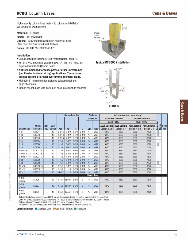
Caps & Bases
89
Copy
righ
t © 2
020
MiT
ek In
dust
ries
, Inc
. Al
l Rig
hts
Rese
rved
Caps & Bases
MiTek® Product Catalog
KCBQ Column Bases
Typical KCBQ66 installation
KCBQ66
High capacity column base fastens to column with MiTek’s WS structural wood screws.
Materials: 10 gaugeFinish: G90 galvanizingOptions: KCBQ models available in rough/full sizes See chart for Corrosion Finish OptionsCodes: IRC R407.3, IBC 2304.10.7
Installation:• Use all specified fasteners. See Product Notes, page 18.• MiTek’s WS2 structural wood screws, 1/4" dia. x 2" long, are
supplied with KCBQ Column Bases.• Not recommended for fence posts or other unrestrained
(not fixed or fastened at top) applications. These bases are not designed to resist overturning (moment) loads.
• Maintain 3" minimum edge distance between post and edge of concrete.
• Embed column base with bottom of base plate flush to concrete.
Corrosion Finish Stainless Steel Gold Coat HDG Triple Zinc
Corrosion Finish Stainless Steel Gold Coat HDG Triple Zinc
Corrosion Finish Stainless Steel Gold Coat HDG Triple Zinc
W1 W24 H L Qty 4 x 4 KCBQ44 -- 10 3-9/16 3-1/2 8-3/4 2-1/4 14 WS2 6870 6530 5330 4570 4 x 6 KCBQ46 -- 10 3-9/16 5-1/2 8-3/4 2-1/4 14 WS2 6870 6530 5330 4570 4 x 8 KCBQ48 -- 10 3-9/16 7-1/2 8-3/4 2-1/4 14 WS2 6870 6530 5330 4570 6 x 4 KCBQ64 -- 10 5-1/2 3-1/2 8-3/4 2-1/4 14 WS2 6870 6530 5330 4570 6 x 6 KCBQ66 -- 10 5-1/2 5-1/2 8-3/4 2-1/4 14 WS2 6870 6530 5330 4570 6 x 8 KCBQ68 -- 10 5-1/2 7-1/2 8-3/4 2-1/4 14 WS2 6870 6530 5330 4570 7-1/8 x 3-1/2 KCBQ71-4 -- 10 7-1/8 3-1/2 8-3/4 2-1/4 14 WS2 6870 6530 5330 4570 7-1/8 x 5-1/2 KCBQ71-6 -- 10 7-1/8 5-1/2 8-3/4 2-1/4 14 WS2 6870 6530 5330 4570 7-1/8 x 7-1/8 KCBQ71-7 -- 10 7-1/8 7-1/8 8-3/4 2-1/4 14 WS2 6870 6530 5330 4570 8 x 6 KCBQ86 -- 10 7-1/2 5-1/2 8-3/4 2-1/4 14 WS2 6870 6530 5330 4570 8 x 8 KCBQ88 -- 10 7-1/2 7-1/2 8-3/4 2-1/4 14 WS2 6870 6530 5330 4570 10 x 10 KCBQ1010 -- 10 9-1/2 9-1/2 8-3/4 2-1/4 14 WS2 6870 6530 5330 4570 10 x 12 KCBQ1012 -- 10 9-1/2 11-1/2 8-3/4 2-1/4 14 WS2 6870 6530 5330 4570 12 x 12 KCBQ1212 -- 10 11-1/2 11-1/2 8-3/4 2-1/4 14 WS2 6870 6530 5330 4570
5-1/8 glulam
KCBQ5 -- 10 5-1/4 Specify 8-3/4 2 14 WS2 6870 6530 5330 4570
6-3/4 glulam
KCBQ7 -- 10 6-7/8 Specify 8-3/4 2 14 WS2 6870 6530 5330 4570
8-3/4 glulam
KCBQ9 -- 10 8-7/8 Specify 8-3/4 2 14 WS2 6870 6530 5330 4570
1) Uplift loads have been increased 60% for wind or seismic loads; no further increase shall be permitted. 2) MiTek's WS2 structural wood screws are 1/4" dia. x 2" long and are included with KCBQ Column Bases. 3) Concrete compressive strength shall be 2,500 psi or greater at 28 days. 4) "Specify" denotes the required width that must be specified at the time of ordering.
ASCE SeismicDesign A & B
ASCE SeismicDesign A & B
ASCE SeismicDesign C-F
ASCE SeismicDesign C-F
Uncracked ConcreteDimensions (in)
--
CodeRef.
Glulam Sizes
TypeColumn SizeMiTek
Stock No.
--
Corr
osio
nFi
nish
Uplift 160%1 Uplift 160%1
Ref. No.
Steel Gauge
Cracked ConcreteFastener
Schedule2DF/SP Allowable Loads (Lbs.)3
L
W2
8"
H
W1
3” min.edge
distance
Uplift
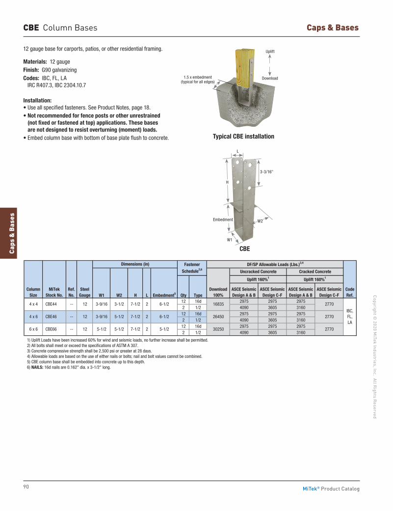
90
Copyright © 2020 M
iTek Industries, Inc. All Rights Reserved
Caps & Bases
Caps
& B
ases
MiTek® Product Catalog
CBE Column Bases
12 gauge base for carports, patios, or other residential framing.
Materials: 12 gaugeFinish: G90 galvanizingCodes: IBC, FL, LA IRC R407.3, IBC 2304.10.7
Installation:• Use all specified fasteners. See Product Notes, page 18.• Not recommended for fence posts or other unrestrained
(not fixed or fastened at top) applications. These bases are not designed to resist overturning (moment) loads.
• Embed column base with bottom of base plate flush to concrete.
W1 W2 H L Embedment5 Qty Type12 16d 2975 2975 29752 1/2 4090 3605 316012 16d 2975 2975 29752 1/2 4090 3605 316012 16d 2975 2975 29752 1/2 4090 3605 3160
1) Uplift Loads have been increased 60% for wind and seismic loads, no further increase shall be permitted. 2) All bolts shall meet or exceed the specifications of ASTM A 307. 3) Concrete compressive strength shall be 2,500 psi or greater at 28 days. 4) Allowable loads are based on the use of either nails or bolts; nail and bolt values cannot be combined. 5) CBE column base shall be embedded into concrete up to this depth. 6) NAILS: 16d nails are 0.162" dia. x 3-1/2" long.
5-1/2
Uplift 160%1
DF/SP Allowable Loads (Lbs.)3,4
26450
30250
2770
2770
2770
Dimensions (in)
Uplift 160%1
3-1/2
5-1/2
5-1/25-1/212
Ref. No.
3-9/16
3-9/16
2
2
2
7-1/2
7-1/2
7-1/26 x 6
CBE44
CBE46
CBE66
--
--
--
4 x 4
4 x 6
CodeRef.
MiTekStock No.
Column Size
SteelGauge
ASCE SeismicDesign A & B
Download100%
1683512
12
6-1/2
6-1/2
ASCE SeismicDesign C-F
ASCE SeismicDesign A & B
ASCE SeismicDesign C-F
IBC,FL,LA
Fastener
Schedule2,6 Uncracked Concrete Cracked Concrete
Typical CBE installation
CBE
1.5 x embedment (typical for all edges)
3-3/16"
H
Embedment
W1
W2
L
Uplift
Download
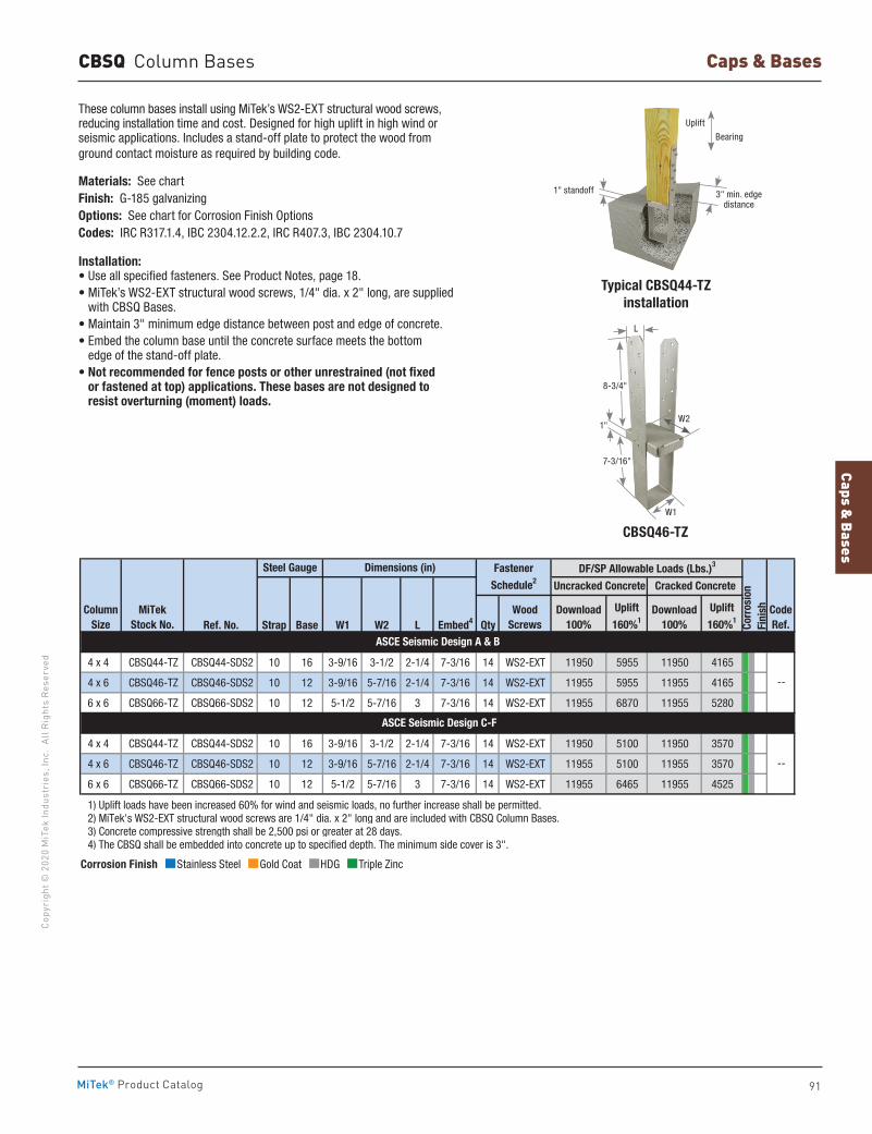
Caps & Bases
91
Copy
righ
t © 2
020
MiT
ek In
dust
ries
, Inc
. Al
l Rig
hts
Rese
rved
Caps & Bases
MiTek® Product Catalog
CBSQ Column Bases
These column bases install using MiTek’s WS2-EXT structural wood screws, reducing installation time and cost. Designed for high uplift in high wind or seismic applications. Includes a stand-off plate to protect the wood from ground contact moisture as required by building code.
Materials: See chartFinish: G-185 galvanizingOptions: See chart for Corrosion Finish OptionsCodes: IRC R317.1.4, IBC 2304.12.2.2, IRC R407.3, IBC 2304.10.7
Installation:• Use all specified fasteners. See Product Notes, page 18.• MiTek’s WS2-EXT structural wood screws, 1/4" dia. x 2" long, are supplied
with CBSQ Bases.• Maintain 3" minimum edge distance between post and edge of concrete.• Embed the column base until the concrete surface meets the bottom
edge of the stand-off plate.• Not recommended for fence posts or other unrestrained (not fixed
or fastened at top) applications. These bases are not designed to resist overturning (moment) loads.
Typical CBSQ44-TZ installation
Ref. No. Strap Base W1 W2 L Embed4 Qty
4 x 4 CBSQ44-TZ CBSQ44-SDS2 10 16 3-9/16 3-1/2 2-1/4 7-3/16 14 WS2-EXT 11950 5955 11950 4165
4 x 6 CBSQ46-TZ CBSQ46-SDS2 10 12 3-9/16 5-7/16 2-1/4 7-3/16 14 WS2-EXT 11955 5955 11955 4165
6 x 6 CBSQ66-TZ CBSQ66-SDS2 10 12 5-1/2 5-7/16 3 7-3/16 14 WS2-EXT 11955 6870 11955 5280
4 x 4 CBSQ44-TZ CBSQ44-SDS2 10 16 3-9/16 3-1/2 2-1/4 7-3/16 14 WS2-EXT 11950 5100 11950 3570
4 x 6 CBSQ46-TZ CBSQ46-SDS2 10 12 3-9/16 5-7/16 2-1/4 7-3/16 14 WS2-EXT 11955 5100 11955 3570
6 x 6 CBSQ66-TZ CBSQ66-SDS2 10 12 5-1/2 5-7/16 3 7-3/16 14 WS2-EXT 11955 6465 11955 4525
1) Uplift loads have been increased 60% for wind and seismic loads, no further increase shall be permitted. 2) MiTek's WS2-EXT structural wood screws are 1/4" dia. x 2" long and are included with CBSQ Column Bases. 3) Concrete compressive strength shall be 2,500 psi or greater at 28 days. 4) The CBSQ shall be embedded into concrete up to specified depth. The minimum side cover is 3".
Fastener
Schedule2
CodeRef.
--
DF/SP Allowable Loads (Lbs.)3
Corr
osio
nFi
nishDownload
100%
Uncracked Concrete Cracked Concrete
Download100%
ASCE Seismic Design A & B
Dimensions (in)Steel Gauge
ASCE Seismic Design C-F
Uplift
160%1
Uplift
160%1
--
WoodScrews
ColumnSize
MiTekStock No.
Corrosion Finish Stainless Steel Gold Coat HDG Triple Zinc
Corrosion Finish Stainless Steel Gold Coat HDG Triple Zinc
Corrosion Finish Stainless Steel Gold Coat HDG Triple Zinc
CBSQ46-TZ
3" min. edge distance
1" standoff
Bearing
L
W21"
W1
7-3/16"
8-3/4"
Uplift
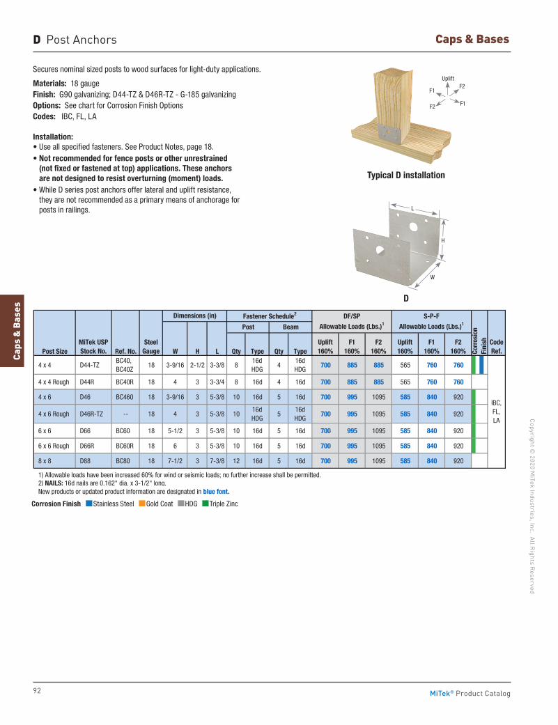
92
Copyright © 2020 M
iTek Industries, Inc. All Rights Reserved
Caps & Bases
Caps
& B
ases
MiTek® Product Catalog
Secures nominal sized posts to wood surfaces for light-duty applications.
Materials: 18 gaugeFinish: G90 galvanizing; D44-TZ & D46R-TZ - G-185 galvanizingOptions: See chart for Corrosion Finish OptionsCodes: IBC, FL, LA
Installation:• Use all specified fasteners. See Product Notes, page 18.• Not recommended for fence posts or other unrestrained
(not fixed or fastened at top) applications. These anchors are not designed to resist overturning (moment) loads.
• While D series post anchors offer lateral and uplift resistance, they are not recommended as a primary means of anchorage for posts in railings.
Typical D installation
D
W
D Post Anchors
Post Size Ref. No. W H L Qty Type Qty Type
4 x 4 D44-TZ BC40, BC40Z
18 3-9/16 2-1/2 3-3/8 816d HDG
416d HDG
700 885 885 565 760 760
4 x 4 Rough D44R BC40R 18 4 3 3-3/4 8 16d 4 16d 700 885 885 565 760 760
4 x 6 D46 BC460 18 3-9/16 3 5-3/8 10 16d 5 16d 700 995 1095 585 840 920
4 x 6 Rough D46R-TZ -- 18 4 3 5-3/8 1016dHDG
516dHDG
700 995 1095 585 840 920
6 x 6 D66 BC60 18 5-1/2 3 5-3/8 10 16d 5 16d 700 995 1095 585 840 920
6 x 6 Rough D66R BC60R 18 6 3 5-3/8 10 16d 5 16d 700 995 1095 585 840 920
8 x 8 D88 BC80 18 7-1/2 3 7-3/8 12 16d 5 16d 700 995 1095 585 840 920
1) Allowable loads have been increased 60% for wind or seismic loads; no further increase shall be permitted. 2) NAILS: 16d nails are 0.162" dia. x 3-1/2" long. New products or updated product information are designated in blue font.
DF/SP Allowable Loads (Lbs.)1
MiTek USPStock No.
SteelGauge
Post Beam
Uplift160%
F1160%
F2160%
Dimensions (in) Fastener Schedule2
IBC, FL, LA
CodeRef.
S-P-FAllowable Loads (Lbs.)1
Corr
osio
nFi
nishUplift
160%F1
160%F2
160%
Corrosion Finish Stainless Steel Gold Coat HDG Triple Zinc
Corrosion Finish Stainless Steel Gold Coat HDG Triple Zinc
Corrosion Finish Stainless Steel Gold Coat HDG Triple Zinc
H
L
F1
F1
F2
F2
Uplift
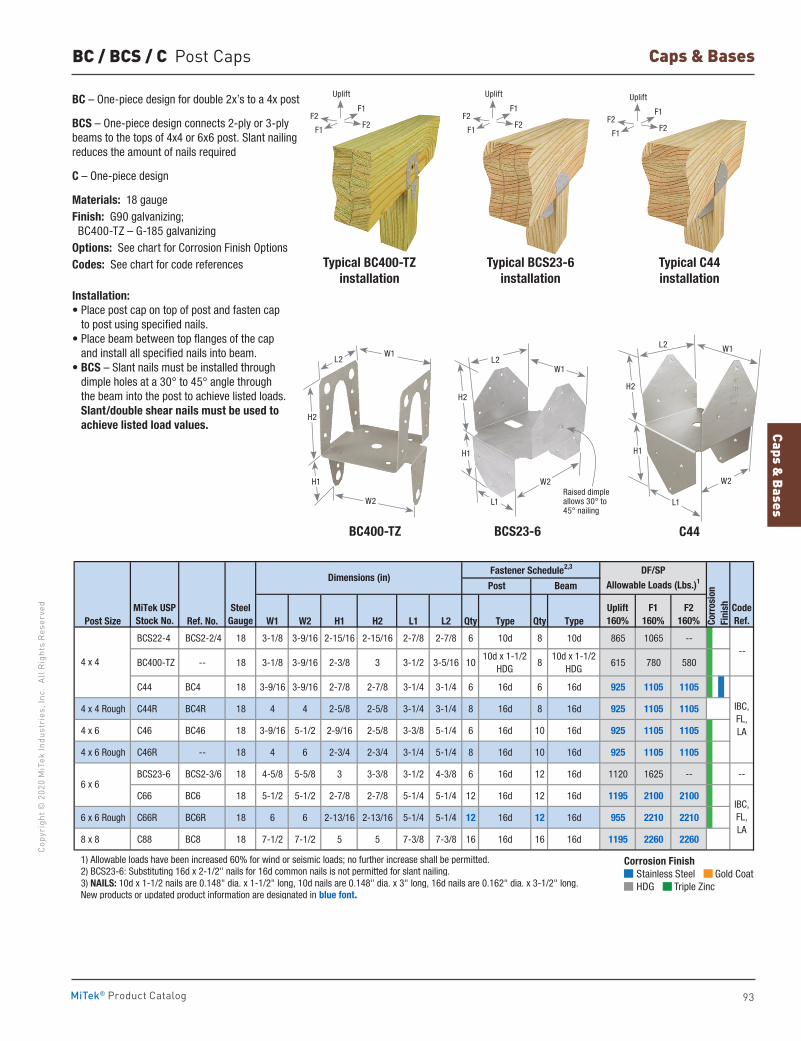
Caps & Bases
93
Copy
righ
t © 2
020
MiT
ek In
dust
ries
, Inc
. Al
l Rig
hts
Rese
rved
Caps & Bases
MiTek® Product Catalog
BC / BCS / C Post Caps
BC – One-piece design for double 2x’s to a 4x post
BCS – One-piece design connects 2-ply or 3-ply beams to the tops of 4x4 or 6x6 post. Slant nailing reduces the amount of nails required
C – One-piece design
Materials: 18 gaugeFinish: G90 galvanizing; BC400-TZ – G-185 galvanizingOptions: See chart for Corrosion Finish OptionsCodes: See chart for code references
Installation:• Place post cap on top of post and fasten cap
to post using specified nails. • Place beam between top flanges of the cap
and install all specified nails into beam.• BCS – Slant nails must be installed through
dimple holes at a 30° to 45° angle through the beam into the post to achieve listed loads. Slant/double shear nails must be used to achieve listed load values.
Typical C44 installation
Typical BC400-TZ installation
Typical BCS23-6 installation
C44BC400-TZ BCS23-6
Post Size Ref. No. W1 W2 H1 H2 L1 L2 Qty Type Qty Type
BCS22-4 BCS2-2/4 18 3-1/8 3-9/16 2-15/16 2-15/16 2-7/8 2-7/8 6 10d 8 10d 865 1065 --
BC400-TZ -- 18 3-1/8 3-9/16 2-3/8 3 3-1/2 3-5/16 1010d x 1-1/2
HDG8
10d x 1-1/2HDG
615 780 580
C44 BC4 18 3-9/16 3-9/16 2-7/8 2-7/8 3-1/4 3-1/4 6 16d 6 16d 925 1105 1105
4 x 4 Rough C44R BC4R 18 4 4 2-5/8 2-5/8 3-1/4 3-1/4 8 16d 8 16d 925 1105 1105
4 x 6 C46 BC46 18 3-9/16 5-1/2 2-9/16 2-5/8 3-3/8 5-1/4 6 16d 10 16d 925 1105 1105
4 x 6 Rough C46R -- 18 4 6 2-3/4 2-3/4 3-1/4 5-1/4 8 16d 10 16d 925 1105 1105
BCS23-6 BCS2-3/6 18 4-5/8 5-5/8 3 3-3/8 3-1/2 4-3/8 6 16d 12 16d 1120 1625 -- --
C66 BC6 18 5-1/2 5-1/2 2-7/8 2-7/8 5-1/4 5-1/4 12 16d 12 16d 1195 2100 2100
6 x 6 Rough C66R BC6R 18 6 6 2-13/16 2-13/16 5-1/4 5-1/4 12 16d 12 16d 955 2210 2210
8 x 8 C88 BC8 18 7-1/2 7-1/2 5 5 7-3/8 7-3/8 16 16d 16 16d 1195 2260 2260
1) Allowable loads have been increased 60% for wind or seismic loads; no further increase shall be permitted. 2) BCS23-6: Substituting 16d x 2-1/2" nails for 16d common nails is not permitted for slant nailing. 3) NAILS: 10d x 1-1/2 nails are 0.148" dia. x 1-1/2" long, 10d nails are 0.148" dia. x 3" long, 16d nails are 0.162" dia. x 3-1/2" long. New products or updated product information are designated in blue font.
--
6 x 6
IBC,FL,LA
IBC,FL,LA
4 x 4
MiTek USPStock No.
SteelGauge
Code Ref.Co
rros
ion
Fini
sh
Dimensions (in)Fastener Schedule2,3
Post Beam
DF/SP Allowable Loads (Lbs.)1
Uplift160%
F1160%
F2160%
Corrosion Finish Stainless Steel Gold Coat HDG Triple Zinc
Corrosion Finish Stainless Steel Gold Coat HDG Triple Zinc
Corrosion Finish Stainless Steel Gold Coat HDG Triple Zinc
W2
W1L2
H2
H1
W1
W2
L2
L1
H2
H1
Raised dimple allows 30° to 45° nailing
H1
H2
L2
L1
W1
W2
F1
F1
F2F2
Uplift
F1
F1
F2F2
Uplift
F1
F1
F2F2
Uplift
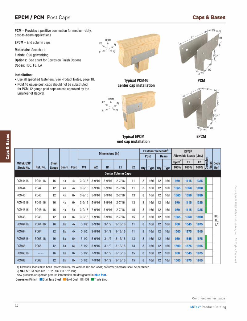
94
Copyright © 2020 M
iTek Industries, Inc. All Rights Reserved
Caps & Bases
Caps
& B
ases
MiTek® Product Catalog
Corrosion Finish Stainless Steel Gold Coat HDG Triple Zinc
Corrosion Finish Stainless Steel Gold Coat HDG Triple Zinc
Corrosion Finish Stainless Steel Gold Coat HDG Triple Zinc
EPCM / PCM Post Caps
PCM – Provides a positive connection for medium-duty, post-to-beam applications
EPCM – End column caps
Materials: See chartFinish: G90 galvanizingOptions: See chart for Corrosion Finish OptionsCodes: IBC, FL, LA
Installation:• Use all specified fasteners. See Product Notes, page 18.• PCM 16 gauge post caps should not be substituted
for PCM 12 gauge post caps unless approved by the Engineer of Record.
Typical PCM46 center cap installation
PCM
Typical EPCM end cap installation
EPCM
L1W2
H1
W1
W2
L1
L2
3-3/4"
L2 H1
3-3/4"
F2
F2
F1
F1
Uplift
F2
F2
F1
F1
Uplift
W1
Continued on next page
Uplift1 F1 F2
Ref. No. Beam Post W1 W2 H1 L1 L2 Qty Type Qty Type 160% 160% 160%
PCM4416 PC44-16 16 4x 4x 3-9/16 3-9/16 3-9/16 2-7/16 11 8 16d 12 16d 970 1115 1335
PCM44 PC44 12 4x 4x 3-9/16 3-9/16 3-9/16 2-7/16 11 8 16d 12 16d 1665 1350 1890
PCM46 PC46 12 4x 6x 3-9/16 5-9/16 3-9/16 2-7/16 13 8 16d 12 16d 1665 1350 1890
PCM4616 PC46-16 16 4x 6x 3-9/16 5-9/16 3-9/16 2-7/16 13 8 16d 12 16d 970 1115 1335
PCM4816 PC48-16 16 4x 8x 3-9/16 7-9/16 3-9/16 2-7/16 15 8 16d 12 16d 970 1115 1335
PCM48 PC48 12 4x 8x 3-9/16 7-9/16 3-9/16 2-7/16 15 8 16d 12 16d 1665 1350 1890
PCM6416 PC64-16 16 6x 4x 5-1/2 3-9/16 3-1/2 3-13/16 11 8 16d 12 16d 950 1545 1675
PCM64 PC64 12 6x 4x 5-1/2 3-9/16 3-1/2 3-13/16 11 8 16d 12 16d 1500 1875 1915
PCM6616 PC66-16 16 6x 6x 5-1/2 5-9/16 3-1/2 3-13/16 13 8 16d 12 16d 950 1545 1675
PCM66 PC66 12 6x 6x 5-1/2 5-9/16 3-1/2 3-13/16 13 8 16d 12 16d 1500 1875 1915
PCM6816 -- -- 16 6x 8x 5-1/2 7-9/16 3-1/2 3-13/16 15 8 16d 12 16d 950 1545 1675
PCM68 PC68 12 6x 8x 5-1/2 7-9/16 3-1/2 3-13/16 15 8 16d 12 16d 1500 1875 1915
1) Allowable loads have been increased 60% for wind or seismic loads; no further increase shall be permitted. 2) NAILS: 16d nails are 0.162" dia. x 3-1/2" long. New products or updated product information are designated in blue font.
IBC,FL,LA
Corr
osio
nFi
nish
Center Column Caps
Fastener Schedule2
Post Beam
Steel Gauge
Dimensions (in)
CodeRef.
MiTek USPStock No.
DF/SPAllowable Loads (Lbs.)
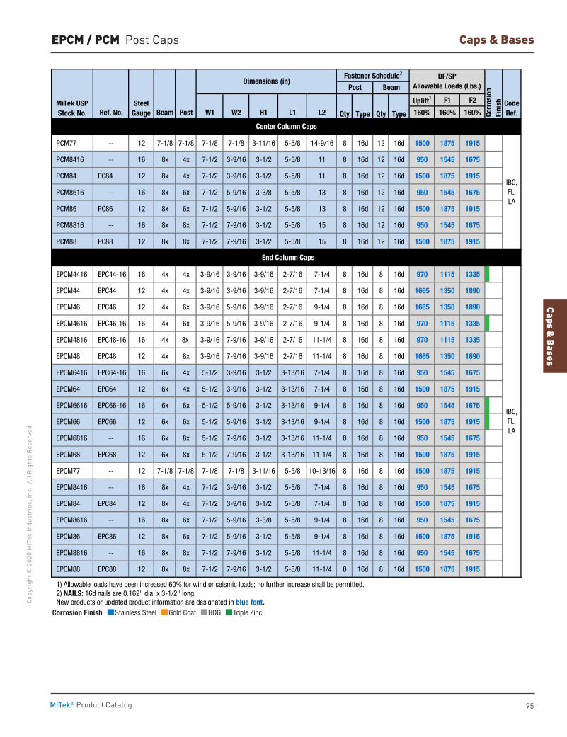
Caps & Bases
95
Copy
righ
t © 2
020
MiT
ek In
dust
ries
, Inc
. Al
l Rig
hts
Rese
rved
Caps & Bases
MiTek® Product Catalog
Corrosion Finish Stainless Steel Gold Coat HDG Triple Zinc
Corrosion Finish Stainless Steel Gold Coat HDG Triple Zinc
Corrosion Finish Stainless Steel Gold Coat HDG Triple Zinc
Uplift1 F1 F2
Ref. No. Beam Post W1 W2 H1 L1 L2 Qty Type Qty Type 160% 160% 160%
PCM77 -- 12 7-1/8 7-1/8 7-1/8 7-1/8 3-11/16 5-5/8 14-9/16 8 16d 12 16d 1500 1875 1915
PCM8416 -- 16 8x 4x 7-1/2 3-9/16 3-1/2 5-5/8 11 8 16d 12 16d 950 1545 1675
PCM84 PC84 12 8x 4x 7-1/2 3-9/16 3-1/2 5-5/8 11 8 16d 12 16d 1500 1875 1915
PCM8616 -- 16 8x 6x 7-1/2 5-9/16 3-3/8 5-5/8 13 8 16d 12 16d 950 1545 1675
PCM86 PC86 12 8x 6x 7-1/2 5-9/16 3-1/2 5-5/8 13 8 16d 12 16d 1500 1875 1915
PCM8816 -- 16 8x 8x 7-1/2 7-9/16 3-1/2 5-5/8 15 8 16d 12 16d 950 1545 1675
PCM88 PC88 12 8x 8x 7-1/2 7-9/16 3-1/2 5-5/8 15 8 16d 12 16d 1500 1875 1915
EPCM4416 EPC44-16 16 4x 4x 3-9/16 3-9/16 3-9/16 2-7/16 7-1/4 8 16d 8 16d 970 1115 1335
EPCM44 EPC44 12 4x 4x 3-9/16 3-9/16 3-9/16 2-7/16 7-1/4 8 16d 8 16d 1665 1350 1890
EPCM46 EPC46 12 4x 6x 3-9/16 5-9/16 3-9/16 2-7/16 9-1/4 8 16d 8 16d 1665 1350 1890
EPCM4616 EPC46-16 16 4x 6x 3-9/16 5-9/16 3-9/16 2-7/16 9-1/4 8 16d 8 16d 970 1115 1335
EPCM4816 EPC48-16 16 4x 8x 3-9/16 7-9/16 3-9/16 2-7/16 11-1/4 8 16d 8 16d 970 1115 1335
EPCM48 EPC48 12 4x 8x 3-9/16 7-9/16 3-9/16 2-7/16 11-1/4 8 16d 8 16d 1665 1350 1890
EPCM6416 EPC64-16 16 6x 4x 5-1/2 3-9/16 3-1/2 3-13/16 7-1/4 8 16d 8 16d 950 1545 1675
EPCM64 EPC64 12 6x 4x 5-1/2 3-9/16 3-1/2 3-13/16 7-1/4 8 16d 8 16d 1500 1875 1915
EPCM6616 EPC66-16 16 6x 6x 5-1/2 5-9/16 3-1/2 3-13/16 9-1/4 8 16d 8 16d 950 1545 1675
EPCM66 EPC66 12 6x 6x 5-1/2 5-9/16 3-1/2 3-13/16 9-1/4 8 16d 8 16d 1500 1875 1915
EPCM6816 -- 16 6x 8x 5-1/2 7-9/16 3-1/2 3-13/16 11-1/4 8 16d 8 16d 950 1545 1675
EPCM68 EPC68 12 6x 8x 5-1/2 7-9/16 3-1/2 3-13/16 11-1/4 8 16d 8 16d 1500 1875 1915
EPCM77 -- 12 7-1/8 7-1/8 7-1/8 7-1/8 3-11/16 5-5/8 10-13/16 8 16d 8 16d 1500 1875 1915
EPCM8416 -- 16 8x 4x 7-1/2 3-9/16 3-1/2 5-5/8 7-1/4 8 16d 8 16d 950 1545 1675
EPCM84 EPC84 12 8x 4x 7-1/2 3-9/16 3-1/2 5-5/8 7-1/4 8 16d 8 16d 1500 1875 1915
EPCM8616 -- 16 8x 6x 7-1/2 5-9/16 3-3/8 5-5/8 9-1/4 8 16d 8 16d 950 1545 1675
EPCM86 EPC86 12 8x 6x 7-1/2 5-9/16 3-1/2 5-5/8 9-1/4 8 16d 8 16d 1500 1875 1915
EPCM8816 -- 16 8x 8x 7-1/2 7-9/16 3-1/2 5-5/8 11-1/4 8 16d 8 16d 950 1545 1675
EPCM88 EPC88 12 8x 8x 7-1/2 7-9/16 3-1/2 5-5/8 11-1/4 8 16d 8 16d 1500 1875 1915
1) Allowable loads have been increased 60% for wind or seismic loads; no further increase shall be permitted. 2) NAILS: 16d nails are 0.162" dia. x 3-1/2" long. New products or updated product information are designated in blue font.
Dimensions (in)Fastener Schedule2 DF/SP
Allowable Loads (Lbs.)
Corr
osio
nFi
nish
Post Beam
MiTek USPStock No.
Steel Gauge
CodeRef.
End Column Caps
IBC,FL,LA
Center Column Caps
IBC,FL,LA
EPCM / PCM Post Caps
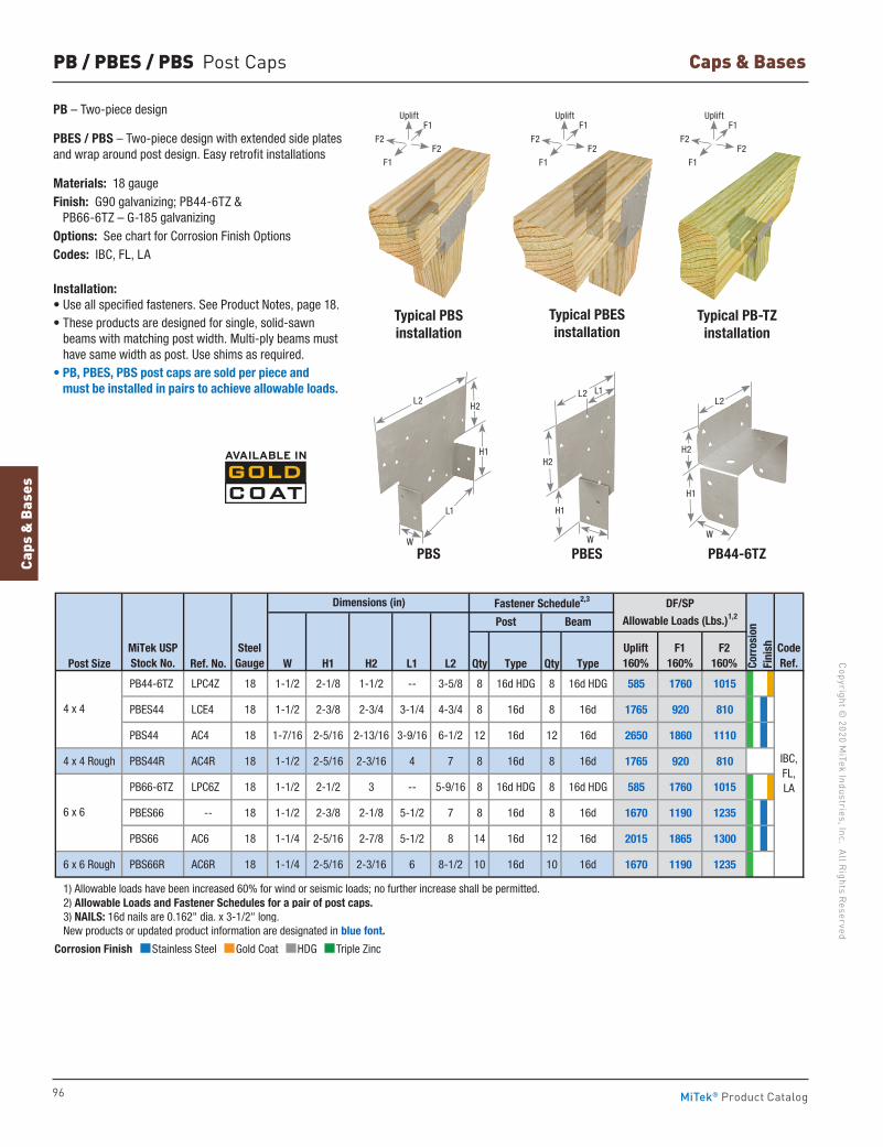
96
Copyright © 2020 M
iTek Industries, Inc. All Rights Reserved
Caps & Bases
Caps
& B
ases
MiTek® Product Catalog
Corrosion Finish Stainless Steel Gold Coat HDG Triple Zinc
Corrosion Finish Stainless Steel Gold Coat HDG Triple Zinc
Corrosion Finish Stainless Steel Gold Coat HDG Triple Zinc
PB / PBES / PBS Post Caps
PB – Two-piece design
PBES / PBS – Two-piece design with extended side plates and wrap around post design. Easy retrofit installations
Materials: 18 gaugeFinish: G90 galvanizing; PB44-6TZ & PB66-6TZ – G-185 galvanizingOptions: See chart for Corrosion Finish OptionsCodes: IBC, FL, LA
Installation:• Use all specified fasteners. See Product Notes, page 18.• These products are designed for single, solid-sawn
beams with matching post width. Multi-ply beams must have same width as post. Use shims as required.
• PB, PBES, PBS post caps are sold per piece and must be installed in pairs to achieve allowable loads.
Post Size Ref. No. W H1 H2 L1 L2 Qty Type Qty Type
PB44-6TZ LPC4Z 18 1-1/2 2-1/8 1-1/2 -- 3-5/8 8 16d HDG 8 16d HDG 585 1760 1015
PBES44 LCE4 18 1-1/2 2-3/8 2-3/4 3-1/4 4-3/4 8 16d 8 16d 1765 920 810
PBS44 AC4 18 1-7/16 2-5/16 2-13/16 3-9/16 6-1/2 12 16d 12 16d 2650 1860 1110
4 x 4 Rough PBS44R AC4R 18 1-1/2 2-5/16 2-3/16 4 7 8 16d 8 16d 1765 920 810
PB66-6TZ LPC6Z 18 1-1/2 2-1/2 3 -- 5-9/16 8 16d HDG 8 16d HDG 585 1760 1015
PBES66 -- 18 1-1/2 2-3/8 2-1/8 5-1/2 7 8 16d 8 16d 1670 1190 1235
PBS66 AC6 18 1-1/4 2-5/16 2-7/8 5-1/2 8 14 16d 12 16d 2015 1865 1300
6 x 6 Rough PBS66R AC6R 18 1-1/4 2-5/16 2-3/16 6 8-1/2 10 16d 10 16d 1670 1190 1235
1) Allowable loads have been increased 60% for wind or seismic loads; no further increase shall be permitted. 2) Allowable Loads and Fastener Schedules for a pair of post caps. 3) NAILS: 16d nails are 0.162" dia. x 3-1/2" long. New products or updated product information are designated in blue font.
4 x 4
6 x 6
MiTek USPStock No.
SteelGauge
Code Ref.Co
rros
ion
Fini
shIBC,FL,LA
Fastener Schedule2,3
Post Beam
DF/SP
Allowable Loads (Lbs.)1,2
Uplift160%
F1160%
F2160%
Dimensions (in)
Typical PBS installation
PB44-6TZPBS
Typical PBESinstallation
Typical PB-TZinstallation
PBES
L2
W
H2
H1
L1
W
L2
H2
H1
L1
W
L2
H2
H1
F2F2
Uplift
F1
F1
F2F2
Uplift
F1
F1
F2F2
Uplift
F1
F1
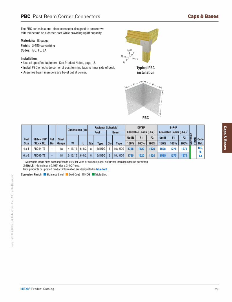
Caps & Bases
97
Copy
righ
t © 2
020
MiT
ek In
dust
ries
, Inc
. Al
l Rig
hts
Rese
rved
Caps & Bases
MiTek® Product Catalog
PBC Post Beam Corner Connectors
The PBC series is a one-piece connector designed to secure two mitered beams on a corner post while providing uplift capacity.
Materials: 18 gaugeFinish: G-185 galvanizingCodes: IBC, FL, LA
Installation:• Use all specified fasteners. See Product Notes, page 18.• Install PBC on outside corner of post forming tabs to inner side of post.• Assumes beam members are bevel cut at corner.
Typical PBCinstallation
PBC
Uplift F1 F2 Uplift F1 F2
W L Qty Type Qty Type 160% 160% 160% 160% 160% 160%
4 x 4 PBC44-TZ -- 18 4-15/16 6-1/2 8 16d HDG 8 16d HDG 1765 1520 1520 1525 1275 1275
6 x 6 PBC66-TZ -- 18 6-15/16 6-1/2 8 16d HDG 8 16d HDG 1765 1520 1520 1525 1275 1275
1) Allowable loads have been increased 60% for wind or seismic loads; no further increase shall be permitted. 2) NAILS: 16d nails are 0.162" dia. x 3-1/2" long. New products or updated product information are designated in blue font.
CodeRef.
IBC,FL,LA
PostSize
MiTek USPStock No.
SteelGauge Co
rros
ion
Fini
sh
DF/SP
Allowable Loads (Lbs.)1
S-P-F
Allowable Loads (Lbs.)1Dimensions (in)Fastener Schedule2
Post Beam
Ref. No.
W
L
W
Corrosion Finish Stainless Steel Gold Coat HDG Triple Zinc
Corrosion Finish Stainless Steel Gold Coat HDG Triple Zinc
Corrosion Finish Stainless Steel Gold Coat HDG Triple Zinc
F2F2
Uplift
F1
F1
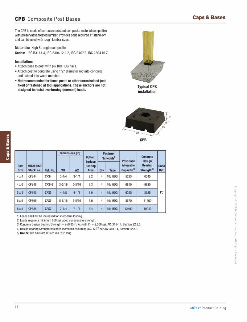
98
Copyright © 2020 M
iTek Industries, Inc. All Rights Reserved
Caps & Bases
Caps
& B
ases
MiTek® Product Catalog
The CPB is made of corrosion resistant composite material compatible with preservative treated lumber. Provides code required 1" stand-off and can be used with rough lumber sizes.
Materials: High Strength compositeCodes: IRC R317.1.4, IBC 2304.12.2.2, IRC R407.3, IBC 2304.10.7
Installation:• Attach base to post with (4) 10d HDG nails.• Attach post to concrete using 1/2" diameter rod into concrete
and extend into wood member.• Not recommended for fence posts or other unrestrained (not
fixed or fastened at top) applications. These anchors are not designed to resist overturning (moment) loads.
Typical CPBinstallation
CPB
CPB Composite Post Bases
Ref. No. W1 W2 Qty Type
4 x 4 CPB44 CPS4 3-1/4 3-1/4 2.2 4 10d HDG 5235 6545
4 x 6 CPB46 CPS46 3-5/16 5-5/16 3.3 4 10d HDG 6810 9820
5 x 5 CPB55 CPS5 4-1/8 4-1/8 3.0 4 10d HDG 6295 8925
6 x 6 CPB66 CPS6 5-5/16 5-5/16 3.9 4 10d HDG 8570 11600
8 x 8 CPB88 CPS7 7-1/4 7-1/4 6.4 4 10d HDG 12490 19040
1) Loads shall not be increased for short-term loading. 2) Loads require a minimum 650 psi wood compressive strength. 3) Concrete Design Bearing Strength = Ø (0.85 f'C A1) with f'C = 2,500 psi. ACI 318-14, Section 22.8.3. 4) Design Bearing Strength has been increased assuming (A2 / A1)
0.5 per ACI 318-14, Section 22.8.3. 5) NAILS: 10d nails are 0.148" dia. x 3" long.
Post Size
CodeRef.
PC
ConcreteDesign Bearing
Strength3,4
BottomSurfaceBearing
AreaMiTek USPStock No.
Post BaseAllowable
Capacity1,2
Fastener
Schedule5
Dimensions (in)
W1
W2
1"
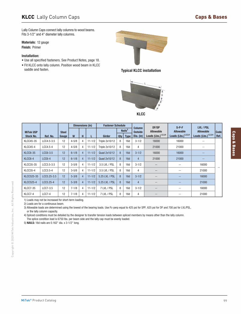
Caps & Bases
99
Copy
righ
t © 2
020
MiT
ek In
dust
ries
, Inc
. Al
l Rig
hts
Rese
rved
Caps & Bases
MiTek® Product Catalog
KLCC Lally Column Caps
Ref. No. W H L Qty Type
KLCC45-35 LCC4.5-3.5 12 4-5/8 4 11-1/2 Triple 2x10/12 8 16d 3-1/2 16000 16000 --
KLCC45-4 LCC4.5-4 12 4-5/8 4 11-1/2 Triple 2x10/12 8 16d 4 21000 21000 --
KLCC6-35 LCC6-3.5 12 6-1/8 4 11-1/2 Quad 2x10/12 8 16d 3-1/2 16000 16000 --
KLCC6-4 LCC6-4 12 6-1/8 4 11-1/2 Quad 2x10/12 8 16d 4 21000 21000 --
KLCC35-35 LCC3.5-3.5 12 3-5/8 4 11-1/2 3.5 LVL / PSL 8 16d 3-1/2 -- -- 16000
KLCC35-4 LCC3.5-4 12 3-5/8 4 11-1/2 3.5 LVL / PSL 8 16d 4 -- -- 21000
KLCC525-35 LCC5.25-3.5 12 5-3/8 4 11-1/2 5.25 LVL / PSL 8 16d 3-1/2 -- -- 16000
KLCC525-4 LCC5.25-4 12 5-3/8 4 11-1/2 5.25 LVL / PSL 8 16d 4 -- -- 21000
KLCC7-35 LCC7-3.5 12 7-1/8 4 11-1/2 7 LVL / PSL 8 16d 3-1/2 -- -- 16000
KLCC7-4 LCC7-4 12 7-1/8 4 11-1/2 7 LVL / PSL 8 16d 4 -- -- 21000
1) Loads may not be increased for short-term loading. 2) Loads are for a continuous beam. 3) Allowable loads are determined using the lowest of the bearing loads. Use Fc-perp equal to 425 psi for SPF, 625 psi for DF and 700 psi for LVL/PSL, or the lally column capacity. 4) Spliced conditions must be detailed by the designer to transfer tension loads between spliced members by means other than the lally column. The splice condition load is 6750 lbs. per beam side and the lally cap must be evenly loaded. 5) NAILS: 16d nails are 0.162" dia. x 3-1/2" long.
--
Column Outside Dia. (in)
Fastener Schedule
Nails5CodeRef.
LVL / PSLAllowable
Loads (Lbs.)1,2,3,4MiTek USPStock No.
SteelGauge
DF/SPAllowable
Loads (Lbs.)1,2,3,4
S-P-FAllowable
Loads (Lbs.)1,2,3,4Girder
Dimensions (in)
Lally Column Caps connect lally columns to wood beams. Fits 3-1/2" and 4" diameter lally columns.
Materials: 12 gaugeFinish: Primer
Installation:• Use all specified fasteners. See Product Notes, page 18.• Fit KLCC onto lally column. Position wood beam in KLCC
saddle and fasten. Typical KLCC installation
KLCC
H
W
L
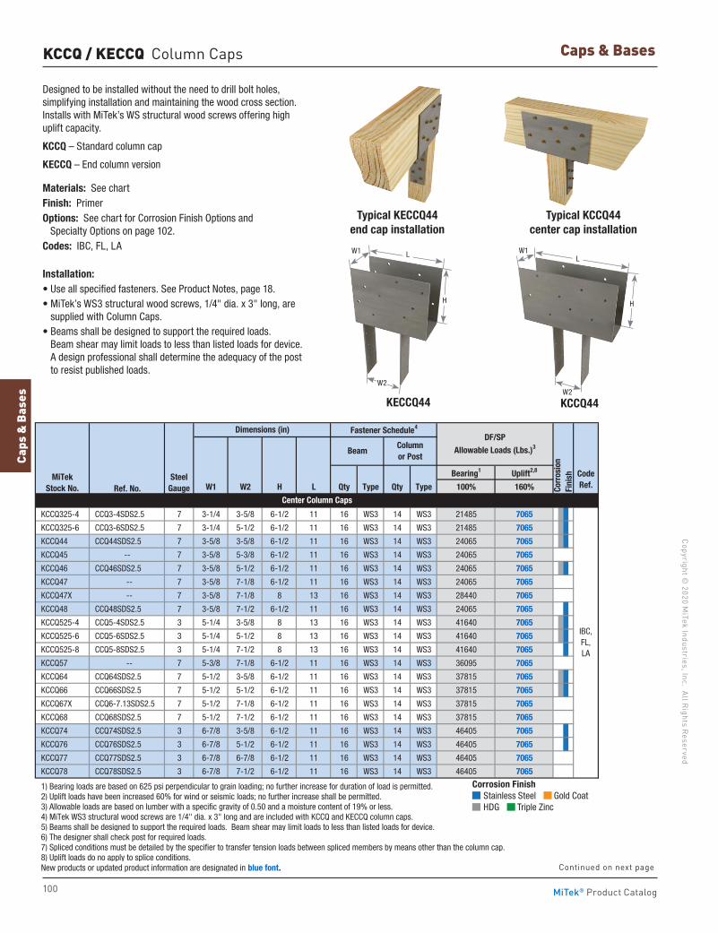
100
Copyright © 2020 M
iTek Industries, Inc. All Rights Reserved
Caps & Bases
Caps
& B
ases
MiTek® Product Catalog
KCCQ / KECCQ Column Caps
Designed to be installed without the need to drill bolt holes, simplifying installation and maintaining the wood cross section. Installs with MiTek’s WS structural wood screws offering high uplift capacity.
KCCQ – Standard column cap
KECCQ – End column version
Materials: See chartFinish: PrimerOptions: See chart for Corrosion Finish Options and Specialty Options on page 102.Codes: IBC, FL, LA
Installation:• Use all specified fasteners. See Product Notes, page 18.• MiTek’s WS3 structural wood screws, 1/4" dia. x 3" long, are
supplied with Column Caps.• Beams shall be designed to support the required loads.
Beam shear may limit loads to less than listed loads for device. A design professional shall determine the adequacy of the post to resist published loads.
Bearing1 Uplift2,8
Ref. No. W1 W2 H L Qty Type Qty Type 100% 160%
KCCQ325-4 CCQ3-4SDS2.5 7 3-1/4 3-5/8 6-1/2 11 16 WS3 14 WS3 21485 7065
KCCQ325-6 CCQ3-6SDS2.5 7 3-1/4 5-1/2 6-1/2 11 16 WS3 14 WS3 21485 7065
KCCQ44 CCQ44SDS2.5 7 3-5/8 3-5/8 6-1/2 11 16 WS3 14 WS3 24065 7065
KCCQ45 -- 7 3-5/8 5-3/8 6-1/2 11 16 WS3 14 WS3 24065 7065
KCCQ46 CCQ46SDS2.5 7 3-5/8 5-1/2 6-1/2 11 16 WS3 14 WS3 24065 7065
KCCQ47 -- 7 3-5/8 7-1/8 6-1/2 11 16 WS3 14 WS3 24065 7065
KCCQ47X -- 7 3-5/8 7-1/8 8 13 16 WS3 14 WS3 28440 7065
KCCQ48 CCQ48SDS2.5 7 3-5/8 7-1/2 6-1/2 11 16 WS3 14 WS3 24065 7065
KCCQ525-4 CCQ5-4SDS2.5 3 5-1/4 3-5/8 8 13 16 WS3 14 WS3 41640 7065
KCCQ525-6 CCQ5-6SDS2.5 3 5-1/4 5-1/2 8 13 16 WS3 14 WS3 41640 7065
KCCQ525-8 CCQ5-8SDS2.5 3 5-1/4 7-1/2 8 13 16 WS3 14 WS3 41640 7065
KCCQ57 -- 7 5-3/8 7-1/8 6-1/2 11 16 WS3 14 WS3 36095 7065
KCCQ64 CCQ64SDS2.5 7 5-1/2 3-5/8 6-1/2 11 16 WS3 14 WS3 37815 7065
KCCQ66 CCQ66SDS2.5 7 5-1/2 5-1/2 6-1/2 11 16 WS3 14 WS3 37815 7065
KCCQ67X CCQ6-7.13SDS2.5 7 5-1/2 7-1/8 6-1/2 11 16 WS3 14 WS3 37815 7065
KCCQ68 CCQ68SDS2.5 7 5-1/2 7-1/2 6-1/2 11 16 WS3 14 WS3 37815 7065
KCCQ74 CCQ74SDS2.5 3 6-7/8 3-5/8 6-1/2 11 16 WS3 14 WS3 46405 7065
KCCQ76 CCQ76SDS2.5 3 6-7/8 5-1/2 6-1/2 11 16 WS3 14 WS3 46405 7065
KCCQ77 CCQ77SDS2.5 3 6-7/8 6-7/8 6-1/2 11 16 WS3 14 WS3 46405 7065
KCCQ78 CCQ78SDS2.5 3 6-7/8 7-1/2 6-1/2 11 16 WS3 14 WS3 46405 7065
1) Bearing loads are based on 625 psi perpendicular to grain loading; no further increase for duration of load is permitted. 2) Uplift loads have been increased 60% for wind or seismic loads; no further increase shall be permitted. 3) Allowable loads are based on lumber with a specific gravity of 0.50 and a moisture content of 19% or less. 4) MiTek WS3 structural wood screws are 1/4" dia. x 3" long and are included with KCCQ and KECCQ column caps. 5) Beams shall be designed to support the required loads. Beam shear may limit loads to less than listed loads for device. 6) The designer shall check post for required loads. 7) Spliced conditions must be detailed by the specifier to transfer tension loads between spliced members by means other than the column cap. 8) Uplift loads do no apply to splice conditions. New products or updated product information are designated in blue font.
Dimensions (in) Fastener Schedule4
DF/SPAllowable Loads (Lbs.)3
Corr
osio
nFi
nish
BeamColumnor Post
IBC, FL, LA
MiTekStock No.
SteelGauge
CodeRef.
Center Column Caps
Continued on next page
Typical KECCQ44end cap installation
Typical KCCQ44center cap installation
KECCQ44 KCCQ44
H
LW1
W2
H
LW1
W2
Corrosion Finish Stainless Steel Gold Coat HDG Triple Zinc
Corrosion Finish Stainless Steel Gold Coat HDG Triple Zinc
Corrosion Finish Stainless Steel Gold Coat HDG Triple Zinc

Caps & Bases
101
Copy
righ
t © 2
020
MiT
ek In
dust
ries
, Inc
. Al
l Rig
hts
Rese
rved
Caps & Bases
MiTek® Product Catalog
KCCQ / KECCQ Column Caps
Ref. No. W1 W2 H L Qty Type Qty Type
KCCQ71-4 CCQ7.1-4SDS2.5 3 7-1/4 3-5/8 6-1/2 11 16 WS3 14 WS3 48125 7065
KCCQ71-6 CCQ7.1-6SDS2.5 3 7-1/4 5-1/2 6-1/2 11 16 WS3 14 WS3 48125 7065
KCCQ71-71 CCQ7.1-7.1SDS2.5 3 7-1/4 7-1/4 6-1/2 11 16 WS3 14 WS3 48125 7065
KCCQ71-8 CCQ7.1-8SDS2.5 3 7-1/4 7-1/2 6-1/2 11 16 WS3 14 WS3 48125 7065
KCCQ84 -- 7 7-1/2 3-5/8 6-1/2 11 16 WS3 14 WS3 51565 7065
KCCQ86 CCQ86SDS2.5 7 7-1/2 5-1/2 6-1/2 11 16 WS3 14 WS3 51565 7065
KCCQ88 CCQ88SDS2.5 7 7-1/2 7-1/2 6-1/2 11 16 WS3 14 WS3 51565 7065
KCCQ94 -- 7 8-7/8 3-5/8 6-1/2 11 16 WS3 14 WS3 60155 7065
KCCQ96 CCQ96SDS2.5 7 8-7/8 5-1/2 6-1/2 11 16 WS3 14 WS3 60155 7065
KCCQ98 CCQ98SDS2.5 7 8-7/8 7-1/2 6-1/2 11 16 WS3 14 WS3 60155 7065
KCCQ106 CCQ106SDS2.5 7 9-1/2 5-1/2 6-1/2 11 16 WS3 14 WS3 65315 7065
KECCQ325-4 ECCQ3-4SDS2.5 7 3-1/4 3-5/8 6-1/2 7-1/2 16 WS3 14 WS3 14650 6860
KECCQ325-6 ECCQ3-6SDS2.5 7 3-1/4 5-1/2 6-1/2 7-1/2 16 WS3 14 WS3 14650 6860
KECCQ44 ECCQ44SDS2.5 7 3-5/8 3-5/8 6-1/2 8-1/2 16 WS3 14 WS3 16965 6860
KECCQ45 -- 7 3-5/8 5-3/8 6-1/2 7-1/2 16 WS3 14 WS3 16405 6860
KECCQ46 ECCQ46SDS2.5 7 3-5/8 5-1/2 6-1/2 8-1/2 16 WS3 14 WS3 18595 6860
KECCQ47 -- 7 3-5/8 7-1/8 6-1/2 9-1/2 16 WS3 14 WS3 20780 6860
KECCQ47X -- 7 3-5/8 7-1/8 8 9-1/2 16 WS3 14 WS3 20780 6860
KECCQ48 ECCQ48SDS2.5 7 3-5/8 7-1/2 6-1/2 8-1/2 16 WS3 14 WS3 18595 6860
KECCQ525-4 ECCQ5-4SDS2.5 3 5-1/4 3-5/8 8 9-1/2 16 WS3 14 WS3 22330 6860
KECCQ525-6 ECCQ5-6SDS2.5 3 5-1/4 5-1/2 8 9-1/2 16 WS3 14 WS3 27300 6860
KECCQ525-8 ECCQ5-8SDS2.5 3 5-1/4 7-1/2 8 9-1/2 16 WS3 14 WS3 30430 6860
KECCQ57 -- 7 5-3/8 7-1/8 6-1/2 9-1/2 16 WS3 14 WS3 31170 6860
KECCQ64 ECCQ64SDS2.5 7 5-1/2 3-5/8 6-1/2 8-1/2 16 WS3 14 WS3 23535 6860
KECCQ66 ECCQ66SDS2.5 7 5-1/2 5-1/2 6-1/2 8-1/2 16 WS3 14 WS3 28910 6860
KECCQ67X ECCQ6-7.13SDS2.5 7 5-1/2 7-1/8 6-1/2 8-1/2 16 WS3 14 WS3 29220 6860
KECCQ68 ECCQ68SDS2.5 7 5-1/2 7-1/2 6-1/2 8-1/2 16 WS3 14 WS3 29220 6860
KECCQ74 ECCQ74SDS2.5 3 6-7/8 3-5/8 6-1/2 8-1/2 16 WS3 14 WS3 27465 6860
KECCQ76 ECCQ76SDS2.5 3 6-7/8 5-1/2 6-1/2 8-1/2 16 WS3 14 WS3 35860 6860
KECCQ77 ECCQ77SDS2.5 3 6-7/8 6-7/8 6-1/2 8-1/2 16 WS3 14 WS3 35860 6860
KECCQ78 ECCQ78SDS2.5 3 6-7/8 7-1/2 6-1/2 8-1/2 16 WS3 14 WS3 35860 6860
KECCQ71-4 ECCQ7.1-4SDS2.5 3 7-1/4 3-5/8 6-1/2 8-1/2 16 WS3 14 WS3 28240 6860
KECCQ71-6 ECCQ7.1-6SDS2.5 3 7-1/4 5-1/2 6-1/2 8-1/2 16 WS3 14 WS3 35285 6860
KECCQ71-71 ECCQ7.1-7.1SDS2.5 3 7-1/4 7-1/4 6-1/2 8-1/2 16 WS3 14 WS3 37190 6860
KECCQ71-8 ECCQ7.1-8SDS2.5 3 7-1/4 7-1/2 6-1/2 8-1/2 16 WS3 14 WS3 37190 6860
KECCQ84 -- 7 7-1/2 3-5/8 6-1/2 8-1/2 16 WS3 14 WS3 29785 6860
KECCQ86 ECCQ86SDS2.5 7 7-1/2 5-1/2 6-1/2 8-1/2 16 WS3 14 WS3 37390 6860
KECCQ88 ECCQ88SDS2.5 7 7-1/2 7-1/2 6-1/2 8-1/2 16 WS3 14 WS3 39845 6860
KECCQ94 -- 7 8-7/8 3-5/8 6-1/2 8-1/2 16 WS3 14 WS3 33595 6860
KECCQ96 ECCQ96SDS2.5 7 8-7/8 5-1/2 6-1/2 8-1/2 16 WS3 14 WS3 42630 6860
KECCQ98 ECCQ98SDS2.5 7 8-7/8 7-1/2 6-1/2 8-1/2 16 WS3 14 WS3 46485 6860
KECCQ106 ECCQ106SDS2.5 7 9-1/2 5-1/2 6-1/2 8-1/2 16 WS3 14 WS3 45760 6860
1) Bearing loads are based on 625 psi perpendicular to grain loading; no further increase for duration of load is permitted. 2) Uplift loads have been increased 60% for wind or seismic loads; no further increase shall be permitted. 3) Allowable loads are based on lumber with a specific gravity of 0.50 and a moisture content of 19% or less. 4) MiTek WS3 structural wood screws are 1/4" dia. x 3" long and are included with KCCQ and KECCQ column caps. 5) Beams shall be designed to support the required loads. Beam shear may limit loads to less than listed loads for device. 6) The designer shall check post for required loads. 7) Spliced conditions must be detailed by the specifier to transfer tension loads between spliced members by means other than the column cap. 8) Uplift loads do no apply to splice conditions.
IBC, FL, LA
End Column Caps
MiTekStock No.
SteelGauge
CodeRef.
Center Column Caps
IBC, FL, LA
Columnor Post
Fastener Schedule4
Corr
osio
nFi
nish
Dimensions (in)
Beam
DF/SPAllowable Loads (Lbs.)3
Bearing1
100%Uplift2,8
160%
Continued on next page
Corrosion Finish Stainless Steel Gold Coat HDG Triple Zinc
Corrosion Finish Stainless Steel Gold Coat HDG Triple Zinc
Corrosion Finish Stainless Steel Gold Coat HDG Triple Zinc
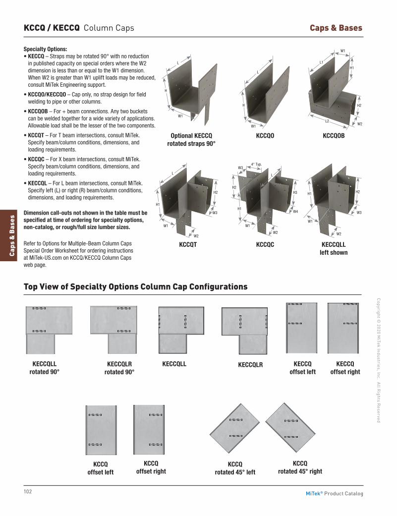
102
Copyright © 2020 M
iTek Industries, Inc. All Rights Reserved
Caps & Bases
Caps
& B
ases
MiTek® Product Catalog
KCCQ / KECCQ Column Caps
KCCQT
KCCQO
KECCQLLKECCQLLrotated 90°
KCCQ offset right
KCCQC
Optional KECCQrotated straps 90°
KECCQLRKECCQLRrotated 90°
KCCQrotated 45° left
KCCQ offset left
KCCQOB
KECCQLLleft shown
KECCQ offset left
KECCQ offset right
KCCQrotated 45° right
Top View of Specialty Options Column Cap Configurations
L
H
W1
Specialty Options:• KECCQ – Straps may be rotated 90° with no reduction
in published capacity on special orders where the W2 dimension is less than or equal to the W1 dimension. When W2 is greater than W1 uplift loads may be reduced, consult MiTek Engineering support.
• KCCQO/KECCQO – Cap only, no strap design for field welding to pipe or other columns.
• KCCQOB – For + beam connections. Any two buckets can be welded together for a wide variety of applications. Allowable load shall be the lesser of the two components.
• KCCQT – For T beam intersections, consult MiTek. Specify beam/column conditions, dimensions, and loading requirements.
• KCCQC – For X beam intersections, consult MiTek. Specify beam/column conditions, dimensions, and loading requirements.
• KECCQL – For L beam intersections, consult MiTek. Specify left (L) or right (R) beam/column conditions, dimensions, and loading requirements.
Dimension call-outs not shown in the table must be specified at time of ordering for specialty options, non-catalog, or rough/full size lumber sizes.
Refer to Options for Multiple-Beam Column Caps Special Order Worksheet for ordering instructions at MiTek-US.com on KCCQ/KECCQ Column Caps web page.
L
H2
W3
W2
W1
H1
W1
W2
W4
W3
H2
H1
H3
4" Typ.
L
W1
W3
W2
H2H1
L1
L2
H1
H2
W2
W1
L
H
W1
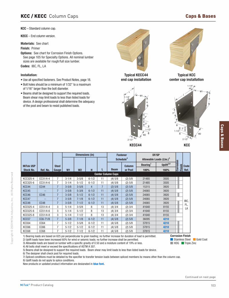
Caps & Bases
103
Copy
righ
t © 2
020
MiT
ek In
dust
ries
, Inc
. Al
l Rig
hts
Rese
rved
Caps & Bases
MiTek® Product Catalog
KCC / KECC Column Caps
KCC – Standard column cap.
KECC – End column version.
Materials: See chartFinish: PrimerOptions: See chart for Corrosion Finish Options. See page 105 for Specialty Options. All nominal lumber
sizes are available for rough/full size lumber. Codes: IBC, FL, LA
Installation:• Use all specified fasteners. See Product Notes, page 18.• Bolt holes should be a minimum of 1/32" to a maximum
of 1/16" larger than the bolt diameter.• Beams shall be designed to support the required loads.
Beam shear may limit loads to less than listed loads for device. A design professional shall determine the adequacy of the post and beam to resist published loads.
Typical KCCcenter cap installation
Typical KECC44end cap installation
KCC KECC44
Bearing1 Uplift2,8
Ref. No. W1 W2 H L Beam 100% 160%
KCC325-4 CC31/4-4 7 3-1/4 3-5/8 6-1/2 11 (4) 5/8 (2) 5/8 21485 3505 KCC325-6 CC31/4-6 7 3-1/4 5-1/2 6-1/2 11 (4) 5/8 (2) 5/8 21485 3505 KCC44 CC44 7 3-5/8 3-5/8 4 7 (2) 5/8 (2) 5/8 15315 3920 KCC45 -- 7 3-5/8 5-3/8 6-1/2 11 (4) 5/8 (2) 5/8 24065 3920 KCC46 CC46 7 3-5/8 5-1/2 6-1/2 11 (4) 5/8 (2) 5/8 24065 3920 KCC47 -- 7 3-5/8 7-1/8 6-1/2 11 (4) 5/8 (2) 5/8 24065 3920 KCC48 CC48 7 3-5/8 7-1/2 6-1/2 11 (4) 5/8 (2) 5/8 24065 3920 KCC525-4 CC51/4-4 3 5-1/4 3-5/8 8 13 (4) 3/4 (2) 3/4 41640 8155 KCC525-6 CC51/4-6 3 5-1/4 5-1/2 8 13 (4) 3/4 (2) 3/4 41640 8155 KCC525-8 CC51/4-8 3 5-1/4 7-1/2 8 13 (4) 3/4 (2) 3/4 41640 8155 KCC57 CC6-71/8 7 5-3/8 7-1/8 6-1/2 11 (4) 5/8 (2) 5/8 36095 4210 KCC64 CC64 7 5-1/2 3-5/8 6-1/2 11 (4) 5/8 (2) 5/8 37815 4210 KCC66 CC66 7 5-1/2 5-1/2 6-1/2 11 (4) 5/8 (2) 5/8 37815 4210 KCC68 CC68 7 5-1/2 7-1/2 6-1/2 11 (4) 5/8 (2) 5/8 37815 4210
1) Bearing loads are based on 625 psi perpendicular to grain loading; no further increase for duration of load is permitted. 2) Uplift loads have been increased 60% for wind or seismic loads; no further increase shall be permitted. 3) Allowable loads are based on lumber with a specific gravity of 0.50 and a moisture content of 19% or less. 4) All bolts shall meet or exceed the specifications of ASTM A 307. 5) Beams shall be designed to support the required loads. Beam shear may limit loads to less than listed loads for device. 6) The designer shall check post for required loads. 7) Spliced conditions must be detailed by the specifier to transfer tension loads between spliced members by means other than the column cap. 8) Uplift loads do not apply to splice conditions. New products or updated product information are designated in blue font.
IBC, FL, LA
Dimensions (in) Fastener Schedule4
Corr
osio
nFi
nish
Center Column Caps
MiTek USPStock No.
DF/SPAllowable Loads (Lbs.)3
SteelGauge
Columnor Post
Code Ref.
2-1/2"
1-1/2"
3"
1-1/4"
4"
W1
W2
H
L
W2
2-1/2"
1-1/2"
1-1/4"
3"
4"
3"
H
LW1
Continued on next page
Corrosion Finish Stainless Steel Gold Coat HDG Triple Zinc
Corrosion Finish Stainless Steel Gold Coat HDG Triple Zinc
Corrosion Finish Stainless Steel Gold Coat HDG Triple Zinc
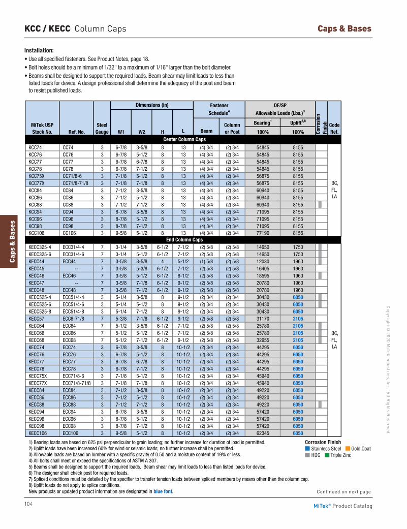
104
Copyright © 2020 M
iTek Industries, Inc. All Rights Reserved
Caps & Bases
Caps
& B
ases
MiTek® Product Catalog
Bearing1 Uplift2,8
Ref. No. W1 W2 H L Beam 100% 160%
KCC74 CC74 3 6-7/8 3-5/8 8 13 (4) 3/4 (2) 3/4 54845 8155 KCC76 CC76 3 6-7/8 5-1/2 8 13 (4) 3/4 (2) 3/4 54845 8155 KCC77 CC77 3 6-7/8 6-7/8 8 13 (4) 3/4 (2) 3/4 54845 8155 KCC78 CC78 3 6-7/8 7-1/2 8 13 (4) 3/4 (2) 3/4 54845 8155 KCC75X CC71/8-6 3 7-1/8 5-1/2 8 13 (4) 3/4 (2) 3/4 56875 8155 KCC77X CC71/8-71/8 3 7-1/8 7-1/8 8 13 (4) 3/4 (2) 3/4 56875 8155 KCC84 CC84 3 7-1/2 3-5/8 8 13 (4) 3/4 (2) 3/4 60940 8155 KCC86 CC86 3 7-1/2 5-1/2 8 13 (4) 3/4 (2) 3/4 60940 8155 KCC88 CC88 3 7-1/2 7-1/2 8 13 (4) 3/4 (2) 3/4 60940 8155 KCC94 CC94 3 8-7/8 3-5/8 8 13 (4) 3/4 (2) 3/4 71095 8155 KCC96 CC96 3 8-7/8 5-1/2 8 13 (4) 3/4 (2) 3/4 71095 8155 KCC98 CC98 3 8-7/8 7-1/2 8 13 (4) 3/4 (2) 3/4 71095 8155 KCC106 CC106 3 9-5/8 5-1/2 8 13 (4) 3/4 (2) 3/4 77190 8155
KECC325-4 ECC31/4-4 7 3-1/4 3-5/8 6-1/2 7-1/2 (2) 5/8 (2) 5/8 14650 1750 KECC325-6 ECC31/4-6 7 3-1/4 5-1/2 6-1/2 7-1/2 (2) 5/8 (2) 5/8 14650 1750 KECC44 ECC44 7 3-5/8 3-5/8 4 5-1/2 (1) 5/8 (2) 5/8 12030 1960 KECC45 -- 7 3-5/8 5-3/8 6-1/2 7-1/2 (2) 5/8 (2) 5/8 16405 1960 KECC46 ECC46 7 3-5/8 5-1/2 6-1/2 8-1/2 (2) 5/8 (2) 5/8 18595 1960 KECC47 -- 7 3-5/8 7-1/8 6-1/2 9-1/2 (2) 5/8 (2) 5/8 20780 1960 KECC48 ECC48 7 3-5/8 7-1/2 6-1/2 9-1/2 (2) 5/8 (2) 5/8 20780 1960 KECC525-4 ECC51/4-4 3 5-1/4 3-5/8 8 9-1/2 (2) 3/4 (2) 3/4 30430 6050 KECC525-6 ECC51/4-6 3 5-1/4 5-1/2 8 9-1/2 (2) 3/4 (2) 3/4 30430 6050 KECC525-8 ECC51/4-8 3 5-1/4 7-1/2 8 9-1/2 (2) 3/4 (2) 3/4 30430 6050 KECC57 ECC6-71/8 7 5-3/8 7-1/8 6-1/2 9-1/2 (2) 5/8 (2) 5/8 31170 2105 KECC64 ECC64 7 5-1/2 3-5/8 6-1/2 7-1/2 (2) 5/8 (2) 5/8 25780 2105 KECC66 ECC66 7 5-1/2 5-1/2 6-1/2 7-1/2 (2) 5/8 (2) 5/8 25780 2105 KECC68 ECC68 7 5-1/2 7-1/2 6-1/2 9-1/2 (2) 5/8 (2) 5/8 32655 2105 KECC74 ECC74 3 6-7/8 3-5/8 8 10-1/2 (2) 3/4 (2) 3/4 44295 6050 KECC76 ECC76 3 6-7/8 5-1/2 8 10-1/2 (2) 3/4 (2) 3/4 44295 6050 KECC77 ECC77 3 6-7/8 6-7/8 8 10-1/2 (2) 3/4 (2) 3/4 44295 6050 KECC78 ECC78 3 6-7/8 7-1/2 8 10-1/2 (2) 3/4 (2) 3/4 44295 6050 KECC75X ECC71/8-6 3 7-1/8 5-1/2 8 10-1/2 (2) 3/4 (2) 3/4 45940 6050 KECC77X ECC71/8-71/8 3 7-1/8 7-1/8 8 10-1/2 (2) 3/4 (2) 3/4 45940 6050 KECC84 ECC84 3 7-1/2 3-5/8 8 10-1/2 (2) 3/4 (2) 3/4 49220 6050 KECC86 ECC86 3 7-1/2 5-1/2 8 10-1/2 (2) 3/4 (2) 3/4 49220 6050 KECC88 ECC88 3 7-1/2 7-1/2 8 10-1/2 (2) 3/4 (2) 3/4 49220 6050 KECC94 ECC94 3 8-7/8 3-5/8 8 10-1/2 (2) 3/4 (2) 3/4 57420 6050 KECC96 ECC96 3 8-7/8 5-1/2 8 10-1/2 (2) 3/4 (2) 3/4 57420 6050 KECC98 ECC98 3 8-7/8 7-1/2 8 10-1/2 (2) 3/4 (2) 3/4 57420 6050 KECC106 ECC106 3 9-5/8 5-1/2 8 10-1/2 (2) 3/4 (2) 3/4 62345 6050
1) Bearing loads are based on 625 psi perpendicular to grain loading; no further increase for duration of load is permitted. 2) Uplift loads have been increased 60% for wind or seismic loads; no further increase shall be permitted. 3) Allowable loads are based on lumber with a specific gravity of 0.50 and a moisture content of 19% or less. 4) All bolts shall meet or exceed the specifications of ASTM A 307. 5) Beams shall be designed to support the required loads. Beam shear may limit loads to less than listed loads for device. 6) The designer shall check post for required loads. 7) Spliced conditions must be detailed by the specifier to transfer tension loads between spliced members by means other than the column cap. 8) Uplift loads do not apply to splice conditions. New products or updated product information are designated in blue font.
IBC, FL, LA
Fastener Schedule4
DF/SPAllowable Loads (Lbs.)3
Corr
osio
nFi
nish
Dimensions (in)
End Column Caps
Center Column Caps
IBC, FL, LA
MiTek USPStock No.
SteelGauge
Columnor Post
Code Ref.
KCC / KECC Column Caps
Corrosion Finish Stainless Steel Gold Coat HDG Triple Zinc
Corrosion Finish Stainless Steel Gold Coat HDG Triple Zinc
Corrosion Finish Stainless Steel Gold Coat HDG Triple Zinc
Installation:• Use all specified fasteners. See Product Notes, page 18.• Bolt holes should be a minimum of 1/32" to a maximum of 1/16" larger than the bolt diameter.• Beams shall be designed to support the required loads. Beam shear may limit loads to less than
listed loads for device. A design professional shall determine the adequacy of the post and beam to resist published loads.
Continued on next page
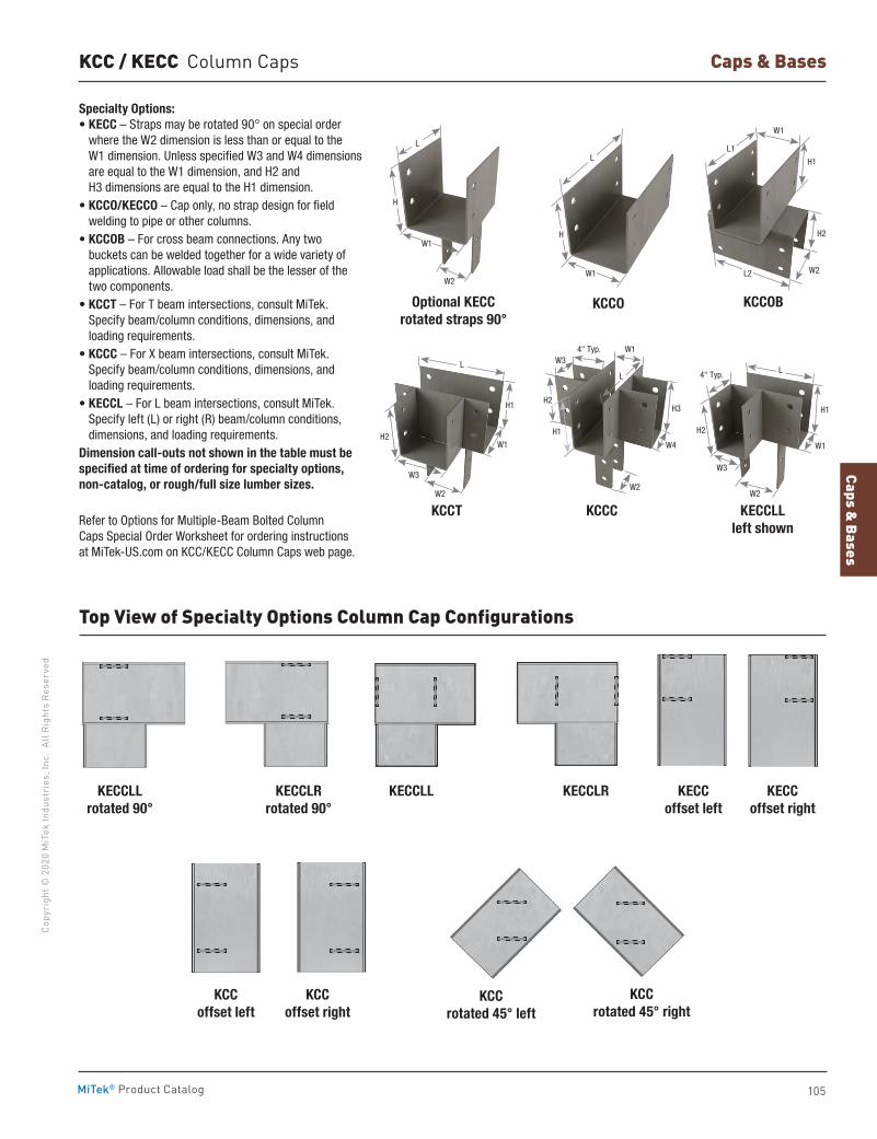
Caps & Bases
105
Copy
righ
t © 2
020
MiT
ek In
dust
ries
, Inc
. Al
l Rig
hts
Rese
rved
Caps & Bases
MiTek® Product Catalog
Specialty Options:• KECC – Straps may be rotated 90° on special order
where the W2 dimension is less than or equal to the W1 dimension. Unless specified W3 and W4 dimensions are equal to the W1 dimension, and H2 and H3 dimensions are equal to the H1 dimension.
• KCCO/KECCO – Cap only, no strap design for field welding to pipe or other columns.
• KCCOB – For cross beam connections. Any two buckets can be welded together for a wide variety of applications. Allowable load shall be the lesser of the two components.
• KCCT – For T beam intersections, consult MiTek. Specify beam/column conditions, dimensions, and loading requirements.
• KCCC – For X beam intersections, consult MiTek. Specify beam/column conditions, dimensions, and loading requirements.
• KECCL – For L beam intersections, consult MiTek. Specify left (L) or right (R) beam/column conditions, dimensions, and loading requirements.
Dimension call-outs not shown in the table must be specified at time of ordering for specialty options, non-catalog, or rough/full size lumber sizes.
Refer to Options for Multiple-Beam Bolted Column Caps Special Order Worksheet for ordering instructions at MiTek-US.com on KCC/KECC Column Caps web page.
KCCT
KCCO
KCCC
Optional KECCrotated straps 90°
KCCOB
KECCLLleft shown
Top View of Specialty Options Column Cap Configurations
KECCLLKECCLLrotated 90°
KECCLRKECCLRrotated 90°
KCCrotated 45° left
KECC offset left
KCC offset left
KCCoffset right
KCCrotated 45° right
KCC / KECC Column Caps
W2
W1
L
4" Typ.
W4
W3
H3H2
H1
L
H
W1
L
H1
W1
W2
W3
H2
W3
W2
4" Typ.
W1
H2
H1
L
KECCoffset right
L2 W2
H2
H1
L1
W1
W2
L
H
W1
106
Copyright © 2020 M
iTek Industries, Inc. All Rights Reserved
Angles & Straps
Angl
es &
Str
aps
MiTek® Product Catalog
Angles & Straps
Angles 108-111, 113-115 Clips 112, 118-119Header Hangers 118Knee Braces 135Lateral Joist Connectors 120Ornamental Connectors 125Straps 121-134Stud Plate Ties 116-117
pg. 108-135
107
Copy
righ
t © 2
020
MiT
ek In
dust
ries
, Inc
. Al
l Rig
hts
Rese
rved
Angles & Straps
Angles & Straps
MiTek® Product Catalog
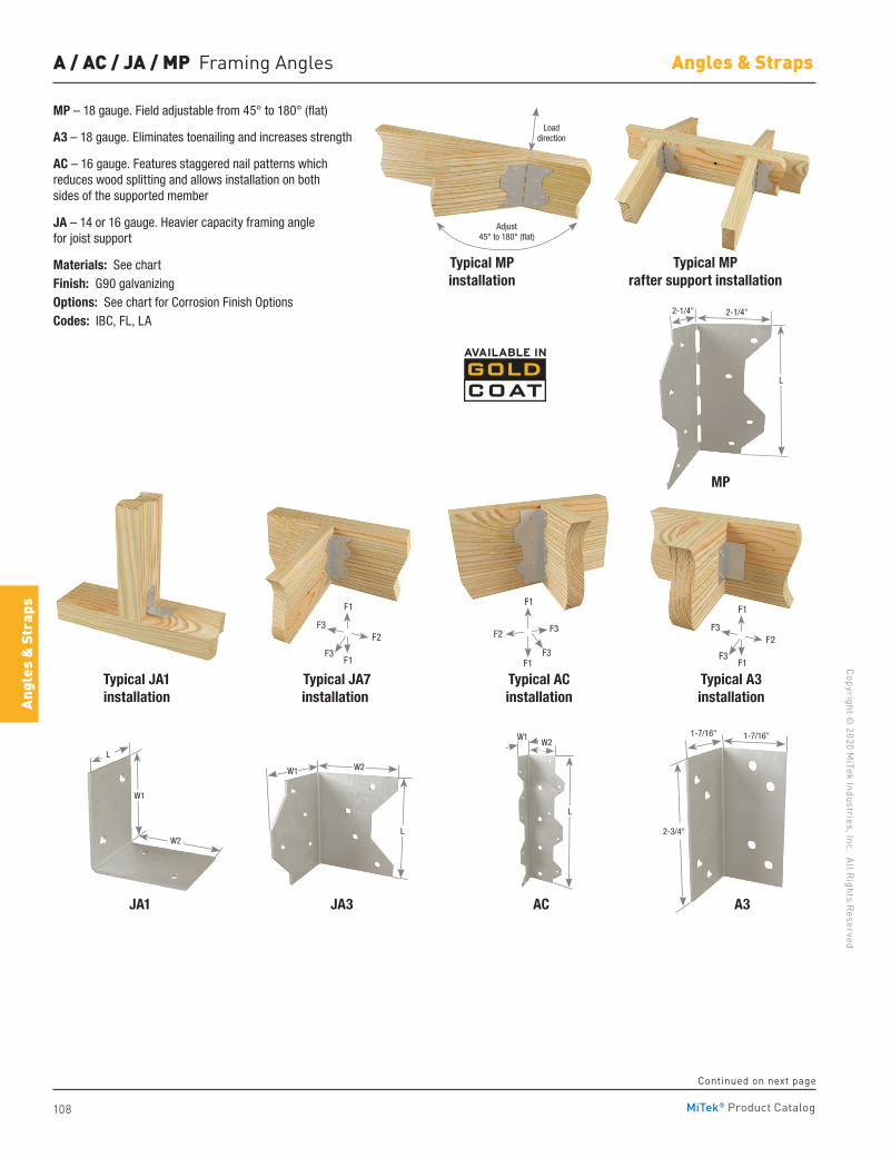
108
Copyright © 2020 M
iTek Industries, Inc. All Rights Reserved
Angles & Straps
Angl
es &
Str
aps
MiTek® Product Catalog
A / AC / JA / MP Framing Angles
Typical MP rafter support installation
Typical MP installation
MP
Typical JA1installation
JA3JA1
Typical JA7installation
Typical ACinstallation
Typical A3installation
A3AC
MP – 18 gauge. Field adjustable from 45° to 180° (flat)
A3 – 18 gauge. Eliminates toenailing and increases strength
AC – 16 gauge. Features staggered nail patterns which reduces wood splitting and allows installation on both sides of the supported member
JA – 14 or 16 gauge. Heavier capacity framing angle for joist support
Materials: See chartFinish: G90 galvanizingOptions: See chart for Corrosion Finish OptionsCodes: IBC, FL, LA
L
2-1/4"
Adjust 45° to 180° (flat)
Load direction
2-1/4"
W1W2
2-3/4"
1-7/16" 1-7/16"
L
L
W1 W2
W1
W2
L
F3
F3F2
F1
F1
F3
F3
F1
F1
F2F3
F3
F1
F1
F2
Continued on next page
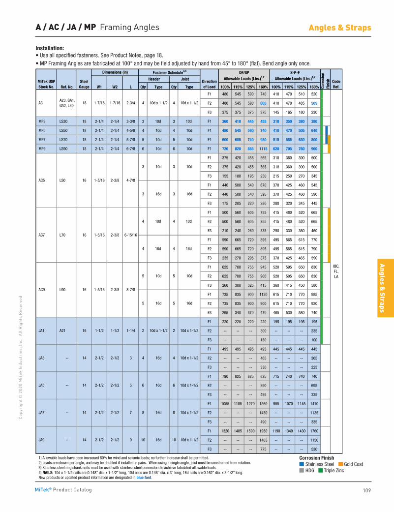
109
Copy
righ
t © 2
020
MiT
ek In
dust
ries
, Inc
. Al
l Rig
hts
Rese
rved
Angles & Straps
Angles & Straps
MiTek® Product Catalog
A / AC / JA / MP Framing Angles
Ref. No. W1 W2 L Qty Type Qty Type 100% 115% 125% 160% 100% 115% 125% 160%
F1 480 545 590 740 410 470 510 520
F2 480 545 590 605 410 470 485 505
F3 375 375 375 375 145 165 180 230
MP3 LS30 18 2-1/4 2-1/4 3-3/8 3 10d 3 10d F1 360 410 445 455 310 350 380 380
MP5 LS50 18 2-1/4 2-1/4 4-5/8 4 10d 4 10d F1 480 545 590 740 410 470 505 640
MP7 LS70 18 2-1/4 2-1/4 5-7/8 5 10d 5 10d F1 600 685 740 930 515 585 630 800
MP9 LS90 18 2-1/4 2-1/4 6-7/8 6 10d 6 10d F1 720 820 885 1115 620 705 760 960
F1 375 420 455 565 310 360 390 500
F2 375 420 455 565 310 360 390 500
F3 155 180 195 250 215 250 270 345
F1 440 500 540 670 370 425 460 545
F2 440 500 540 595 370 425 460 590
F3 175 205 220 280 280 320 345 445
F1 500 560 605 755 415 480 520 665
F2 500 560 605 755 415 480 520 665
F3 210 240 260 335 290 330 360 460
F1 590 665 720 895 495 565 615 770
F2 590 665 720 895 495 565 615 790
F3 235 270 295 375 370 425 465 590
F1 625 700 755 945 520 595 650 830
F2 625 700 755 900 520 595 650 830
F3 260 300 325 415 360 415 450 580
F1 735 835 900 1120 615 710 770 985
F2 735 835 900 900 615 710 770 920
F3 295 340 370 470 465 530 580 740
F1 220 220 220 220 195 195 195 195
F2 -- -- -- 300 -- -- -- 235
F3 -- -- -- 150 -- -- -- 100
F1 495 495 495 495 445 445 445 445
F2 -- -- -- 465 -- -- -- 365
F3 -- -- -- 330 -- -- -- 225
F1 790 825 825 825 715 740 740 740
F2 -- -- -- 890 -- -- -- 695
F3 -- -- -- 495 -- -- -- 335
F1 1055 1185 1270 1560 955 1070 1145 1410
F2 -- -- -- 1450 -- -- -- 1135
F3 -- -- -- 490 -- -- -- 335
F1 1320 1485 1590 1950 1190 1340 1430 1760
F2 -- -- -- 1465 -- -- -- 1150
F3 -- -- -- 775 -- -- -- 530
1) Allowable loads have been increased 60% for wind and seismic loads; no further increase shall be permitted. 2) Loads are shown per angle, and may be doubled if installed in pairs. When using a single angle, joist must be constrained from rotation. 3) Stainless steel ring shank nails must be used with stainless steel connectors to achieve tabulated allowable loads. 4) NAILS: 10d x 1-1/2 nails are 0.148" dia. x 1-1/2" long, 10d nails are 0.148" dia. x 3" long, 16d nails are 0.162" dia. x 3-1/2" long. New products or updated product information are designated in blue font.
Fastener Schedule3,4
10d x 1-1/2
7
Header Directionof Load
2-1/2 2-1/2
62-1/2 2-1/2 5 16d
3
1-5/16 2-3/8
16d
10d x 1-1/2
16d 4
2-3/4 4
10d x 1-1/2
10d x 1-1/2
10d x 1-1/2
SteelGauge
4
CodeRef.
10d
1-1/2
MiTek USPStock No.
3
4-7/8
10d
16d
AC5 L50 16
AC9 L90 16 1-5/16
AC7 L70 16 1-5/16
16d
10d
Joist
JA1 A21 16 1-1/4 2
JA5 -- 14
JA3 -- 14
A3 A23, GA1, GA2, L30
18 1-7/16 1-7/16
10d
16d
10d x 1-1/2
10d
16d
4
JA9 -- 14 9 10
JA7 -- 14 2-1/2 8
102-1/2 2-1/2
16d 8
16d
2
4
1-1/2
6
10d x 1-1/2
10d x 1-1/2
Dimensions (in) DF/SP
Allowable Loads (Lbs.)1,2
S-P-F
Allowable Loads (Lbs.)1,2
IBC,FL,LA
Corr
osio
nFi
nish
2-1/2
3 3
3
2-3/8 8-7/8
5 5
5 5
2-3/8 6-15/16
4
4 4
10d
16d
Corrosion Finish Stainless Steel Gold Coat HDG Triple Zinc
Corrosion Finish Stainless Steel Gold Coat HDG Triple Zinc
Corrosion Finish Stainless Steel Gold Coat HDG Triple Zinc
Installation:• Use all specified fasteners. See Product Notes, page 18.• MP Framing Angles are fabricated at 100° and may be field adjusted by hand from 45° to 180° (flat). Bend angle only once.
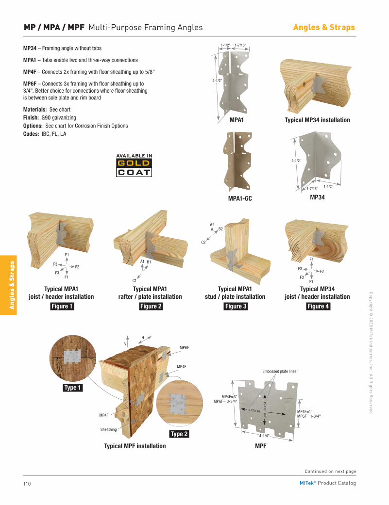
110
Copyright © 2020 M
iTek Industries, Inc. All Rights Reserved
Angles & Straps
Angl
es &
Str
aps
MiTek® Product Catalog
MP / MPA / MPF Multi-Purpose Framing Angles
MP34 – Framing angle without tabs
MPA1 – Tabs enable two and three-way connections
MP4F – Connects 2x framing with floor sheathing up to 5/8"
MP6F – Connects 3x framing with floor sheathing up to 3/4". Better choice for connections where floor sheathing is between sole plate and rim board
Materials: See chartFinish: G90 galvanizingOptions: See chart for Corrosion Finish OptionsCodes: IBC, FL, LA
MP34MPA1-GC
MPA1 Typical MP34 installation
Typical MPA1joist / header installation
Typical MPA1rafter / plate installation
Typical MPF installation
Typical MPA1stud / plate installation
MPF
Typical MP34joist / header installation
1-7/16"1-1/2"
4-1/2"
2-1/2"
1-1/2"1-7/16"
Embossed plate lines
MP4F=1"MP6F= 1-3/4"
MP4F=3"MP6F= 3-3/4"
4-1/4"
Figure 1
Type 1
Figure 3
Type 2
Figure 2 Figure 4
MP6FV
H
MP4F
MP4F
Sheathing
F3F2
F3
F1
F1
F3F2
F3
F1
F1
B1
C1
A1
B2
C2
A2
Continued on next page
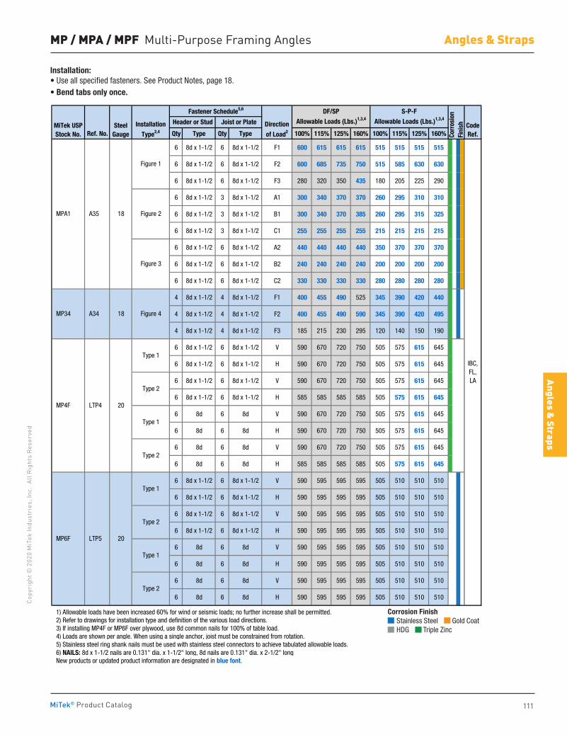
111
Copy
righ
t © 2
020
MiT
ek In
dust
ries
, Inc
. Al
l Rig
hts
Rese
rved
Angles & Straps
Angles & Straps
MiTek® Product Catalog
MP / MPA / MPF Multi-Purpose Framing Angles
Ref. No. Qty Type Qty Type 100% 115% 125% 160% 100% 115% 125% 160%
6 8d x 1-1/2 6 8d x 1-1/2 F1 600 615 615 615 515 515 515 515
6 8d x 1-1/2 6 8d x 1-1/2 F2 600 685 735 750 515 585 630 630
6 8d x 1-1/2 6 8d x 1-1/2 F3 280 320 350 435 180 205 225 290
6 8d x 1-1/2 3 8d x 1-1/2 A1 300 340 370 370 260 295 310 310
6 8d x 1-1/2 3 8d x 1-1/2 B1 300 340 370 385 260 295 315 325
6 8d x 1-1/2 3 8d x 1-1/2 C1 255 255 255 255 215 215 215 215
6 8d x 1-1/2 6 8d x 1-1/2 A2 440 440 440 440 350 370 370 370
6 8d x 1-1/2 6 8d x 1-1/2 B2 240 240 240 240 200 200 200 200
6 8d x 1-1/2 6 8d x 1-1/2 C2 330 330 330 330 280 280 280 280
4 8d x 1-1/2 4 8d x 1-1/2 F1 400 455 490 525 345 390 420 440
4 8d x 1-1/2 4 8d x 1-1/2 F2 400 455 490 590 345 390 420 495
4 8d x 1-1/2 4 8d x 1-1/2 F3 185 215 230 295 120 140 150 190
6 8d x 1-1/2 6 8d x 1-1/2 V 590 670 720 750 505 575 615 645
6 8d x 1-1/2 6 8d x 1-1/2 H 590 670 720 750 505 575 615 645
6 8d x 1-1/2 6 8d x 1-1/2 V 590 670 720 750 505 575 615 645
6 8d x 1-1/2 6 8d x 1-1/2 H 585 585 585 585 505 575 615 645
6 8d 6 8d V 590 670 720 750 505 575 615 645
6 8d 6 8d H 590 670 720 750 505 575 615 645
6 8d 6 8d V 590 670 720 750 505 575 615 645
6 8d 6 8d H 585 585 585 585 505 575 615 645
6 8d x 1-1/2 6 8d x 1-1/2 V 590 595 595 595 505 510 510 510
6 8d x 1-1/2 6 8d x 1-1/2 H 590 595 595 595 505 510 510 510
6 8d x 1-1/2 6 8d x 1-1/2 V 590 595 595 595 505 510 510 510
6 8d x 1-1/2 6 8d x 1-1/2 H 590 595 595 595 505 510 510 510
6 8d 6 8d V 590 595 595 595 505 510 510 510
6 8d 6 8d H 590 595 595 595 505 510 510 510
6 8d 6 8d V 590 595 595 595 505 510 510 510
6 8d 6 8d H 590 595 595 595 505 510 510 510
1) Allowable loads have been increased 60% for wind or seismic loads; no further increase shall be permitted. 2) Refer to drawings for installation type and definition of the various load directions. 3) If installing MP4F or MP6F over plywood, use 8d common nails for 100% of table load. 4) Loads are shown per angle. When using a single anchor, joist must be constrained from rotation. 5) Stainless steel ring shank nails must be used with stainless steel connectors to achieve tabulated allowable loads. 6) NAILS: 8d x 1-1/2 nails are 0.131" dia. x 1-1/2" long, 8d nails are 0.131" dia. x 2-1/2" long New products or updated product information are designated in blue font.
IBC,FL,LA
CodeRef.
Fastener Schedule5,6
Corr
osio
nFi
nish
DF/SP
Allowable Loads (Lbs.)1,3,4
S-P-F
Allowable Loads (Lbs.)1,3,4
SteelGauge
Direction
of Load2
A35
MiTek USPStock No.
Installation
Type2,4
Joist or PlateHeader or Stud
MPA1
Figure 1
Figure 2
Figure 3
18
Type 1
Type 2
MP6F LTP5 20
MP34
Type 1
Type 2
Type 1
Type 2
MP4F LTP4 20
Type 1
Type 2
A34 18 Figure 4
Corrosion Finish Stainless Steel Gold Coat HDG Triple Zinc
Corrosion Finish Stainless Steel Gold Coat HDG Triple Zinc
Corrosion Finish Stainless Steel Gold Coat HDG Triple Zinc
Installation:• Use all specified fasteners. See Product Notes, page 18.• Bend tabs only once.
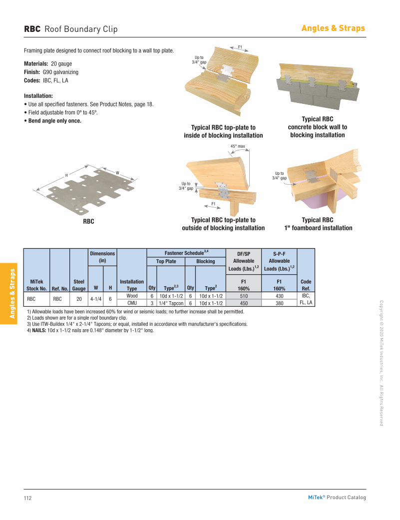
112
Copyright © 2020 M
iTek Industries, Inc. All Rights Reserved
Angles & Straps
Angl
es &
Str
aps
MiTek® Product Catalog
RBC Roof Boundary Clip
Framing plate designed to connect roof blocking to a wall top plate.
Materials: 20 gaugeFinish: G90 galvanizingCodes: IBC, FL, LA
Installation:• Use all specified fasteners. See Product Notes, page 18.• Field adjustable from 0º to 45º.• Bend angle only once. Typical RBC
concrete block wall to blocking installation
Typical RBC top-plate to inside of blocking installation
Typical RBC top-plate to outside of blocking installation
RBC Typical RBC 1" foamboard installation
Ref. No. W H Qty Type2,3 Qty Type2
Wood 6 10d x 1-1/2 6 10d x 1-1/2 510 430CMU 3 1/4" Tapcon 6 10d x 1-1/2 450 380
1) Allowable loads have been increased 60% for wind or seismic loads; no further increase shall be permitted. 2) Loads shown are for a single roof boundary clip. 3) Use ITW-Buildex 1/4" x 2-1/4" Tapcons; or equal, installed in accordance with manufacturer's specifications. 4) NAILS: 10d x 1-1/2 nails are 0.148" diameter by 1-1/2" long.
IBC,FL, LA
RBC RBC 20 4-1/4 6
MiTekStock No.
Fastener Schedule3,4
CodeRef.
SteelGauge
F1160%
F1160%
DF/SPAllowable
Loads (Lbs.)1,2
S-P-FAllowable
Loads (Lbs.)1,2
Installation Type
Dimensions(in) Top Plate Blocking
WH
F1
Up to 3/4" gap
Up to 3/4" gap
F1
45° max
Up to 3/4" gap
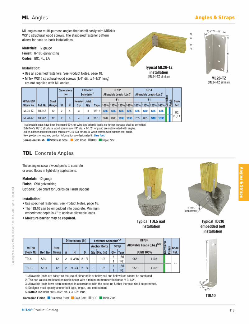
113
Copy
righ
t © 2
020
MiT
ek In
dust
ries
, Inc
. Al
l Rig
hts
Rese
rved
Angles & Straps
Angles & Straps
MiTek® Product Catalog
Corrosion Finish Stainless Steel Gold Coat HDG Triple Zinc
Corrosion Finish Stainless Steel Gold Coat HDG Triple Zinc
Corrosion Finish Stainless Steel Gold Coat HDG Triple Zinc
ML angles are multi-purpose angles that install easily with MiTek’s WS15 structural wood screws. The staggered fastener pattern allows for back-to-back installations.
Materials: 12 gau geFinish: G-185 galvanizingCodes: IBC, FL, LA
Installation:• Use all specified fasteners. See Product Notes, page 18.• MiTek WS15 structural wood screws (1/4" dia. x 1-1/2" long)
are not supplied with ML angles.ML26-TZ
(ML24-TZ similar)
WW
H
Ref. No. W H Type 100% 115% 125% 160% 100% 115% 125% 160%
ML24-TZ ML24Z 12 2 4 3 3 WS15 655 655 655 655 565 650 655 655
ML26-TZ ML26Z 12 2 6 4 4 WS15 920 1060 1090 1090 755 865 940 1090
1) Allowable loads have been increased 60% for wind and seismic loads; no further increase shall be permitted. 2) MiTek's WS15 structural wood screws are 1/4" dia. x 1-1/2" long and are not included with angles. 3) For exterior applications use MiTek's WS15-EXT structural wood screws with exterior coat finish. New products or updated product information are designated in blue font.
IBC,FL, LA
MiTek USPStock No.
SteelGauge
F1 F1
Corr
osio
n Fi
nish
DF/SP
Allowable Loads (Lbs.)1
S-P-F
Allowable Loads (Lbs.)1Dimensions
(in)
CodeRef.
HeaderQty
JoistQty
Fastener
Schedule2,3
F1
Typical ML26-TZinstallation
(ML24-TZ similar)
ML Angles
F1
TDL Concrete Angles
These angles secure wood posts to concrete or wood floors in light-duty applications.
Materials: 12 gaugeFinish: G90 galvanizingOptions: See chart for Corrosion Finish Options
Installation:• Use specified fasteners. See Product Notes, page 18.• The TDL10 can be embedded into concrete. Minimum
embedment depth is 4" to achieve allowable loads.• Moisture barrier may be required.
TDL10
Typical TDL10 embedded bolt
installation
Typical TDL5 nail installation
Corrosion Finish Stainless Steel Gold Coat HDG Triple Zinc
Corrosion Finish Stainless Steel Gold Coat HDG Triple Zinc
Corrosion Finish Stainless Steel Gold Coat HDG Triple Zinc
Anchor Bolts
Ref. No. W H D Qty Dia. (in) Qty Type4 16d1 1/24 16d1 1/2
1) Allowable loads are based on the use of either nails or bolts; nail and bolt values cannot be combined. 2) The bolt values are based on single shear with a minimum member thickness of 3-1/2". 3) Allowable loads have been increased in accordance with the code; no further increase shall be permitted. 4) Designer must specify anchor bolt type, length, and embedment. 5) NAILS: 16d nails are 0.162" dia. x 3-1/2" long.
Corr
osio
nFi
nish
955 1105--
MiTekStock No.
Dimensions (in)
CodeRef.
Fastener Schedule4,5
Uplift 160%Steel
Gauge
TDL5 A24 12 2 2-1/45-3/16 1 1/2 955 1105
DF/SP
Allowable Loads (Lbs.)1,2,3Strap
2-1/4 1 1/2 TDL10 A311 12 2 9-3/4
4" min.embedment
H
D
W
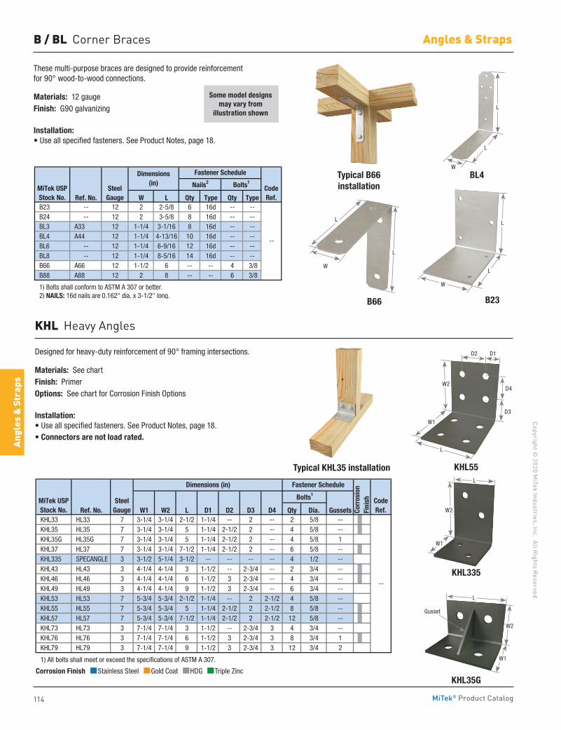
114
Copyright © 2020 M
iTek Industries, Inc. All Rights Reserved
Angles & Straps
Angl
es &
Str
aps
MiTek® Product Catalog
KHL Heavy Angles
These multi-purpose braces are designed to provide reinforcement for 90° wood-to-wood connections.
Materials: 12 gaugeFinish: G90 galvanizing
Installation:• Use all specified fasteners. See Product Notes, page 18.
B66 B23
Typical B66installation
BL4
B / BL Corner Braces
Ref. No. W L Qty Type Qty Type B23 -- 12 2 2-5/8 6 16d -- -- B24 -- 12 2 3-5/8 8 16d -- -- BL3 A33 12 1-1/4 3-1/16 8 16d -- -- BL4 A44 12 1-1/4 4-13/16 10 16d -- -- BL6 -- 12 1-1/4 6-9/16 12 16d -- -- BL8 -- 12 1-1/4 8-5/16 14 16d -- -- B66 A66 12 1-1/2 6 -- -- 4 3/8 B88 A88 12 2 8 -- -- 6 3/8
1) Bolts shall conform to ASTM A 307 or better. 2) NAILS: 16d nails are 0.162" dia. x 3-1/2" long.
--
Bolts1
Fastener Schedule
MiTek USPStock No.
SteelGauge
Nails2
CodeRef.
Dimensions(in)
Some model designs may vary from
illustration shownL
L
W
L
W
L
Designed for heavy-duty reinforcement of 90° framing intersections.
Materials: See chartFinish: PrimerOptions: See chart for Corrosion Finish Options
Installation:• Use all specified fasteners. See Product Notes, page 18.• Connectors are not load rated.
KHL335
KHL35G
Typical KHL35 installation KHL55
Ref. No. W1 W2 L D1 D2 D3 D4 Qty Dia. Gussets KHL33 HL33 7 3-1/4 3-1/4 2-1/2 1-1/4 -- 2 -- 2 5/8 -- KHL35 HL35 7 3-1/4 3-1/4 5 1-1/4 2-1/2 2 -- 4 5/8 -- KHL35G HL35G 7 3-1/4 3-1/4 5 1-1/4 2-1/2 2 -- 4 5/8 1 KHL37 HL37 7 3-1/4 3-1/4 7-1/2 1-1/4 2-1/2 2 -- 6 5/8 -- KHL335 SPECANGLE 3 3-1/2 5-1/4 3-1/2 -- -- -- -- 4 1/2 -- KHL43 HL43 3 4-1/4 4-1/4 3 1-1/2 -- 2-3/4 -- 2 3/4 -- KHL46 HL46 3 4-1/4 4-1/4 6 1-1/2 3 2-3/4 -- 4 3/4 -- KHL49 HL49 3 4-1/4 4-1/4 9 1-1/2 3 2-3/4 -- 6 3/4 -- KHL53 HL53 7 5-3/4 5-3/4 2-1/2 1-1/4 -- 2 2-1/2 4 5/8 -- KHL55 HL55 7 5-3/4 5-3/4 5 1-1/4 2-1/2 2 2-1/2 8 5/8 -- KHL57 HL57 7 5-3/4 5-3/4 7-1/2 1-1/4 2-1/2 2 2-1/2 12 5/8 -- KHL73 HL73 3 7-1/4 7-1/4 3 1-1/2 -- 2-3/4 3 4 3/4 -- KHL76 HL76 3 7-1/4 7-1/4 6 1-1/2 3 2-3/4 3 8 3/4 1 KHL79 HL79 3 7-1/4 7-1/4 9 1-1/2 3 2-3/4 3 12 3/4 2
1) All bolts shall meet or exceed the specifications of ASTM A 307.
CodeRef.
--
MiTek USPStock No.
SteelGauge
Dimensions (in)
Bolts1
Fastener Schedule
Corr
osio
nFi
nish
Corrosion Finish Stainless Steel Gold Coat HDG Triple Zinc
Corrosion Finish Stainless Steel Gold Coat HDG Triple Zinc
Corrosion Finish Stainless Steel Gold Coat HDG Triple Zinc
D2 D1
L
W1
W2
D3
D4
L
W1
W2
Gusset
L
W1
W2
L
L
W
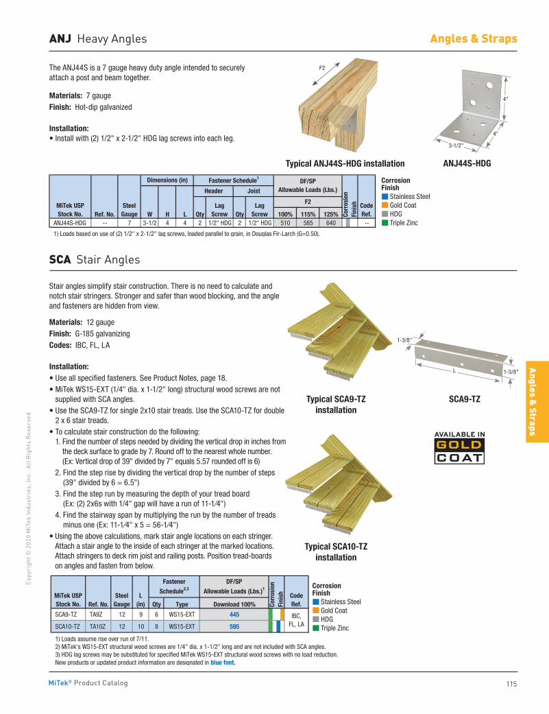
115
Copy
righ
t © 2
020
MiT
ek In
dust
ries
, Inc
. Al
l Rig
hts
Rese
rved
Angles & Straps
Angles & Straps
MiTek® Product Catalog
F2The ANJ44S is a 7 gauge heavy duty angle intended to securely attach a post and beam together.
Materials: 7 gaugeFinish: Hot-dip galvanized
Installation:• Install with (2) 1/2" x 2-1/2" HDG lag screws into each leg.
ANJ44S-HDGTypical ANJ44S-HDG installation
ANJ Heavy Angles
Ref. No. W H L Qty Qty 100% 115% 125% ANJ44S-HDG -- 7 3-1/2 4 4 2 1/2" HDG 2 1/2" HDG 510 585 640 --
1) Loads based on use of (2) 1/2" x 2-1/2" lag screws, loaded parallel to grain, in Douglas Fir-Larch (G=0.50).
CodeRef.
Dimensions (in)
MiTek USPStock No.
SteelGauge
Header Joist
Fastener Schedule1DF/SP
Allowable Loads (Lbs.)
F2Lag Screw
Lag Screw Co
rros
ion
Fini
sh
4"
4"
3-1/2"
SCA Stair Angles
Corrosion Finish Stainless Steel Gold Coat HDG Triple Zinc
Corrosion Finish Stainless Steel Gold Coat HDG Triple Zinc
Corrosion Finish Stainless Steel Gold Coat HDG Triple Zinc
Typical SCA9-TZ installation
SCA9-TZ
Typical SCA10-TZ installation
Stair angles simplify stair construction. There is no need to calculate and notch stair stringers. Stronger and safer than wood blocking, and the angle and fasteners are hidden from view.
Materials: 12 gaugeFinish: G-185 galvanizingCodes: IBC, FL, LA
Installation:• Use all specified fasteners. See Product Notes, page 18.• MiTek WS15-EXT (1/4" dia. x 1-1/2" long) structural wood screws are not
supplied with SCA angles.• Use the SCA9-TZ for single 2x10 stair treads. Use the SCA10-TZ for double
2 x 6 stair treads. • To calculate stair construction do the following:
1. Find the number of steps needed by dividing the vertical drop in inches from the deck surface to grade by 7. Round off to the nearest whole number. (Ex: Vertical drop of 39" divided by 7" equals 5.57 rounded off is 6)
2. Find the step rise by dividing the vertical drop by the number of steps (39" divided by 6 = 6.5")
3. Find the step run by measuring the depth of your tread board (Ex: (2) 2x6s with 1/4" gap will have a run of 11-1⁄4")
4. Find the stairway span by multiplying the run by the number of treads minus one (Ex: 11-1⁄4" x 5 = 56-1⁄4")
• Using the above calculations, mark stair angle locations on each stringer. Attach a stair angle to the inside of each stringer at the marked locations. Attach stringers to deck rim joist and railing posts. Position tread-boards on angles and fasten from below.
Ref. No. Qty Type Download 100%
SCA9-TZ TA9Z 12 9 6 WS15-EXT 445
SCA10-TZ TA10Z 12 10 8 WS15-EXT 595
1) Loads assume rise over run of 7/11. 2) MiTek's WS15-EXT structural wood screws are 1/4" dia. x 1-1/2" long and are not included with SCA angles. 3) HDG lag screws may be substituted for specified MiTek WS15-EXT structural wood screws with no load reduction. New products or updated product information are designated in blue font.
IBC,FL, LA
CodeRef.
MiTek USPStock No.
SteelGauge
L(in) Co
rros
ion
Fini
sh
DF/SP
Allowable Loads (Lbs.)1
Fastener
Schedule2,3
Corrosion Finish Stainless Steel Gold Coat HDG Triple Zinc
Corrosion Finish Stainless Steel Gold Coat HDG Triple Zinc
Corrosion Finish Stainless Steel Gold Coat HDG Triple Zinc
L 1-3/8"
1-3/8"
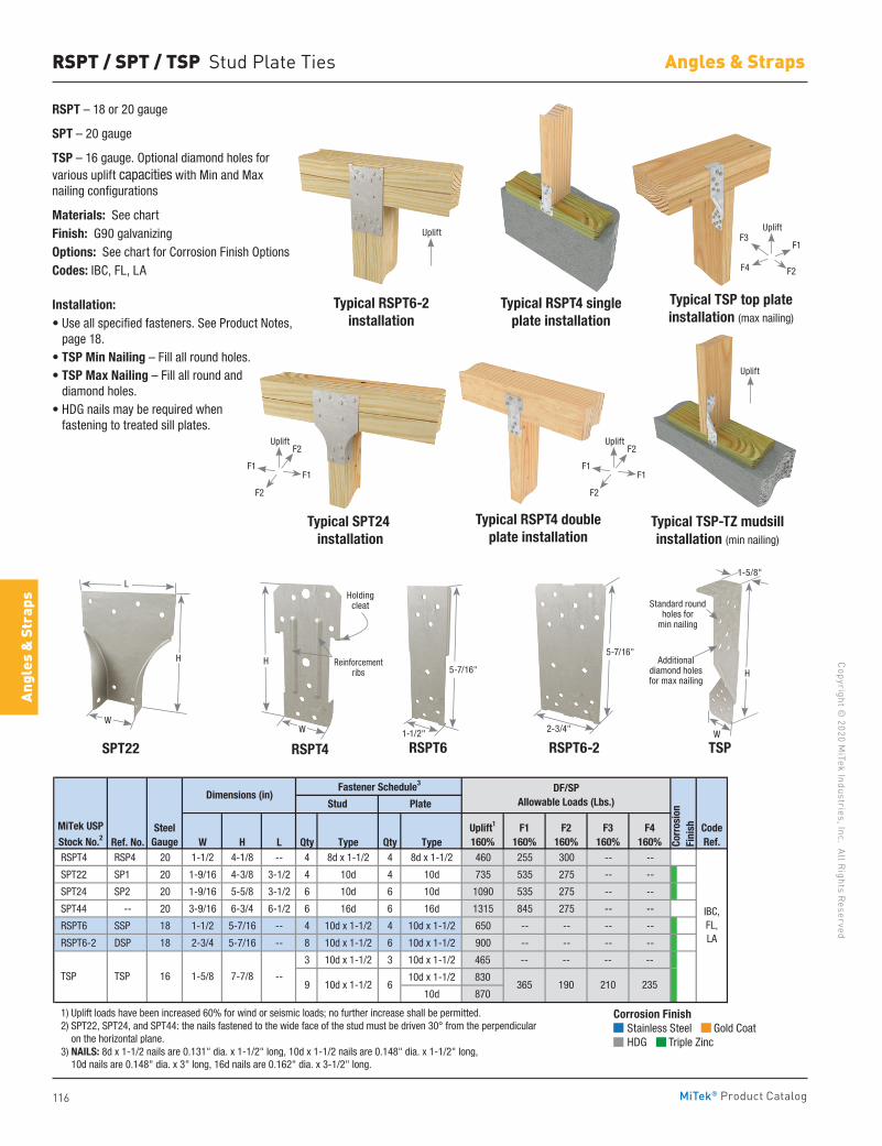
116
Copyright © 2020 M
iTek Industries, Inc. All Rights Reserved
Angles & Straps
Angl
es &
Str
aps
MiTek® Product Catalog
RSPT / SPT / TSP Stud Plate Ties
RSPT – 18 or 20 gauge
SPT – 20 gauge
TSP – 16 gauge. Optional diamond holes for various uplift capacities with Min and Max nailing configurations
Materials: See chartFinish: G90 galvanizingOptions: See chart for Corrosion Finish OptionsCodes: IBC, FL, LA
Installation:• Use all specified fasteners. See Product Notes,
page 18.• TSP Min Nailing – Fill all round holes.• TSP Max Nailing – Fill all round and
diamond holes.• HDG nails may be required when
fastening to treated sill plates.
Typical SPT24 installation
SPT22
Typical RSPT6-2 installation
RSPT6-2RSPT6
Typical RSPT4 single plate installation
Typical RSPT4 double plate installation
RSPT4
H
W
Reinforcementribs
Holding cleat
Ref. No. W H L Qty Type Qty Type RSPT4 RSP4 20 1-1/2 4-1/8 -- 4 8d x 1-1/2 4 8d x 1-1/2 460 255 300 -- --
SPT22 SP1 20 1-9/16 4-3/8 3-1/2 4 10d 4 10d 735 535 275 -- --
SPT24 SP2 20 1-9/16 5-5/8 3-1/2 6 10d 6 10d 1090 535 275 -- --
SPT44 -- 20 3-9/16 6-3/4 6-1/2 6 16d 6 16d 1315 845 275 -- --
RSPT6 SSP 18 1-1/2 5-7/16 -- 4 10d x 1-1/2 4 10d x 1-1/2 650 -- -- -- --
RSPT6-2 DSP 18 2-3/4 5-7/16 -- 8 10d x 1-1/2 6 10d x 1-1/2 900 -- -- -- --
3 10d x 1-1/2 3 10d x 1-1/2 465 -- -- -- --
10d x 1-1/2 830
10d 870
1) Uplift loads have been increased 60% for wind or seismic loads; no further increase shall be permitted. 2) SPT22, SPT24, and SPT44: the nails fastened to the wide face of the stud must be driven 30° from the perpendicular on the horizontal plane. 3) NAILS: 8d x 1-1/2 nails are 0.131" dia. x 1-1/2" long, 10d x 1-1/2 nails are 0.148" dia. x 1-1/2" long, 10d nails are 0.148" dia. x 3" long, 16d nails are 0.162" dia. x 3-1/2" long.
1-5/8 7-7/8 --235
IBC,FL,LA
CodeRef.
DF/SPAllowable Loads (Lbs.)
TSP TSP 16
Uplift1
160%F1
160%F4
160%
Dimensions (in)
Corr
osio
nFi
nish
Plate
MiTek USP
Stock No.2Steel
Gauge
Fastener Schedule3
Stud
F2160%
F3160%
210365 1909 10d x 1-1/2 6
H
L
W
5-7/16"
1-1/2"
5-7/16"
2-3/4"
TSP
H
1-5/8"
W
Additional diamond holes for max nailing
Standard round holes for
min nailing
Typical TSP top plate installation (max nailing)
Typical TSP-TZ mudsill installation (min nailing)
Uplift
F1F1
F2
F2
Uplift
F1F1
F2
F2
Uplift
Corrosion Finish Stainless Steel Gold Coat HDG Triple Zinc
Corrosion Finish Stainless Steel Gold Coat HDG Triple Zinc
Corrosion Finish Stainless Steel Gold Coat HDG Triple Zinc
F3
F2
F1
F4
UpliftUplift
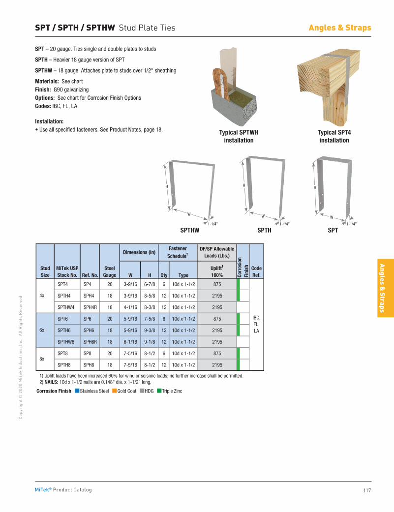
117
Copy
righ
t © 2
020
MiT
ek In
dust
ries
, Inc
. Al
l Rig
hts
Rese
rved
Angles & Straps
Angles & Straps
MiTek® Product Catalog
SPT / SPTH / SPTHW Stud Plate Ties
SPT – 20 gauge. Ties single and double plates to studs
SPTH – Heavier 18 gauge version of SPT
SPTHW – 18 gauge. Attaches plate to studs over 1/2" sheathing
Materials: See chartFinish: G90 galvanizingOptions: See chart for Corrosion Finish OptionsCodes: IBC, FL, LA
Installation:• Use all specified fasteners. See Product Notes, page 18.
SPTHW SPTH
Typical SPT4 installation
Typical SPTWH installation
SPT
Ref. No. W H Qty Type
SPT4 SP4 20 3-9/16 6-7/8 6 10d x 1-1/2 875
SPTH4 SPH4 18 3-9/16 8-5/8 12 10d x 1-1/2 2195
SPTHW4 SPH4R 18 4-1/16 8-3/8 12 10d x 1-1/2 2195
SPT6 SP6 20 5-9/16 7-5/8 6 10d x 1-1/2 875
SPTH6 SPH6 18 5-9/16 9-3/8 12 10d x 1-1/2 2195
SPTHW6 SPH6R 18 6-1/16 9-1/8 12 10d x 1-1/2 2195
SPT8 SP8 20 7-5/16 8-1/2 6 10d x 1-1/2 875
SPTH8 SPH8 18 7-5/16 8-1/2 12 10d x 1-1/2 2195
1) Uplift loads have been increased 60% for wind or seismic loads; no further increase shall be permitted. 2) NAILS: 10d x 1-1/2 nails are 0.148" dia. x 1-1/2" long.
8x
IBC,FL,LA
Fastener
Schedule2
Uplift1
160%
Dimensions (in)
Corr
osio
nFi
nishStud
SizeMiTek USPStock No.
SteelGauge
4x
6x
CodeRef.
DF/SP Allowable Loads (Lbs.)
H
W
1-1/4"
H
W
1-1/4"
W
H
1-1/4"
Corrosion Finish Stainless Steel Gold Coat HDG Triple Zinc
Corrosion Finish Stainless Steel Gold Coat HDG Triple Zinc
Corrosion Finish Stainless Steel Gold Coat HDG Triple Zinc
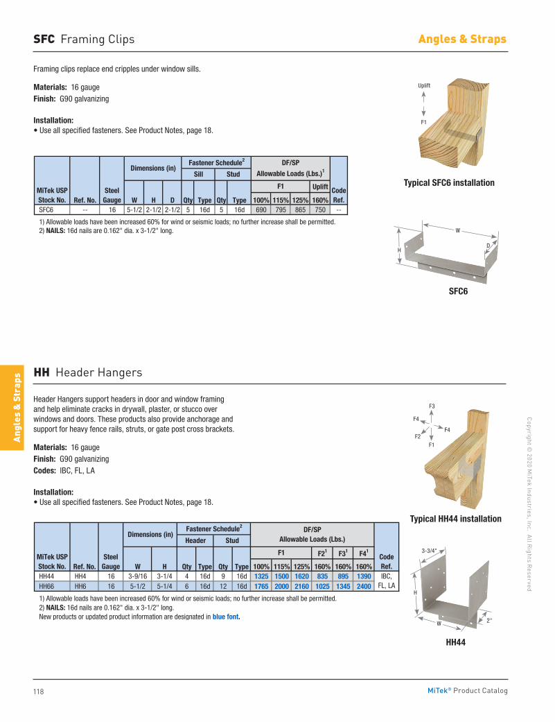
118
Copyright © 2020 M
iTek Industries, Inc. All Rights Reserved
Angles & Straps
Angl
es &
Str
aps
MiTek® Product Catalog
SFC Framing Clips
Framing clips replace end cripples under window sills.
Materials: 16 gaugeFinish: G90 galvanizing
Installation:• Use all specified fasteners. See Product Notes, page 18.
Header Hangers support headers in door and window framing and help eliminate cracks in drywall, plaster, or stucco over windows and doors. These products also provide anchorage and support for heavy fence rails, struts, or gate post cross brackets.
Materials: 16 gaugeFinish: G90 galvanizingCodes: IBC, FL, LA
Installation:• Use all specified fasteners. See Product Notes, page 18.
SFC6
HH44
Typical SFC6 installation
Typical HH44 installation
HH Header Hangers
Uplift
Ref. No. W H D Qty Type Qty Type 100% 115% 125% 160% SFC6 -- 16 5-1/2 2-1/2 2-1/2 5 16d 5 16d 690 795 865 750 --
1) Allowable loads have been increased 60% for wind or seismic loads; no further increase shall be permitted. 2) NAILS: 16d nails are 0.162" dia. x 3-1/2" long.
CodeRef.
Fastener Schedule2
MiTek USPStock No.
SteelGauge
F1
Sill Stud
DF/SP
Allowable Loads (Lbs.)1Dimensions (in)
F21 F31 F41
Ref. No. W H Qty Type Qty Type 100% 115% 125% 160% 160% 160% HH44 HH4 16 3-9/16 3-1/4 4 16d 9 16d 1325 1500 1620 835 895 1390 HH66 HH6 16 5-1/2 5-1/4 6 16d 12 16d 1765 2000 2160 1025 1345 2400
1) Allowable loads have been increased 60% for wind or seismic loads; no further increase shall be permitted. 2) NAILS: 16d nails are 0.162" dia. x 3-1/2" long. New products or updated product information are designated in blue font.
CodeRef.IBC,
FL, LA
MiTek USPStock No.
SteelGauge
F1
Header Stud
Fastener Schedule2DF/SP
Allowable Loads (Lbs.)Dimensions (in)
2"W
H
3-3/4"
W
HD
Uplift
F1
F4
F4F2
F3
F1
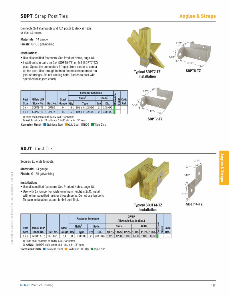
119
Copy
righ
t © 2
020
MiT
ek In
dust
ries
, Inc
. Al
l Rig
hts
Rese
rved
Angles & Straps
Angles & Straps
MiTek® Product Catalog
SDPT Strap Post Ties
SDPT7-TZ
SDPT5-TZ Typical SDPT7-TZinstallation
Connects 2x4 stair posts and 4x4 posts to deck rim joist or stair stringers.
Materials: 14 gaugeFinish: G-185 galvanizing
Installation:• Use all specified fasteners. See Product Notes, page 18. • Install units in pairs on 2x4 (SDPT5-TZ) or 4x4 (SDPT7-TZ)
post. Space the connectors 5" apart from center to center on the post. Use through bolts to fasten connectors to rim joist or stringer. Do not use lag bolts. Fasten to post with specified nails (see chart).
Ref. No. Qty Type Qty Dia.2 x 4 SDPT5-TZ DPT5Z 14 5 10d x 1-1/2 HDG 2 3/8 HDG
4 x 4 SDPT7-TZ DPT7Z 14 5 10d x 1-1/2 HDG 2 3/8 HDG
1) Bolts shall conform to ASTM A 307 or better. 2) NAILS: 10d x 1-1/2 nails are 0.148" dia. x 1-1/2" long.
Corr
osio
nFi
nish
Fastener Schedule
CodeRef.
--
Post Size
MiTek USPStock No.
SteelGauge
Nails2 Bolts1Corrosion Finish Stainless Steel Gold Coat HDG Triple Zinc
Corrosion Finish Stainless Steel Gold Coat HDG Triple Zinc
Corrosion Finish Stainless Steel Gold Coat HDG Triple Zinc
1-1/2"
1-1/2"
3-1/2"
3-1/2"
3-1/2"
3-1/2"
SDJT14-TZTypical SDJT14-TZinstallation
SDJT Joist Tie
Secures 2x joists to posts.
Materials: 14 gaugeFinish: G-185 galvanizing
Installation:• Use all specified fasteners. See Product Notes, page 18. • Use with 2x lumber for joists (minimum height is 2x4). Install
with either specified nails or through bolts. Do not use lag bolts. To ease installation, attach to 4x4 post first.
Ref. No. Qty Type Qty Dia. 100% 115% 125% 100% 115% 125%4 x 4 SDJT14-TZ DJT14Z 14 8 16d HDG 2 3/8 HDG 1120 1290 1400 1400 1400 1400 --
1) Bolts shall conform to ASTM A 307 or better. 2) NAILS: 16d HDG nails are 0.162" dia. x 3-1/2" long.
DF/SPAllowable Loads (Lbs.)
Fastener Schedule
CodeRef.
Post Size
Nails BoltsMiTek USPStock No.
SteelGauge
Nails2 Bolts1
Corr
osio
nFi
nish
3-1/8"
3-1/8"
2-3/4"
Corrosion Finish Stainless Steel Gold Coat HDG Triple Zinc
Corrosion Finish Stainless Steel Gold Coat HDG Triple Zinc
Corrosion Finish Stainless Steel Gold Coat HDG Triple Zinc
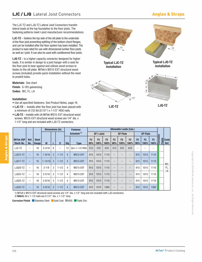
120
Copyright © 2020 M
iTek Industries, Inc. All Rights Reserved
Angles & Straps
Angl
es &
Str
aps
MiTek® Product Catalog
F2 F2
LJC / LJQ Lateral Joist Connectors
The LJC-TZ and LJQ-TZ Lateral Joist Connectors transfer lateral loads at the top foundation to the floor joists. The fastening patterns meet I-joist manufacturer recommendations.
LJC-TZ – fastens the top side of the sill plate to the underside of the floor joist preventing splitting of the bottom chord flanges, and can be installed after the floor system has been installed. The product is load rated for use with dimensional lumber floor joists as well as I-joist. It can also be used with cantilevered floor joists.
LJQ-TZ – is a higher capacity connector designed for higher loads. It is similar in design to a joist hanger with a seat for the floor joist to bear against and utilizes wood screws to fasten to the sill plate. MiTek’s WS15-EXT structural wood screws (included) provide quick installation without the need to predrill holes.
Materials: See chartFinish: G-185 galvanizingCodes: IBC, FL, LA
Installation:• Use all specified fasteners. See Product Notes, page 18.• LJC-TZ – Installs after the floor joist has been placed with
a minimum of (12) 8d (0.131") x 1-1/2" HDG nails.• LJQ-TZ – Installs with (4) MiTek WS15-EXT structural wood
screws. WS15-EXT structural wood screws are 1/4" dia. x 1-1/2" long and are included with LJQ-TZ connectors.
LJC-TZ LJQ-TZ
Typical LJC-TZ installation
Typical LJQ-TZ installation
W L D Qty Type
LJC-TZ -- 18 3-3/16 8 -- 12 8d x 1-1/2 HDG 515 570 670 515 570 670 -- -- --
LJQ15-TZ -- 16 1-9/16 3 1-1/2 4 WS15-EXT 915 1015 1110 -- -- -- 915 1015 1110
LJQ17-TZ -- 16 1-13/16 3 1-1/2 4 WS15-EXT 915 1015 1110 -- -- -- 915 1015 1110
LJQ20-TZ -- 16 2-1/8 3 1-1/2 4 WS15-EXT 915 1015 1110 -- -- -- 915 1015 1110
LJQ23-TZ -- 16 2-5/16 3 1-1/2 4 WS15-EXT 915 1015 1110 -- -- -- 915 1015 1110
LJQ25-TZ -- 16 2-9/16 3 1-1/2 4 WS15-EXT 915 1015 1110 -- -- -- 915 1015 1110
LJQ35-TZ -- 16 3-9/16 3 1-1/2 4 WS15-EXT 915 1015 1260 -- -- -- 915 1015 1260
1) MiTek's WS15-EXT structural wood screws are 1/4" dia. x 1/2" long and are included with LJQ connectors. 2) NAILS: 8d x 1-1/2 nails are 0.131" dia. x 1-1/2" long.
IBC,FL,LA
Dimensions (in)
Corr
osio
nFi
nish
DF I-Joist DF Plate SP Plate
MiTek USPStock No.
Ref. No.
SteelGauge
CodeRef.
FastenerSchedule1,2
Allowable Loads (Lbs.)
F290%
F2100%
F2160%
F290%
F2100%
F2160%
F290%
F2100%
F2160%
L
D
W
W
L
1/2"
Corrosion Finish Stainless Steel Gold Coat HDG Triple Zinc
Corrosion Finish Stainless Steel Gold Coat HDG Triple Zinc
Corrosion Finish Stainless Steel Gold Coat HDG Triple Zinc
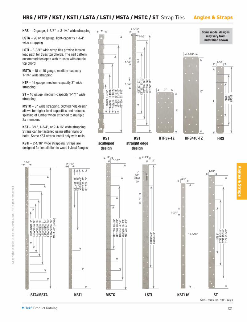
121
Copy
righ
t © 2
020
MiT
ek In
dust
ries
, Inc
. Al
l Rig
hts
Rese
rved
Angles & Straps
Angles & Straps
MiTek® Product Catalog
HRS – 12 gauge, 1-3/8" or 3-1/4" wide strapping
LSTA – 20 or 18 gauge, light-capacity 1-1/4" wide strapping
LSTI – 3-3/4" wide strap ties provide tension load path for truss top chords. The nail pattern accommodates open web trusses with double top chord
MSTA – 18 or 16 gauge, medium-capacity 1-1/4" wide strapping
HTP – 16 gauge, medium-capacity 3" wide strapping
ST – 16 gauge, medium-capacity 1-1/4" wide strapping
MSTC – 3" wide strapping. Slotted hole design allows for higher load capacities and reduces splitting of lumber when attached to multiple 2x members
KST – 3/4", 1-3/4", or 2-1/16" wide strapping. Straps can be fastened using either nails or bolts. Some KST straps install only with nails
KSTI – 2-1/16" wide strapping. Straps are designed for installation to wood I-Joist flanges
HRS / HTP / KST / KSTI / LSTA / LSTI / MSTA / MSTC / ST Strap Ties
Some model designs may vary from
illustration shown
KST scalloped
design
LSTA/MSTA KSTI MSTC LSTI KST116 ST
KSTstraight edge
design
HRS
1-3/8"
L HRS1
2HR
S8HR
S6
HTP37-TZ HRS416-TZ
16"
3-1/4"
3"
7"
W
KST2
9 9
-7/1
6"KS
T213
12-
11/1
6"KS
T216
15-
15/1
6"KS
T218
19-
3/16
"KS
T224
22-
7/16
"KS
T234
32-
3/16
"
2-1/16"
1-1/2"
KST2
27 2
7"KS
T237
37-
1/2"
KST2
48 4
8"KS
T260
60"
KST2
72 7
2"
4-1/2"
1-1/2"
1-1/4"
LSTA
/MST
A 9
"LS
TA/M
STA
12"
LSTA
/MST
A 1
5"LS
TA/M
STA
18"
LSTA
/MST
A 2
1"LS
TA/M
STA
24"
LSTA
/MST
A 3
0"LS
TA/M
STA
36"
MST
A 4
8" (s
imila
r)
2-1/16"
KSTI
226
26"
KSTI
236
36"
KSTI
248
48"
KSTI
260
60"
KSTI
272
72"
3"1-1/2"
MST
C28
28-
1/4"
MST
C40
40-
1/4"
MST
C52
52-1
/4"
MST
C66
65-
3/4"
MST
C78
77-
3/4"
3-3/4"2"
LSTI
49 4
9"LS
TI73
73"
3"
3/8" offset
typ
16-5/16"
3/4"
1-3/4"
ST9
9"ST
12 1
1-5/
8"ST
18 1
7-3/
4"ST
22 2
1-5/
8"
1-1/4"
Continued on next page
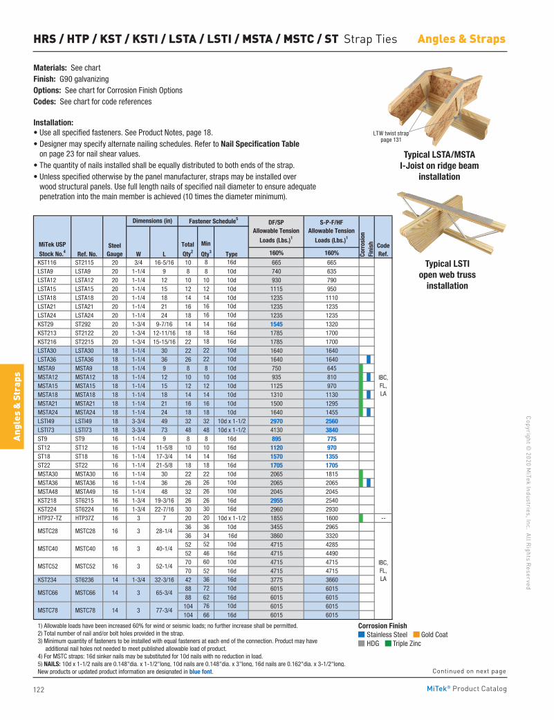
122
Copyright © 2020 M
iTek Industries, Inc. All Rights Reserved
Angles & Straps
Angl
es &
Str
aps
MiTek® Product Catalog
HRS / HTP / KST / KSTI / LSTA / LSTI / MSTA / MSTC / ST Strap Ties
Materials: See chartFinish: G90 galvanizingOptions: See chart for Corrosion Finish OptionsCodes: See chart for code references
Installation:• Use all specified fasteners. See Product Notes, page 18.• Designer may specify alternate nailing schedules. Refer to Nail Specification Table
on page 23 for nail shear values. • The quantity of nails installed shall be equally distributed to both ends of the strap. • Unless specified otherwise by the panel manufacturer, straps may be installed over
wood structural panels. Use full length nails of specified nail diameter to ensure adequate penetration into the main member is achieved (10 times the diameter minimum).
Typical LSTA/MSTA I-Joist on ridge beam
installation
Typical LSTI open web truss
installation
Min
Ref. No. W L Qty3 Type 160% 160%
KST116 ST2115 20 3/4 16-5/16 10 8 16d 665 665 LSTA9 LSTA9 20 1-1/4 9 8 8 10d 740 635 LSTA12 LSTA12 20 1-1/4 12 10 10 10d 930 790 LSTA15 LSTA15 20 1-1/4 15 12 12 10d 1115 950 LSTA18 LSTA18 20 1-1/4 18 14 14 10d 1235 1110 LSTA21 LSTA21 20 1-1/4 21 16 16 10d 1235 1235 LSTA24 LSTA24 20 1-1/4 24 18 16 10d 1235 1235 KST29 ST292 20 1-3/4 9-7/16 14 14 16d 1545 1320 KST213 ST2122 20 1-3/4 12-11/16 18 18 16d 1785 1700 KST216 ST2215 20 1-3/4 15-15/16 22 18 16d 1785 1700 LSTA30 LSTA30 18 1-1/4 30 22 22 10d 1640 1640 LSTA36 LSTA36 18 1-1/4 36 26 22 10d 1640 1640 MSTA9 MSTA9 18 1-1/4 9 8 8 10d 750 645 MSTA12 MSTA12 18 1-1/4 12 10 10 10d 935 810 MSTA15 MSTA15 18 1-1/4 15 12 12 10d 1125 970 MSTA18 MSTA18 18 1-1/4 18 14 14 10d 1310 1130 MSTA21 MSTA21 18 1-1/4 21 16 16 10d 1500 1295 MSTA24 MSTA24 18 1-1/4 24 18 18 10d 1640 1455 LSTI49 LSTI49 18 3-3/4 49 32 32 10d x 1-1/2 2970 2560 LSTI73 LSTI73 18 3-3/4 73 48 48 10d x 1-1/2 4130 3840 ST9 ST9 16 1-1/4 9 8 8 16d 895 775 ST12 ST12 16 1-1/4 11-5/8 10 10 16d 1120 970 ST18 ST18 16 1-1/4 17-3/4 14 14 16d 1570 1355 ST22 ST22 16 1-1/4 21-5/8 18 18 16d 1705 1705 MSTA30 MSTA30 16 1-1/4 30 22 22 10d 2065 1815 MSTA36 MSTA36 16 1-1/4 36 26 26 10d 2065 2065 MSTA48 MSTA49 16 1-1/4 48 32 26 10d 2045 2045 KST218 ST6215 16 1-3/4 19-3/16 26 26 16d 2955 2540 KST224 ST6224 16 1-3/4 22-7/16 30 30 16d 2960 2930 HTP37-TZ HTP37Z 16 3 7 20 20 10d x 1-1/2 1855 1600 --
36 36 10d 3455 296536 34 16d 3860 332052 52 10d 4715 428552 46 16d 4715 449070 60 10d 4715 471570 52 16d 4715 4715
KST234 ST6236 14 1-3/4 32-3/16 42 36 16d 3775 366088 72 10d 6015 601588 62 16d 6015 6015
104 76 10d 6015 6015104 66 16d 6015 6015
1) Allowable loads have been increased 60% for wind or seismic loads; no further increase shall be permitted. 2) Total number of nail and/or bolt holes provided in the strap. 3) Minimum quantity of fasteners to be installed with equal fasteners at each end of the connection. Product may have additional nail holes not needed to meet published allowable load of product. 4) For MSTC straps: 16d sinker nails may be substituted for 10d nails with no reduction in load. 5) NAILS: 10d x 1-1/2 nails are 0.148"dia. x 1-1/2"long, 10d nails are 0.148"dia. x 3"long, 16d nails are 0.162"dia. x 3-1/2"long. New products or updated product information are designated in blue font.
28-1/43
IBC,FL,LA
IBC,FL,LA
CodeRef.Co
rros
ion
Fini
sh
Dimensions (in)
Total
Qty2
Fastener Schedule5DF/SP
Allowable Tension
Loads (Lbs.)1
S-P-F/HFAllowable Tension
Loads (Lbs.)1
MSTC78 MSTC78 14 3 77-3/4
MSTC66 MSTC66 14 3
40-1/4
MSTC52 MSTC52 16 3 52-1/4
MSTC40 MSTC40 16 3
65-3/4
MiTek USP
Stock No.4Steel
Gauge
MSTC28 MSTC28 16
Corrosion Finish Stainless Steel Gold Coat HDG Triple Zinc
Corrosion Finish Stainless Steel Gold Coat HDG Triple Zinc
Corrosion Finish Stainless Steel Gold Coat HDG Triple Zinc
LTW twist strap page 131
Continued on next page
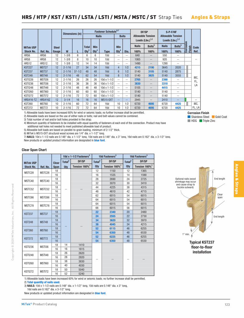
123
Copy
righ
t © 2
020
MiT
ek In
dust
ries
, Inc
. Al
l Rig
hts
Rese
rved
Angles & Straps
Angles & Straps
MiTek® Product Catalog
HRS / HTP / KST / KSTI / LSTA / LSTI / MSTA / MSTC / ST Strap Ties
Nails Bolts5 Nails Bolts5
Ref. No. W L Type Dia. 160% 160% 160% 160% HRS6 HRS6 12 1-3/8 6 6 6 10d -- -- 640 -- 550 -- HRS8 HRS8 12 1-3/8 8 10 10 10d -- -- 1065 -- 920 -- HRS12 HRS12 12 1-3/8 12 14 14 10d -- -- 1490 -- 1290 -- KST227 MST27 12 2-1/16 27 34 34 16d 4 1/2 4215 2190 3645 2020 KST237 MST37 12 2-1/16 37-1/2 48 48 16d 6 1/2 5140 3105 5140 2875 KST248 MST48 12 2-1/16 48 62 54 16d 8 1/2 5140 3825 5140 3555 KSTI226 MSTI26 12 2-1/16 26 26 26 10d x 1-1/2 -- -- 2765 -- 2390 -- KSTI236 MSTI36 12 2-1/16 36 36 36 10d x 1-1/2 -- -- 3830 -- 3310 -- KSTI248 MSTI48 12 2-1/16 48 48 48 10d x 1-1/2 -- -- 5105 -- 4415 -- KSTI260 MSTI60 12 2-1/16 60 60 60 10d x 1-1/2 -- -- 5140 -- 5140 -- KSTI272 MSTI72 12 2-1/16 72 72 60 10d x 1-1/2 -- -- 5140 -- 5140 -- HRS416-TZ HRS416Z 12 3-1/4 16 16 16 WS15-EXT -- -- 2945 -- 2410 -- -- KST260 MST60 10 2-1/16 60 72 64 16d 10 1/2 6720 4695 6720 4425 KST272 MST72 10 2-1/16 72 72 64 16d 10 1/2 6720 4695 6720 4425
1) Allowable loads have been increased 60% for wind or seismic loads; no further increase shall be permitted. 2) Allowable loads are based on the use of either nails or bolts; nail and bolt values cannot be combined. 3) Total number of nail and/or bolt holes provided in the strap. 4) Minimum quantity of fasteners to be installed with equal quantity of fasteners at each end of the connection. Product may have additional nail holes not needed to meet published allowable load of product. 5) Allowable bolt loads are based on parallel-to-grain loading, minimum of 2-1/2" thick. 6) MiTek's WS15-EXT structural wood screws are 1/4" dia. x 1-1/2" long. 7) NAILS: 10d x 1-1/2 nails are 0.148" dia. x 1-1/2" long, 10d nails are 0.148" dia. x 3" long, 16d nails are 0.162" dia. x 3-1/2" long. New products or updated product information are designated in blue font.
IBC,FL, LA
--
MiTek USPStock No.
SteelGauge
TotalQty3
CodeRef.Co
rros
ion
Fini
sh
Dimensions (in)Fastener Schedule6,7
BoltsDF/SP
Allowable TensionLoads (Lbs.)1,2
S-P-F/HFAllowable Tension
Loads (Lbs.)1,2Nails
MinQty4
MinQty4
IBC,FL,LA
Total2 DF/SP Total2 DF/SP Total2 DF/SP
Ref. No. Qty Tension 160%1 Qty Tension 160%1 Qty Tension 160%1
18 12 1150 12 136516 16 1535 14 159018 28 2690 24 272516 32 3070 30 341018 44 4225 38 431516 48 4610 42 471518 62 6015 54 601516 64 6015 54 601518 64 6015 54 601516 66 6015 56 601518 22 2340 20 248016 24 2555 22 273018 34 3620 32 397016 38 4045 34 421518 52 6115 46 625516 54 6350 48 653018 52 6225 46 625516 54 6350 48 653018 14 141016 16 161518 26 262016 28 282018 38 383016 40 403018 50 504016 52 5240
1) Allowable loads have been increased 60% for wind or seismic loads; no further increase shall be permitted. 2) Total quantity of nails used. 3) NAILS: 10d x 1-1/2 nails are 0.148" dia. x 1-1/2" long, 10d nails are 0.148" dia. x 3" long, 16d nails are 0.162" dia. x 3-1/2" long. New products or updated product information are designated in blue font.
16d Fasteners310d x 1-1/2 Fasteners3
KST237
KST248
MST37
MST48
MSTC78 MSTC78
MSTC52
MSTC40
MSTC52
MSTC66
--
MSTC40
MSTC66
10d Fasteners3
MiTek USPStock No.
ClearSpan
MSTC28 MSTC28
KST260 MST60
MST72
KSTI272 MSTI72
KSTI260 MSTI60
KSTI236 MSTI36
KSTI248 MSTI48
KST272
--
-- --
--
--
--
--
Typical KST237 floor-to-floor installation
Clear Span Chart
1" min.
Optional nails (wood shrinkage may occur and cause strap to buckle outward)
End length
End length
Clear span
Corrosion Finish Stainless Steel Gold Coat HDG Triple Zinc
Corrosion Finish Stainless Steel Gold Coat HDG Triple Zinc
Corrosion Finish Stainless Steel Gold Coat HDG Triple Zinc
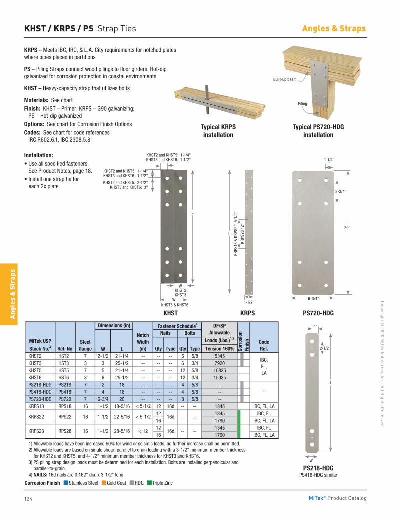
124
Copyright © 2020 M
iTek Industries, Inc. All Rights Reserved
Angles & Straps
Angl
es &
Str
aps
MiTek® Product Catalog
KHST / KRPS / PS Strap Ties
KRPS – Meets IBC, IRC, & L.A. City requirements for notched plates where pipes placed in partitions
PS – Piling Straps connect wood pilings to floor girders. Hot-dip galvanized for corrosion protection in coastal environments
KHST – Heavy-capacity strap that utilizes bolts
Materials: See chartFinish: KHST – Primer; KRPS – G90 galvanizing; PS – Hot-dip galvanizedOptions: See chart for Corrosion Finish OptionsCodes: See chart for code references IRC R602.6.1, IBC 2308.5.8
Installation:• Use all specified fasteners.
See Product Notes, page 18.• Install one strap tie for
each 2x plate.
Typical KRPSinstallation
KHST KRPS PS720-HDG
PS218-HDGPS418-HDG similar
Typical PS720-HDG installation
Ref. No. W L Qty Type Qty Type Tension 160% KHST2 HST2 7 2-1/2 21-1/4 -- -- -- 6 5/8 5345 KHST3 HST3 3 3 25-1/2 -- -- -- 6 3/4 7920 KHST5 HST5 7 5 21-1/4 -- -- -- 12 5/8 10825 KHST6 HST6 3 6 25-1/2 -- -- -- 12 3/4 15935 PS218-HDG PS218 7 2 18 -- -- -- 4 5/8 -- PS418-HDG PS418 7 4 18 -- -- -- 4 5/8 -- PS720-HDG PS720 7 6-3/4 20 -- -- -- 8 5/8 -- KRPS18 RPS18 16 1-1/2 18-5/16 < 5-1/2 12 16d -- -- 1345 IBC, FL, LA
12 1345 IBC, FL16 1790 IBC, FL, LA12 1345 IBC, FL16 1790 IBC, FL, LA
1) Allowable loads have been increased 60% for wind or seismic loads; no further increase shall be permitted. 2) Allowable loads are based on single shear, parallel to grain loading with a 3-1/2" minimum member thickness for KHST2 and KHST5, and 4-1/2" minimum member thickness for KHST3 and KHST6. 3) PS piling strap design loads must be determined for each installation. Bolts are installed perpendicular and parallel-to-grain. 4) NAILS: 16d nails are 0.162" dia. x 3-1/2" long.
KRPS22 RPS22 16
--
Dimensions (in)
MiTek USP
Stock No.3Steel
Gauge
IBC, FL, LA
Nails BoltsFastener Schedule4
CodeRef.
DF/SPAllowable
Loads (Lbs.)1,2NotchWidth
(in) Corr
osio
nFi
nish
--
KRPS28 RPS28 16 1-1/2 28-5/16 < 12 16d -- --
1-1/2 22-5/16 < 5-1/2 --16d
Corrosion Finish Stainless Steel Gold Coat HDG Triple Zinc
Corrosion Finish Stainless Steel Gold Coat HDG Triple Zinc
Corrosion Finish Stainless Steel Gold Coat HDG Triple Zinc
Piling
Built-up beam
KHST2 and KHST5: 1-1/4"KHST3 and KHST6: 1-1/2"
KHST5 & KHST6W
20"
1-1/4"
6-3/4"
3-3/4"
L
W
2-1/2
1"
KRPS
18 &
KRP
S22
5-1
/2"
KRPS
28 1
2"
1-1/2"
L
W
KHST2 and KHST5: 2-1/2"KHST3 and KHST6: 3"
L
KHST2 and KHST5: 1-1/4"KHST3 and KHST6: 1-1/2"
KHST2KHST3
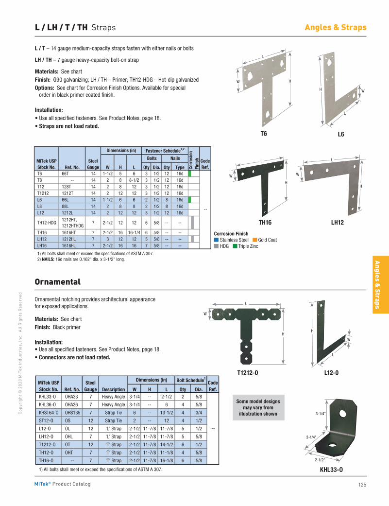
125
Copy
righ
t © 2
020
MiT
ek In
dust
ries
, Inc
. Al
l Rig
hts
Rese
rved
Angles & Straps
Angles & Straps
MiTek® Product Catalog
Ornamental notching provides architectural appearance for exposed applications.
Materials: See chartFinish: Black primer
Installation:• Use all specified fasteners. See Product Notes, page 18.• Connectors are not load rated.
L12-0
L6
KHL33-O
LH12
T1212-0
T6
TH16
Ornamental
L / T – 14 gauge medium-capacity straps fasten with either nails or bolts
LH / TH – 7 gauge heavy-capacity bolt-on strap
Materials: See chartFinish: G90 galvanizing; LH / TH – Primer; TH12-HDG – Hot-dip galvanizedOptions: See chart for Corrosion Finish Options. Available for special order in black primer coated finish.
Installation:• Use all specified fasteners. See Product Notes, page 18.• Straps are not load rated.
L / LH / T / TH Straps
Some model designs may vary from
illustration shown
Ref. No. Description W H L Qty Dia. KHL33-O OHA33 7 Heavy Angle 3-1/4 -- 2-1/2 2 5/8
KHL36-O OHA36 7 Heavy Angle 3-1/4 -- 6 4 5/8
KHST64-O OHS135 7 Strap Tie 6 -- 13-1/2 4 3/4
ST12-O OS 12 Strap Tie 2 -- 12 4 1/2
L12-O OL 12 'L' Strap 2-1/2 11-7/8 11-7/8 5 1/2
LH12-O OHL 7 'L' Strap 2-1/2 11-7/8 11-7/8 5 5/8
T1212-O OT 12 'T' Strap 2-1/2 11-7/8 14-1/2 6 1/2
TH12-O OHT 7 'T' Strap 2-1/2 11-7/8 11-1/8 4 5/8
TH16-O -- 7 'T' Strap 2-1/2 11-7/8 16-1/8 6 5/8
1) All bolts shall meet or exceed the specifications of ASTM A 307.
Bolt Schedule1
CodeRef.
--
MiTek USPStock No.
SteelGauge
Dimensions (in)
Ref. No. W H L Qty Dia. Qty Type T6 66T 14 1-1/2 5 6 3 1/2 12 16d T8 -- 14 2 8 8-1/2 3 1/2 12 16d T12 128T 14 2 8 12 3 1/2 12 16d T1212 1212T 14 2 12 12 3 1/2 12 16d L6 66L 14 1-1/2 6 6 2 1/2 8 16d L8 88L 14 2 8 8 2 1/2 8 16d L12 1212L 14 2 12 12 3 1/2 12 16d
TH12-HDG 1212HT, 1212HTHDG
7 2-1/2 12 12 6 5/8 -- --
TH16 1616HT 7 2-1/2 16 16-1/4 6 5/8 -- -- LH12 1212HL 7 3 12 12 5 5/8 -- -- LH16 1616HL 7 2-1/2 16 16 7 5/8 -- --
1) All bolts shall meet or exceed the specifications of ASTM A 307. 2) NAILS: 16d nails are 0.162" dia. x 3-1/2" long.
CodeRef.
--
Dimensions (in)
MiTek USPStock No.
Bolts Nails
Fastener Schedule1,2
SteelGauge Co
rros
ion
Fini
sh
Corrosion Finish Stainless Steel Gold Coat HDG Triple Zinc
Corrosion Finish Stainless Steel Gold Coat HDG Triple Zinc
Corrosion Finish Stainless Steel Gold Coat HDG Triple Zinc
H
W
2-1/2"
3-1/4"
3-1/4"
H
L
W
H
L
W
H
L
W
L
H
L
W W
H
L
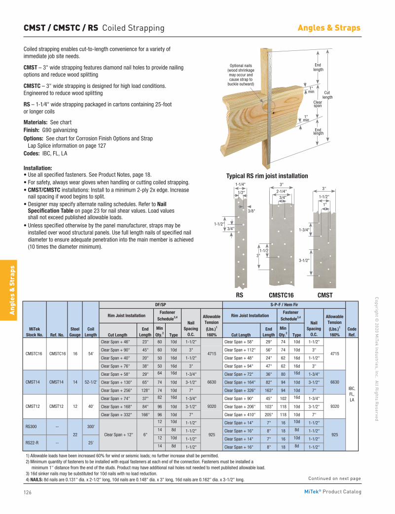
126
Copyright © 2020 M
iTek Industries, Inc. All Rights Reserved
Angles & Straps
Angl
es &
Str
aps
MiTek® Product Catalog
RS CMSTC16 CMST
CMST / CMSTC / RS Coiled Strapping
Coiled strapping enables cut-to-length convenience for a variety of immediate job site needs.
CMST – 3" wide strapping features diamond nail holes to provide nailing options and reduce wood splitting
CMSTC – 3" wide strapping is designed for high load conditions. Engineered to reduce wood splitting
RS – 1-1⁄4" wide strapping packaged in cartons containing 25-foot or longer coils
Materials: See chartFinish: G90 galvanizingOptions: See chart for Corrosion Finish Options and Strap Lap Splice information on page 127Codes: IBC, FL, LA
Installation:• Use all specified fasteners. See Product Notes, page 18. • For safety, always wear gloves when handling or cutting coiled strapping. • CMST/CMSTC installations: Install to a minimum 2-ply 2x edge. Increase
nail spacing if wood begins to split.• Designer may specify alternate nailing schedules. Refer to Nail
Specification Table on page 23 for nail shear values. Load values shall not exceed published allowable loads.
• Unless specified otherwise by the panel manufacturer, straps may be installed over wood structural panels. Use full length nails of specified nail diameter to ensure adequate penetration into the main member is achieved (10 times the diameter minimum).
Ref. No. Cut Length Type Cut Length Type
Clear Span + 46" 23" 60 10d 1-1/2" Clear Span + 58" 29" 74 10d 1-1/2"
Clear Span + 90" 45" 60 10d 3" Clear Span + 112" 56" 74 10d 3"
Clear Span + 40" 20" 50 16d 1-1/2" Clear Span + 48" 24" 62 16d 1-1/2"
Clear Span + 76" 38" 50 16d 3" Clear Span + 94" 47" 62 16d 3"
Clear Span + 58" 29" 64 16d 1-3/4" Clear Span + 72" 36" 80 16d 1-3/4"
Clear Span + 130" 65" 74 10d 3-1/2" Clear Span + 164" 82" 94 10d 3-1/2"
Clear Span + 256" 128" 74 10d 7" Clear Span + 326" 163" 94 10d 7"
Clear Span + 74" 37" 82 16d 1-3/4" Clear Span + 90" 45" 102 16d 1-3/4"
Clear Span + 168" 84" 96 10d 3-1/2" Clear Span + 206" 103" 118 10d 3-1/2"
Clear Span + 332" 166" 96 10d 7" Clear Span + 410" 205" 118 10d 7"
12 10d 1-1/2" Clear Span + 14" 7" 16 10d 1-1/2"
14 8d 1-1/2" Clear Span + 16" 8" 18 8d 1-1/2"
12 10d 1-1/2" Clear Span + 14" 7" 16 10d 1-1/2"
14 8d 1-1/2" Clear Span + 16" 8" 18 8d 1-1/2"
1) Allowable loads have been increased 60% for wind or seismic loads; no further increase shall be permitted. 2) Minimum quantity of fasteners to be installed with equal fasteners at each end of the connection. Fasteners must be installed a minimum 1" distance from the end of the studs. Product may have additional nail holes not needed to meet published allowable load. 3) 16d sinker nails may be substituted for 10d nails with no load reduction. 4) NAILS: 8d nails are 0.131" dia. x 2-1/2" long, 10d nails are 0.148" dia. x 3" long, 16d nails are 0.162" dia. x 3-1/2" long.
22
12
16 54'
14 52-1/2'
25'
SteelGauge
CoilLength
MiTekStock No.
CMST12 CMST12
CMST14 CMST14
CMSTC16
RS22-R --
CMSTC16
RS300 --
Clear Span + 12"
40'
300'
CodeRef.
EndLength
6630
9320
925
6630
9320
9256"
NailSpacing
O.C.
IBC,FL,LA
S-P-F / Hem Fir
4715
DF/SP
Rim Joist InstallationFastener
Schedule3,4Fastener
Schedule3,4 Allowable Tension (Lbs.)1
160%
Rim Joist Installation
Min Qty.2
EndLength
Min Qty.2
4715
NailSpacing
O.C.
Allowable Tension (Lbs.)1
160%
1"
1-1/2"
3"
1-3/4"
3-1/2"
3/4"
1/2"
3/8"
1-1/4"
1-1/2"
3"
2-1/4"
3/4"
3"1-1/2
Continued on next page
Typical RS rim joist installation
Optional nails (wood shrinkage may occur and cause strap to
buckle outward)
1" min
1" min Cut
length
End length
End length
Clear span
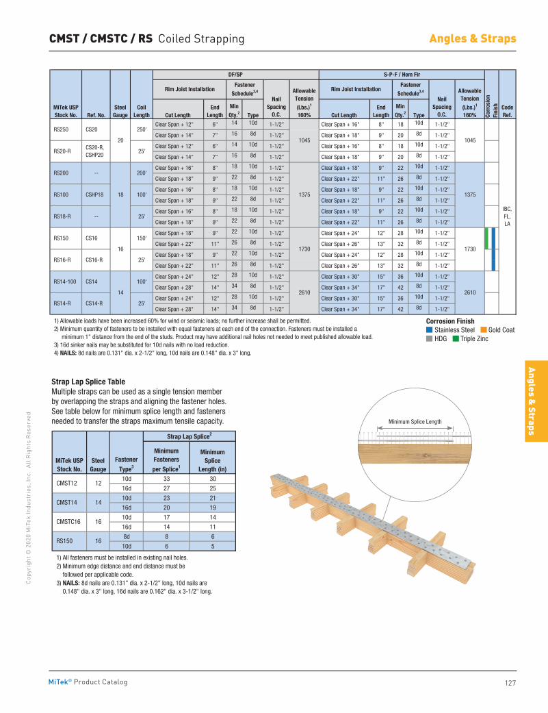
127
Copy
righ
t © 2
020
MiT
ek In
dust
ries
, Inc
. Al
l Rig
hts
Rese
rved
Angles & Straps
Angles & Straps
MiTek® Product Catalog
Corrosion Finish Stainless Steel Gold Coat HDG Triple Zinc
Corrosion Finish Stainless Steel Gold Coat HDG Triple Zinc
Corrosion Finish Stainless Steel Gold Coat HDG Triple Zinc
CMST / CMSTC / RS Coiled Strapping
Ref. No. Cut Length Type Cut Length Type
Clear Span + 12" 6" 14 10d 1-1/2" Clear Span + 16" 8" 18 10d 1-1/2"
Clear Span + 14" 7" 16 8d 1-1/2" Clear Span + 18" 9" 20 8d 1-1/2"
Clear Span + 12" 6" 14 10d 1-1/2" Clear Span + 16" 8" 18 10d 1-1/2"
Clear Span + 14" 7" 16 8d 1-1/2" Clear Span + 18" 9" 20 8d 1-1/2"
Clear Span + 16" 8" 18 10d 1-1/2" Clear Span + 18" 9" 22 10d 1-1/2"
Clear Span + 18" 9" 22 8d 1-1/2" Clear Span + 22" 11" 26 8d 1-1/2"
Clear Span + 16" 8" 18 10d 1-1/2" Clear Span + 18" 9" 22 10d 1-1/2"
Clear Span + 18" 9" 22 8d 1-1/2" Clear Span + 22" 11" 26 8d 1-1/2"
Clear Span + 16" 8" 18 10d 1-1/2" Clear Span + 18" 9" 22 10d 1-1/2"
Clear Span + 18" 9" 22 8d 1-1/2" Clear Span + 22" 11" 26 8d 1-1/2"
Clear Span + 18" 9" 22 10d 1-1/2" Clear Span + 24" 12" 28 10d 1-1/2"
Clear Span + 22" 11" 26 8d 1-1/2" Clear Span + 26" 13" 32 8d 1-1/2"
Clear Span + 18" 9" 22 10d 1-1/2" Clear Span + 24" 12" 28 10d 1-1/2"
Clear Span + 22" 11" 26 8d 1-1/2" Clear Span + 26" 13" 32 8d 1-1/2"
Clear Span + 24" 12" 28 10d 1-1/2" Clear Span + 30" 15" 36 10d 1-1/2"
Clear Span + 28" 14" 34 8d 1-1/2" Clear Span + 34" 17" 42 8d 1-1/2"
Clear Span + 24" 12" 28 10d 1-1/2" Clear Span + 30" 15" 36 10d 1-1/2"
Clear Span + 28" 14" 34 8d 1-1/2" Clear Span + 34" 17" 42 8d 1-1/2"
1) Allowable loads have been increased 60% for wind or seismic loads; no further increase shall be permitted. 2) Minimum quantity of fasteners to be installed with equal fasteners at each end of the connection. Fasteners must be installed a minimum 1" distance from the end of the studs. Product may have additional nail holes not needed to meet published allowable load. 3) 16d sinker nails may be substituted for 10d nails with no load reduction. 4) NAILS: 8d nails are 0.131" dia. x 2-1/2" long, 10d nails are 0.148" dia. x 3" long.
Corr
osio
nFi
nish
Rim Joist InstallationFastener
Schedule3,4 Allowable Tension (Lbs.)1
160%
Rim Joist InstallationFastener
Schedule3,4 Allowable Tension (Lbs.)1
160%Min Qty.2
EndLength
Min Qty.2
DF/SP S-P-F / Hem Fir
CodeRef.
RS250 CS20
20
250'
1045 1045
NailSpacing
O.C.
NailSpacing
O.C.MiTek USPStock No.
SteelGauge
CoilLength
EndLength
IBC,FL,LA
RS20-R CS20-R, CSHP20
25'
RS200
RS100 CSHP18 100'
--
18
200'
1375 1375
RS150 CS16
16
150'
1730 1730
RS18-R -- 25'
RS16-R CS16-R 25'
RS14-100 CS14
14
100'
2610
RS14-R CS14-R 25'
2610
10d 33 30
16d 27 25
10d 23 21
16d 20 19
10d 17 14
16d 14 11
8d 8 6
10d 6 5
2) Minimum edge distance and end distance must be followed per applicable code. 3) NAILS: 8d nails are 0.131" dia. x 2-1/2" long, 10d nails are 0.148" dia. x 3" long, 16d nails are 0.162" dia. x 3-1/2" long.
1) All fasteners must be installed in existing nail holes.
RS150 16
Minimum Splice
Length (in)
Strap Lap Splice2
16
14
CMSTC16
CMST14
MiTek USPStock No.
SteelGauge
CMST12 12
Minimum Fasteners
per Splice1
Fastener
Type3
Strap Lap Splice TableMultiple straps can be used as a single tension member by overlapping the straps and aligning the fastener holes. See table below for minimum splice length and fasteners needed to transfer the straps maximum tensile capacity. Minimum Splice Length
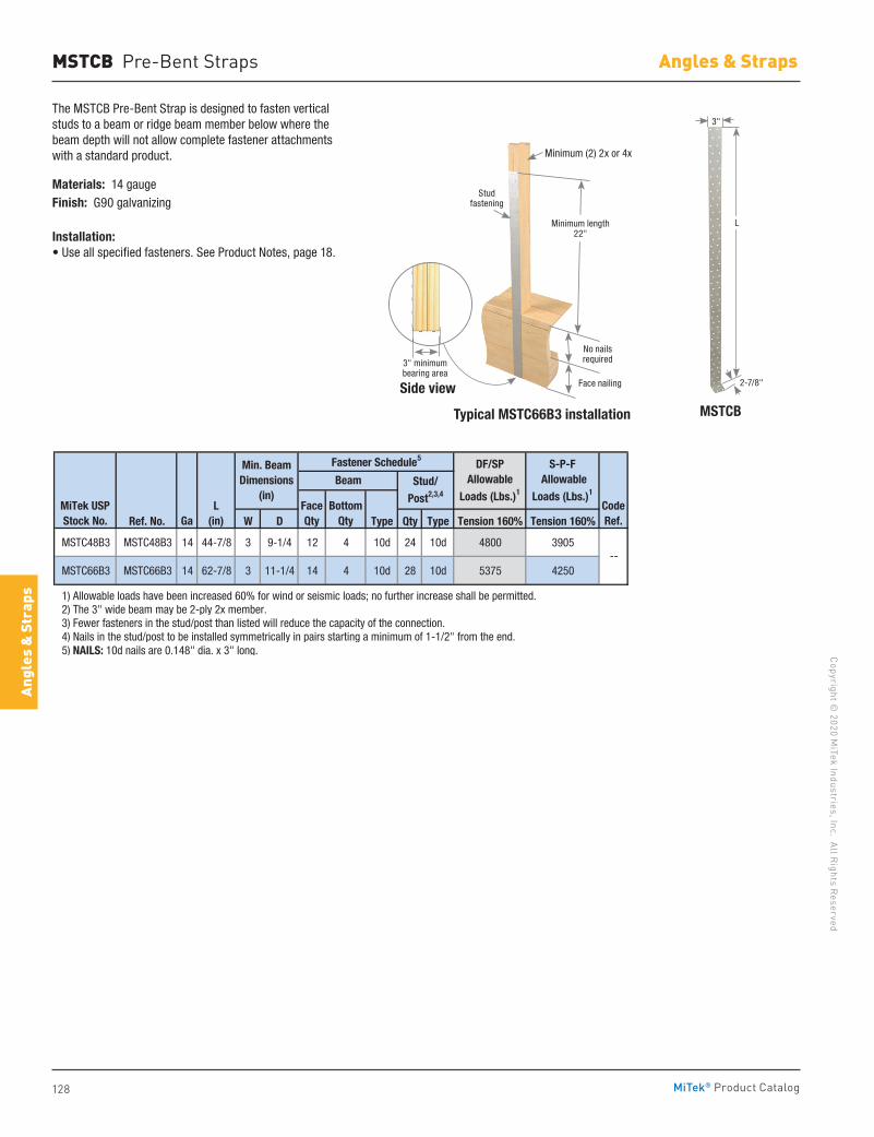
128
Copyright © 2020 M
iTek Industries, Inc. All Rights Reserved
Angles & Straps
Angl
es &
Str
aps
MiTek® Product Catalog
Typical MSTC66B3 installation MSTCB
The MSTCB Pre-Bent Strap is designed to fasten vertical studs to a beam or ridge beam member below where the beam depth will not allow complete fastener attachments with a standard product.
Materials: 14 gaugeFinish: G90 galvanizing
Installation:• Use all specified fasteners. See Product Notes, page 18.
MSTCB Pre-Bent Straps
Ref. No. W D Type Qty Type Tension 160% Tension 160%
MSTC48B3 MSTC48B3 14 44-7/8 3 9-1/4 12 4 10d 24 10d 4800 3905
MSTC66B3 MSTC66B3 14 62-7/8 3 11-1/4 14 4 10d 28 10d 5375 4250
1) Allowable loads have been increased 60% for wind or seismic loads; no further increase shall be permitted. 2) The 3" wide beam may be 2-ply 2x member. 3) Fewer fasteners in the stud/post than listed will reduce the capacity of the connection. 4) Nails in the stud/post to be installed symmetrically in pairs starting a minimum of 1-1/2" from the end. 5) NAILS: 10d nails are 0.148" dia. x 3" long.
--
CodeRef.
MiTek USPStock No. Ga
Fastener Schedule5
BeamDF/SP
AllowableLoads (Lbs.)1
S-P-F Allowable
Loads (Lbs.)1
Min. BeamDimensions
(in)FaceQty
BottomQty
L(in)
Stud/Post2,3,4
3"
2-7/8"
L
Side view
3" minimum bearing area
Face nailing
No nails required
Minimum length 22"
Minimum (2) 2x or 4x
Stud fastening
Minimum(2) 2x or 4x
Minimum Length 22˝
StudFastening
No NailsRequired
Face Nailing3˝ MinimumBearing Area
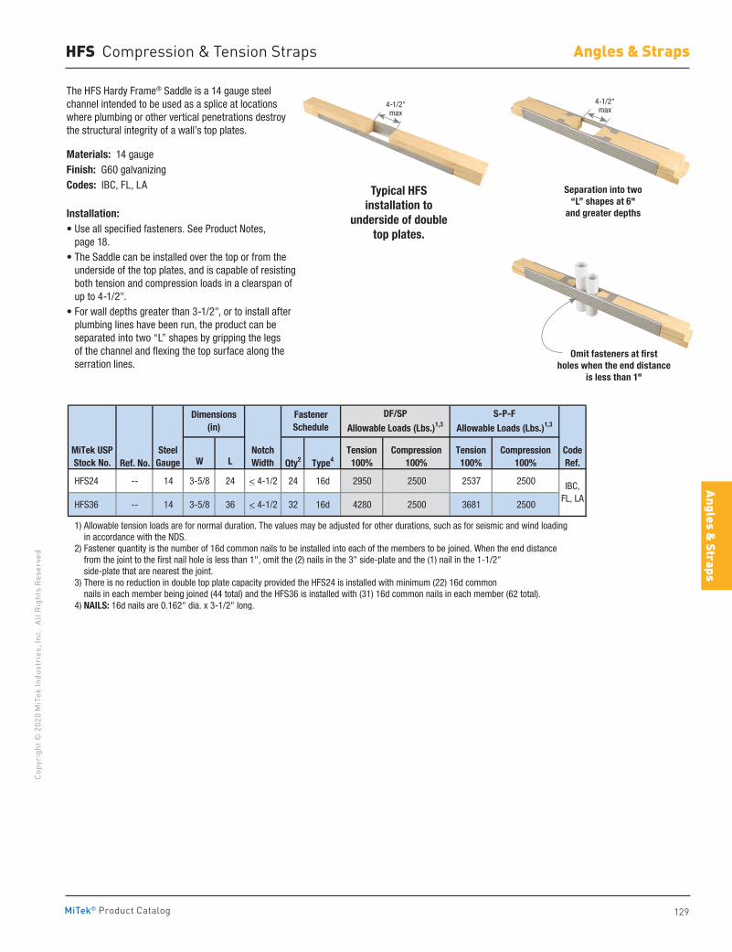
129
Copy
righ
t © 2
020
MiT
ek In
dust
ries
, Inc
. Al
l Rig
hts
Rese
rved
Angles & Straps
Angles & Straps
MiTek® Product Catalog
HFS Compression & Tension Straps
The HFS Hardy Frame® Saddle is a 14 gauge steel channel intended to be used as a splice at locations where plumbing or other vertical penetrations destroy the structural integrity of a wall’s top plates.
Materials: 14 gaugeFinish: G60 galvanizingCodes: IBC, FL, LA
Installation:• Use all specified fasteners. See Product Notes,
page 18.• The Saddle can be installed over the top or from the
underside of the top plates, and is capable of resisting both tension and compression loads in a clearspan of up to 4-1/2".
• For wall depths greater than 3-1/2", or to install after plumbing lines have been run, the product can be separated into two “L” shapes by gripping the legs of the channel and flexing the top surface along the serration lines.
Typical HFS installation to
underside of double top plates.
Separation into two “L” shapes at 6"
and greater depths
Omit fasteners at first holes when the end distance
is less than 1"
Ref. No. W L Qty2 Type4
HFS24 -- 14 3-5/8 24 < 4-1/2 24 16d 2950 2500 2537 2500
HFS36 -- 14 3-5/8 36 < 4-1/2 32 16d 4280 2500 3681 2500
1) Allowable tension loads are for normal duration. The values may be adjusted for other durations, such as for seismic and wind loading in accordance with the NDS. 2) Fastener quantity is the number of 16d common nails to be installed into each of the members to be joined. When the end distance from the joint to the first nail hole is less than 1", omit the (2) nails in the 3" side-plate and the (1) nail in the 1-1/2" side-plate that are nearest the joint. 3) There is no reduction in double top plate capacity provided the HFS24 is installed with minimum (22) 16d common nails in each member being joined (44 total) and the HFS36 is installed with (31) 16d common nails in each member (62 total). 4) NAILS: 16d nails are 0.162" dia. x 3-1/2" long.
Fastener Schedule
Dimensions(in)
MiTek USPStock No.
SteelGauge
IBC,FL, LA
CodeRef.
Tension100%
Compression100%
NotchWidth
Tension100%
Compression100%
DF/SPAllowable Loads (Lbs.)1,3
S-P-FAllowable Loads (Lbs.)1,3
4-1/2" max
4-1/2" max
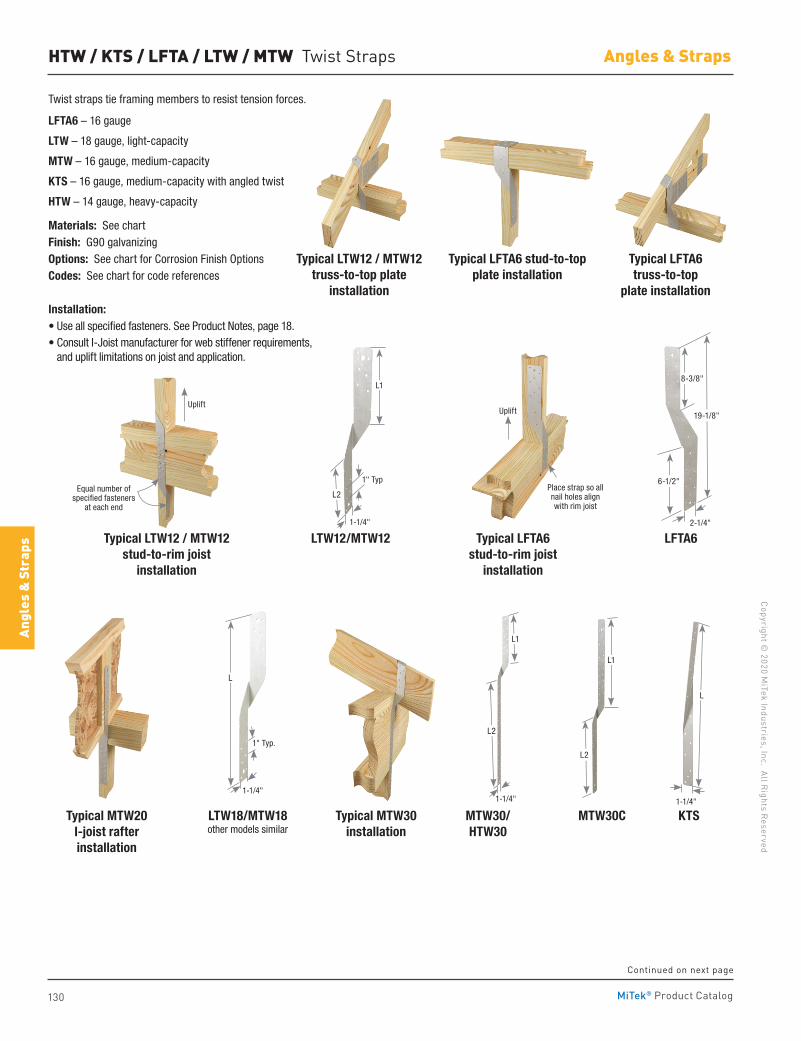
130
Copyright © 2020 M
iTek Industries, Inc. All Rights Reserved
Angles & Straps
Angl
es &
Str
aps
MiTek® Product Catalog
LTW12/MTW12
HTW / KTS / LFTA / LTW / MTW Twist Straps
Twist straps tie framing members to resist tension forces.
LFTA6 – 16 gauge
LTW – 18 gauge, light-capacity
MTW – 16 gauge, medium-capacity
KTS – 16 gauge, medium-capacity with angled twist
HTW – 14 gauge, heavy-capacity
Materials: See chartFinish: G90 galvanizingOptions: See chart for Corrosion Finish OptionsCodes: See chart for code references
Installation:• Use all specified fasteners. See Product Notes, page 18.• Consult I-Joist manufacturer for web stiffener requirements,
and uplift limitations on joist and application.
Typical LFTA6 truss-to-top
plate installation
Typical LFTA6 stud-to-rim joist
installation
Typical LFTA6 stud-to-topplate installation
LFTA6
Typical LTW12 / MTW12truss-to-top plate
installation
Typical LTW12 / MTW12stud-to-rim joist
installation
19-1/8"
6-1/2"
2-1/4"
8-3/8"
LTW18/MTW18other models similar
Typical MTW30installation
KTSMTW30/HTW30
MTW30CTypical MTW20I-joist rafter installation
Uplift
Equal number of specified fasteners
at each end
Place strap so all nail holes align with rim joist
1-1/4"
L
1-1/4"
L2
L1
L
1-1/4"
1" Typ.
L1
L2
L1
L2
1-1/4"
1" Typ
Uplift
Continued on next page
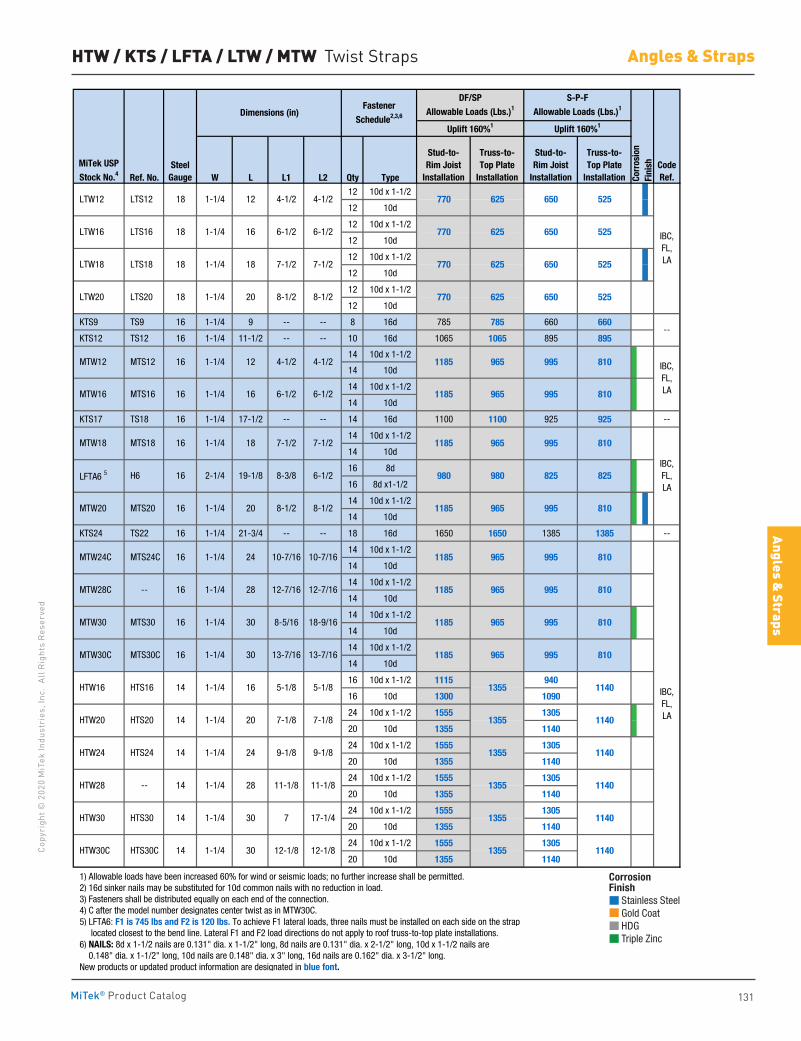
131
Copy
righ
t © 2
020
MiT
ek In
dust
ries
, Inc
. Al
l Rig
hts
Rese
rved
Angles & Straps
Angles & Straps
MiTek® Product Catalog
Ref. No. W L L1 L2 Qty Type12 10d x 1-1/2
12 10d
12 10d x 1-1/2
12 10d
12 10d x 1-1/2
12 10d
12 10d x 1-1/2
12 10d
KTS9 TS9 16 1-1/4 9 -- -- 8 16d 785 785 660 660
KTS12 TS12 16 1-1/4 11-1/2 -- -- 10 16d 1065 1065 895 895
14 10d x 1-1/2
14 10d
14 10d x 1-1/2
14 10d
KTS17 TS18 16 1-1/4 17-1/2 -- -- 14 16d 1100 1100 925 925 --
14 10d x 1-1/2
14 10d
16 8d
16 8d x1-1/2
14 10d x 1-1/2
14 10d
KTS24 TS22 16 1-1/4 21-3/4 -- -- 18 16d 1650 1650 1385 1385 --
14 10d x 1-1/2
14 10d
14 10d x 1-1/2
14 10d
14 10d x 1-1/2
14 10d
14 10d x 1-1/2
14 10d
16 10d x 1-1/2 1115 940
16 10d 1300 1090
24 10d x 1-1/2 1555 1305
20 10d 1355 1140
24 10d x 1-1/2 1555 1305
20 10d 1355 1140
24 10d x 1-1/2 1555 1305
20 10d 1355 1140
24 10d x 1-1/2 1555 1305
20 10d 1355 1140
24 10d x 1-1/2 1555 1305
20 10d 1355 1140
1) Allowable loads have been increased 60% for wind or seismic loads; no further increase shall be permitted. 2) 16d sinker nails may be substituted for 10d common nails with no reduction in load. 3) Fasteners shall be distributed equally on each end of the connection. 4) C after the model number designates center twist as in MTW30C. 5) LFTA6: F1 is 745 lbs and F2 is 120 lbs. To achieve F1 lateral loads, three nails must be installed on each side on the strap located closest to the bend line. Lateral F1 and F2 load directions do not apply to roof truss-to-top plate installations. 6) NAILS: 8d x 1-1/2 nails are 0.131" dia. x 1-1/2" long, 8d nails are 0.131" dia. x 2-1/2" long, 10d x 1-1/2 nails are 0.148" dia. x 1-1/2" long, 10d nails are 0.148" dia. x 3" long, 16d nails are 0.162" dia. x 3-1/2" long. New products or updated product information are designated in blue font.
7-1/2
6-1/2
5-1/8
8-1/2 8-1/2
650
650
1-1/4
7-1/2
770
770
8-3/8
625
625
6-1/2
6-1/2
1185
1185
1185
1185
18-9/16
10-7/16
12-7/16
10-7/16
965
980
965
965
Stud-to-Rim Joist
Installation
525
525
525
525
810
810
810
825
810
810
965
965
MiTek USP
Stock No.4Steel
Gauge
1-1/4
1-1/4
1-1/4
4-1/2
6-1/2
8-1/2
MTS12
MTW16 MTS16
MTW18 MTS18
7-1/2 LTW18
LTS20
MTW12
1-1/4
1-1/4
LTW16 LTS16 1-1/4
LTW12 4-1/2 LTS12 18
18
4-1/2
6-1/2
12
16
S-P-F
Allowable Loads (Lbs.)1
DF/SP
Allowable Loads (Lbs.)1
Uplift 160%1 Uplift 160%1
Truss-to-Top Plate
Installation
625
625
Stud-to-Rim Joist
Installation
770
770
Dimensions (in)Fastener
Schedule2,3,6
Truss-to-Top Plate
Installation
HTW30C HTS30C
18
18
16
16
16
HTW28 --
HTW30 HTS30
HTW20 HTS20
HTW24 HTS24
MTW30C MTS30C
MTW20 MTS20
14
14
14
LFTA6 5
14
14
14
16
16
16
16
24
28
LTW20
HTW16
20
HTS16
16 2-1/4 19-1/8
MTW30 MTS30
MTW24C MTS24C
MTW28C --
16
H6
30
13-7/16
5-1/8
13-7/16
7-1/8
9-1/8
1-1/4
1-1/4
4-1/2
8-1/2
7-1/8
1-1/4
1-1/4
1-1/4
1-1/4
1-1/4
1-1/4
1-1/4
1-1/4
1-1/4
30
16
20
24
Corr
osio
nFi
nish
IBC,FL,LA
IBC,FL,LA
IBC,FL,LA
IBC,FL,LA
CodeRef.
995
995
995
995
995
650
650
825
995
995
995
--
1140
1140
1140
1140
1140
LTS18
12-1/812-1/8
7
1140
1185
1185
1185
1185
1355
1355
1355
810
810
810
965
965
965
1355
1355
1355
18
12
16
7-1/2
8-5/16
980
11-1/8 11-1/8
17-1/430
20
30
12-7/16
28
9-1/8
18
HTW / KTS / LFTA / LTW / MTW Twist Straps
Corrosion Finish Stainless Steel Gold Coat HDG Triple Zinc
Corrosion Finish Stainless Steel Gold Coat HDG Triple Zinc
Corrosion Finish Stainless Steel Gold Coat HDG Triple Zinc
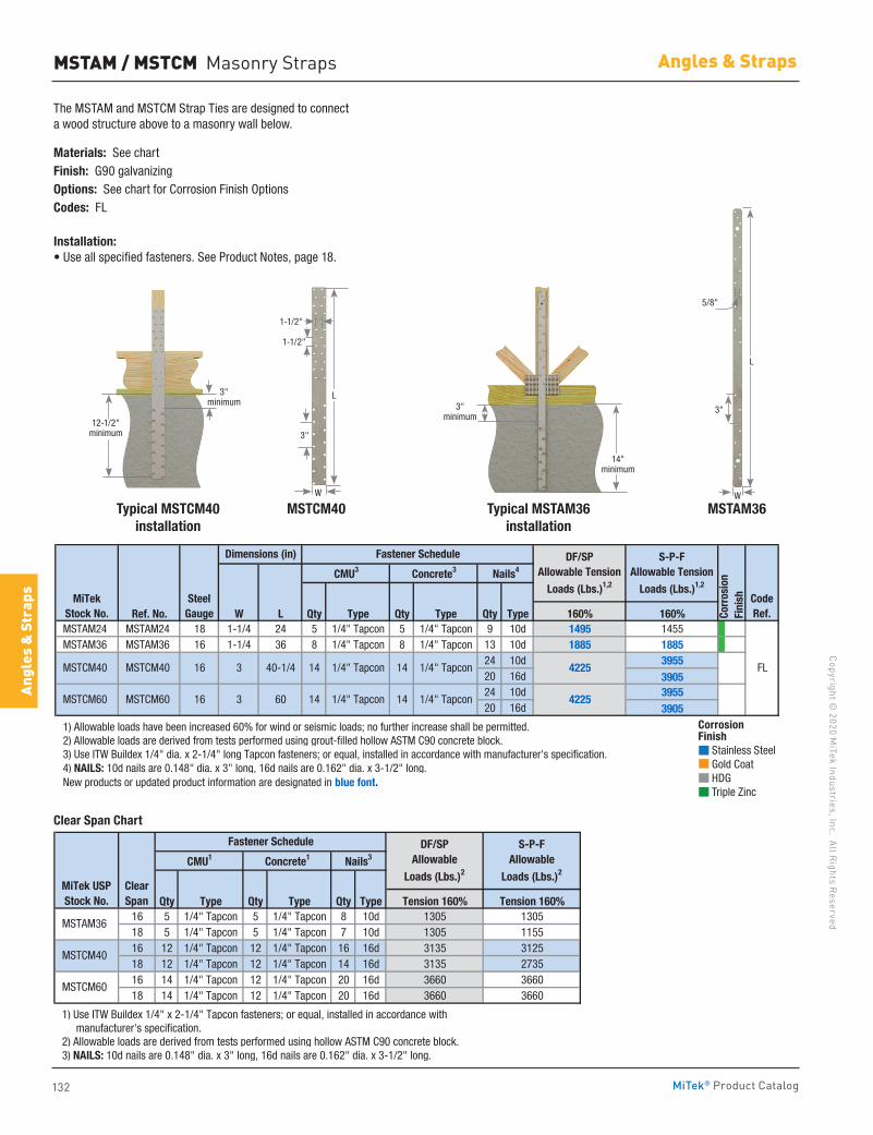
132
Copyright © 2020 M
iTek Industries, Inc. All Rights Reserved
Angles & Straps
Angl
es &
Str
aps
MiTek® Product Catalog
MSTAM / MSTCM Masonry Straps
The MSTAM and MSTCM Strap Ties are designed to connect a wood structure above to a masonry wall below.
Materials: See chartFinish: G90 galvanizingOptions: See chart for Corrosion Finish OptionsCodes: FL
Installation:• Use all specified fasteners. See Product Notes, page 18.
Typical MSTCM40installation
MSTCM40 MSTAM36Typical MSTAM36installation
Ref. No. W L Qty Type Qty Type Qty Type 160% 160% MSTAM24 MSTAM24 18 1-1/4 24 5 1/4" Tapcon 5 1/4" Tapcon 9 10d 1495 1455 MSTAM36 MSTAM36 16 1-1/4 36 8 1/4" Tapcon 8 1/4" Tapcon 13 10d 1885 1885
24 10d 395520 16d 390524 10d 395520 16d 3905
1) Allowable loads have been increased 60% for wind or seismic loads; no further increase shall be permitted. 2) Allowable loads are derived from tests performed using grout-filled hollow ASTM C90 concrete block. 3) Use ITW Buildex 1/4" dia. x 2-1/4" long Tapcon fasteners; or equal, installed in accordance with manufacturer's specification. 4) NAILS: 10d nails are 0.148" dia. x 3" long, 16d nails are 0.162" dia. x 3-1/2" long. New products or updated product information are designated in blue font.
MiTekStock No.
SteelGauge
4225
14 1/4" Tapcon 14 1/4" Tapcon 4225 MSTCM60 MSTCM60 16 3 60
14 MSTCM40 MSTCM40 16 3 40-1/4
Dimensions (in)
CMU3
Fastener Schedule
CodeRef.
1/4" Tapcon 14 1/4" Tapcon
DF/SP Allowable Tension
Loads (Lbs.)1,2
FL
Corr
osio
nFi
nish
S-P-FAllowable Tension
Loads (Lbs.)1,2Concrete3 Nails4
Qty Type Qty Type Qty Type Tension 160% Tension 160%16 5 1/4" Tapcon 5 1/4" Tapcon 8 10d 1305 130518 5 1/4" Tapcon 5 1/4" Tapcon 7 10d 1305 115516 12 1/4" Tapcon 12 1/4" Tapcon 16 16d 3135 312518 12 1/4" Tapcon 12 1/4" Tapcon 14 16d 3135 273516 14 1/4" Tapcon 12 1/4" Tapcon 20 16d 3660 366018 14 1/4" Tapcon 12 1/4" Tapcon 20 16d 3660 3660
1) Use ITW Buildex 1/4" x 2-1/4" Tapcon fasteners; or equal, installed in accordance with manufacturer's specification. 2) Allowable loads are derived from tests performed using hollow ASTM C90 concrete block. 3) NAILS: 10d nails are 0.148" dia. x 3" long, 16d nails are 0.162" dia. x 3-1/2" long.
S-P-FAllowable
Loads (Lbs.)2
Fastener Schedule
MSTCM60
CMU1 Concrete1 Nails3
MSTAM36
MSTCM40
MiTek USPStock No.
ClearSpan
DF/SPAllowable
Loads (Lbs.)2
Clear Span Chart
Corrosion Finish Stainless Steel Gold Coat HDG Triple Zinc
Corrosion Finish Stainless Steel Gold Coat HDG Triple Zinc
Corrosion Finish Stainless Steel Gold Coat HDG Triple Zinc
12-1/2" minimum
3" minimum 3"
minimum
14" minimum
3"
5/8"
L
W
3"
1-1/2"
1-1/2"
W
L
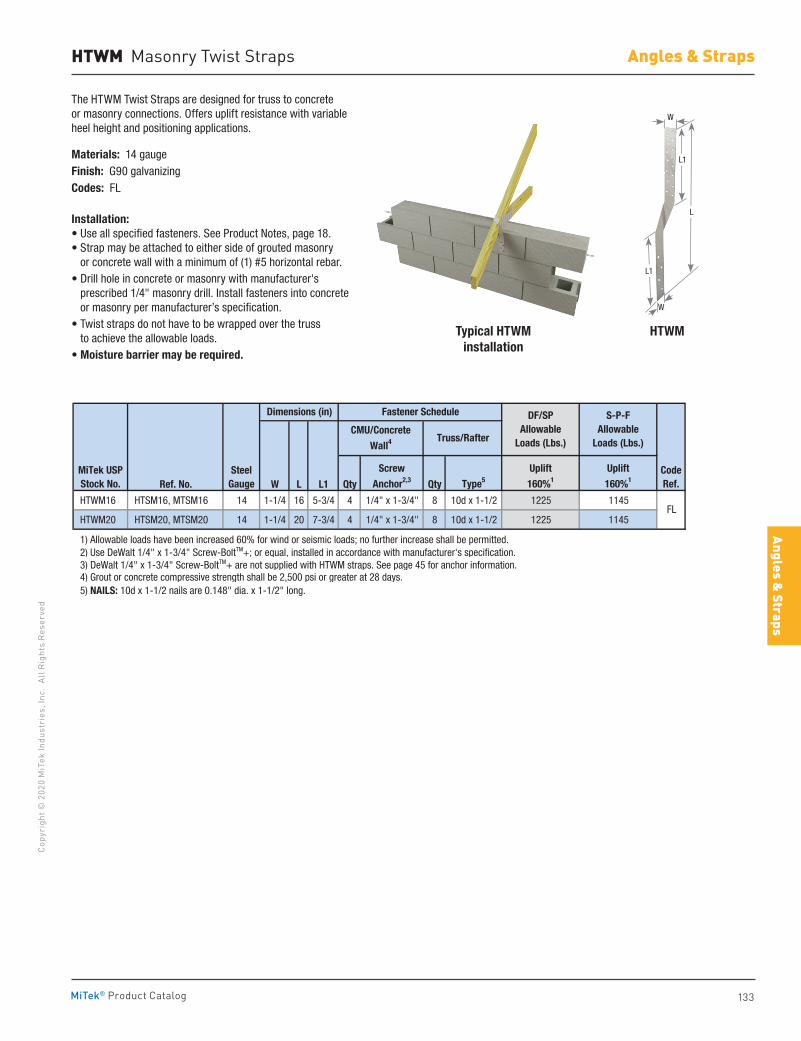
133
Copy
righ
t © 2
020
MiT
ek In
dust
ries
, Inc
. Al
l Rig
hts
Rese
rved
Angles & Straps
Angles & Straps
MiTek® Product Catalog
HTWM Masonry Twist Straps
The HTWM Twist Straps are designed for truss to concrete or masonry connections. Offers uplift resistance with variable heel height and positioning applications.
Materials: 14 gaugeFinish: G90 galvanizingCodes: FL
Installation:• Use all specified fasteners. See Product Notes, page 18.• Strap may be attached to either side of grouted masonry
or concrete wall with a minimum of (1) #5 horizontal rebar.• Drill hole in concrete or masonry with manufacturer's
prescribed 1/4" masonry drill. Install fasteners into concrete or masonry per manufacturer’s specification.
• Twist straps do not have to be wrapped over the truss to achieve the allowable loads.
• Moisture barrier may be required.
Ref. No. W L L1 Qty Qty
HTWM16 HTSM16, MTSM16 14 1-1/4 16 5-3/4 4 1/4" x 1-3/4" 8 10d x 1-1/2 1225 1145
HTWM20 HTSM20, MTSM20 14 1-1/4 20 7-3/4 4 1/4" x 1-3/4" 8 10d x 1-1/2 1225 1145
1) Allowable loads have been increased 60% for wind or seismic loads; no further increase shall be permitted. 2) Use DeWalt 1/4" x 1-3/4" Screw-BoltTM+; or equal, installed in accordance with manufacturer's specification. 3) DeWalt 1/4" x 1-3/4" Screw-BoltTM+ are not supplied with HTWM straps. See page 45 for anchor information. 4) Grout or concrete compressive strength shall be 2,500 psi or greater at 28 days. 5) NAILS: 10d x 1-1/2 nails are 0.148" dia. x 1-1/2" long.
MiTek USPStock No.
SteelGauge
CodeRef.
FL
Dimensions (in)
Screw
Anchor2,3
Fastener Schedule
Type5
DF/SPAllowable
Loads (Lbs.)
Uplift
160%1
Uplift
160%1
S-P-FAllowable
Loads (Lbs.)CMU/Concrete
Wall4Truss/Rafter
Typical HTWM installation
HTWM
L
L1
L1
W
W
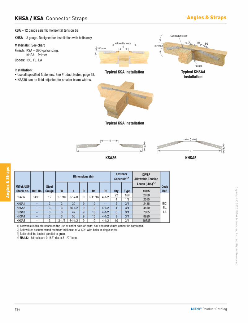
134
Copyright © 2020 M
iTek Industries, Inc. All Rights Reserved
Angles & Straps
Angl
es &
Str
aps
MiTek® Product Catalog
Ref. No. W L O D1 D2 Qty Type 160%22 16d 26204 1/2 2015
KHSA1 -- 3 3 30 9 10 -- 2 3/4 2435 KHSA2 -- 3 3 38-1/2 9 10 4-1/2 4 3/4 4810 KHSA3 -- 3 3 47 9 10 4-1/2 6 3/4 7005 KHSA4 -- 3 3 56 9 10 4-1/2 8 3/4 8920 KHSA5 -- 3 3-1/2 64-1/2 9 10 4-1/2 10 3/4 10785
1) Allowable loads are based on the use of either nails or bolts; nail and bolt values cannot be combined. 2) Bolt values assume wood member thickness of 3-1/2" with bolts in single shear. 3) Bolts shall be loaded parallel to grain. 4) NAILS: 16d nails are 0.162" dia. x 3-1/2" long.
Fastener
Schedule3,4
CodeRef.
IBC, FL, LA
92-1/16 37-7/8 6-11/16 4-1/2
Dimensions (in) DF/SPAllowable Tension
Loads (Lbs.)1,2
MiTek USPStock No.
SteelGauge
KSA36 SA36 12
KSA36 KHSA5
L
O
W
L
O
W
Typical KSA installation Typical KHSA4 installation
Typical KSA installation
KSA – 12 gauge seismic horizontal tension tie
KHSA – 3 gauge. Designed for installation with bolts only
Materials: See chartFinish: KSA – G90 galvanizing;
KHSA – PrimerCodes: IBC, FL, LA
Installation:• Use all specified fasteners. See Product Notes, page 18.• KSA36 can be field adjusted for smaller beam widths.
KHSA / KSA Connector Straps
O
15° max
Hanger
Connector strap
D1 D2Allowable loads0
18° max
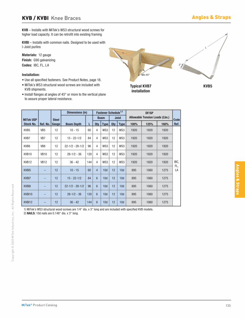
135
Copy
righ
t © 2
020
MiT
ek In
dust
ries
, Inc
. Al
l Rig
hts
Rese
rved
Angles & Straps
Angles & Straps
MiTek® Product Catalog
Typical KVB7installation
KVB5
KVB – Installs with MiTek’s WS3 structural wood screws for higher load capacity. It can be retrofit into existing framing
KVBI – Installs with common nails. Designed to be used with I-Joist purlins
Materials: 12 gaugeFinish: G90 galvanizingCodes: IBC, FL, LA
Installation:• Use all specified fasteners. See Product Notes, page 18.• MiTek’s WS3 structural wood screws are included with
KVB shipments. • Install flanges at angles of 45° or more to the vertical plane
to assure proper lateral resistance.
KVB / KVBI Knee Braces
Ref. No. Beam Depth L Qty Type Qty Type 100% 125% 160%
KVB5 VB5 12 10 - 15 60 4 WS3 12 WS3 1920 1920 1920
KVB7 VB7 12 15 - 22-1/2 84 4 WS3 12 WS3 1920 1920 1920
KVB8 VB8 12 22-1/2 - 28-1/2 96 4 WS3 12 WS3 1920 1920 1920
KVB10 VB10 12 28-1/2 - 36 120 4 WS3 12 WS3 1920 1920 1920
KVB12 VB12 12 36 - 42 144 4 WS3 12 WS3 1920 1920 1920
KVBI5 -- 12 10 - 15 60 4 10d 12 10d 895 1060 1275
KVBI7 -- 12 15 - 22-1/2 84 6 10d 12 10d 895 1060 1275
KVBI8 -- 12 22-1/2 - 28-1/2 96 6 10d 12 10d 895 1060 1275
KVBI10 -- 12 28-1/2 - 36 120 6 10d 12 10d 895 1060 1275
KVBI12 -- 12 36 - 42 144 6 10d 12 10d 895 1060 1275
1) MiTek's WS3 structural wood screws are 1/4" dia. x 3" long and are included with specified KVB models. 2) NAILS: 10d nails are 0.148" dia. x 3" long.
CodeRef.
IBC,FL,LA
MiTek USPStock No.
SteelGauge
Dimensions (in) Fastener Schedule1,2
Beam Joist
DF/SPAllowable Tension Loads (Lbs.)
L
2"
Min 45°
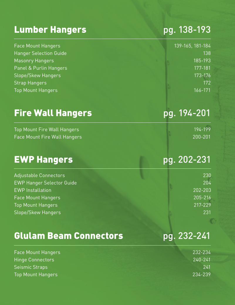
136
Copyright © 2020 M
iTek Industries, Inc. All Rights Reserved
Lumber Hangers
Lum
ber H
ange
rs
MiTek® Product Catalog
Lumber HangersFace Mount Hangers 139-165, 181-184Hanger Selection Guide 138Masonry Hangers 185-193Panel & Purlin Hangers 177-181Slope/Skew Hangers 173-176Strap Hangers 172Top Mount Hangers 166-171
pg. 138-193
EWP Hangers Adjustable Connectors 230EWP Hanger Selector Guide 204 EWP Installation 202-203Face Mount Hangers 205-216Top Mount Hangers 217-229Slope/Skew Hangers 231
pg. 202-231
Glulam Beam Connectors Face Mount Hangers 232-234 Hinge Connectors 240-241Seismic Straps 241Top Mount Hangers 234-239
pg. 232-241
Fire Wall HangersTop Mount Fire Wall Hangers 194-199 Face Mount Fire Wall Hangers 200-201
pg. 194-201
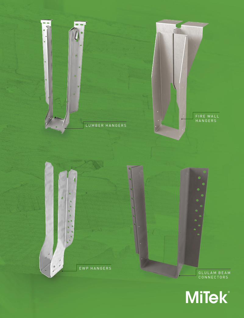
Lumber Hangers
137
Copy
righ
t © 2
020
MiT
ek In
dust
ries
, Inc
. Al
l Rig
hts
Rese
rved
Lumber Hangers
MiTek® Product Catalog
L U M B E R H A N G E R S
G L U L A M B E A M C O N N E C T O R S
F I R E W A L L H A N G E R S
E W P H A N G E R S
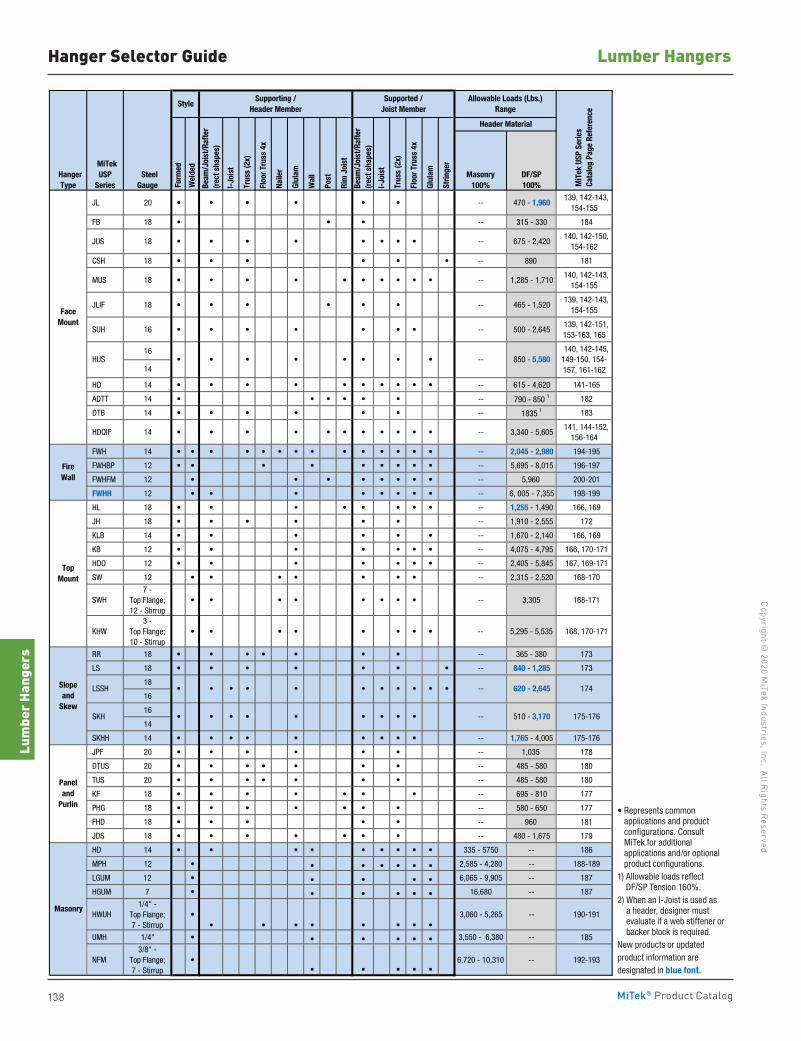
138
Copyright © 2020 M
iTek Industries, Inc. All Rights Reserved
Lumber Hangers
Lum
ber H
ange
rs
MiTek® Product Catalog
HangerType
MiTek USP
Series SteelGauge F
orm
ed
Wel
ded
Masonry100%
DF/SP100%
JL 20 • • • • • • -- 470 - 1,960 139, 142-143,
154-155
FB 18 • • • -- 315 - 330 184
JUS 18 • • • • • • • • -- 675 - 2,420 140, 142-150,
154-162
CSH 18 • • • • • • -- 890 181
MUS 18 • • • • • • • • • • -- 1,285 - 1,710 140, 142-143,
154-155
JLIF 18 • • • • • • -- 465 - 1,520 139, 142-143,
154-155
SUH 16 • • • • • • • -- 500 - 2,645 139, 142-151, 153-163, 165
16
14
HD 14 • • • • • • • • • • -- 615 - 4,620 141-165
ADTT 14 • • • • • • -- 790 - 850 1 182
DTB 14 • • • • • • -- 1835 1 183
HDQIF 14 • • • • • • • • • • • -- 3,340 - 5,605 141, 144-152,
156-164
FWH 14 • • • • • • • • • • • • • • -- 2,045 - 2,980 194-195
FWHBP 12 • • • • • • • • • -- 5,695 - 8,015 196-197
FWHFM 12 • • • • • • • • -- 5,960 200-201
FWHH 12 • • • • • • • • -- 6, 005 - 7,355 198-199
HL 18 • • • • • • • • -- 1,255 - 1,490 166, 169
JH 18 • • • • • • -- 1,910 - 2,555 172
KLB 14 • • • • • • -- 1,670 - 2,140 166, 169
KB 12 • • • • • • • -- 4,075 - 4,795 166, 170-171
HDO 12 • • • • • • • -- 2,405 - 5,845 167, 169-171
SW 12 • • • • • • • -- 2,315 - 2,520 168-170
SWH7 -
Top Flange;12 - Stirrup
• • • • • • • • -- 3,305 168-171
KHW3 -
Top Flange;10 - Stirrup
• • • • • • • • -- 5,295 - 5,535 168, 170-171
RR 18 • • • • • • • -- 365 - 380 173
LS 18 • • • • • • • -- 840 - 1,285 173
18
16
16
14
SKHH 14 • • • • • • • • • -- 1,765 - 4,005 175-176
JPF 20 • • • • • • -- 1,035 178
DTUS 20 • • • • • • • -- 485 - 580 180
TUS 20 • • • • • • • -- 485 - 580 180
KF 18 • • • • • • • -- 695 - 810 177
PHG 18 • • • • • • • -- 580 - 650 177
FHD 18 • • • • • -- 960 181
JDS 18 • • • • • • • -- 480 - 1,675 179
HD 14 • • • • • • • • • 335 - 5750 -- 186
MPH 12 • • • • • • • 2,585 - 4,280 -- 188-189
LGUM 12 • • • • • 6,065 - 9,905 -- 187
HGUM 7 • • • • • • 16,680 -- 187
HWUH1/4" -
Top Flange;7 - Stirrup
•• • • • • • • •
3,060 - 5,265 -- 190-191
UMH 1/4" • • • • • • 3,550 - 6,380 -- 185
NFM3/8" -
Top Flange;7 - Stirrup
•• • • • •
6,720 - 10,310 -- 192-193
• Represents common applications and product configurations. Consult MiTek for additional applications and/or optional product configurations. 1) Allowable loads reflect DF/SP Tension 160%. 2) When an I-Joist is used as a header, designer must evaluate if a web stiffener or backer block is required. New products or updated product information are designated in blue font.
-- 510 - 3,170
MiT
ek U
SP S
erie
s C
atal
og P
age
Refe
renc
e
140, 142-145, 149-150, 154-157, 161-162
174
175-176
Allowable Loads (Lbs.)Range
Header Material
850 - 5,580
Strin
ger
620 - 2,645
--
--
• •
•
• • • •
•
•
Masonry
•
•
Slopeand
Skew
•
Paneland
Purlin
SKH
TopMount
FaceMount
LSSH
HUS
Fire Wall
•
•
• •
• •• • • ••
•
• •
Rim
Joi
st
• •
Style
I-Jo
ist
Trus
s (2
x)
Floo
r Tru
ss 4
x
Glul
am
Beam
/Joi
st/R
afte
r(r
ect s
hape
s)
Beam
/Joi
st/R
afte
r(r
ect s
hape
s)
Supported /Joist Member
Supporting / Header Member
Trus
s (2
x)
Floo
r Tru
ss 4
x
Naile
r
Wal
l
Post
Glul
am
I-Jo
ist
Hanger Selector Guide
• Represents common applications and product configurations. Consult MiTek for additional applications and/or optional product configurations.
1) Allowable loads reflect DF/SP Tension 160%.
2) When an I-Joist is used as a header, designer must evaluate if a web stiffener or backer block is required.
New products or updated product information are designated in blue font.
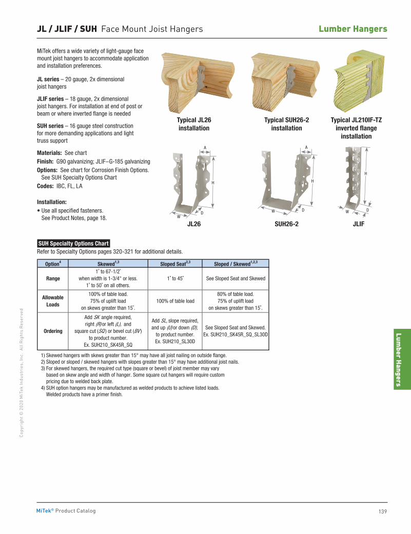
Lumber Hangers
139
Copy
righ
t © 2
020
MiT
ek In
dust
ries
, Inc
. Al
l Rig
hts
Rese
rved
Lumber Hangers
MiTek® Product Catalog
JL / JLIF / SUH Face Mount Joist Hangers
Option4 Skewed1,3 Sloped Seat2,3 Sloped / Skewed1,2,3
1) Skewed hangers with skews greater than 15° may have all joist nailing on outside flange. 2) Sloped or sloped / skewed hangers with slopes greater than 15° may have additional joist nails. 3) For skewed hangers, the required cut type (square or bevel) of joist member may vary based on skew angle and width of hanger. Some square cut hangers will require custom pricing due to welded back plate. 4) SUH option hangers may be manufactured as welded products to achieve listed loads. Welded products have a primer finish.
Range
Ordering
AllowableLoads
100% of table load
1˚ to 45˚
Add SK angle required,right (R) or left (L), and
square cut (SQ ) or bevel cut (BV )to product number.
Ex. SUH210_SK45R_SQ
Add SL, slope required,and up (U) or down (D),
to product number.Ex. SUH210_SL30D
See Sloped Seat and Skewed.Ex. SUH210_SK45R_SQ_SL30D
See Sloped Seat and Skewed1˚ to 67-1/2˚
when width is 1-3/4" or less.1˚ to 50˚ on all others.
100% of table load.75% of uplift load
on skews greater than 15˚.
80% of table load.75% of uplift load
on skews greater than 15˚.
Typical SUH26-2installation
SUH26-2 JLIF
Typical JL26installation
JL26
Typical JL210IF-TZ inverted flange
installation
SUH Specialty Options Chart Refer to Specialty Options pages 320-321 for additional details.
A
DW
H
A
DW
H
MiTek offers a wide variety of light-gauge face mount joist hangers to accommodate application and installation preferences.
JL series – 20 gauge, 2x dimensional joist hangers
JLIF series – 18 gauge, 2x dimensional joist hangers. For installation at end of post or beam or where inverted flange is needed
SUH series – 16 gauge steel construction for more demanding applications and light truss support
Materials: See chartFinish: G90 galvanizing; JLIF–G-185 galvanizingOptions: See chart for Corrosion Finish Options. See SUH Specialty Options ChartCodes: IBC, FL, LA
Installation:• Use all specified fasteners.
See Product Notes, page 18.DW
H
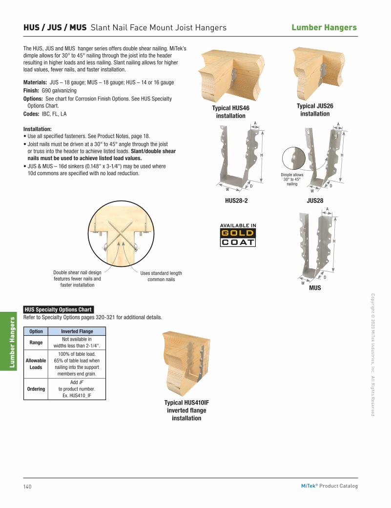
140
Copyright © 2020 M
iTek Industries, Inc. All Rights Reserved
Lumber Hangers
Lum
ber H
ange
rs
MiTek® Product Catalog
HUS / JUS / MUS Slant Nail Face Mount Joist Hangers
Typical JUS26installation
Typical HUS46installation
Typical HUS410IF inverted flange
installation
MUS
HUS28-2
Double shear nail designfeatures fewer nails and
faster installation
Uses standard length common nails
The HUS, JUS and MUS hanger series offers double shear nailing. MiTek’s dimple allows for 30° to 45° nailing through the joist into the header resulting in higher loads and less nailing. Slant nailing allows for higher load values, fewer nails, and faster installation.
Materials: JUS – 18 gauge; MUS – 18 gauge; HUS – 14 or 16 gaugeFinish: G90 galvanizingOptions: See chart for Corrosion Finish Options. See HUS Specialty Options Chart.Codes: IBC, FL, LA
Installation:• Use all specified fasteners. See Product Notes, page 18.• Joist nails must be driven at a 30° to 45° angle through the joist
or truss into the header to achieve listed loads. Slant/double shear nails must be used to achieve listed load values.
• JUS & MUS – 16d sinkers (0.148" x 3-1⁄4") may be used where 10d commons are specified with no load reduction.
Option Inverted Flange
Not available inwidths less than 2-1/4".
100% of table load.65% of table load whennailing into the support
members end grain.
Add IFto product number.
Ex. HUS410_IFOrdering
AllowableLoads
Range
HUS Specialty Options Chart Refer to Specialty Options pages 320-321 for additional details.
W
W
A
DW
H
Dimple allows 30° to 45°
nailing
A
D
H
JUS28A
D
H
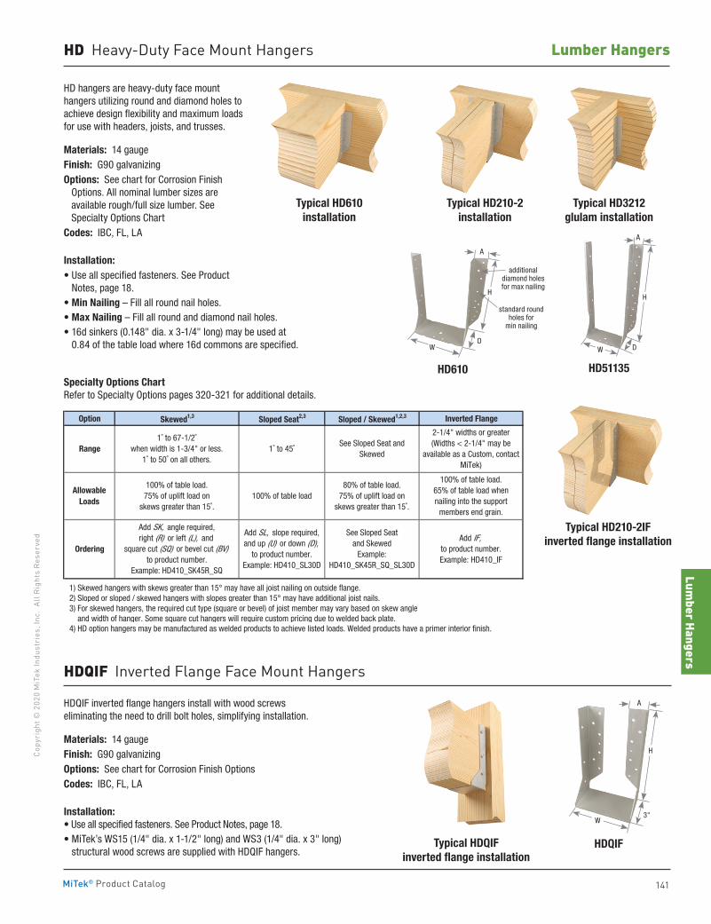
Lumber Hangers
141
Copy
righ
t © 2
020
MiT
ek In
dust
ries
, Inc
. Al
l Rig
hts
Rese
rved
Lumber Hangers
MiTek® Product Catalog
HD Heavy-Duty Face Mount Hangers
HD hangers are heavy-duty face mount hangers utilizing round and diamond holes to achieve design flexibility and maximum loads for use with headers, joists, and trusses.
Materials: 14 gaugeFinish: G90 galvanizingOptions: See chart for Corrosion Finish Options. All nominal lumber sizes are
available rough/full size lumber. See Specialty Options Chart
Codes: IBC, FL, LA
Installation:• Use all specified fasteners. See Product
Notes, page 18.• Min Nailing – Fill all round nail holes.• Max Nailing – Fill all round and diamond nail holes.• 16d sinkers (0.148" dia. x 3-1/4" long) may be used at
0.84 of the table load where 16d commons are specified.
Option Skewed1,3 Sloped Seat2,3 Sloped / Skewed1,2,3 Inverted Flange
1) Skewed hangers with skews greater than 15° may have all joist nailing on outside flange. 2) Sloped or sloped / skewed hangers with slopes greater than 15° may have additional joist nails. 3) For skewed hangers, the required cut type (square or bevel) of joist member may vary based on skew angle and width of hanger. Some square cut hangers will require custom pricing due to welded back plate. 4) HD option hangers may be manufactured as welded products to achieve listed loads. Welded products have a primer interior finish.
Range
Allowable Loads
See Sloped Seat and Skewed
100% of table load.75% of uplift load on
skews greater than 15˚.
100% of table load.65% of table load when nailing into the support
members end grain.
1˚ to 67-1/2˚when width is 1-3/4" or less.
1˚ to 50˚ on all others.
2-1/4" widths or greater(Widths < 2-1/4" may be
available as a Custom, contact MiTek)
100% of table load
1˚ to 45˚
80% of table load. 75% of uplift load on
skews greater than 15˚.
OrderingAdd IF,
to product number.Example: HD410_IF
Add SK, angle required,right (R) or left (L), and
square cut (SQ) or bevel cut (BV)to product number.
Example: HD410_SK45R_SQ
Add SL, slope required,and up (U) or down (D),
to product number.Example: HD410_SL30D
See Sloped Seat and Skewed
Example:HD410_SK45R_SQ_SL30D
HD610
Typical HD3212glulam installation
Typical HDQIFinverted flange installation
Typical HD210-2IF inverted flange installation
HDQIF
HD51135
Typical HD610installation
Typical HD210-2installation
Specialty Options Chart Refer to Specialty Options pages 320-321 for additional details.
HDQIF inverted flange hangers install with wood screws eliminating the need to drill bolt holes, simplifying installation.
Materials: 14 gaugeFinish: G90 galvanizingOptions: See chart for Corrosion Finish OptionsCodes: IBC, FL, LA
Installation:• Use all specified fasteners. See Product Notes, page 18.• MiTek’s WS15 (1/4" dia. x 1-1/2" long) and WS3 (1/4" dia. x 3" long)
structural wood screws are supplied with HDQIF hangers.
HDQIF Inverted Flange Face Mount Hangers
H
A
W D
H
A
3"W
A
H
DW
additional diamond holes for max nailing
standard round holes for
min nailing
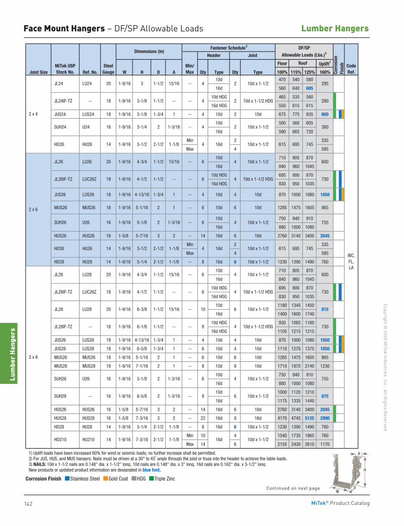
142
Copyright © 2020 M
iTek Industries, Inc. All Rights Reserved
Lumber Hangers
Lum
ber H
ange
rs
MiTek® Product Catalog
Face Mount Hangers – DF/SP Allowable Loads
Floor Uplift1
Joist Size Ref. No. W H D A Qty Type Qty Type 100% 115% 125% 160%
10d 470 540 580
16d 560 640 695
10d HDG 465 535 580
16d HDG 550 615 615
JUS24 LUS24 18 1-9/16 3-1/8 1-3/4 1 -- 4 10d 2 10d 675 775 835 660
10d 500 560 605
16d 590 665 720
Min 2 335
Max 4 585
10d 710 805 870
16d 840 960 1045
10d HDG 695 800 870
16d HDG 830 950 1035
JUS26 LUS26 18 1-9/16 4-13/16 1-3/4 1 -- 4 10d 4 10d 870 1000 1080 1050
MUS26 MUS26 18 1-9/16 5-1/16 2 1 -- 6 10d 6 10d 1285 1475 1605 865
10d 750 840 910
16d 880 1000 1080
HUS26 HUS26 16 1-5/8 5-7/16 3 2 -- 14 16d 6 16d 2760 3140 3400 2045
Min 2 335
Max 4 585
HD28 HU28 14 1-9/16 5-1/4 2-1/2 1-1/8 -- 8 16d 6 10d x 1-1/2 1230 1390 1490 760
10d 710 805 870
16d 840 960 1045
10d HDG 695 800 870
16d HDG 830 950 1035
10d 1180 1345 1450
16d 1400 1600 1740
10d HDG 930 1065 1160
16d HDG 1105 1215 1215
JUS26 LUS26 18 1-9/16 4-13/16 1-3/4 1 -- 4 10d 4 10d 870 1000 1080 1050
JUS28 LUS28 18 1-9/16 6-5/8 1-3/4 1 -- 6 10d 4 10d 1110 1270 1375 1050
MUS26 MUS26 18 1-9/16 5-1/16 2 1 -- 6 10d 6 10d 1285 1475 1605 865
MUS28 MUS28 18 1-9/16 7-1/16 2 1 -- 8 10d 8 10d 1710 1970 2140 1230
10d 750 840 910
16d 880 1000 1080
10d 1000 1120 1210
16d 1175 1335 1440
HUS26 HUS26 16 1-5/8 5-7/16 3 2 -- 14 16d 6 16d 2760 3140 3400 2045
HUS28 HUS28 16 1-5/8 7-3/16 3 2 -- 22 16d 8 16d 4170 4745 5125 2990
HD28 HU28 14 1-9/16 5-1/4 2-1/2 1-1/8 -- 8 16d 6 10d x 1-1/2 1230 1390 1490 760
Min 10 4 1540 1735 1865 760
Max 14 6 2155 2430 2610 1170
1) Uplift loads have been increased 60% for wind or seismic loads; no further increase shall be permitted. 2) For JUS, HUS, and MUS hangers: Nails must be driven at a 30° to 45˚ angle through the joist or truss into the header to achieve the table loads. 3) NAILS: 10d x 1-1/2 nails are 0.148" dia. x 1-1/2" long, 10d nails are 0.148" dia. x 3" long, 16d nails are 0.162" dia. x 3-1/2" long. New products or updated product information are designated in blue font.
LU28 1-9/16
6-1/8 JL28IF-TZ --
--
--
--
815
730
JL26IF-TZ 1-1/2 730
8
4
10 6 10d x 1-1/2
6
1-9/16
--
6-3/8
2 x 4
HD26 HU26 14 1-9/16 3-1/2 2-1/2
2 x 6
JL26 LU26
SUH26 U26
JL26IF-TZ
JL24 LU24
16
1-1/2
SUH24 U24
18 1-1/2
20 1-9/16 3
2 x 8
16 1-9/16
2
1-9/16 5-1/8 2 1-3/16
1-1/2 --
4-1/2
15/16
SUH28 -- 1-3/16
14 1-9/16 7-3/16
JL26 LU26 15/16
HD210 HU210
20
6006 4
16 1-9/16 3-1/4 2 1-3/16
10d x 1-1/2 HDG
4
10d x 1-1/2
10d x 1-1/2 HDG
--
1-1/2 15/16
JL24IF-TZ -- 1-9/16 3-1/8
1-1/8
LUC26Z
JL28
18
--
6
4 16d
--
--
1-1/2
20 1-9/16 4-3/4 1-1/2
18 1-9/16
1-9/16 4-3/4
1-9/16 4-1/218
HD26 HU26 14 1-9/16 3-1/2
380
600
730
7554
615 695 745
--
--
--
--
--
10d x 1-1/2
4 2
10d x 1-1/2
10d x 1-1/2 HDG
10d x 1-1/2
295
280
Roof CodeRef.Co
rros
ion
Fini
sh
Header Joist
DF/SPAllowable Loads (Lbs.)2
2 10d x 1-1/2
6 4
46
615 69516d 10d x 1-1/2 745
IBC, FL, LA
Fastener Schedule3
875
755
2-1/2 1-1/8
6-5/8
5-1/8 2 1-3/16
16 1-9/16
4 10d x 1-1/2
6 10d x 1-1/2--
16d 10d x 1-1/2
6
8
Dimensions (in)
MiTek USPStock No.
SteelGauge
LUC26Z
Min/Max
--1-1/2 15/16
4
2-1/2 1-1/8
4 2 10d x 1-1/2
4 10d x 1-1/2 HDG
SUH26 U26
20
Corrosion Finish Stainless Steel Gold Coat HDG Triple Zinc
Corrosion Finish Stainless Steel Gold Coat HDG Triple Zinc
Corrosion Finish Stainless Steel Gold Coat HDG Triple Zinc
A
D
H
WContinued on next page
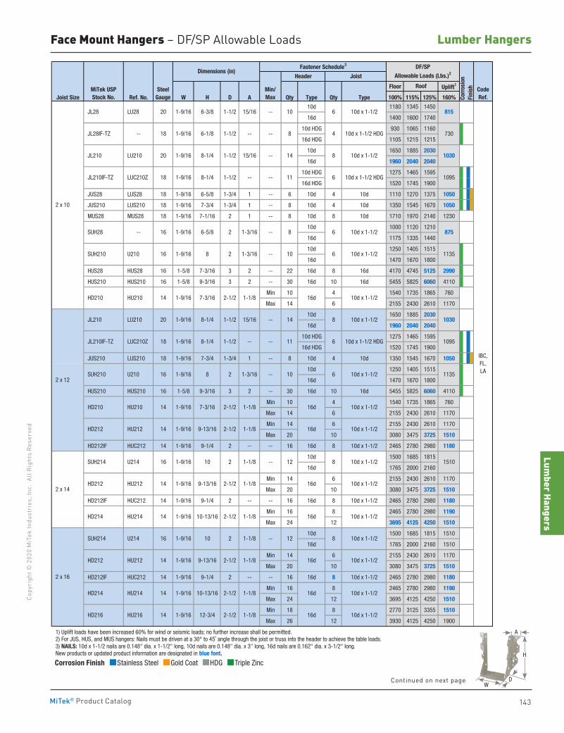
Lumber Hangers
143
Copy
righ
t © 2
020
MiT
ek In
dust
ries
, Inc
. Al
l Rig
hts
Rese
rved
Lumber Hangers
MiTek® Product Catalog
A
D
H
W
Face Mount Hangers – DF/SP Allowable Loads
Floor Uplift1
Joist Size Ref. No. W H D A Qty Type Qty Type 100% 115% 125% 160%
10d 1180 1345 1450
16d 1400 1600 1740
10d HDG 930 1065 1160
16d HDG 1105 1215 1215
10d 1650 1885 2030
16d 1960 2040 2040
10d HDG 1275 1465 1595
16d HDG 1520 1745 1900
JUS28 LUS28 18 1-9/16 6-5/8 1-3/4 1 -- 6 10d 4 10d 1110 1270 1375 1050
JUS210 LUS210 18 1-9/16 7-3/4 1-3/4 1 -- 8 10d 4 10d 1350 1545 1670 1050
MUS28 MUS28 18 1-9/16 7-1/16 2 1 -- 8 10d 8 10d 1710 1970 2140 1230
10d 1000 1120 1210
16d 1175 1335 1440
10d 1250 1405 1515
16d 1470 1670 1800
HUS28 HUS28 16 1-5/8 7-3/16 3 2 -- 22 16d 8 16d 4170 4745 5125 2990
HUS210 HUS210 16 1-5/8 9-3/16 3 2 -- 30 16d 10 16d 5455 5825 6060 4110
Min 10 4 1540 1735 1865 760
Max 14 6 2155 2430 2610 1170
10d 1650 1885 2030
16d 1960 2040 2040
10d HDG 1275 1465 1595
16d HDG 1520 1745 1900
JUS210 LUS210 18 1-9/16 7-3/4 1-3/4 1 -- 8 10d 4 10d 1350 1545 1670 1050
10d 1250 1405 1515
16d 1470 1670 1800
HUS210 HUS210 16 1-5/8 9-3/16 3 2 -- 30 16d 10 16d 5455 5825 6060 4110
Min 10 4 1540 1735 1865 760
Max 14 6 2155 2430 2610 1170
Min 14 6 2155 2430 2610 1170
Max 20 10 3080 3475 3725 1510
HD212IF HUC212 14 1-9/16 9-1/4 2 -- -- 16 16d 8 10d x 1-1/2 2465 2780 2980 1180
10d 1500 1685 1815
16d 1765 2000 2160
Min 14 6 2155 2430 2610 1170
Max 20 10 3080 3475 3725 1510
HD212IF HUC212 14 1-9/16 9-1/4 2 -- -- 16 16d 8 10d x 1-1/2 2465 2780 2980 1180
Min 16 8 2465 2780 2980 1190
Max 24 12 3695 4125 4250 1510
10d 1500 1685 1815 1510
16d 1765 2000 2160 1510
Min 14 6 2155 2430 2610 1170
Max 20 10 3080 3475 3725 1510
HD212IF HUC212 14 1-9/16 9-1/4 2 -- -- 16 16d 8 10d x 1-1/2 2465 2780 2980 1180
Min 16 8 2465 2780 2980 1190
Max 24 12 3695 4125 4250 1510
Min 18 8 2770 3125 3355 1510
Max 26 12 3930 4125 4250 1900
1) Uplift loads have been increased 60% for wind or seismic loads; no further increase shall be permitted. 2) For JUS, HUS, and MUS hangers: Nails must be driven at a 30° to 45˚ angle through the joist or truss into the header to achieve the table loads. 3) NAILS: 10d x 1-1/2 nails are 0.148" dia. x 1-1/2" long, 10d nails are 0.148" dia. x 3" long, 16d nails are 0.162" dia. x 3-1/2" long. New products or updated product information are designated in blue font.
IBC, FL, LA
12 8 10d x 1-1/2
815
730
1030
1095
875
1135
1030
1095
1135
1510
14 8 10d x 1-1/2
11 6 10d x 1-1/2 HDG
10 6 10d x 1-1/2
6
10 6 10d x 1-1/2
8 4 10d x 1-1/2 HDG
14 8 10d x 1-1/2
--
1-1/8
1-1/8
8 2
--
9-13/16
10-13/16
12-3/4
2-1/2
2-1/2
2-1/2
1-1/8
1-1/8
1-1/8
2-1/2
2-1/2
14 1-9/16
14 1-9/16
14 1-9/16
--
9-13/16
10-13/16
2-1/2
2-1/2
1-1/8
1-1/8
14 1-9/16
14
1-9/16
1-9/16
7-3/16
9-13/16
12
1-9/16
HD212
Fastener Schedule3
Min/Max
--
--
--
--
--
--
2
16 1-9/16 10 2
HD212
HD214
HU212
HU214
14
2 x 10
HD210 HU210 14 1-9/16 7-3/16 2-1/2 1-1/8
15/16
16 1-9/16 2 1-3/168
JL28 LU28
JL28IF-TZ --
JL210 LU210
SUH28 --
SUH210
2 x 12
HD210
2 x 14
2 x 16
HU212
HU214
HU216
JL210 LU210
SUH214 U214
SUH214 U214
HD212
HU210
HU212
HD214
HD216
18 1-9/16 8-1/4 1-1/2 --
16
--
--
2 1-3/16
16d 10d x 1-1/2
10d x 1-1/2 HDG11
8 6 10d x 1-1/2
10 6 10d x 1-1/2
1-1/8
1-9/16 6-5/8
1-1/8
16d 10d x 1-1/2
CodeRef.Co
rros
ion
Fini
sh
Header Joist
DF/SPAllowable Loads (Lbs.)2Dimensions (in)
1-9/16
15/16
--
8-1/4
1-9/16 --
6-3/8
MiTek USPStock No.
SteelGauge
Roof
1-3/16
1-1/2
18 1-9/16 8-1/4 1-1/2
16 1-9/16
1-1/2 15/16
20 1-9/16
6-1/8 1-1/2
JL210IF-TZ LUC210Z
SUH210 U210
JL210IF-TZ LUC210Z
U210
20
18
20
16d 10d x 1-1/2
16d 10d x 1-1/2
16d 10d x 1-1/2
16d 10d x 1-1/2
16d 10d x 1-1/2
16d 10d x 1-1/2
8 10d x 1-1/2
1-9/16 8-1/4 1-1/2
16 1-9/16 10
14
Corrosion Finish Stainless Steel Gold Coat HDG Triple Zinc
Corrosion Finish Stainless Steel Gold Coat HDG Triple Zinc
Corrosion Finish Stainless Steel Gold Coat HDG Triple Zinc
Continued on next page
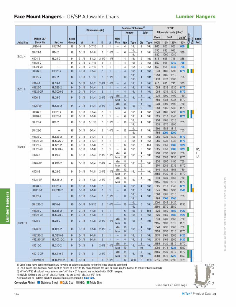
144
Copyright © 2020 M
iTek Industries, Inc. All Rights Reserved
Lumber Hangers
Lum
ber H
ange
rs
MiTek® Product Catalog
Face Mount Hangers – DF/SP Allowable Loads
Floor Uplift1
Joist Size Ref. No. W H D A Qty Type Qty Type 100% 115% 125% 160% JUS24-2 LUS24-2 18 3-1/8 3-7/16 2 1 -- 4 16d 2 16d 805 900 900 660
10d 750 840 910
16d 880 1000 1080
HD24-2 HU24-2 14 3-1/8 3-1/2 2-1/2 1-1/8 -- 4 16d 2 10d 615 695 745 365
HUS24-2 -- 14 3-1/8 3-7/16 2 1 -- 4 16d 2 16d 850 965 1040 765 HUS24-2IF -- 14 3-1/8 3-7/16 2 1 -- 4 16d 2 16d 850 965 1040 765 JUS26-2 LUS26-2 18 3-1/8 5-1/4 2 1 -- 4 16d 4 16d 1040 1185 1290 1270
10d 1250 1405 1515
16d 1470 1670 1800
HD24-2 HU24-2 14 3-1/8 3-1/2 2-1/2 1-1/8 -- 4 16d 2 10d 615 695 745 365
HUS26-2 HUS26-2 14 3-1/8 5-1/4 2 1 -- 4 16d 4 16d 1085 1235 1330 1170 HUS26-2IF HUSC26-2 14 3-1/8 5-1/4 2 1 -- 4 16d 4 16d 1085 1235 1330 1170
Min 8 4 1230 1390 1490 760
Max 12 6 1850 2085 2235 1170
Min 8 4 1230 1390 1490 760
Max 12 6 1850 2085 2235 1170
JUS26-2 LUS26-2 18 3-1/8 5-1/4 2 1 -- 4 16d 4 16d 1040 1185 1290 1270 JUS28-2 LUS28-2 18 3-1/8 7-1/8 2 1 -- 6 16d 4 16d 1325 1510 1645 1270
10d 1250 1405 1515
16d 1470 1670 1800
10d 1500 1685 1815
16d 1765 2000 2000 HUS26-2 HUS26-2 14 3-1/8 5-1/4 2 1 -- 4 16d 4 16d 1085 1235 1330 1170 HUS26-2IF HUSC26-2 14 3-1/8 5-1/4 2 1 -- 4 16d 4 16d 1085 1235 1330 1170 HUS28-2 HUS28-2 14 3-1/8 7-1/8 2 1 -- 6 16d 6 16d 1625 1850 1880 2420 HUS28-2IF HUSC28-2 14 3-1/8 7-1/8 2 1 -- 6 16d 6 16d 1625 1850 1880 2420
Min 8 4 1230 1390 1490 760
Max 12 6 1850 2085 2235 1170
Min 8 4 1230 1390 1490 760
Max 12 6 1850 2085 2235 1170
Min 10 4 1540 1735 1865 780
Max 14 6 2155 2430 2610 1170
Min 10 4 1540 1735 1865 780
Max 14 6 2155 2430 2610 1170
JUS28-2 LUS28-2 18 3-1/8 7-1/8 2 1 -- 6 16d 4 16d 1325 1510 1645 1270 JUS210-2 LUS210-2 18 3-1/8 9-1/8 2 1 -- 8 16d 6 16d 1845 2105 2290 2345
10d 1500 1685 1815
16d 1765 2000 2000-- 10d 2000 2245 2420
16d 2350 2670 2880
HUS28-2 HUS28-2 14 3-1/8 7-1/8 2 1 -- 6 16d 6 16d 1625 1850 1880 2420 HUS28-2IF HUSC28-2 14 3-1/8 7-1/8 2 1 -- 6 16d 6 16d 1625 1850 1880 2420
Min 10 4 1540 1735 1865 780
Max 14 6 2155 2430 2610 1170
Min 10 4 1540 1735 1865 780
Max 14 6 2155 2430 2610 1170
HUS210-2 HUS210-2 14 3-1/8 9-1/8 2 1 -- 8 16d 8 16d 2170 2465 2660 2420 HUS210-2IF HUSC210-2 14 3-1/8 9-1/8 2 1 -- 8 16d 8 16d 2170 2465 2660 2420
Min 14 6 2155 2430 2610 1170
Max 20 10 3080 3475 3725 1950
Min 14 6 2155 2430 2610 1170
Max 20 10 3080 3475 3725 1950
HDQ210-2IF HUCQ210-2 14 3-1/4 9 3 1-1/2 -- 12 WS3 6 WS3 5015 5590 5590 2975
1) Uplift loads have been increased 60% for wind or seismic loads; no further increase shall be permitted. 2) For JUS and HUS hangers: Nails must be driven at a 30° to 45˚ angle through the joist or truss into the header to achieve the table loads. 3) MiTek's WS3 structural wood screws are 1/4" dia. x 3" long and are included with HDQIF hangers. 4) NAILS: 10d nails are 0.148" dia. x 3" long, 16d are 0.162" dia. x 3-1/2" long. New products or updated product information are designated in blue font.
IBC, FL, LA
380
755
755
755
755
1135
12 4 10d
12 4 10d
16 6 10d
6 2 10d
10 4 10d
10 4 10d
(2) 2 x 6
HU26-2
HUC26-2
SUH26-2
(2) 2 x 4
SUH24-2 U24-2 1-1/816 3-1/8 3-1/8 2
2-1/2 --
--
1-1/8 U26-2 16 3-1/8 5-1/16 2
16d
16d
10d
10d
--
14 3-1/8 5-1/4
3-1/8 9 2-1/2
2-1/2 1-1/8
14 3-1/8 5-1/4
1-1/8
2-1/2 1-1/8
3-1/8 6-1/4 2
3-1/8 5-1/4 2-1/2 --
(2) 2 x 8
14
(2) 2 x 10
SUH28-2 --
SUH210-2 U210-2
HD28-2 HU28-2
HD210-2IF HUC210-2
HD210-2 HU210-2
16
16
14
14
MiTek USPStock No.
SteelGauge
SUH26-2 U26-2
SUH28-2 --
HU28-2
14
14
16
HD26-2 HU26-2
HD28-2
16
HUC26-2 14
HD26-2
HD26-2IF
CodeRef.Co
rros
ion
Fini
sh
Dimensions (in)DF/SP
Allowable Loads (Lbs.)2Fastener Schedule3,4
Min/Max
Joist
Roof
16d 10d
Header
--
--1-1/8
3-1/8 5-1/16 2
3-1/8 26-1/4
1-1/8
3-1/8 5-1/4 2-1/2
16d 10d HD26-2IF
16d 10d
16d 10d
16d 10d
16d 10d
1-1/8
1-1/8
3-1/8 7-1/8
--
1-1/8
--
14 3-1/8 9 2-1/2 1-1/8
3-1/8
16d 10d HD28-2IF HUC28-2
HD28-2IF HUC28-2 14 3-1/8 7-1/8 2-1/2 -- 16d 10d
8-9/16 2
3-1/8 7-1/8 2-1/2
3-1/8 7-1/8 2-1/2 --
Corrosion Finish Stainless Steel Gold Coat HDG Triple Zinc
Corrosion Finish Stainless Steel Gold Coat HDG Triple Zinc
Corrosion Finish Stainless Steel Gold Coat HDG Triple Zinc
A
D
H
WContinued on next page
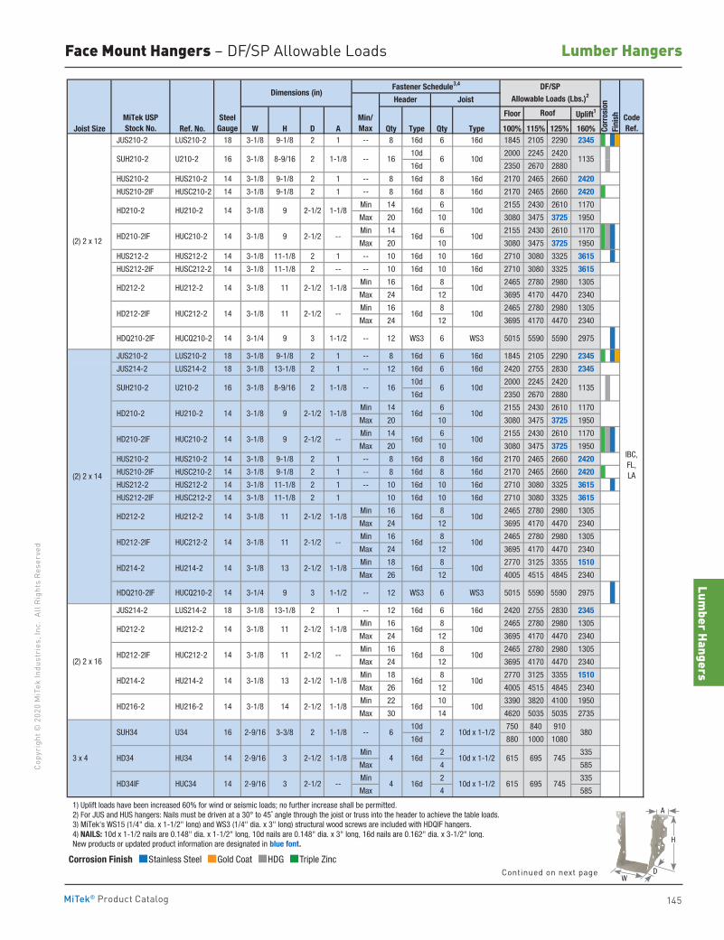
Lumber Hangers
145
Copy
righ
t © 2
020
MiT
ek In
dust
ries
, Inc
. Al
l Rig
hts
Rese
rved
Lumber Hangers
MiTek® Product Catalog
Face Mount Hangers – DF/SP Allowable Loads
Floor Uplift1
Joist Size Ref. No. W H D A Qty Type Qty Type 100% 115% 125% 160% JUS210-2 LUS210-2 18 3-1/8 9-1/8 2 1 -- 8 16d 6 16d 1845 2105 2290 2345
10d 2000 2245 2420
16d 2350 2670 2880
HUS210-2 HUS210-2 14 3-1/8 9-1/8 2 1 -- 8 16d 8 16d 2170 2465 2660 2420
HUS210-2IF HUSC210-2 14 3-1/8 9-1/8 2 1 -- 8 16d 8 16d 2170 2465 2660 2420
Min 14 6 2155 2430 2610 1170
Max 20 10 3080 3475 3725 1950
Min 14 6 2155 2430 2610 1170
Max 20 10 3080 3475 3725 1950
HUS212-2 HUS212-2 14 3-1/8 11-1/8 2 1 -- 10 16d 10 16d 2710 3080 3325 3615
HUS212-2IF HUSC212-2 14 3-1/8 11-1/8 2 -- -- 10 16d 10 16d 2710 3080 3325 3615
Min 16 8 2465 2780 2980 1305
Max 24 12 3695 4170 4470 2340
Min 16 8 2465 2780 2980 1305
Max 24 12 3695 4170 4470 2340
HDQ210-2IF HUCQ210-2 14 3-1/4 9 3 1-1/2 -- 12 WS3 6 WS3 5015 5590 5590 2975
JUS210-2 LUS210-2 18 3-1/8 9-1/8 2 1 -- 8 16d 6 16d 1845 2105 2290 2345
JUS214-2 LUS214-2 18 3-1/8 13-1/8 2 1 -- 12 16d 6 16d 2420 2755 2830 2345
10d 2000 2245 2420
16d 2350 2670 2880
Min 14 6 2155 2430 2610 1170
Max 20 10 3080 3475 3725 1950
Min 14 6 2155 2430 2610 1170
Max 20 10 3080 3475 3725 1950
HUS210-2 HUS210-2 14 3-1/8 9-1/8 2 1 -- 8 16d 8 16d 2170 2465 2660 2420
HUS210-2IF HUSC210-2 14 3-1/8 9-1/8 2 1 -- 8 16d 8 16d 2170 2465 2660 2420
HUS212-2 HUS212-2 14 3-1/8 11-1/8 2 1 -- 10 16d 10 16d 2710 3080 3325 3615
HUS212-2IF HUSC212-2 14 3-1/8 11-1/8 2 1 10 16d 10 16d 2710 3080 3325 3615
Min 16 8 2465 2780 2980 1305
Max 24 12 3695 4170 4470 2340
Min 16 8 2465 2780 2980 1305
Max 24 12 3695 4170 4470 2340
Min 18 8 2770 3125 3355 1510
Max 26 12 4005 4515 4845 2340
HDQ210-2IF HUCQ210-2 14 3-1/4 9 3 1-1/2 -- 12 WS3 6 WS3 5015 5590 5590 2975
JUS214-2 LUS214-2 18 3-1/8 13-1/8 2 1 -- 12 16d 6 16d 2420 2755 2830 2345
Min 16 8 2465 2780 2980 1305
Max 24 12 3695 4170 4470 2340
Min 16 8 2465 2780 2980 1305
Max 24 12 3695 4170 4470 2340
Min 18 8 2770 3125 3355 1510
Max 26 12 4005 4515 4845 2340
Min 22 10 3390 3820 4100 1950
Max 30 14 4620 5035 5035 2735
10d 750 840 910
16d 880 1000 1080
Min 2 335
Max 4 585
Min 2 335
Max 4 585
1) Uplift loads have been increased 60% for wind or seismic loads; no further increase shall be permitted. 2) For JUS and HUS hangers: Nails must be driven at a 30° to 45˚ angle through the joist or truss into the header to achieve the table loads. 3) MiTek's WS15 (1/4" dia. x 1-1/2" long) and WS3 (1/4" dia. x 3" long) structural wood screws are included with HDQIF hangers. 4) NAILS: 10d x 1-1/2 nails are 0.148" dia. x 1-1/2" long, 10d nails are 0.148" dia. x 3" long, 16d nails are 0.162" dia. x 3-1/2" long. New products or updated product information are designated in blue font.
(2) 2 x 14
SUH210-2 U210-2 1-1/816 3-1/8 8-9/16 2
2-1/2 --
HD212-2 HU212-2 14 3-1/8 11 2-1/2 1-1/8
HD210-2IF HUC210-2 14 3-1/8 9
HU214-2 13
HU210-2 14 3-1/8 9
HD214-2 14 3-1/8
HD212-2IF
2-1/2
2-1/2
HD210-2
IBC, FL, LA
3-1/8 11 2-1/2 --
2-1/2 1-1/8
1-1/8
16d 10d
16d 10d
16d 10d
16d 10d
16d 10d
--
615 695 745
615 69514
2-9/16
2-9/16
3
14 3-1/8 14
113510d616
745
3806 2 10d x 1-1/2
14 3-1/8 13 2-1/2 1-1/8
2-1/2
16
14
(2) 2 x 16
3 x 4
HD212-2 HU212-2
HD212-2IF HUC212-2
HD214-2 HU214-2
HD216-2 HU216-2
SUH34
HD34 HU34
HD34IF HUC34
U34
CodeRef.
MiTek USPStock No.
SteelGauge
1-1/8
2-1/2
3
16d
16d
4 10d x 1-1/2
4 10d x 1-1/2
14 3-1/8 11 2-1/2 1-1/8
HUC212-2 14 3-1/8 11
1-1/8
--
14
Dimensions (in)DF/SP
Allowable Loads (Lbs.)2
Corr
osio
nFi
nish
Header Joist
Roof
Fastener Schedule3,4
Min/Max
--
16d 10d
16d 10d
16d 10d
16d 10d
2-9/16 3-3/8 2
2-1/2 1-1/8
--
8-9/16
(2) 2 x 12
113510d616--1-1/83-1/816 U210-2
10d16d1-1/82-1/293-1/814
1-1/8
HD210-2IF HUC210-2 14 3-1/8 9
HU210-2 HD210-2
2
2-1/2 -- HD212-2IF 10d16d
10d16d
10d16d
SUH210-2
HUC212-2 14 3-1/8 11
2-1/2 --
HD212-2 HU212-2 14 3-1/8 11 2-1/2
Corrosion Finish Stainless Steel Gold Coat HDG Triple Zinc
Corrosion Finish Stainless Steel Gold Coat HDG Triple Zinc
Corrosion Finish Stainless Steel Gold Coat HDG Triple Zinc
A
D
H
WContinued on next page
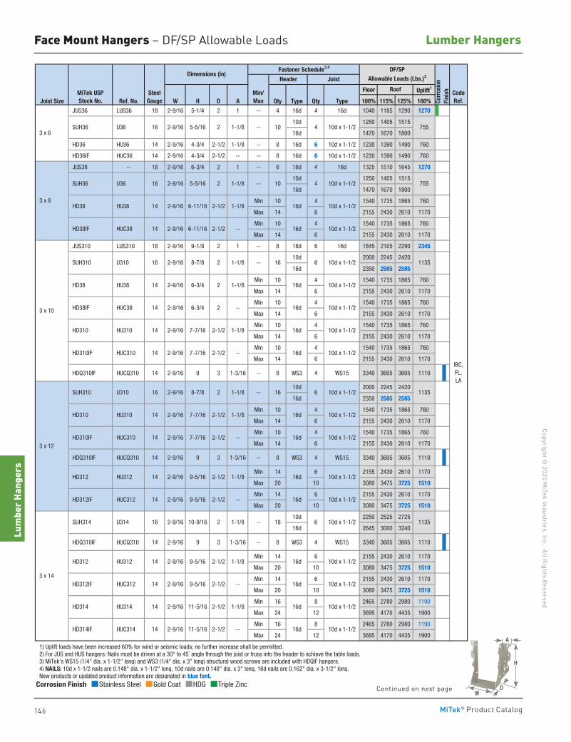
146
Copyright © 2020 M
iTek Industries, Inc. All Rights Reserved
Lumber Hangers
Lum
ber H
ange
rs
MiTek® Product Catalog
Face Mount Hangers – DF/SP Allowable Loads
Floor Uplift1
Joist Size Ref. No. W H D A Qty Type Qty Type 100% 115% 125% 160%
JUS36 LUS36 18 2-9/16 5-1/4 2 1 -- 4 16d 4 16d 1040 1185 1290 1270
10d 1250 1405 1515
16d 1470 1670 1800
HD36 HU36 14 2-9/16 4-3/4 2-1/2 1-1/8 -- 8 16d 6 10d x 1-1/2 1230 1390 1490 760
HD36IF HUC36 14 2-9/16 4-3/4 2-1/2 -- -- 8 16d 6 10d x 1-1/2 1230 1390 1490 760
JUS38 -- 18 2-9/16 6-3/4 2 1 -- 6 16d 4 16d 1325 1510 1645 1270
10d 1250 1405 1515
16d 1470 1670 1800
Min 10 4 1540 1735 1865 760
Max 14 6 2155 2430 2610 1170
Min 10 4 1540 1735 1865 760
Max 14 6 2155 2430 2610 1170
JUS310 LUS310 18 2-9/16 9-1/8 2 1 -- 8 16d 6 16d 1845 2105 2290 2345
10d 2000 2245 2420
16d 2350 2585 2585
Min 10 4 1540 1735 1865 760
Max 14 6 2155 2430 2610 1170
Min 10 4 1540 1735 1865 760
Max 14 6 2155 2430 2610 1170
Min 10 4 1540 1735 1865 760
Max 14 6 2155 2430 2610 1170
Min 10 4 1540 1735 1865 760
Max 14 6 2155 2430 2610 1170
HDQ310IF HUCQ310 14 2-9/16 9 3 1-3/16 -- 8 WS3 4 WS15 3340 3605 3605 1110
10d 2000 2245 2420
16d 2350 2585 2585
Min 10 4 1540 1735 1865 760
Max 14 6 2155 2430 2610 1170
Min 10 4 1540 1735 1865 760
Max 14 6 2155 2430 2610 1170
HDQ310IF HUCQ310 14 2-9/16 9 3 1-3/16 -- 8 WS3 4 WS15 3340 3605 3605 1110
Min 14 6 2155 2430 2610 1170
Max 20 10 3080 3475 3725 1510
Min 14 6 2155 2430 2610 1170
Max 20 10 3080 3475 3725 1510
10d 2250 2525 2725
16d 2645 3000 3240
HDQ310IF HUCQ310 14 2-9/16 9 3 1-3/16 -- 8 WS3 4 WS15 3340 3605 3605 1110
Min 14 6 2155 2430 2610 1170
Max 20 10 3080 3475 3725 1510
Min 14 6 2155 2430 2610 1170
Max 20 10 3080 3475 3725 1510
Min 16 8 2465 2780 2980 1190
Max 24 12 3695 4170 4435 1900
Min 16 8 2465 2780 2980 1190
Max 24 12 3695 4170 4435 1900
1) Uplift loads have been increased 60% for wind or seismic loads; no further increase shall be permitted. 2) For JUS and HUS hangers: Nails must be driven at a 30° to 45˚ angle through the joist or truss into the header to achieve the table loads. 3) MiTek's WS15 (1/4" dia. x 1-1/2" long) and WS3 (1/4" dia. x 3" long) structural wood screws are included with HDQIF hangers. 4) NAILS: 10d x 1-1/2 nails are 0.148" dia. x 1-1/2" long, 10d nails are 0.148" dia. x 3" long, 16d nails are 0.162" dia. x 3-1/2" long. New products or updated product information are designated in blue font.
755
755
16 6 10d x 1-1/2 1135
11356 10d x 1-1/216
10 4 10d x 1-1/2
16d 10d x 1-1/2
16d 10d x 1-1/2
16d 10d x 1-1/2
10d x 1-1/2
4 10d x 1-1/2
16d
10
10d x 1-1/2
16d 10d x 1-1/2
HD314IF HUC314 14 2-9/16 11-5/16 2-1/2 -- 16d
-- 16d 10d x 1-1/2
HD314 HU314 14 2-9/16 11-5/16 2-1/2 1-1/8
1-1/8
3 x 12
16d 10d x 1-1/2
HD312IF HUC312 14 2-9/16 9-5/16 2-1/2
HD312 HU312 14 2-9/16 9-5/16 2-1/2
3 x 14
SUH314 U314 16 2-9/16 10-9/16 2 1-1/8 --
HD312IF HUC312 14 2-9/16 9-5/16 2-1/2 -- 16d
16d 10d x 1-1/2
10d x 1-1/2
11356 10d x 1-1/218
IBC, FL, LA
2-9/16 7-7/16 2-1/2 -- 16d 10d x 1-1/2
-- 16d 10d x 1-1/2
2 1-1/8 --
1-1/8 16d 10d x 1-1/2
1-1/8
2-9/16 8-7/8
HD312 HU312 14 2-9/16 9-5/16 2-1/2 1-1/8
HD310IF HUC310 14
HD310 HU310 14 2-9/16 7-7/16 2-1/2
SUH310 U310 16
HD38 HU38 14 2-9/16 6-3/4 2
HD310IF HUC310 14 2-9/16 7-7/16 2-1/2
3 x 10
SUH310 U310 16 2-9/16 8-7/8 2 1-1/8 --
1-1/8
HD310 HU310 14 2-9/16 7-7/16 2-1/2 1-1/8
HD38IF HUC38 14 2-9/16 6-3/4 2 --
HD38IF HUC38 14 2-9/16 6-11/16 2-1/2 -- 16d 10d x 1-1/2
-- SUH36 U36 16 2-9/16 5-5/16 2
3 x 8
SUH36 U36 16 2-9/16 5-5/16 2
3 x 6
1-1/8
1-1/8
--
HD38 HU38 14 2-9/16 6-11/16 2-1/2
MiTek USPStock No.
SteelGauge
Min/Max
Roof CodeRef.
Dimensions (in)Fastener Schedule3,4 DF/SP
Allowable Loads (Lbs.)2
Corr
osio
nFi
nish
Header Joist
Corrosion Finish Stainless Steel Gold Coat HDG Triple Zinc
Corrosion Finish Stainless Steel Gold Coat HDG Triple Zinc
Corrosion Finish Stainless Steel Gold Coat HDG Triple Zinc
A
D
H
WContinued on next page
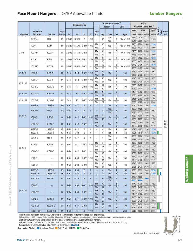
Lumber Hangers
147
Copy
righ
t © 2
020
MiT
ek In
dust
ries
, Inc
. Al
l Rig
hts
Rese
rved
Lumber Hangers
MiTek® Product Catalog
Face Mount Hangers – DF/SP Allowable Loads
Floor Uplift1
Joist Size Ref. No. W H D A Qty Type Qty Type 100% 115% 125% 160%10d 2250 2525 2725
16d 2645 3000 3240
Min 16 8 2465 2780 2980 1190
Max 24 12 3695 4170 4435 1900
Min 16 8 2465 2780 2980 1190
Max 24 12 3695 4170 4435 1900
Min 18 8 2770 3125 3355 1510
Max 26 12 4005 4435 4435 1900
Min 18 8 2770 3125 3355 1510
Max 26 12 4005 4435 4435 1900
Min 10 4 1540 1735 1865 780
Max 14 6 2155 2430 2610 1170
Min 10 4 1540 1735 1865 780
Max 14 6 2155 2430 2610 1170
Min 14 6 2155 2430 2610 1170
Max 20 10 3080 3475 3725 1510
Min 16 8 2465 2780 2980 1305
Max 24 12 3695 4170 4470 2340
Min 16 8 2465 2780 2980 1305
Max 24 12 3695 4170 4470 2340
JUS26-3 LUS26-3 18 4-5/8 4-1/2 2 1 -- 4 16d 4 16d 1040 1185 1290 1270
10d 1000 1120 1210
16d 1175 1335 1440
Min 8 4 1230 1390 1490 760
Max 12 6 1850 2085 2235 1170
Min 8 4 1230 1390 1490 760
Max 12 6 1850 2085 2235 1170
JUS26-3 LUS26-3 18 4-5/8 4-1/2 2 1 -- 4 16d 4 16d 1040 1185 1290 1270
JUS28-3 LUS28-3 18 4-5/8 6-3/8 2 1 -- 6 16d 4 16d 1325 1510 1645 1270
10d 1000 1120 1210
16d 1175 1335 1440
Min 8 4 1230 1390 1490 760
Max 12 6 1850 2085 2235 1170
Min 8 4 1230 1390 1490 760
Max 12 6 1850 2085 2235 1170
Min 10 4 1540 1735 1865 780
Max 14 6 2155 2430 2610 1170
Min 10 4 1540 1735 1865 780
Max 14 6 2155 2430 2610 1170
JUS28-3 LUS28-3 18 4-5/8 6-3/8 2 1 -- 6 16d 4 16d 1325 1510 1645 1270
JUS210-3 LUS210-3 18 4-5/8 8-3/8 2 1 -- 8 16d 6 16d 1845 2105 2290 2345
10d 1750 1965
16d 2000 2000
Min 10 4 1540 1735 1865 780
Max 14 6 2155 2430 2610 1170
Min 10 4 1540 1735 1865 780
Max 14 6 2155 2430 2610 1170
Min 14 6 2155 2430 2610 1170
Max 20 10 3080 3475 3725 1950
Min 14 6 2155 2430 2610 1170
Max 20 10 3080 3475 3725 1950
HDQ210-3IF HUCQ210-3 14 4-5/8 9 3 1-1/2 -- 12 WS3 6 WS3 5015 5590 5590 2975
1) Uplift loads have been increased 60% for wind or seismic loads; no further increase shall be permitted. 2) For JUS and HUS hangers: Nails must be driven at a 30° to 45˚ angle through the joist or truss into the header to achieve the table loads. 3) MiTek's WS3 structural wood screws are 1/4" dia. x 3" long and are included with HDQIF hangers. 4) NAILS: 10d x 1-1/2 nails are 0.148" dia. x 1-1/2" long, 10d nails are 0.148" dia. x 3" long, 16d nails are 0.162" dia. x 3-1/2" long. New products or updated product information are designated in blue font.
10d
16d 10d
(2) 3 x 8
(2) 3 x 10
(2) 3 x 12
IBC, FL, LA
113520006 10d14
18 6 10d x 1-1/2 1135
8 10d2 380
8 2 10d 380
16d 10d
16d
3 x 16
SUH314 U314 16 2-9/16 10-9/16 2 1-1/8 --
1-1/8
HD316 HU316 14 2-9/16 13-5/16 2-1/2 1-1/8
10d x 1-1/2
HD314IF HUC314 14 16d 10d x 1-1/2
16d
10d x 1-1/2
HD316IF HUC316 14 2-9/16 13-5/16 2-1/2 -- 16d 10d x 1-1/2
16d
2-9/16 11-5/16 2-1/2 --
HD314 HU314 14 2-9/16 11-5/16 2-1/2
2-1/2 --
HD210-3 HU210-3 14 4-5/8 8-1/4 2-1/2 1-1/8
HD210-3IF HUC210-3 14 4-5/8 8-1/4
--
HD28-3 -- 14 4-5/8 6-3/8 2-1/2 1-1/8
HD28-3IF -- 14 4-5/8 6-3/8
--
HD28-3 -- 14 4-5/8 6-3/8 2-1/2 1-1/8
HD26-3IF HUC26-3 14 4-5/8 4-1/2
1-1/8
HD26-3IF HUC26-3 14 4-5/8
4-1/2
4-1/2
SUH26-3 U26-3 16 4-5/8
14 4-5/8 2-1/2
2-1/2
--
HD38-2 HU38-2 14 5-1/8 6-1/8 2-1/2 1-1/8
HD38-2 HU38-2 14 5-1/8 6-1/8
5-1/4 2 1
2-1/2 1-1/8
8
10
2-1/2 1-1/8
HD310-2 HU310-2
1-1/8
1-1/8
2-1/2
4-5/8 SUH26-3 U26-3 16
1-1/8
--
(2) 3 x 14
(3) 2 x 6
(3) 2 x 8
14 5-1/8 2-1/2
HD312-2 HU312-2 14 5-1/8
HD312-2 HU312-2 14 5-1/8 10
HD26-3 HU26-3
4-1/2 2-1/2
2-1/2
2-1/2
--
(3) 2 x 10
SUH210-3 U210-3 16 4-5/8
HD28-3IF -- 14 4-5/8
8-3/8 2 1 --
6-3/8 2-1/2 --
5-1/4 2 1
HD26-3 HU26-3 14 4-5/8
MiTek USPStock No.
SteelGauge
Roof CodeRef.Co
rros
ion
Fini
sh
Header Joist
DF/SPAllowable Loads (Lbs.)2Dimensions (in)
Fastener Schedule3,4
Min/Max
10d
16d 10d
16d 10d
16d 10d
16d 10d
16d
16d 10d
16d 10d
16d 10d
16d 10d
16d 10d
16d 10d
16d 10d
Corrosion Finish Stainless Steel Gold Coat HDG Triple Zinc
Corrosion Finish Stainless Steel Gold Coat HDG Triple Zinc
Corrosion Finish Stainless Steel Gold Coat HDG Triple Zinc
A
D
H
WContinued on next page
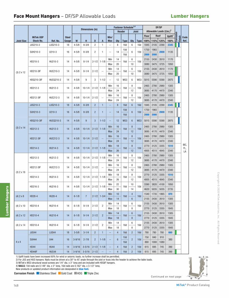
148
Copyright © 2020 M
iTek Industries, Inc. All Rights Reserved
Lumber Hangers
Lum
ber H
ange
rs
MiTek® Product Catalog
Face Mount Hangers – DF/SP Allowable Loads
Floor Uplift1
Joist Size Ref. No. W H D A Qty Type Qty Type 100% 115% 125% 160%
JUS210-3 LUS210-3 18 4-5/8 8-3/8 2 1 -- 8 16d 6 16d 1845 2105 2290 2345
10d 1750 1965
16d 2000 2000
Min 14 6 2155 2430 2610 1170
Max 20 10 3080 3475 3725 1950
Min 14 6 2155 2430 2610 1170
Max 20 10 3080 3475 3725 1950
HDQ210-3IF HUCQ210-3 14 4-5/8 9 3 1-1/2 -- 12 WS3 6 WS3 5015 5590 5590 2975
Min 16 8 2465 2780 2980 1305
Max 24 12 3695 4170 4470 2340
Min 16 8 2465 2780 2980 1305
Max 24 12 3695 4170 4470 2340
JUS210-3 LUS210-3 18 4-5/8 8-3/8 2 1 -- 8 16d 6 16d 1845 2105 2290 2345
10d 1750 1965
16d 2000 2000
HDQ210-3IF HUCQ210-3 14 4-5/8 9 3 1-1/2 -- 12 WS3 6 WS3 5015 5590 5590 2975
Min 16 8 2465 2780 2980 1305
Max 24 12 3695 4170 4470 2340
Min 16 8 2465 2780 2980 1305
Max 24 12 3695 4170 4470 2340
Min 18 8 2770 3125 3355 1510
Max 26 12 4005 4515 4845 2340
Min 16 8 2465 2780 2980 1305
Max 24 12 3695 4170 4470 2340
Min 16 8 2465 2780 2980 1305
Max 24 12 3695 4170 4470 2340
Min 18 8 2770 3125 3355 1510
Max 26 12 4005 4515 4845 2340
Min 22 10 3390 3820 4100 1950
Max 30 14 4620 5035 5035 2735
Min 10 4 1540 1735 1865 870
Max 14 6 2155 2430 2610 1305
Min 14 6 2155 2430 2610 1305
Max 18 8 2770 3125 3355 1845
Min 14 6 2155 2430 2610 1305
Max 18 8 2770 3125 3355 1845
Min 14 6 2155 2430 2610 1305
Max 18 8 2770 3125 3355 1845
JUS44 LUS44 18 3-5/8 3-1/4 2 1 -- 4 16d 2 16d 780 780 780 660
10d 750 840 910
16d 880 1000 1080
HD44 HU44 14 3-9/16 3-5/16 2-1/2 1-1/8 -- 4 16d 2 10d 615 695 745 390
HD44IF HUC44 14 3-9/16 3-5/16 2-1/2 -- -- 4 16d 2 10d 615 695 745 390
1) Uplift loads have been increased 60% for wind or seismic loads; no further increase shall be permitted. 2) For JUS and HUS hangers: Nails must be driven at a 30° to 45˚ angle through the joist or truss into the header to achieve the table loads. 3) MiTek's WS3 structural wood screws are 1/4" dia. x 3" long and are included with HDQIF hangers. 4) NAILS: 10d nails are 0.148" dia. x 3" long, 16d nails are 0.162" dia. x 3-1/2" long. New products or updated product information are designated in blue font.
2 10d6 380
6 10d14 11352000
113520006 10d14
10d
16d 10d
16d 10d
16d 10d
16d
16d
16d
4 x 4--3-9/16 2-7/8 2 1-1/816 SUH44 U44
(4) 2 x 14 HD210-4 HU210-4 14 6-1/8 9-1/4 2-1/2 2 16d
(3) 2 x 16
HU210-4 14 6-1/8 9-1/4 2-1/2 2
HD216-3 HU216-3 14 4-5/8 13-1/4 2-1/2 1-1/8
16d
16d
(4) 2 x 10 HD210-4 HU210-4 14 6-1/8 9-1/4 2-1/2 2 16d
(4) 2 x 8 HD28-4 HU28-4 14 6-1/8 7 2-1/2 1-3/4 16d
(4) 2 x 12 HD210-4
16d
HD214-3 HU214-3 14 4-5/8 12-1/4 2-1/2 1-1/8 16d 10d
2-1/2 1-1/8 16d 10d
HD212-3IF HUC212-3 14 4-5/8 10-1/4 2-1/2
HD212-3 HU212-3 14 4-5/8 10-1/4
-- 16d 10d
HD212-3IF HUC212-3 14 4-5/8 10-1/4 2-1/2 -- 16d 10d
(3) 2 x 14
SUH210-3 U210-3 16 4-5/8 8-3/8 2 1
(3) 2 x 12
HD212-3 HU212-3 14 4-5/8 10-1/4 2-1/2 1-1/8
HD214-3 HU214-3 14 4-5/8 12-1/4 2-1/2 1-1/8
--
HD212-3IF HUC212-3 14 4-5/8 10-1/4 2-1/2 -- 10d
--
16d
HD212-3 HU212-3 14 4-5/8 10-1/4 2-1/2 1-1/8 16d 10d
IBC, FL, LA
SUH210-3 U210-3 16 4-5/8 8-3/8 2 1 --
HD210-3 HU210-3 14 4-5/8 8-1/4 2-1/2 1-1/8 16d 10d
HD210-3IF HUC210-3 14 4-5/8 8-1/4 2-1/2
MiTek USPStock No.
SteelGauge
Min/Max
Roof CodeRef.
Dimensions (in)Fastener Schedule3,4 DF/SP
Allowable Loads (Lbs.)2
Corr
osio
nFi
nish
Header Joist
Corrosion Finish Stainless Steel Gold Coat HDG Triple Zinc
Corrosion Finish Stainless Steel Gold Coat HDG Triple Zinc
Corrosion Finish Stainless Steel Gold Coat HDG Triple Zinc
A
D
H
WContinued on next page
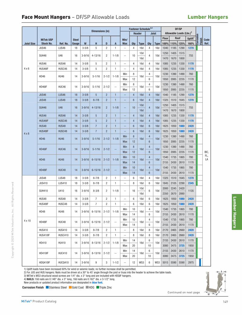
Lumber Hangers
149
Copy
righ
t © 2
020
MiT
ek In
dust
ries
, Inc
. Al
l Rig
hts
Rese
rved
Lumber Hangers
MiTek® Product Catalog
Face Mount Hangers – DF/SP Allowable Loads
Floor Uplift1
Joist Size Ref. No. W H D A Qty Type Qty Type 100% 115% 125% 160%
JUS46 LUS46 18 3-5/8 5 2 1 -- 4 16d 4 16d 1040 1185 1290 1270
10d 1250 1405 1515
16d 1470 1670 1800
HUS46 HUS46 14 3-5/8 5 2 1 -- 4 16d 4 16d 1085 1235 1330 1170
HUS46IF HUSC46 14 3-5/8 5 2 1 -- 4 16d 4 16d 1085 1235 1330 1170
Min 8 4 1230 1390 1490 760
Max 12 6 1850 2085 2235 1170
Min 8 4 1230 1390 1490 760
Max 12 6 1850 2085 2235 1170
JUS46 LUS46 18 3-5/8 5 2 1 -- 4 16d 4 16d 1040 1185 1290 1270
JUS48 LUS48 18 3-5/8 6-7/8 2 1 -- 6 16d 4 16d 1325 1510 1645 1270
10d 1250 1405 1515
16d 1470 1670 1800
HUS46 HUS46 14 3-5/8 5 2 1 -- 4 16d 4 16d 1085 1235 1330 1170
HUS46IF HUSC46 14 3-5/8 5 2 1 -- 4 16d 4 16d 1085 1235 1330 1170
HUS48 HUS48 14 3-5/8 7 2 1 -- 6 16d 6 16d 1625 1850 1880 2420
HUS48IF HUSC48 14 3-5/8 7 2 1 -- 6 16d 6 16d 1625 1850 1880 2420
Min 8 4 1230 1390 1490 760
Max 12 6 1850 2085 2235 1170
Min 8 4 1230 1390 1490 760
Max 12 6 1850 2085 2235 1170
Min 10 4 1540 1735 1865 780
Max 14 6 2155 2430 2610 1170
Min 10 4 1540 1735 1865 780
Max 14 6 2155 2430 2610 1170
JUS48 LUS48 18 3-5/8 6-7/8 2 1 -- 6 16d 4 16d 1325 1510 1645 1270
JUS410 LUS410 18 3-5/8 8-7/8 2 1 -- 8 16d 6 16d 1845 2105 2290 2345
10d 2000 2245 2420
16d 2350 2670 2880
HUS48 HUS48 14 3-5/8 7 2 1 -- 6 16d 6 16d 1625 1850 1880 2420
HUS48IF HUSC48 14 3-5/8 7 2 1 -- 6 16d 6 16d 1625 1850 1880 2420
Min 10 4 1540 1735 1865 780
Max 14 6 2155 2430 2610 1170
Min 10 4 1540 1735 1865 780
Max 14 6 2155 2430 2610 1170
HUS410 HUS410 14 3-5/8 8-7/8 2 1 -- 8 16d 8 16d 2170 2465 2660 2420
HUS410IF HUSC410 14 3-5/8 8-7/8 2 1 -- 8 16d 8 16d 2170 2465 2660 2420
Min 14 6 2155 2430 2610 1170
Max 20 10 3080 3475 3725 1950
Min 14 6 2155 2430 2610 1170
Max 20 10 3080 3475 3725 1950
HDQ410IF HUCQ410 14 3-9/16 9 3 1-1/2 -- 12 WS3 6 WS3 5015 5590 5590 2975
1) Uplift loads have been increased 60% for wind or seismic loads; no further increase shall be permitted. 2) For JUS and HUS hangers: Nails must be driven at a 30° to 45˚ angle through the joist or truss into the header to achieve the table loads. 3) MiTek's WS3 structural wood screws are 1/4" dia. x 3" long and are included with HDQIF hangers. 4) NAILS: 10d nails are 0.148" dia. x 3" long, 16d nails are 0.162" dia. x 3-1/2" long. New products or updated product information are designated in blue font.
--
8-13/16
8-13/16
2-1/2
HD410IF HUC410 14 3-9/16 2-1/2
2-1/2 --
HD410 HU410 14 3-9/16 1-1/8
HD48IF HUC48 14 3-9/16 6-15/16
14 3-9/16 6-15/16 2-1/2 1-1/8
6-15/16 2-1/2 1-1/8
14 3-9/16 6-15/16 2-1/2 --
14 3-9/16
3-9/16 8-3/8 2 1-1/8
4 x 6
4 x 8
--
--
--
3-9/16 4-13/16 2 1-1/8
3-9/16 5-1/16 2-1/2 1-1/8
HD46IF HUC46 14 3-9/16
4 x 10
HD46 HU46 14 3-9/16
HD48 HU48
HD48 HU48
HD46IF HUC46 14 3-9/16
HD48IF HUC48
Dimensions (in)
MiTek USPStock No.
SteelGauge
16 SUH410 U410
16
16
14
U46 SUH46
HD46 HU46
SUH46 U46
--
3-9/16 4-13/16 2 1-1/8
RoofMin/Max
5-1/16 2-1/2 --
10
16d 10d
5-1/16 2-1/2 1-1/8
16d 10d
5-1/16 2-1/2
16 6 10d
10d
16d 10d
10d16d
16d 10d
16d
CodeRef.Co
rros
ion
Fini
sh
Header Joist
DF/SPAllowable Loads (Lbs.)2
Fastener Schedule3,4
IBC, FL, LA
1135
4 10d 755
10 4 10d 755
16d 10d
16d 10d
16d 10d
16d 10d
Corrosion Finish Stainless Steel Gold Coat HDG Triple Zinc
Corrosion Finish Stainless Steel Gold Coat HDG Triple Zinc
Corrosion Finish Stainless Steel Gold Coat HDG Triple Zinc
A
D
H
WContinued on next page
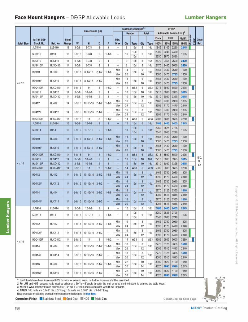
150
Copyright © 2020 M
iTek Industries, Inc. All Rights Reserved
Lumber Hangers
Lum
ber H
ange
rs
MiTek® Product Catalog
Face Mount Hangers – DF/SP Allowable Loads
Floor Uplift1
Joist Size Ref. No. W H D A Qty Type Qty Type 100% 115% 125% 160% JUS410 LUS410 18 3-5/8 8-7/8 2 1 -- 8 16d 6 16d 1845 2105 2290 2345
10d 2000 2245 2420
16d 2350 2670 2880
HUS410 HUS410 14 3-5/8 8-7/8 2 1 -- 8 16d 8 16d 2170 2465 2660 2420
HUS410IF HUSC410 14 3-5/8 8-7/8 2 1 -- 8 16d 8 16d 2170 2465 2660 2420
Min 14 6 2155 2430 2610 1170
Max 20 10 3080 3475 3725 1950
Min 14 6 2155 2430 2610 1170
Max 20 10 3080 3475 3725 1950
HDQ410IF HUCQ410 14 3-9/16 9 3 1-1/2 -- 12 WS3 6 WS3 5015 5590 5590 2975
HUS412 HUS412 14 3-5/8 10-7/8 2 1 -- 10 16d 10 16d 2710 3080 3325 3615
HUS412IF HUSC412 14 3-5/8 10-7/8 2 1 -- 10 16d 10 16d 2710 3080 3325 3615
Min 16 8 2465 2780 2980 1305
Max 24 12 3695 4170 4470 2340
Min 16 8 2465 2780 2980 1305
Max 24 12 3695 4170 4470 2340
HDQ412IF HUCQ412 14 3-9/16 11 3 1-1/2 -- 14 WS3 6 WS3 5605 5605 5605 3280
JUS414 LUS414 18 3-5/8 12-7/8 2 1 -- 12 16d 6 16d 2405 2405 2405 2345
10d 2250 2525 2725
16d 2645 3000 3240
Min 14 6 2155 2430 2610 1170
Max 20 10 3080 3475 3725 1950
Min 14 6 2155 2430 2610 1170
Max 20 10 3080 3475 3725 1950
HDQ410IF HUCQ410 14 3-9/16 9 3 1-1/2 -- 12 WS3 6 WS3 5015 5590 5590 2975
HUS412 HUS412 14 3-5/8 10-7/8 2 1 -- 10 16d 10 16d 2710 3080 3325 3615
HUS412IF HUSC412 14 3-5/8 10-7/8 2 1 -- 10 16d 10 16d 2710 3080 3325 3615
HDQ412IF HUCQ412 14 3-9/16 11 3 1-1/2 -- 14 WS3 6 WS3 5605 5605 5605 3280
Min 16 8 2465 2780 2980 1305
Max 24 12 3695 4170 4470 2340
Min 16 8 2465 2780 2980 1305
Max 24 12 3695 4170 4470 2340
Min 18 8 2770 3125 3355 1510
Max 26 12 4005 4515 4815 2340
Min 18 8 2770 3125 3355 1510
Max 26 12 4005 4515 4815 2340
JUS414 LUS414 18 3-5/8 12-7/8 2 1 -- 12 16d 6 16d 2405 2405 2405 2345
10d 2250 2525 2725
16d 2645 3000 3240
Min 16 8 2465 2780 2980 1305
Max 24 12 3695 4170 4470 2340
Min 16 8 2465 2780 2980 1305
Max 24 12 3695 4170 4470 2340
HDQ412IF HUCQ412 14 3-9/16 11 3 1-1/2 -- 14 WS3 6 WS3 5605 5605 5605 3280
Min 18 8 2770 3125 3355 1510
Max 26 12 4005 4515 4815 2340
Min 18 8 2770 3125 3355 1510
Max 26 12 4005 4515 4815 2340
Min 22 10 3390 3820 4100 1950
Max 30 14 4620 4990 4990 2245
Min 22 10 3390 3820 4100 1950
Max 30 14 4620 4990 4990 2245
1) Uplift loads have been increased 60% for wind or seismic loads; no further increase shall be permitted. 2) For JUS and HUS hangers: Nails must be driven at a 30° to 45˚ angle through the joist or truss into the header to achieve the table loads. 3) MiTek's WS3 structural wood screws are 1/4" dia. x 3" long and are included with HDQIF hangers. 4) NAILS: 10d nails are 0.148" dia. x 3" long, 16d nails are 0.162" dia. x 3-1/2" long. New products or updated product information are designated in blue font.
--
12-13/16
2-1/2
IBC, FL, LA
6 10d 113516
18 6 10d 1135
6 10d18 1135
16d 10d
10d
16d 10d
16d 10d
16d
HUC414 14 3-9/16
HD414
16d 10d
16d 10d
16d 10d
16d 10d
10d16d
14-13/16
HU414 14 3-9/16 12-13/16
HD416IF HUC416
10d
1-1/8 16d
12-13/16 2-1/2
12-13/16
4 x 16
HD412IF
2-1/2 1-1/8 HD414
2-1/2 --
2-1/2 1-1/8
2-1/2
2-1/2 --
HD416 HU416 14 3-9/16
14 3-9/16 14-13/16
-- HD414IF
2 1-1/8
HUC412 14 3-9/16 10-13/16
--
HD412 HU412 14 3-9/16 10-13/16
--
HD410 HU410 14
HD410IF HUC410 14
2-1/2 1-1/8
--
10-13/16 2-1/2
16d 10d
16d
3-9/16
3-9/16 8-13/16 2-1/2 1-1/8
3-9/16 8-13/16
1-1/82
2-1/2
2-1/2
--
1-1/8
10d
16d 10d
4 x 14
HD412IF HUC412 14 3-9/16
HD414IF HUC414 14 3-9/16
SUH414
HU414 14 3-9/16
2-1/2 -- 16d 10d
HD412IF HUC412 14 3-9/16 10-13/16 2-1/2 -- 16d 10d
HD412 HU412 14 3-9/16 10-13/16 2-1/2 1-1/8 16d 10d
2 1-1/8 --
HD410 HU410 14 3-9/16 8-13/16 2-1/2 1-1/8
4 x 12
SUH410 U410 16 3-9/16 8-3/8
HD412 HU412 14 3-9/16 10-13/16
SUH414 U414 16 3-9/16 10-1/16
U414 16
HD410IF HUC410 14 3-9/16 8-13/16
10-1/16
MiTek USPStock No.
SteelGauge
Min/Max
Roof CodeRef.
Dimensions (in)Fastener Schedule3,4 DF/SP
Allowable Loads (Lbs.)2
Corr
osio
nFi
nish
Header Joist
Corrosion Finish Stainless Steel Gold Coat HDG Triple Zinc
Corrosion Finish Stainless Steel Gold Coat HDG Triple Zinc
Corrosion Finish Stainless Steel Gold Coat HDG Triple Zinc
A
D
H
WContinued on next page
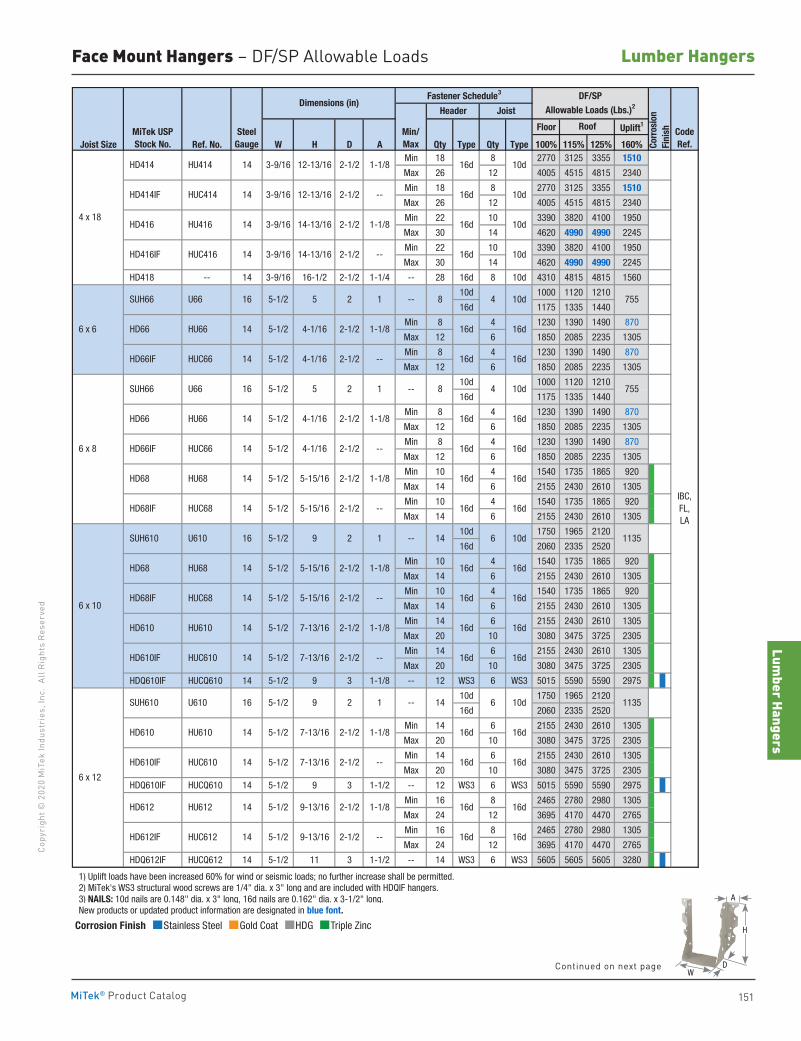
Lumber Hangers
151
Copy
righ
t © 2
020
MiT
ek In
dust
ries
, Inc
. Al
l Rig
hts
Rese
rved
Lumber Hangers
MiTek® Product Catalog
Face Mount Hangers – DF/SP Allowable Loads
Floor Uplift1
Joist Size Ref. No. W H D A Qty Type Qty Type 100% 115% 125% 160%Min 18 8 2770 3125 3355 1510
Max 26 12 4005 4515 4815 2340
Min 18 8 2770 3125 3355 1510
Max 26 12 4005 4515 4815 2340
Min 22 10 3390 3820 4100 1950
Max 30 14 4620 4990 4990 2245
Min 22 10 3390 3820 4100 1950
Max 30 14 4620 4990 4990 2245
HD418 -- 14 3-9/16 16-1/2 2-1/2 1-1/4 -- 28 16d 8 10d 4310 4815 4815 1560
10d 1000 1120 1210
16d 1175 1335 1440
Min 8 4 1230 1390 1490 870
Max 12 6 1850 2085 2235 1305
Min 8 4 1230 1390 1490 870
Max 12 6 1850 2085 2235 1305
10d 1000 1120 1210
16d 1175 1335 1440
Min 8 4 1230 1390 1490 870
Max 12 6 1850 2085 2235 1305
Min 8 4 1230 1390 1490 870
Max 12 6 1850 2085 2235 1305
Min 10 4 1540 1735 1865 920
Max 14 6 2155 2430 2610 1305
Min 10 4 1540 1735 1865 920
Max 14 6 2155 2430 2610 1305
10d 1750 1965 2120
16d 2060 2335 2520
Min 10 4 1540 1735 1865 920
Max 14 6 2155 2430 2610 1305
Min 10 4 1540 1735 1865 920
Max 14 6 2155 2430 2610 1305
Min 14 6 2155 2430 2610 1305
Max 20 10 3080 3475 3725 2305
Min 14 6 2155 2430 2610 1305
Max 20 10 3080 3475 3725 2305
HDQ610IF HUCQ610 14 5-1/2 9 3 1-1/8 -- 12 WS3 6 WS3 5015 5590 5590 2975
10d 1750 1965 2120
16d 2060 2335 2520
Min 14 6 2155 2430 2610 1305
Max 20 10 3080 3475 3725 2305
Min 14 6 2155 2430 2610 1305
Max 20 10 3080 3475 3725 2305
HDQ610IF HUCQ610 14 5-1/2 9 3 1-1/2 -- 12 WS3 6 WS3 5015 5590 5590 2975
Min 16 8 2465 2780 2980 1305
Max 24 12 3695 4170 4470 2765
Min 16 8 2465 2780 2980 1305
Max 24 12 3695 4170 4470 2765
HDQ612IF HUCQ612 14 5-1/2 11 3 1-1/2 -- 14 WS3 6 WS3 5605 5605 5605 3280
1) Uplift loads have been increased 60% for wind or seismic loads; no further increase shall be permitted. 2) MiTek's WS3 structural wood screws are 1/4" dia. x 3" long and are included with HDQIF hangers. 3) NAILS: 10d nails are 0.148" dia. x 3" long, 16d nails are 0.162" dia. x 3-1/2" long. New products or updated product information are designated in blue font.
14 6 10d 1135
7554 10d8
8 4 10d 755
14 6 10d 1135
16d 16d
16d 16d
16d 16d
16d 16d
4 x 18
6 x 12
SUH610 U610 16 5-1/2 9 2
1
6 x 10
SUH610 U610 16
2-1/2 --
HD610 HU610 14 5-1/2 7-13/16 2-1/2 1-1/8
HD68IF HUC68 14
1
--
--
--
--
2-1/2 1-1/85-1/2
2-1/2 --
2-1/2 --
5-1/2 5-15/16
2-1/2 --
4-1/1614 5-1/2
16d 16d 6 x 6
6 x 8
1
1
SUH66 U66 16 5-1/2 5
SUH66 U66 16 5-1/2 5
2
2
HD66 HU66 14 4-1/16
HD66IF HUC66
14 3-9/16
HD414IF HUC414 14 3-9/16
HD416 HU416 14 3-9/16
HD416IF HUC416
HD414 HU414 14
MiTek USPStock No.
SteelGauge
Roof CodeRef.
Min/Max
Fastener Schedule3
16d 10d
IBC, FL, LA
16d 10d--
Dimensions (in)DF/SP
Allowable Loads (Lbs.)2
Corr
osio
nFi
nish
Header Joist
14-13/16
12-13/16 2-1/2
14-13/16
3-9/16 12-13/16 2-1/2 1-1/8
2-1/2 1-1/8 16d 10d
16d 10d2-1/2 --
HD66 HU66 14 5-1/2 4-1/16 2-1/2 1-1/8
2-1/2 --
HD68 HU68 14 5-1/2 5-15/16 2-1/2 1-1/8
HD66IF HUC66 14 5-1/2 4-1/16
HD68 HU68 14 5-1/2 5-15/16 2-1/2 1-1/8
HD68IF HUC68 14 5-1/2 5-15/16
5-1/2 9 2
HD610 HU610 14 5-1/2 7-13/16 2-1/2 1-1/8
HD610IF HUC610 14 5-1/2 7-13/16
HD612IF HUC612 14 5-1/2 9-13/16
2-1/2 --
HD612 HU612 14 5-1/2 9-13/16 2-1/2 1-1/8
HD610IF HUC610 14 5-1/2 7-13/16
2-1/2 --
16d 16d
16d 16d
16d 16d
16d 16d
16d 16d
16d 16d
16d 16d
16d 16d
16d 16d
Corrosion Finish Stainless Steel Gold Coat HDG Triple Zinc
Corrosion Finish Stainless Steel Gold Coat HDG Triple Zinc
Corrosion Finish Stainless Steel Gold Coat HDG Triple Zinc
A
D
H
WContinued on next page
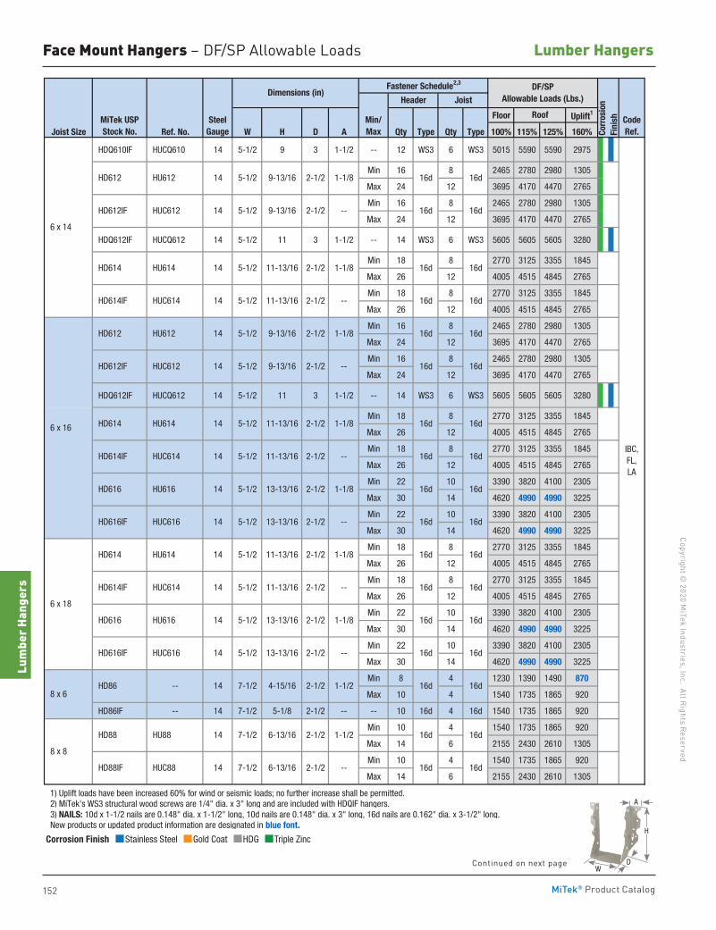
152
Copyright © 2020 M
iTek Industries, Inc. All Rights Reserved
Lumber Hangers
Lum
ber H
ange
rs
MiTek® Product Catalog
Face Mount Hangers – DF/SP Allowable Loads
Floor Uplift1
Joist Size Ref. No. W H D A Qty Type Qty Type 100% 115% 125% 160%
HDQ610IF HUCQ610 14 5-1/2 9 3 1-1/2 -- 12 WS3 6 WS3 5015 5590 5590 2975
Min 16 8 2465 2780 2980 1305
Max 24 12 3695 4170 4470 2765
Min 16 8 2465 2780 2980 1305
Max 24 12 3695 4170 4470 2765
HDQ612IF HUCQ612 14 5-1/2 11 3 1-1/2 -- 14 WS3 6 WS3 5605 5605 5605 3280
Min 18 8 2770 3125 3355 1845
Max 26 12 4005 4515 4845 2765
Min 18 8 2770 3125 3355 1845
Max 26 12 4005 4515 4845 2765
Min 16 8 2465 2780 2980 1305
Max 24 12 3695 4170 4470 2765
Min 16 8 2465 2780 2980 1305
Max 24 12 3695 4170 4470 2765
HDQ612IF HUCQ612 14 5-1/2 11 3 1-1/2 -- 14 WS3 6 WS3 5605 5605 5605 3280
Min 18 8 2770 3125 3355 1845
Max 26 12 4005 4515 4845 2765
Min 18 8 2770 3125 3355 1845
Max 26 12 4005 4515 4845 2765
Min 22 10 3390 3820 4100 2305
Max 30 14 4620 4990 4990 3225
Min 22 10 3390 3820 4100 2305
Max 30 14 4620 4990 4990 3225
Min 18 8 2770 3125 3355 1845
Max 26 12 4005 4515 4845 2765
Min 18 8 2770 3125 3355 1845
Max 26 12 4005 4515 4845 2765
Min 22 10 3390 3820 4100 2305
Max 30 14 4620 4990 4990 3225
Min 22 10 3390 3820 4100 2305
Max 30 14 4620 4990 4990 3225
Min 8 4 1230 1390 1490 870
Max 10 4 1540 1735 1865 920
HD86IF -- 14 7-1/2 5-1/8 2-1/2 -- -- 10 16d 4 16d 1540 1735 1865 920
Min 10 4 1540 1735 1865 920
Max 14 6 2155 2430 2610 1305
Min 10 4 1540 1735 1865 920
Max 14 6 2155 2430 2610 1305
1) Uplift loads have been increased 60% for wind or seismic loads; no further increase shall be permitted. 2) MiTek's WS3 structural wood screws are 1/4" dia. x 3" long and are included with HDQIF hangers. 3) NAILS: 10d x 1-1/2 nails are 0.148" dia. x 1-1/2" long, 10d nails are 0.148" dia. x 3" long, 16d nails are 0.162" dia. x 3-1/2" long. New products or updated product information are designated in blue font.
1-1/22-1/26-13/167-1/214 HU88 HD88
8 x 8
16d--2-1/26-13/167-1/214 HUC88 HD88IF 16d
2-1/2 1-1/2 HD86 -- 14 7-1/2 4-15/16
HD616 HU616 14 5-1/2 13-13/16 2-1/2 1-1/8
HD616IF HUC616 14 5-1/2 13-13/16 2-1/2 --
16d16d
HU614 14 5-1/2 11-13/16 2-1/2 1-1/8
HD614IF HUC614 14 5-1/2 11-13/16 2-1/2 --
HD614
HD616 HU616 14 5-1/2 13-13/16 2-1/2 1-1/8
HD616IF HUC616 14 5-1/2 13-13/16 2-1/2 --
6 x 14
6 x 16 HD614 HU614 14 5-1/2 11-13/16 2-1/2 1-1/8
1-1/8
HD614IF HUC614 14 5-1/2 11-13/16 2-1/2 --
1-1/8
HD612 HU612 14 5-1/2 9-13/16 2-1/2
2-1/2
Dimensions (in)
14 HD614IF HUC614 5-1/2 11-13/16 2-1/2 --
1-1/8
HD612IF HUC612 14 5-1/2 9-13/16 2-1/2 --
MiTek USPStock No.
SteelGauge
6 x 18
8 x 6
Fastener Schedule2,3
Min/Max
HD612 HU612 14 5-1/2 9-13/16 2-1/2
HD612IF HUC612 14 5-1/2 9-13/16 2-1/2 --
HD614 HU614
16d 16d
14 5-1/2 11-13/16
16d
DF/SPAllowable Loads (Lbs.)
Corr
osio
nFi
nish
Header Joist
Roof
16d 16d
16d 16d
16d
CodeRef.
16d 16d
16d 16d
16d 16d
16d 16d
IBC, FL, LA
16d 16d
16d 16d
16d 16d
16d 16d
16d 16d
16d 16d
16d 16d
Corrosion Finish Stainless Steel Gold Coat HDG Triple Zinc
Corrosion Finish Stainless Steel Gold Coat HDG Triple Zinc
Corrosion Finish Stainless Steel Gold Coat HDG Triple Zinc
A
D
H
WContinued on next page
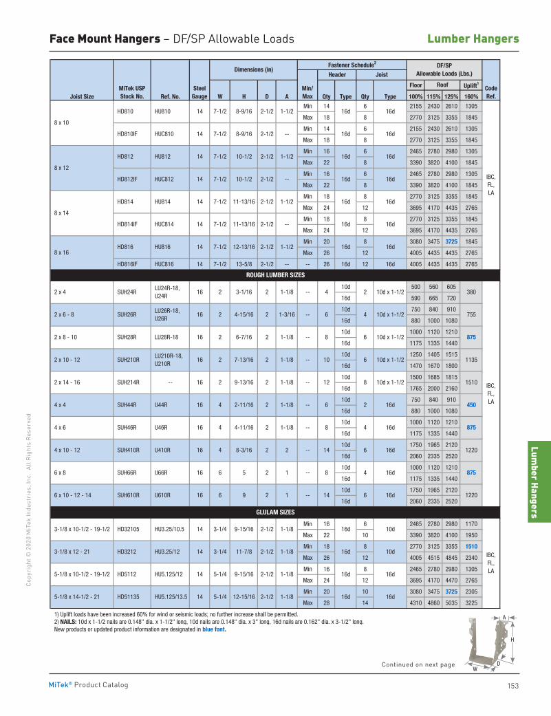
Lumber Hangers
153
Copy
righ
t © 2
020
MiT
ek In
dust
ries
, Inc
. Al
l Rig
hts
Rese
rved
Lumber Hangers
MiTek® Product Catalog
Face Mount Hangers – DF/SP Allowable Loads
Floor Uplift1
Joist Size Ref. No. W H D A Qty Type Qty Type 100% 115% 125% 160%
Min 14 6 2155 2430 2610 1305
Max 18 8 2770 3125 3355 1845
Min 14 6 2155 2430 2610 1305
Max 18 8 2770 3125 3355 1845
Min 16 6 2465 2780 2980 1305
Max 22 8 3390 3820 4100 1845
Min 16 6 2465 2780 2980 1305
Max 22 8 3390 3820 4100 1845
Min 18 8 2770 3125 3355 1845
Max 24 12 3695 4170 4435 2765
Min 18 8 2770 3125 3355 1845
Max 24 12 3695 4170 4435 2765
Min 20 8 3080 3475 3725 1845
Max 26 12 4005 4435 4435 2765
HD816IF HUC816 14 7-1/2 13-5/8 2-1/2 -- -- 26 16d 12 16d 4005 4435 4435 2765
10d 500 560 605
16d 590 665 720
10d 750 840 910
16d 880 1000 1080
10d 1000 1120 1210
16d 1175 1335 1440
10d 1250 1405 1515
16d 1470 1670 1800
10d 1500 1685 1815
16d 1765 2000 2160
10d 750 840 910
16d 880 1000 1080
10d 1000 1120 1210
16d 1175 1335 1440
10d 1750 1965 2120
16d 2060 2335 2520
10d 1000 1120 1210
16d 1175 1335 1440
10d 1750 1965 2120
16d 2060 2335 2520
Min 16 6 2465 2780 2980 1170
Max 22 10 3390 3820 4100 1950
Min 18 8 2770 3125 3355 1510
Max 26 12 4005 4515 4845 2340
Min 16 8 2465 2780 2980 1305
Max 24 12 3695 4170 4470 2765
Min 20 10 3080 3475 3725 2305
Max 28 14 4310 4860 5035 3225
1) Uplift loads have been increased 60% for wind or seismic loads; no further increase shall be permitted. 2) NAILS: 10d x 1-1/2 nails are 0.148" dia. x 1-1/2" long, 10d nails are 0.148" dia. x 3" long, 16d nails are 0.162" dia. x 3-1/2" long. New products or updated product information are designated in blue font.
16d 16d
16d 16d
5-1/8 x 14-1/2 - 21 HD51135
1220
380
755
875
1135
1510
450
875
1220
875
HU5.125/13.5 14 5-1/4 12-15/16 2-1/2 1-1/8
5-1/8 x 10-1/2 - 19-1/2 HD5112
16d
16d
16d
10d
1-1/8 16d 10d
1-1/8 -- 4 2 10d x 1-1/2
GLULAM SIZES
3-1/8 x 10-1/2 - 19-1/2 HD32105 HU3.25/10.5 14 3-1/4 9-15/16 2-1/2
2-1/2 IBC, FL, LA
3-1/8 x 12 - 21 HD3212
HU5.125/12 14 5-1/4 9-15/16 2-1/2 1-1/8
16d
2 1 -- 14 6 16d 6 x 10 - 12 - 14 SUH610R U610R 16 6 9
HU3.25/12 14 3-1/4 11-7/8 1-1/8
2 1 -- 8 4 16d 6 x 8 SUH66R U66R 16 6 5
2 2 -- 14 6 16d 4 x 10 - 12 SUH410R U410R 16 4 8-3/16
2 1-1/8 -- 8 4 16d 4 x 6 SUH46R U46R 16 4 4-11/16
2 1-1/8 -- 6 2 16d 4 x 4 SUH44R U44R 16 4 2-11/16
2 1-1/8 -- 12 8 10d x 1-1/2 2 x 14 - 16 SUH214R -- 16 2 9-13/16
2 1-1/8 -- 10 6 10d x 1-1/2 2 x 10 - 12 SUH210R LU210R-18, U210R
16 2 7-13/16
8 6 10d x 1-1/2 2 x 8 - 10 SUH28R LU28R-18 16 2 6-7/16
IBC, FL, LA
ROUGH LUMBER SIZES
2 x 4 SUH24R LU24R-18, U24R
16 2 3-1/16 2
2 1-3/16 -- 6 4 10d x 1-1/2 2 x 6 - 8 SUH26R LU26R-18, U26R
16 2 4-15/16
2 1-1/8 --
8 x 16 HD816 HU816 14 7-1/2 2-1/2
2-1/2 1-1/2
HD814IF HUC814 14 7-1/2 2-1/2
8 x 14
HD814 HU814 14 7-1/2
1-1/2
8 x 10
HD810 HU810 14 7-1/2 8-9/16 2-1/2 1-1/2
HD812IF HUC812 14 7-1/2 10-1/2 2-1/2 --
8 x 12
HD812 HU812 14 7-1/2 10-1/2 2-1/2 1-1/2
CodeRef.
11-13/16
12-13/16
11-13/16
IBC, FL, LA
HD810IF HUC810 14 7-1/2 8-9/16 2-1/2 --
--
16d
16d
16d
16d
16d
16d
16d
16d
16d
16d
16d
Dimensions (in)Fastener Schedule2 DF/SP
Allowable Loads (Lbs.)Header Joist
MiTek USPStock No.
SteelGauge
Min/Max
Roof
A
D
H
WContinued on next page
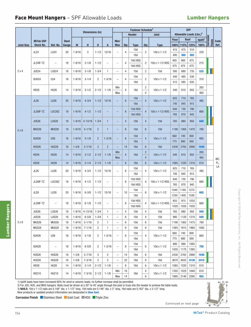
154
Copyright © 2020 M
iTek Industries, Inc. All Rights Reserved
Lumber Hangers
Lum
ber H
ange
rs
MiTek® Product Catalog
Face Mount Hangers – SPF Allowable Loads
Floor Uplift1
Joist Size Ref. No. W H D A Qty Type Qty Type 100% 115% 125% 160%
10d 415 475 510
16d 495 560 565
10d HDG 405 460 475
16d HDG 475 475 475
JUS24 LUS24 18 1-9/16 3-1/8 1-3/4 1 -- 4 10d 2 10d 595 680 735 525
10d 440 495 530
16d 515 585 635
Min 2 265
Max 4 465
10d 625 710 765
16d 740 845 915
10d HDG 640 730 790
16d HDG 765 870 945
JUS26 LUS26 18 1-9/16 4-13/16 1-3/4 1 -- 4 10d 4 10d 765 880 950 840
MUS26 MUS26 18 1-9/16 5-1/16 2 1 -- 6 10d 6 10d 1190 1365 1475 760
10d 660 740 800
16d 775 880 950
HUS26 HUS26 16 1-5/8 5-7/16 3 2 -- 14 16d 6 16d 2430 2765 2990 1640
Min 2 265
Max 4 465
HD28 HU28 14 1-9/16 5-1/4 2-1/2 1-1/8 -- 8 16d 6 10d x 1-1/2 1085 1220 1310 610
10d 625 710 765
16d 740 845 915
10d HDG 640 730 790
16d HDG 765 870 945
10d 1040 1185 1275
16d 1230 1405 1530
10d HDG 855 975 1035
16d HDG 1020 1035 1035
JUS26 LUS26 18 1-9/16 4-13/16 1-3/4 1 -- 4 10d 4 10d 765 880 950 840
JUS28 LUS28 18 1-9/16 6-5/8 1-3/4 1 -- 6 10d 4 10d 980 1120 1210 840
MUS26 MUS26 18 1-9/16 5-1/16 2 1 -- 6 10d 6 10d 1190 1365 1475 760
MUS28 MUS28 18 1-9/16 7-1/16 2 1 -- 8 10d 8 10d 1585 1815 1965 1085
10d 660 740 800
16d 775 880 950
10d 880 990 1065
16d 1035 1175 1265
HUS26 HUS26 16 1-5/8 5-7/16 3 2 -- 14 16d 6 16d 2430 2765 2990 1640
HUS28 HUS28 16 1-5/8 7-3/16 3 2 -- 22 16d 8 16d 3670 4035 4130 2410
HD28 HU28 14 1-9/16 5-1/4 2-1/2 1-1/8 -- 8 16d 6 10d x 1-1/2 1085 1220 1310 610
Min 10 4 1355 1525 1640 610
Max 14 6 1895 2140 2295 955
1) Uplift loads have been increased 60% for wind or seismic loads; no further increase shall be permitted. 2) For JUS, HUS, and MUS hangers: Nails must be driven at a 30° to 45˚ angle through the joist or truss into the header to achieve the table loads. 3) NAILS: 10d x 1-1/2 nails are 0.148" dia. x 1-1/2" long, 10d nails are 0.148" dia. x 3" long, 16d nails are 0.162" dia. x 3-1/2" long. New products or updated product information are designated in blue font.
540 610 655
665
235
215
310
485
660
665
485
660
655
--
2 1-3/16
16 1-9/16
16d 10d x 1-1/2
6
8
4 10d x 1-1/2
6 10d x 1-1/2
10d x 1-1/2
8 4 10d x 1-1/2 HDG
705
665
660
Fastener Schedule3
Min/Max
--
--
--
--
--
--
--
10d x 1-1/2
4 2
4 2
10d x 1-1/2
10d x 1-1/2 HDG
--
4 2 10d x 1-1/2
6 4
46
6
Dimensions (in)
1-1/2 --
2 1-3/16
10d x 1-1/2
10d x 1-1/2 HDG
10d x 1-1/2
3-1/2
1-9/16 3-1/8
16
20
MiTek USPStock No.
SteelGauge
Roof CodeRef.Co
rros
ion
Fini
sh
Header Joist
SPFAllowable Loads (Lbs.)2
16 1-9/16 3-1/4 2 1-3/16
20 1-9/16 3 1-1/2 15/16
4
10 6
1-9/16 5-1/8
LU24
JL24IF-TZ --
6-5/8
5-1/8 SUH26 U26
SUH28 --
20 1-9/16 4-3/4
1-9/16 4-1/218
HD26 HU26 14 1-9/16
JL26 LU26
JL26IF-TZ LUC26Z
JL28
2 x 6
JL26 LU26
SUH24 U24
LUC26Z
2 x 4
HD26 HU26
JL24
14 1-9/16 3-1/2 2-1/2 1-1/8
SUH26 U26
JL26IF-TZ
18
1-1/2 15/16
1-1/2 --
20 6-3/8 1-1/2 15/16
540 610
10d x 1-1/2
10d x 1-1/2 HDG
IBC, FL, LA
18 1-9/16 1-1/2 --
2-1/2 1-1/8
4 16d 10d x 1-1/2
4 16d
4
6 41-9/16 4-3/4 1-1/2
18 1-9/16 4-1/2 1-1/2
15/16
--
HD210 HU210
2 x 8
LU28 1-9/16
6-1/8 JL28IF-TZ --
--
--
--
16 1-9/16
2 1-3/16
14 1-9/16 7-3/16 2-1/2 1-1/8
6
Corrosion Finish Stainless Steel Gold Coat HDG Triple Zinc
Corrosion Finish Stainless Steel Gold Coat HDG Triple Zinc
Corrosion Finish Stainless Steel Gold Coat HDG Triple Zinc
A
D
H
WContinued on next page
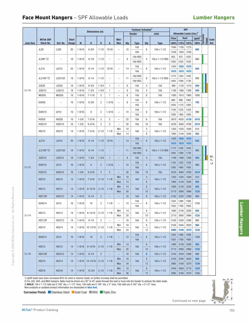
Lumber Hangers
155
Copy
righ
t © 2
020
MiT
ek In
dust
ries
, Inc
. Al
l Rig
hts
Rese
rved
Lumber Hangers
MiTek® Product Catalog
Face Mount Hangers – SPF Allowable Loads
Corrosion Finish Stainless Steel Gold Coat HDG Triple Zinc
Corrosion Finish Stainless Steel Gold Coat HDG Triple Zinc
Corrosion Finish Stainless Steel Gold Coat HDG Triple Zinc
Floor Uplift1
Joist Size Ref. No. W H D A Qty Type Qty Type 100% 115% 125% 160%
10d 1040 1185 1275
16d 1230 1405 1530
10d HDG 855 975 1035
16d HDG 1020 1035 1035
10d 1455 1655 1675
16d 1675 1675 1675
10d HDG 1175 1345 1445
16d HDG 1405 1590 1730
JUS28 LUS28 18 1-9/16 6-5/8 1-3/4 1 -- 6 10d 4 10d 980 1120 1210 840
JUS210 LUS210 18 1-9/16 7-3/4 1-3/4 1 -- 8 10d 4 10d 1190 1360 1395 840
MUS28 MUS28 18 1-9/16 7-1/16 2 1 -- 8 10d 8 10d 1585 1815 1965 1085
10d 880 990 1065
16d 1035 1175 1265
10d 1100 1235 1330
16d 1295 1465 1585
HUS28 HUS28 16 1-5/8 7-3/16 3 2 -- 22 16d 8 16d 3670 4035 4130 2410
HUS210 HUS210 16 1-5/8 9-3/16 3 2 -- 30 16d 10 16d 4235 4565 4780 3410
Min 10 4 1355 1525 1640 610
Max 14 6 1895 2140 2295 955
10d 1455 1655 1675
16d 1675 1675 1675
10d HDG 1175 1345 1445
16d HDG 1405 1590 1730
JUS210 LUS210 18 1-9/16 7-3/4 1-3/4 1 -- 8 10d 4 10d 1190 1360 1395 840
10d 1100 1235 1330
16d 1295 1465 1585
HUS210 HUS210 16 1-5/8 9-3/16 3 2 -- 30 16d 10 16d 4235 4565 4780 3410
Min 10 4 1355 1525 1640 610
Max 14 6 1895 2140 2295 955
Min 14 6 1895 2140 2295 955
Max 20 10 2710 2900 2990 1225
HD212IF HUC212 14 1-9/16 9-1/4 2 -- -- 16 16d 8 10d x 1-1/2 2165 2320 2390 960
10d 1320 1480 1595
16d 1550 1760 1900
Min 14 6 1895 2140 2295 955
Max 20 10 2710 2900 2990 1225
HD212IF HUC212 14 1-9/16 9-1/4 2 -- -- 16 16d 8 10d x 1-1/2 2165 2320 2390 960
Min 16 8 2165 2445 2620 960
Max 24 12 2985 3160 3270 1230
10d 1320 1480 1595
16d 1550 1760 1900
Min 14 6 1895 2140 2295 955
Max 20 10 2710 2900 2990 1225
HD212IF HUC212 14 1-9/16 9-1/4 2 -- -- 16 16d 8 10d x 1-1/2 2165 2320 2390 960
Min 16 8 2165 2445 2620 960
Max 24 12 2985 3160 3270 1230
Min 18 8 2440 2640 2710 1220
Max 26 12 2985 3160 3270 1550
1) Uplift loads have been increased 60% for wind or seismic loads; no further increase shall be permitted. 2) For JUS, HUS, and MUS hangers: Nails must be driven at a 30° to 45˚ angle through the joist or truss into the header to achieve the table loads. 3) NAILS: 10d x 1-1/2 nails are 0.148" dia. x 1-1/2" long, 10d nails are 0.148" dia. x 3" long, 16d nails are 0.162" dia. x 3-1/2" long. New products or updated product information are designated in blue font.
12 8 10d x 1-1/2
665
660
845
995
705
990
845
995
990
1330
14 8 10d x 1-1/2
11 6 10d x 1-1/2 HDG
10 6 10d x 1-1/2
6
10
8 4 10d x 1-1/2 HDG
14 8 10d x 1-1/2
12
10d x 1-1/2 HDG11
8 6 10d x 1-1/2
10 6 10d x 1-1/2
--
9-13/16
10-13/16
2-1/2
2-1/2
1-1/8
1-1/8
--
1-1/8
1-1/8
8 2
14 1-9/16
14 1-9/16
--
9-13/16
10-13/16
12-3/4
2-1/2
2-1/2
2-1/2
1-1/8
1-1/8
1-1/8
2-1/2
1-9/16
1-9/16
7-3/16
9-13/16
HD212
SUH214 U214
16 1-9/16 10 2
16 1-9/16 10 2
HD212
HD214
HU212
HU214
14
14 1-9/16
2 x 10
HD210 HU210 14 1-9/16 7-3/16 2-1/2 1-1/8
15/16
16 1-9/16 2 1-3/168
JL28 LU28
JL28IF-TZ --
JL210 LU210
SUH28 --
SUH210 U210
JL210IF-TZ LUC210Z
--
--
--
--
--
--
2 x 12
HD210
HD212
HU210
HU212
2 x 14
2 x 16
HU212
HU214
HU216
HD214
HD216
1-1/8
1-9/16 6-5/8
1-1/8
JL210 LU210
SUH214 U214
18 1-9/16 8-1/4 1-1/2 --
16
--
--
1-9/16
14 1-9/16
14
14
2-1/2
CodeRef.Co
rros
ion
Fini
sh
Header Joist
SPFAllowable Loads (Lbs.)2Dimensions (in)
1-9/16
15/16
--
8-1/4
1-9/16 --
6-3/8
2 1-3/16
1-9/16 8-1/4 1-1/2
Fastener Schedule3
Min/Max
MiTek USPStock No.
SteelGauge
Roof
1-3/16
1-1/2
18 1-9/16 8-1/4 1-1/2
16 1-9/16
1-1/2 15/16
20 1-9/16
6-1/8 1-1/2
JL210IF-TZ LUC210Z
SUH210 U210
20
18
20
IBC, FL, LA
16d 10d x 1-1/2
16d 10d x 1-1/2
16d 10d x 1-1/2
16d 10d x 1-1/2
16d 10d x 1-1/2
16d 10d x 1-1/2
16d 10d x 1-1/2
16d 10d x 1-1/2
8 10d x 1-1/2
1330
6 10d x 1-1/2
A
D
H
WContinued on next page
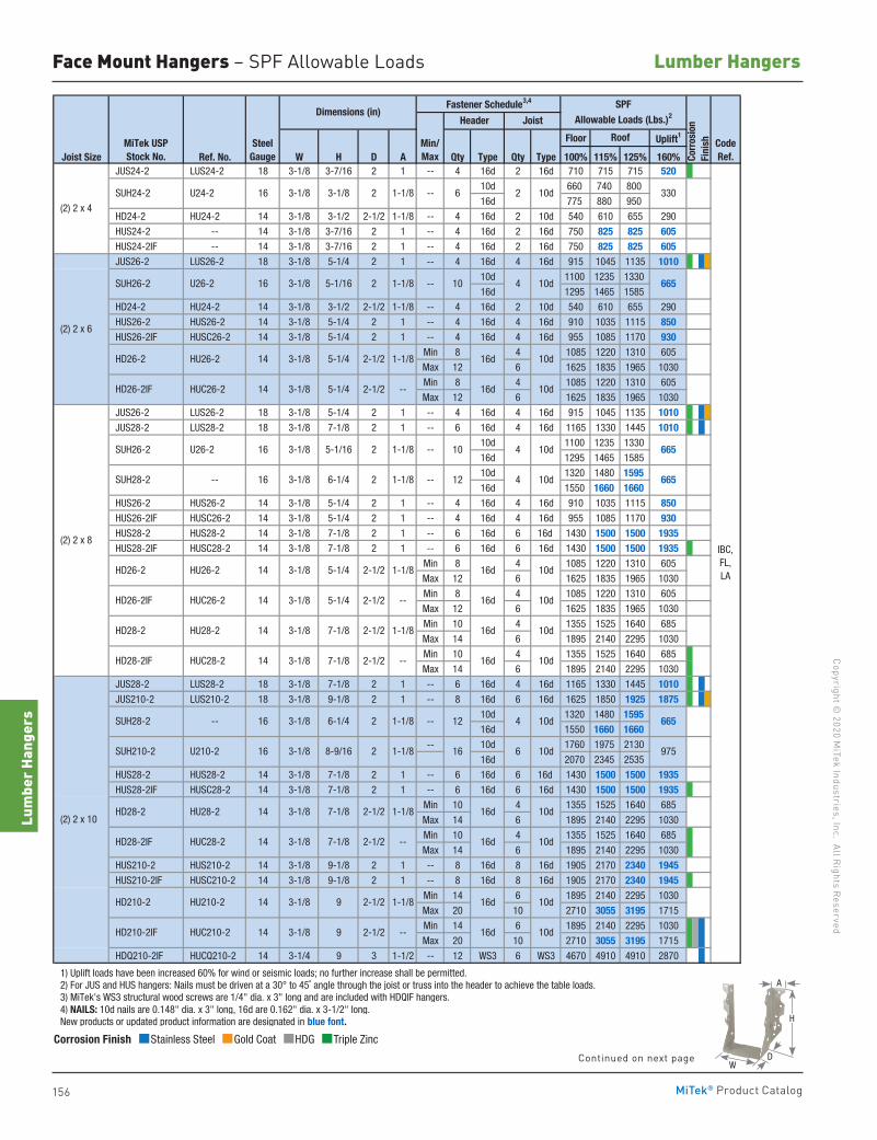
156
Copyright © 2020 M
iTek Industries, Inc. All Rights Reserved
Lumber Hangers
Lum
ber H
ange
rs
MiTek® Product Catalog
Floor Uplift1
Joist Size Ref. No. W H D A Qty Type Qty Type 100% 115% 125% 160% JUS24-2 LUS24-2 18 3-1/8 3-7/16 2 1 -- 4 16d 2 16d 710 715 715 520
10d 660 740 800
16d 775 880 950
HD24-2 HU24-2 14 3-1/8 3-1/2 2-1/2 1-1/8 -- 4 16d 2 10d 540 610 655 290
HUS24-2 -- 14 3-1/8 3-7/16 2 1 -- 4 16d 2 16d 750 825 825 605 HUS24-2IF -- 14 3-1/8 3-7/16 2 1 -- 4 16d 2 16d 750 825 825 605 JUS26-2 LUS26-2 18 3-1/8 5-1/4 2 1 -- 4 16d 4 16d 915 1045 1135 1010
10d 1100 1235 1330
16d 1295 1465 1585
HD24-2 HU24-2 14 3-1/8 3-1/2 2-1/2 1-1/8 -- 4 16d 2 10d 540 610 655 290
HUS26-2 HUS26-2 14 3-1/8 5-1/4 2 1 -- 4 16d 4 16d 910 1035 1115 850 HUS26-2IF HUSC26-2 14 3-1/8 5-1/4 2 1 -- 4 16d 4 16d 955 1085 1170 930
Min 8 4 1085 1220 1310 605
Max 12 6 1625 1835 1965 1030
Min 8 4 1085 1220 1310 605
Max 12 6 1625 1835 1965 1030
JUS26-2 LUS26-2 18 3-1/8 5-1/4 2 1 -- 4 16d 4 16d 915 1045 1135 1010 JUS28-2 LUS28-2 18 3-1/8 7-1/8 2 1 -- 6 16d 4 16d 1165 1330 1445 1010
10d 1100 1235 1330
16d 1295 1465 1585
10d 1320 1480 159516d 1550 1660 1660
HUS26-2 HUS26-2 14 3-1/8 5-1/4 2 1 -- 4 16d 4 16d 910 1035 1115 850 HUS26-2IF HUSC26-2 14 3-1/8 5-1/4 2 1 -- 4 16d 4 16d 955 1085 1170 930 HUS28-2 HUS28-2 14 3-1/8 7-1/8 2 1 -- 6 16d 6 16d 1430 1500 1500 1935 HUS28-2IF HUSC28-2 14 3-1/8 7-1/8 2 1 -- 6 16d 6 16d 1430 1500 1500 1935
Min 8 4 1085 1220 1310 605
Max 12 6 1625 1835 1965 1030
Min 8 4 1085 1220 1310 605
Max 12 6 1625 1835 1965 1030
Min 10 4 1355 1525 1640 685
Max 14 6 1895 2140 2295 1030
Min 10 4 1355 1525 1640 685
Max 14 6 1895 2140 2295 1030
JUS28-2 LUS28-2 18 3-1/8 7-1/8 2 1 -- 6 16d 4 16d 1165 1330 1445 1010 JUS210-2 LUS210-2 18 3-1/8 9-1/8 2 1 -- 8 16d 6 16d 1625 1850 1925 1875
10d 1320 1480 159516d 1550 1660 1660
-- 10d 1760 1975 2130
16d 2070 2345 2535
HUS28-2 HUS28-2 14 3-1/8 7-1/8 2 1 -- 6 16d 6 16d 1430 1500 1500 1935 HUS28-2IF HUSC28-2 14 3-1/8 7-1/8 2 1 -- 6 16d 6 16d 1430 1500 1500 1935
Min 10 4 1355 1525 1640 685
Max 14 6 1895 2140 2295 1030
Min 10 4 1355 1525 1640 685
Max 14 6 1895 2140 2295 1030
HUS210-2 HUS210-2 14 3-1/8 9-1/8 2 1 -- 8 16d 8 16d 1905 2170 2340 1945 HUS210-2IF HUSC210-2 14 3-1/8 9-1/8 2 1 -- 8 16d 8 16d 1905 2170 2340 1945
Min 14 6 1895 2140 2295 1030
Max 20 10 2710 3055 3195 1715
Min 14 6 1895 2140 2295 1030
Max 20 10 2710 3055 3195 1715
HDQ210-2IF HUCQ210-2 14 3-1/4 9 3 1-1/2 -- 12 WS3 6 WS3 4670 4910 4910 2870
1) Uplift loads have been increased 60% for wind or seismic loads; no further increase shall be permitted. 2) For JUS and HUS hangers: Nails must be driven at a 30° to 45˚ angle through the joist or truss into the header to achieve the table loads. 3) MiTek's WS3 structural wood screws are 1/4" dia. x 3" long and are included with HDQIF hangers. 4) NAILS: 10d nails are 0.148" dia. x 3" long, 16d are 0.162" dia. x 3-1/2" long. New products or updated product information are designated in blue font.
IBC, FL, LA
16d 10d HD28-2IF HUC28-2
HD28-2IF HUC28-2 14 3-1/8 7-1/8 2-1/2 -- 16d 10d
8-9/16 2
3-1/8 7-1/8 2-1/2
16d 10d HD26-2IF
16d 10d
16d 10d
16d 10d
16d 10d
1-1/8
1-1/8
3-1/8 7-1/8
--
1-1/8
--
2-1/2 1-1/8
3-1/8 6-1/4 2
14 3-1/8 9 2-1/2 1-1/8
3-1/8
CodeRef.Co
rros
ion
Fini
sh
Dimensions (in)SPF
Allowable Loads (Lbs.)2Fastener Schedule3,4
Min/Max
Joist
Roof
16d 10d
Header
--
--1-1/8
3-1/8 5-1/16 2
3-1/8
1-1/8
3-1/8 5-1/4 2-1/2
MiTek USPStock No.
SteelGauge
SUH26-2 U26-2
SUH28-2 --
HD26-2
HD26-2IF
1-1/8
U26-2 16
14
16
HD26-2 HU26-2
HD28-2
16
HUC26-2 14
26-1/4
--
1-1/83-1/8 5-1/16 2
(2) 2 x 8
14
(2) 2 x 10
SUH28-2 --
SUH210-2 U210-2
HD28-2 HU28-2
HD210-2IF HUC210-2
HD210-2 HU210-2
16
16
14
14
HU28-2
14
16d
16d
10d
10d
--
14 3-1/8 5-1/4
3-1/8 9 2-1/2
2-1/2 1-1/8
14 3-1/8 5-1/4
3-1/8 5-1/4 2-1/2 --
3-1/8 7-1/8 2-1/2 --
(2) 2 x 6
HU26-2
HUC26-2
SUH26-2
(2) 2 x 4
SUH24-2 U24-2 1-1/816 3-1/8 3-1/8 2
2-1/2 --
330
665
665
665
665
975
12 4 10d
12 4 10d
16 6 10d
6 2 10d
10 4 10d
10 4 10d
Corrosion Finish Stainless Steel Gold Coat HDG Triple Zinc
Corrosion Finish Stainless Steel Gold Coat HDG Triple Zinc
Corrosion Finish Stainless Steel Gold Coat HDG Triple Zinc
Face Mount Hangers – SPF Allowable Loads
A
D
H
WContinued on next page
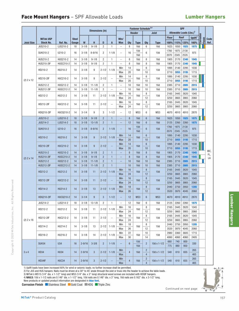
Lumber Hangers
157
Copy
righ
t © 2
020
MiT
ek In
dust
ries
, Inc
. Al
l Rig
hts
Rese
rved
Lumber Hangers
MiTek® Product Catalog
Corrosion Finish Stainless Steel Gold Coat HDG Triple Zinc
Corrosion Finish Stainless Steel Gold Coat HDG Triple Zinc
Corrosion Finish Stainless Steel Gold Coat HDG Triple Zinc
Floor Uplift1
Joist Size Ref. No. W H D A Qty Type Qty Type 100% 115% 125% 160% JUS210-2 LUS210-2 18 3-1/8 9-1/8 2 1 -- 8 16d 6 16d 1625 1850 1925 1875
10d 1760 1975 2130
16d 2070 2345 2535
HUS210-2 HUS210-2 14 3-1/8 9-1/8 2 1 -- 8 16d 8 16d 1905 2170 2340 1945
HUS210-2IF HUSC210-2 14 3-1/8 9-1/8 2 1 -- 8 16d 8 16d 1905 2170 2340 1945
Min 14 6 1895 2140 2295 1030
Max 20 10 2710 3055 3195 1715
Min 14 6 1895 2140 2295 1030
Max 20 10 2710 3055 3195 1715
HUS212-2 HUS212-2 14 3-1/8 11-1/8 2 1 -- 10 16d 10 16d 2385 2710 2885 2915
HUS212-2IF HUSC212-2 14 3-1/8 11-1/8 2 -- -- 10 16d 10 16d 2385 2710 2885 2915
Min 16 8 2165 2445 2620 1045
Max 24 12 3250 3665 3865 2060
Min 16 8 2165 2445 2620 1045
Max 24 12 3250 3665 3865 2060
HDQ210-2IF HUCQ210-2 14 3-1/4 9 3 1-1/2 -- 12 WS3 6 WS3 4670 4910 4910 2870
JUS210-2 LUS210-2 18 3-1/8 9-1/8 2 1 -- 8 16d 6 16d 1625 1850 1925 1875
JUS214-2 LUS214-2 18 3-1/8 13-1/8 2 1 -- 12 16d 6 16d 2125 2260 2260 1875
10d 1760 1975 2130
16d 2070 2345 2535
Min 14 6 1895 2140 2295 1030
Max 20 10 2710 3055 3195 1715
Min 14 6 1895 2140 2295 1030
Max 20 10 2710 3055 3195 1715
HUS210-2 HUS210-2 14 3-1/8 9-1/8 2 1 -- 8 16d 8 16d 1905 2170 2340 1945
HUS210-2IF HUSC210-2 14 3-1/8 9-1/8 2 1 -- 8 16d 8 16d 1905 2170 2340 1945
HUS212-2 HUS212-2 14 3-1/8 11-1/8 2 1 -- 10 16d 10 16d 2385 2710 2885 2915
HUS212-2IF HUSC212-2 14 3-1/8 11-1/8 2 1 10 16d 10 16d 2385 2710 2885 2915
Min 16 8 2165 2445 2620 1045
Max 24 12 3250 3665 3865 2060
Min 16 8 2165 2445 2620 1045
Max 24 12 3250 3665 3865 2060
Min 18 8 2440 2750 2950 1205
Max 26 12 3520 3970 4045 2060
HDQ210-2IF HUCQ210-2 14 3-1/4 9 3 1-1/2 -- 12 WS3 6 WS3 4670 4910 4910 2870
JUS214-2 LUS214-2 18 3-1/8 13-1/8 2 1 -- 12 16d 6 16d 2125 2260 2260 1875
Min 16 8 2165 2445 2620 1045
Max 24 12 3250 3665 3865 2060
Min 16 8 2165 2445 2620 1045
Max 24 12 3250 3665 3865 2060
Min 18 8 2440 2750 2950 1205
Max 26 12 3520 3970 4045 2060
Min 22 10 2980 3360 3605 1715
Max 30 14 4060 4060 4060 2405
10d 660 740 800
16d 775 880 950
Min 2 265
Max 4 465
Min 2 265
Max 4 465
1) Uplift loads have been increased 60% for wind or seismic loads; no further increase shall be permitted. 2) For JUS and HUS hangers: Nails must be driven at a 30° to 45˚ angle through the joist or truss into the header to achieve the table loads. 3) MiTek's WS15 (1/4" dia. x 1-1/2" long) and WS3 (1/4" dia. x 3" long) structural wood screws are included with HDQIF hangers. 4) NAILS: 10d x 1-1/2 nails are 0.148" dia. x 1-1/2" long, 10d nails are 0.148" dia. x 3" long, 16d nails are 0.162" dia. x 3-1/2" long. New products or updated product information are designated in blue font.
HD210-2
2
2-1/2 -- HD212-2IF 10d16d
10d16d
10d16d
HUC212-2 14 3-1/8 11
2-1/2 --
HD212-2 HU212-2 14 3-1/8 11 2-1/2
(2) 2 x 12
97510d616--1-1/83-1/816 U210-2
10d16d1-1/82-1/293-1/814
1-1/8
HD210-2IF HUC210-2 14 3-1/8 9
HU210-2
Dimensions (in)SPF
Allowable Loads (Lbs.)2
Corr
osio
nFi
nish
Header Joist
Roof
Fastener Schedule3,4
Min/Max
--
16d 10d
16d 10d
16d 10d
16d 10d
2-9/16 3-3/8 2
2-1/2 1-1/8
--
8-9/16
CodeRef.
MiTek USPStock No.
SteelGauge
1-1/8
2-1/2
3
16d
16d
4 10d x 1-1/2
4 10d x 1-1/2
14 3-1/8 11 2-1/2 1-1/8
HUC212-2 14 3-1/8 11
1-1/8
--
14 (2) 2 x 16
3 x 4
HD212-2 HU212-2
HD212-2IF HUC212-2
HD214-2 HU214-2
HD216-2 HU216-2
SUH34
HD34 HU34
HD34IF HUC34
U34
14
2-9/16
2-9/16
3
14 3-1/8 14 2-1/2 1-1/8
2-1/2
16
14
14 3-1/8 13 2-1/2 1-1/8
10d x 1-1/2
2-1/2 1-1/8
16d 10d
16d 10d
16d 10d
16d
6 2
10d
2-1/2 --
3-1/8 11 2-1/2 --
HU214-2 13
97510d616
IBC, FL, LA
HD210-2 HU210-2 14 3-1/8 9
HD214-2 14 3-1/8
HD212-2IF
540 610 655
540 610 655
SUH210-2
330
10d
16d
(2) 2 x 14
SUH210-2 U210-2 1-1/816 3-1/8 8-9/16 2
2-1/2 --
HD212-2 HU212-2 14 3-1/8 11 2-1/2 1-1/8
HD210-2IF HUC210-2 14 3-1/8 9
Face Mount Hangers – SPF Allowable Loads
A
D
H
WContinued on next page
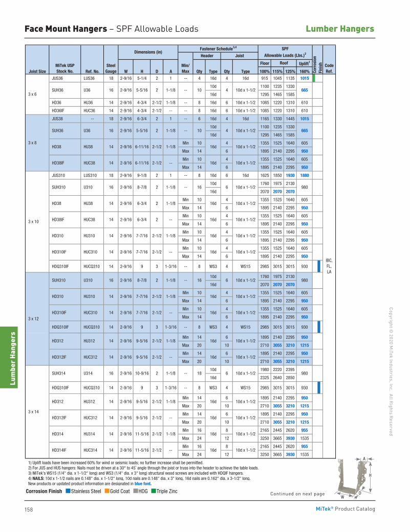
158
Copyright © 2020 M
iTek Industries, Inc. All Rights Reserved
Lumber Hangers
Lum
ber H
ange
rs
MiTek® Product Catalog
Floor Uplift1
Joist Size Ref. No. W H D A Qty Type Qty Type 100% 115% 125% 160%
JUS36 LUS36 18 2-9/16 5-1/4 2 1 -- 4 16d 4 16d 915 1045 1135 1015
10d 1100 1235 1330
16d 1295 1465 1585
HD36 HU36 14 2-9/16 4-3/4 2-1/2 1-1/8 -- 8 16d 6 10d x 1-1/2 1085 1220 1310 610
HD36IF HUC36 14 2-9/16 4-3/4 2-1/2 -- -- 8 16d 6 10d x 1-1/2 1085 1220 1310 610
JUS38 -- 18 2-9/16 6-3/4 2 1 -- 6 16d 4 16d 1165 1330 1445 1015
10d 1100 1235 1330
16d 1295 1465 1585
Min 10 4 1355 1525 1640 605
Max 14 6 1895 2140 2295 950
Min 10 4 1355 1525 1640 605
Max 14 6 1895 2140 2295 950
JUS310 LUS310 18 2-9/16 9-1/8 2 1 -- 8 16d 6 16d 1625 1850 1930 1880
10d 1760 1975 2130
16d 2070 2070 2070
Min 10 4 1355 1525 1640 605
Max 14 6 1895 2140 2295 950
Min 10 4 1355 1525 1640 605
Max 14 6 1895 2140 2295 950
Min 10 4 1355 1525 1640 605
Max 14 6 1895 2140 2295 950
Min 10 4 1355 1525 1640 605
Max 14 6 1895 2140 2295 950
HDQ310IF HUCQ310 14 2-9/16 9 3 1-3/16 -- 8 WS3 4 WS15 2985 3015 3015 930
10d 1760 1975 2130
16d 2070 2070 2070
Min 10 4 1355 1525 1640 605
Max 14 6 1895 2140 2295 950
Min 10 4 1355 1525 1640 605
Max 14 6 1895 2140 2295 950
HDQ310IF HUCQ310 14 2-9/16 9 3 1-3/16 -- 8 WS3 4 WS15 2985 3015 3015 930
Min 14 6 1895 2140 2295 950
Max 20 10 2710 3055 3210 1215
Min 14 6 1895 2140 2295 950
Max 20 10 2710 3055 3210 1215
10d 1980 2220 2395
16d 2325 2640 2850
HDQ310IF HUCQ310 14 2-9/16 9 3 1-3/16 -- 8 WS3 4 WS15 2985 3015 3015 930
Min 14 6 1895 2140 2295 950
Max 20 10 2710 3055 3210 1215
Min 14 6 1895 2140 2295 950
Max 20 10 2710 3055 3210 1215
Min 16 8 2165 2445 2620 955
Max 24 12 3250 3665 3930 1535
Min 16 8 2165 2445 2620 955
Max 24 12 3250 3665 3930 1535
1) Uplift loads have been increased 60% for wind or seismic loads; no further increase shall be permitted. 2) For JUS and HUS hangers: Nails must be driven at a 30° to 45˚ angle through the joist or truss into the header to achieve the table loads. 3) MiTek's WS15 (1/4" dia. x 1-1/2" long) and WS3 (1/4" dia. x 3" long) structural wood screws are included with HDQIF hangers. 4) NAILS: 10d x 1-1/2 nails are 0.148" dia. x 1-1/2" long, 10d nails are 0.148" dia. x 3" long, 16d nails are 0.162" dia. x 3-1/2" long. New products or updated product information are designated in blue font.
MiTek USPStock No.
SteelGauge
Min/Max
Roof CodeRef.
Dimensions (in)Fastener Schedule3,4 SPF
Allowable Loads (Lbs.)2
Corr
osio
nFi
nish
Header Joist
-- SUH36 U36 16 2-9/16 5-5/16 2
3 x 8
SUH36 U36 16 2-9/16 5-5/16 2
3 x 6
1-1/8
1-1/8
--
HD38 HU38 14 2-9/16 6-11/16 2-1/2 1-1/8 16d
10
10d x 1-1/2
HD38IF HUC38 14 2-9/16 6-11/16 2-1/2 -- 16d 10d x 1-1/2
4 10d x 1-1/2
3 x 10
SUH310 U310 16 2-9/16 8-7/8 2 1-1/8 --
1-1/8
HD310 HU310 14 2-9/16 7-7/16 2-1/2 1-1/8
HD38IF HUC38 14 2-9/16 6-3/4 2 --
HD38 HU38 14 2-9/16 6-3/4 2
HD310IF HUC310 14 2-9/16 7-7/16 2-1/2 -- 16d 10d x 1-1/2
2 1-1/8 --
HD310 HU310 14 2-9/16 7-7/16 2-1/2
SUH310 U310 16 2-9/16 8-7/8
1-1/8 16d 10d x 1-1/2
HD310IF HUC310 14 2-9/16 7-7/16 2-1/2 -- 16d 10d x 1-1/2
14 2-9/16 9-5/16 2-1/2 -- 16d 10d x 1-1/2
HD312 HU312 14 2-9/16 9-5/16 2-1/2 1-1/8 16d 10d x 1-1/2
10d x 1-1/218
IBC, FL, LA
3 x 12
16d 10d x 1-1/2
HD312IF HUC312 14 2-9/16 9-5/16 2-1/2
HD312 HU312 14 2-9/16 9-5/16 2-1/2
3 x 14
SUH314 U314 16
HD312IF HUC312
2-9/16 10-9/16 2 1-1/8 --
10d x 1-1/2
16d 10d x 1-1/2
HD314IF HUC314 14 2-9/16 11-5/16 2-1/2 -- 16d
-- 16d 10d x 1-1/2
HD314 HU314 14 2-9/16 11-5/16 2-1/2 1-1/8
1-1/8
665
665
16 6 10d x 1-1/2 980
9806 10d x 1-1/216
10 4 10d x 1-1/2
16d 10d x 1-1/2
16d 10d x 1-1/2
16d 10d x 1-1/2
9806
Corrosion Finish Stainless Steel Gold Coat HDG Triple Zinc
Corrosion Finish Stainless Steel Gold Coat HDG Triple Zinc
Corrosion Finish Stainless Steel Gold Coat HDG Triple Zinc
Face Mount Hangers – SPF Allowable Loads
A
D
H
WContinued on next page
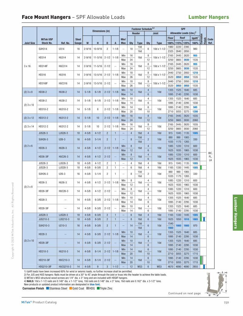
Lumber Hangers
159
Copy
righ
t © 2
020
MiT
ek In
dust
ries
, Inc
. Al
l Rig
hts
Rese
rved
Lumber Hangers
MiTek® Product Catalog
Corrosion Finish Stainless Steel Gold Coat HDG Triple Zinc
Corrosion Finish Stainless Steel Gold Coat HDG Triple Zinc
Corrosion Finish Stainless Steel Gold Coat HDG Triple Zinc
Floor Uplift1
Joist Size Ref. No. W H D A Qty Type Qty Type 100% 115% 125% 160%10d 1980 2220 2395
16d 2325 2640 2850
Min 16 8 2165 2445 2620 955
Max 24 12 3250 3665 3930 1535
Min 16 8 2165 2445 2620 955
Max 24 12 3250 3665 3930 1535
Min 18 8 2440 2750 2950 1210
Max 26 12 3520 3950 3950 1535
Min 18 8 2440 2750 2950 1210
Max 26 12 3520 3950 3950 1535
Min 10 4 1355 1525 1640 685
Max 14 6 1895 2140 2295 1030
Min 10 4 1355 1525 1640 685
Max 14 6 1895 2140 2295 1030
Min 14 6 1895 2140 2295 945
Max 20 10 2710 3055 3275 1200
Min 16 8 2165 2445 2620 1035
Max 24 12 3250 3665 3930 2060
Min 16 8 2165 2445 2620 1035
Max 24 12 3250 3665 3930 2060
JUS26-3 LUS26-3 18 4-5/8 4-1/2 2 1 -- 4 16d 4 16d 915 1045 1135 1005
10d 880 990 1065
16d 1035 1175 1265
Min 8 4 1085 1220 1310 600
Max 12 6 1625 1835 1965 1030
Min 8 4 1085 1220 1310 600
Max 12 6 1625 1835 1965 1030
JUS26-3 LUS26-3 18 4-5/8 4-1/2 2 1 -- 4 16d 4 16d 915 1045 1135 1005
JUS28-3 LUS28-3 18 4-5/8 6-3/8 2 1 -- 6 16d 4 16d 1165 1330 1445 1005
10d 880 990 1065
16d 1035 1175 1265
Min 8 4 1085 1220 1310 600
Max 12 6 1625 1835 1965 1030
Min 8 4 1085 1220 1310 600
Max 12 6 1625 1835 1965 1030
Min 10 4 1355 1525 1640 685
Max 14 6 1895 2140 2295 1030
Min 10 4 1355 1525 1640 685
Max 14 6 1895 2140 2295 1030
JUS28-3 LUS28-3 18 4-5/8 6-3/8 2 1 -- 6 16d 4 16d 1165 1330 1445 1005
JUS210-3 LUS210-3 18 4-5/8 8-3/8 2 1 -- 8 16d 6 16d 1625 1850 1910 1865
10d 1540
16d 1660
Min 10 4 1355 1525 1640 685
Max 14 6 1895 2140 2295 1030
Min 10 4 1355 1525 1640 685
Max 14 6 1895 2140 2295 1030
Min 14 6 1895 2140 2295 1030
Max 20 10 2710 3055 3275 1715
Min 14 6 1895 2140 2295 1030
Max 20 10 2710 3055 3275 1715
HDQ210-3IF HUCQ210-3 14 4-5/8 9 3 1-1/2 -- 12 WS3 6 WS3 4670 4890 4890 2855
1) Uplift loads have been increased 60% for wind or seismic loads; no further increase shall be permitted. 2) For JUS and HUS hangers: Nails must be driven at a 30° to 45˚ angle through the joist or truss into the header to achieve the table loads. 3) MiTek's WS3 structural wood screws are 1/4" dia. x 3" long and are included with HDQIF hangers. 4) NAILS: 10d x 1-1/2 nails are 0.148" dia. x 1-1/2" long, 10d nails are 0.148" dia. x 3" long, 16d nails are 0.162" dia. x 3-1/2" long. New products or updated product information are designated in blue font.
IBC, FL, LA
16d 10d
16d 10d
16d 10d
16d 10d
16d 10d
16d 10d
16d 10d
16d 10d
16d 10d
16d 10d
16d 10d
16d
MiTek USPStock No.
SteelGauge
Roof CodeRef.Co
rros
ion
Fini
sh
Header Joist
SPFAllowable Loads (Lbs.)2Dimensions (in)
Fastener Schedule3,4
Min/Max
--
(3) 2 x 10
SUH210-3 U210-3 16 4-5/8
HD28-3IF -- 14 4-5/8
8-3/8 2 1 --
6-3/8 2-1/2 --
5-1/4 2 1
HD26-3 HU26-3 14 4-5/8
(2) 3 x 8
(2) 3 x 10
(2) 3 x 12
(2) 3 x 14
(3) 2 x 6
(3) 2 x 8
14 5-1/8 2-1/2
HD312-2 HU312-2 14 5-1/8
HD312-2 HU312-2 14 5-1/8 10
HD26-3 HU26-3
4-1/2 2-1/2
2-1/2
2-1/2
1-1/8
1-1/8
2-1/2
4-5/8 SUH26-3 U26-3 16
1-1/8
--
--
HD38-2 HU38-2 14 5-1/8 6-1/8 2-1/2 1-1/8
HD38-2 HU38-2 14 5-1/8 6-1/8
5-1/4 2 1
2-1/2 1-1/8
8
10
2-1/2 1-1/8
HD310-2 HU310-2
1-1/8
HD26-3IF HUC26-3 14 4-5/8
4-1/2
4-1/2
SUH26-3 U26-3 16 4-5/8
14 4-5/8 2-1/2
2-1/2
--
HD28-3 -- 14 4-5/8 6-3/8 2-1/2 1-1/8
HD26-3IF HUC26-3 14 4-5/8 4-1/2
--
HD28-3 -- 14 4-5/8 6-3/8 2-1/2 1-1/8
HD28-3IF -- 14 4-5/8 6-3/8
2-1/2 --
HD210-3 HU210-3 14 4-5/8 8-1/4 2-1/2 1-1/8
HD210-3IF HUC210-3 14 4-5/8 8-1/4
16d 10d x 1-1/2
HD316IF HUC316 14 2-9/16 13-5/16 2-1/2 -- 16d 10d x 1-1/2
16d 10d x 1-1/2
HD316 HU316 14 2-9/16 13-5/16 2-1/2 1-1/8 16d 10d x 1-1/2
10d
3 x 16
SUH314 U314 16 2-9/16 10-9/16 2 1-1/8 --
1-1/8
HD314IF HUC314 14 2-9/16 11-5/16 2-1/2 --
HD314 HU314 14 2-9/16 11-5/16 2-1/2
10d
1660 97016606 10d14
18 6 10d x 1-1/2 980
8 10d2 330
8 2 10d 330
16d 10d
16d 10d
16d
Face Mount Hangers – SPF Allowable Loads
A
D
H
WContinued on next page
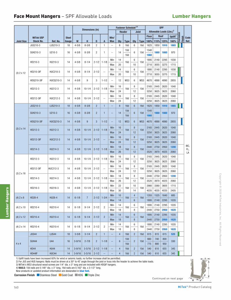
160
Copyright © 2020 M
iTek Industries, Inc. All Rights Reserved
Lumber Hangers
Lum
ber H
ange
rs
MiTek® Product Catalog
Floor Uplift1
Joist Size Ref. No. W H D A Qty Type Qty Type 100% 115% 125% 160%
JUS210-3 LUS210-3 18 4-5/8 8-3/8 2 1 -- 8 16d 6 16d 1625 1850 1910 1865
10d 1540
16d 1660
Min 14 6 1895 2140 2295 1030
Max 20 10 2710 3055 3275 1715
Min 14 6 1895 2140 2295 1030
Max 20 10 2710 3055 3275 1715
HDQ210-3IF HUCQ210-3 14 4-5/8 9 3 1-1/2 -- 12 WS3 6 WS3 4670 4890 4890 2855
Min 16 8 2165 2445 2620 1040
Max 24 12 3250 3625 3625 2060
Min 16 8 2165 2445 2620 1040
Max 24 12 3250 3625 3625 2060
JUS210-3 LUS210-3 18 4-5/8 8-3/8 2 1 -- 8 16d 6 16d 1625 1850 1910 1865
10d 1540
16d 1660
HDQ210-3IF HUCQ210-3 14 4-5/8 9 3 1-1/2 -- 12 WS3 6 WS3 4670 4890 4890 2855
Min 16 8 2165 2445 2620 1040
Max 24 12 3250 3625 3625 2060
Min 16 8 2165 2445 2620 1040
Max 24 12 3250 3625 3625 2060
Min 18 8 2440 2750 2950 1200
Max 26 12 3520 3970 4025 2060
Min 16 8 2165 2445 2620 1040
Max 24 12 3250 3625 3625 2060
Min 16 8 2165 2445 2620 1040
Max 24 12 3250 3625 3625 2060
Min 18 8 2440 2750 2950 1200
Max 26 12 3520 3970 4025 2060
Min 22 10 2980 3360 3605 1715
Max 30 14 4035 4035 4035 2405
Min 10 4 1355 1525 1640 685
Max 14 6 1895 2140 2295 1035
Min 14 6 1895 2140 2295 1035
Max 18 8 2440 2750 2950 1620
Min 14 6 1895 2140 2295 1035
Max 18 8 2440 2750 2950 1620
Min 14 6 1895 2140 2295 1035
Max 18 8 2440 2750 2950 1620
JUS44 LUS44 18 3-5/8 3-1/4 2 1 -- 4 16d 2 16d 615 615 615 520
10d 660 740 800
16d 775 880 950
HD44 HU44 14 3-9/16 3-5/16 2-1/2 1-1/8 -- 4 16d 2 10d 540 610 655 345
HD44IF HUC44 14 3-9/16 3-5/16 2-1/2 -- -- 4 16d 2 10d 540 610 655 345
1) Uplift loads have been increased 60% for wind or seismic loads; no further increase shall be permitted. 2) For JUS and HUS hangers: Nails must be driven at a 30° to 45˚ angle through the joist or truss into the header to achieve the table loads. 3) MiTek's WS3 structural wood screws are 1/4" dia. x 3" long and are included with HDQIF hangers. 4) NAILS: 10d nails are 0.148" dia. x 3" long, 16d nails are 0.162" dia. x 3-1/2" long. New products or updated product information are designated in blue font.
MiTek USPStock No.
SteelGauge
Min/Max
Roof CodeRef.
Dimensions (in)Fastener Schedule3,4 SPF
Allowable Loads (Lbs.)2
Corr
osio
nFi
nish
Header Joist
SUH210-3 U210-3 16 4-5/8 8-3/8 2 1 --
HD210-3 HU210-3 14 4-5/8 8-1/4 2-1/2 1-1/8 16d 10d
HD210-3IF HUC210-3 14 4-5/8 8-1/4 2-1/2
HD212-3IF HUC212-3 14 4-5/8 10-1/4 2-1/2 -- 10d
10d
-- 16d 10d
--
16d
HD212-3 HU212-3 14 4-5/8 10-1/4 2-1/2 1-1/8 16d
IBC, FL, LA
(3) 2 x 14
SUH210-3 U210-3 16 4-5/8 8-3/8 2 1
(3) 2 x 12
HD212-3 HU212-3 14 4-5/8 10-1/4 2-1/2 1-1/8
HD214-3 HU214-3 14 4-5/8 12-1/4 2-1/2 1-1/8
HD212-3IF HUC212-3 14 4-5/8 10-1/4 2-1/2 -- 16d 10d
2-1/2 1-1/8 16d 10d
HD212-3IF HUC212-3 14 4-5/8 10-1/4 2-1/2
HD212-3 HU212-3 14 4-5/8 10-1/4
-- 16d 10d
HD214-3 HU214-3 14 4-5/8 12-1/4 2-1/2 1-1/8 16d 10d
7 2-1/2 1-3/4 16d
HD216-3 HU216-3 14 4-5/8 13-1/4 2-1/2 1-1/8 16d
16d
4 x 4--3-9/16 2-7/8 2 1-1/816 SUH44 U44
(4) 2 x 14 HD210-4 HU210-4 14 6-1/8 9-1/4 2-1/2 2 16d
(3) 2 x 16
HU210-4 14 6-1/8 9-1/4 2-1/2 2 16d
16d
(4) 2 x 10 HD210-4
16d
HU210-4 14 6-1/8 9-1/4 2-1/2 2 16d
(4) 2 x 8 HD28-4 HU28-4 14 6-1/8
1660
1660
16d
(4) 2 x 12 HD210-4
2 10d6 330
6 10d14 9701660
97016606 10d14
10d
16d 10d
16d 10d
Corrosion Finish Stainless Steel Gold Coat HDG Triple Zinc
Corrosion Finish Stainless Steel Gold Coat HDG Triple Zinc
Corrosion Finish Stainless Steel Gold Coat HDG Triple Zinc
Face Mount Hangers – SPF Allowable Loads
A
D
H
WContinued on next page
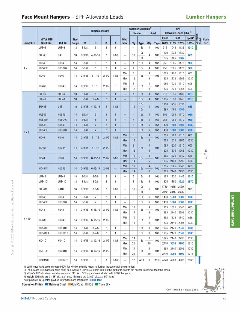
Lumber Hangers
161
Copy
righ
t © 2
020
MiT
ek In
dust
ries
, Inc
. Al
l Rig
hts
Rese
rved
Lumber Hangers
MiTek® Product Catalog
Corrosion Finish Stainless Steel Gold Coat HDG Triple Zinc
Corrosion Finish Stainless Steel Gold Coat HDG Triple Zinc
Corrosion Finish Stainless Steel Gold Coat HDG Triple Zinc
Floor Uplift1
Joist Size Ref. No. W H D A Qty Type Qty Type 100% 115% 125% 160%
JUS46 LUS46 18 3-5/8 5 2 1 -- 4 16d 4 16d 915 1045 1135 1010
10d 1100 1235 1330
16d 1295 1465 1585
HUS46 HUS46 14 3-5/8 5 2 1 -- 4 16d 4 16d 955 1085 1170 930
HUS46IF HUSC46 14 3-5/8 5 2 1 -- 4 16d 4 16d 955 1085 1170 930
Min 8 4 1085 1220 1310 605
Max 12 6 1625 1835 1965 1030
Min 8 4 1085 1220 1310 605
Max 12 6 1625 1835 1965 1030
JUS46 LUS46 18 3-5/8 5 2 1 -- 4 16d 4 16d 915 1045 1135 1010
JUS48 LUS48 18 3-5/8 6-7/8 2 1 -- 6 16d 4 16d 1165 1330 1445 1010
10d 1100 1235 1330
16d 1295 1465 1585
HUS46 HUS46 14 3-5/8 5 2 1 -- 4 16d 4 16d 955 1085 1170 930
HUS46IF HUSC46 14 3-5/8 5 2 1 -- 4 16d 4 16d 955 1085 1170 930
HUS48 HUS48 14 3-5/8 7 2 1 -- 6 16d 6 16d 1430 1500 1500 1930
HUS48IF HUSC48 14 3-5/8 7 2 1 -- 6 16d 6 16d 1430 1500 1500 1930
Min 8 4 1085 1220 1310 605
Max 12 6 1625 1835 1965 1030
Min 8 4 1085 1220 1310 605
Max 12 6 1625 1835 1965 1030
Min 10 4 1355 1525 1640 685
Max 14 6 1895 2140 2295 1030
Min 10 4 1355 1525 1640 685
Max 14 6 1895 2140 2295 1030
JUS48 LUS48 18 3-5/8 6-7/8 2 1 -- 6 16d 4 16d 1165 1330 1445 1010
JUS410 LUS410 18 3-5/8 8-7/8 2 1 -- 8 16d 6 16d 1625 1850 1920 1870
10d 1760 1975 2130
16d 2070 2345 2535
HUS48 HUS48 14 3-5/8 7 2 1 -- 6 16d 6 16d 1430 1500 1500 1930
HUS48IF HUSC48 14 3-5/8 7 2 1 -- 6 16d 6 16d 1430 1500 1500 1930
Min 10 4 1355 1525 1640 685
Max 14 6 1895 2140 2295 1030
Min 10 4 1355 1525 1640 685
Max 14 6 1895 2140 2295 1030
HUS410 HUS410 14 3-5/8 8-7/8 2 1 -- 8 16d 8 16d 1905 2170 2340 1935
HUS410IF HUSC410 14 3-5/8 8-7/8 2 1 -- 8 16d 8 16d 1905 2170 2340 1935
Min 14 6 1895 2140 2295 1030
Max 20 10 2710 3055 3190 1715
Min 14 6 1895 2140 2295 1030
Max 20 10 2710 3055 3190 1715
HDQ410IF HUCQ410 14 3-9/16 9 3 1-1/2 -- 12 WS3 6 WS3 4670 4900 4900 2865
1) Uplift loads have been increased 60% for wind or seismic loads; no further increase shall be permitted. 2) For JUS and HUS hangers: Nails must be driven at a 30° to 45˚ angle through the joist or truss into the header to achieve the table loads. 3) MiTek's WS3 structural wood screws are 1/4" dia. x 3" long and are included with HDQIF hangers. 4) NAILS: 10d nails are 0.148" dia. x 3" long, 16d nails are 0.162" dia. x 3-1/2" long. New products or updated product information are designated in blue font.
IBC, FL, LA
16d 10d
16d 10d
16d 10d
16d 10d
16d 10d
16d 10d
16d 10d
10d16d
16d 10d
CodeRef.Co
rros
ion
Fini
sh
3-9/16 8-3/8 2 1-1/8
3-9/16 4-13/16 2 1-1/8
Roof
Header Joist
SPFAllowable Loads (Lbs.)2
Fastener Schedule3,4
Min/Max
5-1/16 2-1/2 --
5-1/16 2-1/2 1-1/8
16d 10d
HD48 HU48
HD46IF HUC46 14 3-9/16
HD48IF HUC48
Dimensions (in)
MiTek USPStock No.
SteelGauge
16 SUH410 U410
16
16
14
U46 SUH46
HD46 HU46
SUH46 U46
--
4 x 6
4 x 8
--
--
--
3-9/16 4-13/16 2 1-1/8
3-9/16 5-1/16 2-1/2 1-1/8
HD46IF HUC46 14 3-9/16
4 x 10
HD46 HU46 14 3-9/16
HD48 HU48
14 3-9/16 6-15/16 2-1/2 1-1/8
6-15/16 2-1/2 1-1/8
14 3-9/16 6-15/16 2-1/2 --
14 3-9/16
--
8-13/16
8-13/16
2-1/2
HD410IF HUC410 14 3-9/16 2-1/2
2-1/2 --
HD410 HU410 14 3-9/16 1-1/8
HD48IF HUC48 14 3-9/16 6-15/16
5-1/16 2-1/2
16 6 10d 975
10 4 10d 665
10 4 10d 665
Face Mount Hangers – SPF Allowable Loads
A
D
H
WContinued on next page
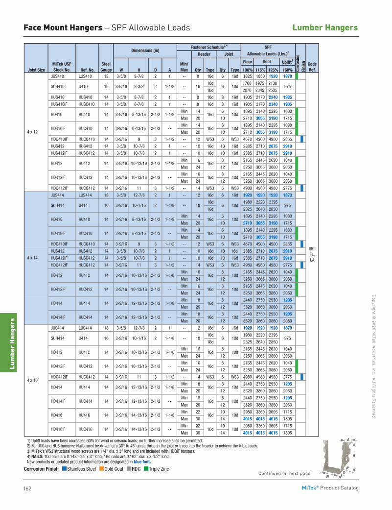
162
Copyright © 2020 M
iTek Industries, Inc. All Rights Reserved
Lumber Hangers
Lum
ber H
ange
rs
MiTek® Product Catalog
Floor Uplift1
Joist Size Ref. No. W H D A Qty Type Qty Type 100% 115% 125% 160% JUS410 LUS410 18 3-5/8 8-7/8 2 1 -- 8 16d 6 16d 1625 1850 1920 1870
10d 1760 1975 2130
16d 2070 2345 2535
HUS410 HUS410 14 3-5/8 8-7/8 2 1 -- 8 16d 8 16d 1905 2170 2340 1935
HUS410IF HUSC410 14 3-5/8 8-7/8 2 1 -- 8 16d 8 16d 1905 2170 2340 1935
Min 14 6 1895 2140 2295 1030
Max 20 10 2710 3055 3190 1715
Min 14 6 1895 2140 2295 1030
Max 20 10 2710 3055 3190 1715
HDQ410IF HUCQ410 14 3-9/16 9 3 1-1/2 -- 12 WS3 6 WS3 4670 4900 4900 2865
HUS412 HUS412 14 3-5/8 10-7/8 2 1 -- 10 16d 10 16d 2385 2710 2875 2910
HUS412IF HUSC412 14 3-5/8 10-7/8 2 1 -- 10 16d 10 16d 2385 2710 2875 2910
Min 16 8 2165 2445 2620 1040
Max 24 12 3250 3665 3860 2060
Min 16 8 2165 2445 2620 1040
Max 24 12 3250 3665 3860 2060
HDQ412IF HUCQ412 14 3-9/16 11 3 1-1/2 -- 14 WS3 6 WS3 4980 4980 4980 2775
JUS414 LUS414 18 3-5/8 12-7/8 2 1 -- 12 16d 6 16d 1920 1920 1920 1870
10d 1980 2220 2395
16d 2325 2640 2850
Min 14 6 1895 2140 2295 1030
Max 20 10 2710 3055 3190 1715
Min 14 6 1895 2140 2295 1030
Max 20 10 2710 3055 3190 1715
HDQ410IF HUCQ410 14 3-9/16 9 3 1-1/2 -- 12 WS3 6 WS3 4670 4900 4900 2865
HUS412 HUS412 14 3-5/8 10-7/8 2 1 -- 10 16d 10 16d 2385 2710 2875 2910
HUS412IF HUSC412 14 3-5/8 10-7/8 2 1 -- 10 16d 10 16d 2385 2710 2875 2910
HDQ412IF HUCQ412 14 3-9/16 11 3 1-1/2 -- 14 WS3 6 WS3 4980 4980 4980 2775
Min 16 8 2165 2445 2620 1040
Max 24 12 3250 3665 3860 2060
Min 16 8 2165 2445 2620 1040
Max 24 12 3250 3665 3860 2060
Min 18 8 2440 2750 2950 1205
Max 26 12 3520 3860 3860 2060
Min 18 8 2440 2750 2950 1205
Max 26 12 3520 3860 3860 2060
JUS414 LUS414 18 3-5/8 12-7/8 2 1 -- 12 16d 6 16d 1920 1920 1920 1870
10d 1980 2220 2395
16d 2325 2640 2850
Min 16 8 2165 2445 2620 1040
Max 24 12 3250 3665 3860 2060
Min 16 8 2165 2445 2620 1040
Max 24 12 3250 3665 3860 2060
HDQ412IF HUCQ412 14 3-9/16 11 3 1-1/2 -- 14 WS3 6 WS3 4980 4980 4980 2775
Min 18 8 2440 2750 2950 1205
Max 26 12 3520 3860 3860 2060
Min 18 8 2440 2750 2950 1205
Max 26 12 3520 3860 3860 2060
Min 22 10 2980 3360 3605 1715
Max 30 14 4015 4015 4015 1805
Min 22 10 2980 3360 3605 1715
Max 30 14 4015 4015 4015 1805
1) Uplift loads have been increased 60% for wind or seismic loads; no further increase shall be permitted. 2) For JUS and HUS hangers: Nails must be driven at a 30° to 45˚ angle through the joist or truss into the header to achieve the table loads. 3) MiTek's WS3 structural wood screws are 1/4" dia. x 3" long and are included with HDQIF hangers. 4) NAILS: 10d nails are 0.148" dia. x 3" long, 16d nails are 0.162" dia. x 3-1/2" long. New products or updated product information are designated in blue font.
MiTek USPStock No.
SteelGauge
Min/Max
Roof CodeRef.
Dimensions (in)Fastener Schedule3,4 SPF
Allowable Loads (Lbs.)2
Corr
osio
nFi
nish
Header Joist
1-1/8
4 x 12
SUH410 U410 16 3-9/16 8-3/8
HD412 HU412 14 3-9/16 10-13/16
10-13/16
HD410IF HUC410 14
U414 16
2 1-1/8
HD412IF HUC412 14 3-9/16
--
HD410 HU410 14 3-9/16 8-13/16 2-1/2 1-1/8
HD410IF HUC410 14 3-9/16 8-13/16 2-1/2 --
HD412 HU412 14 3-9/16 10-13/16 2-1/2 1-1/8 16d 10d
2-1/2 -- 16d 10d
IBC, FL, LA 4 x 14
HD412IF HUC412 14 3-9/16
HD414IF HUC414 14 3-9/16
SUH414
HU414 14 3-9/16
1-1/810-1/16 2
HD410 HU410 14
--
HD412 HU412 14 3-9/16 10-13/16
--
16d 10d
16d 10d
16d 10d
16d 10d
16d
3-9/16
3-9/16 8-13/16 2-1/2 1-1/8
3-9/16 8-13/16 2-1/2
HD414IF HUC414 14 3-9/16 12-13/16
2-1/2 1-1/8
--
10-13/16 2-1/2 --
1-1/8
12-13/16 2-1/2
12-13/16
2-1/2
SUH414 U414 16 3-9/16 10-1/16 2 1-1/8
2-1/2
14 3-9/16 10-13/16
--
4 x 16
HD412IF
2-1/2 1-1/8 HD414
2-1/2 --
2-1/2 1-1/8
2-1/2
2-1/2 --
HD416 HU416 14 3-9/16
--
14 3-9/16 14-13/16
16d 10d
HD414
16d 10d
16d 10d
16d 10d
16d 10d
10d16d
14-13/16
HU414 14 3-9/16 12-13/16
HD416IF HUC416
10d
16d 10d
HUC412
6 10d 97516
18 6 10d
6 10d18
16d 10d
975
975
16d 10d
Corrosion Finish Stainless Steel Gold Coat HDG Triple Zinc
Corrosion Finish Stainless Steel Gold Coat HDG Triple Zinc
Corrosion Finish Stainless Steel Gold Coat HDG Triple Zinc
Face Mount Hangers – SPF Allowable Loads
A
D
H
WContinued on next page
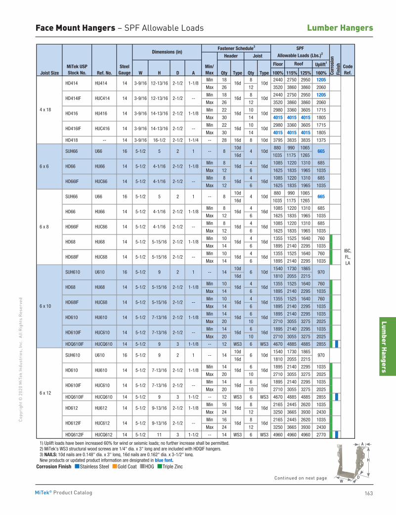
Lumber Hangers
163
Copy
righ
t © 2
020
MiT
ek In
dust
ries
, Inc
. Al
l Rig
hts
Rese
rved
Lumber Hangers
MiTek® Product Catalog
Corrosion Finish Stainless Steel Gold Coat HDG Triple Zinc
Corrosion Finish Stainless Steel Gold Coat HDG Triple Zinc
Corrosion Finish Stainless Steel Gold Coat HDG Triple Zinc
Floor Uplift1
Joist Size Ref. No. W H D A Qty Type Qty Type 100% 115% 125% 160%Min 18 8 2440 2750 2950 1205
Max 26 12 3520 3860 3860 2060
Min 18 8 2440 2750 2950 1205
Max 26 12 3520 3860 3860 2060
Min 22 10 2980 3360 3605 1715
Max 30 14 4015 4015 4015 1805
Min 22 10 2980 3360 3605 1715
Max 30 14 4015 4015 4015 1805
HD418 -- 14 3-9/16 16-1/2 2-1/2 1-1/4 -- 28 16d 8 10d 3795 3835 3835 1375
10d 880 990 1065
16d 1035 1175 1265
Min 8 4 1085 1220 1310 685
Max 12 6 1625 1835 1965 1035
Min 8 4 1085 1220 1310 685
Max 12 6 1625 1835 1965 1035
10d 880 990 1065
16d 1035 1175 1265
Min 8 4 1085 1220 1310 685
Max 12 6 1625 1835 1965 1035
Min 8 4 1085 1220 1310 685
Max 12 6 1625 1835 1965 1035
Min 10 4 1355 1525 1640 760
Max 14 6 1895 2140 2295 1035
Min 10 4 1355 1525 1640 760
Max 14 6 1895 2140 2295 1035
10d 1540 1730 1865
16d 1810 2055 2215
Min 10 4 1355 1525 1640 760
Max 14 6 1895 2140 2295 1035
Min 10 4 1355 1525 1640 760
Max 14 6 1895 2140 2295 1035
Min 14 6 1895 2140 2295 1035
Max 20 10 2710 3055 3275 2025
Min 14 6 1895 2140 2295 1035
Max 20 10 2710 3055 3275 2025
HDQ610IF HUCQ610 14 5-1/2 9 3 1-1/8 -- 12 WS3 6 WS3 4670 4885 4885 2855
10d 1540 1730 1865
16d 1810 2055 2215
Min 14 6 1895 2140 2295 1035
Max 20 10 2710 3055 3275 2025
Min 14 6 1895 2140 2295 1035
Max 20 10 2710 3055 3275 2025
HDQ610IF HUCQ610 14 5-1/2 9 3 1-1/2 -- 12 WS3 6 WS3 4670 4885 4885 2855
Min 16 8 2165 2445 2620 1035
Max 24 12 3250 3665 3930 2430
Min 16 8 2165 2445 2620 1035
Max 24 12 3250 3665 3930 2430
HDQ612IF HUCQ612 14 5-1/2 11 3 1-1/2 -- 14 WS3 6 WS3 4960 4960 4960 2770
1) Uplift loads have been increased 60% for wind or seismic loads; no further increase shall be permitted. 2) MiTek's WS3 structural wood screws are 1/4" dia. x 3" long and are included with HDQIF hangers. 3) NAILS: 10d nails are 0.148" dia. x 3" long, 16d nails are 0.162" dia. x 3-1/2" long. New products or updated product information are designated in blue font.
16d 16d
16d 16d
16d 16d
16d 16d
16d 16d
16d 16d
16d 16d
16d 16d
16d 16d
5-1/2 9-13/16 2-1/2 1-1/8
HD610IF HUC610 14 5-1/2 7-13/16
HD68 HU68 14 5-1/2 5-15/16 2-1/2 1-1/8
HD68IF HUC68 14 5-1/2 5-15/16
5-1/2 9 2
HU66 14 5-1/2 4-1/16 2-1/2 1-1/8
2-1/2 --
HD68 HU68 14 5-1/2 5-15/16 2-1/2 1-1/8
HD66IF HUC66 14 5-1/2 4-1/16
16d 10d--
Dimensions (in)SPF
Allowable Loads (Lbs.)2
Corr
osio
nFi
nish
Header Joist
14-13/16
12-13/16 2-1/2
14-13/16
3-9/16 12-13/16 2-1/2 1-1/8
2-1/2 1-1/8 16d 10d
16d 10d2-1/2 --
HD414 HU414 14
MiTek USPStock No.
SteelGauge
Roof CodeRef.
Min/Max
Fastener Schedule3
16d 10d
IBC, FL, LA
14 5-1/2
14 3-9/16
HUC414 14 3-9/16
HU416 14 3-9/16
HUC416
16d 16d 6 x 6
6 x 8
1
1
SUH66 U66 16 5-1/2 5
SUH66 U66 16 5-1/2 5
2
2
HD66 HU66 14 4-1/16
HD66IF HUC66
16d
--
--
--
--
2-1/2 1-1/85-1/2
2-1/2 --
2-1/2 --
5-1/2 5-15/16
2-1/2 --
4-1/16
5-1/2 7-13/16
7-13/16 2-1/2 1-1/8
14
1
2-1/2 --
HD610 HU610 14 5-1/2 7-13/16 2-1/2 1-1/8
HD610IF HUC610 14
HD612IF HUC612 14 5-1/2 9-13/16
2-1/2 --
HD612 HU612 14
16d
4 x 18
6 x 12
SUH610 U610 16 5-1/2 9 2
1
6 x 10
SUH610 U610 16
2-1/2 --
HD610 HU610 14 5-1/2
HD414IF
HD416
HD68IF HUC68
HD416IF
HD66
14 6 10d 970
6654 10d8
8 4 10d 665
14 6 10d 970
16d 16d
16d 16d
16d
16d
Face Mount Hangers – SPF Allowable Loads
A
D
H
WContinued on next page
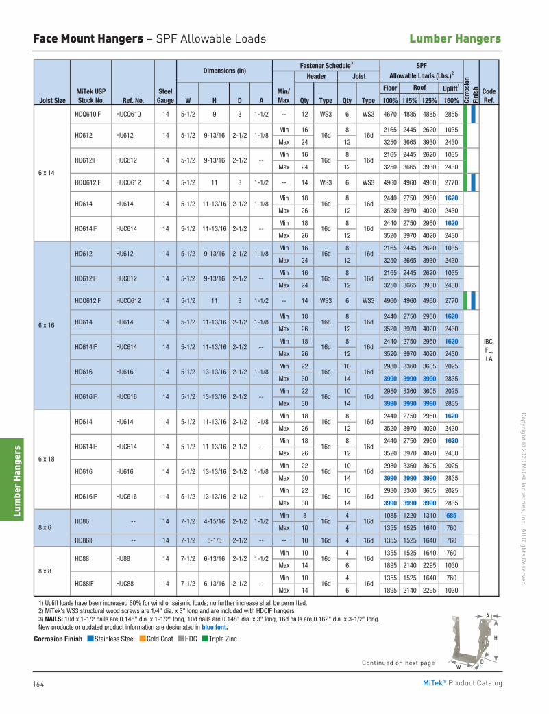
164
Copyright © 2020 M
iTek Industries, Inc. All Rights Reserved
Lumber Hangers
Lum
ber H
ange
rs
MiTek® Product Catalog
Floor Uplift1
Joist Size Ref. No. W H D A Qty Type Qty Type 100% 115% 125% 160%
HDQ610IF HUCQ610 14 5-1/2 9 3 1-1/2 -- 12 WS3 6 WS3 4670 4885 4885 2855
Min 16 8 2165 2445 2620 1035
Max 24 12 3250 3665 3930 2430
Min 16 8 2165 2445 2620 1035
Max 24 12 3250 3665 3930 2430
HDQ612IF HUCQ612 14 5-1/2 11 3 1-1/2 -- 14 WS3 6 WS3 4960 4960 4960 2770
Min 18 8 2440 2750 2950 1620
Max 26 12 3520 3970 4020 2430
Min 18 8 2440 2750 2950 1620
Max 26 12 3520 3970 4020 2430
Min 16 8 2165 2445 2620 1035
Max 24 12 3250 3665 3930 2430
Min 16 8 2165 2445 2620 1035
Max 24 12 3250 3665 3930 2430
HDQ612IF HUCQ612 14 5-1/2 11 3 1-1/2 -- 14 WS3 6 WS3 4960 4960 4960 2770
Min 18 8 2440 2750 2950 1620
Max 26 12 3520 3970 4020 2430
Min 18 8 2440 2750 2950 1620
Max 26 12 3520 3970 4020 2430
Min 22 10 2980 3360 3605 2025
Max 30 14 3990 3990 3990 2835
Min 22 10 2980 3360 3605 2025
Max 30 14 3990 3990 3990 2835
Min 18 8 2440 2750 2950 1620
Max 26 12 3520 3970 4020 2430
Min 18 8 2440 2750 2950 1620
Max 26 12 3520 3970 4020 2430
Min 22 10 2980 3360 3605 2025
Max 30 14 3990 3990 3990 2835
Min 22 10 2980 3360 3605 2025
Max 30 14 3990 3990 3990 2835
Min 8 4 1085 1220 1310 685
Max 10 4 1355 1525 1640 760
HD86IF -- 14 7-1/2 5-1/8 2-1/2 -- -- 10 16d 4 16d 1355 1525 1640 760
Min 10 4 1355 1525 1640 760
Max 14 6 1895 2140 2295 1030
Min 10 4 1355 1525 1640 760
Max 14 6 1895 2140 2295 1030
1) Uplift loads have been increased 60% for wind or seismic loads; no further increase shall be permitted. 2) MiTek's WS3 structural wood screws are 1/4" dia. x 3" long and are included with HDQIF hangers. 3) NAILS: 10d x 1-1/2 nails are 0.148" dia. x 1-1/2" long, 10d nails are 0.148" dia. x 3" long, 16d nails are 0.162" dia. x 3-1/2" long. New products or updated product information are designated in blue font.
16d 16d
16d
16d 16d
16d 16d
16d 16d
16d 16d
16d 16d
IBC, FL, LA
16d 16d
16d 16d
16d
SPFAllowable Loads (Lbs.)2
Corr
osio
nFi
nish
Header Joist
Roof
16d 16d
16d
16d
16d
CodeRef.
16d 16d
16d 16d
16d
16d 16d
6 x 18
8 x 6
Fastener Schedule3
Min/Max
HD612 HU612 14 5-1/2 9-13/16 2-1/2
HD612IF HUC612 14 5-1/2 9-13/16 2-1/2 --
HD614 HU614
16d 16d
14 5-1/2 11-13/16 2-1/2
Dimensions (in)
14 HD614IF HUC614 5-1/2 11-13/16 2-1/2 --
1-1/8
HD612IF HUC612 14 5-1/2 9-13/16 2-1/2 --
MiTek USPStock No.
SteelGauge
6 x 14
6 x 16 HD614 HU614 14 5-1/2 11-13/16 2-1/2 1-1/8
1-1/8
HD614IF HUC614 14 5-1/2 11-13/16 2-1/2 --
1-1/8
HD612 HU612 14 5-1/2 9-13/16 2-1/2
HD616 HU616 14 5-1/2 13-13/16 2-1/2 1-1/8
HD616IF HUC616 14 5-1/2 13-13/16 2-1/2 --
HD614 HU614 14 5-1/2 11-13/16 2-1/2 1-1/8
HD614IF HUC614 14 5-1/2 11-13/16 2-1/2 --
HD616 HU616 14 5-1/2 13-13/16 2-1/2 1-1/8
HD616IF HUC616 14 5-1/2 13-13/16 2-1/2 --
2-1/2 1-1/2 HD86
8 x 8
16d--2-1/26-13/167-1/214 HUC88 HD88IF
16d1-1/22-1/26-13/167-1/214 HU88 HD88
-- 14 7-1/2 4-15/16
Corrosion Finish Stainless Steel Gold Coat HDG Triple Zinc
Corrosion Finish Stainless Steel Gold Coat HDG Triple Zinc
Corrosion Finish Stainless Steel Gold Coat HDG Triple Zinc
Face Mount Hangers – SPF Allowable Loads
A
D
H
WContinued on next page
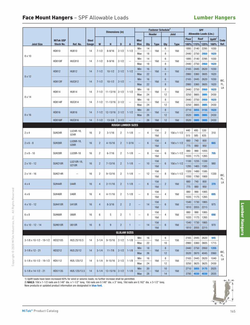
Lumber Hangers
165
Copy
righ
t © 2
020
MiT
ek In
dust
ries
, Inc
. Al
l Rig
hts
Rese
rved
Lumber Hangers
MiTek® Product Catalog
Floor Uplift1
Joist Size Ref. No. W H D A Qty Type Qty Type 100% 115% 125% 160%
Min 14 6 1895 2140 2295 1030
Max 18 8 2440 2750 2950 1620
Min 14 6 1895 2140 2295 1030
Max 18 8 2440 2750 2950 1620
Min 16 6 2165 2445 2620 1030
Max 22 8 2980 3360 3605 1620
Min 16 6 2165 2445 2620 1030
Max 22 8 2980 3360 3605 1620
Min 18 8 2440 2750 2950 1620
Max 24 12 3250 3665 3885 2430
Min 18 8 2440 2750 2950 1620
Max 24 12 3250 3665 3885 2430
Min 20 8 2710 3055 3155 1620
Max 26 12 3520 3885 3885 2430
HD816IF HUC816 14 7-1/2 13-5/8 2-1/2 -- -- 26 16d 12 16d 3520 3885 3885 2430
10d 440 495 530
16d 515 585 635
10d 660 740 800
16d 775 880 950
10d 880 990 1055
16d 1035 1175 1265
10d 1100 1235 1330
16d 1295 1465 1585
10d 1320 1480 1595
16d 1550 1760 1900
10d 660 740 800
16d 775 880 950
10d 880 990 1065
16d 1035 1175 1265
10d 1540 1730 1865
16d 1810 2055 2215
10d 880 990 1065
16d 1035 1175 1265
10d 1540 1730 1865
16d 1810 2055 2215
Min 16 6 2165 2445 2620 945
Max 22 10 2980 3360 3605 1715
Min 18 8 2440 2750 2950 1205
Max 26 12 3520 3970 4045 2060
Min 16 8 2165 2445 2620 1040
Max 24 12 3250 3625 3625 2430
Min 20 10 2710 3055 3175 2025
Max 28 14 3795 4030 4030 2835
1) Uplift loads have been increased 60% for wind or seismic loads; no further increase shall be permitted. 2) NAILS: 10d x 1-1/2 nails are 0.148" dia. x 1-1/2" long, 10d nails are 0.148" dia. x 3" long, 16d nails are 0.162" dia. x 3-1/2" long. New products or updated product information are designated in blue font.
Dimensions (in)Fastener Schedule2 SPF
Allowable Loads (Lbs.)Header Joist
MiTek USPStock No.
SteelGauge
Min/Max
Roof CodeRef.
11-13/16
12-13/16
11-13/16
IBC, FL, LA
HD810IF HUC810 14 7-1/2 8-9/16 2-1/2 --
--
16d
16d
16d
16d
16d
16d
16d
16d
16d
16d
16d
8 x 10
HD810 HU810 14 7-1/2 8-9/16 2-1/2 1-1/2
HD812IF HUC812 14 7-1/2 10-1/2 2-1/2 --
8 x 12
HD812 HU812 14 7-1/2 10-1/2 2-1/2 1-1/2
8 x 16 HD816 HU816 14 7-1/2 2-1/2
2-1/2 1-1/2
HD814IF HUC814 14 7-1/2 2-1/2
8 x 14
HD814 HU814 14 7-1/2
1-1/2
IBC, FL, LA
ROUGH LUMBER SIZES
2 x 4 SUH24R LU24R-18, U24R
16 2 3-1/16 2
2 1-3/16 -- 6 4 10d x 1-1/2 2 x 6 - 8 SUH26R LU26R-18, U26R
16 2 4-15/16
2 1-1/8 -- 8 6 10d x 1-1/2 2 x 8 - 10 SUH28R LU28R-18 16 2 6-7/16
2 1-1/8 -- 10 6 10d x 1-1/2 2 x 10 - 12 SUH210R LU210R-18, U210R
16 2 7-13/16
2 1-1/8 -- 12 8 10d x 1-1/2 2 x 14 - 16 SUH214R -- 16 2 9-13/16
2 1-1/8 -- 6 2 16d 4 x 4 SUH44R U44R 16 4 2-11/16
2 1-1/8 -- 8 4 16d 4 x 6 SUH46R U46R 16 4 4-11/16
2 2 -- 14 6 16d 4 x 10 - 12 SUH410R U410R 16 4 8-3/16
2 1 -- 8 4 16d 6 x 8 SUH66R U66R 16 6 5
6 16d 6 x 10 - 12 - 14 SUH610R U610R 16 6 9
HU3.25/12 14 3-1/4 11-7/8 1-1/8
HU5.125/12 14 5-1/4 9-15/16 2-1/2 1-1/8
16d
2 1 -- 14
16d
16d
16d
10d
1-1/8 16d 10d
1-1/8 -- 4 2 10d x 1-1/2
GLULAM SIZES
3-1/8 x 10-1/2 - 19-1/2 HD32105 HU3.25/10.5 14 3-1/4 9-15/16 2-1/2
2-1/2 IBC, FL, LA
3-1/8 x 12 - 21 HD3212
16d 16d
16d 16d
5-1/8 x 14-1/2 - 21 HD51135
970
310
665
705
980
1330
370
695
975
690
HU5.125/13.5 14 5-1/4 12-15/16 2-1/2 1-1/8
5-1/8 x 10-1/2 - 19-1/2 HD5112
Face Mount Hangers – SPF Allowable Loads
A
D
H
W
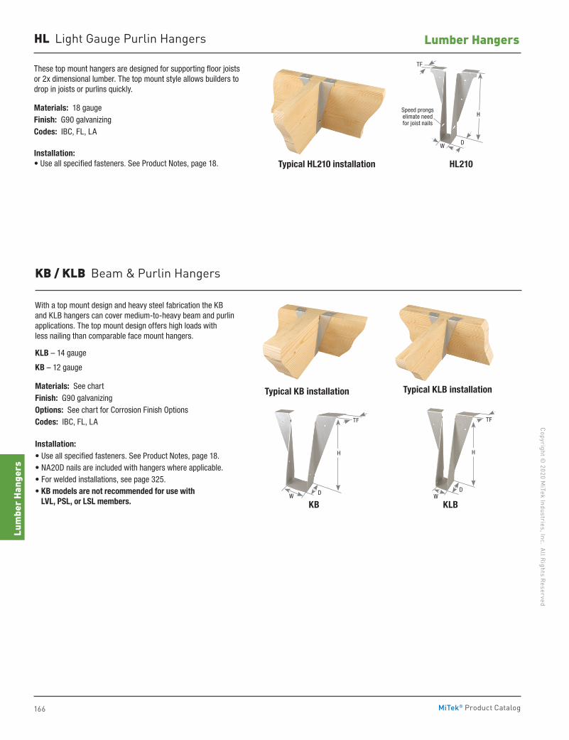
166
Copyright © 2020 M
iTek Industries, Inc. All Rights Reserved
Lumber Hangers
Lum
ber H
ange
rs
MiTek® Product Catalog
These top mount hangers are designed for supporting floor joists or 2x dimensional lumber. The top mount style allows builders to drop in joists or purlins quickly.
Materials: 18 gaugeFinish: G90 galvanizingCodes: IBC, FL, LA
Installation:• Use all specified fasteners. See Product Notes, page 18. HL210Typical HL210 installation
HL Light Gauge Purlin Hangers
DW
TF
Speed prongs elimate need for joist nails
H
KB / KLB Beam & Purlin Hangers
With a top mount design and heavy steel fabrication the KB and KLB hangers can cover medium-to-heavy beam and purlin applications. The top mount design offers high loads with less nailing than comparable face mount hangers.
KLB – 14 gauge
KB – 12 gauge
Materials: See chartFinish: G90 galvanizingOptions: See chart for Corrosion Finish OptionsCodes: IBC, FL, LA
Installation:• Use all specified fasteners. See Product Notes, page 18.• NA20D nails are included with hangers where applicable.• For welded installations, see page 325.• KB models are not recommended for use with
LVL, PSL, or LSL members. KB
Typical KLB installation
KLB
Typical KB installation
DW
TF
H H
DW
TF
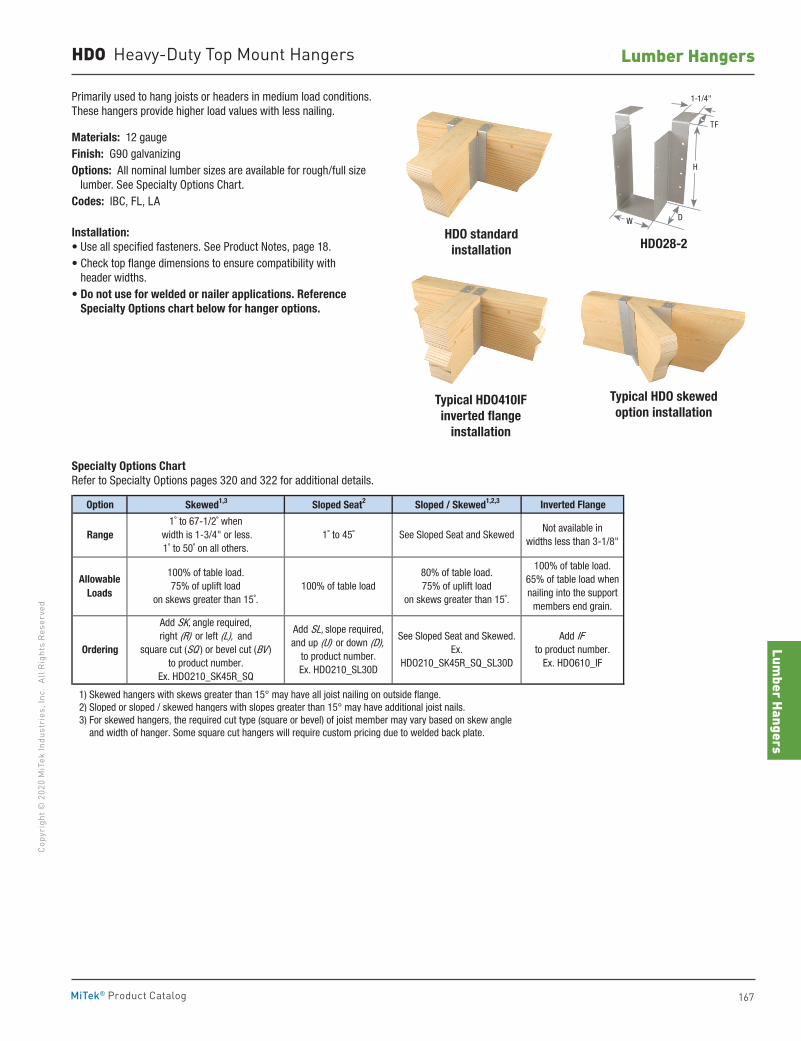
Lumber Hangers
167
Copy
righ
t © 2
020
MiT
ek In
dust
ries
, Inc
. Al
l Rig
hts
Rese
rved
Lumber Hangers
MiTek® Product Catalog
HDO28-2
Typical HDO skewed option installation
HDO standard installation
Typical HDO410IFinverted flange
installation
Primarily used to hang joists or headers in medium load conditions. These hangers provide higher load values with less nailing.
Materials: 12 gaugeFinish: G90 galvanizingOptions: All nominal lumber sizes are available for rough/full size lumber. See Specialty Options Chart.Codes: IBC, FL, LA
Installation:• Use all specified fasteners. See Product Notes, page 18.• Check top flange dimensions to ensure compatibility with
header widths.• Do not use for welded or nailer applications. Reference
Specialty Options chart below for hanger options.
HDO Heavy-Duty Top Mount Hangers
Option Skewed1,3 Sloped Seat2 Sloped / Skewed1,2,3 Inverted Flange
1) Skewed hangers with skews greater than 15° may have all joist nailing on outside flange. 2) Sloped or sloped / skewed hangers with slopes greater than 15° may have additional joist nails. 3) For skewed hangers, the required cut type (square or bevel) of joist member may vary based on skew angle and width of hanger. Some square cut hangers will require custom pricing due to welded back plate.
Not available inwidths less than 3-1/8"
Add IFto product number.
Ex. HDO610_IF
AllowableLoads
Ordering
100% of table load.75% of uplift load
on skews greater than 15˚.100% of table load
80% of table load.75% of uplift load
on skews greater than 15˚.
100% of table load.65% of table load whennailing into the support
members end grain.
Add SK, angle required,right (R) or left (L), and
square cut (SQ ) or bevel cut (BV )to product number.
Ex. HDO210_SK45R_SQ
1˚ to 67-1/2˚ when width is 1-3/4" or less.1˚ to 50˚ on all others.
1˚ to 45˚ See Sloped Seat and Skewed
See Sloped Seat and Skewed.Ex.
HDO210_SK45R_SQ_SL30D
Add SL, slope required,and up (U) or down (D),
to product number.Ex. HDO210_SL30D
Range
Specialty Options Chart Refer to Specialty Options pages 320 and 322 for additional details.
D
TF
1-1/4"
W
H
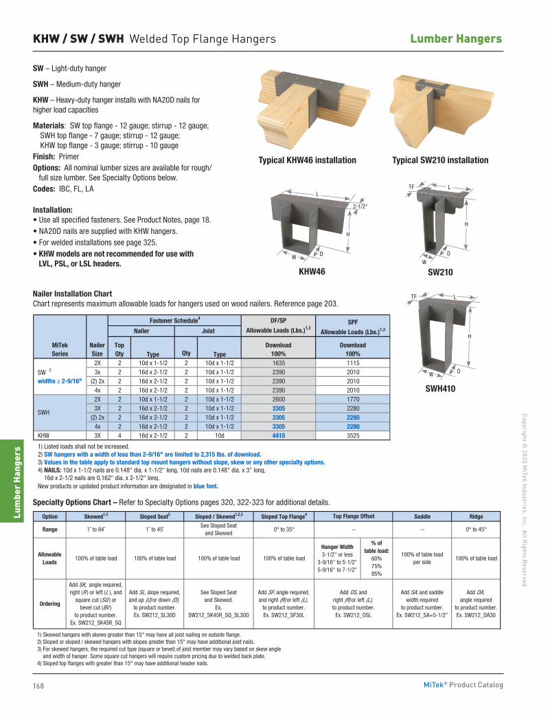
168
Copyright © 2020 M
iTek Industries, Inc. All Rights Reserved
Lumber Hangers
Lum
ber H
ange
rs
MiTek® Product Catalog
KHW / SW / SWH Welded Top Flange Hangers
SW – Light-duty hanger
SWH – Medium-duty hanger
KHW – Heavy-duty hanger installs with NA20D nails for higher load capacities
Materials: SW top flange - 12 gauge; stirrup - 12 gauge; SWH top flange - 7 gauge; stirrup - 12 gauge; KHW top flange - 3 gauge; stirrup - 10 gaugeFinish: PrimerOptions: All nominal lumber sizes are available for rough/ full size lumber. See Specialty Options below.Codes: IBC, FL, LA
Installation:• Use all specified fasteners. See Product Notes, page 18.• NA20D nails are supplied with KHW hangers.• For welded installations see page 325.• KHW models are not recommended for use with
LVL, PSL, or LSL headers.
Typical SW210 installationTypical KHW46 installation
SW210KHW46
SWH410
Nailer Installation Chart Chart represents maximum allowable loads for hangers used on wood nailers. Reference page 203.
Specialty Options Chart – Refer to Specialty Options pages 320, 322-323 for additional details.
Type Qty Type2X 2 10d x 1-1/2 2 10d x 1-1/2 1635 11153x 2 16d x 2-1/2 2 10d x 1-1/2 2390 2010
(2) 2x 2 16d x 2-1/2 2 10d x 1-1/2 2390 20104x 2 16d x 2-1/2 2 10d x 1-1/2 2390 20102X 2 10d x 1-1/2 2 10d x 1-1/2 2600 17703X 2 16d x 2-1/2 2 10d x 1-1/2 3305 2280
(2) 2x 2 16d x 2-1/2 2 10d x 1-1/2 3305 22804x 2 16d x 2-1/2 2 10d x 1-1/2 3305 2280
KHW 3X 4 16d x 2-1/2 2 10d 4415 3525
1) Listed loads shall not be increased. 2) SW hangers with a width of less than 2-9/16" are limited to 2,315 lbs. of download. 3) Values in the table apply to standard top mount hangers without slope, skew or any other specialty options. 4) NAILS: 10d x 1-1/2 nails are 0.148" dia. x 1-1/2" long, 10d nails are 0.148" dia. x 3" long, 16d x 2-1/2 nails are 0.162" dia. x 2-1/2" long. New products or updated product information are designated in blue font.
SWH
MiTekSeries
NailerSize
DF/SP
Allowable Loads (Lbs.)1,3SPF
Allowable Loads (Lbs.)1,3
Fastener Schedule4
Nailer Joist
SW 2
widths ≥ 2-9/16"
TopQty
Download100%
Download100%
Option Skewed1,3 Sloped Seat2 Sloped / Skewed1,2,3 Sloped Top Flange4 Saddle Ridge
1) Skewed hangers with skews greater than 15° may have all joist nailing on outside flange. 2) Sloped or sloped / skewed hangers with slopes greater than 15° may have additional joist nails. 3) For skewed hangers, the required cut type (square or bevel) of joist member may vary based on skew angle and width of hanger. Some square cut hangers will require custom pricing due to welded back plate. 4) Sloped top flanges with greater than 15° may have additional header nails.
Range
AllowableLoads
Ordering
1˚ to 84˚
100% of table load
See Sloped Seat and Skewed
Add SK, angle required,right (R ) or left (L ), and
square cut (SQ ) or bevel cut (BV )
to product number.Ex. SW212_SK45R_SQ
Add SL, slope required,and up (U) or down (D),
to product number.Ex. SW212_SL30D
See Sloped Seat and Skewed.
Ex. SW212_SK45R_SQ_SL30D
Add SF, angle required,and right (R) or left (L),
to product number.Ex. SW212_SF30L
100% of table load 100% of table load 100% of table load
1˚ to 45˚ 0° to 35°
Add DA, angle required
to product number.Ex. SW212_DA30
Top Flange Offset
Add OS, andright (R) or left (L),to product number.
Ex. SW212_OSL
% of table load:
60%75%85%
100% of table loadper side
Hanger Width3-1/2" or less
3-9/16" to 5-1/2"5-9/16" to 7-1/2"
100% of table load
0° to 45°----
Add SA, and saddlewidth required
to product number.Ex. SW212_SA=5-1/2"
D
H
2-1/2"
L
WD
H
W
LTF
D
TF L
H
W
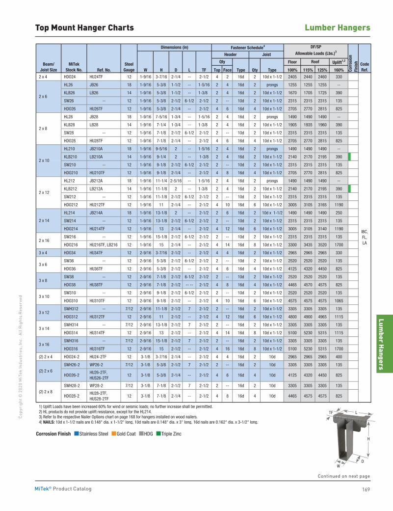
Lumber Hangers
169
Copy
righ
t © 2
020
MiT
ek In
dust
ries
, Inc
. Al
l Rig
hts
Rese
rved
Lumber Hangers
MiTek® Product Catalog
Top Mount Hanger Charts
Floor Uplift1,2
Ref. No. W H D L TF Top Face Type Qty Type 100% 115% 125% 160%
2 x 4 HDO24 HU24TF 12 1-9/16 3-7/16 2-1/4 -- 2-1/2 4 2 16d 2 10d x 1-1/2 2405 2440 2460 330
HL26 JB26 18 1-9/16 5-3/8 1-1/2 -- 1-5/16 2 4 16d 2 prongs 1255 1255 1255 --
KLB26 LB26 14 1-9/16 5-3/8 1-1/2 -- 1-3/8 2 4 16d 2 10d x 1-1/2 1670 1705 1725 390
SW26 -- 12 1-9/16 5-3/8 2-1/2 6-1/2 2-1/2 2 -- 10d 2 10d x 1-1/2 2315 2315 2315 135
HDO26 HU26TF 12 1-9/16 5-3/8 2-1/4 -- 2-1/2 4 6 16d 4 10d x 1-1/2 2705 2770 2815 825
HL28 JB28 18 1-9/16 7-5/16 1-3/4 -- 1-5/16 2 4 16d 2 prongs 1490 1490 1490 --
KLB28 LB28 14 1-9/16 7-1/4 1-3/4 -- 1-3/8 2 4 16d 2 10d x 1-1/2 1905 1935 1960 390
SW28 -- 12 1-9/16 7-1/8 2-1/2 6-1/2 2-1/2 2 -- 10d 2 10d x 1-1/2 2315 2315 2315 135
HDO28 HU28TF 12 1-9/16 7-1/8 2-1/4 -- 2-1/2 4 6 16d 4 10d x 1-1/2 2705 2770 2815 825
HL210 JB210A 18 1-9/16 9-5/16 2 -- 1-5/16 2 4 16d 2 prongs 1490 1490 1490 --
KLB210 LB210A 14 1-9/16 9-1/4 2 -- 1-3/8 2 4 16d 2 10d x 1-1/2 2140 2170 2195 390
SW210 -- 12 1-9/16 9-1/8 2-1/2 6-1/2 2-1/2 2 -- 10d 2 10d x 1-1/2 2315 2315 2315 135
HDO210 HU210TF 12 1-9/16 9-1/8 2-1/4 -- 2-1/2 4 8 16d 4 10d x 1-1/2 2705 2770 2815 825
HL212 JB212A 18 1-9/16 11-1/4 2-5/16 -- 1-5/16 2 4 16d 2 prongs 1490 1490 1490 --
KLB212 LB212A 14 1-9/16 11-1/8 2 -- 1-3/8 2 4 16d 2 10d x 1-1/2 2140 2170 2195 390
SW212 -- 12 1-9/16 11-1/8 2-1/2 6-1/2 2-1/2 2 -- 10d 2 10d x 1-1/2 2315 2315 2315 135
HDO212 HU212TF 12 1-9/16 11 2-1/4 -- 2-1/2 4 10 16d 6 10d x 1-1/2 3005 3105 3165 1190
HL214 JB214A 18 1-9/16 13-1/8 2 -- 2-1/2 2 6 16d 2 10d x 1-1/2 1490 1490 1490 250
SW214 -- 12 1-9/16 13-1/8 2-1/2 6-1/2 2-1/2 2 -- 10d 2 10d x 1-1/2 2315 2315 2315 135
HDO214 HU214TF 12 1-9/16 13 2-1/4 -- 2-1/2 4 12 16d 6 10d x 1-1/2 3005 3105 3140 1190
SW216 -- 12 1-9/16 15-1/8 2-1/2 6-1/2 2-1/2 2 -- 10d 2 10d x 1-1/2 2315 2315 2315 135
HDO216 HU216TF, LB216 12 1-9/16 15 2-1/4 -- 2-1/2 4 14 16d 8 10d x 1-1/2 3300 3435 3520 1700
3 x 4 HDO34 HU34TF 12 2-9/16 3-7/16 2-1/2 -- 2-1/2 4 4 16d 2 10d x 1-1/2 2965 2965 2965 330
SW36 -- 12 2-9/16 5-3/8 2-1/2 6-1/2 2-1/2 2 -- 10d 2 10d x 1-1/2 2520 2520 2520 135
HDO36 HU36TF 12 2-9/16 5-3/8 2-1/2 -- 2-1/2 4 6 16d 4 10d x 1-1/2 4125 4320 4450 825
SW38 -- 12 2-9/16 7-1/8 2-1/2 6-1/2 2-1/2 2 -- 10d 2 10d x 1-1/2 2520 2520 2520 135
HDO38 HU38TF 12 2-9/16 7-1/8 2-1/2 -- -- 2-1/2 4 8 16d 4 10d x 1-1/2 4465 4570 4575 825
SW310 -- 12 2-9/16 9-1/8 2-1/2 6-1/2 2-1/2 2 -- 10d 2 10d x 1-1/2 2520 2520 2520 135
HDO310 HU310TF 12 2-9/16 9-1/8 2-1/2 -- 2-1/2 4 10 16d 6 10d x 1-1/2 4575 4575 4575 1065
SWH312 -- 7/12 2-9/16 11-1/8 2-1/2 7 2-1/2 2 -- 16d 2 10d x 1-1/2 3305 3305 3305 135
HDO312 HU312TF 12 2-9/16 11 2-1/2 -- 2-1/2 4 12 16d 6 10d x 1-1/2 4800 4900 4965 1115
SWH314 -- 7/12 2-9/16 13-1/8 2-1/2 7 2-1/2 2 -- 16d 2 10d x 1-1/2 3305 3305 3305 135
HDO314 HU314TF 12 2-9/16 13 2-1/2 -- 2-1/2 4 14 16d 8 10d x 1-1/2 5100 5230 5315 1115
SWH316 -- 7/12 2-9/16 15-1/8 2-1/2 7 2-1/2 2 -- 16d 2 10d x 1-1/2 3305 3305 3305 135
HDO316 HU316TF 12 2-9/16 15 2-1/2 -- 2-1/2 4 16 16d 8 10d x 1-1/2 5100 5230 5315 1700
(2) 2 x 4 HDO24-2 HU24-2TF 12 3-1/8 3-7/16 2-1/4 -- 2-1/2 4 4 16d 2 10d 2965 2965 2965 400
SWH26-2 WP26-2 7/12 3-1/8 5-3/8 2-1/2 7 2-1/2 2 -- 16d 2 10d 3305 3305 3305 135
HDO26-2 HU26-2TF, HUS26-2TF
12 3-1/8 5-3/8 2-1/4 -- 2-1/2 4 6 16d 4 10d 4125 4320 4450 825
SWH28-2 WP28-2 7/12 3-1/8 7-1/8 2-1/2 7 2-1/2 2 -- 16d 2 10d 3305 3305 3305 135
HDO28-2 HU28-2TF, HUS28-2TF
12 3-1/8 7-1/8 2-1/4 -- 2-1/2 4 8 16d 4 10d 4465 4575 4575 825
1) Uplift Loads have been increased 60% for wind or seismic loads; no further increase shall be permitted. 2) HL products do not provide uplift resistance, except for the HL214. 3) Refer to the respective Nailer Options chart on page 168 for hangers installed on wood nailers. 4) NAILS: 10d x 1-1/2 nails are 0.148" dia. x 1-1/2" long, 10d nails are 0.148" dia. x 3" long, 16d nails are 0.162" dia. x 3-1/2" long.
IBC,FL,LA
CodeRef.
2 x 8
RoofMiTekStock No.
(2) 2 x 6
(2) 2 x 8
2 x 14
2 x 16
3 x 6
3 x 8
3 x 10
3 x 12
3 x 14
3 x 16Co
rros
ion
Fini
sh
DF/SPAllowable Loads (Lbs.)3
2 x 10
2 x 12
2 x 6
Dimensions (in) Fastener Schedule4
Header Joist
Beam/Joist Size
SteelGauge
Qty
Continued on next page
D
H
W
LTF
Corrosion Finish Stainless Steel Gold Coat HDG Triple Zinc
Corrosion Finish Stainless Steel Gold Coat HDG Triple Zinc
Corrosion Finish Stainless Steel Gold Coat HDG Triple Zinc
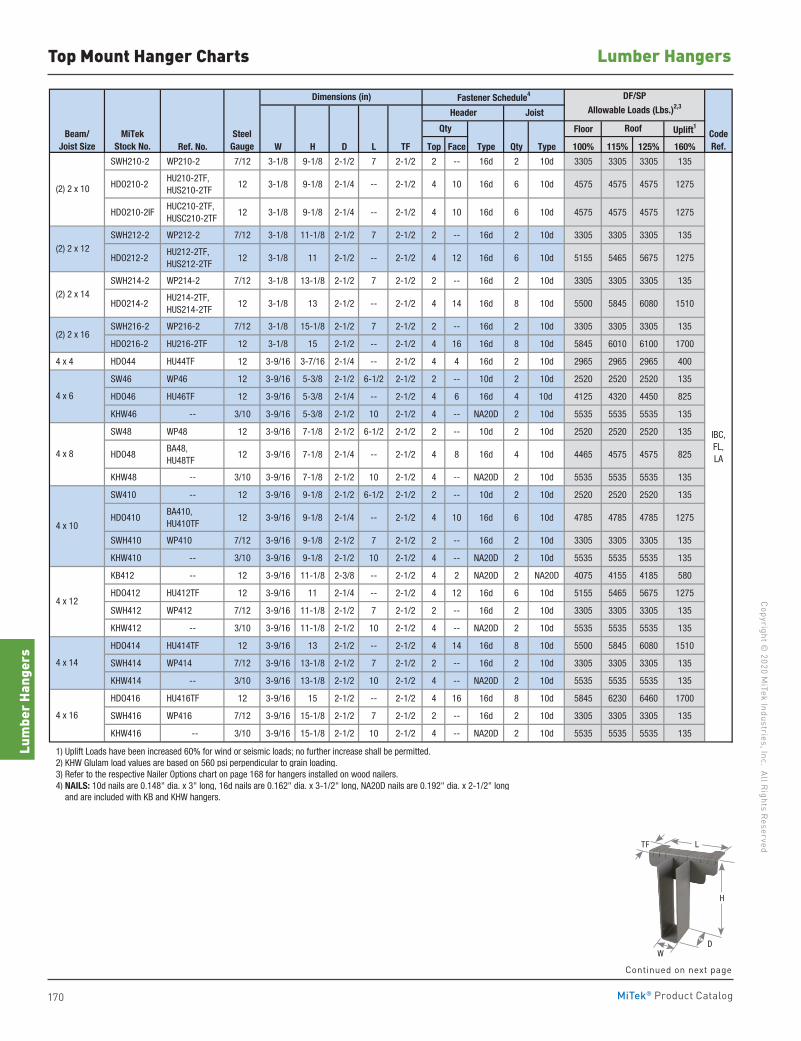
170
Copyright © 2020 M
iTek Industries, Inc. All Rights Reserved
Lumber Hangers
Lum
ber H
ange
rs
MiTek® Product Catalog
Top Mount Hanger Charts
Floor Uplift1
Ref. No. W H D L TF Top Face Type Qty Type 100% 115% 125% 160%
SWH210-2 WP210-2 7/12 3-1/8 9-1/8 2-1/2 7 2-1/2 2 -- 16d 2 10d 3305 3305 3305 135
HDO210-2 HU210-2TF, HUS210-2TF
12 3-1/8 9-1/8 2-1/4 -- 2-1/2 4 10 16d 6 10d 4575 4575 4575 1275
HDO210-2IF HUC210-2TF, HUSC210-2TF
12 3-1/8 9-1/8 2-1/4 -- 2-1/2 4 10 16d 6 10d 4575 4575 4575 1275
SWH212-2 WP212-2 7/12 3-1/8 11-1/8 2-1/2 7 2-1/2 2 -- 16d 2 10d 3305 3305 3305 135
HDO212-2 HU212-2TF, HUS212-2TF
12 3-1/8 11 2-1/2 -- 2-1/2 4 12 16d 6 10d 5155 5465 5675 1275
SWH214-2 WP214-2 7/12 3-1/8 13-1/8 2-1/2 7 2-1/2 2 -- 16d 2 10d 3305 3305 3305 135
HDO214-2 HU214-2TF, HUS214-2TF
12 3-1/8 13 2-1/2 -- 2-1/2 4 14 16d 8 10d 5500 5845 6080 1510
SWH216-2 WP216-2 7/12 3-1/8 15-1/8 2-1/2 7 2-1/2 2 -- 16d 2 10d 3305 3305 3305 135
HDO216-2 HU216-2TF 12 3-1/8 15 2-1/2 -- 2-1/2 4 16 16d 8 10d 5845 6010 6100 1700
4 x 4 HDO44 HU44TF 12 3-9/16 3-7/16 2-1/4 -- 2-1/2 4 4 16d 2 10d 2965 2965 2965 400
SW46 WP46 12 3-9/16 5-3/8 2-1/2 6-1/2 2-1/2 2 -- 10d 2 10d 2520 2520 2520 135
HDO46 HU46TF 12 3-9/16 5-3/8 2-1/4 -- 2-1/2 4 6 16d 4 10d 4125 4320 4450 825
KHW46 -- 3/10 3-9/16 5-3/8 2-1/2 10 2-1/2 4 -- NA20D 2 10d 5535 5535 5535 135
SW48 WP48 12 3-9/16 7-1/8 2-1/2 6-1/2 2-1/2 2 -- 10d 2 10d 2520 2520 2520 135
HDO48 BA48, HU48TF
12 3-9/16 7-1/8 2-1/4 -- 2-1/2 4 8 16d 4 10d 4465 4575 4575 825
KHW48 -- 3/10 3-9/16 7-1/8 2-1/2 10 2-1/2 4 -- NA20D 2 10d 5535 5535 5535 135
SW410 -- 12 3-9/16 9-1/8 2-1/2 6-1/2 2-1/2 2 -- 10d 2 10d 2520 2520 2520 135
HDO410 BA410, HU410TF
12 3-9/16 9-1/8 2-1/4 -- 2-1/2 4 10 16d 6 10d 4785 4785 4785 1275
SWH410 WP410 7/12 3-9/16 9-1/8 2-1/2 7 2-1/2 2 -- 16d 2 10d 3305 3305 3305 135
KHW410 -- 3/10 3-9/16 9-1/8 2-1/2 10 2-1/2 4 -- NA20D 2 10d 5535 5535 5535 135
KB412 -- 12 3-9/16 11-1/8 2-3/8 -- 2-1/2 4 2 NA20D 2 NA20D 4075 4155 4185 580
HDO412 HU412TF 12 3-9/16 11 2-1/4 -- 2-1/2 4 12 16d 6 10d 5155 5465 5675 1275
SWH412 WP412 7/12 3-9/16 11-1/8 2-1/2 7 2-1/2 2 -- 16d 2 10d 3305 3305 3305 135
KHW412 -- 3/10 3-9/16 11-1/8 2-1/2 10 2-1/2 4 -- NA20D 2 10d 5535 5535 5535 135
HDO414 HU414TF 12 3-9/16 13 2-1/2 -- 2-1/2 4 14 16d 8 10d 5500 5845 6080 1510
SWH414 WP414 7/12 3-9/16 13-1/8 2-1/2 7 2-1/2 2 -- 16d 2 10d 3305 3305 3305 135
KHW414 -- 3/10 3-9/16 13-1/8 2-1/2 10 2-1/2 4 -- NA20D 2 10d 5535 5535 5535 135
HDO416 HU416TF 12 3-9/16 15 2-1/2 -- 2-1/2 4 16 16d 8 10d 5845 6230 6460 1700
SWH416 WP416 7/12 3-9/16 15-1/8 2-1/2 7 2-1/2 2 -- 16d 2 10d 3305 3305 3305 135
KHW416 -- 3/10 3-9/16 15-1/8 2-1/2 10 2-1/2 4 -- NA20D 2 10d 5535 5535 5535 135
1) Uplift Loads have been increased 60% for wind or seismic loads; no further increase shall be permitted. 2) KHW Glulam load values are based on 560 psi perpendicular to grain loading. 3) Refer to the respective Nailer Options chart on page 168 for hangers installed on wood nailers. 4) NAILS: 10d nails are 0.148" dia. x 3" long, 16d nails are 0.162" dia. x 3-1/2" long, NA20D nails are 0.192" dia. x 2-1/2" long and are included with KB and KHW hangers.
(2) 2 x 10
Dimensions (in) Fastener Schedule4 DF/SP
Allowable Loads (Lbs.)2,3Header Joist
4 x 6
IBC,FL,LA
Beam/Joist Size
MiTekStock No.
SteelGauge
Qty Roof CodeRef.
4 x 8
4 x 10
4 x 12
4 x 14
4 x 16
(2) 2 x 14
(2) 2 x 16
(2) 2 x 12
Continued on next page
D
H
W
LTF
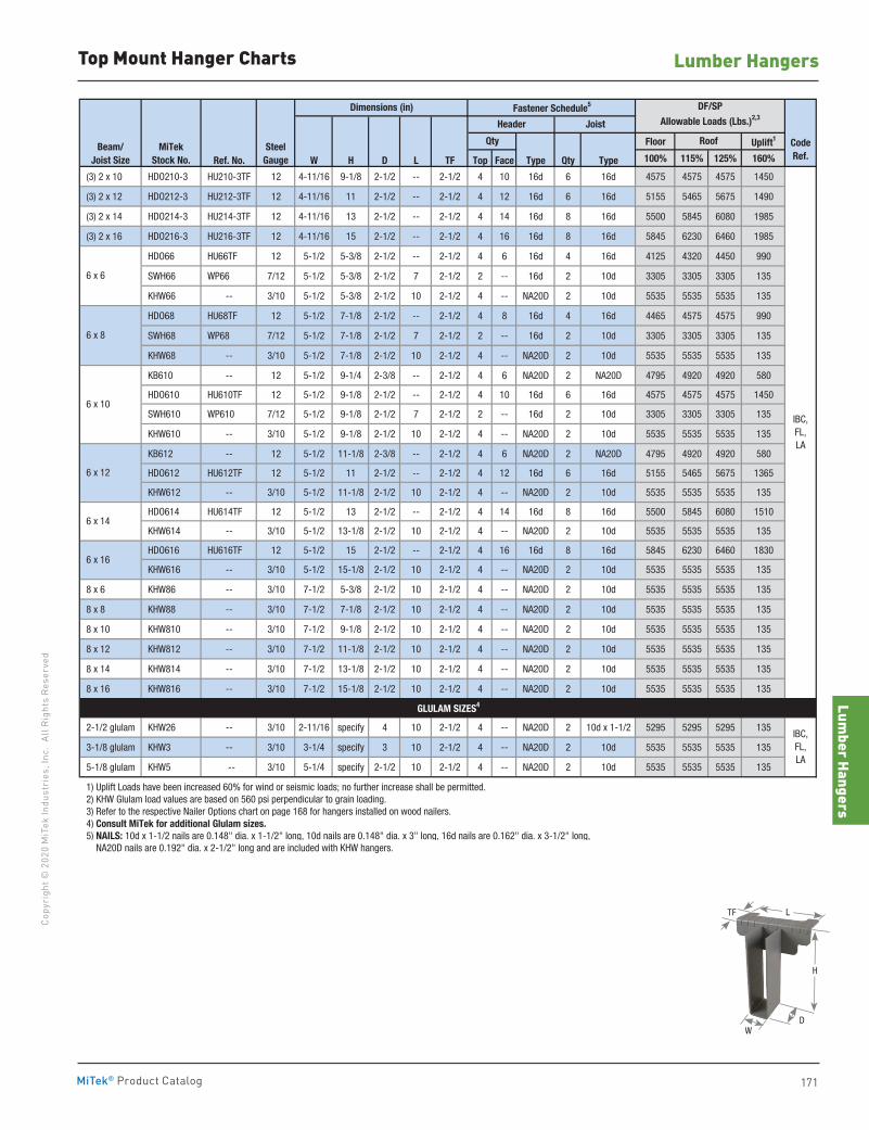
Lumber Hangers
171
Copy
righ
t © 2
020
MiT
ek In
dust
ries
, Inc
. Al
l Rig
hts
Rese
rved
Lumber Hangers
MiTek® Product Catalog
Top Mount Hanger Charts
Floor Uplift1
Ref. No. W H D L TF Top Face Type Qty Type 100% 115% 125% 160%
(3) 2 x 10 HDO210-3 HU210-3TF 12 4-11/16 9-1/8 2-1/2 -- 2-1/2 4 10 16d 6 16d 4575 4575 4575 1450
(3) 2 x 12 HDO212-3 HU212-3TF 12 4-11/16 11 2-1/2 -- 2-1/2 4 12 16d 6 16d 5155 5465 5675 1490
(3) 2 x 14 HDO214-3 HU214-3TF 12 4-11/16 13 2-1/2 -- 2-1/2 4 14 16d 8 16d 5500 5845 6080 1985
(3) 2 x 16 HDO216-3 HU216-3TF 12 4-11/16 15 2-1/2 -- 2-1/2 4 16 16d 8 16d 5845 6230 6460 1985
HDO66 HU66TF 12 5-1/2 5-3/8 2-1/2 -- 2-1/2 4 6 16d 4 16d 4125 4320 4450 990
SWH66 WP66 7/12 5-1/2 5-3/8 2-1/2 7 2-1/2 2 -- 16d 2 10d 3305 3305 3305 135
KHW66 -- 3/10 5-1/2 5-3/8 2-1/2 10 2-1/2 4 -- NA20D 2 10d 5535 5535 5535 135
HDO68 HU68TF 12 5-1/2 7-1/8 2-1/2 -- 2-1/2 4 8 16d 4 16d 4465 4575 4575 990
SWH68 WP68 7/12 5-1/2 7-1/8 2-1/2 7 2-1/2 2 -- 16d 2 10d 3305 3305 3305 135
KHW68 -- 3/10 5-1/2 7-1/8 2-1/2 10 2-1/2 4 -- NA20D 2 10d 5535 5535 5535 135
KB610 -- 12 5-1/2 9-1/4 2-3/8 -- 2-1/2 4 6 NA20D 2 NA20D 4795 4920 4920 580
HDO610 HU610TF 12 5-1/2 9-1/8 2-1/2 -- 2-1/2 4 10 16d 6 16d 4575 4575 4575 1450
SWH610 WP610 7/12 5-1/2 9-1/8 2-1/2 7 2-1/2 2 -- 16d 2 10d 3305 3305 3305 135
KHW610 -- 3/10 5-1/2 9-1/8 2-1/2 10 2-1/2 4 -- NA20D 2 10d 5535 5535 5535 135
KB612 -- 12 5-1/2 11-1/8 2-3/8 -- 2-1/2 4 6 NA20D 2 NA20D 4795 4920 4920 580
HDO612 HU612TF 12 5-1/2 11 2-1/2 -- 2-1/2 4 12 16d 6 16d 5155 5465 5675 1365
KHW612 -- 3/10 5-1/2 11-1/8 2-1/2 10 2-1/2 4 -- NA20D 2 10d 5535 5535 5535 135
HDO614 HU614TF 12 5-1/2 13 2-1/2 -- 2-1/2 4 14 16d 8 16d 5500 5845 6080 1510
KHW614 -- 3/10 5-1/2 13-1/8 2-1/2 10 2-1/2 4 -- NA20D 2 10d 5535 5535 5535 135
HDO616 HU616TF 12 5-1/2 15 2-1/2 -- 2-1/2 4 16 16d 8 16d 5845 6230 6460 1830
KHW616 -- 3/10 5-1/2 15-1/8 2-1/2 10 2-1/2 4 -- NA20D 2 10d 5535 5535 5535 135
8 x 6 KHW86 -- 3/10 7-1/2 5-3/8 2-1/2 10 2-1/2 4 -- NA20D 2 10d 5535 5535 5535 135
8 x 8 KHW88 -- 3/10 7-1/2 7-1/8 2-1/2 10 2-1/2 4 -- NA20D 2 10d 5535 5535 5535 135
8 x 10 KHW810 -- 3/10 7-1/2 9-1/8 2-1/2 10 2-1/2 4 -- NA20D 2 10d 5535 5535 5535 135
8 x 12 KHW812 -- 3/10 7-1/2 11-1/8 2-1/2 10 2-1/2 4 -- NA20D 2 10d 5535 5535 5535 135
8 x 14 KHW814 -- 3/10 7-1/2 13-1/8 2-1/2 10 2-1/2 4 -- NA20D 2 10d 5535 5535 5535 135
8 x 16 KHW816 -- 3/10 7-1/2 15-1/8 2-1/2 10 2-1/2 4 -- NA20D 2 10d 5535 5535 5535 135
2-1/2 glulam KHW26 -- 3/10 2-11/16 specify 4 10 2-1/2 4 -- NA20D 2 10d x 1-1/2 5295 5295 5295 135
3-1/8 glulam KHW3 -- 3/10 3-1/4 specify 3 10 2-1/2 4 -- NA20D 2 10d 5535 5535 5535 135
5-1/8 glulam KHW5 -- 3/10 5-1/4 specify 2-1/2 10 2-1/2 4 -- NA20D 2 10d 5535 5535 5535 135
1) Uplift Loads have been increased 60% for wind or seismic loads; no further increase shall be permitted. 2) KHW Glulam load values are based on 560 psi perpendicular to grain loading. 3) Refer to the respective Nailer Options chart on page 168 for hangers installed on wood nailers. 4) Consult MiTek for additional Glulam sizes. 5) NAILS: 10d x 1-1/2 nails are 0.148" dia. x 1-1/2" long, 10d nails are 0.148" dia. x 3" long, 16d nails are 0.162" dia. x 3-1/2" long, NA20D nails are 0.192" dia. x 2-1/2" long and are included with KHW hangers.
IBC,FL,LA
Dimensions (in) Fastener Schedule5 DF/SP
Allowable Loads (Lbs.)2,3Header Joist
Qty Roof
6 x 6
6 x 8
IBC,FL,LA
CodeRef.
GLULAM SIZES4
Beam/Joist Size
MiTekStock No.
SteelGauge
6 x 10
6 x 12
6 x 14
6 x 16
D
H
W
LTF
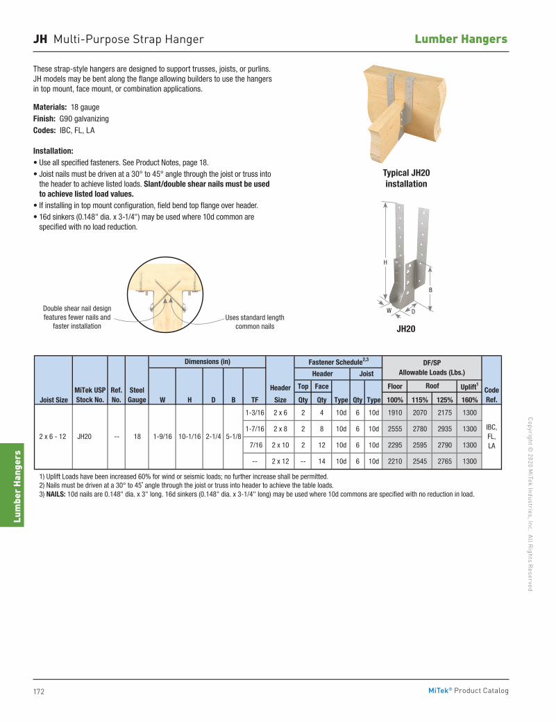
172
Copyright © 2020 M
iTek Industries, Inc. All Rights Reserved
Lumber Hangers
Lum
ber H
ange
rs
MiTek® Product Catalog
JH Multi-Purpose Strap Hanger
These strap-style hangers are designed to support trusses, joists, or purlins. JH models may be bent along the flange allowing builders to use the hangers in top mount, face mount, or combination applications.
Materials: 18 gaugeFinish: G90 galvanizingCodes: IBC, FL, LA
Installation:• Use all specified fasteners. See Product Notes, page 18.• Joist nails must be driven at a 30° to 45° angle through the joist or truss into
the header to achieve listed loads. Slant/double shear nails must be used to achieve listed load values.
• If installing in top mount configuration, field bend top flange over header.• 16d sinkers (0.148" dia. x 3-1/4") may be used where 10d common are
specified with no load reduction.
Header Top Face Floor Uplift1
Joist Size W H D B TF Size Qty Qty Type Qty Type 100% 115% 125% 160%
1-3/16 2 x 6 2 4 10d 6 10d 1910 2070 2175 1300
1-7/16 2 x 8 2 8 10d 6 10d 2555 2780 2935 1300
7/16 2 x 10 2 12 10d 6 10d 2295 2595 2790 1300
-- 2 x 12 -- 14 10d 6 10d 2210 2545 2765 1300
1) Uplift Loads have been increased 60% for wind or seismic loads; no further increase shall be permitted. 2) Nails must be driven at a 30° to 45˚ angle through the joist or truss into header to achieve the table loads. 3) NAILS: 10d nails are 0.148" dia. x 3" long. 16d sinkers (0.148" dia. x 3-1/4" long) may be used where 10d commons are specified with no reduction in load.
CodeRef.
IBC, FL, LA
2 x 6 - 12 JH20 -- 18
Roof
1-9/16 10-1/16 5-1/82-1/4
MiTek USPStock No.
SteelGauge
Ref.No.
Fastener Schedule2,3
JoistHeader
Dimensions (in) DF/SPAllowable Loads (Lbs.)
Double shear nail designfeatures fewer nails and
faster installationUses standard length
common nails
Typical JH20 installation
JH20
H
DW
B
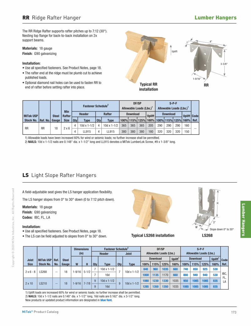
Lumber Hangers
173
Copy
righ
t © 2
020
MiT
ek In
dust
ries
, Inc
. Al
l Rig
hts
Rese
rved
Lumber Hangers
MiTek® Product Catalog
RR Ridge Rafter Hanger
The RR Ridge Rafter supports rafter pitches up to 7:12 (30°). Nesting top flange for back-to-back installation on 2x support beams.
Materials: 18 gaugeFinish: G90 galvanizing
Installation:• Use all specified fasteners. See Product Notes, page 18.• The rafter end at the ridge must be plumb cut to achieve
published loads.• Optional diamond nail holes can be used to fasten RR to
end of rafter before setting rafter into place.Typical RRinstallation
RR
Ref. No. Qty Type Qty Type 100% 115% 125% 100% 115% 125%
4 10d x 1-1/2 4 10d x 1-1/2 365 365 365 205 290 290 290 160
4 LL915 4 LL915 380 380 380 180 320 320 320 150
1) Allowable loads have been increased 60% for wind or seismic loads; no further increase shall be permitted. 2) NAILS: 10d x 1-1/2 nails are 0.148" dia. x 1-1/2" long and LL915 denotes a MiTek LumberLok Screw, #9 x 1-3/8" long.
CodeRef.
--
MinRafterSize
Download DownloadUplift160%
Uplift160%
DF/SP
Allowable Loads (Lbs.)1
S-P-F
Allowable Loads (Lbs.)1Fastener Schedule2
Header Rafter
RR RR 18 2 x 6
MiTek USPStock No.
SteelGauge
Uplift
1-9/16"
1" 4"
3-3/8"
Typical LS268 installation LS268
A field-adjustable seat gives the LS hanger application flexibility.
The LS hanger slopes from 0° to 30° down (0 to 7:12 pitch down).
Materials: 18 gaugeFinish: G90 galvanizingCodes: IBC, FL, LA
Installation:• Use all specified fasteners. See Product Notes, page 18.• The LS can be field adjusted to slopes from 0° to 30° down.
LS Light Slope Rafter Hangers
Uplift1 Uplift1
W H Qty Type Qty Type 100% 115% 125% 160% 100% 115% 125% 160%
7 10d x 1-1/2 840 960 1035 660 740 850 925 530
7 16d 1000 1135 1170 660 880 940 940 530
9 10d x 1-1/2 1080 1230 1330 1035 950 1085 1085 835
9 16d 1285 1350 1350 1035 1085 1085 1085 835
1) Uplift loads are increased 60% for wind or seismic loads; no further increase shall be permitted. 2) NAILS: 10d x 1-1/2 nails are 0.148" dia. x 1-1/2" long, 16d nails are 0.162" dia. x 3-1/2" long. New products or updated product information are designated in blue font.
S-P-FAllowable Loads (Lbs.)
Download
DF/SPAllowable Loads (Lbs.)
Dimensions(in)
1-9/16 7-7/8
Header JoistFastener Schedule2
Download
10d x 1-1/27
9 10d x 1-1/2
CodeRef.
IBC,FL,LA
Joist Size
MiTek USPStock No.
SteelGauge
2 x 6 - 8 LS268 -- 18 1-9/16 5-1/2
2 x 10 LS210 -- 18
Ref.No.
W
3"
Slope down 0° to 30°
H
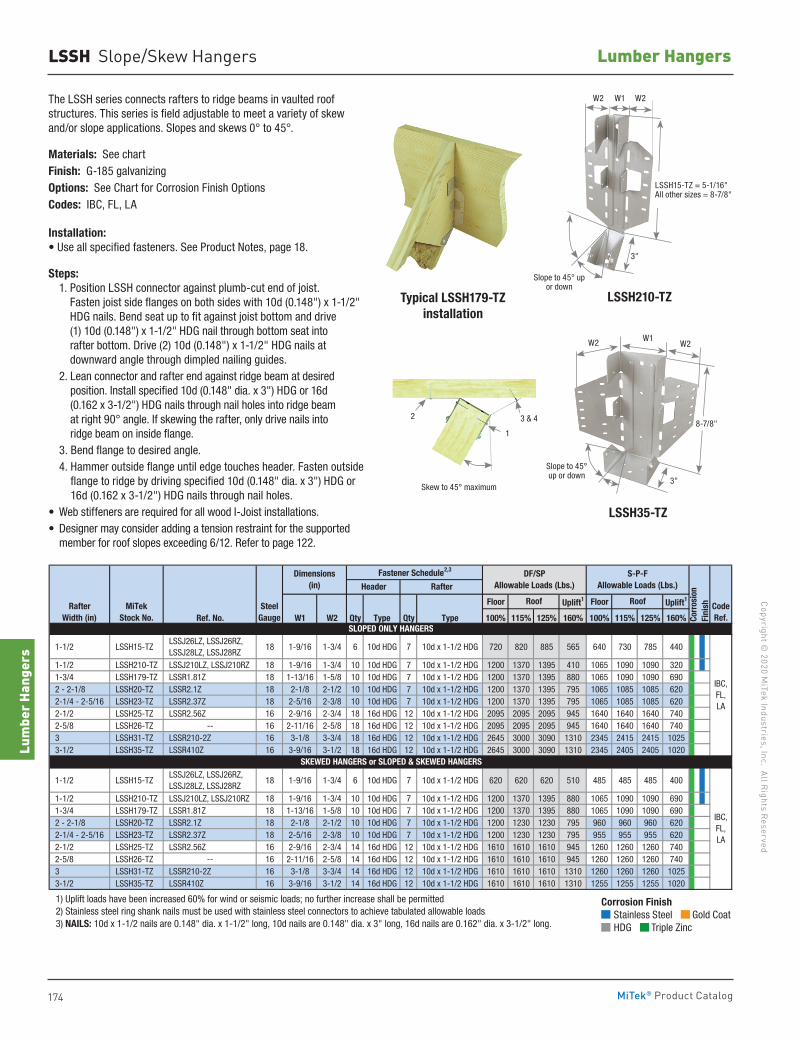
174
Copyright © 2020 M
iTek Industries, Inc. All Rights Reserved
Lumber Hangers
Lum
ber H
ange
rs
MiTek® Product Catalog
LSSH Slope/Skew Hangers
Typical LSSH179-TZinstallation
LSSH35-TZ
The LSSH series connects rafters to ridge beams in vaulted roof structures. This series is field adjustable to meet a variety of skew and/or slope applications. Slopes and skews 0° to 45°.
Materials: See chartFinish: G-185 galvanizingOptions: See Chart for Corrosion Finish OptionsCodes: IBC, FL, LA
Installation:• Use all specified fasteners. See Product Notes, page 18.
Steps: 1. Position LSSH connector against plumb-cut end of joist.
Fasten joist side flanges on both sides with 10d (0.148") x 1-1/2" HDG nails. Bend seat up to fit against joist bottom and drive (1) 10d (0.148") x 1-1/2" HDG nail through bottom seat into rafter bottom. Drive (2) 10d (0.148") x 1-1/2" HDG nails at downward angle through dimpled nailing guides.
2. Lean connector and rafter end against ridge beam at desired position. Install specified 10d (0.148" dia. x 3") HDG or 16d (0.162 x 3-1/2") HDG nails through nail holes into ridge beam at right 90° angle. If skewing the rafter, only drive nails into ridge beam on inside flange.
3. Bend flange to desired angle. 4. Hammer outside flange until edge touches header. Fasten outside
flange to ridge by driving specified 10d (0.148" dia. x 3") HDG or 16d (0.162 x 3-1/2") HDG nails through nail holes.
• Web stiffeners are required for all wood I-Joist installations.• Designer may consider adding a tension restraint for the supported
member for roof slopes exceeding 6/12. Refer to page 122.
Skew to 45° maximum
2 3 & 4
1
LSSH15-TZ = 5-1/16" All other sizes = 8-7/8"
W2 W1 W2
3"
Slope to 45° up or down
LSSH210-TZ
W2 W1W2
3"
Slope to 45° up or down
8-7/8"
Floor Uplift1 Floor Uplift1
Ref. No. W1 W2 Qty Type Qty Type 100% 115% 125% 160% 100% 115% 125% 160%
1-1/2 LSSH15-TZ LSSJ26LZ, LSSJ26RZ, LSSJ28LZ, LSSJ28RZ
18 1-9/16 1-3/4 6 10d HDG 7 10d x 1-1/2 HDG 720 820 885 565 640 730 785 440
1-1/2 LSSH210-TZ LSSJ210LZ, LSSJ210RZ 18 1-9/16 1-3/4 10 10d HDG 7 10d x 1-1/2 HDG 1200 1370 1395 410 1065 1090 1090 320 1-3/4 LSSH179-TZ LSSR1.81Z 18 1-13/16 1-5/8 10 10d HDG 7 10d x 1-1/2 HDG 1200 1370 1395 880 1065 1090 1090 690 2 - 2-1/8 LSSH20-TZ LSSR2.1Z 18 2-1/8 2-1/2 10 10d HDG 7 10d x 1-1/2 HDG 1200 1370 1395 795 1065 1085 1085 620 2-1/4 - 2-5/16 LSSH23-TZ LSSR2.37Z 18 2-5/16 2-3/8 10 10d HDG 7 10d x 1-1/2 HDG 1200 1370 1395 795 1065 1085 1085 620 2-1/2 LSSH25-TZ LSSR2.56Z 16 2-9/16 2-3/4 18 16d HDG 12 10d x 1-1/2 HDG 2095 2095 2095 945 1640 1640 1640 740 2-5/8 LSSH26-TZ -- 16 2-11/16 2-5/8 18 16d HDG 12 10d x 1-1/2 HDG 2095 2095 2095 945 1640 1640 1640 740 3 LSSH31-TZ LSSR210-2Z 16 3-1/8 3-3/4 18 16d HDG 12 10d x 1-1/2 HDG 2645 3000 3090 1310 2345 2415 2415 1025 3-1/2 LSSH35-TZ LSSR410Z 16 3-9/16 3-1/2 18 16d HDG 12 10d x 1-1/2 HDG 2645 3000 3090 1310 2345 2405 2405 1020
1-1/2 LSSH15-TZ LSSJ26LZ, LSSJ26RZ, LSSJ28LZ, LSSJ28RZ
18 1-9/16 1-3/4 6 10d HDG 7 10d x 1-1/2 HDG 620 620 620 510 485 485 485 400
1-1/2 LSSH210-TZ LSSJ210LZ, LSSJ210RZ 18 1-9/16 1-3/4 10 10d HDG 7 10d x 1-1/2 HDG 1200 1370 1395 880 1065 1090 1090 690 1-3/4 LSSH179-TZ LSSR1.81Z 18 1-13/16 1-5/8 10 10d HDG 7 10d x 1-1/2 HDG 1200 1370 1395 880 1065 1090 1090 690 2 - 2-1/8 LSSH20-TZ LSSR2.1Z 18 2-1/8 2-1/2 10 10d HDG 7 10d x 1-1/2 HDG 1200 1230 1230 795 960 960 960 620 2-1/4 - 2-5/16 LSSH23-TZ LSSR2.37Z 18 2-5/16 2-3/8 10 10d HDG 7 10d x 1-1/2 HDG 1200 1230 1230 795 955 955 955 620 2-1/2 LSSH25-TZ LSSR2.56Z 16 2-9/16 2-3/4 14 16d HDG 12 10d x 1-1/2 HDG 1610 1610 1610 945 1260 1260 1260 740 2-5/8 LSSH26-TZ -- 16 2-11/16 2-5/8 14 16d HDG 12 10d x 1-1/2 HDG 1610 1610 1610 945 1260 1260 1260 740 3 LSSH31-TZ LSSR210-2Z 16 3-1/8 3-3/4 14 16d HDG 12 10d x 1-1/2 HDG 1610 1610 1610 1310 1260 1260 1260 1025 3-1/2 LSSH35-TZ LSSR410Z 16 3-9/16 3-1/2 14 16d HDG 12 10d x 1-1/2 HDG 1610 1610 1610 1310 1255 1255 1255 1020
1) Uplift loads have been increased 60% for wind or seismic loads; no further increase shall be permitted. 2) Stainless steel ring shank nails must be used with stainless steel connectors to achieve tabulated allowable loads. 3) NAILS: 10d x 1-1/2 nails are 0.148" dia. x 1-1/2" long, 10d nails are 0.148" dia. x 3" long, 16d nails are 0.162" dia. x 3-1/2" long.
IBC,FL,LA
IBC,FL,LA
Rafter Width (in)
Dimensions(in)
CodeRef.
SLOPED ONLY HANGERS
SKEWED HANGERS or SLOPED & SKEWED HANGERS
MiTekStock No.
SteelGauge
Roof Roof
Corr
osio
n Fi
nish
Fastener Schedule2,3
Header RafterDF/SP
Allowable Loads (Lbs.)S-P-F
Allowable Loads (Lbs.)
Corrosion Finish Stainless Steel Gold Coat HDG Triple Zinc
Corrosion Finish Stainless Steel Gold Coat HDG Triple Zinc
Corrosion Finish Stainless Steel Gold Coat HDG Triple Zinc
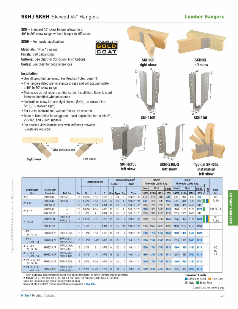
Lumber Hangers
175
Copy
righ
t © 2
020
MiT
ek In
dust
ries
, Inc
. Al
l Rig
hts
Rese
rved
Lumber Hangers
MiTek® Product Catalog
SKH / SKHH Skewed 45° Hangers
SKH26R right skew
SKH26L left skew
SKH – Standard 45° skew hanger allows for a 40° to 50° skew range, without hanger modification
SKHH – For heavier applications
Materials: 14 or 16 gaugeFinish: G90 galvanizingOptions: See chart for Corrosion Finish OptionsCodes: See chart for code references
Installation:• Use all specified fasteners. See Product Notes, page 18.• The hangers listed are for standard sizes and will accommodate
a 40° to 50° skew range. • Most sizes do not require a miter cut for installation. Refer to chart
footnote identified with an asterisk.• Illustrations show left and right skews. (SKH_L = skewed left;
SKH_R = skewed right)• For I-Joist installations, web stiffeners are required.• Refer to illustration for staggered I-Joist application for double 2",
2-5/16", and 2-1/2" models.• For double I-Joist installations, web stiffeners between
I-Joists are required.
SKH210LSKH210R
Left skewRight skew
Drive nails at angle
W
H
D
W
D
H
Corrosion Finish Stainless Steel Gold Coat HDG Triple Zinc
Corrosion Finish Stainless Steel Gold Coat HDG Triple Zinc
Corrosion Finish Stainless Steel Gold Coat HDG Triple Zinc
SKHH210L-2left skew
SKHH210Lleft skew
W
H
W
DD
W
Floor Uplift1 Floor Uplift1
Ref. No. W H D Qty Type Qty Type 100% 115% 125% 160% 100% 115% 125% 160% 2 x 4 SKH24L/R SUR/L24 16 1-9/16 3-1/4 1-7/8 4 16d 4 10d x 1-1/2 510 510 510 545 395 395 395 425
SKH26L/R SUR/L26 16 1-9/16 5-1/4 1-7/8 6 16d 6 10d x 1-1/2 840 890 890 1135 700 700 700 980
SKHH26L/R -- 16 1-5/8 5-1/8 3-1/4 18 16d 12 10d x 1-1/2 1765 1795 1795 795 1450 1450 1450 645 --
SKH28L/R -- 16 1-9/16 7-1/4 1-7/8 10 16d 8 10d x 1-1/2 1400 1465 1465 1350 1160 1160 1160 1070 IBC, FL, LA
SKHH28L/R -- 16 1-5/8 7 3-1/4 26 16d 16 10d x 1-1/2 2350 2525 2525 1155 2055 2055 2055 940 --
SKH210L/R SUR/L210, SUR/L214
16 1-9/16 9-1/4 1-7/8 14 16d 10 10d x 1-1/2 1790 1790 1790 1530 1425 1425 1425 1220IBC,
FL, LA
SKHH210L/R -- 16 1-5/8 9 4-1/4 34 16d 20 10d x 1-1/2 2625 2625 2625 1420 2150 2150 2150 1160 --
1-3/4 x 11-1/4 - 18
SKH1724L/R SUR/L1.81/11, SUR/L1.81/14
16 1-13/16 11-1/8 1-7/8 16 10d 10 10d x 1-1/2 1890 2170 2360 1530 1635 1880 2035 1220
2 - 2-1/8 x 9-1/4 - 14
SKH2020L/R SUR/L2.06/9, SUR/L2.1/9 16 2-1/8 9 1-7/8 14 10d 10 10d x 1-1/2 1650 1760 1760 1530 1390 1390 1390 1210
2 - 2-1/8 x 11-1/4 - 18
SKH2024L/R SUR/L2.06/11, SUR/L2.1/11
16 2-1/8 11 1-7/8 16 10d 10 10d x 1-1/2 1890 2170 2360 1530 1635 1880 2020 1210
2-1/4 - 2-5/16 x 11-1/4 - 18
SKH2324L/R SUR/L2.37/11, SUR/L2.37/14
16 2-3/8 10-7/8 1-7/8 16 10d 10 10d x 1-1/2 1890 2170 2360 1530 1635 1880 2020 1210
1) Uplift loads have been increased 60% for wind and seismic loads; no further increase shall be permitted. 2) NAILS: 10d x 1-1/2 nails are 0.148" dia. x 1-1/2" long, 16d nails are 0.162" dia. x 3-1/2" long. *Miter cut required on end of joist to achieve design loads. New products or updated product information are designated in blue font.
Beam/JoistSize
2 x 6-8
2 x 8-12
CodeRef.
Roof
IBC,FL, LA
DF/SPAllowable Loads (Lbs.)
S-P-FAllowable Loads (Lbs.)
MiTek USPStock No. Co
rros
ion
Fini
sh
Dimensions (in)
Ga.
Fastener Schedule2
Roof
Header Joist
2 x 10-14
1-3/4 x 9-1/4 - 14
2-1/4 - 2-5/16 x 9-1/4 - 14
SKH1720L/R SUR/L1.81/9
SKH2320L/R SUR/L2.37/9
16
16 2-3/8 8-7/8
1-13/16 9-1/8
IBC,FL,LA
14 10d 10 10d x 1-1/2 1650 1760 1760 1530 1390 1390
122014 10d 10
1390 1210
17601-7/8
1-7/8
1400 140010d x 1-1/2 1650 1530 14001760
Typical SKH26L installationleft skew
Continued on next page
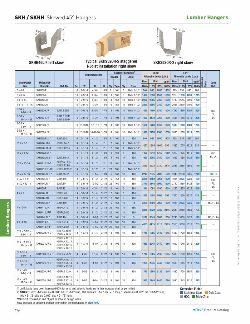
176
Copyright © 2020 M
iTek Industries, Inc. All Rights Reserved
Lumber Hangers
Lum
ber H
ange
rs
MiTek® Product Catalog
SKH / SKHH Skewed 45° Hangers
Floor Uplift1 Floor Uplift1
Ref. No. W H D Qty Type Qty Type 100% 115% 125% 160% 100% 115% 125% 160%
3 x 6-8 SKH36L/R -- 16 2-9/16 4-3/4 1-3/8 6 16d 6 10d x 1-1/2 840 965 1050 1135 725 830 830 980
3 x 8-12 SKH38L/R -- 16 2-9/16 6-3/4 1-3/8 10 16d 8 10d x 1-1/2 1400 1550 1550 1510 1210 1230 1230 1215
3 x 10-14 SKH310L/R -- 16 2-9/16 8-3/4 1-3/8 14 16d 10 10d x 1-1/2 2060 2365 2465 1530 1780 2045 2090 1220
3 x 12 - 14 - 16 SKH312L/R -- 16 2-9/16 10-3/4 1-3/8 16 16d 10 10d x 1-1/2 2350 2705 2750 1530 2035 2190 2190 1220
SKH26L/R-2 * SUR/L26-2 16 3-1/16 4-1/2 1-3/8 6 16d 6 10d 840 965 1050 1135 725 835 865 980
SKHH26L/R-2 HSUR/L26-2 14 3-1/16 5-1/4 2 12 16d 4 16d x 2-1/2
SKHH26L/R-2IF HSUR/LC26-2 14 3-1/16 5-1/4 2 12 16d 4 16d x 2-1/2
(2) 2 x 8-12 SKH28L/R-2 * -- 16 3-1/16 6-1/2 1-3/8 10 16d 8 10d 1400 1610 1750 1350 1210 1395 1515 1060
SKH210L/R-2 * SUR/L210-2 16 3-1/16 8-1/2 1-3/8 14 16d 10 10d 1960 2255 2450 1530 1695 1950 2120 1210
SKHH210L/R-2 HSUR/L210-2, HSUR/L214-2
14 3-1/16 8-1/2 2 20 16d 6 16d x 2-1/2
SKHH210L/R-2IF HSUR/LC210-2 14 3-1/16 8-1/2 2 20 16d 6 16d x 2-1/2
(2) 2 x 12-16 SKH212L/R-2 * SUR/L214-2 16 3-1/16 10-1/2 1-3/8 16 16d 10 10d 2240 2575 2800 1530 1940 2230 2405 1210 IBC, FL
3-1/2 x 8-14 SKH410L/R * SUR/L410 14 3-9/16 8-1/2 2-1/2 16 16d 10 16d 2305 2650 2865 1530 1995 2225 2225 1190
3-1/2 x 12-18 SKH414L/R * SUR/L414 14 3-9/16 12-1/2 2-1/2 22 16d 10 16d 3170 3645 3960 1530 2740 3150 3425 1190
SKH46L/R * SUR/L46 14 3-9/16 4-3/4 2-1/2 10 16d 6 16d 1440 1590 1590 1350 1225 1225 1225 1040
SKHH46L/R HSUR/L46 14 3-9/16 5-1/4 2-1/2 12 16d 6 16d
SKHH46L/RIF HSUR/LC46 14 3-9/16 5-1/4 2-1/2 12 16d 6 16d
SKH410L/R * SUR/L410 14 3-9/16 8-1/2 2-1/2 16 16d 10 16d 2305 2650 2865 1530 1995 2225 2225 1190 IBC, FL, LA
SKHH410L/R HSUR/L410 14 3-9/16 8-1/2 2-1/2 20 16d 10 16d
SKHH410L/RIF HSUR/LC410 14 3-9/16 8-1/2 2-1/2 20 16d 10 16d
SKH414L/R * SUR/L414 14 3-9/16 12-1/2 2-1/2 22 16d 10 16d 3170 3645 3960 1530 2740 3150 3425 1190 IBC, FL, LA
SKHH414L/R HSUR/L414 14 3-9/16 12-1/2 2-1/2 26 16d 10 16d
SKHH414L/RIF HSUR/LC414 14 3-9/16 12-1/2 2-1/2 26 16d 10 16d
(2) 2 - 2-1/8 x 9-1/4 - 14
SKH2020L/R-2 * HSUR/L4.12/9, HSUR/L4.28/9 14 4-3/16 9-1/4 3-1/2 14 10d 10 10d 1710 1965 2135 1645 1480 1700 1850 1265
(2) 2 - 2-1/8 x 11-1/4 - 18
SKH2024L/R-2 *
HSUR/L4.12/11, HSUR/L4.12/14, HSUR/L4.12/16, HSUR/L4.28/11
14 4-3/16 11-1/4 3-1/2 16 10d 10 10d 1950 2245 2440 1680 1690 1945 2110 1295
(2) 2-5/16 x 11-1/4 - 18
SKH2324L/R-2 * HSUR/L4.75/11, HSUR/L4.75/14, HSUR/L4.75/16
14 4-7/8 11-1/4 3-1/2 16 10d 10 10d 1950 2245 2440 1680 1690 1945 2110 1295
(2) 2-1/2 x 11-1/4 - 16
SKH2524L/R-2 * HSUR/L5.12/11, HSUR/L5.12/14, HSUR/L5.12/16
14 5-1/8 11-1/4 3-1/2 16 10d 10 10d 1950 2245 2440 1680 1690 1945 2110 1295
1) Uplift loads have been increased 60% for wind and seismic loads; no further increase shall be permitted. 2) NAILS: 10d x 1-1/2 nails are 0.148" dia. x 1-1/2" long, 10d nails are 0.148" dia. x 3" long, 16d nails are 0.162" dia. x 3-1/2" long, 16d x 2-1/2 nails are 0.162" dia. x 2-1/2" long. *Miter cut required on end of joist to achieve design loads. New products or updated product information are designated in blue font.
Corr
osio
nFi
nish
Header Joist
1480 1700 1850 1265
CodeRef.
IBC,FL,LA
IBC,FL,LA
--
--
--
--
IBC,FL, LA
3310
IBC,FL,LA
14 10d 12651965 2135
Beam/JoistSize
MiTek USPStock No. Ga.
Roof Roof
Dimensions (in)Fastener Schedule2 DF/SP
Allowable Loads (Lbs.)S-P-F
Allowable Loads (Lbs.)
9-1/4
(2) 2-5/16 x 9-1/4 - 14
SKH2320L/R-2 * HSUR/L4.75/9 14 4-7/8 9-1/4 3-1/2 14
3-1/2 (2) 2-1/2 x 9-1/4 - 14
SKH2520L/R-2 * HSUR/L5.12/9 14 5-1/8 1645 1480 1700 185010 10d 1710
635
4005 4115 4115 2115 3310
10d 10 10d 1710 1965 2135 1645
1520
1380 1380
3330 2115
7951850 1905 1520
1525
(2) 2 x 10-14
1905
3310 1705
2685 2685 2685 1710
1520 4 x 6-8
3080 3330
4 x 14-18
3080 3330 3330 2115 2680 2680 2680 1705 4 x 10-14
1530
2-9/16 10-3/4 1-7/8
10-11/16 1-7/8 16 10d
10d x 1-1/2 1650 1760 1760
1880 2010 1205
1380 1205
2170 2360 1530
635 (2) 2 x 6-8
14 10d 10 10d x 1-1/2
16 10d 10 10d x 1-1/2 SUR/L2.56/11, SUR/L2.56/14
SKH2524L/R
SKH2520L/R SUR/L2.56/9
1850 1905 1905 795 1525
10
2-1/2 x 11-1/4 - 16
2-5/8 x 9-1/4 - 14
2-1/2 x 9-1/4 - 14
1890
1380
1525
1530 1635
2-11/16 8-11/16 1-7/8 14 10d
2-11/16 10 10d x 1-1/2 1890 2170 2360
1880 2010
--
1205
1205
2-5/8 x 11-1/4 - 16
SKH2620L/R -- 16
SKH2624L/R -- 16
8-5/8 1-7/82-9/1616
16
1380
1635
1650 1760 1760 1530 1380
SKHH46LIF left skew Typical SKH2520R-2 staggered I-Joist installation right skew
SKH2520R-2 right skew
D
H
W
D
H
W
Corrosion Finish Stainless Steel Gold Coat HDG Triple Zinc
Corrosion Finish Stainless Steel Gold Coat HDG Triple Zinc
Corrosion Finish Stainless Steel Gold Coat HDG Triple Zinc
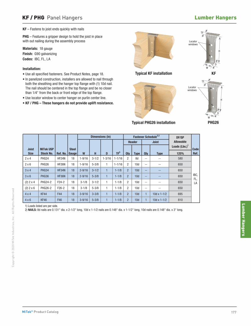
Lumber Hangers
177
Copy
righ
t © 2
020
MiT
ek In
dust
ries
, Inc
. Al
l Rig
hts
Rese
rved
Lumber Hangers
MiTek® Product Catalog
KF – Fastens to joist ends quickly with nails
PHG – Features a gripper design to hold the joist in place with out nailing during the assembly process
Materials: 18 gaugeFinish: G90 galvanizingCodes: IBC, FL, LA
Installation:• Use all specified fasteners. See Product Notes, page 18.• In panelized construction, installers are allowed to nail through
both the sheathing and the hanger top flange with (1) 10d nail. The nail should be centered in the top flange and be no closer than 1/4" from the back or front edge of the top flange.
• Use locator window to center hanger on purlin center line.• KF / PHG – These hangers do not provide uplift resistance.
Typical KF installation
Typical PHG26 installation
KF
PHG26W
H
TF
D
Locator windows
H
TF
DW
Locator windows
KF / PHG Panel Hangers
Ref. No. W H D TF5 Qty Type Qty Type 125%
2 x 4 PHG24 HF24N 18 1-9/16 3-1/2 1-3/16 1-1/16 2 8d -- -- 580
2 x 6 PHG26 HF26N 18 1-9/16 5-3/8 1 1-1/16 2 10d -- -- 650
3 x 4 PHG34 HF34N 18 2-9/16 3-1/2 1 1-1/8 2 10d -- -- 650
3 x 6 PHG36 HF36N 18 2-9/16 5-3/8 1 1-1/8 2 10d -- -- 650
(2) 2 x 4 PHG24-2 F24-2 18 3-1/8 3-1/2 1 1-1/8 2 10d -- -- 650
(2) 2 x 6 PHG26-2 F26-2 18 3-1/8 5-3/8 1 1-1/8 2 10d -- -- 650
4 x 4 KF44 F44 18 3-9/16 3-3/8 1 1-1/8 2 10d 1 10d x 1-1/2 695
4 x 6 KF46 F46 18 3-9/16 5-3/8 1 1-1/8 2 10d 1 10d x 1-1/2 810
1) Loads listed are per side. 2) NAILS: 8d nails are 0.131" dia. x 2-1/2" long, 10d x 1-1/2 nails are 0.148" dia. x 1-1/2" long, 10d nails are 0.148" dia. x 3" long.
Joist Size
MiTek USPStock No.
SteelGauge
Dimensions (in)
IBC, FL, LA
Joist
Fastener Schedule2,3
Header
CodeRef.
DF/SPAllowable
Loads (Lbs.)1
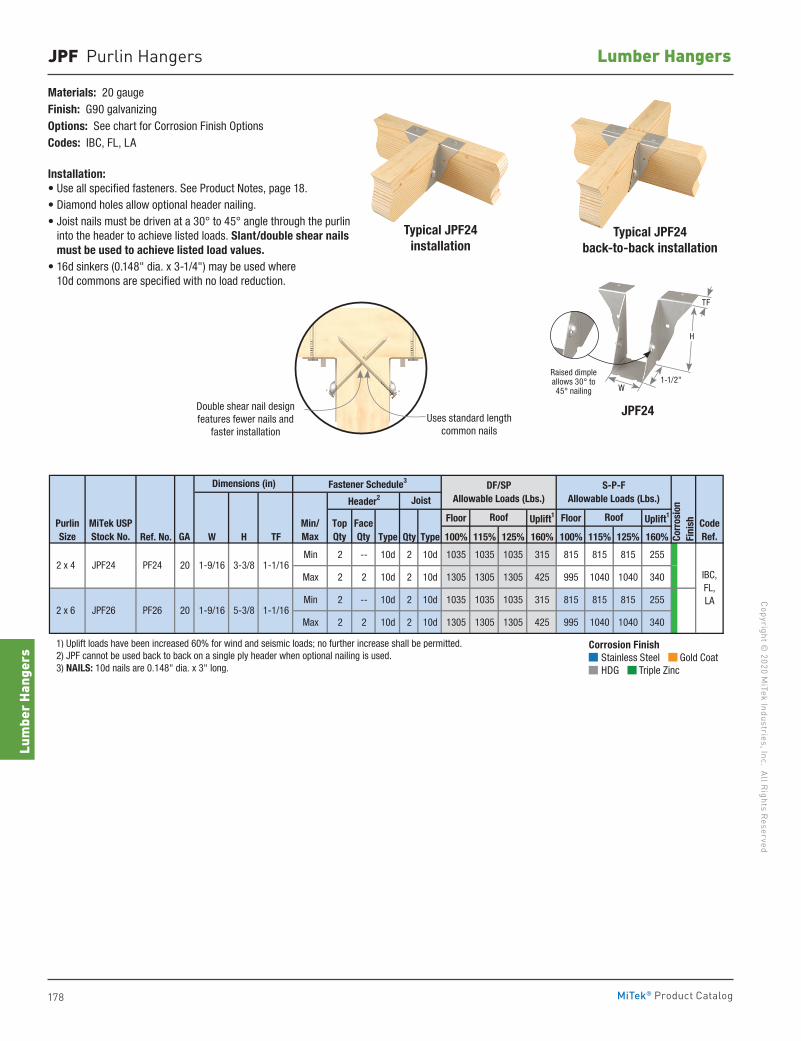
178
Copyright © 2020 M
iTek Industries, Inc. All Rights Reserved
Lumber Hangers
Lum
ber H
ange
rs
MiTek® Product Catalog
JPF Purlin Hangers
Materials: 20 gaugeFinish: G90 galvanizingOptions: See chart for Corrosion Finish OptionsCodes: IBC, FL, LA
Installation:• Use all specified fasteners. See Product Notes, page 18.• Diamond holes allow optional header nailing.• Joist nails must be driven at a 30° to 45° angle through the purlin
into the header to achieve listed loads. Slant/double shear nails must be used to achieve listed load values.
• 16d sinkers (0.148" dia. x 3-1/4") may be used where 10d commons are specified with no load reduction.
JPF24
Floor Uplift1 Floor Uplift1
Ref. No. W H TF Type Qty Type 100% 115% 125% 160% 100% 115% 125% 160%
Min 2 -- 10d 2 10d 1035 1035 1035 315 815 815 815 255
Max 2 2 10d 2 10d 1305 1305 1305 425 995 1040 1040 340
Min 2 -- 10d 2 10d 1035 1035 1035 315 815 815 815 255
Max 2 2 10d 2 10d 1305 1305 1305 425 995 1040 1040 340
1) Uplift loads have been increased 60% for wind and seismic loads; no further increase shall be permitted. 2) JPF cannot be used back to back on a single ply header when optional nailing is used. 3) NAILS: 10d nails are 0.148" dia. x 3" long.
Corr
osio
nFi
nish
PF26 20
2 x 4 JPF24 PF24
Dimensions (in)
Header2 Joist
DF/SPAllowable Loads (Lbs.)
S-P-FAllowable Loads (Lbs.)
TopQty
FaceQty
Fastener Schedule3
Min/Max
IBC, FL, LA
Roof CodeRef.
PurlinSize
MiTek USPStock No. GA
Roof
1-9/16
1-1/16
1-1/16
20 3-3/8
5-3/8
1-9/16
2 x 6 JPF26
Double shear nail designfeatures fewer nails and
faster installationUses standard length
common nails
Typical JPF24installation
Typical JPF24back-to-back installation
Corrosion Finish Stainless Steel Gold Coat HDG Triple Zinc
Corrosion Finish Stainless Steel Gold Coat HDG Triple Zinc
Corrosion Finish Stainless Steel Gold Coat HDG Triple Zinc
TF
H
W1-1/2"
Raised dimple allows 30° to 45° nailing
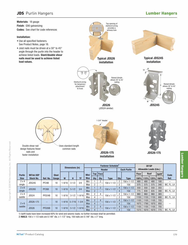
Lumber Hangers
179
Copy
righ
t © 2
020
MiT
ek In
dust
ries
, Inc
. Al
l Rig
hts
Rese
rved
Lumber Hangers
MiTek® Product Catalog
JDS Purlin Hangers
Top Face Floor Uplift1
Ref. No. W H TF Qty Qty Type Qty Type 100% 115% 125% 160%Min 1 2 2 10d x 1-1/2 480 480 480 180 --Max 2 -- 2 10d 575 575 575 340 IBC, FL, LAMin 1 2 4 10d x 1-1/2 550 550 550 355 --Max 2 -- 4 10d 775 830 835 390 IBC, FL, LAMin 2 4 2 10d x 1-1/2 960 960 960 365 --Max 4 -- 2 10d 1155 1155 1155 680 IBC, FL, LAMin 2 4 4 10d x 1-1/2 1105 1105 1105 705Max 4 -- 4 10d 1675 1790 1870 950Min 2 4 4 10d x 1-1/2 1105 1105 1105 705Max 4 -- 4 10d 1575 1670 1670 775 IBC, FL, LA
1) Uplift loads have been increased 60% for wind and seismic loads; no further increase shall be permitted. 2) NAILS: 10d x 1-1/2 nails are 0.148" dia. x 1-1/2" long, 10d nails are 0.148" dia. x 3" long.
--
PFD26B
2 x 6 saddle
Header
MiTek USPStock No.
SteelGauge
18
18
18
18 1-9/16
3-1/2
3-1/2
5-1/2
5-1/2
CodeRef.
Purlin Size
DF/SPAllowable Loads (Lbs.)
Dimensions (in)
2 x 4 single
PF24B JDS24S
PF26B
1-9/161-9/16
3/4
Roof
1-9/16
Fastener Schedule2
Min/Max
10d x 1-1/2
10d x 1-1/2
1-9/16 3/4
Each Purlin
2 x 4 saddle
2 x 6single
10d x 1-1/2
10d x 1-1/2
10d x 1-1/2 JDS26
JDS26-175 -- 18 1-9/16
1-9/16
5-7/16 1-3/4
PFD24B
JDS26S
JDS24
Materials: 18 gaugeFinish: G90 galvanizingCodes: See chart for code references
Installation:• Use all specified fasteners.
See Product Notes, page 18.• Joist nails must be driven at a 30° to 45°
angle through the purlin into the header to achieve listed loads. Slant/double shear nails must be used to achieve listed load values.
JDS24S
Typical JDS24Sinstallation
JDS26-175
Double shear nail design features fewer
nails andfaster installation
Uses standard length common nails
Typical JDS26installation
Top opening ofstarburst prong
provides a witness hole
JDS26 (JDS24 similar)
Raised dimpleallows 30˚ to 45˚
nailingRaised dimple
allows 30˚ to 45˚ nailing
H
W
TF
JDS26-175installation
1-3/4" Header
Starburst prong for temporary attachment
to truss
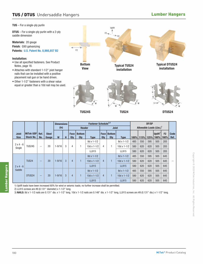
180
Copyright © 2020 M
iTek Industries, Inc. All Rights Reserved
Lumber Hangers
Lum
ber H
ange
rs
MiTek® Product Catalog
TUS – For a single-ply purlin
DTUS – For a single-ply purlin with a 2-ply saddle dimension
Materials: 20 gaugeFinish: G90 galvanizingPatents: U.S. Patent No. 8,966,857 B2
Installation:• Use all specified fasteners. See Product
Notes, page 18.• Attaches with standard 1-1/2" joist hanger
nails that can be installed with a positive placement nail gun or be hand driven.
• Other 1-1/2" fasteners with a shear value equal or greater than a 10d nail may be used.
TUS / DTUS Undersaddle Hangers
W H Type Type 100% 115% 125%
8d x 1-1/2 8d x 1-1/2 485 550 595 505 205
10d x 1-1/2 10d x 1-1/2 580 620 620 505 205
LL915 LL915 580 620 620 505 205
8d x 1-1/2 8d x 1-1/2 485 550 595 505 645
10d x 1-1/2 10d x 1-1/2 580 620 620 505 645
LL915 LL915 580 620 620 505 645
8d x 1-1/2 8d x 1-1/2 485 550 595 505 645
10d x 1-1/2 10d x 1-1/2 580 620 620 505 645
LL915 LL915 580 620 620 505 645
1) Uplift loads have been increased 60% for wind or seismic loads; no further increase shall be permitted. 2) LL915 screws are #9 (0.131" diameter) x 1-1/2" long. 3) NAILS: 8d x 1-1/2 nails are 0.131" dia. x 1-1/2" long, 10d x 1-1/2 nails are 0.148" dia. x 1-1/2" long, LL915 screws are #9 (0.131" dia.) x 1-1/2" long.
1 4
Uplift1
160%F2
160%FaceQty
BottomQty
FaceQty
BottomQty
4
JoistSize
Ref. No.
SteelGauge
2 x 4 - 6Single
TUS24S -- 20
MiTek USPStock No.
2 x 4 - 6Saddle
3 4
TUS24 -- 20
1 DTUS24 -- 20 1-9/16 1 4
DF/SPAllowable Loads (Lbs.)1
Dimensions(in)
CodeRef.
1-9/16 3
Fastener Schedule2,3
1-9/16 3
Header Joist
1 4 1
--1
4
Typical DTUS24installation
DTUS24TUS24
BottomView
Typical TUS24installation
F2
TUS24S
H
WW
3-1/4"
H
WW
H
F2F2
Uplift
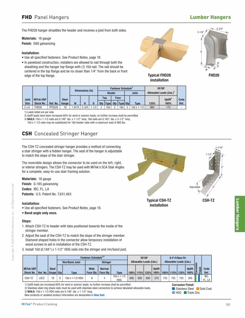
Lumber Hangers
181
Copy
righ
t © 2
020
MiT
ek In
dust
ries
, Inc
. Al
l Rig
hts
Rese
rved
Lumber Hangers
MiTek® Product Catalog
FHD Panel Hangers
The FHD26 hanger straddles the header and receives a joist from both sides.
Materials: 18 gaugeFinish: G90 galvanizing
Installation:• Use all specified fasteners. See Product Notes, page 18.• In panelized construction, installers are allowed to nail through both the
sheathing and the hanger top flange with (1) 10d nail. The nail should be centered in the top flange and be no closer than 1/4" from the back or front edge of the top flange. Typical FHD26
installationFHD26
Ref. No. W H D Qty Type Qty Type Qty Type 125% 2 x 6 FHD26 PFDS26 18 1-9/16 5-3/8 1-1/2 2 16d 2 16d 2 10d x 1-1/2 960 175 --
1) Loads listed are per side. 2) Uplift loads have been increased 60% for wind or seismic loads; no further increase shall be permitted. 3) NAILS: 10d x 1-1/2 nails are 0.148" dia. x 1-1/2" long, 16d nails are 0.162" dia. x 3-1/2" long. 10d x 1-1/2 nails may be substituted for 16d header nails with a maximum load of 960 lbs.
CodeRef.
Joist Size
MiTek USPStock No.
SteelGauge
Joist
Uplift2
160%
Fastener Schedule3
Face
DF/SP
Allowable Loads (Lbs.)1Dimensions (in)
Top
Header
3-1/8"3-3/4"
H
DW
The CSH-TZ concealed stringer hanger provides a method of connecting a stair stringer with a hidden hanger. The seat of the hanger is adjustable to match the slope of the stair stringer.
The reversible design allows the connector to be used on the left, right, or interior stringers. The CSH-TZ may be used with MiTek’s SCA Stair Angles for a complete, easy-to-use stair framing solution.
Materials: 18 gaugeFinish: G-185 galvanizingCodes: IBC, FL, LAPatents: U.S. Patent No. 7,631,463
Installation:• Use all specified fasteners. See Product Notes, page 18.• Bend angle only once.
Steps:1. Attach CSH-TZ to header with tabs positioned towards the inside of the
stringer member. 2. Adjust the seat of the CSH-TZ to match the slope of the stringer member.
Diamond shaped holes in the connector allow temporary installation of wood screws to aid in installation of the CSH-TZ.
3. Install 10d (0.148") x 1-1/2" HDG nails into the stringer and rim/band joist.
Typical CSH-TZinstallation
CSH-TZ
CSH Concealed Stringer Hanger
Ref. No. Qty Type Type 100% 115% 125% 100% 115% 125%
CSH-TZ LSCZ 18 8 10d x 1-1/2 HDG 4 110d x 1-1/2
HDG890 890 890 370 725 725 725 305
IBC, FL, LA
1) Uplift loads are increased 60% for wind or seismic loads; no further increase shall be permitted. 2) Stainless steel ring shank nails must be used with stainless steel connectors to achieve tabulated allowable loads. 3) NAILS: 10d x 1-1/2 HDG nails are 0.148" dia. x 1-1/2" long. New products or updated product information are designated in blue font.
CodeRef.
MiTek USPStock No.
SteelGauge
Rim/Band Joist
DF/SPAllowable Loads (Lbs.)
S-P-F/Hem FirAllowable Loads (Lbs.)
Corr
osio
nFi
nishUplift
160%Uplift160%
Stringer
Wide Face Qty
Narrow Face Qty
Fastener Schedule2,3
Adjustable 5"
5"
1-7/16"
1-1/2"
Corrosion Finish Stainless Steel Gold Coat HDG Triple Zinc
Corrosion Finish Stainless Steel Gold Coat HDG Triple Zinc
Corrosion Finish Stainless Steel Gold Coat HDG Triple Zinc
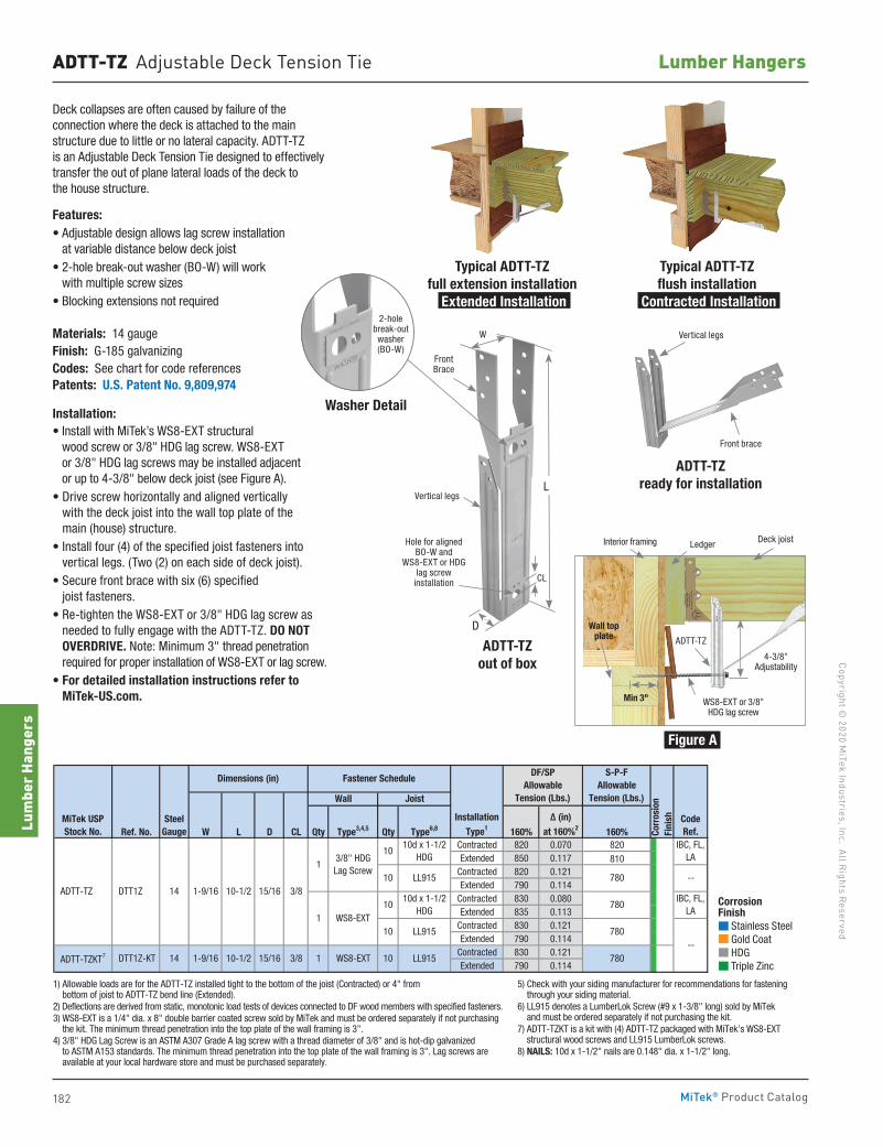
182
Copyright © 2020 M
iTek Industries, Inc. All Rights Reserved
Lumber Hangers
Lum
ber H
ange
rs
MiTek® Product Catalog
ADTT-TZ Adjustable Deck Tension Tie
Deck collapses are often caused by failure of the connection where the deck is attached to the main structure due to little or no lateral capacity. ADTT-TZ is an Adjustable Deck Tension Tie designed to effectively transfer the out of plane lateral loads of the deck to the house structure.
Features: • Adjustable design allows lag screw installation
at variable distance below deck joist• 2-hole break-out washer (BO-W) will work
with multiple screw sizes• Blocking extensions not required
Materials: 14 gaugeFinish: G-185 galvanizingCodes: See chart for code referencesPatents: U.S. Patent No. 9,809,974
Installation: • Install with MiTek’s WS8-EXT structural
wood screw or 3/8" HDG lag screw. WS8-EXT or 3/8" HDG lag screws may be installed adjacent or up to 4-3/8" below deck joist (see Figure A).
• Drive screw horizontally and aligned vertically with the deck joist into the wall top plate of the main (house) structure.
• Install four (4) of the specified joist fasteners into vertical legs. (Two (2) on each side of deck joist).
• Secure front brace with six (6) specified joist fasteners.
• Re-tighten the WS8-EXT or 3/8" HDG lag screw as needed to fully engage with the ADTT-TZ. DO NOT OVERDRIVE. Note: Minimum 3" thread penetration required for proper installation of WS8-EXT or lag screw.
• For detailed installation instructions refer to MiTek-US.com.
Typical ADTT-TZ full extension installation
Extended Installation
Typical ADTT-TZ flush installation
Contracted Installation
Front brace
Vertical legs
ADTT-TZ ready for installation
Ref. No. W L D CL Qty Type3,4,5 Qty Type6,8 160% 160%Contracted 820 0.070 820Extended 850 0.117 810
Contracted 820 0.121Extended 790 0.114
Contracted 830 0.080Extended 835 0.113
Contracted 830 0.121Extended 790 0.114
Contracted 830 0.121Extended 790 0.114
1) Allowable loads are for the ADTT-TZ installed tight to the bottom of the joist (Contracted) or 4-inches from bottom of joist to ADTT-TZ bend line (Extended). 2) Deflections are derived from static, monotonic load tests of devices connected to DF wood members with specified fasteners. 3) WS8-EXT is a 1/4" dia. x 8" long double barrier coated screw sold by MiTek and must be ordered seperately if not purchasing the kit. The minimum thread penetration into the top plate of the wall framing is 3-inches. 4) 3/8" HDG Lag Screw is an ASTM A307 Grade A lag screw with a thread diameter of 3/8" and is hot-dip galvanized to ASTM A153 standards. The minimum thread penetration into the top plate of the wall framing is 3-inches. Lag screws are available at your local hardware store and must be purchased seperately. 5) Check with your siding manufacturer for recommendations for fastening through your siding material. 6) LL915 denotes a LumberLok Screw (#9 x 1-3/8" long) sold by MiTek and must be ordered seperately if not purchasing the kit. 7) ADTT-TZKT is a kit with (4) ADTT-TZ packaged with MiTek's WS8-EXT structural wood screws and LL915 LumberLok screws. 8) NAILS: 10d x 1-1/2 nails are 0.148" dia. x 1-1/2" long.
LL915
780
780
780
780
LL915
15/16 3/8 1 WS8-EXT 10 ADTT-TZKT7 DTT1Z-KT 14 1-9/16 10-1/2
ADTT-TZ DTT1Z 14 1-9/16 10-1/210
10d x 1-1/2HDG
15/16 3/8
13/8" HDG Lag Screw
1 WS8-EXT
--
MiTek USPStock No.
DF/SPAllowable
Tension (Lbs.)
S-P-FAllowable
Tension (Lbs.)
Δ (in)at 160%2
SteelGauge
Wall Joist
Dimensions (in) Fastener Schedule
InstallationType1
10 LL915
1010d x 1-1/2
HDG
10
CodeRef.Co
rros
ion
Fini
sh
IBC, FL,LA
IBC, FL,LA
--
Ledger Deck joist
Figure A
ADTT-TZ
4-3/8" Adjustability
Interior framing
WS8-EXT or 3/8" HDG lag screw
Wall top plate
Min 3"
Corrosion Finish Stainless Steel Gold Coat HDG Triple Zinc
Corrosion Finish Stainless Steel Gold Coat HDG Triple Zinc
Corrosion Finish Stainless Steel Gold Coat HDG Triple Zinc
1) Allowable loads are for the ADTT-TZ installed tight to the bottom of the joist (Contracted) or 4" from bottom of joist to ADTT-TZ bend line (Extended).
2) Deflections are derived from static, monotonic load tests of devices connected to DF wood members with specified fasteners.3) WS8-EXT is a 1/4" dia. x 8" double barrier coated screw sold by MiTek and must be ordered separately if not purchasing
the kit. The minimum thread penetration into the top plate of the wall framing is 3". 4) 3/8" HDG Lag Screw is an ASTM A307 Grade A lag screw with a thread diameter of 3/8" and is hot-dip galvanized
to ASTM A153 standards. The minimum thread penetration into the top plate of the wall framing is 3". Lag screws are available at your local hardware store and must be purchased separately.
5) Check with your siding manufacturer for recommendations for fastening through your siding material.
6) LL915 denotes a LumberLok Screw (#9 x 1-3/8" long) sold by MiTek and must be ordered separately if not purchasing the kit.
7) ADTT-TZKT is a kit with (4) ADTT-TZ packaged with MiTek’s WS8-EXT structural wood screws and LL915 LumberLok screws.
8) NAILS: 10d x 1-1/2" nails are 0.148" dia. x 1-1/2" long.
ADTT-TZ out of box
D
W
L
Front Brace
Vertical legs
Hole for aligned BO-W and
WS8-EXT or HDG lag screw
installation CL
Washer Detail
2-hole break-out washer(BO-W)
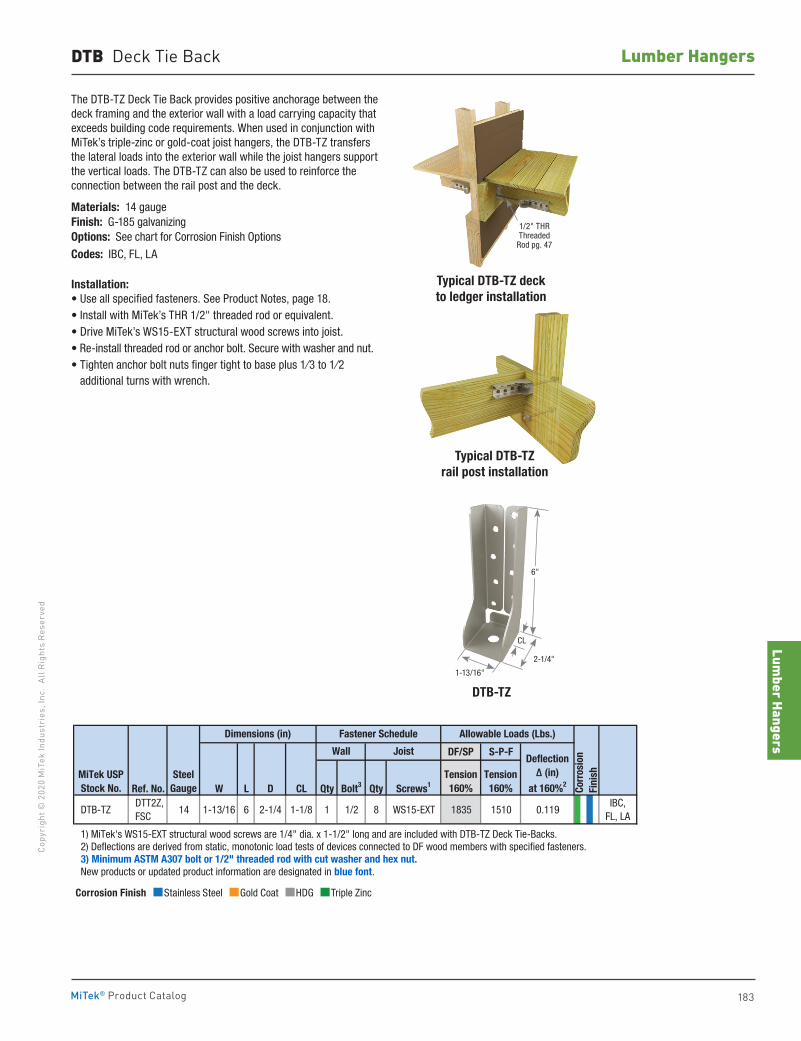
Lumber Hangers
183
Copy
righ
t © 2
020
MiT
ek In
dust
ries
, Inc
. Al
l Rig
hts
Rese
rved
Lumber Hangers
MiTek® Product Catalog
DF/SP S-P-F
Ref. No. W L D CL Qty Bolt3 Qty Screws1
DTB-TZ DTT2Z, FSC
14 1-13/16 6 2-1/4 1-1/8 1 1/2 8 WS15-EXT 1835 1510 0.119IBC,
FL, LA
1) MiTek's WS15-EXT structural wood screws are 1/4" dia. x 1-1/2" long and are included with DTB-TZ Deck Tie-Backs. 2) Deflections are derived from static, monotonic load tests of devices connected to DF wood members with specified fasteners. 3) Minimum ASTM A307 bolt or 1/2" threaded rod with cut washer and hex nut. New products or updated product information are designated in blue font.
MiTek USPStock No.
Tension160%
Dimensions (in)
Corr
osio
nFi
nishSteel
Gauge
Fastener Schedule
Wall Joist
Tension160%
Deflection Δ (in)
at 160%2
Allowable Loads (Lbs.)
Corrosion Finish Stainless Steel Gold Coat HDG Triple Zinc
Corrosion Finish Stainless Steel Gold Coat HDG Triple Zinc
Corrosion Finish Stainless Steel Gold Coat HDG Triple Zinc
DTB Deck Tie Back
The DTB-TZ Deck Tie Back provides positive anchorage between the deck framing and the exterior wall with a load carrying capacity that exceeds building code requirements. When used in conjunction with MiTek’s triple-zinc or gold-coat joist hangers, the DTB-TZ transfers the lateral loads into the exterior wall while the joist hangers support the vertical loads. The DTB-TZ can also be used to reinforce the connection between the rail post and the deck.
Materials: 14 gau geFinish: G-185 galvanizingOptions: See chart for Corrosion Finish Options
Codes: IBC, FL, LA
Installation:• Use all specified fasteners. See Product Notes, page 18. • Install with MiTek’s THR 1/2" threaded rod or equivalent.• Drive MiTek’s WS15-EXT structural wood screws into joist. • Re-install threaded rod or anchor bolt. Secure with washer and nut. • Tighten anchor bolt nuts finger tight to base plus 1⁄3 to 1⁄2
additional turns with wrench.
Typical DTB-TZrail post installation
Typical DTB-TZ deck to ledger installation
DTB-TZ
6"
2-1/4"
CL
1-13/16"
1/2" THRThreaded
Rod pg. 47
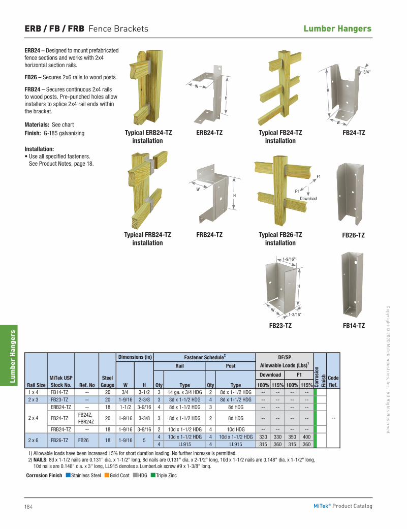
184
Copyright © 2020 M
iTek Industries, Inc. All Rights Reserved
Lumber Hangers
Lum
ber H
ange
rs
MiTek® Product Catalog
ERB / FB / FRB Fence Brackets
ERB24 – Designed to mount prefabricated fence sections and works with 2x4 horizontal section rails.
FB26 – Secures 2x6 rails to wood posts.
FRB24 – Secures continuous 2x4 rails to wood posts. Pre-punched holes allow installers to splice 2x4 rail ends within the bracket.
Materials: See chartFinish: G-185 galvanizing
Installation:• Use all specified fasteners.
See Product Notes, page 18.
Rail Size Ref. No W H Qty Type Qty Type 100% 115% 100% 115% 1 x 4 FB14-TZ -- 20 3/4 3-1/2 3 14 ga. x 3/4 HDG 2 8d x 1-1/2 HDG -- -- -- -- 2 x 3 FB23-TZ -- 20 1-9/16 2-3/8 3 8d x 1-1/2 HDG 4 8d x 1-1/2 HDG -- -- -- --
ERB24-TZ -- 18 1-1/2 3-9/16 4 8d x 1-1/2 HDG 3 8d HDG -- -- -- --
FB24-TZ FB24Z, FBR24Z
20 1-9/16 3-3/8 3 8d x 1-1/2 HDG 2 8d HDG -- -- -- --
FRB24-TZ -- 18 1-9/16 3-9/16 2 10d x 1-1/2 HDG 4 10d HDG -- -- -- --4 10d x 1-1/2 HDG 4 10d x 1-1/2 HDG 330 330 350 4004 LL915 4 LL915 315 360 315 360
1) Allowable loads have been increased 15% for short duration loading. No further increase is permitted. 2) NAILS: 8d x 1-1/2 nails are 0.131" dia. x 1-1/2" long, 8d nails are 0.131" dia. x 2-1/2" long, 10d x 1-1/2 nails are 0.148" dia. x 1-1/2" long, 10d nails are 0.148" dia. x 3" long, LL915 denotes a LumberLok screw #9 x 1-3/8" long.
2 x 6
DF/SP
Allowable Loads (Lbs)1
FB26-TZ
2 x 4
Rail Post
1-9/16 5
MiTek USPStock No.
SteelGauge
Dimensions (in) Fastener Schedule2
FB26
Corr
osio
nFi
nish
18
CodeRef.
Download F1
--
FB24-TZ
FB26-TZ
FB14-TZ
Typical FB24-TZ installation
Typical FB26-TZinstallation
FB23-TZ
ERB24-TZ
FRB24-TZ
Typical ERB24-TZinstallation
Typical FRB24-TZinstallation
W
H
Corrosion Finish Stainless Steel Gold Coat HDG Triple Zinc
Corrosion Finish Stainless Steel Gold Coat HDG Triple Zinc
Corrosion Finish Stainless Steel Gold Coat HDG Triple Zinc
H
WH
3/4"
W
1-3/16"
1-9/16"
H
W
F1
F1
Download
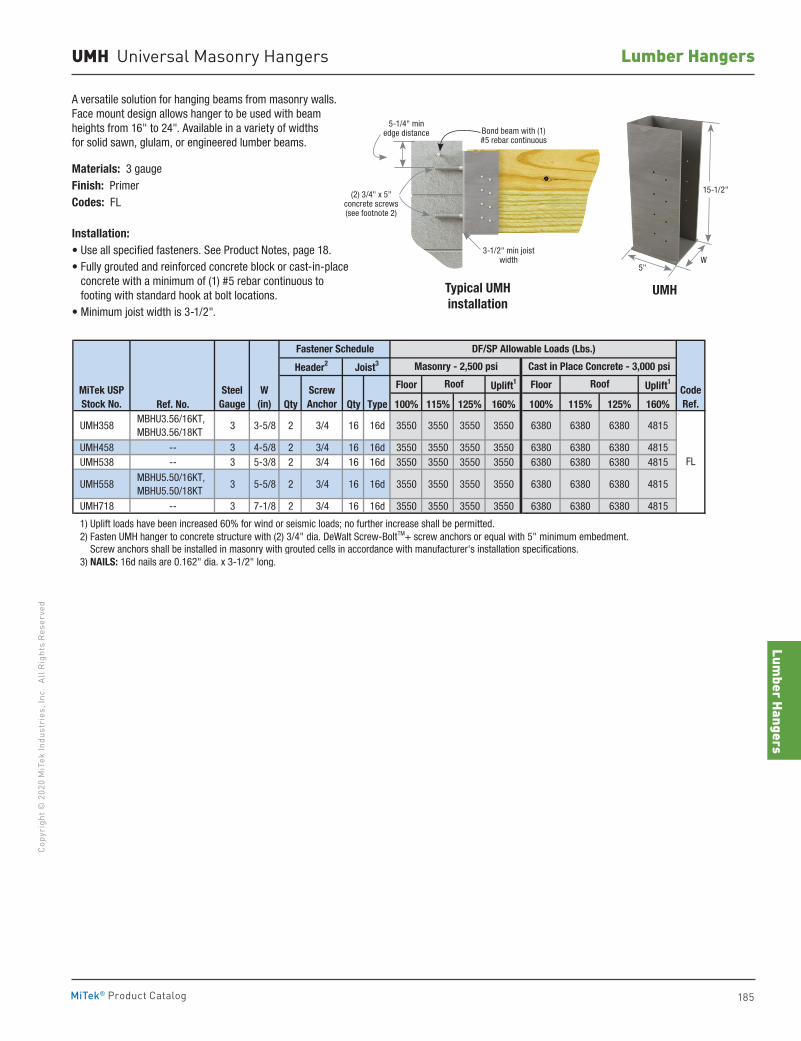
Lumber Hangers
185
Copy
righ
t © 2
020
MiT
ek In
dust
ries
, Inc
. Al
l Rig
hts
Rese
rved
Lumber Hangers
MiTek® Product Catalog
UMH Universal Masonry Hangers
A versatile solution for hanging beams from masonry walls. Face mount design allows hanger to be used with beam heights from 16" to 24". Available in a variety of widths for solid sawn, glulam, or engineered lumber beams.
Materials: 3 gaugeFinish: PrimerCodes: FL
Installation:• Use all specified fasteners. See Product Notes, page 18.• Fully grouted and reinforced concrete block or cast-in-place
concrete with a minimum of (1) #5 rebar continuous to footing with standard hook at bolt locations.
• Minimum joist width is 3-1/2".
Floor Uplift1 Floor Uplift1
Ref. No. Qty Qty Type 100% 115% 125% 160% 100% 115% 125% 160%
UMH358 MBHU3.56/16KT, MBHU3.56/18KT
3 3-5/8 2 3/4 16 16d 3550 3550 3550 3550 6380 6380 6380 4815
UMH458 -- 3 4-5/8 2 3/4 16 16d 3550 3550 3550 3550 6380 6380 6380 4815 UMH538 -- 3 5-3/8 2 3/4 16 16d 3550 3550 3550 3550 6380 6380 6380 4815
UMH558 MBHU5.50/16KT, MBHU5.50/18KT
3 5-5/8 2 3/4 16 16d 3550 3550 3550 3550 6380 6380 6380 4815
UMH718 -- 3 7-1/8 2 3/4 16 16d 3550 3550 3550 3550 6380 6380 6380 4815
1) Uplift loads have been increased 60% for wind or seismic loads; no further increase shall be permitted. 2) Fasten UMH hanger to concrete structure with (2) 3/4" dia. DeWalt Screw-BoltTM+ screw anchors or equal with 5" minimum embedment. Screw anchors shall be installed in masonry with grouted cells in accordance with manufacturer's installation specifications. 3) NAILS: 16d nails are 0.162" dia. x 3-1/2" long.
CodeRef.
FL
RoofMiTek USPStock No.
SteelGauge
RoofScrewAnchor
W(in)
Fastener Schedule DF/SP Allowable Loads (Lbs.)
Masonry - 2,500 psi Cast in Place Concrete - 3,000 psiHeader2 Joist3
Typical UMHinstallation
UMH
15-1/2"
5"W
3-1/2" min joist width
5-1/4" min edge distance
(2) 3/4" x 5" concrete screws (see footnote 2)
Bond beam with (1) #5 rebar continuous
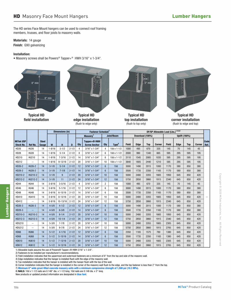
186
Copyright © 2020 M
iTek Industries, Inc. All Rights Reserved
Lumber Hangers
Lum
ber H
ange
rs
MiTek® Product Catalog
2" min
8" min
8" min
HD Masonry Face Mount Hangers
The HD series Face Mount hangers can be used to connect roof framing members, trusses, and floor joists to masonry walls.
Materials: 14 gaugeFinish: G90 galvanizing
Installation:• Masonry screws shall be Powers® Tapper+® HWH 3/16" x 1-3/4".
Typical HD top installation
(flush to top only)
Typical HD corner installation (flush to edge and top)
Typical HD edge installation
(flush to edge only)
W H D Qty Qty Type8 Field Edge Top Corner Field Edge Top Corner
HD26 HU26 14 1-9/16 3-1/2 2-1/2 4 3/16" x 1-3/4" 4 10d x 1-1/2 1000 495 670 335 145 70 145 45
HD28 HU28 14 1-9/16 5-1/4 2-1/2 8 3/16" x 1-3/4" 6 10d x 1-1/2 2000 990 1340 665 595 295 595 195
HD210 HU210 14 1-9/16 7-3/16 2-1/2 14 3/16" x 1-3/4" 6 10d x 1-1/2 3110 1545 2085 1035 595 295 595 195
HD212 -- 14 1-9/16 9-13/16 2-1/2 20 3/16" x 1-3/4" 10 10d x 1-1/2 3640 1805 2440 1210 595 295 595 195
HD26-2 HU26-2 14 3-1/8 5-1/4 2-1/2 12 3/16" x 1-3/4" 6 10d 3000 1490 2015 1000 1170 580 850 380
HD28-2 HU28-2 14 3-1/8 7-1/8 2-1/2 14 3/16" x 1-3/4" 6 10d 3500 1735 2350 1165 1170 580 850 380
HD210-2 HU210-2 14 3-1/8 9 2-1/2 20 3/16" x 1-3/4" 10 10d 5000 2480 3355 1665 1950 645 850 420
HD212-2 HU212-2 14 3-1/8 11 2-1/2 24 3/16" x 1-3/4" 12 10d 5750 2850 3860 1915 2340 645 850 420
HD44 HU44 14 3-9/16 3-5/16 2-1/2 4 3/16" x 1-3/4" 2 10d 1000 495 670 335 145 70 145 45
HD46 HU46 14 3-9/16 5-1/16 2-1/2 12 3/16" x 1-3/4" 6 10d 3000 1490 2015 1000 1170 580 850 380
HD48 HU48 14 3-9/16 6-15/16 2-1/2 14 3/16" x 1-3/4" 6 10d 3500 1735 2350 1165 1170 580 850 380
HD410 HU410 14 3-9/16 8-13/16 2-1/2 20 3/16" x 1-3/4" 10 10d 5000 2480 3355 1665 1950 645 850 420
HD412 -- 14 3-9/16 10-13/16 2-1/2 24 3/16" x 1-3/4" 12 10d 5750 2850 3860 1915 2340 645 850 420
HD26-3 HU26-3 14 4-5/8 4-1/2 2-1/2 12 3/16" x 1-3/4" 6 10d 3000 1490 2015 1000 1170 580 850 380
HD28-3 -- 14 4-5/8 6-3/8 2-1/2 14 3/16" x 1-3/4" 6 10d 3500 1735 2350 1165 1170 580 850 380
HD210-3 HU210-3 14 4-5/8 8-1/4 2-1/2 20 3/16" x 1-3/4" 10 10d 5000 2480 3355 1665 1950 645 850 420
HD212-3 HU212-3 14 4-5/8 10-1/4 2-1/2 24 3/16" x 1-3/4" 12 10d 5750 2850 3860 1915 2340 645 850 420
HD5210 -- 14 5-3/8 7-7/8 2-1/2 20 3/16" x 1-3/4" 10 10d 5000 2480 3355 1665 2305 645 850 420
HD5212 -- 14 5-3/8 9-7/8 2-1/2 24 3/16" x 1-3/4" 12 10d 5750 2850 3860 1915 2765 645 850 420
HD66 HU66 14 5-1/2 4-1/16 2-1/2 12 3/16" x 1-3/4" 6 10d 2350 1165 1575 780 1380 645 850 420
HD68 HU68 14 5-1/2 5-15/16 2-1/2 14 3/16" x 1-3/4" 6 10d 3500 1735 2350 1165 1380 645 850 420
HD610 HU610 14 5-1/2 7-13/16 2-1/2 20 3/16" x 1-3/4" 10 10d 5000 2480 3355 1665 2305 645 850 420
HD612 HU612 14 5-1/2 9-13/16 2-1/2 24 3/16" x 1-3/4" 12 10d 5750 2850 3860 1915 2765 645 850 420
1) Allowable loads assume the use of Powers® Tapper+® HWH 3/16" x 1-3/4". 2) Fasteners to be installed per manufacturer's recommendations. 3) Field installation indicates that the uppermost and outermost fasteners are a minimum of 8" from the top and side of the masonry wall. 4) Edge installation indicates that the hanger is installed flush with the edge of the masonry wall. 5) Top installation indicates that the hanger is installed with the hanger flush with the top of the wall. 6) Corner installation indicates that the hanger is installed in the corner of the masonry wall flush to the edge, and the top fastener is less than 2" from the top. 7) Minimum 6" wide grout-filled concrete masonry units with a minimum compressive strength of 1,500 psi (10.3 MPa). 8) NAILS: 10d x 1-1/2 nails are 0.148" dia. x 1-1/2 long, 10d nails are 0.148 dia. x 3" long. New products or updated product information are designated in blue font.
CodeRef.
--
Uplift (160%)Joist/BeamMasonry7 Download (100%)
MiTek USPStock No.
SteelGauge
DF/SP Allowable Load (Lbs.)1,4,5,6Dimensions (in) Fastener Schedule2
Tapper+® HWHScrew AnchorRef No.
Typical HD field installation
2" min
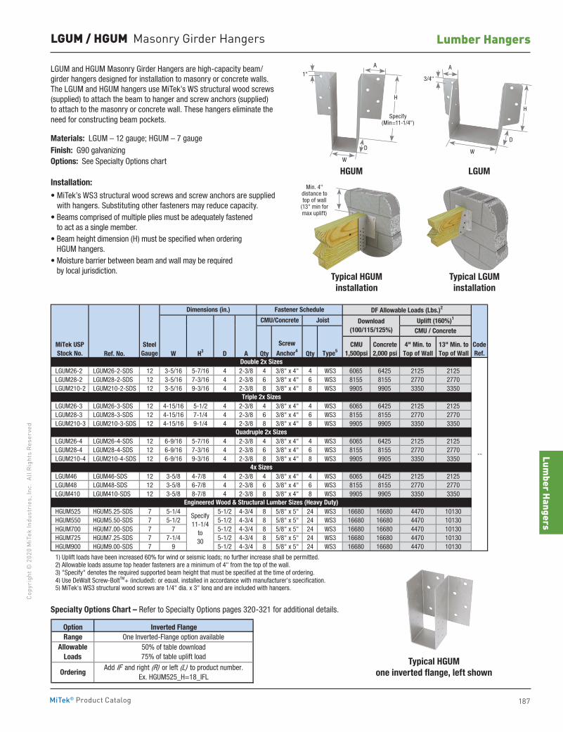
Lumber Hangers
187
Copy
righ
t © 2
020
MiT
ek In
dust
ries
, Inc
. Al
l Rig
hts
Rese
rved
Lumber Hangers
MiTek® Product Catalog
LGUM / HGUM Masonry Girder Hangers
LGUM and HGUM Masonry Girder Hangers are high-capacity beam/girder hangers designed for installation to masonry or concrete walls. The LGUM and HGUM hangers use MiTek’s WS structural wood screws (supplied) to attach the beam to hanger and screw anchors (supplied) to attach to the masonry or concrete wall. These hangers eliminate the need for constructing beam pockets.
Materials: LGUM – 12 gauge; HGUM – 7 gaugeFinish: G90 galvanizingOptions: See Specialty Options chart
Installation:• MiTek’s WS3 structural wood screws and screw anchors are supplied
with hangers. Substituting other fasteners may reduce capacity.• Beams comprised of multiple plies must be adequately fastened
to act as a single member.• Beam height dimension (H) must be specified when ordering
HGUM hangers.• Moisture barrier between beam and wall may be required
by local jurisdiction.
Ref. No. W H3 D A Qty Qty
LGUM26-2 LGUM26-2-SDS 12 3-5/16 5-7/16 4 2-3/8 4 3/8" x 4" 4 WS3 6065 6425 2125 2125 LGUM28-2 LGUM28-2-SDS 12 3-5/16 7-3/16 4 2-3/8 6 3/8" x 4" 6 WS3 8155 8155 2770 2770 LGUM210-2 LGUM210-2-SDS 12 3-5/16 9-3/16 4 2-3/8 8 3/8" x 4" 8 WS3 9905 9905 3350 3350
LGUM26-3 LGUM26-3-SDS 12 4-15/16 5-1/2 4 2-3/8 4 3/8" x 4" 4 WS3 6065 6425 2125 2125 LGUM28-3 LGUM28-3-SDS 12 4-15/16 7-1/4 4 2-3/8 6 3/8" x 4" 6 WS3 8155 8155 2770 2770 LGUM210-3 LGUM210-3-SDS 12 4-15/16 9-1/4 4 2-3/8 8 3/8" x 4" 8 WS3 9905 9905 3350 3350
LGUM26-4 LGUM26-4-SDS 12 6-9/16 5-7/16 4 2-3/8 4 3/8" x 4" 4 WS3 6065 6425 2125 2125 LGUM28-4 LGUM28-4-SDS 12 6-9/16 7-3/16 4 2-3/8 6 3/8" x 4" 6 WS3 8155 8155 2770 2770 LGUM210-4 LGUM210-4-SDS 12 6-9/16 9-3/16 4 2-3/8 8 3/8" x 4" 8 WS3 9905 9905 3350 3350
LGUM46 LGUM46-SDS 12 3-5/8 4-7/8 4 2-3/8 4 3/8" x 4" 4 WS3 6065 6425 2125 2125 LGUM48 LGUM48-SDS 12 3-5/8 6-7/8 4 2-3/8 6 3/8" x 4" 6 WS3 8155 8155 2770 2770 LGUM410 LGUM410-SDS 12 3-5/8 8-7/8 4 2-3/8 8 3/8" x 4" 8 WS3 9905 9905 3350 3350
HGUM525 HGUM5.25-SDS 7 5-1/4 5-1/2 4-3/4 8 5/8" x 5" 24 WS3 16680 16680 4470 10130 HGUM550 HGUM5.50-SDS 7 5-1/2 5-1/2 4-3/4 8 5/8" x 5" 24 WS3 16680 16680 4470 10130 HGUM700 HGUM7.00-SDS 7 7 5-1/2 4-3/4 8 5/8" x 5" 24 WS3 16680 16680 4470 10130 HGUM725 HGUM7.25-SDS 7 7-1/4 5-1/2 4-3/4 8 5/8" x 5" 24 WS3 16680 16680 4470 10130 HGUM900 HGUM9.00-SDS 7 9 5-1/2 4-3/4 8 5/8" x 5" 24 WS3 16680 16680 4470 10130
1) Uplift loads have been increased 60% for wind or seismic loads; no further increase shall be permitted. 2) Allowable loads assume top header fasteners are a minimum of 4" from the top of the wall. 3) "Specify" denotes the required supported beam height that must be specified at the time of ordering. 4) Use DeWalt Screw-BoltTM+ (included); or equal, installed in accordance with manufacturer's specification. 5) MiTek's WS3 structural wood screws are 1/4" dia. x 3" long and are included with hangers.
Dimensions (in.) Fastener Schedule DF Allowable Loads (Lbs.)2
Type5
Uplift (160%)1
4" Min. to Top of Wall
CMU 1,500psi
Concrete2,000 psi
Download(100/115/125%)
JoistCMU/Concrete
CMU / Concrete
CodeRef.
--
Double 2x Sizes
Specify11-1/4
to30
Engineered Wood & Structural Lumber Sizes (Heavy Duty)
4x Sizes
Quadruple 2x Sizes
Triple 2x Sizes
MiTek USPStock No.
SteelGauge
13" Min. to Top of Wall
ScrewAnchor4
Typical HGUM installation
Typical LGUM installation
Min. 4" distance to top of wall
(13" min for max uplift)
HGUM LGUMW
W
D
A
1"3/4"
A
D
HSpecify
(Min=11-1/4")
Option Inverted FlangeRange One Inverted-Flange option available
50% of table download75% of table uplift load
OrderingAdd IF and right (R) or left (L) to product number.
Ex. HGUM525_H=18_IFL
AllowableLoads Typical HGUM
one inverted flange, left shown
Specialty Options Chart – Refer to Specialty Options pages 320-321 for additional details.
H
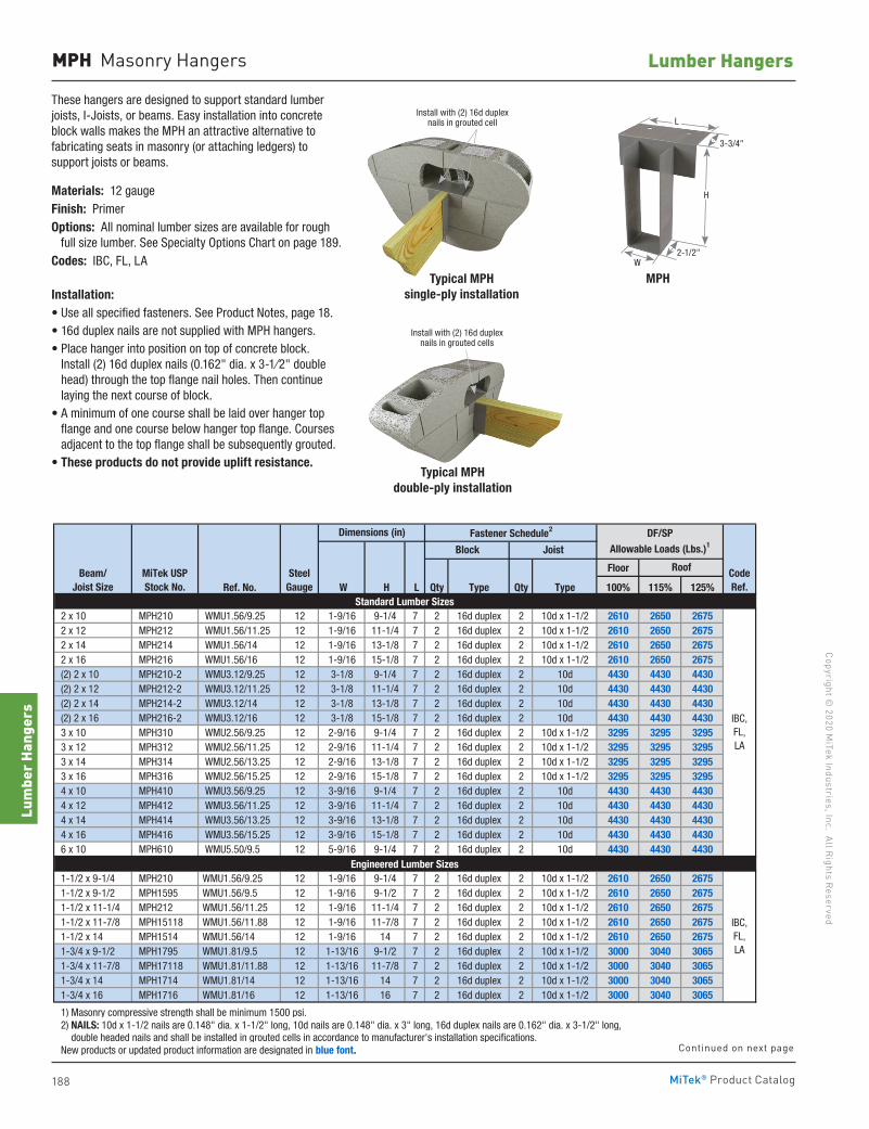
188
Copyright © 2020 M
iTek Industries, Inc. All Rights Reserved
Lumber Hangers
Lum
ber H
ange
rs
MiTek® Product Catalog
MPH Masonry Hangers
These hangers are designed to support standard lumber joists, I-Joists, or beams. Easy installation into concrete block walls makes the MPH an attractive alternative to fabricating seats in masonry (or attaching ledgers) to support joists or beams.
Materials: 12 gaugeFinish: PrimerOptions: All nominal lumber sizes are available for rough full size lumber. See Specialty Options Chart on page 189.Codes: IBC, FL, LA
Installation:• Use all specified fasteners. See Product Notes, page 18.• 16d duplex nails are not supplied with MPH hangers.• Place hanger into position on top of concrete block.
Install (2) 16d duplex nails (0.162" dia. x 3-1⁄2" double head) through the top flange nail holes. Then continue laying the next course of block.
• A minimum of one course shall be laid over hanger top flange and one course below hanger top flange. Courses adjacent to the top flange shall be subsequently grouted.
• These products do not provide uplift resistance.
Typical MPHsingle-ply installation
Typical MPHdouble-ply installation
Install with (2) 16d duplex nails in grouted cells
Install with (2) 16d duplex nails in grouted cell
Floor
Ref. No. W H L Qty Type Qty Type 100% 115% 125%
2 x 10 MPH210 WMU1.56/9.25 12 1-9/16 9-1/4 7 2 16d duplex 2 10d x 1-1/2 2610 2650 2675 2 x 12 MPH212 WMU1.56/11.25 12 1-9/16 11-1/4 7 2 16d duplex 2 10d x 1-1/2 2610 2650 2675 2 x 14 MPH214 WMU1.56/14 12 1-9/16 13-1/8 7 2 16d duplex 2 10d x 1-1/2 2610 2650 2675 2 x 16 MPH216 WMU1.56/16 12 1-9/16 15-1/8 7 2 16d duplex 2 10d x 1-1/2 2610 2650 2675 (2) 2 x 10 MPH210-2 WMU3.12/9.25 12 3-1/8 9-1/4 7 2 16d duplex 2 10d 4430 4430 4430 (2) 2 x 12 MPH212-2 WMU3.12/11.25 12 3-1/8 11-1/4 7 2 16d duplex 2 10d 4430 4430 4430 (2) 2 x 14 MPH214-2 WMU3.12/14 12 3-1/8 13-1/8 7 2 16d duplex 2 10d 4430 4430 4430 (2) 2 x 16 MPH216-2 WMU3.12/16 12 3-1/8 15-1/8 7 2 16d duplex 2 10d 4430 4430 4430 3 x 10 MPH310 WMU2.56/9.25 12 2-9/16 9-1/4 7 2 16d duplex 2 10d x 1-1/2 3295 3295 3295 3 x 12 MPH312 WMU2.56/11.25 12 2-9/16 11-1/4 7 2 16d duplex 2 10d x 1-1/2 3295 3295 3295 3 x 14 MPH314 WMU2.56/13.25 12 2-9/16 13-1/8 7 2 16d duplex 2 10d x 1-1/2 3295 3295 3295 3 x 16 MPH316 WMU2.56/15.25 12 2-9/16 15-1/8 7 2 16d duplex 2 10d x 1-1/2 3295 3295 3295 4 x 10 MPH410 WMU3.56/9.25 12 3-9/16 9-1/4 7 2 16d duplex 2 10d 4430 4430 4430 4 x 12 MPH412 WMU3.56/11.25 12 3-9/16 11-1/4 7 2 16d duplex 2 10d 4430 4430 4430 4 x 14 MPH414 WMU3.56/13.25 12 3-9/16 13-1/8 7 2 16d duplex 2 10d 4430 4430 4430 4 x 16 MPH416 WMU3.56/15.25 12 3-9/16 15-1/8 7 2 16d duplex 2 10d 4430 4430 4430 6 x 10 MPH610 WMU5.50/9.5 12 5-9/16 9-1/4 7 2 16d duplex 2 10d 4430 4430 4430
1-1/2 x 9-1/4 MPH210 WMU1.56/9.25 12 1-9/16 9-1/4 7 2 16d duplex 2 10d x 1-1/2 2610 2650 2675 1-1/2 x 9-1/2 MPH1595 WMU1.56/9.5 12 1-9/16 9-1/2 7 2 16d duplex 2 10d x 1-1/2 2610 2650 2675 1-1/2 x 11-1/4 MPH212 WMU1.56/11.25 12 1-9/16 11-1/4 7 2 16d duplex 2 10d x 1-1/2 2610 2650 2675 1-1/2 x 11-7/8 MPH15118 WMU1.56/11.88 12 1-9/16 11-7/8 7 2 16d duplex 2 10d x 1-1/2 2610 2650 2675 1-1/2 x 14 MPH1514 WMU1.56/14 12 1-9/16 14 7 2 16d duplex 2 10d x 1-1/2 2610 2650 2675 1-3/4 x 9-1/2 MPH1795 WMU1.81/9.5 12 1-13/16 9-1/2 7 2 16d duplex 2 10d x 1-1/2 3000 3040 3065 1-3/4 x 11-7/8 MPH17118 WMU1.81/11.88 12 1-13/16 11-7/8 7 2 16d duplex 2 10d x 1-1/2 3000 3040 3065 1-3/4 x 14 MPH1714 WMU1.81/14 12 1-13/16 14 7 2 16d duplex 2 10d x 1-1/2 3000 3040 3065 1-3/4 x 16 MPH1716 WMU1.81/16 12 1-13/16 16 7 2 16d duplex 2 10d x 1-1/2 3000 3040 3065
1) Masonry compressive strength shall be minimum 1500 psi. 2) NAILS: 10d x 1-1/2 nails are 0.148" dia. x 1-1/2" long, 10d nails are 0.148" dia. x 3" long, 16d duplex nails are 0.162" dia. x 3-1/2" long, double headed nails and shall be installed in grouted cells in accordance to manufacturer's installation specifications. New products or updated product information are designated in blue font.
Floor
Ref. No. W H L Qty Type Qty Type 100% 115% 125%
2-5/16 x 9-1/2 MPH2395 WMU2.37/9.5 12 2-3/8 9-1/2 7 2 16d duplex 2 10d x 1-1/2 3880 3920 3945 2-5/16 x 11-7/8 MPH23118 WMU2.37/11.88 12 2-3/8 11-7/8 7 2 16d duplex 2 10d x 1-1/2 3880 3920 3945 2-5/16 x 14 MPH2314 WMU2.37/14 12 2-3/8 14 7 2 16d duplex 2 10d x 1-1/2 3880 3920 3945 2-5/16 x 16 MPH2316 WMU2.37/16 12 2-3/8 16 7 2 16d duplex 2 10d x 1-1/2 3880 3920 3945 2-5/16 x 18 MPH2318 WMU2.37/18 12 2-3/8 18 7 2 16d duplex 2 10d x 1-1/2 3880 3920 3945 2-5/16 x 20 MPH2320 WMU2.37/20 12 2-3/8 20 7 2 16d duplex 2 10d x 1-1/2 3880 3920 3945 2-1/2 x 9-1/4 MPH25925 WMU2.56/9.25 12 2-1/2 9-1/4 7 2 16d duplex 2 10d x 1-1/2 4170 4210 4240 2-1/2 x 9-1/2 MPH2595 WMU2.56/9.5 12 2-1/2 9-1/2 7 2 16d duplex 2 10d x 1-1/2 4170 4210 4240 2-1/2 x 11-1/4 MPH25112 WMU2.56/11.25 12 2-1/2 11-1/4 7 2 16d duplex 2 10d x 1-1/2 4170 4210 4240 2-1/2 x 11-7/8 MPH25118 WMU2.56/11..88 12 2-1/2 11-7/8 7 2 16d duplex 2 10d x 1-1/2 4170 4210 4240 2-1/2 x 14 MPH2514 WMU2.56/14 12 2-1/2 14 7 2 16d duplex 2 10d x 1-1/2 4170 4210 4240 2-1/2 x 16 MPH2516 WMU2.56/16 12 2-1/2 16 7 2 16d duplex 2 10d x 1-1/2 4170 4210 4240 2-1/2 x 18 MPH2518 WMU2.56/18 12 2-1/2 18 7 2 16d duplex 2 10d x 1-1/2 4170 4210 4240 2-1/2 x 20 MPH2520 WMU2.56/20 12 2-1/2 20 7 2 16d duplex 2 10d x 1-1/2 4170 4210 4240 2-1/2 x 22 MPH2522 WMU2.56/22 12 2-1/2 22 7 2 16d duplex 2 10d x 1-1/2 4170 4210 4240 2-1/2 x 24 MPH2524 WMU2.56/24 12 2-1/2 24 7 2 16d duplex 2 10d x 1-1/2 4170 4210 4240 2-1/2 x 26 MPH2526 WMU2.56/26 12 2-1/2 26 7 2 16d duplex 2 10d x 1-1/2 4170 4210 4240 3 x 9-1/4 MPH210-2 WMU3.12/9.25 12 3-1/8 9-1/4 7 2 16d duplex 2 10d 4430 4430 4430 3 x 9-1/2 MPH1595-2 WMU3.12/9.5 12 3-1/8 9-1/2 7 2 16d duplex 2 10d 4430 4430 4430 3 x 11-1/4 MPH15112-2 WMU3.12/11.25 12 3-1/8 11-1/4 7 2 16d duplex 2 10d 4430 4430 4430 3 x 11-7/8 MPH15118-2 WMU3.12/11.88 12 3-1/8 11-7/8 7 2 16d duplex 2 10d 4430 4430 4430 3-1/2 x 12 MPH3512 WMU3.62/12 12 3-1/2 12 7 2 16d duplex 2 10d 4430 4430 4430 3-1/2 x 14 MPH3514 WMU3.62/14 12 3-1/2 14 7 2 16d duplex 2 10d 4430 4430 4430 3-1/2 x 16 MPH3516 WMU3.62/16 12 3-1/2 16 7 2 16d duplex 2 10d 4430 4430 4430 3-1/2 x 18 MPH3518 WMU3.62/18 12 3-1/2 18 7 2 16d duplex 2 10d 4430 4430 4430 3-1/2 x 20 MPH3520 WMU3.62/20 12 3-1/2 20 7 2 16d duplex 2 10d 4430 4430 4430 3-1/2 x 9-1/4 MPH410 WMU3.56/9.25 12 3-9/16 9-1/4 7 2 16d duplex 2 10d 4430 4430 4430 3-1/2 x 11-1/4 MPH412 WMU3.56/11.25 12 3-9/16 11-1/4 7 2 16d duplex 2 10d 4430 4430 4430 3-1/2 x 9-1/2 MPH1795-2 WMU3.56/9.5 12 3-5/8 9-1/2 7 2 16d duplex 2 10d 4430 4430 4430 3-1/2 x 11-7/8 MPH17118-2 WMU3.56/11.88 12 3-5/8 11-7/8 7 2 16d duplex 2 10d 4430 4430 4430 4-5/8 x 11-7/8 MPH23118-2 WMU4.75/11.88 12 4-5/8 11-7/8 7 2 16d duplex 2 10d 4430 4430 4430 4-5/8 x 14 MPH2314-2 WMU4.75/14 12 4-5/8 14 7 2 16d duplex 2 10d 4430 4430 4430 4-5/8 x 16 MPH2316-2 WMU4.75/16 12 4-5/8 16 7 2 16d duplex 2 10d 4430 4430 4430 4-5/8 x 18 MPH2318-2 WMU4.75/18 12 4-5/8 18 7 2 16d duplex 2 10d 4430 4430 4430 4-5/8 x 20 MPH2320-2 WMU4.75/20 12 4-5/8 20 7 2 16d duplex 2 10d 4430 4430 4430 5-1/4 x 9-1/2 MPH5595 WMU5.50/9.5 12 5-5/8 9-1/2 7 2 16d duplex 2 10d 4430 4430 4430 5-1/4 x 11-7/8 MPH55118 WMU5.50/11.88 12 5-5/8 11-7/8 7 2 16d duplex 2 10d 4430 4430 4430 7 x 9-1/2 MPH3595-2 WMU7.12/9.5 12 7-1/8 9-1/2 8 2 16d duplex 2 10d 4490 4490 4490 7 x 11-1/4 MPH35112-2 WMU7.12/11.25 12 7-1/8 11-1/4 8 2 16d duplex 2 10d 4490 4490 4490 7 x 11-7/8 MPH35118-2 WMU7.12/11.88 12 7-1/8 11-7/8 8 2 16d duplex 2 10d 4490 4490 4490 7 x 14 MPH3514-2 WMU7.12/14 12 7-1/8 14 8 2 16d duplex 2 10d 4490 4490 4490 7 x 16 MPH3516-2 WMU7.12/16 12 7-1/8 16 8 2 16d duplex 2 10d 4490 4490 4490 7 x 18 MPH3518-2 WMU7.12/18 12 7-1/8 18 8 2 16d duplex 2 10d 4490 4490 4490
3-1/8 x glulam MPH325 WMU3.25X 12 3-1/4 specify 7 2 16d duplex 2 10d 4430 4430 4430 5-1/8 x glulam MPH525 WMU5.25X 12 5-1/4 specify 7 2 16d duplex 2 10d 4430 4430 4430
1) Masonry compressive strength shall be minimum 1500 psi. 2) NAILS: 10d x 1-1/2 nails are 0.148" dia. x 1-1/2" long, 10d nails are 0.148" dia. x 3" long, 16d duplex nails are 0.162" dia. x 3-1/2" long, double headed nails and shall be installed in grouted cells in accordance to manufacturer's installation specifications. New products or updated product information are designated in blue font.
SteelGauge
Roof
IBC,FL,LA
Dimensions (in)
SteelGauge
Block Joist
Roof
Fastener Schedule2 DF/SPAllowable Loads (Lbs.)1
Engineered Lumber Sizes
Standard Lumber Sizes
Glulam SizesIBC,
FL, LA
Beam/Joist Size
MiTek USPStock No.
CodeRef.
IBC,FL,LA
Engineered Lumber Sizes
Dimensions (in) Fastener Schedule2 DF/SPAllowable Loads (Lbs.)1Block
IBC,FL,LA
CodeRef.
Joist
Beam/Joist Size
MiTek USPStock No.
MPH
H
2-1/2"
3-3/4"
W
L
Continued on next page
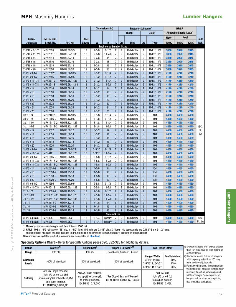
Lumber Hangers
189
Copy
righ
t © 2
020
MiT
ek In
dust
ries
, Inc
. Al
l Rig
hts
Rese
rved
Lumber Hangers
MiTek® Product Catalog
MPH Masonry Hangers
Floor
Ref. No. W H L Qty Type Qty Type 100% 115% 125%
2 x 10 MPH210 WMU1.56/9.25 12 1-9/16 9-1/4 7 2 16d duplex 2 10d x 1-1/2 2610 2650 2675 2 x 12 MPH212 WMU1.56/11.25 12 1-9/16 11-1/4 7 2 16d duplex 2 10d x 1-1/2 2610 2650 2675 2 x 14 MPH214 WMU1.56/14 12 1-9/16 13-1/8 7 2 16d duplex 2 10d x 1-1/2 2610 2650 2675 2 x 16 MPH216 WMU1.56/16 12 1-9/16 15-1/8 7 2 16d duplex 2 10d x 1-1/2 2610 2650 2675 (2) 2 x 10 MPH210-2 WMU3.12/9.25 12 3-1/8 9-1/4 7 2 16d duplex 2 10d 4430 4430 4430 (2) 2 x 12 MPH212-2 WMU3.12/11.25 12 3-1/8 11-1/4 7 2 16d duplex 2 10d 4430 4430 4430 (2) 2 x 14 MPH214-2 WMU3.12/14 12 3-1/8 13-1/8 7 2 16d duplex 2 10d 4430 4430 4430 (2) 2 x 16 MPH216-2 WMU3.12/16 12 3-1/8 15-1/8 7 2 16d duplex 2 10d 4430 4430 4430 3 x 10 MPH310 WMU2.56/9.25 12 2-9/16 9-1/4 7 2 16d duplex 2 10d x 1-1/2 3295 3295 3295 3 x 12 MPH312 WMU2.56/11.25 12 2-9/16 11-1/4 7 2 16d duplex 2 10d x 1-1/2 3295 3295 3295 3 x 14 MPH314 WMU2.56/13.25 12 2-9/16 13-1/8 7 2 16d duplex 2 10d x 1-1/2 3295 3295 3295 3 x 16 MPH316 WMU2.56/15.25 12 2-9/16 15-1/8 7 2 16d duplex 2 10d x 1-1/2 3295 3295 3295 4 x 10 MPH410 WMU3.56/9.25 12 3-9/16 9-1/4 7 2 16d duplex 2 10d 4430 4430 4430 4 x 12 MPH412 WMU3.56/11.25 12 3-9/16 11-1/4 7 2 16d duplex 2 10d 4430 4430 4430 4 x 14 MPH414 WMU3.56/13.25 12 3-9/16 13-1/8 7 2 16d duplex 2 10d 4430 4430 4430 4 x 16 MPH416 WMU3.56/15.25 12 3-9/16 15-1/8 7 2 16d duplex 2 10d 4430 4430 4430 6 x 10 MPH610 WMU5.50/9.5 12 5-9/16 9-1/4 7 2 16d duplex 2 10d 4430 4430 4430
1-1/2 x 9-1/4 MPH210 WMU1.56/9.25 12 1-9/16 9-1/4 7 2 16d duplex 2 10d x 1-1/2 2610 2650 2675 1-1/2 x 9-1/2 MPH1595 WMU1.56/9.5 12 1-9/16 9-1/2 7 2 16d duplex 2 10d x 1-1/2 2610 2650 2675 1-1/2 x 11-1/4 MPH212 WMU1.56/11.25 12 1-9/16 11-1/4 7 2 16d duplex 2 10d x 1-1/2 2610 2650 2675 1-1/2 x 11-7/8 MPH15118 WMU1.56/11.88 12 1-9/16 11-7/8 7 2 16d duplex 2 10d x 1-1/2 2610 2650 2675 1-1/2 x 14 MPH1514 WMU1.56/14 12 1-9/16 14 7 2 16d duplex 2 10d x 1-1/2 2610 2650 2675 1-3/4 x 9-1/2 MPH1795 WMU1.81/9.5 12 1-13/16 9-1/2 7 2 16d duplex 2 10d x 1-1/2 3000 3040 3065 1-3/4 x 11-7/8 MPH17118 WMU1.81/11.88 12 1-13/16 11-7/8 7 2 16d duplex 2 10d x 1-1/2 3000 3040 3065 1-3/4 x 14 MPH1714 WMU1.81/14 12 1-13/16 14 7 2 16d duplex 2 10d x 1-1/2 3000 3040 3065 1-3/4 x 16 MPH1716 WMU1.81/16 12 1-13/16 16 7 2 16d duplex 2 10d x 1-1/2 3000 3040 3065
1) Masonry compressive strength shall be minimum 1500 psi. 2) NAILS: 10d x 1-1/2 nails are 0.148" dia. x 1-1/2" long, 10d nails are 0.148" dia. x 3" long, 16d duplex nails are 0.162" dia. x 3-1/2" long, double headed nails and shall be installed in grouted cells in accordance to manufacturer's installation specifications. New products or updated product information are designated in blue font.
Floor
Ref. No. W H L Qty Type Qty Type 100% 115% 125%
2-5/16 x 9-1/2 MPH2395 WMU2.37/9.5 12 2-3/8 9-1/2 7 2 16d duplex 2 10d x 1-1/2 3880 3920 3945 2-5/16 x 11-7/8 MPH23118 WMU2.37/11.88 12 2-3/8 11-7/8 7 2 16d duplex 2 10d x 1-1/2 3880 3920 3945 2-5/16 x 14 MPH2314 WMU2.37/14 12 2-3/8 14 7 2 16d duplex 2 10d x 1-1/2 3880 3920 3945 2-5/16 x 16 MPH2316 WMU2.37/16 12 2-3/8 16 7 2 16d duplex 2 10d x 1-1/2 3880 3920 3945 2-5/16 x 18 MPH2318 WMU2.37/18 12 2-3/8 18 7 2 16d duplex 2 10d x 1-1/2 3880 3920 3945 2-5/16 x 20 MPH2320 WMU2.37/20 12 2-3/8 20 7 2 16d duplex 2 10d x 1-1/2 3880 3920 3945 2-1/2 x 9-1/4 MPH25925 WMU2.56/9.25 12 2-1/2 9-1/4 7 2 16d duplex 2 10d x 1-1/2 4170 4210 4240 2-1/2 x 9-1/2 MPH2595 WMU2.56/9.5 12 2-1/2 9-1/2 7 2 16d duplex 2 10d x 1-1/2 4170 4210 4240 2-1/2 x 11-1/4 MPH25112 WMU2.56/11.25 12 2-1/2 11-1/4 7 2 16d duplex 2 10d x 1-1/2 4170 4210 4240 2-1/2 x 11-7/8 MPH25118 WMU2.56/11..88 12 2-1/2 11-7/8 7 2 16d duplex 2 10d x 1-1/2 4170 4210 4240 2-1/2 x 14 MPH2514 WMU2.56/14 12 2-1/2 14 7 2 16d duplex 2 10d x 1-1/2 4170 4210 4240 2-1/2 x 16 MPH2516 WMU2.56/16 12 2-1/2 16 7 2 16d duplex 2 10d x 1-1/2 4170 4210 4240 2-1/2 x 18 MPH2518 WMU2.56/18 12 2-1/2 18 7 2 16d duplex 2 10d x 1-1/2 4170 4210 4240 2-1/2 x 20 MPH2520 WMU2.56/20 12 2-1/2 20 7 2 16d duplex 2 10d x 1-1/2 4170 4210 4240 2-1/2 x 22 MPH2522 WMU2.56/22 12 2-1/2 22 7 2 16d duplex 2 10d x 1-1/2 4170 4210 4240 2-1/2 x 24 MPH2524 WMU2.56/24 12 2-1/2 24 7 2 16d duplex 2 10d x 1-1/2 4170 4210 4240 2-1/2 x 26 MPH2526 WMU2.56/26 12 2-1/2 26 7 2 16d duplex 2 10d x 1-1/2 4170 4210 4240 3 x 9-1/4 MPH210-2 WMU3.12/9.25 12 3-1/8 9-1/4 7 2 16d duplex 2 10d 4430 4430 4430 3 x 9-1/2 MPH1595-2 WMU3.12/9.5 12 3-1/8 9-1/2 7 2 16d duplex 2 10d 4430 4430 4430 3 x 11-1/4 MPH15112-2 WMU3.12/11.25 12 3-1/8 11-1/4 7 2 16d duplex 2 10d 4430 4430 4430 3 x 11-7/8 MPH15118-2 WMU3.12/11.88 12 3-1/8 11-7/8 7 2 16d duplex 2 10d 4430 4430 4430 3-1/2 x 12 MPH3512 WMU3.62/12 12 3-1/2 12 7 2 16d duplex 2 10d 4430 4430 4430 3-1/2 x 14 MPH3514 WMU3.62/14 12 3-1/2 14 7 2 16d duplex 2 10d 4430 4430 4430 3-1/2 x 16 MPH3516 WMU3.62/16 12 3-1/2 16 7 2 16d duplex 2 10d 4430 4430 4430 3-1/2 x 18 MPH3518 WMU3.62/18 12 3-1/2 18 7 2 16d duplex 2 10d 4430 4430 4430 3-1/2 x 20 MPH3520 WMU3.62/20 12 3-1/2 20 7 2 16d duplex 2 10d 4430 4430 4430 3-1/2 x 9-1/4 MPH410 WMU3.56/9.25 12 3-9/16 9-1/4 7 2 16d duplex 2 10d 4430 4430 4430 3-1/2 x 11-1/4 MPH412 WMU3.56/11.25 12 3-9/16 11-1/4 7 2 16d duplex 2 10d 4430 4430 4430 3-1/2 x 9-1/2 MPH1795-2 WMU3.56/9.5 12 3-5/8 9-1/2 7 2 16d duplex 2 10d 4430 4430 4430 3-1/2 x 11-7/8 MPH17118-2 WMU3.56/11.88 12 3-5/8 11-7/8 7 2 16d duplex 2 10d 4430 4430 4430 4-5/8 x 11-7/8 MPH23118-2 WMU4.75/11.88 12 4-5/8 11-7/8 7 2 16d duplex 2 10d 4430 4430 4430 4-5/8 x 14 MPH2314-2 WMU4.75/14 12 4-5/8 14 7 2 16d duplex 2 10d 4430 4430 4430 4-5/8 x 16 MPH2316-2 WMU4.75/16 12 4-5/8 16 7 2 16d duplex 2 10d 4430 4430 4430 4-5/8 x 18 MPH2318-2 WMU4.75/18 12 4-5/8 18 7 2 16d duplex 2 10d 4430 4430 4430 4-5/8 x 20 MPH2320-2 WMU4.75/20 12 4-5/8 20 7 2 16d duplex 2 10d 4430 4430 4430 5-1/4 x 9-1/2 MPH5595 WMU5.50/9.5 12 5-5/8 9-1/2 7 2 16d duplex 2 10d 4430 4430 4430 5-1/4 x 11-7/8 MPH55118 WMU5.50/11.88 12 5-5/8 11-7/8 7 2 16d duplex 2 10d 4430 4430 4430 7 x 9-1/2 MPH3595-2 WMU7.12/9.5 12 7-1/8 9-1/2 8 2 16d duplex 2 10d 4490 4490 4490 7 x 11-1/4 MPH35112-2 WMU7.12/11.25 12 7-1/8 11-1/4 8 2 16d duplex 2 10d 4490 4490 4490 7 x 11-7/8 MPH35118-2 WMU7.12/11.88 12 7-1/8 11-7/8 8 2 16d duplex 2 10d 4490 4490 4490 7 x 14 MPH3514-2 WMU7.12/14 12 7-1/8 14 8 2 16d duplex 2 10d 4490 4490 4490 7 x 16 MPH3516-2 WMU7.12/16 12 7-1/8 16 8 2 16d duplex 2 10d 4490 4490 4490 7 x 18 MPH3518-2 WMU7.12/18 12 7-1/8 18 8 2 16d duplex 2 10d 4490 4490 4490
3-1/8 x glulam MPH325 WMU3.25X 12 3-1/4 specify 7 2 16d duplex 2 10d 4430 4430 4430 5-1/8 x glulam MPH525 WMU5.25X 12 5-1/4 specify 7 2 16d duplex 2 10d 4430 4430 4430
1) Masonry compressive strength shall be minimum 1500 psi. 2) NAILS: 10d x 1-1/2 nails are 0.148" dia. x 1-1/2" long, 10d nails are 0.148" dia. x 3" long, 16d duplex nails are 0.162" dia. x 3-1/2" long, double headed nails and shall be installed in grouted cells in accordance to manufacturer's installation specifications. New products or updated product information are designated in blue font.
SteelGauge
Roof
IBC,FL,LA
Dimensions (in)
SteelGauge
Block Joist
Roof
Fastener Schedule2 DF/SPAllowable Loads (Lbs.)1
Engineered Lumber Sizes
Standard Lumber Sizes
Glulam SizesIBC,
FL, LA
Beam/Joist Size
MiTek USPStock No.
CodeRef.
IBC,FL,LA
Engineered Lumber Sizes
Dimensions (in) Fastener Schedule2 DF/SPAllowable Loads (Lbs.)1Block
IBC,FL,LA
CodeRef.
Joist
Beam/Joist Size
MiTek USPStock No.
Specialty Options Chart – Refer to Specialty Options pages 320, 322-323 for additional details.
Option Skewed1,3 Sloped Seat2 Sloped / Skewed1,2,3 Top Flange Offset
Range 1˚ to 60˚ 1˚ to 45˚ See Sloped Seat and Skewed
1) Skewed hangers with skews greater than 15° may have all joist nailing on outside flange. 2) Sloped or sloped / skewed hangers with slopes greater than 15° may have additional joist nails. 3) For skewed hangers, the required cut type (square or bevel) of joist member may vary based on skew angle and width of hanger. Some square cut hangers will require custom pricing due to welded back plate.
--
See Sloped Seat and Skewed.Ex. MPH210_SK45R_SQ_SL30D
Add OS, andright (R) or left (L), to product number.Ex. MPH210_OSL
Allowable Loads
Ordering
100% of table load
Add SK, angle required,right (R) or left (L), and
square cut (SQ) or bevel cut (BV)to product number.
Ex. MPH210_SK45R_SQ
Add SL, slope required,and up (U) or down (D),
to product number.Ex. MPH210_SL30D
100% of table load 100% of table load
Hanger Width3-1/2" or less
3-9/16" to 5-1/2"5-9/16" to 7-1/2"
% of table load:60%75%85%
1) Skewed hangers with skews greater than 15° may have all joist nailing on outside flange.
2) Sloped or sloped / skewed hangers with slopes greater than 15° may have additional joist nails.
3) For skewed hangers, the required cut type (square or bevel) of joist member may vary based on skew angle and width of hanger. Some square cut hangers will require custom pricing due to welded back plate.
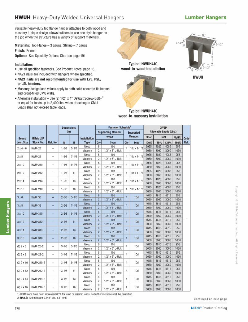
190
Copyright © 2020 M
iTek Industries, Inc. All Rights Reserved
Lumber Hangers
Lum
ber H
ange
rs
MiTek® Product Catalog
HWUH Heavy-Duty Welded Universal Hangers
Floor Uplift1
W H Qty Type Qty Type 100% 115% 125% 160%Wood 6 10d 3925 4020 4085 955
Masonry 2 1/2" x 6" J-Bolt 3060 3060 3060 1030Wood 6 10d 3925 4020 4085 955
Masonry 2 1/2" x 6" J-Bolt 3060 3060 3060 1030Wood 6 10d 3925 4020 4085 955
Masonry 2 1/2" x 6" J-Bolt 3060 3060 3060 1030Wood 6 10d 3925 4020 4085 955
Masonry 2 1/2" x 6" J-Bolt 3060 3060 3060 1030Wood 6 10d 3925 4020 4085 955
Masonry 2 1/2" x 6" J-Bolt 3060 3060 3060 1030Wood 6 10d 3925 4020 4085 955
Masonry 2 1/2" x 6" J-Bolt 3060 3060 3060 1030Wood 6 10d 4615 4615 4615 955
Masonry 2 1/2" x 6" J-Bolt 3060 3060 3060 1030Wood 6 10d 4615 4615 4615 955
Masonry 2 1/2" x 6" J-Bolt 3060 3060 3060 1030Wood 6 10d 4615 4615 4615 955
Masonry 2 1/2" x 6" J-Bolt 3060 3060 3060 1030Wood 6 10d 4615 4615 4615 955
Masonry 2 1/2" x 6" J-Bolt 3060 3060 3060 1030Wood 6 10d 4615 4615 4615 955
Masonry 2 1/2" x 6" J-Bolt 3060 3060 3060 1030Wood 6 10d 4615 4615 4615 955
Masonry 2 1/2" x 6" J-Bolt 3060 3060 3060 1030Wood 6 10d 4615 4615 4615 955
Masonry 2 1/2" x 6" J-Bolt 3060 3060 3060 1030Wood 6 10d 4615 4615 4615 955
Masonry 2 1/2" x 6" J-Bolt 3060 3060 3060 1030Wood 6 10d 4615 4615 4615 955
Masonry 2 1/2" x 6" J-Bolt 3060 3060 3060 1030Wood 6 10d 4615 4615 4615 955
Masonry 2 1/2" x 6" J-Bolt 3060 3060 3060 1030Wood 6 10d 4615 4615 4615 955
Masonry 2 1/2" x 6" J-Bolt 3060 3060 3060 1030Wood 6 10d 4615 4615 4615 955
Masonry 2 1/2" x 6" J-Bolt 3060 3060 3060 1030
1) Uplift loads have been increased 60% for wind or seismic loads; no further increase shall be permitted. 2) NAILS: 10d nails are 0.148" dia. x 3" long.
Floor Uplift1
W H Qty Type Qty Type 100% 115% 125% 160%Wood 6 NA21 5265 5265 5265 675
Masonry 2 1/2" x 6" J-Bolt 3060 3060 3060 1030Wood 6 NA21 5265 5265 5265 675
Masonry 2 1/2" x 6" J-Bolt 3060 3060 3060 1030Wood 6 NA21 5265 5265 5265 675
Masonry 2 1/2" x 6" J-Bolt 3060 3060 3060 1030Wood 6 NA21 5265 5265 5265 675
Masonry 2 1/2" x 6" J-Bolt 3060 3060 3060 1030Wood 6 NA21 5265 5265 5265 675
Masonry 2 1/2" x 6" J-Bolt 3060 3060 3060 1030Wood 6 NA21 5265 5265 5265 675
Masonry 2 1/2" x 6" J-Bolt 3060 3060 3060 1030Wood 6 NA21 5265 5265 5265 675
Masonry 2 1/2" x 6" J-Bolt 3060 3060 3060 1030Wood 6 NA21 5265 5265 5265 675
Masonry 2 1/2" x 6" J-Bolt 3060 3060 3060 1030Wood 6 NA21 5265 5265 5265 675
Masonry 2 1/2" x 6" J-Bolt 3060 3060 3060 1030Wood 6 NA21 5265 5265 5265 675
Masonry 2 1/2" x 6" J-Bolt 3060 3060 3060 1030Wood 6 NA21 5265 5265 5265 675
Masonry 2 1/2" x 6" J-Bolt 3060 3060 3060 1030Wood 6 NA21 5265 5265 5265 675
Masonry 2 1/2" x 6" J-Bolt 3060 3060 3060 1030Wood 6 NA21 5265 5265 5265 675
Masonry 2 1/2" x 6" J-Bolt 3060 3060 3060 1030Wood 6 NA21 5265 5265 5265 675
Masonry 2 1/2" x 6" J-Bolt 3060 3060 3060 1030Wood 6 NA21 5265 5265 5265 675
Masonry 2 1/2" x 6" J-Bolt 3060 3060 3060 1030Wood 6 NA21 5265 5265 5265 675
Masonry 2 1/2" x 6" J-Bolt 3060 3060 3060 1030Wood 6 NA21 5265 5265 5265 675
Masonry 2 1/2" x 6" J-Bolt 3060 3060 3060 1030Wood 6 NA21 5265 5265 5265 675
Masonry 2 1/2" x 6" J-Bolt 3060 3060 3060 1030
1) Uplift loads have been increased 60% for wind or seismic loads; no further increase shall be permitted. 2) NAILS: NA21 nails are 0.192" dia. x 1-3/4" long and are included with 4x, 6x, and 8x HWUH hangers.
--
--
Dimensions(in)
Fastener Schedule2
Supporting Member SupportedMemberWood Roof Code
Ref.
DF/SP Allowable Loads (Lbs.)
InstallationType
7-1/2
7-1/2
7-1/2
7-1/2
11
13
16
11
13
16
5-3/8
7-1/8
9-1/8
5-1/2
5-1/2
5-1/2
7-1/2
7-1/2
5-1/2 5-3/8
5-1/2 7-1/8
5-1/2 9-1/8
11
13
16
3-1/8
3-1/8
3-1/8
3-1/8
3-9/16
5-3/8
7-1/8
9-1/8
11
13
16
3-9/16
3-9/16
3-9/16
3-9/16
3-9/16
5-3/8
7-1/8
9-1/8
11
13
16
11
7-1/8
9-1/8
13
16
5-3/8
HWUH816
1-5/8 5-3/8
1-5/8
1-5/8
1-5/8
1-5/8
1-5/8
2-5/8
2-5/8
2-5/8
2-5/8
2-5/8
2-5/8
3-1/8
3-1/8
HWUH86
HWUH88
HWUH810
HWUH812
HWUH814
HWUH68
HWUH610
HWUH612
HWUH614
HWUH616
HWUH410
HWUH412
HWUH414
HWUH416
HWUH66
HWUH212-2
HWUH214-2
HWUH216-2
HWUH46
HWUH48
MiTek USPStock No.
8 x 16
HWUH26
HWUH28
HWUH210
HWUH212
HWUH214
HWUH216
HWUH36
HWUH38
HWUH310
HWUH312
HWUH314
HWUH316
HWUH26-2
HWUH28-2
HWUH210-2
8 x 6
8 x 8
8 x 10
8 x 12
8 x 14
6 x 8
6 x 10
6 x 12
6 x 14
6 x 16
4 x 10
4 x 12
4 x 14
4 x 16
6 x 6
(2) 2 x 12
(2) 2 x 14
(2) 2 x 16
4 x 6
4 x 8
Beam/Joist Size
--
2 x 4 - 6
2 x 8
2 x 10
2 x 12
2 x 14
2 x 16
3 x 6
3 x 8
3 x 10
3 x 12
3 x 14
3 x 16
(2) 2 x 6
(2) 2 x 8
(2) 2 x 10
--
--
--
--
--
--
--
--
--
--
--
--
--
--
--
--
--
--
--
--
Ref. No.
--
--
--
--
--
--
--
--
--
4 10d
4 10d
4 10d
4 10d
4 10d
4 10d
4 10d
4 10d
4 10d
4 10d
4 10d
4 10d
4 10d
4 10d
4 10d
10d
4 10d
4 10d
4 10d
4 10d
4 10d
4
4 10d
4 10d
4 10d
4 10d
4 10d
4 10d
4 10d
4 10d
4 10d
10d x 1-1/2
4 10d x 1-1/2
4 10d x 1-1/2
Beam/Joist Size
MiTek USPStock No.
Wood Roof
4 10d x 1-1/2
4 10d x 1-1/2
4
--
--
--
--
--
7-1/8
9-1/8
CodeRef.
SupportedMember
DF/SP Allowable Loads (Lbs.)
InstallationTypeRef. No.
Dimensions(in) Supporting Member
Fastener Schedule2
4 10d x 1-1/2
--
Versatile heavy-duty top flange hanger attaches to both wood and masonry. Unique design allows builders to use one style hanger on the job when the structure has a variety of support materials.
Materials: Top Flange – 3 gauge; Stirrup – 7 gaugeFinish: PrimerOptions: See Specialty Options Chart on page 191
Installation:• Use all specified fasteners. See Product Notes, page 18.• NA21 nails are included with hangers where specified.• NA21 nails are not recommended for use with LVL, PSL,
or LSL headers.• Masonry design load values apply to both solid concrete tie beams
and grout-filled CMU walls.• Alternate installation – Use (2) 1/2" x 4" DeWalt Screw-Bolt+TM
or equal for loads up to 2,400 lbs. when attaching to CMU. Loads shall not exceed table loads.
Typical HWUH410wood-to-masonry installation
HWUH
Typical HWUH410wood-to-wood installation
H
W3-1/2"
3-1/2"3-1/2"
10"
Continued on next page
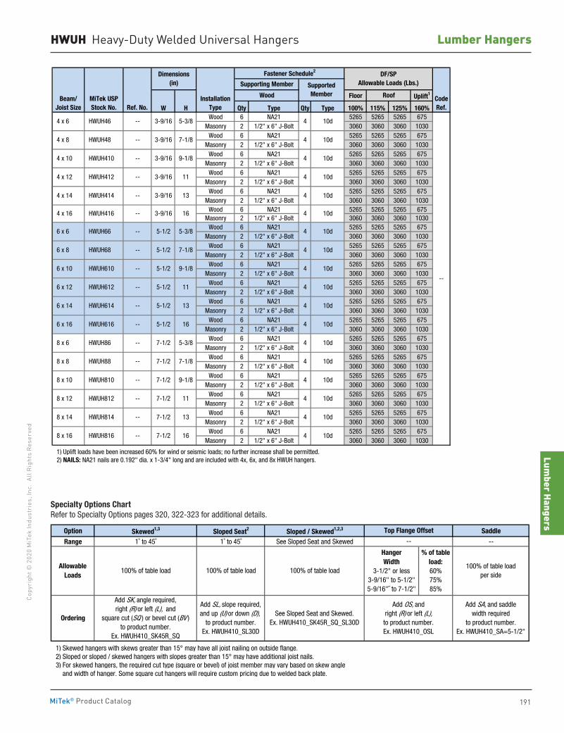
Lumber Hangers
191
Copy
righ
t © 2
020
MiT
ek In
dust
ries
, Inc
. Al
l Rig
hts
Rese
rved
Lumber Hangers
MiTek® Product Catalog
HWUH Heavy-Duty Welded Universal Hangers
Floor Uplift1
W H Qty Type Qty Type 100% 115% 125% 160%Wood 6 10d 3925 4020 4085 955
Masonry 2 1/2" x 6" J-Bolt 3060 3060 3060 1030Wood 6 10d 3925 4020 4085 955
Masonry 2 1/2" x 6" J-Bolt 3060 3060 3060 1030Wood 6 10d 3925 4020 4085 955
Masonry 2 1/2" x 6" J-Bolt 3060 3060 3060 1030Wood 6 10d 3925 4020 4085 955
Masonry 2 1/2" x 6" J-Bolt 3060 3060 3060 1030Wood 6 10d 3925 4020 4085 955
Masonry 2 1/2" x 6" J-Bolt 3060 3060 3060 1030Wood 6 10d 3925 4020 4085 955
Masonry 2 1/2" x 6" J-Bolt 3060 3060 3060 1030Wood 6 10d 4615 4615 4615 955
Masonry 2 1/2" x 6" J-Bolt 3060 3060 3060 1030Wood 6 10d 4615 4615 4615 955
Masonry 2 1/2" x 6" J-Bolt 3060 3060 3060 1030Wood 6 10d 4615 4615 4615 955
Masonry 2 1/2" x 6" J-Bolt 3060 3060 3060 1030Wood 6 10d 4615 4615 4615 955
Masonry 2 1/2" x 6" J-Bolt 3060 3060 3060 1030Wood 6 10d 4615 4615 4615 955
Masonry 2 1/2" x 6" J-Bolt 3060 3060 3060 1030Wood 6 10d 4615 4615 4615 955
Masonry 2 1/2" x 6" J-Bolt 3060 3060 3060 1030Wood 6 10d 4615 4615 4615 955
Masonry 2 1/2" x 6" J-Bolt 3060 3060 3060 1030Wood 6 10d 4615 4615 4615 955
Masonry 2 1/2" x 6" J-Bolt 3060 3060 3060 1030Wood 6 10d 4615 4615 4615 955
Masonry 2 1/2" x 6" J-Bolt 3060 3060 3060 1030Wood 6 10d 4615 4615 4615 955
Masonry 2 1/2" x 6" J-Bolt 3060 3060 3060 1030Wood 6 10d 4615 4615 4615 955
Masonry 2 1/2" x 6" J-Bolt 3060 3060 3060 1030Wood 6 10d 4615 4615 4615 955
Masonry 2 1/2" x 6" J-Bolt 3060 3060 3060 1030
1) Uplift loads have been increased 60% for wind or seismic loads; no further increase shall be permitted. 2) NAILS: 10d nails are 0.148" dia. x 3" long.
Floor Uplift1
W H Qty Type Qty Type 100% 115% 125% 160%Wood 6 NA21 5265 5265 5265 675
Masonry 2 1/2" x 6" J-Bolt 3060 3060 3060 1030Wood 6 NA21 5265 5265 5265 675
Masonry 2 1/2" x 6" J-Bolt 3060 3060 3060 1030Wood 6 NA21 5265 5265 5265 675
Masonry 2 1/2" x 6" J-Bolt 3060 3060 3060 1030Wood 6 NA21 5265 5265 5265 675
Masonry 2 1/2" x 6" J-Bolt 3060 3060 3060 1030Wood 6 NA21 5265 5265 5265 675
Masonry 2 1/2" x 6" J-Bolt 3060 3060 3060 1030Wood 6 NA21 5265 5265 5265 675
Masonry 2 1/2" x 6" J-Bolt 3060 3060 3060 1030Wood 6 NA21 5265 5265 5265 675
Masonry 2 1/2" x 6" J-Bolt 3060 3060 3060 1030Wood 6 NA21 5265 5265 5265 675
Masonry 2 1/2" x 6" J-Bolt 3060 3060 3060 1030Wood 6 NA21 5265 5265 5265 675
Masonry 2 1/2" x 6" J-Bolt 3060 3060 3060 1030Wood 6 NA21 5265 5265 5265 675
Masonry 2 1/2" x 6" J-Bolt 3060 3060 3060 1030Wood 6 NA21 5265 5265 5265 675
Masonry 2 1/2" x 6" J-Bolt 3060 3060 3060 1030Wood 6 NA21 5265 5265 5265 675
Masonry 2 1/2" x 6" J-Bolt 3060 3060 3060 1030Wood 6 NA21 5265 5265 5265 675
Masonry 2 1/2" x 6" J-Bolt 3060 3060 3060 1030Wood 6 NA21 5265 5265 5265 675
Masonry 2 1/2" x 6" J-Bolt 3060 3060 3060 1030Wood 6 NA21 5265 5265 5265 675
Masonry 2 1/2" x 6" J-Bolt 3060 3060 3060 1030Wood 6 NA21 5265 5265 5265 675
Masonry 2 1/2" x 6" J-Bolt 3060 3060 3060 1030Wood 6 NA21 5265 5265 5265 675
Masonry 2 1/2" x 6" J-Bolt 3060 3060 3060 1030Wood 6 NA21 5265 5265 5265 675
Masonry 2 1/2" x 6" J-Bolt 3060 3060 3060 1030
1) Uplift loads have been increased 60% for wind or seismic loads; no further increase shall be permitted. 2) NAILS: NA21 nails are 0.192" dia. x 1-3/4" long and are included with 4x, 6x, and 8x HWUH hangers.
--
--
Dimensions(in)
Fastener Schedule2
Supporting Member SupportedMemberWood Roof Code
Ref.
DF/SP Allowable Loads (Lbs.)
InstallationType
7-1/2
7-1/2
7-1/2
7-1/2
11
13
16
11
13
16
5-3/8
7-1/8
9-1/8
5-1/2
5-1/2
5-1/2
7-1/2
7-1/2
5-1/2 5-3/8
5-1/2 7-1/8
5-1/2 9-1/8
11
13
16
3-1/8
3-1/8
3-1/8
3-1/8
3-9/16
5-3/8
7-1/8
9-1/8
11
13
16
3-9/16
3-9/16
3-9/16
3-9/16
3-9/16
5-3/8
7-1/8
9-1/8
11
13
16
11
7-1/8
9-1/8
13
16
5-3/8
HWUH816
1-5/8 5-3/8
1-5/8
1-5/8
1-5/8
1-5/8
1-5/8
2-5/8
2-5/8
2-5/8
2-5/8
2-5/8
2-5/8
3-1/8
3-1/8
HWUH86
HWUH88
HWUH810
HWUH812
HWUH814
HWUH68
HWUH610
HWUH612
HWUH614
HWUH616
HWUH410
HWUH412
HWUH414
HWUH416
HWUH66
HWUH212-2
HWUH214-2
HWUH216-2
HWUH46
HWUH48
MiTek USPStock No.
8 x 16
HWUH26
HWUH28
HWUH210
HWUH212
HWUH214
HWUH216
HWUH36
HWUH38
HWUH310
HWUH312
HWUH314
HWUH316
HWUH26-2
HWUH28-2
HWUH210-2
8 x 6
8 x 8
8 x 10
8 x 12
8 x 14
6 x 8
6 x 10
6 x 12
6 x 14
6 x 16
4 x 10
4 x 12
4 x 14
4 x 16
6 x 6
(2) 2 x 12
(2) 2 x 14
(2) 2 x 16
4 x 6
4 x 8
Beam/Joist Size
--
2 x 4 - 6
2 x 8
2 x 10
2 x 12
2 x 14
2 x 16
3 x 6
3 x 8
3 x 10
3 x 12
3 x 14
3 x 16
(2) 2 x 6
(2) 2 x 8
(2) 2 x 10
--
--
--
--
--
--
--
--
--
--
--
--
--
--
--
--
--
--
--
--
Ref. No.
--
--
--
--
--
--
--
--
--
4 10d
4 10d
4 10d
4 10d
4 10d
4 10d
4 10d
4 10d
4 10d
4 10d
4 10d
4 10d
4 10d
4 10d
4 10d
10d
4 10d
4 10d
4 10d
4 10d
4 10d
4
4 10d
4 10d
4 10d
4 10d
4 10d
4 10d
4 10d
4 10d
4 10d
10d x 1-1/2
4 10d x 1-1/2
4 10d x 1-1/2
Beam/Joist Size
MiTek USPStock No.
Wood Roof
4 10d x 1-1/2
4 10d x 1-1/2
4
--
--
--
--
--
7-1/8
9-1/8
CodeRef.
SupportedMember
DF/SP Allowable Loads (Lbs.)
InstallationTypeRef. No.
Dimensions(in) Supporting Member
Fastener Schedule2
4 10d x 1-1/2
--
Specialty Options Chart Refer to Specialty Options pages 320, 322-323 for additional details.
Option Skewed1,3 Sloped Seat2 Sloped / Skewed1,2,3 Saddle
Range 1˚ to 45˚ 1˚ to 45˚ See Sloped Seat and Skewed --
1) Skewed hangers with skews greater than 15° may have all joist nailing on outside flange. 2) Sloped or sloped / skewed hangers with slopes greater than 15° may have additional joist nails. 3) For skewed hangers, the required cut type (square or bevel) of joist member may vary based on skew angle and width of hanger. Some square cut hangers will require custom pricing due to welded back plate.
Add SA, and saddlewidth required
to product number.Ex. HWUH410_SA=5-1/2"
% of table load:60%75%85%
Add SL, slope required,and up (U) or down (D),
to product number.Ex. HWUH410_SL30D
See Sloped Seat and Skewed.Ex. HWUH410_SK45R_SQ_SL30D
Add OS, and right (R) or left (L),to product number.Ex. HWUH410_OSL
100% of table loadper side
Top Flange Offset
--
AllowableLoads
Ordering
100% of table load
Add SK, angle required,right (R) or left (L), and
square cut (SQ ) or bevel cut (BV )to product number.
Ex. HWUH410_SK45R_SQ
100% of table load 100% of table load
Hanger Width
3-1/2" or less3-9/16" to 5-1/2"5-9/16"˝ to 7-1/2"
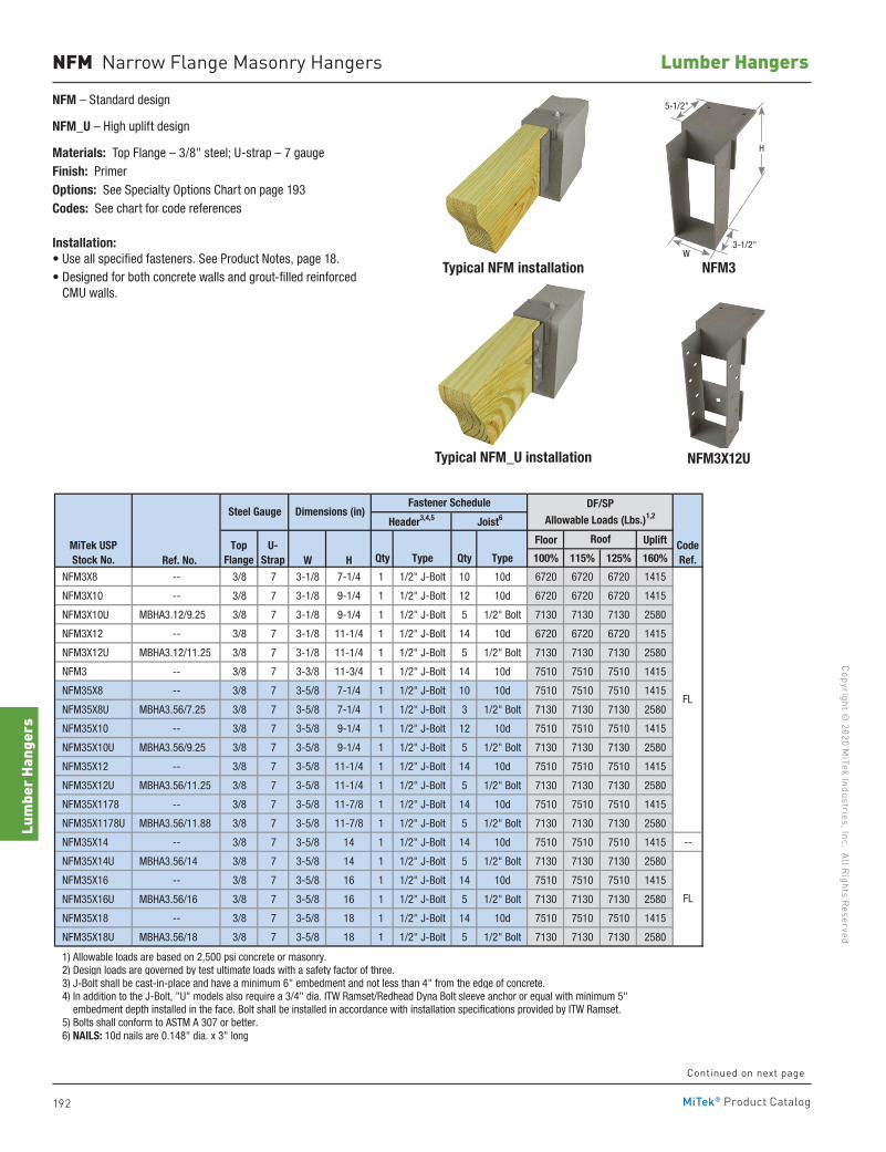
192
Copyright © 2020 M
iTek Industries, Inc. All Rights Reserved
Lumber Hangers
Lum
ber H
ange
rs
MiTek® Product Catalog
Floor Uplift
Ref. No. W H Qty Type Qty Type 100% 115% 125% 160%
NFM3X8 -- 3/8 7 3-1/8 7-1/4 1 1/2" J-Bolt 10 10d 6720 6720 6720 1415
NFM3X10 -- 3/8 7 3-1/8 9-1/4 1 1/2" J-Bolt 12 10d 6720 6720 6720 1415
NFM3X10U MBHA3.12/9.25 3/8 7 3-1/8 9-1/4 1 1/2" J-Bolt 5 1/2" Bolt 7130 7130 7130 2580
NFM3X12 -- 3/8 7 3-1/8 11-1/4 1 1/2" J-Bolt 14 10d 6720 6720 6720 1415
NFM3X12U MBHA3.12/11.25 3/8 7 3-1/8 11-1/4 1 1/2" J-Bolt 5 1/2" Bolt 7130 7130 7130 2580
NFM3 -- 3/8 7 3-3/8 11-3/4 1 1/2" J-Bolt 14 10d 7510 7510 7510 1415
NFM35X8 -- 3/8 7 3-5/8 7-1/4 1 1/2" J-Bolt 10 10d 7510 7510 7510 1415
NFM35X8U MBHA3.56/7.25 3/8 7 3-5/8 7-1/4 1 1/2" J-Bolt 3 1/2" Bolt 7130 7130 7130 2580
NFM35X10 -- 3/8 7 3-5/8 9-1/4 1 1/2" J-Bolt 12 10d 7510 7510 7510 1415
NFM35X10U MBHA3.56/9.25 3/8 7 3-5/8 9-1/4 1 1/2" J-Bolt 5 1/2" Bolt 7130 7130 7130 2580
NFM35X12 -- 3/8 7 3-5/8 11-1/4 1 1/2" J-Bolt 14 10d 7510 7510 7510 1415
NFM35X12U MBHA3.56/11.25 3/8 7 3-5/8 11-1/4 1 1/2" J-Bolt 5 1/2" Bolt 7130 7130 7130 2580
NFM35X1178 -- 3/8 7 3-5/8 11-7/8 1 1/2" J-Bolt 14 10d 7510 7510 7510 1415
NFM35X1178U MBHA3.56/11.88 3/8 7 3-5/8 11-7/8 1 1/2" J-Bolt 5 1/2" Bolt 7130 7130 7130 2580
NFM35X14 -- 3/8 7 3-5/8 14 1 1/2" J-Bolt 14 10d 7510 7510 7510 1415 --
NFM35X14U MBHA3.56/14 3/8 7 3-5/8 14 1 1/2" J-Bolt 5 1/2" Bolt 7130 7130 7130 2580
NFM35X16 -- 3/8 7 3-5/8 16 1 1/2" J-Bolt 14 10d 7510 7510 7510 1415
NFM35X16U MBHA3.56/16 3/8 7 3-5/8 16 1 1/2" J-Bolt 5 1/2" Bolt 7130 7130 7130 2580
NFM35X18 -- 3/8 7 3-5/8 18 1 1/2" J-Bolt 14 10d 7510 7510 7510 1415
NFM35X18U MBHA3.56/18 3/8 7 3-5/8 18 1 1/2" J-Bolt 5 1/2" Bolt 7130 7130 7130 2580
1) Allowable loads are based on 2,500 psi concrete or masonry. 2) Design loads are governed by test ultimate loads with a safety factor of three. 3) J-Bolt shall be cast-in-place and have a minimum 6" embedment and not less than 4" from the edge of concrete. 4) In addition to the J-Bolt, "U" models also require a 3/4" dia. ITW Ramset/Redhead Dyna Bolt sleeve anchor or equal with minimum 5" embedment depth installed in the face. Bolt shall be installed in accordance with installation specifications provided by ITW Ramset. 5) Bolts shall conform to ASTM A 307 or better. 6) NAILS: 10d nails are 0.148" dia. x 3" long
Floor Uplift
Ref. No. W H Qty Type Qty Type 100% 115% 125% 160%
NFM6X8U MBHA5.50/7.25 3/8 7 5-5/8 7-1/4 1 1/2" J-Bolt 3 1/2" Bolt 10310 10310 10310 2580
NFM6X10U MBHA5.50/9.25 3/8 7 5-5/8 9-1/4 1 1/2" J-Bolt 5 1/2" Bolt 10310 10310 10310 2580
NFM6X12U MBHA5.50/11.25 3/8 7 5-5/8 11-1/4 1 1/2" J-Bolt 5 1/2" Bolt 10310 10310 10310 2580
NFM6X1178 -- 3/8 7 5-5/8 11-7/8 1 1/2" J-Bolt 14 10d 7510 7510 7510 1415
NFM6X1178U MBHA5.50/11.88 3/8 7 5-5/8 11-7/8 1 1/2" J-Bolt 5 1/2" Bolt 10310 10310 10310 2580
NFM6X14U MBHA5.50/14 3/8 7 5-5/8 14 1 1/2" J-Bolt 5 1/2" Bolt 10310 10310 10310 2580
NFM6X16 -- 3/8 7 5-5/8 16 1 1/2" J-Bolt 14 10d 7510 7510 7510 1415
NFM6X16U MBHA5.50/16 3/8 7 5-5/8 16 1 1/2" J-Bolt 5 1/2" Bolt 10310 10310 10310 2580
NFM6X18 -- 3/8 7 5-5/8 18 1 1/2" J-Bolt 14 10d 7510 7510 7510 1415
NFM6X18U MBHA5.50/18 3/8 7 5-5/8 18 1 1/2" J-Bolt 5 1/2" Bolt 10310 10310 10310 2580
1) Allowable loads are based on 2,500 psi concrete or masonry. 2) Design loads are governed by test ultimate loads with a safety factor of three. 3) J-Bolt shall be cast-in-place and have a minimum 6" embedment and not less than 4" from the edge of concrete. 4) In addition to the J-Bolt, "U" models also require a 3/4" dia. ITW Ramset/Redhead Dyna Bolt sleeve anchor or equal with minimum 5" embedment depth installed in the face. Bolt shall be installed in accordance with installation specifications provided by ITW Ramset. 5) Bolts shall conform to ASTM A 307 or better. 6) NAILS: 10d nails are 0.148" dia. x 3" long
FL
MiTek USPStock No.
RoofTopFlange
U-Strap
CodeRef.
DF/SPAllowable Loads (Lbs.)1,2Dimensions (in)Steel Gauge
Fastener Schedule
Header3,4,5 Joist6
FL
FL
Steel Gauge Dimensions (in)Fastener Schedule DF/SP
Allowable Loads (Lbs.)1,2Header3,4,5 Joist6
MiTek USPStock No.
TopFlange
U-Strap
Roof CodeRef.
NFM Narrow Flange Masonry Hangers
NFM – Standard design
NFM_U – High uplift design
Materials: Top Flange – 3/8" steel; U-strap – 7 gaugeFinish: PrimerOptions: See Specialty Options Chart on page 193Codes: See chart for code references
Installation:• Use all specified fasteners. See Product Notes, page 18.• Designed for both concrete walls and grout-filled reinforced
CMU walls.
Typical NFM installation
Typical NFM_U installation
NFM3
NFM3X12U
Continued on next page
H
3-1/2"
5-1/2"
W
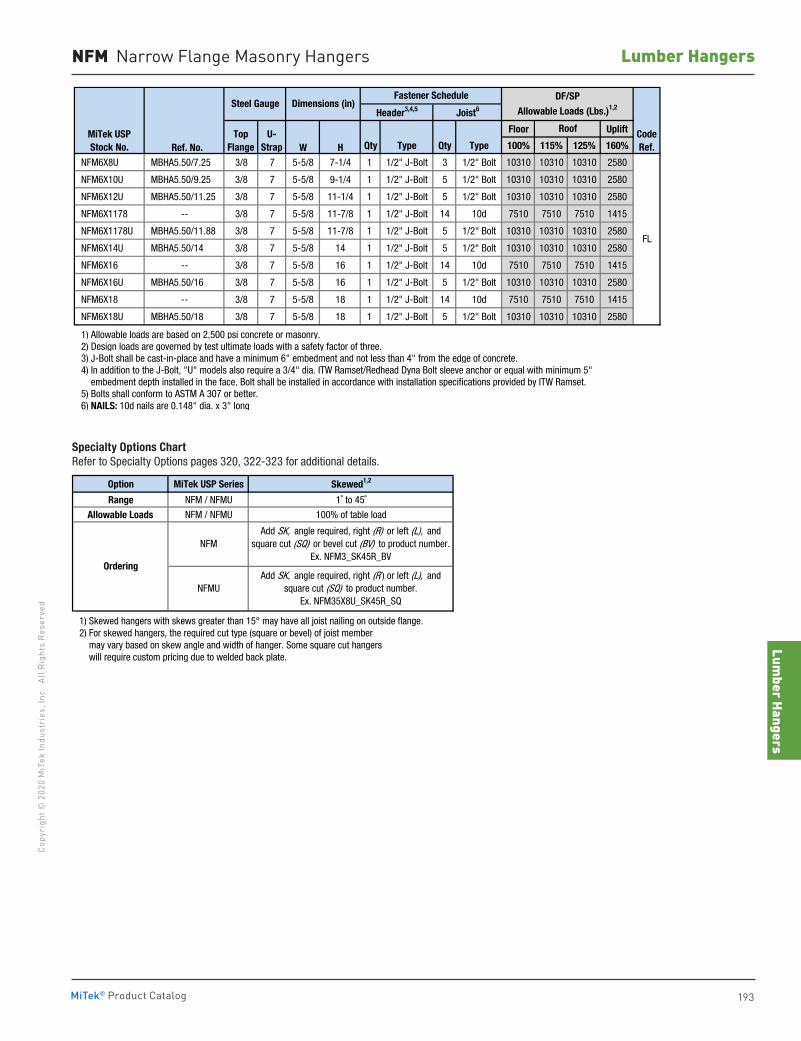
Lumber Hangers
193
Copy
righ
t © 2
020
MiT
ek In
dust
ries
, Inc
. Al
l Rig
hts
Rese
rved
Lumber Hangers
MiTek® Product Catalog
NFM Narrow Flange Masonry Hangers
Floor Uplift
Ref. No. W H Qty Type Qty Type 100% 115% 125% 160%
NFM3X8 -- 3/8 7 3-1/8 7-1/4 1 1/2" J-Bolt 10 10d 6720 6720 6720 1415
NFM3X10 -- 3/8 7 3-1/8 9-1/4 1 1/2" J-Bolt 12 10d 6720 6720 6720 1415
NFM3X10U MBHA3.12/9.25 3/8 7 3-1/8 9-1/4 1 1/2" J-Bolt 5 1/2" Bolt 7130 7130 7130 2580
NFM3X12 -- 3/8 7 3-1/8 11-1/4 1 1/2" J-Bolt 14 10d 6720 6720 6720 1415
NFM3X12U MBHA3.12/11.25 3/8 7 3-1/8 11-1/4 1 1/2" J-Bolt 5 1/2" Bolt 7130 7130 7130 2580
NFM3 -- 3/8 7 3-3/8 11-3/4 1 1/2" J-Bolt 14 10d 7510 7510 7510 1415
NFM35X8 -- 3/8 7 3-5/8 7-1/4 1 1/2" J-Bolt 10 10d 7510 7510 7510 1415
NFM35X8U MBHA3.56/7.25 3/8 7 3-5/8 7-1/4 1 1/2" J-Bolt 3 1/2" Bolt 7130 7130 7130 2580
NFM35X10 -- 3/8 7 3-5/8 9-1/4 1 1/2" J-Bolt 12 10d 7510 7510 7510 1415
NFM35X10U MBHA3.56/9.25 3/8 7 3-5/8 9-1/4 1 1/2" J-Bolt 5 1/2" Bolt 7130 7130 7130 2580
NFM35X12 -- 3/8 7 3-5/8 11-1/4 1 1/2" J-Bolt 14 10d 7510 7510 7510 1415
NFM35X12U MBHA3.56/11.25 3/8 7 3-5/8 11-1/4 1 1/2" J-Bolt 5 1/2" Bolt 7130 7130 7130 2580
NFM35X1178 -- 3/8 7 3-5/8 11-7/8 1 1/2" J-Bolt 14 10d 7510 7510 7510 1415
NFM35X1178U MBHA3.56/11.88 3/8 7 3-5/8 11-7/8 1 1/2" J-Bolt 5 1/2" Bolt 7130 7130 7130 2580
NFM35X14 -- 3/8 7 3-5/8 14 1 1/2" J-Bolt 14 10d 7510 7510 7510 1415 --
NFM35X14U MBHA3.56/14 3/8 7 3-5/8 14 1 1/2" J-Bolt 5 1/2" Bolt 7130 7130 7130 2580
NFM35X16 -- 3/8 7 3-5/8 16 1 1/2" J-Bolt 14 10d 7510 7510 7510 1415
NFM35X16U MBHA3.56/16 3/8 7 3-5/8 16 1 1/2" J-Bolt 5 1/2" Bolt 7130 7130 7130 2580
NFM35X18 -- 3/8 7 3-5/8 18 1 1/2" J-Bolt 14 10d 7510 7510 7510 1415
NFM35X18U MBHA3.56/18 3/8 7 3-5/8 18 1 1/2" J-Bolt 5 1/2" Bolt 7130 7130 7130 2580
1) Allowable loads are based on 2,500 psi concrete or masonry. 2) Design loads are governed by test ultimate loads with a safety factor of three. 3) J-Bolt shall be cast-in-place and have a minimum 6" embedment and not less than 4" from the edge of concrete. 4) In addition to the J-Bolt, "U" models also require a 3/4" dia. ITW Ramset/Redhead Dyna Bolt sleeve anchor or equal with minimum 5" embedment depth installed in the face. Bolt shall be installed in accordance with installation specifications provided by ITW Ramset. 5) Bolts shall conform to ASTM A 307 or better. 6) NAILS: 10d nails are 0.148" dia. x 3" long
Floor Uplift
Ref. No. W H Qty Type Qty Type 100% 115% 125% 160%
NFM6X8U MBHA5.50/7.25 3/8 7 5-5/8 7-1/4 1 1/2" J-Bolt 3 1/2" Bolt 10310 10310 10310 2580
NFM6X10U MBHA5.50/9.25 3/8 7 5-5/8 9-1/4 1 1/2" J-Bolt 5 1/2" Bolt 10310 10310 10310 2580
NFM6X12U MBHA5.50/11.25 3/8 7 5-5/8 11-1/4 1 1/2" J-Bolt 5 1/2" Bolt 10310 10310 10310 2580
NFM6X1178 -- 3/8 7 5-5/8 11-7/8 1 1/2" J-Bolt 14 10d 7510 7510 7510 1415
NFM6X1178U MBHA5.50/11.88 3/8 7 5-5/8 11-7/8 1 1/2" J-Bolt 5 1/2" Bolt 10310 10310 10310 2580
NFM6X14U MBHA5.50/14 3/8 7 5-5/8 14 1 1/2" J-Bolt 5 1/2" Bolt 10310 10310 10310 2580
NFM6X16 -- 3/8 7 5-5/8 16 1 1/2" J-Bolt 14 10d 7510 7510 7510 1415
NFM6X16U MBHA5.50/16 3/8 7 5-5/8 16 1 1/2" J-Bolt 5 1/2" Bolt 10310 10310 10310 2580
NFM6X18 -- 3/8 7 5-5/8 18 1 1/2" J-Bolt 14 10d 7510 7510 7510 1415
NFM6X18U MBHA5.50/18 3/8 7 5-5/8 18 1 1/2" J-Bolt 5 1/2" Bolt 10310 10310 10310 2580
1) Allowable loads are based on 2,500 psi concrete or masonry. 2) Design loads are governed by test ultimate loads with a safety factor of three. 3) J-Bolt shall be cast-in-place and have a minimum 6" embedment and not less than 4" from the edge of concrete. 4) In addition to the J-Bolt, "U" models also require a 3/4" dia. ITW Ramset/Redhead Dyna Bolt sleeve anchor or equal with minimum 5" embedment depth installed in the face. Bolt shall be installed in accordance with installation specifications provided by ITW Ramset. 5) Bolts shall conform to ASTM A 307 or better. 6) NAILS: 10d nails are 0.148" dia. x 3" long
FL
MiTek USPStock No.
RoofTopFlange
U-Strap
CodeRef.
DF/SPAllowable Loads (Lbs.)1,2Dimensions (in)Steel Gauge
Fastener Schedule
Header3,4,5 Joist6
FL
FL
Steel Gauge Dimensions (in)Fastener Schedule DF/SP
Allowable Loads (Lbs.)1,2Header3,4,5 Joist6
MiTek USPStock No.
TopFlange
U-Strap
Roof CodeRef.
Option MiTek USP Series Skewed1,2
Range NFM / NFMU 1˚ to 45˚
Allowable Loads NFM / NFMU 100% of table load
1) Skewed hangers with skews greater than 15° may have all joist nailing on outside flange. 2) For skewed hangers, the required cut type (square or bevel) of joist member may vary based on skew angle and width of hanger. Some square cut hangers will require custom pricing due to welded back plate.
Ordering
Add SK, angle required, right (R) or left (L), and square cut (SQ) or bevel cut (BV) to product number.
Ex. NFM3_SK45R_BV
Add SK, angle required, right (R ) or left (L), and square cut (SQ) to product number.
Ex. NFM35X8U_SK45R_SQ
NFM
NFMU
Specialty Options Chart Refer to Specialty Options pages 320, 322-323 for additional details.
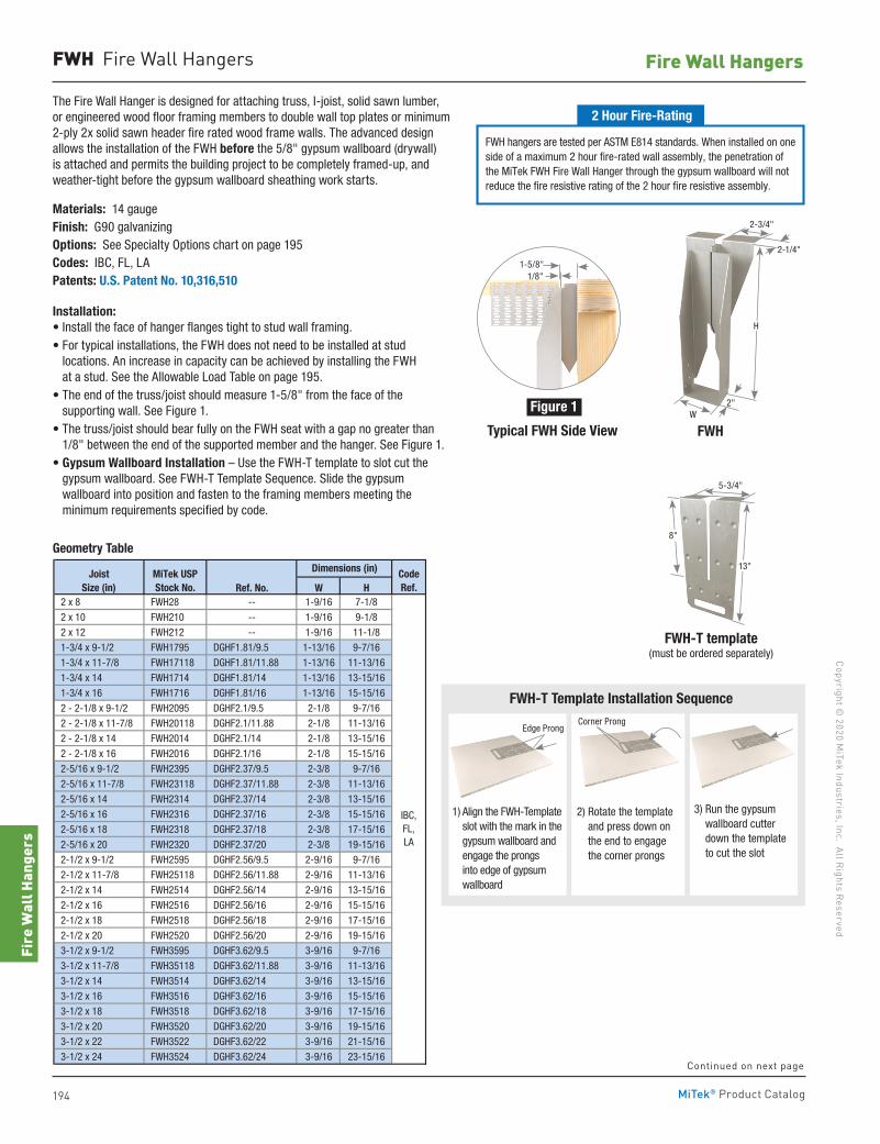
194
Copyright © 2020 M
iTek Industries, Inc. All Rights Reserved
Fire Wall Hangers
Fire
Wal
l Han
gers
MiTek® Product Catalog
Ref. No. W H 2 x 8 FWH28 -- 1-9/16 7-1/8
2 x 10 FWH210 -- 1-9/16 9-1/8
2 x 12 FWH212 -- 1-9/16 11-1/8
1-3/4 x 9-1/2 FWH1795 DGHF1.81/9.5 1-13/16 9-7/16
1-3/4 x 11-7/8 FWH17118 DGHF1.81/11.88 1-13/16 11-13/16
1-3/4 x 14 FWH1714 DGHF1.81/14 1-13/16 13-15/16
1-3/4 x 16 FWH1716 DGHF1.81/16 1-13/16 15-15/16
2 - 2-1/8 x 9-1/2 FWH2095 DGHF2.1/9.5 2-1/8 9-7/16
2 - 2-1/8 x 11-7/8 FWH20118 DGHF2.1/11.88 2-1/8 11-13/16
2 - 2-1/8 x 14 FWH2014 DGHF2.1/14 2-1/8 13-15/16
2 - 2-1/8 x 16 FWH2016 DGHF2.1/16 2-1/8 15-15/16
2-5/16 x 9-1/2 FWH2395 DGHF2.37/9.5 2-3/8 9-7/16
2-5/16 x 11-7/8 FWH23118 DGHF2.37/11.88 2-3/8 11-13/16
2-5/16 x 14 FWH2314 DGHF2.37/14 2-3/8 13-15/16
2-5/16 x 16 FWH2316 DGHF2.37/16 2-3/8 15-15/16
2-5/16 x 18 FWH2318 DGHF2.37/18 2-3/8 17-15/16
2-5/16 x 20 FWH2320 DGHF2.37/20 2-3/8 19-15/16
2-1/2 x 9-1/2 FWH2595 DGHF2.56/9.5 2-9/16 9-7/16
2-1/2 x 11-7/8 FWH25118 DGHF2.56/11.88 2-9/16 11-13/16
2-1/2 x 14 FWH2514 DGHF2.56/14 2-9/16 13-15/16
2-1/2 x 16 FWH2516 DGHF2.56/16 2-9/16 15-15/16
2-1/2 x 18 FWH2518 DGHF2.56/18 2-9/16 17-15/16
2-1/2 x 20 FWH2520 DGHF2.56/20 2-9/16 19-15/16
3-1/2 x 9-1/2 FWH3595 DGHF3.62/9.5 3-9/16 9-7/16
3-1/2 x 11-7/8 FWH35118 DGHF3.62/11.88 3-9/16 11-13/16
3-1/2 x 14 FWH3514 DGHF3.62/14 3-9/16 13-15/16
3-1/2 x 16 FWH3516 DGHF3.62/16 3-9/16 15-15/16
3-1/2 x 18 FWH3518 DGHF3.62/18 3-9/16 17-15/16
3-1/2 x 20 FWH3520 DGHF3.62/20 3-9/16 19-15/16
3-1/2 x 22 FWH3522 DGHF3.62/22 3-9/16 21-15/16
3-1/2 x 24 FWH3524 DGHF3.62/24 3-9/16 23-15/16
MiTek USPStock No.
JoistSize (in)
Dimensions (in) CodeRef.
IBC,FL,LA
FWH Fire Wall Hangers
Continued on next page
Geometry Table
The Fire Wall Hanger is designed for attaching truss, I-joist, solid sawn lumber, or engineered wood floor framing members to double wall top plates or minimum 2-ply 2x solid sawn header fire rated wood frame walls. The advanced design allows the installation of the FWH before the 5/8" gypsum wallboard (drywall) is attached and permits the building project to be completely framed-up, and weather-tight before the gypsum wallboard sheathing work starts.
Materials: 14 gauge Finish: G90 galvanizingOptions: See Specialty Options chart on page 195Codes: IBC, FL, LAPatents: U.S. Patent No. 10,316,510
Installation:• Install the face of hanger flanges tight to stud wall framing.• For typical installations, the FWH does not need to be installed at stud
locations. An increase in capacity can be achieved by installing the FWH at a stud. See the Allowable Load Table on page 195.
• The end of the truss/joist should measure 1-5/8" from the face of the supporting wall. See Figure 1.
• The truss/joist should bear fully on the FWH seat with a gap no greater than 1/8" between the end of the supported member and the hanger. See Figure 1.
• Gypsum Wallboard Installation – Use the FWH-T template to slot cut the gypsum wallboard. See FWH-T Template Sequence. Slide the gypsum wallboard into position and fasten to the framing members meeting the minimum requirements specified by code.
FWH
H
2"
2-1/4"
W
FWH hangers are tested per ASTM E814 standards. When installed on one side of a maximum 2 hour fire-rated wall assembly, the penetration of the MiTek FWH Fire Wall Hanger through the gypsum wallboard will not reduce the fire resistive rating of the 2 hour fire resistive assembly.
2 Hour Fire-Rating
1/8"1-5/8"
Figure 1
Typical FWH Side View
5-3/4"
FWH-T template (must be ordered separately)
8"
13"
1) Align the FWH-Template slot with the mark in the gypsum wallboard and engage the prongs into edge of gypsum wallboard
Edge Prong
3) Run the gypsum wallboard cutter down the template to cut the slot
2) Rotate the template and press down on the end to engage the corner prongs
Corner Prong
FWH-T Template Installation Sequence
2-3/4"
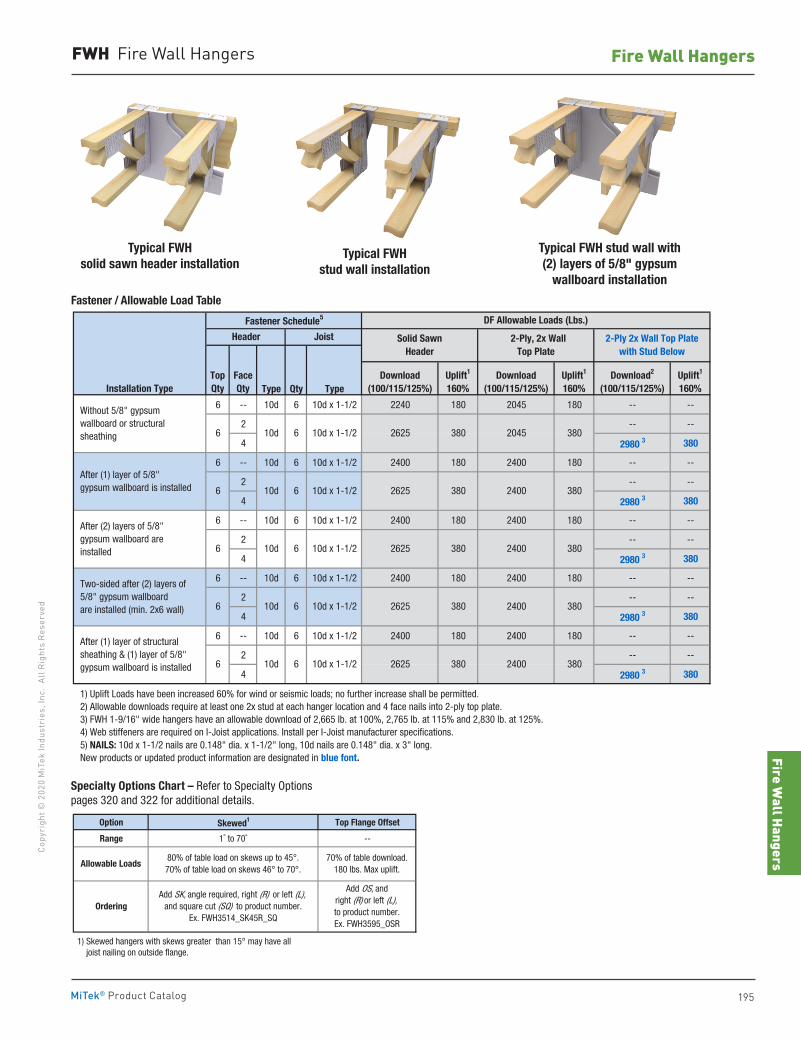
Fire Wall Hangers
195
Copy
righ
t © 2
020
MiT
ek In
dust
ries
, Inc
. Al
l Rig
hts
Rese
rved
Fire Wall Hangers
MiTek® Product Catalog
FWH Fire Wall Hangers
Option Skewed1 Top Flange Offset
Range 1˚ to 70˚ --
1) Skewed hangers with skews greater than 15° may have all joist nailing on outside flange.
OrderingAdd SK, angle required, right (R) or left (L),
and square cut (SQ) to product number.Ex. FWH3514_SK45R_SQ
Allowable Loads80% of table load on skews up to 45°.70% of table load on skews 46° to 70°.
Add OS, and right (R) or left (L),to product number.Ex. FWH3595_OSR
70% of table download.180 lbs. Max uplift.
Type Qty Type
6 -- 10d 6 10d x 1-1/2 2240 180 2045 180 -- --
2 -- --
4 2980 3 380
6 -- 10d 6 10d x 1-1/2 2400 180 2400 180 -- --
2 -- --
4 2980 3 380
6 -- 10d 6 10d x 1-1/2 2400 180 2400 180 -- --
2 -- --
4 2980 3 380
6 -- 10d 6 10d x 1-1/2 2400 180 2400 180 -- --
2 -- --
4 2980 3 380
6 -- 10d 6 10d x 1-1/2 2400 180 2400 180 -- --
2 -- --
4 2980 3 380
1) Uplift Loads have been increased 60% for wind or seismic loads; no further increase shall be permitted. 2) Allowable downloads require at least one 2x stud at each hanger location and 4 face nails into 2-ply top plate. 3) FWH 1-9/16" wide hangers have an allowable download of 2,665 lb. at 100%, 2,765 lb. at 115% and 2,830 lb. at 125%. 4) Web stiffeners are required on I-Joist applications. Install per I-Joist manufacturer specifications. 5) NAILS: 10d x 1-1/2 nails are 0.148" dia. x 1-1/2" long, 10d nails are 0.148" dia. x 3" long. New products or updated product information are designated in blue font.
2625
2625
2625
6
6 10d 6 10d x 1-1/2
6 10d 6 10d x 1-1/2
6 10d 6 10d x 1-1/2
Download2
(100/115/125%)Uplift1
160%
380
380
380
2400
2400
2400
2400
DF Allowable Loads (Lbs.)
Solid Sawn Header
2-Ply, 2x Wall Top Plate
2-Ply 2x Wall Top Plate with Stud Below
380
Download(100/115/125%)
Uplift1
160%
2625 380380
2625 380
2045
380
380
380
Without 5/8" gypsum wallboard or structural sheathing
After (1) layer of structural sheathing & (1) layer of 5/8" gypsum wallboard is installed
Two-sided after (2) layers of 5/8" gypsum wallboard are installed (min. 2x6 wall)
After (2) layers of 5/8" gypsum wallboard are installed
After (1) layer of 5/8" gypsum wallboard is installed
Fastener Schedule5
Joist
10d 6 10d x 1-1/2
6 10d 6 10d x 1-1/2
Installation TypeFaceQty
Header
Uplift1
160%Download
(100/115/125%)TopQty
Specialty Options Chart – Refer to Specialty Options pages 320 and 322 for additional details.
Typical FWHstud wall installation
Typical FWH stud wall with (2) layers of 5/8" gypsum
wallboard installation
Typical FWHsolid sawn header installation
Fastener / Allowable Load Table
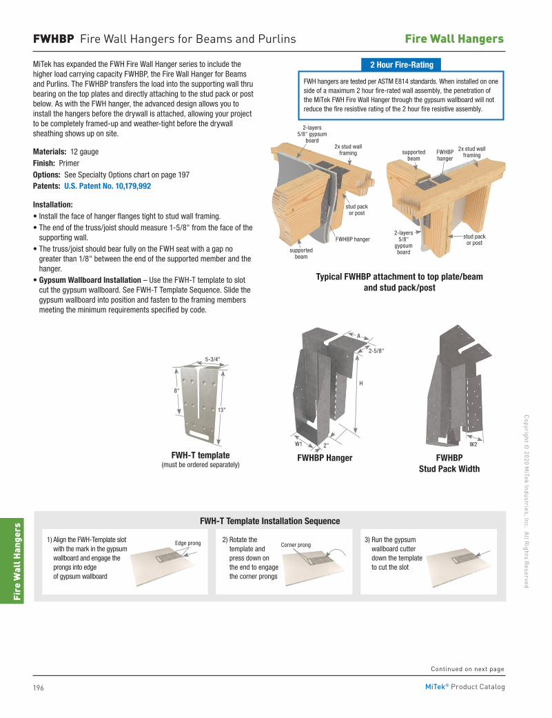
196
Copyright © 2020 M
iTek Industries, Inc. All Rights Reserved
Fire Wall Hangers
Fire
Wal
l Han
gers
MiTek® Product Catalog
FWHBP Fire Wall Hangers for Beams and Purlins
MiTek has expanded the FWH Fire Wall Hanger series to include the higher load carrying capacity FWHBP, the Fire Wall Hanger for Beams and Purlins. The FWHBP transfers the load into the supporting wall thru bearing on the top plates and directly attaching to the stud pack or post below. As with the FWH hanger, the advanced design allows you to install the hangers before the drywall is attached, allowing your project to be completely framed-up and weather-tight before the drywall sheathing shows up on site.
Materials: 12 gaugeFinish: PrimerOptions: See Specialty Options chart on page 197Patents: U.S. Patent No. 10,179,992
Installation:• Install the face of hanger flanges tight to stud wall framing.• The end of the truss/joist should measure 1-5/8" from the face of the
supporting wall. • The truss/joist should bear fully on the FWH seat with a gap no
greater than 1/8" between the end of the supported member and the hanger.
• Gypsum Wallboard Installation – Use the FWH-T template to slot cut the gypsum wallboard. See FWH-T Template Sequence. Slide the gypsum wallboard into position and fasten to the framing members meeting the minimum requirements specified by code.
2x stud wall framing
supported beam
FWHBP hanger
stud pack or post
2-layers 5/8" gypsum
board2x stud wall
framingsupported beam
FWHBP hanger
stud pack or post
2-layers 5/8"
gypsum board
FWHBP Hanger FWHBP Stud Pack Width
2-5/8"
H
2"W1
A
W2
Typical FWHBP attachment to top plate/beam and stud pack/post
Continued on next page
5-3/4"
FWH-T template (must be ordered separately)
8"
13"
1) Align the FWH-Template slot with the mark in the gypsum wallboard and engage the prongs into edge of gypsum wallboard
FWH-T Template Installation Sequence
Edge prong 3) Run the gypsum wallboard cutter down the template to cut the slot
2) Rotate the template and press down on the end to engage the corner prongs
Corner prong
FWH hangers are tested per ASTM E814 standards. When installed on one side of a maximum 2 hour fire-rated wall assembly, the penetration of the MiTek FWH Fire Wall Hanger through the gypsum wallboard will not reduce the fire resistive rating of the 2 hour fire resistive assembly.
2 Hour Fire-Rating
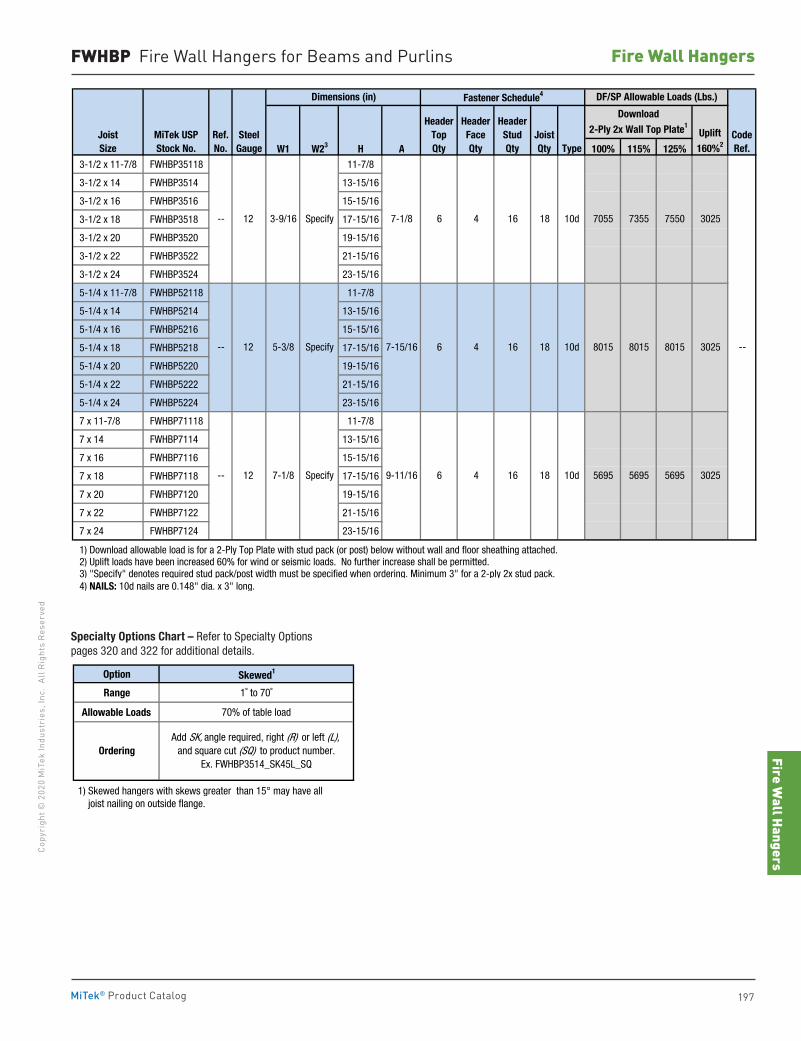
Fire Wall Hangers
197
Copy
righ
t © 2
020
MiT
ek In
dust
ries
, Inc
. Al
l Rig
hts
Rese
rved
Fire Wall Hangers
MiTek® Product Catalog
FWHBP Fire Wall Hangers for Beams and Purlins
W1 W23 H A 100% 115% 125% 3-1/2 x 11-7/8 FWHBP35118 11-7/8
3-1/2 x 14 FWHBP3514 13-15/16
3-1/2 x 16 FWHBP3516 15-15/16
3-1/2 x 18 FWHBP3518 17-15/16
3-1/2 x 20 FWHBP3520 19-15/16
3-1/2 x 22 FWHBP3522 21-15/16
3-1/2 x 24 FWHBP3524 23-15/16
5-1/4 x 11-7/8 FWHBP52118 11-7/8
5-1/4 x 14 FWHBP5214 13-15/16
5-1/4 x 16 FWHBP5216 15-15/16
5-1/4 x 18 FWHBP5218 17-15/16
5-1/4 x 20 FWHBP5220 19-15/16
5-1/4 x 22 FWHBP5222 21-15/16
5-1/4 x 24 FWHBP5224 23-15/16
7 x 11-7/8 FWHBP71118 11-7/8
7 x 14 FWHBP7114 13-15/16
7 x 16 FWHBP7116 15-15/16
7 x 18 FWHBP7118 17-15/16
7 x 20 FWHBP7120 19-15/16
7 x 22 FWHBP7122 21-15/16
7 x 24 FWHBP7124 23-15/16
1) Download allowable load is for a 2-Ply Top Plate with stud pack (or post) below without wall and floor sheathing attached. 2) Uplift loads have been increased 60% for wind or seismic loads. No further increase shall be permitted. 3) "Specify" denotes required stud pack/post width must be specified when ordering. Minimum 3" for a 2-ply 2x stud pack. 4) NAILS: 10d nails are 0.148" dia. x 3" long.
SteelGauge
12
12
Dimensions (in)
--
7-1/8
7-15/16
9-11/1612
JoistSize
Uplift
160%2
--
--
Ref.No.
MiTek USPStock No.
8015 8015 30256 4 16 18 10d 8015
6 4 16 18
CodeRef.
--
5695 5695 3025
7355 7550 3025
7-1/8
Specify
5-3/8 Specify
3-9/16
Specify 18
10d
DF/SP Allowable Loads (Lbs.)
Download
2-Ply 2x Wall Top Plate1
Fastener Schedule4
JoistQty Type
HeaderTopQty
HeaderFaceQty
HeaderStudQty
569510d6 4 16
7055
Option Skewed1
Range 1˚ to 70˚
Allowable Loads 70% of table load
1) Skewed hangers with skews greater than 15° may have all joist nailing on outside flange.
OrderingAdd SK, angle required, right (R) or left (L),
and square cut (SQ) to product number.Ex. FWHBP3514_SK45L_SQ
Specialty Options Chart – Refer to Specialty Options pages 320 and 322 for additional details.
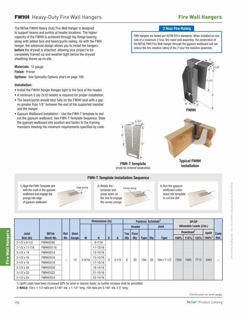
198
Copyright © 2020 M
iTek Industries, Inc. All Rights Reserved
Fire Wall Hangers
Fire
Wal
l Han
gers
MiTek® Product Catalog
FWHH Heavy-Duty Fire Wall Hangers
The MiTek FWHH Heavy-Duty Fire Wall Hanger is designed to support beams and purlins at header locations. The higher capacity of the FWHH is achieved through top flange bearing along with added face and beam/purlin nailing. As with the FWH hanger, the advanced design allows you to install the hangers before the drywall is attached, allowing your project to be completely framed-up and weather-tight before the drywall sheathing shows up on site.
Materials: 12 gaugeFinish: PrimerOptions: See Specialty Options chart on page 199
Installation:• Install the FWHH hanger flanges tight to the face of the header.• A minimum 2-ply 2x10 header is required for proper installation.• The beam/purlin should bear fully on the FWHH seat with a gap
no greater than 1/8" between the end of the supported member and the hanger.
• Gypsum Wallboard Installation - Use the FWH-T template to slot cut the gypsum wallboard. See FWH-T Template Sequence. Slide the gypsum wallboard into position and fasten to the framing members meeting the minimum requirements specified by code.
FWHH
5-3/4"
FWH-T template (must be ordered separately)
8"
13"
Typical FWHHinstallation
1) Align the FWH-Template slot with the mark in the gypsum wallboard and engage the prongs into edge of gypsum wallboard
FWH-T Template Installation Sequence
Edge prong 3) Run the gypsum wallboard cutter down the template to cut the slot
2) Rotate the template and press down on the end to engage the corner prongs
Corner prong
Header
W H D A 100% 115% 125% 3-1/2 x 9-1/2 FWHH3595 9-7/16
3-1/2 x 11-7/8 FWHH35118 11-13/16
3-1/2 x 14 FWHH3514 13-15/16
3-1/2 x 16 FWHH3516 15-15/16
3-1/2 x 18 FWHH3518 17-15/16
3-1/2 x 20 FWHH3520 19-15/16
3-1/2 x 22 FWHH3522 21-15/16
3-1/2 x 24 FWHH3524 23-15/16
1) Uplift Loads have been increased 60% for wind or seismic loads; no further increase shall be permitted. 2) NAILS: 10d x 1-1/2 nails are 0.148" dia. x 1-1/2" long, 10d nails are 0.148" dia. x 3" long.
Header
W H D A 100% 115% 125% 5-1/4 x 9-1/4 FWHH52925 9-1/8
5-1/4 x 9-1/2 FWHH5295 9-7/16
5-1/4 x 11-7/8 FWHH52118 11-13/16
5-1/4 x 14 FWHH5214 13-15/16
5-1/4 x 16 FWHH5216 15-15/16
5-1/4 x 18 FWHH5218 17-15/16
5-1/4 x 20 FWHH5220 19-15/16
5-1/4 x 22 FWHH5222 21-15/16
5-1/4 x 24 FWHH5224 23-15/16
5-1/2 x 9-1/4 FWHH55925 9-1/8
5-1/2 x 9-1/2 FWHH5595 9-7/16 ` 5-1/2 x 11-7/8 FWHH55118 11-13/16
5-1/2 x 14 FWHH5514 13-15/16
5-1/2 x 16 FWHH5516 15-15/16
5-1/2 x 18 FWHH5518 17-15/16
5-1/2 x 20 FWHH5520 19-15/16
5-1/2 x 22 FWHH5522 21-15/16
5-1/2 x 24 FWHH5524 23-15/16
7 x 11-7/8 FWHH71118 11-13/16
7 x 14 FWHH7114 13-15/16
7 x 16 FWHH7116 15-15/16
7 x 18 FWHH7118 17-15/16
7 x 20 FWHH7120 19-15/16
7 x 22 FWHH7122 21-15/16
7 x 24 FWHH7124 23-15/16
1) Uplift Loads have been increased 60% for wind or seismic loads; no further increase shall be permitted. 2) NAILS: 10d x 1-1/2 nails are 0.148" dia. x 1-1/2" long, 10d nails are 0.148" dia. x 3" long.
-- 12
SteelGauge
TopQty
6
DF/SP Allowable Loads (Lbs.)
Qty
Uplift
160%2
7715 771520
20
DF/SP Allowable Loads (Lbs.)
Download1Uplift
160%2
7355
10d x 1-/2
Fastener Schedule3
Joist
FaceQty Type
Dimensions (in) Fastener Schedule3
TopQty
Joist
Type TypeFaceQty
JoistSize (in)
MiTekStock No.
Ref.No.
SteelGauge
10d
62 3-1/4
4-3/16
20
20
JoistSize (in)
MiTekStock No.
Ref.No.
10d
Dimensions (in)
CodeRef.
7685 7715 3445
7715 3445
Download1
CodeRef.
--
--
3445
6005 6005 3445
7715 7715
-- 12 7-1/8 2 5-1/16
10d x 1-1/2
Qty
-- 12 5-5/8 2 4-3/16
5-3/8 2
6
Type
-- 12 3-9/16
7715
10d x 1-1/2 60056 20 10d 20
10d x 1-/210d 2020
FWH hangers are tested per ASTM E814 standards. When installed on one side of a maximum 2 hour fire-rated wall assembly, the penetration of the MiTek FWH Fire Wall Hanger through the gypsum wallboard will not reduce the fire resistive rating of the 2 hour fire resistive assembly.
2 Hour Fire-Rating
Continued on next page
A
W D
H
7-1/2"
2-5/8"
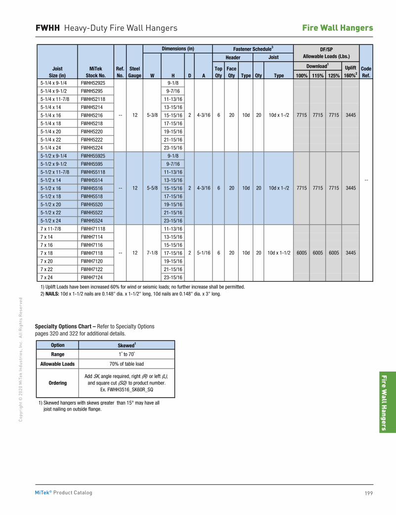
Fire Wall Hangers
199
Copy
righ
t © 2
020
MiT
ek In
dust
ries
, Inc
. Al
l Rig
hts
Rese
rved
Fire Wall Hangers
MiTek® Product Catalog
FWHH Heavy-Duty Fire Wall Hangers
Header
W H D A 100% 115% 125% 3-1/2 x 9-1/2 FWHH3595 9-7/16
3-1/2 x 11-7/8 FWHH35118 11-13/16
3-1/2 x 14 FWHH3514 13-15/16
3-1/2 x 16 FWHH3516 15-15/16
3-1/2 x 18 FWHH3518 17-15/16
3-1/2 x 20 FWHH3520 19-15/16
3-1/2 x 22 FWHH3522 21-15/16
3-1/2 x 24 FWHH3524 23-15/16
1) Uplift Loads have been increased 60% for wind or seismic loads; no further increase shall be permitted. 2) NAILS: 10d x 1-1/2 nails are 0.148" dia. x 1-1/2" long, 10d nails are 0.148" dia. x 3" long.
Header
W H D A 100% 115% 125% 5-1/4 x 9-1/4 FWHH52925 9-1/8
5-1/4 x 9-1/2 FWHH5295 9-7/16
5-1/4 x 11-7/8 FWHH52118 11-13/16
5-1/4 x 14 FWHH5214 13-15/16
5-1/4 x 16 FWHH5216 15-15/16
5-1/4 x 18 FWHH5218 17-15/16
5-1/4 x 20 FWHH5220 19-15/16
5-1/4 x 22 FWHH5222 21-15/16
5-1/4 x 24 FWHH5224 23-15/16
5-1/2 x 9-1/4 FWHH55925 9-1/8
5-1/2 x 9-1/2 FWHH5595 9-7/16 ` 5-1/2 x 11-7/8 FWHH55118 11-13/16
5-1/2 x 14 FWHH5514 13-15/16
5-1/2 x 16 FWHH5516 15-15/16
5-1/2 x 18 FWHH5518 17-15/16
5-1/2 x 20 FWHH5520 19-15/16
5-1/2 x 22 FWHH5522 21-15/16
5-1/2 x 24 FWHH5524 23-15/16
7 x 11-7/8 FWHH71118 11-13/16
7 x 14 FWHH7114 13-15/16
7 x 16 FWHH7116 15-15/16
7 x 18 FWHH7118 17-15/16
7 x 20 FWHH7120 19-15/16
7 x 22 FWHH7122 21-15/16
7 x 24 FWHH7124 23-15/16
1) Uplift Loads have been increased 60% for wind or seismic loads; no further increase shall be permitted. 2) NAILS: 10d x 1-1/2 nails are 0.148" dia. x 1-1/2" long, 10d nails are 0.148" dia. x 3" long.
-- 12
SteelGauge
TopQty
6
DF/SP Allowable Loads (Lbs.)
Qty
Uplift
160%2
7715 771520
20
DF/SP Allowable Loads (Lbs.)
Download1Uplift
160%2
7355
10d x 1-/2
Fastener Schedule3
Joist
FaceQty Type
Dimensions (in) Fastener Schedule3
TopQty
Joist
Type TypeFaceQty
JoistSize (in)
MiTekStock No.
Ref.No.
SteelGauge
10d
62 3-1/4
4-3/16
20
20
JoistSize (in)
MiTekStock No.
Ref.No.
10d
Dimensions (in)
CodeRef.
7685 7715 3445
7715 3445
Download1
CodeRef.
--
--
3445
6005 6005 3445
7715 7715
-- 12 7-1/8 2 5-1/16
10d x 1-1/2
Qty
-- 12 5-5/8 2 4-3/16
5-3/8 2
6
Type
-- 12 3-9/16
7715
10d x 1-1/2 60056 20 10d 20
10d x 1-/210d 2020
Option Skewed1
Range 1˚ to 70˚
Allowable Loads 70% of table load
1) Skewed hangers with skews greater than 15° may have all joist nailing on outside flange.
OrderingAdd SK, angle required, right (R) or left (L),
and square cut (SQ) to product number.Ex. FWHH3516_SK60R_SQ
Specialty Options Chart – Refer to Specialty Options pages 320 and 322 for additional details.
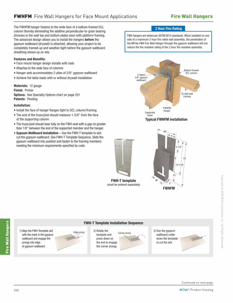
200
Copyright © 2020 M
iTek Industries, Inc. All Rights Reserved
Fire Wall Hangers
Fire
Wal
l Han
gers
MiTek® Product Catalog
FWHFM Fire Wall Hangers for Face Mount Applications
The FWHFM hanger fastens to the wide face of a balloon framed SCL column thereby eliminating the additive perpendicular-to-grain bearing stresses in the wall top and bottom plates seen with platform framing. The advanced design allows you to install the hangers before the gypsum wallboard (drywall) is attached, allowing your project to be completely framed-up and weather-tight before the gypsum wallboard sheathing shows up on site.
Features and Benefits:• Face mount hanger design installs with nails• Attaches to the wide face of columns • Hanger web accommodates 2-plies of 5/8" gypsum wallboard
• Achieve full table loads with or without drywall installation
Materials: 12 gaugeFinish: PrimerOptions: See Specialty Options chart on page 201 Patents: Pending
Installation:• Install the face of hanger flanges tight to SCL column/framing.• The end of the truss/joist should measure 1-5/8" from the face
of the supporting column. • The truss/joist should bear fully on the FWH seat with a gap no greater
than 1/8" between the end of the supported member and the hanger. • Gypsum Wallboard Installation – Use the FWH-T template to slot
cut the gypsum wallboard. See FWH-T Template Sequence. Slide the gypsum wallboard into position and fasten to the framing members meeting the minimum requirements specified by code.
FWH-T template (must be ordered separately)
Continued on next page
Typical FWHFM installation
FWHFM
2x stud wall framing
Supported beam
FWHFM hanger
Balloon framed SCL column
2-layers 5/8" gypsum
wallboard
2"W1
H1
A
4-1/2"
W2
H2
13-1/16"
1) Align the FWH-Template slot with the mark in the gypsum wallboard and engage the prongs into edge of gypsum wallboard
FWH-T Template Installation Sequence
Edge prong 3) Run the gypsum wallboard cutter down the template to cut the slot
2) Rotate the template and press down on the end to engage the corner prongs
Corner prong
FWH hangers are tested per ASTM E814 standards. When installed on one side of a maximum 2 hour fire-rated wall assembly, the penetration of the MiTek FWH Fire Wall Hanger through the gypsum wallboard will not reduce the fire resistive rating of the 2 hour fire resistive assembly.
2 Hour Fire-Rating
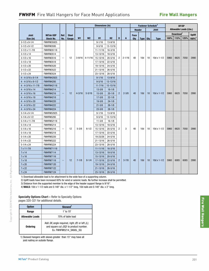
Fire Wall Hangers
201
Copy
righ
t © 2
020
MiT
ek In
dust
ries
, Inc
. Al
l Rig
hts
Rese
rved
Fire Wall Hangers
MiTek® Product Catalog
Header
W1 W2 H1 H2 D A 100% 115% 125%
3-1/2 x 9-1/4 FWHFM35925 9-1/16 13-9/16
3-1/2 x 9-1/2 FWHFM3595 9-5/16 13-13/16
3-1/2 x 11-7/8 FWHFM35118 11-11/16 16-3/16
3-1/2 x 14 FWHFM3514 13-13/16 18-5/16
3-1/2 x 16 FWHFM3516 15-13/16 20-5/16
3-1/2 x 18 FWHFM3518 17-13/16 22-5/16
3-1/2 x 20 FWHFM3520 19-13/16 24-5/16
3-1/2 x 22 FWHFM3522 21-13/16 26-5/16
3-1/2 x 24 FWHFM3524 23-13/16 28-5/16
4 - 4-3/16 x 9-1/4 FWHFM42925 9-1/16 13-9/16
4 - 4-3/16 x 9-1/2 FWHFM4295 9-5/16 13-13/16
4 - 4-3/16 x 11-7/8 FWHFM42118 11-7/16 15-15/16
4 - 4-3/16 x 14 FWHFM4214 13-5/8 18-1/8
4 - 4-3/16 x 16 FWHFM4216 15-5/8 20-1/8
4 - 4-3/16 x 18 FWHFM4218 17-5/8 22-1/8
4 - 4-3/16 x 20 FWHFM4220 19-5/8 24-1/8
4 - 4-3/16 x 22 FWHFM4222 21-5/8 26-1/8
4 - 4-3/16 x 24 FWHFM4224 23-5/8 28-1/8
5-1/4 x 9-1/4 FWHFM52925 9-1/16 13-9/16
5-1/4 x 9-1/2 FWHFM5295 9-5/16 13-13/16
5-1/4 x 11-7/8 FWHFM52118 11-5/8 16-1/8
5-1/4 x 14 FWHFM5214 13-13/16 18-5/16
5-1/4 x 16 FWHFM5216 15-13/16 20-5/16
5-1/4 x 18 FWHFM5218 17-13/16 22-5/16
5-1/4 x 20 FWHFM5220 19-23/28 24-5/16
5-1/4 x 22 FWHFM5222 21-13/16 26-5/16
5-1/4 x 24 FWHFM5224 23-13/16 28-5/16
7 x 11-7/8 FWHFM71118 11-11/16 16-3/16
7 x 14 FWHFM7114 13-13/16 18-5/16
7 x 16 FWHFM7116 15-13/16 20-5/16
7 x 18 FWHFM7118 17-13/16 22-5/16
7 x 20 FWHFM7120 19-13/16 24-5/16
7 x 22 FWHFM7122 21-13/16 26-5/16
7 x 24 FWHFM7124 23-13/16 28-5/16
1) Download allowable load is for attachment to the wide face of a supporting column. 2) Uplift loads have been increased 60% for wind or seismic loads. No further increase shall be permitted. 3) Distance from the supported member to the edge of the header support flange is 9/16". 4) NAILS: 10d x 1-1/2 nails are 0.148" dia. x 1-1/2" long, 10d nails are 0.148" dia. x 3" long.
10d x 1-1/2 5960 662510d 18
40 10d 18
Joist
Type Type
DF/SP Allowable Loads (Lbs.)
QtyJoist
Size (in)MiTek USP Stock No.
Ref.No.
SteelGauge
FaceQty
Uplift
160%2
Dimensions (in) Fastener Schedule3
-- 12 3-9/16 4-11/16
6625
10d x 1-1/2 59602 2-1/16
-- 12 4-3/16 5-5/16 2 2-3/8 40
Download1
7050 2990
6085 6085 2990
5960
5960
6625 7050 2990
7050 2990
-- 12 5-3/8 2 36-1/2
-- 12 7-1/8 28-1/4 3-7/8 40 10d 18
10d x 1-1/240 10d 18
10d x 1-1/2
FWHFM Fire Wall Hangers for Face Mount Applications
Option Skewed1
Range 1˚ to 70˚
Allowable Loads 70% of table load
1) Skewed hangers with skews greater than 15° may have all joist nailing on outside flange.
OrderingAdd SK, angle required, right (R) or left (L),
and square cut (SQ) to product number.Ex. FWHFM5214_SK60L_SQ
Specialty Options Chart – Refer to Specialty Options pages 320-321 for additional details.
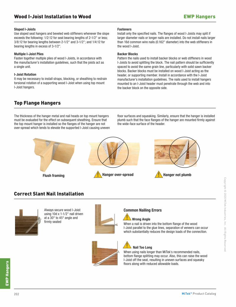
202 MiTek® Product Catalog
Copyright © 2020 M
iTek Industries, Inc. All Rights Reserved
EWP Hangers
EWP
Hang
ers
Wood I-Joist Installation to Wood
Sloped I-JoistsUse sloped seat hangers and beveled web stiffeners whenever the slope exceeds the following: 1/2:12 for seat bearing lengths of 2-1/2" or less; 3/8:12 for bearing lengths between 2-1/2" and 3-1/2"; and 1/4:12 for bearing lengths in excess of 3-1/2".
Multiple I-Joist PliesFasten together multiple plies of wood I-Joists, in accordance with the manufacturer’s installation guidelines, such that the joists act as a single unit.
I-Joist RotationIt may be necessary to install straps, blocking, or sheathing to restrain torsional rotation of a supporting wood I-Joist when using top mount I-Joist hangers.
FastenersInstall only the specified nails. The flanges of wood I-Joists may split if larger diameter nails or longer nails are installed. Do not install nails larger than 16d common wire nails (0.162" diameter) into the web stiffeners in the wood I-Joist.
Backer BlocksPattern the nails used to install backer blocks or web stiffeners in wood I-Joists to avoid splitting the block. The nail pattern should be sufficiently spaced to avoid the same grain line, particularly with solid sawn backer blocks. Backer blocks must be installed on wood I-Joist acting as the header, or supporting member. Install in accordance with the I-Joist manufacturer’s installation guidelines. The nails used to install hangers mounted to an I-Joist header must penetrate through the web and into the backer block on the opposite side.
The thickness of the hanger metal and nail heads on top mount hangers must be evaluated for the effect on subsequent sheathing. Ensure that the top mount hanger is installed so the flanges of the hanger are not over-spread which tends to elevate the supported I-Joist causing uneven
floor surfaces and squeaking. Similarly, ensure that the hanger is installed plumb such that the face flanges of the hanger are mounted firmly against the wide-face surface of the header.
Common Nailing Errors
Wrong AngleWhen a nail is driven into the bottom flange of the wood I-Joist parallel to the glue lines, separation of veneers can occur which substantially reduces the design loads of the connection.
Nail Too LongWhen using nails longer than MiTek’s recommended nails, bottom flange splitting may occur. Also, this can raise the wood I-Joist off the seat, resulting in uneven surfaces and squeaky floors along with reduced allowable loads.
Always secure wood I-Joist using 10d x 1-1⁄2" nail driven at a 30° to 45° angle and firmly seated
Top Flange Hangers
Correct Slant Nail Installation
!
!
Flush framing Hanger over-spread Hanger not plumb!!
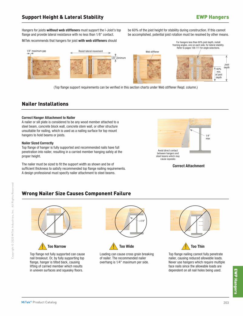
EWP Hangers
203MiTek® Product Catalog
Copy
righ
t © 2
020
MiT
ek In
dust
ries
, Inc
. Al
l Rig
hts
Rese
rved
EWP HangersSupport Height & Lateral Stability
Hangers for joists without web stiffeners must support the I-Joist’s top flange and provide lateral resistance with no less than 1⁄8" contact.
MiTek recommends that hangers for joist with web stiffeners should
be 60% of the joist height for stability during construction. If this cannot be accomplished, potential joist rotation must be resolved by other means.
(Top flange support requirements can be verified in this section charts under Web stiffener Reqd. column.)
Correct Hanger Attachment to NailerA nailer or sill plate is considered to be any wood member attached to a steel beam, concrete block wall, concrete stem wall, or other structure unsuitable for nailing, which is used as a nailing surface for top mount hangers to hold beams or joists.
Nailer Sized CorrectlyTop flange of hanger is fully supported and recommended nails have full penetration into nailer, resulting in a carried member hanging safely at the proper height.
The nailer must be sized to fit the support width as shown and be of sufficient thickness to satisfy recommended top flange nailing requirements. A design professional must specify nailer attachment to steel beams.
Top flange not fully supported can cause nail breakout. Or, by fully supporting top flange, hanger is tilted back, causing lifting of carried member which results in uneven surfaces and squeaky floors.
Loading can cause cross grain breaking of nailer. The recommended nailer overhang is 1⁄4" maximum per side.
Top flange nailing cannot fully penetrate nailer, causing reduced allowable loads. Never use hangers which require multiple face nails since the allowable loads are dependent on all nail holes being used.
Nailer Installations
Wrong Nailer Size Causes Component Failure
Correct Attachment
Too Narrow Too Wide Too Thin!!!
Web stiffener
>1/4"
1/8" maximum gap
60% min.
of joist depth
Joist depth
1/4" max
Avoid direct contact between hangers and
steel beams which may cause squeaks
For hangers less than 60% joist depth, install framing angles, one on each side, for lateral stability.
Refer to pages 108-111 for angle selections.Resist lateral movement
1/8" minimum
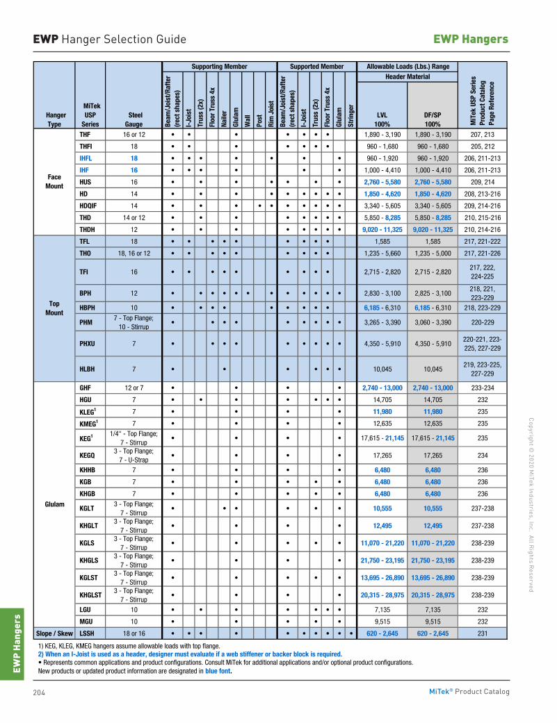
204 MiTek® Product Catalog
Copyright © 2020 M
iTek Industries, Inc. All Rights Reserved
EWP Hangers
EWP
Hang
ers
HangerType
MiTekUSP
Series SteelGauge
LVL100%
DF/SP100%
THF 16 or 12 • • • • • • • 1,890 - 3,190 1,890 - 3,190 207, 213
THFI 18 • • • • • • • 960 - 1,680 960 - 1,680 205, 212
IHFL 18 • • • • • • • 960 - 1,920 960 - 1,920 206, 211-213
IHF 16 • • • • • • 1,000 - 4,410 1,000 - 4,410 206, 211-213
HUS 16 • • • • • • • 2,760 - 5,580 2,760 - 5,580 209, 214
HD 14 • • • • • • • • • 1,850 - 4,620 1,850 - 4,620 208, 213-216
HDQIF 14 • • • • • • • • • • 3,340 - 5,605 3,340 - 5,605 209, 214-216
THD 14 or 12 • • • • • • • • 5,850 - 8,285 5,850 - 8,285 210, 215-216
THDH 12 • • • • • • • • 9,020 - 11,325 9,020 - 11,325 210, 214-216
TFL 18 • • • • • • • • • 1,585 1,585 217, 221-222
THO 18, 16 or 12 • • • • • • • • • 1,235 - 5,660 1,235 - 5,000 217, 221-226
TFI 16 • • • • • • • • • 2,715 - 2,820 2,715 - 2,820217, 222, 224-225
BPH 12 • • • • • • • • • • • • 2,830 - 3,100 2,825 - 3,100218, 221,223-229
HBPH 10 • • • • • • • • • 6,185 - 6,310 6,185 - 6,310 218, 223-229
PHM7 - Top Flange;
10 - Stirrup• • • • • • • • • 3,265 - 3,390 3,060 - 3,390 220-229
PHXU 7 • • • • • • • • • 4,350 - 5,910 4,350 - 5,910220-221, 223-225, 227-229
HLBH 7 • • • • • • 10,045 10,045219, 223-225,
227-229
GHF 12 or 7 • • • • 2,740 - 13,000 2,740 - 13,000 233-234
HGU 7 • • • • • • • 14,705 14,705 232
KLEG1 7 • • • • 11,980 11,980 235
KMEG1 7 • • • • 12,635 12,635 235
KEG1 1/4" - Top Flange;7 - Stirrup
• • • • 17,615 - 21,145 17,615 - 21,145 235
KEGQ3 - Top Flange;
7 - U-Strap• • • • 17,265 17,265 234
KHHB 7 • • • • 6,480 6,480 236
KGB 7 • • • • • 6,480 6,480 236
KHGB 7 • • • • • 6,480 6,480 236
KGLT3 - Top Flange;
7 - Stirrup• • • • • • 10,555 10,555 237-238
KHGLT3 - Top Flange;
7 - Stirrup• • • • 12,495 12,495 237-238
KGLS3 - Top Flange;
7 - Stirrup• • • • • 11,070 - 21,220 11,070 - 21,220 238-239
KHGLS3 - Top Flange;
7 - Stirrup• • • • 21,750 - 23,195 21,750 - 23,195 238-239
KGLST3 - Top Flange;
7 - Stirrup• • • • • 13,695 - 26,890 13,695 - 26,890 238-239
KHGLST3 - Top Flange;
7 - Stirrup• • • • 20,315 - 28,975 20,315 - 28,975 238-239
LGU 10 • • • • • • • 7,135 7,135 232
MGU 10 • • • • • 9,515 9,515 232
Slope / Skew LSSH 18 or 16 • • • • • • • • • • 620 - 2,645 620 - 2,645 231
1) KEG, KLEG, KMEG hangers assume allowable loads with top flange. 2) When an I-Joist is used as a header, designer must evaluate if a web stiffener or backer block is required. • Represents common applications and product configurations. Consult MiTek for additional applications and/or optional product configurations. New products or updated product information are designated in blue font.
TopMount
FaceMount
Glulam
Allowable Loads (Lbs.) Range
Beam
/Joi
st/R
afte
r(r
ect s
hape
s)
Beam
/Joi
st/R
afte
r(r
ect s
hape
s)
Trus
s (2
x)
Floo
r Tru
ss 4
x
Naile
r
Glul
am
Rim
Joi
st
Wal
l
Post
I-Jo
ist
Trus
s (2
x)
MiT
ek U
SP S
erie
s P
rodu
ct C
atal
og
Pag
e Re
fere
nce
Header MaterialSupporting Member
Floo
r Tru
ss 4
x
Glul
am
Strin
ger
I-Jo
ist
Supported Member
EWP Hanger Selection Guide
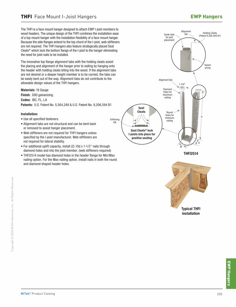
EWP Hangers
205MiTek® Product Catalog
Copy
righ
t © 2
020
MiT
ek In
dust
ries
, Inc
. Al
l Rig
hts
Rese
rved
EWP HangersTHFI Face Mount I-Joist Hangers
The THFI is a face mount hanger designed to attach EWP I-joist members to wood headers. The unique design of the THFI combines the installation ease of a top mount hanger with the installation flexibility of a face mount hanger. Because the side flanges extend to the top chord of the I-joist, web stiffeners are not required. The THFI hangers also feature strategically placed Seat Cleats® which lock the bottom flange of the I-joist to the hanger eliminating the need for joist nails to be installed.
The innovative top flange alignment tabs with the holding cleats assist the placing and alignment of the hanger prior to nailing by hanging onto the header with holding cleats biting into the wood. If the alignment tabs are not desired or a deeper height member is to be carried, the tabs can be easily bent out of the way. Alignment tabs do not contribute to the allowable design values of the THFI hangers.
Materials: 18 GaugeFinish: G90 galvanizingCodes: IBC, FL, LAPatents: U.S. Patent No. 5,564,248 & U.S. Patent No. 9,206,594 B1
Installation:• Use all specified fasteners.• Alignment tabs are not structural and can be bent back
or removed to assist hanger placement.• Web stiffeners are not required for THFI hangers unless
specified by the I-joist manufacturer. Web stiffeners are not required for lateral stability.
• For additional uplift capacity, install (2) 10d x 1-1/2" nails through diamond holes and into the joist member. (web stiffeners required)
• THFI2514 model has diamond holes in the header flange for Min/Max nailing option. For the Max nailing option, install nails in both the round and diamond shaped header holes.
Typical THFIinstallation
THFI2514
1-3/8"
Holding Cleats (Patent 9,206,594 B1)Guide tabs
for joist placement
Alignment tab
Speedprong
SeatCleats
Seat Cleats® lock I-joists into place for
positive seating
Stiffeningtab
Alignment tab
D
W
Diamond holes for maximum
nailing
Round holes for minimum
nailing
H
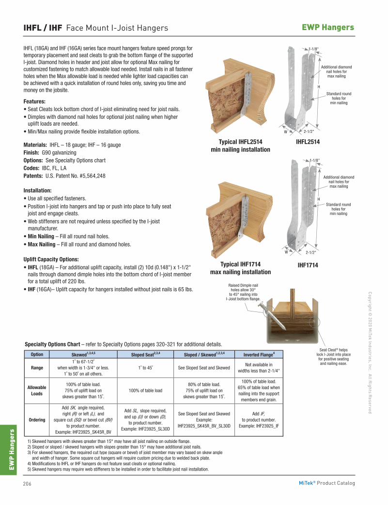
206 MiTek® Product Catalog
Copyright © 2020 M
iTek Industries, Inc. All Rights Reserved
EWP Hangers
EWP
Hang
ers
IHFL / IHF Face Mount I-Joist Hangers
IHFL (18GA) and IHF (16GA) series face mount hangers feature speed prongs for temporary placement and seat cleats to grab the bottom flange of the supported I-joist. Diamond holes in header and joist allow for optional Max nailing for customized fastening to match allowable load needed. Install nails in all fastener holes when the Max allowable load is needed while lighter load capacities can be achieved with a quick installation of round holes only, saving you time and money on the jobsite.
Features:• Seat Cleats lock bottom chord of I-joist eliminating need for joist nails.• Dimples with diamond nail holes for optional joist nailing when higher
uplift loads are needed.• Min/Max nailing provide flexible installation options.
Materials: IHFL – 18 gauge; IHF – 16 gauge Finish: G90 galvanizing Options: See Specialty Options chart Codes: IBC, FL, LA Patents: U.S. Patent No. #5,564,248
Installation:• Use all specified fasteners.• Position I-joist into hangers and tap or push into place to fully seat
joist and engage cleats.• Web stiffeners are not required unless specified by the I-joist
manufacturer. • Min Nailing – Fill all round nail holes.• Max Nailing – Fill all round and diamond holes. Uplift Capacity Options:• IHFL (18GA) – For additional uplift capacity, install (2) 10d (0.148") x 1-1/2"
nails through diamond dimple holes into the bottom chord of I-joist member for a total uplift of 220 lbs.
• IHF (16GA)– Uplift capacity for hangers installed without joist nails is 65 lbs.Raised Dimple nail
holes allow 30° to 45° nailing into
I-Joist bottom flange.
Seat Cleat® helps lock I-Joist into place for positive seating and nailing ease.
IHFL2514
IHF1714
Typical IHFL2514 min nailing installation
Additional diamond nail holes for max nailing
Standard round holes for
min nailing
H
1-1/8"
2-1/2"W
Typical IHF1714 max nailing installation
H
W
Additional diamond nail holes for max nailing
Standard round holes for
min nailing
2-1/2"
Option Skewed1,3,4,5 Sloped Seat2,3,4 Sloped / Skewed1,2,3,4 Inverted Flange4
1) Skewed hangers with skews greater than 15° may have all joist nailing on outside flange. 2) Sloped or sloped / skewed hangers with slopes greater than 15° may have additional joist nails. 3) For skewed hangers, the required cut type (square or bevel) of joist member may vary based on skew angle and width of hanger. Some square cut hangers will require custom pricing due to welded back plate. 4) Modifications to IHFL or IHF hangers do not feature seat cleats or optional nailing. 5) Skewed hangers may require web stiffeners to be installed in order to facilitate joist nail installation.
Range
Allowable Loads
Ordering
Add SK, angle required,right (R) or left (L), and
square cut (SQ) or bevel cut (BV)to product number.
Example: IHF23925_SK45R_BV
100% of table load.75% of uplift load on
skews greater than 15˚.
Add SL, slope required,and up (U) or down (D),
to product number.Example: IHF23925_SL30D
See Sloped Seat and SkewedExample:
IHF23925_SK45R_BV_SL30D
Add IF,to product number.
Example: IHF23925_IF
1˚ to 67-1/2˚when width is 1-3/4" or less.
1˚ to 50˚ on all others.
100% of table load
Not available inwidths less than 2-1/4"
1˚ to 45˚
100% of table load.65% of table load when nailing into the support
members end grain.
80% of table load. 75% of uplift load on
skews greater than 15˚.
See Sloped Seat and Skewed
Specialty Options Chart – refer to Specialty Options pages 320-321 for additional details.
1-1/8"
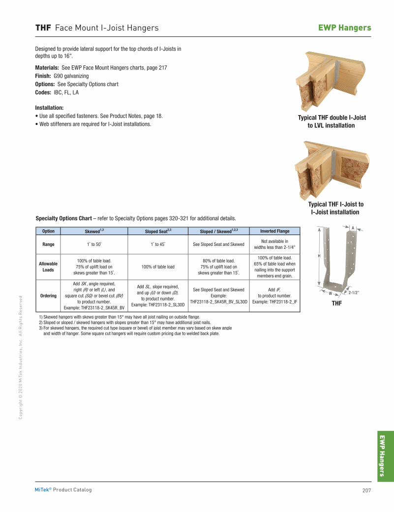
EWP Hangers
207MiTek® Product Catalog
Copy
righ
t © 2
020
MiT
ek In
dust
ries
, Inc
. Al
l Rig
hts
Rese
rved
EWP HangersTHF Face Mount I-Joist Hangers
Option Skewed1,3 Sloped Seat2,3 Sloped / Skewed1,2,3 Inverted Flange
1) Skewed hangers with skews greater than 15° may have all joist nailing on outside flange. 2) Sloped or sloped / skewed hangers with slopes greater than 15° may have additional joist nails. 3) For skewed hangers, the required cut type (square or bevel) of joist member may vary based on skew angle and width of hanger. Some square cut hangers will require custom pricing due to welded back plate.
Range
Allowable Loads
Ordering
Add SK , angle required,right (R) or left (L) , and
square cut (SQ) or bevel cut (BV)to product number.
Example: THF23118-2_SK45R_BV
100% of table load.75% of uplift load on
skews greater than 15˚.
Add SL, slope required,and up (U) or down (D),
to product number.Example: THF23118-2_SL30D
See Sloped Seat and SkewedExample:
THF23118-2_SK45R_BV_SL30D
Add IF,to product number.
Example: THF23118-2_IF
1˚ to 50˚
100% of table load
Not available inwidths less than 2-1/4"
1˚ to 45˚
100% of table load.65% of table load when nailing into the support
members end grain.
80% of table load. 75% of uplift load on
skews greater than 15˚.
See Sloped Seat and Skewed
Specialty Options Chart – refer to Specialty Options pages 320-321 for additional details.
Designed to provide lateral support for the top chords of I-Joists in depths up to 16".
Materials: See EWP Face Mount Hangers charts, page 217Finish: G90 galvanizingOptions: See Specialty Options chartCodes: IBC, FL, LA
Installation:• Use all specified fasteners. See Product Notes, page 18.• Web stiffeners are required for I-Joist installations.
Typical THF I-Joist to I-Joist installation
Typical THF double I-Joist to LVL installation
THF
H
W 2-1/2"
A
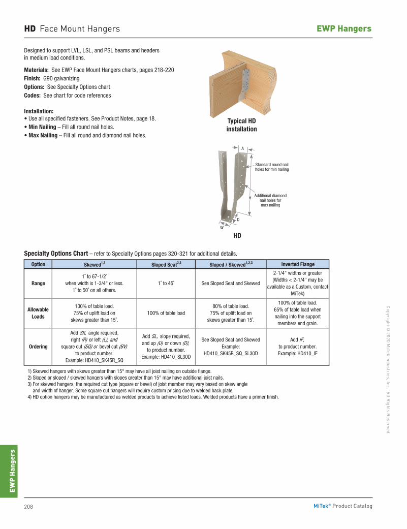
208 MiTek® Product Catalog
Copyright © 2020 M
iTek Industries, Inc. All Rights Reserved
EWP Hangers
EWP
Hang
ers
Designed to support LVL, LSL, and PSL beams and headers in medium load conditions.
Ma terials: See EWP Face Mount Hangers charts, pages 218-220Finish: G90 galvanizingOptions: See Specialty Options chartCodes: See chart for code references
Installation:• Use all specified fasteners. See Product Notes, page 18.• Min Nailing – Fill all round nail holes.• Max Nailing – Fill all round and diamond nail holes.
Option Skewed1,3 Sloped Seat2,3 Sloped / Skewed1,2,3 Inverted Flange
1) Skewed hangers with skews greater than 15° may have all joist nailing on outside flange. 2) Sloped or sloped / skewed hangers with slopes greater than 15° may have additional joist nails. 3) For skewed hangers, the required cut type (square or bevel) of joist member may vary based on skew angle and width of hanger. Some square cut hangers will require custom pricing due to welded back plate. 4) HD option hangers may be manufactured as welded products to achieve listed loads. Welded products have a primer finish.
Range
Allowable Loads
See Sloped Seat and Skewed
100% of table load.75% of uplift load on
skews greater than 15˚.
100% of table load.65% of table load when nailing into the support
members end grain.
1˚ to 67-1/2˚when width is 1-3/4" or less.
1˚ to 50˚ on all others.
2-1/4" widths or greater(Widths < 2-1/4" may be
available as a Custom, contact MiTek)
100% of table load
1˚ to 45˚
80% of table load. 75% of uplift load on
skews greater than 15˚.
OrderingAdd IF,
to product number.Example: HD410_IF
Add SK, angle required,right (R) or left (L), and
square cut (SQ) or bevel cut (BV)to product number.
Example: HD410_SK45R_SQ
Add SL, slope required,and up (U) or down (D),
to product number.Example: HD410_SL30D
See Sloped Seat and SkewedExample:
HD410_SK45R_SQ_SL30D
Typical HDinstallation
Specialty Options Chart – refer to Specialty Options pages 320-321 for additional details.
HD Face Mount Hangers
HDW
D
H Additional diamond nail holes for max nailing
Standard round nail holes for min nailing
A
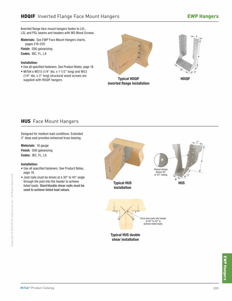
EWP Hangers
209MiTek® Product Catalog
Copy
righ
t © 2
020
MiT
ek In
dust
ries
, Inc
. Al
l Rig
hts
Rese
rved
EWP HangersHDQIF Inverted Flange Face Mount Hangers
Inverted flange face mount hangers fasten to LVL, LSL and PSL beams and headers with WS Wood Screws.
Ma terials: See EWP Face Mount Hangers charts, pages 218-220
Finish: G90 galvanizingCodes: IBC, FL, LA
Installation:• Use all specified fasteners. See Product Notes, page 18.• MiTek’s WS15 (1/4" dia. x 1-1/2" long) and WS3
(1/4" dia. x 3" long) structural wood screws are supplied with HDQIF hangers.
Designed for medium load conditions. Extended 3" deep seat provides enhanced truss bearing.
Materials: 16 gaugeFinish: G90 galvanizingCodes: IBC, FL, LA
Installation:• Use all specified fasteners. See Product Notes,
page 18.• Joist nails must be driven at a 30° to 45° angle
through the joist into the header to achieve listed loads. Slant/double shear nails must be used to achieve listed load values.
HDQIF
Typical HUSinstallation
Typical HDQIFinverted flange installation
Typical HUS double shear installation
HUS
HUS Face Mount Hangers
Drive joist nails into header at 30° to 45° to
achieve listed loads.
2"
H
W
3"
Raised dimple allows 30°
to 45° nailing
3"
H
W
A
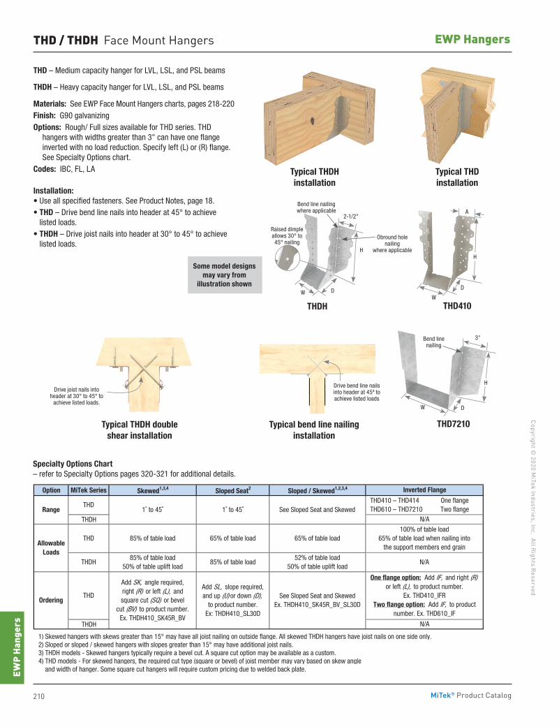
210 MiTek® Product Catalog
Copyright © 2020 M
iTek Industries, Inc. All Rights Reserved
EWP Hangers
EWP
Hang
ers
THD / THDH Face Mount Hangers
THD – Medium capacity hanger for LVL, LSL, and PSL beams
THDH – Heavy capacity hanger for LVL, LSL, and PSL beams
Materials: See EWP Face Mount Hangers charts, pages 218-220Finish: G90 galvanizingOp tions: Rough/ Full sizes available for THD series. THD
hangers with widths greater than 3" can have one flange inverted with no load reduction. Specify left (L) or (R) flange. See Specialty Options chart.
Codes: IBC, FL, LA
Installation:• Use all specified fasteners. See Product Notes, page 18.• THD – Drive bend line nails into header at 45° to achieve
listed loads.• THDH – Drive joist nails into header at 30° to 45° to achieve
listed loads.
Specialty Options Chart – refer to Specialty Options pages 320-321 for additional details.
Option MiTek Series Skewed1,3,4 Sloped Seat2 Sloped / Skewed1,2,3,4
THDH
THDH
1) Skewed hangers with skews greater than 15° may have all joist nailing on outside flange. All skewed THDH hangers have joist nails on one side only. 2) Sloped or sloped / skewed hangers with slopes greater than 15° may have additional joist nails. 3) THDH models - Skewed hangers typically require a bevel cut. A square cut option may be available as a custom. 4) THD models - For skewed hangers, the required cut type (square or bevel) of joist member may vary based on skew angle and width of hanger. Some square cut hangers will require custom pricing due to welded back plate.
N/A
Inverted Flange
N/A
100% of table load65% of table load when nailing into
the support members end grain
N/A
One flange option: Add IF, and right (R) or left (L), to product number.
Ex. THD410_IFRTwo flange option: Add IF, to product
number. Ex. THD610_IF
THD410 – THD414 THD610 – THD7210
One flangeTwo flange1˚ to 45˚ 1˚ to 45˚ See Sloped Seat and Skewed
65% of table load
85% of table load50% of table uplift load
85% of table load
Ordering
Range
AllowableLoads
THD
THD
65% of table load
85% of table load52% of table load
50% of table uplift load
See Sloped Seat and SkewedEx. THDH410_SK45R_BV_SL30D
THD
THDH
Add SK, angle required,right (R) or left (L), andsquare cut (SQ) or bevel
cut (BV) to product number. Ex. THDH410_SK45R_BV
Add SL, slope required,and up (U) or down (D),
to product number.Ex: THDH410_SL30D
Some model designs may vary from
illustration shown
Typical THDHinstallation
Typical THDinstallation
Typical THDH double shear installation
Typical bend line nailing installation
THD410THDH
Drive joist nails into header at 30° to 45° to
achieve listed loads.
H
D
W
H
DW
Raised dimple allows 30° to 45° nailing
2-1/2"
Drive bend line nails into header at 45º to achieve listed loads
Bend line nailing where applicable
Obround hole nailing
where applicable
THD7210
W
3"Bend line nailing
D
H
A
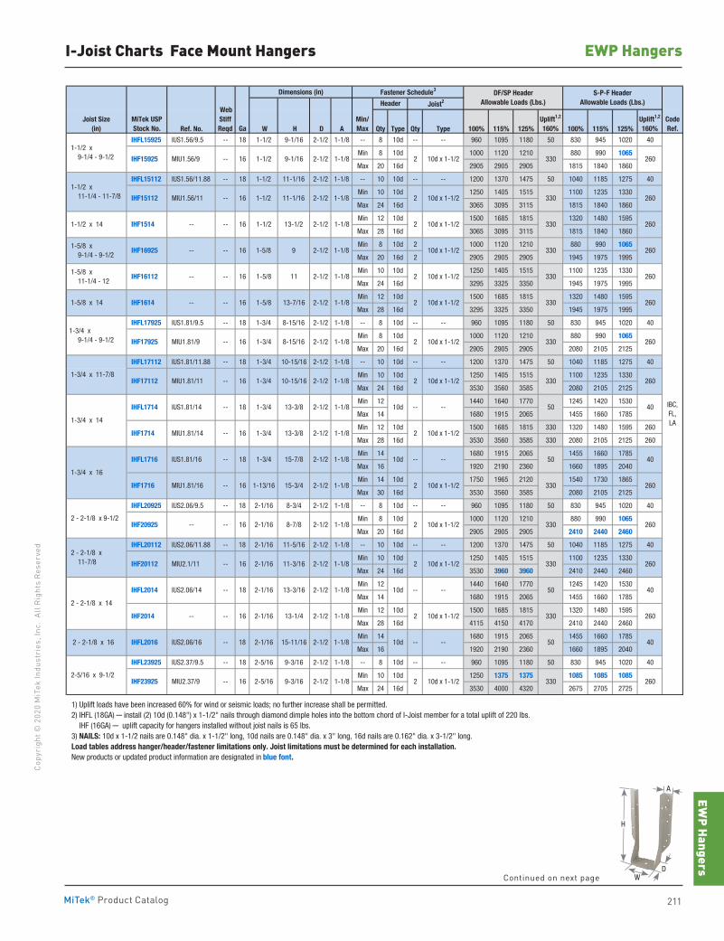
EWP Hangers
211MiTek® Product Catalog
Copy
righ
t © 2
020
MiT
ek In
dust
ries
, Inc
. Al
l Rig
hts
Rese
rved
EWP HangersI-Joist Charts Face Mount Hangers
Dimensions (in)
Ref. No. W H D A Qty Type Qty Type 100% 115% 125% 100% 115% 125%
IHFL15925 IUS1.56/9.5 -- 18 1-1/2 9-1/16 2-1/2 1-1/8 -- 8 10d -- -- 960 1095 1180 50 830 945 1020 40
Min 8 10d 1000 1120 1210 880 990 1065
Max 20 16d 2905 2905 2905 1815 1840 1860
IHFL15112 IUS1.56/11.88 -- 18 1-1/2 11-1/16 2-1/2 1-1/8 -- 10 10d -- -- 1200 1370 1475 50 1040 1185 1275 40
Min 10 10d 1250 1405 1515 1100 1235 1330
Max 24 16d 3065 3095 3115 1815 1840 1860
Min 12 10d 1500 1685 1815 1320 1480 1595
Max 28 16d 3065 3095 3115 1815 1840 1860
Min 8 10d 2 1000 1120 1210 880 990 1065
Max 20 16d 2 2905 2905 2905 1945 1975 1995
Min 10 10d 1250 1405 1515 1100 1235 1330
Max 24 16d 3295 3325 3350 1945 1975 1995
Min 12 10d 1500 1685 1815 1320 1480 1595
Max 28 16d 3295 3325 3350 1945 1975 1995
IHFL17925 IUS1.81/9.5 -- 18 1-3/4 8-15/16 2-1/2 1-1/8 -- 8 10d -- -- 960 1095 1180 50 830 945 1020 40
Min 8 10d 1000 1120 1210 880 990 1065
Max 20 16d 2905 2905 2905 2080 2105 2125
IHFL17112 IUS1.81/11.88 -- 18 1-3/4 10-15/16 2-1/2 1-1/8 -- 10 10d -- -- 1200 1370 1475 50 1040 1185 1275 40
Min 10 10d 1250 1405 1515 1100 1235 1330
Max 24 16d 3530 3560 3585 2080 2105 2125
Min 12 1440 1640 1770 1245 1420 1530
Max 14 1680 1915 2065 1455 1660 1785
Min 12 10d 1500 1685 1815 330 1320 1480 1595 260
Max 28 16d 3530 3560 3585 330 2080 2105 2125 260
Min 14 1680 1915 2065 1455 1660 1785
Max 16 1920 2190 2360 1660 1895 2040
Min 14 10d 1750 1965 2120 1540 1730 1865
Max 30 16d 3530 3560 3585 2080 2105 2125
IHFL20925 IUS2.06/9.5 -- 18 2-1/16 8-3/4 2-1/2 1-1/8 -- 8 10d -- -- 960 1095 1180 50 830 945 1020 40
Min 8 10d 1000 1120 1210 880 990 1065
Max 20 16d 2905 2905 2905 2410 2440 2460
IHFL20112 IUS2.06/11.88 -- 18 2-1/16 11-5/16 2-1/2 1-1/8 -- 10 10d -- -- 1200 1370 1475 50 1040 1185 1275 40
Min 10 10d 1250 1405 1515 1100 1235 1330
Max 24 16d 3530 3960 3960 2410 2440 2460
Min 12 1440 1640 1770 1245 1420 1530
Max 14 1680 1915 2065 1455 1660 1785
Min 12 10d 1500 1685 1815 1320 1480 1595
Max 28 16d 4115 4150 4170 2410 2440 2460
Min 14 1680 1915 2065 1455 1660 1785
Max 16 1920 2190 2360 1660 1895 2040
IHFL23925 IUS2.37/9.5 -- 18 2-5/16 9-3/16 2-1/2 1-1/8 -- 8 10d -- -- 960 1095 1180 50 830 945 1020 40
Min 10 10d 1250 1375 1375 1085 1085 1085
Max 24 16d 3530 4000 4320 2675 2705 2725
1) Uplift loads have been increased 60% for wind or seismic loads; no further increase shall be permitted. 2) IHFL (18GA) ─ install (2) 10d (0.148") x 1-1/2" nails through diamond dimple holes into the bottom chord of I-Joist member for a total uplift of 220 lbs. IHF (16GA) ─ uplift capacity for hangers installed without joist nails is 65 lbs. 3) NAILS: 10d x 1-1/2 nails are 0.148" dia. x 1-1/2" long, 10d nails are 0.148" dia. x 3" long, 16d nails are 0.162" dia. x 3-1/2" long. Load tables address hanger/header/fastener limitations only. Joist limitations must be determined for each installation. New products or updated product information are designated in blue font.
CodeRef.
330
330 260
1-5/8 11 2-1/2 2
Joist Size(in)
Uplift1,2
160%Uplift1,2
160%
IHF16112
1-1/2 x 9-1/4 - 9-1/2
1-1/2 x 11-1/4 - 11-7/8
1-1/2 x 14
1-5/8 x 9-1/4 - 9-1/2
260
10d x 1-1/2
10d x 1-1/22
10d x 1-1/2 330
1-1/8
1-1/8
1-3/4 x 16
-- -- 16
2 - 2-1/8 x 9-1/2
2 - 2-1/8 x 11-7/8
2 - 2-1/8 x 14
1-5/8 x 11-1/4 - 12
S-P-F HeaderAllowable Loads (Lbs.)
MiTek USPStock No.
Joist2
WebStiffReqd Ga
Header
Fastener Schedule3
Min/Max
DF/SP HeaderAllowable Loads (Lbs.)
MIU1.56/9 -- 16 1-1/2 9-1/16 2-1/2 2
1-5/8 x 14
1-3/4 x 9-1/4 - 9-1/2
1-3/4 x 11-7/8
1-3/4 x 14
10d x 1-1/22
260
330 260
IHF15925
IHF15112
IHF1514
IHF16925
10d x 1-1/2
9 2-1/2-- --
MIU1.56/11 -- 16 1-1/2 11-1/16 2-1/2
IHF1614 -- -- 16 1-5/8 13-7/16 2-1/2 2 10d x 1-1/2 330
-- -- 16 1-1/2 13-1/2 2-1/2
16 1-5/8
1-1/8
1-1/8
1-1/8
1-1/8
10d x 1-1/2
330
IHFL1714 IUS1.81/14 -- 18 1-3/4 13-3/8 2-1/2 -- -- 50
IHF17112 MIU1.81/11 -- 16 1-3/4 10-15/16 2-1/2 2 10d x 1-1/2
50
IHF1716 MIU1.81/16 -- 16 1-13/16 15-3/4 2-1/2 2 10d x 1-1/2 330
10d x 1-1/2
IHFL1716 IUS1.81/16 -- 18 1-3/4 15-7/8 2-1/2 -- --
1-1/8
2
10d
IHF20112 MIU2.1/11 2-1/2
IHF20925 -- -- 16 2-1/16 8-7/8 2-1/2 2
IHFL2014 IUS2.06/14 -- 18 2-1/16 13-3/16 2-1/2 --
1-1/8
1-1/8
--
IHF2014 -- -- 16 2-1/16 13-1/4 2-1/2 2 10d x 1-1/2
1-1/8
1-1/8
IHF17925 MIU1.81/9 -- 16 1-3/4 8-15/16
10d
10d
2
IHF1714 MIU1.81/14 -- 16 1-3/4 13-3/8 2-1/2 2
2-1/2 1-1/8
1-1/8
1-1/8
1-1/8
1-1/8
260
260
260
40
260
IBC,FL,LA
-- 16 2-1/16 11-3/16
10d x 1-1/2
260
330
330
330
260
260
260
40
40
330
330
50
10d x 1-1/2
10d 40
26033022-1/2 10d x 1-1/2 MIU2.37/9 -- 16 2-5/16 9-3/16
-- -- 501-1/8
1-1/8
IHFL2016 IUS2.06/16 -- 18 2-1/16 15-11/16 2-1/2
2-5/16 x 9-1/2 IHF23925
2 - 2-1/8 x 16
Continued on next page
H
WD
A
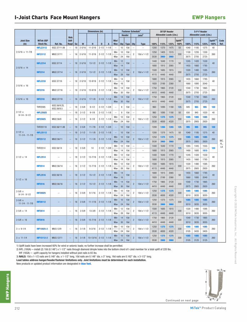
212 MiTek® Product Catalog
Copyright © 2020 M
iTek Industries, Inc. All Rights Reserved
EWP Hangers
EWP
Hang
ers
I-Joist Charts Face Mount Hangers
Dimensions (in)
Ref. No. W H D A Qty Type Qty Type 100% 115% 125% 100% 115% 125%
IHFL23112 IUS2.37/11.88 -- 18 2-5/16 11-3/16 2-1/2 1-1/8 -- 10 10d -- -- 1200 1370 1475 50 1040 1185 1275 40
Min 10 10d 1250 1405 1515 1100 1235 1330
Max 24 16d 3530 3960 3960 2675 2705 2725
Min 12 1440 1640 1770 1245 1420 1530
Max 14 1680 1915 2065 1455 1660 1785
Min 12 10d 1500 1685 1815 1320 1480 1595
Max 28 16d 4115 4440 4440 2675 2705 2725
Min 14 1680 1915 2065 1455 1660 1785
Max 16 1920 2190 2360 1660 1895 2040
Min 14 10d 1750 1965 2120 1540 1730 1865
Max 30 16d 4410 4440 4440 2675 2705 2725
Min 14 10d 1750 1965 2120 1540 1730 1865
Max 30 16d 4410 4440 4440 2675 2705 2725
THFI2595 IUS2.56/9.25, IUS2.56/9.5
-- 18 2-5/8 9-1/2 2-1/2 1-3/8 -- 8 10d -- -- 960 1095 1180 125 845 965 995 100
IHFL25925 -- -- 18 2-1/2 9-1/8 2-1/2 1-1/8 -- 8 10d -- -- 960 1095 1180 50 830 945 1020 40
Min 10 10d 1250 1375 1375 1085 1085 1085
Max 24 16d 3530 4000 4320 2875 2905 2920
THFI25118 IUS2.56/11.88 -- 18 2-5/8 11-7/8 2-1/2 1-3/8 -- 10 10d -- -- 1200 1265 1265 125 995 995 995 100
IHFL25112 -- -- 18 2-1/2 11-1/8 2-1/2 1-1/8 -- 10 10d -- -- 1200 1370 1475 50 1040 1185 1275 40
Min 10 10d 1250 1375 1375 1085 1085 1085
Max 24 16d 3530 3960 3960 2875 2905 2920
Min 12 10d -- -- 1440 1640 1770 1265 1445 1555
Max 14 10d -- -- 1680 1915 2065 1480 1685 1815
Min 12 10d 1440 1640 1770 1245 1420 1530
Max 14 10d 1680 1915 2065 1455 1660 1785
Min 12 10d 1500 1685 1815 1320 1480 1595
Max 28 16d 4115 4440 4440 2875 2905 2920
Min 14 1680 1915 2065 1455 1660 1785
Max 16 1920 2190 2360 1660 1895 2040
Min 14 10d 1750 1965 2120 1540 1730 1865
Max 30 16d 4410 4440 4440 2875 2905 2920
Min 10 10d 1250 1375 1375 1085 1085 1085
Max 24 16d 3530 4000 4320 3010 3035 3055
Min 10 10d 1250 1375 1375 1085 1085 1085
Max 24 16d 3530 3960 3960 3010 3035 3055
Min 12 10d 1500 1685 1815 1320 1480 1595
Max 28 16d 4115 4440 4440 3010 3035 3055
Min 14 10d 1750 1965 2120 1540 1730 1865
Max 30 16d 4410 4440 4440 3010 3035 3055
Min 10 10d 1250 1375 1375 1085 1085 1085
Max 24 16d 3530 4000 4320 3105 3435 3455
Min 10 10d 1250 1375 1375 1085 1085 1085
Max 24 16d 3530 3960 3960 3105 3125 3125
1) Uplift loads have been increased 60% for wind or seismic loads; no further increase shall be permitted. 2) IHFL (18GA) ─ install (2) 10d (0.148") x 1-1/2" nails through diamond dimple holes into the bottom chord of I-Joist member for a total uplift of 220 lbs. IHF (16GA) ─ uplift capacity for hangers installed without joist nails is 65 lbs. 3) NAILS: 10d x 1-1/2 nails are 0.148" dia. x 1-1/2" long, 10d nails are 0.148" dia. x 3" long, 16d nails are 0.162" dia. x 3-1/2" long. Load tables address hanger/header/fastener limitations only. Joist limitations must be determined for each installation. New products or updated product information are designated in blue font.
1-1/8
1-1/8
1-1/8
1-1/8
1-1/8
1-1/8
1-1/8
1-1/8
1-1/8
1-1/8
1-1/8
1-1/8
1-1/8
1-1/8
1-1/8
1-3/8
10d x 1-1/2 330
15-7/16 2-1/2 2 10d x 1-1/2 330 IHF2616 -- --
-- --
260
IHF26925 -- -- 16 2-5/8 9-1/16 2-1/2 2 10d x 1-1/2 260
16 2-5/8 13-3/8 2-1/2
260
260
260
2 10d x 1-1/2 330
3302 10d x 1-1/2-- 16 3-1/8 3 x 11-1/4 10-13/16 IHF15112-2 MIU3.12/11
2-5/8 x 14
2-5/8 x 16
IHF15925-2 MIU3.12/9 -- 16 3-1/8
16 2-5/8
9-3/16 2-1/2
2-1/2
2-1/2 x 16
2-5/8 x 9-1/4 - 9-1/2
2-5/8 x 11-1/4 - 11-7/8
IHFL2514 -- -- 18 2-1/2 13-7/16
15-1/2 IHFL2516 IUS2.56/16 -- 18 2-1/2
IHF2516 MIU2.56/16 -- 16 2-1/2
3 x 9-1/4
IHF2614
40
2-1/2 -- -- 50
2-1/2 2 10d x 1-1/2 330
10d2-1/2 -- -- 50
260
1-1/8
1-1/8
1-1/8
26015-1/2 2-1/2 2 10d x 1-1/2 330
2-5/16 x 11-7/8
2-5/16 x 14
2-5/16 x 16
2-5/16 x 18
2-1/2 x 9-1/4 - 9-1/2
330
330
330
40
260
40
260
260
260
260
2-1/2 x 14
THFI2514 IUS2.56/14
2-1/2 13-7/16
100
2-1/2 11-1/8 2-1/2 2 10d x 1-1/2 IHF25112 MIU2.56/11 -- 16
2-5/8 14 2-1/2-- 18
2-1/2 9-1/8 2-1/2 2 10d x 1-1/2
2-1/2 x 11-1/4 - 11-7/8
40
330
260
2 10d x 1-1/2 330
IHF26112 -- -- 16 2-5/8 11-1/16 2-1/2 2
IHF2514 MIU2.56/14 -- 16
IUS2.37/16
IHF2318 MIU2.37/18 -- 16
IHF25925 MIU2.56/9 -- 16
2-1/2
IHF2314 MIU2.37/14 -- 16 2-5/16
50
IHF2316 MIU2.37/16 -- 16 2-5/16 15-9/16 2-1/2 2 10d x 1-1/2 330
10d2-5/16 15-9/16 2-1/2 -- -- IHFL2316
10d x 1-1/2
Joist Size(in)
MiTek USPStock No.
Min/Max
Uplift1,2
160%Uplift1,2
160%
260
IHFL2314 IUS2.37/14 -- 18 2-5/16 13-1/2 2-1/2 -- -- 5010d
IHF23112 MIU2.37/11 -- 16 2-5/16 11-3/16
IBC,FL,LA
330
125
CodeRef.
WebStiffReqd Ga
Fastener Schedule3 DF/SP HeaderAllowable Loads (Lbs.)
S-P-F HeaderAllowable Loads (Lbs.)Header Joist2
2 10d x 1-1/2 330
13-1/2 2-1/2 2 10d x 1-1/2
-- 18
2-5/16 17-1/8 2-1/2 2
Continued on next page
H
WD
A
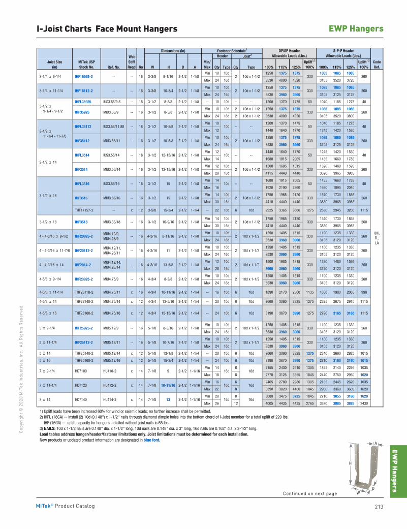
EWP Hangers
213MiTek® Product Catalog
Copy
righ
t © 2
020
MiT
ek In
dust
ries
, Inc
. Al
l Rig
hts
Rese
rved
EWP HangersI-Joist Charts Face Mount Hangers
Dimensions (in)
Ref. No. W H D A Qty Type Qty Type 100% 115% 125% 100% 115% 125%
Min 10 10d 1250 1375 1375 1085 1085 1085
Max 24 16d 3530 4000 4320 3105 3520 3720
Min 10 10d 1250 1375 1375 1085 1085 1085
Max 24 16d 3530 3960 3960 3105 3125 3125
IHFL35925 IUS3.56/9.5 -- 18 3-1/2 8-5/8 2-1/2 1-1/8 -- 10 10d -- -- 1200 1370 1475 50 1040 1185 1275 40
Min 10 10d 2 10d x 1-1/2 1250 1375 1375 1085 1085 1085
Max 24 16d 2 10d x 1-1/2 3530 4000 4320 3105 3520 3800
Min 10 1200 1370 1475 1040 1185 1275
Max 12 1440 1640 1770 1245 1420 1530
Min 10 10d 1250 1375 1375 1085 1085 1085
Max 24 16d 3530 3960 3960 3105 3125 3125
Min 12 1440 1640 1770 1245 1420 1530
Max 14 1680 1915 2065 1455 1660 1785
Min 12 10d 1500 1685 1815 1320 1480 1595
Max 28 16d 4115 4440 4440 3620 3965 3985
Min 14 1680 1915 2065 1455 1660 1785
Max 16 1920 2190 2360 1660 1895 2040
Min 14 10d 1750 1965 2120 1540 1730 1865
Max 30 16d 4410 4440 4440 3880 3965 3985
THF17157-2 -- x 12 3-5/8 15-3/4 2-1/2 1-1/4 -- 22 10d 6 10d 2925 3365 3660 1275 2560 2945 3200 1115
Min 14 10d 1750 1965 2120 1540 1730 1865
Max 30 16d 4410 4440 4440 3880 3965 3985
Min 10 10d 1250 1405 1515 1100 1235 1330
Max 24 16d 3530 3960 3960 3105 3120 3120
Min 10 10d 1250 1405 1515 1100 1235 1330
Max 24 16d 3530 3960 3960 3105 3120 3120
Min 12 10d 1500 1685 1815 1320 1480 1595
Max 28 16d 3960 3960 3960 3120 3120 3120
Min 10 10d 1250 1405 1515 1100 1235 1330
Max 24 16d 3530 3960 3960 3105 3120 3120
4-5/8 x 11-1/4 THF23118-2 MIU4.75/11 x 16 4-3/4 10-11/16 2-1/2 1-1/4 -- 16 10d 6 10d 1890 2170 2360 1135 1650 1900 2065 990
4-5/8 x 14 THF23140-2 MIU4.75/14 x 12 4-3/4 13-5/16 2-1/2 1-1/4 -- 20 10d 6 10d 2660 3060 3325 1275 2325 2675 2910 1115
4-5/8 x 16 THF23160-2 MIU4.75/16 x 12 4-3/4 15-15/16 2-1/2 1-1/4 -- 24 10d 6 10d 3190 3670 3990 1275 2790 3165 3165 1115
Min 10 10d 1250 1405 1515 1100 1235 1330
Max 24 16d 3530 3960 3960 3105 3120 3120
Min 10 10d 1250 1405 1515 1100 1235 1330
Max 24 16d 3530 3960 3960 3105 3120 3120
5 x 14 THF25140-2 MIU5.12/14 x 12 5-1/8 13-1/8 2-1/2 1-1/4 -- 20 10d 6 10d 2660 3060 3325 1275 2340 2690 2925 1015
5 x 16 THF25160-2 MIU5.12/16 x 12 5-1/8 15-3/4 2-1/2 1-1/4 -- 24 10d 6 10d 3190 3670 3990 1275 2810 3160 3160 1015
Min 14 6 2155 2430 2610 1305 1895 2140 2295 1035
Max 18 8 2770 3125 3355 1845 2440 2750 2950 1620
Min 16 6 2465 2780 2980 1305 2165 2445 2620 1035
Max 22 8 3390 3820 4100 1845 2980 3360 3605 1620
Min 20 8 3080 3475 3725 1845 2710 3055 3160 1620
Max 26 12 4005 4435 4435 2765 3520 3885 3885 2430
1) Uplift loads have been increased 60% for wind or seismic loads; no further increase shall be permitted. 2) IHFL (18GA) ─ install (2) 10d (0.148") x 1-1/2" nails through diamond dimple holes into the bottom chord of I-Joist member for a total uplift of 220 lbs. IHF (16GA) ─ uplift capacity for hangers installed without joist nails is 65 lbs. 3) NAILS: 10d x 1-1/2 nails are 0.148" dia. x 1-1/2" long, 10d nails are 0.148" dia. x 3" long, 16d nails are 0.162" dia. x 3-1/2" long. Load tables address hanger/header/fastener limitations only. Joist limitations must be determined for each installation. New products or updated product information are designated in blue font.
IBC,FL,LA
330
330
50
330
330
330
330
330
330
40
260
40
260
260
260
330
330
HD7140
IHF3516
IHF3518
IHF20925-2
IHF20112-2
IHF2014-2
IHF23925-2
IHF25925-2
IHF25112-2
HD7100
IHF16925-2
IHF16112-2
IHF35925
IHFL35112
IHF35112
IHFL3514
IHF3514
IHFL3516
9
3-1/2
-- -- 16 3-3/8 10-3/4
12-15/16
8-11/16
13-5/8
8-3/16
-- -- 16
IUS3.56/11.88
IUS3.56/14
2-1/2 16d 16d
7 x 11-1/4 10-11/16 2-1/2
7 x 9-1/4 HU410-2 x 14
HD7120
1-1/16
1-1/16
7 x 14
Min/Max
Uplift1,2
160%Uplift1,2
160%Joist Size
(in)MiTek USPStock No.
HU412-2 x 16d
16d
16d
16d HU414-2 x 14 7-1/8
14 7-1/8
13 2-1/2
7-1/8
MIU3.56/9 -- 16
CodeRef.
WebStiffReqd Ga
Fastener Schedule3 DF/SP HeaderAllowable Loads (Lbs.)
S-P-F HeaderAllowable Loads (Lbs.)Header Joist2
10d
8-5/8 2-1/2 330
260
260
260
2-1/2 -- -- 50-- 40
260
-- 50
18 3-1/2 10d
18 3-1/2 12-15/16 2-1/2 -- --
10-5/8 2-1/2 2
10-5/8
2-1/2 2 10d x 1-1/2
3-3/8 9-1/16 2-1/2 2 10d x 1-1/2
10d x 1-1/2 MIU3.56/11 --
-- -- IUS3.56/16 -- 18 3-1/2 10d
2-1/2 2 MIU3.56/14 -- 16 3-1/2
15 2-1/2
10d x 1-1/2
16 3-1/2
MIU3.56/18 -- 16 3-1/2 16-9/16 2-1/2 2 10d x 1-1/2 3301-1/8
15 2-1/2 2 10d x 1-1/2 330 MIU3.56/16 -- 16 3-1/2
2-1/2 2 10d x 1-1/2 MIU4.12/9, MIU4.28/9
-- 16 4-3/16
11 2-1/2 2 10d x 1-1/2 MIU4.12/11, MIU4.28/11
-- 16 4-3/16
2 10d x 1-1/2 MIU5.12/11 -- 16 5-1/8
2-1/2 2 10d x 1-1/2 MIU4.12/14, MIU4.28/14
-- 16 4-3/16
8-3/8 2-1/2 2 10d x 1-1/2 MIU4.75/9 -- 16 4-3/4
3-1/2 x 14
3-1/2 x 11-1/4 - 11-7/8
3-1/2 x 9-1/4 - 9-1/2
3-1/4 x 11-1/4
3-1/4 x 9-1/4
4 - 4-3/16 x 11-7/8
4 - 4-3/16 x 9-1/2
3-1/2 x 18
3-1/2 x 16
5 x 9-1/4
4-5/8 x 9-1/4
4 - 4-3/16 x 14
5 x 11-1/4
260
260
260
260
260
10-7/16
1-1/8
1-1/8
1-1/8
1-1/8
1-1/8
1-1/8
2-1/2 2 10d x 1-1/2 MIU5.12/9 -- 16 5-1/8
2-1/2
1-1/16
1-1/8
1-1/8
1-1/8
1-1/8
1-1/8
1-1/8
1-1/8
1-1/8
1-1/8
H
WD
A
Continued on next page
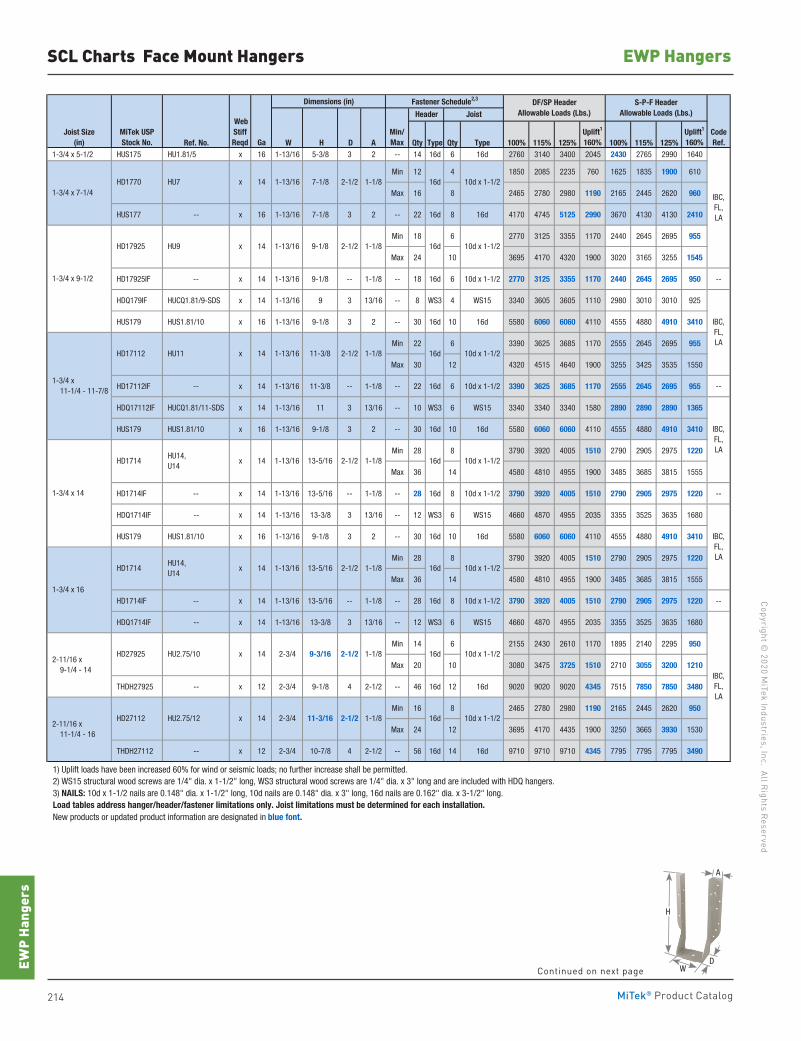
214 MiTek® Product Catalog
Copyright © 2020 M
iTek Industries, Inc. All Rights Reserved
EWP Hangers
EWP
Hang
ers
Dimensions (in)
Ref. No. W H D A Qty Type Qty Type 100% 115% 125% 100% 115% 125% 1-3/4 x 5-1/2 HUS175 HU1.81/5 x 16 1-13/16 5-3/8 3 2 -- 14 16d 6 16d 2760 3140 3400 2045 2430 2765 2990 1640
Min 12 4 1850 2085 2235 760 1625 1835 1900 610
Max 16 8 2465 2780 2980 1190 2165 2445 2620 960
HUS177 -- x 16 1-13/16 7-1/8 3 2 -- 22 16d 8 16d 4170 4745 5125 2990 3670 4130 4130 2410
Min 18 6 2770 3125 3355 1170 2440 2645 2695 955
Max 24 10 3695 4170 4320 1900 3020 3165 3255 1545
HD17925IF -- x 14 1-13/16 9-1/8 -- 1-1/8 -- 18 16d 6 10d x 1-1/2 2770 3125 3355 1170 2440 2645 2695 950 --
HDQ179IF HUCQ1.81/9-SDS x 14 1-13/16 9 3 13/16 -- 8 WS3 4 WS15 3340 3605 3605 1110 2980 3010 3010 925
HUS179 HUS1.81/10 x 16 1-13/16 9-1/8 3 2 -- 30 16d 10 16d 5580 6060 6060 4110 4555 4880 4910 3410
Min 22 6 3390 3625 3685 1170 2555 2645 2695 955
Max 30 12 4320 4515 4640 1900 3255 3425 3535 1550
HD17112IF -- x 14 1-13/16 11-3/8 -- 1-1/8 -- 22 16d 6 10d x 1-1/2 3390 3625 3685 1170 2555 2645 2695 955 --
HDQ17112IF HUCQ1.81/11-SDS x 14 1-13/16 11 3 13/16 -- 10 WS3 6 WS15 3340 3340 3340 1580 2890 2890 2890 1365
HUS179 HUS1.81/10 x 16 1-13/16 9-1/8 3 2 -- 30 16d 10 16d 5580 6060 6060 4110 4555 4880 4910 3410
Min 28 8 3790 3920 4005 1510 2790 2905 2975 1220
Max 36 14 4580 4810 4955 1900 3485 3685 3815 1555
HD1714IF -- x 14 1-13/16 13-5/16 -- 1-1/8 -- 28 16d 8 10d x 1-1/2 3790 3920 4005 1510 2790 2905 2975 1220 --
HDQ1714IF -- x 14 1-13/16 13-3/8 3 13/16 -- 12 WS3 6 WS15 4660 4870 4955 2035 3355 3525 3635 1680
Min 14 6 2155 2430 2610 1170 1895 2140 2295 950
Max 20 10 3080 3475 3725 1510 2710 3055 3200 1210
THDH27925 -- x 12 2-3/4 9-1/8 4 2-1/2 -- 46 16d 12 16d 9020 9020 9020 4345 7515 7850 7850 3480
Min 16 8 2465 2780 2980 1190 2165 2445 2620 950
Max 24 12 3695 4170 4435 1900 3250 3665 3930 1530
THDH27112 -- x 12 2-3/4 10-7/8 4 2-1/2 -- 56 16d 14 16d 9710 9710 9710 4345 7795 7795 7795 3490
1) Uplift loads have been increased 60% for wind or seismic loads; no further increase shall be permitted. 2) WS15 structural wood screws are 1/4" dia. x 1-1/2" long, WS3 structural wood screws are 1/4" dia. x 3" long and are included with HDQ hangers. 3) NAILS: 10d x 1-1/2 nails are 0.148" dia. x 1-1/2" long, 10d nails are 0.148" dia. x 3" long, 16d nails are 0.162" dia. x 3-1/2" long. Load tables address hanger/header/fastener limitations only. Joist limitations must be determined for each installation. New products or updated product information are designated in blue font.
11-3/16 2-1/2
13-5/16
16d 10d x 1-1/2
16d 10d x 1-1/2
16d
2-1/2
10d x 1-1/2
10d x 1-1/2
2-1/2
1-1/8
1-1/8
1-1/8
IBC,FL,LA
IBC,FL,LA
10d x 1-1/2
1-1/8
1-3/4 x 11-1/4 - 11-7/8
HU9 x 14 1-1/8
2-11/16 x 11-1/4 - 16
2-11/16 x 9-1/4 - 14
1-3/4 x 16
1-3/4 x 14
2-3/4 HU2.75/12 x 14
HD17112
2-1/2
16d14 1-13/16 11-3/8 HU11 x 1-1/82-1/2
14
1-13/16 HU14, U14
x 14
HU7 x 14
1-3/4 x 9-1/2
1-3/4 x 7-1/4 HD1770
HD17925
2-3/4
10d x 1-1/29-1/8
7-1/81-13/16 2-1/2 10d x 1-1/2
16d
16d
2-1/21-13/16
1-1/8
Joist Size(in)
CodeRef.Ga
WebStiffReqd
Header JoistDF/SP Header
Allowable Loads (Lbs.)S-P-F Header
Allowable Loads (Lbs.)
Uplift1
160%Uplift1
160%Min/Max
Fastener Schedule2,3
MiTek USPStock No.
IBC,FL,LA
IBC,FL,LA
IBC,FL,LA
HD1714
HD27925
HD27112
HD1714 16d
9-3/16
HU14, U14
x 14 1-13/16 13-5/16
HU2.75/10 x
SCL Charts Face Mount Hangers
Continued on next page
H
WD
A
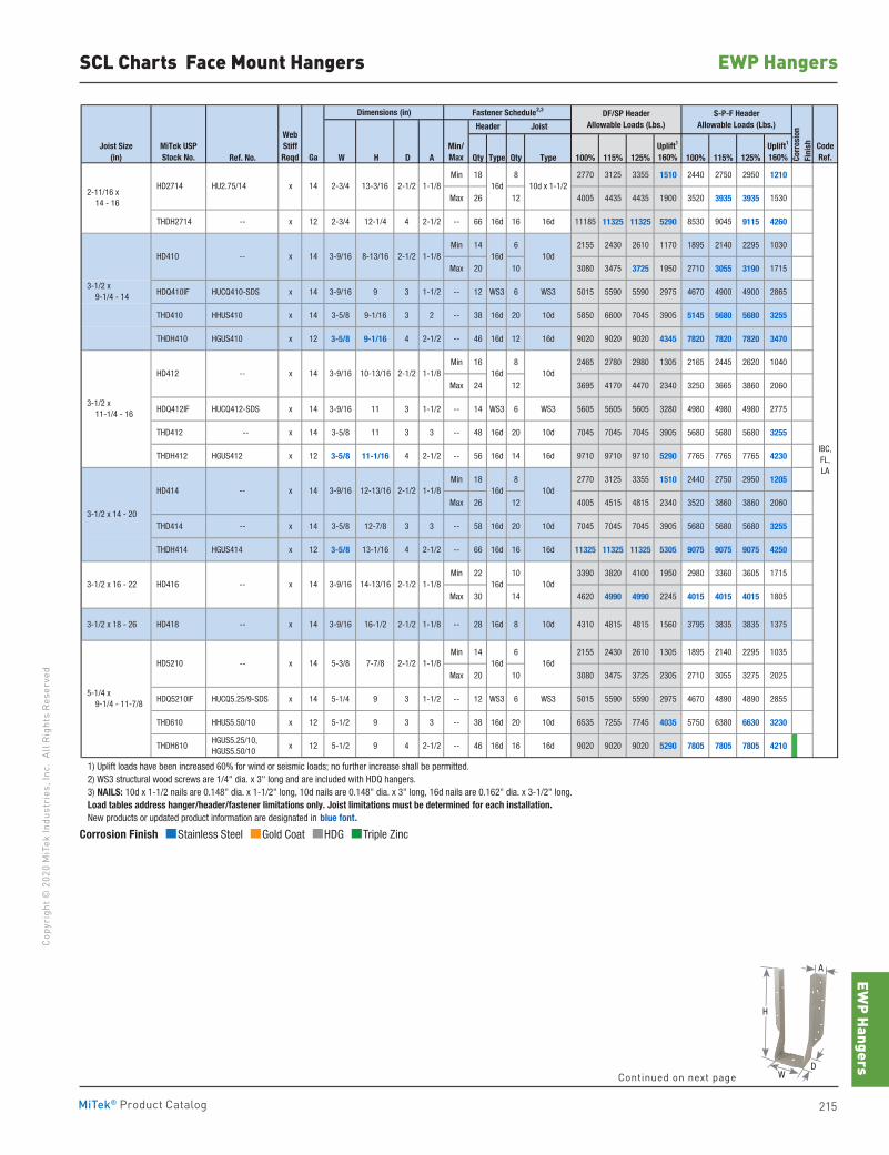
EWP Hangers
215MiTek® Product Catalog
Copy
righ
t © 2
020
MiT
ek In
dust
ries
, Inc
. Al
l Rig
hts
Rese
rved
EWP HangersSCL Charts Face Mount Hangers
Dimensions (in)
Ref. No. W H D A Qty Type Qty Type 100% 115% 125% 100% 115% 125%
Min 18 8 2770 3125 3355 1510 2440 2750 2950 1210
Max 26 12 4005 4435 4435 1900 3520 3935 3935 1530
THDH2714 -- x 12 2-3/4 12-1/4 4 2-1/2 -- 66 16d 16 16d 11185 11325 11325 5290 8530 9045 9115 4260
Min 14 6 2155 2430 2610 1170 1895 2140 2295 1030
Max 20 10 3080 3475 3725 1950 2710 3055 3190 1715
HDQ410IF HUCQ410-SDS x 14 3-9/16 9 3 1-1/2 -- 12 WS3 6 WS3 5015 5590 5590 2975 4670 4900 4900 2865
THD410 HHUS410 x 14 3-5/8 9-1/16 3 2 -- 38 16d 20 10d 5850 6600 7045 3905 5145 5680 5680 3255
THDH410 HGUS410 x 12 3-5/8 9-1/16 4 2-1/2 -- 46 16d 12 16d 9020 9020 9020 4345 7820 7820 7820 3470
Min 16 8 2465 2780 2980 1305 2165 2445 2620 1040
Max 24 12 3695 4170 4470 2340 3250 3665 3860 2060
HDQ412IF HUCQ412-SDS x 14 3-9/16 11 3 1-1/2 -- 14 WS3 6 WS3 5605 5605 5605 3280 4980 4980 4980 2775
THD412 -- x 14 3-5/8 11 3 3 -- 48 16d 20 10d 7045 7045 7045 3905 5680 5680 5680 3255
THDH412 HGUS412 x 12 3-5/8 11-1/16 4 2-1/2 -- 56 16d 14 16d 9710 9710 9710 5290 7765 7765 7765 4230
Min 18 8 2770 3125 3355 1510 2440 2750 2950 1205
Max 26 12 4005 4515 4815 2340 3520 3860 3860 2060
THD414 -- x 14 3-5/8 12-7/8 3 3 -- 58 16d 20 10d 7045 7045 7045 3905 5680 5680 5680 3255
THDH414 HGUS414 x 12 3-5/8 13-1/16 4 2-1/2 -- 66 16d 16 16d 11325 11325 11325 5305 9075 9075 9075 4250
Min 22 10 3390 3820 4100 1950 2980 3360 3605 1715
Max 30 14 4620 4990 4990 2245 4015 4015 4015 1805
3-1/2 x 18 - 26 HD418 -- x 14 3-9/16 16-1/2 2-1/2 1-1/8 -- 28 16d 8 10d 4310 4815 4815 1560 3795 3835 3835 1375
Min 14 6 2155 2430 2610 1305 1895 2140 2295 1035
Max 20 10 3080 3475 3725 2305 2710 3055 3275 2025
HDQ5210IF HUCQ5.25/9-SDS x 14 5-1/4 9 3 1-1/2 -- 12 WS3 6 WS3 5015 5590 5590 2975 4670 4890 4890 2855
THD610 HHUS5.50/10 x 12 5-1/2 9 3 3 -- 38 16d 20 10d 6535 7255 7745 4035 5750 6380 6630 3230
THDH610 HGUS5.25/10, HGUS5.50/10
x 12 5-1/2 9 4 2-1/2 -- 46 16d 16 16d 9020 9020 9020 5290 7805 7805 7805 4210
1) Uplift loads have been increased 60% for wind or seismic loads; no further increase shall be permitted. 2) WS3 structural wood screws are 1/4" dia. x 3" long and are included with HDQ hangers. 3) NAILS: 10d x 1-1/2 nails are 0.148" dia. x 1-1/2" long, 10d nails are 0.148" dia. x 3" long, 16d nails are 0.162" dia. x 3-1/2" long. Load tables address hanger/header/fastener limitations only. Joist limitations must be determined for each installation. New products or updated product information are designated in blue font.
1-1/8
1-1/8
1-1/8
1-1/8
1-1/8
1-1/8
CodeRef.
WebStiffReqd Ga
Fastener Schedule2,3 DF/SP HeaderAllowable Loads (Lbs.)
S-P-F HeaderAllowable Loads (Lbs.)Header Joist
Corr
osio
nFi
nishJoist Size
(in)MiTek USPStock No.
Min/Max
Uplift1
160%Uplift1
160%
10d HD416 -- x 14 3-9/16 14-13/16 2-1/2
3-1/2 x 9-1/4 - 14
HD410 -- x 14
2-11/16 x 14 - 16
HD2714 HU2.75/14 x 14
14
IBC,FL,LA
2-3/4
2-1/2 16d 10d
3-9/16 16d 10d
13-3/16 2-1/2 16d 10d x 1-1/2
3-9/16 8-13/16
16d
HD414 x
3-1/2 x 11-1/4 - 16
HD412 -- x
2-1/2 16d 10d14 3-9/16
3-1/2 x 16 - 22
10-13/16 2-1/2
5-1/4 x 9-1/4 - 11-7/8
16d16d HD5210 -- x 14 5-3/8 7-7/8 2-1/2
--
3-1/2 x 14 - 20
12-13/16
Corrosion Finish Stainless Steel Gold Coat HDG Triple Zinc
Corrosion Finish Stainless Steel Gold Coat HDG Triple Zinc
Corrosion Finish Stainless Steel Gold Coat HDG Triple Zinc
Continued on next page
H
WD
A
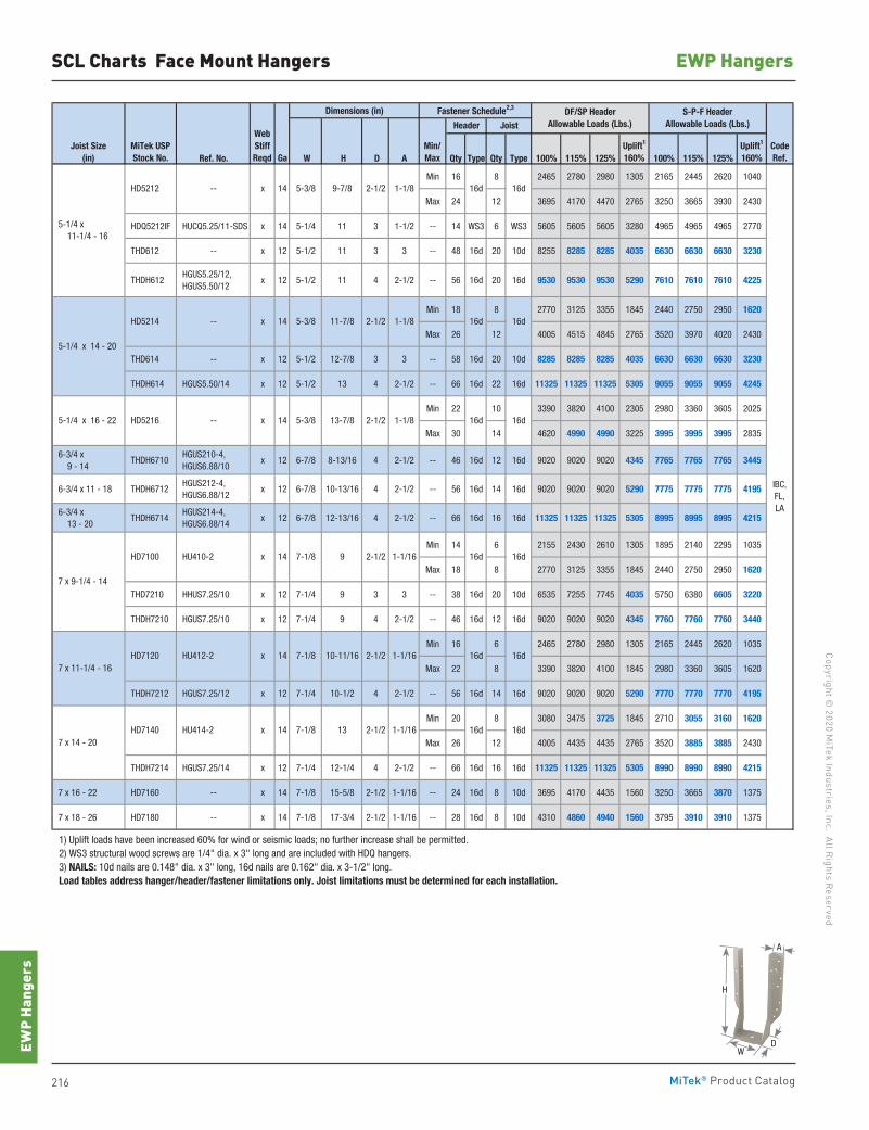
216 MiTek® Product Catalog
Copyright © 2020 M
iTek Industries, Inc. All Rights Reserved
EWP Hangers
EWP
Hang
ers
SCL Charts Face Mount Hangers
Dimensions (in)
Ref. No. W H D A Qty Type Qty Type 100% 115% 125% 100% 115% 125%
Min 16 8 2465 2780 2980 1305 2165 2445 2620 1040
Max 24 12 3695 4170 4470 2765 3250 3665 3930 2430
HDQ5212IF HUCQ5.25/11-SDS x 14 5-1/4 11 3 1-1/2 -- 14 WS3 6 WS3 5605 5605 5605 3280 4965 4965 4965 2770
THD612 -- x 12 5-1/2 11 3 3 -- 48 16d 20 10d 8255 8285 8285 4035 6630 6630 6630 3230
THDH612 HGUS5.25/12, HGUS5.50/12
x 12 5-1/2 11 4 2-1/2 -- 56 16d 20 16d 9530 9530 9530 5290 7610 7610 7610 4225
Min 18 8 2770 3125 3355 1845 2440 2750 2950 1620
Max 26 12 4005 4515 4845 2765 3520 3970 4020 2430
THD614 -- x 12 5-1/2 12-7/8 3 3 -- 58 16d 20 10d 8285 8285 8285 4035 6630 6630 6630 3230
THDH614 HGUS5.50/14 x 12 5-1/2 13 4 2-1/2 -- 66 16d 22 16d 11325 11325 11325 5305 9055 9055 9055 4245
Min 22 10 3390 3820 4100 2305 2980 3360 3605 2025
Max 30 14 4620 4990 4990 3225 3995 3995 3995 2835
6-3/4 x 9 - 14
THDH6710 HGUS210-4, HGUS6.88/10
x 12 6-7/8 8-13/16 4 2-1/2 -- 46 16d 12 16d 9020 9020 9020 4345 7765 7765 7765 3445
6-3/4 x 11 - 18 THDH6712 HGUS212-4, HGUS6.88/12
x 12 6-7/8 10-13/16 4 2-1/2 -- 56 16d 14 16d 9020 9020 9020 5290 7775 7775 7775 4195
6-3/4 x 13 - 20
THDH6714 HGUS214-4, HGUS6.88/14
x 12 6-7/8 12-13/16 4 2-1/2 -- 66 16d 16 16d 11325 11325 11325 5305 8995 8995 8995 4215
Min 14 6 2155 2430 2610 1305 1895 2140 2295 1035
Max 18 8 2770 3125 3355 1845 2440 2750 2950 1620
THD7210 HHUS7.25/10 x 12 7-1/4 9 3 3 -- 38 16d 20 10d 6535 7255 7745 4035 5750 6380 6605 3220
THDH7210 HGUS7.25/10 x 12 7-1/4 9 4 2-1/2 -- 46 16d 12 16d 9020 9020 9020 4345 7760 7760 7760 3440
Min 16 6 2465 2780 2980 1305 2165 2445 2620 1035
Max 22 8 3390 3820 4100 1845 2980 3360 3605 1620
THDH7212 HGUS7.25/12 x 12 7-1/4 10-1/2 4 2-1/2 -- 56 16d 14 16d 9020 9020 9020 5290 7770 7770 7770 4195
Min 20 8 3080 3475 3725 1845 2710 3055 3160 1620
Max 26 12 4005 4435 4435 2765 3520 3885 3885 2430
THDH7214 HGUS7.25/14 x 12 7-1/4 12-1/4 4 2-1/2 -- 66 16d 16 16d 11325 11325 11325 5305 8990 8990 8990 4215
7 x 16 - 22 HD7160 -- x 14 7-1/8 15-5/8 2-1/2 1-1/16 -- 24 16d 8 10d 3695 4170 4435 1560 3250 3665 3870 1375
7 x 18 - 26 HD7180 -- x 14 7-1/8 17-3/4 2-1/2 1-1/16 -- 28 16d 8 10d 4310 4860 4940 1560 3795 3910 3910 1375
1) Uplift loads have been increased 60% for wind or seismic loads; no further increase shall be permitted. 2) WS3 structural wood screws are 1/4" dia. x 3" long and are included with HDQ hangers. 3) NAILS: 10d nails are 0.148" dia. x 3" long, 16d nails are 0.162" dia. x 3-1/2" long. Load tables address hanger/header/fastener limitations only. Joist limitations must be determined for each installation.
16d16d
2-1/2
2-1/2 16d 16d
2-1/2 16d 16d
2-1/2
16d16d
16d16d
2-1/2 1-1/167-1/814x HD7140 HU414-2
13-7/8
Joist Size(in)
5-1/4 x 16 - 22 HD5216 -- x
-- HD5214 x
5-1/4 x 11-1/4 - 16
MiTek USPStock No.
CodeRef.
WebStiffReqd Ga
DF/SP HeaderAllowable Loads (Lbs.)
S-P-F HeaderAllowable Loads (Lbs.)
Uplift1
160%Uplift1
160%Min/Max
Fastener Schedule2,3
Header Joist
7 x 14 - 20
7 x 11-1/4 - 16
7 x 9-1/4 - 14
5-1/4 x 14 - 20
11-7/814 5-3/8
x 14 7-1/8 9
13
HD7120 HU412-2
HD7100 HU410-2
IBC,FL,LA
2-1/2 16d16d HD5212 -- x 14 5-3/8 9-7/8
x 14 7-1/8 10-11/16
14 5-3/8
1-1/16
1-1/16
1-1/8
1-1/8
1-1/8
H
WD
A
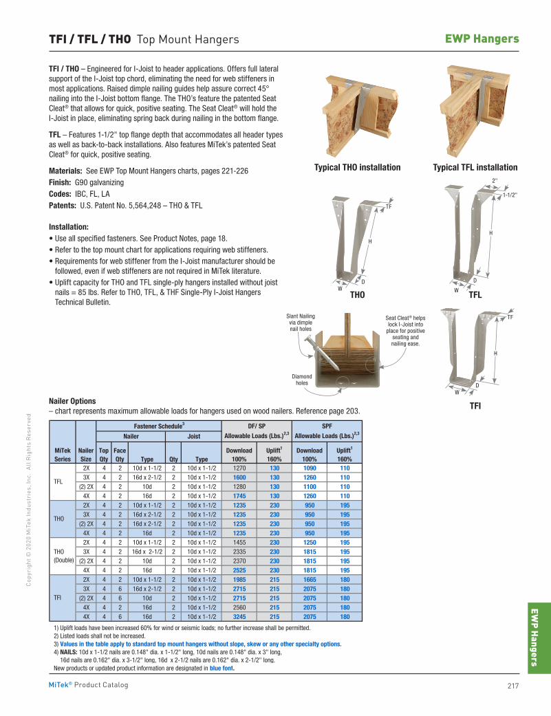
EWP Hangers
217MiTek® Product Catalog
Copy
righ
t © 2
020
MiT
ek In
dust
ries
, Inc
. Al
l Rig
hts
Rese
rved
EWP HangersTFI / TFL / THO Top Mount Hangers
TFI / THO – Engineered for I-Joist to header applications. Offers full lateral support of the I-Joist top chord, eliminating the need for web stiffeners in most applications. Raised dimple nailing guides help assure correct 45° nailing into the I-Joist bottom flange. The THO’s feature the patented Seat Cleat® that allows for quick, positive seating. The Seat Cleat® will hold the I-Joist in place, eliminating spring back during nailing in the bottom flange.
TFL – Features 1-1/2" top flange depth that accommodates all header types as well as back-to-back installations. Also features MiTek’s patented Seat Cleat® for quick, positive seating.
Materials: See EWP Top Mount Hangers charts, pages 221-226Finish: G90 galvanizingCodes: IBC, FL, LAPatents: U.S. Patent No. 5,564,248 – THO & TFL
Installation:• Use all specified fasteners. See Product Notes, page 18.• Refer to the top mount chart for applications requiring web stiffeners.• Requirements for web stiffener from the I-Joist manufacturer should be
followed, even if web stiffeners are not required in MiTek literature.• Uplift capacity for THO and TFL single-ply hangers installed without joist
nails = 85 lbs. Refer to THO, TFL, & THF Single-Ply I-Joist Hangers Technical Bulletin.
Typical THO installation Typical TFL installation
THO TFL
TFI
Type Qty Type2X 4 2 10d x 1-1/2 2 10d x 1-1/2 1270 130 1090 1103X 4 2 16d x 2-1/2 2 10d x 1-1/2 1600 130 1260 110
(2) 2X 4 2 10d 2 10d x 1-1/2 1280 130 1100 1104X 4 2 16d 2 10d x 1-1/2 1745 130 1260 1102X 4 2 10d x 1-1/2 2 10d x 1-1/2 1235 230 950 1953X 4 2 16d x 2-1/2 2 10d x 1-1/2 1235 230 950 195
(2) 2X 4 2 16d x 2-1/2 2 10d x 1-1/2 1235 230 950 1954X 4 2 16d 2 10d x 1-1/2 1235 230 950 1952X 4 2 10d x 1-1/2 2 10d x 1-1/2 1455 230 1250 1953X 4 2 16d x 2-1/2 2 10d x 1-1/2 2335 230 1815 195
(2) 2X 4 2 10d 2 10d x 1-1/2 2370 230 1815 1954X 4 2 16d 2 10d x 1-1/2 2525 230 1815 1952X 4 2 10d x 1-1/2 2 10d x 1-1/2 1985 215 1665 1803X 4 6 16d x 2-1/2 2 10d x 1-1/2 2715 215 2075 180
(2) 2X 4 6 10d 2 10d x 1-1/2 2715 215 2075 1804X 4 2 16d 2 10d x 1-1/2 2560 215 2075 1804X 4 6 16d 2 10d x 1-1/2 3245 215 2075 180
1) Uplift loads have been increased 60% for wind or seismic loads; no further increase shall be permitted. 2) Listed loads shall not be increased. 3) Values in the table apply to standard top mount hangers without slope, skew or any other specialty options. 4) NAILS: 10d x 1-1/2 nails are 0.148" dia. x 1-1/2" long, 10d nails are 0.148" dia. x 3" long, 16d nails are 0.162" dia. x 3-1/2" long, 16d x 2-1/2 nails are 0.162" dia. x 2-1/2" long. New products or updated product information are designated in blue font.
Download100%
THO (Double)
TFI
Uplift1
160%Uplift1
160%
DF/ SP
Allowable Loads (Lbs.)2,3
SPF
Allowable Loads (Lbs.)2,3
THO
MiTekSeries
NailerSize
Fastener Schedule3
Nailer Joist
TFL
TopQty
FaceQty
Download100%
Nailer Options– chart represents maximum allowable loads for hangers used on wood nailers. Reference page 203.
Slant Nailingvia dimplenail holes
Diamondholes
Seat Cleat® helps lock I-Joist into
place for positive seating and nailing ease.
H
D
W
2"
1-1/2"
DW
TF
H
WD
H
TF
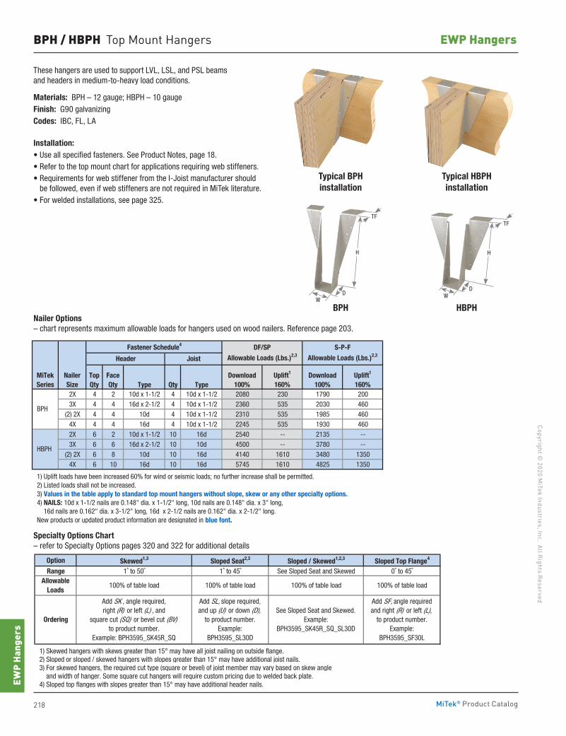
218 MiTek® Product Catalog
Copyright © 2020 M
iTek Industries, Inc. All Rights Reserved
EWP Hangers
EWP
Hang
ers
BPH / HBPH Top Mount Hangers
These hangers are used to support LVL, LSL, and PSL beams and headers in medium-to-heavy load conditions.
Materials: BPH – 12 gauge; HBPH – 10 gaugeFinish: G90 galvanizingCodes: IBC, FL, LA
Installation:• Use all specified fasteners. See Product Notes, page 18.• Refer to the top mount chart for applications requiring web stiffeners.• Requirements for web stiffener from the I-Joist manufacturer should
be followed, even if web stiffeners are not required in MiTek literature.• For welded installations, see page 325.
Typical BPHinstallation
Typical HBPHinstallation
BPH HBPHNailer Options– chart represents maximum allowable loads for hangers used on wood nailers. Reference page 203.
Specialty Options Chart– refer to Specialty Options pages 320 and 322 for additional details
Type Qty Type2X 4 2 10d x 1-1/2 4 10d x 1-1/2 2080 230 1790 2003X 4 4 16d x 2-1/2 4 10d x 1-1/2 2360 535 2030 460
(2) 2X 4 4 10d 4 10d x 1-1/2 2310 535 1985 4604X 4 4 16d 4 10d x 1-1/2 2245 535 1930 4602X 6 2 10d x 1-1/2 10 16d 2540 -- 2135 --3X 6 6 16d x 2-1/2 10 10d 4500 -- 3780 --
(2) 2X 6 8 10d 10 16d 4140 1610 3480 13504X 6 10 16d 10 16d 5745 1610 4825 1350
1) Uplift loads have been increased 60% for wind or seismic loads; no further increase shall be permitted. 2) Listed loads shall not be increased. 3) Values in the table apply to standard top mount hangers without slope, skew or any other specialty options. 4) NAILS: 10d x 1-1/2 nails are 0.148" dia. x 1-1/2" long, 10d nails are 0.148" dia. x 3" long, 16d nails are 0.162" dia. x 3-1/2" long, 16d x 2-1/2 nails are 0.162" dia. x 2-1/2" long. New products or updated product information are designated in blue font.
HBPH
BPH
Uplift1
160%Uplift1
160%
DF/SP
Allowable Loads (Lbs.)2,3
S-P-F
Allowable Loads (Lbs.)2,3
MiTekSeries
NailerSize
Fastener Schedule4
Header Joist
TopQty
FaceQty
Download100%
Download100%
Option Skewed1,3 Sloped Seat2,3 Sloped / Skewed1,2,3 Sloped Top Flange4
Range 1˚ to 50˚ 1˚ to 45˚ See Sloped Seat and Skewed 0˚ to 45˚
1) Skewed hangers with skews greater than 15° may have all joist nailing on outside flange. 2) Sloped or sloped / skewed hangers with slopes greater than 15° may have additional joist nails. 3) For skewed hangers, the required cut type (square or bevel) of joist member may vary based on skew angle and width of hanger. Some square cut hangers will require custom pricing due to welded back plate. 4) Sloped top flanges with slopes greater than 15° may have additional header nails.
100% of table load
Add SK , angle required,right (R) or left (L) , and
square cut (SQ) or bevel cut (BV)to product number.
Example: BPH3595_SK45R_SQ
Add SL, slope required,and up (U) or down (D),
to product number.Example:
BPH3595_SL30D
See Sloped Seat and Skewed.Example:
BPH3595_SK45R_SQ_SL30D
Add SF, angle requiredand right (R) or left (L),
to product number.Example:
BPH3595_SF30L
AllowableLoads
Ordering
100% of table load 100% of table load 100% of table load
H
WD
TF
H
WD
TF
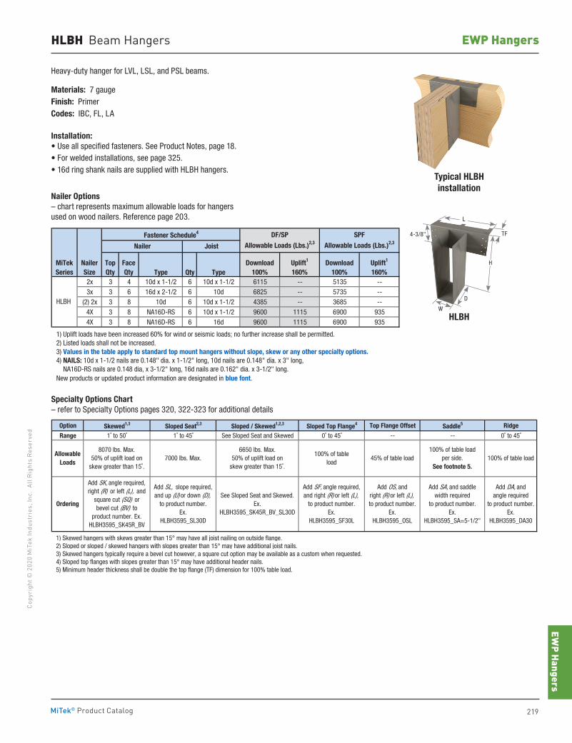
EWP Hangers
219MiTek® Product Catalog
Copy
righ
t © 2
020
MiT
ek In
dust
ries
, Inc
. Al
l Rig
hts
Rese
rved
EWP HangersHLBH Beam Hangers
Heavy-duty hanger for LVL, LSL, and PSL beams.
Materials: 7 gaugeFinish: PrimerCodes: IBC, FL, LA
Installation:• Use all specified fasteners. See Product Notes, page 18.• For welded installations, see page 325.• 16d ring shank nails are supplied with HLBH hangers.
Typical HLBHinstallation
HLBH
Fastener Schedule4
Type Qty Type2x 3 4 10d x 1-1/2 6 10d x 1-1/2 6115 -- 5135 --3x 3 6 16d x 2-1/2 6 10d 6825 -- 5735 --
(2) 2x 3 8 10d 6 10d x 1-1/2 4385 -- 3685 --4X 3 8 NA16D-RS 6 10d x 1-1/2 9600 1115 6900 9354X 3 8 NA16D-RS 6 16d 9600 1115 6900 935
1) Uplift loads have been increased 60% for wind or seismic loads; no further increase shall be permitted. 2) Listed loads shall not be increased. 3) Values in the table apply to standard top mount hangers without slope, skew or any other specialty options. 4) NAILS: 10d x 1-1/2 nails are 0.148" dia. x 1-1/2" long, 10d nails are 0.148" dia. x 3" long, NA16D-RS nails are 0.148 dia, x 3-1/2" long, 16d nails are 0.162" dia. x 3-1/2" long. New products or updated product information are designated in blue font.
DF/SP
Allowable Loads (Lbs.)2,3
SPF
Allowable Loads (Lbs.)2,3Nailer Joist
HLBH
NailerSize
Uplift1
160%Uplift1
160%MiTek Series
TopQty
FaceQty
Download100%
Download100%
Option Skewed1,3 Sloped Seat2,3 Sloped / Skewed1,2,3 Sloped Top Flange4 Top Flange Offset Saddle5 Ridge
Range 1˚ to 50˚ 1˚ to 45˚ See Sloped Seat and Skewed 0˚ to 45˚ -- -- 0˚ to 45˚
1) Skewed hangers with skews greater than 15° may have all joist nailing on outside flange. 2) Sloped or sloped / skewed hangers with slopes greater than 15° may have additional joist nails. 3) Skewed hangers typically require a bevel cut however, a square cut option may be available as a custom when requested. 4) Sloped top flanges with slopes greater than 15° may have additional header nails. 5) Minimum header thickness shall be double the top flange (TF) dimension for 100% table load.
Ordering
Add SK, angle required,right (R) or left (L), and
square cut (SQ) or bevel cut (BV) to
product number. Ex. HLBH3595_SK45R_BV
AllowableLoads
8070 lbs. Max.50% of uplift load on
skew greater than 15˚.
Add SF, angle required,and right (R) or left (L),
to product number.Ex.
HLBH3595_SF30L
7000 lbs. Max.6650 lbs. Max.
50% of uplift load onskew greater than 15˚.
Add SL, slope required,and up (U) or down (D),
to product number.Ex.
HLBH3595_SL30D
See Sloped Seat and Skewed.Ex.
HLBH3595_SK45R_BV_SL30D
Add OS, and right (R) or left (L),to product number.
Ex. HLBH3595_OSL
100% of tableload
45% of table load100% of table load
per side.See footnote 5.
100% of table load
Add SA, and saddlewidth required
to product number.Ex.
HLBH3595_SA=5-1/2"
Add DA, and angle required
to product number.Ex.
HLBH3595_DA30
Nailer Options– chart represents maximum allowable loads for hangers used on wood nailers. Reference page 203.
Specialty Options Chart– refer to Specialty Options pages 320, 322-323 for additional details
H
L
4-3/8"
D
TF
W
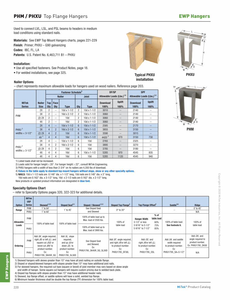
220 MiTek® Product Catalog
Copyright © 2020 M
iTek Industries, Inc. All Rights Reserved
EWP Hangers
EWP
Hang
ers
PHM / PHXU Top Flange Hangers
Typical PHXUinstallation
PHXU
PHM
Nailer Options – chart represents maximum allowable loads for hangers used on wood nailers. Reference page 203.
Specialty Options Chart– refer to Specialty Options pages 320, 322-323 for additional details.
Used to connect LVL, LSL, and PSL beams to headers in medium load conditions using standard nails.
Materials: See EWP Top Mount Hangers charts, pages 221-229Finish: Primer; PHXU – G90 galvanizingCodes: IBC, FL, LAPatents: U.S. Patent No. 6,463,711 B1 – PHXU
Installation:• Use all specified fasteners. See Product Notes, page 18.• For welded installations, see page 325.
Fastener Schedule5
Uplift Uplift
Type Qty Type 160% 160%2X 2 -- 10d x 1-1/2 2 10d x 1-1/2 3010 -- 2140 --3X 2 -- 16d x 2-1/2 2 10d x 1-1/2 3060 -- 2140 --
(2) 2X 2 -- 10d 2 10d x 1-1/2 3060 -- 2140 --4X 2 -- 16d 2 10d x 1-1/2 3060 -- 2140 --2X 4 -- 10d x 1-1/2 6 10d x 1-1/2 2585 -- 2170 --3X 4 2 16d x 2-1/2 6 10d x 1-1/2 3855 -- 3150 --
(2) 2X 4 2 10d 6 10d x 1-1/2 3590 -- 3015 --
4X 3 4 4 16d 6 10d x 1-1/2 4420 3 870 3150 7302X 4 -- 10d x 1-1/2 6 10d 2765 -- 2325 --3X 4 2 16d x 2-1/2 6 10d 3895 -- 3270 --
(2) 2X 4 2 10d 6 10d 3785 -- 3180 --4X 4 4 16d 6 10d x 1-1/2 5285 970 4545 8354X 4 4 16d 6 10d 5285 1120 4545 940
1) Listed loads shall not be increased. 2) Loads valid for hanger height ≤ 20". For hanger height ≥ 22", consult MiTek Engineering. 3) PHXU hangers with a width of less than 2-3/4" on 4x nailers are 4,350 lbs of download. 4) Values in the table apply to standard top mount hangers without slope, skew or any other specialty options. 5) NAILS: 10d x 1-1/2 nails are 0.148" dia. x 1-1/2" long, 10d nails are 0.148" dia. x 3" long, 16d nails are 0.162" dia. x 3-1/2" long, 16d x 2-1/2 nails are 0.162" dia. x 2-1/2" long. New products or updated product information are designated in blue font.
PHXU 3
widths < 3-1/2"
PHXU 2
widths > 3-1/2"
SPF
Allowable Loads (Lbs.)1,4
PHM
Nailer Joist
MiTekSeries
NailerSize
DF/SP
Allowable Loads (Lbs.)1,4
TopQty
FaceQty
Download100%
Download100%
Option Skewed1,3,5 Sloped Seat2,3 Sloped / Skewed1,2,3 Sloped Top Flange4 Saddle5,6 RidgePHM 1˚ to 84˚ 0˚ to 45˚PHXU 1˚ to 60˚ N/A
1) Skewed hangers with skews greater than 15° may have all joist nailing on outside flange. 2) Sloped or sloped/skewed hangers with slopes greater than 15° may have additional joist nails. 3) For skewed hangers, the required cut type (square or bevel) of joist member may vary based on skew angle and width of hanger. Some square cut hangers will require custom pricing due to welded back plate. 4) Sloped top flanges with slopes greater than 15° may have additional header nails. 5) Skewed, top flange offset, or saddle options will have a solid, welded top flange. 6) Minimum header thickness shall be double the top flange (TF) dimension for 100% table load.
Range
Allowable Loads
Add SK , angle required,right (R) or left (L) , and
square cut (SQ) orbevel cut (BV) to product number.
Ex: PHXU1795_SK45R_SQ
Ordering
PHM
100% of table load
PHM
PHXU
100% of table load.See footnote 6.
Add OS, andright (R) or left (L),to product number.
Ex: PHXU1795_OSL
Add SL, slope required,
and up (U) or down (D), to
product number.Ex:
PHXU1795_SL30D
See Sloped Seatand Skewed.
Ex: PHXU1795_SK45R_SQ_SL30D
Add SF, angle required,and right (R) or left (L),
to product number.Ex:
PHXU1795_SF30L
100% of table load
100% of table load up toMax. load of 3900 lbs.
% oftable load
MiTek USP
Series
Hanger Width 3-1/2" or less 3-9/16" to 5-1/2" 5-9/16" to 7-1/2"
60%75%85%
Add DA, and angle required to product number.
Ex. PHXU1795_DA30
N/A
Top Flange Offset5
See Sloped Seat and Skewed
--0° to 35° --1˚ to 45˚
Add SA, and saddlewidth required
to product number.Ex:
PHXU1795_SA=5-1/2"
100% of table load
100% of table load
100% of table load up toMax. load of 2500 lbs.
PHXU
L
DW
H
TF
L
DW
TF
H
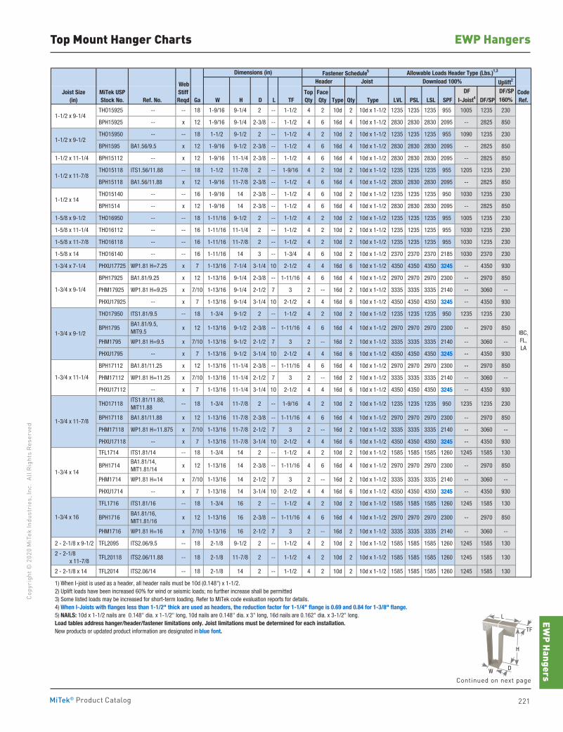
EWP Hangers
221MiTek® Product Catalog
Copy
righ
t © 2
020
MiT
ek In
dust
ries
, Inc
. Al
l Rig
hts
Rese
rved
EWP HangersTop Mount Hanger Charts
Fastener Schedule5
Uplift2
DF/SPRef. No. Ga W H D L TF Type Qty Type LVL PSL LSL SPF DF/SP 160%
THO15925 -- -- 18 1-9/16 9-1/4 2 -- 1-1/2 4 2 10d 2 10d x 1-1/2 1235 1235 1235 955 1005 1235 230
BPH15925 -- x 12 1-9/16 9-1/4 2-3/8 -- 1-1/2 4 6 16d 4 10d x 1-1/2 2830 2830 2830 2095 -- 2825 850
THO15950 -- -- 18 1-1/2 9-1/2 2 -- 1-1/2 4 2 10d 2 10d x 1-1/2 1235 1235 1235 955 1090 1235 230
BPH1595 BA1.56/9.5 x 12 1-9/16 9-1/2 2-3/8 -- 1-1/2 4 6 16d 4 10d x 1-1/2 2830 2830 2830 2095 -- 2825 850
1-1/2 x 11-1/4 BPH15112 -- x 12 1-9/16 11-1/4 2-3/8 -- 1-1/2 4 6 16d 4 10d x 1-1/2 2830 2830 2830 2095 -- 2825 850
THO15118 ITS1.56/11.88 -- 18 1-1/2 11-7/8 2 -- 1-9/16 4 2 10d 2 10d x 1-1/2 1235 1235 1235 955 1205 1235 230
BPH15118 BA1.56/11.88 x 12 1-9/16 11-7/8 2-3/8 -- 1-1/2 4 6 16d 4 10d x 1-1/2 2830 2830 2830 2095 -- 2825 850
THO15140 -- -- 16 1-9/16 14 2-3/8 -- 1-1/2 4 6 10d 2 10d x 1-1/2 1235 1235 1235 950 1030 1235 230
BPH1514 -- x 12 1-9/16 14 2-3/8 -- 1-1/2 4 6 16d 4 10d x 1-1/2 2830 2830 2830 2095 -- 2825 850
1-5/8 x 9-1/2 THO16950 -- -- 18 1-11/16 9-1/2 2 -- 1-1/2 4 2 10d 2 10d x 1-1/2 1235 1235 1235 955 1005 1235 230
1-5/8 x 11-1/4 THO16112 -- -- 16 1-11/16 11-1/4 2 -- 1-1/2 4 2 10d 2 10d x 1-1/2 1235 1235 1235 955 1030 1235 230
1-5/8 x 11-7/8 THO16118 -- -- 16 1-11/16 11-7/8 2 -- 1-1/2 4 2 10d 2 10d x 1-1/2 1235 1235 1235 955 1030 1235 230
1-5/8 x 14 THO16140 -- -- 16 1-11/16 14 3 -- 1-3/4 4 6 10d 2 10d x 1-1/2 2370 2370 2370 2185 1030 2370 230
1-3/4 x 7-1/4 PHXU17725 WP1.81 H=7.25 x 7 1-13/16 7-1/4 3-1/4 10 2-1/2 4 4 16d 6 10d x 1-1/2 4350 4350 4350 3245 -- 4350 930
BPH17925 BA1.81/9.25 x 12 1-13/16 9-1/4 2-3/8 -- 1-11/16 4 6 16d 4 10d x 1-1/2 2970 2970 2970 2300 -- 2970 850
PHM17925 WP1.81 H=9.25 x 7/10 1-13/16 9-1/4 2-1/2 7 3 2 -- 16d 2 10d x 1-1/2 3335 3335 3335 2140 -- 3060 --
PHXU17925 -- x 7 1-13/16 9-1/4 3-1/4 10 2-1/2 4 4 16d 6 10d x 1-1/2 4350 4350 4350 3245 -- 4350 930
THO17950 ITS1.81/9.5 -- 18 1-3/4 9-1/2 2 -- 1-1/2 4 2 10d 2 10d x 1-1/2 1235 1235 1235 950 1235 1235 230
BPH1795 BA1.81/9.5, MIT9.5
x 12 1-13/16 9-1/2 2-3/8 -- 1-11/16 4 6 16d 4 10d x 1-1/2 2970 2970 2970 2300 -- 2970 850
PHM1795 WP1.81 H=9.5 x 7/10 1-13/16 9-1/2 2-1/2 7 3 2 -- 16d 2 10d x 1-1/2 3335 3335 3335 2140 -- 3060 --
PHXU1795 -- x 7 1-13/16 9-1/2 3-1/4 10 2-1/2 4 4 16d 6 10d x 1-1/2 4350 4350 4350 3245 -- 4350 930
BPH17112 BA1.81/11.25 x 12 1-13/16 11-1/4 2-3/8 -- 1-11/16 4 6 16d 4 10d x 1-1/2 2970 2970 2970 2300 -- 2970 850
PHM17112 WP1.81 H=11.25 x 7/10 1-13/16 11-1/4 2-1/2 7 3 2 -- 16d 2 10d x 1-1/2 3335 3335 3335 2140 -- 3060 --
PHXU17112 -- x 7 1-13/16 11-1/4 3-1/4 10 2-1/2 4 4 16d 6 10d x 1-1/2 4350 4350 4350 3245 -- 4350 930
THO17118 ITS1.81/11.88, MIT11.88
-- 18 1-3/4 11-7/8 2 -- 1-9/16 4 2 10d 2 10d x 1-1/2 1235 1235 1235 950 1235 1235 230
BPH17118 BA1.81/11.88 x 12 1-13/16 11-7/8 2-3/8 -- 1-11/16 4 6 16d 4 10d x 1-1/2 2970 2970 2970 2300 -- 2970 850
PHM17118 WP1.81 H=11.875 x 7/10 1-13/16 11-7/8 2-1/2 7 3 2 -- 16d 2 10d x 1-1/2 3335 3335 3335 2140 -- 3060 --
PHXU17118 -- x 7 1-13/16 11-7/8 3-1/4 10 2-1/2 4 4 16d 6 10d x 1-1/2 4350 4350 4350 3245 -- 4350 930
TFL1714 ITS1.81/14 -- 18 1-3/4 14 2 -- 1-1/2 4 2 10d 2 10d x 1-1/2 1585 1585 1585 1260 1245 1585 130
BPH1714 BA1.81/14, MIT1.81/14
x 12 1-13/16 14 2-3/8 -- 1-11/16 4 6 16d 4 10d x 1-1/2 2970 2970 2970 2300 -- 2970 850
PHM1714 WP1.81 H=14 x 7/10 1-13/16 14 2-1/2 7 3 2 -- 16d 2 10d x 1-1/2 3335 3335 3335 2140 -- 3060 --
PHXU1714 -- x 7 1-13/16 14 3-1/4 10 2-1/2 4 4 16d 6 10d x 1-1/2 4350 4350 4350 3245 -- 4350 930
TFL1716 ITS1.81/16 -- 18 1-3/4 16 2 -- 1-1/2 4 2 10d 2 10d x 1-1/2 1585 1585 1585 1260 1245 1585 130
BPH1716 BA1.81/16, MIT1.81/16
x 12 1-13/16 16 2-3/8 -- 1-11/16 4 6 16d 4 10d x 1-1/2 2970 2970 2970 2300 -- 2970 850
PHM1716 WP1.81 H=16 x 7/10 1-13/16 16 2-1/2 7 3 2 -- 16d 2 10d x 1-1/2 3335 3335 3335 2140 -- 3060 --
2 - 2-1/8 x 9-1/2 TFL2095 ITS2.06/9.5 -- 18 2-1/8 9-1/2 2 -- 1-1/2 4 2 10d 2 10d x 1-1/2 1585 1585 1585 1260 1245 1585 130
2 - 2-1/8 x 11-7/8
TFL20118 ITS2.06/11.88 -- 18 2-1/8 11-7/8 2 -- 1-1/2 4 2 10d 2 10d x 1-1/2 1585 1585 1585 1260 1245 1585 130
2 - 2-1/8 x 14 TFL2014 ITS2.06/14 -- 18 2-1/8 14 2 -- 1-1/2 4 2 10d 2 10d x 1-1/2 1585 1585 1585 1260 1245 1585 130
1) When I-joist is used as a header, all header nails must be 10d (0.148") x 1-1/2. 2) Uplift loads have been increased 60% for wind or seismic loads; no further increase shall be permitted 3) Some listed loads may be increased for short-term loading. Refer to MiTek code evaluation reports for details. 4) When I-Joists with flanges less than 1-1/2" thick are used as headers, the reduction factor for 1-1/4" flange is 0.69 and 0.84 for 1-3/8" flange. 5) NAILS: 10d x 1-1/2 nails are 0.148" dia. x 1-1/2" long, 10d nails are 0.148" dia. x 3" long, 16d nails are 0.162" dia. x 3-1/2" long. Load tables address hanger/header/fastener limitations only. Joist limitations must be determined for each installation. New products or updated product information are designated in blue font.
Joist Size(in)
DF I-Joist4
CodeRef.
Dimensions (in)
MiTek USPStock No.
Allowable Loads Header Type (Lbs.)1,3
Download 100% WebStiffReqd
Header Joist
TopQty
FaceQty
IBC,FL,LA
1-1/2 x 9-1/4
1-1/2 x 9-1/2
1-3/4 x 11-1/4
1-3/4 x 11-7/8
1-3/4 x 9-1/2
1-1/2 x 11-7/8
1-1/2 x 14
1-3/4 x 9-1/4
1-3/4 x 14
1-3/4 x 16
H
W
L
TF
D
Continued on next page
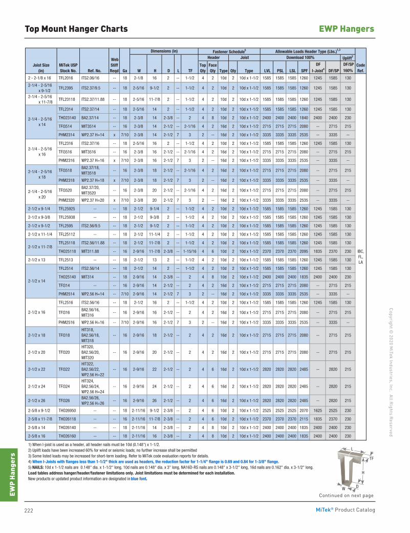
222 MiTek® Product Catalog
Copyright © 2020 M
iTek Industries, Inc. All Rights Reserved
EWP Hangers
EWP
Hang
ers
H
W
L
TF
D
Top Mount Hanger Charts
Fastener Schedule5
Uplift2
DF/SPRef. No. Ga W H D L TF Type Qty Type LVL PSL LSL SPF DF/SP 160%
2 - 2-1/8 x 16 TFL2016 ITS2.06/16 -- 18 2-1/8 16 2 -- 1-1/2 4 2 10d 2 10d x 1-1/2 1585 1585 1585 1260 1245 1585 130
2-1/4 - 2-5/16 x 9-1/2
TFL2395 ITS2.37/9.5 -- 18 2-5/16 9-1/2 2 -- 1-1/2 4 2 10d 2 10d x 1-1/2 1585 1585 1585 1260 1245 1585 130
2-1/4 - 2-5/16 x 11-7/8
TFL23118 ITS2.37/11.88 -- 18 2-5/16 11-7/8 2 -- 1-1/2 4 2 10d 2 10d x 1-1/2 1585 1585 1585 1260 1245 1585 130
TFL2314 ITS2.37/14 -- 18 2-5/16 14 2 -- 1-1/2 4 2 10d 2 10d x 1-1/2 1585 1585 1585 1260 1245 1585 130
THO23140 BA2.37/14 -- 18 2-3/8 14 2-3/8 -- 2 4 8 10d 2 10d x 1-1/2 2400 2400 2400 1840 2400 2400 230
TFI3514 MIT3514 -- 16 2-3/8 14 2-1/2 -- 2-1/16 4 2 16d 2 10d x 1-1/2 2715 2715 2715 2080 -- 2715 215
PHM2314 WP2.37 H=14 x 7/10 2-3/8 14 2-1/2 7 3 2 -- 16d 2 10d x 1-1/2 3335 3335 3335 2535 -- 3335 --
TFL2316 ITS2.37/16 -- 18 2-5/16 16 2 -- 1-1/2 4 2 10d 2 10d x 1-1/2 1585 1585 1585 1260 1245 1585 130
TFI3516 MIT3516 -- 16 2-3/8 16 2-1/2 -- 2-1/16 4 2 16d 2 10d x 1-1/2 2715 2715 2715 2080 -- 2715 215
PHM2316 WP2.37 H=16 x 7/10 2-3/8 16 2-1/2 7 3 2 -- 16d 2 10d x 1-1/2 3335 3335 3335 2535 -- 3335 --
TFI3518 BA2.37/18, MIT3518
-- 16 2-3/8 18 2-1/2 -- 2-1/16 4 2 16d 2 10d x 1-1/2 2715 2715 2715 2080 -- 2715 215
PHM2318 WP2.37 H=18 x 7/10 2-3/8 18 2-1/2 7 3 2 -- 16d 2 10d x 1-1/2 3335 3335 3335 2535 -- 3335 --
TFI3520 BA2.37/20, MIT3520
-- 16 2-3/8 20 2-1/2 -- 2-1/16 4 2 16d 2 10d x 1-1/2 2715 2715 2715 2080 -- 2715 215
PHM2320 WP2.37 H=20 x 7/10 2-3/8 20 2-1/2 7 3 2 -- 16d 2 10d x 1-1/2 3335 3335 3335 2535 -- 3335 --
2-1/2 x 9-1/4 TFL25925 -- -- 18 2-1/2 9-1/4 2 -- 1-1/2 4 2 10d 2 10d x 1-1/2 1585 1585 1585 1260 1245 1585 130
2-1/2 x 9-3/8 TFL25938 -- -- 18 2-1/2 9-3/8 2 -- 1-1/2 4 2 10d 2 10d x 1-1/2 1585 1585 1585 1260 1245 1585 130
2-1/2 x 9-1/2 TFL2595 ITS2.56/9.5 -- 18 2-1/2 9-1/2 2 -- 1-1/2 4 2 10d 2 10d x 1-1/2 1585 1585 1585 1260 1245 1585 130
2-1/2 x 11-1/4 TFL25112 -- -- 18 2-1/2 11-1/4 2 -- 1-1/2 4 2 10d 2 10d x 1-1/2 1585 1585 1585 1260 1245 1585 130
TFL25118 ITS2.56/11.88 -- 18 2-1/2 11-7/8 2 -- 1-1/2 4 2 10d 2 10d x 1-1/2 1585 1585 1585 1260 1245 1585 130
THO25118 MIT311.88 -- 16 2-9/16 11-7/8 2-3/8 -- 1-15/16 4 6 10d 2 10d x 1-1/2 2370 2370 2370 2095 1835 2370 230
2-1/2 x 13 TFL2513 -- -- 18 2-1/2 13 2 -- 1-1/2 4 2 10d 2 10d x 1-1/2 1585 1585 1585 1260 1245 1585 130
TFL2514 ITS2.56/14 -- 18 2-1/2 14 2 -- 1-1/2 4 2 10d 2 10d x 1-1/2 1585 1585 1585 1260 1245 1585 130
THO25140 MIT314 -- 18 2-9/16 14 2-3/8 -- 2 4 8 10d 2 10d x 1-1/2 2400 2400 2400 1835 2400 2400 230
TFI314 -- -- 16 2-9/16 14 2-1/2 -- 2 4 2 16d 2 10d x 1-1/2 2715 2715 2715 2080 -- 2715 215
PHM2514 WP2.56 H=14 -- 7/10 2-9/16 14 2-1/2 7 3 2 -- 16d 2 10d x 1-1/2 3335 3335 3335 2535 -- 3335 --
TFL2516 ITS2.56/16 -- 18 2-1/2 16 2 -- 1-1/2 4 2 10d 2 10d x 1-1/2 1585 1585 1585 1260 1245 1585 130
TFI316 BA2.56/16, MIT316
-- 16 2-9/16 16 2-1/2 -- 2 4 2 16d 2 10d x 1-1/2 2715 2715 2715 2080 -- 2715 215
PHM2516 WP2.56 H=16 -- 7/10 2-9/16 16 2-1/2 7 3 2 -- 16d 2 10d x 1-1/2 3335 3335 3335 2535 -- 3335 --
2-1/2 x 18 TFI318 HIT318, BA2.56/18, MIT318
-- 16 2-9/16 18 2-1/2 -- 2 4 2 16d 2 10d x 1-1/2 2715 2715 2715 2080 -- 2715 215
2-1/2 x 20 TFI320 HIT320, BA2.56/20, MIT320
-- 16 2-9/16 20 2-1/2 -- 2 4 2 16d 2 10d x 1-1/2 2715 2715 2715 2080 -- 2715 215
2-1/2 x 22 TFI322 HIT322, BA2.56/22, WP2.56 H=22
-- 16 2-9/16 22 2-1/2 -- 2 4 6 16d 2 10d x 1-1/2 2820 2820 2820 2485 -- 2820 215
2-1/2 x 24 TFI324 HIT324, BA2.56/24, WP2.56 H=24
-- 16 2-9/16 24 2-1/2 -- 2 4 6 16d 2 10d x 1-1/2 2820 2820 2820 2485 -- 2820 215
2-1/2 x 26 TFI326 BA2.56/26, WP2.56 H=26
-- 16 2-9/16 26 2-1/2 -- 2 4 6 16d 2 10d x 1-1/2 2820 2820 2820 2485 -- 2820 215
2-5/8 x 9-1/2 THO26950 -- -- 18 2-11/16 9-1/2 2-3/8 -- 2 4 6 10d 2 10d x 1-1/2 2525 2525 2525 2070 1625 2525 230
2-5/8 x 11-7/8 THO26118 -- -- 16 2-11/16 11-7/8 2-3/8 -- 2 4 6 10d 2 10d x 1-1/2 2370 2370 2370 2115 1835 2370 230
2-5/8 x 14 THO26140 -- -- 18 2-11/16 14 2-3/8 -- 2 4 8 10d 2 10d x 1-1/2 2400 2400 2400 1835 2400 2400 230
2-5/8 x 16 THO26160 -- -- 18 2-11/16 16 2-3/8 -- 2 4 8 10d 2 10d x 1-1/2 2400 2400 2400 1835 2400 2400 230
1) When I-joist is used as a header, all header nails must be 10d (0.148") x 1-1/2. 2) Uplift loads have been increased 60% for wind or seismic loads; no further increase shall be permitted 3) Some listed loads may be increased for short-term loading. Refer to MiTek code evaluation reports for details. 4) When I-Joists with flanges less than 1-1/2" thick are used as headers, the reduction factor for 1-1/4" flange is 0.69 and 0.84 for 1-3/8" flange. 5) NAILS: 10d x 1-1/2 nails are 0.148" dia. x 1-1/2" long, 10d nails are 0.148" dia. x 3" long, NA16D-RS nails are 0.148" x 3-1/2" long, 16d nails are 0.162" dia. x 3-1/2" long. Load tables address hanger/header/fastener limitations only. Joist limitations must be determined for each installation. New products or updated product information are designated in blue font.
Joist Size(in)
2-1/4 - 2-5/16 x 14
2-1/4 - 2-5/16 x 16
2-1/2 x 11-7/8IBC,FL,LA
2-1/2 x 14
2-1/2 x 16
2-1/4 - 2-5/16 x 18
2-1/4 - 2-5/16 x 20
MiTek USPStock No.
DF I-Joist4
CodeRef.
WebStiffReqd
Allowable Loads Header Type (Lbs.)1,3Dimensions (in)Header Joist Download 100%
TopQty
FaceQty
Continued on next page
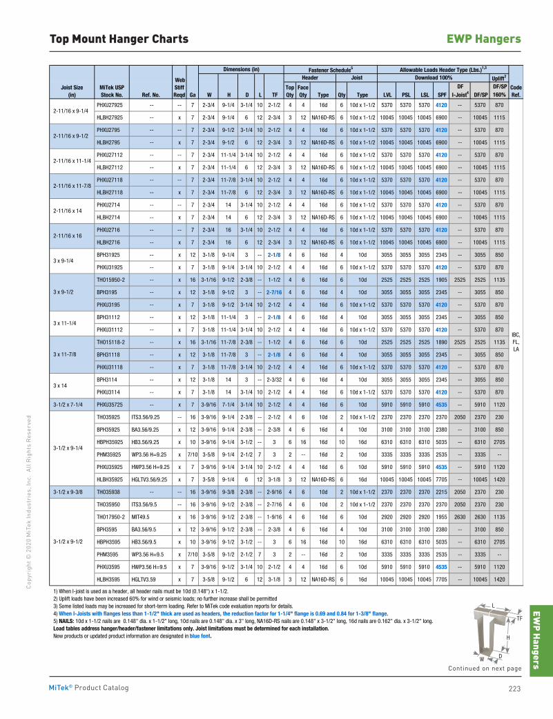
EWP Hangers
223MiTek® Product Catalog
Copy
righ
t © 2
020
MiT
ek In
dust
ries
, Inc
. Al
l Rig
hts
Rese
rved
EWP HangersTop Mount Hanger Charts
H
W
L
TF
D
Continued on next page
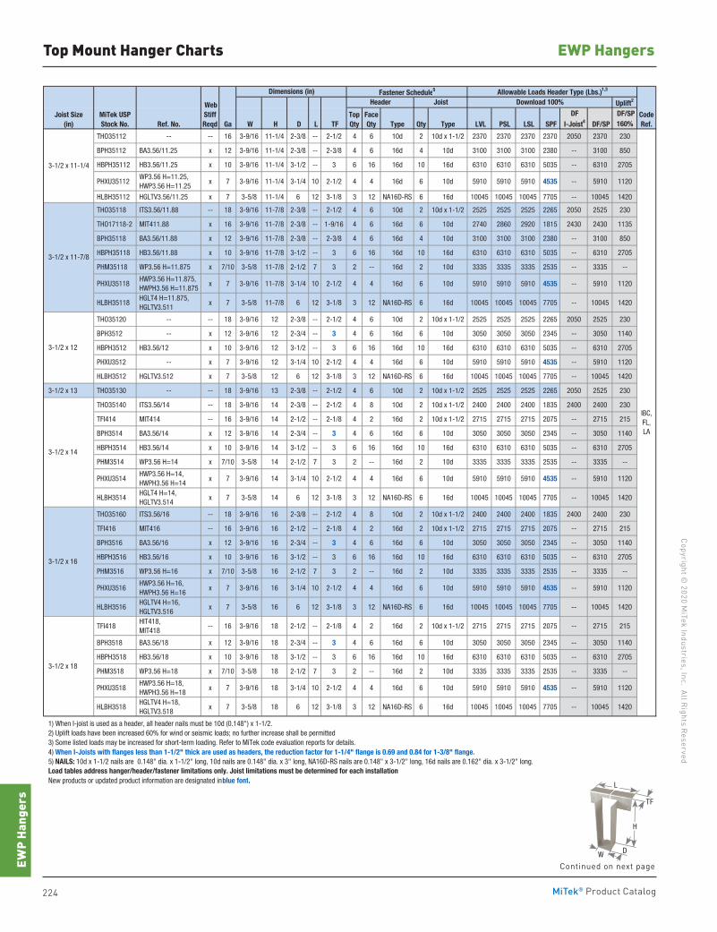
224 MiTek® Product Catalog
Copyright © 2020 M
iTek Industries, Inc. All Rights Reserved
EWP Hangers
EWP
Hang
ers
Top Mount Hanger Charts
Fastener Schedule5
Uplift2
DF/SPRef. No. Ga W H D L TF Type Qty Type LVL PSL LSL SPF DF/SP 160%
THO35112 -- -- 16 3-9/16 11-1/4 2-3/8 -- 2-1/2 4 6 10d 2 10d x 1-1/2 2370 2370 2370 2370 2050 2370 230
BPH35112 BA3.56/11.25 x 12 3-9/16 11-1/4 2-3/8 -- 2-3/8 4 6 16d 4 10d 3100 3100 3100 2380 -- 3100 850
HBPH35112 HB3.56/11.25 x 10 3-9/16 11-1/4 3-1/2 -- 3 6 16 16d 10 16d 6310 6310 6310 5035 -- 6310 2705
PHXU35112 WP3.56 H=11.25, HWP3.56 H=11.25
x 7 3-9/16 11-1/4 3-1/4 10 2-1/2 4 4 16d 6 10d 5910 5910 5910 4535 -- 5910 1120
HLBH35112 HGLTV3.56/11.25 x 7 3-5/8 11-1/4 6 12 3-1/8 3 12 NA16D-RS 6 16d 10045 10045 10045 7705 -- 10045 1420
THO35118 ITS3.56/11.88 -- 18 3-9/16 11-7/8 2-3/8 -- 2-1/2 4 6 10d 2 10d x 1-1/2 2525 2525 2525 2265 2050 2525 230
THO17118-2 MIT411.88 x 16 3-9/16 11-7/8 2-3/8 -- 1-9/16 4 6 16d 6 10d 2740 2860 2920 1815 2430 2430 1135
BPH35118 BA3.56/11.88 x 12 3-9/16 11-7/8 2-3/8 -- 2-3/8 4 6 16d 4 10d 3100 3100 3100 2380 -- 3100 850
HBPH35118 HB3.56/11.88 x 10 3-9/16 11-7/8 3-1/2 -- 3 6 16 16d 10 16d 6310 6310 6310 5035 -- 6310 2705
PHM35118 WP3.56 H=11.875 x 7/10 3-5/8 11-7/8 2-1/2 7 3 2 -- 16d 2 10d 3335 3335 3335 2535 -- 3335 --
PHXU35118 HWP3.56 H=11.875, HWPH3.56 H=11.875
x 7 3-9/16 11-7/8 3-1/4 10 2-1/2 4 4 16d 6 10d 5910 5910 5910 4535 -- 5910 1120
HLBH35118 HGLT4 H=11.875, HGLTV3.511
x 7 3-5/8 11-7/8 6 12 3-1/8 3 12 NA16D-RS 6 16d 10045 10045 10045 7705 -- 10045 1420
THO35120 -- -- 18 3-9/16 12 2-3/8 -- 2-1/2 4 6 10d 2 10d x 1-1/2 2525 2525 2525 2265 2050 2525 230
BPH3512 -- x 12 3-9/16 12 2-3/4 -- 3 4 6 16d 6 10d 3050 3050 3050 2345 -- 3050 1140
HBPH3512 HB3.56/12 x 10 3-9/16 12 3-1/2 -- 3 6 16 16d 10 16d 6310 6310 6310 5035 -- 6310 2705
PHXU3512 -- x 7 3-9/16 12 3-1/4 10 2-1/2 4 4 16d 6 10d 5910 5910 5910 4535 -- 5910 1120
HLBH3512 HGLTV3.512 x 7 3-5/8 12 6 12 3-1/8 3 12 NA16D-RS 6 16d 10045 10045 10045 7705 -- 10045 1420
3-1/2 x 13 THO35130 -- -- 18 3-9/16 13 2-3/8 -- 2-1/2 4 6 10d 2 10d x 1-1/2 2525 2525 2525 2265 2050 2525 230
THO35140 ITS3.56/14 -- 18 3-9/16 14 2-3/8 -- 2-1/2 4 8 10d 2 10d x 1-1/2 2400 2400 2400 1835 2400 2400 230
TFI414 MIT414 -- 16 3-9/16 14 2-1/2 -- 2-1/8 4 2 16d 2 10d x 1-1/2 2715 2715 2715 2075 -- 2715 215
BPH3514 BA3.56/14 x 12 3-9/16 14 2-3/4 -- 3 4 6 16d 6 10d 3050 3050 3050 2345 -- 3050 1140
HBPH3514 HB3.56/14 x 10 3-9/16 14 3-1/2 -- 3 6 16 16d 10 16d 6310 6310 6310 5035 -- 6310 2705
PHM3514 WP3.56 H=14 x 7/10 3-5/8 14 2-1/2 7 3 2 -- 16d 2 10d 3335 3335 3335 2535 -- 3335 --
PHXU3514 HWP3.56 H=14, HWPH3.56 H=14
x 7 3-9/16 14 3-1/4 10 2-1/2 4 4 16d 6 10d 5910 5910 5910 4535 -- 5910 1120
HLBH3514 HGLT4 H=14, HGLTV3.514
x 7 3-5/8 14 6 12 3-1/8 3 12 NA16D-RS 6 16d 10045 10045 10045 7705 -- 10045 1420
THO35160 ITS3.56/16 -- 18 3-9/16 16 2-3/8 -- 2-1/2 4 8 10d 2 10d x 1-1/2 2400 2400 2400 1835 2400 2400 230
TFI416 MIT416 -- 16 3-9/16 16 2-1/2 -- 2-1/8 4 2 16d 2 10d x 1-1/2 2715 2715 2715 2075 -- 2715 215
BPH3516 BA3.56/16 x 12 3-9/16 16 2-3/4 -- 3 4 6 16d 6 10d 3050 3050 3050 2345 -- 3050 1140
HBPH3516 HB3.56/16 x 10 3-9/16 16 3-1/2 -- 3 6 16 16d 10 16d 6310 6310 6310 5035 -- 6310 2705
PHM3516 WP3.56 H=16 x 7/10 3-5/8 16 2-1/2 7 3 2 -- 16d 2 10d 3335 3335 3335 2535 -- 3335 --
PHXU3516 HWP3.56 H=16, HWPH3.56 H=16
x 7 3-9/16 16 3-1/4 10 2-1/2 4 4 16d 6 10d 5910 5910 5910 4535 -- 5910 1120
HLBH3516 HGLTV4 H=16, HGLTV3.516
x 7 3-5/8 16 6 12 3-1/8 3 12 NA16D-RS 6 16d 10045 10045 10045 7705 -- 10045 1420
TFI418 HIT418, MIT418
-- 16 3-9/16 18 2-1/2 -- 2-1/8 4 2 16d 2 10d x 1-1/2 2715 2715 2715 2075 -- 2715 215
BPH3518 BA3.56/18 x 12 3-9/16 18 2-3/4 -- 3 4 6 16d 6 10d 3050 3050 3050 2345 -- 3050 1140
HBPH3518 HB3.56/18 x 10 3-9/16 18 3-1/2 -- 3 6 16 16d 10 16d 6310 6310 6310 5035 -- 6310 2705
PHM3518 WP3.56 H=18 x 7/10 3-5/8 18 2-1/2 7 3 2 -- 16d 2 10d 3335 3335 3335 2535 -- 3335 --
PHXU3518 HWP3.56 H=18, HWPH3.56 H=18
x 7 3-9/16 18 3-1/4 10 2-1/2 4 4 16d 6 10d 5910 5910 5910 4535 -- 5910 1120
HLBH3518 HGLTV4 H=18, HGLTV3.518
x 7 3-5/8 18 6 12 3-1/8 3 12 NA16D-RS 6 16d 10045 10045 10045 7705 -- 10045 1420
1) When I-joist is used as a header, all header nails must be 10d (0.148") x 1-1/2. 2) Uplift loads have been increased 60% for wind or seismic loads; no further increase shall be permitted 3) Some listed loads may be increased for short-term loading. Refer to MiTek code evaluation reports for details. 4) When I-Joists with flanges less than 1-1/2" thick are used as headers, the reduction factor for 1-1/4" flange is 0.69 and 0.84 for 1-3/8" flange. 5) NAILS: 10d x 1-1/2 nails are 0.148" dia. x 1-1/2" long, 10d nails are 0.148" dia. x 3" long, NA16D-RS nails are 0.148" x 3-1/2" long, 16d nails are 0.162" dia. x 3-1/2" long. Load tables address hanger/header/fastener limitations only. Joist limitations must be determined for each installation. New products or updated product information are designated in blue font.
IBC,FL,LA
3-1/2 x 18
Header
3-1/2 x 16
Download 100%
DF I-Joist4
CodeRef.
3-1/2 x 11-7/8
3-1/2 x 14
3-1/2 x 12
3-1/2 x 11-1/4
TopQty
FaceQty
Allowable Loads Header Type (Lbs.)1,3Dimensions (in)Joist
Joist Size(in)
MiTek USPStock No.
WebStiffReqd
H
W
L
TF
D
Continued on next page
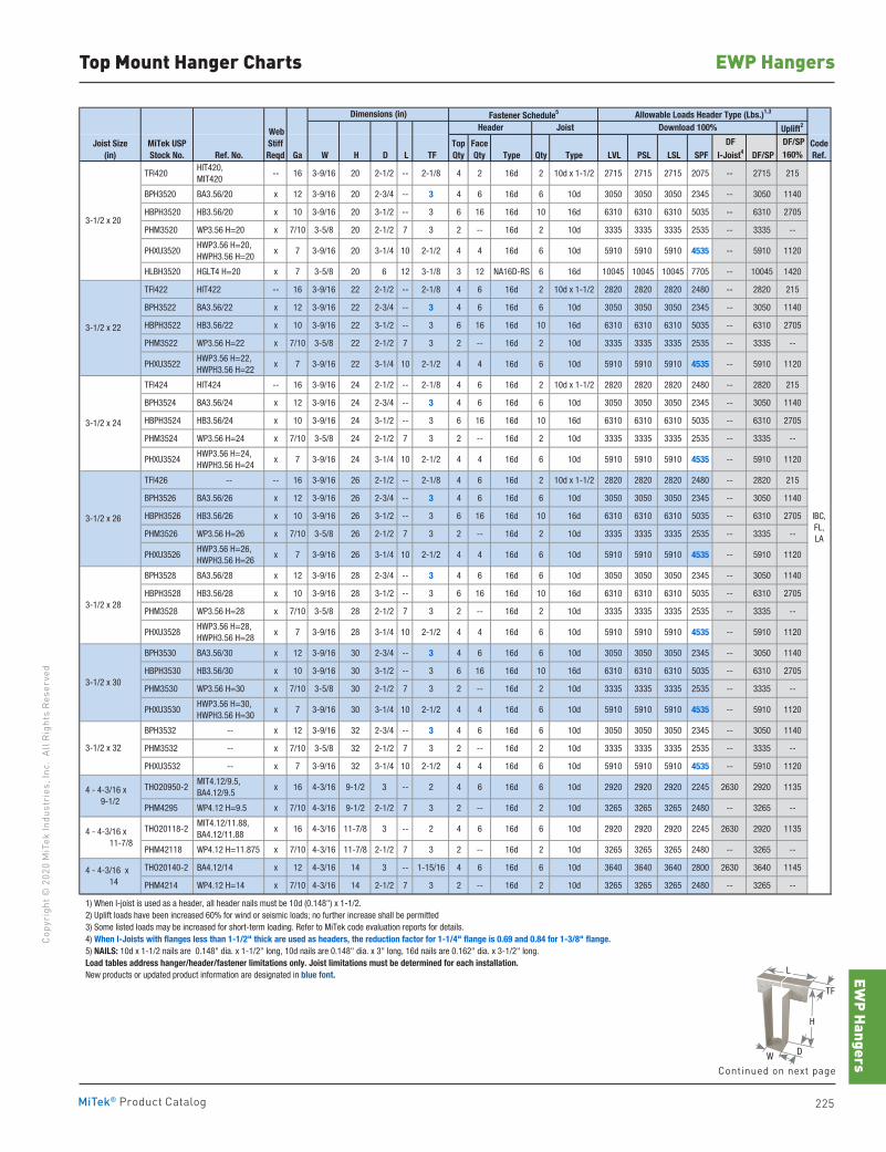
EWP Hangers
225MiTek® Product Catalog
Copy
righ
t © 2
020
MiT
ek In
dust
ries
, Inc
. Al
l Rig
hts
Rese
rved
EWP HangersTop Mount Hanger Charts
Fastener Schedule5
Uplift2
DF/SPRef. No. Ga W H D L TF Type Qty Type LVL PSL LSL SPF DF/SP 160%
TFI420 HIT420, MIT420
-- 16 3-9/16 20 2-1/2 -- 2-1/8 4 2 16d 2 10d x 1-1/2 2715 2715 2715 2075 -- 2715 215
BPH3520 BA3.56/20 x 12 3-9/16 20 2-3/4 -- 3 4 6 16d 6 10d 3050 3050 3050 2345 -- 3050 1140
HBPH3520 HB3.56/20 x 10 3-9/16 20 3-1/2 -- 3 6 16 16d 10 16d 6310 6310 6310 5035 -- 6310 2705
PHM3520 WP3.56 H=20 x 7/10 3-5/8 20 2-1/2 7 3 2 -- 16d 2 10d 3335 3335 3335 2535 -- 3335 --
PHXU3520 HWP3.56 H=20, HWPH3.56 H=20
x 7 3-9/16 20 3-1/4 10 2-1/2 4 4 16d 6 10d 5910 5910 5910 4535 -- 5910 1120
HLBH3520 HGLT4 H=20 x 7 3-5/8 20 6 12 3-1/8 3 12 NA16D-RS 6 16d 10045 10045 10045 7705 -- 10045 1420
TFI422 HIT422 -- 16 3-9/16 22 2-1/2 -- 2-1/8 4 6 16d 2 10d x 1-1/2 2820 2820 2820 2480 -- 2820 215
BPH3522 BA3.56/22 x 12 3-9/16 22 2-3/4 -- 3 4 6 16d 6 10d 3050 3050 3050 2345 -- 3050 1140
HBPH3522 HB3.56/22 x 10 3-9/16 22 3-1/2 -- 3 6 16 16d 10 16d 6310 6310 6310 5035 -- 6310 2705
PHM3522 WP3.56 H=22 x 7/10 3-5/8 22 2-1/2 7 3 2 -- 16d 2 10d 3335 3335 3335 2535 -- 3335 --
PHXU3522 HWP3.56 H=22, HWPH3.56 H=22
x 7 3-9/16 22 3-1/4 10 2-1/2 4 4 16d 6 10d 5910 5910 5910 4535 -- 5910 1120
TFI424 HIT424 -- 16 3-9/16 24 2-1/2 -- 2-1/8 4 6 16d 2 10d x 1-1/2 2820 2820 2820 2480 -- 2820 215
BPH3524 BA3.56/24 x 12 3-9/16 24 2-3/4 -- 3 4 6 16d 6 10d 3050 3050 3050 2345 -- 3050 1140
HBPH3524 HB3.56/24 x 10 3-9/16 24 3-1/2 -- 3 6 16 16d 10 16d 6310 6310 6310 5035 -- 6310 2705
PHM3524 WP3.56 H=24 x 7/10 3-5/8 24 2-1/2 7 3 2 -- 16d 2 10d 3335 3335 3335 2535 -- 3335 --
PHXU3524 HWP3.56 H=24, HWPH3.56 H=24
x 7 3-9/16 24 3-1/4 10 2-1/2 4 4 16d 6 10d 5910 5910 5910 4535 -- 5910 1120
TFI426 -- -- 16 3-9/16 26 2-1/2 -- 2-1/8 4 6 16d 2 10d x 1-1/2 2820 2820 2820 2480 -- 2820 215
BPH3526 BA3.56/26 x 12 3-9/16 26 2-3/4 -- 3 4 6 16d 6 10d 3050 3050 3050 2345 -- 3050 1140
HBPH3526 HB3.56/26 x 10 3-9/16 26 3-1/2 -- 3 6 16 16d 10 16d 6310 6310 6310 5035 -- 6310 2705
PHM3526 WP3.56 H=26 x 7/10 3-5/8 26 2-1/2 7 3 2 -- 16d 2 10d 3335 3335 3335 2535 -- 3335 --
PHXU3526 HWP3.56 H=26, HWPH3.56 H=26
x 7 3-9/16 26 3-1/4 10 2-1/2 4 4 16d 6 10d 5910 5910 5910 4535 -- 5910 1120
BPH3528 BA3.56/28 x 12 3-9/16 28 2-3/4 -- 3 4 6 16d 6 10d 3050 3050 3050 2345 -- 3050 1140
HBPH3528 HB3.56/28 x 10 3-9/16 28 3-1/2 -- 3 6 16 16d 10 16d 6310 6310 6310 5035 -- 6310 2705
PHM3528 WP3.56 H=28 x 7/10 3-5/8 28 2-1/2 7 3 2 -- 16d 2 10d 3335 3335 3335 2535 -- 3335 --
PHXU3528 HWP3.56 H=28, HWPH3.56 H=28
x 7 3-9/16 28 3-1/4 10 2-1/2 4 4 16d 6 10d 5910 5910 5910 4535 -- 5910 1120
BPH3530 BA3.56/30 x 12 3-9/16 30 2-3/4 -- 3 4 6 16d 6 10d 3050 3050 3050 2345 -- 3050 1140
HBPH3530 HB3.56/30 x 10 3-9/16 30 3-1/2 -- 3 6 16 16d 10 16d 6310 6310 6310 5035 -- 6310 2705
PHM3530 WP3.56 H=30 x 7/10 3-5/8 30 2-1/2 7 3 2 -- 16d 2 10d 3335 3335 3335 2535 -- 3335 --
PHXU3530 HWP3.56 H=30, HWPH3.56 H=30
x 7 3-9/16 30 3-1/4 10 2-1/2 4 4 16d 6 10d 5910 5910 5910 4535 -- 5910 1120
BPH3532 -- x 12 3-9/16 32 2-3/4 -- 3 4 6 16d 6 10d 3050 3050 3050 2345 -- 3050 1140
PHM3532 -- x 7/10 3-5/8 32 2-1/2 7 3 2 -- 16d 2 10d 3335 3335 3335 2535 -- 3335 --
PHXU3532 -- x 7 3-9/16 32 3-1/4 10 2-1/2 4 4 16d 6 10d 5910 5910 5910 4535 -- 5910 1120
THO20950-2 MIT4.12/9.5, BA4.12/9.5
x 16 4-3/16 9-1/2 3 -- 2 4 6 16d 6 10d 2920 2920 2920 2245 2630 2920 1135
PHM4295 WP4.12 H=9.5 x 7/10 4-3/16 9-1/2 2-1/2 7 3 2 -- 16d 2 10d 3265 3265 3265 2480 -- 3265 --
THO20118-2 MIT4.12/11.88, BA4.12/11.88
x 16 4-3/16 11-7/8 3 -- 2 4 6 16d 6 10d 2920 2920 2920 2245 2630 2920 1135
PHM42118 WP4.12 H=11.875 x 7/10 4-3/16 11-7/8 2-1/2 7 3 2 -- 16d 2 10d 3265 3265 3265 2480 -- 3265 --
THO20140-2 BA4.12/14 x 12 4-3/16 14 3 -- 1-15/16 4 6 16d 6 10d 3640 3640 3640 2800 2630 3640 1145
PHM4214 WP4.12 H=14 x 7/10 4-3/16 14 2-1/2 7 3 2 -- 16d 2 10d 3265 3265 3265 2480 -- 3265 --
1) When I-joist is used as a header, all header nails must be 10d (0.148") x 1-1/2. 2) Uplift loads have been increased 60% for wind or seismic loads; no further increase shall be permitted 3) Some listed loads may be increased for short-term loading. Refer to MiTek code evaluation reports for details. 4) When I-Joists with flanges less than 1-1/2" thick are used as headers, the reduction factor for 1-1/4" flange is 0.69 and 0.84 for 1-3/8" flange. 5) NAILS: 10d x 1-1/2 nails are 0.148" dia. x 1-1/2" long, 10d nails are 0.148" dia. x 3" long, 16d nails are 0.162" dia. x 3-1/2" long. Load tables address hanger/header/fastener limitations only. Joist limitations must be determined for each installation. New products or updated product information are designated in blue font.
Allowable Loads Header Type (Lbs.)1,3
3-1/2 x 32
Header Joist Download 100%
DF I-Joist4
3-1/2 x 28
3-1/2 x 30
Dimensions (in)
MiTek USPStock No.
WebStiffReqd
Joist Size(in)
3-1/2 x 22
3-1/2 x 20
TopQty
FaceQty
CodeRef.
4 - 4-3/16 x 14
3-1/2 x 26
3-1/2 x 24
4 - 4-3/16 x 11-7/8
4 - 4-3/16 x 9-1/2
IBC,FL,LA
H
W
L
TF
D
Continued on next page
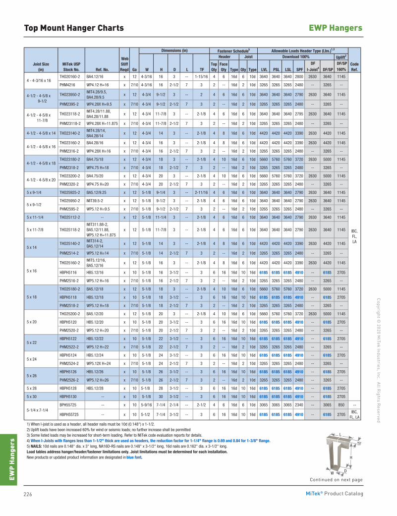
226 MiTek® Product Catalog
Copyright © 2020 M
iTek Industries, Inc. All Rights Reserved
EWP Hangers
EWP
Hang
ers
Top Mount Hanger Charts
Fastener Schedule5
Uplift2
DF/SPRef. No. Ga W H D L TF Type Qty Type LVL PSL LSL SPF DF/SP 160%
THO20160-2 BA4.12/16 x 12 4-3/16 16 3 -- 1-15/16 4 6 16d 6 10d 3640 3640 3640 2800 2630 3640 1145
PHM4216 WP4.12 H=16 x 7/10 4-3/16 16 2-1/2 7 3 2 -- 16d 2 10d 3265 3265 3265 2480 -- 3265 --
THO23950-2 MIT4.28/9.5, BA4.28/9.5
x 12 4-3/4 9-1/2 3 -- 2 4 6 16d 6 10d 3640 3640 3640 2790 2630 3640 1145
PHM2395-2 WP4.28X H=9.5 x 7/10 4-3/4 9-1/2 2-1/2 7 3 2 -- 16d 2 10d 3265 3265 3265 2480 -- 3265 --
THO23118-2 MIT4.28/11.88, BA4.28/11.88
x 12 4-3/4 11-7/8 3 -- 2-1/8 4 6 16d 6 10d 3640 3640 3640 2795 2630 3640 1145
PHM23118-2 WP4.28X H=11.875 x 7/10 4-3/4 11-7/8 2-1/2 7 3 2 -- 16d 2 10d 3265 3265 3265 2480 -- 3265 --
4-1/2 - 4-5/8 x 14 THO23140-2 MIT4.28/14, BA4.28/14
x 12 4-3/4 14 3 -- 2-1/8 4 8 16d 6 10d 4420 4420 4420 3390 2630 4420 1145
THO23160-2 BA4.28/16 x 12 4-3/4 16 3 -- 2-1/8 4 8 16d 6 10d 4420 4420 4420 3390 2630 4420 1145
PHM2316-2 WP4.28X H=16 x 7/10 4-3/4 16 2-1/2 7 3 2 -- 16d 2 10d 3265 3265 3265 2480 -- 3265 --
THO23180-2 BA4.75/18 x 12 4-3/4 18 3 -- 2-1/8 4 10 16d 6 10d 5660 5760 5760 3720 2630 5000 1145
PHM2318-2 WP4.75 H=18 x 7/10 4-3/4 18 2-1/2 7 3 2 -- 16d 2 10d 3265 3265 3265 2480 -- 3265 --
THO23200-2 BA4.75/20 x 12 4-3/4 20 3 -- 2-1/8 4 10 16d 6 10d 5660 5760 5760 3720 2630 5000 1145
PHM2320-2 WP4.75 H=20 x 7/10 4-3/4 20 2-1/2 7 3 2 -- 16d 2 10d 3265 3265 3265 2480 -- 3265 --
5 x 9-1/4 THO25925-2 BA5.12/9.25 x 12 5-1/8 9-1/4 3 -- 2-11/16 4 6 16d 6 10d 3640 3640 3640 2790 2630 3640 1145
THO25950-2 MIT39.5-2 x 12 5-1/8 9-1/2 3 -- 2-1/8 4 6 16d 6 10d 3640 3640 3640 2790 2630 3640 1145
PHM2595-2 WP5.12 H=9.5 x 7/10 5-1/8 9-1/2 2-1/2 7 3 2 -- 16d 2 10d 3265 3265 3265 2480 -- 3265 --
5 x 11-1/4 THO25112-2 -- x 12 5-1/8 11-1/4 3 -- 2-1/8 4 6 16d 6 10d 3640 3640 3640 2790 2630 3640 1145
5 x 11-7/8 THO25118-2 MIT311.88-2, BA5.12/11.88, WP5.12 H=11.875
x 12 5-1/8 11-7/8 3 -- 2-1/8 4 6 16d 6 10d 3640 3640 3640 2790 2630 3640 1145
THO25140-2 MIT314-2, BA5.12/14
x 12 5-1/8 14 3 -- 2-1/8 4 8 16d 6 10d 4420 4420 4420 3390 2630 4420 1145
PHM2514-2 WP5.12 H=14 x 7/10 5-1/8 14 2-1/2 7 3 2 -- 16d 2 10d 3265 3265 3265 2480 -- 3265 --
THO25160-2 MIT5.12/16, BA5.12/16
x 12 5-1/8 16 3 -- 2-1/8 4 8 16d 6 10d 4420 4420 4420 3390 2630 4420 1145
HBPH5116 HB5.12/16 x 10 5-1/8 16 3-1/2 -- 3 6 16 16d 10 16d 6185 6185 6185 4910 -- 6185 2705
PHM2516-2 WP5.12 H=16 x 7/10 5-1/8 16 2-1/2 7 3 2 -- 16d 2 10d 3265 3265 3265 2480 -- 3265 --
THO25180-2 BA5.12/18 x 12 5-1/8 18 3 -- 2-1/8 4 10 16d 6 10d 5660 5760 5760 3720 2630 5000 1145
HBPH5118 HB5.12/18 x 10 5-1/8 18 3-1/2 -- 3 6 16 16d 10 16d 6185 6185 6185 4910 -- 6185 2705
PHM2518-2 WP5.12 H=18 x 7/10 5-1/8 18 2-1/2 7 3 2 -- 16d 2 10d 3265 3265 3265 2480 -- 3265 --
THO25200-2 BA5.12/20 x 12 5-1/8 20 3 -- 2-1/8 4 10 16d 6 10d 5660 5760 5760 3720 2630 5000 1145
HBPH5120 HB5.12/20 x 10 5-1/8 20 3-1/2 -- 3 6 16 16d 10 16d 6185 6185 6185 4910 -- 6185 2705
PHM2520-2 WP5.12 H=20 x 7/10 5-1/8 20 2-1/2 7 3 2 -- 16d 2 10d 3265 3265 3265 2480 -- 3265 --
HBPH5122 HB5.12/22 x 10 5-1/8 22 3-1/2 -- 3 6 16 16d 10 16d 6185 6185 6185 4910 -- 6185 2705
PHM2522-2 WP5.12 H=22 x 7/10 5-1/8 22 2-1/2 7 3 2 -- 16d 2 10d 3265 3265 3265 2480 -- 3265 --
HBPH5124 HB5.12/24 x 10 5-1/8 24 3-1/2 -- 3 6 16 16d 10 16d 6185 6185 6185 4910 -- 6185 2705
PHM2524-2 WP5.12X H=24 x 7/10 5-1/8 24 2-1/2 7 3 2 -- 16d 2 10d 3265 3265 3265 2480 -- 3265 --
HBPH5126 HB5.12/26 x 10 5-1/8 26 3-1/2 -- 3 6 16 16d 10 16d 6185 6185 6185 4910 -- 6185 2705
PHM2526-2 WP5.12 H=26 x 7/10 5-1/8 26 2-1/2 7 3 2 -- 16d 2 10d 3265 3265 3265 2480 -- 3265 --
5 x 28 HBPH5128 HB5.12/28 x 10 5-1/8 28 3-1/2 -- 3 6 16 16d 10 16d 6185 6185 6185 4910 -- 6185 2705
5 x 30 HBPH5130 -- x 10 5-1/8 30 3-1/2 -- 3 6 16 16d 10 16d 6185 6185 6185 4910 -- 6185 2705
BPH55725 -- x 10 5-9/16 7-1/4 2-1/4 -- 2-1/2 4 6 16d 6 10d 3065 3065 3065 2340 -- 3065 850 --
HBPH55725 -- x 10 5-1/2 7-1/4 3-1/2 -- 3 6 16 16d 10 16d 6185 6185 6185 4910 -- 6185 2705IBC,
FL, LA
1) When I-joist is used as a header, all header nails must be 10d (0.148") x 1-1/2. 2) Uplift loads have been increased 60% for wind or seismic loads; no further increase shall be permitted 3) Some listed loads may be increased for short-term loading. Refer to MiTek code evaluation reports for details. 4) When I-Joists with flanges less than 1-1/2" thick are used as headers, the reduction factor for 1-1/4" flange is 0.69 and 0.84 for 1-3/8" flange. 5) NAILS: 10d nails are 0.148" dia. x 3" long, NA16D-RS nails are 0.148" x 3-1/2" long, 16d nails are 0.162" dia. x 3-1/2" long. Load tables address hanger/header/fastener limitations only. Joist limitations must be determined for each installation. New products or updated product information are designated in blue font.
MiTek USPStock No.
Joist Size(in)
5 x 9-1/2
5 x 14
5 x 16
5 x 22
5 x 24
5 x 26
5-1/4 x 7-1/4
IBC,FL,LA
5 x 20
5 x 18
4-1/2 - 4-5/8 x 20
4-1/2 - 4-5/8 x 16
4-1/2 - 4-5/8 x 18
4 - 4-3/16 x 16
4-1/2 - 4-5/8 x 9-1/2
4-1/2 - 4-5/8 x 11-7/8
DF I-Joist4
CodeRef.
WebStiffReqd
Allowable Loads Header Type (Lbs.)1,3Dimensions (in)Header Joist Download 100%
TopQty
FaceQty
H
W
L
TF
D
Continued on next page
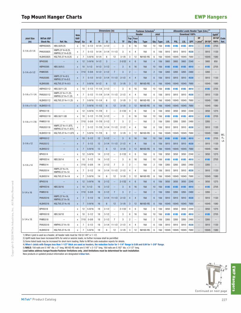
EWP Hangers
227MiTek® Product Catalog
Copy
righ
t © 2
020
MiT
ek In
dust
ries
, Inc
. Al
l Rig
hts
Rese
rved
EWP HangersTop Mount Hanger Charts
Fastener Schedule5
Uplift2
DF/SPRef. No. Ga W H D L TF Type Qty Type LVL PSL LSL SPF DF/SP 160%
HBPH55925 HB5.50/9.25 x 10 5-1/2 9-1/4 3-1/2 -- 3 6 16 16d 10 16d 6185 6185 6185 4910 -- 6185 2705
PHXU55925 HWP5.37 H=9.25, HWPH5.37 H=9.25
x 7 5-1/2 9-1/4 3-1/4 11-1/2 3 4 4 16d 6 10d 5910 5910 5910 4530 -- 5910 1120
HLBH55925 HGLTV5.37 H=9.25 x 7 5-9/16 9-1/4 6 12 3-1/8 3 12 NA16D-RS 6 16d 10045 10045 10045 7680 -- 10045 1580
BPH5595 -- x 12 5-9/16 9-1/2 3 -- 2-5/32 4 6 16d 4 10d 3065 3065 3065 2340 -- 3065 850
HBPH5595 HB5.50/9.5 x 10 5-1/2 9-1/2 3-1/2 -- 3 6 16 16d 10 16d 6185 6185 6185 4910 -- 6185 2705
PHM5595 -- x 7/10 5-5/8 9-1/2 2-1/2 7 3 2 -- 16d 2 10d 3265 3265 3265 2480 -- 3265 --
PHXU5595 HWP5.37 H=9.5, HWPH5.37 H=9.5
x 7 5-1/2 9-1/2 3-1/4 11-1/2 2-1/2 4 4 16d 6 10d 5910 5910 5910 4530 -- 5910 1120
HLBH5595 HGLTV5.37 H=9.5 x 7 5-9/16 9-1/2 6 12 3-1/8 3 12 NA16D-RS 6 16d 10045 10045 10045 7680 -- 10045 1580
HBPH55112 HB5.50/11.25 x 10 5-1/2 11-1/4 3-1/2 -- 3 6 16 16d 10 16d 6185 6185 6185 4910 -- 6185 2705
PHXU55112 HWP5.37 H=11.25, HWPH5.37 H=11.25
x 7 5-1/2 11-1/4 3-1/4 11-1/2 2-1/2 4 4 16d 6 10d 5910 5910 5910 4530 -- 5910 1120
HLBH55112 HGLTV5.37 H=11.25 x 7 5-9/16 11-1/4 6 12 3-1/8 3 12 NA16D-RS 6 16d 10045 10045 10045 7680 -- 10045 1580
5-1/4 x 11-1/2 HLBH55115 -- x 7 5-9/16 11-1/2 6 12 3-1/8 3 12 NA16D-RS 6 16d 10045 10045 10045 7680 -- 10045 1580
BPH55118 -- x 12 5-9/16 11-7/8 3 -- 2-1/32 4 6 16d 6 10d 3050 3050 3050 2340 -- 3050 1275
HBPH55118 HB5.50/11.88 x 10 5-1/2 11-7/8 3-1/2 -- 3 6 16 16d 10 16d 6185 6185 6185 4910 -- 6185 2705
PHM55118 -- x 7/10 5-5/8 11-7/8 2-1/2 7 3 2 -- 16d 2 10d 3265 3265 3265 2480 -- 3265 --
PHXU55118 HWP5.37 H=11.875, HWPH5.37 H=11.875
x 7 5-1/2 11-7/8 3-1/4 11-1/2 2-1/2 4 4 16d 6 10d 5910 5910 5910 4530 -- 5910 1120
HLBH55118 HGLTV5.37 H=11.875 x 7 5-9/16 11-7/8 6 12 3-1/8 3 12 NA16D-RS 6 16d 10045 10045 10045 7680 -- 10045 1580
HBPH5512 -- x 10 5-1/2 12 3-1/2 -- 3 6 16 16d 10 16d 6185 6185 6185 4910 -- 6185 2705
PHXU5512 -- x 7 5-1/2 12 3-1/4 11-1/2 2-1/2 4 4 16d 6 10d 5910 5910 5910 4530 -- 5910 1120
HLBH5512 -- x 7 5-9/16 12 6 12 3-1/8 3 12 NA16D-RS 6 16d 10045 10045 10045 7680 -- 10045 1580
BPH5514 -- x 12 5-9/16 14 2-1/2 -- 2-1/32 4 6 16d 6 10d 3050 3050 3050 2340 -- 3050 1275
HBPH5514 HB5.50/14 x 10 5-1/2 14 3-1/2 -- 3 6 16 16d 10 16d 6185 6185 6185 4910 -- 6185 2705
PHM5514 -- x 7/10 5-5/8 14 2-1/2 7 3 2 -- 16d 2 10d 3265 3265 3265 2480 -- 3265 --
PHXU5514 HWP5.37 H=14, HWPH5.37 H=14
x 7 5-1/2 14 3-1/4 11-1/2 2-1/2 4 4 16d 6 10d 5910 5910 5910 4530 -- 5910 1120
HLBH5514 HGLTV5.37 H=14 x 7 5-9/16 14 6 12 3-1/8 3 12 NA16D-RS 6 16d 10045 10045 10045 7680 -- 10045 1580
BPH5516 -- x 12 5-9/16 16 2-1/2 -- 2-1/32 4 6 16d 6 10d 3050 3050 3050 2340 -- 3050 1275
HBPH5516 HB5.50/16 x 10 5-1/2 16 3-1/2 -- 3 6 16 16d 10 16d 6185 6185 6185 4910 -- 6185 2705
PHM5516 -- x 7/10 5-5/8 16 2-1/2 7 3 2 -- 16d 2 10d 3265 3265 3265 2480 -- 3265 --
PHXU5516 HWP5.37 H=16, HWPH5.37 H=16
x 7 5-1/2 16 3-1/4 11-1/2 2-1/2 4 4 16d 6 10d 5910 5910 5910 4530 -- 5910 1120
HLBH5516 HGLTV5.37 H=16 x 7 5-9/16 16 6 12 3-1/8 3 12 NA16D-RS 6 16d 10045 10045 10045 7680 -- 10045 1580
BPH5518 -- x 12 5-9/16 18 2-1/2 -- 2-1/32 4 6 16d 6 10d 3050 3050 3050 2340 -- 3050 1275
HBPH5518 HB5.50/18 x 10 5-1/2 18 3-1/2 -- 3 6 16 16d 10 16d 6185 6185 6185 4910 -- 6185 2705
PHM5518 -- x 7/10 5-5/8 18 2-1/2 7 3 2 -- 16d 2 10d 3265 3265 3265 2480 -- 3265 --
PHXU5518 HWPH5.37 H=18 x 7 5-1/2 18 3-1/4 11-1/2 2-1/2 4 4 16d 6 10d 5910 5910 5910 4530 -- 5910 1120
HLBH5518 HGLTV5.37 H=18 x 7 5-9/16 18 6 12 3-1/8 3 12 NA16D-RS 6 16d 10045 10045 10045 7680 -- 10045 1580
1) When I-joist is used as a header, all header nails must be 10d (0.148") x 1-1/2. 2) Uplift loads have been increased 60% for wind or seismic loads; no further increase shall be permitted 3) Some listed loads may be increased for short-term loading. Refer to MiTek code evaluation reports for details. 4) When I-Joists with flanges less than 1-1/2" thick are used as headers, the reduction factor for 1-1/4" flange is 0.69 and 0.84 for 1-3/8" flange. 5) NAILS: 10d nails are 0.148" dia. x 3" long, NA16D-RS nails are 0.148" x 3-1/2" long, 16d nails are 0.162" dia. x 3-1/2" long. Load tables address hanger/header/fastener limitations only. Joist limitations must be determined for each installation. New products or updated product information are designated in blue font.
5-1/4 x 11-7/8
5-1/4 x 9-1/2
Joist Size(in)
TopQty
FaceQty
5-1/4 x 14
5-1/4 x 12
MiTek USPStock No.
DF I-Joist4
CodeRef.
IBC,FL,LA
5-1/4 x 18
5-1/4 x 16
WebStiffReqd
Allowable Loads Header Type (Lbs.)1,3Dimensions (in)Header Joist Download 100%
5-1/4 x 9-1/4
5-1/4 x 11-1/4
Continued on next page
H
W
L
TF
D
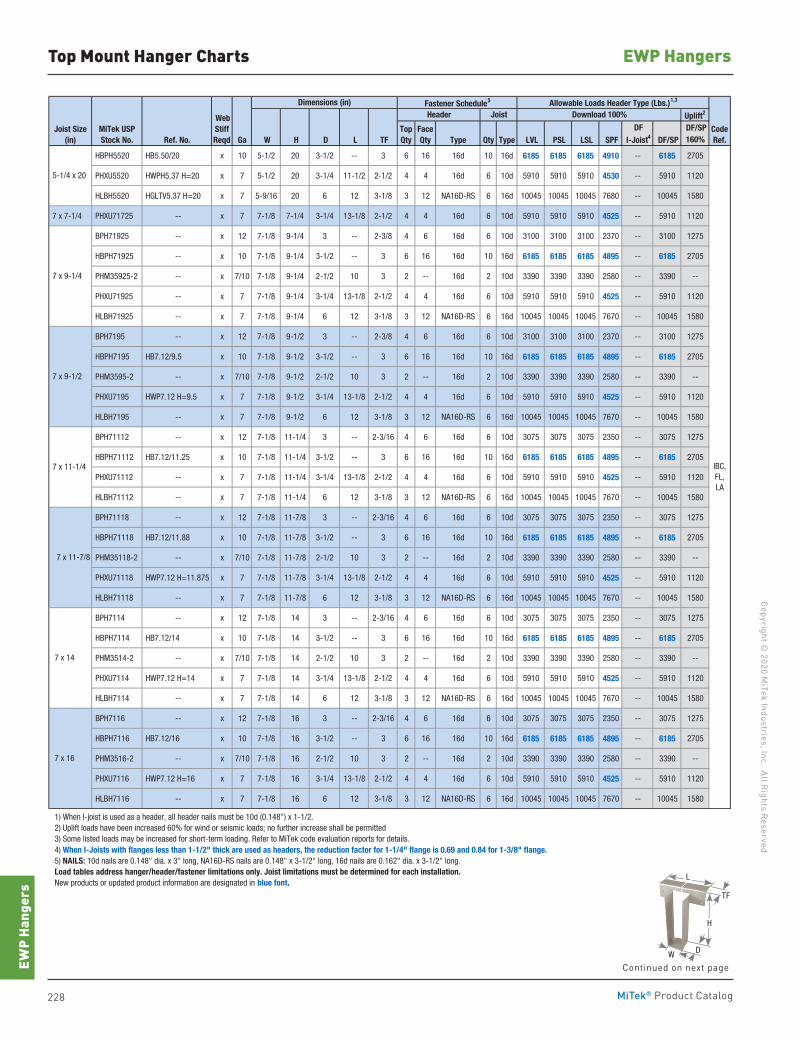
228 MiTek® Product Catalog
Copyright © 2020 M
iTek Industries, Inc. All Rights Reserved
EWP Hangers
EWP
Hang
ers
Top Mount Hanger Charts
Fastener Schedule5
Uplift2
DF/SPRef. No. Ga W H D L TF Type Qty Type LVL PSL LSL SPF DF/SP 160%
HBPH5520 HB5.50/20 x 10 5-1/2 20 3-1/2 -- 3 6 16 16d 10 16d 6185 6185 6185 4910 -- 6185 2705
PHXU5520 HWPH5.37 H=20 x 7 5-1/2 20 3-1/4 11-1/2 2-1/2 4 4 16d 6 10d 5910 5910 5910 4530 -- 5910 1120
HLBH5520 HGLTV5.37 H=20 x 7 5-9/16 20 6 12 3-1/8 3 12 NA16D-RS 6 16d 10045 10045 10045 7680 -- 10045 1580
7 x 7-1/4 PHXU71725 -- x 7 7-1/8 7-1/4 3-1/4 13-1/8 2-1/2 4 4 16d 6 10d 5910 5910 5910 4525 -- 5910 1120
BPH71925 -- x 12 7-1/8 9-1/4 3 -- 2-3/8 4 6 16d 6 10d 3100 3100 3100 2370 -- 3100 1275
HBPH71925 -- x 10 7-1/8 9-1/4 3-1/2 -- 3 6 16 16d 10 16d 6185 6185 6185 4895 -- 6185 2705
PHM35925-2 -- x 7/10 7-1/8 9-1/4 2-1/2 10 3 2 -- 16d 2 10d 3390 3390 3390 2580 -- 3390 --
PHXU71925 -- x 7 7-1/8 9-1/4 3-1/4 13-1/8 2-1/2 4 4 16d 6 10d 5910 5910 5910 4525 -- 5910 1120
HLBH71925 -- x 7 7-1/8 9-1/4 6 12 3-1/8 3 12 NA16D-RS 6 16d 10045 10045 10045 7670 -- 10045 1580
BPH7195 -- x 12 7-1/8 9-1/2 3 -- 2-3/8 4 6 16d 6 10d 3100 3100 3100 2370 -- 3100 1275
HBPH7195 HB7.12/9.5 x 10 7-1/8 9-1/2 3-1/2 -- 3 6 16 16d 10 16d 6185 6185 6185 4895 -- 6185 2705
PHM3595-2 -- x 7/10 7-1/8 9-1/2 2-1/2 10 3 2 -- 16d 2 10d 3390 3390 3390 2580 -- 3390 --
PHXU7195 HWP7.12 H=9.5 x 7 7-1/8 9-1/2 3-1/4 13-1/8 2-1/2 4 4 16d 6 10d 5910 5910 5910 4525 -- 5910 1120
HLBH7195 -- x 7 7-1/8 9-1/2 6 12 3-1/8 3 12 NA16D-RS 6 16d 10045 10045 10045 7670 -- 10045 1580
BPH71112 -- x 12 7-1/8 11-1/4 3 -- 2-3/16 4 6 16d 6 10d 3075 3075 3075 2350 -- 3075 1275
HBPH71112 HB7.12/11.25 x 10 7-1/8 11-1/4 3-1/2 -- 3 6 16 16d 10 16d 6185 6185 6185 4895 -- 6185 2705
PHXU71112 -- x 7 7-1/8 11-1/4 3-1/4 13-1/8 2-1/2 4 4 16d 6 10d 5910 5910 5910 4525 -- 5910 1120
HLBH71112 -- x 7 7-1/8 11-1/4 6 12 3-1/8 3 12 NA16D-RS 6 16d 10045 10045 10045 7670 -- 10045 1580
BPH71118 -- x 12 7-1/8 11-7/8 3 -- 2-3/16 4 6 16d 6 10d 3075 3075 3075 2350 -- 3075 1275
HBPH71118 HB7.12/11.88 x 10 7-1/8 11-7/8 3-1/2 -- 3 6 16 16d 10 16d 6185 6185 6185 4895 -- 6185 2705
PHM35118-2 -- x 7/10 7-1/8 11-7/8 2-1/2 10 3 2 -- 16d 2 10d 3390 3390 3390 2580 -- 3390 --
PHXU71118 HWP7.12 H=11.875 x 7 7-1/8 11-7/8 3-1/4 13-1/8 2-1/2 4 4 16d 6 10d 5910 5910 5910 4525 -- 5910 1120
HLBH71118 -- x 7 7-1/8 11-7/8 6 12 3-1/8 3 12 NA16D-RS 6 16d 10045 10045 10045 7670 -- 10045 1580
BPH7114 -- x 12 7-1/8 14 3 -- 2-3/16 4 6 16d 6 10d 3075 3075 3075 2350 -- 3075 1275
HBPH7114 HB7.12/14 x 10 7-1/8 14 3-1/2 -- 3 6 16 16d 10 16d 6185 6185 6185 4895 -- 6185 2705
PHM3514-2 -- x 7/10 7-1/8 14 2-1/2 10 3 2 -- 16d 2 10d 3390 3390 3390 2580 -- 3390 --
PHXU7114 HWP7.12 H=14 x 7 7-1/8 14 3-1/4 13-1/8 2-1/2 4 4 16d 6 10d 5910 5910 5910 4525 -- 5910 1120
HLBH7114 -- x 7 7-1/8 14 6 12 3-1/8 3 12 NA16D-RS 6 16d 10045 10045 10045 7670 -- 10045 1580
BPH7116 -- x 12 7-1/8 16 3 -- 2-3/16 4 6 16d 6 10d 3075 3075 3075 2350 -- 3075 1275
HBPH7116 HB7.12/16 x 10 7-1/8 16 3-1/2 -- 3 6 16 16d 10 16d 6185 6185 6185 4895 -- 6185 2705
PHM3516-2 -- x 7/10 7-1/8 16 2-1/2 10 3 2 -- 16d 2 10d 3390 3390 3390 2580 -- 3390 --
PHXU7116 HWP7.12 H=16 x 7 7-1/8 16 3-1/4 13-1/8 2-1/2 4 4 16d 6 10d 5910 5910 5910 4525 -- 5910 1120
HLBH7116 -- x 7 7-1/8 16 6 12 3-1/8 3 12 NA16D-RS 6 16d 10045 10045 10045 7670 -- 10045 1580
1) When I-joist is used as a header, all header nails must be 10d (0.148") x 1-1/2. 2) Uplift loads have been increased 60% for wind or seismic loads; no further increase shall be permitted 3) Some listed loads may be increased for short-term loading. Refer to MiTek code evaluation reports for details. 4) When I-Joists with flanges less than 1-1/2" thick are used as headers, the reduction factor for 1-1/4" flange is 0.69 and 0.84 for 1-3/8" flange. 5) NAILS: 10d nails are 0.148" dia. x 3" long, NA16D-RS nails are 0.148" x 3-1/2" long, 16d nails are 0.162" dia. x 3-1/2" long. Load tables address hanger/header/fastener limitations only. Joist limitations must be determined for each installation. New products or updated product information are designated in blue font.
Joist Size(in)
7 x 9-1/2
7 x 11-1/4
7 x 16
7 x 14
7 x 11-7/8
7 x 9-1/4
5-1/4 x 20
IBC,FL,LA
Header Joist Download 100%
MiTek USPStock No.
DF I-Joist4
WebStiffReqd
Allowable Loads Header Type (Lbs.)1,3Dimensions (in)
CodeRef.
TopQty
FaceQty
Continued on next page
H
W
L
TF
D
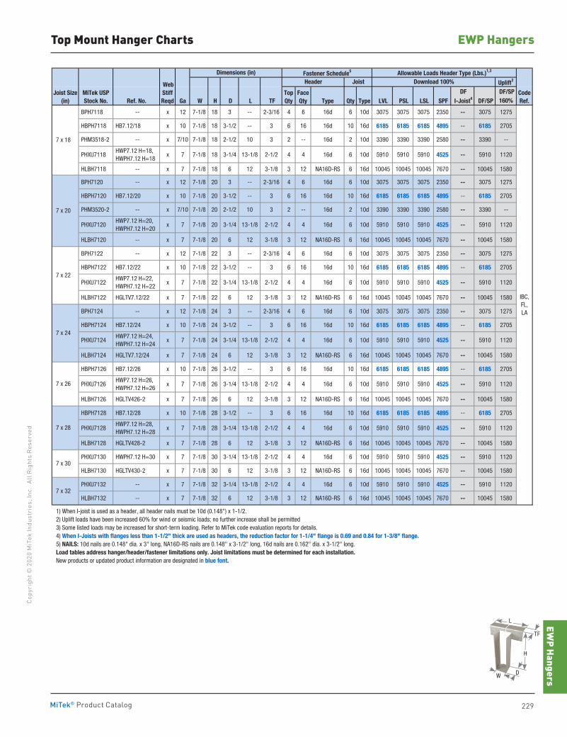
EWP Hangers
229MiTek® Product Catalog
Copy
righ
t © 2
020
MiT
ek In
dust
ries
, Inc
. Al
l Rig
hts
Rese
rved
EWP HangersTop Mount Hanger Charts
Fastener Schedule5
Uplift2
DF/SPRef. No. Ga W H D L TF Type Qty Type LVL PSL LSL SPF DF/SP 160%
BPH7118 -- x 12 7-1/8 18 3 -- 2-3/16 4 6 16d 6 10d 3075 3075 3075 2350 -- 3075 1275
HBPH7118 HB7.12/18 x 10 7-1/8 18 3-1/2 -- 3 6 16 16d 10 16d 6185 6185 6185 4895 -- 6185 2705
PHM3518-2 -- x 7/10 7-1/8 18 2-1/2 10 3 2 -- 16d 2 10d 3390 3390 3390 2580 -- 3390 --
PHXU7118 HWP7.12 H=18, HWPH7.12 H=18
x 7 7-1/8 18 3-1/4 13-1/8 2-1/2 4 4 16d 6 10d 5910 5910 5910 4525 -- 5910 1120
HLBH7118 -- x 7 7-1/8 18 6 12 3-1/8 3 12 NA16D-RS 6 16d 10045 10045 10045 7670 -- 10045 1580
BPH7120 -- x 12 7-1/8 20 3 -- 2-3/16 4 6 16d 6 10d 3075 3075 3075 2350 -- 3075 1275
HBPH7120 HB7.12/20 x 10 7-1/8 20 3-1/2 -- 3 6 16 16d 10 16d 6185 6185 6185 4895 -- 6185 2705
PHM3520-2 -- x 7/10 7-1/8 20 2-1/2 10 3 2 -- 16d 2 10d 3390 3390 3390 2580 -- 3390 --
PHXU7120 HWP7.12 H=20, HWPH7.12 H=20
x 7 7-1/8 20 3-1/4 13-1/8 2-1/2 4 4 16d 6 10d 5910 5910 5910 4525 -- 5910 1120
HLBH7120 -- x 7 7-1/8 20 6 12 3-1/8 3 12 NA16D-RS 6 16d 10045 10045 10045 7670 -- 10045 1580
BPH7122 -- x 12 7-1/8 22 3 -- 2-3/16 4 6 16d 6 10d 3075 3075 3075 2350 -- 3075 1275
HBPH7122 HB7.12/22 x 10 7-1/8 22 3-1/2 -- 3 6 16 16d 10 16d 6185 6185 6185 4895 -- 6185 2705
PHXU7122 HWP7.12 H=22, HWPH7.12 H=22
x 7 7-1/8 22 3-1/4 13-1/8 2-1/2 4 4 16d 6 10d 5910 5910 5910 4525 -- 5910 1120
HLBH7122 HGLTV7.12/22 x 7 7-1/8 22 6 12 3-1/8 3 12 NA16D-RS 6 16d 10045 10045 10045 7670 -- 10045 1580
BPH7124 -- x 12 7-1/8 24 3 -- 2-3/16 4 6 16d 6 10d 3075 3075 3075 2350 -- 3075 1275
HBPH7124 HB7.12/24 x 10 7-1/8 24 3-1/2 -- 3 6 16 16d 10 16d 6185 6185 6185 4895 -- 6185 2705
PHXU7124 HWP7.12 H=24, HWPH7.12 H=24
x 7 7-1/8 24 3-1/4 13-1/8 2-1/2 4 4 16d 6 10d 5910 5910 5910 4525 -- 5910 1120
HLBH7124 HGLTV7.12/24 x 7 7-1/8 24 6 12 3-1/8 3 12 NA16D-RS 6 16d 10045 10045 10045 7670 -- 10045 1580
HBPH7126 HB7.12/26 x 10 7-1/8 26 3-1/2 -- 3 6 16 16d 10 16d 6185 6185 6185 4895 -- 6185 2705
PHXU7126 HWP7.12 H=26, HWPH7.12 H=26
x 7 7-1/8 26 3-1/4 13-1/8 2-1/2 4 4 16d 6 10d 5910 5910 5910 4525 -- 5910 1120
HLBH7126 HGLTV426-2 x 7 7-1/8 26 6 12 3-1/8 3 12 NA16D-RS 6 16d 10045 10045 10045 7670 -- 10045 1580
HBPH7128 HB7.12/28 x 10 7-1/8 28 3-1/2 -- 3 6 16 16d 10 16d 6185 6185 6185 4895 -- 6185 2705
PHXU7128 HWP7.12 H=28, HWPH7.12 H=28
x 7 7-1/8 28 3-1/4 13-1/8 2-1/2 4 4 16d 6 10d 5910 5910 5910 4525 -- 5910 1120
HLBH7128 HGLTV428-2 x 7 7-1/8 28 6 12 3-1/8 3 12 NA16D-RS 6 16d 10045 10045 10045 7670 -- 10045 1580
PHXU7130 HWPH7.12 H=30 x 7 7-1/8 30 3-1/4 13-1/8 2-1/2 4 4 16d 6 10d 5910 5910 5910 4525 -- 5910 1120
HLBH7130 HGLTV430-2 x 7 7-1/8 30 6 12 3-1/8 3 12 NA16D-RS 6 16d 10045 10045 10045 7670 -- 10045 1580
PHXU7132 -- x 7 7-1/8 32 3-1/4 13-1/8 2-1/2 4 4 16d 6 10d 5910 5910 5910 4525 -- 5910 1120
HLBH7132 -- x 7 7-1/8 32 6 12 3-1/8 3 12 NA16D-RS 6 16d 10045 10045 10045 7670 -- 10045 1580
1) When I-joist is used as a header, all header nails must be 10d (0.148") x 1-1/2. 2) Uplift loads have been increased 60% for wind or seismic loads; no further increase shall be permitted 3) Some listed loads may be increased for short-term loading. Refer to MiTek code evaluation reports for details. 4) When I-Joists with flanges less than 1-1/2" thick are used as headers, the reduction factor for 1-1/4" flange is 0.69 and 0.84 for 1-3/8" flange. 5) NAILS: 10d nails are 0.148" dia. x 3" long, NA16D-RS nails are 0.148" x 3-1/2" long, 16d nails are 0.162" dia. x 3-1/2" long. Load tables address hanger/header/fastener limitations only. Joist limitations must be determined for each installation. New products or updated product information are designated in blue font.
IBC,FL,LA
7 x 18
7 x 20
7 x 22
7 x 32
7 x 24
7 x 26
7 x 28
7 x 30
Joist Size(in)
MiTek USPStock No.
DF I-Joist4
CodeRef.
WebStiffReqd
Dimensions (in) Allowable Loads Header Type (Lbs.)1,3
Header Joist Download 100%
TopQty
FaceQty
H
W
L
TF
D
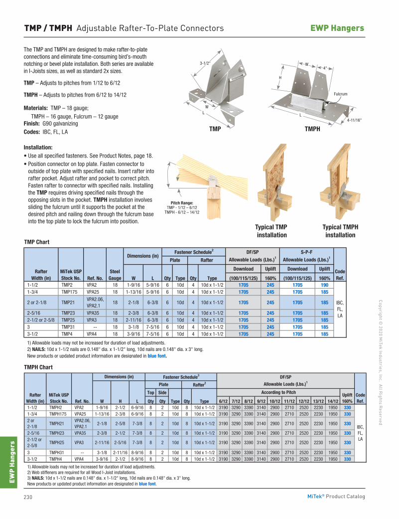
230 MiTek® Product Catalog
Copyright © 2020 M
iTek Industries, Inc. All Rights Reserved
EWP Hangers
EWP
Hang
ers
TMP / TMPH Adjustable Rafter-To-Plate Connectors
The TMP and TMPH are designed to make rafter-to-plate connections and eliminate time-consuming bird’s-mouth notching or bevel plate installation. Both series are available in I-Joists sizes, as well as standard 2x sizes.
TMP – Adjusts to pitches from 1/12 to 6/12
TMPH – Adjusts to pitches from 6/12 to 14/12
Ma terials: TMP – 18 gauge; TMPH – 16 gauge, Fulcrum – 12 gauge
Finish: G90 galvanizing Codes: IBC, FL, LA
Installation:• Use all specified fasteners. See Product Notes, page 18.• Position connector on top plate. Fasten connector to
outside of top plate with specified nails. Insert rafter into rafter pocket. Adjust rafter and pocket to correct pitch. Fasten rafter to connector with specified nails. Installing the TMP requires driving specified nails through the opposing slots in the pocket. TMPH installation involves sliding the fulcrum until it supports the pocket at the desired pitch and nailing down through the fulcrum base into the top plate to lock the fulcrum into position.
Typical TMPH installation
Typical TMP installation
TMPHTMP
Download Uplift Download Uplift
Ref. No. W L Qty Type Qty Type (100/115/125) 160% (100/115/125) 160% 1-1/2 TMP2 VPA2 18 1-9/16 5-9/16 6 10d 4 10d x 1-1/2 1705 245 1705 190 1-3/4 TMP175 VPA25 18 1-13/16 5-9/16 6 10d 4 10d x 1-1/2 1705 245 1705 185
2 or 2-1/8 TMP21 VPA2.06, VPA2.1
18 2-1/8 6-3/8 6 10d 4 10d x 1-1/2 1705 245 1705 185
2-5/16 TMP23 VPA35 18 2-3/8 6-3/8 6 10d 4 10d x 1-1/2 1705 245 1705 185 2-1/2 or 2-5/8 TMP25 VPA3 18 2-11/16 6-3/8 6 10d 4 10d x 1-1/2 1705 245 1705 185 3 TMP31 -- 18 3-1/8 7-5/16 6 10d 4 10d x 1-1/2 1705 245 1705 185 3-1/2 TMP4 VPA4 18 3-9/16 7-5/16 6 10d 4 10d x 1-1/2 1705 245 1705 185
1) Allowable loads may not be increased for duration of load adjustments. 2) NAILS: 10d x 1-1/2 nails are 0.148" dia. x 1-1/2" long, 10d nails are 0.148" dia. x 3" long. New products or updated product information are designated in blue font.
CodeRef.
IBC,FL,LA
Rafter Width (in)
S-P-F
Allowable Loads (Lbs.)1Dimensions (in)Fastener Schedule2
Plate Rafter
DF/SP
Allowable Loads (Lbs.)1
MiTek USPStock No.
SteelGauge
Top Side
Ref. No. W H L Qty Qty Type Qty Type 6/12 7/12 8/12 9/12 10/12 11/12 12/12 13/12 14/12 1-1/2 TMPH2 VPA2 1-9/16 2-1/2 6-9/16 8 2 10d 8 10d x 1-1/2 3190 3290 3390 3140 2900 2710 2520 2230 1950 330 1-3/4 TMPH175 VPA25 1-13/16 2-3/8 6-9/16 8 2 10d 8 10d x 1-1/2 3190 3290 3390 3140 2900 2710 2520 2230 1950 330 2 or 2-1/8
TMPH21 VPA2.06, VPA2.1
2-1/8 2-5/8 7-3/8 8 2 10d 8 10d x 1-1/2 3190 3290 3390 3140 2900 2710 2520 2230 1950 330
2-5/16 TMPH23 VPA35 2-3/8 2-1/2 7-3/8 8 2 10d 8 10d x 1-1/2 3190 3290 3390 3140 2900 2710 2520 2230 1950 330
3 TMPH31 -- 3-1/8 2-11/16 8-9/16 8 2 10d 8 10d x 1-1/2 3190 3290 3390 3140 2900 2710 2520 2230 1950 330 3-1/2 TMPH4 VPA4 3-9/16 2-1/2 8-9/16 8 2 10d 8 10d x 1-1/2 3190 3290 3390 3140 2900 2710 2520 2230 1950 330
1) Allowable loads may not be increased for duration of load adjustments. 2) Web stiffeners are required for all Wood I-Joist installations. 3) NAILS: 10d x 1-1/2 nails are 0.148" dia. x 1-1/2" long, 10d nails are 0.148" dia. x 3" long. New products or updated product information are designated in blue font.
Uplift160%
2710 2520 2230 1950 3303190 3290 3390 3140 2900 2-1/2 or 2-5/8
RafterWidth (in)
TMPH25 VPA3 2-11/16
IBC,FL,LA
CodeRef.
According to PitchMiTek USPStock No.
Dimensions (in) Fastener Schedule3
Plate Rafter2
DF/SP
Allowable Loads (Lbs.)1
2-5/16 7-3/8 8 2 10d 8 10d x 1-1/2
3-1/2"
LW
Pitch Range: TMP - 1/12 – 6/12
TMPH - 6/12 – 14/12
L
4"
4-11/16"
Fulcrum
H
W
TMP Chart
TMPH Chart
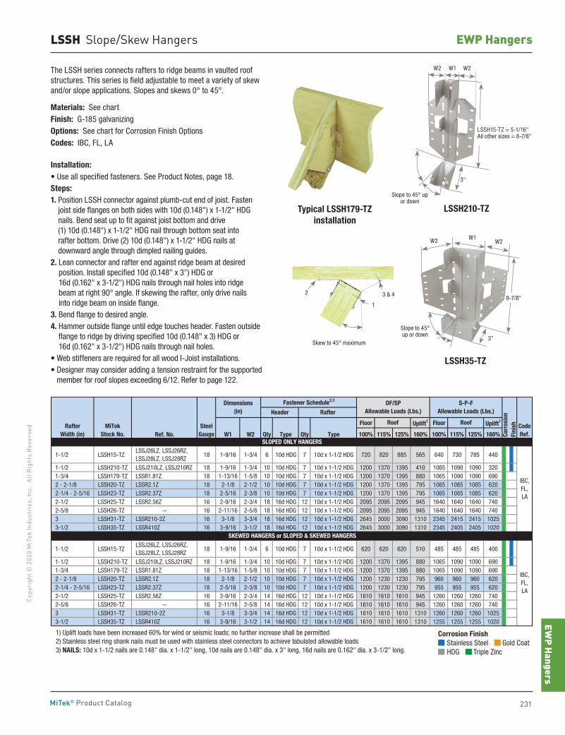
EWP Hangers
231MiTek® Product Catalog
Copy
righ
t © 2
020
MiT
ek In
dust
ries
, Inc
. Al
l Rig
hts
Rese
rved
EWP HangersLSSH Slope/Skew Hangers
The LSSH series connects rafters to ridge beams in vaulted roof structures. This series is field adjustable to meet a variety of skew and/or slope applications. Slopes and skews 0° to 45°.
Materials: See chartFinish: G-185 galvanizingOptions: See chart for Corrosion Finish OptionsCodes: IBC, FL, LA
Installation:• Use all specified fasteners. See Product Notes, page 18.Steps:1. Position LSSH connector against plumb-cut end of joist. Fasten
joist side flanges on both sides with 10d (0.148") x 1-1/2" HDG nails. Bend seat up to fit against joist bottom and drive (1) 10d (0.148") x 1-1/2" HDG nail through bottom seat into rafter bottom. Drive (2) 10d (0.148") x 1-1/2" HDG nails at downward angle through dimpled nailing guides.
2. Lean connector and rafter end against ridge beam at desired position. Install specified 10d (0.148" x 3") HDG or 16d (0.162" x 3-1/2") HDG nails through nail holes into ridge beam at right 90° angle. If skewing the rafter, only drive nails into ridge beam on inside flange.
3. Bend flange to desired angle.4. Hammer outside flange until edge touches header. Fasten outside
flange to ridge by driving specified 10d (0.148" x 3) HDG or 16d (0.162" x 3-1/2") HDG nails through nail holes.
• Web stiffeners are required for all wood I-Joist installations.• Designer may consider adding a tension restraint for the supported
member for roof slopes exceeding 6/12. Refer to page 122.
Floor Uplift1 Floor Uplift1
Ref. No. W1 W2 Qty Type Qty Type 100% 115% 125% 160% 100% 115% 125% 160%
1-1/2 LSSH15-TZ LSSJ26LZ, LSSJ26RZ, LSSJ28LZ, LSSJ28RZ
18 1-9/16 1-3/4 6 10d HDG 7 10d x 1-1/2 HDG 720 820 885 565 640 730 785 440
1-1/2 LSSH210-TZ LSSJ210LZ, LSSJ210RZ 18 1-9/16 1-3/4 10 10d HDG 7 10d x 1-1/2 HDG 1200 1370 1395 410 1065 1090 1090 320 1-3/4 LSSH179-TZ LSSR1.81Z 18 1-13/16 1-5/8 10 10d HDG 7 10d x 1-1/2 HDG 1200 1370 1395 880 1065 1090 1090 690 2 - 2-1/8 LSSH20-TZ LSSR2.1Z 18 2-1/8 2-1/2 10 10d HDG 7 10d x 1-1/2 HDG 1200 1370 1395 795 1065 1085 1085 620 2-1/4 - 2-5/16 LSSH23-TZ LSSR2.37Z 18 2-5/16 2-3/8 10 10d HDG 7 10d x 1-1/2 HDG 1200 1370 1395 795 1065 1085 1085 620 2-1/2 LSSH25-TZ LSSR2.56Z 16 2-9/16 2-3/4 18 16d HDG 12 10d x 1-1/2 HDG 2095 2095 2095 945 1640 1640 1640 740 2-5/8 LSSH26-TZ -- 16 2-11/16 2-5/8 18 16d HDG 12 10d x 1-1/2 HDG 2095 2095 2095 945 1640 1640 1640 740 3 LSSH31-TZ LSSR210-2Z 16 3-1/8 3-3/4 18 16d HDG 12 10d x 1-1/2 HDG 2645 3000 3090 1310 2345 2415 2415 1025 3-1/2 LSSH35-TZ LSSR410Z 16 3-9/16 3-1/2 18 16d HDG 12 10d x 1-1/2 HDG 2645 3000 3090 1310 2345 2405 2405 1020
1-1/2 LSSH15-TZ LSSJ26LZ, LSSJ26RZ, LSSJ28LZ, LSSJ28RZ
18 1-9/16 1-3/4 6 10d HDG 7 10d x 1-1/2 HDG 620 620 620 510 485 485 485 400
1-1/2 LSSH210-TZ LSSJ210LZ, LSSJ210RZ 18 1-9/16 1-3/4 10 10d HDG 7 10d x 1-1/2 HDG 1200 1370 1395 880 1065 1090 1090 690 1-3/4 LSSH179-TZ LSSR1.81Z 18 1-13/16 1-5/8 10 10d HDG 7 10d x 1-1/2 HDG 1200 1370 1395 880 1065 1090 1090 690 2 - 2-1/8 LSSH20-TZ LSSR2.1Z 18 2-1/8 2-1/2 10 10d HDG 7 10d x 1-1/2 HDG 1200 1230 1230 795 960 960 960 620 2-1/4 - 2-5/16 LSSH23-TZ LSSR2.37Z 18 2-5/16 2-3/8 10 10d HDG 7 10d x 1-1/2 HDG 1200 1230 1230 795 955 955 955 620 2-1/2 LSSH25-TZ LSSR2.56Z 16 2-9/16 2-3/4 14 16d HDG 12 10d x 1-1/2 HDG 1610 1610 1610 945 1260 1260 1260 740 2-5/8 LSSH26-TZ -- 16 2-11/16 2-5/8 14 16d HDG 12 10d x 1-1/2 HDG 1610 1610 1610 945 1260 1260 1260 740 3 LSSH31-TZ LSSR210-2Z 16 3-1/8 3-3/4 14 16d HDG 12 10d x 1-1/2 HDG 1610 1610 1610 1310 1260 1260 1260 1025 3-1/2 LSSH35-TZ LSSR410Z 16 3-9/16 3-1/2 14 16d HDG 12 10d x 1-1/2 HDG 1610 1610 1610 1310 1255 1255 1255 1020
1) Uplift loads have been increased 60% for wind or seismic loads; no further increase shall be permitted. 2) Stainless steel ring shank nails must be used with stainless steel connectors to achieve tabulated allowable loads. 3) NAILS: 10d x 1-1/2 nails are 0.148" dia. x 1-1/2" long, 10d nails are 0.148" dia. x 3" long, 16d nails are 0.162" dia. x 3-1/2" long.
IBC,FL,LA
IBC,FL,LA
Rafter Width (in)
Dimensions(in)
CodeRef.
SLOPED ONLY HANGERS
SKEWED HANGERS or SLOPED & SKEWED HANGERS
MiTekStock No.
SteelGauge
Roof Roof
Corr
osio
n Fi
nish
Fastener Schedule2,3
Header RafterDF/SP
Allowable Loads (Lbs.)S-P-F
Allowable Loads (Lbs.)
Corrosion Finish Stainless Steel Gold Coat HDG Triple Zinc
Corrosion Finish Stainless Steel Gold Coat HDG Triple Zinc
Corrosion Finish Stainless Steel Gold Coat HDG Triple Zinc
Typical LSSH179-TZinstallation
LSSH35-TZ
Skew to 45° maximum
2 3 & 4
1
LSSH15-TZ = 5-1/16" All other sizes = 8-7/8"
W2 W1 W2
3"
Slope to 45° up or down
LSSH210-TZ
W2 W1W2
3"
Slope to 45° up or down
8-7/8"
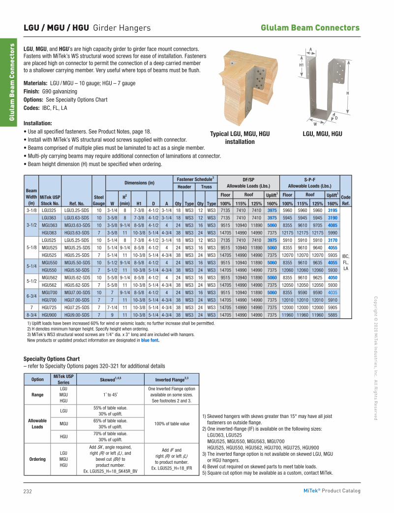
232
Copyright © 2020 M
iTek Industries, Inc. All Rights Reserved
Glulam Beam Connectors
Glul
am B
eam
Con
nect
ors
MiTek® Product Catalog
LGU / MGU / HGU Girder Hangers
LGU, MGU, and HGU’s are high capacity girder to girder face mount connectors. Fastens with MiTek’s WS structural wood screws for ease of installation. Fasteners are placed high on connector to permit the connection of a deep carried member to a shallower carrying member. Very useful where tops of beams must be flush.
Materials: LGU / MGU – 10 gauge; HGU – 7 gaugeFinish: G90 galvanizing Options: See Specialty Options ChartCodes: IBC, FL, LA
Installation:• Use all specified fasteners. See Product Notes, page 18.• Install with MiTek’s WS structural wood screws supplied with connector. • Beams comprised of multiple plies must be laminated to act as a single member.• Multi-ply carrying beams may require additional connection of laminations at connector.• Beam height dimension (H) must be specified when ordering.
Typical LGU, MGU, HGUinstallation
LGU, MGU, HGU
Floor Uplift1 Floor Uplift1
Ref. No. W H1 D A Qty Type Qty Type 100% 115% 125% 160% 100% 115% 125% 160%3-1/8 LGU325 LGU3.25-SDS 10 3-1/4 8 7-3/8 4-1/2 3-1/4 18 WS3 12 WS3 7135 7410 7410 3975 5960 5960 5960 3195
LGU363 LGU3.63-SDS 10 3-5/8 8 7-3/8 4-1/2 3-1/4 18 WS3 12 WS3 7135 7410 7410 3975 5945 5945 5945 3190
MGU363 MGU3.63-SDS 10 3-5/8 9-1/4 8-5/8 4-1/2 4 24 WS3 16 WS3 9515 10940 11890 5060 8355 9610 9705 4085
HGU363 HGU3.63-SDS 7 3-5/8 11 10-3/8 5-1/4 4-3/4 38 WS3 24 WS3 14705 14990 14990 7375 12175 12175 12175 5990
LGU525 LGU5.25-SDS 10 5-1/4 8 7-3/8 4-1/2 3-1/4 18 WS3 12 WS3 7135 7410 7410 3975 5910 5910 5910 3170
MGU525 MGU5.25-SDS 10 5-1/4 9-1/4 8-5/8 4-1/2 4 24 WS3 16 WS3 9515 10940 11890 5060 8355 9610 9640 4055
HGU525 HGU5.25-SDS 7 5-1/4 11 10-3/8 5-1/4 4-3/4 38 WS3 24 WS3 14705 14990 14990 7375 12070 12070 12070 5935
MGU550 MGU5.50-SDS 10 5-1/2 9-1/4 8-5/8 4-1/2 4 24 WS3 16 WS3 9515 10940 11890 5060 8355 9610 9635 4055
HGU550 HGU5.50-SDS 7 5-1/2 11 10-3/8 5-1/4 4-3/4 38 WS3 24 WS3 14705 14990 14990 7375 12060 12060 12060 5930
MGU562 MGU5.62-SDS 10 5-5/8 9-1/4 8-5/8 4-1/2 4 24 WS3 16 WS3 9515 10940 11890 5060 8355 9610 9625 4050
HGU562 HGU5.62-SDS 7 5-5/8 11 10-3/8 5-1/4 4-3/4 38 WS3 24 WS3 14705 14990 14990 7375 12050 12050 12050 5930
MGU700 MGU7.00-SDS 10 7 9-1/4 8-5/8 4-1/2 4 24 WS3 16 WS3 9515 10940 11890 5060 8355 9590 9590 4035
HGU700 HGU7.00-SDS 7 7 11 10-3/8 5-1/4 4-3/4 38 WS3 24 WS3 14705 14990 14990 7375 12010 12010 12010 5910
7 HGU725 HGU7.25-SDS 7 7-1/4 11 10-3/8 5-1/4 4-3/4 38 WS3 24 WS3 14705 14990 14990 7375 12000 12000 12000 5905
8-3/4 HGU900 HGU9.00-SDS 7 9 11 10-3/8 5-1/4 4-3/4 38 WS3 24 WS3 14705 14990 14990 7375 11960 11960 11960 5885
1) Uplift loads have been increased 60% for wind or seismic loads; no further increase shall be permitted. 2) H denotes minimum hanger height. Specify height when ordering. 3) MiTek's WS3 structural wood screws are 1/4" dia. x 3" long and are included with hangers. New products or updated product information are designated in blue font.
IBC,FL,LA
SteelGauge
CodeRef.
3-1/2
5-1/8
Roof RoofH2
(min)
BeamWidth
(in)
DF/SPAllowable Loads (Lbs.)
S-P-FAllowable Loads (Lbs.)
Dimensions (in)
MiTek USPStock No.
Fastener Schedule3
Header Truss
5-1/4
5-1/2
6-3/4
OptionMiTek USP
Series Skewed1,4,5 Inverted Flange2,3
1) Skewed hangers with skews greater than 15° may have all joist fasteners on outside flange. 2) One inverted flange (IF) is available on the following sizes: LGU363, LGU525 MGU525, MGU550, MGU563, MGU700 HGU525, HGU550, HGU562,HGU700, HGU725, HGU900 3) The inverted flange option is not available on skewed LGU, MGU or HGU hangers. 4) Bevel cut rquired on skewed parts to meet table loads. 5) Square cut option may be available as a Custom, contact MiTek.
One Inverted Flange option available on some sizes.See footnotes 2 and 3.
100% of table value
Ordering
Add SK , angle required,right (R) or left (L) , and
bevel cut (BV) to product number.
Ex. LGU525_H=18_SK45R_BV
Add IF and right (R) or left (L)to product number.
Ex. LGU525_H=18_IFR
AllowableLoads
Range 1˚ to 45˚
LGUMGUHGU
LGUMGUHGU
LGU55% of table value.
30% of uplift.
MGU65% of table value.
30% of uplift.
HGU70% of table value.
30% of uplift.
Specialty Options Chart– refer to Specialty Options pages 320-321 for additional details
A
H
D
W
H1
1) Skewed hangers with skews greater than 15° may have all joist fasteners on outside flange.
2) One inverted-flange (IF) is available on the following sizes: LGU363, LGU525 MGU525, MGU550, MGU563, MGU700 HGU525, HGU550, HGU562, HGU700, HGU725, HGU900
3) The inverted flange option is not available on skewed LGU, MGU or HGU hangers.
4) Bevel cut required on skewed parts to meet table loads.5) Square cut option may be available as a custom, contact MiTek.
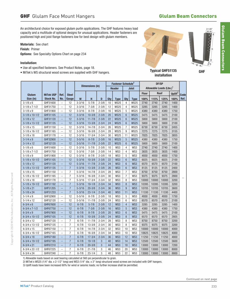
233
Copy
righ
t © 2
020
MiT
ek In
dust
ries
, Inc
. Al
l Rig
hts
Rese
rved
Glulam Beam Connectors
Glulam Beam
Connectors
MiTek® Product Catalog
GHF Glulam Face Mount Hangers
Typical GHF51135installation
GHF
An architectural choice for exposed glulam purlin applications. The GHF features heavy load capacity and a multitude of optional designs for unusual applications. Header fasteners are positioned high and joist flange fasteners low for best design with glulam members.
Materials: See chartFinish: Primer Options: See Specialty Options Chart on page 234
Installation:• Use all specified fasteners. See Product Notes, page 18.• MiTek’s WS structural wood screws are supplied with GHF hangers.
Floor Uplift3
W H D Qty Type Qty Type 100% 115% 125% 160% 3-1/8 x 6 GHF31600 -- 12 3-3/16 5-7/8 2-3/8 10 WS25 4 WS25 2740 2740 2740 1400 3-1/8 x 7-1/2 GHF31750 -- 12 3-3/16 7-3/8 2-3/8 12 WS25 4 WS25 3285 3285 3285 1400 3-1/8 x 9 GHF31900 -- 12 3-3/16 8-7/8 2-3/8 16 WS25 5 WS25 4380 4380 4380 1750 3-1/8 x 10-1/2 GHF31105 -- 12 3-3/16 10-3/8 2-3/8 20 WS25 6 WS25 5475 5475 5475 2100 3-1/8 x 12 GHF31120 -- 12 3-3/16 11-7/8 2-3/8 22 WS25 6 WS25 5800 5800 5800 2100 3-1/8 x 13-1/2 GHF31135 -- 12 3-3/16 13-3/8 2-3/4 24 WS25 6 WS25 5800 5800 5800 2100 3-1/8 x 15 GHF31150 -- 12 3-3/16 14-7/8 2-3/4 26 WS25 7 WS25 6730 6730 6730 2455 3-1/8 x 16-1/2 GHF31165 -- 12 3-3/16 16-3/8 2-3/4 28 WS25 9 WS25 7275 7275 7275 3155 3-1/8 x 18 GHF31178 -- 12 3-3/16 17-3/4 2-3/4 30 WS25 11 WS25 7825 7825 7825 3855 3-1/4 x 9 GHF32900 -- 12 3-5/16 8-7/8 2-3/8 16 WS25 5 WS25 4380 4380 4380 1750 3-1/4 x 12 GHF32120 -- 12 3-5/16 11-7/8 2-3/8 22 WS25 6 WS25 5800 5800 5800 2100 5-1/8 x 6 GHF51600 -- 12 5-3/16 5-7/8 2-3/8 10 WS3 4 WS3 2740 2740 2740 1400 5-1/8 x 7-1/2 GHF51750 -- 12 5-3/16 7-3/8 2-3/8 14 WS3 4 WS3 3835 3835 3835 1400 5-1/8 x 9 GHF51900 -- 12 5-3/16 8-7/8 2-3/8 18 WS3 5 WS3 4930 4930 4930 1750 5-1/8 x 10-1/2 GHF51105 -- 12 5-3/16 10-3/8 2-3/8 22 WS3 6 WS3 6025 6025 6025 2100 5-1/8 x 12 GHF51120 -- 12 5-3/16 11-7/8 2-3/8 24 WS3 6 WS3 6570 6570 6570 2100 5-1/8 x 13-1/2 GHF51135 -- 7 5-3/16 13-3/8 2-3/8 26 WS3 6 WS3 8125 8125 8125 2400 5-1/8 x 15 GHF51150 -- 7 5-3/16 14-7/8 2-3/4 28 WS3 7 WS3 8750 8750 8750 2800 5-1/8 x 16-1/2 GHF51165 -- 7 5-3/16 16-3/8 2-3/4 30 WS3 7 WS3 9375 9375 9375 2800 5-1/8 x 18 GHF51178 -- 7 5-3/16 17-3/4 2-3/4 32 WS3 8 WS3 10000 10000 10000 3200 5-1/8 x 19-1/2 GHF51192 -- 7 5-3/16 19-1/8 2-3/4 34 WS3 8 WS3 10395 10395 10395 3200 5-1/8 x 21 GHF51205 -- 7 5-3/16 20-3/8 2-3/4 36 WS3 9 WS3 10705 10705 10705 3600 5-1/8 x 24 GHF51233 -- 7 5-3/16 23-1/4 2-3/4 40 WS3 11 WS3 11330 11330 11330 4400 5-1/4 x 9 GHF52900 -- 12 5-5/16 8-7/8 2-3/8 18 WS3 5 WS3 4930 4930 4930 1750 5-1/4 x 12 GHF52120 -- 12 5-5/16 11-7/8 2-3/8 24 WS3 6 WS3 6570 6570 6570 2100 6-3/4 x 6 GHF67600 -- 12 6-7/8 5-7/8 2-3/8 12 WS3 4 WS3 3285 3285 3285 1400 6-3/4 x 7-1/2 GHF67750 -- 12 6-7/8 7-3/8 2-3/8 16 WS3 5 WS3 4380 4380 4380 1750 6-3/4 x 9 GHF67900 -- 12 6-7/8 8-7/8 2-3/8 20 WS3 6 WS3 5475 5475 5475 2100 6-3/4 x 10-1/2 GHF67105 -- 12 6-7/8 10-3/8 2-3/8 24 WS3 8 WS3 6570 6570 6570 2805 6-3/4 x 12 GHF67120 -- 7 6-7/8 11-7/8 2-3/4 28 WS3 8 WS3 8750 8750 8750 3200 6-3/4 x 13-1/2 GHF67135 -- 7 6-7/8 13-3/8 2-3/4 30 WS3 8 WS3 9375 9375 9375 3200 6-3/4 x 15 GHF67150 -- 7 6-7/8 14-7/8 2-3/4 32 WS3 10 WS3 10000 10000 10000 4000 6-3/4 x 16-1/2 GHF67165 -- 7 6-7/8 16-3/8 2-3/4 34 WS3 10 WS3 10625 10625 10625 4000 6-3/4 x 18 GHF67180 -- 7 6-7/8 17-3/4 2-3/4 36 WS3 12 WS3 11250 11250 11250 4800 6-3/4 x 19-1/2 GHF67195 -- 7 6-7/8 19-1/8 3 40 WS3 14 WS3 12500 12500 12500 5600 6-3/4 x 21 GHF67210 -- 7 6-7/8 20-3/8 3 44 WS3 18 WS3 13000 13000 13000 7200 6-3/4 x 22-1/2 GHF67225 -- 7 6-7/8 21-7/8 3 46 WS3 20 WS3 13000 13000 13000 8000 6-3/4 x 24 GHF67240 -- 7 6-7/8 23-1/4 3 48 WS3 22 WS3 13000 13000 13000 8800
1) Allowable loads based on seat bearing calculated at 560 psi perpendicular to grain. 2) MiTek's WS25 (1/4" dia. x 2-1/2" long) and WS3 (1/4" dia. x 3" long) structural wood screws are included with GHF hangers. 3) Uplift loads have been increased 60% for wind or seismic loads; no further increase shall be permitted.
--
Dimensions (in)
GlulamSize (in)
MiTek USPStock No.
SteelGauge
CodeRef.
Joist
Roof
Fastener Schedule2
Header
DF/SP
Allowable Loads (Lbs.)1
Ref. No.
W D
H
2-1/8"
Continued on next page
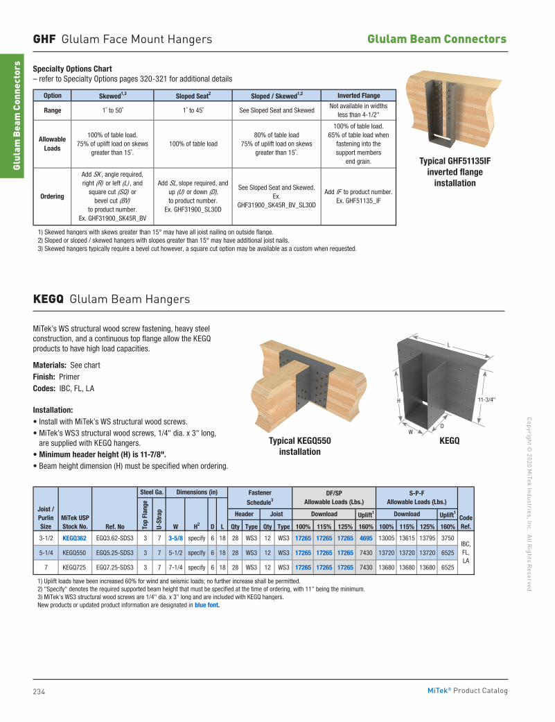
234
Copyright © 2020 M
iTek Industries, Inc. All Rights Reserved
Glulam Beam Connectors
Glul
am B
eam
Con
nect
ors
MiTek® Product Catalog
GHF Glulam Face Mount Hangers
Specialty Options Chart– refer to Specialty Options pages 320-321 for additional details
Option Skewed1,3 Sloped Seat2 Sloped / Skewed1,2 Inverted Flange
1) Skewed hangers with skews greater than 15° may have all joist nailing on outside flange. 2) Sloped or sloped / skewed hangers with slopes greater than 15° may have additional joist nails. 3) Skewed hangers typically require a bevel cut however, a square cut option may be available as a custom when requested.
AllowableLoads
Ordering
80% of table load75% of uplift load on skews
greater than 15˚.
100% of table load.65% of table load when
fastening into thesupport members
end grain.
Add SK , angle required,right (R) or left (L) , and
square cut (SQ) orbevel cut (BV)
to product number.Ex. GHF31900_SK45R_BV
See Sloped Seat and Skewed.Ex.
GHF31900_SK45R_BV_SL30D
Add IF to product number.Ex. GHF51135_IF
Add SL, slope required, and up (U) or down (D), to product number.
Ex. GHF31900_SL30D
100% of table load100% of table load.
75% of uplift load on skewsgreater than 15˚.
Range 1˚ to 50˚ 1˚ to 45˚ See Sloped Seat and SkewedNot available in widths
less than 4-1/2"
Typical GHF51135IF inverted flange
installation
KEGQ Glulam Beam Hangers
MiTek’s WS structural wood screw fastening, heavy steel construction, and a continuous top flange allow the KEGQ products to have high load capacities.
Materials: See chartFinish: PrimerCodes: IBC, FL, LA
Installation:• Install with MiTek’s WS structural wood screws.• MiTek’s WS3 structural wood screws, 1/4" dia. x 3" long,
are supplied with KEGQ hangers.• Minimum header height (H) is 11-7/8".• Beam height dimension (H) must be specified when ordering.
Uplift1 Uplift1
Ref. No W H2 D L Qty Type Qty Type 100% 115% 125% 160% 100% 115% 125% 160%
3-1/2 KEGQ362 EGQ3.62-SDS3 3 7 3-5/8 specify 6 18 28 WS3 12 WS3 17265 17265 17265 4695 13005 13615 13795 3750
5-1/4 KEGQ550 EGQ5.25-SDS3 3 7 5-1/2 specify 6 18 28 WS3 12 WS3 17265 17265 17265 7430 13720 13720 13720 6525
7 KEGQ725 EGQ7.25-SDS3 3 7 7-1/4 specify 6 18 28 WS3 12 WS3 17265 17265 17265 7430 13680 13680 13680 6525
1) Uplift loads have been increased 60% for wind and seismic loads; no further increase shall be permitted. 2) "Specify" denotes the required supported beam height that must be specified at the time of ordering, with 11" being the minimum. 3) MiTek's WS3 structural wood screws are 1/4" dia. x 3" long and are included with KEGQ hangers. New products or updated product information are designated in blue font.
Joist /PurlinSize
IBC,FL,LA
Dimensions (in)Steel Ga.
Top
Flan
ge
CodeRef.U-
Stra
p
S-P-FAllowable Loads (Lbs.)
Download
DF/SP Allowable Loads (Lbs.)
Download
Fastener
Schedule3
Header JoistMiTek USPStock No.
Typical KEGQ550installation
KEGQ
DW
L
11-3/4"H
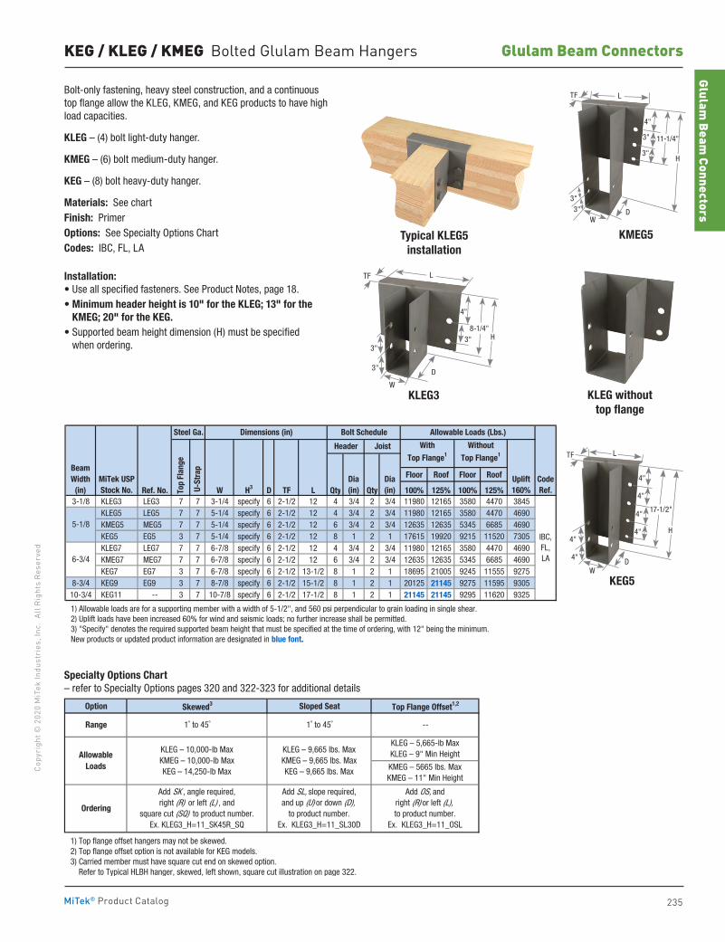
235
Copy
righ
t © 2
020
MiT
ek In
dust
ries
, Inc
. Al
l Rig
hts
Rese
rved
Glulam Beam Connectors
Glulam Beam
Connectors
MiTek® Product Catalog
KEG / KLEG / KMEG Bolted Glulam Beam Hangers
Bolt-only fastening, heavy steel construction, and a continuous top flange allow the KLEG, KMEG, and KEG products to have high load capacities.
KLEG – (4) bolt light-duty hanger.
KMEG – (6) bolt medium-duty hanger.
KEG – (8) bolt heavy-duty hanger.
Materials: See chartFinish: PrimerOptions: See Specialty Options ChartCodes: IBC, FL, LA
Installation:• Use all specified fasteners. See Product Notes, page 18.• Minimum header height is 10" for the KLEG; 13" for the
KMEG; 20" for the KEG.• Supported beam height dimension (H) must be specified
when ordering.
Typical KLEG5installation
KLEG3
KEG5
KLEG without top flange
KMEG5
Floor Roof Floor Roof
Ref. No. W H3 D TF L Qty Qty 100% 125% 100% 125%3-1/8 KLEG3 LEG3 7 7 3-1/4 specify 6 2-1/2 12 4 3/4 2 3/4 11980 12165 3580 4470 3845
KLEG5 LEG5 7 7 5-1/4 specify 6 2-1/2 12 4 3/4 2 3/4 11980 12165 3580 4470 4690 KMEG5 MEG5 7 7 5-1/4 specify 6 2-1/2 12 6 3/4 2 3/4 12635 12635 5345 6685 4690 KEG5 EG5 3 7 5-1/4 specify 6 2-1/2 12 8 1 2 1 17615 19920 9215 11520 7305 KLEG7 LEG7 7 7 6-7/8 specify 6 2-1/2 12 4 3/4 2 3/4 11980 12165 3580 4470 4690 KMEG7 MEG7 7 7 6-7/8 specify 6 2-1/2 12 6 3/4 2 3/4 12635 12635 5345 6685 4690 KEG7 EG7 3 7 6-7/8 specify 6 2-1/2 13-1/2 8 1 2 1 18695 21005 9245 11555 9275
8-3/4 KEG9 EG9 3 7 8-7/8 specify 6 2-1/2 15-1/2 8 1 2 1 20125 21145 9275 11595 930510-3/4 KEG11 -- 3 7 10-7/8 specify 6 2-1/2 17-1/2 8 1 2 1 21145 21145 9295 11620 9325
1) Allowable loads are for a supporting member with a width of 5-1/2", and 560 psi perpendicular to grain loading in single shear. 2) Uplift loads have been increased 60% for wind and seismic loads; no further increase shall be permitted. 3) "Specify" denotes the required supported beam height that must be specified at the time of ordering, with 12" being the minimum. New products or updated product information are designated in blue font.
Allowable Loads (Lbs.)Dimensions (in)Steel Ga.
Top
Flan
ge
Bolt Schedule
Header Joist With
Top Flange1
Without
Top Flange1
CodeRef.
IBC,FL,LA
U-S
trap
5-1/8
6-3/4
MiTek USPStock No.
Dia(in)
Dia(in)
BeamWidth
(in)Uplift160%
Option Skewed3 Sloped Seat Top Flange Offset1,2
1) Top flange offset hangers may not be skewed. 2) Top flange offset option is not available for KEG models. 3) Carried member must have square cut end on skewed option. Refer to Typical HLBH hanger, skewed, left shown, square cut illustration on page 322.
Add SK , angle required,right (R) or left (L) , and
square cut (SQ) to product number.Ex. KLEG3_H=11_SK45R_SQ
Add SL, slope required,and up (U) or down (D),
to product number.Ex. KLEG3_H=11_SL30D
Add OS, andright (R) or left (L),to product number.
Ex. KLEG3_H=11_OSL
Allowable Loads
Ordering
Range --
KLEG – 10,000-lb MaxKMEG – 10,000-lb MaxKEG – 14,250-lb Max
KLEG – 9,665 lbs. MaxKMEG – 9,665 lbs. MaxKEG – 9,665 lbs. Max
1˚ to 45˚ 1˚ to 45˚
KMEG – 5665 lbs. MaxKMEG – 11" Min Height
KLEG – 5,665-lb MaxKLEG – 9" Min Height
Specialty Options Chart– refer to Specialty Options pages 320 and 322-323 for additional details
D
W
3"
3"
TF L
H8-1/4"
4"
3"
H4"
4"
4"
4"
4"
4"
DW
17-1/2"
LTF
H
4"
3"
3"
DW
LTF
3"
11-1/4"
3"
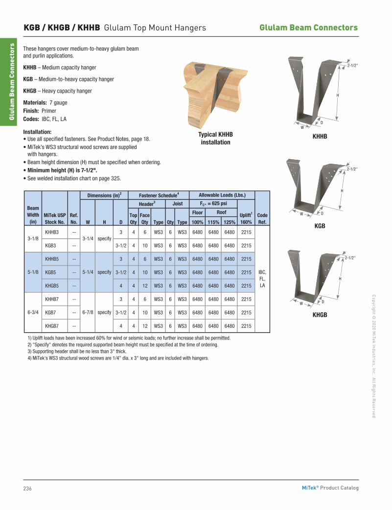
236
Copyright © 2020 M
iTek Industries, Inc. All Rights Reserved
Glulam Beam Connectors
Glul
am B
eam
Con
nect
ors
MiTek® Product Catalog
KGB / KHGB / KHHB Glulam Top Mount Hangers
These hangers cover medium-to-heavy glulam beam and purlin applications.
KHHB – Medium capacity hanger
KGB – Medium-to-heavy capacity hanger
KHGB – Heavy capacity hanger
Materials: 7 gaugeFinish: PrimerCodes: IBC, FL, LA
Installation: • Use all specified fasteners. See Product Notes, page 18.• MiTek’s WS3 structural wood screws are supplied
with hangers.• Beam height dimension (H) must be specified when ordering. • Minimum height (H) is 7-1/2".• See welded installation chart on page 325.
Floor
W H D Type Qty Type 100% 115% 125%
KHHB3 -- 3 4 6 WS3 6 WS3 6480 6480 6480 2215
KGB3 -- 3-1/2 4 10 WS3 6 WS3 6480 6480 6480 2215
KHHB5 -- 3 4 6 WS3 6 WS3 6480 6480 6480 2215
KGB5 -- 3-1/2 4 10 WS3 6 WS3 6480 6480 6480 2215
KHGB5 -- 4 4 12 WS3 6 WS3 6480 6480 6480 2215
KHHB7 -- 3 4 6 WS3 6 WS3 6480 6480 6480 2215
KGB7 -- 3-1/2 4 10 WS3 6 WS3 6480 6480 6480 2215
KHGB7 -- 4 4 12 WS3 6 WS3 6480 6480 6480 2215
1) Uplift loads have been increased 60% for wind or seismic loads; no further increase shall be permitted. 2) "Specify" denotes the required supported beam height must be specified at the time of ordering. 3) Supporting header shall be no less than 3" thick. 4) MiTek's WS3 structural wood screws are 1/4" dia. x 3" long and are included with hangers.
Allowable Loads (Lbs.)
RoofMiTek USPStock No.
Dimensions (in)2
FC^ = 625 psi
Fastener Schedule4
Header3 Joist
Uplift1
160%Ref. No.
BeamWidth
(in)
3-1/8
5-1/8
6-3/4
CodeRef.
TopQty
FaceQty
3-1/4 specify
5-1/4 specify
6-7/8 specify
IBC,FL, LA
Typical KHHB installation
KHGB
KHHB
KGB
H
DW
2-1/2"
D
2-1/2"
H
W
D
2-1/2"
H
W
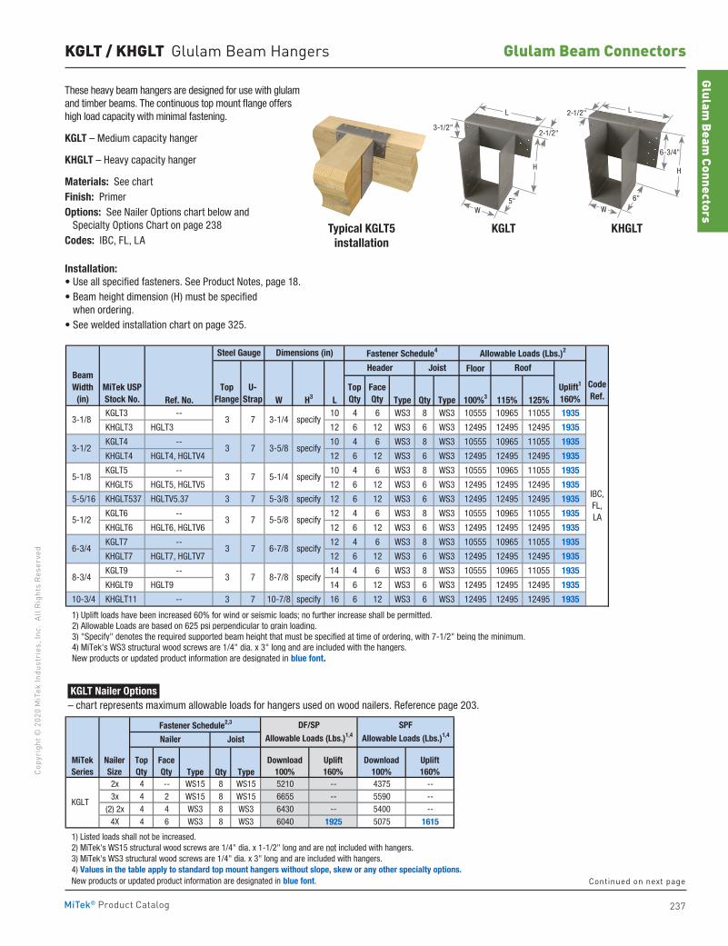
237
Copy
righ
t © 2
020
MiT
ek In
dust
ries
, Inc
. Al
l Rig
hts
Rese
rved
Glulam Beam Connectors
Glulam Beam
Connectors
MiTek® Product Catalog
KGLT / KHGLT Glulam Beam Hangers
Typical KGLT5 installation
KGLT KHGLT
These heavy beam hangers are designed for use with glulam and timber beams. The continuous top mount flange offers high load capacity with minimal fastening.
KGLT – Medium capacity hanger
KHGLT – Heavy capacity hanger
Materials: See chartFinish: PrimerOptions: See Nailer Options chart below and Specialty Options Chart on page 238Codes: IBC, FL, LA
Installation:• Use all specified fasteners. See Product Notes, page 18.• Beam height dimension (H) must be specified
when ordering.• See welded installation chart on page 325.
Floor
Ref. No. W H3 L Type Qty Type 100%3 115% 125% KGLT3 -- 10 4 6 WS3 8 WS3 10555 10965 11055 1935
KHGLT3 HGLT3 12 6 12 WS3 6 WS3 12495 12495 12495 1935
KGLT4 -- 10 4 6 WS3 8 WS3 10555 10965 11055 1935
KHGLT4 HGLT4, HGLTV4 12 6 12 WS3 6 WS3 12495 12495 12495 1935
KGLT5 -- 10 4 6 WS3 8 WS3 10555 10965 11055 1935
KHGLT5 HGLT5, HGLTV5 12 6 12 WS3 6 WS3 12495 12495 12495 1935
5-5/16 KHGLT537 HGLTV5.37 3 7 5-3/8 specify 12 6 12 WS3 6 WS3 12495 12495 12495 1935
KGLT6 -- 12 4 6 WS3 8 WS3 10555 10965 11055 1935
KHGLT6 HGLT6, HGLTV6 12 6 12 WS3 6 WS3 12495 12495 12495 1935
KGLT7 -- 12 4 6 WS3 8 WS3 10555 10965 11055 1935
KHGLT7 HGLT7, HGLTV7 12 6 12 WS3 6 WS3 12495 12495 12495 1935
KGLT9 -- 14 4 6 WS3 8 WS3 10555 10965 11055 1935
KHGLT9 HGLT9 14 6 12 WS3 6 WS3 12495 12495 12495 1935
10-3/4 KHGLT11 -- 3 7 10-7/8 specify 16 6 12 WS3 6 WS3 12495 12495 12495 1935
1) Uplift loads have been increased 60% for wind or seismic loads; no further increase shall be permitted. 2) Allowable Loads are based on 625 psi perpendicular to grain loading. 3) "Specify" denotes the required supported beam height that must be specified at time of ordering, with 7-1/2" being the minimum. 4) MiTek's WS3 structural wood screws are 1/4" dia. x 3" long and are included with the hangers. New products or updated product information are designated in blue font.
8-3/4
3-1/8
3-1/2
5-1/8
5-1/2
6-3/4
IBC,FL,LA
RoofHeader Joist
CodeRef.
TopQty
FaceQty
Uplift1
160%MiTek USPStock No.
TopFlange
Steel Gauge
U-Strap
BeamWidth
(in)
specify
specify
specify
specify
Allowable Loads (Lbs.)2Dimensions (in) Fastener Schedule4
specify
specify
3 7 3-1/4
3 7 3-5/8
3 7 8-7/8
3 7 5-1/4
3 7 5-5/8
3 7 6-7/8
L
H
5"
3-1/2"2-1/2"
W
L
H
6"
2-1/2"
6-3/4"
W
Fastener Schedule2,3
Type Qty Type2x 4 -- WS15 8 WS15 5210 -- 4375 --3x 4 2 WS15 8 WS15 6655 -- 5590 --
(2) 2x 4 4 WS3 8 WS3 6430 -- 5400 --4X 4 6 WS3 8 WS3 6040 1925 5075 1615
1) Listed loads shall not be increased. 2) MiTek's WS15 structural wood screws are 1/4" dia. x 1-1/2" long and are not included with hangers. 3) MiTek's WS3 structural wood screws are 1/4" dia. x 3" long and are included with hangers. 4) Values in the table apply to standard top mount hangers without slope, skew or any other specialty options. New products or updated product information are designated in blue font.
DF/SP
Allowable Loads (Lbs.)1,4
SPF
Allowable Loads (Lbs.)1,4Nailer Joist
KGLT
NailerSize
Uplift160%
Uplift160%
MiTekSeries
TopQty
FaceQty
Download100%
Download100%
KGLT Nailer Options – chart represents maximum allowable loads for hangers used on wood nailers. Reference page 203.
Continued on next page
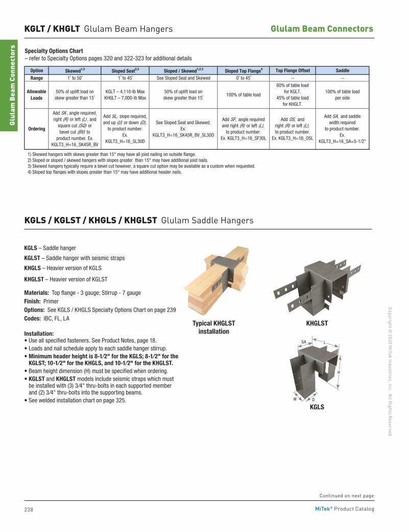
238
Copyright © 2020 M
iTek Industries, Inc. All Rights Reserved
Glulam Beam Connectors
Glul
am B
eam
Con
nect
ors
MiTek® Product Catalog
KGLT / KHGLT Glulam Beam Hangers
Option Skewed1,3 Sloped Seat2,3 Sloped / Skewed1,2,3 Sloped Top Flange4 Top Flange Offset Saddle
Range 1˚ to 50˚ 1˚ to 45˚ See Sloped Seat and Skewed 0˚ to 45˚ -- --
1) Skewed hangers with skews greater than 15° may have all joist nailing on outside flange. 2) Sloped or sloped / skewed hangers with slopes greater than 15° may have additional joist nails. 3) Skewed hangers typically require a bevel cut however, a square cut option may be available as a custom when requested. 4) Sloped top flanges with slopes greater than 15° may have additional header nails.
AllowableLoads
Ordering
50% of uplift load onskew greater than 15˚
Add SK , angle required,right (R) or left (L) , and
square cut (SQ) or bevel cut (BV) to
product number. Ex. KGLT3_H=16_SK45R_BV
Add SA, and saddlewidth required
to product number.Ex.
KGLT3_H=16_SA=5-1/2"
KGLT – 4,110-lb MaxKHGLT – 7,000-lb Max
Add SL, slope required,and up (U) or down (D),
to product number.Ex.
KGLT3_H=16_SL30D
See Sloped Seat and Skewed.Ex.
KGLT3_H=16_SK45R_BV_SL30D
Add SF, angle requiredand right (R) or left (L),
to product number.Ex. KGLT3_H=16_SF30L
Add OS, andright (R) or left (L),to product number.
Ex. KGLT3_H=16_OSL
50% of uplift load onskew greater than 15˚
100% of table load
60% of table loadfor KGLT.
45% of table loadfor KHGLT.
100% of table loadper side
Specialty Options Chart– refer to Specialty Options pages 320 and 322-323 for additional details
KGLS – Saddle hanger
KGLST – Saddle hanger with seismic straps
KHGLS – Heavier version of KGLS
KHGLST – Heavier version of KGLST
Materials: Top flange - 3 gauge; Stirrup - 7 gaugeFinish: PrimerOptions: See KGLS / KHGLS Specialty Options Chart on page 239Codes: IBC, FL, LA
Installation:• Use all specified fasteners. See Product Notes, page 18. • Loads and nail schedule apply to each saddle hanger stirrup.• Minimum header height is 8-1⁄2" for the KGLS; 8-1⁄2" for the
KGLST; 10-1⁄2" for the KHGLS, and 10-1⁄2" for the KHGLST. • Beam height dimension (H) must be specified when ordering.• KGLST and KHGLST models include seismic straps which must
be installed with (3) 3⁄4" thru-bolts in each supported member and (2) 3⁄4" thru-bolts into the supporting beams.
• See welded installation chart on page 325.
KHGLST
KGLS
Typical KHGLSTinstallation
SA L
DW
H
KGLS / KGLST / KHGLS / KHGLST Glulam Saddle Hangers
Continued on next page
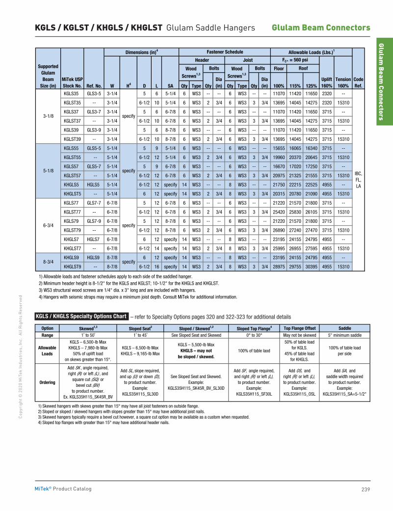
239
Copy
righ
t © 2
020
MiT
ek In
dust
ries
, Inc
. Al
l Rig
hts
Rese
rved
Glulam Beam Connectors
Glulam Beam
Connectors
MiTek® Product Catalog
KGLS / KGLST / KHGLS / KHGLST Glulam Saddle Hangers
Floor
Ref. No. W H4 D L SA Qty Type Qty Qty Type Qty 100% 115% 125%
KGLS35 GLS3-5 3-1/4 5 6 5-1/4 6 WS3 -- -- 6 WS3 -- -- 11070 11420 11650 2320 --
KGLST35 -- 3-1/4 6-1/2 10 5-1/4 6 WS3 2 3/4 6 WS3 3 3/4 13695 14045 14275 2320 15310
KGLS37 GLS3-7 3-1/4 5 6 6-7/8 6 WS3 -- -- 6 WS3 -- -- 11070 11420 11650 3715 --
KGLST37 -- 3-1/4 6-1/2 10 6-7/8 6 WS3 2 3/4 6 WS3 3 3/4 13695 14045 14275 3715 15310
KGLS39 GLS3-9 3-1/4 5 6 8-7/8 6 WS3 -- -- 6 WS3 -- -- 11070 11420 11650 3715 --
KGLST39 -- 3-1/4 6-1/2 10 8-7/8 6 WS3 2 3/4 6 WS3 3 3/4 13695 14045 14275 3715 15310
KGLS55 GLS5-5 5-1/4 5 9 5-1/4 6 WS3 -- -- 6 WS3 -- -- 15655 16065 16340 3715 --
KGLST55 -- 5-1/4 6-1/2 12 5-1/4 6 WS3 2 3/4 6 WS3 3 3/4 19960 20370 20645 3715 15310
KGLS57 GLS5-7 5-1/4 5 9 6-7/8 6 WS3 -- -- 6 WS3 -- -- 16670 17020 17250 3715 --
KGLST57 -- 5-1/4 6-1/2 12 6-7/8 6 WS3 2 3/4 6 WS3 3 3/4 20975 21325 21555 3715 15310
KHGLS5 HGLS5 5-1/4 6-1/2 12 specify 14 WS3 -- -- 8 WS3 -- -- 21750 22215 22525 4955 --
KHGLST5 -- 5-1/4 6 12 specify 14 WS3 2 3/4 8 WS3 3 3/4 20315 20780 21090 4955 15310
KGLS77 GLS7-7 6-7/8 5 12 6-7/8 6 WS3 -- -- 6 WS3 -- -- 21220 21570 21800 3715 --
KGLST77 -- 6-7/8 6-1/2 12 6-7/8 6 WS3 2 3/4 6 WS3 3 3/4 25420 25830 26105 3715 15310
KGLS79 GLS7-9 6-7/8 5 12 8-7/8 6 WS3 -- -- 6 WS3 -- -- 21220 21570 21800 3715 --
KGLST79 -- 6-7/8 6-1/2 12 8-7/8 6 WS3 2 3/4 6 WS3 3 3/4 26890 27240 27470 3715 15310
KHGLS7 HGLS7 6-7/8 6 12 specify 14 WS3 -- -- 8 WS3 -- -- 23195 24155 24795 4955 --
KHGLST7 -- 6-7/8 6-1/2 14 specify 14 WS3 2 3/4 8 WS3 3 3/4 25995 26955 27595 4955 15310
KHGLS9 HGLS9 8-7/8 6 12 specify 14 WS3 -- -- 8 WS3 -- -- 23195 24155 24795 4955 --
KHGLST9 -- 8-7/8 6-1/2 16 specify 14 WS3 2 3/4 8 WS3 3 3/4 28975 29755 30395 4955 15310
1) Allowable loads and fastener schedules apply to each side of the saddled hanger. 2) Minimum header height is 8-1/2" for the KGLS and KGLST; 10-1/2" for the KHGLS and KHGLST. 3) WS3 structural wood screws are 1/4" dia. x 3" long and are included with hangers. 4) Hangers with seismic straps may require a minimum joist depth. Consult MiTek for additional information.
specify
specify
specify
specify
Uplift160%
IBC,FL,LA
CodeRef.
Tension160%
Allowable Loads (Lbs.)1
Roof
FC^ = 560 psi
8-3/4
Joist
3-1/8
5-1/8
6-3/4
BoltsSupportedGlulamBeam
Size (in)MiTek USPStock No.
Dimensions (in)4
Dia(in)
Wood
Screws1,3
Wood
Screws1,3
Dia(in)
Fastener Schedule
Bolts
Header
Option Skewed1,3 Sloped Seat2 Sloped / Skewed1,2 Sloped Top Flange4 Top Flange Offset Saddle
Range 1˚ to 50˚ 1˚ to 45˚ See Sloped Seat and Skewed 0° to 30° May not be skewed 5" minimum saddle
1) Skewed hangers with skews greater than 15° may have all joist fasteners on outside flange. 2) Sloped or sloped / skewed hangers with slopes greater than 15° may have additional joist nails. 3) Skewed hangers typically require a bevel cut however, a square cut option may be available as a custom when requested. 4) Sloped top flanges with greater than 15° may have additional header nails.
50% of table loadfor KGLS.
45% of table loadfor KHGLS.
Add SL, slope required,and up (U) or down (D),
to product number.Example:
KGLS35H115_SL30D
Add SF, angle required,and right (R) or left (L),
to product number.Example:
KGLS35H115_SF30L
See Sloped Seat and Skewed.Example:
KGLS35H115_SK45R_BV_SL30D
100% of table loadper side
Add OS, andright (R) or left (L),to product number.
Example:KGLS35H115_OSL
Add SA, andsaddle width requiredto product number.
Example:KGLS35H115_SA=5-1/2"
KGLS – 5,500-lb MaxKHGLS – may not
be sloped / skewed.100% of table laod
Allowable Loads
Ordering
KGLS – 6,500-lb MaxKHGLS – 7,980-lb Max
50% of uplift load on skews greater than 15°.
Add SK , angle required,right (R) or left (L) , and
square cut (SQ) or bevel cut (BV)
to product number.Ex. KGLS35H115_SK45R_BV
KGLS – 6,500-lb MaxKHGLS – 9,165-lb Max
KGLS / KHGLS Specialty Options Chart – refer to Specialty Options pages 320 and 322-323 for additional details
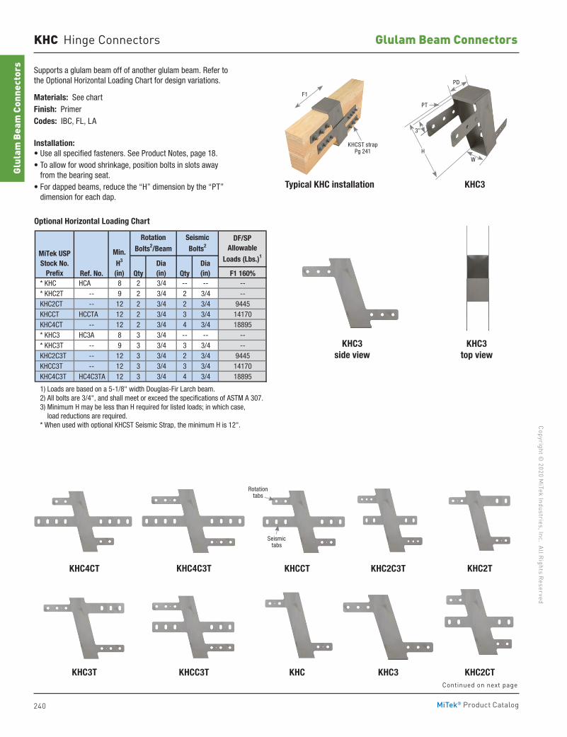
240
Copyright © 2020 M
iTek Industries, Inc. All Rights Reserved
Glulam Beam Connectors
Glul
am B
eam
Con
nect
ors
MiTek® Product Catalog
KHC Hinge Connectors
Supports a glulam beam off of another glulam beam. Refer to the Optional Horizontal Loading Chart for design variations.
Materials: See chartFinish: PrimerCodes: IBC, FL, LA
Installation:• Use all specified fasteners. See Product Notes, page 18.• To allow for wood shrinkage, position bolts in slots away
from the bearing seat.• For dapped beams, reduce the “H” dimension by the “PT”
dimension for each dap.
Ref. No. Qty Qty F1 160% * KHC HCA 8 2 3/4 -- -- -- * KHC2T -- 9 2 3/4 2 3/4 -- KHC2CT -- 12 2 3/4 2 3/4 9445 KHCCT HCCTA 12 2 3/4 3 3/4 14170 KHC4CT -- 12 2 3/4 4 3/4 18895 * KHC3 HC3A 8 3 3/4 -- -- -- * KHC3T -- 9 3 3/4 3 3/4 -- KHC2C3T -- 12 3 3/4 2 3/4 9445 KHCC3T -- 12 3 3/4 3 3/4 14170 KHC4C3T HC4C3TA 12 3 3/4 4 3/4 18895
1) Loads are based on a 5-1/8" width Douglas-Fir Larch beam. 2) All bolts are 3/4", and shall meet or exceed the specifications of ASTM A 307. 3) Minimum H may be less than H required for listed loads; in which case, load reductions are required. * When used with optional KHCST Seismic Strap, the minimum H is 12".
MiTek USPStock No.
Prefix
Rotation
Bolts2/Beam
Seismic
Bolts2Min.
H3
(in)
DF/SPAllowable
Loads (Lbs.)1
Dia(in)
Dia(in)
Typical KHC installation KHC3
KHC3side view
KHC3top view
Optional Horizontal Loading Chart
KHC4CT KHCCTKHC4C3T KHC2C3T KHC2T
KHC3KHCC3T KHC2CTKHC3T KHCContinued on next page
WH
PD
PT
3"
KHCST strap Pg 241
F1
Rotation tabs
Seismic tabs
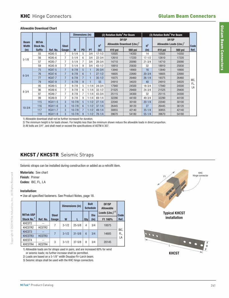
241
Copy
righ
t © 2
020
MiT
ek In
dust
ries
, Inc
. Al
l Rig
hts
Rese
rved
Glulam Beam Connectors
Glulam Beam
Connectors
MiTek® Product Catalog
Typical KHCST installation
Ref. No. W PD PT 410 psi 560 psi 410 psi 560 psi55 HCA5-5 7 5-1/4 5 3/4 17-1/2 10505 14350 14 10505 1435056 HCA5-6 7 5-1/4 6 3/4 22-3/4 12610 17220 17-1/2 12610 1722057 HCA5-7 7 5-1/4 7 3/4 28-3/4 14710 20090 21-3/4 14710 2009059 HCA5-9 7 5-1/4 9 3/4 43-1/2 18910 25830 32 18910 2583075 HCA7-5 7 6-7/8 5 1 20-3/4 13840 18900 16 13840 1890076 HCA7-6 7 6-7/8 6 1 27-1/2 16605 22680 20-3/4 16605 2268077 HCA7-7 7 6-7/8 7 1 35-1/2 19375 26460 26-1/4 19375 2646079 HCA7-9 7 6-7/8 9 1 55 24910 34020 40 24910 3402095 HCA9-5 7 8-7/8 5 1-1/4 24-3/4 17940 24500 18-3/4 17940 2450096 HCA9-6 7 8-7/8 6 1-1/4 33-1/2 21525 29400 24-3/4 21525 2940097 HCA9-7 7 8-7/8 7 1-1/4 43-3/4 25115 34300 32 25115 3430099 HCA9-9 7 8-7/8 9 1-1/4 69-1/4 32290 44100 49-3/4 32290 44100115 HCA11-5 3 10-7/8 5 1-1/2 27-1/4 22040 30100 20-1/4 22040 30100116 HCA11-6 3 10-7/8 6 1-1/2 37-1/4 26445 36120 27 26445 36120117 HCA11-7 3 10-7/8 7 1-1/2 49-1/4 30855 42140 35-1/4 30855 42140119 HCA11-9 3 10-7/8 9 1-1/2 78-1/4 39670 54180 55-1/4 39670 54180
1) Allowable download shall not be further increased for duration. 2) The minimum height is for loads shown. For heights less than the minimum shown reduce the allowable loads in direct proportion. 3) All bolts are 3/4", and shall meet or exceed the specifications of ASTM A 307.
Dimensions (in) (2) Rotation Bolts3 Per Beam (3) Rotation Bolts3 Per Beam
DF/SP
Allowable Download (Lbs.)1
DF/SP
Allowable Loads (Lbs.)1
H2
(in)H2
(in)CodeRef.
IBC,FL,LA
5-1/8
6-3/4
8-3/4
10-3/4
SteelGauge
MiTek Stock No.
Suffix
BeamWidth
(in)
Allowable Download Chart
KHC Hinge Connectors
KHCST
Ref. No. W L Qty F1 160% KHCST2 -- KHCSTR2 HCSTR2 KHCST3 -- KHCSTR3 HCSTR3 KHCST4 -- KHCSTR4 HCSTR4
1) Allowable loads are for straps used in pairs, and are increased 60% for wind or seismic loads; no further increase shall be permitted. 2) Loads are based on a 5-1/8" width Douglas-Fir-Larch beam. 3) Seismic straps shall be used with the KHC hinge connectors.
Dimensions (in)
CodeRef.
MiTek USP
Stock No.3Steel
Gauge
IBC,FL,LA
7
7
3-1/2
3-1/2
25-5/8
31-5/8
3 3-1/2 37-5/8
6 3/4
20145
4 3/4
DF/SPAllowable
Loads (Lbs.)1,2
Bolt Schedule
8 3/4
10075
14685
Dia(in)
KHCST / KHCSTR Seismic Straps
Seismic straps can be installed during construction or added as a retrofit item.
Materials: See chartFinish: PrimerCodes: IBC, FL, LA
Installation:• Use all specified fasteners. See Product Notes, page 18.
KHC Hinge connectorF1
L W
242
Copyright © 2020 M
iTek Industries, Inc. All Rights Reserved
Truss & Rafter
Trus
s &
Raf
ter
MiTek® Product Catalog242
Truss & Rafter
Angles 255-256 Girder Tiedowns 251-254, 257-259 Hurricane Ties 256, 262-264 Moisture Barrier Plates 244 Strap Connector 265Truss Anchors 244-250Truss Structural Wood Screw 260-261
pg. 244-265
Truss & Rafter
243
Copy
righ
t © 2
020
MiT
ek In
dust
ries
, Inc
. Al
l Rig
hts
Rese
rved
Truss & Rafter
MiTek® Product Catalog
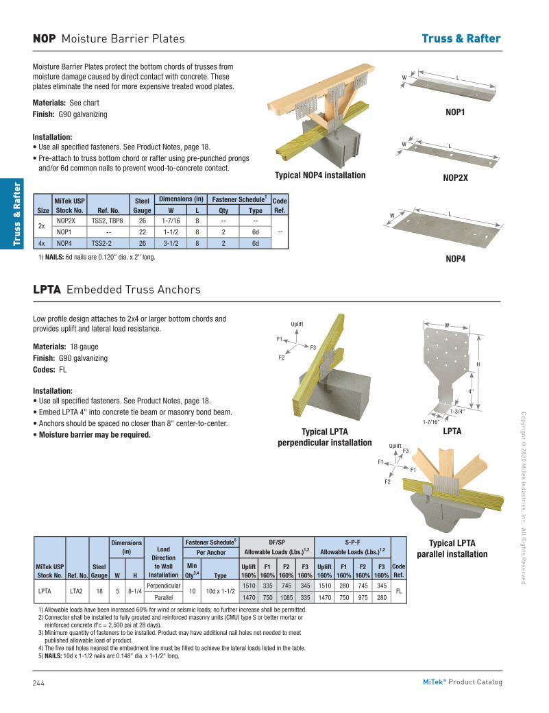
244
Copyright © 2020 M
iTek Industries, Inc. All Rights Reserved
Truss & Rafter
Trus
s &
Raf
ter
MiTek® Product Catalog
NOP2X
NOP1
Typical LPTA perpendicular installation
Typical LPTA parallel installation
NOP4
Typical NOP4 installation
NOP Moisture Barrier Plates
Moisture Barrier Plates protect the bottom chords of trusses from moisture damage caused by direct contact with concrete. These plates eliminate the need for more expensive treated wood plates.
Materials: See chartFinish: G90 galvanizing
Installation:• Use all specified fasteners. See Product Notes, page 18.• Pre-attach to truss bottom chord or rafter using pre-punched prongs
and/or 6d common nails to prevent wood-to-concrete contact.
Size Ref. No. W L Qty Type NOP2X TSS2, TBP8 26 1-7/16 8 -- --
NOP1 -- 22 1-1/2 8 2 6d
4x NOP4 TSS2-2 26 3-1/2 8 2 6d
1) NAILS: 6d nails are 0.120" dia. x 2" long.
2x
CodeRef.
--
MiTek USPStock No.
SteelGauge
Dimensions (in) Fastener Schedule1
LPTA Embedded Truss Anchors
Low profile design attaches to 2x4 or larger bottom chords and provides uplift and lateral load resistance.
Materials: 18 gaugeFinish: G90 galvanizingCodes: FL
Installation:• Use all specified fasteners. See Product Notes, page 18.• Embed LPTA 4" into concrete tie beam or masonry bond beam.• Anchors should be spaced no closer than 8" center-to-center.• Moisture barrier may be required.
Ref. No. W H Type
Perpendicular 1510 335 745 345 1510 280 745 345
Parallel 1470 750 1085 335 1470 750 975 280
1) Allowable loads have been increased 60% for wind or seismic loads; no further increase shall be permitted. 2) Connector shall be installed to fully grouted and reinforced masonry units (CMU) type S or better mortar or reinforced concrete (f'c = 2,500 psi at 28 days). 3) Minimum quantity of fasteners to be installed. Product may have additional nail holes not needed to meet published allowable load of product. 4) The five nail holes nearest the embedment line must be filled to achieve the lateral loads listed in the table. 5) NAILS: 10d x 1-1/2 nails are 0.148" dia. x 1-1/2" long.
LoadDirectionto Wall
InstallationCodeRef.
FL18
Dimensions(in)
10 10d x 1-1/2
Uplift160%
Uplift160%
Per Anchor
F1160%
F2160%
F3160%
F1160%
F2160%
MinQty3,4
F3160%
DF/SP Allowable Loads (Lbs.)1,2
S-P-FAllowable Loads (Lbs.)1,2
Fastener Schedule5
LPTA LTA2 5 8-1/4
MiTek USPStock No.
SteelGauge
LW
LW
LW
Uplift
F1
F3
F2
LPTA1-7/16"
1-3/4"
H
W
4"
Uplift
F1F1
F3
F2
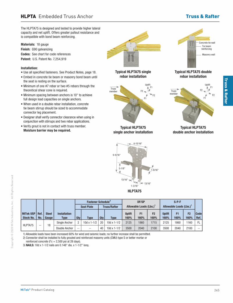
Truss & Rafter
245
Copy
righ
t © 2
020
MiT
ek In
dust
ries
, Inc
. Al
l Rig
hts
Rese
rved
Truss & Rafter
MiTek® Product Catalog
The HLPTA75 is designed and tested to provide higher lateral capacity and net uplift. Offers greater pullout resistance and is compatible with bond beam reinforcing.
Materials: 18 gaugeFinish: G90 galvanizing Codes: See chart for code referencesPatent: U.S. Patent No. 7,254,919
Installation:• Use all specified fasteners. See Product Notes, page 18.• Embed in concrete tie beam or masonry bond beam until
the seat is resting on the surface.• Minimum of one #7 rebar or two #5 rebars through the
theoretical shear cone is required.• Minimum spacing between anchors is 10" to achieve
full design load capacities on single anchors.• When used in a double rebar installation, concrete
tie beam stirrup should be sized to accommodate connector leg placement.
• Designer shall verify connector clearance when using in conjunction with stirrups and two rebar applications.
• Verify grout is not in contact with truss member. Moisture barrier may be required.
HLPTA Embedded Truss Anchor
Typical HLPTA75 single rebar installation
Typical HLPTA75single anchor installation
HLPTA75
Typical HLPTA75 double rebar installation
Typical HLPTA75double anchor installation
Qty Type Qty Type
Single Anchor 2 10d x 1-1/2 20 10d x 1-1/2 2125 1860 1715 2125 1860 1160 FL
Double Anchor -- -- 40 10d x 1-1/2 3500 2040 2100 3500 2040 2100 --
1) Allowable loads have been increased 60% for wind and seismic loads; no further increase shall be permitted. 2) Connector shall be installed to fully grouted and reinforced masonry units (CMU) type S or better mortar or reinforced concrete (f'c = 2,500 psi at 28 days). 3) NAILS: 10d x 1-1/2 nails are 0.148" dia. x 1-1/2" long.
CodeRef.
Fastener Schedule3
Seat Plate Truss/Rafter
DF/SP
Allowable Loads (Lbs.)1
Uplift160%
S-P-F
Allowable Loads (Lbs.)1
Uplift160%
F1160%
F2160%
F1160%
F2160%
InstallationType
HLPTA75
MiTek USPStock No.
SteelGauge
-- 18
Ref. No.
Truss member Truss
member
Masonry wall
Tie beam reinforcing
Concrete tie wall
1-3/16"
4-15/16"
9-9/16"
5-1/8"1-9/16"
13/16"
13/16"
F2
F2
F1
F1
Uplift
F2
F2
F1
F1
Uplift
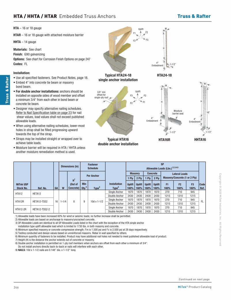
246
Copyright © 2020 M
iTek Industries, Inc. All Rights Reserved
Truss & Rafter
Trus
s &
Raf
ter
MiTek® Product Catalog
HTA24-18
HTA – 16 or 18 gauge
HTAR – 16 or 18 gauge with attached moisture barrier
HHTA – 14 gauge
Materials: See chartFinish: G90 galvanizingOptions: See chart for Corrosion Finish Options on page 247Codes: FL
Installation:• Use all specified fasteners. See Product Notes, page 18.• Embed 4" into concrete tie beam or masonry
bond beam.• For double anchor installations: anchors should be
installed on opposite sides of wood member and offset a minimum 3/4" from each other in bond beam or concrete tie beam.
• Designer may specify alternative nailing schedules. Refer to Nail Specification table on page 23 for nail shear values, load values shall not exceed published allowable loads.
• When using alternative nailing schedules, lower-most holes in strap shall be filled progressing upward towards the top of the strap.
• Straps may be installed straight or wrapped over to achieve table loads.
• Moisture barrier will be required in HTA / HHTA unless another moisture remediation method is used.
HTA / HHTA / HTAR Embedded Truss Anchors
Continued on next page
H
4" Embedment
W
1-1/2"
3/4" min offset for
single-ply roof
Typical HTA24-18 single anchor installation
Typical HTA16 double anchor installation
HTA16R
H
4" Embedment
W
1-1/2"
Moisture barrier seat
1 Ply 2 Ply 1 Ply 2 Ply
Ref. No. Type9
Single Anchor 1870 1870 1870 1870 270 710 945Double Anchor 2430 2430 2430 2430 1215 1310 1215Single Anchor 1870 1870 1870 1870 270 710 945Double Anchor 2430 2430 2430 2430 1215 1310 1215Single Anchor 1870 1870 1870 1870 270 710 945Double Anchor 2430 2430 2430 2430 1215 1310 1215
1) Allowable loads have been increased 60% for wind or seismic loads; no further increase shall be permitted. 2) Allowable loads are based on anchorage to masonry/uncracked concrete.
3) DF Allowable Loads are identical to all SP Allowable Loads listed in the chart with the exception of the HTA single anchor installation type uplift allowable load which is limited to 1730 lbs. in both masonry and concrete. 4) Minimum specified masonry or concrete compressive strength, f'm is 1,500 psi and f'c is 2,500 psi at 28 days respectively. 5) Testing conducted and design values based on unreinforced masonry. Rebar in wall specified by others. 6) Minimum quantity of fasteners to be installed. Product may have additional nail holes not needed to meet published allowable load of product. 7) Height (H) is the distance the anchor extends out of concrete or masonry. 8) Double anchor installation is permitted on 1-ply roof members when anchors are offset from each other a minimum of 3/4". Do not install anchors directly back-to-back or nails will interfere with each other. 9) NAILS: 10d x 1-1/2 nails are 0.148" dia. x 1-1/2" long.
HTA12-2R HETA12-TSS2-2
1-1/4 8 916
FastenerSchedule
HTA12
HTA12R
HETA12
HETA12-TSS2 10d x 1-1/2
MiTek USPStock No.
Per Anchor
Dimensions (in)
FL
SP
Allowable Loads (Lbs.)1,2,3,4,5
Uplift160%
Uplift160%
Masonry Concrete Lateral LoadsMasonry/Concrete (1 or 2 Ply)
CodeRef.
F2160%
F3160%GA W
Min
Qty.6F1
160%Uplift160%
H7
(Out of Concrete)
Uplift160%
Installation
Type8
F1
F3
F2
F2
Uplift
F3
F1
F2
F2
Uplift
HHTA16
16"
4" Embedment
W
1-1/2"
H
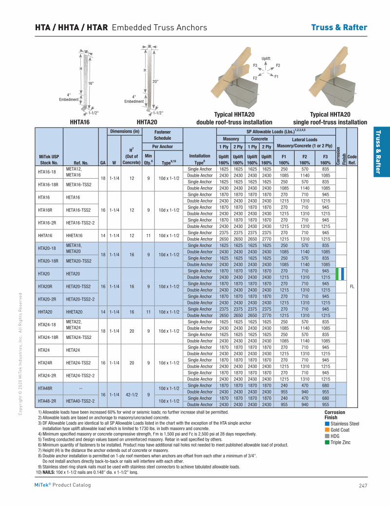
Truss & Rafter
247
Copy
righ
t © 2
020
MiT
ek In
dust
ries
, Inc
. Al
l Rig
hts
Rese
rved
Truss & Rafter
MiTek® Product Catalog
1 Ply 2 Ply 1 Ply 2 Ply
Ref. No. Type9,10
Single Anchor 1625 1625 1625 1625 250 570 835Double Anchor 2430 2430 2430 2430 1085 1140 1085Single Anchor 1625 1625 1625 1625 250 570 835Double Anchor 2430 2430 2430 2430 1085 1140 1085Single Anchor 1870 1870 1870 1870 270 710 945Double Anchor 2430 2430 2430 2430 1215 1310 1215Single Anchor 1870 1870 1870 1870 270 710 945Double Anchor 2430 2430 2430 2430 1215 1310 1215Single Anchor 1870 1870 1870 1870 270 710 945Double Anchor 2430 2430 2430 2430 1215 1310 1215Single Anchor 2375 2375 2375 2375 270 710 945Double Anchor 2650 2650 2650 2770 1215 1310 1215Single Anchor 1625 1625 1625 1625 250 570 835Double Anchor 2430 2430 2430 2430 1085 1140 1085Single Anchor 1625 1625 1625 1625 250 570 835Double Anchor 2430 2430 2430 2430 1085 1140 1085Single Anchor 1870 1870 1870 1870 270 710 945Double Anchor 2430 2430 2430 2430 1215 1310 1215Single Anchor 1870 1870 1870 1870 270 710 945Double Anchor 2430 2430 2430 2430 1215 1310 1215Single Anchor 1870 1870 1870 1870 270 710 945Double Anchor 2430 2430 2430 2430 1215 1310 1215Single Anchor 2375 2375 2375 2375 270 710 945Double Anchor 2650 2650 2650 2770 1215 1310 1215Single Anchor 1625 1625 1625 1625 250 570 835Double Anchor 2430 2430 2430 2430 1085 1140 1085Single Anchor 1625 1625 1625 1625 250 570 835Double Anchor 2430 2430 2430 2430 1085 1140 1085Single Anchor 1870 1870 1870 1870 270 710 945Double Anchor 2430 2430 2430 2430 1215 1310 1215Single Anchor 1870 1870 1870 1870 270 710 945Double Anchor 2430 2430 2430 2430 1215 1310 1215Single Anchor 1870 1870 1870 1870 270 710 945Double Anchor 2430 2430 2430 2430 1215 1310 1215Single Anchor 1870 1870 1870 1870 240 470 680Double Anchor 2430 2430 2430 2430 955 940 955Single Anchor 1870 1870 1870 1870 240 470 680Double Anchor 2430 2430 2430 2430 955 940 955
1) Allowable loads have been increased 60% for wind or seismic loads; no further increase shall be permitted. 2) Allowable loads are based on anchorage to masonry/uncracked concrete.
3) DF Allowable Loads are identical to all SP Allowable Loads listed in the chart with the exception of the HTA single anchor installation type uplift allowable load which is limited to 1730 lbs. in both masonry and concrete. 4) Minimum specified masonry or concrete compressive strength, f'm is 1,500 psi and f'c is 2,500 psi at 28 days respectively. 5) Testing conducted and design values based on unreinforced masonry. Rebar in wall specified by others. 6) Minimum quantity of fasteners to be installed. Product may have additional nail holes not needed to meet published allowable load of product. 7) Height (H) is the distance the anchor extends out of concrete or masonry. 8) Double anchor installation is permitted on 1-ply roof members when anchors are offset from each other a minimum of 3/4". Do not install anchors directly back-to-back or nails will interfere with each other. 9) Stainless steel ring shank nails must be used with stainless steel connectors to achieve tabulated allowable loads.10) NAILS: 10d x 1-1/2 nails are 0.148" dia. x 1-1/2" long.
SP Allowable Loads (Lbs.)1,2,3,4,5
Corr
osio
nFi
nish
Masonry Concrete Lateral LoadsMasonry/Concrete (1 or 2 Ply)
H7
(Out of Concrete)
Uplift160%
Dimensions (in)
Per Anchor
FastenerSchedule
Uplift160%
Uplift160%
F1160%
F2160%
F3160%
CodeRef.
MiTek USPStock No. GA W
MinQty.6
InstallationType8
Uplift160%
10d x 1-1/2
FL
HTA16-18R META16-TSS2
HTA16 HETA16
16 1-1/4 12 9
HTA16-18 META12, META16
18 1-1/4 12 9
10d x 1-1/2 HTA16R HETA16-TSS2
HTA16-2R HETA16-TSS2-2
HHTA16 HHETA16 14 1-1/4 12 11 10d x 1-1/2
HTA20-18 META18, META20
18 1-1/4 16 9 10d x 1-1/2 HTA20-18R
9 10d x 1-1/2 HTA20R HETA20-TSS2
HTA20-2R HETA20-TSS2-2
META20-TSS2
HTA20 HETA20
16 1-1/4 16
10d x 1-1/2
HTA24-18 META22, META24
18 1-1/4 20 9 10d x 1-1/2 HTA24-18R META24-TSS2
HHTA20 HHETA20 14 1-1/4 16 11
910d x 1-1/2
HTA48-2R HETA40-TSS2-2 10d x 1-1/2
10d x 1-1/2 HTA24R HETA24-TSS2
HTA24-2R HETA24-TSS2-2
HTA48R --16 1-1/4 42-1/2
HTA24 HETA24
16 1-1/4 20 9
Corrosion Finish Stainless Steel Gold Coat HDG Triple Zinc
Corrosion Finish Stainless Steel Gold Coat HDG Triple Zinc
Corrosion Finish Stainless Steel Gold Coat HDG Triple Zinc
HTA / HHTA / HTAR Embedded Truss Anchors
HHTA16
H
4" Embedment
W
1-1/2"
16"
HHTA20Typical HHTA20
double roof-truss installationTypical HHTA20
single roof-truss installation
H
4" Embedment
W
20"
1-1/2"
F3
F1
F2
F2
Uplift
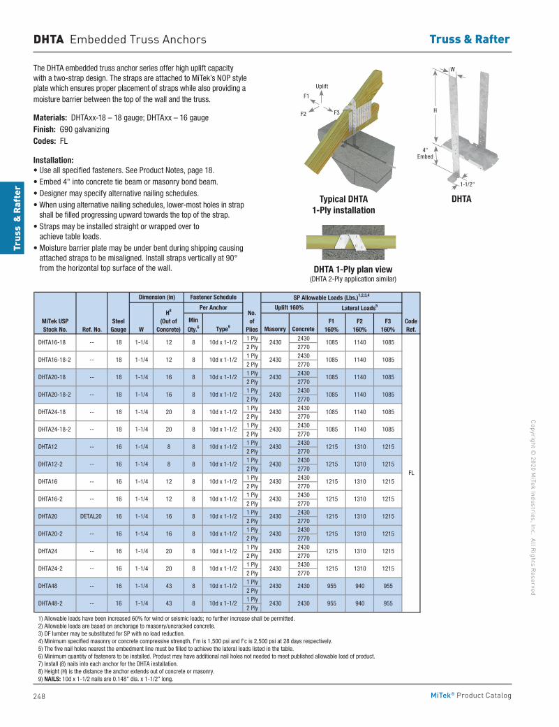
248
Copyright © 2020 M
iTek Industries, Inc. All Rights Reserved
Truss & Rafter
Trus
s &
Raf
ter
MiTek® Product Catalog
DHTA Embedded Truss Anchors
The DHTA embedded truss anchor series offer high uplift capacity with a two-strap design. The straps are attached to MiTek’s NOP style plate which ensures proper placement of straps while also providing a moisture barrier between the top of the wall and the truss.
Materials: DHTAxx-18 – 18 gauge; DHTAxx – 16 gaugeFinish: G90 galvanizingCodes: FL
Installation:• Use all specified fasteners. See Product Notes, page 18.• Embed 4" into concrete tie beam or masonry bond beam.• Designer may specify alternative nailing schedules. • When using alternative nailing schedules, lower-most holes in strap
shall be filled progressing upward towards the top of the strap.• Straps may be installed straight or wrapped over to
achieve table loads.• Moisture barrier plate may be under bent during shipping causing
attached straps to be misaligned. Install straps vertically at 90° from the horizontal top surface of the wall.
Ref. No. Type9 Masonry Concrete1 Ply 24302 Ply 27701 Ply 24302 Ply 27701 Ply 24302 Ply 27701 Ply 24302 Ply 27701 Ply 24302 Ply 27701 Ply 24302 Ply 27701 Ply 24302 Ply 27701 Ply 24302 Ply 27701 Ply 24302 Ply 27701 Ply 24302 Ply 27701 Ply 24302 Ply 27701 Ply 24302 Ply 27701 Ply 24302 Ply 27701 Ply 24302 Ply 27701 Ply2 Ply1 Ply2 Ply
1) Allowable loads have been increased 60% for wind or seismic loads; no further increase shall be permitted. 2) Allowable loads are based on anchorage to masonry/uncracked concrete. 3) DF lumber may be substituted for SP with no load reduction. 4) Minimum specified masonry or concrete compressive strength, f'm is 1,500 psi and f'c is 2,500 psi at 28 days respectively. 5) The five nail holes nearest the embedment line must be filled to achieve the lateral loads listed in the table. 6) Minimum quantity of fasteners to be installed. Product may have additional nail holes not needed to meet published allowable load of product. 7) Install (8) nails into each anchor for the DHTA installation. 8) Height (H) is the distance the anchor extends out of concrete or masonry. 9) NAILS: 10d x 1-1/2 nails are 0.148" dia. x 1-1/2" long.
955
FL
2430 955 940 9552430
1215
1215
DHTA48-2 -- 1-1/4 43 8
DHTA48 -- 1-1/4 43 816
16
DHTA24-2 -- 1-1/4 20 8
DHTA24 -- 1-1/4 20 816
16
10d x 1-1/2 2430 1215 1310 1215 DHTA20-2 -- 16 1-1/4 16 8
10d x 1-1/2 2430 1215 1310 1215 DHTA20 DETAL20 16 1-1/4 16 8
10d x 1-1/2 2430 1215 1310 1215 DHTA16-2 -- 16 1-1/4 12 8
10d x 1-1/2 2430 1215 1310 1215 DHTA16 -- 16 1-1/4 12 8
10d x 1-1/2 2430 1215 1310 1215 DHTA12-2 -- 16 1-1/4 8 8
10d x 1-1/2 2430 1215 1310 1215 DHTA12 -- 16 1-1/4 8 8
10d x 1-1/2 2430 1085 1140 1085 DHTA24-18-2 -- 18 1-1/4 20 8
10d x 1-1/2 2430 1085 1140 1085 DHTA24-18 -- 18 1-1/4 20 8
10d x 1-1/2 2430 1085 1140 1085 DHTA20-18-2 -- 18 1-1/4 16 8
10d x 1-1/2 2430 1085 1140 1085 DHTA20-18 -- 18 1-1/4 16 8
10d x 1-1/2 2430 1085 1140 1085 DHTA16-18-2 -- 18 1-1/4 12 8
10d x 1-1/2 2430 1085 1140 1085 DHTA16-18 -- 18 1-1/4 12 8
CodeRef.
MiTek USPStock No.
SteelGauge W
Min
Qty.6F1
160%F2
160%F3
160%
Dimension (in) Fastener Schedule SP Allowable Loads (Lbs.)1,2,3,4
H8
(Out of Concrete)
Per AnchorNo.of
Plies
Uplift 160% Lateral Loads5
10d x 1-1/2
10d x 1-1/2
10d x 1-1/2
10d x 1-1/2
2430
2430
1215
1215
1310
1310
2430 2430 955 940
DHTATypical DHTA 1-Ply installation
DHTA 1-Ply plan view(DHTA 2-Ply application similar)
W
H
1-1/2"
4" Embed
F1
F3
Uplift
F2
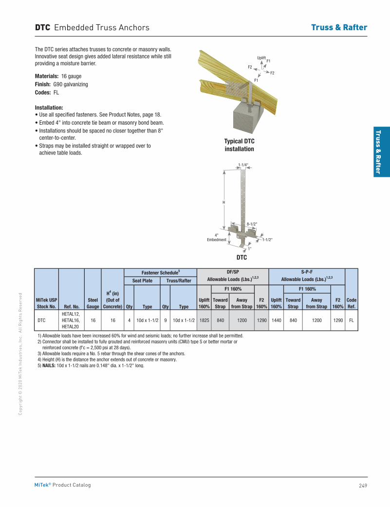
Truss & Rafter
249
Copy
righ
t © 2
020
MiT
ek In
dust
ries
, Inc
. Al
l Rig
hts
Rese
rved
Truss & Rafter
MiTek® Product Catalog
DTC Embedded Truss Anchors
The DTC series attaches trusses to concrete or masonry walls. Innovative seat design gives added lateral resistance while still providing a moisture barrier.
Materials: 16 gaugeFinish: G90 galvanizingCodes: FL
Installation:• Use all specified fasteners. See Product Notes, page 18.• Embed 4" into concrete tie beam or masonry bond beam.• Installations should be spaced no closer together than 8"
center-to-center.• Straps may be installed straight or wrapped over to
achieve table loads.
Typical DTCinstallation
DTC
Ref. No. Qty Type Qty Type
DTC HETAL12, HETAL16, HETAL20
16 16 4 10d x 1-1/2 9 10d x 1-1/2 1825 840 1200 1290 1440 840 1200 1290 FL
1) Allowable loads have been increased 60% for wind and seismic loads; no further increase shall be permitted. 2) Connector shall be installed to fully grouted and reinforced masonry units (CMU) type S or better mortar or reinforced concrete (f'c = 2,500 psi at 28 days). 3) Allowable loads require a No. 5 rebar through the shear cones of the anchors. 4) Height (H) is the distance the anchor extends out of concrete or masonry. 5) NAILS: 10d x 1-1/2 nails are 0.148" dia. x 1-1/2" long.
CodeRef.
Fastener Schedule5
F1 160% F1 160%
Seat Plate Truss/Rafter
DF/SP
Allowable Loads (Lbs.)1,2,3
S-P-F
Allowable Loads (Lbs.)1,2,3
F2160%
F2160%
Away from Strap
MiTek USPStock No.
SteelGauge
TowardStrap
TowardStrap
Away from Strap
Uplift160%
Uplift160%
H4 (in)(Out of
Concrete)
1-1/4"
H
4" Embedment
1"
1-1/2"
8-1/2"
F2F2
UpliftF1
F1
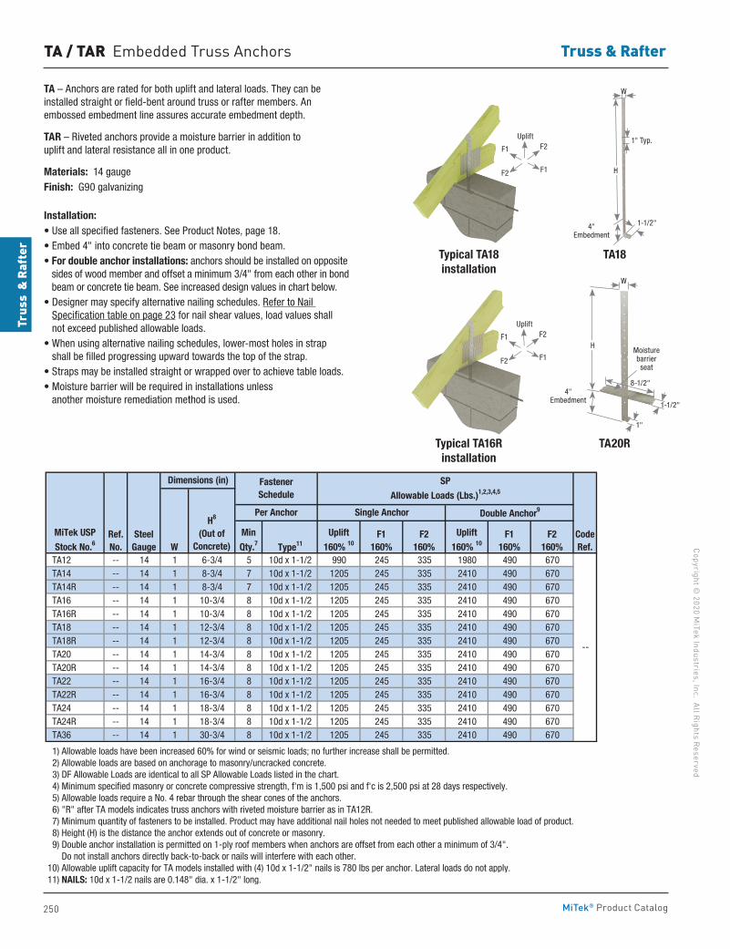
250
Copyright © 2020 M
iTek Industries, Inc. All Rights Reserved
Truss & Rafter
Trus
s &
Raf
ter
MiTek® Product Catalog
Type11
TA12 -- 14 1 6-3/4 5 10d x 1-1/2 990 245 335 1980 490 670 TA14 -- 14 1 8-3/4 7 10d x 1-1/2 1205 245 335 2410 490 670 TA14R -- 14 1 8-3/4 7 10d x 1-1/2 1205 245 335 2410 490 670 TA16 -- 14 1 10-3/4 8 10d x 1-1/2 1205 245 335 2410 490 670 TA16R -- 14 1 10-3/4 8 10d x 1-1/2 1205 245 335 2410 490 670 TA18 -- 14 1 12-3/4 8 10d x 1-1/2 1205 245 335 2410 490 670 TA18R -- 14 1 12-3/4 8 10d x 1-1/2 1205 245 335 2410 490 670 TA20 -- 14 1 14-3/4 8 10d x 1-1/2 1205 245 335 2410 490 670 TA20R -- 14 1 14-3/4 8 10d x 1-1/2 1205 245 335 2410 490 670 TA22 -- 14 1 16-3/4 8 10d x 1-1/2 1205 245 335 2410 490 670 TA22R -- 14 1 16-3/4 8 10d x 1-1/2 1205 245 335 2410 490 670 TA24 -- 14 1 18-3/4 8 10d x 1-1/2 1205 245 335 2410 490 670 TA24R -- 14 1 18-3/4 8 10d x 1-1/2 1205 245 335 2410 490 670 TA36 -- 14 1 30-3/4 8 10d x 1-1/2 1205 245 335 2410 490 670
1) Allowable loads have been increased 60% for wind or seismic loads; no further increase shall be permitted. 2) Allowable loads are based on anchorage to masonry/uncracked concrete. 3) DF Allowable Loads are identical to all SP Allowable Loads listed in the chart. 4) Minimum specified masonry or concrete compressive strength, f'm is 1,500 psi and f'c is 2,500 psi at 28 days respectively. 5) Allowable loads require a No. 4 rebar through the shear cones of the anchors. 6) "R" after TA models indicates truss anchors with riveted moisture barrier as in TA12R. 7) Minimum quantity of fasteners to be installed. Product may have additional nail holes not needed to meet published allowable load of product. 8) Height (H) is the distance the anchor extends out of concrete or masonry. 9) Double anchor installation is permitted on 1-ply roof members when anchors are offset from each other a minimum of 3/4". Do not install anchors directly back-to-back or nails will interfere with each other. 10) Allowable uplift capacity for TA models installed with (4) 10d x 1-1/2" nails is 780 lbs per anchor. Lateral loads do not apply. 11) NAILS: 10d x 1-1/2 nails are 0.148" dia. x 1-1/2" long.
Dimensions (in) Fastener Schedule
H8
(Out of Concrete)
Per Anchor
SP
Allowable Loads (Lbs.)1,2,3,4,5
Single Anchor Double Anchor9
CodeRef.
--
MiTek USP
Stock No.6Steel
Gauge W
Min
Qty.7F2
160%
Uplift
160% 10F1
160%F2
160%
Uplift
160% 10F1
160%Ref. No.
TA20R
TA18
TA / TAR Embedded Truss Anchors
H
4" Embedment
W
1-1/2"
1" Typ.
4" Embedment
H
8-1/2"
W
1-1/2"
1"
Typical TA18 installation
Typical TA16R installation
Moisture barrier seat
TA – Anchors are rated for both uplift and lateral loads. They can be installed straight or field-bent around truss or rafter members. An embossed embedment line assures accurate embedment depth.
TAR – Riveted anchors provide a moisture barrier in addition to uplift and lateral resistance all in one product.
Materials: 14 gaugeFinish: G90 galvanizing
Installation:• Use all specified fasteners. See Product Notes, page 18.• Embed 4" into concrete tie beam or masonry bond beam.• For double anchor installations: anchors should be installed on opposite
sides of wood member and offset a minimum 3/4" from each other in bond beam or concrete tie beam. See increased design values in chart below.
• Designer may specify alternative nailing schedules. Refer to Nail Specification table on page 23 for nail shear values, load values shall not exceed published allowable loads.
• When using alternative nailing schedules, lower-most holes in strap shall be filled progressing upward towards the top of the strap.
• Straps may be installed straight or wrapped over to achieve table loads.• Moisture barrier will be required in installations unless
another moisture remediation method is used.
F1
F1
F2
F2
Uplift
F1
F1
F2
F2
Uplift
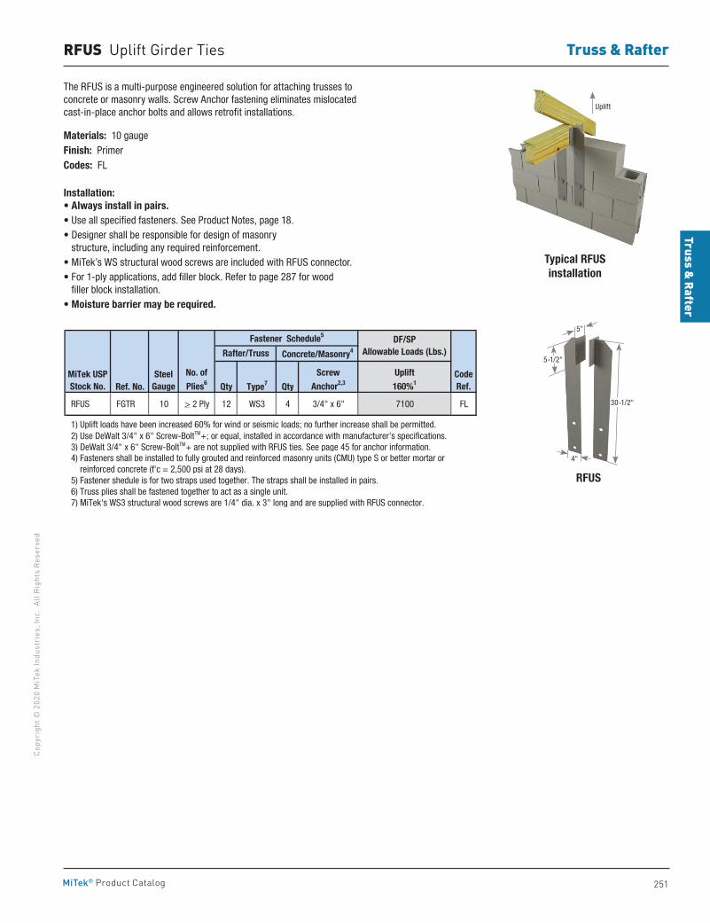
Truss & Rafter
251
Copy
righ
t © 2
020
MiT
ek In
dust
ries
, Inc
. Al
l Rig
hts
Rese
rved
Truss & Rafter
MiTek® Product Catalog
RFUS Uplift Girder Ties
The RFUS is a multi-purpose engineered solution for attaching trusses to concrete or masonry walls. Screw Anchor fastening eliminates mislocated cast-in-place anchor bolts and allows retrofit installations.
Materials: 10 gaugeFinish: PrimerCodes: FL Installation:• Always install in pairs.• Use all specified fasteners. See Product Notes, page 18.• Designer shall be responsible for design of masonry
structure, including any required reinforcement.• MiTek’s WS structural wood screws are included with RFUS connector.• For 1-ply applications, add filler block. Refer to page 287 for wood
filler block installation.• Moisture barrier may be required.
Ref. No. Qty Type7 Qty
RFUS FGTR 10 > 2 Ply 12 WS3 4 3/4" x 6" 7100 FL
1) Uplift loads have been increased 60% for wind or seismic loads; no further increase shall be permitted. 2) Use DeWalt 3/4" x 6" Screw-BoltTM+; or equal, installed in accordance with manufacturer's specifications. 3) DeWalt 3/4" x 6" Screw-BoltTM+ are not supplied with RFUS ties. See page 45 for anchor information. 4) Fasteners shall be installed to fully grouted and reinforced masonry units (CMU) type S or better mortar or reinforced concrete (f'c = 2,500 psi at 28 days). 5) Fastener shedule is for two straps used together. The straps shall be installed in pairs. 6) Truss plies shall be fastened together to act as a single unit. 7) MiTek's WS3 structural wood screws are 1/4" dia. x 3" long and are supplied with RFUS connector.
CodeRef.
MiTek USPStock No.
No. of
Plies6Steel
Gauge
Fastener Schedule5
Rafter/Truss Concrete/Masonry4
DF/SP Allowable Loads (Lbs.)
Uplift
160%1
Screw
Anchor2,3
Typical RFUS installation
RFUS
30-1/2"
4"
5-1/2"
5"
Uplift
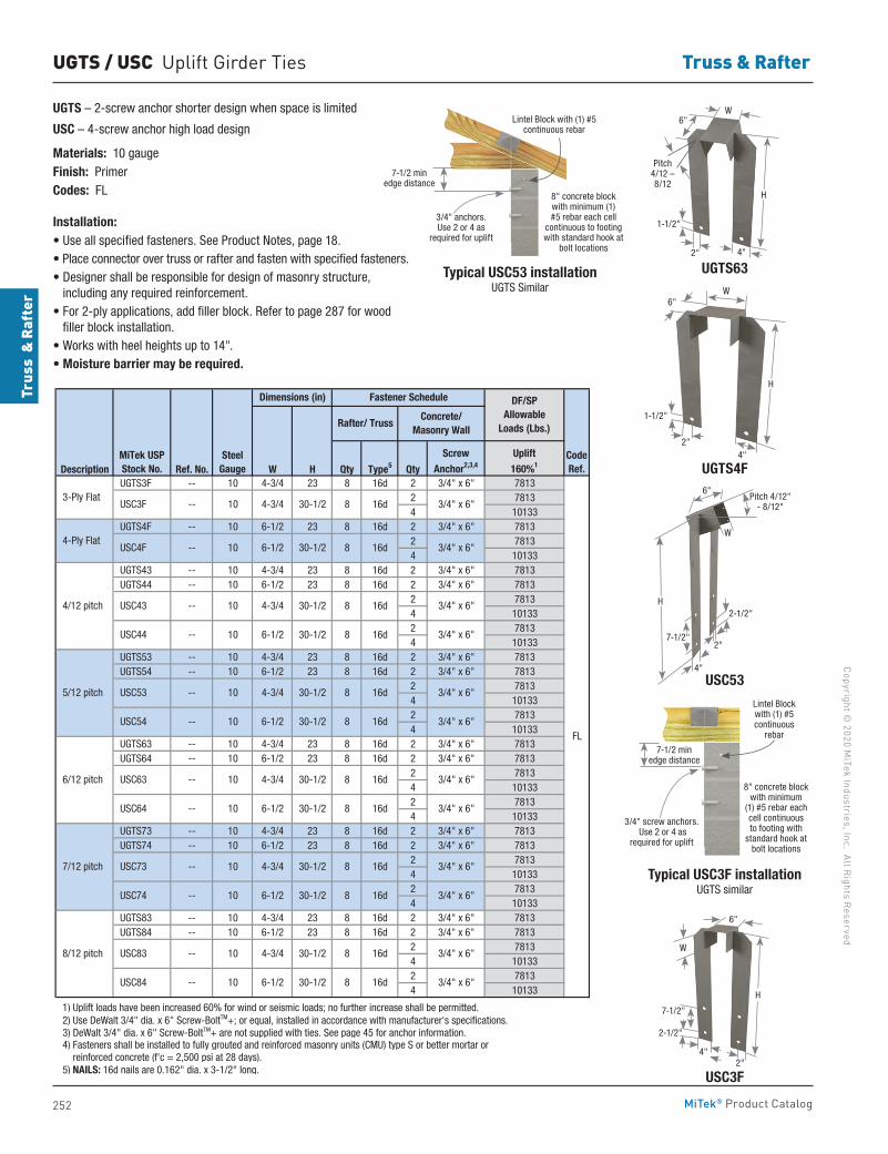
252
Copyright © 2020 M
iTek Industries, Inc. All Rights Reserved
Truss & Rafter
Trus
s &
Raf
ter
MiTek® Product Catalog
UGTS / USC Uplift Girder Ties
UGTS – 2-screw anchor shorter design when space is limited
USC – 4-screw anchor high load design
Materials: 10 gaugeFinish: PrimerCodes: FL
Installation:• Use all specified fasteners. See Product Notes, page 18. • Place connector over truss or rafter and fasten with specified fasteners.• Designer shall be responsible for design of masonry structure,
including any required reinforcement.• For 2-ply applications, add filler block. Refer to page 287 for wood
filler block installation.• Works with heel heights up to 14".• Moisture barrier may be required.
UGTS63Typical USC53 installationUGTS Similar
Typical USC3F installationUGTS similar
UGTS4F
USC3F
Description Ref. No. W H Qty Type5 Qty UGTS3F -- 10 4-3/4 23 8 16d 2 3/4" x 6" 7813
2 78134 10133
UGTS4F -- 10 6-1/2 23 8 16d 2 3/4" x 6" 78132 78134 10133
UGTS43 -- 10 4-3/4 23 8 16d 2 3/4" x 6" 7813 UGTS44 -- 10 6-1/2 23 8 16d 2 3/4" x 6" 7813
2 78134 101332 78134 10133
UGTS53 -- 10 4-3/4 23 8 16d 2 3/4" x 6" 7813 UGTS54 -- 10 6-1/2 23 8 16d 2 3/4" x 6" 7813
2 78134 101332 78134 10133
UGTS63 -- 10 4-3/4 23 8 16d 2 3/4" x 6" 7813 UGTS64 -- 10 6-1/2 23 8 16d 2 3/4" x 6" 7813
2 78134 101332 78134 10133
UGTS73 -- 10 4-3/4 23 8 16d 2 3/4" x 6" 7813 UGTS74 -- 10 6-1/2 23 8 16d 2 3/4" x 6" 7813
2 78134 101332 78134 10133
UGTS83 -- 10 4-3/4 23 8 16d 2 3/4" x 6" 7813 UGTS84 -- 10 6-1/2 23 8 16d 2 3/4" x 6" 7813
2 78134 101332 78134 10133
1) Uplift loads have been increased 60% for wind or seismic loads; no further increase shall be permitted. 2) Use DeWalt 3/4" dia. x 6" Screw-BoltTM+; or equal, installed in accordance with manufacturer's specifications. 3) DeWalt 3/4" dia. x 6" Screw-BoltTM+ are not supplied with ties. See page 45 for anchor information. 4) Fasteners shall be installed to fully grouted and reinforced masonry units (CMU) type S or better mortar or reinforced concrete (f'c = 2,500 psi at 28 days). 5) NAILS: 16d nails are 0.162" dia. x 3-1/2" long.
8/12 pitch
4-3/4 USC43 --
USC74 --
4-3/4
4-3/4
6-1/2
10
--
6-1/2
10
6-1/2
10
10
USC84 --
USC83 --
10
10
10
10
CodeRef.
30-1/2
30-1/2
30-1/2
30-1/2
30-1/2
FL
DF/SP Allowable
Loads (Lbs.)
30-1/2
30-1/2
30-1/2
Fastener Schedule
Concrete/Masonry Wall
Rafter/ Truss
Dimensions (in)
4-3/4 30-1/2
6-1/2
6-1/2
4-3/4
8 16d
8 16d
10
10
4-3/4
30-1/2
30-1/2
MiTek USPStock No.
SteelGauge
30-1/26-1/210
USC3F -- 10
USC4F --
3-Ply Flat
4-Ply Flat
USC53
--
--
USC63
USC64
--
--
--
4/12 pitch
5/12 pitch
6/12 pitch
7/12 pitch
USC44
USC54
USC73
ScrewAnchor2,3,4
Uplift160%1
8 16d
8 16d
3/4" x 6"
3/4" x 6"
3/4" x 6"
3/4" x 6"
3/4" x 6"
3/4" x 6"
3/4" x 6"
3/4" x 6"
3/4" x 6"
3/4" x 6"
8 16d
8 16d
8 16d
8 16d
8 16d 3/4" x 6"
3/4" x 6"
8 16d
8 16d
8 16d
7-1/2 min edge distance
Lintel Block with (1) #5 continuous rebar
8" concrete block with minimum (1) #5 rebar each cell
continuous to footing with standard hook at
bolt locations
3/4" anchors. Use 2 or 4 as
required for uplift
USC53
7-1/2 min edge distance
Lintel Block with (1) #5 continuous
rebar
8" concrete block with minimum
(1) #5 rebar each cell continuous to footing with
standard hook at bolt locations
3/4" screw anchors. Use 2 or 4 as
required for uplift
4"
Pitch 4/12" - 8/12"
2-1/2"
W
2"
6"
7-1/2"
H
4"2"
1-1/2"
Pitch 4/12 – 8/12
H
6"W
W6"
2"4"
1-1/2"
H
H
6"
W
7-1/2"
2-1/2"
4"2"
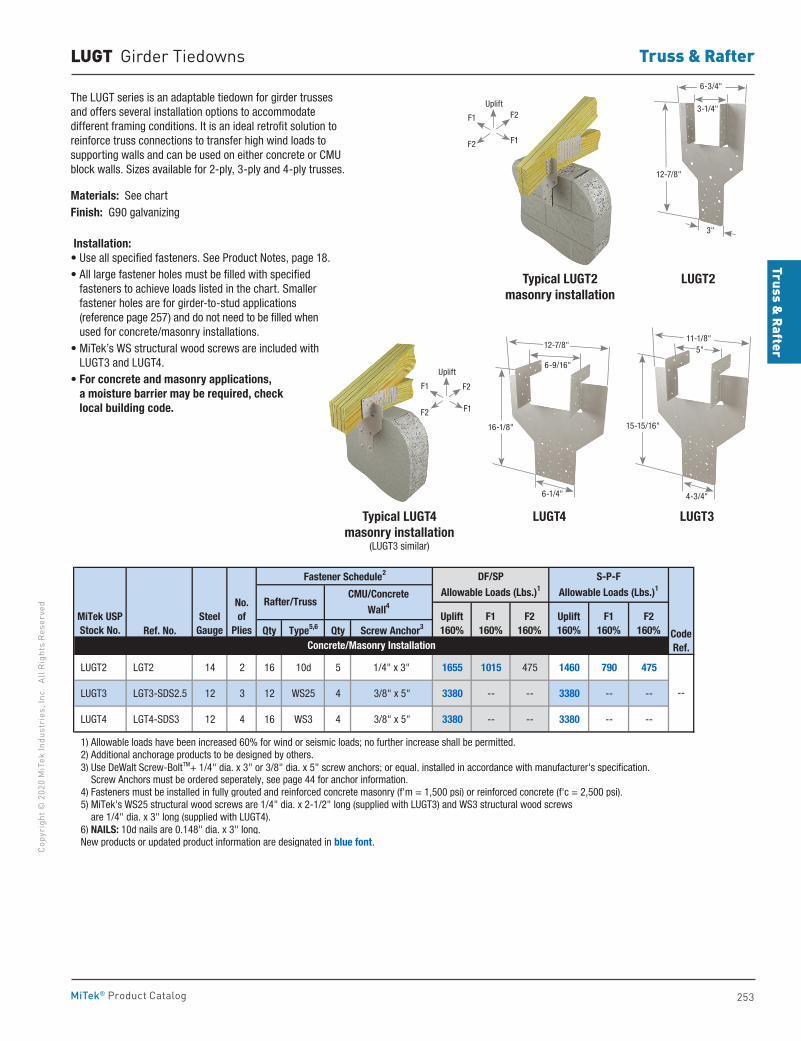
Truss & Rafter
253
Copy
righ
t © 2
020
MiT
ek In
dust
ries
, Inc
. Al
l Rig
hts
Rese
rved
Truss & Rafter
MiTek® Product Catalog
Ref. No. Qty Type5,6 Qty Screw Anchor3
LUGT2 LGT2 14 2 16 10d 5 1/4" x 3" 1655 1015 475 1460 790 475
LUGT3 LGT3-SDS2.5 12 3 12 WS25 4 3/8" x 5" 3380 -- -- 3380 -- --
LUGT4 LGT4-SDS3 12 4 16 WS3 4 3/8" x 5" 3380 -- -- 3380 -- --
1) Allowable loads have been increased 60% for wind or seismic loads; no further increase shall be permitted. 2) Additional anchorage products to be designed by others. 3) Use DeWalt Screw-BoltTM+ 1/4" dia. x 3" or 3/8" dia. x 5" screw anchors; or equal, installed in accordance with manufacturer's specification. Screw Anchors must be ordered seperately, see page 44 for anchor information. 4) Fasteners must be installed in fully grouted and reinforced concrete masonry (f'm = 1,500 psi) or reinforced concrete (f'c = 2,500 psi). 5) MiTek's WS25 structural wood screws are 1/4" dia. x 2-1/2" long (supplied with LUGT3) and WS3 structural wood screws are 1/4" dia. x 3" long (supplied with LUGT4). 6) NAILS: 10d nails are 0.148" dia. x 3" long. New products or updated product information are designated in blue font.
Concrete/Masonry Installation
--
S-P-FAllowable Loads (Lbs.)1
Uplift160%
Fastener Schedule2
MiTek USPStock No.
SteelGauge
No. of
Plies
DF/SPAllowable Loads (Lbs.)1
CMU/Concrete Wall4
Rafter/TrussUplift160%
F1160%
F2160%
F1160%
F2160% Code
Ref.
LUGT Girder Tiedowns
LUGT2
LUGT4
Typical LUGT2masonry installation
Typical LUGT4 masonry installation
(LUGT3 similar)
LUGT3
The LUGT series is an adaptable tiedown for girder trusses and offers several installation options to accommodate different framing conditions. It is an ideal retrofit solution to reinforce truss connections to transfer high wind loads to supporting walls and can be used on either concrete or CMU block walls. Sizes available for 2-ply, 3-ply and 4-ply trusses.
Materials: See chartFinish: G90 galvanizing Installation:• Use all specified fasteners. See Product Notes, page 18.• All large fastener holes must be filled with specified
fasteners to achieve loads listed in the chart. Smaller fastener holes are for girder-to-stud applications (reference page 257) and do not need to be filled when used for concrete/masonry installations.
• MiTek’s WS structural wood screws are included with LUGT3 and LUGT4.
• For concrete and masonry applications, a moisture barrier may be required, check local building code.
15-15/16"
11-1/8"5"
4-3/4"
16-1/8"
12-7/8"
6-9/16"
6-1/4"
12-7/8"
3"
6-3/4"
3-1/4"F1
F1
F2
F2
Uplift
F1
F1
F2
F2
Uplift
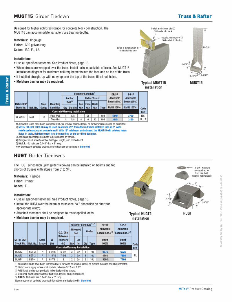
254
Copyright © 2020 M
iTek Industries, Inc. All Rights Reserved
Truss & Rafter
Trus
s &
Raf
ter
MiTek® Product Catalog
MUGT15 Girder Tiedown
Designed for higher uplift resistance for concrete block construction. The MUGT15 can accommodate variable truss bearing depths.
Materials: 12 gaugeFinish: G90 galvanizingCodes: IBC, FL, LA
Installation:• Use all specified fasteners. See Product Notes, page 18.• When straps are wrapped over the truss, install nails in backside of truss. See MUGT15
installation diagram for minimum nail requirements into the face and on top of the truss.• If installed straight-up with no wrap over the top of the truss, fill all nail holes.• Moisture barrier may be required. Typical MUGT15
installationMUGT15
Ref. No. Qty Dia (in) Type Uplift 160%1 Uplift 160%1
Face-Max 1 5/8 -- 28 -- 10d 4240 3730Top-Min 1 5/8 4 6 12 10d 3945 3160
1) Allowable loads have been increased 60% for wind or seismic loads; no further increase shall be permitted.
reinforced masonry or concrete wall. With 12" minimum embedment, the MUGT15 will achieve loads listed in table. Reinforcement is to be specified by the certified designer. 3) Additional anchorage products to be designed by others. 4) Designer must specify anchor bolt type, length, and embedment. 5) NAILS: 10d nails are 0.148" dia. x 3" long. New products or updated product information are designated in blue font.
Fastener Schedule3
Rafter/Truss5Anchor
Bolt2,4
S-P-FAllowable
Loads (Lbs.)
Concrete/Masonry Installation
2) MiTek CIA-GEL 7000-C may be used to anchor 5/8" threaded rod when installed into an 8" wide
CodeRef.
MountingCondition
MiTek USPStock No.
SteelGauge
IBC,FL, LA
MUGT15 MGT 12
DF/SP Allowable
Loads (Lbs.)TopQty
FaceQty
BackQty
HUGTTypical HUGT2installation
The HUGT series high uplift girder tiedowns can be installed on beams and top chords of trusses with slopes from 0˚ to 34˚.
Materials: 7 gaugeFinish: PrimerCodes: FL
Installation:• Use all specified fasteners. See Product Notes, page 18.• Install the HUGT over the beam or truss (see “W” dimension on chart for
appropriate width).• Attached members shall be designed to resist applied loads.• Moisture barrier may be required.
Ref. No. Qty Qty Type
HUGT2 HGT-2 7 3-5/16 5-3/4 2 3/4 8 10d 9575 6925 HUGT3 HGT-3 7 4-15/16 7-3/8 2 3/4 8 10d 9860 7805 HUGT4 HGT-4 7 6-7/8 9 2 3/4 8 10d 9860 7790
1) Allowable loads have been increased 60% for wind or seismic loads; no further increase shall be permitted. 2) Listed loads apply where roof pitch is between 3:12 and 8:12. 3) Additional anchorage products to be designed by others. 4) Designer must specify anchor bolt type, length, and embedment. 5) NAILS: 10d nails are 0.148" dia. x 3" long. New products or updated product information are designated in blue font.
FL
Girder
DF/SPAllowable
Loads (Lbs.)1,2
S-P-FAllowable
Loads (Lbs.)1,2
Uplift160%
Uplift160%
Concrete/Masonry InstallationCodeRef.
MiTek USPStock No.
SteelGauge
ThreadedRod
W(in)
O.C. DimBetweenAnchors
(in)
Fastener Schedule3,4,5
Dia(in)
HUGT Girder Tiedowns
(2) 3/4" washers are required for 3/4" dia. bolt.
(washer not included)
4"
2-3/16"W
2-7/8"
14-5/8"
1-1/4"
3-11/16" 2-7/16"
Install a minimum of (12) 10d nails into back
Install a minimum of (4) 10d nails into the top
Install a minimum of (6) 10d nails into face
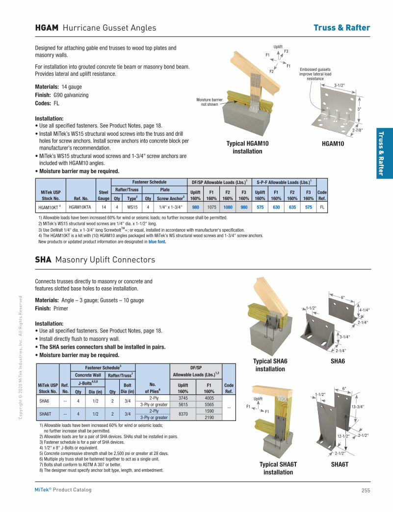
Truss & Rafter
255
Copy
righ
t © 2
020
MiT
ek In
dust
ries
, Inc
. Al
l Rig
hts
Rese
rved
Truss & Rafter
MiTek® Product Catalog
HGAM Hurricane Gusset Angles
SHA Masonry Uplift Connectors
Connects trusses directly to masonry or concrete and features slotted base holes to ease installation.
Materials: Angle – 3 gauge; Gussets – 10 gaugeFinish: Primer
Installation:• Use all specified fasteners. See Product Notes, page 18.• Install directly flush to masonry wall.• The SHA series connectors shall be installed in pairs.• Moisture barrier may be required.
Typical SHA6installation
Typical SHA6Tinstallation
SHA6
SHA6T
Qty Dia (in) Qty 2-Ply 3745 4005
3-Ply or greater 5615 5565 2-Ply 1590
3-Ply or greater 2190
1) Allowable loads have been increased 60% for wind or seismic loads; no further increase shall be permitted. 2) Allowable loads are for a pair of SHA devices. SHAs shall be installed in pairs. 3) Fastener schedule is for a pair of SHA devices. 4) 1/2" x 8" J-Bolts or equivalent. 5) Concrete compressive strength shall be 2,500 psi or greater at 28 days. 6) Multiple ply truss shall be fastened together to act as a single unit. 7) Bolts shall conform to ASTM A 307 or better. 8) The designer must specify anchor bolt type, length, and embedment.
CodeRef.
--8370
4 3/4
4 3/4
1/2
1/2
2
2
No.
of Plies6Bolt
Dia (in)Uplift160%
F1160%
SHA6T
--
--
MiTek USPStock No.
SHA6
DF/SP
Allowable Loads (Lbs.)1,2Fastener Schedule3
Concrete Wall
Ref. No.
Rafter/Truss7
J-Bolts4,5,8
Designed for attaching gable end trusses to wood top plates and masonry walls.
For installation into grouted concrete tie beam or masonry bond beam. Provides lateral and uplift resistance.
Materials: 14 gaugeFinish: G90 galvanizingCodes: FL
Installation:• Use all specified fasteners. See Product Notes, page 18.• Install MiTek’s WS15 structural wood screws into the truss and drill
holes for screw anchors. Install screw anchors into concrete block per manufacturer’s recommendation.
• MiTek’s WS15 structural wood screws and 1-3/4" screw anchors are included with HGAM10 angles.
• Moisture barrier may be required.
Ref. No. Qty Type2 Qty Screw Anchor3
HGAM10KT 4 HGAM10KTA 14 4 WS15 4 1/4" x 1-3/4" 980 1075 1080 980 575 630 635 575 FL
1) Allowable loads have been increased 60% for wind or seismic loads; no further increase shall be permitted. 2) MiTek's WS15 structural wood screws are 1/4" dia. x 1-1/2" long. 3) Use DeWalt 1/4" dia. x 1-3/4" long ScrewboltTM+; or equal, installed in accordance with manufacturer's specification. 4) The HGAM10KT is a kit with (10) HGAM10 angles packaged with MiTek's WS structural wood screws and 1-3/4" screw anchors. New products or updated product information are designated in blue font.
CodeRef.
DF/SP Allowable Loads (Lbs.)1
MiTek USPStock No.
SteelGauge
Fastener Schedule
Rafter/Truss Plate Uplift160%
F1160%
F2160%
F3160%
S-P-F Allowable Loads (Lbs.)1
Uplift160%
F1160%
F2160%
F3160%
Typical HGAM10 installation
HGAM10
Embossed gussets improve lateral load
resistance
3-1/2"
3"
2-7/8"
Moisture barrier not shown
1-1/2"
6"
4-1/4"
3-1/4"
2-1/4"
2-1/4"
6"
13-3/4"
2-1/2"
2-1/2"
12-1/2"
1-1/2"
F1
F1
F3
F2
Uplift
Uplift
F1F1
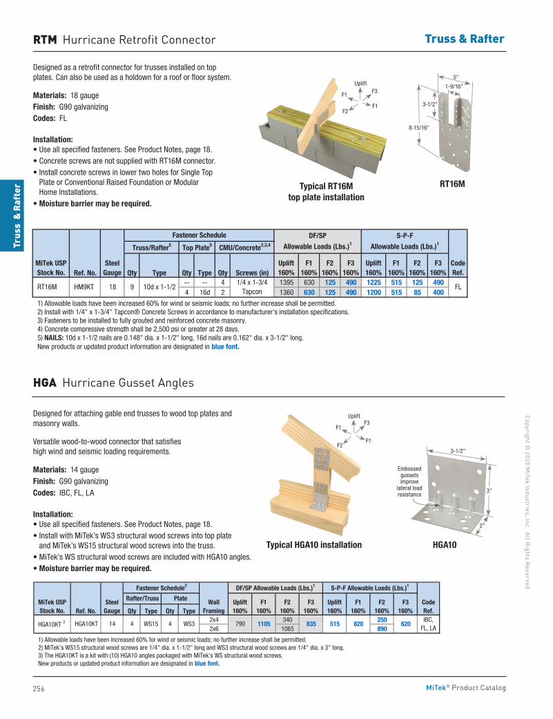
256
Copyright © 2020 M
iTek Industries, Inc. All Rights Reserved
Truss & Rafter
Trus
s &
Raf
ter
MiTek® Product Catalog
RTM Hurricane Retrofit Connector
Designed as a retrofit connector for trusses installed on top plates. Can also be used as a holdown for a roof or floor system.
Materials: 18 gaugeFinish: G90 galvanizingCodes: FL
Installation:• Use all specified fasteners. See Product Notes, page 18.• Concrete screws are not supplied with RT16M connector.• Install concrete screws in lower two holes for Single Top
Plate or Conventional Raised Foundation or Modular Home Installations.
• Moisture barrier may be required.
Typical RT16Mtop plate installation
RT16M
Ref. No. Qty Type Qty Type Qty Screws (in)-- -- 4 1395 630 125 490 1225 515 125 4904 16d 2 1360 630 125 490 1200 515 85 400
1) Allowable loads have been increased 60% for wind or seismic loads; no further increase shall be permitted. 2) Install with 1/4" x 1-3/4" Tapcon® Concrete Screws in accordance to manufacturer's installation specifications. 3) Fasteners to be installed to fully grouted and reinforced concrete masonry. 4) Concrete compressive strength shall be 2,500 psi or greater at 28 days. 5) NAILS: 10d x 1-1/2 nails are 0.148" dia. x 1-1/2" long, 16d nails are 0.162" dia. x 3-1/2" long. New products or updated product information are designated in blue font.
HM9KT RT16M
Truss/Rafter5 Top Plate5
MiTek USPStock No.
18
SteelGauge
9 10d x 1-1/2
F3160%
Fastener Schedule
CodeRef.
FL
CMU/Concrete2,3,4
Uplift160%
DF/SP Allowable Loads (Lbs.)1
Uplift160%
S-P-F Allowable Loads (Lbs.)1
1/4 x 1-3/4 Tapcon
F1160%
F2160%
F3160%
F1160%
F2160%
Typical HGA10 installation HGA10
Designed for attaching gable end trusses to wood top plates and masonry walls.
Versatile wood-to-wood connector that satisfies high wind and seismic loading requirements.
Materials: 14 gaugeFinish: G90 galvanizingCodes: IBC, FL, LA
Installation:• Use all specified fasteners. See Product Notes, page 18.• Install with MiTek’s WS3 structural wood screws into top plate
and MiTek’s WS15 structural wood screws into the truss.• MiTek’s WS structural wood screws are included with HGA10 angles.• Moisture barrier may be required.
Ref. No. Qty Type Qty Type2x4 340 2502x6 1065 890
1) Allowable loads have been increased 60% for wind or seismic loads; no further increase shall be permitted. 2) MiTek's WS15 structural wood screws are 1/4" dia. x 1-1/2" long and WS3 structural wood screws are 1/4" dia. x 3" long. 3) The HGA10KT is a kit with (10) HGA10 angles packaged with MiTek's WS structural wood screws. New products or updated product information are designated in blue font.
CodeRef.
Uplift160%
4 WS3IBC,
FL, LA790 1105 835 HGA10KT 3 HGA10KT 14 4 WS15
DF/SP Allowable Loads (Lbs.)1
MiTek USPStock No.
SteelGauge
Fastener Schedule2
Rafter/Truss Plate F1160%
F2160%
F3160%
WallFraming
S-P-F Allowable Loads (Lbs.)1
Uplift160%
F1160%
F2160%
515 820 620
F3160%
HGA Hurricane Gusset Angles
5"
1-9/16"
8-15/16"
3-1/2"
3-1/2"
Embossed gussets improve
lateral load resistance
3"
2"
F1
F1
F3
F2
Uplift
F1
F1
F3
F2
Uplift
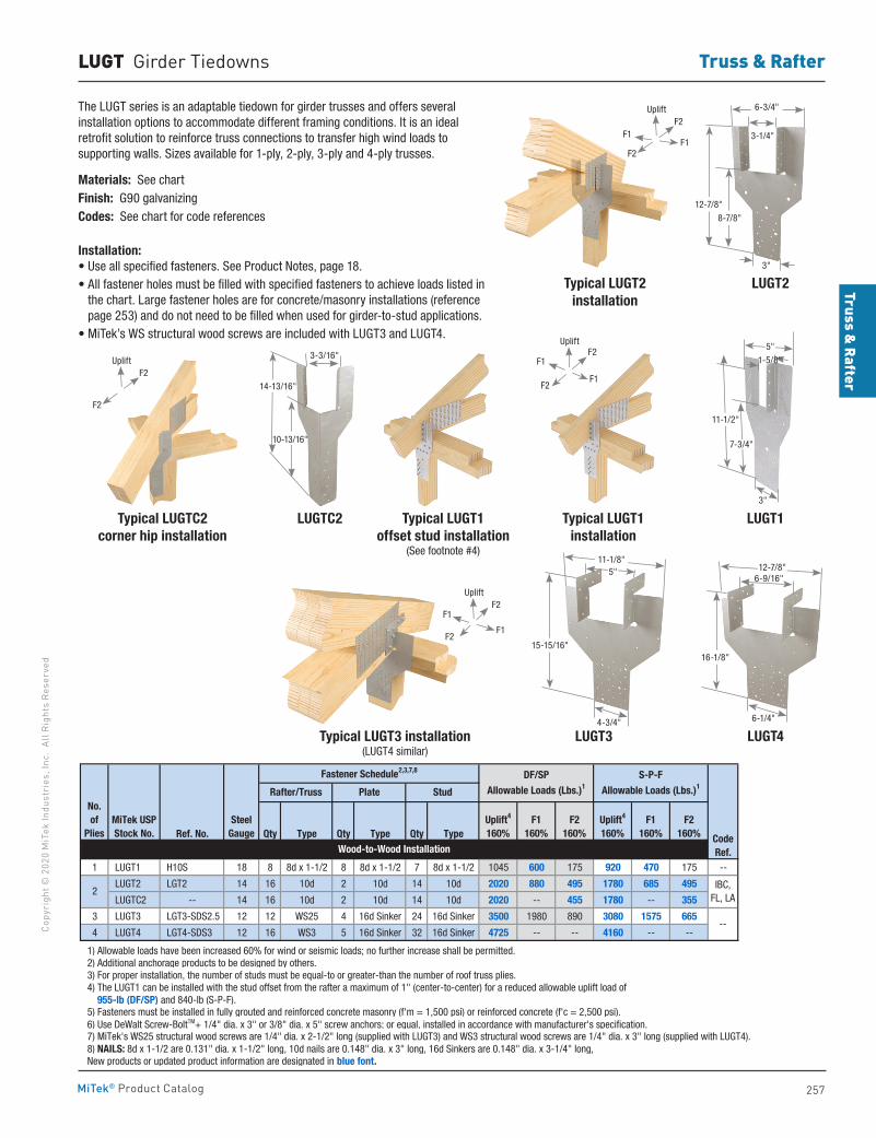
Truss & Rafter
257
Copy
righ
t © 2
020
MiT
ek In
dust
ries
, Inc
. Al
l Rig
hts
Rese
rved
Truss & Rafter
MiTek® Product Catalog
LUGT Girder Tiedowns
The LUGT series is an adaptable tiedown for girder trusses and offers several installation options to accommodate different framing conditions. It is an ideal retrofit solution to reinforce truss connections to transfer high wind loads to supporting walls. Sizes available for 1-ply, 2-ply, 3-ply and 4-ply trusses.
Materials: See chartFinish: G90 galvanizingCodes: See chart for code references
Installation:• Use all specified fasteners. See Product Notes, page 18.• All fastener holes must be filled with specified fasteners to achieve loads listed in
the chart. Large fastener holes are for concrete/masonry installations (reference page 253) and do not need to be filled when used for girder-to-stud applications.
• MiTek’s WS structural wood screws are included with LUGT3 and LUGT4.
Typical LUGT2 installation
Typical LUGT1installation
Typical LUGTC2corner hip installation
LUGT1LUGTC2
Typical LUGT3 installation(LUGT4 similar)
Ref. No. Qty Type Qty Type Qty Type
1 LUGT1 H10S 18 8 8d x 1-1/2 8 8d x 1-1/2 7 8d x 1-1/2 1045 600 175 920 470 175 --
LUGT2 LGT2 14 16 10d 2 10d 14 10d 2020 880 495 1780 685 495
LUGTC2 -- 14 16 10d 2 10d 14 10d 2020 -- 455 1780 -- 355
3 LUGT3 LGT3-SDS2.5 12 12 WS25 4 16d Sinker 24 16d Sinker 3500 1980 890 3080 1575 665
4 LUGT4 LGT4-SDS3 12 16 WS3 5 16d Sinker 32 16d Sinker 4725 -- -- 4160 -- --
1) Allowable loads have been increased 60% for wind or seismic loads; no further increase shall be permitted. 2) Additional anchorage products to be designed by others. 3) For proper installation, the number of studs must be equal-to or greater-than the number of roof truss plies. 4) The LUGT1 can be installed with the stud offset from the rafter a maximum of 1" (center-to-center) for a reduced allowable uplift load of 955-lb (DF/SP) and 840-lb (S-P-F). 5) Fasteners must be installed in fully grouted and reinforced concrete masonry (f'm = 1,500 psi) or reinforced concrete (f'c = 2,500 psi). 6) Use DeWalt Screw-BoltTM+ 1/4" dia. x 3" or 3/8" dia. x 5" screw anchors; or equal, installed in accordance with manufacturer's specification. 7) MiTek's WS25 structural wood screws are 1/4" dia. x 2-1/2" long (supplied with LUGT3) and WS3 structural wood screws are 1/4" dia. x 3" long (supplied with LUGT4). 8) NAILS: 8d x 1-1/2 are 0.131" dia. x 1-1/2" long, 10d nails are 0.148" dia. x 3" long, 16d Sinkers are 0.148" dia. x 3-1/4" long, New products or updated product information are designated in blue font.
2
F1160%
Wood-to-Wood Installation
No. of
Plies
DF/SPAllowable Loads (Lbs.)1
S-P-FAllowable Loads (Lbs.)1
Rafter/Truss Plate Stud
Uplift4
160%F1
160%F2
160%Uplift4
160%F2
160%
Fastener Schedule2,3,7,8
IBC, FL, LA
--
CodeRef.
MiTek USPStock No.
SteelGauge
LUGT4LUGT3
LUGT2
11-1/2"
1-5/8"
5"
3"
12-7/8"
8-7/8"
6-3/4"
3-1/4"
3"
Typical LUGT1 offset stud installation
(See footnote #4)
F1F1
F2
F2
Uplift
F1
F1
F2
F2
Uplift
F2
F2
Uplift
F1
F1
F2
F2
Uplift
7-3/4"
3-3/16"
14-13/16"
10-13/16"
15-15/16"
11-1/8"5"
4-3/4"
16-1/8"
12-7/8"6-9/16"
6-1/4"
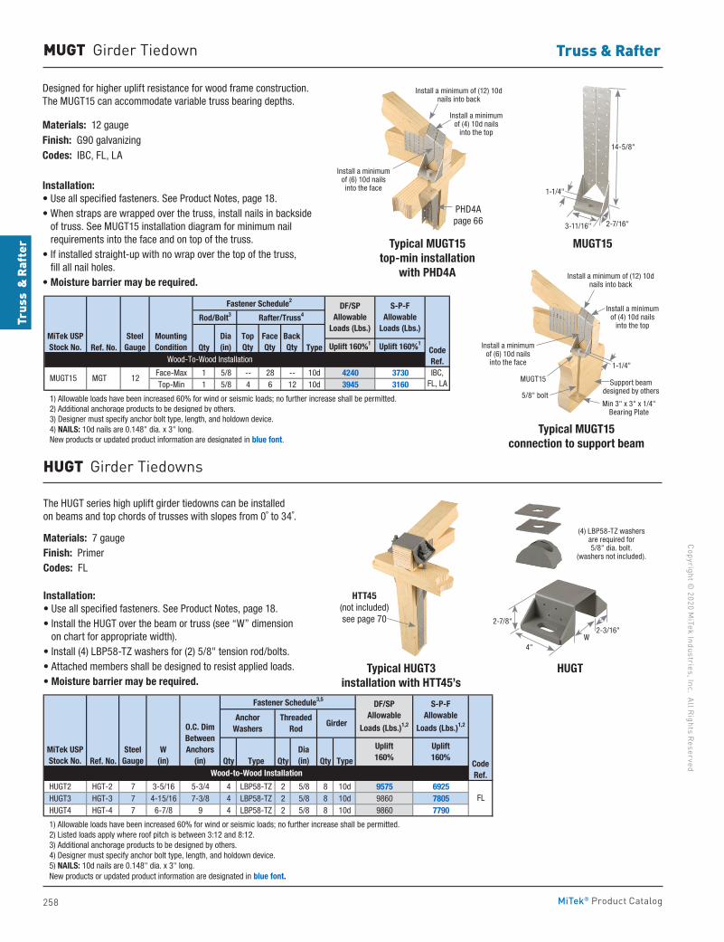
258
Copyright © 2020 M
iTek Industries, Inc. All Rights Reserved
Truss & Rafter
Trus
s &
Raf
ter
MiTek® Product Catalog
MUGT Girder Tiedown
Designed for higher uplift resistance for wood frame construction. The MUGT15 can accommodate variable truss bearing depths.
Materials: 12 gaugeFinish: G90 galvanizingCodes: IBC, FL, LA
Installation:• Use all specified fasteners. See Product Notes, page 18.• When straps are wrapped over the truss, install nails in backside
of truss. See MUGT15 installation diagram for minimum nail requirements into the face and on top of the truss.
• If installed straight-up with no wrap over the top of the truss, fill all nail holes.
• Moisture barrier may be required.
Ref. No. Qty Type Uplift 160%1 Uplift 160%1
Face-Max 1 5/8 -- 28 -- 10d 4240 3730Top-Min 1 5/8 4 6 12 10d 3945 3160
1) Allowable loads have been increased 60% for wind or seismic loads; no further increase shall be permitted. 2) Additional anchorage products to be designed by others. 3) Designer must specify anchor bolt type, length, and holdown device. 4) NAILS: 10d nails are 0.148" dia. x 3" long. New products or updated product information are designated in blue font.
MountingCondition
MiTek USPStock No.
SteelGauge
S-P-FAllowable
Loads (Lbs.)
IBC,FL, LA
MUGT15 MGT 12
DF/SP Allowable
Loads (Lbs.)
Fastener Schedule2
Rod/Bolt3 Rafter/Truss4
TopQty
FaceQty
BackQty
Dia(in)
Wood-To-Wood InstallationCodeRef.
Typical MUGT15top-min installation
with PHD4A
Typical MUGT15connection to support beam
MUGT15
HUGT Girder Tiedowns
The HUGT series high uplift girder tiedowns can be installed on beams and top chords of trusses with slopes from 0˚ to 34˚.
Materials: 7 gaugeFinish: PrimerCodes: FL
Installation:• Use all specified fasteners. See Product Notes, page 18.• Install the HUGT over the beam or truss (see “W” dimension
on chart for appropriate width).• Install (4) LBP58-TZ washers for (2) 5/8" tension rod/bolts.• Attached members shall be designed to resist applied loads.• Moisture barrier may be required.
Typical HUGT3installation with HTT45’s
HUGT
Ref. No. Qty Type Qty Qty Type
HUGT2 HGT-2 7 3-5/16 5-3/4 4 LBP58-TZ 2 5/8 8 10d 9575 6925 HUGT3 HGT-3 7 4-15/16 7-3/8 4 LBP58-TZ 2 5/8 8 10d 9860 7805 HUGT4 HGT-4 7 6-7/8 9 4 LBP58-TZ 2 5/8 8 10d 9860 7790
1) Allowable loads have been increased 60% for wind or seismic loads; no further increase shall be permitted. 2) Listed loads apply where roof pitch is between 3:12 and 8:12. 3) Additional anchorage products to be designed by others. 4) Designer must specify anchor bolt type, length, and holdown device. 5) NAILS: 10d nails are 0.148" dia. x 3" long. New products or updated product information are designated in blue font.
FL
Girder
DF/SPAllowable
Loads (Lbs.)1,2
S-P-FAllowable
Loads (Lbs.)1,2
Uplift160%
Uplift160%
Wood-to-Wood InstallationCodeRef.
MiTek USPStock No.
SteelGauge
Anchor Washers
ThreadedRod
Dia(in)
W(in)
O.C. DimBetweenAnchors
(in)
Fastener Schedule3,5
14-5/8"
1-1/4"
3-11/16" 2-7/16"
(4) LBP58-TZ washers are required for 5/8" dia. bolt.
(washers not included).
2-3/16"W
4"
2-7/8"
PHD4A page 66
Install a minimum of (4) 10d nails
into the top
Install a minimum of (12) 10d nails into back
Install a minimum of (6) 10d nails into the face
HTT45 (not included) see page 70
Min 3" x 3" x 1/4" Bearing Plate
Support beam designed by others
1-1/4"
Install a minimum of (4) 10d nails
into the top
Install a minimum of (12) 10d nails into back
Install a minimum of (6) 10d nails into the face
MUGT15
5/8" bolt
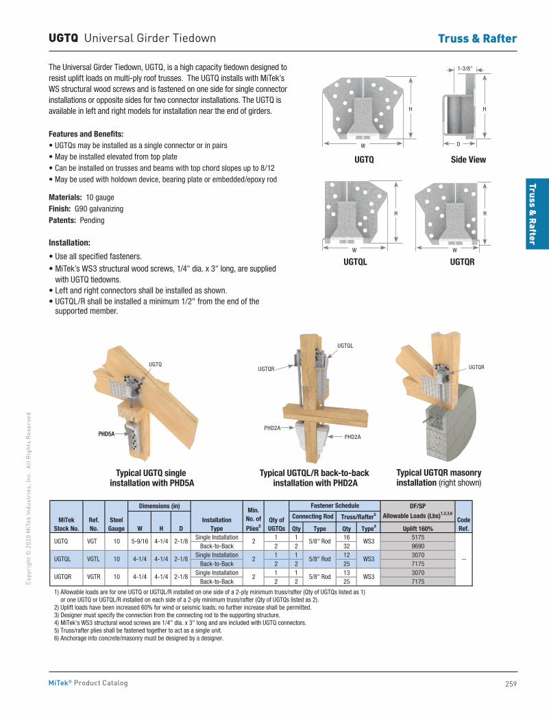
Truss & Rafter
259
Copy
righ
t © 2
020
MiT
ek In
dust
ries
, Inc
. Al
l Rig
hts
Rese
rved
Truss & Rafter
MiTek® Product Catalog
UGTQ Universal Girder Tiedown
The Universal Girder Tiedown, UGTQ, is a high capacity tiedown designed to resist uplift loads on multi-ply roof trusses. The UGTQ installs with MiTek’s WS structural wood screws and is fastened on one side for single connector installations or opposite sides for two connector installations. The UGTQ is available in left and right models for installation near the end of girders.
Features and Benefits:• UGTQs may be installed as a single connector or in pairs• May be installed elevated from top plate• Can be installed on trusses and beams with top chord slopes up to 8/12• May be used with holdown device, bearing plate or embedded/epoxy rod
Materials: 10 gaugeFinish: G90 galvanizingPatents: Pending
Installation:
• Use all specified fasteners.• MiTek’s WS3 structural wood screws, 1/4" dia. x 3" long, are supplied
with UGTQ tiedowns.• Left and right connectors shall be installed as shown.• UGTQL/R shall be installed a minimum 1/2" from the end of the
supported member.
Dimensions (in)
Qty Type Qty Type4 Uplift 160%Single Installation 1 1 16 5175
Back-to-Back 2 2 32 9690Single Installation 1 1 12 3070
Back-to-Back 2 2 25 7175Single Installation 1 1 13 3070
Back-to-Back 2 2 25 7175
1) Allowable loads are for one UGTQ or UGTQL/R installed on one side of a 2-ply minimum truss/rafter (Qty of UGTQs listed as 1) or one UGTQ or UGTQL/R installed on each side of a 2-ply minimum truss/rafter (Qty of UGTQs listed as 2). 2) Uplift loads have been increased 60% for wind or seismic loads; no further increase shall be permitted. 3) Designer must specify the connection from the connecting rod to the supporting structure. 4) MiTek's WS3 structural wood screws are 1/4" dia. x 3" long and are included with UGTQ connectors. 5) Truss/rafter plies shall be fastened together to act as a single unit. 6) Anchorage into concrete/masonry must be designed by a designer.
CodeRef.
--5/8" Rod
5/8" Rod WS3
WS3
DF/SPAllowable Loads (Lbs)1,2,3,6
Fastener Schedule
Connecting Rod Truss/Rafter5
WS35/8" Rod
MiTekStock No.
SteelGauge
Qty ofUGTQs
5-9/16 4-1/4 2-1/8
Min.No. ofPlies5W H D
UGTQ VGT 10
InstallationType
UGTQL 4-1/4
UGTQR
VGTL
VGTR
10
10 2
Ref. No.
4-1/4
2-1/8
2-1/8
4-1/4
4-1/4
2
2
UGTQ Side View
UGTQL UGTQR
W
W W
H H
H H
D
1-3/8"
PHD2A
PHD2A
Typical UGTQR masonry installation (right shown)
Typical UGTQ single installation with PHD5A
Typical UGTQL/R back-to-back installation with PHD2A
PHD5APHD5A
UGTQL
UGTQUGTQR UGTQR
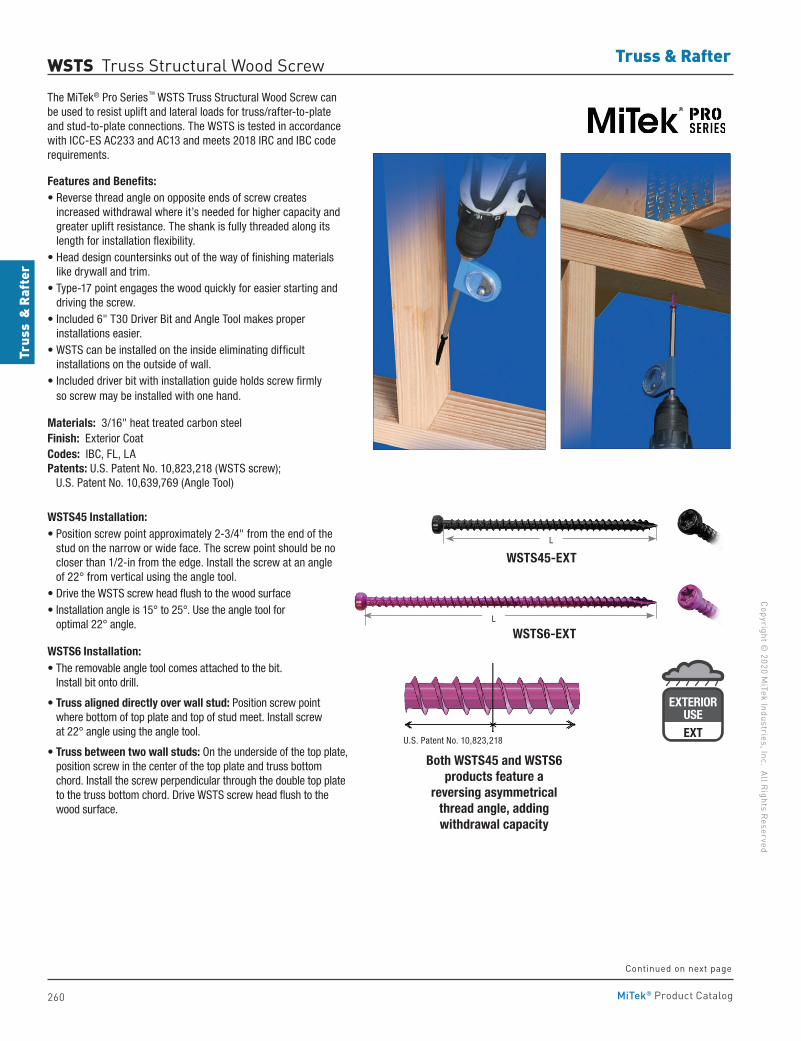
260
Copyright © 2020 M
iTek Industries, Inc. All Rights Reserved
Truss & Rafter
Trus
s &
Raf
ter
MiTek® Product Catalog
WSTS Truss Structural Wood ScrewThe MiTek® Pro Series TM WSTS Truss Structural Wood Screw can be used to resist uplift and lateral loads for truss/rafter-to-plate and stud-to-plate connections. The WSTS is tested in accordance with ICC-ES AC233 and AC13 and meets 2018 IRC and IBC code requirements.
Features and Benefits:• Reverse thread angle on opposite ends of screw creates
increased withdrawal where it’s needed for higher capacity and greater uplift resistance. The shank is fully threaded along its length for installation flexibility.
• Head design countersinks out of the way of finishing materials like drywall and trim.
• Type-17 point engages the wood quickly for easier starting and driving the screw.
• Included 6" T30 Driver Bit and Angle Tool makes proper installations easier.
• WSTS can be installed on the inside eliminating difficult installations on the outside of wall.
• Included driver bit with installation guide holds screw firmly so screw may be installed with one hand.
Materials: 3/16" heat treated carbon steelFinish: Exterior CoatCodes: IBC, FL, LA Patents: U.S. Patent No. 10,823,218 (WSTS screw); U.S. Patent No. 10,639,769 (Angle Tool)
WSTS45 Installation:• Position screw point approximately 2-3/4" from the end of the
stud on the narrow or wide face. The screw point should be no closer than 1/2-in from the edge. Install the screw at an angle of 22° from vertical using the angle tool.
• Drive the WSTS screw head flush to the wood surface• Installation angle is 15° to 25°. Use the angle tool for
optimal 22° angle.
WSTS6 Installation:• The removable angle tool comes attached to the bit.
Install bit onto drill.
• Truss aligned directly over wall stud: Position screw point where bottom of top plate and top of stud meet. Install screw at 22° angle using the angle tool.
• Truss between two wall studs: On the underside of the top plate, position screw in the center of the top plate and truss bottom chord. Install the screw perpendicular through the double top plate to the truss bottom chord. Drive WSTS screw head flush to the wood surface.
WSTS6-EXT
WSTS45-EXT
EXTERIORUSE
G185-TZ
EXTERIORUSEEXT
L
L
Continued on next page
Both WSTS45 and WSTS6 products feature a
reversing asymmetrical thread angle, adding withdrawal capacity
U.S. Patent No. 10,823,218
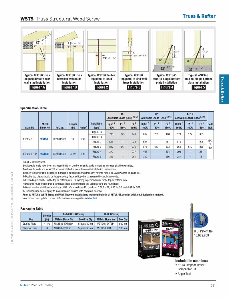
Truss & Rafter
261
Copy
righ
t © 2
020
MiT
ek In
dust
ries
, Inc
. Al
l Rig
hts
Rese
rved
Truss & Rafter
MiTek® Product Catalog
Ref. No. Finish1
Figure 1A
Figure 1B
Figure 2 616 -- 228 637 -- 257 616 -- 228
Figure 3 847 547 336 876 547 373 662 519 235
Figure 4 372 -- 277 493 -- 334 296 -- 231
Figure 5 313 -- 251 380 -- 266 281 -- 161
1) EXT = Exterior Coat. 2) Allowable loads have been increased 60% for wind or seismic loads; no further increase shall be permitted. 3) Allowable loads are for WSTS screws installed in accordance with installation instructions. 4) When the screw is to be loaded in multiple directions simultaneously, refer to note 1 in Design Notes on page 18. 5) Double top plates should be independently fastened together as required by applicable code. 6) F1 loading is parallel to the top or bottom plate. F2 loading is perpendicular to the top or bottom plate. 7) Designer must ensure that a continuous load path transfers the uplift loads to the foundation. 8) Wood species shall have a minimum NDS referenced specific gravity of 0.50 for DF, 0.55 for SP, and 0.42 for SPF. 9) Table loads to do not apply to installations in trusses with end grain bearing. Refer to MiTek’s WSTS Truss and Wall Tiedown Installations technical bulletin at MiTek-US.com for additional design information. New products or updated product information are designated in blue font.
S-P-FAllowable Loads (Lbs.) 2,3,4,8
MiTekStock No.
Length(in)
Uplift 7
160%
IBC,FL,LA
CodeRef.
F2 6
160%Uplift 7
160%F1 6
160%
225 443 802 263 496 573 177
Size (in)
DFAllowable Loads (Lbs.) 2,3,4,8
SPAllowable Loads (Lbs.) 2,3,4,8
0.152 x 6 WSTS6 SDWC15600 6 EXT
InstallationType 5
F1 6
160%F2 6
160%Uplift 7
160%F1 6
160%F2 6
160%
715 355
0.152 x 4-1/2 WSTS45 SDWC15450 4-1/2 EXT
Specification Table
MiTek Stock No. Box/Ctn Qty MiTek Stock No. Box Qty
Stud to Plate 4-1/2 WSTS45-EXTR50 5-pack/50-ea WSTS45-EXTBP 500-ea
Plate to Truss 6 WSTS6-EXTR50 5-pack/50-ea WSTS6-EXTBP 500-ea
Retail Box Offering Bulk OfferingLength(in)Use
Packaging Table
WSTS Truss Structural Wood Screw
Included in each box:• 6" T30 Impact-Driver
Compatible Bit• Angle Tool
Typical WSTS6 truss aligned directly over wall stud installation
Figure 1A
Typical WSTS6 truss between wall studs
installation
Figure 1B
Typical WSTS6 double top plate-to-stud
installation
Figure 2
Typical WSTS6 top plate-to-end wall
truss installation
Figure 3
Typical WSTS45 stud-to-single bottom
plate installation
Figure 4
Typical WSTS45 stud-to-single bottom
plate installation
Figure 5
25°
25° 25°
22°
22° 22°
15°
15°15°
0°
0° 0°
1-3/4" +/– 1/4"
3/4" +/– 1/4" 3/4" +/– 1/4"
2-3/4" 2-3/4"
U.S. Patent No. 10,639,769
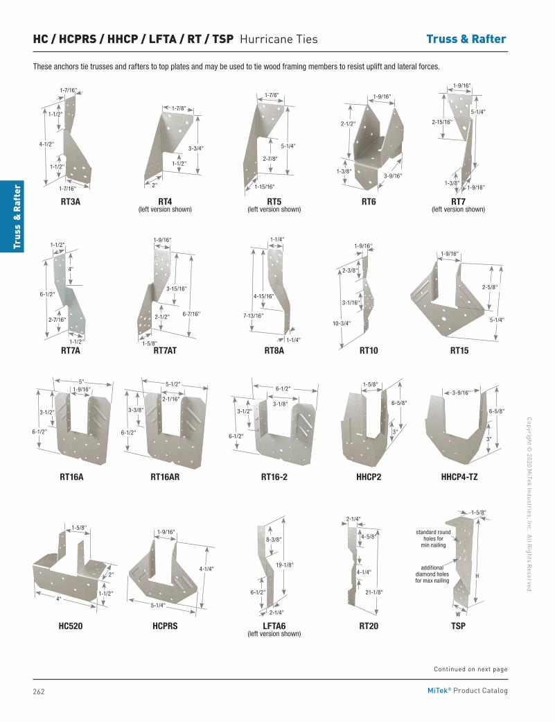
262
Copyright © 2020 M
iTek Industries, Inc. All Rights Reserved
Truss & Rafter
Trus
s &
Raf
ter
MiTek® Product Catalog
HC / HCPRS / HHCP / LFTA / RT / TSP Hurricane Ties
HHCP4-TZ
RT6RT4(left version shown)
RT7A
LFTA6 (left version shown)
HHCP2
RT5(left version shown)
RT3A RT7(left version shown)
RT16A
RT10
RT16-2
RT15RT8ART7AT
RT16AR
RT20 TSPHC520 HCPRS
1-1/4"
1-1/4"
7-13/16"
4-15/16"
5-1/4"
2-5/8"
1-9/16"
5"
6-1/2"
3-1/2"
1-9/16"
19-1/8"
8-3/8"
6-1/2"
2-1/4"
1-15/16"
2-7/8"
5-1/4"
1-7/8" 1-9/16"
2-1/2"
1-3/8"3-9/16"
1-9/16"
10-3/4"
3-1/16"
2-3/8"
6-1/2"
6-1/2"
3-1/8"3-1/2"
3"
6-5/8"
1-5/8"
4"1-1/2"
1-5/8"
2" 4-1/4"
4-5/8"
2-1/4"
21-1/8"
5-1/2"
6-1/2"
2-1/16"
3-3/8"
1-9/16"
3-15/16"
2-1/2"
1-5/8"
6-7/16"
6-5/8"
3"
3-9/16"
1-9/16"
5-1/4"
4-1/4"
1-1/2"
1-1/2"
6-1/2"
2-7/16"
4"
1-7/16"
1-7/16"
1-1/2"
1-1/2"
4-1/2"
These anchors tie trusses and rafters to top plates and may be used to tie wood framing members to resist uplift and lateral forces.
Continued on next page
H
1-5/8"
W
additional diamond holes for max nailing
standard round holes for
min nailing
1-1/2"
2"
3-3/4"
1-7/8"
1-9/16"
1-9/16"
5-1/4"
2-15/16"
1-3/8"
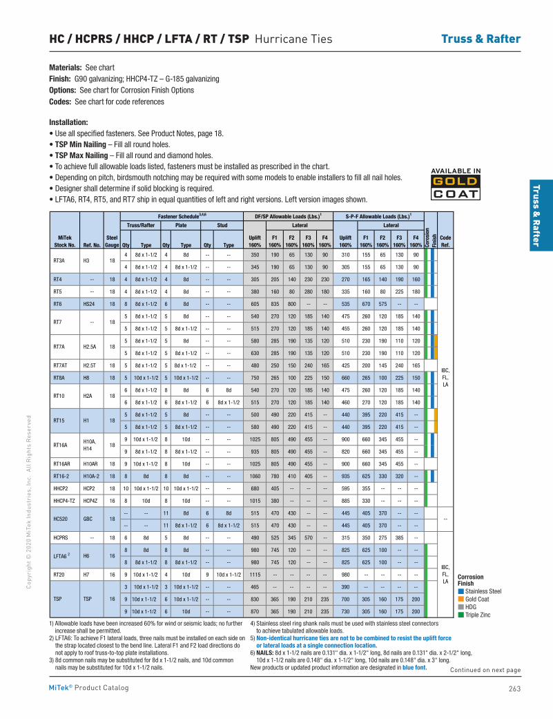
Truss & Rafter
263
Copy
righ
t © 2
020
MiT
ek In
dust
ries
, Inc
. Al
l Rig
hts
Rese
rved
Truss & Rafter
MiTek® Product Catalog
HC / HCPRS / HHCP / LFTA / RT / TSP Hurricane Ties
Ref. No. Qty Type Qty Type Qty Type
4 8d x 1-1/2 4 8d -- -- 350 190 65 130 90 310 155 65 130 90
4 8d x 1-1/2 4 8d x 1-1/2 -- -- 345 190 65 130 90 305 155 65 130 90
RT4 -- 18 4 8d x 1-1/2 4 8d -- -- 305 205 140 230 230 270 165 140 190 160
RT5 -- 18 4 8d x 1-1/2 4 8d -- -- 380 160 80 280 180 335 160 80 225 180
RT6 HS24 18 8 8d x 1-1/2 6 8d -- -- 605 835 800 -- -- 535 670 575 -- --
5 8d x 1-1/2 5 8d -- -- 540 270 120 185 140 475 260 120 185 140
5 8d x 1-1/2 5 8d x 1-1/2 -- -- 515 270 120 185 140 455 260 120 185 140
5 8d x 1-1/2 5 8d -- -- 580 285 190 135 120 510 230 190 110 120
5 8d x 1-1/2 5 8d x 1-1/2 -- -- 630 285 190 135 120 510 230 190 110 120
RT7AT H2.5T 18 5 8d x 1-1/2 5 8d x 1-1/2 -- -- 480 250 150 240 165 425 200 145 240 165
RT8A H8 18 5 10d x 1-1/2 5 10d x 1-1/2 -- -- 750 265 100 225 150 660 265 100 225 150
6 8d x 1-1/2 8 8d 6 8d 540 270 120 185 140 475 260 120 185 140
6 8d x 1-1/2 6 8d x 1-1/2 6 8d x 1-1/2 515 270 120 185 140 460 270 120 185 140
5 8d x 1-1/2 5 8d -- -- 500 490 220 415 -- 440 395 220 415 --
5 8d x 1-1/2 5 8d x 1-1/2 -- -- 580 490 220 415 -- 440 395 220 415 --
9 10d x 1-1/2 8 10d -- -- 1025 805 490 455 -- 900 660 345 455 --
9 8d x 1-1/2 8 8d x 1-1/2 -- -- 935 805 490 455 -- 820 660 345 455 --
RT16AR H10AR 18 9 10d x 1-1/2 8 10d -- -- 1025 805 490 455 -- 900 660 345 455 --
RT16-2 H10A-2 18 8 8d 8 8d -- -- 1060 780 410 405 -- 935 625 330 320 --
HHCP2 HCP2 18 10 10d x 1-1/2 10 10d x 1-1/2 -- -- 680 405 -- -- -- 595 355 -- -- --
HHCP4-TZ HCP4Z 16 8 10d 8 10d -- -- 1015 380 -- -- -- 885 330 -- -- --
-- -- 11 8d 6 8d 515 470 430 -- -- 445 405 370 -- --
-- -- 11 8d x 1-1/2 6 8d x 1-1/2 515 470 430 -- -- 445 405 370 -- --
HCPRS -- 18 6 8d 5 8d -- -- 490 525 345 570 -- 315 350 275 385 --
8 8d 8 8d -- -- 980 745 120 -- -- 825 625 100 -- --
8 8d x 1-1/2 8 8d x 1-1/2 -- -- 980 745 120 -- -- 825 625 100 -- --
RT20 H7 16 9 10d x 1-1/2 4 10d 9 10d x 1-1/2 1115 -- -- -- -- 980 -- -- -- --
3 10d x 1-1/2 3 10d x 1-1/2 -- -- 465 -- -- -- -- 390 -- -- -- --
9 10d x 1-1/2 6 10d x 1-1/2 -- -- 830 365 190 210 235 700 305 160 175 200
9 10d x 1-1/2 6 10d -- -- 870 365 190 210 235 730 305 160 175 200
1) Allowable loads have been increased 60% for wind or seismic loads; no further increase shall be permitted. 2) LFTA6: To achieve F1 lateral loads, three nails must be installed on each side on the strap located closest to the bend line. Lateral F1 and F2 load directions do not apply to roof truss-to-top plate installations. 3) 8d common nails may be substituted for 8d x 1-1/2 nails, and 10d common nails may be substituted for 10d x 1-1/2 nails. 4) Stainless steel ring shank nails must be used with stainless steel connectors to achieve tabulated allowable loads. 5) Non-identical hurricane ties are not to be combined to resist the uplift force or lateral loads at a single connection location. 6) NAILS: 8d x 1-1/2 nails are 0.131" dia. x 1-1/2" long, 8d nails are 0.131" dia. x 2-1/2" long, 10d x 1-1/2 nails are 0.148" dia. x 1-1/2" long, 10d nails are 0.148" dia. x 3" long. New products or updated product information are designated in blue font.
IBC,FL,LA
--
IBC,FL,LA
GBC HC520 18
LFTA6 2 H6 16
18 H1
H2A 18
RT16A H10A, H14
18
MiTekStock No.
SteelGauge
RT3A
18-- RT7
RT7A H2.5A 18
H3 18
TSP TSP 16
Lateral
F3160%
F4160%
Lateral
F3160%
F4160%
F1160%
F2160%
Uplift160%
Stud
RT15
RT10
Fastener Schedule3,4,6 DF/SP Allowable Loads (Lbs.)1 S-P-F Allowable Loads (Lbs.)1
CodeRef.Co
rosi
onFi
nishF1
160%F2
160%Uplift160%
Truss/Rafter Plate
Corrosion Finish Stainless Steel Gold Coat HDG Triple Zinc
Corrosion Finish Stainless Steel Gold Coat HDG Triple Zinc
Corrosion Finish Stainless Steel Gold Coat HDG Triple Zinc
Materials: See chartFinish: G90 galvanizing; HHCP4-TZ – G-185 galvanizingOptions: See chart for Corrosion Finish OptionsCodes: See chart for code references
Installation:• Use all specified fasteners. See Product Notes, page 18.• TSP Min Nailing – Fill all round holes.• TSP Max Nailing – Fill all round and diamond holes.• To achieve full allowable loads listed, fasteners must be installed as prescribed in the chart.• Depending on pitch, birdsmouth notching may be required with some models to enable installers to fill all nail holes.• Designer shall determine if solid blocking is required.• LFTA6, RT4, RT5, and RT7 ship in equal quantities of left and right versions. Left version images shown.
Continued on next page
1) Allowable loads have been increased 60% for wind or seismic loads; no further increase shall be permitted.
2) LFTA6: To achieve F1 lateral loads, three nails must be installed on each side on the strap located closest to the bend line. Lateral F1 and F2 load directions do not apply to roof truss-to-top plate installations.
3) 8d common nails may be substituted for 8d x 1-1/2 nails, and 10d common nails may be substituted for 10d x 1-1/2 nails.
4) Stainless steel ring shank nails must be used with stainless steel connectors to achieve tabulated allowable loads.
5) Non-identical hurricane ties are not to be combined to resist the uplift force or lateral loads at a single connection location.
6) NAILS: 8d x 1-1/2 nails are 0.131" dia. x 1-1/2" long, 8d nails are 0.131" dia. x 2-1/2" long, 10d x 1-1/2 nails are 0.148" dia. x 1-1/2" long, 10d nails are 0.148" dia. x 3" long.
New products or updated product information are designated in blue font.
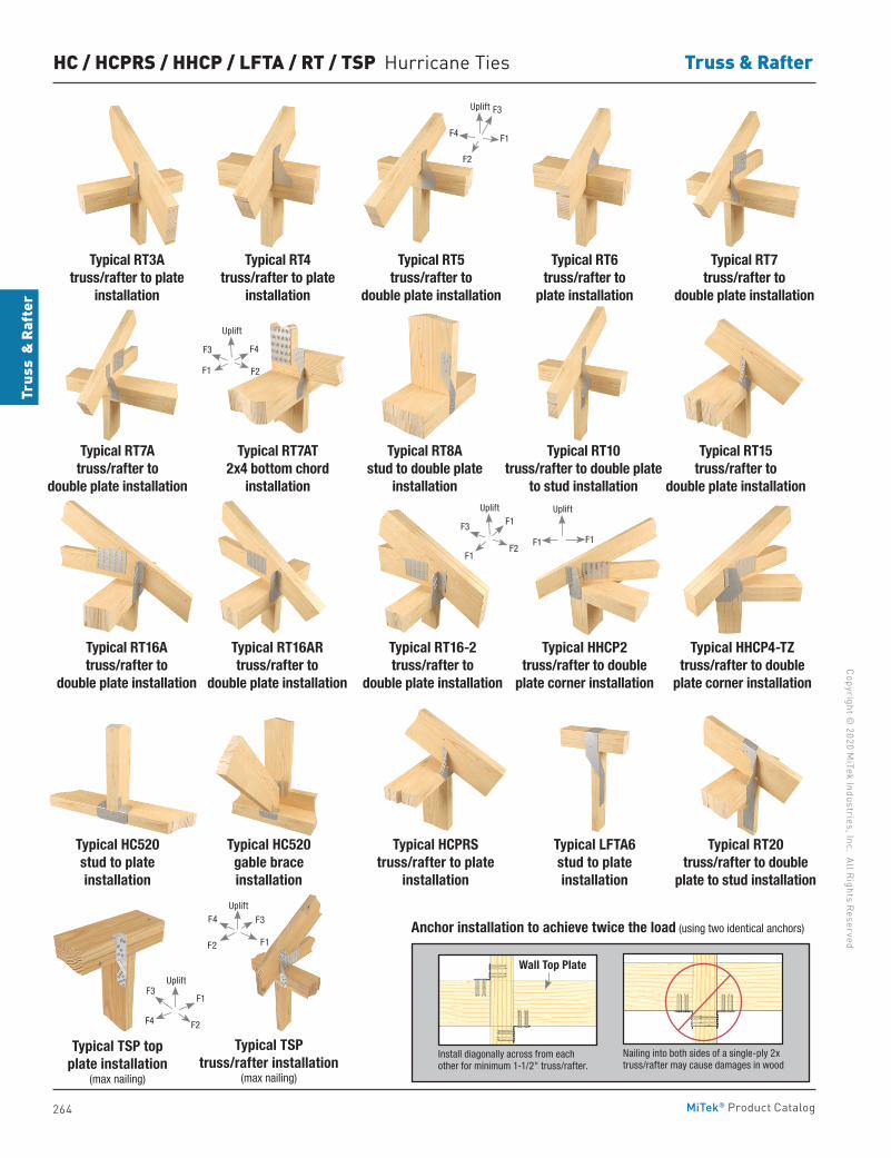
264
Copyright © 2020 M
iTek Industries, Inc. All Rights Reserved
Truss & Rafter
Trus
s &
Raf
ter
MiTek® Product Catalog
Typical RT6 truss/rafter to
plate installation
Typical RT4 truss/rafter to plate
installation
Typical RT3Atruss/rafter to plate
installation
Typical RT10 truss/rafter to double plate
to stud installation
Typical RT15 truss/rafter to
double plate installation
Typical RT8Astud to double plate
installation
Typical RT7AT2x4 bottom chord
installation
Typical RT7A truss/rafter to
double plate installation
Typical RT5truss/rafter to
double plate installation
Typical RT7truss/rafter to
double plate installation
HC / HCPRS / HHCP / LFTA / RT / TSP Hurricane Ties
Typical HHCP4-TZtruss/rafter to double
plate corner installation
Typical LFTA6stud to plate installation
Typical HHCP2 truss/rafter to double
plate corner installation
Typical RT16Atruss/rafter to
double plate installation
Typical RT16ARtruss/rafter to
double plate installation
Typical RT16-2truss/rafter to
double plate installation
Typical RT20 truss/rafter to double
plate to stud installation
Typical HC520 gable brace installation
Typical HC520 stud to plate installation
Typical HCPRS truss/rafter to plate
installation
Anchor installation to achieve twice the load (using two identical anchors)
Install diagonally across from each other for minimum 1-1/2" truss/rafter.
Nailing into both sides of a single-ply 2x truss/rafter may cause damages in wood
Wall Top Plate
Typical TSP top plate installation
(max nailing)
Typical TSP truss/rafter installation
(max nailing)
Uplift
F3
F1F2
F4
F4 F1
F3
F2
Uplift
F1
F4
F2
F3
Uplift
F1
F1
F2
F3
Uplift
F1 F1
Uplift
F3
F2
F1
F4
Uplift
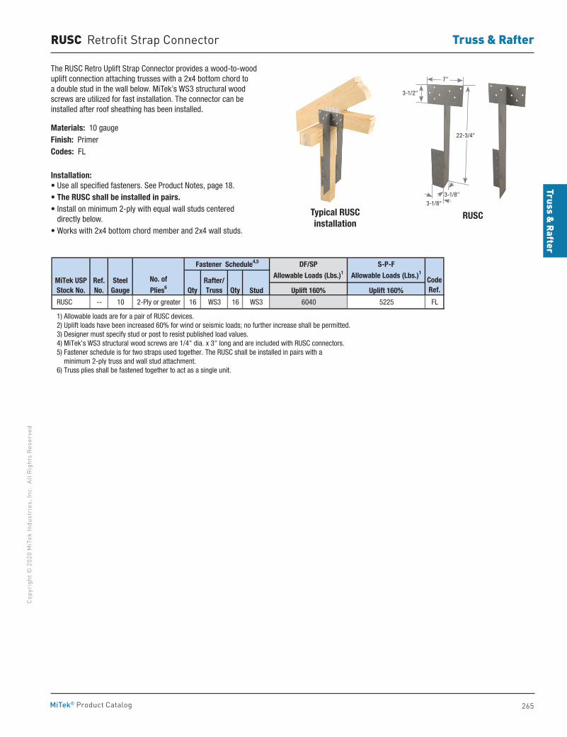
Truss & Rafter
265
Copy
righ
t © 2
020
MiT
ek In
dust
ries
, Inc
. Al
l Rig
hts
Rese
rved
Truss & Rafter
MiTek® Product Catalog
RUSC Retrofit Strap Connector
Typical RUSCinstallation
RUSC
The RUSC Retro Uplift Strap Connector provides a wood-to-wood uplift connection attaching trusses with a 2x4 bottom chord to a double stud in the wall below. MiTek’s WS3 structural wood screws are utilized for fast installation. The connector can be installed after roof sheathing has been installed.
Materials: 10 gaugeFinish: PrimerCodes: FL Installation:• Use all specified fasteners. See Product Notes, page 18.• The RUSC shall be installed in pairs.• Install on minimum 2-ply with equal wall studs centered
directly below.• Works with 2x4 bottom chord member and 2x4 wall studs.
Stud Uplift 160% Uplift 160%
RUSC -- 10 2-Ply or greater 16 WS3 16 WS3 6040 5225 FL
1) Allowable loads are for a pair of RUSC devices. 2) Uplift loads have been increased 60% for wind or seismic loads; no further increase shall be permitted. 3) Designer must specify stud or post to resist published load values. 4) MiTek's WS3 structural wood screws are 1/4" dia. x 3" long and are included with RUSC connectors. 5) Fastener schedule is for two straps used together. The RUSC shall be installed in pairs with a minimum 2-ply truss and wall stud attachment. 6) Truss plies shall be fastened together to act as a single unit.
CodeRef.
MiTek USPStock No.
Fastener Schedule4,5 DF/SP
Allowable Loads (Lbs.)1
S-P-F
Allowable Loads (Lbs.)1
QtyRafter/Truss Qty
SteelGauge
No. of
Plies6Ref.No.
7"
3-1/2"
22-3/4"
3-1/8"
3-1/8"
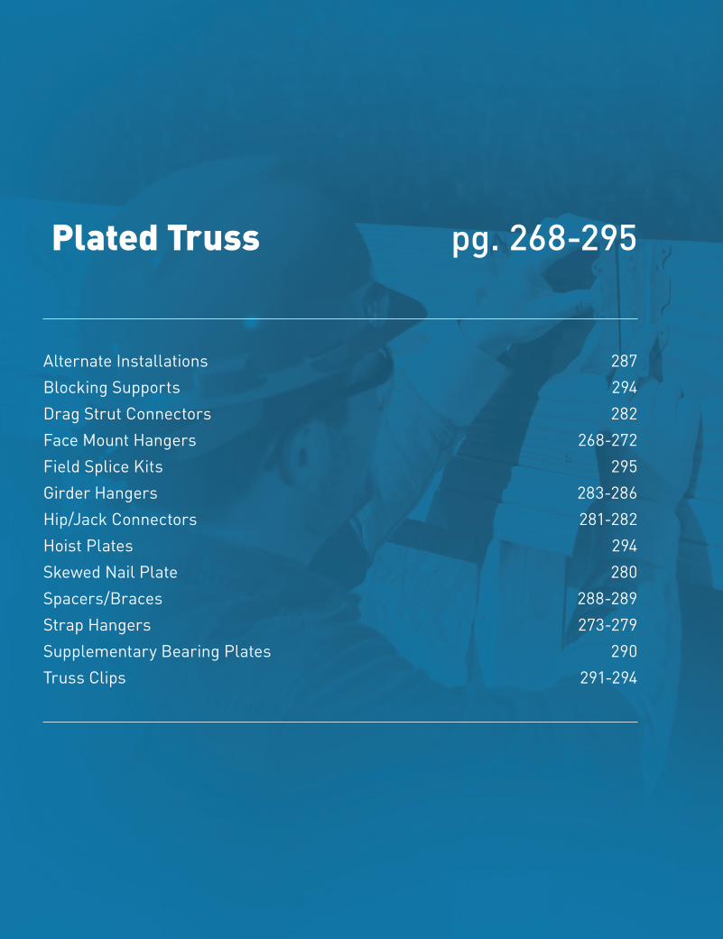
266
Copyright © 2020 M
iTek Industries, Inc. All Rights Reserved
Plated Truss
Plat
ed T
russ
MiTek® Product Catalog
Plated Truss
Alternate Installations 287Blocking Supports 294Drag Strut Connectors 282 Face Mount Hangers 268-272 Field Splice Kits 295 Girder Hangers 283-286Hip/Jack Connectors 281-282 Hoist Plates 294 Skewed Nail Plate 280 Spacers/Braces 288-289Strap Hangers 273-279 Supplementary Bearing Plates 290Truss Clips 291-294
pg. 268-295
267
Plated TrussCo
pyri
ght ©
202
0 M
iTek
Indu
stri
es, I
nc.
All R
ight
s Re
serv
ed
Plated Truss
MiTek® Product Catalog
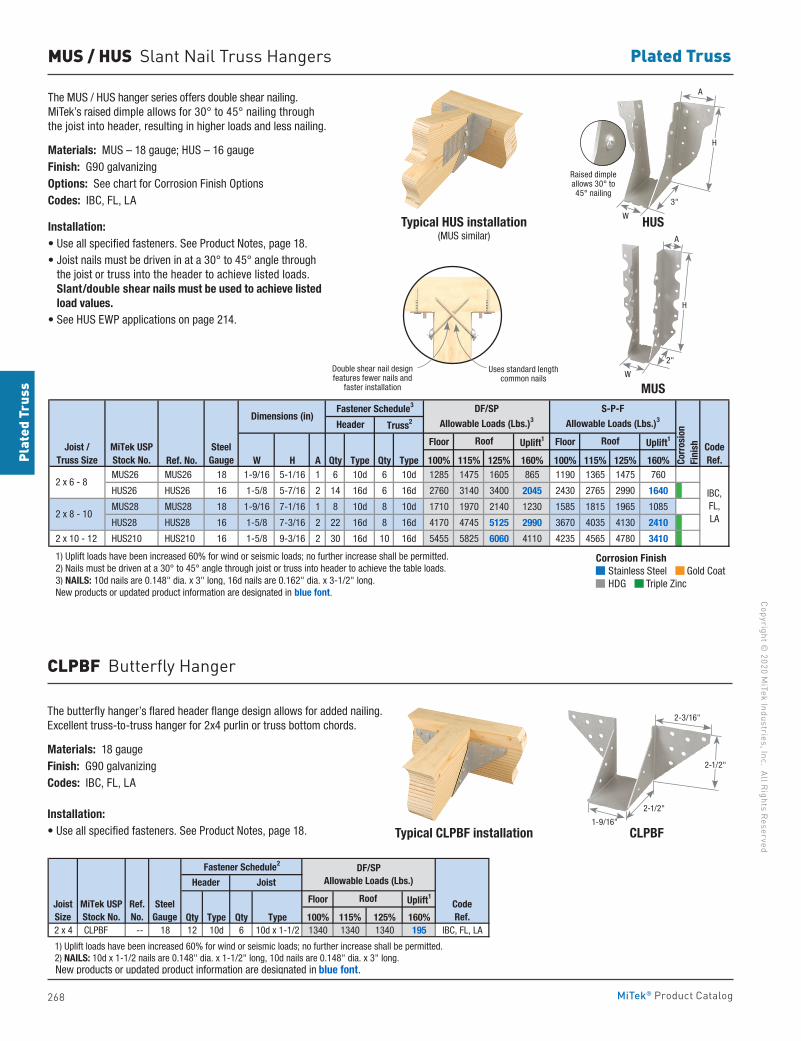
268
Copyright © 2020 M
iTek Industries, Inc. All Rights Reserved
Plated Truss
Plat
ed T
russ
MiTek® Product Catalog
MUS / HUS Slant Nail Truss Hangers
The MUS / HUS hanger series offers double shear nailing. MiTek’s raised dimple allows for 30° to 45° nailing through the joist into header, resulting in higher loads and less nailing.
Materials: MUS – 18 gauge; HUS – 16 gauge Finish: G90 galvanizingOptions: See chart for Corrosion Finish OptionsCodes: IBC, FL, LA
Installation:• Use all specified fasteners. See Product Notes, page 18.• Joist nails must be driven in at a 30° to 45° angle through
the joist or truss into the header to achieve listed loads. Slant/double shear nails must be used to achieve listed load values.
• See HUS EWP applications on page 214.
The butterfly hanger’s flared header flange design allows for added nailing. Excellent truss-to-truss hanger for 2x4 purlin or truss bottom chords.
Materials: 18 gauge Finish: G90 galvanizingCodes: IBC, FL, LA
Installation:• Use all specified fasteners. See Product Notes, page 18.
Floor Uplift1 Floor Uplift1
Ref. No. W H A Qty Type Qty Type 100% 115% 125% 160% 100% 115% 125% 160% MUS26 MUS26 18 1-9/16 5-1/16 1 6 10d 6 10d 1285 1475 1605 865 1190 1365 1475 760
HUS26 HUS26 16 1-5/8 5-7/16 2 14 16d 6 16d 2760 3140 3400 2045 2430 2765 2990 1640
MUS28 MUS28 18 1-9/16 7-1/16 1 8 10d 8 10d 1710 1970 2140 1230 1585 1815 1965 1085
HUS28 HUS28 16 1-5/8 7-3/16 2 22 16d 8 16d 4170 4745 5125 2990 3670 4035 4130 2410
2 x 10 - 12 HUS210 HUS210 16 1-5/8 9-3/16 2 30 16d 10 16d 5455 5825 6060 4110 4235 4565 4780 3410
1) Uplift loads have been increased 60% for wind or seismic loads; no further increase shall be permitted. 2) Nails must be driven at a 30° to 45° angle through joist or truss into header to achieve the table loads. 3) NAILS: 10d nails are 0.148" dia. x 3" long, 16d nails are 0.162" dia. x 3-1/2" long. New products or updated product information are designated in blue font.
IBC,FL,LA
Dimensions (in)
CodeRef.
Joist /Truss Size
MiTek USPStock No.
SteelGauge
2 x 6 - 8
2 x 8 - 10
Corr
osio
nFi
nish
Fastener Schedule3
Roof Roof
Header Truss2
DF/SP
Allowable Loads (Lbs.)3
S-P-F
Allowable Loads (Lbs.)3
Typical HUS installation(MUS similar)
Typical CLPBF installation
HUS
MUS
CLPBF
CLPBF Butterfly Hanger
Floor Uplift1
Qty Type Qty Type 100% 115% 125% 160%2 x 4 CLPBF -- 18 12 10d 6 10d x 1-1/2 1340 1340 1340 195 IBC, FL, LA
1) Uplift loads have been increased 60% for wind or seismic loads; no further increase shall be permitted. 2) NAILS: 10d x 1-1/2 nails are 0.148" dia. x 1-1/2" long, 10d nails are 0.148" dia. x 3" long. New products or updated product information are designated in blue font.
Fastener Schedule2 DF/SPAllowable Loads (Lbs.)
Joist Size
CodeRef.
MiTek USPStock No.
SteelGauge
Roof
Header Joist
Ref.No.
Corrosion Finish Stainless Steel Gold Coat HDG Triple Zinc
Corrosion Finish Stainless Steel Gold Coat HDG Triple Zinc
Corrosion Finish Stainless Steel Gold Coat HDG Triple Zinc
3"
W
W
Raised dimple allows 30° to 45° nailing
H
A
2"
A
H
Double shear nail designfeatures fewer nails and
faster installation
Uses standard length common nails
2-1/2"
2-3/16"
2-1/2"
1-9/16"
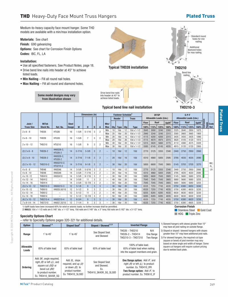
269
Plated TrussCo
pyri
ght ©
202
0 M
iTek
Indu
stri
es, I
nc.
All R
ight
s Re
serv
ed
Plated Truss
MiTek® Product Catalog
THD Heavy-Duty Face Mount Truss Hangers
Medium-to-heavy capacity face mount hanger. Some THD models are available with a min/max installation option.
Materials: See chartFinish: G90 galvanizingOptions: See chart for Corrosion Finish OptionsCodes: IBC, FL, LA
Installation:• Use all specified fasteners. See Product Notes, page 18.• Drive bend line nails into header at 45° to achieve
listed loads.• Min Nailing – Fill all round nail holes.• Max Nailing – Fill all round and diamond holes.
Some model designs may vary from illustration shown
Typical THD28 installation THD210
Floor Uplift1 Floor Uplift1
Ref. No. W H D A Qty Type Qty Type 100% 115% 125% 160% 100% 115% 125% 160%Min 18 16d 12 10d x 1-1/2 2645 3000 3240 2265 2325 2640 2850 1875Max 20 16d 20 10d x 1-1/2 2940 3240 3240 2315 2585 2665 2665 1900Min 28 16d 16 10d x 1-1/2 4115 4200 4200 2315 3435 3435 3435 1890Max 28 16d 26 10d x 1-1/2 4115 4670 4975 2315 3620 4105 4120 1915Min 38 16d 20 10d x 1-1/2 5315 5620 5660 3775 4110 4380 4575 3320Max 38 16d 32 10d x 1-1/2 5585 6145 6145 4035 4915 5120 5120 3365
4 x 6 - 8 THD46 HHUS46 14 3-5/8 5-5/16 3 2 -- 18 16d 12 10d 2770 3125 3355 2340 2440 2750 2950 2060 4 x 8 - 10 THD48 HHUS48 14 3-5/8 7-1/16 3 2 -- 28 16d 16 10d 4310 4860 5005 2595 3795 4020 4020 2080 4 x 10 -12 THD410 HHUS410 14 3-5/8 9-1/16 3 2 -- 38 16d 20 10d 5850 6600 7045 3905 5145 5680 5680 3255 4 x 12 - 14 THD412 -- 14 3-5/8 11 3 2 -- 48 16d 20 10d 7045 7045 7045 3905 5680 5680 5680 3255 4 x 14 - 16 THD414 -- 14 3-5/8 12-7/8 3 2 -- 58 16d 20 10d 7045 7045 7045 3905 5680 5680 5680 3255 (3) 2 x 10 - 12 THD210-3 HHUS210-3 12 5-1/8 9 3 3 -- 38 16d 20 10d 6535 7255 7745 4035 5750 6380 6650 3240 6 x 10 -12 THD610 HHUS5.50/10 12 5-1/2 9 3 2 -- 38 16d 20 10d 6535 7255 7745 4035 5750 6380 6630 3230 6 x 12 - 14 THD612 -- 12 5-1/2 11 3 2 -- 48 16d 20 10d 8255 8285 8285 4035 6630 6630 6630 3230 6 x 14 - 16 THD614 -- 12 5-1/2 12-7/8 3 2 -- 58 16d 20 10d 8285 8285 8285 4035 6630 6630 6630 3230 (4) 2 x 10 - 12 THD210-4 HHUS210-4 12 6-3/4 9 3 3 -- 38 16d 20 10d 6535 7255 7745 4035 5750 6380 6620 3230 7 x 9-1/4 - 14 THD7210 HHUS7.25/10 12 7-1/4 9 3 3 -- 38 16d 20 10d 6535 7255 7745 4035 5750 6380 6605 3220
1) Uplift loads have been increased 60% for wind or seismic loads; no further increase shall be permitted. 2) NAILS: 10d x 1-1/2 nails are 0.148" dia. x 1-1/2" long, 10d nails are 0.148" dia. x 3" long,16d nails are 0.162" dia. x 3-1/2" long.
Dimensions (in)
IBC,FL,LA
2
2
2
2
2
2
5850 6600 7045 3905
2340
2595
2770 3125 3355
4310 4860 5005
2440 2750 2950 2060
3795 4035 4035
20 10d
2090
5145 5705 5705 3270
12 10d
16d 16 10d
3
3
3
-- 18
-- 38
-- 28
16d
3-7/16
3-7/16
3-7/16
5-3/8
7-1/8
9-1/8
14
(2) 2 x 6 - 8
(2) 2 x 8 - 10
14 16d
HTU26
(2) 2 x 10 - 12
THD26-2
THD28-2
THD210-2
HHUS26-2, HTU26-2
HHUS28-2, HTU28-2
HHUS210-2, HTU210-2
14
Header Truss
CodeRef.
DF/SPAllowable Loads (Lbs.)
Corr
osio
nFi
nish
Fastener Schedule2
Min/Max
S-P-FAllowable Loads (Lbs.)
RoofJoist /Truss Size
MiTekStock No.
SteelGauge
Roof
HTU28
HTU210
16
16
2 x 6 - 8
2 x 8 - 10
2 x 10 - 12
THD26
THD28
3
3
3
1-5/8
1-5/8
1-5/8
16
5-1/16
7
9 THD210
Option Skewed1,3 Sloped Seat2 Sloped / Skewed1,2,3
1) Skewed hangers with skews greater than 15° may have all joist nailing on outside flange. 2) Sloped or sloped / skewed hangers with slopes greater than 15° may have additional joist nails. 3) For skewed hangers, the required cut type (square or bevel) of joist member may vary based on skew angle and width of hanger. Some square cut hangers will require custom pricing due to welded back plate.
See Sloped Seat and Skewed.
Ex. THD410_SK45R_SQ_SL30D
AllowableLoads
Inverted Flange
100% of table load.65% of table load when nailing
into the support members end grain.
One flange option: Add IF, and right (R) or left (L), to product
number. Ex. THD410_IFRTwo flange option: Add IF, to product number. Ex. THD610_IF
N/AOne flangeTwo flange
Range THD26 – THD210 THD26-2 – THD414 THD210-3 – THD7210
1˚ to 45˚ 1˚ to 45˚See Sloped Seat
and Skewed
Ordering
85% of table load 65% of table load 65% of table load
Add SK , angle required,right (R) or left (L) , and
square cut (SQ) orbevel cut (BV)
to product number.Ex. THD410_SK45R_SQ
Add SL, slope required, and up (U)
or down (D), to product number.
Ex. THD410_SL30D
Corrosion Finish Stainless Steel Gold Coat HDG Triple Zinc
Corrosion Finish Stainless Steel Gold Coat HDG Triple Zinc
Corrosion Finish Stainless Steel Gold Coat HDG Triple Zinc
Specialty Options Chart – refer to Specialty Options pages 320-321 for additional details.
1) Skewed hangers with skews greater than 15° may have all joist nailing on outside flange.
2) Sloped or sloped / skewed hangers with slopes greater than 15° may have additional joist nails.
3) For skewed hangers, the required cut type (square or bevel) of joist member may vary based on skew angle and width of hanger. Some square cut hangers will require custom pricing due to welded back plate.
Typical bend line nail installation
Drive bend line nails into header at 45° to achieve listed loads.
H
A
W D
Additional diamond holes for max nailing
Standard round holes for min
nailing
THD210-3
W
ABend line
nailing
D
H
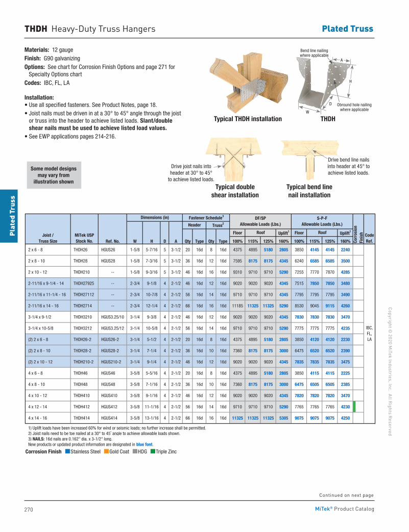
270
Copyright © 2020 M
iTek Industries, Inc. All Rights Reserved
Plated Truss
Plat
ed T
russ
MiTek® Product Catalog
Materials: 12 gaugeFinish: G90 galvanizingOptions: See chart for Corrosion Finish Options and page 271 for Specialty Options chartCodes: IBC, FL, LA
Installation:• Use all specified fasteners. See Product Notes, page 18.• Joist nails must be driven in at a 30° to 45° angle through the joist
or truss into the header to achieve listed loads. Slant/double shear nails must be used to achieve listed load values.
• See EWP applications pages 214-216.
THDH Heavy-Duty Truss Hangers
Floor Uplift1 Floor Uplift1
Ref. No. W H D A Qty Type Qty Type 100% 115% 125% 160% 100% 115% 125% 160%
2 x 6 - 8 THDH26 HGUS26 1-5/8 5-7/16 5 3-1/2 20 16d 8 16d 4375 4895 5180 2805 3850 4145 4145 2240
2 x 8 - 10 THDH28 HGUS28 1-5/8 7-3/16 5 3-1/2 36 16d 12 16d 7595 8175 8175 4345 6240 6585 6585 3500
2 x 10 - 12 THDH210 -- 1-5/8 9-3/16 5 3-1/2 46 16d 16 16d 9310 9710 9710 5290 7255 7770 7870 4285
2-11/16 x 9-1/4 - 14 THDH27925 -- 2-3/4 9-1/8 4 2-1/2 46 16d 12 16d 9020 9020 9020 4345 7515 7850 7850 3480
2-11/16 x 11-1/4 - 16 THDH27112 -- 2-3/4 10-7/8 4 2-1/2 56 16d 14 16d 9710 9710 9710 4345 7795 7795 7795 3490
2-11/16 x 14 - 16 THDH2714 -- 2-3/4 12-1/4 4 2-1/2 66 16d 16 16d 11185 11325 11325 5290 8530 9045 9115 4260
3-1/4 x 9-1/2 THDH3210 HGUS3.25/10 3-1/4 9-3/8 4 2-1/2 46 16d 12 16d 9020 9020 9020 4345 7830 7830 7830 3470
3-1/4 x 10-5/8 THDH3212 HGUS3.25/12 3-1/4 10-5/8 4 2-1/2 56 16d 14 16d 9710 9710 9710 5290 7775 7775 7775 4235
(2) 2 x 6 - 8 THDH26-2 HGUS26-2 3-1/4 5-1/2 4 2-1/2 20 16d 8 16d 4375 4895 5180 2805 3850 4120 4120 2230
(2) 2 x 8 - 10 THDH28-2 HGUS28-2 3-1/4 7-1/4 4 2-1/2 36 16d 10 16d 7360 8175 8175 3000 6475 6520 6520 2390
(2) 2 x 10 - 12 THDH210-2 HGUS210-2 3-1/4 9-1/4 4 2-1/2 46 16d 12 16d 9020 9020 9020 4345 7835 7835 7835 3475
4 x 6 - 8 THDH46 HGUS46 3-5/8 5-5/16 4 2-1/2 20 16d 8 16d 4375 4895 5180 2805 3850 4115 4115 2225
4 x 8 - 10 THDH48 HGUS48 3-5/8 7-1/16 4 2-1/2 36 16d 10 16d 7360 8175 8175 3000 6475 6505 6505 2385
4 x 10 - 12 THDH410 HGUS410 3-5/8 9-1/16 4 2-1/2 46 16d 12 16d 9020 9020 9020 4345 7820 7820 7820 3470
4 x 12 - 14 THDH412 HGUS412 3-5/8 11-1/16 4 2-1/2 56 16d 14 16d 9710 9710 9710 5290 7765 7765 7765 4230
4 x 14 - 16 THDH414 HGUS414 3-5/8 13-1/16 4 2-1/2 66 16d 16 16d 11325 11325 11325 5305 9075 9075 9075 4250
1) Uplift loads have been increased 60% for wind or seismic loads; no further increase shall be permitted. 2) Joist nails need to be toe nailed at a 30° to 45˚ angle to achieve allowable loads shown. 3) NAILS: 16d nails are 0.162" dia. x 3-1/2" long. New products or updated product information are designated in blue font.
IBC,FL,LA
Joist / Truss Size
MiTek USPStock No.
Fastener Schedule3
Header Truss2
CodeRef.
Roof Roof
DF/SPAllowable Loads (Lbs.)
S-P-FAllowable Loads (Lbs.)
Corr
osio
nFi
nish
Dimensions (in)
Some model designs may vary from
illustration shown
Corrosion Finish Stainless Steel Gold Coat HDG Triple Zinc
Corrosion Finish Stainless Steel Gold Coat HDG Triple Zinc
Corrosion Finish Stainless Steel Gold Coat HDG Triple Zinc
Continued on next page
Typical THDH installation
Drive joist nails into header at 30° to 45°
to achieve listed loads.
Typical bend line nail installation
Drive bend line nailsinto header at 45° to achieve listed loads.
THDH
H
D
W
Obround hole nailing where applicable
Bend line nailing where applicable
Typical double shear installation
A
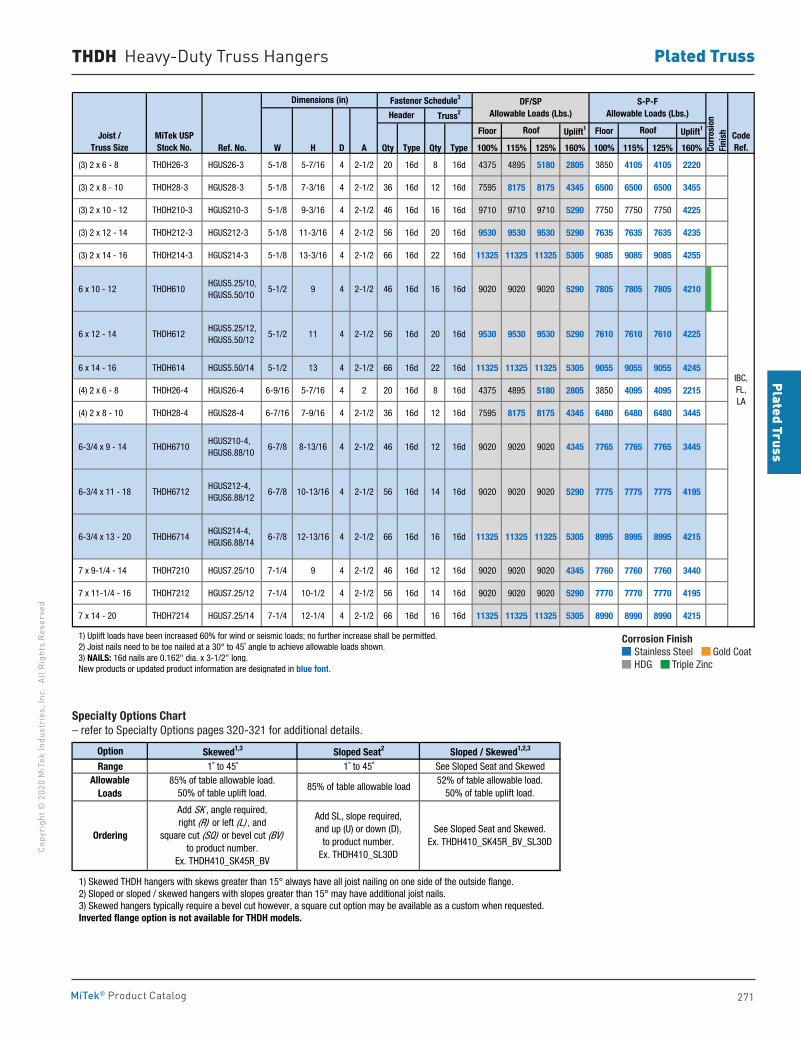
271
Plated TrussCo
pyri
ght ©
202
0 M
iTek
Indu
stri
es, I
nc.
All R
ight
s Re
serv
ed
Plated Truss
MiTek® Product Catalog
Corrosion Finish Stainless Steel Gold Coat HDG Triple Zinc
Corrosion Finish Stainless Steel Gold Coat HDG Triple Zinc
Corrosion Finish Stainless Steel Gold Coat HDG Triple Zinc
Option Skewed1,3 Sloped Seat2 Sloped / Skewed1,2,3
Range 1˚ to 45˚ 1˚ to 45˚ See Sloped Seat and Skewed
1) Skewed THDH hangers with skews greater than 15° always have all joist nailing on one side of the outside flange. 2) Sloped or sloped / skewed hangers with slopes greater than 15° may have additional joist nails. 3) Skewed hangers typically require a bevel cut however, a square cut option may be available as a custom when requested. Inverted flange option is not available for THDH models.
85% of table allowable loadAllowable
Loads85% of table allowable load.
50% of table uplift load.52% of table allowable load.
50% of table uplift load.
Ordering
Add SK , angle required,right (R) or left (L) , and
square cut (SQ) or bevel cut (BV)to product number.
Ex. THDH410_SK45R_BV
Add SL, slope required,and up (U) or down (D),
to product number.Ex. THDH410_SL30D
See Sloped Seat and Skewed.Ex. THDH410_SK45R_BV_SL30D
THDH Heavy-Duty Truss Hangers
Specialty Options Chart – refer to Specialty Options pages 320-321 for additional details.
Floor Uplift1 Floor Uplift1
Ref. No. W H D A Qty Type Qty Type 100% 115% 125% 160% 100% 115% 125% 160%
(3) 2 x 6 - 8 THDH26-3 HGUS26-3 5-1/8 5-7/16 4 2-1/2 20 16d 8 16d 4375 4895 5180 2805 3850 4105 4105 2220
(3) 2 x 8 - 10 THDH28-3 HGUS28-3 5-1/8 7-3/16 4 2-1/2 36 16d 12 16d 7595 8175 8175 4345 6500 6500 6500 3455
(3) 2 x 10 - 12 THDH210-3 HGUS210-3 5-1/8 9-3/16 4 2-1/2 46 16d 16 16d 9710 9710 9710 5290 7750 7750 7750 4225
(3) 2 x 12 - 14 THDH212-3 HGUS212-3 5-1/8 11-3/16 4 2-1/2 56 16d 20 16d 9530 9530 9530 5290 7635 7635 7635 4235
(3) 2 x 14 - 16 THDH214-3 HGUS214-3 5-1/8 13-3/16 4 2-1/2 66 16d 22 16d 11325 11325 11325 5305 9085 9085 9085 4255
6 x 10 - 12 THDH610 HGUS5.25/10, HGUS5.50/10
5-1/2 9 4 2-1/2 46 16d 16 16d 9020 9020 9020 5290 7805 7805 7805 4210
6 x 12 - 14 THDH612 HGUS5.25/12, HGUS5.50/12
5-1/2 11 4 2-1/2 56 16d 20 16d 9530 9530 9530 5290 7610 7610 7610 4225
6 x 14 - 16 THDH614 HGUS5.50/14 5-1/2 13 4 2-1/2 66 16d 22 16d 11325 11325 11325 5305 9055 9055 9055 4245
(4) 2 x 6 - 8 THDH26-4 HGUS26-4 6-9/16 5-7/16 4 2 20 16d 8 16d 4375 4895 5180 2805 3850 4095 4095 2215
(4) 2 x 8 - 10 THDH28-4 HGUS28-4 6-7/16 7-9/16 4 2-1/2 36 16d 12 16d 7595 8175 8175 4345 6480 6480 6480 3445
6-3/4 x 9 - 14 THDH6710 HGUS210-4, HGUS6.88/10
6-7/8 8-13/16 4 2-1/2 46 16d 12 16d 9020 9020 9020 4345 7765 7765 7765 3445
6-3/4 x 11 - 18 THDH6712 HGUS212-4, HGUS6.88/12
6-7/8 10-13/16 4 2-1/2 56 16d 14 16d 9020 9020 9020 5290 7775 7775 7775 4195
6-3/4 x 13 - 20 THDH6714 HGUS214-4, HGUS6.88/14
6-7/8 12-13/16 4 2-1/2 66 16d 16 16d 11325 11325 11325 5305 8995 8995 8995 4215
7 x 9-1/4 - 14 THDH7210 HGUS7.25/10 7-1/4 9 4 2-1/2 46 16d 12 16d 9020 9020 9020 4345 7760 7760 7760 3440
7 x 11-1/4 - 16 THDH7212 HGUS7.25/12 7-1/4 10-1/2 4 2-1/2 56 16d 14 16d 9020 9020 9020 5290 7770 7770 7770 4195
7 x 14 - 20 THDH7214 HGUS7.25/14 7-1/4 12-1/4 4 2-1/2 66 16d 16 16d 11325 11325 11325 5305 8990 8990 8990 4215
1) Uplift loads have been increased 60% for wind or seismic loads; no further increase shall be permitted. 2) Joist nails need to be toe nailed at a 30° to 45˚ angle to achieve allowable loads shown. 3) NAILS: 16d nails are 0.162" dia. x 3-1/2" long. New products or updated product information are designated in blue font.
CodeRef.
IBC,FL,LA
Fastener Schedule3 DF/SPAllowable Loads (Lbs.)
S-P-FAllowable Loads (Lbs.)
Corr
osio
nFi
nish
Header Truss2
Dimensions (in)
Joist / Truss Size
MiTek USPStock No.
Roof Roof
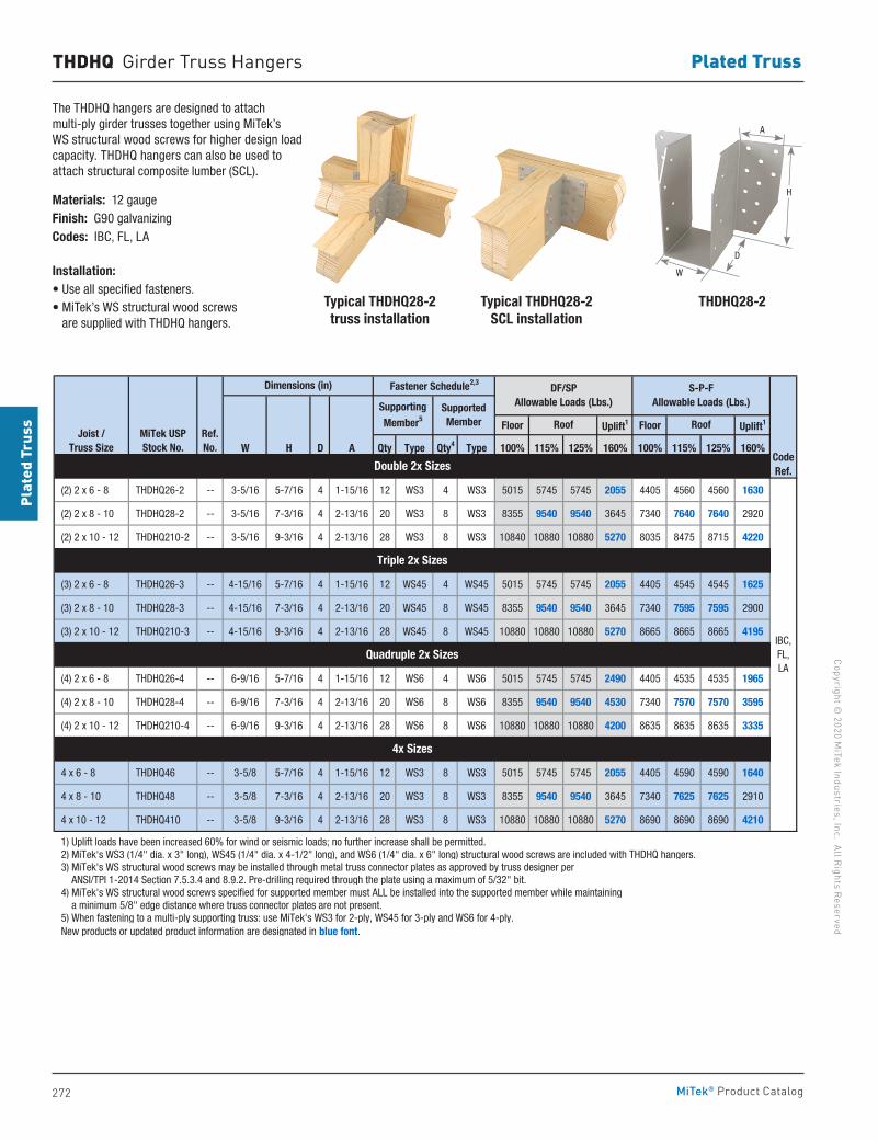
272
Copyright © 2020 M
iTek Industries, Inc. All Rights Reserved
Plated Truss
Plat
ed T
russ
MiTek® Product Catalog
THDHQ Girder Truss Hangers
The THDHQ hangers are designed to attach multi-ply girder trusses together using MiTek’s WS structural wood screws for higher design load capacity. THDHQ hangers can also be used to attach structural composite lumber (SCL).
Materials: 12 gauge Finish: G90 galvanizingCodes: IBC, FL, LA
Installation:• Use all specified fasteners. • MiTek’s WS structural wood screws
are supplied with THDHQ hangers.
Floor Uplift1 Floor Uplift1
W H D A Qty Type Qty4 Type 100% 115% 125% 160% 100% 115% 125% 160%
(2) 2 x 6 - 8 THDHQ26-2 -- 3-5/16 5-7/16 4 1-15/16 12 WS3 4 WS3 5015 5745 5745 2055 4405 4560 4560 1630
(2) 2 x 8 - 10 THDHQ28-2 -- 3-5/16 7-3/16 4 2-13/16 20 WS3 8 WS3 8355 9540 9540 3645 7340 7640 7640 2920
(2) 2 x 10 - 12 THDHQ210-2 -- 3-5/16 9-3/16 4 2-13/16 28 WS3 8 WS3 10840 10880 10880 5270 8035 8475 8715 4220
(3) 2 x 6 - 8 THDHQ26-3 -- 4-15/16 5-7/16 4 1-15/16 12 WS45 4 WS45 5015 5745 5745 2055 4405 4545 4545 1625
(3) 2 x 8 - 10 THDHQ28-3 -- 4-15/16 7-3/16 4 2-13/16 20 WS45 8 WS45 8355 9540 9540 3645 7340 7595 7595 2900
(3) 2 x 10 - 12 THDHQ210-3 -- 4-15/16 9-3/16 4 2-13/16 28 WS45 8 WS45 10880 10880 10880 5270 8665 8665 8665 4195
(4) 2 x 6 - 8 THDHQ26-4 -- 6-9/16 5-7/16 4 1-15/16 12 WS6 4 WS6 5015 5745 5745 2490 4405 4535 4535 1965
(4) 2 x 8 - 10 THDHQ28-4 -- 6-9/16 7-3/16 4 2-13/16 20 WS6 8 WS6 8355 9540 9540 4530 7340 7570 7570 3595
(4) 2 x 10 - 12 THDHQ210-4 -- 6-9/16 9-3/16 4 2-13/16 28 WS6 8 WS6 10880 10880 10880 4200 8635 8635 8635 3335
4 x 6 - 8 THDHQ46 -- 3-5/8 5-7/16 4 1-15/16 12 WS3 8 WS3 5015 5745 5745 2055 4405 4590 4590 1640
4 x 8 - 10 THDHQ48 -- 3-5/8 7-3/16 4 2-13/16 20 WS3 8 WS3 8355 9540 9540 3645 7340 7625 7625 2910
4 x 10 - 12 THDHQ410 -- 3-5/8 9-3/16 4 2-13/16 28 WS3 8 WS3 10880 10880 10880 5270 8690 8690 8690 4210
1) Uplift loads have been increased 60% for wind or seismic loads; no further increase shall be permitted. 2) MiTek's WS3 (1/4" dia. x 3" long), WS45 (1/4" dia. x 4-1/2" long), and WS6 (1/4" dia. x 6" long) structural wood screws are included with THDHQ hangers. 3) MiTek's WS structural wood screws may be installed through metal truss connector plates as approved by truss designer per ANSI/TPI 1-2014 Section 7.5.3.4 and 8.9.2. Pre-drilling required through the plate using a maximum of 5/32" bit. 4) MiTek's WS structural wood screws specified for supported member must ALL be installed into the supported member while maintaining a minimum 5/8" edge distance where truss connector plates are not present. 5) When fastening to a multi-ply supporting truss: use MiTek's WS3 for 2-ply, WS45 for 3-ply and WS6 for 4-ply. New products or updated product information are designated in blue font.
Double 2x Sizes
Triple 2x Sizes
Quadruple 2x Sizes
4x Sizes
IBC,FL,LA
CodeRef.
Joist / Truss Size
MiTek USPStock No.
Supporting Member5
Supported Member
Ref. No.
Dimensions (in) Fastener Schedule2,3
Roof Roof
DF/SPAllowable Loads (Lbs.)
S-P-FAllowable Loads (Lbs.)
Typical THDHQ28-2truss installation
Typical THDHQ28-2SCL installation
H
D
W
A
THDHQ28-2
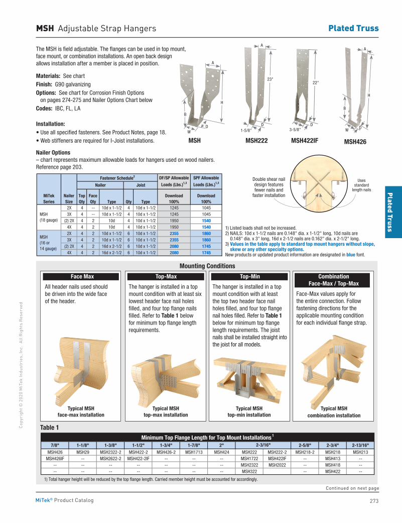
273
Plated TrussCo
pyri
ght ©
202
0 M
iTek
Indu
stri
es, I
nc.
All R
ight
s Re
serv
ed
Plated Truss
MiTek® Product Catalog
MSH Adjustable Strap Hangers
The MSH is field adjustable. The flanges can be used in top mount, face mount, or combination installations. An open back design allows installation after a member is placed in position.
Materials: See chartFinish: G90 galvanizingOptions: See chart for Corrosion Finish Options on pages 274-275 and Nailer Options Chart belowCodes: IBC, FL, LA
Installation:• Use all specified fasteners. See Product Notes, page 18.• Web stiffeners are required for I-Joist installations. MSH MSH422IFMSH222 MSH426
H
D
B
WD
22"
3-5/8"
H
DW
B
Face Max
All header nails used should be driven into the wide face of the header.
Top-Max
The hanger is installed in a top mount condition with at least six lowest header face nail holes filled, and four top flange nails filled. Refer to Table 1 below for minimum top flange length requirements.
Top-Min
The hanger is installed in a top mount condition with at least the top two header face nail holes filled, and four top flange nail holes filled. Refer to Table 1 below for minimum top flange length requirements. The joist nails shall be installed straight into the joist for all models.
Combination Face-Max / Top-Max
Face-Max values apply for the entire connection. Follow fastening directions for the applicable mounting condition for each individual flange strap.
Typical MSH face-max installation
Typical MSH top-max installation
Typical MSH top-min installation
Typical MSH combination installation
D
23"
1-5/8"
Mounting Conditions
Table 1
Double shear nail design features fewer nails and
faster installation
Uses standard
length nails
Fastener Schedule2
Type Qty Type2X 4 -- 10d x 1-1/2 4 10d x 1-1/2 1245 10453X 4 -- 10d x 1-1/2 4 10d x 1-1/2 1245 1045
(2) 2X 4 2 10d 4 10d x 1-1/2 1950 15404X 4 2 10d 4 10d x 1-1/2 1950 15402X 4 2 10d x 1-1/2 6 10d x 1-1/2 2355 18603X 4 2 10d x 1-1/2 6 10d x 1-1/2 2355 1860
(2) 2X 4 2 16d x 2-1/2 6 10d x 1-1/2 2080 17454X 4 2 16d x 2-1/2 6 10d x 1-1/2 2080 1745
1) Listed loads shall not be increased. 2) NAILS: 10d x 1-1/2 nails are 0.148" dia. x 1-1/2" long, 10d nails are 0.148" dia. x 3" long, 16d x 2-1/2 nails are 0.162" dia. x 2-1/2" long. 3) Values in the table apply to standard top mount hangers without slope, skew or any other specialty options. New products or updated product information are designated in blue font.
MSH (18 gauge)
MSH (16 or 14 gauge)
Nailer Joist
MiTekSeries
NailerSize
Download100%
Download100%
DF/SP Allowable
Loads (Lbs.)1,3
SPF Allowable
Loads (Lbs.)1,3
TopQty
FaceQty
Nailer Options – chart represents maximum allowable loads for hangers used on wood nailers. Reference page 203.
1) Listed loads shall not be increased.2) NAILS: 10d x 1-1/2 nails are 0.148" dia. x 1-1/2" long, 10d nails are
0.148" dia. x 3" long, 16d x 2-1/2 nails are 0.162" dia. x 2-1/2" long.3) Values in the table apply to standard top mount hangers without slope,
skew or any other specialty options.New products or updated product information are designated in blue font.
7/8" 1-1/8" 1-3/8" 1-1/2" 1-3/4" 1-7/8" 2" 2-5/8" 2-3/4" 2-13/16"MSH426 MSH29 MSH2322-2 MSH422-2 MSH426-2 MSH1713 MSH424 MSH222 MSH222-2 MSH218-2 MSH218 MSH213
MSH426IF -- MSH2622-2 MSH422-2IF -- -- -- MSH1722 MSH422IF -- MSH413 ---- -- -- -- -- -- -- MSH2322 MSH2022 -- MSH418 ---- -- -- -- -- -- -- MSH322 -- MSH422 --
1) Total hanger height will be reduced by the top flange length. Carried member height must be accounted for accordingly.
Minimum Top Flange Length for Top Mount Installations 1
2-3/16"
A
AA
Continued on next page
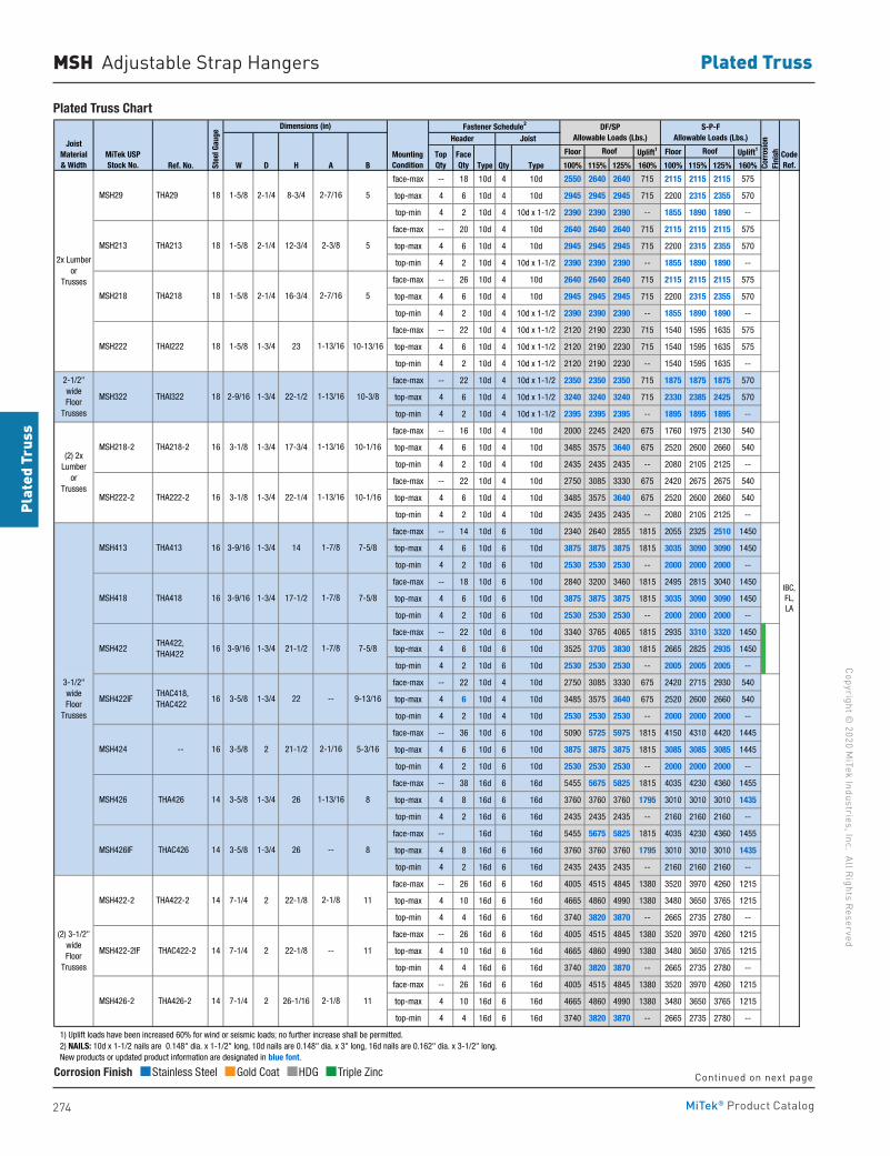
274
Copyright © 2020 M
iTek Industries, Inc. All Rights Reserved
Plated Truss
Plat
ed T
russ
MiTek® Product Catalog
Floor Uplift1 Floor Uplift1
Ref. No. W D H A B Type Qty Type 100% 115% 125% 160% 100% 115% 125% 160%
face-max -- 18 10d 4 10d 2550 2640 2640 715 2115 2115 2115 575
top-max 4 6 10d 4 10d 2945 2945 2945 715 2200 2315 2355 570
top-min 4 2 10d 4 10d x 1-1/2 2390 2390 2390 -- 1855 1890 1890 --
face-max -- 20 10d 4 10d 2640 2640 2640 715 2115 2115 2115 575
top-max 4 6 10d 4 10d 2945 2945 2945 715 2200 2315 2355 570
top-min 4 2 10d 4 10d x 1-1/2 2390 2390 2390 -- 1855 1890 1890 --
face-max -- 26 10d 4 10d 2640 2640 2640 715 2115 2115 2115 575
top-max 4 6 10d 4 10d 2945 2945 2945 715 2200 2315 2355 570
top-min 4 2 10d 4 10d x 1-1/2 2390 2390 2390 -- 1855 1890 1890 --
face-max -- 22 10d 4 10d x 1-1/2 2120 2190 2230 715 1540 1595 1635 575
top-max 4 6 10d 4 10d x 1-1/2 2120 2190 2230 715 1540 1595 1635 575
top-min 4 2 10d 4 10d x 1-1/2 2120 2190 2230 -- 1540 1595 1635 --
face-max -- 22 10d 4 10d x 1-1/2 2350 2350 2350 715 1875 1875 1875 570
top-max 4 6 10d 4 10d x 1-1/2 3240 3240 3240 715 2330 2385 2425 570
top-min 4 2 10d 4 10d x 1-1/2 2395 2395 2395 -- 1895 1895 1895 --
face-max -- 16 10d 4 10d 2000 2245 2420 675 1760 1975 2130 540
top-max 4 6 10d 4 10d 3485 3575 3640 675 2520 2600 2660 540
top-min 4 2 10d 4 10d 2435 2435 2435 -- 2080 2105 2125 --
face-max -- 22 10d 4 10d 2750 3085 3330 675 2420 2675 2675 540
top-max 4 6 10d 4 10d 3485 3575 3640 675 2520 2600 2660 540
top-min 4 2 10d 4 10d 2435 2435 2435 -- 2080 2105 2125 --
face-max -- 14 10d 6 10d 2340 2640 2855 1815 2055 2325 2510 1450
top-max 4 6 10d 6 10d 3875 3875 3875 1815 3035 3090 3090 1450
top-min 4 2 10d 6 10d 2530 2530 2530 -- 2000 2000 2000 --
face-max -- 18 10d 6 10d 2840 3200 3460 1815 2495 2815 3040 1450
top-max 4 6 10d 6 10d 3875 3875 3875 1815 3035 3090 3090 1450
top-min 4 2 10d 6 10d 2530 2530 2530 -- 2000 2000 2000 --
face-max -- 22 10d 6 10d 3340 3765 4065 1815 2935 3310 3320 1450
top-max 4 6 10d 6 10d 3525 3705 3830 1815 2665 2825 2935 1450
top-min 4 2 10d 6 10d 2530 2530 2530 -- 2005 2005 2005 --
face-max -- 22 10d 4 10d 2750 3085 3330 675 2420 2715 2930 540
top-max 4 6 10d 4 10d 3485 3575 3640 675 2520 2600 2660 540
top-min 4 2 10d 4 10d 2530 2530 2530 -- 2000 2000 2000 --
face-max -- 36 10d 6 10d 5090 5725 5975 1815 4150 4310 4420 1445
top-max 4 6 10d 6 10d 3875 3875 3875 1815 3085 3085 3085 1445
top-min 4 2 10d 6 10d 2530 2530 2530 -- 2000 2000 2000 --
face-max -- 38 16d 6 16d 5455 5675 5825 1815 4035 4230 4360 1455
top-max 4 8 16d 6 16d 3760 3760 3760 1795 3010 3010 3010 1435
top-min 4 2 16d 6 16d 2435 2435 2435 -- 2160 2160 2160 --
face-max -- 16d 16d 5455 5675 5825 1815 4035 4230 4360 1455
top-max 4 8 16d 6 16d 3760 3760 3760 1795 3010 3010 3010 1435
top-min 4 2 16d 6 16d 2435 2435 2435 -- 2160 2160 2160 --
face-max -- 26 16d 6 16d 4005 4515 4845 1380 3520 3970 4260 1215
top-max 4 10 16d 6 16d 4665 4860 4990 1380 3480 3650 3765 1215
top-min 4 4 16d 6 16d 3740 3820 3870 -- 2665 2735 2780 --
face-max -- 26 16d 6 16d 4005 4515 4845 1380 3520 3970 4260 1215
top-max 4 10 16d 6 16d 4665 4860 4990 1380 3480 3650 3765 1215
top-min 4 4 16d 6 16d 3740 3820 3870 -- 2665 2735 2780 --
face-max -- 26 16d 6 16d 4005 4515 4845 1380 3520 3970 4260 1215
top-max 4 10 16d 6 16d 4665 4860 4990 1380 3480 3650 3765 1215
top-min 4 4 16d 6 16d 3740 3820 3870 -- 2665 2735 2780 --
1) Uplift loads have been increased 60% for wind or seismic loads; no further increase shall be permitted. 2) NAILS: 10d x 1-1/2 nails are 0.148" dia. x 1-1/2" long, 10d nails are 0.148" dia. x 3" long, 16d nails are 0.162" dia. x 3-1/2" long. New products or updated product information are designated in blue font.
1-7/8
--
2-1/16
1-13/16
--
2-1/8
--
2-1/8
2-7/16
2-3/8
2-7/16
1-13/16
1-13/16
1-13/16
1-13/16
1-7/8
1-7/8IBC,FL,LA
8
MSH222
MSH218
TopQty
FaceQtySt
eel G
auge
CodeRef.
16
THAC418, THAC422
16
16
221-3/4 9-13/16
14
17-1/2
21-1/2
3-1/8
3-5/8
Fastener Schedule2Dimensions (in)
Header
1-5/8
2-1/4
JoistJoist
Material& Width
7-5/8
MSH426 THA426 8
MiTek USPStock No.
MountingCondition
2-1/2" wideFloor
Trusses
THA218
1-5/8
MSH322 THAI322 18
MSH422IF
MSH422 THA422, THAI422
231-3/4
2x Lumberor
Trusses
(2) 2x Lumber
orTrusses
3-1/2" wideFloor
Trusses
3-5/8 1-3/4
22-1/22-9/16
1-3/4
1-3/4
17-3/4
16
22-1/4
26
3-9/16
Roof
MSH418 THA418
3-9/16
3-9/16
MSH413 THA413
1-5/8
10-13/16
10-3/8
2-1/4 5
Roof
12-3/4 5
5
8-3/4 MSH29 THA29
18
18
MSH222-2 THA222-2
THAI222
14 7-1/4 2 26-1/16 11
14 7-1/4 11 MSH422-2 THA422-2 22-1/82
(2) 3-1/2" wideFloor
Trusses
21-1/2 5-3/16 MSH424 -- 3-5/8
1-3/4
18
18
1-5/8
MSH218-2 THA218-2
1-3/4
1-3/4
1-3/4
10-1/16
MSH426IF THAC426 14 3-5/8 1-3/4 26
MSH426-2 THA426-2
Corr
osio
n Fi
nish
MSH422-2IF THAC422-2 14 7-1/4 2 22-1/8 11
DF/SPAllowable Loads (Lbs.)
S-P-FAllowable Loads (Lbs.)
10-1/16
7-5/8
7-5/816
3-1/8
2
2-1/4 16-3/4
MSH213
16
14
16
THA213
MSH Adjustable Strap Hangers
Plated Truss Chart
Corrosion Finish Stainless Steel Gold Coat HDG Triple Zinc
Corrosion Finish Stainless Steel Gold Coat HDG Triple Zinc
Corrosion Finish Stainless Steel Gold Coat HDG Triple Zinc
Continued on next page
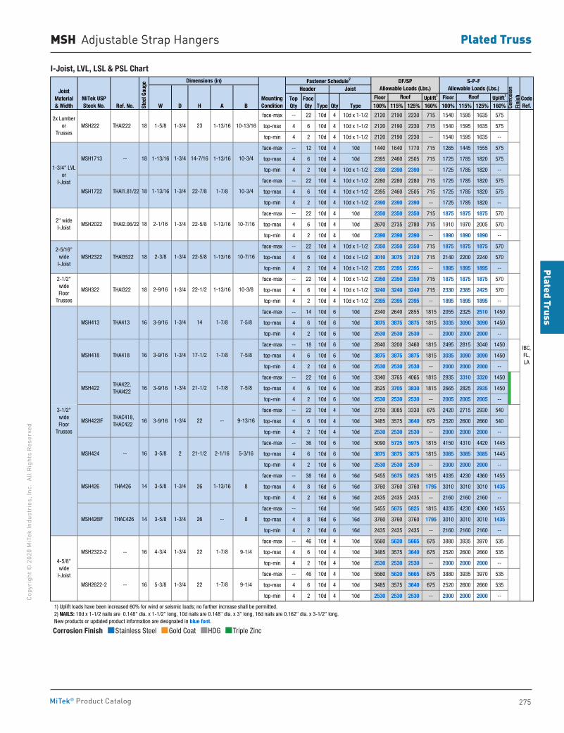
275
Plated TrussCo
pyri
ght ©
202
0 M
iTek
Indu
stri
es, I
nc.
All R
ight
s Re
serv
ed
Plated Truss
MiTek® Product Catalog
Floor Uplift1 Floor Uplift1
Ref. No. W D H A B Type Qty Type 100% 115% 125% 160% 100% 115% 125% 160%
face-max -- 22 10d 4 10d x 1-1/2 2120 2190 2230 715 1540 1595 1635 575
top-max 4 6 10d 4 10d x 1-1/2 2120 2190 2230 715 1540 1595 1635 575
top-min 4 2 10d 4 10d x 1-1/2 2120 2190 2230 -- 1540 1595 1635 --
face-max -- 12 10d 4 10d 1440 1640 1770 715 1265 1445 1555 575
top-max 4 6 10d 4 10d 2395 2460 2505 715 1725 1785 1820 575
top-min 4 2 10d 4 10d x 1-1/2 2390 2390 2390 -- 1725 1785 1820 --
face-max -- 22 10d 4 10d x 1-1/2 2280 2280 2280 715 1725 1785 1820 575
top-max 4 6 10d 4 10d x 1-1/2 2395 2460 2505 715 1725 1785 1820 575
top-min 4 2 10d 4 10d x 1-1/2 2390 2390 2390 -- 1725 1785 1820 --
face-max -- 22 10d 4 10d 2350 2350 2350 715 1875 1875 1875 570
top-max 4 6 10d 4 10d 2670 2735 2780 715 1910 1970 2005 570
top-min 4 2 10d 4 10d 2390 2390 2390 -- 1890 1890 1890 --
face-max -- 22 10d 4 10d x 1-1/2 2350 2350 2350 715 1875 1875 1875 570
top-max 4 6 10d 4 10d x 1-1/2 3010 3075 3120 715 2140 2200 2240 570
top-min 4 2 10d 4 10d x 1-1/2 2395 2395 2395 -- 1895 1895 1895 --
face-max -- 22 10d 4 10d x 1-1/2 2350 2350 2350 715 1875 1875 1875 570
top-max 4 6 10d 4 10d x 1-1/2 3240 3240 3240 715 2330 2385 2425 570
top-min 4 2 10d 4 10d x 1-1/2 2395 2395 2395 -- 1895 1895 1895 --
face-max -- 14 10d 6 10d 2340 2640 2855 1815 2055 2325 2510 1450
top-max 4 6 10d 6 10d 3875 3875 3875 1815 3035 3090 3090 1450
top-min 4 2 10d 6 10d 2530 2530 2530 -- 2000 2000 2000 --
face-max -- 18 10d 6 10d 2840 3200 3460 1815 2495 2815 3040 1450
top-max 4 6 10d 6 10d 3875 3875 3875 1815 3035 3090 3090 1450
top-min 4 2 10d 6 10d 2530 2530 2530 -- 2000 2000 2000 --
face-max -- 22 10d 6 10d 3340 3765 4065 1815 2935 3310 3320 1450
top-max 4 6 10d 6 10d 3525 3705 3830 1815 2665 2825 2935 1450
top-min 4 2 10d 6 10d 2530 2530 2530 -- 2005 2005 2005 --
face-max -- 22 10d 4 10d 2750 3085 3330 675 2420 2715 2930 540
top-max 4 6 10d 4 10d 3485 3575 3640 675 2520 2600 2660 540
top-min 4 2 10d 4 10d 2530 2530 2530 -- 2000 2000 2000 --
face-max -- 36 10d 6 10d 5090 5725 5975 1815 4150 4310 4420 1445
top-max 4 6 10d 6 10d 3875 3875 3875 1815 3085 3085 3085 1445
top-min 4 2 10d 6 10d 2530 2530 2530 -- 2000 2000 2000 --
face-max -- 38 16d 6 16d 5455 5675 5825 1815 4035 4230 4360 1455
top-max 4 8 16d 6 16d 3760 3760 3760 1795 3010 3010 3010 1435
top-min 4 2 16d 6 16d 2435 2435 2435 -- 2160 2160 2160 --
face-max -- 16d 16d 5455 5675 5825 1815 4035 4230 4360 1455
top-max 4 8 16d 6 16d 3760 3760 3760 1795 3010 3010 3010 1435
top-min 4 2 16d 6 16d 2435 2435 2435 -- 2160 2160 2160 --
face-max -- 46 10d 4 10d 5560 5620 5665 675 3880 3935 3970 535
top-max 4 6 10d 4 10d 3485 3575 3640 675 2520 2600 2660 535
top-min 4 2 10d 4 10d 2530 2530 2530 -- 2000 2000 2000 --
face-max -- 46 10d 4 10d 5560 5620 5665 675 3880 3935 3970 535
top-max 4 6 10d 4 10d 3485 3575 3640 675 2520 2600 2660 535
top-min 4 2 10d 4 10d 2530 2530 2530 -- 2000 2000 2000 --
1) Uplift loads have been increased 60% for wind or seismic loads; no further increase shall be permitted. 2) NAILS: 10d x 1-1/2 nails are 0.148" dia. x 1-1/2" long, 10d nails are 0.148" dia. x 3" long, 16d nails are 0.162" dia. x 3-1/2" long. New products or updated product information are designated in blue font.
1-7/8
1-13/16
1-7/8
1-7/8
1-7/8
--
2-1/16
1-13/16
--
1-7/8
IBC,FL,LA
CodeRef.
21-1/2 5-3/16
1-3/4
1-3/4
10-7/16
14 7-5/8
22-5/81-3/4
22-7/8
23
1-3/4 14-7/16 10-3/4
9-13/1622
17-1/2
7-5/8
10-3/4
10-3/8
7-5/8
Roof
4-3/4 1-3/4 22
18 1-13/16
21-1/2
14 3-5/8
1-3/4
2-3/8
16
1-3/4
3-5/8 2
3-9/16 1-3/4
22-1/22-9/16
16
1-3/4
18 2-1/16
2-5/16" wide
I-Joist
MiTek USPStock No.
MountingCondition
Roof
Fastener Schedule2Dimensions (in)Header Joist
22-5/8
TopQty
FaceQtySt
eel G
auge
1-13/16
1-13/16
1-7/8
1-13/16
1-13/16
--
10-7/16
10-13/16
1-3/4
2x Lumberor
Trusses MSH222 THAI222 18
1-3/4
1-3/4
MSH1713
1-5/8
MSH2322 THAI3522
MSH1722 THAI1.81/22
-- 18 1-13/16
18
18
2" wideI-Joist
MSH2022 THAI2.06/22
--
JoistMaterial& Width
THA413
9-1/4
9-1/4
826
MSH422
MSH426 THA426
THA422, THAI422
MSH424
5-3/8 1-3/4 22
16
16
16 3-9/16
3-9/16
16 3-9/16
16
MSH422IF
Corr
osio
n Fi
nish
1-3/4" LVLor
I-Joist
4-5/8" wide
I-Joist
DF/SPAllowable Loads (Lbs.)
S-P-FAllowable Loads (Lbs.)
3-1/2" wideFloor
Trusses
MSH426IF THAC426 14 3-5/8 1-3/4 26 8
2-1/2" wideFloor
Trusses
MSH2622-2 --
MSH413
MSH418 THA418
MSH322 THAI322
MSH2322-2
THAC418, THAC422
MSH Adjustable Strap Hangers
I-Joist, LVL, LSL & PSL Chart
Corrosion Finish Stainless Steel Gold Coat HDG Triple Zinc
Corrosion Finish Stainless Steel Gold Coat HDG Triple Zinc
Corrosion Finish Stainless Steel Gold Coat HDG Triple Zinc
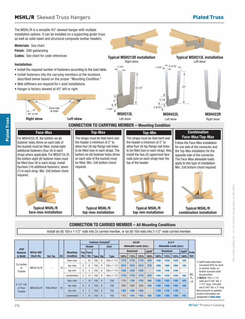
276
Copyright © 2020 M
iTek Industries, Inc. All Rights Reserved
Plated Truss
Plat
ed T
russ
MiTek® Product Catalog
MSHL/R Skewed Truss Hangers
The MSHL/R is a versatile 45° skewed hanger with multiple installation options. It can be installed on a supporting girder truss as well as solid-sawn and structural composite lumber headers.
Materials: See chartFinish: G90 galvanizingCodes: See chart for code references
Installation:• Install the required number of fasteners according to the load table.• Install fasteners into the carrying members at the locations
described below based on the proper “Mounting Condition.” • Web stiffeners are required for I-Joist installations.• Hanger is factory skewed at 45° left or right.
Typical MSH213R installationRight skew
Typical MSH213L installationLeft skew
Uplift1 Uplift1
Ref. No. Type Qty Type 100% 115% 125% 160% 100% 115% 125% 160%
face-max -- 22 10d 6 10d x 1-1/2 1770 1770 1770 670 1430 1430 1430 540
top-max 4 6 10d 6 10d x 1-1/2 1810 1810 1810 670 1460 1460 1460 540
top-min 4 2 10d 6 10d x 1-1/2 1325 1325 1325 -- 1240 1240 1240 --
combination 2 14 10d 6 10d x 1-1/2 1770 1770 1770 670 1430 1430 1430 540
face-max -- 14 10d 6 10d 1750 1755 1755 560 1395 1395 1395 445
top-max 4 6 10d 6 10d 1820 1820 1820 560 1490 1490 1490 445
top-min 4 2 10d 6 10d 1385 1385 1385 -- 1100 1100 1100 --
combination 2 10 10d 6 10d 1750 1755 1755 560 1395 1395 1395 445
1) Uplift loads have been increased 60% for wind or seismic loads; no further increase shall be permitted. 2) NAILS: 10d x 1-1/2 nails are 0.148" dia. x 1-1/2" long, 10d nails are 0.148" dia. x 3" long. New products or updated product information are designated in blue font.
Header
S-P-FAllowable Loads (Lbs.)
JoistMaterial& Width
MiTek USPStock No. GA
MountingCondition
Joist
Fastener Schedule2 DF/SPAllowable Loads (Lbs.)
TopQty
FaceQty
Download Download
3-1/2" LVLor FloorTrusses
CodeRef.
THAL/R422 16
2x Lumberor
Trusses-- MSH213L/R
MSH422L/R
18
IBC,FL,LA
MSH213L Left skew
13-1/4"
5"
1-5/8"
1-3/4"
Right skew Left skew
Drive nails at angle
40° to 50°
Typical MSHL/R face-max installation
Typical MSHL/R top-max installation
Typical MSHL/R top-min installation
Typical MSHL/R combination installation
Install six (6) 10d x 1-1/2" nails into 2x carried member, or six (6) 10d nails into 3-1/2" wide carried member.
CONNECTION TO CARRYING MEMBER – Mounting Condition
CONNECTION TO CARRIED MEMBER – All Mounting Conditions
Top-Max The straps must be field-bent over the header a minimum of 2" to allow four (4) top flange nail holes to be filled (two in each strap). The bottom six (6) fastener holes (three on each side of the bucket) must be filled. Min. 2x6 bottom chord required.
Top-MinThe straps must be field bent over the header a minimum of 2" to allow four (4) top flange nail holes to be filled (two in each strap). Also install the two (2) uppermost face nails (one on each strap) near the top of the header.
MSH422R Right skew
MSH422L Left skew
22"
5-1/8"
1-3/4"
3-9/16"
9-5/16"
Combination Face-Max/Top-Max
Follow the Face-Max installation for one side of the connector and the Top-Max installation for the opposite side of the connector. The Face-Max allowable loads apply to this type of installation. Min. 2x6 bottom chord required.
1) Uplift loads have been increased 60% for wind or seismic loads; no further increase shall be permitted.
2) NAILS: 10d x 1-1/2 nails are 0.148" dia. x 1-1/2" long, 10d nails are 0.148" dia. x 3" long
New products or updated product information are designated in blue font.
Face-Max For MSH422L/R, the bottom six (6) fastener holes (three on each side of the bucket) must be filled. Install eight additional fasteners (four (4) in each strap) where applicable. For MSH213L/R, the bottom eight (8) fastener holes must be filled (four (4) in each strap). Install fourteen (14) additional fasteners, seven (7) in each strap. Min. 2x6 bottom chord required.
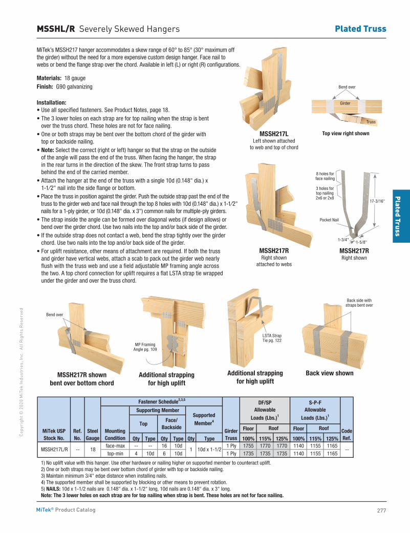
277
Plated TrussCo
pyri
ght ©
202
0 M
iTek
Indu
stri
es, I
nc.
All R
ight
s Re
serv
ed
Plated Truss
MiTek® Product Catalog
MSSHL/R Severely Skewed Hangers
MiTek’s MSSH217 hanger accommodates a skew range of 60° to 85° (30° maximum off the girder) without the need for a more expensive custom design hanger. Face nail to webs or bend the flange strap over the chord. Available in left (L) or right (R) configurations.
Materials: 18 gaugeFinish: G90 galvanizing
Installation:• Use all specified fasteners. See Product Notes, page 18.• The 3 lower holes on each strap are for top nailing when the strap is bent
over the truss chord. These holes are not for face nailing.• One or both straps may be bent over the bottom chord of the girder with
top or backside nailing.• Note: Select the correct (right or left) hanger so that the strap on the outside
of the angle will pass the end of the truss. When facing the hanger, the strap in the rear turns in the direction of the skew. The front strap turns to pass behind the end of the carried member.
• Attach the hanger at the end of the truss with a single 10d (0.148" dia.) x 1-1⁄2" nail into the side flange or bottom.
• Place the truss in position against the girder. Push the outside strap past the end of the truss to the girder web and face nail through the top 8 holes with 10d (0.148" dia.) x 1-1⁄2" nails for a 1-ply girder, or 10d (0.148" dia. x 3") common nails for multiple-ply girders.
• The strap inside the angle can be formed over diagonal webs (if design allows) or bend over the girder chord. Use two nails into the top and/or back side of the girder.
• If the outside strap does not contact a web, bend the strap tightly over the girder chord. Use two nails into the top and/or back side of the girder.
• For uplift resistance, other means of attachment are required. If both the truss and girder have vertical webs, attach a scab to pack out the girder web nearly flush with the truss web and use a field adjustable MP framing angle across the two. A top chord connection for uplift requires a flat LSTA strap tie wrapped under the girder and over the truss chord.
MSSH217LLeft shown attached
to web and top of chord
MSSH217RRight shown
attached to webs
Top view right shown
MSSH217RRight shown
Pocket Nail
8 holes for face nailing
3 holes for top nailing 2x6 or 2x8
17-3/16"
1-5/8"1-3/4"
MSSH217R shownbent over bottom chord
Additional strappingfor high uplift
Additional strappingfor high uplift
Back view shown
Floor Floor
Qty Type Qty Type Qty Type 100% 115% 125% 100% 115% 125%face-max -- -- 16 10d 1 Ply 1755 1770 1770 1140 1155 1165top-min 4 10d 6 10d 1 Ply 1735 1735 1735 1140 1155 1165
1) No uplift value with this hanger. Use other hardware or nailing higher on supported member to counteract uplift. 2) One or both straps may be bent over bottom chord of girder with top or backside nailing. 3) Maintain minimum 3/4" edge distance when installing nails. 4) The supported member shall be supported by blocking or other means to prevent rotation. 5) NAILS: 10d x 1-1/2 nails are 0.148" dia. x 1-1/2" long, 10d nails are 0.148" dia. x 3" long. Note: The 3 lower holes on each strap are for top nailing when strap is bent. These holes are not for face nailing.
MSSH217L/R --
Top
1 10d x 1-1/2
Ref. No.
MiTek USPStock No.
SteelGauge
MountingCondition
Supported
Member4
Supporting Member
Face/Backside
18
Fastener Schedule2,3,5
--
DF/SPAllowable
Loads (Lbs.)1
S-P-FAllowable
Loads (Lbs.)1
RoofGirderTruss
Roof CodeRef.
MP Framing Angle pg. 109
Back side with straps bent over
LSTA StrapTie pg. 122
Bend over
Bend over
Girder
Truss
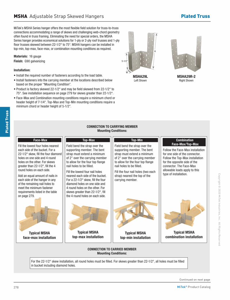
278
Copyright © 2020 M
iTek Industries, Inc. All Rights Reserved
Plated Truss
Plat
ed T
russ
MiTek® Product Catalog
MiTek’s MSHA Series hanger offers the most flexible field solution for truss-to-truss connections accommodating a range of skews and challenging web-chord geometry often found in truss framing. Eliminating the need for special orders, the MSHA Series hanger provides economical solutions for 1-ply or 2-ply roof trusses and 1-ply floor trusses skewed between 22-1/2° to 75°. MSHA hangers can be installed in top-min, top-max, face-max, or combination mounting conditions as required.
Materials: 16 gauge Finish: G90 galvanizing
Installation:
• Install the required number of fasteners according to the load table.• Install fasteners into the carrying member at the locations described below
based on the proper “Mounting Condition”. • Product is factory skewed 22-1/2° and may be field skewed from 22-1/2° to
75°. See installation sequence on page 279 for skews greater than 22-1/2°.• Face-Max and Combination mounting conditions require a minimum chord or
header height of 7-1/4". Top-Max and Top-Min mounting conditions require a minimum chord or header height of 5-1/2".
MSHA Adjustable Strap Skewed Hangers
MSHA29LLeft Shown
MSHA29R-2Right Shown
H
5-1/2"
W
Typical MSHA combination installation
Typical MSHA top-min installation
Typical MSHA face-max installation
Typical MSHA top-max installation
CONNECTION TO CARRYING MEMBERMounting Conditions:
CONNECTION TO CARRIED MEMBERMounting Conditions:
For the 22-1/2° skew installation, all round holes must be filled. For skews greater than 22-1/2°, all holes must be filled in bucket including diamond holes.
Face-Max
Fill the lowest four holes nearest each side of the bucket. For a 22-1/2° skew, fill the four diamond holes on one side and 4 round holes on the other. For skews greater than 22-1/2°, fill the 4 round holes on each side.
Add an equal amount of nails in each side of the hanger in any of the remaining nail holes to meet the minimum fastener requirements listed in the table on page 279.
Top-Max
Field bend the strap over the supporting member. The bent strap must extend a minimum of 2" over the carrying member to allow for the four top flange nail holes to be filled.
Fill the lowest four nail holes nearest each side of the bucket. For a 22-1/2° skew, fill the four diamond holes on one side and 4 round holes on the other. For skews greater than 22-1/2°, fill the 4 round holes on each side.
Top-Min
Field bend the strap over the supporting member. The bent strap must extend a minimum of 2" over the carrying member to allow for the four top flange nail holes to be filled.
Fill the four nail holes (two each strap) nearest the top of the carrying member.
Combination Face-Max/Top-Max
Follow the Face-Max installation for one side of the connector. Follow the Top-Max installation for the opposite side of the connector. The Face-Max allowable loads apply to this type of installation.
Continued on next page
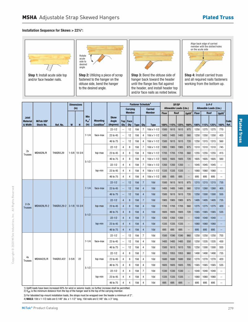
279
Plated TrussCo
pyri
ght ©
202
0 M
iTek
Indu
stri
es, I
nc.
All R
ight
s Re
serv
ed
Plated Truss
MiTek® Product Catalog
Floor Uplift1 Floor Uplift1
Ref. No. W H Type Qty Type 100% 115% 125% 160% 100% 115% 125% 160%
22-1/2 -- 12 10d 7 10d x 1-1/2 1500 1615 1615 975 1250 1275 1275 770
23 to 45 -- 12 10d 4 10d x 1-1/2 1485 1485 1485 560 1250 1350 1350 435
46 to 75 -- 12 10d 4 10d x 1-1/2 1500 1615 1615 720 1250 1315 1315 560
22-1/2 4 8 10d 7 10d x 1-1/2 1985 1985 1985 975 1510 1510 1510 745
23 to 45 4 8 10d 4 10d x 1-1/2 1705 1705 1705 560 1255 1255 1255 415
46 to 75 4 8 10d 4 10d x 1-1/2 1605 1605 1605 720 1605 1605 1605 560
22-1/2 4 4 10d 7 10d x 1-1/2 1350 1350 1350 -- 1045 1045 1045 --
23 to 45 4 4 10d 4 10d x 1-1/2 1335 1335 1335 -- 1060 1060 1060 --
46 to 75 4 4 10d 4 10d x 1-1/2 695 695 695 -- 695 695 695 --
22-1/2 -- 12 10d 7 10d 1500 1615 1615 975 1215 1215 1215 735
23 to 45 -- 12 10d 4 10d 1485 1485 1485 560 1210 1260 1260 405
46 to 75 -- 12 10d 4 10d 1500 1615 1615 720 1250 1300 1300 555
22-1/2 4 8 10d 7 10d 1985 1985 1985 975 1495 1495 1495 735
23 to 45 4 8 10d 4 10d 1705 1705 1705 560 1275 1275 1275 420
46 to 75 4 8 10d 4 10d 1605 1605 1605 720 1565 1565 1565 535
22-1/2 4 4 10d 7 10d 1350 1350 1350 -- 1040 1040 1040 --
23 to 45 4 4 10d 4 10d 1335 1335 1335 -- 1060 1060 1060 --
46 to 75 4 4 10d 4 10d 695 695 695 -- 695 695 695 --
22-1/2 -- 12 10d 7 10d 1500 1590 1590 960 1250 1250 1250 755
23 to 45 -- 12 10d 4 10d 1485 1485 1485 550 1250 1335 1335 430
46 to 75 -- 12 10d 4 10d 1500 1615 1615 705 1250 1300 1300 555
22-1/2 4 8 10d 7 10d 1955 1955 1955 960 1490 1490 1490 735
23 to 45 4 8 10d 4 10d 1680 1680 1680 550 1270 1270 1270 420
46 to 75 4 8 10d 4 10d 1605 1605 1605 705 1565 1565 1565 535
22-1/2 4 4 10d 7 10d 1330 1330 1330 -- 1040 1040 1040 --
23 to 45 4 4 10d 4 10d 1335 1335 1335 -- 1060 1060 1060 --
46 to 75 4 4 10d 4 10d 695 695 695 -- 695 695 695 --
1) Uplift loads have been increased 60% for wind or seismic loads; no further increase shall be permitted. 2) Heff is the minimum distance from the top of the hanger seat to the top of the carrying member.
3) For tabulated top-mount installation loads, the straps must be wrapped over the header a minimum of 2". 4) NAILS: 10d x 1-1/2 nails are 0.148" dia. x 1-1/2" long, 10d nails are 0.148" dia. x 3" long.
3-1/8
10-3/4
10-3/4
Dimensions(in)
4xTrusses
2-2xTrusses
MSHA29L/R
MSHA29L/R-2
THASR/L29
THASR/L29-2
2xTrusses
CarryingMember
CarriedMember
JoistMaterial& Width
MiTek USPStock No.
1-5/8
7-1/4
5-1/2
7-1/4
5-1/2
face-max
--
face-max
face-max
top-min
top-max
TopQty
FaceQty
MSHA422L/R THASR/L422
top-min
top-max
top-min
3-5/8 22
MountingCondition3
SkewAngle
(degrees)
Fastener Schedule4
Min Heff
2
(in)
top-max
7-1/4
5-1/2
CodeRef.
Roof Roof
DF/SPAllowable Loads (Lbs.)
S-P-FAllowable Loads (Lbs.)
MSHA Adjustable Strap Skewed Hangers
Installation Sequence for Skews > 22½°:
Step 1: Install acute side top and/or face header nails.
Step 2: Utilizing a piece of scrap fastened to the hanger on the obtuse side, bend the hanger to the desired angle.
Step 3: Bend the obtuse side of hanger back toward the header until the flange lies flat against the header, and install header top and/or face nails as noted below.
Step 4: Install carried truss and all required nails fasteners working from the bottom up.
Rotate acute side todesired angle
Align back edge of carried member with the slotted holes on the acute side
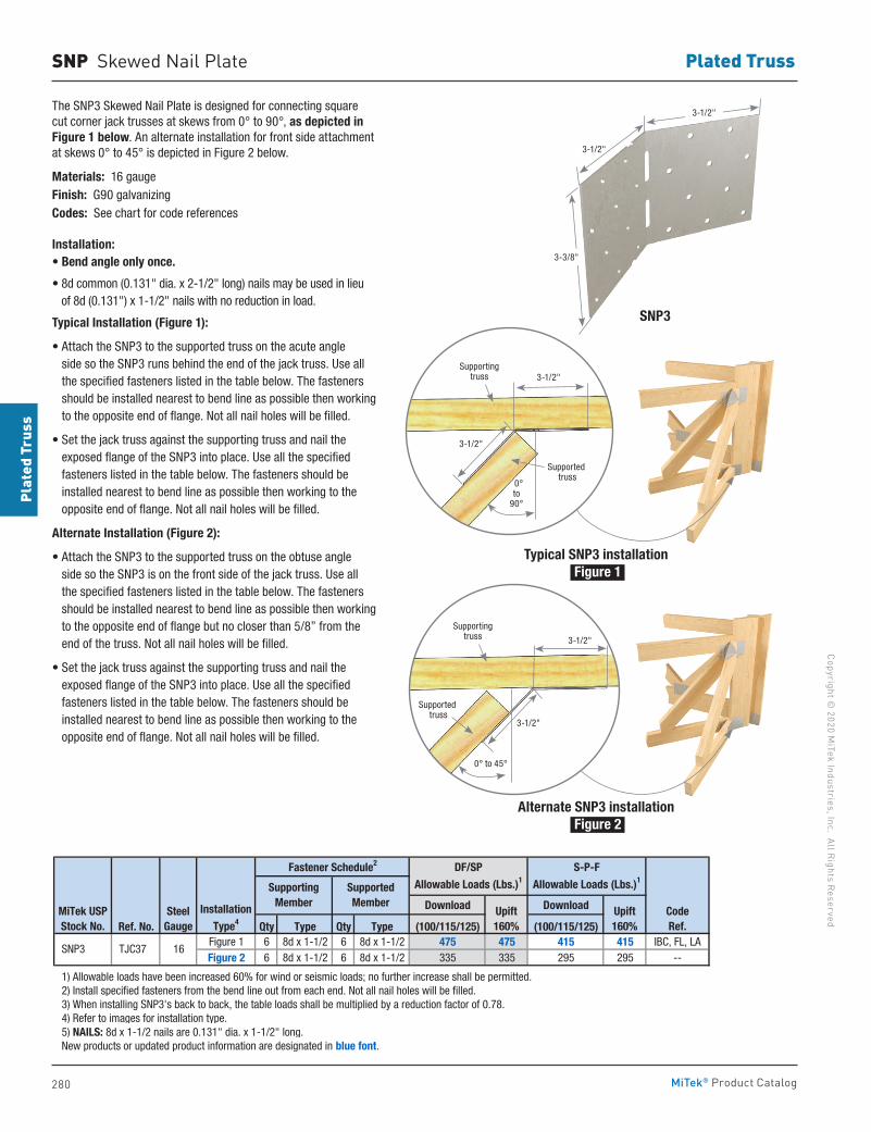
280
Copyright © 2020 M
iTek Industries, Inc. All Rights Reserved
Plated Truss
Plat
ed T
russ
MiTek® Product Catalog
SNP Skewed Nail Plate
The SNP3 Skewed Nail Plate is designed for connecting square cut corner jack trusses at skews from 0° to 90°, as depicted in Figure 1 below. An alternate installation for front side attachment at skews 0° to 45° is depicted in Figure 2 below.
Materials: 16 gaugeFinish: G90 galvanizingCodes: See chart for code references
Installation:• Bend angle only once.
• 8d common (0.131" dia. x 2-1/2" long) nails may be used in lieu of 8d (0.131") x 1-1/2" nails with no reduction in load.
Typical Installation (Figure 1):
• Attach the SNP3 to the supported truss on the acute angle side so the SNP3 runs behind the end of the jack truss. Use all the specified fasteners listed in the table below. The fasteners should be installed nearest to bend line as possible then working to the opposite end of flange. Not all nail holes will be filled.
• Set the jack truss against the supporting truss and nail the exposed flange of the SNP3 into place. Use all the specified fasteners listed in the table below. The fasteners should be installed nearest to bend line as possible then working to the opposite end of flange. Not all nail holes will be filled.
Alternate Installation (Figure 2):
• Attach the SNP3 to the supported truss on the obtuse angle side so the SNP3 is on the front side of the jack truss. Use all the specified fasteners listed in the table below. The fasteners should be installed nearest to bend line as possible then working to the opposite end of flange but no closer than 5/8” from the end of the truss. Not all nail holes will be filled.
• Set the jack truss against the supporting truss and nail the exposed flange of the SNP3 into place. Use all the specified fasteners listed in the table below. The fasteners should be installed nearest to bend line as possible then working to the opposite end of flange. Not all nail holes will be filled.
Download Download
Ref. No. Qty Type Qty Type (100/115/125) (100/115/125)Figure 1 6 8d x 1-1/2 6 8d x 1-1/2 475 475 415 415 IBC, FL, LAFigure 2 6 8d x 1-1/2 6 8d x 1-1/2 335 335 295 295 --
1) Allowable loads have been increased 60% for wind or seismic loads; no further increase shall be permitted. 2) Install specified fasteners from the bend line out from each end. Not all nail holes will be filled. 3) When installing SNP3's back to back, the table loads shall be multiplied by a reduction factor of 0.78. 4) Refer to images for installation type. 5) NAILS: 8d x 1-1/2 nails are 0.131" dia. x 1-1/2" long. New products or updated product information are designated in blue font.
SNP3 TJC37 16
Installation
Type4CodeRef.
Upift160%
Upift160%
Fastener Schedule2 DF/SP
Allowable Loads (Lbs.)1
S-P-F
Allowable Loads (Lbs.)1
MiTek USPStock No.
SteelGauge
Supporting Member
Supported Member
Typical SNP3 installation Figure 1
SNP3
Alternate SNP3 installation Figure 2
Supporting truss
3-1/2"
3-1/2"
Supported truss
0°to
90°
Supporting truss
3-1/2"
3-1/2"
Supported truss
0° to 45°
3-1/2"
3-1/2"
3-3/8"
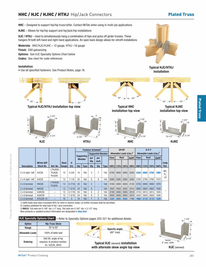
281
Plated TrussCo
pyri
ght ©
202
0 M
iTek
Indu
stri
es, I
nc.
All R
ight
s Re
serv
ed
Plated Truss
MiTek® Product Catalog
HHC / HJC / HJHC / HTHJ Hip/Jack Connectors
HHC – Designed to support hip/hip truss/rafter. Contact MiTek when using in multi-ply applications
HJHC – Allows for hip/hip support and hip/jack/hip installations
HJC / HTHJ – Used to simultaneously hang a combination of hips and jacks off girder trusses. These hangers fit both left-hand and right-hand applications. An open back design allows for retrofit installations
Materials: HHC/HJC/HJHC – 12 gauge, HTHJ –18 gauge Finish: G90 galvanizingOptions: See HJC Specialty Options Chart belowCodes: See chart for code references
Installation:• Use all specified fasteners. See Product Notes, page 18.
Typical HJC/HTHJinstallation
Typical HJC/HTHJ installation top view
HJC
Typical HHC installation top view
Typical HJC (skewed) installationwith alternate skew angle top view
HHCHTHJ
Typical HJHCinstallation top view
HJC (skewed)
HJHC
Floor Uplift1 Floor Uplift1
Description Ref. No. Qty Type Qty Qty Type 100% 115% 125% 160% 100% 115% 125% 160%
2 x 6 right / left HJC26 LTHJA26, THJA26, THJU26
12 5-3/8 16 16d 5 7 10d 2750 3055 3265 2345 2420 2685 2750 1905
2 x 8 right / left HJC28 -- 12 7-1/8 20 16d 6 8 10d 3385 3385 3385 2345 2760 2760 2760 1910
2 x 6 terminal HHC26 LTHJA26, THJA26
12 5-7/16 20 16d 5 -- 10d 3100 3505 3505 2130 2725 2800 2800 1870
2 x 8 terminal HHC28 -- 12 7-3/16 24 16d 6 -- 10d 3505 3505 3505 2410 2805 2805 2805 1930 2 x 6 terminal HJHC26 -- 12 5-7/16 20 16d 5 2 10d 3100 3505 3505 2410 2725 2815 2815 1935 2 x 8 terminal HJHC28 -- 12 7-3/16 24 16d 6 2 10d 3505 3505 3505 2410 2820 2820 2820 1940 2 x 6 terminal HTHJ26-18 -- 18 5 16 16d 7 5 16d 2295 2605 2695 1790 1985 2110 2110 1225
1) Uplift loads have been increased 60% for wind or seismic loads; no further increase shall be permitted. 2) Loading published for total load of hip / jack connection. 3) NAILS: 10d nails are 0.148" dia. x 3" long, 16d nails are 0.162" dia. x 3-1/2" long. New products or updated product information are designated in blue font.
--
MiTek USPStock No.
SteelGauge
RoofRoof
H(in)
Supported Member
IBC,FL,LA
Fastener Schedule3
CodeRef.
DF/SP
Allowable Loads (Lbs.)2
S-P-F
Allowable Loads (Lbs.)2
perHip
per Jack
SupportingMember
Option Hip Truss Skew
Range 30˚ to 60˚
Allowable Loads 100% of table load
OrderingAdd SK, angle of hip
required, to product number.Ex. HJC26_SK55
HJC Specialty Options Chart – Refer to Specialty Options pages 320-321 for additional details.
45°45°
Specify angle(60° max)
45°45°
45° 45°
6"3-1/4"
1-3/4"
H
5"5-7/8"
2"
H
9"
1-7/8"
3-1/4"
H
10-1/2"
1-3/4"
3-1/4"
H
Varies 8" max. width
H
3-1/4"
1-3/4"
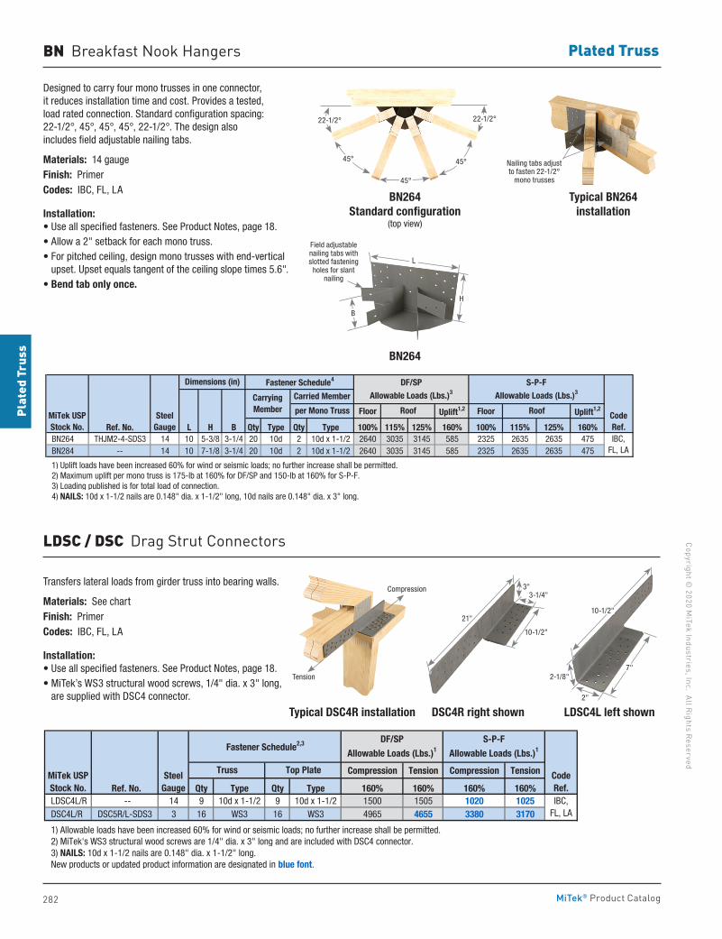
282
Copyright © 2020 M
iTek Industries, Inc. All Rights Reserved
Plated Truss
Plat
ed T
russ
MiTek® Product Catalog
BN Breakfast Nook Hangers
Designed to carry four mono trusses in one connector, it reduces installation time and cost. Provides a tested, load rated connection. Standard configuration spacing: 22-1/2°, 45°, 45°, 45°, 22-1/2°. The design also includes field adjustable nailing tabs.
Materials: 14 gaugeFinish: PrimerCodes: IBC, FL, LA
Installation:• Use all specified fasteners. See Product Notes, page 18.• Allow a 2" setback for each mono truss.• For pitched ceiling, design mono trusses with end-vertical
upset. Upset equals tangent of the ceiling slope times 5.6".• Bend tab only once.
Typical DSC4R installation LDSC4L left shownDSC4R right shown
BN264Standard configuration
(top view)
BN264
Floor Uplift1,2 Floor Uplift1,2
Ref. No. L H B Qty Type Qty Type 100% 115% 125% 160% 100% 115% 125% 160% BN264 THJM2-4-SDS3 14 10 5-3/8 3-1/4 20 10d 2 10d x 1-1/2 2640 3035 3145 585 2325 2635 2635 475 BN284 -- 14 10 7-1/8 3-1/4 20 10d 2 10d x 1-1/2 2640 3035 3145 585 2325 2635 2635 475
1) Uplift loads have been increased 60% for wind or seismic loads; no further increase shall be permitted. 2) Maximum uplift per mono truss is 175-lb at 160% for DF/SP and 150-lb at 160% for S-P-F. 3) Loading published is for total load of connection. 4) NAILS: 10d x 1-1/2 nails are 0.148" dia. x 1-1/2" long, 10d nails are 0.148" dia. x 3" long.
CodeRef.IBC,
FL, LA
Dimensions (in)
MiTek USPStock No.
SteelGauge
Roof
Carried Member
per Mono Truss
Fastener Schedule4
Carrying Member
DF/SPAllowable Loads (Lbs.)3
S-P-FAllowable Loads (Lbs.)3
Roof
LDSC / DSC Drag Strut Connectors
Transfers lateral loads from girder truss into bearing walls.
Materials: See chartFinish: PrimerCodes: IBC, FL, LA
Installation:• Use all specified fasteners. See Product Notes, page 18.• MiTek’s WS3 structural wood screws, 1/4" dia. x 3" long,
are supplied with DSC4 connector.
Compression Tension Compression Tension
Ref. No. Qty Type Qty Type 160% 160% 160% 160% LDSC4L/R -- 14 9 10d x 1-1/2 9 10d x 1-1/2 1500 1505 1020 1025 DSC4L/R DSC5R/L-SDS3 3 16 WS3 16 WS3 4965 4655 3380 3170
1) Allowable loads have been increased 60% for wind or seismic loads; no further increase shall be permitted. 2) MiTek's WS3 structural wood screws are 1/4" dia. x 3" long and are included with DSC4 connector. 3) NAILS: 10d x 1-1/2 nails are 0.148" dia. x 1-1/2" long. New products or updated product information are designated in blue font.
S-P-F
Allowable Loads (Lbs.)1Fastener Schedule2,3
IBC,FL, LA
CodeRef.
MiTek USPStock No.
SteelGauge
Truss Top Plate
DF/SP
Allowable Loads (Lbs.)1
22-1/2° 22-1/2°
45°
45°
45°
Typical BN264installation
Nailing tabs adjust to fasten 22-1/2°
mono trusses
21"
3-1/4"
10-1/2"
3"
10-1/2"
7"2-1/8"
2"
Field adjustable nailing tabs with slotted fastening
holes for slant nailing
L
H
B
Compression
Tension
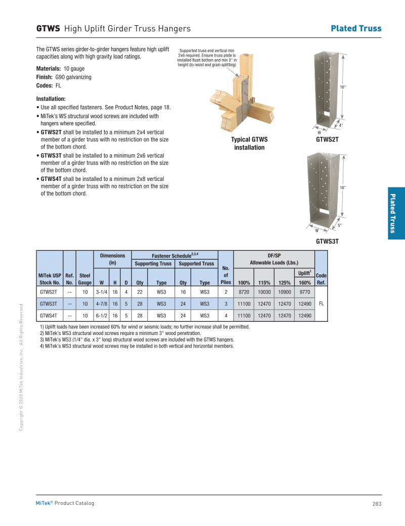
283
Plated TrussCo
pyri
ght ©
202
0 M
iTek
Indu
stri
es, I
nc.
All R
ight
s Re
serv
ed
Plated Truss
MiTek® Product Catalog
GTWS High Uplift Girder Truss Hangers
The GTWS series girder-to-girder hangers feature high uplift capacities along with high gravity load ratings.
Materials: 10 gaugeFinish: G90 galvanizingCodes: FL
Installation:• Use all specified fasteners. See Product Notes, page 18.
• MiTek’s WS structural wood screws are included with hangers where specified.
• GTWS2T shall be installed to a minimum 2x4 vertical member of a girder truss with no restriction on the size of the bottom chord.
• GTWS3T shall be installed to a minimum 2x6 vertical member of a girder truss with no restriction on the size of the bottom chord.
• GTWS4T shall be installed to a minimum 2x8 vertical member of a girder truss with no restriction on the size of the bottom chord.
Uplift1
W H D Qty Type Qty Type 100% 115% 125% 160%
GTWS2T -- 10 3-1/4 16 4 22 WS3 16 WS3 2 8720 10030 10900 9770
GTWS3T -- 10 4-7/8 16 5 28 WS3 24 WS3 3 11100 12470 12470 12490
GTWS4T -- 10 6-1/2 16 5 28 WS3 24 WS3 4 11100 12470 12470 12490
1) Uplift loads have been increased 60% for wind or seismic loads; no further increase shall be permitted. 2) MiTek's WS3 structural wood screws require a minimum 3" wood penetration. 3) MiTek's WS3 (1/4" dia. x 3" long) structural wood screws are included with the GTWS hangers. 4) MiTek's WS3 structural wood screws may be installed in both vertical and horizontal members.
MiTek USPStock No.
SteelGauge
No.of
Plies
Dimensions(in)
Ref. No.
FL
CodeRef.
Fastener Schedule2,3,4 DF/SPAllowable Loads (Lbs.)Supporting Truss Supported Truss
GTWS3T
GTWS2TTypical GTWSinstallation
16"
5"W
16"
4"
W
Supported truss end vertical min 2x6 required. Ensure truss plate is
installed flush bottom and min 3" in height (to resist end grain splitting)
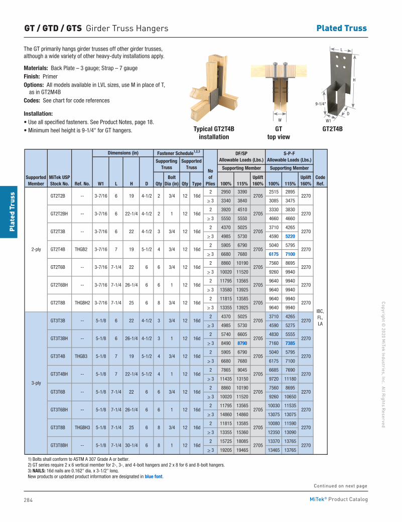
284
Copyright © 2020 M
iTek Industries, Inc. All Rights Reserved
Plated Truss
Plat
ed T
russ
MiTek® Product Catalog
GT / GTD / GTS Girder Truss Hangers
The GT primarily hangs girder trusses off other girder trusses, although a wide variety of other heavy-duty installations apply.
Materials: Back Plate – 3 gauge; Strap – 7 gaugeFinish: PrimerOptions: All models available in LVL sizes, use M in place of T, as in GT2M4BCodes: See chart for code references
Installation:• Use all specified fasteners. See Product Notes, page 18.• Minimum heel height is 9-1/4" for GT hangers. Typical GT2T4B
installation
Ref. No. W1 L H D Qty Qty Type 100% 115% 100% 115%
2 2950 3390 2515 2895
> 3 3340 3840 3085 3475
2 3920 4510 3330 3830
> 3 5550 5550 4660 4660
2 4370 5025 3710 4265
> 3 4985 5730 4590 5220
2 5905 6790 5040 5795
> 3 6680 7680 6175 7100
2 8860 10190 7560 8695
> 3 10020 11520 9260 9940
2 11795 13565 9640 9940
> 3 13580 13925 9640 9940
2 11815 13585 9640 9940
> 3 13355 13925 9640 9940
2 4370 5025 3710 4265
> 3 4985 5730 4590 5275
2 5740 6605 4830 5555
> 3 8490 8790 7160 7385
2 5905 6790 5040 5795
> 3 6680 7680 6175 7100
2 7865 9045 6685 7690
> 3 11435 13150 9720 11180
2 8860 10190 7560 8695
> 3 10020 11520 9260 10650
2 11795 13565 10030 11535
> 3 14860 14860 13075 13075
2 11815 13585 10080 11590
> 3 13355 15360 12350 13090
2 15725 18085 13370 13765
> 3 19205 19465 13465 13765
1) Bolts shall conform to ASTM A 307 Grade A or better. 2) GT series require 2 x 6 vertical member for 2-, 3-, and 4-bolt hangers and 2 x 8 for 6 and 8-bolt hangers. 3) NAILS: 16d nails are 0.162" dia. x 3-1/2" long. New products or updated product information are designated in blue font.
IBC,FL, LA
CodeRef.
2270
2270
2270
2270
2270
2270
2270
2270
2270
2270
2270
8 1 12 16d 2705 GT3T8BH -- 5-1/8 7-1/4 30-1/4 6
8 3/4 12 16d 2705 GT3T8B THGBH3 5-1/8 7-1/4 25 6
6 1 12 16d 2705 GT3T6BH -- 5-1/8 7-1/4 26-1/4 6
12 16d 2705
12 16d 2705
GT3T6B -- 5-1/8 7-1/4 22 6 6 3/4
16d 2705
GT3T4B THGB3 5-1/8 7 19
GT3T4BH -- 5-1/8 7 22-1/4 5-1/2 4 1
5-1/2 4 3/4 12 16d 2705
3-ply
GT3T3B -- 5-1/8 6
2-ply
2705 2270
GT3T3BH -- 5-1/8 6 26-1/4 4-1/2 3
22 4-1/2 3 3/4 12 16d
1 12
GT2T8B
3/4 12 16d 2705
4-1/2
2705 2270
6 6
5-1/2 4 3/4 12 16d
3 3/4 12 16d 2705
12 16d 2705
12 16d 2705 2270 THGBH2
6 1
3-7/16 7-1/4 25 6 8 3/4
6 GT2T6BH -- 3-7/16 7-1/4 26-1/4
GT2T3B -- 3-7/16 6 22
GT2T6B -- 3-7/16 7-1/4 22
19 GT2T4B THGB2 3-7/16 7
2270
GT2T2BH -- 3-7/16 6 22-1/4 4-1/2 2 1
4-1/2 2 3/4 12 16d 2705 GT2T2B -- 3-7/16 6 19
12 16d 2705
Dimensions (in) Fastener Schedule1,2,3 DF/SPAllowable Loads (Lbs.)
S-P-F Allowable Loads (Lbs.)Supporting
TrussSupported
Truss
SupportedMember
MiTek USPStock No.
Noof
Plies
Supporting Member Supporting Member
BoltDia (in)
Uplift160%
Uplift160%
GT top view
GT2T4B
9-1/4"
H
D
W1
L
W
Continued on next page
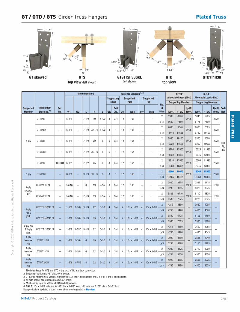
285
Plated TrussCo
pyri
ght ©
202
0 M
iTek
Indu
stri
es, I
nc.
All R
ight
s Re
serv
ed
Plated Truss
MiTek® Product Catalog
W1 W2 L H B Qty Qty Type Qty Type 100% 115% 100% 115%
2 5905 6790 5040 5795
> 3 6680 7680 6175 7100
2 7860 9040 6685 7685
> 3 11440 11555 9720 10100
2 8860 10185 7560 8690
> 3 10020 11525 9260 10650
2 11790 13560 10025 11530
> 3 14860 14860 13075 13075
2 11810 13580 10080 11590
> 3 13360 15365 12345 13090
2 15690 18045 13340 15345
> 3 19465 19465 16350 16350
2 2920 3355 2555 2715
> 3 3295 3785 3075 3075
2 5835 6710 5110 5875
> 3 6585 7575 6220 6675
2 4215 4850 3690 4005
> 3 4755 5470 4495 4570
2 5830 6705 5105 5760
> 3 6580 7565 5590 5760
2 4215 4850 3690 3985
> 3 4755 5470 4495 4545
2 2920 3360 2555 2940
> 3 3295 3790 3115 3295
2 4240 4875 3710 3990
> 3 4785 5500 4520 4550
2 4225 4855 3695 3975
> 3 4765 5480 4500 4535
1) The listed loads for GTS and GTD is the total of hip and jack connection. 2) Bolts shall conform to ASTM A 307 or better. 3) GT Series require 2 x 6 vertical member for 2, 3, and 4 bolt hangers and 2 x 8 for 6 and 8 bolt hangers. 4) All side pocket applications assume 45° angle. 5) Must specify right or left for all GTS and GT skewed. 6) NAILS: 10d x 1-1/2 nails are 0.148" dia. x 1-1/2" long, 16d nails are 0.162" dia. x 3-1/2" long. New products or updated product information are designated in blue font.
1-5/8
1-5/8
1-5/8
1-5/8
1-5/8
IBC,FL, LA
GT4T4BH
GT4T6B
GT4T6BH
GT4T8B
GT5T8BH
4 1 12 16d
1 12 16d
8 3/4 12 16d
8 1
4-ply
5-ply
--
--
--
--
--
THGBH4
GT4T4B
--
-- --
-- --
12 16d
4 3/4 12 16d
6 3/4 12 16d
6
--
--
--
--
6
6
6
6
4 3/4 4 10d x 1-1/2 4 10d x 1-1/2
5 3/4 4 10d x 1-1/2 4 10d x 1-1/2
22702705
2705
2705
9-1/4 30-1/4
6-1/2 7-1/2
6-1/2 7-1/2
6-1/2 7-1/2
6-1/2 7-1/2
6-1/2 7-1/2
22-1/4
26-1/4
22
25
19
CodeRef.
BoltDia.
3/4 12 16d -- --
1600
1600
--
-- --
--
-- --
--
2270
2270
2270
2270
2270
2705
2705
2705
Supporting Member
6
8
9-1/4
5-1/2
5-1/2
5-1/2
5-1/2
5-1/2
3 3/4 12 16d -- --
5
4 10d x 1-1/2
3 3/4 4 10d x 1-1/2 4 10d x 1-1/2
Ref. No.
No.of
Plies
2-plyskewed
45°
Fastener Schedule2,3,6
Supporting Truss
Supported Truss
SupportedHip
9-1/4
SupportedMember
MiTek USP
Stock No.4,5
--
--
--
--
--
--
--
--
Dimensions (in)
3-7/16
3-7/16
5-1/2
5-1/2
8-1/8
1-plyhip & jack
2-ply hip & 1-ply
jack
1-ply terminal
hip
2-ply terminal
hip
GT2T2BSKL/R
GT2T4BSKL/R
GTS1T1H3BSKL/R
GTS1T1H4BSKL/R
GTS1T2H3BSKL/R
GTD1T1H3B
GTD1T2H3B
1-ply terminal
hip GTD1T1H2B
--
--
--
--
--
-- 6 19
-- 7-1/4
1-5/8 9-1/4
1-5/8 9-1/4
3-7/16 9-1/4
1-5/8
3-7/16
19
22
19
22
22
22 --
--
S-P-FAllowable Loads (Lbs.)
Supporting Member
Uplift160%
3 3/4 4 10d x 1-1/2 4 10d x 1-1/2
Uplift160%
DF/SPAllowable Loads (Lbs.)
2000
2000
--
--
--
--
--
4 3/4 4 10d x 1-1/2
10d x 1-1/2 4 10d x 1-1/2 -- ---- 1-5/8 1-5/8 6 19 5-1/2 2 3/4 4
GT / GTD / GTS Girder Truss Hangers
GTS top view (left shown)
GTS1T2H3BSKL (left shown)
GTD top view
GTD1T1H3BGT skewed
1-5/8"
W2 W245°45°
45°W2
W11-5/8"
5-1/2"
4-1/2"
L
H
W2W2
5-1/2"
L
H
W1
L
H
B
1-5/8"
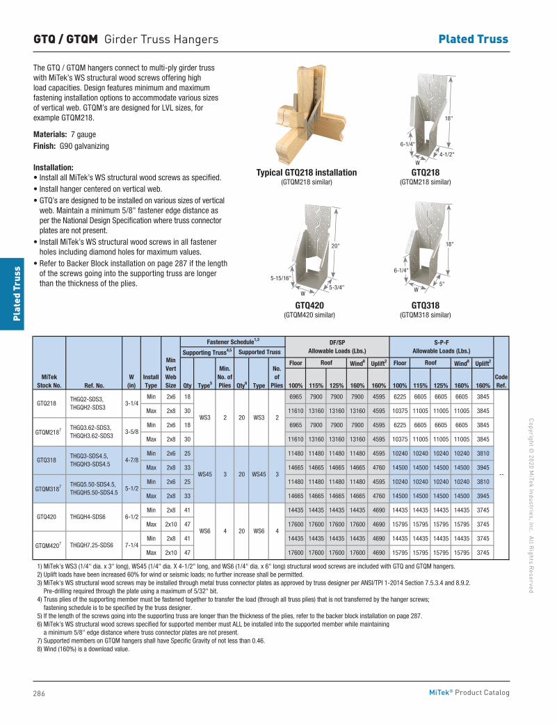
286
Copyright © 2020 M
iTek Industries, Inc. All Rights Reserved
Plated Truss
Plat
ed T
russ
MiTek® Product Catalog
GTQ / GTQM Girder Truss Hangers
The GTQ / GTQM hangers connect to multi-ply girder truss with MiTek’s WS structural wood screws offering high load capacities. Design features minimum and maximum fastening installation options to accommodate various sizes of vertical web. GTQM’s are designed for LVL sizes, for example GTQM218.
Materials: 7 gaugeFinish: G90 galvanizing
Installation:• Install all MiTek’s WS structural wood screws as specified. • Install hanger centered on vertical web.• GTQ’s are designed to be installed on various sizes of vertical
web. Maintain a minimum 5/8" fastener edge distance as per the National Design Specification where truss connector plates are not present.
• Install MiTek’s WS structural wood screws in all fastener holes including diamond holes for maximum values.
• Refer to Backer Block installation on page 287 if the length of the screws going into the supporting truss are longer than the thickness of the plies.
GTQ218(GTQM218 similar)
GTQ318(GTQM318 similar)
GTQ420(GTQM420 similar)
Typical GTQ218 installation(GTQM218 similar)
Floor Wind8 Uplift2 Floor Wind8 Uplift2
Ref. No. Qty Type5 Qty6 Type 100% 115% 125% 160% 160% 100% 115% 125% 160% 160%
Min 2x6 18 6965 7900 7900 7900 4595 6225 6605 6605 6605 3845
Max 2x8 30 11610 13160 13160 13160 4595 10375 11005 11005 11005 3845
Min 2x6 18 6965 7900 7900 7900 4595 6225 6605 6605 6605 3845
Max 2x8 30 11610 13160 13160 13160 4595 10375 11005 11005 11005 3845
Min 2x6 25 11480 11480 11480 11480 4595 10240 10240 10240 10240 3810
Max 2x8 33 14665 14665 14665 14665 4760 14500 14500 14500 14500 3945
Min 2x6 25 11480 11480 11480 11480 4595 10240 10240 10240 10240 3810
Max 2x8 33 14665 14665 14665 14665 4760 14500 14500 14500 14500 3945
Min 2x8 41 14435 14435 14435 14435 4690 14435 14435 14435 14435 3745
Max 2x10 47 17600 17600 17600 17600 4690 15795 15795 15795 15795 3745
Min 2x8 41 14435 14435 14435 14435 4690 14435 14435 14435 14435 3745
Max 2x10 47 17600 17600 17600 17600 4690 15795 15795 15795 15795 3745
1) MiTek's WS3 (1/4" dia. x 3" long), WS45 (1/4" dia. X 4-1/2" long, and WS6 (1/4" dia. x 6" long) structural wood screws are included with GTQ and GTQM hangers. 2) Uplift loads have been increased 60% for wind or seismic loads; no further increase shall be permitted. 3) MiTek's WS structural wood screws may be installed through metal truss connector plates as approved by truss designer per ANSI/TPI 1-2014 Section 7.5.3.4 and 8.9.2. Pre-drilling required through the plate using a maximum of 5/32" bit. 4) Truss plies of the supporting member must be fastened together to transfer the load (through all truss plies) that is not transferred by the hanger screws; fastening schedule is to be specified by the truss designer. 5) If the length of the screws going into the supporting truss are longer than the thickness of the plies, refer to the backer block installation on page 287. 6) MiTek's WS structural wood screws specified for supported member must ALL be installed into the supported member while maintaining a minimum 5/8" edge distance where truss connector plates are not present. 7) Supported members on GTQM hangers shall have Specific Gravity of not less than 0.46. 8) Wind (160%) is a download value.
THGQH7.25-SDS6
THGQH4-SDS6
GTQM4207
GTQ218
GTQM2187
GTQ318
GTQM3187
GTQ420
THGQ5.50-SDS4.5, THGQH5.50-SDS4.5
THGQ3-SDS4.5, THGQH3-SDS4.5
20
3-5/8
WS45
MiTekStock No.
THGQ2-SDS3, THGQH2-SDS3
THGQ3.62-SDS3, THGQH3.62-SDS3
7-1/4
6-1/2
4-7/8
5-1/2
CodeRef.
--
4
W(in)
Min. No. of Plies
No. of
Plies
3-1/4
InstallType
WS3
WS45 3 20
RoofRoofMinVertWebSize
WS6 4 20
DF/SP Allowable Loads (Lbs.)
S-P-FAllowable Loads (Lbs.)Supported Truss
Fastener Schedule1,3
Supporting Truss4,5
WS3 2
3
WS6
2
W
18"
4-1/2"
6-1/4"
W5"
18"
6-1/4"
20"
5-3/4"W
5-15/16"
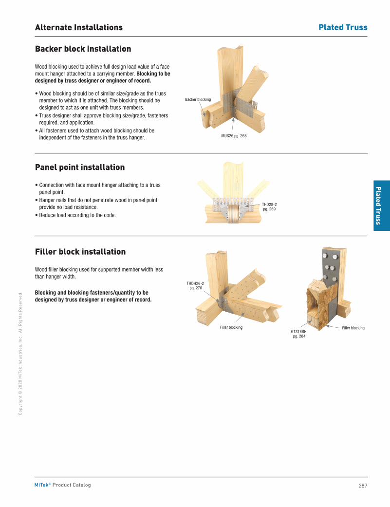
287
Plated TrussCo
pyri
ght ©
202
0 M
iTek
Indu
stri
es, I
nc.
All R
ight
s Re
serv
ed
Plated Truss
MiTek® Product Catalog
Alternate Installations
Backer block installation
Wood blocking used to achieve full design load value of a face mount hanger attached to a carrying member. Blocking to be designed by truss designer or engineer of record.
• Wood blocking should be of similar size/grade as the truss member to which it is attached. The blocking should be designed to act as one unit with truss members.
• Truss designer shall approve blocking size/grade, fasteners required, and application.
• All fasteners used to attach wood blocking should be independent of the fasteners in the truss hanger.
Panel point installation
• Connection with face mount hanger attaching to a truss panel point.
• Hanger nails that do not penetrate wood in panel point provide no load resistance.
• Reduce load according to the code.
Filler block installation
Wood filler blocking used for supported member width less than hanger width.
Blocking and blocking fasteners/quantity to be designed by truss designer or engineer of record.
MUS26 pg. 268
Backer blocking
THD28-2 pg. 269
THDH26-2 pg. 270
Filler blocking
GT3T6BH pg. 284
Filler blocking
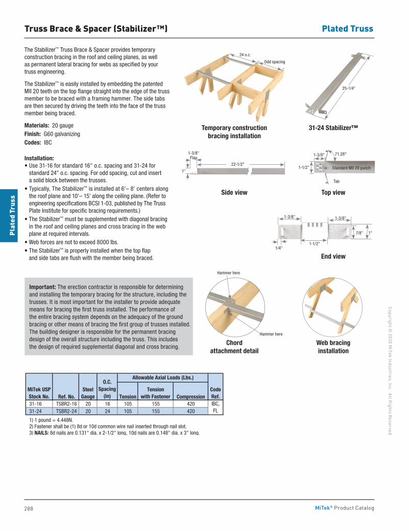
288
Copyright © 2020 M
iTek Industries, Inc. All Rights Reserved
Plated Truss
Plat
ed T
russ
MiTek® Product Catalog
Truss Brace & Spacer (Stabilizer™)
The Stabilizer™ Truss Brace & Spacer provides temporary construction bracing in the roof and ceiling planes, as well as permanent lateral bracing for webs as specified by your truss engineering.
The Stabilizer™ is easily installed by embedding the patented MII 20 teeth on the top flange straight into the edge of the truss member to be braced with a framing hammer. The side tabs are then secured by driving the teeth into the face of the truss member being braced.
Materials: 20 gaugeFinish: G60 galvanizingCodes: IBC
Installation:• Use 31-16 for standard 16" o.c. spacing and 31-24 for
standard 24" o.c. spacing. For odd spacing, cut and insert a solid block between the trusses.
• Typically, The Stabilizer™ is installed at 6'– 8' centers along the roof plane and 10'– 15' along the ceiling plane. (Refer to engineering specifications BCSI 1-03, published by The Truss Plate Institute for specific bracing requirements.)
• The Stabilizer™ must be supplemented with diagonal bracing in the roof and ceiling planes and cross bracing in the web plane at required intervals.
• Web forces are not to exceed 8000 lbs.• The Stabilizer™ is properly installed when the top flap
and side tabs are flush with the member being braced.
Temporary constructionbracing installation
Side view
Chordattachment detail
Web bracinginstallation
31-24 Stabilizer™
Top view
End view
Important: The erection contractor is responsible for determining and installing the temporary bracing for the structure, including the trusses. It is most important for the installer to provide adequate means for bracing the first truss installed. The performance of the entire bracing system depends on the adequacy of the ground bracing or other means of bracing the first group of trusses installed. The building designer is responsible for the permanent bracing design of the overall structure including the truss. This includes the design of required supplemental diagonal and cross bracing.
Ref. No. Tension Compression 31-16 TSBR2-16 20 16 105 155 420 31-24 TSBR2-24 20 24 105 155 420
1) 1 pound = 4.448N. 2) Fastener shall be (1) 8d or 10d common wire nail inserted through nail slot. 3) NAILS: 8d nails are 0.131" dia. x 2-1/2" long, 10d nails are 0.148" dia. x 3" long.
MiTek USPStock No.
SteelGauge
CodeRef.IBC,FL
Allowable Axial Loads (Lbs.)
Tensionwith Fastener
O.C.Spacing
(in)
24 o.c.
Odd spacing
25-1/4"
71.28°1-3/8"
1-1/2"
Tab
Standard MII 20 punch
1-3/8"
1-1/2"
1"7/8"
1/4"
1-3/8"
Hammer here
Hammer here
1-3/8" Flap
1"
22-1/2"
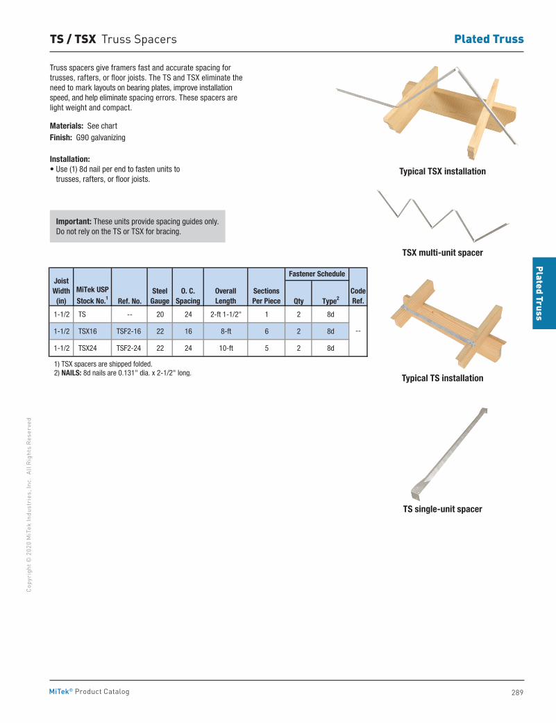
289
Plated TrussCo
pyri
ght ©
202
0 M
iTek
Indu
stri
es, I
nc.
All R
ight
s Re
serv
ed
Plated Truss
MiTek® Product Catalog
TS / TSX Truss Spacers
Truss spacers give framers fast and accurate spacing for trusses, rafters, or floor joists. The TS and TSX eliminate the need to mark layouts on bearing plates, improve installation speed, and help eliminate spacing errors. These spacers are light weight and compact.
Materials: See chartFinish: G90 galvanizing
Installation:• Use (1) 8d nail per end to fasten units to
trusses, rafters, or floor joists.Typical TSX installation
Typical TS installation
TS single-unit spacer
TSX multi-unit spacer
Important: These units provide spacing guides only. Do not rely on the TS or TSX for bracing.
Ref. No. Qty Type2
1-1/2 TS -- 20 24 2-ft 1-1/2" 1 2 8d
1-1/2 TSX16 TSF2-16 22 16 8-ft 6 2 8d
1-1/2 TSX24 TSF2-24 22 24 10-ft 5 2 8d
1) TSX spacers are shipped folded. 2) NAILS: 8d nails are 0.131" dia. x 2-1/2" long.
--
CodeRef.
Joist Width
(in)SectionsPer Piece
MiTek USP
Stock No.1Steel
GaugeO. C.
SpacingOverallLength
Fastener Schedule
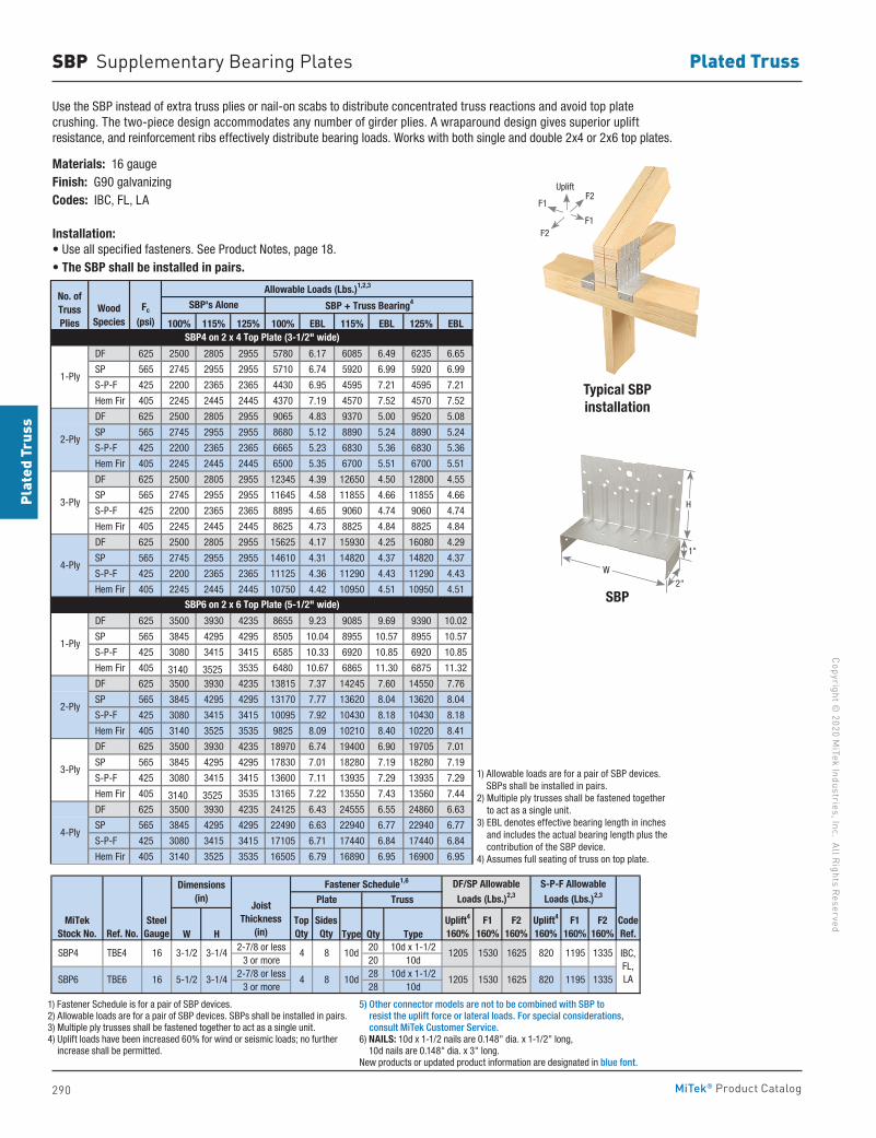
290
Copyright © 2020 M
iTek Industries, Inc. All Rights Reserved
Plated Truss
Plat
ed T
russ
MiTek® Product Catalog
SBP Supplementary Bearing Plates
100% 115% 125% 100% EBL 115% EBL 125% EBL
DF 625 2500 2805 2955 5780 6.17 6085 6.49 6235 6.65
SP 565 2745 2955 2955 5710 6.74 5920 6.99 5920 6.99
S-P-F 425 2200 2365 2365 4430 6.95 4595 7.21 4595 7.21
Hem Fir 405 2245 2445 2445 4370 7.19 4570 7.52 4570 7.52
DF 625 2500 2805 2955 9065 4.83 9370 5.00 9520 5.08
SP 565 2745 2955 2955 8680 5.12 8890 5.24 8890 5.24
S-P-F 425 2200 2365 2365 6665 5.23 6830 5.36 6830 5.36
Hem Fir 405 2245 2445 2445 6500 5.35 6700 5.51 6700 5.51
DF 625 2500 2805 2955 12345 4.39 12650 4.50 12800 4.55
SP 565 2745 2955 2955 11645 4.58 11855 4.66 11855 4.66
S-P-F 425 2200 2365 2365 8895 4.65 9060 4.74 9060 4.74
Hem Fir 405 2245 2445 2445 8625 4.73 8825 4.84 8825 4.84
DF 625 2500 2805 2955 15625 4.17 15930 4.25 16080 4.29
SP 565 2745 2955 2955 14610 4.31 14820 4.37 14820 4.37
S-P-F 425 2200 2365 2365 11125 4.36 11290 4.43 11290 4.43
Hem Fir 405 2245 2445 2445 10750 4.42 10950 4.51 10950 4.51
DF 625 3500 3930 4235 8655 9.23 9085 9.69 9390 10.02
SP 565 3845 4295 4295 8505 10.04 8955 10.57 8955 10.57
S-P-F 425 3080 3415 3415 6585 10.33 6920 10.85 6920 10.85
Hem Fir 405 3140 3525 3535 6480 10.67 6865 11.30 6875 11.32
DF 625 3500 3930 4235 13815 7.37 14245 7.60 14550 7.76
SP 565 3845 4295 4295 13170 7.77 13620 8.04 13620 8.04
S-P-F 425 3080 3415 3415 10095 7.92 10430 8.18 10430 8.18
Hem Fir 405 3140 3525 3535 9825 8.09 10210 8.40 10220 8.41
DF 625 3500 3930 4235 18970 6.74 19400 6.90 19705 7.01
SP 565 3845 4295 4295 17830 7.01 18280 7.19 18280 7.19
S-P-F 425 3080 3415 3415 13600 7.11 13935 7.29 13935 7.29
Hem Fir 405 3140 3525 3535 13165 7.22 13550 7.43 13560 7.44
DF 625 3500 3930 4235 24125 6.43 24555 6.55 24860 6.63
SP 565 3845 4295 4295 22490 6.63 22940 6.77 22940 6.77
S-P-F 425 3080 3415 3415 17105 6.71 17440 6.84 17440 6.84
Hem Fir 405 3140 3525 3535 16505 6.79 16890 6.95 16900 6.95
1) Allowable loads are for a pair of SBP devices. SBP's shall be installed in pairs. 2) Multiple ply trusses shall be fastened together to act as a single unit. 3) EBL denotes effective bearing length and includes the actual bearing length in inches plus the contribution of the SBP device. 4) Assumes full seating of truss on top plate.
SBP6 on 2 x 6 Top Plate (5-1/2" wide)
4-Ply
1-Ply
2-Ply
3-Ply
4-Ply
1-Ply
2-Ply
3-Ply
SBP's Alone SBP + Truss Bearing4
Allowable Loads (Lbs.)1,2,3
SBP4 on 2 x 4 Top Plate (3-1/2" wide)
No. ofTrussPlies
WoodSpecies
Fc
(psi)
W H Type Qty Type2-7/8 or less 20 10d x 1-1/2
3 or more 20 10d2-7/8 or less 28 10d x 1-1/2
3 or more 28 10d
1) Fastener Schedule is for a pair of SBP devices. 2) Allowable loads are for a pair of SBP devices. SBPs shall be installed in pairs. 3) Multiple ply trusses shall be fastened together to act as a single unit. 4) Uplift loads have been increased 60% for wind or seismic loads; no further increase shall be permitted. 5) Other connector models are not to be combined with SBP to resist the uplift force or lateral loads. For special considerations, consult MiTek Customer Service. 6) NAILS: 10d x 1-1/2 nails are 0.148" dia. x 1-1/2" long, 10d nails are 0.148" dia. x 3" long. New products or updated product information are designated in blue font.
1195
CodeRef.
IBC,FL,LA1335820
820 1195 1335
5-1/2 3-1/4 1530 1625120510d84
S-P-F Allowable Loads (Lbs.)2,3
10d8
Truss
1530 16251205
F2160%
Uplift4
160%F1
160%F2
160%
Fastener Schedule1,6
Plate
4
TopQty
SidesQty
Uplift4
160%
JoistThickness
(in)
SBP6 TBE6
F1160%
DF/SP Allowable Loads (Lbs.)2,3
Ref. No.
SBP4 TBE4 16 3-1/2 3-1/4
MiTek Stock No.
SteelGauge
Dimensions(in)
16
Use the SBP instead of extra truss plies or nail-on scabs to distribute concentrated truss reactions and avoid top plate crushing. The two-piece design accommodates any number of girder plies. A wraparound design gives superior uplift resistance, and reinforcement ribs effectively distribute bearing loads. Works with both single and double 2x4 or 2x6 top plates.
Materials: 16 gaugeFinish: G90 galvanizingCodes: IBC, FL, LA
Installation:• Use all specified fasteners. See Product Notes, page 18.• The SBP shall be installed in pairs.
Typical SBP installation
SBP
H
W
2"
1"
1) Allowable loads are for a pair of SBP devices. SBPs shall be installed in pairs.
2) Multiple ply trusses shall be fastened together to act as a single unit.
3) EBL denotes effective bearing length in inches and includes the actual bearing length plus the contribution of the SBP device.
4) Assumes full seating of truss on top plate.
F1
F1
F2
F2
Uplift
1) Fastener Schedule is for a pair of SBP devices.2) Allowable loads are for a pair of SBP devices. SBPs shall be installed in pairs.3) Multiple ply trusses shall be fastened together to act as a single unit.4) Uplift loads have been increased 60% for wind or seismic loads; no further
increase shall be permitted.
5) Other connector models are not to be combined with SBP to resist the uplift force or lateral loads. For special considerations, consult MiTek Customer Service.
6) NAILS: 10d x 1-1/2 nails are 0.148" dia. x 1-1/2" long, 10d nails are 0.148" dia. x 3" long.
New products or updated product information are designated in blue font.
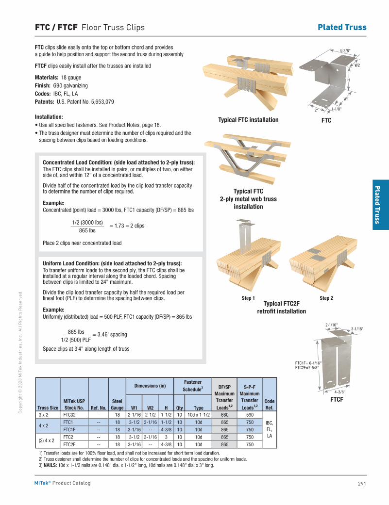
291
Plated TrussCo
pyri
ght ©
202
0 M
iTek
Indu
stri
es, I
nc.
All R
ight
s Re
serv
ed
Plated Truss
MiTek® Product Catalog
FTC / FTCF Floor Truss Clips
FTC clips slide easily onto the top or bottom chord and provides a guide to help position and support the second truss during assembly
FTCF clips easily install after the trusses are installed
Materials: 18 gaugeFinish: G90 galvanizingCodes: IBC, FL, LAPatents: U.S. Patent No. 5,653,079
Installation:• Use all specified fasteners. See Product Notes, page 18.• The truss designer must determine the number of clips required and the
spacing between clips based on loading conditions.
FTCTypical FTC installation
Typical FTC 2-ply metal web truss
installation
Typical FTC2F retrofit installation
Ref. No. W1 W2 H Qty Type 3 x 2 FTC32 -- 18 2-1/16 2-1/2 1-1/2 10 10d x 1-1/2 680 590
FTC1 -- 18 3-1/2 3-1/16 1-1/2 10 10d 865 750
FTC1F -- 18 3-1/16 -- 4-3/8 10 10d 865 750
FTC2 -- 18 3-1/2 3-1/16 3 10 10d 865 750
FTC2F -- 18 3-1/16 -- 4-3/8 10 10d 865 750
1) Transfer loads are for 100% floor load, and shall not be increased for short term load duration. 2) Truss designer shall determine the number of clips for concentrated loads and the spacing for uniform loads. 3) NAILS: 10d x 1-1/2 nails are 0.148" dia. x 1-1/2" long, 10d nails are 0.148" dia. x 3" long.
CodeRef.
4 x 2
(2) 4 x 2
MiTek USPStock No.
SteelGauge
IBC,FL, LA
DF/SPMaximum Transfer
Loads1,2
S-P-FMaximum Transfer
Loads1,2Truss Size
Fastener
Schedule3Dimensions (in)
Step 1 Step 2
4-3/8"
W2
W1
1-1/8"2"
H
FTCF
FTC1F= 6-1/16"FTC2F=7-5/8"
4-3/8"
3-1/16"2-1/16"
Concentrated Load Condition: (side load attached to 2-ply truss):The FTC clips shall be installed in pairs, or multiples of two, on either side of, and within 12" of a concentrated load.
Divide half of the concentrated load by the clip load transfer capacity to determine the number of clips required.
Example:Concentrated (point) load = 3000 lbs, FTC1 capacity (DF/SP) = 865 lbs
1/2 (3000 lbs) = 1.73 = 2 clips 865 lbs
Place 2 clips near concentrated load
Uniform Load Condition: (side load attached to 2-ply truss):To transfer uniform loads to the second ply, the FTC clips shall be installed at a regular interval along the loaded chord. Spacing between clips is limited to 24" maximum.
Divide the clip load transfer capacity by half the required load per lineal foot (PLF) to determine the spacing between clips.
Example:Uniformly (distributed) load = 500 PLF, FTC1 capacity (DF/SP) = 865 lbs 865 lbs = 3.46' spacing 1/2 (500) PLF
Space clips at 3'4" along length of truss
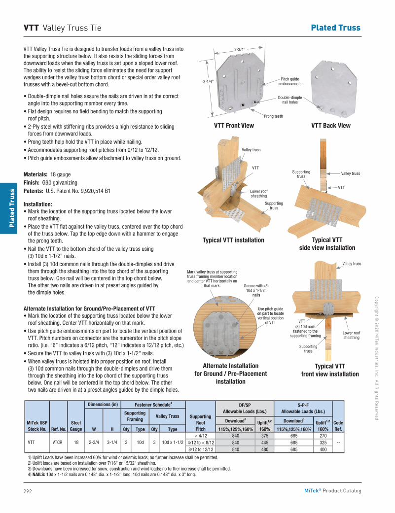
292
Copyright © 2020 M
iTek Industries, Inc. All Rights Reserved
Plated Truss
Plat
ed T
russ
MiTek® Product Catalog
VTT Valley Truss Tie
Download3 Download3
Ref. No. W H Qty Type Qty Type 115%,125%,160% 115%,125%,160%< 4/12 840 375 685 270
4/12 to < 8/12 840 445 685 3258/12 to 12/12 840 480 685 400
1) Uplift Loads have been increased 60% for wind or seismic loads; no further increase shall be permitted. 2) Uplift loads are based on installation over 7/16" or 15/32" sheathing. 3) Downloads have been increased for snow, construction and wind loads; no further increase shall be permitted. 4) NAILS: 10d x 1-1/2 nails are 0.148" dia. x 1-1/2" long, 10d nails are 0.148" dia. x 3" long.
10d x 1-1/2 VTT VTCR 18 2-3/4 3-1/4
CodeRef.
--
Dimensions (in) Fastener Schedule4
MiTek USPStock No.
SteelGauge
SupportingFraming
Valley Truss SupportingRoof Pitch
Uplift1,2
160%Uplift1,2
160%
DF/SPAllowable Loads (Lbs.)
S-P-FAllowable Loads (Lbs.)
3 10d 3
Typical VTT side view installation
Typical VTT front view installation
VTT Valley Truss Tie is designed to transfer loads from a valley truss into the supporting structure below. It also resists the sliding forces from downward loads when the valley truss is set upon a sloped lower roof. The ability to resist the sliding force eliminates the need for support wedges under the valley truss bottom chord or special order valley roof trusses with a bevel-cut bottom chord.
• Double-dimple nail holes assure the nails are driven in at the correct angle into the supporting member every time.
• Flat design requires no field bending to match the supporting roof pitch.
• 2-Ply steel with stiffening ribs provides a high resistance to sliding forces from downward loads.
• Prong teeth help hold the VTT in place while nailing.• Accommodates supporting roof pitches from 0/12 to 12/12.• Pitch guide embossments allow attachment to valley truss on ground.
Materials: 18 gaugeFinish: G90 galvanizingPatents: U.S. Patent No. 9,920,514 B1
Installation:• Mark the location of the supporting truss located below the lower
roof sheathing.• Place the VTT flat against the valley truss, centered over the top chord
of the truss below. Tap the top edge down with a hammer to engage the prong teeth.
• Nail the VTT to the bottom chord of the valley truss using (3) 10d x 1-1/2" nails.
• Install (3) 10d common nails through the double-dimples and drive them through the sheathing into the top chord of the supporting truss below. One nail will be centered in the top chord below. The other two nails are driven in at preset angles guided by the dimple holes.
Alternate Installation for Ground/Pre-Placement of VTT• Mark the location of the supporting truss located below the lower
roof sheathing. Center VTT horizontally on that mark.• Use pitch guide embossments on part to locate the vertical position of
VTT. Pitch numbers on connector are the numerator in the pitch slope ratio. (i.e. “6” indicates a 6/12 pitch, “12” indicates a 12/12 pitch, etc.)
• Secure the VTT to valley truss with (3) 10d x 1-1/2" nails.• When valley truss is hoisted into proper position on roof, install
(3) 10d common nails through the double-dimples and drive them through the sheathing into the top chord of the supporting truss below. One nail will be centered in the top chord below. The other two nails are driven in at a preset angles guided by the dimple holes.
VTT Front View VTT Back View
Prong teeth
Double-dimple nail holes
Pitch guide embossments3-1/4"
Typical VTT installation
VTT
Lower roof sheathing
Supporting truss
Valley truss
Valley truss
VTT
Supporting truss
Alternate Installation
for Ground / Pre-Placement installation
Use pitch guide on part to locate vertical position
of VTT
Mark valley truss at supporting truss framing member location and center VTT horizontally on
that mark. Secure with (3) 10d x 1-1/2"
nails
Lower roof sheathing
Valley truss
VTT
Supporting truss
(3) 10d nails fastened to the
supporting framing
2-3/4"
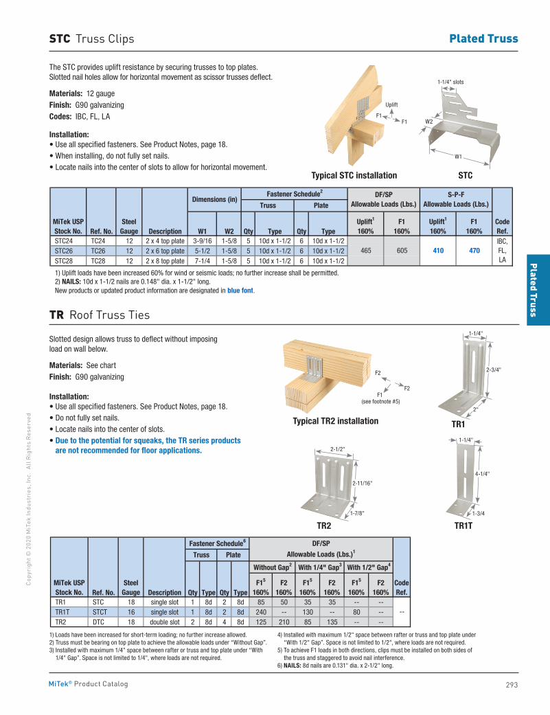
293
Plated TrussCo
pyri
ght ©
202
0 M
iTek
Indu
stri
es, I
nc.
All R
ight
s Re
serv
ed
Plated Truss
MiTek® Product Catalog
STC Truss Clips
STC
TR1T
Typical TR2 installation
TR2
TR1
The STC provides uplift resistance by securing trusses to top plates. Slotted nail holes allow for horizontal movement as scissor trusses deflect.
Materials: 12 gaugeFinish: G90 galvanizingCodes: IBC, FL, LA
Installation:• Use all specified fasteners. See Product Notes, page 18.• When installing, do not fully set nails.• Locate nails into the center of slots to allow for horizontal movement.
Typical STC installation
Ref. No. Description W1 W2 Qty Type Qty Type STC24 TC24 12 2 x 4 top plate 3-9/16 1-5/8 5 10d x 1-1/2 6 10d x 1-1/2 STC26 TC26 12 2 x 6 top plate 5-1/2 1-5/8 5 10d x 1-1/2 6 10d x 1-1/2 STC28 TC28 12 2 x 8 top plate 7-1/4 1-5/8 5 10d x 1-1/2 6 10d x 1-1/2
1) Uplift loads have been increased 60% for wind or seismic loads; no further increase shall be permitted. 2) NAILS: 10d x 1-1/2 nails are 0.148" dia. x 1-1/2" long. New products or updated product information are designated in blue font.
MiTek USPStock No.
SteelGauge
Fastener Schedule2
Truss PlateDimensions (in)
410 470IBC,FL,LA
CodeRef.
DF/SPAllowable Loads (Lbs.)
S-P-FAllowable Loads (Lbs.)
F1160%
Uplift1
160%Uplift1
160%F1
160%
605465
Slotted design allows truss to deflect without imposing load on wall below.
Materials: See chartFinish: G90 galvanizing
Installation:• Use all specified fasteners. See Product Notes, page 18.• Do not fully set nails.• Locate nails into the center of slots.• Due to the potential for squeaks, the TR series products
are not recommended for floor applications.
TR Roof Truss Ties
Ref. No. Description Qty Type Qty Type TR1 STC 18 single slot 1 8d 2 8d 85 50 35 35 -- -- TR1T STCT 16 single slot 1 8d 2 8d 240 -- 130 -- 80 -- TR2 DTC 18 double slot 2 8d 4 8d 125 210 85 135 -- --
1) Loads have been increased for short-term loading; no further increase allowed. 2) Truss must be bearing on top plate to achieve the allowable loads under "Without Gap". 3) Installed with maximum 1/4-in space between rafter or truss and top plate under "With 1/4" Gap". Space is not limited to 1/4-in, where loads are not required. 4) Installed with maximum 1/2" space between rafter or truss and top plate under "With 1/2" Gap". Space is not limited to 1/2-in, where loads are not required. 5) To achieve F1 loads in both directions, clips must be installed on both sides of the truss and staggered to avoid nail interference. 6) NAILS: 8d nails are 0.131" dia. x 2-1/2" long.
F15
160%
--
CodeRef.
MiTek USPStock No.
SteelGauge
Fastener Schedule6
Without Gap2 With 1/4" Gap3
Truss Plate
With 1/2" Gap4
DF/SPAllowable Loads (Lbs.)1
F2160%
F2160%
F2160%
F15
160%F15
160%
1) Loads have been increased for short-term loading; no further increase allowed.2) Truss must be bearing on top plate to achieve the allowable loads under “Without Gap”.3) Installed with maximum 1/4" space between rafter or truss and top plate under “With
1/4" Gap”. Space is not limited to 1/4", where loads are not required.
4) Installed with maximum 1/2" space between rafter or truss and top plate under “With 1/2" Gap”. Space is not limited to 1/2", where loads are not required.
5) To achieve F1 loads in both directions, clips must be installed on both sides of the truss and staggered to avoid nail interference.
6) NAILS: 8d nails are 0.131" dia. x 2-1/2" long.
2-3/4"
1-1/4"
2"(see footnote #5)
F1F1
Uplift
1-1/4" slots
W2
W1
2-1/2"
2-11/16"
1-7/8"
1-1/4"
4-1/4"
1-3/4
F2
F2F1
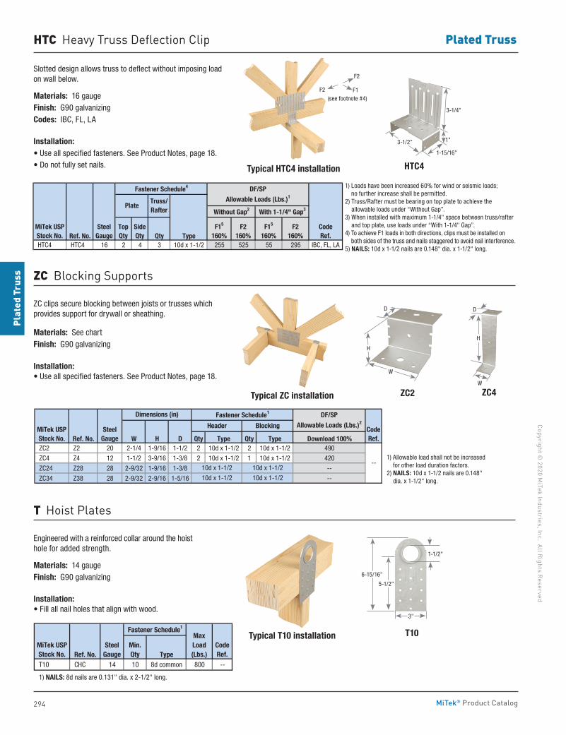
294
Copyright © 2020 M
iTek Industries, Inc. All Rights Reserved
Plated Truss
Plat
ed T
russ
MiTek® Product Catalog
HTC Heavy Truss Deflection Clip
Slotted design allows truss to deflect without imposing load on wall below.
Materials: 16 gaugeFinish: G90 galvanizingCodes: IBC, FL, LA
Installation:• Use all specified fasteners. See Product Notes, page 18.• Do not fully set nails.
Ref. No. Qty Type HTC4 HTC4 16 2 4 3 10d x 1-1/2 255 525 55 295 IBC, FL, LA
1) Loads have been increased 60% for wind or seismic loads; no further increase shall be permitted. 2) Truss/Rafter must be bearing on top plate to achieve the allowable loads under "Without Gap". 3) When installed with maximum 1-1/4" space between truss/rafter and top plate, use loads under "With 1-1/4" Gap". 4) To achieve F1 loads in both directions, clips must be installed on both sides of the truss and staggered to avoid nail interference. 5) NAILS: 10d x 1-1/2 nails are 0.148" dia. x 1-1/2" long.
CodeRef.
MiTek USPStock No.
SteelGauge
Fastener Schedule4
Without Gap2 With 1-1/4" Gap3
DF/SP
Allowable Loads (Lbs.)1Truss/Rafter
F15
160%F2
160%F15
160%F2
160%
Plate
TopQty
SideQty
HTC4
ZC2
T10
ZC4
Typical HTC4 installation
Typical ZC installation
Typical T10 installation
ZC clips secure blocking between joists or trusses which provides support for drywall or sheathing.
Materials: See chartFinish: G90 galvanizing
Installation:• Use all specified fasteners. See Product Notes, page 18.
Engineered with a reinforced collar around the hoist hole for added strength.
Materials: 14 gaugeFinish: G90 galvanizing
Installation:• Fill all nail holes that align with wood.
ZC Blocking Supports
T Hoist Plates
Ref. No. W H D Qty Type Qty Type Download 100% ZC2 Z2 20 2-1/4 1-9/16 1-1/2 2 10d x 1-1/2 2 10d x 1-1/2 490
ZC4 Z4 12 1-1/2 3-9/16 1-3/8 2 10d x 1-1/2 1 10d x 1-1/2 420
ZC24 Z28 28 2-9/32 1-9/16 1-3/8 --
ZC34 Z38 28 2-9/32 2-9/16 1-5/16 --
1) Allowable load shall not be increased for other load duration factors. 2) NAILS: 10d x 1-1/2 nails are 0.148" dia. x 1-1/2" long.
CodeRef.
SteelGauge
MiTek USPStock No.
Fastener Schedule1
Header Blocking
DF/SPAllowable Loads (Lbs.)2
Dimensions (in)
10d x 1-1/2
10d x 1-1/2 10d x 1-1/2
10d x 1-1/2--
Ref. No. Type T10 CHC 14 10 8d common 800 --
1) NAILS: 8d nails are 0.131" dia. x 2-1/2" long.
CodeRef.
Max Load(Lbs.)
MiTek USPStock No.
SteelGauge
Fastener Schedule1
Min. Qty
1) Loads have been increased 60% for wind or seismic loads; no further increase shall be permitted.
2) Truss/Rafter must be bearing on top plate to achieve the allowable loads under “Without Gap”.
3) When installed with maximum 1-1/4" space between truss/rafter and top plate, use loads under “With 1-1/4" Gap”.
4) To achieve F1 loads in both directions, clips must be installed on both sides of the truss and nails staggered to avoid nail interference.
5) NAILS: 10d x 1-1/2 nails are 0.148" dia. x 1-1/2" long.
1) Allowable load shall not be increased for other load duration factors.
2) NAILS: 10d x 1-1/2 nails are 0.148" dia. x 1-1/2" long.
D
W
H
1-1/2"
6-15/16"
5-1/2"
3"
(see footnote #4)
W
D
H
3-1/4"
1"
1-15/16"
3-1/2"
F1
F2
F2
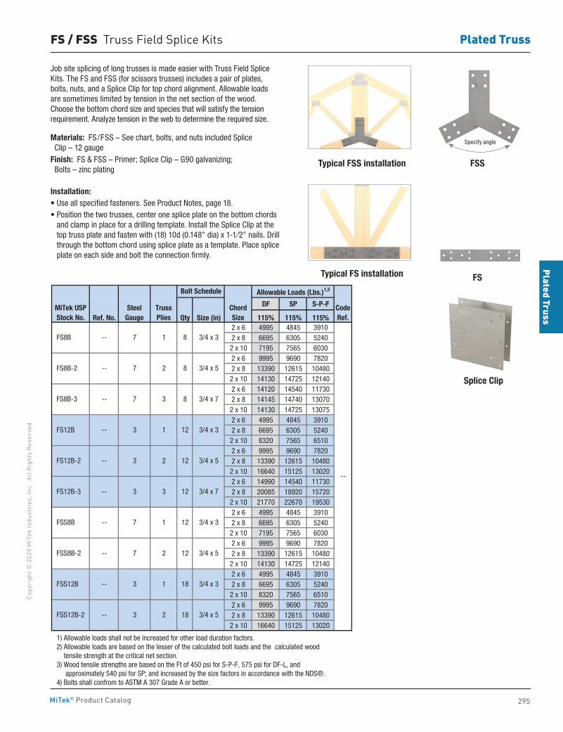
295
Plated TrussCo
pyri
ght ©
202
0 M
iTek
Indu
stri
es, I
nc.
All R
ight
s Re
serv
ed
Plated Truss
MiTek® Product Catalog
FS / FSS Truss Field Splice Kits
FSS
FS
Splice Clip
Typical FSS installation
Typical FS installation
Job site splicing of long trusses is made easier with Truss Field Splice Kits. The FS and FSS (for scissors trusses) includes a pair of plates, bolts, nuts, and a Splice Clip for top chord alignment. Allowable loads are sometimes limited by tension in the net section of the wood. Choose the bottom chord size and species that will satisfy the tension requirement. Analyze tension in the web to determine the required size.
Materials: FS/FSS – See chart, bolts, and nuts included Splice Clip – 12 gaugeFinish: FS & FSS – Primer; Splice Clip – G90 galvanizing; Bolts – zinc plating
Installation:• Use all specified fasteners. See Product Notes, page 18.• Position the two trusses, center one splice plate on the bottom chords
and clamp in place for a drilling template. Install the Splice Clip at the top truss plate and fasten with (18) 10d (0.148" dia) x 1-1⁄2" nails. Drill through the bottom chord using splice plate as a template. Place splice plate on each side and bolt the connection firmly.
Allowable Loads (Lbs.)1,2
DF SP S-P-F
Ref. No. Qty Size (in) 115% 115% 115%2 x 6 4995 4845 39102 x 8 6695 6305 52402 x 10 7195 7565 60302 x 6 9995 9690 78202 x 8 13390 12615 104802 x 10 14130 14725 121402 x 6 14120 14540 117302 x 8 14145 14740 130702 x 10 14130 14725 130752 x 6 4995 4845 39102 x 8 6695 6305 52402 x 10 8320 7565 65102 x 6 9995 9690 78202 x 8 13390 12615 104802 x 10 16640 15125 130202 x 6 14990 14540 117302 x 8 20085 18920 157202 x 10 21770 22670 195302 x 6 4995 4845 39102 x 8 6695 6305 52402 x 10 7195 7565 60302 x 6 9995 9690 78202 x 8 13390 12615 104802 x 10 14130 14725 121402 x 6 4995 4845 39102 x 8 6695 6305 52402 x 10 8320 7565 65102 x 6 9995 9690 78202 x 8 13390 12615 104802 x 10 16640 15125 13020
1) Allowable loads shall not be increased for other load duration factors. 2) Allowable loads are based on the lesser of the calculated bolt loads and the calculated wood tensile strength at the critical net section. 3) Wood tensile strengths are based on the Ft of 450 psi for S-P-F, 575 psi for DF-L, and approximately 540 psi for SP; and increased by the size factors in accordance with the NDS®. 4) Bolts shall confrom to ASTM A 307 Grade A or better.
MiTek USPStock No.
SteelGauge
TrussPlies
CodeRef.
Chord Size
12
8
3 12
--
7 2 12
8
3 2 18
12
3 1 18
7 1
2
3 1
3 3
7 1
7 2
7 3
--
--
--
--
--
FS8B
FS12B
FS8B-2
FS12B-2
FS8B-3
FS12B-3
FSS8B
FSS12B
FSS8B-2
FSS12B-2
--
--
--
--
--
Bolt Schedule
3/4 x 3
3/4 x 3
3/4 x 5
8
12
3/4 x 5
3/4 x 5
3/4 x 5
3/4 x 7
3/4 x 7
3/4 x 3
3/4 x 3
Specify angle
296
Copyright © 2020 M
iTek Industries, Inc. All Rights Reserved
Deck & Fences
Deck
& F
ence
s
MiTek® Product Catalog
Deck & Fences
Angles 302Deck Connectors 298-300, 302 Fence Hardware 303-305Stair Angles 301
pg. 298-305
297
Deck & FencesCo
pyri
ght ©
202
0 M
iTek
Indu
stri
es, I
nc.
All R
ight
s Re
serv
ed
Deck & Fences
MiTek® Product Catalog
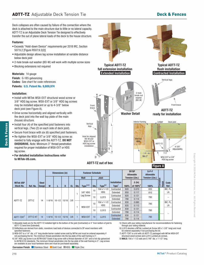
298
Copyright © 2020 M
iTek Industries, Inc. All Rights Reserved
Deck & Fences
Deck
& F
ence
s
MiTek® Product Catalog
ADTT-TZ Adjustable Deck Tension Tie
Ref. No. W L D CL Qty Type3,4,5 Qty Type6,8 160% 160%Contracted 820 0.070 820Extended 850 0.117 810
Contracted 820 0.121Extended 790 0.114
Contracted 830 0.080Extended 835 0.113
Contracted 830 0.121Extended 790 0.114
Contracted 830 0.121Extended 790 0.114
1) Allowable loads are for the ADTT-TZ installed tight to the bottom of the joist (Contracted) or 4-inches from bottom of joist to ADTT-TZ bend line (Extended). 2) Deflections are derived from static, monotonic load tests of devices connected to DF wood members with specified fasteners. 3) WS8-EXT is a 1/4" dia. x 8" long double barrier coated screw sold by MiTek and must be ordered seperately if not purchasing the kit. The minimum thread penetration into the top plate of the wall framing is 3-inches. 4) 3/8" HDG Lag Screw is an ASTM A307 Grade A lag screw with a thread diameter of 3/8" and is hot-dip galvanized to ASTM A153 standards. The minimum thread penetration into the top plate of the wall framing is 3-inches. Lag screws are available at your local hardware store and must be purchased seperately. 5) Check with your siding manufacturer for recommendations for fastening through your siding material. 6) LL915 denotes a LumberLok Screw (#9 x 1-3/8" long) sold by MiTek and must be ordered seperately if not purchasing the kit. 7) ADTT-TZKT is a kit with (4) ADTT-TZ packaged with MiTek's WS8-EXT structural wood screws and LL915 LumberLok screws. 8) NAILS: 10d x 1-1/2 nails are 0.148" dia. x 1-1/2" long.
LL915
780
780
780
780
LL915
15/16 3/8 1 WS8-EXT 10 ADTT-TZKT7 DTT1Z-KT 14 1-9/16 10-1/2
ADTT-TZ DTT1Z 14 1-9/16 10-1/210
10d x 1-1/2HDG
15/16 3/8
13/8" HDG Lag Screw
1 WS8-EXT
--
MiTek USPStock No.
DF/SPAllowable
Tension (Lbs.)
S-P-FAllowable
Tension (Lbs.)
Δ (in)at 160%2
SteelGauge
Wall Joist
Dimensions (in) Fastener Schedule
InstallationType1
10 LL915
1010d x 1-1/2
HDG
10
CodeRef.Co
rros
ion
Fini
sh
IBC, FL,LA
IBC, FL,LA
--
Corrosion Finish Stainless Steel Gold Coat HDG Triple Zinc
Corrosion Finish Stainless Steel Gold Coat HDG Triple Zinc
Corrosion Finish Stainless Steel Gold Coat HDG Triple Zinc
1) Allowable loads are for the ADTT-TZ installed tight to the bottom of the joist (Contracted) or 4" from bottom of joist to ADTT-TZ bend line (Extended).
2) Deflections are derived from static, monotonic load tests of devices connected to DF wood members with specified fasteners.
3) WS8-EXT is a 1/4" dia. x 8" long double barrier coated screw sold by MiTek and must be ordered separately if not purchasing the kit. The minimum thread penetration into the top plate of the wall framing is 3".
4) 3/8" HDG Lag Screw is an ASTM A307 Grade A lag screw with a thread diameter of 3/8" and is hot-dip galvanized to ASTM A153 standards. The minimum thread penetration into the top plate of the wall framing is 3". Lag screws are available at your local hardware store and must be purchased separately.
5) Check with your siding manufacturer for recommendations for fastening through your siding material.
6) LL915 denotes a MiTek LumberLok Screw (#9 x 1-3/8" long) and must be ordered separately if not purchasing the kit.
7) ADTT-TZKT is a kit with (4) ADTT-TZ packaged with MiTek WS8-EXT structural wood screws and LL915 LumberLok screws.
8) NAILS: 10d x 1-1/2 nails are 0.148" dia. x 1-1/2" long.
Deck collapses are often caused by failure of the connection where the deck is attached to the main structure due to little or no lateral capacity. ADTT-TZ is an Adjustable Deck Tension Tie designed to effectively transfer the out of plane lateral loads of the deck to the house structure.
Features: • Exceeds “Hold-down Device” requirements per 2018 IRC, Section
507.9.2 [Figure R507.9.2(2)]• Adjustable design allows lag screw installation at variable distance
below deck joist• 2-hole break-out washer (BO-W) will work with multiple screw sizes• Blocking extensions not required
Materials: 14 gaugeFinish: G-185 galvanizing Codes: See chart for code references
Patents: U.S. Patent No. 9,809,974
Installation: • Install with MiTek WS8-EXT structural wood screw or
3/8" HDG lag screw. WS8-EXT or 3/8" HDG lag screws may be installed adjacent or up to 4-3/8" below deck joist (see Figure A).
• Drive screw horizontally and aligned vertically with the deck joist into the wall top plate of the main (house) structure.
• Install four (4) of the specified joist fasteners into vertical legs. (Two (2) on each side of deck joist).
• Secure front brace with six (6) specified joist fasteners.• Re-tighten the WS8-EXT or 3/8" HDG lag screw as
needed to fully engage with the ADTT-TZ. DO NOT OVERDRIVE. Note: Minimum 3" thread penetration required for proper installation of WS8-EXT or HDG lag screw.
• For detailed installation instructions refer to MiTek-US.com.
Typical ADTT-TZ full extension installation
Extended Installation
Typical ADTT-TZ flush installation
Contracted Installation
Front brace
Vertical legs
ADTT-TZ ready for installation
ADTT-TZ out of box
L
Front brace
Vertical legs
Hole for aligned BO-W and
WS8-EXT or HDG lag screw
installation
W
D
CL
Washer Detail
2-hole break-out washer(BO-W)
Ledger Deck joist
Figure A
ADTT-TZ4-3/8"
Adjustability
Interior framing
WS8-EXT or 3/8" HDG lag screw
Wall top plate
Min 3"
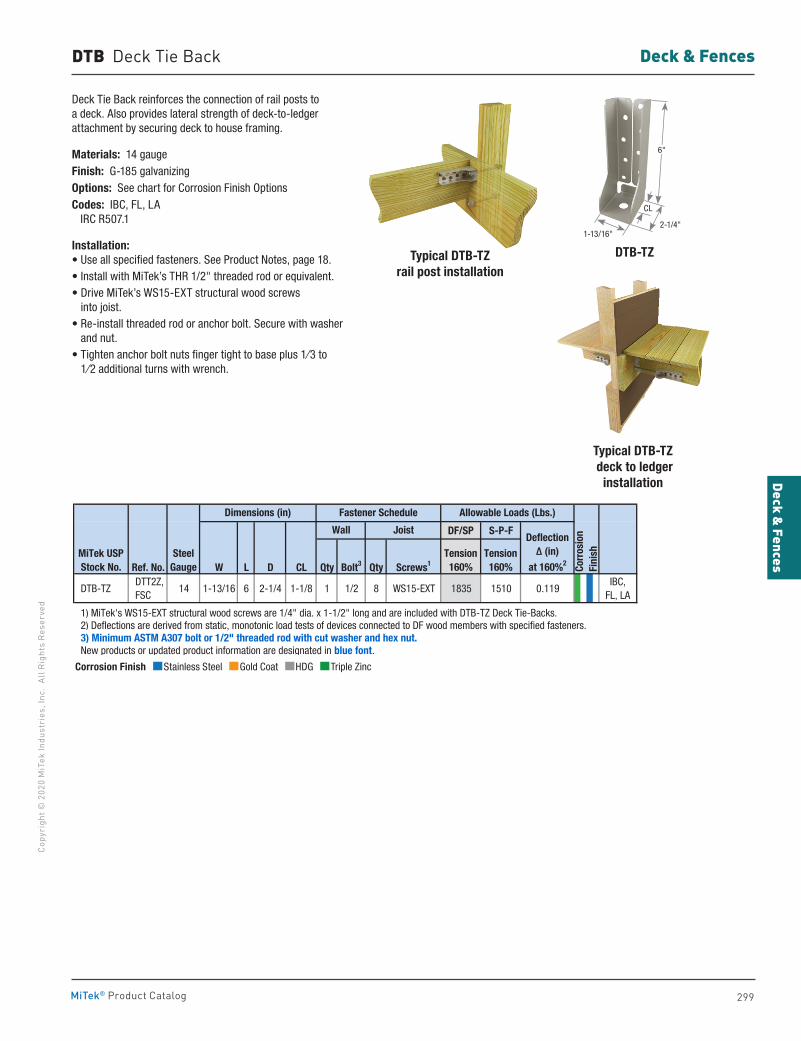
299
Deck & FencesCo
pyri
ght ©
202
0 M
iTek
Indu
stri
es, I
nc.
All R
ight
s Re
serv
ed
Deck & Fences
MiTek® Product Catalog
Deck Tie Back reinforces the connection of rail posts to a deck. Also provides lateral strength of deck-to-ledger attachment by securing deck to house framing.
Materials: 14 gau geFinish: G-185 galvanizingOptions: See chart for Corrosion Finish OptionsCodes: IBC, FL, LA IRC R507.1
Installation:• Use all specified fasteners. See Product Notes, page 18. • Install with MiTek’s THR 1/2" threaded rod or equivalent.• Drive MiTek’s WS15-EXT structural wood screws
into joist. • Re-install threaded rod or anchor bolt. Secure with washer
and nut. • Tighten anchor bolt nuts finger tight to base plus 1⁄3 to
1⁄2 additional turns with wrench.
DTB-TZ
Typical DTB-TZ deck to ledger
installation
DTB Deck Tie Back
Typical DTB-TZrail post installation
DF/SP S-P-F
Ref. No. W L D CL Qty Bolt3 Qty Screws1
DTB-TZ DTT2Z, FSC
14 1-13/16 6 2-1/4 1-1/8 1 1/2 8 WS15-EXT 1835 1510 0.119IBC,
FL, LA
1) MiTek's WS15-EXT structural wood screws are 1/4" dia. x 1-1/2" long and are included with DTB-TZ Deck Tie-Backs. 2) Deflections are derived from static, monotonic load tests of devices connected to DF wood members with specified fasteners. 3) Minimum ASTM A307 bolt or 1/2" threaded rod with cut washer and hex nut. New products or updated product information are designated in blue font.
MiTek USPStock No.
Tension160%
Dimensions (in)
Corr
osio
nFi
nishSteel
Gauge
Fastener Schedule
Wall Joist
Tension160%
Deflection Δ (in)
at 160%2
Allowable Loads (Lbs.)
Corrosion Finish Stainless Steel Gold Coat HDG Triple Zinc
Corrosion Finish Stainless Steel Gold Coat HDG Triple Zinc
Corrosion Finish Stainless Steel Gold Coat HDG Triple Zinc
6"
1-13/16"
CL
2-1/4"
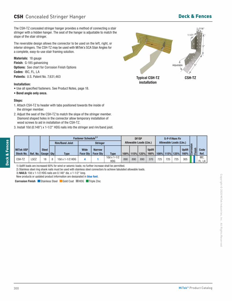
300
Copyright © 2020 M
iTek Industries, Inc. All Rights Reserved
Deck & Fences
Deck
& F
ence
s
MiTek® Product Catalog
Corrosion Finish Stainless Steel Gold Coat HDG Triple Zinc
Corrosion Finish Stainless Steel Gold Coat HDG Triple Zinc
Corrosion Finish Stainless Steel Gold Coat HDG Triple Zinc
The CSH-TZ concealed stringer hanger provides a method of connecting a stair stringer with a hidden hanger. The seat of the hanger is adjustable to match the slope of the stair stringer.
The reversible design allows the connector to be used on the left, right, or interior stringers. The CSH-TZ may be used with MiTek’s SCA Stair Angles for a complete, easy-to-use stair framing solution.
Materials: 18 gaugeFinish: G-185 galvanizingOptions: See chart for Corrosion Finish OptionsCodes: IBC, FL, LAPatents: U.S. Patent No. 7,631,463
Installation:• Use all specified fasteners. See Product Notes, page 18.• Bend angle only once.
Steps:1. Attach CSH-TZ to header with tabs positioned towards the inside of
the stringer member. 2. Adjust the seat of the CSH-TZ to match the slope of the stringer member.
Diamond shaped holes in the connector allow temporary installation of wood screws to aid in installation of the CSH-TZ.
3. Install 10d (0.148") x 1-1/2" HDG nails into the stringer and rim/band joist.
Typical CSH-TZinstallation
CSH-TZ
CSH Concealed Stringer Hanger
Ref. No. Qty Type Type 100% 115% 125% 100% 115% 125%
CSH-TZ LSCZ 18 8 10d x 1-1/2 HDG 4 110d x 1-1/2
HDG890 890 890 370 725 725 725 305
IBC, FL, LA
1) Uplift loads are increased 60% for wind or seismic loads; no further increase shall be permitted. 2) Stainless steel ring shank nails must be used with stainless steel connectors to achieve tabulated allowable loads. 3) NAILS: 10d x 1-1/2 HDG nails are 0.148" dia. x 1-1/2" long. New products or updated product information are designated in blue font.
CodeRef.
MiTek USPStock No.
SteelGauge
Rim/Band Joist
DF/SPAllowable Loads (Lbs.)
S-P-F/Hem FirAllowable Loads (Lbs.)
Corr
osio
nFi
nishUplift
160%Uplift160%
Stringer
Wide Face Qty
Narrow Face Qty
Fastener Schedule2,3
Adjustable 5"
5"
1-7/16"
1-1/2"
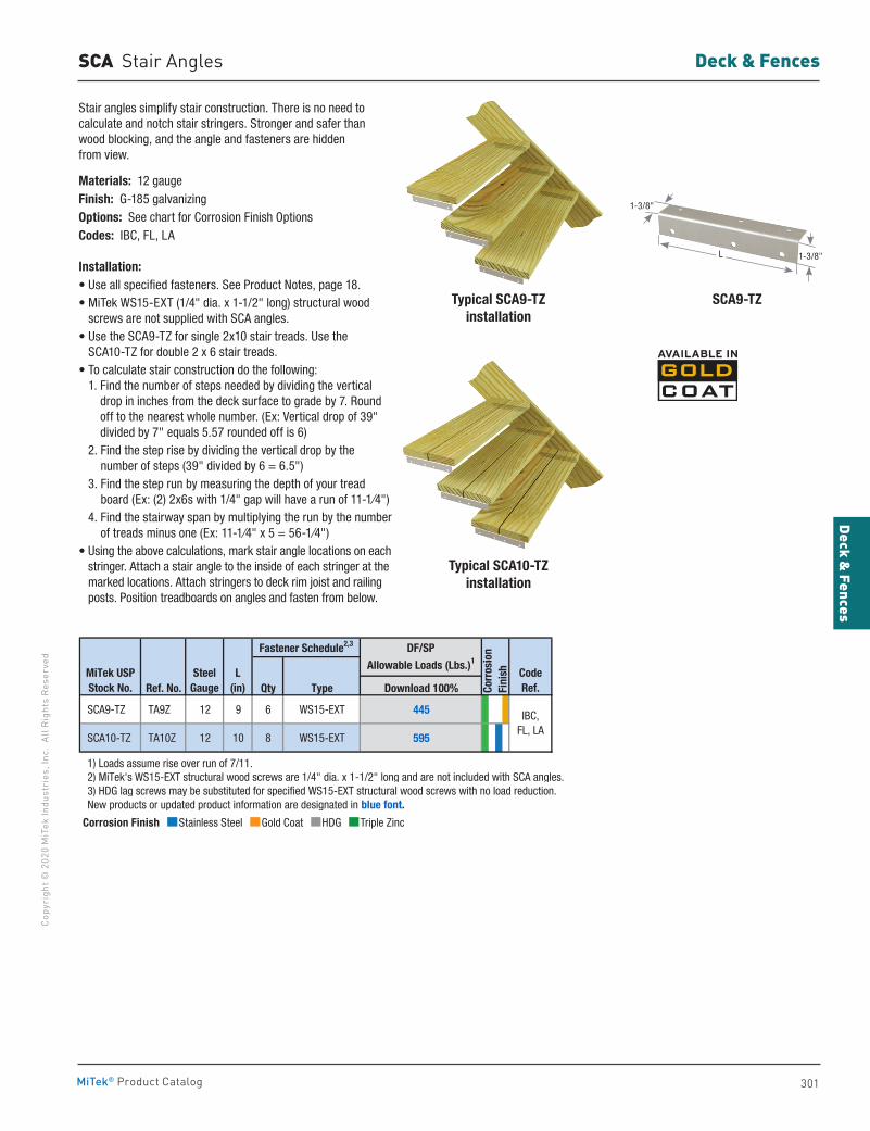
301
Deck & FencesCo
pyri
ght ©
202
0 M
iTek
Indu
stri
es, I
nc.
All R
ight
s Re
serv
ed
Deck & Fences
MiTek® Product Catalog
Typical SCA9-TZ installation
SCA9-TZ
Typical SCA10-TZ installation
SCA Stair Angles
Stair angles simplify stair construction. There is no need to calculate and notch stair stringers. Stronger and safer than wood blocking, and the angle and fasteners are hidden from view.
Materials: 12 gaugeFinish: G-185 galvanizingOptions: See chart for Corrosion Finish OptionsCodes: IBC, FL, LA
Installation:• Use all specified fasteners. See Product Notes, page 18.• MiTek WS15-EXT (1/4" dia. x 1-1/2" long) structural wood
screws are not supplied with SCA angles.• Use the SCA9-TZ for single 2x10 stair treads. Use the
SCA10-TZ for double 2 x 6 stair treads. • To calculate stair construction do the following:
1. Find the number of steps needed by dividing the vertical drop in inches from the deck surface to grade by 7. Round off to the nearest whole number. (Ex: Vertical drop of 39" divided by 7" equals 5.57 rounded off is 6)
2. Find the step rise by dividing the vertical drop by the number of steps (39" divided by 6 = 6.5")
3. Find the step run by measuring the depth of your tread board (Ex: (2) 2x6s with 1/4" gap will have a run of 11-1⁄4")
4. Find the stairway span by multiplying the run by the number of treads minus one (Ex: 11-1⁄4" x 5 = 56-1⁄4")
• Using the above calculations, mark stair angle locations on each stringer. Attach a stair angle to the inside of each stringer at the marked locations. Attach stringers to deck rim joist and railing posts. Position treadboards on angles and fasten from below.
Ref. No. Qty Type Download 100%
SCA9-TZ TA9Z 12 9 6 WS15-EXT 445
SCA10-TZ TA10Z 12 10 8 WS15-EXT 595
1) Loads assume rise over run of 7/11. 2) MiTek's WS15-EXT structural wood screws are 1/4" dia. x 1-1/2" long and are not included with SCA angles. 3) HDG lag screws may be substituted for specified WS15-EXT structural wood screws with no load reduction. New products or updated product information are designated in blue font.
IBC,FL, LA
CodeRef.
MiTek USPStock No.
SteelGauge
L(in) Co
rros
ion
Fini
sh
DF/SP
Allowable Loads (Lbs.)1Fastener Schedule2,3
Corrosion Finish Stainless Steel Gold Coat HDG Triple Zinc
Corrosion Finish Stainless Steel Gold Coat HDG Triple Zinc
Corrosion Finish Stainless Steel Gold Coat HDG Triple Zinc
L 1-3/8"
1-3/8"
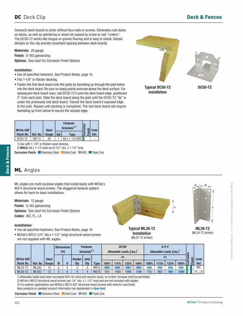
302
Copyright © 2020 M
iTek Industries, Inc. All Rights Reserved
Deck & Fences
Deck
& F
ence
s
MiTek® Product Catalog
DC Deck Clip
Connects deck boards to joists without face nails or screws. Eliminates rust stains on decks, as well as splintering or wood rot caused by screw or nail “craters”. The DC50-TZ works like tongue-in-groove flooring and is easy to install. Raised dimples on the clip provide consistent spacing between deck boards.
Materials: 20 gaugeFinish: G-185 galvanizingOptions: See chart for Corrosion Finish Options
Installation:• Use all specified fasteners. See Product Notes, page 18.• Fits 1-1/8" or thicker decking. • Fasten the first deck board onto the joists by toenailing up through the joist below
into the deck board. Be sure no sharp points protrude above the deck surface. For subsequent deck board rows, nail DC50-TZ's onto the deck board edge, positioned 2" from each joist. Slide the deck board along the joist until the DC50-TZ “lip” is under the previously laid deck board. Toenail the deck board’s exposed edge to the joist. Repeat until decking is completed. The last deck board will require toenailing up from below to secure the outside edge.
ML angles are multi-purpose angles that install easily with MiTek’s WS15 structural wood screws. The staggered fastener pattern allows for back-to-back installations.
Materials: 12 gau geFinish: G-185 galvanizingOptions: See chart for Corrosion Finish OptionsCodes: IBC, FL, LA
Installation:• Use all specified fasteners. See Product Notes, page 18.• MiTek’s WS15 (1/4" dia x 1-1/2" long) structural wood screws
are not supplied with ML angles.
Typical DC50-TZ installation
Typical ML26-TZinstallation
(ML24-TZ similar)
DC50-TZ
ML26-TZ(ML24-TZ similar)
Ref. No. Qty Type DC50-TZ DBT1Z 20 1 8d x 1-1/2 HDG --
1) Use with 1-1/8" or thicker wood decking. 2) NAILS: 8d x 1-1/2 nails are 0.131" dia. x 1-1/2" long.
MiTek USPStock No.
SteelGauge
CodeRef.Co
rros
ion
Fini
sh
Fastener
Schedule1,2
ML Angles
F1 H
WW
Ref. No. W H Type 100% 115% 125% 160% 100% 115% 125% 160% ML24-TZ ML24Z 12 2 4 3 3 WS15 655 655 655 655 565 650 655 655 ML26-TZ ML26Z 12 2 6 4 4 WS15 920 1060 1090 1090 755 865 940 1090
1) Allowable loads have been increased 60% for wind and seismic loads; no further increase shall be permitted. 2) MiTek's WS15 structural wood screws are 1/4" dia. x 1-1/2" long and are not included with angles. 3) For exterior applications use MiTek's WS15-EXT structural wood screws with exterior coat finish. New products or updated product information are designated in blue font.
IBC,FL, LA
MiTek USPStock No.
SteelGauge
F1 F1
Corr
osio
n Fi
nish
DF/SP
Allowable Loads (Lbs.)1
S-P-F
Allowable Loads (Lbs.)1Dimensions
(in)
CodeRef.
HeaderQty
JoistQty
Fastener
Schedule2,3
Corrosion Finish Stainless Steel Gold Coat HDG Triple Zinc
Corrosion Finish Stainless Steel Gold Coat HDG Triple Zinc
Corrosion Finish Stainless Steel Gold Coat HDG Triple Zinc
Corrosion Finish Stainless Steel Gold Coat HDG Triple Zinc
Corrosion Finish Stainless Steel Gold Coat HDG Triple Zinc
Corrosion Finish Stainless Steel Gold Coat HDG Triple Zinc
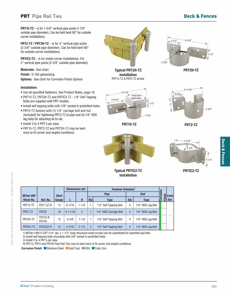
303
Deck & FencesCo
pyri
ght ©
202
0 M
iTek
Indu
stri
es, I
nc.
All R
ight
s Re
serv
ed
Deck & Fences
MiTek® Product Catalog
PRT Pipe Rail Ties
Typical PRT2H-TZinstallation
PRT15-TZ & PRT2-TZ similar
Typical PRTIC2-TZinstallation
PRTIC2-TZ
PRT2-TZ
PRT2H-TZ
PRT15-TZ – is for 1-5/8" vertical pipe posts (1-7/8" outside pipe diameter). Can be field bent 90° for outside corner installations.
PRT2-TZ / PRT2H-TZ – is for 2" vertical pipe posts (2-3/8" outside pipe diameter). Can be field bent 90° for outside corner installations.
PRTIC2-TZ – is for inside corner installations. For 2" vertical pipe posts (2-3/8" outside pipe diameter).
Materials: See chartFinish: G-185 galvanizingOptions: See chart for Corrosion Finish Options
Installation:• Use all specified fasteners. See Product Notes, page 18.• PRT15-TZ, PRT2H-TZ and PRTIC2-TZ - 1/4" Self Tapping
Bolts are supplied with PRT models.• Install self tapping bolts with 3/8" socket in predrilled holes.• PRT2-TZ fastens with (1) 1/4" carriage bolt and nut
(included) for tightening PRT2-TZ to pipe and (4) 1/4" HDG lag bolts for attaching tie to rail.
• Install 3 to 4 PRT's per pipe.• PRT15-TZ, PRT2-TZ and PRT2H-TZ may be bent
once to fit corner and angled conditions.
Ref. No. L H Qty Type Qty Type
PRT15-TZ PGT1.5Z-R 12 6-7/16 1-1/2 1 1/4" Self Tapping Bolt 4 1/4" HDG Lag Bolt
PRT2-TZ PGT2E 16 4-11/16 2 1 1/4" HDG Carriage Bolt 4 1/4" HDG Lag Bolt
PRT2H-TZ PGT2Z-R, PGT2A
12 6-3/8 1-1/2 1 1/4" Self Tapping Bolt 4 1/4" HDG Lag Bolt
PRTIC2-TZ PGTIC2Z-R 12 4-3/16 2-1/2 2 1/4" Self Tapping Bolt 4 1/4" HDG Lag Bolt
1) MiTek's WS15-EXT (1/4" dia. x 1-1/2" long) structural wood screws can be substituted for specified lag bolts. 2) Install self tapping bolts (included) with 3/8" socket in predrilled holes. 3) Install 3 to 4 PRT's per pipe. 4) PRT15, PRT2 and PRT2H Pipe Rail Ties may be bent once to fit corner and angled conditions.
--
CodeRef.
MiTek USPStock No.
SteelGauge
Pipe Rail
Fastener Schedule1Dimensions (in)
Corr
osio
nFi
nish
2-3/8"
4-3/16"
2-1/2"
2"
1-9/16"
2-3/8"
4-11/16"
1-1/2"
2-1/2"
2-3/8"
6-3/8"
PRT15-TZ
Corrosion Finish Stainless Steel Gold Coat HDG Triple Zinc
Corrosion Finish Stainless Steel Gold Coat HDG Triple Zinc
Corrosion Finish Stainless Steel Gold Coat HDG Triple Zinc
1-1/2"
2-9/16"
1-7/8"
6-7/16"Field bentapplication
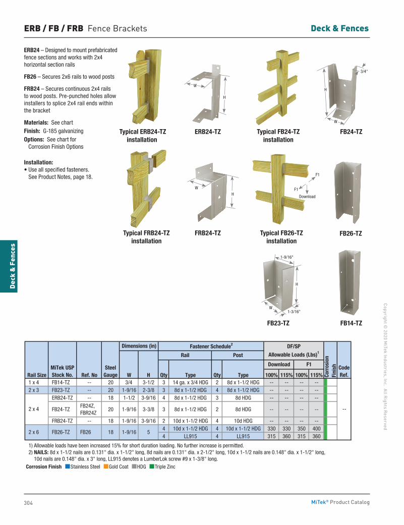
304
Copyright © 2020 M
iTek Industries, Inc. All Rights Reserved
Deck & Fences
Deck
& F
ence
s
MiTek® Product Catalog
ERB / FB / FRB Fence Brackets
ERB24 – Designed to mount prefabricated fence sections and works with 2x4 horizontal section rails
FB26 – Secures 2x6 rails to wood posts
FRB24 – Secures continuous 2x4 rails to wood posts. Pre-punched holes allow installers to splice 2x4 rail ends within the bracket
Materials: See chartFinish: G-185 galvanizingOptions: See chart for Corrosion Finish Options
Installation:• Use all specified fasteners.
See Product Notes, page 18.
Rail Size Ref. No W H Qty Type Qty Type 100% 115% 100% 115% 1 x 4 FB14-TZ -- 20 3/4 3-1/2 3 14 ga. x 3/4 HDG 2 8d x 1-1/2 HDG -- -- -- -- 2 x 3 FB23-TZ -- 20 1-9/16 2-3/8 3 8d x 1-1/2 HDG 4 8d x 1-1/2 HDG -- -- -- --
ERB24-TZ -- 18 1-1/2 3-9/16 4 8d x 1-1/2 HDG 3 8d HDG -- -- -- --
FB24-TZ FB24Z, FBR24Z
20 1-9/16 3-3/8 3 8d x 1-1/2 HDG 2 8d HDG -- -- -- --
FRB24-TZ -- 18 1-9/16 3-9/16 2 10d x 1-1/2 HDG 4 10d HDG -- -- -- --4 10d x 1-1/2 HDG 4 10d x 1-1/2 HDG 330 330 350 4004 LL915 4 LL915 315 360 315 360
1) Allowable loads have been increased 15% for short duration loading. No further increase is permitted. 2) NAILS: 8d x 1-1/2 nails are 0.131" dia. x 1-1/2" long, 8d nails are 0.131" dia. x 2-1/2" long, 10d x 1-1/2 nails are 0.148" dia. x 1-1/2" long, 10d nails are 0.148" dia. x 3" long, LL915 denotes a LumberLok screw #9 x 1-3/8" long.
Corr
osio
nFi
nish
18
CodeRef.
Download F1
--
2 x 6
DF/SP
Allowable Loads (Lbs)1
FB26-TZ
2 x 4
Rail Post
1-9/16 5
MiTek USPStock No.
SteelGauge
Dimensions (in) Fastener Schedule2
FB26
FB24-TZ
FB26-TZ
FB14-TZ
Typical FB24-TZ installation
Typical FB26-TZinstallation
FB23-TZ
ERB24-TZ
FRB24-TZ
Typical ERB24-TZinstallation
Typical FRB24-TZinstallation
W
H
Corrosion Finish Stainless Steel Gold Coat HDG Triple Zinc
Corrosion Finish Stainless Steel Gold Coat HDG Triple Zinc
Corrosion Finish Stainless Steel Gold Coat HDG Triple Zinc
H
WH
3/4"
W
1-3/16"
1-9/16"
H
W
F1
F1
Download
305
Deck & FencesCo
pyri
ght ©
202
0 M
iTek
Indu
stri
es, I
nc.
All R
ight
s Re
serv
ed
Deck & Fences
MiTek® Product Catalog
PCP Plastic Post Caps
SMP
PCP66
BD
SFP30
Typical PCP44installation
Typical BDinstallation
Typical SMPinstallation
Typical SFP30installation
These seamless caps keep water off post tops, protecting wood from moisture damage. The PCP’s plastic construction is corrosion-proof and paintable. Not available in rough or full lumber sizes.
Materials: Hi-impact plasticFinish: Gray color
Installation:• Fasten cap to post top with (1) 8d HDG or 10d HDG nail.
SFP / SMP Fence Post Connectors
BD Bolt Down
Take the work out of fence post installation and repair with the Speedpost, SFP30, and Speedmender, SMP. The Speedpost is used to install 4x4 fence posts without digging post holes or pouring concrete. The Speedmender plates act as reinforcement brackets for rotted or damaged 4x4 fence posts.
SFP30 – For 6' nominally-sized 4x4 fence posts.
SMP – For nominally-sized 4x4 posts.
Materials: 13 gaugeFinish: PaintPatent: U.S. Patent No. 7,152,841
Installation:• Step-by-step installation instructions are labeled onto each product.
Anchors 4x4 post to wood or concrete surfaces.
Materials: 13 gaugeFinish: PaintPatents: U.S. Patent No. 7,152,841
Installation:• Use all specified fasteners. See Product Notes, page 18.• Not rated for overturning resistance. Not recommended
for unrestrained posts.
Ref. No. W Color 4 x 4 PCP44 DPPC4BK 3-5/8 Gray
6 x 6 PCP66 DPPC6BK 5-5/8 Gray
1) Not available in rough or full lumber sizes.
Post /Column
Size1MiTek USPStock No.
CodeRef.
--
Dimension(in)
Ref. No. Qty Type4 x 4 SFP30 FPBS44 13 3 1/4" HDG Lag Bolt4 x 4 SMP1 FPBM44 13 20 10d HDG
1) Fastener schedule is per pair of SMPs. 2) NAILS: 10d nails are 0.148" dia. x 3" long.
PostSize
MiTek USPStock No.
CodeRef.
--
SteelGauge
Fastener Schedule2
Post Size Ref. No. Qty Type (in)4 x 4 BD FPBB44 13 3 1/4 x 1-1/2 HDG Lag Bolt --
MiTek USPStock No.
SteelGauge
Fastener Schedule CodeRef.
WW
30"
28-1/16"
5-5/8"
3-5/8"
5-5/8"
3-5/8"
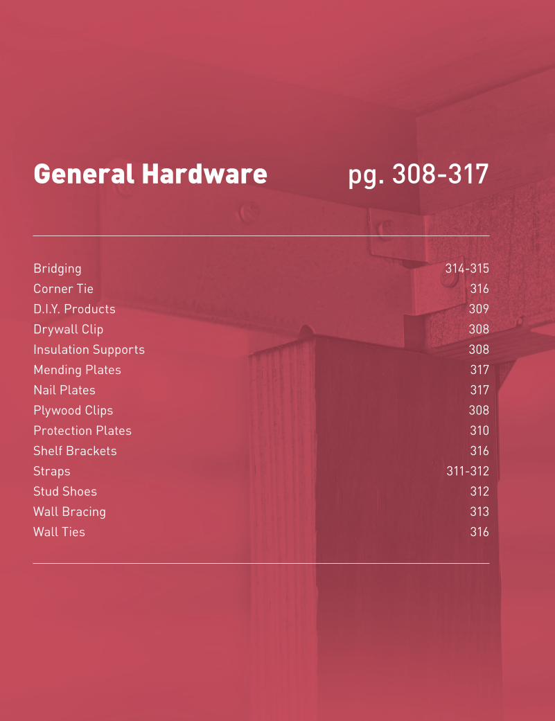
306
Copyright © 2018 M
iTek Industries, Inc. All Rights Reserved
General Hardware
Gene
ral H
ardw
are
MiTek® Product Catalog
General Hardware
Bridging 314-315Corner Tie 316 D.I.Y. Products 309Drywall Clip 308 Insulation Supports 308Mending Plates 317 Nail Plates 317Plywood Clips 308Protection Plates 310Shelf Brackets 316Straps 311-312 Stud Shoes 312Wall Bracing 313Wall Ties 316
pg. 308-317
307
General Hardware
Copy
righ
t © 2
018
MiT
ek In
dust
ries
, Inc
. Al
l Rig
hts
Rese
rved
General Hardware
MiTek® Product Catalog
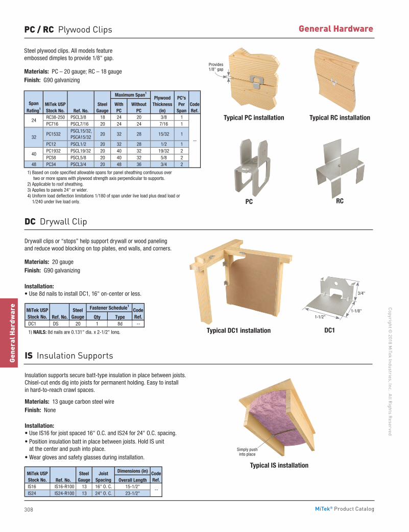
308
Copyright © 2018 M
iTek Industries, Inc. All Rights Reserved
General Hardware
Gene
ral H
ardw
are
MiTek® Product Catalog
PC / RC Plywood Clips
Steel plywood clips. All models feature embossed dimples to provide 1/8" gap.
Materials: PC – 20 gauge; RC – 18 gaugeFinish: G90 galvanizing
Ref. No. RC38-250 PSCL3/8 18 24 20 3/8 1 PC716 PSCL7/16 20 24 24 7/16 1
PC1532 PSCL15/32, PSCA15/32
20 32 28 15/32 1
PC12 PSCL1/2 20 32 28 1/2 1 PC1932 PSCL19/32 20 40 32 19/32 2 PC58 PSCL5/8 20 40 32 5/8 2
48 PC34 PSCL3/4 20 48 36 3/4 2
1) Based on code specified allowable spans for panel sheathing continuous over two or more spans with plywood strength axis perpendicular to supports. 2) Applicable to roof sheathing. 3) Applies to panels 24" or wider. 4) Uniform load deflection limitations 1/180 of span under live load plus dead load or 1/240 under live load only.
--
PlywoodThickness
(in)
PC'sPer
Span
Maximum Span1
Span
Rating1MiTek USPStock No.
SteelGauge
CodeRef.
WithoutPC
With PC
24
32
40
Typical DC1 installation
Typical IS installation
DC1
Drywall clips or “stops” help support drywall or wood paneling and reduce wood blocking on top plates, end walls, and corners.
Materials: 20 gaugeFinish: G90 galvanizing
Installation:• Use 8d nails to install DC1, 16" on-center or less.
Insulation supports secure batt-type insulation in place between joists. Chisel-cut ends dig into joists for permanent holding. Easy to install in hard-to-reach crawl spaces.
Materials: 13 gauge carbon steel wireFinish: None
Installation:• Use IS16 for joist spaced 16" O.C. and IS24 for 24" O.C. spacing.• Position insulation batt in place between joists. Hold IS unit
at the center and push into place.• Wear gloves and safety glasses during installation.
DC Drywall Clip
IS Insulation Supports
Ref. No. Qty Type DC1 DS 20 1 8d --
1) NAILS: 8d nails are 0.131" dia. x 2-1/2" long.
MiTek USPStock No.
SteelGauge
Fastener Schedule1CodeRef.
Dimensions (in)
Ref. No. Overall Length IS16 IS16-R100 13 16" O. C. 15-1/2" IS24 IS24-R100 13 24" O. C. 23-1/2"
MiTek USPStock No.
SteelGauge
--
CodeRef.
Joist Spacing
3/4"
1-1/8"1-1/2"
Simply push into place
Typical PC installation Typical RC installation
PC RC
Provides 1/8" gap
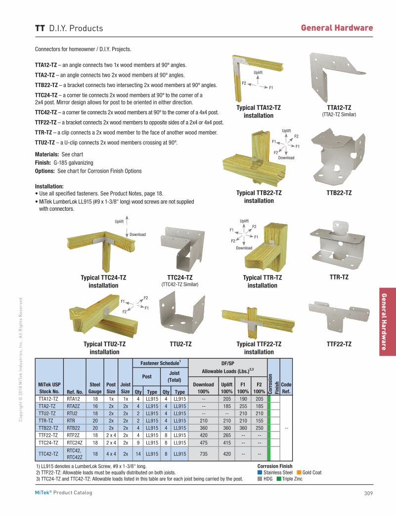
309
General Hardware
Copy
righ
t © 2
018
MiT
ek In
dust
ries
, Inc
. Al
l Rig
hts
Rese
rved
General Hardware
MiTek® Product Catalog
TT D.I.Y. Products
Connectors for homeowner / D.I.Y. Projects.
TTA12-TZ – an angle connects two 1x wood members at 90º angles.
TTA2-TZ – an angle connects two 2x wood members at 90º angles.
TTB22-TZ – a bracket connects two intersecting 2x wood members at 90º angles.
TTC24-TZ – a corner tie connects 2x wood members at 90º to the corner of a 2x4 post. Mirror design allows for post to be oriented in either direction.
TTC42-TZ – a corner tie connects 2x wood members at 90º to the corner of a 4x4 post.
TTF22-TZ – a bracket connects 2x wood members to opposite sides of a 2x4 or 4x4 post.
TTR-TZ – a clip connects a 2x wood member to the face of another wood member.
TTU2-TZ – a U-clip connects 2x wood members crossing at 90º.
Materials: See chartFinish: G-185 galvanizingOptions: See chart for Corrosion Finish Options
Installation:• Use all specified fasteners. See Product Notes, page 18.• MiTek LumberLok LL915 (#9 x 1-3/8" long) wood screws are not supplied
with connectors.
TTB22-TZ
TTR-TZ
TTF22-TZ
Typical TTB22-TZinstallation
Typical TTR-TZinstallation
Typical TTF22-TZinstallation
TTA12-TZ(TTA2-TZ Similar)
TTC24-TZ(TTC42-TZ Similar)
TTU2-TZ
Typical TTA12-TZinstallation
Typical TTC24-TZinstallation
Typical TTU2-TZinstallation
Ref. No. Qty Type Qty Type TTA12-TZ RTA12 18 1x 1x 4 LL915 4 LL915 -- 205 190 205 TTA2-TZ RTA2Z 16 2x 2x 4 LL915 4 LL915 -- 185 255 185 TTU2-TZ RTU2 18 2x 2x 2 LL915 4 LL915 -- -- 210 210 TTR-TZ RTR 20 2x 2x 2 LL915 4 LL915 210 210 210 155 TTB22-TZ RTB22 20 2x 2x 4 LL915 4 LL915 360 360 360 250 TTF22-TZ RTF2Z 18 2 x 4 2x 4 LL915 8 LL915 420 265 -- -- TTC24-TZ RTC24Z 18 2 x 4 2x 9 LL915 8 LL915 475 415 -- --
TTC42-TZ RTC42, RTC42Z
18 4 x 4 2x 14 LL915 8 LL915 735 420 -- --
1) LL915 denotes a LumberLok Screw, #9 x 1-3/8" long.2) TTF22-TZ: Allowable loads must be equally distributed on both joists.3) TTC24-TZ and TTC42-TZ: Allowable loads listed in this table are for each joist being carried by the post.
--
Post
Corr
osio
nFi
nish
DF/SP
Allowable Loads (Lbs.)2,3
Uplift100%
F1100%
F2100%
Download100%
MiTek USPStock No.
Fastener Schedule1
SteelGauge
CodeRef.
Post Size
JoistSize
Joist (Total)
Corrosion Finish Stainless Steel Gold Coat HDG Triple Zinc
Corrosion Finish Stainless Steel Gold Coat HDG Triple Zinc
Corrosion Finish Stainless Steel Gold Coat HDG Triple Zinc
F1F2
Uplift
F1F1
F2
F2
Uplift
Download
F1
F1
F2
F2
Uplift
Download
Uplift
Download
F1
F1
F2
F2
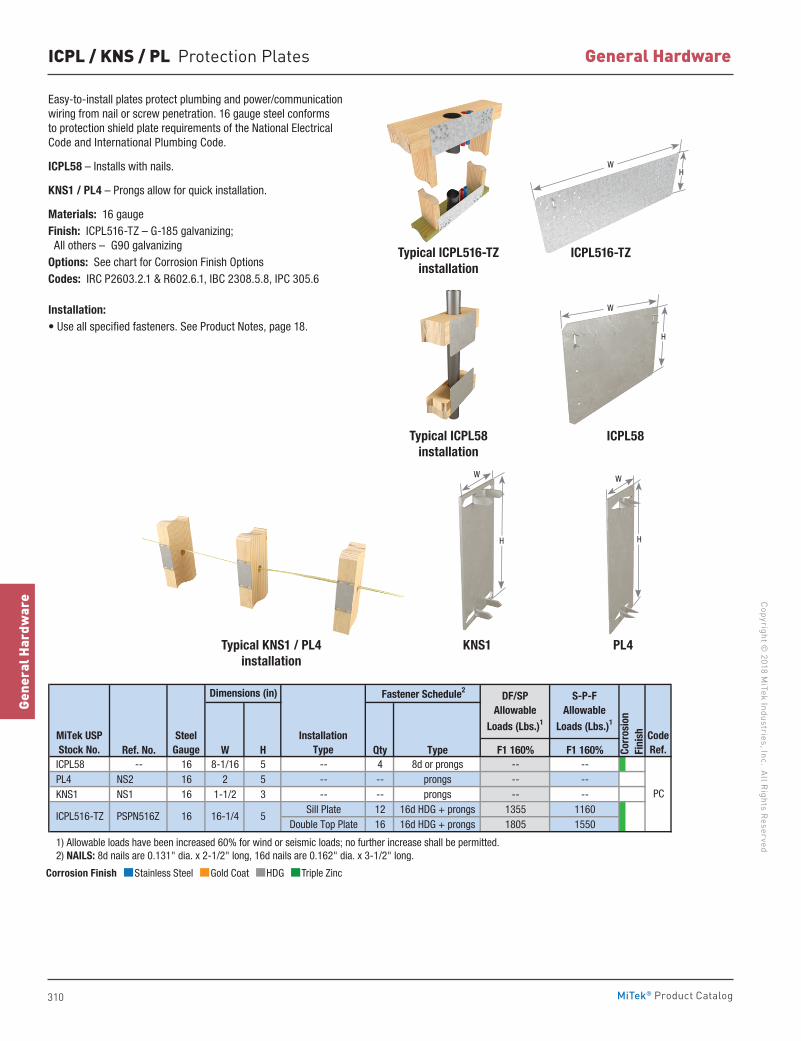
310
Copyright © 2018 M
iTek Industries, Inc. All Rights Reserved
General Hardware
Gene
ral H
ardw
are
MiTek® Product Catalog
ICPL / KNS / PL Protection Plates
Easy-to-install plates protect plumbing and power/communication wiring from nail or screw penetration. 16 gauge steel conforms to protection shield plate requirements of the National Electrical Code and International Plumbing Code.
ICPL58 – Installs with nails.
KNS1 / PL4 – Prongs allow for quick installation.
Materials: 16 gaugeFinish: ICPL516-TZ – G-185 galvanizing; All others – G90 galvanizingOptions: See chart for Corrosion Finish OptionsCodes: IRC P2603.2.1 & R602.6.1, IBC 2308.5.8, IPC 305.6
Installation:• Use all specified fasteners. See Product Notes, page 18.
ICPL58
PL4
Typical ICPL58installation
KNS1
ICPL516-TZTypical ICPL516-TZinstallation
Ref. No. W H Qty Type F1 160% F1 160% ICPL58 -- 16 8-1/16 5 -- 4 8d or prongs -- -- PL4 NS2 16 2 5 -- -- prongs -- -- KNS1 NS1 16 1-1/2 3 -- -- prongs -- --
Sill Plate 12 16d HDG + prongs 1355 1160Double Top Plate 16 16d HDG + prongs 1805 1550
1) Allowable loads have been increased 60% for wind or seismic loads; no further increase shall be permitted. 2) NAILS: 8d nails are 0.131" dia. x 2-1/2" long, 16d nails are 0.162" dia. x 3-1/2" long.
CodeRef.
DF/SPAllowable
Loads (Lbs.)1
S-P-FAllowable
Loads (Lbs.)1
PC
Corr
osio
nFi
nish
16-1/4
InstallationType
Dimensions (in) Fastener Schedule2
5
MiTek USPStock No.
SteelGauge
ICPL516-TZ PSPN516Z 16
Corrosion Finish Stainless Steel Gold Coat HDG Triple Zinc
Corrosion Finish Stainless Steel Gold Coat HDG Triple Zinc
Corrosion Finish Stainless Steel Gold Coat HDG Triple Zinc
Typical KNS1 / PL4installation
W
H
W
H
WH
W
H
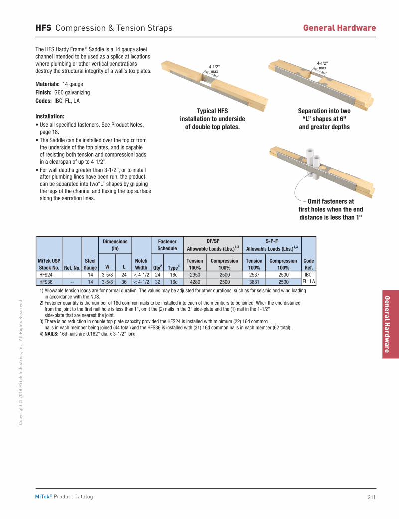
311
General Hardware
Copy
righ
t © 2
018
MiT
ek In
dust
ries
, Inc
. Al
l Rig
hts
Rese
rved
General Hardware
MiTek® Product Catalog
HFS Compression & Tension Straps
The HFS Hardy Frame® Saddle is a 14 gauge steel channel intended to be used as a splice at locations where plumbing or other vertical penetrations destroy the structural integrity of a wall’s top plates.
Materials: 14 gaugeFinish: G60 galvanizingCodes: IBC, FL, LA
Installation:• Use all specified fasteners. See Product Notes,
page 18.• The Saddle can be installed over the top or from
the underside of the top plates, and is capable of resisting both tension and compression loads in a clearspan of up to 4-1/2".
• For wall depths greater than 3-1/2", or to install after plumbing lines have been run, the product can be separated into two“L” shapes by gripping the legs of the channel and flexing the top surface along the serration lines.
Typical HFS installation to underside
of double top plates.
Separation into two “L” shapes at 6"
and greater depths
Omit fasteners at first holes when the end distance is less than 1"
Ref. No. W L Qty2 Type4
HFS24 -- 14 3-5/8 24 < 4-1/2 24 16d 2950 2500 2537 2500 HFS36 -- 14 3-5/8 36 < 4-1/2 32 16d 4280 2500 3681 2500
1) Allowable tension loads are for normal duration. The values may be adjusted for other durations, such as for seismic and wind loading in accordance with the NDS. 2) Fastener quantity is the number of 16d common nails to be installed into each of the members to be joined. When the end distance from the joint to the first nail hole is less than 1", omit the (2) nails in the 3" side-plate and the (1) nail in the 1-1/2" side-plate that are nearest the joint. 3) There is no reduction in double top plate capacity provided the HFS24 is installed with minimum (22) 16d common nails in each member being joined (44 total) and the HFS36 is installed with (31) 16d common nails in each member (62 total). 4) NAILS: 16d nails are 0.162" dia. x 3-1/2" long.
Fastener Schedule
Dimensions(in)
MiTek USPStock No.
SteelGauge
IBC,FL, LA
CodeRef.
Tension100%
Compression100%
NotchWidth
Tension100%
Compression100%
DF/SPAllowable Loads (Lbs.)1,3
S-P-FAllowable Loads (Lbs.)1,3
4-1/2" max
4-1/2" max
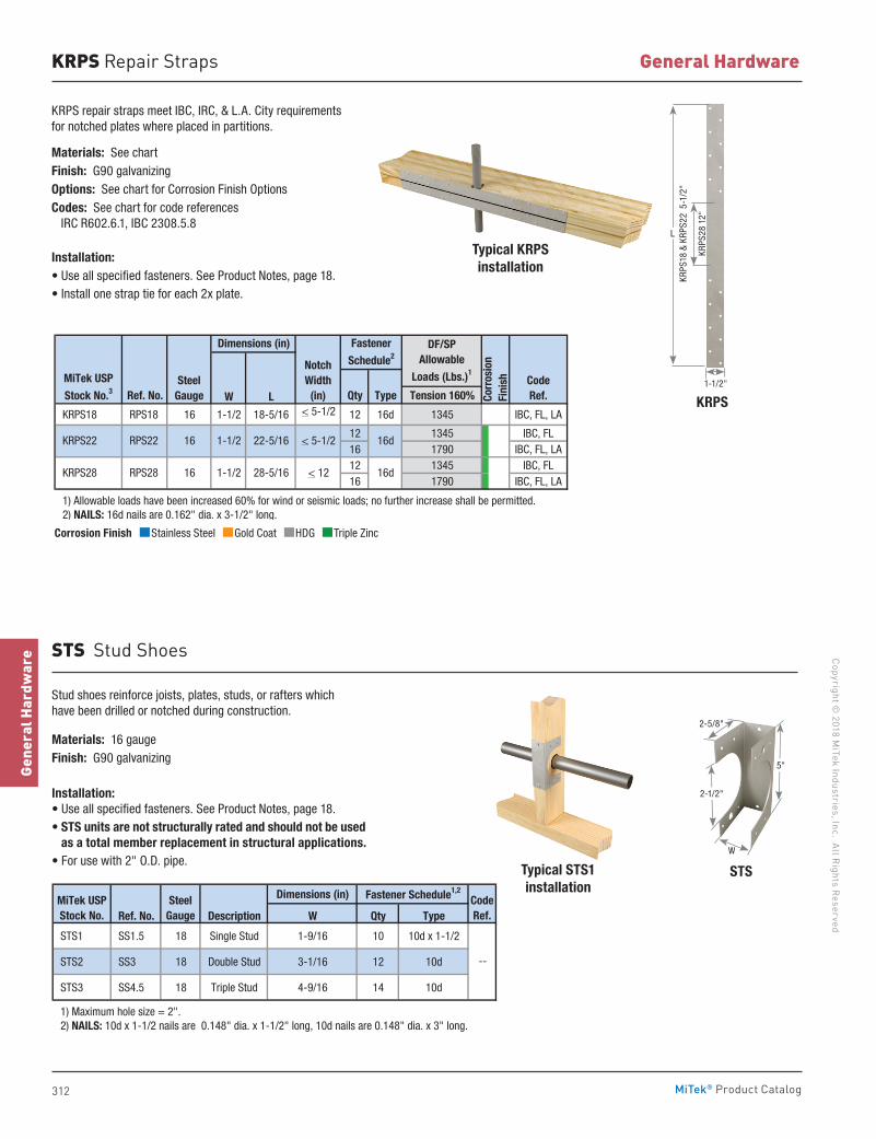
312
Copyright © 2018 M
iTek Industries, Inc. All Rights Reserved
General Hardware
Gene
ral H
ardw
are
MiTek® Product Catalog
STSTypical STS1installation
Stud shoes reinforce joists, plates, studs, or rafters which have been drilled or notched during construction.
Materials: 16 gaugeFinish: G90 galvanizing
Installation:• Use all specified fasteners. See Product Notes, page 18.• STS units are not structurally rated and should not be used
as a total member replacement in structural applications.• For use with 2" O.D. pipe.
STS Stud Shoes
Dimensions (in)
Ref. No. Description W Qty Type
STS1 SS1.5 18 Single Stud 1-9/16 10 10d x 1-1/2
STS2 SS3 18 Double Stud 3-1/16 12 10d
STS3 SS4.5 18 Triple Stud 4-9/16 14 10d
1) Maximum hole size = 2". 2) NAILS: 10d x 1-1/2 nails are 0.148" dia. x 1-1/2" long, 10d nails are 0.148" dia. x 3" long.
--
MiTek USPStock No.
SteelGauge
Fastener Schedule1,2
CodeRef.
5"
2-1/2"
2-5/8"
W
KRPS Repair Straps
KRPS repair straps meet IBC, IRC, & L.A. City requirements for notched plates where placed in partitions.
Materials: See chartFinish: G90 galvanizingOptions: See chart for Corrosion Finish OptionsCodes: See chart for code references IRC R602.6.1, IBC 2308.5.8
Installation:• Use all specified fasteners. See Product Notes, page 18.• Install one strap tie for each 2x plate.
Typical KRPSinstallation
KRPSRef. No. W L Qty Type Tension 160%
KRPS18 RPS18 16 1-1/2 18-5/16 < 5-1/2 12 16d 1345 IBC, FL, LA
12 1345 IBC, FL16 1790 IBC, FL, LA12 1345 IBC, FL16 1790 IBC, FL, LA
1) Allowable loads have been increased 60% for wind or seismic loads; no further increase shall be permitted. 2) NAILS: 16d nails are 0.162" dia. x 3-1/2" long.
RPS22 16
Fastener
Schedule2Dimensions (in)
MiTek USP
Stock No.3Steel
GaugeCodeRef.
DF/SPAllowable
Loads (Lbs.)1NotchWidth
(in) Corr
osio
nFi
nish
KRPS28 RPS28 16 1-1/2 28-5/16 < 12 16d
1-1/2 22-5/16 < 5-1/2 16d KRPS22Corrosion Finish Stainless Steel Gold Coat HDG Triple Zinc
Corrosion Finish Stainless Steel Gold Coat HDG Triple Zinc
Corrosion Finish Stainless Steel Gold Coat HDG Triple Zinc
KRPS
18 &
KRP
S22
5-1
/2"
KRPS
28 1
2"
1-1/2"
L
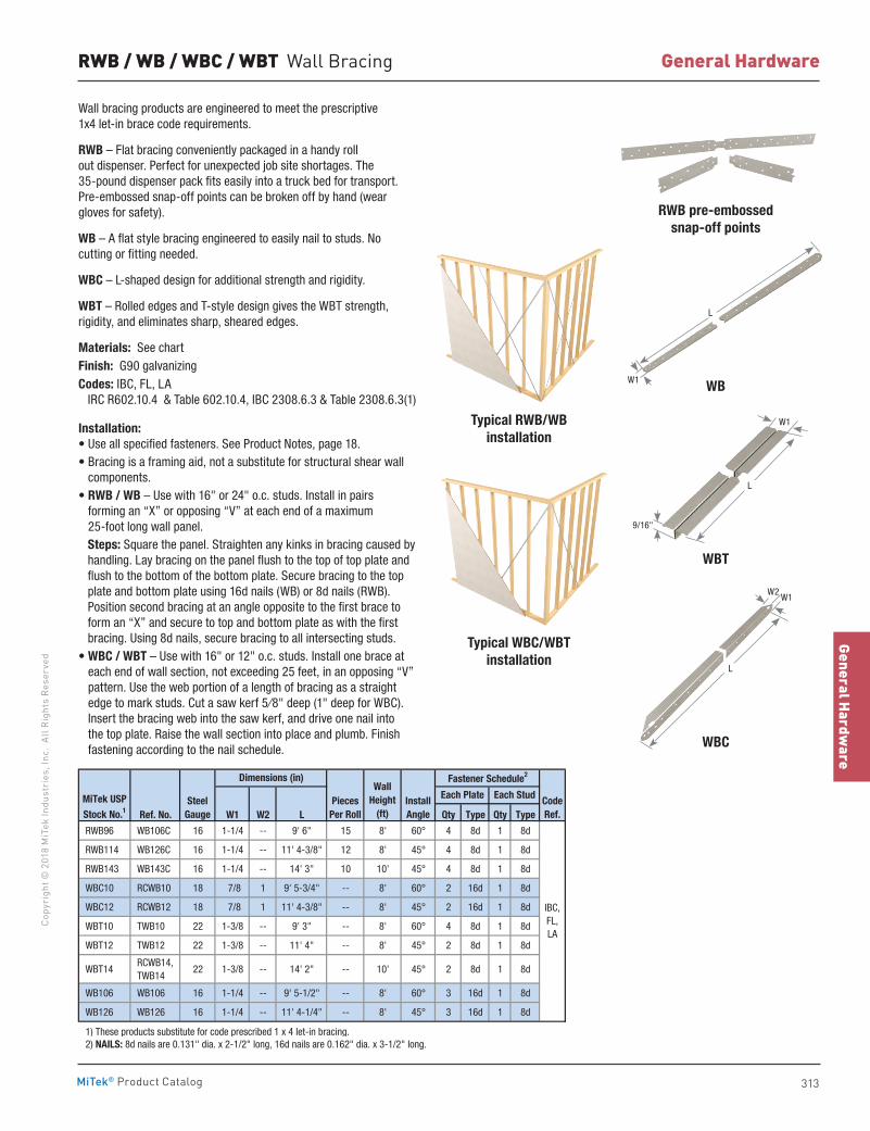
313
General Hardware
Copy
righ
t © 2
018
MiT
ek In
dust
ries
, Inc
. Al
l Rig
hts
Rese
rved
General Hardware
MiTek® Product Catalog
RWB / WB / WBC / WBT Wall Bracing
Wall bracing products are engineered to meet the prescriptive 1x4 let-in brace code requirements.
RWB – Flat bracing conveniently packaged in a handy roll out dispenser. Perfect for unexpected job site shortages. The 35-pound dispenser pack fits easily into a truck bed for transport. Pre-embossed snap-off points can be broken off by hand (wear gloves for safety).
WB – A flat style bracing engineered to easily nail to studs. No cutting or fitting needed.
WBC – L-shaped design for additional strength and rigidity.
WBT – Rolled edges and T-style design gives the WBT strength, rigidity, and eliminates sharp, sheared edges.
Materials: See chartFinish: G90 galvanizingCodes: IBC, FL, LA IRC R602.10.4 & Table 602.10.4, IBC 2308.6.3 & Table 2308.6.3(1)
Installation:• Use all specified fasteners. See Product Notes, page 18.• Bracing is a framing aid, not a substitute for structural shear wall
components.• RWB / WB – Use with 16" or 24" o.c. studs. Install in pairs
forming an “X” or opposing “V” at each end of a maximum 25-foot long wall panel.
Steps: Square the panel. Straighten any kinks in bracing caused by handling. Lay bracing on the panel flush to the top of top plate and flush to the bottom of the bottom plate. Secure bracing to the top plate and bottom plate using 16d nails (WB) or 8d nails (RWB). Position second bracing at an angle opposite to the first brace to form an “X” and secure to top and bottom plate as with the first bracing. Using 8d nails, secure bracing to all intersecting studs.
• WBC / WBT – Use with 16" or 12" o.c. studs. Install one brace at each end of wall section, not exceeding 25 feet, in an opposing “V” pattern. Use the web portion of a length of bracing as a straight edge to mark studs. Cut a saw kerf 5⁄8" deep (1" deep for WBC). Insert the bracing web into the saw kerf, and drive one nail into the top plate. Raise the wall section into place and plumb. Finish fastening according to the nail schedule.
RWB pre-embossedsnap-off points
Typical RWB/WBinstallation
Typical WBC/WBTinstallation
WB
WBT
WBC
Ref. No. W1 W2 L Qty Type Qty Type
RWB96 WB106C 16 1-1/4 -- 9' 6" 15 8' 60° 4 8d 1 8d
RWB114 WB126C 16 1-1/4 -- 11' 4-3/8" 12 8' 45° 4 8d 1 8d
RWB143 WB143C 16 1-1/4 -- 14' 3" 10 10' 45° 4 8d 1 8d
WBC10 RCWB10 18 7/8 1 9' 5-3/4" -- 8' 60° 2 16d 1 8d
WBC12 RCWB12 18 7/8 1 11' 4-3/8" -- 8' 45° 2 16d 1 8d
WBT10 TWB10 22 1-3/8 -- 9' 3" -- 8' 60° 4 8d 1 8d
WBT12 TWB12 22 1-3/8 -- 11' 4" -- 8' 45° 2 8d 1 8d
WBT14 RCWB14, TWB14
22 1-3/8 -- 14' 2" -- 10' 45° 2 8d 1 8d
WB106 WB106 16 1-1/4 -- 9' 5-1/2" -- 8' 60° 3 16d 1 8d
WB126 WB126 16 1-1/4 -- 11' 4-1/4" -- 8' 45° 3 16d 1 8d
1) These products substitute for code prescribed 1 x 4 let-in bracing. 2) NAILS: 8d nails are 0.131" dia. x 2-1/2" long, 16d nails are 0.162" dia. x 3-1/2" long.
IBC,FL,LA
MiTek USP
Stock No.1Steel
GaugePieces
Per RollCodeRef.
WallHeight
(ft)
Fastener Schedule2Dimensions (in)
Each Plate Each StudInstallAngle
L
W1
L
W1
9/16"
W2W1
L
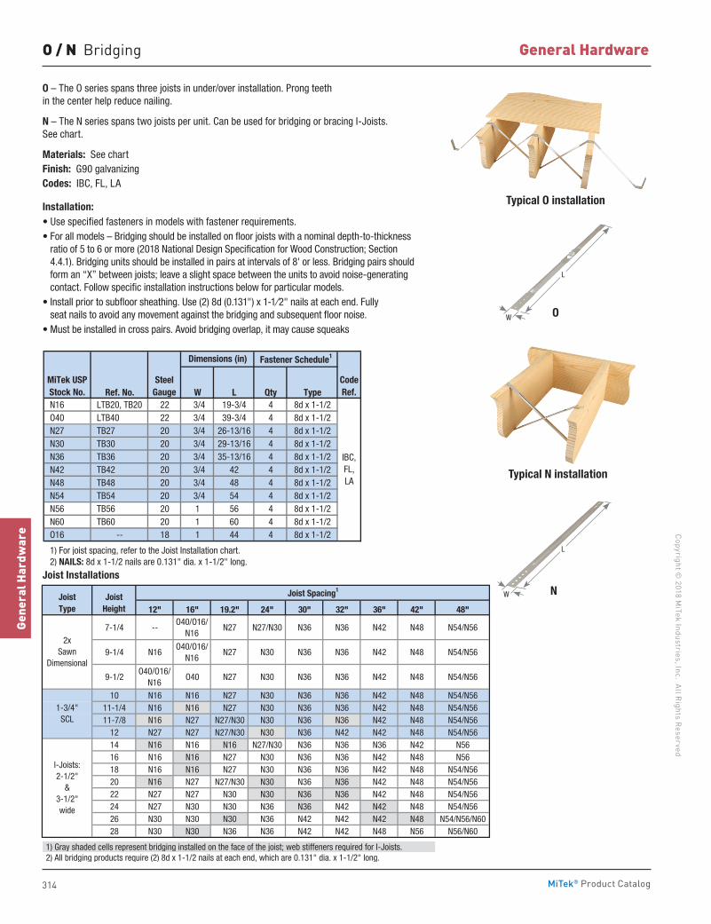
314
Copyright © 2018 M
iTek Industries, Inc. All Rights Reserved
General Hardware
Gene
ral H
ardw
are
MiTek® Product Catalog
O / N Bridging
O
Typical O installation
Typical N installation
O – The O series spans three joists in under/over installation. Prong teeth in the center help reduce nailing.
N – The N series spans two joists per unit. Can be used for bridging or bracing I-Joists. See chart.
Materials: See chartFinish: G90 galvanizingCodes: IBC, FL, LA
Installation:• Use specified fasteners in models with fastener requirements.• For all models – Bridging should be installed on floor joists with a nominal depth-to-thickness
ratio of 5 to 6 or more (2018 National Design Specification for Wood Construction; Section 4.4.1). Bridging units should be installed in pairs at intervals of 8' or less. Bridging pairs should form an “X” between joists; leave a slight space between the units to avoid noise-generating contact. Follow specific installation instructions below for particular models.
• Install prior to subfloor sheathing. Use (2) 8d (0.131") x 1-1⁄2" nails at each end. Fully seat nails to avoid any movement against the bridging and subsequent floor noise.
• Must be installed in cross pairs. Avoid bridging overlap, it may cause squeaks
Joist Installations
Ref. No. W L Qty Type N16 LTB20, TB20 22 3/4 19-3/4 4 8d x 1-1/2 O40 LTB40 22 3/4 39-3/4 4 8d x 1-1/2 N27 TB27 20 3/4 26-13/16 4 8d x 1-1/2 N30 TB30 20 3/4 29-13/16 4 8d x 1-1/2 N36 TB36 20 3/4 35-13/16 4 8d x 1-1/2 N42 TB42 20 3/4 42 4 8d x 1-1/2 N48 TB48 20 3/4 48 4 8d x 1-1/2 N54 TB54 20 3/4 54 4 8d x 1-1/2 N56 TB56 20 1 56 4 8d x 1-1/2 N60 TB60 20 1 60 4 8d x 1-1/2 O16 -- 18 1 44 4 8d x 1-1/2
1) For joist spacing, refer to the Joist Installation chart. 2) NAILS: 8d x 1-1/2 nails are 0.131" dia. x 1-1/2" long.
IBC,FL, LA
Dimensions (in)
MiTek USPStock No.
SteelGauge
Fastener Schedule1
CodeRef.
12" 16" 19.2" 24" 30" 32" 36" 42" 48"
7-1/4 --O40/O16/
N16N27 N27/N30 N36 N36 N42 N48 N54/N56
9-1/4 N16O40/O16/
N16N27 N30 N36 N36 N42 N48 N54/N56
9-1/2O40/O16/
N16O40 N27 N30 N36 N36 N42 N48 N54/N56
10 N16 N16 N27 N30 N36 N36 N42 N48 N54/N5611-1/4 N16 N16 N27 N30 N36 N36 N42 N48 N54/N5611-7/8 N16 N27 N27/N30 N30 N36 N36 N42 N48 N54/N56
12 N27 N27 N27/N30 N30 N36 N42 N42 N48 N54/N5614 N16 N16 N16 N27/N30 N36 N36 N36 N42 N5616 N16 N16 N27 N30 N36 N36 N42 N48 N5618 N16 N16 N27 N30 N36 N36 N42 N48 N54/N5620 N16 N27 N27/N30 N30 N36 N36 N42 N48 N54/N5622 N27 N27 N30 N30 N36 N36 N42 N48 N54/N5624 N27 N30 N30 N36 N36 N42 N42 N48 N54/N5626 N30 N30 N30 N36 N42 N42 N42 N48 N54/N56/N6028 N30 N30 N36 N36 N42 N42 N48 N56 N56/N60
1) Gray shaded cells represent bridging installed on the face of the joist; web stiffeners required for I-Joists. 2) All bridging products require (2) 8d x 1-1/2 nails at each end, which are 0.131" dia. x 1-1/2" long.
JoistType
2xSawn
Dimensional
1-3/4" SCL
I-Joists: 2-1/2"
& 3-1/2" wide
Joist Spacing1Joist
Height
L
W
N
L
W
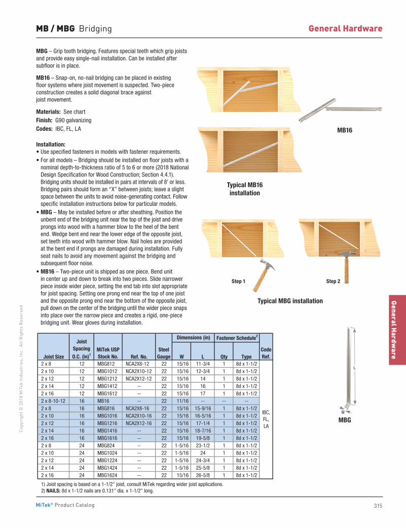
315
General Hardware
Copy
righ
t © 2
018
MiT
ek In
dust
ries
, Inc
. Al
l Rig
hts
Rese
rved
General Hardware
MiTek® Product Catalog
MB / MBG Bridging
MBG – Grip tooth bridging. Features special teeth which grip joists and provide easy single-nail installation. Can be installed after subfloor is in place.
MB16 – Snap-on, no-nail bridging can be placed in existing floor systems where joist movement is suspected. Two-piece construction creates a solid diagonal brace against joist movement.
Materials: See chartFinish: G90 galvanizingCodes: IBC, FL, LA
Installation:• Use specified fasteners in models with fastener requirements.• For all models – Bridging should be installed on floor joists with a
nominal depth-to-thickness ratio of 5 to 6 or more (2018 National Design Specification for Wood Construction; Section 4.4.1). Bridging units should be installed in pairs at intervals of 8' or less. Bridging pairs should form an “X” between joists; leave a slight space between the units to avoid noise-generating contact. Follow specific installation instructions below for particular models.
• MBG – May be installed before or after sheathing. Position the unbent end of the bridging unit near the top of the joist and drive prongs into wood with a hammer blow to the heel of the bent end. Wedge bent end near the lower edge of the opposite joist, set teeth into wood with hammer blow. Nail holes are provided at the bent end if prongs are damaged during installation. Fully seat nails to avoid any movement against the bridging and subsequent floor noise.
• MB16 – Two-piece unit is shipped as one piece. Bend unit in center up and down to break into two pieces. Slide narrower piece inside wider piece, setting the end tab into slot appropriate for joist spacing. Setting one prong end near the top of one joist and the opposite prong end near the bottom of the opposite joist, pull down on the center of the bridging until the wider piece snaps into place over the narrow piece and creates a rigid, one-piece bridging unit. Wear gloves during installation.
Typical MB16installation
MB16
MBG
Step 1 Step 2
Joist Size Ref. No. W L Qty Type 2 x 8 12 MBG812 NCA2X8-12 22 15/16 11-3/4 1 8d x 1-1/2 2 x 10 12 MBG1012 NCA2X10-12 22 15/16 12-3/4 1 8d x 1-1/2 2 x 12 12 MBG1212 NCA2X12-12 22 15/16 14 1 8d x 1-1/2 2 x 14 12 MBG1412 -- 22 15/16 16 1 8d x 1-1/2 2 x 16 12 MBG1612 -- 22 15/16 17 1 8d x 1-1/2 2 x 8-10-12 16 MB16 -- 22 11/16 -- -- -- 2 x 8 16 MBG816 NCA2X8-16 22 15/16 15-9/16 1 8d x 1-1/2 2 x 10 16 MBG1016 NCA2X10-16 22 15/16 16-5/16 1 8d x 1-1/2 2 x 12 16 MBG1216 NCA2X12-16 22 15/16 17-1/4 1 8d x 1-1/2 2 x 14 16 MBG1416 -- 22 15/16 18-7/16 1 8d x 1-1/2 2 x 16 16 MBG1616 -- 22 15/16 19-5/8 1 8d x 1-1/2 2 x 8 24 MBG824 -- 22 1-5/16 23-1/2 1 8d x 1-1/2 2 x 10 24 MBG1024 -- 22 1-5/16 24 1 8d x 1-1/2 2 x 12 24 MBG1224 -- 22 1-5/16 24-3/4 1 8d x 1-1/2 2 x 14 24 MBG1424 -- 22 1-5/16 25-5/8 1 8d x 1-1/2 2 x 16 24 MBG1624 -- 22 15/16 26-5/8 1 8d x 1-1/2
1) Joist spacing is based on a 1-1/2" joist, consult MiTek regarding wider joist applications. 2) NAILS: 8d x 1-1/2 nails are 0.131" dia. x 1-1/2" long.
IBC,FL,LA
JoistSpacing
O.C. (in)1
Dimensions (in)
MiTek USPStock No.
SteelGauge
CodeRef.
Fastener Schedule2
Typical MBG installation
W
L
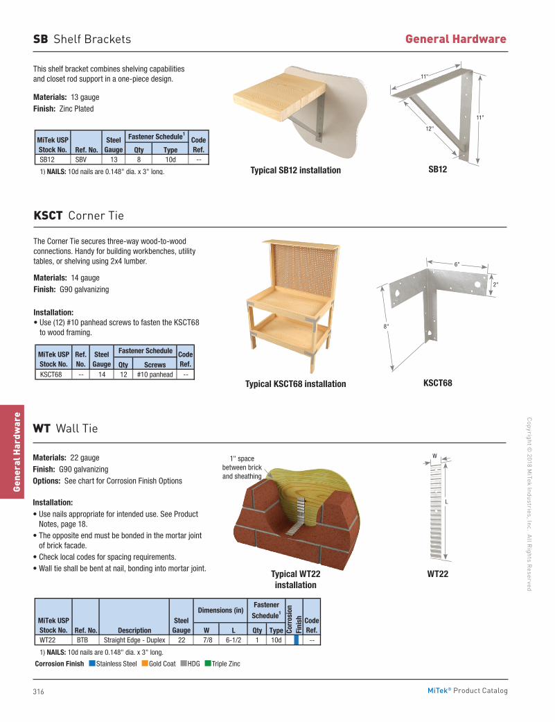
316
Copyright © 2018 M
iTek Industries, Inc. All Rights Reserved
General Hardware
Gene
ral H
ardw
are
MiTek® Product Catalog
SB Shelf Brackets
This shelf bracket combines shelving capabilities and closet rod support in a one-piece design.
Materials: 13 gaugeFinish: Zinc Plated
Typical SB12 installation
Typical KSCT68 installation
SB12
KSCT68
Ref. No. Qty Type SB12 SBV 13 8 10d --
1) NAILS: 10d nails are 0.148" dia. x 3" long.
MiTek USPStock No.
SteelGauge
CodeRef.
Fastener Schedule1
The Corner Tie secures three-way wood-to-wood connections. Handy for building workbenches, utility tables, or shelving using 2x4 lumber.
Materials: 14 gaugeFinish: G90 galvanizing
Installation:• Use (12) #10 panhead screws to fasten the KSCT68
to wood framing.
KSCT Corner Tie
Qty Screws KSCT68 -- 14 12 #10 panhead --
MiTek USPStock No.
SteelGauge
CodeRef.
Fastener ScheduleRef.No.
11"
11"
12"
6"
8"
2"
Typical WT22 installation
WT22
WT Wall Tie
Materials: 22 gaugeFinish: G90 galvanizingOptions: See chart for Corrosion Finish Options
Installation:• Use nails appropriate for intended use. See Product
Notes, page 18.• The opposite end must be bonded in the mortar joint
of brick facade.• Check local codes for spacing requirements.• Wall tie shall be bent at nail, bonding into mortar joint.
Ref. No. Description W L Qty Type WT22 BTB Straight Edge - Duplex 22 7/8 6-1/2 1 10d --
1) NAILS: 10d nails are 0.148" dia. x 3" long.
CodeRef.
MiTek USPStock No.
SteelGauge Co
rros
ion
Fini
sh
Fastener
Schedule1Dimensions (in)Corrosion Finish Stainless Steel Gold Coat HDG Triple Zinc
Corrosion Finish Stainless Steel Gold Coat HDG Triple Zinc
Corrosion Finish Stainless Steel Gold Coat HDG Triple Zinc
1" space between brick and sheathing
L
W
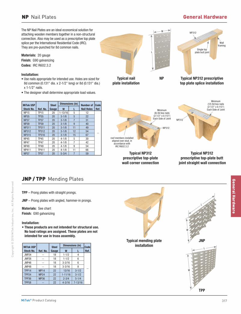
317
General Hardware
Copy
righ
t © 2
018
MiT
ek In
dust
ries
, Inc
. Al
l Rig
hts
Rese
rved
General Hardware
MiTek® Product Catalog
Minimum (6) 8d box nails
(2-1/2" x 0.113")Each Side of Joint
roof members installed aligned over stud, in
accordance with IRC R602.3.2
NP312
NP Nail Plates
TPP – Prong plates with straight prongs.
JNP – Prong plates with angled, hammer-in prongs.
Materials: See chartFinish: G90 galvanizing
Installation:• These products are not intended for structural use.
No load ratings are assigned. These plates are not intended for use in truss assembly.
Typical mending plate installation
Typical nail plate installation
Typical NP312 prescriptive top plate splice installation
JNP
TPP
NP
The NP Nail Plates are an ideal economical solution for attaching wooden members together in a non-structural connection. Also may be used as a prescriptive top plate splice per the International Residential Code (IRC). They are pre-punched for 8d common nails.
Materials: 20 gaugeFinish: G90 galvanizingCodes: IRC R602.3.2
Installation:• Use nails appropriate for intended use. Holes are sized for
8d common (0.131" dia. x 2-1/2" long) or 8d (0.131" dia.) x 1-1⁄2" nails.
• The designer shall determine appropriate load values.
JNP / TPP Mending Plates
Dimensions (in)
Ref. No. W L NP15 TP15 20 1-13/16 5 12 NP35 TP35 20 3-1/8 5 22 NP37 TP37 20 3-1/8 7 31 NP39 TP39 20 3-1/8 9 40 NP311 TP311 20 3-1/8 11 49 NP312 TP312 20 3-1/8 12 54 NP315 TP316 20 3-1/8 15 67 NP45 TP45 20 4-1/8 5 30 NP47 TP47 20 4-1/8 7 42 NP49 TP49 20 4-1/8 9 54 NP411 TP411 20 4-1/8 11 66 NP57 TP57 20 5-3/4 7 59
MiTek USPStock No.
SteelGauge
Number ofNail Holes
--
CodeRef.
Ref. No. W L JNP24 -- 18 1-1/2 4 JNP26 -- 18 1-1/2 6 JNP46 -- 18 3-3/16 6 JNP48 -- 18 3-3/16 8 TPP14 MP14 22 13/16 3-1/2 TPP24 MP24 22 1-11/16 3-1/2 TPP36 MP36 22 2-3/4 5-1/4 TPP58 -- 22 4-3/16 7-13/16
--
Dimensions (in)MiTek USPStock No.
SteelGauge
CodeRef.
W
L
W
L
W
L
Single top plate butt joint
NP312
Wall framing
Typical NP312 prescriptive top-plate
wall corner connection
Typical NP312 prescriptive top-plate butt
joint straight wall connection
NP312
Minimum (12) 8d box nails (2-1/2" x 0.113")Each Side of Joint
318
Copyright © 2020 M
iTek Industries, Inc. All Rights Reserved
Specialty Options
Spec
ialt
y Op
tions
MiTek® Product Catalog
Specialty Options
Face Mount Hanger 321Open Top Flange Hanger 322Part Number System 325Solid Top Flange Hanger 322-323Specialty Options & General Notes 320 Top Flange Nailer Options 323-324Welded Top Flange Hanger 325
pg. 320-325
319
Specialty OptionsCo
pyri
ght ©
202
0 M
iTek
Indu
stri
es, I
nc.
All R
ight
s Re
serv
ed
Specialty Options
MiTek® Product Catalog
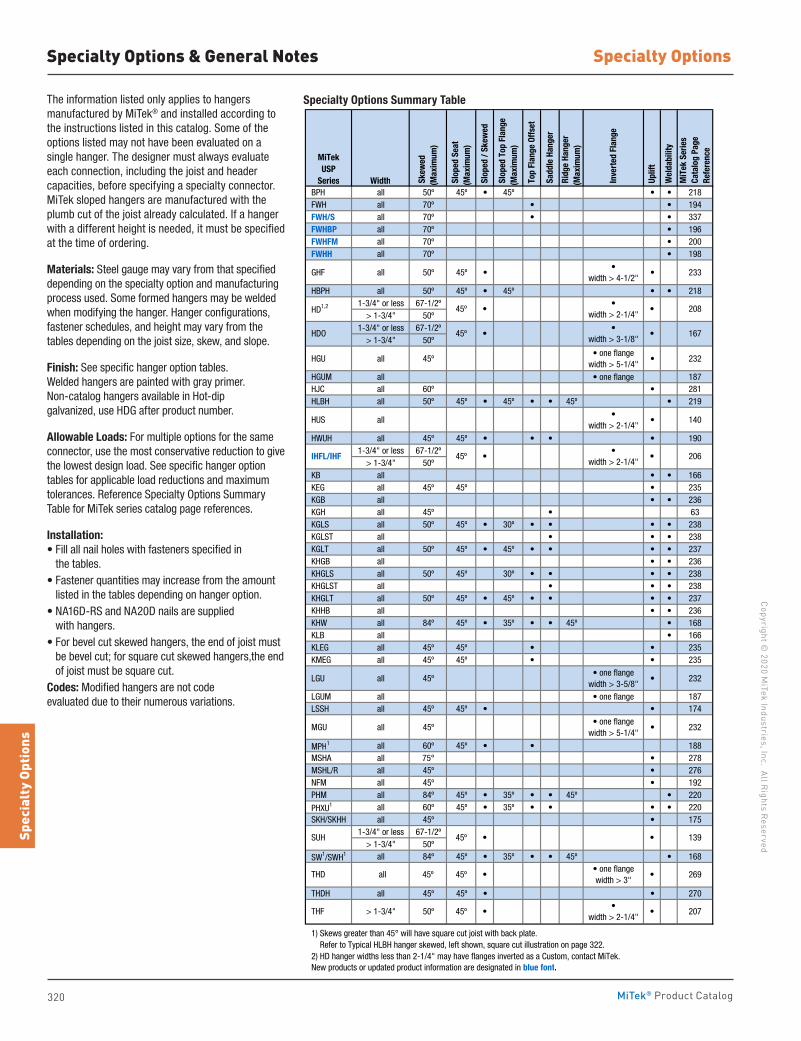
320
Copyright © 2020 M
iTek Industries, Inc. All Rights Reserved
Specialty Options
Spec
ialt
y Op
tions
MiTek® Product Catalog
The information listed only applies to hangers manufactured by MiTek® and installed according to the instructions listed in this catalog. Some of the options listed may not have been evaluated on a single hanger. The designer must always evaluate each connection, including the joist and header capacities, before specifying a specialty connector. MiTek sloped hangers are manufactured with the plumb cut of the joist already calculated. If a hanger with a different height is needed, it must be specified at the time of ordering.
Materials: Steel gauge may vary from that specified depending on the specialty option and manufacturing process used. Some formed hangers may be welded when modifying the hanger. Hanger configurations, fastener schedules, and height may vary from the tables depending on the joist size, skew, and slope.
Finish: See specific hanger option tables. Welded hangers are painted with gray primer. Non-catalog hangers available in Hot-dip galvanized, use HDG after product number.
Allowable Loads: For multiple options for the same connector, use the most conservative reduction to give the lowest design load. See specific hanger option tables for applicable load reductions and maximum tolerances. Reference Specialty Options Summary Table for MiTek series catalog page references.
Installation:• Fill all nail holes with fasteners specified in
the tables.• Fastener quantities may increase from the amount
listed in the tables depending on hanger option.• NA16D-RS and NA20D nails are supplied
with hangers.• For bevel cut skewed hangers, the end of joist must
be bevel cut; for square cut skewed hangers,the end of joist must be square cut.
Codes: Modified hangers are not code evaluated due to their numerous variations.
MiTek USP
Series Width Ske
wed
(Max
imum
)
Slop
ed S
eat
(Max
imum
)
Slo
ped
/ Ske
wed
Slop
ed T
op F
lang
e(M
axim
um)
Top
Fla
nge
Offs
et
Sad
dle
Hang
er
Ridg
e Ha
nger
(Max
imum
)
Inve
rted
Fla
nge
Upl
ift
Wel
dabi
lity
MiT
ek S
erie
s Ca
talo
g Pa
ge
Refe
renc
e
BPH all 50º 45º • 45º • • 218 FWH all 70º • • 194 FWH/S all 70º • • 337 FWHBP all 70º • 196 FWHFM all 70º • 200 FWHH all 70º • 198
GHF all 50º 45º ••
width > 4-1/2"• 233
HBPH all 50º 45º • 45º • • 2181-3/4" or less 67-1/2º
> 1-3/4" 50º1-3/4" or less 67-1/2º
> 1-3/4" 50º
HGU all 45º• one flange
width > 5-1/4"• 232
HGUM all • one flange 187 HJC all 60º • 281 HLBH all 50º 45º • 45º • • 45º • 219
HUS all•
width > 2-1/4"• 140
HWUH all 45º 45º • • • • 1901-3/4" or less 67-1/2º
> 1-3/4" 50º KB all • • 166 KEG all 45º 45º • 235 KGB all • • 236 KGH all 45º • 63 KGLS all 50º 45º • 30º • • • • 238 KGLST all • • • 238 KGLT all 50º 45º • 45º • • • • 237 KHGB all • • 236 KHGLS all 50º 45º 30º • • • • 238 KHGLST all • • • 238 KHGLT all 50º 45º • 45º • • • • 237 KHHB all • • 236 KHW all 84º 45º • 35º • • 45º • 168 KLB all • 166 KLEG all 45º 45º • • 235 KMEG all 45º 45º • • 235
LGU all 45º• one flange
width > 3-5/8"• 232
LGUM all • one flange 187 LSSH all 45º 45º • • 174
MGU all 45º• one flange
width > 5-1/4"• 232
MPH1 all 60º 45º • • 188 MSHA all 75° • 278 MSHL/R all 45º • 276 NFM all 45º • 192 PHM all 84º 45º • 35º • • 45º • 220
PHXU1 all 60º 45º • 35º • • • • 220 SKH/SKHH all 45º • 175
1-3/4" or less 67-1/2º> 1-3/4" 50º
SW1/SWH1 all 84º 45º • 35º • • 45º • 168
THDH all 45º 45º • • 270
1) Skews greater than 45° will have square cut joist with back plate. Refer to Typical HLBH hanger skewed, left shown, square cut illustration on page 322. 2) HD hanger widths less than 2-1/4" may have flanges inverted as a Custom, contact MiTek. New products or updated product information are designated in blue font.
•
•width > 2-1/4"
> 1-3/4" 50º
208
167
THF
45º 45º •
45º •
THD all• one flangewidth > 3"
•
•
•
45º
45º
SUH 45º
HD1,2
HDO
IHFL/IHF 45º
•width > 2-1/4"
••
•
207
269
139
•width > 3-1/8"
•
•
•width > 2-1/4"
• 206
Specialty Options & General Notes
Specialty Options Summary Table
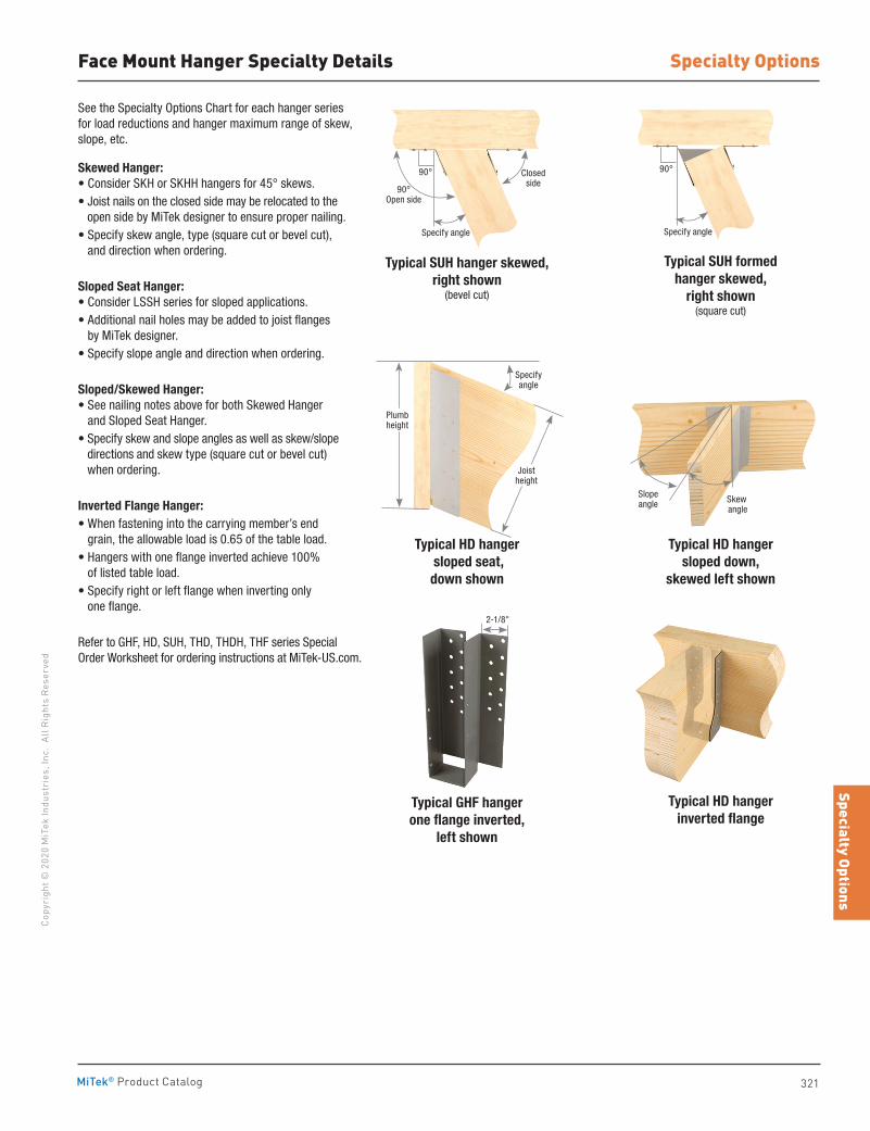
321
Specialty OptionsCo
pyri
ght ©
202
0 M
iTek
Indu
stri
es, I
nc.
All R
ight
s Re
serv
ed
Specialty Options
MiTek® Product Catalog
Face Mount Hanger Specialty Details
See the Specialty Options Chart for each hanger series for load reductions and hanger maximum range of skew, slope, etc.
Skewed Hanger:• Consider SKH or SKHH hangers for 45° skews.• Joist nails on the closed side may be relocated to the
open side by MiTek designer to ensure proper nailing.• Specify skew angle, type (square cut or bevel cut),
and direction when ordering.
Sloped Seat Hanger:• Consider LSSH series for sloped applications.• Additional nail holes may be added to joist flanges
by MiTek designer.• Specify slope angle and direction when ordering.
Sloped/Skewed Hanger:• See nailing notes above for both Skewed Hanger
and Sloped Seat Hanger.• Specify skew and slope angles as well as skew/slope
directions and skew type (square cut or bevel cut) when ordering.
Inverted Flange Hanger:• When fastening into the carrying member’s end
grain, the allowable load is 0.65 of the table load.• Hangers with one flange inverted achieve 100%
of listed table load.• Specify right or left flange when inverting only
one flange.
Refer to GHF, HD, SUH, THD, THDH, THF series Special Order Worksheet for ordering instructions at MiTek-US.com.
Typical SUH hanger skewed, right shown
(bevel cut)
Typical HD hanger sloped seat,down shown
Typical GHF hanger one flange inverted,
left shown
Typical SUH formed hanger skewed,
right shown(square cut)
Typical HD hanger inverted flange
90° Open side
Specify angle
Closed side
Specify angle
Specify angle
Plumb height
Joist height
2-1/8"
Typical HD hanger sloped down,
skewed left shown
Slope angle Skew
angle
90° 90°
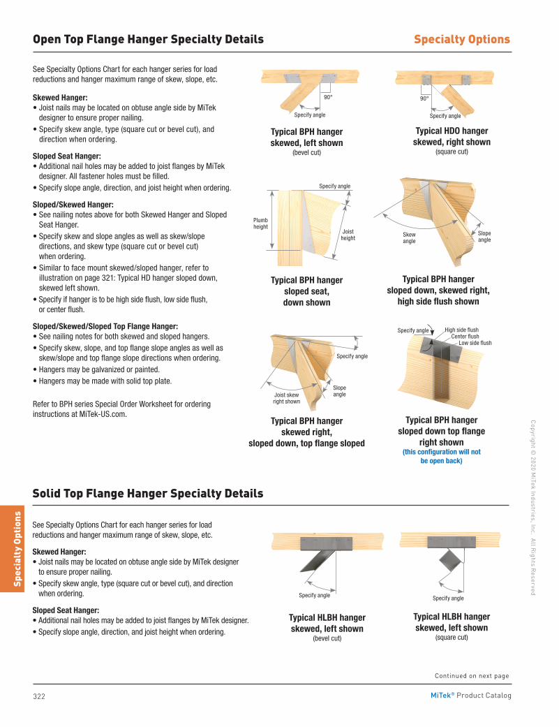
322
Copyright © 2020 M
iTek Industries, Inc. All Rights Reserved
Specialty Options
Spec
ialt
y Op
tions
MiTek® Product Catalog
Open Top Flange Hanger Specialty Details
See Specialty Options Chart for each hanger series for load reductions and hanger maximum range of skew, slope, etc.
Skewed Hanger:• Joist nails may be located on obtuse angle side by MiTek
designer to ensure proper nailing.• Specify skew angle, type (square cut or bevel cut), and
direction when ordering.
Sloped Seat Hanger:• Additional nail holes may be added to joist flanges by MiTek
designer. All fastener holes must be filled.• Specify slope angle, direction, and joist height when ordering.
Sloped/Skewed Hanger:• See nailing notes above for both Skewed Hanger and Sloped
Seat Hanger.• Specify skew and slope angles as well as skew/slope
directions, and skew type (square cut or bevel cut) when ordering.
• Similar to face mount skewed/sloped hanger, refer to illustration on page 321: Typical HD hanger sloped down, skewed left shown.
• Specify if hanger is to be high side flush, low side flush, or center flush.
Sloped/Skewed/Sloped Top Flange Hanger:• See nailing notes for both skewed and sloped hangers.• Specify skew, slope, and top flange slope angles as well as
skew/slope and top flange slope directions when ordering.• Hangers may be galvanized or painted.• Hangers may be made with solid top plate.
Refer to BPH series Special Order Worksheet for ordering instructions at MiTek-US.com.
Typical BPH hangerskewed, left shown
(bevel cut)
Typical BPH hangersloped seat,down shown
Typical BPH hangerskewed right,
sloped down, top flange sloped
Typical HLBH hangerskewed, left shown
(bevel cut)
Typical HDO hanger skewed, right shown
(square cut)
Typical BPH hangersloped down, skewed right,
high side flush shown
Typical BPH hangersloped down top flange
right shown (this configuration will not
be open back)
Typical HLBH hangerskewed, left shown
(square cut)
See Specialty Options Chart for each hanger series for load reductions and hanger maximum range of skew, slope, etc.
Skewed Hanger:• Joist nails may be located on obtuse angle side by MiTek designer
to ensure proper nailing.• Specify skew angle, type (square cut or bevel cut), and direction
when ordering.
Sloped Seat Hanger:• Additional nail holes may be added to joist flanges by MiTek designer.• Specify slope angle, direction, and joist height when ordering.
Solid Top Flange Hanger Specialty Details
Specify angle
Specify angle Specify angle
Specify angle
Slope angle
Skew angle
Specify angle
Joist skew right shown
Slope angle
Specify angle
Joist height
Plumb height
Specify angle High side flushCenter flush
Low side flush
90° 90°
Continued on next page
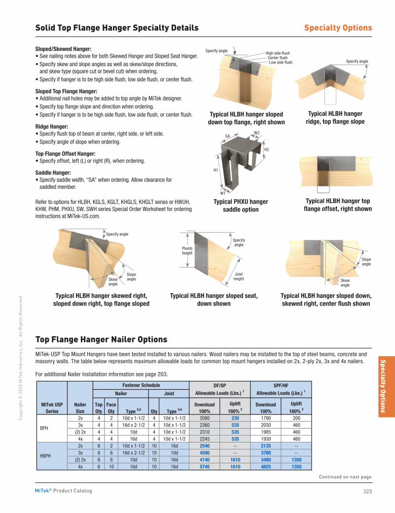
323
Specialty OptionsCo
pyri
ght ©
202
0 M
iTek
Indu
stri
es, I
nc.
All R
ight
s Re
serv
ed
Specialty Options
MiTek® Product Catalog
Top Flange Hanger Nailer Options
Continued on next page
Solid Top Flange Hanger Specialty Details
Typical PHXU hangersaddle option
Typical HLBH hanger sloped down, skewed right, center flush shown
Typical HLBH hangerridge, top flange slope
Typical HLBH hanger top flange offset, right shown
Typical HLBH hanger sloped seat, down shown
Typical HLBH hanger skewed right, sloped down right, top flange sloped
Sloped/Skewed Hanger:• See nailing notes above for both Skewed Hanger and Sloped Seat Hanger.• Specify skew and slope angles as well as skew/slope directions,
and skew type (square cut or bevel cut) when ordering.• Specify if hanger is to be high side flush, low side flush, or center flush.
Sloped Top Flange Hanger:• Additional nail holes may be added to top angle by MiTek designer.• Specify top flange slope and direction when ordering.• Specify if hanger is to be high side flush, low side flush, or center flush.
Ridge Hanger:• Specify flush top of beam at center, right side, or left side.• Specify angle of slope when ordering.
Top Flange Offset Hanger:• Specify offset, left (L) or right (R), when ordering.
Saddle Hanger:• Specify saddle width, “SA” when ordering. Allow clearance for
saddled member.
Refer to options for HLBH, KGLS, KGLT, KHGLS, KHGLT series or HWUH, KHW, PHM, PHXU, SW, SWH series Special Order Worksheet for ordering instructions at MiTek-US.com.
Typical HLBH hanger sloped down top flange, right shown
Specify angle
W1
H1
SAW2
H2
Plumb height
Specify angle
Joist height
Specify angle High side flushCenter flushLow side flush
Slope angle
Skew angle
Skew angle
Slope angle
Specify angle
MiTek-USP Top Mount Hangers have been tested installed to various nailers. Wood nailers may be installed to the top of steel beams, concrete and masonry walls. The table below represents maximum allowable loads for common top mount hangers installed on 2x, 2-ply 2x, 3x and 4x nailers.
For additional Nailer Installation information see page 203.
Type 5,6 Qty Type 5,6
2x 4 2 10d x 1-1/2 4 10d x 1-1/2 2080 230 1790 2003x 4 4 16d x 2-1/2 4 10d x 1-1/2 2360 535 2030 460
(2) 2x 4 4 10d 4 10d x 1-1/2 2310 535 1985 4604x 4 4 16d 4 10d x 1-1/2 2245 535 1930 4602x 6 2 10d x 1-1/2 10 16d 2540 -- 2135 --3x 6 6 16d x 2-1/2 10 10d 4500 -- 3780 --
(2) 2x 6 8 10d 10 16d 4140 1610 3480 13504x 6 10 16d 10 16d 5745 1610 4825 1350
SPF/HF Allowable Loads (Lbs.) 1
Top Qty
Face Qty
Nailer Joist
Download100%
Uplift160% 2
Download100%
Uplift160% 2
Fastener Schedule
BPH
HBPH
DF/SP Allowable Loads (Lbs.) 1
MiTek USP Series
NailerSize
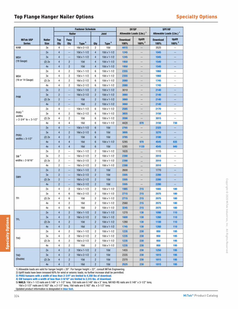
324
Copyright © 2020 M
iTek Industries, Inc. All Rights Reserved
Specialty Options
Spec
ialt
y Op
tions
MiTek® Product Catalog
Top Flange Hanger Nailer Options
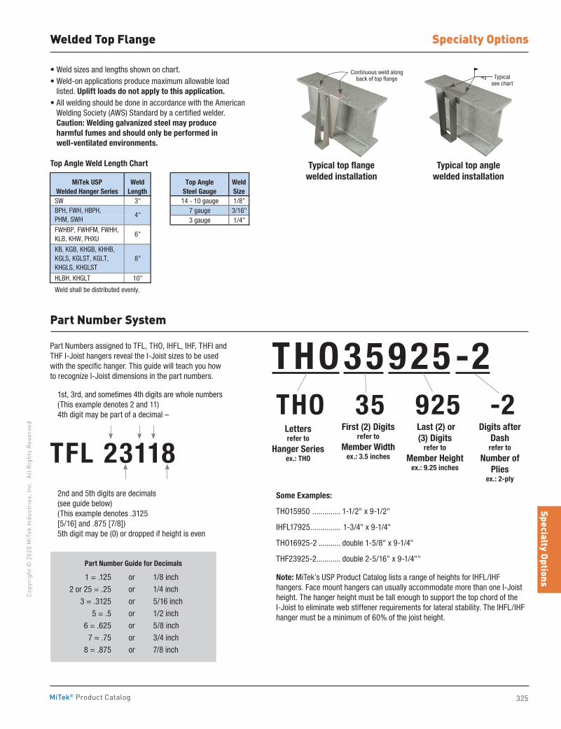
325
Specialty OptionsCo
pyri
ght ©
202
0 M
iTek
Indu
stri
es, I
nc.
All R
ight
s Re
serv
ed
Specialty Options
MiTek® Product Catalog
Welded Top Flange
• Weld sizes and lengths shown on chart.• Weld-on applications produce maximum allowable load
listed. Uplift loads do not apply to this application.• All welding should be done in accordance with the American
Welding Society (AWS) Standard by a certified welder. Caution: Welding galvanized steel may produce harmful fumes and should only be performed in well-ventilated environments.
SW 3" 14 - 10 gauge 1/8"7 gauge 3/16"3 gauge 1/4"
HLBH, KHGLT 10"
Weld shall be distributed evenly.
Top AngleSteel Gauge
WeldSize
MiTek USPWelded Hanger Series
WeldLength
BPH, FWH, HBPH, PHM, SWH
FWHBP, FWHFM, FWHH, KLB, KHW, PHXU
KB, KGB, KHGB, KHHB, KGLS, KGLST, KGLT, KHGLS, KHGLST
4"
6"
8"
Typical top flange welded installation
Typical top anglewelded installation
Continuous weld along back of top flange
Part Number System
Part Numbers assigned to TFL, THO, IHFL, IHF, THFI and THF I-Joist hangers reveal the I-Joist sizes to be used with the specific hanger. This guide will teach you how to recognize I-Joist dimensions in the part numbers.
1st, 3rd, and sometimes 4th digits are whole numbers (This example denotes 2 and 11) 4th digit may be part of a decimal –
TFL 23118 2nd and 5th digits are decimals
(see guide below) (This example denotes .3125 [5/16] and .875 [7/8]) 5th digit may be (0) or dropped if height is even
THO 35 925 -2
Part Number Guide for Decimals
1 = .125 or 1/8 inch
2 or 25 = .25 or 1/4 inch
3 = .3125 or 5/16 inch
5 = .5 or 1/2 inch
6 = .625 or 5/8 inch
7 = .75 or 3/4 inch
8 = .875 or 7/8 inch
THO 35 925 -2
Letters refer to
Hanger Seriesex.: THO
First (2) Digitsrefer to
Member Widthex.: 3.5 inches
Last (2) or (3) Digits
refer to
Member Heightex.: 9.25 inches
Digits after Dash
refer to
Number of Plies
ex.: 2-ply
Some Examples:
THO15950 .............. 1-1/2" x 9-1/2"
IHFL17925 ............... 1-3/4" x 9-1/4"
THO16925-2 ........... double 1-5/8" x 9-1/4"
THF23925-2............ double 2-5/16" x 9-1/4""
Note: MiTek’s USP Product Catalog lists a range of heights for IHFL/IHF hangers. Face mount hangers can usually accommodate more than one I-Joist height. The hanger height must be tall enough to support the top chord of the I-Joist to eliminate web stiffener requirements for lateral stability. The IHFL/IHF hanger must be a minimum of 60% of the joist height.
Top Angle Weld Length Chart
Typicalsee chart
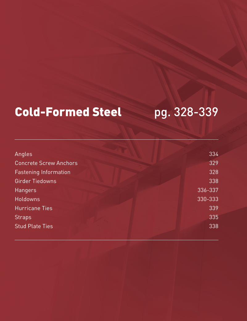
326
Copyright © 2020 M
iTek Industries, Inc. All Rights Reserved
Cold-Formed Steel Connectors
CFS
Conn
ecto
rs
MiTek® Product Catalog
Cold-Formed Steel
Angles 334 Concrete Screw Anchors 329 Fastening Information 328Girder Tiedowns 338Hangers 336-337 Holdowns 330-333Hurricane Ties 339Straps 335 Stud Plate Ties 338
pg. 328-339
327
CFS ConnectorsCo
pyri
ght ©
202
0 M
iTek
Indu
stri
es, I
nc.
All R
ight
s Re
serv
ed
Cold-Formed Steel Connectors
MiTek® Product Catalog
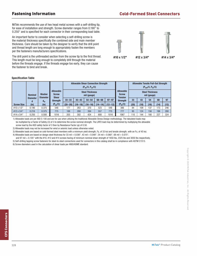
328
Copyright © 2020 M
iTek Industries, Inc. All Rights Reserved
Cold-Formed Steel Connectors
CFS
Conn
ecto
rs
MiTek® Product Catalog
MiTek recommends the use of hex head metal screws with a self-drilling tip, for ease of installation and strength. Screw diameter ranges from 0.190" to 0.250" and is specified for each connector in their corresponding load table.
An important factor to consider when selecting a self-drilling screw is the material thickness specifically the combined side and main member thickness. Care should be taken by the designer to verify that the drill point and thread length are long enough to appropriately fasten the members per the fasteners manufacturers specifications.
The drill point is the unthreaded section from the screw tip to the first thread. This length must be long enough to completely drill through the material before the threads engage. If the threads engage too early, they can cause the fastener to bind and break.
Specification Table
33─33 43─43 54─54 68─68 97─97 33 43 54 68 97
(20─20) (18─18) (16─16) (14─14) (12─12) (20) (18) (16) (14) (12) #10 x 1/2" 0.190 0.375 548 177 263 370 523 548 386 84 109 137 173 246 #12 x 3/4" 0.216 0.375 775 188 280 394 557 775 777 95 124 156 196 280 #14 x 3/4" 0.250 0.500 1016 203 302 424 600 1016 1067 110 144 180 227 324
1) Allowable loads are per AISI S-100 and are for use when utilizing the traditional Allowable Stress Design methodology. The tabulated loads may be multiplied by a Factor of Safety (Ω) of 3 to determine the screw nominal strength. The LRFD load may be determined by multiplying the allowable screw load by the ASD safety factor of 3 then by Resistance Factor (φ) of 0.50. 2) Allowable loads may not be increased for wind or seismic load unless otherwise noted. 3) Allowable loads are based on cold-formed steel members with a minimum yield strength, Fy, of 33 ksi and tensile strength, with an Fu, of 45 ksi. 4) Allowable loads are based on design steel thickness for 33 mil = 0.036", 43 mil = 0.048", 54 mil = 0.060", 68 mil = 0.075", and 97 mil = 0.105" with the #10, #12 and #14 screws having of minimum nominal shear strength of 1650 lbs, 2325 lbs and 3050 lbs respectively. 5) Self-drilling tapping screw fasteners for steel-to-steel connections used for connectors in this catalog shall be in compliance with ASTM C1513. 6) Screw diameters used in the calculation of shear loads per ANSI/ASME standard.
AllowableScrew
TensionStrength(Pts/Ω)
Allowable Tensile Pull-Out Strength(Pnot/Ω, Pts/Ω)
Steel Thicknessmil (gauge)
Screw Size
NominalDiameter
d(in)
WasherDiameter
dw
(in)
AllowableScrewShear
Strength (Pss/Ω)
Allowable Shear Connection Strength(Pns/Ω, Pss/Ω)
Steel Thicknessmil (gauge)
Fastening Information
#10 x 1/2" #12 x 3/4" #14 x 3/4"
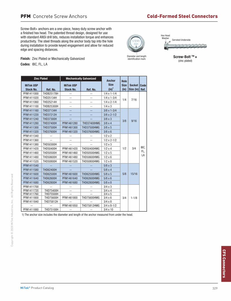
329
CFS ConnectorsCo
pyri
ght ©
202
0 M
iTek
Indu
stri
es, I
nc.
All R
ight
s Re
serv
ed
Cold-Formed Steel Connectors
MiTek® Product Catalog
Ref. No. Ref. No. PFM1411000 THDB25178H -- -- 1/4 x 1-1/4 PFM1411020 THD25134H -- -- 1/4 x 1-3/4 PFM1411060 THD25214H -- -- 1/4 x 2-1/4 PFM1411100 THDB25300H -- -- 1/4 x 3 PFM1411160 THD37134H -- -- 3/8 x 1-3/4 PFM1411220 THD37212H -- -- 3/8 x 2-1/2 PFM1411240 THD37300H -- -- 3/8 x 3 PFM1411280 THD37400H PFM1461280 THD37400HMG 3/8 x 4 PFM1411300 THD37500H PFM1461300 THD37500HMG 3/8 x 5 PFM1411320 THD37600H PFM1461320 THD37600HMG 3/8 x 6 PFM1411340 -- -- -- 1/2 x 2 PFM1411360 -- -- -- 1/2 x 2-1/2 PFM1411380 THD50300H -- -- 1/2 x 3 PFM1411420 THD50400H PFM1461420 THD50400HMG 1/2 x 4 PFM1411460 THD50500H PFM1461460 THD50500HMG 1/2 x 5 PFM1411480 THD50600H PFM1461480 THD50600HMG 1/2 x 6 PFM1411520 THD50800H PFM1461520 THD50800HMG 1/2 x 8 PFM1411540 -- -- -- 5/8 x 3 PFM1411580 THD62400H -- -- 5/8 x 4 PFM1411600 THD62500H PFM1461600 THD62500HMG 5/8 x 5 PFM1411640 THD62600H PFM1461640 THD62600HMG 5/8 x 6 PFM1411680 THD62800H PFM1461680 THD62800HMG 5/8 x 8 PFM1411700 -- -- -- 3/4 x 3 PFM1411720 THD75400H -- -- 3/4 x 4 PFM1411760 THD75500H -- -- 3/4 x 5 PFM1411800 THD75600H PFM1461800 THD75600HMG 3/4 x 6 PFM1411840 THD75812H -- -- 3/4 x 8
-- -- PFM1461850 THD75812HMG 3/4 x 8-1/2 PFM1411880 THD75100H -- -- 3/4 x 10
1) The anchor size includes the diameter and length of the anchor measured from under the head.
Zinc Plated Mechanically GalvanizedAnchor
Size
(in)1
HoleSize(in)
MiTek USPStock No.
MiTek USPStock No.
CodeRef.
IBC,FL,LA
3/8 9/16
1/2 3/4
5/8 15/16
1/4 7/16
SocketSize (in)
3/4 1-1/8
PFM Concrete Screw Anchors
Screw-Bolt+ anchors are a one-piece, heavy duty screw anchor with a finished hex head. The patented thread design, designed for use with standard ANSI drill bits, reduces installation torque and enhances productivity. The steel threads along the anchor body tap into the hole during installation to provide keyed engagement and allow for reduced edge and spacing distances.
Finish: Zinc Plated or Mechanically Galvanized
Codes: IBC, FL, LA
Screw-Bolt TM + (zinc plated)
Hex Head Washer
Diameter and length identification mark
Serrated Underside
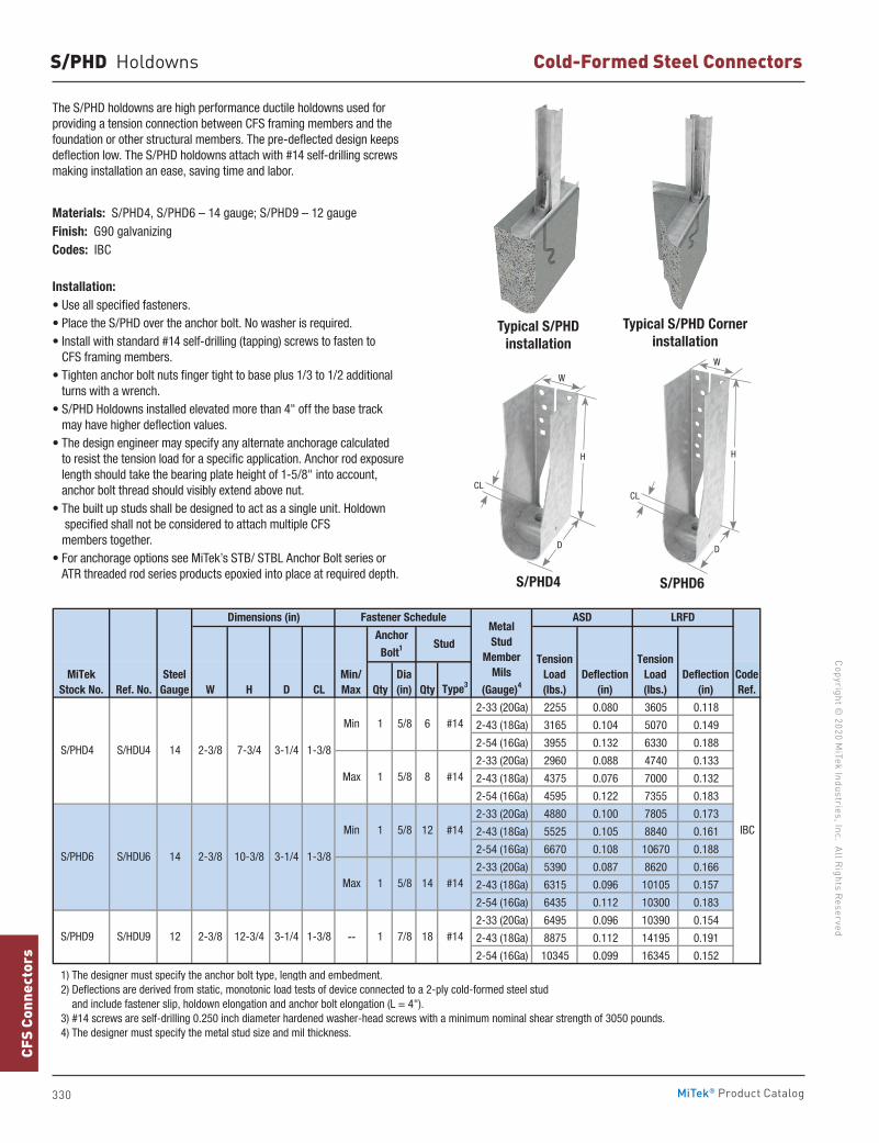
330
Copyright © 2020 M
iTek Industries, Inc. All Rights Reserved
Cold-Formed Steel Connectors
CFS
Conn
ecto
rs
MiTek® Product Catalog
S/PHD Holdowns
The S/PHD holdowns are high performance ductile holdowns used for providing a tension connection between CFS framing members and the foundation or other structural members. The pre-deflected design keeps deflection low. The S/PHD holdowns attach with #14 self-drilling screws making installation an ease, saving time and labor.
Materials: S/PHD4, S/PHD6 – 14 gauge; S/PHD9 – 12 gaugeFinish: G90 galvanizingCodes: IBC
Installation:• Use all specified fasteners.• Place the S/PHD over the anchor bolt. No washer is required.• Install with standard #14 self-drilling (tapping) screws to fasten to
CFS framing members.• Tighten anchor bolt nuts finger tight to base plus 1/3 to 1/2 additional
turns with a wrench.• S/PHD Holdowns installed elevated more than 4" off the base track
may have higher deflection values.• The design engineer may specify any alternate anchorage calculated
to resist the tension load for a specific application. Anchor rod exposure length should take the bearing plate height of 1-5/8" into account, anchor bolt thread should visibly extend above nut.
• The built up studs shall be designed to act as a single unit. Holdown specified shall not be considered to attach multiple CFS members together.
• For anchorage options see MiTek’s STB/ STBL Anchor Bolt series or ATR threaded rod series products epoxied into place at required depth. S/PHD4 S/PHD6
Typical S/PHD installation
Typical S/PHD Corner installation
Ref. No. W H D CL Qty Qty Type3
2-33 (20Ga) 2255 0.080 3605 0.118
2-43 (18Ga) 3165 0.104 5070 0.149
2-54 (16Ga) 3955 0.132 6330 0.188
2-33 (20Ga) 2960 0.088 4740 0.133
2-43 (18Ga) 4375 0.076 7000 0.132
2-54 (16Ga) 4595 0.122 7355 0.183
2-33 (20Ga) 4880 0.100 7805 0.173
2-43 (18Ga) 5525 0.105 8840 0.161
2-54 (16Ga) 6670 0.108 10670 0.188
2-33 (20Ga) 5390 0.087 8620 0.166
2-43 (18Ga) 6315 0.096 10105 0.157
2-54 (16Ga) 6435 0.112 10300 0.183
2-33 (20Ga) 6495 0.096 10390 0.154
2-43 (18Ga) 8875 0.112 14195 0.191
2-54 (16Ga) 10345 0.099 16345 0.152
1) The designer must specify the anchor bolt type, length and embedment. 2) Deflections are derived from static, monotonic load tests of device connected to a 2-ply cold-formed steel stud and include fastener slip, holdown elongation and anchor bolt elongation (L = 4"). 3) #14 screws are self-drilling 0.250 inch diameter hardened washer-head screws with a minimum nominal shear strength of 3050 pounds. 4) The designer must specify the metal stud size and mil thickness.
IBC
Anchor
Bolt1 Stud
Fastener Schedule
CodeRef.
5/8
1 5/8
1 5/8
18 #14
12 #14
14 #14
S/PHD9 S/HDU9 12 2-3/8 12-3/4 3-1/4
1-3/8
Min
Max
3-1/4
1-3/8 1 7/8--
1 5/8
S/PHD6 S/HDU6 14 2-3/8 10-3/8
#14
Max 8 #14
S/PHD4 S/HDU4 14 2-3/8 7-3/4 3-1/4 1-3/8
Min 61
TensionLoad(lbs.)
Deflection (in)
Dimensions (in)Metal Stud
MemberMils
(Gauge)4
ASD LRFD
Dia(in)
MiTekStock No.
SteelGauge
Min/Max
TensionLoad(lbs.)
Deflection (in)
CL
H
W
D
CL
D
H
W
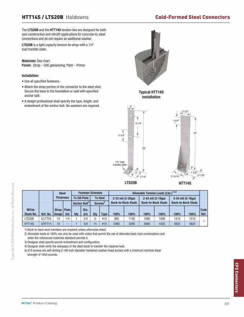
331
CFS ConnectorsCo
pyri
ght ©
202
0 M
iTek
Indu
stri
es, I
nc.
All R
ight
s Re
serv
ed
Cold-Formed Steel Connectors
MiTek® Product Catalog
HTT14S / LTS20B Holdowns
Typical HTT14S installation
HTT14S
The LTS20B and the HTT14S tension ties are designed for both new construction and retrofit applications for concrete-to-steel connections and do not require an additional washer.
LTS20B is a light capacity tension tie strap with a 1/4" load transfer plate.
Materials: See chart Finish: Strap – G90 galvanizing; Plate – Primer
Installation:
• Use all specified fasteners.
• Attach the strap portion of the connector to the steel stud. Secure the base to the foundation or wall with specified anchor bolt.
• A design professional shall specify the type, length, and embedment of the anchor bolt. No washers are required.
Ref. No. Qty Qty Type 100% 160% 100% 160% 100% 160% LTS20B S/LTT20 12 1/4 1 3/4 5 #10 885 1140 1090 1090 1210 1210
HTT14S S/HTT14 10 -- 1 5/8 14 #10 2480 3290 3680 4425 4825 4825
1) Back-to-back stud members are required unless otherwise noted. 2) Allowable loads at 160% can only be used with codes that permit the use of alternate basic load combinations and when the referenced materials standard permits it. 3) Designer shall specify anchor embedment and configuration. 4) Designer shall verify the adequacy of the steel studs to transfer the required load. 5) #10 screws are self-drilling 0.190 inch diameter hardened washer-head screws with a minimum nominal shear strength of 1650 pounds.
CodeRef.
--
Dia.(in)
Allowable Tension Loads (Lbs.)1,2,4Fastener Schedule
To Stud
Screws5
2-33 mil (2-20ga)Back-to-Back Studs
2-43 mil (2-18ga)Back-to-Back Studs
2-54 mil (2-16ga)Back-to-Back Studs
MiTekStock No.
Anchor Bolt3
To Sill PlateSteel
Thickness
StrapGauge
Plate(in)
16"
2-1/2"
1-3/4"
2-13/16" 2-1/16"1-3/8"
LTS20B
20"
3-1/8"
6-1/4"
2"
2"
1/4" load transfer plate
3-3/4"
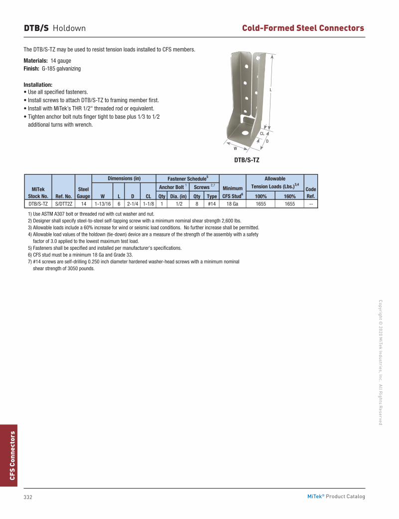
332
Copyright © 2020 M
iTek Industries, Inc. All Rights Reserved
Cold-Formed Steel Connectors
CFS
Conn
ecto
rs
MiTek® Product Catalog
DTB/S Holdown
Ref. No. W L D CL Qty Dia. (in) Qty Type 100% 160%DTB/S-TZ S/DTT2Z 14 1-13/16 6 2-1/4 1-1/8 1 1/2 8 #14 18 Ga 1655 1655 --
1) Use ASTM A307 bolt or threaded rod with cut washer and nut. 2) Designer shall specify steel-to-steel self-tapping screw with a minimum nominal shear strength 2,600 lbs. 3) Allowable loads include a 60% increase for wind or seismic load conditions. No further increase shall be permitted. 4) Allowable load values of the holdown (tie-down) device are a measure of the strength of the assembly with a safety factor of 3.0 applied to the lowest maximum test load. 5) Fasteners shall be specified and installed per manufacturer's specifications. 6) CFS stud must be a minimum 18 Ga and Grade 33. 7) #14 screws are self-drilling 0.250 inch diameter hardened washer-head screws with a minimum nominal shear strength of 3050 pounds.
CodeRef.
Allowable
Tension Loads (Lbs.)3,4
MiTekStock No.
SteelGauge
Dimensions (in)
Minimum
CFS Stud6
Fastener Schedule5
Anchor Bolt 1 Screws 2,7
The DTB/S-TZ may be used to resist tension loads installed to CFS members.
Materials: 14 gau geFinish: G-185 galvanizing
Installation:• Use all specified fasteners.• Install screws to attach DTB/S-TZ to framing member first.• Install with MiTek’s THR 1/2" threaded rod or equivalent.• Tighten anchor bolt nuts finger tight to base plus 1⁄3 to 1⁄2
additional turns with wrench.
DTB/S-TZ
L
D
CL
W
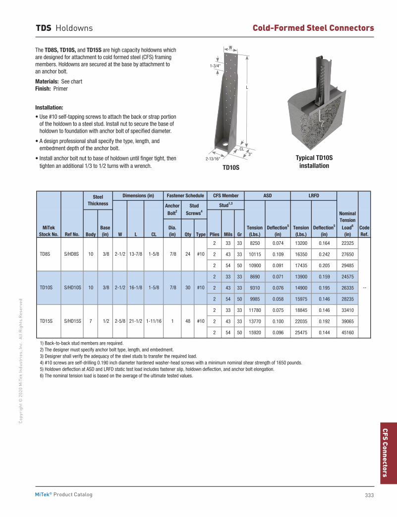
333
CFS ConnectorsCo
pyri
ght ©
202
0 M
iTek
Indu
stri
es, I
nc.
All R
ight
s Re
serv
ed
Cold-Formed Steel Connectors
MiTek® Product Catalog
Typical TD10S installation
The TD8S, TD10S, and TD15S are high capacity holdowns which are designed for attachment to cold formed steel (CFS) framing members. Holdowns are secured at the base by attachment to an anchor bolt.
Materials: See chart Finish: Primer
Installation:
• Use #10 self-tapping screws to attach the back or strap portion of the holdown to a steel stud. Install nut to secure the base of holdown to foundation with anchor bolt of specified diameter.
• A design professional shall specify the type, length, and embedment depth of the anchor bolt.
• Install anchor bolt nut to base of holdown until finger tight, then tighten an additional 1/3 to 1/2 turns with a wrench.
Body W L CL Qty Type Plies Mils Gr
2 33 33 8250 0.074 13200 0.164 22325
2 43 33 10115 0.109 16350 0.242 27650
2 54 50 10900 0.091 17435 0.205 29485
2 33 33 8690 0.071 13900 0.159 24575
2 43 33 9310 0.076 14900 0.195 26335
2 54 50 9985 0.058 15975 0.146 28235
2 33 33 11780 0.075 18845 0.146 33410
2 43 33 13770 0.100 22035 0.192 39065
2 54 50 15920 0.096 25475 0.144 45160
1) Back-to-back stud members are required. 2) The designer must specify anchor bolt type, length, and embedment. 3) Designer shall verify the adequacy of the steel studs to transfer the required load. 4) #10 screws are self-drilling 0.190 inch diameter hardened washer-head screws with a minimum nominal shear strength of 1650 pounds. 5) Holdown deflection at ASD and LRFD static test load includes fastener slip, holdown deflection, and anchor bolt elongation. 6) The nominal tension load is based on the average of the ultimate tested values.
CodeRef.
--
Dia. (in)
Stud1,3
24 #10
NominalTension
Load6
(in)
#10
ASD LRFD
Tension(Lbs.)
Deflection5
(in)Tension(Lbs.)
Deflection5
(in)
Anchor
Bolt2Stud
Screws4
TD15S 7 1/2 2-5/8 21-1/2 S/HD15S
#10
2-1/2 13-7/8
1-11/16 1 48
7/8
2-1/2 16-1/8 1-5/8
MiTekStock No.
30
Fastener Schedule CFS Member
TD10S 10
TD8S 10 3/8
S/HD10S
Ref No.
S/HD8S
7/8
1-5/8
Dimensions (in)
Base(in)
SteelThickness
3/8
TD10S
L
W
1-3/4"
2-13/16"3"
CL
TDS Holdowns
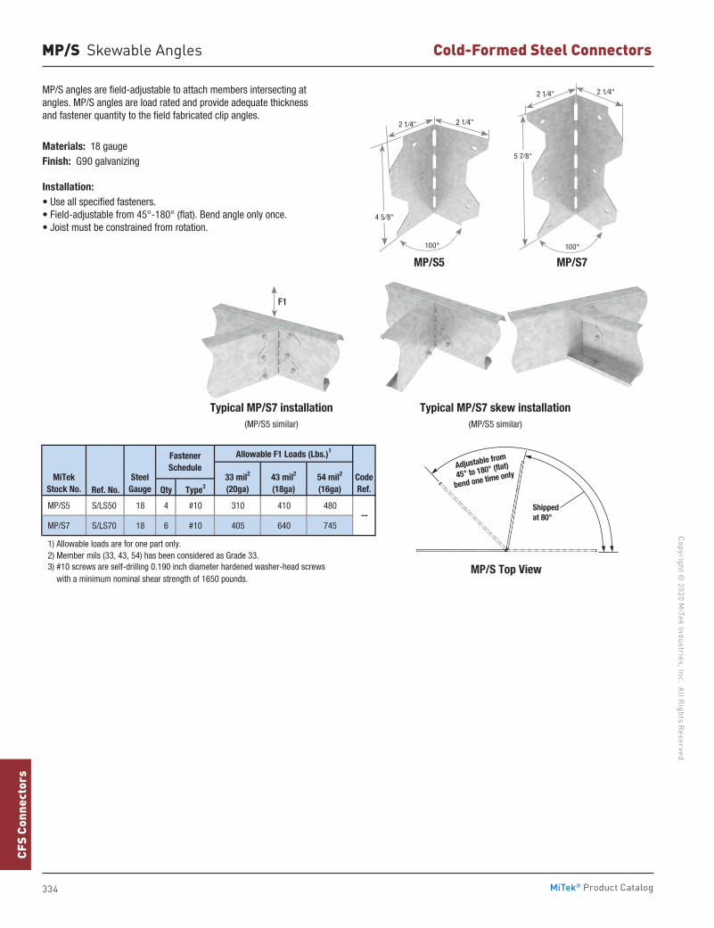
334
Copyright © 2020 M
iTek Industries, Inc. All Rights Reserved
Cold-Formed Steel Connectors
CFS
Conn
ecto
rs
MiTek® Product Catalog
MP/S Skewable Angles
MP/S angles are field-adjustable to attach members intersecting at angles. MP/S angles are load rated and provide adequate thickness and fastener quantity to the field fabricated clip angles.
Materials: 18 gaugeFinish: G90 galvanizing
Installation:• Use all specified fasteners.• Field-adjustable from 45°-180° (flat). Bend angle only once.• Joist must be constrained from rotation.
MP/S5 MP/S7
Typical MP/S7 installation(MP/S5 similar)
Typical MP/S7 skew installation(MP/S5 similar)
MP/S Top View
Shippedat 80°
Adjustable from
45° to 180° (flat)
bend one time only
Ref. No. Qty Type3
MP/S5 S/LS50 18 4 #10 310 410 480
MP/S7 S/LS70 18 6 #10 405 640 745
1) Allowable loads are for one part only. 2) Member mils (33, 43, 54) has been considered as Grade 33.
with a minimum nominal shear strength of 1650 pounds. 3) #10 screws are self-drilling 0.190 inch diameter hardened washer-head screws
MiTekStock No.
--
CodeRef.
SteelGauge
FastenerSchedule
Allowable F1 Loads (Lbs.)1
33 mil2
(20ga)43 mil2
(18ga)54 mil2
(16ga)
F1
100°
4 5⁄8"
2 1⁄4" 2 1⁄4"
100°
2 1⁄4" 2 1⁄4"
5 7⁄8"
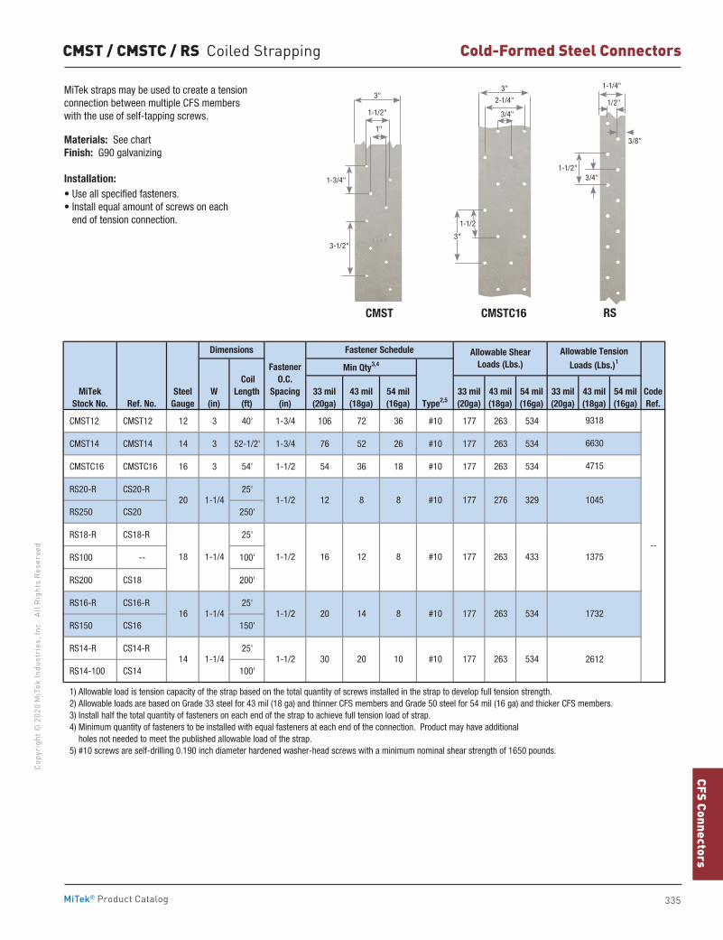
335
CFS ConnectorsCo
pyri
ght ©
202
0 M
iTek
Indu
stri
es, I
nc.
All R
ight
s Re
serv
ed
Cold-Formed Steel Connectors
MiTek® Product Catalog
CMST12 CMST12 12 3 40' 1-3/4 106 72 36 #10 177 263 534
CMST14 CMST14 14 3 52-1/2' 1-3/4 76 52 26 #10 177 263 534
CMSTC16 CMSTC16 16 3 54' 1-1/2 54 36 18 #10 177 263 534
RS20-R CS20-R 25'
RS250 CS20 250'
RS18-R CS18-R 25'
RS100 -- 100'
RS200 CS18 200'
RS16-R CS16-R 25'
RS150 CS16 150'
RS14-R CS14-R 25'
RS14-100 CS14 100'
1) Allowable load is tension capacity of the strap based on the total quantity of screws installed in the strap to develop full tension strength. 2) Allowable loads are based on Grade 33 steel for 43 mil (18 ga) and thinner CFS members and Grade 50 steel for 54 mil (16 ga) and thicker CFS members. 3) Install half the total quantity of fasteners on each end of the strap to achieve full tension load of strap. 4) Minimum quantity of fasteners to be installed with equal fasteners at each end of the connection. Product may have additional holes not needed to meet the published allowable load of the strap. 5) #10 screws are self-drilling 0.190 inch diameter hardened washer-head screws with a minimum nominal shear strength of 1650 pounds.
2612
CodeRef.
--
9318
6630
4715
1045
1375
43 mil(18ga)
54 mil(16ga)
1732
Allowable Tension Loads (Lbs.)1
Allowable Shear Loads (Lbs.)
Dimensions
33 mil(20ga)
43 mil(18ga)
54 mil(16ga)
33 mil(20ga)
43 mil(18ga)
54 mil(16ga)
Fastener Schedule
33 mil(20ga)
MiTekStock No.
SteelGauge
W(in)
Fastener O.C.
Spacing(in) Type2,5
Coil Length
(ft)
Min Qty3,4
Ref. No.
276 3291-1/2
1-1/2
#1012
177 263 433
177
#1016 12 8
8 8
20 141-1/2 8
20 1-1/4
18 1-1/4
177 263 534
14 1-1/4 1-1/2 #1030 20 10 177 263 534
16 1-1/4 #10
MiTek straps may be used to create a tension connection between multiple CFS members with the use of self-tapping screws.
Materials: See chartFinish: G90 galvanizing
Installation:• Use all specified fasteners.• Install equal amount of screws on each
end of tension connection.
RSCMSTC16CMST
1"
1-1/2"
3"
1-3/4"
3-1/2"
3/4"
1/2"
3/8"
1-1/4"
1-1/2"
3"
2-1/4"
3/4"
3"
1-1/2
CMST / CMSTC / RS Coiled Strapping
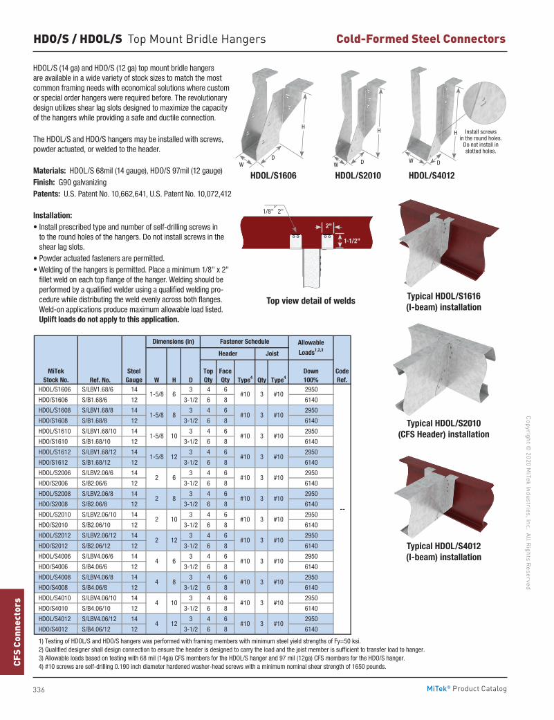
336
Copyright © 2020 M
iTek Industries, Inc. All Rights Reserved
Cold-Formed Steel Connectors
CFS
Conn
ecto
rs
MiTek® Product Catalog
HDO/S / HDOL/S Top Mount Bridle Hangers
HDOL/S (14 ga) and HDO/S (12 ga) top mount bridle hangers are available in a wide variety of stock sizes to match the most common framing needs with economical solutions where custom or special order hangers were required before. The revolutionary design utilizes shear lag slots designed to maximize the capacity of the hangers while providing a safe and ductile connection.
The HDOL/S and HDO/S hangers may be installed with screws, powder actuated, or welded to the header.
Ma terials: HDOL/S 68mil (14 gauge), HDO/S 97mil (12 gauge)Finish: G90 galvanizingPatents: U.S. Patent No. 10,662,641, U.S. Patent No. 10,072,412
Installation:• Install prescribed type and number of self-drilling screws in
to the round holes of the hangers. Do not install screws in the shear lag slots.
• Powder actuated fasteners are permitted.• Welding of the hangers is permitted. Place a minimum 1/8" x 2"
fillet weld on each top flange of the hanger. Welding should be performed by a qualified welder using a qualified welding pro-cedure while distributing the weld evenly across both flanges. Weld-on applications produce maximum allowable load listed. Uplift loads do not apply to this application.
Ref. No. W H D Type4 Qty Type4
HDOL/S1606 S/LBV1.68/6 14 3 4 6 2950
HDO/S1606 S/B1.68/6 12 3-1/2 6 8 6140
HDOL/S1608 S/LBV1.68/8 14 3 4 6 2950
HDO/S1608 S/B1.68/8 12 3-1/2 6 8 6140
HDOL/S1610 S/LBV1.68/10 14 3 4 6 2950
HDO/S1610 S/B1.68/10 12 3-1/2 6 8 6140
HDOL/S1612 S/LBV1.68/12 14 3 4 6 2950
HDO/S1612 S/B1.68/12 12 3-1/2 6 8 6140
HDOL/S2006 S/LBV2.06/6 14 3 4 6 2950
HDO/S2006 S/B2.06/6 12 3-1/2 6 8 6140
HDOL/S2008 S/LBV2.06/8 14 3 4 6 2950
HDO/S2008 S/B2.06/8 12 3-1/2 6 8 6140
HDOL/S2010 S/LBV2.06/10 14 3 4 6 2950
HDO/S2010 S/B2.06/10 12 3-1/2 6 8 6140
HDOL/S2012 S/LBV2.06/12 14 3 4 6 2950
HDO/S2012 S/B2.06/12 12 3-1/2 6 8 6140
HDOL/S4006 S/LBV4.06/6 14 3 4 6 2950
HDO/S4006 S/B4.06/6 12 3-1/2 6 8 6140
HDOL/S4008 S/LBV4.06/8 14 3 4 6 2950
HDO/S4008 S/B4.06/8 12 3-1/2 6 8 6140
HDOL/S4010 S/LBV4.06/10 14 3 4 6 2950
HDO/S4010 S/B4.06/10 12 3-1/2 6 8 6140
HDOL/S4012 S/LBV4.06/12 14 3 4 6 2950
HDO/S4012 S/B4.06/12 12 3-1/2 6 8 6140
1) Testing of HDOL/S and HDO/S hangers was performed with framing members with minimum steel yield strengths of Fy=50 ksi. 2) Qualified designer shall design connection to ensure the header is designed to carry the load and the joist member is sufficient to transfer load to hanger. 3) Allowable loads based on testing with 68 mil (14ga) CFS members for the HDOL/S hanger and 97 mil (12ga) CFS members for the HDO/S hanger. 4) #10 screws are self-drilling 0.190 inch diameter hardened washer-head screws with a minimum nominal shear strength of 1650 pounds.
CodeRef.
--
2 10
4 10
4 12
2 12
4 6
4 8
#10
1-5/8
#10
#10
#10
3
3
#10
3 #10
3 #10#10
3 #10
3 #10
3 #10
3 #10
3 #10
3 #10
3 #10
3
#10
#10
#10
#10
#10
#10
#10
1-5/8
1-5/8 8 #10
#10
2 6
2 8
6
10
1-5/8 12
MiTekStock No.
SteelGauge
Down100%
Dimensions (in) Fastener Schedule Allowable
Loads1,2,3Header Joist
TopQty
FaceQty
Typical HDOL/S1616 (I-beam) installation
Top view detail of welds
HDOL/S1606 HDOL/S2010 HDOL/S4012
Typical HDOL/S2010 (CFS Header) installation
Typical HDOL/S4012 (I-beam) installation
WD
H
W D
H
W D
H
2"
1/8" 2"
1-1/2"
Install screws in the round holes.
Do not install in slotted holes.
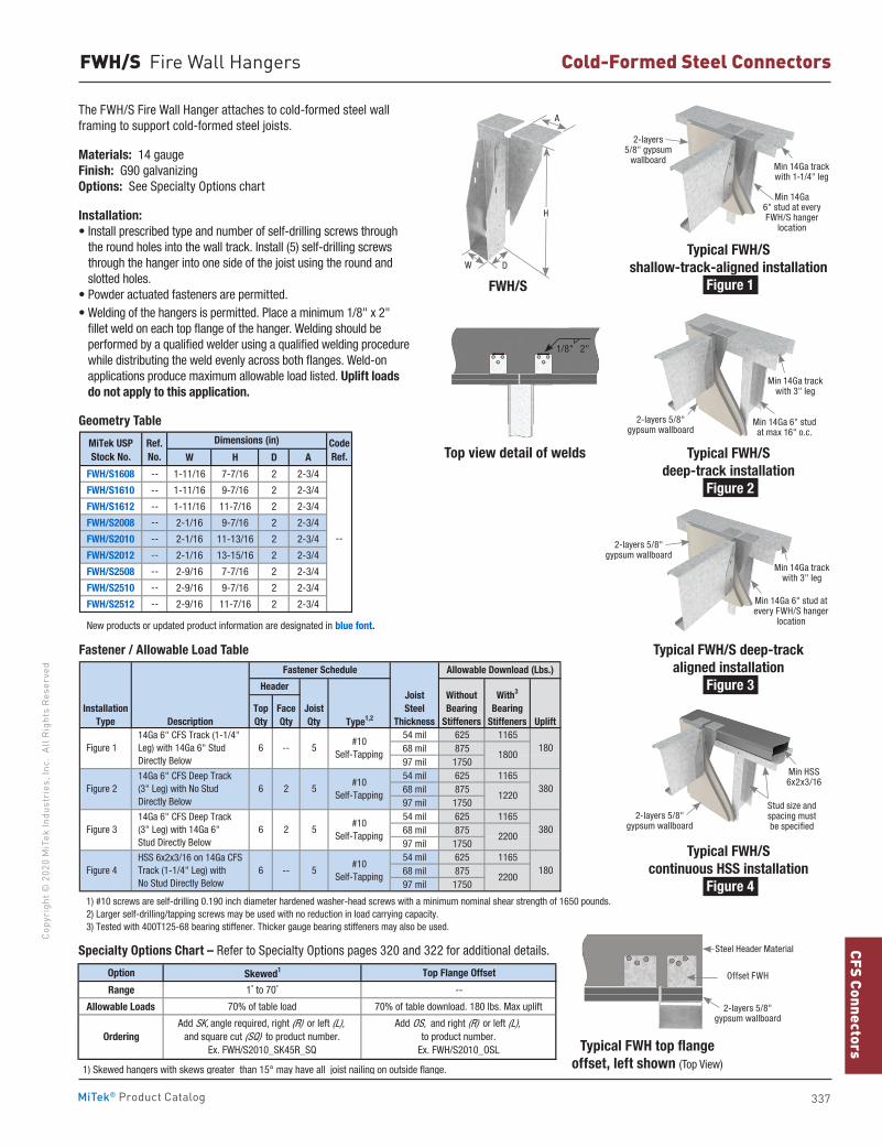
337
CFS ConnectorsCo
pyri
ght ©
202
0 M
iTek
Indu
stri
es, I
nc.
All R
ight
s Re
serv
ed
Cold-Formed Steel Connectors
MiTek® Product Catalog
Typical FWH top flange offset, left shown (Top View)
The FWH/S Fire Wall Hanger attaches to cold-formed steel wall framing to support cold-formed steel joists.
Materials: 14 gaugeFinish: G90 galvanizingOptions: See Specialty Options chart
Installation:• Install prescribed type and number of self-drilling screws through
the round holes into the wall track. Install (5) self-drilling screws through the hanger into one side of the joist using the round and slotted holes.
• Powder actuated fasteners are permitted.• Welding of the hangers is permitted. Place a minimum 1/8" x 2"
fillet weld on each top flange of the hanger. Welding should be performed by a qualified welder using a qualified welding procedure while distributing the weld evenly across both flanges. Weld-on applications produce maximum allowable load listed. Uplift loads do not apply to this application.
FWH/S Fire Wall Hangers
W H D A
FWH/S1608 -- 1-11/16 7-7/16 2 2-3/4
FWH/S1610 -- 1-11/16 9-7/16 2 2-3/4
FWH/S1612 -- 1-11/16 11-7/16 2 2-3/4
FWH/S2008 -- 2-1/16 9-7/16 2 2-3/4
FWH/S2010 -- 2-1/16 11-13/16 2 2-3/4
FWH/S2012 -- 2-1/16 13-15/16 2 2-3/4
FWH/S2508 -- 2-9/16 7-7/16 2 2-3/4
FWH/S2510 -- 2-9/16 9-7/16 2 2-3/4
FWH/S2512 -- 2-9/16 11-7/16 2 2-3/4
New products or updated product information are designated in blue font.
MiTek USPStock No.
Ref. No.
Dimensions (in) CodeRef.
--
Geometry Table
Fastener / Allowable Load Table
Type1,2
54 mil 625 116568 mil 87597 mil 175054 mil 625 116568 mil 87597 mil 175054 mil 625 116568 mil 87597 mil 175054 mil 625 116568 mil 87597 mil 1750
1) #10 screws are self-drilling 0.190 inch diameter hardened washer-head screws with a minimum nominal shear strength of 1650 pounds. 2) Larger self-drilling/tapping screws may be used with no reduction in load carrying capacity. 3) Tested with 400T125-68 bearing stiffener. Thicker gauge bearing stiffeners may also be used.
1801800
Fastener Schedule Allowable Download (Lbs.)
InstallationType
TopQty
FaceQty Uplift
WithoutBearing
Stiffeners
With3
BearingStiffeners
#10 Self-Tapping
JoistSteel
Thickness
#10 Self-Tapping
JoistQty
Header
14Ga 6" CFS Track (1-1/4" Leg) with 14Ga 6" Stud Directly Below
Figure 1 6 -- 5
Description
14Ga 6" CFS Deep Track (3" Leg) with No Stud Directly Below
Figure 2 6 2 5
#10 Self-Tapping
HSS 6x2x3/16 on 14Ga CFS Track (1-1/4" Leg) with No Stud Directly Below
Figure 4 6 -- 5#10
Self-Tapping
14Ga 6" CFS Deep Track (3" Leg) with 14Ga 6" Stud Directly Below
Figure 3 6 2 5
380
380
180
1220
2200
2200
FWH/S
Option Skewed1 Top Flange Offset
Range 1˚ to 70˚ --
Allowable Loads 70% of table load 70% of table download. 180 lbs. Max uplift
1) Skewed hangers with skews greater than 15° may have all joist nailing on outside flange.
OrderingAdd SK, angle required, right (R) or left (L),
and square cut (SQ) to product number. Ex. FWH/S2010_SK45R_SQ
Add OS, and right (R) or left (L), to product number.
Ex. FWH/S2010_OSL
Specialty Options Chart – Refer to Specialty Options pages 320 and 322 for additional details.
H
DW
A
Typical FWH/S shallow-track-aligned installation
Figure 1
Min 14Ga track with 1-1/4" leg
Min 14Ga 6" stud at every FWH/S hanger
location
2-layers 5/8" gypsum
wallboard
Typical FWH/Sdeep-track installation
Figure 2
Min 14Ga 6" stud at max 16" o.c.
Min 14Ga track with 3" leg
2-layers 5/8" gypsum wallboard
Typical FWH/S deep-track aligned installation
Figure 3
Min 14Ga track with 3" leg
Min 14Ga 6" stud at every FWH/S hanger
location
2-layers 5/8" gypsum wallboard
Typical FWH/Scontinuous HSS installation
Figure 4
Min HSS 6x2x3/16
Stud size and spacing must be specified
2-layers 5/8" gypsum wallboard
Top view detail of welds
1/8" 2"
2-layers 5/8" gypsum wallboard
Offset FWH
Steel Header Material
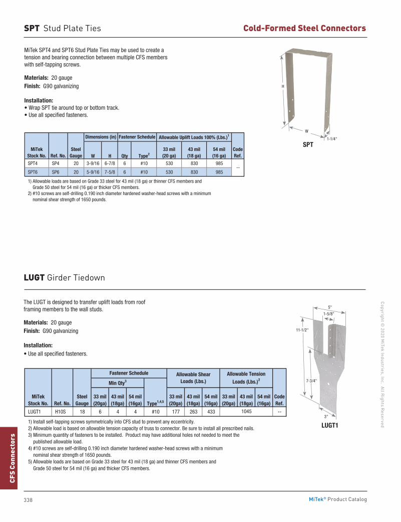
338
Copyright © 2020 M
iTek Industries, Inc. All Rights Reserved
Cold-Formed Steel Connectors
CFS
Conn
ecto
rs
MiTek® Product Catalog
LUGT Girder Tiedown
Type1,4,5
LUGT1 H10S 18 6 4 4 #10 177 263 433 --
1) Install self-tapping screws symmetrically into CFS stud to prevent any eccentricity. 2) Allowable load is based on allowable tension capacity of truss to connector. Be sure to install all prescribed nails. 3) Minimum quantity of fasteners to be installed. Product may have additional holes not needed to meet the published allowable load. 4) #10 screws are self-drilling 0.190 inch diameter hardened washer-head screws with a minimum nominal shear strength of 1650 pounds. 5) Allowable loads are based on Grade 33 steel for 43 mil (18 ga) and thinner CFS members and Grade 50 steel for 54 mil (16 ga) and thicker CFS members.
MiTekStock No. Ref. No.
33 mil(20ga)
43 mil(18ga)
54 mil(16ga)
Min Qty3
33 mil(20ga)
43 mil(18ga)
54 mil(16ga)
Fastener Schedule
SteelGauge
Allowable Shear Loads (Lbs.)
Allowable Tension Loads (Lbs.)2
CodeRef.
33 mil(20ga)
43 mil(18ga)
54 mil(16ga)
1045
LUGT1
11-1/2"
1-5/8"
5"
3"
7-3/4"
The LUGT is designed to transfer uplift loads from roof framing members to the wall studs.
Materials: 20 gaugeFinish: G90 galvanizing
Installation:• Use all specified fasteners.
W H Qty Type2
SPT4 SP4 20 3-9/16 6-7/8 6 #10 530 830 985
SPT6 SP6 20 5-9/16 7-5/8 6 #10 530 830 985
1) Allowable loads are based on Grade 33 steel for 43 mil (18 ga) or thinner CFS members and Grade 50 steel for 54 mil (16 ga) or thicker CFS members. 2) #10 screws are self-drilling 0.190 inch diameter hardened washer-head screws with a minimum nominal shear strength of 1650 pounds.
CodeRef.
--
Dimensions (in) Fastener Schedule
MiTekStock No.
SteelGaugeRef. No.
Allowable Uplift Loads 100% (Lbs.)1
33 mil (20 ga)
43 mil(18 ga)
54 mil (16 ga)
MiTek SPT4 and SPT6 Stud Plate Ties may be used to create a tension and bearing connection between multiple CFS members with self-tapping screws.
Materials: 20 gaugeFinish: G90 galvanizing
Installation:• Wrap SPT tie around top or bottom track.• Use all specified fasteners.
H
W
1-1/4"
SPT
SPT Stud Plate Ties
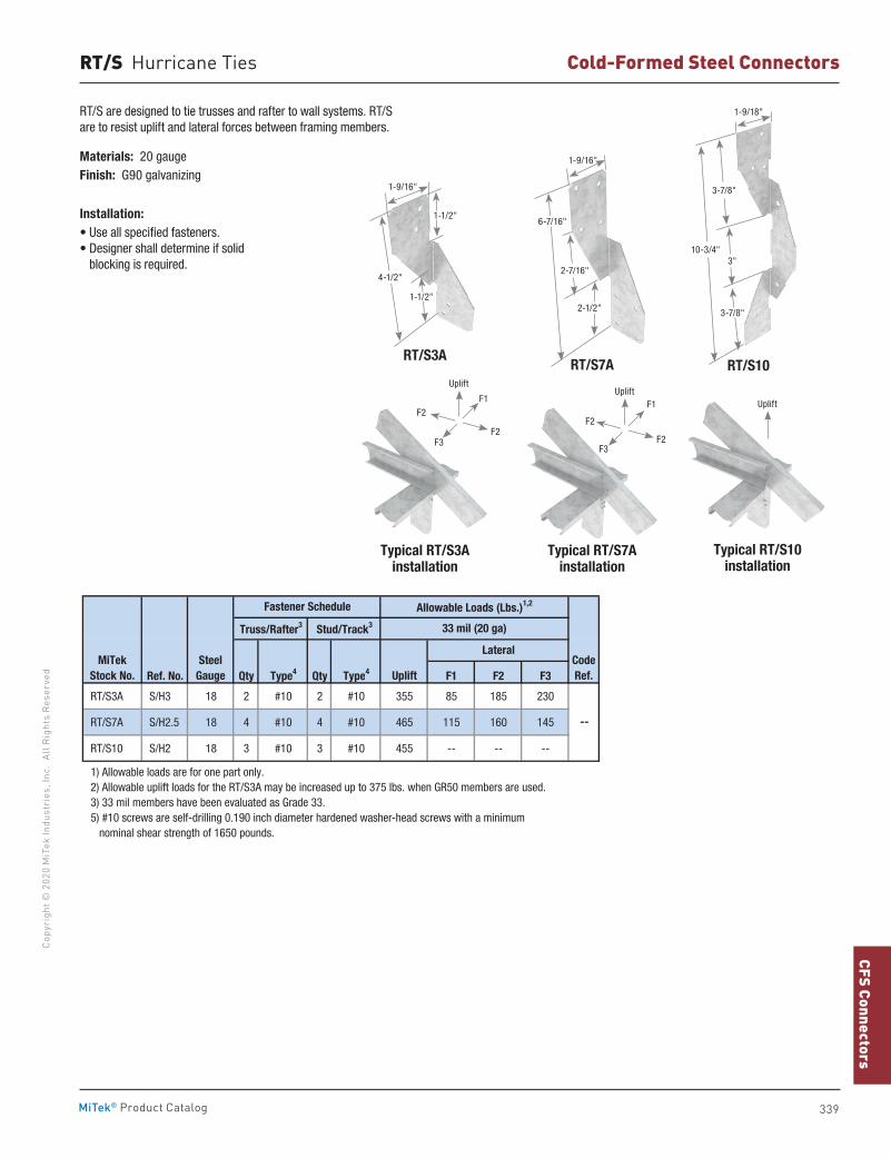
339
CFS ConnectorsCo
pyri
ght ©
202
0 M
iTek
Indu
stri
es, I
nc.
All R
ight
s Re
serv
ed
Cold-Formed Steel Connectors
MiTek® Product Catalog
RT/S Hurricane Ties
RT/S are designed to tie trusses and rafter to wall systems. RT/S are to resist uplift and lateral forces between framing members.
Materials: 20 gaugeFinish: G90 galvanizing
Installation:• Use all specified fasteners.• Designer shall determine if solid
blocking is required.
RT/S3ART/S7A
Typical RT/S3Ainstallation
Typical RT/S7Ainstallation
Typical RT/S10installation
Ref. No. Qty Type4 Qty Type4 F1 F2 F3
RT/S3A S/H3 18 2 #10 2 #10 355 85 185 230
RT/S7A S/H2.5 18 4 #10 4 #10 465 115 160 145
RT/S10 S/H2 18 3 #10 3 #10 455 -- -- --
1) Allowable loads are for one part only. 2) Allowable uplift loads for the RT/S3A may be increased up to 375 lbs. when GR50 members are used. 3) 33 mil members have been evaluated as Grade 33.
5) #10 screws are self-drilling 0.190 inch diameter hardened washer-head screws with a minimum nominal shear strength of 1650 pounds.
CodeRef.
--
Allowable Loads (Lbs.)1,2
33 mil (20 ga)
MiTekStock No.
SteelGauge
Fastener Schedule
Uplift
Lateral
Truss/Rafter3 Stud/Track3
UpliftUplift
F2
F1
F2F3
Uplift
F2
F1
F2F3
1-1/2"
1-1/2"
4-1/2"
1-9/16"
1-9/16"
2-1/2"
6-7/16"
2-7/16"
RT/S10
10-3/4"
1-9/18"
3-7/8"
3"
3-7/8"
340
Manufactured Housing ConnectorsCopyright ©
2020 MiTek Industries, Inc. All R
ights ReservedM
H Co
nnec
tors
MiTek® Product Catalog
Manufactured Housing
Foundation Anchor 347Hangers 344 Installation Notes 342Nails 343Nail Plates 348 Plate Tie 347 Post Anchors 348Protection Plates 349Rafter Ties 345-346Stud Plate Ties 346
pg. 342-349
341
MH Connectors
Manufactured Housing ConnectorsCo
pyri
ght ©
202
0 M
iTek
Indu
stri
es, I
nc.
All R
ight
s Re
serv
ed
MiTek® Product Catalog
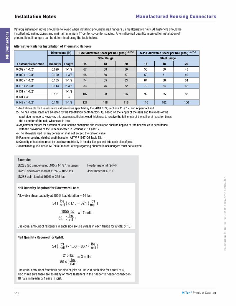
342
Manufactured Housing ConnectorsCopyright ©
2020 MiTek Industries, Inc. All R
ights ReservedM
H Co
nnec
tors
MiTek® Product Catalog
Catalog installation notes should be followed when installing pneumatic nail hangers using alternative nails. All fasteners should be installed into nailing zones and maintain minimum 1" center-to-center spacing. Alternative nail quantity required for installation of pneumatic nail hangers can be determined using the table below.
54 ( lbs ) x 1.15 = 62.1 ( lbs )
nail
nail
54 ( lbs ) x 1.60 = 86.4 ( lbs )
nail
nail
Alternative Nails for Installation of Pneumatic Hangers
14 18 20 14 18 20
0.099 x 1-1/2" 0.099 1-1/2 67 58 56 58 50 48
0.100 x 1-3/8" 0.100 1-3/8 68 60 57 59 51 49
0.105 x 1-1/2" 0.105 1-1/2 74 65 63 64 56 54
0.113 x 2-3/8" 0.113 2-3/8 83 75 72 72 64 62
0.131 x 1-1/2" 1-1/2
0.131 x 3" 3
0.148 x 1-1/2" 0.148 1-1/2 127 118 116 110 102 100
1) Nail allowable load values were calculated as specified by the 2018 NDS; Sections 11 & 12, and Appendix I and L. 2) The nail lateral loads are adjusted by the Penetration depth factors, Cd, based on the length of the nails and thickness of the steel side members. However, this assumes sufficient wood thickness to receive the full length of the nail or at least ten times the diameter of the nail, whichever is less. 3) Adjustment factors for duration of load, service conditions and installation shall be applied to the nail values in accordance with the provisions of the NDS delineated in Sections 2, 11 and 12. 4) The allowable load for any connector shall not exceed the catalog value. 5) Fastener bending yield strength based on ASTM F1667-05 Table S1.1. 6) Quantity of fasteners must be used symmetrically in header flanges and into each side of joist. 7) Installation guidelines in MiTek's Product Catalog regarding pneumatic nail hangers must be followed.
S-P-F Allowable Shear per Nail (Lbs.)1,2,3,4,5
Steel Gauge Steel Gauge
Fastener Description Diameter Length
Dimensions (in) DF/SP Allowable Shear per Nail (Lbs.)1,2,3,4,5
85 830.131 107 98 96 92
Example:
JN28E (20 gauge) using .105 x 1-1/2" fasteners Header material: S-P-F
JN28E downward load at 115% = 1055 lbs. Joist material: S-P-F
JN28E uplift load at 160% = 245 lbs.
Nail Quantity Required for Downward Load:
Allowable shear capacity at 100% load duration = 54 lbs.
Use equal amount of fasteners in each side so use 9 nails in each flange for a total of 18.
Nail Quantity Required for Uplift:
Use equal amount of fasteners per side of joist so use 2 in each side for a total of 4. Also make sure there are as many or more fasteners in the hanger to header connection. 18 nails in header ≥ 4 nails in joist.
Installation Notes
1055 lbs = 17 nails
62.1 ( lbs )
nail
245 lbs = 3 nails
86.4 ( lbs )
nail
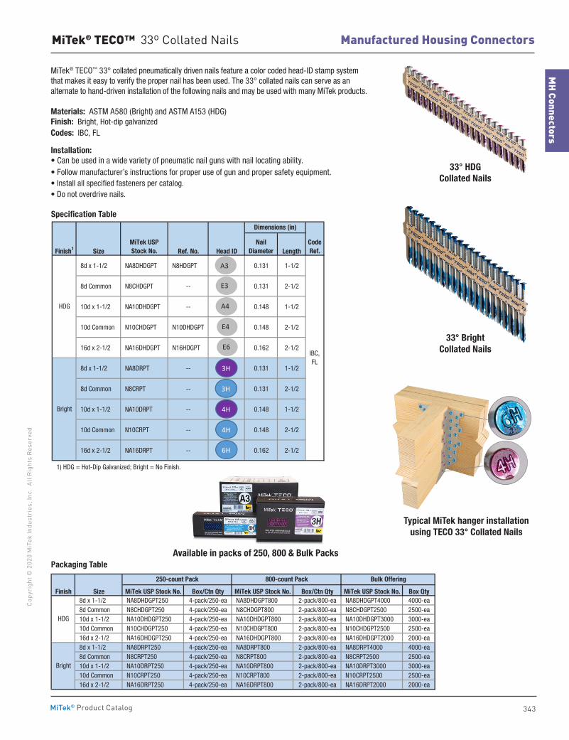
343
MH Connectors
Manufactured Housing ConnectorsCo
pyri
ght ©
202
0 M
iTek
Indu
stri
es, I
nc.
All R
ight
s Re
serv
ed
MiTek® Product Catalog
MiTek® TECO™ 33º Collated Nails
MiTek® TECO™ 33° collated pneumatically driven nails feature a color coded head-ID stamp system that makes it easy to verify the proper nail has been used. The 33° collated nails can serve as an alternate to hand-driven installation of the following nails and may be used with many MiTek products.
Materials: ASTM A580 (Bright) and ASTM A153 (HDG)Finish: Bright, Hot-dip galvanizedCodes: IBC, FL
Installation:• Can be used in a wide variety of pneumatic nail guns with nail locating ability. • Follow manufacturer’s instructions for proper use of gun and proper safety equipment. • Install all specified fasteners per catalog.• Do not overdrive nails.
Finish1 Size Ref. No. Head ID Length
8d x 1-1/2 NA8DHDGPT N8HDGPT 0.131 1-1/2
8d Common N8CHDGPT -- 0.131 2-1/2
10d x 1-1/2 NA10DHDGPT -- 0.148 1-1/2
10d Common N10CHDGPT N10DHDGPT 0.148 2-1/2
16d x 2-1/2 NA16DHDGPT N16HDGPT 0.162 2-1/2
8d x 1-1/2 NA8DRPT -- 0.131 1-1/2
8d Common N8CRPT -- 0.131 2-1/2
10d x 1-1/2 NA10DRPT -- 0.148 1-1/2
10d Common N10CRPT -- 0.148 2-1/2
16d x 2-1/2 NA16DRPT -- 0.162 2-1/2
1) HDG = Hot-Dip Galvanized; Bright = No Finish.
Dimensions (in)
MiTek USPStock No.
NailDiameter
Bright
CodeRef.
IBC, FL
HDG
3H
3H
4H
A3
E3
A4
E4
E6
4H
6H
33° HDG Collated Nails
Available in packs of 250, 800 & Bulk Packs
33° Bright Collated Nails
Typical MiTek hanger installation using TECO 33° Collated Nails
Packaging Table
Specification Table
Finish Size MiTek USP Stock No. Box/Ctn Qty MiTek USP Stock No. Box/Ctn Qty MiTek USP Stock No. Box Qty 8d x 1-1/2 NA8DHDGPT250 4-pack/250-ea NA8DHDGPT800 2-pack/800-ea NA8DHDGPT4000 4000-ea 8d Common N8CHDGPT250 4-pack/250-ea N8CHDGPT800 2-pack/800-ea N8CHDGPT2500 2500-ea 10d x 1-1/2 NA10DHDGPT250 4-pack/250-ea NA10DHDGPT800 2-pack/800-ea NA10DHDGPT3000 3000-ea 10d Common N10CHDGPT250 4-pack/250-ea N10CHDGPT800 2-pack/800-ea N10CHDGPT2500 2500-ea 16d x 2-1/2 NA16DHDGPT250 4-pack/250-ea NA16DHDGPT800 2-pack/800-ea NA16DHDGPT2000 2000-ea 8d x 1-1/2 NA8DRPT250 4-pack/250-ea NA8DRPT800 2-pack/800-ea NA8DRPT4000 4000-ea 8d Common N8CRPT250 4-pack/250-ea N8CRPT800 2-pack/800-ea N8CRPT2500 2500-ea 10d x 1-1/2 NA10DRPT250 4-pack/250-ea NA10DRPT800 2-pack/800-ea NA10DRPT3000 3000-ea 10d Common N10CRPT250 4-pack/250-ea N10CRPT800 2-pack/800-ea N10CRPT2500 2500-ea 16d x 2-1/2 NA16DRPT250 4-pack/250-ea NA16DRPT800 2-pack/800-ea NA16DRPT2000 2000-ea
HDG
Bright
Bulk Offering250-count Pack 800-count Pack
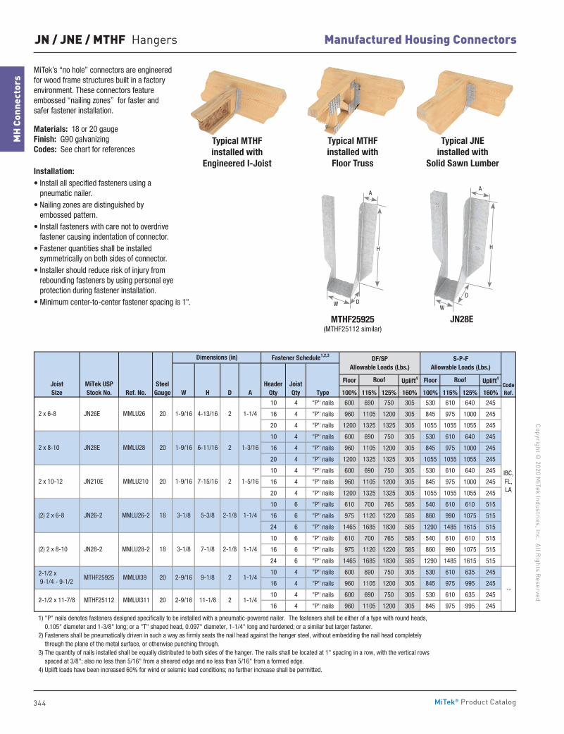
344
Manufactured Housing ConnectorsCopyright ©
2020 MiTek Industries, Inc. All R
ights ReservedM
H Co
nnec
tors
MiTek® Product Catalog
MiTek’s “no hole” connectors are engineered for wood frame structures built in a factory environment. These connectors feature embossed “nailing zones” for faster and safer fastener installation.
Materials: 18 or 20 gauge Finish: G90 galvanizing Codes: See chart for references
Installation:• Install all specified fasteners using a
pneumatic nailer.• Nailing zones are distinguished by
embossed pattern.• Install fasteners with care not to overdrive
fastener causing indentation of connector.• Fastener quantities shall be installed
symmetrically on both sides of connector.• Installer should reduce risk of injury from
rebounding fasteners by using personal eye protection during fastener installation.
• Minimum center-to-center fastener spacing is 1".
Floor Uplift4 Floor Uplift4
Ref. No. W H D A Type 100% 115% 125% 160% 100% 115% 125% 160%
10 4 "P" nails 600 690 750 305 530 610 640 245
16 4 "P" nails 960 1105 1200 305 845 975 1000 245
20 4 "P" nails 1200 1325 1325 305 1055 1055 1055 245
10 4 "P" nails 600 690 750 305 530 610 640 245
16 4 "P" nails 960 1105 1200 305 845 975 1000 245
20 4 "P" nails 1200 1325 1325 305 1055 1055 1055 245
10 4 "P" nails 600 690 750 305 530 610 640 245
16 4 "P" nails 960 1105 1200 305 845 975 1000 245
20 4 "P" nails 1200 1325 1325 305 1055 1055 1055 245
10 6 "P" nails 610 700 765 585 540 610 610 515
16 6 "P" nails 975 1120 1220 585 860 990 1075 515
24 6 "P" nails 1465 1685 1830 585 1290 1485 1615 515
10 6 "P" nails 610 700 765 585 540 610 610 515
16 6 "P" nails 975 1120 1220 585 860 990 1075 515
24 6 "P" nails 1465 1685 1830 585 1290 1485 1615 515
10 4 "P" nails 600 690 750 305 530 610 635 245
16 4 "P" nails 960 1105 1200 305 845 975 995 245
10 4 "P" nails 600 690 750 305 530 610 635 245
16 4 "P" nails 960 1105 1200 305 845 975 995 245
1) "P" nails denotes fasteners designed specifically to be installed with a pneumatic-powered nailer. The fasteners shall be either of a type with round heads, 0.105" diameter and 1-3/8" long; or a "T" shaped head, 0.097" diameter, 1-1/4" long and hardened; or a similar but larger fastener. 2) Fasteners shall be pneumatically driven in such a way as firmly seats the nail head against the hanger steel, without embedding the nail head completely through the plane of the metal surface, or otherwise punching through. 3) The quantity of nails installed shall be equally distributed to both sides of the hanger. The nails shall be located at 1" spacing in a row, with the vertical rows spaced at 3/8"; also no less than 5/16" from a sheared edge and no less than 5/16" from a formed edge. 4) Uplift loads have been increased 60% for wind or seismic load conditions; no further increase shall be permitted.
MMLU26 20
20
Roof
Fastener Schedule1,2,3
SteelGauge
Dimensions (in)
4-13/16
1-3/16
JN28-2 3-1/8
6-11/161-9/16
1-9/16 7-15/16
5-3/8
7-1/8
MMLU210
MMLU28-2
JN28E MMLU28
20
3-1/8
JN210E
JN26-2
MTHF25112
JN26E
MiTek USPStock No.
2 1-1/4
MMLUI311 20 2-9/16 11-1/8 2 1-1/4
MTHF25925 MMLUI39 20
18
1-5/16
2-9/16 9-1/8
MMLU26-2 18
S-P-FAllowable Loads (Lbs.)
Roof
1-9/16
1-1/4
2-1/8
2-1/8
2
1-1/4
1-1/4
DF/SPAllowable Loads (Lbs.)
2
2
(2) 2 x 8-10
2-1/2 x 9-1/4 - 9-1/2
2-1/2 x 11-7/8
JoistSize
2 x 6-8
2 x 8-10
2 x 10-12
(2) 2 x 6-8
IBC,FL,LA
--
CodeRef.
HeaderQty
JoistQty
JN / JNE / MTHF Hangers
A
H
D
W
JN28E MTHF25925(MTHF25112 similar)
A
H
DW
Typical JNE installed with
Solid Sawn Lumber
Typical MTHF installed with
Engineered I-Joist
Typical MTHF installed with
Floor Truss
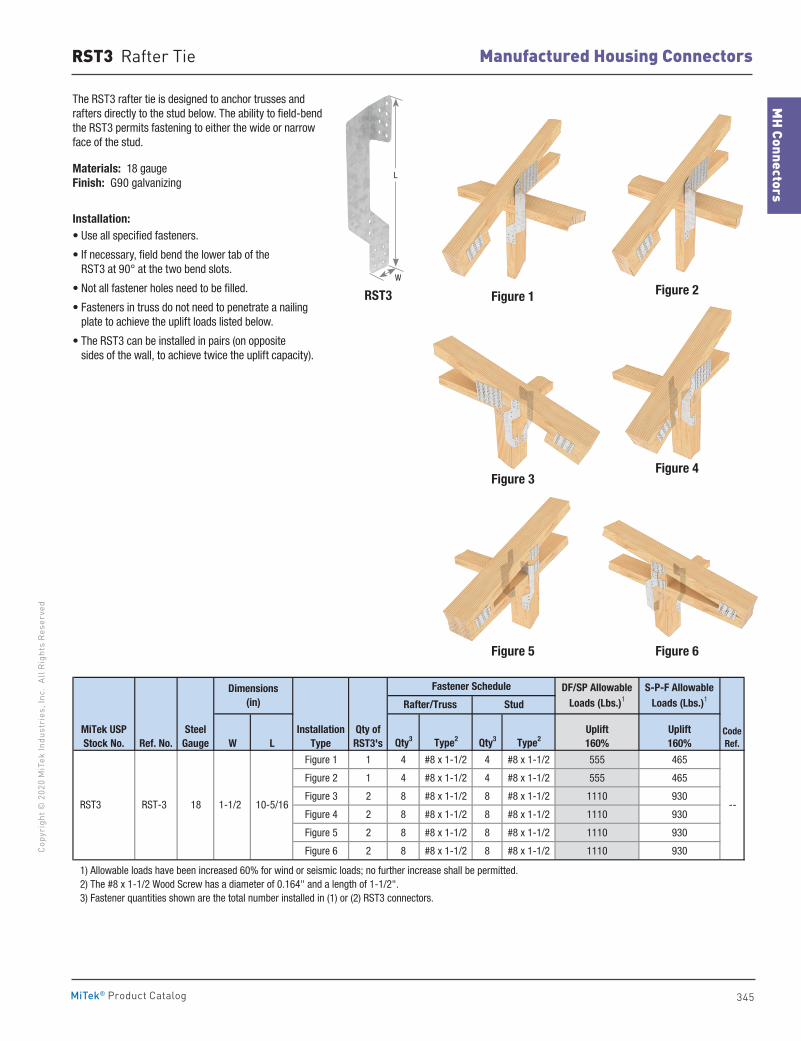
345
MH Connectors
Manufactured Housing ConnectorsCo
pyri
ght ©
202
0 M
iTek
Indu
stri
es, I
nc.
All R
ight
s Re
serv
ed
MiTek® Product Catalog
The RST3 rafter tie is designed to anchor trusses and rafters directly to the stud below. The ability to field-bend the RST3 permits fastening to either the wide or narrow face of the stud.
Materials: 18 gauge Finish: G90 galvanizing
Installation:• Use all specified fasteners.
• If necessary, field bend the lower tab of the RST3 at 90° at the two bend slots.
• Not all fastener holes need to be filled.
• Fasteners in truss do not need to penetrate a nailing plate to achieve the uplift loads listed below.
• The RST3 can be installed in pairs (on opposite sides of the wall, to achieve twice the uplift capacity). twice the uplift load capacity.)
Figure 1
Figure 3
Figure 2
Figure 6Figure 5
Figure 4
W L Qty3 Type2 Qty3 Type2
Figure 1 1 4 #8 x 1-1/2 4 #8 x 1-1/2 555 465
Figure 2 1 4 #8 x 1-1/2 4 #8 x 1-1/2 555 465
Figure 3 2 8 #8 x 1-1/2 8 #8 x 1-1/2 1110 930
Figure 4 2 8 #8 x 1-1/2 8 #8 x 1-1/2 1110 930
Figure 5 2 8 #8 x 1-1/2 8 #8 x 1-1/2 1110 930
Figure 6 2 8 #8 x 1-1/2 8 #8 x 1-1/2 1110 930
1) Allowable loads have been increased 60% for wind or seismic loads; no further increase shall be permitted. 2) The #8 x 1-1/2 Wood Screw has a diameter of 0.164" and a length of 1-1/2". 3) Fastener quantities shown are the total number installed in (1) or (2) RST3 connectors.
Qty ofRST3's
InstallationType
RST3 1-1/2 10-5/1618 RST-3
MiTek USPStock No.
SteelGaugeRef. No.
Dimensions(in) Stud
Fastener Schedule DF/SP AllowableLoads (Lbs.)1
S-P-F Allowable Loads (Lbs.)1
--
CodeRef.
Uplift160%
Uplift160%
Rafter/Truss
RST3
L
W
RST3 Rafter Tie
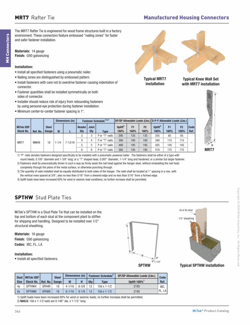
346
Manufactured Housing ConnectorsCopyright ©
2020 MiTek Industries, Inc. All R
ights ReservedM
H Co
nnec
tors
MiTek® Product Catalog
The MRT7 Rafter Tie is engineered for wood frame structures built in a factory environment. These connectors feature embossed “nailing zones” for faster and safer fastener installation.
Materials: 14 gauge Finish: G90 galvanizing
Installation:• Install all specified fasteners using a pneumatic nailer.• Nailing zones are distinguished by embossed pattern.• Install fasteners with care not to overdrive fastener causing indentation of
connector.• Fastener quantities shall be installed symmetrically on both
sides of connector.• Installer should reduce risk of injury from rebounding fasteners
by using personal eye protection during fastener installation.• Minimum center-to-center fastener spacing is 1".
MRT7
L
W
4x or 6x stud
1/2" sheathing
Typical MRT7 installation
Typical Knee Wall Setwith MRT7 installation
Ref. No. W L Type3 3 P or "T" nails 295 135 135 255 85 85
4 4 P or "T" nails 390 180 180 340 115 115
5 5 P or "T" nails 490 195 195 425 145 145
6 6 P or "T" nails 585 195 195 510 175 175
1) "P" nails denotes fasteners designed specifically to be installed with a pneumatic-powered nailer. The fasteners shall be either of a type with round heads, 0.105" diameter and 1-3/8" long; or a "T" shaped head, 0.097" diameter, 1-1/4" long and hardened; or a similar but larger fastener. 2) Fasteners shall be pneumatically driven in such a way as firmly seats the nail head against the hanger steel, without embedding the nail head completely through the plane of the metal surface, or otherwise punching through. 3) The quantity of nails installed shall be equally distributed to both sides of the hanger. The nails shall be located at 1" spacing in a row, with the vertical rows spaced at 3/8"; also no less than 5/16" from a sheared edge and no less than 5/16" from a formed edge. 4) Uplift loads have been increased 60% for wind or seismic load conditions; no further increase shall be permitted.
--
HeaderQty
JoistQty
Fastener Schedule1,2,3
F1160%
F2160%
Uplift4
160%
S-P-F Allowable Loads (Lbs.)
Uplift4
160%F1
160%F2
160%
DF/SP Allowable Loads (Lbs.)
CodeRef.
MiTek USPStock No.
SteelGauge
Dimensions (in)
MRT7 MMH8 18 1-1/4 7-13/16
MRT7 Rafter Tie
Typical SPTHW installation
MiTek’s SPTHW is a Stud Plate Tie that can be installed on the top and bottom of each stud at the component plant to stiffen for shipping and handling. Designed to be installed over 1/2" structural sheathing.
Materials: 18 gaugeFinish: G90 galvanizingCodes: IBC, FL, LA
Installation:• Install all specified fasteners.
DF/SP Allowable Loads (Lbs.)
Ref. No. W H Qty Type Uplift 160%1
4x SPTHW4 SPH4R 18 4-1/16 8-3/8 12 10d x 1-1/2 2195
6x SPTHW6 SPH6R 18 6-1/16 9-1/8 12 10d x 1-1/2 2195
1) Uplift loads have been increased 60% for wind or seismic loads; no further increase shall be permitted. 2) NAILS: 10d x 1-1/2 nails are 0.148" dia. x 1-1/2" long.
IBC, FL, LA
StudSize
MiTek USPStock No.
SteelGauge
CodeRef.
Dimensions (in) Fastener Schedule2
SPTHW
H
W
1-1/4"
SPTHW Stud Plate Ties
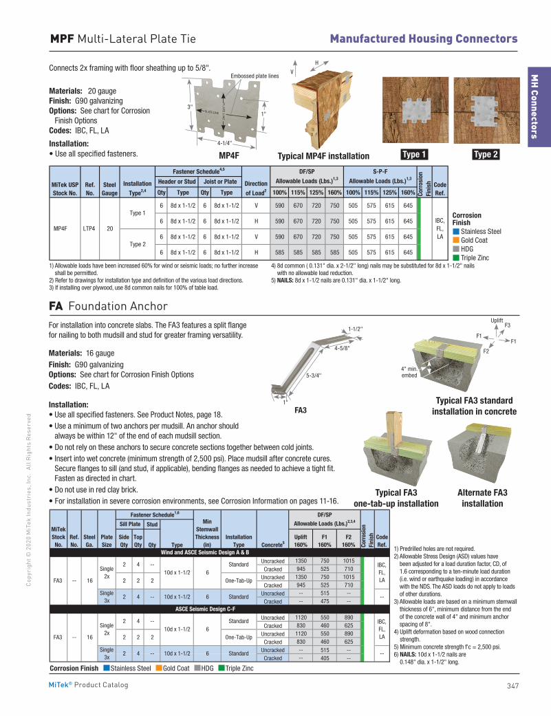
347
MH Connectors
Manufactured Housing ConnectorsCo
pyri
ght ©
202
0 M
iTek
Indu
stri
es, I
nc.
All R
ight
s Re
serv
ed
MiTek® Product Catalog
Connects 2x framing with floor sheathing up to 5/8".
Materials: 20 gauge Finish: G90 galvanizing Options: See chart for Corrosion Finish Options Codes: IBC, FL, LA
Installation:• Use all specified fasteners. Typical MP4F installation
Alternate FA3 installation
Qty Type Qty Type 100% 115% 125% 160% 100% 115% 125% 160%
6 8d x 1-1/2 6 8d x 1-1/2 V 590 670 720 750 505 575 615 645
6 8d x 1-1/2 6 8d x 1-1/2 H 590 670 720 750 505 575 615 645
6 8d x 1-1/2 6 8d x 1-1/2 V 590 670 720 750 505 575 615 645
6 8d x 1-1/2 6 8d x 1-1/2 H 585 585 585 585 505 575 615 645
1) Allowable loads have been increased 60% for wind or seismic loads; no further increase shall be permitted. 2) Refer to drawings for installation type and definition of the various load directions. 3) If installing over plywood, use 8d common nails for 100% of table load. 4) 8d common ( 0.131" dia. x 2-1/2" long) nails may be substituted for 8d x 1-1/2" nails with no allowable load reduction. 5) NAILS: 8d x 1-1/2 nails are 0.131" dia. x 1-1/2" long.
S-P-F
Allowable Loads (Lbs.)1,3
SteelGauge
Direction
of Load2CodeRef.
IBC,FL,LA
Ref.No.
MP4F LTP4 20
Type 1
Type 2
MiTek USPStock No.
Installation
Type2,4
Joist or PlateHeader or Stud
Corr
osio
nFi
nish
Fastener Schedule4,5 DF/SP
Allowable Loads (Lbs.)1,3
Stud
Qty Type Concrete5
Uncracked 1350 750 1015Cracked 945 525 710
Uncracked 1350 750 1015Cracked 945 525 710
Uncracked -- 515 --Cracked -- 475 --
Uncracked 1120 550 890Cracked 830 460 625
Uncracked 1120 550 890Cracked 830 460 625
Uncracked -- 515 --Cracked -- 405 --
1) Predrilled holes are not required. 2) Allowable Stress Design (ASD) values have been adjusted for a load duration factor, CD, of 1.6 corresponding to a ten-minute load duration (i.e. wind or earthquake loading) in accordance with the NDS. The ASD loads do not apply to loads of other durations. 3) Allowable loads are based on a minimum stemwall thickness of 6", minimum distance from the end of the concrete wall of 4" and minimum anchor spacing of 8". 4) Uplift deformation based on wood connection strength. 5) Minimum concrete strength f'c = 2,500 psi. 6) NAILS: 10d x 1-1/2 nails are 0.148" dia. x 1-1/2" long.
64 -- 10d x 1-1/2
2 --10d x 1-1/2
One-Tab-Up
4
2 2
PlateSize
Single 2x
10d x 1-1/2 6
10d x 1-1/2 6
Wind and ASCE Seismic Design A & B
SteelGa.
Single 3x
6
2 2-- FA3 216
FA3 -- 16 2
Single 3x
Single 2x
2
Standard
Standard
InstallationType
ASCE Seismic Design C-F
Standard2 4 --
2 4 --
One-Tab-Up
Standard
SideQty
TopQty
MinStemwallThickness
(in)CodeRef.
MiTekStock
No.F1
160%F2
160%
DF/SP Allowable Loads (Lbs.)2,3,4Sill Plate
Fastener Schedule1,6
Corr
osio
n Fi
nishUplift
160%Ref. No.
IBC,FL,LA
--
IBC,FL,LA
--
1) Predrilled holes are not required.2) Allowable Stress Design (ASD) values have
been adjusted for a load duration factor, CD, of 1.6 corresponding to a ten-minute load duration (i.e. wind or earthquake loading) in accordance with the NDS. The ASD loads do not apply to loads of other durations.
3) Allowable loads are based on a minimum stemwall thickness of 6", minimum distance from the end of the concrete wall of 4" and minimum anchor spacing of 8".
4) Uplift deformation based on wood connection strength.
5) Minimum concrete strength f'c = 2,500 psi.6) NAILS: 10d x 1-1/2 nails are
0.148" dia. x 1-1/2" long.
MPF Multi-Lateral Plate Tie
4-1/4"
3"
MP4F
Embossed plate lines
1"
FA3
Typical FA3 one-tab-up installation
Type 1 Type 2
1) Allowable loads have been increased 60% for wind or seismic loads; no further increase shall be permitted.
2) Refer to drawings for installation type and definition of the various load directions.3) If installing over plywood, use 8d common nails for 100% of table load.
4) 8d common ( 0.131" dia. x 2-1/2" long) nails may be substituted for 8d x 1-1/2" nails with no allowable load reduction.
5) NAILS: 8d x 1-1/2 nails are 0.131" dia. x 1-1/2" long.
For installation into concrete slabs. The FA3 features a split flange for nailing to both mudsill and stud for greater framing versatility.
Materials: 16 gaugeFinish: G90 galvanizing Options: See chart for Corrosion Finish OptionsCodes: IBC, FL, LA
Installation:• Use all specified fasteners. See Product Notes, page 18.• Use a minimum of two anchors per mudsill. An anchor should
always be within 12" of the end of each mudsill section.• Do not rely on these anchors to secure concrete sections together between cold joints.• Insert into wet concrete (minimum strength of 2,500 psi). Place mudsill after concrete cures.
Secure flanges to sill (and stud, if applicable), bending flanges as needed to achieve a tight fit. Fasten as directed in chart.
• Do not use in red clay brick.• For installation in severe corrosion environments, see Corrosion Information on pages 11-16.
FA Foundation Anchor
F1F1
F3
F2
Uplift
4" min. embed
V
H
Corrosion Finish Stainless Steel Gold Coat HDG Triple Zinc
Corrosion Finish Stainless Steel Gold Coat HDG Triple Zinc
Corrosion Finish Stainless Steel Gold Coat HDG Triple Zinc
Corrosion Finish Stainless Steel Gold Coat HDG Triple Zinc
Corrosion Finish Stainless Steel Gold Coat HDG Triple Zinc
Corrosion Finish Stainless Steel Gold Coat HDG Triple Zinc
1-1/2"
4-5/8"
5-3/4"
1" Typical FA3 standard installation in concrete
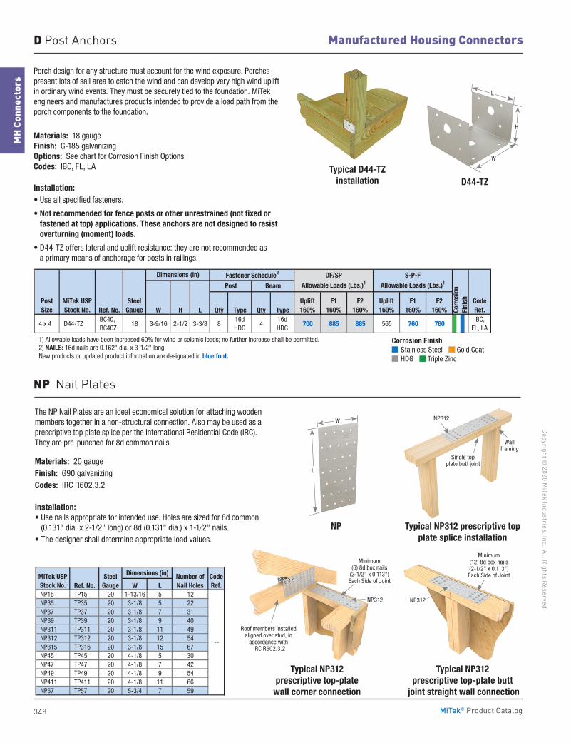
348
Manufactured Housing ConnectorsCopyright ©
2020 MiTek Industries, Inc. All R
ights ReservedM
H Co
nnec
tors
MiTek® Product Catalog
Porch design for any structure must account for the wind exposure. Porches present lots of sail area to catch the wind and can develop very high wind uplift in ordinary wind events. They must be securely tied to the foundation. MiTek engineers and manufactures products intended to provide a load path from the porch components to the foundation.
Materials: 18 gauge Finish: G-185 galvanizing Options: See chart for Corrosion Finish Options Codes: IBC, FL, LA
Installation:• Use all specified fasteners.
• Not recommended for fence posts or other unrestrained (not fixed or fastened at top) applications. These anchors are not designed to resist overturning (moment) loads.
• D44-TZ offers lateral and uplift resistance: they are not recommended as a primary means of anchorage for posts in railings.
D44-TZ
W
H
L
Typical D44-TZinstallation
Ref. No. W H L Qty Type Qty Type
4 x 4 D44-TZ BC40, BC40Z
18 3-9/16 2-1/2 3-3/8 816d HDG
416d HDG
700 885 885 565 760 760IBC,
FL, LA
1) Allowable loads have been increased 60% for wind or seismic loads; no further increase shall be permitted. 2) NAILS: 16d nails are 0.162" dia. x 3-1/2" long. New products or updated product information are designated in blue font.
Post Size
DF/SP Allowable Loads (Lbs.)1
MiTek USPStock No.
SteelGauge
Post Beam
Uplift160%
F1160%
F2160%
Dimensions (in) Fastener Schedule2
CodeRef.
S-P-FAllowable Loads (Lbs.)1
Corr
osio
nFi
nishUplift
160%F1
160%F2
160%
D Post Anchors
NP Nail Plates
Minimum (6) 8d box nails
(2-1/2" x 0.113")Each Side of Joint
Roof members installed aligned over stud, in
accordance with IRC R602.3.2
NP312
Typical NP312 prescriptive top plate splice installation
NP
The NP Nail Plates are an ideal economical solution for attaching wooden members together in a non-structural connection. Also may be used as a prescriptive top plate splice per the International Residential Code (IRC). They are pre-punched for 8d common nails.
Materials: 20 gaugeFinish: G90 galvanizingCodes: IRC R602.3.2
Installation:• Use nails appropriate for intended use. Holes are sized for 8d common
(0.131" dia. x 2-1/2" long) or 8d (0.131" dia.) x 1-1⁄2" nails.• The designer shall determine appropriate load values.
Dimensions (in)
Ref. No. W L NP15 TP15 20 1-13/16 5 12 NP35 TP35 20 3-1/8 5 22 NP37 TP37 20 3-1/8 7 31 NP39 TP39 20 3-1/8 9 40 NP311 TP311 20 3-1/8 11 49 NP312 TP312 20 3-1/8 12 54 NP315 TP316 20 3-1/8 15 67 NP45 TP45 20 4-1/8 5 30 NP47 TP47 20 4-1/8 7 42 NP49 TP49 20 4-1/8 9 54 NP411 TP411 20 4-1/8 11 66 NP57 TP57 20 5-3/4 7 59
MiTek USPStock No.
SteelGauge
Number ofNail Holes
--
CodeRef.
W
L
Single top plate butt joint
NP312
Wall framing
Typical NP312 prescriptive top-plate
wall corner connection
Typical NP312 prescriptive top-plate butt
joint straight wall connection
NP312
Minimum (12) 8d box nails (2-1/2" x 0.113")Each Side of Joint
Corrosion Finish Stainless Steel Gold Coat HDG Triple Zinc
Corrosion Finish Stainless Steel Gold Coat HDG Triple Zinc
Corrosion Finish Stainless Steel Gold Coat HDG Triple Zinc
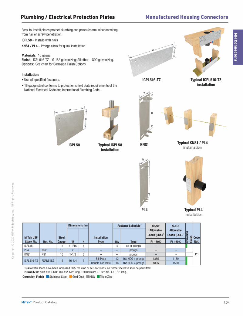
349
MH Connectors
Manufactured Housing ConnectorsCo
pyri
ght ©
202
0 M
iTek
Indu
stri
es, I
nc.
All R
ight
s Re
serv
ed
MiTek® Product Catalog
Easy-to-install plates protect plumbing and power/communication wiring from nail or screw penetration.
ICPL58 – Installs with nails
KNS1 / PL4 – Prongs allow for quick installation
Materials: 16 gauge Finish: ICPL516-TZ – G-185 galvanizing; All other – G90 galvanizing. Options: See chart for Corrosion Finish Options
Installation:• Use all specified fasteners.
• 16 gauge steel conforms to protection shield plate requirements of the National Electrical Code and International Plumbing Code.
Typical PL4installation
Ref. No. W H Qty Type F1 160% F1 160% ICPL58 -- 16 8-1/16 5 -- 4 8d or prongs -- -- PL4 NS2 16 2 5 -- -- prongs -- -- KNS1 NS1 16 1-1/2 3 -- -- prongs -- --
Sill Plate 12 16d HDG + prongs 1355 1160Double Top Plate 16 16d HDG + prongs 1805 1550
1) Allowable loads have been increased 60% for wind or seismic loads; no further increase shall be permitted. 2) NAILS: 8d nails are 0.131" dia. x 2-1/2" long, 16d nails are 0.162" dia. x 3-1/2" long.
CodeRef.
DF/SPAllowable
Loads (Lbs.)1
S-P-FAllowable
Loads (Lbs.)1
PC
Corr
osio
nFi
nish
16-1/4
InstallationType
Dimensions (in) Fastener Schedule2
5
MiTek USPStock No.
SteelGauge
ICPL516-TZ PSPN516Z 16
ICPL516-TZ Typical ICPL516-TZinstallation
WH
Plumbing / Electrical Protection Plates
ICPL58
PL4
Typical ICPL58installation
KNS1 Typical KNS1 / PL4installation
W
H
W
H
W
H
Corrosion Finish Stainless Steel Gold Coat HDG Triple Zinc
Corrosion Finish Stainless Steel Gold Coat HDG Triple Zinc
Corrosion Finish Stainless Steel Gold Coat HDG Triple Zinc
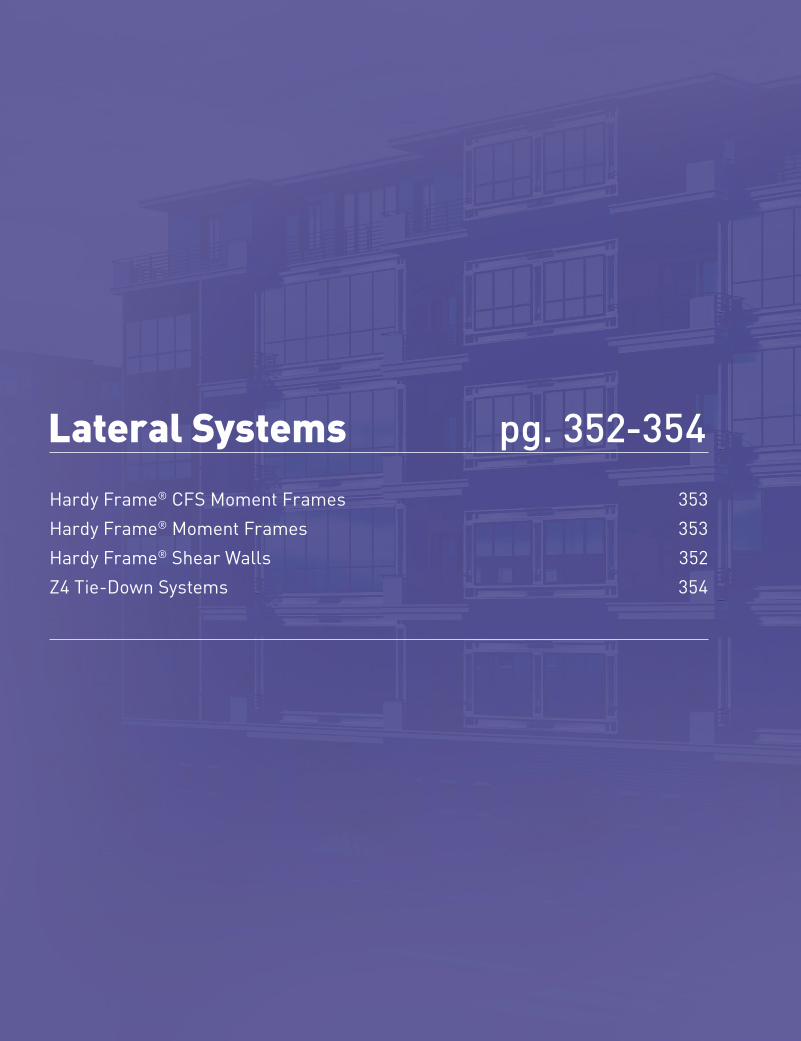
350
Copyright © 2020 M
iTek Industries, Inc. All Rights Reserved
Lateral Systems
Late
ral S
yste
ms
MiTek® Product Catalog
Lateral Systems pg. 352-354Hardy Frame® CFS Moment Frames 353 Hardy Frame® Moment Frames 353Hardy Frame® Shear Walls 352Z4 Tie-Down Systems 354
351
Lateral Systems
Copy
righ
t © 2
020
MiT
ek In
dust
ries
, Inc
. Al
l Rig
hts
Rese
rved
Lateral Systems
MiTek® Product Catalog
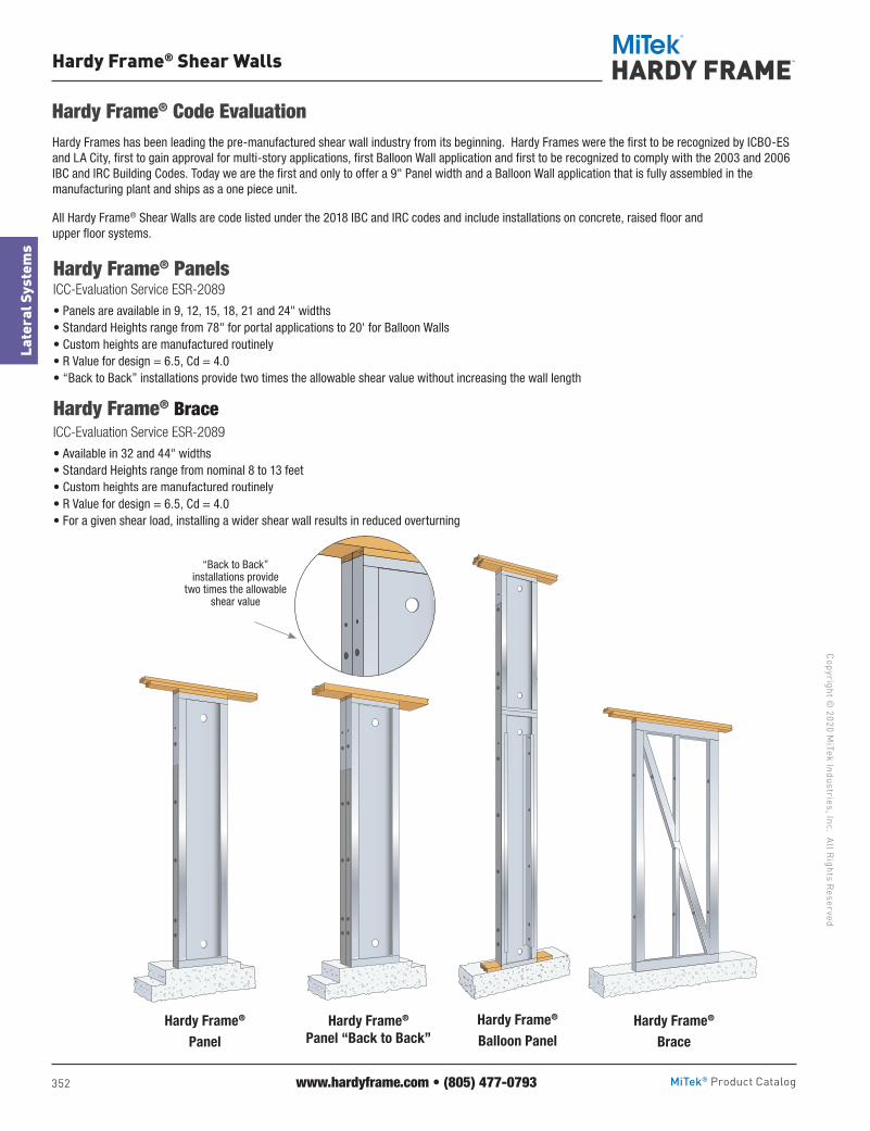
352
Copyright © 2020 M
iTek Industries, Inc. All Rights Reserved
Lateral Systems
Late
ral S
yste
ms
MiTek® Product Catalog
Hardy Frame® Shear Walls
Hardy Frames has been leading the pre-manufactured shear wall industry from its beginning. Hardy Frames were the first to be recognized by ICBO-ES and LA City, first to gain approval for multi-story applications, first Balloon Wall application and first to be recognized to comply with the 2003 and 2006 IBC and IRC Building Codes. Today we are the first and only to offer a 9" Panel width and a Balloon Wall application that is fully assembled in the manufacturing plant and ships as a one piece unit.
All Hardy Frame® Shear Walls are code listed under the 2018 IBC and IRC codes and include installations on concrete, raised floor and upper floor systems.
Hardy Frame® Panels ICC-Evaluation Service ESR-2089
• Panels are available in 9, 12, 15, 18, 21 and 24" widths• Standard Heights range from 78" for portal applications to 20' for Balloon Walls• Custom heights are manufactured routinely• R Value for design = 6.5, Cd = 4.0• “Back to Back” installations provide two times the allowable shear value without increasing the wall length
www.hardyframe.com • (805) 477-0793
Hardy Frame® Code Evaluation
Hardy Frame® Brace ICC-Evaluation Service ESR-2089
• Available in 32 and 44" widths• Standard Heights range from nominal 8 to 13 feet• Custom heights are manufactured routinely• R Value for design = 6.5, Cd = 4.0• For a given shear load, installing a wider shear wall results in reduced overturning
“Back to Back” installations provide
two times the allowable shear value
Shear Wall Systems
Hardy Frame® Brace
Hardy Frame®
Balloon PanelHardy Frame®
PanelHardy Frame®
Panel “Back to Back”

353
Lateral Systems
Copy
righ
t © 2
020
MiT
ek In
dust
ries
, Inc
. Al
l Rig
hts
Rese
rved
Lateral Systems
MiTek® Product Catalog
Hardy Frame® Moment Frames
Shear Wall Systems
www.hardyframe.com • (805) 477-0793
MiTek Hardy Frame® Special Moment Frames are constructed of wide flange columns connected to hollow structural steel (HSS) beams with SidePlate special moment connections.
The SidePlate special moment connection is approved in the AISC 358 Prequalified Moment Connections Standard and the review included testing that confirmed lateral bracing to prevent twist and out-of-plane displacements is not required at the hollow structural section (HSS) beams. Standard configurations are the Hardy Frame® Moment Frame with a pinned base and the Hardy Frame® Picture Frame.
Hardy Frame® Moment Frame• Standard designs for nominal 6" through 14" column depths with pinned base anchorage
are now available• Delivery options for pre-assembled, bolted column splice or “knock-down”• All standard designs fit in typical 8" wall framing, 6" column depths fit 6" framing• New construction and retrofit applications• Includes wood nailers at top & bottom of HSS beam and at all column flanges
Hardy Frame® Picture Frame• Constructed with HSS beams at top and bottom of Frame, SidePlate special moment connections at
all four corners• HSS beam at bottom of Frame eliminates the engineering and field construction of costly grade beams• Significant reductions in installation time result from elimination of field built grade beam• Standard designs for nominal 6" through 14" column depths that fit into typical wall framing with double the capacity of our pinned base option are now available• All the same delivery options and wood nailer inclusions as the Hardy Frame® Moment Frame with pinned base
The all new MiTek Hardy Frame® CFS Moment Frame and CFS Picture Frame are the industries first standardized, pre-engineered, pre-manufactured cold formed steel moment frames.
Lighter and less cost than structural steel moment frames, our CFS product line provides high capacities, ductility and cost economics that complete a spectrum of MiTek shear wall solutions.
Standard configurations are the Hardy Frame® CFS Moment Frame (portal applications) and the Hardy Frame CFS Picture Frame for stacking in multi-story applications.
Hardy Frame® CFS Moment FrameCode Report: ER-491• Similar materials and installation as Hardy Frame Panels the industry leader for 20 years• Available in standard designs and standard detailing• Capacities that are equal to four or five Hardy Frame Panels of same width• Can be installed “Back to Back” to double the capacity
Hardy Frame® CFS Picture Frame• Sill beam that assembles at the bottom of the Frame distributes compression over wood below to significantly
reduce crushing and maintain shear capacity• Incorporates the MiTek Z4 Continuous Tie-Down System to transfer overturning and uplift forces to the foundation• Narrow columns (12 through 21") and shallow beam depths (12 and 15") enable large openings and
architectural freedom• Ships as a “knock-down” unit: easy to handle, ship and field assemble
The First and Only Cold Formed Steel (CFS) Moment Frames
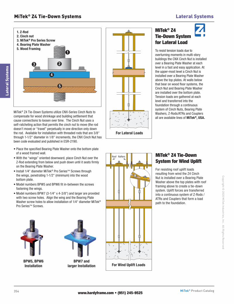
354
Copyright © 2020 M
iTek Industries, Inc. All Rights Reserved
Lateral Systems
Late
ral S
yste
ms
MiTek® Product Catalog
MiTek® Z4 Tie-Down Systems
MiTek® Z4 Tie-Down System for Lateral Load
To resist tension loads due to overturning moments in multi-story buildings the CNX Cinch Nut is installed over a Bearing Plate Washer at each level in a fast and easy application. At the upper-most level a Cinch Nut is installed over a Bearing Plate Washer above the top plates. At walls below that bear on wood floor systems, the Cinch Nut and Bearing Plate Washer are installed over the bottom plate. Tension loads are gathered at each level and transferred into the foundation through a continuous system of Cinch Nuts, Bearing Plate Washers, Z-Rods/ATRs and Couplers all are available lines of MiTek®, USA.
MiTek® Z4 Tie-Down System for Wind Uplift
For resisting roof uplift loads resulting from wind the Z4 Cinch Nut is installed over a Bearing Plate Washer above the top plates with roof framing above to create a tie-down system. Uplift forces are transferred into a continuous system of Z-Rods / ATRs and Couplers that form a load path to the foundation.
1
4
3
5
2Lorem ipsum
BPW5, BPW6 Installation
BPW7 and larger Installation
1. Z-Rod2. Cinch nut3. MiTek® Pro Series Screw4. Bearing Plate Washer5. Wood Framing
For Lateral Loads
For Wind Uplift Loads
Roof Rafters
MiTek® Z4 Tie-Down Systems utilize CNX-Series Cinch Nuts to compensate for wood shrinkage and building settlement that cause connections to loosen over time. The Cinch Nut uses a self-ratcheting action that permits the cinch nut to move (the rod doesn’t move) or “travel” perpetually in one direction only down the rod. Available for installation with threaded rods that are 3/8" through 1-1/2" diameter in 1/8" increments, the CNX Cinch Nut has been code evaluated and published in ESR-2190.
• Place the specified Bearing Plate Washer onto the bottom plate of a wood framed wall.
• With the “wings” oriented downward, place Cinch Nut over the Z-Rod extending from below and push down until it seats firmly on the Bearing Plate Washer.
• Install 1/4" diameter MiTek® Pro Series™ Screws through the wings, penetrating 1-1/2" (minimum) into the wood bottom plate.
• Model numbers BPW5 and BPW6 fit in-between the screws fastening the wings.
• Model numbers BPW7 (3-1/4" x 4-3/8") and larger are provided with two screw holes. Align the wing and the Bearing Plate Washer screw holes to allow installation of 1/4" diameter MiTek® Pro Series™ Screws.
www.hardyframe.com • (951) 245-9525

MiTek Services Division
FOCUSED ON HELPING YOU GROW YOUR BUSINESS WITH HIGHLY SKILLED RESOURCES THAT SCALE AS YOUR REQUIREMENTS CHANGE.
EXPAND YOUR CAPABILITIES WITHOUT ADDING STAFF.
MiTek Industries, Inc.Providing integrated solutions to the construction industry. Services | Software | Automation | Engineered Products
Serving Building Materials Providers with the following solutions:HVAC, Electrical, Lumber, and Component Estimates | Kitchen & Bath Design, Drafting and Estimation | Window & Door Estimation
Service Categories and Capabilities:
→ DESIGN / DRAFTING→ ESTIMATING→ RENDERING→ ADMINISTRATION / PROJECT MANAGEMENT→ SPECIALIZED
→ You manage the resource.
→ Dedicated to your team and your business.
→ Realize positive return on your investment with as little as 13-15 hours of demand per week.
→ The Direct Allocated Model is available at an annual cost.
MiTek can offer a range of flexible options to meet your initial or irregular staffing needs. MiTek can manage the same highly skilled resources on your behalf as you transition to the Direct Allocated Model.
PLATINUM GLOBAL DIRECT ALLOCATED MODEL
MiTek offers Platinum Global services to help you grow.
MiTek offers ambitious and highly skilled resources along with a process for quickly developing and scaling resources as your demand changes.
MiTek and Platinum Global provide you with risk reduction.
Contact your MiTek partner to learn more, or visit MiTek-US.com/Services

3
MITEK IS MORE THAN JUST ENGINEERED PRODUCTS
WE’RE WORKING TO BE YOUR HOLISTIC BUILDING SOLUTIONS PARTNERSEE MORE OF OUR SOLUTIONS ON THE INSIDE-FRONT COVER >
SERVICES
Scale your outputs (design, take-offs, estimating, job quotes, and more) without scaling your labor costs with
MiTek® PlanServices™.
MiTek-US.com/Machinery
MiTek-US.com/Services
AUTOMATION
Our comprehensive offsite design and fabrication
solutions are changing the way the world is building.
MITEK IS MORE THAN JUST ENGINEERED PRODUCTS
WE’RE WORKING TO BE YOUR HOLISTIC BUILDING SOLUTIONS PARTNER< SEE MORE OF OUR SOLUTIONS ON THE INSIDE-FRONT COVER
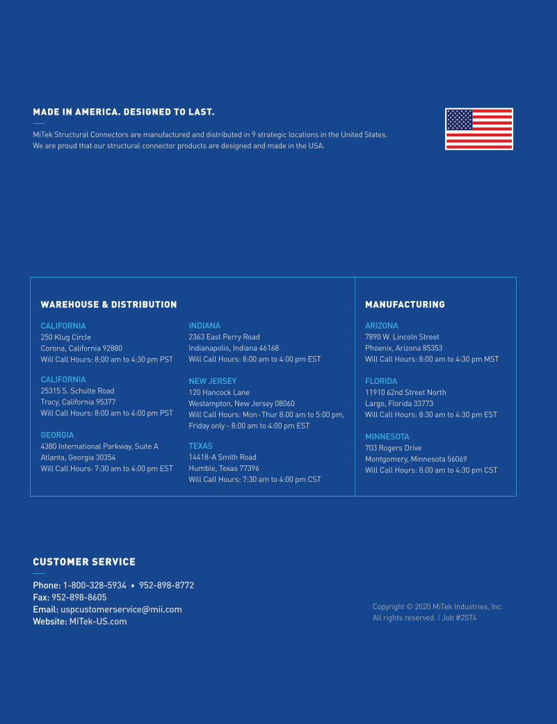
CALIFORNIA 250 Klug CircleCorona, California 92880Will Call Hours: 8:00 am to 4:30 pm PST
CALIFORNIA 25315 S. Schulte RoadTracy, California 95377Will Call Hours: 8:00 am to 4:00 pm PST
GEORGIA 4380 International Parkway, Suite AAtlanta, Georgia 30354Will Call Hours: 7:30 am to 4:00 pm EST
ARIZONA 7890 W. Lincoln StreetPhoenix, Arizona 85353 Will Call Hours: 8:00 am to 4:30 pm MST
FLORIDA 11910 62nd Street NorthLargo, Florida 33773Will Call Hours: 8:30 am to 4:30 pm EST
MINNESOTA 703 Rogers DriveMontgomery, Minnesota 56069Will Call Hours: 8:00 am to 4:30 pm CST
WAREHOUSE & DISTRIBUTION MANUFACTURING
Copyright © 2020 MiTek Industries, Inc. All rights reserved. | Job #2574
CUSTOMER SERVICE
Phone: 1-800-328-5934 • 952-898-8772Fax: 952-898-8605Email: [email protected]: MiTek-US.com
MADE IN AMERICA. DESIGNED TO LAST.
MiTek Structural Connectors are manufactured and distributed in 9 strategic locations in the United States. We are proud that our structural connector products are designed and made in the USA.
INDIANA 2363 East Perry RoadIndianapolis, Indiana 46168Will Call Hours: 8:00 am to 4:00 pm EST
NEW JERSEY 120 Hancock LaneWestampton, New Jersey 08060Will Call Hours: Mon-Thur 8:00 am to 5:00 pm,Friday only - 8:00 am to 4:00 pm EST
TEXAS 14418-A Smith RoadHumble, Texas 77396Will Call Hours: 7:30 am to 4:00 pm CST


