Embed Size (px)
Citation preview

Service Manual
071-8073-00NOVEMBER 2000
PROFILE PDR 200V I D E O F I L E S E R V E R

Copyright Copyright © 2000 Grass Valley Group Inc. All rights reserved. Printed in the United States ofAmerica.
This document may not be copied in whole or in part, or otherwise reproduced except asspecifically permitted under U.S. copyright law, without the prior written consent of Grass ValleyGroup Inc., P.O. Box 59900, Nevada City, California 95959-7900
Trademarks Grass Valley, GRASS VALLEY GROUP, Profile and Profile XP are either registered trademarksor trademarks of Grass Valley Group in the United States and/or other countries. Other trademarksused in this document are either registered trademarks or trademarks of the manufacturers orvendors of the associated products. Grass Valley Group products are covered by U.S. and foreignpatents, issued and pending. Additional information regarding
Grass Valley Group's trademarks and other proprietary rights may be found atwww.grassvalleygroup.com.
Disclaimer Product options and specifications subject to change without notice. The information in this manualis furnished for informational use only, is subject to change without notice, and should not beconstrued as a commitment by Grass Valley Group. Grass Valley Group assumes no responsibilityor liability for any errors or inaccuracies that may appear in this publication.
U.S. Government Restricted Rights Legend
Use, duplication, or disclosure by the United States Government is subject to restrictions as setforth in subparagraph (c)(1)(ii) of the Rights in Technical Data and Computer Software clause atDFARS 252.277-7013 or in subparagraph c(1) and (2) of the Commercial Computer SoftwareRestricted Rights clause at FAR 52.227-19, as applicable. Manufacturer is Grass Valley GroupInc., P.O. Box 59900, Nevada City, California 95959-7900 U.S.A.
Revision Status
Rev Date Description
June, 1997 Initial release of Service Manual 070-9675-00.
November, 2000 Updated Product Support contact information. Part number 071-8073-00.

Grass Valley Group Product SupportYou can get technical assistance, check on the status of problems, or report new problems by contacting our Product Support Group.
United States and CanadaMonday–Friday 5:30AM–5:00PM Pacific Time(800) 547-8949
EuropeMonday–Friday 9:00AM–5:30PM
Asia and South America
World Wide24-hour Emergency Hotline (530) 478-4148 (Contract and warranty customers)
World Wide Web http://www.grassvalleygroup.com/support/FTP Site ftp.grassvalleygroup.comUsers Group [email protected]
France 01 45 29 73 00 United Kingdom 01628 405830Germany 49 221 1791 234 Other +44 1753 218 777Italy 02 25086606
Australia- from overseas
02-9888 010061-2-9888 0100
Japan 81-3-3448-3111Korea 82-2-528-5299
Beijing 86-10-62351230ext. 711
Mexico 52-5-666-6333Singapore 65-356-3900
Brazil 55-11-3741-8422 Taiwan 886-2-27571571Hong Kong 852-2585-6579
PDR200 Service Manual iii

iv PDR200 Service Manual

Contents
Grass Valley Group Product Support..................................................................................... iii
Chapter 1 IntroductionAbout This Manual ................................................................................................................. 1-1Related Documentation ......................................................................................................... 1-2Organization of the Manual .................................................................................................... 1-2Product Description................................................................................................................ 1-3
System Control.................................................................................................................. 1-3Video ................................................................................................................................. 1-3Audio ................................................................................................................................. 1-4Fibre Channel Networking................................................................................................. 1-4Ethernet............................................................................................................................. 1-4Storage.............................................................................................................................. 1-4Reference Genlock and Time Code.................................................................................. 1-4
Chapter 2 SpecificationsGeneral Information ............................................................................................................... 2-1Test Equipment...................................................................................................................... 2-1Electrical Specifications ......................................................................................................... 2-2
Environmental Criteria....................................................................................................... 2-11Mechanical Specifications ................................................................................................. 2-11
Chapter 3 Theory of OperationSystem Overview ................................................................................................................... 3-2
Video Recording System................................................................................................... 3-4Fibre Channel.................................................................................................................... 3-5Audio Recording System................................................................................................... 3-5
Specific Boards ...................................................................................................................... 3-6Mother Board .................................................................................................................... 3-6
EISA Bus ...................................................................................................................... 3-6Video Bus ..................................................................................................................... 3-6
Reference Genlock ........................................................................................................... 3-7Master Enhanced Disk Recorder ...................................................................................... 3-8
Real-Time Processor.................................................................................................... 3-9GPCI Bus Connection .................................................................................................. 3-9RTP to GPCI Interface ................................................................................................. 3-9RTP to EISA Interface .................................................................................................. 3-9EISA to EDR Interface.................................................................................................. 3-10LPCI Bus ...................................................................................................................... 3-10EISA to LPCI Interface ................................................................................................. 3-10EISA DMA Controller.................................................................................................... 3-10GPCI to LPCI Interface................................................................................................. 3-11LPCI to Dual JPEG Interface........................................................................................ 3-11LPCI to SCSI Interfaces ............................................................................................... 3-11Video Bus Interface ...................................................................................................... 3-11PCI Bus Arbitration ....................................................................................................... 3-11RTP Interrupts .............................................................................................................. 3-12Clocks........................................................................................................................... 3-13
Slave Enhanced Disk Recorder ........................................................................................ 3-13PCI Board.......................................................................................................................... 3-13
PDR200 Service Manual v

Audio Signal Processing Board ........................................................................................ 3-14Digital I/O ..................................................................................................................... 3-14Audio Processing and Storage..................................................................................... 3-14Clocking and Synchronization ...................................................................................... 3-15API/Profile Protocol Extensions ................................................................................... 3-15VdrPanel Support ......................................................................................................... 3-15
Fibre Channel ................................................................................................................... 3-16Mix Effects ........................................................................................................................ 3-17
Chapter 4 TroubleshootingMaking Basic Checks ............................................................................................................ 4-1Initial Fault Isolation Checks .................................................................................................. 4-2
System Interface Problems............................................................................................... 4-2Front Panel Indicators and Control ................................................................................... 4-4
Power Indicator ............................................................................................................ 4-4Disk Access.................................................................................................................. 4-5System Fault ................................................................................................................ 4-5Fan Fault ...................................................................................................................... 4-5Over Temp ................................................................................................................... 4-5Standby/On Switch....................................................................................................... 4-5
Rear Panel Indicators and Control .................................................................................... 4-6PAC208/216 Basic Troubleshooting ...................................................................................... 4-8Start-up Problems.................................................................................................................. 4-9SCSI Bus Errors .................................................................................................................... 4-11
Profile.log File ................................................................................................................... 4-11Sample SCSI Listings .................................................................................................. 4-11
Troubleshooting the SCSI Bus.......................................................................................... 4-14System SCSI Error Messages ..................................................................................... 4-14Profile.log SCSI Error Messages ................................................................................. 4-15
Video Problems ..................................................................................................................... 4-16Audio Problems ..................................................................................................................... 4-18
AES/EBU Digital Audio Problems ..................................................................................... 4-18Analog Audio Problems .................................................................................................... 4-19Embedded Audio Problems .............................................................................................. 4-19
Networking Problems............................................................................................................. 4-20Diagnostics ............................................................................................................................ 4-21Starting the Diagnostics Program .......................................................................................... 4-21
Diagnostics Window Menu Bar ......................................................................................... 4-22Diagnostics Window Layout .............................................................................................. 4-25
Board Configuration ..................................................................................................... 4-25Board Tests and Selection ........................................................................................... 4-25Board Tests Results ..................................................................................................... 4-25
Running Board Diagnostics ................................................................................................... 4-25Executing Test All Boards ................................................................................................. 4-26Executing Individual Board Tests...................................................................................... 4-28
Executing All (Board) Tests.......................................................................................... 4-29Done............................................................................................................................. 4-29
Diagnostic Test Exceptions............................................................................................... 4-30Pentium Board (Slot J1) ............................................................................................... 4-30VGA Board (Slot J2)..................................................................................................... 4-31Ethernet LAN Board (Slot J3)....................................................................................... 4-31SCSI Board (Slot J4).................................................................................................... 4-31RS-422 Board Tests (Slot J17) .................................................................................... 4-32Empty Slots .................................................................................................................. 4-32
vi PDR200 Service Manual

Contents
Chapter 5 MaintenanceTools Required....................................................................................................................... 5-1Preventive Maintenance ........................................................................................................ 5-2
Cleaning ............................................................................................................................ 5-2Exterior ......................................................................................................................... 5-2Interior .......................................................................................................................... 5-2
Visual Inspection ............................................................................................................... 5-2Cleaning or Replacing Air Filters ........................................................................................... 5-3
Removing the PDR200 Filters .......................................................................................... 5-3Replacing the PDR200 Filters........................................................................................... 5-5Removing the PAC208/216 Filter...................................................................................... 5-6Replacing the PAC208/216 Filter ...................................................................................... 5-7Cleaning the Filters ........................................................................................................... 5-7Additional Air Filters .......................................................................................................... 5-7
Software Upgrades and Repairs ............................................................................................ 5-8Upgrades........................................................................................................................... 5-8Updating an Emergency Repair Disk ................................................................................ 5-8Repairing Corrupt Windows NT Software ......................................................................... 5-9Reloading the CMOS Chip ................................................................................................ 5-10
Chapter 6 Parts Removal and ReplacementTools Required....................................................................................................................... 6-1PDR200 Replaceable Parts List ............................................................................................ 6-2Profile Chassis ....................................................................................................................... 6-6Chassis Covers ...................................................................................................................... 6-8Bezel and Air Filters ............................................................................................................... 6-8LED Board ............................................................................................................................. 6-9System Drive.......................................................................................................................... 6-12Media Disk Drive .................................................................................................................... 6-14SCSI Backplane..................................................................................................................... 6-16Fan Tray................................................................................................................................. 6-18Internal Fans .......................................................................................................................... 6-20Fan Board .............................................................................................................................. 6-21Disk Drive Tray ...................................................................................................................... 6-22Floppy Disk Drive ................................................................................................................... 6-24Distribution Board .................................................................................................................. 6-26LED EMI Board ...................................................................................................................... 6-28External Fan........................................................................................................................... 6-29Boards.................................................................................................................................... 6-30
Board Retainer Brackets ................................................................................................... 6-30Board Removal and Replacement .................................................................................... 6-33PCI Board.......................................................................................................................... 6-35
Serial EMI Board .................................................................................................................... 6-37Mouse/Keyboard EMI Board .................................................................................................. 6-38Power Supply ......................................................................................................................... 6-40Motherboard........................................................................................................................... 6-44Interior Cabling....................................................................................................................... 6-45PAC208/216 Replaceable Parts ............................................................................................ 6-48PAC208/216 Bezel and Air Filter ........................................................................................... 6-48PAC208/216 Cover ................................................................................................................ 6-49PAC208/216 LED................................................................................................................... 6-50PAC208/216 Fan ................................................................................................................... 6-52PAC208/216 Power Supply ................................................................................................... 6-54PAC208/216 Switch ............................................................................................................... 6-56PAC208/216 Power Connector and Line Filter ...................................................................... 6-57PAC208/216 Daughter Board ................................................................................................ 6-58PAC208/216 Main Board ....................................................................................................... 6-60
PDR200 Service Manual vii

PAC208/216 XLR Board ........................................................................................................ 6-62Repair Verification ................................................................................................................. 6-64
Rebuilding the Disk File System ....................................................................................... 6-64Testing .............................................................................................................................. 6-64
Appendix A Connector Pin-outsS-VGA Board Connectors...................................................................................................... A-1Local Area Network (LAN) Board Connectors ....................................................................... A-3SCSI-2 Connector.................................................................................................................. A-4Fibre Channel Connector....................................................................................................... A-6Reference Genlock D-Connector........................................................................................... A-7Audio Signal Processing Board Connector............................................................................ A-8RS-232 Connectors ............................................................................................................... A-10
Index
viii PDR200 Service Manual

Contents
Figures1-1 The PDR200 .................................................................................................................. 1-1
2-1 PDR200 Dimensions .................................................................................................... 2-12
3-1 Basic PDR200 Concept ................................................................................................. 3-23-2 Profile High Level System Partitioning ........................................................................... 3-33-3 Block Diagram - EDRs and Fibre Channel ..................................................................... 3-83-4 Block Diagram - EISA to EDR Interface ........................................................................3-103-5 Block Diagram - EDR to JPEG Interface ...................................................................... 3-13
4-1 Front Panel Indicators .................................................................................................... 4-34-2 Starting The PDR Diagnostics Program ....................................................................... 4-204-3 Diagnostics Window ..................................................................................................... 4-214-4 Diagnostics Window Menu Bar .................................................................................... 4-214-5 Board Configuration List ............................................................................................... 4-224-6 Preferences Dialog Box ................................................................................................ 4-234-7 GDB960 (i960) Window ................................................................................................ 4-254-8 Test Status Box ............................................................................................................ 4-264-9 Diagnostics Window with the i960 Report Window ...................................................... 4-274-10 Pentium Board Status .................................................................................................. 4-294-11 VGA Slot Message ....................................................................................................... 4-304-12 LAN and SCSI Boards Message .................................................................................. 4-304-13 RS-422 Diagnostics Menu ............................................................................................ 4-314-15 Empty Slot Message .................................................................................................... 4-30
5-1 PDR200 Rack Retaining Screw ..................................................................................... 5-35-2 Front Panel, Handles, and Gasket Removal .................................................................. 5-45-3 Power LED Cable and Filter Removal ............................................................................ 5-55-4 PAC208/216 Filter Removal ........................................................................................... 5-6
6-1 PDR200 Replaceable Parts Locations (1 of 2) .............................................................. 6-46-2 PDR200 Replaceable Parts Locations (2 of 2) .............................................................. 6-56-3 PDR200 Rack Retaining Screw ..................................................................................... 6-66-4 Rack Slide Stop Latch .................................................................................................... 6-66-5 Removal of the Top Covers .............................................................................................6-86-6 Front Panel, Handles, and Gasket Removal .................................................................. 6-96-7 LED Board Removal ..................................................................................................... 6-106-8 Removal of the System Drive ....................................................................................... 6-136-9 Removal of a Media Disk Drive .................................................................................... 6-156-10 Removal of the SCSI Backplane .................................................................................. 6-176-11 Removal of Fan Tray and Fan ...................................................................................... 6-196-12 Media Disk Drive Tray Removal ................................................................................... 6-236-13 Removal of the Floppy Disk Drive ................................................................................ 6-256-14 Removal of the Distribution Board ................................................................................ 6-276-15 Removal of the LED EMI Board ................................................................................... 6-286-16 Removal of an External Fan ......................................................................................... 6-296-17 Rear Board Retainer Bracket ....................................................................................... 6-306-18 Removal of Board Retainer Brackets ........................................................................... 6-316-19 Installation of Board Retainer Brackets ........................................................................ 6-326-20 Removal of a Full-size Board ....................................................................................... 6-336-21 Removal of a Short Board ............................................................................................ 6-346-22 PCI Board Location ...................................................................................................... 6-356-23 PCI Board ..................................................................................................................... 6-366-24 Removal of the Serial EMI Board ................................................................................. 6-376-25 Removal of the Mouse/Keyboard EMI Board ............................................................... 6-386-26 Removal of the Power Supply Shield ........................................................................... 6-39
PDR200 Service Manual ix

6-27 Power Supply Cable Disconnections ........................................................................... 6-406-28 Removal of the Power Supply ...................................................................................... 6-416-29 PDR200 Replaceable Cable Locations ........................................................................ 6-446-30 PAC208/216 LED Removal .......................................................................................... 6-476-31 PAC208/216 Power Supply Shield and Fan Removal ................................................. 6-496-32 PAC208/216 Power Supply Removal .......................................................................... 6-516-33 PAC208/216 Switch and Cable Removal ..................................................................... 6-526-34 PAC208/216 Power Connector and Line Filter Removal ............................................. 6-546-35 PAC208/216 Daughter Board Removal ....................................................................... 6-576-36 PAC208/216 Main Board Removal .............................................................................. 6-596-37 PAC208/216 XLR Board Removal ............................................................................... 6-61
A-1 SVGA Board Monitor Connector ................................................................................... A-1A-2 LAN RJ-45 Connector ................................................................................................... A-3A-3 SCSI 2 Connector ......................................................................................................... A-4A-4 Fibre Channel Connector .............................................................................................. A-6A-5 Reference Genlock 25-pin Connector ........................................................................... A-7A-6 ASPB Connector ........................................................................................................... A-8A-7 RS-232 Connector Pin-outs ........................................................................................ A-10
Tables2-1 Serial Digital Video Input/Output .................................................................................... 2-22-2 Analog Composite Video E-E (Direct - Factory installed) ............................................... 2-32-3 Analog Composite Video E-E (Direct - Customer installed) .......................................... 2-42-4 Analog Composite Video E-E (Direct - Customer installed) ........................................... 2-52-5 Program Input Genlock .................................................................................................. 2-62-6 Analog Input/Output ....................................................................................................... 2-62-7 Component Analog Input/Output .................................................................................... 2-62-8 Component Analog Video Performance ......................................................................... 2-72-9 Format Voltage Level Definitions for CAV mtrxN ........................................................... 2-82-10 Format Voltage Level Definitions for CAV mtrxP ........................................................... 2-92-11 Reference Genlock ........................................................................................................ 2-92-12 Time Code ...................................................................................................................... 2-92-13 Analog Audio Mode ...................................................................................................... 2-102-14 Power Source ............................................................................................................... 2-102-15 Power Supply Specifications (from Manufacturer) ....................................................... 2-102-16 Environmental Criteria .................................................................................................. 2-112-17 Mechanical Specifications ............................................................................................ 2-11
4-1 System Interface Problems ............................................................................................ 4-24-2 PAC208/216 Basic Troubleshooting .............................................................................. 4-7
6-1 PDR200 Replaceable Parts List .................................................................................... 6-26-2 PDR200 Replaceable Cables ...................................................................................... 6-456-3 PAC Replaceable Parts List ......................................................................................... 6-46
A-1 S-VGA Board Monitor Connector Pin-outs .................................................................... A-1A-2 SVGA Board Parallel Port Connector Pin-outs ............................................................. A-2A-3 RJ-45 Connector Pin-outs ............................................................................................. A-3A-4 LAN 9-Pin Connector Pin-outs ...................................................................................... A-3A-5 SCSI 2 Connector Pin-outs ........................................................................................... A-5A-6 Fibre Channel Connector Pin-outs ................................................................................ A-6A-7 Reference Genlock D-connector Pin-outs .................................................................... A-7A-8 ASPB Connector Pin-outs ............................................................................................. A-9A-9 RS-232 Connector Pin-outs ........................................................................................ A-10
x PDR200 Service Manual

Safety Summaries
General Safety SummaryReview the following safety precautions to avoid injury and prevent damage to this product or any products connected to it.
Only qualified personnel should perform service procedures.
While using this product, you may need to access other parts of the system. Read the General Safety Summary in other system manuals for warnings and cautions related to operating the system.
Injury Precautions
Use Proper PowerCord
To avoid fire hazard, use only the power cord specified for this product.
Ground the Product This product is grounded through the grounding conductor of the power cord. To avoid electric shock, the grounding conductor must be connected to earth ground. Before making connections to the input or output terminals of the product, ensure that the product is properly grounded.
Do Not OperateWithout Covers
To avoid electric shock or fire hazard, do not operate this product with covers or panels removed.
Use Proper Fuse To avoid fire hazard, use only the fuse type and rating specified for this product.
Do Not operate inWet/Damp
Conditions
To avoid electric shock, do not operate this product in wet or damp conditions.
Do Not Operate in anExplosive
Atmosphere
To avoid injury or fire hazard, do not operate this product in an explosive atmosphere.
Avoid ExposedCircuitry
To avoid injury, remove jewelry such as rings, watches, and other metallic objects. Do not touch exposed connections and components when power is present.
PDR200 Service Manual xi

xii
Product Damage Precautions
Use Proper PowerSource
Do not operate this product from a power source that applies more than the voltage specified.
Provide ProperVentilation
To prevent product overheating, provide proper ventilation.
Do Not Operate WithSuspected Failures
If you suspect there is damage to this product, have it inspected by qualified service personnel.
PDR200 Service Manual

Service Safety Summary
Service Safety SummaryReview the following safety precautions to avoid injury and prevent damage to this product or any products connected to it.
Only qualified personnel should perform service procedures.
While using this product, you may need to access other parts of the system. Read the General Safety summary in other system manuals for warnings and cautions related to operating the system.
Safety Terms and SymbolsTerms in This
ManualThese terms may appear in this manual:
WARNING: Warning statements identify conditions or practices that can result in personal injury or loss of life.
CAUTION: Caution statements identify conditions or practices that can result in damage to the equipment or other property.
Terms on theProduct
These terms may appear on the product:
DANGER indicates a personal injury hazard immediately accessible as one reads the marking.
WARNING indicates a personal injury hazard not immediately accessible as you read the marking.
CAUTION indicates a hazard to property including the product.
Symbols on theProduct
The following symbols may appear on the product:
DANGER high voltage
Protective ground (earth) terminal
ATTENTION – refer to manual
!
!
!
!
!
PDR200 Service Manual xiii

xiv
Certifications and CompliancesCanadian Certified
Power CordsCanadian approval includes the products and power cords appropriate for use in the North America power network. All other power cords supplied are approved for the country of use.
FCC EmissionControl
This equipment has been tested and found to comply with the limits for a Class A digital device, pursuant to Part 15 of the FCC Rules. These limits are designed to provide reasonable protection against harmful interference when the equipment is operated in a commercial environment. This equipment generates, uses, and can radiate radio frequency energy and, if not installed and used in accordance with the instruction manual, may cause harmful interference to radio communications. Operation of this equipment in a residential area is likely to cause harmful interference in which case the user will be required to correct the interference at his own expense. Changes or modifications not expressly approved by Grass Valley Group can affect emission compliance and could void the user’s authority to operate this equipment.
Canadian EMCNotice of
Compliance
This digital apparatus does not exceed the Class A limits for radio noise emissions from digital apparatus set out in the Radio Interference Regulations of the Canadian Department of Communications.
Le présent appareil numérique n émet pas de bruits radioélectriques dépassant les limites applicables aux appareils numériques de la classe A préscrites dans le Règlement sur le brouillage radioélectrique édicté par le ministère des Communications du Canada.
Canadian CertifiedAC Adapter
Canadian approval includes the AC adapters appropriate for use in the North America power network. All other AC adapters supplied are approved for the country of use.
EN55022 Class AWarning
For products that comply with Class A. In a domestic environment this product may cause radio interference in which case the user may be required to take adequate measures.
Laser Compliance
Laser SafetyRequirements
The device used in this product is a Class 1 certified laser product. Operating this product outside specifications or altering from its original design may result in hazardous radiation exposure, and may be considered an act of modifying or new manufacturing of a laser product under US regulations contained in 21CFR Chapter 1, subchapter J or CENELEC regulations in HD 482 S1. People performing such an act are required by law to recertify and reidentify this product in accordance with provisions of 21CFR subchapter J for distribution within the U.S.A., and in accordance with CENELEC HD 482 S1 for distribution within countries using the IEC 825 standard.
PDR200 Service Manual

Certification
Laser Safety Laser safety in the United States is regulated by the Center for Devices and Radiological Health (CDRH). The laser safety regulations are published in the “Laser Product Performance Standard,” Code of Federal Regulation (CFR), Title 21, Subchapter J.
The International Electrotechnical Commission (IEC) Standard 825, “Radiation of Laser Products, Equipment Classification, Requirements and User’s Guide,” governs laser products outside the United States. Europe and member nations of the European Free Trade Association fall under the jurisdiction of the Comité Européen de Normalization Electrotechnique (CENELEC).
For the CDRH: the radiant power is detected through a 7 mm aperture at a distance of 200mm from the source focused through a lens with a focal length of 100 mm.
For IEC compliance: the radiant power is detected through a 7 mm aperture at a distance of 100mm from the source focused through a lens with a focal length of 100 mm.
FCC EmissionLimits
This device complies with Part 15 of the FCC Rules. Operation is subject to the following two conditions: (1) This device may not cause harmful interference, and (2) this device must accept any interference received, including interference that may cause undesirable operation. This device has been tested and found to comply with FCC Part 15 Class B limits for a digital device when tested with a representative laser-based fiber optical system that complies with ANSI X3T11 Fiber Channel Standard.
Certification
Category Standard
Safety Designed/tested for compliance with:
UL1950 - Safety of Information Technology Equipment, including Electrical Business Equipment (Third Edition, 1995)
IEC 950 - Safety of Information Technology Equipment, including Electrical Business Equipment (Second edition, 1991)
CAN/CSA C22.2, No. 950-95 - Safety of Information Technology Equipment, including Electrical Business Equipment
EN60950 - Safety of Information Technology Equipment, including Electrical Business Equipment
PDR200 Service Manual xv

xvi
PDR200 Service Manual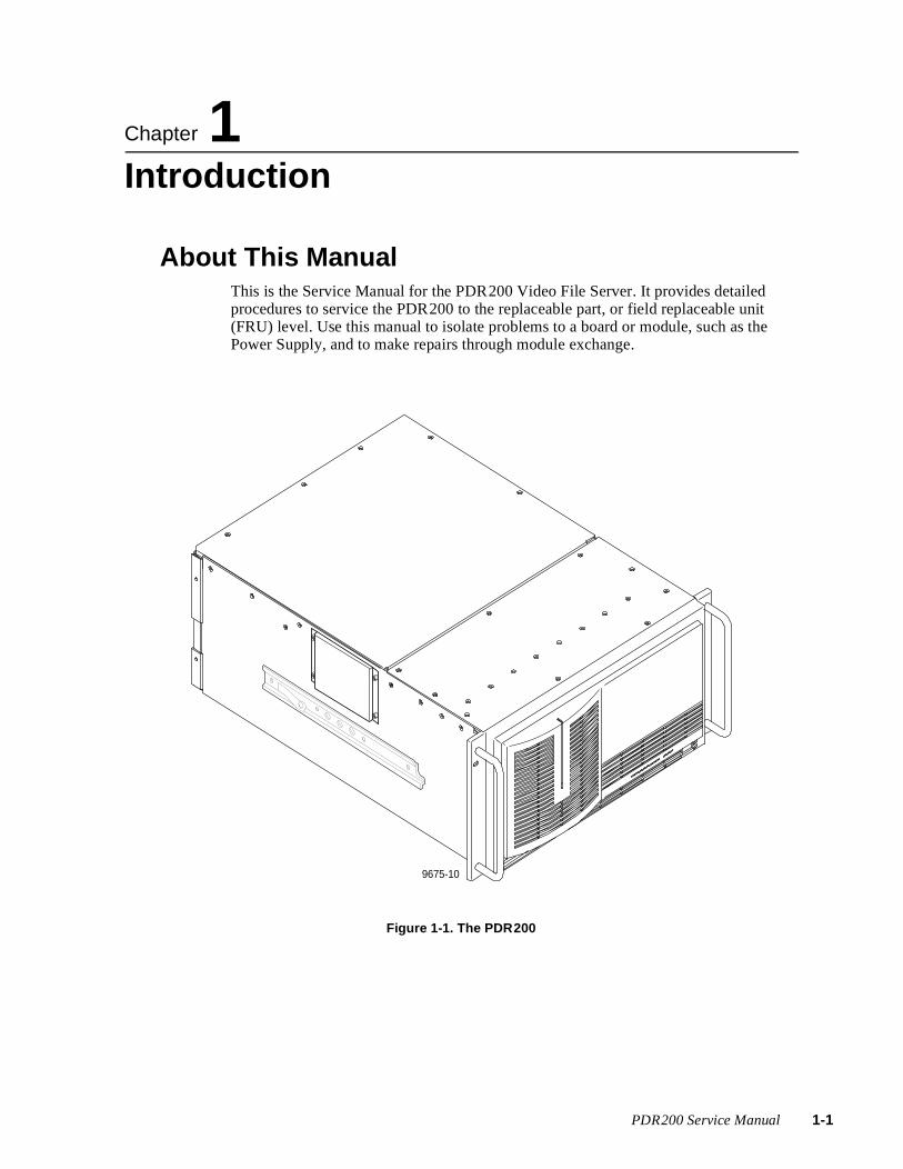
Chapter
1 IntroductionAbout This ManualThis is the Service Manual for the PDR200 Video File Server. It provides detailed procedures to service the PDR200 to the replaceable part, or field replaceable unit (FRU) level. Use this manual to isolate problems to a board or module, such as the Power Supply, and to make repairs through module exchange.
Figure 1-1. The PDR200
9675-10
PDR200 Service Manual 1-1

Chapter 1 Introduction
1-2
Related DocumentationProfile Family User Manual
PDR200 Installation Manual
Profile Release Notes
PDX208 Disk Expansion Chassis Instruction Manual
Organization of the ManualThe Service Manual is divided into the chapters identified and described below.
Chapter 1 - Introduction: This chapter describes the contents of the manual and provides an in-depth functional description of the PDR200 system.
Chapter 2 - Specifications: This chapter consists of physical and electrical specifications, and environmental criteria.
Chapter 3 - Theory of Operation: This chapter provides a basic understanding of how the PDR200 system functions and how certain boards operate within those functions.
Chapter 4 - Troubleshooting: This chapter describes how to determine the cause of a PDR200 malfunction. It includes descriptions of fault indications and execution of the diagnostics program which resides on the system hard disk.
Chapter 5 - Maintenance: This chapter consists of maintenance information, including software upgrades and repairs.
Chapter 6 - Removal and Replacement: This chapter contains removal and replacement procedures and replaceable parts lists for the PDR200 and thePAC208/216. It also includes verification information.
Appendix A - Connector Pin-outs: This appendix identifies certain connectors and the signals present on the pins of those connectors.
PDR200 Service Manual
Product Description
Product DescriptionThe PDR200 Video File Server is a computer-controlled, disk-based system. It can be used in any application that involves the recording, storage, manipulation, transfer, and playback of video. Application software runs on the Windows NTTM operating system. The system’s total amount of program material storage depends on the number of disk drives connected and the selected compression factor.
System ControlAn internal Pentium processor board controls the system which uses a dedicated (system) hard disk for program and application storage. The Microsoft Windows NT operating software also resides on this disk. A 31/2-inch floppy disk drive (or an optional parallel port CD-ROM) provides for software updates and additions.
The system supports three control interfaces: RS-232, RS-422 (eight ports), and keyboard/mouse. In addition, an internal VGA board supports an optional SVGA monitor (1024 × 768 @ 72 Hz.).
VideoThe PDR200 accepts the following video formats:
• Serial Digital I/O.
• Analog Component (input only, 525 or 625 line).
• Analog Composite I/O (PAL or NTSC).
It converts these formats to parallel digital data and then routes the data to the Disk Recorder board via an internal video router. The PDR200 compresses (JPEG) the parallel digital data and stores it on the media hard disks.
Upon recovery, the system decompresses the parallel digital component video and routes it to the output circuitry where it is converted back to serial digital or analog format. Composite outputs undergo an additional conversion back to either the NTSC or PAL format. The composite output board supports up to four composite program outputs and a monitor channel. The monitor channel can have time code burned in.
Each video channel can be supported by up to four channels of audio. The system stores the audio signal on a hard disk along with the video. For playback, the system recovers the audio from its storage location and outputs it with the same video signal relationship it had when recorded.
PDR200 Service Manual 1-3

Chapter 1 Introduction
1-4
AudioIn its standard configuration, the PDR200 supports 16 channels of AES/EBU digital audio connected to the PDR200 through the Audio Signal Processing Board (ASPB) from either the XLR216 or BNC216 external panel. With the optional PAC208/PAC216 Analog/Digital Interface chassis, the PDR200 supports 8/16 channels of analog audio I/O through the ASPB. In addition, the Serial Digital I/O board supports embedded audio, which is also processed by the ASPB.
Fibre Channel NetworkingWith the Fibre Channel option, the PDR200 provides for the transfer and sharing of material with other Profiles on the Fibre Channel network. Compressed digital data flows from one Profile to another Profile over the high speed Fibre Channel network at up to 4-5 times real time. The Fibre Channel network requires Ethernet for command and control signals.
EthernetEthernet supplies the LAN communication, command, and file transfer ability to the PDR200.
StorageThe Enhanced Disk Recorder (EDR) boards control the media hard disks, and provide the JPEG compression/decompression. The Master EDR can control as few as four and as many as twelve 9GB Ultra SCSI hard disk drives. A Slave EDR can be added to control four to twelve additional 9GB hard disks.
The optional PDX208 Disk Expansion Chassis contains its own power supply and eight 9GB hard disks in a three rack units high chassis. It may be configured as two banks of four to support a 4-channel Profile (i.e., a Profile with Master and Slave EDRs) or one bank of eight hard disks to support a 2-channel Profile (i.e., one with only a Master EDR).
Up to 96 hours of program material storage can be realized by the addition of one or more PRS200A RAID units. The PLS200 Profile Data Tape Library System can also be added to the PDR200 for off-line storage of material in its compressed data format.
Note that you may choose to have a PDR200 without any internal media hard disk drives. A “diskless” PDR200 requires internal termination of the SCSI bus(es) through software.
Reference Genlock and Time CodeThe Reference Genlock board provides a reference signal to the PDR200, either internally if no house signal is available or through BNC connectors at the rear panel. This reference signal synchronizes the system’s 27 MHz video clock and provides field reference for the system.
This board also provides eight (four inputs and four outputs) Longitudinal Time Code interfaces through the DB-25 connector at the rear panel.
PDR200 Service Manual

Chapter
2 SpecificationsGeneral InformationThis chapter provides tables of electrical specifications for the video and audio characteristics, as well as environmental criteria and power and mechanical characteristics. The tables in this chapter make it easier to present the specifications in numerical values. The following terms apply to the PDR200 Characteristics and Descriptions in the tables.
Specification: A document or a section of a document that lists and describes characteristics and performance requirements of equipment and certain program material.
Requirement (Performance Requirement): A statement that defines a characteristic, usually in limit form.
Supplemental Data: Statements that explain performance requirements or provide performance information. These are not considered to be statements of guaranteed performance and are not ordinarily supported by a performance check procedure.
Test EquipmentGrass Valley Group uses the following test equipment to verify the performance requirements listed in this chapter.
• VM700A
• Signal Source (Video and Audio)
• Signal Generator
• Monitor
PDR200 Service Manual 2-1

Chapter 2 Specifications
2-2
Electrical SpecificationsThe Performance Requirements listed in the Electrical Specifications apply over an ambient temperature range of +20.5 C to +30.5 C. The Performance Requirement tolerances listed in the Electrical Specification are doubled over the temperature range of 0 to +40.5 C, unless there is a specific exception.
Table 2-1. Serial Digital Video Input/Output
Characteristics Description
Number of Inputs Supplemental Data:Two component serial digital
Input Type Supplemental Data:75Ω terminated
Number of Outputs Supplemental Data:Two component serial digital
Output Timing Range Requirement: -21/2 H to +148 HSupplemental Data:Independent for each outputSupplemental Data:Resolution; 74 ns
Digital Format Supplemental Data:CCIR 601 Component 525/625 8 bit data, Scrambled NRZI; complies with SMPTE 259M and CCIR 656
Bit Rate Supplemental Data:270 Mb/s
Source Impedance Supplemental Data:75Ω
Return Loss Supplemental Data:≥15 dB from 5 MHz to 270 MHz
DC Offset Requirement: 0 ±0.5V
Rise and Fall Times Requirement: 400 - 1000ps; 20% to 80% amplitude slew rate
Jitter Requirement: ≤±360 ps
Input Level Supplemental Data:800 mV p-p ±10%Supplemental Data:Input voltages outside this range may cause reduced
receiver performance
Serial Receiver Equalization Range
Requirement: Proper operation with up to 17 dB loss at 135 MHz using coaxial cable having 1/√F loss characteristics. 800 mV launch amplitude
Output Level Requirement: 800 mV p-p ±10%Supplemental Data:Can be adjusted for 740 mV p-to-p ±10%
PDR200 Service Manual

Electrical Specifications
Table 2-2. Analog Composite Video E-to-E (Direct)(Valid only for Factory Installed Analog Composite Input/Output)
Characteristics Description
Program Gain Requirement: 1 ±1% Direct1 ±2% AGC Path
Program Input Gain Range Requirement: 70% to 140% or Better Direct PathSupplemental Data:Approximately ±3 dB
Frequency Response Requirement: 500 kHz to 5.8 MHz ±2% Direct or AGC PathSupplemental Data:-3 dB Nominally 6.25 MHz
Signal-to-Noise Ratio Requirement: > 50 dB Direct> 45 dB AGC Path
Chrominance-to-Luminance Delay Error
Requirement: ≤10 ns NTSC Direct or AGC Path≤15 ns PAL Direct or AGC Path
Differential Gain Requirement: ≤1.5% NTSC Direct or AGC Path≤1.5% PAL Direct or AGC Path
Differential Phase Requirement: ≤1.5° Direct or AGC Path
K-Factor Requirement: ≤1% Direct or AGC Path
2T Pulse-to-Bar Ratio Requirement: ≤1% Direct or AGC Path
Output Timing Range Requirement: -21/2H to +148HSupplemental Data:Independent for each outputSupplemental Data:Resolution; ≈0.3° of 3.58 MHzSupplemental Data:Timing Stability: 1°
Sync and Burst Insertion Timing Accuracy
Requirement: Meets RS-170A, and CCIR RPT 624-3;always on
Insertion Phase Error Requirement: ≤1° Direct or AGC Path
Chrominance Phase Error with Reference Burst Frequency Change
Requirement: ≤1° with an input burst. This is a frequency change of ±10 Hz Direct or AGC Path
Chrominance Phase Error with Reference Signal Amplitude Change
Requirement: ≤1° with a ±3 dB amplitude changeDirect or AGC Path
DC Offset Requirement: ≤±50 mV Direct or AGC Path
Inserted Sync and Burst Amplitude Accuracy
Requirement: Sync Direct or AGC Path NTSC 40 IRE ±1 IRE PAL 300 mV ±7 mV Burst Direct or AGC Path NTSC 40 IRE ±1 IRE PAL 300 mV ±7 mV
Inserted Sync and Burst SCH Phase Accuracy
Requirement: 0° ±5° Direct or AGC Path
Black Level Error Requirement: ±3.5 mV Direct±5 mV AGC Path
PDR200 Service Manual 2-3
Chapter 2 Specifications
2-4
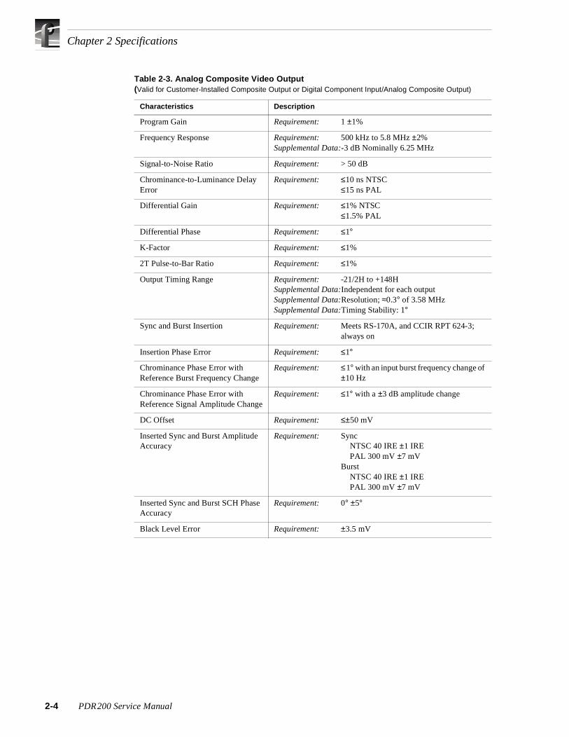
Table 2-3. Analog Composite Video Output(Valid for Customer-Installed Composite Output or Digital Component Input/Analog Composite Output)
Characteristics Description
Program Gain Requirement: 1 ±1%
Frequency Response Requirement: 500 kHz to 5.8 MHz ±2%Supplemental Data:-3 dB Nominally 6.25 MHz
Signal-to-Noise Ratio Requirement: > 50 dB
Chrominance-to-Luminance Delay Error
Requirement: ≤10 ns NTSC≤15 ns PAL
Differential Gain Requirement: ≤1% NTSC≤1.5% PAL
Differential Phase Requirement: ≤1°
K-Factor Requirement: ≤1%
2T Pulse-to-Bar Ratio Requirement: ≤1%
Output Timing Range Requirement: -21/2H to +148HSupplemental Data:Independent for each outputSupplemental Data:Resolution; ≈0.3° of 3.58 MHzSupplemental Data:Timing Stability: 1°
Sync and Burst Insertion Requirement: Meets RS-170A, and CCIR RPT 624-3; always on
Insertion Phase Error Requirement: ≤1°
Chrominance Phase Error with Reference Burst Frequency Change
Requirement: ≤1° with an input burst frequency change of ±10 Hz
Chrominance Phase Error with Reference Signal Amplitude Change
Requirement: ≤1° with a ±3 dB amplitude change
DC Offset Requirement: ≤±50 mV
Inserted Sync and Burst Amplitude Accuracy
Requirement: SyncNTSC 40 IRE ±1 IREPAL 300 mV ±7 mV
BurstNTSC 40 IRE ±1 IREPAL 300 mV ±7 mV
Inserted Sync and Burst SCH Phase Accuracy
Requirement: 0° ±5°
Black Level Error Requirement: ±3.5 mV
PDR200 Service Manual

ns
Electrical SpecificatioTable 2-4. Analog Composite Video E-to-E (Direct)(Valid for Customer-installed Composite Output or Digital Component Input/Analog Composite Output)
Characteristics Description
Program Gain Requirement: 1 ±3% Direct or AGC PathSupplemental Data:Typically 1 ±1%
Program Input Gain Range Requirement: 70% to 140% or Better Direct or AGC PathSupplemental Data:Approximately ±3 dB
Frequency Response Requirement: 500 kHz to 5.8 MHz ±6% Direct or AGC PathSupplemental Data:-3 dB Nominally 6.25 MHz
Signal-to-Noise Ratio Requirement: > 50 dB Direct> 45 dB AGC Path
Chrominance-to-Luminance Delay Error
Requirement: ≤30 ns Direct or AGC PathSupplemental Data:Typically ≤10 ns
Differential Gain Requirement: ≤3% Direct or AGC PathSupplemental Data:Typically ≤1%
Differential Phase Requirement: ≤3° Direct or AGC PathSupplemental Data:Typically ≤1°
K-Factor Requirement: ≤3% Direct or AGC PathSupplemental Data:Typically ≤1%
2T Pulse-to-Bar Ratio Requirement: ≤3% Direct or AGC PathSupplemental Data:Typically ≤1%
Output Timing Range Requirement: -21/2H to +148HSupplemental Data:Independent for each outputSupplemental Data:Resolution; ≈0.3° of 3.58 MHzSupplemental Data:Timing Stability: 1°
Sync and Burst Insertion Requirement: Meets RS-170A, and CCIR RPT 624-3; always on
Insertion Phase Error Requirement: ≤3° Direct or AGC Path
Chrominance Phase Error with Reference Burst Frequency Change
Requirement: ≤3° with an input burst frequency change of ±10 Hz Direct or AGC Path
Supplemental Data:Typically ≤1°
Chrominance Phase Error with Reference Signal Amplitude Change
Requirement: ≤3° with a ±3 dB amplitude change Direct or AGC Path
Supplemental Data:Typically ≤1°
DC Offset Requirement: ≤±50 mV Direct or AGC Path
Inserted Sync and Burst Amplitude Accuracy
Requirement: Sync Direct or AGC PathNTSC 40 IRE ±3 IREPAL 300 mV ±21 mV
Burst Direct or AGC PathNTSC 40 IRE ±3 IREPAL 300 mV ±21 mV
Supplemental Data:TypicallySync
NTSC 40 IRE ±1 IREPAL 300 mV ±7 mV
BurstNTSC 40 IRE ±1 IREPAL 300 mV ±7 mV
Inserted Sync and Burst SCH Phase Accuracy
Requirement: 0° ±15° Direct or AGC PathSupplemental Data:Typically 0° ±5°
Black Level Error Requirement: ±0.5 mV Direct±15 mV AGC Path
PDR200 Service Manual 2-5

Chapter 2 Specifications
2-6
Table 2-5. Program Input Genlock
Characteristics Description
Burst Frequency Lock Range Requirement: ±50 Hz at subcarrierSupplemental Data:Remains locked or initial lock
Signal Amplitude Lock Range
Requirement: Stays locked to +6 dB and -3 dB
Phase Jitter (Analog Input and Analog Output)
Requirement: ≤1°
Phase Jitter (Analog Output Only)
Requirement: ≤0.5°
Hum Rejection Requirement: ≥32 dB
Recovery Time Requirement: Fast - Within 35.7 mV in 2 to 3 linesMedium - Within 35.7 mV in 10 to 30 linesSlow - Within 35.7 mV in > 30 lines
Switch Points Requirement: Fast - Medium 30 to 40 dB signal-to-noiseSupplemental Data:Medium - Slow 20 to 30 dB signal-to-noise
Table 2-6. Analog Input/Output
Characteristics Description
Program Input Return Loss Requirement: ≥40 dB to 5 MHz
Program Output Return Loss Requirement: ≥40 dB to 5 MHz
Table 2-7. Component Analog Video Input
Characteristic Specification
Input connectors: BNCx (3) terminating
Impedance: 75 ohms
Return loss: ≤ -40dB to 5.0MHz
Input formats supported (525/60):
BetacamBetacam without setupBetacam (non-EBU)MIIMII without setup (SMPTE/EBU-N10)GBR (700mv no setup)
Input formats supported (625/50):
SMPTE/EBU-N 10Betacam (non-EBU)GBR (700mv no setup)
Reference: Sync on Y/G video input
PDR200 Service Manual
Electrical Specifications
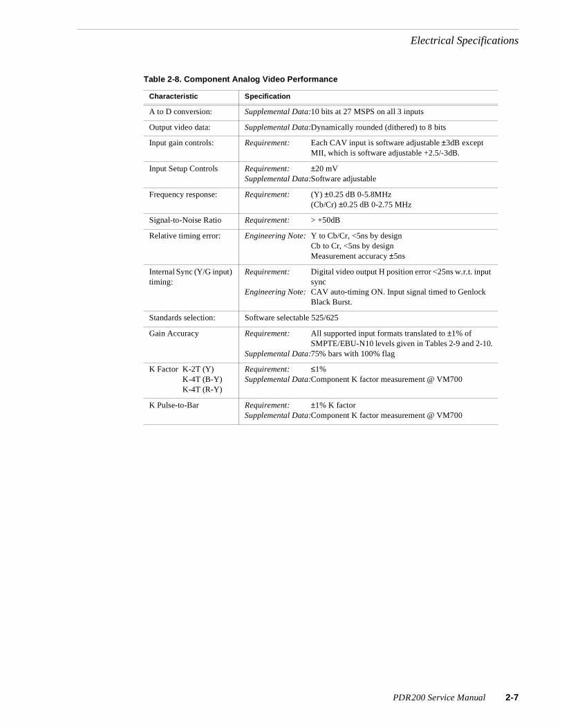
Table 2-8. Component Analog Video Performance
Characteristic Specification
A to D conversion: Supplemental Data:10 bits at 27 MSPS on all 3 inputs
Output video data: Supplemental Data:Dynamically rounded (dithered) to 8 bits
Input gain controls: Requirement: Each CAV input is software adjustable ±3dB except MII, which is software adjustable +2.5/-3dB.
Input Setup Controls Requirement: ±20 mVSupplemental Data:Software adjustable
Frequency response: Requirement: (Y) ±0.25 dB 0-5.8MHz (Cb/Cr) ±0.25 dB 0-2.75 MHz
Signal-to-Noise Ratio Requirement: > +50dB
Relative timing error: Engineering Note: Y to Cb/Cr, <5ns by designCb to Cr, <5ns by designMeasurement accuracy ±5ns
Internal Sync (Y/G input) timing:
Requirement: Digital video output H position error <25ns w.r.t. input sync
Engineering Note: CAV auto-timing ON. Input signal timed to Genlock Black Burst.
Standards selection: Software selectable 525/625
Gain Accuracy Requirement: All supported input formats translated to ±1% of SMPTE/EBU-N10 levels given in Tables 2-9 and 2-10.
Supplemental Data:75% bars with 100% flag
K Factor K-2T (Y)K-4T (B-Y)K-4T (R-Y)
Requirement: ≤1%Supplemental Data:Component K factor measurement @ VM700
K Pulse-to-Bar Requirement: ±1% K factorSupplemental Data:Component K factor measurement @ VM700
PDR200 Service Manual 2-7

Chapter 2 Specifications
2-8
Table 2-9. Format Voltage Level Definitions for CAVmtrxN Colorbar Matrix Test Clip
Format White Yellow Cyan Green Magenta Red Blue Black
SMPTE/EBU-N10 (MII w/o setup)
Y 700 465.2 368 308.2 216.8 157.0 59.9 0
B-Y 0 -262.5 88.6 -173.9 173.9 -88.6 262.5 0
R-Y 0 42.7 -262.5 -219.8 219.8 262.5 -42.7 0
MII
Y 700 482.8 392.9 337.6 253.1 197.7 107.9 52.5
B-Y 0 -242.8 81.9 -160.9 160.9 -81.9 242.8 0
R-Y 0 39.5 -242.8 -203.3 203.3 242.8 -39.5 0
Betacam
Y 714.3 492.6 400.9 344.4 258.2 201.7 110.1 53.6
B-Y 0 -350 118.1 -231.9 231.9 -118.1 350 0
R-Y 0 56.9 -350 -293.1 293.1 350 -56.9 0
Betacam w/o setup
Y 714.3 474.6 375.5 314.5 221.2 160.2 61.1 0
B-Y 0 -378.4 127.7 -250.7 250.7 -127.7 378.4 0
R-Y 0 61.5 -378.4 -316.8 316.8 378.4 -61.5 0
Betacam w/o setup (non-EBU)
Y 700 465.2 368 308.2 216.8 157.0 59.9 0
B-Y 0 -350 118.1 -231. 9 231. 9 -118.1 350 0
R-Y 0 56.9 -350 -293.1 293.1 350 -56.9 0
GBR
G 700 525 525 525 0 0 0 0
B 700 0 525 0 525 0 525 0
R 700 525 0 0 525 525 0 0
PDR200 Service Manual

Electrical Specifications
Table 2-10. Format Voltage Level Definitions for CAVmtrxP Colorbar Matrix Test Clip
Format White Yellow Cyan Green Magenta Red Blue Black
SMPTE/EBU-N10 (MII w/o setup)
Y 700 465.2 368 308.2 216.8 157.0 59.9 0
B-Y 0 -262.5 88.6 -173.9 173.9 -88.6 262.5 0
R-Y 0 42.7 -262.5 -219.8 219.8 262.5 -42.7 0
Betacam w/o setup (non-EBU)
Y 700 465.2 368 308.2 216.8 157.0 59.9 0
B-Y 0 -350 118.1 -231. 9 231. 9 -118.1 350 0
R-Y 0 56.9 -350 -293.1 293.1 350 -56.9 0
GBR
G 700 525 525 525 0 0 0 0
B 700 0 525 0 525 0 525 0
R 700 525 0 0 525 525 0 0
Table 2-11. Reference Genlock
Characteristics Description
Color Field Detection, Based on SCH Phase
Requirement: Correct color framing for signals having an average SCH phase ±40°; Lockup ±10°
Supplemental Data:Once locked to color field, it will stay locked over a range of 0° to ±90°
Burst Frequency Lock Range Requirement: PAL,±10 Hz at subcarrierNTSC, ±20 Hz at subcarrier
Signal Amplitude Lock Range Requirement: Stays locked to +6 dB and -3 dB
Reference Genlock Input Return Loss
Requirement: ≥40 dB to 5 MHz
Table 2-12. Time Code
Characteristics Description
Input Supplemental Data:Longitudinal Time Code. AC coupled, differential input
Input Impedance Supplemental Data:20 kΩ. Switch selectable 600 Ω input.
Input Amplitude Supplemental Data:0.1 V p-p, differential, minimum
Maximum Input Voltage Supplemental Data:2.5 V p-p, differential, maximum
PDR200 Service Manual 2-9

Chapter 2 Specifications
2-10
Table 2-13. Analog Audio Mode
Characteristics Description
Through Gain Requirement: 1 ±1 dBSupplemental Data:Non-mix mode each of
four channels
Frequency Response Requirement: 20 Hz to 20 kHz, with between +0.5 dB, -2 dB maximum deviation from flatness at 48 kHz sample rate
Input Impedance Supplemental Data:600 Ω or 20 kΩ eachchannel throughindependent jumperselection
Input/Output Signal Levels Supplemental Data:Nominal Line Level: 0 dBuNominal Peak Line Level: +9 dBu Digital Clipping: +18 dBu (16-bit quantization)
THD+N at 1020 Hz and 60 Hz Requirement: -70 dBm (0.031%) at +9dBu input
Table 2-14. PDR 200 Power Source
Characteristics Description
Electrical Rating Requirement: 100 -240V, 50/60 Hz, 10A maximum
Supply Type Supplemental Data:Single Phase
Supply Connection Supplemental Data:Detachable cord set
Power Consumption Supplemental Data:<600 VA
Table 2-15. PDR 200 Power Supply Specifications (from Manufacturer)
Characteristics Description
Output voltages Supplemental Data:+5Vdc @ 70 A max.-5Vdc @ 5 A max.+12Vdc1 @ 10 A max.+12Vdc2 @ 6 A max.-12Vdc @ 6A max.
Total wattage Supplemental Data:1000 W maximum
Ripple Supplemental Data:200 mV p-p on + 5V supply50 mV p-p on -5V supply120 mV p-p on +12V supplies225 mV p-p on -12V supply
Regulation Supplemental Data:±3% on +5, -5, and -12 V supplies±5% on +12 V supplies
PDR200 Service Manual

Environmental Criteria
Environmental CriteriaTable 2-16 lists the environmental criteria for the PDR200/PAC208/216.
Mechanical SpecificationsTable 2-17 lists the PDR200 mechanical specifications and Figure 2-1 shows the dimensions as listed in Table 2-17.
Table 2-16. Environmental Criteria
Characteristics Description
Operating Temperature Requirement: 5° to 40°C (+41° to 122°F)
Storage Temperature Requirement: -40° to 65°C (-40° to 149°F)
Operating Altitude Requirement: To 15,000 feet (4572 meters)Supplemental Data:IEC 950 compliant to 2000 meters
Storage Altitude Requirement: To 50,000 feet (15,240 meters)
Mechanical Shock Mil Specification: Mil-T-28800D, Class 6 (Non-Operating Only)
Transportation Requirement: Qualified under NSTA Test Procedure 1A, Category II (24 inch drop)
Equipment Type Supplemental Data:Information Technology
Equipment Class Supplemental Data:Class I
Installation Category Requirement: Category II Local level, appliances, portable equipment, etc.
Pollution Degree Requirement: Level 2 Normally only non-conductive pollution occurs. Occasionally a temporary conductivity caused by condensation must be expected.
Humidity Requirement: Operating 20% - 80%Non-Operating 8% - 90%Transportation 5% - 95%Maximum Wet Bulb Temperature 26°
Supplemental Data:Do not operate with visible moisture on the circuit boards
Table 2-17. PDR 200 Mechanical Specifications
Characteristic Description
Dimensions Requirement: Height: 8.720 inches(22.149 centimeters)Width: 19.000 inches (48.260 centimeters)Depth: 24.150 inches (61.341 centimeters)
Weight Requirement: Net: 70 pounds (31.818kilograms)Shipping: 85 pounds (38.636 kilograms)
PDR200 Service Manual 2-11

Chapter 2 Specifications
2-12
Figure 2-1. PDR200 Dimensions
Table 2-18. PAC208/216 Power Requirements
Characteristic Specification
Voltages/current from power supply +5V, 1.9 A maximum
Typical Total Power 9.0 Watts typical
Maximum Heat Dissipation 32.42 BTU/hour (9.5 watts)
16.750"
18.0"
19.0"
2.72"
26.15"
8.72"7.25"
22.85"
2.0"
1.3"
9675-55
PDR200 Service Manual

Chapter
3 Theory of OperationThis chapter consists of an overview of the PDR200 and brief descriptions of the modules that provide the video CODECs and storage, and the movement of data through the system. The overview of the PDR200 provides a basic understanding of the operation of the Profile Video File System to support module-level servicing. The overview begins with a description of the general flow of information in the PDR200 followed by a look at implementation in hardware.
PDR200 Service Manual 3-1

Chapter 3 Theory of Operation
3-2
System OverviewThe Profile system consists of three major types of functions:
• Input and output of audio and video signals, regardless of encoding standards.
• Video processing, conversion and storage, controlled by the system processor over the EISA bus.
• the User Interface and System I/O, which consists of the system processor, system hard and floppy drives, and the keyboard and mouse, along with the monitoring used to control the entire system.
The optional LAN board provides an Ethernet networking capability and the Fibre Channel option adds file sharing between Profiles.
Figure 3-1 shows the basic 4-channel PDR200 concept.
Figure 3-1. Basic PDR200 Concept
Video in and out, and mix effects travel through the 32 x 32 video router to the Record and Play devices. These devices provide video compression prior to hard disk storage and decompression upon retrieval, both across an Ultra SCSI bus. The increased power of the system lies in its ability to process digital, analog, and embedded audio through a single 16-channel processor.
The Media Hard Disk array provides program material and allows fast transfer of data both within the system from disk to controller and externally from the Fibre Channel interface.
9675-49
VideoIn
Rec/PlayCODECs
Rec/PlayCODECs
32 x 32Router
Processor16 Ch.
InputMx
OutputMx
VideoOut
F/C
MediaHard DisksFx
AESEmbedded
Analog
PDR200 Service Manual

System Overview
Figure 3-2. Profile High Level System Partitioning
An internal Pentium system processor board, which operates on an EISA bus structure, controls the PDR200. The Pentium processor uses the Windows NT operating system. The system processor has its own dedicated hard disk, which stores the Windows NT operating system and the required PDR200 operating and applications software. In addition, a floppy-disk drive, or an optional parallel port CD-ROM, provides for installation or repair of software.
User Interface consists of a keyboard and mouse, and an RS-422 interface. Two additional RS-232 interfaces, which are full communications ports, are supplied for service and diagnostic purposes. A VGA monitor output, to drive a SVGA monitor, provides a Graphic User Interface (GUI).
Media I/O circuitry converts video signals for recording to CCIR-601-2 parallel 8-bit digital format before the video is routed to media disks for storage. The parallel format video is routed through a 32 by 32, 8-bit video routing switch.
9675-50
BufferProtocol
Tx/Rx
PCIBus
EISABus
VideoRouter
CODECsVxDiskI/F
MediaHard DisksCODECs
DiskI/F
F/C
MEDR
SEDR
DSPProcessor
ASPB
Link Ports
2 In 2 Out
PAC
In
Out
Serial I/O
Fx
3 In
F/C Interface1 GB
1 Out
AES
Embedded
Analog
PDR200 Service Manual 3-3

Chapter 3 Theory of Operation
3-4
For recording, JPEG CODEC chips on the Disk Controller (or Controllers) compress the output of the Video Router and the Controller(s) then route the output for storage on the Media Hard Disk array. The Media Hard Disk array uses an Ultra SCSI-2 bus to communicate between the Media Hard Disks and the Disk Controller(s).
For playback, parallel video is decompressed and output to the Video Router. This Video Router directs the parallel digital video signal to either the optional serial Mix Effects circuit board, for more processing before the signal is output, or routes the signal directly to the Video Output section of I/O circuitry.
Video Recording SystemVideo synchronization, through the PDR200, requires a reference, either internal (from the video input) or from an external reference. External genlock is to a reference color black or composite sync. The Reference Genlock outputs a 27 MHz video clock and a Field Reference signal that is used throughout the system. The Reference Genlock also provides the I/O for longitudinal time code.
The CCIR 601-2 signal, output from the Video I/O, is input to the Video Router, which is a 32-by-32 cross-point matrix with 8-bit inputs and outputs. Video Router outputs include the Effects inputs, the EDR inputs, and the Video Output. The Effects circuitry, which provides production switching capability, consists of a 6-input and 2-output configuration, controlled by the system processor.
The Master Enhanced Disk Recorder (MEDR) has two compression/decompression channels. The JPEG compression algorithm is applied one field at a time. Each channel is bidirectional for either encoding or decoding. Video data sampling is synchronized to CCIR-601 Start-of-Active Video (SAV) and only active pixels are compressed and stored. Parallel digitized video is routed over a SCSI-2 fast wide bus to and from the Media Hard Disks. Video, for output, is sent in 8-bit parallel component format to the Video Router.
Software controls the entire recording/playback operation. The system processor, with its independent Hard Disk program storage, controls all operations through the EISA bus. The System Hard Disk contains the Windows NT operating system and application-specific software. The Processor can be controlled through the RS-422 Interface, which provides up to eight individual ports, or with the keyboard and mouse. A VGA Interface is included to drive a SVGA monitor (optional), which provides a color Graphic User Interface.
PDR200 Service Manual
Fibre Channel
Fibre ChannelFibre Channel describes the physical interface connection which provides for the high speed transfer of large amounts of data between Profiles. The Fibre Channel implementation in Profile is an EISA board, which uses the Fibre Channel Arbitrated Loop protocol and an on-board Gigabaud Link Module for the functionality to network numerous Profiles.
Video enters the Fibre Channel board through the rear panel connector and transfers to the EDR(s) over a high speed PCI local bus. The EDR(s) then control transfer of compressed/decompressed digitized video to the SCSI bus and media disks. This transfer is independent of the video CODECs. If the video system requires more bandwidth, the Fibre Channel board slows down to accommodate video.
Audio Recording SystemThe PDR200 supports AES/EBU digital, analog, and embedded audio formats. The Audio Signal Processing Board (ASPB), standard on the Profile, handles 16 channels (8 pairs) of AES/EBU digital audio. The PAC208 adds the capability of 8 channels of analog audio and the PAC216 (which includes an Expansion chassis) brings Profile ability to process analog audio up to 16 channels.
The MEDR moves audio data over the EISA bus and assigns it to available hard disk space over the SCSI bus. The audio signal is not compressed. During play back, audio is recovered from the hard disks and routed back onto the EISA bus. The associated Video Input provides a clock signal to maintain synchronization.
The system processor controls Audio operations in much the same manner that it controls the video record and play operations through the EISA bus.
PDR200 Service Manual 3-5

Chapter 3 Theory of Operation
3-6
Specific BoardsThe specific boards discussed below are:
• Mother Board.
• Reference Genlock.
• Master and Slave Enhanced Disk Recorder.
• PCI Board
• ASPB
• Fibre Channel
• Mix Effects
Mother BoardThis mother board provides three main functions:
• Power supply distribution for the plug in circuit boards.
• The EISA bus for program control for the PDR200.
• The video bus, or router, to move the parallel digital video signal through the Profile.
EISA Bus
The EISA bus interconnects all 17 plug-in circuit board slots. Slot 2 is an ISA-only slot used for the VGA Interface board and Slot 1 is dedicated to the system processor board. The system processor communicates with all plug-in circuit boards, including the ISA board over the EISA bus, which is ISA-compatible.
Video Bus
The Video Bus is not a bus in the usual sense. It provides a common set of connectors into and out of the Video Router. Each connector is physically limited to four inputs and four outputs, with the exception of Slots 6 and 7, which have six inputs and two outputs. Most of the plug-in circuit boards do not require all four inputs and outputs. However, in some cases more than four inputs or outputs may be required. In those cases, inputs or outputs from adjacent slots are borrowed.
Each of the 12 video slots (J05 - J16) has a 96-pin Dual-In-Line (DIN) connector. Each connector has eight, 8-bit router interfaces. In all but slots 6 and 7, these are divided into A through D as inputs from the router, and E through H as outputs to the router. For slots 6 and 7 only, G and H are also used as inputs from the router. Clock signals are also routed to each of the 12 connectors.
The Video Router is a 32-by-32 cross-point video switch. The video data paths, 8-bits wide, conform with CCIR-601. The router connects video data from an I/O to the EDR circuitry and back. Mix Effects provides additional video manipulation.
PDR200 Service Manual

Reference Genlock
Reference GenlockThe GenLock circuit board, a seven inch high EISA-compatible board, performs multiple functions. The board is the source of the internal reference timing signals(27 MHz and Field Reference) that go to other boards in the system. It accepts a color black or composite analog signal as the reference input. If there is no reference input signal, the Genlock circuit free-runs.
In addition to the system timing functions, the board also provides four Longitudinal Time Code (LTC) inputs and four outputs through a DB-25 connector on the rear of the Reference Genlock circuit board.
Reference Genlock board features are:
• Sync Extraction provides horizontal (line) and vertical (field) timing information to the Timing Generator. Its frame sync capability provides good noisy signal handling.
• Chroma Lock, which locks up to the incoming burst, provides the timing generator with the location and duration of the burst. This in turn aids the Timing Generator in locating valid sync.
• Timing Generator provides the reference timing signals. This Generator operates on a clock derived from the color burst on the incoming reference. The Timing Generator obtains vertical and horizontal phasing from the Sync Extraction circuit. The overall timing of the Timing Generator may be offset from the reference input under operator control.
• LTC Reader implemented by a time code reader chip.
• LTC Writer generates an LTC signal under processor control.
• EISA Bus Interface is a 16-bit EISA Slave I/O interface. In addition to mapping the on-board control registers into the slot specific EISA Bus I/O space, this interface also responds with the standard EISA ID Word for software board identification purposes.
PDR200 Service Manual 3-7

Chapter 3 Theory of Operation
3-8
Master Enhanced Disk RecorderThe Master Enhanced Disk Recorder (MEDR) is a 7-inch high EISA compatible board with two real time video compression/decompression channels (JPEG channels). It implements a field-at-a-time JPEG compression/decompression algorithm, two differential Ultra-SCSI interfaces, a Real Time (control) Processor (RTP), a 32-bit EISA Bus Master and Slave interface, and an intra-board 32-bit, 33 MHz Global Peripheral Component Interconnect (GPCI) bus interface.
Connection of the MEDR board to an optional Slave Enhanced Disk Recorder (SEDR) board adds two more JPEG channels and two SCSI channels. Figure 3-3 shows a block diagram of how a set of EDR boards (Master and Slave) and a Fibre Channel board interconnect in a Profile system.
Figure 3-3. Block Diagram - Profile EDRs and Fibre Channel
NTProces-
EISABridge
NTDRAM
NT SystemProcessor
FibreChannel
EISABridge
EISABridge
Local/IBus
DEC21152
JPEG
PCI9060ES
RTPi960H
RAMController& Arbiter
EDODRAM
SRAM
PCI9060ES
Ch. ACO-
Ch. A RAM
Ch. BRAM
Ch. BCO-
SCSI A
SCSI B
Arbiter
Local/IBus
DEC21152
JPEG
Ch. ACO-
Ch. A RAM
Ch. BRAM
Ch. BCO-
SCSI A
SCSI B
Arbiter
LPCI
Bus
LPCI
Bus
RTP
Bus
Master EDR Slave EDR
EISA
CPU
PDR200 Service Manual

Master Enhanced Disk Recorder
Real-Time Processor
The Real Time Processor (RTP) consists of an Intel i960HD and RAM executing at a 33Mhz clock rate. It initiates and monitors the following controls:
• JPEG Channels on all EDR boards.
• SCSI Controllers on all EDR boards.
• Fibre Channel network board.
• EISA Direct Memory Access (DMA) channel which is built into the EISA bus interface for rapidly transfer of data to/from Audio boards.
• Control of other Grass Valley Group supplied EISA boards which implement Profile capabilities, such as Analog and Serial Digital Video boards, Reference Generator boards, etc.
• Communication to the system’s application processor.
GPCI Bus Connection
The GPCI bus is an “over-the-top” bus. That is, boards with a GPCI interface must be placed adjacent to each other in the Profile chassis so that their GPCI edge connectors are mechanically aligned on the top edge of the boards. The PCI board then plugs down onto the boards, thereby electrically connecting the GPCI bus to each of them.
The PCI board consists of a small backplane board which routes PCI bus signals, clocks, interrupts, and arbitration signals from the MEDR board connector. In addition, the PCI board routes a unique PCI Address/Data line to the identification select (IDSEL) line on each of the non-master slots. This allows each non-master slot to be configured using the PCI 2.1 configuration scheme.
RTP to GPCI Interface
The interface from the RTP to the GPCI is through a PCI9060 chip which allows the RTP to perform direct bus master transfers on the GPCI bus. In addition the chip provides two independent bi-directional DMA channels with bi-directional FIFOs supporting burst transfers between RTP memory and memory on other busses connected to the GPCI.
RTP to EISA Interface
The RTP interfaces to the EISA bus through the following:
• A chip that provides a master interface to an internal PCI bus.
• A high-density programmable logic device that connects that bus to the EISA bus and provides the master interface to the EISA bus.
• A bi-directional clocked FIFO memory
• Various bus drivers and transceivers.
The master interface and logic device allow the RTP to do single word (4 byte), half word (2 byte), and single byte transfers to the EISA bus in either the I/O or memory address regions. The logic device also provides an interrupt to the system processor via the EISA IRQ10 interrupt line.
PDR200 Service Manual 3-9

Chapter 3 Theory of Operation
3-10
EISA to EDR Interface
The EISA to EDR bus interface is provided by the EISA_PLDs EISA slave interface. Figure 3-4 shows a block diagram of this interface.
Figure 3-4. Block Diagram - EISA to EDR Interface
LPCI Bus
The local PCI (LPCI) bus provides an internal PCI bus connecting the two SCSI controllers and the JPEG control logic. The LPCI also contains a bridge to the GPCI bus and a interface which allows the EISA bus access to the LPCI.
EISA to LPCI Interface
The EISA to LPCI interface is provided by the EISA_PLD chip, the IB_FIFO chip, and a set of switch parts. When the EISA_PLD decodes the EISA address as being targeted for the LPCI bus, it requests mastership of the LPCI bus. When it is granted LPCI mastership, the set of switches, which electrically connect the IB_Bus to the LPCI bus, are enabled. This interface again allows an EISA master to do single word, half word, and byte accesses to the LPCI bus.
EISA DMA Controller
The EISA DMA controller is implemented in the EISA_PLD, along with the IB_FIFO chip. It provides a high bandwidth connection between the JPEG memory buffers and external EISA slaves, such as the audio boards. The EISA_PLD contains registers which control the DMA engine.
LPLXPLX9060ES
Quick Switches
Addr Xcvrs Output Buffer Input Buffer Data Xcvrs Data Xcvr
EISA_PLD81500a
EISA FIFO74ABT3615
EISA BoardControl 7128
LPCI BusRTP Bus
IB_PCI BusBoard
ControlSignals
EISA Bus
PDR200 Service Manual

Master Enhanced Disk Recorder
GPCI to LPCI Interface
The GPCI bus is interfaced to the LPCI bus through a PCI-PCI bridge chip, which is PCI Local Bus Specification, Revision 2.1 compliant. The chip provides full support for delayed transactions for buffering memory reads and has separate posted write, read data, and delayed transaction queues.The address range and operating parameters for the chip must be configured through its primary PCI interface, which is connected to the GPCI bus. The initialization software for the EDR boards and the Fibre Channel board is contained in the vdrsvc program, which runs on the system processor.
LPCI to Dual JPEG Interface
The LPCI bus interface to two JPEG channels consists of a PCI slave interface with two JPEG DMA Controllers implemented in the PCI_JPEG_PLD and two LSI JPEG CODEC Chip sets, DRAM Controllers, and Block-Raster Controllers. The LPCI - Dual JPEG interface provides a high bandwidth connection between 2 Serial Video Channels, JPEG memory buffers, and SCSI and EISA DMA controllers via the Local PCI Bus.
The JPEG DMA Engine is capable of multiple 8-word transfers, indicated by the count value, between JPEG memory buffers and the LSI JPEG Codecs. DMA control bits indicate whether the transfer is for Record, Playback or Init Table transfers. Upon completion or upon encountering an error, the JPEG DMA engines send an interrupt to the RTP.
LPCI to SCSI Interfaces
The EDR boards provide two 16-bit differential SCSI interfaces which are capable of supporting SCSI-1, SCSI-2, and Fast-20 SCSI standards.
With the Fast-20 extension, the EDR’s SCSI bus bandwidth increases to a maximum of 40 MBytes/second when Fast-20 compatible disks are used. The on-board SCSI terminators, which software can enable, means that external SCSI terminators do not have to be used when the Profile is configured with only internal disks or when a Profile is configured with only external disks. The SCSI termination power for external terminations at the other end of the SCSI bus is from the +5V supply.
Video Bus Interface
The two Video bus interfaces connect the EDR JPEG Controllers to the Profile motherboard CCIR 601 serial video crosspoint router. This is through a 96-pin DIN connector in front of the EISA connector on the motherboard.
PCI Bus Arbitration
Arbitration for the three PCI buses on the EDR, the IB_Bus, the LPCI bus, and the GPCI bus are all handled by the arbiter/interrupt control PLD, (ARB_INT_PLD). The arbitration logic is similar for each of the busses and is implemented as a round-robin scheme which gives equal priority to each master on that bus. However, for decreasing the latency for the RTP’s access to JPEG controls during time critical periods, the SCSI chips bus request signals on all LPCI busses are disabled when the vertical and JPEG interrupts are asserted.
PDR200 Service Manual 3-11

Chapter 3 Theory of Operation
3-12
Figure 3-5. Block Diagram - EDR to JPEG Interface
RTP Interrupts
The ARB_INT_PLD also synchronizes and combines the multiple interrupts coming from the GPCI, the LPCI, and the EISA interfaces. These interrupts are then presented to the RTP as a set of seven interrupts plus a non-maskable interrupt (NMI). The seven interrupts that are sent to the RTP are grouped by the ARB_INT_PLD by type.
EDODRAM
Controller(Altera7K ISP)
Block-RasterConverter
(Xilinx)&
64 KBSRAM
LSI64735/45
MotionJPEG
Chip Set
601VideoCross
barEDO DRAM8/16/32 MB
QuickSwitch JPEGChannel 0
Next
Ras, Cas,
/QXD
EDODRAM
Controller(Altera7K ISP)
Block-RasterConverter
(Xilinx)&
64 KBSRAM
LSI64735/45
MotionJPEG
Chip Set
EDO DRAM8/16/32 MB
Next
QuickSwitch
/QXD
PCIDualJPEG
Interface(Altera 8K)
Ad-
Ready
RD [31..0]
Addr.Cmd
Ready
Channel0
Controller
Channel1
Controller
JPEGChannel 1
FIFOStat [..], LC
601VideoCross
bar
JPEGInterrupt)
LocalPCIBus
FIFOStat [..], LC
R<>B Interrupt
Ras, Cas, WE
PDR200 Service Manual

Slave Enhanced Disk Recorder
Clocks
Clock generation for the EDR boards and for other GPCI bus capable boards is done on the master EDR board using a 33.333 Mhz clock oscillator chip and a set of PLL clock chips. The PLL clock chips provide multiple clock outputs that are phase locked to the oscillator frequency. In addition the PLL chips provide a 2x version of the clock which is used by the RTP and the JPEG memory controllers.
One of two PLL chips on the master EDR provides local clocks which are distributed to on-board logic. The second PLL chip provides individual clocks which are routed through the GPCI connector to the PCI_IC board. The PCI_IC board then routes a clock line to each of the GPCI slots. For slave EDR boards, this clock is then used by its PLL clock chips to provide phase locked clocks for its on-board logic. This method of clock distribution provides a very low skew between all of the GPCI interface logic resulting in a more robust design.
Slave Enhanced Disk RecorderThe Slave Enhanced Disk Recorder (SEDR) board uses the same circuit board as the MEDR, but is only loaded with the components needed to implement the EISA, LPCI, JPEG, SCSI, and GPCI interfaces. Since board routing is the same, each EDR board generates a Master/Slave signal. Where a pull-up generates the signal on a Master EDR, a pull-down resistor generates it on a Slave EDR. For the MEDR board, this signal is what enables it to handle GPCI interrupts and arbitration.
This same signal is connected to the EISA configuration PLD and is used to present the corresponding Master or Slave EISA ID value when the EISA ID register is accessed. On a SEDR board, the GPCI bus clock through the PLL clock generates the PCI bus clocks.
PCI BoardA Profile configuration with one MEDR board, one SEDR board, and one Fibre Channel board uses a three connector PCI board. This board has one unique connector (labelled MASTER) which must be connected to the MEDR board. The other connectors have identical signal connections, except for the generation of their G_IDSEL signal. To configure the PCI interfaces to components on the boards that connect to the GPCI bus, the GPCI address lines are connected through a resistor to the G_IDSEL signal for a connector.
Note that connectors are always referenced by the MASTER connector on the PCI board. Also note that the PCI board does not route the VCC_NC signals between connectors, but these signals are connected to the VCC plane on each of the boards to provide a good signal impedance characteristic.
PDR200 Service Manual 3-13

Chapter 3 Theory of Operation
3-14
Audio Signal Processing BoardThe Audio Signal Processing Board (ASPB) is a 7-inch high EISA compatible board which occupies a slot in the Profile card cage. Interface to the Profile is through edge board connectors and a DB-80 connector provides AES I/O to the chassis rear panel. The ASPB accepts and simultaneously processes 16 AES inputs and outputs at up to 4 simultaneous clock rates. The ASPB consists of:
• an Audio DSP sub-system of five SHARC 21062 processors
• 8 transmit/receive pairs (16 inputs/16 outputs)
• 32 channel embedded audio I/O processing ports
• a 27 MHz video reference clock control
• On-board memory of up to 256K-by-32 dual-port RAM and 128K-by-32 global SRAM
The functional capability of the ASPB includes:
• Digital audio
• Audio processing and storage
• Clocking and synchronization
• API/Profile protocol extensions
• VdrPanel support
Digital I/O
The ASPB provides the following digital audio support:
- Up to 32 channels AES/EBU from up to four embedded audio sources
- 16 AES inputs
- 16 AES outputs
AES Inputs and Outputs are accessible through the 80-pin rear panel connector.
- Monitor output
- AES external reference input
Audio Processing and Storage
Audio processing and storage characteristics of the ASPB are:
• All audio is internally processed in floating point at 48KHz
• Storage resolution is selectable in either 16- or 20-bits at 48KHz
PDR200 Service Manual

Audio Signal Processing Board
Clocking and Synchronization
The ASPB provides clocking and synchronization as follows:
• AES inputs may be individually clocked in groups of 4 with sample rates from 30 to 50KHz
• Any source can be locked to any video or linear time code via Audio Mapping and Crosspoint control.
• Sample rate conversion, available on all AES inputs, provides uniform storage at 48KHz
• Output clocking is synchronous to any selected reference
• Embedded audio and video source is phase locked to system reference for processing
• AES output phase can be locked to an external reference
API/Profile Protocol Extensions
The ASPB provides the following API/Profile protocol extensions:
• 16 virtual tracks may be freely allocated to allow many different configurations beyond the traditional 4-track recorder/player
• 16 X 16 Mixing (static), including support for track bounce and voice-over
• Automatic click elimination with fade-in and fade-out at clip transitions
• Level setting (static) and Level metering (PPM ballistics with peak and hold)
• Sample-accurate editing
• Clock control with selectable clock input
• Scrubbing up to 3 times playout
VdrPanel Support
ASPB VdrPanel support consists of:
• Static mixing (track assignment/crosspoint)
• Professional metering and static level adjustment
• Automatic click elimination with fade-in and fade-out at clip transitions
• Scrubbing
PDR200 Service Manual 3-15

Chapter 3 Theory of Operation
3-16
Fibre ChannelThe Fibre Channel board is a 7-inch high EISA compatible board which occupies a slot in the Profile card cage. Edge board connectors interface the board to the EISA bus and an “over the top” connector provides the PCI bus interface to the MEDR and SEDR boards. A 9-pin D connector Interfaces the Fibre Channel board to external devices (another Profile or a Video Network hub).
The Fibre Channel board is a networking device which uses the Fibre Channel Arbitrated Loop (FC-AL) protocol. The Fibre Channel board provides an interconnect between two or more PDRs in network mode. A Gigabaud Link Module (GLM) on the board provides a copper interface to the FC-AL as the network media.
Fibre Channel features include:
• On-board microprocessor.
• 100ns machine cycle.
• Single-cycle instruction execution.
• 128KB of 35ns static Program RAM
• Single chip FC controller interface which supports 1062 MBaud Links with eight DMA channels and has full duplex operation. All control, communications, and data transfers are done through this dedicated chip.
• Single chip DMA controller for PCI interface with four bidirectional FIFO registers.
• GLM interface.
• Rear panel red Fibre Active LED.
PDR200 Service Manual

Mix Effects
Mix EffectsThe Mix Effects board is a 7-inch high EISA compatible board that operates on the system’s internal digital component video (CCIR 601). The board contains six video inputs (two used as keys) and two video outputs. All video inputs and outputs are connected to the system video crosspoints via a motherboard DIN connector.
The primary functions of the Mix Effects board combine videos or transitions between videos. The effects may be under control of an EISA bus master (the i960 cpu), on-board pattern generators, or keys. The transitions supported include fades, dissolves, cuts, push-on/push-offs, push-overs, and the standard family of video switcher wipe patterns (horizontal wipes, vertical wipes, diamond wipes, etc.).
The Mix Effects board contains two separate mixers. Each of the two mixers has two source videos, one key video, and one output video. The mixers may be used as two separate two-video one-key mixers, or may be stacked up and used as a single three-video two-key mixer.
Two Mix Effects boards may be installed in a system to provide four separate two-in one-out mixers, or flexible layering of up to five videos.
Note that the Mix Effects board may only be installed in slot 6 or 7. If a Mix Effects board is installed in slot 6, no video output board may be installed in slot 5; if a Mix Effects board is installed in slot 7 no video output board may be installed in slot 8. These restrictions exist because the Mix Effects board shares Video Router connections between slots 6 and 5, and between slots 7 and 8. Other boards such as the Audio Input/Output or the Analog Composite Input can be installed next to the Mix Effects board.
The following summarizes the hardware capabilities of the Mix Effects board.
• Four video and two key inputs (via DIN connector).
• Two video outputs (via DIN connector).
• Processor-controlled mixes (full raster dissolves, etc.).
• Pattern generator-controlled mixes with optional borders of variable color, width, opacity, and edge softness.
• Key-controlled layering (hole-cutter and fill capabilities) based on the luminance data of the incoming key video.
• Key inversion (background/foreground swaps).
• Self-keys (luminance).
• Multiplicative or additive mixing of the videos (additive for when foreground is pre-shaped).
• Replacement of any input video with a processor-selected matte.
• Fades to/from matte (typically black) downstream of the layering.
• Push ON/OFF Effects with optional borders.
• Push OVER effects with optional borders and/or drop shadows.
• Blanking processor at the outputs with ability to blank all vertical interval lines or to pass active portion of lines that may contain VITS or VITC (no ability to pass ancillary data in horizontal blanking).
PDR200 Service Manual 3-17

Chapter 3 Theory of Operation
3-18
• Adjustable delay on all input and output video paths (including keys).
• Adjustable throughput delay to support several system timing configurations. The typical mixer delay shall be one video frame or two video lines.
• EISA address and data FIFOs to allow greater flexibility when writing to the board (with a mode to allow multiple video fields of parameters to be stacked and then performed in sequence at a later time).
• 525 or 625 line video operation.
• Diagnostic capabilities (i.e. self-test).
PDR200 Service Manual

Chapter
4 TroubleshootingThis chapter describes methods of isolating a PDR200 or PAC208/216 fault to a field replaceable unit (FRU), also called replaceable part. FRUs, listed in Chapter 6, are parts which can be replaced in the field usually without much difficulty If you determine that a part must be replaced, refer to “Parts Removal and Replacement” in Chapter 6. This chapter assumes that the equipment was installed properly and operational prior to a malfunction. It also assumes service personnel have a working knowledge of PDR200 operation. The chapter covers the items listed and briefly described below.
Troubleshooting is usually a process of elimination - what isn’t wrong or what is working properly. It involves going from the simplest possibilities, through a series of steps, to the more complex.
Making basic checks - A list of things quickly checked to insure that the system is physically in the correct condition.
Initial fault isolation checks - These checks, also quickly performed, can either be resolved with a minimum of effort or point to appropriate starting possibilities.
- System interfaces.
- Front and rear panel indicators.
Start-up problems - If you shut the system down and then had problems restarting, look at these possibilities.
Examining SCSI bus errors - Information here will help correct or eliminate storage or retrieval problems.
Video problems - System error messages and symptoms will often point to video problems, as shown by examples here of problems and corrective actions
Audio problems - Examples of audio problems and corrective actions.
Networking problems - Ethernet and/or Fibre Channel problems.
Board diagnostics - Board level checks for board-specific problems usually associated with other symptoms, such as video, audio, or networking problems.
Making Basic ChecksAlthough installed and previously operating properly, power cords and signal cables may become loose or inadvertently disconnected. A power switch may also mistakenly be turned Off. Perform the basic checks listed below.
• Check all power cord connections.
• Check all cable connections.
• Insure all power switches (front and rear panel) are On.
• Check all cable connectors for broken or bent pins, replace as necessary
PDR200 Service Manual 4-1

Chapter 4 Troubleshooting
4-2
Initial Fault Isolation ChecksBefore turning power Off, if possible save program material and configurations. Turn power Off, wait a few seconds, and turn power back On. When power is applied to the PDR200, LEDs on the front panel and on some of the boards (visible at the rear panel) turn On briefly. These LEDs, along with observation of the system start-up sequence, provide initial fault isolation at power On.
Note that if the Windows NT operating system is running and you can log into the system processor:
• The EISA data bus is functional.
• The EISA address bus is functional.
• Most, if not all, of the EISA “handshake” lines on the Mother Board are functional.
System Interface ProblemsSystem interface problems are those associated with the mouse, keyboard, monitor, and any RS-422 controller devices connected to the Profile through the RS-422 Breakout Box. See Table 4-1.
PDR200 Service Manual

System Interface Problems
* Must reboot after mouse replacement.
Table 4-1. System Interface Problems
Symptom Possible Cause Corrective Action
System does not respond to mouse. 1. Mouse cable loose/disconnected/bad. Reconnect cable/replace mouse.
2. Dirty or bad mouse. Clean or replace mouse.*
3. Bad mouse/keyboard EMI board cable. Replace cable.
4. Bad mouse/keyboard EMI board. Replace EMI board.
5. Bad Pentium board. Replace Pentium board.
6. Bad Concentrator. Replace Concentrator.
System does not respond to keyboard. 1. Keyboard cable loose/disconnected/bad. Reconnect/replace keyboard cable.
2. Dirty or bad keyboard. Clean or replace keyboard.
3. Bad mouse/keyboard board cable. Replace cable.
4. Bad mouse/keyboard board. Replace board.
5. Bad Pentium board. Replace Pentium board.
6. Bad Concentrator. Replace Concentrator.
Monitor does not come On. 1. Monitor cables loose/disconnected/bad. Reconnect/replace cables.
2. Bad VGA board. Replace VGA board.
3. Bad monitor. Replace monitor.
Status light on the monitor remains orange.
Incorrect or no sync from Profile. Provide correct sync to Profile.
RS-422 controllers do not respond. 1. Cable from RS-422 Board to RS-422 Breakout panel is loose/disconnected/bad.
Reconnect/replace cable.
2. RS-422 Board bad. Replace board.
3. RS-422 Breakout panel bad. Replace RS-422 Breakout panel.
One RS-422 controller does not respond.
1. Breakout panel or device bad. 1. Move device to a known good connector on the panel. If: a. Device still bad, replace device. b. Device good, replace panel.
PDR200 Service Manual 4-3

Chapter 4 Troubleshooting
4-4
Front Panel Indicators and ControlThe indicators on the PDR200 front panel (Figure 4-1) can provide information to aid in troubleshooting the equipment.
Figure 4-1. Front Panel Indicators
Power Indicator
This green LED is normally On when both the rear panel power switch and front panel switch are On. The following describes various LED problems which could occur and what to do about them.
If LED is Off when both the rear panel and front panel power switches are On andother LEDs are Off and equipment is inoperative:
- Insure that source power is available to the rack and equipment.
- Check power cord and connection. Reconnect or replace as necessary.
- Distribution board bad, replace
- Power Supply bad, replace.
If LED is Off when both the rear panel and front panel power switches are On andother LEDs are Off and equipment is operational:
- LED board bad, replace.
- LED board cable bad, replace.
If LED is Off when both the rear panel and front panel power switches are On andother LEDs are On and equipment is operational:
- LED and cable bad, replace.
- LED board bad, replace.
9675-54
Power On DiskActivity
SystemFault
FanFault
OverTemp
PDR200 Service Manual

Front Panel Indicators and Control
Disk Access
These green LEDs flash when the associated disk is being accessed. The following describe various problems which could occur and what to do about them.
If an LED never flashes or never goes Off:
- The associated disk drive is bad. See Profile.log to confirm bad disk drive andreplace.
- LED board bad, replace.
If more than one of these LEDs never flashes or never goes Off:
- LED board bad, replace.
- The associated disk drives are bad. See Profile.log to confirm bad diskdrives and replace.
Refer to the ‘Diagnostics’, page 4-21, for discussion of Profile.log usage and SCSI Errors.
System Fault
This red LED is not used at this time.
Fan Fault
This red LED is normally Off.
If On:
- One or more of the three internal fans defective. To determine which fan(s):
1. Turn Profile power Off.
2. Remove Profile from rack.
3. Remove both top covers.
4. Briefly turn power back On to see which fan is defective.
5. Refer to Removal and Replacement procedures to replace defective fan(s).
- LED board bad, replace.
Over Temp
This red LED is normally Off.
If On:
- Dirty air filter. See ‘Cleaning and Changing the Air Filter’ on page 5-3.
- Obstructed air flow at front or rear of the Profile. Remove obstruction.
Standby/On Switch
If the front panel switch is bad, you will be unable to turn power Off from the switch and once turned Off (using the rear panel switch), you will be unable to turn power back On.
PDR200 Service Manual 4-5
Chapter 4 Troubleshooting
4-6
Rear Panel Indicators and ControlLEDs on some of the boards in the PDR200 can provide information to aid in troubleshooting the equipment. Your system may not have all the boards described below. See ‘Diagnostics’, page 4-21, to run board diagnostics. Note that when the LEDs depends on board initialization by the i960. Boards and their LEDs are:
System LAN - This board, usually in Slot J3, has two LEDs, one green and one amber. The green LED lights when there is an active connection between the board and Ethernet. The amber LED flashes when there is network activity.
If the green LED is Off when it should be On:
- Check the cable connection to Ethernet, reconnect or replace as necessary.
- Replace.
If the green LED is On, but the amber LED does not flash when it should:
- Check the cable connection to Ethernet, reconnect or replace as necessary.
- Replace.
Analog Composite VIDEO IN - The red LED on this board flashes On at power up and should then go Off.
If LED does not flash or remains On:
- Check the Profile.log to ensure the system sees the board and replace boardif it doesn’t.
- Run board diagnostics.
Analog Composite VIDEO OUT - The red LED on this board flashes On at power up and should then go Off.
If LED does not flash or remains On:
- Check the Profile.log to ensure the system sees the board and replace boardif it doesn’t.
- Run board diagnostics.
Analog Component VIDEO IN - The red LED on this board flashes On at power up and should then go Off.
If LED does not flash or remains On:
- Check the Profile.log to ensure the system sees the board and replace boardif it doesn’t.
- Run board diagnostics.
FIBRE CHANNEL - The red LED on this board flashes On at power up and should then go Off.
If LED does not flash or remains On:
- Check the Profile.log to ensure the system sees the board and replace boardif it doesn’t.
- Run board diagnostics.
PDR200 Service Manual

Rear Panel Indicators and Control
DISK RECORDER Master/Slave - The red LEDs on these boards flash On at power up and should then go Off.
If LED does not flash or remains On:
- Check the Profile.log to ensure the system sees the board and replace boardif it doesn’t.
- Run board diagnostics for appropriate board.
If the LED on the Master Enhanced Disk Recorder (MEDR) board remains On:
- The 27 MHz clock from the Reference Generator board may be missing, rundiagnostics for the MEDR and the Reference Genlock boards.
Serial Digital Component VIDEO I/O - The red LED on this board flashes On at power up and should then go Off.
If LED does not flash or remains On:
- Check the Profile.log to ensure the system sees the board and replace boardif it doesn’t.
- Run board diagnostics.
AUDIO I/O Digital AES/EBU - The red LED on this board flashes On at power up and should then go Off.
If LED does not flash or remains On:
- Check the Profile.log to ensure the system sees the board and replace boardif it doesn’t.
- Run board diagnostics.
REFERENCE Analog Video - The red LED on this board flashes On at power up and should then go Off.
If LED does not flash or remains On:
- Check the Profile.log to ensure the system sees the board and replace boardif it doesn’t.
- Run board diagnostics.
NOTE: If the LEDs on all boards remain Off or On, reload CMOS and reboot.
PDR200 Service Manual 4-7

Chapter 4 Troubleshooting
4-8
PAC208/216 Basic TroubleshootingTable 4-2 identifies basic symptoms for the PAC208/216.
Table 4-2. PAC208/216 Basic Troubleshooting
Symptom Possible Cause Corrective Action
LED off, fan is on. LED and cable bad. Replace LED and cable
Fan is off, power LED on. Fan bad. Replace fan.
LED is off, fan is off when switch is on. 1. Power supply bad. Replace power supply.
2. Switch or switch cable bad. Replace switch and cable.
3. Line filter bad. Replace power connector/line filter
4. Power cord bad Replace power cord.
PDR200 Service Manual

Start-up Problems
Start-up ProblemsStart-up problems may be indicated by system messages or symptoms. Representative messages and symptoms are discussed below.
NOTE: If you suspect system registers were changed, at “Press spacebar for last known good configuration” message, press spacebar and follow screen directions.
Message: Hard disk controller failure.
System drive bad, replace
or
VGA Board bad, replace.
Message: Can’t locate OS.
CMOS reset incorrectly or bad system drive.
Reboot. If problem persists, replace system drive.
Message: Hardware failure, contact Grass Valley Group support.
CPU bad, replace.
Symptom: No VdrPanel.
Reset CMOS.
Message: Real time processor failure.
If this message is not replaced in a few seconds by the File system corrupt message (see below), i960 bad, replace MEDR
Message: File system corrupt.
Check the Profile.log, looking at SCSI list for:
(1) Address out of range. (For example, the drive in the A3 location looks likeA.07.00 in the list.)
Bad drive, replace.
or
Bad connector on the SCSI Backplane, replace Backplane.
(2) Drive missing in the list.
Bad drive, replace.
or
If an external drive, check cable to the external device.
(3) Also see ‘SCSI Bus Errors’, page 4-10
PDR200 Service Manual 4-9

Chapter 4 Troubleshooting
4-10
Message: Could not configure. with all items requested
VdrPanel comes up but above message appears.
VdrPanel resources (video CODECs, audio channels, Timecode recorders, etc.) are in use by other applications.
Shut down any unnecessary applications using those resources.
Symptom: No VdrPanel.
Check of Profile.log shows log started but nothing else. Looking at Process Viewer in PDR Debug Tools group shows no processes are running.
CMOS corrupt. Reboot holding 0/INS on the keypad down, reload CMOS (seepage 5-10) and then do a normal reboot.
Symptom: Keyboard LEDs did not flash at power up.
Check cable length, must be 12 feet maximum, replace as necessary.
Check cable and connector. If OK, replace Serial EMI board.
Symptom: NT won’t boot.
CPU bad, replace.
PDR200 Service Manual

SCSI Bus Errors
SCSI Bus ErrorsMost errors related to the SCSI Bus A and, for a 4-channel Profile, SCSI Bus C cause the system to generate a pop-up message informing you of the error. In the following discussion, drives are notated by SCSI addresses such as x.yy.zz where:
x = the bus (for example A.yy.zz = Bus Ayy = disk drive (for example C.03.00 = Bus C, drive 3)zz = the Logical Unit Number used for RAID drive groupings (for internal drives, zz = 00)
The Profile.log file provides a primary source for troubleshooting the SCSI buses.
Profile.log FileAll i960 activity is reported to the Profile.log file which you can view by selecting the Profile.log icon on your desktop. In the log, for a 4-channel Profile, you will see something similar to:
Found 2 SCSI buses.
Looking further, you will see something similar to:
SCSI bus A: x hard disks.SCSI bus B: no devicesSCSI bus C: x hard disks.SCSI bus D: no devices
The x is the number of video disk drives on the bus. This number varies depending on your disk configuration. The notation shown above would appear for a 4-channel Profile. The SCSI bus C notation will not be there for a 2-channel Profile and the number (x) should be the same for both buses in a 4-channel Profile. Further in the log, a notation similar to the following should appear:
Found file system “int:”
The default file system name is “int.”. Scrolling the log, you will find a list of the SCSI drives. See the samples below. Note that there is no x.07.00, which is reserved for the Controller.
Sample SCSI Listings
The following samples show SCSI drive lists in the Profile.log file.
Sample 1: 4-channel Profile, no external drives.
PIL Vendor ID Product ID Rev. Serial Num. Blocks BlkSz
- - - - - - - - - - - - - - - - - - - - - - - - - - - - - - - - - - - - - - - - - - - - - - - - - - - - - - - - - -
A.03.00 SEAGATE ST19171W D309 00202930 2373630 4096A.04.00 SEAGATE ST19171W D309 LA205807 2373630 4096A.05.00 SEAGATE ST19171W D309 LA202576 2373630 4096A.06.00 SEAGATE ST19171W D309 LA205810 2373630 4096C.03.00 SEAGATE ST19171W D309 LA204717 2373630 4096C.04.00 SEAGATE ST19171W D309 LA230340 2373630 4096C.05.00 SEAGATE ST19171W D309 LA206877 2373630 4096C.06.00 SEAGATE ST19171W D309 LA204731 2373630 4096
PDR200 Service Manual 4-11

Chapter 4 Troubleshooting
4-12
Sample 2: 4-channel Profile, one PDX208.
PIL Vendor ID Product ID Rev. Serial Num. Blocks BlkSz
- - - - - - - - - - - - - - - - - - - - - - - - - - - - - - - - - - - - - - - - - - - - - - - - - - - - - - - - - -
A.03.00 SEAGATE ST19171W D309 LA202930 2373630 4096A.04.00 SEAGATE ST19171W D309 LA205807 2373630 4096A.05.00 SEAGATE ST19171W D309 LA202576 2373630 4096A.06.00 SEAGATE ST19171W D309 LA205810 2373630 4096A.08.00 SEAGATE ST19171W D309 LA483654 2373630 4096A.09.00 SEAGATE ST19171W D309 LA524662 2373630 4096A.10.00 SEAGATE ST19171W D309 LA609777 2373630 4096A.11.00 SEAGATE ST19171W D309 LA614757 2373630 4096C.03.00 SEAGATE ST19171W D309 LA204717 2373630 4096C.04.00 SEAGATE ST19171W D309 LA230340 2373630 4096C.05.00 SEAGATE ST19171W D309 LA206877 2373630 4096C.06.00 SEAGATE ST19171W D309 LA204731 2373630 4096C.08.00 SEAGATE ST19171W D309 LA655497 2373630 4096C.09.00 SEAGATE ST19171W D309 LA657764 2373630 4096C.10.00 SEAGATE ST19171W D309 LA660305 2373630 4096C.11.00 SEAGATE ST19171W D309 LA604515 2373630 4096
Sample 3: 4-channel Profile, one PDX208 connected to each bus.
PIL Vendor ID Product ID Rev. Serial Num. Blocks BlkSz
- - - - - - - - - - - - - - - - - - - - - - - - - - - - - - - - - - - - - - - - - - - - - - - - - - - - - - - - - -
A.03.00 SEAGATE ST19171W D309 LA202930 2373630 4096A.04.00 SEAGATE ST19171W D309 LA205807 2373630 4096A.05.00 SEAGATE ST19171W D309 LA202576 2373630 4096A.06.00 SEAGATE ST19171W D309 LA205810 2373630 4096A.08.00 SEAGATE ST19171W D309 LA483654 2373630 4096A.09.00 SEAGATE ST19171W D309 LA524662 2373630 4096A.10.00 SEAGATE ST19171W D309 LA609777 2373630 4096A.11.00 SEAGATE ST19171W D309 LA614757 2373630 4096A.12.00 SEAGATE ST19171W D309 LA483655 2373630 4096A.13.00 SEAGATE ST19171W D309 LA524663 2373630 4096A.14.00 SEAGATE ST19171W D309 LA609778 2373630 4096A.15.00 SEAGATE ST19171W D309 LA614758 2373630 4096C.03.00 SEAGATE ST19171W D309 LA204717 2373630 4096C.04.00 SEAGATE ST19171W D309 LA230340 2373630 4096C.05.00 SEAGATE ST19171W D309 LA206877 2373630 4096C.06.00 SEAGATE ST19171W D309 LA204731 2373630 4096C.08.00 SEAGATE ST19171W D309 LA655497 2373630 4096C.09.00 SEAGATE ST19171W D309 LA657764 2373630 4096C.10.00 SEAGATE ST19171W D309 LA660305 2373630 4096C.11.00 SEAGATE ST19171W D309 LA604515 2373630 4096C.12.00 SEAGATE ST19171W D309 LA483664 2373630 4096C.13.00 SEAGATE ST19171W D309 LA524672 2373630 4096C.14.00 SEAGATE ST19171W D309 LA609787 2373630 4096C.15.00 SEAGATE ST19171W D309 LA614767 2373630 4096
PDR200 Service Manual

Profile.log File
Sample 4: 4-channel Profile, one 20-drive PRS200A RAID connected to each bus.
PIL Vendor ID Product ID Rev. Serial Num. Blocks BlkSz
- - - - - - - - - - - - - - - - - - - - - - - - - - - - - - - - - - - - - - - - - - - - - - - - - - - - - - - - - -
A.08.00 DGC RAID 3 D309 LA483654 2373630 4096A.08.01 DGC RAID 3 D309 LA524662 2373630 4096A.08.02 DGC RAID 3 D309 LA609777 2373630 4096A.08.03 DGC RAID 3 D309 LA609778 2373630 4096C.08.00 DGC RAID 3 D309 LA655497 2373630 4096C.08.01 DGC RAID 3 D309 LA657764 2373630 4096C.08.02 DGC RAID 3 D309 LA660305 2373630 4096C.08.03 DGC RAID 3 D309 LA660306 2373630 4096
With RAID, Profile sees each 5-drive array, or Logical Unit Number (LUN), as one disk. In the above sample, the RAID SCSI Controller is set to 8, the first LUN is set to 00, the second LUN to 01, the third LUN to 02, and the fourth to 03.
Sample 5: 2-channel Profile, 4 internal drives, one PDX208.
PIL Vendor ID Product ID Rev. Serial Num. Blocks BlkSz
- - - - - - - - - - - - - - - - - - - - - - - - - - - - - - - - - - - - - - - - - - - - - - - - - - - - - - - - - -
A.03.00 SEAGATE ST19171W D309 LA202930 2373630 4096A.04.00 SEAGATE ST19171W D309 LA205807 2373630 4096A.05.00 SEAGATE ST19171W D309 LA202576 2373630 4096A.06.00 SEAGATE ST19171W D309 LA205810 2373630 4096A.08.00 SEAGATE ST19171W D309 LA483654 2373630 4096A.09.00 SEAGATE ST19171W D309 LA524662 2373630 4096A.10.00 SEAGATE ST19171W D309 LA609777 2373630 4096A.11.00 SEAGATE ST19171W D309 LA614757 2373630 4096A.12.00 SEAGATE ST19171W D309 LA483655 2373630 4096A.13.00 SEAGATE ST19171W D309 LA524663 2373630 4096A.14.00 SEAGATE ST19171W D309 LA609778 2373630 4096A.15.00 SEAGATE ST19171W D309 LA614758 2373630 4096
PDR200 Service Manual 4-13

Chapter 4 Troubleshooting
4-14
Troubleshooting the SCSI BusProfile provides two ways which work hand in hand to troubleshoot SCSI bus problems: Pop-up system error messages and the Profile.log file.
CAUTION: When troubleshooting the SCSI bus, power down all devices attached to the bus before making changes such as removing a disk drive or disconnecting a cable. Failure to do so could damage the EDR board(s).
For general SCSI bus troubleshooting:
• Check the Profile.log drive list to insure the number of drives reported is correct.
• Check cable connections to any external drive arrays (PDX208, PRS200, etc.).
• Check all external cable connectors, including bus Terminators, for bent or broken pins.
• Insure that Terminators are attached to the last device on each SCSI bus: PDX208, the PRS200, etc.
• Insure external drives, if any, are powered up for 1 - 2 minutes before PDR200 is powered up.
System SCSI Error Messages
The system generates certain pop-up error message boxes to indicate a SCSI bus problem. The following identifies SCSI bus pop-up error messages, describes them, and provides corrective actions.
Message: utilDiskHandler: realloc returned for wrong drive
Message: utilDiskHandler: format returned for wrong drive
Message utilDiskHandler: load microcode returned for wrong drive
These three errors usually result from i960 code failure, replace the MasterEnhanced Disk Recorder board.
Message: SCSI Device Init: failed to start motor on device x.yy.zz
Drive failed to start, replace drive specified as x.yy.zz.
Message: At least one disk has out-of-date firmware and may cause systemhangs/crashes
One or more drives contains firmware that has been superseded by a later release.Use the Disk Utility to update the microcode on any drive with out-of-datefirmware. NOTE: Some changes to drive firmware may not affect systemperformance and you, therefore, may want to delay updating the firmware.Grass Valley Group engineering and product support will notify of criticalchanges.
!
PDR200 Service Manual

Troubleshooting the SCSI Bus
Message: Microcode download to disk x.yy.zz failed
Using the Disk Utility, an attempt to download new firmware to the x.yy.zz drivecould not be accomplished. Insure that the download file specified for the drivetype is correct and re-try. Try rebooting. If error persists, replace drive, checkProfile.log for SCSI related errors during download and notify Grass Valley Group of these messages.
Message: x.yy.zz: Unrecognized disk drive type
The x.yy.zz drive fails to report a known drive type. Check cables and connectors,especially if the drive is in an external chassis, re-connect or replace. If failurepersists, replace drive.
Profile.log SCSI Error Messages
The Profile.log starts each time the i960 is initialized and data is always being appended to the file. Start at the end of the file to read the most recent data and work backwards to the latest time and date entry (i.e., the current log started). Below are examples of SCSI bus error messages which may appear in the Profile.log file.
Message: A.03.00 drNcr720ScsiFullTransact: msgQReceive () timed out!
This error says that SCSI drive A3 is not responding and hung the SCSI buses.Look for the first occurrence of the error since the current log started. Similarentries may then appear after that for every disk on the A bus. Scroll the Log filefor previous SCSI errors. Usually, the first drive error since the log started is thedrive causing the other errors. Power the Profile down, pull the suspected driveand reboot. If error does not reappear, replace the drive, otherwise, replaceMEDR.
Message: C.05.00 drNcr720ScsiHandler: Couldn’t handle 720 non-SCRIPTinterrupt error
Again, another disk drive could be causing this error. Scroll the Log file forprevious drive errors, not necessarily on the same disk. Usually the first driveerror after the current log started is the drive causing the this error. Power theProfile down, pull the suspected drive and reboot. If error does not reappear,replace the drive, otherwise, replace MEDR.
Message: A.04.00 drNcr720ScsiFullTransact: msgQReceive () failed to start motor
The A4 drive is not spinning up. Power down the PDR when it gets warm. If drivethen spins up, schedule backup to replace the drive. If drive doesn’t spin up whenthe PDR is warm, replace drive.
Message: C.08.00 drNcr720HandleNonSIRInterrupt: phase mismatch error -- will reset SCSI bus
Message: A.09.00 drNcr720HandleNonSIRInterrupt: sym720 illegal instruction detected
Both of the above errors are usually caused by cable problems. Swap A and C buscables going to external drives. If the message stays the same, check the cable forbent or broken connector pins, replace as necessary. If the message now showsthe same error, but the SCSI bus address for the device on the swapped cable (e.g.,C:08 becomes A:08), Power the Profile down, pull the suspected drive andreboot. If error does not reappear, replace the drive, otherwise, replace MEDR.Note that SCSI addresses above 6 are external to the PDR200.
PDR200 Service Manual 4-15

Chapter 4 Troubleshooting
4-16
Video ProblemsOnce the SCSI bus has been eliminated as a source of a problem, video problems arise from the video board(s), the video router on the Motherboard, or software. If the causes and solutions given below do not help, run the board diagnostics.
Symptom: No playback
Use the video cross-points in VdrPanel as an excellent troubleshooting aid for video problems. Re-routing video in or out of different JPEG decoders and boards can usually isolate the problem fairly quickly.
If you notice a signal problem coming out of the Profile, you must first determine if the material was recorded that way. Look at the E-E signal. If the output is good and the input is of the correct format, try swapping the JPEG channels between the MEDR and the SEDR. The MEDR processes JPEG 1 and 2 video and the SEDR processes JPEG 3 and 4 video.
To load and play PDR200 internal test clips:
1. From the C:/profile/diag/testclips directory in an MS-DOS window type fromnt
2. At the prompt, enter one of the following:
cavmtrxn.vid (Component Analog Video NTSC test)cavmtrxp.vid (Component Analog Video PAL test)mekey.vid (Mix Effects Key test)ntscmtrx.vid (NTSC Test pattern)palmtrx.vid (PAL Test pattern)
3. Use the VdrPanel to select one of the above and load and play in loop mode through different JPEGs or outputs.
If everything looks good, the problem is most likely a video input board, Mother Board, or the incoming signal itself. Run Board diagnostics to confirm or eliminate the video input board(s) and the Mother Board. If they pass, check the incoming signal.
Symptom: No video or video is not as the expected.
Use VdrPanel to check video crosspoints, correct as necessary.
Check cabling, replace as necessary.
PDR200 Service Manual
Video Problems
Symptom: When playing known good clip, black or bad fields appear.
Check the Profile.log looking for:
XBF (Buffer for X JPEG is full, where X is 0 or 1 for MEDR, or 2 or 3 for SEDR.)
(1) Try stopping a process on another channel.
(2) Try swapping JPEG, if problem persists, replace MEDR or SEDR.
XB2R (Block-to-Raster read errors)
Check the Profile.log for SCSI problems (see “SCSI Problems.”)
Symptom: Record function starts and then stops.
The most common reason for this problem is that the SCSI system is full.
Check the percent of disk space available at the bottom of the VdrPanel. A verylow percentage indicates your clip database is reaching its limit.
Try deleting any unnecessary clips or clips that are the same but havedifferent names. Note that clips and their names must be deleted from theVdrPanel.
Check configuration of VdrPanel in use to ensure assignment of a JPEG resource.
PDR200 Service Manual 4-17

Chapter 4 Troubleshooting
4-18
Audio ProblemsProblems with audio can usually be isolated between the Audio Signal Processing Board (ASPB) and either:
• The AES/EBU XLR216/BNC216 Breakout panel for digital audio, or
• The Profile Audio Chassis (PAC208/216) for analog audio and the Digital Expansion Chassis included with the PAC216, or
• The Serial I/O board for embedded audio.
AES/EBU Digital Audio Problems
Symptom: All audio is missing.
1. Check cable from ASPB to the XLR/BNC Breakout panel, connect, tighten, or replace as necessary.
2. Run ASPB diagnostics, replace ASPB as necessary.
3. Replace Breakout panel.
Symptom: Audio is missing on one channel.
1. Check source cables to the XLR/BNC Breakout panel, connect, tighten, or replace as necessary.
2. Move source cables from good channels to bad channels. If fault follows the cable, replace the cable; if fault remains at the channel, replace the Breakout panel.
3. Run ASPB diagnostics, replace ASPB as necessary.
4. Replace Breakout panel.
Symptom: Audio is intermittent.
1. Check cable to XLR/BNC Breakout panel, replace as necessary.
2. Run ASPB diagnostics, replace as necessary.
3. Replace Breakout panel.
PDR200 Service Manual

Analog Audio Problems
Analog Audio ProblemsIn addition to the descriptions below, ensure that audio crosspoints are correctly assigned. For example SD1 to Bank 1 (channels 1-4), SD2 to other Bank 1 (channels 5-8), etc.
Symptom: All audio is missing.
1. Check cables from ASPB to the PAC208/216 and from the Expansion panel to the PAC208/216, connect, tighten, or replace as necessary.
2. Check source cables.
3. Run ASPB diagnostics, replace ASPB as necessary.
4. Run diagnostics on other audio boards as appropriate, replace as necessary.
5. Replace the PAC208/216 chassis.
Symptom: Audio is missing one channel:
1. Check source cables to the PAC208/216 chassis, connect, tighten, or replace as necessary.
2. Move source cables from good channels to bad channels. If fault follows the cable, replace the cable; if fault remains at the channel;
a. If the bad channel is one of the analog channels 9-16, replace the PAC Expansion panel. If fault persists, replace the Daughter Board in thePAC208/216 chassis.
b. If the bad channel is one of the analog channels 1-8, replace the Main Board in the PAC208/216 chassis.
3. Run ASPB diagnostics, replace ASPB as necessary.
4. Run diagnostics on other audio boards as appropriate, replace as necessary.
Symptom: Audio is intermittent.
1. Check cables from Expansion panel to the PAC208/216 and from the ASPB to thePAC208/216 chassis.
2. Run ASPB diagnostics, replace as necessary.
3. Replace the PAC208/216 chassis.
Embedded Audio ProblemsFor problems with embedded audio:
1. Check cables, connect or replace as necessary.
2. Run ASPB board diagnostics, replace as necessary.
3. Run Serial I/O board diagnostics, replace as necessary.
PDR200 Service Manual 4-19
Chapter 4 Troubleshooting
4-20
Networking ProblemsIndications of a network problem show up as an inability to:
• Move material from or to another Profile on the net.
• Access Ethernet.
To troubleshoot networking problems:
1. Check cables to the LAN Board and the Fibre Channel Board, connect, tighten, replace as necessary.
2. If you have added or deleted Profiles and your system was operating correctly prior to that, check both the Ethernet configuration and the Fibre Channel configuration. Correct as necessary.
3. Type fcconfig to verify that the Fibre Channel hardware address is set.
4. Ensure that each Profile has a unique IP name and that the Ethernet TCP/IP names are the same as the Fibre Channel names with a _fc0 suffix. For example, an Ethernet TCP/IP name Profile1 must have a Fibre Channel TCP/IP name of Profile1_fc0. Check file c:\WinNT\sys32\drivers\etc\Host for this information.
5. If a Profile has been added, ensure that there are no name and IP address conflicts. Type ping <IP name> to check for conflicts.
6. If OK, type fcping -all to test for Fibre Channel connectivity.
If you have a problem with steps 4 or 5, try:
a. Deinstalling TCP/IP.
b. Reboot.
c. Reinstalling TCP/IP.
d. Reboot.
e. Repeat step 4 or 5.
6. Run the Fibre Channel Board diagnostics, replace as necessary.
7. Replace the LAN Board.
PDR200 Service Manual

Diagnostics
DiagnosticsThe PDR200 diagnostics program, resident on the system hard drive, providesboard-level fault isolation. This program consists of an application written for the Windows NT operating system and the i960 computer machine code. The diagnostics program is intended to isolate problems to the board level including the Mother Board.
The Windows NT operating system, which runs on the system processor, provides the graphic user interface (GUI) and data logging, configuration, and date/time information.
The i960 executed files perform the diagnostics and exerciser tests, make pass/fail decisions, count the errors for the current test, print pass/fail error messages in the i960 window, and report pass/fail information (in ASCII format) to the Profile.log through the system processor. The system processor appends the date and time to the report, and creates or updates the appropriate log files.
Starting the Diagnostics ProgramTo start the diagnostics program, open the PDR Debug Tools group and select the PDR Diagnostics icon as shown in Figure 4-2.
Figure 4-2. Starting The PDR Diagnostics Program
As the PDR Diagnostics start up, the cursor appears momentarily as an hourglass, indicating that the program is checking the board configuration of the PDR200. (The diagnostics program can only identify boards that have an EISA identification). The Diagnostics window then appears (see Figure 4-3 for an example).
If this windows appears, the diagnostics program is running and some (if not all) of the diagnostic program is intact. If the board configuration fails to appear on the left, bad or missing software is probably the cause. Note that when the Diagnostics window opens, the following message may appear:
Checking availability of VDR Services. Please wait. . .
After approximately one minute, this message goes away and you may proceed. If it does not go away, restart the Profile and the Diagnostics program. If the message still does not go away, contact Grass Valley Group Product Support (see front of manual).
PDR200 Service Manual 4-21

Chapter 4 Troubleshooting
4-22
Figure 4-3. Diagnostics Window
Diagnostics Window Menu BarMenu items on the Diagnostics Window menu bar, shown in Figure 4-4, are described below. Selection of an item on the menu bar causes a pop-down menu to appear.
Figure 4-4. Diagnostics Window Menu Bar
File - The File menu consists of a single item - Exit. Selection of this item terminates the diagnostics and closes the Diagnostics Window (the same as selecting Quit at the bottom of the Board Configuration Panel).
Tests - The Tests menu consists of a single item - Test All Boards. Selection of this item executes all automatic tests on all installed boards. (Automatic tests are those which do not require any action by the user. For example, any scope test or test requiring attachment of a loopback connector would not be an automatic test.) See ‘Executing Test All Boards’, page 4-25, for additional details about this item.
Board Configuration Panel
Board Tests and Selection Panel
Board Test Results Panel
PDR200 Service Manual

Diagnostics Window Menu Bar
View - The View menu consists of the following two items:
Logs - This item allows you to select a log file to view results of board tests.The selected log appears in the lower right panel of the Diagnostics window.
Configuration - This item brings the configuration list into the lower right panel. Figure 4-5 shows an example.
Figure 4-5. Board Configuration List
By slot number, the configuration lists all installed boards and identifies:
- Board manufacturer, if possible. Note in the example that Slot J2 is an ISAslot which cannot be identified by the software.
- Board ID number
- The latest revision number of each identified board.
PDR200 Service Manual 4-23

Chapter 4 Troubleshooting
4-24
Options - The Options menu consists of a single item - Preferences. Selection of this item brings up the Preferences dialog box shown in Figure 4-6. This dialog box allows you to select certain parameters which apply to all diagnostic tests when executed. The box consists of a Run panel and an On Error panel.
Figure 4-6. Preferences Dialog Box
The Run panel allows you to specify either how many times to run any selected test from 0 (indefinitely) up to 99,999 times, or how long to run any selected test from 0 hours, 0 minutes (00:00) up to 99 hours, 59 minutes (99:59). Default is run 1 time. To specify how many times or length of time mode, select the appropriate option on the left.
The On Error panel allows you to specify what the program should do when a selected diagnostic test fails. Modes and their descriptions are:
Stop - Cease executing any more tests at the completion of the test in progress.This is the default setting.
Continue - Go on to the next test.
Loop - Execute the failed test the number of times entered in the box to the right.The Loop value can be from 0 (indefinitely) to 99,999 times.
When satisfied, select OK to accept the parameters and close the Preferences dialog box.
NOTE: Changes to these parameters are valid only during the current session. Starting a new session sets the parameters to their default values.
PDR200 Service Manual

Diagnostics Window Layout
Diagnostics Window LayoutThe Diagnostics Window consists of three panels: one along the left side, one at the upper right, and one at the lower right. See Figure 4-3
Board Configuration
The panel along the left side identifies the board configuration of the Profile. Facing the front of the PDR200, the board slots are numbered from left to right, J1 through J17. A double hyphen (- -) in place of a board name indicates an empty slot. If the board is not recognized by the diagnostics software, UNKNOWN BOARD TYPE appears in the push-button. Slot J17 normally contains an RS-422 Interface board, which is an ISA board not detectable with the EISA configuration check. Therefore, slot J17 is labeled RS-422, if installed.
A Quit button is at the bottom of this panel. The button allows you to terminate diagnostic testing at the completion of the test in progress.
Board Tests and Selection
The panel on the upper right is the board tests identification and selection panel. The top of this panel initially reads No Board Selected. When a board is selected, the slot number of the board and the name of the board appears at the top and test selection push-buttons for that board appear in the panel.
Board Tests Results
The panel on the lower right will contain diagnostic reports generated by the system processor when board tests are selected for execution. Note that i960 diagnostic report window hides much of this panel during and after test execution. See ‘Executing Test All Boards’, page 4-25, for additional information about this panel.
Running Board DiagnosticsThere are two ways of running board diagnostics. One way tests all installed EISA boards and the Motherboard in succession without user interaction. The second way allows you to select specific boards for testing one at a time.
Note that diagnostics for the Audio Signal Processing Board (ASPB) include basic testing of the Profile Audio Chassis, if connected.
PDR200 Service Manual 4-25

Chapter 4 Troubleshooting
4-26
Executing Test All BoardsIf a board problem cannot be isolated to one board (or as a confidence check after repairs), select Test All Boards from the Tests menu on the Diagnostics window menu bar. Note that this selection takes about 15 minutes to complete, depending on your Profile board configuration. The execution process begins immediately.
Selection of Test All Boards (or any board diagnostic test), initializes the system as follows:
• A DRSTART window opens to indicate that the diagnostic program is loading.
• At the completion of loading the diagnostics program, a GDB960 window takes the place of the DRSTART window. This is the i960 information and report window. See Figure 4-7 for an example.
Figure 4-7. GDB960 (i960) Window
Just as the configuration panel on the left varies with your configuration, information and reporting in the GDB960 window varies with the test selected. Typically this window initially shows test conditions used to execute the selected test. While the information is being entered in this window, the panels of the Diagnostics window are dimmed. When test conditions entries complete, the program begins testing all installed EISA boards, one at a time.
PDR200 Service Manual

Executing Test All Boards
• The Test Status box opens on top of the panel on the left. See Figure 4-8 for an example.
Figure 4-8. Test Status Box
This box consists of:
- Test: Identifies the test in progress.
- Pass: How many times the test has been run, cannot exceed number in the Of: field, which was set in Preferences box.
- Time: How long the test in progress has been running.
- Warnings: The number of times, if any, a test parameter was exceeded.
- Errors: The number of errors, if any, which occurred during testing. (This depends on options selected in the Preferences box.)
- Status: Running appears here during test execution. If no errors were detected, PASSED appears and if an error occurred, FAILED appears.
- Cancel button which, if selected, terminates all testing at the completion of testing the current board. (If testing an individual board, testing terminates at the completion of the test in progress.)
• Simultaneously with the above, the lower right system report and information panel, partially hidden by the GDB960 window, initially shows the loading of the diagnostics program ID data. As a test begins, both the lower right panel of the Diagnostics window and the GDB960 window show the test being run and the test results (i.e., Passed or Failed).
PDR200 Service Manual 4-27

Chapter 4 Troubleshooting
4-28
Executing Individual Board TestsAfter execution of the Test All Boards diagnostics, you may want to execute diagnostic tests on an individual board to confirm that the board is bad. To execute diagnostic tests on an individual board, select the appropriate button from the board configuration in the panel on the left. When an individual board has been selected, the system goes through the same initialization as it does for Test All Boards, except it is board specific. At the completion of initialization:
• The Board Configuration Panel is dimmed or disabled.
• The top right panel contains buttons for the individual tests available for the selected board.
• The message Select a test from the button panel above. appears on the Test Results Panel.
• The message Select item from <board selected> button panel. appears on the second to last line on the GDB960 window.
• READY appears on the last line of the GDB960 window.
Individual test buttons vary according to the board selected. Figure 4-9 is an example of what the screen looks like when the Master EDR (Rev 0) board was selected.
Figure 4-9. Diagnostics Window with the i960 Report Window
PDR200 Service Manual

Executing Individual Board Tests
Board diagnostics is a very comprehensive set of multi-level tests. The majority of these tests are for factory-level purposes. to isolation a fault to board level, only two buttons in the Board Tests and Selection Panel ar e used, All Tests and << Done.
Executing All (Board) Tests
Select All Tests to execute all tests of the selected board which do not require user interaction (that is, they are automatic). The results of the tests and the slot number appear on the GDB960 window, as well on the Tests Results Panel of the Diagnostics window. The system processor then appends the date and time and creates a log file (named alltests.log).
The number of the slot tested is also recorded in the log file, to identify the board if two or more boards of the same type are installed. Only the results of the most recent test for that board type are saved, even though there may be two or more boards of the same type in the Profile. When two boards of different types are tested, the system retains the log files for both boards.
The system organizes log files into directories by slot number and slot directories reside in the Logs directory. For example, at the completion of All Tests selection for the MEDR board in Slot J10, the alltests.log file appears in the directory c:\profile\diag\Logs\Slot_J10.
During execution of All Tests, the program dims out the Board Tests and Selection Panel. When testing completes, the upper right panel returns to normal while the left panel remains grayed out. If a board fails any test, replace that board.
Note that if testing of the ASPB indicates a problem with the PAC, check cables and connectors, re-connect or replace as necessary. If problem persists, check the log for previous ASPB errors and replace the ASPB or PAC as necessary.
Done
Select << Done to remove the diagnostics for the selected board and:
• Clear the Board Tests and Selection Panel.
• Return the Board Configuration Panel to normal for additional testing.
• Remove the Test Status box.
• Clear the Test Results Panel.
• Close the GDB960 window.
PDR200 Service Manual 4-29

Chapter 4 Troubleshooting
4-30
Diagnostic Test ExceptionsThere are certain boards on which you will not be able to run diagnostics. They are listed below. In addition, the RS-422 board requires user interaction and is handled differently.
• Pentium CPU board.
• VGA board.
• Ethernet LAN board.
• SCSI board.
• RS-422 board.
Pentium Board (Slot J1)
The Pentium CPU cannot be specifically tested, However, selecting the board provides information as to certain system hardware and the board’s status. SeeFigure 4-10 for an example.
Figure 4-10. Pentium Board Status
The Installed Hardware panel provides basic hardware information which the system sees. If there are any blanks or None where there should be an entry, you will have to perform other troubleshooting or replace the Pentium board. For example, if no entry appears opposite Floppy Disk A, investigate whether the Floppy Disk is mounted, accessible, etc. With no Floppy Disk problems, replace the Pentium board.
The System Status panel shows the status of essential system requirements. For any error in this area, replace the Pentium board.
PDR200 Service Manual

Diagnostic Test Exceptions
VGA Board (Slot J2)
The VGA board resides in a non-EISA slot and, therefore, cannot be recognized by the diagnostics. Selecting this board brings up the message shown in Figure 4-11.
Figure 4-11. VGA Slot Message
Ethernet LAN Board (Slot J3)
The LAN board currently does not have diagnostic testing. Selecting the board brings up the message shown in Figure 4-12.
Figure 4-12. LAN and SCSI Boards Message
SCSI Board (Slot J4)
The SCSI board currently does not have diagnostic testing. Selecting the board brings up the same message shown in Figure 4-12.
PDR200 Service Manual 4-31

Chapter 4 Troubleshooting
4-32
RS-422 Board Tests (Slot J17)
Unlike other diagnostic tests, the RS-422 board tests use an MS-DOS-based program that does not use the i960 or an executable file for the i960.
To start the tests, select RS422, if installed. An MS-DOS window appears with instructions for making loopback connections and for setting switches on the breakout box. See Figure 4-13. If you wish to continue the test, type Y (upper or lower case) and then press Enter: to cancel the test, type N and then press Enter.
Figure 4-13. RS-422 Diagnostics Menu
When the tests are complete, the program asks you to press Enter to quit. Pass/fail information is returned for logging, the date and time are appended to the test results, and the results are logged.
Empty Slots
If you inadvertently select a blank board slot, the message shown in Figure 4-14 appears.
Figure 4-14. Empty Slot Message
PDR200 Service Manual

Chapter
5 MaintenanceThis chapter consists of:
• Maintenance information.
• Software upgrade information.
• Updating the Emergency Repair Disk.
• Windows NT repair.
• Reloading CMOS.
Tools RequiredPerforming the procedures in this chapter require a Torx tool with T10 and T15 magnetic tips.
PDR200 Service Manual 5-1

Chapter 5 Maintenance
Preventive MaintenancePreventive maintenance consists of cleaning and visual inspection. The preventive maintenance schedule established for the equipment should be based on the environment in which it is operated and the amount of use. Under average conditions, scheduled preventive maintenance should be performed every 2000 hours of operation.
CleaningThe equipment should be cleaned often enough to prevent dust or dirt from accumulating. Dirt acts as a thermal insulating blanket that prevents effective heat dissipation, and can provide high-resistance electrical leakage paths between conductors or components in a humid environment.
Exterior
Clean the dust from the outside by wiping with a soft cloth or small brush. A brush is especially useful to remove dust from around the connectors. Hardened dirt may be removed with a cloth dampened in water that contains 50% Isopropyl alcohol. Abrasive cleaners should not be used.
Interior
Clean the interior by loosening the accumulated dust with a dry, soft brush. Once the dirt is loosened, remove it with low-pressure air (high-velocity air can damage some parts). Hardened dirt or grease may be removed with a cotton-tipped applicator dampened with a solution of 50% Isopropyl alcohol and water. Abrasive cleaners should not be used. If the circuit board assemblies must be removed for cleaning, follow the removal/replacement instructions.
After cleaning, allow the interior to thoroughly dry before applying power to the unit.
CAUTION: Do not allow water to get inside any enclosed assembly or component. Do not clean any plastic materials with organic cleaning solvents, such as benzene, toluene, xylene, acetone, or similar compounds, because they may damage the plastic.
Visual InspectionAfter cleaning, carefully check the equipment for defective connections, damaged parts, and improperly seated connectors and plug in components. If heat-damaged parts are discovered, to prevent additional damage, determine the cause of overheating before replacing the damaged part.
!
5-2 PDR200 Service Manual

Cleaning or Replacing Air Filters
Cleaning or Replacing Air FiltersIn order to operate in all environmental conditions, the PDR200 and PAC208/216 require clean, unrestricted internal air flow. For the PDR200, three internal fans pull air into the chassis through the front panel and around the disk drive caddy. The air then flows across the boards and is exhausted out of the chassis through the rear panel. For the PAC208/216, a single internal fan pulls air into the chassis through the front panel. Air flows across the boards and power supply and is exhausted out through the rear panel and right side panel.
Air filtration is provided by filters attached to the inside of the front panel. The PDR200 contains two filters and the PAC208/216 one. Check these air filters frequently for dust and grime buildup. Much of the buildup of dust and lint can be removed through the front panel with a portable vacuum cleaner. However, frequent cleaning ensures adequate, clean cooling air to the equipment.
Removing the PDR200 FiltersRemoval of the air filters for cleaning or replacement requires removal of the front panel, but does not require removal of the PDR200 from the rack. Front panel removal requires a Torx tool with T15 and T10 tips. To remove the PDR200 air filters:
1. Turn PDR200 power Off and disconnect the power cord.
2. Loosen the front panel screw which secures the PDR200 in the rack. See Figure 5-1.
Figure 5-1. PDR200 Rack Retaining Screw
3. Slide the PDR200 forward enough to access the screws which secure both the handles to the front panel and the front panel to the chassis. Be careful not to exert stress on any cables connected to the rear panel.
9675-11
PDR200 Service Manual 5-3

Chapter 5 Maintenance
CAUTION: Support the front panel during removal from the chassis so as to not place stress on the LED cable.
4. Use the Torx tool with the T15 tip to remove the two screws on each side which secure the handles and front panel to the chassis. See Figure 5-2.
Figure 5-2. Front Panel, Handles, and Gasket Removal
5. Carefully move the front panel away from the chassis.
6. Disconnect the LED cable connector from the chassis to the front panel and place the front panel face down on a flat level surface.
7. Use the Torx tool with the T10 tip to remove the two screws holding the metal gasket to the front panel.
9675-19
31
2 DisconnectLED cable
!
5-4 PDR200 Service Manual

Replacing the PDR200 Filters
8. Disconnect the power LED cable from the front panel. See Figure 5-3.
Figure 5-3. Power LED Cable and Filter Removal
9. Remove the air filter strip along the bottom of the panel and the one across the face of the panel.
Replacing the PDR200 FiltersOnce the filters have been cleaned, reinstall the filters and front panel as follows:
1. Attach the air filters to the velcro fasteners in the front panel (Figure 5-3).
1. Reconnect the power LED cable.
2. Use the Torx tool with the T10 tip to reattach the metal gasket with the two screws previously removed (Figure 5-2).
3. While supporting the front panel, reconnect the LED cable from the front panel to the chassis.
4. Use the Torx tool with the T15 tip to reattach the front panel and handles with the screws that secure the handles and front panel to the chassis.
5. Slide the PDR200 all the way back into the rack and tighten the retaining thumb screw (Figure 5-1).
9675-22
1 DisconnectLED cable
2 Separate air filters(2) fromvelcro fasteners and remove.
PDR200 Service Manual 5-5

Chapter 5 Maintenance
Removing the PAC208/216 FilterRemoval of the air filter for cleaning or replacement does not require removal of the PAC208/216 from the rack or the use of any tools. To remove the PAC208/216 air filter:
1. Grasp the front panel bezel at both sides and snap loose from the chassis.
2. Place face down and remove the filter from the mounting posts on the inside of the bezel (Figure 5-4).
Figure 5-4. PAC208/216 Filter Removal
1
2
Fan Filter
9675-40
5-6 PDR200 Service Manual

Replacing the PAC208/216 Filter
Replacing the PAC208/216 FilterOnce the filter has been cleaned, reinstall the filter and front panel as follows:
1. Place the front panel bezel face down and attach the filter to the mounting posts on the inside of the bezel (Figure 5-4).
2. Position the front panel bezel at the chassis so that the bezel mounting posts align with the holes in the chassis and snap the front panel bezel onto the chassis.
Cleaning the FiltersThe air filters supplied with this PDR200 and PAC208/216 can easily be cleaned and used again. Wash them in warm water and mild detergent. Make sure the filters are dry before reinstalling them and powering up the PDR200 or PAC208/216.
Additional Air FiltersAdditional air filters can be ordered directly from Grass Valley Group. See the Replaceable Parts Lists in Chapter 6 for the part numbers for the air filters.
PDR200 Service Manual 5-7

Chapter 5 Maintenance
Software Upgrades and RepairsGrass Valley Group provides the following software with your PDR200:
• Windows NT Kit on CD-ROM.
• Profile System Software Kit, which includes an Emergency Repair Disk, on floppy diskettes. The kit also includes Profile Release Notes which contain the latest information which may not appear in the Profile Family User Manual.
• Other diskettes which may contain specific software, such as for ToolBox and OEM applications.
UpgradesProfile software upgrades, similar to the Profile System Software Kit, consist of floppy diskettes and Release Notes. The Release Notes explain the upgrade and tell you how to install the software.
NOTE: To maintain its usability, you must update the Emergency Repair Disk every time you update or make a change to the system software.
Updating an Emergency Repair DiskWhenever you upgrade your system software, you must upgrade the Emergency Repair Disk shipped with your Profile. Using the Emergency Repair Disk minimizes the chance that you will need to completely re-load the software for a minor problem.
NOTE: The Emergency Repair Disk is PDR 200 unit-specific. (The disk shipped with your PDR200, is the only one that will work with that PDR 200). Make sure that the Emergency Repair Disk is clearly marked with its PDR200 serial number and keep track of this disk.
1. From the Start menu, choose the Run command.
2. Enter rdisk /s in the Run dialog box.
3. Select the Update Repair Disk button.
4. Insert the Emergency Repair floppy disk in the A drive and select OK. The utility then formats the disk and loads all of the information from the registry.
5. When the operation is complete, select the Exit button to leave the Repair Disk Utility.
6. Remove the Emergency Repair Disk from the Profile and store in a safe location.
5-8 PDR200 Service Manual

Repairing Corrupt Windows NT Software
Repairing Corrupt Windows NT SoftwareRepairing corrupt Windows NT software requires use of the Emergency Repair Disk. (Note that the procedure below will not correct severe problems with the Windows NT software, such as the mistaken deletion of files. See the Windows NT manual for additional information.)
NOTE: The Emergency Repair Disk is PDR 200 unit-specific. (The disk shipped with your PDR200, is the only one that will work with that PDR 200). Make sure that the Emergency Repair Disk is clearly marked with its PDR200 serial number and keep track of this disk.
Repairing the Window NT operating system requires a copy of Windows NT. To repair Windows NT:
1. Verify that you have the Emergency Repair Disk for this PDR200.
2. Insert the Windows NT Setup Disk (Disk 1).
3. Restart the PDR 200.
4. When the Windows NT setup screen appears, press R (for repair). Note that the system may ask you to insert Windows NT Disk 2 and Disk 3.
5. When prompted, insert the Emergency Repair Disk.
6. The Emergency Repair Disk performs the following:
a. Runs chkdks.exe.
b. Verifies each file in the installation and replaces any that are missing or corrupt.
c. Replaces the System, Security, and Security Accounts Manager hives in the registry.
d. Reinstalls the Boot Loader (the boot sector, boot.ini, etc.).
7. Reboot.
PDR200 Service Manual 5-9

Chapter 5 Maintenance
Reloading the CMOS ChipCorrupt data on the CMOS chip on the Pentium CPU Board can prevent the Vdrpanel and other processes from running. Reloading the CMOS corrects these types of problems.
To reload the CMOS chip go to the PDR Debug group and select Load CMOS.
5-10 PDR200 Service Manual

Chapter
6 Parts Removal and ReplacementThis chapter identifies the replaceable parts in the PDR200 and provides the procedures to remove and replace them. The chapter also identifies the tools required to perform the removal and replacement procedures.
NOTE: Do not discard any hardware unless specifically instructed to do so.
WARNING: To avoid serious injury from high currents, insure that the power cord is disconnected prior to performing any removal and replacement procedure.
Tools RequiredThe tools required to perform the removal and replacement procedures are:
• Torx tool with T10 and T15 magnetic tips.
• Medium Phillips screwdriver.
• Small Phillips screwdriver.
• 11/32-inch and 3/16-inch nutdrivers.
• Small wire cutters.
!
PDR200 Service Manual 6-1

Chapter 6 Parts Removal and Replacement
PDR200 Replaceable Parts ListTable 6-1 lists all the replaceable parts (also called Field Replaceable Units or FRUs) for the PDR200, except internal cables. Figure 6-1 and Figure 6-2, keyed to Table 6-1, show the locations of these parts. Table 6-2 lists the replaceable cables and Figure 6-3 shows their locations. Note that you may not have all the boards or all eight media hard disk drives, or the PAC. Also note that board locations may vary.
Table 6-1. PDR200 Replaceable Parts List
Key Description Part Number
1 Front Bezel, PDR200 333-4229-XX
2 Air Filter 378-0425-XX
3 Air Filter 378-0428-XX
4 Disk Drive Caddie 407-4478-XX
5 Video Disk Drive, 9GB, Single-ended 119-5638-XX
6 Disk Tray 386-6759-XX
7 LED Board, PDR200 671-4033-XX
8 LED EMI Board 671-3320-XX
9 SCSI Backplane, 2X4 671-4155-XX
10 Fan, Tubeaxial, 12V 119-4827-XX
11 Fan Board 671-3336-XX
12 Disk Drive, Floppy 119-5677-XX
13 Distribution Board 671-4047-XX
14 System Drive, 840 MB NT4.0 050-3262-XX
15 Fan, DC, safety Controlled 119-4984-XX
16 RS-422 Board 118-9155-XX
17 4 LTC Ref. Genlock Board 671-3706-XX
18 Analog Composite Input Board 671-3081-XX
19 Decoder Board 671-3083-XX
20 CAV Input Board 671-3727-XX
21 ASPB Board Assembly 672-1463-XX
22 Analog Composite Output Board 671-3149-XX
23 Serial I/O Board 671-3734-XX
24 Enhanced Disk Recorder, Slave 671-3757-XX
25 Enhanced Disk Recorder, Master 671-3795-XX
26 Fibre Channel Board Assembly 671-1462-XX
27 Mix Effect Board 671-3080-XX
28 System SCSI Board 119-5542-XX
29 LAN Ethernet Board 118-9403-XX
6-2 PDR200 Service Manual

PDR200 Replaceable Parts List
* Externally connected parts.
See Interior Cabling for replaceable cables.
30 VGA Card Kit, DTI CEX595 050-3200-XX
31 Pentium CPU Board 118-9239-XX
32 PCI Interconnect Board 671-3794-XX
33 Motherboard, Backplane 671-3079-XX
34 Mouse/Keyboard EMI Board 671-3585-XX
35 Serial EMI Board 671-4075-XX
36 Power Supply 119-4505-XX
The following are not keyed to illustrations
SCSI Terminator, Low Profile 011-0170-XX
Cable, RS422 Breakout* 174-3507-XX
Mouse* 119-4330-XX
Keyboard, 101 Key* 119-4899-XX
RS-422 Interface (panel)* 039-0028-XX
XLR216 Audio Breakout panel xxx-xxxx-XX
BNC216 Audio Breakout panel xxx-xxxx-XX
Table 6-1. PDR200 Replaceable Parts List (Continued)
Key Description Part Number
PDR200 Service Manual 6-3

Chapter 6 Parts Removal and Replacement
Figure 6-1. PDR200 Replaceable Parts Locations (1 of 2)
9675-17
4
10
11
1213
14
15
8
9
2
3
1
7
5
6
6-4 PDR200 Service Manual
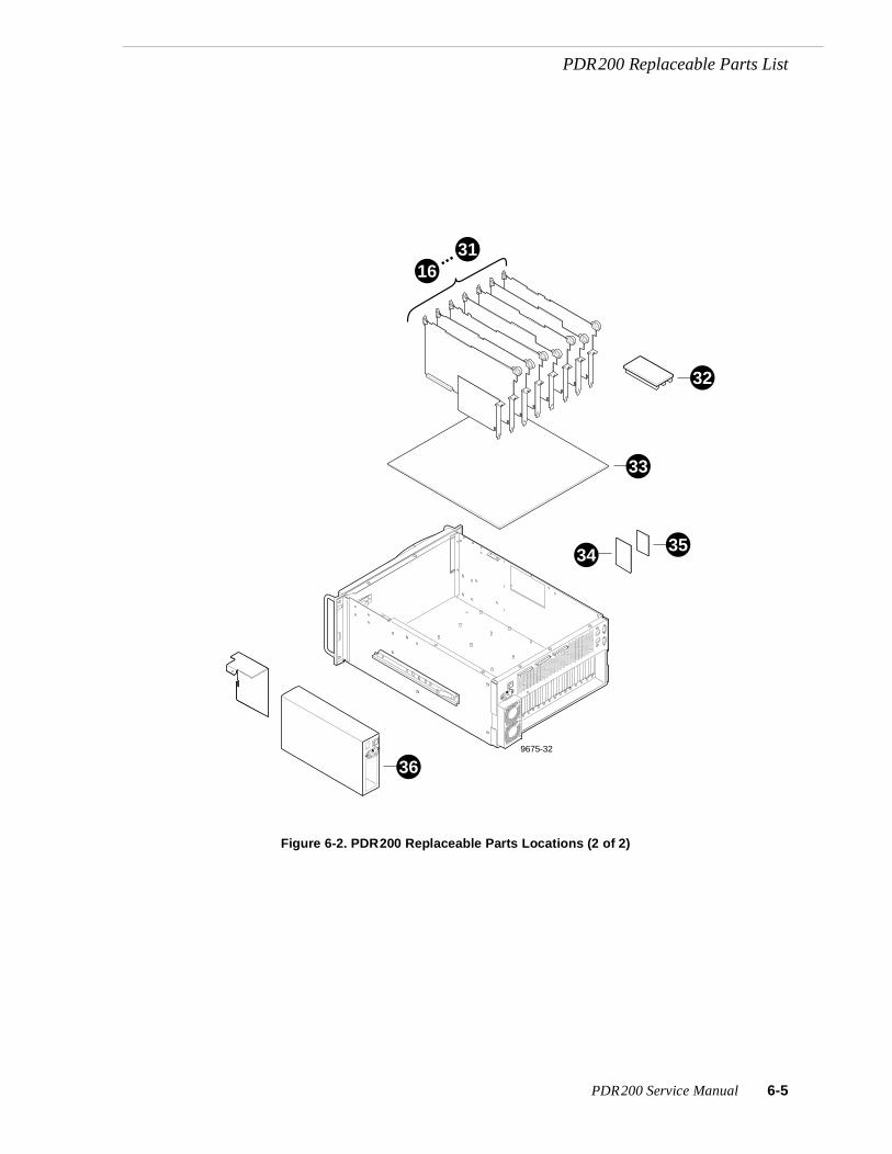
PDR200 Replaceable Parts List
Figure 6-2. PDR200 Replaceable Parts Locations (2 of 2)
9675-32
32
3116
33
35
36
34
...
PDR200 Service Manual 6-5

Chapter 6 Parts Removal and Replacement
Profile ChassisThe removal and replacement of some PDR200 parts require removal of the chassis from the equipment rack. Obviously, externally connected parts would not (seeTable 6-1 and table footnote). Additionally, removal and replacement of items 1 - 15 from Table 6-1 do not require removal of the chassis from the equipment rack.
To remove the Profile chassis from the rack:
1. Turn PDR200 power Off and disconnect the power cord.
2. Disconnect all cables from the rear of the chassis. (Making a diagram of the cables and connections prior to disconnecting them can be a big help for reconnection.)
3. Loosen the retaining screw which secures the chassis in the rack (Figure 6-3).
Figure 6-3. PDR200 Rack Retaining Screw
WARNING: To prevent serious injury, insure that the rack is anchored to the floor so that it cannot tip over when the PDR 200 is extended out of the rack.
4. Slide the chassis out of the rack until the rack slide stop latches on each side engage (Figure 6-4).
Figure 6-4. Rack Slide Stop Latch
9675-11
Stop Latch
!
6-6 PDR200 Service Manual

Profile Chassis
WARNING: To prevent injury, two people are required to lift the PDR200. It is too heavy for one person to remove from or install into the rack.
5. Depress the stop latches and being careful to fully support the it, slide the chassis completely out of the rack and place on a flat, level surface.
To install the chassis:
WARNING: To prevent serious injury, insure that the rack is anchored to the floor so that it cannot tip over when the PDR 200 is extended out of the rack.
WARNING: To prevent injury, two people are required to lift the PDR200. It is too heavy for one person to remove from or install into the rack.
1. Align the chassis slides with those on the rack and slide the chassis in until the stop latches engage (Figure 6-4).
2. Depress the stop latches and slide the chassis completely into the rack.
3. Use the retaining screw to secure the chassis to the rack (Figure 6-3).
4. Reconnect all necessary cables.
5. Reconnect the power cord and turn power On.
!
!
!
PDR200 Service Manual 6-7

Chapter 6 Parts Removal and Replacement
Chassis CoversWARNING: Power connections with high current capacity are potentially accessible inside the PDR200 chassis. Before removing the chassis covers, be sure to turn power Off and disconnect the power cord.
The PDR200 uses two top covers to maintain internal environmental integrity. The one at the front covers the media disk drive area and the one at the rear covers the board area. Front cover screws maintain media disk drive stability and help secure the rear cover to the chassis.
Access to the media disk drive area, for removal of most of the parts in that area, does not require removal of the rear cover, while access to the board area requires removal of both covers. Referring to Figure 6-5, removal of the chassis covers requires a Torx tool with a T10 tip. Bear in mind that all chassis cover screws must be reattached when replacing the covers.
Figure 6-5. Removal of the Top Covers
Bezel and Air FiltersUnder all but the most exceptional circumstances the front panel bezel should rarely require replacement. See ‘Cleaning or Replacing Air Filters’ in Chapter 5, page 5-3 for the procedure to remove and replace the air filters.
!
9675-9
2
1
6-8 PDR200 Service Manual

LED Board
LED BoardThe LED board contains the following LEDs:
• System Fault.
• Fan Fault.
• Over Temp
• Disk Activity
The cables for the power LED and to the SCSI Backplane and Fan board also connect to this board.
To remove the LED board:
1. Turn PDR200 power Off and disconnect the power cord.
2. Loosen the front panel retaining thumb screw which secures the chassis in the rack (Figure 6-3, page 6-6) and slide the chassis forward enough to access the screws which secure both the handles to the front panel and the front panel to the chassis. Be careful not to exert stress on any cables connected to the rear panel.
3. Being careful to support the front panel, use the Torx tool with the T15 tip to remove the two handle and panel mounting screws on each side (1 in Figure 6-6).
Figure 6-6. Front Panel, Handles, and Gasket Removal
9675-19
31
2 DisconnectLED cable
PDR200 Service Manual 6-9

Chapter 6 Parts Removal and Replacement
4. Carefully move the front panel far enough away from the chassis to access the LED cable.
5. Disconnect the LED cable connector (2 in Figure 6-6) which runs from the chassis to the front panel and place the front panel face down on a flat level surface.
6. If necessary, use the Torx tool with the T15 tip to remove the gasket (3 in Figure6-6).
7. Disconnect all cables from the board (1 in Figure 6-7).
Figure 6-7. LED Board Removal
8. Use the Torx tool with the T10 tip to remove the screws which secure the board to the panel (2 in Figure 6-7).
9675-20
1 Disconnectcabling
2 Remove screwsand LED board
6-10 PDR200 Service Manual

LED Board
To replace the LED board:
1. Use the Torx tool with the T10 tip to attach the LED board to the front panel(Figure 6-7).
2. Reconnect the previously removed cables to the board.
3. Being careful to support the front panel, position the front panel at the chassis and reconnect the LED cable connector to the board (Figure 6-6)
4. Use the Torx tool with the T15 tip to attach the handles and front panel to the chassis with the mounting screws, two on each side to the chassis.
5. Slide the PDR200 into the chassis and tighten the retaining screw (Figure 6-3,page 6-6).
6. Reconnect the power cord and turn power On.
PDR200 Service Manual 6-11

Chapter 6 Parts Removal and Replacement
System DriveThe system drive contains the Windows NT operating system software and the Profile application software. The system drive occupies a slot in the left side of the chassis and mounts to a bracket which is attached to the chassis. Removal and replacement of the system drive does not require removal of the chassis from the rack or removal of any covers.
To remove the system drive:
1. Turn PDR200 power Off and disconnect the power cord.
2. Loosen the chassis rack retaining screw (Figure 6-3, page 6-6) and slide the chassis out of the rack far enough to access the system drive bracket on the left side as facing the chassis. See Figure 6-8.
CAUTION: Support the system drive bracket during removal so as to not place stress on the drive cable.
3. Use the 11/32-inch nutdriver to remove the four nuts which secure the system drive bracket to the side of the chassis (1 in Figure 6-8).
4. Carefully move the bracket far enough away from the chassis to access the cable connector on the drive (2 in Figure 6-8).
5. Disconnect the drive cable and place the drive on a flat, level, static-proof surface with the bracket up (3 in Figure 6-8).
6. Use the medium Phillips screwdriver to remove the four screws which secure the drive to the bracket (4 in Figure 6-8).
To replace the system drive:
1. Place the new drive face down on a flat, level, static-proof surface.
2. Position the bracket onto the drive aligning the drive mounting screws.
3. Use the medium Phillips screwdriver and attach the drive to the bracket with the four screws previously removed.
CAUTION: Support the system drive bracket during installation so as to not place stress on the drive cable.
4. Position the drive and bracket at the slot in the side of the chassis and connect the drive cable to the drive (Figure 6-8).
5. Use the 11/32-inch nutdriver to attach the system drive bracket to the side of the chassis with the four nuts previously removed.
6. Slide the chassis back into the rack and secure with the retaining screw (Figure 6-3, page 6-6).
7. Reconnect the power cord and turn power On.
!
!
6-12 PDR200 Service Manual

System Drive
Figure 6-8. Removal of the System Drive
4
1
9675-23
23
PDR200 Service Manual 6-13

Chapter 6 Parts Removal and Replacement
Media Disk DriveEach media disk drive mounts in its own drive caddie which slides into the drive tray mounted in the chassis. A screw through the cover, which is removed when the cover is removed, maintains caddie stability. Removal and replacement of a drive caddie and media disk drive does not require removal of the drive tray or removal of the chassis from the rack, but does require removal of the front cover.
NOTE: If you are removing more than one media disk drive at a time and intend to reinstall all of them, mark the locations of each drive to insure replacement in the same location. Figure 6-9 shows locations.
To remove a media disk drive:
1. Turn PDR200 power Off and disconnect the power cord.
2. Loosen the chassis rack retaining screw (Figure 6-3, page 6-6) and, taking care to not stress rear panel cables, slide the chassis out of the rack far enough to access the front cover mounting screws.
3. Use the Torx tool with the T10 tip to remove the front cover mounting screws and set the cover aside (Figure 6-5, page 6-8).
CAUTION: Media disk drives are very sensitive to shock and vibration. To prevent damage, do not drop or bang a drive when handling. Do not stack drives upon each other.
CAUTION: Media disk drives are also very sensitive to electrostatic discharge (ESD), particularly the SCSI connector. To prevent damage, take ESD precautions when handling the drives. Also, when returning them, the drives should only be transported and stored in the ESD bags they were shipped in.
4. Grasp the top of the disk drive caddie to be removed and pull straight up and out of the chassis and place on a flat, level, static-proof surface with the caddie side up (1 in Figure 6-9).
5. Use the Torx tool with the T10 tip to remove the four screws (two on each side) which mount the drive to the caddie (2 and 3 in Figure 6-9).
!
!
6-14 PDR200 Service Manual

Media Disk Drive
Figure 6-9. Removal of a Media Disk Drive
To replace a media disk drive:
CAUTION: Media disk drives are very sensitive to shock and vibration. To prevent damage, do not drop or bang a drive when handling. Do not stack drives upon each other.
CAUTION: Media disk drives are also very sensitive to electrostatic discharge (ESD), particularly the SCSI connector. To prevent damage, take ESD precautions when handling the drives. Also, the drives should only be transported and stored in the ESD bags they were shipped in.
1. Drive mounting holes in the caddie are numbered 6 and 7. Position the drive in the caddie so that the number 6 holes align with the screw holes in the drive (Figure 6-9).
2. Use the Torx tool with the T10 tip to mount the new drive to the drive caddie with the four screws (two on each side) previously removed.
3. Slide the drive caddie into the drive tray and firmly press down to connect the drive connector to the SCSI Backplane.
4. Use the Torx tool with the T10 tip to replace the front cover, being sure to use all the screws previously removed.
5. Slide the chassis back in the chassis and tighten the rack retaining screw (Figure 6-3,page 6-6).
6. Reconnect the power cord and turn power On.
1
23
9675-15
Removescrews(4)Remove disk
from caddie
Slide disk from tray
A3A4
A5A6
C3
Disk IDs C4C5
C6
!
!
PDR200 Service Manual 6-15

Chapter 6 Parts Removal and Replacement
SCSI BackplaneThe SCSI Backplane mounts to stand-offs on the disk drive tray. This Backplane provides power and control and data signals for the media hard disk drives. The Backplane receives power and signals from the system and routes them to individual connectors for each hard disk drive. Removal and replacement of the SCSI Backplane does not require removal of the chassis from the rack or removal of the rear cover. Removal of the Floppy Disk Drive and the Distribution Board requires removal of the SCSI Backplane.
To remove the SCSI Backplane:
CAUTION: Media disk drives are very sensitive to shock. To prevent damage, do not drop or bang a drive when handling.
1. Perform steps 1-4 of the media disk drive removal procedure (page 6-14) for all media disk drives, being sure to mark the locations of all of the drives (1 in Figure 6-9,page 6-15).
2. Disconnect all cables from the SCSI Backplane (1 in Figure 6-10).
3. Use the Torx tool with the T15 tip to remove the screws which secure the SCSI Backplane to the stand-offs on the disk drive tray (2 in Figure 6-10).
4. Move the SCSI Backplane toward the rear of the chassis to clear the flange on the disk drive tray and then lift it up and out of the chassis.
To replace the SCSI Backplane:
1. Position the SCSI Backplane over the stand-offs on the disk drive tray, being sure to clear the flange on the front of the tray and aligning the SCSI Backplane mounting holes with the stand-offs.
2. Use the Torx tool with the T15 tip to attach the SCSI Backplane to the stand-offs.
3. Connect all cables previously removed to the SCSI Backplane (Figure 6-10).
4. Referring to Figure 6-9 for placement, replace the media disk drives.
!
6-16 PDR200 Service Manual

SCSI Backplane
Figure 6-10. Removal of the SCSI Backplane
9675-18
1 Disconnect cabling
2Remove screws(8) and lift SCSIboard out of hard disk tray.
SCSIBoard
DiskTray
PDR200 Service Manual 6-17

Chapter 6 Parts Removal and Replacement
Fan TrayThe three main fans for interior air circulation and the Fan board mount on the removable Fan Tray. This tray mounts across the chassis between the Media Hard Disks and the board area. Fan tray removal and replacement does not require removal of the chassis from the rack or removal of the rear cover.
Removal and replacement of the parts listed below require removal of the fan tray.
• Fans (internal)
• Fan board
• Disk drive tray
• Floppy disk drive
• Distribution board for the floppy disk drive and system drive
To remove the fan tray:
1. Turn PDR200 power Off and disconnect the power cord.
2. Loosen the chassis rack retaining thumb screw (Figure 6-3, page 6-6) and, taking care to not stress rear panel cables, slide the chassis out of the rack far enough to access the front cover mounting screws.
3. Use the Torx tool with the T10 tip to remove the front cover mounting screws and set the cover aside (Figure 6-5, page 6-8).
4. Use the Torx tool with the T15 tip to remove the four screws (two on each side) which secure the fan tray to the chassis (1 in Figure 6-11).
5. Disconnect all cables to the Fan board (1 and 2 in Figure 6-11).
6. Being careful to move cabling out of the way, lift the fan tray up and out of the chassis.
6-18 PDR200 Service Manual

Fan Tray
Figure 6-11. Removal of Fan Tray and Fan
To replace the fan tray:
1. Being careful to keep cabling out of the way, position the fan tray in the chassis.
2. Use the Torx tool with the T15 tip to secure the fan tray to the chassis with the four screws previously removed (Figure 6-11).
3. Reconnect all previously removed cables to the Fan board.
4. Use the Torx tool with the T10 tip to replace the front cover, being sure to use all the screws previously removed.
5. Reconnect the power cord and turn power On.
9675-5
1
3 2Removescrews(4)
Unplug fan wirefrom Fan board
Unplug wires from fan board,remove screws(4) andlift fan module
Fanboard
PDR200 Service Manual 6-19

Chapter 6 Parts Removal and Replacement
Internal FansInternal fans, mounted to the fan tray, provide air circulation in the chassis. Internal fan removal and replacement requires removal of the fan tray.
To remove an internal fan:
1. Perform the Fan Tray removal procedure, including power off and power cable disconnect (page 6-18).
2. Disconnect the appropriate fan cable connector from the Fan board on the fan tray (2 in Figure 6-11, page 6-19).
3. Use the Torx tool with the T15 tip to remove the four screws which attach the fan to the fan tray (3 in Figure 6-11).
To replace an internal fan:
1. Use the Torx tool with the T15 tip to attach the new fan to the fan tray with the screws previously removed.
2. Connect the new fan cable connector to the Fan board on the fan tray.
3. Perform the Fan Tray replacement procedure.
6-20 PDR200 Service Manual

Fan Board
Fan BoardThe Fan board, mounted to the fan tray, provides distribution of power from the power supply to the three internal fans, the two rear panel fans, and the Distribution Board. Removal and replacement of the Fan board requires removal of the fan tray.
To remove the Fan board:
1. Perform the Fan Tray removal procedure, including power off and power cable disconnect page 6-18.
2. Use the Torx tool with the T15 tip to remove the screws which attach the Fan board to the fan tray (Figure 6-11, page 6-19).
To replace an internal fan:
1. Use the Torx tool with the T15 tip to attach the Fan board to the fan tray with the screws previously removed.
2. Perform the Fan Tray replacement procedure.
PDR200 Service Manual 6-21

Chapter 6 Parts Removal and Replacement
Disk Drive TrayThe disk drive tray houses the SCSI Backplane and the media disk drives, and helps maintain disk drive stability. Removal and reinstallation of the disk drive tray does not require removal of the chassis from the rack or removal of the rear cover. Removal of the parts listed below require removal of the disk drive tray.
• LED EMI Board
• Floppy Disk Drive
• Distribution Board
To remove the disk drive tray:
CAUTION: Media disk drives are very sensitive to shock. To prevent damage, do not drop or bang a drive when handling and do not stack drives upon each other. Use ESD precautions, especially with regard to the connectors.
1. Perform steps 1-4 of the media disk drive removal procedure, being sure to mark the locations of all of the drives (page 6-14).
2. Perform the fan tray removal procedure (page 6-18).
3. Disconnect all cables from the SCSI Backplane (Figure 6-10, page 6-17).
4. Use the Torx tool with the T10 tip to remove the disk drive tray mounting screws from the bottom of the chassis (1 in Figure 6-12).
5. Use the Torx tool with the T15 tip to remove the disk drive tray mounting screws from the right side of the chassis (2 in Figure 6-12). (The screws on the left side were removed when the cover was removed.)
6. Being careful of cabling, lift the disk drive tray up and out of the chassis (3 inFigure 6-12).
To reinstall the disk drive tray:
1. Being careful of cabling, position the disk drive tray in the chassis (Figure 6-12).
2. Use the Torx tool with the T15 tip to attach the disk drive tray mounting screws through each side of the chassis, but do not tighten.
3. Use the Torx tool with the T10 tip to attach the disk drive tray mounting screws from the bottom of the chassis (Figure 6-12).
4. Tighten all screws.
5. Reconnect all cables to the SCSI Backplane (Figure 6-10).
6. Perform the fan tray installation procedure
CAUTION: Media disk drives are very sensitive to shock. To prevent damage, do not drop or bang a drive when handling and do not stack drives upon each other. Use ESD precautions, especially with regard to the connectors.
7. Perform the media disk drive replacement procedure, being sure to reinstall the drives in the locations they were removed from (Figure 6-9, page 6-15).
!
!
6-22 PDR200 Service Manual

Disk Drive Tray
Figure 6-12. Media Disk Drive Tray Removal
9675-6
2
3
1
PDR200 Service Manual 6-23

Chapter 6 Parts Removal and Replacement
Floppy Disk DriveThe Floppy Disk Drive mounts to a plate attached to the left side of the chassis in the Media Disk Drive area. Floppy Disk Drive removal and replacement does not require removal of the chassis from the rack or removal of the rear cover. Removal and replacement does require removal of the fan tray, media disk drives, and disk drive tray.
To remove the Floppy Disk Drive:
1. Perform the disk drive tray removal procedure (page 6-22).
2. Perform the Fan Tray removal procedure, except, at the Distribution board, disconnect the cable from the Fan board (page 6-18).
3. Being careful to support the plate, use the Torx tool with the T10 tip to remove the four screws which attach the plate to the side of the chassis (1 in Figure 6-13).
4. Disconnect the remaining cables from the Distribution board (2 in Figure 6-13).
5. Move the rear of the plate back and into the chassis to clear the floppy drive flange through the front panel slot and then lift the plate up and out of the chassis (3 inFigure 6-13). Place on a flat, level, static-proof surface with the drive and board up.
6. Use the small Phillips screwdriver to remove the screws which secure the floppy drive to the plate (4 in Figure 6-13).
To replace the Floppy Disk Drive:
1. Use the small Phillips screwdriver to attach the floppy drive to the plate with the screws previously removed (Figure 6-13).
2. Guide the plate into the chassis so that the floppy drive flange clears the slot in the chassis and use the Torx tool with the T10 tip to attach the plate to the side of the chassis with the screws previously removed.
3. Reconnect all cables but the Fan board cable to the Distribution board.
4. Perform the Fan Tray reinstallation procedure (page 6-19).
5. Reconnect the cable from the Fan board to the Distribution Board.
6. Perform the disk drive tray reinstallation procedure (page 6-22).
6-24 PDR200 Service Manual

Floppy Disk Drive
Figure 6-13. Removal of the Floppy Disk Drive
2
9675-29
Unplugcabling
3 Remove floppy drive/distribution module
1 Removescrews(4)
4 Removefloppy drive
PDR200 Service Manual 6-25

Chapter 6 Parts Removal and Replacement
Distribution BoardThe Distribution Board mounts to a plate attached to the left side of the chassis in the Media Disk Drive area. Removal and replacement of the board does not require removal of the chassis from the rack or removal of the rear cover. Removal and replacement does require removal of the fan tray, media disk drives, and disk drive tray.
To remove the Distribution Board:
1. Perform the Fan Tray removal procedure, except, at the Distribution board, disconnect the cable from the Fan board (page 6-18).
2. Perform the disk drive tray removal procedure (page 6-22).
3. Disconnect the remaining cables from the Distribution board (1 in Figure 6-14).
4. Use the Torx tool with the T15 tip to remove the screws which attach the Distribution Board to the plate at the side of the chassis (2 in Figure 6-14).
To replace the Distribution Board:
1. Use the Torx tool with the T15 tip to attach the Distribution Board to the plate at the side of the chassis with the screws previously removed.
2. Reconnect all cables to the Distribution board, except the cable from the Fan board.
3. Perform the Fan Tray reinstallation procedure (page 6-19).
4. Reconnect the cable from the Fan board to the Distribution Board.
5. Perform the disk drive tray reinstallation procedure (page 6-22).
6-26 PDR200 Service Manual

Distribution Board
Figure 6-14. Removal of the Distribution Board
1
9675-30
Unplug cabling
2
PDR200 Service Manual 6-27

Chapter 6 Parts Removal and Replacement
LED EMI BoardThe LED EMI Board mounts to a plate attached to the grill at the front of the chassis in the Media Disk Drive area. Removal and replacement of the board does not require removal of the chassis from the rack or removal of the rear cover. Removal and replacement does require removal of the fan tray, media disk drives, and disk drive tray.
To remove the LED EMI Board:
1. Remove the front panel bezel as shown in Figure 6-6, page 6-8.
2. Perform the Fan Tray removal procedure (page 6-18).
3. Perform the disk drive tray removal procedure (page 6-22).
4. Use the Torx tool with the T15 tip to remove the screws which attach the LED EMI Board to the plate inside the front grill of the chassis (3 in Figure 6-15).
5. Disconnect the remaining cable from the LED EMI Board (1 in Figure 6-15.
To replace the LED EMI Board:
1. Reconnect the cable to the LED EMI Board (Figure 6-15).
2. Use the Torx tool with the T15 tip to attach the LED EMI Board to the plate inside the front grill of the chassis with the screws previously removed.
3. Perform the Fan Tray reinstallation procedure (page 6-19).
4. Perform the disk drive tray reinstallation procedure (page 6-22).
5. Reinstall the front panel bezel (Figure 6-6, page 6-8).
Figure 6-15. Removal of the LED EMI Board
9675-27
2
1Disconnectcable fromopposite side.
3
6-28 PDR200 Service Manual

External Fan
External FanThe two external fans at the rear of the chassis exhaust air from the power supply. Removal and replacement of one of these fans does not require removal of the chassis from the rack or removal of any covers. Both fans and the fan cover are attached to the rear of the chassis by eight long screws. These screws go into the fan cover, through a corner of each fan assembly, and then into screw holes in the chassis. The fans receive power through a connector on a cable routed from the Fan board on the fan tray.
To remove an external fan:
1. Turn PDR200 power Off and disconnect the power cord.
2. While supporting the cover and fans, use a Torx tool with the T15 tip to remove the screws which secure the cover and fans to the chassis (Figure 6-16).
3. Disconnect the power cable from the appropriate fan.
To replace an external fan:
1. Connect the power cable to the appropriate fan.
2. While supporting the cover and fans, use a Torx tool with the T15 tip to thread the screws previously removed through the cover and fans into the chassis screw holes (Figure 6-16).
3. Reconnect the power cord and turn PDR200 power On.
Figure 6-16. Removal of an External Fan
1
2 9675-28
Remove fan cover and unplugcabling, remove fans.
Remove screws(8)
PDR200 Service Manual 6-29

Chapter 6 Parts Removal and Replacement
BoardsThe removal and installation of boards in slots requires removal of both covers and the removal of the two board retainer brackets. Note that removal of the Profile chassis from the rack simplifies the removal of boards and other parts housed in the board area.
One of the board retainer brackets is slotted so that it holds full-size boards in place and helps maintain their alignment. The other bracket holds short boards in place, but must also be removed to remove any full-size board. This bracket has extenders which may be moved to adapt to the locations of any short board(s).
Board Retainer BracketsThe retainer bracket at the rear of the boards keeps the boards seated in their sockets. The bracket fits directly on top of the full-size boards and requires extenders to reach shorter boards. The extenders can be moved to different positions to accommodate changes to the board configuration (Figure 6-17).
Figure 6-17. Rear Board Retainer Bracket
The slotted bracket in the center of the board area maintains proper spacing of the full-size boards. The bracket only contacts full-size boards, but must be removed to remove or install any board.
9674-6
1
2
6-30 PDR200 Service Manual

Board Retainer Brackets
To remove board retainer brackets:
1. Perform the procedure to remove the Profile chassis from the rack (page 6-6).
2. Remove the Profile chassis covers (page 6-8).
3. Use the Torx tool with the T10 tip to remove the screws which secure both brackets to the Profile chassis (Figure 6-18).
4. Lift each bracket up and out of the Profile chassis.
Figure 6-18. Removal of Board Retainer Brackets
9675-2
1
3
4
2
PDR200 Service Manual 6-31

Chapter 6 Parts Removal and Replacement
To reinstall board retainer brackets, refer to Figure 6-19 and:
1. Insert the rear board bracket into the board area and ensure that the extender(s) are on the top edge of all short boards.
2. If necessary, use the Torx tool with the T15 tip to adjust locations of the extenders for short boards (Figure 6-17, page 6-30).
3. Use the Torx tool with the T10 tip to install the bracket with the screw previously removed (Figure 6-19).
4. Place the slotted bracket over the boards.
5. Align the full-size boards to the correct bracket slots (see insert in Figure 6-19) and carefully seat the bracket onto the boards.
6. Use the Torx tool with the T10 bit to install the bracket with the screw previously removed.
7. Reinstall the covers (page 6-8) and reinstall the Profile chassis into the rack.
8. Reconnect any cables previously removed.
9. Reconnect the power cord and turn power On.
Figure 6-19. Installation of Board Retainer Brackets
9675-3
4
2
1
3
6-32 PDR200 Service Manual
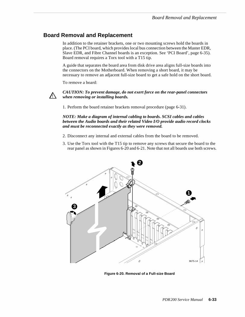
Board Removal and Replacement
Board Removal and ReplacementIn addition to the retainer brackets, one or two mounting screws hold the boards in place. (The PCI board, which provides local bus connection between the Master EDR, Slave EDR, and Fibre Channel boards is an exception. See ‘PCI Board’, page 6-35). Board removal requires a Torx tool with a T15 tip.
A guide that separates the board area from disk drive area aligns full-size boards into the connectors on the Motherboard. When removing a short board, it may be necessary to remove an adjacent full-size board to get a safe hold on the short board.
To remove a board:
CAUTION: To prevent damage, do not exert force on the rear-panel connectors when removing or installing boards.
1. Perform the board retainer brackets removal procedure (page 6-31).
NOTE: Make a diagram of internal cabling to boards. SCSI cables and cables between the Audio boards and their related Video I/O provide audio record clocks and must be reconnected exactly as they were removed.
2. Disconnect any internal and external cables from the board to be removed.
3. Use the Torx tool with the T15 tip to remove any screws that secure the board to the rear panel as shown in Figures 6-20 and 6-21. Note that not all boards use both screws.
Figure 6-20. Removal of a Full-size Board
!!
9675-14
2
1
3
PDR200 Service Manual 6-33
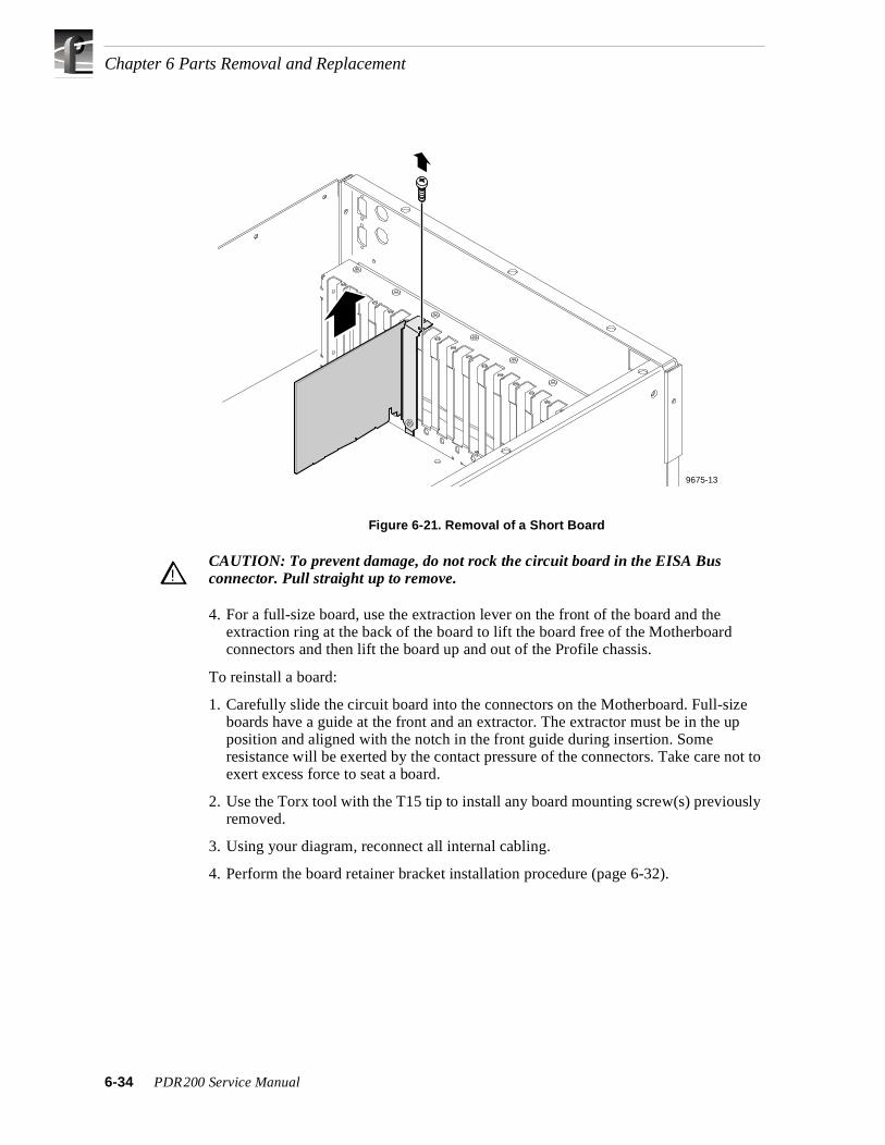
Chapter 6 Parts Removal and Replacement
Figure 6-21. Removal of a Short Board
CAUTION: To prevent damage, do not rock the circuit board in the EISA Bus connector. Pull straight up to remove.
4. For a full-size board, use the extraction lever on the front of the board and the extraction ring at the back of the board to lift the board free of the Motherboard connectors and then lift the board up and out of the Profile chassis.
To reinstall a board:
1. Carefully slide the circuit board into the connectors on the Motherboard. Full-size boards have a guide at the front and an extractor. The extractor must be in the up position and aligned with the notch in the front guide during insertion. Some resistance will be exerted by the contact pressure of the connectors. Take care not to exert excess force to seat a board.
2. Use the Torx tool with the T15 tip to install any board mounting screw(s) previously removed.
3. Using your diagram, reconnect all internal cabling.
4. Perform the board retainer bracket installation procedure (page 6-32).
9675-13
!!
6-34 PDR200 Service Manual

PCI Board
PCI BoardThe PCI board connects across the top of the Slave EDR, Master EDR, and Fibre Channel boards. See Figure 6-22. Removal of any of these boards requires removal of the PCI board. Removal and replacement of the PCI board itself does not require any tools. However, it does require removal of the covers.
To remove the PCI board:
1. Turn PDR200 power Off and disconnect the power cord.
2. Perform the procedure to remove the Profile chassis from the rack (page 6-6).
3. Remove the Profile chassis covers (page 6-8).
4. Disconnect the PCI board from the Slave EDR, Master EDR, and Fibre Channel boards and lift it up and out of the Profile chassis.
Figure 6-22. PCI Board Location
9675-34
PDR200 Service Manual 6-35

Chapter 6 Parts Removal and Replacement
To install the PCI board:
The three PCI board connectors (Figure 6-23) are keyed to ensure correct orientation and the bottom of the board (which faces up when installed) identifies the connectors as J1, J2, and J3. J2 is further identified as MASTER. Note that the SCSI cables to the EDR boards must be connected prior to installation of the PCI board.
Figure 6-23. PCI Board
To install the PCI board, refer to Figures 6-22 and 6-23 and:
1. Hold the PCI with the connectors pointing down and the connector identifications towards the rear of the Profile chassis (Figure 6-23).
2. Align the PCI connectors so that J1 is over the Fibre Channel board edge-board contacts, Master J2 over the Master EDR connector, and J3 over the Slave EDR connector, and the connector keys are over the key slots on the boards.
3. Attach the PCI board by gently but firmly pressing down until the PCI board is fully seated on all three boards (Figure 6-22).
4. Reinstall the Profile chassis covers (page 6-8).
5. Perform the procedure to reinstall the Profile chassis in the rack (page 6-7).
6. Reconnect the power cord and turn PDR200 power On.
9674-15
Master
J1
J2
J3Index Notch
6-36 PDR200 Service Manual

Serial EMI Board
Serial EMI BoardThe Serial EMI board assists in maintaining the environmental integrity of the PDR200 when RS-232 devices are connected to the rear panel serial connectors. Removal and installation requires removal of both covers and removal of as many boards as necessary to access the Serial EMI board.
To remove the Serial EMI board:
1. Turn PDR200 power Off and disconnect the power cord.
2. Perform the procedure to remove the Profile chassis from the rack (page 6-6).
3. Remove the Profile chassis covers (page 6-8).
4. Remove as many boards as necessary to access the Serial EMI board.
5. Use the 3/16-inch nutdriver to remove the jackscrews which secure the board to the rear panel and lift the board up and out of the Profile chassis (1 in Figure 6-24).
6. Disconnect the cable to the Serial EMI board (2 in Figure 6-24).
Figure 6-24. Removal of the Serial EMI Board
To install the Serial EMI board:
1. Position the board in the Profile chassis so that the connectors protrude out of the rear panel.
2. Align the screw holes and use the 3/16-inch nutdriver to secure the board to the Profile chassis with the screws previously removed (Figure 6-24).
3. Connect the cable previously removed to the board.
4. Reinstall any boards removed (page 6-34).
5. Replace chassis covers (page 6-8) and reinstall the chassis in the rack (page 6-7).
6. Reconnect the power cord and turn PDR200 power On.
9675-16
1
2
Removescrews(4)
Unplug cabling andremove EMI board.
PDR200 Service Manual 6-37

Chapter 6 Parts Removal and Replacement
Mouse/Keyboard EMI BoardThe Mouse and Keyboard EMI board assists in maintaining the environmental integrity of the PDR200 with a mouse and keyboard connected to the rear panel. Removal and installation requires removal of both covers and removal of as many boards as necessary to access the Mouse/Keyboard EMI board.
To remove the Mouse/Keyboard EMI board:
1. Turn PDR200 power Off and disconnect the power cord.
2. Perform the procedure to remove the Profile chassis from the rack (page 6-6).
3. Remove the Profile chassis covers (page 6-8).
4. Remove as many boards as necessary to access the Mouse/Keyboard EMI board (page 6-33).
5. Use the Torx tool with the T10 tip to remove the screws which secure board to the rear panel (1 in Figure 6-25) and lift the board up and out of the chassis.
6. Disconnect the cable to the Mouse/Keyboard EMI board (2 in Figure 6-25).
Figure 6-25. Removal of the Mouse/Keyboard EMI Board
9675-12
1
2
Removescrews(2)
Unplug cabling andremove EMI board.
6-38 PDR200 Service Manual

Mouse/Keyboard EMI Board
To install the Mouse/Keyboard EMI board:
1. Position the board in the Profile chassis so that the connectors protrude out of the rear panel.
2. Align the screw holes and use the Torx tool with the T10 tip to secure the board to the Profile chassis with the screws previously removed (Figure 6-25).
3. Connect the cable previously removed to the board.
4. Reinstall any boards removed (Figures 6-20 and 6-21 and pages 6-33 and 6-34).
5. Replace chassis covers (page 6-8) and reinstall the chassis in the rack (page 6-7).
6. Reconnect the power cord and turn PDR200 power On.
PDR200 Service Manual 6-39

Chapter 6 Parts Removal and Replacement
Power SupplyThe power supply for the PDR200 is mounted at the right rear side of the PDR200. Removal and replacement of the power supply requires removal of a number of parts.
To remove the power supply:
1. Turn PDR200 power Off and disconnect the power cord.
2. Perform the procedure to remove the Profile chassis from the rack (page 6-6).
3. Remove the covers (page 6-8).
4. Remove the SCSI cable hold-down(s).
5. Remove the board retainer brackets (page 6-30).
6. Remove the RS-422 board in slot J17 (page 6-33).
7. Perform the fan tray removal procedure (page 6-18).
8. Being sure to identify them for reinstallation and observing the ESD cautions, remove the A3 and A4 media disk drives and caddies.
9. Disconnect the two white power connectors from the SCSI Backplane (page 6-16).
10.Use the Torx tool with the T10 tip to remove the screw which secures the power supply shield to the right side of the chassis (1 in Figure 6-26) and remove the shield.
Figure 6-26. Removal of the Power Supply Shield
9675-4
1
2
6-40 PDR200 Service Manual

Power Supply
11.Disconnect all other cables from the power supply (Figure 6-27).
12.Use the Torx tool with the T15 tip to disconnect power supply cables from the Motherboard.
Figure 6-27. Power Supply Cable Disconnections
9675-25
Disconnectcables from
power supply
Disconnectcable from
mother board
Disconnectblack(3) cables
Disconnectred(3) cables
PowerSupply
MotherBoard
PDR200 Service Manual 6-41

Chapter 6 Parts Removal and Replacement
13.Use the Torx tool with the T10 tip to remove the screws which secure the power supply to the right side of the chassis (1 in Figure 6-28).
14.Slide the power supply towards the front and center of the chassis to clear the rear panel switch and connector and right side chassis flange, and lift the power supply out of the chassis (2 in Figure 6-28).
Figure 6-28. Removal of the Power Supply
9675-24
2
1
6-42 PDR200 Service Manual

Power Supply
To install the power supply:
1. Position the power supply in the Profile chassis on the right side and slide towards the rear panel until the holes in the chassis align with the power supply screw holes.
2. Use the Torx tool with the T10 tip to attach the power supply to the side of the chassis with the screws previously removed (Figure 6-28, page 6-42).
3. Reconnect the two white connectors to the SCSI Backplane (page 6-16).
4. Reconnect all other previously removed cables to the power supply (Figure 6-27, page 6-41).
5. Use the torx tool with the T15 tip to connect power supply cables to the Motherboard.
6. Being careful to not crimp or damage cabling, use the Torx tool with the T10 tip to install the power supply shield with the screw previously removed (Figure 6-26).
7. Noting the positions they were removed from and observing the disk handling cautions, reinstall the disk drive caddies A3 and A4 (page 6-14).
8. Perform the fan tray installation procedure (page 6-18).
9. Reinstall the RS-422 Board in slot J17 (page 6-34).
10.Reinstall the board retainer brackets (page 6-32).
11.Reinstall the SCSI cable hold-downs.
12.Replace the covers (page 6-8) and reinstall the Profile chassis in the rack (page 6-7).
13.Reconnect the power cord and turn PDR200 power On.
PDR200 Service Manual 6-43

Chapter 6 Parts Removal and Replacement
MotherboardThe Motherboard is mounted on the bottom panel of the PDR200 chassis. Removal and replacement requires removal of a number of parts.
To remove the Motherboard:
1. Turn PDR200 power Off and disconnect the power cord.
2. Perform the procedure to remove the Profile chassis from the rack (page 6-6).
3. Remove the covers (page 6-8).
4. Perform the fan tray removal procedure (page 6-18).
5. Remove the board retainer brackets (page 6-31).
6. Being sure to note the board locations, remove all boards (pages 6-33 - 6-36).
7. Perform the power supply removal procedure (pages 6-40 - 6-42).
8. Use the Torx tool with the T15 tip to remove the screws which secure the Motherboard to the bottom panel.
To install the Motherboard:
1. Use the Torx tool with the T15 tip to attach the Motherboard to the bottom panel of the chassis.
2. Perform the power supply installation procedure (page 6-43).
3. Reinstall all boards from the slots they were removed from (pages 6-33 - 6-36).
4. Reinstall board retainer brackets (page 6-32).
5. Perform the fan tray installation procedure (page 6-19).
6. Replace covers (page 6-8) and reinstall the Profile chassis in the rack (page 6-7).
7. Reconnect the power cord and turn PDR200 power On.
6-44 PDR200 Service Manual

Interior Cabling
Interior CablingInterior cables for the PDR200 consist of three main types: ribbon cables, SCSI cables, and wire harness cables. In addition, coax cables provide interconnection between Audio boards.
Ribbon cables of various sizes provide connections to and from many boards and assemblies. These are standard types of ribbon cables terminated with standard ribbon cable connectors. Short ribbon cables provide interconnection between adjacent circuit boards, such as between the Analog Composite Input and the Decoder boards. Remove these cables from both connectors to avoid the risk of damaging one of the multi-pin connectors they plug into.
SCSI cables provide routing of digitized video and associated audio between the Enhanced Disk Recorder boards and the Media Hard Disks, and to rear panel SCSI connectors. SCSI cables provide interconnection between:
• The SCSI connectors on the SCSI Backplane to the EDR boards.
• The EDR boards to SCSI connectors on the rear panel.
Wire harness cables primarily provide power and ground sources to various assemblies.
Figure 6-29 shows the locations and Table 6-2, keyed to Figure 6-29, lists the replaceable cables in the PDR200. Note that removal of some cables may require using the small wire cutters to cut the small straps which aid in the routing of the cables in the Profile chassis.
PDR200 Service Manual 6-45

Chapter 6 Parts Removal and Replacement
Figure 6-29. Replaceable Cable Locations
9675-33
4
11
12
10
6
7
8
9
5
3
12
6-46 PDR200 Service Manual

Interior Cabling
Table 6-2. PDR200 Replaceable Cables
Key Description Part Number
1 Cable, LED & Power Switch 174-3672-XX
2 Cable, Power Switch/Cable Assy 174-3468-XX
3 Cable, LED SCSI Signal 174-3667-XX
4 Cable, Ribbon 174-3285-XX
5 Cable, Power, Drives 15” 174-3666-XX
6 Cable, Power, Drives, 37” 174-3665-XX
7 Cable, 68 Pos. SCSI 174-3550-XX
8 Cable, SCSI “C” 174-3677-XX
9 Cable, SCSI Internal-External 174-3668-XX
10 Cable, Analog Output (coax) 174-2677-XX
11 Cable, 100 Pos. Ribbon 174-3276-XX
12 Cable, Power to Floppy Drive 174-3790-XX
PDR200 Service Manual 6-47

Chapter 6 Parts Removal and Replacement
PAC208/216 Replaceable PartsTable 6-3 lists the replaceable parts for the PAC208/216. The removal and replacement procedures do not cover all the parts listed in Table 6-3.
.
PAC208/216 Bezel and Air FilterUnder all but the most exceptional circumstances the front panel bezel should rarely require replacement. See ‘Cleaning or Replacing Air Filters’ in Chapter 5 for the procedure to remove and replace the air filter.
Table 6-3. PAC Replaceable Parts List
Description Part Number
PAC208 Replacement Unit 118-9538-XX
PAC216 Replacement Unit 118-9539-XX
Expansion Chassis, Digital 437-0455-XX
PAC Digital Transition Board 671-3895-XX
PAC Expansion Transition Board 671-3885-XX
PAC XLR Board 671-3683-XX
Cable, Champ to Champ 174-3678-XX
Cable, LED Assy 174-3617-XX
Fan 119-4827-XX
Power Supply 119-5437-XX
Switch Cable Assy 174-3613-XX
PAC Front Panel Bezel 333-4201-XX
Air Filter, PAC208 378-0436-XX
Cable, AC w/Switch 174-3612-XX
PAC Main Board 671-3649-XX
PAC Daughter Board 671-3861-XX
Cable, Pwr Supply to Main Board 174-3614-XX
6-48 PDR200 Service Manual

PAC208/216 Cover
PAC208/216 CoverTo remove the cover:
1. Turn PAC208/216 power Off and disconnect the power cord.
2. Remove the PAC 208/216 from the rack and place on a flat, level surface.
3. Use the Torx tool with the T15 tip to remove the screws which secure the top cover (Figure 6-30).
Figure 6-30. PAC208/216 Cover Removal
9675-41
PDR200 Service Manual 6-49

Chapter 6 Parts Removal and Replacement
PAC208/216 LEDThe power LED on the PAC208/216 is an integral part of the LED cable. The LED attaches to the inside of the chassis front so as to be visible through the bezel.
To remove the power LED cable:
1. Perform the cover removal procedure (page 6-49).
2. Pull the LED out of the front panel (1 in Figure 6-31).
3. Disconnect the cable from the Main Board (2 in Figure 6-31).
Figure 6-31. PAC208/216 LED Removal
9675-48
2
1
6-50 PDR200 Service Manual

PAC208/216 LED
To replace the power LED cable:
1. Connect the new cable to the Main Board (Figure 6-31).
2. Insert the LED into the front panel.
3. Use the Torx tool with the T15 tip to attach the top cover with the screws previously removed.
4. Replace the PAC208/216 in the rack.
5. Reconnect the power cord and turn PAC208/216 power On.
PDR200 Service Manual 6-51
Chapter 6 Parts Removal and Replacement
PAC208/216 FanThe fan in the PAC208/216 mounts to the power supply shield.
To remove the fan:
1. Perform the cover removal procedure (page 6-49).
2. Disconnect the fan cable from the Main Board (Figure 6-32).
3. Use the Torx tool with the T15 tip to remove the screws and the 11/32-inch nutdriver to remove the nuts which secure the power supply shield to the chassis (1 inFigure 6-32).
4. Lift the shield carefully up and out of the chassis and place upside down on a flat level surface (2 in Figure 6-32).
5. Use the Torx tool with the T15 tip to remove the screws which secure the fan to the shield (3 in Figure 6-32).
To replace the fan:
1. Thread the fan mounting screws through the fan holes at each corner and, with the Torx tool with the T15 tip attach the fan to the power supply shield (Figure 6-32).
2. Carefully position the shield in the chassis, aligning the studs and screw holes.
3. Use the Torx tool with the T15 tip and the 11/32-inch nutdriver to attach the shield to the chassis with the screws and nuts previously removed.
4. Connect the fan cable to the Main Board.
5. Use the Torx tool with the T15 tip to attach the top cover with the screws previously removed (page 6-49).
6. Replace the PAC208/216 in the rack.
7. Reconnect the power cord and turn PAC208/216 power On.
6-52 PDR200 Service Manual

PAC208/216 Fan
Figure 6-32. PAC208/216 Power Supply Shield and Fan Removal
9675-47
2
3
1
PDR200 Service Manual 6-53

Chapter 6 Parts Removal and Replacement
PAC208/216 Power SupplyThe power supply on the PAC208/216 consists of two modules which mount on stand-offs on the bottom panel of the chassis. A power supply failure requires removal of both modules. Removal and replacement requires removal of the shield and fan.
To remove the power supply:
1. Perform the fan removal procedure except do remove the fan from the shield(page 6-52).
2. Disconnect the cables from power supply (1 in Figure 6-33).
3. Use the Torx tool with the T15 tip to remove the screws (four per module) which secure the power supply to the stand-offs and lift each module up and out of the chassis (2 in Figure 6-33).
To replace the power supply:
1. Position each power supply module on the stand-offs on the bottom panel of the chassis and use the Torx tool with the T15 tip to secure the modules with the screws previously removed (Figure 6-33).
2. Reconnect the cables previously disconnected.
3. Perform the fan replacement procedure (page 6-52).
6-54 PDR200 Service Manual

PAC208/216 Power Supply
Figure 6-33. PAC208/216 Power Supply Removal
9675-44
1
2
PDR200 Service Manual 6-55

Chapter 6 Parts Removal and Replacement
PAC208/216 SwitchThe power switch and cable connect to the power supply and to the line filter on the power cord connector. The switch is attached to the chassis with retaining clips.
To remove the switch and cable:
1. Perform the fan removal procedure except do remove the fan from the shield(page 6-52).
2. Disconnect the cables from the power supply and the rear panel line filter(1 and 2 in Figure 6-34).
3. Compress the retaining clips on the switch and remove the switch and cable through the front of the chassis (3 in Figure 6-34).
Figure 6-34. PAC 208/216 Switch and Cable Removal
To install the switch and cable:
1. Slide the cable and switch through the front of the chassis so that the 0 on the switch is on the left (Figure 6-34).
2. Compress the retaining clips and snap the switch into position.
3. Reconnect the cables to the power supply and the rear panel line filter.
4. Perform the fan replacement procedure (page 6-52)
9675-46
3
2
1
6-56 PDR200 Service Manual

PAC208/216 Power Connector and Line Filter
PAC208/216 Power Connector and Line FilterThe power connector and line filter at the rear panel connect to the front panel switch. The connector uses retaining clips for attachment to the chassis.
To remove the connector and line filter:
1. Perform the fan removal procedure except do remove the fan from the shield(page 6-52).
2. Disconnect the cable from the front panel switch (1 in Figure 6-35).
3. Use the 11/32-inch nutdriver to remove the nut which secures the ground cable to the bottom of the chassis (2 in Figure 6-35).
4. Compress the retaining clips on the connector and remove the connector and line filter through the rear of the chassis (3 in Figure 6-35).
Figure 6-35. PAC 208/216 Power Connector and Line Filter Removal
To install the connector and line filter:
1. Slide the connector and line filter through the rear of the chassis (Figure 6-35).
2. Compress the retaining clips and snap the connector into position.
3. Reconnect the cable to the front panel switch.
4. Use the 11/32-inch nutdriver to connect the ground cable to the bottom of the chassis with the nut previously removed.
5. Perform the fan replacement procedure (page 6-52).
9675-45
2
3
1
PDR200 Service Manual 6-57

Chapter 6 Parts Removal and Replacement
PAC208/216 Daughter BoardThe Daughter Board attaches to stand-offs on the Main Board.
To remove the Daughter Board:
1. Perform the cover removal procedure (page 6-49).
2. Use the Torx tool with the T15 tip to remove the screws which secure the Daughter Board to the stand-offs on the Main Board (Figure 6-36).
3. Carefully disconnect the Daughter Board from the connector on the Main Board and lift up and out of the chassis.
To replace the Daughter Board:
1. Carefully connect the Daughter Board to the connector on the Main Board and align the screw holes in the Daughter Board with the stand-offs on the Main Board(Figure 6-36).
2. Use the Torx tool with the T15 tip to secure the Daughter Board to the stand-offs on the Main Board with the screws previously removed.
3. Use the Torx tool with the T15 tip to secure the top cover with the screws previously removed.
4. Replace the PAC208/216 in the rack.
5. Reconnect the power cord and turn PAC208/216 power On.
6-58 PDR200 Service Manual

PAC208/216 Daughter Board
Figure 6-36. PAC208/216 Daughter Board Removal
9675-51
PDR200 Service Manual 6-59

Chapter 6 Parts Removal and Replacement
PAC208/216 Main BoardThe Main Board attaches to stand-offs on the bottom panel of the chassis. The Daughter Board, if any, and the power supply shield must be removed to remove the Main Board.
To remove the Main Board:
1. Perform the cover removal procedure (page 6-49).
2. If present, remove the Daughter Board (page 6-58).
3. Disconnect the cables from the Main Board (1 in Figure 6-37).
4. Use the Torx tool with the T15 tip to remove the screws and the 11/32-inch nut driver to remove the nuts which secure the shield to the chassis and lift the shield up and out of the chassis (page 6-52).
5. Use the small Phillips screwdriver to remove the screws from the rear panel (2 in Figure 6-37).
6. Use the Torx tool with the T15 tip to remove the screws which secure the Main Board to the stand-offs on the bottom of the chassis. Note that three of these screws also attach Daughter Board stand-offs to the Main Board (3 in Figure 6-37).
7. Carefully disconnect the Main Board from the XLR Board connector and, being careful of the rear panel connectors, slide the Main Board up and out of the chassis.
To replace the Main Board:
1. Being sure to clear rear panel connectors, carefully reconnect the Main Board to the XLR Board connector, and align the board screw holes with the stand-offs on the bottom of the chassis (Figure 6-37).
2. Use the Torx tool with the T15 tip to secure the Daughter Board stand-offs and the Main Board to the stand-offs on the bottom of the chassis with the screws previously removed.
3. Use the small Phillips screwdriver to attach the rear panel connector screws previously removed.
4. Reconnect the cables to the Main Board.
5. If necessary, install the Daughter Board (page 6-58).
6. Perform the fan replacement procedure (page 6-52).
6-60 PDR200 Service Manual

PAC208/216 Main Board
Figure 6-37. PAC208/216 Main Board Removal
9675-52
1
2
3
PDR200 Service Manual 6-61

Chapter 6 Parts Removal and Replacement
PAC208/216 XLR BoardThe XLR Board houses the XLR connectors to the rear panel. Removal of this board requires removal of the Daughter Board, if any, the power supply shield, and the Main Board.
To remove the XLR Board:
1. Perform the cover removal procedure (page 6-49).
2. If present, remove the Daughter Board (page 6-58).
3. Perform the Main Board removal procedure (page 6-60).
4. Use the small Phillips screwdriver to remove the screws on the outside of the rear panel which secure the XLR Board to the rear panel (1 in Figure 6-38).
5. Use the Torx tool with the T15 tip to remove the screws which secure the XLR Board inside the rear panel and lift the board up and out of the chassis (2 and 3 inFigure 6-38).
To replace the XLR Board:
1. Being careful to align screw holes and connector holes in the rear panel, position the XLR Board at the rear panel and use the small Phillips screwdriver to secure the board with the screws previously removed from the outside of the rear panel (Figure 6-38). Do not tighten any screws until all are started.
2. Use the Torx tool with the T15 tip to secure the XLR Board with the screws removed from inside the rear panel.
3. Perform the Main Board installation procedure (Figure 3-36).
4. If necessary, install the Daughter Board (Figure 6-35).
5. Use the Torx tool with the T15 tip to secure the top cover with the screws previously removed.
6. Replace the PAC208/216 in the rack.
7. Reconnect the power cord and turn PAC208/216 power On.
6-62 PDR200 Service Manual

PAC208/216 XLR Board
Figure 6-38. PAC208/216 XLR Board Removal
9675-53
1
2
3
PDR200 Service Manual 6-63

Chapter 6 Parts Removal and Replacement
Repair VerificationAfter any removal and replacement procedure, verify that the PDR200 is operational before placing back in service. Before verification testing, if drives were replaced, Grass Valley Group recommends rebuilding the disk file system.
Rebuilding the Disk File System
NOTE: Under normal circumstances the VdrPanel will start automatically when you bring up the PDR200, but it is important to run the PDR200 Disk Utility before you start the VdrPanel. The following step opens the login window when you power up the PDR200, which prevents the VdrPanel from starting automatically.
1. Hold down the shift key as you turn on the PDR200 and continue to hold it down during the start up process until the login window appears.
2. Login as administrator.
For Username, enter: administratorFor Password, enter: triton
3. Double-click the PDR Disk Utility in the PDR Applications group.
4. Check the listing of SCSI drives in the C:\PROFILE\load960.exe window. The list should include all installed drive IDs (e.g., A3-A6, C3-C6). If any of the drive IDs do not appear, shut down the PDR200 and check the installation of the cables inside the chassis.
5. Use the PDR Disk Utility to arrange the hard disks in logical groups. Refer to ‘Using the PDR Disk Utility’ in the Profile User Manual for information and instructions.
6. Log off and reboot.
TestingTo test the PDR200 after repair:
1. Turn power on and ensure login name is not administrator. If the PDR200 goes through normal power-on self testing the VdrPanel should appear.
2. Perform the function in process before the failure.
6-64 PDR200 Service Manual

Appendix
A Connector Pin-outsThis appendix contains the pin-outs for the connectors at the rear panel of the PDR200
S-VGA Board ConnectorsThe S-VGA board has two rear panel connectors: one for the Monitor and one for a Parallel Port The SVGA board communicates over the ISA bus. The S-VGA board rear panel Monitor connector is a high density15 female connector. Figure A-1 shows the SVGA Monitor connector and Table A-1 lists the pin-outs.
Figure A-1. SVGA Board Monitor Connector
Table A-1. S-VGA Board Monitor Connector Pin-outs
Pin # Signal Pin # Signal Pin # Signal
1 Analog Red Output 6 Ground 11 not used
2 Analog Green Output 7 Ground 12 not used
3 Analog Blue Output 8 Ground 13 Horizontal Sync
4 not used 9 Ground 14 Vertical Sync
5 not used 10 not used 15 not used
16
11
510
15
PDR200 Installation Manual A-1

Appendix A Connector Pin-outs
A-2
Table A-2 lists the pin-outs for the Parallel Port connector on the S-VGA board.
Table A-2. SVGA Board Parallel Port Connector Pin-outs
Pin Signal
1 STROBE/
2 PD(0)
3 PD(1)
4 PD(2)
5 PD(3)
6 PD(4)
7 PD(5)
8 PD(6)
9 PD(7)
10 ACK
11 BUSY
12 PAPER ERROR
13 SLCT
14 AUTO FEED
15 ERROR
16 INIT
17 SLCTIN/
18 GND
19 GND
20 GND
21 GND
22 GND
23 GND
24 GND
25 GND
PDR200 Installation Manual

Local Area Network (LAN) Board Connectors
Local Area Network (LAN) Board ConnectorsThe LAN board has two connectors for 10/100 BaseT format. The connector used with the Profile is the 8-pin RJ-45 snap-in telephone-type connector which supports Category 5 unshielded twisted pairs. Figure A-2 shows the RJ-45 connector and Table A-3 lists the pin-outs.
Figure A-2. LAN RJ-45 Connector
Table A-4 lists the pin-outs for the LAN board 9-pin DIN connector.
Table A-3. RJ-45 Connector Pin-outs
Pin # Signal Pin # Signal
1 Transmit + 5 not used
2 Transmit - 6 Receive -
3 Receive + 7 not used
4 not used 8 not used
Table A-4. LAN 9-Pin Connector Pin-outs
Pin Signal
1 Receive +
2 not used
3 not used
4 not used
5 Transmit +
6 Receive -
7 not used
8 not used
9 Transmit -
9676-18Pin 8
Pin 1
87654321
PDR200 Installation Manual A-3

Appendix A Connector Pin-outs
A-4
SCSI-2 ConnectorThe PDR200 provides a number of SCSI-2 68-pin interface connectors at the rear panel, including the one on the SCSI board which is reserved for the PLS200 Library System.
For a 2-channel Profile, SCSI interfaces are identified as:
SCSI A - Master EDR board rear panel connectorSCSI B - Rear Panel connector
For a 4-channel Profile, SCSI interfaces are identified as:
SCSI A - Master EDR board rear panel connectorSCSI B - Rear Panel connectorSCSI C - Slave EDR board rear panel connectorSCSI D - Rear Panel connector
All SCSI-2 connectors have the same pin-outs. This includes an internal SCSI-2 interface that is used with the disk drives that are resident within the PDR200. Figure A-3 shows a SCSI connector and Table A-5 lists the pin-outs.
Note that in Table A-5, signals preceded by a dash (-) indicate signals that are true, asserted, and active when low.
Figure A-3. SCSI 2 Connector
1 35
34 68
PDR200 Installation Manual

SCSI-2 Connector
Table A-5. SCSI 2 Connector Pin-outs
Pin # Mnemonic Signal Description Pin # Mnemonic Signal Description
1 DB12 Data Bus bit 12 35 -DB12 Data Bus bit 12
2 DB13 Data Bus bit 13 36 -DB13 Data Bus bit 13
3 DB14 Data Bus bit 14 37 -DB14 Data Bus bit 14
4 DB15 Data Bus bit 15 38 -DB15 Data Bus bit 15
5 DB P1 Data Bus Parity (8-15) 39 -DB P1 Data Bus Parity (8-15)
6 GND Signal Ground 40 GND Signal Ground
7 DB0 Data Bus bit 0 41 -DB0 Data Bus bit 0
8 DB1 Data Bus bit 1 42 -DB1 Data Bus bit 1
9 DB2 Data Bus bit 2 43 -DB2 Data Bus bit 2
10 DB3 Data Bus bit 3 44 -DB3 Data Bus bit 3
11 DB4 Data Bus bit 4 45 -DB4 Data Bus bit 4
12 DB5 Data Bus bit 5 46 -DB5 Data Bus bit 5
13 DB6 Data Bus bit 6 47 -DB6 Data Bus bit 6
14 DB7 Data Bus bit 7 48 -DB7 Data Bus bit 7
15 DB P Data Bus Parity (0-7) 49 -DB P Data Bus Parity (0-7)
16 DIFFSENS Differential (Drive) Sensor 50 GND Signal Ground
17 TERMPWR Termination Power 51 TERMPWR Termination Power
18 TERMPWR Termination Power 52 TERMPWR Termination Power
19 Reserved n.a. 53 Reserved n.a.
20 ATN Attention 54 -ATN Attention
21 GND Signal Ground 55 GND Signal Ground
22 BSY SCSI Bus Busy 56 -BSY SCSI Bus Busy
23 ACK Data Xfer Acknowledge 57 -ACK Data Xfer Acknowledge
24 RST Reset 58 -RST Reset
25 MSG Message 59 -MSG Message
26 SEL Select 60 -SEL Select
27 C/D (Control)Data 61 -C/D Control(Data)
28 REQ Data Xfer Request 62 -REQ Data Xfer Request
29 I/O Input/Output 63 -I/O Input/Output
30 GND Signal Ground 64 GND Signal Ground
31 DB8 Data Bus bit 8 65 -DB8 Data Bus bit 8
32 DB9 Data Bus bit 9 66 -DB9 Data Bus bit 9
33 DB10 Data Bus bit 10 67 -DB10 Data Bus bit 10
34 DB11 Data Bus bit 11 68 -DB11 Data Bus bit 11
PDR200 Installation Manual A-5

Appendix A Connector Pin-outs
A-6
Fibre Channel ConnectorThe Fibre Channel board uses a 9-pin subminiature D-type connector. Figure A-4 shows the connector and Table A-6 lists the pin-outs.
Figure A-4. Fibre Channel Connector
Fibre Channel Cable Specifications
Both copper wire and fiber cable specifications are given.
Copper wire:
Cable type: 150 ohm twinax copper wireMaximum length:30 meters (98 feet) (GLM dependent)Connector type: DB9
Fiber:
Cable type: duplex zip cord, plenum gradeFiber: 50/125Maximum length:1.2 kilometers (3,937 feet) (GLM dependent)Connector type: SC Duplex Polish PC
Table A-6. Fibre Channel Connector Pin-outs
Pin # Mnemonic Description
1 Tx+ Differential Transmit Data IN
2 Vcc 5VDC (nominal)
3 Fault Module Fault Detect
4 KEY Mechanical Key Position
5 Rx+ Differential Receive Data OUT
6 Tx- Differential Transmit Data OUT
7 ODIS+ Optical Output Disable
8 GND Signal Ground
9 Rx- Differential Receive Data In
1
5
6
9
PDR200 Installation Manual

Reference Genlock D-Connector
Reference Genlock D-ConnectorThe 25-pin D connector on the Reference Genlock board provides eight Longitudinal Time Code (LTC) interfaces (four input channels and four output channels). The LTC Breakout cable with a DB25 connector on one end and eight XLR connectors on the other can then be connected to the Reference Genlock 25-pin D connector at the rear panel of the Profile. Figure A-5 shows the connector and Table A-7 lists the pin-outs.
Figure A-5. Reference Genlock 25-pin Connector
Table A-7. Reference Genlock D-connector Pin-outs
Pin # Description Pin # Description
1 Ch 0 Input + 14 Ch 0 Output Common
2 Ch 0 Input - 15 Ch 0 Output +
3 Ch 0 Input Common 16 Ch 0 Output -
4 Ch 1 Input + 17 Ch 1 Output Common
5 Ch 1 Input - 18 Ch 1 Output +
6 Ch 1 Input Common 19 Ch 1 Output -
7 Ch 2 Input + 20 Ch 2 Output Common
8 Ch 2 Input - 21 Ch 2 Output +
9 Ch 2 Input Common 22 Ch 2 Output -
10 Ch 3 Input + 23 Ch 3 Output Common
11 Ch 3 Input - 24 Ch 3 Output +
12 Ch 3 Input Common 25 Ch 3 Output -
13 Power On Indicator
1
13
14
25
PDR200 Installation Manual A-7

Appendix A Connector Pin-outs
A-8
Audio Signal Processing Board ConnectorThe Audio digital Signal Processor board (ASPB) accepts 16 channels of digital audio input and provides 16 channels of digital audio output via a 80-pin connector on the rear panel. The cable to this connector is from the Profile Audio Chassis or from the XLR/BNC 216 Digital Breakout Box. Figure A-6 shows the ASPB rear panel connector and Table A-8 lists the pin-outs.
Figure A-6. ASPB Connector
1 35
40 80
PDR200 Installation Manual
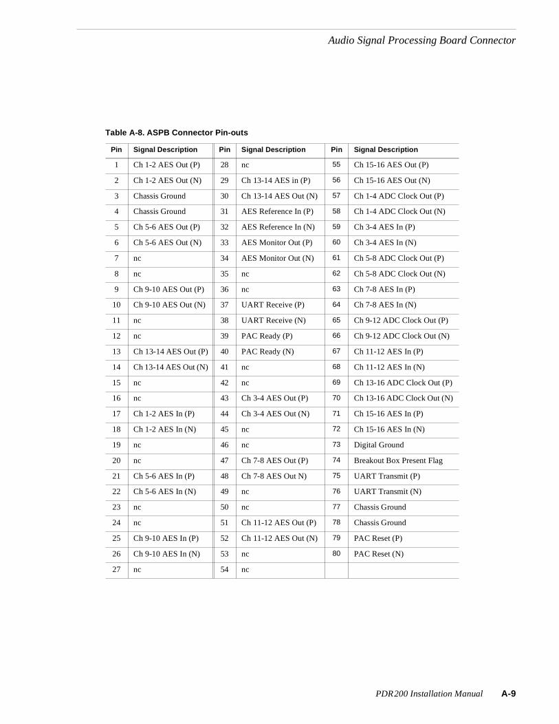
Audio Signal Processing Board Connector
Table A-8. ASPB Connector Pin-outs
Pin Signal Description Pin Signal Description Pin Signal Description
1 Ch 1-2 AES Out (P) 28 nc 55 Ch 15-16 AES Out (P)
2 Ch 1-2 AES Out (N) 29 Ch 13-14 AES in (P) 56 Ch 15-16 AES Out (N)
3 Chassis Ground 30 Ch 13-14 AES Out (N) 57 Ch 1-4 ADC Clock Out (P)
4 Chassis Ground 31 AES Reference In (P) 58 Ch 1-4 ADC Clock Out (N)
5 Ch 5-6 AES Out (P) 32 AES Reference In (N) 59 Ch 3-4 AES In (P)
6 Ch 5-6 AES Out (N) 33 AES Monitor Out (P) 60 Ch 3-4 AES In (N)
7 nc 34 AES Monitor Out (N) 61 Ch 5-8 ADC Clock Out (P)
8 nc 35 nc 62 Ch 5-8 ADC Clock Out (N)
9 Ch 9-10 AES Out (P) 36 nc 63 Ch 7-8 AES In (P)
10 Ch 9-10 AES Out (N) 37 UART Receive (P) 64 Ch 7-8 AES In (N)
11 nc 38 UART Receive (N) 65 Ch 9-12 ADC Clock Out (P)
12 nc 39 PAC Ready (P) 66 Ch 9-12 ADC Clock Out (N)
13 Ch 13-14 AES Out (P) 40 PAC Ready (N) 67 Ch 11-12 AES In (P)
14 Ch 13-14 AES Out (N) 41 nc 68 Ch 11-12 AES In (N)
15 nc 42 nc 69 Ch 13-16 ADC Clock Out (P)
16 nc 43 Ch 3-4 AES Out (P) 70 Ch 13-16 ADC Clock Out (N)
17 Ch 1-2 AES In (P) 44 Ch 3-4 AES Out (N) 71 Ch 15-16 AES In (P)
18 Ch 1-2 AES In (N) 45 nc 72 Ch 15-16 AES In (N)
19 nc 46 nc 73 Digital Ground
20 nc 47 Ch 7-8 AES Out (P) 74 Breakout Box Present Flag
21 Ch 5-6 AES In (P) 48 Ch 7-8 AES Out N) 75 UART Transmit (P)
22 Ch 5-6 AES In (N) 49 nc 76 UART Transmit (N)
23 nc 50 nc 77 Chassis Ground
24 nc 51 Ch 11-12 AES Out (P) 78 Chassis Ground
25 Ch 9-10 AES In (P) 52 Ch 11-12 AES Out (N) 79 PAC Reset (P)
26 Ch 9-10 AES In (N) 53 nc 80 PAC Reset (N)
27 nc 54 nc
PDR200 Installation Manual A-9

Appendix A Connector Pin-outs
A-1
RS-232 ConnectorsThe PDR200 has two RS-232 interface connectors on the rear panel. Figure A-7 shows a 9-pin RS-232 rear panel connector (both are male) and Table A-9 lists the pin-outs.
Figure A-7. RS-232 Connector Pin-outs
Table A-9. RS-232 Connector Pin-outs
Pin # Signal Description
1 DCD Received line Signal Detector
2 RXD Received Data
3 TXD Transmitted Data
4 DTR Data Terminal Ready
5 GND Ground
6 DSR Data Set Ready
7 RTS Request To Send
8 CTS Clear To Send
9 CE Ring Detect
5
1
9
6
0 PDR200 Installation Manual

Index
AAbout This Manual 1-1Additional Air Filters 5-7AES/EBU Digital Audio Problems
All audio is missing 4-18Air Filters
Replacing 5-3Air filters
Cleaning 5-3All analog audio is missing 4-19All digital audio is missing (digital only
system) 4-18Analog Audio is intermittent 4-19Analog Audio is missing one channel 4-19Analog Audio Mode Specifications 2-10Analog Audio Problems 4-19
All audio missing 4-19Audio is intermittent 4-19Audio missing one channel 4-19
Analog Composite Video E-to-E (Direct)Specifications 2-3, 2-5
Analog Composite Video OutputSpecifications 2-4Analog Input/Output Specifications 2-6API/Profile Protocol Extensions 3-15Asia and South America, Grass Valley Group
Product Support iiiAsia, Grass Valley Group Product Support iiiAt least one disk has out-of-date firmware and
may cause system hangs/crashes 4-14Audio 1-4Audio Problems 4-18
Analog 4-19Digital 4-18Embedded Serial I/O 4-19
Audio Processing and Storage 3-14Audio Recording System 3-5Audio Signal Processing Board 3-14
API/Profile Protocol Extensions 3-15
Audio Processing and Storage 3-14Clocking and Synchronization 3-15Digital I/O 3-14Vdrpanel Support 3-15
Audio Signal Processing BoardConnector A-8
BBezel and Air Filters, see Chapter 5,
Cleaning and replacing AirFilters’ 6-8
Board Configuration 4-25Board Removal and Replacement, PDR 200
6-33Board Retainer Brackets, Removal and
Replacement 6-30Board Tests and Selection 4-25Board Tests Results 4-25Boards, PDR 200, Removal and Replacement
6-30
CCan’t locate OS 4-9Canada, Grass Valley Group Product Support
iiiCanadian Certified AC Adapter x, xvCanadian Certified Power Cords x, xvCanadian EMC Notice of Compliance x, xvCertification xi, xviCertifications and Compliances x, xvChassis Covers, PDR 200, Removal and
Replacement 6-8Chroma Lock 3-7Cleaning 5-2Cleaning or Replacing Air Filters 5-3Cleaning the Filters 5-7Clocking and Synchronization 3-15Clocks 3-13Component Analog Video Input
Specifications 2-6Component Analog Video Performance
Specifications 2-7Connector Pin-outs A-1
Audio Signal Processing Board A-8
PDR200 Service Manual IND-1

IND
Ethernet A-3Fibre Channel A-6Local Area Network (LAN) Board A-3Reference Genlock A-7RS-232 A-10SCSI II A-4SVGA Board A-1
Could not configure 4-10Couldn’t handle 720 non-SCRIPTinterrupt er-
ror 4-15
DDiagnostic Test Exceptions 4-30Diagnostics 4-21Diagnostics Window Layout 4-25Diagnostics Window Menu Bar 4-22Digital Audio is intermittent 4-18Digital Audio is missing one channel 4-18Digital Audio Problems 4-18
Audio intermittent 4-18Audio is missing one channel 4-18
Digital I/O 3-14Disk Access 4-5Disk Drive Tray, Removal and Replacement
6-22Distribution Board, Removal andReplacement 6-26Done 4-29drive timed out! 4-15
EEISA Bus 3-6EISA Bus Interface 3-7EISA DMA Controller 3-10EISA to EDR Interface 3-10EISA to LPCI Interface 3-10Electrical Characteristics
Power Source 2-10Electrical Specifications 2-2
Power Supply 2-10Reference Genlock 2-2Time Code 2-2
Embedded Audio Problems 4-19Empty Slots 4-32EN55022 Class A Warning x, xvEnvironmental Criteria 2-11
Error message 4-14Can’t locate OS 4-9Could not configure 4-10Couldn’t handle 720
non-SCRIPTinterrupt error 4-15drive timed out! 4-15failed to start motor 4-15File system corrupt 4-9Hard disk controller failure 4-9Hardware failure, contact Grass Valley
Group support 4-9Microcode download to disk x.yy.zz
failed 4-15phase mismatch error -- will reset SCSI
bus 4-15SCSI Device Init
failed to start motor on device x.yy.zz4-14
sym720 illegal instruction detected 4-15Unrecognized disk drive type 4-15utilDiskHandler
format returned for wrong drive 4-14load microcode returned for wrong
drive 4-14realloc returned for wrong drive 4-14
Error messagesReal time processor failure 4-9
Ethernet 1-4Ethernet Connectors A-3Ethernet LAN Board (Slot J3) 4-31Europe, Grass Valley Group
Product Support iiiExecuting All (Board) Tests 4-29Executing Individual Board Tests 4-28Executing Test All Boards 4-26Exterior, Cleaning 5-2External Fan, Removal and Replacement 6-29
Ffailed to start motor 4-15Fan Board, Removal and Replacment 6-21Fan Fault 4-5Fan Tray, Removal and Replacement 6-18FCC Emission Control x, xvFCC Emission Limits xi, xvi
-2 PDR200 Service Manual

Fibre Channel 3-16Fibre Channel Cable Specifications A-6Fibre Channel Connector A-6Fibre Channel Networking 1-4File system corrupt 4-9Floppy Disk Drive, Removal and
Replacement 6-24Format Voltage Level Definitions for
CAVmtrxN Colorbar Matrix Test Clip2-8
Format Voltage Level Definitions forCAVmtrxP Colorbar Matrix Test Clip2-9
Front Panel Indicators and Control 4-4
GGeneral Information, Specifications 2-1General Safety Summary viiGPCI Bus Connection 3-9GPCI to LPCI Interface 3-11Grass Valley Group Product Support iii
HHard disk controller failure 4-9Hardware failure, contact Grass Valley Group
support 4-9
IInitial Fault Isolation Checks 4-2
System Interface Problems 4-2Injury Precautions viiInterior Cabling, PDR 200 6-45Interior, Cleaning 5-2Internal Fans, PDR 200, Removal and
Replacement 6-20Introduction 1-1
KKeyboard LEDs did not flash at
power up 4-10
LLaser Compliance x, xv
FCC Emission Limits xi, xviLaser Safety xi, xviLaser Safety Requirements x, xv
Laser Safety xi, xvi
Laser Safety Requirements x, xvLED Board, Removal and Replacement 6-9
LED EMI Board, Removal and Replacement6-28
Local Area Network (LAN) BoardConnectors A-3
Longitudinal Time Code 1-4LPCI Bus 3-10LPCI to Dual JPEG Interface 3-11LPCI to SCSI Interfaces 3-11LTC Reader 3-7LTC Writer 3-7
MMaintenance 5-1
Cleaning 5-2Visual Inspection 5-2
Making Basic Checks 4-1Manual Organization 1-2Master Enhanced Disk Recorder 3-8
Clocks 3-13EISA DMA Controller 3-10EISA to EDR Interface 3-10EISA to LPCI Interface 3-10GPCI Bus Connection 3-9GPCI to LPCI Interface 3-11LPCI Bus 3-10LPCI to Dual JPEG Interface 3-11LPCI to SCSI Interfaces 3-11PCI Bus Arbitration 3-11Real-Time Controller 3-9RTP Interrupts 3-12RTP to EISA Interface 3-9RTP to GPCI Interface 3-9Video Bus Interface 3-11
Mechanical Specifications 2-11Media Disk Drive, Removal and Replacement
6-14Microcode download to disk x.yy.zz
failed 4-15Mix Effects 3-17Motherboard
EISA Bus 3-6Video Bus 3-6
PDR200 Service Manual IND-3

IND
Video Router 3-6Motherboard, Removal and
Replacement 6-44Mouse/Keyboard EMI Board, Removal and
Replacement 6-38
NNetworking Problems 4-20Networking, Fibre Channel 1-4No Playback 4-16No Vdrpanel 4-9, 4-10No video or video is not as expected 4-16NT won’t boot 4-10
OOrganization of the Manual 1-2Over Temp 4-5
PPAC208/216 Cover, Removal and
Replacement 6-49PAC208/216 Daughter Board, Removal and
Replacement 6-58PAC208/216 Fan, Removal and Replacement
6-52PAC208/216 LED, Removal and
Replacement 6-50PAC208/216 Main Board, Removal and
Replacement 6-60PAC208/216 Power Connector and Line
Filter, Removal andReplacement 6-57
PAC208/216 Power Supply, Removal andReplacement 6-54
PAC208/216 Replaceable Parts List 6-48PAC208/216 Switch, Removal and
Replacement 6-56PAC208/216 XLR Board, Removal and
Replacement 6-62Parts List
PAC208/216 6-48PDR 200 6-2
PCI Board 3-13PCI Board, Removal and Replacement 6-35PCI Bus Arbitration 3-11PDR 200 Replaceable Parts List 6-2
Pentium Board (Slot J1) 4-30phase mismatch error -- will reset SCSI
bus 4-15Power Indicator 4-4Power Source 2-10Power Supply Specifications 2-10Power Supply, PDR 200, Removal and
Replacement 6-40Preventive Maintenance 5-2Product Damage Precautions viiiProduct Description 1-3
System ControlVideo
AudioNetworking
Storage 1-3Profile Chassis, Removal and
Replacement 6-6Profile.Log File 4-11Profile.Log SCSI Error Messages 4-15Program Input Genlock Specifications 2-6
RReal time processor failure 4-9Real-Time Controller 3-9Rear Panel Indicators and Control 4-6Rebuilding the Disk File System 6-64Record function starts and then stops 4-17Reference Genlock
Chroma Lock 3-7EISA Bus Interface 3-7LTC Reader 3-7LTC Writer 3-7Sync Extraction 3-7Timing Generator 3-7
Reference Genlock and Time Code 1-4Reference Genlock D-Connector A-7Reference Genlock Specifications 2-9Related Documentation 1-2Reloading the CMOS Chip 5-10Removal and Replacement
Air Filters 5-3Board Retainer Brackets 6-30Boards, PDR 200 6-30Chassis Covers, PDR 200 6-8
-4 PDR200 Service Manual

Disk Drive Tray 6-22Distribution Board 6-26External Fan 6-29Fan Board 6-21Fan Tray 6-18Floppy Disk Drive 6-24Internal Fans, PDR 200 6-20LED Board 6-9LED EMI Board 6-28Media Disk Drive 6-14Motherboard 6-44Mouse/Keyboard EMI Board 6-38PAC208/216 Cover 6-49PAC208/216 Daughter Board 6-58PAC208/216 Fan 6-52PAC208/216 LED 6-50PAC208/216 Main Board 6-60PAC208/216 Power Connector and Line
Filter 6-57PAC208/216 Power Supply 6-54PAC208/216 Switch 6-56PAC208/216 XLR Board 6-62PCI Board 6-35Power Supply, PDR 200 6-40Profile Chassis 6-6SCSI Backplane 6-16Serial EMI Board 6-37System Drive 6-12
Removing the Filters 5-3Removing the PAC208/216 Filter 5-6Repair Verification 6-64
Testing 6-64Repairing Corrupt Windows NT Software 5-9Replacing the Filters 5-5Replacing the PAC208/216 Filter 5-7RS-232 Connectors A-10RS-422 Board Tests (Slot J17) 4-32RTP Interrupts 3-12RTP to EISA Interface 3-9RTP to GPCI Interface 3-9Running Board Diagnostics 4-25
SSample SCSI Listings 4-11
SCSI Backplane, Removal and Replacement6-16
SCSI Board (Slot J4) 4-31SCSI Bus Errors
Profile.Log File 4-11SCSI Device Init
failed to start motor ondevice x.yy.zz 4-14
SCSI-II Connector A-4Serial Digital Video Input/Output
Specifications 2-2Serial EMI Board, Removal and
Replacement 6-37Service 6-1Service Safety Summary ix, xiiiSlave Enhanced Disk Recorder 3-13Software Upgrades and Repairs 5-8
Reloading the CMOS Chip 5-10Repairing Corrupt Windows NT Software
5-9Updating an Emergency Repair Disk 5-8Upgrades 5-8
Source Power 2-10South America, Grass Valley Group Product
Support iiiSpecification
Electrical CharacteristicsPower Source 2-10
Specifications 2-1Analog Audio Mode 2-10Analog Composite Video E-E 2-3, 2-5Analog Composite Video Output 2-4Analog I/O 2-6Component Analog Video Input 2-6Component Analog Video
Performance 2-7Electrical 2-2Environmental 2-11Fibre Channel Cable A-6Mechanical 2-11Power Supply 2-10Program Input Genlock 2-6Reference Genlock 2-9Serial Digital I/O 2-2Time Code 2-9
PDR200 Service Manual IND-5

IND
Standby/On Switch 4-5Starting the Diagnostics Program 4-21Start-up Problems 4-9
Keyboard LEDs did not flash atpower up 4-10
No Vdrpanel 4-9NT won’t boot 4-10
Storage 1-4SVGA Board Connectors A-1sym720 illegal instruction detected 4-15Symptom
All analog audio missing 4-19All digital audio missing 4-18Analog audio intermittent 4-19Analog audio missing one channel 4-19black or bad fields 4-17Digital audio is intermittent 4-18Digital audio missing one channel 4-18Keyboard LEDs did not flash at power up
4-10No Playback 4-16No Vdrpanel 4-9, 4-10No video 4-16NT won’t boot 4-10Record function starts and then stops 4-17Video not as expected 4-16
Sync Extraction 3-7System Control 1-3System Drive, Removal and
Replacement 6-12System Fault 4-5System Interface Problems 4-2System Overview 3-2System SCSI Error Messages 4-14
TTest Equipment 2-1Testing, Repair Verification 6-64Theory of Operation 3-1
Audio Recording System 3-5Master Enhanced Disk Recorder 3-8Mother Board 3-6Specific Boards 3-6System Overview 3-2Video Recording System 3-4
Time Code Specification 2-9Time Code, Longitudinal 1-4Timing Generator 3-7Tools Required 5-1, 6-1Troubleshooting 4-1
Initial Fault Isolation Checks 4-2Making Basic Checks 4-1
Troubleshooting the SCSI Bus 4-14
UUnited States and Canada, Grass Valley
Group Product Support iiiUnrecognized disk drive type 4-15Updating an Emergency Repair Disk 5-8Upgrades, software 5-8utilDiskHandler
format returned for wrong drive 4-14load microcode returned for wrong drive
4-14realloc returned for wrong drive 4-14
VVdrpanel Support 3-15VGA Board (Slot J2) 4-31Video 1-3Video Bus 3-6Video Bus Interface 3-11Video Problems 4-16
No Playback 4-16No video or video is not as expected 4-16Record function starts and then stops 4-17When playing known good clip, black or
bad fields appear 4-17Video Recording System 3-4Visual Inspection 5-2
WWhen playing known good clip, black or bad
fields appear 4-17World Wide Grass Valley Group Product
Support iii
-6 PDR200 Service Manual


