Embed Size (px)
Citation preview
Programming Embedded Systems in C and C++
Michael Barr
Publisher: O'Reilly
First Edition January 1999ISBN: 1-56592-354-5, 191 pages
This book introduces embedded systems to C and C++ programmers. Topics include testing memory devices,writing and erasing Flash memory, verifying nonvolatile memory contents, controlling on-chip peripherals, devicedriver design and implementation, optimizing embedded code for size and speed, and making the most of C++without a performance penalty.

Why I Wrote This BookI once heard an estimate that in the United States there are eight microprocessor-based devices for every person. Atthe time, I wondered how this could be. Are there really that many computers surrounding us? Later, when I hadmore time to think about it, I started to make a list of the things I used that probably contained a microprocessor.Within five minutes, my list contained ten items: television, stereo, coffee maker, alarm clock, VCR, microwave,dishwasher, remote control, bread machine, and digital watch. And those were just my personal possessions-Iquickly came up with ten more devices I used at work.The revelation that every one of those products contains not only a processor, but also software, was not far behind.At last, I knew what I wanted to do with my life. I wanted to put my programming skills to work developingembedded computer systems. But how would I acquire the necessary knowledge? At this point, I was in my last yearof college. There hadn't been any classes on embedded systems programming so far, and I wasn't able to find anylisted in the course catalog.Fortunately, when I graduated I found a company that let me write embedded software while I was still learning. ButI was pretty much on my own. The few people who knew about embedded software were usually too busy to explainthings to me, so I searched high and low for a book that would teach me. In the end, I found I had to learneverything myself. I never found that book, and I always wondered why no one had written it.Now I've decided to write that book myself. And in the process, I've discovered why no one had done it before. Oneof the hardest things about this subject is knowing when to stop writing. Each embedded system is unique, and Ihave learned that there is an exception to every rule. Nevertheless, I have tried to boil the subject down to its essenceand present only those things that programmers definitely need to know about embedded systems.
Intended AudienceThis is a book about programming embedded systems in C and C++. As such, it assumes that the reader already hassome programming experience and is at least familiar with the syntax of these two languages. It also helps if youhave some familiarity with basic data structures, such as linked lists. The book does not assume that you have agreat deal of knowledge about computer hardware, but it does expect that you are willing to learn a little bit abouthardware along the way. This is, after all, a part of the job of an embedded programmer.While writing this book, I had two types of readers in mind. The first reader is a beginner-much as I was when Igraduated from college. She has a background in computer science or engineering and a few years of programmingexperience. The beginner is interested in writing embedded software for a living but is not sure just how to getstarted. After reading the first five chapters, she will be able to put her programming skills to work developingsimple embedded programs. The rest of the book will act as her reference for the more advanced topics encounteredin the coming months and years of her career.The second reader is already an embedded systems programmer. She is familiar with embedded hardware andknows how to write software for it but is looking for a reference book that explains key topics. Perhaps theembedded systems programmer has experience only with assembly language programming and is relatively new toC and C++. In that case, the book will teach her how to use those languages in an embedded system, and the laterchapters will provide the advanced material she requires.Whether you fall into one of these categories or not, I hope this book provides the information you are looking for ina format that is friendly and easily accessible.
Organization
The book contains ten chapters, one appendix, a glossary, and an annotated bibliography. The ten chapters can bedivided quite nicely into two parts. The first part consists of Chapter 1 through Chapter 5 and is intended mainly fornewcomers to embedded systems. These chapters should be read in their entirety and in the order that they appear.This will bring you up to speed quickly and introduce you to the basics of embedded software development. Aftercompleting Chapter 5, you will be ready to develop small pieces of embedded software on your own.The second part of the book consists of Chapter 6 through Chapter 10 and discusses advanced topics that are ofinterest to inexperienced and experienced embedded programmers alike. These chapters are mostly self-containedand can be read in any order. In addition, Chapter 6 through Chapter 9 contain example programs that might beuseful to you on a future embedded software project.
• Chapter 1 introduces you to embedded systems. It defines the term, gives examples, and explains why Cand C++ were selected as the languages of the book.
• Chapter 2 walks you through the process of writing a simple embedded program in C. This is roughly theequivalent of the "Hello, World" example presented in most other programming books.
• Chapter 3 introduces the software development tools you will be using to prepare your programs forexecution by an embedded processor.
• Chapter 4 presents various techniques for loading your executable programs into an embedded system. Italso describes the debugging tools and techniques that are available to you.
• Chapter 5 outlines a simple procedure for learning about unfamiliar hardware platforms. After completingthis chapter, you will be ready to write and debug simple embedded programs.
• Chapter 6 tells you everything you need to know about memory in embedded systems. The chapter includessource code implementations of memory tests and Flash memory drivers.
• Chapter 7 explains device driver design and implementation techniques and includes an example driver fora common peripheral called a timer.
• Chapter 8 includes a very basic operating system that can be used in any embedded system. It also helpsyou decide if you'll need an operating system at all and, if so, whether to buy one or write your own.
• Chapter 9 expands on the device driver and operating system concepts presented in the previous chapters. Itexplains how to control more complicated peripherals and includes a complete example application thatpulls together everything you've learned so far.
• Chapter 10 explains how to simultaneously increase the speed and decrease the memory requirements ofyour embedded software. This includes tips for taking advantage of the most beneficial C++ featureswithout paying a significant performance penalty.
Throughout the book, I have tried to strike a balance between specific examples and general knowledge. Wheneverpossible, I have eliminated minor details in the hopes of making the book more readable. You will gain the mostfrom the book if you view the examples, as I do, only as tools for understanding important concepts. Try not to getbogged down in the details of any one circuit board or chip. If you understand the general concepts, you should beable to apply them to any embedded system you encounter.
Conventions, Typographical and Otherwise
The following typographical conventions are used throughout the book:
Italic
is used for the names of files, functions, programs, methods, routines, and options when theyappear in the body of a paragraph. Italic is also used for emphasis and to introduce newterms.
Constant Width
is used in the examples to show the contents of files and the output of commands. In the bodyof a paragraph, this style is used for keywords, variable names, classes, objects, parameters,and other code snippets.
Constant Width Bold
is used in the examples to show commands and options that you type literally.
is used in the examples to show commands and options that you type literally.
This symbol is used to indicate a tip, suggestion, or general note.
This symbol is used to indicate a warning.
Other conventions relate to gender and roles. With respect to gender, I have purposefullyalternated my use of the terms "he" and "she" throughout the book. "He" is used in the odd-numbered chapters and "she" in all of the even-numbered ones.
With respect to roles, I have occasionally distinguished between the tasks of hardware engineers,embedded software engineers, and application programmers in my discussion. But these titlesrefer only to roles played by individual engineers, and it should be noted that it can and oftendoes happen that one individual fills more than one of these roles.
Obtaining the Examples OnlineThis book includes many source code listing, and all but the most trivial one-liners are available online. Theseexamples are organized by chapter number and include build instructions (makefiles) to help you recreate each ofthe executables. The complete archive is available via FTP, atftp://ftp.oreilly.com/pub/examples/nutshell/embedded_c/.

How to Contact Us
We have tested and verified all the information in this book to the best of our ability, but you may find that featureshave changed (or even that we have made mistakes!). Please let us know about any errors you find, as well as yoursuggestions for future editions, by writing to:
O'Reilly & Associates
1005 Gravenstein Highway North
Sebastopol, CA 95472
800-998-9938 (in the U.S. or Canada)
707-829-0515 (international/local)
707-829-0104 (FAX)
You can also send us messages electronically. To be put on the mailing list or request a catalog, send email to:
To ask technical questions or comment on the book, send email to:
We have a web site for the book, where we'll list examples, errata, and any plans for future editions. You can accessthis page at:
http://www.oreilly.com/catalog/embsys/
For more information about this book and others, see the O'Reilly web site:
http://www.oreilly.com

Personal Comments and AcknowledgmentsAs long as I can remember I have been interested in writing a book or two. But now that I have done so, I mustconfess that I was naive when I started. I had no idea how much work it would take, nor how many other peoplewould have to get involved. Another thing that surprised me was how easy it was to find a willing publisher. I hadexpected that to be the hard part.From proposal to publication, this project has taken almost two years to complete. But, then, that's mostly because Iworked a full-time job throughout and tried to maintain as much of my social life as possible. Had I known when Istarted that I'd still be agonizing over final drafts at this late date, I would have probably quit working and finishedthe book more quickly. But continuing to work has been good for the book (as well as my bank account!). It hasallowed me the luxury of discussing my ideas regularly with a complete cast of embedded hardware and softwareprofessionals. Many of these same folks have also contributed to the book more directly by reviewing drafts of someor all of the chapters.I am indebted to all of the following people for sharing their ideas and reviewing my work: Toby Bennett, PaulCabler (and the other great folks at Arcom), Mike Corish, Kevin D'Souza, Don Davis, Steve Edwards, Mike Ficco,Barbara Flanagan, Jack Ganssle, Stephen Harpster (who christened me "King of the Sentence Fragment" afterreading an early draft), Jonathan Harris, Jim Jensen, Mark Kohler, Andy Kollegger, Jeff Mallory, Ian Miller, HenryNeugauss, Chris Schanck, Brian Silverman, John Snyder, Jason Steinhorn (whose constant stream of grammaticaland technical critiques have made this book worth reading), Ian Taylor, Lindsey Vereen, Jeff Whipple, and GregYoung.I would also like to thank my editor, Andy Oram. Without his enthusiasm for my initial proposal, overabundantpatience, and constant encouragement, this book would never have been completed.Finally, I'd like to thank Alpa Dharia for her support and encouragement throughout this long process.Michael Barr [email protected]
Chapter 1.
IntroductionI think there is a world market for maybe five computers.
-Thomas Watson, Chairman of IBM, 1943
There is no reason anyone would want a computer in their home.
-Ken Olson, President of Digital Equipment Corporation, 1977
One of the more surprising developments of the last few decades has been the ascendance of computers to a positionof prevalence in human affairs. Today there are more computers in our homes and offices than there are people wholive and work in them. Yet many of these computers are not recognized as such by their users. In this chapter, I'llexplain what embedded systems are and where they are found. I will also introduce the subject of embeddedprogramming, explain why I have selected C and C++ as the languages for this book, and describe the hardwareused in the examples.
1.1 What Is an Embedded System?An embedded system is a combination of computer hardware and software, and perhaps additional mechanical orother parts, designed to perform a specific function. A good example is the microwave oven. Almost everyhousehold has one, and tens of millions of them are used every day, but very few people realize that a processor andsoftware are involved in the preparation of their lunch or dinner.This is in direct contrast to the personal computer in the family room. It too is comprised of computer hardware andsoftware and mechanical components (disk drives, for example). However, a personal computer is not designed toperform a specific function. Rather, it is able to do many different things. Many people use the term general-purposecomputer to make this distinction clear. As shipped, a general-purpose computer is a blank slate; the manufacturerdoes not know what the customer will do with it. One customer may use it for a network file server, another may useit exclusively for playing games, and a third may use it to write the next great American novel.Frequently, an embedded system is a component within some larger system. For example, modern cars and truckscontain many embedded systems. One embedded system controls the anti-lock brakes, another monitors andcontrols the vehicle's emissions, and a third displays information on the dashboard. In some cases, these embeddedsystems are connected by some sort of a communications network, but that is certainly not a requirement.At the possible risk of confusing you, it is important to point out that a general-purpose computer is itself made upof numerous embedded systems. For example, my computer consists of a keyboard, mouse, video card, modem,hard drive, floppy drive, and sound card-each of which is an embedded system. Each of these devices contains aprocessor and software and is designed to perform a specific function. For example, the modem is designed to sendand receive digital data over an analog telephone line. That's it. And all of the other devices can be summarized in asingle sentence as well.If an embedded system is designed well, the existence of the processor and software could be completely unnoticedby a user of the device. Such is the case for a microwave oven, VCR, or alarm clock. In some cases, it would evenbe possible to build an equivalent device that does not contain the processor and software. This could be done byreplacing the combination with a custom integrated circuit that performs the same functions in hardware. However,a lot of flexibility is lost when a design is hard-coded in this way. It is much easier, and cheaper, to change a fewlines of software than to redesign a piece of custom hardware.
1.1.1 History and Future
Given the definition of embedded systems earlier in this chapter, the first such systems could not possibly haveappeared before 1971. That was the year Intel introduced the world's first microprocessor. This chip, the 4004, wasdesigned for use in a line of business calculators produced by the Japanese company Busicom. In 1969, Busicomasked Intel to design a set of custom integrated circuits-one for each of their new calculator models. The 4004 wasIntel's response. Rather than design custom hardware for each calculator, Intel proposed a general-purpose circuitthat could be used throughout the entire line of calculators. This general-purpose processor was designed to read andexecute a set of instructions-software-stored in an external memory chip. Intel's idea was that the software wouldgive each calculator its unique set of features.The microprocessor was an overnight success, and its use increased steadily over the next decade. Early embeddedapplications included unmanned space probes, computerized traffic lights, and aircraft flight control systems. In the1980s, embedded systems quietly rode the waves of the microcomputer age and brought microprocessors into everypart of our personal and professional lives. Many of the electronic devices in our kitchens (bread machines, food
processors, and microwave ovens), living rooms (televisions, stereos, and remote controls), and workplaces (faxmachines, pagers, laser printers, cash registers, and credit card readers) are embedded systems.It seems inevitable that the number of embedded systems will continue to increase rapidly. Already there arepromising new embedded devices that have enormous market potential: light switches and thermostats that can becontrolled by a central computer, intelligent air-bag systems that don't inflate when children or small adults arepresent, palm-sized electronic organizers and personal digital assistants (PDAs), digital cameras, and dashboardnavigation systems. Clearly, individuals who possess the skills and desire to design the next generation of embeddedsystems will be in demand for quite some time.
1.1.2 Real-Time Systems
One subclass of embedded systems is worthy of an introduction at this point. As commonly defined, areal-timesystem is a computer system that has timing constraints. In other words, a real-time system is partly specified interms of its ability to make certain calculations or decisions in a timely manner. These important calculations aresaid to have deadlines for completion. And, for all practical purposes, a missed deadline is just as bad as a wronganswer.The issue of what happens if a deadline is missed is a crucial one. For example, if the real-time system is part of anairplane's flight control system, it is possible for the lives of the passengers and crew to be endangered by a singlemissed deadline. However, if instead the system is involved in satellite communication, the damage could be limitedto a single corrupt data packet. The more severe the consequences, the more likely it will be said that the deadline is"hard" and, thus, the system a hard real-time system. Real-time systems at the other end of this continuum are said tohave "soft" deadlines.All of the topics and examples presented in this book are applicable to the designers of real-time systems. However,the designer of a real-time system must be more diligent in his work. He must guarantee reliable operation of thesoftware and hardware under all possible conditions. And, to the degree that human lives depend upon the system'sproper execution, this guarantee must be backed by engineering calculations and descriptive paperwork.
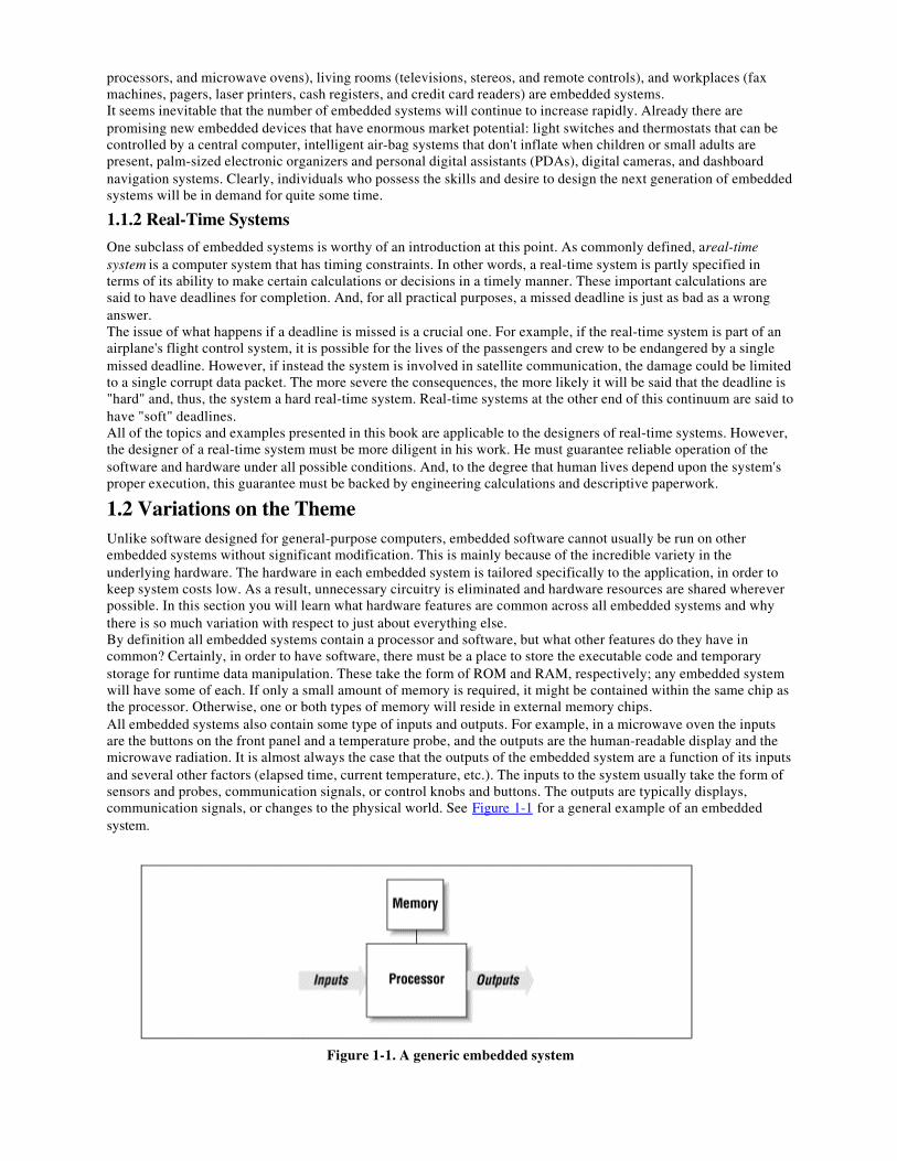
1.2 Variations on the ThemeUnlike software designed for general-purpose computers, embedded software cannot usually be run on otherembedded systems without significant modification. This is mainly because of the incredible variety in theunderlying hardware. The hardware in each embedded system is tailored specifically to the application, in order tokeep system costs low. As a result, unnecessary circuitry is eliminated and hardware resources are shared whereverpossible. In this section you will learn what hardware features are common across all embedded systems and whythere is so much variation with respect to just about everything else.By definition all embedded systems contain a processor and software, but what other features do they have incommon? Certainly, in order to have software, there must be a place to store the executable code and temporarystorage for runtime data manipulation. These take the form of ROM and RAM, respectively; any embedded systemwill have some of each. If only a small amount of memory is required, it might be contained within the same chip asthe processor. Otherwise, one or both types of memory will reside in external memory chips.All embedded systems also contain some type of inputs and outputs. For example, in a microwave oven the inputsare the buttons on the front panel and a temperature probe, and the outputs are the human-readable display and themicrowave radiation. It is almost always the case that the outputs of the embedded system are a function of its inputsand several other factors (elapsed time, current temperature, etc.). The inputs to the system usually take the form ofsensors and probes, communication signals, or control knobs and buttons. The outputs are typically displays,communication signals, or changes to the physical world. See Figure 1-1 for a general example of an embeddedsystem.
Figure 1-1. A generic embedded system
With the exception of these few common features, the rest of the embedded hardware is usually unique. Thisvariation is the result of many competing design criteria. Each system must meet a completely different set ofrequirements, any or all of which can affect the compromises and tradeoffs made during the development of theproduct. For example, if the system must have a production cost of less than $10, then other things-like processingpower and system reliability-might need to be sacrificed in order to meet that goal.Of course, production cost is only one of the possible constraints under which embedded hardware designers work.Other common design requirements include the following:
Processing power
The amount of processing power necessary to get the job done. A common way to compareprocessing power is the MIPS (millions of instructions per second) rating. If two processorshave ratings of 25 MIPS and 40 MIPS, the latter is said to be the more powerful of the two.However, other important features of the processor need to be considered. One of these is theregister width, which typically ranges from 8 to 64 bits. Today's general-purpose computersuse 32- and 64-bit processors exclusively, but embedded systems are still commonly builtwith older and less costly 8- and 16-bit processors.
Memory
The amount of memory (ROM and RAM) required to hold the executable software and thedata it manipulates. Here the hardware designer must usually make his best estimate up frontand be prepared to increase or decrease the actual amount as the software is being developed.The amount of memory required can also affect the processor selection. In general, theregister width of a processor establishes the upper limit of the amount of memory it canaccess (e.g., an 8-bit address register can select one of only 256 unique memory locations).[1]
[1] Of course, the smaller the register width, the more likely it is that the processor employs tricks likemultiple address spaces to support more memory. A few hundred bytes just isn't enough to do much ofanything. Several thousand bytes is a more likely minimum, even for an 8-bit processor.
Development cost
The cost of the hardware and software design processes. This is a fixed, one-time cost, so itmight be that money is no object (usually for high-volume products) or that this is the onlyaccurate measure of system cost (in the case of a small number of units produced).
Number of units
The tradeoff between production cost and development cost is affected most by the numberof units expected to be produced and sold. For example, it is usually undesirable to developyour own custom hardware components for a low-volume product.
Expected lifetime
How long must the system continue to function (on average)? A month, a year, or a decade?This affects all sorts of design decisions from the selection of hardware components to howmuch the system may cost to develop and produce.
Reliability
How reliable must the final product be? If it is a children's toy, it doesn't always have to workright, but if it's a part of a space shuttle or a car, it had sure better do what it is supposed toeach and every time.
In addition to these general requirements, there are the detailed functional requirements of the system itself. Theseare the things that give the embedded system its unique identity as a microwave oven, pacemaker, or pager.
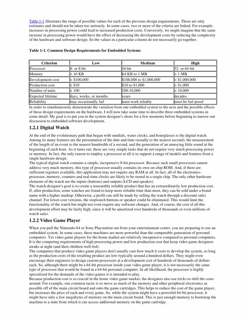
Table 1-1 illustrates the range of possible values for each of the previous design requirements. These are onlyestimates and should not be taken too seriously. In some cases, two or more of the criteria are linked. For example,increases in processing power could lead to increased production costs. Conversely, we might imagine that the sameincrease in processing power would have the effect of decreasing the development costs-by reducing the complexityof the hardware and software design. So the values in a particular column do not necessarily go together.
Table 1-1. Common Design Requirements for Embedded Systems
Criterion Low Medium HighProcessor 4- or 8-bit 16-bit 32- or 64-bitMemory < 16 KB 64 KB to 1 MB > 1 MB
Development cost < $100,000 $100,000 to $1,000,000 > $1,000,000Production cost < $10 $10 to $1,000 > $1,000Number of units < 100 100-10,000 > 10,000
Expected lifetime days, weeks, or months years decadesReliability may occasionally fail must work reliably must be fail-proofIn order to simultaneously demonstrate the variation from one embedded system to the next and the possible effectsof these design requirements on the hardware, I will now take some time to describe three embedded systems insome detail. My goal is to put you in the system designer's shoes for a few moments before beginning to narrow ourdiscussion to embedded software development.
1.2.1 Digital Watch
At the end of the evolutionary path that began with sundials, water clocks, and hourglasses is the digital watch.Among its many features are the presentation of the date and time (usually to the nearest second), the measurementof the length of an event to the nearest hundredth of a second, and the generation of an annoying little sound at thebeginning of each hour. As it turns out, these are very simple tasks that do not require very much processing poweror memory. In fact, the only reason to employ a processor at all is to support a range of models and features from asingle hardware design.The typical digital watch contains a simple, inexpensive 8-bit processor. Because such small processors cannotaddress very much memory, this type of processor usually contains its own on-chip ROM. And, if there aresufficient registers available, this application may not require any RAM at all. In fact, all of the electronics-processor, memory, counters and real-time clocks-are likely to be stored in a single chip. The only other hardwareelements of the watch are the inputs (buttons) and outputs (LCD and speaker).The watch designer's goal is to create a reasonably reliable product that has an extraordinarily low production cost.If, after production, some watches are found to keep more reliable time than most, they can be sold under a brandname with a higher markup. Otherwise, a profit can still be made by selling the watch through a discount saleschannel. For lower-cost versions, the stopwatch buttons or speaker could be eliminated. This would limit thefunctionality of the watch but might not even require any software changes. And, of course, the cost of all thisdevelopment effort may be fairly high, since it will be amortized over hundreds of thousands or even millions ofwatch sales.
1.2.2 Video Game Player
When you pull the Nintendo-64 or Sony Playstation out from your entertainment center, you are preparing to use anembedded system. In some cases, these machines are more powerful than the comparable generation of personalcomputers. Yet video game players for the home market are relatively inexpensive compared to personal computers.It is the competing requirements of high processing power and low production cost that keep video game designersawake at night (and their children well-fed).The companies that produce video game players don't usually care how much it costs to develop the system, so longas the production costs of the resulting product are low-typically around a hundred dollars. They might evenencourage their engineers to design custom processors at a development cost of hundreds of thousands of dollarseach. So, although there might be a 64-bit processor inside your video game player, it is not necessarily the sametype of processor that would be found in a 64-bit personal computer. In all likelihood, the processor is highlyspecialized for the demands of the video games it is intended to play.Because production cost is so crucial in the home video game market, the designers also use tricks to shift the costsaround. For example, one common tactic is to move as much of the memory and other peripheral electronics aspossible off of the main circuit board and onto the game cartridges. This helps to reduce the cost of the game player,but increases the price of each and every game. So, while the system might have a powerful 64-bit processor, itmight have only a few megabytes of memory on the main circuit board. This is just enough memory to bootstrap themachine to a state from which it can access additional memory on the game cartridge.

1.2.3 Mars Explorer
In 1976, two unmanned spacecraft arrived on the planet Mars. As part of their mission, they were to collect samplesof the Martian surface, analyze the chemical makeup of each, and transmit the results to scientists back on Earth.Those Viking missions are amazing to me. Surrounded by personal computers that must be rebooted almost daily, Ifind it remarkable that more than 20 years ago a team of scientists and engineers successfully built two computersthat survived a journey of 34 million miles and functioned correctly for half a decade. Clearly, reliability was one ofthe most important requirements for these systems.What if a memory chip had failed? Or the software had bugs that caused it to crash? Or an electrical connectionbroke during impact? There is no way to prevent such problems from occurring. So, all of these potential failurepoints and many others had to be eliminated by adding redundant circuitry or extra functionality: an extra processorhere, special memory diagnostics there, a hardware timer to reset the system if the software got stuck, and so on.More recently, NASA launched the Pathfinder mission. Its primary goal was to demonstrate the feasibility of gettingto Mars on a budget. Of course, given the advances in technology made since the mid-70s, the designers didn't haveto give up too much to accomplish this. They might have reduced the amount of redundancy somewhat, but they stillgave Pathfinder more processing power and memory than Viking ever could have. The Mars Pathfinder was actuallytwo embedded systems: a landing craft and a rover. The landing craft had a 32-bit processor and 128 MB of RAM;the rover, on the other hand, had only an 8-bit processor and 512KB. These choices probably reflect the differentfunctional requirements of the two systems. But I'm sure that production cost wasn't much of an issue in either case.
1.3 C: The Least Common DenominatorOne of the few constants across all these systems is the use of the C programming language. More than any other, Chas become the language of embedded programmers. This has not always been the case, and it will not continue tobe so forever. However, at this time, C is the closest thing there is to a standard in the embedded world. In thissection I'll explain why C has become so popular and why I have chosen it and its descendent C++ as the primarylanguages of this book.Because successful software development is so frequently about selecting the best language for a given project, it issurprising to find that one language has proven itself appropriate for both 8-bit and 64-bit processors; in systemswith bytes, kilobytes, and megabytes of memory; and for development teams that consist of from one to a dozen ormore people. Yet this is precisely the range of projects in which C has thrived.Of course, C is not without advantages. It is small and fairly simple to learn, compilers are available for almostevery processor in use today, and there is a very large body of experienced C programmers. In addition, C has thebenefit of processor-independence, which allows programmers to concentrate on algorithms and applications, ratherthan on the details of a particular processor architecture. However, many of these advantages apply equally to otherhigh-level languages. So why has C succeeded where so many other languages have largely failed?Perhaps the greatest strength of C-and the thing that sets it apart from languages like Pascal and FORTRAN-is that itis a very "low-level" high-level language. As we shall see throughout the book, C gives embedded programmers anextraordinary degree of direct hardware control without sacrificing the benefits of high-level languages. The "low-level" nature of C was a clear intention of the language's creators. In fact, Kernighan and Ritchie included thefollowing comment in the opening pages of their book The C Programming Language :
C is a relatively "low level" language. This characterization is not pejorative; it simplymeans that C deals with the same sort of objects that most computers do. These may becombined and moved about with the arithmetic and logical operators implemented by realmachines.
Few popular high-level languages can compete with C in the production of compact, efficient code for almost allprocessors. And, of these, only C allows programmers to interact with the underlying hardware so easily.
1.3.1 Other Embedded Languages
Of course, C is not the only language used by embedded programmers. At least three other languages-assembly,C++, and Ada-are worth mentioning in greater detail.In the early days, embedded software was written exclusively in the assembly language of the target processor. Thisgave programmers complete control of the processor and other hardware, but at a price. Assembly languages havemany disadvantages, not the least of which are higher software development costs and a lack of code portability. Inaddition, finding skilled assembly programmers has become much more difficult in recent years. Assembly is nowused primarily as an adjunct to the high-level language, usually only for those small pieces of code that must beextremely efficient or ultra-compact, or cannot be written in any other way.C++ is an object-oriented superset of C that is increasingly popular among embedded programmers. All of the corelanguage features are the same as C, but C++ adds new functionality for better data abstraction and a more object-oriented style of programming. These new features are very helpful to software developers, but some of them do
reduce the efficiency of the executable program. So C++ tends to be most popular with large development teams,where the benefits to developers outweigh the loss of program efficiency.Ada is also an object-oriented language, though it is substantially different than C++. Ada was originally designedby the U.S. Department of Defense for the development of mission-critical military software. Despite being twiceaccepted as an international standard (Ada83 and Ada95), it has not gained much of a foothold outside of thedefense and aerospace industries. And it is losing ground there in recent years. This is unfortunate because the Adalanguage has many features that would simplify embedded software development if used instead of C++.
1.3.2 Choosing a Language for the Book
A major question facing the author of a book like this is, which programming languages should be included in thediscussion? Attempting to cover too many languages might confuse the reader or detract from more importantpoints. On the other hand, focusing too narrowly could make the discussion unnecessarily academic or (worse forthe author and publisher) limit the potential market for the book.Certainly, C must be the centerpiece of any book about embedded programming-and this book will be no exception.More than half of the sample code is written in C, and the discussion will focus primarily on C-related programmingissues. Of course, everything that is said about C programming applies equally to C++. In addition, I will coverthose features of C++ that are most useful for embedded software development and use them in the later examples.Assembly language will be discussed in certain limited contexts, but will be avoided whenever possible. In otherwords, I will mention assembly language only when a particular programming task cannot be accomplished in anyother way.I feel that this mixed treatment of C, C++, and assembly most accurately reflects how embedded software is actuallydeveloped today and how it will continue to be developed in the near-term future. I hope that this choice will keepthe discussion clear, provide information that is useful to people developing actual systems, and include as large apotential audience as possible.
1.4 A Few Words About HardwareIt is the nature of programming that books about the subject must include examples. Typically, these examples areselected so that they can be easily experimented with by interested readers. That means readers must have access tothe very same software development tools and hardware platforms used by the author. Unfortunately, in the case ofembedded programming, this is unrealistic. It simply does not make sense to run any of the example programs onthe platforms available to most readers-PCs, Macs, and Unix workstations.Even selecting a standard embedded platform is difficult. As you have already learned, there is no such thing as a"typical" embedded system. Whatever hardware is selected, the majority of readers will not have access to it. Butdespite this rather significant problem, I do feel it is important to select a reference hardware platform for use in theexamples. In so doing, I hope to make the examples consistent and, thus, the entire discussion more clear.In order to illustrate as many points as possible with a single piece of hardware, I have found it necessary to select amiddle-of-the-road platform. This hardware consists of a 16-bit processor (Intel's 80188EB[2] ), a decent amount ofmemory (128KB of RAM and 256 KB of ROM), and some common types of inputs, outputs, and peripheralcomponents. The board I've chosen is called the Target188EB and is manufactured and sold by Arcom ControlSystems. More information about the Arcom board and instructions for obtaining one can be found in Appendix A.
[2] Intel's 80188EB processor is a special version of the 80186 that has been redesigned for use in embedded systems.The original 80186 was a successor to the 8086 processor that IBM used in their very first personal computer-thePC/XT. The 80186 was never the basis of any PC because it was passed over (in favor of the 80286) when IBMdesigned their next model-the PC/AT. Despite that early failure, versions of the 80186 from Intel and AMD haveenjoyed tremendous success in embedded systems in recent years.
If you have access to the reference hardware, you will be able to work through the examples in the book exactly asthey are presented. Otherwise, you will need to port the example code to an embedded platform that you do haveaccess to. Toward that end, every effort has been made to make the example programs as portable as possible.However, the reader should bear in mind that the hardware in each embedded system is different and that some ofthe examples might be meaningless on his hardware. For example, it wouldn't make sense to port the Flash memorydriver presented in Chapter 6 to a board that had no Flash memory devices.Anyway I'll have a lot more to say about hardware in Chapter 5. But first we have a number of software issues todiscuss. So let's get started.
Chapter 2.
Your First Embedded ProgramACHTUNG! Das machine is nicht fur gefingerpoken und mittengrabben. Ist easyschnappen der springenwerk, blowenfusen und corkenpoppen mit spitzensparken. Istnicht fur gewerken by das dummkopfen. Das rubbernecken sightseeren keepen hands indas pockets. Relaxen und vatch das blinkenlights!
In this chapter we'll dive right into embedded programming by way of an example. The program we'll look at issimilar in spirit to the "Hello, World!" example found in the beginning of most other programming books. As wediscuss the code, I'll provide justification for the selection of the particular program and point out the parts of it thatare dependent on the target hardware. This chapter contains only the source code for this first program. We'll discusshow to create the executable and actually run it in the two chapters that follow.
2.1 Hello, World!It seems like every programming book ever written begins with the same example-a program that prints "Hello,World!" on the user's screen. An overused example like this might seem a bit boring. But it does help readers toquickly assess the ease or difficulty with which simple programs can be written in the programming environment athand. In that sense, "Hello, World!" serves as a useful benchmark of programming languages and computerplatforms. Unfortunately, by this measure, embedded systems are among the most difficult computer platforms forprogrammers to work with. In some embedded systems, it might even be impossible to implement the "Hello,World!" program. And in those systems that are capable of supporting it, the printing of text strings is usually moreof an endpoint than a beginning.You see, the underlying assumption of the "Hello, World!" example is that there is some sort of output device onwhich strings of characters can be printed. A text window on the user's monitor often serves that purpose. But mostembedded systems lack a monitor or analogous output device. And those that do have one typically require a specialpiece of embedded software, called a display driver, to be implemented first-a rather challenging way to begin one'sembedded programming career.It would be much better to begin with a small, easily implemented, and highly portable embedded program in whichthere is little room for programming mistakes. After all, the reason my book-writing counterparts continue to use the"Hello, World!" example is that it is a no-brainer to implement. This eliminates one of the variables if the reader'sprogram doesn't work right the first time: it isn't a bug in their code; rather, it is a problem with the developmenttools or process that they used to create the executable program.Embedded programmers must be self-reliant. They must always begin each new project with the assumption thatnothing works-that all they can rely on is the basic syntax of their programming language. Even the standard libraryroutines might not be available to them. These are the auxiliary functions-like printf and scanf -that most otherprogrammers take for granted. In fact, library routines are often as much a part of the language standard as the basicsyntax. However, that part of the standard is more difficult to support across all possible computing platforms and isoccasionally ignored by the makers of compilers for embedded systems.So you won't find an actual "Hello, World!" program in this chapter. Instead, we will assume only the basic syntaxof C is available for our first example. As we progress through the book, we will gradually add C++ syntax, standardlibrary routines, and the equivalent of a character output device to our repertoire. Then, in Chapter 9, we'll finallyimplement a "Hello, World!" program. By that time you'll be well on your way to becoming an expert in the field ofembedded systems programming.
2.2 Das BlinkenlightsEvery embedded system that I've encountered in my career has had at least one LED that could be controlled bysoftware. So my substitute for the "Hello, World!" program has been one that blinks an LED at a rate of 1 Hz (onecomplete on-off cycle per second).[1] Typically, the code required to turn an LED on and off is limited to a few linesof C or assembly, so there is very little room for programming errors to occur. And because almost all embeddedsystems have LEDs, the underlying concept is extremely portable.
[1] Of course, the rate of blink is completely arbitrary. But one of the things I like about the 1 Hz rate is that it's easy toconfirm with a stopwatch. Simply start the stopwatch, count off some number of blinks, and see if the number ofelapsed seconds is the same as the number of blinks. Need greater accuracy? Simply count off more blinks.
The superstructure of the Blinking LED program is shown below. This part of the program is hardware-independent.However, it relies on the hardware-dependent functions toggleLed and delay to change the state of the LED andhandle the timing, respectively./********************************************************************** * * Function: main() * * Description: Blink the green LED once a second. * * Notes: This outer loop is hardware-independent. However, * it depends on two hardware-dependent functions. * * Returns: This routine contains an infinite loop. * **********************************************************************/voidmain(void){ while (1) { toggleLed(LED_GREEN); /* Change the state of the LED. */ delay(500); /* Pause for 500 milliseconds. */ }
} /* main() */
2.2.1 toggleLed
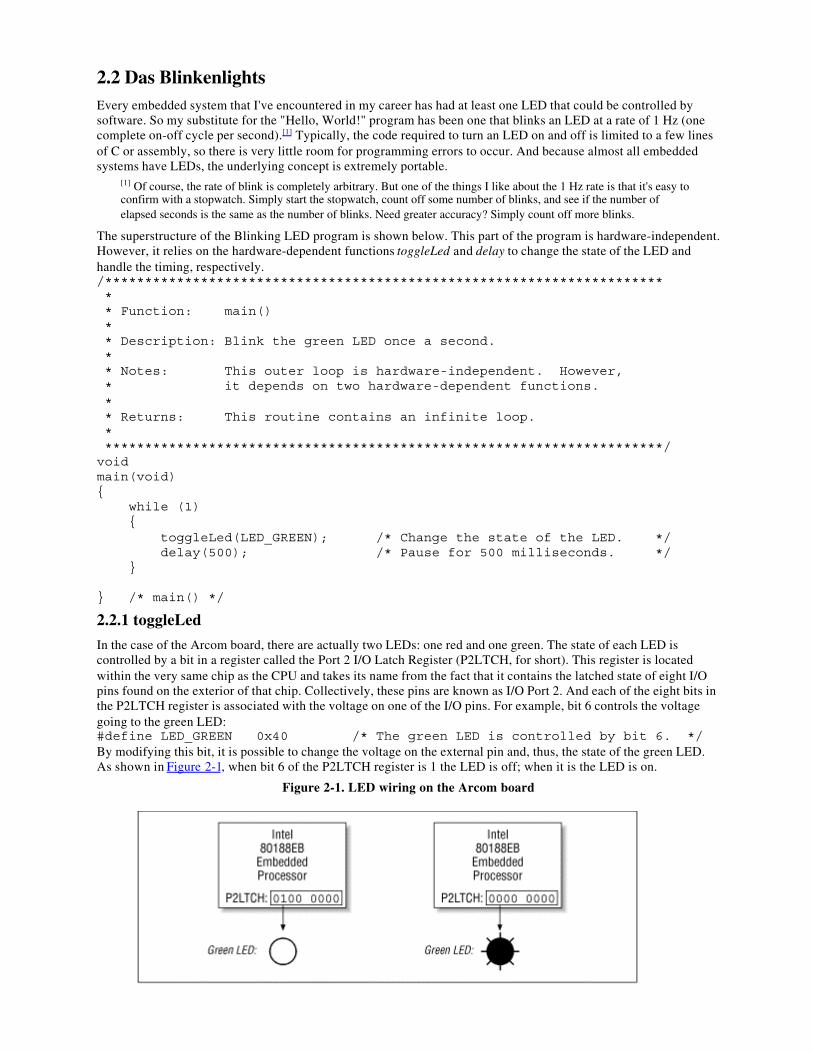
In the case of the Arcom board, there are actually two LEDs: one red and one green. The state of each LED iscontrolled by a bit in a register called the Port 2 I/O Latch Register (P2LTCH, for short). This register is locatedwithin the very same chip as the CPU and takes its name from the fact that it contains the latched state of eight I/Opins found on the exterior of that chip. Collectively, these pins are known as I/O Port 2. And each of the eight bits inthe P2LTCH register is associated with the voltage on one of the I/O pins. For example, bit 6 controls the voltagegoing to the green LED:#define LED_GREEN 0x40 /* The green LED is controlled by bit 6. */By modifying this bit, it is possible to change the voltage on the external pin and, thus, the state of the green LED.As shown in Figure 2-1, when bit 6 of the P2LTCH register is 1 the LED is off; when it is the LED is on.
Figure 2-1. LED wiring on the Arcom board
The P2LTCH register is located in a special region of memory called the I/O space, at offset 0xFF5E. Unfortunately,registers within the I/O space of an 80x86 processor can be accessed only by using the assembly languageinstructions in and out. The C language has no built-in support for these operations. Its closest replacements are thelibrary routines inport and outport, which are declared in the PC-specific header file dos.h . Ideally, we would justinclude that header file and call those library routines from our embedded program. However, because they are partof the DOS programmer's library, we'll have to assume the worst: that they won't work on our system. At the veryleast, we shouldn't rely on them in our very first program.An implementation of the toggleLed routine that is specific to the Arcom board and does not rely on any libraryroutines is shown below. The actual algorithm is straightforward: read the contents of the P2LTCH register, togglethe bit that controls the LED of interest, and write the new value back into the register. You will notice that althoughthis routine is written in C, the functional part is actually implemented in assembly language. This is a handytechnique, known as inline assembly, that separates the programmer from the intricacies of C's function calling andparameter passing conventions but still gives her the full expressive power of assembly language.[2]
[2] Unfortunately, the exact syntax of inline assembly varies from compiler to compiler. In the example, I'm using theformat preferred by the Borland C++ compiler. Borland's inline assembly format is one of the best because it supportsreferences to variables and constants that are defined within the C code.
#define P2LTCH 0xFF5E /* The offset of the P2LTCH register. */
/********************************************************************** * * Function: toggleLed() * * Description: Toggle the state of one or both LEDs. * * Notes: This function is specific to Arcom's Target188EB board. * * Returns: None defined. * **********************************************************************/voidtoggleLed(unsigned char ledMask){ asm { mov dx, P2LTCH /* Load the address of the register. */ in al, dx /* Read the contents of the register. */
mov ah, ledMask /* Move the ledMask into a register. */ xor al, ah /* Toggle the requested bits. */
out dx, al /* Write the new register contents. */ };
} /* toggleLed() */
2.2.2 delay
We also need to implement a half-second (500 ms) delay between LED toggles. This is done by busy-waiting withinthe delay routine shown below. This routine accepts the length of the requested delay, in milliseconds, as its onlyparameter. It then multiplies that number by the constant CYCLES_PER_MS to obtain the total number of while-loop iterations required to delay for the requested time period.
/********************************************************************** * * Function: delay() * * Description: Busy-wait for the requested number of milliseconds. * * Notes: The number of decrement-and-test cycles per millisecond * was determined through trial and error. This value is * dependent upon the processor type and speed. * * Returns: None defined. ***********************************************************************/voiddelay(unsigned int nMilliseconds){ #define CYCLES_PER_MS 260 /* Number of decrement-and-test cycles. */
unsigned long nCycles = nMilliseconds * CYCLES_PER_MS;
while (nCycles--);
} /* delay() */The hardware-specific constant CYCLES_PER_MS represents the number of decrement-and-test cycles (nCycles--!= 0) that the processor can perform in a single millisecond. To determine this number I used trial and error. I madean approximate calculation (I think it came out to around 200), then wrote the remainder of the program, compiledit, and ran it. The LED was indeed blinking but at a rate faster than 1 Hz. So I used my trusty stopwatch to make aseries of small changes to CYCLES_PER_MS until the rate of blink was as close to 1 Hz as I cared to test.That's it! That's all there is to the Blinking LED program. The three functions main, toggleLed, and delay do thewhole job. If you want to port this program to some other embedded system, you should read the documentation thatcame with your hardware, rewrite toggleLed as necessary, and change the value of CYCLES_PER_MS. Of course,we do still need to talk about how to build and execute this program. We'll examine those topics in the next twochapters. But first, I have a little something to say about infinite loops and their role in embedded systems.
2.3 The Role of the Infinite LoopOne of the most fundamental differences between programs developed for embedded systems and those written forother computer platforms is that the embedded programs almost always end with an infinite loop. Typically, thisloop surrounds a significant part of the program's functionality-as it does in the Blinking LED program. The infiniteloop is necessary because the embedded software's job is never done. It is intended to be run until either the worldcomes to an end or the board is reset, whichever happens first.In addition, most embedded systems have only one piece of software running on them. And although the hardware isimportant, it is not a digital watch or a cellular phone or a microwave oven without that embedded software. If thesoftware stops running, the hardware is rendered useless. So the functional parts of an embedded program are almostalways surrounded by an infinite loop that ensures that they will run forever.This behavior is so common that it's almost not worth mentioning. And I wouldn't, except that I've seen quite a fewfirst-time embedded programmers get confused by this subtle difference. So if your first program appears to run, butinstead of blinking the LED simply changes its state once, it could be that you forgot to wrap the calls to toggleLedand delay in an infinite loop.
Chapter 3.
Compiling, Linking, and LocatingI consider that the golden rule requires that if I like a program I must share it with otherpeople who like it. Software sellers want to divide the users and conquer them, makingeach user agree not to share with others. I refuse to break solidarity with other users inthis way. I cannot in good conscience sign a nondisclosure agreement or a softwarelicense agreement. So that I can continue to use computers without dishonor, I havedecided to put together a sufficient body of free software so that I will be able to getalong without any software that is not free.
-Richard Stallman, Founder of the GNU Project, The GNU Manifesto
In this chapter, we'll examine the steps involved in preparing your software for execution on an embedded system.We'll also discuss the associated development tools and see how to build the Blinking LED program shown inChapter 2. But before we get started, I want to make it clear that embedded systems programming is notsubstantially different from the programming you've done before. The only thing that has really changed is that eachtarget hardware platform is unique. Unfortunately, that one difference leads to a lot of additional softwarecomplexity, and it's also the reason you'll need to be more aware of the software build process than ever before.
3.1 The Build ProcessThere are a lot of things that software development tools can do automatically when the target platform is welldefined.[1] This automation is possible because the tools can exploit features of the hardware and operating systemon which your program will execute. For example, if all of your programs will be executed on IBM-compatible PCsrunning DOS, your compiler can automate-and, therefore, hide from your view-certain aspects of the software buildprocess. Embedded software development tools, on the other hand, can rarely make assumptions about the targetplatform. Instead, the user must provide some of his own knowledge of the system to the tools by giving them moreexplicit instructions.
[1] Used this way, the term "target platform" is best understood to include not only the hardware but also the operatingsystem that forms the basic runtime environment for your software. If no operating system is present-as is sometimesthe case in an embedded system-the target platform is simply the processor on which your program will be run.
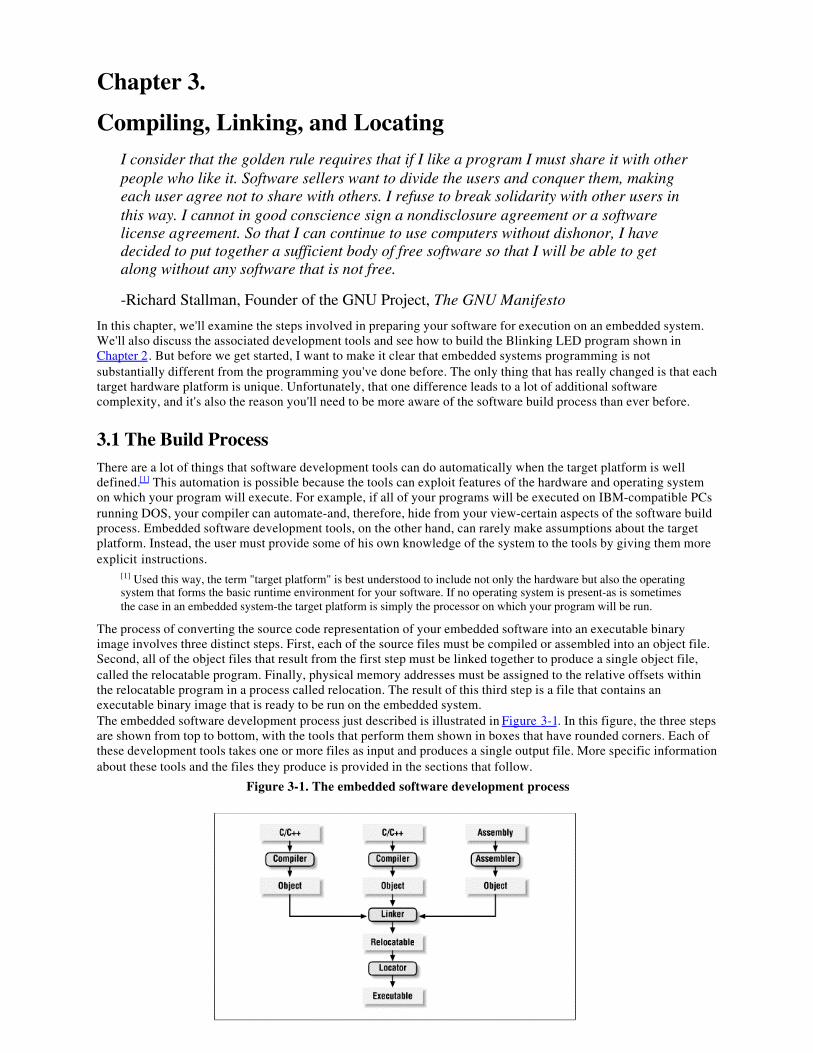
The process of converting the source code representation of your embedded software into an executable binaryimage involves three distinct steps. First, each of the source files must be compiled or assembled into an object file.Second, all of the object files that result from the first step must be linked together to produce a single object file,called the relocatable program. Finally, physical memory addresses must be assigned to the relative offsets withinthe relocatable program in a process called relocation. The result of this third step is a file that contains anexecutable binary image that is ready to be run on the embedded system.The embedded software development process just described is illustrated in Figure 3-1. In this figure, the three stepsare shown from top to bottom, with the tools that perform them shown in boxes that have rounded corners. Each ofthese development tools takes one or more files as input and produces a single output file. More specific informationabout these tools and the files they produce is provided in the sections that follow.
Figure 3-1. The embedded software development process
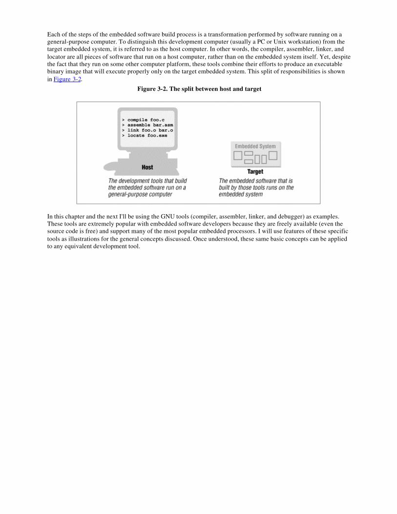
Each of the steps of the embedded software build process is a transformation performed by software running on ageneral-purpose computer. To distinguish this development computer (usually a PC or Unix workstation) from thetarget embedded system, it is referred to as the host computer. In other words, the compiler, assembler, linker, andlocator are all pieces of software that run on a host computer, rather than on the embedded system itself. Yet, despitethe fact that they run on some other computer platform, these tools combine their efforts to produce an executablebinary image that will execute properly only on the target embedded system. This split of responsibilities is shownin Figure 3-2.
Figure 3-2. The split between host and target
In this chapter and the next I'll be using the GNU tools (compiler, assembler, linker, and debugger) as examples.These tools are extremely popular with embedded software developers because they are freely available (even thesource code is free) and support many of the most popular embedded processors. I will use features of these specifictools as illustrations for the general concepts discussed. Once understood, these same basic concepts can be appliedto any equivalent development tool.
3.2 CompilingThe job of a compiler is mainly to translate programs written in some human-readable language into an equivalentset of opcodes for a particular processor. In that sense, an assembler is also a compiler (you might call it an"assembly language compiler") but one that performs a much simpler one-to-one translation from one line ofhuman-readable mnemonics to the equivalent opcode. Everything in this section applies equally to compilers andassemblers. Together these tools make up the first step of the embedded software build process.Of course, each processor has its own unique machine language, so you need to choose a compiler that is capable ofproducing programs for your specific target processor. In the embedded systems case, this compiler almost alwaysruns on the host computer. It simply doesn't make sense to execute the compiler on the embedded system itself. Acompiler such as this-that runs on one computer platform and produces code for another-is called a cross-compiler.The use of a cross-compiler is one of the defining features of embedded software development.The GNU C/C++ compiler ( gcc ) and assembler (as ) can be configured as either native compilers or cross-compilers. As cross-compilers these tools support an impressive set of host-target combinations. Table 3-1 listssome of the most popular of the supported hosts and targets. Of course, the selections of host platform and targetprocessor are independent; these tools can be configured for any combination.
Table 3-1. Hosts and Targets Supported by the GNU Compiler
Host Platforms Target Processors
DEC Alpha Digital UnixHP 9000/700 HP-UXIBM Power PC AIXIBM RS6000 AIXSGI Iris IRIXSun SPARC SolarisSun SPARC SunOSX86 Windows 95/NTX86 Red Hat Linux
AMD/Intel x86 (32-bit only)Fujitsu SPARCliteHitachi H8/300, H8/300H, H8/SHitachi SHIBM/Motorola PowerPCIntel i960MIPS R3xxx, R4xx0Mitsubishi D10V, M32R/DMotorola 68kSun SPARC, MicroSPARCToshiba TX39
Regardless of the input language (C/C++, assembly, or any other), the output of the cross-compiler will be an objectfile. This is a specially formatted binary file that contains the set of instructions and data resulting from the languagetranslation process. Although parts of this file contain executable code, the object file is not intended to be executeddirectly. In fact, the internal structure of an object file emphasizes the incompleteness of the larger program.The contents of an object file can be thought of as a very large, flexible data structure. The structure of the file isusually defined by a standard format like the Common Object File Format (COFF) or Extended Linker Format(ELF). If you'll be using more than one compiler (i.e., you'll be writing parts of your program in different sourcelanguages), you need to make sure that each is capable of producing object files in the same format. Although manycompilers (particularly those that run on Unix platforms) support standard object file formats like COFF and ELF (gcc supports both), there are also some others that produce object files only in proprietary formats. If you're usingone of the compilers in the latter group, you might find that you need to buy all of your other development toolsfrom the same vendor.Most object files begin with a header that describes the sections that follow. Each of these sections contains one ormore blocks of code or data that originated within the original source file. However, these blocks have beenregrouped by the compiler into related sections. For example, all of the code blocks are collected into a sectioncalled text, initialized global variables (and their initial values) into a section called data, and uninitialized globalvariables into a section called bss.There is also usually a symbol table somewhere in the object file that contains the names and locations of all thevariables and functions referenced within the source file. Parts of this table may be incomplete, however, becausenot all of the variables and functions are always defined in the same file. These are the symbols that refer tovariables and functions defined in other source files. And it is up to the linker to resolve such unresolved references.
3.3 LinkingAll of the object files resulting from step one must be combined in a special way before the program can beexecuted. The object files themselves are individually incomplete, most notably in that some of the internal variableand function references have not yet been resolved. The job of the linker is to combine these object files and, in theprocess, to resolve all of the unresolved symbols.The output of the linker is a new object file that contains all of the code and data from the input object files and is inthe same object file format. It does this by merging the text, data, and bss sections of the input files. So, when thelinker is finished executing, all of the machine language code from all of the input object files will be in the textsection of the new file, and all of the initialized and uninitialized variables will reside in the new data and bsssections, respectively.While the linker is in the process of merging the section contents, it is also on the lookout for unresolved symbols.For example, if one object file contains an unresolved reference to a variable named foo and a variable with thatsame name is declared in one of the other object files, the linker will match them up. The unresolved reference willbe replaced with a reference to the actual variable. In other words, if foo is located at offset 14 of the output datasection, its entry in the symbol table will now contain that address.The GNU linker (ld ) runs on all of the same host platforms as the GNU compiler. It is essentially a command-linetool that takes the names of all the object files to be linked together as arguments. For embedded development, aspecial object file that contains the compiled startup code must also be included within this list. (See Startup Codelater in this chapter.) The GNU linker also has a scripting language that can be used to exercise tighter control overthe object file that is output.
Startup CodeOne of the things that traditional software development tools do automatically is to insert startup code.
Startup code is a small block of assembly language code that prepares the way for the execution ofsoftware written in a high-level language. Each high-level language has its own set of expectations
about the runtime environment. For example, C and C++ both utilize an implicit stack. Space for thestack has to be allocated and initialized before software written in either language can be properly
executed. That is just one of the responsibilities assigned to startup code for C/C++ programs.Most cross-compilers for embedded systems include an assembly language file called startup.asm,crt0.s (short for C runtime), or something similar. The location and contents of this file are usuallydescribed in the documentation supplied with the compiler.Startup code for C/C++ programs usually consists of the following actions, performed in the orderdescribed:
1. Disable all interrupts.2. Copy any initialized data from ROM to RAM.3. Zero the uninitialized data area.4. Allocate space for and initialize the stack.5. Initialize the processor's stack pointer.6. Create and initialize the heap.7. Execute the constructors and initializers for all global variables (C++ only).8. Enable interrupts.9. Call main.
Typically, the startup code will also include a few instructions after the call to main. These instructionswill be executed only in the event that the high-level language program exits (i.e., the call to mainreturns). Depending on the nature of the embedded system, you might want to use these instructions tohalt the processor, reset the entire system, or transfer control to a debugging tool.Because the startup code is not inserted automatically, the programmer must usually assemble it himselfand include the resulting object file among the list of input files to the linker. He might even need togive the linker a special command-line option to prevent it from inserting the usual startup code.Working startup code for a variety of target processors can be found in a GNU package called libgloss.
If the same symbol is declared in more than one object file, the linker is unable to proceed. It will likely appeal tothe programmer-by displaying an error message-and exit. However, if a symbol reference instead remainsunresolved after all of the object files have been merged, the linker will try to resolve the reference on its own. Thereference might be to a function that is part of the standard library, so the linker will open each of the librariesdescribed to it on the command line (in the order provided) and examine their symbol tables. If it finds a functionwith that name, the reference will be resolved by including the associated code and data sections within the outputobject file.[2]
[2] Beware that I am only talking about static linking here. In non-embedded environments, dynamic linking of librariesis very common. In that case, the code and data associated with the library routine are not inserted into the programdirectly.
Unfortunately, the standard library routines often require some changes before they can be used in an embeddedprogram. The problem here is that the standard libraries provided with most software development tool suites arriveonly in object form. So you only rarely have access to the library source code to make the necessary changesyourself. Thankfully, a company called Cygnus has created a freeware version of the standard C library for use inembedded systems. This package is called newlib. You need only download the source code for this library from theCygnus web site, implement a few target-specific functions, and compile the whole lot. The library can then belinked with your embedded software to resolve any previously unresolved standard library calls.After merging all of the code and data sections and resolving all of the symbol references, the linker produces aspecial "relocatable" copy of the program. In other words, the program is complete except for one thing: no memoryaddresses have yet been assigned to the code and data sections within. If you weren't working on an embeddedsystem, you'd be finished building your software now.But embedded programmers aren't generally finished with the build process at this point. Even if your embeddedsystem includes an operating system, you'll probably still need an absolutely located binary image. In fact, if there isan operating system, the code and data of which it consists are most likely within the relocatable program too. Theentire embedded application-including the operating system-is almost always statically linked together and executedas a single binary image.
3.4 LocatingThe tool that performs the conversion from relocatable program to executable binary image is called a locator. Ittakes responsibility for the easiest step of the three. In fact, you will have to do most of the work in this stepyourself, by providing information about the memory on the target board as input to the locator. The locator will usethis information to assign physical memory addresses to each of the code and data sections within the relocatableprogram. It will then produce an output file that contains a binary memory image that can be loaded into the targetROM.In many cases, the locator is a separate development tool. However, in the case of the GNU tools, this functionalityis built right into the linker. Try not to be confused by this one particular implementation. Whether you are writingsoftware for a general-purpose computer or an embedded system, at some point the sections of your relocatableprogram must have actual addresses assigned to them. In the first case, the operating system does it for you at loadtime. In the second, you must perform the step with a special tool. This is true even if the locator is a part of thelinker, as it is in the case of ld.The memory information required by the GNU linker can be passed to it in the form of a linker script. Such scriptsare sometimes used to control the exact order of the code and data sections within the relocatable program. But here,we want to do more than just control the order; we also want to establish the location of each section in memory.What follows is an example of a linker script for a hypothetical embedded target that has 512 KB each of RAM andROM:
MEMORY{ ram : ORIGIN = 0x00000, LENGTH = 512K rom : ORIGIN = 0x80000, LENGTH = 512K}
SECTIONS{ data ram : /* Initialized data. */ { _DataStart = . ; *(.data) _DataEnd = . ;
} >rom
bss : /* Uninitialized data. */ { _BssStart = . ; *(.bss) _BssEnd = . ; }
_BottomOfHeap = . ; /* The heap starts here. */ _TopOfStack = 0x80000; /* The stack ends here. */
text rom : /* The actual instructions. */ { *(.text)
}}This script informs the GNU linker's built-in locator about the memory on the target board and instructs it to locatethe data and bss sections in RAM (starting at address 0x00000) and the text section in ROM (starting at 0x80000).However, the initial values of the variables in the data segment will be made a part of the ROM image by theaddition of >rom at the end of that section's definition.All of the names that begin with underscores (_TopOfStack, for example) are variables that can be referenced fromwithin your source code. The linker will use these symbols to resolve references in the input object files. So, forexample, there might be a part of the embedded software (usually within the startup code) that copies the initialvalues of the initialized variables from ROM to the data section in RAM. The start and stop addresses for thisoperation can be established symbolically, by referring to the integer variables _DataStart and _DataEnd .The result of this final step of the build process is an absolutely located binary image that can be downloaded to theembedded system or programmed into a read-only memory device. In the previous example, this memory imagewould be exactly 1 MB in size. However, because the initial values for the initialized data section are stored inROM, the lower 512 kilobytes of this image will contain only zeros, so only the upper half of this image issignificant. You'll see how to download and execute such memory images in the next chapter.
3.5 Building das BlinkenlightsUnfortunately, because we're using the Arcom board as our reference platform, we won't be able to use the GNUtools to build the examples. Instead we'll be using Borland's C++ Compiler and Turbo Assembler. These tools canbe run on any DOS or Windows-based PC.[3] If you have an Arcom board to experiment with, this would be a goodtime to set it up and install the Borland development tools on your host computer. (See Appendix A for orderinginformation). I used version 3.1 of the compiler, running on a Windows 95-based PC. However, any version of theBorland tools that can produce code for the 80186 processor will do.
[3] It is interesting to note that Borland's C++ compiler was not specifically designed for use by embedded softwaredevelopers. It was instead designed to produce DOS and Windows-based programs for PCs that had 80x86 processors.However, the inclusion of certain command-line options allows us to specify a particular 80x86 processor-the 80186,for example-and, thus, use this tool as a cross-compiler for embedded systems like the Arcom board.
As I have implemented it, the Blinking LED example consists of three source modules: led.c, blink.c, andstartup.asm. The first step in the build process is to compile these two files. The command-line options we'll needare -c for "compile, but don't link," -v for "include symbolic debugging information in the output," -ml for "use thelarge memory model," and -1 for "the target is an 80186 processor." Here are the actual commands:bcc -c -v -ml -1 led.cbcc -c -v -ml -1 blink.cOf course, these commands will work only if the bcc.exe program is in your PATH and the two source files are inthe current directory. In other words, you should be in the Chapter2 subdirectory. The result of each of thesecommands is the creation of an object file that has the same prefix as the .c file and the extension .obj. So if all goeswell, there will now be two additional files-led.obj and blink.obj -in the working directory.Although it would appear that there are only these two object files to be linked together in our example, there areactually three. That's because we must also include some startup code for the C program. (See Startup Code earlierin this chapter.) Example startup code for the Arcom board is provided in the file startup.asm, which is included in
the Chapter3 subdirectory. To assemble this code into an object file, change to that directory and issue the followingcommand:tasm /mx startup.asmThe result should be the file startup.obj in that directory. The command that's actually used to link the three objectfiles together is shown here. Beware that the order of the object files on the command line does matter in this case:the startup code must be placed first for proper linkage.
tlink /m /v /s ..\Chapter3\startup.obj led.obj blink.obj,blink.exe, blink.map
As a result of the tlink command, Borland's Turbo Linker will produce two new files: blink.exe and blink.map in theworking directory. The first file contains the relocatable program and the second contains a human-readableprogram map. If you have never seen such a map file before, be sure to take a look at this one before reading on. Itprovides information similar to the contents of the linker script described earlier. However, these are results and,therefore, include the lengths of the sections and the names and locations of the public symbols found in therelocatable program.One more tool must be used to make the Blinking LED program executable: a locator. The locating tool we'll beusing is provided by Arcom, as part of the SourceVIEW development and debugging package included with theboard. Because this tool is designed for this one particular embedded platform, it does not have as many options as amore general locator.[4]
[4] However, being free, it is also a lot cheaper than a more general locator.
In fact, there are just three parameters: the name of the relocatable binary image, the starting address of the ROM (inhexadecimal) and the total size of the destination RAM (in kilobytes):tcrom blink.exe C000 128SourceVIEW Borland C ROM Relocator v1.06Copyright (c) Arcom Control Systems Ltd 1994Relocating code to ROM segment C000H, data to RAM segment 100HChanging target RAM size to 128 KbytesOpening 'blink.exe'... Startup stack at 0102:0402 PSP Program size 550H bytes (2K) Target RAM size 20000H bytes (128K) Target data size 20H bytes (1K)Creating 'blink.rom'... ROM image size 550H bytes (2K)The tcrom locator massages the contents of the relocatable input file-assigning base addresses to each section-andoutputs the file blink.rom. This file contains an absolutely located binary image that is ready to be loaded directlyinto ROM. But rather than load it into the ROM with a device programmer, we'll create a special ASCII version ofthe binary image that can be downloaded to the ROM over a serial port. For this we will use a utility provided byArcom, called bin2hex. Here is the syntax of the command:bin2hex blink.rom /A=1000This extra step creates a new file, called blink.hex, that contains exactly the same information as blink.rom, but in anASCII representation called Intel Hex Format.
Chapter 4.
Downloading and DebuggingI can remember the exact instant when I realized that a large part of my life from then onwas going to be spent in finding mistakes in my own programs.
-Maurice Wilkes, Head of the Computer Laboratory of the University of Cambridge,1949
Once you have an executable binary image stored as a file on the host computer, you will need a way to downloadthat image to the embedded system and execute it. The executable binary image is usually loaded into a memorydevice on the target board and executed from there. And if you have the right tools at your disposal, it will bepossible to set breakpoints in the program or to observe its execution in less intrusive ways. This chapter describesvarious techniques for downloading, executing, and debugging embedded software.
4.1 When in ROM ...One of the most obvious ways to download your embedded software is to load the binary image into a read-onlymemory device and insert that chip into a socket on the target board. Obviously, the contents of a truly read-onlymemory device could not be overwritten. However, as you'll see in Chapter 6, embedded systems commonly employspecial read-only memory devices that can be programmed (or reprogrammed) with the help of a special piece ofequipment called a device programmer. A device programmer is a computer system that has several memory socketson the top-of varying shapes and sizes-and is capable of programming memory devices of all sorts.In an ideal development scenario, the device programmer would be connected to the same network as the hostcomputer. That way, files that contain executable binary images could be easily transferred to it for ROMprogramming. After the binary image has been transferred to the device programmer, the memory chip is placed intothe appropriately sized and shaped socket and the device type is selected from an on-screen menu. The actual deviceprogramming process can take anywhere from a few seconds to several minutes, depending on the size of the binaryimage and the type of memory device you are using.After you program the ROM, it is ready to be inserted into its socket on the board. Of course, this shouldn't be donewhile the embedded system is still powered on. The power should be turned off and then reapplied only after thechip has been carefully inserted.As soon as power is applied to it, the processor will begin to fetch and execute the code that is stored inside theROM. However, beware that each type of processor has its own rules about the location of its first instruction. Forexample, when the Intel 80188EB processor is reset, it begins by fetching and executing whatever is stored atphysical address FFFF0h. This is called the reset address, and the instructions located there are collectively knownas the reset code.If your program doesn't appear to be working, it could be there is something wrong with your reset code. You mustalways ensure that the binary image you've loaded into the ROM satisfies the target processor's reset rules. Duringproduct development, I often find it useful to turn on one of the board's LEDs just after the reset code has beencompleted. That way, I know at a glance that my new ROM either does or doesn't satisfy the processor's most basicrequirements.
Debugging Tip #1: One of the most primitive debugging techniques available is the use of an LED as indicator ofyou first begin with the LED enable code at the reset address. If the LED turns on, then you can edit the program,moving the LED enable code to just after the next execution milestone, rebuild, and test. This works best for verysimple, linearly executed programs like the startup code. But if you don't have access to a remote debugger or any ofthe other debugging tools described later in this chapter, this type of debugging might be your only choice.The Arcom board includes a special in-circuit programmable memory, called Flash memory, that does not have tobe removed from the board to be reprogrammed. In fact, software that can perform the device programming functionis already installed in another memory device on the board. You see, the Arcom board actually has two read-onlymemory devices-one (a true ROM) contains a simple program that allows the user to in-circuit program the other (aFlash memory device). All the host computer needs to talk to the monitor program is a serial port and a terminal
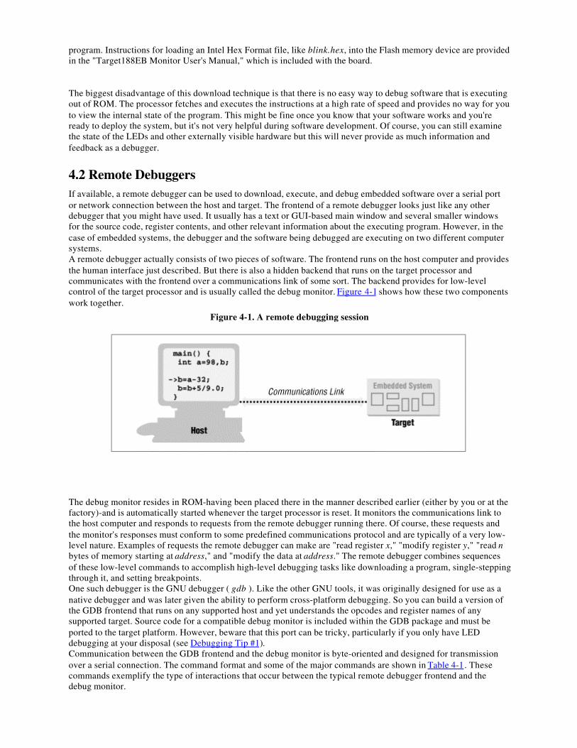
program. Instructions for loading an Intel Hex Format file, like blink.hex, into the Flash memory device are providedin the "Target188EB Monitor User's Manual," which is included with the board.
The biggest disadvantage of this download technique is that there is no easy way to debug software that is executingout of ROM. The processor fetches and executes the instructions at a high rate of speed and provides no way for youto view the internal state of the program. This might be fine once you know that your software works and you'reready to deploy the system, but it's not very helpful during software development. Of course, you can still examinethe state of the LEDs and other externally visible hardware but this will never provide as much information andfeedback as a debugger.
4.2 Remote DebuggersIf available, a remote debugger can be used to download, execute, and debug embedded software over a serial portor network connection between the host and target. The frontend of a remote debugger looks just like any otherdebugger that you might have used. It usually has a text or GUI-based main window and several smaller windowsfor the source code, register contents, and other relevant information about the executing program. However, in thecase of embedded systems, the debugger and the software being debugged are executing on two different computersystems.A remote debugger actually consists of two pieces of software. The frontend runs on the host computer and providesthe human interface just described. But there is also a hidden backend that runs on the target processor andcommunicates with the frontend over a communications link of some sort. The backend provides for low-levelcontrol of the target processor and is usually called the debug monitor. Figure 4-1 shows how these two componentswork together.
Figure 4-1. A remote debugging session
The debug monitor resides in ROM-having been placed there in the manner described earlier (either by you or at thefactory)-and is automatically started whenever the target processor is reset. It monitors the communications link tothe host computer and responds to requests from the remote debugger running there. Of course, these requests andthe monitor's responses must conform to some predefined communications protocol and are typically of a very low-level nature. Examples of requests the remote debugger can make are "read register x," "modify register y," "read nbytes of memory starting at address," and "modify the data at address." The remote debugger combines sequencesof these low-level commands to accomplish high-level debugging tasks like downloading a program, single-steppingthrough it, and setting breakpoints.One such debugger is the GNU debugger ( gdb ). Like the other GNU tools, it was originally designed for use as anative debugger and was later given the ability to perform cross-platform debugging. So you can build a version ofthe GDB frontend that runs on any supported host and yet understands the opcodes and register names of anysupported target. Source code for a compatible debug monitor is included within the GDB package and must beported to the target platform. However, beware that this port can be tricky, particularly if you only have LEDdebugging at your disposal (see Debugging Tip #1).Communication between the GDB frontend and the debug monitor is byte-oriented and designed for transmissionover a serial connection. The command format and some of the major commands are shown in Table 4-1. Thesecommands exemplify the type of interactions that occur between the typical remote debugger frontend and thedebug monitor.
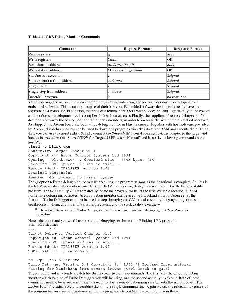
Table 4-1. GDB Debug Monitor Commands
Command Request Format Response Format
Read registers g data
Write registers Gdata OKRead data at address maddress,length data
Write data at address Maddress,length:data OKStart/restart execution c Ssignal
Start execution from address caddress Ssignal
Single step s Ssignal
Single step from address saddress Ssignal
Reset/kill program k no response
Remote debuggers are one of the most commonly used downloading and testing tools during development ofembedded software. This is mainly because of their low cost. Embedded software developers already have therequisite host computer. In addition, the price of a remote debugger frontend does not add significantly to the cost ofa suite of cross-development tools (compiler, linker, locator, etc.). Finally, the suppliers of remote debuggers oftendesire to give away the source code for their debug monitors, in order to increase the size of their installed user base.As shipped, the Arcom board includes a free debug monitor in Flash memory. Together with host software providedby Arcom, this debug monitor can be used to download programs directly into target RAM and execute them. To dothis, you can use the tload utility. Simply connect the SourceVIEW serial communications adapter to the target andhost as instructed in the "SourceVIEW for Target188EB User's Manual" and issue the following command on thehost PC:tload -g blink.exeSourceView Target Loader v1.4Copyright (c) Arcom Control Systems Ltd 1994Opening 'blink.exe'... download size 750H bytes (2K)Checking COM1 (press ESC key to exit)...Remote ident: TDR188EB version 1.02Download successfulSending 'GO' command to target systemThe -g option tells the debug monitor to start executing the program as soon as the download is complete. So, this isthe RAM equivalent of execution directly out of ROM. In this case, though, we want to start with the relocatableprogram. The tload utility will automatically locate the program for us, at the first available location in RAM.For remote debugging purposes, Arcom's debug monitor can be used with Borland's Turbo Debugger as thefrontend. Turbo Debugger can then be used to step through your C/C++ and assembly language programs, setbreakpoints in them, and monitor variables, registers, and the stack as they execute.[1]
[1] The actual interaction with Turbo Debugger is no different than if you were debugging a DOS or Windowsapplication.
Here's the command you would use to start a debugging session for the Blinking LED program:tdr blink.exetver -3.1Target Debugger Version Changer v1.2Copyright (c) Arcom Control Systems Ltd 1994Checking COM1 (press ESC key to exit)...Remote ident: TDR188EB version 1.02TDR88 set for TD version 3.1
td -rp1 -rs3 blink.exeTurbo Debugger Version 3.1 Copyright (c) 1988,92 Borland InternationalWaiting for handshake from remote driver (Ctrl-Break to quit)The tdr command is actually a batch file that invokes two other commands. The first tells the on-board debugmonitor which version of Turbo Debugger you will be using, and the second actually invokes it. Both of thesecommands need to be issued each time you want to start a remote debugging session with the Arcom board. Thetdr.bat batch file exists solely to combine them into a single command line. Again we use the relocatable version ofthe program because we will be downloading the program into RAM and executing it from there.
The debugger startup options -rp1 and -rs3 establish the parameters for the communications link to the debugmonitor. -rp1 means "remote-port=1" (COM1) and -rs3 means "remote-speed=3" (38,400 baud). These are theparameters required to communicate with Arcom's debug monitor. After establishing a connection to the debugmonitor, Turbo Debugger should start running. If it does not, there might be a problem with the serial link. Compareyour setup of the link to the one in the SourceVIEW user's manual.Once you're in Turbo Debugger, you will see a dialog box that says: "Program out of date on remote, send overlink?" When you select "Yes," the contents of the file blink.exe will be downloaded to the target RAM. Thedebugger will then set an initial breakpoint at main and instruct the debug monitor to execute the program until thatpoint is reached. So the next thing you should see is the C source code for main, with a cursor indicating that theembedded processor's instruction pointer is at the entry point to that routine.Using normal Turbo Debugger commands, you can step through the program, set breakpoints, monitor the valuesstored in variables and registers, and do all of the other things debuggers allow. Or you can simply press the F9 keyto immediately execute the rest of the program. If you do this, you should then see the green LED on the front of theboard start blinking. When you are satisfied that the program and the debugger are both working properly, press thereset switch attached to the Arcom board. This will cause the embedded processor to be reset, the LED to stopblinking, and Turbo Debugger to again respond to your commands.
4.3 EmulatorsRemote debuggers are helpful for monitoring and controlling the state of embedded software, but only an in-circuitemulator (ICE) allows you to examine the state of the processor on which that program is running. In fact, an ICEactually takes the place of-or emulates-the processor on your target board. It is itself an embedded system, with itsown copy of the target processor, RAM, ROM, and its own embedded software. As a result, in-circuit emulators areusually pretty expensive-often more expensive than the target hardware. But they are a powerful tool, and in a tightdebugging spot nothing else will help you get the job done better.Like a debug monitor, an emulator uses a remote debugger for its human interface. In some cases, it is even possibleto use the same debugger frontend for both. But because the emulator has its own copy of the target processor it ispossible to monitor and control the state of the processor in real time. This allows the emulator to support suchpowerful debugging features as hardware breakpoints and real-time tracing, in addition to the features provided byany debug monitor.With a debug monitor, you can set breakpoints in your program. However, these software breakpoints are restrictedto instruction fetches-the equivalent of the command "stop execution if this instruction is about to be fetched."Emulators, by contrast, also support hardware breakpoints. Hardware breakpoints allow you to stop execution inresponse to a wide variety of events. These events include not only instruction fetches, but also memory and I/Oreads and writes, and interrupts. For example, you might set a hardware breakpoint on the event "variable foocontains 15 and register AX becomes 0."Another useful feature of an in-circuit emulator is real-time tracing. Typically, an emulator incorporates a largeblock of special-purpose RAM that is dedicated to storing information about each of the processor cycles that areexecuted. This feature allows you to see in exactly what order things happened, so it can help you answer questions,such as, did the timer interrupt occur before or after the variable bar became 94? In addition, it is usually possible toeither restrict the information that is stored or post-process the data prior to viewing it in order to cut down on theamount of trace data to be examined.
4.3.1 ROM Emulators
One other type of emulator is worth mentioning at this point. A ROM emulator is a device that emulates a read-onlymemory device. Like an ICE, it is an embedded system that connects to the target and communicates with the host.However, this time the target connection is via a ROM socket. To the embedded processor, it looks like any otherread-only memory device. But to the remote debugger, it looks like a debug monitor.ROM emulators have several advantages over debug monitors. First, no one has to port the debug monitor code toyour particular target hardware. Second, the ROM emulator supplies its own serial or network connection to thehost, so it is not necessary to use the target's own, usually limited, resources. And finally, the ROM emulator is atrue replacement for the original ROM, so none of the target's memory is used up by the debug monitor code.
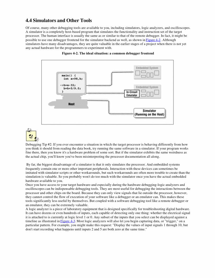
4.4 Simulators and Other ToolsOf course, many other debugging tools are available to you, including simulators, logic analyzers, and oscilloscopes.A simulator is a completely host-based program that simulates the functionality and instruction set of the targetprocessor. The human interface is usually the same as or similar to that of the remote debugger. In fact, it might bepossible to use one debugger frontend for the simulator backend as well, as shown in Figure 4-2. Althoughsimulators have many disadvantages, they are quite valuable in the earlier stages of a project when there is not yetany actual hardware for the programmers to experiment with.
Figure 4-2. The ideal situation: a common debugger frontend
Debugging Tip #2: If you ever encounter a situation in which the target processor is behaving differently from howyou think it should from reading the data book, try running the same software in a simulator. If your program worksfine there, then you know it's a hardware problem of some sort. But if the simulator exhibits the same weirdness asthe actual chip, you'll know you've been misinterpreting the processor documentation all along.
By far, the biggest disadvantage of a simulator is that it only simulates the processor. And embedded systemsfrequently contain one or more other important peripherals. Interaction with these devices can sometimes beimitated with simulator scripts or other workarounds, but such workarounds are often more trouble to create than thesimulation is valuable. So you probably won't do too much with the simulator once you have the actual embeddedhardware available to you.Once you have access to your target hardware-and especially during the hardware debugging-logic analyzers andoscilloscopes can be indispensable debugging tools. They are most useful for debugging the interactions between theprocessor and other chips on the board. Because they can only view signals that lie outside the processor, however,they cannot control the flow of execution of your software like a debugger or an emulator can. This makes thesetools significantly less useful by themselves. But coupled with a software debugging tool like a remote debugger oran emulator, they can be extremely valuable.A logic analyzer is a piece of laboratory equipment that is designed specifically for troubleshooting digital hardware.It can have dozens or even hundreds of inputs, each capable of detecting only one thing: whether the electrical signalit is attached to is currently at logic level 1 or 0. Any subset of the inputs that you select can be displayed against atimeline as illustrated in Figure 4-3. Most logic analyzers will also let you begin capturing data, or "trigger," on aparticular pattern. For example, you might make this request: "Display the values of input signals 1 through 10, butdon't start recording what happens until inputs 2 and 5 are both zero at the same time."
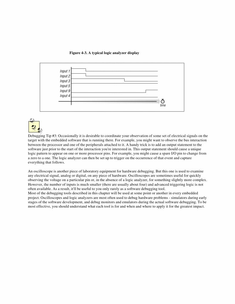
Figure 4-3. A typical logic analyzer display
Debugging Tip #3: Occasionally it is desirable to coordinate your observation of some set of electrical signals on thetarget with the embedded software that is running there. For example, you might want to observe the bus interactionbetween the processor and one of the peripherals attached to it. A handy trick is to add an output statement to thesoftware just prior to the start of the interaction you're interested in. This output statement should cause a uniquelogic pattern to appear on one or more processor pins. For example, you might cause a spare I/O pin to change froma zero to a one. The logic analyzer can then be set up to trigger on the occurrence of that event and captureeverything that follows.
An oscilloscope is another piece of laboratory equipment for hardware debugging. But this one is used to examineany electrical signal, analog or digital, on any piece of hardware. Oscilloscopes are sometimes useful for quicklyobserving the voltage on a particular pin or, in the absence of a logic analyzer, for something slightly more complex.However, the number of inputs is much smaller (there are usually about four) and advanced triggering logic is notoften available. As a result, it'll be useful to you only rarely as a software debugging tool.Most of the debugging tools described in this chapter will be used at some point or another in every embeddedproject. Oscilloscopes and logic analyzers are most often used to debug hardware problems - simulators during earlystages of the software development, and debug monitors and emulators during the actual software debugging. To bemost effective, you should understand what each tool is for and when and where to apply it for the greatest impact.

Chapter 5.
Getting to Know the Hardwarehardware n. The part of a computer system that can be kicked.
As an embedded software engineer, you'll have the opportunity to work with many different pieces of hardware inyour career. In this chapter, I will teach you a simple procedure that I use to familiarize myself with any new board.In the process, I'll guide you through the creation of a header file that describes the board's most important featuresand a piece of software that initializes the hardware to a known state.
5.1 Understand the Big PictureBefore writing software for an embedded system, you must first be familiar with the hardware on which it will run.At first, you just need to understand the general operation of the system. You do not need to understand every littledetail of the hardware; that kind of knowledge will not be needed right away and will come with time.Whenever you receive a new board, you should take some time to read whatever documents have been providedwith it. If the board is an off-the-shelf product, it might arrive with a "User's Guide" or "Programmer's Manual" thathas been written with the software developer in mind. However, if the board was custom designed for your project,the documentation might be more cryptic or written mainly for the reference of the hardware designers. Either way,this is the single best place for you to start.While you are reading the documentation, set the board itself aside. This will help you to focus on the big picture.There will be plenty of time to examine the actual board more closely when you have finished reading. Beforepicking up the board, you should be able to answer two basic questions about it:
• What is the overall purpose of the board?• How does data flow through it?
For example, imagine that you are a member of a modem design team. You are a software developer who has justreceived an early prototype board from the hardware designers. Because you are already familiar with modems, theoverall purpose of the board and the data-flow through it should be fairly obvious to you. The purpose of the boardis to send and receive digital data over an analog telephone line. The hardware reads digital data from one set ofelectrical connections and writes an analog version of the data to an attached telephone line. Data also flows in theopposite direction, when analog data is read from the telephone line jack and output digitally.Though the purpose of most systems is fairly obvious, the flow of the data might not be. I often find that a data-flowdiagram is helpful in achieving rapid comprehension. If you are lucky, the documentation provided with yourhardware will contain a superset of the block diagram you need. However, you might still find it useful to createyour own data-flow diagram. That way, you can leave out those hardware components that are unrelated to the basicflow of data through the system.In the case of the Arcom board, the hardware was not designed with a particular application in mind. So for theremainder of this chapter, we'll have to imagine that it does have a purpose. We shall assume the board was designedfor use as a printer-sharing device. A printer-sharing device allows two computers to share a single printer. The userof the device connects one computer to each serial port and a printer to the parallel port. Both computers can thensend documents to the printer, though only one of them can do so at a given time.In order to illustrate the flow of data through the printer-sharing device, I've drawn the diagram in Figure 5-1. (Onlythose hardware devices that are involved in this application of the Arcom board are shown.) By looking at the blockdiagram, you should be able to quickly visualize the flow of the data through the system. Data to be printed isaccepted from either serial port, held in RAM until the printer is ready for more data, and delivered to the printer viathe parallel port. The software that makes all of this happen is stored in ROM.
Figure 5-1. Data-flow diagram for the printer-sharing device
Once you've created a block diagram, don't just crumple it up and throw it away. You should instead put it whereyou can refer to it throughout the project. I recommend creating a project notebook or binder, with this data-flowdiagram on the first page. As you continue working with this piece of hardware, write down everything you learnabout it in your notebook. You might also want to keep notes about the software design and implementation. Aproject notebook is valuable not only while you are developing the software, but also once the project is complete.You will appreciate the extra effort you put into keeping a notebook when you need to make changes to yoursoftware, or work with similar hardware, months or years later.If you still have any big-picture questions after reading the hardware documents, ask a hardware engineer for somehelp. If you don't already know the hardware's designer, take a few minutes to introduce yourself. If you have sometime, take him out to lunch or buy him a beer after work. (You don't even have to talk about the project the wholetime!) I have found that many software engineers have difficulty communicating with hardware engineers, and viceversa. In embedded systems development, it is especially important that the hardware and software teams be able tocommunicate with one another.
5.2 Examine the LandscapeIt is often useful to put yourself in the processor's shoes for a while. After all, the processor is only going to do whatyou ultimately instruct it to do with your software. Imagine what it is like to be the processor: what does theprocessor's world look like? If you think about it from this perspective, one thing you quickly realize is that theprocessor has a lot of compatriots. These are the other pieces of hardware on the board, with which the processorcan communicate directly. In this section you will learn to recognize their names and addresses.The first thing to notice is that there are two basic types: memories and peripherals. Obviously, memories are fordata and code storage and retrieval. But you might be wondering what the peripherals are. These are specializedhardware devices that either coordinate interaction with the outside world (I/O) or perform a specific hardwarefunction. For example, two of the most common peripherals in embedded systems are serial ports and timers. Theformer is an I/O device, and the latter is basically just a counter.Members of Intel's 80x86 and some other processor families have two distinct address spaces through which theycan communicate with these memories and peripherals. The first address space is called the memory space and isintended mainly for memory devices; the second is reserved exclusively for peripherals and is called the I/O space.However, peripherals can also be located within the memory space, at the discretion of the hardware designer. Whenthat happens, we say that those peripherals are memory-mapped.From the processor's point of view, memory-mapped peripherals look and act very much like memory devices.However, the function of a peripheral is obviously quite different from that of a memory. Instead of simply storingthe data that is provided to it, a peripheral might instead interpret it as a command or as data to be processed in someway. If peripherals are located within the memory space, we say that the system has memory-mapped I/O.The designers of embedded hardware often prefer to use memory-mapped I/O exclusively, because it has advantagesfor both the hardware and software developers. It is attractive to the hardware developer because he might be able toeliminate the I/O space, and some of its associated wires, altogether. This might not significantly reduce theproduction cost of the board, but it might reduce the complexity of the hardware design. Memory-mappedperipherals are also better for the programmer, who is able to use pointers, data structures, and unions to interactwith the peripherals more easily and efficiently.[1]
[1] The toggleLed function wouldn't have required a single line of assembly code if the P2LTCH register had beenmemory-mapped.
5.2.1 Memory Map
All processors store their programs and data in memory. In some cases this memory resides on the very same chip asthe processor, but more often it is located in external memory chips. These chips are located in the processor'smemory space, and the processor communicates with them by way of two sets of electrical wires called the addressbus and the data bus. To read or write a particular location in memory, the processor first writes the desired addressonto the address bus. The data is then transferred over the data bus.As you are reading about a new board, create a table that shows the name and address range of each memory deviceand peripheral that is located in the memory space. Organize the table so that the lowest address is at the bottom andthe highest address is at the top. Each time you add a device to the memory map, place it in its approximate locationin memory and label the starting and ending addresses, in hexadecimal. After you have finished inserting all of thedevices into the memory map, be sure to label any unused memory regions as such.If you look back at the block diagram of the Arcom board in Figure 5-1, you will see that there are three devicesattached to the address and data buses. These devices are the RAM and ROM and a mysterious device labeled"Zilog 85230 Serial Controller." The documentation provided by Arcom says that the RAM is located at the bottom
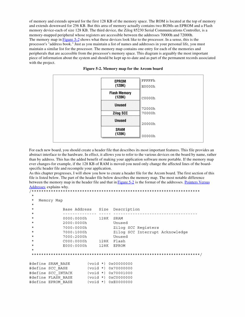
of memory and extends upward for the first 128 KB of the memory space. The ROM is located at the top of memoryand extends downward for 256 KB. But this area of memory actually contains two ROMs-an EPROM and a Flashmemory device-each of size 128 KB. The third device, the Zilog 85230 Serial Communications Controller, is amemory-mapped peripheral whose registers are accessible between the addresses 70000h and 72000h.The memory map in Figure 5-2 shows what these devices look like to the processor. In a sense, this is theprocessor's "address book." Just as you maintain a list of names and addresses in your personal life, you mustmaintain a similar list for the processor. The memory map contains one entry for each of the memories andperipherals that are accessible from the processor's memory space. This diagram is arguably the most importantpiece of information about the system and should be kept up-to-date and as part of the permanent records associatedwith the project.
Figure 5-2. Memory map for the Arcom board
For each new board, you should create a header file that describes its most important features. This file provides anabstract interface to the hardware. In effect, it allows you to refer to the various devices on the board by name, ratherthan by address. This has the added benefit of making your application software more portable. If the memory mapever changes-for example, if the 128 KB of RAM is moved-you need only change the affected lines of the board-specific header file and recompile your application.As this chapter progresses, I will show you how to create a header file for the Arcom board. The first section of thisfile is listed below. The part of the header file below describes the memory map. The most notable differencebetween the memory map in the header file and that in Figure 5-2 is the format of the addresses. Pointers VersusAddresses explains why./********************************************************************** * * Memory Map * * Base Address Size Description * -------------- ----- ----------------------------------- * 0000:0000h 128K SRAM * 2000:0000h Unused * 7000:0000h Zilog SCC Registers * 7000:1000h Zilog SCC Interrupt Acknowledge * 7000:2000h Unused * C000:0000h 128K Flash * E000:0000h 128K EPROM * **********************************************************************/
#define SRAM_BASE (void *) 0x00000000#define SCC_BASE (void *) 0x70000000#define SCC_INTACK (void *) 0x70001000#define FLASH_BASE (void *) 0xC0000000#define EPROM_BASE (void *) 0xE0000000

Pointers Versus AddressesIn both C and C++, the value of a pointer is an address. So when we say that we have a pointer to some
data, we really mean that we have the address at which the data is stored. But programmers don't usuallyset or examine these addresses directly. The exception to this rule are the developers of operatingsystems, device drivers, and embedded software, who sometimes need to set the value of a pointer
explicitly in their code.Unfortunately, the exact representation of an address can change from processor to processor or caneven be compiler dependent. This means that a physical address like 12345h might not be stored inexactly that form, or might even be stored differently by different compilers.[2] The issue that then arisesis how a programmer can set the value of a pointer explicitly so that it points to the desired location inthe memory map.Most C/C++ compilers for 80x86 processors use 32-bit pointers. However, the older processors don'thave a simple linear 32-bit address space. For example, Intel's 80188EB processor has only a 20-bitaddress space. And, in addition, none of its internal registers can hold more than 16 bits. So on thisprocessor, two 16-bit registers-a segment register and an offset register-are combined to create the 20-bit physical address. (The physical address computation involves left-shifting the contents of thesegment register by four bits and adding the contents of the offset register to the result. Any overflowinto the 21st bit is ignored.)To declare and initialize a pointer to a register located at physical address 12345h we therefore write:int * pRegister = (int *) 0x10002345;where the leftmost 16 bits contain the segment value and the rightmost 16 bits contain the offset value.For convenience, 80x86 programmers sometimes write addresses as segment:offset pairs. Using thisnotation, the physical address 12345h would be written as 0x1000:2345. This is precisely the value-sanscolon-that we used to initialize the pointer above. However, for each possible physical address there are4096 distinct segment:offset pairs that point to a given physical address. For example, the pairs0x1200:0345 and 0x1234:0005 (and 4093 others) also refer to physical address 12345h.
[2] This situation gets even more complicated if you consider the various memory models provided by some processors.All of the examples in this book assume that the 80188's large memory model is used. In this memory model all of thespecifics I'm about to tell you hold for all pointer types. But in the other memory models, the format of the addressstored in a pointer differs depending upon the type of code or data pointed to!
5.2.2 I/O Map
If a separate I/O space is present, it will be necessary to repeat the memory map exercise to create an I/O map for theboard as well. The process is exactly the same. Simply create a table of peripheral names and address ranges,organized in such a way that the lowest addresses are at the bottom. Typically, a large percentage of the I/O spacewill be unused because most of the peripherals located there will have only a handful of registers.The I/O map for the Arcom board is shown in Figure 5-3. It includes three devices: the peripheral control block(PCB), parallel port, and debugger port. The PCB is a set of registers within the 80188EB that are used to control theon-chip peripherals. The chips that control the parallel port and debugger port reside outside of the processor. Theseports are used to communicate with the printer and a host-based debugger, respectively.
Figure 5-3. I/O map for the Arcom board
The I/O map is also useful when creating the header file for your board. Each region of the I/O space maps directlyto a constant, called the base address. The translation of the above I/O map into a set of constants can be found in thefollowing listing:
/********************************************************************** * * I/O Map * * Base Address Description * --------------- ---------------------------------------- * 0000h Unused * FC00h SourceVIEW Debugger Port (SVIEW) * FD00h Parallel I/O Port (PIO) * FE00h Unused * FF00h Peripheral Control Block (PCB) * **********************************************************************/
#define SVIEW_BASE 0xFC00#define PIO_BASE 0xFD00#define PCB_BASE 0xFF00
5.3 Learn How to CommunicateNow that you know the names and addresses of the memory and peripherals attached to the processor, it is time tolearn how to communicate with the latter. There are two basic communication techniques: polling and interrupts. Ineither case, the processor usually issues some sort of commands to the device-by way of the memory or I/O space-and waits for the device to complete the assigned task. For example, the processor might ask a timer to count downfrom 1000 to 0. Once the countdown begins, the processor is interested in just one thing: is the timer finishedcounting yet?If polling is used, then the processor repeatedly checks to see if the task has been completed. This is analogous to thesmall child who repeatedly asks "are we there yet?" throughout a long trip. Like the child, the processor spends alarge amount of otherwise useful time asking the question and getting a negative response. To implement polling insoftware, you need only create a loop that reads the status register of the device in question. Here is an example: do { // Play games, read, listen to music, etc. ...
// Poll to see if we're there yet. status = areWeThereYet();
} while (status == NO);The second communication technique uses interrupts. An interrupt is an asynchronous electrical signal from aperipheral to the processor. When interrupts are used, the processor issues commands to the peripheral exactly asbefore, but then waits for an interrupt to signal completion of the assigned work. While the processor is waiting forthe interrupt to arrive, it is free to continue working on other things. When the interrupt signal is finally asserted, theprocessor temporarily sets aside its current work and executes a small piece of software called the interrupt serviceroutine (ISR). When the ISR completes, the processor returns to the work that was interrupted.Of course, this isn't all automatic. The programmer must write the ISR himself and "install" and enable it so that itwill be executed when the relevant interrupt occurs. The first few times you do this, it will be a significant challenge.But, even so, the use of interrupts generally decreases the complexity of one's overall code by giving it a betterstructure. Rather than device polling being embedded within an unrelated part of the program, the two pieces ofcode remain appropriately separate.On the whole, interrupts are a much more efficient use of the processor than polling. The processor is able to use alarger percentage of its waiting time to perform useful work. However, there is some overhead associated with eachinterrupt. It takes a good bit of time-relative to the length of time it takes to execute an opcode-to put aside theprocessor's current work and transfer control to the interrupt service routine. Many of the processor's registers mustbe saved in memory, and lower-priority interrupts must be disabled. So in practice both methods are used frequently.Interrupts are used when efficiency is paramount or multiple devices must be monitored simultaneously. Polling isused when the processor must respond to some event more quickly than is possible using interrupts.
5.3.1 Interrupt Map
Most embedded systems have only a handful of interrupts. Associated with each of these are an interrupt pin (on theoutside of the processor chip) and an ISR. In order for the processor to execute the correct ISR, a mapping mustexist between interrupt pins and ISRs. This mapping usually takes the form of an interrupt vector table. The vectortable is usually just an array of pointers to functions, located at some known memory address. The processor usesthe interrupt type (a unique number associated with each interrupt pin) as its index into this array. The value storedat that location in the vector table is usually just the address of the ISR to be executed.[3]
[3] A few processors actually have the first few instructions of the ISR stored there, rather than a pointer to the routine.
It is important to initialize the interrupt vector table correctly. (If it is done incorrectly, the ISR might be executed inresponse to the wrong interrupt or never executed at all.) The first part of this process is to create an interrupt mapthat organizes the relevant information. An interrupt map is a table that contains a list of interrupt types and thedevices to which they refer. This information should be included in the documentation provided with the board.Table 5-1 shows the interrupt map for the Arcom board.
Table 5-1. Interrupt Map for the Arcom Board
Interrupt Type Generating Device8 Timer/Counter #0
17 Zilog 85230 SCC18 Timer/Counter #119 Timer/Counter #2
20 Serial Port Receive21 Serial Port TransmitOnce again, our goal is to translate the information in the table into a form that is useful for the programmer. Afterconstructing an interrupt map like the one above, you should add a third section to the board-specific header file.Each line of the interrupt map becomes a single #define within the file, as shown:
/********************************************************************** * * Interrupt Map * **********************************************************************/
/* * Zilog 85230 SCC */#define SCC_INT 17
/* * On-Chip Timer/Counters */#define TIMER0_INT 8#define TIMER1_INT 18#define TIMER2_INT 19
/* * On-Chip Serial Ports */#define RX_INT 20#define TX_INT 21
5.4 Get to Know the ProcessorIf you haven't worked with the processor on your board before, you should take some time to get familiar with itnow. This shouldn't take very long if you do all of your programming in C or C++. To the user of a high-levellanguage, most processors look and act pretty much the same. However, if you'll be doing any assembly languageprogramming, you will need to familiarize yourself with the processor's architecture and basic instruction set.Everything you need to know about the processor can be found in the databooks provided by the manufacturer. Ifyou don't have a databook or programmer's guide for your processor already, you should obtain one immediately. Ifyou are going to be a successful embedded systems programmer, you must be able to read databooks and getsomething out of them. Processor databooks are usually well written-as databooks go-so they are an ideal place tostart. Begin by flipping through the databook and noting the sections that are most relevant to the tasks at hand.Then go back and begin reading the processor overview section.
5.4.1 Processors in General
Many of the most common processors are members of families of related devices. In some cases, the members ofsuch a processor family represent points along an evolutionary path. The most obvious example is Intel's 80x86family, which spans from the original 8086 to the Pentium II-and beyond. In fact, the 80x86 family has been sosuccessful that it has spawned an entire industry of imitators.As it is used in this book, the term processor refers to any of three types of devices known as microprocessors,microcontrollers, and digital signal processors. The name microprocessor is usually reserved for a chip that containsa powerful CPU that has not been designed with any particular computation in mind. These chips are usually thefoundation of personal computers and high-end workstations. The most common microprocessors are members ofMotorola's 68k-found in older Macintosh computers-and the ubiquitous 80x86 families.A microcontroller is very much like a microprocessor, except that it has been designed specifically for use inembedded systems. Microcontrollers typically include a CPU, memory (a small amount of RAM, ROM, or both),and other peripherals in the same integrated circuit. If you purchase all of these items on a single chip, it is possibleto reduce the cost of an embedded system substantially. Among the most popular microcontrollers are the 8051 andits many imitators and Motorola's 68HCxx series. It is also common to find microcontroller versions of popularmicroprocessors. For example, Intel's 386EX is a microcontroller version of the very successful 80386microprocessor.The final type of processor is a digital signal processor, or DSP. The CPU within a DSP is specially designed toperform discrete-time signal processing calculations-like those required for audio and video communications-extremely fast. Because DSPs can perform these types of calculations much faster than other processors, they offer apowerful, low-cost microprocessor alternative for designers of modems and other telecommunications andmultimedia equipment. Two of the most common DSP families are the TMS320Cxx and 5600x series from TI andMotorola, respectively.
5.4.2 Intel's 80188EB Processor
The processor on the Arcom board is an Intel 80188EB-a microcontroller version of the 80186. In addition to theCPU, the 80188EB contains an interrupt control unit, two programmable I/O ports, three timer/counters, two serialports, a DRAM controller, and a chip-select unit. These extra hardware devices are located within the same chip andare referred to as on-chip peripherals. The CPU is able to communicate with and control the on-chip peripheralsdirectly, via internal buses.Although the on-chip peripherals are distinct hardware devices, they act like little extensions of the 80186 CPU. Thesoftware can control them by reading and writing a 256-byte block of registers known as the peripheral controlblock (PCB). You may recall that we encountered this block when we first discussed the memory and I/O maps forthe board. By default the PCB is located in the I/O space, beginning at address FF00h. However, if so desired, thePCB can be relocated to any convenient address in either the I/O or memory space.The control and status registers for each of the on-chip peripherals are located at fixed offsets from the PCB baseaddress. The exact offset of each register can be found in a table in the 80188EB Microprocessor User's Manual. Toisolate these details from your application software, it is good practice to include the offsets of any registers you willbe using in the header file for your board. I have done this for the Arcom board, but only those registers that will bediscussed in later chapters of the book are shown here:/********************************************************************** * * On-Chip Peripherals * **********************************************************************/
/* * Interrupt Control Unit
*/#define EOI (PCB_BASE + 0x02)#define POLL (PCB_BASE + 0x04)#define POLLSTS (PCB_BASE + 0x06)
#define IMASK (PCB_BASE + 0x08)#define PRIMSK (PCB_BASE + 0x0A)
#define INSERV (PCB_BASE + 0x0C)#define REQST (PCB_BASE + 0x0E)#define INSTS (PCB_BASE + 0x10)
/* * Timer/Counters */#define TCUCON (PCB_BASE + 0x12)
#define T0CNT (PCB_BASE + 0x30)#define T0CMPA (PCB_BASE + 0x32)#define T0CMPB (PCB_BASE + 0x34)#define T0CON (PCB_BASE + 0x36)
#define T1CNT (PCB_BASE + 0x38)#define T1CMPA (PCB_BASE + 0x3A)#define T1CMPB (PCB_BASE + 0x3C)#define T1CON (PCB_BASE + 0x3E)
#define T2CNT (PCB_BASE + 0x40)#define T2CMPA (PCB_BASE + 0x42)#define T2CON (PCB_BASE + 0x46)
/* * Programmable I/O Ports */#define P1DIR (PCB_BASE + 0x50)#define P1PIN (PCB_BASE + 0x52)#define P1CON (PCB_BASE + 0x54)#define P1LTCH (PCB_BASE + 0x56)
#define P2DIR (PCB_BASE + 0x58)#define P2PIN (PCB_BASE + 0x5A)#define P2CON (PCB_BASE + 0x5C)#define P2LTCH (PCB_BASE + 0x5E)Other things you'll want to learn about the processor from its databook are:
• Where should the interrupt vector table be located? Does it have to be located at a specific address inmemory? If not, how does the processor know where to find it?
• What is the format of the interrupt vector table? Is it just a table of pointers to ISR functions?• Are there any special interrupts, sometimes called traps, that are generated within the processor itself? Must
an ISR be written to handle each of these?• How are interrupts enabled and disabled (globally and individually)?• How are interrupts acknowledged or cleared?
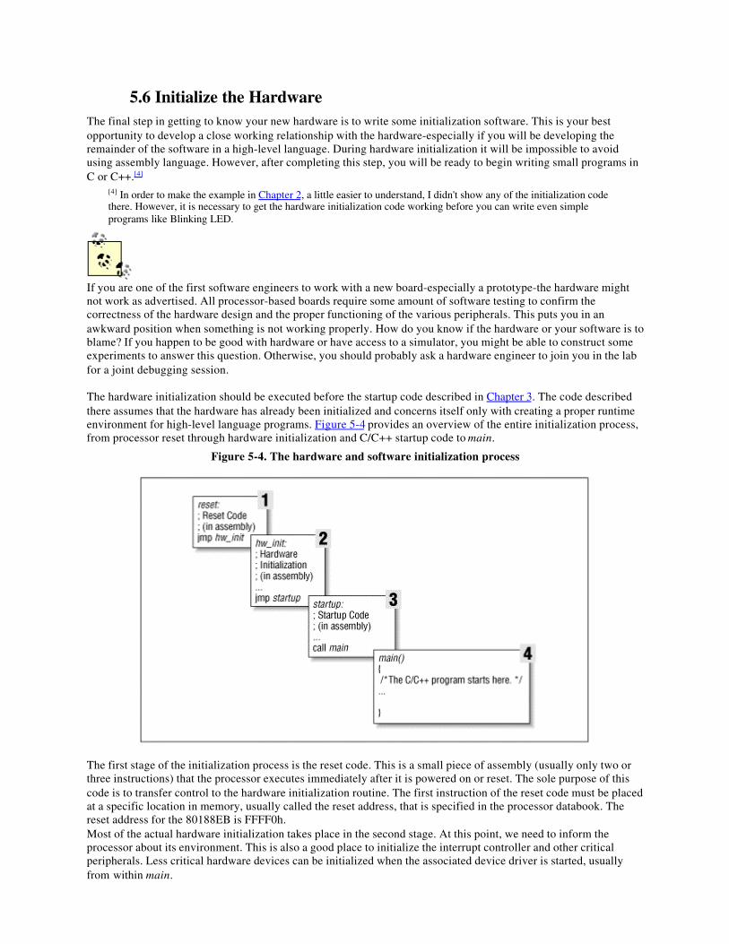
5.6 Initialize the HardwareThe final step in getting to know your new hardware is to write some initialization software. This is your bestopportunity to develop a close working relationship with the hardware-especially if you will be developing theremainder of the software in a high-level language. During hardware initialization it will be impossible to avoidusing assembly language. However, after completing this step, you will be ready to begin writing small programs inC or C++.[4]
[4] In order to make the example in Chapter 2, a little easier to understand, I didn't show any of the initialization codethere. However, it is necessary to get the hardware initialization code working before you can write even simpleprograms like Blinking LED.
If you are one of the first software engineers to work with a new board-especially a prototype-the hardware mightnot work as advertised. All processor-based boards require some amount of software testing to confirm thecorrectness of the hardware design and the proper functioning of the various peripherals. This puts you in anawkward position when something is not working properly. How do you know if the hardware or your software is toblame? If you happen to be good with hardware or have access to a simulator, you might be able to construct someexperiments to answer this question. Otherwise, you should probably ask a hardware engineer to join you in the labfor a joint debugging session.
The hardware initialization should be executed before the startup code described in Chapter 3. The code describedthere assumes that the hardware has already been initialized and concerns itself only with creating a proper runtimeenvironment for high-level language programs. Figure 5-4 provides an overview of the entire initialization process,from processor reset through hardware initialization and C/C++ startup code to main.
Figure 5-4. The hardware and software initialization process
The first stage of the initialization process is the reset code. This is a small piece of assembly (usually only two orthree instructions) that the processor executes immediately after it is powered on or reset. The sole purpose of thiscode is to transfer control to the hardware initialization routine. The first instruction of the reset code must be placedat a specific location in memory, usually called the reset address, that is specified in the processor databook. Thereset address for the 80188EB is FFFF0h.Most of the actual hardware initialization takes place in the second stage. At this point, we need to inform theprocessor about its environment. This is also a good place to initialize the interrupt controller and other criticalperipherals. Less critical hardware devices can be initialized when the associated device driver is started, usuallyfrom within main.
Intel's 80188EB has several internal registers that must be programmed before any useful work can be done with theprocessor. These registers are responsible for setting up the memory and I/O maps and are part of the processor'sinternal chip-select unit. By programming the chip-select registers, you are essentially waking up each of thememory and I/O devices that are connected to the processor. Each chip-select register is associated with a single"chip enable" wire that runs from the processor to some other chip. The association between particular chip-selectsand hardware devices must be established by the hardware designer. All you need to do is get a list of chip-selectsettings from him and load those settings into the chip-select registers.Upon reset, the 80188EB assumes a worst-case scenario. It assumes there are only 1024 bytes of ROM-located inthe address range FFC00h to FFFFFh-and that no other memory or I/O devices are present. This is the processor's"fetal position," and it implies that the hw_init routine must be located at address FFC00h (or higher). It must alsonot require the use of any RAM. The hardware initialization routine should start by initializing the chip-selectregisters to inform the processor about the other memory and I/O devices that are installed on the board. By the timethis task is complete, the entire range of ROM and RAM addresses will be enabled, so the remainder of yoursoftware can be located at any convenient address in either ROM or RAM.The third initialization stage contains the startup code. This is the assembly-language code that we saw back inChapter 3. In case you don't remember, its job is to the prepare the way for code written in a high-level language. Ofimportance here is only that the startup code calls main. From that point forward, all of your other software can bewritten in C or C++.Hopefully, you are starting to understand how embedded software gets from processor reset to your main program.Admittedly, the very first time you try to pull all of these components together (reset code, hardware initialization,C/C++ startup code, and application) on a new board there will be problems. So expect to spend some timedebugging each of them. Honestly, this will be the hardest part of the project. You will soon see that once you havea working Blinking LED program to fall back on, the work just gets easier and easier-or at least more similar toordinary computer programming.Up to this point in the book we have been building the infrastructure for embedded programming. But the topicswe're going to talk about in the remaining chapters concern higher-level structures: memory tests, device drivers,operating systems, and actually useful programs. These are pieces of software you've probably seen before on othercomputer systems projects. However, there will still be some new twists related to the embedded programmingenvironment.
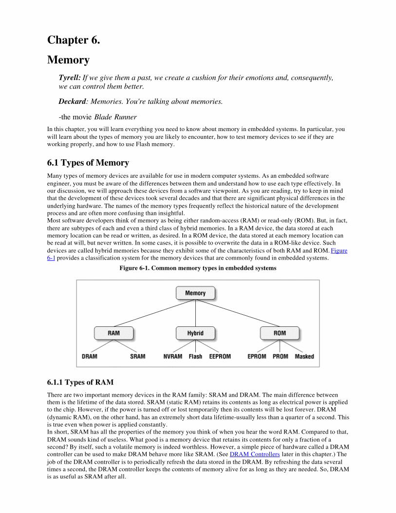
Chapter 6.
MemoryTyrell: If we give them a past, we create a cushion for their emotions and, consequently,we can control them better.
Deckard: Memories. You're talking about memories.
-the movie Blade Runner
In this chapter, you will learn everything you need to know about memory in embedded systems. In particular, youwill learn about the types of memory you are likely to encounter, how to test memory devices to see if they areworking properly, and how to use Flash memory.
6.1 Types of MemoryMany types of memory devices are available for use in modern computer systems. As an embedded softwareengineer, you must be aware of the differences between them and understand how to use each type effectively. Inour discussion, we will approach these devices from a software viewpoint. As you are reading, try to keep in mindthat the development of these devices took several decades and that there are significant physical differences in theunderlying hardware. The names of the memory types frequently reflect the historical nature of the developmentprocess and are often more confusing than insightful.Most software developers think of memory as being either random-access (RAM) or read-only (ROM). But, in fact,there are subtypes of each and even a third class of hybrid memories. In a RAM device, the data stored at eachmemory location can be read or written, as desired. In a ROM device, the data stored at each memory location canbe read at will, but never written. In some cases, it is possible to overwrite the data in a ROM-like device. Suchdevices are called hybrid memories because they exhibit some of the characteristics of both RAM and ROM. Figure6-1 provides a classification system for the memory devices that are commonly found in embedded systems.
Figure 6-1. Common memory types in embedded systems
6.1.1 Types of RAM
There are two important memory devices in the RAM family: SRAM and DRAM. The main difference betweenthem is the lifetime of the data stored. SRAM (static RAM) retains its contents as long as electrical power is appliedto the chip. However, if the power is turned off or lost temporarily then its contents will be lost forever. DRAM(dynamic RAM), on the other hand, has an extremely short data lifetime-usually less than a quarter of a second. Thisis true even when power is applied constantly.In short, SRAM has all the properties of the memory you think of when you hear the word RAM. Compared to that,DRAM sounds kind of useless. What good is a memory device that retains its contents for only a fraction of asecond? By itself, such a volatile memory is indeed worthless. However, a simple piece of hardware called a DRAMcontroller can be used to make DRAM behave more like SRAM. (See DRAM Controllers later in this chapter.) Thejob of the DRAM controller is to periodically refresh the data stored in the DRAM. By refreshing the data severaltimes a second, the DRAM controller keeps the contents of memory alive for as long as they are needed. So, DRAMis as useful as SRAM after all.
DRAM ControllersIf your embedded system includes DRAM, there is probably a DRAM controller on board (or on-chip)
as well. The DRAM controller is an extra piece of hardware placed between the processor and thememory chips. Its main purpose is to perform the refresh operations required to keep your data alive in
the DRAM. However, it cannot do this properly without some help from you.One of the first things your software must do is initialize the DRAM controller. If you do not have anyother RAM in the system, you must do this before creating the stack or heap. As a result, thisinitialization code is usually written in assembly language and placed within the hardware initializationmodule.Almost all DRAM controllers require a short initialization sequence that consists of one or more setupcommands. The setup commands tell the controller about the hardware interface to the DRAM and howfrequently the data there must be refreshed. To determine the initialization sequence for your particularsystem, consult the designer of the board or read the databooks that describe the DRAM and DRAMcontroller. If the DRAM in your system does not appear to be working properly, it could be that theDRAM controller either is not initialized or has been initialized incorrectly.
When deciding which type of RAM to use, a system designer must consider access time and cost. SRAM devicesoffer extremely fast access times (approximately four times faster than DRAM) but are much more expensive toproduce. Generally, SRAM is used only where access speed is extremely important. A lower cost per byte makesDRAM attractive whenever large amounts of RAM are required. Many embedded systems include both types: asmall block of SRAM (a few hundred kilobytes) along a critical data path and a much larger block of DRAM (in themegabytes) for everything else.
6.1.2 Types of ROM
Memories in the ROM family are distinguished by the methods used to write new data to them (usually calledprogramming) and the number of times they can be rewritten. This classification reflects the evolution of ROMdevices from hardwired to one-time programmable to erasable-and-programmable. A common feature across allthese devices is their ability to retain data and programs forever, even during a power failure.The very first ROMs were hardwired devices that contained a preprogrammed set of data or instructions. Thecontents of the ROM had to be specified before chip production, so the actual data could be used to arrange thetransistors inside the chip! Hardwired memories are still used, though they are now called "masked ROMs" todistinguish them from other types of ROM. The main advantage of a masked ROM is a low production cost.Unfortunately, the cost is low only when hundreds of thousands of copies of the same ROM are required.One step up from the masked ROM is the PROM (programmable ROM), which is purchased in an unprogrammedstate. If you were to look at the contents of an unprogrammed PROM, you would see that the data is made upentirely of 1's. The process of writing your data to the PROM involves a special piece of equipment called a deviceprogrammer. The device programmer writes data to the device one word at a time, by applying an electrical chargeto the input pins of the chip. Once a PROM has been programmed in this way, its contents can never be changed. Ifthe code or data stored in the PROM must be changed, the current device must be discarded. As a result, PROMs arealso known as one-time programmable (OTP) devices.An EPROM (erasable-and-programmable ROM) is programmed in exactly the same manner as a PROM. However,EPROMs can be erased and reprogrammed repeatedly. To erase an EPROM, you simply expose the device to astrong source of ultraviolet light. (There is a "window" in the top of the device to let the ultraviolet light reach thesilicon.) By doing this, you essentially reset the entire chip to its initial-unprogrammed-state. Though moreexpensive than PROMs, their ability to be reprogrammed makes EPROMs an essential part of the softwaredevelopment and testing process.
6.1.3 Hybrid Types
As memory technology has matured in recent years, the line between RAM and ROM devices has blurred. There arenow several types of memory that combine the best features of both. These devices do not belong to either groupand can be collectively referred to as hybrid memory devices. Hybrid memories can be read and written as desired,like RAM, but maintain their contents without electrical power, just like ROM. Two of the hybrid devices,EEPROM and Flash, are descendants of ROM devices; the third, NVRAM, is a modified version of SRAM.EEPROMs are electrically-erasable-and-programmable. Internally, they are similar to EPROMs, but the eraseoperation is accomplished electrically, rather than by exposure to ultraviolet light. Any byte within an EEPROM canbe erased and rewritten. Once written, the new data will remain in the device forever-or at least until it is electricallyerased. The tradeoff for this improved functionality is mainly higher cost. Write cycles are also significantly longerthan writes to a RAM, so you wouldn't want to use an EEPROM for your main system memory.
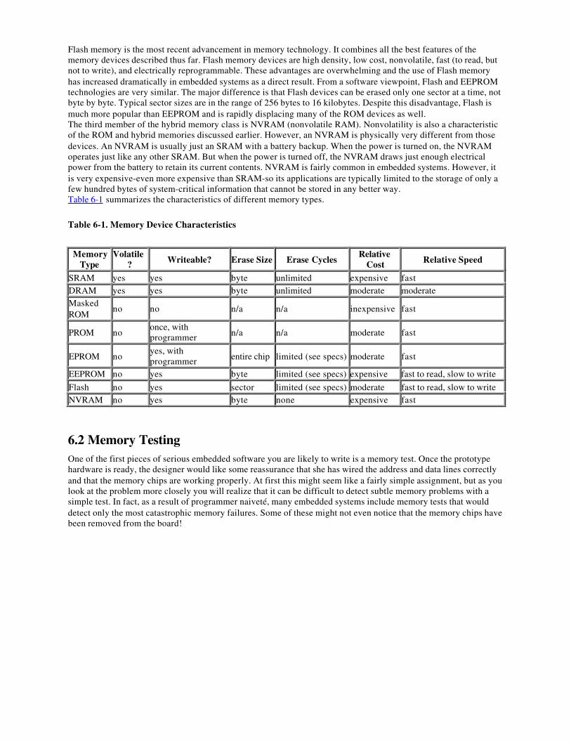
Flash memory is the most recent advancement in memory technology. It combines all the best features of thememory devices described thus far. Flash memory devices are high density, low cost, nonvolatile, fast (to read, butnot to write), and electrically reprogrammable. These advantages are overwhelming and the use of Flash memoryhas increased dramatically in embedded systems as a direct result. From a software viewpoint, Flash and EEPROMtechnologies are very similar. The major difference is that Flash devices can be erased only one sector at a time, notbyte by byte. Typical sector sizes are in the range of 256 bytes to 16 kilobytes. Despite this disadvantage, Flash ismuch more popular than EEPROM and is rapidly displacing many of the ROM devices as well.The third member of the hybrid memory class is NVRAM (nonvolatile RAM). Nonvolatility is also a characteristicof the ROM and hybrid memories discussed earlier. However, an NVRAM is physically very different from thosedevices. An NVRAM is usually just an SRAM with a battery backup. When the power is turned on, the NVRAMoperates just like any other SRAM. But when the power is turned off, the NVRAM draws just enough electricalpower from the battery to retain its current contents. NVRAM is fairly common in embedded systems. However, itis very expensive-even more expensive than SRAM-so its applications are typically limited to the storage of only afew hundred bytes of system-critical information that cannot be stored in any better way.Table 6-1 summarizes the characteristics of different memory types.
Table 6-1. Memory Device Characteristics
MemoryType
Volatile? Writeable? Erase Size Erase Cycles
RelativeCost Relative Speed
SRAM yes yes byte unlimited expensive fastDRAM yes yes byte unlimited moderate moderateMaskedROM
no no n/a n/a inexpensive fast
PROM noonce, withprogrammer n/a n/a moderate fast
EPROM noyes, withprogrammer entire chip limited (see specs) moderate fast
EEPROM no yes byte limited (see specs) expensive fast to read, slow to write
Flash no yes sector limited (see specs) moderate fast to read, slow to writeNVRAM no yes byte none expensive fast
6.2 Memory TestingOne of the first pieces of serious embedded software you are likely to write is a memory test. Once the prototypehardware is ready, the designer would like some reassurance that she has wired the address and data lines correctlyand that the memory chips are working properly. At first this might seem like a fairly simple assignment, but as youlook at the problem more closely you will realize that it can be difficult to detect subtle memory problems with asimple test. In fact, as a result of programmer naiveté, many embedded systems include memory tests that woulddetect only the most catastrophic memory failures. Some of these might not even notice that the memory chips havebeen removed from the board!
Direct Memory AccessDirect memory access (DMA) is a technique for transferring blocks of data directly between two
hardware devices. In the absence of DMA, the processor must read the data from one device and write itto the other, one byte or word at a time. If the amount of data to be transferred is large, or the frequency
of transfers is high, the rest of the software might never get a chance to run. However, if a DMAcontroller is present it is possible to have it perform the entire transfer, with little assistance from the
processor.Here's how DMA works. When a block of data needs to be transferred, the processor provides the DMAcontroller with the source and destination addresses and the total number of bytes. The DMA controllerthen transfers the data from the source to the destination automatically. After each byte is copied, eachaddress is incremented and the number of bytes remaining is reduced by one. When the number of bytesremaining reaches zero, the block transfer ends and the DMA controller sends an interrupt to theprocessor.In a typical DMA scenario, the block of data is transferred directly to or from memory. For example, anetwork controller might want to place an incoming network packet into memory as it arrives, but onlynotify the processor once the entire packet has been received. By using DMA, the processor can spendmore time processing the data once it arrives and less time transferring it between devices. Theprocessor and DMA controller must share the address and data buses during this time, but this ishandled automatically by the hardware and the processor is otherwise uninvolved with the actualtransfer.The purpose of a memory test is to confirm that each storage location in a memory device is working. In otherwords, if you store the number 50 at a particular address, you expect to find that number stored there until anothernumber is written. The basic idea behind any memory test, then, is to write some set of data values to each addressin the memory device and verify the data by reading it back. If all the values read back are the same as those thatwere written, then the memory device is said to pass the test. As you will see, it is only through careful selection ofthe set of data values that you can be sure that a passing result is meaningful.Of course, a memory test like the one just described is unavoidably destructive. In the process of testing thememory, you must overwrite its prior contents. Because it is generally impractical to overwrite the contents ofnonvolatile memories, the tests described in this section are generally used only for RAM testing. However, if thecontents of a hybrid memory are unimportant-as they are during the product development stage-these samealgorithms can be used to test those devices as well. The problem of validating the contents of a nonvolatile memoryis addressed in a later section of this chapter.
6.2.1 Common Memory Problems
Before learning about specific test algorithms, you should be familiar with the types of memory problems that arelikely to occur. One common misconception among software engineers is that most memory problems occur withinthe chips themselves. Though a major issue at one time (a few decades ago), problems of this type are increasinglyrare. The manufacturers of memory devices perform a variety of post-production tests on each batch of chips. Ifthere is a problem with a particular batch, it is extremely unlikely that one of the bad chips will make its way intoyour system.The one type of memory chip problem you could encounter is a catastrophic failure. This is usually caused by somesort of physical or electrical damage received by the chip after manufacture. Catastrophic failures are uncommonand usually affect large portions of the chip. Because a large area is affected, it is reasonable to assume thatcatastrophic failure will be detected by any decent test algorithm.In my experience, a more common source of memory problems is the circuit board. Typical circuit board problemsare:
• Problems with the wiring between the processor and memory device• Missing memory chips• Improperly inserted memory chips
These are the problems that a good memory test algorithm should be able to detect. Such a test should also be able todetect catastrophic memory failures without specifically looking for them. So let's discuss circuit board problems inmore detail.
6.2.1.1 Electrical wiring problems
An electrical wiring problem could be caused by an error in design or production of the board or as the result ofdamage received after manufacture. Each of the wires that connect the memory device to the processor is one ofthree types: an address line, a data line, or a control line. The address and data lines are used to select the memorylocation and to transfer the data, respectively. The control lines tell the memory device whether the processor wantsto read or write the location and precisely when the data will be transferred. Unfortunately, one or more of these
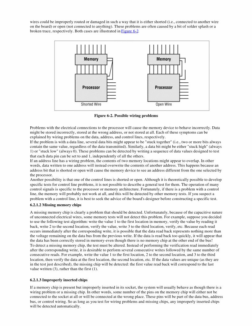
wires could be improperly routed or damaged in such a way that it is either shorted (i.e., connected to another wireon the board) or open (not connected to anything). These problems are often caused by a bit of solder splash or abroken trace, respectively. Both cases are illustrated in Figure 6-2.
Figure 6-2. Possible wiring problems
Problems with the electrical connections to the processor will cause the memory device to behave incorrectly. Datamight be stored incorrectly, stored at the wrong address, or not stored at all. Each of these symptoms can beexplained by wiring problems on the data, address, and control lines, respectively.If the problem is with a data line, several data bits might appear to be "stuck together" (i.e., two or more bits alwayscontain the same value, regardless of the data transmitted). Similarly, a data bit might be either "stuck high" (always1) or "stuck low" (always 0). These problems can be detected by writing a sequence of data values designed to testthat each data pin can be set to and 1, independently of all the others.If an address line has a wiring problem, the contents of two memory locations might appear to overlap. In otherwords, data written to one address will instead overwrite the contents of another address. This happens because anaddress bit that is shorted or open will cause the memory device to see an address different from the one selected bythe processor.Another possibility is that one of the control lines is shorted or open. Although it is theoretically possible to developspecific tests for control line problems, it is not possible to describe a general test for them. The operation of manycontrol signals is specific to the processor or memory architecture. Fortunately, if there is a problem with a controlline, the memory will probably not work at all, and this will be detected by other memory tests. If you suspect aproblem with a control line, it is best to seek the advice of the board's designer before constructing a specific test.
6.2.1.2 Missing memory chips
A missing memory chip is clearly a problem that should be detected. Unfortunately, because of the capacitive natureof unconnected electrical wires, some memory tests will not detect this problem. For example, suppose you decidedto use the following test algorithm: write the value 1 to the first location in memory, verify the value by reading itback, write 2 to the second location, verify the value, write 3 to the third location, verify, etc. Because each readoccurs immediately after the corresponding write, it is possible that the data read back represents nothing more thanthe voltage remaining on the data bus from the previous write. If the data is read back too quickly, it will appear thatthe data has been correctly stored in memory-even though there is no memory chip at the other end of the bus!To detect a missing memory chip, the test must be altered. Instead of performing the verification read immediatelyafter the corresponding write, it is desirable to perform several consecutive writes followed by the same number ofconsecutive reads. For example, write the value 1 to the first location, 2 to the second location, and 3 to the thirdlocation, then verify the data at the first location, the second location, etc. If the data values are unique (as they arein the test just described), the missing chip will be detected: the first value read back will correspond to the lastvalue written (3), rather than the first (1).
6.2.1.3 Improperly inserted chips
If a memory chip is present but improperly inserted in its socket, the system will usually behave as though there is awiring problem or a missing chip. In other words, some number of the pins on the memory chip will either not beconnected to the socket at all or will be connected at the wrong place. These pins will be part of the data bus, addressbus, or control wiring. So as long as you test for wiring problems and missing chips, any improperly inserted chipswill be detected automatically.
Before going on, let's quickly review the types of memory problems we must be able to detect. Memory chips onlyrarely have internal errors, but if they do, they are probably catastrophic in nature and will be detected by any test. Amore common source of problems is the circuit board, where a wiring problem can occur or a memory chip might bemissing or improperly inserted. Other memory problems can occur, but the ones described here are the mostcommon and also the simplest to test in a generic way.
6.2.2 Developing a Test Strategy
By carefully selecting your test data and the order in which the addresses are tested, it is possible to detect all of thememory problems described earlier. It is usually best to break your memory test into small, single-minded pieces.This helps to improve the efficiency of the overall test and the readability of the code. More specific tests can alsoprovide more detailed information about the source of the problem, if one is detected.I have found it is best to have three individual memory tests: a data bus test, an address bus test, and a device test.The first two test for electrical wiring problems and improperly inserted chips; the third is intended to detect missingchips and catastrophic failures. As an unintended consequence, the device test will also uncover problems with thecontrol bus wiring, though it cannot provide useful information about the source of such a problem.The order in which you execute these three tests is important. The proper order is: data bus test first, followed by theaddress bus test, and then the device test. That's because the address bus test assumes a working data bus, and thedevice test results are meaningless unless both the address and data buses are known to be good. If any of the testsfail, you should work with a hardware engineer to locate the source of the problem. By looking at the data value oraddress at which the test failed, she should be able to quickly isolate the problem on the circuit board.
6.2.2.1 Data bus test
The first thing we want to test is the data bus wiring. We need to confirm that any value placed on the data bus bythe processor is correctly received by the memory device at the other end. The most obvious way to test that is towrite all possible data values and verify that the memory device stores each one successfully. However, that is notthe most efficient test available. A faster method is to test the bus one bit at a time. The data bus passes the test ifeach data bit can be set to and 1, independently of the other data bits.A good way to test each bit independently is to perform the so-called "walking 1's test." Table 6-2 shows the datapatterns used in an 8-bit version of this test. The name, walking 1's, comes from the fact that a single data bit is setto 1 and "walked" through the entire data word. The number of data values to test is the same as the width of thedata bus. This reduces the number of test patterns from 2n to n, where n is the width of the data bus.
Table 6-2. Consecutive Data Values for the Walking 1's Test
00000001
000000100000010000001000
000100000010000001000000
10000000Because we are testing only the data bus at this point, all of the data values can be written to the same address. Anyaddress within the memory device will do. However, if the data bus splits as it makes its way to more than onememory chip, you will need to perform the data bus test at multiple addresses, one within each chip.To perform the walking 1's test, simply write the first data value in the table, verify it by reading it back, write thesecond value, verify, etc. When you reach the end of the table, the test is complete. It is okay to do the readimmediately after the corresponding write this time because we are not yet looking for missing chips. In fact, thistest may provide meaningful results even if the memory chips are not installed!The function memTestDataBus shows how to implement the walking 1's test in C. It assumes that the caller willselect the test address, and tests the entire set of data values at that address. If the data bus is working properly, thefunction will return 0. Otherwise it will return the data value for which the test failed. The bit that is set in thereturned value corresponds to the first faulty data line, if any.
typedef unsigned char datum; /* Set the data bus width to 8 bits. */
/********************************************************************** * * Function: memTestDataBus()
* * Description: Test the data bus wiring in a memory region by * performing a walking 1's test at a fixed address * within that region. The address (and hence the * memory region) is selected by the caller. * * Notes: * * Returns: 0 if the test succeeds. * A nonzero result is the first pattern that failed. * **********************************************************************/datummemTestDataBus(volatile datum * address){ datum pattern;
/* * Perform a walking 1's test at the given address. */ for (pattern = 1; pattern != 0; pattern <<= 1) { /* * Write the test pattern. */ *address = pattern;
/* * Read it back (immediately is okay for this test). */ if (*address != pattern) { return (pattern); } }
return (0);
} /* memTestDataBus() */
6.2.2.2 Address bus test
After confirming that the data bus works properly, you should next test the address bus. Remember that address busproblems lead to overlapping memory locations. There are many possible addresses that could overlap. However, itis not necessary to check every possible combination. You should instead follow the example of the previous databus test and try to isolate each address bit during testing. You simply need to confirm that each of the address pinscan be set to and 1 without affecting any of the others.The smallest set of addresses that will cover all possible combinations is the set of "power-of-two" addresses. Theseaddresses are analogous to the set of data values used in the walking 1's test. The corresponding memory locationsare 00001h, 00002h, 00004h, 00008h, 00010h, 00020h, and so forth. In addition, address 00000h must also betested. The possibility of overlapping locations makes the address bus test harder to implement. After writing to oneof the addresses, you must check that none of the others has been overwritten.It is important to note that not all of the address lines can be tested in this way. Part of the address-the leftmost bits-selects the memory chip itself. Another part-the rightmost bits-might not be significant if the data bus width isgreater than 8 bits. These extra bits will remain constant throughout the test and reduce the number of test addresses.For example, if the processor has 20 address bits, as the 80188EB does, then it can address up to 1 megabyte ofmemory. If you want to test a 128-kilobyte block of memory, the three most significant address bits will remainconstant.[1] In that case, only the 17 rightmost bits of the address bus can actually be tested.
[1] 128 kilobytes is one-eighth of the total 1-megabyte address space.
To confirm that no two memory locations overlap, you should first write some initial data value at each power-of-two offset within the device. Then write a new value-an inverted copy of the initial value is a good choice-to the firsttest offset, and verify that the initial data value is still stored at every other power-of-two offset. If you find a
location (other than the one just written) that contains the new data value, you have found a problem with the currentaddress bit. If no overlapping is found, repeat the procedure for each of the remaining offsets.The function memTestAddressBus shows how this can be done in practice. The function accepts two parameters.The first parameter is the base address of the memory block to be tested, and the second is its size, in bytes. The sizeis used to determine which address bits should be tested. For best results, the base address should contain a in eachof those bits. If the address bus test fails, the address at which the first error was detected will be returned.Otherwise, the function returns NULL to indicate success./**********************************************************************
* Function: memTestAddressBus() * * Description: Test the address bus wiring in a memory region by * performing a walking 1's test on the relevant bits * of the address and checking for aliasing. The test * will find single-bit address failures such as stuck * -high, stuck-low, and shorted pins. The base address * and size of the region are selected by the caller. * * Notes: For best results, the selected base address should * have enough LSB 0's to guarantee single address bit * changes. For example, to test a 64 KB region, select * a base address on a 64 KB boundary. Also, select the * region size as a power-of-two--if at all possible. * * Returns: NULL if the test succeeds. * A nonzero result is the first address at which an * aliasing problem was uncovered. By examining the * contents of memory, it may be possible to gather * additional information about the problem. * **********************************************************************/datum *memTestAddressBus(volatile datum * baseAddress, unsigned long nBytes){ unsigned long addressMask = (nBytes - 1); unsigned long offset; unsigned long testOffset;
datum pattern = (datum) 0xAAAAAAAA; datum antipattern = (datun) 0x55555555;
/* * Write the default pattern at each of the power-of-two offsets.. */ for (offset = sizeof(datum); (offset & addressMask) != 0; offset <<= 1) { baseAddress[offset] = pattern; }
/* * Check for address bits stuck high. */ testOffset = 0; baseAddress[testOffset] = antipattern;
for (offset = sizeof(datum); (offset & addressMask) != 0; offset <<= 1) { if (baseAddress[offset] != pattern) { return ((datum *) &baseAddress[offset]); } }
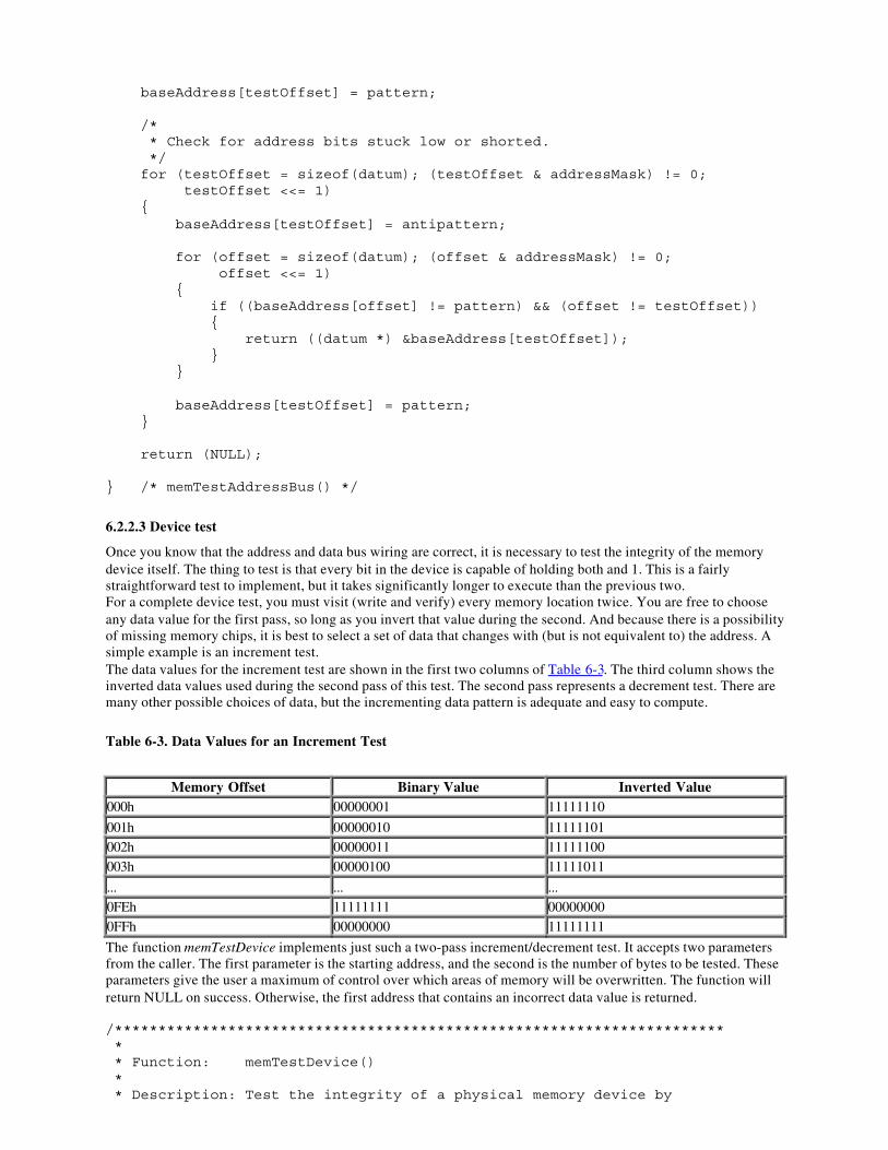
baseAddress[testOffset] = pattern;
/* * Check for address bits stuck low or shorted. */ for (testOffset = sizeof(datum); (testOffset & addressMask) != 0; testOffset <<= 1) { baseAddress[testOffset] = antipattern;
for (offset = sizeof(datum); (offset & addressMask) != 0; offset <<= 1) { if ((baseAddress[offset] != pattern) && (offset != testOffset)) { return ((datum *) &baseAddress[testOffset]); } }
baseAddress[testOffset] = pattern; }
return (NULL);
} /* memTestAddressBus() */
6.2.2.3 Device test
Once you know that the address and data bus wiring are correct, it is necessary to test the integrity of the memorydevice itself. The thing to test is that every bit in the device is capable of holding both and 1. This is a fairlystraightforward test to implement, but it takes significantly longer to execute than the previous two.For a complete device test, you must visit (write and verify) every memory location twice. You are free to chooseany data value for the first pass, so long as you invert that value during the second. And because there is a possibilityof missing memory chips, it is best to select a set of data that changes with (but is not equivalent to) the address. Asimple example is an increment test.The data values for the increment test are shown in the first two columns of Table 6-3. The third column shows theinverted data values used during the second pass of this test. The second pass represents a decrement test. There aremany other possible choices of data, but the incrementing data pattern is adequate and easy to compute.
Table 6-3. Data Values for an Increment Test
Memory Offset Binary Value Inverted Value000h 00000001 11111110
001h 00000010 11111101002h 00000011 11111100003h 00000100 11111011
... ... ...0FEh 11111111 000000000FFh 00000000 11111111
The function memTestDevice implements just such a two-pass increment/decrement test. It accepts two parametersfrom the caller. The first parameter is the starting address, and the second is the number of bytes to be tested. Theseparameters give the user a maximum of control over which areas of memory will be overwritten. The function willreturn NULL on success. Otherwise, the first address that contains an incorrect data value is returned.
/********************************************************************** * * Function: memTestDevice() * * Description: Test the integrity of a physical memory device by
* performing an increment/decrement test over the * entire region. In the process every storage bit * in the device is tested as a zero and a one. The * base address and the size of the region are * selected by the caller. * * Notes: * * Returns: NULL if the test succeeds. Also, in that case, the * entire memory region will be filled with zeros. * * A nonzero result is the first address at which an * incorrect value was read back. By examining the * contents of memory, it may be possible to gather * additional information about the problem. * **********************************************************************/datum *memTestDevice(volatile datum * baseAddress, unsigned long nBytes){ unsigned long offset; unsigned long nWords = nBytes / sizeof(datum);
datum pattern; datum antipattern;
/* * Fill memory with a known pattern. */ for (pattern = 1, offset = 0; offset < nWords; pattern++, offset++) { baseAddress[offset] = pattern; }
/* * Check each location and invert it for the second pass. */ for (pattern = 1, offset = 0; offset < nWords; pattern++, offset++) { if (baseAddress[offset] != pattern) { return ((datum *) &baseAddress[offset]); }
antipattern = ~pattern; baseAddress[offset] = antipattern; }
/* * Check each location for the inverted pattern and zero it. */ for (pattern = 1, offset = 0; offset < nWords; pattern++, offset++) { antipattern = ~pattern; if (baseAddress[offset] != antipattern) { return ((datum *) &baseAddress[offset]); }
baseAddress[offset] = 0; }
return (NULL);
} /* memTestDevice() */
6.2.2.4 Putting it all together
To make our discussion more concrete, let's consider a practical example. Suppose that we wanted to test the second64-kilobyte chunk of the SRAM on the Arcom board. To do this, we would call each of the three test routines inturn. In each case, the first parameter would be the base address of the memory block. Looking at our memory map,we see that the physical address is 10000h, which is represented by the segment:offset pair 0x1000:0000. The widthof the data bus is 8 bits (a feature of the 80188EB processor), and there are a total of 64 kilobytes to be tested(corresponding to the rightmost 16 bits of the address bus).If any of the memory test routines returns a nonzero (or non-NULL) value, we'll immediately turn on the red LED tovisually indicate the error. Otherwise, after all three tests have completed successfully, we will turn on the greenLED. In the event of an error, the test routine that failed will return some information about the problemencountered. This information can be useful when communicating with a hardware engineer about the nature of theproblem. However, it is visible only if we are running the test program in a debugger or emulator.The best way to proceed is to assume the best, download the test program, and let it run to completion. Then, if andonly if the red LED comes on, must you use the debugger to step through the program and examine the return codesand contents of the memory to see which test failed and why.#include "led.h"
#define BASE_ADDRESS (volatile datum *) 0x10000000#define NUM_BYTES 0x10000
/********************************************************************** * * Function: main() * * Description: Test the second 64 KB bank of SRAM. * * Notes: * * Returns: 0 on success. * Otherwise -1 indicates failure. * **********************************************************************/main(void){ if ((memTestDataBus(BASE_ADDRESS) != 0) || (memTestAddressBus(BASE_ADDRESS, NUM_BYTES) != NULL) || (memTestDevice(BASE_ADDRESS, NUM_BYTES) != NULL)) { toggleLed(LED_RED); return (-1); } else { toggleLed(LED_GREEN); return (0); }
} /* main() */Unfortunately, it is not always possible to write memory tests in a high-level language. For example, C and C++both require the use of a stack. But a stack itself requires working memory. This might be reasonable in a systemthat has more than one memory device. For example, you might create a stack in an area of RAM that is alreadyknown to be working, while testing another memory device. In a common such situation, a small SRAM could betested from assembly and the stack could be created there afterward. Then a larger block of DRAM could be testedusing a nicer test algorithm, like the one shown earlier. If you cannot assume enough working RAM for the stackand data needs of the test program, then you will need to rewrite these memory test routines entirely in assemblylanguage.Another option is to run the memory test program from an emulator. In this case, you could choose to place the stackin an area of the emulator's own internal memory. By moving the emulator's internal memory around in the targetmemory map, you could systematically test each memory device on the target.
The need for memory testing is perhaps most apparent during product development, when the reliability of thehardware and its design are still unproved. However, memory is one of the most critical resources in any embeddedsystem, so it might also be desirable to include a memory test in the final release of your software. In that case, thememory test and other hardware confidence tests should be run each time the system is powered-on or reset.Together, this initial test suite forms a set of hardware diagnostics. If one or more of the diagnostics fail, a repairtechnician can be called in to diagnose the problem and repair or replace the faulty hardware.
6.3 Validating Memory ContentsIt does not usually make sense to perform the type of memory testing described earlier when dealing with ROM andhybrid memory devices. ROM devices cannot be written at all, and hybrid devices usually contain data or programsthat cannot be overwritten. However, it should be clear that the same sorts of memory problems can occur with thesedevices. A chip might be missing or improperly inserted or physically or electrically damaged, or there could be anelectrical wiring problem. Rather than just assuming that these nonvolatile memory devices are functioningproperly, you would be better off having some way to confirm that the device is working and that the data it containsis valid. That's where checksums and cyclic redundancy codes come in.
6.3.1 Checksums
How can we tell if the data or program stored in a nonvolatile memory device is still valid? One of the easiest waysis to compute a checksum of the data when it is known to be good-prior to programming the ROM, for example.Then, each time you want to confirm the validity of the data, you need only recalculate the checksum and comparethe result to the previously computed value. If the two checksums match, the data is assumed to be valid. Bycarefully selecting the checksum algorithm, we can increase the probability that specific types of errors will bedetected.The simplest checksum algorithm is to add up all the data bytes (or, if you prefer a 16-bit checksum, words),discarding carries along the way. A noteworthy weakness of this algorithm is that if all of the data (including thestored checksum) is accidentally overwritten with 0's, then this data corruption will be undetectable. The sum of alarge block of zeros is also zero. The simplest way to overcome this weakness is to add a final step to the checksumalgorithm: invert the result. That way, if the data and checksum are somehow overwritten with 0's, the test will failbecause the proper checksum would be FFh.Unfortunately, a simple sum-of-data checksum like this one cannot detect many of the most common data errors.Clearly if one bit of data is corrupted (switched from 1 to 0, or vice versa), the error would be detected. But what iftwo bits from the very same "column" happened to be corrupted alternately (the first switches from 1 to 0, the otherfrom to 1)? The proper checksum does not change, and the error would not be detected. If bit errors can occur, youwill probably want to use a better checksum algorithm. We'll see one of these in the next section.After computing the expected checksum, we'll need a place to store it. One option is to compute the checksum aheadof time and define it as a constant in the routine that verifies the data. This method is attractive to the programmerbut has several shortcomings. Foremost among them is the possibility that the data-and, as a result, the expectedchecksum-might change during the lifetime of the product. This is particularly likely if the data being tested isactually embedded software that will be periodically updated as bugs are fixed or new features added.A better idea is to store the checksum at some fixed location in memory. For example, you might decide to use thevery last location of the memory device being verified. This makes insertion of the checksum easy-just compute thechecksum and insert it into the memory image prior to programming the memory device. When you recalculate thechecksum, you simply skip over the location that contains the expected result, and compare the new result to thevalue stored there. Another good place to store the checksum is in another nonvolatile memory device. Both of thesesolutions work very well in practice.
6.3.2 Cyclic Redundancy Codes
A cyclic redundancy code (CRC) is a specific checksum algorithm that is designed to detect the most common dataerrors. The theory behind the CRC is quite mathematical and beyond the scope of this book. However, cyclicredundancy codes are frequently useful in embedded applications that require the storage or transmission of largeblocks of data. What follows is a brief explanation of the CRC technique and some source code that shows how itcan be done in C. Thankfully, you don't need to understand why CRCs detect data errors-or even how they areimplemented-to take advantage of their ability to detect errors.Here's a very brief explanation of the mathematics. When computing a CRC, you consider the set of data to be avery long string of 1's and 0's (called the message). This binary string is divided-in a rather peculiar way-by asmaller fixed binary string called the generator polynomial . The remainder of this binary long division is the CRCchecksum. By carefully selecting the generator polynomial for certain desirable mathematical properties, you canuse the resulting checksum to detect most (but never all) errors within the message. The strongest of these generatorpolynomials are able to detect all single and double bit errors, and all odd-length strings of consecutive error bits. Inaddition, greater than 99.99% of all burst errors-defined as a sequence of bits that has one error at each end-can be
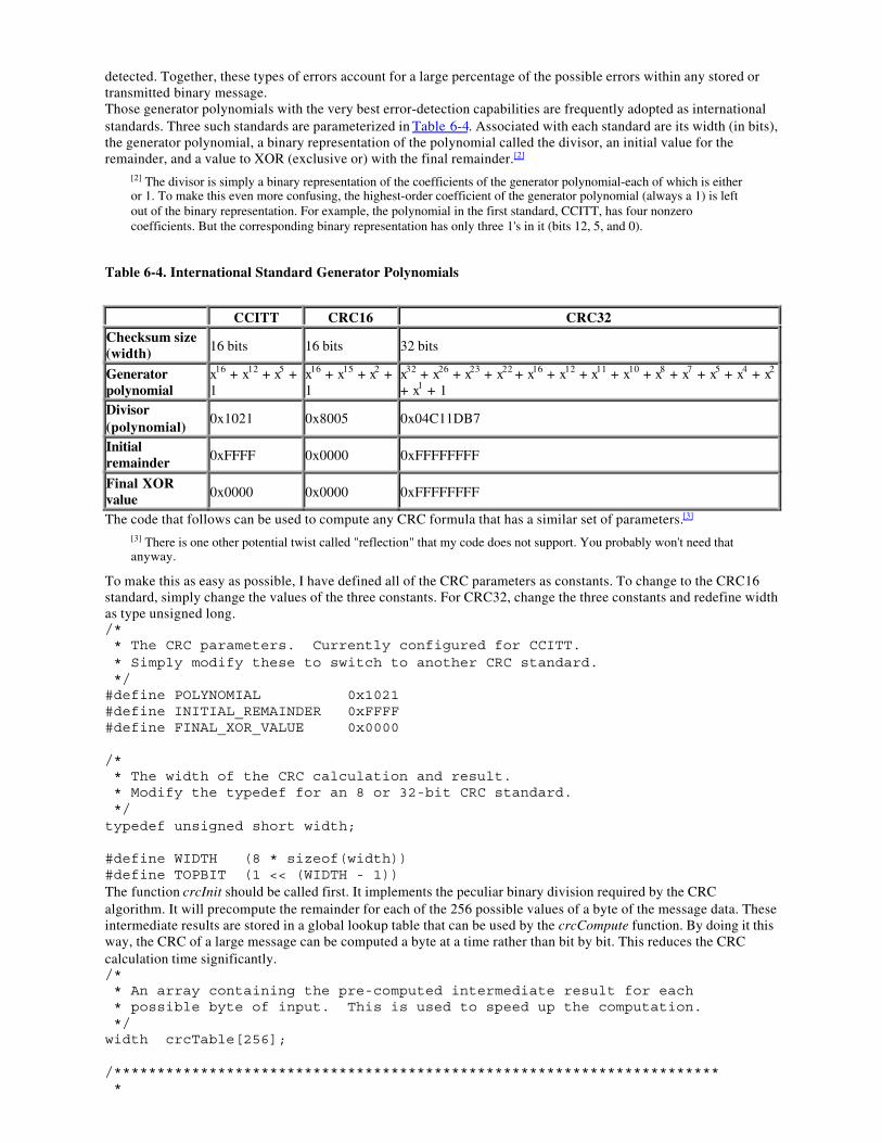
detected. Together, these types of errors account for a large percentage of the possible errors within any stored ortransmitted binary message.Those generator polynomials with the very best error-detection capabilities are frequently adopted as internationalstandards. Three such standards are parameterized in Table 6-4. Associated with each standard are its width (in bits),the generator polynomial, a binary representation of the polynomial called the divisor, an initial value for theremainder, and a value to XOR (exclusive or) with the final remainder.[2]
[2] The divisor is simply a binary representation of the coefficients of the generator polynomial-each of which is eitheror 1. To make this even more confusing, the highest-order coefficient of the generator polynomial (always a 1) is leftout of the binary representation. For example, the polynomial in the first standard, CCITT, has four nonzerocoefficients. But the corresponding binary representation has only three 1's in it (bits 12, 5, and 0).
Table 6-4. International Standard Generator Polynomials
CCITT CRC16 CRC32Checksum size(width) 16 bits 16 bits 32 bits
Generatorpolynomial
x16 + x12 + x5 +1
x16 + x15 + x2 +1
x32 + x26 + x23 + x22 + x16 + x12 + x11 + x10 + x8 + x7 + x5 + x4 + x2
+ x1 + 1Divisor(polynomial)
0x1021 0x8005 0x04C11DB7
Initialremainder 0xFFFF 0x0000 0xFFFFFFFF
Final XORvalue 0x0000 0x0000 0xFFFFFFFF
The code that follows can be used to compute any CRC formula that has a similar set of parameters.[3]
[3] There is one other potential twist called "reflection" that my code does not support. You probably won't need thatanyway.
To make this as easy as possible, I have defined all of the CRC parameters as constants. To change to the CRC16standard, simply change the values of the three constants. For CRC32, change the three constants and redefine widthas type unsigned long./* * The CRC parameters. Currently configured for CCITT. * Simply modify these to switch to another CRC standard. */#define POLYNOMIAL 0x1021#define INITIAL_REMAINDER 0xFFFF#define FINAL_XOR_VALUE 0x0000
/* * The width of the CRC calculation and result. * Modify the typedef for an 8 or 32-bit CRC standard. */typedef unsigned short width;
#define WIDTH (8 * sizeof(width))#define TOPBIT (1 << (WIDTH - 1))The function crcInit should be called first. It implements the peculiar binary division required by the CRCalgorithm. It will precompute the remainder for each of the 256 possible values of a byte of the message data. Theseintermediate results are stored in a global lookup table that can be used by the crcCompute function. By doing it thisway, the CRC of a large message can be computed a byte at a time rather than bit by bit. This reduces the CRCcalculation time significantly./* * An array containing the pre-computed intermediate result for each * possible byte of input. This is used to speed up the computation. */width crcTable[256];
/********************************************************************** *
* Function: crcInit() * * Description: Initialize the CRC lookup table. This table is used * by crcCompute() to make CRC computation faster. * * Notes: The mod-2 binary long division is implemented here. * * Returns: None defined. * **********************************************************************/voidcrcInit(void){ width remainder; width dividend; int bit;
/* * Perform binary long division, a bit at a time. */ for (dividend = 0; dividend < 256; dividend++) { /* * Initialize the remainder. */ remainder = dividend << (WIDTH - 8);
/* * Shift and XOR with the polynomial. */ for (bit = 0; bit < 8; bit++) { /* * Try to divide the current data bit. */ if (remainder & TOPBIT) { remainder = (remainder << 1) ^ POLYNOMIAL; } else { remainder = remainder << 1; } }
/* * Save the result in the table. */ crcTable[dividend] = remainder; }
} /* crcInit() */Finally, we arrive at the actual workhorse routine, crcCompute. This is a routine that you can call over and overfrom your application to compute and verify CRC checksums. An additional benefit of splitting the computationbetween crcInit and crcCompute is that the crcInit function need not be executed on the embedded system. Instead,this function can be run in advance-on any computer-to produce the contents of the lookup table. The values in thetable can then be stored in ROM (requiring only 256 bytes of storage) and referenced over and over by crcCompute.
/********************************************************************** * * Function: crcCompute()
* * Description: Compute the CRC checksum of a binary message block. * * Notes: This function expects that crcInit() has been called * first to initialize the CRC lookup table. * * Returns: The CRC of the data. * **********************************************************************/widthcrcCompute(unsigned char * message, unsigned int nBytes){ unsigned int offset; unsigned char byte; width remainder = INITIAL_REMAINDER;
/* * Divide the message by the polynomial, a byte at a time. */ for (offset = 0; offset < nBytes; offset++) { byte = (remainder >> (WIDTH - 8)) ^ message[offset]; remainder = crcTable[byte] ^ (remainder << 8); }
/* * The final remainder is the CRC result. */ return (remainder ^ FINAL_XOR_VALUE);
} /* crcCompute() */
6.4 Working with Flash MemoryFrom the programmer's viewpoint, Flash is arguably the most complicated memory device ever invented. Thehardware interface has improved somewhat since the original devices were introduced in 1988, but there is still along way to go. Reading from Flash memory is fast and easy, as it should be. In fact, reading data from a Flash isnot all that different from reading from any other memory device.[4] The processor simply provides the address, andthe memory device returns the data stored at that location. Most Flash devices enter this type of "read" modeautomatically whenever the system is reset; no special initialization sequence is required to enable reading.
[4] There is one small difference worth noting here. The erase and write cycles take longer than the read cycle. So if aread is attempted in the middle of one of those operations, the result will be either delayed or incorrect, depending onthe device.
Writing data to a Flash is much harder. Three factors make writes difficult. First, each memory location must beerased before it can be rewritten. If the old data is not erased, the result of the write operation will be some logicalcombination of the old and new values, and the stored value will usually be something other than what you intended.The second thing that makes writes to a Flash difficult is that only one sector, or block, of the device can be erasedat a time; it is impossible to erase a single byte. The size of an individual sector varies by device, but it is usually onthe order of several thousand bytes. For example, the Flash device on the Arcom board-an AMD 29F010-has eightsectors, each containing 16 kilobytes.Finally, the process of erasing the old data and writing the new varies from one manufacturer to another and isusually rather complicated. These device programming interfaces are so awkward that it is usually best to add alayer of software to make the Flash memory easier to use. If implemented, this hardware-specific layer of softwareis usually called the Flash driver.
6.4.1 Flash Drivers
Because it can be difficult to write data to the Flash device, it often makes sense to create a Flash driver. Thepurpose of the Flash driver is to hide the details of a specific chip from the rest of the software. This driver should
present a simple application programming interface (API) consisting of the erase and write operations. Parts of theapplication software that need to modify data stored in Flash memory simply call the driver to handle the details.This allows the application programmer to make high-level requests like "erase the block at address D0000h" or"write a block of data, beginning at address D4000h." It also keeps the device-specific code separate, so it can beeasily modified if another manufacturer's Flash device is later used.A Flash driver for the AMD 29F010 device on the Arcom board is shown below. This driver contains just twofunctions: flashErase and flashWrite. These functions erase an entire sector and write an array of bytes, respectively.You should be able to see from the code listings that the interaction with the Flash device is no picnic. This codewill work only with an AMD 29F010 device. However, the same API could be used with any Flash memory device.#include "tgt188eb.h"
/* * Features of the AMD 29F010 Flash memory device. */#define FLASH_SIZE 0x20000#define FLASH_BLOCK_SIZE 0x04000
#define UNLOCK1_OFFSET 0x5555#define UNLOCK2_OFFSET 0x2AAA#define COMMAND_OFFSET 0x5555
#define FLASH_CMD_UNLOCK1 0xAA#define FLASH_CMD_UNLOCK2 0x55#define FLASH_CMD_READ_RESET 0xF0#define FLASH_CMD_AUTOSELECT 0x90#define FLASH_CMD_BYTE_PROGRAM 0xA0#define FLASH_CMD_ERASE_SETUP 0x80#define FLASH_CMD_CHIP_ERASE 0x10#define FLASH_CMD_SECTOR_ERASE 0x30
#define DQ7 0x80#define DQ5 0x20
/********************************************************************** * * Function: flashWrite() * * Description: Write data to consecutive locations in the Flash. * * Notes: This function is specific to the AMD 29F010 Flash * memory. In that device, a byte that has been * previously written must be erased before it can be * rewritten successfully. * * Returns: The number of bytes successfully written. * **********************************************************************/intflashWrite(unsigned char * baseAddress, const unsigned char data[], unsigned int nBytes){ unsigned char * flashBase = FLASH_BASE; unsigned int offset;
for (offset = 0; offset < nBytes; offset++) { /* * Issue the command sequence for byte program. */ flashBase[UNLOCK1_OFFSET] = FLASH_CMD_UNLOCK1; flashBase[UNLOCK2_OFFSET] = FLASH_CMD_UNLOCK2;
flashBase[COMMAND_OFFSET] = FLASH_CMD_BYTE_PROGRAM;
/* * Perform the actual write operation. */ baseAddress[offset] = data[offset];
/* * Wait for the operation to complete or time-out. */ while (((baseAddress[offset] & DQ7) != (data[offset] & DQ7)) && !(baseAddress[offset] & DQ5));
if ((baseAddress[offset] & DQ7) != (data[offset] & DQ7)) { break; } }
return (offset);
} /* flashWrite() */
/********************************************************************** * * Function: flashErase() * * Description: Erase a block of the Flash memory device. * * Notes: This function is specific to the AMD 29F010 Flash * memory. In this device, individual sectors may be * hardware protected. If this algorithm encounters * a protected sector, the erase operation will fail * without notice. * * Returns: O on success. * Otherwise -1 indicates failure. * **********************************************************************/intflashErase(unsigned char * sectorAddress){ unsigned char * flashBase = FLASH_BASE;
/* * Issue the command sequence for sector erase. */ flashBase[UNLOCK1_OFFSET] = FLASH_CMD_UNLOCK1; flashBase[UNLOCK2_OFFSET] = FLASH_CMD_UNLOCK2; flashBase[COMMAND_OFFSET] = FLASH_CMD_ERASE_SETUP; flashBase[UNLOCK1_OFFSET] = FLASH_CMD_UNLOCK1; flashBase[UNLOCK2_OFFSET] = FLASH_CMD_UNLOCK2;
*sectorAddress = FLASH_CMD_SECTOR_ERASE;
/* * Wait for the operation to complete or time-out. */ while (!(*sectorAddress & DQ7) && !(*sectorAddress & DQ5));
if (!(*sectorAddress & DQ7)) { return (-1);
}
return (0);
} /* flashErase() */Of course, this is just one possible way to interface to a Flash memory-and not a particularly advanced one at that. Inparticular, this implementation does not handle any of the chip's possible errors. What if the erase operation nevercompletes? The function flashErase will just keep spinning its wheels, waiting for that to occur. A more robustimplementation would use a software time-out as a backup. For example, if the Flash device doesn't respond withintwice the maximum expected time (as stated in the databook), the routine could stop polling and indicate the error tothe caller (or user) in some way.Another thing that people sometimes do with Flash memory is to implement a small filesystem. Because the Flashmemory provides nonvolatile storage that is also rewriteable, it can be thought of as similar to any other secondarystorage system, such as a hard drive. In the filesystem case, the functions provided by the driver would be more file-oriented. Standard filesystem functions like open, close, read, and write provide a good starting point for the driver'sprogramming interface. The underlying filesystem structure can be as simple or complex as your system requires.However, a well-understood format like the File Allocation Table (FAT) structure used by DOS is good enough formost embedded projects.
Chapter 7.
PeripheralsEach pizza glides into a slot like a circuit board into a computer, clicks into place as thesmart box interfaces with the onboard system of the car. The address of the customer iscommunicated to the car, which computes and projects the optimal route on a heads-updisplay.
-Neal Stephenson, Snow Crash
In addition to the processor and memory, most embedded systems contain a handful of other hardware devices.Some of these devices are specific to the application domain, while others-like timers and serial ports-are useful in awide variety of systems. The most generically useful of these are often included within the same chip as theprocessor and are called internal, or on-chip, peripherals. Hardware devices that reside outside the processor chipare, therefore, said to be external peripherals. In this chapter we'll discuss the most common software issues thatarise when interfacing to a peripheral of either type.
7.1 Control and Status RegistersThe basic interface between an embedded processor and a peripheral device is a set of control and status registers.These registers are part of the peripheral hardware, and their locations, size, and individual meanings are features ofthe peripheral. For example, the registers within a serial controller are very different from those in a timer/counter.In this section, I'll describe how to manipulate the contents of these control and status registers directly from yourC/C++ programs.Depending upon the design of the processor and board, peripheral devices are located either in the processor'smemory space or within the I/O space. In fact, it is common for embedded systems to include some peripherals ofeach type. These are called memory-mapped and I/O-mapped peripherals, respectively. Of the two types, memory-mapped peripherals are generally easier to work with and are increasingly popular.Memory-mapped control and status registers can be made to look just like ordinary variables. To do this, you needsimply declare a pointer to the register, or block of registers, and set the value of the pointer explicitly. For example,if the P2LTCH register from Chapter 2, were memory-mapped and located at physical address 7205Eh, we couldhave implemented toggleLed entirely in C, as shown below. A pointer to an unsigned short-a 16-bit register-isdeclared and explicitly initialized to the address 0x7200:005E. From that point on, the pointer to the register looksjust like a pointer to any other integer variable:unsigned short * pP2LTCH = (unsigned short *) 0x7200005E;
voidtoggleLed(void){ *pP2LTCH ^= LED_GREEN; /* Read, xor, and modify. */
} /* toggleLed() */Note, however, that there is one very important difference between device registers and ordinary variables. Thecontents of a device register can change without the knowledge or intervention of your program. That's because theregister contents can also be modified by the peripheral hardware. By contrast, the contents of a variable will notchange unless your program modifies them explicitly. For that reason, we say that the contents of a device registerare volatile, or subject to change without notice.The C/C++ keyword volatile should be used when declaring pointers to device registers. This warns the compilernot to make any assumptions about the data stored at that address. For example, if the compiler sees a write to thevolatile location followed by another write to that same location, it will not assume that the first write is anunnecessary use of processor time. In other words, the keyword volatile instructs the optimization phase of thecompiler to treat that variable as though its behavior cannot be predicted at compile time.Here's an example of the use of volatile to warn the compiler about the P2LTCH register in the previous codelisting:volatile unsigned short * pP2LTCH = (unsigned short *) 0x7200005E;It would be wrong to interpret this statement to mean that the pointer itself is volatile. In fact, the value of thevariable pP2LTCH will remain 0x7200005E for the duration of the program (unless it is changed somewhere else,
of course). Rather, it is the data pointed to that is subject to change without notice. This is a very subtle point, and itis easy to confuse yourself by thinking about it too much. Just remember that the location of a register is fixed,though its contents might not be. And if you use the volatile keyword, the compiler will assume the same.The primary disadvantage of the other type of device registers, I/O-mapped registers, is that there is no standard wayto access them from C or C++. Such registers are accessible only with the help of special machine-languageinstructions. And these processor-specific instructions are not supported by the C or C++ language standards. So it isnecessary to use special library routines or inline assembly (as we did in Chapter 2) to read and write the registers ofan I/O-mapped device.
7.2 The Device Driver PhilosophyWhen it comes to designing device drivers, you should always focus on one easily stated goal: hide the hardwarecompletely. When you're finished, you want the device driver module to be the only piece of software in the entiresystem that reads or writes that particular device's control and status registers directly. In addition, if the devicegenerates any interrupts, the interrupt service routine that responds to them should be an integral part of the devicedriver. In this section, I'll explain why I recommend this philosophy and how it can be achieved.Of course, attempts to hide the hardware completely are difficult. Any programming interface you select will reflectthe broad features of the device. That's to be expected. The goal should be to create a programming interface thatwould not need to be changed if the underlying peripheral were replaced with another in its general class. Forexample, all Flash memory devices share the concepts of sectors (though the sector size can differ between chips).An erase operation can be performed only on an entire sector, and once erased, individual bytes or words can berewritten. So the programming interface provided by the Flash driver example in the last chapter should work withany Flash memory device. The specific features of the AMD 29F010 are hidden from that level, as desired.Device drivers for embedded systems are quite different from their workstation counterparts. In a modern computerworkstation, device drivers are most often concerned with satisfying the requirements of the operating system. Forexample, workstation operating systems generally impose strict requirements on the software interface betweenthemselves and a network card. The device driver for a particular network card must conform to this softwareinterface, regardless of the features and capabilities of the underlying hardware. Application programs that want touse the network card are forced to use the networking API provided by the operating system and don't have directaccess to the card itself. In this case, the goal of hiding the hardware completely is easily met.By contrast, the application software in an embedded system can easily access your hardware. In fact, because all ofthe software is linked together into a single binary image, there is rarely even a distinction made between applicationsoftware, operating system, and device drivers. The drawing of these lines and the enforcement of hardware accessrestrictions are purely the responsibilities of the software developers. Both are design decisions that the developersmust consciously make. In other words, the implementers of embedded software can more easily cheat on thesoftware design than their non-embedded peers.The benefits of good device driver design are threefold. First, because of the modularization, the structure of theoverall software is easier to understand. Second, because there is only one module that ever interacts directly withthe peripheral's registers, the state of the hardware can be more accurately tracked. And, last but not least, softwarechanges that result from hardware changes are localized to the device driver. Each of these benefits can and willhelp to reduce the total number of bugs in your embedded software. But you have to be willing to put in a bit ofextra effort at design time in order to realize such savings.If you agree with the philosophy of hiding all hardware specifics and interactions within the device driver, it willusually consist of the five components in the following list. To make driver implementation as simple andincremental as possible, these elements should be developed in the order in which they are presented.
1. A data structure that overlays the memory-mapped control and status registers of the device
The first step in the driver development process is to create a C-style struct that looks justlike the memory-mapped registers of your device. This usually involves studying the databook for the peripheral and creating a table of the control and status registers and theiroffsets. Then, beginning with the register at the lowest offset, start filling out the struct. (Ifone or more locations are unused or reserved, be sure to place dummy variables there to fillin the additional space.)
An example of such a data structure is shown below. This structure describes the registers inone of the on-chip timer/counter units within the 80188EB processor. The device has threeregisters, arranged as shown in the TimerCounter data structure below. Each register is 16
bits wide and should be treated as an unsigned integer, although one of them, the controlregister, is actually a collection of individually significant bits.struct TimerCounter{ unsigned short count; // Current Count, offset 0x00 unsigned short maxCountA; // Maximum Count, offset 0x02 unsigned short _reserved; // Unused Space, offset 0x04 unsigned short control; // Control Bits, offset 0x06};
To make the bits within the control register easier to read and write individually, we mightalso define the following bitmasks:#define TIMER_ENABLE 0xC000 // Enable the timer.#define TIMER_DISABLE 0x4000 // Disable the timer.#define TIMER_INTERRUPT 0x2000 // Enable timer interrupts.#define TIMER_MAXCOUNT 0x0020 // Timer complete?#define TIMER_PERIODIC 0x0001 // Periodic timer?
2. A set of variables to track the current state of the hardware and device driver
The second step in the driver development process is to figure out what variables you willneed to track the state of the hardware and device driver. For example, in the case of thetimer/counter unit described earlier we'll probably need to know if the hardware has beeninitialized. And if it has been, we might also want to know the length of the runningcountdown.
Some device drivers create more than one software device. This is a purely logical devicethat is implemented over the top of the basic peripheral hardware. For example, it is easy toimagine that more than one software timer could be created from a single timer/counter unit.The timer/counter unit would be configured to generate a periodic clock tick, and the devicedriver would then manage a set of software timers of various lengths by maintaining stateinformation for each.
3. A routine to initialize the hardware to a known state
Once you know how you'll track the state of the physical and logical devices, it's time to startwriting the functions that actually interact with and control the device. It is probably best tobegin with the hardware initialization routine. You'll need that one first anyway, and it's agood way to get familiar with the device interaction.
4. A set of routines that, taken together, provide an API for users of the device driver
After you've successfully initialized the device, you can start adding other functionality to thedriver. Hopefully, you've already settled on the names and purposes of the various routines,as well as their respective parameters and return values. All that's left to do now is implementand test each one. We'll see examples of such routines in the next section.
5. One or more interrupt service routines
It's best to design, implement, and test most of the device driver routines before enablinginterrupts for the first time. Locating the source of interrupt-related problems can be quitechallenging. And, if you add possible bugs in the other driver modules to the mix, it couldeven approach impossible. It's far better to use polling to get the guts of the driver working.That way you'll know how the device works (and that it is indeed working) when you startlooking for the source of your interrupt problems. And there will almost certainly be some ofthose.
7.3 A Simple Timer DriverThe device driver example that we're about to discuss is designed to control one of the timer/counter units containedwithin the 80188EB processor. I have chosen to implement this driver-and all of the remaining examples in thebook-in C++. Although C++ offers no additional assistance over C in accessing hardware registers, there are manygood reasons to use it for this type of abstraction. Most notably, C++ classes allow us to hide the actual hardwareinterface more completely than any C features or programming techniques. For example, a constructor can beincluded to automatically configure the hardware each time a new timer object is declared. This eliminates the needfor an explicit call from the application software to the driver initialization routine. In addition, it is possible to hidethe data structure that corresponds to the device registers within the private part of the associated class. This helps toprevent the application programmer from accidentally reading or writing the device registers from some other partof the program.The definition of the Timer class is as follows:enum TimerState { Idle, Active, Done };enum TimerType { OneShot, Periodic };
class Timer{ public:
Timer(); ~Timer();
int start(unsigned int nMilliseconds, TimerType = OneShot); int waitfor(); void cancel();
TimerState state; TimerType type; unsigned int length;
unsigned int count; Timer * pNext;
private:
static void interrupt Interrupt();};Before discussing the implementation of this class, let's examine the previous declaration and consider the devicedriver's overall structure. The first thing we see are two enumerated types, TimerState and TimerType. The mainpurpose of these types is to make the rest of the code more readable. From them we learn that each software timerhas a current state-Idle, Active, or Done-and a type-OneShot or Periodic. The timer's type tells the driver what to dowith the timer when it expires; a Periodic timer is to be restarted then.The constructor for the Timer class is also the device driver's initialization routine. It ensures that the timer/counterhardware is actively generating a clock tick every 1 millisecond. The other public methods of the class-start,waitfor, and cancel -provide an API for an easy-to-use software timer. These methods allow applicationprogrammers to start one-shot and periodic timers, wait for them to expire, and cancel running timers, respectively.This is a much simpler and more generic interface than that provided by the timer/counter hardware within the80188EB chip. For one thing, the timer hardware does not know about human units of time, like milliseconds. Butbecause the timer driver hides the specifics of this particular hardware, the application programmer need never evenknow about that.The data members of the class should also help give you some insight into the device driver implementation. Thefirst three items are variables that answer the following questions about this software timer:
• What is the timer's current state (idle, active, or done)?• What type of a timer is it (one-shot or periodic)?• What is the total length of the timer (in units called ticks)?
Following those are two more data members, both of which contain information that is specific to thisimplementation of the timer driver. The values of count and pNext have meaning only within the context of a linkedlist of active software timers. This linked list is ordered by the number of ticks remaining for each timer. So countcontains information about the number of ticks remaining before this software timer is set to expire,[1] and pNext is apointer to the software timer that will expire the soonest after this one.
[1] Specifically, it represents the number of clock ticks remaining after all of the timers ahead of it in the list haveexpired.
Finally, there is a private method called Interrupt -our interrupt service routine. The Interrupt method is declaredstatic because it is not allowed to manipulate the data members of the individual software timers. So, for example,the interrupt service routine is not allowed to modify the state of any timer. By using the keyword static, thisrestriction is automatically enforced for us by the C++ compiler.The most important thing to learn from the class declaration is that, although all of the software timers are driven bythe same hardware timer/counter unit, each has its own private data store. This allows the application programmer tocreate multiple simultaneous software timers and the device driver to manage them behind the scenes. Once yougrasp that idea, you're ready to look at the implementation of the driver's initialization routine, API, and interruptservice routine.The constructor for the Timer class is responsible for initializing both the software timer and the underlyinghardware. With respect to the latter, it is responsible for configuring the timer/counter unit, inserting the address ofthe interrupt service routine into the interrupt vector table, and enabling timer interrupts. However, because thismethod is a constructor that may be called several times (once for each of the Timer objects declared), ourimplementation of the constructor must be smart enough to perform these hardware initializations only during thevery first call to it. Otherwise, the timer/counter unit might be reset at an inopportune time or become out of syncwith the device driver.That is the reason for the static variable bInitialized in the following code. This variable is declared with an initialvalue of zero and set to one after the hardware initialization sequence has been performed. Subsequent calls to theTimer constructor will see that bInitialized is no longer zero and skip that part of the initialization sequence.#include "i8018xEB.h"#include "timer.h"
#define CYCLES_PER_TICK (25000/4) // Number of clock cycles per tick.
/********************************************************************** * * Method: Timer() * * Description: Constructor for the Timer class. * * Notes: * * Returns: None defined. * **********************************************************************/Timer::Timer(void){ static int bInitialized = 0;
// // Initialize the new software timer. // state = Idle; type = OneShot; length = 0; count = 0; pNext = NULL;
// // Initialize the timer hardware, if not previously done. // if (!bInitialized) { // // Install the interrupt handler and enable timer interrupts. // gProcessor.installHandler(TIMER2_INT, Timer::Interrupt); gProcessor.pPCB->intControl.timerControl &= ~(TIMER_MASK | TIMER_PRIORITY);
// // Initialize the hardware device (use Timer #2). // gProcessor.pPCB->timer[2].count = 0; gProcessor.pPCB->timer[2].maxCountA = CYCLES_PER_TICK; gProcessor.pPCB->timer[2].control = TIMER_ENABLE | TIMER_INTERRUPT | TIMER_PERIODIC;
// // Mark the timer hardware initialized. // bInitialized = 1; }} /* Timer() */The global object gProcessor is declared in a header file called i8018xEB.h . It represents the Intel 80188EBprocessor. The i8018xEB class is something that I wrote, and it includes methods to make interaction with theprocessor and its on-chip peripherals easier. One of these methods is called installHandler, and its job is to insert aninterrupt service routine into the interrupt vector table. This class also includes a global data structure called PCBthat can be overlaid upon the memory-mapped registers of the peripheral control block.[2] The three registersassociated with timer/counter unit 2 make up just one small part of this 256-byte structure. (For purely aestheticreasons, I've implemented the PCB data structure as a set of nested structures. Hence, the control register oftimer/counter unit 2 is accessible as pPCB->timer[2].control.)
[2] Astute readers might recall that in Chapter 5, I stated that the PCB was located in the I/O space of the 80188EBprocessor. However, because memory-mapped registers are more likely in a device driver situation, I've relocated theentire PCB to physical address 72000h, in the memory space. This new location will be assumed for the rest of thebook. To see how this relocation was performed, take a look at the constructor for the i8018xEB class.
The initialization of the timer/counter unit consists of resetting its count register to 0, loading the maxCountAregister with the countdown length, and setting several bits within the control register. What we are doing above isstarting a 1 ms periodic timer that generates an interrupt at the end of each cycle. (This periodic timer will act as theclock tick we need to create software timers of arbitrary lengths.) The value that is loaded into maxCountA can bedetermined mathematically because it represents the number of clock cycles input to the timer/counter unit in a 1 msperiod. According to the 80188EB databook, this will be one fourth of the number of processor cycles in a 1 msperiod. So, for a 25 MHz processor like the one we're using (that's 25,000,000 cycles per second, or, if you prefer,25,000 cycles per millisecond), maxCountA should be set to 25,000/4-as it is in the constant CYCLES_PER_TICKearlier.Once the hardware has been initialized and the clock tick established, it is possible to start a software timer of anylength, so long as that length can be expressed as an integral number of ticks. Because our clock tick is 1 ms long,the application programmer can create timers of any length from 1 to 65,535 ms (65.536 seconds). He would do thisby calling the start method:/********************************************************************** * * Method: start() * * Description: Start a software timer, based on the tick from the * underlying hardware timer. * * Notes: * * Returns: 0 on success, -1 if the timer is already in use. * **********************************************************************/intTimer::start(unsigned int nMilliseconds, TimerType timerType){ if (state != Idle) { return (-1); }
//
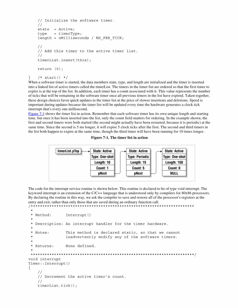
// Initialize the software timer. // state = Active; type = timerType; length = nMilliseconds / MS_PER_TICK;
// // Add this timer to the active timer list. // timerList.insert(this);
return (0);
} /* start() */When a software timer is started, the data members state, type, and length are initialized and the timer is insertedinto a linked list of active timers called the timerList. The timers in the timer list are ordered so that the first timer toexpire is at the top of the list. In addition, each timer has a count associated with it. This value represents the numberof ticks that will be remaining in the software timer once all previous timers in the list have expired. Taken together,these design choices favor quick updates to the timer list at the price of slower insertions and deletions. Speed isimportant during updates because the timer list will be updated every time the hardware generates a clock tickinterrupt-that's every one millisecond.Figure 7-1 shows the timer list in action. Remember that each software timer has its own unique length and startingtime, but once it has been inserted into the list, only the count field matters for ordering. In the example shown, thefirst and second timers were both started (the second might actually have been restarted, because it is periodic) at thesame time. Since the second is 5 ms longer, it will expire 5 clock ticks after the first. The second and third timers inthe list both happen to expire at the same time, though the third timer will have been running for 10 times longer.
Figure 7-1. The timer list in action
The code for the interrupt service routine is shown below. This routine is declared to be of type void interrupt. Thekeyword interrupt is an extension of the C/C++ language that is understood only by compilers for 80x86 processors.By declaring the routine in this way, we ask the compiler to save and restore all of the processor's registers at theentry and exit, rather than only those that are saved during an ordinary function call./********************************************************************** * * Method: Interrupt() * * Description: An interrupt handler for the timer hardware. * * Notes: This method is declared static, so that we cannot * inadvertently modify any of the software timers. * * Returns: None defined. * **********************************************************************/void interruptTimer::Interrupt(){ // // Decrement the active timer's count. // timerList.tick();
// // Acknowledge the timer interrupt. // gProcessor.pPCB->intControl.eoi = EOI_NONSPECIFIC;
// // Clear the Maximum Count bit (to start the next cycle). // gProcessor.pPCB->timer[2].control &= ~TIMER_MAXCOUNT;
} /* Interrupt() */Of course, the tick method of the TimerList class does most of the work here. This method is mostly concerned withlinked list manipulation and is not very exciting to look at. Briefly stated, the tick method starts by decrementing thetick count of the timer at the top of the list. If that timer's count has reached zero, it changes the state of the softwaretimer to Done and removes it from the timer list. It also does the same for any timers that are set to expire on thevery same tick. These are the ones at the new head of the list that also have a count of zero.After creating and starting a software timer, the application programmer can do some other processing and thencheck to see if the timer has expired. The waitfor method is provided for that purpose. This routine will block untilthe software timer's state is changed to Done by timerList.tick . The implementation of this method is as follows:/********************************************************************** * * Method: waitfor() * * Description: Wait for the software timer to finish. * * Notes: * * Returns: 0 on success, -1 if the timer is not running. * **********************************************************************/intTimer::waitfor(){ if (state != Active) { return (-1); }
// // Wait for the timer to expire. // while (state != Done);
// // Restart or idle the timer, depending on its type. // if (type == Periodic) { state = Active; timerList.insert(this); } else { state = Idle; }
return (0);
} /* waitfor() */One important thing to notice about this code is that the test while (state != Done) is not an infinite loop. That'sbecause, as we just learned a few paragraphs back, the timer's state is modified by timerList.tick , which is calledfrom the interrupt service routine. In fact, if we were being careful embedded programmers, we would have declared
state as volatile. Doing so would prevent the compiler from incorrectly assuming that the timer's state is either doneor not done and optimizing away the while loop.[3]
[3] A word of caution about waitfor : this implementation spins its wheels waiting for the software timer to change tothe done state. This technique is called busy-waiting, and it is neither elegant nor an efficient use of the processor. InChapter 8, we'll see how the introduction of an operating system allows us to improve upon this implementation.
The final method of the Timer class is used to cancel a running timer. This is easy to implement because we needonly remove the timer from the timer list and change its state to Idle. The code that actually does this is shown here:/********************************************************************** * * Method: cancel() * * Description: Stop a running timer. * * Notes: * * Returns: None defined. * **********************************************************************/voidTimer::cancel(void){ // // Remove the timer from the timer list. // if (state == Active) { timerList.remove(this); }
// // Reset the timer's state. // state = Idle;
} /* cancel() */Of course, there is also a destructor for the Timer class, though I won't show the code here. Suffice it to say that itjust checks to see if the software timer is active and, if so, removes it from the timer list. This prevents a periodictimer that has gone out of scope from remaining in the timer list indefinitely and any pointers to the "dead" timerfrom remaining in the system.For completeness, it might be nice to add a public method, perhaps called poll, that allows users of the Timer classto test the state of a software timer without blocking. In the interest of space, I have left this out of myimplementation, but it would be easy to add such a routine. It need only return the current value of the comparisonstate == Done. However, in order to do this, some technique would need to be devised to restart periodic timers forwhich waitfor is never called.
Watchdog TimersAnother type of timer you might hear mentioned frequently in reference to embedded systems is a
watchdog timer. This is a special piece of hardware that protects the system from software hangs. Ifpresent, the watchdog timer is always counting down from some large number to zero. This process
typically takes a few seconds to complete. In the meantime, it is possible for the embedded software to"kick" the watchdog timer, to reset its counter to the original large number. If the counter ever doesreach zero, the watchdog timer will assume that the software is hung. It then resets the embedded
processor and, thus, restarts the software.This is a common way to recover from unexpected software hangs that occur after the system isdeployed. For example, suppose that your company's new product will travel into space. No matter howmuch testing you do before deployment, the possibility remains that there are undiscovered bugs lurkingin the software and that one or more of these is capable of hanging the system altogether. If the softwarehangs, you won't be able to communicate with it at all, so you can't just issue a reset command remotely.Instead, you must build an automatic recovery mechanism into the system. And that's where thewatchdog timer comes in.The implementation of the watchdog timer "kick" would look just like the Blinking LED program inthis chapter, except that instead of toggling the LED the watchdog timer's counter would be reset.Another potential feature of the Timer class is asynchronous callbacks. In other words, why not allow the creator ofa software timer to attach a function to it. This function could then be called automatically-via timerList.tick -eachtime that timer expires. As you read the next section, be sure to think about how different the Blinking LED programwould look if asynchronous callbacks were used instead. This is one type of application to which asynchronousfunction calls are particularly well suited.
7.4 Das Blinkenlights, RevisitedNow that we have the Timer class at our disposal, it is possible to rewrite the book's very first example to make itstiming more precise. Recall that in our original implementation, we relied on the fact that the length of a "decrementand compare" operation was fixed for a given processor and speed. We simply took a guess as to how long thatmight be and then revised our estimate based on empirical testing. By utilizing the Timer class, we cansimultaneously eliminate this guesswork and increase the readability of the program.In the revised Blinking LED program below you will see that we can now simply start a periodic 500 ms softwaretimer, toggle the LED, and then wait for the timer to expire before toggling the LED again. In the meantime, wecould perform other processing tasks required by the application at hand.
#include "timer.h"#include "led.h"/********************************************************************** * Function: main() * Description: Blink the green LED once a second. * Notes: This outer loop is hardware-independent. However, it * calls the hardware-dependent function toggleLed(). * Returns: This routine contains an infinite loop. **********************************************************************/void
main(void){ Timer timer;
timer.start(500, Periodic); // Start a periodic 500 ms timer.
while (1) { toggleLed(LED_GREEN); // Toggle the green LED. //*********** Do other useful work here. ***************** timer.waitfor(); // Wait for the timer to expire. }
} /* main() */
Chapter 8.
Operating Systemsosophobia n. A common fear among embedded systems programmers.
All but the most trivial of embedded programs will benefit from the inclusion of an operating system. This can rangefrom a small kernel written by you to a full-featured commercial operating system. Either way, you'll need to knowwhat features are the most important and how their implementation will affect the rest of your software. At the veryleast, you need to understand what an embedded operating system looks like on the outside. But there's probably nobetter way to understand the exterior interfaces than to examine a small operating system in its entirety. So that'swhat we'll do in this chapter.
8.1 History and PurposeIn the early days of computing there was no such thing as an operating system. Application programmers werecompletely responsible for controlling and monitoring the state of the processor and other hardware. In fact, thepurpose of the first operating systems was to provide a virtual hardware platform that made application programseasier to write. To accomplish this goal, operating system developers needed only provide a loose collection ofroutines-much like a modern software library-for resetting the hardware to a known state, reading the state of theinputs, and changing the state of the outputs.Modern operating systems add to this the ability to execute multiple software tasks simultaneously on a singleprocessor. Each such task is a piece of the software that can be separated from and run independently of the rest. Aset of embedded software requirements can usually be decomposed into a small number of such independent pieces.For example, the printer-sharing device described in Chapter 5, contains three obvious software tasks:
• Task 1: Receive data from the computer attached to serial port A.• Task 2: Receive data from the computer attached to serial port B.• Task 3: Format and send the waiting data (if any) to the printer attached to the parallel port.
Tasks provide a key software abstraction that makes the design and implementation of embedded software easierand the resulting source code simpler to understand and maintain. By breaking the larger program up into smallerpieces, the programmer can more easily concentrate her energy and talents on the unique features of the systemunder development.Strictly speaking, an operating system is not a required component of any computer system-embedded or otherwise.It is always possible to perform the same functions from within the application program itself. Indeed, all of theexamples so far in this book have done just that. There is simply one path of execution-starting at main -that isdownloaded into the system and run. This is the equivalent of having only one task. But as the complexity of theapplication expands beyond just blinking an LED, the benefits of an operating system far outweigh the associatedcosts.If you have never worked on operating system internals before, you might have the impression that they arecomplex. I'm sure the operating system vendors would like you to continue to believe that they are and that only ahandful of computer scientists are capable of writing one. But I'm here to let the cat out of the bag: it's not all thathard! In fact, embedded operating systems are even easier to write than their desktop cousins-the requiredfunctionality is smaller and better defined. Once you learn what that functionality is and a few implementationtechniques, you will see that an operating system is no harder to develop than any other piece of embedded software.Embedded operating systems are small because they lack many of the things you would expect to find on yourdesktop computer. For example, embedded systems rarely have disk drives or graphical displays, and hence theyneed no filesystem or graphical user interface in their operating systems. In addition, there is only one "user" (i.e.,all of the tasks that comprise the embedded software cooperate), so the security features of multiuser operatingsystems do not apply. All of these are features that could be part of an embedded operating system but areunnecessary in the majority of cases.
8.2 A Decent Embedded Operating SystemWhat follows is a description of an embedded operating system that I have developed on my own. I call myoperating system ADEOS (pronounced the same as the Spanish farewell), which is an acronym for "A DecentEmbedded Operating System." I think that name really sums it up nicely. Yes, it is an embedded operating system;but it is neither the best nor the worst in any regard. In all, there are less than 1000 lines of source code. Of these,three quarters are platform-independent and written in C++. The rest are hardware- or processor-specific and,therefore, written in assembly language. In the discussion later, I will present and explain all of the routines that arewritten in C++ along with the theory you need to understand them. In the interest of clarity, I will not present the
source code for the assembly language routines. Instead, I will simply state their purpose and assume that interestedreaders will download and examine that code on their own.If you would like to use ADEOS (or a modified version of it) in your embedded system, please feel free to do so. Infact, I would very much like to hear from anyone who uses it. I have made every effort to test the code and improveupon the weaknesses I have uncovered. However, I can make no guarantee that the code presented in this chapter isuseful for any purpose other than learning about operating systems. If you decide to use it anyway, please beprepared to spend some amount of your time finding and fixing bugs in the operating system itself.
8.2.1 Tasks
We have already talked about multitasking and the idea that an operating system makes it possible to executemultiple "programs" at the same time. But what does that mean? How is it possible to execute several tasksconcurrently? In actuality, the tasks are not executed at the same time. Rather, they are executed in pseudoparallel.They merely take turns using the processor. This is similar to the way several people might read the same copy of abook. Only one person can actually use the book at a given moment, but they can both read it by taking turns usingit.An operating system is responsible for deciding which task gets to use the processor at a particular moment. Inaddition, it maintains information about the state of each task. This information is called the task's context, and itserves a purpose similar to a bookmark. In the multiple book reader scenario, each reader is presumed to have herown bookmark. The bookmark's owner must be able to recognize it (e.g., it has her name written on it), and it mustindicate where she stopped reading when last she gave up control of the book. This is the reader's context.A task's context records the state of the processor just prior to another task's taking control of it. This usuallyconsists of a pointer to the next instruction to be executed (the instruction pointer), the address of the current top ofthe stack (the stack pointer), and the contents of the processor's flag and general-purpose registers. On 16-bit 80x86processors, these are the registers CS and IP, SS and SP, Flags, and DS, ES, SI, DI, AX, BX, CX, and DX,respectively.In order to keep tasks and their contexts organized, the operating system maintains a bit of information about eachtask. Operating systems written in C often keep this information in a data structure called the task control block.However, ADEOS is written in C++ and one of the advantages of this approach is that the task-specific data isautomatically made a part of the task object itself. The definition of a Task, which includes the information that theoperating system needs, is as follows:class Task{ public:
Task(void (*function)(), Priority p, int stackSize);
TaskId id; Context context; TaskState state; Priority priority; int * pStack; Task * pNext;
void (*entryPoint)();
private:
static TaskId nextId;};Many of the data members of this class will make sense only after we discuss the operating system in greater detail.However, the first two fields-id and context --should already sound familiar. The id contains a unique integer(between and 255) that identifies the task. In other words, it is the name on the bookmark. The context is theprocessor-specific data structure that actually contains the state of the processor the last time this task gave upcontrol of the processor.
8.2.1.1 Task states
Remember how I said that only one task could actually be using the processor at a given time? That task is said to bethe " running" task, and no other task can be in that same state at the same time. Tasks that are ready to run-but arenot currently using the processor-are in the "ready" state, and tasks that are waiting for some event external tothemselves to occur before going on are in the "waiting" state. Figure 8-1 shows the relationships between thesethree states.
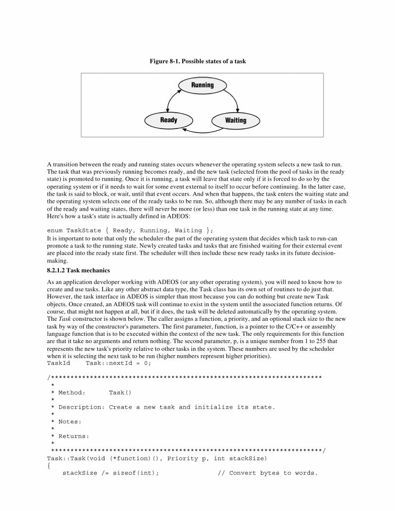
Figure 8-1. Possible states of a task
A transition between the ready and running states occurs whenever the operating system selects a new task to run.The task that was previously running becomes ready, and the new task (selected from the pool of tasks in the readystate) is promoted to running. Once it is running, a task will leave that state only if it is forced to do so by theoperating system or if it needs to wait for some event external to itself to occur before continuing. In the latter case,the task is said to block, or wait, until that event occurs. And when that happens, the task enters the waiting state andthe operating system selects one of the ready tasks to be run. So, although there may be any number of tasks in eachof the ready and waiting states, there will never be more (or less) than one task in the running state at any time.Here's how a task's state is actually defined in ADEOS:
enum TaskState { Ready, Running, Waiting };It is important to note that only the scheduler-the part of the operating system that decides which task to run-canpromote a task to the running state. Newly created tasks and tasks that are finished waiting for their external eventare placed into the ready state first. The scheduler will then include these new ready tasks in its future decision-making.
8.2.1.2 Task mechanics
As an application developer working with ADEOS (or any other operating system), you will need to know how tocreate and use tasks. Like any other abstract data type, the Task class has its own set of routines to do just that.However, the task interface in ADEOS is simpler than most because you can do nothing but create new Taskobjects. Once created, an ADEOS task will continue to exist in the system until the associated function returns. Ofcourse, that might not happen at all, but if it does, the task will be deleted automatically by the operating system.The Task constructor is shown below. The caller assigns a function, a priority, and an optional stack size to the newtask by way of the constructor's parameters. The first parameter, function, is a pointer to the C/C++ or assemblylanguage function that is to be executed within the context of the new task. The only requirements for this functionare that it take no arguments and return nothing. The second parameter, p, is a unique number from 1 to 255 thatrepresents the new task's priority relative to other tasks in the system. These numbers are used by the schedulerwhen it is selecting the next task to be run (higher numbers represent higher priorities).TaskId Task::nextId = 0;
/********************************************************************** * * Method: Task() * * Description: Create a new task and initialize its state. * * Notes: * * Returns: * **********************************************************************/Task::Task(void (*function)(), Priority p, int stackSize){ stackSize /= sizeof(int); // Convert bytes to words.
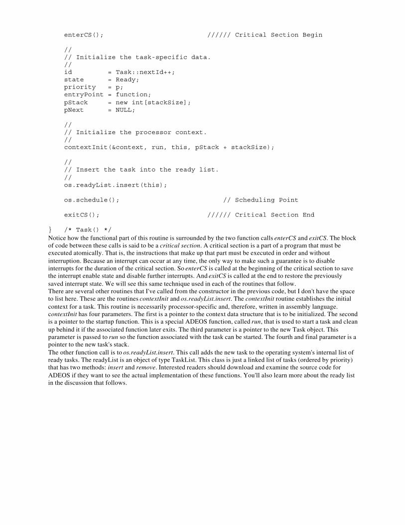
enterCS(); ////// Critical Section Begin
// // Initialize the task-specific data. // id = Task::nextId++; state = Ready; priority = p; entryPoint = function; pStack = new int[stackSize]; pNext = NULL;
// // Initialize the processor context. // contextInit(&context, run, this, pStack + stackSize);
// // Insert the task into the ready list. // os.readyList.insert(this);
os.schedule(); // Scheduling Point
exitCS(); ////// Critical Section End
} /* Task() */Notice how the functional part of this routine is surrounded by the two function calls enterCS and exitCS. The blockof code between these calls is said to be a critical section. A critical section is a part of a program that must beexecuted atomically. That is, the instructions that make up that part must be executed in order and withoutinterruption. Because an interrupt can occur at any time, the only way to make such a guarantee is to disableinterrupts for the duration of the critical section. So enterCS is called at the beginning of the critical section to savethe interrupt enable state and disable further interrupts. And exitCS is called at the end to restore the previouslysaved interrupt state. We will see this same technique used in each of the routines that follow.There are several other routines that I've called from the constructor in the previous code, but I don't have the spaceto list here. These are the routines contextInit and os.readyList.insert. The contextInit routine establishes the initialcontext for a task. This routine is necessarily processor-specific and, therefore, written in assembly language.contextInit has four parameters. The first is a pointer to the context data structure that is to be initialized. The secondis a pointer to the startup function. This is a special ADEOS function, called run, that is used to start a task and cleanup behind it if the associated function later exits. The third parameter is a pointer to the new Task object. Thisparameter is passed to run so the function associated with the task can be started. The fourth and final parameter is apointer to the new task's stack.The other function call is to os.readyList.insert. This call adds the new task to the operating system's internal list ofready tasks. The readyList is an object of type TaskList. This class is just a linked list of tasks (ordered by priority)that has two methods: insert and remove. Interested readers should download and examine the source code forADEOS if they want to see the actual implementation of these functions. You'll also learn more about the ready listin the discussion that follows.
Application Programming InterfacesOne of the most annoying things about embedded operating systems is their lack of a common API.
This is a particular problem for companies that want to share application code between products that arebased on different operating systems. One company I worked for even went so far as to create their ownlayer above the operating system solely to isolate their application programmers from these differences.
But surely this was just adding to the overall problem-by creating yet another API.The basic functionality of every embedded operating system is much the same. Each function or methodrepresents a service that the operating system can perform for the application program. But there aren'tthat many different services possible. And it is frequently the case that the only real difference betweentwo implementations is the name of the function or method.This problem has persisted for several decades, and there is no end in sight. Yet during that same timethe Win32 and POSIX APIs have taken hold on PCs and Unix workstations, respectively. So why hasn'ta similar standard emerged for embedded systems? It hasn't been for a lack of trying. In fact, the authorsof the original POSIX standard (IEEE 1003.1) also created a standard for real-time systems (IEEE1003.4b). And a few of the more Unix-like embedded operating systems (VxWorks and LynxOS cometo mind) are compliant with this standard API. However, for the vast majority of applicationprogrammers, it is necessary to learn a new API for each operating system used.Fortunately, there is a glimmer of hope. The Java programming language has support for multitaskingand task synchronization built in. That means that no matter what operating system a Java program isrunning on, the mechanics of creating and manipulating tasks and synchronizing their activities remainthe same. For this and several other reasons, Java would be a very nice language for embeddedprogrammers. I hope that there will some day be a need for a book about embedded systemsprogramming in Java and that a sidebar like this one will, therefore, no longer be required.
8.2.2 Scheduler
The heart and soul of any operating system is its scheduler. This is the piece of the operating system that decideswhich of the ready tasks has the right to use the processor at a given time. If you've written software for amainstream operating system, then you might be familiar with some of the more common scheduling algorithms:first-in-first-out, shortest job first, and round robin. These are simple scheduling algorithms that are used innonembedded systems.First-in-first-out (FIFO) scheduling describes an operating system like DOS, which is not a multitasking operatingsystem at all. Rather, each task runs until it is finished, and only after that is the next task started. However, in DOSa task can suspend itself, thus freeing up the processor for the next task. And that's precisely how older version ofthe Windows operating system permitted users to switch from one task to another. True multitasking wasn't a part ofany Microsoft operating system before Windows NT.Shortest job first describes a similar scheduling algorithm. The only difference is that each time the running taskcompletes or suspends itself, the next task selected is the one that will require the least amount of processor time tocomplete. Shortest job first was common on early mainframe systems because it has the appealing property ofmaximizing the number of satisfied customers. (Only the customers who have the longest jobs tend to notice orcomplain.)Round robin is the only scheduling algorithm of the three in which the running task can be preempted, that is,interrupted while it is running. In this case, each task runs for some predetermined amount of time. After that timeinterval has elapsed, the running task is preempted by the operating system and the next task in line gets its chanceto run. The preempted task doesn't get to run again until all of the other tasks have had their chances in that round.Unfortunately, embedded operating systems cannot use any of these simplistic scheduling algorithms. Embeddedsystems (particularly real-time systems) almost always require a way to share the processor that allows the mostimportant tasks to grab control of the processor as soon as they need it. Therefore, most embedded operatingsystems utilize a priority-based scheduling algorithm that supports preemption. This is a fancy way of saying that atany given moment the task that is currently using the processor is guaranteed to be the highest-priority task that isready to do so. Lower-priority tasks must wait until higher-priority tasks are finished using the processor beforeresuming their work. The word preemptive adds that any running task can be interrupted by the operating system if atask of higher priority becomes ready. The scheduler detects such conditions at a finite set of time instants calledscheduling points.When a priority-based scheduling algorithm is used, it is also necessary to have a backup policy. This is thescheduling algorithm to be used in the event that several ready tasks have the same priority. The most commonbackup scheduling algorithm is round robin. However, for simplicity's sake, I've implemented only a FIFO schedulerfor my backup policy. For that reason, users of ADEOS should take care to assign a unique priority to each taskwhenever possible. This shouldn't be a problem though, because ADEOS supports as many priority levels as tasks(up to 255 of each).
The scheduler in ADEOS is implemented in a class called Sched:class Sched{ public:
Sched();
void start(); void schedule();
void enterIsr(); void exitIsr();
static Task * pRunningTask; static TaskList readyList;
enum SchedState { Uninitialized, Initialized, Started };
private:
static SchedState state; static Task idleTask; static int interruptLevel; static int bSchedule;};After defining this class, an object of this type is instantiated within one of the operating system modules. That way,users of ADEOS need only link the file sched.obj to include an instance of the scheduler. This instance is called osand is declared as follows:extern Sched os;References to this global variable can be made from within any part of the application program. But you'll soon seethat only one such reference will be necessary per application.
8.2.2.1 Scheduling points
Simply stated, the scheduling points are the set of operating system events that result in an invocation of thescheduler. We have already encountered two such events: task creation and task deletion. During each of theseevents, the method os.schedule is called to select the next task to be run. If the currently executing task still has thehighest priority of all the ready tasks, it will be allowed to continue using the processor. Otherwise, the highestpriority ready task will be executed next. Of course, in the case of task deletion a new task is always selected: thecurrently running task is no longer ready, by virtue of the fact that it no longer exists!A third scheduling point is called the clock tick. The clock tick is a periodic event that is triggered by a timerinterrupt. The clock tick provides an opportunity to awake tasks that are waiting for a software timer to expire. Thisis almost exactly the same as the timer tick we saw in the previous chapter. In fact, support for software timers is acommon feature of embedded operating systems. During the clock tick, the operating system decrements and checkseach of the active software timers. When a timer expires, all of the tasks that are waiting for it to complete arechanged from the waiting state to the ready state. Then the scheduler is invoked to see if one of these newlyawakened tasks has a higher priority than the task that was running prior to the timer interrupt.The clock tick routine in ADEOS is almost exactly the same as the one in Chapter 7. In fact, we still use the sameTimer class. Only the implementation of this class has been changed, and that only slightly. These changes aremeant to account for the fact that multiple tasks might be waiting for the same software timer. In addition, all of thecalls to disable and enable have been replaced by enterCS and exitCS, and the length of a clock tick has beenincreased from 1 ms to 10 ms.
8.2.2.2 Ready list
The scheduler uses a data structure called the ready list to track the tasks that are in the ready state. In ADEOS, theready list is implemented as an ordinary linked list, ordered by priority. So the head of this list is always the highestpriority task that is ready to run. Following a call to the scheduler, this will be the same as the currently running task.In fact, the only time that won't be the case is during a reschedule. Figure 8-2 shows what the ready list might looklike while the operating system is in use.
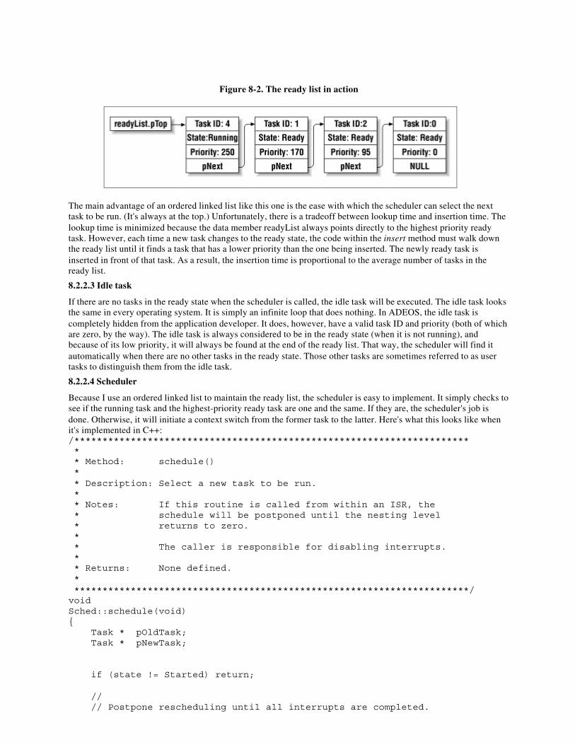
Figure 8-2. The ready list in action
The main advantage of an ordered linked list like this one is the ease with which the scheduler can select the nexttask to be run. (It's always at the top.) Unfortunately, there is a tradeoff between lookup time and insertion time. Thelookup time is minimized because the data member readyList always points directly to the highest priority readytask. However, each time a new task changes to the ready state, the code within the insert method must walk downthe ready list until it finds a task that has a lower priority than the one being inserted. The newly ready task isinserted in front of that task. As a result, the insertion time is proportional to the average number of tasks in theready list.
8.2.2.3 Idle task
If there are no tasks in the ready state when the scheduler is called, the idle task will be executed. The idle task looksthe same in every operating system. It is simply an infinite loop that does nothing. In ADEOS, the idle task iscompletely hidden from the application developer. It does, however, have a valid task ID and priority (both of whichare zero, by the way). The idle task is always considered to be in the ready state (when it is not running), andbecause of its low priority, it will always be found at the end of the ready list. That way, the scheduler will find itautomatically when there are no other tasks in the ready state. Those other tasks are sometimes referred to as usertasks to distinguish them from the idle task.
8.2.2.4 Scheduler
Because I use an ordered linked list to maintain the ready list, the scheduler is easy to implement. It simply checks tosee if the running task and the highest-priority ready task are one and the same. If they are, the scheduler's job isdone. Otherwise, it will initiate a context switch from the former task to the latter. Here's what this looks like whenit's implemented in C++:/********************************************************************** * * Method: schedule() * * Description: Select a new task to be run. * * Notes: If this routine is called from within an ISR, the * schedule will be postponed until the nesting level * returns to zero. * * The caller is responsible for disabling interrupts. * * Returns: None defined. * **********************************************************************/voidSched::schedule(void){ Task * pOldTask; Task * pNewTask;
if (state != Started) return;
// // Postpone rescheduling until all interrupts are completed.
// if (interruptLevel != 0) { bSchedule = 1; return; }
// // If there is a higher-priority ready task, switch to it. // if (pRunningTask != readyList.pTop) { pOldTask = pRunningTask; pNewTask = readyList.pTop;
pNewTask->state = Running; pRunningTask = pNewTask;
if (pOldTask == NULL) { contextSwitch(NULL, &pNewTask->context); } else { pOldTask->state = Ready; contextSwitch(&pOldTask->context, &pNewTask->context); } }
} /* schedule() */As you can see from this code, there are two situations during which the scheduler will not initiate a context switch.The first is if multitasking has not been enabled. This is necessary because application programmers sometimes wantto create some or all of their tasks before actually starting the scheduler. In that case, the application's main routinewould look like the following one. Each time a Task object is created, the scheduler is invoked.[1]
[1] Remember, task creation is one of our scheduling points. If the scheduler has been started, there is also a possibilitythat the new task will be the highest priority ready task.
However, because schedule checks the value of state to ensure that multitasking has been started, no contextswitches will occur until after start is called.#include "adeos.h"
void taskAfunction(void);void taskBfunction(void);
/* * Create two tasks, each with its own unique function and priority. */Task taskA(taskAfunction, 150, 256);Task taskB(taskBfunction, 200, 256);
/********************************************************************* * * Function: main() * * Description: This is what an application program might look like * if ADEOS were used as the operating system. This * function is responsible for starting the operating * system only. * * Notes: Any code placed after the call to os.start() will * never be executed. This is because main() is not a * task, so it does not get a chance to run once the * scheduler is started.
* * Returns: This function will never return! * *********************************************************************/voidmain(void){ os.start();
// This point will never be reached.
} /* main() */Because this is an important piece of code, let me reiterate what you are looking at. This is an example of theapplication code you might write as a user of ADEOS. You begin by including the header file adeos.h and declaringyour tasks. After you declare the tasks and call os.start, the task functions taskAfunction and taskBfunction willbegin to execute (in pseudoparallel). Of course, taskB has the highest priority of the two (200), so it will get to runfirst. However, as soon as it relinquishes control of the processor for any reason, the other task will have a chance torun as well.The other situation in which the ADEOS scheduler will not perform a context switch is during interrupt processing.The operating system tracks the nesting level of the current interrupt service routine and allows context switchesonly if the nesting level is zero. If the scheduler is called from an ISR (as it is during the timer tick), the bScheduleflag is set to indicate that the scheduler should be called again as soon as the outermost interrupt handler exits. Thisdelayed scheduling speeds up interrupt response times throughout the system.
8.2.3 Context Switch
The actual process of changing from one task to another is called a context switch. Because contexts are processor-specific, so is the code that implements the context switch. That means it must always be written in assemblylanguage. Rather than show you the 80x86-specific assembly code that I used in ADEOS, I'll show the contextswitch routine in a C-like pseudocode:voidcontextSwitch(PContext pOldContext, PContext pNewContext){ if (saveContext(pOldContext)) { // // Restore new context only on a nonzero exit from saveContext(). // restoreContext(pNewContext);
// This line is never executed! }
// Instead, the restored task continues to execute at this point.}The contextSwitch routine is actually invoked by the scheduler, which is in turn called from one of the operatingsystem calls that disables interrupts. So it is not necessary to disable interrupts here. In addition, because theoperating system call that invoked the scheduler is written in a high-level language, most of the running task'sregisters have already been saved onto its local stack. That reduces the amount of work that needs to be done by theroutines saveContext and restoreContext. They need only worry about saving the instruction pointer, stack pointer,and flags.The actual behavior of contextSwitch at runtime is difficult to see simply by looking at the previous code. Mostsoftware developers think serially, assuming that each line of code will be executed immediately following theprevious one. However, this code is actually executed two times, in pseudoparallel. When one task (the new task)changes to the running state, another (the old task) must simultaneously go back to the ready state. Imagine what thenew task sees when it is restored inside the restoreContext code. No matter what the new task was doing before, italways wakes up inside the saveContext code-because that's where its instruction pointer was saved.How does the new task know whether it is coming out of saveContext for the first time (i.e., in the process of goingto sleep) or the second time (in the process of waking up)? It definitely does need to know the difference, so I've hadto implement saveContext in a slightly sneaky way. Rather than saving the precise current instruction pointer,saveContext actually saves an address a few instructions ahead. That way, when the saved context is restored,execution continues from a different point in the saveContext routine. This also makes it possible for saveContext toreturn different values: nonzero when the task goes to sleep and zero when the task wakes up. The contextSwitch
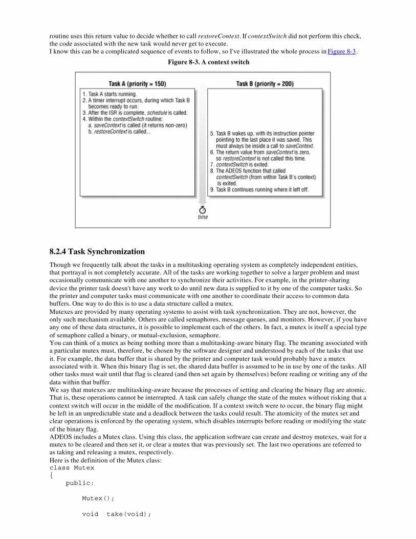
routine uses this return value to decide whether to call restoreContext. If contextSwitch did not perform this check,the code associated with the new task would never get to execute.I know this can be a complicated sequence of events to follow, so I've illustrated the whole process in Figure 8-3.
Figure 8-3. A context switch
8.2.4 Task Synchronization
Though we frequently talk about the tasks in a multitasking operating system as completely independent entities,that portrayal is not completely accurate. All of the tasks are working together to solve a larger problem and mustoccasionally communicate with one another to synchronize their activities. For example, in the printer-sharingdevice the printer task doesn't have any work to do until new data is supplied to it by one of the computer tasks. Sothe printer and computer tasks must communicate with one another to coordinate their access to common databuffers. One way to do this is to use a data structure called a mutex.Mutexes are provided by many operating systems to assist with task synchronization. They are not, however, theonly such mechanism available. Others are called semaphores, message queues, and monitors. However, if you haveany one of these data structures, it is possible to implement each of the others. In fact, a mutex is itself a special typeof semaphore called a binary, or mutual-exclusion, semaphore.You can think of a mutex as being nothing more than a multitasking-aware binary flag. The meaning associated witha particular mutex must, therefore, be chosen by the software designer and understood by each of the tasks that useit. For example, the data buffer that is shared by the printer and computer task would probably have a mutexassociated with it. When this binary flag is set, the shared data buffer is assumed to be in use by one of the tasks. Allother tasks must wait until that flag is cleared (and then set again by themselves) before reading or writing any of thedata within that buffer.We say that mutexes are multitasking-aware because the processes of setting and clearing the binary flag are atomic.That is, these operations cannot be interrupted. A task can safely change the state of the mutex without risking that acontext switch will occur in the middle of the modification. If a context switch were to occur, the binary flag mightbe left in an unpredictable state and a deadlock between the tasks could result. The atomicity of the mutex set andclear operations is enforced by the operating system, which disables interrupts before reading or modifying the stateof the binary flag.ADEOS includes a Mutex class. Using this class, the application software can create and destroy mutexes, wait for amutex to be cleared and then set it, or clear a mutex that was previously set. The last two operations are referred toas taking and releasing a mutex, respectively.Here is the definition of the Mutex class:class Mutex{ public:
Mutex();
void take(void);
void release(void);
private:
TaskList waitingList;
enum { Available, Held } state;};The process of creating a new Mutex is simple. The following constructor will be executed automatically each timea new mutex object is instantiated:/********************************************************************** * * Method: Mutex() * * Description: Create a new mutex. * * Notes: * * Returns: * **********************************************************************/Mutex::Mutex(){ enterCS(); ////// Critical Section Begin
state = Available; waitingList.pTop = NULL;
exitCS(); ////// Critical Section End
} /* Mutex() */All mutexes are created in the Available state and are associated with a linked list of waiting tasks that is initiallyempty. Of course, once you've created a mutex it is necessary to have some way to change its state, so the nextmethod we'll discuss is take. This routine would typically be called by a task, before it reads or writes a sharedresource. When the call to take returns, the calling task's exclusive access to that resource is guaranteed by theoperating system. The code for this routine is as follows:/********************************************************************** * * Method: take() * * Description: Wait for a mutex to become available, then take it. * * Notes: * * Returns: None defined. * **********************************************************************/voidMutex::take(void){ Task * pCallingTask;
enterCS(); ////// Critical Section Begin
if (state == Available) { // // The mutex is available. Simply take it and return. // state = Held; waitingList.pTop = NULL;
} else { // // The mutex is taken. Add the calling task to the waiting list. // pCallingTask = os.pRunningTask; pCallingTask->state = Waiting; os.readyList.remove(pCallingTask); waitingList.insert(pCallingTask);
os.schedule(); // Scheduling Point
// When the mutex is released, the caller begins executing here. }
exitCS(); ////// Critical Section End
} /* take() */The neatest thing about the take method is that if the mutex is currently held by another task (that is, the binary flagis already set), the calling task will be suspended until the mutex is released by that other task. This is kind of liketelling your spouse that you are going to take a nap and asking him or her to wake you up when dinner is ready. It iseven possible for multiple tasks to be waiting for the same mutex. In fact, the waiting list associated with eachmutex is ordered by priority, so the highest-priority waiting task will always be awakened first.The method that comes next is used to release a mutex. Although this method could be called by any task, it isexpected that only a task that previously called take would invoke it. Unlike take, this routine will never block.However, one possible result of releasing the mutex could be to wake a task of higher priority. In that case, thereleasing task would immediately be forced (by the scheduler) to give up control of the processor, in favor of thehigher-priority task.
/********************************************************************** * * Method: release() * * Description: Release a mutex that is held by the calling task. * * Notes: * * Returns: None defined. * **********************************************************************/voidMutex::release(void){ Task * pWaitingTask;
enterCS(); ////// Critical Section Begins
if (state == Held) { pWaitingTask = waitingList.pTop;
if (pWaitingTask != NULL) { // // Wake the first task on the waiting list. // waitingList.pTop = pWaitingTask->pNext; pWaitingTask->state = Ready; os.readyList.insert(pWaitingTask);
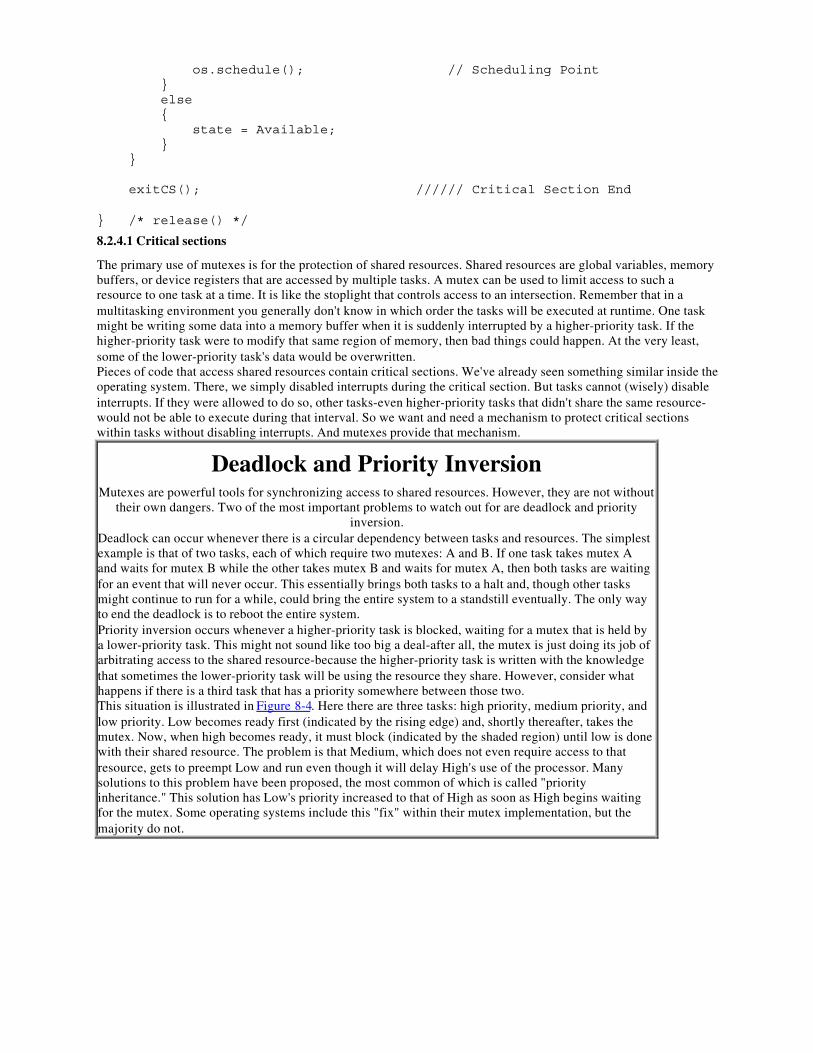
os.schedule(); // Scheduling Point } else { state = Available; } }
exitCS(); ////// Critical Section End
} /* release() */
8.2.4.1 Critical sections
The primary use of mutexes is for the protection of shared resources. Shared resources are global variables, memorybuffers, or device registers that are accessed by multiple tasks. A mutex can be used to limit access to such aresource to one task at a time. It is like the stoplight that controls access to an intersection. Remember that in amultitasking environment you generally don't know in which order the tasks will be executed at runtime. One taskmight be writing some data into a memory buffer when it is suddenly interrupted by a higher-priority task. If thehigher-priority task were to modify that same region of memory, then bad things could happen. At the very least,some of the lower-priority task's data would be overwritten.Pieces of code that access shared resources contain critical sections. We've already seen something similar inside theoperating system. There, we simply disabled interrupts during the critical section. But tasks cannot (wisely) disableinterrupts. If they were allowed to do so, other tasks-even higher-priority tasks that didn't share the same resource-would not be able to execute during that interval. So we want and need a mechanism to protect critical sectionswithin tasks without disabling interrupts. And mutexes provide that mechanism.
Deadlock and Priority InversionMutexes are powerful tools for synchronizing access to shared resources. However, they are not without
their own dangers. Two of the most important problems to watch out for are deadlock and priorityinversion.
Deadlock can occur whenever there is a circular dependency between tasks and resources. The simplestexample is that of two tasks, each of which require two mutexes: A and B. If one task takes mutex Aand waits for mutex B while the other takes mutex B and waits for mutex A, then both tasks are waitingfor an event that will never occur. This essentially brings both tasks to a halt and, though other tasksmight continue to run for a while, could bring the entire system to a standstill eventually. The only wayto end the deadlock is to reboot the entire system.Priority inversion occurs whenever a higher-priority task is blocked, waiting for a mutex that is held bya lower-priority task. This might not sound like too big a deal-after all, the mutex is just doing its job ofarbitrating access to the shared resource-because the higher-priority task is written with the knowledgethat sometimes the lower-priority task will be using the resource they share. However, consider whathappens if there is a third task that has a priority somewhere between those two.This situation is illustrated in Figure 8-4. Here there are three tasks: high priority, medium priority, andlow priority. Low becomes ready first (indicated by the rising edge) and, shortly thereafter, takes themutex. Now, when high becomes ready, it must block (indicated by the shaded region) until low is donewith their shared resource. The problem is that Medium, which does not even require access to thatresource, gets to preempt Low and run even though it will delay High's use of the processor. Manysolutions to this problem have been proposed, the most common of which is called "priorityinheritance." This solution has Low's priority increased to that of High as soon as High begins waitingfor the mutex. Some operating systems include this "fix" within their mutex implementation, but themajority do not.
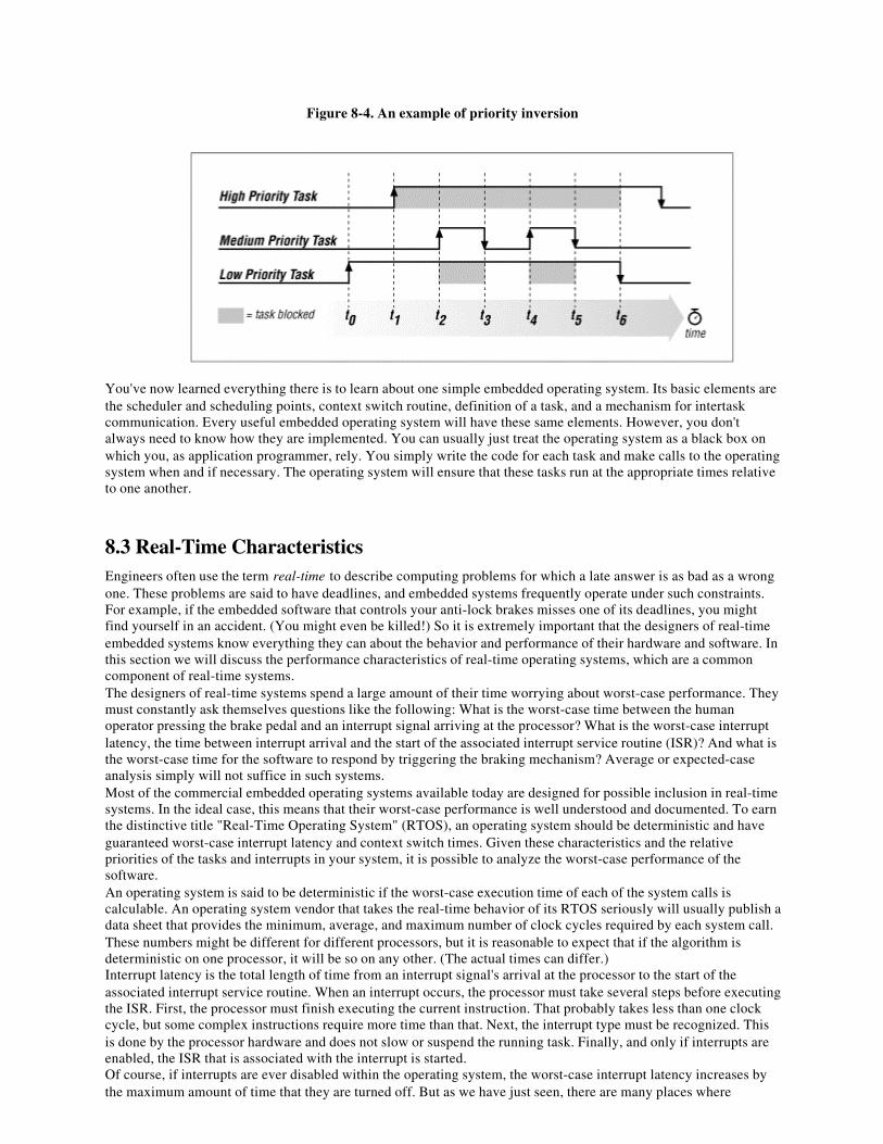
Figure 8-4. An example of priority inversion
You've now learned everything there is to learn about one simple embedded operating system. Its basic elements arethe scheduler and scheduling points, context switch routine, definition of a task, and a mechanism for intertaskcommunication. Every useful embedded operating system will have these same elements. However, you don'talways need to know how they are implemented. You can usually just treat the operating system as a black box onwhich you, as application programmer, rely. You simply write the code for each task and make calls to the operatingsystem when and if necessary. The operating system will ensure that these tasks run at the appropriate times relativeto one another.
8.3 Real-Time CharacteristicsEngineers often use the term real-time to describe computing problems for which a late answer is as bad as a wrongone. These problems are said to have deadlines, and embedded systems frequently operate under such constraints.For example, if the embedded software that controls your anti-lock brakes misses one of its deadlines, you mightfind yourself in an accident. (You might even be killed!) So it is extremely important that the designers of real-timeembedded systems know everything they can about the behavior and performance of their hardware and software. Inthis section we will discuss the performance characteristics of real-time operating systems, which are a commoncomponent of real-time systems.The designers of real-time systems spend a large amount of their time worrying about worst-case performance. Theymust constantly ask themselves questions like the following: What is the worst-case time between the humanoperator pressing the brake pedal and an interrupt signal arriving at the processor? What is the worst-case interruptlatency, the time between interrupt arrival and the start of the associated interrupt service routine (ISR)? And what isthe worst-case time for the software to respond by triggering the braking mechanism? Average or expected-caseanalysis simply will not suffice in such systems.Most of the commercial embedded operating systems available today are designed for possible inclusion in real-timesystems. In the ideal case, this means that their worst-case performance is well understood and documented. To earnthe distinctive title "Real-Time Operating System" (RTOS), an operating system should be deterministic and haveguaranteed worst-case interrupt latency and context switch times. Given these characteristics and the relativepriorities of the tasks and interrupts in your system, it is possible to analyze the worst-case performance of thesoftware.An operating system is said to be deterministic if the worst-case execution time of each of the system calls iscalculable. An operating system vendor that takes the real-time behavior of its RTOS seriously will usually publish adata sheet that provides the minimum, average, and maximum number of clock cycles required by each system call.These numbers might be different for different processors, but it is reasonable to expect that if the algorithm isdeterministic on one processor, it will be so on any other. (The actual times can differ.)Interrupt latency is the total length of time from an interrupt signal's arrival at the processor to the start of theassociated interrupt service routine. When an interrupt occurs, the processor must take several steps before executingthe ISR. First, the processor must finish executing the current instruction. That probably takes less than one clockcycle, but some complex instructions require more time than that. Next, the interrupt type must be recognized. Thisis done by the processor hardware and does not slow or suspend the running task. Finally, and only if interrupts areenabled, the ISR that is associated with the interrupt is started.Of course, if interrupts are ever disabled within the operating system, the worst-case interrupt latency increases bythe maximum amount of time that they are turned off. But as we have just seen, there are many places where
interrupts are disabled. These are the critical sections we talked about earlier, and there are no alternative methodsfor protecting them. Each operating system will disable interrupts for a different length of time, so it is importantthat you know what your system's requirements are. One real-time project might require a guaranteed interruptresponse time as short as 1 µs, while another requires only 100 µs.The third real-time characteristic of an operating system is the amount of time required to perform a context switch.This is important because it represents overhead across your entire system. For example, imagine that the averageexecution time of any task before it blocks is 100 µs but that the context switch time is also 100 µs. In that case,fully one-half of the processor's time is spent within the context switch routine! Again, there is no magic number andthe actual times are usually processor-specific because they are dependent on the number of registers that must besaved and where. Be sure to get these numbers from any operating system vendor you are thinking of using. Thatway, there won't be any last-minute surprises.
8.4 Selection ProcessDespite my earlier statement about how easy it is to write your own operating system, I still strongly recommendbuying one if you can afford to. Let me say that again: I highly recommend buying a commercial operating system,rather than writing your own. I know of several good operating systems that can be obtained for just a few thousanddollars. Considering the cost of engineering time these days, that's a bargain by almost any measure. In fact, a widevariety of operating systems are available to suit most projects and pocketbooks. In this section we will discuss theprocess of selecting the commercial operating system that best fits the needs of your project.Commercial operating systems form a continuum of functionality, performance, and price. Those at the lower end ofthe spectrum offer only a basic scheduler and a few other system calls. These operating systems are usuallyinexpensive, come with source code that you can modify, and do not require payment of royalties. AcceleratedTechnology's Nucleus and Kadak's AMX both fall into this category,[2] as do any of the embedded versions of DOS.
[2] Please don't write to complain. I'm not maligning either of these operating systems. In fact, from what I know ofboth, I would highly recommend them as high-quality, low-cost commercial solutions.
Operating systems at the other end of the spectrum typically include a lot of useful functionality beyond just thescheduler. They might also make stronger (or better) guarantees about real-time performance. These operatingsystems can be quite expensive, though, with startup costs ranging from $10,000 to $50,000 and royalties due onevery copy shipped in ROM. However, this price often includes free technical support and training and a set ofintegrated development tools. Examples are Wind River Systems' VxWorks, Integrated Systems' pSOS, andMicrotec's VRTX. These are three of the most popular real-time operating systems on the market.Between these two extremes are the operating systems that have a bit more functionality than just the basicscheduler and make some reasonable guarantees about their real-time performance. While the up-front costs androyalties are reasonable, these operating systems usually do not include source code, and technical support mightcost extra. This is the category for most of the commercial operating systems not mentioned earlier.With such a wide variety of operating systems and features to choose from, it can be difficult to decide which is thebest for your project. Try putting your processor, real-time performance, and budgetary requirements first. These arecriteria that you cannot change, so you can use them to narrow the possible choices to a dozen or fewer products.Then contact all of the vendors of the remaining operating systems for more detailed technical information.At this point, many people make their decision based on compatibility with existing cross-compilers, debuggers, andother development tools. But it's really up to you to decide what additional features are most important for yourproject. No matter what you decide to buy, the basic kernel will be about the same as the one described in thischapter. The differences will most likely be measured in processors supported, minimum and maximum memoryrequirements, availability of add-on software modules (networking protocol stacks, device drivers, and Flashfilesystems are common examples), and compatibility with third-party development tools.Remember that the best reason to choose a commercial operating system is the advantage of using something that isbetter tested and, therefore, more reliable than a kernel you have developed internally (or obtained for free out of abook). So one of the most important things you should be looking for from your OS vendor is experience. And ifyour system demands real-time performance, you will definitely want to go with an operating system that has beenused successfully in lots of real-time systems. For example, find out which operating system NASA used for itsmost recent mission. I'd be willing to bet it's a good one.
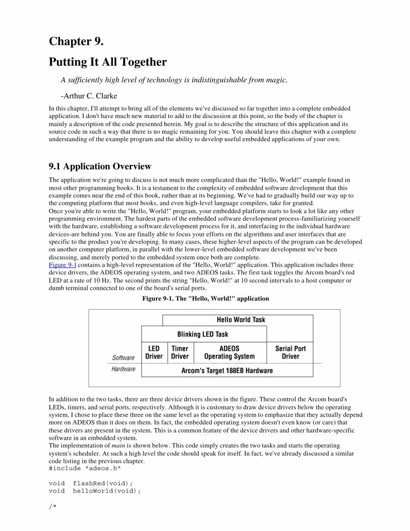
Chapter 9.
Putting It All TogetherA sufficiently high level of technology is indistinguishable from magic.
-Arthur C. Clarke
In this chapter, I'll attempt to bring all of the elements we've discussed so far together into a complete embeddedapplication. I don't have much new material to add to the discussion at this point, so the body of the chapter ismainly a description of the code presented herein. My goal is to describe the structure of this application and itssource code in such a way that there is no magic remaining for you. You should leave this chapter with a completeunderstanding of the example program and the ability to develop useful embedded applications of your own.
9.1 Application OverviewThe application we're going to discuss is not much more complicated than the "Hello, World!" example found inmost other programming books. It is a testament to the complexity of embedded software development that thisexample comes near the end of this book, rather than at its beginning. We've had to gradually build our way up tothe computing platform that most books, and even high-level language compilers, take for granted.Once you're able to write the "Hello, World!" program, your embedded platform starts to look a lot like any otherprogramming environment. The hardest parts of the embedded software development process-familiarizing yourselfwith the hardware, establishing a software development process for it, and interfacing to the individual hardwaredevices-are behind you. You are finally able to focus your efforts on the algorithms and user interfaces that arespecific to the product you're developing. In many cases, these higher-level aspects of the program can be developedon another computer platform, in parallel with the lower-level embedded software development we've beendiscussing, and merely ported to the embedded system once both are complete.Figure 9-1 contains a high-level representation of the "Hello, World!" application. This application includes threedevice drivers, the ADEOS operating system, and two ADEOS tasks. The first task toggles the Arcom board's redLED at a rate of 10 Hz. The second prints the string "Hello, World!" at 10 second intervals to a host computer ordumb terminal connected to one of the board's serial ports.
Figure 9-1. The "Hello, World!" application
In addition to the two tasks, there are three device drivers shown in the figure. These control the Arcom board'sLEDs, timers, and serial ports, respectively. Although it is customary to draw device drivers below the operatingsystem, I chose to place these three on the same level as the operating system to emphasize that they actually dependmore on ADEOS than it does on them. In fact, the embedded operating system doesn't even know (or care) thatthese drivers are present in the system. This is a common feature of the device drivers and other hardware-specificsoftware in an embedded system.The implementation of main is shown below. This code simply creates the two tasks and starts the operatingsystem's scheduler. At such a high level the code should speak for itself. In fact, we've already discussed a similarcode listing in the previous chapter.#include "adeos.h"
void flashRed(void);void helloWorld(void);
/*
* Create the two tasks. */Task taskA(flashRed, 150, 512);Task taskB(helloWorld, 200, 512);
/********************************************************************* * * Function: main() * * Description: This function is responsible for starting the ADEOS * scheduler only. * * Notes: * * Returns: This function will never return! * *********************************************************************/voidmain(void){ os.start();
// This point will never be reached.
} /* main() */
9.2 Flashing the LEDAs I said earlier, one of two things this application does is blink the red LED. This is done by the code shown below.Here the function flashRed is executed as a task. However, ignoring that and the new function name, this is almostexactly the same Blinking LED function we studied in Chapter 7. The only differences at this level are the newfrequency (10 Hz) and LED color (red).#include "led.h"#include "timer.h"
/********************************************************************** * * Function: flashRed() * * Description: Blink the red LED ten times a second. * * Notes: This outer loop is hardware-independent. However, it * calls the hardware-dependent function toggleLed(). * * Returns: This routine contains an infinite loop. * **********************************************************************/voidflashRed(void){ Timer timer;
timer.start(50, Periodic); // Start a periodic 50ms timer.
while (1) { toggleLed(LED_RED); // Toggle the red LED. timer.waitfor(); // Wait for the timer to expire. }
} /* flashRed() */The most significant changes to the Blinking LED program are not visible in this code. These are changes made tothe toggleLed function and the Timer class to make them compatible with a multitasking environment. ThetoggleLed function is what I am now calling the LED driver. Once you start thinking about it this way, it mightmake sense to consider rewriting the driver as a C++ class and add new methods to set and clear an LED explicitly.However, it is sufficient to leave our implementation as it was in Chapter 7 and simply use a mutex to protect theP2LTCH register from simultaneous access by more than one task.[1]
[1] There is a race condition within the earlier toggleLed functions. To see it, look back at the code and imagine that twotasks are sharing the LEDs and that the first task has just called that function to toggle the red LED. Inside toggleLed,the state of both LEDs is read and stored in a processor register when, all of the sudden, the first task is preempted bythe second. Now the second task causes the state of both LEDs to be read once more and stored in another processorregister, modified to change the state of the green LED, and the result written out to the P2LTCH register. When theinterrupted task is restarted, it already has a copy of the LED state, but this copy is no longer accurate! After making itschange to the red LED and writing the new state out to the P2LTCH register, the second task's change will be undone.Adding a mutex eliminates this potential.
Here is the modified code:#include "i8018xEB.h"#include "adeos.h"
static Mutex gLedMutex;
/********************************************************************** * * Function: toggleLed() * * Description: Toggle the state of one or both LEDs. * * Notes: This version is ready for multitasking. * * Returns: None defined. * **********************************************************************/voidtoggleLed(unsigned char ledMask){ gLedMutex.take();
// Read P2LTCH, modify its value, and write the result. // gProcessor.pPCB->ioPort[1].latch ^= ledMask;
gLedMutex.release();
} /* toggleLed() */A similar change must be made to the timer driver from Chapter 7 before it can be used in a multitaskingenvironment. However, in this case there is no race condition.[2] Rather, we need to use a mutex to eliminate thepolling in the waitfor method. By associating a mutex with each software timer, we can put any task that is waitingfor a timer to sleep and, thereby, free up the processor for the execution of lower-priority ready tasks. When theawaited timer expires, the sleeping task will be reawakened by the operating system.
[2] Recall that the timer hardware is initialized only once-during the first constructor invocation-and thereafter, thetimer-specific registers are only read and written by one function: the interrupt service routine.
Toward this end, a pointer to a mutex object, called pMutex, will be added to the class definition:class Timer{ public:
Timer(); ~Timer();
int start(unsigned int nMilliseconds, TimerType = OneShot);
int waitfor(); void cancel();
TimerState state; TimerType type; unsigned int length;
Mutex * pMutex;
unsigned int count; Timer * pNext;
private:
static void interrupt Interrupt();};This pointer is initialized each time a software timer is created by the constructor. And, thereafter, whenever a timerobject is started, its mutex is taken as follows:/********************************************************************** * * Method: start() * * Description: Start a software timer, based on the tick from the * underlying hardware timer. * * Notes: This version is ready for multitasking. * * Returns: 0 on success, -1 if the timer is already in use. * **********************************************************************/intTimer::start(unsigned int nMilliseconds, TimerType timerType){ if (state != Idle) { return (-1); }
// // Take the mutex. It will be released when the timer expires. // pMutex->take();
// // Initialize the software timer. // state = Active; type = timerType; length = nMilliseconds / MS_PER_TICK;
// // Add this timer to the active timer list. // timerList.insert(this);
return (0);
} /* start() */By taking the mutex when the timer is started, we guarantee that no task (not even the one that started this timer)will be able to take it again until the same mutex is released. And that won't happen until either the timer expiresnaturally (via the interrupt service routine) or the timer is canceled manually (via the cancel method). So the pollingloop inside waitfor can be replaced with pMutex->take(), as follows:
/********************************************************************** * * Method: waitfor() * * Description: Wait for the software timer to finish. * * Notes: This version is ready for multitasking. * * Returns: 0 on success, -1 if the timer is not running. * **********************************************************************/intTimer::waitfor(){ if (state != Active) { return (-1); }
// // Wait for the timer to expire. // pMutex->take();
// // Restart or idle the timer, depending on its type. // if (type == Periodic) { state = Active; timerList.insert(this); } else { pMutex->release(); state = Idle; }
return (0);
} /* waitfor() */When the timer does eventually expire, the interrupt service routine will release the mutex and the calling task willawake inside waitfor. In the process of waking, the mutex will already be taken for the next run of the timer. Themutex need only be released if the timer is of type OneShot and, because of that, not automatically restarted.
9.3 Printing "Hello, World!"The other part of our example application is a task that prints the text string "Hello, World!" to one of the serial portsat a regular interval. Again, the timer driver is used to create the periodicity. However, this task also depends on aserial port driver that we haven't seen before. The guts of the serial driver will be described in the final two sectionsof this chapter, but the task that uses it is shown here. The only thing you need to know about serial ports tounderstand this task is that a SerialPort is a C++ class and that the puts method is used to print a string of charactersfrom that port.#include "timer.h"#include "serial.h"
/********************************************************************** * * Function: helloWorld() * * Description: Send a text message to the serial port periodically.
* * Notes: This outer loop is hardware-independent. * * Returns: This routine contains an infinite loop. * **********************************************************************/voidhelloWorld(void){ Timer timer; SerialPort serial(PORTA, 19200L);
timer.start(10000, Periodic); // Start a periodic 10 s timer.
while (1) { serial.puts("Hello, World!"); // Output a simple text message. timer.waitfor(); // Wait for the timer to expire. }
} /* helloWorld() */Though the periodicity has a different length, the general structure of this task is the same as that of the flashRedfunction. So, the only thing left for us to discuss is the makeup of the serial port driver. We'll start with a descriptionof a generalized serial ports interface and then finish with the specifics of the serial controller found on the Arcomboard.
9.4 Working with Serial PortsAt the application level, a serial port is simply a bidirectional data channel. This channel is usually terminated oneach end with a hardware device called a serial communications controller (SCC). Each serial port within the SCC-there are usually at least two serial ports per controller-is connected to the embedded processor on one side and to acable (or the connector for one) on the other side. At the other end of that cable there is usually a host computer (orsome other embedded system) that has an internal serial communications controller of its own.Of course, the actual purpose of the serial port is application-dependent. But the general idea is this: to communicatestreams of data between two intelligent systems or between one such device (the target) and a human operator.Typically, the smallest unit of data that can be sent or received over a serial port is an 8-bit character. So streams ofbinary data need to be reorganized into bytes before transmission. This restriction is similar to that of C's stdiolibrary, so it makes sense to borrow some programming conventions from that interface.In order to support serial communications and emulate a stdio-style interface, I've defined the SerialPort class as it isshown below. This class abstracts the application's use of the serial port as bidirectional data channel and makes theinterface as similar as possible to what we've all seen before. In addition to the constructor and destructor, the classincludes four methods-putchar,[3] puts, getchar, and gets -for sending characters and strings of characters andreceiving the same. These routines are defined exactly as they would be in any ANSI C-compliant version of theheader file stdio.h .
[3] You might be wondering why this method accepts an integer argument rather than a character. After all, we'resending 8-bit characters over the serial port, right? Well, don't ask me. I'm just trying to be consistent with the ANSI Clibrary standard and wondering the very same thing myself.
Here's the actual class definition:#include "circbuf.h"
#define PORTA 0#define PORTB 1
class SerialPort{ public:
SerialPort(int port, unsigned long baudRate = 19200L,
unsigned int txQueueSize = 64, // Transmit Buffer Size unsigned int rxQueueSize = 64); // Receive Buffer Size ~SerialPort();
int putchar(int c); int puts(const char *s);
int getchar(); char * gets(char *s);
private:
int channel;
CircBuf * pTxQueue; // Transmit Buffer CircBuf * pRxQueue; // Receive Buffer};Note the private data members channel, pTxQueue, and pRxQueue. These are initialized within the constructor andused to interface to the hardware-specific part of the serial driver described in the next section. I'll have more to sayabout this interface shortly, but for now just be aware that the SerialPort class does not contain any code that isspecific to a particular Serial Controller. All of that is hidden inside the SCC class that it references.Let's take a look at the SerialPort constructor. This routine is responsible for initializing the three private datamembers and configuring the requested data channel within the SCC hardware:#include "scc.h"
static SCC scc;
/********************************************************************** * * Method: SerialPort() * * Description: Default constructor for the serial port class. * * Notes: * * Returns: None defined. * **********************************************************************/SerialPort::SerialPort(int port, unsigned long baudRate, unsigned int txQueueSize, unsigned int rxQueueSize){ // // Initialize the logical device. // switch (port) { case PORTA: channel = 0; break;
case PORTB: channel = 1; break;
default: channel = -1; break; }
//
// Create input and output FIFOs. // pTxQueue = new CircBuf(txQueueSize); pRxQueue = new CircBuf(rxQueueSize);
// // Initialize the hardware device. // scc.reset(channel); scc.init(channel, baudRate, pTxQueue, pRxQueue);
} /* SerialPort() */Once a SerialPort object has been created, the aforementioned methods for sending and receiving data can be used.For example, in the helloWorld function shown earlier, puts("Hello, World!") is the statement that sends the textstring to serial port A (a.k.a. SCC channel 0). The data is sent over the serial channel at a rate of 19,200 bits persecond, as selected by the baudRate parameter to the SerialPort constructor.The send and receive methods rely on the circular buffers pointed to by pTxQueue and pRxQueue, respectively.pTxQueue is a transmit buffer that provides overflow memory in case the rate at which characters are sent by theapplication exceeds the baud rate of the channel. This usually happens in short spurts, so it is expected that thetransmit buffer won't usually fill up all the way. Similarly, the receive buffer, pRxQueue, provides overflow memoryfor bytes that have been received at the serial port but not yet read by the application. By default, the aboveconstructor creates each of these as 64-byte buffers. However, these sizes can be set to smaller or larger values,depending on the needs of your application, simply by overriding the default arguments to the constructor.The implementations of the send methods putchar and puts are shown below. In putchar we start by checking if thetransmit buffer is already full. If so, we return an error indication to the caller, so he will know that the character wasnot sent. Otherwise, we add the new character to the transmit buffer, ensure that the SCC transmit engine is running,and return success. The puts method makes a series of calls to putchar, one for each character in the string and thenadds a newline character at the end./********************************************************************** * * Method: putchar() * * Description: Write one character to the serial port. * * Notes: * * Returns: The transmitted character is returned on success. * -1 is returned in the case of an error. * **********************************************************************/intSerialPort::putchar(int c){ if (pTxQueue->isFull()) { return (-1); }
// // Add the character to the transmit FIFO. // pTxQueue->add((char) c);
// // Start the transmit engine (if it's stalled). // scc.txStart(channel);
return (c);
} /* putchar() */
/********************************************************************** * * Method: puts() * * Description: Copies the null-terminated string s to the serial * port and appends a newline character. * * Notes: In rare cases, this function may return success though * the newline was not actually sent. * * Returns: The number of characters transmitted successfully. * Otherwise, -1 is returned to indicate error. * **********************************************************************/intSerialPort::puts(const char * s){ const char * p;
// // Send each character of the string. // for (p = s; *p != '\0'; p++) { if (putchar(*p) < 0) break; }
// // Add a newline character. // putchar('\n');
return ((p - s) + 1);
} /* puts() */The receive method getchar is similar to putchar. It starts by checking if the receive buffer is empty. If so, an errorcode is returned. Otherwise, one byte of data is removed from the receive buffer and returned to the caller. The getsmethod calls getchar repeatedly until either a newline character is found or there is no more data available at theserial port. It then returns whatever string was found up to that point. The code for both of these methods follows:
/********************************************************************** * * Method: getchar() * * Description: Read one character from the serial port. * * Notes: * * Returns: The next character found on this input stream. * -1 is returned in the case of an error. * **********************************************************************/intSerialPort::getchar(void){ int c;
if (pRxQueue->isEmpty()) {
return (-1); // There is no input data available. }
int rxStalled = pRxQueue->isFull();
// // Read the next byte out of the receive FIFO. // c = pRxQueue->remove();
// // If the receive engine is stalled, restart it. // if (rxStalled) { scc.rxStart(channel); }
return (c);
} /* getchar() */
/********************************************************************** * * Method: gets() * * Description: Collects a string of characters terminated by a new- * line character from the serial port and places it in s. * The newline character is replaced by a null character. * * Notes: The caller is responsible for allocating adequate space * for the string. * * Warnings: This function does not block waiting for a newline. * If a complete string is not found, it will return * whatever is available in the receive queue. * * Returns: A pointer to the string. * Otherwise, NULL is returned to indicate an error. * **********************************************************************/char *SerialPort::gets(char * s){ char * p; int c;
// // Read characters until a newline is found or no more data. // for (p = s; (c = getchar()) != '\n' && c >= 0; p++) { *p = c; }
// // Terminate the string. // *p = '\0';
return (s);
} /* gets() */
9.5 The Zilog 85230 Serial ControllerThe two serial ports on the Arcom board are part of the same Zilog 85230 Serial Communications Controller. Thisparticular chip is, unfortunately, rather complicated to configure and use. So, rather than fill up the SerialPort classshown earlier with device-specific code, I decided to divide the serial driver into two parts. The upper layer is theclass we have just discussed. This upper layer will work with any two-channel SCC that provides byte-orientedtransmit and receive interfaces and configurable baud rates. All that is necessary is to implement a device-specificSCC class (the lower layer described next) that has the same reset, init, txStart, and rxStart interfaces as those calledfrom the SerialPort class.In fact, one of the reasons the Zilog 85230 SCC device is so difficult to configure and use is that it has many moreoptions than are really necessary for this simple application. The chip is capable of sending not only bytes but alsocharacters that have any number of bits up to 8. And in addition to being able to select the baud rate, it is alsopossible to configure many other features of one or both channels and to support a variety of other communicationprotocols.Here's how the SCC class is actually defined:#include "circbuf.h"
class SCC{ public:
SCC();
void reset(int channel); void init(int channel, unsigned long baudRate, CircBuf * pTxQueue, CircBuf * pRxQueue);
void txStart(int channel); void rxStart(int channel);
private:
static void interrupt Interrupt(void);};Notice that this class also depends upon the CircBuf class. The pTxQueue and pRxQueue arguments to the initmethod are used to establish the input and output buffers for that channel. This makes it possible to link a logicalSerialPort object with one of the physical channels within the SCC device. The reason for defining the init methodseparately from the constructor is that most SCC chips control two or more serial channels. The constructor resetsthem both the first time it is called. Then, init is called to set the baud rate and other parameters for a particularchannel.Everything else about the SCC class is an internal feature that is specific to the Zilog 85230 device. For that reason,I have decided not to list or explain this rather long and complex module within the book. Suffice it to say that thecode consists of macros for reading and writing the registers of the device, an interrupt service routine to handlereceive and transmit interrupts, and methods for restarting the receive and transmit processes if they have previouslystalled while waiting for more data. Interested readers will find the actual code in the file scc.cpp.
Chapter 10.
Optimizing Your CodeThings should be made as simple as possible, but not any simpler.
-Albert Einstein
Though getting the software to work correctly seems like the logical last step for a project, this is not always thecase in embedded systems development. The need for low-cost versions of our products drives hardware designersto provide just barely enough memory and processing power to get the job done. Of course, during the softwaredevelopment phase of the project it is more important to get the program to work correctly. And toward that endthere are usually one or more "development" boards around, each with additional memory, a faster processor, orboth. These boards are used to get the software working correctly, and then the final phase of the project becomescode optimization. The goal of this final step is to make the working program run on the lower-cost "production"version of the hardware.
10.1 Increasing Code EfficiencySome degree of code optimization is provided by all modern C and C++ compilers. However, most of theoptimization techniques that are performed by a compiler involve a tradeoff between execution speed and code size.Your program can be made either faster or smaller, but not both. In fact, an improvement in one of these areas canhave a negative impact on the other. It is up to the programmer to decide which of these improvements is mostimportant to her. Given that single piece of information, the compiler's optimization phase can make the appropriatechoice whenever a speed versus size tradeoff is encountered.Because you can't have the compiler perform both types of optimization for you, I recommend letting it do what itcan to reduce the size of your program. Execution speed is usually important only within certain time-critical orfrequently executed sections of the code, and there are many things you can do to improve the efficiency of thosesections by hand. However, code size is a difficult thing to influence manually, and the compiler is in a much betterposition to make this change across all of your software modules.By the time your program is working you might already know, or have a pretty good idea, which subroutines andmodules are the most critical for overall code efficiency. Interrupt service routines, high-priority tasks, calculationswith real-time deadlines, and functions that are either compute-intensive or frequently called are all likelycandidates. A tool called a profiler, included with some software development suites, can be used to narrow yourfocus to those routines in which the program spends most (or too much) of its time.Once you've identified the routines that require greater code efficiency, one or more of the following techniques canbe used to reduce their execution time:
Inline functions
In C++, the keyword inline can be added to any function declaration. This keyword makes arequest to the compiler to replace all calls to the indicated function with copies of the codethat is inside. This eliminates the runtime overhead associated with the actual function calland is most effective when the inline function is called frequently but contains only a fewlines of code.
Inline functions provide a perfect example of how execution speed and code size aresometimes inversely linked. The repetitive addition of the inline code will increase the size ofyour program in direct proportion to the number of times the function is called. And,obviously, the larger the function, the more significant the size increase will be. The resultingprogram runs faster, but now requires more ROM.
Table lookups
A switch statement is one common programming technique to be used with care. Each testand jump that makes up the machine language implementation uses up valuable processor
time simply deciding what work should be done next. To speed things up, try to put theindividual cases in order by their relative frequency of occurrence. In other words, put themost likely cases first and the least likely cases last. This will reduce the average executiontime, though it will not improve at all upon the worst-case time.
If there is a lot of work to be done within each case, it might be more efficient to replace theentire switch statement with a table of pointers to functions. For example, the followingblock of code is a candidate for this improvement:enum NodeType { NodeA, NodeB, NodeC };
switch (getNodeType()){ case NodeA: . . case NodeB: . . case NodeC: . .}
To speed things up, we would replace this switch statement with the following alternative.The first part of this is the setup: the creation of an array of function pointers. The secondpart is a one-line replacement for the switch statement that executes more efficiently.int processNodeA(void);int processNodeB(void);int processNodeC(void);
/* * Establishment of a table of pointers to functions. */int (* nodeFunctions[])() = { processNodeA, processNodeB, processNodeC };
.
.
/* * The entire switch statement is replaced by the next line. */status = nodeFunctions[getNodeType()]();
Hand-coded assembly
Some software modules are best written in assembly language. This gives the programmer anopportunity to make them as efficient as possible. Though most C/C++ compilers producemuch better machine code than the average programmer, a good programmer can still dobetter than the average compiler for a given function. For example, early in my career Iimplemented a digital filtering algorithm in C and targeted it to a TI TMS320C30 DSP. Thecompiler we had back then was either unaware or unable to take advantage of a specialinstruction that performed exactly the mathematical operations I needed. By manuallyreplacing one loop of the C program with inline assembly instructions that did the samething, I was able to decrease the overall computation time by more than a factor of ten.
Register variables

The keyword register can be used when declaring local variables. This asks the compiler toplace the variable into a general-purpose register, rather than on the stack. Used judiciously,this technique provides hints to the compiler about the most frequently accessed variablesand will somewhat enhance the performance of the function. The more frequently thefunction is called, the more likely such a change is to improve the code's performance.
Global variables
It is more efficient to use a global variable than to pass a parameter to a function. Thiseliminates the need to push the parameter onto the stack before the function call and pop itback off once the function is completed. In fact, the most efficient implementation of anysubroutine would have no parameters at all. However, the decision to use a global variablecan also have some negative effects on the program. The software engineering communitygenerally discourages the use of global variables, in an effort to promote the goals ofmodularity and reentrancy, which are also important considerations.
Polling
Interrupt service routines are often used to improve program efficiency. However, there aresome rare cases in which the overhead associated with the interrupts actually causes aninefficiency. These are cases in which the average time between interrupts is of the sameorder of magnitude as the interrupt latency. In such cases it might be better to use polling tocommunicate with the hardware device. Of course, this too leads to a less modular softwaredesign.
Fixed-point arithmetic
Unless your target platform includes a floating-point coprocessor, you'll pay a very largepenalty for manipulating float data in your program. The compiler-supplied floating-pointlibrary contains a set of software subroutines that emulate the instruction set of a floating-point coprocessor. Many of these functions take a long time to execute relative to theirinteger counterparts and also might not be reentrant.
If you are only using floating-point for a few calculations, it might be better to reimplementthe calculations themselves using fixed-point arithmetic only. Although it might be difficultto see just how this can be done, it is theoretically possible to perform any floating-pointcalculation with fixed-point arithmetic. (After all, that's how the floating-point softwarelibrary does it, right?) Your biggest advantage is that you probably don't need to implementthe entire IEEE 754 standard just to perform one or two calculations. If you do need that kindof complete functionality, stick with the compiler's floating-point library and look for otherways to speed up your program.
10.2 Decreasing Code SizeAs I said earlier, when it comes to reducing code size your best bet is to let the compiler do the work for you.However, if the resulting program is still too large for your available ROM, there are several programmingtechniques you can use to further reduce the size of your program. In this section we'll discuss both automatic andmanual code size optimizations.
Of course, Murphy's Law dictates that the first time you enable the compiler's optimization feature your previouslyworking program will suddenly fail. Perhaps the most notorious of the automatic optimizations is " dead codeelimination." This optimization eliminates code that the compiler believes to be either redundant or irrelevant. Forexample, adding zero to a variable requires no runtime calculation whatsoever. But you might still want the compilerto generate those "irrelevant" instructions if they perform some function that the compiler doesn't know about.
For example, given the following block of code, most optimizing compilers would remove the first statementbecause the value of *pControl is not used before it is overwritten (on the third line):
*pControl = DISABLE; *pData = 'a'; *pControl = ENABLE;But what if pControl and pData are actually pointers to memory-mapped device registers? In that case, theperipheral device would not receive the DISABLE command before the byte of data was written. This couldpotentially wreak havoc on all future interactions between the processor and this peripheral. To protect yourselffrom such problems, you must declare all pointers to memory-mapped registers and global variables that are sharedbetween threads (or a thread and an ISR) with the keyword volatile. And if you miss just one of them, Murphy'sLaw will come back to haunt you in the final days of your project. I guarantee it.
Never make the mistake of assuming that the optimized program will behave the same as the unoptimized one. Youmust completely retest your software at each new optimization level to be sure its behavior hasn't changed.
To make matters worse, debugging an optimized program is challenging, to say the least. With the compiler'soptimization enabled, the correlation between a line of source code and the set of processor instructions thatimplements that line is much weaker. Those particular instructions might have moved or been split up, or twosimilar code blocks might now share a common implementation. In fact, some lines of the high-level languageprogram might have been removed from the program altogether (as they were in the previous example)! As a result,you might be unable to set a breakpoint on a particular line of the program or examine the value of a variable ofinterest.Once you've got the automatic optimizations working, here are some tips for further reducing the size of your codeby hand:
Avoid standard library routines
One of the best things you can do to reduce the size of your program is to avoid using largestandard library routines. Many of the largest are expensive only because they try to handleall possible cases. It might be possible to implement a subset of the functionality yourselfwith significantly less code. For example, the standard C library's sprintf routine isnotoriously large. Much of this bulk is located within the floating-point manipulationroutines on which it depends. But if you don't need to format and display floating-pointvalues (%f or %d ), you could write your own integer-only version of sprintf and save severalkilobytes of code space. In fact, a few implementations of the standard C library (Cygnus'newlib comes to mind) include just such a function, called siprintf.
Native word size
Every processor has a native word size, and the ANSI C and C++ standards state that datatype int must always map to that size. Manipulation of smaller and larger data typessometimes requires the use of additional machine-language instructions. By consistentlyusing int whenever possible in your program, you might be able to shave a precious fewhundred bytes from your program.
Goto statements
As with global variables, good software engineering practice dictates against the use of thistechnique. But in a pinch, goto statements can be used to remove complicated controlstructures or to share a block of oft repeated code.
In addition to these techniques, several of the ones described in the previous section could be helpful, specificallytable lookups, hand-coded assembly, register variables, and global variables. Of these, the use of hand-codedassembly will usually yield the largest decrease in code size.
10.3 Reducing Memory UsageIn some cases, it is RAM rather than ROM that is the limiting factor for your application. In these cases, you'll wantto reduce your dependence on global data, the stack, and the heap. These are all optimizations better made by theprogrammer than by the compiler.Because ROM is usually cheaper than RAM (on a per-byte basis), one acceptable strategy for reducing the amountof global data might be to move constant data into ROM. This can be done automatically by the compiler if youdeclare all of your constant data with the keyword const. Most C/C++ compilers place all of the constant global datathey encounter into a special data segment that is recognizable to the locator as ROM-able. This technique is mostvaluable if there are lots of strings or table-oriented data that does not change at runtime.If some of the data is fixed once the program is running but not necessarily constant, the constant data segmentcould be placed in a hybrid memory device instead. This memory device could then be updated over a network or bya technician assigned to make the change. An example of such data is the sales tax rate for each locale in which yourproduct will be deployed. If a tax rate changes, the memory device can be updated, but additional RAM can besaved in the meantime.Stack size reductions can also lower your program's RAM requirement. One way to figure out exactly how muchstack you need is to fill the entire memory area reserved for the stack with a special data pattern. Then, after thesoftware has been running for a while-preferably under both normal and stressful conditions-use a debugger toexamine the modified stack. The part of the stack memory area that still contains your special data pattern has neverbeen overwritten, so it is safe to reduce the size of the stack area by that amount.[1]
[1] Of course, you might want to leave a little extra space on the stack-just in case your testing didn't last long enough ordid not accurately reflect all possible runtime scenarios. Never forget that a stack overflow is a potentially fatal eventfor your software and to be avoided at all costs.
Be especially conscious of stack space if you are using a real-time operating system. Most operating systems createa separate stack for each task. These stacks are used for function calls and interrupt service routines that occurwithin the context of a task. You can determine the amount of stack required for each task stack in the mannerdescribed earlier. You might also try to reduce the number of tasks or switch to an operating system that has aseparate "interrupt stack" for execution of all interrupt service routines. The latter method can significantly reducethe stack size requirement of each task.The size of the heap is limited to the amount of RAM left over after all of the global data and stack space has beenallocated. If the heap is too small, your program will not be able to allocate memory when it is needed, so always besure to compare the result of malloc or new with NULL before dereferencing it. If you've tried all of thesesuggestions and your program is still requiring too much memory, you might have no choice but to eliminate theheap altogether.
10.4 Limiting the Impact of C++One of the biggest issues I faced upon deciding to write this book was whether or not to include C++ in thediscussion. Despite my familiarity with C++, I had written almost all of my embedded software in C and assembly.In addition, there has been much debate within the embedded software community about whether C++ is worth theperformance penalty. It is generally agreed that C++ programs produce larger executables that run more slowly thanprograms written entirely in C. However, C++ has many benefits for the programmer, and I wanted to talk aboutsome of those benefits in the book. So I ultimately decided to include C++ in the discussion, but to use in myexamples only those features with the least performance penalty.I believe that many readers will face the same issue in their own embedded systems programming. Before ending thebook, I wanted to briefly justify each of the C++ features I have used and to warn you about some of the moreexpensive features that I did not use.
The Embedded C++ StandardYou might be wondering why the creators of the C++ language included so many expensive-in terms ofexecution time and code size-features. You are not alone; people around the world have wondered thesame thing-especially the users of C++ for embedded programming. Many of these expensive featuresare recent additions that are neither strictly necessary nor part of the original C++ specification. These
features have been added one by one as part of the ongoing "standardization" process.In 1996, a group of Japanese processor vendors joined together to define a subset of the C++ languageand libraries that is better suited for embedded software development. They call their new industrystandard Embedded C++. Surprisingly, for its young age, it has already generated a great deal of interestand excitement within the C++ user community.A proper subset of the draft C++ standard, Embedded C++ omits pretty much anything that can be leftout without limiting the expressiveness of the underlying language. This includes not only expensivefeatures like multiple inheritance, virtual base classes, runtime type identification, and exceptionhandling, but also some of the newest additions like templates, namespaces, and new-style casts. What'sleft is a simpler version of C++ that is still object-oriented and a superset of C, but with significantlyless runtime overhead and smaller runtime libraries.A number of commercial C++ compilers already support the Embedded C++ standard specifically.Several others allow you to manually disable individual language features, thus enabling you to emulateEmbedded C++ or create your very own flavor of the C++ language.
Of course, not everything introduced in C++ is expensive. Many older C++ compilers incorporate a technologycalled C-front that turns C++ programs into C and feeds the result into a standard C compiler. The mere fact that thisis possible should suggest that the syntactical differences between the languages have little or no runtime costassociated with them.[2] It is only the newest C++ features, like templates, that cannot be handled in this manner.
[2] Moreover, it should be clear that there is no penalty for compiling an ordinary C program with a C++ compiler.
For example, the definition of a class is completely benign. The list of public and private member data and functionsare not much different than a struct and a list of function prototypes. However, the C++ compiler is able to use thepublic and private keywords to determine which method calls and data accesses are allowed and disallowed.Because this determination is made at compile time, there is no penalty paid at runtime. The addition of classesalone does not affect either the code size or efficiency of your programs.Default parameter values are also penalty-free. The compiler simply inserts code to pass the default value wheneverthe function is called without an argument in that position. Similarly, function name overloading is a compile-timemodification. Functions with the same names but different parameters are each assigned unique names during thecompilation process. The compiler alters the function name each time it appears in your program, and the linkermatches them up appropriately. I haven't used this feature of C++ in any of my examples, but I could have done sowithout affecting performance.Operator overloading is another feature I could have used but didn't. Whenever the compiler sees such an operator, itsimply replaces it with the appropriate function call. So in the code listing that follows, the last two lines areequivalent and the performance penalty is easily understood:Complex a, b, c;
c = operator+(a, b); // The traditional way: Function Callc = a + b; // The C++ way: Operator OverloadingConstructors and destructors also have a slight penalty associated with them. These special methods are guaranteedto be called each time an object of the type is created or goes out of scope, respectively. However, this small amountof overhead is a reasonable price to pay for fewer bugs. Constructors eliminate an entire class of C programmingerrors having to do with uninitialized data structures. This feature has also proved useful for hiding the awkwardinitialization sequences that are associated with complex classes like Timer and Task.Virtual functions also have a reasonable cost/benefit ratio. Without going into too much detail about what virtualfunctions are, let's just say that polymorphism would be impossible without them. And without polymorphism, C++would not be a true object-oriented language. The only significant cost of virtual functions is one additional memorylookup before a virtual function can be called. Ordinary function and method calls are not affected.The features of C++ that are too expensive for my taste are templates, exceptions, and runtime type identification.All three of these negatively impact code size, and exceptions and runtime type identification also increaseexecution time. Before deciding whether to use these features, you might want to do some experiments to see howthey will affect the size and speed of your own application.

Appendix A.
Arcom's Target188EBAll of the examples in this book have been written for and tested on an embedded platform called the Target188EB.This board is a low-cost, high-speed embedded controller designed, manufactured, and sold by Arcom ControlSystems. The following paragraphs contain information about the hardware, required and included softwaredevelopment tools, and instructions for ordering a board for yourself.The Target188EB hardware consists of the following:
• Processor: Intel 80188EB (25 MHz)• RAM: 128K of SRAM (256K available), with optional battery backup• ROM: 128K of EPROM and 128K of Flash (512K maximum)• Two RS232-compatible serial ports (with external DB9 connectors)• 24-channel parallel port• 3 programmable timer/counters• 4 available interrupt inputs• An 8-bit PC/104 expansion bus interface• An optional 8-bit STEBus expansion interface• A remote debugging adapter containing two additional RS232-compatible serial ports
Software development for this board is as easy as PC programming. Free development tools and utilities includedwith the board allow you to develop your embedded application in C/C++ or assembly language, using Borland'sC++ compiler and Turbo Assembler. In addition, a debug monitor preinstalled in the onboard Flash memory makesit possible to use Borland's Turbo Debugger to easily find and fix bugs in your application. Finally, a library ofhardware interface routines makes manipulating the onboard hardware as simple as interacting with C's stdio library.All of the programs in this book were assembled, compiled, linked, and debugged with a copy of Borland C++ 3.1.However, any version of the Borland tool chain capable of producing code for an 80186 processor will do just fine.This includes the popular versions 3.1, 4.5, and 4.52. If you already have one of these versions, you can use that.Otherwise, you might want to check with Arcom to find out if the latest version of Borland's tools is compatiblewith their development and debugging tools.In small quantities, the Target188EB board (part number TARGET188EB-SBC) retails for $195.[A] Ordinarily, thisdoes not include the software development tools and power supply. However, Arcom has generously agreed toprovide a free copy of their Target Development Kit (a $100 value) to readers of this book.[B]
[A] The price and availability of this board are beyond my control. Please contact Arcom for the latest information.
[B] No financial or contractual relationship exists between myself or O'Reilly & Associates, Inc. and Arcom ControlSystems. I only promote the board here out of thanks to Arcom for producing a quality product and supporting me withthis project.
Simply mention the book when placing your order and you will be eligible for this special offer. To place an order,contact the manufacturer directly at:
Arcom Control Systems
13510 South Oak Street
Kansas City, MO 64145
Phone: 888-941-2224
Fax: 816-941-7807
Email: [email protected]
Web: http://www.arcomcontrols.com/
A
ASIC
Application-Specific Integrated Circuit. A piece of custom-designed hardware in a chip.
address bus
A set of electrical lines connected to the processor and all of the peripherals with which itcommunicates. The address bus is used by the processor to select a specific memory locationor register within a particular peripheral. If the address bus contains n electrical lines, theprocessor can uniquely address up to 2n such locations.
application software
Software modules specific to a particular embedded project. The application software isunlikely to be reusable across embedded platforms, simply because each embedded systemhas a different application.
assembler
A software development tool that translates human-readable assembly language programsinto machine-language instructions that the processor can understand and execute.
assembly language
A human-readable form of a processor's instruction set. Most processor-specific functionsmust be written in assembly language.
B
binary semaphore
A type of semaphore that has only two states. Also called a mutex.
board support package
Part of a software package that is processor- or platform-dependent. Typically, samplesource code for the board support package is provided by the package developer. The samplecode must be modified as necessary, compiled, and linked with the rest of the softwarepackage.
breakpoint
A location in a program at which execution is to be stopped and control of the processorswitched to the debugger. Mechanisms for creating and removing breakpoints are providedby most debugging tools.
< BACK CONTINUE >
CCISCComplex Instruction Set Computer. Describes the architecture of a processor family. CISC processors generallyfeature variable-length instructions and multiple addressing formats, and contain only a small number of general-purpose registers. Intel's 80x86 family is the quintessential example of CISC. Contrast with RISC.
CPUCentral Processing Unit. The part of a processor that executes instructions.
compilerA software development tool that translates high-level language programs into the machine-language instructionsthat a particular processor can understand and execute.
contextThe current state of the registers and flags of the processor.
context switchThe process of switching from one task to another in a multitasking operating system. A context switch involvessaving the context of the running task and restoring the previously saved context of the other. The piece of code thatdoes this is necessarily processor-specific.
counting semaphoreA type of semaphore that is used to track multiple resources of the same type. An attempt to take a countingsemaphore is blocked only if all of the available resources are in use. Contrast with binary semaphore.
critical section
A block of code that must be executed in sequence and without interruption to guarantee correct operation of thesoftware. See also race condition.
cross-compilerA compiler that runs on a different platform than the one for which it produces object code. A cross-compiler runson a host computer and produces object code for the target.
D
DMA
Direct Memory Access. A technique for transferring data directly between two peripherals(usually memory and an I/O device) with only minimal intervention by the processor. DMAtransfers are managed by a third peripheral called a DMA controller.
DRAM
Dynamic Random-Access Memory. A type of RAM that maintains its contents only as longas the data stored in the device is refreshed at regular intervals. The refresh cycles are usuallyperformed by a peripheral called a DRAM controller.
DSP
See digital signal processor.
data bus
A set of electrical lines connected to the processor and all of the peripherals with which itcommunicates. When the processor wants to read (or write) the contents of a memorylocation or register within a particular peripheral, it sets the address bus pins appropriatelyand receives (or transmits) the contents on the data bus.
deadline
The time by which a particular set of computations must be completed. See also real-timesystem.
deadlock
An unwanted software situation in which an entire set of tasks is blocked, waiting for anevent that only a task within the same set can cause. If a deadlock occurs, the only solution isto reset the system. However, it is usually possible to prevent deadlocks altogether byfollowing certain software design practices.
debug monitor
A piece of embedded software that has been designed specifically for use as a debuggingtool. It usually resides in ROM and communicates with a debugger via a serial port ornetwork connection. The debug monitor provides a set of primitive commands to view andmodify memory locations and registers, create and remove breakpoints, and execute yourprogram. The debugger combines these primitives to fulfill higher-level requests likeprogram download and single-step.
debugger
A software development tool used to test and debug embedded software. The debugger runson a host computer and connects to the target through a serial port or network connection.Using a debugger, you can download software to the target for immediate execution. You canalso set breakpoints and examine the contents of specific memory locations and registers.
device driver
A software module that hides the details of a particular peripheral and provides a high-levelprogramming interface to it.
device programmer
A tool for programming nonvolatile memories and other electrically programmable devices.Typically, the programmable device is inserted into a socket on the device programmer andthe contents of a memory buffer are then transferred into it.
digital signal processor
A device that is similar to a microprocessor, except that the internal CPU has been optimizedfor use in applications involving discrete-time signal processing. In addition to standardmicroprocessor instructions, DSPs usually support a set of complex instructions to performcommon signal-processing computations quickly. Common DSP families are TI's 320Cxxand Motorola's 5600x series.
E
EEPROM
Electrically Erasable, Programmable Read-Only Memory. (Pronounced "double-E PROM.")A type of PROM that can be erased electronically.
EPROM
Erasable, Programmable Read-Only Memory. A type of PROM that can be erased byexposing it to ultraviolet light. Once erased, an EPROM can be reprogrammed with the helpof a device programmer.
embedded system
A combination of computer hardware and software, and perhaps additional mechanical orother parts, designed to perform a specific function. Contrast with general-purpose computer.
emulator
Short for In-Circuit Emulator (ICE). A debugging tool that takes the place of-emulates-theprocessor on your target board. Emulators frequently incorporate a special "bond-out"version of the target processor that allows you to observe and record its internal state as yourprogram is executing.
executable
A file containing object code that is ready for execution on the target. All that remains is toplace the object code into a ROM or download it via a debugging tool.
firmware
Embedded software that is stored as object code within a ROM. This name is most commonamong the programmers of digital signal processors.
Flash memory
A RAM-ROM hybrid that can be erased and rewritten under software control. Such devicesare divided into blocks, called sectors, that are individually erasable. Flash memory iscommon in systems that require nonvolatile data storage at very low cost. In some cases, alarge Flash memory is even used instead of a disk-drive.
general-purpose computer
A combination of computer hardware and software that serves as a general-purposecomputing platform. For example, a personal computer. Contrast with embedded system.
H
HLL
See high-level language.
heap
An area of memory that is used for dynamic memory allocation. Calls to malloc and free andthe C++ operators new and delete result in runtime manipulation of the heap.
high-level language
A language, such as C or C++, that is processor-independent. When you program in a high-level language, it is possible to concentrate on algorithms and applications without worryingabout the details of a particular processor.
host
A general-purpose computer that communicates with the target via a serial port or networkconnection. This term is usually used to distinguish the computer on which the debugger isrunning from the embedded system that is being developed.
I
ICE
In-Circuit Emulator. See emulator.
I/O
Input/Output. The interface between a processor and the world around it. The simplestexamples are switches (inputs) and LEDs (outputs).
I/O device
A piece of hardware that interfaces between the processor and the outside world. Commonexamples are switches and LEDs, serial ports, and network controllers.
I/O map
A table or diagram containing the name and address range of each peripheral addressable bythe processor within the I/O space. I/O maps are a helpful aid in getting to know thehardware.
I/O space
A special memory region provided by some processors and generally reserved for theattachment of I/O devices. Memory locations and registers within an I/O space can beaccessed only via special instructions. For example, processors in the 80x86 family havespecial I/O space instructions called in and out. Contrast with memory space.
< BACK CONTINUE >
LlinkerA software development tool that accepts one or more object files as input and outputs a relocatable program. Thelinker is thus run after all of the source files have been compiled or assembled.
locator
A software development tool that assigns physical addresses to the relocatable program produced by the linker. Thisis the last step in the preparation of software for execution by an embedded system, and the resulting file is called anexecutable. In some cases, the locator's function is hidden within the linker.
logic analyzerA hardware debugging tool that can be used to capture the logic levels (0 or 1) of dozens, or even hundreds, ofelectrical signals in real time. Logic analyzers can be quite helpful for debugging hardware problems and complexprocessor-peripheral interactions.
M
memory map
A table or diagram containing the name and address range of each peripheral addressable bythe processor within the memory space. Memory maps are a helpful aid in getting to knowthe hardware.
memory-mapped I/O
Common hardware design methodology in which I/O devices are placed into the memoryspace rather than the I/O space. From the processor's point of view, memory-mapped I/Odevices look very much like memory devices.
memory space
A processor's standard address space. Contrast with I/O space.
microcontroller
A microcontroller is very similar to a microprocessor. The main difference is that amicrocontroller is designed specifically for use in embedded systems. Microcontrollerstypically include a CPU, memory (a small amount of RAM, ROM, or both), and otherperipherals on the same chip. Common examples are the 8051, Intel's 80196, and Motorola's68HCxx series.
microprocessor
A piece of silicon containing a general-purpose CPU. The most common examples are Intel's80x86 and Motorola's 680x0 families.
monitor
In the context of this book, a debug monitor. However, there is a second meaning for thisword that is associated with intertask communication. In that context, a monitor is alanguage-level synchronization feature.
multiprocessing
The use of more than one processor in a single computer system. So-called "multiprocessorsystems" usually have a common memory space through which the processors cancommunicate and share data. In addition, some multiprocessor systems support parallelprocessing.
multitasking
The execution of multiple software routines in pseudoparallel. Each routine represents aseparate "thread of execution" and is referred to as a task. The operating system isresponsible for simulating parallelism by parceling out the processor's time.
mutex
A data structure for mutual exclusion, also known as a binary semaphore. A mutex isbasically a multitasking -aware binary flag that can be used to protect critical sections frominterruption.
mutual exclusion
A guarantee of exclusive access to a shared resource. In embedded systems, the sharedresource is typically a block of memory, a global variable, or a set of registers. Mutualexclusion can be achieved with the use of a semaphore or mutex.
< BACK CONTINUE >
NNVRAM
Nonvolatile Random-Access Memory. A type of RAM that retains its data even when the system is powered down.NVRAM frequently consists of an SRAM and a long-life battery.
OTP
See one-time programmable.
object code
A set of processor-readable opcodes and data. The output of compilers, assemblers, linkers,and locators are files containing object code.
object file
A file containing object code. The output of a compiler or assembler.
one-time programmable
Any programmable device, like a PROM, that can be programmed just once by the end user.However, this term is used almost exclusively to refer to microcontrollers that have on-chipPROM.
opcode
A sequence of bits that is recognized by the processor as one of the instructions in itsinstruction set.
operating system
A piece of software that makes multitasking possible. An operating system typically consistsof a set of function calls, or software interrupts, and a periodic clock tick. The operatingsystem is responsible for deciding which task should be using the processor at a given timeand for controlling access to shared resources.
oscilloscope
A hardware debugging tool that allows you to view the voltage on one or more electricallines. For example, you might use an oscilloscope to determine if a particular interrupt iscurrently asserted.
P
PROM
Programmable Read-Only Memory. A type of ROM that can be written (programmed) with adevice programmer. These memory devices can be programmed only once, so they aresometimes referred to as write-once or one-time programmable devices.
parallel processing
The ability to apply two or more processors to a single computation.
peripheral
A piece of hardware other than the processor, usually memory or an I/O device. Theperipheral can reside within the same chip as the processor, in which case it is called aninternal peripheral.
physical address
The actual address that is placed on the address bus when accessing a memory location orregister.
preemptive
A scheduler is said to be preemptive if it allows the running task to be suspended when ahigher-priority task becomes ready. Non-preemptive schedulers are easier to implement butless appropriate for embedded systems.
priority
The relative importance of one task compared to another.
priority inversion
An unwanted software situation in which a high-priority task is delayed while waiting foraccess to a shared resource that is not even being used at the time. For all practical purposes,the priority of this task has been lowered during the delay period.
process
A word that is often confused with task or thread. The crucial distinction is that all of thetasks in a system share a common memory space. Processes, on the other hand, always havetheir own private memory space. Processes are common in multi-user systems but are rarely,if ever, found in embedded systems.
processor
A generic term that does not distinguish between microprocessor, microcontroller, anddigital signal processor. I have purposefully used this term throughout the book because theactual processor type has very little impact on the type of embedded software developmentdescribed here.
processor family
A set of related processors, usually successive generations from the same manufacturer. Forexample, Intel's 80x86 family began with the 8086 and now includes the 80186, 286, 386,486, Pentium, and many others. The later models in a family are typically backwards-compatible with the ones that came before.
processor-independent
A piece of software that is independent of the processor on which it will be run. Mostprograms that can be written in a high-level language are processor-independent. Contrastwith processor-specific.
processor-specific
A piece of software that is highly dependent on the processor on which it will be run. Suchcode must usually be written in assembly language. Contrast with processor-independent.
profiler
A software development tool that collects and reports execution statistics for your programs.These statistics include the number of calls to each subroutine and the total amount of timespent within each. This data can be used to learn which subroutines are the most critical and,therefore, demand the greatest code efficiency.
program counter
See instruction pointer.
R
RAM
Random-Access Memory. A broad classification of memory devices that includes all devicesin which individual memory locations can be read or written as required.
RISC
Reduced Instruction Set Computer. Describes the architecture of a processor family. RISCprocessors generally feature fixed-length instructions, a load-store memory architecture, anda large number of general-purpose registers or register windows. The MIPS processor familyis an excellent example. Contrast with CISC.
ROM
Read-Only Memory. A broad classification of memory devices that includes all devices inwhich the individual memory locations can be read but not written.
ROM emulator
A debugging tool that takes the place of-or emulates-the ROM on your target board. A ROMemulator acts very much like a debug monitor, except that it includes its own serial ornetwork connection to the host.
ROM monitor
See debug monitor.
RTOS
Real-Time Operating System. An operating system designed specifically for use in real-timesystems.
race condition
A situation in which the outcome of a program can be affected by the exact order in whichthe instructions are executed. Race conditions are only an issue where interrupts and/orpreemption are possible and where critical sections exist.
real-time system
Any computer system, embedded or otherwise, that has deadlines. The following questioncan be used to identify real-time systems: is a late answer as bad as, or even worse than, awrong answer? In other words, what happens if the computation doesn't finish in time? Ifnothing bad happens, it's not a real-time system. If someone dies or the mission fails, it'sgenerally considered "hard" real-time, which is meant to imply that the system has "hard"deadlines. Everything in between is "soft" real-time.
recursive
Refers to software that calls itself. Recursion should generally be avoided in an embeddedsystem because it frequently requires a large stack.
reentrant
Refers to software that can be executed multiple times simultaneously. A reentrant functioncan be safely called recursively or from multiple tasks. The key to making code reentrant isto ensure mutual exclusion whenever accessing global variables or shared registers.
register
A memory location that is part of a processor or a peripheral. In other words, it's not normalmemory. Generally, each bit or set of bits within the register controls some behavior of thelarger device.
relocatable
A file containing object code that is almost ready for execution on the target. The final step isto use a locator to fix the remaining relocatable addresses within the code. The result of thatprocess is an executable.
reset address
The address from which the first instruction will be fetched after the processor is powered onor reset.
reset code
A small piece of code that is placed at the reset address. The reset code is usually written inassembly language and might simply be the equivalent of "jump to the startup code."
reset vector
See reset address.
S
SRAM
Static Random-Access Memory. A type of RAM that retains its contents as long as power issupplied to it. Data stored in an SRAM is lost when the system is powered down or reset.
scheduler
The part of an operating system that decides which task to run next. This decision is based onthe readiness of each task, their relative priorities, and the specific scheduling algorithmimplemented.
semaphore
A data structure that is used for intertask communication. Semaphores are usually providedby the operating system.
simulator
A debugging tool that runs on the host and pretends to be the target processor. A simulatorcan be used to test pieces of the software before the embedded hardware is available.Unfortunately, attempts to simulate interactions with complex peripherals are often moretrouble than they are worth.
software interrupt
An interrupt that is generated by a software instruction. Software interrupts are commonlyused to implement breakpoints and operating system entry points. Compare with trap.
stack
An area of memory that contains a last-in-first-out queue of storage for parameters, automaticvariables, return addresses, and other information that must be maintained across functioncalls. In multitasking situations, each task generally has its own stack.
stack frame
An area of the stack associated with a particular function call.
startup code
A piece of assembly language code that prepares the way for software written in a high-levellanguage. Most C/C++ cross-compilers come with startup code that you can modify,compile, and link with your embedded programs.
T
target
Another name for the embedded system. This term is usually used during softwaredevelopment, to distinguish the embedded system from the host with which it communicates.
task
The central abstraction of an operating system. Each task must maintain its own copy of theinstruction pointer and general-purpose registers. Unlike processes, tasks share a commonmemory space and must be careful to avoid overwriting each other's code and data.
thread
Another name for a task. This name is more common in operating systems that supportprocesses. A task is simply a thread in a single-process system.
tracepoint
Similar to a breakpoint except that a counter is incremented rather than stopping theprogram. Tracepoints are not supported by all debugging tools.
trap
An interrupt that is generated by the processor's own internal hardware. For example, theprocessor might trap if an illegal opcode is found in your program. Compare with softwareinterrupt.
volatile
A value that can change without the intervention of software is said to be volatile. Forexample, values within the registers of some I/O devices change in response to externalevents. C's volatile keyword should be used to warn your compiler about any pointers thatpoint to such registers. This will ensure that the actual value is reread each time the data isused.
W
watchdog timer
A hardware timer that is periodically reset by software. If the software crashes or hangs, thewatchdog timer will expire, and the entire system will be reset automatically.
BibliographyOne of the most frustrating aspects of developing embedded software is that there are few references available.Many of the books that have been written are poor or out of print, and there are only a handful of periodicalsdedicated to the subject. What follows is an annotated list of the books, magazines, and other resources I found mosthelpful in writing this book. This is not an attempt to itemize all of the relevant publications. In fact, I havespecifically omitted several books and magazines that did not impress me. What's left is a list of books worthowning, magazines and conferences worthy of your time, and World Wide Web sites worth bookmarking.
12.1 Books
Ball, Stuart R. Embedded Microprocessor Systems: Real World Design. Newton, Mass.:Butterworth-Heinemann, 1996.
This tiny book is packed full of information about hardware design and embedded systemdevelopment that every embedded software engineer should understand to be effective.
Brown, John Forrest. Embedded Systems Programming in C and Assembly. New York: VanNostrand Reinhold, 1994.
It's a good thing I didn't know about this book a few years ago. If I had, I might not have triedwriting my own. It is obvious to me that Mr. Brown and I had similar visions for our books.And since I have tried to stay away from assembly language as much as possible, this bookwould make an excellent companion to the one you are reading.
Ganssle, Jack G. The Art of Programming Embedded Systems. San Diego: Academic Press,1992.
Some very practical advice from one of our industry's most vocal gurus. The author of amonthly column in Embedded Systems Programming (described later in this bibliography),Mr. Ganssle has helpfully collected some of his most lasting tips and rules of thumb in thisbook. A handy reference for topics that are too specific to be covered here.
Kernighan, Brian W., and Dennis M. Ritchie. The C Programming Language. Englewood Cliffs,N.J.: Prentice-Hall, 1988.
A concise explanation of C's syntax and semantics direct from the founding fathers. Anecessary component of any programmer's bookshelf.
Labrosse, Jean J. µC/OS: The Real-Time Kernel. Lawrence, Kans.: R & D Publications, 1992.
A real-time operating system with source code and explanatory text-all for the price of abook. A great investment for someone who's thinking of writing their own operating system,or just looking for free source code. µC/OS (pronounced "micro-COS") has been ported tomany processors and has a large user base.
Rosenberg, Jonathan B. How Debuggers Work: Algorithms, Data Structures, and Architecture.New York: John P. Wiley & Sons, 1996.
If you've ever wondered what a debugger looks like on the inside, this book is for you. It willalso give you a better understanding of the split between debugger and debug monitor andthe potential for interference between the debugger and your programs.
Satir, Gregory, and Doug Brown. C++: The Core Language. Cambridge, Mass.: O'Reilly &Associates, 1995.
An excellent introduction to C++ for competent C programmers. If you don't already have aC++ book that you like, try this one.
Van der Linden, Peter. Expert C Programming: Deep C Secrets. Englewood Cliffs, N.J.:Prentice-Hall, 1994.
Written by a member of Sun Microsystems' compiler development team, this book helps tofill the gaps in knowledge between an ordinary C programmer and a guru. Although notentirely necessary, an understanding of these advanced topics can only make you a betterembedded programmer. This book is an excellent reference as well as an entertaining read.
Van Sickle, Ted. Programming Microcontrollers in C. Solana Beach, Calif.: HighTextPublications, 1994.
Like many of the embedded programming books that I've found, this one is specific to aparticular processor family. However, because the book is well written and Motorola'smicrocontrollers are quite popular, some readers will still find it useful.
12.2 Magazines and Conferences
Embedded Systems Programming
A monthly publication devoted specifically to the issues embedded software developers faceon the job. Every article and column is packed with practical advice and written in a casualstyle familiar to readers of this and other Nutshell Handbooks. I highly recommend thateveryone reading this sentence immediately put my book down and take a few minutes tosign up for a free subscription at http://www.embedded.com/mag.shtml. It usually takesseveral months to get going, but is well worth the wait.
In addition, you might want to purchase a copy of the CD-ROM archive. This searchabledatabase contains hundreds of past articles and columns and was an indispensable referencein the creation of this book. More information is available athttp://www.embedded.com/cd.htm.
Embedded Systems Conference
A technical conference hosted several times each year by the publishers of the magazine justdescribed. The conference has been running for about 10 years, and the number of exhibitorsand attendees continues to grow each year. The knowledge to be gained here far outweighsthe cost of traveling to the conference and attending the classes. I try to go as often as I can.
Chip Directory (http://www.hitex.com/ )
An unbelievably large collection of information about common processors and peripherals. This is not the onlysuch site on the Web, but it is one of the best maintained and it has links to many of the others.
CPU Info Center (http://bwrc.eecs.berkeley.edu/CIC/)
Tons of information about new and old processors alike. Includes a section specifically about commonembedded processors.
CRC Pitstop (http://www.ross.net/crc/)
A site dedicated to information about CRC implementation, including Ross Williams' "Painless Guide to CRCError Detection Algorithms." The latter is the most readable explanation of CRC calculations I've ever found.
Electronic Engineers' Toolbox (http://www.eetoolbox.com/ebox.htm)
Focused on embedded systems, real-time software development issues, and Internet-enabling technologies, the"EE Toolbox" is designed to make your job easier. The publishers of this site have identified, indexed, andsummarized thousands of relevant Internet resources and brought them all together in one place.
Embedded Intel Architecture (http://www.intel.com/design/intarch/)
Intel's home page for their embedded processor line, including the 80188EB. In addition to technicalinformation about the hardware, there are also free development and debugging tools and example source codelistings.
news:comp.arch.embedded
A newsgroup devoted to many of the topics discussed in this book. Discussions frequently involve softwaredevelopment tools and processes, comparisons of commercial real-time operating systems, and suggestions forprocessor selection criteria.
news:comp.realtime
Another good newsgroup for embedded systems discussion. This one tends to focus more heavily on real-timescheduling issues, however, so not all of the information is relevant. A list of FAQs from this group can befound at http://www.faqs.org/faqs/by-newsgroup/comp/comp.realtime.html .
ColophonOur look is the result of reader comments, our own experimentation, and feedback from distribution channels.Distinctive covers complement our distinctive approach to technical topics, breathing personality and life intopotentially dry subjects.The insects on the cover of Programming Embedded Systems in C and C++ are ticks. There are approximately 850species of these small to microscopic, blood-feeding parasites distributed worldwide. They are particularly abundantin tropical and subtropical regions. There are two main families of ticks: hard ticks, whose mouth parts are visiblefrom above, and soft ticks, whose mouth parts are hidden.In both hard and soft ticks, the mouth is made up of three major parts: the palps, the chelicerae, and the hypostome.It is the hypostome that is inserted into the host's skin while the tick is feeding. A series of backward-facingprojections on the hypostome make it difficult to remove the tick from the skin. Most ticks also secrete a stickysubstance that glues them into place. This substance dissolves when the tick is done feeding. Their external bodysurface expands from 200 to 600 percent to accommodate the blood that is ingested.Ticks go through three life stages: larva, nymph, and adult. At each stage they feed on a mammal, reptile, or birdhost. Ticks wait for a host by perching on leaves or other surfaces with their front two legs extended. When a hostbrushes up against them they latch on and attach themselves. Adult female hard ticks lay a single batch of thousandsof eggs and then die. Adult male ticks also die after a single mating.As parasites go, ticks can be very nasty. They transmit more disease than any other blood-sucking parasite,including Lyme disease, Rocky Mountain spotted fever, and relapsing fever. They can also cause excessive bloodloss. Some ticks secrete nerve poisons that can potentially cause death. A tick can be removed from skin by graspingit with a tweezer or a special tick-removing device as close to the skin as possible, and pulling in one steady motion.Do not squeeze the tick. Immediately flush it down the toilet-or place it in a sealed container and hold onto it for onemonth, in case you develop symptoms of a disease.Melanie Wang was the production editor and proofreader for Embedded Programming Systems in C and C++.Sheryl Avruch was the production manager; Paulette A. Miley was the copy editor; Nancy Kotary and MadeleineNewell provided quality control. Seth Maislin wrote the index.Edie Freedman designed the cover of this book, using a 19th-century engraving from the Dover Pictorial Archive.The cover layout was produced with QuarkXPress 3.3 using the ITC Garamond font.The inside layout was designed by Edie Freedman and implemented in FrameMaker by Mike Sierra. The text andheading fonts are ITC Garamond Light and Garamond Book. The illustrations that appear in the book were createdin Macromedia Freehand 7.0 by Robert Romano. This colophon was written by Clairemarie Fisher O'Leary.


