Embed Size (px)
Citation preview
DSA Submittal
PROJECT MANUAL// HMC ARCHITECTS
PALOMAR COLLEGE NEW STORAGE BUILDINGS
PROJECT NO: 3443001-302// 10.18.2017
PALOMAR COMMUNITY COLLEGE DISTRICT
1140 W. MISSION ROAD SAN MARCOS, CA 92069
HMC Architects
PALOMAR COLLEGE NEW STORAGE BUILDINGS
HMC # 3443001-302 IDENTIFICATION STAMP DIV. OF THE STATE ARCHITECT
04115420" ACS~FLs¼_ss.J(tz . DATE OCT 1 S 2017 rL'J~t.~ ACS: {'. 1.r, £ ~s~ ~b,e__
HMC ARCHITECTS
Electrical Engineer
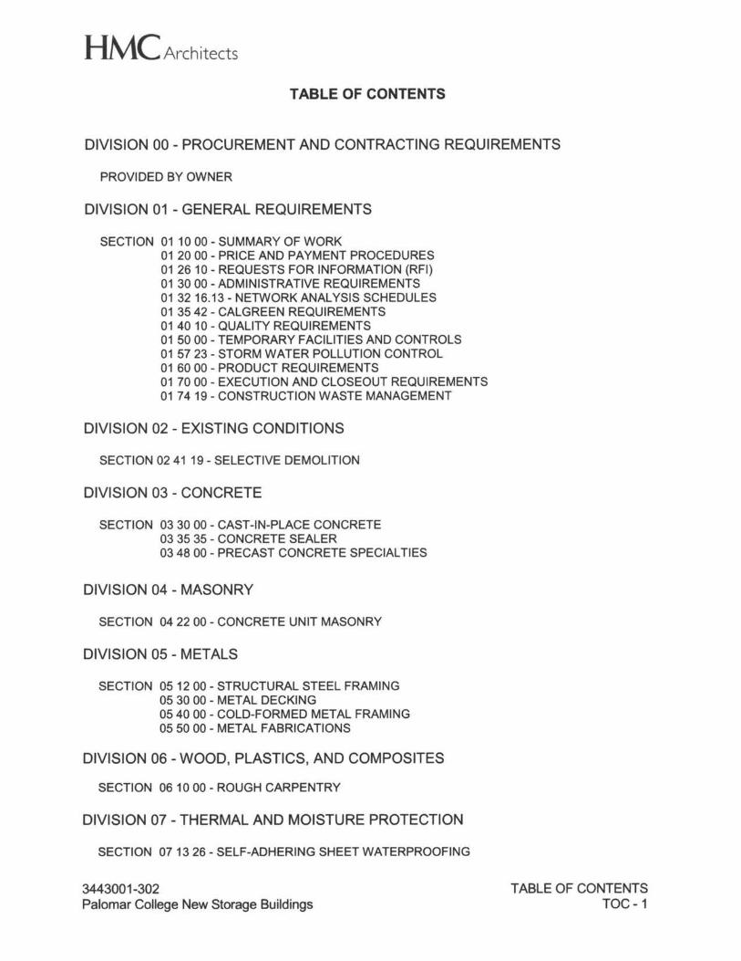
HMC Architects TABLE OF CONTENTS
DIVISION 00 - PROCUREMENT AND CONTRACTING REQUIREMENTS
PROVIDED BY OWNER
DIVISION 01 - GENERAL REQUIREMENTS
SECTION 01 10 00 - SUMMARY OF WORK 01 20 00 - PRICE AND PAYMENT PROCEDURES 012610 - REQUESTS FOR INFORMATION (RFI) 01 30 00 -ADMINISTRATIVE REQUIREMENTS 01 32 16.13 - NETWORK ANALYSIS SCHEDULES 01 35 42 - CALGREEN REQUIREMENTS 014010 - QUALITY REQUIREMENTS 01 50 00 - TEMPORARY FACILITIES AND CONTROLS 015723 - STORM WATER POLLUTION CONTROL 01 60 00 - PRODUCT REQUIREMENTS 01 70 00 - EXECUTION AND CLOSEOUT REQUIREMENTS 017419 - CONSTRUCTION WASTE MANAGEMENT
DIVISION 02 - EXISTING CONDITIONS
SECTION 02 41 19 - SELECTIVE DEMOLITION
DIVISION 03 - CONCRETE
SECTION 03 30 00 - CAST-IN-PLACE CONCRETE 03 35 35 - CONCRETE SEALER 03 48 00 - PRECAST CONCRETE SPECIAL TIES
DIVISION 04 - MASONRY
SECTION 04 22 00 - CONCRETE UNIT MASONRY
DIVISION 05 - METALS
SECTION 05 12 00 - STRUCTURAL STEEL FRAMING 05 30 00 - METAL DECKING 05 40 00 - COLD-FORMED METAL FRAMING 05 50 00 - METAL FABRICATIONS
DIVISION 06 - WOOD, PLASTICS, AND COMPOSITES
SECTION 06 10 00 - ROUGH CARPENTRY
DIVISION 07 - THERMAL AND MOISTURE PROTECTION
SECTION 07 13 26 - SELF-ADHERING SHEET WATERPROOFING
3443001-302 Palomar College New Storage Buildings
TABLE OF CONTENTS TOC-1
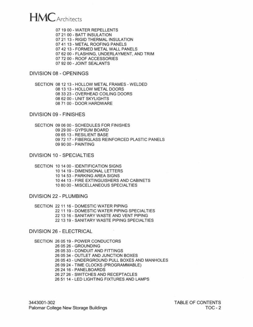
HMC Architects 07 19 00 - WATER REPELLENTS 07 21 00 - BATI INSULATION 07 2113 - RIGID THERMAL INSULATION 07 41 13 - METAL ROOFING PANELS 07 42 13- FORMED METAL WALL PANELS 07 62 00 - FLASHING, UNDERLAYMENT, AND TRIM 07 72 00 - ROOF ACCESSORIES 07 92 00 - JOINT SEALANTS
DIVISION 08 - OPENINGS
SECTION 08 12 13 - HOLLOW METAL FRAMES-WELDED 08 13 13 - HOLLOW METAL DOORS 08 33 23 - OVERHEAD COILING DOORS 08 62 00 - UNIT SKYLIGHTS 08 71 00 - DOOR HARDWARE
DIVISION 09 - FINISHES
SECTION 09 06 00 - SCHEDULES FOR FINISHES 09 29 00 - GYPSUM BOARD 09 65 13 - RESILIENT BASE 09 72 17 - FIBERGLASS REINFORCED PLASTIC PANELS 09 90 00 - PAINTING
DIVISION 10 - SPECIAL TIES
SECTION 10 14 00 - IDENTIFICATION SIGNS 10 14 19 - DIMENSIONAL LETTERS 10 14 53 - PARKING AREA SIGNS 10 4413 - FIRE EXTINGUISHERS AND CABINETS 10 80 00 - MISCELLANEOUS SPECIALTIES
DIVISION 22 - PLUMBING
SECTION 22 11 16 - DOMESTIC WATER PIPING 22 11 19- DOMESTIC WATER PIPING SPECIALTIES 22 1316 - SANITARY WASTE AND VENT PIPING 22 13 19 - SANITARY WASTE PIPING SPECIALTIES
DIVISION 26 - ELECTRICAL
SECTION 26 05 19 - POWER CONDUCTORS 26 05 26 - GROUNDING 26 05 33 - CONDUIT AND FITTINGS 26 05 34 - OUTLET AND JUNCTION BOXES 26 05 43 - UNDERGROUND PULL BOXES AND MANHOLES 26 09 24 - TIME CLOCKS (PROGRAMMABLE) 262416-PANELBOARDS 26 27 26 - SWITCHES AND RECEPTACLES 26 51 14 - LED LIGHTING FIXTURES AND LAMPS
3443001-302 Palomar College New Storage Buildings
TABLE OF CONTENTS TOC-2
HMC Architects
DIVISION 28 - ELECTRONIC SAFETY AND SECURITY
SECTION 28 30 00 - FIRE ALARM SYSTEM
DIVISION 31 - EARTHWORK
SECTION 312315 - SITE EARTHWORK 312317 - TRENCHING 31 23 23 - BACKFILLING
DIVISION 32 - EXTERIOR IMPROVEMENTS
SECTION 32 12 16 - ASPHALTIC CONCRETE PAVING 32 13 13 - SITEWORK CONCRETE 32 17 23 - PAVEMENT MARKING 32 31 13 - FENCES AND GATES
DIVISION 33 - UTILITIES
SECTION 33 11 00 - WATER SYSTEM 33 31 00 - SANITARY SEWAGE SYSTEMS 33 41 00 - STORM DRAIN SYSTEMS
END OF TABLE OF CONTENTS
3443001-302 Palomar College New Storage Buildings
TABLE OF CONTENTS TOC-3
HMC Architects
SECTION 01 10 00
SUMMARY OF WORK
PART 1 - GENERAL
1.01 SUMMARY OF WORK
A. This Contract includes work necessary for and incidental to execution and completion of
PALOMAR COLLEGE - NEW STORAGE BUILDINGS PALOMAR COLLEGE DISTRICT
1140 W. MISSION RD., SAN MARCOS, CA 92069
in accordance with Contract Documents dated prepared by HMC Architects, 3546 Concours, Ontario, California 91764.
1.02 GENERAL DESCRIPTION OF WORK
A. Work under this Contract includes furnishing all labor, materials, services and transportation, except as specifically excluded which is required for completion of Project in accordance with provisions of Contract Documents.
B. The intent of these Contract Documents is to modify the facility for compliance with 2013 California Building Code (CCR, Title 24, Part 2, Chapter 11 B) requirements for accessibility to persons with disabilities. Should any conditions arise, or be discovered, that are not covered by the Contact Documents, and that would cause the finished work to fail to comply with those requirements, a Change Order will be executed and approved DSA-ACS before proceeding with the Work.
C. Work to be included as part of this Contract: 1. Construct three New Storage Buildings and related site work, but not limited to
underground utilities and fire lane.
D. The following restrictions apply to access and to use of site 1. General: During construction period, Contractor shall have full use of premises
for construction operations, including use of site. Contractor's use of premises is limited only by Owner's right to perform work or to retain other contractors on portions of Project.
2. Use of Site: Limit use of premises to Work in areas indicated. Confine operations to areas within Contract limits indicated. Do not disturb portions of site beyond areas in which Work is indicated. Allow for Owner occupancy and use by public.
3. Driveways and Entrances: Keep driveways and entrances serving premises clear and accessible to Owner, Owner's employees, and emergency vehicles at all times. Do not use these areas for parking or storage of materials. Schedule deliveries to minimize space and time requirements for storage of materials and equipment on site.
3443001-302 Palomar College New Storage Buildings
SUMMARY OF WORK 01 10 00 - 1
HMC Architects
4. Partial Owner Occupancy: Owner reserves right to occupy and to place and install equipment in completed areas of building before Certified Completion, provided such occupancy does not interfere with completion of Work. Such placing of equipment and partial occupancy shall not constitute acceptance of total Work.
5. Full Owner Occupancy: Owner will occupy site and existing buildings during entire construction period. Cooperate with Owner during construction operations to minimize conflicts and facilitate Owner usage. Perform Work so as not to interfere with Owner's operations.
6. Limit site disturbance, including earthwork and clearing of vegetation, to 40 feet beyond building perimeter; 5 feetbeyond primary roadway curbs, walkways, and main utility branch trenches; and 25 feet beyond pervious paving areas.
1.03 PERMISSIBLE WORKING DAYS AND HOURS
A. Work may be conducted on regularly scheduled school attendance days between the hours of 7:00 A.M. and 4:00 P.M.
B. Work may be conducted at any hour during Saturdays, Sundays and non-school session days, at no extra cost to the Owner, when written notification to Owner has been submitted and anticipated schedule of Work activities has been approved.
C. Conform to Division 01, General Requirements for required payment for Inspector's services performed during overtime hours.
1.04 INTERRUPTION OF EXISTING UTILITY SERVICES
A. When necessary to interrupt any existing utility service to make connections, minimum of 48 hours advance notice shall be given to Owner and Architect. Interruptions in utility services shall be of shortest possible duration for Work at hand and shall be approved by Architect.
B. In event any utility service is interrupted without required 48 hours notice, Contractor shall be financially liable for all damages suffered by Owner due to unauthorized interruption.
1.05 VERIFICATION OF EXISTING CONDITIONS
A. Contractor shall be responsible to examine site of Work and after investigation to decide for himself/herself character of materials, equipment and utilities to be encountered and all other existing conditions affecting Work. Contractor is also responsible to provide sufficient costs to cover provisions of all items of Work under existing conditions referred to herein.
PART 2 - PRODUCTS
NOT USED
PART 3 - EXECUTION
NOT USED.
3443001-302 Palomar College New Storage Buildings
SUMMARY OF WORK 011000-2
HMC Architects
END OF SECTION
3443001-302 Palomar College New Storage Buildings
SUMMARY OF WORK 01 10 00 - 3

HMC Architects
SECTION 01 20 00
PRICE AND PAYMENT PROCEDURES
PART 1 - GENERAL
1.01 SECTION INCLUDES
A. Changes in the Work.
B. Schedule of Values.
1.02 CHANGES IN THE WORK
A. Approval by Division of the State Architect (DSA) Required: Changes in the Work affecting structural safety, fire and life-safety, or accessibility shall be submitted to and approved by DSA, using Form DSA-140 in accordance with CAC Section 4-338(c).
B. Minor Changes in the Work: Architect will issue supplemental instructions authorizing minor changes in the Work, not involving adjustment to the Contract Sum or the Contract Time, on AIA Document G710 or Architect's form, accompanied by Form DSA-141 or approved Form DSA-140.
C. Proposal Requests 1. Owner-Initiated Proposal Requests: Architect will issue a detailed description of
proposed changes in the Work that may require adjustment to the Contract Sum or the Contract Time, on AIA Document G709 or Architect's form, accompanied by Form DSA-141 or approved Form DSA-140. If necessary, the description will include supplemental or revised Drawings and Specifications. a. Work Change Proposal Requests issued by Architect are not instructions
either to stop work in progress or to execute the proposed change. b. Within time specified in the General and Supplementary Conditions after
receipt of Proposal Request, submit a quotation estimating cost adjustments to the Contract Sum and the Contract Time necessary to execute the change. 1) Include a list of quantities of products required or eliminated and unit
costs, with total amount of purchases and credits to be made. If requested, furnish survey data to substantiate quantities.
2) Indicate applicable taxes, delivery charges, equipment rental, and amounts of trade discounts.
3) Include costs of labor and supervision directly attributable to the change.
4) Include an updated Contractor's construction schedule that indicates the effect of the change, including, but not limited to, changes in activity duration, start and finish times, and activity relationship. Use available total float before requesting an extension of the Contract Time.
5) Quotation Form: Use CSI Form 13.6A, "Change Order Request (Proposal}," with attachments CSI Form 13.60, "Proposal Worksheet Summary," and Form 13.6C, "Proposal Worksheet Detail."
3443001-302 Palomar College New Storage Buildings
PRICE AND PAYMENT PROCEDURES 01 20 00 - 1
HMC Architects
2. Contractor-Initiated Proposals: If latent or changed conditions require modifications to the Contract, Contractor may initiate a claim by submitting a request for a change to Architect. a. Include a statement outlining reasons for the change and the effect of the
change on the Work. Provide a complete description of the proposed change. Indicate the effect of the proposed change on the Contract Sum and the Contract Time.
b. Include a list of quantities of products required or eliminated and unit costs, with total amount of purchases and credits to be made. If requested, furnish survey data to substantiate quantities.
c. Indicate applicable taxes, delivery charges, equipment rental, and amounts of trade discounts.
d. Include costs of labor and supervision directly attributable to the change. e. Include an updated Contractor's construction schedule that indicates the
effect of the change, including, but not limited to, changes in activity duration, start and finish times, and activity relationship. Use available total float before requesting an extension of the Contract Time.
f. Comply with requirements in Section 01 60 00 "Product Requirements" if the proposed change requires substitution of one product or system for product or system specified.
g. Proposal Request Form: Use CSI Form 13.6A, "Change Order Request (Proposal)," with attachments CSI Form 13.60, "Proposal Worksheet Summary," and Form 13.6C, "Proposal Worksheet Detail."
D. Construction Change Directive 1. Construction Change Directive: Architect may issue a Construction Change
Directive on AIA Document G714 or Architect's form, accompanied by Form DSA-141 or approved Form DSA-140. Construction Change Directive instructs Contractor to proceed with a change in the Work, for subsequent inclusion in a Change Order. a. Construction Change Directive contains a complete description of change in
the Work. It also designates method to be followed to determine change in the Contract Sum or the Contract Time.
2. Documentation: Maintain detailed records on a time and material basis of work required by the Construction Change Directive. a. After completion of change, submit an itemized account and supporting
data necessary to substantiate cost and time adjustments to the Contract, using CSI Form 13.6A, "Change Order Request (Proposal)," with attachments CSI Form 13.60, "Proposal Worksheet Summary," and Form 13.6C, "Proposal Worksheet Detail.".
E. Change Orders Procedures: On Owner's approval of a Change Order Request, Architect will issue a Change Order for signatures of Owner and Contractor on AIA Document G701 or Architect's form. 1. Stipulated Price Change Order: Based on Contractor's Change Order Request
as approved by Architect. 2. Time and Material Change Orders: Submit itemized account and supporting data
after completion of change within time limits indicated in Conditions of Contract. Architect will determine change allowable in Contract Price and Contract Time as provided in Contract Documents.
3443001-302 Palomar College New Storage Buildings
PRICE AND PAYMENT PROCEDURES 01 20 00 - 2

HMC Architects 3. Maintain detailed records of work done on Time and Material basis. Provide full
information required for evaluation of proposed changes, and to substantiate costs for changes in Work.
4. Refer to the General and Supplementary Conditions for additional requirements. 5. Execution of Change Orders: Architect will issue Change Orders for signature of
parties as provided in Conditions of the Contract. 6. Unit Price Change Order: For pre-determined unit prices and quantities, Change
Order will be executed on fixed unit price basis. For unit costs or quantities of units of Work that are not pre-determined, execute Work under Construction Change Directive. Change in Contract Price or Contract Time will be computed as specified for Time and Material Change Order.
1.03 SCHEDULE OF VALUES
A. Submit printed schedule on AIA Forms G702 and G703 - Application and Certificate for Payment and Continuation Sheet. Contractor's standard form or electronic media printout will be considered, submit sample forms to Architect for approval.
B. Submit application for progress payment in accordance with the General and Supplementary Conditions.
C. Submit Schedule of Values in duplicate within 15 calendar days after date of Owner-Contractor Agreement for Architect's approval.
D. Format: Utilize Table of Contents of this Project Manual. Identify each line item with number and title of the major Specification Section. Identify site mobilization and bonds and insurance. On projects of more than one building, list buildings separately. List mechanical, electrical, plumbing and fire protection Work separately for each building and for site Work.
E. Break down the plumbing and mechanical portions of the work at a minimum into a rough, finish, including air balance and electrical portion.
F. Break out rough grading, fine grading, and underground utilities.
G. Include separate line items, showing amount of General Contractor's overhead and profit, bonds and insurance, supervision, and then remainder of general items.
H. Revise schedule to list approved Change Orders, with each Application for Payment.
I. Include in each line item, amount of Allowances specified in this section. For Unit Cost Allowances, identify quantities taken from Contract Documents multiplied by unit cost to achieve total for item.
3443001-302 Palomar College New Storage Buildings
PRICE AND PAYMENT PROCEDURES 01 20 00 - 3
HMC Architects
PART 2 - PRODUCTS
2.01 NOT USED.
PART 3 - EXECUTION
3.01 NOT USED.
END OF SECTION
3443001-302 Palomar College New Storage Buildings
PRICE AND PAYMENT PROCEDURES 01 20 00 - 4
HMC Architects
SECTION 01 26 10
REQUESTS FOR INFORMATION (RFI)
PART 1 - GENERAL
1.01 SECTION INCLUDES
A. Administrative requirements for Requests for Information (RFI).
1.02 DEFINITIONS
A. Request for Information: 1. Written request prepared by Contractor requesting additional information
necessary to clarify an item which he believes is not clearly shown or called for in the drawings or specifications, or to address problems which have arisen under field conditions, hereinafter referred to as RFI.
2. Properly prepared request for information shall include detailed written statement that indicates specific Drawings or Specification in need of clarification and nature of clarification requested. a. Drawings shall be identified by Drawing number and location on Drawing
sheet. b. Specifications shall be identified by Section number, page and paragraph.
3. Contractor's documents with similar titles, such as "Request for Interpretation" or "Request for Clarification" shall be considered RFls.
4. RFls and Architect's responses are not Changes in the Work; if a Change in the Work is required in response to an RFI, separate documents shall be issued in accordance with Section 01 20 00.
B. Improper RFls: 1. RFls that are not properly prepared or incomplete. 2. Improper RFls will be processed by Architect at Architect's standard hourly rate
and Architect will charge Owner, and such costs will be deducted from moneys still due the Contractor. Architect will notify Contractor before processing of improper RFls.
C. Frivolous RFls: 1. RFls that request information that is clearly shown on Contract Documents. 2. Frivolous RFls may be returned unanswered or may be processed by Architect at
Architect's standard hourly rate and Architect will charge Owner, and such costs will be deducted from moneys still due Contractor. Architect will notify Contractor before processing of frivolous RF ls.
1.03 CONTRACTOR'S REQUESTS FOR INFORMATION
A. When the Contractor is unable to determine from Contract Documents, material, process or system to be installed, Architect will be requested to make clarification of indeterminate item.
3443001-302 Palomar College New Storage Buildings
REQUESTS FOR INFORMATION (RFI) 01 26 10 - 1
HMC Architects 1. Whenever possible, such clarification shall be requested at next appropriate
project meeting, with response entered into meeting minutes. When clarification at meeting is not possible, because of urgency of need, or complexity of item, Contractor shall prepare and submit RFI to Architect.
B. Contractor shall endeavor to keep number of RFls to a minimum. In the event the process becomes unwieldy, in the opinion of Architect, because of number and frequency of RFls submitted, the Architect may require the Contractor to abandon process and submit future requests as either submittals, substitutions or requests for change.
C. RFls shall be submitted on form acceptable to Architect. Forms shall be completely filled in, and if prepared by hand, shall be fully legible after photocopying or transmission by facsimile (fax) or eMail scan. Each page of attachments to RFls shall bear RFI number in lower right corner.
D. RFl's shall be originated by Contractor: 1. RFls from subcontractors or material suppliers shall be submitted through,
reviewed by, and signed by Contractor before submittal to Architect. 2. RFls sent by subcontractor or suppliers directly to Architect or Architect's
consultants shall not be accepted and will be returned unanswered.
E. Contractor shall carefully study Contract Documents to ensure that requested information is not available therein. RFls which request information available in Contract Documents will be deemed "improper" or "frivolous" as noted above.
F. In cases where RFls are issued to request clarification of coordination issues, for example pipe and duct routing, clearances, specific locations of Work shown diagrammatically, and similar items, Contractor shall fully lay out suggested solution using drawings or sketches drawn to scale, and submit same with RFI. RFls which fail to include suggested solution will be returned unanswered with requirement that Contractor submit a complete request. 1. Contractors are encouraged to utilize photocopies of Contract Documents to
completely illustrate their questions, and to provide sketches as required to communicate question, concepts and suggestions.
G. Do not use RFls for following purposes: 1. To request approval of submittals. 2. To request approval of substitutions. 3. To request changes which entail additional cost or credit. 4. To request changes which entail change of time of completion. 5. To request different methods of performing Work than those drawn and specified.
H. In event Contractor believes that clarification by Architect results in additional cost or time, Contractor shall not proceed with Work indicated by RFI until Change Order or Construction Change Directive is prepared and approved in accordance with Section 01 20 00. RFls shall not automatically justify cost increase in Work or change in project schedule. 1. Answered RFls shall not be construed as approval to perform extra Work. 2. Unanswered RFls will be returned with stamp or notation: Not Reviewed.
3443001-302 Palomar College New Storage Buildings
REQUESTS FOR INFORMATION (RFI) 012610-2
HMC Architects
I. Contractor shall prepare and maintain log of RFls, and at any time requested by Architect, Contractor shall furnish copies of log showing outstanding RFls. Contractor shall note unanswered RFls in log.
J. Contractor shall allow up to 7 days review and response time for RFls, however, Architect will endeavor to respond in timely fashion to RFls.
1.04 ARCHITECT'S RESPONSE TO RFls
A. Architect will respond to RF ls on one of following forms: 1. Properly prepared RFls:
a. If no Change in the Work is required, Architect will respond in space provided on the RFI form.
b. If a Change in the Work is required, Architect will issue in accordance with Section 01 20 00.
2. Improper or Frivolous RFls: a. Notification of Processing Fee(s). b. Unanswered RFls will be returned with stamp or notation: "Not Reviewed".
B. Architect may opt to retain RFls for discussion during regularly scheduled project meetings for inclusion of responses in meeting minutes in lieu of responding on written form.
PART 2 - PRODUCTS
NOT USED
PART 3 - EXECUTION
NOT USED
END OF SECTION
3443001-302 Palomar College New Storage Buildings
REQUESTS FOR INFORMATION (RFI) 01 26 10 - 3
HMC Architects
SECTION 01 30 00
ADMINISTRATIVE REQUIREMENTS
PART 1 - GENERAL
1.01 SECTION INCLUDES
A. Project Management and Coordination: Project Coordination, Project Meetings.
B. Construction Progress Documentation: Construction Progress Schedule, Project Website Construction Photographs, Two-week Look Ahead Schedule.
C. Submittal Procedures: Shop Drawings, Product Data, Samples, Source Quality Control Reports, Deferred Approval Items, Finishes Materials Schedule, and CHPS Submittals.
1.02 PROJECT COORDINATION
A. Coordinate scheduling, submittals, and Work of various Sections of Project Manual to ensure efficient and orderly sequence of installation of interdependent construction elements, with provisions for accommodating items installed later.
B. Verify utility requirements and characteristics of operating equipment are compatible with building utilities. Coordinate Work of various Sections having interdependent responsibilities for installing, connecting to, and placing in service, such equipment.
C. Coordinate space requirements and installation of mechanical and electrical Work that are indicated diagrammatically on Drawings. Follow routing shown for pipes, ducts, and conduit, as closely as practicable; place runs parallel with line of building. Utilize spaces efficiently to maximize accessibility for other installation, for maintenance, and for repairs.
D. In finished areas except as otherwise indicated, conceal pipes, ducts, and wiring within construction. Coordinate locations of fixtures and outlets with finish elements.
E. Coordinate completion and clean up of Work of separate sections in preparation for Certified Completion and for portions of Work designated for Owner's occupancy.
F. After Owner occupancy of premises, coordinate access to site for correction of defective Work and Work not in accordance with Contract Documents, to minimize disruption of Owner's activities.
1.03 PRECONSTRUCTION MEETING
A. Architect will schedule meeting after Notice of Award.
B. Attendance Required: Architect, Prime Contractors, Major Subcontractors, Project Inspector and key Owner personnel.
C. Agenda:
3443001-302 Palomar College New Storage Buildings
ADMINISTRATIVE REQUIREMENTS 01 30 00 - 1
HMC Architects 1. Contract Agreement:
a. Transmit 5 signed originals of the Agreement to the Owner. b. Transmit Attachment Certifications to the Owner. c. Transmit Performance and Payment Bonds to the Owner. d. Contractor to transmit Certificates of Insurance to the Owner. e. Owner to transmit copy of Certificates of Property Insurance to Contractor. f. Review General and Supplementary Conditions.
2. Receive documentation from Contractor: a. Construction Progress Schedule. b. Schedule of Values. c. List of Subcontractors with addresses and phone numbers. d. List of Submittals and estimated date of submittal.
3. Project Administration: a. Application for Payment, Stop-Notice Lien Release, Record Drawings. b. Change Order Requests, Change Orders, Request For Proposals,
Construction Change Directive/Instruction Bulletins. Preparation of Change Orders by Architect according to 2013 California Administrative Code, Code of Regulations Title 24 Part 1, Section 4-233.
c. Submittals d. Substitution procedures. e. Site Meetings. f. Testing Laboratory. g. Verified Reports. h. Designation of key personnel and their duties. i. Lines of communications. j. Procedures for RFls. k. Procedures for testing and inspecting. I. Distribution of the Contract Documents. m. Sustainable design requirements. n. Preparation of record documents. o. Work restrictions. p. Working hours. q. Procedures for moisture and mold control. r. Procedures for disruptions and shutdowns. s. Construction waste management and recycling. t. Parking availability. u. Storage areas. v. Equipment deliveries and priorities. w. Security. x. Progress cleaning.
4. Special Owner Conditions: a. Temporary Facilities. b. Owner Occupancy. c. Work by Owner. d. Access to Site - Owner Contact.
5. Construction Process: a. Contractor shall discuss overview of construction. b. Contractor shall identify items to be selected by Architect/Owner and date
selections must be made.
3443001-302 Palomar College New Storage Buildings
ADMINISTRATIVE REQUIREMENTS 01 30 00 - 2

HMC Architects c. Contractor shall review special requirements for equipment, safety, and
noise. 6. Pre-Job Conference:
a. Prevailing Wage Requirements. b. Checklist and signatures.
D. Architect will record minutes and distribute copies within seven days after meeting to participants and those affected by decisions made.
1.04 PROGRESS MEETINGS
A. Architect will schedule and administer meetings throughout progress of Work as needed.
B. Architect will make arrangement for meetings, prepare agenda with copies for participants, preside at meetings.
C. Attendance Required: Project Coordinator, Prime Contractors, Major Subcontractors and Suppliers, Project Inspector, key Owner personnel and Architect as appropriate to agenda topics for each meeting.
D. Agenda: 1. Review minutes of previous meetings. 2. Review of Work progress. 3. Field observations, problems, and decisions. 4. Identification of problems that impede planned progress. 5. Review of submittals schedule and status of submittals. 6. Maintenance of Construction Progress Schedule. 7. Corrective measures to regain projected schedules. 8. Maintenance of quality and work standards. 9. Effect of proposed changes on progress schedule and coordination. 10. Other business relating to Work.
E. Architect will record minutes and distribute copies within seven days after meeting to participants, and those affected by decisions made.
1.05 PREINSTALLATION MEETING
A. When required in individual Specification Sections, convene pre-installation meeting before starting Work of Section.
B. Require attendance of parties directly affecting, or affected by, Work of specific Section.
C. Notify Architect four days in advance of meeting date.
D. Prepare agenda and preside at meeting: 1. Review conditions of installation, preparation and installation procedures. 2. Review coordination with related Work.
3443001-302 Palomar College New Storage Buildings
ADMINISTRATIVE REQUIREMENTS 01 30 00 - 3
HMC Architects
E. Contractor shall record minutes and distribute copies within three days after meeting to participants, Architect and those affected by decisions made.
1.06 SUBMITTAL PROCEDURES
A. Transmit separate request for EACH Section submittal directly to Architect. 1. Bind submittals sturdily, neatly label covers. 2. Include HMC Architects job number as it appears on Contract Documents. 3. Include Authority Having Jurisdiction application or approval number.
B. Submittal number shall use a sequential number followed by a hyphen then the Specification Section followed by a hyphen and then the revision number (e.g., 0001-051200-0). Resubmittals shall have the original number and include the revision number as the suffix (e.g., 0001-051200-1).
C. Identify Project, Contractor, Subcontractor or supplier; pertinent Drawing sheet and detail number(s), and Specification Section number, as appropriate. 1. Provide name telephone number of individual who may be contacted for further
information.
D. Apply Contractor's dated stamp with Contractor's original signature or initials affixed thereto, certifying that review, verification of products required, field dimensions, adjacent construction Work, and coordination of information is according to requirements of Work and Contract Documents. Stamped signatures or initials are not acceptable.
E. Schedule submittals to expedite Project. Coordinate submission of related items. 1. Make submittals according to Construction Schedule and adequate enough in
advance of scheduled dates of installation to provide required time for reviews for securing necessary approvals for possible revision and re-submittal and for placing orders and securing delivery.
2. Schedule submittals such that related materials and assemblies that support or are affected by the submitted materials are either submitted simultaneously or in order of installation sequence such that impacts and coordination can be evaluated as part of the review.
F. Late submittals, not in accordance with the "Schedule for Submission of Shop Drawings, Product Data and Samples" and the Construction Schedule, will not be considered an acceptable reason for initiating a substitution requests caused by late ordering and procurement of materials.
G. Identify variations from Contract Documents and Product or system limitations that is detrimental to performance of completed Work.
H. Substitutions: Submit only as approved per Section 01 60 00, state effect of approved substitution on construction schedule, and changes required in other work or products.
3443001-302 Palomar College New Storage Buildings
ADMINISTRATIVE REQUIREMENTS 01 30 00 - 4

HMC Architects
I. Owner-Directed Substitution Approval: Substitution submittals specifically directed by Owner to be approved by the Architect for this project shall pertain to a specific item only. The Architect's stamped approval of Owner-Directed Substitution does not constitute approval for any other item, other projects or parts of project. A Change Order shall be prepared to effect the Owner's authorization of Owner-Directed Substitution.
J. Provide space for Contractor and Architect review stamps.
K. Revise and resubmit submittals in their entirety, identify changes made since previous submittal.
L. Distribute copies of reviewed submittals to concerned parties. Instruct parties to promptly report any inability to comply with provisions.
M. Determine and verify field dimensions and conditions, materials, catalog numbers and similar data.
N. Coordinate as required with all trades and all public agencies involved.
0. Unless otherwise specifically authorized by Architect, make submittals in groups containing associated items within the same Section. Architect may reject partial submittals as not complying with provisions of this Section.
P. Where individual Sections require structural calculations, prepare submittal under direction of qualified California Licensed Structural Engineer and shall bear the Engineer's stamp and signature.
Q. Format of Submittals: Submit Electronic Submittals, including but not limited to: Product Data, Shop Drawings, Schedules, Certifications, tests, logs, for ease of information distribution. At Contractor's option he may submit standard printed data on reproducible media and in number of copies required per this Sectin and other project Sections. Identify submitted items that are applicable to the project, including any deviations, with arrows, clouds, or other distint graphic, or in highlighted writing that can be reporduced with black and white copiers easily discernible from background information.
1.07 CONSTRUCTION PROGRESS SCHEDULE
A. Submit Construction Progress Schedule in duplicate within 15 calendar days after the date on the Notice to Proceed for Architect's review. 1. Schedule shall reflect amount of time stipulated in Agreement. 2. If the Contractor proposes an earlier completion dated than stipulated in the
Agreement, Change Order will be issued reflecting revised completion date at no change in Contract Sum.
B. Revise and resubmit as required.
3443001-302 Palomar College New Storage Buildings
ADMINISTRATIVE REQUIREMENTS 01 30 00 - 5
HMC Architects
C. Scheduling may utilize programs including: Microsoft Project Schedule, Primavera Project Planner (P3), Primavera SureTrak Project Manager®, Meridian Project Systems or similar programs addressing the requirements.
D. Submit computer generated network analysis diagram in accordance with Section 01 32 16.13 using Critical Path Method, generally as outlined in Associated General Contractors of America (AGC) publication "Construction Planning and Scheduling", Latest Edition.
E. Indicate complete sequence of construction by activity, identifying Work of separate stages and other logically grouped activities. Indicate early and late start, early and late finish, float dates and duration. Ownership of float time is shared commodity, not for exclusive use by either party. Use float time to make up Work behind schedule until float time is depleted. Submittals returned in less time than allowed by Contract, shall be used to reduce Contractor time extension requests.
F. Indicate Milestones and target date and their activities including completion dates.
G. No Time extensions will be granted nor delay damages paid until a delay occurs that impacts the schedule consumes all available float or contingency time available, and extends the work beyond the contract completion date.
H. Indicate estimated percentage of completion for each item of Work at each submission.
I. Schedule for Submission of Shop Drawings, Product Data and Samples: Incorporate "Schedule for Submission of Shop Drawings, Product Data and Samples" in Construction Progress Schedule. This schedule shall include submittal dates required for shop drawings, product data, samples and product delivery dates, including Deferred Approval Items, if any, and including those items furnished by Owner. Provide time in schedule for Architect's review of submittals according to Contract Time. Allow 21 calendar days for submittals requiring consultants' review.
J. Submit revised schedules with each Application for Payment identifying changes since previous version.
K. As a minimum allow 15 calendar days in schedule for final inspections before final acceptance. Include time to correct punch list items prior to final acceptance.
L. Substantially Completed buildings, alterations, additions and relocatables: in projects consisting of different buildings, alterations, additions and relocatables, scheduled to be substantially completed and delivered to the Owner for beneficial occupancy prior to Final Completion of entire project, indicate in the Construction Schedule each building, alteration, addition and relocatable progress, completion date, Punch List items and time for completion of Punch list items.
3443001-302 Palomar College New Storage Buildings
ADMINISTRATIVE REQUIREMENTS 01 30 00 - 6
HMC Architects 1. DSA 152-Project Inspection Cards: The Inspector shall post the forms in his/her
job file and shall electronically post the forms. Inspection Cards required: DSA-issued 152-Project Inspection Cards for EACH building, alteration, addition, each relocatable, and one for the site work when site work is involved. The Project Inspector is responsible to sign off applicable blocks and sections on the form as the Work progresses as required in accordance with DSA Procedures. No one is allowed to modify the Project Inspection Cards except the Project Inspector.
1.08 CONSTRUCTION PHOTOGRAPHS
A. Photographer: Engage qualified photographer to take construction photographs.
B. Photographic Film: Medium format, 2-1 /4 by 2-3/4 inches.
C. Do not permit prints to be issued for any purpose without specific written authorization from the Architect.
D. Digital Images: Provide images in uncompressed TIFF format, produced by a digital camera with minimum sensor size of 4.0 megapixels, and at an image resolution of not less than 1600 by 1200. 1. Provide 2 sets (CD's) of copies to Owner.
E. Date Stamp: Unless otherwise indicated, date and time stamp each photographs as it is being taken so stamp is integral to photograph. 1. Identify each print with job name, location from which photograph was taken,
photographer's name address and photograph number.
F. Pre-Construction Photographs: Before starting construction, take 4 color photographs of Project site and surrounding properties from different vantage points, as directed by Architect. Show existing conditions adjacent to property.
G. Periodic Construction Photographs: Take 4 color photographs monthly, coinciding with cutoff date associated with each Application of Payment. Photographer shall select vantage points to best show status of construction and progress since last photographs were taken. Take photographs same time of day. 1. Field Office Prints: Retain 1 set of prints of periodic photographs in field office at
Project site available at all times for reference. Identify photographs same as for those submitted to Architect.
2. Final Completion Construction Photographs: Take 8 color photographs after date of Substantial Completion for submission as Project Record Documents.
1.09 COORDINATED DRAWINGS
A. Submit drawings that indicate routing, locations, sizes, types and number of components in concealed spaces where potential conflict may occur between structures, mechanical, electrical, communications and ceiling suspension systems.
3443001-302 Palomar College New Storage Buildings
ADMINISTRATIVE REQUIREMENTS 01 30 00 - 7
HMC Architects
B. Indicate locations of ceiling penetrations and surface-mounted items. Provide cross sections at areas to indicate proper support of ceilings and non-interference with work of other Sections of specifications. Cross sections shall indicate coordination required and proposed solutions for routing of elements where potential conflict exists. Reproduction of Architect's reflected ceiling plan is not acceptable.
C. Drawings shall be based on field measurements, shop drawings and product data.
D. Conflicts shall be brought to Architect's attention immediately.
E. Submit to Architect, in writing, requests for clarification or interpretations that will affect intent and/or scope of Contract Documents.
F. Coordinated drawings shall indicate each class of Work in affected area. Drawing or written submittal shall include Contractor's recommendations for solution of any potential conflicts as well as recommendations tendered by any Work of any Section of Specifications which may be affected thereby.
G. Submit coordinated drawings in scale of not less than 1/8" = 1'-0" with necessary sections and profiles at an appropriate, clearly readable enlarged scale. Submit coordinated drawings as one electronic (CD) copy and one bond (hard) copy.
H. Architect will review submittals, make appropriate notations and comments to ensure solution meets intent of Contract Documents and then return to Contractor for implementation.
I. Contractor shall be responsible for proper coordination of Work of Sections of Specifications in execution of coordinated drawings. Installation of materials, components or equipment under one Section of Specifications without full and complete, agreement, knowledge and consent by fabricators of adjacent or otherwise related or affected Work will not be approved.
J. It shall be incumbent upon Contractor that fabricators of Work involved in execution of coordinated drawings be informed, consulted and advised in sufficient advance time to arrive at solutions where no extension of contract time for extra cost to Owner will be approved due to Contractor's negligence in expeditious, timely submittal of coordinated drawings.
1.10 SHOP DRAWINGS
A. Within 15 days from Notice to Proceed, submit to Architect for review and acceptance, "Schedule for Submission of Shop Drawings, Product Data and Samples" (Submission Schedule) listing required submittals and review dates. Schedule shall allow sufficient time for checking by Architect. Incorporate Submission Schedule in Construction Progress Schedule. Days: Calendar Days. 1. Additionally, submit all Shop Drawings, Product Data and Samples according to
the following guidelines. Guidelines are provided to allow Architect and Engineers adequate time for review and is not intended to dictate contractor's means and methods:
3443001-302 Palomar College New Storage Buildings
ADMINISTRATIVE REQUIREMENTS 01 30 00 - 8
HMC Architects a. Contract of 60 to 90 days: Submit within 15 days from acceptance of
Submission Schedule. Allow Architect 15 days to respond (defined as reviewed and returned). Re-submittals: allow contractor 7 days, allow Architect 10 days to respond.
b. Contract of 90 to 180 days: Submit within 30 days from Notice to Proceed. Allow Architect 15 days to respond. Re-submittals: allow Contractor 10 days, and Architect 15 days to respond.
c. Contract of 180 to 270 days: Submit within 45 days from Notice to Proceed. Allow Architect 21 days to respond. Re-submittals: allow Contractor 10 days, and Architect 15 days to respond.
d. Contract of 270 to 360 days: Submit within 60 days from Notice to Proceed. Allow Architect 21 days to respond. Re-submittals: allow Contractor 10 days, and Architect 15 days to respond.
B. Submit newly prepared information, drawn to accurate scale. Highlight, encircle or otherwise indicate deviations from Contract Documents. Do not reproduce Contract Documents or copy standard information as the basis of Shop Drawings. Standard information prepared without specific reference to Project will not be approved as shop drawings.
C. Shop drawings shall include fabrications and installation drawings, setting diagrams, schedules, patterns, templates and similar drawings. Include following information: 1. Dimensions 2. Identification of products and materials included. 3. Compliance with specified standards. 4. Notation of coordination requirements. 5. Notation of dimensions established by field measurement.
D. Sheet Size: Except for templates, patterns and similar full-size drawings, submit shop drawings on sheets at least 8-1/2 inch x 11 inch, but not larger than 30 inch x 42 inch.
E. Contractor shall review, stamp with his approval as herein required, and submit with reasonable promptness and in orderly sequence, according to Submittal Schedule, all shop drawings required by Contract Documents or subsequently by Architect as covered by modifications. Shop drawings shall be properly identified. At time of submission Contractor shall inform Architect in writing and with highlighted annotation on shop drawings of any deviation in shop drawings from requirements of Contract Documents.
F. Stamp: Each page of shop drawings shall bear Contractor's stamp, which shall signify Contractor's representation that he has determined and verified materials, field measurements and field construction criteria related thereto, or will do so, and has checked and coordinated information contained in shop drawings. Each stamp shall be accompanied by wet signature or initial of employee of Contractor who may be contacted for information. Stamped signatures or initials are not acceptable.
3443001-302 Palomar College New Storage Buildings
ADMINISTRATIVE REQUIREMENTS 01 30 00 - 9
HMC Architects
G. Method of Review: Submit Electronic Shop Drawing Submittals. At Contractor's option he may submit standard printed shop drawings, five (5) prints or bond copies and one (1) 20-lb xerographic bond (reproducible). Identify submitted items that are applicable to the project, including any deviations, with arrows, clouds, or other distinct graphic, or in highlighted writing that can be reproduced with black and white copiers easily discernible from background information. 1. Comments or corrections will be noted on submittals and returned to Contractor,
who shall identify all changes made since previous submittal and resubmit in same manner. When reviewed, submittals will be stamped and returned to Contractor who shall make distribution of electronic copies as required.
H. Processing Time 1. Allow enough time for submittal review, including time for re-submittals, as
follows: a. Time for review shall commence on Architect's receipt of submittal. No
extension of the Contract Time will be authorized because of failure to transmit submittals enough in advance of the Work to permit processing, including re-submittals.
b. In accordance with the Schedule for Submission of Shop Drawings, Product Data and Samples. Review of each submittal for conformance with design concept of Project and with information given in Contract Documents. Architect's review of a separate item shall not indicate acceptance of assembly in which that item functions. Allow additional time if coordination with subsequent submittals is required. Architect will advise Contractor when a submittal being processed must be delayed for coordination.
c. Submittals requiring Consultants' Review: Where review of submittals by Architect's consultants is required, allow minimum 21 calendar days for review of each submittal.
2. Re-submittal Review: In accordance with the Schedule for Submission of Shop Drawings, Product Data and Samples for each re-submittal.
I. Submittal of shop drawings to Architect, shall be made by Contractor with dated transmittal form or letter, and not by subcontractors or suppliers.
J. Architect's review of shop drawings shall not relieve Contractor of responsibility for any deviation from requirements of Contract Documents unless Contractor has informed Architect in writing of such deviation at time of submission and Architect has given written acceptance to specific deviation, nor shall Architect's review relieve Contractor from responsibility for errors or omissions in shop drawings.
K. No portion of Work requiring shop drawings shall be commenced until shop drawings have been returned with review by Architect.
L. At Contractor's option, he may request and if Architect approves use Architect's computer-generated drawings in electronic format. Contractor's request must be in writing with list of drawings requested and CAD format required. Contractor assumes all liability for accuracy of shop drawings if he opts to use Architect's drawings. Software for CAD formats requested by Contractor not currently available to Architect will be provided by Contractor at his own expense. Complete Cad Drawing Request Form at the end of this Section for request.
3443001-302 Palomar College New Storage Buildings
ADMINISTRATIVE REQUIREMENTS 01 30 00 - 10
HMC Architects 1. Engineers' Drawings, CAD engineers' drawings are available only at discretion of
the Engineer.
1.11 PRODUCT DATA
A. Submit within time required by Shop Drawings.
B. Submit six (6) copies. Four (4) copies will be retained by Architect.
C. Mark each copy to identify applicable products, models, options and other data. Supplement manufacturers' standard data to provide information unique to this Project.
D. After review, distribute and provide copies for Record Documents.
1.12 SAMPLES
A. Submit within time required by Shop Drawings.
B. Submit samples to illustrate functional and aesthetic characteristics of product with integral parts and attachment devices. Coordinate sample submittals for interfacing Work.
C. Submit samples of finishes from the full range of manufacturers' standard colors, textures and patterns for Architect selections, or in custom colors selected.
D. Include identification on each sample with full Project information.
E. Submit minimum of three (3) samples or as specified in individual Sections of Specifications, two (2) of which will be retained by Architect.
F. Reviewed samples which may be used in the Work are indicated Sections of the Specifications, two (2) of which will be retained by the Architect.
G. Selection or rejection of samples will be determined by Architect in writing.
H. Colors: Materials that are visually related to other finishes require that subcontractors submit their samples before normally scheduled in order that color selection can be made for other items that are scheduled to be ordered earlier in construction schedule. Complete submittal of color charts and color samples shall be made before related colors will be selected Architect. Contractor shall be responsible to coordinate submittal schedules so as not to delay Work.
1.13 FINISHES MATERIALS SCHEDULE
A. Submit in accordance with Submittal Procedures.
B. Submit Schedule verifying lead times of materials and products as scheduled in Section 09 06 00, Schedules for Finishes.
3443001-302 Palomar College New Storage Buildings
ADMINISTRATIVE REQUIREMENTS 01 30 00 - 11
HMC Architects
1.14 MANUFACTURER'S INSTRUCTIONS
A. When specified in individual Specification Sections, submit manufacturer's printed instruction for delivery, storage, assembly, installation, start-up, adjusting and finishing in quantities specified for product data.
B. Identify conflicts between manufacturer's instructions and contract documents.
1.15 MANUFACTURER'S CERTIFICATIONS
A. When specified in individual Specification Sections, submit manufacturers' certificate to Architect for review in quantities specified for product data.
B. Indicate that material or product conforms to or exceeds specified requirements. Submit supporting reference data, affidavits and certifications as appropriate.
C. Certificates may be recent or previous test results on material or product, but must be acceptable to Architect.
1.16 PRECEDENCE
A. The Contract and each of the Contract Documents are complementary and they shall be interpreted so that what is called for in any one shall be as binding as if called for in all.
B. In the event of conflicts or discrepancies among the Contract Documents, interpretations will be based on the following priorities: 1. The Agreement. 2. Addenda, with those of later date having precedence over those of earlier date. 3. The Supplementary Conditions. 4. The General Conditions of the Contract for Construction. 5. Drawings and Technical Specifications. 6. In the case of an inconsistency between Drawings and Specifications or within
either Document not clarified by addendum, the better quality or greater quantity of Work shall be provided in accordance with the Architect's interpretation.
7. Any work called for in the Drawings and not mentioned in the Specifications, or vice versa, shall be performed as though fully set forth in both.
8. Contractor shall secure written permission from, Architect before proceeding with work affected by omission or discrepancies in the Contract.
C. Separate sections of this Specification are arranged only for convenience of Contractor, and nothing stated herein should be misconstrued as suggesting jurisdiction over items of work by any different building trades.
1.17 TWO-WEEK LOOK AHEAD SCHEDULE
A. Submit a Two Week Look Ahead Schedule and shall contain the following:
3443001-302 Palomar College New Storage Buildings
ADMINISTRATIVE REQUIREMENTS 01 30 00 - 12
HMC Architects 1. Prepare detailed two-week schedule projections for the Work to be performed
during the following weeks beyond the week it is presented at the weekly construction meeting or at the request of the Architect during the construction period.
2. Be plotted in bar chart or time scale logic format and be of such size that all activity numbers and descriptions are clearly legible.
3. Be sorted by sub contractor responsibility, actual start, early start and total float. 4. Include activity ID, description and float for each activity. 5. Include all activities, completed, in progress and scheduled to start within the
time frame of the date minus one week to the data date plus two weeks. 6. Schedule shall be updated and provided at each regular progress meeting for
review and comparison to approved project schedule status.
PART 2 - PRODUCTS
2.01 PRODUCTS FOR PATCHING AND EXTENDING WORK
A. Refer to Section 01 70 00 Execution Requirements.
B. New Materials: As specified in product sections; match existing products and Work for patching and extending Work.
C. Type and Quality of Existing Products: Determine by inspecting and testing products where necessary, referring to existing Work as standard.
PART 3. - EXECUTION
3.01 NOT USED.
END OF SECTION
3443001-302 Palomar College New Storage Buildings
ADMINISTRATIVE REQUIREMENTS 01 30 00 - 13
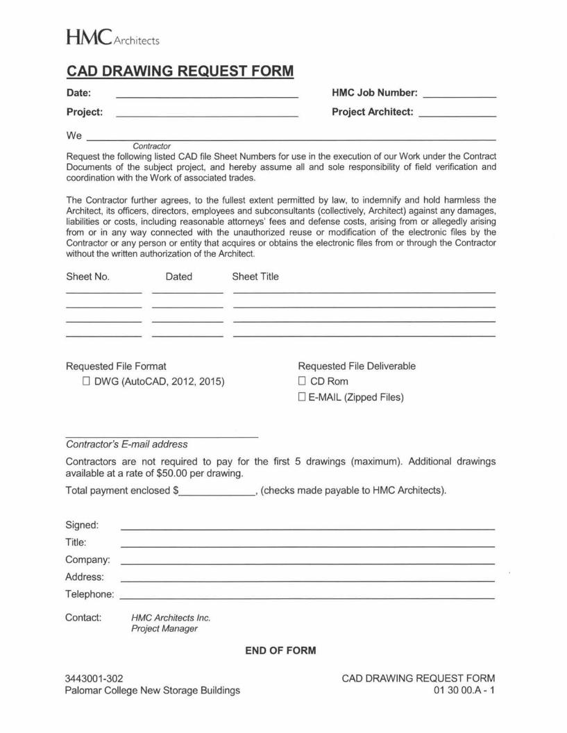
HMC Architects CAD DRAWING REQUEST FORM Date:
Project:
HMC Job Number: ------ Project Architect: _
We _ Contractor
Request the following listed CAD file Sheet Numbers for use in the execution of our Work under the Contract Documents of the subject project, and hereby assume all and sole responsibility of field verification and coordination with the Work of associated trades.
The Contractor further agrees, to the fullest extent permitted by law, to indemnify and hold harmless the Architect, its officers, directors, employees and subconsultants (collectively, Architect) against any damages, liabilities or costs, including reasonable attorneys' fees and defense costs, arising from or allegedly arising from or in any way connected with the unauthorized reuse or modification of the electronic files by the Contractor or any person or entity that acquires or obtains the electronic files from or through the Contractor without the written authorization of the Architect.
Sheet No. Dated Sheet Title
Requested File Format D DWG (AutoCAD, 2012, 2015)
Requested File Deliverable D CD Rom DE-MAIL (Zipped Files)
Contractor's E-mail address
Contractors are not required to pay for the first 5 drawings (maximum). Additional drawings available at a rate of $50.00 per drawing. Total payment enclosed$ , (checks made payable to HMC Architects).
Signed:
Title: Company: Address: Telephone:
Contact: HMC Architects Inc. Project Manager
END OF FORM
3443001-302 Palomar College New Storage Buildings
CAD DRAWING REQUEST FORM 013000.A- 1
HMC Architects
SECTION 01 32 16.13
NETWORK ANALYSIS SCHEDULES
PART 1 - GENERAL
1.01 SECTION INCLUDES
A. References
B. Quality Assurance.
C. Format
D. Schedule
E. Submittals
F. Review and Evaluation.
G. Updating Schedule.
H. Distribution
1.02 REFERENCES
A. "Construction Planning and Scheduling", The Associated General Contractors of America (AGC), Washington, D.C., Latest Edition.
1.03 QUALITY ASSURANCE
A. Scheduler: Contractor's Personnel specializing in CPM scheduling with one year minimum experience in scheduling construction Work of complexity comparable to this Project, and having use of computer facilities capable of delivering detailed graphic printout within 48 hours of request.
B. Contractor's Administrative Personnel: One year minimum experience in using and monitoring CPM schedule on comparable projects.
1.04 FORMAT
A. Scheduling may utilize programs (Latest Editions) including Microsoft Project, Primavera Project Planner for Windows (P3), Primavera SureTrack Project Manager, Meridian Project Systems or similar programs addressing the requirements.
B. Listings: Reading from left to right, in ascending order for each activity. Identify each activity with applicable Specification section number.
C. Diagram Sheet Size: 30 inches high by width required.
D. Scale and Spacing: To allow for notations and revisions.
3443001-302 Palomar College New Storage Buildings
NETWORK ANALYSIS SCHEDULES 013216.13-1
HMC Architects
1.05 SCHEDULE
A. Prepare Network Analysis Schedule and supporting mathematical analyses using Critical Path Method, under concepts and methods outlines in AGC's "Construction Planning and Scheduling".
B. Diagrams to illustrate order and interdependence of activities and sequence of Work, how start of given activity depends on completion of preceding activities, and how completion of activity may restrain start of subsequent activities.
C. Illustrate complete sequence of construction by activity, identifying Work of separate stages and other logically grouped activities. Indicate early and late start, early and late finish, float dates and duration. Provide dates for procurement and delivery of critical products and dates for installation and provision for testing. Provide legend for symbols and abbreviations used. Indicate fabrication, delivery and installation activities.
D. Incorporate Schedule for Submission of Shop Drawings and Samples. Submittal dates required for shop drawings, product data, samples and product delivery dates, including those furnished by Owner. Provide time in schedule for review of submittals.
E. Mathematical Analysis: Tabulate each activity of detailed network diagrams, using calendar dates and identifying for each activity: 1. Preceding and following event number. 2. Activity description. 3. Estimated duration of activity, in maximum 15 day intervals. 4. Earliest start date. 5. Earliest finish date. 6. Actual start date. 7. Actual finish date. 8. Latest start date. 9. Latest finish date. 10. Lag time, total and free float for each activity and critical path. 11. Monetary value of activity, keyed to Schedule of Values. 12. Manpower and cost loading of scheduled activities. 13. Percentage of activity completed. 14. Responsibility
F. Analysis Program: Capable of compiling monetary value of completed and partially completed activities of accepting revised completion dates and re-computation of all dates and float.
G. Required Sorts: List activities in sorts or groups: 1. By preceding Work item or event number from lowest to highest. 2. By amount of float, then in order of early start. 3. By responsibility in order of earliest possible start date. 4. In order of latest allowable start dates. 5. In order of latest allowable finish dates. 6. Contractor's periodic payment request sorted by Schedule of Values. 7. Listing of basic input data that generates report. 8. Listing of activities on critical path.
3443001-302 Palomar College New Storage Buildings
NETWORK ANALYSIS SCHEDULES 013216.13-2
HMC Architects
H. Coordinate contents with Schedule of Values.
I. Contractor shall not sequester float through strategies including extending activity duration estimates to consume available float, using preferential logic, using extensive or insufficient crew or resource loading, use of float suppression techniques, special lead or lag logic restraints or imposed dates.
1.06 SUBMITTALS
A. PRELIMINARY Network Analysis Schedule: Within 15 days after date established in the Notice to Proceed, submit proposed PRELIMINARY Network Analysis Schedule defining planned operations for first 30 days of Work, with general outline for remainder of Work.
B. COMPLETE Network Analysis Schedule: Within 15 days after Notice to Proceed, submit Draft of proposed COMPLETE Network Analysis Schedule for review. Include written certification that major mechanical and electrical Subcontractors have reviewed and accepted proposed schedule. Make submittals in sufficient time for Architect's review.
C. PRELIMINARY Network Analysis Schedule: Within 20 days after joint review of proposed PRELIMINARY Network Analysis Schedule, submit proposed COMPLETE Network Analysis Schedule for review consisting of network diagrams and mathematical analysis. Include written certification that major subcontractors have reviewed and accepted proposed schedule.
D. COMPLETE Network Analysis Schedule: Within 10 days after joint review of Draft of proposed COMPLETE Network Analysis Schedule, submit COMPLETE Network Analysis Schedule consisting of network diagrams and mathematical analysis. Include written certification that major subcontractors have reviewed and accepted proposed schedule.]
E. Participate in review of Preliminary and Complete Network Analysis Schedule jointly with Architect.
F. Number of opaque reproductions Contractor requires, plus three copies which will be retained by Architect.
G. One reproducible transparency and one opaque reproduction.
H. All schedule submittals, including progress updates for duration of Work, shall include electronic submittal in original file format, by e-mail or delivered on storage media agreed to.
I. Updated network schedule with each Application for Payment.
3443001-302 Palomar College New Storage Buildings
NETWORK ANALYSIS SCHEDULES 013216.13-3
HMC Architects
1.07 REVIEW AND EVALUATION
A. Participate in joint review and evaluation of network diagrams and analysis with Architect at each submittal.
B. Evaluate project status to determine Work behind schedule and Work ahead of schedule.
C. After review, revise as necessary as result of review and resubmit within 10 days.
1.08 UPDATING SCHEDULE
A. Maintain schedule to record actual start and finish dates of completed activities. 1. Submit updated schedule at each scheduled project meeting or monthly,
whichever is more frequent.
B. Indicate progress of each activity to date of revision with project completion date of each activity. Update diagrams to graphically depict current status of Work.
C. Identify activities modified since previous submittal, major changes in Work, and other identifiable changes.
D. Indicate changes required to maintain Date of Certified Completion.
E. Submit sorts required to support recommended changes.
F. Provide narrative report to define problem areas, anticipated delays and impact on Schedule. Report corrective action taken, or proposed and its effect including effect of change on schedule of separate contractors.
1.09 DISTRIBUTION
A. Following joint review, distribute copies of updated schedule to Contractor's project site file, to Subcontractors, Suppliers, Architect, Owner and other concerned parties.
B. Instruct recipients to promptly report, in writing, problems anticipated by projections shown in schedule.
PART 2 - PRODUCTS
2.01 NOT USED.
PART 3 - EXECUTION
3.01 NOT USED.
END OF SECTION
3443001-302 Palomar College New Storage Buildings
NETWORK ANALYSIS SCHEDULES 013216.13 - 4
HMC Architects
SECTION 01 35 42
CALGREEN REQUIREMENTS
PART 1 - GENERAL
1.01 DESCRIPTION
A. This Section includes general requirements and procedures for compliance with 2013 CALGreen nonresidential mandatory requirements.
B. Related Sections: 1. Divisions 01 through 48 Sections, as applicable, for CALGreen requirements
specific to the work of each of those Sections.
1.02 SUBMITTALS
A. CALGreen submittals are in addition to other submittals. If submitted item is identical to that submitted to comply with other requirements, submit duplicate copies as a separate submittal to verify compliance with indicated CALGreen requirements.
B. Contractor shall develop a spreadsheet or use one furnished by the Architect building department to track submittals required by CALGreen.
C. CALGreen Submittals: 1. Furnish documentation showing verification of CALGreen compliance as required
by enforcing agency. 2. Section 5.106.1 - Storm Water Loss Prevention Plan: Newly constructed projects
and additions which disturb less than one acre of land shall prevent the pollution of stormwater runoff from the construction activities through one or more of the following measures: a. Local ordinance, 5.106.1.2. b. Best management practices (BMP) complying with Section 5.106.1.2.
3. Section 5.106.10 - Grading and Paving: Furnish drawing showing grading and paving designed to keep surface water from entering buildings.
4. Section 5.408.2 - Construction Waste Management Plan: Furnish a construction waste management plan complying with specified requirements.
5. Section 5.504.4.5 - Composite Wood Products: Furnish documentation showing compliance with Section 5.504.4.5.
D. SUMMARY OF CALGREEN REQUIREMENTS[Division 5.1 - Planning and Design: 1. Site Development Requirements: Comply with the applicable requirements of
Section 5.106. a. Section 5.106.1 - Storm Water Pollution Program: Newly constructed
projects and additions which disturb less than one acre of land shall prevent the pollution of stormwater runoff from the construction activities through one or more of the following measures: 1) Local ordinance, 5.106.1.2. 2) Best management practices (BMP) complying with Section 5.106.1.2.
3443001-302 Palomar College New Storage Buildings
CALGREEN REQUIREMENTS 01 35 42 - 1
HMC Architects b. Section 5.106.4 - Bicycle Parking: Comply with Section 5.106.4.1 or
5.106.4.2, as applicable, for short-term and long-term bicycle parking. c. Section 5.106.5.2 - Designated Parking: Comply with Section 5.106.5.2 for
designated parking for low-emitting, fuel-efficient and carpool/van pool vehicles.
d. Section 5.106.8- Light Pollution Reduction: Comply with Section 5.106.8.1 for outdoor lighting systems.
e. Section 5.106.10 - Grading and Paving: Construction and grading plans shall comply with Section 5.106.10.
E. Division 5.3 - Water Efficiency and Conservation: 1. Section 5.303 - Indoor Water Use: Comply with the applicable requirements of
Section 5.303 and Table 5.303.2.2 for Indoor Water Use Baseline. 2. Section 5.304 - Outdoor Water Use: Comply with the applicable requirements of
Section 5.304.
F. Division 5.4 - Material Conservation and Resource Efficiency: 1. Section 5.407 - Water Resistance and Moisture Management: Comply with
requirements specified in Section 5.407 for Weather Protection and Moisture Control.
2. Section 5.408 - Construction Waste Reduction, Disposal and Recycling: Comply with requirements specified in Section 5.408. a. Recycled and/or salvage for reuse a minimum of SO-percent of the
nonhazardous construction and demolition waste or meet a local construction and demolition waste management ordinance, whichever is more stringent.
b. Where the local jurisdiction does not have a construction and demolition waste management ordinance, submit a construction waste management plan with the following: 1) Identify the materials to be diverted from disposal by efficient usage,
recycling, reuse on the Project or salvage for future use or sale. 2) Determine if materials will be sorted on-site or mixed. 3) Identify diversion facilities where material collected will be taken. 4) Indicate the amount of materials diverted, calculated by weight or
volume, but not by both. c. Utilize a waste management company that can provide verifiable
documentation that the percentage of construction and demolition waste material diverted from the landfill complies with Section 5.408.1.2.
d. The combined weight of new construction disposal that does not exceed 2-pounds per sq. ft. of building area may be deemed to meet the SO-percent minimum requirement.
e. Documentation shall be provided to the enforcing agency which demonstrated compliance with Section 5.408.1 thru 5.408.1.3. The waste management plan shall be updated as required and shall be accessible during construction for examination by the enforcing agency.
f. 100-percent of trees, stumps, rocks and associated vegetation and soils resulting primarily from land clearing shall be reused or recycled.
3. Section 5.410 - Building Maintenance and Operation: Comply with the requirements specified in Section 5.410.
3443001-302 Palomar College New Storage Buildings
CALGREEN REQUIREMENTS 01 35 42 - 2
HMC Architects a. Provide readily accessible areas that serve the entire building and are
identified for the depositing, storage and collection of non-hazardous materials for recycling, including paper, corrugated cardboard, glass, plastics and metals.
b. For new buildings of 10,000-sq. ft. or more, comply with the commissioning requirements specified in Section 5.410.2. Commissioning shall be performed by trained personnel with experience on projects of comparable size and complexity. General commissioning requirements include the following. The specific requirements of each item are specified in Section 5.410.2.1 thru 5.410.2.6. 1) Owner's or Owner Representative's project requirements. 2) Basis of design. 3) Commissioning measures shown in the Construction Documents. 4) Commissioning plan. 5) Functional performance testing. 6) Documentation and training. 7) Commissioning report.
c. For new buildings less than 10,000-sq. ft., test and adjust systems as specified in Sections 5.410.4.2 thru 5.410.4.5.
G. Division 5.5 - Environmental Quality: 1. Section 5.504 - Pollutant Control: Comply with the requirements specified in
Section 5.504. a. The permanent HVAC system shall only be used during construction if
necessary to condition the building or areas of addition or alteration within the required temperature range for material and equipment installation. If the HVAC system is used during construction, use return air filters with a minimum MERV of 8.
b. Cover duct openings and protect mechanical equipment during construction as specified in Section 5.504.3.
c. Finish materials shall comply with the requirement specified in Sections 5.504.4.1 thru 5.504.4.4, as follows: 1) Adhesives, adhesive bonding primers, adhesive primers and caulks
shall meet the following requirements: a) Adhesives, adhesive bonding primers, adhesive primers,
sealants, sealant primers, and caulks shall comply with local or regional air pollution control or air quality management district rules where applicable or SCAQMD Rule 1168 VOC limits as shown in Tables 5.504.4.1 and 5.504.2.
b) Aerosol adhesives and smaller unit sizes of adhesives, and sealant or caulking compounds shall comply with statewide VOC standards and other requirements, including prohibitions on use of certain toxic compounds, of CCR Title 17, commencing with Section 94507.
2) Architectural paints and coatings shall comply with VOC limits in Table 1 of the ARB Architectural Coatings Suggested Control Measure, as shown in Table 5.504.4.3 unless more stringent local limits apply.
3443001-302 Palomar College New Storage Buildings
CALGREEN REQUIREMENTS 01 35 42 - 3
HMC Architects a) Aerosol paints and coatings shall meet the PWMIR Limits for
ROC in Section 94522(a)(3) and other requirements, including prohibitions on use of certain toxic compounds and ozone depleting substances, ion Sections 94522(c)(2) and (d)(2) of CCR, Title 17, commencing with Section 94520 and in areas under the jurisdiction of the Bay Area Air Quality Management District additionally comply with the percent voe by weight of product limits of Regulation 8 Rule 49.
3) Composite wood products, including hardwood plywood, particleboard and medium density fiberboard, used on the interior or exterior of the building shall meet the requirements for formaldehyde as specified in ARB's Air Toxics Control Measure for Composite Wood (17 CCR 93120 et seq.) by or before the dates specified in those sections, as shown in Table 5.504.4.5.
d. Provide regularly occupied areas of the building with air filtration media for outside and return air prior to occupancy that provides at least a MERV of 8 as specified in Section 5.504.5.3.
e. Where outdoor areas are provided for smoking, prohibit smoking within 25-feet of building entries, outdoor air intakes and operable windows and in buildings; or as enforced by ordinances, regulations or policies of any city or county, whichever are more stringent. Post signage to inform building occupants of the prohibitions.
2. Indoor Moisture Control: Comply with the requirements specified in Section 5.505.
3. Indoor Air Quality: Comply. with the requirements specified in Section 5.506. 4. Environmental Comfort: Comply with the requirements specified in Section 5.507. 5. Outdoor Air Quality: Comply with the requirements specified in Section 5.508.
H. Summary: 1. Certain CALGreen Measures needed to comply with code are dependent on
material selections, documentation and means and methods of the work. Each item related to CALGreen may not be specifically identified as CALGreen requirements in this Section. Refer to CALGreen Code, CCR Title 24, Part 11 for complete descriptions of measures and submittal requirements.
2. Designate an onsite field staff person contact for all CALGreen prerequisites and credit documentation, subcontractor supervision and submittal coordination and to manage the Contractor's portions of the CALGreen submittal process.
3. Documentation for CALGreen Measures shall be submitted in the format required by the CALGreen code.
4. A copy of the CALGreen code, CCR Title 24, Part 11 shall be available on-site at all times.
5. Additional information on CALGreen can be found at http://www.bsc.ca.gov.
I. Meetings: 1. Contractor shall conduct CALGreen compliance meetings as required. Contractor
personnel who shall attend CALGreen compliance meetings include, but are not limited to: a. Contractor's project manager. b. Owner's Representative. c. Other attendees designated by Owner's Representative. d. Subcontractor representatives as appropriate to stage of work.
3443001-302 Palomar College New Storage Buildings
CALGREEN REQUIREMENTS 01 35 42 - 4
HMC Architects 2. At a minimum, CALGreen compliance issues shall be discussed at the following
meetings: a. Preconstruction meetings. b. Progress meetings. c. Subcontractor meetings. d. Meetings shall be scheduled as part of regularly scheduled job meetings
on-site.
PART 2 - PRODUCTS
2.01 NOT USED.
PART 3 - EXECUTION
3.01 NOT USED.
END OF SECTION
3443001-302 Palomar College New Storage Buildings
CALGREEN REQUIREMENTS 01 35 42 - 5
HMC Architects
SECTION 01 40 10
QUALITY REQUIREMENTS
PART 1 - GENERAL
1.01 SECTION INCLUDES
A. Reference Standards.
B. Quality Assurance and Control of Installation.
C. Field Samples.
D. Project Inspector and Inspections.
E. Permits and Fees.
F. Verified Reports.
G. Manufacturers' Field Services and Reports.
H. Laboratory Testing Services.
1.02 REFERENCE STANDARDS
A. Conform to reference standards by date of issue current on date of Contract Documents.
B. For products or workmanship specified by Association, Trade or Federal Standards, comply with requirements of standard, except when more rigid requirements are specified or are required by applicable codes.
C. Obtain copies of standards when required by Contract Documents.
D. Maintain copy of standards at jobsite during submittals, planning and progress of the specified Work until Certified Completion.
E. Should specified reference standards conflict with Contract Documents, request clarification from the Architect before proceeding.
F. The contractual relationship of the parties to the Contract shall not be altered from the Contract Documents by mention or inference otherwise in any reference document.
1.03 QUALITY ASSURANCE/CONTROL OF INSTALLATION
A. Monitor quality control over suppliers, products, services, site conditions and workmanship to produce Work of specified quality.
B. Comply fully with manufacturers' instructions including each step in sequence.
3443001-302 Palomar College New Storage Buildings
QUALITY REQUIREMENTS 01 40 10 - 1
HMC Architects
C. Should manufacturers' instructions conflict with Contract Documents, request clarification from Architect before proceeding.
D. Perform Work by persons qualified to produce workmanship of specified quality.
E. Where experience minimums for workmen, applicators, companies or manufacturers are required in individual Sections, written certification and documentation substantiating such minimums shall be submitted and approved by the Architect, when requested.
F. Secure products in place with positive anchorage devices designed and sized to withstand stresses, vibration, physical distortion or disfigurement.
G. Field Samples 1. Obtain field samples for review by Architect.
1.04 PROJECT INSPECTOR
A. An Inspector, herein referred to as the "Project Inspector", "Job Inspector", or "Inspector of Record" (IOR) will be employed by the Owner approved by the Architect, Structural Engineer, and the Division of State Architect (DSA) in accordance with CAC Section 4-333(b). The Inspector of Record's duties are described in CAC Section 4-342, and DSA Procedure 13-01.
B. Class of Inspector required for this project in accordance with Title 24, Part I, Section 4-333(b): 1. Class 1 Inspector.
C. The Work of construction in all stages of progress shall be subject to the personal continuous observation of the Project Inspector. He shall have free access to any or all part of the Work at any time. The Contractor shall furnish the Inspector reasonable facilities for obtaining such information as may be necessary to keep him fully informed respecting the progress and manner of the Work and the character of the materials. Inspection of the Work shall not relieve the Contractor from any obligation to fulfill this Contract.
1.05 PERMITS AND FEES
A. Where required by the provisions of individual sections of the Specifications, and where required to carry out construction operations, Contractor shall obtain and pay for permits and fees, including, but not limited to, Demolition, Grading, Disposals, requirements of Water, Gas, Sewer, Flood and Sanitary Districts, Municipal and County Building Departments having jurisdiction. 1. Fees for final utility connections shall be paid by the Contractor and reimbursed
to the Contractor by the Owner at direct cost. 2. Building Permits or approvals issued by DSA requiring fees will be obtained and
paid by the Owner.
3443001-302 Palomar College New Storage Buildings
QUALITY REQUIREMENTS 014010 - 2
HMC Architects
1.06 VERIFIED REPORTS
A. Contractor shall comply with CAC Sections 4-336 and 4-343 and issue verified reports through the Architect as required.
1.07 MANUFACTURERS' FIELD SERVICES AND REPORTS
A. When specified in individual Specification Sections, require material or product suppliers or manufacturers to provide qualified staff personnel to observe site conditions, conditions of surfaces and installation, quality of workmanship, start-up of equipment, test, adjust and balance of equipment and as applicable and to initiate instructions when necessary.
B. Manufacturers' representatives shall report observations and site decisions or instructions given to applicators or installers that are supplemental or contrary to manufacturers' written instructions.
C. Submit report of observation to Architect for review.
1.08 CODES AND REGULATIONS
A. All work pertaining to and all materials supplied for executing and completing this Contract shall comply with provisions specified in the Contract Documents and with all applicable laws, regulations and ordinances governing Work including, but not necessarily limited to, those of: 1. California Code of Regulations (CCR), Title 24, California Building Standards
Code a. CAC - 2013 California Administrative Code, 24 CCR Part 1 b. CBC - 2013 California Building Code, 24 CCR Part 2 ('12 IBC w/CA
Amendments) c. CEC - 2013 California Electrical Code, 24 CCR Part 3 ('11 NEC w/CA
Amendments) d. CMC - 2013 California Mechanical Code, 24 CCR Part 4 ('12] UMC w/CA
Amendments) e. CPC - 2013 California Plumbing Code, 24 CCR Part 5 ('12 UPC w/CA
Amendments) f. 2013 California Energy Code, 24 CCR Part 6 g. CFC - 20130 California Fire Code, 24 CCR Part 9 ('12 IFC w/CA
Amendments) h. CALGreen - 2013 California Green Building Standards Code, 24 CCR Part
11 i. CRSC - 2013 California Reference Standards Code, 24 CCR Part 12
2. California Code of Regulations (CCR), Title 19, Public Safety, Division 1, State Fire Marshal.
B. Administrative Regulations, CCR Title 24, Part 1, California Administrative Code: 1. DSA not subject to Arbitration. 2. Copy of Part 1 and Part 2, Volume 1 and 2 (CBC), and Parts 3 through 5 of Title
24 CCR, shall be kept and made available at the construction site office during construction.
3443001-302 Palomar College New Storage Buildings
QUALITY REQUIREMENTS 014010 - 3
HMC Architects
C. ADA - Americans with Disabilities Act of 1990, as amended 1. Standards - ADA Title II Regulations and the 2010 ADA Standards for
Accessible Design.
D. Enforcement includes all other codes, regulations, or standards referenced in the above listed codes.
E. The preceding listed codes, regulations and ordinances of the regulatory agencies are hereby made a part of this Contract. Nothing in the Contract shall be construed as allowing any violation of any provision of any of above listed documents.
F. The intent of these drawings and specifications is that the work of the alteration, rehabilitation or reconstruction is to be in accordance with Title 24, California Code of Regulations. Should any existing conditions such as deterioration or non-complying construction be discovered which is not covered by the contract documents wherein the finished work will not comply with Title 24, California Code of Regulations, a construction change document, or a separate set of plans and specifications, detailing and specifying the required work shall be submitted to and approved by DSA before proceeding with the work.
G. Should any existing conditions such as deterioration or noncomplying construction be discovered which is not covered by the DSA approved documents wherein the finished work will not comply with Title 24, California Code of Regulations, a construction change document, or a separate set of plans and specifications, detailing and specifying the required repair work shall be submitted to and approved by DSA before proceeding with the repair work.
1.09 VARIATIONS WITH LAWS
A. If Contractor, his subcontractors or suppliers, or any of their employees ascertain at any time that requirements of this Contract conflict with or are in violation of applicable laws, codes, regulations and ordinances he shall not proceed with Work in question, except at his own risk. Contractor shall be required to remove that Work from site and replace such Work with all complying Work at no additional cost to Owner.
1.10 SELECTION AND PAYMENT - TESTING LABORATORY AND SPECIAL INSPECTORS
A. Owner will employ and pay for services of independent Testing Laboratory and Special Inspectors approved by Architect and DSA to perform inspection and testing in accordance with Part 1, Title 24, Section 4-335, California Code of Regulations and this Section. Lab shall posess DSA LEA program acceptance.
B. Offsite fabrication requiring Inspection and Testing: submit the qualifications of Inspectors and laboratory, including proposals for services, to the Owner and Architect and DSA for approval of qualifications and costs. Inspectors and laboratories shall conform to the requirements of Part 1 Title 24 Section 4-335.
C. Inspector of Record (IOR) / Testing Laboratory Travel Expenses
3443001-302 Palomar College New Storage Buildings
QUALITY REQUIREMENTS 01 40 10 - 4
HMC Architects 1. Initial Testing. For initial testing required by this Manual, Owner shall pay IOR,
Testing Laboratory or both, for travel expenses, including mileage, room and board, when travel for inspection and testing of products purchased by the Contractor exceeds 50 miles or 2 hours from the project site.
2. Additional Testing. When initial testing fails, IOR and Testing Laboratory travel expenses, as described above, attributable to required retesting shall be borne by the Contractor and will be deducted by Change Order from funds due and payable, or that become due and payable to Contractor.
3. IOR, Testing Laboratory or both, as applicable, shall forward billings and records of such expenses to the Owner.
D. When tests and inspections are required on an overtime basis, initial payment will be made by Owner. At termination of Work or completion of Project, all costs for overtime testing and inspections will be deducted from Contractor's final payment (or any funds due and payable) by Change Order.
E. Before the Testing Laboratory files testing and inspection billings with Owner, they shall be billed indicating segregated straight time from overtime costs. All overtime costs shall be substantiated with detailed explanation for necessity of such work costs.
F. When materials tested fail to meet requirements herein specified, they shall be promptly corrected or removed and replaced, re-inspected and retested in a manner required by the Architect. Costs involved in re-inspection and retesting will be paid by the Owner and deducted from Contractor's final payment (or any funds due and payable) by Change Order.
G. Employment of testing laboratory shall in no way relieve Contractor of obligation to perform work in accordance with requirements of Contract Documents.
1.11 LABORATORY RESPONSIBILITIES
A. Laboratory shall be licensed to conduct testing and inspection operations in California and shall be approved by DSA. It shall be supervised by a State Licensed Civil Engineer who shall certify and sign all reports.
B. Provide qualified personnel at site. Cooperate with Architect, Project Inspector and Contractor in performance of services.
C. Perform specified inspection, sampling and testing of products in accordance with standards specified herein.
D. Ascertain compliance of materials and mixes with requirements of Contract Documents.
E. Promptly notify Architect, Project Inspector and Contractor by letter of observed irregularities or non-conformance of Work or products.
F. Perform additional inspections and test required by Architect or governing agencies.
3443001-302 Palomar College New Storage Buildings
QUALITY REQUIREMENTS 01 40 10 - 5
HMC Architects
G. Immediately upon Testing Laboratory determination of a test failure, the laboratory shall telephone the results of test to Architect. On the same day, laboratory shall send written test results to those named on the distribution list below.
1.12 LABORATORY REPORTS
A. After each inspection and test, promptly submit one copy of laboratory report to the following: 1. Owner 2. Contractor 3. Inspector of Record (IOR) 4. Special Inspectors: Special Inspector's Verified Reports as required by Section
4-336 and shall be submitted in a timely manner. 5. Architect 6. Structural Engineer 7. Mechanical and Electrical Engineers (Related Tests and Inspections). 8. Division of the State Architect (DSA)
B. Include: 1. Date issued. 2. Project title, Architect's number, DSA Application and File number. 3. Name of inspector. 4. Date and time of sampling and Specifications Section. 5. Identification of product and Specifications Section. 6. Location in the Project. 7. Type of inspection or tests. 8. Date of test and ambient conditions at time of test. 9. Results of tests. 10. Conformance with Contract Documents. 11. Signature by Registered Professional Engineer licensed in California. 12. Statement that tests were conducted in accordance with Parts 1 and 2, Title 24,
California Code of Regulations.
C. Test reports shall include tests made, whether such tests indicate that the material performed satisfactorily or not. Samples taken but not tested shall be reported. Reports shall show that the materials were sampled and tested in accordance with the requirements of the approved Specifications. Reports shall show the specified design strength and shall state whether or not the materials tested comply with requirements. Report special sampling operations where required.
D. Submit a report verifying that tests and inspections herein specified and otherwise required have been completed and material and workmanship complies with the Contract Documents. Such verification reports shall be submitted at the completion of the Project and at any time the Project is suspended. Parties to receive such reports are the same as listed above.
E. When requested by Architect, provide interpretation of test results.
3443001-302 Palomar College New Storage Buildings
QUALITY REQUIREMENTS 014010 - 6
HMC Architects
1.13 LIMITS ON TESTING LABORATORY AUTHORITY
A. Laboratory may not release, revoke, alter or enlarge on requirements of Contract Documents.
B. Laboratory may not approve or accept any portion of the Work.
C. Laboratory may not assume any duties of Contractor.
D. Laboratory has no authority to stop the Work.
E. Laboratory shall not interpret code in relation to the design of the building.
1.14 CONTRACTOR RESPONSIBILITIES
A. Administration of construction by Contractor per CAC Sections 4-330 and 4-343.
B. Deliver to laboratory at designated location, adequate samples of materials proposed to be used which require testing. Selection of materials required to be tested shall be by the Lab or Owner's Representative and not by the Contractor.
C. Cooperate with laboratory personnel, Owner's Representative, Project Inspector and the Architect, and provide access to the Work including weekends and after work hours and to manufacturer's facilities.
D. Provide incidental labor materials and facilities to provide at all times, safe access to Work to be tested, to obtain and handle samples at the site or at source of products to be tested, to facilitate tests and inspections, storage and curing of test samples.
E. Notify Architect, Project Inspector and laboratory 24 hours prior to expected time for operations requiring inspection and testing services. Contractor shall pay for costs incurred if testing or inspections are cancelled and are required to be rescheduled due to the Contractor's failure to notify the Project Inspector in advance as required. Also, notify Owner in advance of manufacturer of materials to allow testing at source of supply.
F. In accordance with CBC-17A, Section 1704.A, Contractor shall execute and submit a Statement of Responsibility regarding special inspections and testing required for principle wind- and seismic-load bearing systems to the Inspector of Record and the Owner.
G. The Owner, Project Inspector, DSA, or the Architect shall have the right to reject materials and workmanship that are defective or to require their correction. Rejected workmanship shall be satisfactorily corrected and rejected materials shall be removed from the premises without cost to the Owner. If the Contractor fails to correct such rejected Work within a reasonable time, fixed by written notice, the Owner will correct same and charge the expense to the Contractor by Construction Change Directive.
3443001-302 Palomar College New Storage Buildings
QUALITY REQUIREMENTS 01 40 10 - 7
HMC Architects
H. Should it be considered necessary or advisable by the Owner at any time before date of completion of the entire Work to make an examination of Work already completed by removing or tearing out the same, the Contractor shall on request promptly furnish all necessary facilities, labor and materials. If such Work is found to be defective in any respect due to fault of the Contractor or his subcontractor, all extra expenses shall be charged to the Contractor by Change Order. If however such Work is found to meet the requirements of the Contract Documents, the additional cost of labor and materials involved in the examination and for replacement costs shall be allowed to the Contractor by Change Order.
I. When changes of construction schedule are necessary during construction, coordinate such changes with the Testing Laboratory as required.
J. When the Testing Laboratory is ready to test according to the established schedule, but is prevented from testing or taking specimens due to incompleteness of the Work, extra charges for testing attributable to the delay shall be charged to the Contractor by Change Order.
K. Inspecting and testing performed exclusively for the Contractor's convenience shall be the sole responsibility of the Contractor.
L. Selection of materials to be tested shall be made by the Testing Laboratory or the Project Inspector and not by the Contractor.
M. Any material shipped by the contractor from the source of supply prior to having satisfactorily passed such testing and inspection or prior to the receipt of notice from said representative that such testing and inspection will not be required, shall not be incorporated in the Work.
1.15 EXPANSION BOLTS OR EPOXY-TYPE ANCHORS - APPROVED ANCHORS
A. Anchors complying with requirements of CBC 1913A.7 and allowable shear and tension values and test loads shall be acceptable to DSA. Post-installed anchors must be listed in a current evaluation report issued by an evaluation agency recognized by DSA
B. Basis of Design Capacities: Design capacities for expansion type and epoxy (adhesive) type anchors should reflect the tested capacity of the anchors including the degree of scatter in the recorded peak loads and the load-displacement response, the type and mechanical properties of the concrete or masonry in which the anchor is installed, anchor edge distance and spacing, and whether the anchors are installed through metal decking into concrete fill. In addition, the potential for concrete cracking in the vicinity of the anchor during its service life and the effect of such cracking on the capacity of the anchor to resist loads shall be considered. The effects of temperature variations on epoxy (adhesive) type anchors shall also be taken into account where applicable. The age, composition and mechanical properties of the materials in which the anchor will be installed shall be evaluated.
3443001-302 Palomar College New Storage Buildings
QUALITY REQUIREMENTS 014010 - 8
HMC Architects
C. The relevant mechanical properties include unit weight, compressive strength, and aggregate size and type. Evaluation of compressive strength on the basis of cores taken at or near the anchor locations shall be permitted. The compressive strength of the material in which the anchor will be installed shall meet or exceed the compressive strength of the material in which the anchor was tested.
· D. Expansion-type anchors: Concrete A"=> NO"t"~P 0"-1 fL-~N~
· E. Expansion-type anchors: Concrete filled CMU Masonry ~s ~ a -r~ t!IN f'v ~1'.YS
F. Epoxy-Type Adhesive Anchors: AS )Jat'~P ON ~ vANS
G. Expansion-type anchors. Expansive type anchors may be used, provided the allowable shear and tension loads are determined by test in accordance with following: 1. The design values listed in an ICC-ES Evaluation Service Report, with special
inspection, may be used. Strength design values may be used provided the anchors have been tested in accordance with AC193, latest revision, including the seismic qualification tests of ACI 355.2 Sections 9.6 and 9.7 and Annex 1 of AC-193.
2. If anchors have not been tested in accordance with the requirements for seismic qualification tests of AC 01, Section 5.6, the allowable load values listed in the ICC-ES Report may be used with the following modifications: a. Allowable shear and tension loads shall be limited to 80% of the tabulated
allowable values for anchors installed with special inspection.
H. Epoxy-type anchors. Epoxy-type (adhesive) anchors include anchors that rely on organic and inorganic compounds (including) epoxies, polyurethanes, methacrylates and vinyl esters) to develop the bond to the concrete. 1. The use of shallow epoxy-type (adhesive) anchors to resist direct tension loads
where concrete cracking may occur is not permitted. Shallow epoxy-type {adhesive) anchors are those with an embedment to diameter ratio less than 8.
2. Epoxy-type (adhesive) anchors should only be installed in conditioned, interior spaces. Where epoxy type anchors are used as shear dowels at the perimeter of an existing opening (slab or wall) to be filled with concrete, or are being used to connect new concrete elements to existing concrete elements (e.g. gunite), they may be installed in exterior locations with prior approval by DSA.
3443001-302 Palomar College New Storage Buildings
QUALITY REQUIREMENTS 014010 - 9
HMC Architects 3. If epoxy-type (adhesive) anchors are exposed to fire, all anchors in the affected
area shall be inspected and evaluated by a qualified person to ensure their load carrying capability has not been compromised.
4. The design shear and tension capacities of epoxy-type anchors must be determined in accordance with the following: ACI 318-11 and ICC ESR Report. a. The allowable loads may be based on the values listed in an ICC ES Report
that complies with requirements of AC 58 for a specific anchor in the same configuration as tested. Supporting data shall include the Seismic Qualification test performed in accordance with procedures of Section 5.3. 7 of AC 58.
b. Where epoxy-type (adhesive) anchors are used for structural applications, such as dowels between new and existing concrete the anchors shall be installed in a manner such as that the ultimate tensile capacity is controlled by the ultimate strength of the steel element.
c. When epoxy-type (adhesive) anchors are used to resist tensile forces in structural applications, the minimum depth of embedment shall be greater than or equal to the development length, Id, determined in Section 1907 A for a cast-in-place reinforcing bar of the same diameter and grade when considering a tensile splitting failure mode. Where tensile splitting need not be considered, the depth of embedment, may be determined in accordance with Appendix D of ACI 318-11 as amended by Section 3.3 of AC 308.
I. Embedment, Spacing, and Edge Distance: All anchors shall meet the minimum embedment, spacing, edge distance, and slab thickness criteria established by the relevant ICC-ES Report. 1. Unless otherwise noted in the Report, the edge distance should be a minimum of
ten (10) bolt diameters from the free edge of the slab and center-to-center spacing should be a minimum of twelve (12) bolt diameters.
J. Holes shall be clean and free from dust immediately prior to installation of the anchor.
1.16 TESTING AND INSPECTION REQUIREMENTS FOR EXPANSION AND EPOXY ANCHORS
A. Post-installed anchors shall be tested in accordance with the previsions of CBC Section 1913A. 7 by an accepted testing facility or Special Inspector. If any anchor fails testing, test all anchors of the same type, not previously tested until twenty (20) consecutive anchors pass, then resume the initial test frequency. If the anchors are used for the support and bracing of non-structural components (pipe, duct or conduit), the twenty (20) shall be only those anchors installed by the same trade. Refer to 1.19G.8 on the Test Values Table (this Section) for acceptance/failure criteria.
B. Structural Applications: Tension test all expansion-type anchors. Expansion-type anchors shall not be used as hold-down bolts. When used for sill plate bolting application 10% of the anchors shall be tension tested.
C. Non-Structural Applications: Tension test 50% or alternate bolts including at least one-half the anchors in each group, shall be tension tested. in a group. Nonstructural may include such applications as equipment anchorage.
3443001-302 Palomar College New Storage Buildings
QUALITY REQUIREMENTS 014010-10
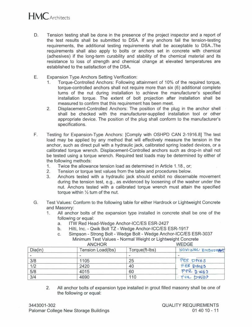
HMC Architects
D. Tension testing shall be done in the presence of the project inspector and a report of the test results shall be submitted to DSA. If any anchors fail the tension-testing requirements, the additional testing requirements shall be acceptable to DSA..The requirements shall also apply to bolts or anchors set in concrete with chemical (adhesives) if the long-term curability and stability of the chemical material and its resistance to loss of strength and chemical change at elevated temperatures are established to the satisfaction of the DSA.
E. Expansion Type Anchors Setting Verification: 1. Torque-Controlled Anchors: Following attainment of 10% of the required torque,
torque-controlled anchors shall not require more than six (6) additional complete turns of the nut during installation to achieve the manufacturer's specified installation torque. The extent of bolt projection after installation shall be measured to confirm that this requirement has been meet.
2. Displacement-Controlled Anchors: The position of the plug in the anchor shell shall be checked with the manufacturer-supplied installation tool or other appropriate device. The position of the plug shall conform to the manufacturer's specifications.
F. Testing for Expansion-Type Anchors: [Comply with OSHPD CAN 2-1916.8] The test load may be applied by any method that will effectively measure the tension in the anchor, such as direct pull with a hydraulic jack, calibrated spring loaded devices, or a calibrated torque wrench. Displacement-Controlled anchors such as drop-in shall not be tested using a torque wrench. Required test loads may be determined by either of the following methods: 1. Twice the allowance tension load as determined in Article 1.18., or; 2. Tension or torque test values from the table and procedures below. 3. Anchors tested with a hydraulic jack should exhibit no discernable movement
during the tension test, e.g., as evidenced by loosening of the washer under the nut. Anchors tested with a calibrated torque wrench must attain the specified torque within½ turn of the nut.
G. Test Values: Conform to the following table for either Hardrock or Lightweight Concrete and Masonry: 1. All anchor bolts of the expansion type installed in concrete shall be one of the
following or equal: a. ITW Red Head-Wedge Anchor-ICC/ES ESR-2427 b. Hilti, Inc. - Qwik Bolt TZ - Wedge Anchor-ICC/ES ESR-1917 c. Simpson - Strong Bolt - Wedge Bolt - Wedge Anchor-ICC/ES ESR-3037
Minimum Test Values - Normal Weight or Lightweight Concrete ANCHOR WEDGE
Dia(in) Tension Load(lbs) Torque(ft-lbs) NO\tl \l,JM..> El't\~1:,:,~ - - - - 3/8 1105 25 ~e:!C'. P1'f6.S 1/2 2420 40 "' e~ ~ t.r <s-!I 5/8 4015 60 f'E'12- Ow6-~ 3/4 4690 110 . 'f\;"L p,mo
2. All anchor bolts of expansion type installed in grout filled masonry shall be one of the following or equal:
3443001-302 Palomar College New Storage Buildings
QUALITY REQUIREMENTS 01 40 10 - 11
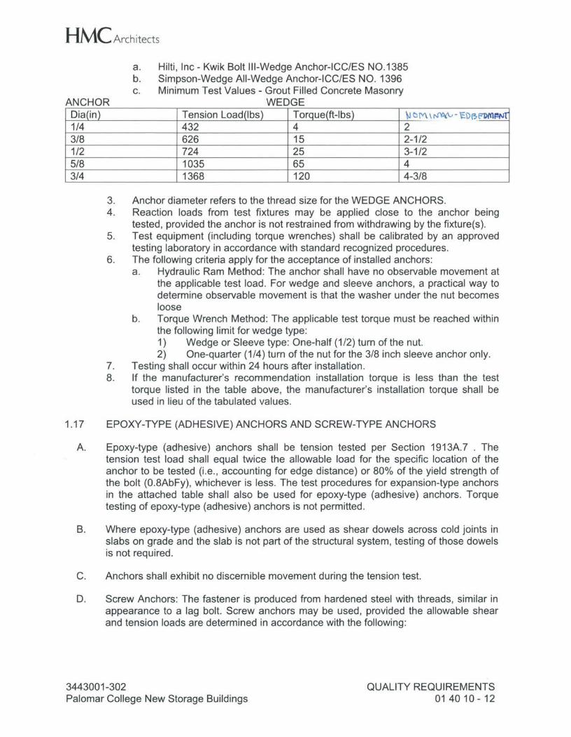
HMC Architects
ANCHOR
a. Hilti, Inc - Kwik Bolt Ill-Wedge Anchor-ICC/ES N0.1385 b. Simpson-Wedge All-Wedge Anchor-ICC/ES NO. 1396 c. Minimum Test Values - Grout Filled Concrete Masonry
WEDGE Dia(in) Tension Load(lbs) Torque(ft-lbs) \J Cl!Y\, ~- 'i:O~~l!Nt 1/4 432 4 2 3/8 626 15 2-1/2 1/2 724 25 3-1/2 5/8 1035 65 4 3/4 1368 120 4-3/8
3. Anchor diameter refers to the thread size for the WEDGE ANCHORS. 4. Reaction loads from test fixtures may be applied close to the anchor being
tested, provided the anchor is not restrained from withdrawing by the fixture(s). 5. Test equipment (including torque wrenches) shall be calibrated by an approved
testing laboratory in accordance with standard recognized procedures. 6. The following criteria apply for the acceptance of installed anchors:
a. Hydraulic Ram Method: The anchor shall have no observable movement at the applicable test load. For wedge and sleeve anchors, a practical way to determine observable movement is that the washer under the nut becomes loose
b. Torque Wrench Method: The applicable test torque must be reached within the following limit for wedge type: 1) Wedge or Sleeve type: One-half (1/2) turn of the nut. 2) One-quarter (1 /4) turn of the nut for the 3/8 inch sleeve anchor only.
7. Testing shall occur within 24 hours after installation. 8. If the manufacturer's recommendation installation torque is less than the test
torque listed in the table above, the manufacturer's installation torque shall be used in lieu of the tabulated values.
1.17 EPOXY-TYPE (ADHESIVE) ANCHORS AND SCREW-TYPE ANCHORS
A. Epoxy-type (adhesive) anchors shall be tension tested per Section 1913A. 7 . The tension test load shall equal twice the allowable load for the specific location of the anchor to be tested (i.e., accounting for edge distance) or 80% of the yield strength of the bolt (0.8AbFy), whichever is less. The test procedures for expansion-type anchors in the attached table shall also be used for epoxy-type (adhesive) anchors. Torque testing of epoxy-type (adhesive) anchors is not permitted.
B. Where epoxy-type (adhesive) anchors are used as shear dowels across cold joints in slabs on grade and the slab is not part of the structural system, testing of those dowels is not required.
C. Anchors shall exhibit no discernible movement during the tension test.
D. Screw Anchors: The fastener is produced from hardened steel with threads, similar in appearance to a lag bolt. Screw anchors may be used, provided the allowable shear and tension loads are determined in accordance with the following:
3443001-302 Palomar College New Storage Buildings
QUALITY REQUIREMENTS 01 40 10 - 12
HMC Architects 1. The allowable values listed in an ICC ES Report, with special inspection, may be
used for allowable stress design, provided the report states that the anchors were tested in accordance with AC 106, latest revisions, including the seismic qualification tests of AC106 Section 4.6.
2. Welding to these anchors is not permitted. 3. Screw anchors may be used to attach components, such as equipment,
mechanical vibration isolators or snubbers, to structural (reinforced) concrete, or for sill bolting applications. All screw anchors installed through a wood sill plate requires a plate washer in conformance with Section 2308.6.
4. The use of screw anchors is not permitted in overhead applications or for discrete hold down forces, such as shear walls.
5. Masonry Anchors: 1/4" diameter, Tapcon with Advance Threadform Technology, heat-treated steel, by Illinois Tool Works/Buildex, ICC-ESR-1671. Slotted Hex Washer Head.
E. Screw-type anchors shall be torque tested in accordance with the testing procedures in Test Values Table and procedures herein.
F. Screw-type anchors: Simpson Strong-Tie Titen-HD concrete anchor, 3/8, 1/2 and 3/4 inch diameter, ICC ESR-2713, by Simpson Strong-Tie, Pleasanton, CA or equal with ICC report number.
G. Screw-type anchors: Simpson Strong-Tie Titen-HD grout-filled CMU anchor, 3/8, 1/2, 5/8, and 3/4 inch diameter, ICC ESR-1056, by Simpson Strong-Tie, Pleasanton, CA or equal with ICC report number.
1.18 POWDER ACTUATED FASTENERS
A. Powder-Actuated Fasteners: Powder-actuated fasteners (shot pins) are not addressed by Chapter 1908A 1.1 of CBC. Powder-actuated fasteners may be used for limited application provided the allowable shear and tension loads are determined in accordance with the following: 1. The allowable values listed in an ICC ES Evaluation Services Report, with
special inspection, may be used for allowable stress design, provided the report states that the anchors were tested in accordance with AC 70, latest revision. Powder-actuated fasteners may be used for hanging metal suspension systems for lay-in panel ceilings and for the attachment of metal track in conjunction with non-bearing partitions. The use of powder-actuated fasteners for other applications shall be subject to review and approval of DSA.
B. Powder actuated fasteners (Shot Pins): Installer shall utilize tools recommended by the manufacture in compliance with the ICC code reports. Pins shall have a minimum diameter of 0.145 inch and be installed to conform to the load requirements of this Section and: 1. Tables 1 (driven into steel}, 2 (driven into concrete), and 4 (driven into Structural.
lightweight concrete) of ICC ESR-1663, Hilti or 2. Table 1 or 3 (driven into concrete), 2 (driven into steel), 5 (driven into structural
lightweight concrete), and 6 (driven in hollow concrete masonry units) of ICC ESR-2138, Simpson Strong-Tie powder-actuated fasteners or
3443001-302 Palomar College New Storage Buildings
QUALITY REQUIREMENTS 014010-13
HMC Architects 3. Table 1 and 2 (driven into concrete), 3 (driven into structural lightweight
concrete), --4 (d1 iveR il"lto Rellovo cu11c1 ete l'lie~ORPJ units~ 5 ( driven into steel) of ICC ESR-2811, Simpson Strong-Tie gas-actuated fasteners or equal with ICC report.
C. Allowable Loads: Limited to 100 lbs. maximum or 80% of ICC approved values whichever is less. Testing required.
D. Use of Powder actuated fasteners for tension loads is limited to support of minor loads such as suspended acoustical ceilings, ductwork and conduit. Permissible Loads for Ceiling Clip Assembly: 1. Normal-Weight Concrete: Ceiling Clip Assembly Hilti X-CW, minimum 0.138"
diameter, minimum penetration 1-1/8". Allowable Loads: 210 lbs. tension listed in ICC Report: ICC ESR 2184: 4000 psi Concrete Compressive Strength. a. Type X-CW X-C 32 KWIK, by Hilti, Inc., Tulsa, OK, or equal.
2. Lightweight Concrete: Ceiling Clip Assembly, minimum 0.138" diameter, minimum penetration 1-1/8". Required Allowable Loads: 150 lbs tension values listed in ICC ESR 2184: 3000 psi Concrete Compressive Strength. a. Type X-CW C-C 32, by Hilti, Inc., Tulsa, OK, or equal.
3. Use manufacture's drill bits and recommended tools.
E. Permissible Loads for Sills. Light gage steel and Interior Wood Plate Anchorages: 1. Low Velocity Power-Driven Fasteners: normal-weight concrete: Hilti OS and
X-CR (stainless steel for exterior applications), 0.177", 0.145 for X-CR, shank diameter with washers, ICC-ESR Report ER-1663, Table 2. Exterior or Perimeter Sill and Interior Plate Anchorages.
2. Low Velocity Power-Driven Fasteners: normal-weight concrete: Simpson PDPWL-300, 3 inches long, 0.300 inch head diameter and 0.145 inch shank diameter with washer, ICC ESR-2138, Table 1 or 4. Exterior or Perimeter Sill and Interior Plate Anchorages.
1.19 REQUIRED TESTING FOR POWDER ACTUATED FASTENERS
A. Testing: Operator, tool and fastener shall be pre-qualified by the Project Inspector. 1. Tools shall conform to ANSI A 10.3 safety requirements for Powder Actuated
Fastening Systems and to all OSHA requirements. 2. Manufacturer's representative shall provide safety training for all installation
personnel and provide powder actuated tool operator certification in accordance with OSHA requirements.
B. The Project Inspector shall observe the testing of the first 10 fastener installations.
C. A test pullout load of not less than twice the design load or 200 lbs., whichever is greater, shall be applied to the fastener in such a manner as not to resist the spalling tendency of concrete in which the fastener is imbedded. Thereafter, random tests under the Project Inspector's supervision shall be made of approximately 1 in 10 fasteners.
D. Should failure occur on any fastener tested, all installations shall be tested until twenty consecutive fasteners pass, then resume the initial testing frequency.
3443001-302 Palomar College New Storage Buildings
QUALITY REQUIREMENTS 01 40 10 - 14
HMC Architects
1.20 INSTALLATION
A. When installing drilled-in anchors or powder driven pins in reinforced concrete, use care and caution to avoid cutting or damaging reinforcing bars. When required by the Architect, locate the reinforcing by using a non-destructive method prior to installation. Exercise extreme care and caution to avoid cutting or damaging reinforcing during installation. Maintain a minimum clearance of one inch between the reinforcing and the anchor and/or pin.
PART 2- PRODUCTS
2.01 NOT USED
PART 3 - EXECUTION
3.01 NOT USED
END OF SECTION
3443001-302 Palomar College New Storage Buildings
QUALITY REQUIREMENTS 01 40 10 - 15
HMC Architects
SECTION 01 50 00
TEMPORARY FACILITIES AND CONTROLS
PART 1 - GENERAL
1.01 SECTION INCLUDES
A. Temporary Utilities: Electricity, lighting, heat, ventilation, telephone service, water and sanitary facilities.
B. Temporary Controls: Barriers, enclosures, fencing, protection of Work and security.
C. Construction Facilities: Access, roads parking, progress cleaning, project sign, Architect's banner, and field office trailer.
D. Special Controls: Waste disposal facilities, Water Control, Dust Control, Erosion and Sediment Control, Noise Control, Pollution Control.
E. Comply with Title 24, Part 9, California Fire Code, Chapter 14 Fire Safety During Construction and Demolition, 2012 International Fire Code with City and State Amendments during all Phases of project.
F. INTERIM LIFE SAFETY MEASURES (ILSM) requirements in this Section.
1.02 SUBMITTALS
A. Site Plan: Show temporary facilities, utility hookups, staging areas, and parking areas for construction personnel.
1.03 TEMPORARY ELECTRICITY
A. Provide temporary electrical service suitable to conduct construction operations.
B. Connect to existing power service. Power consumption shall not disrupt Owner's need for continuous service.
C. Contractor to cooperate with Owner in ascertaining prorated cost of energy used for his portion of Work.
D. Provide power outlets for construction operations with branch wiring and distribution boxes located where needed. Provide flexible power cords as required.
E. Provide feeder switch at source distribution equipment.
F. Permanent existing convenience receptacles may [not] be utilized during construction.
1.04 TEMPORARY LIGHTING
A. Provide and maintain adequate lighting for construction operations.
3443001-302 Palomar College New Storage Buildings
TEMPORARY FACILITIES AND CONTROLS 01 50 00 - 1
HMC Architects
B. Maintain lighting and provide routine repairs.
C. Permanent building lighting may be utilized during construction.
1.05 TEMPORARY HEAT
A. Provide heating devices and heat as required to maintain specified conditions for construction operations.
B. Utilize Owner's existing heat plant, extend and supplement with temporary heating devices as required to maintain specified conditions for construction operations.
C. Contractor shall pay cost of energy used. Exercise measures to conserve energy.
1.06 TEMPORARY VENTILATION
A. Ventilate enclosed areas to assist cure of materials to dissipate humidity and noxious fumes and to prevent accumulation of dust, fumes, vapors or gases.
1.07 TELEPHONE SERVICE
A. Provide, maintain and pay for two separate telephone service lines and telephone service to field office and Project Inspector's field office at time of project mobilization. Project Inspector's telephone shall be equipped with exterior, clearly audible bell.
B. Provide and pay for cellular telephone service for Project Inspector's use at time of project mobilization.
C. Provide, maintain, and pay for copy machine with 11 by 17 inch capability.
1.08 TEMPORARY WATER SERVICE
A. Provide for suitable quality water service. [Connect to existing water source for construction operations.]
B. Contractor shall pay cost of water used. Exercise measures to conserve water.
C. Extend branch piping with outlets located so water is available by hose with threaded connections.
1.09 TEMPORARY SANITARY FACILITIES
A. Provide and maintain required facilities and enclosures. Existing facilities shall not be used.
1.10 TEMPORARY FIRE PROTECTION
A. Provide fire protection during construction according to CFC Chapter 14, International Fire Code with City and State Amendments including but not limited to fire extinguisher requirements and exit access requirements.
3443001-302 Palomar College New Storage Buildings
TEMPORARY FACILITIES AND CONTROLS 01 50 00 - 2
HMC Architects
B. Conform to Title 24, Part 9, California Fire Code, Chapter 14, International Fire Code with City and State Amendments, Fire Safety During Construction/Demolition.
1.11 BARRIERS
A. Provide barriers to prevent unauthorized entry to construction areas and to protect existing facilities and adjacent properties from damage from construction operations and demolition.
B. Provide barricades required by governing authority for public rights-of-way and for public access to existing facilities.
C. Provide protection for plant life designated to remain. Replace damaged plant life.
D. Protect non-owned vehicular traffic, stored materials, site and structures from damage.
E. Provide steel trench plates, orange mesh fencing, construction site marker and other protective means to keep site and users[, Owner's personnel, visitors and students] safe, protected, and separated from ongoing construction operations. Provide temporary access at all paths of travel. Yellow warning tape is not acceptable means of separation and protection. At all open trenching operations, enclose entire trenching operation area including stockpiled backfill within orange mesh construction fencing. Provide steel trench plate "bridges" at all walkways. 1. Notify Fire Marshall at least 48-hours prior to beginning utility work in the existing
Fire Lane. 2. Allow Fire Marshall access at reasonable times during progress of the work for
inspections.
1.12 FENCING FOR CONSTRUCTION OPERATIONS
A. Construction: Commercial grade chain link fence, removable panels, 1-3/4 inch mesh, 11 gauge, top and bottom knuckled selvage (closed end). 1. Provide screen full height of fence, 1-3/4 inch mesh, 11 gauge, woven open
mesh 100% polypropylene with 78 percent wind break, reinforced tape at grommets at 18 inches centers at perimeter, attach screen to chain link fence with 11 gauge hog rings by Roxford Fordell, Los Angeles, CA.
B. Provide 6 foot high fence around construction site; equip with vehicular and pedestrian gates with locks.
C. Submit detailed fencing and construction traffic plan for review and approval by Architect.
D. At completion of project repair concrete or A.C. substrate, fill holes to match existing materials flush with adjacent surface.
1.13 STAGING AREAS
A. Coordinate with Owner for location, extent and type of construction staging area.
3443001-302 Palomar College New Storage Buildings
TEMPORARY FACILITIES AND CONTROLS 01 50 00 - 3
HMC Architects
1.14 EXTERIOR ENCLOSURES
A. Provide temporary weather-tight closure of exterior openings to accommodate acceptable working conditions and protection for products, to allow for temporary heating and maintenance of required ambient temperatures identified in individual Specification Sections, and to prevent entry of unauthorized persons. Provide access doors with hardware and locks.
1.15 INTERIOR ENCLOSURES
A. Provide temporary partitions and ceilings as required to separate Work areas from Owner occupied areas, to prevent penetration of dust and moisture into Owner occupied areas and to prevent damage to existing materials and equipment.
B. Construction: Wood framing , plywood or gypsum board sheet materials with closed joints and sealed edges at intersections with existing surfaces, translucent or opaque as directed by Owner.
C. Accessories Sets as required: ZipWall SLP: Springloaded Poles, Foam Rails, Side Clams, GripDisks, "Zip-Up" Self Adhesive Zippers. By Americover Inc. San Diego, CA. www.americover.com. or equal.
D. Paint surfaces exposed to view from Owner-occupied areas where required for rigid wall construction.
1.16 PROTECTION OF INSTALLED WORK
A. Protect installed Work and provide special protection where specified in individual Specification Sections.
B. Provide temporary and removable protection for installed products. Control activity in immediate work area to minimize damage.
C. Provide protective coverings at walls, projections, jambs, sills and openings. Provide protective and removal coverings for metal finishes intended to be exposed.
D. Prohibit traffic or storage upon waterproofed or roofed surfaces.
E. Prohibit traffic from landscaped areas.
F. Provide sticky track mats at transition areas to minimize footprints and distribution of dirt from construction areas through occupied corridors, [classrooms,] and adjacent workspaces. At carpet floors provide "Velcro Brand Carpet" protection in lieu of sticky mats.
1.17 SECURITY
A. Provide security and facilities to protect Work, existing facilities and Owner's operations from unauthorized entry, vandalism or theft.
B. Coordinate with Owner's security program.
3443001-302 Palomar College New Storage Buildings
TEMPORARY FACILITIES AND CONTROLS 01 50 00 - 4
HMC Architects
C. Within 48 hour period, replace or repair, to Architect's satisfaction, all surfaces or items damaged by graffiti during course of construction.
D. Where security or fire detection systems are disabled for any reason, including where Owner has given approval for such system shutdown, provide fire watch or security guard service as directed by Owner at no additional cost to Owner.
1.18 ACCESS ROADS
A. Construct and maintain temporary roads accessing public thoroughfares to serve construction area.
B. Extend and relocate as Work progress requires. Provide detours necessary for unimpeded traffic flow.
C. Provide and maintain access to fire hydrants, free of obstructions. Where required by local fire authority, provide and maintain a 26 foot wide fire apparatus access road.
D. Provide means of removing mud from vehicle wheels before entering streets.
E. Designated existing on-site roads may be used for construction traffic.
F. Where construction traffic occurs when students and staff are on campus , provide "spotter" responsible for leading construction traffic through site areas.
G. Route construction equipment, trucks, and similar vehicles via existing public streets to and from site as approved by governing authorities.
1.19 PARKING
A. Arrange for temporary parking areas to accommodate construction personnel.
B. When site space is not adequate, provide additional off-site parking.
1.20 PROGRESS CLEANING
A. Refer to Section 01 70 00 Execution Requirements and the requirements of this Section.
B. Maintain areas free of waste materials, debris and rubbish. Maintain site in a clean and orderly condition.
C. Remove debris and rubbish from closed or remote spaces, prior to enclosing space.
D. Broom and vacuum clean interior areas prior to start of surface finishing and continue cleaning to eliminate dust. Clean substrate; remove dirt, oil, grease, construction markings, and foreign matter that could adversely affect surface finish appearance or performance.
E. Remove waste materials, debris and rubbish from site weekly and dispose off-site.
3443001-302 Palomar College New Storage Buildings
TEMPORARY FACILITIES AND CONTROLS 01 50 00 - 5
HMC Architects
F. Maintain public streets free of mud, dust and debris and as required by jurisdictional authority.
1.21 PROJECT SIGNAGE
A. Provide project sign, as designed by Architect. Fabricate using exterior-grade plywood and wood frame construction, acrylic painted with exhibit lettering by professional sign painter. 1. List title of Project, names of Owner and State of California Office of Public
School Construction, Architect and Contractor. 2. Erect on site at locations established by mutual agreement of Owner, Architect
and Contractor.
B. Except for signs required by law, no other signs will be permitted without express written permission from Owner. Signs required by law may not obscure any of the banners.
1.22 FIELD OFFICE TRAILER(S)
A. Owner will provide space for office and project meetings.
B. Field Office Trailer: Provide field office trailer, weather tight with lighting, electrical outlets, communications capabilities, heating, cooling and ventilating equipment and equipped to adequately conduct meetings for construction operations, minimum size; 480 sq. ft. Provide restroom: facilities within trailer or chemical toilet(s) portable chemical toilet facilities. Quantity of portable chemical toilet facilities shall be based on total number of workers and shall be in accordance with CAL/OSHA standards .. 1. In SAME Field Office trailer provide separate private office similarly equipped and
furnished with desk, 2 drawer file cabinet, a table and two chairs for use by Project Inspector, Owner and Architect including plan rack suitable for 30 by 42 inch drawings, minimum size 120 square feet. Inspector's office must be lockable and have direct access to outside, provide private telephone line and access to the Internet to inspector's office.
2. Provide a SECOND separate Field Office Trailer similarly equipped as Contractor's office trailer and furnished desk, 2 drawer file cabinet, table, chairs and lockable for use by Project Inspector, Architect and Owner, provide private telephone line and access to the Internet to inspector's office, minimum size 480 sq. ft. (For Project Inspector's office trailer only, size 240 sq. ft.)
C. Cost of use permits, occupancy permits and related fees, if any required by Governing Authorities for temporary construction facilities, shall be paid by Contractor.
D. Provide 4 by 8 feet conference table, 6 conference chairs and 3 by 6 feet white markerboard at conference room.
E. Install no closer than 45 feet from project buildings in accordance with NFPA 241.
F. Maintain facility until Substantial Completion of entire project. Remove within 1 week of Substantial Completion.
3443001-302 Palomar College New Storage Buildings
TEMPORARY FACILITIES AND CONTROLS 01 50 00 - 6
HMC Architects
G. Provide property insurance and protection.
1.23 REMOVAL OF UTILITIES, FACILITIES AND CONTROLS
A. Remove temporary above grade or buried utilities, equipment, facilities, materials prior to Certified Completion inspection.
B. Remove temporary underground or overhead installations.
C. Clean and repair damage caused by installation or use of temporary Work.
D. Restore permanent facilities used during construction to original condition. Restore permanent facilities used during construction to specified condition.
1.24 RELOCATION OF UTILITIES
A. Contractor shall not have responsibility of timely removal, relocation or protection of public utility facilities that are not identified by Owner in Drawings and Specifications, in accordance with California Government Code 4215. Owner shall compensate Contractor for costs of locating and repairing damage not due to failure of Contractor to exercise reasonable care in removing and relocating such public utility facilities. If Contractor, while performing Contract, discovers public utility facilities not identified by Owner in Contract Drawings or Specifications, he shall immediately notify Owner and utility in writing. Contractor shall not be assessed liquidated damages for delay when delay was caused by failure of Owner to provide for relocation for utility facilities.
1.25 WATER CONTROL
A. Do not permit surface, rainwater or subsurface water or other liquids to accumulate in or about premises and vicinity thereof. Should such conditions be encountered or develop, control water or other liquid shall be suitably disposed of by means of temporary pumps, piping, drainage lines, troughs, ditches, dams or other methods as reviewed by Architect and approved by authority having jurisdiction.
B. Dispose of rainwater in lawful manner that will not result in flooding Project or adjoining properties nor endanger permanent Work or temporary facilities.
1.26 DUST CONTROL
A. Conduct earthwork operations in a manner to prevent windblown dust and dirt from interfering with progress of Work, Owner's activities and existing occupied structures in areas immediately adjacent as well as adjacent properties.
B. Periodically water construction areas as required minimizing accumulation of dust and dirt.
C. Water spray or cover with tarpaulins truck loads of soil to additionally minimize generation of dust and dirt from construction operations.
3443001-302 Palomar College New Storage Buildings
TEMPORARY FACILITIES AND CONTROLS 01 50 00 - 7
HMC Architects
D. Prevent dust and dirt from accumulating on walks, roadways, parking areas and from washing into sewer and storm drain lines.
1.27 EROSION AND SEDIMENT CONTROL
A. Plan and execute construction by methods to control surface drainage from cuts and fills from borrow and waste disposal areas. Prevent erosion and sedimentation.
B. Minimize amount of bare soil exposed at one time.
C. Provide temporary measures such as berms, dikes and drains to prevent water flow over adjacent properties or City rights-of-way.
D. Construct fill and waste areas by selective placement to avoid erosive surface silts or clays.
E. Periodically inspect earthwork to detect evidence of erosion and sedimentation; promptly apply corrective measures.
1.28 NOISE CONTROL
A. Avoid excessive noise where adjacent Owner's functions may be detrimentally affected.
B. Refer to requirements in Section 01 57 20, Control of Construction Noise.Noise Control Plan: Submit Noise Control Plan after the Contract is awarded, prior to the commencement of the work, Contractor shall meet with the Owner to discuss the proposed Noise Control Plan and to develop mutual understanding relative to details of the Plan. 1. The Noise Control Plan shall comply with the constraints set forth by the Owner,
and be in compliance with the noise control laws of the City of San Marcos. 2. Submit a description of the instruments to be used in monitoring noise. 3. Show the areas and boundaries where noisy work will occur. 4. Approval of the Contractor's Noise Control Plan will not relieve the Contractor of
responsibility for proper and continuing control of noise throughout the project site.
1.29 POLLUTION CONTROL
A. Provide methods, means and facilities to prevent contamination of soil, water and atmosphere from discharge of noxious, toxic substances and pollutants produced by construction operations.
B. Burning of refuse, debris or other materials will not be permitted on Site.
C. Comply with regulatory requirements and anti-pollution ordinances during course of construction and disposal operations.
3443001-302 Palomar College New Storage Buildings
TEMPORARY FACILITIES AND CONTROLS 01 50 00 - 8
HMC Architects
1.30 WASTE DISPOSAL FACILITIES
A. Comply with requirements of Authorities Having Jurisdiction. Remove loose refuse and dispose off site legally.
B. Provide waste-collection containers in sizes adequate to handle waste from construction operations.
C. Provide and maintain trash bins on the Project site. Trash bins shall be serviced on an as needed basis.
1.31 PROTECTION OF EXISTING FACILITIES AND SITEWORK
A. Provide site plan of proposed route of construction equipment for approval by Owner.
B. Use caution to minimize disturbance and damage to existing landscaped areas and sitework.
C. Protect sidewalks, curbs, entry areas and utilities.
D. The Contractor shall preserve and protect all structures, equipment, and vegetation (such as trees, shrubs, and grass) and irrigation on or adjacent to the work site, which are not to be removed and which do not unreasonably interfere with the work required under this contract.
E. Protect from damage all existing improvements and utilities at or near the work site and on adjacent property of a third party, the locations of which are made known to or should be known by the Contractor. Repair any damage to those facilities, including those that are the property of a third party, resulting from failure to comply with the requirements of this contract or failure to exercise reasonable care in performing the work.
F. Repair landscaped areas, irrigation and sidewalks and any other damaged facilities where trucks, erection equipment or other construction equipment was used in removal and replacement of the HVAC units during construction. Repair damaged areas to match existing construction to satisfaction of the Owner, and at no additional cost to the Owner.
1.32 CONTRACTOR CONDUCT AND DRESS CODE
A. Contractor's and subcontractors' personnel shall observe and abide by Owner requirements concerning appropriate conduct, loud noise (unrelated to construction activities) and dress requirements for a safe and un-disturbing work place. Conduct work activities in a professional manner at all times.
B. Dress Code requirements: contractor's personnel shall wear traditional work attire or uniforms without logos, graphics or wording detrimental to work [school] environment; unless logos, graphics or wording are for business identification purposes.
3443001-302 Palomar College New Storage Buildings
TEMPORARY FACILITIES AND CONTROLS 01 50 00 - 9
HMC Architects
C. Identification badges issued by the Owner shall be worn at all times, worn on the left side shirt-pocket area, displayed in full view and not concealed.
D. No radios permitted.
E. Owner reserves the right to remove any person(s) not observing conduct and dress requirements specified herein.
1.33 MOBILIZATION AND DEMOBILIZATION
A. The work consists of the mobilization and demobilization of the contractor's forces and equipment necessary for performing the work required under the contract. It does not include mobilization and demobilization for specific items of work for which payment is provided elsewhere in the contract. Mobilization will not be considered as work in fulfilling the contract requirements for commencement of work.
B. Mobilization: Equipment and Material: Mobilization shall include all activities and associated costs for transportation of contractor's personnel, equipment, and operating supplies to the site; establishment of offices, buildings, and other necessary general facilities for the contractor's operations at the site; premiums paid for performance and payment bonds including coinsurance and reinsurance agreements as applicable.
C. Demobilization shall include all activities and costs for transportation of personnel, equipment, and supplies not required or included in the contract from the site; including the disassembly, removal, and site cleanup of offices, buildings, and other facilities assembled on the site specifically for this contract.
D. This work includes mobilization and demobilization required by the contract at the time of award. If additional mobilization and demobilization activities and costs are required during the performance of the contract as a result of changed, deleted, or added items of work for which the contractor is entitled to an adjustment in contract price, compensation for such costs will be included in the price adjustment for the item or items of work changed or added.
E. Payment: Payment will be made as the work proceeds, after presentation of paid invoices or documentation of direct costs by the contractor showing specific mobilization and demobilization costs and supporting evidence of the charges of suppliers, subcontractors, and others. When the total of such payments is less than the lump sum contract price, the balance remaining will be included in the final contract payment. Payment of the lump sum contract price for mobilization and demobilization will constitute full compensation for completion of the work.
F. Payment will not be made under this item for the purchase costs of materials having a residual value, the purchase costs of materials to be incorporated in the project, or the purchase costs of operating supplies.
3443001-302 Palomar College New Storage Buildings
TEMPORARY FACILITIES AND CONTROLS 01 50 00 - 10
HMC Architects
1.34 INTERIM LIFE SAFETY MEASURES (ILSM)
A. The Interim Life Safety Measures (ILSM) itemized below are a series of administrative actions that must be taken to compensate for the hazards posed by NFPA 101 - 2003 Life Safety Code (LSC) deficiencies temporarily caused by construction activities. In addition, the ILSM shall include all applicable sections of NFPA 241, Safeguarding Construction, Alteration, and Demolition Operations, a copy of which shall be maintained at the site by the Contractor for reference.
B. ILSM must be implemented in, or adjacent to, all construction areas within the scope of work of this contract. ILSM apply to all construction personnel, including personnel of the General Contractor, Sub-contractors, Vendors, Suppliers, and any other personnel under the supervision and coordination of the General Contractor. ILSM shall be continuously enforced by the Contractor throughout the duration of the Contract. The Contractor shall comply with all the ILSM and shall be responsible and liable for the consequences of failing to comply, including a Type 1 Deficiency issued by the Joint Commission on Accreditation of Health Organization (JCAHO) and the loss of the Owner's JCAHO accreditation.
C. The Contractor shall ensure that exits provide free and un-obstructive egress. 1. Unless provided elsewhere, the Contractor shall provide a Construction Egress
Plan, showing temporary barricades, egress paths, and exits from, around, and (if necessary through) the construction area. Temporary exits shown on the Plan must be identified with exit signs approved by the local authority having jurisdiction.
2. The Contractor shall present the Plan to and obtain approval from the Owner and the local authority having jurisdiction prior to implementation.
3. The Contractor, in conjunction with the Owner, shall conduct an ILSM meeting prior to the commencement of the work. The purpose of the meeting will be to present the Construction Egress Plan and to review the ILSM. The meeting shall be attended by the Owner's and the Contractor's designated personnel. The Contractor is responsible to present the ILSM to all personnel under his supervision and coordination, whether or not they attend the ILSM meeting.
4. The Contractor shall update and revise as required by construction progress and phasing.
5. The paths of egress and exits shown on the Plan must be inspected daily and maintained at all times.
6. Where temporary alternate exits cannot be provided, the Contractor shall provide a continuous, 24 hour per day Fire Watch, consisting of one designated person per floor assigned solely to observing and reporting fire and life safety conditions and hazards to the General Contractor and the Owner, as well as initiating any required code red alarms.
D. The Contractor shall ensure free and unobstructed access to emergency departments and services for emergency forces.
E. The Contractor shall ensure that fire alarm, detection, and suppression systems, as well as structural and compartmentation features of fire safety outside the construction area are not impaired or compromised.
3443001-302 Palomar College New Storage Buildings
TEMPORARY FACILITIES AND CONTROLS 01 50 00 - 11
HMC Architects 1. When the existing fire systems or fire safety features outside the construction
area must be impaired or compromised a temporary but equivalent system or feature shall be provided. All temporary systems must be tested and inspected monthly.
2. In lieu of temporary systems or features, the Contractor may provide a Fire Watch as described in Item C.6 above and other measures as required by the authority having jurisdiction.
F. The Contractor shall ensure that temporary construction barricades and barricade doors are smoke tight and made of non-combustible or limited combustible materials that will not contribute to the development of smoke or fire.
G. The Contractor shall provide additional fire-fighting equipment and user-training for his personnel.
H. The Contractor shall ensure the prohibition of smoking by his personnel in accordance with MA.1.3.15 of the "Management and Administrative Service" manual, Volume 1, a copy of which shall be provided to the Contractor by the Owner.
I. The Contractor shall develop and enforce storage and debris-removal practices that reduce the flammable and combustible fire load of the construction area to the lowest level necessary for daily operations.
J. The Contractor shall conduct a minimum of one fire drill every month throughout the duration of the project.
K. The Contractor shall provide daily hazard surveillance of the construction area with special attention to excavations, construction storage, and field offices. ]
PART 2 - PRODUCTS
2.01 MATERIALS
A. Materials for temporary work may be new or used. 1. Use materials that are adequate in capacity for the required use and loads. 2. Do not use materials that would create unsafe conditions. 3. Do not violate requirements of authorities having jurisdiction. 4. Sticky Track Mats: Trim-Tack Adhesive mats by Markell Industries, Manchester,
CT or equal. At carpet floors provide "Velcro Brand Carpet" protection in lieu of sticky mats.
B. Electrical Materials 1. Power Receptacles: 15 ampere, 120 volt, duplex grounding type with ground
fault circuit interrupters. Furnish in suitable boxes with hinged cover plates. 2. Light Fixtures and Lamps: Medium-base, rubber pigtail, type lamp sockets or
porcelain lampholders furnish with boxes, and lamps. 3. Conductors: insulated copper or aluminum, with phase conductor insulation
rated for the circuit voltage, and insulation or jacketing suitable for the conditions, and branch circuit conductors - No. 12 AWG minimum size, except No. 10 AWG where length of branch circuit exceeds 100 feet.
3443001-302 Palomar College New Storage Buildings
TEMPORARY FACILITIES AND CONTROLS 01 50 00 - 12
HMC Architects
C. Mechanical Materials 1. Portable Equipment may be new or used, temporary units that will not damage
construction materials or processes, that will not create unhealthy conditions for workers, and that can be operated with approval from the authorities having jurisdiction.
2. Fixed Equipment may be new or used, temporary or permanent, devices including any heat generating or cooling equipment that can be operated in a safe manner and with approval from the authorities having jurisdiction.
3. Fuel. Use only devices that burn either natural gas or fuel oil. a. Store fuel oil in portable tanks with a 60 gallon maximum capacity, located
on the same level as the devices, and equipped with fills and vents outside the enclosed space.
b. Locate the tanks a minimum of 10 feet from heating devices. Label tanks with proper type of fuel.
c. Biodiesel Fuel: B20 blend, 20% vegetable oil and 80% petrodiesel, per ASTM D7467-10.
d. Diesel engines: no equipment/engine modification required for B20 biodiesel.
4. Biodiesel Fuel. Use on-site construction equipment, vehicles that burn biodiesel fuel, supplier-transportation vehicles. a. Store fuel oil in portable tanks with a 500 gallon maximum capacity, located
on the same level as the devices, and equipped with fills and vents outside the enclosed space.
b. Locate the tanks a minimum of 10 feet from heating devices. Label tanks with proper type of fuel.
c. Biodiesel Fuel: B20 blend, 20% vegetable oil and 80% petrodiesel, per ASTM D7467-10.
d. Diesel engines: no equipment/engine modification required for B20 blend biodiesel.
e. Administrative Requirements: Refer to Section 01 35 43 Special Environmental Requirements for LEED Credits.
PART 3 - EXECUTION
3.01 REMOVAL
A. Remove all temporary control measures in accordance with regulatory requirements at completion of construction.
END OF SECTION
3443001-302 Palomar College New Storage Buildings
TEMPORARY FACILITIES AND CONTROLS 01 50 00 - 13
HMC Architects
SECTION 01 57 23
STORM WATER POLLUTION CONTROL
PART 1 - GENERAL
1.01 SUMMARY
A. Section Includes 1. Preparation, implementation, and monitoring of Storm Water Pollution Prevention
Plan (SWPPP) for the purpose of preventing the discharge of pollutants from the Project site into receiving waters. This includes the elimination of pollution discharges such as improper dumping, storm water that has been in contact with pollutants, erosions, spills or leakage from storage tanks or transfer areas.
2. Compliance with local, state, and federal regulations. 3. Payment of application and annual fees required by the State Water Resources
Control Board (SWRCB) up until the date of Substantial Completion. 4. Certification the Project has met all of the conditions of the General Construction
Activity Storm Water Permit (GCASP).
B. Related Sections 1. Section 01 50 00: Temporary Facilities and Controls 2. Section 01 70 00: Execution Requirements
1.02 SUBMITTALS
A. Provide documentation in accordance with specific requirements of approved SWPPP.
B. Retain the following documents on site until Substantial Completion. 1. Copy of NOi and supporting documents 2. SWPPP and Monitoring Program
C. Retain the following documents on site until Substantial Completion. Upon Substantial Completion, forward all required documentation to Architect. 1. Inspection Records. 2. Annual Compliance Certification. 3. Noncompliance Reporting. 4. Training Records.
1.03 QUALITY ASSURANCE
A. Comply with the following as a minimum requirement: California Storm Water Best Management Practice Handbook for Construction Activity (BMP Handbook) Current adopted edition.
3443001-302 Palomar College New Storage Buildings
STORM WATER POLLUTION CONTROL 01 57 23 - 1
HMC Architects
PART 2 - PRODUCTS
2.01 MATERIALS
A. Provide the quality, grade and type of materials as specified in Best Management Practice, BMP, Handbook
PART 3 - EXECUTION
3.01 PREPARATION AND SUBMITTAL
A. Prepare and submit to the Architect within ten (10) days after the date established in the Notice to Proceed, four (4) copies of the Storm Water Pollution Prevention Plan (SWPPP) as required to comply with storm water pollution regulations for Project site.
B. District will establish Project File with State Water Resources Board at http://smarts.waterboards.ca.gov .
C. Submit, along with NOi, the appropriate application fee made payable to: State Water Resources Control Board.
D. For new or existing Project sites with land disturbance of less than one (1) acre a Notice of Intent (NOi) is not required, however any BMP indicated in BMP Handbook required to prevent or minimize storm water pollution shall be implemented at no cost to OWNER. CONTRACTOR shall prepare and submit to Architect a SWPPP for review and approval by OWNER.
E. In addition to the above requirements, new or existing Project sites with land disturbance of one (1) or more acres, submit to Architect, a Notice of Intent (NOi) with the appropriate filing fee. Pay annual renewal fees until Substantial Completion of the Work. No progress payment will be made to CONTRACTOR until CONTRACTOR has prepared and obtained Architect approval of the plan in addition to, if required, a properly prepared Notice of Intent with the appropriate filing fee to OWNER.
F. Prepare SWPPP by following the format in Chapter 2 of the BMP Handbook. The publication is available from www.cabmphandbooks.com :
Blue Print Service Los Angeles County Department of Public 1700 Jefferson Street Works, Cashier's Office
900 S. Fremont Avenue Oakland, CA 94612 Alhambra, CA 91803
3.02 IMPLEMENTATION
A. Install perimeter controls prior to starting Work at the Project site.
B. Contain on-site storm water on the Project site. Do not drain on-site water directly into the storm drain.
3443001-302 Palomar College New Storage Buildings
STORM WATER POLLUTION CONTROL 01 57 23 - 2
HMC Architects
C. Designate trained personnel for the proper implementation of the SWPPP.
D. Revise SWPPP to suit changing Project site conditions and also when properly installed systems are ineffective.
E. Upon Substantial Completion: 1. Leave storm water pollution prevention controls in place when required for
post-construction storm water management and remove those that are not needed as determined by Civil Engineer. OWNER will maintain prevention controls left in place.
2. Provide Site Monitoring Reports, SWPPP revisions, Compliance Certifications and related documents to Architect. Post-construction storm water operation and the management plan as mentioned in the compliance certifications are considered to be in place at Substantial Completion.
3. Notice of Termination (NOT)
3.03 MONITORING
A. Conduct examination of pollution prevention controls and provide Site Monitoring Reports on a monthly basis, as well as before and after each storm and each day during storm events. Prepare and maintain, at the Project site, a log of each inspection using Site Monitoring Report forms. Notify to RWQCB within 30 days if there is any noncompliance.
B. CONTRACTOR shall provide proof annually (no later than July 1) that construction activities are in compliance with SWPPP. Non-compliance shall be reported to OAR immediately.
3.04 SPECIAL MONITORING OF RUNOFF
A. CONTRACTOR is responsible for providing proper storage of tools and materials. If rain or storm water run off comes in contact with pollutants (such as soil stabilizers, paint or fluid from vehicles) report to Architect immediately. CONTRACTOR will be required to sample and remediate contaminated water.
3.05 LIABILITIES AND PENAL TIES
A. Review of the SWPPP and inspection log by Architect shall not relieve CONTRACTOR from liabilities arising from non-compliance of storm water pollution regulations.
B. Payment of penalties for non-compliance by CONTRACTOR shall be the sole responsibility of CONTRACTOR.
C. Compliance with the Clean Water Act pertaining is the sole responsibility of CONTRACTOR. Any fine against OWNER due to non-compliance by CONTRACTOR, OWNER shall recover all costs of the fine by appropriate OWNER Assessment.
3443001-302 Palomar College New Storage Buildings
STORM WATER POLLUTION CONTROL 01 57 23 - 3
HMC Architects
3.06 CHANGE OF INFORMATION
A. Submit to Architect completed NOi Form for change of information (Construction Site Information and Material Handling/Management Practices).
3.07 NOTICE OF TERMINATION
A. Upon Substantial Completion CONTRACTOR shall submit a Notice of Termination (NOT) to Architect.
3.08 ATTACHMENTS
A. Attachment A - Site Monitoring Report.
B. Attachment B - Compliance Certification.
END OF SECTION
3443001-302 Palomar College New Storage Buildings
STORM WATER POLLUTION CONTROL 01 57 23 - 4
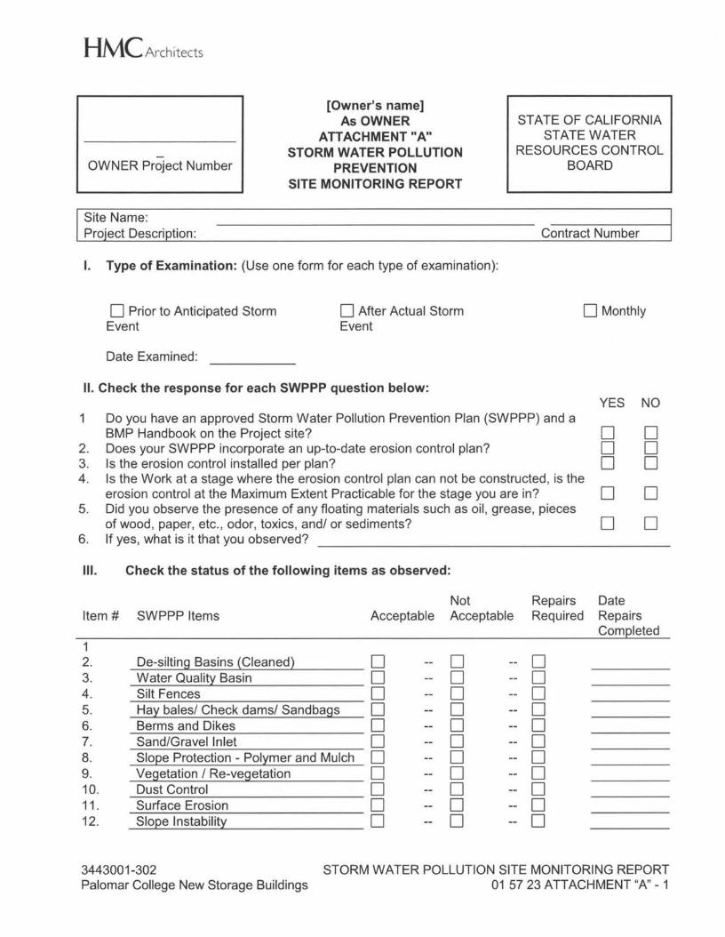
HMC Architects
- OWNER Project Number
[Owner's name] As OWNER
ATTACHMENT "A" STORM WATER POLLUTION
PREVENTION SITE MONITORING REPORT
STATE OF CALIFORNIA STATE WATER
RESOURCES CONTROL BOARD
Site Name: Proiect Descri tion: Contract Number
I. Type of Examination: (Use one form for each type of examination):
D Prior to Anticipated Storm Event
Date Examined:
D After Actual Storm Event
D Monthly
II. Check the response for each SWPPP question below: YES NO
1 Do you have an approved Storm Water Pollution Prevention Plan (SWPPP) and a BMP Handbook on the Project site? D
2. Does your SWPPP incorporate an up-to-date erosion control plan? D 3. Is the erosion control installed per plan? D 4. Is the Work at a stage where the erosion control plan can not be constructed, is the
erosion control at the Maximum Extent Practicable for the stage you are in? D 5. Did you observe the presence of any floating materials such as oil, grease, pieces
of wood, paper, etc., odor, toxics, and/ or sediments? D 6. If yes, what is it that you observed?
Ill. Check the status of the following items as observed:
D D D D D
Not Repairs Date Item# SWPPP Items Acceptable Acceptable Required Repairs
Com~leted 1 2. De-silting Basins {Cleaned} D D -- D 3. Water Qualitt Basin D D -- D 4. Silt Fences D D -- D 5. Hay bales/ Check dams/ Sandbags D D -- D 6. Berms and Dikes D D -- D 7. Sand/Gravel Inlet D D -- D 8. Slo~e Protection - Polymer and Mulch D D -- D 9. Vegetation / Re-vegetation D D -- D 10. Dust Control D D -- D 11. Surface Erosion D D -- D 12. Slo~e Instability D D -- D
3443001-302 STORM WATER POLLUTION SITE MONITORING REPORT Palomar College New Storage Buildings 01 57 23 ATTACHMENT "A" - 1
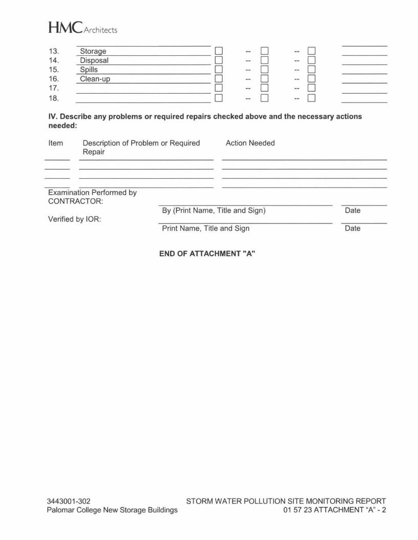
HMC Architects 13. Storage D D -- D 14. DiSQOSal D D -- D 15. SQills D D -- D 16. Clean-LIQ D D -- D 17. D D -- D 18. D D -- D IV. Describe any problems or required repairs checked above and the necessary actions needed:
Item Description of Problem or Required Repair
Action Needed
Examination Performed by CONTRACTOR:
By (Print Name, Title and Sign) Date Verified by IOR:
Print Name, Title and Sign Date
END OF ATTACHMENT "A"
3443001-302 STORM WATER POLLUTION SITE MONITORING REPORT Palomar College New Storage Buildings 01 57 23 ATTACHMENT "A" - 2
HMC Architects
OWNER Project Number
[Owner's name] As OWNER
ATTACHMENT "B" GENERAL CONSTRUCTION ACTIVITY
STORM WATER PERMIT COMPLIANCE
STATE OF CALIFORNIA ST ATE WATER BOARD WDIDNO. -----
Site Name: Protect Descri tion: Contract Number
ANNUAL CERTIFICATION
I certify the Project has met the following conditions: All elements of the Storm Water Pollution Prevention Plan are in place; construction materials and equipment maintenance waste have been disposed of properly; and the Project site is in compliance with all local storm water management requirements including erosion/sediment control requirements, and the appropriate use permits have been obtained.
CONTRACTOR:
Print Name:
Signature:
Title: ----------------- Date:
SUBSTANTIAL COMPLETION CERTIFICATION
I certify the Project has been completed and the following conditions have been met: All elements of the Storm Water Pollution Prevention Plan have been completed; construction materials and equipment maintenance waste have been disposed of properly; the Project site is in compliance with all local storm water management requirements including erosion/sediment control requirements and the appropriate use permits have been obtained; and a post construction storm water operation, and management plan is in place.
CONTRACTOR: Print Name: Signature:
Title: ----------------- Date: -----------------
END OF ATTACHMENT "B"
<>.c HMC
STORM WATER PERMIT COMPLIANCE 01 57 23 ATTACHMENT "B" - 1
HMC Architects
SECTION 01 60 00
PRODUCT REQUIREMENTS
PART 1 - GENERAL
1.01 SECTION INCLUDES
A. Products
B. Transportation and handling.
C. Storage and protection.
D. Product options.
E. Substitutions
1.02 PRODUCTS
A. Product: means new material, machinery, components, equipment, fixtures and systems forming Work. Does not include machinery and equipment used for preparation, fabrication, conveying and erection of Work. Products may also include existing materials or components required for reuse.
B. Do not use materials and equipment removed from existing premises, except as specifically permitted by Contract Documents.
C. Provide interchangeable components from the same manufacturer.
1.03 TRANSPORTATION AND HANDLING
A. Transport and handle products in accordance with manufacturer's instructions.
B. Promptly inspect shipments to assure that products comply with requirements, quantities are correct and products are undamaged.
C. Provide equipment and personnel to handle products by methods to prevent soiling, disfigurement or damage.
1.04 STORAGE AND PROTECTION
A. Store and protect products in accordance with manufacturer's instructions, with seals and labels intact and legible. Store sensitive products in weather-tight, climate controlled enclosures.
B. For exterior storage of fabricated products, place on sloped supports, above ground and protect as necessary to prevent deterioration or damage to the product.
3443001-302 Palomar College New Storage Buildings
PRODUCT REQUIREMENTS 01 60 00 - 1
HMC Architects
C. When approved by the Owner, provide off-site storage and protection in a bonded warehouse approved by Owner when site does not permit on-site storage or protection at no cost to Owner.
D. Cover products subject to deterioration with impervious sheet covering. Provide ventilation to avoid condensation.
E. Store loose granular materials on solid flat surfaces in well-drained area. Prevent mixing with foreign matter.
F. Provide equipment and personnel to store products by methods to prevent soiling, disfigurement or damage.
G. Arrange storage of products to permit access for inspection. Periodically inspect to ensure products are undamaged and are maintained under specified conditions.
1.05 PRODUCT OPTIONS
A. Where products are specified by reference standards or by description only, provide products meeting those standards or that description, made by a manufacturer acceptable to Architect.
B. Where products are specified by naming one or more manufacturers, provide products of one of the named manufacturers that meets or exceeds specifications.
C. Where any specific article, device, equipment, product, material, fixture, patented process, form, method, or type of construction is indicated or specified by name, make, trade name, or catalog number, whether with or without the phrase "or equal," such specification shall be deemed to establish the minimum qualities of function, dimension, appearance, and performance (collectively the Basis of Design) for that material, process, or article. Such specification shall be deemed to be followed by the phrase "or equal."
D. If a named product, or named manufacturer's equivalent product does not fully meet the specification, that manufacturer shall provide a custom or modified product to meet the specification.
E. Where expressly noted "no substitutions" in individual Sections, no product options are permitted.
F. When the phrase "or equal" is used or implied, it shall mean "an equivalent product, approved by the Architect in accordance with the requirements of this Section."
G. Products, proposed as substitutions, shall conform to requirements listed in the respective Section of this Manual and have at least 10 successful installations in commercial projects similar in scale and complexity to those required for this Project that have been in service for minimum of 5 years and remain in satisfactory condition.
3443001-302 Palomar College New Storage Buildings
PRODUCT REQUIREMENTS 01 60 00 - 2
HMC Architects
1.06 SUBSTITUTIONS
A. Manufacturers and products listed in Specifications form basis for design and quality intended. Bidders may propose substitutions of equal design and quality and must be accompanied by completed Request Form included at end of this Section, other forms not permitted. Submit separate form for each proposed substitution. Except for Sections listed in Section 09 06 00 Schedules for Finishes that require submittal prior to bid, all substitution requests shall be submitted as required herein. 1. Substitution requests, if any, shall be submitted to Architect within 35 calendar
days after Contract Award. Architect will issue acceptance or rejection of request.
B. Substitutions must clearly be in Owner's best interest because of quality, cost, performance, conformity to code requirements or availability. Architect will make decision as to acceptance of proposed substitution. 1. Submittal of proposed substitutions shall be made only by Prime Contractor(s).
Architect will not review direct submittal by manufacturers, suppliers or subcontractors.
2. Burden of proof as to equality of any material, process or article shall rest with Contractor. Provision authorizing submissions of "or equal" justification data shall not in any way authorize an extension of time for performance of this Contract.
3. Substitutions shall, without exception, be manufactured of same basic materials and comply with or exceed all Specification requirements of dimension, function, structure and appearance, without deviation. Provide itemized comparison of quality and performance.
4. Use of approved substitutions shall in no way relieve Contractor from responsibility for compliance with Contract Documents after installation. Contractor shall assume all extra costs caused by use of approved substitute materials.
5. Statement indicating why specified material or product cannot be provided. 6. Coordination information, including list of changes or modifications needed to
other parts of Work and to construction performed by Owner and separate contractors that will be necessary to accommodate proposed substitution.
7. Detailed side by side comparison of significant qualities of proposed substitution with those of the Work specified. Mark clearly affected specification Section for any differences from item specified. Significant qualities may include attributes such as performance, weight, size, durability, visual effect and specific features and requirements indicated.
8. Product Data Samples, including drawings and descriptions of products and fabrication and installation procedures.
9. List of similar installations for completed projects with project names and addresses and names and addresses of Architects and Owners.
10. Material test reports from qualified testing agency indicating and interpreting test results for compliance with requirements indicated.
11. Cost information, including a proposal of change, if any, in the Contract Sum. 12. Substitutions for specified product, brand or manufacture that have been
submitted and disapproved by Architect shall not be resubmitted in any modified form.
13. In case materials are substituted and installed without proper authorization, Contractor shall remove such materials and install those specified at his own expense.
3443001-302 Palomar College New Storage Buildings
PRODUCT REQUIREMENTS 01 60 00 - 3
HMC Architects 14. Contractor shall determine effect approved substitutions will have on other
portions of Work and so inform his subcontractors and employees of these effects.
15. Acceptance of proposed substitution shall be determined solely by specifying Architect. The final decision shall be the Architect's in accordance with the General Conditions.
C. Substitutions may be considered when product becomes unavailable through no fault of Contractor. Provide letter from manufacturer, on manufacturer's letterhead, stating lack of availability.
D. Unacceptable Substitutions: substitution requests initiated by late submittals that have caused materials to become unavailable due to delay in ordering and procurement will not be acceptable reason for substitutions.
E. Provide same warranty for substitution as for specified product.
F. Contractor shall pay costs for time required by Architect for review and for any redesign services associated with substitutions and for costs of re-approval by Regulatory Agencies.
G. Substitutions will not be considered when they are indicated or implied on shop drawing or product data submittals, without separate written request.
H. Each subcontractor is responsible for providing products and construction methods compatible with products and construction methods of other subcontractors. If dispute arises between subcontractors over concurrently selectable but incompatible products, Architect will determine which products shall be used.
I. Substitution Submittal Procedure: In accordance with Division 01, General Requirements for Administrative Requirements and this Section.
J. All Substitutions for any material, system or product that would otherwise be regulated by DSA shall be included in an Addendum or Form DSA-140, and shall be approved by DSA prior to fabrication or use. (CAC Section 4-338(c) and IR A-6)
1.07 OWNER-FURNISHED, OWNER-INSTALLED WORK (OFOI)
A. Indicate in construction progress schedule owner-furnish owner-installed items and schedule time for installation.
B. Items indicated on Drawings as OFOI will be furnished by Owner and installed by Owner. Work indicated as OFOI will be performed under separate contract employees by Owner at its discretion. Where work of this Contract adjoins or conflicts with OFOI, work, Contractor shall cooperate with Owner and its employees in manner that will provide for reasonable and accurate completion of this Contract and work under separate contact.
C. Coordinate with OFOI work affecting this contract. Including verification and interfacing of this contract with OFOI work.
3443001-302 Palomar College New Storage Buildings
PRODUCT REQUIREMENTS 01 60 00 - 4
HMC Architects
1.08 OWNER-FURNISHED, CONTRACTOR-INSTALLED WORK (OFCI)
A. Indicate in the construction progress Schedule Owner-Furnish Contractor-Installed items and schedule time for their installation.
B. Contractor shall verify exact sizes and services required for each item of equipment indicated on Drawings or in Project Manual as OFCI and shall obtain from Owner rough-in drawings, diagrams, setting templates and other necessary information to ensure proper mating of assemblies.
C. Contractor shall receive at project site each item of equipment from Owner and from that time on shall assume full responsibility for items and equipment until one year from date of Certified Completion.
D. Contractor shall give Owner 15 days prior notice of requirements for delivery to site of all OFCI equipment.
E. Contractor shall be responsible for receiving OFCI items and equipment and shall uncrate, inspect and notify Owner in writing within 7 days of receiving said items or equipment of acceptance or rejection of items or equipment. Owner, after receiving notice, will take appropriate action to have items or equipment made acceptable for Contractor's use. Rejected items shall be carefully stored and protected from damage by Contractor until Owner takes appropriate action.
F. Contractor shall be responsible for final placing, installation, connection, start-up, checking, testing and demonstrated satisfactory operation. Owner will provide names of manufacturer's representatives, who shall assist the Contractor in checking, testing and demonstrating equipment.
PART 2 - PRODUCTS
2.01 NOT USED
PART 3 - EXECUTION
3.01 NOT USED
END OF SECTION
3443001-302 Palomar College New Storage Buildings
PRODUCT REQUIREMENTS 01 60 00 - 5
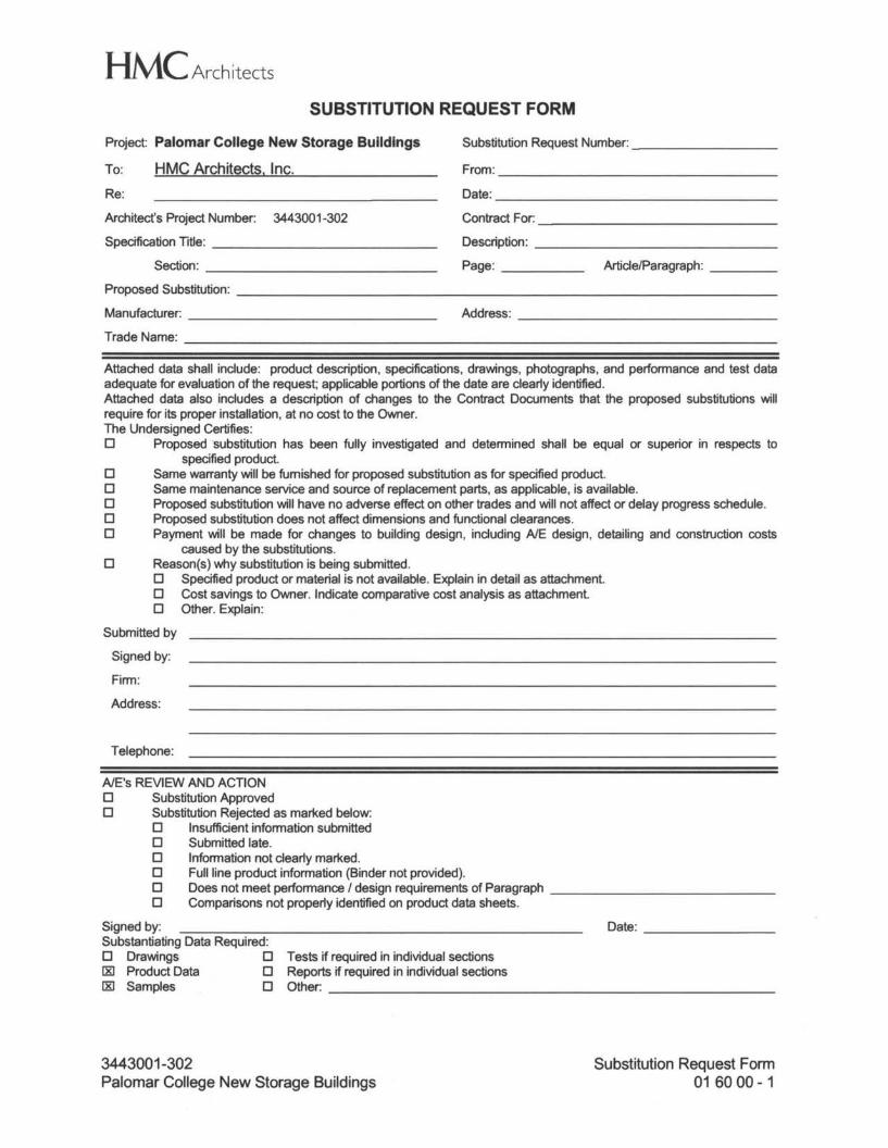
HMC Architects SUBSTITUTION REQUEST FORM
Project: Palomar College New Storage Buildings
To:
Re:
Architect's Project Number: 3443001-302
HMC Architects, Inc.
Substitution Request Number: _
From: _
Specification Title: _
Section: _
Proposed Substitution: --------------------------------- Manufacturer: _
Trade Name: ------------------------------------
Date: _
Contract For: _
Description: _
Page: _ Article/Paragraph: _
Address: _
Attached data shall include: product description, specifications, drawings, photographs, and performance and test data adequate for evaluation of the request; applicable portions of the date are clearly identified. Attached data also includes a description of changes to the Contract Documents that the proposed substitutions will require for its proper installation, at no cost to the Owner. The Undersigned Certifies: D Proposed substitution has been fully investigated and determined shall be equal or superior in respects to
specified product. D Same warranty will be furnished for proposed substitution as for specified product. D Same maintenance service and source of replacement parts, as applicable, is available. D Proposed substitution will have no adverse effect on other trades and will not affect or delay progress schedule. D Proposed substitution does not affect dimensions and functional clearances. D Payment will be made for changes to building design, including A/E design, detailing and construction costs
caused by the substitutions. D Reason(s) why substitution is being submitted.
D Specified product or material is not available. Explain in detail as attachment. D Cost savings to Owner. Indicate comparative cost analysis as attachment. D Other. Explain:
Submitted by
Signed by:
Firm:
Address:
Telephone:
A/E's REVIEW AND ACTION D Substitution Approved D Substitution Rejected as marked below:
D Insufficient information submitted D Submitted late. D Information not clearly marked. D Full line product information (Binder not provided). D Does not meet performance/ design requirements of Paragraph _ D Comparisons not properly identified on product data sheets.
Signed by: Substantiating Data Required: D Drawings D Tests if required in individual sections 00 Product Data D Reports if required in individual sections [&] Samples D Other: _
Date: _
3443001-302 Palomar College New Storage Buildings
Substitution Request Form 01 60 00 - 1
HMC Architects
SECTION 01 70 00
EXECUTION AND CLOSEOUT REQUIREMENTS
PART 1 - GENERAL
1.01 ACRONYMS, ABBREVIATIONS AND DEFINITIONS
A. CAC - 2013 California Administrative Code (CCR Title 24, Part 1 as adopted and amended by DSA)
B. CFC - 2013 California Fire Code 1. CFC-26 - CFC Chapter 26, Welding and Hot Work
C. Debris. Unless expressly specified or directed to be salvaged for the Owner's benefit, materials such as trash, rubbish, empty packaging, excess construction materials, removed materials generated from demolition, including concrete ruble, bricks, fencing, etc., unsuitable soils and materials resulting from site clearing , brush and tree removal are debris.
D. DSA - Division of State Architect, a division of California Department of General Services
E. Emergency Contact for Service means an employee, agent or service representative of a company that is available 24/7/365, including nights, weekends and holidays.
F. Identical Materials, for purposes of matching existing work, means material with the same formulation from the same manufacturer, that is well matched in visual and performance characteristics to the materials in the existing work.
G. Record Documents are the field record of actual progress of the work, created by a process of regular annotations made to the Construction Documents.
H. SCAQMD - South Coast Air Quality Management District:
1.02 ADMINISTRATIVE REQUIREMENTS
A. Promptly report to the Architect loss or destruction of any survey datum or reference point or relocation of such point required due to changes in or progress of the work.
B. Architect reserves right to withhold certification of Contractor's payment requests, in whole or in part, for Contractor's failure to keep Project clean in accordance with requirements of this Section.
1.03 SUBMITTALS
A. Action Submittals 1. Statement of Qualifications from Land Surveyor 2. Cutting / Patching Request
3443001-302 Palomar College New Storage Buildings
EXECUTION AND CLOSEOUT REQUIREMENTS 01 70 00 - 1
HMC Architects 3. Samples of materials proposed as good match for patching, repair or extending
existing work 4. Applications for Payment, including certifications that Record Documents are
current
B. Record Submittals 1. Statement of Qualifications from professional cleaning company 2. Certified Copy of existing utility survey 3. Existing Condition Documentation
C. Closeout Submittals 1. Final Waste Management Report 2. 0 & M Manuals 3. Record Documents 4. Warranty Manual
1.04 QUALITY ASSURANCE
A. In addition to requirements specified in this Section, work and its execution shall comply with applicable requirements of authorities having jurisdiction.
B. Land Surveyor: licensed Surveyor in the State of California with minimum 3-year experience surveying construction sites and building layouts for commercial projects similar in scale, complexity and quality to those required for this Project.
C. Professional Cleaning Company, assigned to final cleaning prior to Owner occupancy, shall have minimum 6-years experienced cleaning commercial construction projects similar in scale, complexity and quality to those required for this Project.
D. Existing Condition Documentation: one or more of the following, individually or in any combination. 1. Photgraphs, taken with film, submit 2 sets of 4- by 6-inch prints. Where needed
for clarity or scale add a ruler or object of known size to foreground of image. 2. Digital Photographs shall have resolution and file size suitable for enlargement to
8- by 10-inch print. 3. Video recordings digital HD (High Definintion)
1.05 PROJECT RECORD DOCUMENTS
A. Owner will provide one set of Contract Documents for use during construction to record changes made and as constructed conditions of completed work. 1. Store Record Documents separate from documents used for construction. 2. To replace soiled or illegible documents, make arrangements directly with
Architect.
B. Record, on weekly basis, in concise manner and using industry-standard drafting and annotation techniques revisions to work and the actual alignment of work shown diagrammatically including at least the following. 1. Changes made by Addenda 2. Changes made by Construction Change Directives, Instruction Bulletins,
Architect's Supplemental Instructions, and other minor modifications to work
3443001-302 Palomar College New Storage Buildings
EXECUTION AND CLOSEOUT REQUIREMENTS 01 70 00 - 2
HMC Architects 3. Change Orders or other executed Modifications to Contract 4. Changes made by Clarification Drawings 5. Changes made to Specifications, including actual material selections as well as
accepted substitutions 6. Revisions made by acceptance of Shop Drawings, Product Data and Samples.
C. Specifications. Legibly mark-up each Section to identify actual products installed, including following and identify any changes to installation or testing procedures. 1. Manufacturer's name, trade name, product model and number and supplier 2. Indicate whether item is authorized product substitution 3. Cite changes made by Addenda and Modifications
D. Drawings. Legibly mark-up each sheet to record actual construction including at least the following. 1. Measured depths of foundations in relation to finish first floor datum. 2. Measured horizontal and vertical (invert) locations of underground utilities and
appurtenances, including capped and abandoned piping left in place. a. Measures shall be referenced to permanent surface improvements. b. Identify drains and sewers by invert elevation.
3. Measured locations of internal utilities and appurtenances concealed in construction, referenced to visible and accessible features of Work. a. Show actual routing and locations of piping and wiring shown
diagrammatically in Contract Drawings. b. Identify ducts, dampers, valves, access doors and control equipment wiring.
4. Field changes of dimension and detail 5. Details not on original drawings
E. Obtain Project Inspector's signed affidavit that Record Documents are fully up-to-date prior to submitting monthly application for payment. Applications for Payment received without such affidavit will be rejected.
F. Reproducible Record Drawings. In addition to the Field Copy of Record Documents required by this Section, upon completion of Work incorporate changes and annotations from the Record Drawings onto reproducible Record Drawing set.
1.06 FIELD ENGINEERING QUALITY CONTROL
A. Contractor shall locate and protect survey control and reference points. 1. Control datum for survey is that established by Owner provided survey. 2. Maintain complete and accurate log of control and survey Work as it progresses.
B. Establish elevations, lines and levels. Locate and lay out by instrumentation and similar appropriate means, make use of laser instrumentation. 1. Site improvements including pavements; stakes for grading, fill placement; utility
locations, slopes, invert elevations and batter boards 2. Grid or axis for structures 3. Building foundation, column locations, ground floor elevations 4. Floor elevations of existing structures that relate to project 5. Partition layouts on rough floor as a guide to all trades
C. Periodically verify layouts by same means.
3443001-302 Palomar College New Storage Buildings
EXECUTION AND CLOSEOUT REQUIREMENTS 01 70 00 - 3
HMC Architects
D. On completion of foundation walls, floor slabs and major site improvements, prepare a certified survey illustrating dimensions, locations, angles and elevations of construction.
1.07 CUTTING AND PATCHING
A. Where Work requires that a portion of a construction element be removed, it is the intention of this Manual, that such cutting and patching is considered to be part of work for that construction element, whether or not specified in that Section. 1. Where cutting and patching is incidental to installation of a specific item or piece
of equipment such cutting and patching is considered to be part of work for that item or piece of equipment, whether or not specified in that Section.
2. New Work required to patch such removals shall be considered a part of Sections covering similar new construction.
3. Where doubt exists, Contractor shall determine which trade is responsible for cutting, patching, repairs and extensions.
B. Contractor shall verify and check areas to be cut and patched and shall coordinate work of various trades involved.
C. Where doubt exists as to size, location, or method of cutting concrete or any other structural element, Contractor shall contact Architect before proceeding. 1. Cut steel in accordance with CFC-26.
D. Unless specifically indicated otherwise, existing Work cut, altered or revised to accommodate new work shall be patched, filled-in or extended to duplicate undisturbed adjacent finishes, colors, textures, and profiles. Patches, repairs and extensions of existing work shall be finished to match adjacent existing work unless noted otherwise.
E. Cutting / Patching Request 1. Obtain approval from Architect prior to cutting or making alterations that could
affect one or more of the following individually or in any combination. a. Structural integrity of an element b. Weather- or moisture-resistance integrity of an element c. Efficiency, maintenance or safety of an operational element d. Visual qualities of an element that will be exposed to view in completed
work e. Work of Owner or separate Contractor
2. Include in Request at least the following. a. Identification of Project. b. Location and description of affected Work. c. Necessity for cutting or alteration. d. Description of proposed Work and products to be used. e. Alternatives to cutting and patching. f. Effect on Work of Owner or separate Contractor. g. Written permission of affected separate Contractor. h. Date and time Work will be executed.
3443001-302 Palomar College New Storage Buildings
EXECUTION AND CLOSEOUT REQUIREMENTS 01 70 00 - 4
HMC Architects
1.08 CLOSEOUT PROCEDURES
A. Beneficial Occupancy Inspection. Contractor, upon determination that work complies with the requirements of Construction Documents, shall submit a Request for Certified Completion Inspection to the Architect. 1. Work and project documentation shall conform to CAC Section 4-336
requirements for verified reports and closeout procedures. 2. Request shall include a list of items that remain to be completed or corrected
(Punchlist) prepared in conjunction with Project Inspector. List may be developed by areas when approved by Architect.
3. Within reasonable time after receipt of Request, Architect, accompanied by Owner, will inspect the work to determine status of completion.
4. Should Architect determine that Work is not suitable for Owner's occupancy, Architect will promptly notify Contractor in writing, giving reasons for this determination. a. Contractor shall remedy deficiencies and notify Architect when Work is
ready for re-inspection. b. Architect will re-inspect Work. c. Should the Work require a third or subsequent Inspection, Architect may
invoice Owner for its time and expenses as an Additional Service. Owner will deduct such charges from monies then due to about to become due to Contractor by Change Order.
5. When Architect concurs that Work is substantially complete and ready for occupancy, [Architect will advise Owner to] [Architect will] prepare the Notice of Completion together with a final list of items to be completed or corrected as verified by Architect.
6. The Certified Notice of Completion will be submitted to the Owner and to Contractor for their written acceptance of responsibilities assigned to them in such notice.
7. Contractor shall provide consent of surety for Owner's Partial or Beneficial Occupancy
B. Final Completion Inspection. Contractor, upon determination that work is ready for Final Completion Inspection and acceptance, shall submit a Request for such inspection to Architect. 1. Request shall certify that work is complete and in compliance with contract
requirements including at least the following. a. Work has been completed in accordance with Contract Documents b. Work has passed requisite inspections by governing agencies; append
copies of the following as applicable 1) Executed Inspection Reports/ Certificates of Inspection 2) Letters of Acceptance 3) Certificates of Occupancy
c. Equipment, and safety and security systems are operational and have been tested as required
d. That Owner's personnel have been trained in system operation and maintenance as specified in this Manual
2. Architect will make an inspection to verify status of completion. 3. Should Architect determine Work is incomplete or defective, Architect will
promptly notify Contractor in writing, listing incomplete or defective Work.
3443001-302 Palomar College New Storage Buildings
EXECUTION AND CLOSEOUT REQUIREMENTS 017000 - 5
HMC Architects a. Contractor shall remedy deficiencies promptly and notify Architect when
ready for re-inspection. b. Architect will re-inspect Work. c. Should the Work require a third or subsequent Inspection, Architect may
invoice Owner for its time and expenses as an Additional Service. Owner will deduct such charges from monies then due to about to become due to Contractor by Change Order.
4. When Architect determines the Work is acceptable in accordance with the Contract Documents, Architect will request Contractor's Final [Application for] Payment [Request] and closeout submittals. a. Final [Application for] Payment [Request] shall show all adjustments to
Contract Sum.
C. Closeout Submittals include, but are not necessarily limited to the following. 1. List of subcontractors, service organizations and principal vendors, including
names, addresses and telephone numbers, of their emergency contact for service
2. Evidence of material and sub-contract payments and Release of Liens 3. Permanent Keys and Keying Schedule 4. Extra Materials 5. Operation and Maintenance Manuals 6. Warranty Manual or Binder 7. Project Record Documents 8. 0 & M Training Materials and Videos 9. Consent of Surety for Final Payment
D. Final Payment. Upon a finding that work, closeout submittals, and Payment Application are in order and complete Owner will make final payment, as stipulated in the General Conditions. 1. Retention will be released no sooner than 35 days after Notice of Completion has
been recorded with County.
1.09 INSTRUCTIONS TO OWNER'S PERSONNEL
A. Instruct Owner's personnel in proper operation and maintenance of all systems, equipment and similar items which were provided as part of Work. Provide maintenance and inspection schedules that conform to manufacturer's recommendations.
B. Contractor shall provide schedule to Owner for approval for each of instruction periods required. 1. Organize instruction sessions into group sizes and schedule elapsed time for
instruction in manner to provide complete coverage of subject matter. Video tape each session and provide Owner with two (2) copies.
C. Instruction sessions will be held in Owner designated area on project site and at Owner's convenience.
D. Prepare and submit to Architect a sign-in sheet with subject, date and time, signed by all participants for each session.
3443001-302 Palomar College New Storage Buildings
EXECUTION AND CLOSEOUT REQUIREMENTS 01 70 00 - 6

HMC Architects
E. Instructors shall be qualified by product manufacturer in subject matter presented at each session. 1. Submit names of instructors and qualifications to Architect and Owner for
approval, 30 days prior to each scheduled session. 2. Substitution of instructors will not be permitted without prior approval of Architect
or Owner.
PART 2 - PRODUCTS
2.01 MATERIALS
A. To patch, repair or extend new work, use materials specified in this Manual for such work.
B. To patch, repair or extend existing products, use materials that match the existing work. Determine type and quality of existing by inspection and testing, if necessary. If identical materials are not available, obtain Architect's approval of proposed materials.
C. Cleaning materials and equipment shall be low voe materials and processes compatible with surfaces being cleaned, and acceptable to manufacturer of material being cleaned. 1. voe content shall be within limits set by SCAQMD.
PART 3 - EXECUTION
3.01 EXAMINATION
A. Before beginning Work, investigate and verify existence and location of mechanical and electrical systems and other construction affecting Work, including concealed and underground utilities. 1. Before construction, survey and record points of connection of utility services. 2. Locate invert elevation at points of connection to existing sanitary- and
storm-sewers, water-service piping, and underground electrical services. 3. Employ a utility service locator company to locate underground utilities. 4. Verify Owner's Record Drawings. 5. Furnish survey of existing utilities.
B. Verify existing conditions prior to commencing Work, including conditions of elements subject to damage or displacement during cutting and patching. 1. Take photographs, digital photos or video recordings of conditions likely to be
subject to dispute.
C. Confirm status and extents of current warranties and guarantees.
D. Do not begin any work item until unsatisfactory conditions are corrected. Beginning such work means acceptance of related existing conditions and preparatory work of others.
3443001-302 Palomar College New Storage Buildings
EXECUTION AND CLOSEOUT REQUIREMENTS 01 70 00 - 7
HMC Architects
3.02 PREPARATION
A. Prior to cutting, boring or drilling through new or existing structural members or elements including reinforcing bars not specifically detailed, Contractor shall prepare detailed drawings for review and approval by Architect , Structural Engineer of Record and DSA Field Engineer. 1. Approval by DSA is required prior to commencement of Work. Agency
approvals will be obtained by Architect not Contractor.
3.03 CUTTING AND PATCHING
A. Provide temporary support to ensure structural integrity of Work. Provide devices and methods to protect other portions of Project from damage. 1. Provide protection from elements for areas that may be exposed by uncovering
Work.
B. Do the cutting, fitting, patching and related work required to fit the several parts of the work together, to open or uncover work to permit installation of ill-timed work, to remove defective or non-conforming work, to remove samples not part of final work and to provide openings for penetrations. 1. Execute Work by methods to avoid damage to other Work and which will provide
appropriate surfaces to receive patching and finish. 2. Cut rigid materials using masonry saw or core drill. Pneumatic tools not allowed
without prior approval. 3. Restore Work with new products in accordance with requirements of Contract
Documents. 4. Fit Work air tight to pipes, sleeves, ducts, conduits and other penetrations
through surfaces. 5. Refinish surfaces to match adjacent finish. For continuous surfaces, refinish to
nearest intersection or natural break. For an assembly, refinish entire unit.
C. Provide sleeves and hangers for conduit, outlet boxes, piping, inserts or other materials or equipment necessary to be built into Work. Promptly furnish same and set such sleeves or other materials as construction program required. 1. In event delays occur in delivery of sleeves or other materials, arrange to have
boxes or other forms set at locations where piping or other material is to pass through or into slabs or other Work.
D. Upon subsequent installation of sleeves or other material, install fill materials as required. Necessary expenditures incurred for boxing out or filling shall be without extra cost to Owner.
3.04 PROGRESS CLEANING
A. Conduct daily inspection, and more often if necessary, to verify that requirements of cleanliness are being met.
B. General Requirements
3443001-302 Palomar College New Storage Buildings
EXECUTION AND CLOSEOUT REQUIREMENTS 01 70 00 - 8
HMC Architects 1. Store construction products and supplies in orderly arrangements allowing
access, not impeding drainage or traffic and providing required protection of materials.
2. Do not allow accumulation of scrap, debris, waste material, and other items not required for construction of this Work.
3. At least twice each month, and more often if necessary, remove scrap, debris, and waste material from jobsite.
4. Provide adequate storage for items waiting removal from jobsite, observing requirements for fire protection and protection of ecology.
C. Site Cleaning 1. Daily, and more often if necessary, inspect site and pick up debris and waste
material, use rake or suitable tools if needed. 2. Place items in bins or containers designated for their storage. 3. Remove combustible waste from site promptly. Keep combustible waste,
awaiting removal, in sealed metal containers with lids. 4. Weekly, and more often if necessary, inspect, arrangements of materials stored
on site, re-stack, tidy, or otherwise service arrangements to meet requirements specified above.
5. Maintain site in neat and orderly condition.
D. Structure Cleaning 1. Weekly, and more often if necessary, inspect structures, pick up debris and
sweep interior spaces clean. a. Clean, for purpose of this subparagraph, means free from dust and other
material capable of being removed by use of reasonable effort and handheld broom (i.e. broom-clean).
b. Place items in bins or containers designated for their storage. 2. As required to prepare for succeeding construction processes, clean structures,
or pertinent portions thereof, to degree and using methods recommended by manufacturer of succeeding material.
3. Following installation and while Work is being performed in space in which finish materials have been installed, clean finished floors daily, and more often if necessary. a. Clean, for purposes of this subparagraph, means free from foreign
materials which, in opinion of Architect, may be injurious to finish floor material (i.e. vacuum or damp-mop clean).
3.05 FINAL CLEANING
A. Except as otherwise specifically provided, clean, for purpose of Article, means level of cleanliness generally provided by professional commercial cleaners using commercial quality building maintenance equipment and materials (i.e. scrub and polish clean).
B. Complete Final Cleaning operations before submitting request for Beneficial Occupancy Inspection.
C. Site Cleaning 1. Remove from Site tools, surplus materials and supplies, equipment, scrap,
debris, and waste.
3443001-302 Palomar College New Storage Buildings
EXECUTION AND CLOSEOUT REQUIREMENTS 01 70 00 - 9
HMC Architects 2. Clean Project site, yard, and grounds, in any and all areas disturbed by
construction activities, including landscaped and hard-scaped areas, of rubbish, waste material, litter, debris and other foreign matter. a. Unless otherwise specifically directed by Architect, water and broom clean
paved areas on site and public paved areas directly adjacent to site. Remove resultant debris.
3. Rake grounds that are neither planted nor paved to smooth, even-textured surface.
4. Remove debris and surface dust from limited access spaces, including roofs, plenums, shafts, trenches, equipment vaults, manholes, attics, and similar spaces
D. Structure Cleaning 1. Clean exterior building and structure surfaces installed or affected by work under
this Contract. Remove soils, waste material, smudges and other foreign matter. Remove traces of splashed material from adjacent surfaces. a. Wash windows b. Remove protective films from prefinished metals c. Hose down new masonry and plaster. If necessary to achieve uniform
degree of exterior cleanliness, hose down exterior of structure. d. In event of stubborn stains not removable with water, Architect may require
light sandblasting or other cleaning without claim for Change in Contract Sum or Schedule.
2. Clean interior building and fixture surfaces installed or affected by work under this Contract. Remove traces of dirt, dust, waste material, smudges and other foreign matter. Remove traces of misplaced materials (ie paints, sealants, adhesives). Remove paint drippings, spots, stains, and dirt from finished surfaces. Use only cleaning materials and equipment instructed by manufacturer of surface material.
3. Clean transparent materials, including mirrors and glass in doors and windows. Remove mis-placed glazing compounds and other noticeable, vision-obscuring materials. Replace chipped or broken glass and other damaged transparent materials. Polish mirrors and glass, taking care not to scratch surfaces.
4. Polished Surfaces: On surfaces requiring routine application of buffed polish, apply polish recommended by manufacturer of material being polished. Glossy surfaces shall be cleaned and shined as intended by manufacturer.
5. Touch up and otherwise repair and restore marred, exposed finishes and surfaces. Replace finishes and surfaces that cannot be satisfactorily repaired or restored or that already show evidence of repair or restoration. a. Do not paint over "UL" and similar labels, including mechanical and
electrical nameplates.
E. Mechanical and Electrical Systems 1. Wipe exterior surfaces of mechanical, electrical and similar equipment clean.
Remove dirt, dust, excess lubrication, paint and mortar droppings and other foreign matter. a. Replace parts subject to unusual operating conditions. b. Replace disposable air filters and clean permanent air filters. Clean
exposed surfaces of diffusers, registers, and grills. c. Clean interior of ducts, blowers and coils if units were operated during
construction.
3443001-302 Palomar College New Storage Buildings
EXECUTION AND CLOSEOUT REQUIREMENTS 01 70 00 - 10
HMC Architects 2. Clean light fixtures, lamps, globes and reflectors to function with full efficiency.
Replace burned-out bulbs, and those noticeably dimmed by hours of use and defective and noisy starters in fluorescent and mercury vapor fixtures to comply with requirements for new fixtures.
3. Clean plumbing fixtures to a sanitary condition, free of stains, including stains resulting from water exposure.
3.06 CLEANING DURING OWNER OCCUPANCY
A. Should Owner take posession of Work, or any portion thereof, prior to Architect's certification of completion based on its Beneficial Occupancy Inspection, responsibilities for interim and final cleaning of such occupied spaces shall be determined by Architect in accordance with General Conditions of the Contract.
END OF SECTION
3443001-302 Palomar College New Storage Buildings
EXECUTION AND CLOSEOUT REQUIREMENTS 01 70 00 - 11
HMCArchitects
SECTION 01 74 19
CONSTRUCTION WASTE MANAGEMENT
PART 1 - GENERAL
1.01 SUMMARY
A. Section Includes: Preparation and implementation, including reporting and documentation, of a Waste Management Plan for reusing, recycling, salvage or disposal of non-hazardous waste materials generated during demolition and/or new construction (Construction & Demolition (C&D) Waste), to foster material recovery and re-use and to minimize disposal in land fills.
B. Related Sections 1. Section 01 30 00 Administrative Requirements
1.02 REFERENCES
A. California Integrated Waste management Act of 1989 (AB 939)
B. California Code of Regulations Title 14, Section 18700
1.03 ACTION SUBMITTALS
A. Waste Management Plan (Appendix A): Within 10 calendar days after the Notice to Proceed and prior to any waste removal, submit the following to the Architect for review and approval. Update quarterly. Include: 1. Materials to be recycled, reused, or salvaged, either onsite or offsite. 2. Estimates of construction waste quantity (in tons) by type of material. (If waste is
measured by volume, give factors for conversion to weight in tons.) 3. Procedures for recycling/ reuse program. 4. Permit or license and location of Project waste-disposal areas. 5. Site plan for placement of waste containers.
B. Waste Management Monthly Progress Report (Appendix B): Summary of Waste generated by Project, monthly with Application for Payment. Include: 1. Firms accepting the recovered or waste materials. 2. Type and location of accepting facilities (landfill, recovery facility, used materials
yard, etc.). If materials are reused or recycled on the Project site, location should be designated as "on-site reuse/ recycling".
3. Type of materials and net weight (tons) of each. 4. Value of the materials or disposal fee paid. 5. Attach weigh bills and other documentation confirming amount and disposal
location of waste materials.
C. Waste Management Final Compliance Report: Final update of Waste Management Plan to provide summary of total waste generated by Project.
3443001-302 Palomar College New Storage Buildings
CONSTRUCTION WASTE MANAGEMENT 017419-1
HMC Architects
PART 2 - PRODUCTS
2.01 SYSTEM DESCRIPTION
A. Collection and separation of all construction waste materials generated on-site, reuse or recycling on-site, transportation to approved recyclers or reuse organizations, or transportation to legally designated landfills, for the purpose of recycling salvaging and/or reusing a minimum of 75% of the construction waste generated.
PART 3 - EXECUTION
3.01 IMPLEMENTATION
A. Implement approved Waste Management Plan including collecting, segregating, storing, transporting and documenting each type of waste material generated, recycled or reused, or disposed in landfills.
B. Designate an on-site person to be responsible for instructing workers and overseeing the sorting and recording of waste/recyclable materials.
C. Include waste management and recycling in worker orientation and as an agenda item for regular Project meetings.
D. Recyclable and waste bin areas shall be limited to areas approved on the Waste Management Plan. Keep recycling and waste bins neat and clearly marked to avoid contamination of materials.
3.02 ATTACHMENTS
A. Appendix A: Waste Management Plan
B. Appendix B: Waste Management Monthly Progress Report
END OF SECTION
3443001-302 Palomar College New Storage Buildings
CONSTRUCTION WASTE MANAGEMENT 017419-2
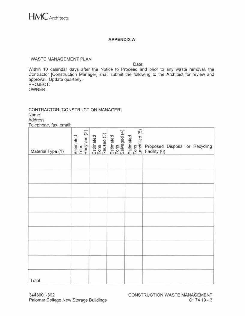
HMC Architects
APPENDIX A
WASTE MANAGEMENT PLAN Date:
Within 10 calendar days after the Notice to Proceed and prior to any waste removal, the Contractor [Construction Manager] shall submit the following to the Architect for review and approval. Update quarterly. PROJECT: OWNER:
CONTRACTOR [CONSTRUCTION MANAGER] Name: Address: Telephone, fax, email:
,...... ,...... N ,...... ~ .._.,
8 "'O "'O "'O "'O "'O Q) Q) Q) +-' Q) +-' "'O +-' Q) cu (.) cu Q) cu 0) E U) >- E U) U) E U) cu :.=.c0 :.=; C :::J :.=; C >
Material Type (1) U) 0 Q) U) 0 Q) U> 0 CU w I- a::: w I- a::: w I- Cf.)
,...... ~
"'O "'O 2 Q) cu :§ ~ ~ Proposed Disposal or Recycling ifl (=. j Facility (6)
Total
3443001-302 Palomar College New Storage Buildings
CONSTRUCTION WASTE MANAGEMENT 017419-3
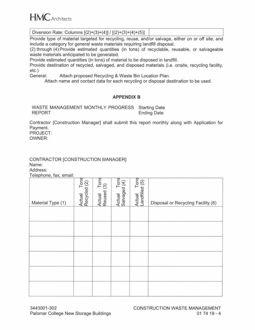
HMC Architects I Diversion Rate: Columns [(2)+(3)+(4 )] / [(2)+(3)+(4 )+(5)] Provide type of material targeted for recycling, reuse, and/or salvage, either on or off site, and include a category for general waste materials requiring landfill disposal. (2) through (4) Provide estimated quantities (in tons) of recyclable, reusable, or salvageable waste materials anticipated to be generated. Provide estimated quantities (in tons) of material to be disposed in landfill. Provide destination of recycled, salvaged, and disposed materials (i.e. onsite, recycling facility, etc.) General: Attach proposed Recycling & Waste Bin Location Plan.
Attach name and contact data for each recycling or disposal destination to be used.
APPENDIX B
WASTE MANAGEMENT MONTHLY PROGRESS Starting Date REPORT Ending Date
Contractor [Construction Manager] shall submit this report monthly along with Application for Payment. PROJECT: OWNER:
CONTRACTOR [CONSTRUCTION MANAGER] Name: Address: T I h f ·1 e ep one, ax, emau:
VI VI VJ v,.---. C .---. C C .---. CLO ON 0 ----- o,o;;f" 0 ......... I- ......... I-~ I- ......... I- "O "O "O
Q) "O Q) Q)
-u - Q) - 0) co..:: co >, co (/) co co :::Ju :::J ::, ::, > :::J "O t5 Q) t5 Q) -- -c
Material Type ( 1) <! er:: <! er:: ;j~ ~.s Disposal or Recycling Facility (6)
3443001-302 Palomar College New Storage Buildings
CONSTRUCTION WASTE MANAGEMENT 017419-4
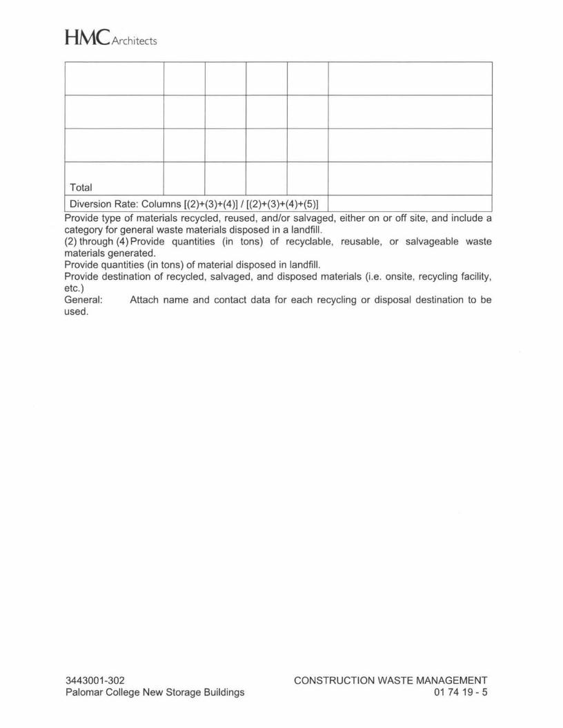
HMC Architects
Total Diversion Rate: Columns [(2)+(3)+(4)] / [(2)+(3)+(4)+(5)]
Provide type of materials recycled, reused, and/or salvaged, either on or off site, and include a category for general waste materials disposed in a landfill. (2) through (4) Provide quantities (in tons) of recyclable, reusable, or salvageable waste materials generated. Provide quantities (in tons) of material disposed in landfill. Provide destination of recycled, salvaged, and disposed materials (i.e. onsite, recycling facility, etc.) General: Attach name and contact data for each recycling or disposal destination to be used.
3443001-302 Palomar College New Storage Buildings
CONSTRUCTION WASTE MANAGEMENT 017419-5
HMC Architects
SECTION 02 41 19
SELECTIVE DEMOLITION
PART 1 - GENERAL
1.01 SUMMARY
A. Section Includes 1. Removing designated portions of sitework, fixtures, components and utilities
including of adjacent area, and similar site improvements as indicated and required to permit execution of new construction.
1.02 REFERENCES
A. ANSI - American National Standards Institute 1. ANSI-A 10.6 - Safety Requirements for Demolition Operations
B. CBC - 2013 California Building Code (CCR Title 24, Part 2 as adopted amended by DSA OSHPD AHJ) 1. CBC-19A - California Building Code, Chapter 19A, Concrete 2. CBC-33 - CBC Chapter 33, Safeguards During Construction
C. CCR - California Code of Regulations 1. CCR-8.4 - CCR Title 8, Subchapter 4, Construction Safety Orders 2. CCR-19. - CCR Title 19, Div. 1, State Fire Marshal Regulations
D. CFC - 2013 California Fire Code 1. CFC-5 - CFC Chapter 5, Fire Fighter Safety Requirements 2. CFC-9 - CFC Chapter 9, Fire Suppression Systems 3. CFC-14 - CFC Chapter 14, Fire Safety During Construction and Demolition 4. CFC-27 - CFC Chapter 27, Hazardous Materials
E. DSA - Division of the State Architect, Interpretation of Regulations (IR) 1. DSA IR 25-2 - Metal Suspension Systems for Lay-In Panel Ceilings
F. NFPA- National Fire Protection Association 1. NFPA-241 - Safeguarding Construction, Alteration and Demolition Operations
G. SCAQMD - South Coast Air Quality Management District: with hidden colon 1. SCAQMD-403 - SCAQMD Rule 403, Fugitive Dust 2. SCAQMD-1136.1 - SCAQMD Rule 1136.1, Chipping and Grinding Activities 3. SCAQMD-1140 - SCAQMD Rule 1140, Abrasive Blasting 4. SCAQMD-1171 - SCAQMD Rule 1171, Solvent Cleaning Operations
1.03 ADMINISTRATIVE REQUIREMENTS
A. Pre-Demolition Conference. Convene conference at Site at least 1 week prior to commencing this work.
3443001-302 Palomar College New Storage Buildings
SELECTIVE DEMOLITION 02 41 19 - 1
HMC Architects 1. Review procedures, verify existing conditions and coordinate with related work of
others. 2. Architect Contractor shall facilitate meeting and take and distribute minutes in
accordance with Division 01 requirements for administrative requirements.
1.04 SUBMITTALS
A. Action Submittals 1. Selective Demolition Schedule
B. Record Submittals 1. Statement of Qualifications from demolition firm 2. SWPPP Compliance Activity Logs
C. Closeout Submittals 1. Project Record Documents
1.05 QUALITY ASSURANCE
A. Work shall comply with governing EPA and SCAQMD notification regulations before beginning selective demolition. Comply with hauling and disposal regulations of authorities having jurisdiction. 1. Work shall comply with ANSI A 10.6 and NFPA 241.
B. Demolition Firm: company with minimum 6-years experience in demolition work similar in scope and complexity to those indicated for this Project.
C. Selective Demolition Schedule shall include at least the following. 1. Sequence of selective demolition and removal work, with starting and ending
dates for each activity 2. Utility service interruptions indicating purpose and duration of interruption 3. Coordination for shutoff, capping, and continuation of utility services 4. Use of elevator and stairs 5. Means of protection for items and finishes indicated to remain and items in path
of waste removal from building
PART 2 - PRODUCTS
A. Patching and Repair Materials: same quality and type specified in this Manual for similar new construction. Where no similar new construction is specified, provide materials commensurate with level of quality required by this Manual, and selected to closely match existing work in appearance.
B. Concrete Bonding Agent: epoxy-modified, cementitious bonding and anticorrosion agent that consists of water-intensive epoxy adhesive, portland cement, and water-based solution of corrosion-inhibiting chemicals that forms a protective film on steel reinforcement.
3443001-302 Palomar College New Storage Buildings
SELECTIVE DEMOLITION 02 41 19 - 2
HMC Architects
PART 3 - EXECUTION
3.01 EXAMINATION
A. Verify Site conditions are ready for the work of this Section.
B. Do not begin any selective demolition until unsatisfactory conditions are corrected. Beginning such work means acceptance of existing conditions and preparatory work of others.
3.02 PREPARATION
A. Locate buried and concealed utilities that may interfere with progress of this work. 1. Disconnect, remove and cap designated utility services within demolition areas. 2. Notify Owner at least 48 hours in advance of any utility shut-down.
B. Protect existing items that are indicated to remain.
C. Adequately protect staff and public from harm and accident during demolition operations. 1. Erect proper barricades or guard rails, post signs, set lighting, and take other
safety precautions; conform to CCR-8.4, CFC-5 and -14 and NFPA 241. 2. Install substantial enclosures, weatherproof and dust-proof shields, protective
covers, screens and similar devices. Erect and move when necessary to permit use of existing rooms, areas or facilities. Remove entirely when their use is no longer essential. Patch or repair all areas where devices have been removed.
3.03 TEMPORARY LIFE SAFETY MEASURES
A. Establish, administer and implement or deploy any and all safety measures required to protect Owner and its property from harm, loss or damage due to the prosecution of this work.
B. Instruct construction personnel in fire safety and fire drill policies appropriate for areas where demolition operations occur.
C. Post NO SMOKING signs in English and Spanish, in number and location as approved by Architect.
D. Maintain free and unobstructed access to emergency services in accordance with CFC-5 Sections 503.1; 503.1.1, 503.4; CFC-14, Sections 1410.1 and 1412.1 and as required by Owner. 1. No enclosure, shield or protective covering shall interfere with use of emergency
exits in existing facilities at any time. 2. Temporary work altering or extending rated egress systems shall have the same
rating as the existing work.
E. Provide temporary, but equivalent, fire alarm, detection or suppression systems when any system is impaired by Work of this Section. Temporary systems shall be inspected and tested monthly or at other more frequent intervals as required by Owner.
3443001-302 Palomar College New Storage Buildings
SELECTIVE DEMOLITION 02 41 19- 3
HMC Architects 1. Impairment of fire protection systems, if any, shall be in accordance with CFC-14,
Section 1408.6 and CFC-9, Section 901. 2. Systems, or portions thereof, taken out of service shall be in accordance with
CFC-9, Sections 901.7 through 901.7.6.
F. Maintain fully charged, certified compliant, fire extinguishers and water hoses readily available during demolition operations.
G. Reduce flammable and combustible fire load to minimum by daily removal of debris.
H. Test electrical conductors for disconnection prior to removing.
3.04 EXECUTION
A. Demolish work in an orderly and careful manner. Work shall be fully coordinated to ensure proper sequence, limits, methods and time of performance. Arrange Work so as to impose a minimum of hardship on present operation of facilities. 1. Remove such existing ceilings, floors, walls, finish materials or equipment as
required to complete Work. 2. Items not specifically mentioned shall be removed as indicated on drawings or as
required to prepare work for new construction.
B. Provide adequate ventilation during operations to prevent accumulation of dust, fumes, vapors and noxious gases.
C. Jack-hammers and vibratory cutting equipment may be used under following conditions. Excessive noise or vibrations will constitute just cause for immediate stoppage of Work. 1. With prior written approval from Owner of activity, equipment, schedule and
duration. 2. With minimum of 24 hours advance notice of actual commencement of work 3. Compressors shall be well muffled 4. With due consideration taken to ensure comfort of staff and public
D. Remove AC paving including sub-base where indicated in drawings and dispose of debris at sites legally franchised to accept such materials. Do not conduct crushing operations on site; use of pulverized AC as base or fill material will not accepted.
E. Extend concrete paving removal, in all directions from area shown, to the nearest expansion or contraction joint or similar termination. 1. Cut concrete with saws or other approved method, but do not overcut openings. 2. Reinforcing bars, except where shown bonded into new concrete, shall be cut off
and ends painted with bituminous paint before being enclosed. 3. Where cut edges of concrete will remain exposed in completed work, finish
edges with cement mortar at least 3/4 inch thick, applied with epoxy bonding agent and finished to match adjoining surfaces.
3443001-302 Palomar College New Storage Buildings
SELECTIVE DEMOLITION 02 41 19 - 4
HMC Architects
3.05 PATCHING AND REPAIR
A. New and existing Work, indicated to remain, that is cut into, altered or damaged, by the work of this Section, shall be restored to its existing or better conditions. Materials and their installation shall conform to applicable provisions of this Manual for similar new work. If no work of like construction is specified in this Manual, work shall be commensurate in quality to work that is specified by qualified trades people. 1. Concrete Repair. Keep edges of existing concrete damp for 24 hours and scrub
with Neat Portland Cement grout just before new concrete is placed, or use an epoxy concrete adhesive acceptable to Architect. Finish shall match existing adjoining Work. a. Concrete mixes for patching shall be determined by qualified engineer in
accordance with ACI 318, Section 5.2 as adopted and amended by CBC-19A, Section 1905A.2.
b. Concrete for patching slabs on grade shall be minimum 3,000-psi concrete. c. Concrete for patching structural members or deck fill shall have strength
determined by Architect.
B. Trenching: 1. Bedding materials for utility trenches: sand consisting of natural or manufactured
granular material conforming to Subsection 200-1.5.5, SSPWC, must achieve compaction of a minimum 90%.
2. Backfill, stockpiled fill: Granular, free of debris, no gravel larger than 3 inches in any dimension, non-expansive, approved by the Architect prior to placement on the site. Install clean backfill and re-compact 6" lifts to 90% per ASTM 01557.
3.06 DISPOSAL
A. Unless indicated or specified to be salvaged, demolished and removed materials are debris and become the Contractor's property upon removal.
B. Debris shall be picked up and disposed of, off Site, by Contractor promptly and continuously as Work progresses, and not allowed to accumulate. Sprinkle debris during handling and hauling to prevent dust nuisance. 1. Do not utilize Owner's disposal system. 2. Do not burn or bury materials on Site. 3. Contractor shall make every reasonable effort to divert debris to recycling or
reuse facilities
C. Secure and pay for required hauling permits and pay dumping fees and charges.
D. Upon completion of Work, leave areas of Work in clean condition.
END OF SECTION
3443001-302 Palomar College New Storage Buildings
SELECTIVE DEMOLITION 02 41 19 - 5
SECTION 03 30 00
CAST-IN-PLACE CONCRETE
PART 1 - GENERAL
1.1 RELATED DOCUMENTS
A. Drawings and general provisions of the Contract, including General and Supplementary Conditions and Division 01 Specification Sections, apply to this Section.
1.2 SUMMARY
A. This Section specifies cast-in place concrete, including formwork, reinforcement, concrete materials, mixture design, placement procedures, and finishes, for the following:
1. Footings.
2. Slabs-on-grade.
3. Concrete equipment pads.
B. Related Sections include the following:
1. Section 031000 Section "Earth Moving" for drainage fill under slabs-on-grade.
2. Section 033535 Section "Concrete Sealer".
1.3 DEFINITIONS
A. Cementitious Materials: Portland cement alone or in combination with one or more of the following: blended hydraulic cement, fly ash and other pozzolans, ground granulated blast-furnace' slag, and silica fume; subject to compliance with requirements.
B. Cast-in-Place Architecturally Visible Concrete: Formed concrete that is viewed on surfaces of completed structure or building and that requires special concrete materials, formwork, placement, or finishes to obtain specified architectural appearance.
1.4 SUBMITTALS
A. Product Data: For each type of product indicated.
B. Design Mixtures: For each concrete mixture. Submit alternate design mixtures when characteristics of materials, Project conditions, weather, test results, or other circumstances warrant adjustments.
1. Indicate amounts of mixing water to be withheld for later addition at Project site.
3443001-302 - PALOMAR COLLEGE NEW STORAGE BUILDINGS
CAST-IN-PLACE CONCRETE 03 30 00 - 1
2. Indicate and provide documentation for each type of add mixture.
3. Indicate water-cement ratio and strength for each mixture.
C. Steel Reinforcement Shop Drawings: Placing drawings that detail fabrication, bending, and placement. Include bar sizes, lengths, material, grade, bar schedules, stirrup spacing, bent bar diagrams, bar arrangement, splices and laps, mechanical connections, tie spacing, hoop spacing, and supports for concrete reinforcement.
D. Sustainable design requirements project submittal form, found in Appendix A of Section 01810 "Sustainable Design Requirements". Provide the following information for all cast-in-place concrete:
1 . Recycled content
2. Regional materials (if applicable)
1.5 QUALITY ASSURANCE
A. Installer Qualifications: A qualified installer who employs on Project personnel qualified as ACl-certified Flatwork Technician and Finisher and a supervisor who is an ACl certified Concrete Flatwork Technician. Submit evidence of certification to Architect and District.
B. Manufacturer Qualifications: A firm experienced in manufacturing ready-mixed concrete products and that complies with ASTM C 94/C 94M requirements for production facilities and equipment.
1. Manufacturer certified according to NRMCA's "Certification of Ready Mixed Concrete Production Facilities."
C. Testing Agency Qualifications: An independent agency, retained by the Owner and approved by the Division of State Architect, qualified according to ASTM C 1077 and ASTM E 329 for testing indicated, as documented according to ASTM E 548.
1. Personnel conducting field tests shall be qualified as ACI Concrete Field Testing Technician, Grade 1, according to ACI CP-01 or an equivalent certification program.
2. Personnel performing laboratory tests shall be ACl-certified Concrete Strength Testing Technician and Concrete Laboratory Testing Technician - Grade I. Testing Agency laboratory supervisor shall be an ACl-certified Concrete Laboratory Testing Technician - Grade II.
D. Source Limitations: Obtain each type or class of cementitious material of the same brand from the same manufacturer's plant, obtain aggregate from one source, and obtain admixtures through one source from a single manufacturer.
E. ACI Publications: Comply with the following unless modified by requirements in the Contract Documents:
3443001-302 - PALOMAR COLLEGE NEW STORAGE BUILDINGS
CAST-IN-PLACE CONCRETE 03 30 00 - 2
1. ACI 301, "Specification for Structural Concrete,"
2. ACI 117, "Specifications for Tolerances for Concrete Construction and Materials."
F. Pre-installation Conference: Conduct conference at Project site with Architect, Structural Engineer and Testing Agency to comply with requirements in Division 01 Section "Project Management and Coordination."
1. Before submitting design mixtures, review concrete design mixture and examine procedures for ensuring quality of concrete materials. Require representatives of each entity directly concerned with cast-in-place concrete to attend, including the following:
a. Contractor's superintendent.
b. Independent testing agency responsible for concrete design mixtures.
c. Ready-mix concrete manufacturer.
d. Concrete subcontractor.
2. Review special inspection and testing and inspecting agency procedures for field quality control, concrete finishes and finishing, cold and hot-weather concreting procedures, curing procedures, construction contraction and isolation joints, and joint-filler strips, semi-rigid joint fillers, forms and form removal limitations, vapor retarder installation, anchor rod and anchorage device installation tolerances, steel reinforcement installation, concrete repair procedures, and concrete protection.
G. Mockups: before casting architecturally visible concrete, build mockups to verify selections made under sample submittals and to demonstrate typical joints, surface finish, texture, tolerances, and standard of workmanship. Build mockups to comply with the following requirements, using materials indicated for the complete work:
1. Build mockups in the location and of the size indicated, if not indicated, as directed by Architect.
2. Build mockups of typical exterior wall of cast-in-place architectural concrete as shown on drawings to show reveals, pop outs, joints, form ties, and any other architectural features. Contractor to provide shop drawings of proposed mockup for approval prior to constructing mockups.
3. Demonstrate curing, cleaning, and protecting of cast-in-place architectural concrete, finishes, and contraction joints, as applicable.
4. In presence of Architect, damage part of the exposed-face surface for each finish, color, and texture and demonstrate materials and techniques proposed for repair of tie holes, and surface blemishes to match adjacent undamaged surfaces.
3443001-302- PALOMAR COLLEGE NEW STORAGE BUILDINGS
CAST-IN-PLACE CONCRETE 03 30 00 - 3
5. Obtain Architect/District approval of mockups before casting concrete. No concrete shall be placed beyond footings without approval by Architect/District.
1.6 DELIVERY, STORAGE, AND HANDLING
A. Steel Reinforcement: Deliver, store, and handle steel reinforcement to prevent bending and damage. Store reinforcing on dunnage
B. Waterstops: Store waterstops under cover to protect from moisture, sunlight, dirt, oil, and other contaminants.
PART 2 - PRODUCTS
2.1 MANUFACTURERS
A. In other Part 2 articles where titles below introduce lists, the following requirements apply to product selection:
1. Available Products: Subject to compliance with requirements, products that may be incorporated into the Work include, but are not limited to, products specified.
2. Available Manufacturers: Subject to compliance with requirements, manufacturers offering products that may be incorporated into the Work include, but are not limited to, manufacturers specified.
2.2 FORM-FACING MATERIALS
A. Smooth-Formed Finished Concrete: Form-facing panels that will provide continuous, true, and smooth concrete surfaces. Furnish in largest practicable sizes to minimize number of joints.
1. Plywood, metal, or other approved panel materials.
2. Exterior-grade plywood panels, suitable for concrete forms, complying with DOC PS 1, and as follows:
a. High-density overlay, Class 1 or better.
b. Medium-density overlay, Class 1 or better; mill-release agent treated and edge sealed.
c. Structural 1, B-B or better; mill oiled and edge sealed.
d. 8-B (Concrete Form), Class 1 or better; mill oiled and edge sealed.
B. Rough-Formed Finished Concrete: Plywood, lumber, metal, or another approved material. Provide lumber dressed on at least two edges and one side for tight fit.
C. Chamfer Strips: Wood, metal, PVC, or rubber strips, 3/4 by 3/4 inch, minimum.
D. Rustication Strips: Wood, metal, PVC, or rubber strips, kerfed for ease of form removal.
3443001-302 - PALOMAR COLLEGE NEW STORAGE BUILDINGS
CAST-IN-PLACE CONCRETE 03 30 00 - 4
E. Form-Release Agent: Commercially formulated form-release agent that will not bond with, stain, or adversely affect concrete surfaces and will not impair subsequent treatments of concrete surfaces.
1. Formulate form-release agent with rust inhibitor for steel form-facing materials.
F. Form Ties: Factory-fabricated, removable or snap-off metal or glass-fiber-reinforced plastic form ties designed to resist lateral pressure of fresh concrete on forms and to prevent spalling of concrete on removal.
1. Furnish units that will leave no corrodible metal closer than 1 inch to the plane of exposed concrete surface.
2. Furnish ties that, when removed, will leave holes no larger than 1 inch in diameter in concrete surface.
3. Furnish ties with integral water-barrier plates to walls indicated to receive damp proofing or waterproofing.
2.3 STEEL REINFORCEMENT
A. Reinforcing Bars: ASTM A 615/A 615M, Grade 60, deformed. Unless otherwise indicated on drawings.
B. Reinforcing Bars at Shear Wall Boundaries and Bars to be Welded: A 706, Grade 60, deformed.
C. Plain-Steel Wire: ASTM A 82, as indicated.
D. Plain-Steel Welded Wire Reinforcement: ASTM A 185, plain, fabricated from as-drawn steel wire into flat sheets, 60ksi minimum.
2.4 REINFORCEMENT ACCESSORIES
A. Joint Dowel Bars: ASTM A 615/A 615M, Grade 60, plain-steel bars, cut bars true to length with ends square and free of burrs.
B. Bar Supports: Bolsters, chairs, spacers, and other devices for spacing, supporting, and fastening reinforcing bars and welded wire reinforcement in place. Manufacture bar supports from steel wire, plastic, or precast concrete according to CRSl's "Manual of Standard Practice," of greater compressive strength than concrete and as follows:
1. For concrete surfaces exposed to view where legs of wire bar supports contact forms, use CRSI Class 1 plastic-protected steel wire or CRSI Class 2 stainless steel bar supports.
C. Reinforcing Bar Couplers: Provide Type II where indicated on plans. For couplers to be used as alternate to lap splices, submit proposed coupler and proposed location for review and approval by EOR and DSA.
2.5 CONCRETE MATERIALS
3443001-302 - PALOMAR COLLEGE NEW STORAGE BUILDINGS
CAST-IN-PLACE CONCRETE 03 30 00 - 5
A. Cementitious Material: Use the following cementitious materials, of the same type, brand, and source, as noted below for the following conditions:
1. Portland Cement at Architecturally Visible Concrete: ASTM C 150, Type V gray.
2. Portland Cement at all other conditions: ASTM C 150, Type as indicated on drawings.
a. Fly Ash: ASTM C 618, Class C or F, 1001bs. maximum per cubic yard, containing 1 % or less carbon. Fly ash shall not be used in excess of 30% by weight of total cement quantity.
B. Normal-Weight Aggregates: ASTM C 33, coarse aggregate or better, graded. Provide aggregates from a single source with documented service record data of at least 10 years' satisfactory service in similar applications and service conditions using similar aggregates and cementitious materials.
1. Maximum Coarse-Aggregate Size: 1-1 /2 inches nominal.
2. Fine Aggregate: Free of materials with deleterious reactivity to alkali in cement.
C. Water: ASTM C 94/C 94M and potable.
2.6 ADMIXTURES
A. Chemical (Water Reducing) Admixture: ASTM C494, Type A, D, or E. Only one brand. When used, are subject to approval of Owner's Representative, and must reduce the mixing water at least 10% without entraining air in excess of 2% by volume. If the water reducing agent entrains more than 2% air, the water reduction shall be at least 12 %, but in no case shall the water reducing agent entrain air in excess of 4%.
B. Air-entraining admix: ASTM C260.
C. Pozzolan: ASTM C618, Class F or C Fly Ash, 100 lbs. maximum per cubic yard, containing 1 % or less carbon. Fly ash shall not be used in excess of 30% by weight of total cement quantity.
D. Super-Plasticizers (High Range Water Reducers): ASTM C494, Type For G. Master Builders "Rheobuild", Euclid "Eucon 37" or equal, capable of producing concrete which can be placed at 8-11" slump without segregation, capable of maintaining slump within 2" of that initially mixed for 2 hours, and of maintaining concrete temperature within 2° F. from time of batching for 2 hours minimum.
2.7 WATERSTOPS
A. Flexible Rubber Waterstops (where indicated on drawings): CE CRD-C 513 for embedding in concrete to prevent passage of fluids through joints. Factory fabricate corners, intersections, and directional changes.
1. Manufacturers:
a. Green streak.
3443001-302- PALOMAR COLLEGE NEW STORAGE BUILDINGS
CAST-IN-PLACE CONCRETE 03 30 00 - 6
b. Progress Unlimited, Inc.
c. Williams Products, Inc.
d. Tremco Parastop II
e. Henry HF 302 Hydro-Flex Watertop
f. Cetco Waterstop-RX
g. Or approved equal
2.8 VAPOR RETARDERS
A. Granular Fill: Clean mixture of crushed stone or crushed or uncrushed gravel; ASTM D 448, Size 57, with 100 percent passing a 1-1 /2-inch sieve and O to 5 percent passing a No. 8 sieve.
B. Fine-Graded Granular Material: Clean mixture of crushed stone, crushed gravel, and manufactured or natural sand; ASTM D 448, Size 10, with 100 percent passing a 3/8- inch sieve, 10 to 30 percent passing a No. 100 sieve, and at least 5 percent passing No. 200 sieve; complying with deleterious substance limits of ASTM C 33 for fine aggregates.
C. Plastic Vapor Retarder: ASTM E 1745, Class B. Include manufacturer's recommended adhesive or pressure-sensitive tape.
1. Stego Wrap; thickness as indicated on drawings, 10 mils minimum.
2.9 CURING MATERIALS
A. Curing and Sealing Compound: Curing and sealing compound shall be VOC compliant, comply with ASTM C309, compatible with flooring adhesives. Chemical curing compounds not allowed.
B. Absorptive Cover: MSHTO M 182, Class 2, burlap cloth made from jute or kenaf, weighing approximately 9 oz./sq. yd. when dry.
C. Moisture-Retaining Cover: polyethylene sheet.
D. Water: Potable.
ASTM C 171, polyethylene film or white burlap-
E. Concrete Sealer: Refer to Section 033535.
2.10 RELATED MATERIALS
A. Expansion and Isolation-Joint-Filler Strips: ASTM D 1751, asphalt-saturated cellulosic fiber or ASTM D 1752, cork or self-expanding cork.
B. Bonding Agent: ASTM C 1059, Type II, non-redispersible, acrylic emulsion or styrene butadiene.
3443001-302 - PALOMAR COLLEGE NEW STORAGE BUILDINGS
CAST-IN-PLACE CONCRETE 03 30 00 - 7
C. Styrofoam: Expanded Polystyrene, Type X1, Density = 1 pcf, Compressive strength 5psi@ 10% deformation.
2.11 CONCRETE MIXTURES FOR BUILDING ELEMENTS
A. Footings: Proportion normal-weight concrete mixture as follows:
1. Minimum Compressive Strength: 3,000 psi, or as indicated on drawings, at 28 days.
2. Maximum Water-Cementitious Materials Ratio: 0.50.
3. Slump Limit: Maximum 4 inches.
B. Slabs-on-Grade: Proportion normal-weight concrete mixture as follows:
1. Minimum Compressive Strength: 4,000 psi, or as indicated on drawings, at 28 days.
2. Minimum Cementitious Materials Content: 540 lb/cu. yd.
3. Slump Limit: Maximum 4 inches.
4. Maximum Water-Cementitious Materials Ratio: 0.45 for concrete surfaces to receive adhered flooring - 0.50 (elsewhere)
PART 3 - EXECUTION
3.1 FORMWORK
A. Design, erect, shore, brace, and maintain formwork, according to ACI 301, to support vertical, lateral, static, and dynamic loads, and construction loads that might be applied, until structure can support such loads.
B. Construct formwork so concrete members and structures are of size, shape, alignment, elevation, and position indicated, within tolerance limits of ACI 117.
C. Limit concrete surface irregularities, designated by ACI 347R as abrupt or gradual, as follows:
1. Refer to Architectural drawings for locations of finished surfaces.
D. Construct forms tight enough to prevent loss of concrete mortar.
E. Fabricate forms for easy removal without hammering or prying against concrete surfaces. Provide crush or wrecking plates where stripping may damage cast concrete surfaces. Provide top forms for inclined surfaces steeper than 1.5 horizontal to 1 vertical.
1. Install keyways, reglets, recesses, and the like, for easy removal.
3443001-302- PALOMAR COLLEGE NEW STORAGE BUILDINGS
CAST-IN-PLACE CONCRETE 03 30 00 - 8
2. Do not use rust-stained steel form-facing material.
F. Set edge forms, bulkheads, and intermediate screed strips for slabs to achieve required elevations and slopes in finished concrete surfaces. Provide and secure units to support screed strips; use strike-off templates or compacting-type screeds.
G. Provide temporary openings for cleanouts and inspection ports where interior area of formwork is inaccessible. Close openings with panels tightly fitted to forms and securely braced to prevent loss of concrete mortar. Locate temporary openings in forms at inconspicuous locations.
H. Chamfer exterior corners and edges of permanently exposed concrete as directed by Architect.
I. Form openings, chases, offsets, sinkages, keyways, reglets, blocking, screeds, and bulkheads required in the Work. Determine sizes and locations from trades providing such items.
J. Clean forms and adjacent surfaces to receive concrete. Remove chips, wood, sawdust, dirt, and other debris just before placing concrete.
K. Retighten forms and bracing before placing concrete, as required, to prevent mortar leaks and maintain proper alignment.
L. Coat contact surfaces of forms with form-release agent, according to manufacturer's written instructions, before placing reinforcement.
M. Provide metal (smooth) formwork for Architecturally Visible Concrete to attain desired finish as directed in mockup.
3.2 EMBEDDED ITEMS
A. Place and secure anchorage devices and other embedded items required for adjoining work that is attached to or supported by cast-in-place concrete. Use setting drawings, templates, diagrams, instructions, and directions furnished with items to be embedded.
1. Install anchor rods, accurately located, to elevations required and complying with tolerances in Section 7.5 of AISC's "Code of Standard Practice for Steel Buildings and Bridges."
3.3 REMOVING AND REUSING FORMS
A. General: Formwork for sides of beams, walls, columns, and similar parts of the Work that does not support weight of concrete may be removed after cumulatively curing at not less than 50 deg F for 24 hours after placing concrete, if concrete is hard enough to not be damaged by form-removal operations and curing and protection operations are maintained.
1. Leave formwork for beam soffits, joists, slabs, and other structural elements that supports weight of concrete in place until concrete has achieved at least 75 percent of its 28-day design compressive strength.
3443001-302 - PALOMAR COLLEGE NEW STORAGE BUILDINGS
CAST-IN-PLACE CONCRETE 03 30 00 - 9
2. Remove forms only if shores have been arranged to permit removal of forms without loosening or disturbing shores.
B. Clean and repair surfaces of forms to be reused in the Work. Split, frayed, delaminated, or otherwise damaged form-facing material will not be acceptable for exposed surfaces. Apply new form-release agent.
C. When forms are reused, clean surfaces, remove fins and laitance, and tighten to close joints. Align and secure joints to avoid offsets. Do not use patched forms for exposed concrete surfaces unless approved by Architect.
3.4 VAPOR RETARDERS
A. Granular Course: Cover vapor retarder with granular fill or fine-graded granular material, moisten, and compact with mechanical equipment to elevation tolerances of plus O inch or minus 3/4 inch.
B. Vapor Retarders: Place membrane, lap edges and tape per manufacture recommendatons.
3.5 STEEL REINFORCEMENT
A. General: Comply with CRSl's "Manual of Standard Practice" for placing reinforcement.
1. Do not cut or puncture vapor retarder. Repair damage and reseal vapor retarder before placing concrete.
B. Clean reinforcement of loose rust and mill scale, earth, ice, and other foreign materials that would reduce bond to concrete.
C. Accurately position, support, and secure reinforcement against displacement. Locate and support reinforcement with bar supports to maintain minimum concrete cover. Do not tack weld crossing reinforcing bars.
D. Set wire ties with ends directed into concrete, not toward exposed concrete surfaces.
E. Install welded wire reinforcement in longest practicable lengths on bar supports spaced to minimize sagging. Lap edges and ends of adjoining sheets at least one mesh spacing. Offset laps of adjoining sheet widths to prevent continuous laps in either direction. Lace overlaps with wire.
3.6 JOINTS
A. General: Construct joints true to line with faces perpendicular to surface plane of concrete.
B. Construction Joints: Install so strength and appearance of concrete are not impaired, at locations indicated or as approved by Architect.
1. Space vertical joints in walls as indicated. Locate joints beside piers integral with walls, near corners, and in concealed locations where possible.
3443001-302 - PALOMAR COLLEGE NEW STORAGE BUILDINGS
CAST-IN-PLACE CONCRETE 03 30 00 - 10
2. Use a bonding agent at locations where fresh concrete is placed against hardened or partially hardened concrete surfaces.
3. Use epoxy-bonding adhesive at locations where fresh concrete is placed against hardened or partially hardened concrete surfaces. .... v..1..1\ .a....
'\ • p.eu,\,\-\tl) ,~ttf'~i o,F F ,~it ~ -i O '"'I' A.M~C,\-ivOf'. C. Contraction Joints in Slabs-on-Grade: Form weakened-plane contraction joints,
sectioning concrete into areas as indicated. Construct contraction joints for a depth equal to at least one-fourth of concrete thickness as follows:
1. Grooved Joints: Form contraction joints after initial floating by grooving and finishing each edge of joint to a radius of 1/8 inch. Repeat grooving of contraction joints after applying surface finishes. Eliminate groover tool marks on concrete surfaces.
2. Sawed Joints: Form contraction joints with power saws equipped with shatterproof abrasive or diamond-rimmed blades. Cut 1 /8-inch- wide joints into concrete when cutting action will not tear, abrade, or otherwise damage surface and before concrete develops random contraction cracks. Do not cut reinforcing.
D. Isolation Joints in Slabs-on-Grade: After removing formwork, install joint-filler strips at slab junctions with vertical surfaces, such as column pedestals, foundation walls, grade beams, and other locations, as indicated.
1. Extend joint-filler strips full width and depth of joint, terminating flush with finished concrete surface, unless otherwise indicated.
2. Terminate full-width joint-filler strips not less than 1/2 inch or more than 1 inch below finished concrete surface where joint sealants, specified in Division 07 Section "Joint Sealants," are indicated.
3. Install joint-filler strips in lengths as long as practicable. Where more than one length is required, lace or clip sections together.
E. Doweled Joints: Install dowel bars and support assemblies at joints where indicated. Lubricate one-half of dowel length to prevent concrete bonding to one side of joint.
3.7 WATERSTOPS
A. Flexible Waterstops: Install in construction joints and at other joints indicated to form a continuous diaphragm. Install in longest lengths practicable. Support and protect exposed waterstops during progress of the Work. Field fabricate joints in waterstops according to manufacturer's written instructions.
3.8 CONCRETE PLACEMENT
A. Before placing concrete, verify that installation of formwork, reinforcement, and embedded items is complete and that required inspections have been performed.
B. Do not add water to concrete during delivery, at Project site, or during placement unless approved by Architect.
3443001-302 - PALOMAR COLLEGE NEW STORAGE BUILDINGS
CAST-IN-PLACE CONCRETE 03 30 00 - 11
C. Deposit concrete continuously in one layer or in horizontal layers of such thickness that no new concrete will be placed on concrete that has hardened enough to cause seams or planes of weakness. If a section cannot be placed continuously, provide construction joints as indicated. Deposit concrete to avoid segregation.
1. Deposit concrete in horizontal layers of depth to not exceed formwork design pressures and in a manner to avoid inclined construction joints.
2. Consolidate placed concrete with mechanical vibrating equipment according to ACI 301.
3. Do not use vibrators to transport concrete inside forms. Insert and withdraw vibrators vertically at uniformly spaced locations to rapidly penetrate placed layer and at least 6 inches into preceding layer. Do not insert vibrators into lower layers of concrete that have begun to lose plasticity. At each insertion, limit duration of vibration to time necessary to consolidate concrete and complete embedment of reinforcement and other embedded items without causing mixture constituents to segregate.
D. Deposit and consolidate concrete for floors and slabs in a continuous operation, within limits of construction joints, until placement of a panel or section is complete.
1. Consolidate concrete during placement operations so concrete is thoroughly worked around reinforcement and other embedded items and into corners.
2. Maintain reinforcement in position on chairs during concrete placement.
3. Screed slab surfaces with a straightedge and strike off to correct elevations.
4. Slope surfaces uniformly to drains where required.
5. Begin initial floating using bull floats or darbies to form a uniform and open textured surface plane, before excess bleedwater appears on the surface. Do not further disturb slab surfaces before starting finishing operations.
E. Cold-Weather Placement: Comply with ACI 306.1 and as follows. Protect concrete work from physical damage or reduced strength that could be caused by frost, freezing actions, or low temperatures.
1. When average high and low temperature is expected to fall below 40 deg F for three successive days, maintain delivered concrete mixture temperature within the temperature range required by ACI 301.
2. Do not use frozen materials or materials containing ice or snow. Do not place concrete on frozen subgrade or on subgrade containing frozen materials.
3. Do not use calcium chloride, salt, or other materials containing antifreeze agents or chemical accelerators unless otherwise specified and approved in mixture designs.
F. Hot-Weather Placement: Comply with ACI 301 and ACI 305R and as follows:
3443001-302- PALOMAR COLLEGE NEW STORAGE BUILDINGS
CAST-IN-PLACE CONCRETE 03 30 00 - 12
1. During hot weather, proper attention shall be provided for ingredients, production methods, handling, placing, protection and curing, to prevent excessive concrete temperatures or water evaporation which could impair required strength or durability.
2. Maintain concrete temperature below 90 deg F at time of placement. Chilled mixing water or chopped ice may be used to control temperature, provided water equivalent of ice is calculated to total amount of mixing water. Using liquid nitrogen to cool concrete is Contractor's option.
3. Fog-spray forms, steel reinforcement, and subgrade just before placing concrete. Keep subgrade uniformly moist without standing water, soft spots, or dry areas.
3.9 FINISHING FORMED SURFACES
A. Rough-Formed Finish: As-cast concrete texture imparted by form-facing material with tie holes and defects repaired and patched. Remove fins and other projections that exceed specified limits on formed-surface irregularities.
1. Apply to concrete surfaces not exposed to public view.
B. Smooth-Formed Finish: As-cast concrete texture imparted by form-facing material, arranged in an orderly and symmetrical manner with a minimum of seams. Repair and patch tie holes and defects. Remove fins and other projections that exceed specified limits on formed-surface irregularities.
1. Apply to concrete surfaces exposed to public view (Architecturally Visible Concrete).
C. Related Unformed Surfaces: At tops of walls, horizontal offsets, and similar unformed surfaces adjacent to formed surfaces, strike off smooth and finish with a texture matching adjacent formed surfaces. Continue final surface treatment of formed surfaces uniformly across adjacent unformed surfaces, unless otherwise indicated.
3.10 FINISHING FLOORS AND SLABS
A. General: Comply with ACI 302.1 R recommendations for screeding, restraightening, and finishing operations for concrete surfaces. Do not wet concrete surfaces.
B. Trowel Finish: After float finish, minimum 2 trowel operations, apply first trowel finish and consolidate concrete by hand or power-driven trowel. Continue trowel passes and restraighten until surface is free of trowel marks and uniform in texture and appearance. Grind smooth any surface defects that would telegraph through applied coatings or floor coverings. Provide a minimum Static Coefficient of Friction of 0.6.
3.11 MISCELLANEOUS CONCRETE ITEMS
A. Filling In: Fill in holes and openings left in concrete structures, unless otherwise indicated, after work of other trades is in place. Mix, place, and cure concrete, as specified, to blend with in-place construction. Provide other miscellaneous concrete filling indicated or required to complete the Work.
3443001-302- PALOMAR COLLEGE NEW STORAGE BUILDINGS
CAST-IN-PLACE CONCRETE 03 30 00 - 13
B. Curbs: Provide monolithic finish to interior curbs by stripping forms while concrete is still green and by steel-troweling surfaces to a hard, dense finish with corners, intersections, and terminations slightly rounded.
C. Equipment Bases and Foundations: Provide machine and equipment bases and foundations as shown on Drawings. Set anchor bolts for machines and equipment at correct elevations, complying with diagrams or templates from manufacturer furnishing machines and equipment.
3.12 CONCRETE PROTECTING AND CURING
A. General: Protect freshly placed concrete from premature drying and excessive cold or hot temperatures. Comply with ACI 306.1 for cold-weather protection and ACI 305R for hot-weather protection during curing.
B. Evaporation Retarder: Apply evaporation retarder to unformed concrete surfaces if hot, dry, or windy conditions cause moisture loss approaching 0.2 lb/sq. ft. x h before and during finishing operations. Apply according to manufacturer's written instructions after placing, screeding, and bull floating or darbying concrete, but before float finishing.
C. Formed Surfaces: Cure formed concrete surfaces, including underside of beams, supported slabs, and other similar surfaces. If forms remain during curing period, moist cure after loosening forms. If removing forms before end of curing period, continue curing for the remainder of the curing period.
D. Unformed Surfaces: Begin curing immediately after finishing concrete. Cure unformed surfaces, including floors and slabs, concrete floor toppings, and other surfaces.
E. Cure concrete according to ACI 308.1, by one or a combination of the following methods (submit procedure as part of submittal process):
1. Moisture Curing (Preferred District Method): Keep surfaces continuously moist for not less than seven days with the following materials:
a. Water.
b. Continuous water-fog spray.
c. Absorptive cover, water saturated, and kept continuously wet. Cover concrete surfaces and edges with 12-inch lap over adjacent absorptive covers.
2. Moisture-Retaining-Cover Curing: Cover concrete surfaces with moisture retaining cover for curing concrete, placed in widest practicable width, with sides and ends lapped at least 12 inches, and sealed by waterproof tape or adhesive. Cure for not less than seven days. Immediately repair any holes or tears during curing period using cover material and waterproof tape.
a. Moisture cure or use moisture-retaining covers to cure concrete surfaces to receive floor coverings.
3443001-302 - PALOMAR COLLEGE NEW STORAGE BUILDINGS
CAST-IN-PLACE CONCRETE 03 30 00 - 14
b. Moisture cure or use moisture-retaining covers to cure concrete surfaces to receive penetrating liquid floor treatments.
3. Curing Compound: Apply uniformly in continuous operation by power spray or roller according to manufacturer's written instructions. Recoat areas subjected to heavy rainfall within three hours after initial application. Maintain continuity of coating and repair damage during curing period.
a. After curing period has elapsed, remove curing compound without damaging concrete surfaces by method recommended by curing compound manufacturer.
4. Curing and Sealing Compound: Apply uniformly to floors and slabs indicated in a continuous operation by power spray or roller according to manufacturer's written instructions. Recoat areas subjected to heavy rainfall within three hours after initial application. Repeat process 24 hours later and apply a second coat. Maintain continuity of coating and repair damage during curing period.
3.13 JOINT FILLING
A. Prepare, clean, and install joint filler according to manufacturer's written instructions where indicated on drawings.
1. Defer joint filling until concrete has aged at least one month. Do not fill joints until construction traffic has permanently ceased.
B. Remove dirt, debris, saw cuttings, curing compounds, and sealers from joints; leave contact faces of joint clean and dry.
C. Install semi-rigid joint filler full depth in saw-cut joints and at least 2 inches deep in formed joints. Overfill joint and trim joint filler flush with top of joint after hardening.
3.14 CONCRETE SURFACE REPAIRS
A. Defective Concrete: Repair and patch defective areas when approved by Architect. Remove and replace concrete that cannot be repaired and patched to Architect's approval.
B. Patching Mortar: Mix dry-pack patching mortar, consisting of one part Portland cement to two and one-half parts fine aggregate passing a No. 16 sieve, using only enough water for handling and placing.
C. Repairing Formed Surfaces: Surface defects include color and texture irregularities, cracks, spalls, air bubbles, honeycombs, rock pockets, fins and other projections on the surface, and stains and other discolorations that cannot be removed by cleaning.
1. Immediately after form removal, cut out honeycombs, rock pockets, and voids more than 1 /2 inch in any dimension in solid concrete, but not less than 1 inch in depth. Make edges of cuts perpendicular to concrete surface. Clean, dampen with water, and brush-coat holes and voids with bonding agent. Fill and compact
3443001-302 - PALOMAR COLLEGE NEW STORAGE BUILDINGS
CAST-IN-PLACE CONCRETE 03 30 00 - 15
with patching mortar before bonding agent has dried. Fill form-tie voids with patching mortar or cone plugs secured in place with bonding agent.
2. Repair defects on surfaces exposed to view by blending white Portland cement and standard Portland cement so that, when dry, patching mortar will match surrounding color. Patch a test area at inconspicuous locations to verify mixture and color match before proceeding with patching. Compact mortar in place and strike off slightly higher than surrounding surface.
3. Repair defects on concealed formed surfaces that affect concrete's durability and structural performance as determined by Architect.
D. Repairing Unformed Surfaces: Test unformed surfaces, such as floors and slabs, for finish and verify surface tolerances specified for each surface. Correct low and high areas. Test surfaces sloped to drain for trueness of slope and smoothness; use a sloped template.
1. Repair finished surfaces containing defects. Surface defects include spalls, pop outs, honeycombs, rock pockets, crazing and cracks in excess of 0.01 inch wide or that penetrate to reinforcement or completely through unreinforced sections regardless of width, and other objectionable conditions.
2. After concrete has cured at least 14 days, correct high areas by grinding.
3. Correct localized low areas during or immediately after completing surface finishing operations by cutting out low areas and replacing with patching mortar. Finish repaired areas to blend into adjacent concrete.
4. Repair defective areas, except random cracks and single holes 1 inch or less in diameter, by cutting out and replacing with fresh concrete. Remove defective areas with clean, square cuts and expose steel reinforcement with at least a 3/4- inch clearance all around. Dampen concrete surfaces in contact with patching concrete and apply bonding agent. Mix patching concrete of same materials and mixture as original concrete except without coarse aggregate. Place, compact, and finish to blend with adjacent finished concrete. Cure in same manner as adjacent concrete.
5. Repair random cracks and single holes 1 inch or less in diameter with patching mortar. Groove top of cracks and cut out holes to sound concrete and clean off dust, dirt, and loose particles. Dampen cleaned concrete surfaces and apply bonding agent. Place patching mortar before bonding agent has dried. Compact patching mortar and finish to match adjacent concrete. Keep patched area continuously moist for at least 72 hours.
E. Perform structural repairs of concrete, subject to Architect's approval, using epoxy adhesive and patching mortar.
F. Repair materials and installation not specified above may be used, subject to Architect's approval.
3.15 FIELD QUALITY CONTROL
3443001-302 - PALOMAR COLLEGE NEW STORAGE BUILDINGS
CAST-IN-PLACE CONCRETE 03 30 00 - 16
A. Testing and Inspecting: Owner will engage a special inspector and qualified testing and inspecting agency to perform field tests and inspections and prepare test reports.
B. Inspections:
1. Steel reinforcement placement.
2. Headed bolts and studs.
3. Verification of use of required design mixture.
4. Concrete placement, including conveying and depositing.
5. Curing procedures and maintenance of curing temperature.
6. As indicated on DSA Form 103.
C. Concrete Tests: Testing of composite samples of fresh concrete obtained according to ASTM C 172 shall be performed according to the following requirements:
1. Testing Frequency: Obtain at least one composite sample for each 50 cu. yd. or fraction thereof of each concrete mixture placed each day, plus not less than one for each 2,000 square feet of slabs or walls.
a. When frequency of testing will provide fewer than five compressive-strength tests for each concrete mixture, testing shall be conducted from at least five randomly selected batches or from each batch if fewer than five are used.
2. Slump: ASTM C 143/C 143M; one test at point of placement for each composite sample, but not less than one test for each day's pour of each concrete mixture. Perform additional tests when concrete consistency appears to change.
3. Air Content: ASTM C 231, pressure method, for normal-weight concrete; ASTM C 173/C 173M, volumetric method, for structural lightweight concrete; one test for each composite sample, but not less than one test for each day's pour of each concrete mixture.
4. Concrete Temperature: ASTM C 1064/C 1064M; one test hourly when air temperature is 40 deg F and below and when 80 deg F and above, and one test for each composite sample.
5. Unit Weight: ASTM C 567, fresh unit weight of structural lightweight concrete; one test for each composite sample, but not less than one test for each day's pour of each concrete mixture.
6. Compression Test Specimens: ASTM C 31/C 31M.
a. Cast and laboratory cure two sets of two standard cylinder specimens for each composite sample.
7. Compressive-Strength Tests: ASTM C 39/C 39M; test one set of two laboratory cured specimens at 7 days and one set of two specimens at 28 days.
3443001-302 - PALOMAR COLLEGE NEW STORAGE BUILDINGS
CAST-IN-PLACE CONCRETE 03 30 00 - 17
a. A compressive-strength test shall be the average compressive strength from a set of two specimens obtained from same composite sample and tested at age indicated.
8. When strength of field-cured cylinders is less than 85 percent of companion laboratory-cured cylinders, Contractor shall evaluate operations and provide corrective procedures for protecting and curing in-place concrete.
9. Strength of each concrete mixture will be satisfactory if every average of any three consecutive compressive-strength tests equals or exceeds specified compressive strength and no compressive-strength test value falls below specified compressive strength by more than 500 psi.
a. If 28-day compressive-strength test falls below satisfactory levels, strength test the spare cylinder at age determined by the Contractor and average with the strength of the 28-day specimens. The average strength of the three cylinders shall be considered one compressive-strength test.
10. Test results shall be reported in writing to Architect, concrete manufacturer, Project Inspector, and Contractor within 48 hours of testing. Reports of compressive-strength tests shall contain Project identification name and number, date of concrete placement, name of concrete testing and inspecting agency, location of concrete batch in Work, design compressive strength at 28 days, concrete mixture proportions and materials, compressive breaking strength, and type of break for both 7- and 28-day tests.
11. Nondestructive Testing: Impact hammer, sonoscope, or other nondestructive device may be permitted by Architect but will not be used as sole basis for approval or rejection of concrete.
12. Additional Tests: Testing and inspecting agency shall make additional tests of concrete when test results indicate that slump, air entrainment, compressive strengths, or other requirements have not been met, as directed by Architect. Testing and inspecting agency may conduct tests to determine adequacy of concrete by cored cylinders complying with ASTM C 42/C 42M or by other methods as directed by Architect.
a. Concrete with inadequate slumps, air entrainment, etc. shall not be placed. Costs associated with additional testing will be incurred by Contractor.
13. Additional testing and inspecting, at Contractor's expense, will be performed to determine compliance of replaced or additional work with specified requirements.
14. Correct deficiencies in the Work that test reports and inspections indicate dos not comply with the Contract Documents.
15. Measure floor and slab flatness and levelness according to ASTM E 1155 within 24 hours of finishing.
END OF SECTION
3443001-302 - PALOMAR COLLEGE NEW STORAGE BUILDINGS
CAST-IN-PLACE CONCRETE 03 30 00 - 18
HMC Architects
SECTION 03 35 35
CONCRETE SEALER
PART 1 - GENERAL
1.01 SECTION INCLUDES
A. Penetrating floor sealer hardener and densifier, at all exterior and interior exposed concrete floors.
B. Related Sections: 1. Section 03 30 00, Cast-In-Place Concrete. 2. Section 32 13 13, Concrete Sitework.
1.02 REFERENCES
A. ASTM C779-05 - Standard Test Method for Abrasion Resistance of Horizontal Concrete Surfaces.
1.03 PERFORMANCE REQUIREMENTS
A. 1 /8 - 1 /4 inch minimum penetration of existing concrete floors.
B. Dustproofing
C. Hardener, sealer, densifier.
1.04 SUBMITTALS
A. Product data for coating materials.
B. Samples
C. Manufacturers' installation instructions.
D. Maintenance data. Include maintenance and cleaning requirements for coatings, and re-coating techniques.
1.05 QUALITY ASSURANCE
A. Manufacturer: Company specializing in manufacture of concrete sealers with five years experience.
B. Applicator: Company specializing in applying work of this Section with three years experience and approved by manufacturer.
C. Field Samples 1. Provide field sample panel, 48 inch long by 48 inch wide, illustrating surface
sheen. 2. Locate where approved by Architect.
3443001-302 Palomar College New Storage Buildings
CONCRETE SEALER 03 35 35 - 1
HMC Architects 3. Accepted sample may remain as part of the Work.
1.06 DELIVERY, STORAGE AND HANDLING
A. Deliver products to site under provisions of Division 01, General Requirements.
B. Store and protect products under provisions of Division 01, General Requirements.
1.07 ENVIRONMENTAL REQUIREMENTS
A. Non-toxic, non-flammable material.
B. Restrict traffic from area where coating is being applied or is curing.
C. Do not apply materials when humidity is above 90 percent.
1.08 WARRANTY
A. Provide ten year application warranty and 20 year material warranty under provisions of Division 01.
PART 2 - PRODUCTS
2.01 MANUFACTURERS
A. Products of following manufacturers form basis for design and quality intended. 1. Curecrete Chemical Co., Springville, UT; ASHFORD FORMULA 2. Paul M. Wolff Co., Inc., Orange, CA; SHURSEAL 3. Tnemec Company, Garland, TX; Chemprobe CT Densifyer 629
B. Or equal as approved in accordance with Division 01, General Requirements for substitutions.
2.02 MATERIALS
A. Penetrating Liquid Floor Treatment: Clear, chemically reactive, waterborne solution of inorganic silicate materials and proprietary components; odorless; that penetrates, hardens, and densities concrete surfaces.
B. Combination Hardener and Sealer: 1. ASHFORD FORMULA. Waterbase, inorganic silicate material. 2. SHUR-SEAL, silicate blend.
C. Verify curing compounds have not been used. 1. Refer to Section 03 30 00.
3443001-302 Palomar College New Storage Buildings
CONCRETE SEALER 03 35 35 - 2
HMC Architects
PART 3 - EXECUTION
3.01 EXAMINATION
A. Verify that surfaces are ready to receive Work of this Section as instructed by manufacturer. Surfaces shall be clean, dry and free of substances that could affect penetration and finish.
B. Do not begin installation until unsatisfactory conditions are corrected. Beginning installation means acceptance of existing conditions and preparatory work of others.
3.02 PROTECTION
A. Protect elements surrounding and work of this Section from damage or disfiguration.
3.03 PREPARATION
A. Mask and protect adjacent surfaces and materials not receiving coating materials. Repair damage.
3.04 APPLICATION - COATING
A. Apply hardenser-sealer after slab is suitable for foot traffic and within 48 hrs of pour.
B. Apply two coatings in accordance with manufacturer's instructions.
C. Brush, mop or spray apply solution at rates recommended by manufacturer (approximately 400 square feet per gallon). Patch test required to determine coverage rate.
3.05 FIELD QUALITY CONTROL
A. Field inspection will be performed under provisions of Division O 1, General Requirements.
B. Do not allow water on surface for 30 days.
3.06 CLEANING
A. Clean surfaces of overspray or splatter and excess material.
3.07 PROTECTIONS
A. Protect finished installation. Prevent construction traffic by use of suitable covering for 5 hours.
B. Protection. There is no known satisfactory chemical or cleaning procedure available to remove petroleum stains from the concrete surface. Protect the finished floor until the Date of Substantial Completion.
3443001-302 Palomar College New Storage Buildings
CONCRETE SEALER 03 35 35 - 3
HMC Architects 1. All hydraulic powered equipment must be diapered to avoid staining of the
concrete. 2. No trade shall park vehicles on interior slabs. If necessary to complete their
scope of work, drop cloths shall be placed under vehicles at all times. 3. No pipe cutting machine shall be used on interior slabs. 4. Steel shall not be placed on interior slabs to avoid rust staining. 5. All equipment must be equipped with non-marking tires.
END OF SECTION
3443001-302 Palomar College New Storage Buildings
CONCRETE SEALER 03 35 35- 4
HMC Architects
SECTION 03 48 00
PRECAST CONCRETE SPECIAL TIES
PART 1 - GENERAL
1.01 SECTION INCLUDES
A. Architectural precast concrete exterior components, splash blocks.
1.02 REFERENCE STANDARDS
A. Conform to reference standards by date of issue current on date of Contract Documents.
B. ASTM C33 - Concrete Aggregates.
C. ASTM C150 - Portland Cement.
D. ASTM C494 - Chemical Admixture for concrete.
E. PCI MNL 117 Manual for Quality Control for Plants and Production of Architectural Precast Concrete.
1.03 SUBMITTALS
A. Shop Drawings: indicate profiles and sizes.
B. Three samples, illustrating surface finish, color, profile and texture.
C. Maintenance Data: Indicate surface cleaning instructions.
1.04 QUALITY ASSURANCE
A. Qualitications 1. Fabricator: Company specializing in performing the work of this Section with
minimum five years experience.
1.05 DELIVERY, STORAGE AND HANDLING
A. Protect units to prevent staining, chipping or spalling of concrete.
1.06 FIELD MEASUREMENTS
A. Verify field measurements.
1.07 WARRANTY
A. Provide under provisions of Division 01, General Requirements.
3443001-302 Palomar College New Storage Buildings
PRECAST CONCRETE SPECIAL TIES 03 48 00 - 1
HMC Architects B. Warranty shall state that all work is free from defects in materials and workmanship for
a period of two years from the date of Certified Completion. Contractor shall agree to repair or replace defective materials and workmanship during the warranty period at no additional cost to the Owner.
C. Defective materials and workmanship is hereby defined to include evidence of abnormal deterioration, aging or weathering of the work, structural failure resulting from exposure to normal loads and forces, sealant failures, deterioration or discoloration of finishes in excess or normal weathering and aging.
PART 2 - PRODUCTS
2.01 MANUFACTURERS
A. Products of following manufacturers form the basis for design and quality intended. 1. Dura Art Stone, Fontana, CA. 2. Wausau Tile, Wausau, WI 3. Architectural Molded Products, Los Angeles, CA. 4. Concrete Designs, Inc., Tucson, AZ. 5. Stepstone Inc. Gardena, CA
B. Or equal as approved in accordance with Division 01 General Requirements for substitutions.
2.02 CONCRETE MATERIALS
A. Cement: ASTM C150, Type I or II, white-gray mix for natural finish, white for coloring.
B. Concrete Materials: ASTM C33; water and sand. 1. Coarse Aggregate: maximum size 3/4".
C. Integral color: ASTM C979, natural mineral-oxide type, limeproof and nonfading.
D. Admixtures: ASTM C494, Type A, water reducing, manufacturer's recommended type.
E. Surface Finish: "TRAVERTINE" texture, unless noted otherwise 1. Color: as selected by Architect.
2.03 ACCESSORIES
A. Sealant: Two component polyurethane, as specified in Section 07 92 00.
2.04 MIX
A. Concrete: Minimum 5,000 psi, 28 day strength.
2.05 FABRICATION
A. Use rigid molds, constructed to maintain precast unit uniform in shape, size and finish.
B. Maintain consistent quality during manufacture.
3443001-302 Palomar College New Storage Buildings
PRECAST CONCRETE SPECIAL TIES 03 48 00 - 2
HMC Architects 2.06 FINISH - PRECAST UNITS
A. Finish: Ensure exposed-to-view finish surfaces of precast units are uniform in color and appearance and identical to approved samples.
PART 3 - EXECUTION
3.01 EXAMINATION
A. Verify site conditions.
B. Verify that substrate, structure, and openings are ready to receive work of this Section.
3.02 APPLICATION
A. Remove all traces of deleterious materials from substrate.
B. Arrange units for similar - appearing assemblies and spacing.
C. Field cut units for proper sizing and placement. Utilize Diamond Blade equipment only.
D. Install precast architectural concrete units level, plumb, square, and true.
3.03 PROTECTION
A. Protect work from damage.
3.04 CLEANING
A. Clean exposed facings to remove dirt and stains that may be on units after erection and completion of joint treatment. Wash and rinse in accordance with manufacturer's recommendations. Protect other work from damage due to cleaning operations. Do not use cleaning materials or processes that could change the character of exposed finishes.
3.05 REPAIRS
A. Conduct inspections, perform testing and make repairs or replace unsatisfactory precast units.
B. Limitations as to the amount of patching that will be permitted is subject to approval of Architect.
C. In addition to above, units may be rejected for anyone of the following: 1. Exceeding the specified installation tolerances. 2. Damaged during construction operations. 3. Exposed-to-view surfaces that develop cracks or surface finish deficiencies.
3443001-302 Palomar College New Storage Buildings
PRECAST CONCRETE SPECIAL TIES 03 48 00 - 3
HMC Architects 3.06 SCHEDULE
A. Splash blocks
END OF SECTION
3443001-302 Palomar College New Storage Buildings
PRECAST CONCRETE SPECIAL TIES 03 48 00 - 4
SECTION 04 22 00
CONCRETE UNIT MASONRY
PART1-GENERAL
1.01 RELATED DOCUMENTS
A. Drawings and general provisions of the Contract, including General and Supplementary Conditions and Division 01 Specification Sections, apply to this Section.
1.02 SUMMARY
A. Section Includes: 1. Concrete masonry units. 2. Mortar and grout. 3. Steel reinforcing bars. 4. Miscellaneous masonry accessories.
B. Related Sections: 1. Section 0330000 Cast-In-Place Concrete.
1.03 DEFINITIONS
A. CMU(s): Concrete masonry unit(s).
B. Reinforced Masonry: Masonry containing reinforcing steel in grouted cells.
1.04 PRECONSTRUCTION TESTING
A. Preconstruction Testing Service: Owner will engage a qualified independent testing agency to perform preconstruction testing indicated below. Retesting of materials that fail to comply with specified requirements shall be done at Contractor's expense. 1. Concrete Masonry Unit Test: For each type of unit required, according to
ASTM C 140 for compressive strength. 2. Mortar Test (Property Specification): For each mix required, according to
ASTM C 109/C 109M for compressive strength, ASTM C 1506 for water reten tion, and ASTM C 91 for air content.
3. Mortar Test (Property Specification): For each mix required, according to ASTM C 780 for compressive strength.
4. Grout Test (Compressive Strength): For each mix required, according to ASTM C 1019.
1.05 ACTION SUBMITTALS
A. Product Data: For each type of product indicated.
B. Shop Drawings: For the following: 1. Masonry Units: Show sizes, profiles, coursing, and locations of special shapes.
3443001-302 - PALOMAR COLLEGE NEW STORAGE BUILDINGS
CONCRETE UNIT MASONRY 04 22 00 - 1
2. Reinforcing Steel: Detail bending and placement of unit masonry reinforcing bars. Comply with ACI 315, "Details and Detailing of Concrete Reinforcement." Show elevations of reinforced walls.
1.06 INFORMATIONAL SUBMITTALS
A. Qualification Data: For testing agency.
B. Material Certificates: For each type and size of the following: 1. Masonry units.
a. Include material test reports substantiating compliance with requirements. 2. Cementitious materials. Include brand, type, and name of manufacturer. 3. Preblended, dry mortar mixes. Include description of type and proportions of in
gredients. 4. Grout mixes. Include description of type and proportions of ingredients. 5. Reinforcing bars.
C. Mix Designs: For each type of mortar and grout. Include description of type and pro portions of ingredients. 1. Include test reports for mortar mixes required to comply with property specifica
tion. Test according to ASTM C 109/C 109M for compressive strength, ASTM C 1506 for water retention, and ASTM C 91 for air content.
2. Include test reports, according to ASTM C 1019, for grout mixes required to comply with compressive strength requirement.
D. Cold-Weather and Hot-Weather Procedures: Detailed description of methods, materi als, and equipment to be used to comply with requirements.
1.07 QUALITY ASSURANCE
A. Source Limitations for Masonry Units: Obtain exposed masonry units of a uniform tex ture and color, or a uniform blend within the ranges accepted for these characteristics, from single source from single manufacturer for each product required.
B. Source Limitations for Mortar Materials: Obtain mortar ingredients of a uniform quality, including color for exposed masonry, from single manufacturer for each cementitious component and from single source or producer for each aggregate.
C. Masonry Standard: Comply with ACI 530.1/ASCE 6/TMS 602 unless modified by re quirements in the Contract Documents.
D. Preinstallation Conference: Conduct conference at Project site to comply with require ments in Division 01 Section "Project Management and Coordination."
1.08 DELIVERY, STORAGE, AND HANDLING
A. Store masonry units on elevated platforms in a dry location. If units are not stored in an enclosed location, cover tops and sides of stacks with waterproof sheeting, securely tied. If units become wet, do not install until they are dry.
B. Store cementitious materials on elevated platforms, under cover, and in a dry location. Do not use cementitious materials that have become damp.
3443001-302 - PALOMAR COLLEGE NEW STORAGE BUILDINGS
CONCRETE UNIT MASONRY 04 22 00 - 2
C. Store aggregates where grading and other required characteristics can be maintained and contamination avoided.
D. Always retain first paragraph below in case Contractor uses a preblended, dry mortar mix.
E. Deliver preblended, dry mortar mix in moisture-resistant containers designed for use with dispensing silos. Store preblended, dry mortar mix in delivery containers on ele vated platforms, under cover, and in a dry location or in covered weatherproof dispens ing silos.
F. Store masonry accessories, including metal items, to prevent corrosion and accumula tion of dirt and oil.
1.09 PROJECT CONDITIONS
A. Protection of Masonry: During construction, cover tops of walls, projections, and sills with waterproof sheeting at end of each day's work. Cover partially completed masonry when construction is not in progress. 1. Extend cover a minimum of 24 inches (600 mm) down both sides of walls and
hold cover securely in place.
B. Do not apply uniform floor or roof loads for at least 12 hours and concentrated loads for at least three days after building masonry walls or columns.
C. Stain Prevention: Prevent grout, mortar, and soil from staining the face of masonry to be left exposed or painted. Immediately remove grout, mortar, and soil that come in contact with such masonry. 1. Protect base of walls from rain-splashed mud and from mortar splatter by
spreading coverings on ground and over wall surface. 2. Protect sills, ledges, and projections from mortar droppings. 3. Protect surfaces of window and door frames, as well as similar products with
painted and integral finishes, from mortar droppings. 4. Turn scaffold boards near the wall on edge at the end of each day to prevent
rain from splashing mortar and dirt onto completed masonry.
D. Cold-Weather Requirements: Comply with cold-weather construction requirements contained in ACI 530.1/ASCE 6/TMS 602. 1. Cold-Weather Cleaning: Use liquid cleaning methods only when air temperature
is 40° F (4 deg C) and higher and will remain so until masonry has dried, but not less than 7 days after completing cleaning.
E. Hot-Weather Requirements: Comply with hot-weather construction requirements con tained in ACI 530.1/ASCE 6/TMS 602.
PART 2 - PRODUCTS
2.01 MASONRY UNITS, GENERAL
3443001-302 - PALOMAR COLLEGE NEW STORAGE BUILDINGS
CONCRETE UNIT MASONRY 04 22 00 - 3
A. Defective Units: Referenced masonry unit standards may allow a certain percentage of units to contain chips, cracks, or other defects exceeding limits stated in the standard. Do not use units where such defects will be exposed in the completed Work.
2.02 CONCRETE MASONRY UNITS
A. Regional Materials: CMUs shall be manufactured within 500 miles (800 km) of Project site from aggregates and cement that have been extracted, harvested, or recovered, as well as manufactured, within 500 miles (800 km) of Project site.
B. Shapes: Provide shapes indicated and as follows, with exposed surfaces matching ex posed faces of adjacent units unless otherwise indicated. 1. Provide special shapes for lintels, corners, jambs, sashes, movement joints,
headers, bonding, and other special conditions. 2. Provide square-edged units for outside corners unless otherwise indicated.
C. Concrete Unit Masonry: Conforming to ASTM C90, Grade N-1, hollow load-bearing concrete unit masonry, precision block. 1. Density Classification: Medium weight unless otherwise indicated. 2. Size (Width): Manufactured to dimensions 3/8 inch less than nominal dimen
sions.
D. Cap Block: Gray to match standard CMU.
E. Color: Gray, uniform color for entire project.
2.03 MORTAR AND GROUT MATERIALS
A. Regional Materials: Aggregate for mortar and grout, cement, and lime shall be extract ed, harvested, or recovered, as well as manufactured, within 500 miles (800 km) of Project site.
B. Portland Cement: ASTM C 150, Type I or II, except Type Ill may be used for cold weather construction. Provide natural color or white cement as required to produce mortar color indicated.
C. Hydrated Lime: ASTM C 207, Type S.
D. Portland Cement-Lime Mix: Packaged blend of Portland cement and hydrated lime containing no other ingredients.
E. Aggregate for Mortar: ASTM C 144.
F. Aggregate for Grout: ASTM C 404.
G. Water: Potable.
2.04 REINFORCEMENT
3443001-302- PALOMAR COLLEGE NEW STORAGE BUILDINGS
CONCRETE UNIT MASONRY 04 22 00 - 4
A. Uncoated Steel Reinforcing Bars: ASTM A 615/A 615M, Grade 60, or ASTM A 706/A 706M (Grade 420).
2.05 MISCELLANEOUS ANCHORS
A Anchor Bolts: Headed steel bolts complying with ASTM F 1544, Grade 36 (ASTM F 568M, Property Class 4.6); with ASTM A 563 (ASTM A 563M), Grade A hex nuts and; ASTM F 436 flat washers, UNO drawings.
2.06 MISCELLANEOUS MASONRY ACCESSORIES
A Preformed Control-Joint Gaskets: Made from PVC, complying with ASTM D 2287, Type PVC-65406 and designed to fit standard sash block and to maintain lateral stabil ity in masonry wall; size and configuration as indicated.
B. Elastomeric Sealant: ASTM C 920, chemically curing polysulfide sealant; of type, grade, class, and use classifications required to seal joints and remain watertight.
C. Reinforcing Bar Positioners: Wire units designed to fit into mortar bed joints spanning masonry unit cells and hold reinforcing bars in center of cells. Units are formed from 0.148-inch (3.77-mm) steel wire, hot-dip galvanized after fabrication. Provide units de signed for number of bars indicated.
2.07 MORTAR AND GROUT MIXES
A General: Do not use admixtures, including pigments, air-entraining agents, accelera tors, retarders, water-repellent agents, antifreeze compounds, or other admixtures un less otherwise indicated. 1. Do not use calcium chloride in mortar or grout. 2. Use portland cement-lime mortar unless otherwise indicated. 3. Add cold-weather admixture (if used) at same rate for all mortar that will be ex
posed to view, regardless of weather conditions, to ensure that mortar color is consistent.
B. Preblended, Dry Mortar Mix: Furnish dry mortar ingredients in form of a preblended mix. Measure quantities by weight to ensure accurate proportions, and thoroughly blend ingredients before delivering to Project site.
C. Mortar for Unit Masonry: Comply with ASTM C 270, Property Specification for Type S.
D. Grout for Unit Masonry: Comply with ASTM C 476. 1. Use grout that will comply with Table 1.16.1 in ACI 530/ASCE 5/TMS 402 for
dimensions of grout spaces and pour height. 2. Proportion grout in accordance with ASTM C 476, paragraph 4.2.2 for specified
28-day compressive strength indicated, but not less than 2000 psi (14 MPa). 3. Provide grout with a slump of 8 to 11 inches (203 to 279 mm) as measured ac
cording to ASTM C 143/C 143M.
3443001-302- PALOMAR COLLEGE NEW STORAGE BUILDINGS
CONCRETE UNIT MASONRY 04 22 00 - 5
PART 3 - EXECUTION
3.01 EXAMINATION
A. Examine conditions, with Installer present, for compliance with requirements for instal lation tolerances and other conditions affecting performance of the Work. 1. For the record, prepare written report, endorsed by Installer, listing conditions
detrimental to performance of work. 2. Verify that foundations are within tolerances specified. 3. Verify that reinforcing dowels are properly placed.
B. Before installation, examine rough-in and built-in construction for piping systems to verify actual locations of piping connections.
C. Proceed with installation only after unsatisfactory conditions have been corrected.
3.02 INSTALLATION, GENERAL
A. Build chases and recesses to accommodate items specified in this and other Sections.
B. Leave openings for equipment to be installed before completing masonry. After in stalling equipment, complete masonry to match the construction immediately adjacent to opening.
C. Use full-size units without cutting if possible. If cutting is required to provide a continu ous pattern or to fit adjoining construction, cut units with motor-driven saws; provide clean, sharp, unchipped edges. Allow units to dry before laying unless wetting of units is specified. Install cut units with cut surfaces and, where possible, cut edges con cealed.
3.03 TOLERANCES
A. Dimensions and Locations of Elements: 1. For dimensions in cross section or elevation, do not vary by more than plus 1/2
inch or minus 1/4 inch. 2. For location of elements in plan, do not vary from that indicated by more than
plus or minus 1/2 inch. 3. For location of elements in elevation, do not vary from that indicated by more
than plus or minus 1/4 inch in a story height or 1/2 inch total.
B. Lines and Levels: 1. For bed joints and top surfaces of bearing walls do not vary from level by more
than 1/4 inch in 10 feet, or 1/2 inch maximum. 2. For conspicuous horizontal lines, such as lintels, sills, parapets, and reveals, do
not vary from level by more than 1 /8 inch in 10 feet, 1 /4 inch in 20 feet, or 1 /2 inch maximum.
3. For vertical lines and surfaces do not vary from plumb by more than 1 /4 inch in 10 feet, 3/8 inch in 20 feet, or 1 /2 inch maximum.
3443001-302- PALOMAR COLLEGE NEW STORAGE BUILDINGS
CONCRETE UNIT MASONRY 04 22 00 - 6
4. For conspicuous vertical lines, such as external corners, door jambs, reveals, and expansion and control joints, do not vary from plumb by more than 1/8 inch in 10 feet, 1/4 inch in 20 feet, or 1/2 inch maximum.
5. For lines and surfaces do not vary from straight by more than 1 /4 inch in 10 feet, 3/8 inch in 20 feet, or 1/2 inch maximum.
6. For vertical alignment of exposed head joints, do not vary from plumb by more than 1/4 inch in 10 feet, or 1/2 inch maximum.
C. Joints: 1. For bed joints, do not vary from thickness indicated by more than plus or minus
1/8 inch, with a maximum thickness limited to 1/2 inch. 2. For exposed bed joints, do not vary from bed-joint thickness of adjacent courses
by more than 1/8 inch. 3. For head and collar joints, do not vary from thickness indicated by more than
plus 3/8 inch or minus 1/4 inch. 4. For exposed head joints, do not vary from thickness indicated by more than plus
or minus 1/8 inch.
3.04 LAYING MASONRY WALLS
A. Lay out walls in advance for accurate spacing of surface bond patterns with uniform joint thicknesses and for accurate location of openings, movement-type joints, returns, and offsets. Avoid using less-than-half-size units, particularly at corners, jambs, and, where possible, at other locations.
B. Bond Pattern for Exposed Masonry: Unless otherwise indicated, lay exposed masonry in running bond; do not use units with less than nominal 4-inch (100-mm) horizontal face dimensions at corners or jambs.
C. Stopping and Resuming Work: Stop work by racking back units in each course from those in course below; do not tooth. When resuming work, clean masonry surfaces that are to receive mortar before laying fresh masonry.
D. Built-in Work: As construction progresses, build in items specified in this and other Sections. Fill in solidly with masonry around built-in items.
E. Fill space between steel frames and masonry solidly with mortar unless otherwise indi cated.
F. Build non-load-bearing interior partitions full height of story to underside of solid floor or roof structure above unless otherwise indicated. 1. Install compressible filler in joint between top of partition and underside of struc
ture above. 2. At fire-rated partitions, treat joint between top of partition and underside of struc
ture above to comply with Division 07 Section "Fire-Resistive Joint Systems."
3443001-302 - PALOMAR COLLEGE NEW STORAGE BUILDINGS
CONCRETE UNIT MASONRY 04 22 00 - 7
3.05 MORTAR BEDDING AND JOINTING
A. Lay hollow CMUs as follows: 1. With face shells fully bedded in mortar and with head joints of depth equal to
bed joints. 2. With webs fully bedded in mortar in all courses of piers, columns, and pilasters. 3. With webs fully bedded in mortar in grouted masonry, including starting course
on footings.
B. Tool exposed joints slightly concave when thumbprint hard, using a jointer larger than joint thickness unless otherwise indicated.
C. Cut joints flush for masonry walls to receive plaster or other direct-applied finishes (other than paint) unless otherwise indicated.
3.06 CONTROL AND EXPANSION JOINTS
A. General: Install control and expansion joint materials in unit masonry as masonry pro gresses. Do not allow materials to span control and expansion joints without provision to allow for in-plane wall or partition movement.
B. Form control joints in concrete masonry as follows: 1. Install preformed control-joint gaskets designed to fit standard sash block. 2. Keep head joints free and clear of mortar or rake out joint for application of
sealant.
3.07 FLASHING
A. General: Install embedded flashing in masonry at lintels, ledges, other obstructions to downward flow of water in wall, and where indicated.
B. Install flashing as follows unless otherwise indicated: 1. Prepare masonry surfaces so they are smooth and free from projections that
could puncture flashing. Where flashing is within mortar joint, place through-wall flashing on sloping bed of mortar and cover with mortar. Before covering with mortar, seal penetrations in flashing with adhesive, sealant, or tape as recom mended by flashing manufacturer.
2. At lintels, extend flashing a minimum of 6 inches into masonry at each end. At heads and sills, extend flashing 6 inches at ends and turn up not less than 2 inches to form end dams.
3. Interlock end joints of ribbed sheet metal flashing by overlapping ribs not less than 1-1/2 inches or as recommended by flashing manufacturer, and seal lap with elastomeric sealant complying with requirements in Division 07 Section "Joint Sealants" for application indicated.
4. Install metal drip edges with ribbed sheet metal flashing by interlocking hemmed edges to form hooked seam. Seal seam with elastomeric sealant com plying with requirements in Division 07 Section "Joint Sealants" for application indicated.
3443001-302 - PALOMAR COLLEGE NEW STORAGE BUILDINGS
CONCRETE UNIT MASONRY 04 22 00 - 8
5. Retain one of three subparagraphs below if flexible flashing materials are used. See Evaluations.
6. Install metal drip edges beneath flexible flashing at exterior face of wall. Stop flexible flashing 1/2 inch back from outside face of wall and adhere flexible flash ing to top of metal drip edge.
C. Install reglets and nailers for flashing and other related construction where they are shown to be built into masonry.
3.08 REINFORCED UNIT MASONRY INSTALLATION
A. Temporary Formwork and Shores: Construct formwork and shores as needed to sup port reinforced masonry elements during construction. 1. Construct formwork to provide shape, line, and dimensions of completed ma
sonry as indicated. Make forms sufficiently tight to prevent leakage of mortar and grout. Brace, tie, and support forms to maintain position and shape during construction and curing of reinforced masonry.
2. Do not remove forms and shores until reinforced masonry members have hard ened sufficiently to carry their own weight and other loads that may be placed on them during construction.
B. Placing Reinforcement: Comply with requirements in ACI 530.1/ASCE 6/TMS 602.
C. Prior to grouting, mark exposed face of wall with locations for coring for drain pipe out let. Coring to be done in un-reinforced cells.
D. Grouting: Do not place grout until entire height of masonry to be grouted has attained enough strength to resist grout pressure. 1. Comply with requirements in ACI 530.1/ASCE 6/TMS 602 for cleanouts and for
grout placement, including minimum grout space and maximum pour height. 2. Limit height of vertical grout pours to not more than 60 inches (1520 mm).
3.09 FIELD QUALITY CONTROL
A. Testing and Inspecting: Owner will engage special inspectors to perform tests and in spections and prepare reports. Allow inspectors access to scaffolding and work areas, as needed to perform tests and inspections. Retesting of materials that fail to meet specified requirements shall be done at Contractor's expense.
B. Inspections: Level 1 special inspections according to the "California Building Code." 1. Begin masonry construction only after inspectors have verified proportions of
site-prepared mortar. 2. Place grout only after inspectors have verified compliance of grout spaces and
of grades, sizes, and locations of reinforcement. 3. Place grout only after inspectors have verified proportions of site-prepared
grout.
C. Concrete Masonry Unit Test: For each type of unit provided, according to ASTM C 140 for compressive strength.
3443001-302 - PALOMAR COLLEGE NEW STORAGE BUILDINGS
CONCRETE UNIT MASONRY 04 22 00 - 9
D. Mortar Test (Property Specification): For each mix provided, according to ASTM C 780. Test mortar for mortar air content and compressive strength.
E. Grout Test (Compressive Strength): For each mix provided, according to ASTM C 1019.
3.10 REPAIRING, POINTING, AND CLEANING
A. Remove and replace masonry units that are loose, chipped, broken, stained, or other wise damaged or that do not match adjoining units. Install new units to match adjoining units; install in fresh mortar, pointed to eliminate evidence of replacement.
B. Pointing: During the tooling of joints, enlarge voids and holes, except weep holes, and completely fill with mortar. Point up joints, including corners, openings, and adjacent construction, to provide a neat, uniform appearance. Prepare joints for sealant applica tion, where indicated.
C. In-Progress Cleaning: Clean unit masonry as work progresses by dry brushing to re move mortar fins and smears before tooling joints.
D. Final Cleaning: After mortar is thoroughly set and cured, clean exposed masonry as follows: 1. Remove large mortar particles by hand with wooden paddles and nonmetallic
scrape hoes or chisels. 2. Test cleaning methods on sample wall panel; leave one-half of panel uncleaned
for comparison purposes. Obtain Architect's approval of sample cleaning before proceeding with cleaning of masonry.
3. Clean concrete masonry by cleaning method indicated in NCMA TEK 8-2A ap plicable to type of stain on exposed surfaces.
3.11 MASONRY WASTE DISPOSAL
A. Salvageable Materials: Unless otherwise indicated, excess masonry materials are Contractor's property. At completion of unit masonry work, remove from Project site.
B. Excess Masonry Waste: Remove excess clean masonry waste and other masonry waste, and legally dispose of off Owner's property.
END OF SECTION
3443001-302 - PALOMAR COLLEGE NEW STORAGE BUILDINGS
CONCRETE UNIT MASONRY 04 22 00 - 10
SECTION 05 12 00
STRUCTURAL STEEL FRAMING
PART 1 - GENERAL
1.1 RELATED DOCUMENTS
A. Drawings and general provisions of the Contract, including General and Supplementary Conditions and Division 01 Specification Sections, apply to this Section.
1.2 SUMMARY
A. This Section includes the following:
1. Structural steel.
2. Grout.
B. Related Sections include the following:
1. Division 01 Section "Quality Requirements" for independent testing agency procedures and administrative requirements.
2. Division 05 Section "Steel Decking" for field installation of shear connectors.
3. Division 05 Section "Metal Fabrications" for miscellaneous steel fabrications and other metal items not defined as structural steel.
4. Division 01 Section "Sustainable Design Requirements"
1.3 DEFINITIONS
A. Structural Steel: Elements of structural-steel frame, as classified by AISC's "Code of Standard Practice for Steel Buildings and Bridges," that support design loads.
1.4 SUBMITTALS
A. Product Data: For each type of product indicated.
B. Shop Drawings: Show fabrication of structural-steel components.
1. Include details of cuts, connections, splices, camber, holes, and other pertinent data.
2. Include embedment drawings.
3. Indicate welds by standard AWS symbols, distinguishing between shop and field welds, and show size, length, and type of each weld.
3443001-302- PALOMAR COLLEGE NEW STORAGE BUILDINGS
STRUCTURAL STEEL 05 12 00 - 1
4. Indicate type, size, and length of bolts, distinguishing between shop and field bolts. Identify pre-tensioned and slip-critical high-strength bolted connections.
C. Weld Procedures: Submit weld procedures for connections other than rigid frames. Weld procedures shall be qualified as described in AWS D1 .5, Section 5.12 or 5.13 for self shielded FCAW, Weld procedures shall indicate joints details and tolerances, preheat and interpass temperature, post-heat treatment, single or multiple stringer passes, peening of stringer passes for groove welds except for the first and the last pass, electrode type and size, welding current, polarity and amperes and root treatment. The welding variables for each stringer pass shall be recorded and averaged, from these averages the weld heat input shall be calculated.
D. Welder's Certificates: Field welders shall be Project certified in accordance with AWS D1. 1-10. Shop welders shall be Project certified for FCAWS in accordance with AWS D1. 1-10.
E. Qualification Data: For Installer and fabricator.
F. Mill Test Reports: Signed by manufacturers certifying that the following products comply with requirements:
1. Structural steel including chemical and physical properties.
2. Bolts, nuts, and washers including mechanical properties and chemical analysis.
3. Direct-tension indicators.
4. Tension-control, high-strength bolt-nut-washer assemblies.
5. Shear stud connectors.
6. Shop primers.
7. Non-shrink grout.
G. Source quality-control test reports.
H. Charpy-V-Notch (CVN) Impact Test: Submit certified copies of Charpy-V-Notch (CVN) Impact Test by the manufacturer for applicable steel members and components.
1. Charpy-V-Notch (CVN) Impact Test for Base Metal: Moment frame columns, girders and other structural steel which is to be complete joint penetration welded and subjected to Charpy-V-Notch impact test in accordance with ASTM E 23 and ASTM A 673.
Exception: Rolled shapes listed under Groups 4 and 5 of the 14th edition of the AISC Manual of Steel Construction shall have the Charpy-V-Notch test, as specified above, performed on flange material at the juncture of the web and flange, shown in AISC Manual.
2. Charpy-V-Notch test shall be performed by the manufacturer employing Test Frequency (P) in accordance with ASTM A 673 and utilizing standard specimen
3443001-302 - PALOMAR COLLEGE NEW STORAGE BUILDINGS
STRUCTURAL STEEL 05 12 00- 2
sizes shown in Figure 6 of ASTM E 23. The absorbed energy in a CVN impact test shall not be less than that specified in Material Part 2 of this section.
1.5 QUALITY ASSURANCE
A. Welding: Qualify procedures and personnel according to AWS 01 .1, "Structural Welding Code--Steel."
B. Comply with applicable provisions of the following current specifications and documents:
1. AISC's "Code of Standard Practice for Steel Buildings and Bridges."
2. AISC's "Seismic Provisions for Structural Steel Buildings" and "Supplement No. 2."
3. AISC's "Load and Resistance Factor Design Specification for Structural Steel Buildings."
4. AISC's "Specification for Load and Resistance Factor Design of Single-Angle Members."
5. RCSC's "Specification for Structural Joints Using ASTM A 325 or A 490 Bolts."
6. AWS 01 .8 "Structural Welding Code - Seismic Supplement".
C. Pre-installation Conference: Conduct conference at Project site to comply with requirements in Division 01 Section "Project Management and Coordination."
1.6 DELIVERY, STORAGE, AND HANDLING
A. Store materials to permit easy access for inspection and identification. Keep steel members off ground and spaced by using pallets, dunnage, or other supports and spacers. Protect steel members and packaged materials from erosion and deterioration.
1. Store fasteners in a protected place. Clean and relubricate bolts and nuts that become dry or rusty before use.
2. Do not store materials on structure in a manner that might cause distortion, damage, or overload to members or supporting structures. Repair or replace damaged materials or structures as directed.
B. Provide and install 10 tons of structural steel in addition to quatities shown on the drawings at no additional cost to Owner. This additional steel shall be installed during construction, in sizes and locations as directed.
1.7 COORDINATION
A. Furnish anchorage items to be embedded in or attached to other construction without delaying the Work. Provide setting diagrams, sheet metal templates, instructions, and directions for installation.
3443001-302 - PALOMAR COLLEGE NEW STORAGE BUILDINGS
STRUCTURAL STEEL 05 12 00 - 3
PART 2 - PRODUCTS
2.1 STRUCTURAL-STEEL MATERIALS
A. W-Shapes: ASTM A 992, ASTM A 572, Grade 50.
B. Channels, Angles, M, S-Shapes: ASTM A 36 Grade 36.
C. Plate and Bar: ASTM A 36, Grade 36, U.N.O.
D. Cold-Formed Hollow Structural Sections: ASTM A 500, Grade B, structural tubing, 46 ksi.
E. Steel Pipe: ASTM A 53, Type E or S, Grade B, 35 ksi.
1. Finish: Primer and galvanized where indicated.
F. Welding Electrodes: Comply with AWS requirements.
2.2 BOLTS, CONNECTORS, AND ANCHORS
A. High-Strength Bolts, Nuts, and Washers: ASTM A 325, Type 1, heavy hex steel structural bolts; ASTM A 563 heavy hex carbon-steel nuts; and ASTM F 436 hardened carbon-steel washers, plain.
1. Finish: Plain.
2. Direct-Tension Indicators: ASTM F 959, Type 325 compressible-washer type.
a. Finish: Plain.
B. High-Strength Bolts, Nuts, and Washers: ASTM A 490, Type 1, heavy hex steel structural bolts or tension-control, bolt-nut-washer assemblies with splined ends; ASTM A 563 heavy hex carbon-steel nuts; and ASTM F 436 hardened carbon-steel washers, plain.
1. Direct-Tension Indicators: ASTM F 959, Type 490, compressible-washer type, plain.
C. Tension-Control, High-Strength Bolt-Nut-Washer Assemblies: ASTM F 1852, Type 1, heavy hex head steel structural bolts with splined ends; ASTM A 563 heavy hex carbon-steel nuts; and ASTM F 436 hardened carbon-steel washers.
1. Finish: Plain.
D. Shear Connectors: ASTM A29, Grades 1015 through 1020, headed-stud type, cold finished carbon steel; AWS 01 .1, Type B.
E. Headed Anchor Rods: ASTM A 307, Grade A, unless specified otherwise on drawings.
1. Nuts: ASTM A 563 hex carbon steel.
3443001-302 - PALOMAR COLLEGE NEW STORAGE BUILDINGS
STRUCTURAL STEEL 05 12 00 ".' 4
2. Plate Washers: ASTM A 36 carbon steel.
3. Washers: ASTM F 436 hardened carbon steel.
4. Finish: Plain.
F. Threaded Rods: ASTM A 36.
1. Nuts: ASTM A 563 hex carbon steel.
2. Washers: ASTM F 436 hardened carbon steel.
3. Finish: Plain.
2.3 PRIMER
A. Primer: SSPC-Paint 25, Type II, iron oxide, zinc oxide, raw linseed oil, and alkyd.
2.4 GROUT
A. Nonmetallic, Shrinkage-Resistant Grout: ASTM C 1107, factory-packaged, non metallic aggregate grout, non-corrosive, non-staining, mixed with water to consistency suitable for application and a 30-minute working time.
2.5 FABRICATION
A. Structural Steel: Fabricate and assemble in shop to greatest extent possible. Fabricate according to AISC's "Code of Standard Practice for Steel Buildings and Bridges" and AISC's "Load and Resistance Factor Design Specification for Structural Steel Buildings."
1. Camber structural-steel members where indicated.
2. Identify high-strength structural steel according to ASTM A 6/ A 6M and maintain markings until structural steel has been erected.
3. Mark and match-mark materials for field assembly.
4. Complete structural-steel assemblies, including welding of units, before starting shop-priming operations.
B. Thermal Cutting: Perform thermal cutting by machine to greatest extent possible.
1. Plane thermally cut edges to be welded to comply with requirements in AWS D1.1.
C. Bolt Holes: Cut, drill, mechanically thermal cut, or punch standard bolt holes perpendicular to metal surfaces.
D. Finishing: Accurately finish ends of columns and other members transmitting bearing loads.
3443001-302- PALOMAR COLLEGE NEW STORAGE BUILDINGS
STRUCTURAL STEEL 05 12 00 - 5
E. Shear Connectors: Prepare steel surfaces as recommended by manufacturer of shear connectors. Use automatic end welding of headed-stud shear connectors according to AWS D1 .1 and manufacturer's written instructions.
F. Holes: Provide holes required for securing other work to structural steel and for passage of other work through steel framing members.
1. Cut, drill, or punch holes perpendicular to steel surfaces. Do not thermally cut bolt holes or enlarge holes by burning.
2. Base-Plate Holes: Cut, drill, mechanically thermal cut, or punch holes perpendicular to steel surfaces.
3. Weld threaded nuts to framing and other specialty items indicated to receive other work.
2.6 SHOP CONNECTIONS
A. High-Strength Bolts: Shop install high-strength bolts according to RCSC's "Specification for Structural Joints Using ASTM A 325 or A 490 Bolts" for type of bolt and type of joint specified.
1. Joint Type: Snug tightened, pre-tensioned or slip critical as indicated.
B. Weld Connections: Comply with AWS D1 .1 for welding procedure specifications, tolerances, appearance, and quality of welds and for methods used in correcting welding work.
1. Assemble and weld built-up sections by methods that will maintain true alignment of axes without exceeding tolerances of AISC's "Code of Standard Practice for Steel Buildings and Bridges" for mill material.
2.7 SHOP PRIMING
A. Shop prime steel surfaces except the following:
1. Surfaces embedded in concrete or mortar. Extend priming of partially embedded members to a depth of 2 inches.
2. Surfaces to be field welded.
3. Surfaces to be high-strength bolted with slip-critical connections.
4. Surfaces to receive sprayed fire-resistive materials.
B. Surface Preparation: Clean surfaces to be painted. Remove loose rust and mill scale and spatter, slag, or flux deposits. Prepare surfaces according to the following specifications and standards:
1. SSPC-SP 2, "Hand Tool Cleaning."
3443001-302 - PALOMAR COLLEGE NEW STORAGE BUILDINGS
STRUCTURAL STEEL 05 12 00 - 6
C. Priming: Immediately after surface preparation, apply primer according to manufacturer's written instructions and at rate recommended by SSPC to provide a dry film thickness of not less than 1.5 mils. Use priming methods that result in full coverage of joints, corners, edges, and exposed surfaces.
1. Apply two coats of shop paint to inaccessible surfaces after assembly or erection. Change color of first coat to distinguish it from the shop applied coat.
2.8 SOURCE QUALITY CONTROL
A. Owner will engage an independent testing and inspecting agency to perform shop tests and inspections and prepare test reports.
1. Provide testing agency with access to places where structural-steel work is being fabricated or produced to perform tests and inspections.
B. Correct deficiencies in Work that test reports and inspections indicate does not comply with the Contract Documents.
C. Bolted Connections: Shop-bolted connections will be tested and inspected according to RCSC's "Specification for Structural Joints Using ASTM A 325 or A 490 Bolts."
D. Welded Connections: In addition to visual inspection, shop-welded connections will be tested and inspected according to AWS D1 .1 and the following inspection procedures, at testing agency's option:
1. Magnetic Particle Inspection: ASTM E 709; performed on root pass and on finished weld. Cracks or zones of incomplete fusion or penetration will not be accepted.
2. Ultrasonic Inspection: ASTM E 164.
3. Radiographic Inspection: ASTM E 94.
E. In addition to visual inspection, shop-welded shear connectors will be tested and inspected according to requirements in AWS D1 .1 for stud welding and as follows:
1. Bend tests will be performed if visual inspections reveal either a less-than continuous 360-degree flash or welding repairs to any shear connector.
2. Tests will be conducted on additional shear connectors if weld fracture occurs on shear connectors already tested, according to requirements in AWS D1 .1.
PART 3 - EXECUTION
3.1 EXAMINATION
A. Verify elevations of concrete- and masonry-bearing surfaces and locations of anchor rods, bearing plates, and other embedments, with steel erector present, for compliance with requirements.
B. Proceed with installation only after unsatisfactory conditions have been corrected.
3443001-302 - PALOMAR COLLEGE NEW STORAGE BUILDINGS
STRUCTURAL STEEL 05 12 00 - 7
3.2 PREPARATION
A. Provide temporary shores, guys, braces, and other supports during erection to keep structural steel secure, plumb, and in alignment against temporary construction loads and loads equal in intensity to design loads. Remove temporary supports when permanent structural steel, connections, and bracing are in place, unless otherwise indicated.
1. Do not remove temporary shoring supporting composite deck construction until cast-in-place concrete has attained its design compressive strength.
3.3 ERECTION
A. Set structural steel accurately in locations and to elevations indicated and according to AISC's "Code of Standard Practice for Steel Buildings and Bridges" and "Load and Resistance Factor Design Specification for Structural Steel Buildings."
B. Base and Bearing Plates: Clean concrete bearing surfaces of bond-reducing materials, and roughen surfaces prior to setting base and bearing plates. Clean bottom surface of base and bearing plates.
1. Set base and bearing plates for structural members on wedges, shims, or setting nuts as required.
2. Weld plate washers to top of base plate.
3. Snug-tighten anchor rods after supported members have been positioned and plumbed. Do not remove wedges or shims but, if protruding, cut off flush with edge of base or bearing plate before packing with grout.
4. Promptly pack grout solidly between bearing surfaces and base or bearing plates so no voids remain. Neatly finish exposed surfaces; protect grout and allow to cure. Comply with manufacturer's written installation instructions for shrinkage resistant grouts.
C. Maintain erection tolerances of structural steel within AISC's "Code of Standard Practice for Steel Buildings and Bridges."
D. Align and adjust various members forming part of complete frame or structure before permanently fastening. Before assembly, clean bearing surfaces and other surfaces that will be in permanent contact with members. Perform necessary adjustments to compensate for discrepancies in elevations and alignment.
1. Level and plumb individual members of structure.
2. Make allowances for difference between temperature at time of erection and mean temperature when structure is completed and in service.
E. Splice members only where indicated.
3443001-302 - PALOMAR COLLEGE NEW STORAGE BUILDINGS
STRUCTURAL STEEL 05 12 00- 8
F. Do not enlarge unfair holes in members by burning or using drift pins. Ream holes that must be enlarged to admit bolts.
G. Shear Connectors: Prepare steel surfaces as recommended by manufacturer of shear connectors. Use automatic end welding of headed-stud shear connectors according to AWS D1 .1 and manufacturer's written instructions.
3.4 FIELD CONNECTIONS
A. High-Strength Bolts: Install high-strength bolts according to RCSC's "Specification for Structural Joints Using ASTM A 325 or A 490 Bolts" for type of bolt and type of joint specified.
1. Joint Type: Snug tightened.
B. Weld Connections: Comply with AWS D1 .1 and D1 .8 for welding procedure specifications, tolerances, appearance, and quality of welds and for methods used in correcting welding work.
1. Comply with AISC's "Code of Standard Practice for Steel Buildings and Bridges" and "Load and Resistance Factor Design Specification for Structural Steel Buildings" for bearing, adequacy of temporary connections, alignment, and removal of paint on surfaces adjacent to field welds.
3.5 FIELD QUALITY CONTROL
A. Testing Agency: Owner will engage a qualified independent testing and inspecting agency to inspect field welds and high-strength bolted connections.
B. Bolted Connections: Shop-bolted connections will be tested and inspected according to RCSC's "Specification for Structural Joints Using ASTM A325 or A490 Bolts."
C. Welded Connections: Field welds will be visually inspected according to AWS D1 .1 and D1 .8.
1. In addition to visual inspection, field welds will be tested according to AWS D1 .1, D1 .8 and the following inspection procedures, at testing agency's option:
a. Magnetic Particle Inspection: ASTM E 709; performed on root pass and on finished weld. Cracks or zones of incomplete fusion or penetration will not be accepted.
b. Ultrasonic Inspection: ASTM E 164.
c. Radiographic Inspection: ASTM E 94.
D. In addition to visual inspection, test and inspect field-welded shear connectors according to requirements in AWS D1 .1 for stud welding and as follows:
1. Perform bend tests if visual inspections reveal either a less-than- continuous 360-degree flash or welding repairs to any shear connector.
3443001-302- PALOMAR COLLEGE NEW STORAGE BUILDINGS
STRUCTURAL STEEL 05 12 00 - 9
2. Conduct tests on additional shear connectors if weld fracture occurs on shear connectors already tested, according to requirements in AWS 01 .1.
E. Correct deficiencies in Work that test reports and inspections indicate does not comply with the Contract Documents.
3.6 REPAIRS AND PROTECTION
A. Touchup Painting: After installation, promptly clean, prepare, and prime or reprime field connections, rust spots, and abraded surfaces of prime-painted joists and accessories, bearing plates, and abutting structural steel. Applicable to galvanized connections.
1. Clean and prepare surfaces by SSPC-SP 2 hand-tool cleaning or SSPC-SP 3 power-tool cleaning.
2. Apply a compatible primer of same type as shop primer used on adjacent surfaces.
B. Touchup Painting: Cleaning and touchup painting are specified in Division 09 painting Sections.
END OF SECTION
3443001-302 - PALOMAR COLLEGE NEW STORAGE BUILDINGS
STRUCTURAL STEEL 0512 00-10
SECTION 05 30 00
METAL DECKING
PART 1 - GENERAL
1.1 SUMMARY
A. Section Includes:
1. Steel roof deck with accessories.
2. Bent plate and sheet metal closures at decking edges and openings.
3. Holes through decking, with reinforcing.
B. Related Work Specified Elsewhere:
1. Structural steel framing and supports for steel decking.
1.2 SUBMITTALS
A. Shop Drawings: Submit fully detailing and dimensioning all steel decking including accessories, fastenings, welding, holes with reinforcing, flashings, and closures. Indicate welding according to AWS Standard Welding Symbols. Show dimensioned layouts for openings and reinforcing details.
B. Calculations and Data: If steel decking of type differing from that indicated or specified is proposed, submit the manufacturer's calculations and supporting data showing that proposed decking conforms to requirements indicated and specified. Include the decking manufacturer's technical product data and copies of code approvals for proposed decking. Submit with shop drawings and obtain approval prior to fabrication and delivery of decking.
1.3 QUALITY ASSURANCE
A. Qualifications of Welders: Employ welding operators currently tested and certified in accordance with code.
B. Requirements of Regulatory Agencies: Provide steel floor and roof deck system that, with concrete fill, meets UL and code requirements for 2-hour fire-rated deck system.
C. Source Quality Control: Furnish the decking manufacturer's certified mill analyses and test reports covering all decking.
PART 2 - PRODUCTS
3443001-302 - PALOMAR COLLEGE NEW STORAGE BUILDINGS
METAL DECKING 05 30 00-1
2.1 DECKING MATERIALS
A. Furnish metal roof decking fabricated of steel conforming to ASTM A653, Grade 50 (minimum), minimum yield strength of 50,000 psi.; galvanized per ASTM A653, G60 unless otherwise noted on drawings.
B. Roof Decking: Type and manufacture noted on the drawings, lengths to span over at least 3 supports unless otherwise shown, each panel factory slotted or having rolled-in moisture venting provisions.
C. Decking Accessories: Provide indicated and required decking accessories includ ing, without limitation, welding washers and welding anchors, closures, transitions, and filler strips, as required for complete installations. Provide bent plate closures, angles, channels, and attachments as required for openings through decking for ducts, shafts, piping, and other penetrations; where decking changes direction; and at decking perimeter; fabricated of 16 gage galvanized steel unless otherwise shown. Provide roof drain and overflow sumps of minimum 14 gage galvanized steel.
D. Galvanizing Repair Paint: Zinc rich paint conforming to Mil Spec MIL-P-21035 (SHIPS).
PART 3 - EXECUTION
3.1 INSTALLATION OF DECKING: Verify dimensions and actual site conditions to en sure proper fit and installation.
A. Placing: Place steel decking on supports with full bearings, end joints centered over supports, and adjust to correct final position before completing permanent at tachments. Place units in straight alignment for the entire length of run of flutes with close registration of flutes and with maximum 1/8" gap between ends of units, minimum 2" bearing on the supports. Do not splice units except at supports. Con form to code approvals and approved submittals.
B. Cutting and Fitting: Perform cutting and fitting at columns, perimeters, shafts, stairs, and other openings. Provide tight fitting closures at the open uncovered ends and edges of decking, and all miscellaneous supports required to carry the metal deck ing. Secure hole reinforcement to decking with fillet welds placed on both sides of reinforcing members. Place reinforcement channels and angles across flutes and to project a distance beyond sides of openings equal to the maximum size of the open ing unless otherwise shown. Perform field cutting and trimming square and neat, equal to factory cutting. Decking shall run through all openings/penetrations besides piping sleeves smaller than 12" diameter through deck. Decking shall not be cut until contractor is ready to install penetrating parts.
3443001-302 - PALOMAR COLLEGE NEW STORAGE BUILDINGS
METAL DECKING 05 30 00-2
C. Welding: Use materials and methods in accordance with recommendations of metal decking manufacturer and approved submittals. Conform to AWS 01 .1 and 01 .3 and to the patterns and weld types shown, finished welds free of sharp points or edges. Field coat all welds and abraded surfaces upon completion with repair mate rial. Omit the field coating where welds or abrasions are covered by concrete fill or sprayed fireproofing.
D. Damaged Decking: Remove and replace all metal decking showing denting or other damage that adversely affects decking strength or subsequent materials, as directed.
3.2 CLEANING AND TOUCH-UP
A. Remove surplus materials. Clean and touch-up raw edges of decking cut for open ings with anodic galvanizing repair paint. Leave decks ready to receive subse quent materials.
3.3 FIELD QUALITY CONTROL
A. Install all metal decking under continuous inspection, welding approved by Inspector before being covered. Conform welder qualifications and welding inspection to Code.
END OF SECTION
3443001-302 - PALOMAR COLLEGE NEW STORAGE BUILDINGS
METAL DECKING 05 30 00-3
SECTION 05 40 00
COLD-FORMED METAL FRAMING
PART 1 - GENERAL
1.1 RELATED DOCUMENTS
A. Drawings and general provrsions of the Contract, including General and Supplementary Conditions and Division 01 Specification Sections, apply to this Section.
1.2 SUMMARY
A. This Section includes the following:
1. Exterior non-load-bearing wall framing.
B. Related Sections include the following:
1. Division 05 Section "Metal Fabrications" for masonry shelf angles and connections.
2. Division 09 Section "Non-Structural Metal Framing" for interior non-load-bearing, metal-stud framing and ceiling-suspension assemblies.
3. Division 09 Section "Gypsum Board Shaft Wall Assemblies" for interior non-load bearing, metal-stud-framed, shaft-wall assemblies.
1.3 SUBMITTALS
A. Product Data: For each type of cold-formed metal framing product and accessory indicated.
B. Shop Drawings: Show layout, spacings, sizes, thicknesses, and types of cold-formed metal framing; fabrication; and fastening and anchorage details, including mechanical fasteners. Show reinforcing channels, opening framing, supplemental framing, strapping, bracing, bridging, splices, accessories, connection details, and attachment to adjoining work. Include veneer support angle attachment locations and to ensure coordination with this installation. Show locations of expansion and seismic joints.
C. Welding certificates.
D. Product Test Reports: From a qualified testing agency, unless otherwise stated, indicating that each of the following complies with requirements, based on evaluation of comprehensive tests for current products:
1. Steel sheet.
2. Expansion anchors.
3443001-302- PALOMAR COLLEGE NEW STORAGE BUILDINGS
COLD-FORMED METAL FRAMING 05 40 00 -1
3. Power-actuated anchors.
4. Mechanical fasteners.
5. Horizontal drift deflection clips
6. Miscellaneous structural clips and accessories.
E. Research/Evaluation Reports: For cold-formed metal framing.
1.4 QUALITY ASSURANCE
A. Testing Agency Qualifications: An independent testing agency, acceptable to authorities having jurisdiction, qualified according to ASTM E 329 to conduct the testing indicated.
B. Product Tests: Mill certificates or data from a qualified independent testing agency indicating steel sheet complies with requirements, including base-metal thickness, yield strength, tensile strength, total elongation, chemical requirements, and metallic-coating thickness.
C. Welding: Qualify procedures and personnel according to AWS 01 .1 /01 .1 M, "Structural Welding Code--Steel," and AWS 01 .3, "Structural Welding Code--Sheet Steel."
D. Fire-Test-Response Characteristics: Where indicated, provide cold-formed metal framing identical to that of assemblies tested for fire resistance per ASTM E 119 by a testing and inspecting agency acceptable to authorities having jurisdiction.
E. AISI Specifications and Standards: Comply with AISl's "North American Specification for the Design of Cold-Formed Steel Structural Members" and its "Standard for Cold Formed Steel Framing - General Provisions."
F. Comply with AISl's "Standard for Cold-Formed Steel Framing" AISI S100 (2007) and Supplement.
1.5 DELIVERY, STORAGE, AND HANDLING
A. Protect cold-formed metal framing from corrosion, deformation, and other damage during delivery, storage, and handling.
B. Store cold-formed metal framing, protect with a waterproof covering, and ventilate to avoid condensation.
PART 2 - PRODUCTS
2.1 MANUFACTURERS
A. Manufacturers: Subject to compliance with requirements, provide cold-formed metal framing by one of the following:
1. Current members of the Steel Stud Manufactures Association (ICC-ESR Report #3064P).
3443001-302- PALOMAR COLLEGE NEW STORAGE BUILDINGS
COLD-FORMED MET AL FRAMING 05 40 00 - 2
2. Clark Dietrich Building Systems (ICC-ESR Report 1166P).
3. Or approved equal.
2.2 MATERIALS
A. Steel Sheet: ASTM A 1003/A 1003M, Structural Grade, Type H, metallic coated, of grade and coating weight as follows:
1. Grade: Grade 50, U.N.O. on plans.
2. Coating: G60.
B. Steel Sheet for Clips: ASTM A 653/A 653M, structural steel, zinc coated, of grade and coating as follows:
1. Grade: Grade 50, U.N.O. on plans.
2. Coating: G60.
2.3 EXTERIOR NON-LOAD-BEARING WALL FRAMING
A. Steel Studs: Manufacturer's standard C-shaped steel studs, of web depths indicated, punched, with stiffened flanges, and as follows:
1. Minimum Base-Metal Thickness: As noted on plans.
2. Flange Width: As noted on plans.
B. Steel Track: Manufacturer's standard U-shaped steel track, of web depths indicated, unpunched, with unstiffened flanges, and as follows:
1. Minimum Base-Metal Thickness: As noted on plans.
2. Flange Width: As noted on plans.
C. Single Deflection Track: Manufacturer's single, deep-leg, U-shaped steel track; unpunched, with unstiffened flanges, of web depth to contain studs while allowing free vertical movement, with flanges designed to support horizontal and lateral loads and transfer them to the primary structure, and as follows:
1. Manufacturers: Subject to compliance with requirements, provide products in compliance with SSMA:
2. Minimum Base-Metal Thickness: As noted on plans.
3. Flange Width: As noted on plans.
D. Drift Clips: Manufacturer's standard bypass or head clips, capable of isolating wall stud from upward and downward vertical displacement and lateral drift of primary structure.
2.4 FRAMING ACCESSORIES
3443001-302- PALOMAR COLLEGE NEW STORAGE BUILDINGS
COLD-FORMED METAL FRAMING 05 40 00 - 3
A. Fabricate steel-framing accessories from steel sheet, ASTM A 1003/A 1003M, Structural Grade, Type H, metallic coated, of same grade and coating weight used for framing members.
B. Provide accessories of manufacturer's standard thickness and configuration, unless otherwise indicated, as follows:
1. Bracing, bridging, and solid blocking.
2. Anchor clips.
3. End clips.
4. Foundation clips.
5. Backer plates.
2.5 ANCHORS, CLIPS, AND FASTENERS
A. Steel Shapes and Clips: ASTM A 36/A 36M, zinc coated by hot-dip process according to ASTM A 123/A 123M.
B. Anchor Bolts: ASTM F 1554, Grade 36 (U.N.O. on plans), threaded carbon-steel hex headed bolts, and carbon-steel nuts; and flat, hardened-steel washers; zinc coated by hot-dip process according to ASTM A 153/A 153M, Class C.
C. Expansion Anchors: Fabricated from corrosion-resistant materials, with capability to sustain, without failure, a load equal to 5 times design load, as determined by testing per ASTM E 488 conducted by a qualified independent testing agency.
D. Power-Actuated Anchors: Fastener system of type suitable for application indicated, fabricated from corrosion-resistant materials, with capability to sustain, without failure, a load equal to 10 times design load, as determined by testing per ASTM E 1190 conducted by a qualified independent testing agency.
E. Mechanical Fasteners: ASTM C 1513, corrosion-resistant-coated, self-drilling, self tapping steel drill screws.
1. Head Type: Low-profile head beneath sheathing, manufacturer's standard elsewhere.
F. Welding Electrodes: Comply with AWS standards.
2.6 MISCELLANEOUS MATERIALS
A. Nonmetallic, Nonshrink Grout: Premixed, nonmetallic, noncorrosive, nonstaining grout containing selected silica sands, portland cement, shrinkage-compensating agents, and plasticizing and water-reducing agents, complying with ASTM C 1107, with fluid consistency and 30-minute working time.
B. Shims: Load bearing, high-density multi-monomer plastic, non-leaching.
3443001-302- PALOMAR COLLEGE NEW STORAGE BUILDINGS
COLD-FORMED METAL FRAMING 05 40 00 - 4
C. Sealer Gaskets: Closed-cell neoprene foam, 1/4 inch thick, selected from manufacturer's standard widths to match width of bottom track or rim track members.
2.7 FABRICATION
A. Fabricate cold-formed metal framing and accessories plumb, square, and true to line, and with connections securely fastened, according to referenced AISl's specifications and standards, manufacturer's written instructions, and requirements in this Section.
1. Fabricate framing assemblies using jigs or templates.
2. Cut framing members by sawing or shearing; do not torch cut.
3. Fasten cold-formed metal framing members by welding, screw fastening, clinch fastening, or riveting as standard with fabricator. Wire tying of framing members is not permitted.
a. Comply with AWS D1 .3 requirements and procedures for welding, appearance and quality of welds, and methods used in correcting welding work.
b. Locate mechanical fasteners and install according to Shop Drawings, with screw penetrating joined members by not less than three exposed screw threads.
4. Fasten other materials to cold-formed metal framing by welding, bolting, or screw fastening, according to Shop Drawings.
B. Reinforce, stiffen, and brace framing assemblies to withstand handling, delivery, and erection stresses. Lift fabricated assemblies to prevent damage or permanent distortion.
C. Fabrication Tolerances: Fabricate assemblies level, plumb, and true to line to a maximum allowable tolerance variation of 1 /8 inch in 10 feet and as follows:
1. Spacing: Space individual framing members no more than plus or minus 1/8 inch from plan location. Cumulative error shall not exceed minimum fastening requirements of sheathing or other finishing materials.
2. Squareness: Fabricate each cold-formed metal framing assembly to a maximum out-of-square tolerance of 1/8 inch.
PART 3 - EXECUTION
3.1 EXAMINATION
A. Examine supporting substrates and abutting structural framing for compliance with requirements for installation tolerances and other conditions affecting performance.
1. Proceed with installation only after unsatisfactory conditions have been corrected.
3443001-302 - PALOMAR COLLEGE NEW STORAGE BUILDINGS
COLD-FORMED METAL FRAMING 05 40 00 - 5
3.2 PREPARATION
A. Before sprayed fire-resistive materials are applied, attach continuous angles, supplementary framing, or tracks to structural members indicated to receive sprayed fire-resistive materials. All post application patch work to be performed per manufacture specifications and by approved applicator meeting manufacture requirements.
B. After applying sprayed fire-resistive materials, remove only as much of these materials as needed to complete installation of cold-formed framing without reducing thickness of fire-resistive materials below that are required to obtain fire-resistance rating indicated. Protect remaining fire-resistive materials from damage.
C. Install load bearing shims or grout between the underside of wall bottom track or rim track and the top of foundation wall or slab at stud or joist locations to ensure a uniform bearing surface on supporting concrete or masonry construction.
D. Install sealer gaskets to isolate the underside of wall bottom track or rim track and the top of foundation wall or slab at stud or joist locations.
3.3 INSTALLATION, GENERAL
A. Cold-formed metal framing may be shop or field fabricated for installation, or it may be field assembled.
B. Install cold-formed metal framing according to AISl's "Standard for Cold-Formed Steel Framing - General Provisions" and to manufacturer's written instructions unless more stringent requirements are indicated.
C. Install shop- or field-fabricated, cold-formed framing and securely anchor to supporting structure.
1. Screw, bolt, or weld wall panels at horizontal and vertical junctures to produce flush, even, true-to-line joints with maximum variation in plane and true position between fabricated panels not exceeding 1 /16 inch.
D. Install cold-formed metal framing and accessories plumb, square, and true to line, and with connections securely fastened.
1. Cut framing members by sawing or shearing; do not torch cut.
2. Fasten cold-formed metal framing members by welding, screw fastening, clinch fastening, or riveting. Wire tying of framing members is not permitted.
a. Comply with AWS 01 .3 requirements and procedures for welding, appearance and quality of welds, and methods used in correcting welding work.
b. Locate mechanical fasteners and install according to Shop Drawings, and complying with requirements for spacing, edge distances, and screw penetration.
3443001-302 - PALOMAR COLLEGE NEW STORAGE BUILDINGS
COLD-FORMED METAL FRAMING 05 40 00 - 6
E. Install framing members in one-piece lengths unless splice connections are indicated for track or tension members.
F. Install temporary bracing and supports to secure framing and support loads comparable in intensity to those for which structure was designed. Maintain braces and supports in place, undisturbed, until entire integrated supporting structure has been completed and permanent connections to framing are secured.
G. Do not bridge building expansion and control joints with cold-formed metal framing. Independently frame both sides of joints.
H. Install insulation, specified in Division 07 Section "Thermal Insulation," in built-up exterior framing members, such as headers, sills, boxed joists, and multiple studs at openings, that are inaccessible on completion of framing work.
I. Fasten hole reinforcing plate over web penetrations that exceed size of manufacturer's standard punched openings.
J. Erection Tolerances: Install cold-formed metal framing level, plumb, and true to line to a maximum allowable tolerance variation of 1 /8 inch in 10 feet and as follows:
1. Space individual framing members no more than plus or minus 1 /8 inch from plan location. Cumulative error shall not exceed minimum fastening requirements of sheathing or other finishing materials.
3.4 EXTERIOR NON-LOAD-BEARING WALL INSTALLATION
A. Install continuous tracks sized to match studs. Align tracks accurately and securely anchor to supporting structure as indicated.
B. Fasten both flanges of studs to top and bottom track, unless otherwise indicated. Space studs as follows:
1 . Stud Spacing: 16 inches or as indicated.
C. Set studs plumb, except as needed for diagonal bracing or required for nonplumb walls or warped surfaces and similar requirements.
D. Isolate non-load-bearing steel framing from building structure to prevent transfer of vertical loads while providing lateral support.
1. Install single-leg deflection tracks and anchor to building structure.
2. Connect drift clips to cold formed metal framing and anchor to building structure.
E. Install horizontal bridging in wall studs, spaced in rows indicated on drawings but not more than 48 inches apart. Fasten at each stud intersection.
1. Top Bridging for Single Deflection Track: Install row of horizontal bridging within 12 inches of single deflection track. Install a combination of flat, taut, steel sheet straps of width and thickness indicated and stud or stud-track solid blocking of
3443001-302 - PALOMAR COLLEGE NEW STORAGE BUILDINGS
COLD-FORMED METAL FRAMING 05 40 00 - 7
width and thickness matching studs. Fasten flat straps to stud flanges and secure solid blocking to stud webs or flanges.
a. Install solid blocking at centers indicated.
2. Bridging: Cold-rolled steel channel, welded or mechanically fastened to webs of punched studs.
3. Bridging: Combination of flat, taut, steel sheet straps of width and thickness indicated and stud-track solid blocking of width and thickness to match studs. Fasten flat straps to stud flanges and secure solid blocking to stud webs or flanges.
4. Bridging: Proprietary bridging bars installed according to manufacturer's written instructions.
F. Install miscellaneous framing and connections, including stud kickers, web stiffeners, clip angles, continuous angles, anchors, fasteners, and stud girts, to provide a complete and stable wall-framing system.
G. Secure joists to load-bearing interior walls to prevent lateral movement of bottom flange.
H. Install miscellaneous joist framing and connections, including web stiffeners, closure pieces, clip angles, continuous angles, hold-down angles, anchors, and fasteners, to provide a complete and stable joist-framing assembly.
3.5 REPAIRS AND PROTECTION
A. Galvanizing Repairs: Prepare and repair damaged galvanized coatings on fabricated and installed cold-formed metal framing with galvanized repair paint according to ASTM A 780 and manufacturer's written instructions.
B. Provide final protection and maintain conditions, in a manner acceptable to manufacturer and Installer, that ensure that cold-formed metal framing is without damage or deterioration at time of Substantial Completion.
END OF SECTION
3443001-302 - PALOMAR COLLEGE NEW STORAGE BUILDINGS
COLD-FORMED METAL FRAMING 05 40 00 - 8
HMC Architects
SECTION 05 50 00
METAL FABRICATIONS
PART 1 - GENERAL
1.01 SUMMARY
A. Section Includes: 1. Shop fabricated ferrous metal items
a. Steel, galvanized, and prime painted. b. Stainless steel metal items
B. Related Sections 1. Section 09 90 00 - Painting
1.02 REFERENCES
A. American Society of Mechanical Engineers (ASME) 1. ASME B18 Fasteners
B. American Society for Testing and Materials (ASTM) 1. ASTM A 36 - Carbon Structural Steel 2. ASTM A 48 - Gray Iron Castings 3. ASTM A 53 - Pipe, Steel, Black and Hot-Dipped, Zinc-coated Welded and
Seamless 4. ASTM A 123 - Zinc (Hot-Dip Galvanized) on Coatings on Iron and Steel Products 5. ASTM A 153 - Zinc Coating (Hot-Dip) on Iron and Steel Hardware 6. ASTM A 240 - Chromium and Chromium-Nickel Stainless Steel Plate, Sheet and
Strip for Pressure Vessels and for General Applications 7. ASTM A 307 - Carbon Steel Bolts and Studs, 60,000 psi Tensile Strength 8. ASTM A 325 - Structural Bolts, Steel, Heat Treated, 120/105ksi Minimum Tensile
Strength 9. ASTM A 500 - Cold-Formed Welded and Seamless Carbon Steel Structural
Tubing in Round and Shapes 10. ASTM A563 - Carbon and Alloy Steel Nuts 11. ASTM A653 - Steel Sheet, Zinc-Coated (Galvanized) or Zinc-Iron Alloy-Coated
(Galvannealed) by the Hot-Dip Process 12. ASTM A 992 - Structural Steel Shapes 13. ASTM C 1107 - Packaged Dry Hydraulic - Cement Grout (Non-Shrink) 14. ASTM F 1554 - Anchor Bolts, Steel, 36, 55, and 105-ksi Yield Strength
C. American Welding Society (AWS) 1. AWS A2.4 - Standard Symbols for Welding, Brazing and Non Destructive
Examination 2. AWS A5.1 - Carbon Steel Covered Arc-Welding Electrodes
D. California Code of Regulations (CCR) 1. Title 8, Chapter 3.2 2. Title 8, Division 1, Subchapter 7, Group 1, Article 4, Section 3277, Fixed Ladders
3443001-302 Palomar College New Storage Buildings
METAL FABRICATIONS 05 50 00 - 1
HMC Architects 3. Cal/OSHA, Subchapter 4 Construction Safety Orders 4. Title 24, Part 2, 2013 California Building Code (CBC), Chapter 22A. 5. Title 12, California Fire Code Chapter 26 Welding and Other Hot Work.
E. National Ornamental and Miscellaneous Metals Association (NOMMA) 1. NOMMA Guidelines - Guideline 1 Joint Finishes
F. Steel Structures Painting Council (SSPC) 1. SSPC SP-2 - Steel Preparation
1.03 SUBMITTALS
A. Action Submittals 1. Shop Drawings. Indicate profiles, sizes, connection attachments, reinforcing,
anchorage, size and type of fasteners and accessories. Include erection drawings, elevations and details where applicable. Indicate welded connections using standard AWS A2.4 Welding Symbols. Indicate net weld lengths.
B. Record Submittals 1. Welder Certifications. 2. Manufacturer's Certificates certifying welders employed on the work have been
AWS qualified within the previous 12 months, in accordance with AWS-WHB-1. 3. Written Welding Procedure Specification (WPS)
C. Closeout Submittals 1. Record Documentation.
1.04 QUALITY ASSURANCE
A. Welding: Qualify procedures and personnel according to the following 1. AWS 01 .1, Structural Welding Code--Steel. 2. AWS 01 .3, Structural Welding Code--Sheet Steel. 3. AWS Certified welders.
B. Coating applicator - Galvanized Metal Fabrications: Company specializing in hot-dip galvanizing after fabrication and following the procedures in the Quality Assurance Manual of the American Galvanizers Association.
1.05 FIELD MEASUREMENTS
A. Verify field measurements.
PART 2 - PRODUCTS
2.01 METALS, GENERAL
A. Metal Surfaces, General: Provide materials with smooth, flat surfaces, unless otherwise indicated. For metal fabrications exposed to view in completed Work, provide materials without seam marks, roller marks, rolled trade names, or blemishes.
3443001-302 Palomar College New Storage Buildings
METAL FABRICATIONS 05 50 00 - 2
HMC Architects
2.02 FERROUS METALS
A. Steel Sections: ASTM A 992 for W-Shape sections and ASTM A36 for all other members.
B. Steel Plates, Shapes, and Bars: ASTM A 36.
C. Bending or cold-formed steel Plate ASTM A 283, Grade C.
D. Steel Round Structural Tubing ASTM A 500, Grade B.
E. Pipe ASTM A 53, Grade B, Type E or S, Schedule 40, galvanized where indicated.
F. Cast Iron ASTM A 48/A 48M, Class 30, unless another class is indicated or required by structural loads.
G. Cast steel ASTM A27, Grade 65-35.
H. Square and rectangular steel tubing structural, carbon steel conforming to ASTM A 500. Hot or cold rolled carbon steel for non-structural tubing, electric welded tubing.
2.03 FASTENERS
A. General: Provide Type 304 or 316 stainless-steel fasteners for exterior use and zinc-plated fasteners with coating complying with ASTM B 633, Class Fe/Zn 5, where built into exterior walls. Select fasteners for type, grade, and class required.
B. Bolts and Nuts: Regular hexagon-head bolts, ASTM A 307, Grade A; with hex nuts, ASTM A563 and ANSI B18.2.1; and, where indicated, flat washers and ASTM A 325 as indicated on drawings.
C. Stainless-Steel Bolts and Nuts: Regular hexagon-head annealed stainless steel bolts, nuts and, where indicated, flat washers; ASTM F 593 for bolts and ASTM F 594 for nuts, Alloy Group 1 (A 1 ). 1. Stainless Steel Fastenings and Fittings at Food Preparation areas:
a. Bolts and screws with countersunk flat heads at interior and exterior visible or accessible surfaces.
b. Use concealed fastenings where possible.
D. High Strength Bolts ASTM A 325.
E. Anchor Bolts ASTM F 1554, Grade 36.
F. Machine Screws ASME B18.6.3.
G. Lag Bolts ASME B18.2.1.
H. Wood Screws Flat head, carbon steel, ASME B18.6.1.
I. Plain Washers Round, carbon steel, ASME B18.22.1.
3443001-302 Palomar College New Storage Buildings
METAL FABRICATIONS 05 50 00 - 3
HMC Architects
J. Lock Washers Helical, spring type, carbon steel, ASME B18.21.1.
K. Self-drilling, self-tapping screws, ASTM C954, galvanized, minimum #10 unless noted otherwise on drawings. By Buildex/Tomarco or equal.
L. Anchorage Devices, Drilled Expansion Anchors Minimum 5/8-inch diameter with 3 inch embedment unless noted otherwise on drawings. Allowable shear and tension values as permitted in ICC-ES, ESR-1917 Hilti Kwik Bolt TZ Concrete Anchor or Hilti Kwik Bolt 3, ESR-1385 for masonry anchors, by Hilti Inc., Tulsa, OK.
2.04 MISCELLANEOUS MATERIALS
A. Shop Primer fabricator's rust inhibitive suitable finish scheduled in Section 09 90 00 or equal as approved in accordance with Division 01, General Requirements for substitutions.
B. Galvanizing Repair Compound: 1. ASTM D520 Type Ill, "ultra pure" high purity grade. Touch-Up products for
Galvanized Surfaces Ready mixed Zinc rich galvanizing compound, 95% zinc. a. Finish: Galvilite by ZRC Products Company, Marshfield, MA or equal.
Reflective Metallic Sheen for exposed galvanized finish. b. Finish: ZRC Products Company, Marshfield, MA or equal. Primer for
repaired galvanized to receive a painting finish. 2. Zinc-Based Solders/Alloys: Solder Zinc Alloy for Repair ASTM A780 Annex A 1;
Welco Gal-Viz self-fluxing solder alloy, Galvalloy, Galvabar or equal, ASTM A780, paragraph A 1. Repair Using Zinc-Based Alloys.
C. Welding Rods and Bare Electrodes: Select according to AWS specifications for metal alloy welded. f>E.1( ,112.\lc..-tuf?-N,., P~A'Nicve,.
D. Grout ASTM C1107, Non-shrink type, pre-mixed compound consisting of non-metallic aggregate, cement, water reducing and plasticizing additives, capable of developing a minimum compressive strength of 8,000 psi at 7 days; of consistency suitable for application and a 30 minute working time.
2.05 FABRICATION
A. Fit and shop assemble in largest practical sections for delivery to site.
B. Ease exposed edges to small uniform radius.
C. Fabricate items with joints tightly fitted and secured.
D. Welded Joints. Seal joined members by continuous welds. Dress welded joints, leaving no burrs, or sharp or abrasive corners, edges or surfaces. 1. Where exposed to view in finished spaces, dress welds in accordance with
NOMMA Guidelines for Finish 1. 2. Where exposed to view in utility spaces, dress welds in accordance with NOMMA
Guidelines for Finish 2.
3443001-302 Palomar College New Storage Buildings
METAL FABRICATIONS 05 50 00 - 4
HMC Architects 3. Where concealed, dress welds in accordance with NOMMA Guidelines for Finish
3.
E. Exposed Mechanically Fastened Joints. Make exposed, mechanically fastened joints hairline-tight, flush, butt joints. Secure with flush-mount, countersunk, screws or bolts; unobtrusively located; consistent with design of component, except where specifically indicated otherwise.
F. Provide components required for anchorage of fabrications. Fabricate anchors and related components of same material and finish as related metal fabrication, unless expressly indicated otherwise.
2.06 FINISHES
A. Steel and Iron 1. Clean surfaces of rust, scale, grease and foreign matter prior to finishing. Prepare
in accordance with SSPC SP-2. 2. Galvanize steel items to zinc coating thickness in accordance with ASTM A 123,
minimum Coating Grade 80 (1.9 oz/sq. ft.). Surfaces shall be free of icicles, spangles and puddling. Provide venting holes at all enclosed sections, "V" notch, and drilled holes are acceptable. Locate to prevent rainwater from entering enclosed sections at exterior galvanized items. For sheet steel items, galvanize per ASTM A653 G60 Coating Designation.
3. Do not prime surfaces in direct contact with concrete or where field welding is required.
4. For painted surfaces, prime items with two coats in accordance with requirements of primer specified herein.
B. Apply two coats of bituminous paint to concealed aluminum and steel surfaces in contact with cementitious materials or between dissimilar metals. Bituminous Paint: Cold-applied asphalt emulsion complying with ASTM D1187.
PART 3 - EXECUTION
3.01 EXAMINATION
A. Verify that field conditions are acceptable and are ready to receive work.
B. Beginning of installation means erector accepts existing conditions.
3.02 PREPARATION
A. Clean and strip primed steel items to bare metal where site welding is required.
B. Supply items required to be cast into concrete or embedded in masonry with setting templates to appropriate sections.
3.03 INSTALLATION
A. Install items plumb and level, accurately fitted, free from distortion or defects.
3443001-302 Palomar College New Storage Buildings
METAL FABRICATIONS 05 50 00 - 5
HMC Architects
B. Allow for erection loads and for sufficient temporary bracing to maintain true alignment until completion of erection and installation of permanent attachments.
C. Field weld components indicated on shop drawings. 1. Weld joints using shielded metallic electric arc (SMAW) method. Use coated
welded rods, not fluxed, or type recommended by manufacturer for use with parent metal. Use only certified welders for structural construction.
2. Grinding: Grind welds on surfaces subject to traffic or contact to smooth flush joints.
3. Peening: Remove flux and weld spatter as necessary to eliminate unsightly conditions and grind off sharp projections.
4. Permanently Concealed Welds: No treatment required other than preparation for painting or galvanizing.
D. Perform field welding in accordance with AWS standards and procedures for metal alloy welded.
E. Obtain Architect approval prior to site cutting or making adjustments not scheduled.
F. After erection, prime welds, abrasions and surfaces not shop primed except surfaces to be in contact with concrete.
G. Repair of Galvanized Surfaces: Ready mixed, zinc-rich galvanizing compound, ASTM 0520. Repair Using Paints Containing Zinc Dust, minimum thickness 5 mils.
H. Repair of Galvanized Surfaces No flux is required. ASTM A780 Annex A 1, apply Gal-Viz while metal is still hot. Tin surface with Gal-Viz with wire brush. Do not direct flame on alloy. Minimum thickness, 5 mils.
I. Erection Tolerance 1. Maximum Variation From Plumb 1 /4 inch per story, non-cumulative. 2. Maximum Offset From True Alignment 1/4 inch.
3.04 FINISHES
A. Paint per Section 09 90 00 Painting.
3.05 SCHEDULE
A. Schedule is list of principal items only. Refer to Drawing details for items not specifically scheduled.
B. Fasteners: Provide fasteners and connectors of approved types, whether indicated or not.
C. Door Frames for Overhead Door Openings and Wall Openings Channel sections; galvanized finish.
D. Steel Backing Plates 1/4 inch thick x widths and lengths required to support wall bumper, plumbing fixture hanger, equipment and as detailed.
3443001-302 Palomar College New Storage Buildings
METAL FABRICATIONS 05 50 00 - 6
HMC Architects
E. Grates and Frames Provide all gratings, covers and frames for catch basins, trench and storm drains. All Work shall be galvanized cast iron. Provide heavy-duty traffic trench type gratings, covers and frames in all traffic areas; manufactured by Alhambra Foundry Co., Alhambra, CA, McKinley Iron Works, Fort Worth, TX, or Neenah Foundry Co., Neenah, WI, Barry Pattern and Foundry Co, Inc, or equal as approved in accordance with Division 01, General Requirements for substitutions. 1. Gratings in traffic areas shall be narrow slot type, with openings not greater than
1 /2 inch with direction of slots placed perpendicular to direction of traffic. 2. Covers shall be provided with recessed bolt attachment to frame.
END OF SECTION
3443001-302 Palomar College New Storage Buildings
METAL FABRICATIONS 05 50 00 - 7
HMC Architects
SECTION 06 10 00
ROUGH CARPENTRY
PART 1 - GENERAL
1.01 SECTION INCLUDES
A. Rough carpentry.
B. Related Sections: 1. Section 01 35 42, CALGreen Requirements.
1.02 REFERENCES
A. ASTM International 1. ASTM E 84 - Surface Burning Characteristics of Building Materials.
B. Chapters 7 and 23, 2013 California Building Code, CBC.
C. California Green Building Standards Code, CALGreen - 2013.
D. DOC PS 1-07 - Department of Commerce Product Standard, U. S. Product Standard for Construction and Industrial Plywood.
E. DOC PS 20-05 - Department of Commerce Product Standard, American Softwood Lumber Standards.
F. DOC PS 2-04 - Department of Commerce Product Standard, U. S. Product Standard for Construction, Performance Standard for Wood-Based Structural-Use Panels.
G. ANSI A135.4-1995 - Basic Hardboard.
H. WWPA - Western Lumber Grading Rules 88, Latest Edition, by Western Wood Products Association.
I. HPVA HP-1 - American National Standard Institute, Hardwood Plywood and Veneer Association, 2009 Edition.
J. APA - The Engineered Wood Association. The Construction Guide.
K. AQMD - Local Air Quality Management District Regulations.
L. AWPA C1, C2, C3, C9, C27 - American Wood Preservers Association - Manual of Recommended Practice.
M. AWPA C20-02 - American Wood Preservers Association Standards, Structural Lumber " Fire-Retardant Treatment by Pressure Process. 1. WCLIB - West Coast Lumber Inspection Bureau Standard Grading Rules No. 17.
N. Title 8 - California Code of Regulations, Construction Safety Orders.
3443001-302 Palomar College New Storage Buildings
ROUGH CARPENTRY 06 10 00 - 1
HMC Architects
0. ICC -ES - International Code Council Evaluation Service, Inc. Legacy Reports.
P. RIS - Redwood Inspection Service, Standard Specifications for Grades of California Redwood Lumber, 1997.
Q. SCAQMD - South Coast Air Quality Management District Rule 1168 - Adhesives and Sealants.
1.03 SUBMITTALS
A. Product data and current ICC Legacy Reports for framing anchors.
B. CALGreen Submittals: 1. Product Data Sheets and Declaration Statements showing compliance with
CALGreen Code per 1.04.A.
1.04 QUALITY ASSURANCE
A. California Green Building Standards Code, CALGreen - 2013. 1. Adhesives, sealants, primers, and caulks shall comply with air quality
management district rules where applicable, or SCAQMD Rule 1168 VOC limits, per CALGreen Tables 5.504.4.1 and 5.504.4.2.
2. Paints and Coatings shall comply with VOC limits in Table 1 of the ARB, per CALGreen Table 5.504.4.3.
3. Composite wood products (plywood, particle board, medium density fiberboard) shall comply with Formaldehyde limits per CALGreen Table 5.504.4.5.
B. Rough Carpentry Lumber: Visible grade stamp on all products required.
C. Grade Stamp: Association under whose rules it was graded, or official grade mark of other recognized grading agencies using grading rules, equivalent to WWPA or WCLIB.
D. Association performing grading and grade marking of lumber shall be approved by Architect and Division of the State Architect.
E. Nailing guns and nail operators shall be approved in accordance with Title 8 Construction Safety Orders.
F. All Plywood shall be free of urea-formaldehyde binders and adhesives.
1.05 DELIVERY, STORAGE AND HANDLING
A. Do not deliver rough carpentry items until site conditions are adequate to receive the Work. Protect items from weather while in transit.
3443001-302 Palomar College New Storage Buildings
ROUGH CARPENTRY 06 10 00 - 2
HMC Architects
B. Store lumber and plywood at the site under cover or otherwise protected against exposure to weather, raise above ground and out of contact with damp or wet surfaces. Stack lumber and plywood and provide for air circulation within and around stacks and under temporary covers. For pressure treated lumber and plywood, provide spacers between courses to permit air circulation.
C. Install bracing as required. Make proper provision to take care of stresses resulting from construction loads, whenever piles materials, erection equipment or other loads are carried by frame during its erection.
1.06 PROJECT CONDITIONS
A. Cooperate with other trades in coordinating their Work with the Work of this Section. Provide wood grounds, blocking and nailer where indicated or as required for Work of other trades.
PART 2 - PRODUCTS
2.01 ROUGH CARPENTRY MATERIALS
A. Plywood: Section 2303.1.4 CBC, Douglas Fir 1 Group Species, PS 1, APA Structural I Rated Sheathing. Bond Classification; Exterior plywood grade. Thickness as indicated, span rating sized for spacing. 1. APA Sanded Plywood Panels, Panel Grade A-C, Group 1, Exterior plywood
grade, sanded face, touch sanded back side. Orient A-Side to interior. A-Side to be painted.
2. Thickness: Minimum 5/8 inch or as indicated on Drawings.
B. Plywood to metal studs: 1. At plywood edges and field:
a. #8 x 1" self-drilling wafer-head screw with wings. b. At plywood edges and field under FRP panel: Hilti 5-WW, self-drilling wing
screw, or equal.
C. Bolts, Nuts, Washers, Lags, Pins and Screws: Section 2304.9 CBC, sized to suit application, galvanized for exterior locations, high humidity locations and treated wood, plain finish for other interior locations. Full diameter body bolts only per ASME B18.2.1(.2) or B18.2.6 for structural applications.
D. Soffit vents: Soffit Vents: Extruded aluminum material, 4-inch soffit vent unless otherwise noted on drawings. By Belmont, CA, Flannery, Inc., San Fernando, CA, Fry Reglet Company, Alhambra, CA, or equal.
E. Expansion type or powder actuated type for anchorage to solid masonry or concrete. 1. Kwik Bolt TZ (KB-TZ) Concrete Anchor, 3/8 to 3/4 inch diameter, ICC ESR-1917,
by Hilti Inc., Tulsa, OK, Strong-Bolt concrete anchor, 1/2, 5/8, 3/4 and 1 inch diameter, ICC ESR-1771, by Simpson Strong-Tie, Pleasanton, CA, Or equal with ICC Report Number.
3443001-302 Palomar College New Storage Buildings
ROUGH CARPENTRY 06 10 00 - 3
HMC Architects 2. Kwik Bolt 3 (KB3), 1/4 to 3/4 inch diameter, ICC ESR-1385, by Hilti. Wedge-All
grout-filled CMU anchor, 3/8, 1 /2, 5/8, and 3/4 inch diameter, ICC ESR-1396, by Simpson Strong-Tie. Or equal with ICC Report Number
F. Stock Framing Connectors: Section 2304.9 CBC types indicated on Drawings, galvanized, with nails fully driven in all holes in each face of connector. Conform to the following. 1. Manufacturers: Simpson Strong Tie Co., Inc., San Leandro, CA, United Steel
Products, Montgomery, MN. or equal as approved in accordance with Division 01 General Requirements for Substitutions.
2. ICC Listed.
G. Non-Stock Framing Connectors: Conform to details.
H. Nonshrink Grout: ASTM C1107, premixed compound consisting of non-metallic aggregate, cement, water reducing and plasticizing agents; capable of developing minimum compressive strength of 5,000 psi in 24 hours and 8,000 psi in 7 days; of consistency for application and a 30 minute working time. Acceptable Manufacturers: Dayton Superior, Miamisburg, OH; Sonneborn, Shakopee, MN; Novex Systems International, Clifton NJ, or equal.
I. Sill-Sealer Gaskets: Closed-cell neoprene foam, 1/4 inch (6.4 mm) thick, selected from manufacturer's standard widths to suit width of sill members indicated.
J. Adhesives: Formulation complying with ASTM D 3498 that is approved for use indicated by adhesive manufacturer. 1. Use adhesives that have a VOC content of 50 g/L or less when calculated
according to SCAQMD Rule 1168, paragraph (b)(31) or (b)(32).
PART 3 - EXECUTION
3.01 LAYOUT MARKINGS
A. Layout markings shall not be made with xylene-based inks, paint, or dyes, or with other solvent-based products that may bleed through finishes.
3.02 PLYWOOD PANELING
A. Thickness as indicated on the Drawings, minimum thickness 1/2 inch.
B. Boundary Screwing: Not less than 3/8 inch from edge, spaced not more than 12 inches on center. See pattern on Drawings.
C. Blocking: Panel edges shall bear on framing members or solid blocking.
D. Provide 1/8" gap at all joints.
E. Minimum Size Vertical Panel: 16 inches wide.
F. Minimum Size Horizontal Panel: 24 inches wide.
3443001-302 Palomar College New Storage Buildings
ROUGH CARPENTRY 06 10 00 - 4
HMC Architects
G. Oriented Strand Board not permitted for shear panels unless indicated on structural drawings.
END OF SECTION
3443001-302 Palomar College New Storage Buildings
ROUGH CARPENTRY 06 10 00 - 5
HMC Architects
SECTION 07 13 26
SELF-ADHERING SHEET WATERPROOFING
PART 1 - GENERAL
1.01 SECTION INCLUDES
A. Self-Adhered applied elastomeric sheet membrane waterproofing at exterior retaining wall.
B. Composite drainage panels at exterior retaining wall.
1.02 REFERENCES
A. ASTM D412 - Rubber Properties in Tension.
B. ASTM E154 - Water Vapor Retarders Used in Contact with Earth under Concrete Slabs, on Walls, or as Ground Cover.
C. ASTM D570 - Water Absorption of Plastics.
D. AQMD - Local Air Quality Management District Regulations.
1.03 SUBMITTALS
A. Product data for sealing openings, joints, projections, holes, slots, sleeves and corners.
B. Manufacturer's installation instructions.
1.04 QUALITY ASSURANCE
A. Qualifications 1. Membrane Manufacturer: Company specializing in waterproofing sheet
membranes with five years experience. 2. Applicator: Company specializing in application of specified waterproofing with
five years experience.
B. Mock-Up 1. Provide mock-up of installed membrane. 2. Mock-up to represent conditions of finished work including internal and external
corners, seam jointing, attachment method, sealing and counterflashing cover, control and expansion joints.
3. Approved sample may be incorporated as part of the work.
C. Pre-construction Conference 1. Convene two weeks before installation. 2. Who Should Attend:
a. Contractor's Representative b. Architect's Representative
3443001-302 Palomar College New Storage Buildings
SELF-ADHERING SHEET WATERPROOFING 07 13 26- 1
HMC Architects c. Owner's Representative d. Manufacturer's Representative e. Sub-Contractor/Installer.
3. Inspection before backfilling.
1.05 ENVIRONMENTAL REQUIREMENTS
A. Do not apply waterproofing during inclement weather or when air temperature is below 50 degrees F.
B. Do not store materials where temperature exceeds 90 degrees F.
C. Do not store or apply liquid material in unventilated spaces.
D. Do not employ products that do not comply with AQMD, Local Regulations. Chlorinated primer, solvent-based primers or asphalt emulsion not permitted.
1.06 WARRANTY
A. Special Warranty (Extended Warranty): Manufacturer agrees to repair or replace waterproofing material that does not comply with requirements or that fails to remain watertight within specified warranty period. 1. Warranty does not include failure of waterproofing due to failure of substrate
prepared and treated according to requirements or formation of new joints and cracks in substrate exceeding 1 /16" in width.
2. Include coverage of materials and installation and resultant damage from failure of installation to resist penetration of moisture.
3. Warranty Period: 5 years from date of Certified Completion.
B. Special Installer's Warranty (Extended Warranty): Specified form, signed by installer, covering Work of this Section, for Warranty period of 2 years. 1. Warranty includes removing and reinstalling protection board, drainage panels.
PART 2 - PRODUCTS
2.01 MANUFACTURERS
A. Products of following manufacturers form basis for design and quality intended. 1. W.R. Grace and Co., Cambridge, MA. Products: Bituthene 4000 with surface
conditioner and Hydroduct 660. 2. W.R. Meadows, Inc., Hampshire, IL. Products: Mel-Roi with surface conditioner
and Mel-Drain. 3. Carlisle Coatings and Waterproofing Inc., South Sapulpa, OK. Product: CCW/
MiraDRI 860 and MiraDRAIN 6000/6200. 4. Polyguard Products, Inc., Ennis, TX. Product: Polyguard 650. 5. SOPREMA Inc., Wadsworth, OH; Product: Colphene 3000. 6. IKO, Wilmington, DE; Product: Aquabarrier FP.
B. Or equal as approved in accordance with Division 01, General Requirements for substitutions.
3443001-302 Palomar College New Storage Buildings
SELF-ADHERING SHEET WATERPROOFING 071326-2
HMC Architects
2.02 MEMBRANE MATERIALS
A. Membrane: Heavy Duty Composite Sheet, minimum of 60 mils thick, consisting of one layer of rubberized asphalt or polymeric 56 mils thick and one layer woven polypropylene film 4 mils thick, covered with release paper, self adhesive, conforming to the following properties:
Properties Tensile Strength Elongation Puncture Resistance Hydrostatic Head Resistance Water Absorption
B. Seaming: Self-adhering.
2.03 ADHESIVE MATERIALS
Test ASTM 0412 ASTM 0412 ASTM E154
ASTM 0570
Results 250 psi min. 300 percent min. 40 pounds. min.
150 feet water min. 0.15 percent max.
A. Surface Conditioner: manufacturer.
Water based, VOC compliant as recommended by
B. Mastic: Rubberized asphaltic type, Grace LM2 or manufacturer's approved product.
C. Liquid Membrane Patch: Two-component elastomeric.
D. Adhesive tape: Bitustik tape.
E. Stripping (flashing) Materials: manufacturer's products for corner and edge details.
F. Primer: as recommended by manufacturer for product specified.
2.04 ACCESSORIES
A. Composite Drainage Panels for Vertical Walls: HYDRODUCT 220, by Grace Construction Products, with non-woven polypropylene filter fabric or MIRADRAIN 6200 by CCW/MiraDRI, Mel-Drain 5035-B by W.R. Meadows, or equal as approved in Accordance with Division 01, General Requirements for substitutions.
B. Sealant and backing material: One component polyurethane and closed-cell polyethylene foam rod per Section 07 92 00.
PART 3 - EXECUTION
3.01 INSPECTION
A. Verify items that penetrate surfaces to receive waterproofing are rigidly installed.
3443001-302 Palomar College New Storage Buildings
SELF-ADHERING SHEET WATERPROOFING 07 13 26- 3
HMC Architects
B. Verify surfaces are smooth free of cracks, depressions, waves, or projections that may be detrimental to successful installation.
C. Do not apply waterproofing to damp, frozen, dirty or dusty surfaces.
D. Beginning of installation means acceptance of existing surfaces.
3.02 PREPARATION
A. Protect adjacent surfaces not designated to receive waterproofing.
3.03 INSTALLATION
A. Install membrane waterproofing in accordance with manufacturer's instructions.
B. Roll out membrane. Minimize wrinkles and bubbles.
C. Apply surface conditioner at rate recommended by manufacturer, and with spray or roller equipment as required.
D. Remove release paper layer. Roll out on to surface with mechanical roller to encourage full contact bond. Start at bottom, minimize bubbles.
E. Overlap edges and ends minimum 2-1/2 inches. Stagger end laps. Roll on membrane firmly. Patch misaligned seams with multiple layers. Seal patched edges with the specified mastic.
F. Shingle joints in direction of drainage. Apply liquid membrane at minimum 90 mil thickness at inside corners and double layers at outside corners.
G. Seal to adjoining surfaces.
H. Continue membrane up vertical surfaces minimum 6 inches above finish grade unless otherwise noted.
I. Seal items penetrating membrane with double layers of membrane material, or apply the specified liquid membrane patch, overlapping the sheet membrane minimum 2 inches.
J. Install flashings where indicated. Seal watertight to membrane. Apply trowelled bead of specified mastic to all vertical and horizontal terminations.
K. Reinforce membrane with multiple thickness of membrane material over joints, whether joints are static or moving.
3.04 FIELD QUALITY CONTROL
A. On completion of installation of horizontal membrane, dam level installation in preparation for flood testing.
3443001-302 Palomar College New Storage Buildings
SELF-ADHERING SHEET WATERPROOFING 07 13 26 - 4
HMC Architects
B. Flood to minimum depth of two inches with clean water. After 48 hours, check for leaks. Obtain approval prior to adding dead load of water.
C. If leaking is found, patching using new waterproofing materials; repeat flood test.
D. When area is proved watertight, drain water and remove dam. Clean up area affected by test.
E. Notify Architect before backfilling and Work is covered. Approval by Architect shall be received before or any Work is covered. Work that has been covered prior to inspection and approval shall be uncovered for inspection and recovered.
3.05 PROTECTION
A. Protect finished installation.
B. Vertical Surfaces: 1. Apply drainage panels with filter fabric facing backfill.
C. After installation, close off area to prevent unauthorized traffic.
D. Do not permit foot or vehicular traffic on unprotected membrane.
E. Protect waterproofing from damage and wear during remainder of construction period.
F. Protect installed drainage panels from damage due to ultraviolet light, harmful weather exposures, physical abuse, and other causes. Provide temporary coverings where insulation will be subject to abuse and cannot be concealed and protected by permanent construction immediately after installation.
G. Clean spillage and soiling from adjacent construction using cleaning agents and procedures recommended by manufacturer of affected construction.
END OF SECTION
3443001-302 Palomar College New Storage Buildings
SELF-ADHERING SHEET WATERPROOFING 07 13 26 - 5
HMC Architects
SECTION 07 19 00
WATER REPELLENTS
PART 1 - GENERAL
1.01 SECTION INCLUDES
A. Water repellent coatings to exterior concrete masonry unit.
B. Related Sections: 1. Section 01 35 42, CALGreen Requirements.
1.02 REFERENCES
A. AQMD - Local Air Quality Management District Regulations.
B. California Green Building Standards Code, CALGreen - 2013.
1.03 SUBMITTALS
A. CALGreen Submittals: 1. Product Data Sheets and Declaration Statements showing compliance with
CALGreen Code per 1.04.A.
B. Product data including details of product description, tests performed, limitations to coating, cautionary procedures required during application and chemical properties, including percentage of solids.
C. Manufacturer's installation instructions.
D. Provide qualification data as required by Paragraph under Quality Assurance.
1.04 QUALITY ASSURANCE
A. California Green Building Standards Code, CALGreen - 2013. 1. Adhesives, sealants, primers, and caulks shall comply with air quality
management district rules where applicable, or SCAQMD Rule 1168 VOC limits, per CALGreen Tables 5.504.4.1 and 5.504.4.2.
2. Paints and Coatings shall comply with VOC limits in Table 1 of the ARB, per CALGreen Table 5.504.4.3.
B. Manufacturer: Company specializing in manufacture of water repellent coatings with 5 years minimum experience.
C. Applicator: 5 years experience in the application of the specified product and approved by the manufacturer.
D. Field Sample 1. Apply coating to maximum 4 square feet vertical or horizontal area of surface.
3443001-302 Palomar College New Storage Buildings
WATER REPELLENTS 07 19 00 - 1
HMC Architects
E. Do not proceed with full application until sample has been subjected to water application and approved by Architect.
1.05 ENVIRONMENTAL REQUIREMENTS
A. Do not apply coating when surface temperature is lower than 50 degrees F or higher than 100 degrees F.
B. Comply with AQMD Regulations. 1. Water repellents less than 400 grams per liter.
1.06 WARRANTY
A. General Warranty: Special warranty specified in this Article shall not deprive Owner of other rights Owner may have under other provisions of Contract Documents and shall be in addition to, and run concurrent with, other warranties made by Contractor under requirements of Contract Documents.
B. Special Warranty: Submit written warranty, executed by applicator and water repellent manufacturer, covering materials and labor, agreeing to repair or replace materials that fail to provide water repellency within specified warranty period. Warranty does not include deterioration or failure of coating due to unusual weather phenomena, failure of prepared and treated substrate, formation of new joints and cracks in excess of 1/16 inchwide, fire, vandalism, or abuse by maintenance equipment.
C. Warranty Period: 5 years from Date of Certified Completion.
PART 2 - PRODUCTS
2.01 MANUFACTURERS
A. Products of following manufacturers form basis for design and quality intended. 1. Prosoco., Inc., Kansas City, KS. Product: Weather Seal Siloxane WB
Concentrate. 2. Raingard International Products Co, Corona Del Mar, CA; Product: Micro-Seal
Concentrate. 3. Okon, Inc., Denver, CO; Products: Plugger 4. Monopole, Inc., Los Angeles, CA. Product: 5. Harris Specialty Chemicals lnc./Hydrozo, Jacksonville, FL. 6. Diedrich Technologies Inc., Oak Creek, WI. 7. Sivento Inc., Somerset, NJ, Aqua-Trete Concentrate. 8. Tnemec, Product: Chemprobe
B. Or equal as approved in accordance with Division 01, General Requirements for substitutions.
3443001-302 Palomar College New Storage Buildings
WATER REPELLENTS 07 19 00 - 2
HMC Architects
2.02 MATERIAL CHARACTERISTICS
A. Weather Seal Siloxane WB: Self-emulsifying water repellent concentrate for dilution with fresh water at jobsite. Solvent-free blend of silanes and oligomeric alkoxysiloxanes mixes easily with water, with following characteristics: 1. Form: Liquid 2. Color: Clear, amber 3. Specific Gravity: 0.96 4. Active Substance: Microemulsion concentrate of silanes and oligomeric alkyl
alkoxysiloxanes 5. Solids: 100% concentrate 6. VOC: Maximum VOC content 120 grams/liter. 7. Flash Point 69°F (in concentrate) (140°F @ 1 :9 dilution) (145°F @1 :14 dilution)
ASTM D 3278
PART 3 - EXECUTION
3.01 INSPECTION
A. Verify joint sealants are installed and cured.
B. Verify cracks and mortar-joint holes, bee holes are mortared.
C. Verify surfaces to be coated are dry, clean, and free of efflorescence, oil, or other matter detrimental to application of coating.
D. Beginning of installation means acceptance of substrate.
3.02 PREPARATION
A. Remove loose particles and foreign matter.
B. Remove oil or foreign substance with chemical solvent that will not affect coating.
C. Scrub and rinse surfaces with water and let dry completely.
D. Protect adjacent surfaces not scheduled to receive coating.
E. If applied on unscheduled surfaces, remove immediately by approved method.
F. Protect landscaping, property and vehicles.
3.03 APPLICATION
A. Delay work until masonry mortar substrate is cured minimum of 60 days, or as acceptable to coating manufacturer.
B. Concrete surfaces: Cured.
3443001-302 Palomar College New Storage Buildings
WATER REPELLENTS 071900-3
HMC Architects
C. Apply coating in accordance with manufacturer's instructions by airless spray to provide continuous uniform coat.
D. Coatings: 1. Apply multiple coatings recommended by manufacturer for specific porosity of
surface material, minimum two coats. Apply prepared solution within 8 hours of preparation. a. Weather Seal Siloxane WB: Dilution ratio 1 part concentrate: 9 parts water
for vertical surfaces and 1 part concentrate: 5 parts water for horizontal surfaces.
END OF SECTION
3443001-302 Palomar College New Storage Buildings
WATER REPELLENTS 071900-4
HMC Architects
SECTION 07 21 00
BATT INSULATION
PART 1 - GENERAL
1.01 SECTION INCLUDES
A. Thermal insulation in exterior wall construction.
B. Related Sections: 1. Section 01 35 42, CALGreen Requirements.
1.02 REFERENCES
A. ASTM - American Society for Testing and Materials 1. ASTM C 612 - Mineral Fiber Block and Board Thermal Insulation 2. ASTM C 665 - Mineral Fiber Blanket Thermal Insulation for Light Frame
Construction and Manufactured Housing 3. ASTM C 1104 - Test Method for Determining the Water Vapor Sorption of
Unfaced Mineral Fiber Insulation 4. ASTM C 1304 - Test Method for Assessing the Odor Emission of Thermal
Insulation Materials 5. ASTM C 1338 - Test Method for Determining Fungi Resistance of Insulation
Materials and Facings 6. ASTM D 816 - Rubber Cements 7. ASTM E 84 - Surface Burning Characteristics of Building Materials 8. ASTM E 96 - Test Methods for Water Vapor Transmission of Materials 9. ASTM E 136 - Test Method for Behavior of Materials in a Vertical Tube Furnace
at 750 degrees C.
B. CBC - 2013 California Building Code 1. CBC-7 - CBC Chapter 7, Fire and Smoke Protection Features.
C. California Green Building Standards Code, CALGreen - 2013.
D. Title 24 California Code of Regulations Part 6 California Energy Code, Section 118, 2013.
E. SCAQMD - South Coast Air Quality Management District Regulations Rule 1168 Adhesive and Sealant Applications.
1.03 PERFORMANCE REQUIREMENTS
A. Materials shall provide continuity of thermal barrier at building enclosure elements.
B. Materials shall provide continuity of sound barrier at designated room enclosure elements.
3443001-302 Palomar College New Storage Buildings
BATT INSULATION 07 21 00 - 1
HMC Architects
C. Materials shall conform to Section 720 California Building Code and Section 118 California Energy Code.
1.04 SUBMITTALS
A. CALGreen Submittals: 1. Product Data Sheets and Declaration Statements showing compliance with
CALgreen per 1.05.A.
B. Product Data: Provide data on product characteristics, performance criteria and methods of installation.
C. Three samples of each material specified minimum 12 inches square. Provide fasteners, clips and other accessories.
D. Certification of Compliance with Section 118 California Energy Code, 2013 and Part 12, Title 24,CCR Standards for Insulating Materials Chapter 12-13, Section 12-13-1555.
1.05 QUALITY ASSURANCE
A. California Green Building Standards Code, CALGreen - 2013. 1. Adhesives, sealants, primers, and caulks shall comply with air quality
management district rules where applicable, or SCAQMD Rule 1168 VOC limits, per CALgreen Tables 5.504.4.1 and 5.504.4.2.
B. Provide R-value in accordance with Section 143, Table 143-A of 2013 California Energy Code, Title 24 Part 6 California Code of Regulations.
C. Adhesives shall comply with voe content limits defined by SCAQMD Rule 1168 .
PART 2 - PRODUCTS
2.01 MANUFACTURERS
A. Products of following manufacturers form basis for design and quality intended. 1. Johns Manville Insulations, Commercial/Industrial Division, Denver, CO. 2. Certainteed Corporation, Valley Forge, PA. 3. Owens - Corning, Toledo, OH. 4. Thermafiber Division of USG Corp., Wabash, IN.
B. Or equal as approved in accordance with Division 01, General Requirements for Substitutions.
2.02 MATERIALS - THERMAL
A. Batt Insulation: ASTM C665, Type Ill, Class A, Category 1. Preformed, faced, formaldehyde-free glass fiber batt insulation, with tabs, conforming to following: 1. Thermal Resistance: R-19 at exterior 2. Batt Size: As required to fully fill cavity width and height or length.
3443001-302 Palomar College New Storage Buildings
BATT INSULATION 07 21 00 - 2
HMC Architects 3. Thickness: Per Drawings. 4. Facing: Faced on one side with flame resistant foil facing. 5. Flame Spread: Less than 25, ASTM E 84. 6. Smoke Developed Rating: Maximum 50, ASTM E 84. 7. Permeance: 0.05 perms, ASTM E 96. 8. Recycled Content: Minimum 25 percent.
2.03 ACCESSORIES
A. Fasteners, type and size to suit application.
B. Tape: Acrylic with Polypropylene backing, Class A, flame spread less than 25, adhering type, 2-1/2 inch wide; No. 8086 CONTRACTOR SHEATHING TAPE, manufactured by 3m Company, St. Paul, MN, or equal as approved in accordance with Division 01, General Requirements for substitutions.
C. Adhesive: Tuff Bond Hanger Adhesive manufactured by Gemco, Dansville, OH, or equal as approved in accordance with Division 01, General Requirements for Substitutions.
D. Do not use salvage cut-offs, materials less than space width, or in multiple short lengths to fill-in the gaps.
PART 3 - EXECUTION
3.01 EXAMINATION
A. Verify site conditions.
B. Verify that substrate and adjacent materials are satisfactorily installed and in place and are ready to receive insulation.
3.02 INSTALLATION
A. Install insulation in accordance with insulation manufacturer's instructions. 1. Clean tracks prior to installation.
B. Install in cavities designated to receive thermal insulation without gaps or voids. Extend material full height of cavity.
C. Cut insulation to fit tightly at cavities between studs not standard 16 inches on center spacing.
D. Trim insulation neatly to fit spaces.
E. Fit insulation tight in spaces and tight to exterior side of mechanical and electrical services within the plane of insulation. Leave no gaps or voids.
F. Extend thermal materials full height of cavity to structure above and as otherwise required to produce a completely insulated building envelope.
3443001-302 Palomar College New Storage Buildings
BATT INSULATION 07 21 00 - 3
HMC Architects
G. Tape and seal tears or cuts in foil in thermal batts.
H. Friction fit semi-rigid sound insulation batts in cavities, no gaps voids permitted.
I. Metal Framing: Place foil side of thermal batts toward inside of building. Place insulation fasteners at 36 inches on centers, vertically in two rows at each stud cavity. Tape and seal tears or cuts in foil.
J. Install material to preclude slipping from place by use of nails, screws, wires or other approved fastening devices.
K. Where tight, congested, difficult or otherwise unforeseen conditions are encountered, employ alternate application methods or materials to effect the intended insulation system. Alternate methods or materials shall be submitted to Architect for review and approval..
3.03 INSPECTION
A. Notify Project Inspector before Work is covered. Approval by Project Inspector shall be received before any Work is concealed. Work that has been covered prior to inspection and approval shall be uncovered for inspection and recovered.
END OF SECTION
3443001-302 Palomar College New Storage Buildings
BATT INSULATION 07 21 00 - 4
HMC Architects
SECTION 07 21 13
RIGID THERMAL INSULATION
PART 1 - GENERAL
1.01 SECTION INCLUDES
A. Rigid thermal insulation board for roof installation.
B. Related Sections: 1. Section 01 35 42, CALGreen Requirements. 2. Section 07 41 13, Metal Roofing Metal
1.02 REFERENCES
A. ASTM C1289 - Faced Rigid Cellular Polyisocyanurate Thermal Insulation Board.
B. ASTM D1621 - Compression Properties of Rigid Cellular Products.
C. ASTM E84 - Surface Burning Characteristics of Building Materials.
D. California Green Building Standards Code, CALGreen - 2013.
E. SCAQMD - South Coast Air Quality Management District Regulations Rule 1168 Adhesive and Sealant Applications.
1.03 PERFORMANCE REQUIREMENTS
A. Materials shall provide continuity of thermal barrier at roofing.
1.04 SUBMITTALS
A. CALGreen Submittals: 1. Product Data Sheets and Declaration Statements showing compliancce with
CALGreen Code per 1.05.A.
B. Product Data: Provide data on product characteristics, performance criteria and methods of installation.
C. Three samples of insulation material specified, minimum 12 inches square. Provide fasteners and other accessories.
D. Certification of Compliance with Section 118 California Energy Code, 2013 and Part 12 CCR Standards for Insulating Materials Chapter 12-13, Section 12-13-1555.
1.05 QUALITY ASSURANCE
A. California Green Building Standards Code - 2013.
3443001-302 Palomar College New Storage Buildings
RIGID THERMAL INSULATION 07 21 13 - 1
HMC Architects 1. Adhesives, sealants, primers, and caulks shall comply with air quality
management district rules where applicable, or SCAQMD Rule 1168 VOC limits, per CALGreen Tables 5.504.4.1 and 5.504.4.2.
PART 2 - PRODUCTS
2.01 MANUFACTURERS - INSULATION MATERIALS
A. Products of following manufacturers form basis for design and quality intended. 1. Johns Manville, Denver, CO. 2. Apache Products Co., Anderson, SC 3. GAF Corporation, Wayne, NJ. 4. Hunter Panels, LLC. 5. Dow Chemical Company, Midland, Ml. 6. Rmax, Inc, Dallas. TX.
B. Or equal as approved in accordance with Division 01 General Requirements for substitutions.
2.02 MATERIALS - THERMAL
A. Roof Rigid Insulation: ASTM C1289 Type II, Class I, Grade 2, rigid polyisocyanurate, Johns Manville ENRGY 3 ; conforming to following: 1. Thermal Resistance R30 2. Size 48 x 48 inches or 48 x 96 inches 3. Thickness 3-inches 4. Facings coated polymer bonded glass fiber mat. 5. Flame Spread Less than 25, ASTM E84 6. Smoke-developed rating of not more and 450 as tested per California Building
Code Section 719.5. 7. Compression Resistance 10 percent Consolidation 20 pounds per square inch;
ASTM 01621.
2.03 ACCESSORIES
A. Fasteners: type and size to suit application.
B. Tape: Acrylic with Polypropylene backing, Class A, flame spread less than 25, adhering type, 2-1/2 inch wide; No. 8086 CONTRACTOR SHEATHING TAPE, manufactured by 3m Company, St. Paul, MN., or equal as approved in accordance with Division 01, General Requirements for substitutions. 1. Rigid Roof Insulation Fasteners: Solid stainless steel with drill points, Factory
Mutual approved for rating Class 1-90 uplift, with lengths sufficient to penetrate deck minimum of 3/4 inch with 3 inch diameter plastic or metal stress plate.
C. Insulation Caulk: Provide insulation manufacturer's recommended caulk for sealing small penetrations and anchors: Henry HE925-BES or equal.
3443001-302 Palomar College New Storage Buildings
RIGID THERMAL INSULATION 072113-2
HMC Architects
PART 3 - EXECUTION
3.01 EXAMINATION
A. Verify site conditions.
B. Verify that substrate and adjacent materials are satisfactorily installed and in place and are ready to receive insulation.
3.02 INSULATION OVER ROOF DECK INSTALLATION
A. Install according to insulation manufacturer's recommended procedures. 1. Secure roof insulation with specified fasteners in pattern to achieve Class FM
1-90.
B. Neatly cut to fit around penetrations and projections.
C. Do not install more insulation board than can be covered with roof membrane by the end of the day or the onset of inclement weather.
D. Mechanical Attachment: 1. Insulation board shall be mechanically fastened to the deck with approved
fasteners and plates at rate according to the insulation manufacturer's, FM's and manufacturers recommendations for fastening rates and patterns. The quantity and locations of the fasteners and plates shall also cause the boards to rest evenly on the roof deck so that there are no significant and avoidable air spaces between the boards and the substrate. Each insulation board shall be installed tightly against the adjacent boards on all sides.
2. Fasteners are to have minimum penetration into structural deck recommended by the fastener manufacturer and roofing manufacturer.
3. Use fastener tools with a depth locator and torque-limiting attachment as recommended or supplied by fastener manufacturer to ensure proper installation.
4. Install minimum 5 fasteners for each 4' x 8' and 4' x 4' board for mechanically attached roofing.
3.03 INSPECTION
A. Notify Project Inspector before work is covered. Approval of Project Inspector shall be received before any work is concealed in manner that will make inspection difficult. Work that has been covered prior to inspection and approval shall be uncovered for inspection and recovered.
END OF SECTION
3443001-302 Palomar College New Storage Buildings
RIGID THERMAL INSULATION 072113-3
HMC Architects
SECTION 07 41 13
METAL ROOFING PANEL
PART 1 - GENERAL
1.01 SECTION INCLUDES
A. Metal Roofing Panel system.
B. Flashings, miscellaneous trim, closures, drip flashings.
C. Rigid Thermal Insulation.
D. Roof Boards
E. Underlayment
F. Gutters and Downspouts
G. Related Sections: 1. Section 05 30 00, Metal Decking. 2. Section 07 21 13, Rigid Thermal Insulation. 3. Section 09 06 00, Schedules for Finishes 4. Section 09 29 00, Gypsum Board.
1.02 REFERENCES
A. ASTM A446 - Steel Sheet, Zinc-Coated (Galvanized) by the Hot-Dip Process, Structural (Physical Quality).
B. ASTM A653 and ASTM A924 Steel Sheet, Zinc Coated (Galvanized).
C. ASTM D4869 - Asphalt - Saturated Organic Felt Shingle Underlayment used in Roofing.
D. Chapter 15, California Building Code, 2010.
E. Metal Roofing Manual - The NRCA Roofing and Waterproofing Manual - Fourth Edition.
F. SMACNA - Architectural Sheet Metal Manual.
1.03 PERFORMANCE REQUIREMENTS
A. Testing and Certification: Wind driven rain test and wind resistance tests in accordance with ICC Research Committee acceptance criteria for special roofing systems.
3443001-302 Palomar College New Storage Buildings
METAL ROOFING PANEL 07 41 13 - 1
HMC Architects
1.04 SUBMITTALS
A. Three (3) copies of manufacturer's installation instructions.
B. Three (3) copies of manufacturer's maintenance instructions.
C. Samples: Three full size metal roofing panels 36 inches wide by 24 inches long. Submit complete line of manufacturer's standard colors.
1.05 QUALITY ASSURANCE
A. Comply with Title 24, Chapter 15, CCR.
1.06 PRODUCT DELIVERY, STORAGE AND HANDLING
A. Keep all panels dry.
B. Protect against damage and discoloration.
C. Handle panels with non-marring slings.
D. Do not bend panels.
E. Store panels above ground, with one end elevated for drainage.
F. Protect panels against standing water and condensation between adjacent surfaces.
G. If panels become wet, immediately separate sheets, wipe dry with clean cloths and separate sheets for air drying.
1.07 WARRANTY
A. Manufacturer's product Warranty: Warrant in writing to the Owner, for 20 years, following Certified Completion date, that panels will not rupture, fail structurally or perforate.
B. Contractor's Warranty: Warrant in writing to the Owner, all panels, flashing, sealants, fasteners and accessories, against defective materials and workmanship and that the entire installed roof assembly will remain watertight and weatherproof with normal usage for 2 years following date of Certified Completion. Contractor shall repair or replace at his expense any leaks and resulting damage to other materials and building contents as may occur during the 2 year period.
PART 2 - PRODUCTS
2.01 MANUFACTURERS
A. Products of the following manufacturers form the basis for design and quality intended. 1. Metal Sales Manufacturing Corporation, Fontana, CA. 2. Berridge Manufacturing Co. , Houston, Texas
3443001-302 Palomar College New Storage Buildings
METAL ROOFING PANEL 07 41 13 - 2
HMC Architects
B. Or equal as approved in accordance with Division 01, General Requirements for substitutions.
2.02 MATERIALS
A. Roof Panel 1. Product: Metal Sales Manufacturering, Vertical Seam (Basis of Design):
a. Panel: 12" OC seam spacing, Seam height 1-3/4", flat pan, concealed fastened, Site formed.
2. Site-formed: Continuous lengths from ridge to gutter. 3. Factory applied sealant by roof panel manufacturer. 4. Attachment to deck with concealed drill point stainless steel screws penetrating
deck minimum 1 ", and anchor clips spaced at 20 inches on center. 5. Where required, panel assembly shall bear Underwriter's Laboratories Label UL
Class 90, pursuant to Construction Numbers: 436, 446, and 448. 6. ICC Evaluation Report: ESR-2385.
B. Sheet Materials 1. Prefinished Metal shall be Hot-Dipped Galvanized - ASTM A446 Grade C G90
Coating A525 24 Gauge core steel. 2. Finish: Full Strength Kynar 500, minimum 70 percent resin. Refer to Section 09
06 00, Schedules for Finishes .. 3. Strippable film shall be applied to top side of painted coil to protect finish during
fabrication, shipping and field handling. This strippable film must be removed before installation.
2.03 ACCESSORY MA TE RIALS
A. Roof Board: Refer to Section 09 29 00, Gypsum Board.
B. Panel Penetration Flashing: As recommended by panel manufacturer.
C. Flashing, Except Panel Penetration Flashing: Factory painted steel to match panels. Do not use lead or copper.
D. Fasteners: Stainless Steel with washers where required.
E. End Closures: Waterproof, laminated, semi-rigid, cross-linked, polyethylene foam of size and shape to tightly fit panel configurations.
F. Underlayment: No. 30 Asphalt - Saturated (non-perforated) felt ASTM 04869.
G. Sealant Compound: Two component polyurethane as specified in Section 07 92 00.
H. Sealant Tape: As recommended by panel manufacturer. Provide a low-density, polyvinyl chloride foam sealant, 5/32 inch thick by 1/4 inch wide with adhesive on one side only.
I. Bearing Plates: Minimum 18 MSG 6 in. by 6 in. to conform with manufacturer's roofing system
3443001-302 Palomar College New Storage Buildings
METAL ROOFING PANEL 07 41 13 - 3
HMC Architects
J. Rigid lnsulationPurlins: No. 16 MSG (0.056 in. min.) coated steel, 50 ksi, "Zee" shaped, ASTM A570, 2" legs, depth of web to equal depth of rigid insulation systems, minimum 2 layers totaling 4 inches and R-20.
K. Rigid Insulation: Refer to Section 07 21 13, Rigid Thermal Insulation.
L. Sheet metal gutters and downspouts: Refer to Section 07 62 00.
2.04 FABRICATION
A. Exposed adjacent flashing shall be of the same material and finish as the roof panels.
B. Hem all exposed edges of flashing on underside, 1/2 inch.
PART 3 - EXECUTION
3.01 PRELIMINARY INSPECTION
A. Inspect existing roof deck prior to beginning of roofing work.
B. Beginning work indicates Contractor's acceptance of the existing roof deck.
3.02 PREPARATION
A. Field Measurements: Verify prior to fabrication. If field measurements differ from drawing dimensions, modify work as required for accurate fit. If measurements differ substantially notify Architect prior to fabrication.
B. Protection: Treat contacting surfaces of dissimilar materials to prevent electrolytic corrosion. Require workmen who will be walking on roofing panels to wear clean, soft-soled work shoes that will not pick-up stones or other abrasive material which could damage panel surfaces. Protect work of other trades against damage and discoloration caused by work of this section.
3.03 INSTALLATION
A. Do not overload the existing roof deck with new roofing materials.
B. Sheathing: Apply Gypsum board sheathing over the deck. Attach specified fasteners. Space fasteners at 6 inches on centers. Allow minimum 1 /8 inch space at joints.
C. Underlayment: Apply in accordance with recommendations of the NRCA Metal Roofing Manual, minimum 6" overlap at sides and 18" end laps.
D. Rigid Insulation Panels: Install rigid insulation to conform with NRCA INS-S specifications. Cut and fit between Z-purlins.
3443001-302 Palomar College New Storage Buildings
METAL ROOFING PANEL 07 41 13 - 4
HMC Architects
E. Panels: Follow manufacturer's directions. Vertical and horizontal overlaps of adjoining panels shall be 3 inches and 12 inches, respectively. Apply in accordance with recommendation of the NRCA Metal Roofing Manual.
F. Screw Fastener Requirements: Space as indicated below when located at the ridge, eave or gable of the roof. The fastener spacing applied over the roof area a distance from the ridge, eave or gable of 10 feet or 0.1 times the least width of the structure, whichever is smaller. The following applies to perimeter of roof: 1. Maximum spacing of 10 inches on center in panels or trim when attaching to
plywood sheathing. 2. Maximum spacing of 5 inches on center on trim when connecting into panels.
G. Flashing: Follow manufacturer's directions. Overlap panels at least 6 inches. At flashing running perpendicular to panel corrugations notch and fold down flashing into space between corrugations.
H. Cutting and Fitting: Perform work neat, square and true. Torch cutting prohibited where cut is exposed to view. Openings 6 inches and large in any direction: Shop fabricate and reinforce to maintain original load capacity. Openings less than 6 inches in largest dimension: Field Cut.
I. Touch-Up: Touch-up damaged paint surfaces with same paint used in shop. Apply in accordance with paint manufacturer's directions.
J. Cleaning and Repairing: At completion of each day's work and at work completion, sweep panels, flashing and gutters clean. Do not allow fasteners, cuttings, fillings or scraps to accumulate on finish surfaces. Clean, repair and touch-up or replace when directed, products which have soiled, discolored, or damaged by work of this Section. Remove debris from project site upon work completion.
END OF SECTION
3443001-302 Palomar College New Storage Buildings
METAL ROOFING PANEL 07 41 13 - 5
HMC Architects
SECTION 07 42 13
FORMED METAL WALL PANELS
PART 1 - GENERAL
1.01 SUMMARY
A. Section Includes factory-formed, prefinished, exposed metal fasteners, metal wall panel systems, including the following. 1. 36-inch exposure, structural ribbed panels 2. Weather Barrier. 3. Flashing and trim 4. Rough and finish hardware
B. Related Sections 1. Section 05 40 00, Cold Formed Metal Framing - Structural 2. Section 07 21 00, Insulation 3. Section 07 62 00, Sheet Metal Flashing and Trim 4. Section 07 92 00, Joint Sealants
1.02 REFERENCES
A. ASTM - American Society for Testing and Materials 1. ASTM A653 - Specification for Steel Sheet, Zinc-Coated (Galvanized) or
Zinc-Iron Alloy-Coated (Galvannealed) by the Hot-Dip Process 2. ASTM 02244 - Calculation of Color Tolerances and Color Differences from
Instrumentally Measured Color Coordinates 3. ASTM 04214 - Test Methods for Evaluating the Degree of Chalking of Exterior
Paint Films 4. ASTM E1592 - Standard Test Method for Structural Performance of Sheet Metal
Roof and Siding Systems by Uniform Static Air Pressure Difference
B. UL - Underwriters Laboratories, Inc. 1. UL 263 - Fire Tests of Building Construction and Materials 2. UL 2218 - Impact Resistance Test
1.03 SUBMITTALS
A. Action Submittals 1. Product Data for each type of panel and accessory item 2. Shop Drawings for each type of installation 3. 3 Samples of each factory applied finish that will be exposed in finished work
B. Record Submittals 1. Certificates of Compliance regarding specified material and performance
requirements 2. Statement of Qualifications from installer 3. Manufacturer's Installation Instructions
3443001-302 Palomar College New Storage Buildings
FORMED METAL WALL PANELS 07 42 13 - 1
HMC Architects
C. Closeout Submittals 1. Executed Warranties
1.04 QUALITY ASSURANCE
A. Wall Panel installation shall comply with applicable requirements of 2013 CBC, Chapter 14 and 22A.
B. Installer: an authorized or licensed installation/service agent for manufacturer with rrururnurn 6-years' experience installing formed metal wall panels for commercial projects similar in scale, complexity, and quality (comparable) to those required for this Project. 1. Installer shall have completed at least 5 comparable projects that are more than
2-years old (qualified); submit list of qualified projects together with the names and telephone numbers of knowledgeable client contacts.
C. Pre-Installation Conference. Convene Conference to discuss project requirements, substrate conditions, manufacturer's installation instructions and manufacturer's warranty requirements with affected trades. Conduct Conference in accordance with Division 01, General Requirements, for project coordination.
1.05 DELIVERY, STORAGE AND HANDLING
A. Deliver materials in manufacturer's original, unopened, undamaged containers with identification labels intact. Identify fabricated components with UL 90 Classified label where appropriate.
B. Store materials protected from exposure to harmful conditions. Store material in dry, above ground location. 1. Stack pre-finished material to prevent twisting, bending, abrasion, scratching and
denting. Elevate one end of each skid to allow for moisture to run off. 2. Prevent contact with material that may cause corrosion, discoloration or staining. 3. Do not expose to direct sunlight or extreme heat trim material with factory applied
strippable film.
1.06 WARRANTIES
A. Finish Warranty. Manufacturer shall warrant finish on wall panels against failure for a period of at least 15-years from Date of Certified Completion. Upon written notice from Owner they shall promptly, without cost, and with least practicable inconvenience to Owner correct such defects. 1. Failure of finish shall be evidenced by one or more of the following individually or
in any combination. a. Fading or color change in excess of 6 ASTM D 2244 NBS units b. Chalking in excess of 7 when measured using ASTM D 4214 c. Peeling, cracking, crazing, chipping, blistering or delaminating
3443001-302 Palomar College New Storage Buildings
FORMED METAL WALL PANELS 07 42 13 - 2
HMC Architects
B. System Warranty. Manufacturer shall warrant installed wall panel systems to be and to remain water- and weather-tight for a period of at least 5-years from Date of Certified Completion. Upon written notice from Owner, manufacturer shall promptly, without cost, and with least practicable inconvenience to Owner correct such defects.
PART 2 - PRODUCTS
2.01 FORMED METAL WALL PANELS
A. Acceptable Manufacturers. Products of following manufacturers form basis for design and quality intended. 1. Metal Sales Manufacturing Corporation, Fontana, CA 2. Or equal, approved in accordance with Division 01 requirements for substitutions.
B. MWP Metal Wall Panels: prefinished, exposed fastener, wall panel system without reveals. Furnish with inside and outside closures trim and drips as required for complete installation as indicated. 1. Material: minimum 22 gage, G90 hot-dip, galvanized steel sheet 2. Colors
a. MWP: to match existing adjacent color as approved by Architect. 3. Acceptable Products
a. MWP: Metal Sales Manufacturing, T6-A Panel (Basis-of-Design)
2.02 ACCESSORIES
A. Trim: manufacturer's standard flashing and closure trim. For shapes not available from manufacturer fabricate from matching sheet metal as specified in Section 07 62 00.
B. Fasteners: galvanized or stainless steel, sized to penetrate framing members. Furnish resilient washer for each fastener.
C. Weather-Barrier: 1 layer 30 lb felt, as specified in section 07 62 00. Furnish with fasteners, fastener plates, seam tape, 1 layer 30 lb felt and other accessories recommended by membrane manufacturer for each condition.
D. Self-Adhesive Flashing: 40 mil, nominal thickness, composite sheet, fabricated with nominal 8-mil polyethylene film and 32-mil rubberized asphalt sheet, as specified in Section 07 62 00. 1. Furnish with prefabricated corner pieces, if available from sheet manufacturer.
E. Sealants: as specified in Section 07 92 00; furnish with primers, joint fillers, backer-rods, bond-breaker tape, and other accessories recommended by sealant manufacturer for each condition.
3443001-302 Palomar College New Storage Buildings
FORMED METAL WALL PANELS 07 42 13 - 3
HMC Architects
2.03 FABRICATION
A. Verify required dimensions by taking measurements on Site. Show measured dimension on shop drawings. Fabricate this work to fit measured dimensions. Coordinate field measurements, fabrication schedule with construction progress to avoid construction delays.
2.04 FINISHES
A. Exposed Sheet Metal Surfaces: 2 coat, minimum 1.6-mil OFT, 70-percent PVDF resin based coating system both coats factory applied and oven cured. 1. Primer and Finish Coat: 0.8-mil OFT minimum, each. 2. Colors: as scheduled in Section 09 06 00.
B. Concealed Sheet Metal Surfaces: manufacturer's standard wash coat of front finish.
C. Fasteners: galvanized except, where heads are exposed, use galvanized fasteners with heads painted to match panel finishes.
PART 3 - EXECUTION
3.01 EXAMINATION
A. Verify substrate conditions are acceptable for project installation in accordance with manufacturer's instructions. Promptly notify Contractor and District of conditions, if any, that could adversely affect panel installation, appearance, or performance.
B. Do not begin installation until unsatisfactory conditions are corrected. Beginning installation means acceptance of existing conditions and preparatory work of others.
3.02 PREPARATION
A. Weather Barrier. Cover surface scheduled for panels with weather barrier membrane. Secure with mechanical fasteners. Minimum 6" overlap at sides, and 18" overlap at ends. Coordinate with installation of flashing at openings and penetrations.
B. Install metal flashing and trim at panel terminations; manufacturer's instructions.
follow panel system
C. Flashing at Openings and Penetrations. Flash with 12 inch wide strip Self-adhesive Flashing, in weatherboard fashion at sills, jambs and head openings. Make waterproof, using prefabricated or field-cut corner pieces; assemble overlapping in "weatherboard" fashion, with minimum 4" flanges. Coordinate with installation of weather barrier. Follow the panel system manufacturer's recommendations when installing flashing in weatherboard fashion.
3443001-302 Palomar College New Storage Buildings
FORMED METAL WALL PANELS 07 42 13 - 4
HMC Architects
3.03 INSTALLATION
A. Install metal panels in locations and configurations indicated and as required by manufacturer for a water- and weather-tight installation. Install fasteners to allow for structural and thermal movements. Install sealant bead in seams for water tight installation. 1. Fasteners: concealed to extent possible in exposed work. Install panels
working from top down to conceal fasteners for upper course with successive course of panel or trim.
2. Provide sealant-bead in joint where indicated. Form joints to conceal sealant.
B. Coordination: Coordinate metal wall panels with other Work (drainage, flashing and trim, wall substrate) and other adjoining work to provide a non-corrosive and leak-proof installation.
3.04 FIELD QUALITY REQUIREMENTS
A. Site Tests. Owner reserves right to perform post installation testing of installed sheet metal wall panels.
B. Manufacturer's Field Services. Upon Owner's request, provide manufacturer's field service consisting of product use recommendations and periodic site visit for inspection of product installation in accordance with manufacturer's instructions
3.05 CLEANING
A. Cleaning: Remove temporary coverings and protection of adjacent work areas. Repair or replace damaged installed products. Clean installed products in accordance with manufacturer's instructions prior to owner's acceptance. Remove construction debris from project site and legally dispose of debris.
3.06 PROTECTION
A. Protection. Protect installed product from damage during construction until Date of Certified Completion.
END OF SECTION
3443001-302 Palomar College New Storage Buildings
FORMED METAL WALL PANELS 07 42 13 - 5
HMC Architects
SECTION 07 62 00
FLASHING, UNDERLAYMENT AND TRIM
PART 1 - GENERAL
1.01 SUMMARY
A. Section Includes: 1. Reglets and counterflashing over bituminous base flashings. 2. Plumbing Vents. 3. Counterflashings for skylights. 4. Flashings for electrical conduits, mechanical lines and plumbing water lines roof
penetrations. 5. Formed sheet metal flashing and trim. 6. Underlayment. 7. Self-adhesive flashing.
B. Related Sections: 1. Section 01 35 42, CALGreen Requirements.
1.02 REFERENCES
A. California Building Code 2013, Chapters 14 and 15.
B. California Green Building Standards Code, CALGreen - 2013.
C. American Society for Testing and Materials (ASTM) 1. ASTM A480 - General Requirements for Flat-Rolled Stainless Steel and Heat
Resisting Steel Plate, Sheet, and Strip. 2. ASTM A653 - Sheet Steel, Zinc-Coated (Galvanized) or Zinc - Iron Alloy Coated
by the Hot-Dip Process 3. ASTM 832 - Solder Metal 4. ASTM 8209 - Aluminum and Aluminum-Alloy Sheet and Plate. 5. ASTM 87 49 - Lead and Lead Alloy Strip, Sheet and Plate Products 6. ASTM 04601 - Asphalt-Coated Glass Fiber Base Sheet Used in Roofing
D. National Roofing Contractors Association (NRCA) 1. NRCA Manual - Fifth Edition.
E. Sheet Metal and Air Conditioning Contractors National Association, Inc. (SMACNA) 1. SMACNA Manual - Architectural Sheet Metal Manual, Current Edition
1.03 SUBMITTALS
A. CALGreen Submittals: 1. Product Data Sheets and Declaration Statements showing compliance with
CALGreen Code per 1.05.A.
3443001-302 Palomar College New Storage Buildings
FLASHING UNDERLAYMENT AND TRIM 07 62 00 - 1
HMC Architects
B. Shop drawings showing material profile, jointing pattern, jointing details, fastening methods and installation details.
C. Product data.
D. Manufacturer's installation instructions.
E. Samples for each type of sheet metal flashing and trim indicated with field-applied color finishes.
1.04 STORAGE AND HANDLING
A. Stack preformed and pre-finished material to prevent twisting, bending, or abrasion and to provide ventilation.
B. Prevent contact with materials during storage that may cause discoloration, staining or damage.
1.05 California Green Building Standards Code, CALGreen - 2013. 1. Adhesives, sealants, primers, and caulks shall comply with air quality
management district rules where applicable, or SCAQMD Rule 1168 VOC limits, per CALGreen Tables 5.504.4.1and 5.504.4.2.
2. Paints and Coatings shall comply with VOC limits in Table 1 of the ARB, per CALGreen Table 5.504.4.3.
PART 2 - PRODUCTS
2.01 SHEET MATERIALS
A. Galvanized Steel: ASTM A653, G90.
B. Aluminum: ASMT 8209, 3003-H14 or 5052-H34c Alloy.
C. Lead Sheet: ASTM B-749, L51121 Grade.
2.02 ACCESSORIES
A. Fasteners: round head, galvanized steel with soft neoprene washers at exposed fasteners. Finish exposed fasteners same as flashing metal.
B. Self-Adhesive Flashing: 40 mils, nominal, thickness composite sheet, fabricated with 8-mil polyethylene film backing and 32-mil rubberized asphalt sheet waterproofing. 1. Acceptable Products: as follows, or equal, approved in accordance with Division
01, General Requirements, for substitutions. a. Perm-A-Barrier sheet by W.R. Grace Construction Products, Cambridge,
MA b. Carlisle Coatings and Waterproofing CCW-705T-WF c. Henry Company, Blueskin-SA d. FortiFlash 40 Recessed Window Flashing by Fortifiber.
3443001-302 Palomar College New Storage Buildings
FLASHING UNDERLAYMENT AND TRIM 07 62 00 - 2
HMC Architects 2. Furnish with prefabricated corner pieces, if available from sheet manufacturer.
Provide manufacturer's edge and top sealant or mastic, and primers.
C. Underlayment: ASTM D 226, Type II (No. 30), asphalt-saturated organic felt, non perforated.
D. Ice Dam Underlayment: ASTM D 1970, Rubberized asphalt coated polyethylene film, 40 mils thick, Ice and Water Shield, by W.R. Grace & Co., Cambridge, MA, or equal as approved in accordance with Division 01 for substitutions.
E. Metal Primer: For repair of Galvanized sheet metal, Zinc type, Galvilite by ZRC or equal.
F. Protective Backing Paint: Bituminous.
G. Sealant: Two-component, polyurethane-type specified in Section 07 92 00, Joint Sealers.
H. Solder: ASTM 832; Grade Sn50, flux type and alloy composition as required for use with metals to be soldered. Raw muriatic acid for galvanized steel; rosin for lead; non-corrosive soldering salts for uncoated copper and acid-type flux formulated for soldering stainless steel.
I. Rosin-Sized sheathing paper: Sealtight Red Rosin Paper by W.R. Meadows.
J. Termination Bar: Versa Bar manufactured by Fry Reglet Corp; Mill finished Extruded aluminum (6063 alloy) with radius corners, 10 inches long by 0.100-inch thick.
2.03 PREFABRICATED COMPONENTS
A. Reglets and Counterflashing: Surface-mounted or recessed as indicated on the drawings, galvanized steel, 24 gauge reglet with 26 gauge counterflashing, face and ends covered with plastic tape. SPRINGLOK; manufactured by Fry Reglet Corp., Alhambra, CA, or equal as approved in accordance with Division 01 for Substitutions.
2.04 WALL SHEET METAL FABRICATIONS - WALL FLASHING
A. Through-Wall Flashing: Fabricate continuous flashings in minimum 96" long sections, under copings, at shelf angles, and where indicated. Fabricate discontinuous lintel, sill and similar flashings to extend 6 inches beyond each side of wall openings. Form with 2 inch high end dams. Fabricate from the following material: 1. Galvanized Steel: 24 gauge 0.0217 inch thick.
B. Openings Flashing in Frame Steel Stud Construction: Fabricate head, sill, jamb and similar opening flashings to extend 4 inches beyond wall openings. Form head and sill flashing with 2 inch high end dams. Fabricate from the following material: 1. Galvanized Steel: 24 gauge 0.0217 inch thick.
3443001-302 Palomar College New Storage Buildings
FLASHING UNDERLAYMENT AND TRIM 07 62 00 - 3
HMC Architects
2.05 FABRICATION
A. Form sections true to shape, accurate in size, square and free from distortion or defects. Fabricate all components per SMACNA standards unless more stringent conditions are imposed by the Roofing Contractor, in that case the more stringent conditions shall prevail.
B. Fabricate cleats and starter strips of same material as sheet, interlockable with sheet.
C. Form pieces in longest practical lengths.
D. Hem exposed edges on underside 1 /2 inch; miter and seam corners.
E. Form material with flat lock seam.
F. Solder lap seams of all non-moving metal joints and seal other metal joints. After soldering, remove flux. Wipe and wash solder joints clean.
G. Fabricate corners from one piece with minimum 18 inch long legs; seam for rigidity, seal with sealant.
H. Fabricate vertical faces with bottom edge formed outward 1/4 inch and hemmed to form drip.
I. Fabricate flashings to allow toe to extend 2 inches over roofing. Return and break edges.
J. Provide expansion joints for gutters at every 30 feet. Fabricate per SMACNA details.
2.06 FINISH
A. Shop prepare and prime exposed ferrous metal surfaces.
PART 3- EXECUTION
3.01 INSPECTION
A. Verify roof openings, curbs, pipes, sleeves, ducts or vents through roof are solidly set, cant strips and reglets in place and nailing strips located.
B. Verify membrane termination and base flashings are in place, sealed and secure.
C. Beginning of installation means acceptance of existing conditions.
3.02 PREPARATION
A. Field measure site conditions prior to fabricating Work.
B. Install starter and edge strips and cleats before starting installation.
3443001-302 Palomar College New Storage Buildings
FLASHING UNDERLAYMENT AND TRIM 07 62 00 - 4
HMC Architects
C. Install reglets true to lines and levels. For surface-mounted seal top of reglets with sealant.
D. Insert counterflashings into reglets to form tight fit. Seal flashings into reglets with sealant.
E. Secure flashings in place using concealed fasteners. Use exposed fasteners only in locations approved by Architect.
F. Lock and seal all joints.
G. Apply plastic-cement compound between metal flashings and felt flashings.
H. Fit flashings tight in place. Make corners square, surfaces true and straight in planes and lines accurate to profiles.
I. Seal metal joints watertight.
3.03 INSTALLATION
A. Wall Flashing: Flashing shall be installed in such a manner so as to prevent moisture from entering the wall or to redirect it to the exterior. Flashing shall be installed at the perimeters of exterior door and window assemblies, penetrations and terminations of exterior wall assemblies, exterior wall intersections with roofs, decks, balconies and similar projections and at built-in gutters and similar locations where moisture could enter the wall. Flashings with projecting flanges shall be installed on both sides and the ends of copings, under sills and continuously above projecting trim, Section 1405.3 CBC.
B. General: Install sheet metal wall flashing to intercept and exclude penetrating moisture according to SMACNA recommendations. Coordinate installation of wall flashing with installation of wall-opening components such as windows, doors, and louvers.
C. Through-Wall Flashing: Installation of manufactured or formed through-wall flashings are specified in this Section.
D. Openings Flashing in Frame Stud Construction: Install continuous head, sill, [jamb.] and similar opening flashings to extend 4 inches beyond wall openings. Install over self-adhesive flashings.
E. Sealants for penetrations: specified in section 07 92 00 Joint Sealers.
F. Submit shop drawings showing details for approval and use minimum of 24 gauge galvanized steel.
G. Parapet Copings and Flashings: Use 20 gauge galvanized steel. Provide all copings and caps of the types and shapes indicated on the Drawings. Install Self-Adhesive Flashing (Ice dam) under copings. Build in integral expansion joints allowing for movement of the metal without resulting in distortion of coping or leaks of any kind. All Work shall be watertight.
3443001-302 Palomar College New Storage Buildings
FLASHING UNDERLAYMENT AND TRIM 07 62 00 - 5
HMC Architects
H. Fascias: Fabricate to detail of 20 gauge galvanized sheet. Apply sealant in all crevices. Fabricate scuppers with 6 inch flanges.
I. Roof Flashings: Provide roof flashings as indicated in drawings and required to complete entire project. Submit shop drawings showing details for approval, use minimum of 24 gauge galvanized steel.
J. Reglets and Counterflashings: Minimum 24 gauge as detail in drawings, submit shop drawings. 1. Reglets: For Surface-mounted and imbed applications. 2. Counterflashings: Over bituminous base flashings. 3. Counterflashings: Roof mounted mechanical equipment and vent stacks. 4. Counterflashings: Skylights.
K. Gutters: Fabricate to detail of 20 gauge galvanized sheet metal. Install an expansion joint every 30 linear feet of gutter; install cover plates over expansion joints. Fabricate gutter without longitudinal seams. Install cradles of 1/4 inch x 1-1/2 inch galvanized steel at 36 inch centers. Gutters shall rest in cradles, but shall not be mechanically fastened to allow for expansion and contraction.
L. Downspouts and Strainers: Downspouts shall be 20 gauge galvanized steel, rectangular unless noted otherwise. Strainers shall be 10 gauge galvanized steel wire basket type. Provide all anchor clips and straps as required for installation. Install a wire basket strainer in all downspouts at gutter level. Rivet and solder flange of downspout to gutters per SMACNA details. Locate downspouts every 30 feet unless otherwise noted on drawing.
M. Plumbing Vents: Provide two-piece flashing, minimum 2.5 lbs. per square foot sheet lead flashing at plumbing vents, roll minimum of 1 inch into pipe at top of pipe.
N. Counterflashings for roof hatches and skylights: 24 gauge sheet metal flashing, removable, per NRCA BUR/MB-14.
0. Roof Pipe Penetrations Flashings: Provide pre-manufactured flashings and counterflashings for pipe penetrations for electrical conduits, mechanical and plumbing lines. Flashing, 4 lb lead, seamless, reinforced with steel boot, with 6" flange, field seal per Section 07 92 00. 1. Counterflashing: Single pipe penetration, cast iron ring with set screw to secure
to pipe,. Model 1100-4 Series by Elmdor/Stoneman, City of Industry, CA. Install per manufacturer's instructions.
2. Counterflashing: Multiple pipe penetration, within single pre-manufactured flashing unit: Counterflashing PVC cap, adapter base and compression nut. Compression rings and gasket. Model 915 by Elmdor/Stoneman, City of Industry, CA. Install per manufacturer's instructions.
P. Roof Pipe Penetrations Flashing: Prefabricated Alum-Flash System by Portals Plus, Inc. Bensenville, IL. aluminum base flange with EPDM compression molded rubber cap and stainless steel snaplock clamp for roof penetration including for electrical conduits, mechanical lines and plumbing water lines.
3443001-302 Palomar College New Storage Buildings
FLASHING UNDERLAYMENT AND TRIM 07 62 00 - 6
HMC Architects
Q. Door Drips: Provide door drips of 20 gauge galvanized sheet metal at heads of all doors and windows in exterior walls where no roof or overhead protection occurs. Extend drips 2 inches beyond jambs, unless otherwise indicated.
R. Equipment Roof Curbs and Flashing: Fabricate equipment roof curbs with 20 gauge galvanized steel, not less than 8" high, with 6" flanges, full welded construction. Provide curb flashings and counterflashings, 24 gauge galvanized sheet metal fully soldered and mitered corners. Lengths, sizes, quantities, and location to completely flash roof equipment curbs.
S. Roof Penetrations: Equipment support stand penetrations; 8" high Flashing Collar flanged 6", overlapped 4" by Rain Collar, 24 gauge components, secured with stainless steel drawband sealed top with polyurethane sealant. Stripping and roofing cement products per Roofing Section. Pitch pockets not permitted.
T. Miscellaneous: Provide miscellaneous flashings as indicated in drawings and required to complete entire project, except for items provided under other Sections. Submit shop drawings showing details for approval and use minimum of 24 gauge galvanized steel. 1. Terminate and seal top of sheet flashings and mechanically anchor to substrate
through termination bars.
3.04 FINISH
A. Paint exposed metal flashings with high performance paints in accordance with Section 09 90 00, for Special Coatings.
END OF SECTION
3443001-302 Palomar College New Storage Buildings
FLASHING UNDERLAYMENT AND TRIM 07 62 00 - 7

HMC Architects
SECTION 07 72 00
ROOF ACCESSORIES
PART 1 - GENERAL
1.01 SECTION INCLUDES
A. Gravity Ventilators.
1.02 REFERENCES
A. U.L. - Underwriters Laboratories.
B. FM - Factory Mutual.
1.03 SUBMITTALS
A. Shop drawings showing general construction, configurations, jointing methods and locations when applicable, and fastening methods.
B. Manufacturer's installation instructions.
PART 2 - PRODUCTS
2.01 GRAVITY VENTILATOR MANUFACTURERS
A. Turbine-Style Gravity Ventilators: Manufacturer's standard unit fabricated from the following materials, with manufacturer's standard welded or sealed mechanical joints: 1. Available Manufacturers:
a. Active Ventilation Products. b. Commodity Products Company, Inc. c. Loren Cook Company. d. Metallic Products Corporation. e. Solar Group (The). f. Thaler Metal Industries Ltd. g. ThyCurb; Div of Thybar Corporation. h. Western Canwell. i. Lomanco Inc.
B. Or equal as approved in accordance with Division 01, General Requirements for substitutions.
C. Ventilators: 1. Provide integral weathertight base cap, outlet duct, and rotating louvered turbine. 2. Dimensions: As indicated. 3. Style: As indicated. 4. Bird Screens: Manufacturer's standard mesh with rewireable frame. 5. Weathertight Base Cap, Outlet Duct, and Turbine Material: Galvanized steel
sheet, of manufacturer's standard thickness.
3443001-302 Palomar College New Storage Buildings
ROOF ACCESSORIES 07 72 00 - 1
HMC Architects
2.02 FABRICATION
A. Provide for removal of condensation.
B. Provide weathertight assembly.
PART 3 - EXECUTION
3.01 INSTALLATION
A. Install in accordance with manufacturer's instructions. Coordinate with installation of roofing system and related flashings. Provide weathertight installation.
B. Apply bituminous paint on metal surfaces of units in contact with cementitious materials and dissimilar metals.
C. Gravity Ventilator Installation: 1. Check relief vents for proper operation and unrestricted airflow.
END OF SECTION
3443001-302 Palomar College New Storage Buildings
ROOF ACCESSORIES 07 72 00 - 2
HMC Architects
SECTION 07 92 00
JOINT SEALANTS
PART 1 - GENERAL
1.01 SUMMARY
A. Section Includes preparing substrate surfaces, joint sizing and sealant installation
B. Related Sections 1. Section 01 35 42, CALGreen Requirements. 2. Section 08 62 00 - Unit Skylights 3. Section 09 06 00 - Schedules for Finishes
1.02 REFERENCES
A. ASTM -American Society for Testing and Materials 1. ASTM C 790 - Use of Latex Sealing Compounds 2. ASTM C 804 - Use of Solvent Release Type Sealants 3. ASTM C 834 - Latex Sealing Compounds 4. ASTM C 881 - Epoxy-Resin Base Bonding Systems for Concrete 5. ASTM C 919 - Use of Sealants in Acoustical Applications 6. ASTM C 920 - Elastomeric Joint Sealants 7. ASTM C 1193 - Standard Guide for Use of Joint Sealants 8. ASTM C 1311 - Solvent Release Sealants. Butyl and acrylic base polymer 9. ASTM C 1330 - Cylindrical Sealant Backing for Use with Cold Liquid-Applied
Sealants 10. ASTM D 1056 - Flexible Cellular Materials - Sponge or Expanded Rubber
B. California Green Building Standards Code, CALGreen - 2013.
C. MIL-SPEC - Military Specification 1. MIL-SPEC A-46146 - Adhesives-Sealants, Silicone, RTV, Noncorrosive (for use
with Sensitive Metals and Equipment)
D. SCAQMD - South Coast Air Quality Management District 1. SCAQMD-1113 - SCAQMD Rule 1113, Architectural Coatings 2. SCAQMD-1168- SCAQMD Rule 1168, Adhesive and Sealant Applications
E. SWRI - Sealant, Waterproofing and Restoration Institute 1. SWRI Specifications - SWRI Sealant and Caulking Guide Specification
1.03 SUBMITTALS:
A. CALGreen Submittals: 1. Product Data Sheets and Declaration Statements showing compliance with
CALGreen Code per 1.04.A.
B. Action Submittals
3443001-302 Palomar College New Storage Buildings
JOINT SEALANTS 07 92 00 - 1
HMC Architects 1. Product Data for each type of sealant and accessory item.
1.04 QUALITY ASSURANCE
A. California Green Building Standards Code, CALGreen - 2013. 1. Adhesives, sealants, primers, and caulks shall comply with air quality
management district rules where applicable, or SCAQMD Rule 1168 VOC limits, per CALGreen Tables 5.504.4.1 and 504.4.2.
B. For each type of joint sealant system, system components, including joint sizing devices, primers, and other accessories shall be by or as recommended by a single manufacturer for use together in commercial joint sealant systems.
C. Sealants, adhesives, coatings, sealers and paints, that will be field applied and exposed to interior of building shall have VOC content within limits set by SCAQMD. 1. Coatings, Sealers and Paints: comply with SCAQMD-1113. 2. Sealants and Adhesives: comply with SCAQMD-1168.
D. Perform Work in accordance with sealant manufacturer's requirements for preparation of surfaces and material installation instructions. 1. Perform acoustical sealant application work in accordance with ASTM C919.
E. Manufacturers: companies with minimum 10-years experience manufacturing elastomeric joint sealants for commercial projects similar in scale and complexity to those required for this Project.
F. Installer: company with minimum 6-years experience installing elastomeric joint sealants for commercial projects similar in scale and complexity to those required for this Project. 1. Installer's qualifications: approved by manufacturer. 2. Installer: joint sealing specialty contractor licensed in State of California.
G. Field Samples. Prepare first 10-linear feet of each type of joint as Field Sample; one end of Field Sample shall be cut-away view showing each step in sealant system. Provide Owner, Architect and Inspector of Record minimum 10-days advance notice of Field Sample installation. 1. Install Field Samples in presence of Architect and Inspector or Record. 2. Modify materials and methods of installation as required to obtain Architect's
approval. 3. Document materials and methods used to obtain Architect's approval. Maintain
at least one copy of this documentation in a readily accessible location on Site while this work is in progress.
4. Maintain access to and protect Field Samples from damage while this work is in progress.
5. Upon acceptance of related work, remove Field Samples and complete joint with new complying work.
1.05 DELIVERY, STORAGE, AND HANDLING
A. Deliver materials in their manufacturer's original, unopened, undamaged packaging with labels intact and legible.
3443001-302 Palomar College New Storage Buildings
JOINT SEALANTS 07 92 00 - 2
HMC Architects 1. Inspect materials promptly upon delivery for defects, missing, and non-complying
items. Make claims, or place orders to obtain proper materials in a timely manner; do not delay the orderly progress of the work.
B. Store materials to prevent damage from the elements, and construction procedures.
1.06 PROJECT CONDITIONS
A. Maintain temperature and humidity recommended by the sealant manufacturer during and after installation.
1.07 EXTENDED WARRANTY
A. Manufacturer and installer shall jointly warrant installed sealants to be and to remain free from defect in material and installation for a period of at least 2 -years from Date of Substantial Completion. Upon written notice from Owner they shall promptly, without cost, and with least practicable inconvenience to Owner correct such defects. 1. Defect in material, installation or both shall be evidenced by one or more of the
following individually, or in any combination. a. failure to achieve air- or water-tight seal b. loss of adhesion or cohesion c. failure to cure
PART 2 - PRODUCTS
2.01 SEALANTS
A. Acceptable Manufacturers. Products of the following manufacturers represent the basis of design and quality required for use in this Project. Inclusion in this list is not intended to imply that a manufacturer makes all required products. Products made by listed manufacturers must comply with specified requirements. 1. Bostik Construction Products 2. Dow Corning Corporation 3. Sika Corporation 4. General Electric Company 5. Pecora Corporation 6. Mameco International 7. TremcoNulkem 8. Sonneborn, ChemRex Inc. 9. 3M Company 10. Or equal, approved in accordance with Division 01 requirements for substitutions.
B. Sealant Type 1: single-component urethane meeting ASTM C 920, Type S, Grade NS, Class 35, Use NT, A, M, and O; USDA and FDA status. 1. Use for interior joints subject to movement, unless construction is acoustically
rated. 2. Acceptable Products
a. Pecora, Dynatrol I-XL b. BASF/Sonneborne, Sonolastic NP-1 c. Or equal
3443001-302 Palomar College New Storage Buildings
JOINT SEALANTS 07 92 00 - 3
HMC Architects
C. Paintable Sealant: acrylic-latex sealant meeting ASTM C 834, Type OP or C, Grade 18. 1.
2.
Use for interior joints not subject to movement, unless construction is acoustically rated. Acceptable Products a. Pecora, AC-20 b. BASF/Sopnneborne, Sonolac c. Or equal
D. Acoustic Sealant: gun-grade, non-drying, non-hardening permanently flexible, meeting ASTM C 919, ASTM C 834 and ASTM C 920. 1. Use for interior joints in acoustically rated assemblies. 2. Acceptable Products
a. Tremco Acoustical Sealant b. Gypsum Sheetrock Acoustical Sealant c. Pecora Corp. BA-98 d. Or equal
E. Sanitary Sealant: neutral cure, single-component, silicone sealant meeting ASTM C 920, Type S, Grade NS, Class 35, Use NT, G, A, M, and O; USDA, NSF and FDA 21 CFR 177.2600 approved. 1. Use for joints in ceramic tile walls and floors, around equipment, around plumbing
fixtures and joints at casework with sinks. 2. Acceptable Products
a. Pecora, 898 Sanitary Silcone Sealant b. Dow, Silicone 786, Mildew Resistant c. GE, Sanitary 1700 d. Or equal
F. Sealant Type 6: neutral cure, single-component silicone sealant meeting ASTM C 920, Type S, Class 100/50, Grade P, Use T, and 0. 1. Use for metal-to-metal joints. 2. Acceptable Products
a. Dow, 756 Building Sealant -HP
G. Adhesives: Mil.Spec MIL-A-46146 1. Acceptable Product: Dow, 3145 Silicone Adhesive, or equal. 2. Color: clear or translucent. 3. Peel Strength: 75.
H. Sealant Colors. Provide sealants in colors indicated; if no color is indicated, submit set of samples documenting manufacturer's full range of available colors for Architect's selections.
2.02 ACCESSORIES
A. Primer: non-staining type, recommended by sealant manufacturer to suit application.
B. Joint Cleaner: non-corrosive, non-staining type, recommended by sealant manufacturer; compatible with joint forming materials.
3443001-302 Palomar College New Storage Buildings
JOINT SEALANTS 07 92 00 - 4
HMC Architects
C. Bond Breaker: pressure sensitive tape recommended by sealant manufacturer to suit application.
D. Joint Filler: ASTM C 612, Class 1, mineral fiber board, same thickness as joint, and depth as required to fill void completely behind backer-up rod.
PART 3 - EXECUTION
3.01 EXAMINATION
A. Verify Site conditions are ready for the work of this Section. 1. Verify adequacy of backing and support framing. 2. Verify that substrate surfaces and joint openings are ready to receive Work. 3. Verify that joint backing and release tapes are compatible with sealant.
B. Do not begin installation until unsatisfactory conditions are corrected. Beginning installation means acceptance of existing conditions and preparatory work of others.
3.02 PREPARATION
A. Remove loose materials and foreign matter which might impair adhesion of sealant.
B. Clean, prepare and size joints in accordance with manufacturer's instructions. Prime joint surfaces where recommended by sealant manufacturer.
C. Protect elements surrounding the Work of this Section from damage.
D. At deep joints use joint-filler behind the backer-rod to position the rod at proper depth for required sealant section properties.
3.03 INSTALLATION
A. Install sealants in accordance with manufacturer's instructions and ASTM C 1193. 1. Select materials for compatibility with joint surfaces and other indicated
exposures. 2. Select modulus of elasticity and grade recommended by manufacturer for each
condition. 3. Where exposed to foot traffic, select materials with sufficient cured hardness to
withstand stiletto heel traffic without damage or deterioration of sealer system. 4. Measure joint dimensions and size materials to achieve required 2: 1 width/depth
ratios. 5. Install joint backing to achieve a neck dimension no greater than 1 /3 of the joint
width. 6. Install bond breaker where joint backing is not used. 7. Install sealant free of air pockets, foreign embedded matter, ridges, and sags.
B. At gypsum board framed, acoustically rated walls, apply sealant in accordance with ASTM C 919 along sides of runners and in annular spaces at miscellaneous openings and cutouts.
3443001-302 Palomar College New Storage Buildings
JOINT SEALANTS 07 92 00 - 5
HMC Architects
C. Apply sealant within recommended application temperature ranges. Consult manufacturer when sealant cannot be applied within these temperature ranges.
D. Tool joints concave unless detailed otherwise.
3.04 CLEANING
A. Clean adjacent soiled surfaces.
3.05 PROTECTION OF FINISHED WORK
A. Protect sealants until cured.
B. Protect finished installation until Date of Certified Substantial Completion.
END OF SECTION
3443001-302 Palomar College New Storage Buildings
JOINT SEALANTS 07 92 00 - 6
HMC Architects
SECTION 08 12 13
HOLLOW METAL FRAMES - WELDED
PART 1 - GENERAL
1.01 SECTION INCLUDES
A. Non-rated Welded steel frames for doors and windows.
B. Related Sections 1. Section 09 06 00, Schedules for Finishes.
1.02 REFERENCES
A. SDI - Steel Door Institute. 1. SDI 100 - Recommended Specifications for Standard Steel Doors and Frames,
Latest Edition. 2. SDI 111 - Recommended Standard Details Steel Doors and Frames. 3. SDI 117 - Manufacturing Tolerances Standard Steel Doors and Frames.
B. ANSI - American National Standards Institute 1. ANSI A224.1 - Standard Test Procedure and Acceptance Criteria for Prime
Painted Steel Surfaces for Steel Doors and Frames. 2. ANSI A250.4 and A450.5 - Test Procedure / Acceptance Criteria for Physical
Conformance. 3. ANSI A250.6- Hardware on Steel Doors (Reinforcement Applications). 4. ANSI A250.8/SDl-100 - Recommended Specifications for Standard Steel Doors
and Frames, Latest Edition. 5. ANSI A250.10 - Test Procedure and Acceptance Criteria for Prime Steel
Surfaces for Steel Doors and Frames. 6. ANSI A250.11/SDl-105 - Recommended Erection Instructions for Steel Frames.
C. ASTM - American Society for Testing and Materials 1. ASTM A653 - Sheet Steel, Zinc-Coated (Galvanized) or Zinc - Iron Alloy-Coated
(Galvannealed) by the Hot-Dip Process. 2. ASTM A924 - General Requirements for Steel Sheet, Metallic-Coated by the
Hot-Dip Process. 3. ASTM A 1008 - Steel, Sheet, Cold-Rolled, Carbon, Structural, High-Strength
Low-Alloy and High-Strength Low-Alloy with Improved Formability. 4. ASTM D6386 - Preparation of Hot-Dipped Galvanized Coated Iron and Steel and
Hardware Surfaces for Painting.
D. ADA - Americans with Disabilities Act of 1990, as amended. 1. ADA Standards - ADA Title II Regulations .ano the 2010 ADA Standards for
Accessible Design.
E. CBC - 2013 California Building Code.
F. CRSC - California Referenced Standards Code (CCR Title 24, Part 12)
3443001-302 Palomar College New Storage Buildings
HOLLOW METAL FRAMES-WELDED 08 12 13 - 1
HMC Architects 1. CRSC-7 A.2 - Standard 12-7 A-2, Exterior Windows 2. CRSC-10.2 - Standard 12-10-2 Single Point Latching or Locking Devices 3. CRSC-10.3 - Standard 12-10-3 Emergency Exit and Panic Hardware
1.03 SUBMITTALS
A. Shop drawings indicating frame configuration, anchor types and spacing, location of cutouts for hardware, reinforcement and finish.
B. Product data.
C. Manufacturer's installation instructions.
D. Job Closeout: provide one complete manufacturer's catalog to Owner's lock shop or Authorized Representative.
1.04 QUALITY ASSURANCE
A. Manufacture frames to conform to SDI standards except where exceeded by this Specification.
B. Comply with ANSI/SDI A250.4 Level A, one million cycle swing test performance for 3070 door frames.
C. Manufacturer: Company specializing in manufacturing products specified in this Section having minimum five (5) years experience.
D. Installer: Firm with minimum five (5) years experience in installation of metal doors and frames.
1.05 DELIVERY, STORAGE AND PROTECTION
A. Deliver and protect frames with manufacturer's shipping safeguards.
B. Attach spreader bars on welded frames to preclude warping or bending during delivery and storage.
C. Storage: Store in dry secure location. Place units on minimum 4 inch high wood blocking. Avoid non-vented plastic or canvas shelters. Provide 1/4 inch wide spaces between stacked units.
1.06 WARRANTY
A. One-year warranty against defects in materials and workmanship. Warranty to commence at Date of Certified Substantial Completion.
PART 2 - PRODUCTS
2.01 MANUFACTURERS
A. Products of following manufacturers form basis for design and quality intended.
3443001-302 Palomar College New Storage Buildings
HOLLOW METAL FRAMES-WELDED 08 12 13 - 2
HMC Architects 1. Manufacturers belonging to Steel Door Institute, Cleveland, OH.
B. Or equal in accordance with Division 01, General Requirements for Substitutions.
2.02 WELDED FRAMES
A. Type: Standard frames with integral stop and flat trim, double rabbet, profiles as indicated on Drawings, cold rolled steel, Commercial Steel, ASTM A 1008, galvanized or paintable galvannealed steel ASTM A653 and ASTMA924 for exterior applications. Minimum: 16 gauge. 1. Drywall: Provide backbend returns. 2. With Fixed (borrow lite) Windows as indicated.
B. Anchors: Provide two anchors at head for openings up to 48 inches, three if wider, maximum 30 inches on centers. Provide three at jamb for doors up to 84 inches in height, additional anchors at maximum 30 inches on centers for higher doors. 1. Provide appropriate type of anchors consistent with type of wall construction for
each installation and in conformance with SDI 111 and ANSI 250.11.
C. Floor Attachment: Provide adjustable base anchor with extension for expansion anchor attachment to concrete floor. Extension factory welded. Minimum thickness: 14 gauge. 1. Wedge Type: KWIK Bolt TZ, 3/8 to 3/4 inch diameter, ICC ESR-1917, by Hilti
Inc., Tulsa, OK. Refer to Section 01 40 00. 2. Monolithic Concrete Slabs: Clip-type anchors, with holes to receive fasteners.
D. Hardware Attachment: Mortise, reinforce, drill and tap at factory to receive specified hardware. Install minimum 10 gauge reinforcing welded to frame for surface mounted hardware, except install 7 gauge reinforcing for hinges. Tap to templates. 1. Install reinforcing for closers, both sides of frames, on all frames, single and
pairs, labeled and non-labeled. 2. Use 10 Gauge reinforcing for locks, panics, closers, and hold-open arms.
E. Silencers: Make provision for minimum three rubber silencers at strike jamb of all doors except fire-rated doors, and one at head of each leaf of double doors, except fire-rated doors.
2.03 PROTECTIVE COATINGS
A. Exterior Frames: 1. Metallic coating protection required: ASTM A653, zinc type G60 Grade
designation. 2. Pretreat and shop prime, air-dried, conforming to ANSI A250.10, approved primer
Series L69 Hi Build Epoxoline II @ 3-4 mils OFT Gray, by Tnemec or equal. 3. Finish paint frames under Section 09 90 00. 4. Wipe coat galvanized steel is not permitted.
B. On surfaces where metallic coating has been damaged or removed during fabrication, frames shall be touched-up with factory-applied primer.
3443001-302 Palomar College New Storage Buildings
HOLLOW METAL FRAMES - WELDED 08 12 13 - 3
HMC Architects
2.04 FABRICATION
A. Fabricate exterior welded steel door and window frames machine-mitered and full welded (continuously) unit type. Weld and grind smooth. No intermittent welds or plate splices permitted at intersections.
B. Fabricate interior welded steel door [and window] frames as machine-mitered face-welded unit type. Weld and grind smooth.
C. Where cross mullions or T intersections occur, frames shall be fabricated as butted and face-welded assembly joints. At mullion-to-base intersections extend mullion to floor and face weld. Where butted joints are exposed to weather, seal intersection as specified in Section 07 92 00. 1. At window frames apply minimum 5/8 inch high, 16 gauge channel stops. Attach
with flat head machine screws, countersunk, tamper-proof type where exposed to weather.
D. Machine mitered faces and butt-joined integral stops permitted with continuous welds.
E. Fabricate frames with hardware reinforcement plates welded in place.
F. Fabricate frames to accept anchors as described in SDl-111 for type of wall construction.
G. Reinforce frames for door closers on both sides of frames.
H. Apply primer to all surfaces of frames, in accordance with requirements of ANSI A250.10. Metallic-coated protected surfaces shall be pretreated prior to application of primer.
PART 3 - EXECUTION
3.01 INSTALLATION
A. Install frames in accordance with ANSI A250.11/SDl-105. 1. Installation of jamb anchors to steel framing: weld to studs. 2. Install Floor anchors, 1 clip angle per jamb with expansion wedge type anchor. 3. Install T-shaped anchors. Grout frame in the area of the anchors as block
courses are laid up. 4. Check plumb, squareness, and twist of frames as walls are constructed. Shim
as necessary to comply with installation tolerances.
B. Install insulation behind frames.
C. Coordinate anchor placement with type of wall construction.
D. Paint frames under Section 09 90 00, Painting.
3443001-302 Palomar College New Storage Buildings
HOLLOW METAL FRAMES - WELDED 08 12 13 - 4
HMC Architects
3.02 TOLERANCES
A. Conform to standard of tolerances as required in SDl-117.
END OF SECTION
3443001-302 Palomar College New Storage Buildings
HOLLOW METAL FRAMES - WELDED 08 12 13 - 5
HMC Architects
SECTION 08 13 13
HOLLOW METAL DOORS
PART 1 - GENERAL
1.01 SECTION INCLUDES
A. Non-rated rolled-steel doors.
B. Louvers
C. Glass stops.
D. Related Sections: 1. Section 09 06 00, Schedules for Finishes.
1.02 REFERENCES
A. ADA - Americans with Disabilities Act of 1990, as amended. 1. ADA Standards " ADA Title II Regulations and the 2013 ADA Standards for
Accessible Design.
B. SDI - Steel Door Institute. 1. SDI 100 - Recommended Specifications for Standard Steel Doors and Frames,
Latest Edition. 2. SDI 111 - Standard Details Steel Doors and Frames . 3. SDI 117 - Manufacturing Tolerances Standard Steel Doors and Frames.
C. ANSI - American National Standards Institute 1. ANSI A250.4 - Test Procedures and Acceptance Criteria for Physical Endurance
for Steel Doors and Hardware Reinforcings. 2. ANSI A250.5 - Accelerated Physical Endurance Test Procedure for Steel Doors,
Frames, and Frame Anchors. 3. ANSI A250.8/SDI 100 - Recommended Specifications for Standard Steel Doors
and Frames. 4. ANSI A250.10 - Test Procedure and Acceptance Criteria for Prime Painted Steel
Surfaces for Steel Doors and Frames. 5. ANSI A250.11/105 - Recommended Erection Instructions for Steel Frames.
D. ASTM - American Society for Testing and Materials 1. ASTM A653 - Standard Specification for Sheet Steel, Zinc-Coated (Galvanized)
or Zinc-Iron Alloy Coated (Galvannealed) by the Hot-Dip Process. 2. ASTM A924 - General Requirements for Steel Sheet, Metallic-Coated by the
Hot-Dip Process. 3. ASTM A1008 - Standard Specifications for Steel, Sheet, Cold-Rolled, Carbon,
Structural, High-Strength Low-Alloy and High-Strength Low-Alloy with Improved Formability.
4. ASTM A568 - General Requirements for Steel, Sheet, Carbon, and High-Strength, Low-Alloy, Hot-Rolled and Cold-Rolled.
3443001-302 Palomar College New Storage Buildings
HOLLOW METAL DOORS 08 13 13 - 1
HMC Architects
E. CBC - 2013 California Building Code 1. CBC-10 - CBC Chapter 10, Means of Egress 2. CBC-11 - CBC Chapter 11 B, Accessibility to Public Buildings, Public
Accommodations, Commercial Facilities and Publicly Funded Housing
F. CRSC - California Referenced Standards Code (CCR Title 24, Part 12) 1. CRSC-7 A.4 - Standard 12-7-4 Fire Resistive Standards, Fire Door Assemble
Tests 2. CRSC-7 A.2 - Standard 12-7 A-2, Exterior Windows 3. CRSC-10.2 - Standard 12-10-2 Single Point Latching or Locking Devices 4. CRSC-10.3 - Standard 12-10-3 Emergency Exit and Panic Hardware
G. ITS-WH - lntertek Testing Services-Warnock-Hersey.
1.03 SUBMITTALS
A. Shop drawings indicating core material, location of cutouts for hardware, reinforcement and finish.
B. Product data.
C. Manufacturer's installation instructions.
1.04 QUALITY ASSURANCE
A. Manufacture doors to conform to SDI standards except where exceeded by this Specification.
B. Comply with ANSI/SDI A250.4 Test Procedure and Acceptance Criteria for -Physical Endurance for Steel Doors and Hardware Reinforcings. Level A, one million cycle swing test performance.
C. ADA-The Americans with Disabilities Act - Title II-Uniform Federal Accessibility Standards.
1.05 DELIVERY, STORAGE AND PROTECTION
A. Deliver and protect doors with manufacturer's shipping safeguards.
B. Storage: Store in dry secure location. Place units on minimum 4 inch high wood blocking. Avoid non-vented plastic or canvas shelters. Provide 1/4 inch wide spaces between stacked doors.
1.06 WARRANTY
A. One year warranty against defects in materials and workmanship. Warranty to commence at Date of Certified Substantial Completion.
3443001-302 Palomar College New Storage Buildings
HOLLOW METAL DOORS 08 13 13 - 2
HMC Architects
PART 2 - PRODUCTS
2.01 MANUFACTURERS
A. Products of following manufacturers form the basis for design and quality intended. 1. Any manufacture belonging to the Steel Door Institute.
B. Or equal in accordance with Division 01, General Requirements for Substitutions.
2.02 DOORS
A. Exterior Doors: ANSI A250.8/SDl-100, Level 3, extra heavy-duty, 1-3/4 inches thick, Model 2 Seamless, 16 gauge cold-rolled face sheets, ASTM A653, Seamless, continuously welded seam dressed smooth, hollow-steel construction, sizes as scheduled on drawings. Close top and bottom with flush end closures, make top closures watertight. Beveled edge profile.
B. End Closures: Minimum 18 gauge .. 14 gauge for temperature-rise doors.
2.03 DOOR CORE
A. Performance Test Procedures Requirements: Conform to ANSI A250.4
B. Core for non-fire-rated doors: 1. Core for exterior doors and Thermal-Rated (Insulated) Doors: vertical stiffeners 6
inches o.c., 20 gauge steel, spot welded to face sheets 6 inches o.c. with minimum 1.5 lb/cu.ft. density insulation U-factor 0.29 minimum and R-factor of 3 min. or with min. polystyrene 1 lb/cu ft. density of U-factor 0.21 min. and R-factor of 5 min., full thickness of cavities.
2. Core for interior doors: rigid polystyrene foam board 1 lb/cu.ft. minimum density. Compressive strength 1750 psf and shear strength minimum 18 psi. U-factor of 0.21 min. and R-factor 5 min.
3. Core construction shall conform to requirements of the grade of door specified in accordance with ANSI A250.8/SDl-100, Sections 2.3.2 and 1.4.
2.04 ACCESSORIES
A. Louvers 1. Inverted split Y type, non-vrsron, Model FDLS. Manufactured by Anemostat
Products Division, Carson, CA, or an approved equal. a. Frame: 18 gauge. b. Louver Blades: 16 gauge. c. Finish: Factory primed. Paint under Section 09 90 00. d. Exterior Doors: Provide one-way vandal-proof through-bolts and 18-14
mesh insect screen. Unit shall be hot-dip galvanized after fabrication. e. Sizes: refer to drawings for types.
2.05 PROTECTIVE COATINGS
A. Exterior Doors:
3443001-302 Palomar College New Storage Buildings
HOLLOW METAL DOORS 08 13 13 - 3
HMC Architects 1. Metallic coating protection required, types permitted: ASTM A653, hot-dip
galvanized, zinc-coated Commercial Steel, G60 Grade coating designation or zinc-iron alloy A60 paintable galvannealed coating.
2. Pre-treat and shop prime with modified alkyd, air-dried, conforming to ANSI A250.10. Approved primer: Series L69 Hi Build Epoxoline II at 3- to 4-mils OFT gray, by Tnemec or equal.
3. Finish paint doors under Section 09 90 00, colors per Section 09 06 00.
B. On surfaces where zinc has been damaged or removed during fabrication, doors shall be touched-up with factory-applied primer.
2.06 FABRICATION
A. Fabricate doors from cold-rolled steel conforming to ASTM A1008/A1008M or ASTM A924. Stretcher-leveled standard of flatness for face sheets. 1. Fabricate dutch door shelf, 16 gauge stainless steel 5-1 /8" deep, with (2)
brackets. Width: 5-1/2" less from each edge. Welded construction, grind welds smooth in accordance with NOMMA Guidelines for Finish 1.
B. Manufacturing tolerances per SDI 117 - Manufacturing Tolerances Standard Steel Doors and Frames.
C. Fabricate doors with cutouts sized for hardware and openings as indicated. Non-handed doors using hinge fillers are not permitted.
D. Reinforce, drill and tap doors to receive mortise hinges, locks, latches, flush bolts and closer. Use reinforcing gauges as listed in Table 4 of ANSI A250.8/SDl-100. Channel or plate reinforcing only.
E. Locate hardware according to Table 5, ANSI A250.8/SDl-100, CBC 11 B-404.2.7.
F. Apply primer to all surfaces of doors in accordance with requirements of ANSI A250.10. Metallic-coated surfaces shall be pre-treated prior to application of primer.
G. Attach fire-rated label to hinge-stile of each fire-rated door unit and frames.
H. Hardware Enclosures: Provide enclosures and junction boxes within doors for electrically operated door hardware, interconnected with UL-approved, 1/2-inch diameter conduit and connectors.
PART 3 - EXECUTION
3.01 INSTALLATION
A. Install doors per manufacturer's and SDI recommendations.
B. Paint doors under Section 09 90 00.
END OF SECTION
3443001-302 Palomar College New Storage Buildings
HOLLOW METAL DOORS 08 13 13- 4
HMC Architects
SECTION 08 33 23
OVERHEAD COILING DOORS
PART 1 - GENERAL
1.01 SECTION INCLUDES
A. Standard non-rated overhead coiling doors; manual operated; factory precoated, field painted finish.
B. Related Sections: 1. Section 09 06 00, Schedules for Finishes.
1.02 REFERENCES
A. ASTM A653 - Standard Specifications for Steel Sheet, Zinc-coated (Galvanized) or Zinc-Iron Alloy Coated (Galvanized) by the Hot-Dip Process, latest edition.
B. UL Bulletin 325 - Door, Drapery, Gate, Louver and Window Operators and Systems.
C. NFPA 72E - Automatic Fire Detectors.
D. NFPA 80 - Fire Doors and Windows.
E. UL Fire Resistance Directory - Volume 3 Latest Edition for Fire Rated.
1.03 SYSTEM DESCRIPTION
A. Manual unit(s) with overhead counterbalance device.
1.04 WARRANTY
A. Warrant door units for 2 years against defects and workmanship and materials.
B. Submit per Division 01 General Requirements.
1.05 SUBMITTALS
A. Shop drawings. Provide pertinent dimensioning, general construction, component connections and details, anchorage methods, hardware location, and installation details.
B. Product data.
C. Manufacturer's installation instructions.
D. Three samples of slats.
E. Manufacturer's operation and maintenance data.
3443001-302 Palomar College New Storage Buildings
OVERHEAD COILING DOORS 08 33 23 - 1
HMC Architects
PART 2 - PRODUCTS
2.01 MANUFACTURERS
A. Products of following manufacturers form basis for design and quality intended. 1. Cookson Company, Phoenix, AZ. UL No. R2712 2. Cornell Iron Works, Inc., Mt. Juliet, TN. UL No. R1422 3. Lawrence Doors, Baldwin Park, CA. UL No. R2820 4. Overhead Door Co., Dallas, TX. UL No. R5490
B. Or equal as approved in accordance with Division 01, General Requirements for Substitutions.
2.02 MATERIALS
A. Curtain: 1. Steel; Interlocking slats, G-90 galvanized in accordance with ASTM A653,
bonderized, with rust inhibiting epoxy primer and final coat as specified herein. a. Slat: No. 5, 22 gauge , 2-1/4 inch high, 5/8 inch thick.
B. Fit each slat with endlocks to act as wearing surface in guides and to prevent lateral movement; fit bottom with angles to provide reinforcement and positive contact with sill in closed position.
C. Curtain Guides: Formed galvanized steel angles for required sizes and configurations.
D. Bottom Bars: two, equal leg 2- by 1/8-inch steel angles, mechanically joined back-to-back. 1. Galvanized steel with baked enamel shop primed.
E. Wall Brackets: Steel, 1/4" thick, bolted to wall with min. 1/2" bolts.
F. Roller Shaft (Counterbalance): Steel pipe and helical steel spring system capable of producing sufficient torque to assure easy operation of curtain from any position; adjustable spring tension. Finish: rust-inhibiting prime paint.
G. Housing/Hood: 24 gauge galvanized and primed steel; internally reinforced to maintain rigidity and form. 1. 24 gauge primed steel housing to cover gear system at both ends of roller shaft.
Minimum size to follow profiles at end of housing. Paint to match housing.
H. Weatherstripping: Water and rot proof, resilient type; located along jamb edges, bottom of curtain and within housing, at non-fire rated assembly.
I. Locking: Provide one slide bolt.
2.03 MODEL DESCRIPTION
A. Model FC chain operated; face of wall mounted, size as scheduled. Provide chain lock.
3443001-302 Palomar College New Storage Buildings
OVERHEAD COILING DOORS 08 33 23 - 2
HMC Architects
2.04 FINISH
A. Finishes as specified below for curtain, accessories, hardware, fasteners and supports.
B. Field painted finish, paint in accordance with Section 09 90 00.
C. Colors per Section 09 06 00.
PART 3 - EXECUTION
3.01 INSTALLATION
A. Install overhead coiling doors, in accordance with manufacturer's instructions.
B. Fit, align and adjust door assembly level and plumb; provide smooth operation.
3.02 FINISH
A. Paint per section 09 90 00, colors per Section 09 06 00.
END OF SECTION
3443001-302 Palomar College New Storage Buildings
OVERHEAD COILING DOORS 08 33 23 - 3
HMC Architects
SECTION 08 62 00
UNIT SKYLIGHTS
PART 1 - GENERAL
1.01 SECTION INCLUDES
A. Plastic Glass skylight curb-mounted with integral curb.
B. Counterflashings.
1.02 REFERENCES
A. Chapters 24 and 26, 2013 California Building Code.
1.03 PERFORMANCE REQUIREMENTS
A. System to provide for expansion and contraction within system components caused by a cycling temperature range of 170 F degrees without causing detrimental effects to system or components.
B. Design and size members to withstand dead loads and live loads caused by snow, hail, and pressure or suction of wind acting vertically to a design pressure of 40 psf and a suction of 20 psf.
C. Materials: Materials shall comply with CC1 Classification for combustibility and shall not exceed area limitations listed in Sections 2406.1.2 and 2606, California Building Code.
1.04 SUBMITTALS
A. Product data showing configurations, dimensions, locations, fastening methods and installation details. Include characteristics of light admitted, transparency, and insulation value of unit.
B. Manufacturer's installation instructions.
1.05 SEQUENCING AND SCHEDULING
A. Coordinate work of this Section with the installation of roofing system.
1.06 WARRANTY
A. Provide under Provisions of Division 01, General Requirements.
B. Provide two year manufacturer's warranty.
C. Warranty: Include coverage of weather and water tightness of skylight assembly and seal with roofing system.
3443001-302 Palomar College New Storage Buildings
UNIT SKYLIGHTS 08 62 00 - 1
HMC Architects
PART 2 - PRODUCTS
2.01 MANUFACTURERS
A. Products of following manufacturers form basis for design and quality intended. 1. Bristol Fiberlite Industries, Santa Ana, CA. (ICC ER- 31 "1-1-)-(~A'Sl4) a 'F t>E-Sl~r-:>) 2. Dur-Red Products, Cudahy, CA. (ICC ER-1563) 3. Lane Aire Manufacturing Corporation, Carson, CA. (ICC ER-1998) 4. TriStar Skylights, Inc., Santa Ana, CA. (ICC ER-1550) 5. Acralight International Skylights, Santa Ana. (ICC ER-2415)
B. Or equal as approved in accordance with Division 01, General Requirements for substitutions.
2.02 MATERIALS
A. Nominal Size: As indicated in drawings .
B. Shape(s): Bristolite; Alumi-lite Convex {dome) AL-SF (Self-Flashing Curb).
C. Double Dome: Acrylic plastic 1 /4 inch thick; outer layer white transparent, inner layer clear colorless, 49 percent light transmittance, U-value of 0.52.
D. Unit Frame: Extruded aluminum thermally broken, reinforced and welded corner joints, integral curb frame mounting flange (self-flashing) and counterflashing to receive roof flashing system, with integral condensation drainage gutter.
E. Support Curb: Sheet aluminum, sandwich construction; one inch thick, 12 inch high; fibrous glass insulated; with 2-3/4" integral flange for anchorage to roof deck or curb. 1. Wood backing.
2.03 ACCESSORIES
A. Anchorage Devices: Type recommended by manufacturer.
B. Counterflashings: Same metal type and finish as roof flashing metal.
C. Protective Back Coating: Asphalt Primer, CONCRETE PRIMER, manufactured by Johns Manville Commercial/Industrial, Roofing Systems, Denver, CO, or equal as approved in accordance with Division 01, General Requirements for Substitutions.
D. Sealant: As specified in Section 07 92 00, Type 2, Dynatrol II, non-sagging, multi-part polyurethane base.
2.04 FABRICATION
A. Fabricate free of visual distortion and defects.
B. Provide for removal of condensation.
3443001-302 Palomar College New Storage Buildings
UNIT SKYLIGHTS 08 62 00 - 2
HMC Architects
C. Provide weathertight assembly.
D. Fabricate to drain water entering joints, or migrating moisture occurring within unit to exterior.
2.05 FACTORY FINISHING
A. Finish: Exposed aluminum surfaces clear anodized to be architectural corrosion resistant finish equal to ANSI/AAMA 611.
PART 3 - EXECUTION
3.01 INSTALLATION
A. Install in accordance with manufacturer's instructions.
B. Coordinate with installation of roofing system and related flashings.
C. Apply protective back coating on aluminum surfaces of units in contact with cementitious materials or dissimilar metals.
D. Provide weathertight installation.
END OF SECTION
,1·· • ,,
3443001-302 Palomar College New Storage Buildings
UNIT SKYLIGHTS 08 62 00 - 3
HM( Architects
SECTION 08 71 00 DOOR HARDWARE
PART 1 - GENERAL
1.1 SUMMARY A. Section Includes:
1 . Door hardware B. Related Divisions:
1. Division 06 - door hardware installation 2. Division 07 - sealant at exterior thresholds 3. Division 08 - metal doors and frames, interior aluminum frames, wood
doors, integrated security systems, specialty doors, storefront and glazed curtainwall systems.
4. Division 10 - operable partitions 5. Division 21 - fire and life safety systems 6. Division 28 - security access systems
C. Specific Omissions: Hardware for the following is specified or indicated elsewhere. 1. Windows. 2. Cabinets, including open wall shelving and locks. 3. Signs, except where scheduled. 4. Toilet accessories, including grab bars. 5. Installation. 6. Rough hardware. 7. Conduit, junction boxes & wiring. 8. Folding partitions, except cylinders where detailed. 9. Sliding aluminum doors, except cylinders where detailed. 10. Access doors and panels, except cylinders where detailed. 11. Corner Guards. 12. Welded steel gates and supports.
1.01 ADMINISTRATIVE REQUIREMENTS
A. COORDINATION 1. Coordinate layout and installation of floor-recessed door hardware with floor
construction. Cast anchoring inserts into concrete. 2. Installation Templates: Distribute for doors, frames, and other work specified to
be factory prepared. Check Shop Drawings of other work to confirm that adequate provisions are made for locating and installing door hardware to comply with indicated requirements.
3. Security: Coordinate installation of door hardware, keying, and access control with Owner's security consultant.
3443001-302 New Storage Buildings
DOOR HARDWARE 08 71 00 -1
HM( Architects 4. Electrical System Roughing-In: Coordinate layout and installation of electrified
door hardware with connections to power supplies and building safety and security systems.
5. Existing Openings: Where hardware components are scheduled for application to existing construction or where modifications to existing door hardware are required, field verify existing conditions and coordinate installation of door hardware to suit opening conditions and to provide proper door operation.
B. Preinstallation Meetings 1. Keying Conference: Conduct conference at Project site to comply with
requirements in Divisions 00 and 01 In addition to Owner, Contractor, and Architect, conference participants shall also include Installer's Architectural Hardware Consultant. Incorporate keying conference decisions into final keying schedule after reviewing door hardware keying system including, but not limited to, the following: a. Function of building, flow of traffic, purpose of each area, degree of security
required, and plans for future expansion. b. Preliminary key system schematic diagram. c. Requirements for key control system. d. Requirements for access control. e. Address for delivery of keys.
2. Preinstallation Conference: Conduct conference at Project site. a. Review and finalize construction schedule and verify availability of
materials, Installer's personnel, equipment, and facilities needed to make progress and avoid delays.
b. Inspect and discuss preparatory work performed by other trades. c. [Inspect and discuss electrical roughing-in for electrified door
hardware. d. Review sequence of operation for each type of electrified door
hardware.] e. Review required testing, inspecting, and certifying procedures.
1.3 REFERENCES: A. Use date of standard in effect as of Bid date.
1. American National Standards Institute a) ANSI 156.18 - Materials and Finishes. b) ICC/ANSI A 117.1 - 1998 - Specifications for making buildings and
facilities usable by physically handicapped people. [omit for CA work - not applicable]
2. BHMA - Builders Hardware Manufacturers Association 3. 2014 California Building Code
a) Chapter 11 B - Accessibility To Public Buildings, Public Accommodations, Commercial Buildings and Public Housing
4. DHI - Door and Hardware Institute
3443001-302 New Storage Buildings
DOOR HARDWARE 08 71 00 -2
HM( Architects 5. NFPA - National Fire Protection Association
a) NFPA 80 2013 Edition - Standard for Fire Doors and Other Opening Protectives.
b) NFPA 105 - Smoke and Draft Control Door Assemblies c) NFPA 252 - Fire Tests of Door Assemblies
6. UL - Underwriters Laboratories a) UL 1 OC - Positive Pressure Fire Tests of Door Assemblies. b) UL 305 - Panic Hardware
7. WHI - Warnock Hersey Incorporated State of California Building Code 8. Local applicable codes 9. SDI - Steel Door Institute 10. WI - Woodwork Institute 11. AWi -Architectural Woodwork Institute 12. NAAMM - National Association of Architectural Metal Manufacturers
B. Abbreviations 1. Manufacturers: see table at 2.1.A of this section 2. Finishes: see 2.7 of this section.
1.4 SUBMITTALS & SUBSTITUTIONS A. SUBMITTALS: Submit six copies of schedule per D. Only submittals printed one
sided will be accepted and reviewed. Organize vertically formatted schedule into "Hardware Sets" with index of doors and headings, indicating complete designations of every item required for each door or opening. Minimum 1 Opt font size. Include following information: 1. Type, style, function, size, quantity and finish of hardware items. 2. Use BHMA Finish codes per ANSI A 156.18. 3. Name, part number and manufacturer of each item. 4. Fastenings and other pertinent information. 5. Location of hardware set coordinated with floor plans and door schedule. 6. Explanation of abbreviations, symbols, and codes contained in schedule. 7. Mounting locations for hardware. 8. Door and frame sizes, materials and degrees of swing. 9. List of manufacturers used and their nearest representative with address
and phone number. 10. Catalog cuts. 11. Point-to-point wiring diagrams. 12. Manufacturer's technical data and installation instructions for electronic
hardware. B. Bid and submit manufacturer's updated/improved item if scheduled item is
discontinued. C. Deviations: Highlight, encircle or otherwise identify deviations from "Schedule of
Finish Hardware" on submittal with notations clearly designating those portions as deviating from this section.
3443001-302 New Storage Buildings
DOOR HARDWARE 08 71 00 -3
HM( Architects D. If discrepancy between drawings and scheduled material in this section, bid the
more expensive of the two choices, note the discrepancy in the submittal and request direction from Architect for resolution.
E. Substitutions per Division 1. Include product data and indicate benefit to the Project. Furnish operating samples on request.
F. Items listed with no substitute manufacturers have been requested by Owner to meet existing standard.
G. Furnish as-built/as-installed schedule with closeout documents, including keying schedule, riser and point-to-point wiring diagrams, manufacturers' installation, adjustment and maintenance information, and supplier's final inspection report.
1.5 QUALITY ASSURANCE: A. Qualifications:
1. Hardware supplier: direct factory contract supplier who employs a certified architectural hardware consultant (AHC), available at reasonable times during course of work for project hardware consultation to Owner, Architect and Contractor. a) Responsible for detailing, scheduling and ordering of finish
hardware. Detailing implies that the submitted schedule of hardware is correct and complete for the intended function and performance of the openings.
8. Hardware: Free of defects, blemishes and excessive play. Obtain each kind of hardware (latch and locksets, exit devices, hinges and closers) from one manufacturer.
C. Exit Doors: Operable from inside with single motion without the use of a key or special knowledge or effort.
D. Fire-Rated Openings: NFPA 80 compliant. Hardware UL 10C (positive pressure) compliant for given type/size opening and degree of label. Provide proper latching hardware, non-flaming door closers, approved-bearing hinges, and resilient seals. Coordinate with wood door section for required intumescent seals. Furnish openings complete.
E. Furnish hardware items required to complete the work in accordance with specified performance level and design intent, complying with manufacturers' instructions and code requirements.
1.6 DELIVERY, STORAGE AND HANDLING:
A. Delivery: coordinate delivery to appropriate locations (shop or field). 1. Permanent keys and cores: secured delivery direct to Owner's
representative.
3443001-302 New Storage Buildings
DOOR HARDWARE 08 71 00 -4
HM( Architects B. Acceptance at Site: Items individually packaged in manufacturers' original
containers, complete with proper fasteners and related pieces. Clearly mark packages to indicate contents, locations in hardware schedule and door numbers.
C. Storage: Provide securely locked storage area for hardware, protect from moisture, sunlight, paint, chemicals, dust, excessive heat and cold, etc.
1.7 PROJECT CONDITIONS AND COORDINATION:
A. Where exact types of hardware specified are not adaptable to finished shape or size of members requiring hardware, provide suitable types having as nearly as practical the same operation and quality as type specified, subject to Architect's approval.
B. Coordination: Coordinate hardware with other work. Furnish hardware items of proper design for use on doors and frames of the thickness, profile, swing, security and similar requirements indicated, as necessary for proper installation and function, regardless of omissions or conflicts in the information on the Contract Documents.
C. Check Shop Drawings for doors and entrances to confirm that adequate provisions will be made for proper hardware installation.
D. Environmental considerations: segregate unused recyclable paper and paper product packaging, uninstalled metals, and plastics, and have these sent to a recycling center.
1.8 WARRANTY: A. Part of respective manufacturers' regular terms of sale. Provide manufacturers'
written warranties.
B. Include factory order numbers with close-out documents warranty information:
C. Minimum warranties:
1. 2. 3.
4.
5. 6.
Locksets: Extra Heavy Duty Cylindrical Lock: Exit Devices:
Closers:
Hinges: Other Hardware
Three years Seven Years Three years mechanical One year electrical Thirty years mechanical Two years electrical One year Two years
1.9 COMMISSIONING: A. Conduct these tests prior to request for certificate of substantial completion:
3443001-302 New Storage Buildings
DOOR HARDWARE 08 71 00 -5
HM( Architects 1.
2.
3.
With installer present, test door hardware operation with climate control system and stairwell pressurization system both at rest and while in full operation. With installer, access control contractor and electrical contractor present, test electrical, electronic and electro-pneumatic hardware systems for satisfactory operation. With installer and electrical contractor present, test hardware interfaced with fire/life-safety system for proper operation and release.
1.10 REGULATORY REQUIREMENTS: code citations are CBC 2013
A. Locate latching hardware between 34 inches to 44 inches above the finished floor, per 2013 California Building Code, Section 118-404.2.7.
1. Panic hardware: locate between 36 inches to 44 inches above the finished floor.
B. Handles, pull, latches, locks, other operable parts:
1 . Readily openable from egress side with one hand and without tight grasping, tight pinching, or twisting of the wrist to operate. 2013 California Building Code Section 11 B-309.4.
2. Force required to activate the operable parts: 5.0 pounds maximum, per 2013 California Building Code Section 11 B-309.4.
C. Adjust doors to open with not more than 5.0-pounds pressure to open at exterior doors and 5.0-pounds at interior doors. As allowed per 2013 California Building Code Section 118-404.2.9, local authority may increase the allowable pressure for fire doors to achieve positive latching, but not to exceed 15-pounds.
1. Exception: exterior doors' pressure-to-open may be increased to 8.5- pounds if: at a single location, and one of a bank of eight leafs or fraction of eight, and one leaf of this bank is fitted with a low- or high-energy operator.
D. Low-energy powered doors: comply with ANSI/BHMA A 156.19. Reference: 2013 California Building Code Section 118-404.2.9, Exception 2.
1. Where powered door serves an occupancy of 150 or more, provide back up battery power or stand-by generator power, capable of supporting a minimum of 150 cycles.
2. Actuators, vertical bar type: minimum 2-inches wide, 30-inches high, bottom located minimum 5-inches above floor or ground, top located minimum 35-inches above floor or ground. Displays International Symbol of Accessibility, per 2013 California Building Code Section 11 B-703.7.
3. Actuators, plate type: use two at each side of the opening. Minimum 4- inches diameter or 4-inches square. Displays International Symbol of Accessibility, per 2013 California Building Code Section 118-703. 7. Locate centerline of lower plate between 7- and 8-inches above floor or ground, and upper plate between 34- and 44-inches above floor or ground, 11 B-404.2.7.
3443001-302 New Storage Buildings
DOOR HARDWARE 08 71 00 -6
HM( Architects 4.
E.
Actuator location: conspicuously located, clear and level floor/ground space for forward or parallel approach.
Door closing speed shall be as follows: CBC 11 B-404.2.8
1. Closer shall be adjusted so that the required time to move a door from an open position of 90 degrees to a position of 12 degrees from the latch is 5 seconds minimum
2. Spring hinges shall be adjusted so that the required time to move a door from an open position of 70 degrees to the closed position is 1.5 seconds minimum
F. Smooth surfaces at bottom 10 inches of push sides of doors, facilitating push open with wheelchair footrests, per 2013 California Building Code Section 118- 404.2.10.
1. Applied kickplates and armor plates: bevel the left and right edges; free of sharp or abrasive edges.
2. Tempered glass doors without stiles: bottom rail may be less than 10 inches if top leading edge is tapered 60 degrees minimum.
G. Door opening clear width no less than 32 inches, measured from face of frame stop, or edge of inactive leaf of pair of doors, to door face with door opened to 90 degrees. Hardware projection not a factor in clear width if located above 30 inches and below 80 inches, and the hardware projects no more than 4 inches. 2013 California Building Code Section 118-404.2.3.
1. Exception: doors not requiring full passage through the opening, that is, to spaces less than 24 inches in depth, may have the clear opening width reduced to 20 inches. Example: shallow closets.
2. Door closers and overhead stops: not less than 78 inches above the finished floor or ground, per 2013 California Building Code 11 B-307.4.
H. Thresholds: floor or landing no more than 0.50 inches below the top of the threshold of the doorway, per 2013 California Building Code Section 118- 404.2.5. Vertical rise no more than 0.25 inches, change in level between 0.25 inches and 0.50 inches: beveled to slope no greater than 1 :2 (50 percent slope). 2013 California Building Code Section 11 B-303.2 & -.3.
I. Floor stops: Do not locate in path of travel. Locate no more than 4 inches from walls, per DSA Policy #99-08 (Access).
J. Pairs of doors with independently-activated hardware both leafs: limit swing of right-hand or right-hand-reverse leaf to 90 degrees to protect persons reading wall-mounted tactile signage, per 2013 California Building Code Section 118- 703.4.2.1
3443001-302 New Storage Buildings
DOOR HARDWARE 08 71 00 -7
HM( Architects K. Door and door hardware encroachment: when door is swung fully-open into
means-of-egress path, the door may not encroach/project more than 7 inches into the required exit width, with the exception of door release hardware such as lockset levers or panic hardware. These hardware items must be located no less than 34-inches and no more than 48-inches above the floor/ground. 2013 California Building Code, Section 1005.7.1. 1. In 1-2 occupancies, latch release hardware is not permitted to project in
the required exit width, regardless of its mounting height, per 2013 California Building Code, Section 1005.7.1 at Exception 1.
L. Hardware (including panic hardware) shall not be provided with "night latch" (NL) function for any accessible doors or gates unless the following conditions are met per DSA interpretation 10-08 DSA/ AC ( external), revised 4/28/09. Such conditions must be clearly demonstrated and indicated in the specifications: 1. Such hardware has dogging feature 2. It is dogged during the time the facility is open 3. Such dogging operation is performed only by employees as their job
function (non-public use)
3443001-302 New Storage Buildings
DOOR HARDWARE 08 71 00 -8
HM( Architects PART2 PRODUCTS
2.1 MANUFACTURERS:
A. Listed acceptable alternate manufacturers: these will be considered; submit for review products with equivalent function and features of scheduled products.
ITEM: MANUFACTURER: ACCEPTABLE ALTERNATE:
Hinges (IVE) Ives Bommer
Key System (SCH) Schlage Owner standard
Mechanical Locks (SCH) Schlage Owner standard
Exit Devices (VON) Von Duprin Owner standard
Closers (LCN) LCN Owner standard
Auto Flush Bolts (IVE) Ives DCI
Coordinators (IVE) Ives DCI
Kickplates (IVE) Ives Rockwood, Trimco
Stops & Holders (IVE) Ives Rockwood, Trimco
Thresholds (NGP) NGP Zero, Reese
Seals & Bottoms (NGP) NGP Zero, Reese
2.2 HINGING METHODS:
A. Drawings typically depict doors at 90 degrees, doors will actually swing to maximum allowable. Use wide-throw conventional or continuous hinges as needed up to 8 inches in width to allow door to stand parallel to wall for true 180- degree opening. Advise architect if 8-inch width is insufficient.
8. Conform to manufacturer's published hinge selection standard for door dimensions, weight and frequency, and to hinge selection as scheduled. Where manufacturer's standard exceeds the scheduled product, furnish the heavier of the two choices, notify Architect of deviation from scheduled hardware.
C. Conventional Hinges: Steel or stainless steel pins and approved bearings. Hinge open widths minimum, but of sufficient throw to permit maximum door swing.
1. Outswinging exterior doors: non-ferrous with non-removable (NRP) pins and security studs.
3443001-302 New Storage Buildings
DOOR HARDWARE 08 71 00 -9
HM( Architects 2. Non-ferrous material exteriors and at doors subject to corrosive
atmospheric conditions.
2.3 LOCKSETS, LATCHSETS, DEADBOLTS: A. Mortise Locksets and Latchsets: as scheduled.
1. Chassis: cold-rolled steel, handing field-changeable without disassembly. 2. Universal lock case - 10 functions in one case. 3. Floating mounting tabs automatically adjusts to fit a beveled door edge. 4. Latch bolts: 0. 75 inch throw stainless steel anti-friction type. 5. Lever Trim: through-bolted, accessible design, cast lever or solid
extruded bar type levers as scheduled. Filled hollow tube design unacceptable. a) Spindles: security design independent breakaway. Breakage of
outside lever does not allow access to inside lever's hubworks to gain wrongful entry.
b) Inside lever applied by screwless shank mounting - no exposed trim mount screws.
c) Levers rotate up or down for ease of use. d) Vandalgard locks: locked lever freely rotates down while
remaining securely locked. This feature prevents damage to internal lock components when subjected to excessive force.
6. Furnish solid cylinder collars with wave springs. Wall of collar to cover rim of mortise cylinder.
7. Turnpieces: accessible offset turn-lever design not requiring pinching or twisting motions to operate.
8. Deadbolts: stainless steel 1-inch throw. 9. Electric operation: Manufacturer-installed continuous duty solenoid. 10. Strikes: 16 gage curved steel, bronze or brass with 1 inch deep box
construction, lips of sufficient length to clear trim and protect clothing. 11. Scheduled Lock Series and Design: Schlage L series, 12. Certifications:
a) ANSI A 156.13, 1994, Grade 1 Operational, b) ANSI/ASTM F476-84 Grade 31 UL Listed.
13. Accessibility: Require not more than 5 lb to retract the latchbolt or deadbolt, or both, per CBC 2013 11 B-404.2.7 and 11 B-309.4.
2.6 CLOSERS A. Surface Closers: 4011 /4111
1. Full rack-and-pinion type cylinder with removable non-ferrous cover and cast iron body. Double heat-treated pinion shaft, single piece forged piston, chrome-silicon steel spring.
1. ISO 2000 certified. Units stamped with date-of-manufacture code. 2. Independent lab-tested 10,000,000 cycles.
3443001-302 New Storage Buildings
DOOR HARDWARE 08 71 00 -10
HM( Architects 3. Non-sized and adjustable. Place closers inside building, stairs and
rooms. 4. Plates, brackets and special templating when needed for interface with
particular header, door and wall conditions and neighboring hardware. 5. Advanced Variable Backcheck (AVB): where scheduled, these units
commence backcheck at approximately 45 degrees. 6. Adjustable to open with not more than 5.0-pounds pressure to open at
exterior doors and 5.0-pounds at interior doors. As allowed per California Building Code, Section 1133B.2.5 and 1008.1.3, local authority may increase the allowable pressure for fire doors to achieve positive latching, but not to exceed 15-pounds.
7. Adjust doors to open with not more than 5.0-pounds pressure to open at exterior doors and 5.0-pounds at interior doors. As allowed per 2013 California Building Code Section 11 B-404.2.9, local authority may increase the allowable pressure for fire doors to achieve positive latching, but not to exceed 15-pounds.
a) Exception: exterior doors' pressure-to-open may be increased to 8.5-pounds if: at a single location, and one of a bank of eight leafs or fraction of eight, and one leaf of this bank is fitted with a low- or high-energy operator.
8. Separate adjusting valves for closing speed, latching speed and backcheck, fourth valve for delayed action where scheduled.
9. Extra-duty arms (EDA) at exterior doors scheduled with parallel arm units. EDA arms: rigid main and forearm, reinforced elbow.
10. Exterior door closers: tested to 100 hours of ASTM B 117 salt spray test, furnish data on request.
11. Exterior doors: seasonal adjustments not required for temperatures form 120 degrees F to -30 degrees F, furnish checking fluid data on request.
12. Non-flaming fluid, will not fuel door or floor covering fires. 13. Pressure Relief Valves (PRV) not permitted.
2.7 OTHER HARDWARE
A. Automatic Flush Bolts: Low operating force design. B. Overhead Stops: Non-plastic mechanisms and finished metal end caps. Field
changeable hold-open, friction and stop-only functions.
C. Kick Plates: Four beveled edges, .050 inches minimum thickness, height and width as scheduled. Sheet-metal screws of bronze or stainless steel to match other hardware.
D. Door Stops: Provide stops to protect walls, casework or other hardware. 1. Unless otherwise noted in Hardware Sets, provide floor type with
appropriate fasteners. Where floor type cannot be used, provide wall type. If neither can be used, provide overhead type.
2. Locate overhead stops for maximum possible opening. Consult with Owner for furniture locations. Minimum: 90deg stop / 95deg deadstop. Note degree of opening in submittal.
3443001-302 New Storage Buildings
DOOR HARDWARE 08 71 00 -11
HM( Architects E. Automatic door bottoms: low operating force units.
1. Include automatic type door bottoms, as opposed to fixed sweeps, at stairs and elevator lobbies to allow fine-tuning of pressurization systems.
F. Thresholds: As scheduled and per details. Comply with CBC 2013 11 B-404.2.5. Substitute products: certify that the products equal or exceed specified material's thickness. Proposed substitutions: submit for approval. 2. Saddle thresholds: 0.125 inches minimum thickness. 3. Exteriors: Seal perimeter to exclude water and vermin. Use sealant
complying with requirements in Division 7 "Thermal and Moisture Protection". Minimum 0.25 inch diameter fasteners and lead expansion shield anchors, or Red-Head #SFS-1420 ( or approved equivalent) Flat Head Sleeve Anchors. National Guard Products' "COMBO" or Pemko Manufacturing's "FHSL".
4. Fire-rated openings, 90-minutes or less duration: use thresholds to interrupt floor covering material under the door where that material has a critical radiant flux value less than 0.22 watts per square centimeter, per NFPA 253. Use threshold unit as scheduled. If none scheduled, include a 0.25in high Sin wide saddle in the bid, and request direction from Architect.
5. Fire-rated openings, 3-hour duration: Thresholds, where scheduled, to extend full jamb depth.
6. Acoustic openings: Set units in full bed of Division-7-compliant, leave no air space between threshold and substrate.
7. Plastic plugs with wood or sheet metal screws are not an acceptable substitute for specified fastening methods.
8. Fasteners: Generally, exposed screws to be Phillips or Robertson drive. Pinned TORX drive at high security areas. Flat head sleeve anchors (FHSL) may be slotted drive. Sheet metal and wood screws: full-thread. Sleeve nuts: full length to prevent door compression.
G. Through-bolts: Do not use. Coordinate with wood doors; ensure provision of proper blocking to support wood screws for mounting panic hardware and door closers. Coordinate with metal doors and frames; ensure provision of proper reinforcement to support machine screws for mounting panic hardware and door closers. 1. Exception: surface-mounted overhead stops, holders, and friction stays.
2.8 FINISH: 1. Generally: BHMA 626 Satin Chromium Areas using BHMA 626: furnish
push-plates, pulls and protection plates of BHMA 630, Satin Stainless Steel, unless otherwise scheduled.
H. Door closers: factory powder coated to match other hardware, unless otherwise noted.
3443001-302 New Storage Buildings
DOOR HARDWARE 08 71 00 -12
HM( Architects 2.9 KEYING REQUIREMENTS:
A. Key System: Schlage Everest Primus high-security utility-patented keyway, interchangeable core throughout. Utility patent protection to extend at least until 2014 Key blanks available only from factory-direct sources, not available from after-market keyblank manufacturers. For estimate use factory GMK charge. Initiate and conduct meeting(s) with Owner and Allegion representatives to determine system keyway(s), keybow styles, structure, stamping, degree of physical security and degree of geographic exclusivity. Furnish Owner's written approval of the system; do not order keys or cylinders without written confirmation of actual requirements from the Owner. Contractor will install permanent cylinders/cores. Contact Dennis Astl, manager, construction & facilities planning at 760-7 44-1150 X 2772 for keying specifics
1. Existing factory-registered master key system. 2. Construction keying: furnish temporary keyed-alike cores. Remove at
substantial completion and install permanent cylinders/cores in Owner's presence. Demonstrate that construction key no longer operates.
3. Temporary cylinders/cores remain supplier's property. 4. Furnish 10 construction keys. 5. Furnish 2 construction control keys. 6. Key Cylinders: furnish 6-pin solid brass construction.
B. Cylinders/cores: keyed at factory of lock manufacturer where permanent records are maintained. Locksets and cylinders same manufacturer.
C. Permanent keys: use secured shipment direct from point of origination to Owner.
1. For estimate: 3 keys per change combination, 5 master keys per group, 5 grand-master keys, 3 control keys.
2. For estimate: VKC stamping plus "DO NOT DUPLICATE".
Bitting List: use secured shipment direct from point of origination to Owner at completion.
D.
PART 3- EXECUTION
3.1 ACCEPTABLE INSTALLERS:
A. Can read and understand manufacturers' templates, suppliers' hardware schedule and printed installation instructions. Can readily distinguish drywall screws from manufacturers' furnished fasteners. Available to meet with manufacturers' representatives and related trades to discuss installation of hardware.
3.2 PREPARATION:
A. Ensure that walls and frames are square and plumb before hardware installation. Make corrections before commencing hardware installation. Installation denotes acceptance of wall/frame condition.
3443001-302 New Storage Buildings
DOOR HARDWARE 08 71 00 -13
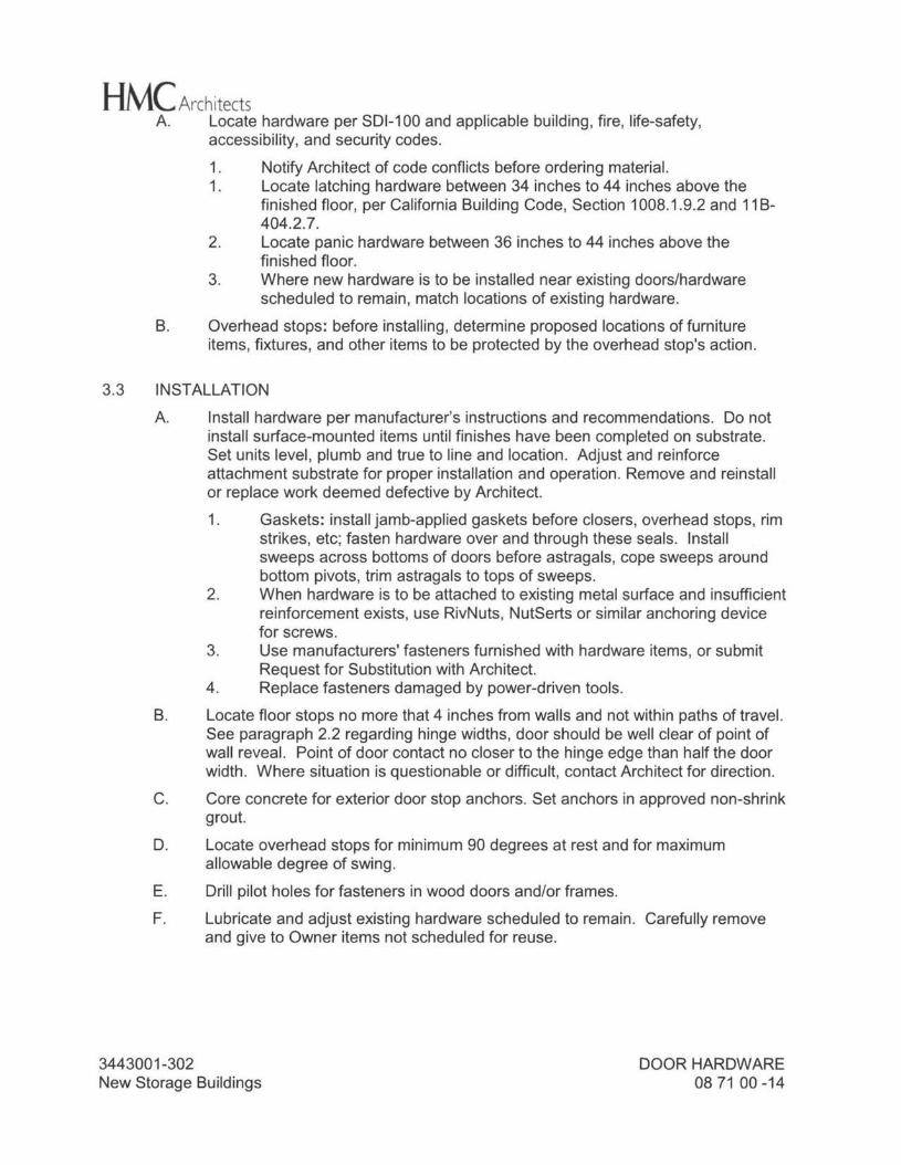
HM( Architects A. Locate hardware per SDl-100 and applicable building, fire, life-safety,
accessibility, and security codes.
1. Notify Architect of code conflicts before ordering material. 1. Locate latching hardware between 34 inches to 44 inches above the
finished floor, per California Building Code, Section 1008.1.9.2 and 11 B- 404.2. 7.
2. Locate panic hardware between 36 inches to 44 inches above the finished floor.
3. Where new hardware is to be installed near existing doors/hardware scheduled to remain, match locations of existing hardware.
B. Overhead stops: before installing, determine proposed locations of furniture items, fixtures, and other items to be protected by the overhead stop's action.
3.3 INSTALLATION A. Install hardware per manufacturer's instructions and recommendations. Do not
install surface-mounted items until finishes have been completed on substrate. Set units level, plumb and true to line and location. Adjust and reinforce attachment substrate for proper installation and operation. Remove and reinstall or replace work deemed defective by Architect. 1. Gaskets: install jamb-applied gaskets before closers, overhead stops, rim
strikes, etc; fasten hardware over and through these seals. Install sweeps across bottoms of doors before astragals, cope sweeps around bottom pivots, trim astragals to tops of sweeps.
2. When hardware is to be attached to existing metal surface and insufficient reinforcement exists, use RivNuts, NutSerts or similar anchoring device for screws.
3. Use manufacturers' fasteners furnished with hardware items, or submit Request for Substitution with Architect.
4. Replace fasteners damaged by power-driven tools. B. Locate floor stops no more that 4 inches from walls and not within paths of travel.
See paragraph 2.2 regarding hinge widths, door should be well clear of point of wall reveal. Point of door contact no closer to the hinge edge than half the door width. Where situation is questionable or difficult, contact Architect for direction.
C. Core concrete for exterior door stop anchors. Set anchors in approved non-shrink grout.
D. Locate overhead stops for minimum 90 degrees at rest and for maximum allowable degree of swing.
E. Drill pilot holes for fasteners in wood doors and/or frames. F. Lubricate and adjust existing hardware scheduled to remain. Carefully remove
and give to Owner items not scheduled for reuse.
3443001-302 New Storage Buildings
DOOR HARDWARE 08 71 00 -14
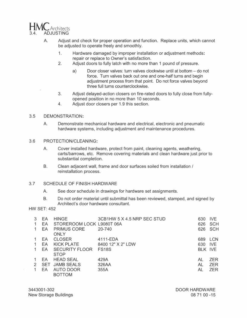
HM( Architects 3.4. ADJUSTING
A. Adjust and check for proper operation and function. Replace units, which cannot be adjusted to operate freely and smoothly. 1. Hardware damaged by improper installation or adjustment methods:
repair or replace to Owner's satisfaction. 2. Adjust doors to fully latch with no more than 1 pound of pressure.
a) Door closer valves: turn valves clockwise until at bottom - do not force. Turn valves back out one and one-half turns and begin adjustment process from that point. Do not force valves beyond three full turns counterclockwise.
3. Adjust delayed-action closers on fire-rated doors to fully close from fully opened position in no more than 1 O seconds.
4. Adjust door closers per 1.9 this section.
3.5 DEMONSTRATION: A. Demonstrate mechanical hardware and electrical, electronic and pneumatic
hardware systems, including adjustment and maintenance procedures.
3.6 PROTECTION/CLEANING:
A. Cover installed hardware, protect from paint, cleaning agents, weathering, carts/barrows, etc. Remove covering materials and clean hardware just prior to substantial completion.
B. Clean adjacent wall, frame and door surfaces soiled from installation / reinstallation process.
3.7 SCHEDULE OF FINISH HARDWARE A. See door schedule in drawings for hardware set assignments. B. Do not order material until submittal has been reviewed, stamped, and signed by
Architect's door hardware consultant. HW SET: 452
3 EA HINGE 3CB1HW 5 X 4.5 NRP SEC STUD 630 IVE 1 EA STOREROOM LOCK L9080T 06A 626 SCH 1 EA PRIMUS CORE 20-740 626 SCH
ONLY 1 EA CLOSER 4111-EDA 689 LCN 1 EA KICK PLATE 8400 12" X 2" LOW 630 IVE 1 EA SECURITY FLOOR FS18S BLK IVE
STOP 1 EA HEAD SEAL 429A AL ZER 2 SET JAMB SEALS 326AA AL ZER 1 EA AUTO DOOR 355A AL ZER
BOTTOM
3443001-302 New Storage Buildings
DOOR HARDWARE 08 71 00 -15
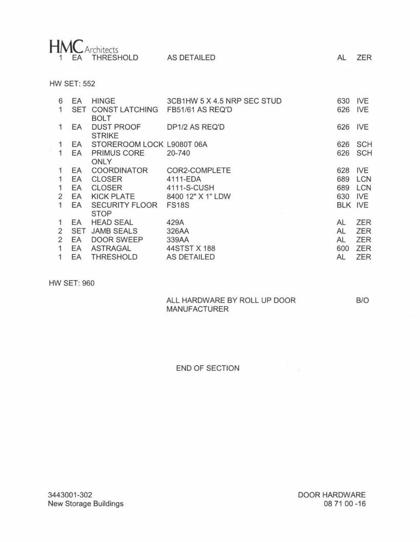
HM( Architects 1 EA THRESHOLD AS DETAILED AL ZER
HW SET: 552
6 EA HINGE 3CB1 HW 5 X 4.5 NRP SEC STUD 630 IVE 1 SET CONST LATCHING FB51/61 AS REQ'D 626 IVE
BOLT 1 EA DUST PROOF DP1/2 AS REQ'D 626 IVE
STRIKE 1 EA STOREROOM LOCK L9080T 06A 626 SCH 1 EA PRIMUS CORE 20-740 626 SCH
ONLY 1 EA COORDINATOR COR2-COMPLETE 628 IVE 1 EA CLOSER 4111-EDA 689 LCN 1 EA CLOSER 4111-S-CUSH 689 LCN 2 EA KICK PLATE 8400 12" X 1" LOW 630 IVE 1 EA SECURITY FLOOR FS18S BLK IVE
STOP 1 EA HEAD SEAL 429A AL ZER 2 SET JAMB SEALS 326AA AL ZER 2 EA DOOR SWEEP 339AA AL ZER 1 EA ASTRAGAL 44STST X 188 600 ZER 1 EA THRESHOLD AS DETAILED AL ZER
HW SET: 960
ALLHARDWAREBYROLLUPDOOR B/0 MANUFACTURER
END OF SECTION
3443001-302 New Storage Buildings
DOOR HARDWARE 08 71 00 -16
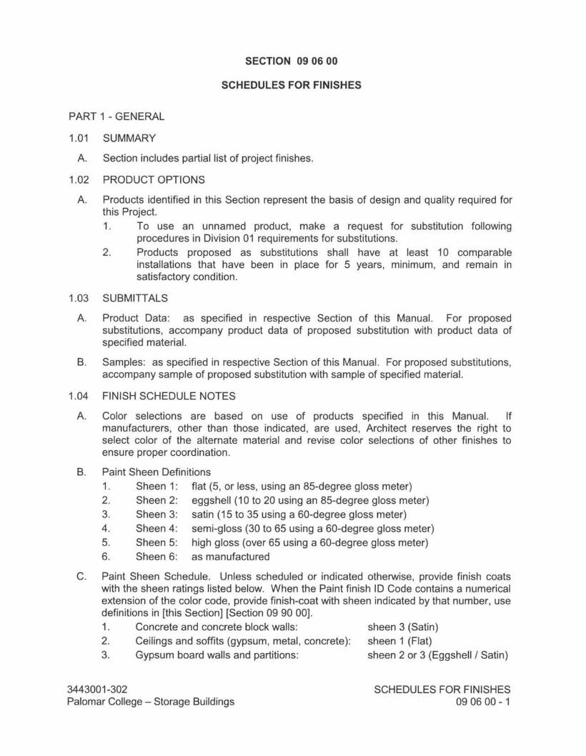
SECTION 09 06 00
SCHEDULES FOR FINISHES
PART 1 - GENERAL
1.01 SUMMARY
A. Section includes partial list of project finishes.
1.02 PRODUCT OPTIONS
A. Products identified in this Section represent the basis of design and quality required for this Project. 1. To use an unnamed product, make a request for substitution following
procedures in Division 01 requirements for substitutions. 2. Products proposed as substitutions shall have at least 10 comparable
installations that have been in place for 5 years, minimum, and remain in satisfactory condition.
1.03 SUBMITTALS
A. Product Data: as specified in respective Section of this Manual. For proposed substitutions, accompany product data of proposed substitution with product data of specified material.
B. Samples: as specified in respective Section of this Manual. For proposed substitutions, accompany sample of proposed substitution with sample of specified material.
1.04 FINISH SCHEDULE NOTES
A. Color selections are based on use of products specified in this Manual. If manufacturers, other than those indicated, are used, Architect reserves the right to select color of the alternate material and revise color selections of other finishes to ensure proper coordination.
Paint Sheen Definitions 1. Sheen 1: flat (5, or less, using an 85-degree gloss meter) 2. Sheen 2: eggshell ( 10 to 20 using an 85-degree gloss meter) 3. Sheen 3: satin (15 to 35 using a 60-degree gloss meter) 4. Sheen 4: semi-gloss (30 to 65 using a 60-degree gloss meter) 5. Sheen 5: high gloss (over 65 using a 60-degree gloss meter) 6. Sheen 6: as manufactured
8.
C. Paint Sheen Schedule. Unless scheduled or indicated otherwise, provide finish coats with the sheen ratings listed below. When the Paint finish ID Code contains a numerical extension of the color code, provide finish-coat with sheen indicated by that number, use definitions in [this Section] [Section 09 90 00]. 1. Concrete and concrete block walls: 2. Ceilings and soffits (gypsum, metal, concrete): 3. Gypsum board walls and partitions:
3443001-302 Palomar College - Storage Buildings
sheen 3 (Satin) sheen 1 (Flat) sheen 2 or 3 (Eggshell/ Satin)
SCHEDULES FOR FINISHES 09 06 00 - 1
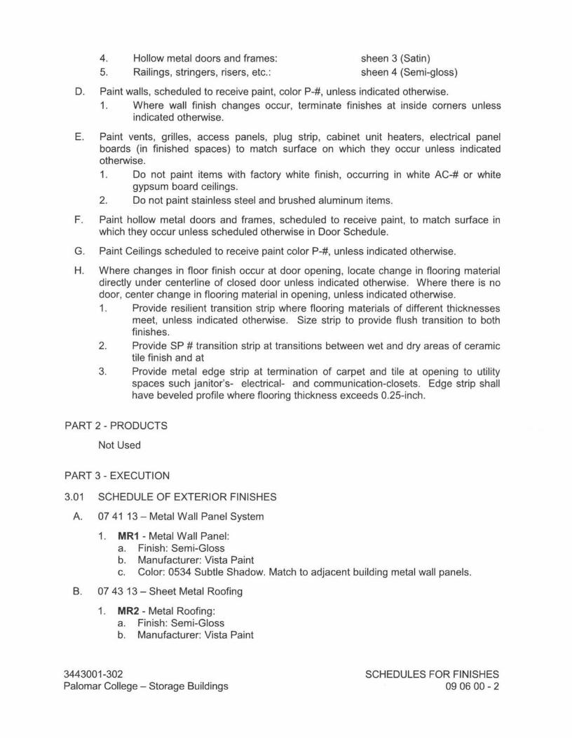
4. 5.
Hollow metal doors and frames: Railings, stringers, risers, etc.:
sheen 3 (Satin) sheen 4 (Semi-gloss)
D. Paint walls, scheduled to receive paint, color P-#, unless indicated otherwise. 1. Where wall finish changes occur, terminate finishes at inside corners unless
indicated otherwise.
E. Paint vents, grilles, access panels, plug strip, cabinet unit heaters, electrical panel boards (in finished spaces) to match surface on which they occur unless indicated otherwise. 1. Do not paint items with factory white finish, occurring in white AC-# or white
gypsum board ceilings. 2. Do not paint stainless steel and brushed aluminum items.
F. Paint hollow metal doors and frames, scheduled to receive paint, to match surface in which they occur unless scheduled otherwise in Door Schedule.
G. Paint Ceilings scheduled to receive paint color P-#, unless indicated otherwise.
H. Where changes in floor finish occur at door opening, locate change in flooring material directly under centerline of closed door unless indicated otherwise. Where there is no door, center change in flooring material in opening, unless indicated otherwise. 1. Provide resilient transition strip where flooring materials of different thicknesses
meet, unless indicated otherwise. Size strip to provide flush transition to both finishes.
2. Provide SP # transition strip at transitions between wet and dry areas of ceramic tile finish and at
3. Provide metal edge strip at termination of carpet and tile at opening to utility spaces such janitor's- electrical- and communication-closets. Edge strip shall have beveled profile where flooring thickness exceeds 0.25-inch.
PART 2 - PRODUCTS
Not Used
PART 3 - EXECUTION
3.01 SCHEDULE OF EXTERIOR FINISHES
A. 07 41 13 - Metal Wall Panel System
1. MR1 - Metal Wall Panel: a. Finish: Semi-Gloss b. Manufacturer: Vista Paint c. Color: 0534 Subtle Shadow. Match to adjacent building metal wall panels.
B. 07 43 13 - Sheet Metal Roofing
1. MR2 - Metal Roofing: a. Finish: Semi-Gloss b. Manufacturer: Vista Paint
3443001-302 Palomar College - Storage Buildings
SCHEDULES FOR FINISHES 09 06 00 - 2
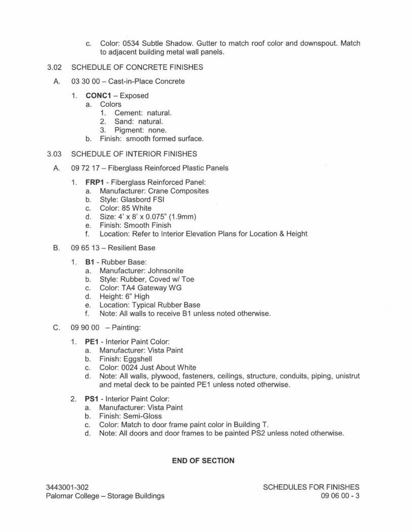
c. Color: 0534 Subtle Shadow. Gutter to match roof color and downspout. Match to adjacent building metal wall panels.
3.02 SCHEDULE OF CONCRETE FINISHES
A. 03 30 00 - Cast-in-Place Concrete
1. CONC1 - Exposed a. Colors
1. Cement: natural. 2. Sand: natural. 3. Pigment: none.
b. Finish: smooth formed surface.
3.03 SCHEDULE OF INTERIOR FINISHES
A. 09 72 17 - Fiberglass Reinforced Plastic Panels
1. FRP1 - Fiberglass Reinforced Panel: a. Manufacturer: Crane Composites b. Style: Glasbord FSI c. Color: 85 White d. Size: 4' x 8' x 0.075" (1.9mm) e. Finish: Smooth Finish f. Location: Refer to Interior Elevation Plans for Location & Height
B. 09 65 13 - Resilient Base
1. B1 - Rubber Base: a. Manufacturer: Johnsonite b. Style: Rubber, Coved w/ Toe c. Color: TA4 Gateway WG d. Height: 6" High e. Location: Typical Rubber Base f. Note: All walls to receive B 1 unless noted otherwise.
C. 09 90 00 - Painting:
1. PE1 - Interior Paint Color: a. Manufacturer: Vista Paint b. Finish: Eggshell c. Color: 0024 Just About White d. Note: All walls, plywood, fasteners, ceilings, structure, conduits, piping, unistrut
and metal deck to be painted PE1 unless noted otherwise.
2. PS1 - Interior Paint Color: a. Manufacturer: Vista Paint b. Finish: Semi-Gloss c. Color: Match to door frame paint color in Building T. d. Note: All doors and door frames to be painted PS2 unless noted otherwise.
END OF SECTION
3443001-302 Palomar College - Storage Buildings
SCHEDULES FOR FINISHES 09 06 00 - 3
HMC Architects
SECTION 09 29 00
GYPSUM BOARD
PART 1 - GENERAL
1.01 SECTION INCLUDES
A. Roof Board Panels.
B. Vertical wall gypsum board application.
C. Taped and sanded joint treatment.
D. Exterior gypsum sheathing board.
E. Repair of Gypsum Board surfaces.
F. Related Sections 1. Section 01 35 42, CALGreen Requirements. 2. Section 05 40 00, Cold-Formed Metal Framing. 3. Section 07 41 13, Metal Roofing Panel. 4. Section 07 42 13, Formed Metal Wall Panels.
1.02 REFERENCES
A. American Society for Testing and Materials (ASTM) 1. ASTM C475 - Joint Compound and Joint Tape for Finishing Gypsum Board. 2. ASTM C645 - Specification for Nonstructural Steel Framing Members. 3. ASTM C754 - Specification for Installation of Steel Framing Members to Receive
Screw-Attached Gypsum Panel Products. 4. ASTM C840 - Application and Finishing of Gypsum Board. 5. ASTM C954 - Specification for Steel Drill Screws for the Application of Gypsum
Panel Products or Metal Plaster Bases to Steel Studs from 0.033 in. to 0.112 in. in thickness.
6. ASTM C1002 - Steel Drill Screws for the Application of Gypsum Board or Metal Plaster Bases.
7. ASTM C1177 - Glass Mat Gypsum Substrate for Use as Sheathing. 8. ASTM C1396 - Specification for Gypsum Board.
B. Gypsum Association (GA) 1. GA-201 - Gypsum Board for Walls and Ceilings 2. GA-214 - Levels of Gypsum Board Finish 3. GA-216 - Application and Finishing of Gypsum Board
C. 2013 California Building Code (CBC) 1. CBC-25 - Chapter 25, Gypsum Board and Plaster
D. California Green Building Standards Code, CALGreen - 2013.
3443001-302 Palomar College New Storage Buildings
GYPSUM BOARD 09 29 00 - 1
HMC Architects
1.03 SUBMITTALS
A. CALGreen Submittals: 1. Product Data Sheets and Declaration Statements showing compliance with
CALGreen Code per 1.04.A.
B. Product Data: For each type of product indicated.
C. Shop Drawings: Show locations, fabrication, and installation of control and expansion joints including plans, elevations, sections, details of components, and attachments to other units of Work.
D. Samples: For following products: 1. Trim Accessories: Full-size sample in 12-inch-long length for each trim
accessory indicated.
1.04 QUALITY ASSURANCE
A. California Green Building Standards Code, CALGreen - 2013. 1. Adhesive, sealants, primers, and caulks shall comply with air quality
management district rules where applicable, or SCAQMD Rule 1168 VOC limits, per CALGreen Tables 5.504.4.1 and 5.504.4.2.
2. Paints and Coatings shall comply with VOC limits in Table 1 of the ARB, per CALGreen Table 5.504.4.3.
B. Applicator: Company specializing in gypsum board systems work with three years experience.
1.05 DELIVERY, STORAGE, AND HANDLING
A. Deliver materials in original packages, containers, or bundles bearing brand name and identification of manufacturer or supplier.
B. Store materials inside under cover and keep them dry and protected against damage from weather, direct sunlight, surface contamination, corrosion, construction traffic, and other causes. Stack gypsum panels flat to prevent sagging.
C. Steel Framing and related accessories shall be stored and handled in accordance with AISI Code of Standard Practice.
1.06 PROJECT CONDITIONS
A. Environmental Limitations: Comply with ASTM C840 requirements or gypsum board manufacturer's written recommendations, whichever are more stringent.
PART 2 - PRODUCTS
2.01 MANUFACTURERS
A. Products of following manufacturer form basis for design and quality intended:
3443001-302 Palomar College New Storage Buildings
GYPSUM BOARD 09 29 00 - 2
HMC Architects 1. United States Gypsum Corporation (USG), Chicago, IL.
B. Subject to compliance with requirements, other acceptable manufacturers include the following: 1. Georgia-Pacific, Atlanta, GA. 2. National Gypsum Co./Gold Bond Building Products, Charlotte, NC. 3. Pabco Gypsum, Rancho Cordova, CA. 4. CertainTeed Corporation, Valley Forge, PA.
C. Or equal as approved in accordance with Division 01, General Requirements for Substitutions.
2.02 BOARD MATERIALS
A. Regular Gypsum Board: ASTM C1396; 5/8 inch thick, maximum permissible length; ends square cut, tapered round edges, USG SHEETROCK BRAND TAPERED GYPSUM PANELS.
B. Exterior Gypsum Sheathing Board.under metal wall panels, System: ASTM C1177; moisture resistant, and fire resistant, Type X, 1/2 inch thick, maximum permissible length, ends square cut, inorganic glass fiber mat faced, 48 inch width, DensGlass Exterior Sheathing by Georgia Pacific, USG Securock Glass-Mat, Gold Bonde XP by National Gypsum, GlasRoc Brand Sheathing by Certainteed, Pabco Glass by Pabco Gypsum or equal. 1. Install Weather Resistive Barrier at exterior wall over sheathing substrate.
C. Roof Boards: Exterior gypsum board 1/2 inch, DensDeck Prime Roof Boards by Georgia-Pacific, ASTM C1177, Class A (UL 790).
2.03 MATERIALS
A. Angles: 1-3/8 inch by 7/8 inch, 24 gauge, Dietrich Metal Framing, CEMCO GALVANIZED METAL ANGLES or equal.
B. Runner Channels: Minimum weights, sizes and maximum spans conform to reference standard listed in Table 2506.2 California Building Code, 1-1/2", 1.12 lbs/foot, hot-rolled channels as defined therein.
C. Taping, Bedding and Finishing Compound: ASTM C475; compatible with tape and substrate. 1. USG SHEETROCK Brand Taping Joint Compound Ready-Mixed, drying-type,
non-asbestos, vinyl base. 2. USG SHEETROCK Brand Topping Joint Compound Ready-Mixed, drying-type
non-asbestos, vinyl base. 3. USG SHEETROCK Powder Joint Compound, drying-type, non-asbestos vinyl
base, conventionally drying. For Taping and Topping. 4. USG SHEETROCK Powder Setting-type Joint Compound, chemical hardening. 5. Contractor's Option: USG SHEETROCK Lightweight All Purpose Joint
Compound (Plus 3) with Dust Control. 6. USG SHEETROCK Brand All Purpose Joint Compound Ready-Mixed for
laminating gypsum panels in multilayer partitions.
3443001-302 Palomar College New Storage Buildings
GYPSUM BOARD 09 29 00 - 3
HMC Architects 7. USG SHEETROCK Brand Joint Tape-Heavy, ASTM C475, high strength
cross-fibered paper tape. 8. Drywall Primers: USG First Coat. 9. Or equal as approved in accordance with Division 01, General Requirements for
substitutions.
D. Accessories: Corrosive Protective-Coated steel. 1. U-Trims: USG, Dietrich No. 200-A for joint compound or equal. [USG, Dietrich
No. 801A for one-coat plaster system and No. 701A for two-coat plaster]. 2. J-Trim Casings, reveal type: USG, Dietrich No. 401 for 1/2" panels, 402 for 5/8"
panels, no finishing compound. 3. Control Joint: Dietrich 093, USG Control Joint No. 093, Zinc metal. 4. Corner Bead: USG, Dietrich No. 103 for joint compounds or equal. [USG
Dietrich MiniBead, No. 800 or 900 for veneer plaster applications].
E. Fasteners: Self-drilling tapping screws shall comply ASTM C 954; Self piercing screws shall comply ASTM C 1002; 1. ASTM C1002, No. 2 Phillips recessed, bugle head, power-driven. Nails not
permitted. 2. Type S-12, ASTM C954, 16 gage steel studs, minimum penetration 3/8 inch. 3. Type S, ASTM C 1002, 20 gage steel studs, minimum penetration 3/8 inch.
PART 3 - EXECUTION
3.01 INSPECTION
A. Verify that site conditions are ready to receive Work.
8. Beginning installation means acceptance of substrate.
3.02 PREPARATION
A. Delivery and Storage: Arrange for an adequate supply of materials on the jobsite so that progress of Work will be uninterrupted. Materials and accessories shall be delivered in original containers and bundles, and identified with the manufacturer's name and brand. Store gypsum board on flat, solid supports in dry areas, well protected from the elements.
B. Provide fixtures, anchors, sleeves, inserts and miscellaneous items, and provide openings and chases as necessary. Prior to closing in and finishing of dry wall Work, ascertain that piping, conduit, ductwork and fixtures which are to be concealed and which penetrate gypsum boards are in place, tested and approved.
C. Protection, Patching and Cleaning: Adjacent surfaces of other materials shall be protected from damage. Dry wall surfaces that have been cut out shall be neatly patched. Damaged or defective gypsum board finish shall be replaced. During progress of Work, rubbish droppings and water materials shall be removed.
3443001-302 Palomar College New Storage Buildings
GYPSUM BOARD 09 29 00 - 4
HMC Architects
3.03 GYPSUM BOARD INSTALLATION
A. Install gypsum board in accordance with ASTM C840, GA 201, GA 216 and Section 2508 California Building Code. Conform to DSA, IR 25-3. Use board types as indicated; if not indicated use board types as follows.
B. Non-rated: Erect single layer gypsum board parallel or perpendicular on vertical framing, attached to studs and framing members with the specified fasteners spaced at 16" on center with screws and at top and bottom, 12" on center with screws at ceilings. Solid backing not required at joints running perpendicular to studs and framing members for walls.
C. Place control joints consistent with lines of building spaces as indicated or at maximum of 30 ft on centers.
D. Seal all cutout and penetrations: For electrical, mechanical, plumbing and structural framing cutouts and penetration at interior surfaces. Per Section 07 92 00 for non-rated walls.
E. Foil-backed gypsum board shall be applied on the inside of exterior walls.
3.04 JOINT TREATMENT
A. Exposed gypsum board in wall areas and ceiling areas shall have joint compound and be taped and sanded per requirements of GA-114 for levels specified and ready for paint.
B. On installations where two layers of gypsum board are required, only the face layer will require finishing of joints and screwheads.
C. Gypsum wallboard joints in walls may either be exposed or covered with joint tape and joint compound for the portion of the wall above a suspended ceiling, which is part of a fire resistive floor-ceiling or roof-ceiling assembly, as listed in U.L. Fire Resistive Ratings (BXUV), when the following conditions are met: 1. Vertical joints occur over framing members. 2. Horizontal joints are staggered 24 inches on opposite sides or covered with 6
inch wide strips of gypsum board attached with 1-1 /2 inch laminating screws at 8 inches on centers.
3. Partition is two-ply system with joints staggered 16 inches or 24 inches. 4. Partition is not part of a smoke or sound control system.
D. Joints, except where excluded above including internal corners, shall be filled and taped. Thin uniform layer of joint compound, approximately 3 inches wide, shall be applied over joint. Tape shall be set in joint compound and finish levels required below. Internal angles, both horizontal and vertical, shall be reinforced and with tape folded to form straight and true angle. Metal external corners shall be set in place. Joints shall be allowed to dry at least 24 hours between each application of cement.
E. Gypsum board finish shall be to the following levels as defined by GA-214: 1. Plenum areas above ceilings - Level 1.
3443001-302 Palomar College New Storage Buildings
GYPSUM BOARD 09 29 00 - 5
HMC Architects 2. Substrate for tile, tackable wall panels, tackboards and markerboards - Level 2. 3. Areas receiving heavy textured paint - Level 3. 4. Areas receiving non-textured, flat, egg-shell, gloss or semi-gloss paint - Level 4.
This is the standard Level of board finish for project. 5. Level 5, not used.
3.05 EXTERIOR GYPSUM SHEATHING INSTALLATION AT WALLS
A. Erect exterior gypsum sheathing horizontally with edges butted tight and ends occurring over firm bearing. Install screw pattern per Gypsum Association G216 for vertical application.
B. Do not install more exterior sheathing than can be covered with weather barrier by the end of the day or the onset of inclement weather.
3.06 ROOF BOARD INSTALLATION
A. DensDeck Roof Board or equal shall be installed according to roofing manufacturer's instructions and to achieve FM 1-90.
B. DensDeck shall be neatly cut to fit around penetrations and projections.
C. Do not install more roof board than can be covered with roof membrane by the end of the day or the onset of inclement weather.
D. Install weather barrier
E. Mechanical Attachment: 1. Dens Deck shall be mechanically fastened to the deck with approved fasteners
and plates at a rate according to the insulation manufacturer's, FM's and manufacturers' recommendations for fastening rates and patterns. The quantity and locations of the fasteners and plates shall also cause the boards to rest evenly on the roof deck so that there are no significant and avoidable air spaces between the boards and the substrate. Each Dens Deck board shall be installed tightly against the adjacent boards on all sides.
2. Fasteners are to be installed consistently in accordance with fastener manufacturer's recommendations. Fasteners are to have minimum penetration into structural deck recommended by the fastener manufacturer and roofing manufacturer.
3. Use fastener tools with a depth locator and torque-limiting attachment as recommended or supplied by fastener manufacturer to ensure proper installation.
F. Install 12 fasteners, minimum for each 4 x 8 sheet unless different quantity required for FMRC-90 wind-uplift for roof board specified.
3.07 REPAIR OF GYPSUM BOARD SURFACES
A. Interior Walls: Repair all walls after ceilings are completed.
3443001-302 Palomar College New Storage Buildings
GYPSUM BOARD 09 29 00 - 6
HMC Architects
3.08 TOLERANCES
A. Maximum Variation from True Flatness: 1 /8 inch in 10 feet in any direction.
END OF SECTION
3443001-302 Palomar College New Storage Buildings
GYPSUM BOARD 09 29 00 - 7
HMC Architects
SECTION 09 65 13
RESILIENT BASE
PART 1 - GENERAL
1.01 SECTION INCLUDES
A. Resilient base, rubber.
B. Accessories.
C. Related Sections 1. Section 01 35 42, CALGreen Requirements. 2. Section 09 06 00, Schedules for Finishes.
1.02 REFERENCES
A. ASTM E648 and NFPA 253 - Critical Radiant Flux of Floor Covering Systems.
B. ASTM E84 - Test Method for Surface Burning Characteristics of Building Materials
C. ASTM F1861 - Resilient Wall Base
D. California Green Building Standards Code, CALGreen - 2013.
E. Local SCAQMD - Local South Coast Air Quality Management District Regulations Rule 1168 Adhesive and Sealant Applications
F. Green Seal Standard GS-36, Commercial Adhesives
1.03 FIRE CLASSIFICATION REQUIREMENTS
A. ASTM E648, NFPA 253: Class 1, Critical Radiant Flux Flame Spread Value: minimum 0.45 watts per sq cm.
B. ASTM E84, smoke density less than 450.
1.04 SUBMITTALS
A. CALGreen Submittals: 1. Product Data Sheets and Declaration Statements showing compliance with
CALGreen Code per 1.05.A.
B. Product data on specified products and colors available.
C. Three 6 inch long samples of base material for each color selected.
D. Manufacturer's installation instructions.
E. Maintenance procedures and recommended maintenance materials.
3443001-302 Palomar College New Storage Buildings
RESILIENT BASE 09 65 13- 1
HMC Architects
1.05 QUALITY ASSURANCE
A. California Green Building Standards Code, CALGreen - 2013. 1. Adhesives, sealants, primers, and caulks shall comply with air quality
management district rules where applicable, or SCAQMD Rule 1168 VOC limits, per CALGreen Tables 5.504.4.1 and 5.504.4.2.
2. Paints and Coatings shall comply with VOC limits in Table 1 of the ARB, per CALGreen Table 5.504.4.3.
1.06 ENVIRONMENTAL REQUIREMENTS
A. Store materials for three days prior to installation in area of installation to achieve temperature stability.
B. Maintain minimum 70 degrees F temperature three days prior to, during and 24 hours after installation of materials.
C. Provide adequate ventilation to carry off volatile fumes.
1.07 WARRANTY
A. Submit under provisions of Division 01, General Requirements.
B. Provide manufacturer's 1 year warranty against defects and wear-through.
1.08 REPLACEMENT MATERIALS
A. Provide minimum three percent of all materials furnished for each color and size of materials installed.
PART 2 - PRODUCTS
2.01 MANUFACTURERS, RUBBER
A. Johnsonite, Chagrin Falls, OH.
B. Burke Mercer Flooring Products, San Jose, CA.
C. Nora Flooring Systems, Lawrence, MA.
D. Endura Co., Waltham, MA.
E. Roppe Corp., Fostoria, OH.
F. Or equal as approved in accordance with Division 01, General Requirements for substitutions.
2.02 BASE MATERIALS
A. Base: Rubber vinyl, 1/8 inch gauge, standard toe, 4 inches.
3443001-302 Palomar College New Storage Buildings
RESILIENT BASE 09 65 13 - 2
HMC Architects
B. Base material shall meet ASTM F1861 Type TS for rubber base, Group I or II, Style B Coved profile for hard surface floors .
C. Base Accessories: size and color as base.
D. Adhesive: As recommended by the manufacturer and if full compliance with California voe regulations.
E. Non-aerosol adhesives applied on-site shall comply with VOC content limits defined by SCAQMD Rule 1168. Aerosol adhesives shall comply with VOC contents limits by Green Seal Standard GS-36.
F. Colors: Refer to Section 09 06 00, Schedules for Finishes.
PART 3 - EXECUTION
3.01 EXAMINATION
A. Verify that surfaces are smooth and flat with maximum variation of 1/8 inch in 10 ft and are ready to receive Work.
B. Verify that surfaces are finished, ready to receive base installation.
C. Beginning of installation means acceptance of existing substrate and site conditions.
3.02 INSTALLATION - BASE MATERIAL
A. Fit joints tight and vertical. Maintain minimum measurement of 18 inches between joints.
B. At 90 degree external corners: Cut from 120 foot rolls only, do not use 4" segments. At corners more or less than 90 degrees, shave a vertical strip down the back side of the material, 1/4 inch wide and not more than 1/2 the thickness at the point of bend. Bend coved toe to required angle. Bond material firmly to wall on both sides of joint to ensure a tight fit with no open void at top.
C. Inside Corners: Cut an inverted V-shaped notch in the toe of the wall base at the place where the corner is to be formed. Bend the base once or twice at a right angle to shape the corner. Form the corner and check the fit. Apply adhesive completely to the back of the base and to the wall area to be covered by the corner. Press firmly in position on and roll with a small hand roller.
D. Pre-molded units will not be accepted.
E. Install base on solid backing. Bond tight to wall and floor surfaces.
F. Scribe and fit to door frames and other interruptions.
3443001-302 Palomar College New Storage Buildings
RESILIENT BASE 09 65 13 - 3
HMC Architects
3.03 CLEANING
A. Remove excess adhesive from floor, base and wall surfaces without damage.
B. Protection: Protect work until completion. Repair or make good any damage to this work and other materials damaged during installation of base material.
3.04 SCHEDULE
A. Install at all walls not specified to receive integral base and as scheduled in the finish schedule.
B. Do not apply base to toe kick at casework.
END OF SECTION
3443001-302 Palomar College New Storage Buildings
RESILIENT BASE 09 65 13- 4
HMC Architects
SECTION 09 72 17
FIBERGLASS REINFORCED PLASTIC PANELS
PART 1 - GENERAL
1.01 SECTION INCLUDES
A. Fiberglass Reinforced Plastic Wall Panels. (FRP).
B. Components and moldings.
C. Sealants
1.02 REFERENCES
A. USDA - United States Department of Agriculture.
B. ASME E84 - Surface Burning Characteristics of Building Materials.
C. AQMD, Local Regulations.
1.03 SUBMITTALS
A. Product data.
B. Manufacturer's current recommended method of installation.
C. Three (3) sets of samples of panels and molding illustrating color, texture, thickness and physical characteristics.
D. Certification of USDA approval for use of material in food handling facilities.
1.04 QUALITY ASSURANCE
A. Product Manufacturer: Company specializing in manufacturing products specified herein with minimum ten years experience.
B. Applicator: Company specializing in installation of specified products with minimum five years experience.
C. Flame spread classification requirements 1. ASTM E84, Class I/A flame spread less than 25, smoke density less than 450.
1.05 DELIVERY, STORAGE AND HANDLING
A. Deliver materials to the project site with manufacturer's labels intact and legible.
B. Handle materials with care to prevent damage.
C. Deliver materials bearing USDA accepted label and required classification numbers.
3443001-302 Palomar College New Storage Buildings
FIBERGLASS REINFORCED PLASTIC PANELS 09 72 17 - 1
HMC Architects
D. Store materials under cover, stacked flat, off floor.
E. Stack panels so that long lengths are not over short lengths.
1.06 ENVIRONMENTAL CONDITIONS
A. Maintain temperature range between 55 degrees F. to 70 degrees F. for 24 hours before, during and after gypsum wallboard and joint treatment applications.
B. Provide ventilation during and following sealing of joints.
C. Adhesives shall conform to AQMD, Local Regulations.
PART 2 - PRODUCTS
2.01 MANUFACTURERS
A. Products of the following manufacturers form the basis for design and quality intended. 1. Crane Composites, Channatton, IL. 2. Marlite Inc., Dover, OH. 3. Nudo Products, Inc., Springfield, IL.
B. Or equal as approved in accordance with Division 01, General Requirements for substitutions.
2.02 MATERIALS
A. Crane Composites; Class A, 0.075 inch thick, interior liner panels, chemical, stain, odor, moisture and impact resistant. Panels shall not support mold or mildew.
B. Colors and Materials: Refer to Section 09 06 00, Schedules for Finishes.
2.03 ACCESSORIES
A. Moldings: Aluminum . Designs and thickness shall match panels. Provide at all edges, divider joints, interior corners and exterior corners.
B. Sealant: MS250 clear, one-part silicone, conforming to requirements of Section 07 92 00.
C. Adhesive: C375 neoprene based or C551 latex based construction adhesive, VOC Compliant.
PART 3 - EXECUTION
3.01 EXAMINATION
A. Verify that surfaces are ready to receive the work of this section.
3443001-302 Palomar College New Storage Buildings
FIBERGLASS REINFORCED PLASTIC PANELS 09 72 17 - 2
HMC Architects
B. Verify that plywood substrate fasteners have been countersunk at areas to receive FRP.
C. Beginning of installation means installer accepts existing surfaces.
3.02 INSTALLATION
A. Install panels plumb, level and with all vertical joints on bearing.
B. Verify location and install all trim required. Install all trim and sealant in accordance with the manufacturer's recommendations.
3.03 CLEANING
A. Do not allow the accumulation of debris, immediately remove spilled or splashed material and all trace of residues.
END OF SECTION
3443001-302 Palomar College New Storage Buildings
FIBERGLASS REINFORCED PLASTIC PANELS 09 72 17 - 3
HMC Architects
SECTION 09 90 00
PAINTING
PART 1 - GENERAL
1.01 SUMMARY
A. Section Includes: Fluid applied paints and coatings. Upon completion of Work, all visible interior and exterior surfaces, within the Contract limits shall be painted unless scheduled "Not to Be Painted" in this Section. 1. Each paint system includes:
a. Surface preparation, including touch-up of shop applied primers, if needed. b. Prime coat application, where scheduled as part of finish system. c. Finish coat application, where scheduled apply two or more finish coats.
2. Paint semi-concealed areas (e.g. inside of light troughs and valances, behind grilles, and projecting edges above and below sight lines, behind wall-mounted items).
B. Surfaces Not To Be Painted: 1. Items with factory-applied final finish 2. Concealed ducts, pipes, and conduit. 3. Surfaces of steel items that will be embedded in concrete. 4. Surfaces specifically scheduled or noted on the Drawings not to be painted. 5. Performance Rating labels on equipment.
C. Related Sections: 1. Section 01 35 42, CALGreen Requirements. 2. Section 09 06 00, Schedules for Finishes
1.02 REFERENCES
A. ASTM International - American Society for Testing and Materials: 1. ASTM D 4444 - Use and Calibration of Hand-Held Moisture Meters 2. ASTM D 6386 - Preparation of Zinc (Hot-Dip Galvanized) Coated Iron and Steel
Product and Hardware Surfaces for Painting
B. Green Seal Standard GC-03, Anti Corrosive Paints, Second Edition, January 1997.
C. AQMD - Air Quality Management District 1. AQMD Regulations - Local Regulations
D. California Green Building Standards Code, CALGreen - 2013.
E. SCAQMD - South Coast Air Quality Management District 1. SCAQMD-1113 - Rule 1113, Architectural Coatings
F. SSPC - Steel Structures Painting Council.
3443001-302 Palomar College New Storage Buildings
PAINTING 09 90 00 - 1
HMC Architects
1.03 SUBMITTALS
A. CALGreen Submittals: 1. Product Data Sheets and Declaration Statements showing compliance with
CALGreen Code per 1.05.A.
B. Product Data: For each paint system product and accessory item
C. Samples: Of each specified finish system color, texture, and sheen; samples shall be minimum 8-1 /2 by 11 inches in size. 1. Prepare transparent wood finish samples on type and quality of wood specified.
D. Certified Copies of moisture test results
E. Closeout Submittals 1. Material Safety Data Sheets.
F. Submit Qualifications data for manufacturer and applicator required under Quality Assurance.
1.04 MAINTENANCE MATERIALS SUBMITTALS
A. For each color, type, and gloss of paint used in the work provide, as Extra Materials, a quantity equal to approximately 10 percent of the quantity required for its installation rounded to the nearest gallon, or five gallons, whichever is less. 1. Extra Materials shall be from same production run as installed materials. 2. Label each container with locations and dates of related installations; do not
obscure manufacturer's label. 3. Deliver Extra Materials to Site as directed by Owner.
1.05 QUALITY ASSURANCE
A. California Green Building Standards Code, CALGreen - 2013. 1. Adhesives, sealants, primers, and caulks shall comply with air quality
management district rules where applicable, or SCAQMD Rule 1168 VOC limits per CALGreen Tables 5.504.4.1 and 5.504.4.2.
2. Paints and Coatings shall comply with VOC limits in Table 1 of the ARB, per CALGreen Table 5.504.4.3.
B. Manufacturers Qualifications: Company with minimum 10-years' experience manufacturing quality paint and finish products for commercial projects similar in scale and complexity to those required for this Project.
C. Applicator Qualifications: Company with minimum 5-years' experience painting and finishing commercial projects similar in scale and complexity to those required for this Project.
D. Materials, for each paint system, shall be by, or as recommended by, a single coating manufacturer for use together in commercial quality paint / coating system for the substrate and exposure conditions indicated.
3443001-302 Palomar College New Storage Buildings
PAINTING 09 90 00 - 2
HMC Architects
E. Regulatory Requirements 1. Conform to SCAQMD-1113 for maximum voe limits. 2. Comply with applicable codes and regulations of authorities having jurisdiction
including those with jurisdiction over airborne emissions and industrial waste disposal. Where those requirements conflict with this Specification, comply with the more stringent provisions.
F. Field Samples. Provide Field Sample of each finish system color, texture, and sheen scheduled. Do not proceed with coating application until sample panel has been approved. 1. Field Sample shall be full height of wall by 10-feet. 2. Locate as approved by Architect. 3. Adjust materials and methods of installation as required to obtain Architect's
approval. 4. Document materials and methods used to obtain Architect's approval and
maintain at least one copy of this documentation on site while related work is in progress.
5. Maintain access to and protect Field Sample from damage while related work is in progress.
6. Upon acceptance of related work, approved sample may remain as part of Work.
1.06 DELIVERY, STORAGE AND HANDLING
A. Deliver products to site in their original, sealed, undamaged containers with labels intact and legible. 1. Labels shall include manufacturer's name, type of paint, brand name, brand
code, color designation, recommended surface preparation, typical coverage, drying times, cleanup procedures, and instructions for mixing and reducing, if permitted.
B. Store paint materials ambient temperatures between 45- and 90-degrees F, in well ventilated area unless permitted otherwise by manufacturer's instructions.
C. Take precautionary measures to prevent fire hazards and spontaneous combustion.
1.07 FIELD CONDITIONS
A. Supply continuous ventilation and heating facilities to maintain surface and ambient temperatures above 45 degrees F for 24 hours before, during and 48 hours after application of finishes, unless permitted otherwise by manufacturer's instructions.
B. Do not apply exterior coatings during rain, or when relative humidity is above 50 percent, unless permitted otherwise by manufacturer's instructions.
C. Minimum Application Temperatures for Latex Paints: 45 degrees F for interiors; 50 degrees F for exterior; unless required otherwise by manufacturer's instructions.
D. Minimum Application Temperature for Varnish and transparent Finishes: 65 degrees F for interior or exterior, unless permitted otherwise by manufacturer's instructions.
3443001-302 Palomar College New Storage Buildings
PAINTING 09 90 00 - 3
HMC Architects
E. Maintain lighting level sufficient to conduct painting operations.
1.08 GUARANTEE
A. Guarantee the painting Work against peeling, fading, cracking, blistering or crazing for a period of two years from the Date of Certified Completion for painting of new surfaces and existing surfaces.
PART 2 - PRODUCTS
2.01 PAINTS AND COATINGS
A. Acceptable Manufacturers. Products of following manufacturers form basis for design and quality intended. 1. Vista Paint Corporation, Fullerton, CA 2. Dunn-Edwards Corporation, Los Angeles, CA 3. Sherwin-Williams Company, Cleveland, OH 4. Kelly-Moore Paint Company Inc, San Carlos, CA 5. Glidden Professional and Devoe Coatings, Cleveland, OH 6. PPG Industries Inc, Pittsburgh, PA 7. Tnemec Company Inc, Kansas City, MO 8. Carboline Company, St Louis, MO 9. Rust-Oleum Corporation, Somerset, NJ 10. Benjamin Moore & Co, , Montvale, NJ
B. Or equal, approved in accordance with Division 01, General Requirements, for substitutions.
2.02 MATERIALS
A. Coatings: Ready mixed, except field-catalyzed coatings. Process pigments to soft paste consistency, capable of being readily and uniformly dispersed to homogeneous coating.
B. Colors and Glosses: As scheduled in Section 09 06 00. Architect will select color and hue to be used in various types of paint specified and will be sole judge of acceptability of various glosses obtained from materials proposed to be used in Work. During actual painting, Architect may make minor modifications in tone and shade to adjust for actual surface and lighting conditions encountered.
C. Undercoats and Thinners. Provide undercoat paint produced by same manufacturer as finish coat. Use only thinners recommended by paint manufacturer and use only to recommended limits. Use undercoat, finish coat and thinner material as parts of a unified system of paint finish.
D. Coatings: Good flow and brushing properties; capable of drying or curing free of streaks or sags.
3443001-302 Palomar College New Storage Buildings
PAINTING 09 90 00 - 4
HMC Architects
E. Accessory Materials: Linseed oil, shellac, turpentine, paint thinners and other materials not specifically indicated but required to achieve the finishes specified of commercial quality.
2.03 APPLICATION EQUIPMENT
A. For application of the approved paint, use only such equipment as is recommended by the manufacturer.
B. Compatibility: Prior to actual use of application equipment, use all means necessary to verify that the proposed equipment is actually compatible with the material to be applied and that the integrity of the finish will not be jeopardized by use of the proposed application equipment.
2.04 FINISHES
A. Refer to schedule at end of Section for surface finish and Section 09 06 00. Notwithstanding product numbers listed in schedule, Contractor shall conform to most recent product numbers as published by the manufacturer.
PART 3 - EXECUTION
3.01 INSPECTION
A. Verify that surfaces are ready to receive Work as instructed by the product manufacturer.
B. Examine surfaces scheduled to be finished prior to commencement of Work. Report any condition that may potentially affect proper application.
C. Measure moisture content of new surfaces using an electronic moisture meter. Apply finishes only when moisture content of surfaces are below the following maximums. Conduct moisture measurements in presence of the project inspector, document readings and submit to Architect under Part 1. 1. Plaster and Gypsum Wallboard: 12 percent. 2. Masonry, Concrete, and Concrete Unit Masonry: 12 Percent. 3. Interior Located Wood: 15 percent, measured in accordance with ASTM D 4442
and ASTM D 4444. 4. Exterior Located Wood: 19 percent, measured in accordance with ASTM D 4442
and ASTM D 4444.
D. Beginning installation means acceptance of existing surfaces and conditions.
3.02 MATERIALS PREPARATION
A. Mix and prepare painting material in accordance with manufacturer's recommendations.
B. Store materials not in actual use in tightly covered containers.
3443001-302 Palomar College New Storage Buildings
PAINTING 09 90 00 - 5
HMC Architects
C. Maintain containers used in storage, mixing and application of paint in a clean condition, free from foreign materials and residue.
D. Stir all materials before application to produce a mixture of uniform density and as required during the application of materials. Do not stir into the material any film that may form on the surface. Remove the film and strain the material before using.
3.03 SURFACE PREPARATION
A. Remove electrical plates, hardware, light fixture trim and fittings prior to preparing surfaces for finishing.
B. Correct minor defects and clean surfaces which surfaces which affect Work of this section.
C. Shellac and seal marks that may bleed through surface finishes.
D. Impervious Surfaces: Remove mildew by scrubbing with solution of tri-sodium phosphate and bleach. Rinse with clean water and allow surface to dry.
E. Gypsum Board Surfaces: Fill minor defects, joints and nail head depressions with spackling compounds. Prime in accordance with primer manufacturer's recommendations. Apply primer over skim coat for Level 5 finish.
F. Surface Preparation for Exterior Metal (Except Galvanized): Preparation in accordance with SSPC-6 Commercial Blast Cleaning.
G. Galvanized Surfaces: 1. Prepare galvanized steel and nonferrous metal surfaces in accordance with
ASTM D 6386-Surface Preparation of Galvanized Surfaces and manufacturer's instructions.
2. Ensure surfaces are dry. 3. Interior Exposure (Dry/Benign): Remove visible oil, grease, dirt, dust, protective
mill coatings, and other soluble contaminants in accordance with SSPC-SP 1 or manufacturer's instructions as specified for coating system. Hand or Power tool clean to remove all insoluble contaminants
4. Interior and exterior Exposure (moderate to severe): Remove visible oil, grease, dirt, dust, protective mill coatings, and other soluble contaminants in accordance with SSPC-SP 1 or manufacturer's instructions as specified for coating system. Follow initial cleaning with one of the following Methods: a. SURFACE PREPARATION METHOD A (Preferred): Thoroughly roughen
the entire surface to be coated using compressed air brush off blast cleaning with a fine abrasive to achieve a uniform anchor profile of 1-2 mils. Reference ASTM D 6386-99 (2005) Section 5.4.1.
b. SURFACE PREPARATION METHOD B (Alternate method when Method A is not feasible): Chemically Treat with one of the following products to etch the galvanized surface to be coated: Henkel Galvaprep 5 or Clean & Etch by Great Lakes Laboratory. Reference ASTM D 6386-99 (2005) Section 5.4.2.
3443001-302 Palomar College New Storage Buildings
PAINTING 09 90 00 - 6
HMC Architects
H. Uncoated Steel and Iron Surfaces: Remove grease, scale, dirt and rust. Where heavy coatings of scale are evident, remove by wire brushing or sandblasting; clean by washing with solvent. Apply a treatment of phosphoric acid solution, ensuring weld joints, bolts and nuts are similarly cleaned. Prime paint after repairs with Tnemec Series L69 Hi Build Epoxoline II or Carboline 890 VOC or approved in accordance with Division 01, General Requirements for Substitutions.
I. Shop Primed Steel Surfaces: Sand and scrape to remove loose primer and rust. Feather edges to make touch-up patches inconspicuous. Clean surfaces with solvent. Spot prime bare steel surfaces to match existing primer.
J. Door and Window Frames, Side Lites, jambs and headers: clean and light sand smooth.
3.04 PROTECTION
A. Protect elements surrounding the Work of this Section from damage or disfiguration.
B. Repair damage to other surfaces caused by Work of this Section.
C. Furnish drop cloths, shields and protective methods to prevent spray or droppings from disfiguring other surfaces.
D. Remove empty paint containers from site.
3.05 APPLICATION
A. Apply products in accordance with manufacturer's instructions.
B. Do not apply finishes to surfaces that are not dry.
C. Apply each coat to uniform finish. Number of coats specified is a . minimum. Additional coats shall be applied at no extra cost, if coatings show evidence of uneven application, uneven pigmentation, brush strokes or otherwise unsatisfactory distribution of material.
D. Under coats shall be lighter and brighter in tint than finish coat.
E. Sand lightly between coats to achieve required finish.
F. Allow applied coat to dry before next coat is applied.
G. Where clear finishes are required, tint fillers to match wood. Work fillers into the grain before set. Wipe excess from surface.
H. Seal Tops, bottoms and cutouts for hardware and accessories of wood doors and plastic-laminate covered doors.
I. Paint Frames: Split paint door frames to match color of walls on each side of opening unless directed otherwise by Architect.
3443001-302 Palomar College New Storage Buildings
PAINTING 09 90 00 - 7
HMC Architects
J. Exterior fascia, trims, reveals, and ornamental fences and gates shall receive accent paint colors different from field paint color.
K. Paint finish shall continue through behind all wall-mounted items (e.g. markerboards, chalk and tack boards).
3.06 CLEANING
A. As Work proceeds, promptly remove paint where spilled, splashed, or spattered.
B. During progress of Work maintain premises free of unnecessary accumulation of tools, equipment, surplus materials and debris.
C. Collect cotton waste, cloths, and material that may constitute a fire hazard, place in closed metal containers and remove daily from site.
3.07 FINISH SYSTEM SCHEDULE - EXTERIOR EXPOSURE
Dunn- Sherwin- Vista Edwards Williams
A. Ferrous - Semi Gloss - Acrylic 1. Primer, 1 Coat 4800 BRPROO B66 2. Tie Coat, 1 Coats 4800 SSHLSO B31WJ8651 3. Finish, 1 Coat 8400 SSHLSO B31WJ8651
B. Galvanized Steel and Aluminum - Semi-Gloss - Acrylic 1. Surface Prep JASCO GE-123 JASCO
P&P P&P 2. Primer, 1 Coat 4800 GAPROO B66-310 3. Finish, 2 Coats 8400 W7500 B31WJ8651
3.08 FINISH SYSTEM SCHEDULE - INTERIOR SURFACES
A.
Vista
Plywood - Opaque - Eggshell - Acrylic 1. Primer, 1 Coat 4200 2. Finish, 2 Coats 8300
Dunn Edwards
W707V W440V
Sherwin Williams
B51W20 B20W200
B. Gypsum Board - Semi Gloss -Acrylic (Skim Coat required for Level 5 finish) 1. Primer, 1 Coat 6000 W101 V B28W600 2. Finish, 2 Coats 6400 W7500 B31-600
C. Ferrous - Semi Gloss - Acrylic 1. Primer, 1 Coat 4800 2. Tie Coat, 1 Coat 4800 3. Finish, 1 Coat 8400
43-5 W7500 W7500
B66 B31-600 B31-600
3443001-302 Palomar College New Storage Buildings
PAINTING 09 90 00 - 8
HMC Architects
D.
2. 3.
Galvanized and Aluminum - Semi Gloss - Acrylic 1. Surface Prep JASCO SCME-01
P&P 4800 8400
Primer, 2 Coats Finish, 2 Coats
UGPROO W7500
SSPC SP1 B66-310 B66-600
END OF SECTION
3443001-302 Palomar College New Storage Buildings
PAINTING 09 90 00 - 9
HMC Architects
SECTION 10 14 00
IDENTIFICATION SIGNS
PART 1 - GENERAL
1.01 SECTION INCLUDES
A. Plastic Signs, raised character, tactile, room identification, exit door signs, and non-tactile signs.
8. Path of Travel (POT) signs, Informational Signs not Identification Signs.
1.02 REFERENCES
A. American Society for Testing and Materials (ASTM) 1. ASTM D4802 - Poly (Methyl Methacrylate) Acrylic Plastic Sheet
B. ADA - Americans with Disabilities Act of 1990 as amended. 1. ADA/Standards - ADA Title II Regulations and the 2010 ADA Standards for
Accessible Design.
C. CBC - 2013 California Building Code (CBC) 1. CBC 13 - Chapter 10, Egress Requirements 2. CBC 11 B- Chapter 11 B , Accessibility for Public Buildings, Public
Accommodations, Commercial Facilities and Publicly Funded Housing
D. CFC - 2013 California Fire Code.
E. California Code of Regulations (CCR) 1. CCR 19-3 - Title 19, Chapter 3
F. Fed.Stnd - Federal Standard 1. Fed.Stnd 595C, Colors Used in Federal Procurement
1.03 SUBMITTALS
A. Shop Drawings of each sign, indicating lettering styles and locations and overall dimensions.
B. Three sample, full size, signs, of types, styles and colors specified including method of mounting. If accepted, samples may be installed in Project.
C. Manufacturer's Installation Instructions
D. Lettering Samples: 1-inch high, uppercase I, and O letters in each font specified, for required Quality Assurance testing.
3443001-302 Palomar College New Storage Buildings
IDENTIFICATION SIGNS 10 14 00 - 1
HMC Architects
1.04 QUALITY ASSURANCE
A. Pre-Installation Conference 1. Notify Architect when signs are ready for installation. Arrange for conference at
site. Do not proceed with installation until Architect's approval of specific locations and methods of attachment has been obtained.
2. Provide signs from one manufacturer, unless otherwise approved.
1.05 DELIVERY, STORAGE AND HANDLING
A. Deliver products to site and protect from damage. Store until immediately prior to Notice of Completion.
PART 2 - PRODUCTS
2.01 REGULATORY REQUIREMENTS
A. Tactile Character Type: Tactile characters on signs shall be raised 1/32 inch minimum, and shall be sans serif uppercase characters accompanied by Contracted (Grade 2) Braille. Italic, oblique script, highly decorative or unusual style forms not permitted. CBC Section 11 B-703.1.
B. Character Proportions: Raised characters on signs shall be selected from fonts where the width of the uppercase letter "O" is 60% minimum and 110% maximum of the height of the uppercase letter "I".
C. Tactile Character Height: Raised characters shall be a minimum of 5/8 inch and a maximum of 2 inches high. CBC Section 11 B-703.2.5.
D. Stroke thickness of the uppercase letter "I" shall be 15% maximum of the height of the character. CBC Section 11 B-703.2.6
E. Character spacing measured between the two closest points of adjacent raised characters within a message. Where characters have rectangular cross sections, spacing shall be 1/8" minimum and 4 times the stroke width, maximum. Where characters have other cross sections, spacing between individual raised characters shall be 1 /16" minimum and 4 times the stroke width maximum at the base of the cross sections, and 1/8" minimum and 4 times the stroke width maximum at the top of the cross sections. Characters hall be separated from raised borders and decorative elements 3/8" minimum.
F. Line Spacing: Spacing between the baselines of separate lines of raised characters within a message shall be 135% minimum and 170% maximum of the raised character height.
G. Finish and Contrast: Characters and their background shall have a non-glare finish. Characters shall contrast with their background with either light characters on dark background or dark characters on light background.
3443001-302 Palomar College New Storage Buildings
IDENTIFICATION SIGNS 10 14 00 - 2
HMC Architects
H. Braille: California (Contracted) Grade 2 Braille. Dot base diameter shall be 0.059 inch to 0.063 inch. Dots shall be 0.100 inch on center in each cell with 0.300 inch space between corresponding dots in adjacent cells. Distance between corresponding dots from one cell directly below, 0.395 to 0.400 inch. Dots shall be raised 0.025 to 0.037 inch above the background. Braille dots shall be domed or rounded.
I. Mounting Height and Location: Signs with raised characters and Braille shall be located 48" minimum to the baseline of the lowest line of Braille cells and 60" maximum to the baseline of the highest line of raised characters above the finish floor or ground surfaces. Mounting location shall be located so that a clear space of 18" minimum by minimum by 18" minimum, centered on the tactile characters, is provided beyond the arc of any door swing between the closed position and 45 degree open position. CBC Section 11 B-703.4.
2.02 MANUFACTURERS
A. Products of following manufacturers form basis for design and quality intended. 1. Mohawk Sign Systems, Inc., Schenectady, NY. 2. Roemer Industries, Masury, OH. 3. ASI Modulex, Inc., Dallas, TX. 4. Vomar Products. 5. Apco Signs, Atlanta, GA. 6. Nelson-Harkins Industries, Inc. 7. Mathews International Corporation 8. Vista System
B. Or approved equal in accordance with Division 01 General Requirements for substitutions.
2.03 PLASTIC SIGN MATERIALS
A. Tactile Plastic Sign Materials: Thermosetting high pressure laminate.
B. Non-Tactile Signs: Acrylic Plastic Sheet: ASTM 04802, Category A-1, 1/4 inch overall thickness, laminated acrylic plastic sheets.
2.04 SIGN FABRICATION - GENERAL
A. Plastic Signs 1. Tactile and Braille Copy: Sand-Carved signs; thermosetting high pressure
laminate using Graphic Process Sand-Carved signs, with square corners, and square cut edges Graphics, Braille and tactile copy required. a. Unframed Signs: Mohawk 1000 ADA System signs, Series 200A, Design
M-311 or Design M310A/B window plaques where indicated, by Mohawk Sign Systems or equal. Custom copy by Architect.
2. Non-tactile Plastic Signs: 1 /4 inch overall thickness, laminated acrylic plastic sheets, using sub-surface screen-print process graphics and symbols, exterior-grade at exterior locations, 3/8-inch square corners, square cut edge, drilled holes for countersunk screws, polished edges. a. Unframed Signs.
3443001-302 Palomar College New Storage Buildings
IDENTIFICATION SIGNS 10 14 00 - 3
HMC Architects 3. Apply UV inhibitor overcoat for exterior signs.
B. Fasteners: Stainless steel screws, flat head, pin-in-head torx screws for vandal-proof and clear silicone adhesive.
C. Lettering Type Style: Helvetica Regular, uppercase letters only, refer to QUALITY ASSURANCE for letter-proportion compliance.
D. Colors: As selected by Architect.
2.05 ROOM IDENTIFICATION SIGNS
A. Room Identification Signs: raised character, tactile plastic signs in colors as selected by Architect. 1. ADA Tactile and Braille Signs: Thermosetting high pressure-laminate using
Graphic Process Sand-Carved signs. 2. Non-Tactile Signs: Acrylic Plastic Sheet: ASTM D4802, Category A-1.
B. Size: 2-1/2 inches high, minimum, by 8 inches long, with 7/8 inch high, letters minimum 1 /32 inch thick, minimum 3/32 inch thick for metal signs, fully tactile, with BRAILLE indicator. 1. Provide one sign with up to 13 letters for each door. 2. Provide one sign with up to 3 numerals for each door.
2.06 OCCUPANT LOAD SIGNS
A. Posting of occupant load signage in each room or area use for assembly per CBC 1004.3, CFC & Title 19.
B. Provide maximum occupancy load signs. Post in a conspicuous place near main exits or exit-access doorway of following areas: 1. As indicated on Drawings.
C. Material: 1. Non-Tactile Signs: Acrylic Plastic Sheet: ASTM D4802, Category A-1.
a. Overall thickness of 1/4 inch, colors as selected by Architect. b. Upper Layer: Non-glare clear acrylic 1/8 inch thick. c. Lower Layer: Opaque acrylic, 1 /8 inch thick. d. Polished edges.
D. Size: 4 inches high by 8 inches, minimum, long, sub-surface application, 7/8 inch high letters, and 1 inch high numbers. 1. Message: MAXIMUM OCCUPANCY LOAD ti## 2. Occupant load number as indicated on Drawings. 3. Conform to Sections 1004.3 California Building Code.
3443001-302 Palomar College New Storage Buildings
IDENTIFICATION SIGNS 10 14 00 - 4
HMC Architects
2.07 ACCESSIBLE ENTRANCE SIGNS AND PATH OF TRAVEL DIRECTIONAL SIGNS
A. Accessibility Entrance signs: Provide at each accessible building entrance an International Symbol of Accessibility sign, CBC Sections 11 B-216.6 and 1007.10 and with additional directional signs, manufacturer's standard, approved by Architect. Sign shall be visible to persons along approaching pedestrian ways. 1. Non-Tactile Signs: Acrylic Plastic Sheet: ASTM D4802 Category A-1.
a. Upper Layer: Non-glare clear acrylic 1/8 inch thick. b. Lower Layer: Opaque acrylic, 1/8 inch thick. c. Polished edges.
B. PATH OF TRAVEL (POT) signs: Provide aluminum Directional Signs around a barrier in the Path of Travel with arrow indicators and International Sign of Accessibility, CBC Sections 11 B-202.4. 1. Posts for Path of Travel Signs: 2 by 2 inch galvanized steel tubing, weighing
minimum of 4.31 pounds per foot and conforming to ASTM A500, Grade B, 3/16 inch thick wall thickness. Provide 80 inches minimum clear from post footing to bottom of sign when in Path of Travel.
C. Aluminum signs: Anodic finish applied before fabrication. Background finish enamel applied after fabrication. Color as selected by Architect form manufacturer's standard range of colors.
2.08 TACTILE EXIT SIGNS
A. Conform to Sections 1011.4, 11B.703.1, 11B.703.2, 11B.703.3, and 11B.703.5, CBC 2016.
B. Install sign at each exit door as conditions required in CBC Sections 1011.4. 1. Each grade-level exterior exit door that is required to comply with 1011.1 shall be
identified by a tactile exit sign with the word, "EXIT". 2. Each exit door that is required to comply with Section 1011.1 and that leads
directly to a grade-level exterior exit by means of a stairway or ramp shall be identified by a tactile exit sign with the following words as appropriate: a. "EXIT STAIR DOWN" b. "EXIT RAMP DOWN" c. "EXIT STAIR UP" d. "EXIT RAMP UP"
3. Each exit door that is required to comply with Section 1011.1 and that leads directly to a grade-level exterior exit by means of an exit enclosure that does not utilize a stair or ramp, or an exit passageway shall be identified by a tactile exit sign with the words, "EXIT ROUTE".
4. Each exit access door from an interior room or area that is required to comply with Section 1011.1 shall be identified by a tactile exit sign with the words, "EXIT ROUTE".
5. Each exit door through a horizontal exit shall be identified by a tactile exit sign with the words "TO EXIT".
3443001-302 Palomar College New Storage Buildings
IDENTIFICATION SIGNS 10 14 00 - 5
HMC Architects
2.09 MISCELLENEOUS SIGNS
A. Fire Extinguisher: 2-way Plastic 12 by 4 inches, White/Red. Portable fire extinguishers per CFC 906 and Title 19. Refer to Section 10 44 13.
B. No Smoking signage in high-piled storage areas per CFC 310 & 2305.3.
2.10 FIRE SPRINKLER SIGNS
A. Provide the following signs: 1. FIRE SPRINKLER RISER ROOM 2. FIRE ALARM PANEL ROOM 3. SPRINKLER FIRE ALARM (at each bell)
B. Locate one sign at each fire sprinkler riser room door and fire alarm panel room, whether indicated on drawings or not.
C. Text: Sign to read "Fire Sprinkler Riser Room", "Fire Alarm Panel Room• Sprinkler Fire Alarm", white color letters, 1 inch high on red background.
D. Text: "Fire Riser Inside Building", white color letters, 1 inch high on red background.
PART 3 - EXECUTION
3.01 EXAMINATION
A. Verify that surfaces are ready to receive Work.
B. Beginning of installation means installer accepts existing surfaces.
3.02 INSTALLATION
A. Install signs only after surfaces are finished, install at all rooms. 1. At single-leaf doors, locate signs on wall adjacent to latch side of applicable door
opening, centered horizontally within 18-inch space adjacent to latch side of door, 60 inches from finish floor to center line of sign. Mounting location shall be located so that a clear space of 18" minimum by minimum by 18" minimum, centered on the tactile characters, is provided beyond the arc of any door swing between the closed position and 45 degree open position. CBC Section 11 B-703.4.2.
B. Mounting 1. Tactile Plastic Signs: Stainless steel screws, pin torx, vandal-proof. 2. Non-tactile Plastic Signs:
a. Install with four (4) stainless steel countersunk flathead screws, pin torx, vandal-proof. Pre-drill holes to prevent breaking plastic, use countersunk drill bits to flush screw head with sign surface.
3443001-302 Palomar College New Storage Buildings
IDENTIFICATION SIGNS 10 14 00 - 6
HMC Architects
C. Mount Path of Travel Directional Signs to posts with minimum two 3/16 inch diameter round head bolts with tamperproof nuts, galvanized. 1. Set posts in 3000 psi concrete base, minimum 12-inch diameter and 18 inches
deep. Signs set in asphalt-concrete paved surfaces or concrete sidewalks shall be mounted in core drilled holes 8 inch minimum diameter, 18 inches deep with top of base flush to finish.
D. Clean and polish signs following manufacturer's instructions.
3.03 FIELD QUALITY CONTROL
A. DSA Inspections: Signs and identifications or other information shall be field inspected after installation and approved by Division of the State Architect prior to the issuance of a final certificate of occupancy, or final approval where no certificate of occupancy is issued. The inspection shall include, but not limited to, verification that Braille dots and cells are properly spaced and the size, proportion and type of raised characters are in compliance with CBC, Section 11 B-703.1.1.2.
3.04 SIGN TYPES AND SCHEDULE
A. As indicated on Drawings.
END OF SECTION
3443001-302 Palomar College New Storage Buildings
IDENTIFICATION SIGNS 10 14 00 - 7
HMC Architects
SECTION 10 1419
DIMENSIONAL LETTERS
PART 1 - GENERAL
1.01 SECTION INCLUDES
A. Building Identification Signage.
B. Exterior Dimensional Metal Letters.
1.02 SUBMITTALS
A. Product Data: Submit product data for specified products. Include material details for each sign specified.
B. Shop Drawings: Submit shop drawings showing layout, profiles, and product components, including dimensions, anchorage, and accessories.
C. Samples: Submit supplier's standard color chart for selection purposes and selected colors for verification purposes.
D. Installation: Submit supplier's installation instructions.
E. Closeout Submittals per Division 01.
F. Submit operation and maintenance data for installed products, including precautions against harmful cleaning materials and methods.
G. Submit warranty documents specified herein.
1.03 QUALITY ASSURANCE
A. Supplier: Obtain all products in this section from a single supplier.
B. Regulatory Requirements: Products shall meet requirements of the Americans With Disabilities Act Accessibility Guidelines (ADAAG) and local amendments and modifications.
C. Installer: Installation shall be performed by installer specialized and experienced in work similar to that required for this project.
1.04 DELIVERY, STORAGE, AND HANDLING
A. Comply with requirements of Division 01. 1. Comply with manufacturer's ordering instructions and lead time requirements to
avoid construction delays.
3443001-302 Palomar College New Storage Buildings
DIMENSIONAL LETTERS 101419-1
HMC Architects 2. Deliver products in manufacturer's original, unopened, undamaged containers
with identification labels intact. 3. Store products protected from weather, temperature, and other harmful
conditions as recommended by supplier. 4. Handle products in accordance with manufacturer's instructions.
1.05 WARRANTY
A. Project Warranty: Comply with requirements of Division 01.
B. Manufacturer's Warranty: Submit manufacturer's standard warranty document executed by authorized company official. 1. Warranty Period: One year from product ship date. Warranty specifically
excludes letter mounting substrate.
PART 2 - PRODUCTS
2.01 SIGNAGE SYSTEMS
A. Acceptable Manufacturers 1. ASI-Modulex, Dallas, TX. 2. A.R.K. Ramos, Oklahoma City, OK. 3. Gemini Incorporated, Cannon Falls, MN.
B. Or equal as approved in accordance with Division 01, General Requirements for substitutions.
2.02 FABRICATED METAL LETTERS - DIMENSIONAL LETTERS
A. Graphic Material: ASI -Modulex, LF Series 1. Face material: Stainless Steel. 2. Return material: Stainless Steel.
B. Fabricated Letter: 1. Letterstyle: as indicated on drawings. 2. Height: as indicated on drawings. 3. Depth: 1" 4. Finish: polished stainless steel, face and sides .
C. Mounting Method: Flush Stud Mount to fabricated steel plate by others. See detail in Drawings.
2.03 FABRICATION - GENERAL
A. General: Comply with requirements indicated for materials, thicknesses, finishes, colors, designs, shapes, sizes, and details of construction.
B. Design, fabricate, and install sign assemblies to prevent buckling, opening up of joints, and over-stressing of welds and fasteners.
3443001-302 Palomar College New Storage Buildings
DIMENSIONAL LETTERS 101419-2
HMC Architects
C. Mill joints to a tight, hairline fit. Form joints exposed to the weather to exclude water penetration.
D. Conceal fasteners if possible; otherwise, locate fasteners where they will be inconspicuous.
E. Create signage to required sizes and layout. Comply with requirements indicated for design, dimensions, finish, color, and details of construction.
PART 3 - EXECUTION
3.01 EXAMINATION
A. Site Verification of Conditions: Verify installation conditions previously established under other sections are acceptable for product installation in accordance with manufacturer's instructions.
B. Scheduling of installation by Owner or it's representative implies that substrate and conditions are prepared and ready for product installation. Proceeding with installation implies installer's acceptance of substrate and conditions.
3.02 INSTALLATION
A. Install product in accordance with supplier's instructions.
B. Install product in locations indicated using mounting methods specified recommended by sign manufacturer and free from distortion, warp, or defect adversely affecting appearance.
C. Install product level, plumb, and at heights indicated per mounting specified.
D. Install signs within the following tolerances and in accordance with manufacturer's recommendations.
E. Exterior Signs: Within 1 inch vertically and horizontally of intended location.
3.03 CLEANING, PROTECTION, AND REPAIR
A. Repair scratches and other damage which might have occurred during installation. Replace components where repairs were made but are still visible to the unaided eye from a distance of 10 feet.
B. Remove temporary coverings and protection to adjacent work areas. Clean installed products in accordance with manufacturer's instructions prior to Owner's acceptance. Remove construction debris from project in accordance with provisions in Division 01.
3.04 SIGN SCHEDULE
A. Schedule: Refer to Drawings for sizes, locations, and layout of signage types, sign text copy, and graphics.
3443001-302 Palomar College New Storage Buildings
DIMENSIONAL LETTERS 101419-3
HMC Architects
END OF SECTION
3443001-302 Palomar College New Storage Buildings
DIMENSIONAL LETTERS 101419-4
HMC Architects
SECTION 10 14 53
PARKING AREA SIGNS
PART 1 - GENERAL
1.01 SECTION INCLUDES
A. Fire lane law signs.
B. Posts, mounting brackets, fasteners, and accessories.
1.02 REFERENCES
A. CBC - California Building Code, 2013.
B. ASTM - American Society for Testing and Materials 1. ASTM A53 - Pipe, Steel, Black and Hot-Dipped, Zinc-Coated Welded and
Seamless. 2. ASTM A500 - Cold-Formed Welded and Seamless Carbon Steel Structural
Tubing in Rounds and Shapes. 3. ASTM D4956-01 a - Reflective Sheeting for Traffic Controls. 4. ASTM 8209-96 - Aluminum and Aluminum-Alloy Sheet and Plate.
C. FED-STD-5958 - Colors used in Government Procurement.
D. California Vehicle Code.
E. MUTCD - Department of Transportation, Manual for Uniform Traffic Control Devices.
F. IR 11 B-7 - Interpretation of Regulations, Title 24 California Building Standards Code, California Building Code Chapter 11 B, Requirements for Accessible Parking Spaces.
1.03 SUBMITTALS
A. Product data listing sign styles, lettering and locations and overall dimensions of each sign.
B. Three samples illustrating full size sample sign, of type, style and color specified.
1.04 REGULATORY REQUIREMENTS
A. Conform to CBC for accessibility provisions.
1.05 DELIVERY, STORAGE AND HANDLING
A. Store and protect products.
3443001-302 Palomar College New Storage Buildings
PARKING AREA SIGNS 10 14 53 - 1
HMC Architects
PART 2 - PRODUCTS
2.01 MANUFACTURERS
A. Products of following manufacturers form basis for design and quality intended. 1. Western Highway Products, Inc, Stanton, CA.
B. Or equal in accordance with Division 1, General Requirements for Substitutions.
2.02 CONSTRUCTION
A. Post- and Wall-Mounted Signs: fabricated from 0.080- to 0.063-inch thick, Alloy 5052-H32 or 5053-H38 aluminum, with screen-printing on 3M, Type 2, Engineer Grade reflective sheeting.
B. Mount signs to posts with minimum two 3/16 inch diameter round head bolts with tamperproof nuts, galvanized.
C. Posts: 1. 1/2" inch diameter galvanized steel pipe weighing minimum of 2.72 pounds per
foot and conforming to ASTM A53 Schedule 40.
D. Comply with Transportation, Manual for Uniform Traffic Control Devices.
2.03 ACCESSIBLE PARKING WARNING SIGNS AT TRAFFIC ENTRY
A. Warning Sign: Post - or Wall-Mounted Sign, not less than 17 by 22 inches with 1 inch high lettering and reading per CBC 11 B-502.8.1. Coordinate with owner for telephone numbers, blank lines not permitted. Sign shall read:
"Unauthorized vehicles parked in designated accessible spaces not displaying distinguishing placards or special license plates issued for persons with disabilities will be towed away at
owner's expense. Towed vehicles may be reclaimed at ] or by telephoning [##if. ##if.-####-]."
1. Insert address and telephone number indicated on Drawings. A blank space or line for on site modification is not permitted.
2. All lettering, including reclamation contact information, shall be permanent part of factory produced sign.
B. Position sign in conspicuous location immediately adjacent to each entrance to off street parking facility or immediately adjacent to and visible from each stall or space.
C. Sign shall be mounted 36 inches maximum from bottom of sign to adjacent finish grade or ground or 80 inches to pedestrian way or sidewalk, or as indicated on Drawings.
D. Comply with California Building Code Section 11 B-502.8 and Transportation, Manual for Uniform Traffic Control Devices.
3443001-302 Palomar College New Storage Buildings
PARKING AREA SIGNS 10 14 53 - 2
HMC Architects
2.04 FIRE LANE LAW SIGNS
A. Single post mount, 6 feet, 8 inches from bottom of sign to finish grade.
B. Fire Lane Law Sign shall be 24 inches wide by 18 inches high with white and black letters fabricated with sign in contrasting color design. Coordinate with owner for telephone numbers, blank lines not permitted. Sign shall read:
TRAFFIC AND PARKING LAWS ENFORCED THIS PROPERTY SUBJECT TO ALL REGULATIONS AND CONTROLS PROVIDED BY THE CITY OF SAN MARCOS ORDINANCES AND eve 22500.1 VIOLATORS WILL BE TOWED AT
OWNERS EXPENSE, CITY OF SAN MARCOS POLICE DEPARTMENT (760) (744-1050)
C. "NO PARKING - FIRE LANE - CVC22500.1". Sign shall be 12 inches wide by 18 inches high with white background, red border. Lettering to be red 1 inch high on white background and white where there is red background.
D. Posts: 1-1/2" diameter galvanized steel pipe weighing minimum of 2.72 pounds per foot and conforming to ASTM A53 Schedule 40.
E. Comply with Transportation, Manual for Uniform Traffic Control Devices.
PART 3 - EXECUTION
3.01 EXAMINATION
A. Verify that surfaces are ready to receive work.
8. Beginning of installation means installer accepts existing surfaces.
3.02 INSTALLATION
A. Set posts in 3000 psi concrete base, minimum 12-inch diameter and 18 inches deep. Signs set in asphalt, concrete paved surfaces or concrete sidewalks shall be set in core-drilled holes minimum 8 inch diameter, 18 inches deep with top of base flush to finish. Signs mounted to walls shall be attached firmly with appropriate expansion anchors or bolting, adhesive not permitted. Seal all holes watertight.
B. Clean and polish.
END OF SECTION
3443001-302 Palomar College New Storage Buildings
PARKING AREA SIGNS 10 14 53 - 3
HMC Architects
SECTION 10 44 13
FIRE EXTINGUISHERS AND CABINETS
PART 1 - GENERAL
1.01 SECTION INCLUDES
A. Fire extinguishers and mounting brackets.
B. Cabinets.
1.02 REFERENCES
A. NFPA 10 - 2012 - Standard for Portable Fire Extinguishers.
B. CFC - California Fire Code 2013, Section 906.
C. Title 19, CCR, California Code of Regulations, Public Safety, State Fire Marshal Regulations, Division 01, Chapter 3, Article 5.
D. UL Underwriters Laboratories Inc. Fire Protection Equipment.
E. ADA - Americans with Disabilities Act of 1990 1. ADA Standards - ADA Title II Regulations and the 2010 ADA Standards for
Accessible Design.
1.03 SUBMITTALS
A. Product data showing physical dimensions, operational features, color and finish, anchorage details, rough-in measurements, location and details.
B. Manufacturer's installation instructions.
C. Manufacturer's operation and maintenance data. Include test, refill or recharge schedules, procedures and re-certification including requirements applicable to Work.
1.04 QUALITY ASSURANCE
A. Conform to Title 19-CCR, Division 01 Chapters 1 and 3, and 2013 CFC, Section 906 requirements for extinguishers.
B. Fire extinguishers shall have current certification tag attached.
C. Fire extinguishers must be UL certified.
D. Fire Extinguisher Cabinets must comply with CBC Sections 11 B-307, 11 B-308, 11 B-309 and 11 B-403.
3443001-302 Palomar College New Storage Buildings
FIRE EXTINGUISHERS AND CABINETS 104413-1
HMC Architects
PART 2 - PRODUCTS
2.01 MANUFACTURERS
A. Products of following manufacturers form basis for design and quality intended. 1. Larsen's Manufacturer's Company, Ft. Lauderdale, FL. 2. Potter-Roemer, Inc., Santa Ana, CA UL No. EX 3697. 3. Amerex Corporation, Los Angeles, CA, UL No. EX 2835. 4. Ansul Inc, Marinette, WI., UL No. EX 2199. 5. Kidde Mebane, NC., UL No. EX 966
B. Or equal as approved in accordance with Division 01, General Requirements for substitutions.
2.02 EXTINGUISHERS
A. ABC Multi-Purpose Dry Chemical: 1. Red glossy polyester coated steel cylinder with pressure gauge and nozzle. 2. Size: 5 lbs 3. Class: 2A:10B:C 4. Positioning: 48 inches max. to handle. 5. Provide and install hanger bracket accessory at exposed wall-mounted
fire-extinguisher units.
2.03 CABINETS
A. Model: Larsen's - Model: 2409-6R (2-1/2" trim). 1. Size: To accommodate extinguisher specified herein. 2. Mounting Style: Semi-recessed, 4 inches maximum projection.
a. Stainless Steel: No. 304 stainless with No. 4 finish. 3. Door Style:
a. Duo Vertical Panel with lock. 4. Glazing:
a. Clear tempered safety glass. 5. Lettering
a. Vertical: white
B. Accessibility Type Latching and locking hardware be operable with a single effort by lever type hardware, or other hardware designed so as to not require grasping the opening hardware and not require a force greater than 5 lbs to open. 1. Force required to activate controls shall not exceed 5 lbs. 2. Be semi-recessed in order not to protrude more than 4 inches from face of wall. 3. Mount between 15-48 inches AFF for forward approach. 4. Mounted Between 15-48 inches AFF for side approach.
2.04 FABRICATION OF CABINETS
A. Form body of cabinet with tight inside corners and seams.
B. Pre-drill holes for anchorage.
3443001-302 Palomar College New Storage Buildings
FIRE EXTINGUISHERS AND CABINETS 104413-2
HMC Architects
C. Form perimeter trim and door stiles by welding, filling and grinding smooth.
D. Hinge doors for 180 degree opening with continuous piano hinge.
E. Glaze doors with resilient channel gasket glazing.
F. Pull Handle: U-pull type with roller catch, 5 pounds maximum operating force.
2.05 MOUNTING BRACKETS
A. Manufacturer's standard steel, designed to secure extinguisher, of sizes required for types and capacities of extinguishers indicated, with plated or baked-enamel finish.
B. Provide brackets for extinguishers not located in cabinets sized for unit.
PART 3 - EXECUTION
3.01 INSPECTION
A. Verify rough openings for cabinets and backing for mounting brackets are correctly sized and located.
B. Beginning of installation means acceptance of existing conditions.
3.02 INSTALLATION
A. Install cabinets plumb and level in wall openings. Locate cabinets to a height to yield a maximum of 48 inches from finish floor to top of handle of fire extinguisher unit.
B. Mount brackets to a height to yield 48 inches maximum to handle of fire extinguisher where no cabinets are indicated.
C. Secure rigidly in place.
3.03 INSPECTION BY REGULATORY AGENCIES
A. Schedule inspection with agencies and Owner.
B. Furnish approval certificates issued by jurisdictional authorities.
3.04 SCHEDULE: FIRE EXTINGUISHERS AND CABINETS
A. As indicated in drawings.
END OF SECTION
3443001-302 Palomar College New Storage Buildings
FIRE EXTINGUISHERS AND CABINETS 10 44 13 - 3
HMC Architects
SECTION 10 80 00
MISCELLANEOUS SPECIAL TIES
PART 1 - GENERAL
1.01 SECTION INCLUDES
A. Miscellaneous specialty items applicable to Work and not specified under individual technical sections.
1.02 SUBMITTALS
A. Shop drawings and product data for all components, hardware and accessories under provisions of Division 01, General Requirements. Show construction and fabrications details, procedures, layout and erection diagrams, anchorages and pertinent information for specified specialty item.
B. Samples sufficiently sized to illustrate clearly all sizes, available colors, materials, patterns and finishes.
C. Manufacturer's installation instructions and maintenance recommendations under provisions of Division 01, General Requirements.
1.03 FIELD MEASUREMENTS
A. Verify site conditions. Obtain accurate dimensions of openings, levels, locations and arrangements of embedded and concealed anchorages. Report discrepancies between drawings and field dimensions to Architect before commencing work.
PART 2 - PRODUCTS
2.01 SPECIAL TY ITEMS
A. LOCK BOX - INDIVIDUAL SECURITY LOCKER 1. Heavy Duty 3200-R Knox Box Surface Mounted. 2. Capacity: 10 keys and access cards. 3. Finish: Polyester powder coat, black. 4. Manufacturer: The Knox Co., Newport Beach, CA, or equal.
B. EMERGENCY EYE WASH STATION 1. Manufacturer: Haws, or equal 2. Model Number: 8309WC, Axion MSR Combination Shower and Eye/Face Wash
a. Barrier free combination shower and eye/face wash, stainless steel 11" round bowl, Axion MSR eye/face wash head with inverted direction laminar flow which achieves Zero Vertical Velocity, schedule 40 hot-dipped galvanized steel pipe and fittings, powder-coated cast-iron 9" diameter floor flange, and yellow plastic pop-off dust cover.
3. Locations and Quantity: As indicated on Drawings. 4. Coordinate with Division 22 for plumbing requirements.
3443001-302 Palomar College New Storage Buildings
MISCELLANEOUS SPECIAL TIES 10 80 00 - 1
HMC Architects
PART 3 - EXECUTION
3.01 INSTALLATION
A. Install equipment specialties according to manufacturer's recommended procedures.
B. Provide connections to building systems. Wire internal connections when part of units functionality.
C. Install with wall and floor anchors per manufacturer's recommendations.
END OF SECTION
3443001-302 Palomar College New Storage Buildings
MISCELLANEOUS SPECIAL TIES 10 80 00 - 2
HMC Architects
SECTION 22 11 16
DOMESTIC WATER PIPING
PART 1 - GENERAL
1.1 RELATED DOCUMENTS
A. Drawings and general provisions of the Contract, including General and Supplementary Conditions and Division 01 Specification Sections, apply to this Section.
1.2 SUMMARY
A. Section Includes:
1. Under-building slab and aboveground domestic water pipes, tubes, fittings, and specialties inside the building.
2. Encasement for piping. 3. Specialty valves. 4. Flexible connectors.
B. Related Section:
1. Division 22 Section "Facility Water Distribution Piping" for water-service piping outside the building from source to the point where water-service piping enters the building.
1.3 PERFORMANCE REQUIREMENTS
A. Seismic Performance: Domestic water piping and support and installation shall withstand effects of earthquake motions determined according to ASCE/SEI 7.
1.4 ACTION SUBMITTALS
A. Product Data: For the following products:
1. Specialty valves. 2. Transition fittings. 3. Dielectric fittings. 4. Flexible connectors. 5. Water meters. 6. Backflow preventers and vacuum breakers. 7. Water penetration systems.
3443001-302 Palomar College New Storage Buildings
DOMESTIC WATER PIPING 22 11 16 - 1
HMC Architects 1.5 INFORMATIONAL SUBMITTALS
A. Water Samples: Specified in "Cleaning" Article.
B. Field quality-control reports.
1.6 QUALITY ASSURANCE
A. Piping materials shall bear label, stamp, or other markings of specified testing agency.
B. Comply with NSF 14 for plastic, potable domestic water piping and components.
C. Comply with NSF 61 for potable domestic water piping and components.
1.7 PROJECT CONDITIONS
A. Interruption of Existing Water Service: Do not interrupt water service to facilities occupied by Owner or others unless permitted under the following conditions and then only after arranging to provide temporary water service according to requirements indicated:
1. Notify Owner no fewer than two days in advance of proposed interruption of water service.
2. Do not proceed with interruption of water service without Owner's written permission.
1.8 COORDINATION
A. Coordinate sizes and locations of concrete bases with actual equipment provided.
PART 2 - PRODUCTS
2.1 PIPING MATERIALS
A. Comply with requirements in "Piping Schedule" Article for applications of pipe, tube, fitting materials, and joining methods for specific services, service locations, and pipe sizes.
2.2 COPPER TUBE AND FITTINGS
A. Hard Copper Tube: ASTM B 88, Type L water tube, drawn temper.
1. Wrought-Copper Solder-Joint Fittings: ASME 816.22, wrought-copper pressure fittings.
2. Bronze Flanges: ASME 816.24, Class 150, with solder-joint ends.
3443001-302 Palomar College New Storage Buildings
DOMESTIC WATER PIPING 22 11 16 - 2
HMC Architects 3. Copper Unions: MSS SP-123, cast-copper-alloy, hexagonal-stock body, with
ball-and-socket, metal-to-metal seating surfaces, and solder-joint or threaded ends.
B. Soft copper tube: ASTM B88, Type K (ASTM B88M, Type A) water tube, annealed temper.
2.3 PIPING JOINING MATERIALS
A. Pipe-Flange Gasket Materials: AWWA C110, rubber, flat face, 1/8 inch thick or ASME B 16.21, nonmetallic and asbestos free, unless otherwise indicated; full-face or ring type unless otherwise indicated.
B. Metal, Pipe-Flange Bolts and Nuts: ASME B 18.2.1, carbon steel unless otherwise indicated.
C. Solder Filler Metals: ASTM B 32, lead-free alloys. Include water-flushable flux according to ASTM B 813.
D. Brazing Filler Metals: AWS A5.8/A5.8M, BCuP Series, copper-phosphorus alloys for general-duty brazing unless otherwise indicated.
2.4 ENCASEMENT FOR PIPING
A. Standard: ASTM A 674 or AWWA C105.
B. Form: Sheet or Tube.
C. Material: LLDPE film of 0.008-inch minimum thickness.
D. Color: Black or Natural .
2.5 SPECIAL TY VALVES
A. Comply with requirements in Division 22 Section "General-Duty Valves for Plumbing Piping" for general-duty metal valves.
B. Comply with requirements in Division 22 Section "Domestic Water Piping Specialties" for balancing valves, drain valves, backflow preventers, and vacuum breakers.
2.6 TRANSITION FITTINGS
A. General Requirements:
1. Same size as pipes to be joined. 2. Pressure rating at least equal to pipes to be joined. 3. End connections compatible with pipes to be joined.
3443001-302 Palomar College New Storage Buildings
DOMESTIC WATER PIPING 22 11 16 - 3
HMC Architects 8. Fitting-Type Transition Couplings: Manufactured piping coupling or specified piping
system fitting.
C. Sleeve-Type Transition Coupling: AWWA C219.
1. Manufacturers: Subject to compliance with requirements, available manufacturers offering products that may be incorporated into the Work include, but are not limited to, the following:
a. Cascade Waterworks Manufacturing. b. Smith-Blair, Inc; a Sensus company. c. Viking Johnson; c/o Mueller Co.
2.7 FLEXIBLE CONNECTORS
A. Manufacturers: Subject to compliance with requirements, provide products by one of the following:
1. Flex-Hose Co., Inc. 2. Flexicraft Industries. 3. Hyspan Precision Products, Inc. 4. Metraflex, Inc.
8. Stainless-Steel-Hose Flexible Connectors: Corrugated-stainless-steel tubing with stainless-steel wire-braid covering and ends welded to inner tubing.
1. Working-Pressure Rating: Minimum 200 psig . 2. End Connections NPS 2 and Smaller: Threaded steel-pipe nipple. 3. End Connections NPS 2-1/2 and Larger: Flanged steel nipple.
2.8 WATER METERS
A. Turbine-Type Water Meters:
1. Manufacturers: Subject to compliance with requirements, provide products by one of the following : a. Mueller Company; Water Products Division. b. Schlumberger Limited; Water Division. c. Sensus Metering Systems.
2. Description:
a. Standard: AWWA C701. b. Pressure Rating: 150-psig working pressure. c. Body Design: Turbine; totalization meter. d. Registration: In gallons as required by utility company . e. Case: Bronze. f. End Connections for Meters NPS 2 and Smaller: Threaded. g. End Connections for Meters NPS 2-1/2 and Larger: Flanged.
3443001-302 Palomar College New Storage Buildings
DOMESTIC WATER PIPING 22 11 16 - 4
HMC Architects PART 3 - EXECUTION
3.1 EARTHWORK
A. Comply with requirements in Division 31 Section "Earth Moving" for excavating, trenching, and backfilling.
3.2 PIPING INSTALLATION
A. Drawing plans, schematics, and diagrams indicate general location and arrangement of domestic water piping. Indicated locations and arrangements are used to size pipe and calculate friction loss, expansion, and other design considerations. Install piping as indicated unless deviations to layout are approved on Coordination Drawings.
B. Install copper tubing under building slab according to CDA's "Copper Tube Handbook."
C. Install underground copper tube in PE encasement according to ASTM A 674 or AWWA C105.
D. Install shutoff valve, hose-end drain valve, strainer, pressure gage, and test tee with valve, inside the building at each domestic water service entrance. Comply with requirements in Division 22 Section "Meters and Gages for Plumbing Piping" for pressure gages and Division 22 Section "Domestic Water Piping Specialties" for drain valves and strainers.
E. Install shutoff valve immediately upstream of each dielectric fitting.
F. Install water-pressure-reducing valves downstream from shutoff valves. Comply with requirements in Division 22 Section "Domestic Water Piping Specialties" for pressure reducing valves.
G. Install domestic water piping level and plumb.
H. Rough-in domestic water piping for water-meter installation according to utility company's requirements.
I. Install seismic restraints on piping. Comply with requirements in Division 22 Section "Vibration and Seismic Controls for Plumbing Piping and Equipment" for seismic restraint devices.
J. Install piping concealed from view and protected from physical contact by building occupants unless otherwise indicated and except in equipment rooms and service areas.
K. Install piping indicated to be exposed and piping in equipment rooms and service areas at right angles or parallel to building walls. Diagonal runs are prohibited unless specifically indicated otherwise.
3443001-302 Palomar College New Storage Buildings
DOMESTIC WATER PIPING 22 11 16 - 5
HMC Architects L. Install piping above accessible ceilings to allow sufficient space for ceiling panel
removal, and coordinate with other services occupying that space.
M. Install piping adjacent to equipment and specialties to allow service and maintenance.
N. Install piping to permit valve servicing.
0. Install nipples, unions, special fittings, and valves with pressure ratings the same as or higher than system pressure rating used in applications below unless otherwise indicated.
P. Install piping free of sags and bends.
Q. Install fittings for changes in direction and branch connections.
R. Install unions in copper tubing at final connection to each piece of equipment, machine, and specialty.
S. Install pressure gages on suction and discharge piping from each plumbing pump and packaged booster pump. Comply with requirements in Division 22 Section "Meters and Gages for Plumbing Piping" for pressure gages.
T. Install thermometers on inlet and outlet piping from each water heater. Comply with requirements in Division 22 Section "Meters and Gages for Plumbing Piping" for thermometers.
U. Install sleeves for piping penetrations of walls, ceilings, and floors. Comply with requirements for sleeves specified in Division 22 Section "Sleeves and Sleeve Seals for Plumbing Piping."
V. Install sleeve seals for piping penetrations of concrete walls and slabs. Comply with requirements for sleeve seals specified in Division 22 Section "Sleeves and Sleeve Seals for Plumbing Piping."
W. Install escutcheons for piping penetrations of walls, ceilings, and floors. Comply with requirements for escutcheons specified in Division 22 Section "Escutcheons for Plumbing Piping."
3.3 JOINT CONSTRUCTION
A. Ream ends of pipes and tubes and remove burrs. Bevel plain ends of steel pipe.
B. Remove scale, slag, dirt, and debris from inside and outside of pipes, tubes, and fittings before assembly.
C. Threaded Joints: Thread pipe with tapered pipe threads according to ASME 81 .20.1. Cut threads full and clean using sharp dies. Ream threaded pipe ends to remove burrs and restore full ID. Join pipe fittings and valves as follows:
1. Apply appropriate tape or thread compound to external pipe threads.
3443001-302 Palomar College New Storage Buildings
DOMESTIC WATER PIPING 22 11 16 - 6
HMC Architects 2. Damaged Threads: Do not use pipe or pipe fittings with threads that are
corroded or damaged.
D. Brazed Joints: Join copper tube and fittings according to CDA's "Copper Tube Handbook," "Brazed Joints" Chapter.
E. Soldered Joints: Apply ASTM B 813, water-flushable flux to end of tube. Join copper tube and fittings according to ASTM B 828 or CDA's "Copper Tube Handbook."
F. PEX Piping Joints: Join according to ASTM F 1807.
G. Dissimilar-Material Piping Joints: Make joints using adapters compatible with materials of both piping systems.
3.4 VALVE INSTALLATION
A. General-Duty Valves: Comply with requirements in Division 22 Section "General-Duty Valves for Plumbing Piping" for valve installations.
B. Install shutoff valve close to water main on each branch and riser serving plumbing fixtures or equipment, on each water supply to equipment, and on each water supply to plumbing fixtures that do not have supply stops. Use full port ball valves for piping NPS 2 and smaller. Use butterfly valves for piping NPS 2-1/2 and larger.
C. Install drain valves for equipment at base of each water riser, at low points in horizontal piping, and where required to drain water piping. Drain valves are specified in Division 22 Section "Domestic Water Piping Specialties."
1. Hose-End Drain Valves: At low points in water mains, risers, and branches. Provide hose bib end cap.
D. Install balancing valve in each hot-water circulation return branch and discharge side of each pump and circulator. Set balancing valves partly open to restrict but not stop flow. Use ball valves for piping NPS 2 and smaller. Comply with requirements in Division 22 Section "Domestic Water Piping Specialties" for balancing valves.
E. Install calibrated balancing valves in each hot-water circulation return branch and discharge side of each pump and circulator. Set calibrated balancing valves partly open to restrict but not stop flow. Comply with requirements in Division 22 Section "Domestic Water Piping Specialties" for calibrated balancing valves.
3.5 TRANSITION FITTING INSTALLATION
A. Install transition couplings at joints of dissimilar piping.
B. Transition Fittings in Underground Domestic Water Piping:
1. NPS 1-1/2 and Smaller: Fitting-type coupling. 2. NPS 2 and Larger: Sleeve-type coupling.
3443001-302 Palomar College New Storage Buildings
DOMESTIC WATER PIPING 22 11 16 - 7
HMC Architects C. Transition Fittings in Aboveground Domestic Water Piping NPS 2 and Smaller: Plastic
to-metal transition fittings.
3.6 FLEXIBLE CONNECTOR INSTALLATION
A. Install flexible connectors in suction and discharge prprnq connections to each domestic water pump and in suction and discharge manifold connections to each domestic water booster pump.
B. Install stainless-steel-hose flexible connectors in steel domestic water piping.
3.7 WATER METER INSTALLATION
A. Rough-in domestic water piping for water meter installation according to utility company's requirements.
B. Water meters will be furnished and installed by utility company.
3.8 HANGER AND SUPPORT INSTALLATION
A. Comply with requirements in Division 22 Section "Vibration and Seismic Controls for Plumbing Piping and Equipment" for seismic-restraint devices.
B. Comply with requirements in Division 22 Section "Hangers and Supports for Plumbing Piping and Equipment" for pipe hanger and support products and installation.
1. Vertical Piping: MSS Type 8 or 42, clamps. 2. Individual, Straight, Horizontal Piping Runs:
a. 100 Feet and Less: MSS Type 1, adjustable, steel clevis hangers. b. Longer Than 100 Feet: MSS Type 43, adjustable roller hangers. c. Longer Than 100 Feet If Indicated: MSS Type 49, spring cushion rolls.
3. Multiple, Straight, Horizontal Piping Runs 100 Feet or Longer: MSS Type 44, pipe rolls. Support pipe rolls on trapeze.
4. Base of Vertical Piping: MSS Type 52, spring hangers.
C. Support vertical piping and tubing at base and at each floor.
D. Rod diameter may be reduced one size for double-rod hangers, to a minimum of 3/8 inch.
E. Install hangers for copper tubing with the following maximum horizontal spacing and minimum rod diameters:
1. NPS 3/4 and Smaller: 60 inches with 3/8-inch rod. 2. NPS 1 and NPS 1-1/4: 72 inches with 3/8-inch rod. 3. NPS 1-1/2 and NPS 2: 96 inches with 3/8-inch rod. 4. NPS 2-1 /2: 108 inches with 1 /2-inch rod.
3443001-302 Palomar College New Storage Buildings
DOMESTIC WATER PIPING 22 11 16 - 8
HMC Architects 5. NPS 3 to NPS 5: 10 feet with 1 /2-inch rod. 6. NPS 6: 10 feet with 5/8-inch rod. 7. NPS 8: 1 O feet with 3/4-inch rod.
F. Install supports for vertical copper tubing every 10 feet.
G. Support piping and tubing not listed in this article according to MSS SP-69 and manufacturer's written instructions.
3.9 CONNECTIONS
A. Drawings indicate general arrangement of piping, fittings, and specialties.
B. Install piping adjacent to equipment and machines to allow service and maintenance.
C. Connect domestic water piping to exterior water-service piping. Use transition fitting to join dissimilar piping materials.
D. Connect domestic water piping to water-service piping with shutoff valve; extend and connect to the following:
1. Water Heaters: Cold-water inlet and hot-water outlet piping in sizes indicated, but not smaller than sizes of water heater connections.
2. Plumbing Fixtures: Cold- and hot-water supply piping in sizes indicated, but not smaller than required by plumbing code. Comply with requirements in Division 22 plumbing fixture Sections for connection sizes.
3. Equipment: Cold- and hot-water supply piping as indicated, but not smaller than equipment connections. Provide shutoff valve and union for each connection. Use flanges instead of unions for NPS 2-1/2 and larger.
3.10 IDENTIFICATION
A. Identify system components. Comply with requirements in Division 22 Section "Identification for Plumbing Piping and Equipment" for identification materials and installation.
B. Label pressure piping with system operating pressure.
3.11 FIELD QUALITY CONTROL
A. Perform tests and inspections.
B. Piping Inspections:
1. Do not enclose, cover, or put piping into operation until it has been inspected and approved by authorities having jurisdiction.
3443001-302 Palomar College New Storage Buildings
DOMESTIC WATER PIPING 22 11 16 - 9
HMC Architects 2. During installation, notify authorities having jurisdiction at least one day before
inspection must be made. Perform tests specified below in presence of authorities having jurisdiction:
a. Roughing-in Inspection: Arrange for inspection of piping before concealing or closing-in after roughing-in and before setting fixtures.
b. Final Inspection: Arrange final inspection for authorities having jurisdiction to observe tests specified below and to ensure compliance with requirements.
3. Reinspection: If authorities having jurisdiction find that piping will not pass tests or inspections, make required corrections and arrange for reinspection.
4. Reports: Prepare inspection reports and have them signed by authorities having jurisdiction.
C. Piping Tests:
1. Fill domestic water piping. Check components to determine that they are not air bound and that piping is full of water.
2. Test for leaks and defects in new piping and parts of existing piping that have been altered, extended, or repaired. If testing is performed in segments, submit a separate report for each test, complete with diagram of portion of piping tested.
3. Leave new, altered, extended, or replaced domestic water piping uncovered and unconcealed until it has been tested and approved. Expose work that was covered or concealed before it was tested.
4. Cap and subject piping to static water pressure of 50 psig above operating pressure, without exceeding pressure rating of piping system materials. Isolate test source and allow to stand for four hours. Leaks and loss in test pressure constitute defects that must be repaired.
5. Repair leaks and defects with new materials and retest piping or portion thereof until satisfactory results are obtained.
6. Prepare reports for tests and for corrective action required.
D. Domestic water piping will be considered defective if it does not pass tests and inspections.
E. Prepare test and inspection reports.
3.12 ADJUSTING
A. Perform the following adjustments before operation:
1. Close drain valves, hydrants, and hose bibbs. 2. Open shutoff valves to fully open position. 3. Open throttling valves to proper setting. 4. Adjust balancing valves in hot-water-circulation return piping to provide adequate
flow.
a. Manually adjust ball-type balancing valves in hot-water-circulation return piping to provide flow of hot water in each branch.
3443001-302 Palomar College New Storage Buildings
DOMESTIC WATER PIPING 22 11 16 - 10
HMC Architects b. Adjust calibrated balancing valves to flows indicated.
5. Remove plugs used during testing of piping and for temporary sealing of piping during installation.
6. Remove and clean strainer screens. Close drain valves and replace drain plugs. 7. Remove filter cartridges from housings and verify that cartridges are as specified
for application where used and are clean and ready for use. 8. Check plumbing specialties and verify proper settings, adjustments, and
operation.
3.13 CLEANING
A. Clean and disinfect potable and non-potable domestic water piping as follows:
1. Purge new piping and parts of existing piping that have been altered, extended, or repaired before using.
2. Use purging and disinfecting procedures prescribed by authorities having jurisdiction; if methods are not prescribed, use procedures described in either AWWA C651 or AWWA C652 or follow procedures described below:
a. Flush piping system with clean, potable water until dirty water does not appear at outlets.
b. Fill and isolate system according to either of the following:
a) Fill system or part thereof with water/chlorine solution with at least 50 ppm (50 mg/L) of chlorine. Isolate with valves and allow to stand for 24 hours.
c. Flush system with clean, potable water until no chlorine is in water coming from system after the standing time.
d. Submit water samples in sterile bottles to authorities having jurisdiction. Repeat procedures if biological examination shows contamination.
3.14 PIPING SCHEDULE
A. Transition and special fittings with pressure ratings at least equal to piping rating may be used in applications below unless otherwise indicated.
B. Flanges and unions may be used for aboveground piping joints unless otherwise indicated.
C. Fitting Option: Extruded-tee connections and brazed joints may be used on aboveground copper tubing.
D. Under-building-slab, domestic water, building service piping, NPS 3 and smaller , shall be the following:
1. Soft copper tube, ASTM B 88, Type K (ASTM B 88M, Type A) ; joints.
3443001-302 Palomar College New Storage Buildings
DOMESTIC WATER PIPING 22 11 16 - 11
HMC Architects E. Under-building-slab, domestic water, building-service piping, NPS 4 to NPS 8 and
larger , shall be the following:
1. Soft copper tube, ASTM B 88, Type K ; wrought-copper solder-joint fittings; and brazed joints.
F. Aboveground domestic water piping, NPS 2 and smaller , shall be one of the following:
1. Hard copper tube, ASTM B 88, Type L (ASTM B 88M, Type B) ; wrought copper solder-joint fittings; and soldered joints.
2. Hard copper tube, ASTM B 88, Type L (ASTM B 88M, Type B) ; copper push on-joint fittings; and push-on joints.
G. Aboveground domestic water piping, NPS 2-1/2 to NPS 4, shall be the following:
1. Hard copper tube, ASTM B 88, Type L ; wrought- copper solder-joint fittings; and brazed joints.
3.15 VALVE SCHEDULE
A. Drawings indicate valve types to be used. Where specific valve types are not indicated, the following requirements apply:
1. Shutoff Duty: Use full port ball valves for piping NPS 2 and smaller. Use ball valves for piping NPS 2-1 /2 and larger.
2. Throttling Duty: Use Throttling valves for piping NPS 2 and smaller. Use ball valves for piping NPS 2-1/2 and larger.
3. Hot-Water Circulation Piping, Balancing Duty: Calibrated and Memory-stop balancing valves.
4. Drain Duty: Hose-end drain valves.
B. Use check valves to maintain correct direction of domestic water flow to and from equipment.
END OF SECTION
3443001-302 Palomar College New Storage Buildings
DOMESTIC WATER PIPING 22 11 16 - 12
HMC Architects
SECTION 22 11 19
DOMESTIC WATER PIPING SPECIAL TIES
PART 1 - GENERAL
1.1 RELATED DOCUMENTS
A. Drawings and general provrsions of the Contract, including General and Supplementary Conditions and Division 01 Specification Sections, apply to this Section.
1.2 SUMMARY
A. This Section includes the following domestic water piping specialties:
1. Vacuum breakers. 2. Backflow preventers. 3. Water pressure-reducing valves. 4. Balancing valves. 5. Temperature-actuated water mixing valves. 6. Strainers. 7. Outlet boxes. 8. Hose bibbs. 9. Wall hydrants. 10. Drain valves. 11. Water hammer arresters. 12. Trap-seal primer valves. 13. Trap-seal primer systems.
B. Related Sections include the following:
1. Division 22 Section "Meters and Gages For Plumbing Piping" for thermometers, pressure gages, and flow meters in domestic water piping.
2. Division 22 Section "Domestic Water Piping" for water meters. 3. Division 22 Section "Domestic Water Filtration Equipment" for water filters in
domestic water piping. 4. Division 22 Section "Emergency Plumbing Fixtures" for water tempering
equipment.
1.3 PERFORMANCE REQUIREMENTS
A. Minimum Working Pressure for Domestic Water Piping Specialties: 125 psig , unless otherwise indicated.
3443001-302 Palomar College New Storage Buildings
DOMESTIC WATER PIPING SPECIAL TIES 22 11 19 - 1
HMC Architects 1.4 ACTION SU BM ITT ALS
A. Product Data: For each type of product indicated.
B. Shop Drawings: Diagram power, signal, and control wiring.
1.5 INFORMATIONAL SUBMITTALS
A. Field quality-control test reports.
1.6 CLOSEOUT SUBMITTALS
A. Operation and Maintenance Data: For domestic water piping specialties to include in emergency, operation, and maintenance manuals.
1. 7 QUALITY ASSURANCE
A. Electrical Components, Devices, and Accessories: Listed and labeled as defined in NFPA 70, Article 100, by a testing agency acceptable to authorities having jurisdiction, and marked for intended use.
PART 2 - PRODUCTS
2.1 VACUUM BREAKERS
A. Hose-Connection Vacuum Breakers:
1. Manufacturers: Subject to compliance with requirements, provide products by one of the following:
a. Watts Industries, Inc.; Water Products Div. b. Woodford Manufacturing Company. c. Zurn Plumbing Products Group; Wilkins Div.
2. Standard: ASSE 1011. 3. Body: Bronze, nonremovable, with manual drain. 4. Outlet Connection: Garden-hose threaded complying with ASME B 1.20. 7. 5. Finish: Rough bronze.
B. Laboratory-Faucet Vacuum Breakers:
1. Manufacturers: Subject to compliance with requirements, provide products by one of the following:
a. Conbraco Industries, Inc. b. Watts Industries, Inc.; Water Products Div. c. Woodford Manufacturing Company.
3443001-302 Palomar College New Storage Buildings
DOMESTIC WATER PIPING SPECIAL TIES 22 11 19 - 2
HMC Architects d. Zurn Plumbing Products Group; Wilkins Div.
2. Standard: ASSE 1035. 3. Size: NPS 1 /4 or NPS 3/8 matching faucet size. 4. Body: Bronze. 5. End Connections: Threaded. 6. Finish: Chrome plated.
2.2 BACKFLOW PREVENTERS
A. Reduced-Pressure-Principle Backflow Preventers BP-1:
B. Manufacturers: Subject to compliance with requirements, provide products by one of the following:
a. FEBCO; SPX Valves & Controls. b. Watts Industries, Inc.; Water Products Div. c. Zurn Plumbing Products Group; Wilkins Div.
2. Standard: ASSE 1013. 3. Operation: Continuous-pressure applications. 4. Pressure Loss: 12 psig maximum, through middle 1 /3 of flow range. 5. Size: 2 NPS. 6. Design Flow Rate: 100 gpm. 7. Selected Unit Flow Range Limits: 200 gpm. 8. Pressure Loss at Design Flow Rate: 10 psig for NPS 2 and smaller. 9. Body: Bronze for NPS 2 and smaller and NPS 2-1/2 and larger. 10. End Connections: Threaded for NPS 2 and smaller; flanged for NPS 2-1/2 and
larger. 11. Configuration: Designed for horizontal, straight through flow. 12. Accessories:
a. Valves: Ball type with threaded ends on inlet and outlet of NPS 2 and smaller; outside screw and yoke gate-type with flanged ends on inlet and outlet of NPS 2-1/2 and larger.
b. Air-Gap Fitting: ASME A 112.1.2, matching backflow-preventer connection.
C. Backflow-Preventer Test Kits:
1. Manufacturers: Subject to compliance with requirements, provide products by one of the following:
a. Conbraco Industries, Inc. b. FEBCO; SPX Valves & Controls. c. Watts Industries, Inc.; Water Products Div. d. Zurn Plumbing Products Group; Wilkins Div.
2. Description: Factory calibrated, with gages, fittings, hoses, and carrying case with test-procedure instructions.
3443001-302 Palomar College New Storage Buildings
DOMESTIC WATER PIPING SPECIAL TIES 22 11 19 - 3
HMC Architects 2.3 WATER PRESSURE-REDUCING VALVES
A. Water Regulators:
1. Manufacturers: Subject to compliance with requirements, provide products by one of the following:
a. Watts Industries, Inc.; Water Products Div. b. Zurn Plumbing Products Group; Wilkins Div.
2. Standard: ASSE 1003. 3. Pressure Rating: Initial working pressure of 150 psig. 4. Size: 4 NPS. 5. Design Flow Rate: 180 gpm. 6. Design Inlet Pressure: 11 O psig. 7. Design Outlet Pressure Setting: 80 psig. 8. Body: Bronze for all pipe sizes.Valves for Booster Heater Water Supply: Include
integral bypass. 9. End Connections: Threaded for NPS 2 and smaller; flanged for NPS 2-1/2 and
NPS 3.
B. Water Control Valves:
1. Manufacturers: Subject to compliance with requirements, provide products by one of the following:
a. CLA-VAL Automatic Control Valves. Watts Industries, Inc.; Ames Fluid Control Systems.
b. Watts Industries, Inc.; Watts ACV. Zurn Plumbing Products Group; Wilkins Div.
2. Description: Pilot-operation, diaphragm-type, single-seated main water control valve.
3. Pressure Rating: Initial working pressure of 150 psig minimum with AWWA C550. Include small pilot-control valve, restrictor device, specialty fittings, and sensor piping.
4. Main Valve Body: Cast- or ductile-iron body with AWWA C550, interior epoxy coating.
a. Size: 4 NPS. b. Pattern: Globe-valve design. c. Trim: Stainless steel.
5. Design Flow: 180 gpm. 6. Design Inlet Pressure: 110 psig. 7. Design Outlet Pressure Setting: 80 psig. 8. End Connections: Threaded for NPS 2 and smaller; flanged for NPS 2-1/2 and
larger.
3443001-302 Palomar College New Storage Buildings
DOMESTIC WATER PIPING SPECIAL TIES 22 11 19 - 4
HMC Architects 2.4 BALANCING VALVES
A Copper-Alloy Calibrated Balancing Valves:
1. Manufacturers: Subject to compliance with requirements, provide products by one of the following:
a. Armstrong International, Inc. b. Flo Fab Inc. c. ITT Industries; Bell & Gossett Div.
Watts Industries, Inc.; Water Products Div.
2. Type: Ball valve with two readout ports and memory setting indicator. 3. Body: Brass. 4. Size: Same as connected piping, but not larger than NPS 2. 5. Accessories: Meter hoses, fittings, valves, differential pressure meter, and
carrying case.
B. Cast-Iron Calibrated Balancing Valves:
1. Manufacturers: Subject to compliance with requirements, provide products by one of the following:
a. Armstrong International, Inc. b. Flo Fab Inc. c. ITT Industries; Bell & Gossett Div. d. Watts Industries, Inc.; Water Products Div.
2. Type: Adjustable with Y-pattern globe valve, two readout ports, and memory setting indicator.
3. Size: Same as connected piping, but not smaller than NPS 2-1/2.
C. Accessories: Meter hoses, fittings, valves, differential pressure meter, and carrying case.
D. Memory-Stop Balancing Valves:
1. Manufacturers: Subject to compliance with requirements, provide products by one of the following:
a. Crane Co.; Crane Valve Group; Crane Valves. b. Crane Co.; Crane Valve Group; Jenkins Valves. c. Crane Co.; Crane Valve Group; Stockham Div. d. Milwaukee Valve Company.
2. Standard: MSS SP-110 for two-piece, copper-alloy ball valves. 3. Pressure Rating: 400-psig minimum CWP. 4. Size: NPS 2 or smaller. 5. Body: Copper alloy. 6. Port: Full port.
3443001-302 Palomar College New Storage Buildings
DOMESTIC WATER PIPING SPECIALTIES 22 11 19 - 5
HMC Architects 7. Ball: Chrome-plated brass. 8. Seats and Seals: Replaceable. 9. End Connections: Solder joint or threaded. 10. Handle: Vinyl-covered steel with memory-setting device.
2.5 TEMPERATURE-ACTUATED WATER MIXING VALVES
A. Individual-Fixture, Water Tempering Valves:
1. Manufacturers: Subject to compliance with requirements, provide products by one of the following:
a. Lawler Manufacturing Company, Inc. b. Leonard Valve Company. c. Powers; a Watts Industries Co. d. Watts Industries, Inc.; Water Products Div.
Zurn Plumbing Products Group; Wilkins Div.
2. Standard: ASSE 1016, thermostatically controlled water tempering valve. 3. Pressure Rating: 125 psig minimum, unless otherwise indicated. 4. Body: Bronze body with corrosion-resistant interior components. 5. Temperature Control: Adjustable. 6. Inlets and Outlet: Threaded. 7. Finish: Rough or chrome-plated bronze. 8. Tempered-Water Setting: 80 deg F. 9. Tempered-Water Design Flow Rate: 1.5 gpm.
2.6 STRAINERS FOR DOMESTIC WATER PIPING
A. Y-Pattern Strainers:
1. Pressure Rating: 125 psig minimum, unless otherwise indicated. 2. Body: Bronze for NPS 2 or larger for NPS 2-1/2 and larger. 3. End Connections: Threaded for NPS 2 and smaller; flanged for NPS 2-1/2 and
larger. 4. Screen: Stainless steel with round perforations, unless otherwise indicated. 5. Perforation Size:
a. Strainers NPS 2 and Smaller: 0.033 inch. b. Strainers NPS 2-1/2 to NPS 4: 0.045 inch. c. Strainers NPS 5 and Larger: 0.10 inch.
6. Drain: Factory-installed, hose-end drain valve.
2. 7 OUTLET BOXES
A. lcemaker/Supply Outlet Boxes:
3443001-302 Palomar College New Storage Buildings
DOMESTIC WATER PIPING SPECIAL TIES 22 11 19 - 6
HMC Architects 1. Manufacturers: Subject to compliance with requirements, provide products by
one of the following:
a. Acorn Engineering Company. b. IPS Corporation. c. LSP Products Group, Inc. d. Oatey.
2. Mounting: Recessed. 3. Material and Finish: Plastic box and faceplate. 4. Faucet: Valved fitting complying with ASME A 112.18.1. Include NPS 1/2 or
smaller copper tube outlet. 5. Supply Shutoff Fitting: NPS 1/2 ball valve and NPS 1/2 copper, water tubing.
2.8 HOSE BIBBS
A. Hose Bibbs HB-1:
1. Standard: ASME A 112.18.1 for sediment faucets. 2. Body Material: Bronze. 3. Seat: Bronze, replaceable. 4. Supply Connections: NPS 1/2 or NPS 3/4 threaded or solder-joint inlet. 5. Outlet Connection: Garden-hose thread complying with ASME B1 .20.7. 6. Pressure Rating: 125 psig. 7. Vacuum Breaker: Integral nonremovable, drainable, hose-connection vacuum
breaker complying with ASSE 1011. 8. Finish for Equipment Rooms: Rough bronze, or chrome or nickel plated. 9. Finish for Service Areas: Rough bronze. 10. Finish for Finished Rooms: Chrome or nickel plated. 11. Operation for Equipment Rooms: Wheel handle. 12. Operation for Service Areas: Wheel handle. 13. Operation for Finished Rooms: Wheel handle. 14. Include integral wall flange with each chrome- or nickel-plated hose bibb.
2.9 DRAIN VALVES
A. Ball-Valve-Type, Hose-End Drain Valves:
1. Standard: MSS SP-110 for standard-port, two-piece ball valves. 2. Pressure Rating: 400-psig minimum CWP. 3. Size: NPS 3/4. 4. Body: Copper alloy. 5. Ball: Chrome-plated brass. 6. Seats and Seals: Replaceable. 7. Handle: Vinyl-covered steel. 8. Inlet: Threaded or solder joint. 9. Outlet: Threaded, short nipple with garden-hose thread complying with
ASME B1 .20.7 and cap with brass chain.
3443001-302 Palomar College New Storage Buildings
DOMESTIC WATER PIPING SPECIAL TIES 22 11 19 - 7
HMC Architects 2.10 TRAP-SEAL PRIMER VALVES
A. Supply-Type, Trap-Seal Primer Valves:
1. Manufacturers: Subject to compliance with requirements, provide products by one of the following:
a. MIFAB, Inc. b. PPP Inc. c. Smith, Jay R. Mfg. Co.; Division of Smith Industries, Inc. d. Watts Industries, Inc.; Water Products Div.
2. Standard: ASSE 1018. 3. Pressure Rating: 125 psig minimum. 4. Body: Bronze. 5. Inlet and Outlet Connections: NPS 1/2 threaded or solder joint. 6. Gravity Drain Outlet Connection: NPS 1/2 threaded or solder joint. 7. Finish: Chrome plated, or rough bronze for units used with pipe or tube that is
not chrome finished.
B. Drainage-Type, Trap-Seal Primer Valves:
1. Manufacturers: Subject to compliance with requirements, provide products by one of the following:
a. Smith, Jay R. Mfg. Co.; Division of Smith Industries, Inc.
2. Standard: ASSE 1044, lavatory P-trap with NPS 3/8 minimum, trap makeup connection.
3. Size: NPS 1-1/4 minimum. 4. Material: Chrome-plated, cast brass.
2.11 INDUSTRIAL WATER FAUCETS
a. Industrial Water Faucet: deck mounted, 6-inch vacuum breaker gooseneck spout with outlet fittings as indicated above, 4-inch lever handles; Chicago 930-317SAM-GN2BVB-E7CP929CP-317- GN2AH 13--E7 J KCP, T &S Brass, or equal. Faucet should be placed center back of sink.
b. Flow Controls for Laboratory Sinks, Faucets: Provide 2.0 gpm integral flow controls in aerators or base of faucet spouts.
c. Faucet spout outlet fittings; provide interchangeable fittings for each sink: A non-aerator, laminar flow type; pressure compensating; low noise; non splash; chrome plated brass; 2.0 gpm for sinks; Chicago E29; Chronomite "Omni" Series 200, Eco-Flow or equal.
d. Serrated hose tip; 0.75 gpm flow control; chrome plated brass; Chicago E7- FC.
3443001-302 Palomar College New Storage Buildings
DOMESTIC WATER PIPING SPECIALTIES 22 11 19 - 8
HMC Architects PART 3 - EXECUTION
3.1 INSTALLATION
A. Refer to Division 22 Section "Common Work Results for Plumbing" for piping joining materials, joint construction, and basic installation requirements.
B. Install backflow preventers in each water supply to mechanical equipment and systems and to other equipment and water systems that may be sources of contamination. Comply with authorities having jurisdiction.
1. Locate backflow preventers in same room as connected equipment or system. 2. Install drain for backflow preventers with atmospheric-vent drain connection with
air-gap fitting, fixed air-gap fitting, or equivalent positive pipe separation of at least two pipe diameters in drain piping and pipe to floor drain. Locate air-gap device attached to or under backflow preventer. Simple air breaks are not acceptable for this application.
3. Do not install bypass piping around backflow preventers.
C. Install water regulators with inlet and outlet shutoff valves and bypass piping with isolation valve.. Install pressure gages on inlet and outlet.
D. Install water control valves with inlet and outlet shutoff valves and bypass with ball valve. Install pressure gages on inlet and outlet.
E. Install balancing valves in locations where they can easily be adjusted.
F. Install temperature-actuated water mixing valves with check stops or shutoff valves on inlets and with shutoff valve on outlet.
1. Install thermometers and water regulators if specified. 2. Install cabinet-type units recessed in or surface mounted on wall as specified.
G. Install Y-pattern strainers for water on supply side of each control valve, solenoid valve, and pump.
H. Install outlet boxes recessed in wall. Install 2-by-4-inch fire-retardant-treated- blocking wall reinforcement between studs.
I. Install water hammer arresters in water piping according to PDI-WH 201.
J. Install air vents at high points of water piping.
K. Install supply-type, trap-seal primer valves with outlet piping pitched down toward drain trap a minimum of 1 percent, and connect to floor-drain body, trap, or inlet fitting. Adjust valve for proper flow.
L. Install drainage-type, trap-seal primer valves as lavatory trap with outlet piping pitched down toward drain trap a minimum of 1 percent, and connect to floor-drain body, trap, or inlet fitting.
3443001-302 Palomar College New Storage Buildings
DOMESTIC WATER PIPING SPECIAL TIES 22 11 19 - 9
HMC Architects M. Install trap-seal primer systems with outlet piping pitched down toward drain trap a
minimum of 1 percent, and connect to floor-drain body, trap, or inlet fitting. Adjust system for proper flow.
3.2 CONNECTIONS
A. Piping installation requirements are specified in other Division 22 Sections. Drawings indicate general arrangement of piping and specialties.
B. Ground equipment according to Division 26 Section "Grounding and Bonding for Electrical Systems."
C. Connect wiring according to Division 26 Section "Low-Voltage Electrical Power Conductors and Cables."
3.3 FIELD QUALITY CONTROL
A. Perform the following tests and prepare test reports:
1. Test each reduced-pressure-principle backflow preventer according to authorities having jurisdiction and the device's reference standard.
B. Remove and replace malfunctioning domestic water piping specialties and retest as specified above.
3.4 ADJUSTING
A. Set field-adjustable pressure set points of water pressure-reducing valves.
B. Set field-adjustable flow set points of balancing valves.
C. Set field-adjustable temperature set points of temperature-actuated water mixing valves.
END OF SECTION
3443001-302 Palomar College New Storage Buildings
DOMESTIC WATER PIPING SPECIAL TIES 22 11 19 - 10
HMC Architects
SECTION 22 13 16
SANITARY WASTE AND VENT PIPING
PART 1 - GENERAL
1.1 RELATED DOCUMENTS
A. Drawings and general provisrons of the Contract, including General and Supplementary Conditions and Division 01 Specification Sections, apply to this Section.
1.2 SUMMARY
A. Section Includes:
1. Pipe, tube, and fittings.
B. Related Sections:
1. Section 22 13 29 "Sanitary Sewerage Pumps" for effluent and sewage pumps.
1.3 PERFORMANCE REQUIREMENTS
A. Components and installation shall be capable of withstanding the following minimum working pressure unless otherwise indicated:
1. Soil, Waste, and Vent Piping: 10-foot head of water.
B. Seismic Performance: Soil, waste, and vent piping and support and installation shall withstand the effects of earthquake motions determined according to ASCE/SEI 7.
1.4 ACTION SUBMITTALS
A. Product Data: For each type of product indicated.
1.5 INFORMATIONAL SUBMITTALS
A. Seismic Qualification Certificates: For waste and vent piping, accessories, and components, from manufacturer.
1. Basis for Certification: Indicate whether withstand certification is based on actual test of assembled components or on calculation.
3443001-302 Palomar College New Storage Buildings
SANITARY WASTE AND VENT PIPING 22 13 16 - 1
HMC Architects 2. Detailed description of piping anchorage devices on which the certification is
based and their installation requirements.
B. Field quality-control reports.
1.6 QUALITY ASSURANCE
A. Piping materials shall bear label, stamp, or other markings of specified testing agency.
B. Comply with NSF/ANSI 14, "Plastics Piping Systems Components and Related Materials," for plastic piping components. Include marking with "NSF-dwv" for plastic drain, waste, and vent piping and "NSF-sewer" for plastic sewer piping.
1.7 PROJECT CONDITIONS
A. Interruption of Existing Sanitary Waste Service: Do not interrupt service to facilities occupied by Owner or others unless permitted under the following conditions and then only after arranging to provide temporary service according to requirements indicated:
1. Notify Owner no fewer than two days in advance of proposed interruption of sanitary waste service.
2. Do not proceed with interruption of sanitary waste service without Owner's written permission.
PART 2 - PRODUCTS
2.1 PIPING MATERIALS
A. Comply with requirements in "Piping Schedule" Article for applications of pipe, tube, fitting materials, and joining methods for specific services, service locations, and pipe sizes.
2.2 HUBLESS, CAST-IRON SOIL PIPE AND FITTINGS
A. Pipe and Fittings: ASTM A 888 or CISPI 301.
B. Sovent Stack Fittings: ASME B 16.45 or ASSE 1043, hubless, cast-iron aerator and deaerator drainage fittings.
C. CISPI, Hubless-Piping Couplings:
1. Manufacturers: Subject to compliance with requirements, provide products by one of the following:
a. ANACO-Husky. b. Fernco Inc. c. Matco-Norca, Inc.
3443001-302 Palomar College New Storage Buildings
SANITARY WASTE AND VENT PIPING 22 13 16 - 2
HMC Architects d. Mission Rubber Company; a division of MCP Industries, Inc.
2. Standards: ASTM C 1277 and CISPI 310. 3. Description: Stainless-steel corrugated shield with stainless-steel bands and
tightening devices; and ASTM C 564, rubber sleeve with integral, center pipe stop.
D. Heavy-Duty, Hubless-Piping Couplings:
1. Manufacturers: Subject to compliance with requirements, provide products by one of the following:
a. ANACO-Husky. b. Clamp-All Corp. c. Mission Rubber Company; a division of MCP Industries, Inc.
2. Standards: ASTM C 1277 and ASTM C 1540. 3. Description: Stainless-steel shield with stainless-steel bands and tightening
devices; and ASTM C 564, rubber sleeve with integral, center pipe stop.
E. Cast-Iron, Hubless-Piping Couplings:
1. Manufacturers: Subject to compliance with requirements, provide products by one of the following:
a. MG Piping Products Company.
2. Standard: ASTM C 1277. 3. Description: Two-piece ASTM A 48/A 48M, cast-iron housing; stainless-steel
bolts and nuts; and ASTM C 564, rubber sleeve with integral, center pipe stop.
2.3 PVC PIPE AND FITTINGS
A. Solid-Wall PVC Pipe: ASTM D 2665, drain, waste, and vent.
B. PVC Socket Fittings: ASTM D 2665, made to ASTM D 3311, drain, waste, and vent patterns and to fit Schedule 40 pipe.
C. Adhesive Primer: ASTM F 656.
1. Adhesive primer shall have a VOC content of 550 g/L or less when calculated according to 40 CFR 59, Subpart D (EPA Method 24).
2. Adhesive primer shall comply with the testing and product requirements of the California Department of Health Services' "Standard Practice for the Testing of Volatile Organic Emissions from Various Sources Using Small-Scale Environmental Chambers."
D. Solvent Cement: ASTM D 2564.
1. PVC solvent cement shall have a VOC content of 510 g/L or less when calculated according to 40 CFR 59, Subpart D (EPA Method 24).
3443001-302 Palomar College New Storage Buildings
SANITARY WASTE AND VENT PIPING 22 13 16 - 3
HMC Architects 2. Solvent cement shall comply with the testing and product requirements of the
California Department of Health Services' "Standard Practice for the Testing of Volatile Organic Emissions from Various Sources Using Small-Scale Environmental Chambers."
PART 3- EXECUTION
3.1 EARTH MOVING
A. Comply with requirements for excavating, trenching, and backfilling specified in Section 31 20 00 "Earth Moving."
3.2 PIPING INSTALLATION
A. Drawing plans, schematics, and diagrams indicate general location and arrangement of piping systems. Indicated locations and arrangements were used to size pipe and calculate friction loss, expansion, pump sizing, and other design considerations. Install piping as indicated unless deviations to layout are approved on coordination drawings.
B. Install piping in concealed locations unless otherwise indicated and except in equipment rooms and service areas.
C. Install piping indicated to be exposed and piping in equipment rooms and service areas at right angles or parallel to building walls. Diagonal runs are prohibited unless specifically indicated otherwise.
D. Install piping above accessible ceilings to allow sufficient space for ceiling panel removal.
E. Install piping to permit valve servicing.
F. Install piping at indicated slopes.
G. Install piping free of sags and bends.
H. Install fittings for changes in direction and branch connections.
I. Install piping to allow application of insulation.
J. Install seismic restraints on piping. Comply with requirements for seismic-restraint devices specified in Section 22 05 48 "Vibration and Seismic Controls for Plumbing Piping and Equipment."
K. Make changes in direction for soil and waste drainage and vent piping using appropriate branches, bends, and long-sweep bends. Sanitary tees and short-sweep 1 /4 bends may be used on vertical stacks if change in direction of flow is from horizontal to vertical. Use long-turn, double Y-branch and 1/8-bend fittings if two fixtures are installed back to back or side by side with common drain pipe. Straight tees, elbows, and crosses may be used on vent lines. Do not change direction of flow
3443001-302 Palomar College New Storage Buildings
SANITARY WASTE AND VENT PIPING 22 13 16 - 4
HMC Architects more than 90 degrees. Use proper size of standard increasers and reducers if pipes of different sizes are connected. Reducing size of drainage piping in direction of flow is prohibited.
L. Lay buried building drainage piping beginning at low point of each system. Install true to grades and alignment indicated, with unbroken continuity of invert. Place hub ends of piping . upstream. Install required gaskets according to manufacturer's written instructions for use of lubricants, cements, and other installation requirements. Maintain swab in piping and pull past each joint as completed.
M. Install soil and waste drainage and vent piping at the following minimum slopes unless otherwise indicated:
1. Building Sanitary Drain: 2 percent downward in direction of flow for piping NPS 3 and smaller; 1 percent downward in direction of flow for piping NPS 4 and larger.
2. Horizontal Sanitary Drainage Piping: 1 percent downward in direction of flow. 3. Vent Piping: 1 percent down toward vertical fixture vent or toward vent stack.
N. Install cast-iron soil piping according to CISPl's "Cast Iron Soil Pipe and Fittings Handbook," Chapter IV, "Installation of Cast Iron Soil Pipe and Fittings."
1. Install encasement on underground piping according to ASTM A 674 or AWWA C105/A 21.5.
0. Install underground PVC piping according to ASTM D 2321.
P. Do not enclose, cover, or put piping into operation until it is inspected and approved by authorities having jurisdiction.
Q. Install sleeves for piping penetrations of walls, ceilings, and floors. Comply with requirements for sleeves specified in Section 22 05 17 "Sleeves and Sleeve Seals for Plumbing Piping."
R. Install sleeve seals for piping penetrations of concrete walls and slabs. Comply with requirements for sleeve seals specified in Section 22 05 17 "Sleeves and Sleeve Seals for Plumbing Piping."
S. Install escutcheons for piping penetrations of walls, ceilings, and floors. Comply with requirements for escutcheons specified in Section 22 05 18 "Escutcheons for Plumbing Piping."
3.3 JOINT CONSTRUCTION
A. Join hubless, cast-iron soil piping according to CISPI 310 and CISPl's "Cast Iron Soil Pipe and Fittings Handbook" for hubless-piping coupling joints.
B. Plastic, Nonpressure-Piping, Solvent-Cement Joints: Clean and dry joining surfaces. Join pipe and fittings according to the following:
3443001-302 Palomar College New Storage Buildings
SANITARY WASTE AND VENT PIPING 22 13 16 - 5
HMC Architects 1. Comply with ASTM F 402 for safe-handling practice of cleaners, primers, and
solvent cements. 2. PVC Piping: Join according to ASTM D 2855 and ASTM D 2665 Appendixes.
3.4 VALVE INSTALLATION
A. General valve installation requirements are specified in Section 22 05 23 "General Duty Valves for Plumbing Piping."
B. Shutoff Valves:
1. Install shutoff valve on each sewage pump discharge. 2. Install full-port ball valve for piping NPS 2 and smaller. 3. Install full-port ball valve for piping NPS 2-1/2 and larger.
C. Check Valves: Install swing check valve, between pump and shutoff valve, on each sewage pump discharge.
D. Backwater Valves: Install backwater valves in piping subject to backflow.
1. Horizontal Piping: Horizontal backwater valves. Use normally closed type unless otherwise indicated.
2. Floor Drains: Drain outlet backwater valves unless drain has integral backwater valve.
3. Install backwater valves in accessible locations. 4. Comply with requirements for backwater valve specified in Section 22 13 19
"Sanitary Waste Piping Specialties."
3.5 HANGER AND SUPPORT INSTALLATION
A. Comply with requirements for seismic-restraint devices specified in Section 22 05 48 "Vibration and Seismic Controls for Plumbing Piping and Equipment."
B. Comply with requirements for pipe hanger and support devices and installation specified in Section 22 05 29 "Hangers and Supports for Plumbing Piping and Equipment."
1. Install carbon-steel pipe hangers for horizontal piping in noncorrosive environments.
2. Install stainless-steel pipe hangers for horizontal piping in corrosive environments.
3. Install carbon-steel pipe support clamps for vertical piping in noncorrosive environments.
4. Install stainless-steel pipe support clamps for vertical piping in corrosive environments.
5. Vertical Piping: MSS Type 8 or Type 42, clamps. 6. Install individual, straight, horizontal piping runs:
a. 100 Feet and Less: MSS Type 1, adjustable, steel clevis hangers.
3443001-302 Palomar College New Storage Buildings
SANITARY WASTE AND VENT PIPING 22 13 16 - 6
HMC Architects b. Longer Than 100 Feet: MSS Type 43, adjustable roller hangers. c. Longer Than 100 Feet if Indicated: MSS Type 49, spring cushion rolls.
7. Multiple, Straight, Horizontal Piping Runs 100 Feet or Longer: MSS Type 44, pipe rolls. Support pipe rolls on trapeze.
8. Base of Vertical Piping: MSS Type 52, spring hangers.
C. Support horizontal piping and tubing within 12 inches of each fitting, valve, and coupling.
D. Support vertical piping and tubing at base and at each floor.
E. Rod diameter may be reduced one size for double-rod hangers, with 3/8-inch minimum rods.
F. Install hangers for cast-iron soil piping with the following maximum horizontal spacing and minimum rod diameters:
1. NPS 1-1/2 and NPS 2: 60 inches with 3/8-inch rod. 2. NPS 3: 60 inches with 1/2-inch rod. 3. NPS 4 and NPS 5: 60 inches with 5/8-inch rod. 4. NPS 6 and NPS 8: 60 inches with 3/4-inch rod. 5. NPS 10 and NPS 12: 60 inches with 7/8-inch rod. 6. Spacing for 10-foot lengths may be increased to 10 feet. Spacing for fittings is
limited to 60 inches.
G. Install supports for vertical cast-iron soil piping every 15 feet.
H. Support piping and tubing not listed above according to MSS SP-69 and manufacturer's written instructions.
3.6 CONNECTIONS
A. Drawings indicate general arrangement of piping, fittings, and specialties.
B. Connect soil and waste piping to exterior sanitary sewerage piping. Use transition fitting to join dissimilar piping materials.
C. Connect drainage and vent piping to the following:
1. Plumbing Fixtures: Connect drainage piping in sizes indicated, but not smaller than required by plumbing code.
2. Plumbing Fixtures and Equipment: Connect atmospheric vent piping in sizes indicated, but not smaller than required by authorities having jurisdiction.
3. Plumbing Specialties: Connect drainage and vent piping in sizes indicated, but not smaller than required by plumbing code.
4. Install test tees (wall cleanouts) in conductors near floor and floor cleanouts with cover flush with floor.
5. Install horizontal backwater valves with cleanout cover flush with floor.
3443001-302 Palomar College New Storage Buildings
SANITARY WASTE AND VENT PIPING 22 13 16 - 7
HMC Architects 6. Comply with requirements for backwater valves, cleanouts, and drains specified
in Section 22 13 19 "Sanitary Waste Piping Specialties." 7. Equipment: Connect drainage piping as indicated. Provide shutoff valve if
indicated and union for each connection. Use flanges instead of unions for connections NPS 2-1/2 and larger.
D. Where installing piping adjacent to equipment, allow space for service and maintenance of equipment.
E. Make connections according to the following unless otherwise indicated:
1. Install unions, in piping NPS 2 and smaller, adjacent to each valve and at final connection to each piece of equipment.
2. Install flanges, in piping NPS 2-1/2 and larger, adjacent to flanged valves and at final connection to each piece of equipment.
3.7 IDENTIFICATION
A Identify exposed sanitary waste and vent piptnq. Comply with requirements for identification specified in Section 22 05 53 "Identification for Plumbing Piping and Equipment."
3.8 FIELD QUALITY CONTROL
A During installation, notify authorities having jurisdiction at least 24 hours before inspection must be made. Perform tests specified below in presence of authorities having jurisdiction.
1. Roughing-in Inspection: Arrange for inspection of piping before concealing or closing-in after roughing-in and before setting fixtures.
2. Final Inspection: Arrange for final inspection by authorities having jurisdiction to observe tests specified below and to ensure compliance with requirements.
B. Reinspection: If authorities having jurisdiction find that piping will not pass test or inspection, make required corrections and arrange for reinspection.
C. Reports: Prepare inspection reports and have them signed by authorities having jurisdiction.
D. Test sanitary drainage and vent piping according to procedures of authorities having jurisdiction or, in absence of published procedures, as follows:
1. Test for leaks and defects in new piping and parts of existing piping that have been altered, extended, or repaired. If testing is performed in segments, submit separate report for each test, complete with diagram of portion of piping tested.
2. Leave uncovered and unconcealed new, altered, extended, or replaced drainage and vent piping until it has been tested and approved. Expose work that was covered or concealed before it was tested.
3443001-302 Palomar College New Storage Buildings
SANITARY WASTE AND VENT PIPING 22 13 16 - 8
HMC Architects 3. Roughing-in Plumbing Test Procedure: Test drainage and vent piping except
outside leaders on completion of roughing-in. Close openings in piping system and fill with water to point of overflow, but not less than 10-foot head of water. From 15 minutes before inspection starts to completion of inspection, water level must not drop. Inspect joints for leaks.
4. Finished Plumbing Test Procedure: After plumbing fixtures have been set and traps filled with water, test connections and prove they are gastight and watertight. Plug vent-stack openings on roof and building drains where they leave building. Introduce air into piping system equal to pressure of 1-inch wg. Use U-tube or manometer inserted in trap of water closet to measure this pressure. Air pressure must remain constant without introducing additional air throughout period of inspection. Inspect plumbing fixture connections for gas and water leaks.
5. Repair leaks and defects with new materials and retest piping, or portion thereof, until satisfactory results are obtained.
6. Prepare reports for tests and required corrective action.
3.9 CLEANING AND PROTECTION
A. Clean interior of piping. Remove dirt and debris as work progresses.
B. Protect drains during remainder of construction period to avoid clogging with dirt and debris and to prevent damage from traffic and construction work.
C. Place plugs in ends of uncompleted piping at end of day and when work stops.
D. Exposed PVC Piping: Protect plumbing vents exposed to sunlight with two coats of water-based latex paint.
3.10 PIPING SCHEDULE
A. Flanges and unions may be used on aboveground pressure piping unless otherwise indicated.
B. Aboveground, soil and waste piping NPS 4 and smaller shall be the following:
1. Hubless, cast-iron soil pipe and fittings; CISPI hubless-piping couplings; and coupled joints.
C. Aboveground, soil and waste piping NPS 5 and larger shall be the following:
1. Hubless, cast-iron soil pipe and fittings; CISPI hubless-piping couplings; and coupled joints.
D. Aboveground, vent piping NPS 4 and smaller shall be the following:
1. Hubless, cast-iron soil pipe and fittings; CISPI hubless-piping couplings; and coupled joints.
3443001-302 Palomar College New Storage Buildings
SANITARY WASTE AND VENT PIPING 22 13 16 - 9
HMC Architects E. Aboveground, vent piping NPS 5 and larger shall be the following:
1. Hubless, cast-iron soil pipe and fittings; CISPI hubless-piping couplings; and coupled joints.
F. Underground, soil, waste, and vent piping NPS 4 and smaller shall be the following:
1. Solid wall PVC pipe, PVC socket fittings, and solvent-cemented joints.
G. Underground, soil and waste piping NPS 5 and larger shall be the following:
1. Solid-wall PVC pipe; PVC socket fittings; and solvent-cemented joints.
END OF SECTION
3443001-302 Palomar College New Storage Buildings
SANITARY WASTE AND VENT PIPING 22 13 16 - 10
HMC Architects
SECTION 22 13 19
SANITARY WASTE PIPING SPECIALTIES
PART 1 - GENERAL
1.1 RELATED DOCUMENTS
A. Drawings and general provrsions of the Contract, including General and Supplementary Conditions and Division 01 Specification Sections, apply to this Section.
1.2 SUMMARY
A. Section Includes:
1. Backwater valves. 2. Cleanouts. 3. Floor drains. 4. Roof flashing assemblies. 5. Through-penetration firestop assemblies. 6. Miscellaneous sanitary drainage piping specialties. 7. Flashing materials.
B. Related Requirements:
1. Division 22 Section "Storm Drainage Piping Specialties" for storm drainage piping inside the building, drainage piping specialties, and drains.
2. Division 33 Section "Storm Utility Drainage Piping" for storm draining piping and piping specialties outside the building.
1.3 DEFINITIONS
A. ABS: Acrylonitrile-butadiene-styrene plastic.
B. FOG: Fats, oils, and greases.
C. FRP: Fiberglass-reinforced plastic.
D. HOPE: High-density polyethylene plastic.
E. PE: Polyethylene plastic.
F. PP: Polypropylene plastic.
G. PVC: Polyvinyl chloride plastic.
3443001-302 Palomar College New Storage Buildings
SANITARY WASTE PIPING SPECIALTIES 22 13 19 - 1
HMC Architects 1.4 ACTION SUBMITTALS
A. Shop Drawings: Show fabrication and installation details for frost-resistant vent terminals.
1. Wiring Diagrams: Power, signal, and control wiring.
1.5 INFORMATIONAL SUBMITIALS
A. Manufacturer Seismic Qualification Certification: Submit certification that grease interceptors, oil interceptors, accessories, and components will withstand seismic forces defined in Division 22 Section "Vibration and Seismic Controls for Plumbing Piping and Equipment." Include the following:
1. Basis for Certification: Indicate whether withstand certification is based on actual test of assembled components or on calculation.
a. The term "withstand" means "the unit will remain in place without separation of any parts from the device when subjected to the seismic forces specified."
2. Dimensioned Outline Drawings of Equipment Unit: Identify center of gravity and locate and describe mounting and anchorage provisions.
3. Detailed description of equipment anchorage devices on which the certification is based and their installation requirements.
B. Field quality-control test reports.
1.6 CLOSEOUT SUBMITTALS
A. Operation and Maintenance Data: For drainage piping specialties to include in emergency, operation, and maintenance manuals.
1.7 QUALITY ASSURANCE
A. Drainage piping specialties shall bear label, stamp, or other markings of specified testing agency.
B. Electrical Components, Devices, and Accessories: Listed and labeled as defined in NFPA 70, Article 100, by a testing agency acceptable to authorities having jurisdiction, and marked for intended use.
C. Comply with NSF 14, "Plastics Piping Components and Related Materials," for plastic sanitary piping specialty components.
3443001-302 Palomar College New Storage Buildings
SANITARY WASTE PIPING SPECIALTIES 22 13 19 - 2
HMC Architects 1.8 COORDINATION
A. Coordinate size and location of concrete bases. Cast anchor-bolt inserts into bases. Concrete, reinforcement, and formwork requirements are specified in Division 03.
B. Coordinate size and location of roof penetrations.
PART 2 - PRODUCTS
2.1 BACKWATER VALVES
A. Horizontal, Cast-Iron Backwater Valves: 1. Manufacturers: Subject to compliance with requirements, provide products by
one of the following:
a. Josam Company; Josam Div. b. Smith, Jay R. Mfr. Co.; Division of Smith Industries, Inc. c. Tyler Pipe; Wade Div. d. Watts Drainage Products Inc.
Zurn Plumbing Products Group; Specification Drainage Operation.
2. Standard: ASME A 112.14.1. 3. Size: Same as connected piping. 4. Body: Cast iron. 5. Cover: Cast iron with bolted access check valve. 6. End Connections: Hubless. 7. Type Check Valve: Removable, bronze, swing check, factory assembled or field
modified to hang open for airflow unless subject to backflow condition. 8. Extension: ASTM A 7 4, Service class; full-size, cast-iron, soil-pipe extension to
field-installed cleanout at floor; replaces backwater valve cover.
2.2 CLEAN OUTS
A. Exposed Metal Cleanouts:
1. Manufacturers: Subject to compliance with requirements, provide products by one of the following:
a. Josam Company; Josam Div. b. Smith, Jay R. Mfg. Co.; Division of Smith Industries, Inc. c. Tyler Pipe; Wade Div. d. Watts Drainage Products Inc. e. Zurn Plumbing Products Group; Specification Drainage Operation.
2. Standard: ASME A 112.36.2M for cast iron for cleanout test tee. 3. Size: Same as connected drainage piping 4. Body Material: Hubless, cast-iron soil pipe test tee as required to match
connected piping.
3443001-302 Palomar College New Storage Buildings
SANITARY WASTE PIPING SPECIALTIES 22 13 19 - 3
HMC Architects 5. Closure: Raised-head, cast-iron plug. 6. Closure Plug Size: Same as or not more than one size smaller than cleanout
size. 7. Closure: Stainless-steel plug with seal.
B. Metal Floor Cleanouts:
1. Manufacturers: Subject to compliance with requirements, provide products by one of the following:
a. Josam Company; Josam Div. b. Smith, Jay R. Mfg. Co.; Division of Smith Industries, Inc. c. Tyler Pipe; Wade Div. d. Watts Drainage Products Inc. e. Zurn Plumbing Products Group; Light Commercial Operation.
Zurn Plumbing Products Group; Specification Drainage Operation.
2. Standard: ASME A 112.36.2M for cast-iron soil pipe with cast-iron ferrule cleanout.
3. Size: Same as connected branch. 4. Type: Cast-iron soil pipe with cast-iron ferrule 5. Body or Ferrule: Cast iron . 6. Clamping Device: Not required . 7. Outlet Connection: Threaded. 8. Closure: Cast-iron plug . 9. Adjustable Housing Material: Cast iron with threads . 10. Frame and Cover Material and Finish: Rough bronze 11. Frame and Cover Shape: Round . 12. Top Loading Classification: Lightor Medium Duty. 13. Riser: ASTM A 7 4, Service class, cast-iron drainage pipe fitting and riser to
cleanout.
C. Cast-Iron Wall Cleanouts: Manufacturers: Subject to compliance with requirements, provide products by one of the following:
a. Josam Company; Josam Div. b. Smith, Jay R. Mfg. Co.; Division of Smith Industries, Inc. c. Tyler Pipe; Wade Div. d. Watts Drainage Products Inc.
Zurn Plumbing Products Group; Specification Drainage Operation.
2. Standard: ASME A 112.36.2M. Include wall access. 3. Size: Same as connected drainage piping. 4. Body: Hubless, cast-iron soil pipe test tee as required to match connected
piping. 5. Closure: Raised-head, cast-iron plug. 6. Closure Plug Size: Same as or not more than one size smaller than cleanout
size. 7. Wall Access: Round, flat, chrome-plated brass or stainless-steel cover plate
with screw.
3443001-302 Palomar College New Storage Buildings
SANITARY WASTE PIPING SPECIAL TIES 22 13 19 - 4
HMCArchitects
8. Wall Access: Round , nickel-bronze, copper-alloy, or stainless-steel wall installation frame and cover.
2.3 FLOOR DRAINS
A. Cast-Iron Floor Drains FD-1:
1. Manufacturers: Subject to compliance with requirements, provide products by one of the following:
a. Commercial Enameling Co. b. Josam Company; Josam Div. c. Prier Products, Inc. d. Smith, Jay R. Mfg. Co.; Division of Smith Industries, Inc. e. Tyler Pipe; Wade Div. f. Watts Drainage Products Inc. g. Zurn Plumbing Products Group; Specification Drainage Operation.
2. Standard: ASME A 112.6.3. 3. Pattern: Floor drain. 4. Body Material: Gray iron. 5. Seepage Flange: Not required. 6. Anchor Flange: Required. 7. Clamping Device: Not required. 8. Outlet: Bottom. 9. Backwater Valve: Not required. 10. Coating on Interior and Exposed Exterior Surfaces: Not required. 11. Sediment Bucket: Not required . 12. Top or Strainer Material: Nickel bronze. 13. Top Shape: Round. 14. Dimensions of Top or Strainer: 15. Top Loading Classification: Medium Duty. 16. Funnel: Not required. 17. Inlet Fitting: Not required. 18. Trap Material: Cast iron. 19. Trap Pattern: Standard P-trap. 20. Trap Features: Trap-seal primer valve drain connection.
2.4 ROOF FLASHING ASSEMBLIES
A. Roof Flashing Assemblies:
1. Available Manufacturers: Subject to compliance with requirements, manufacturers offering products that may be incorporated into the Work include, but are not limited to, the following:
a. Acorn Engineering Company; Elmdor/Stoneman Div. b. Thaler Metal Industries Ltd.
3443001-302 Palomar College New Storage Buildings
SANITARY WASTE PIPING SPECIAL TIES 22 13 19 - 5
HMC Architects B. Description: Manufactured assembly made of 6.0-lb/sq. ft., 0.0938-inch- thick, lead
flashing collar and skirt extending at least 8 inches from pipe, with galvanized-steel boot reinforcement and counterflashing fitting.
1. Open-Top Vent Cap: Without cap. 2. Low-Silhouette Vent Cap: With vandal-proof vent cap. 3. Extended Vent Cap: With field-installed, vandal-proof vent cap.
2.5 THROUGH-PENETRATION FIRESTOP ASSEMBLIES
A. Through-Penetration Firestop Assemblies:
1. Available Manufacturers: Subject to compliance with requirements, manufacturers offering products that may be incorporated into the Work include, but are not limited to, the following:
a. ProSet Systems Inc.
2. Standard: UL 1479 assembly of sleeve and stack fitting with firestopping plug. 3. Size: Same as connected soil, waste, or vent stack. 4. Sleeve: Molded PVC plastic, of length to match slab thickness and with integral
nailing flange on one end for installation in cast-in-place concrete slabs. 5. Stack Fitting: ASTM A 48/A 48M, gray-iron, hubless-pattern, wye branch with
neoprene 0-ring at base and gray-iron plug in thermal-release harness. Include PVC protective cap for plug.
2.6 MISCELLANEOUS SANITARY DRAINAGE PIPING SPECIALTIES
A. Deep-Seal Traps :
1. Description: Cast-iron or bronze casting, with inlet and outlet matching connected piping and cleanout trap-seal primer valve connection.
2. Size: Same as connected waste piping.
a. NPS 2: 4-inch- minimum water seal. b. NPS 2-1/2 and Larger: 5-inch- minimum water seal.
B. Floor-Drain, Trap-Seal Primer Fittings :
1. Description: Cast iron, with threaded inlet and threaded or spigot outlet, and trap-seal primer valve connection.
2. Size: Same as floor drain outlet with NPS 1/2 side inlet.
C. Air-Gap Fittings :
1. Standard: ASME A 112.1.2, for fitting designed to ensure fixed, positive air gap between installed inlet and outlet piping.
2. Body: Bronze or cast iron. 3. Inlet: Opening in top of body.
3443001-302 Palomar College New Storage Buildings
SANITARY WASTE PIPING SPECIALTIES 22 13 19 - 6
HMCArchitects
4. Outlet: Larger than inlet. 5. Size: Same as connected waste piping and with inlet large enough for
associated indirect waste piping.
D. Sleeve Flashing Device:
1. Description: Manufactured, cast-iron fitting, with clamping device, that forms sleeve for pipe floor penetrations of floor membrane. Include galvanized-steel pipe extension in top of fitting that will extend 1 inch above finished floor and galvanized-steel pipe extension in bottom of fitting that will extend through floor slab.
2. Size: As required for close fit to riser or stack piping.
E. Stack Flashing Fittings :
1. Description: Counter flashing-type, cast-iron fitting, with bottom recess for terminating roof membrane, and with threaded or hub top for extending vent pipe.
2. Size: Same as connected stack vent or vent stack.
F. Expansion Joints:
1. Standard: ASME A112.21.2M. 2. Body: Cast iron with bronze sleeve, packing, and gland. 3. End Connections: Matching connected piping. 4. Size: Same as connected soil, waste, or vent piping.
2.7 FLASHING MATERIALS
A. Lead Sheet: ASTM B 749, Type L51121, copper bearing, with the following minimum weights and thicknesses, unless otherwise indicated:
1. General Use: 4.0-lb/sq. ft., 0.0625-inch thickness. 2. Vent Pipe Flashing: 3.0-lb/sq. ft., 0.0469-inch thickness. 3. Burning: 6-lb/sq. ft., 0.0938-inch thickness.
B. Copper Sheet: ASTM B 152/B 152M, of the following minimum weights and thicknesses, unless otherwise indicated:
1. General Applications: 12 oz./sq. ft .. 2. Vent Pipe Flashing: 8 oz./sq. ft ..
C. Zinc-Coated Steel Sheet: ASTM A 653/A 653M, with 0.20 percent copper content and 0.04-inch minimum thickness, unless otherwise indicated. Include G90 hot-dip galvanized, mill-phosphatized finish for painting if indicated.
D. Elastic Membrane Sheet: ASTM D 4068, flexible, chlorinated polyethylene, 40-mil minimum thickness.
E. Fasteners: Metal compatible with material and substrate being fastened.
3443001-302 Palomar College New Storage Buildings
SANITARY WASTE PIPING SPECIALTIES 22 13 19 - 7
HMC Architects F. Metal Accessories: Sheet metal strips, clamps, anchoring devices, and similar
accessory units required for installation; matching or compatible with material being installed.
G. Solder: ASTM B 32, lead-free alloy.
H. Bituminous Coating: SSPC-Paint 12, solvent-type, bituminous mastic.
2.8 MOTORS
A. General requirements for motors are specified in Division 22 Section "Common Motor Requirements for Plumbing Equipment."
1. Motor Sizes: Minimum size as indicated. If not indicated, large enough so driven load will not require motor to operate in service factor range above 1.0.
2. Controllers, Electrical Devices, and Wiring: Electrical devices and connections are specified in Division 26 Sections.
PART 3 - EXECUTION
3.1 INSTALLATION
A. Equipment Mounting: Install chemical neutralization tank on concrete equipment base(s). Comply with requirements for equipment bases specified in Division 03 Section
1. Coordinate sizes and locations of concrete bases with actual equipment provided.
2. Construct bases to withstand, without damage to equipment, seismic force required by code.
3. Construct concrete bases 4 inches high and extend base not less than 6 inches in all directions beyond the maximum dimensions of the chemical neutralization tank, unless otherwise indicated or unless required for seismic anchor support.
4. Minimum Compressive Strength: 3000 psi at 28 days. 5. Install dowel rods to connect concrete base to concrete floor. Unless otherwise
indicated, install dowel rods on 18-inch centers around the full perimeter of concrete base.
6. For supported equipment, install epoxy-coated anchor bolts that extend through concrete base, and anchor into structural concrete floor.
7. Place and secure anchorage devices. Use setting drawings, templates, diagrams, instructions, and directions furnished with items to be embedded.
8. Install anchor bolts to elevations required for proper attachment to supported equipment.
B. Install backwater valves in building drain pipmq. For interior installation, provide cleanout deck plate flush with floor and centered over backwater valve cover, and of adequate size to remove valve cover for servicing.
3443001-302 Palomar College New Storage Buildings
SANITARY WASTE PIPING SPECIAL Tl ES 22 13 19 - 8
HMC Architects C. Install cleanouts in aboveground piping and building drain piping according to the
following, unless otherwise indicated:
1. Size same as drainage piping up to NPS 4. Use NPS 4 for larger drainage piping unless larger cleanout is indicated.
2. Locate at each change in direction of piping greater than 45 degrees. 3. Locate at minimum intervals of 50 feet for piping NPS 4 and smaller and 100 feet
for larger piping. 4. Locate at base of each vertical soil and waste stack.
D. For floor cleanouts for piping below floors, install cleanout deck plates with top flush with finished floor.
E. For cleanouts located in concealed piping, install cleanout wall access covers, of types indicated, with frame and cover flush with finished wall.
F. Install floor drains at low points of surface areas to be drained. Set grates of drains flush with finished floor, unless otherwise indicated.
1. Position floor drains for easy access and maintenance. 2. Set floor drains below elevation of surrounding finished floor to allow floor
drainage. Set with grates depressed according to the following drainage area radii:
a. Radius, 30 Inches or Less: Equivalent to 1 percent slope, but not less than 1 /4-inch total depression.
b. Radius, 30 to 60 Inches: Equivalent to 1 percent slope. c. Radius, 60 Inches or Larger: Equivalent to 1 percent slope, but not greater
than 1-inch total depression.
3. Install floor-drain flashing collar or flange so no leakage occurs between drain and adjoining flooring. Maintain integrity of waterproof membranes where penetrated.
4. Install individual traps for floor drains connected to sanitary building drain, unless otherwise indicated.
G. Install roof flashing assemblies on sanitary stack vents and vent stacks that extend through roof.
H. Install through-penetration firestop assemblies in plastic stacks at floor penetrations.
I. Assemble open drain fittings and install with top of hub 2 inches above floor.
J. Install deep-seal traps on floor drains and other waste outlets, if indicated.
K. Install floor-drain, trap-seal primer fittings on inlet to floor drains that require trap-seal primer connection.
1. Exception: Fitting may be omitted if trap has trap-seal primer connection. 2. Size: Same as floor drain inlet.
3443001-302 Palomar College New Storage Buildings
SANITARY WASTE PIPING SPECIALTIES 22 13 19 - 9
HMC Architects L. Install air-gap fittings on draining-type backflow preventers and on indirect-waste piping
discharge into sanitary drainage system.
M. Install sleeve flashing device with each riser and stack passing through floors with waterproof membrane.
N. Install frost-resistant vent terminals on each vent pipe passing through roof in applicable climate zones. Maintain 1-inch clearance between vent pipe and roof substrate.
0. Install expansion joints on vertical stacks and conductors. Position expansion joints for easy access and maintenance.
P. Install wood-blocking reinforcement for wall-mounting-type specialties.
Q. Install traps on plumbing specialty drain outlets. Omit traps on indirect wastes unless trap is indicated.
3.2 CONNECTIONS
A. Piping installation requirements are specified in other Division 22 Sections. Drawings indicate general arrangement of piping, fittings, and specialties.
B. Install piping adjacent to equipment to allow service and maintenance.
C. Connect wiring according to Division 26 Section "Low-Voltage Electrical Power Conductors and Cables."
3.3 FLASHING INSTALLATION
A. Fabricate flashing from single piece unless large pans, sumps, or other drainage shapes are required. Join flashing according to the following if required:
1. Lead Sheets: Burn joints of lead sheets 6.0-lb/sq. ft. (30-kg/sq. m), 0.0938-inch (2.4-mm) thickness or thicker. Solder joints of lead sheets 4.0-lb/sq. ft. (20- kg/sq. m), 0.0625-inch (1.6-mm) thickness or thinner.
B. Install sheet flashing on pipes, sleeves, and specialties passing through or embedded in floors and roofs with waterproof membrane.
1. Pipe Flashing: Sleeve type, matching pipe size, with minimum length of 1 O inches, and skirt or flange extending at least 8 inches around pipe.
2. Sleeve Flashing: Flat sheet, with skirt or flange extending at least 8 inches around sleeve.
3. Embedded Specialty Flashing: Flat sheet, with skirt or flange extending at least 8 inches around specialty.
C. Set flashing on floors and roofs in solid coating of bituminous cement.
3443001-302 Palomar College New Storage Buildings
SANITARY WASTE PIPING SPECIAL TIES 22 13 19 - 10
HMC Architects D. Secure flashing into sleeve and specialty clamping ring or device.
E. Install flashing for piping passing through roofs with counterflashing or commercially made flashing fittings, according to Division 07 Section "Sheet Metal Flashing and Trim."
F. Fabricate and install flashing and pans, sumps, and other drainage shapes.
3.4 LABELING AND IDENTIFYING
A. Equipment Nameplates and Signs: Install engraved plastic-laminate equipment nameplate or sign on or near each of the following:
1. Grease interceptors. 2. Oil interceptors.
B. Distinguish among multiple units, inform operator of operational requirements, indicate safety and emergency precautions, and warn of hazards and improper operations, in addition to identifying unit. Nameplates and signs are specified in Division 22 Section "Identification for Plumbing Piping and Equipment."
3.5 PROTECTION
A. Protect drains during remainder of construction period to avoid clogging with dirt or debris and to prevent damage from traffic or construction work.
B. Place plugs in ends of uncompleted piping at end of each day or when work stops.
END OF SECTION
3443001-302 Palomar College New Storage Buildings
SANITARY WASTE PIPING SPECIALTIES 22 13 19 - 11
HMC Architects SECTION 26 05 19
POWER CONDUCTORS PART 1 - GENERAL
1.1 Furnish and install wire and cable for branch circuits and feeders specified herein and as shown on the electrical drawings.
1.2 Submittals: Submit manufacturers' data for the following items:
1.2.1 All cables and terminations
1.3 Common submittal mistakes which will result in the submittals being rejected:
1.3.1 Not including all items listed in the above itemized description.
1.3.2 Including catalog cut sheets which have several items on a page, and not clearly identifying by highlighting, underlining, or clouding the items to be reviewed, or crossing out the items which are not applicable.
1.3.3 Not including actual manufacturer's catalog information of proposed products.
1.3.4 Do not include multiple manufacturers for similar products and do not indicate "or approved equal" statements, or "to be determined later" statements. The products being submitted must be the products installed
PART 2 - PRODUCTS
2.1 Wire and cable Rated 120 volt to 600 volt.
2.1.1 All wire and cable shall be new, 600 volt insulated copper, of types specified below for each application. All wire and cable shall bear the UL label and shall be brought to the job in unbroken packages. Wire insulation shall be the color as specified herein and shall be type THWN-2. Insulated conductors shall be installed in all exterior exposed raceways. Conductors for branch circuit lighting, receptacle, power and miscellaneous systems shall be a minimum of No. 12 AWG. Increase conductor size to No. 10 AWG for 120 volt circuits greater than 100 feet from the panel to the load and for 277 volt circuits greater than 200 feet from the panel to the load. Circuit home-runs indicated to be larger than No. 12 must be increased the entire length of the circuit, including equipment grounding conductor. Wire sizes No. 14 through No. 10 shall be solid. No. 8 and larger shall be stranded.
2.1.2 Aluminum conductors will be permitted (only where specifically identified on the drawings. See "600 Volt Feeder Schedule") in sizes 2/0 or larger. Conductors shall be listed by Underwriters Laboratories (UL) and suitable for operation at 600 volts or less, at a maximum operating temperature of 90N C maximum in wet or dry locations. Conductors shall be marked "SUN-RES". Aluminum alloy conductors shall be compact stranded conductors of ST AB I LOY® (AA-8030) as manufactured by Alcan Cable or Listed equal. AA-8000 Series aluminum alloy conductor material shall be recognized by The Aluminum Association.
2.1.3 MC type armored cable is not permitted.
3443001-302 - PALOMAR COLLEGE NEW STORAGE BUILDINGS ©JCE #15047
POWER CONDUCTORS 26 05 19-1
HMC Architects 2.2 Wire and cable for systems below120 volts.
2.2.1 All low voltage and communications systems cables routed underground shall be provided with a moisture resistant outer jacket, West Penn "Aquaseal" or equal, unless otherwise specified.
PART 3 - EXECUTION
3.1 Wire and cable shall be pulled into conduits without strain using powdered soapstone, mineralac, or other approved lubricant. In no case shall wire be repulled if same has been pulled out of a conduit run for any purpose. No conductor shall be pulled into conduit until conduit system is complete, including junction boxes, pull boxes, etc.
3.2 All connections of wires shall be made as noted below:
3.2.1 Connections to outlets and switches: Wire formed around binding post of screw.
3.2.2 No. 10 wire and smaller: Circuit wiring connections to lighting fixtures and other hard wired equipment shall be made with pressure type solderless connectors, Buchanan, Scotchlock, Wing Nut, or approved equal. Alternate 'WAGO" #773 series or "IDEAL" #32, 33, 34 and 39 series push wire style connectors are also acceptable.
3.3 All wiring shall be continuous without splicing unless where specifically noted on the drawings or where permitted below.
3.3.1 No. 10 wire and smaller above grade: Quantities as needed, connection made with pressure type solderless connectors, Scotchlock or equal.
3.3.2 No. 10 wire and smaller below grade: Quantities as needed, connection made with 'Raychem' long barrel compression terminals with crimping tool and quantity of crimps as recommended by manufacturer, provide 'Raychem' WCSM-S series in-line heat shrink, sealant coated splice kit. Alternate products must be UL listed for direct burial/submersible and rated to (1 OOOV).
3.3.3 No. 8 wire and larger above grade: Quantities only where indicated, 'Raychem' long barrel compression terminals with crimping tool and quantity of crimps as recommended by manufacturer, provide 'Raychem' WCSM-S series in-line heat shrink, sealant coated splice kit. Alternate products must be UL listed for direct burial/submersible and rated to (1 OOOV).
3.3.4 No. 8 wire and larger below grade: Quantities only where indicated, 'Raychem' long barrel compression terminals with crimping tool and quantity of crimps as recommended by manufacturer, provide 'Raychem' WCSM-S series in-line heat shrink, sealant coated splice kit. Alternate products must be UL listed for direct burial/submersible and rated to (1 OOOV).
3.4 All wiring throughout shall be color coded as follows:
A Phase B Phase C Phase
480 volt system
Brown Orange Yellow
3443001-302 - PALOMAR COLLEGE NEW STORAGE BUILDINGS ©JCE #15047
208 or 240 volt system
Black Red Blue
POWER CONDUCTORS 26 05 19-2
HMC Architects Neutral Ground
Grey Green
White Green
3.5 Wiring must be color coded throughout its entire length, except feeders may have color coded plastic tape at both ends and any other accessible point.
3.6 All control wiring in a circuit shall be color coded, each phase leg having a separate color, and with all segments of the control circuit, whether in apparatus or conduit, utilizing the same color coding.
3.7 At all terminations of control wiring, the wiring shall have a numbered T&B or Brady plastic wire marker.
3.8 Cables when installed are to be properly trained in junction boxes, etc., and in such a manner as to prevent any forces on the cable which might damage the cable.
3.9 All conductors to be installed into a common raceway, shall be pulled into the raceway at the same time.
3.10 All conductors shall be installed in such a manner as to not exceed the manufacturers recommended pulling tension and bending radius. The equipment used for pulling must be specifically designed for the purpose. Motorized vehicles such as pickup trucks, are not acceptable.
END OF SECTION
3443001-302 - PALOMAR COLLEGE NEW STORAGE BUILDINGS ©JCE #15047
POWER CONDUCTORS 26 05 19-3
HMC Architects SECTION 26 05 26
GROUNDING
PART 1 - GENERAL
1.1 Furnish and install grounding and grounding conductors and electrodes as specified herein and as shown on the drawings.
1.2 Submit catalog data for all components.
1.3 Common submittal mistakes which will result in the submittals being rejected:
1.3.1 Not including all items listed in the above itemized description.
1.3.2 Including catalog cut sheets which have several items on a page, and not clearly identifying by highlighting, underlining or clouding the items to be reviewed, or crossing out the items which are not applicable.
1.3.3 Not including actual manufacturer's catalog information of proposed products.
1.3.4 Do not include multiple manufacturers for similar products and do not indicate "or approved equal" statements, or "to be determined later" statements. The products being submitted must be the products installed.
PART 2 - EXECUTION
2.1 Grounding
2.1.1 All panelboard cabinets, equipment, enclosures, and complete conduit system shall be grounded securely in accordance with pertinent sections of CEC Article 250. Conductors shall be copper. All electrically operated equipment shall be bonded to the grounded conduit system. All non current carrying conductive surfaces that are likely to become energized and subject to personal contact shall be grounded by one or more of the methods detailed in CEC Article 250. All ground connections shall have clean contact surfaces. Install all grounding conductors in conduit and make connections readily accessible for inspection.
2.1.2 Provide an insulated equipment grounding conductor in all branch circuit and feeder raceway systems, sized in accordance with CEC 250-95.
2.1.3 Provide an additional individual insulated grounding conductor for each circuit which contains an isolated ground receptacle or surge suppression receptacle.
3443001-302 - PALOMAR COLLEGE NEW STORAGE BUILDING ©JCE #15047
GROUNDING 26 05 26-1
HMC Architects 2.1.4 Grounding of metal raceways shall be assured by means of provisions of
grounding bushings on feeder conduit terminations at the panelboard, and by means of insulated continuous stranded copper grounding wire extended from the ground bus in the panelboard to the conduit grounding bushings.
2.1.5 Except for connections which access for periodic testing is required, make grounding connections which are buried or otherwise inaccessible by exothermite type process.
2.1.6 The following ohmic values shall be test certified for each item listed. A written report signed and witnessed by the project IOR shall be provided to the engineer. If the ohmic value listed cannot be obtained additional grounding shall be installed to reach the value listed.
2.1.6.1 Service 10 ohms.
2.1.6.2 Step down transformers and non-current carrying metal parts ...................... 25 ohms.
2.1.6.3 Manholes, handholes, etc . . . . . . . . . . . . . . . . . . . . . . . . 10 ohms.
END OF SECTION
3443001-302- PALOMAR COLLEGE NEW STORAGE BUILDING ©JCE #15047
GROUNDING 26 05 26-2
HMC Architects SECTION 26 05 33
CONDUIT AND FITTINGS
PART 1 - GENERAL
1.1 Furnish and install conduit and fittings as shown on the drawings and as specified herein.
1.2 Submit Manufacturer's data on the following:
1.2.1 Conduit.
1.2.2 Fittings
1.2.3 Fire stopping Material.
1.2.4 Surface Raceways.
1.2.5 Type MC cable, provide construction details and UL "E" number.
1.3 Common submittal mistakes which will resulting in the submittals being rejected:
1.3.1 Not including all items listed in the above itemized description.
1.3.2 Including catalog cut sheets which have several items on a page, and not clearly identifying by highlighting, underlining or clouding the items to be reviewed, or crossing out the items which are not applicable.
1.3.3 Not including actual manufacturer's catalog information of proposed products.
1.3.4 Do not include multiple manufacturers for similar products and do not indicate "or approved equal" statements, or "to be determined later" statements. The products being submitted must be the products installed.
PART 2 - PRODUCTS
2.1 Rigid steel conduit, intermediate metal conduit (IMC), electrical metallic tubing (EMT) and flexible metallic conduit shall be steel, hot dipped galvanized after fabrication.
2.2 PVC conduit shall be Carlon or approved equal.
2.3 Liquid tight flexible metal conduit shall be Anaconda Sealtite type UA or approved equal. Fittings shall be Appleton, Crouse-Hinds, Steel City, T&B, or equivalent.
2.4 MC type armored cable, when utilized, shall be provided with the following:
3443001-302- PALOMAR COLLEGE NEW STORAGE BUILDINGS ©JCE #15047
CONDUIT AND FITTINGS 26 05 33-1
HMC Architects 2.4.1 Comply with UL 1479 and CEC 330-22(c).
2.4.2 90°C, copper, THHN conductors.
2.4.3 Minimum #12 insulated grounding conductor.
2.4.4 Conductors sized No. 10 and smaller shall be solid, No. 8 and larger shall be stranded.
2.4.5 Oversized (150%) neutrals or separate neutrals shall be provided.
2.4.6 Increase phase conductors to No. 1 O AWG for 120 volt circuits greater than 100 feet from panel to load and for 277 volt circuits greater than 200 feet from panel to load. Where required increase conductor sizes for entire length of circuit.
2.4.7 Interlocked armored aluminum sheath.
2.4.8 AC or BX type armored cable shall not be substituted in lieu of MC type cable.
2.4.9 Color code cable according to cable type and configuration.
2.4.10 Acceptable manufacturers are AFC and Alflex.
2.5 Fire stopping material shall provide an effective seal against fire, heat, smoke and fire gases. Fire stopping material shall be tested to comply with ASTME 814 and UL 1479. The submittal for this product shall include the UL listed system number and installation requirements for each type of penetration seal required for this project.
2.6 Each length of conduit shall be stamped with the name or trademark of the manufacturer and shall bear the UL label.
2. 7 All plastic conduit shall be rigid, schedule 40, heavy wall PVC. All PVC conduit shall be UL listed. Underground utility company conduits shall comply with local utility co. requirements.
2.8 Plastic conduit shall be stored on a flat surface, and protected from the direct rays of the sun.
2.9 Where branch circuit or communication raceways cannot be concealed in ceilings or walls and are required to be exposed in interior spaces, provide nonmetallic surface raceway system sized per the manufacturer capacity requirements. A full complement of nonmetallic fittings must be available and matching device boxes and cover plates must be provided. The color of the raceway system, components and boxes shall be (white). Where data networking cabling is to be installed, all raceway fittings shall meet Category 5 radius requirements. Where specific raceway types have been noted on the drawings they shall be as follows:
3443001-302- PALOMAR COLLEGE NEW STORAGE BUILDINGS ©JCE #15047
CONDUIT AND FITIINGS 26 05 33-2
HMC Architects 2.9.1 System 'SR' Hubbell
Wiremold Panduit Hellerman-Tyton
2.9.2 System 'SR2' Hubbell Wiremold Panduit Hellerman-Tyton
2.9.3 System 'SR3' Hubbell
WALL TRAK 1 series ECLIPSE PN05series LD5 series TSR2 series
WALTRAK22 23000 Series D2P10 TSR3 series
Wiremold Panduit
Hellerman-Tyton
BASETRAK series 5400 - series
70 series MCR lnfostream" series
Provide with offset boxes, inline boxes may only be used where specifically shown on the drawings.
PART 3 - FITTINGS
3.1 All metallic fittings, including those for EMT, flexible conduit, or malleable iron. Die cast fittings of any other material are not permitted.
3.2 Locknuts shall be steel or malleable iron with sharp clean cut threads.
3.3 Entrance seals shall be O.Z. type FSK or equivalent.
3.4 Bushings and locknuts: Where conduits enter boxes, panels, cabinets, etc., they shall be rigidly clamped to the box by locknuts on the outside, and a lock nut and plastic bushing on the inside of the box. All conduits shall enter the box squarely.
3.5 Furnish and install insulated bushings as per CEC article No. 300 - 4 (F) on all conduits. The use of insulated bushings does not exclude the use of double locknuts to fasten conduit to the box.
3.6 Transition from plastic to steel conduits shall be with PVC female threaded adaptors.
3.7 Couplings and connectors for rigid steel or IMC conduit must be threaded, or compression type (set screw fittings are not permitted).
3.8 Couplings and connectors for EMT shall be compression, watertight. Set screw connectors are not acceptable, except for systems below 120 volts.
3.9 MC type armored cable shall be provided with listed clamp type die cast zinc set screw connectors. Anti-short bushings shall be provided at all cable ends.
3443001-302- PALOMAR COLLEGE NEW STORAGE BUILDINGS ©JCE #15047
CONDUIT AND FITTINGS 26 05 33-3
HMC Architects 3.10 Connectors for flexible metal conduit shall be steel or malleable iron with screw
provided to clinch the conduit into the adapter body. For sizes up to ¾" a screw in, "Jake type," fitting may be used.
3.11 Install approved expansion fittings, or liquid tight flex conduit with a minimum 6" slack for conduits passing through all expansion and seismic joints.
PART 4 - EXECUTION
4.1 All branch circuits shall be installed concealed in walls or above ceilings or in concrete floor slabs. PVC conduits installed in concrete floor slabs shall transition to PVC coated rigid steel where conduits penetrate above finished grade or finished floor.
4.2 Conduit sizes for various numbers and sizes of wire shall be as required by the CEC, but not smaller than ½" for power wiring and ¾" for communications and fire alarm systems unless otherwise noted. Conduit in slab or below grade shall be ¾" minimum trade size, unless otherwise identified.
4.3 Conduit size shall be such that the required number and sizes of wires can be easily pulled in and the Contractor shall be responsible for the selection of the conduit sizes to facilitate the ease of pulling. Conduit sizes shown on the drawings are minimum sizes in accordance with appropriate tables in the CEC. If because of bends or elbows a larger conduit size is required, the Contractor shall so furnish without further cost to the Owner.
4.4 The Contractor shall be entirely responsible for the proper protection of this work from the other trades on the job. When conduit becomes bent or holes are punched through same, or outlets moved after being roughed-in, the Contractor shall replace same, without additional cost to the Owner.
4.5 Rigid steel conduit or IMC shall be used as follows:
4.5.1 Exposed exterior locations.
4.5.2 Exposed interior locations below eight feet above floor, except in electrical rooms and closets.
4.5.3 In hazardous or classified areas as required by CEC.
4.6 EMT conduit shall be used for areas as follows:
4.6.1 All interior communications, signal, and data networking systems.
4.6.2 All interior power wiring systems where not required to be in rigid steel, IMC or flexible conduit.
4.7 Flexible conduit shall be used for areas as follows:
3443001-302- PALOMAR COLLEGE NEW STORAGE BUILDINGS ©JCE #15047
CONDUIT AND FITTINGS 26 05 33-4
HMC Architects 4.7.1 To connect motors, transformers, and other equipment subjected to
vibration or where specifically detailed on the drawings.
4.7.2 Flexible conduit shall not be used to replace EMT in other locations where the conduit will be exposed.
4. 7.3 Flexible metal conduit shall be ferrous. Installation shall be such that considerable slack is realized. The conduit shall contain separate code sized grounding conductor.
4.7.4 Liquid tight flexible conduit shall be used in conformance with CEC in lengths not to exceed 4'. For equipment connections, route the conduit at 90 degrees to the adjacent path for point of connection. The conduit shall contain separate code sized grounding conductor. Use liquid tight flexible conduit for all equipment connections exposed in possible wet, corrosive or oil contaminated areas, e.g., shops and outside areas.
4.8 MC armored cable may be used as follows:
4.8.1 All branch circuit wiring for lighting and power circuits where permitted and installed in compliance with UL 1569 and CEC 330.
4.9 MC armored cable shall not be used for the following areas:
4.9.1 Any exterior, underground or buried in concrete circuits.
4.9.2 Any circuits feeding HVAC equipment or pumps or any circuit with 30 AMPs or greater overcurrent protection.
4.9.3 Any exposed interior locations except in electrical, communication or mechanical equipment rooms.
4.9.4 Any exposed interior damp/wet locations, kitchens, science classrooms, shop areas, or concealed in science classroom casework, unless provided with approved PVC jacket.
4.9.5 Any hazardous rated area.
4.10 Plastic conduit shall be used for all exterior underground, in slab, and below slab on grade conduit installations. Install bell ends at all conduit terminations in manholes and pull boxes. Where plastic conduit transitions from below grade to above grade, no plastic conduit shall extend above finished exterior grade, or above interior finished floor level.
4.11 Plastic conduit joints shall be made up in accordance with the manufacturer's recommendations for the particular conduit and coupling selected. Conduit joint couplings shall be made watertight. Plastic conduit joints shall be made up by brushing a plastic solvent cement on the inside of a plastic fitting and on the outside of the conduit ends. The conduit and fitting shall then be slipped together with a quick one-quarter turn twist to set the joint tightly.
3443001-302- PALOMAR COLLEGE NEW STORAGE BUILDINGS ©JCE #15047
CONDUIT AND FITTINGS 26 05 33-5
HMC Architects 4.12 All underground conduit depths shall be as detailed on the drawings or a
minimum of 30" below finished grade (when not specifically detailed otherwise), for all exterior underground conduits. Where concrete slurry or concrete encasement is provided, include "Red" color dye in mixture.
4.13 All underground conduits for power systems (600v and higher), shall be concrete encased and a minimum of 48" below grade or as detailed on the drawings. Where concrete slurry or concrete encasement is provided, include "Red" color dye in mixture.
4.14 Conduit shall be continuous from outlet to outlet, cabinet or junction box, and shall be so arranged that wire may be pulled in with the minimum practical number of junction boxes.
4.15 All conduits shall be concealed wherever possible. All conduit runs may be exposed in mechanical equipment rooms, electrical equipment rooms, electrical closets, and in existing or unfinished spaces. No conduit shall be run exposed in finished areas without the specific approval of the Architect.
4.16 All raceways which are not buried or embedded in concrete shall be supported by straps, clamps, or hangers to provide a rigid installation. Exposed conduit shall be run in straight lines at right angles to or parallel with walls, beams, or columns. In no case shall conduit be supported or fastened to other pipes or installed to prevent the ready removal of other trades piping. Wire shall not be used to support conduit.
4.17 It shall be the responsibility of the Contractor to consult the other trades before installing conduit and boxes. Any conflict between the location of conduit and boxes, piping, duct work, or structural steel supports, shall be adjusted before installation. In general, large pipe mains, waste, drain, and steam lines shall be given priority.
4.18 Conduits above lay-in grid type ceilings shall be installed in such a manner that they do not interfere with the "lift-out" feature of the ceiling system. Conduit runs shall be installed to maintain the following minimum spacing wherever practical.
4.18.1 Water and waste piping not less than 3".
4.18.2 Steam and steam condensate lines not less than 12".
4.18.3 Radiation and reheat lines not less than 6".
4.19 Provide all necessary sleeves and chases required where conduits pass through floors or walls as part of the work of this section. Core drilling will only be permitted where approved by the Architect.
4.20 All empty conduits and surface mounted raceways shall be provided with a ¼" polypropylene plastic pull cord and threaded plastic or metal plugs over the ends.
3443001-302- PALOMAR COLLEGE NEW STORAGE BUILDINGS ©JCE #15047
CONDUIT AND FITTINGS 26 05 33-6
HMC Architects Fasten plastic "Dymo" tape label to exposed spare conduit to identify "power" or "communication" system, and to where it goes.
4.21 The ends of all conduits shall be securely plugged, and all boxes temporarily covered to prevent foreign material from entering the conduits during construction. All conduit shall be thoroughly swabbed out with a dry swab to remove moisture and debris before conductors are drawn into place.
4.22 Bending: Changes in direction shall be made by bends in the conduit. These shall be made smooth and even without flattening the pipe or flaking the finish. Bends shall be of as long a radius as possible, and in no case smaller than CEC requirements.
4.22.1 For power conduits for conductors (600v and below), provide minimum 36" radius (vertical) and 72" radius (horizontal) bends.
4.22.2 For power conduits for conductors (greater than 600v), provide minimum 72" radius (vertical) and 72" radius (horizontal) bends.
4.23 Supports: Conduit shall be supported at intervals as required by the California Electrical Code. Where conduits are run individually, they shall be supported by approved conduit straps or beam clamps. Straps shall be secured by means of toggle bolts on hollow masonry, machine screws or bolts on metal surfaces, and wood screws on wood construction. [No perforated straps or wire hangers of any kind will be permitted. Where individual conduits are routed, or above ceilings, they shall be supported by hanger rods and hangers.] Conduits installed exposed in damp locations shall be provided with clamp backs under each conduit clamp, to prevent accumulation of moisture around the conduits.
4.24 Where a number of conduits are to be run exposed and parallel, one with another, they shall be grouped and supported by trapeze hangers. Hanger rods shall be fastened to structural steel members with suitable beam clamps or to concrete inserts set flush with surface. A reinforced rod shall be installed through the opening provided in the concrete inserts. Beam clamps shall be suitable for structural members and conditions. Rods shall be galvanized steel 3/8" diameter minimum. Each conduit shall be clamped to the trapeze hanger with conduit clamps.
4.25 All concrete inserts and pipe clamps shall be galvanized. All steel bolts, nuts, washers, and screws shall be galvanized or cadmium plated. Individual hangers, trapeze hangers and rods shall be prime-coated.
4.26 Openings through fire rated floors/walls and/or smoke walls through which conduits pass shall be sealed by Fire stopping material to comply with Division 1 to seal off flame, heat, smoke and fire gases. Sleeves shall be provided for power or communication system cables which are not installed in conduits, and shall be sealed inside and out to comply with manufacturers UL system design details. Where multiple conduits and/or cable tray systems pass thru fire-rated walls at one location, the Contractor shall submit copies of the manufacturers UL system design details proposed for use on this project. All Fire stopping material
3443001-302- PALOMAR COLLEGE NEW STORAGE BUILDINGS ©JCE #15047
CONDUIT AND FITTINGS 26 05 33-7
HMC Architects shall have an hourly fire-rating equal to or higher than the fire rating of the floor or wall through which the conduit, cables, or cable trays pass.
4.27 Provide cap or other sealing type fitting on all spare conduits. Conduits stubbed into buildings from underground where cable only extends to equipment, the conduit/cable end shall be sealed to prevent moisture from entering the room or space.
4.28 All conduits which are part of a paralleled feeder or branch circuit shall be installed underground.
4.29 All conduits which are required as a part of systems specified in Divisions 27 or 28, or any other low voltage communication systems, shall be furnished and installed by the Division 26 Contractor.
4.29.1 The Contractor shall coordinate all conduit requirements with each system supplier prior to bid to determine special conduit system requirements.
4.29.2 The Contractor shall provide a pull rope in all conduits for these systems.
4.29.3 The Contractor shall provide conduit sleeves for all open cable installations thru rated walls or block walls. Provide conduit from each building main termination cabinet or backboard to the nearest accessible ceiling for access into all electrical or communications rooms.
4.30 In addition to the above requirements, the following requirements shall apply to all data networking conduits:
4.30.1 Flexible metal conduit may only be used where required at building seismic and/or expansion joints.
4.30.2 All underground conduits shall be provided with minimum 24" radius elbows (vertical) and 60" (horizontal).
4.30.3 No length of conduit above grade shall be installed to exceed 150 feet between pull boxes, or points of connection, unless where specifically detailed on the drawings.
4.30.4 No length of conduit shall be installed to exceed two 90 degree bends between pull boxes, or points of connection, unless where specifically detailed on the drawings.
4.31 Where surface raceways are installed in interior spaces, the Contractor shall take care to route in straight lines at right angles to or parallel with walls, beams, or columns. All raceways and device boxes shall be securely screwed to the finish surface with zinc screw "Auger" anchors Stk #ZSA 1 K by Gray Bar Electric or equal. Tape adhesive application will not be permitted.
3443001-302- PALOMAR COLLEGE NEW STORAGE BUILDINGS ©JCE #15047
CONDUIT AND FITTINGS 26 05 33-8
HMC Architects 4.32 The Contractor who installs surface raceway systems shall provide and install
complete with wire retention clips, one for every (8) vertical feet or (5) horizontal feet or portion thereof. This Contractor shall also provide each raceway channel with pull strings.
4.33 It shall be the responsibility of the Contractor installing the raceway to coordinate the installation of raceway device plates and inserts with the communications or data contractors.
4.34 MC cable shall be cut using a specific metallic sheath armor stripping tool. The use of hacksaws, dikes or any other tools not specifically designed to remove the armor sheath will not be permitted.
4.35 MC cables installed in attic spaces or above lay-in ceilings shall be installed to be protected from physical damage. The cable shall be mounted along the sides or bottom of joists, rafters or studs.
4.36 Support wires used for supporting ceilings, lighting fixtures or other equipment items shall not be used to support MC cables. Conduits, duct work, piping or any other equipment shall not be used to support or mount MC cables.
4.37 MC cable supports, fasteners and clips shall be designed specifically for use with MC cables. Standard conduit supports, fasteners and clips, nails or other items are not permitted for installing MC cables.
END OF SECTION
3443001-302- PALOMAR COLLEGE NEW STORAGE BUILDINGS ©JCE #15047
CONDUIT AND FITTINGS 26 05 33-9
HMC Architects
SECTION 26 05 34
OUTLET AND JUNCTION BOXES
PART 1 - GENERAL
1.1 Furnish and install electrical wiring boxes as specified and as shown on the electrical drawings.
1.2
1.3
Submit manufacturer's data for all items.
Common submittal mistakes which will resulting in the submittals being rejected:
1.3.1 Not including all items listed in the above itemized description.
1.3.2 Including catalog cut sheets which have several items on a page, and not clearly identifying by highlighting, underlining or clouding the items to be reviewed, or crossing out the items which are not applicable.
1.3.3 Not including actual manufacturer's catalog information of proposed products.
1.3.4 Do not include multiple manufacturers for similar products and do not indicate "or approved equal" statements, or "to be determined later" statements. The products being submitted must be the products installed.
PART 2 - PRODUCTS
2.1 Boxes shall be as manufactured by Steel City, Appleton, Raco, or approved equal.
2.2 All boxes must conform to the provisions of Article 370 of the CEC. All boxes shall be of the proper size to accommodate the quantity of conductors enclosed in the box. Minimum box size shall be 4" square x 1-½" deep.
2.3 Boxes generally shall be hot dipped galvanized steel with knockouts. Boxes on exterior surfaces or in damp locations shall be corrosion resistant, cast feraloy and shall have threaded hubs for rigid conduit and neoprene gaskets for their covers. Boxes shall be Appleton Type FS, Crouse-Hinds, or the approved equal. Conduit bodies shall be corrosion resistant, cast malleable iron. Conduit bodies shall have threaded hubs for rigid conduit and neoprene gaskets for their covers. Conduit bodies shall be Appleton Unilets, Crouse-Hinds, or the approved equal. Where recessed, boxes shall have square cut corners.
2.4 Deep boxes shall be used in wall covered by wainscot or paneling and in walls or glazed tile, brick, or other masonry which will not be covered with plaster. Through the wall type boxes shall not be used unless specifically called for. All boxes shall be nongangable. Boxes in concrete shall be of a type to allow the
3443001-302- PALOMAR COLLEGE NEW STORAGE BUILDINGS ©JCE #15047
OUTLET AND JUNCTION BOXES 26 05 34-1
HMC Architects placing of conduit without displacing the reinforcing bars. All lighting fixture outlet boxes shall be equipped with the proper fittings to support and attach a light fixture.
2.5 All light, switch, receptacle, and similar outlets shall be provided with approved boxes, suitable for their function. Back boxes shall be furnished and installed as required for the equipment and/or systems under this contract.
2.6 Pull and junction boxes shall be code gauge boxes with screw covers. Boxes shall be rigid under torsional and deflecting forces and shall be provided with angle from framing where required. Boxes shall be 4" square with a blank cover in unfinished areas and with a plaster ring and blank cover in finished areas. Covers for flush mounted oversize boxes shall extend ¾" past boxes all around. Covers for 4" square boxes shall extend ¼" past box all around.
2.7 All terminal cabinets and junction boxes or equipment back boxes which are required as a part of systems specified in Divisions 27 or 28, or any other low voltage communication systems, shall be furnished and installed by the Division 26 Contractor.
2.7.1 The Division 26 Contractor shall coordinate all box requirements with each system supplier prior to bid to determine special cabinet or back box requirements. The Contractor shall also provide stainless steel blank cover plates for all low voltage systems installed for future equipment.
2.7.2 The Contractor shall provide all plywood backboards indicated on walls or inside equipment enclosures. All backboards shall be a minimum of ¾" thick fire rated type plywood.
2.7.3 The Contractor shall coordinate exact rough in locations and requirements with each system supplier.
2.8 In addition to the above requirements, boxes for data networking wiring and equipment shall comply with the following:
2.8.1 All boxes shall be a minimum of 4-11/16" square x 2-1/8" deep.
2.8.2 Where pull boxes are required on individual conduits 1-¼" or smaller, provide 4-11/16" square x 2-1/8" deep boxes. Where pull boxes are required on conduits larger than 1-¼" for straight pull through, provide eight times the conduit trade size for box length. Where pull boxes are required on conduits larger than 1-¼" for an angle or a U-pull through installation, provide a minimum distance of six times the conduit trade size between the entering and exiting conduit run for each cable.
2.9 Recessed boxes installed in fire rated floors/walls and /or smoke walls shall be sealed by Fire stopping material to comply with Division 1 to seal off flame, heat, smoke and fire gases. The Contractor shall submit copies of the manufacturers UL system design details proposed for use on this project. All Fire stopping
3443001-302- PALOMAR COLLEGE NEW STORAGE BUILDINGS ©JCE #15047
OUTLET AND JUNCTION BOXES 26 05 34-2
HMC Architects material shall have an hourly fire-rating equal to or higher than the fire rating of the floor or wall through which the conduit, cables, or cable trays pass.
PART 3 - EXECUTION
3.1 Boxes shall be installed where required to pull cable or wire, but in finished areas only by approval of the Architect. Boxes shall be rigidly attached to the structure, independent of any conduit support. Boxes shall have their covers accessible. Covers shall be fastened to boxes with machine screws to ensure continuous contact all around. Covers for surface mounted boxes shall line up evenly with the edges of the boxes.
3.2 Outlets are only approximately located on the plans and great care must be used in the actual location of the outlets by consulting the various detailed drawings and specifications. Outlets shall be flush with finished wall or ceiling, boxes installed symmetrically on such trim or fixture. Refer to drawings for location and orientation of all outlet boxes.
3.3 Furnish and install all plaster rings as may be required. Plaster rings shall be installed on all boxes where the boxes are recessed. Plaster rings shall be of a depth to reach the finished surface. Where required, extension rings shall be installed so that the plaster ring is flush with the finished surface.
3.4 All cabinets and boxes shall be secured by means of toggle bolts on hollow masonry; expansion shields and machine screws or standard precast inserts on concrete or solid masonry; machine screws or bolts on metal surfaces and wood screws on wood construction. All wall and ceiling mounted outlet boxes shall be supported by bar supports extending from the studs or channels on either side of the box. Boxes mounted on drywall or plaster shall be secured to wall studs or adequate internal structure.
3.5 Boxes with unused punched-out openings shall have the openings filled with factory-made knockout seals.
3.6 Where standby power and normal power are to be located in the same outlet box or 480V in a switch box, install partition barriers to separate the various systems.
3.7 All outlet boxes and junction boxes for fire alarm system shall be painted red.
END OF SECTION
3443001-302- PALOMAR COLLEGE NEW STORAGE BUILDINGS ©JCE #15047
OUTLET AND JUNCTION BOXES 26 05 34-3
HMC Architects SECTION 26 05 43
UNDERGROUND PULL BOXES AND MANHOLES
PART 1 - GENERAL
1.1
1.2
1.3
Furnish and install electrical underground pullboxes and manholes as specified and as shown on the electrical drawings.
Submit manufacturer's data for all items.
Common submittal mistakes which will result in the submittals being rejected:
1.3.1 Not including all items listed in the above itemized description.
1.3.2 Including catalog cut sheets which have several items on a page, and not clearly identifying by highlighting, underlining or clouding the items to be reviewed, or crossing out the items which are not applicable.
1.3.3 Not including actual manufacturer's catalog information of proposed products.
1.3.4 Do not include multiple manufacturers for similar products and do not indicate "or approved equal" statements or "to be determined later" statements. The products being submitted must be the products installed.
PART 2 - PRODUCTS
2.1 The concrete for pull boxes and manholes shall be class 5500 psi or as noted on the drawings. All pullboxes and manholes and covers located in parking lots, driveways, roads, or any other driveable areas shall be traffic rated.
2.2 Each manhole shall be provided with a fiberglass ladder and ground rod. Ground rods shall be copper or a copper-clad steel 3/4" diameter by 10-feet long. All non-current carrying metallic components shall be grounded to the ground rods with minimum #6 copper wire.
2.3 All underground pullboxes shall be provided with steel bolt down type covers. Bolts shall be bronze or brass. All communication or signal system pullboxes shall be sized to comply with CEC Article 370 unless where other sizes are specifically noted on the drawings.
2.4 All underground pullbox and manhole covers shall be provided with either "electrical" or "telephone" or "fire alarm" markings. The telephone marking shall be used to identify telephone, T.V., clock or any other types of communication systems.
3443001-302- PALOMAR COLLEGE NEW STORAGE BUILDINGS @JCE #15047
UNDERGROUND PULL BOXES AND MANHOLES 26 05 43-1
HMC Architects 2.5 All power and communication systems shall be provided with separate pullboxes
or manholes. Fire alarm circuits shall also be provided with separate pullboxes from any other type of communication systems.
PART 3 - INSTALLATION
3.1 Shoring of the excavation shall be in accordance with all federal, state and local regulations.
3.2 Provide sealing material for the joints between sections per manufacturer's instructions.
3.3 The contractor shall make the top and access assembly or lid flush with surrounding areas where installed in driveable or normal walking areas.
END OF SECTION
3443001-302- PALOMAR COLLEGE NEW STORAGE BUILDINGS ©JCE #15047
UNDERGROUND PULL BOXES AND MANHOLES 26 05 43-2
HMCArchi ects SECTION 26 09 24
TIME CLOCKS (Programmable)
PART 1 - GENERAL
1.1
1.2
1.3
Furnish and install all time clocks that are not specifically called for to be furnished by others.
Submit manufacturer's data.
Common submittal mistakes which will result in submittals being rejected:
1.3.1 Not including all items listed in the above itemized description.
1.3.2 Including catalog cut sheets which have several items on a page, and not clearly identifying by highlighting, underlining or clouding the items to be reviewed, or crossing out the items which are not applicable.
1.3.3 Not including actual manufacturer's catalog information of proposed products.
1.3.4 Do not include multiple manufacturers for similar products and do not indicate "or approved equal" statements, or "to be determined later" statements. The products being submitted must be the products installed.
PART 2 - PRODUCTS
2.1 Acceptable manufacturers are Tork, Paragon, or lntermatic.
2.2 Time clock shall have an external on/off override.
2.3 Contacts shall have a minimum rating of 20 amperes at 120V.
2.4 Controller is to have two channels. Both channels shall be astronomic with 1 to 99 minutes, plus or minus offset from sunrise or sunset.
2.5 Controller shall program in AM/PM or 24-hour format, with one minute resolution, suing two buttons for all basic settings.
2.6 Controller shall be capable of 48 events per channel per week, and separate scheduling for each day of the week.
2.7 Controller shall have the following features:
2. 7 .1 Scheduling of 16 individual holiday dates, and five holiday blocks.
2.7.2 Automatic leap year compensation, and daylight saving.
2.8 Controller shall have 72-hour memory backup with rechargeable backup.
3443001-302- PALOMAR COLLEGE NEW STORAGE BUILDINGS ©JCE #15047
TIME CLOCKS (PROGRAMMABLE) 26 09 24-1
HMC Architects 2.9 Clock shall be housed in a flush enclosure where supply circuits emanate from a
flush mounted panelboard and surface enclosure when supply circuits are from a surface mounted panel.
PART 3 - EXECUTION
3.1 Furnish and install time clocks as shown on the drawings and herein specified.
END OF SECTION
3443001-302 - PALOMAR COLLEGE NEW STORAGE BUILDINGS ©JCE #15047
TIME CLOCKS (PROGRAMMABLE) 26 09 24-2
HMC Architects SECTION 26 24 16
PANEL BOARDS
PART 1 - GENERAL
1.1 Furnish and install branch circuit panel boards as specified herein and as indicated on the drawings. Submit manufacturers' data on all items.
1.2 Submit manufacturers' data on all panel boards and components including:
1.2.1 Enclosures and covers
1.2.2 Breakers
1.2.3 Surge Protective Device (SPD) equipment
1.2.4 Incident energy level calculations
1.2.5 Common submittal mistakes which will result in the submittals being rejected:
1.2.5.1 Not arranging the circuit breakers in panels to match the orientations indicated on the drawings. In other words, if a 30 amp breaker is shown on the drawing in Space #2, this must be the location it appears on the submittal schedule. Standard factory arrangements will not be accepted.
1.2.5.2 Not including all items listed in the above itemized description.
1.2.5.3 Including catalog cut sheets which have several items on a page, and not clearly identifying by highlighting, underlining or clouding the items to be reviewed, or crossing out the items which are not applicable.
1.2.5.4 Not including actual manufacturer's catalog information of proposed products.
1.2.5.5 Do not include multiple manufacturers for similar products and do not indicate "or approved equal" statements or "to be determined later" statements. The products being submitted must be the products installed.
PART 2 - PRODUCTS
2.1 The interrupting rating of circuit breakers shall be 10,000 amps for the 120/208 system and 14,000 amp for 277/480 volt systems. Refer to drawings for higher interrupting rating requirements. All components and equipment enclosures shall be manufactured by the same manufacturer. Circuit breakers shall be permitted to be series rated to limit the available fault current to no more than the above ratings.
3443001-302-PALOMAR COLLEGE NEW STORAGE BUILDINGS ©JCE #15047
PANELBOARDS 26 24 16-1
HMC Architects 2.2 All panels shall be fully bussed. Recessed panel enclosures shall be a maximum
of 20" wide and 5-3/4" deep for all panels 600 amp rated and less.
2.3 All busses shall be tin-plated aluminum and shall be located in the rear of the panelboard cabinet. Individual circuit breakers shall be bolt on type and removable from the cabinet without disturbing the bussing in any way. All panel boards shall contain ground busses.
2.4 Panel covers shall be door in door style, with one lock. Door lock shall allow access to breakers only. Access to wireways without removal of cover shall be permitted by (non removable) screws behind the locked door. Panel cover shall be provided with full length piano hinge. All locks for all panels provided in this project shall be keyed alike.
2.5 Each panel shall have a two-column circuit index card set under glass or glass equivalent on the inside of the door. Each circuit shall be identified as to use and room or area. Areas shall be designated by room numbers. Room numbers shown on the drawings may change and contractor shall verify final room numbers with the architect prior to project completion.
2.6 Tandem mounted or wafer type breakers are not acceptable.
2.7 Multiple breakers shall have one common trip handle or be internally connected. Handle ties are not acceptable.
2.8 Breaker arrangements shown in the drawings shall be maintained. The circuit breakers in panels must match the orientations indicated on the drawings. In other words, if a 30 amp breaker is shown on the drawing in Space #2, this must be the location it appears on the submittal schedule. Standard factory arrangements will not be accepted.
2.9 Where conductor sizes exceed the standard breaker lug wire range, or where multiple conductors per phase are required, the panelboard manufacturer shall provide the breaker with suitable lugs for terminating the specified conductors.
2.10 Acceptable manufacturers are Square D, Eaton, Siemens or General Electric.
2.11 Equipment manufactured by any other manufacturers not specifically listed in Section 2.10 are not considered equal, or approved for use on this project.
Surge Protective Devise (SPD)
2.12 Surge Protective Device (SPD) panelboards, shall be provided with an integrated circuit breaker panelboard and parallel connected suppression / filter system in a single enclosure. The SPD panelboard shall meet the following parameters: IEEE C62.41.1, IEEE C62.41.2, IEEE C62.45, UL 1283 and the UL 1449, Third Edition, effective September 29, 2009.
2.13 The panelboard shall be UL 67 Listed and the SPD shall be UL 1449 labeled as Type 1 or Type 2 or as Type 4 intended for Type 1 or Type 2 applications. SPD shall be factory installed integral to the panel board.
3443001-302-PALOMAR COLLEGE NEW STORAGE BUILDINGS ®JCE #15047
PANELBOARDS 26 24 16-2
HMC Architects 2.14 The SPD panelboard shall be top or bottom feed according to requirements. A
circuit directory shall be located inside the door.
2.15 SPD shall meet or exceed the following criteria:
2.15.1 For standard areas supply SPD having 1 OOkA per phase surge current capacity. For mountain and desert areas (areas with over 5 lightning strikes per year), SPD shall have a per phase surge current capacity of 200kA.
2.15.2 UL 1449 - Third Edition Revision; effective September 29, 2009, Voltage Protection Ratings shall not exceed the following:
VOLTAGE 208Y/120 480Y/277
L-N L-G N-G L-L MCOV 700V 700V 700V 1200V 150V 1200V 1200V 1200V 2000V 320V
2.15.3 SPD shall be UL labeled with 1 OOkA Short Circuit Current Rating (SCCR).
2.16 UL 1449 - Third Edition Revision; effective September 29, 2009, Voltage Protection Ratings shall not exceed the following:
VOLTAGE 208Y/120 480Y/277
L-N L-G N-G L-L MCOV 700V 700V 700V 1200V 150V 1200V 1200V 1200V 2000V 320V
2.17 SPD shall be UL labeled with a minimum 1 OOkVA short circuit rated (SCCR).
2.18 UL 1449 Listed Maximum Continuous Operating Voltage (MCOV) (verifiable at UL.com):
System Voltage 208Y/120 480Y/277
Allowable System Voltage Fluctuation(%) MCOV 25% 150V 15% 320V
2.19 SPD shall incorporate a UL 1283 listed EMI/RFI filter with minimum attenuation of - 50dB at 100 kHz. No filtering is required for a 1 OOkA SPD.
2.20 Suppression components shall be heavy duty 'large block' MOVs, each exceeding 30mm diameter.
2.21 Type 4 SPD shall include a serviceable, replaceable module.
2.22 SPD shall be equipped with the following diagnostics:
2.22.1 Visual LED diagnostics including a minimum of one green LED indicator per phase, and one red service LED.
2.22.2 No other test equipment shall be required for SPD monitoring or testing before or after installation.
3443001-302-PALOMAR COLLEGE NEW STORAGE BUILDINGS ©JCE #15047
PANELBOARDS 26 24 16-3
HMC Architects 2.23 SPD shall have a response time no greater than 1 /2 nanosecond
2.24 SPD shall have a 10 year warranty
2.25 The SPD panelboard shall have removable interior
2.26 The SPD panelboard main bus shall be aluminum and rated for the load current required
2.27 The SPD panelboard shall include a 200% rated neutral assembly with copper neutral bus
The unit shall be provided with a safety ground bus
(SPD) Quality Assurance
2.28 Manufacturer Qualifications: Engage a firm with at least 5 years experience in manufacturing transient voltage surge suppressors.
2.29 Manufacturer shall be ISO 9001 or 9002 certified.
2.30 The manufacturer of this equipment shall have produced similar electrical equipment for a minimum period of ten (10) years. When requested by the Engineer, an acceptable list of installations with similar equipment shall be provided demonstrating compliance with this requirement.
2.31 The SPD shall be compliant with the Restriction of Hazardous Substances (RoHS) Directive 2002/95/EC.
PART 3 - EXECUTION
3.1 Painting of panelboard covers in finished areas shall be done by the general contractor.
3.2 Provide a spare 3/4" conduit stubbed to an accessible area for each of every three (3) spares or spaces provided in recessed panel boards.
3.3 All lugs shall be torque tested in the presence of the inspector of record.
Arc Flash and Shock Hazard
3.4 The Contractor is to provide, and submit to the engineer for approval, incident energy level calculations as determined using the methodologies described in NFPA ?OE or IEEE standard 1584-2002.
3.4.1 All studies shall be performed by "Emerson Electric" (858) 695-9551, MTA (858) 472-0193, or Terra Power Solutions (858) 380-8170. Studies performed by manufactures or other engineering or testing companies must submit qualifications for approval by Johnson Consulting Engineers, 7 days prior to bid for this project.
3443001-302-PALOMAR COLLEGE NEW STORAGE BUILDINGS ©JCE #15047
PANELBOARDS 26 24 16-4
HMC Architects 3.5 A warning label, as specified in the above standard, shall be placed on each
switchboard, panelboard, and safety switch indicating the incident energy levels on the equipment to warn qualified personnel in accordance with NFPA ?OE, section 110.16 Labels shall be laminated white micarta with black lettering on each. Letters shall be no less than 3/8" high.
3.6 The incident level calculations for each piece of equipment shall be given to the owner and maintained on file by the maintenance department
3. 7 The design goal is to minimize the incident energy to which a maintenance employee may be exposed.
END OF SECTION
3443001-302-PALOMAR COLLEGE NEW STORAGE BUILDINGS ©JCE #15047
PANELBOARDS 26 24 16-5
HMC Architects SECTION 26 27 26
SWITCHES AND RECEPTACLES
PART 1 -GENERAL
1.1
1.2
1.3
Furnish and install all wiring devices as shown on drawings and as herein specified. Unless otherwise noted, device and plate numbers shown are Hubbell and shall be considered the minimum standard acceptable. Other acceptable manufacturers are Pass and Seymour, Leviton, General Electric and Bryant.
Submit manufacturers' data on all items.
Common submittal mistakes which will result in the submittals being rejected:
1.3.1 Not correctly indicating ampacity rating of proposed devices.
1.3.2 Not including all items listed in the above itemized description.
1.3.3 Including catalog cut sheets which have several items on a page, and not clearly identifying by highlighting, underlining or clouding the items to be reviewed, or crossing out the items which are not applicable.
1.3.4 Not including actual manufacturer's catalog information of proposed products.
1.3.5 Do not include multiple manufacturers for similar products and do not indicate "or approved equal" statements or "to be determined later" statements. The products being submitted must be the products installed.
PART 2 - PRODUCTS
2.1 All switches shall be of the quiet mechanical type, Specification Grade, 20 amp, 120/277 volt AC as follows:
Single Pole Two Pole Three-way Key Switch
HUBBELL CS120 CS1222 CS320 HBL1221L
LEVITON CS1202 CS2202 CS3202 1221-2L
PASS & SEYMOUR CS20AC1 CSB20AC2 CS20AC3 PS20AC1-L
2.2 All switches shall have the "on" and the "off' position indicated on the handle. If switches of higher ampere ratings are required, they shall be of similar type and quality as those shown above. Groups of switches shown at one location shall be installed under a single plate up to a maximum of six where more than six switches are shown coordinate arrangement with the Architect.
2.3 Dimmer switches for incandescent lamp loads shall be square-law type, slide control dimmer with OFF position, Lutron or Hubbell "Nova-T" Series NT-600 (0-
3443001-302-PALOMAR COLLEGE NEW STORAGE BUILDINGS ©JCE #15047
SWITCHES AND RECEPTACLES 26 27 26-1
HMC Architects 500 watt load), NT-1000 (501-900 watt load), NT-1500 (901-1500 watt load), or equal (no known equal).
2.4 All convenience receptacles and special outlets throughout shall be grounding type. Convenience receptacles shall be side wired, parallel slot, two pole, three wire, 20 amp as follows:
Duplex GFCI Isolated Ground Tamper Proof
HUBBELL 5352 GFR5352A IG5362
LEVITON 5362 8899 53621G 8300SG
PASS & SEYMOUR PS5362 2094 IG6300 TR63H
2.5 All safety or tamper proof receptacles shall have no exposed external current carrying metal parts, and shall have integral wiring leads suitable for two or three wire installations.
2.6 Special receptacles shall be as noted on the drawings.
2.7 Weatherproof plates shall be designed to meet CEC Article 410-57, wet location listed with cover "open." Where weatherproof receptacles have been identified to be provided with locking covers, the cover shall be as manufactured by Pass & Seymour #4600-8 or Cole Lighting 310 Series. Rough-in requirements vary between manufacturers. Contractor to field verify requirements prior to installation.
2.8 All plates throughout shall be stainless steel. Where wiring devices are installed in concrete block walls, provide oversized 3-1 /2" x 5" coverplates.
2.9 All devices shall be white unless otherwise noted or a special purpose outlet.
2.10 Unless where specifically detailed on the drawings, floor boxes shall be PVC suitable for concrete poured floors of minimum 3-1/2" depth, with a modular design to gang two or three sections together.
2.10.1 Carlon #E976 series or approved equal
2.10.2 Provide brass cover with brass carpet flange unless otherwise detailed.
PART 3 - EXECUTION
3.1 Switches for room lighting shall be located no more than 12" center line from door jamb at plus 48" center line above finished floor or +46" to top of devices where located over casework, reference CBC Figure 11 B-5D.
3.2 All receptacles shall be mounted at plus 18" to center line above finished floor unless noted or shown otherwise. All receptacles shall be installed with the ground pin up, at the top of the receptacle to comply with IEEE 602-1986.
3443001-302-PALOMAR COLLEGE NEW STORAGE BUILDINGS ©JCE #15047
SWITCHES AND RECEPTACLES 26 27 26-2
HMC Architects 3.3 Furnish and install wall plates for all wiring devices, and outlet boxes, including
special outlets, sound, communication, signal, and telephone outlets, etc. as required. All cover plates shall be appropriate for type of device.
END OF SECTION
3443001-302-PALOMAR COLLEGE NEW STORAGE BUILDINGS ©JCE #15047
SWITCHES AND RECEPTACLES 26 27 26-3
HMC Architects SECTION 26 51 14
LED LIGHTING FIXTURES AND LAMPS
PART 1 - GENERAL
1.1 Furnish and install all lighting fixtures with lamps as specified and as shown on the drawings. Fixtures shall be complete including canopies, hanger, diffusers, ballasts, etc.
1.2 Submit manufacturer's data for each fixture type including the following:
1.2.1 Lighting fixture catalog data and photometry. 1.2.2 Lamp catalog data for each fixture type. 1.2.3 Driver catalog data for each fixture type. 1.2.4 Fixture warranty.
1.3 Common submittal mistakes which will result in the submittal being rejected:
1.3.1 Not including lamp and driver information for each fixture type.
1.3.2 Not including all items listed in the above itemized description.
1.3.3 Including catalog cut sheets which have several items on a page, and not clearly identifying by highlighting, underlining or clouding the items to be reviewed, or crossing out the items which are not applicable.
1.3.4 Not including actual manufacturer's catalog information of proposed products.
1.3.5 Do not include multiple manufacturers for similar products and do not indicate "or approved equal" statements, or "to be determined later" statements. The products being submitted must be the products installed.
PRODUCT SUBSTITUTION
1.4 All substitutions or alternate fixtures to those indicated on the project fixture schedule shall be submitted for approval (7) business days prior to the project bid date. Approvals when accepted will be issued in the form of an addendum. No consideration for substitutions will be provided after the award of the contract.
1.4.1 The substitution request must include a statement indicating the difference in price of both the specified and alternate product, both contractor and list price. The substitution request must include a comparison of the total fixture wattage, total fixture lumens, fixture efficiency and warranty comparison.
1.4.2 When proposing to substitute lighting fixture and/or fixture retrofit, a point by point photometric calculation of a typical application as used in this
3443001-302-PALOMAR COLLEGE NEW STORAGE BUILDINGS ©JCE #15047
LED LIGHTING FIXTURES AND LAMPS 26 51 14-1
HMC Architects project shall be included. A calculation of the specified and the proposed alternate shall be included.
PART 2 - PRODUCTS
2.1 All catalog numbers are given for manufacturer's identification and shall not relieve Contractor from responsibility of full conformance to all applicable written description requirements governing material and fabrication, either in the general or specific sections. Where catalog numbers are indicated as modified, no modification will be required if the standard unit fully conforms to descriptive requirements in the Specifications and matches specified ceiling.
2.2 All fixtures of the same type shall be of one manufacturer and of identical finish and appearance. All fixtures and component parts shall bear the UL label.
2.3 All steel parts shall be phosphate treated in multistage power spray system for corrosion resistance and paint adhesion. Final finish shall be electrostatically applied baked white enamel of not less than 87 pct. reflectance on reflecting surfaces.
2.4 Each fixture shall have a continuous light-seal gasket seated in such manner as to prevent any light leak through any portion or around any edge of the trim frame.
2.5 Diffusers shall be framed in a hinged, continuous assembly. Diffuser frame latches shall be spring-loaded or cam-operated.
2.6 All recessed fixtures shall be provided with frames appropriate for the type of ceiling involved. No fixtures shall be ordered until the ceiling construction has been verified by the Contractor.
MINIMUM LUMINARY REQUIREMENTS
2.7 Electrical Components, Devices and Accessories: Listed and labeled as defined in NFPA 70 by a qualified testing agency, and marked for intended location and application.
2.8 Recessed Fixtures: Comply with NEMA LE 4.
2.9 CRI of minimum 80 CCT of 4100 K.
2.10 Rated lamp life of 50,000 hours minimum.
2.11 Lamps dimmable from 100 percent to O percent of maximum light output.
2.12 Nominal Operating Voltage: 120 V / 277 V ac
PART 3 - EXECUTION
3.1 All lighting fixtures shall be supported as follows:
3443001-302-PALOMAR COLLEGE NEW STORAGE BUILDINGS ©JCE #15047
LED LIGHTING FIXTURES AND LAMPS 26 51 14-2
HMC Architects 3.1.1 From the outlet box by means of a metal strap where its weight is less
than five pounds.
3.1.2 From its outlet box by means of a hickey or other threaded connection where its weight is from five to fifty pounds.
3.1.3 Directly from the structural slab or joists where its weight exceeds fifty pounds.
3.1.4 Lighting fixtures shall be supported independent of the ceiling system or additional ceiling support must be added to carry the weight of the lighting fixtures. Recessed lighting fixtures supported from ceiling grid tees shall be furnished with hold down clips in conformance with CEC 410 - 16, spring clips will not be permitted. All fixtures which the manufacturer has not provided UL approved clips, must be attached to the fixture and ceiling grid by metal screws.
3.2 Furnish and install supplementary blocking and support as required to support fixture from structural members. Contractor shall submit proposed blocking method for all suspended lighting fixtures for approval prior to rough in.
3.3 Suspended and/or pendant mounted fixtures shall be provided with four aircraft safety cables extending in opposite directions, attached to the fixture, and supported from a structural member. The contractor shall submit proposed fixture mounting and aircraft cable attachment methods for approval prior to fixture rough in.
3.4 Chain suspension may be used only where specifically permitted on the drawings. Chain shall be heavy duty, nickel or cadmium plated, suitable for weight of specific fixture.
3.5 Shop drawings shall be furnished for each fixture type. Catalog cuts, illustrating conformance with specifications, will be acceptable for standard units. Shop drawings shall indicate materials, assembly, finish and dimensions.
3.6 Photometric data shall be furnished for any fixture substituted for those listed on the schedule.
3. 7 Any driver which produces a greater than normal amount of noise shall be replaced by the contractor. Normal will be determined by the level of sound produced by other similar fixtures operating in the area.
END OF SECTION
3443001-302-PALOMAR COLLEGE NEW STORAGE BUILDINGS ©JCE #15047
LED LIGHTING FIXTURES AND LAMPS 26 51 14-3
HMC Architects
SECTION 28 30 00
FIRE ALARM SYSTEM
PART 1 - GENERAL
1.1 Work Included:
1.1.1 Furnish and install all equipment, accessories, and materials in accordance with these specifications and drawings to provide a complete and operating fire alarm system.
1.2 Related Work:
1.2.1 Division 26 01 00: Electrical General Provisions 1.2.2 Division 26 05 33: Conduit and Fittings 1 .2.3 Division 26 05 34: Outlet and Junction Boxes
1.3 The equipment and installation shall comply with the current applicable provisions of the following standards:
NFPA 72-2013 National Fire Alarm Code with California Amendments. CBC - 2013 California Building Code (CBC), Part 2, Title 24, CCR. CEC - 2013 California Electrical Code, (CEC), Part 3, Title 24, CCR. CFC - 2013 California Fire Code (CFC), Part 9. Title 24, CCR.
1.4 The system and all components shall be listed by Underwriters Laboratories. Inc. for use in Fire Protective Signaling Systems under the following standards as applicable:
UL 38 Manually Actuated Signaling Boxes. UL 50 Cabinets and Boxes. UL 268 Smoke Detectors for Fire Protective Signaling Systems. UL 268A Smoke Detectors for Duct Applications UL 346 Waterflow Indicators for Fire Protective Signaling Systems UL 464 Audible Signaling Appliances. UL 521 Heat Detectors for Fire Protective Signaling Systems. UL 864 Control Units for Fire Protective Signaling Systems. UL 1481 Power supplies for Fire Protective Signaling Systems. UL 1971 Visual Signaling Appliances.
1.5 Only Fire Alarm Control Panel Equipment and Peripheral Field Devices have been shown on the Contract Bid Single Line Block Diagram. Specific and complete wiring between Control Equipment and Peripheral Equipment has been deleted for clarity.
1.6 Submittal shall be made in accordance with Division 26 01 00 - Shop Drawings and Submittals. This submittal shall include the following:
1 .6.1 Complete bills of quantities, including all materials, components. devices, and equipment required for this work. The bills of quantities shall be
3443001-302-PALOMAR COLLEGE NEW STORAGE BUILDINGS @JCE #15047
FIRE ALARM SYSTEM 28 30 00-1
HMC Architects
tabulated respective of each and every system as specified, and shall contain the following information for each item listed:
1.6.1.1 1.6.1.2 1.6.1.3 1.6.1.4 1.6.1.5
Quantity of each type of equipment item. Description of each item. Manufacturer's Name and Model Number. Manufacturer's Specification Sheet. California State Fire Marshall Listing Sheets for all components.
1.6.1.6 Equipment items which have individual components, will require that all component parts be listed individually.
1.6.1.7 Letter indicating the contractor's intent to comply with Phase II submittal drawings.
1.7 Phase II Submittal shall be provided within (20) working days after the approval of the Phase I submittals and prior to any fabrication or field conduit installations. All shop drawings shall be engineered and drawn on a CAD System. Each submission shall include 'D' or 'E' size print copies to match the contract drawings, and one (1) data disk copy with files in a AutoCAD 2000i or 2004 format . Building floor plan CAD files on disk, will be made available via express mail after the receipt of payment of $50.00 per building floor plan, or $300.00 minimum which ever is less. Contractor shall make the request for drawings in writing directly to Johnson Consulting Engineers, confirmation of the request and a release form will be forwarded to the contractor to include a signed copy with payment prior to release of files. Detail or riser diagram sheets or any other drawings other than floor or site plans. will not be made available to the contractor.
1. 7 .1 Provide complete shop drawings to include the following:
1.7.1.1 Complete floor plans, at scale of contract documents, showing the locations throughout the project of all receptacles, conduits, wireways, tray. pullboxes. junction boxes, equipment racks, and other devices.
1. 7.1.2 Point to point wiring diagrams showing wiring from panel terminals to each device.
1.7.1.3 Scaled floor plans indicating the location of devices, conduit runs, types, and number of conductors.
1.7.1.4 Riser diagram indicating all wiring and circuits.
1.7.1.5 Current State Fire Marshal listing sheets for all components and devices.
1.7.1.6 Provide battery power supply calculations, indicate point of power supply connection, means of disconnect, over-current protection, etc. for each panel.
3443001-302-PALOMAR COLLEGE NEW STORAGE BUILDINGS ©JCE #15047
FIRE ALARM SYSTEM 28 30 00-2
HMC Architects
1.8
1. 7 .1. 7 Provide detailed information on conductors to be used manufacturer. type, size, insulation, etc.
1.7.1.8 Provide voltage drop calculations for all conductor run is from each panel (i.e., main FACP, remotes, power extenders. etc.) for each panel.
1.7.1.9 Provide written sequence of system operation matrix.
1.7.1.1 O Provide list of zones. (Every device that is addressable.)
1. 7.1.11 Provide detailed drawing for annunciator panel indicating all zones and initiating devices.
Common submittal mistakes which will result in submittals being rejected:
1.8.1 Not including the qualifications of the installing contractor.
1.8.2 Not including all items listed in the above itemized description.
1.8.3 Including catalog cut sheets which have several items on a page. and not clearly identifying by highlighting. underlining or clouding the items to be reviewed, or crossing out the items which are not applicable.
1.8.4 Not including actual manufacturer's catalog information of proposed products.
1.8.5 Do not include multiple manufacturers for similar products and do not indicate "or approved equal" statements, or "to be determined later" statements. The products being submitted must be the products installed.
1.9 All equipment and material shall be new and unused, and listed by Underwriter's Laboratories for the specific intended purpose. All control panel components and field peripherals shall be designed for continuous duty without degradation of function or performance. All equipment covered by this specification or noted on Installation. Drawings shall be equipment suited for the application and shall be provided by a single manufacturer or be recognized and UL listed as compatible by both manufacturers.
1.1 O It will be the responsibility of the Contractor to ensure proper specification adherence for system operation, final connection, test, turnover, warranty compliance, and after-market service. The distributor of the equipment specified must be factory-trained and certified.
1.11 Basic System Functional Operation, upon operation of any automatic, manual or other initiation device the following shall occur:
1 .11.1 The system alarm LED shall flash.
1.11.2 A local piezo electric signal in the control panel shall sound.
3443001-302-PALOMAR COLLEGE NEW STORAGE BUILDINGS ©JCE #15047
FIRE ALARM SYSTEM 28 30 00-3
HMC Architects
1.11.3 A backlit 80 character LCD display shall indicate all information associated with the fire alarm condition, including the alarm point and its location within the protected premises.
1 .11.4 History storage equipment shall log the information associated with each new fire alarm control panel condition. along with time and date of occurrence.
1 .11.5 All system output programs assigned via control by event equations to be activated by the particular point in alarm shall be executed, and the associated system outputs (alarm notification appliances and/or relays) shall be activated.
1.11.6 LED display and audible signaling at the remote annunciator indicating building, fire zone, and type of device.
1.11.7 Automatic retransmission to a UL central station for fire department notification.
1 .11 .8 Automatic shut down of air conditioning units and/or smoke dampers furnished with duct detectors. Each building shall shut down all A/C units and dampers within that building as one zone.
1.12 All equipment and components shall be new. and the manufacturer's current model. The materials. appliances, equipment and devices shall be tested and listed by a nationally recognized approval agency for use as part of a protective signaling system. meeting the NFPA 72, 2016 Edition with California State Amendments.
1.13 All equipment and components shall be installed in strict compliance with manufacturer's recommendations. Consult the manufacturer's installation manuals for all wiring diagrams. schematics. physical equipment sizes, etc .. before beginning system installation.
1 .14 All equipment shall be attached to walls and ceiling/floor assemblies and shall be held firmly in place. Fasteners and supports shall be adequate to support the required load.
1.15 All wiring shall be installed in a conduit system.
1.16 The contractor shall provide as a part of this contract additional control modules. heat detectors, smoke detectors. duct detectors. manual pull stations. strobes, mini-horns and exterior horn devices etc., to equal 10% of the total quantity of devices shown on the drawings, or a minimum of three (3) for each type, whichever is greater. Installation of conduit. boxes and wiring of these devices shall be included, and required locations coordinated with CSFM final approved shop drawings. Any devices not required to be included during construction shall be delivered to the District at the completion of the project. The quantities of these devices shall be listed as a part of the Phase I subrnittals.
3443001-302-PALOMAR COLLEGE NEW STORAGE BUILDINGS JCE #15047
FIRE ALARM SYSTEM 28 30 00--4
HMC Architects
1.17 The installing contractor shall provide a copy of current documentation, indicating that the contractor installing the fire alarm systems or devices and wiring, is certified by Underwriters Laboratories (UL) in its product directories under the listing category "PROTECTIVE SIGNALING SERVICES - LOCAL. AUXILIARY, REMOTE STATION, AND PROPRIETARY." The contractor shall be certified by the manufacturer to install and program the system. The contractor must also provide complete installation of all wiring and equipment, and software programming. Supervised installation of the wiring, devices and/or any software programming shall not be permitted.
1.17.1 The installing contractor must also be an "authorizec dealer" by the equipment manufacturer, and must have completed all required training prior to the bid of this project.
1.17.2 The fire alarm system installation shall be warranted by the manufacturer's representative.
1.17.3 The Contractor shall have a current California C-10 or C- 7 Contractor's License, and all individuals working on this project shall have passed the Department of Industrial Relations Division of Apprenticeship Standards - "Fire Life Safety Certification Program."
1.17.4 The installing contractor shall provide, at the time of submittal, a letter of intent to provide an extended service warranty. This warranty shall extend for a total of three (3) years, starting at the completion, testing, and training of this project. The service warranty shall cover all material and labor to keep operational all system devices installed under this project, and shall include two (2) complete U.L. system's tests and cleaning of all devices at year two (2) and year three (3) of the warranty. Routine cleaning of devices. other than at the two (2) specified U.L. system's testing periods. will not be included as a part of this warranty.
1.17.5 The installing contractor shall provide. at the time of submittal, a letter indicating that the installation crew for this project meets the following NICET certifications:
1.17.5.1 25% of the installing field personnel must have completed NICET Level 2 Certification.
1.17.5.2 One of the installing field personnel and /or supervisor must have completed NICET Level 3 Certification.
1.17.5.3 Contractor shop drawings shall be signed by an individual who has completed NICET Level 4 Certification.
1 .18 All conduit and standard backboxes will be furnished and installed by the Division 26 Contractor. Specialty boxes will be furnished by the equipment supplier to be installed by the Division 26 Contractor.
1.19 Equipment and materials shall be the standard product of Simplex, Notifier, or FCI.
3443001-302-PALOMAR COLLEGE NEW STORAGE BUILDINGS ~JCE #15047
FIRE ALARM SYSTEM 28 30 00-5
HMC Arcrutects
Alternate equipment as manufactured by any other manufacturer not specifically listed above will not be approved for use on this project. D.S.A approved drawings are included as a part of the drawing set
PART 2 - PRODUCTS
2.1 Main Fire Alarm Control Panel
2.1.1 Fire alarm control panel is existing and is a Siemens MXL fire alarm panel.
2.2 Automatic fire detection devices shall be addressable analog smoke and heat detectors. Where used. heat detectors shall be fixed temperature x-rate of rise, fixed at 135 F and a 15 F/min rate of rise. In janitor rooms equipped with kilns. devices sh al I be fixed at 170 F.
2.3 MANUAL FIRE ALARM STATIONS shall be addressable test-reset lock in order that they may be tested, and so designed that after actual emergency operation, they cannot be restored to normal, except by use of a key. An operated station shall automatically condition itself so as to be visually detected. as operated, at a minimum distance of 100 feet, front or side. Manual stations shall be constructed of die-formed, satin-finished aluminum. with operating directions provided on the cover in depressed red letters The word FIRE shall appear on each side of the stations in depressed letters, 1 2-inch in size or larger. Stations shall be suitable for semi-flush mounting on a standard single-gang box or switch plate. and shall be provided with a terminal block for connection of fire alarm system wiring. Manual pull stations must comply with CBC sections 11 8-309 and 118-403.
2.4 HORN/ STROBE DEVICE shall be of the semi-flush type designed for mounting to a standard four-inch square electrical outlet box. Each device shall be provided with a semi-flush accessory plate. Exterior horns shall be weatherproof. The strobe unit shall have a meantime between failure (MTBF) of 1,000 hours or greater. The strobe section shall have a minimum flash rate of approximately one flash per second, with candela rating as per UL standard 1971. Housing shall be white.
2.4.1 In areas containing two or more audible devices, or three or more visual devices, these devices shall be synchronized, Per NFPA 72. Chapter 6 California Amendments (2016).
2.5 STROBES. The strobe unit shall have a meantime between failure (MTBF) of 1,000 hours or greater. The strobe section shall have a minimum flash rate of approximately one flash per second. with candela rating as per UL standard 1971. Housing shall be white.
2.5.1 In areas containing two or more audible devices, or three or more visual devices. these devices shall be synchronized. per NFPA 72. Chapter 6 California Amendments (2016).
2.5.2 Maximum pulse duration to be 0.20 of a second with an ADAAG 4.28.3(3). Visual alarms maximum duty cycle of 40%.
3443001-302-PALOMAR COLLEGE NEW STORAGE BUILDINGS JCE #15047
FIRE ALARM SYSTEM 28 30 00-6
HMC Architects
2.5.3 Capable of providing minimum candela. Intensity as shown on plans (effective strength measured at the source).
2.5.4 The flash rate to be a minimum of 1.Hz and a maximum of 3 Hz.
2.6 HEAT DETECTOR DEVICES shall be addressable, fixed temperature x rate of rise, fixed at 135 F and a 15 F/min rate of rise. In janitor rooms equipped with kilns, devices shall be fixed at 170 F.
2.7 SMOKE DETECTOR DEVICES shall be analog addressable, photo-electric.
2.8 DUCT TYPE DETECTORS shall be analog addressable, photo-electric type, provide with remote test switch and auxiliary contacts as required for control of A/C units or smoke dampers.
PART 3 - EXECUTION
3.1 All wiring shall be (min) #18 AWG copper or as noted on drawings. All underground conductors shall be UL wet location rated for use in wet locations, West Penn "Aquasea1·· or equal. There shall be no splices in underground handholes or vaults. A multi-conductor cable rated for use in wet locations will also be acceptable. It must be labeled "FIRE ALARM" in all pull boxes, using a water-tight labeling system.
3.2 Interior, dry location wiring for low voltage initiating circuits shall be #18 AWG copper, twisted shielded pair minimum, signaling circuits shall be No. 14 AWG minimum, and wiring for 120 volt circuits shall be No. 12 AWG minimum. All wiring shall be color coded, solid copper conductor. Use of power limited cable shall be restricted to controls listed for this purpose. Single conductors shall be type THHN/THWN-2 insulated copper.
3.3 Wire markers shall be provided for each wire connected to equipment. The marker shall be of the taped bank type, of permanent material. and shall be suitable and permanently stamped with the proper identification. The markers shall be attached in a manner that will not permit accidental detachment. Changing of wire colors within circuits shall be unacceptable.
3.4 A terminal cabinet shall be installed in the electric room for the fire alarm systems at each building. All fire alarm wiring shall terminate on UL approved strips in this terminal cabinet. All wiring shall be labeled at each termination strip. Wiring shall be configured such that all end-of-line resistors will be installed at the terminal cabinet.
3.5 Fire Sprinkler Activation detecting System(s) shall each be indicated on a separate zone in the fire alarm control panel.
3.6 Fire Alarm Control Panel and all other equipment shall be mounted with the center of all operable reset buttons, located a maximum of 48" front approach / 54" side approach above floor level.
3. 7 Contractor shall provide complete wiring between all equipment.
3443001-302-PALOMAR COLLEGE NEW STORAGE BUILDINGS ®JCE #15047
FIRE ALARM SYSTEM 28 30 00-7
HMC Architects
3.8 The Fire Alarm/Life Safety Installation shall comply fully with all Local, State and National Codes, and the Local Authority Having Jurisdiction (AHJ) DSA.
3.9 The Fire Alarm Control Panel and power supply shall be connected to a separate dedicated branch circuit, maximum 20 amperes. This circuit shall be labeled at the main Power Distribution Panel as FIRE ALARM CIRCUIT. Breaker shall be red in color and circuit identification shall be noted at the main fire alarm panel.
3.10 The Control Panel Cabinet shall be grounded securely to a power system ground conductor. Provide a 1/2-inch conduit and 1#12 grounding conductor to the building electrical service ground bus.
3.11 Conduit shall enter into the Fire Alarm Control Panel back box only at those areas of the back box which have factory conduit knockouts.
3.12 All field wiring shall be completely supervised. In the event of a primary power failure, disconnected standby battery, removal of any internal modules, or any open circuits in the field wiring; an audible and visual trouble signal will be activated until the system and its associated field wiring are restored to normal condition.
3.13 All cables and wiring shall be listed for Fire Alarm/Life Safety use, and shall be of the type as required by and installed per CEC Article 760.
3.14 Final System Acceptance
3.14.1 Provide an NFPA Certificate of Compliance to DSA, the School District and Local Fire Marshall. Complete fire alarm system shall comply with and be sound-tested for a "Temporal Pattern" in all zones.
3.14.2 Beam detectors shall be tested by two methods:
3.14.2.1 Manual slow cover test to confirm reflector alignment is correct.
3.14.2.2 Software fire test per UL268.5 to demonstrate when signal level is reduced simulating obstruction the detector will go into alarm.
3.14.3 The system will be accepted only after a satisfactory test of the entire system has been accomplished by a Factory-Trained Distributor in the presence of a representative of the authority having jurisdiction and the Owner's representative. This contractor shall provide all personnel, ladders and testing equipment to assist the local authority in completing this test. Actuate each device and verify that the system performs as specified.
3.14.4 The Contractor will present a complete set of "as-built" Fire Alarm/Life Safety system drawings, and the factory supplied Operator's Manuals as required by the General Provisions section of this specification.
3.14.5 Once the system has been tested and the certificate of compliance completed, the contract shall not be considered complete until after owner
3443001-302-PALOMAR COLLEGE NEW STORAGE BUILDINGS ©JCE #15047
FIRE ALARM SYSTEM 28 30 00-8
HMC Arch tects
training has been completed. The contractor shall notify in writing their intent to provide the training for the system. This notification shall be given to the Division 21 Contractor, Architect and the Project Engineer a minimum of 2 weeks prior to the scheduled training session. The Division 21 Contractor and/or the architect shall be responsible for notifying the owner to confirm that the appropriate District personnel will be made available for this training session. If the Division 21 Contractor does not receive confirmation that the training session can be performed on the proposed date. than another time shall be provided. The training shall consist of the following:
3.14.5.1 Provide a minimum of one (1) four-to-six -hour training period located at the project site, to instruct District personnel in proper operation of all systems.
3.14.5.2 Provide a minimum of three (3) complete owner operation manuals for the District records.
3.14.5.3 Provide a minimum of two (2) complete as built sets of drawings for the District records.
3.14.5.4 Provide all spare parts as described in part 1 of these specifications
3.14.5.5 Provide written confirmation and proposed scheduled dates for follow up training and 1 year complete system test.
3.15 Follow up Training
3.15.1 Provide as a part of this contract, the follow up instructional training period within six (6) months after the final acceptance of the systems. This training shall include a minimum of one four-to-six-hour training period to instruct District personnel in proper operation of all systems and shall instruct the District technicians how to repair any non-operational parts of the system as required. All defective parts shall be replaced at no cost to the owner.
END OF SECTION
3443001-302-PALOMAR COLLEGE NEW STORAGE BUILDINGS ~JCE #15047
FIRE ALARM SYSTEM 28 30 00-9
HMC Architects SECTION 31 23 15
SITE EARTHWORK AND BUILDING EXCAVATION
PART 1 - GENERAL
1.01 SECTION INCLUDES
A. Site earthwork preparation.
B. Excavation for building foundations within building area. 1. Building Area: Areas indicated on Drawings, plus 10 feet minimum beyond
footing lines, including covered walks. Refer to project geotechnical report for details.
C. Excavation for site structures.
1.02 REFERENCES
A. ASTM D 1557 - Laboratory Compaction Characteristics of Soil Using Modified Effort.
B. AQMD - South Coast Air Quality Management District, Local Regulations, Rule 403 for Fugitive Dust.
C. Project Geotechnical report titled:
1.03 GENERAL REQUIREMENTS
A. Existing Conditions: Contractor shall examine site of Work and verify existing conditions under which work will be performed, including known subsurface conditions.
B. Operating/Work Hours: Contractor shall prepare and submit to construction manager for approval, a detailed work schedule for project activities including work hours, campus coordination, utility interruptions, shut downs, etc.
C. Drainage and Pumping: Maintain excavations and site free from water throughout work. Run surface water or seepage to sumps with float-switch controlled pumps. Pump to drainage system as approved by Architect.
D. Protection: Provide and maintain protection to retain earthbanks, and protect adjoining existing monuments, grades and structures from caving, sliding, erosions or other damage and provide suitable forms of protection against bodily injury or property damage.
E. Provide barricades and berms at top of slopes to prevent water from flowing over top
F. Borrow. Fill, backfill, aggregate base, and other soil materials obtained from off-site sources shall be sampled and tested in compliance with CA EPA Department of Toxic Substances Control recommendations to prevent the importation of contaminated materials to the Site.
50070023443001-302- PALOMAR COLLEGESITE EARTHWORK AND BUILDING EXCAVATION NEW STORAGE BUILDINGS 31 23 15 - 1
HMC Architects 1. Testing Frequency
a. For borrow up to 1,000-cu.yrd, conduct 1 test for each 250-cu.yrds. b. For borrow between 1,001- and 5,000-cu.yrd; conduct 4 tests for first
1,000- cu.yrd, if material tests acceptable, conduct 1 test for each additional 500-cu.yrds.
c. For borrow over 5,000-cu.yrds, conduct 12 tests during import of first 5,000-cu.yrd, if material tests acceptable, conduct 1 test for each additional 1,000-cu.yrds.
2. Owner's Testing Laboratory shall take samples at source, conduct testing and evaluate test results prior to delivery.
3. Conduct tests for lead and other heavy metals, asbestos, PCB's, pesticides, herbicides, VOCs, and semi-VOCs.
4. When detectable quantities of hazardous materials are found, determine the risk to human health, the environment, or both using the DTSC Preliminary Endangerment Assessment Guidance Manual.
5. Do not import soils that exhibit a known risk to human health, the environment, or both.
1.04 SUBMITTALS
A. Compaction Report indicating requirements per ASTM D1556.
B. Pre-excavation Photographs or Videotape: Show existing conditions of adjoining construction and site improvements, including finish surfaces that might be misconstrued as damage caused by earthwork operations. Submit before earthwork begins.
1.05 FIELD CONDITIONS
A. Geotechnical Investigation Report has been prepared under direction of Owner. Geotechnical Investigation Report is hereby referenced as information for Work of this Section. Architect assumes no responsibility for conclusions Contractor may draw, from information provided. Contract Documents take precedence over recommendations that may be contained in Geotechnical Investigation Report and Contractor must obtain approval for deviations from Contract Documents. Copy of the Geotechnical Investigation Report is available at Architect's office.
B. Verify that survey benchmark and intended elevations for Work are as indicated.
PART 2 - PRODUCTS
Not Used
PART 3 - EXECUTION
3.01 PREPARATION
50070023443001-302- PALOMAR COLLEGESITE EARTHWORK AND BUILDING EXCAVATION NEW STORAGE BUILDINGS 31 23 15 - 2
HMC Architects A. Examine entire site including subsurface conditions.
B. Identify required lines, levels, contours and datum.
C. Identify known underground, above ground and aerial utilities. Stake and flag locations. Replace as necessary throughout construction operations.
D. Notify utility company to remove and relocate utilities where required for construction operations.
E. Protect above and below grade utilities that are to remain.
F. Protect plant life, lawns and other features remaining as portion of final landscaping.
G. Protect bench marks, existing structures, fences, sidewalks, paving and curbs from excavation equipment and vehicular traffic.
H. Repair or replace property damaged by Work of this Section.
I. Commencement of Work means acceptance of existing conditions.
3.02 SITE EARTHWORK
A. Conform to Section 31 10 00 for clearing requirements.
B. Sub-excavate and remove loose existing soils to depths recommended by Geotechnical Engineer.
C. Loose fill and natural on-site soils acceptable to Geotechnical Engineer Testing Laboratory may be stockpiled for subsequent use as fill material.
D. After clearing and removal of loose fill, Geotechnical Engineer will inspect exposed surfaces, before commencing further earthwork operations.
E. After sub-excavating existing soils, Geotechnical Engineer will inspect exposed surfaces. Before commencing further earthwork operations, verify elevations and line. Elevations shall be within 0.2 foot of required.
F. Correct unauthorized over excavation at no cost to Owner.
G. Notify Geotechnical Engineer of unexpected subsurface conditions and discontinue affected work until notified to resume work.
H. Unless otherwise recommended in Geotechnical Report scarify exposed surface to depth of 6 inches. Bring to optimum moisture content and recompact to minimum 90 percent of maximum dry density per ASTM 01557.
I. Place approved fill in 8 inch or less lifts, each lift with optimum moisture content and compacted to minimum 90 percent of maximum dry density per ASTM D 1557.
50070023443001-302-PALOMAR COLLEGESITE EARTHWORK AND BUILDING EXCAVATION NEW STORAGE BUILDINGS 31 2315- 3
HMC Architects J. Bring fill to elevations indicated on structural drawings or to those indicated on grading
plans. Elevations shall be within 0.1 foot of required.
K. Backfill holes, voids or depressions caused by earthwork operations with identical fill and compaction standards.
L. Completed earthwork to determine suitability of exposed soils, will be inspected by Geotechnical Engineer, including cuts, fills and earth bank slopes cut or fill.
3.03 BUILDING AREA PREPARATION
A. Within building area and to distance of 10 feet beyond exterior footings or covered walks, remove existing fill or loose natural soils (sub excavate) to a depth recommended by Geotechnical Engineer.
B. Geotechnical Engineer will inspect exposed surfaces. Additional unsuitable soil, as approved by Geotechnical Engineer shall be removed.
C. Scarify exposed surface to depth of 6 inches. Bring to optimum moisture content and recompact to 90 percent of maximum dry density per ASTM D 1557.
D. Add approved fill to required subgrade elevation in 8 inch maximum lifts. Bring to optimum moisture content and compact to 90 percent of maximum dry density per ASTM D1557.
E. Fill: As specified in Section 31 23 23 and as approved by Geotechnical Engineer.
3.04 EXCAVATION FOR FOUNDATIONS
A. Underpin adjacent structures that may be damaged by excavation work, including utilities, pipes and electrical undergrounding. Protect existing monuments, grades and improvements of any kind. Remove all obstructions to Work.
B. Excavate subsoil to elevations required to accommodate building foundations, slabs on-grade, construction operations, forms, forms removal and inspection. Subexcavate existing soils to depths recommended by Geotechnical Engineer. 1. Side forms in foundation excavations may be omitted where earth remains firm
with no cave-in providing one inch is added to footing width for each form removed.
2. Finish subgrade to a tolerance of 0.05 foot within required elevations for subgrade.
C. Machine slope banks. Earth banks shall be sloped to 1-1/2 (horizontal) to 1 (vertical). Tops of earth banks shall be level to distance of 5 feet minimum from existing structures and 5 feet minimum behind construction barricades adjacent to driveways.
D. Excavation cut not to interfere with normal 45 degree bearing splay of foundation.
E. Grade top perimeter of excavation to prevent surface water from draining into excavation.
50070023443001-302 - PALOMAR COLLEGESITE EARTHWORK AND BUILDING EXCAVATION NEW STORAGE BUILDINGS 31 23 15 - 4
HMC Architects F. Hand trim excavation. Remove loose matter. Machine tamp bottom of excavation.
G. Remove lumped subsoil, boulders and rock up to any size encountered satisfactory to the geotechnical engineer. Totally remove abandoned pipes and utilities found in excavations. Cap or plug both ends of pipes and conduits to provide complete seal with concrete plugs, threaded caps or other approved methods.
H. Notify Geotechnical Engineer of unexpected subsurface conditions and discontinue affected Work in area until notified to resume Work.
I. Correct over-excavation as recommended by Geotechnical Engineer.
J. Correct areas over-excavated by error by filling with specified concrete, as recommended by Geotechnical Engineer.
K. Stockpile approved excavated material in area designated on site and remove excess material not being reused from site.
L. Bulkheads and shoring shall conform to Title 8, California Code of Regulations, Construction Safety Orders.
M. Maintain excavations free of water throughout operations. Run surface water or seepage to sumps or drainage system.
3.05 FIELD QUALITY CONTROL
A. Testing and Inspection: Owner will engage a qualified independent Geotechnical Engineer Testing Laboratory to perform field quality-control testing and inspections. Do not proceed with earthwork, excavation, and/or concrete placement without approval of Geotechnical Engineer.
B. Testing agency will test compaction of soils in place according to ASTM 01556, and ASTM 02937 as applicable. Tests will be performed at the following locations and frequencies: 1. Paved and Building Slab Areas: At subgrade and at each compacted fill and
backfill layer, at least 1 test for every 2000 sq. ft. or less of building slab, but in no case fewer than 3 tests.
2. Foundation Wall Backfill: At each compacted backfill layer, at least 1 test for each 100 feet or less of wall length, but no fewer than 2 tests.
C. Frequency of Tests: Geotechnical Engineer Testing Laboratory may make as many tests as are necessary to ensure specified results.
D. When testing agency reports that subgrades, fills, or backfills have not achieved degree of compaction specified, scarify and moisten or aerate, or remove and replace soil to depth required; recompact and retest until specified compaction is obtained. Cost of retests shall be paid by Owner and deducted from contract sum by Change Order.
50070023443001-302- PALOMAR COLLEGESITE EARTHWORK AND BUILDING EXCAVATION NEW STORAGE BUILDINGS 31 23 15- 5
HMC Architects
3.06 SEASONAL LIMITS
A. No fill material shall be placed, spread or rolled while it is frozen or thawing or during unfavorable weather conditions. When Work is interrupted by heavy rain, fill operations shall not be resumed until field tests by Geotechnical Engineer Testing Laboratory indicate that moisture content and density of fill are as previously specified.
3.07 PROTECTION
A. Protect excavations by methods required to prevent cave-in or loose soil from falling into excavation.
B. Protect bottom of excavations and soil adjacent to and beneath foundation from freezing or excessive water inundation.
END OF SECTION
50070023443001-302- PALOMAR COLLEGESITE EARTHWORK AND BUILDING EXCAVATION NEW STORAGE BUILDINGS 31 23 15- 6
HMC Architects SECTION 31 23 17
TRENCHING
PART 1 - GENERAL
1.01 SECTION INCLUDES
A. Excavate trenches for utilities.
B. Compacted bedding.
C. Backfilling and compaction to required elevations.
D. Slurry concrete.
E. Thrust Blocks.
1.02 REFERENCES
A. ASTM C 150 - Portland Cement.
B. ASTM C494 - Chemical Admixtures for Concrete.
C. ASTM 01557 - Laboratory compaction characteristics of soil using modified effort.
D. SSPWC - Standard Specifications for Public Works Construction, Latest Edition.
E. California Code of Regulations, Title 8, Industrial Relations, Construction Safety Orders, Division 01, Chapter 4, Sub-Chapter 4, Article 6 Excavations.
F. California Public Contract Code, Section 7104 - Public Works Contracts for Digging Trenches or Excavations; Notice on Discovery of Hazardous Waste or Other Unusual Conditions; Investigations; Change Orders; Effect on Contract.
G. California Labor Code, Section 6705 - Public Works Contracts requiring detailed plans for shoring, bracing, sloping, indicating protection from caving ground for trenching work in excess of 5' deep and contract amounts stipulated therein.
1.03 SUBMITTALS
A. The Contractor shall submit in advance of excavation, for acceptance by the Owner's civil or structural engineer, detailed plan(s) showing the design of shoring, bracing, sloping, or other provisions to be made for worker protection from the hazard of caving ground during the excavation of trenches more than 5 feet in depth. If such plan(s) varies from the shoring system standards, the plan shall be prepared by a registered civil or structural engineer.
1.04 QUALITY ASSURANCE
A. Verify survey benchmark and intended elevations for Work.
3443001-302 - PALOMAR COLLEGE NEW STORAGE BUILDINGS
TRENCHING 31 23 17- 1
HMC Architects B. Borrow. Fill, backfill, aggregate base, and other soil materials obtained from off-site
sources shall be sampled and tested in compliance with CA EPA Department of Toxic Substances Control recommendations to prevent the importation of contaminated materials to the Site. 1. Testing Frequency
a. For borrow up to 1,000-cu.yd, conduct 1 test for each 250-cu.yrds. b. For borrow between 1,001- and 5,000-cu.yrd; conduct 4 tests for first
1,000- cu.yrd, if material tests acceptable, conduct 1 test for each additional 500-cu.yrds.
c. For borrow over 5,000-cu.yrds, conduct 12 tests during import of first 5,000-cu.yrd, if material tests acceptable, conduct 1 test for each additional 1,000-cu.yrds.
2. Owner's Testing Laboratory shall take samples at source, conduct testing and evaluate test results prior to delivery.
3. Conduct tests for lead and other heavy metals, asbestos, PCB's, pesticides, herbicides, voes, and semi-VOCs.
4. When detectable quantities of hazardous materials are found, determine the risk to human health, the environment, or both using the DTSC Preliminary Endangerment Assessment Guidance Manual.
5. Do not import soils that exhibit a known risk to human health, the environment, or both.
1.05 SOILS INFORMATION
A. Geotechnical Investigation has been prepared under direction of Owner. Investigation is hereby referenced as information for Work of this Section. Architect assumes no responsibility for conclusions Contractor may draw from information provided. The Contract Documents take precedence over recommendations that may be contained in the Investigation and the contractor must obtain approval for any and all deviations from the Contract Documents. Copy of investigation is available at Architect's office.
PART 2 - PRODUCTS
2.01 FILL AND BEDDING MATERIALS
A. Sand: Sand shall consist of natural or manufactured granular material, or a combination thereof, free of deleterious amounts of organic material, mica, loam, clay and other substances not suitable for the purpose intended. Conform to Subsection 200-1.5.5, SSPWC, for gradation as required for Portland Cement Concrete, sand must achieve compaction of a minimum 90 percent. Materials shall be approved by Geotechnical Engineer.
B. Imported Fill: Granular, free of debris, no gravel larger than 3 inches in any dimension, non-expansive, free from organic materials, and approved by the Architect or Geotechnical Engineer prior to placement on the site.
C. Slurry Concrete: 1. Slump: Between 4 inches and 6 inches.
3443001-302 - PALOMAR COLLEGE NEW STORAGE BUILDINGS
TRENCHING 31 23 17- 2
HMC Architects 2. Aggregate: 40 percent sand by weight, 60 percent pea gravel, minimum 1/4
inch, maximum 5/8 inch. 3. Portland Cement: ASTM C150, 2-sack mix (2 sacks of cement per cubic yard). 4. Admixture: Calcium Chloride free, in proportions not to exceed the
manufacturer's recommendations. 5. Artificial Coloring: ASTM C494. Mix in Mapico Red pigment, proportions as
recommended by the manufacturer, L.M. Scofield or equal. 6. Sufficient water shall be added to produce a fluid, workable mix that will flow and
can be pumped without segregation of aggregate. Material shall be mechanically mixed until the cement and water are thoroughly dispersed.
D. Stockpiled Fill: Onsite soils, stored separately on the site, approved for re-use by the Architect or Geotechnical Engineer.
E. Thrust Blocks: Concrete per Section 32 13 13.
2.02 ACCESSORIES
A. Underground Warning Tape: Metallic Detection Tape, aluminum core, 6 inches wide AASHTO specification colors, by Safety Sign Company, Cleveland, OH, or equal.
B. Color Coding and Lettering: as required for type of underground utility.
PART 3 - EXECUTION
3.01 EXAMINATION
A. Verify fill material to be reused is acceptable to the Geotechnical Engineer.
3.02 PREPARATION
A. Identify required lines, levels, contours and datum.
B. Backfill with approved fill and compact to density equal to or greater than requirements for subsequent backfill material.
C. Prior to commencement of trenching operations, notify Underground Service Alert of Southern California (800) 422-4133, Monday through Friday, 7:00 A.M. to 5:00 P.M.
3.03 EXCAVATION
A. Conform to Construction Safety Orders, Title 8, CCR, For Sloping, Benching, Shoring, Bracing, Protective Systems, and Shafts.
B. Conform to Section 7104, Public Contract Code. Promptly notify Owner of any contact with hazardous materials or differing conditions.
C. Conform to Section 6705, Labor Code. Provide shoring and bracing plan or other provisions intended to prevent caving ground.
3443001-302 - PALOMAR COLLEGE NEW STORAGE BUILDINGS
TRENCHING 31 23 17- 3
HMC Architects D. Excavate subsoil required for utilities. Trenches shall be level or parallel to finish grade
unless designated on drawings to be installed to specific gradient.
E. Cut trenches sufficiently wide to enable installation of utilities and allow inspection.
F. Water, storm drainage piping located in the same trench shall be separated by 12 inches horizontally and vertically, and water line shall be placed on a solid shelf excavated on one side of the common trench. Cross-over water lines shall also be separated 12 inches vertically from storm drainage pipe.
G. Water and sewer piping shall not be located in the same trench and they shall be separated by 10 feet horizontally and 12 inches vertically, or as otherwise shown on plans.
H. Excavation shall not interfere with normal 45 degree bearing splay of foundations. Parallel trenches, no closer than 18 inches from building foundations.
I. Hand trim excavation. Hand trim for bell and spigot pipe joints. Remove loose matter.
J. Remove lumped subsoil, boulders and rock.
K. Correct unauthorized excavation.
L. Stockpile approved excavated material in area designated on site and remove excess material not being used from site.
3.04 BEDDING
A. Support pipe and conduit during placement and compaction of bedding fill. Provide uniform bearing along entire length. Conform to Section 306, SSPWC.
B. Bedding: Place and compact materials in continuous layers not exceeding 6 inches compacted depth, ASTM 01557.
3.05 BACKFILLING
A. Backfill trenches to contours and elevations with unfrozen materials.
B. Fill areas will be inspected, tested and approved by Geotechnical Engineer.
C. Soil Fill over Bedding: Place and compact material in continuous layers as scheduled, compacted to ASTM 01557.
D. Employ placement method that does not disturb or damage conduit, ducts or piping in trench.
E. Maintain optimum moisture content of backfill materials to attain required compaction density. When operations are interrupted by rain, do not resume Work until field tests indicate that moisture content and density of fill are as previously specified.
F. Remove surplus backfill materials from site and dispose legally.
3443001-302- PALOMAR COLLEGE NEW STORAGE BUILDINGS
TRENCHING 31 23 17- 4
HMC Architects G. Leave fill material stockpile areas completely free of excess fill materials.
H. Minimum Cover Over Piping, Conduits or Duct Banks: 24 inches.
I. Lay out and install or otherwise confirm invert elevations of all gravity flow systems to avoid conflict with other sub-surface structures or utilities of any kind. Adjust elevations or layout of pipes, conduits or duct banks to permit the required gravity flow.
J. Jetting for utility trenching compaction may be used outside building perimeter and only when recommended by Geotechnical Engineer, in accordance with Section 306 SSPWC.
K. Pressurized piping shall be installed level, or shall be installed parallel to finish grades unless designated on the Drawings to be installed to specific gradients.
3.06 THRUST BLOCKS
A. Install at turns of water lines and as indicated in drawings.
3.07 TOLERANCES
A. Top Surface of Backfilling Under Paved Areas: 0.2 ft from required elevations.
B. Top Surface of General Backfilling: Plus or minus 0.2 ft from required elevations.
3.08 FIELD QUALITY CONTROL
A. Backfill materials and operations will be inspected and approved by Geotechnical Engineer including earth bank slopes (cut or fill).
B. Tests, analysis and compaction of fill material will be performed in accordance with ASTM 01557.
C. If tests indicate Work does not meet specified requirements, remove Work, replace and retest at no cost to Owner.
D. Frequency of Tests: Geotechnical Engineer Testing Laboratory may make as many tests as are necessary to ensure specified results.
3.09 PROTECTION OF FINISHED WORK
A. Protect finished Work.
B. Recompact fills subjected to vehicular traffic.
3.010 TEMPORARY PROTECTION OF UNFINISHED WORK
A Trenching for placement of underground utilities shall be covered and protected with steel trench plates during non-work hours and during school session hours. Adequate warnings and protection indication of open trenches during work hours must be provided for project safety.
3443001-302 - PALOMAR COLLEGE NEW STORAGE BUILDINGS
TRENCHING 31 23 17- 5
HMC Architects 3.011 SCHEDULE
A. Storm and Sanitary Piping: 1. Bedding Fill: ¾" rock, minimum thickness below piping 0.4 times outside
diameter of pipe but no less than 4 inches. Sand minimum thickness above top of piping, 12 inches, compacted to 90 percent.
2. Cover with stockpiled fill in 8-inch lifts to specified subgrade elevations, compact to 90 percent or to 95 percent under vehicle traffic-supporting paved areas.
3. Fill: Slurry concrete, 6" cover at top, bottom and sides of pipes at exterior paved areas (at vehicle traffic) where minimum fill cover is less than 12" below finished elevation of paving.
4. Bury warning tape marked "Caution Sewer Line" 12 inches above all concrete encased piping. Align tape parallel to and within 3 inches of the centerline of the piping.
B. Power Ducts: Concrete Encased 1. Fill: Slurry concrete, 3 inches cover at top, bottom, between conduits and sides
of duct bank. 2. Fill: Slurry concrete, 6 inches cover at top, bottom and sides of duct bank
conduit at exterior paved areas where minimum fill cover is less than 24" below finished elevation of paving, less than 12" below finished elevations of interior floor slabs and at building footings where conduit is in the footing structural splay.
3. Install two No. 4 bars in slurry concrete at top of bank under paved areas, minimum 3 inch concrete cover.
4. Cover with stockpiled fill in 6-inch lifts to specified subgrade elevation, compact to 90 percent, or to 95 percent under traffic-supporting paved areas.
5. Bury warning tape marked "Caution Buried High Voltage Line" 12 inches above all concrete-encased duct banks. Align tape parallel to and within 3 inches of the centerline of the duct bank.
C. Water Piping and Gas Piping: 1. Bedding Fill: Sand, minimum thickness below piping 0.4 times outside diameter
of pipe but not less than 4". Minimum thickness above top of piping, 6 inches, compacted to 90 percent.
2. Fill: Slurry concrete, 6 inches cover at top, bottom and sides of pipes at exterior paved areas where minimum fill cover is less than 24" below finished elevation of paving, and less than 12" below finished elevations of interior floor slabs and at building footings where piping is in the footing structural splay.
3. Cover with stockpiled fill in 6-inch lifts to specified subgrade elevation, compact to 90 percent, or 95 percent under traffic-supporting paved areas.
4. Observe joints at pressure tests. 5. Bury warning tape marked "Caution Buried Gas (or "Pipeline") Line" 12 inches
above all trenching. Align tape parallel to and within 3 inches of the centerline of trench.
D. Fire Lines: 1. Bedding Fill: Manufactured Sand, minimum 6" thickness under piping, minimum
thickness above top of piping and sides, 6", compact to 90 percent. 2. Fill: Slurry concrete, 6" cover at top pipes at exterior paved areas where
minimum fill cover is less than 24" below finished elevation of paving.
3443001-302 - PALOMAR COLLEGE NEW STORAGE BUILDINGS
TRENCHING 31 23 17- 6
HMC Architects 3. Cover with stockpiled fill in 6-inch lifts to specified subgrade elevation, compact
to 90 percent, or 95 percent under traffic-supporting paved areas. 4. Bury warning tape marked "Caution Buried Pipeline" 12 inches above all
trenching. Align tape parallel to and within 3 inches of the centerline of trench.
E. Low Voltage Conduits and Communications: Direct Burial Minimum trench depth 36 inches. 1. Bedding Fill: Sand, 6 inches at bottom, sides and 12 inches on top, compacted to
95 percent. 2. Cover with stockpiled fill in 6-inch lifts to specified subgrade elevation, compact
to 90 percent, or 95 percent under traffic-supporting paved areas. 3. Bury warning tape marked "Caution Buried Communication Line Below"
12 inches above conduits. Align tape parallel to and within 3 inches of the centerline of conduits.
END OF SECTION
3443001-302- PALOMAR COLLEGE NEW STORAGE BUILDINGS
TRENCHING 31 23 17- 7
HMC Architects SECTION 31 23 23
BACKFILLING
PART 1 - GENERAL
1.01 SECTION INCLUDES
A. Authorized types of fill.
B. Building area backfilling to subgrade elevations.
1.02 REFERENCES
A. ASTM D1557 - Laboratory compaction characteristics of soil using modified effort.
B. SSPWC - Standard Specifications for Public Works Construction, Latest Edition.
C. Chapter 18A and 33, California Building Code.
D. CSS - Caltrans Standard Specifications, Latest Edition.
E. Project Geotechnical report titled:
1.03 SUBMITTALS
A. Material Test Reports: From a qualified testing agency indicating and interpreting test results for compliance of the following with requirements indicated: 1. Classification according to ASTM D 2487 of each on-site and borrow soil material
proposed for fill and backfill. 2. Laboratory compaction curve according to ASTM D 1557 for each on-site and
borrow soil material proposed for fill and backfill.
B. Preexcavation Photographs or Videotape: Show existing conditions of adjoining construction and site improvements, including finish surfaces that might be misconstrued as damage caused by earthwork operations. Submit before earthwork begins.
1.04 QUALITY ASSURANCE
A. Borrow, Fill, backfill, aggregate base, and other soil materials obtained from off-site sources shall be sampled and tested in compliance with CA EPA Department of Toxic Substances Control recommendations to prevent the importation of contaminated materials to the Site. 1. Testing Frequency
a. For borrow up to 1,000-cu.yrd, conduct 1 test for each 250-cu.yrds. b. For borrow between 1,001- and 5,000-cu.yrd; conduct 4 tests for first
1,000- cu.yrd, if material tests acceptable, conduct 1 test for each additional 500-cu.yrds.
3443001-302 - PALOMAR COLLEGE NEW STORAGE BUILDINGS
BACKFILLING 31 23 23 - 1
HMC Architects c. For borrow over 5,000-cu.yrds, conduct 12 tests during import of first
5,000-cu.yrd, if material tests acceptable, conduct 1 test for each additional 1,000-cu.yrds.
2. Owner's Testing Laboratory shall take samples at source, conduct testing and evaluate test results prior to delivery.
3. Conduct tests for lead and other heavy metals, asbestos, PCB's, pesticides, herbicides, voes, and semi-VOCs.
4. When detectable quantities of hazardous materials are found, determine the risk to human health, the environment, or both using the DTSC Preliminary Endangerment Assessment Guidance Manual.
5. Do not import soils that exhibit a known risk to human health, the environment, or both.
PART 2 - PRODUCTS
2.01 FILL MATERIALS
A. This Section establishes standards of quality for backfill materials to be used as approved by Geotechnical Engineer in accordance with Chapter 18A CBC, Section 1803A.2 and Appendix J Section J107, California Building Code, and as scheduled in other Sections of this specification.
B. Crushed Rock and Rock Dust: Crushed rock and rock dust shall be product of crushing rock or gravel. Portion of material that is retained on a 3/8 inch sieve shall contain at least 50 percent of particles having three or more fractured faces. Not over 5 percent shall be pieces that show no such faces resulting from crushing. Of that portion which passes 3/8 inch sieve but is retained on No. 4 sieve, not more than 10 percent shall be gravel particles. Crushed rock shall conform to 3/4 inch sieve size in accordance with Subsection 200-1.2, SSPWC, and Crushed Rock Gradation Table.
C. Pea Gravel: Natural stone; washed, free of clay, shale, organic matter; graded to the following: 1. Minimum Size: 1/4 inch. 2. Maximum Size: 5/8 inch.
D. Sand: Sand shall consist of manufactured granular material, or combination thereof, free of deleterious amounts of organic material, mica, loam, clay and other substances not suitable for purpose intended. Conform to Section 200-1.5.5, SSPWC, for gradation as required for Portland Cement Concrete, sand must achieve compaction of a minimum 90 percent.
E. Crushed Aggregate Base: As specified in Section 32 12 16. Crushed rock and rock dust conforming to requirements of Section 200-1.2, SSPWC, with 3/8 inch sieve requirement waived, or Class 2 aggregate base as defined in Section 26, CSS.
F. Imported Fill: Clean granular, free of debris, no rock larger than 3 inches in any dimension, non-expansive, approved by Geotechnical Engineer prior to placement on site.
G. Concrete: Structural, as specified in Section 32 13 13.
3443001-302 - PALOMAR COLLEGE NEW STORAGE BUILDINGS
BACKFILLING 312323- 2
HMC Architects H. Concrete Slurry: as specified in Section 31 23 17.
I. Stockpiled Fill: On-site soils, stored separately on site, approved for re-use by Geotechnical Engineer.
PART 3 - EXECUTION
3.01 EXAMINATION
A. Verify fill materials to be reused or imported are acceptable to Architect.
B. Verify foundation perimeter drainage installation has been inspected and approved.
3.02 BACKFILLING
A. Backfill and compact areas to contours and elevations with unfrozen materials. Remove debris from areas to receive backfills. 1. Compaction: ASTM D1557, Compact to 90 percent of maximum dry density. 2. Floor slabs shall be in place a minimum of 7 days before backfill is placed
against walls.
B. Fill areas and types of fill shall be inspected, tested and approved by Testing Laboratory.
C. Employ placement method that does not disturb or damage foundation perimeter drainage, foundation waterproofing and protective cover or utilities in trenches. Do not commence backfill until such work is in place, inspected and approved.
D. Maintain optimum moisture content of backfill materials to attain required compaction density. When operations are interrupted by rain, do not resume work until field tests indicate that moisture content and density of the fill are as previously specified.
E. Slope grade away from building minimum 2 inches in 10 ft, unless noted otherwise.
F. Make grade changes gradual. Blend slope into level areas.
G. Remove surplus backfill materials from site.
H. Leave fill material stockpile areas completely free of excess fill materials.
I. Compaction Equipment: Wherever feasible, perform compaction with approved power-driven equipment such as rollers and sheeps-foot compactors. Compact areas inaccessible to rollers with pneumatic tampers or other approved compactors.
J. Flooding and jetting is not permitted.
3.03 TOLERANCES
A. Top Surface of Backfilling Subgrade: Within 0.05 feet from required elevations.
3443001-302 - PALOMAR COLLEGE NEW STORAGE BUILDINGS
BACKFILLING 312323- 3
HMC Architects 3.04 FIELD QUALITY CONTROL
A. No fill shall be placed on any prepared surface until that surface has been inspected and approved by Geotechnical Engineer.
B. If tests indicate work does not meet specified requirements, remove work, replace and retest. Cost of retests shall be paid by Owner and deducted from contract sum by Change Order.
C. Frequency of Tests: Architect and Geotechnical consultant may require as many tests as are necessary to ensure specified results.
3.05 PROTECTION OF FINISHED WORK
A. Protect finished Work.
B. Recompact fills subjected to and damaged by vehicular traffic.
END OF SECTION
3443001-302 - PALOMAR COLLEGE NEW STORAGE BUILDINGS
BACKFILLING 312323- 4
HMC Architects SECTION 32 12 16
ASPHAL TIC CONCRETE PAVING
PART 1 - GENERAL
1.01 SECTION INCLUDES
A. Asphaltic concrete paving and surface sealer.
B. Sub-base preparation.
C. Aggregate base course.
D. Concrete parking bumpers.
E. Related Section 1. Section 32 17 23, Pavement Marking.
F. Slurry sealing.
G. Patching and Repair of asphaltic concrete paving.
1.02 REFERENCES
A. ASTM 01557 - Laboratory compaction characteristics of soil using modified effort.
B. SSPWC - Standard Specifications for Public Works Construction, Latest Edition, with Special Provisions, Performance Grade Paving Asphalt.
C. AQMD Air Quality Management District, Local Regulations, Cutback Asphalt.
D. SCAQMD- South Coast Air Quality Management District 1. SCAQMD-1108 - SCAQMD Rule 1108, Cutback Asphalt
E. CSS - Caltrans Standard Specifications, Latest Edition.
F. ASTM 02026 - Standard Specification for Cutback Asphalt
G. ASTM 02397 - Standard Specification for Cationic Emulsified Asphalt.
H. ASTM 0977 - Standard Specification for Emulsified Asphalt.
I. ISSA - International Slurry Seal Association - Recommended Performance Guidelines for Emulsified Asphalt Slurry Seal, A 105.
J. ASTM 03910 - Design, Testing, and Construction of Slurry Seal.
3443001-302 - PALOMAR COLLEGE NEW STORAGE BUILDINGS
ASPHAL TIC CONCRETE PAVING 32 12 16 - 1
HMC Architects K. AASHTO - American Association of State Highways and Transportation Officials,
AASHTO MP 1 - Performance Graded Asphalt Binders.
L. Project Geotechnical report titled:
1.03 QUALITY ASSURANCE
A. Perform Work in accordance with Sections 200, 203 and 302, SSPWC.
B. Obtain materials from same source throughout, using batch plant method for proportioning and mixing.
1.04 SUBMITTALS
A. Product data, mix design per Section 01 30 00 Administrative Requirements.
1.05 ENVIRONMENTAL REQUIREMENTS
A. Do not place asphalt when base surface temperature is less than 40 degrees F or surface is wet or frozen.
B. Conform to AQMD, Local Regulations.
1.06 SOILS INFORMATION
A. Geotechnical Investigation has been prepared under direction of Owner. Investigation is hereby referenced as information for Work of this Section. Architect assumes no responsibility for conclusions Contractor may draw, from information provided. Contract Documents take precedence over recommendations that may be contained in investigation and Contractor must obtain approval for deviations from Contract Documents. Copy of investigation is available at Architect's office.
1.07 DELIVERY, STORAGE, AND HANDLING
A. Acceptance at site.
B. Deliver pavement marking materials to project site in original packages with seals unbroken and bearing manufacturer's labels containing brand name and type of material, date of manufacture, and directions for storage.
C. Store pavement markings materials is a clean dry protected location within temperature range required by manufacturer. Protect stored materials from direct sunlight.
PART 2 - PRODUCTS
2.01 MATERIALS
A. Asphalt Binder: SSPWC 203-1 or AASHTO MP1, Performance Grade 64-10 South and Central Coast, Inland Valleys regions Grade 70-10 Desert regions, and shall conform to the testing requirements of Table 203-1.2 (B), Section 203 SSPWC.
3443001-302 - PALOMAR COLLEGE NEW STORAGE BUILDINGS
ASPHALTIC CONCRETE PAVING 32 12 16 - 2
HMC Architects B.
C.
2.02
A.
B.
C.
D.
Asphalt Aggregate: Uniformly graded in accordance with Section 203-6.4, SSPWC.
Crushed Aggregate Base (CAB): 3/4 inch maximum grading, crushed rock and rock dust conforming to requirements of Section 200-1.2, SSPWC, with 3/8 inch sieve requirement waived, or Class 2 Aggregate Base as defined in Section 26, CSS.
ACCESSORIES
Primer: ASTM 02026, cutback type, slow curing, Grade SC 250. Grade SC-70 may be used when approved by Architect.
Tack Coat: ASTM 0977, slow setting emulsified asphalt SS-1 h. ASTM 02397 for CQS-1 H, slurry Seal.
Seal Coat: Conform to Section 203-9, SSPWC. 1. GUARDTOP by Industrial AsphalWulcan Material Co., Inc., Irwindale, CA. 2. SATIN SEAL by Blue Diamond Co., Long Beach, CA. 3. Or equal, as approved in accordance with Division 01, General Requirements for
Substitutions.
Parking Bumpers: 1. Precast concrete type, 2500 psi, bars No. 3 minimum size. Bars shall extend to
within 1-1/2 inches of ends of bumpers. Minimum bumper size: 6 inches high, 8 inches wide, 5 feet long unless otherwise indicated on drawings.
E. Soil Sterilizer: Spike 80DF. Non-selective weed and grass killer, by Dow-AgroSciences, Indianapolis, IN, EPA Reg. No. 62719-107, or equal, as approved in accordance with Division 01, General Requirements for Substitutions. 1. Active Ingredients:
a. Tebuthiuron b. Inert Ingredients
80 percent 20 percent
Total 100 Percent
F. Headers: Foundation grade redwood, minimum 2 x 4 inch. Stakes shall be minimum 2 x 3 inch in accordance with Section 302-5.5 SSPWC.
G. Raised Pavement Markers: per Section 32 17 23.
2.03 ASPHALT PAVING MIX
A. Use dry material to avoid foaming. Mix uniformly.
B. Mix: Section 203-6.4 SSPWC, 1/2 inch maximum aggregate size, medium gradation curve, as required by outside temperatures at time of laying. 1. Single Course: C2 Dense Medium or 02 Dense Fine aggregate, Performance
Grade 64-10 asphalt. a. Areas where hand spreading is required: Use 3/8 inch mix.
3443001-302 - PALOMAR COLLEGE NEW STORAGE BUILDINGS
ASPHALTIC CONCRETE PAVING 32 12 16- 3
HMC Architects C. Recycled Asphalt Concrete (RAC), C2-PG 64-10 RAC: Reclaimed Asphalt Pavement
(RAP) maximum 15% unless noted otherwise on drawings, aggregate and asphalt per SSPWC Section 203- 7.
PART 3 - EXECUTION
3.01 SUB-GRADE
A. Bring areas to be surfaced to required subgrades by cutting and filling with suitable equipment.
B. Scarify subgrade to minimum depth of 6 inches. Bring to optimum moisture content and compact to minimum 90 percent density in accordance with ASTM 01557 by rolling with power roller. Provide hard, even surface to receive subsequent base and paving.
C. Finish subgrade to required grades with allowance for compression and for thickness of base course and finish paving thickness.
3.02 SOIL STERILIZATION
A. After subgrade has been compacted and approved by Geotechnical Engineer, treat areas to be paved with specified soil sterilizer. Conform to following: 1. Apply 7.5 lbs. of solution per acre for each 15 gallons of water, spray apply per
manufacturer's instructions.
B. Exercise caution during storage of material and during application. Prevent injury to humans, animal life, adjacent plant life and property. Keep soil sterilization materials minimum three feet from tree wells or any plant life.
C. Legally dispose of containers.
3.03 BASE COURSE
A. Place and compact aggregate base upon finished subgrade in conformance with Section 301-2 SSPWC. Compaction: 95 percent.
B. Thickness of Base After Compaction: As indicated on Drawings but not less than 4 inches if not indicated.
3.04 PREPARATION - PRIMER AND TACK COATS
A. Apply primer coat on base course surfaces in conformance with Section 302-5.3, SSPWC, at rate of 0.10 to 0.25 gallons per sq. yd. Allow to cure prior to application of asphalt course.
B. Apply tack coat to contact surfaces of cold joints, curbs, gutters, manholes and adjacent materials, and over existing asphalt surfaces in conformance with Section 302-5.4, SSPWC.
3443001-302- PALOMAR COLLEGE NEW STORAGE BUILDINGS
ASPHALTIC CONCRETE PAVING 321216- 4
HMC Architects C. Coat surfaces of catch basin frames with oil to prevent bond with asphalt pavement.
Do not tack coat these surfaces.
3.05 PLACING ASPHALT PAVEMENT - SINGLE COURSE
A. Install redwood headers.
B. Place asphalt in conformance with Section 302-5, SSPWC. Conform to temperature maximums and minimums specified therein. Materials shall not be applied which have cooled below lower limit allowable.
1. Install 3/8" mix for single course asphalt payment.
C. Place to thickness as indicated on drawings but not less than 2 inches if not indicated.
D. Install drainage grilles and frames in correct position and elevation.
E. Compact pavement by rolling with equipment specified in Section 302-5.6, SSPWC. Do not displace or extrude pavement from position.
F. Develop rolling with consecutive passes to achieve even and smooth finish, without roller marks, rock pockets, ridges or depressions.
3.06 SEAL COAT
A. Apply seal coat 30 days or more after surface course application, in accordance with manufacturer's recommendations.
B. Apply seal coat to surface course in accordance with Section 302-8.2, SSPWC.
C. Add water to specified seal coat material. When air temperatures of 90 degrees F or more are encountered during application, consult manufacturer for recommendations.
D. If pavement surface exhibits imperfections noted Placing Asphalt Pavement above, as determined by the Architect, the addition of sand aggregate to seal coat, and amounts thereof, shall be as recommended by the manufacturer.
E. A second application shall be made after first coat has dried to the touch. When sand is added to the first seal coat, two additional coats without extra sand shall be applied.
F. Allow seal coat to dry before permitting traffic or striping.
3.07 SLURRY SEALING
A. Prior to slurry application, repair areas and major depressions, wide cracks filled, remove dust, dirt and other foreign material from the surface.
B. Apply a tack coat of diluted emulsified asphalt of same type and grade specified for the slurry.
3443001-302 - PALOMAR COLLEGE NEW STORAGE BUILDINGS
ASPHAL TIC CONCRETE PAVING 32 12 16- 5
HMC Architects C. Apply slurry in accordance with [ASTM D-391 OJ, the Asphalt Institute Standards and
the International Slurry Seal Association. Minimum thickness of 1/4".
3.08 PARKING BUMPERS
A. Securely attach precast concrete parking bumpers into pavement with two 5/8 inch diameter galvanized solid rod anchors. Extend anchors 24 inches into ground. Apply adhesive to underside of concrete bumpers, as recommended by the manufacturer.
3.09 SPOT PATCHING REPAIRS, AND JOINING EXISTING CONCRETE.
A. Patching: Saw cut perimeter of patch and excavate existing pavement section to sound base. Scarify and recompact the upper 12 inches of subgrade to 95% of maxi mum density. Excavate rectangular or trapezoidal patches, extending 12 inches into adjacent sound pavement, unless otherwise indicated. Cut excavation faces vertically. 1. Tack coat faces of excavation and allow to cure before paving. 2. Fill excavation with dense-graded, hot-mix asphalt base mix and, while still hot,
compact flush with adjacent surface. 3. Partially fill excavation with dense-graded, hot-mix asphalt base mix and compact
while still hot. Cover asphalt base course with compacted, hot-mix surface layer finished flush with adjacent surfaces.
3.010 PAVEMENT PAINTING 1. Allow seal coats to cure for ten days before applying paint. 2. Cleaning: Sweep and clean surface to eliminate loose material and dust. 3. Apply paint with mechanical equipment to produce uniform straight edges. Using
painting equipment and templates specifically designed for this purpose. Protect adjoining work from damage.
4. Make lines 4" wide unless otherwise indicated. 5. Layout markings to exact requirements of Owner. Verify layout line widths, and
colors prior to painting.
3.011 FIELD QUALITY CONTROL 1. Before seal coating, flood the paved areas with water to check drainage and
surface irregularities. Replace, or overlay high and low spots in an acceptable manner and water test the paving again after corrections have been made.
2. Replace or repair deficient and damaged asphalt paving. 3. All paving shall drain properly before being accepted. There shall be no variation
greater than 1/4 inch plus or minus from a 10 foot straight-edge, except at grade changes.
3.012 TOLERANCES
A. Flatness: Maximum variation of 1 /4 inch measured with 10-foot straight edge.
B. Scheduled Compacted Thickness: Within 1/4 inch.
C. Variation From True Elevation: Within 1/2 inch.
3443001-302 - PALOMAR COLLEGE NEW STORAGE BUILDINGS
ASPHAL TIC CONCRETE PAVING 32 12 16 - 6
HMC Architects 3.013 PROTECTION
A. Protect asphalt paving against vehicular traffic before and for 48 hours following seal coating.
END OF SECTION
3443001-302 - PALOMAR COLLEGE NEW STORAGE BUILDINGS
ASPHAL TIC CONCRETE PAVING 3212 16 - 7
HMC Architects SECTION 32 13 13
SITEWORK CONCRETE
PART 1 - GENERAL
1.01 SUMMARY
A. Section Includes 1. Cast-In-Place concrete pedestrian paving and sidewalks. 2. Curbs and gutters. 3. Exterior utility concrete pads. 4. Perimeter concrete curbing, mow strips, concrete drainage structures, swales. 5. Thrust Blocks. 6. Slurry Concrete. 7. Detectable Warnings
B. Related Sections: 1. Section 31 23 15 Excavation.
1.02 REFERENCES
A. SSPWC - Standard Specifications for Public Works Construction, Latest Edition
B. ACI 117 - Standard Specifications for Tolerances for Concrete Construction and Materials.
C. ACI 318 - Building Code Requirements for Structural Concrete and Commentary, 2005 Edition.
D. ACI 301 - Structural Concrete for Buildings.
E. ASTM - American Society for Testing and Materials 1. ASTM A185- Steel Welded Wire Reinforcement, Plain, for Concrete 2. ASTM A615 - Deformed and Plain Billet-Steel Bars for Concrete Reinforcement 3. ASTM C33 - Concrete Aggregates 4. ASTM C94 - Ready-Mixed Concrete 5. ASTM C150 - Portland Cement 6. ASTM C171 - Sheet Materials for Curing Concrete 7. ASTM C309 - Liquid Membrane-Forming Compounds for Curing Concrete 8. ASTM C920 - Elastomeric Joint Sealants 9. ASTM C1107 - Packaged Dry, Hydraulic - Cement Grout (Non-Shrink) 10. ASTM 01751 - Preformed Expansion Joint Fillers for Concrete, Paving and
Structural Construction
3443001-302- PALOMAR COLLEGE NEW STORAGE BUILDINGS
SITEWORK CONCRETE 32 13 13 - 1
HMC Architects 1.03 SUBMITTALS
A. Placement Schedule for approval: Provide details or sketches showing location of each placement of concrete Work. Do not deviate from location of expansion joints or scorelines.
B. Product data on concrete mix, joint filler, sealants, curing compounds and reinforcing.
C. Project Record Documents 1. Accurately record actual locations of embedded sleeves, utilities and
components that are concealed from view.
1.04 REGULATORY REQUIREMENTS
A. Pedestrian walks, plazas and paving shall comply with CBC-11 B, Sections 11 B-302.1 and 11 B.302.3. Architect has relied on CACRM published by DSA in its interpretation of these regulations.
1.05 QUALITY ASSURANCE
A. Maintain one copy of all records on site.
B. Acquire cement and aggregate from same source for all Work.
C. Conform to Section 1905A.13, California Building Code, when placing concrete during hot weather.
D. Conform to Section 1905A.12, California Building Code, when placing concrete during cold weather. No placement of concrete permitted below 50 degrees Fahrenheit.
E. Mock-up 1. Install minimum 5 feet by 5 feet mock-up of concrete sidewalk for each surface
treatment specified. 2. Install mock-up one month prior to installation. 3. Locate as approved by the Architect. 4. Use identical forming system, sub-grade type, reinforcing, expansion joints, score
joints, finishing and edge trim as specified for installation. 5. Architect approval required. 6. Mock-up may not be used in final installation. 7. Remove mock-up materials from site and dispose legally.
1.06 EXTENDED WARRANTY
A. Manufacturer shall warrant prefabricated detectable warning texture products against failure in materials or workmanship for at least the specified warranty periods. Upon written notice from Owner manufacturer shall promptly, without cost, and with least practicable inconvenience to Owner correct such defects.
3443001-302 - PALOMAR COLLEGE NEW STORAGE BUILDINGS
SITEWORK CONCRETE 32 13 13- 2
HMC Architects 1. Failures include, but are not limited to, significant degradation in color fastness,
conformation, sound-on-cane acoustic quality, resilience, and attachment will not degrade significantly. a. Significant degradation means that product loses 10 percent or more of its
approved design characteristics, as determined by the authority having jurisdiction.
2. Minimum Warranty Period: 5 years from date of Certified Completion.
PART 2 - PRODUCTS
2.01 REGULATORY REQUIREMENTS
A. Portland cement concrete paving shall be stable, firm, and slip resistant and shall comply with CBC Sections 11 B-302 and 11 B-403.
2.02 CONCRETE MATERIALS
A. Cement: ASTM C150 - Type I - Normal or Type II - Moderate, Portland Cement type, from one manufacturing plant only.
B. Aggregates: ASTM C33, single source for all materials. Maximum size aggregate: 1 inch.
C. Non-Shrink Grout: ASTM C1107, premixed compound consisting of non-metallic aggregate, cement, water reducing and plasticizing agents; capable of developing minimum compressive strength of 4,000 psi in 24 hours and 7,500 psi in 7 days unless otherwise indicated on Drawings; of consistency suitable for application and a 30 minute working time.
D. Crushed Aggregate Base: As specified in Section 32 12 16. 3/4" maximum grading, Crushed rock and rock dust conforming to requirements of Section 200-1.2, SSPWC, with 3/8 inch sieve requirement waived, or Class 2 aggregate base as defined in Section 26, CSS.
2.03 ACCESSORIES
A. Expansion Joints: 1. Expansion Joint Filler - ASTM D1751: Closed cell, 1 /2 inch max. thick; FIBER
EXPANSION JOINT by American Highway Technology, Kankakee, IL, DECK-0- FOAM by W.R. Meadows, or approved equal.
2. Joint Devices: Integral extruded polystyrene plastic; 1/2 inch max. thick, with removable top strip exposing sealant trough; JOINT CAPS.
3. Sealant: Polyurethane two-component type, self-leveling, for level surface application, UREXPAN NR-200 or DYNATRED for sloped surfaces, manufactured by Pecora Corp., Harleysville PA, or equal. Color shall be selected by Architect from manufacturer's standard list of colors.
4. Primer: As recommended by sealant manufacturer.
3443001-302 - PALOMAR COLLEGE NEW STORAGE BUILDINGS
SITEWORK CONCRETE 32 13 13- 3
HMC Architects 5. Joint Backing: ASTM C1330, Cylindrical, Type C, closed cell, polyethylene
backer rod; oversized 30 to 50 percent larger than joint width. Green Rod by Nomaco Inc. or equal.
2.04 CONCRETE MIX
A. Mix and deliver concrete in accordance with Section 1905A, California Building Code. Deliver concrete in transit mixers only. Mix concrete for 10 minutes minimum at a peripheral drum speed of approximately 200 feet per minute. Mix at jobsite minimum 3 minutes. Discharge loads in less than 1-1/2 hours or under 300 revolutions of the drum, whichever comes first, after water is first added. 1. Design Mix:
a. Concrete shall be minimum Class 520-A-2500 per section 201-1 of the SSPWC.
2. Do not exceed 0.50 water-cement ratio by weight for floor slabs and for other concrete.
3. Quantities of Materials: Weighmaster's records not required for sitework concrete.
4. Required Strength: Minimum Class 520-A-2,500 psi for site work concrete. Cross gutters shall be Class 520-A-3,250 psi per standards.
B. Slurry Concrete: 1. Slump: Between 4 inches and 6 inches. 2. Aggregate: 40 percent sand by weight, 60 percent pea gravel, minimum 1/4
inch, maximum 5/8 inch. 3. Portland Cement: ASTM C150, 2-sack mix (2 sacks of cement per cubic yard). 4. Sufficient water shall be added to produce a fluid, workable mix that will flow and
can be pumped without segregation of aggregate. Material shall be mechanically mixed until the cement and water are thoroughly dispersed.
2.05 REINFORCEMENT
A. Reinforcing Steel: ASTM A615; 60 ksi yield grade; deformed billet steel bars, uncoated finish.
B. Welded Wire Reinforcement: Plain type, ASTM A185; in flat sheets; uncoated finish, 6 x 6 - W4.0 x W4.0 unless otherwise note on drawings.
C. Tie Wire: Annealed steel, minimum 16 gage size.
D. Dowels: ASTM A615; 60 ksi yield grade, plain steel, uncoated finish.
2.06 FORMS
A. Conform to Section 1906A.1 and 1906A.2, California Building Code.
B. Plywood Forms: APA - Medium density overlay, Group 1, Exterior, PS-1, for exposed surfaces. APA Plyform B-B, Class 1, Exterior, PS-1 for unexposed surfaces. 1. Use flexible or curved forms for curves with a radius 100 feet or less.
3443001-302 - PALOMAR COLLEGE NEW STORAGE BUILDINGS
SITEWORK CONCRETE 32 13 13-4
HMC Architects C. Lumber: Douglas Fir species, construction grade, Surfaced Lumber, with grade stamp
clearly visible for smooth and straight exposed surface.
D. Form Release Agent; commercially formulated form-release agent that will not bond with, stain or adversely affect concrete surfaces and will not impair subsequent treatments of concrete surfaces.
2.07 CURING MATERIALS
A. Absorptive cover: AASHTO M 182, Class 2, burlap cloth made from jute or kenaf, weighing approximately 9 oz./sq. yd. dry.
B. Polyethylene Film ASTM C171; 10 mil thick, clear, manufactured from virgin resin with no scrap or additives, manufactured by Burke-Edoco, Long Beach, CA, or equal as approved in accordance with Division 01, General Requirements for Substitutions.
C. Water: Potable and not detrimental to concrete.
Curing Compound: ASTM C309, Type 2, Class B; wax resin base, Burke Wax Emulsion White curing compound, by Burke-Edoko, Euclid Chemical Co. or equal as approved in accordance with Division 01, General Requirements for Substitutions. Curing materials and procedures for colored concrete in accordance with coloring material manufacturer's recommendations.
PART 3 - EXECUTION
3.01 EXAMINATION
A. Verify site conditions.
B. Verify requirements for concrete cover over reinforcement.
C. Verify that anchors, seats, plates, reinforcement and other items to be cast into concrete are accurately placed, positioned securely and will not cause hardship in placing concrete.
3.02 PREPARATION
A. Prepare previously placed concrete by cleaning with steel brush and applying bonding agent in accordance with manufacturer's instructions.
B. In locations where new concrete is doweled to existing Work, drill holes in existing concrete, insert steel dowels and pack solid with non-shrink grout.
3.03 PLACING CONCRETE (GENERAL)
A. Convey and deposit concrete in accordance with Section 1905A.9 and 1905A.10, California Building Code. Remove loose dirt from excavations.
B. Notify Job Inspector minimum 24 hours prior to commencement of operations.
3443001-302 - PALOMAR COLLEGE NEW STORAGE BUILDINGS
SITEWORK CONCRETE 32 13 13 - 5
HMC Architects C. Ensure reinforcement, inserts, embedded parts, formed joint fillers, joint devices and
accessories are not disturbed during concrete placement.
D. Ensure sub-base or base materials have been compacted or otherwise treated. 1. Sub-base and base preparation per Section 31 23 15 Excavation and Section 31
23 23 for Backfilling. 2. Remove unsuitable soil, backfill with clean compactable soil or approve granular
material to required elevations. 3. Scarify exposed natural sub-base to depth of 6 inches. Bring to optimum
moisture content and re-compact to 90 percent in accordance with ASTM D 1557.
4. Add approved aggregated base to required elevation in 6 inch maximum lifts. Bring to optimum moisture content and compact to 90 percent in accordance with ASTM D1557.]
E. Install joint fillers, primer and sealant in accordance with manufacturer's instructions.
F. Place concrete continuously between predetermined expansion joints. 1. Install expansion joints at vertical concrete walls at 24 feet on center unless
noted otherwise on drawings.
G. Do not interrupt successive placement; do not permit cold joints to occur. Avoid segregation of materials. Perform tamping and vibrating so as to produce a dense, smooth application free of rock pockets and voids. Do not use vibrators to move concrete horizontally.
H. Do not allow concrete to fall free from any height which will cause materials to segregate. Maximum height of free fall permitted in any case: 5 feet.
I. Defective Installation: Repair and clean at Contractor's expense all concrete damaged or discolored during construction. Where concrete requires repair before acceptance, the repair shall be made by removing and replacing entire section between joints and not by refinishing the damaged portion.
J. Proper curing of concrete surfaces is the responsibility of the Contractor. Concrete failing to meet specified strength shall be removed and replaced.
3.04 ON-SITE CONCRETE SIDEWALKS, PEDESTRIAN PAVED AREAS AND RAMPS
A. Forms, Wood: Free from warp, with smooth and straight upper edges, surfaced one side, minimum thickness 1-1/2 inches adequate to resist springing or deflection from placing concrete.
B. Forms, Metal: Gage sufficient to provide rigidity and strength equivalent to wood.
C. Reinforcing Steel: Place bars at 12 inches on center each way for sidewalks and paved areas and #4 bars for edges unless otherwise indicated on Drawings.
3443001-302 - PALOMAR COLLEGE NEW STORAGE BUILDINGS
SITEWORK CONCRETE 32 13 13 - 6
HMC Architects D. Concrete Placement: Dampen subgrade to retain moisture in concrete mix. Tamp and
spade to consolidate concrete for entire length of pour. Strike off upper surface to specified grades.
E. Isolation Joints: Locate at slabs abutting vertical concrete surfaces and as patterned on drawings. Install vertically, full depth of concrete with preformed joint filler recessed for plastic cap at 1/2 inch depth at top for sealant application. 1. Doweled Isolation Joints at Heavy Vehicle Driveways and Parking: At abutting
building foundations; provide 1/2-inch diameter smooth steel dowels 14 inches long, one end of dowel lubricated and set in capped sleeve to allow for longitudinal movement, spaced at 24 inches on center maximum, 6 inches from edges.
2. Monolithic Curb and Gutter: No expansion joints required between gutter and curb face.
F. Expansion Joints: Locate maximum 24 feet centers and as patterned on drawings. Install vertically, full depth of concrete, install preformed joint filler recessed for plastic cap at 1/2 inch depth at top for sealant application. 1. Monolithic Curb and Gutter: No expansion joints required between gutter and
curb face.
G. Contraction/Crack Control Joints: At 8 feet each way at concrete paved areas, and 5 feet at sidewalks, tool joint with 1/2 inch radius, depth 1/4 the thickness of slab but not less than 1 inch deep. Refer to drawings for required design patterns.
H. Curb Ramps: Form grooves, flush to finished surfaces, 12" wide border. Grooves at 1/4" deep, 1/4" wide and at 3/4" on centers. at 3 sides on level surface of the sidewalk. Provide patterns as indicated in drawings. Detectable Warnings at Curb Ramps per IR 11 B-2 and 11 B-3, 11 B-4 CBC 11 B-406.5.12, 11 B-705.1.2.2 and 11 B-705.1.2.3. 1. Detectable warning (Truncated Domes) required at curb ramps less than 1: 15
(6.7% slope), DSA IR 118-3 2. Detectable Warnings (Truncated Domes) required at all Curb Ramps, American
with Disabilities Act Standards for Accessibility Design Section 4.7.7. a. Set Paver Truncated Dome products in full mortar bed as indicated on
drawings. b. Form bottom edge flush and free of abrupt changes DSA IR 11 B-2.
I. Finish: 1. Screed concrete to required grade, float to a smooth, flat, uniform surface. Edge
all headers to 1/2 inch radius. Edge expansion joints to 1/4 inch radius. Steel trowel to hard surface.
2. Grades less than 6 percent: shall conform to Section 11 B-403.2 After final troweling, apply a medium broom finish transverse to centerline or direction of traffic. Finish shall be at least as slip resistant as that described as a medium salted finish.
3. Grades exceeding 6 percent: shall conform to Section 11 B-403.2 After final troweling, apply a heavy broom finish transverse to centerline or direction of traffic
3443001-302 - PALOMAR COLLEGE NEW STORAGE BUILDINGS
SITEWORK CONCRETE 32 13 13- 7
HMC Architects 4. Walkway grades in excess of 5 percent shall conform to requirements of Section
11 B-401.1 California Building Code.
J. Curing: Cure surfaces utilizing one of the following methods: 1. Spraying: Spray water over slab areas and maintain wet for 7 days, use burlap
mats. 2. Spread polyethylene film over slab areas, lapping edges and sides, minimum 6
inches and sealing with pressure sensitive tape; cover with plywood or otherwise protect film from damage; maintain in place for 7 days.
3. Apply liquid curing compound at rate of 200 sf per gallon, using power sprayer equipped with agitator. Do not apply liquid curing compound to surfaces scheduled to receive paving units of any kind.
K. Remove expansion joint plastic caps. Prime both sides of joint and apply self-leveling sealant per Section 07 92 00. Provide smooth concave surface.
3.05 CURB AND GUTTER, PERIMETER CONCRETE CURBING, CONCRETE DRAINAGE STRUCTURES, SWALES
A. Subgrade Preparation: Subgrade material, base material and compaction requirements as approved by the Geotechnical Engineer.
B. Forms: Single face type required, cut to conform exactly with face batter and radius, sufficiently rigid to resist springing or deflection from concrete placement. Clean forms of all loose dirt, mortar or similar materials and apply a light coating of oil or other suitable material prior to concrete placement. 1. Slip Forms: Contractor's option upon approval of the Architect.
C. Reinforcement: Refer to drawings for size and spacing. Interrupt reinforcement at expansion joints.
D. Concrete Placement: Dampen subgrade to retain moisture in concrete mix. Tamp and spade to consolidate concrete to entire length of pour. Strike off upper surface to specified grades. Cut drain pipes to conform to curb batter.
E. Expansion Joints: Locate joint filler at maximum 20 foot centers. Trim off excess filler material flush to finish surface. No sealant application required.
F. Control Joints: at 8 feet on center, tooled joints, 1/2 inch radius.
G. Finish: Apply thin layer of mortar of 1 part portland cement to 1-1/2 parts sand to exposed faces. Trowel to a smooth and even finish with a fine hair broom applied parallel with the line of the work. Round all edges to 1 /2 inch radius. No Contractor identification permitted.
H. Curing: Cure surfaces utilizing one of the following methods: 1. Spraying: Spray water over curb and gutter and maintain wet for 7 days. 2. Spread polyethylene film over areas, lapping edges and sides, minimum 6 inches
and sealing with pressure sensitive tape; cover with plywood or otherwise protect film from damage; maintain in place for 7 days.
3443001-302 - PALOMAR COLLEGE NEW STORAGE BUILDINGS
SITEWORK CONCRETE 32 13 13- 8
HMC Architects 3. Apply liquid-curing compound at rate of 200 sf per gallon, using power sprayer
equipped with agitator.
3.06 CONCRETE THRUST BLOCKS
A. Refer drawings for locations.
B. Installed where the water main changes direction as at ells and tees and where the irrigation main terminates. Pressure tests shall not be made for a period of 36 hours following the completion of pouring of the thrust blocks. Concrete thrust blocks for supply mains shall be sized and placed in strict accordance with the pipe manufacturer's specifications and shall be of an adequate size and so placed as to take all thrust created by the maximum internal water pressure.
3.07 TOLERANCES
A. Construction tolerances shall not violate dimensions, grades, slopes required by CBC for accessibility requirements. Adjust work accordingly to comply with requirements.
B. Comply with tolerances of ACI 117 and as follows (tolerances may not exceed CBC maximum or minimum): 1. Maximum deviation of 1 /8 inch in 10 feet. 2. Elevation: 1/4 inch (6 mm). 3. Thickness: Plus 3/8 inch (10 mm), minus 1/4 inch (6 mm). 4. Surface: Gap below 10-foot- (3-m-) long, unleveled straightedge not to exceed
1/8 inch (3 mm). 5. Lateral Alignment and Spacing of Tie Bars and Dowels: 1 inch (25 mm). 6. Vertical Alignment of Tie Bars and Dowels: 1/4 inch (6 mm). 7. Alignment of Tie-Bar End Relative to Line Perpendicular to Pavement Edge: 1/2
inch (13 mm). 8. Alignment of Dowel-Bar End Relative to Line Perpendicular to Pavement Edge:
Length of dowel 1/4 inch per 12 inches (6 mm per 300 mm). 9. Joint Spacing: 3 inches (75 mm). 10. Contraction Joint Depth: Plus 1/4 inch (6 mm), no minus. 11. Joint Width: Plus 1/8 inch (3 mm), no minus.
END OF SECTION
3443001-302 - PALOMAR COLLEGE NEW STORAGE BUILDINGS
SITEWORK CONCRETE 32 13 13- 9
HMC Architects SECTION 32 17 23
PAVEMENT MARKING
PART 1 - GENERAL
1.01 SECTION INCLUDES
A. Fire lane markings.
1.02 REFERENCES
A. SSPWC - Standard Specifications for Public Works Construction, Latest Edition.
B. AQMD - Air Quality Management District.
C. Fed. Std 595B - Colors Listed in Government Procurement.
D. CACRM - California Access Compliance Reference Manual, updated based on 2007 California Building Code.
E. MUTCD - Department of Transportation, Manual for Uniform Traffic Control Devices.
F. CSS - Caltrans Standard Specifications, Latest Edition.
G. California Fire Code 2007, Chapter 5 and Appendix D.
H. CBC - California Building Code, Latest Edition
I. ADA - Americans with Disabilities Act
1.03 SUBMITTALS
A. Product data.
B. Shop drawing layout of complete parking lot, indicating stalls, dimensions, lettering, safety zones, directional arrows, widths of lines and colors.
1.04 QUALITY ASSURANCE
A. Product Manufacturer: Company specializing in manufacturing quality traffic line paint products with ten years experience.
B. Applicator: Company specializing in commercial pavement painting with five years experience.
C. Regulatory Requirements 1. Conform to Federal Regulations concerning lead content of paints. 2. Conform to AQMD, Local Regulations. Copy of regulation is on file at Architect's
office.
3443001-302- PALOMAR COLLEGE NEW STORAGE BUILDINGS
PAVEMENT MARKING 32 17 23-1
HMC Architects D. Field Samples
1. Provide field sample in form of one parking lot stall, illustrating coating color, width of stroke, thickness of application and dimensioning.
2. Locate where approved. 3. Accepted sample may remain as part of Work. 4. Do not proceed with pavement marking until sample markings has been
approved.
1.05 DELIVERY, STORAGE AND HANDLING
A. Deliver products to site in sealed and labeled containers.
B. Container labeling to include manufacturer's name, type of paint, brand name, brand code, coverage, surface preparation, drying time, cleanup, color designation and instructions for mixing and reducing.
C. Store paint materials at minimum ambient temperature of 45 degrees F and a maximum of 90 degrees F, unless otherwise recommended by manufacturer.
1.06 REGULATORY REQUIREMENTS
A. Paint products shall produce a coated finish as slip resistant as surrounding pavement.
1.07 EXTRA STOCK
A. Provide one gallon unopened container of each color to Owner.
B. Label each container with color in addition to manufacturer's label.
PART 2 - PRODUCTS
2.01 MANUFACTURERS
A. Products of following manufacturers form basis for design and quality intended. 1. Dunn-Edwards Corporation, Los Angeles, CA. 2. Frazee Paint and Wallcovering, Inc., Anaheim, CA. 3. ICI Paints, Cleveland, OH.
B. Or equal as approved in accordance with Division 01, General Requirements for Substitutions.
2.02 MATERIALS
A. Traffic Line Paint: Waterbourne emulsion type, lead and chromate free, ready mixed, complying with Fed. Spec. TT-P-1952D drying time less than 45 minutes. Color as shown. Paint shall be in containers of at least 18 L (5 gallons). A certificate shall accompany each. 1. Dunn-Edwards: VIN-L-STRIPE TRAFFIC PAINT, VINYL EPOXY EMULSION,
W801. 2. ICI Paints: Traffic Paint 4810, Fast Dry Acrylic.
3443001-302 - PALOMAR COLLEGE NEW STORAGE BUILDINGS
PAVEMENT MARKING 3217 23- 2
HMC Architects 3. Frazee: No. 506 TRAFFIC LINE PAINT.
B. Striping, pavement markings, and curb markings in accordance with Sections 210-1.6 and 310-5.6 SSPWC.
C. Substrate: Asphalt and/or Concrete.
2.03 COLORS
A. Fire Lanes: Red; paint curbs or paint 6 inch red strip if no curb. Paint 4-inch high stenciled white letters on curbs and strip indicating, "NO PARKING - FIRE LANE" at 30 feet on center.
PART 3 - EXECUTION
3.01 INSPECTION
A. Verify that surfaces are ready to receive Work as instructed by product manufacturer.
3.02 APPLICATION
A. Surfaces to be painted shall be clean and free of dust, dirt, grease, oil, water or other contaminates. 1. Existing lines to be removed shall be sandblasted clean.
B. Traffic paint shall not be applied until seal coat has been in place minimum of 10 days.
C. Apply material by machine spray, airless sprayer, roller or brush to provide a minimum thickness of 15 mils average. Precise edges required, no overspray allowed.
D. Perform Work in accordance with approved Shop Drawings. Conform to Section 310- 5.6.8, SSPWC and CACRM [CAS/CAR.]
E. Paint Fire Lane lettering on curbs or pavement.
3.03 DEFECTIVE WORK
A. Remove any paint that demonstrates evidence of checking, cracking, peeling, and discoloration, lack of bonding or poor coverage. Misplaced lines shall be completely removed by paint remover or wet sandblasting per Section 310.5.6.3, SSPWC. Painting over misplaced lines will not be permitted.
END OF SECTION
3443001-302 - PALOMAR COLLEGE NEW STORAGE BUILDINGS
PAVEMENT MARKING 32 17 23- 3
HMC Architects
SECTION 32 3113
FENCES AND GATES
PART 1 - GENERAL
1.01 SECTION INCLUDES
A. Interior Chain Link Fencing.
B. Fence framework, fabric, and accessories
1.02 REFERENCES
A. ASTM International 1. ASTM A 392 - Zinc-Coated Steel Chain-Link Fence Fabric 2. ASTM A 824 - Metallic-Coated Steel Marcelled Tension Wire for Use With Chain
Link Fence 3. ASTM F 552 - Terminology Relating to Chain Link Fencing 4. ASTM F 567 - Installation of Chain-Link Fence 5. ASTM F 626 - Fence Fittings 6. ASTM F 900 - Industrial and Commercial Swing Gates 7. ASTM F 1043 - Strength and Protective Coatings on Steel Industrial Chain Link
Fence Framework 8. ASTM F 1083 - Pipe, Steel, Hot-Dipped Zinc-Coated (Galvanized) Welded, for
Fence Structures 9. ASTM F 2049 - Fences/Barriers for Public, Commercial, and Multi-Family
Residential Use Outdoor Play Areas. 10. ASTM A653 - Steel Sheet, Zinc-Coated (Galvanized) or Zinc-Iron Alloy-Coated
(Galvannealed) by the Hot-Dip Process
B. SSPWC - Standard Specifications for Public Works Construction, Latest Edition
C. CLFM - Chain Link Fence Manufacturer's Institute
D. CBC - 2013 California Building Code 1. Chapter 10, Means of Egress 2. Chapter 11 B, Accessibility to Public Buildings, Public Accommodations,
Commercial Buildings and Public Housing. 3. Chapter 19A, Concrete 4. Chapter 22A, Steel.
E. National Ornamental and Miscellaneous Metals Association (NOMMA) 1. NOMMA Guidelines - Guideline 1 Joint Finishes
1.03 QUALITY ASSURANCE
A. Manufacturer: Company specializing in commercial quality chain link fencing with five years experience.
3443001-302 Palomar College New Storage Buildings
FENCES AND GATES 32 31 13 - 1
HMC Architects
B. Fences for this section are not designed for wind loads and not designed for wind break slats or fabric.
1.04 SUBMITTALS
A. Shop drawings including plan layout, grid, spacing of components, accessories, fittings, hardware, footings, anchorages and schedule of components.
B. Product data.
C. Manufacturer's installation instructions.
D. Three samples illustrating each fence fabric finish.
1.05 WARRANTY
A. Provide two-year warranty to insure materials against rusting or breakdown of finish. Provide adjustments as needed to assure continued smooth operation of gates.
PART 2 - PRODUCTS
2.01 MATERIALS
A. Acceptable Manufacturers 1. Master-Halco/Anchor Fence Inc., Baltimore, MD 2. Boundary Fence and Railing Co., Richmond, NY. 3. Reeves Southeastern Wire Corp., Tampa, FL. 4. Ameristar Fence Products, Tulsa, OK. 5. Or equal in accordance with Division 01, General Requirements for substitutions.
B. Framework: ASTM F1043; Type I Group IA, Schedule 40, ASTM F1083, 50,000 psi, hot-dipped galvanized steel pipe, minimum 1.8 oz/sq.ft. Sized in accordance with Table 206-6.2, Standard Specifications for Public Works Construction. One piece without joints in accordance with CLFM I.
C. Fabric: Type II ASTM A817, Class 2 ASTM A392, Class 2 (not less than 2 oz/ft sq.), galvanized before weaving, 2-inch mesh, 9 gauge, interwoven, top and bottom knuckled selvage. Single width fabric.
2.02 COMPONENTS
A. Nominal pipe size (NPS) and weight in pounds per lineal foot: NPS Pounds/LF
1. 1-1/4: 2.27 2. 1-1/2: 2.72 3. 2: 3.65 4. 2-1/2: 5.79 5. 3: 7.58 6. 3-1/2: 9.11 7. 6: 18.97
3443001-302 Palomar College New Storage Buildings
FENCES AND GATES 32 31 13 - 2
HMC Architects
B. Line Posts for fencing Fence height in feet
1. Less than 6 feet 2. 6 to 7.9 3. 8 to 11.9
Outside diameter in inches 1.9 2.375 2.875
C. Terminal Posts - end, corner and slope. Fence height in feet· Outside diameter in inches
1. Less than 6 feet 2.375 2. 6 to 8 2.875 3. 8 to 12 4.0
D. Top rail, mid rails, bottom rail, and braces: 1-5/8 inches diameter, plain end, sleeve coupled.
E. Top Rail Expansion Sleeve: 7 inches expansion sleeve with spring.
F. Caps: Domed cast steel or malleable iron, galvanized and coated; sized to post dimension, set screw retained.
G. Fittings: Sleeves, bands, clips, rail ends, tension bars, fasteners and fittings: Galvanized Steel.
H. Truss Rod and Tightener: 3/8-inch diameter; furnish one at each end, pull, and gate post, and at both sides of corner posts.
PART 3 - EXECUTION
3.01 INSTALLATION
A. Install framework, fabric, accessories and gates in accordance with manufacture's instructions. 1. Weld a 6" x 6" x 1 /4" galvanized steel plate with 1 /2" quick-bolt expansion
anchors, with 3-3/4" embedment, unless noted otherwise.
B. Provide fence height as indicated on Drawings.
C. Space line posts at intervals not exceeding 10 feet.
D. Provide top rail through line post tops and splice with 7 inch long rail sleeves, outside sleeve type.
E. Brace each gate, corner, and end posts to adjacent line posts with horizontal center brace rail and diagonal truss rods. Install brace rail, one bay from end and gate posts.
F. Center and Bottom Rails: Install mid and bottom rails between posts with fittings and accessories for fabric height 12' and over, inclusive.
G. Install center and bottom brace rail on gate leaves, welded construction.
3443001-302 Palomar College New Storage Buildings
FENCES AND GATES 32 31 13 - 3
HMCArchitects
H. Stretch fabric between terminal posts or at intervals of 100 feet maximum, whichever is less.
I. Position bottom of fabric 1 inch above finished floor
J. Fasten fabric to top, mid, and bottom rails and line posts with tie wires maximum 16 inches on centers, one complete wrap.
K. Attach fabric to end, corner and gate posts with tension bars and tension bar clips.
END OF SECTION
3443001-302 Palomar College New Storage Buildings
FENCES AND GATES 32 31 13 - 4
HA4CArchitects
SECTION 33 11 00
WATER SYSTEM
PART 1 - GENERAL
1.01
A.
1.02
A.
SECTION INCLUDES
Construction of on-site water service facilities and appurtenances, including the installation and testing of water system and services indicated for domestic water services. The Contractor shall furnish and install pressure reducing valves, double check detectors, reduced pressure backflow preventers, blow offs, air release valves, gate valves and appurtenances, in accordance with the Governing Water District. Governing Water District refers to the current local agency for which project is located.
REFERENCES
B.
Geotechnical Report: 1. Geotechnical investigation as been prepared under the direction of the Owner.
Investigation is hereby referenced as information for the work of this section. Architect assumes no responsibility for conclusions the Contractor may draw, from information provided. The Contract Documents take precedence over recommendations that may be contained in the investigation and the contractor must obtain approval for any and all deviations from the Contract Documents. Copy of investigation is available at Architect's office. Copy investigation is bound herein as a reference only.
Publications listed below form a part of this specification to the extent referenced. The publications are referred to in the text by the basic designation only. 1. Standard Specifications:
a. Standard Specifications for Public Works Construction (Latest Edition). b. CalTrans-Manual of Traffic Controls for Construction and Maintenance
Work Zones, Latest Edition. 2. Standard Drawings:
a. Standard Drawings, issued by Governing Water District, shall apply to the work to the extent referenced on plans.
b. Equivalent Materials List, Governing Water District Standard Specifications.
C.
2. 3.
ASTM D2466 ASTM D2564
4.
AMERICAN SOCIETY FOR TESTING AND MATERIALS (ASTM) 1. ASTM D1785 1999 Polyvinyl Chloride (PVC) Plastic Pipe, Schedules 40, 80
and 120 2001 (Vinyl Chloride) (PVC) Plastic Pipe Fitting, Schedule 40 1996 Solvent Cements for Polyvinyl Chloride (PVC) Plastic Pipe and Fittings 2001 Underground Installation of Thermoplastic Pressure Piping 1996 Making Solvent-Cemented Joints with Polyvinyl Chloride (PVC) Pipe and Fittings 1999 Safe Handling of Solvent Cements and Primers Used for Joining Thermoplastic Pipe and Fittings
ASTM D2774
5. ASTM D2855
6. ASTM F402
3443001-302- PALOMAR COLLEGE NEW STORAGE BUILDINGS
WATER SYSTEM 33 11 00 - 1
HMCArchrtects
D.
2. 3. 4. 5.
AMERICAN WATER WORKS ASSOCIATION 1. AWWA C-900 1997 Polyvinyl Chloride (PVC) Pressure Pipe, and Fabricated
Fittings 4 in. through 12 in., for Water District 2001 Resilient-Seated Gate Valves for Water Supply Service 2001 Underground Services Line Valves and Fittings 2002 PVC Pipe-Design and Installation 1995 Concrete Pressure Pipe
AWWA C-509 AWWA C-800 AWWAM-23 AWWAM9
E.
F.
UNDERWRITERS LABORATORIES, INC. (UL) 1. UL 262 1994 Gate Valves for Fire Protection Service, Seventh Edition 2. UL 312 1993 Check Valves for Fire Protection Service Eight Edition 3. UL 789 1993 Indicator Posts for Fire Protection Service, Ninth Edition
UNI-BELL PLASTIC PIPE ASSOCIATION (UBPPA) 1. UBPPA UNI-B-8 1986 Direct Tapping of Polyvinyl Chloride (PVC) Pressure
Water Pipe
1.03 SUBMITTALS
A. Manufacturer's Catalog Data: 1. Pipe and Fittings. 2. Joints and Couplings. 3. Valves, including above-ground double check detector, post indicator valve and
gate valves, reduced pressure Back Flow Preventer. 4. Valve and Meter Boxes.
B. Manufacturer's standard drawings or catalog cuts.
C. Certificates of Compliance: 1. Pipe and Fittings. 2. Pipe Joint Materials. 3. Valves
D. Certificates shall attest that products meet the requirements of the Governing Water District and that tests set forth in each applicable referenced publication have been performed, whether specified in that publication to be mandatory or otherwise and that production control tests have been performed at the intervals or frequency specified in the publication. Other tests shall have been performed within 3 years of the date of submittal of certificates on the same type, class, grade, and size of material as is being provided for the project.
1.04 DELIVERY, STORAGE, AND HANDLING
A. Delivery and Storage: 1. Inspect materials delivered to site for damage. Unload and store with minimum
handling. Store materials on site in enclosures or under protective covering. Store plastic piping, jointing materials under cover out of direct sunlight. Do not store materials directly on the ground. Keep inside of pipes and fittings free of dirt and debris.
3443001-302 - PALOMAR COLLEGE NEW STORAGE BUILDINGS
WATER SYSTEM 33 11 00 - 2
HMCArchrtects
B. Handling: 1. Handle pipe, fittings, valves, hydrants, and other accessories in a manner to
ensure delivery to the trench in sound undamaged condition. Carry, do not drag pipe to the trench. Store plastic piping, jointing materials that are not to be installed immediately, under cover out of direct sunlight.
PART 2 - PRODUCTS
2.01 WATER SERVICE LINE MATERIALS
A. Piping Materials: 1. Plastic piping and fittings shall bear the seal of the National Sanitation
Foundation for potable water service. Plastic pipe and fittings shall be supplied from the same manufacturer and shall be in accordance with the Governing Water District's, "Equivalent Material List" contained in their standard specifications. a. Polyvinyl Chloride (PVC) Plastic Piping Less Than Six Inches in Diameter:
SOR 14 with Class 200 pressure rating manufactured in accordance with AWWA Standard C900, unless otherwise noted. Rubber waterlock rings shall be supplies by pipe supplier.
b. Polyvinyl Chloride (PVC) Plastic Piping Six to Twelve Inches in Diameter: SOR 18 with Class 150 pressure rating manufactured in accordance with AWWA standard C900, unless otherwise noted. Rubber water lockrings shall be supplied by pipe supplier.
2. Ductile Iron Piping (DIP): Ductile iron pipe shall be pressure Class 350 with Tyton joints unless otherwise noted on plans and manufactured in accordance with AWWA standard C151. Ductile iron pipe and fitting shall be supplied by the same manufacturer and shall be in accordance with the governing District's approved materials list contained in their standard specifications.
B. Valves and Valve Covers: 1. Gate Valves and Butterfly Valves:
a. Gate valves, including tapping valves, shall be resilient seat gate valves manufactured in accordance with AWWA standard C509.
b. Butterfly valves shall be manufactured in accordance with AWWA Standard C504. Both gate valves and butterfly valves shall be listed on Governing Water District's approved materials list.
2. Gate Valve Covers and Gate Cans: a. All gate valve covers shall be 8 inch diameter cast iron, having the letters
S.C.W. Co. and the word "Water" in raised letters on top. Gate material shall be 8 inch I.D. PVC pipe, schedule 40.
3. Post Indicator Valves, Double Detector Check Valves, Check Valves and reduced Pressure Backflow Preventers. Comply with the Governing Water District's approved material list.
C. Precast Meter Boxes and Vaults: 1. Comply with the Governing Water District's approved material list and the
standard drawings referenced on the plans.
D. Water Main Appurtenances:
3443001-302 - PALOMAR COLLEGE NEW STORAGE BUILDINGS
WATER SYSTEM 33 11 00 - 3
HMCArchrtects
1. All water main appurtenances including, but not limited to fire hydrants, water meters, fire department connections, air and vacuum release valves, tapping sleeves, blow off assemblies, water services, brass fittings and iron fittings shall comply with the Governing Water District's approved materials list.
E. FIRE HYDRANTS 1. Fire hydrants shall comply with AWWA C503, Vallecitos Water District
specifications and approved materials list, and be UL classified. Hydrants shall be wet barrel type, bronze-bodied, with 6-inch two-piece interchangeable barrel, and shall have two 4-inch and one 2-1/2-inch ports threaded with American National Fire Hose Connection Screw Threads ("NH") as per NFPA 1963.
2. Provide bronze cap and chain for each port. 3. Products: James Jones Company; J-3775 or J-4065C, Clow 2065 or 865 or
approved equal by College representative.
PART 3 - EXECUTION
3.01 INSTALLATION OF PIPELINES
A. Installation of all water mains, appurtenances and water service shall conform to the Governing Water District's standard specifications.
B. The Contractor shall notify Underground Service Alert at 1-800-422-4133 at least two (2) days prior to starting work and shall coordinate all work with utility company representatives. The existence and locations of existing underground facilities indicated on the plans were obtained from a search of available records. The Contractor shall take precautionary measures to protect any existing facility indicated on the plans, and any other which is not of record or indicated on the plans.
C. Prior to commencing the work, the Contractor shall POTHOLE EXISTING UTILITIES at points of connection and crossings.
D. Contractor shall coordinate locations of stubouts from buildings with building plumbing Contractor.
E. Installation of Water Service Piping: 1 . Location:
a. Connect water service piping to the building service where the building service has been installed. Where building service has not been installed, terminate water service lines approximately 5 feet from the building line at the points indicated; such water service lines shall be closed with plugs or caps.
2. Service Line Connections to Water Mains: a. Domestic Service:
1) The Contractor shall be responsible to install the service lateral, 2" ball valve curb stop with PVC pack joint inlet and outlet per the Governing Water District's standard drawings set in a No. 3 Water meter box with extensions. The Contractor shall be responsible to continue water service piping from the 2" water stop to the building terminus as specified in Paragraph 3.01A above.
3443001-302 - PALOMAR COLLEGE NEW STORAGE BUILDINGS
WATER SYSTEM 33 11 00 - 4
HMCArc:hnects b. Fire Sprinkler Service:
1) The Contractor shall be responsible to install fire service piping from the connection at main to the building terminus as specified in Paragraph 3.01A above, including installation of above-ground double check detector assembly, reduced pressure backflow preventer, post indicator valve, thrust blocks, and calculations, and fire department connection as indicated.
F. Special Requirements for Installation of Water Service Piping: 1. Installation of Plastic Piping:
a. Install pipe and fittings in accordance with Section 306-1.2, 306-1.2.13 of the standard specifications and the applicable requirement of ASTM 02774 and ASTM 02855, unless otherwise specified. Handle solvent cements used to join plastic piping in accordance with ASTM F402. 1) Jointing: Make solvent-cemented joints for PVC plastic piping using
the solvent cement previously specified for this material; assemble joints in accordance with ASTM 02855. Make plastic pipe joints to other pipe materials in accordance with the recommendations of the plastic pipe manufacturer. Make push-on joints in accordance with the recommendations of the manufacturer.
2) Plastic Pipe Connections to Appurtenances: Connect plastic pipe service lines to corporation stops and gate valves in accordance with the recommendations of the plastic pipe manufacturer.
G. Pipe Anchorage: 1. Provide concrete thrust blocks for water mains and fire service laterals in
accordance with the Governing Water District's standards.
H. Trenching and Buried Warning Tape: 1. Perform earthwork operations in accordance with Section 31 23 17, Trenching,
including installation of buried warning tape.
I. Disinfection: 1. Flush and disinfect all new water lines including reclaimed water lines and
affected portions of existing potable water lines in accordance with AWWA C651. Apply chlorine by the continuous feed method.
3.02 FIELD QUALITY CONTROL
A. Field Tests and Inspections: 1. The Contractor shall perform pipeline testing in accordance with Section 306-1.4
of the standard specifications and the Governing Water District's standard specifications.
2. The Contractor shall produce evidence, when required, that any item of work has been constructed in accordance with the drawings and specifications.
B. Testing Procedure: 1. Test water mains and water service lines in accordance with the applicable
specified standard. Test PVC plastic water service lines made with PVC plastic water main pipe in accordance with the requirements of UNI B3 for pressure and
3443001-302 - PALOMAR COLLEGE NEW STORAGE BUILDINGS
WATER SYSTEM 33 11 00 - 5
HMCArchrtects
leakage tests. Test water service lines in accordance with applicable requirements of AWWA C600 for hydrostatic testing. No leakage will be allowed at plastic pipe joints.
C. Special Testing Requirements:
1. For pressure test, use a hydrostatic pressure 50 psi greater than the maximum working pressure of the system, except that for those portions of the system having pipe size larger that 2 inches in diameter, hydrostatic test pressure shall be not less that 200 psi. Hold this pressure not less than 2 hours. Prior to the pressure test, fill that portion of the pipeline being tested with water for a soaking period of not less than 24 hours. For leakage test, use a hydrostatic pressure not less than the maximum pressure of the system. Leakage test may be performed at the same time and at the same test pressure as the pressure test.
END OF SECTION
3443001-302- PALOMAR COLLEGE NEW STORAGE BUILDINGS
WATER SYSTEM 33 11 00 - 6
HMC Architects SECTION 33 31 00
SANITARY SEWAGE SYSTEMS
PART 1 - GENERAL
1.01 SECTION INCLUDES
A. Sanitary drainage piping, fittings and accessories.
B. Connection of building sanitary drainage system to site sewer systems.
C. Cleanout access.
D. Connection of site sewer system to campus and/or municipal sewer system unless indicated otherwise on Drawings.
1.02 REFERENCES
A. ASTM D2751 - Acrylonitrile-Butadiene-Styrene (ABS) Sewer Pipe and Fittings.
B. SSPWC - Standard Specifications for Public Works Construction, Latest Edition.
C. APWA-American Public Works Association.
D. ANSI/ ASTM D3034- Type PSM Poly (Vinyl Chloride) (PVC) Sewer Pipe and Fittings.
1.03 REGULATORY REQUIREMENTS
A. Conform to Section 306, Standard Specifications for Public Works Construction, for materials and installation of Work of this Section.
1.04 SUBMITTALS
A. Shop drawings indicating dimensions, locations and elevations of manholes, cleanouts and sub-surface structures.
B. Product data for pipe and pipe accessories.
C. Project Record Documents 1. Accurately record location of pipe runs, connections, manholes, cleanouts and
invert elevations. 2. Identify and describe unexpected variations to subsoil conditions or discovery of
uncharted utilities. 3. Provide final video of complete installation to construction manager 4. Perform mandrel test to satisfaction of inspector of record ..
3443001-302- PALOMAR COLLEGE NEW STORAGE BUILDINGS
SANITARY SEWAGE SYSTEMS 33 31 00 - 1
HMC Architects PART 2 - PRODUCTS
2.01 SEWER PIPE MATERIALS
A. Plastic Pipe: ASTM D2751, acrylonitrile-butadiene-styrene (ABS) material; sizes; bell and spigot style solvent sealed end joints.
B. PVC pipe is for outside conditions. Shall conform to ASTM D 3033 or ASTM D 3034, shall be SOR -35, with ends suitable for elastomeric joints. Pipe shall meet requirements of UNI-B-10-88.
C. Hub and Spigot, Cast-Iron Soil Pipe and Fittings: ASTM A74, Service class, gray cast iron for gasketed joints. Include ASTM C564, rubber compression-type gaskets.
2.02 PIPE ACCESSORIES
A. Pipe Joints: Mechanical clamp ring type, stainless steel expanding and contracting sleeve, neoprene-ribbed gasket for positive seal. Joints shall conform to ASTAM D 3212.
B. Rigid couplings are acceptable, non-rigid shall not be allowed. Joints shall conform to ASTM D 3034.
C. Fittings: Same material as pipe, molded or formed to suit pipe size and end design, in required "T", bends, elbows, cleanouts, reducers, traps and other configurations required.
D. PVC Sewer Pipe and Fittings, NPS 15 and Smaller: ASTM D3034, SOR 35, for solvent-cemented or gasketed joints. 1. Gaskets: ASTM F477, Elastomeric seals.
2.03 CLEANOUTS
A. Lid and Frame: Cast iron construction, removable lid, closed checkerboard grill lid design; nominal lid and frame diameter as required for pipe sizes. (APWA 304-0)
B. Manholes: American Public Works Association, APWA 321-1 [City of San San Diego Standard Drawings].
2.04 FILL MATERIAL
A. Bedding and Fill: As specified in Section 31 23 17.
3443001-302 - PALOMAR COLLEGE NEW STORAGE BUILDINGS
SANITARY SEWAGE SYSTEMS 33 31 00- 2
HMC Architects PART 3 - EXECUTION
3.01 EXAMINATION
A. Verify that trench cut or excavation base is ready to receive work, excavations, dimensions and elevations are as indicated on Drawings.
B. Beginning of installation means acceptance of existing conditions.
C. Verify that existing invert elevations on site will allow proper tie in to new work with proper positive slope. Ascertain accuracy prior to trenching and installation of sanitary sewer system.
3.02 PREPARATION
A. Hand trim excavations to required elevations. Correct over excavation with approved fill material.
B. Remove large stones or other hard matter that could damage sewer pipe or impede consistent backfilling or compaction.
3.03 INSTALLATION - PIPE
A. Prior to commencing Work, Contractor shall pothole existing utilities at points of connection and crossings. Notify Architect in event of discrepancies.
B. Install pipe, fittings and accessories in accordance with Section 306, SSPWC and manufacturer's instructions. Seal joints watertight.
C. Place pipe on bedding as specified in Section 31 23 17.
D. Lay pipe to slope gradient noted on Drawings with maximum variation from true slope of 1/8 inch in 10 feet.
E. Do not displace or damage pipe when compacting.
F. Connect to site sewer outlet system through installed sleeves.
G. Do not cover joints until lines have been tested and approved.
3.04 INSTALLATION - CLEANOUTS
A. Form bottom of excavation clean and smooth to correct elevation.
B. Establish elevations and pipe inverts.
C. Mount lid and frame level in grout secured to top cone section to elevation indicated.
3443001-302 - PALOMAR COLLEGE NEW STORAGE BUILDINGS
SANITARY SEWAGE SYSTEMS 33 31 00- 3
HMC Architects 3.05 VIDEO RECORD
A. Contractor shall submit upon completion of sewer system installation a complete digital video on CD-Rom, (3) three copies, to the construction manager
3.06 MANDREL TEST
A. Contractor shall conduct a mandrel test and submit sufficient documentation of successful results to construction manager. Contractor will be required to repair any and all sections failing mandrel test.
3.07 EXISTING SEWER PIPE ABANDONMENT
A. Once the new sewer system is accepted and connected, the remaining portion of sewer line within the campus shall be slurry filled per section 31 2317 and capped. Manholes will be removed, backfilled, and compacted per section 31 2317.
3.08 PROTECTION
A. Protect pipe cover from damage or displacement until backfilling operation is in progress.
END OF SECTION
3443001-302 - PALOMAR COLLEGE NEW STORAGE BUILDINGS
SANITARY SEWAGE SYSTEMS 33 31 00-4
HMC Architects SECTION 33 41 00
STORM DRAIN SYSTEMS
PART 1 - GENERAL
1.01 SECTION INCLUDES
A. Storm drainage piping, fittings, and accessories.
B. Connection of building storm water drainage system to municipal campus and/or site storm drains.
C. Catch basins, paved area drainage, manhole access and site surface drainage.
1.02 REFERENCES
A. ASTM A74 - Cast Iron Soil Pipe and Fittings.
B. ASTM C76 - Reinforced Concrete Culvert, Storm Drain, and Sewer Pipe.
C. ANSI/ASTM C443 - Joints for Circular Concrete Sewer and Culvert Pipe, Using Rubber Gaskets.
D. ANSI/ASTM D2729 - Poly (Vinyl Chloride) (PVC) Sewer Pipe and Fittings.
E. ANSI/ASTM D3034 - Type PSM Poly (Vinyl Chloride) (PVC) Sewer Pipe and Fittings.
F. ANSI A21.11 - Rubber Gasket Joints for Cast Iron and Ductile-Iron Pressure Pipe and Fittings.
G. SSPWC - Standard Specifications for Public Works Construction, Latest Edition.
H. APWA-American Public Works Association.
I. Project Geotechnical report titled:
1.03 REGULATORY REQUIREMENTS
A. Conform to Section 306, SSPWC, code for materials and installation of the Work of this Section.
1.04 SUBMITTALS
A. Shop drawings indicating dimensions, locations and elevations of catch basins, manholes, cleanouts and subsurface structures.
B. Product data indicating pipe and pipe accessories.
C. Project Record Documents
3443001-302- PALOMAR COLLEGE NEW STORAGE BUILDINGS
STORM DRAIN SYSTEMS 33 41 00 - 1
HMC Architects 1. Accurately record location of pipe runs, connections, catch basins, manholes,
cleanouts and invert elevations. 2. Identify and describe unexpected variations to subsoil conditions or discovery of
uncharted utilities. 3. Provide final video of complete installation to construction manager.
PART 2 - PRODUCTS
2.01 MANUFACTURERS - STORM DRAIN PIPE MATERIALS
A. Products of the following manufacturers form the basis for design and quality intended. 1. Cast Iron Pipes
a. Precast Products, Garden Grove, CA. 2. Reinforced Concrete Pipes, Manholes, Utility Structures
a. Johnson Bateman Co., Ontario, CA. b. Precast Products, Garden Grove, CA. c. Jensen Precast, Fontana, CA.
3. PVC Pipe a. Diamond Plastic Corp., Grand Island, NE. b. Advanced Drainage Systems, Inc., Hilliard, OH.
4. HOPE Pipes a. Advanced Drainage Systems, Inc., Hilliard, OH. b. Hancor, Inc.
B. Or equal as approved in accordance with Division 01, General Requirements for substitutions.
2.02 STORM DRAIN PIPE MATERIALS
A. Cast Iron Pipe: ASTM A74; service type; plain end joints.
B. Cast Iron Pipe Joint Device: ANSI A21.11, rubber gasket joint device.
C. Reinforced Concrete Pipe: ASTM C76, with wall Type B; mesh or bar reinforcement; plain end joints.
D. Reinforced Concrete Pipe Joint Device: ASTM C443, rubber compression gasket joint.
E. Plastic Pipe: ASTM D2729, polyvinyl chloride (PVC) material; bell and spigot style solvent sealed end joints.
F. Plastic Pipe: ASTM D3034 SDR-35, Type PSM, polyvinyl chloride (PVC) material; bell and spigot style solvent sealed end joints.
G. HOPE Pipe: ASTM F2648, ADS N-12 ST IB pipe.
2.03 PIPE ACCESSORIES
3443001-302 - PALOMAR COLLEGE NEW STORAGE BUILDINGS
STORM DRAIN SYSTEMS 33 41 00- 2
HMC Architects A. Pipe Joints: Mechanical clamp ring type, stainless steel expanding and contracting
sleeve, neoprene ribbed gasket for positive seal.
8. Fittings: Same material as pipe, molded or formed to suit pipe size and end design, in required 'T', bends, elbows, cleanouts, reducers, traps, and other configurations required.
2.04 CATCH BASINS
A. Basin Lid and Frame: Welded steel grating construction conforming to ADA spacing requirements, hinged lid, linear grill lid design. 1. Grid/Openings limited to 1/2 - Inch maximum with direction of grate slots
perpendicular to path of travel.
B. Shaft Construction and Cone Top Section: Reinforced precast concrete pipe sections, lipped male/female dry joints.
C. Base Pad: Cast-in-place concrete of type specified in Section 03 30 00; leveled top surface to receive concrete shaft sections, sleeved to receive pipe sections.
D. Accessories: Joint Sealant for gasketing of concrete sections flexible butyl resin sealant, ASTM C990, Concrete Sealants CS-102 and CS-202 by ConSeal by Concrete Sealants Inc., New Carlisle, Ohio. Or equal.
E. Provide catch basin unless otherwise indicated on Drawings.
2.05 MANHOLES AND CLEANOUTS
A. Lid and Frame: Cast iron construction, removable lockable lid, closed lid design; nominal lid and frame diameter of 26 inches; manufactured by Brooks Products, or equal.
B. Shaft Construction and Cone Top Section: Reinforced precast concrete pipe sections, lipped male/female dry joints; cast steel ladder rungs into shaft sections at 12 inches; nominal shaft diameter of 48 inches; manufactured by Brooks Products, or equal.
C. Base Pad: Cast-in-place concrete of type specified in Section 32 13 13; leveled top surface to receive concrete shaft sections, sleeved to receive storm drain pipe sections.
D. Accessories: Joint Sealant for gasketing of concrete sections flexible butyl resin sealant, ASTM C990, Concrete Sealants CS-102 and CS-202 by ConSeal by Concrete Sealants Inc., New Carlisle, Ohio. Or equal.
E. Cleanouts: Iron body type; extra heavy bronze plugs; manufactured by Acorn Engineering Co., J.R. Smith Mfg. Co., or F.A. Zurn Mfg. as follows: 1. Concrete areas: non skid nickle bronze lid, set flush with surface; Acorn 120-11,
Smith 4240, or Zurn Z-1326-10. 2. Non surface and asphalt surface areas: Non skid extra heavy cast iron cover;
Acorn 120-10, Smith 4240, Zurn Z-1326-10.
3443001-302 - PALOMAR COLLEGE NEW STORAGE BUILDINGS
STORM DRAIN SYSTEMS 33 41 00- 3
HMC Architects 2.06 FILL MATERIAL
A. Bedding and Fill: Type specified in Section 31 23 17.
PART 3 - EXECUTION
3.01 EXAMINATION
A. Verify that trench cut or excavation base is ready to receive work.
B. Verify existing invert elevations for proper tie-in of new work prior to trenching and installation of storm drain system.
C. Beginning of installation means acceptance of existing conditions.
3.02 PREPARATION
A. Hand trim excavations to required elevations. Correct over excavation with approved fill material.
B. Remove large stones or other hard matter that could damage drainage pipe or impede consistent backfilling or compaction.
3.03 INSTALLATION - PIPE
A. Prior to commencing Work, Contractor shall pothole existing utilities at points of connection and crossings. Notify Architect in event of discrepancies.
B. Install pipe, fittings, and accessories in accordance with Section 306, SSPWC. Seal joints watertight.
C. Place pipe on bedding as specified in Section 31 23 17.
D. Lay pipe to slope gradients noted on drawings, with maximum variation for true slope of 1/8 inch in 10 feet.
E. Install bedding at sides and over top of pipe. Provide top cover to minimum compacted thickness of 12 inches.
F. Place bedding in maximum 8 inch lifts, consolidating each lift.
G. Do not displace or damage pipe when compacting.
H. Connect to storm drain municipal system through installed sleeves. Do not cover joints until lines have been tested and approved.
3.04 INSTALLATION - CATCH BASINS, MANHOLES AND CLEANOUTS
A. Install per Standard Specifications for Public Works Construction.
B. Form bottom of excavation clean and smooth to correct elevation.
3443001-302- PALOMAR COLLEGE NEW STORAGE BUILDINGS
STORM DRAIN SYSTEMS 33 41 00-4
HMC Architects C. Form and place cast-in-place concrete base pad, with provision for storm drain pipe
end sections.
D. Establish elevations and pipe inverts for inlets and outlets.
E. Mount lid and frame level in grout, secured to top cone section to elevation indicated.
3.05 FIELD QUALITY CONTROL
A. Request inspection by Geotechnical Engineer prior to placing cover over pipe.
3.06 VIDEO RECORD
A. Contractor shall submit upon completion of storm drain system installation a complete digital video on CD-Rom, (3) three copies, to the construction manager.
3.07 PROTECTION
A. Protect pipe and filter aggregate cover from damage or displacement until backfilling operation is in progress.
END OF SECTION
3443001-302 - PALOMAR COLLEGE NEW STORAGE BUILDINGS
STORM DRAIN SYSTEMS 33 41 00- 5


