Embed Size (px)
Citation preview

SOUTHERN ILLINOIS UNIVERSITY EDWARDSVILLE
MATERIAL STANDARDS for ARCHITECTS AND
ENGINEERS
Southern Illinois University Edwardsville Facilities Management
Box 1039 Edwardsville, Illinois 62026
March 2, 2016

SIUE Facilities Construction Standards March 2, 2016
TABLE OF CONTENTS TOC - 1
TABLE OF CONTENTS DIVISION SECTION TITLE
00 PROCUREMENT AND CONTRACTING REQUIREMENTS
CS Cover Sheet
SP Space Planning
CD Contract Drawings
PM Project Manual
DIV 00 Division 00 Sections
000105 Certifications
000107 Seals
003126 Existing Hazardous Material Information
01 GENERAL REQUIREMENTS
015000 Temporary Facilities and Controls
017419 Construction Waste Management and Disposal
017823 Operation and Maintenance Data
017839 Project Record Documents
018113 Sustainable Design Requirements
02 EXISTING CONDITIONS
024119 Selective Demolition
03 CONCRETE
033000 Cast-in-place Concrete
033543 Polished Concrete Finishing
04 MASONRY
042613 Masonry Veneer
044200 Exterior Stone Cladding
05 METALS
DIV 05 Division 05 Sections
055213 Pipe And Tube Railings
06 WOOD, PLASTICS, AND COMPOSITES
061053 Miscellaneous Rough Carpentry
064113 Wood-veneer-faced Architectural Cabinets
064116 Plastic-laminate-faced Architectural Cabinets
066400 Plastic Paneling
07 THERMAL AND MOISTURE PROTECTION
075323 Ethylene-propylene-diene-monomer (epdm) Roofing
076200 Sheet Metal Flashing And Trim
077100 Roof Specialties
SIUE Facilities Construction Standards March 2, 2016
TABLE OF CONTENTS TOC - 2
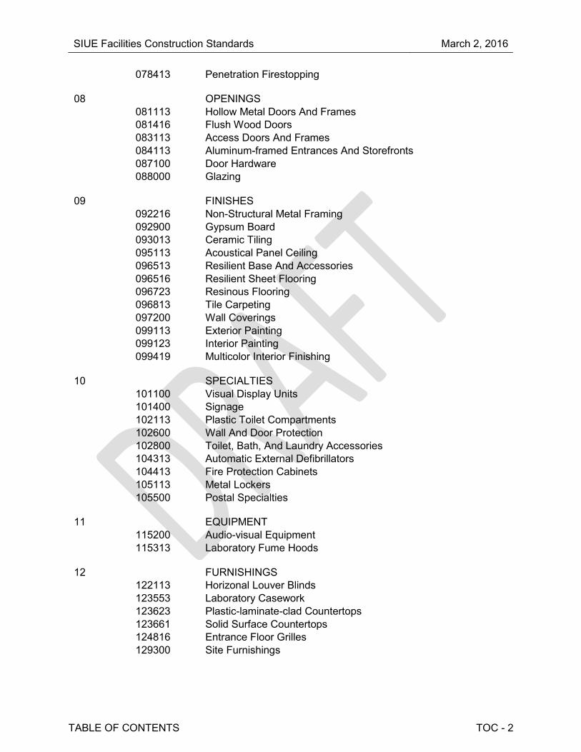
078413 Penetration Firestopping
08 OPENINGS
081113 Hollow Metal Doors And Frames
081416 Flush Wood Doors
083113 Access Doors And Frames
084113 Aluminum-framed Entrances And Storefronts
087100 Door Hardware
088000 Glazing
09 FINISHES
092216 Non-Structural Metal Framing
092900 Gypsum Board
093013 Ceramic Tiling
095113 Acoustical Panel Ceiling
096513 Resilient Base And Accessories
096516 Resilient Sheet Flooring
096723 Resinous Flooring
096813 Tile Carpeting
097200 Wall Coverings
099113 Exterior Painting
099123 Interior Painting
099419 Multicolor Interior Finishing
10 SPECIALTIES
101100 Visual Display Units
101400 Signage
102113 Plastic Toilet Compartments
102600 Wall And Door Protection
102800 Toilet, Bath, And Laundry Accessories
104313 Automatic External Defibrillators
104413 Fire Protection Cabinets
105113 Metal Lockers
105500 Postal Specialties
11 EQUIPMENT
115200 Audio-visual Equipment
115313 Laboratory Fume Hoods
12 FURNISHINGS
122113 Horizonal Louver Blinds
123553 Laboratory Casework
123623 Plastic-laminate-clad Countertops
123661 Solid Surface Countertops
124816 Entrance Floor Grilles
129300 Site Furnishings

SIUE Facilities Construction Standards March 2, 2016
TABLE OF CONTENTS TOC - 3
13 SPECIAL CONSTRUCTION
132600 Custodial Requirements
14 CONVEYING EQUIPMENT
142000 Elevators
21 FIRE SUPPRESSION 210553 Fire Suppression Identification 211300 Fire Protection Systems 213000 Fire Pumps 22 PLUMBING 220553 Plumbing Identification 220719 Plumbing Piping Insulation 220900 Instrumentation 221000 Plumbing Piping 221030 Plumbing Specialties 221123 Domestic Water Pumps 223000 Plumbing Equipment 224000 Plumbing Fixtures 23 HEATING, VENTILATING, AND AIR-CONDITIONING (HVAC) 230500 Basic Mechanical Requirements 230553 HVAC Identification 230713 Ductwork Insulation 230719 HVAC Piping Insulation 230900 Controls 230913 Instrumentation 232100 Hydronic Piping 232123 HVAC Pumps 235216 Condensing Boilers 236416 Air and Water Cooled Chillers 237313 Air Handling Units 238200 Terminal Heat Transfer Units 26 ELECTRICAL 260513 Wire And Cable 260526 Grounding and Bonding 260533 Conduit and Boxes 260553 Electrical Identification 262413 Switchboards 262416 Panelboards 262923 Variable Frequency Drives 263213 Packaged Engine Generator Systems 263600 Transfer Switch 264300 Surge Protection Devices

SIUE Facilities Construction Standards March 2, 2016
TABLE OF CONTENTS TOC - 4
27 COMMUNICATIONS 270000 Telecommunications General
28 ELECTRICAL SAFETY AND SECURITY 280000 Electronic Security General
32 EXTERIOR IMPROVEMENTS
321216 Asphalt Paving
321313 Concrete Paving
329113 Soil Preparation
33 UTILITIES
334100 Storm Utility Drainage Piping
END TABLE OF CONTENTS

SIUE Facilities Construction Standards March 2, 2016
COVER SHEET CS - 1
COVER SHEET
PART 1 - GENERAL
1.1 DESCRIPTION
A. State CDB Project: Utilize CDB’s master.
B. SIUE Project: Provide for specific project.
PART 2 - PRODUCTS (Not Used)
END OF SECTION

SIUE Facilities Construction Standards March 2, 2016
SPACE PLANNING GENERAL SP - 1
SPACE PLANNING GENERAL
PART 1 - GENERAL
1.1 DESCRIPTION
A. Family Restrooms: For new construction and major renovations, at least one gender-neutral, family restroom is to be provided in each building.
B. Classrooms: Varies by department and class size, based on an occupancy count of 20 SF per occupant.
C. Office Space Planning:
Position Description Square Footage Office Module
Chancellor 700
Provost 600
Vice Chancellor 350
Dean 300
Assoc./Asst. Administrator 150
Director/Chair 150
Asst. Director 120
Faculty 120
Instructors, Lecturers 120
Adjunct Faculty 35
Studio Faculty 225
Emeritus Faculty 65
Administrative Staff 130
Clerical/Technical Staff 120
Graduate Assistants 50
Fellows 80
Student Worker 25
1. Office space needs are to be further developed by incorporating the following:
a. Faculty or staff with appointments 50% or greater need a full office module. b. Adjunct faculty and graduate students share office space and are provided
a smaller module of space. c. Office space is provided for contract employees who have administrative
duties. d. An average number of student workers are included in offices, where
identified, by allocating space for a small work area.

SIUE Facilities Construction Standards March 2, 2016
SPACE PLANNING GENERAL SP - 2
e. Conference room space is allocated at 18 square feet per FTE faculty, and administrative staff.
f. Office lounge space is allocated at 5 square feet per FTE for all personnel. g. An office service space allocation (i.e. files, supply storage, work room)
ranging from 10% to 20% of the total calculated office space need is provided for most departments. Certain offices are provided a supplemental office support allocation for:
• Reception and waiting space
• Processing space
• Additional departmental storage
• Larger office modules are provided for faculty in departments who use their office as studio space.
D. Waste Disposal:
1. Site Requirements: Verify size and number of dumpsters needed on a per project basis.
E. Emergency Management and Safety: Refer to SIUE’s Emergency Management and Safety Policies for additional information:
Introduction Fall Protection
Confined Space Entry Forklift & Pallet Lift Safety
Contractor Safety Handling & Sampling of Infectious Waste
Electrical Safety Hearing Conservation Program
Energy Control/Lockout/Tagout
Machine Guarding
Eyewash & Shower Stations
Personal Protection ( eye/face; foot; hand; head; hearing; ppe, respiratory, apparel)
Exposure Monitoring
PART 2 - PRODUCTS (Not Used)
END OF SECTION

SIUE Facilities Construction Standards March 2, 2016
CONTRACT DRAWINGS GENERAL CD - 1
CONTRACT DRAWINGS GENERAL
PART 1 - GENERAL
1.1 DESCRIPTION
A. Drawings
1. Size: D size. 2. Deliverable: Print and electronic.
PART 2 - PRODUCTS (Not Used)
END OF SECTION

SIUE Facilities Construction Standards March 2, 2016
PROJECT MANUAL GENERAL PM - 1
PROJECT MANUAL GENERAL
PART 1 - GENERAL
1.1 DESCRIPTION
A. A/E to provide to SIUE Purchasing:
1. A bond set of drawings and specifications. Do not bind purchasing forms in project manual.
2. A CD containing a PDF copy of:
a. Drawings. b. Project Manual. c. Purchasing forms.
B. Format:
1. Project Manuals to be in CSI format. 2. Technical section format to describe multiple prime contractor responsibilities.
Follow Illinois State CDB format.
C. Sole Source Products:
1. SIUE Purchasing will provide form to be completed by A/E. 2. Only sole source items approved by Purchasing may be incorporated into the
project. 3. Purchasing’s approval of a sole source only applies to that specific project.
Approval for a sole source item needs to be requested on each individual project.
D. A potential bidder cannot assist in the writing of specifications for bidding. This is a direct violation of the Procurement Code.
E. SIUE prequalifies contractors on an annual basis. Send specialized contractor information to Purchasing to get included.
1. SIUE Purchasing can provide project specific prequalification for projects expected to take over a year.
2. Project specific pre-qualification of contractors based on experience and past performance may be performed for specialized or complex work in advance of solicitation of bids. Consult with SIUE Facilities Management and Purchasing.
F. Projects in excess of $250,000 must be set up for multiple prime contractors, including the following as applicable to the project. Separate prime contracts are required if that division of work exceeds the current State of Illinois construction bid limit.
1. General. 2. Electrical. 3. Heating.
SIUE Facilities Construction Standards March 2, 2016
PROJECT MANUAL GENERAL PM - 2
4. Plumbing. 5. Ventilation. 6. Fire Protection.
G. SIUE Purchasing prepares all Addendum.
1. All bidders questions are to go through SIUE Purchasing. Bidders can be disqualified if they contact anybody except purchasing with questions during the bidding process.
2. Purchasing provides A/E with form for answering questions.
H. Substitutions:
1. Acceptable substitutions are to be issued via addendum. 2. Rejected substitution requests require the A/E to contact the requestor to inform
them of the rejection and provide reasoning for such determination.
PART 2 - PRODUCTS (Not Used)
END OF SECTION

SIUE Facilities Construction Standards March 2, 2016
DIVISION 00 SECTIONS DIV 00 - 1
DIVISION 00 SECTIONS
PART 1 - GENERAL
1.1 DESCRIPTION
A. State CDB Project: Utilize CDB’s master sections.
B. SIUE Project: Utilize SIUE sections as provided by Purchasing department.
1. SIUE Purchasing will provide A/E with front end checklist. 2. All pricing requirements to be in the front end documents. Do not put pricing
requirements in the technical sections. 3. Bind Division 00 sections with rest of project manual. 4. Owner/Contractor Agreement: AIA form with SIUE Addendum. 5. Prevailing Wage: Required with PLA.
PART 2 - PRODUCTS (Not Used)
END OF SECTION

SIUE Facilities Construction Standards March 2, 2016
CERTIFICATIONS 000105 - 1
SECTION 000105 – CERTIFICATIONS
PART 1 - GENERAL
1.1 DESCRIPTION
A. SIUE Project: Provide certification page for specific project.
PART 2 - PRODUCTS (Not Used)
END OF SECTION 000105

SIUE Facilities Construction Standards March 2, 2016
SEALS 000107 - 1
SECTION 000107 – SEALS
PART 1 - GENERAL
1.1 DESCRIPTION
A. SIUE Project: Provide seals page for specific project.
PART 2 - PRODUCTS (Not Used)
END OF SECTION 000107

SIUE Facilities Construction Standards March 2, 2016
EXISTING HAZARDOUS MATERIAL INFORMATION 003126 - 1
SECTION 003126 – EXISTING HAZARDOUS MATERIAL INFORMATION
PART 1 - GENERAL
1.1 DESCRIPTION
A. SIUE will provide investigation reports or request accomplishment by the architect-engineer.
PART 2 - PRODUCTS (Not Used)
END OF SECTION 003126

SIUE Facilities Construction Standards March 2, 2016
TEMPORARY FACILITIES AND CONTROLS 015000 - 1
SECTION 015000 – TEMPORARY FACILITIES AND CONTROLS
PART 1 - GENERAL
1.1 DESCRIPTION
A. State CDB Project: Utilize CDB’s master section.
B. SIUE Project: Provide section as required for specific project.
C. Protect existing facilities (buildings, paving, sidewalks, landscaping, turf areas, etc.) from damage. Restore damage items to original condition or better to the satisfaction of SIUE.
1. Repair sidewalks and areas along sidewalks damaged or rutted during construction.
1.2 USE CHARGES
A. SIUE owns water, sewage, gas, and electric. No use charges. Tap into existing where permitted by SIUE.
1.3 SUPPORT FACILITES
A. Field Offices and Storage Sheds: Location and restrictions to be shown in the Construction Documents. Coordinate with SIUE project personnel.
B. Construction Parking: Use SIUE designated areas of existing SIUE parking areas. Contractor parking passes are available from SIUE Facilities Management Department.
C. Existing Elevator Use: Use of Owner's existing elevators will be permitted depending on size and weight of load. Existing elevators are to be cleaned and maintained in a condition acceptable to SIUE.
D. Existing Stair Usage: Use of Owner's existing stairs will be permitted, provided stairs are cleaned and maintained in a condition acceptable to SIUE.
E. Existing Restroom Usage: Use of Owner’s existing restrooms will not be permitted. Contractor is to provide temporary toilets, wash facilities, and drinking water for use of construction personnel.

SIUE Facilities Construction Standards March 2, 2016
TEMPORARY FACILITIES AND CONTROLS 015000 - 2
1.4 TEMPORARY UTILITY WORK
A. Follow SIUE procedures, available from SIUE, for the following:
1. PPE. 2. Tag-out. 3. Arc Flash. 4. Confined space access.
PART 2 - PRODUCTS (Not Used)
END OF SECTION 015000

SIUE Facilities Construction Standards March 2, 2016
CONSTRUCTION WASTE MANAGEMENT AND DISPOSAL 017419 - 1
SECTION 017419 – CONSTRUCTION WASTE MANAGEMENT AND DISPOSAL
PART 1 - GENERAL
1.1 DESCRIPTION
A. State CDB Project: Utilize CDB’s master section.
B. SIUE Project: Provide section as required for specific project.
C. Remove all debris and waste building material from site in legal manner. Do not bury any waste on site.
D. Removed materials shall be recycled off-site to the maximum extent practical and the weights of recycled materials reported to SIUE.
PART 2 - PRODUCTS (Not Used)
END OF SECTION 017419

SIUE Facilities Construction Standards March 2, 2016
OPERATION AND MAINTENANCE DATA 017823 - 1
SECTION 017823 – OPERATION AND MAINTENANCE DATA
PART 1 - GENERAL
1.1 DESCRIPTION
A. State CDB Project: Utilize CDB’s master section.
B. SIUE Project: Provide section as required for specific project.
1. A/E shall consolidate and organize in binders or other agreed upon format, all contractor submitted operation and maintenance manuals, equipment information, and shop drawings for future use and reference by University facilities management staff. Documents shall also be submitted in electronic formats to be specified by the University. For asbestos abatement projects and other projects that included asbestos abatement, the A/E shall complete an Asbestos Abatement Project Summary Report and forward it to the University PM.
PART 2 - PRODUCTS (Not Used)
END OF SECTION 017823

SIUE Facilities Construction Standards March 2, 2016
PROJECT RECORD DOCUMENTS 017839 - 1
SECTION 017839 – PROJECT RECORD DOCUMENTS
PART 1 - GENERAL
1.1 DESCRIPTION
A. State CDB Project: Utilize CDB’s master section.
B. SIUE Project: Provide section as required for specific project.
1. A/E shall submit to the University two sets of revised contract documents labeled “Record Construction Drawings,” which show all changes reported by the contractor(s), and all changes made by change orders, addenda, and clarifications made by the A/E during construction. Documents shall also be submitted in electronic formats to be specified by the University. Verify requirement with the University PM.
PART 2 - PRODUCTS (Not Used)
END OF SECTION 017839

SIUE Facilities Construction Standards March 2, 2016
SUSTAINABLE DESIGN REQUIREMENTS 018113 - 1
SECTION 018113 – SUSTAINABLE DESIGN REQUIREMENTS
PART 1 - GENERAL
1.1 DESCRIPTION
A. State CDB Project: All new State-funded building construction and major renovations of existing State-owned facilities are required to seek LEED certification. New buildings and major renovations of 10,000 square feet or more must achieve the Silver building rating of the Leadership in Energy and Environmental Design's rating system for new commercial construction and major renovation projects, as established by the United States Green Building Council. USGBC LEED certification is required. Coordinate requirements with CDB Project Manager and SIUE.
B. SIUE Project: Minimum LEED Silver certifiable, such that SIUE could get certification if they so choose. Coordinate requirements with SIUE.
C. Consult with SIUE on application of LEED criteria to projects not otherwise required to seek LEED Silver certification.
PART 2 - PRODUCTS (Not Used)
END OF SECTION 018113

SIUE Facilities Construction Standards March 2, 2016
SELECTIVE DEMOLITION 024119 - 1
SECTION 024119 – SELECTIVE DEMOLITION
PART 1 - GENERAL
1.1 DESCRIPTION
A. Hazardous material removal to be by SIUE under separate construction contract. Either prior to or if found during construction.
B. Generally, the salvaging of materials is project specific. In most cases toilet fixtures and accessories will not be returned to SIUE. Door hardware, especially locksets and cores, are always returned to SIUE.
C. Noise Control: As required for specific project. Coordinate requirements for noise control with SIUE.
D. Explosives: Use of explosives is not permitted.
PART 2 - PRODUCTS (Not Used)
END OF SECTION 024119

SIUE Facilities Construction Standards March 2, 2016
CAST-IN-PLACE CONCRETE 033000 - 1
SECTION 033000 – CAST-IN-PLACE CONCRETE
PART 1 - GENERAL
1.1 DESCRIPTION
A. Minimum Strength: Normally 4,000 PSI.
B. If concrete floors are to be sealed, provide product information and maintenance procedures to SIUE.
C. Concrete Door Stoops: Slope away from exterior doors.
D. Concrete Tests:
1. SIUE to engage a qualified testing and inspecting agency to perform field tests and inspections and prepare test reports.
2. Testing: During and after construction.
PART 2 - PRODUCTS (Not Used)
END OF SECTION 033000

SIUE Facilities Construction Standards March 2, 2016
POLISHED CONCRETE FINISHING 033543 - 1
SECTION 033543 – POLISHED CONCRETE FINISHING
PART 1 - GENERAL
1.1 DESCRIPTION
A. Due to experience with poor quality installations, polished concrete floors are not preferred for typical floor areas. Use shall be considered in fire exit stairs, workshops, and industrial- type areas, only after consultation with SIUE.
B. Polished concrete is the preferred floor finish for the following areas:
1. Common areas. 2. Corridors.
C. Refer to other flooring materials for preferred flooring in other spaces/areas.
PART 2 - PRODUCTS (Not Used)
END OF SECTION 033543

SIUE Facilities Construction Standards March 2, 2016
MASONRY VENEER 042613 - 1
SECTION 042613 – MASONRY VENEER
PART 1 - GENERAL
1.1 DESCRIPTION
A. Proposed exterior wall materials and colors require the approval of the Campus Architect. Acceptable materials include:
1. Brick masonry. 2. Stone cladding. 3. Precast concrete.
PART 2 - PRODUCTS
2.1 BRICK
A. Manufacturer: No substitute. SIUE will provide single source letter
1. Richards Brick; Edwardsville Red #1A66 Blend.
B. Due to previous local union concerns, precast brick masonry panels should generally not be used. Consult with SIUE in advance of proposing use of precast brick panels.
2.2 MORTAR
A. Color: Match Solomon Colors, Inc.; SGS 45H Maroon.
END OF SECTION 042613

SIUE Facilities Construction Standards March 2, 2016
EXTERIOR STONE CLADDING 044200 - 1
SECTION 044200 – EXTERIOR STONE CLADDING
PART 1 - GENERAL
1.1 DESCRIPTION
A. Proposed exterior wall materials and colors require the approval of the Campus Architect. Acceptable materials include:
1. Brick masonry. 2. Stone cladding. 3. Precast concrete.
PART 2 - PRODUCTS
2.1 STONE CLADDING
A. Due to previous local union concerns, precast stone masonry panels should generally not be used. Consult with SIUE in advance of proposing use of precast brick panels.
END OF SECTION 044200

SIUE Facilities Construction Standards March 2, 2016
DIVISION 05 SECTIONS DIV 05 - 1
DIVISION 05 SECTIONS
PART 1 - GENERAL
1.1 DESCRIPTION
A. Each contract for the construction, reconstruction, alteration, repair, improvement or maintenance of public works made by a public university shall contain a provision that steel products used or supplied in the performance of the contract or any subcontract thereto shall be manufactured or produced in the United States in accordance with the Steel Products Procurement Act [30 ILCS 565]. [30 ILCS 565/4] For example, a finished supply item that contains a steel component, such as an HVAC system, is not considered a steel product and would not be subject to the Act, but a steel I-beam would be subject to the Act.
PART 2 - PRODUCTS (Not Used)
END OF SECTION

SIUE Facilities Construction Standards March 2, 2016
PIPE AND TUBE RAILINGS 055213 - 1
SECTION 055213 – PIPE AND TUBE RAILINGS
PART 1 - GENERAL
1.1 DESCRIPTION
A. Consider measures to prevent skateboard grind at exterior railings.
B. Painted railings are preferred for maintenance purposes. SIUE to resolve.
C. Anodized aluminum handrails are preferred (especially for exterior use). SIUE to resolve.
PART 2 - PRODUCTS
2.1 MATERIALS
A. Steel products shall be manufactured or produced in the USA unless President of University grants exception (30 ILCS 565).
END OF SECTION 055213

SIUE Facilities Construction Standards March 2, 2016
MISCELLANEOUS ROUGH CARPENTRY 061053 - 1
SECTION 061053 – MISCELLANEOUS ROUGH CARPENTRY
PART 1 - GENERAL
1.1 DESCRIPTION
A. Provide blocking for owner furnished and installed items including but not limited to:
1. Projection screens. 2. Toilet accessories. 3. Wall mounted shelving. 4. Wall mounted cabinets and casework.
PART 2 - PRODUCTS (Not Used)
END OF SECTION 061053

SIUE Facilities Construction Standards March 2, 2016
WOOD-VENEER-FACED ARCHITECTURAL CABINETS 064113 - 1
SECTION 064113 – WOOD-VENEER-FACED ARCHITECTURAL CABINETS
PART 1 - GENERAL (Not Used)
PART 2 - PRODUCTS
2.1 LOCKS
A. Millwork cabinet locks can be standard cam locks.
1. Provide spare keys and blanks. 2. Best cores for millwork cabinet locks is preferred, but not required. At a
minimum, the millwork company is to provide the “standard small format” lock keying/coding information. SIUE Key Control should be consulted regarding master keying for small format locks on a project specific basis.
END OF SECTION 064113

SIUE Facilities Construction Standards March 2, 2016
PLASTIC-LAMINATE-FACED ARCHITECTURAL CABINETS 064116 - 1
SECTION 064116 – PLASTIC-LAMINATE-FACED ARCHITECTURAL CABINETS
PART 1 - GENERAL (Not Used)
PART 2 - PRODUCTS
2.1 LOCKS
A. Millwork cabinet locks can be standard cam locks.
1. Provide spare keys and blanks. 2. Best cores for millwork cabinet locks is preferred, but not required. At a
minimum, the millwork company is to provide the “standard small format” lock keying/coding information. SIUE Key Control should be consulted regarding master keying for small format locks on a project specific basis.
END OF SECTION 064116

SIUE Facilities Construction Standards March 2, 2016
PLASTIC PANELING 066400 - 1
SECTION 066400 – PLASTIC PANELING
PART 1 - GENERAL
1.1 DESCRIPTION
A. Provide glass-fiber-reinforced plastic paneling wall protection at all mop sinks.
PART 2 - PRODUCTS (Not Used)
END OF SECTION 066400

SIUE Facilities Construction Standards March 2, 2016
ETHYLENE-PROPYLENE-DIENE-MONOMER (EPDM) ROOFING 075323 - 1
SECTION 075323 – ETHYLENE-PROPYLENE-DIENE-MONOMER (EPDM) ROOFING
PART 1 - GENERAL
1.1 DESCRIPTION
A. TPO roofing not allowed.
B. Roofs to have minimum 1/4 inch per foot slope.
1.2 WARRANTY
A. Minimum 20 year warranty.
PART 2 - PRODUCTS
2.1 EPDM ROOFING
A. Prefer fully adhered system.
B. Specify white EPDM for LEED projects.
2.2 WALKWAYS
A. Provide walk pads from access point(s) to all equipment.
1. Provide pads not rolls.
END OF SECTION 075323

SIUE Facilities Construction Standards March 2, 2016
SHEET METAL FLASHING AND TRIM 076200 - 1
SECTION 076200 – SHEET METAL FLASHING AND TRIM
PART 1 - GENERAL
1.1 DESCRIPTION
A. Downspouts are to be connected to storm sewer, where feasible.
PART 2 - PRODUCTS (Not Used)
END OF SECTION 076200

SIUE Facilities Construction Standards March 2, 2016
ROOF SPECIALTIES 077100 - 1
SECTION 077100 – ROOF SPECIALTIES
PART 1 - GENERAL (Not Used)
PART 2 - PRODUCTS
2.1 COPINGS
A. Pre-finished metal with concealed fasteners over EPDM flashing.
END OF SECTION 077100

SIUE Facilities Construction Standards March 2, 2016
PENETRATION FIRESTOPPING 078413 - 1
SECTION 078413 – PENETRATION FIRESTOPPING
PART 1 - GENERAL
1.1 DESCRIPTION
A. All floor penetration are to be sealed with the appropriate firestopping.
PART 2 - PRODUCTS (Not Used)
END OF SECTION 078413

SIUE Facilities Construction Standards March 2, 2016
HOLLOW METAL DOORS AND FRAMES 081113 - 1
SECTION 081113 – HOLLOW METAL DOORS AND FRAMES
PART 1 - GENERAL
1.1 DESCRIPTION
A. Prehung doors are not acceptable.
B. Doors with lites to have narrow lite.
PART 2 - PRODUCTS
2.1 DOORS AND FRAMES
A. Doors:
1. Gauge: Minimum 18 gauge. 2. Edge Construction: Seamless. 3. Exterior Doors: Galvanized. 4. Exterior Door Sidelights: Where exterior doors have adjacent sidelights, provide
8 inch to 10 inch high sills.
B. Frames:
1. Gauge: Minimum 16 gauge. 2. Construction: Full profile welded. 3. Exterior Frames: Galvanized.
END OF SECTION 081113

SIUE Facilities Construction Standards March 2, 2016
FLUSH WOOD DOORS 081416 - 1
SECTION 081416 – FLUSH WOOD DOORS
PART 1 - GENERAL
1.1 DESCRIPTION
A. Prehung doors are not acceptable.
B. Doors with lites to have narrow lite.
PART 2 - PRODUCTS
2.1 VENEER-FACED DOORS FOR TRANSPARENT FINISH
A. Solid Core Doors: Particleboard core.
B. Veneer Species: Plain sliced oak.
C. Finish: Factory finish stained doors.
END OF SECTION 081416

SIUE Facilities Construction Standards March 2, 2016
ACCESS DOORS AND FRAMES 083113 - 1
SECTION 083113 – ACCESS DOORS AND FRAMES
PART 1 - GENERAL (Not Used)
PART 2 - PRODUCTS
2.1 ACCESS DOORS AND FRAMES
A. Material: Aluminum.
2.2 LOCKS
A. Keyed with Best 7 pin cores.
END OF SECTION 083113

SIUE Facilities Construction Standards March 2, 2016
ALUMINUM-FRAMED ENTRANCES AND STOREFRONTS 084113 - 1
SECTION 084113 – ALUMINUM-FRAMED ENTRANCES AND STOREFRONTS
PART 1 - GENERAL (Not Used)
PART 2 - PRODUCTS
2.1 FRAMING
A. Windows must be anodized aluminum with insulating glass compatible with the core building materials. Pre-finished metal frames will be considered on an individual basis.
2.2 ENTRANCE DOOR SYSTEMS
A. Door Design: Medium or wide stile.
B. Sidelights: Provide 8 inch to 10 inch high sills at sidelights adjacent to entrance doors.
END OF SECTION 084113

SIUE Facilities Construction Standards March 2, 2016
DOOR HARDWARE 087100 - 1
SECTION 087100 – DOOR HARDWARE
PART 1 - GENERAL
1.1 DESCRIPTION
A. Sole Source Items: SIUE will provide sole source letters.
B. Prefer to allow Key Control to be involved at the very early stages and allow Key Control to number rooms. If A/E chooses to number rooms, always use four digit numbers with the first number being the number of the floor level. (i.e. 0101 in the basement level, 1101 on ground level). Also number in wing style such as 0100 wing, 0200 wing 0300 wing and 0400 wing with numbers in that wing falling within the range indicated. Use all even numbering, that way when renovations take place, there are room numbers available to issue. Avoid using letters after a room number, but it is okay to use on door numbers. Doors that lead between two rooms, but requiring a key to enter should be labeled as the room in which you need a key to get into.
1. Key Control prefers to receive drawings in electronic format. Preferably in DWG format or PDF with layers so that we can turn off the layers they do not need for room numbering purposes. Include the full print, not just new floor plans. These often are useful in the future.
PART 2 - PRODUCTS
2.1 HINGES
A. Provide 4-1/2 by 4-1/2 BB hinges with NRP and 626 finish.
1. No continuous hinges or pivots at entrance doors.
2.2 LOCKS
A. Mortise Locks: Provide at all classrooms.
1. Trim: Similar to Schlage Sparta lever trim. 2. Manufacturers:
a. Best. b. Stanley. c. Do not specify Adams-Rite locks.

SIUE Facilities Construction Standards March 2, 2016
DOOR HARDWARE 087100 - 2
3. Locks to have cylinders provided by lock manufacturer but compatible with Best removable 7 pin cores. Cores to be provided by the Contractor.
a. Best compatible small format interchangeable cores(SFIC). Hardware supplier to pay for cores indicated in specs. Best will contact SIUE Key Control for keying info. SIUE Key Control will install final cores after substantial completion. Any temporary construction cores will be supplied by contractor performing work.
4. Labs and other secured spaces should be provided with push button lock.
a. Manufacturer:
1) Schlage; CO-200, battery operated.
5. Computer classrooms and computer labs should be lockable.
2.3 KEYING
A. Master and Grand Master: Coordinate with SIUE Key Control.
B. Key Lock Box (Knox Box): None required.
2.4 ELECTRIC STRIKES
A. Products:
1. Hess 9600. 2. Hess 1006CS.
2.5 EXIT DEVICES
A. Provide rim devices. BHMA A156.3, Grade 1, UL Listed, meeting NFPA 80 and NFPA 101.
1. Not to have vertical rods, either surface or concealed. 2. On double doors, provide keyed removable mullion.
B. No electric retracting exit devices.
C. Manufacturers:
1. Von Duprin; 33 or 99 series with breakaway lever trim. 2. No Corbin Russwin.

SIUE Facilities Construction Standards March 2, 2016
DOOR HARDWARE 087100 - 3
2.6 AUTOMATIC DOOR OPERATORS
A. All door operators to have push pads inside and outside of opening including each door in a series.
1. Avoid exterior bollards where possible. 2. Avoid sliding door operators.
B. Product:
1. Besam; SW200i.
2.7 CARD READERS
A. Two entry doors per building to be provided with card readers integrated with door operators on the accessible route into the building.
2.8 CLOSERS
A. No floor closers.
B. Product: BHMA A156.4, rack-and-pinion hydraulic type, with adjustable sweep and latch speeds controlled by key-operated valves and forged-steel main arm.
1. LCN; 4040XP with cushion arm.
2.9 ELECTROMAGNETIC HOLDERS
A. To be independent of door closer (not integrated into hold-open).
2.10 DOOR PULLS
A. Provide with door plate at pull.
2.11 RAINGUARDS
A. Provide at exterior hollow metal doors.
2.12 THRESHOLDS
A. Prefer aluminum thresholds.
2.13 SWEEPS
A. Prefer thick neoprene.

SIUE Facilities Construction Standards March 2, 2016
DOOR HARDWARE 087100 - 4
2.14 AUTOMATIC DOOR BOTTOMS
A. Only acceptable where needed for sound control.
2.15 PROTECTION PLATES
A. Provide kick plates at heavy abuse doors.
B. Provide half plates at custodial doors.
END OF SECTION 087100

SIUE Facilities Construction Standards March 2, 2016
GLAZING 088000 - 1
SECTION 088000 – GLAZING
PART 1 - GENERAL (Not Used)
PART 2 - PRODUCTS
2.1 GENERAL
A. Meet code requirements for glass types in doors, rated opening, etc.
B. Glass shall be energy-efficient and incorporate UV protection.
C. Reflective or tinted glazing will be judged in conjunction with the building design and concept.
2.2 GLASS PRODUCTS
A. Monolithic Float Glass: Annealed or Kind HS float glass where heat strengthening is required to resist thermal stresses induced by differential shading of individual glass lites and to comply with system performance.
1. Thickness: 6.0 mm. 2. Use Kind FT for door lites and borrow lites adjacent to doors.
B. Annealed Float Glass: ASTM C 1036, Type I, Quality-Q3, of class indicated.
1. Ultraclear (Low-Iron) Float Glass for Display Glazing: Class I (clear); with visible light transmission of not less than 91 percent and solar heat gain coefficient of not less than 0.87.
a. Provide products by one of the following:
1) AGC Industries Inc.; Clear Vision. 2) Guardian Industries; Ultra White. 3) Pilkington; Optiwhite. 4) PPG Industries, Inc.; Starphire.
C. Tinted Annealed Float Glass: ASTM C 1036, Type I, Class 2 (tinted), Quality-Q3.
1. Tint color varies throughout campus.
D. Heat-Strengthened Float Glass: ASTM C 1048, Type I, Quality-Q3; of class, kind, and condition indicated.
1. Fabrication Process: By horizontal (roller-hearth) process with roll-wave distortion parallel to bottom edge of glass as installed unless otherwise indicated.

SIUE Facilities Construction Standards March 2, 2016
GLAZING 088000 - 2
2. Provide Kind HS (heat-strengthened) float glass in place of annealed float glass where needed to resist thermal stresses induced by differential shading of individual glass lites and to comply with glass design requirements.
3. For uncoated glass, comply with requirements for Condition A. 4. For coated vision glass, comply with requirements for Condition C (other
uncoated glass). 5. Provide Kind FT (fully tempered) float glass in place of annealed or Kind HS float
glass where safety glass is indicated or required.
E. Ceramic-Coated Vision Glass: Float glass with ceramic enamel applied by silk-screened process and complying with ASTM C 1048, Condition C, Type I, Class 1 (clear) or Class 2 (tinted) as indicated, Quality-Q3; and complying with Specification No. 95-1-31 in GANA's "Engineering Standards Manual."
F. Ceramic-Coated Spandrel Glass: ASTM C 1048, Type I, Condition B, Quality-Q3.
1. Fallout Resistance: Provide spandrel units identical to those passing the fallout-resistance test for spandrel glass specified in ASTM C 1048.
2. Provide Kind HS or Kind FT where required by authorities having jurisdiction. 3. Thickness: 6.0 mm. 4. Ceramic Coating Color: Warm gray. 5. Coating Location: Second surface.
G. Sputtter-Coated Float Glass: ASTM C 1376, float glass with metallic-oxide or –nitride coating deposited by vacuum deposition process after manufacture and heat treatment (if any).
H. Laminated Glass: ASTM C 1172. Obscure laminated glass: Interior vertical application.
1. Construction: Laminate glass with polyvinyl butyral interlayer with a proven record of no tendency to bubble, discolor, or lose physical and mechanical properties after fabrication and installation.
2. Interlayer Thickness: Provide 0.030 inch thickness, but not less than required to comply as a Type II safety glass material where Kind FT would otherwise be required.
3. Interlayer Color: Clear, medium frosted.
I. Insulating-Glass Units: Factory-assembled units consisting of sealed lites of glass separated by a dehydrated interspace, qualified according to ASTM E 2190.
1. Provide Kind HS float glass in place of annealed where needed to resist thermal stresses induced by differential shading of individual glass lites and to comply with glass design requirements.
2. Sealing System: Dual seal. 3. Spacer: Manufacturer's standard spacer material and construction. 4. Solar Control Low-E Insulating-Glass Units:
a. Thickness of each Lite: 6.0 mm. b. Interspace Content: Air. c. Airspace: 12 mm.
SIUE Facilities Construction Standards March 2, 2016
GLAZING 088000 - 3
d. Outdoor Lite: Kind HS unless required to be Kind FT. e. Indoor Lite: Class 1 float glass, Kind HS unless required to be Kind FT. f. Low-E Coating: Sputtered on second surface. g. Visible Light Transmittance: 35 percent minimum. h. Ultra-Violet Transmittance: 8 percent. i. Outdoor Visible Reflectance: 7 percent maximum. j. Winter Nighttime U-Factor: 0.29 maximum. k. Summer Daytime U-Factor: 0.28 maximum. l. Solar Heat Gain Coefficient: 0.29 maximum. m. Shading Coefficient: 0.22 maximum.
5. Ceramic Coated Spandrel Insulated-Glass Units: Shall meet same requirements as for monolithic spandrel glass except with coating on fourth surface.
J. Mirror Glass: ASTM C 1503; manufactured using copper-free, low-lead mirror coating process.
1. Thickness: 6.0 mm. 2. Edges: Flat polished after fabrication.
END OF SECTION 088000

SIUE Facilities Construction Standards March 2, 2016
NON-STRUCTURAL METAL FRAMING 092216 - 1
SECTION 092216 – NON-STRUCTURAL METAL FRAMING
PART 1 - GENERAL (Not Used)
PART 2 - PRODUCTS
2.1 NON-STRUCTURAL METAL FRAMING
A. Gauge: Minimum 20 gauge.
END OF SECTION 092216
SIUE Facilities Construction Standards March 2, 2016
GYPSUM BOARD 092900 - 1
SECTION 092900 – GYPSUM BOARD
PART 1 - GENERAL
1.1 DESCRIPTION
A. Limit use of Level 5 finish to where needed due to harsh lighting conditions (natural or electric).
PART 2 - PRODUCTS
A. Gypsum Board: Provide 5/8 inch thick, 1/2 inch thick may be used under special circumstances approved by SIUE.
B. Tile Backer Panels: Provide cementicious board.
C. Moisture/Mold Resistance: Provide in wet areas, such as restrooms.
END OF SECTION 092900

SIUE Facilities Construction Standards March 2, 2016
CERAMIC TILING 093013 - 1
SECTION 093013 – CERAMIC TILING
PART 1 - GENERAL
1.1 DESCRIPTION
A. Provide ceramic tile for all walls in restrooms.
1.2
PART 2 - PRODUCTS (Not Used)
END OF SECTION 093013

SIUE Facilities Construction Standards March 2, 2016
ACOUSTICAL PANEL CEILING 095113 - 1
SECTION 095113 – ACOUSTICAL PANEL CEILING
PART 1 - GENERAL
1.1 MAINTENANCE MATERIAL
A. Furnish extra materials.
1. None.
PART 2 - PRODUCTS
2.1 ACOUSTICAL PANELS
A. Acoustical panels not to exceed 4 feet in any dimension. 2 feet by 2 feet by 5/8 inchthick panels are preferred.
B. Edge Detail: Tegular is acceptable.
2.2 METAL SUSPENSION SYSTEM
A. Specify wide-face 15/16 inch grid.
END OF SECTION 095113

SIUE Facilities Construction Standards March 2, 2016
RESILIENT BASE AND ACCESSORIES 096513 - 1
SECTION 096513 – RESILIENT BASE AND ACCESSORIES
PART 1 - GENERAL
1.1 MAINTENANCE MATERIAL
A. Furnish extra materials.
1. None
PART 2 - PRODUCTS
2.1 VINYL BASE
A. Vinyl cove base is preferred everywhere.
END OF SECTION 096513

SIUE Facilities Construction Standards March 2, 2016
RESILIENT SHEET FLOORING 096516 - 1
SECTION 096516 – RESILIENT SHEET FLOORING
PART 1 - GENERAL
1.1 DESCRIPTION
A. Rubber flooring does not clean well. Use only upon project specific SIUE approval.
1.2 MAINTENANCE MATERIAL
A. Furnish extra materials.
1. None
PART 2 - PRODUCTS (Not Used)
END OF SECTION 096516

SIUE Facilities Construction Standards March 2, 2016
RESINOUS FLOORING 096723 - 1
SECTION 096723 – RESINOUS FLOORING
PART 1 - GENERAL
1.1 DESCRIPTION
A. Provide resinous flooring with integral base at all restrooms.
B. Provide minimum amount of grit in topcoat to meet slip resistance requirements. Too much grit makes floors very difficult to clean.
PART 2 - PRODUCTS (Not Used)
END OF SECTION 096723

SIUE Facilities Construction Standards March 2, 2016
TILE CARPETING 096813 - 1
SECTION 096813 – TILE CARPETING
PART 1 - GENERAL
1.1 DESCRIPTION
A. Use tile carpeting only where needed.
1.2 MAINTENANCE MATERIAL
A. Furnish extra materials, from the same product run.
1. None
PART 2 - PRODUCTS (Not Used)
END OF SECTION 096813

SIUE Facilities Construction Standards March 2, 2016
WALL COVERINGS 097200 - 1
SECTION 097200 – WALL COVERINGS
PART 1 - GENERAL
1.1 DESCRIPTION
A. Wall coverings may only be used upon project specific SIUE approval.
PART 2 - PRODUCTS (Not Used)
END OF SECTION 097200

SIUE Facilities Construction Standards March 2, 2016
EXTERIOR PAINTING 099113 - 1
SECTION 099113 – EXTERIOR PAINTING
PART 1 - GENERAL
1.1 DESCRIPTION
A. SIUE has a purchasing agreement with Sherwin Williams.
1. The local Sherwin Williams manufacturer representative will provide support for specifications and selection of coating systems for all substrates at no cost to the consultant.
2. Contractors bidding work for SIUE are to contact the local Sherwin Williams store to receive negotiated pricing on paint and related products. Identify all projects by Project Name and Project Number when purchasing or receiving quotations for products.
B. All paints water based, including epoxy.
C. Comply with EPS, LEED, and State of Illinois VOC requirements.
D. There is no need for anti-graffiti protection.
PART 2 - PRODUCTS
2.1 MATERIALS
A. All paint products to be Sherwin Williams. SIUE to provide single source letter.
B. Standard Paint for Metal: DMT
1. Metal door frames. 2. Handrails. 3. Bollards.
END OF SECTION 099113

SIUE Facilities Construction Standards March 2, 2016
INTERIOR PAINTING 099123 - 1
SECTION 099123 – INTERIOR PAINTING
PART 1 - GENERAL
1.1 DESCRIPTION
A. SIUE has a purchasing agreement with Sherwin Williams.
1. The local Sherwin Williams manufacturer representative will provide support for specifications and selection of coating systems for all substrates at no cost to the consultant.
2. Contractors bidding work for SIUE are to contact the local Sherwin Williams store to receive negotiated pricing on paint and related products. Identify all projects by Project Name and Project Number when purchasing or receiving quotations for products.
B. All paints water based, including epoxy.
C. Comply with EPS, LEED, and State of Illinois VOC requirements.
PART 2 - PRODUCTS
2.1 MATERIALS
A. All interior paint products to be Sherwin Williams. SIUE to provide single source letter.
B. Standard Interior Paint: Sherwin Williams Promar 200.
1. Standard Color: Dover White SW6385. 2. Standard Sheen:
a. Hallways and Classrooms: Semi-gloss. b. Offices: Eggshell.
C. Standard Paint for Metal: DMT
1. Metal door frames. 2. Handrails. 3. Bollards.
END OF SECTION 099123

SIUE Facilities Construction Standards March 2, 2016
MULTICOLOR INTERIOR FINISHING 099419 - 1
SECTION 099419 – MULTICOLOR INTERIOR FINISHING
PART 1 - GENERAL
1.1 DESCRIPTION
A. Multicolored or Zolotone type paints are not to be used.
PART 2 - PRODUCTS (Not Used)
END OF SECTION 099419

SIUE Facilities Construction Standards March 2, 2016
VISUAL DISPLAY UNITS 101100 - 1
SECTION 101100 – VISUAL DISPLAY UNITS
PART 1 - GENERAL
1.1 DESCRIPTION
A. Provide white boards in all classrooms.
PART 2 - PRODUCTS (Not Used)
END OF SECTION 101100

SIUE Facilities Construction Standards March 2, 2016
SIGNAGE 101400 - 1
SECTION 101400 – SIGNAGE
PART 1 - GENERAL
1.1 DESCRIPTION
A. Interior Way Finding Signage:
1. Comply with SIUE Interior Signage Master Plan with Signage Addendum 1 and Addendum 2.
PART 2 - PRODUCTS (Not Used)
END OF SECTION 101100

SIUE Facilities Construction Standards March 2, 2016
PLASTIC TOILET COMPARTMENTS 102113 - 1
SECTION 102113 – PLASTIC TOILET COMPARTMENTS
PART 1 - GENERAL (Not Used)
PART 2 - PRODUCTS
2.1 COMPARTMENTS
A. Specify ceiling mounted with overhead brace.
B. Hinges: Integral, self-closing type that can be adjusted to hold doors open at any angle up to 90 degrees.
C. Brackets: Full-height continuous polymer or extruded aluminum.
D. Latch and Keeper: Manufacturer's standard recessed latch unit designed for emergency access and with combination rubber-faced door strike and keeper. Provide units that comply with accessibility requirements of authorities having jurisdiction at compartments indicated to be accessible to people with disabilities.
2.2 SCREENS
A. Specify wall mounted.
B. Brackets: Full-height continuous polymer or extruded aluminum.
2.3 MATERIALS
A. Solid, high-density polyethylene (HDPE) panel material, not less than 1 inch thick, seamless, with eased edges, no-sightline system, and with homogenous color and pattern throughout thickness of material.
END OF SECTION 102113

SIUE Facilities Construction Standards March 2, 2016
WALL AND DOOR PROTECTION 102600 - 1
SECTION 102600 – WALL AND DOOR PROTECTION
PART 1 - GENERAL
1.1 DESCRIPTION
A. Provide wall protection behind drinking fountains.
1. Ceramic tile is also acceptable as wall protection behind drinking fountains.
B. Provide corner guards at heavy traffic areas.
PART 2 - PRODUCTS
2.1 CORNER GUARDS
A. Specify surface mounted stainless steel.
1. 4 feet high.
END OF SECTION 102600

SIUE Facilities Construction Standards March 2, 2016
TOILET, BATH, AND LAUNDRY ACCESSORIES 102800 - 1
SECTION 102800 - TOILET, BATH, AND LAUNDRY ACCESSORIES
PART 1 - GENERAL
1.1 DESCRIPTION
A. Soap and paper towel dispensers are to be located to minimize as much as possible soap and water dripping on counter tops and avoid water dripping from wet hands onto floors.
1.2 OWNER FURNISHED AND INSTALLED
A. Paper Towel Dispenser:
1. Georgia Pacific; GPT54338 Vita Push/Peddle Roll Dispenser.
B. Toilet Paper Dispenser:
1. Georgia Pacific; GPT59209 Jumbo Two Roll Toilet Tissue.
C. Soap Dispenser:
1. Renown; REN02471 Foam Soap Dispenser.
D. Trash Cans.
E. Sanitary Napkin Dispenser.
F. Sanitary Napkin Disposal.
PART 2 - PRODUCTS
2.1 MANUFACTURERS
A. American Specialties, Inc.; Simplicity Series.
B. Bobrick Washroom Equipment, Inc.; Trimline Series.
C. Bradley Corporation; Contemporary Series.
2.2 DISPENSERS
A. Do not specify automatic dispensers of any kind.
SIUE Facilities Construction Standards March 2, 2016
TOILET, BATH, AND LAUNDRY ACCESSORIES 102800 - 2
2.3 PUBLIC-USE WASHROOM ACCESSORIES
A. Provide: 1. Grab bars; stainless steel with slip-resistant texture in grip area. 2. Mirrors; stainless steel channel frame.
2.4 SHOWER ROOM ACCESSORIES
A. Provide:
1. Shower curtain rods; 1-14 inch OD stainless steel. 2. Opaque vinyl shower curtains with chrome-plated or stainless steel hooks. 3. Robe hooks; double prong stainless steel or stainless steel strip hooks as
appropriate for use.
2.5 CHILDCARE ACCESSORIES
A. Provide:
1. Diaper Changing Station: Surface mounted HDPE unit with built-in liner dispenser. Manufacturer
a. American Specialties, Inc. b. Diaper Deck & Company, Inc. c. GAMCO Specialty Accessories; a division of Bobrick Washroom
Equipment, Inc. d. Koala Kare Products; a division of Bobrick Washroom Equipment, Inc.
END OF SECTION 102800

SIUE Facilities Construction Standards March 2, 2016
AUTOMATIC EXTERNAL DEFIBRILLATORS 104313 - 1
SECTION 104313 – AUTOMATIC EXTERNAL DEFIBRILLATORS
PART 1 - GENERAL
1.1 DESCRIPTION
A. Provide automatic external defibrillators only as required by code.
PART 2 - PRODUCTS (Not Used)
END OF SECTION 104313

SIUE Facilities Construction Standards March 2, 2016
FIRE PROTECTION CABINETS 104413 - 1
SECTION 104413 – FIRE PROTECTION CABINETS
PART 1 - GENERAL
1.1 DESCRIPTION
A. Provide fire protection cabinets for Owner provided Contractor installed fire extinguishers.
PART 2 - PRODUCTS (Not Used)
END OF SECTION 104413

SIUE Facilities Construction Standards March 2, 2016
METAL LOCKERS 105113 - 1
SECTION 105113 – METAL LOCKERS
PART 1 - GENERAL (Not Used)
PART 2 - PRODUCTS
2.1 LOCKERS
A. Varies by use. Generally specify metal lockers, 12” x 18” x 72” with sloped tops, base mounted on 4 inch high curbs.
B. Specify hasp for padlock.
END OF SECTION 105113

SIUE Facilities Construction Standards March 2, 2016
POSTAL SPECIALTIES 105500 - 1
SECTION 105500 – POSTAL SPECIALTIES
PART 1 - GENERAL (Not Used)
PART 2 - PRODUCTS
2.1 LOCKS
A. Locks to be Best SFIC compatible.
END OF SECTION 105500

SIUE Facilities Construction Standards March 2, 2016
AUDIO-VISUAL EQUIPMENT 115200 - 1
SECTION 115200 – AUDIO-VISUAL EQUIPMENT
PART 1 - GENERAL
1.1 OWNER FURNISHED AND INSTALLED
A. Smart Podiums: Provided by SIUE OIT. Coordinate requirements.
1. Locks: Best SFIC compatible.
B. Projectors: Provided by SIUE OIT. Coordinate requirements.
C. Projection Screens: Provided by SIUE OIT. Coordinate requirements.
D. Smartboards: Provided by SIUE OIT. Coordinate requirements.
E. LCD Displays: Provided by SIUE OIT. Coordinate requirements.
PART 2 - PRODUCTS (Not Used)
END OF SECTION 115200

SIUE Facilities Construction Standards March 2, 2016
LABORATORY FUME HOODS 115313 - 1
SECTION 115313 – LABORATORY FUME HOODS
PART 1 - GENERAL
1.1 DESCRIPTION
A. Specify fume hoods designed to meet ASHRAE requirements for face velocities, etc.
PART 2 - PRODUCTS
2.1 LABORATORY FUME HOODS
A. Manufacturers:
1. Advanced Lab Concepts, 15900 Bratton Lane, Austin, TX 78728 Tel: 800 711- 5227.
2. Jamestown Metal Products, Inc., 178 Blackstone Avenue, Jamestown, NY 14701 Tel: 716 665-5313.
3. Labconco Corporation, 8811 Prospect Avenue, Kansas City, MO 64132 Tel: 1-800-821-5525.
4. Mott Manufacturing Limited, 452 Hardy Road, P. O. Box 1120, Brantford, ON, Canada N3T 5T3 Tel: 519 752-7825.
5. Thermo Fisher Scientific, 1316 18th Street, Two Rivers, WI 54241 Tel: 920 793-1121.
B. Safety label: Labels shall indicate safe operating conditions with respect to fume hood sash position. Labels solely indicating 100 fpm face velocity sash position are not acceptable. Manufacturer: Lab Safety Supply Inc., P. O. Box 1368, Janesville, WI 53547 Tel: 800 356-0783.
C. Finish: Chemically resistant.
END OF SECTION 115313

SIUE Facilities Construction Standards March 2, 2016
HORIZONTAL LOUVER BLINDS 122113 - 1
SECTION 122113 – HORIZONTAL LOUVER BLINDS
PART 1 - GENERAL (Not Used)
PART 2 - PRODUCTS
2.1 HORIZONTAL LOUVER BLINDS
A. Manufacturers:
1. Hunter Douglas; Aluminum Horizontal Blinds 2. Levolor, a Newell Rubbermaid Company; Aluminum Horizontal Blinds 3. Springs Window Fashions Division, Inc.; Aluminum Horizontal Blinds
B. Slats: Aluminum, 1 inch wide.
C. Operation: Manual.
D. Mounting: Between jambs.
END OF SECTION 122113

SIUE Facilities Construction Standards March 2, 2016
LABORATORY CASEWORK 123553 - 1
SECTION 123553 – LABORATORY CASEWORK
PART 1 - GENERAL (Not Used)
PART 2 - PRODUCTS
2.1 LOCKS
A. Manufacturer’s standard cam Best SFIC compatible locks.
1. Provide spare keys and blanks.
2.2 MATERIALS
A. Specify either metal or wood casework.
1. Wood Laboratory Casework:
a. Manufacturers:
1) Advanced Lab Concepts, 15900 Bratton Lane, Austin, TX 78728 Tel: 800 711-LABS.
2) CiF Lab Casework Solutions, 56 Edilcan Drive, Ontario, Canada L4K 3S6 Tel: 905 738-5821.
3) Diversified Woodcrafts, Inc., 300 South Krueger Street, Suring, WI 54174 Tel: 920 842-2136.
4) Mott Manufacturing Limited., 452 Hardy Road, P. O. Box 1120, Brantford, ON, Canada N3T 5T3 Tel: 519 752-7825.
5) Thermo Fisher Scientific, 1316 18th Street, Two Rivers, WI 54241 Tel: 920 793-1121.
b. Comply with AWI quality standards. c. Toe Space:
1) Provide at all tall cabinets to match base cabinet units. 2) Provide at all fully-exposed sides of cabinets, including locations
such as the end of island benches, the end of peninsula benches, and outside-corner cabinets.
d. Extended Ends: At end-of-run base cabinets, provide extended end to cabinet to create closure to the wall without the use of filler panels. Extended end shall be edgebanded on front, bottom, and top edges. Back edge shall be scribed to the wall with a tight hairline joint. Field-applied panels do not meet this requirement.
e. Flush interiors: Set cupboard bottom flush with front-end facers. Surface mounted bottoms and offsets caused by front face frames that interfere with ease of cleaning are not acceptable.
SIUE Facilities Construction Standards March 2, 2016
LABORATORY CASEWORK 123553 - 2
f. Wood Finish: Stain and chemical resistant finish.
2. Metal Laboratory Casework:
a. Manufacturers:
1) Advanced Lab Concepts, 15900 Bratton Lane, Austin, TX 78728 Tel: 800 711-LABS.
2) Bedcolab Ltd, 2305 Francis Hughes Avenue, Laval, Quebec, Canada H7S 1H5 Tel 514 384-2820.
3) Jamestown Metal Products, Inc., 178 Blackstone Avenue, Jamestown, NY 14701 Tel: 716 665-5313.
4) Mott Manufacturing Limited., 452 Hardy Road, P. O. Box 1120, Brantford, ON, Canada N3T 5T3 Tel: 519 752-7825
5) Thermo Fisher Scientific, 1316 18th Street, Two Rivers, WI 54241 Tel: 920 793-1121.
3. Corrosives and Flammable Liquid/Solvent Storage Cabinets:
a. Manufacturers:
1) Eagle Manufacturing Company, 2400 Charles St., Wellsburg, WV 26070 Tel: 304 737-3171.
2) Justrite Manufacturing Company, 2454 Dempster St., Suite 300, Des Plaines, IL 60016 Tel: 800 798-9250.
b. Locks: Cabinet doors shall be lockable. c. Venting: Vent to adjacent fume hood or to exhaust duct system if not
adjacent to fume hood. d. Finish: Chemical resistant.
B. Specify chemical resistant countertops at laboratories.
END OF SECTION 123553

SIUE Facilities Construction Standards March 2, 2016
PLASTIC-LAMINATE-CLAD COUNTERTOPS 123623 - 1
SECTION 123623 – PLASTIC-LAMINATE-CLAD COUNTERTOPS
PART 1 - GENERAL
1.1 DESCRIPTION
A. Provide plastic-laminate countertops at non-wet areas.
B. ADA Protection Skirt: Provide lightweight removable panels. Plastic-laminate panels are not acceptable.
C. Trash or Recycle Disposal: Do not build trash or recycle disposal into countertop.
PART 2 - PRODUCTS (Not Used)
END OF SECTION 123623

SIUE Facilities Construction Standards March 2, 2016
SOLID SURFACE COUNTERTOPS 123661 - 1
SECTION 123661 – SOLID SURFACE COUNTERTOPS
PART 1 - GENERAL
1.1 DESCRIPTION
A. Provide solid surface countertops with integral bowls at toilet rooms.
B. ADA Protection Skirt: Provide lightweight removable panels.
C. Trash or Recycle Disposal: Do not build trash or recycle disposal into countertop.
PART 2 - PRODUCTS (Not Used)
END OF SECTION 123661

SIUE Facilities Construction Standards March 2, 2016
ENTRANCE FLOOR GRILLES 124816 - 1
SECTION 124816 – ENTRANCE FLOOR GRILLES
PART 1 - GENERAL (Not Used)
PART 2 - PRODUCTS
2.1 GRILLES
A. Provide “Pedimat” type, recessed in concrete slab.
END OF SECTION 124816

SIUE Facilities Construction Standards March 2, 2016
SITE FURNISHINGS 129300 - 1
SECTION 129300 – SITE FURNISHINGS
PART 1 - GENERAL (Not Used)
PART 2 - PRODUCTS
2.1 BIKE RACKS
A. Manufacturers:
1. A A A Ribbon Rack Co., Inc.; Division of Brandir International, Inc. 2. American Bicycle Security Company. 3. BRP Enterprises, Inc. 4. Columbia Cascade Company. 5. Creative Pipe, Inc. 6. DuMor Inc.
B. Frame: 2-3/8 inch OD galvanized Schedule 40 steel pipe with powder coating finish. All welded construction.
C. Profile: Continuous ribbon configuration:
D. Style: Double-side parking.
E. Capacity: No fewer than 10 bicycles per section.
F. Installation: Cast into concrete.
END OF SECTION 129300

SIUE Facilities Construction Standards March 2, 2016
CUSTODIAL REQUIREMENTS 132600 - 1
SECTION 132600 – CUSTODIAL REQUIREMENTS
PART 1 - GENERAL
1.1 DESCRIPTION
A. All buildings should have a Building Services Worker office with phone access and area for employee seating for break and space for refrigerator and microwave, 120 sq. ft. min. (1-4 staff).
B. Lockable storage: SIU property vacuums, scrubbers and etc. as well as supplies such as 20-30 cases of paper towels and 15-25 cases of toilet paper and etc. (100 sq. ft.).
C. Lockable storage on each floor for supplies and equipment.
D. Personnel Lockable storage: For personal while working i.e. coats, schoolbooks, lunch box and etc. (lockers).
E. Lockable chemical storage separate for office area.
F. Adequate wet closets throughout building with space to have access with equipment and chemical storage space. (Typically 1 per floor, long buildings should have 1 at each end of each floor.)
G. Provide adequate power outlets to allow use of equipment without requiring extension cords (50’ centers).
H. Provide adequate light for cleaning in the dark. Mood lighting does not do it.
PART 2 - PRODUCTS (Not Used)
END OF SECTION 132600

SIUE Facilities Construction Standards March 2, 2016
ELEVATORS 142000 - 1
SECTION 142000 – ELEVATORS
PART 1 - GENERAL (Not Used)
PART 2 - PRODUCTS
2.1 ELEVATORS
A. Provide electric traction type elevators.
2.2 LOCKS
A. Elevators that include keyed switches for level or door access to be Best SFIC compatible, not tubular keyed locks. (from Key Control)
B. Elevator keys to be Best 7-pin core compatible. (from Carpenter’s meeting)
2.3 CONTROLS
A. Provide soft start for elevator controls.
2.4 FINISHES
A. Car Enclosure:
1. Front Wall: Stainless steel No. 4 finish. 2. Side and Rear Walls: Plastic laminate. 3. Door Faces: Stainless steel No. 4 finish.
B. Hoistway Entrance: Stainless steel No. 4 finish.
END OF SECTION 142000

SIUE Facilities Construction Standards December 21, 2015
FIRE SUPPRESSION IDENTIFICATION 210553 - 1
SECTION 210553 - FIRE SUPPRESSION IDENTIFICATION
PART 1 - GENERAL
1.1 SECTION INCLUDES
A. Identification of products installed under Division 21.
B. Equipment naming convention.
C. Equipment labeling
PART 2 - PRODUCTS
2.1 MATERIALS
A. Aluminum Nameplates: Black enamel background with natural aluminum border and engraved letters furnished with two mounting holes and screws.
B. Brass Tags: Brass background with engraved black letters. Tag size minimum 1-1/2" square or 1-1/2" round.
C. Vinyl Pipe Markers: Colored vinyl with permanent pressure sensitive adhesive backing.
D. Underground Pipe Markers: Bright colored continuously printed plastic ribbon tape 6"wide by 3.5 mils thick, manufactured for direct burial, with aluminum foil core for location by non-ferric metal detectors and bold lettering identifying buried item.
E. Tracer Wire:
1. Single copper conductors shall be solid or stranded annealed or hard uncoated copper per UL83 and ASTM requirements. Tracer tape or copper-coated steel wire is not acceptable.
2. Conductor shall be insulated with HMWPE as specified and applied in a concentric manner. The minimum at any point shall not be less than 90% of the specified average thickness in compliance with UL 83.
3. Tracer wire shall be continuously spark tested at 7500 Volts DC. Other electrical and mechanical tests shall be in accordance with UL 1581.
2.2 EQUIPMENT NAMING CONVENTION
A. All new equipment shall receive a designation consisting of a building number (two characters - see enclosed Attachment A campus map), an equipment code (three characters), and then a floor level followed by the actual equipment number (four

SIUE Facilities Construction Standards December 21, 2015
FIRE SUPPRESSION IDENTIFICATION 210553 - 2
characters).
B. Equipment Code - the first three characters equipment type:
1. Fire Pump FPS
2. Inspector Test Station ITS
EXAMPLE: 06/ITS/2002 = DUNHAM HALL, INSPECTOR, LOCATED ON THE SECOND FLOOR, THE SECOND INSPECTOR TEST STAION ON THAT LEVEL.
EXAMPLE: 02/FPS/B001 = FOUNDERS HALL, FIRE PUMP, LOCATED IN THE BASEMENT.
PART 3 - EXECUTION
3.1 INSTALLATION
A. Degrease and clean surfaces to receive adhesive for identification materials.
B. Valves:
1. All valves (except shutoff valves at equipment) shall have numbered tags.
2. Provide or replace numbered tags on all existing valves that are connectedto new systems or that have been revised.
3. Provide all existing valves used to extend utilities to this project withnumbered tags. Review tag numbering sequence with the Owner prior toordering tags.
4. Secure tags with heavy duty key chain and brass "S" link or withmechanically fastened plastic straps.
5. Attach to handwheel or around valve stem. On lever operated valves, drillthe lever to attach tags.
6. Number all tags and show the service of the pipe.
7. Provide two sets of laminated 8-1/2" x 11" copies of a valve directory listingall valves, with respective tag numbers, uses, and locations. The directoryshall be reviewed by the Owner and Architect/Engineer prior to laminatingfinal copies. Laminated copies shall have brass eyelet in at least onecorner for easy hanging.
C. Pipe Markers:
1. Adhesive Backed Markers: Use Brady Style 1, 2, or 3 on pipes 3" diameterand larger. Use Brady Style 4, 6, or 8 on pipes under 3" diameter. Similarstyles by other listed manufacturers are acceptable. Secure all markers at

SIUE Facilities Construction Standards December 21, 2015
FIRE SUPPRESSION IDENTIFICATION 210553 - 3
both ends with a wrap of pressure sensitive tape completely around the pipe.
2. Apply markers and arrows in the following locations where clearly visible:a. At each valve.b. On both sides of walls that pipes penetrate.c. At least every 20 feet along all pipes.d. On each riser and each leg of each "T" joint.e. At least once in every room and each story traversed.
3. Underground Pipe Markers: Install 8" to 10" below grade, directly aboveburied pipes.
D. Equipment:
1. All equipment not easily identifiable such as controls, relays, gauges, etc.;and all equipment in an area remote from its function such as air handlingunits, exhaust fans, filters, reheat coils, dampers, etc.; shall havenameplates or plastic tags listing name, function, and drawing symbol. Donot label exposed equipment in public areas.
2. Fasten nameplates or plastic tags with stainless steel self-tapping screwsor permanently bonding cement.
E. Miscellaneous:
1. Attach self-adhesive vinyl labels at all duct access doors used to resetfusible links or actuators on fire, fire/smoke, or smoke dampers. Letteringshall be a minimum of 1/2" high. Labels shall indicate damper type.
F. Tracer Wire:
1. Tracer wire shall be installed on top of all non-metallic buried utilities.
2. Tracer wire shall be taped directly to plastic water or drain pipe.
3. Tracer wire shall not be fastened directly or indirectly to gas piping.
4. Tracer wire when attached shall be secured to the pipe a minimum of every10 feet and at all changes of direction.
5. Tape shall be Polyken “930-35”, Protecto-Wrap “310”, or approved equal.
6. Tracer wire shall be continuous between boxes and shall be tested forcontinuity.
7. Splices in tracer wire shall be made with a water proof splice kit to preventcorrosion. Wire nuts shall not be used.
8. The tracer wire shall daylight to grade through a 2” PVC conduit, at thepoint of the utility entrance to building. PVC conduit shall be capped andlabeled as future contact point to locate the utility.

SIUE Facilities Construction Standards December 21, 2015
FIRE SUPPRESSION IDENTIFICATION 210553 - 4
3.2 SCHEDULE
A. Pipes to be marked:
Pipe Service Lettering Color
Background Color
Fire Protection Water White Red
Sprinkler Water White Red
Tracer Wire - Water Pipe Lines --- Blue
Tracer Wire - All other buried types --- Green
B. All piping downstream of the fire protection backflow preventer, upstream ofsprinkler zone valves, standpipe piping, and combination sprinkler standpipepiping shall be labeled Fire Protection Water. All piping downstream of sprinklerzone valves shall be labeled Sprinkler Water.
END OF SECTION 210553

SIUE Facilities Construction Standards December 21, 2015
ATTACHMENT A

SIUE Facilities Construction Standards December 21, 2015
FIRE PROTECTION SYSTEMS 211300 - 1
SECTION 211300 - FIRE PROTECTION SYSTEMS
PART 1 - GENERAL
1.1 SECTION INCLUDES
A. Pipe, Fittings, Valves, and Connections for Fire Protection System.
1.2 EXTRA STOCK
A. None
1.3 SYSTEM DESCRIPTION
A. System shall interface with building fire alarm system. Provide all required wiring.
B. Provide wet pipe and dry pipe sprinkler system(s) to NFPA 13 and building coderequirements as required by Owner’s insurance company and as shown on thedrawings. Provide standpipe system to NFPA 14 and building code requirementsas required by Owner’s insurance company and as shown on the drawings.
1.4 JOB CONDITIONS
A. Fire Protection Contractor shall determine the flow and pressure available at theservice connection. The Fire Protection Contractor is responsible to verify thisinformation and make all tests required. Base all pipe sizing and hydrauliccalculations on flow test data no older than 18 months.
PART 2 - PRODUCTS
2.1 PIPE AND FITTINGS
A. Pipe: 2" and Under - Schedule 40, black steel, ASTM A53. Threaded and coupledor flanged.
B. Pipe: 2-1/2" and Over - Minimum Schedule 10, black steel, grooved, ASTM A135.
C. Schedule 40 Galvanized Steel Pipe shall be utilized for Dry-Pipe System, FirePump Suction, Pipe and Fittings required up to Backflow Preventer
2.2 FLEXIBLE SPRINKLER HOSE WITH THREADED END FITTINGS

SIUE Facilities Construction Standards December 21, 2015
FIRE PROTECTION SYSTEMS 211300 - 2
A. Flexible sprinkler hose may be utilized in lieu of hard pipe sprinkler drops.
B. UL listed per UL 2443.
C. Construction:
1. Hose:
a. Type 304 stainless steel.
b. Straight or elbow hose - maximum six (6)-foot hose length.
c. 1/2” or 3/4” outlet.
d. 175 psi rated pressure.
e. Leak-tested minimum 7/8”.
f. Minimum 7/8” hose Braided hose.
g. O-ring sealed joints are not acceptable.
2. Ceiling Bracket:
a. Zinc plated or galvanized steel – 24” and 48” sizes.
b. Flexible hose attachment: Open hub or set screw.
3. Unit may be prepackaged with sprinkler head.
D. Acceptable Manufacturers: FlexHead Industries, Victaulic Aquaflex.
2.3 BACKFLOW PREVENTERS
A. Provide double check backflow preventers for fire service line serving building.
PART 3 - EXECUTION
3.1 SYSTEMS CLEANING AND TESTING
A. General Requirement:
1. All water used for testing and remaining in the piping system shall treated by corrosion solution company.
2. Coordinate piping and sprinkler locations with all other trades. Ductwork, diffusers and light fixture locations shall have priority over system equipment and sprinklers.

SIUE Facilities Construction Standards December 21, 2015
FIRE PROTECTION SYSTEMS 211300 - 3
B. Installation Requirements in Electrical Rooms:
1. Do not install piping or other equipment above electrical switchboards or panelboards. This includes a dedicated space extending 25 feet from the floor to the structural ceiling with width and depth equal to the equipment. Fire protection equipment dedicated to the electrical equipment room or space may be installed above equipment if other alternatives are not available.
C. Sprinklers:
1. Locate sprinklers to clear lights, ducts and diffusers. Do not run sprinkler pipes through ducts. Ductwork has priority over sprinkler pipes. Offset pipes as needed.
2. Center sprinklers in two directions in ceiling tiles and provide offsets as required.
3. Do not allow concealed sprinkler cover plates to be painted. Sprinkler cover plates are to be factory painted only. Do not field paint.
4. Apply strippable or paper covers so concealed sprinkler cover plates do not receive field paint finish.
END OF SECTION 211300

SIUE Facilities Construction Standards December 21, 2015
FIRE PUMPS 213000 - 1
SECTION 213000 - FIRE PUMPS
PART 1 - GENERAL
1.1 SECTION INCLUDES
A. Fire Pump Package.
B. Fire Pump Motor.
C. Electric Pressure Maintenance (Jockey) Pump.
D. Controllers.
1.2 SYSTEM DESCRIPTION
A. Electric motor driven vertical in-line or horizontal fire pump with jockey pump and electric controllers.
1.3 REGULATORY REQUIREMENTS
A. All materials and installation shall conform to NFPA 20.
B. Provide certificate of compliance from authority having jurisdiction indicating approval of field acceptance tests.
C. All material, equipment and installation shall be approved by the State Insurance Office State Fire Marshal and the Owner's insurance company.
1.4 OPERATION AND MAINTENANCE DATA
A. Include manufacturer’s instructions, start-up data, and trouble-shooting check lists for pumps, drivers and controllers, cleaning procedures, replacement parts lists, and repair data for pumps, drivers and controllers.
1.5 MAINTENANCE SERVICE
A. Furnish service and maintenance of fire pump, driver and controller for one year from Date of Substantial Completion.
PART 2 - PRODUCTS
2.1 ACCEPTABLE MANUFACTURERS
SIUE Facilities Construction Standards December 21, 2015
FIRE PUMPS 213000 - 2
A. Fire Pumps:
1. Aurora Pumps
2. Fairbanks Morse
3. Peerless Pump
4. A-C Pump; ITT Industries
5. Patterson Pump
B. Controllers:
1. Aquarius
2. Firetrol
3. Masters
4. Cutler-Hammer
PART 3 - EXECUTION
3.1 INSTALLATION
A. Install in accordance with manufacturer's instructions, NFPA 20, and NFPA 37.
B. Provide at least the manufacturer’s recommended minimum service space around pumps.
C. Decrease from line size with long radius reducing elbows or reducers. Support piping adjacent to pump so no weight is carried on pump casings. For base mounted pumps, provide supports under suction and discharge elbows.
D. Provide drains for bases and seals, piped to and discharging into floor drains.
E. Install eccentric reducer at suction flange with flat side on top to avoid air pockets in suction piping.
F. Lubricate pumps before start-up.
G. Qualified millwright shall check, align, and certify base mounted pumps prior to start-up.
END OF SECTION 213000

SIUE Facilities Construction Standards December 21, 2015
PLUMBING IDENTIFICATION 220553 - 1
SECTION 220553 - PLUMBING IDENTIFICATION
PART 1 - GENERAL
1.1 SECTION INCLUDES
A. Identification of products installed under Division 22.
B. Equipment naming convention.
C. Equipment labeling.
PART 2 - PRODUCTS
2.1 ACCEPTABLE MANUFACTURERS
A. 3M, Bunting, Calpico, Craftmark, Emedco, Kolbi Industries, Seton, W.H. Brady, Marking Services.
2.2 MATERIALS
A. Aluminum Nameplates: Black enamel background with natural aluminum border and engraved letters furnished with two mounting holes and screws.
B. Brass Tags: Brass background with engraved black letters. Tag size minimum 1-1/2" square or 1-1/2" round.
C. Vinyl Pipe Markers: Colored vinyl with permanent pressure sensitive adhesive backing.
D. Underground Pipe Markers: Bright colored continuously printed plastic ribbon tape 6"wide by 3.5 mils thick, manufactured for direct burial, with aluminum foil core for location by non-ferric metal detectors and bold lettering identifying buried item.
E. Tracer Wire:
1. Single copper conductors shall be solid or stranded annealed or hard uncoated copper per UL83 and ASTM requirements. Tracer tape or copper-coated steel wire is not acceptable.
2. Conductor shall be insulated with HMWPE as specified and applied in a concentric manner. The minimum at any point shall not be less than 90% of the specified average thickness in compliance with UL 83.
3. Tracer wire shall be continuously spark tested at 7500 Volts DC. Other electrical and mechanical tests shall be in accordance with UL 1581.

SIUE Facilities Construction Standards December 21, 2015
PLUMBING IDENTIFICATION 220553 - 2
2.3 EQUIPMENT NAMING CONVENTION
A. All new equipment shall receive a designation consisting of a building number (two characters - see enclosed Attachment A campus map), an equipment code (three characters), and then a floor level followed by the actual equipment number (four characters).
B. Equipment Code - the first three characters equipment type:
1. Domestic Hot Water Circulating Pump DCP
2. Domestic Water Heater - Electric WHE
3. Domestic Water heater - Gas WHG
4. Domestic Water Booster Pump DWP
EXAMPLE: 06/WHE/2002 = DUNHAM HALL, ELECTRIC DOMESTIC WATER HEATER, LOCATED ON THE SECOND FLOOR, THE SECOND ELECTRIC WATER HEATER ON THE SECOND FLOOR.
EXAMPLE: 02/DWP/B001 = FOUNDERS HALL, DOMESTIC WATER BOOSTER PUMP, LOCATED IN THE BASEMENT, THE FIRST DOMESTIC BOOSER PUMP ON THAT LEVEL.
PART 3 - EXECUTION
3.1 INSTALLATION
A. Degrease and clean surfaces to receive adhesive for identification materials.
B. Valves:
1. All valves (except shutoff valves at equipment) shall have numbered tags.
2. Provide or replace numbered tags on all existing valves that are connected to new systems or that have been revised.
3. Provide all existing valves used to extend utilities to this project with numbered tags. Review tag numbering sequence with the Owner prior to ordering tags.
4. Secure tags with heavy duty key chain and brass "S" link or with mechanically fastened plastic straps.
5. Attach to handwheel or around valve stem. On lever operated valves, drill the lever to attach tags.
6. Number all tags and show the service of the pipe.

SIUE Facilities Construction Standards December 21, 2015
PLUMBING IDENTIFICATION 220553 - 3
7. Provide two sets of laminated 8-1/2" x 11" copies of a valve directory listing all valves, with respective tag numbers, uses, and locations. The directory shall be reviewed by the Owner and Architect/Engineer prior to laminating final copies. Laminated copies shall have brass eyelet in at least one corner for easy hanging.
C. Pipe Markers:
1. Adhesive Backed Markers: Use Brady Style 1, 2, or 3 on pipes 3" diameter and larger. Use Brady Style 4, 6, or 8 on pipes under 3" diameter. Similar styles by other listed manufacturers are acceptable. Secure all markers at both ends with a wrap of pressure sensitive tape completely around the pipe.
2. Apply markers and arrows in the following locations where clearly visible:
a. At each valve.
b. On both sides of walls that pipes penetrate.
c. At least every 20 feet along all pipes.
d. On each riser and each leg of each "T" joint.
e. At least once in every room and each story traversed.
3. Underground Pipe Markers: Install 8" to 10" below grade, directly above buried pipes.
D. Equipment:
1. All equipment not easily identifiable such as controls, relays, gauges, etc.; and all equipment in an area remote from its function such as air handling units, exhaust fans, filters, reheat coils, dampers, etc.; shall have nameplates or plastic tags listing name, function, and drawing symbol. Do not label exposed equipment in public areas.
2. Fasten nameplates or plastic tags with stainless steel self-tapping screws or permanently bonding cement.
E. Miscellaneous:
1. Attach self-adhesive vinyl labels at all duct access doors used to reset fusible links or actuators on fire, fire/smoke, or smoke dampers. Lettering shall be a minimum of 1/2" high. Labels shall indicate damper type.
F. Tracer Wire:
1. Tracer wire shall be installed on top of all non-metallic buried utilities.
2. Tracer wire shall be taped directly to plastic water or drain pipe.

SIUE Facilities Construction Standards December 21, 2015
PLUMBING IDENTIFICATION 220553 - 4
3. Tracer wire shall not be fastened directly or indirectly to gas piping.
4. Tracer wire when attached shall be secured to the pipe a minimum of every 10 feet and at all changes of direction.
5. Tape shall be Polyken “930-35”, Protecto-Wrap “310”, or approved equal.
6. Tracer wire shall be continuous between boxes and shall be tested for continuity.
7. Splices in tracer wire shall be made with a water proof splice kit to prevent corrosion. Wire nuts shall not be used.
8. The tracer wire shall daylight to grade through a 2” PVC conduit, at the point of the utility entrance to building. PVC conduit shall be capped and labeled as future contact point to locate the utility.
3.2 SCHEDULE
A. Pipes to be marked:
Pipe Service
Lettering
Color
Background
Color
Condensate Drain Black Yellow
Compressed Air Black Yellow
Domestic Cold Water White Green
Domestic Hot Water - 115°F Black Yellow
Domestic Hot Water - 140°F Black Yellow
Domestic Hot Water Circulating - 115°F Black Yellow
Domestic Hot Water Circulating - 140°F Black Yellow
Sanitary Sewer Black Yellow
Vent Black Yellow
Storm Sewer (Primary and Secondary) White Green
Natural Gas Black Yellow
Non-Potable Water Black Yellow
All Underground Pipes Varies Varies
Medical Vacuum Black White
Waste Anesthetic Gas Disposal White Violet
Carbon Dioxide White Gray
Instrument Air White Red
Medical Air Black Yellow

SIUE Facilities Construction Standards December 21, 2015
PLUMBING IDENTIFICATION 220553 - 5
Pipe Service
Lettering
Color
Background
Color
Nitrogen White Black
Nitrous Oxide White Blue
Oxygen White Green
Deionized Water White Green
Distilled Water White Green
R.O. Water White Green
Fuel Oil Piping (Supply and Return) Black Yellow
Tracer Wire - Water Pipe Lines --- Blue
Tracer Wire - Natural Gas Pipe Lines --- Yellow
Tracer Wire - All other buried types --- Green
B. Medical gas pipe markers shall include the system operating pressure.
C. Medical gas pipe markers for systems not listed shall meet the pipe labeling requirements of NFPA-99.
END OF SECTION 220553

SIUE Facilities Construction Standards December 21, 2015
ATTACHMENT A

SIUE Facilities Construction Standards December 21, 2015
PLUMBING PIPING INSULATION 220719 - 1
SECTION 220719 - PLUMBING PIPING INSULATION
PART 1 - GENERAL
1.1 SECTION INCLUDES
A. Piping Insulation.
B. Insulation Jackets.
PART 2 - PRODUCTS
2.1 INSULATION
A. All insulation shall meet or exceed current AHSRAE 90.1 and International Energy Code requirements. All insulation shall be plenum rated and insulation must meet 25/50.
2.2 JACKET COVERINGS
A. Aluminum Jackets: ASTM B209; 0.016" thick; stucco embossed finish with Z edge seams and aluminum bands for outdoor use.
B. Stainless Steel Jackets: Type 316 stainless steel; .010” thick; smooth finish with Z edge seams and stainless steel bands for outdoor use.
C. Plastic Jackets and Fitting Covers: High impact, glossy white, 0.020" thick for interior use and 0.030" thick for exterior use, self-extinguishing plastic. Suitable for use indoors or outdoors with ultraviolet inhibitors. 25/50 maximum flame spread/smoke developed.
PART 3 - EXECUTION
3.1 INSTALLATION
A. General Installation Requirements:
1. Continue insulation with vapor barrier through penetrations. This applies to all insulated piping. Maintain fire rating of all penetrations.
2. On all insulated piping, provide at each support an insert of same thickness and contour as adjoining insulation, between the pipe and insulation jacket, to prevent insulation from sagging and crushing. The insert shall be suitable for planned temperatures, be suitable for use with specific pipe

SIUE Facilities Construction Standards December 21, 2015
PLUMBING PIPING INSULATION 220719 - 2
material, and shall be a 180 cylindrical segment the same length as metal shields. Inserts shall be a cellular glass (for all temperature ranges) or molded hydrous calcium silicate (for pipe with operating temperatures
above 70F, with a minimum compressive strength of 50 psi. Factory fabricated inserts may be used. Rectangular blocks, plugs, or wood material are not acceptable. Temporary wood blocking may be used by the Piping Contractor for proper height; however, these must be removed and replaced with proper inserts by the Insulation Contractor.
3. Install metal shields between all hangers or supports and the pipe insulation. Shields shall be galvanized sheet metal, half-round with flared edges. Adhere shields to insulation. On cold piping, seal the shields vapor-tight to the insulation as required to maintain the vapor barrier, or add separate vapor barrier jacket.
4. On 1" and smaller piping routed through metal wall studs, provide a plastic grommet to protect the piping. The piping shall be insulated between the wall studs, and the insulation shall butt up to each stud.
B. Insulated Piping Operating Below 60°F:
1. Insulate fittings, valves, unions, flanges, strainers, flexible connections, flexible hoses, and expansion joints. Seal all penetrations of vapor barrier.
2. On piping operating below 60ºF in locations that are not mechanically cooled (e.g., penthouses, mechanical rooms, tunnels, chases at exterior walls, etc.), Elastomeric insulation shall be used.
3. All balance valves with fluid operating below 60°F shall be insulated with a removable plug wrapped with vapor barrier tape to allow reading and adjusting of the valve.
C. Insulated Piping Operating Between 60°F and 140°F:
1. Do not insulate flanges and unions, but bevel and seal ends of insulation at such locations. Insulate all fittings, valves and strainers.
D. Insulated Piping Operating Above 140°F:
1. Insulate fittings, valves, flanges, and strainers.
2. All balance valves with fluid operating above 140°F shall be insulated and an opening shall be left in the insulation to allow for reading and adjusting the valve.
3.2 JACKET COVER INSTALLATION
A. Provide jacket cover an all exterior pips with insulation, including elastomeric insulation.
B. Provide jacket cover on all exposed piping below 8’-0” above floor.

SIUE Facilities Construction Standards December 21, 2015
PLUMBING PIPING INSULATION 220719 - 3
C. Provide jacket cover on all piping in mechanical rooms subject to damage from normal operation.
3.3 SCHEDULE Piping System Insulation Type
A. Domestic Hot Water & Circulating Glass Fiber
B. Domestic Cold Water - Potable and Non-Potable
Glass Fiber or Elastomeric
C. Storm Drainage (include drain bodies and all piping within the building, except underground)
Glass Fiber or Elastomeric
D. Plumbing Vents Within 10' from Roof Penetration
Glass Fiber or Elastomeric
E. Cooling Coil Condensate Drains & Dedicated Floor Drain Branch Piping, Sanitary and Indirect Waste Piping Conveying Fluids below
55F
Elastomeric
F. Above Grade Drains at Ice Machines (include drain bodies, P-trap, and 10’ of downstream drain piping)
Elastomeric
END OF SECTION 220719

SIUE Facilities Construction Standards December 21, 2015
INSTRUMENTATION 220900 - 1
SECTION 220900 - INSTRUMENTATION
PART 1 - GENERAL
1.1 SECTION INCLUDES
A. Positive Displacement Meters.
B. Pressure Gauge.
C. Pressure Gauge Accessories.
D. Thermometers.
E. Test Plugs.
PART 2 - PRODUCTS
2.1 POSITIVE DISPLACEMENT METERS (LIQUID)
A. Positive displacement disc type suitable for fluid with hermetically sealed register, remote reading to AWWA C706.
B. Provide water meters with bronze case with cast iron bottom cap.
C. Meters downstream of utility company meters shall be same manufacturer as utility company meter.
D. Acceptable Manufacturers: Neptune, Badger, or Hersey.
2.2 PRESSURE GAUGES
A. Gauges shall be 4-1/2" diameter with aluminum or stainless steel case with phosphor bronze bourdon tube, brass socket for water or oil application, 1/4" or 1/2" bottom connection. Gauges shall be 1% full scale accurate with bronze brushed brass movement and adjustable pointer. Standard ranges to be either pressure or pressure and vacuum as required of application.
B. Acceptable Manufacturers: Ashcroft, Marsh, Marshalltown, Miljoco, Trerice, U.S. Gauge Figure 1901, Weiss, Weksler, Wika.
C. Select gauge range for normal reading near center of gauge.

SIUE Facilities Construction Standards December 21, 2015
INSTRUMENTATION 220900 - 2
2.3 PRESSURE GAUGE ACCESSORIES
A. All pressure gauges shall have valves and pressure snubbers. All pressure gauges on steam shall have pigtail syphon.
B. Shutoff Valve: 1/4 ball valve as specified for each piping system.
C. Pressure snubber, brass with 1/4" connections, porous metal type.
2.4 THERMOMETERS
A. Alcohol/Spirit Filled Type:
1. 9" long phenolic case, steel stem, accuracy of 1% full scale. Adjustable elbow joint with locking device to allow rotation of thermometer to any angle.
2. Select thermometer for appropriate temperature range.
3. Stem lengths as required for application with minimum insertion of 3-1/2".
4. Thermometers for water, steam, or oil shall have brass or steel separable socket. Wells shall extend through insulation.
5. Acceptable Manufacturer: Marsh, Miljoco, Trerice, Weiss, Weksler, Wika.
B. Select scales to cover expected range of temperatures.
PART 3 - EXECUTION
3.1 INSTALLATION
A. General Installation Requirements:
1. Install per manufacturer's instructions.
2. Coil and conceal excess capillary on remote element instruments.
3. Install gauges and thermometers in locations where they are easily read from normal operating level.
4. Do not install instrumentation when areas are under construction, except for required rough-in, taps, supports and test plugs.
B. Positive Displacement Meters:
1. Install positive displacement meters with shutoff valves on inlet and outlet. Provide full line size valved bypass with globe valve for liquid service meters.

SIUE Facilities Construction Standards December 21, 2015
INSTRUMENTATION 220900 - 3
C. Pressure Gauges:
1. Connect pressure gauges to suction and discharge side of all pumps.
2. Provide snubber for each pressure gauge.
3. Provide coil syphon for each pressure gauge connected to steam piping.
D. Thermometers:
1. Install thermometers in piping systems in sockets in short couplings. Enlarge pipes smaller than 2-1/2" for installation of thermometer sockets.
2. Install thermometer sockets adjacent to control system thermostat, transmitter and sensor sockets.
END OF SECTION 220900

SIUE Facilities Construction Standards December 21, 2015
PLUMBING PIPING 221000 - 1
SECTION 221000 - PLUMBING PIPING
PART 1 - GENERAL
1.1 SECTION INCLUDES
A. Water Piping System
PART 2 - PRODUCTS
2.1 PIPING
A. Domestic and non-potable water:
1. Utilize Type L hard drawn seamless copper for all piping in return air plenums.
2. Joints may be soldered, mechanical press, mechanical push-to-connect, mechanically coupled grooved
3. Consider use of AquaTherm or equivalent pipe for domestic water pipe not located in return air plenums.
4. PVC Pressure Pipe (Outside Building-Underground):
PART 3 - EXECUTION
3.1 INSTALLATION
A. General Installation Requirements:
1. All non-potable outlets shall be clearly marked with a permanently affixed laminated sign with 3/8” high lettering saying “Non-Potable Water Not for Human Consumption.” Sign shall have black lettering on a yellow background.
B. Installation Requirements In Electrical Rooms:
1. Do not install piping or other equipment above electrical switchboards or panelboards. This includes a dedicated space extending 25 feet from the floor to the structural ceiling with width and depth equal to the equipment.
SIUE Facilities Construction Standards December 21, 2015
PLUMBING PIPING 221000 - 2
C. Valves/Fittings and Accessories:
1. Install shutoff valves that permit the isolation of equipment/fixtures in each room without isolating any other room or portion of the building. Individual fixture angle stops do not meet this requirement. Exception: Back-to-back rooms in no more than two adjacent rooms.
2. Provide clearance for installation of insulation and access to valves and fittings.
3. Provide access doors for concealed valves and fittings.
4. Install valve stems upright or horizontal, not inverted.
END OF SECTION 221000

SIUE Facilities Construction Standards December 21, 2015
PLUMBING SPECIALTIES 221030 - 1
SECTION 221030 - PLUMBING SPECIALTIES
PART 1 - GENERAL
1.1 SECTION INCLUDES
A. Roof and Floor Drains.
B. Trap Seals and Primers.
C. Backflow Preventers.
D. Water Hammer Arresters and Air Chambers.
PART 2 - PRODUCTS
2.1 TRAP SEALS AND PRIMERS
A. Provide trap seals or trap primers for all floor drains if not receiving consistent water floor.
2.2 BACKFLOW PREVENTERS
A. Provide RPZ backflow preventer’s at all incoming water supplies to buildings. Provide backflow preventers for connections to other equipment as required by code.
2.3 WATER HAMMER ARRESTERS AND AIR CHAMBERS
A. Install water hammer arresters in accessible locations. Provide access doors as required.
B. Water hammer arrestors shall be bellows type, pre-charged, all lead free stainless steel construction and installed in cold and hot water lines upstream of all plumbing fixtures or equipment, with a quick acting valve or multiple quick acting valves. Quick acting valves shall be defined as solenoid actuated valves, manual flush valves, sensor activated faucets and flush valves, squeeze handle spray faucets, and other similar type valves.
C. Install multiple water hammer arrestors in toilet group branch piping greater than 20 feet in developed length from the cold and hot water mains.
D. Install air chambers at each fixture not protected by a water hammer arrester.

SIUE Facilities Construction Standards December 21, 2015
PLUMBING SPECIALTIES 221030 - 2
E. Air chambers shall meet the requirements of the applicable plumbing code. Minimum 12” long at fixtures and minimum 24” long on risers. Air chambers shall be the same size or larger than the piping it is connected to.
PART 3 - EXECUTION
3.1 INSTALLATION AND APPLICATION
A. Coordinate construction to receive drains at required invert elevations.
B. Cleanouts:
1. Provide cleanouts where shown on the drawings and as required by code, but in no case farther apart than 100 feet apart inside the building.
2. Provide cleanouts at bases of all sanitary and storm risers.
3. Extend cleanouts to the floor with long sweep elbows.
4. Install a full size, two-way cleanout within 5 feet of the foundation inside or outside of building.
5. Extend cleanouts to finished floor or wall surface. Lubricate threaded cleanout plugs with graphite and linseed oil. Ensure clearance at cleanouts for rodding of drainage system.
6. Wall cleanouts shall be installed above the flow line of the pipe they serve, but no less than 12” above the finished floor.
7. Install trap guard or trap primer on drains not receiving continuous discharge and subject to drying out.
8. Connect trap primer to an active water line 1-1/2” in size or less and which will produce a 3 PSI pressure drop upon fixture operation downstream of the trap primer.
C. Floor Drains:
1. Drains in upper floors shall have a flashing of EPDM or similar membrane sheet. The sheet shall be at least 36" X 36" square with the drain in the center. Clamp membrane in auxiliary clamping ring of floor drain. Membrane is not required if upper floor construction is single pour, cast-in-place concrete.
2. Use alternate sealing method when installing drains in existing floor slabs.
3. Coordinate sloping requirements with the architectural plans and specifications.

SIUE Facilities Construction Standards December 21, 2015
PLUMBING SPECIALTIES 221030 - 3
D. Roof Drains:
1. Roof drains shall have bearing pans.
2. Provide auxiliary support steel under drains as required to prevent movement of the drain. All roof drains shall have underdeck clamps.
3. Drains in built-up roofing systems shall have a 36" x 36", 3 density lead sheet flashing.
E. Backflow Preventer:
1. Provide an air gap fitting and piping to drain. On 2-1/2" and larger units, install a tail piece from air gap fitting to drain to prevent water from spraying out of drain air gap receptor. Maintain air gap distance required by Code.
2. Install unit between 12” and 60" above finish floor.
END OF SECTION 221030

SIUE Facilities Construction Standards December 21, 2015
DOMESTIC WATER PUMPS 221123 - 1
SECTION 221123 - DOMESTIC WATER PUMPS
PART 1 - GENERAL
1.1 SECTION INCLUDES
A. Domestic Water In-Line Circulators.
PART 2 - PRODUCTS
2.1 GENERAL
A. Statically and dynamically balance rotating parts.
B. Construction shall permit complete servicing without breaking piping or motor connections.
C. Pumps shall operate at 1750 rpm unless specified otherwise.
D. Pump connections shall be flanged, whenever available.
E. Domestic hot water pumps shall be suitable for 225ºF water.
2.2 DOMESTIC WATER IN-LINE CIRCULATORS
A. Acceptable Manufacturers: B&G (NBF Series), Taco (00 Series), Armstrong (Astro Series), Grundfos (UP Series)
PART 3 - EXECUTION
3.1 INSTALLATION
A. General Installation Requirements:
1. Install all products per manufacturer's recommendations.
2. Install pumps with access for periodic maintenance including removal of motors, impellers, couplings, and accessories.
B. In-Line Pump:
1. Support in-line pumps individually so there is no strain on the piping. Install with a minimum of five diameters of straight pipe on pump suction and discharge.
2. Ensure pumps operate at specified fluid temperatures without vapor binding or cavitation, are non-overloading in parallel or individual operation, and operate within 25% of midpoint of published maximum efficiency curve.

SIUE Facilities Construction Standards December 21, 2015
DOMESTIC WATER PUMPS 221123 - 2
3. Pumps shall be factory aligned. If alignment is not satisfactory, as determined by the Architect/Engineer, manufacturer shall provide a factory trained representative to field align the shafts.
END OF SECTION 221123

SIUE Facilities Construction Standards December 21, 2015
PLUMBING EQUIPMENT 223000 - 1
SECTION 223000 - PLUMBING EQUIPMENT
PART 1 - GENERAL
1.1 SECTION INCLUDES
A. Water Heaters.
B. Water Softeners.
C. Pressure Booster System.
PART 2 - PRODUCTS
2.1 WATER HEATERS
A. Water heaters shall be electric or gas fired condensing high efficiency.
B. Acceptable Manufacturers: A.O. Smith, American, Bradford White, Rheem, Ruud, State,
2.2 COMMERCIAL WATER SOFTENER
A. Acceptable Manufacturers: Culligan, Marlo, Hellenbrand, Diamond, Siemens, Watts, Sterling, Avid.
2.3 PRESSURE BOOSTER SYSTEMS
A. Packaged pressure boosting system shall be completely factory assembled, run-tested, and shipped to site as an integral unit assembled on a steel skid including pumps, motors, valves, vfd’s.
B. Shutoff valves shall be provided on the suction and discharge of each pump. Silent spring- loaded check valves shall be installed on the discharge of each pump.
C. Pressure gauges shall be provided on the front cover of the control panel indicating system suction and discharge pressure. System shall include minimum of two vertical mounted pumps with ANSI flanged or NPT threaded connections, replaceable casing wear rings, and hydraulically balanced impellers. Pumps shall be cast iron, bronze or stainless steel fitted construction with replaceable shaft sleeves and mechanical seals suitable for 175 psig working pressure.
D. Provide and mount on the system skid one VFDs suitable for variable torque applications.

SIUE Facilities Construction Standards December 21, 2015
PLUMBING EQUIPMENT 223000 - 2
E. Provide a high limit pressure switch compatible with the system controls, temperature, and pressure requirements. The pressure switch shall be mounted and wired on the control panel, with sensing line connected to the system discharge manifold. The high limit pressure switch shall shut down the system if the system pressure is in excess of 30 psi above the normal operating pressure.
F. Provide a pressure sensor/transmitter, shipped loose for field installation that provides a modulating output compatible with the system controls. The pressure sensor/transmitter shall be used to control booster pump VFDs to maintain a constant system pressure.
G. Use of a single pressure sensor/transmitter to control system pressure and high limit pressure cutoff is not acceptable. Both the high limit pressure switch and the pressure sensor/transmitter shall be separately wired back to the booster pump control panel.
H. The controller shall be capable of outputting system pressure and a general alarm signal to the building automation system.
I. Non-mercury low pressure control to stop pump operation if incoming water pressure drops to atmospheric.
J. Acceptable Manufacturers: Bell & Gossett, Canariis, Grundfos, Metropolitan, SyncroFlo, VC Systems, or approved equivalent.
PART 3 - EXECUTION
3.1 WATER HEATER INSTALLATION
A. Install water heaters on concrete bases.
B. Install water heaters to maintain manufacturer's recommended clearances. Arrange units so controls and devices needing service are accessible.
C. Install combination temperature and pressure relief valves in top portion of storage tanks. Use relief valves with sensing elements that extend into tanks. Extend drain piping full size from relief valve and discharge by positive air gap onto closest floor drain. Discharge pipe material shall be same as domestic water piping.
D. Install gas water heaters according to NFPA 54.
3.2 WATER SOFTENER INSTALLATION
A. Provide double check valve backflow preventer on incoming CW service to water softeners that do not use a venturi to siphon brine.
B. Provide system start-up and subsequent service, with stocking of spare parts by authorized dealer or factory trained personnel.

SIUE Facilities Construction Standards December 21, 2015
PLUMBING EQUIPMENT 223000 - 3
3.3 PRESSURE BOOSTER INSTALLATION
A. Provide startup by factory authorized start-up technician.
B. Mount pressure sensor/transmitter used to control pressure booster pump VFDs remote from booster pump skid near the most remote critical plumbing fixture as indicated on the drawings, and wire signal directly back to pressure booster control panel. Pressure sensor/transmitter signal shall not interface with or be transmitted across any building information system network. Provide signal amplifiers or repeaters as required to ensure proper control operation.
C. Coordinate installation to ensure manufacturer’s recommended service clearances are met.
END OF SECTION 223000

SIUE Facilities Construction Standards December 21, 2015
PLUMBING FIXTURES 224000 - 1
SECTION 224000 - PLUMBING FIXTURES
PART 1 - GENERAL
1.1 SECTION INCLUDES
A. Plumbing fixtures.
PART 2 - PRODUCTS
2.1 MATERIALS
A. Wall Hung Fixture Carriers:
1. Acceptable Manufacturers: Zurn, Smith, Wade, Josam, Watts, Mifab.
2. Water closet carrier shall be rated to support 500 lbs. unless noted otherwise on the drawings.
B. All china shall be from the same manufacturer where possible.
C. All lavatory and sink trim shall be from the same manufacturer where possible.
D. All fixtures shall be lead free. Faucets, traps, stops, and other fixture accessories shall not contain more lead than allowed per the latest State or Federal Act.
E. Backflow Preventor:
1. Acceptable Manufacturers: Watts, Wilkins, Conbraco
F. Water Closet:
1. Acceptable Manufacturers: Kohler, American Standard, Toto, Zurn
G. Water Closet Flush Valves:
1. Public water closets shall be sensor activated and hard wired.
2. Acceptable Manufacturers: Sloan or Zurn
H. Urinals:
1. Acceptable Manufacturers: Kohler, American Standard, Toto, Zurn
I. Urinal Flush Valves:
1. Public urinals shall be sensor activated and hard wired.

SIUE Facilities Construction Standards December 21, 2015
PLUMBING FIXTURES 224000 - 2
2. Acceptable Manufacturers: Sloan or Zurn
J. Electric Water Cooler:
1. Provide with unit mounted sensor operated bottle filling station with integral drain, automatic shutoff and bottle counter.
2. Acceptable Manufacturers: Elkay, Halsey Tayler, Acorn
K. Lavatory:
1. Acceptable Manufacturers: Kohler, American Standard, Toto, Zurn
L. Faucets:
1. Public lavatories shall be sensor activated hard wired with single-hole conventional spout.
2. Acceptable Manufacturers: Delta, Chicago, American Standard, Moen, Zurn
M. Sinks:
1. General hand washing and breakroom sinks shall be self - rimming and ADA compliant.
2. Acceptable Manufacturers: Elkay, Just
N. Garbage Disposal:
1. Acceptable Manufacturers: In-Sink-Erator, Sinkmaster, Waste King
O. Shower Valves:
1. Acceptable Manufacturers: Symmons, American Standard, Leonard, Powers,
P. Mop Basins:
1. Mop basins shall be floor level type molded stone, white with black accents. Standard size shall be 24”x24” with vinyl bumper guard on exposed sides.
2. Acceptable Manufacturers: Fiat, Williams, Swan, Zurn
Q. Mop Basin Trim:
1. Polished chrome plated finish, single wing handles, 1/4 turn, 3/4” hose thread spout with integral vacuu breaker, wall brace, pail hooks, check stops.
2. Acceptable Manufacturers: Delta, American Standard, Moen, Zurn

SIUE Facilities Construction Standards December 21, 2015
PLUMBING FIXTURES 224000 - 3
R. Frost Free Hydrants:
1. Acceptable Manufacturers: Woodford, Wade, Zurn
S. Sump and Sewage Pumps:
1. Acceptable Manufacturers: Weil, Zoeller, Goulds
PART 3 - EXECUTION
3.1 INSTALLATION
A. General Installation Requirements:
1. Review millwork shop drawings. Confirm location and size of fixtures and openings before rough-in and installation.
2. Install each fixture with trap easily removable for servicing and cleaning. Use screwed tailpiece couplings. Connect fixture waste to stack with slip fitting.
3. Provide fixtures with chrome plated rigid or flexible supplies, loose key stops, reducers, and escutcheons.
4. Caulk joint between finish floor and floor mounted fixtures and between finish walls and wall mounted fixtures with silicon caulk. Caulk the joint, between rim and fixture where a fixture builds into a counter top, with caulking compound. Refer to DIVISION 7 for "Caulking" requirements. Color to match fixture.
5. Where there is a possibility of water following pipe brackets, etc., into a wall; caulk escutcheons, space around brackets, etc., to exclude water. Refer to DIVISION 7 for "Caulking" requirements.
6. All non-potable outlets shall be clearly marked with a permanently affixed laminated sign with 3/8” high lettering saying “Non-Potable Water Not for Human Consumption.” Sign shall have black lettering on a yellow background.
B. Wall-Mounted Fixture Requirements:
1. All wall-mounted fixtures shall have compatible carriers designed for their intended service and suitable for the space available and configuration of fixtures. All carriers shall extend to the floor and be anchored to the slab.
C. Floor-Mounted Fixture Requirements:
1. Where floor mounted fixtures are installed on a sloped floor, the open void below the fixture shall be grouted, leveled, and caulked to eliminate stress on the fixture and to prevent water migration to the floor below.

SIUE Facilities Construction Standards December 21, 2015
PLUMBING FIXTURES 224000 - 4
D. Exposed or Inside Accessible Cabinets Traps, Valve and Pipe Requirements:
1. All traps exposed under fixtures or inside accessible cabinets shall be chrome plated brass.
2. All water or waste piping for plumbing fixtures that is exposed or inside cabinets shall be chrome plated.
3. All exposed flush valves for water closets and urinals shall have a chrome plated hanger to anchor the piping to the wall.
4. All exposed water supply piping and fittings in a finished space to a shower valve, hose bibb, or other water outlet shall be chrome plated.
E. ADA Lavatory Requirements:
1. All handicapped accessible lavatory traps, piping and angle stops shall be installed with an insulating kit specially manufactured for this installation. Armaflex with duct tape is not acceptable.
F. ADA Water Closet Requirements:
1. Handicapped accessible water closet flush valve handles shall face the center of the stall.
2. Coordinate flush valves in handicap accessible locations with grab bars installed by the General Contractor. Make modifications required to flush valve after review by Architect/Engineer.
3.2 ADJUSTING AND CLEANING
A. Adjust stops or valves for intended water flow rate to fixtures without splashing, noise, or overflow.
B. At completion, clean plumbing fixtures, equipment, and faucet aerator screens.
3.3 FIXTURE ROUGH-IN SCHEDULE
A. Rough-in fixture piping connections in accordance with table on plumbing drawings of minimum sizes for particular fixtures.
END OF SECTION 224000

SIUE Facilities Construction Standards December 21, 2015
BASIC MECHANICAL REQUIRMENTS 230500 - 1
SECTION 230500 - BASIC MECHANICAL REQUIREMENTS
PART 1 - GENERAL
1.1 BASIC MECHANICAL METHODS
A. Variable Air Volume (VAV) with Hydronic Reheat
1. Interior air handling units are preferred.
2. Rooftop air handling units can be considered.
3. Adequate coil pull space shall be accounted for in all situations.
4. Air handling units will deliver cooled and dehumidified supply air to individual zones controlled by VAV boxes and reheat coils. Return air and outside air are mixed, heated or cooled, and filtered at the air handling unit. The cooling coil will be served by campus chilled water. Variable frequency drives (VFDs) provided with the air handling unit will allow energy savings at off-peak conditions. An economizer section of the air handling unit will allow up to 100% outside air for “free cooling” when weather conditions allow.
5. Exterior VAV boxes will include fans that can circulate room air through the heating coil without returning to the central air handler, thus avoiding operating the central air handler during unoccupied hours for required space heating.
B. Variable Air Volume (VAV) with Dedicated Outside Air System
1. Central station air handling units will deliver cooled and dehumidified supply air to individual zones controlled by VAV boxes and reheat coils. Return air and outside air are mixed, heated or cooled, and filtered at the air handling unit. The cooling coil will be served by chilled water from centrally located chillers refrigerant from an air-cooled condensing unit. Variable frequency drives (VFDs) provided with the air handling unit will allow energy savings at off-peak conditions. An economizer section of the air handling unit will allow up to 100% outside air for “free cooling” when weather conditions allow. A carbon dioxide sensor located at the return air inlet on the AHU will allow outside airflow rates to be reduced to conserve energy.
2. A hydronic heating system will provide hot water to VAV box heating coils and other terminal heating equipment. The boilers are sequenced and configured such that the water temperature can be reduced during mild outside air temperatures to conserve energy. Heating water pumps will be fitted with VFDs, which allow for further energy savings. To meet code-mandated ventilation flow rates without over-cooling rooms, boilers and

SIUE Facilities Construction Standards December 21, 2015
BASIC MECHANICAL REQUIRMENTS 230500 - 2
pumps will operate in the summer.
3. A separate energy recovery system will deliver dehumidified and partially conditioned air to individual zones controlled by VAV boxes and occupancy sensors. The energy recovery unit saves energy and may allow reduction in total cooling capacity to offset its first cost.
C. Fan Coil Unit (FCU) with Dedicated Outside Air System
1. Four-pipe fan coil units will be located above ceilings to provide heat and cooling. Each fan coil unit has a filter, fan, and coils that are connected to hydronic piping. Fan coil units require frequent access to replace filters. They will be located away from occupied spaces and/or have some lined ductwork to minimize noise transfer.
2. Hydronic piping serves the fan coil units and provides water for the heating and cooling coils. The heating water will be supplied from a central boiler system within the building and the chilled water will be supplied from the campus utility.
3. A separate energy recovery system will deliver dehumidified and partially conditioned air to individual fan coil units. Occupancy open and close ventilation VAV boxes will provide only the amount of ventilation needed. The cooling coil in the energy recovery unit will be served by chilled water from the campus utility. The heating coil in the energy recovery unit will be served from a central boiler system within the building. The heating coil will need to be designed for when the enthalpy wheel in the unit may go into defrost operation and not provide any heat recovery. Variable frequency drives (VFDs) provided with the supply and exhaust fan will allow for reduced airflows at off-peak conditions. The energy recovery unit saves energy and may allow reduction in total cooling capacity to offset its first cost.
D. Hydronic Systems
1. Chilled Water for buildings on campus is provide through a campus loop served from one main plant operations building.
a. Buildings shall have tertiary pumps from the loop system. These pumps shall have a controlled bypass to allow the loop pressure to maintain flow through the building until the pressure provided is not great enough, then the bypass shall close and the tertiary pumps shall operate.
b. Two pumps shall be provided, each at 50% capacity.
2. Building heat shall be provided with localized boilers. When a new boiler system will be installed, individual boilers will be high efficiency condensing.

SIUE Facilities Construction Standards December 21, 2015
BASIC MECHANICAL REQUIRMENTS 230500 - 3
a. Boiler system shall be high efficiency condensing boilers with a system turndown greater than 10:1 turndown capability.
b. N+1 Redundancy shall be provided when possible.
c. Boilers shall be direct vent when possible.
d. Two pumps shall be provided, each at 50% capacity.
PART 2 - PRODUCTS (Not Used)
PART 3 - EXECUTION
3.1 INSTALLATION
A. General Installation Requirements:
1. Install all products per manufacturer’s recommendations.
2. Provide adequate clearance for all maintenance access.
END OF SECTION 230500

SIUE Facilities Construction Standards December 21, 2015
HVAC IDENTIFICATION 230553 - 1
SECTION 230553 - HVAC IDENTIFICATION
PART 1 - GENERAL
1.1 SECTION INCLUDES
A. Identification of products installed under Division 23.
B. Equipment naming convention.
C. Equipment labeling
PART 2 - PRODUCTS
2.1 ACCEPTABLE MANUFACTURERS
2.2 MATERIALS
A. Aluminum Nameplates: Black enamel background with natural aluminum border and engraved letters furnished with two mounting holes and screws.
B. Brass Tags: Brass background with engraved black letters. Tag size minimum 1-1/2" square or 1-1/2" round.
C. Vinyl Pipe Markers: Colored vinyl with permanent pressure sensitive adhesive backing.
D. Underground Pipe Markers: Bright colored continuously printed plastic ribbon tape 6"wide by 3.5 mils thick, manufactured for direct burial, with aluminum foil core for location by non-ferric metal detectors and bold lettering identifying buried item.
E. Tracer Wire:
1. Single copper conductors shall be solid or stranded annealed or hard uncoated copper per UL83 and ASTM requirements. Tracer tape or copper-coated steel wire is not acceptable.
2. Conductor shall be insulated with HMWPE as specified and applied in a concentric manner. The minimum at any point shall not be less than 90% of the specified average thickness in compliance with UL 83.
3. Tracer wire shall be continuously spark tested at 7500 Volts DC. Other electrical and mechanical tests shall be in accordance with UL 1581.
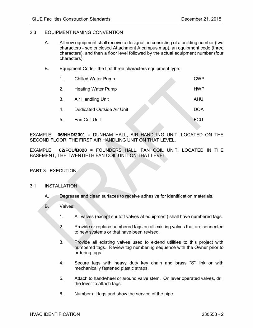
SIUE Facilities Construction Standards December 21, 2015
HVAC IDENTIFICATION 230553 - 2
2.3 EQUIPMENT NAMING CONVENTION
A. All new equipment shall receive a designation consisting of a building number (two characters - see enclosed Attachment A campus map), an equipment code (three characters), and then a floor level followed by the actual equipment number (four characters).
B. Equipment Code - the first three characters equipment type:
1. Chilled Water Pump CWP
2. Heating Water Pump HWP
3. Air Handling Unit AHU
4. Dedicated Outside Air Unit DOA
5. Fan Coil Unit FCU
EXAMPLE: 06/NHD/2001 = DUNHAM HALL, AIR HANDLING UNIT, LOCATED ON THE SECOND FLOOR, THE FIRST AIR HANDLING UNIT ON THAT LEVEL.
EXAMPLE: 02/FCU/B020 = FOUNDERS HALL, FAN COIL UNIT, LOCATED IN THE BASEMENT, THE TWENTIETH FAN COIL UNIT ON THAT LEVEL.
PART 3 - EXECUTION
3.1 INSTALLATION
A. Degrease and clean surfaces to receive adhesive for identification materials.
B. Valves:
1. All valves (except shutoff valves at equipment) shall have numbered tags.
2. Provide or replace numbered tags on all existing valves that are connected to new systems or that have been revised.
3. Provide all existing valves used to extend utilities to this project with numbered tags. Review tag numbering sequence with the Owner prior to ordering tags.
4. Secure tags with heavy duty key chain and brass "S" link or with mechanically fastened plastic straps.
5. Attach to handwheel or around valve stem. On lever operated valves, drill the lever to attach tags.
6. Number all tags and show the service of the pipe.

SIUE Facilities Construction Standards December 21, 2015
HVAC IDENTIFICATION 230553 - 3
7. Provide two sets of laminated 8-1/2" x 11" copies of a valve directory listing all valves, with respective tag numbers, uses, and locations. The directory shall be reviewed by the Owner and Architect/Engineer prior to laminating final copies. Laminated copies shall have brass eyelet in at least one corner for easy hanging.
C. Pipe Markers:
1. Adhesive Backed Markers: Use Brady Style 1, 2, or 3 on pipes 3" diameter and larger. Use Brady Style 4, 6, or 8 on pipes under 3" diameter. Similar styles by other listed manufacturers are acceptable. Secure all markers at both ends with a wrap of pressure sensitive tape completely around the pipe.
2. Apply markers and arrows in the following locations where clearly visible:
a. At each valve.
b. On both sides of walls that pipes penetrate.
c. At least every 20 feet along all pipes.
d. On each riser and each leg of each "T" joint.
e. At least once in every room and each story traversed.
3. Underground Pipe Markers: Install 8" to 10" below grade, directly above buried pipes.
D. Equipment:
1. All equipment not easily identifiable such as controls, relays, gauges, etc.; and all equipment in an area remote from its function such as air handling units, exhaust fans, filters, reheat coils, dampers, etc.; shall have nameplates or plastic tags listing name, function, and drawing symbol. Do not label exposed equipment in public areas.
2. Fasten nameplates or plastic tags with stainless steel self-tapping screws or permanently bonding cement.
E. Miscellaneous:
1. Attach self-adhesive vinyl labels at all duct access doors used to reset fusible links or actuators on fire, fire/smoke, or smoke dampers. Lettering shall be a minimum of 1/2" high. Labels shall indicate damper type.
F. Tracer Wire:
1. Tracer wire shall be installed on top of all non-metallic buried utilities.
2. Tracer wire shall be taped directly to plastic water or drain pipe.

SIUE Facilities Construction Standards December 21, 2015
HVAC IDENTIFICATION 230553 - 4
3. Tracer wire shall not be fastened directly or indirectly to gas piping.
4. Tracer wire when attached shall be secured to the pipe a minimum of every 10 feet and at all changes of direction.
5. Tape shall be Polyken “930-35”, Protecto-Wrap “310”, or approved equal.
6. Tracer wire shall be continuous between boxes and shall be tested for continuity.
7. Splices in tracer wire shall be made with a water proof splice kit to prevent corrosion. Wire nuts shall not be used.
8. The tracer wire shall daylight to grade through a 2” PVC conduit, at the point of the utility entrance to building. PVC conduit shall be capped and labeled as future contact point to locate the utility.
3.2 SCHEDULE
A. Pipes to be marked:
Pipe Service
Lettering
Color
Background
Color
High Temperature Hot Water - over 240ºF Black Yellow
High Pressure Steam Black Yellow
Low Pressure Steam Black Yellow
Heating Water Supply Black Yellow
Heating Water Return Black Yellow
High Pressure Condensate Black Yellow
Low Pressure Condensate Black Yellow
Pumped Condensate Black Yellow
Chilled Water Supply White Green
Chilled Water Return White Green
Condenser Water Supply White Green
Condenser Water Return White Green
Condensate Drain Black Yellow
Compressed Air Black Yellow
Control Compressed Air Black Yellow
Natural Gas Black Yellow
All Underground Pipes Varies Varies
Medical Vacuum Black White

SIUE Facilities Construction Standards December 21, 2015
HVAC IDENTIFICATION 230553 - 5
Pipe Service
Lettering
Color
Background
Color
Waste Anesthetic Gas Disposal White Violet
Carbon Dioxide White Gray
Instrument Air White Red
Medical Air Black Yellow
Nitrogen White Black
Nitrous Oxide White Blue
Oxygen White Green
Refrigerant (Liquid, Suction or Hot Gas) Black Yellow
Fuel Oil Piping (Supply and Return) Black Yellow
Tracer Wire - Natural Gas Pipe Lines --- Yellow
Tracer Wire - All other buried types --- Green
END OF SECTION 230553

SIUE Facilities Construction Standards December 21, 2015
ATTACHMENT A

SIUE Facilities Construction Standards December 21, 2015
DUCTWORK INSULATION 230713 - 1
SECTION 23 07 13 - DUCTWORK INSULATION
PART 1 - GENERAL
1.1 SECTION INCLUDES
A. Ductwork Insulation.
PART 2 - PRODUCTS
2.1 GENERAL
A. All insulation shall meet or exceed current AHSRAE 90.1 and International Energy Code requirements.
2.2 MATERIALS
A. Flexible fiberglass wrap insulation shall be utilized for all supply duct unless inside mechanical rooms, double wall ductwork, or when the use of liner insulation is approved.
B. Semi-rigid fiberglass board wrap shall be utilized for applications when duct is within mechanical spaces.
C. Flexible fiberglass liner shall be used for all return air transfer ducts and must be approved by the University for applications and only considered when acoustical properties are desired.
PART 3 - EXECUTION
3.1 INSTALLATION
A. Follow SMACNA standards and manufacturers requirements for installation.
B. Install materials after ductwork has been tested.
C. Clean surfaces for adhesives.
D. Provide insulation with vapor barrier when air conveyed may be below ambient temperature.
END OF SECTION 230713

SIUE Facilities Construction Standards December 21, 2015
HVAC PIPING INSULATION 230719 - 1
SECTION 230719 - HVAC PIPING INSULATION
PART 1 - GENERAL
1.1 SECTION INCLUDES
A. Piping Insulation.
B. Insulation Jackets.
PART 2 - PRODUCTS
2.1 INSULATION
A. All insulation shall meet or exceed current AHSRAE 90.1 and International Energy Code requirements. All insulation shall be plenum rated and insulation must meet 25/50.
2.2 JACKET COVERINGS
A. Aluminum Jackets: ASTM B209; 0.016" thick; stucco embossed finish with Z edge seams and aluminum bands for outdoor use.
B. Stainless Steel Jackets: Type 316 stainless steel; .010” thick; smooth finish with Z edge seams and stainless steel bands for outdoor use.
C. Plastic Jackets and Fitting Covers: High impact, glossy white, 0.020" thick for interior use and 0.030" thick for exterior use, self-extinguishing plastic. Suitable for use indoors or outdoors with ultraviolet inhibitors. 25/50 maximum flame spread/smoke developed.
PART 3 - EXECUTION
3.1 INSTALLATION
A. General Installation Requirements:
1. Continue insulation with vapor barrier through penetrations. This applies to all insulated piping. Maintain fire rating of all penetrations.
2. On all insulated piping, provide at each support an insert of same thickness and contour as adjoining insulation, between the pipe and insulation jacket, to prevent insulation from sagging and crushing. The insert shall be suitable for planned temperatures, be suitable for use with specific pipe

SIUE Facilities Construction Standards December 21, 2015
HVAC PIPING INSULATION 230719 - 2
material, and shall be a 180 cylindrical segment the same length as metal shields. Inserts shall be a cellular glass (for all temperature ranges) or molded hydrous calcium silicate (for pipe with operating temperatures
above 70F, with a minimum compressive strength of 50 psi. Factory fabricated inserts may be used. Rectangular blocks, plugs, or wood material are not acceptable. Temporary wood blocking may be used by the Piping Contractor for proper height; however, these must be removed and replaced with proper inserts by the Insulation Contractor.
3. Install metal shields between all hangers or supports and the pipe insulation. Shields shall be galvanized sheet metal, half-round with flared edges. Adhere shields to insulation. On cold piping, seal the shields vapor-tight to the insulation as required to maintain the vapor barrier, or add separate vapor barrier jacket.
4. On 1" and smaller piping routed through metal wall studs, provide a plastic grommet to protect the piping. The piping shall be insulated between the wall studs, and the insulation shall butt up to each stud.
B. Insulated Piping Operating Below 60°F:
1. Insulate fittings, valves, unions, flanges, strainers, flexible connections, flexible hoses, and expansion joints. Seal all penetrations of vapor barrier.
2. On piping operating below 60ºF in locations that are not mechanically cooled (e.g., penthouses, mechanical rooms, tunnels, chases at exterior walls, etc.), Elastomeric insulation shall be used.
3. All balance valves with fluid operating below 60°F shall be insulated with a removable plug wrapped with vapor barrier tape to allow reading and adjusting of the valve.
C. Insulated Piping Operating Between 60°F and 140°F:
1. Do not insulate flanges and unions, but bevel and seal ends of insulation at such locations. Insulate all fittings, valves and strainers.
D. Insulated Piping Operating Above 140°F:
1. Insulate fittings, valves, flanges, and strainers.
2. All balance valves with fluid operating above 140°F shall be insulated and an opening shall be left in the insulation to allow for reading and adjusting the valve.
3.2 JACKET COVER INSTALLATION
A. Provide jacket cover an all exterior pips with insulation, including elastomeric insulation.
B. Provide jacket cover on all exposed piping below 8’-0” above floor.

SIUE Facilities Construction Standards December 21, 2015
HVAC PIPING INSULATION 230719 - 3
C. Provide jacket cover on all piping in mechanical rooms subject to damage from normal operation.
3.3 SCHEDULE Piping System Insulation Type/Thickness
A. Chilled Water Supply & Return
All Sizes (located in air conditioned spaces) Glass Fiber or Elastomeric
All Sizes (located in non-air conditioned spaces)
Elastomeric
All Sizes (located in modular chiller enclosure)
Elastomeric
All Sizes (located inside air handling unit airstream)
Elastomeric
B. Cooling Coil Condensate Drains below 55F Elastomeric
C. Heating Water Supply & Return Glass Fiber
D. Condenser Water Supply & Return (Indoor) Glass Fiber or Elastomeric
E. Refrigerant Elastomeric
END OF SECTION 230719

SIUE Facilities Construction Standards December 21, 2015
CONTROLS 230900 - 1
SECTION 230900 - CONTROLS
PART 1 - GENERAL
1.1 SECTION INCLUDES
A. Complete System of Automatic Controls.
B. Control Devices, Components, Wiring and Material.
PART 2 - PRODUCTS
2.1 ACCEPTABLE MANUFACTURERS
A. Johnson Controls.
2.2 TERMINAL AIR BOX (TAB) CONTROLLERS
A. FMCS Volume Controller: Electronic, furnished and installed by TCC. Boxes shall have pressure independent control to maintain constant air volume regardless of duct pressure changes up to 6 inches w.c. Provide velocity and static sensor at box inlet for use by unit controller. Set boxes for maximum and minimum settings shown on the drawings.
B. The controller shall support various digital and analog inputs and outputs as needed for damper control, control valves, electric coils, airflow sensors, remote heating, occupancy sensors, etc. and shall be capable of independent occupancy scheduling.
C. Controller shall provide continuous zone temperature histories internal to device for up to 24 hours and perform its own limit and status monitoring and alarms to limit unnecessary communications.
D. Store all system setpoints, proportional bands, control algorithms, and other programmable parameters such that a power failure of any duration does not necessitate reprogramming of the controller.
E. BACnet TAB controllers shall either be B-AAC devices or B-ASC devices as required to meet the performance and BTL listing.

SIUE Facilities Construction Standards December 21, 2015
CONTROLS 230900 - 2
2.3 HYDRONIC CONTROL VALVES
A. General:
1. Two-position valves shall be a minimum of line size with a maximum allowable pressure drop of 2 psi.
2. Size two-way and three-way modulating valves to provide a pressure drop at full flow of 1 to 4 psi, except boiler three-way and cooling tower bypass valves shall not have a pressure drop over 2 psi.
3. Two-way valves shall be 100% tight-closing. Three-way valves shall be 100% tight-closing in both extreme positions.
4. Modulating two-way valves shall have equal percentage flow characteristics.
5. Modulating three-way valves shall have linear flow characteristics.
6. Piping geometry correction factors for Cv ratings shall be used and stated for ball valves, butterfly valves, or non-characterized valves.
B. Pressure Independent:
1. All chilled water control valves shall be pressure independent.
2. Shall meet all requirements of valve types listed above.
3. Shall be used for chilled water system control valves.
4. Valve shall accurately control flow from 0% to 100% full rated flow with an operating pressure differential range of 5 to 50 PSID across the valve.
5. Maintenance free design. No replacement cartridges or packing allowed.
2.4 ELECTRIC VALVE ACTUATORS
A. General:
1. Actuators shall be sized to operate the valve through its full range of motion and shall close against pump shutoff pressure without producing audible noise at any valve position.
2. Provide visual position indication.
3. Mount actuator directly on valve or provide linear motion assembly as required for valve type.

SIUE Facilities Construction Standards December 21, 2015
CONTROLS 230900 - 3
2.5 CONTROL INSTRUMENTATION
A. BTU Meters:
1. General:
a. The entire Energy Measurement System shall be built and calibrated by a single manufacturer, ONICON Incorporated, and shall consist of a flow meter, two temperature sensors, a BTU meter, temperature thermowells, and all required mechanical installation hardware. A certificate of NIST* traceable calibration shall be provided with each system. All equipment shall be covered by the manufacturer’s two year warranty.
2. BTU Meter:
a. Provide an ONICON System-10 BTU Meter. The BTU meter shall provide the following points both at the integral LCD and as outputs to the building control system: Energy Total, Energy Rate, Flow Rate, Supply Temperature and Return Temperature. Output signals shall be either serial network (protocol conforming to BACnet® MS/TP, BACnet/IP, LONWORKS®, JCI-N2, MODBUS RTU RS485, MODBUS RTU TCP/IP, or Siemens-P1) and/or via individual analog and pulse outputs. Each BTU meter shall be factory programmed for its specific application, and shall be re-programmable using the front panel keypad (no special interface device or computer required).
3. Temperature Sensors:
a. Temperature sensors shall be loop-powered current based (mA) sensors and shall be bath-calibrated and matched (NIST* traceable) for the specific temperature range for each application. The calculated differential temperature used in the energy calculation shall be accurate to within +0.15°F (including the error from individual temperature sensors, sensor matching, input offsets, and calculations).
4. Flow Meter:
a. Provide an ONICON Model F-3500 Insertion Electromagnetic Flow Meter. Materials of construction for wetted metal components shall be 316 SS. For installations in non-metallic pipe, install grounding rings or probes. The flow meter shall average velocity readings from two sets of diametrically opposed electrodes. Each flow meter shall be individually wet-calibrated against a primary volumetric standard that is accurate to within 0.1% and traceable to NIST*. A certificate of calibration shall be provided with each flow meter. Accuracy shall be within ± 1% of rate from 2-20 ft/s. Overall turndown shall exceed 100:1. Output signals shall be completely isolated and shall consist of the following: (1) high resolution frequency output for use with

SIUE Facilities Construction Standards December 21, 2015
CONTROLS 230900 - 4
peripheral devices such as an ONICON display module or Btu meter, (1) analog output; 4-20mA, 0-10V, or 0-5V jumper selectable and (1) scalable dry contact output for totalization. Each flow meter shall be covered by the manufacturer’s two-year warranty.
b. Provide an ONICON F-3200 Series Electromagnetic Flow Meter complete with integral or remote electronics module. The electronics module shall include a backlit graphic display and keypad. Connections to the piping shall be ANSI class 150 flanges (ANSI class 300 available where required). The installing contractor is responsible for providing suitable mating flanges. The flow tube shall be epoxy coated steel; the sensing electrodes shall be 316SS; the liner shall be polypropylene or ebonite for low temperature service, PFTE for hot water service. Each flow meter shall be individually wet-calibrated and accurate to within ±0.2% of reading from 1.6 to33 feet per second velocity. A certificate of calibration shall be provided with each flow meter. Output signals shall be 4-20 mA and programmable pulse. The flow meter shall be capable of measuring bi-directional flow. For installations in non-metallic pipe, install grounding rings between flanges. Each flow meter shall be factory programmed for its specific application, and shall be re-programmable using the integral keypad on the converter (no special interface device or computer required).
5. Transmitter:
a. Each meter shall incorporate an integral mounted programmable transmitter that incorporates a digital display.
b. Each transmitter shall calculate and display flow rate and net totalized flow, along with associated engineering units (e.g., GPM and Gal.)
c. Each transmitter shall produce an analog output signal that is directly proportional to volumetric flow rate. This signal shall be scalable to indicate flow rate in either direction. In lieu of such bidirectional scalability, two separate pulsed outputs shall be provided. One shall indicate incremental flow in one direction, while the other indicates incremental flow in the opposite direction such that net totalized flow can be calculated remotely. Transmitters that produce an output signal indicating direction of flow in conjunction with a flow rate signal that is scalable in one direction only are not acceptable.
d. Unless scheduled or otherwise indicated, the initial span adjustment of each transmitter shall be 0-120% of the scheduled maximum flow rate.
e. Each transmitter shall incorporate self-diagnostics and test functions in order to permit internal checks of all outputs and

SIUE Facilities Construction Standards December 21, 2015
CONTROLS 230900 - 5
displays and to verify the accuracy of the unit and the integrity of the current loop without any external equipment.
6. Accuracy:
a. Non-billing Purposes: Where meters are used for non-billing purposes, the accuracy of each meter/transmitter assembly shall be ± 0.5% of flow rate reading over a range of 3-15 ft/section fluid velocity, with a repeatability of 0.1%. Accuracy at 1 ft/section shall be ± 0.75%.
7. Calibration:
a. Each meter shall be calibrated on a NIST traceable flow stand at a minimum of three operating points. These three points shall be the flow rates associated with fluid velocities of 1.0 FPS, 8.0 FPS, and 15.0 FPS. Written documentation of calibration shall be provided.
8. Installation and Startup:
a. Each meter assembly shall include detailed installation and operation instructions that include piping straight run requirements.
b. Each bid shall include the cost of on-site startup, commissioning, and training.
9. Warranty:
a. Each meter assembly shall carry a performance warranty of at least two years from the date of installation and startup. This warranty shall cover parts and labor for repair or replacement of the meter assembly. Performance during the warranty period shall satisfy the above-stated requirements for accuracy and repeatability.
10. Approved Manufacturers: Onicon.
B. Water Meter (Meter Main Case):
1. Outer cases shall be made of one of the following materials:
a. 2” – 12”: Cast ductile iron alloy equaling or exceeding AWWA Standards such as those listed in ASTM A536 or ASTM A126. The maincase shall be protected by a complete fusion-bonded coating conforming to AWWA C-550.
2. All external bolts and nuts shall be made of bronze or stainless steel, and shall be so designed for easy removal after having been in service for a long period of time.
3. The main case shall withstand a working pressure of 175 PSI without leakage, seepage in the castings, or distortion affecting the free and

SIUE Facilities Construction Standards December 21, 2015
CONTROLS 230900 - 6
accurate operation of the measuring unit.
4. The size of the meter and the direction of flow shall be case in raised letters on the outer surface of the case.
5. Register Cover:
a. The register box shall be made of an engineering plastic with the manufacturer’s serial number inside the register lid. Serial number of the meter shall also be permanently programmed in the electronic register.
b. Register cover box shall be attached to main case in a tamper resistant manner. The register cover box shall be equipped with a hinged lid that will overlap the register to protect the reading area.
6. Register:
a. The factory sealed register shall be electronically driven only and shall be furnished with a low flow leak detection symbol and with a reverse flow notification symbol. The register shall be identical within a given size or model subject to the programming of appropriate flow factors for the particular meter. An effectively tamper proof meter with a displayed tamper indication symbol, is required. The register shall be programmed initially to read in US. Gallons. The transparent LCD register glass lens shall be made of molded heat-treated 0.25” glass to ensure against scratching and breakage. Serial number shall be permanently programmed in the electronic register.
b. As defined in these specifications, a "factory sealed" register shall mean a non-fogging, moisture and dust-proof register, electronically driven by the measuring section transit time sensors. Appearance of any fogging or moisture inside the register within the warranty period shall constitute component failure and will require a factory replacement. Register shall indicate reverse flow, rate of flow, low battery indication, leak alert, as well as no flow condition.
7. Measuring Section:
a. The measuring section shall be a unitized unit, completely integral to the meter body. The measuring section shall not include any moving parts and the measuring section shall have an unobstructed flow passage area at least equal to 50% of the nominal Schedule 40 pipe size corresponding to the meter’s size.
b. All parts of the measuring section shall be similar with assemblies of the same size and material.

SIUE Facilities Construction Standards December 21, 2015
CONTROLS 230900 - 7
c. The measuring section shall be secured in a position in the main case in such a manner that slight distortion of the outer meter case will not affect the sensitivity or registration of the meter.
d. To ensure longevity of service, the performance of the measuring chamber shall be guaranteed to meet required Compound meter accuracy standards of AWWA M6 Manual for a period of two years from date of manufacturer’s shipment.
e. The measuring section shall be covered for this period by written warranty as required or mentioned elsewhere in these specifications.
8. Signal Processing:
a. Two pairs of sensors are to be mounted in the chordal direct configuration in the measuring section to measure the actual transit time of the initiated and reception-generated ultrasonic sound pulses. Transit time measurements for a single pass of initiated and return pulses are to be accurate to within 300 pico-seconds for a loop time.
b. Multiple measurements are sampled at a minimum of 1 second intervals of these transit time loops that are made to significantly improve accuracy over a single pass transit time measurements as employed in typical AWWA C750 ultrasonic meters to achieve low flow rate measuring accuracy.
c. Ultrasonic meters using single directional sound transmission to determine flow measurements are not acceptable. Meters that use measurement principals based on Faraday’s Law are not permitted.
1) Signal Outputs: The meter shall have digital pulse output.
2) The Digital (pulse) Output is to be an open collector (open drain) transistor output that provides pulse per quantity with these options:
a) Two scaled forward flow pulses.
b) One scaled pulse forward flow and one flow direction.
c) One scaled forward flow pulse and one scaled reverse flow pulse.
9. Installation Requirements:
a. Meters shall be designed so that no strainer or straightening vanes are required. There shall be no internal parts blocking the waterway. No straight runs of pipe shall be necessary before or after the meter.

SIUE Facilities Construction Standards December 21, 2015
CONTROLS 230900 - 8
10. Pressure Capability:
a. Meters shall operate up to a working pressure of one hundred seventy five pounds per square inch (PSI) and to a temperature of 122 degrees Fahrenheit, without leakage or damage to any parts. The accuracy shall not be affected when operating at this pressure to possible distortion.
11. Coordinate with the Plumbing Contractor for correct meter size.
12. Meter shall be provided by the Controls Contractor for installation by the Plumbing Contractor.
13. Acceptable Manufacturers: Master Meter Octave
C. Natural Gas Submeter:
1. Meter shall have integral electronics with indication and totalization.
2. Meter shall operate with maximum capacity of 1750 CFH.
3. Meter shall provide pulsed output interface.
4. Meter shall provide gas usage with imperial display.
5. Coordinate with the Plumbing Contractor for correct meter size.
6. Meter shall be provided by the Controls Contractor for installation by the Plumbing Contractor.
7. Manufacturer shall be Sensus Sonix 2000 or equal.
D. Electrical Submeter:
1. Coordinate with the Electrical Contractor to ensure submeter is compatible for TCS monitoring.
2. Provide electrical usage data to TCS as indicated on the drawings.
2.6 PNEUMATIC CONTROLS
A. Pneumatic controls shall not be utilized for new equipment,
PART 3 - EXECUTION
3.1 GENERAL INSTALLATION
A. Verify that systems are ready to receive work. Beginning of installation means installer accepts existing conditions.
SIUE Facilities Construction Standards December 21, 2015
CONTROLS 230900 - 9
B. Install all operators, sensors, and control devices where accessible for service, adjustment, calibration, and repair. Do not install devices where blocked by piping or ductwork. Devices with manual reset or limit adjustments shall be installed below 6'-0" if practical to allow inspection without using a ladder.
C. Verify locations of wall-mounted devices (such as thermostats, temperature and humidity sensors, and other exposed sensors) with drawings and room details before installation. Coordinate mounting heights to be consistent with other wall-mounted devices. Maximum height above finished floor shall not exceed 48”.
D. Provide valves over 3/4" size with position indicators and pilot positioners where sequenced with other controls.
E. Mount control panels adjacent to associated equipment on vibration-free walls or freestanding angle iron supports. One cabinet may accommodate more than one system in same equipment room.
F. After completion of installation, test and adjust control equipment.
G. Check calibration of instruments. Recalibrate or replace.
H. Furnish and install conduit, wire, and cable per the National Electric Code, unless noted otherwise in this section.
I. All controls associated with the proper operation of air handling units, pumps, or other mechanical equipment served by emergency power shall be connected to the emergency power system. Control components shall not be powered from the life safety branch of the emergency power system. Coordinate emergency power source connections with the Architect/Engineer.
J. Labels For Control Devices:
1. Provide labels indicating service of all control devices in panels and other locations.
2. Labels may be made with permanent marking pen in the control panels if clearly legible.
3. Use engraved labels for items outside panel such as outside air thermostats.
4. Labels are not required for room thermostats, damper actuators and other items where their function is obvious.
K. VFDs:
1. Verify output signal required, 4-20 mA or 0-10V dc, with the EC.
2. If VFD has a bypass feature, auxiliary contacts on the drive may not be used for motor status. A separate relay must be used to indicate motor rotation in either hand or auto positions.

SIUE Facilities Construction Standards December 21, 2015
CONTROLS 230900 - 10
3. If a separate current transmitter or switch is indicated for status, install this device between the VFD and the motor. In this case, the drive status may be connected to the auxiliary contacts in the VFD.
4. Some devices, such as low limits and fire alarm shutdown relays, must be hardwired to the fan motor. Make connections such that fan will shut down whether in hand or auto position if the unit has a bypass feature.
3.2 TEST AND BALANCE COORDINATION
A. The Contractor shall furnish a single set of all tools necessary to interface to the control system for test and balance purposes.
B. The Contractor shall provide a minimum of four (4) hours training for the Balancing Contractor in the use of these tools.
C. In addition, the Contractor shall provide a qualified technician to assist in the test and balance process until the first 20 terminal units are balanced.
D. The tools used during the test and balance process shall be returned at the completion of the testing and balancing.
3.3 INSTALLATION OF FLOW METERS
A. Provide manufacturer’s recommended lengths of straight piping upstream and downstream of the flow meter. Up to 30 diameters upstream of the flow meter may be required depending on the piping arrangement and flow meter type.
END OF SECTION 230900

SIUE Facilities Construction Standards December 21, 2015
INSTRUMENTATION 230913 - 1
SECTION 230913 - INSTRUMENTATION
PART 1 - GENERAL
1.1 SECTION INCLUDES
A. Pressure Gauge.
B. Pressure Gauge Accessories.
C. Thermometers.
PART 2 - PRODUCTS
2.1 PRESSURE GAUGES
A. Gauges shall be 4-1/2" diameter with aluminum or stainless steel case with phosphor bronze bourdon tube, brass socket for air, steam, water or oil application, 1/4" or 1/2" bottom connection. Gauges shall be 1% full scale accurate with bronze brushed brass movement and adjustable pointer. Standard ranges to be either pressure or pressure and vacuum as required of application.
B. Acceptable Manufacturers: Ashcroft, Marsh, Marshalltown, Miljoco, Trerice, U.S. Gauge Figure 1901, Weiss, Weksler, Wika.
C. Select gauge range for normal reading near center of gauge.
2.2 PRESSURE GAUGE ACCESSORIES
A. All pressure gauges shall have valves and pressure snubbers. All pressure gauges on steam shall have pigtail syphon.
B. Shutoff Valve: 1/4" ball valve as specified for each piping system.
C. Pressure snubber, brass with 1/4" connections, porous metal type.
2.3 THERMOMETERS
A. Alcohol/Spirit Filled Type:
1. 9" long phenolic case, steel stem, accuracy of 1% full scale. Adjustable elbow joint with locking device to allow rotation of thermometer to any angle.
2. Select thermometer for appropriate temperature range.

SIUE Facilities Construction Standards December 21, 2015
INSTRUMENTATION 230913 - 2
3. Stem lengths as required for application with minimum insertion of 3”.
4. Thermometers for water, steam, or oil shall have brass or steel separable socket. Wells shall extend through insulation. Thermometers for air shall have an aluminum or brass duct flange.
5. Acceptable Manufacturer: Marsh, Miljoco, Trerice, Weiss, Weksler, Wika.
B. Select scales to cover expected range of temperatures.
PART 3 - EXECUTION
3.1 INSTALLATION
A. General Installation Requirements:
1. Install per manufacturer's instructions.
2. Coil and conceal excess capillary on remote element instruments.
3. Install gauges and thermometers in locations where they are easily read from normal operating level.
4. Do not install instrumentation when areas are under construction, except for required rough-in, taps, supports and test plugs.
B. Pressure Gauges:
1. Provide snubber for each pressure gauge.
C. Thermometers:
1. Install thermometers in piping systems in sockets in short couplings. Enlarge pipes smaller than 2-1/2" for installation of thermometer sockets.
2. Install thermometer sockets adjacent to control system thermostat, transmitter and sensor sockets.
3. Locate duct thermometers minimum 10 feet downstream of mixing dampers, coils, or other devices causing air turbulence.
END OF SECTION 230913

SIUE Facilities Construction Standards December 21, 2015
HYDRONIC PIPING 232100 - 1
SECTION 232100 - HYDRONIC PIPING
PART 1 - GENERAL
1.1 SECTION INCLUDES
A. Pipe and Pipe Fittings.
B. Valves.
C. Heating Water Piping System.
D. Glycol Water Piping System.
E. Chilled Water Piping System.
F. Condenser Water Piping System.
G. Heating/Cooling Water Piping System.
H. Acoustical Lagging.
PART 2 - PRODUCTS
2.1 PIPING
A. Piping - 2"and Under:
1. Utilize type L hard drawn seamless copper for all piping in return air plenums.
2. Joints may be soldered, mechanical press, mechanical push-to-connect, mechanically coupled grooved
3. Consider use of AquaTherm or equivalent pipe for hydronic pipe not located in return air plenums.
B. Piping - 2-1/2" and Over:
1. Utilize standard weight black steel, beveled ends, ASTM A53, Type E or S, Grade B for all piping in return air plenums.
2. Joints may be welded, flanged or grooved type with Grade E EPDM molded pressure-responsive gaskets.
3. Consider use of AquaTherm or equivalent pipe for hydronic pipe not located in return air plenums.
SIUE Facilities Construction Standards December 21, 2015
HYDRONIC PIPING 232100 - 2
a. Grooved type, with Grade E EPDM molded pressure-responsive
gaskets suited for 32F to 230F per ASTM D2000.
2.2 CONDENSER WATER (UNDERGROUND) CHILLED WATER (UNDERGROUND)
A. PVC Pressure Pipe:
Maximum Design Temperature: 140F.
1. Pipe: PVC pressure pipe, Class 200 ANSI/AWWA C900 approved, flanged ends.
2. Joints: Push-On Type, elastomeric ring seal per ASTM F477, bevel spigot ends.
3. Fittings: Cast iron bell and spigot type, 200 psig rating, tar coated outside, cement mortar lined inside, ANSI A21.10 or A21.11.
2.3 SUCTION DIFFUSER
A. A separate strainer shall be provided for inlet to pump.
2.4 EXPANSION TANK
A. Tank shall be welded steel, bladder type, with ASME construction and stamped.
2.5 COALESCING TYPE COMBINATION AIR ELIMINATOR AND DIRT SEPARATOR
A. Coalescing type air eliminator and dirt separator shall be fabricated from steel and ASME constructed and certified for 125 psi working pressure and 270ºF operating temperature. Units 2-1/2 inches and smaller shall have threaded connections. Units 3 inches and larger shall have flanged connections.
B. Air elimination and dirt separation shall be by coalescing action by either:
1. Stainless steel PALL rings.
2. Copper tubes with continuous wound, permanently attached copper wire and followed by a separate continuous wound permanently affixed copper wire.
C. Provide brass flushing cock on the separator side to facilitate system fast-fill and to blow down impurities from the water surface within the separator.
D. Provide factory mounted blow-down valve on the unit bottom to allow for draining and cleaning.

SIUE Facilities Construction Standards December 21, 2015
HYDRONIC PIPING 232100 - 3
E. Coalescing separators shall be as sized on the construction drawings, but in no case shall it have less than line size connections nor shall pressure drop exceed 1 psi at design flow. Include on submittal the pressure drop of each unit at its design flow rate.
F. Coalescing separators shall be equipped with removable cover to allow for removal, inspection and cleaning of the internal coalescing media.
PART 3 - EXECUTION
3.1 PREPARATION
A. After completion, fill, clean, and treat systems.
3.2 INSTALLATION
A. Installation Requirements in Electrical Rooms:
1. Do not install piping or other equipment above electrical switchboards or panelboards. This includes a dedicated space extending 25 feet from the floor to the structural ceiling with width and depth equal to the equipment plus its required clearance space.
2. Provide chain operators for all valves over 2" size that are over 10'-0" above finished floor. Extend to 7'-0" above finished floor.
3. Provide valve position indicator on all valves 10’-0” or greater above finish floor and not located above ceiling.
4. Provide clearance for installation of insulation, and access to valves and fittings.
5. Provide access doors where valves are not exposed.
6. Install balancing valves with the manufacturer’s recommended straight upstream and downstream diameters of pipe.
7. Provide shutoff valves and flanges or unions at all connections to equipment, traps, and items that require servicing.
8. Provide flanges or unions at all final connections to equipment, traps and valves.
9. Arrange piping and piping connections so equipment may be serviced or totally removed without disturbing piping beyond final connections and associated shutoff valves.
END OF SECTION 232100

SIUE Facilities Construction Standards December 21, 2015
HVAC PUMPS 232123 - 1
SECTION 232123 - HVAC PUMPS
PART 1 - GENERAL
1.1 SECTION INCLUDES
A. All pumps except where integral with a manufactured piece of equipment.
PART 2 - PRODUCTS
2.1 PUMPS - GENERAL
A. Statically and dynamically balance rotating parts.
B. Construction shall permit complete servicing without breaking piping or motor connections.
C. Pump connections shall be flanged, whenever available.
D. Heating pumps shall be suitable for 225ºF water.
2.2 SPLIT CASE BASE MOUNTED PUMPS
A. Preferred pump for larger flow rate pumps.
B. Type: Centrifugal, single stage, double suction, horizontal or vertical split case,
C. Baseplate: Reinforced heavy steel.
D. Acceptable Manufacturers: Bell & Gossett, Taco, Aurora, Armstrong, Grundfos/Peerless/PACO
2.3 BASE MOUNTED END SUCTION PUMPS
A. Acceptable Manufacturers: Bell & Gossett, Taco, Aurora, Armstrong, Grundfos/Peerless/PACO.
2.4 IN-LINE PUMP
A. Type: Centrifugal, single stage, close coupled in-line, back pullout design, suitable
B. Acceptable Manufacturers: Bell & Gossett, Taco, Aurora, Armstrong, Grundfos/Peerless/PACO.

SIUE Facilities Construction Standards December 21, 2015
HVAC PUMPS 232123 - 2
PART 3 - EXECUTION
3.1 INSTALLATION
A. In-Line Pumps:
1. Support in-line pumps individually so there is no strain on the piping. Install with a minimum of five diameters of straight pipe on pump suction and discharge.
B. Base-Mounted Pumps:
1. Base-mounted pumps shall be factory aligned. If alignment is not satisfactory, as determined by the Architect/Engineer, manufacturer shall provide a factory trained representative to field align the shafts.
2. Unless otherwise shown on the drawings, mount all base mounted pumps on 4" high concrete pads and anchor frames to pads with cast-in-place anchors.
END OF SECTION 232123

SIUE Facilities Construction Standards December 21, 2015
CONDENSING BOILERS 235216 - 1
SECTION 235216 - CONDENSING BOILERS
PART 1 - GENERAL
1.1 SECTION INCLUDES
A. Boilers.
B. Controls and Boiler Trim.
C. Boiler Vent Flue.
PART 2 - PRODUCTS
2.1 BOILERS
A. Acceptable Manufacturer: Lochinvar, Aerco International, Inc,, Cleaver Brooks (Clear Fire), Viessmann, Raypak (Xfrye, Xtherm), Hydrotherm (KN).
2.2 HEAT EXCHANGER
A. Condensing, fire tube design surrounded by water that is suitable for return water temperatures as low as 50ºF.
B. Ten-year non-prorated warranty against leakage due to thermal shock or corrosion.
2.3 BOILER FLUE
A. The boiler flue shall be of material approved by the manufacturer. Vent piping shall be UL listed for use with category III and IV appliances with operating temperatures of up to 480°F.
2.4 HOT WATER BOILER TRIM
A. Provide ASME safety relief valve set at 125 psi or boiler maximum allowable working pressure.
B. Provide neutralization kit for condensate treatment prior to entering sanitary system.
C. Burner to be modulating with a minimum turndown ratio of 5:1.

SIUE Facilities Construction Standards December 21, 2015
CONDENSING BOILERS 235216 - 2
2.5 CONTROL PANEL
A. The boiler system control panel shall include contacts for a trouble alarm to the DDC system.
B. Program relay to control ignition, starting and stopping of burner and provide both pre-combustion purge and post combustion purge. Burner to shut down in event of ignition, or main flame failure. Interlock to shut down burner upon combustion air pressure drop.
C. Manual-automatic selector switch to permit automatic firing in accordance with load demand, or manual control of firing rate at fixed temperature.
D. Panel to include indicating lights to show fault conditions of low water level, flame failure, fuel pressure, exhaust temperature, water temperature, or combustion air pressure. Mount indicating lights and switches in hinged drop-panel for access to wiring.
E. The boiler system control panel shall include contacts for a manual CSD-1 emergency shutdown switch. The switch shall be furnished, installed, and wired by the Electrical Contractor. Switch shall be located at each exit just outside the boiler room door. If boiler room door is on exterior of building, the switch shall be located just inside the door. The switch shall disable all boilers and shall be wired to the boiler burner safety control circuit to interrupt burner operation.
F. The boiler shutdown switch shall be an emergency stop, mushroom head with N.C. contact, turn to release switch with engraved nameplate to read “BOILER EMERGENCY SHUTOFF”.
G. For multiple boiler systems, furnish a boiler management system consisting of controller(s) capable of stopping, starting, and modulating all boilers to maintain maximum efficiency of the boiler plant. The boiler management system shall include all alarms, control points, and setpoints specified.
PART 3 - EXECUTION
3.1 INSTALLATION
A. General Requirements:
1. Pipe safety relief valve and condensate trap to nearest floor drain. Route condensate pipe to acid resistant floor drain.
B. Combustion Inlet and Venting:
1. Provide complete sealed combustion inlet and venting system.
2. Slope all horizontal runs of exhaust vent towards the boilers at a slope of 1” per 4’.

SIUE Facilities Construction Standards December 21, 2015
CONDENSING BOILERS 235216 - 3
C. Service Clearance:
1. Install the boilers with a minimum of three feet clear space behind them for installation of piping and services. Verify exact maintenance clearances required by the manufacturer prior to installation.
3.2 MANUFACTURER'S FIELD SERVICES
A. Prepare and start systems under factory authorized supervision.
B. Provide field representative for starting unit and training operator.
C. Provide combustion test and submit report. Test shall include boiler firing rate, overfire draft, gas flow rate, heat input, burner manifold gas pressure, percent carbon monoxide (CO), percent oxygen (O2), percent excess air, flue gas temperature at outlet, ambient temperature, net stack temperature, percent combustion efficiency, and heat output.
END OF SECTION 235216

SIUE Facilities Construction Standards December 21, 2015
ELECTRIC WATER CHILLERS 236416 - 1
SECTION 236416 - AIR AND WATER COOLED CHILLERS
PART 1 - GENERAL
1.1 SECTION INCLUDES
A. Chiller Package.
PART 2 - PRODUCTS
2.1 ACCEPTABLE MANUFACTURERS
A. Trane
B. York
C. Daikin
PART 3 - EXECUTION
3.1 INSTALLATION
A. Piping Requirements:
1. Provide connections to chilled water piping. On inlet, provide well for temperature sensor, thermometer and well, strainer, flow switch, flexible connector, pressure gauge, two-position control valve, and shutoff valve. On outlet, provide thermometer and well, flexible connector, pressure gauge, and shutoff balancing valve.
2. Provide connections to condenser water piping. On inlet, provide well for temperature limit controller, thermometer and well, strainer, flow switch, flexible connector, pressure gauge, two-position control valve, and shutoff valve. On outlet, provide thermometer and well, flexible connector, pressure gauge, and shutoff balancing valve.
3. Arrange piping for easy dismantling for tube cleaning.
3.2 MANUFACTURER'S FIELD SERVICES
A. Prepare and start systems.
END OF SECTION 236416

SIUE Facilities Construction Standards December 21, 2015
INDOOR MODULAR AIR HANDLING UNITS 237313 - 1
SECTION 237313 - AIR HANDLING UNITS
PART 1 - GENERAL
1.1 SECTION INCLUDES
A. Modular Indoor Air Handling Units and Rooftop Units.
B. SUBMITTALS: Submit certification that modular air handing units, accessories,and components will withstand seismic forces.
1. Basis for Certification: Indicate whether certification is based on actual testof assembled components or on calculation.
a. The term "withstand" means "the unit will remain in place withoutseparation of any parts from the device when subjected to theseismic forces specified."
2. Dimensioned Outline Drawings of Equipment Unit: Identify center of gravityand locate and describe mounting and anchorage provisions.
3. Detailed description of equipment anchorage devices on which thecertification is based and their installation requirements.
1.2 EXTRA STOCK
A. Provide clean filters in all units at time of installation.
B. Provide clean filters in all units at project final completion after all interior finishes are complete.
1.3 DELIVERY, STORAGE, AND HANDLING
A. Deliver products to site with protective coverings in-place. Loose shipped itemsmust be in factory-provided protective coverings, with factory-installed shippingskids and lifting lugs.
B. Store unit in clean dry place and protect from weather and construction traffic.Handle carefully to avoid damage to components, enclosures, and finish.
PART 2 - PRODUCTS

SIUE Facilities Construction Standards December 21, 2015
INDOOR MODULAR AIR HANDLING UNITS 237313 - 2
2.1 AIR HANDLING UNITS
A. Acceptable Manufacturers
1. Trane – “CSI, CSOA. CSAA
2. Daikin – Vision, Skyline.
3. York – Solutions.
B. Housing:
1. Removable access panels for coil and fan removal.
2. Install a stainless steel drain pan under each cooling coil meeting requirements as outlined in ASHRAE 62.1. Extend drain pans the entire width of each coil, including piping and header if in the air stream, and from the upstream face of each coil to a distance 1/2 of the vertical coil height downstream from the downstream face. Pitch drain pans in two directions towards the outlet, with a slope of at least 1/8” per foot. Bottom of drain pan shall be insulated.
C. Coils
1. Maximum air velocity through coil shall not exceed 500 fpm.
2. Coils shall have drain and vent connections at supply and return headers with valves. Extend valving outside of the unit casing.
PART 3 - EXECUTION
3.1 INSTALLATION
A. General Installation Requirements
1. During construction provide temporary closures of metal or taped polyethylene over openings into housing ducts to prevent dust from entering ductwork.
2. Do not operate units for any purpose, temporary or permanent, until ductwork is clean, filters are in place, bearings lubricated, and fan has been test run under observation.
END OF SECTION 237313

SIUE Facilities Construction Standards December 21, 2015
TERMINAL HEAT TRANSFER UNITS 238200 - 1
SECTION 238200 - TERMINAL HEAT TRANSFER UNITS
PART 1 - GENERAL
1.1 SECTION INCLUDES
A. Fan Coil Units.
B. Unit Ventilators.
PART 2 - PRODUCTS
2.1 FAN COIL UNITS
A. All motors shall be three-speed permanent split capacitor with integral thermal overload protection.
[ * * * * * O R * * * * * ]
B. All motors shall be electronically commutated motor (ECM) with integral thermal overload protection.
C. Provide auxiliary drain pan to collect condensation in the valve compartment.
D. Provide condensate piping and tie into drainage system.
E. Filters: 1" woven glass fiber disposable type.
F. Provide a concealed unit-mounted disconnect.
G. Provide oversized left and right end piping compartments.
H. Units shall have separate heating and cooling coils.
I. Acceptable Manufacturers: IEC, Price, Trane, Daikin, Air Therm,
2.2 UNIT VENTILATORS
A. Unit ventilators shall not be utilized.
PART 3 - EXECUTION (NOT USED)
END OF SECTION 238200

SIUE Facilities Construction Standards December 21, 2015
WIRE AND CABLE 260513 - 1
SECTION 260513 - WIRE AND CABLE
PART 1 - GENERAL
1.1 SECTION INCLUDES
A. Building wire
B. Armored cable (AC)
C. Metal-clad cable (MC)
PART 2 - PRODUCTS
2.1 BUILDING WIRE
A. Feeders and Branch Circuits Larger Than 6 AWG: Copper, stranded conductor, 600 volt insulation, THHN/THWN or XHHW-2.
B. Feeders and Branch Circuits Larger than 6 AWG in Underground Conduit: Copper, stranded conductor, 600 volt insulation, THWN or XHHW-2.
C. Feeders and Branch Circuits 6 AWG and Smaller: Copper conductor, 600 volt insulation, THHN/THWN stranded conductor, unless otherwise noted on the drawings.
D. Motor Feeder from Variable Frequency Drives: Copper conductor, 600 volt XHHW-2 insulation, stranded conductor, unless otherwise noted on the drawings. Three conductor stranded coverall helical copper tape shield. Shield shall be terminated at both ends of cable with an approved termination.
2.2 ARMORED CABLE (AC)
A. Conductors shall be copper, 600 volt insulation, THHN. Armored cable shall be constructed in strict accordance with Underwriters Laboratories, Inc. Standard for Armored Cables, UL 4, and include flexible metallic interlocked armor.
B. Minimum conductor size for branch circuit wiring shall be 12 AWG, with larger wires used where specified.
C. Armored cables may only be used for branch circuit wiring to final light fixture connection (not to exceed 6’-0” in length) as defined in NEC 320, subject to acceptance by State and local codes.
D. Armored cable shall NOT be used for circuits serving the Essential Electrical System.

SIUE Facilities Construction Standards December 21, 2015
WIRE AND CABLE 260513 - 2
2.3 METAL-CLAD CABLE (MC)
A. Conductors shall be copper, 600 volt insulation, THHN. Metal clad cable shall be constructed in strict accordance with Underwriters Laboratories, Inc. Standard for Metal-Clad Cables, UL 15694, exterior of metal interlocked armor.
B. Minimum conductor size for branch circuit wiring shall be 12 AWG, with larger wires used where specified.
C. Metal-clad cables may only be used for branch circuit wiring to final light fixture connection (not to exceed 6’-0” in length) as defined in NEC 330, subject to acceptance by State and local codes.
D. Metal-clad cable shall NOT be used for circuits serving the Essential Electrical System.
PART 3 - EXECUTION
3.1 BUILDING WIRING
A. All power wiring is to utilize stranded wires, unless approved by Owner.
B. There shall be no shared neutrals.
C. All wiring to be terminated with conical active wire connectors (wire nuts) where appropriate.
END OF SECTION 260513

SIUE Facilities Construction Standards December 21, 2015
GROUNDING AND BONDING 260526 - 1
SECTION 260526 - GROUNDING AND BONDING
PART 1 - GENERAL
1.1 SECTION INCLUDES
A. Equipment grounding system
B. Bonding system
C. Grounding electrode system
PART 2 - PRODUCTS
2.1 GROUNDING CONDUCTORS
A. For insulated conductors, comply with Division 26 05 13 "Wire and Cable".
B. Material: Copper.
C. Equipment Grounding Conductors: Insulated with green-colored insulation.
D. Grounding Electrode Conductors: Stranded cable.
E. Underground Conductors: Bare, tinned, stranded, unless otherwise indicated.
F. Sizes and types below are typical. Adjust to suit Project conditions and requirements.
G. Copper Bonding Conductors: As follows:
H. Bonding Cable: 28 kcmil, 14 strands of No. 17 AWG copper conductor, 1/4 inch in diameter.
I. Bonding Conductor: No. 4 or No. 6 AWG, stranded copper conductor.
J. Bonding Jumper: Bare copper tape, braided bare copper conductors, terminated with copper ferrules; 1-5/8 inches wide and 1/16 inch thick.
K. Tinned Bonding Jumper: Tinned-copper tape, braided copper conductors, terminated with copper ferrules; 1-5/8 inches wide and 1/16 inch thick.
2.2 CONNECTOR PRODUCTS
A. Comply with UL 467; listed for use for specific types, sizes, and combinations of conductors and connected items.

SIUE Facilities Construction Standards December 21, 2015
GROUNDING AND BONDING 260526 - 2
B. Connectors: Exothermic-welded type, in kit form, and selected per manufacturer’s written instructions.
C. Bolted Connectors: Bolted-pressure-type connectors.
D. Substation connectors shall comply with IEEE 837 listed for use for specific types, sizes, and combinations of conductors and connected items.
2.3 GROUNDING ELECTRODES
A. Ground Rods: Copper-clad steel.
PART 3 - EXECUTION (Not Used)
END OF SECTION 260526
SIUE Facilities Construction Standards December 21, 2015
CONDUIT AND BOXES 260533 - 1
SECTION 260533 - CONDUIT AND BOXES
PART 1 - GENERAL
1.1 SECTION INCLUDES
A. Rigid metallic conduit and fittings
B. Electrical metallic tubing and fittings
C. Flexible metallic conduit and fittings
D. Liquidtight flexible metallic conduit and fittings
E. Rigid polyvinyl chloride conduit and fittings
F. Wall and ceiling outlet boxes
G. Electrical connection
H. Pull and junction boxes
PART 2 - PRODUCTS
2.1 RIGID METALLIC CONDUIT (RMC) AND FITTINGS
A. Acceptable Manufacturers:
1. Acceptable Manufacturers: Allied, LTV, Steelduct, Wheatland Tube Co, O-Z Gedney, or approved equal.
2. Acceptable Manufacturers of RMC Conduit Fittings: Appleton Electric, O-Z/Gedney Co., Electroline, Raco, Bridgeport, Midwest, Regal, Thomas & Betts, Crouse-Hinds, Killark, or approved equal.
B. Minimum Size Galvanized Steel: 3/4 inch (19mm), unless otherwise noted.
C. Fittings and Conduit Bodies:
1. End Bell Fittings: Malleable iron, hot dip galvanized, threaded flare type with provisions for mounting to form.
D. PVC Externally Coated Conduit: Compliant with UL 6, ANSI C80.1 and NEMA RN 1; rigid galvanized steel conduit with external 40 mil PVC coating and internal 2 mil urethane coating surface. All fittings and conduit bodies shall be complete with coating. Threads shall be hot galvanized and coated with a clear coat of urethane. The PVC coated system shall include necessary PVC coated fittings, boxes and

SIUE Facilities Construction Standards December 21, 2015
CONDUIT AND BOXES 260533 - 2
covers to form a complete encapsulated system. Acceptable Manufacturers: Robroy, T&B Ocal or approved equal.
2.2 ELECTRICAL METALLIC TUBING (EMT) AND FITTINGS
A. Minimum Size Electrical Metallic Tubing: 3/4 inch, unless otherwise noted.
B. Acceptable Manufacturers of EMT Conduit: Allied, LTV, Steelduct, Wheatland Tube Co, or approved equal.
C. Fittings and Conduit Bodies:
1. 2" Diameter or Smaller: Steel set screw type of steel designed for their specific application.
2. Larger than 2": Steel set screw type of steel designed for their specific application.
3. Acceptable Manufacturers of EMT Conduit Fittings: Appleton Electric, O-Z/Gedney Co., Electroline, Raco, Bridgeport, Midwest, Regal, Thomas & Betts, or approved equal.
2.3 FLEXIBLE METALLIC CONDUIT (FMC) AND FITTINGS
A. Minimum Size Galvanized Steel: 3/4 inch, unless otherwise noted.
B. Acceptable Manufacturers: American Flex, Alflex, Electri-Flex Co, or approved equal.
C. Construction: Flexible steel, approved for conduit ground, zinc coated, threadless type formed from a continuous length of spirally wound, interlocked zinc coated strip steel. Provide a separate equipment grounding conductor when used for equipment where flexibility is required.
D. Fittings and Conduit Bodies:
1. Threadless hinged clamp type, galvanized zinc coated cadmium plated malleable cast iron or screw-in type, die-cast zinc.
2. Fittings and conduit bodies shall include plastic or cast metal inserts supplied by the manufacturer to protect conductors from sharp edge
2.4 LIQUIDTIGHT FLEXIBLE METALLIC CONDUIT (LFMC) AND FITTINGS
A. Acceptable Manufacturers: Anaconda Type UA, Electri-Flex Type LA, Alflex, Carlon (Lamson & Sessions), or approved equal.
B. Construction: Flexible steel, approved for conduit ground, zinc coated, threadless type formed from a continuous length of spirally wound, interlocked zinc coated strip steel and an extruded PVC cover.

SIUE Facilities Construction Standards December 21, 2015
CONDUIT AND BOXES 260533 - 3
C. Fittings and Conduit Bodies:
1. Watertight, compression type, galvanized zinc coated cadmium plated malleable cast iron, UL listed.
2. Fittings and conduit bodies shall include plastic or cast metal inserts supplied by the manufacturer to protect conductors from sharp edges.
3. Acceptable Manufacturers: Appleton Electric, O-Z/Gedney Co., Electroline, Bridgeport, Thomas & Betts, Midwest, Regal, Carlon (Lamson & Sessions), or approved equal.
2.5 RIGID NON-METALLIC CONDUIT (PVC) AND FITTINGS
A. Minimum Size Rigid Smooth-Wall Nonmetallic Conduit: 3/4 inch, unless otherwise noted.
B. Acceptable Manufacturers: Carlon (Lamson & Sessions) Type 40, Cantex, J.M. Mfg., or approved equal.
C. Construction: Schedule 40 and Schedule 80 rigid polyvinyl chloride (PVC), UL
labeled for 90C.
D. Fittings and Conduit Bodies: NEMA TC 3; sleeve type suitable for and manufactured especially for use with the conduit by the conduit manufacturer.
E. Plastic cement for joining conduit and fittings shall be provided as recommended by the manufacturer.
2.6 OUTLET BOXES
A. Sheet Metal Outlet Boxes: ANSI/NEMA OS 1; galvanized steel, minimum of 14 gauge, with 1/2 inch male fixture studs where required.
B. Nonmetallic Outlet Boxes: ANSI/NEMA OS 2.
C. Cast Boxes: NEMA FB1, Type FD, Aluminum or cast feralloy, deep type, gasketed cover, threaded hubs.
D. Outlet boxes for luminaires to be not less than 1-1/2" deep, deeper if required by the number of wires or construction. The box shall be coordinated with surface luminaires to conceal the box from view or provide a finished trim plate.
E. Switch outlet boxes for local light control switches, dimmers and occupancy sensors shall be 4 inches square by 2-1/8 inches deep, with raised cover to fit flush with finish wall line. Multiple gang switch outlets shall consist of the required number of gang boxes appropriate to the quantity of switches comprising the gang. Where walls are plastered, provide a plaster raised cover. Where switch outlet boxes occur in exposed concrete block walls, boxes shall be installed in the block

SIUE Facilities Construction Standards December 21, 2015
CONDUIT AND BOXES 260533 - 4
cavity with a raised square edge tile cover of sufficient depth to extend out to face of block or masonry boxes.
F. Outlet boxes for telephone substations in walls and columns shall be 4 inches square and 2-1/8 inches deep with single gang raised cover to fit flush with finished wall line equipped with flush telephone plate.
G. Wall or column receptacle outlet boxes shall be 4 inches square with raised cover to fit flush with finished wall line. Boxes in concrete block walls shall be installed the same as for switch boxes in block walls.
2.7 ELECTRICAL CONNECTION
A. Electrical connection to equipment and motors, sized per NEC. Coordinate requirements with contractor furnishing equipment or motor. Refer to specifications and general installation notes for terminations to motors.
2.8 PULL AND JUNCTION BOXES
A. Sheet Metal Boxes: ANSI/NEMA OS 1; galvanized steel.
B. Sheet metal boxes larger than 12 inches in any dimension that contain terminations or components: Continuous hinged enclosure with 1/4 turn latch and white back panel for mounting terminal blocks and electrical components.
C. Cast Metal Boxes for Outdoor and Wet Location Installations: NEMA 250; Type 4 and Type 6, flat-flanged, surface-mounted junction box, UL listed as raintight. Galvanized cast iron box and cover with ground flange, neoprene gasket, and stainless steel cover screws.
PART 3 - EXECUTION
3.1 CONDUIT INSTALLATION
A. All underground conduits that will sweep to above grade shall have RMC 90° elbow to 6” above grade.
B. All underground conduits feeding a facility shall transition to RMC once within 5’-0” of entering the building’s footprint.
C. RMC conduit to be utilized in areas where conduit system could be damaged - IE: Loading Docks, Central Plant, building exterior, pathways that accommodate motorized equipment, etc.
END OF SECTION 260533

SIUE Facilities Construction Standards December 21, 2015
ELECTRICAL IDENTIFICATION 260553 - 1
SECTION 260553 - ELECTRICAL IDENTIFICATION
PART 1 - GENERAL
1.1 SECTION INCLUDES
A. Equipment naming convention.
B. Equipment labeling
1.2 EQUIPMENT NAMING CONVENTION
A. All new electrical equipment shall receive a designation consisting of a building number (two characters - see enclosed Attachment A campus map), an equipment code (three characters), and then a floor level followed by the actual equipment number (four characters).
B. Equipment Code - the first three characters equipment type:
1. AC Motor ACM
2. Automatic Transfer Switch ATS
3. Automatic Transfer Switch - Life Safety ATL
4. Capacitor Bank - Power Factor Correction CAP
5. Branch Circuit Panel - Normal Power 480V. NHP
6. Branch Circuit Panel - Normal Power 208V. NLP
7. Branch Circuit Panel - Emerg. Power 480V. EHP
8. Branch Circuit Panel - Emerg. Power 208V. ELP
9. Distribution Panel - Normal Power 480V. NHD
10. Distribution Panel - Normal Power 208V. NLD
11. Distribution Panel - Emerg. Power 480V. EHD
12. Distribution Panel - Emerg. Power 208V. ELD
13. Switchboard - Normal Power 480V. NHS
14. Switchboard - Normal Power 208V. NLS
15. Switchboard - Emerg. Power 480V. EHS

SIUE Facilities Construction Standards December 21, 2015
ELECTRICAL IDENTIFICATION 260553 - 2
16. Switchboard - Emerg. Power 208V. ELS
17. Transformer (Dry Type) - Normal Power NTD
18. Transformer (Dry Type) - Emerg. Power ETD
19. Transformer (Liquid Type) - Normal Power NTL
20. Transformer (Liquid Type) - Emerg. Power ETL
21. Disconnect/Safety Switch DSW
22. Emergency Generator GEN
23. Uninterruptible Power Supply UPS
24. Fire Alarm Panel FAP
25. Remote Annunciator Panel RAP
EXAMPLE: 06/NHD/2002 = Dunham Hall, Normal Power 480V Distribution Board, located on the Second Floor, the second Distribution Board on that level.
EXAMPLE: 02/FAP/B001 = Founders Hall, Fire Alarm Panel, located in the Basement, the first Fire Alarm Panel on that level.
PART 2 - PRODUCTS
2.1 NAMEPLATES AND SIGNS
A. Installing contractor shall provide a label for all new equipment per these specifications.
B. Engraved, Plastic-Laminated Labels, Signs and Instruction Plates: Engraving stock melamine plastic laminate, 1/16-inch minimum thick for signs up to 20 square inches, or 8 inches in length; 1/8 inch thick for larger sizes. Labels shall be punched for mechanical fasteners. Engraving legend shall be as follows:
1. Black letters on white face for normal power.
2. White letters on red face for emergency power.
3. White letters on green face for grounding.
4. Black letter on yellow face for Caution or UPS.
C. Baked–Enamel Signs for interior Use: Preprinted aluminum signs, punched, or drilled for fasteners, with colors, legend, and size required for application. Mounting ¼" grommets in corners.
SIUE Facilities Construction Standards December 21, 2015
ELECTRICAL IDENTIFICATION 260553 - 3
D. Exterior, Metal-Backed, Butyrate Signs: Weather-resistant, nonfading, preprinted, cellulose-acetate butyrate signs with .0396 inch galvanized-steel backing: and with colors, legend, and size required for application. Mounting ¼" grommets in corners.
E. Safety Signs: Comply with 29 CFR, Chapter XVII, Part 1910.145.
2.2 Fasteners for Plastic-Laminated Signs: Self-tapping stainless steel screws or number 10/32 stainless steel machine screws with nuts and flat and lock washers.
PART 3 - EXECUTION (NOT USED)
END OF SECTION 260553

SIUE Facilities Construction Standards December 21, 2015
ATTACHMENT A

SIUE Facilities Construction Standards December 21, 2015
SWITCHBOARDS 262413 - 1
SECTION 262413 - SWITCHBOARDS
PART 1 - GENERAL
1.1 SECTION INCLUDES
A. Main and distribution switchboards.
PART 2 - PRODUCTS
2.1 GENERAL
A. Approved Manufacturers:
1. Square D
2. Siemens
3. Cutler Hammer
2.2 SWITCHBOARD CONSTRUCTION AND RATINGS
A. Factory-assembled, dead front, metal-enclosed, and self-supporting fusible switchboard assembly conforming to NEMA PB2, and complete from incoming line terminals to load-side terminations.
B. Main Section Devices: Individually mounted and compartmented.
C. Distribution Section Devices: Group mounted.
D. Auxiliary Section Devices: Individually mounted and compartmented.
E. Bus Material: Copper, sized in accordance with NEMA PB 2.
F. Bus Connections: Bolted, accessible from front only for maintenance
G. Bus bars shall be fully isolated, braced for minimum ampere rms symmetrical rating.
H. The bus shall extend the full height of the distribution sections to provide space for future breakers.
I. Provide a 1 X 1/4 inch copper ground bus through the length of the switchboard.
J. Provide metering transformer compartment for Campus Facility’s use.

SIUE Facilities Construction Standards December 21, 2015
SWITCHBOARDS 262413 - 2
K. Enclosure shall be NEMA PB 2; Type 1 - General-Purpose. Sections shall align at front and rear.
L. Finish: Manufacturer's standard light gray enamel over external surfaces. Coat internal surfaces with minimum one coat corrosion-resisting paint, or plate with cadmium or zinc.
M. Future Provisions: In addition to the 25% spare devices and capacity (at the end of the current construction process), provide a minimum of 15 inches of fully equipped space for future devices with bussing and bus connections, suitably insulated and braced for short circuit currents.
2.3 SWITCHING AND OVER-CURRENT PROTECTIVE DEVICES
A. Fusible Switch Assemblies (600 Amperes and Smaller): Quick-make, quick-break, load interrupter enclosed knife switch with externally operable handle. Provide interlock to prevent opening front cover with switch in ON position. Handle lockable in OFF position. Fuse Clips: Designed to accommodate Class 'R' fuses, type as specified, with Class 'R' rejection clips.
B. Fusible Switch Assemblies (800 Amperes and Larger): Bolted pressure contact switches. Fuse Clips: Designed to accommodate Class L fuses
PART 3 - EXECUTION (Not Used)
END OF SECTION 262413
SIUE Facilities Construction Standards December 21, 2015
PANELBOARDS 262416 - 1
SECTION 262416 - PANELBOARDS
PART 1 - GENERAL
1.1 SECTION INCLUDES
A. Service and distribution panelboards.
B. Lighting and appliance branch circuit panelboards.
PART 2 - PRODUCTS
2.1 RATINGS
A. Definitions:
1. Fully rated equipment shall be defined as equipment where all devices in that equipment shall carry a minimum of the AIC rating that is specified. The existing Campus Medium Voltage Secondary loop carries a maximum of 20,000 A.I.C.
B. The panelboards shall be fully rated. All new panels shall accommodate 25% spare breakers and capacity for future use (after current construction process has been completed).
2.2 MAIN AND DISTRIBUTION PANELBOARDS
A. General
1. Approved Manufacturers:
a. Square D QMB, I-Line
b. Siemens F2, P4
c. Cutler Hammer PRL4, PRL5
B. Panelboards: NEMA PB 1.
C. Enclosure: NEMA PB 1; Type 1.
D. Provide cabinet front with concealed trim clamps and hinged trim on door to allow access to wiring gutters without removal of trim and flush lock. Finish in manufacturer's standard gray enamel.

SIUE Facilities Construction Standards December 21, 2015
PANELBOARDS 262416 - 2
E. Provide panelboards with copper bus. Provide copper ground bus in all panelboards.
F. Molded Case Circuit Breakers: Provide circuit breakers with integral thermal and instantaneous magnetic trip in each pole.
G. Molded Case Circuit Breakers with Current Limiters: Provide circuit breakers with replaceable current limiting elements, in addition to integral thermal and instantaneous magnetic trip in each pole.
2.3 Current Limiting Molded Case Circuit Breakers: Provide circuit breakers with integral thermal and instantaneous magnetic trip in each pole, coordinated with automatically resetting current limiting elements in each pole
PART 3 - EXECUTION (Not Used)
END OF SECTION 262416

SIUE Facilities Construction Standards December 21, 2015
PANELBOARDS 262416 - 3

SIUE Facilities Construction Standards December 21, 2015
VARIABLE FREQUENCY DRIVES 262923 - 1
SECTION 262923 - VARIABLE FREQUENCY DRIVES
PART 1 - GENERAL
1.1 SECTION INCLUDES
A. Variable frequency drives
PART 2 - PRODUCTS
ACCEPTABLE MANUFACTURERS:
A. ABB
B. Danfoss
C. Toshiba
DESCRIPTION
A. Converts 60 Hertz input power at voltage specified to a variable AC frequency and voltage for controlling the speed of AC squirrel cage motors. The controller shall be suitable for use with standard NEMA B squirrel cage 1.15 service factor induction motors without requiring any modifications to the motor or the drive.
B. Controller shall have sufficient capacity to provide speed control of the motors shown or noted throughout the specified environmental operating conditions.
C. Controller shall have the functional components listed below:
1. Door interlocked input circuit breaker/fused switch.
2. Input rectifier section to supply fixed DC bus voltage.
3. Smoothing reactor for DC bus.
4. DC bus capacitors.
5. Control transformer.
6. Separate terminal blocks for power and control wiring.
7. Terminal block for operator controls.
8. Sine weighted PWM generating inverter section

SIUE Facilities Construction Standards December 21, 2015
VARIABLE FREQUENCY DRIVES 262923 - 2
DESIGN
A. Pulse Width Modulated (PWM) Variable Frequency Drives:
1. Converter shall be of a diode bridge design with a sine-weighted PWM inverter section.
2. Pulse width modulated (PWM) drives shall be supplied with drive input line reactors with a minimum impedance of 3%. Reactors shall be installed to filter entire drive input circuit.
3. Pulse width modulated (PWM) drives shall be supplied with drive input harmonic filter to reduce the total harmonic distortion to less than the IEEE519-1992 limits at the utility service entrance.
4. Drives that are located beyond the manufacturer’s recommended maximum distance from the motor shall be provided with dV/dt (long lead) filters.
PRODUCT FEATURES
A. Display: Provide integral digital display to indicate all protection faults and drive status (including overcurrent, overvoltage, undervoltage, ground fault, overtemperature, phase loss, input power ON, output voltage, output frequency, and output current.
B. Communications: Provide a communications card to interface VFD with Facility Management Control System (FMCS). Coordinate interface requirements with the FMCS provided under Section 23 09 00. Interface shall allow all parameter settings of VFD to be programmed via FMCS control and displayed on FMCS operator workstation. Provide capability for VFD to retain these settings within the nonvolatile memory.
C. Three- Contactor Automatic Bypass:
1. Provide contactors, motor running overload protection, under-voltage and loss of phase protection, and short circuit protection for full voltage, non-reversing operation of the motor. Include isolation switch to allow maintenance of inverter during bypass operation.
2. All bypass circuitry shall be located within the same enclosure as the variable frequency drive.
3. All fire alarm and/or smoke control interconnections (e.g., air handling unit shutdown) shall apply regardless of whether control is through VFD or bypass.
4. Provide a Drive-Bypass Selector Switch.
5. Provide nameplate with instructions for switching from drive to bypass and

SIUE Facilities Construction Standards December 21, 2015
VARIABLE FREQUENCY DRIVES 262923 - 3
from bypass to drive. Provide instructions for isolating VFD for maintenance.
D. Enclosure:
1. NEMA 12
2. NEMA 4 - Prior Owner approval required.
PART 3 - EXECUTION (Not Used)
END OF SECTION 262923

SIUE Facilities Construction Standards December 21, 2015
PACKAGED ENGINE GENERATOR SYSTEMS 263213 - 1
SECTION 263213 - PACKAGED ENGINE GENERATOR SYSTEMS
PART 1 - GENERAL
1.1 SECTION INCLUDES
A. Packaged engine generator system
B. Exhaust silencer and fittings
C. Fuel fittings and day tank
PART 2 - PRODUCTS
2.1 ACCEPTABLE MANUFACTURERS
A. Caterpillar.
B. Cummins Power Generation.
C. Kohler.
D. Generac
2.2 PACKAGED ENGINE-GENERATOR SET
A. Packaged engine-generator set shall be a coordinated assembly of compatible components.
B. Safety Standard: Comply with ASME B15.1 and UL 2200.
C. Nameplates: Each major system component shall be equipped with a nameplate to identify manufacturer’s name and address, model and serial number, and component rating in integrated set and as required by the contract documents.
D. Fabricate engine-generator set mounting frame and attachment of components to resist generator-set movement during a seismic event when generator-set mounting frame is anchored to building structure.
E. Mounting Frame: Adequate strength and rigidity to maintain alignment of mounted components without depending on concrete foundation. Mounting frame shall be free from sharp edges and corners and shall have lifting attachments arranged for lifting with slings without damaging components. Provide a rigging diagram permanently attached to the mounting frame to indicate the capacity of each lifting attachment and the generator-set center of gravity.

SIUE Facilities Construction Standards December 21, 2015
PACKAGED ENGINE GENERATOR SYSTEMS 263213 - 2
2.3 ENGINE
A. Type: Water-cooled in-line or V-type, four-stroke cycle spark-ignition compression ignition diesel electric ignition internal combustion engine.
B. Rating: Sufficient to operate at 100 percent load for two hours at specified elevation and ambient limits.
C. Fuel: Appropriate for use of No. 2 fuel oil.
D. Engine Speed: 1800 RPM.
E. Governor: Isochronous type with speed sensing.
F. Safety Devices: Engine shutdown on high water temperature, low oil pressure, overspeed, and engine overcrank. Limits as selected by manufacturer.
G. Fuel System: Engine mounted diesel fuel pump and relief-bypass valve.
H. Fuel Supply System: Comply with UL 142 fuel oil tank.
1. Day Tank: UL listed fuel tank with AHJ Required/Owner requested (whichever is greater) rated capacity. Integral rupture basin with 150% of nominal capacity and leak detection. Dual integral self-priming pumps and level control with indication. Low-level sensor at 25% with alarm and contacts. High-level sensor with alarm, contacts, and redundant fuel shutoff. Include flexible fuel line connections for all supply and return lines. Provide with emergency vent cap.
PART 3 - EXECUTION (NOT USED)
END OF SECTION 263213

SIUE Facilities Construction Standards December 21, 2015
TRANSFER SWITCH 263600 - 1
SECTION 263600 - TRANSFER SWITCH
PART 1 - GENERAL
1.1 SECTION INCLUDES
A. Automatic transfer switch and bypass/isolation switch Positive Displacement Meters.
PART 2 - PRODUCTS
2.1 ACCEPTABLE MANUFACTURERS
A. ASCO
B. Russelectric, Inc.
C. Zenith Controls, Inc.
2.2 AUTOMATIC TRANSFER AND BYPASS/ISOLATION SWITCH
A. Description: NEMA ICS 2; automatic transfer switch with manual bypass switch.
B. Configuration: Draw out type electrically operated, mechanically held transfer switch with manually operated CONNECTED, TEST, and DISCONNECTED draw out positions, and with mechanically operated, mechanically held transfer switch connected to bypass automatic switch.
C. Bypass Switch Ratings: Match automatic transfer switch for electrical ratings
PART 3 - EXECUTION (NOT USED)
END OF SECTION 263600

SIUE Facilities Construction Standards December 21, 2015
SURGE PROTECTION DEVICES 264300 - 1
SECTION 264300 - SURGE PROTECTION DEVICES
PART 1 - GENERAL
1.1 SECTION INCLUDES
A. This section describes materials and installation requirements for low voltage surge protection devices (SPD) for the protection of all AC electrical circuits. SPD equipment to be installed at designated service entrance equipment, distribution panels, electronic equipment, and identified receptacle devices.
PART 2 - PRODUCTS
2.1 DESCRIPTION
A. General: The unit shall provide transient voltage suppression, surge current diversion and high-frequency noise attenuation, when connected in parallel to the facilities distribution system. The unit MCOV shall not be less than 115% of the nominal system voltage. Operating frequency shall be for a 60 Hz system. The unit shall provide protection in all normal modes for "wye" and "delta" systems. The short circuit current rating shall be the larger of the listed value on the drawings or as required by the equipment protected.
2.2 RATINGS
A. Service Entrance Suppressors
1. For 277/480 and 120/208 volt, 3 phase, 4 wire, type 2, category C3 unit.
a. Surge current capacity: 100,000/200,000 amps per protection mode/phase
b. Nominal Discharge Current: 20 kA.
c. Mounting: Remote (close proximity) fed by circuit breaker/fusible switch.
d. Voltage Protection Rating: Refer to requirements below.
e. Components: Minimum component size of 20mm metal oxide varistors (MOV).
f. Disconnect: Surge-rated disconnect with 200,000 SCCR.
2. Approved Manufacturers:
a. Square D Surelogic EMA Series

SIUE Facilities Construction Standards December 21, 2015
SURGE PROTECTION DEVICES 264300 - 2
b. Siemens TPS3 Series
c. Cutler Hammer SPD Series
d. Current Technology Current Guard Plus
e. Emerson Network Power 560 Series
B. Secondary Distribution Suppressors:
1. For 277/480 and 120/208 volt, 3 phase, 4 wire, type 2, category B3/C1 unit.
a. Surge current capacity: 60,000/120,000 amps per protection mode/phase
b. Nominal Discharge Current (IN): 20 kA.
c. Mounting: Remote (close proximity) fed by circuit breaker/fusible switch.
d. Voltage Protection Rating: Refer to requirements below.
e. Components: Minimum component size of 20mm metal oxide varistors (MOV).
2. Approved Manufacturers:
a. Square D Surgelogic EMA Series
b. Siemens/APT TPS3 Series
c. Cutler Hammer SPD Series
d. Current Technology Current Guard Plus
e. Emerson Network Power 510 Series.
C. Critical Load Protection – Fixed Equipment:
1. For 120 volt, 1 phase, 3 wire, type 3, category A3 unit.
a. Surge current capacity (IN): 15,000/30,000 amps per protection
mode/phase.
b. Mounting: External, NEMA 12 enclosure
c. Components: Nonmodular units composed of 20mm Metal Oxide Varistors (MOV). Series inductors, SAD, or selenium cells may be used in addition to MOVs.
d. Protection modes and UL 1449 clamping voltage: 475 Volt L-N, L-G, and N-G.

SIUE Facilities Construction Standards December 21, 2015
SURGE PROTECTION DEVICES 264300 - 3
D. Receptacles:
1. For 120 volt, 1 phase, 3 wire, type 3, category A3 unit.
a. Surge current capacity (IN): 12,000 amps per protection mode.
b. Components: 20mm MOV.
c. Maximum Continuous Operating Voltage: 150 Volts.
PART 3 - EXECUTION (NOT USED)
END OF SECTION 264300
SIUE Facilities Construction Standards March 2, 2015
TELECOMMUNICATIONS GENERAL 270000-1
SECTION 270000 –TELECOMMUNICATIONS GENERAL
PART 1 - GENERAL
1.1 DESCRIPTION OF WORK
A. Refer to SIUE ITS document “IT Standards and Services for New Building Construction and Renovation of Existing Spaces” for telecommunication requirements.
PART 2 - PRODUCTS (Not Used)
END OF SECTION 270000

SIUE Facilities Construction Standards March 2, 2016
ELECTRONIC SECURITY GENERAL 280000-1
SECTION 280000 - ELECTRONIC SECURITY GENERAL
PART 1 - GENERAL
1.1 DESCRIPTION OF WORK
A. Refer to SIUE ITS document “IT Standards and Services for New Building Construction and Renovation of Existing Spaces” for telecommunication requirements.
PART 2 - PRODUCTS (Not Used)
END OF SECTION 280000

SIUE Facilities Construction Standards December 21, 2015
FIRE ALARM AND DETECTION SYSTEMS 283100 - 1
SECTION 283100 - FIRE ALARM AND DETECTION SYSTEMS
PART 1 - GENERAL
1.1 SECTION INCLUDES
A. Fire alarm and detection systems
B. One-way emergency communications system with voice notification within-building, wide-area, and distributed recipient coverage.
1.2 SYSTEM DESCRIPTION
A. Performance Statement: Based on the equipment described and the performance required of the system, as presented in these documents, the Vendor and the Contractor are solely responsible for determining all wiring, programming and miscellaneous equipment required for a complete and operational system.
B. This section of the specifications includes the furnishing, installation and connection of the microprocessor controlled, intelligent reporting, fire alarm equipment required to form a complete coordinated system that is ready for operation. It shall include, but is not limited to, alarm initiating devices, voice evacuation equipment, emergency communication systems, control panels, auxiliary control devices, annunciators, power supplies, and wiring.
C. Integrating/Interfacing/Extending the existing fire alarm system (where applicable): Provide all items, components, devices, hardware, software, programming, expansion components, conduit, wiring etc. needed to integrate interface extend the existing fire alarm system with the new fire alarm system. This includes, but is not limited to, additional power supplies, initiating devices and circuits, signaling devices and circuits, monitoring devices and circuits, auxiliary control and related devices such as, door holders and their control, smoke damper control, fan shutdown, etc. The existing fire alarm system shall be integrated/interfaced/extended with the new fire alarm system such that the existing fire alarm system's functionality, integrity and annunciation shall be equivalent to pre-construction conditions unless noted otherwise. The functionality and integrity shall be maintained during construction. The entire system shall be able to be completely reset from any single reset location point. The entire system shall be annunciated at any annunciation location.
D. Extending the existing fire alarm system: The existing control panel shall remain and shall be operational throughout construction. The system shall only be disabled to make new connections and to modify the programming. A fire watch shall be provided for all areas affected during outages. All system outages must be scheduled with the Owner at least one week prior. Individual devices may be disabled as needed based on construction activities to reduce the potential for false alarms, but all devices must be operational when the Contractor is not physically on site. New initiating devices may be connected to the existing

SIUE Facilities Construction Standards December 21, 2015
FIRE ALARM AND DETECTION SYSTEMS 283100 - 2
signaling line circuits where capacity is available. Provide additional signaling line circuits as needed based on existing and new device quantity, including replacement of existing panel components. Provide new notification circuits to serve the new devices, including all necessary power supplies, amplifiers, batteries, and 120 volt input circuits. All new devices shall be programmed to provide the same sequence of operation as the existing devices of the same type, unless noted otherwise.
E. Fire Alarm System: NFPA 72; Automatic and manual fire alarm system, non-coded, analog-addressable with automatic sensitivity control of certain detectors, multiplexed signal transmission.
F. Campus Ethernet IP Network: A complete fire alarm and mass notification Ethernet network shall be provided. The network (primary) shall be Class X, Resilient Ethernet Protocol (REP) 100BaseTX / 100 Mbps that shall be able to operate with any single break and self-restoring network communications. Secondary communication provided through the Telephone LAN system. Each building shall contain an independent building fire alarm / voice communications system, with full command and control from the campus command center. In no case shall read only network annunciation be acceptable as the only networking function. In-Building Network (where applicable): A complete fire alarm system network shall be provided. Provide quantity of control panels as necessary. The network shall be a Style 7 token ring, peer-to-peer network. The network shall be characterized by simultaneous or sequential transmission, or both, and reception of multiple signals on a signaling line circuit or communication channel. The distributed intelligent characteristic of the network shall provide for all nodes independently making pertinent system decisions with no need for a central controller. Each node shall be capable of independent operation should loss of network communications occur. In no case shall read-only network annunciation be acceptable as the only networking function.
G. Voice Communication (where required): The facility shall have an emergency voice alarm communication system. The digitized recorded voice message shall notify occupants that a fire condition has been reported. Emergency manual voice override shall be provided.
H. Firefighter Phone System: A two-way talk path shall be provided for the fire department’s use from the voice command center to the secondary fire alarm attack entrances, elevator lobbies, primary and backup power rooms and the entrance to all enclosed stairways.
I. Emergency Communication System (ECS): A system capable of reproduction of prerecorded, synthesized, or live messages with voice intelligibility to indicate the existence of an emergency situation and communicating information necessary to facilitate an appropriate response and action. The system shall provide alerting in the building, wide-area notification on the campus and interface with
SIUE Facilities Construction Standards December 21, 2015
FIRE ALARM AND DETECTION SYSTEMS 283100 - 3
PART 2 - PRODUCTS
2.1 ACCEPTABLE MANUFACTURERS
A. Simplex
B. Notifier by Honeywell
C. Siemens Fire Safety
PART 3 - EXECUTION
3.1 INSTALLATION
A. General Installation Requirements:
1. All fire alarm system installations shall have “Tech Electronics” (314-645-6200) involved at the very onset of the project/bidding process.
2. Ceiling mounted devices shall be white in color with red letters.
3. Wall mounted devices shall be red in color with white letters.
4. Fire alarm system requires a “D7412” communicator - separate from the other communication systems.
5. All duct detectors shall provide a “Supervisory” notification and NOT an “Alarm”.
6. An electric bell to be mounted on building exterior.
7. Fire alarm system will require a Radionics Receiver (“Linell”) to communicate with the local campus police station.
END OF SECTION 283100

SIUE Facilities Construction Standards March 2, 2016
ASPHALT PAVING 321216 - 1
SECTION 321216 – ASPHALT PAVING
PART 1 - GENERAL
1.1 DESCRIPTION
A. Design bicycle paths to be consistent with Madison County Transit trail standards.
PART 2 - PRODUCTS (Not Used)
END OF SECTION 321216
SIUE Facilities Construction Standards March 2, 2016
CONCRETE PAVING 321313 - 1
SECTION 321313 – CONCRETE PAVING
PART 1 - GENERAL
1.1 DESCRIPTION
A. Provide width, thickness and reinforcing in concrete walks to support maintenance vehicles and snow clearing equipment. Provide transitions at intersections sufficient for vehicle turns.
B. Paths of exposed aggregate concrete will be considered by the Campus Architect on a case-by-case basis.
C. Concrete pavement of appropriate thickness shall be used in the construction of the service drives.
D. Pathways that cross the main roads shall have an accessible sloped concrete transition between the path and the roadway, built in accordance with the latest version of the Illinois Accessibility Code.
PART 2 - PRODUCTS (Not Used)
END OF SECTION 321313

SIUE Facilities Construction Standards March 2, 2016
SOIL PREPARATION 329113 - 1
SECTION 329113 – SOIL PREPARATION
PART 1 - GENERAL (Not Used)
PART 2 - PRODUCTS
2.1 PLANTING SOILS
A. Apply 2 inches of compost to specified depth of topsoil and till into the soil to a depth of 6 - 8 inches. Topsoil should then be firmed and graded smooth. Do not roll the topsoil.
B. Drag area planted with grass seed with chain link fence or similar material after seeding to achieve maximum contact of seed with soil.
C. If compatible with construction schedule include requirement to overseed and fertilize planted area in Fall (September or October)
END OF SECTION 329113

SIUE Facilities Construction Standards March 2, 2016
STORM UTILITY DRAINAGE PIPING 334100 - 1
SECTION 334100 – STORM UTILITY DRAINAGE PIPING
PART 1 - GENERAL
1.1 DESCRIPTION
A. Connect all downspouts to storm sewer.
PART 2 - PRODUCTS (Not Used)
END OF SECTION 334100


![[PART : A] - Engineers Academy](https://img.pdfslide.net/doc/110x75/631608b9c72bc2f2dd04ef61/part-a-engineers-academy.jpg)

