Embed Size (px)
Citation preview

ATA ARCHITECTS INC. 2021
PROJECT SPECIFICATIONS
CHINGUACOUSY WELLNESS CENTRE 995 PETER ROBERTSON
Project # 19-1348


CITY OF BRAMPTON SECTION 00 00 00 CHINGUACOUSY WELLNESS CENTRE CONTACT LIST Brampton, Ontario Project #19-1348 Page 1
ATA ARCHITECTS INC. 2021
Client: The City of Brampton
Architectural: ATA Architects Inc. Ryan Lee Project Manager T: (905) 849-6986 E. [email protected]
Mechanical, Electrical, Structural, Civil B Mantecon Partners Inc. Walter D’Souza T: (905) 648-0373 E: [email protected]
Civil A Moon-Matz Ltd. Vincent Monaco T:(905) 274-7556 E. [email protected]

CITY OF BRAMPTON SECTION 00 01 10 CHINGUACOUSY WELLNESS CENTRE TABLE OF CONTENTS Brampton, Ontario Project #19-1348 Page 1
ATA ARCHITECTS INC. 2021
Each Section and Subsection of the Specification is numbered to conform to six-digit NMS MASTERFORMAT, Division 00 to 49.
The Sections are written as parts of work and have been assigned permanent numbers. They are arranged in sequence for this particular Project. Any gaps in the order of numerical sequence do not indicate that a Specification Section or Subsection has been omitted, but rather that a Section or Subsection is not included in work required for this Project. Neither the organization of the specifications into divisions, sections and parts, nor the arrangement of the drawings, is intended to control the Contractor in dividing the Work among Subcontractors and Suppliers, or in establishing the extent of the work to be performed by any trade.
SPECIFICATION CONTENTS
DIVISIONS 00 – PROCUREMENT AND CONTRACTING REQUIREMENTS Document Title Discipline Pages Cover A 1 00 00 00 Contact List A 1 00 01 10 Table of Contents A 4 00 01 20 List of Tender Documents A 1 00 31 00 Project Information A 1 Refer to Owner’s Document 0 for bidding requirements O
DIVISION 01 – GENERAL CONDITIONS Section Title Discipline Pages 01 00 50 General Instructions A 13 01 11 00 Summary and Staging of Work A 2 01 25 00 Substitution Procedures A 2 01 31 00 Project Management and Coordination A 3 01 32 16 Construction Progress Documentation A 2 01 33 00 Submittal Procedures A 6 01 35 43 Environmental Procedures A 3 01 45 00 Quality Control A 3 01 50 00 Temporary Facilities and Controls A 4 01 61 00 Products and Workmanship A 4 01 71 00 Examination and Preparation A 1 01 73 00 Execution A 2 01 74 11 Cleaning and Waste Management A 3 01 76 00 Protecting Installed Construction A 1 01 77 00 Closeout Procedures A 2 01 78 00 Closeout Submittals A 3 01 80 00 Extended Warranties A 2
DIVISION 02 – EXISTING CONDITIONS Section Title Discipline Pages 02 20 00 Excavating Backfilling and Grading A 4 02 41 13 Selective Site Demolition A 5 02 41 16 Structural Demolition A 3 02 41 99 Demolition for Minor Works A 6 02 81 01 Hazardous Materials A 3

CITY OF BRAMPTON SECTION 00 01 10 CHINGUACOUSY WELLNESS CENTRE TABLE OF CONTENTS Brampton, Ontario Project #19-1348 Page 2
ATA ARCHITECTS INC. 2021
DIVISION 03 – CONCRETE Section Title Discipline Pages 03 30 00 Cast In Place Concrete A 5 03 35 00 Concrete Finishing A 3 03 54 00 Cementitious Underlayment A 3
DIVISION 04 – MASONRY Section Title Discipline Pages 04 05 00 Common Work Results for Masonry A 6 04 01 25 Unit Masonry Patching A 5 04 05 12 Masonry Mortar and Grouting A 4 04 05 19 Masonry Anchorage and Reinforcing A 4 04 05 23 Masonry Accessories A 3 04 21 13 Brick Masonry A 6 04 22 00 Concrete Block Masonry A 7
DIVISION 05 – METALS Section Title Discipline Pages 05 40 00 Cold Formed Metal Framing A 7 05 50 00 Miscellaneous and Metal Fabrication A 6 05 73 00 Handrails and Railings A 7
DIVISION 06 – WOOD, PLASTICS and COMPOSITES
Section Title Discipline Pages 06 10 00 Rough Carpentry A 4 06 20 00 Finish Carpentry A 5 06 40 00 Architectural Woodwork A 6 06 47 00 Plastic Laminate Finishing A 3 06 61 16 Solid Surfacing Fabrication A 8
DIVISION 07 – THERMAL AND MOISTURE PROTECTION Section Title Discipline Pages 07 26 00 Vapour Retarders A 3 07 55 10 Modified Bituminous Membrane Roofing A 12 07 85 00 Fire Stopping and Smoke Seal A 7 07 92 00 Sealant/Caulking A 6
DIVISION 08 – OPENINGS Section Title Discipline Pages 08 11 00 Metal Doors and Frames A 8 08 31 00 Access Doors and Panels A 3

CITY OF BRAMPTON SECTION 00 01 10 CHINGUACOUSY WELLNESS CENTRE TABLE OF CONTENTS Brampton, Ontario Project #19-1348 Page 3
ATA ARCHITECTS INC. 2021
08 33 00 Overhead Coiling Doors and Grilles A 3 08 43 13 Interior Corridor Glazing A 7 08 71 00 Finish Hardware A 10 08 80 50 Glazing A 7 08 83 00 Mirrors A 2 08 87 00 Window Film A 4
DIVISION 09 – FINISHES Section Title Discipline Pages 09 21 16 Interior Board Assemblies A 11 09 30 00 Tile A 10 09 30 50 Tile Setting and Accessories A 4 09 51 13 Acoustic Panel Ceiling A 7 09 54 26 Linear Wood Ceiling A 4 09 65 66 Resilient Athletic Flooring A 7 09 77 00 Special Wall Surfacing A 4 09 91 23 Interior Painting A 11
DIVISION 10 – SPECIALTIES Section Title Discipline Pages 10 21 00 Compartments and Cubicles A 5 10 28 10 Washroom Accessories A 4 10 51 29 Phenolic Lockers A 4 10 95 00 Miscellaneous Specialties A 2
DIVISION 11 – EQUIPMENT Section Title Discipline Pages 11 32 00 Owner Supplied and Contractor Installed Items A 3
DIVISION 13 – SPECIAL CONSTRUCTION Section Title Discipline Pages Section 13 24 16 Sauna A 4
DIVISION 20-25 (AS APPLICABLE FOR MECHANICAL WORK) Section Title Discipline Pages Refer to Mechanical Specification provided under separate cover M
DIVISION 26 – ELECTRICAL Section Title Discipline Pages Refer to Electrical Specification provided under separate cover E

CITY OF BRAMPTON SECTION 00 01 10 CHINGUACOUSY WELLNESS CENTRE TABLE OF CONTENTS Brampton, Ontario Project #19-1348 Page 4
ATA ARCHITECTS INC. 2021
CIVIL A ASPHALT PAVEMENT REPLACEMENT, CONCRETE REPAIR AND SITE LIGHTING
DIVISION 01 – GENERAL CONDITIONS Section Title Discipline Pages Refer to Moon Matz provided under separate cover C
DIVISION 02 – EXISTING CONDITIONS Section Title Discipline Pages Refer to Moon Matz provided under separate cover C
DIVISION 03 – CONCRETE Section Title Discipline Pages Refer to Moon Matz provided under separate cover C
DIVISION 26 – ELECTRICAL Section Title Discipline Pages Refer to Moon Matz provided under separate cover C
DIVISION 31 – EARTHWORK Section Title Discipline Pages Refer to Moon Matz provided under separate cover C
DIVISION 32 – EXTERIOR IMPROVEMENTS Section Title Discipline Pages Refer to Moon Matz provided under separate cover C
APPENDICES
Title Discipline Pages
- Geotech Report O 20 - DSS Report O 27
END OF TABLE OF CONTENTS

CITY OF BRAMPTON SECTION 00 01 20 CHINGUACOUSY WELLNESS CENTRE LIST OF TENDER DOCUMENTS Brampton, Ontario Project #19-1348 Page 1
ATA ARCHITECTS INC. 2021
The Drawings included in the Contract Documents are: ARCHITECTURAL DRAWINGS NO. TITLE A001 COVER PAGE A002 OBC & SCOPE OF WORK A003 WALL & HORIZONTAL ASSEMBLY SCHEDULE A004 DOOR & WINDOW SCHEDULE A005 SCHEDULES A100 SITE PLAN A101 GF – FITNESS CHANGE ROOM – DEMO A102 GF – FITNESS CENTRE – DEMO A103 GF – POOL CHANGE ROOM – DEMO A104 GF – EAST YARD – DEMO A105 GF – FITNESS CENTRE CHANGE ROOM – RCP – DEMO A106 GF – POOL CHANGE ROOM – RCP – DEMO A111 GF – FITNESS CHANGE ROOM PLAN A112 GF – FITNESS CENTRE PLAN A113 GF – POOL CHANGE ROOM PLAN A114 GF – EAST YARD PLAN A115 GF – FITNESS CHANGE ROOM DRAINS PLAN A116 GF – POOL CHANGE ROOM DRAINS PLAN A121 GF – FITNESS CHANGE ROOM RCP PLAN A122 GF – POOL CHANGE ROOM RCP PLAN A125 GF – FITNESS CHANGE ROOM FINISHES AND ACCESSORIES PLAN A126 GF – POOL CHANGE ROOM FINISHES AND ACCESSORIES PLAN A201 INTERIOR ELEVATION – FITNESS CHANGE ROOM MEN’S & WOMEN’S A202 INTERIOR ELEVATION – POOL CHANGE ROOM A203 INTERIOR ELEVATION – POOL CHANGE ROOM A301 EXIST. BLDG NORTH ELEVATION A302 EXIST. BLDG NORTH ELEVATION A303 EXIST. BLDG SOUTH ELEVATION A304 EXIST. BLDG SOUTH ELEVATION A305 EXIST. BLDG EAST ELEVATION A306 EXIST. BLDG EAST ELEVATION A307 EXIST. BLDG WEST ELEVATION A308 EXIST. BLDG WEST ELEVATION A401 FITNESS CHANGE ROOM ENTRANCE DETAIL A402 VANITY DETAIL – MEN’S & WOMEN’S A403 WHIRLPOOL DETAIL – MEN’S & WOMEN’S A404 SAUNA DETAIL – MEN’S & WOMEN’S A405 WASHROOM – MEN’S & WOMEN’S A406 SHOWER – MEN’S & WOMEN’S A407 PVT. CHAGNE ROOM & STAFF ROOM A408 REAR CHANGE ROOM ACCESS A501 DETAILS A502 DETAILS A503 DETAILS A504 DETAILS A505 DETAILS A506 DOOR SCHEDULE DETAILS A507 TYP. WHIRLPOOL DETAILS

CITY OF BRAMPTON SECTION 00 01 20 CHINGUACOUSY WELLNESS CENTRE LIST OF TENDER DOCUMENTS Brampton, Ontario Project #19-1348 Page 2
ATA ARCHITECTS INC. 2021
A601 LOCKER DETAILS A602 LOCKER DETAILS A603 MILLWORK – ACTIVITY STORAGE A604 MILLWORK – STAFF ROOM & CHANGE ROOM BENCHES MECHANICAL DRAWINGS NO. TITLE M0.0 LEAD SHEET M0.1 KEY PLAN M0.2 SPECIFICATIONS M0.3 SPECIFICATIONS M0.4 SPECIFICATIONS M0.5 SPECIFICATIONS M1.0 DEMOLITIONS PLUMBING PLAN M1.1 PROPOSED PLUMBING PLAN M1.2 DEMOLITION DRAINAGE PLAN M1.3 PROPOSED DRAINAGE PLAN M2.0 DEMOLITION FIRE PROTECTION PLAN M2.1 PROPOSED FIRE PROTECTION PLAN M3.0 DEMOLITION HVAC PLAN M3.1 PROPOSED HVAC PLAN M4.0 DETAILS M4.1 DETAILS & SCHEDULES ELECTRICAL DRAWINGS NO. TITLE E0.0 GENERAL NOTES AND LEGENDS E0.1 KEY PLAN E1.0 GROUND FLOOR LIGHTING AND FIRE ALARM DEMOLITIONS PLAN E2.0 GROUND FLOOR POWER DEMOLITION PLAN E3.0 GROUND FLOOR LIGHTING PROPOSED PLAN E4.0 GROUND FLOOR POWER PROPOSED PLAN E5.0 PLAN SCHEDULE STRUCTURAL DRAWINGS NO. TITLE S0.0 GENERAL NOTES S1.0 EXISTING FLOOR DEMO AND NEW S.O.G. PLAN S1.1 PARITAL ROOF FRAMING PLANS FOR OPENINGS S2.0 SECTIONS CIVIL A DRAWINGS NO. TITLE C-1 KEY PLAN & SITE PLAN, NOTES, TYP. TREE PROTECTION FENCE AND MODULAR
FENCE DETAIL C-2 WORK AREA 1: DEMOLITION & PROPOSED PLANS TYPICAL ASPHALT
PAVEMENT, CONC. CURB & WALKWAY DETAILS C-3 WORK AREA 2: DEMOLITION & PROPOSED PLANS, TRAFFIC SIGNPOST DETAIL C-4 WORK AREA 3: DEMOLITION & PROPOSED PLANS, DETAIL & NOTES

CITY OF BRAMPTON SECTION 00 01 20 CHINGUACOUSY WELLNESS CENTRE LIST OF TENDER DOCUMENTS Brampton, Ontario Project #19-1348 Page 3
ATA ARCHITECTS INC. 2021
C-5 WORK AREA 4: TYP. C.B. REPAIR LAYOUT & NOTES WORK AREA 5&6: REPAIR PLANS, AND NOTES
C-6 WORK AREA 7: EX. WEEPING TILE REPLACEMENT LAYOUT AND DETAILS ELECTRICAL A DRAWINGS NO. TITLE E-1 KEY PLAN, LEGEND, NOTES, SCHEDULE AND SIGNLE LINE DIAGRAM E-2 PART SITE PLAN-DEMONLITION/ PROPOSED LIGHTING LAYOUT AND DETAIL E-3 ELECTRICAL ROOM LAYOUT & ENTRANCE GATE DEMOLITION PLAN E-4 DETAILS & DIAGRAMS E-5 DETAILS & BOLLARD SPECIFICATIONS CIVIL B DRAWINGS NO. TITLE C0.00 COVER PAGE C1.01 SITE SERVICING & GRADING PLANS C2.01 SEDIMENT & EROSION CONTROL PLAN
END OF DOCUMENT

CITY OF BRAMPTON SECTION 00 31 00 CHINGUACOUSY WELLNESS CENTRE PROJECT INFORMATION Brampton, Ontario Project #19-1348 Page 1
ATA ARCHITECTS INC. 2021
1 GENERAL
The project is the interior renovation to the fitness and pool change rooms, exterior lighting upgrades and repair and replace damaged asphalt at Chinguacousy Wellness Centre located at 995 Peter Robertson Boulevard in Brampton, ON. The project will include the following key components and its associated works:
• Site Works – Selective asphalt replacement (not the entire lot), LED site lighting upgrade, grading adjustment on the east side of the building and selective concrete sidewalk repairs.
• Complete renovation of the fitness change rooms including lockers, partitions, mechanical and plumbing, tile and full reconfiguration.
• Resurfacing of the walking track in the building • Complete renovation of the pool family change room area including partitions, floor, mechanical
alteration, and plumbing and associated appurtenances. • Complete replacement of the existing pool boilers with new energy efficient boilers, installation of VFD
drives with commissioning and BAS works. • Selected Building Envelope repairs as defined by the project documents including, but not limited to;
siding repairs, complete re-caulking of all openings, masonry repairs, purging, flashings and tuck-pointing.
• Site Works – East Yard regarding
2 APPENDICES 2.1 A copy of the following information is appended at the end of the Document as an appendix. .1 Geotechnical Report Preliminary Geotechnical Investigation Parking Lot Lighting Prepared by G.K. Bell & Associates G.K. Bell & Associates No. 1976 Dated: October 17,2019 20 Pages .2 Designated Substance and Hazardous Materials Report Survey for Designated Substance and Hazardous Materials Prepared by ECOH – Environmental Consulting Occupational Health ECOH Project No. 14963 Dated: February 18th, 2016 27 Pages .3 The reports, by their nature, cannot reveal all conditions that exist or can occur on the site. Should
conditions, in the opinion of the Consultant, be found to vary substantially from the report, immediately notify Consultant in writing and await instructions
.4 Contractor shall not be entitled to extra payment or extension of Contract Time for work, which is
required, and which is reasonably inferable in the report(s) as being necessary.
END OF DOCUMENT

CITY OF BRAMPTON SECTION 01 00 50 CHINGUACOUSY WELLNESS CENTRE GENERAL INSTRUCTIONS Brampton, Ontario Project #19-1348 Page 1
ATA ARCHITECTS INC. 2021
1 SCOPE .1 This section refers to the mobilization, demobilization and other general requirements of the Contract. 2 CONTRACT DOCUMENTS
.1 Work of this Contract comprises of:
Interior renovations to the fitness change room, pool change room and repair and replace exterior damaged asphalt at Chinguacousy Wellness Centre. The existing building site is at 995 Peter Robertson Blvd, Brampton, ON. and is further identified as ATA Architect Inc. Project No. 19-1348.
.2 Work will be performed under one Contract, bound by a purchase order issued by the City of Brampton
and the Canadian Standard Construction Document CCDC-2, 2008 as amended by the City’s Supplementary Conditions, which will be used to govern this project and any discrepancies.
3 GENERALS
.1 The General Conditions of the Contract form an integral part of the Specifications.
.2 The Contract Documents were prepared by the Consultants for the account of the Owner. The material contained herein reflects the Consultant’s best judgement in light of the information available to him at the time of preparation. Any use which a third party makes of the Contract Documents, or any reliance on or decisions to be made based on them, are the responsibility of such third parties. The Consultant accepts no responsibility for damages, if any, suffered by any third party as a result of decisions made or actions based on the Contract Documents.
.3 These specifications are written in imperative mode in an abbreviated form. The imperative language of
the technical sections is directed to the Contractor, unless specifically noted otherwise. Incomplete sentences shall be completed by inserting “shall”, “the Contractor shall” and “shall be”, and similar mandatory phrases by inference in the same manner as they are applied to notes on the Drawings. The words “shall be” will be supplied by inference where a colon (:) is used within sentences and phrases. Except where worded to the contrary, fulfil and perform all indicated requirements whether stated imperatively or otherwise.
.4 Work in this Specification is divided into descriptive sections which are not intended to identify absolute
contractual limits between Subcontractors, nor between the Contractors and their Subcontractors. The Contractor is responsible for organizing division of labour and supply of essential materials to complete the contract. The Consultant assumes no liability to act as an arbiter to establish subcontract limits between Sections or Divisions of Work.
.5 Contractors finding discrepancies or ambiguities in, or omissions from the Drawings Specifications or
other Contract Documents or having doubts as to the meaning and intent of any part thereof shall contact the Owner for clarification.
.6 The terms “approved”, “review”, “reviewed”, “accepted”, “acceptance”, “acceptable”, “satisfactory”,
“selected”, “directed”, “instructed”, “required”, “submitted”, “permitted”, “approved alternative”, “approved equal”, or similar words or phases are used in standards or elsewhere in Contract Documents, it should be understood, that words “by (to) the Consultant” follow unless context provided otherwise.
.7 The term ‘or approved alternative’ following a list of Products, systems or manufactures used in the
Contract Documents shall be construed to mean approved by Consultant. Specified products to be Base Bid. Contractor to follow ‘Substitution’ procedures specified in this Section for submitting proposed
CITY OF BRAMPTON SECTION 01 00 50 CHINGUACOUSY WELLNESS CENTRE GENERAL INSTRUCTIONS Brampton, Ontario Project #19-1348 Page 2
ATA ARCHITECTS INC. 2021
Products, systems and manufactures and obtain Consultant’s approval of the same prior to proceeding with ordering proposed Products and systems or engaging manufacturers. Contractors who purchase Products and systems or engage manufacturers prior to Consultant’s review and acceptance do so at their own risk.
.8 Where the words ‘submit’, ‘acceptable’ and ‘satisfactory’ are used in the Contract Documents, they shall
be considered to be followed by the words “to the Consultant” unless the context provides otherwise. 4 DIVISIONS 00 and 01
.1 The provisions of all Sections of Divisions 00 and 01 shall apply to each Section of this Specification. 5 SUPPLEMENTARY DEFINITIONS
.1 Wherever in the Specification the word "Owner" is used in any form, it shall mean the "The Corporation of the City of Brampton".
.2 Wherever in the Specification the word "Consultant" is used in any form, it shall mean "ATA Architect
Inc.".
.3 In the Specification, reference such as "Shown on the Drawings", "Specified", "Scheduled", "Called for" and the like shall be deemed to include work required by any of the Contract Documents.
.4 In the Specifications the expression Trade(s) is synonymous with Subcontractor(s) if the context
permits. The expression "All Trades" shall be deemed to include the Contractor. 6 REFERENCE STANDARDS .1 Conform to latest date of issue of referenced standards in effect on date of submission of bids, except where a specific date or issue is specifically noted. .2 Read and be familiar with standards referred to in these specifications. .3 Conform to or exceed the requirements of the standards referred to in the specifications. .4 In the event of conflict between the referenced standards and the specifications, the specifications govern. 7 MOBILIZATION AND DEMOBILIZATION
.1 Supply and erect all signs, barricades, flashers, delineators, flag persons, and such other protection as may be required to protect the public during construction.
.2 Provide temporary fencing and hoarding as shown on the drawings and as required to define
Contractor’s working area. The exact locations of temporary fencing and hoarding will be subject to the approval of the Owner or Consultant.
.3 Move onto site and set up offices, storage facilities, sanitary facilities, hoarding, fencing hydro and
telephone as required.
.4 Provide all necessary access to the Project including haul roads, as required and restoration of surface to original condition after haul roads are removed.

CITY OF BRAMPTON SECTION 01 00 50 CHINGUACOUSY WELLNESS CENTRE GENERAL INSTRUCTIONS Brampton, Ontario Project #19-1348 Page 3
ATA ARCHITECTS INC. 2021
.5 Move off site and remove Contractor’s offices, storage facilities, and all temporary facilities and leave the site clean and tidy.
.6 Include all the cost of mobilization, demobilization where indicated on the Bid Documents. The payment
can be included in the first payment certificate issued for the Contract subject to the Owners or Consultants being satisfied that full mobilization has been carried out. If the Owner or Consultants is not so satisfied, then an adjustment to the payment certificate that reflects the degree of mobilization, in the opinion of the Owner or Consultant, will be made.
.7 The payment for demobilization shall become due following Substantial Performance/Completion of the
Works and subject to the Owner or Consultants being satisfied that full demobilization has been carried out. If the Owner or Consultant is not so satisfied, then an adjustment to the payment certificate that reflects the degree of demobilization, in the opinion of the Owner or Consultant will be made.
8 NATURE OF SITE
.1 The Contractor shall make a careful examination of the Site and shall take all such steps as are necessary to ascertain the conditions under which the Works are to be carried out. Claims for additional costs will not be entertained with respect to conditions which could reasonably have been ascertained by an inspection prior to tender closing.
.2 Report any inconsistencies, ambiguities, discrepancies, omissions, and errors between Site conditions
and Contract Documents to the Consultants prior to the commencement of Work. If inconsistencies, ambiguities, discrepancies, omissions, and errors are not reported and clarified, the most stringent requirement shall govern, as determined by the Consultant. Ensure that such Subcontractor performing work related to the site conditions has examined it so that all are fully informed on all particulars which affect the Work thereon in order that construction proceeds competently and expeditiously.
9 DAMAGE TO EXISTING UTILITIES AND STRUCTURES
.1 The access road to the site shall be maintained in its original condition during construction. Any adverse impact and damage by the Contractor’s vehicles shall be dealt with immediately and without any cost to the Owner.
.2 Obtain all the necessary drawings and perform any necessary sub-surface investigations in order to
determine the exact number and location of all existing utility services, structures, underground pipes, cables, utilities and other similar items.
.3 The locations for existing structures and underground pipes, cables, utilities, and other similar items as
shown on the Contract Drawings do not relieve the Contractor of this responsibility.
.4 Take the necessary steps to ensure that no damage is caused to existing structures, buildings, foundations, roads, sidewalks, property, utility services, and other similar items during the progress of the Work.
.5 Take the necessary steps when drilling or cutting openings in existing walls, floors and roofs to prevent
damage to existing piping, conduit and the like that may be hidden within the structure.
.6 If any damage is caused, repair and make good such damage at no additional cost within a reasonable time and to the complete satisfaction of the Owner and the Consultant.
.7 The Contractor shall fence or hoard off all the working area and shall maintain the fence and/or hoarding
at all times
CITY OF BRAMPTON SECTION 01 00 50 CHINGUACOUSY WELLNESS CENTRE GENERAL INSTRUCTIONS Brampton, Ontario Project #19-1348 Page 4
ATA ARCHITECTS INC. 2021
.8 The Contractor shall restore the roads and pathways which shall meet or exceed the existing conditions. 10 BURIED SERVICES
.1 Make all necessary enquiries to determine the location of any existing services such as hydro, telephone, water, gas, sewer, etc. This applies to interior as well as exterior work.
.2 Ascertain the location of any services buried in floor slabs prior to cutting. Unless all existing services
can be visually located, all concrete floor to be cut must be x-ray to determine possible buried services, submit all pertinent information to consultant to obtain approval before work commences. Contractor shall be responsible for any damages which result from negligence.
11 CONTINUITY OF EXISTING SERVICES
.1 Shutdowns and planning of operations that may affect Owner’s use of services shall be coordinated with and in accordance with the Owner’s written directions. Provide notice for all required interruptions to utility, heating, cooling, mechanical, electrical, and life safety systems.
.2 Make written requests for shutdown at least 5 working days in advance, unless specifically stated herein
or as otherwise instructed by the Owner.
.3 Shutdowns shall be scheduled in advance with Owner and shutdown period shall be minimized to Owner’s convenience. Facilities in existing adjacent areas will be occupied during the Work.
.4 Major shutdowns shall take place on weekends or at night by prior arrangement with and at no
additional cost to the Owner. 12 OCCUPYING THE SITE
.1 Use only those areas designated by the Owner or Consultant for the access, except in so far as is necessary for the execution of the Works, and in so doing, do not unnecessarily obstruct the normal traffic of, to, from or about the Site; and do not unreasonably allow any vehicles or materials to stand in front of, or near to, any buildings on the Site or any access thereto.
.2 Confine operations within areas designated for construction, storage and access as shown on the
Contract Drawings and/or as directed by the Owner or Consultant. .3 Limit access to and from the site as instructed by the Owner or Consultant. .4 Maintain safe access to any existing facilities for the operations staff at all times.
13 CONTRACTOR USE OF PREMISES
.1 Arrange with the Owner and Consultants for storage areas and access to the Works. .2 Making arrangement with Owner or Consultant if additional areas are required. Obtain written
agreement and submit copies to Owner or Consultant.
.3 Confine operations within working limits for construction, storage and access.
.4 Carry out the construction of the Works in such a manner that a minimum of inconvenience is caused to the Owners and their occupants of properties adjacent to the Works.

CITY OF BRAMPTON SECTION 01 00 50 CHINGUACOUSY WELLNESS CENTRE GENERAL INSTRUCTIONS Brampton, Ontario Project #19-1348 Page 5
ATA ARCHITECTS INC. 2021
.5 Store materials separately on the Site at locations agreed upon with the Owner and the Consultant, suitably protected to prevent their deterioration or the intrusion of foreign matter. In the opinion of the Owner or Consultant, remove any materials which has deteriorated or been damaged immediately from the Site at no additional cost to the Owner.
.6 During the renovation works, liaise with the owner to schedule work to minimize the impact of
community centre activities and operations.
.7 Obtain written approval or confirmation of arrangement from the Owner for access or to conduct works outside the contract limits.
.8 Use of Facilities such as elevators, loading docks, access corridors and building entrances will be
permitted as directed by Owner’s security personnel and as specified herein. 14 PARTIAL OWNER OCCUPANCY OF THE WORK
.1 Owner may occupy designated areas of the Work for the purpose of storing furnishing and equipment and installing equipment.
15 OWNER FURNISHED ITEMS
.1 Incorporate existing equipment and materials as shown in the Contract Drawings.
.2 The Owner or Consultant will provide as-constructed drawings of the existing facilities, if required by the Contractor.
.3 Turn over existing equipment and materials as shown in the Contract Drawings to Owner.
16 MATERIAL HANDLING AND STORAGE
.1 Store packaged materials in original, undamaged containers with manufacturer's labels and seals intact.
.2 Prevent damage to materials during handling and storage. .3 Damaged materials are not acceptable; remove damaged or rejected materials from site immediately at
contractors’ own expense. 17 TEMPORARY WORK
.1 The expression "Provide" shall be deemed to include the provision, installation and finishing, maintenance, servicing and removal of the work described. All work damaged by temporary installation shall be repaired and made good at no expense to the Owner.
18 EXAMINATION
.1 Each Trade shall examine surfaces prepared by Other Trades which effect its work and shall ensure that defects are corrected. Commencement of work shall imply acceptance of prepared work.
.2 All Trades shall check and verify with the Contractor all dimensions, especially those pertaining to the
work of more than just their Trades.
.3 All details and measurements of any work which is to fit to, or conform with, work already installed by Other Trades, shall be taken at the job site by the Trades concerned.

CITY OF BRAMPTON SECTION 01 00 50 CHINGUACOUSY WELLNESS CENTRE GENERAL INSTRUCTIONS Brampton, Ontario Project #19-1348 Page 6
ATA ARCHITECTS INC. 2021
19 CONSTRUCTION SAFETY .1 Observe and enforce all construction safety measures, as contained in the Ontario Occupational Health & Safety Act Regulations for Construction Projects, the current regulations of the Ministry of the Environment, and other requirements of Federal, Provincial, Municipal and other authorities having jurisdiction. .2 For the purpose of the Occupational Health & Safety Act, the Contractor shall be designated the Constructor, and shall assume the responsibilities of the Constructor as set out in that Act and its Regulations. Be responsible to provide full safety program for anyone who gets paid for services on site including management staff, labour, delivery drives, service personnel and other involved for services on site. .3 In the event of conflict between any of the provisions of Statutes, Regulations and By-laws, and other requirements of authorities, the most stringent provision applies.
.4 Arrange for pre-project meeting related to safety, joint safety inspections with City of Brampton where required, Site safety training and safety inspections with accident investigation procedures.
.5 Joint Health and Safety Committee: The Contractor shall be responsible for the establishment and operation of the Joint Health and Safety Committee as required by the Occupational Health and Safety Act. .6 Provide and maintain temporary ladders and stairs as required during construction. Provide suitable handrails and substantial barricades around all openings for protection of workman. Ladders and handrails will be strongly constructed and will comply with all requirements of safety authorities having jurisdiction over the Work. .7 Be responsible for design, erection, operation, maintenance and removal of temporary structural and other temporary facilities. Engage and pay for registered Professional Engineering personnel skilled in appropriate disciplines to perform these functions where required by law or by Contract Documents; and in ALL cases where such temporary facilities and their method of construction are of such a nature that professional Engineering skill is required to produce safe and satisfactory results. .8 Conform to Construction Safety Association of Ontario’s manual on Propane in construction. Watch work area for minimum of 30 minutes after hot work is completed. Provide Site fire security when required by local building department and/or municipal fire department. Ensure that water supply is adequate for firefighting. .9 Provide detailed procedures for safe handling storage and use of hazardous materials. List special precautions and safe clean up and disposal procedures. Conform to Environmental Protection Act and other requirements of authorities for disposal and clean up requirements. .10 Contractor and all workers on project will conform in every case to good and safe practice in accordance with existing regulations and to requirements as laid down by authorities having jurisdiction over the Work. .11 Promptly report in writing to the Owner all accidents which cause death, personal injury or property damage arising out of or in connection with performance of the Work whether on or adjacent to site. Where death or serious injuries or serious damage are caused, accident will be reported immediately by telephone or messenger to the Owner.

CITY OF BRAMPTON SECTION 01 00 50 CHINGUACOUSY WELLNESS CENTRE GENERAL INSTRUCTIONS Brampton, Ontario Project #19-1348 Page 7
ATA ARCHITECTS INC. 2021
.12 If any claim is made by anyone against Contractor or any Subcontractor on account of any accident, Contractor will promptly report fact in writing to the the Owner giving full details of claim. .13 Provide at site, equipment and medical facilities necessary to supply first-aid service to anyone who may be injured in connection with the Work, and to conform to requirements of authorities having jurisdiction over Work. 20 WHMIS REQUIREMENTS .1 Comply with Workplace Hazardous Materials Information System in accordance with the Occupational Health and Safety Act (OSHA) requirements. .2 Before commencement of work and during full term of the Contract, provide a list with current Materials Safety Data Sheets (MSDS) of all hazardous materials proposed for use on the Project. .3 Label hazardous materials used and/or supplied on the Project in accordance with WHMIS requirements. .4 Provide detailed procedures for safe handling storage and use of hazardous materials. List special precautions and safe clean up and disposal procedures. Conform to Environmental Protection Act and other requirements of authorities for disposal and clean up requirements. .5 Obtain from the Owner, where applicable, a list and MSDS of hazardous materials that may be handled, stored or used by Owner’s employees and/or Other Contractors retained by the Owner at location where work of this Contract will be performed. .6 Ensure that those who handle, and/or are exposed to or are likely to handle or to be exposed to hazardous materials are fully instructed and trained in accordance with WHMIS requirements. 21 CODES AND STANDARDS .1 Reference is made to standards in the specifications to establish minimum acceptable standards of materials, products, and workmanship. Ensure that materials, products, and workmanship meet or exceed requirements of the reference standards specified. .2 In the event of conflict between documents specified herein, execute the Work in accordance with the most stringent requirements. 22 EMERGENCIES .1 Notify the Department of Labour immediately should an emergency arise on the site, including personal injuries and accidents. Provide complete details on extent of emergency, cause and the action being taken. This notification shall be by telephone or facsimile immediately after the occurrence. 23 WORKMANSHIP .1 Workmanship shall be the best quality, executed by workers experienced and skilled in the respective duties for which they are employed. Immediately notify the Consultant if required Work is such as to make it impractical to produce required results. .2 Do not employ any unfit person or anyone unskilled in their required duties. The Consultant reserves the right to require the dismissal from the Place of the Work, workers deemed incompetent, careless, insubordinate or otherwise objectionable.

CITY OF BRAMPTON SECTION 01 00 50 CHINGUACOUSY WELLNESS CENTRE GENERAL INSTRUCTIONS Brampton, Ontario Project #19-1348 Page 8
ATA ARCHITECTS INC. 2021
.3 Decisions as to the quality or fitness of workmanship in cases of dispute rest solely with the Consultant, whose decision is final. 24 SUBSTITUTIONS .1 Requests for substitutions will not be accepted prior to the Notification of Award. Substitutions will be considered by the Consultant provided that: .1 The proposed substitutions have been investigated and complete data are submitted in accordance with the Specifications. .2 Data relating to changes in the Contract Schedule, if any, and relation to other Work have been submitted. .3 Same warranty is given for the substitution as for the original Product specified. .4 All claims are waived for additional costs related to the substitution which may subsequently arise. .5 Installation of the accepted substitution is coordinated into the Work and that full responsibility is assumed when substitutions affect other work. Make any necessary changes required to complete the Work. Revisions to the drawings for incorporation of the substitutions shall be made by the Consultant and all costs associated with the revisions shall be borne by the Contractor. .2 Substitutions to methods or process described in the Specifications or drawings, may be proposed for the consideration of the Consultant. Ensure that such substitutions are in accordance with the following requirements: .1 Time spent by the Consultant in evaluating the substitution shall not be the basis for a claim by the Contractor for extensions to the Contract Time. .2 Clearly indicate how the proposed substitutions would be advantageous to the Owner or in the opinion of the Contractor would improve the operation of the installation. .3 Be responsible for substitutions to methods or processes concerning such Work and ensure that the warranty covering all parts of the Work will not be affected. .4 The cost of all changes in the work of Other Contractors, necessitated by the substituted methods or processes, if accepted, is borne by the Contractor. .5 The substituted methods or processes fit into space allotted for the specified methods or processes. Revisions to the drawings for incorporation of the substitutions shall be made by the Consultant and all costs associated with the revisions shall be borne by the Contractor. .3 Substitutions will not be considered if: .1 They are indicated or implied on shop drawings or Product data without formal request. .2 Acceptance will require substantial revision of the Specifications and Drawings. .4 Do not substitute Products or methods or processes into the Work unless such substitutions have been specifically approved for the Work by the Consultant. .5 Approved substituted Products shall be subject to the Consultant's inspection and testing procedures. Approved substituted Products shall only be installed after receipt of the Consultant's written approval. .6 The Contract Price will be adjusted accordingly to any and all credits arising from the substitutions mentioned above. 25 COORDINATION .1 Coordination of the work of all Sections of the specifications as required to complete the Project is the responsibility of the Contractor.

CITY OF BRAMPTON SECTION 01 00 50 CHINGUACOUSY WELLNESS CENTRE GENERAL INSTRUCTIONS Brampton, Ontario Project #19-1348 Page 9
ATA ARCHITECTS INC. 2021
.2 Pay particular attention to types of ceiling construction and clearances throughout, especially where recessed fixtures are required. .3 Install and arrange ducts, piping, tubing, conduit, equipment, fixtures, materials and products to conserve headroom and space with minimum interference and in neat, orderly and tidy arrangement. Run pipes, ducts, tubing and conduit, vertical, horizontal and square with building grid unless otherwise indicated. Install piping, ducts, and conduit as close to underside of structure as possible unless shown otherwise. .4 Be responsible for coordinating products supplied in metric (SI) and imperial units into the overall layout. .5 Properly coordinate the work of the various Sections and trades, taking into account the existing installations to assure the best arrangement of pipes, conduits, ducts and mechanical, electrical and other equipment, in the available space. Under no circumstances will any extra payment be allowed due to the failure by the Contractor to coordinate the Work. If required, in critical locations, prepare interference and/or installation drawings showing the work of the various Sections as well as the existing installation, and submit these drawings to the Consultant for review before the commencement of Work. 26 SATISFACTION/APPROVAL
.1 The expression "to the satisfaction or approval of the Consultant" shall be implied throughout the Specification in regard to the materials and workmanship.
.2 "Submit for approval" means that the item in question is to be submitted to the Consultant for approval
and that a written acceptance of it and authorization for its use in the work shall be obtained before it is incorporated in the work. Trades shall submit items for approval to the Consultant via the Contractor.
.3 An "approved method" means that which has the manufacturer's recommendation, or which is generally
accepted as good trade practice. The Consultant's approval is also required. 27 WASTE AUDIT AND WASTE REDUCTION
.1 Comply with requirements of jurisdictional authorities.
.2 Deliver to nearest appropriate depot materials accepted for recycling by region or municipality having jurisdiction over the Place of the Work, including but not limited to cardboard, paper, plastic, aluminum, steel, and glass. Deliver to nearest appropriate depot scrap and excess gypsum wallboard for recycling of this material. Costs for this work are to be included in the Contract Price.
.3 Refer to Section 01 74 11 - Cleaning and Waste Management, for additional requirements.
28 SECURITY
.1 Contractor shall be responsible for security of the Place of the Work and material from time the Work commences until completion of the Work.
.2 Provide and maintain signs, hoardings, guard rails, barriers, warning signs, warning lights, and other
protection as required by authorities having jurisdiction for safety of the Place of the Work. Be responsible for adequacy of protection.
29 PUBLICITY RELEASES AND PHOTOGRAPHS
.1 No press or publicity releases will be permitted without prior written approval of the Owner.

CITY OF BRAMPTON SECTION 01 00 50 CHINGUACOUSY WELLNESS CENTRE GENERAL INSTRUCTIONS Brampton, Ontario Project #19-1348 Page 10
ATA ARCHITECTS INC. 2021
.2 No photographs of the Place of the Work or of any portion of the Work will be permitted without written approval of the Owner, except as provided by the Contracts Documents.
30 ELECTRONIC FILES
.1 In the event that the Contractor, a Subcontractor, or a Supplier requests AutoCAD files from the Consultant, the Consultant will be allowed to use their discretion whether or not they will provide them. The Consultant will charge a fee for providing such electronic files and will require a signed endorsement of disclaimer form to the Contractor.
31 OPERATIONAL LIMITATIONS
.1 The existing Chinguacousy Wellness Centre and grounds will remain in full use and occupancy throughout the Work.The Contractor will be responsible for keeping the public safe during the renovations inside and outside the building.
.2 Contractor’s use of the Place of the Work is limited to permit regular use of existing Owner’s facilities to
continue with the least amount of interference and disruptions possible and as specified herein. .1 The Contractor shall organize the Work in cooperation with the Owner so that the operation of the
existing building is not disrupted. Such organization shall take place at least 48 hours prior to commencing work except where a longer lead time is specified in the Contract Documents, in which case the longer lead time shall govern.
.2 Any potential interferences with the ongoing operation of the existing facility required for the proper execution of the Work shall be coordinated with the Owner prior to undertaking such operations. Owner shall require a minimum of ten (10) working days notice of such potential interruptions and any requirements or restrictions that the Owner might reasonably have in connection with such disruptions shall be accommodated by the Contractor at no increase in either the Contract Price or the Contract Time.
.3 In consultation with, and to acceptance of, the Consultant and the Owner, designate an entrance and a
circulation route into and around the Place of the Work that workers shall use and that shall not be used by Owner’s staff or the public. .1 Deliveries to the Place of the Work shall be closely coordinated with the Owner. There shall be no
increase in either the Contract Price or the Contract Time on account of such restrictions. .2 Work within the project hoarding line shall be done between 0730 hours and 1700 hours. The
Contractor shall make special arrangements with the Owner to perform work outside of these hours. Requests for special arrangement shall be made at least 48 hours in advance except where a longer lead time is specified in the Contract Documents, in which case the longer lead time shall govern.
.3 Any cost associated with work outside of regular hours will be charged to and shall be the responsibility of the Contractor. On-site access problems are to be referred to the Owner.
.4 In addition to the requirements for waste removal and disposal specified in Section 01 74 11 and
elsewhere in the Contract Documents, the Contractor shall clean-up and remove debris on a daily basis. Under no circumstances shall the Contractor or workers involved in or retained for the purpose of the Work use the Owner’s garbage disposal containers.
.5 The Contractor shall provide proper and adequate protection for all Owner's property and equipment.
The Contractor shall ensure that dust is kept to a minimum. Refer also to Section 01 74 11 in this regard. The Contractor shall make good, at no additional cost to the Owner, all surfaces disturbed by the execution of the Work whether such surfaces are located within the area of work or not.

CITY OF BRAMPTON SECTION 01 00 50 CHINGUACOUSY WELLNESS CENTRE GENERAL INSTRUCTIONS Brampton, Ontario Project #19-1348 Page 11
ATA ARCHITECTS INC. 2021
.6 The Contractor is confined to areas within the project hoarding line for storage of equipment and materials that are to be stored at the Place of the Work. Such storage shall not violate the terms and conditions set forth in the fire insurance policies of the Owner, or any other jurisdictional authority.
32 FIELD MARKING
.1 Do not use wick pens to mark face of products to be installed in the work. Such pen marks will show through applied paint or vinyl coatings in due course. The Contractor will be held responsible and required to remedy such defects, classified as "latent defects" regardless of when they occur.
33 TRADEMARKS AND LABELS
.1 Trademarks and labels, including applied labels shall not be visible in the finished work. Such trademarks or labels shall be removed by grinding if necessary, or painted out where the particular material has been painted.
.2 The exception of this requirement shall be those essential to obtain identification of mechanical and
electrical equipment and those required to be visible by Authorities having jurisdiction and those on plumbing fixtures and trims, i.e. all U.L.C., C.S.A., and A.S.T.M. labels.
34 FASTENINGS
.1 Unless otherwise specified fasteners shall be concealed. Use where not possible to conceal, exposed metal fasteners and accessories of a permanent type that are of same texture, colour and finish as base metal on which they occur.
.2 Use metal fastenings of the same materials as the metal component they are anchoring or of a metal
which will not set up an electrolytic action which would cause damage to the fastening or metal component.
.3 Use fastenings of a type and size and install them in a manner to provide positive anchorage of the unit
to be anchored in position. Install anchors at required spacing to provide required load bearing or shear capacity.
.4 Keep exposed fastenings to a minimum, evenly spaced and neatly laid out. To be shown on Shop
Drawings. .5 Fastenings which cause spalling or cracking of material to which anchorage is being made are not
permitted. .6 Limitations for Use of Powder Actuated Tools:
.1 The use of powder activated fasteners is prohibited without the written authorization of the Consultant.
.2 Where such authority is given, it will be for low velocity type powder activated fasteners and for horizontal application only.
.3 The manufacturer of the equipment selected, Ramset, Omark or equal, shall send a representative to the site to demonstrate the equipment prior to its use, and this representative shall make periodic inspections to ensure compliance with instructions issued by him and correct application of material. In all cases a shield shall be used where fasteners are to be applied to concrete. The use of fasteners in pre-cast concrete is to be avoided if possible as there is an increased tendency to shatter surfaces.
.4 Fasteners shall be not nearer than 63 mm to the edge of any cast-in-place formed concrete member.

CITY OF BRAMPTON SECTION 01 00 50 CHINGUACOUSY WELLNESS CENTRE GENERAL INSTRUCTIONS Brampton, Ontario Project #19-1348 Page 12
ATA ARCHITECTS INC. 2021
.5 Under no circumstances shall such fasteners be used on concrete members less than 75 mm in thickness.
.6 Such fasteners shall not be in areas where corrosion can take place, for instance due to high humidity or condensation.
.7 Generally use support anchorage of cast-in-place type set into concrete forms prior to pouring concrete, or self-drilling type such as "Red Head" T-32 tie wire type. When drilling upwards, use jig to hold drill steady and plumb.
.8 Provide pull-out tests on anchors, or otherwise test to ensure anchorage is sufficient for the particular application including a minimum safety factor of seven. Provide evidence of such tests if requested.
.9 Submit samples of proposed anchoring or hanging devices with technical data and test data. 35 LOAD BEARING STRUCTURE .1 Do not cut, bore, or sleeve load bearing structure without the written permission of the Consultant unless specifically detailed on the drawings. .2 Submit details with each request for permission. 36 ADJACENT PROPERTY AND BUILDINGS
.1 Examine, protect, and restore if damaged by the execution of the Work, all property adjacent to the Work or that may be affected by the Work, including all equipment and services within the properties.
37 DUST CONTROL
.1 During progress of the Work, provide adequate measures to control dust. If requested by the Project Manager, provide a Dust Control and Monitoring Plan for approval, outlining the proposed dust control methods that will be implemented by the Contractor while working on the site.
.2 Cover or wet down dry materials and rubbish to prevent blowing dust and debris. .3 Transport dusty materials in covered haulage vehicles. .4 Transport wet materials in suitable watertight haulage vehicles. 38 MECHANICAL AND ELECTRICAL WORK
.1 Install and arrange ducts, piping, tubing, equipment and fixtures in such a way as to conserve headroom and space as much as possible, to provide minimum interference and to be neat, orderly and tidy. Unless otherwise noted, run pipes, ducts, tubing and conduit, vertical, horizontal and square with building grid. Conceal pipes, ducts, tubing and conduit above ceiling, rooms and unfinished spaces, unless indicated or specified otherwise. Dimensions and elevations of ceiling heights on Drawings must be maintained.
.2 The Contractor shall include for all cutting, patching, leveling and make good to affected areas or
surfaces indicated on Mechanical and Electrical drawings and as required to meet the requirements and specifications of Divisions 15 and 16.
39 CUTTING AND PATCHING .1 Execute Work to avoid damage to other Work.

CITY OF BRAMPTON SECTION 01 00 50 CHINGUACOUSY WELLNESS CENTRE GENERAL INSTRUCTIONS Brampton, Ontario Project #19-1348 Page 13
ATA ARCHITECTS INC. 2021
.2 Execute cutting, fitting and patching as required to complete the Work. .3 Employ appropriate trades with skilled labour to perform cutting Work. .4 Fit Work segments together, to integrate with penetrations through surfaces and with other Work. .5 Remove and replace defective and non-conforming Work.
.6 Do any drilling, cutting, fitting, patching and finishing that may be required to make the various classes and kinds of other Work fit together in a professional and finished manner. Make watertight connections with adjoining structures.
.7 Provide openings in non-structural elements of Work for penetrations of mechanical and electrical
Work.
.8 Execute Work by methods to avoid damage to other Work and which will provide proper surfaces to receive patching and finishing.
END OF SECTION

CITY OF BRAMPTON SECTION 01 11 00 CHINGUACOUSY WELLNESS CENTRE SUMMARY AND STAGING OF WORK Brampton, Ontario Project #19-1348 Page 1
ATA ARCHITECTS INC. 2021
1 GENERAL 1.1 CONTRACT DOCUMENTS
.1 Work of this Contract comprises of: Interior renovations to the fitness change room and repair and replace exterior damaged asphalt at Chinguacousy Wellness Centre. The existing building site is at 995 Peter Robertson Blvd, Brampton, ON. and is further identified as ATA Architect Inc. Project No. 19-1348.
.2 Division of the Work among Subcontractors and Suppliers is solely the Contractor’s responsibility, and the Consultant assumes no responsibility to act as an arbiter to establish subcontract limits between Sections or Divisions of work.
.3 The Contract Documents were prepared by the Consultants for the account of the Owner. The material
contained herein reflects the Consultant’s best judgement in light of the information available to him at the time of preparation. Any use which a third party makes of the Contract Documents, or any reliance on or decisions to be made based on them, are the responsibility of such third parties. The Consultant accepts no responsibility for damages, if any, suffered by any third party as a result of decisions made or actions based on the Contract Documents.
.4 These specifications are written in imperative mode in an abbreviated form. The imperative language of
the technical sections is directed to the Contractor, unless specifically noted otherwise. Incomplete sentences shall be completed by inserting “shall”, “the Contractor shall” and “shall be”, and similar mandatory phrases by inference in the same manner as they are applied to notes on the Drawings. The words “shall be” will be supplied by inference where a colon (:) is used within sentences and phrases. Except where worded to the contrary, fulfil and perform all indicated requirements whether stated imperatively or otherwise.
1.2 CONTRACT METHOD .1 Work will be performed under one Contract, bound by a purchase order issued by the City of Brampton
and the Canadian Standard Construction Document CCDC-2, 2008 as amended by the City’s Supplementary Conditions, which will be used to govern this project and any discrepancies.
1.3 CONTRACTOR USE OF PREMISES .1 Contractor has unrestricted use of the Place of the Work until Substantial Performance of the Work
where upon Contractor and Subcontractors may be restricted access to and may require approval from the Owner to areas in the Place of Work in order to complete deficiencies in the Work in a timely manner.
1.4 PARTIAL OWNER OCCUPANCY OF THE WORK
.1 The Owner shall have the right to enter or occupy the Place of the Work in whole or in part for the purpose of placing materials, fittings and equipment or for other uses at any time before Substantial Performance of the Work, if, in the reasonable opinion of the Consultant, such entry or occupation does not prevent or substantially interfere with the Contractor's completion of the Contract or achieving Substantial Performance of the Work within the Contract Time. Such entry or occupation or use of equipment or systems shall not be considered as acceptance of the Work in whole or in part, or in any way relieve the Contractor from its responsibility as constructor under the Occupational Health and Safety Act or to complete the Contract.
.2 Refer to GC 5.9 – Non-Conforming Work.

CITY OF BRAMPTON SECTION 01 11 00 CHINGUACOUSY WELLNESS CENTRE SUMMARY AND STAGING OF WORK Brampton, Ontario Project #19-1348 Page 2
ATA ARCHITECTS INC. 2021
1.5 CONSTRUCTION SEQUENCING AND SCHEDULING
.1 This Section does not describe the full extent of the work to be done under this Contract. It is intended to outline the general construction sequence only.
.2 Be responsible for scheduling of the works within the general sequence.
.3 The Owner or Consultant will review and approve the Contractors construction sequence and schedule so as to minimize impact on community centre activities and operations, subject to approval of the Owner.
.4 Be responsible for planning and scheduling of the Work and prepare the below schedules.
.5 Be responsible for ensuring that Subcontractors plan and schedule their respective portions of the Work.
.6 Contract Schedule: .1 Prepare and submit the Contract Schedule within ten (10) days following award of Contract. This
schedule, once it is reviewed by the Consultant and if it meets the Consultant's project requirements, will become contractual.
.2 The Contract Schedule shall be developed using a logic network technique for planning and scheduling.
.3 The Contract Schedule shall be submitted for approval in its optimum levelled form. This presentation may be in either a time scaled network or a bar chart form. It shall be subdivided into either work areas or systems as applicable.
.4 The Contract Schedule shall include the following information: .1 Starting and ending dates of each activity including the float periods; .2 Manpower requirements for each activity; .3 Interdependency with activities of other Contractors; .4 Dates specified in the Contract Documents; .5 Dates on which specific data will be required for submittal, i.e., Vendor data, drawings for
review, etc. .5 This schedule shall be reviewed and updated monthly by the Contractor so as to reflect any
Contract changes as well as major changes to the schedule.
.7 Detailed Construction Schedule: .1 Prepare and submit a detailed construction schedule within two weeks of final review and
acceptance of the Contract Schedule. This schedule, once it is reviewed and accepted by the Consultant, will be updated and submitted monthly with the Contract Schedule and weekly once the Contractor starts on Site.
.2 This schedule shall cover the construction period. It will show, in detail, activities on a daily basis indicating durations, manpower and constraints. The activities shown on this schedule shall further clarify or detail the activities shown on the Contract Schedule.
.3 The detailed construction schedule shall be presented in a bar chart form. 1.6 SUBSTANTIAL PERFORMANCE OF THE WORK .1 Refer to GC 5.4 – Substantial Performance of the Work.
END OF SECTION

CITY OF BRAMPTON SECTION 01 25 00 CHINGUACOUSY WELLNESS CENTRE SUBSTITUTION PROCEDURES Brampton, Ontario Project #19-1348 Page 1
ATA ARCHITECTS INC. 2021
PART 1 GENERAL 1.1 SECTION INCLUDES .1 Product substitution procedures 1.2 PRODUCT SUBSTITUTION PROCEDURES
.1 Request for substitution will only be considered when submitted in sufficient time, in the opinion of the Consultant, to permit proper evaluation by the Consultant
.2 When requesting Consultant review of a proposed Product substitution, demonstrate that the proposed substitution will perform equally as well as better as the specified Product.
.3 Products must be available to be delivered to the site within 30 days from the approval of the substitution by the architect and Owner. General Contractor to confirm that the present COVID-19 pandemic will not affect the proposed construction schedule.
.4 Accompany each request for substitution with a list of properties for both the specified Product and the proposed substitution, including the following information: .1 Product identification, including manufacturer’s name, address, telephone and fax numbers, and
web site address where available. .2 Manufacturer’s Product data sheets, including material descriptions, compliance with applicable reference standards, and performance and test data. .3 A summarized comparison of physical properties and performance characteristics for the specified Product and the proposed substitution, and clearly highlighting significant variations. .4 Indication of availability of maintenance services and sources of replacement materials and parts, including associated costs and time frames. .5 Indication of cost savings and reduction of construction schedule. .6 Verification that the substitute will not result in additional costs or a reduction in performance to
other portions of the Work. .7 Reason for requesting the substitution.
.5 Substitutions to methods or process described in the Specifications or drawings, may be proposed for the consideration of the Consultant. Ensure that such substitutions are in accordance with the following requirements: .1 Time spent by the Consultant in evaluating the substitution shall not be the basis for a claim by the
Contractor for extensions to the Contract Time. .2 Clearly indicate how the proposed substitutions would be advantageous to the Owner or in the
opinion of the Contractor would improve the operation of the installation. .3 Be responsible for substitutions to methods or processes concerning such Work and ensure that
the warranty covering all parts of the Work will not be affected. .4 The cost of all changes in the work of Other Contractors, necessitated by the substituted methods or
processes, if accepted, is borne by the Contractor. .5 The substituted methods or processes fit into space allotted for the specified methods or
processes. Revisions to the drawings for incorporation of the substitutions shall be made by the Consultant and all costs associated with the revisions shall be borne by the Contractor.
.6 The clauses “or equal”, or “approved equal”, or “equivalent”, or other similar clauses, will not be construed as an invitation to submit requests for substitution or to unilaterally substitute Products in place of the specified Products and/or systems.

CITY OF BRAMPTON SECTION 01 25 00 CHINGUACOUSY WELLNESS CENTRE SUBSTITUTION PROCEDURES Brampton, Ontario Project #19-1348 Page 2
ATA ARCHITECTS INC. 2021
.7 Failure to order specified Products in adequate time to meet the approved construction schedule will not be a valid reason to submit a request for substitution. In accordance, with CCDC 2, GC 6.5 – Delays, such delays remain the responsibility of the Contractor, and will not result in an extension to the Contract Time or be subject to reimbursement by the Owner. .8 The Owner is under no obligation to consider Product or System substitution recommended by the Contractor.
.9 Do not remove and replace substitutions incorporated into the Work without the Consultant’s written approval
END OF SECTION

CITY OF BRAMPTON SECTION 01 31 00 CHINGUACOUSY WELLNESS CENTRE PROJECT MANAGEMENT AND COORDINATION Brampton, Ontario Project #19-1348 Page 1
ATA ARCHITECTS INC. 2021
1 GENERAL 1.1 COORDINATION
.1 Coordination of the work of all Sections of the specifications as required to complete the Project is the responsibility of the Contractor.
.2 Coordinate the Work to ensure the Work proceeds safely and expeditiously.
.3 Ensure adequate communication among involved parties.
.4 Allocate mobilization areas of the Place of the Work, for field offices, sheds, access, traffic and parking facilities.
.5 Coordinate use of the Place of the Work and facilities through procedures for submittals, reports and records, schedules, coordination of Drawings, recommendations, and resolution of ambiguities and conflicts.
.6 Submit information required for preparation of coordination and interference drawings. Review and
approve revised drawings for submission to Consultant.
.7 Pay particular attention to types of ceiling construction and clearances throughout, especially where recessed fixtures are required.
.8 Install and arrange ducts, piping, tubing, conduit, equipment, fixtures, materials and products to conserve headroom and space with minimum interference and in neat, orderly and tidy arrangement. Run pipes, ducts, tubing and conduit, vertical, horizontal and square with building grid unless otherwise indicated. Install piping, ducts, and conduit as close to underside of structure as possible unless shown otherwise.
.9 Be responsible for coordinating products supplied in metric (SI) and imperial units into the overall layout.
.10 Properly coordinate the work of the various Sections and trades, taking into account the existing installations to assure the best arrangement of pipes, conduits, ducts and mechanical, electrical and other equipment, in the available space. Under no circumstances will any extra payment be allowed due to the failure by the Contractor to coordinate the Work. If required, in critical locations, prepare interference and/or installation drawings showing the work of the various Sections as well as the existing installation, and submit these drawings to the Consultant for review before the commencement of Work.
1.2 OTHER CONTRACTORS .1 Cooperate with any separate contractor employed by the Owner and, if necessary, co-ordinate with their work. .2 Submit necessary information to Owner to assist in the required scheduling of such contractors. 1.3 CONTINUANCE OF OWNER OPERATIONS .1 Coordinate and schedule the Work to minimize any disruption of the normal functions of the existing building. .2 Changes to the traditional scheduling of construction may be required and certain portions of the Work may not be able to proceed in continuous sequence. .3 Every reasonable effort will be made to cooperate with the construction process.
CITY OF BRAMPTON SECTION 01 31 00 CHINGUACOUSY WELLNESS CENTRE PROJECT MANAGEMENT AND COORDINATION Brampton, Ontario Project #19-1348 Page 2
ATA ARCHITECTS INC. 2021
.4 The Owner may modify proposed scheduling where such changes are in the best interests regarding the operation of the existing building. 1.4 ADMINISTRATIVE .1 Schedule and administer project meetings in consultation with Consultant and Owner, throughout the
progress of the Work. Meetings to occur at regular two-week (14 day) intervals. .2 Prepare agenda for meetings.
.3 Distribute written notice of each meeting five (5) days in advance of meeting date to Consultant and Owner.
.4 Provide physical space and make arrangements for meetings. .5 Preside at meetings. .6 Record the meeting minutes. Include significant proceedings and decisions. Identify actions by parties. .7 Reproduce and distribute copies of minutes within three (3) days after meetings and transmit to meeting
participants, affected parties not in attendance, Consultant and Owner.
.8 Representative of Contractor, Subcontractor and suppliers attending meetings will be qualified and authorized to act on behalf of party each represents.
1.5 PRECONSTRUCTION MEETING
.1 Within ten (10) days after award of Contract, upon notification, attend at a location to be determined, a pre-construction meeting along with authoritative representatives of certain key sub-contractors as specifically requested by the Consultant and Owner.
.2 Consultant shall chair, and issue minutes associated with the pre-construction meeting.
.3 Purpose of meeting is to discuss, and review items of agenda as noted below. Agenda to include but may not necessarily be limited to items as listed below:
.1 Appointment of official representative of participants in the Work. .2 Schedule of Work: in accordance with Section 01 32 16 - Construction Progress Documentation -
Bar Chart. .3 Schedule of submission of shop drawings, samples, colour chips. Submit submittals in
accordance with Section 01 33 00 - Submittal Procedures. .4 Requirements for temporary facilities, site sign, offices, storage sheds, utilities, fences in
accordance with Section 01 50 00 - Temporary Facilities and Controls. .5 Delivery schedule of specified equipment. .6 Site security in accordance with The City of Brampton. .7 Proposed changes, change orders, procedures, approvals required, mark-up percentages
permitted, time extensions, overtime, administrative requirements. .8 Owner provided products. .9 Record drawings in accordance with Section 01 33 00 - Submittal Procedures. .10 Maintenance manuals in accordance with Section 01 78 00 - Closeout Submittals. .11 Take-over procedures, acceptance, warranties in accordance with Section 01 78 00 Closeout
Submittals. .12 Monthly progress claims, administrative procedures, photographs, hold backs.
CITY OF BRAMPTON SECTION 01 31 00 CHINGUACOUSY WELLNESS CENTRE PROJECT MANAGEMENT AND COORDINATION Brampton, Ontario Project #19-1348 Page 3
ATA ARCHITECTS INC. 2021
.13 Appointment of inspection and testing agencies or firms. .14 Insurances, transcript of policies. .15 Proper invoice checklist and procedure for submittal. 1.6 CONSTRUCTION PROGRESS SITE MEETING AND MEETING FREQUENCY
.1 During course of Work Contractor shall chair project (progress) meetings on site, on a bi-weekly basis and will send out notices stating time and place to Owners Representative, Consultants, Contractor and sub-contractors, and/or other persons whose presence may be required. Site meeting frequency shall be weekly if the performance and schedule are not to the satisfaction of the Consultant and the owner, at no additional cost to the Contract.
.2 Progress meetings to be held on Site at times and dates that are mutually agreed to by the Owner,
Consultant, and Contractor. .3 Coordinate and organize attendance of individual Subcontractors and material suppliers when
requested. Relationships and discussions between Subcontractor participants are not the responsibility of the Consultant and do not form part of the meetings content.
.4 Ensure that Contractor representatives in attendance at meetings have required authority to commit
Contractor to actions agreed upon. Assign same persons to attend such meetings throughout the contract period.
.5 During course of Work, a pre-arranged scheduled progress draw meeting will be held once monthly, to
be chaired by the Contractor. .6 All parties will be notified a minimum five (5) days prior to meetings. .7 Minutes of meetings to be circulated to attending parties and affected parties not in attendance within three (3) days after meeting.
.8 Agenda for project/progress meeting to include but may not necessarily be limited to the following: .1 Health and Safety issues to be reviewed and discussed. .2 Review, approval of minutes of previous meeting. .3 Review of Work progress since previous meeting. .4 Field observations, problems, conflicts. .5 Problems which impede construction schedule. .6 Review of off-site fabrication delivery schedules. .7 Corrective measures and procedures to regain projected schedule. .8 Revision to construction schedule. .9 Progress schedule, during succeeding work period. .10 Review submittal schedules: expedite as required. .11 Review of CCN log, CO log, Cash Allowance Allocation log and shop drawing log. .12 Maintenance of quality standards. .13 Review proposed changes for affect on construction schedule and on completion date. .14 Other business.
.9 After Substantial Completion, General Contractor shall chair project (deficiency) meetings on site, on a bi-weekly basis and will coordinate notices stating time and place to Owner’s Representative, Consultants, Contractor and sub-contractors, and/or other persons whose presence may be required. The meetings shall end at Total Completion.
END OF SECTION

CITY OF BRAMPTON SECTION 01 32 16 CHINGUACOUSY WELLNESS CENTRE CONSTRUCTION PROGRESS DOCUMENTATION Brampton, Ontario Project #19-1348 Page 1
ATA ARCHITECTS INC. 2021
1 GENERAL 1.1 SECTION INCLUDES .1 Construction Schedules .2 Construction Photographs 1.2 SUBMISSION REQUIREMENTS .1 Submit initial schedules within ten (10) days after award of Contract and resubmit updated schedules
with each application for payment.
.2 The scheduling shall be done on MS-Project Latest Version; the initial schedule shall be the baseline schedule, and schedule re-submission shall include the baseline schedule with the schedule updates superimposed on same, so schedule issues can readily be identified.
1.3 CONSTRUCTION SCHEDULE - CRITICAL PATH METHOD
.1 Prepare and submit a complete sequence of construction activities within ten (10) days following award of contract.
.2 The construction schedule shall be developed using a logic network technique that includes dates for
commencement and completion of each major element of Work. .3 Show projected percentage of completion of each item as of the first day of the month. .4 Indicate progress of each activity to date of submission of the schedule. .5 This schedule shall be reviewed and updated monthly by the Contractor so as to reflect any Contract
changes as well as major changes to the schedule. This shall be resubmit with each application for progress payment. The Consultant will not review an application for payment that does not include an updated construction schedule. Update schedules shall show the baseline schedule as well as the updates.
.6 Show changes occurring since previous submission of schedule: .1 Major changes in scope .2 Activities modified since previous submission. .3 Revised projections of progress and completion .4 Other identifiable changes. .7 Provide a narrative report to define: .1 Problem areas, anticipated delays, and impact on schedule .2 Corrective action recommended and its effect .3 Effect of changes on schedules of other contractors (sub). 1.4 ADDITIONAL SCHEDULES .1 Concurrently with construction schedule, submit a schedule of values, a shop drawing schedule, a
change management schedule and an equipment delivery schedule in formats acceptable to Consultant.
.2 Schedule of Values: to requirements of the Contract.

CITY OF BRAMPTON SECTION 01 32 16 CHINGUACOUSY WELLNESS CENTRE CONSTRUCTION PROGRESS DOCUMENTATION Brampton, Ontario Project #19-1348 Page 2
ATA ARCHITECTS INC. 2021
.3 Submittal Schedule: .1 Refer to GC 3.10 - Shop Drawings .2 Indicate anticipated submission dates and review periods for shop drawings, samples, lists or materials and other documentation. .3 Highlight critical items, including latest date for submittal review by Consultant. .4 Design sequence of submissions to reflect requirements of construction schedule. .4 Equipment Delivery Schedule: indicate list of manufactured equipment complete with order dates and
anticipated delivery dates.
.5 Change management schedule broken down by Contemplated Change Order Log, Change Order Log Cash Allowance Log and Cash Allowance Allocation Log.
1.5 PROGRESS PHOTOGRAPHS .1 Weekly progress photos shall be submitted to Consultants for review. .2 Positions of photographs may be determined by Consultant. .3 Photographs will be properly exposed and in focus, with unobstructed views of various aspects of the Work. .4 Identify each photograph with: .1 name of Project .2 name of photographer .3 description of view, and .4 date photograph was taken.
END OF SECTION

CITY OF BRAMPTON SECTION 01 33 00 CHINGUACOUSY WELLNESS CENTRE SUBMITTAL PROCEDURES Brampton, Ontario Project #19-1348 Page 1
ATA ARCHITECTS INC. 2021
1 GENERAL 1.1 SECTION INCLUDES .1 This section includes the submittals of the following items:
.1 Shop Drawings and product data.
.2 Samples.
.3 Certificates and transcripts.
.4 Submission of operation and maintenance manuals.
.5 Submission of As-builts. 1.2 ADMINISTRATIVE .1 Submit to Consultant submittals listed for review. Submit promptly and in orderly sequence to not cause
delay in Work. Failure to submit in ample time is not considered sufficient reason for extension of Contract Time and no claim for extension by reason of such default will be allowed.
.2 Do not proceed with Work affected by submittal until review is complete. .3 Present shop drawings, product data, samples and mock-ups in SI Metric units. .4 Where items or information is not produced in SI Metric units converted values are acceptable.
.5 Review submittals prior to submission to Consultant. This review represents that necessary requirements have been determined and verified, or will be, and that each submittal has been checked and coordinated with requirements of Work and Contract Documents. Submittals not stamped, signed, dated and identified as to specific project will be returned without being examined and considered rejected.
.6 Notify Consultant, in writing at time of submission, identifying deviations from requirements of Contract
Documents stating reasons for deviations. .7 Verify field measurements and affected adjacent Work are coordinated.
.8 The Contractor’s responsibility for errors and omissions in submittals is not relieved by the Owner’s or Consultant's review of submittals. Review by the Owner or Consultant is for conformance with the design concept and compliance with the Contract Drawings and Documents.
.9 Contractor's responsibility for deviations in submission from requirements of Contract Documents is not
relieved by Consultant review. .10 Keep one reviewed copy of each submission on site.
.11 As-builts drawings and operation and maintenance manuals: Contractor to submit complete set of As-
builts and operation and maintenance manuals on completion of project to the Consultant and meet additional requirements as specified herein.
1.3 SUBMITTALS PRIOR TO START OF WORK .1 Submit the following documents within the time stipulated, or, if not stipulated, prior to first application
for payment: .1 Insurance certificates .2 Bonds .3 Workplace Safety and Insurance Board certificates

CITY OF BRAMPTON SECTION 01 33 00 CHINGUACOUSY WELLNESS CENTRE SUBMITTAL PROCEDURES Brampton, Ontario Project #19-1348 Page 2
ATA ARCHITECTS INC. 2021
.4 Construction schedule .5 Interference drawings .6 Schedule of values .7 Shop drawing schedule .8 Equipment delivery schedule. 1.4 SHOP DRAWINGS AND PRODUCT DATA .1 Refer to CCDC 2-2008 GC 3.10 – Shop Drawings, in addition to the following.
.2 The term "shop drawings" means drawings, diagrams, illustrations, schedules, performance charts, brochures and other data which are to be provided by the Contractor to illustrate details of a portion of the Works.
.3 Indicate materials, methods of construction and attachment or anchorage, erection diagrams,
connections, explanatory notes and other information necessary for completion of the Works. Where articles or equipment attach or connect to other articles or equipment, indicate that such items have been coordinated, regardless of where they are specified or on which drawings the work appears. Indicate cross-references to Contract Drawings and Specifications.
.4 Adjustments made on shop drawings by the Owner or Consultant do not address the issue of Contract
Price. If adjustments affect the value of the Works, state this in writing to the Owner or Consultant prior to proceeding with the work.
.5 Make all changes to shop drawings as required by the Owner or Consultant and consistent with
Contract Documents. When resubmitting, notify the Consultant in writing of any revisions other than those requested. Clearly denote resubmittals as such.
.6 Accompany submissions with transmittal letter, in duplicate, containing: .1 Date. .2 Project title and number. .3 Contractor's name and address. .4 Identification and quantity of each shop drawing, product data and sample. .5 Other pertinent data. .7 Submissions to include: .1 Date and revision dates. .2 Project title and number. .3 Name and address of: .1 Subcontractor. .2 Supplier. .3 Manufacturer. .4 Contractor's stamp, signed by Contractor's authorized representative certifying approval of
submissions, verification of field measurements and compliance with Contract Documents. .5 Details of appropriate portions of Work as applicable: .1 Fabrication. .2 Layout, showing dimensions, including identified field dimensions, and clearances. .3 Setting or erection details. .4 Capacities. .5 Performance characteristics. .6 Standards. .7 Operating weight. .8 Wiring diagrams.

CITY OF BRAMPTON SECTION 01 33 00 CHINGUACOUSY WELLNESS CENTRE SUBMITTAL PROCEDURES Brampton, Ontario Project #19-1348 Page 3
ATA ARCHITECTS INC. 2021
.9 Single line and schematic diagrams. .10 Relationship to adjacent work. .8 After Consultant's review, distribute copies to affected parties.
.9 Submit six (6) prints of shop drawings for each requirement requested in specification Sections and as Consultant may reasonably request.
.10 Submit six (6) copies of product data sheets or brochures for requirements requested is specification
Sections and as requested by Consultant where shop drawings will not be prepared due to standardized manufacture of product.
.11 Submit six (6) copies of test reports for requirements requested in specification Sections and as
requested by Consultant. .1 Report signed by authorized official of testing laboratory that material, product or system identical
to material, product or system to be provided has been tested in accord with specified requirements.
.2 Testing must have been within 3 years of date of contract award for project. .12 Submit six (6) copies of certificates for requirements requested in specification Sections and as
requested by Consultant. .1 Statements printed on manufacturer's letterhead and signed by responsible officials of
manufacturer of product, system or material attesting that product, system or material meets specification requirements.
.2 Certificates must be dated after award of project contract complete with project name. .13 Submit six (6) copies of manufacturers instructions for requirements requested in specification Sections
and as requested by Consultant. .1 Pre-printed material describing installation of product, system or material, including special notices
and Material Safety Data Sheets concerning impedances, hazards and safety precautions. .14 Submit six (6) copies of Manufacturer's Field Reports for requirements requested in specification
Sections and as requested by Consultant. .1 Documentation of the testing and verification actions taken by manufacturer's representative to
confirm compliance with manufacturer's standards or instructions.
.15 Submit six (6) copies of Operation and Maintenance Data for requirements requested in specification Sections and as requested by Consultant.
.16 Delete or strike out information not applicable to project from all submittals. .17 Supplement standard information to provide details applicable to project.
.18 If upon review by the Owner or Consultant, no errors or omissions are discovered (Reviewed) or if only minor corrections are made (Reviewed as Modified), one electronic copy or two hard copies will be returned, as appropriate, to the Contractor and fabrication and installation of the Works may proceed. If shop drawings are required to be revised and resubmitted or not reviewed, the noted copies will be returned and resubmission of corrected shop drawings, through the same procedure indicated above, must be performed before fabrication and installation of the Works may proceed. The Contractor shall accept full responsibility for the completeness of each resubmittal. The Contractor shall verify that all corrected data and additional information previously requested by the Owner or Consultant are provided on the resubmittal.

CITY OF BRAMPTON SECTION 01 33 00 CHINGUACOUSY WELLNESS CENTRE SUBMITTAL PROCEDURES Brampton, Ontario Project #19-1348 Page 4
ATA ARCHITECTS INC. 2021
.19 When corrected copies are resubmitted, the Contractor shall direct specific attention to all revisions in writing and shall list separately any revisions made other than those called for by the Owner or Consultant on previous submittals. Requirements specified for initial submittals shall also apply to resubmittals. Resubmittals shall bear the number of the first submittal followed by a letter (A, B, etc.).
.20 If more than one resubmittal is required because of failure of the Contractor to provide all previously
requested corrected data or additional information, the Contractor shall reimburse the Owner for the charges of the Consultant for review of the additional resubmittals. This does not include initial submittal data such as shop tests and field tests that are submitted after initial submittal.
.21 When resubmittals are needed, resubmittals shall be made within the number of days of the date on the
letter returning the material to be modified or corrected as required, unless within the number days, as required, the Contractor submits an acceptable request for an extension of time, listing the reasons why the resubmittal cannot be completed within the stipulated time.
.22 The need for more than one resubmittal, or any other delay in obtaining the Owner or Consultant review
of submittals, will not entitle the Contractor to extension of the Contract Times unless delay of the Work is the direct result of a change in the Work authorized by a Change Order.
.23 The review of shop drawings by the Consultant is for sole purpose of ascertaining conformance with
general concept. This review shall not mean that the Consultant approves detail design inherent in shop drawings, responsibility for which shall remain with the Contractor submitting same, and such review shall not relieve the Contractor of responsibility for errors or omissions in shop drawings or of responsibility for meeting all requirements of construction and the Contract Documents. Without restricting the generality of the foregoing, the Contractor is responsible for dimensions to be confirmed and correlated at the job site, for information that pertains solely to fabrication processes or to techniques of construction and installation and for co-ordination of the work of all sub-trades.
.24 Shop drawings which require the approval of a legally constituted authority having jurisdiction shall be
submitted by Contractor to such authority for approval. Such shop drawings shall receive final approval of authority having jurisdiction before Consultant final review.
.25 Shop drawings will be returned with a stamp indicating one of the following:
.1 Reviewed.
.2 Reviewed as Modified.
.3 Revise and Resubmit.
.4 Not Reviewed.
.26 Drawings stamped “Reviewed as Modified” must be revised for inclusion in the Operation and Maintenance Manuals.
1.5 LAYOUT DRAWINGS
.1 Do not use the Contract Drawing measurements for prefabrication and layout of work. Locations and routing are to generally be in accordance with the Contract Drawings, however, layout drawings are to be prepared for all such work. Use established benchmarks for both horizontal and vertical measurements. Coordinate with and make allowances for the work of other trades, accurately layout the work, and be entirely responsible for all work installed in accordance with layout drawings.
.2 Submit three (3) copies of layout drawings to Consultant prior to start of Work. .3 Coordinate and review with interference drawings with affected Subcontractors prior to commencement of their respective portions of Work.

CITY OF BRAMPTON SECTION 01 33 00 CHINGUACOUSY WELLNESS CENTRE SUBMITTAL PROCEDURES Brampton, Ontario Project #19-1348 Page 5
ATA ARCHITECTS INC. 2021
1.6 INTERFERENCE DRAWINGS
.1 Prepare a set of interference drawings, identifying and resolving potential conflicts among various parts of the Work, including fire suppression systems, HVAC ductwork, plumbing and drainage lines, lighting and electrical systems.
.2 Submit three (3) copies of interference drawings to Consultant prior to start of Work.
.3 Coordinate and review interference drawings with affected Subcontractors prior to commencement of their respective portions of Work.
1.7 SAMPLES .1 No later than three (3) weeks after award of Contract, submit to Consultant the following information:
.1 a complete list of Suppliers and/or manufacturers intended for use in the completion of the Contract.
.2 all colour samples required by the individual sections for selection by Consultant. Include the preparation of any representative panels of materials or colours deemed necessary by the Consultant.
.2 Submit samples in duplicate for review as requested in respective specification Sections. Submit
samples with identifying labels bearing material or component description, manufacturer’s name and brand name, Contractor’s name, project name, location in which material or component is to be used, and date. Label samples with origin and intended use.
.3 Deliver samples prepaid to Consultant's business address or as otherwise directed by the Owner or
Consultant. .4 Notify Consultant in writing, at time of submission of deviations in samples from requirements of
Contract Documents. .5 Where colour, pattern or texture is a selection criterion, submit full range of samples.
.6 Adjustments made on samples by the Owner or Consultant does not address the issue of Contract Price. If adjustments affect the value of the Works, state such in writing to the Owner or Consultant prior to proceeding with the Work.
.7 Make changes in samples which Consultant may require, consistent with Contract Documents.
.8 Reviewed and accepted samples will become standard of workmanship and material against which installed Work will be verified.
1.8 MOCK-UPS .1 Erect mock-ups in accordance with 01 45 00 - Quality Control. 1.9 OPERATION AND MAINTENANCE MANUALS
.1 Hand over to the Consultant two (2) copies including one (1) hard copy and one (1) digital copy in format approved by the Owner, of a comprehensive operations and maintenance manual and material suitable for the Owner's maintenance employees. Manuals shall cover all Products supplied and installed under the Contract.

CITY OF BRAMPTON SECTION 01 33 00 CHINGUACOUSY WELLNESS CENTRE SUBMITTAL PROCEDURES Brampton, Ontario Project #19-1348 Page 6
ATA ARCHITECTS INC. 2021
.2 Submit draft of the operation and maintenance manuals for the Consultant's review at least 15 days before testing systems and equipment. Incorporate alterations and additions, as found to be necessary during testing, and prepare the final version of the manual from the corrected draft.
.3 Submit final version of operation and maintenance manuals prior to Total Completion.
.4 Testing of systems and equipment will not be deemed to be complete until the requisite number of
copies of the final version of the manuals has been handed over to the Consultant.
.5 If standard literature is incorporated into the operations and maintenance manual, any irrelevant information shall be deleted, or suitably noted.
.6 The manuals shall have sufficient detail in order that the Owner can totally maintain the equipment
without outside help. .7 Submit all material in English.
1.10 AS-BUILT DRAWINGS
.1 Authorized deviations from drawings shall be marked in red accurately on one set of hard copy drawing prints in a neat, legibly printed manner and shall be dated. Prior to final inspection, submit one (1) printed hard copy set and one (1) digital set to the Consultant in format as approved by the Owner.
.2 Maintain as-built drawings up to date as Work progresses. As-built drawings shall include accurate
dimensioned record of deviations and changes in Work from drawings.
END OF SECTION

CITY OF BRAMPTON SECTION 01 35 43 CHINGUACOUSY WELLNESS CENTRE ENVIRONMENTAL PROCEDURES Brampton, Ontario Project #19-1348 Page 1
ATA ARCHITECTS INC. 2021
1 GENERAL 1.1 DEFINITIONS
.1 Environmental Pollution and Damage: presence of chemical, physical, biological elements or agents which adversely affect human health and welfare; unfavorably alter ecological balances of importance to human life; affect other species of importance to humankind; or degrade environment aesthetically, culturally and/or historically.
.2 Environmental Protection: prevention/control of pollution and habitat or environment disruption during
construction. Control of environmental pollution and damage requires consideration of land, water, and air; biological and cultural resources; and includes management of visual aesthetics; noise; solid, chemical, gaseous, and liquid waste; radiant energy and radioactive material as well as other pollutants.
1.2 SUBMITTALS .1 Submittals: in accordance with Section 01 33 00 - Submittal Procedures.
.2 Prior to commencing construction activities or delivery of materials to site, submit Environmental Protection Plan for review and approval by Consultant and Owner. Environmental Protection Plan is to present comprehensive overview of known or potential environmental issues which must be addressed during construction.
.3 Address topics at level of detail commensurate with environmental issue and required construction task. .4 Environmental protection plan: include:
.1 Name of person responsible for ensuring adherence to Environmental Protection Plan.
.2 Name and qualifications of person responsible for manifesting hazardous waste to be removed from site.
.3 Erosion and sediment control plan which identifies type and location of erosion and sediment controls to be provided including monitoring and reporting requirements to assure that control measures are in compliance with erosion and sediment control plan, Federal, Provincial, and Municipal laws and regulations.
.4 Drawings showing locations of proposed temporary excavations or embankments for haul roads, material storage areas, structures, sanitary facilities, and stockpiles of excess or spoil materials including methods to control runoff and to contain materials on site.
.5 Traffic control plans including measures to reduce erosion of temporary roadbeds by construction traffic, especially during wet weather. Plans include measures to minimize amount of mud transported onto paved public roads by vehicles or runoff.
.6 Work area plan showing proposed activity in each portion of area and identifying areas of limited use or non-use. Plan to include measures for marking limits of use areas including methods for protection of features to be preserved within authorized work areas.
.7 Waste water management plan that identifies methods and procedures for management and/or discharge of waste waters which are directly derived from construction activities, such as concrete curing water, clean-up water, dewatering of ground water, disinfection water, hydrostatic test water, and water used in flushing of lines.
1.3 FIRES .1 Fires and burning of rubbish on site not permitted. 1.4 DISPOSAL OF WASTES

CITY OF BRAMPTON SECTION 01 35 43 CHINGUACOUSY WELLNESS CENTRE ENVIRONMENTAL PROCEDURES Brampton, Ontario Project #19-1348 Page 2
ATA ARCHITECTS INC. 2021
.1 Do not bury rubbish and waste materials on site unless approved by Consultant.
.2 Do not dispose of waste or volatile materials, such as mineral spirits, oil or paint thinner into waterways, storm or sanitary sewers.
1.5 DRAINAGE
.1 Provide erosion and sediment control plan that identifies type and location of erosion and sediment controls to be provided. Plan: include monitoring and reporting requirements to assure that control measures are in compliance with erosion and sediment control plan, Federal, Provincial, and Municipal laws and regulations.
.2 Provide temporary drainage and pumping as necessary to keep excavations and site free from water. .3 Do not pump water containing suspended materials into waterways, sewer or drainage systems. .4 Control disposal or runoff of water containing suspended materials or other harmful substances in
accordance with local authority requirements. 1.6 SITE CLEARING AND PLANT PROTECTION .1 Protect trees and plants on site and adjacent properties where indicated. .2 Wrap in burlap, trees and shrubs adjacent to construction work, storage areas and trucking lanes, and
encase with protective wood framework from grade level to height of 2 m.
.3 Protect roots of designated trees to dripline during excavation and site grading to prevent disturbance or damage. Avoid unnecessary traffic, dumping and storage of materials over root zones.
.4 Minimize stripping of topsoil and vegetation. .5 Restrict tree removal to areas indicated or designated by Consultant. 1.7 POLLUTION CONTROL .1 Maintain temporary erosion and pollution control features installed under this contract. .2 Control emissions from equipment and plant to local authorities' emission requirements. .3 Prevent sandblasting and other extraneous materials from contaminating air and waterways beyond
application area, by providing temporary enclosures. .4 Cover or wet down dry materials and rubbish to prevent blowing dust and debris. Provide dust control
for temporary roads. 1.8 NOTIFICATION
.1 Consultant and/or Owner will notify Contractor in writing of observed noncompliance with Federal Provincial or Municipal environmental laws or regulations, permits, and other elements of Contractor's Environmental Protection plan.
.2 Contractor: after receipt of such notice, inform Consultant of proposed corrective action and take such
action for approval by Consultant.

CITY OF BRAMPTON SECTION 01 35 43 CHINGUACOUSY WELLNESS CENTRE ENVIRONMENTAL PROCEDURES Brampton, Ontario Project #19-1348 Page 3
ATA ARCHITECTS INC. 2021
.3 Consultant will issue stop order of work until satisfactory corrective action has been taken. .4 No time extensions granted, or equitable adjustments allowed to Contractor for such suspensions.
END OF SECTION

CITY OF BRAMPTON SECTION 01 45 00 CHINGUACOUSY WELLNESS CENTRE QUALITY CONTROL Brampton, Ontario
Project #19-1348 Page 1
1 GENERAL 1.1 RELATED SECTIONS .1 Refer to individual Sections for quality control requirements. 1.2 REFERENCES .1 CCDC 2-2008, Stipulated Price Contract. 1.3 INSPECTION .1 Refer to CCDC 2, GC 2.3 – Review and Inspection of Work. 1.4 INDEPENDENT INSPECTION AND TESTING AGENCIES
.1 From time to time, during the progress of the Work, the Owner will require that inspection and testing be performed to determine that materials Provided in the Work meet the requirements of the Contract Documents. Independent Inspection/Testing Agencies will be engaged by the Contractor for purpose of inspecting and/or testing portions of Work.
.2 Provide equipment required for executing inspection and testing by appointed agencies. .3 Employment of inspection/testing agencies does not relax responsibility to perform Work in
accordance with Contract Documents. .4 If defects are revealed during the inspection and/or testing, the appointed agency will request an
additional inspection and/or testing to ascertain the full degree of defect. Correct defect and irregularities as advised by the Consultant at no cost to the Owner. Pay (at no cost to the Owner) costs for retesting and re-inspection.
.5 Subcontractors shall verify with Contractor, in writing, portions of the Work that will require
inspection and/or testing prior to commencing such affected Work. .6 Inspection and testing services shall be required for, but not limited to the following: .1 Excavation, backfill and compaction .2 Concrete strengths .3 Reinforcing .4 Mortar strengths .5 Waterproofing and moisture protection .6 Air/Vapour Barriers .7 Under slab vapour retarders .8 Flashing and sealants .9 Firestopping and smoke seals
1.5 ACCESS TO WORK .1 Allow inspection/testing agencies access to Work, off-site manufacturing and fabrication plants. .2 Co-operate to provide reasonable facilities for such access. 1.6 PROCEDURES

CITY OF BRAMPTON SECTION 01 45 00 CHINGUACOUSY WELLNESS CENTRE QUALITY CONTROL Brampton, Ontario
Project #19-1348 Page 2
.1 Notify appropriate agency and Consultant in advance of requirement for tests in order that attendance arrangements can be made.
.2 Submit samples and/or materials required for testing, as specifically requested in specifications.
Submit with reasonable promptness and in an orderly sequence to not cause delays in Work. .3 Provide labour and facilities to obtain and handle samples and materials on site. Provide
sufficient space to store and cure test samples. 1.7 REJECTED WORK .1 Refer to CCDC, GC 2.4 – Defective/Rejected Work. .2 Remove defective Work, whether the result of poor workmanship, use of defective products or
damage and whether incorporated in Work or not, which has been rejected by Consultant as failing to conform to Contract Documents. Replace or re-execute in accordance with Contract Documents.
.3 Make good other Contractor's Work damaged by such removals or replacements promptly. .4 If in the opinion of Consultant it is not expedient to correct defective Work or Work not performed
in accordance with Contract Documents, Owner will deduct from Contract Price difference in value between Work performed and that called for by Contract Documents, amount of which will be determined by Consultant.
1.8 REPORTS .1 Submit four copies of inspection and test reports to the Consultant. .2 Provide copies to the subcontractor of Work being inspected or tested and manufacturer or
fabricator of material being inspected or tested. 1.9 TESTS AND MIX DESIGNS .1 Furnish test results and mix designs as requested. .2 Cost of tests and mix designs beyond those called for in Contract Documents or beyond those
required by the law of Place of Work will be appraised by Engineer and/or Consultant and may be authorized as recoverable.
1.10 MOCK-UPS .1 Prepare mock-ups for Work specifically requested in specifications. Include for Work of Sections
required to provide mock-ups. .2 Construct in locations acceptable to Consultant or as specified in specific Sections. .3 Prepare mock-ups for Consultant's review with reasonable promptness and in orderly sequence,
to not cause delays in Work. .4 Failure to prepare mock-ups in ample time is not considered sufficient reason for the extension of
Contract Time and no claim for extension by reason of such default will be allowed.
CITY OF BRAMPTON SECTION 01 45 00 CHINGUACOUSY WELLNESS CENTRE QUALITY CONTROL Brampton, Ontario
Project #19-1348 Page 3
.5 If requested, Engineer and/or Consultant will assist in preparing schedule fixing dates for preparation. .6 Specification section identifies whether mock-up may remain as part of Work or if it is to be
removed and when. 1.11 MANUFACTURER’S FIELD REVIEW
.1 Where manufacturer’s field review is specified, manufacturer’s representative shall review the relevant parts of the Work at the Place of the Work, or wherever such affected Work is in progress, to ensure that Work is being executed in accordance with manufacturer’s written recommendations.
.2 Manufacturer’s field review is to ensure that the Products specified are being used in the Work
and are being applied on surfaces prepared in accordance with their recommendations and the requirements of the Contract Documents.
.3 Unless otherwise indicated, manufacturer’s representative shall undertake a minimum of one (1)
field review, with additional reviews as deemed necessary by the manufacturer, to determine that the Work of such sections is in accordance with the manufacturer’s written recommendations.
.4 Manufacturer’s representative shall submit a type-written report on manufacturer’s letterhead
within two (2) working days after each field review. Report shall document manufacturer’s representative’s field observations and recommendations.
.5 Manufacturer’s field review reports shall be prepared and distributed following the procedures
specified for preparation and submittal of inspection and testing reports given above. 1.12 MILL TESTS .1 Submit mill test certificates as may be requested. 1.13 EQUIPMENT AND SYSTEMS .1 Submit adjustment and balancing reports for mechanical, electrical and building equipment systems. .2 Refer to facility services Sections for definitive requirements.
END OF SECTION

CITY OF BRAMPTON SECTION 01 50 00 CHINGUACOUSY WELLNESS CENTRE TEMPORARY FACILITIES Brampton, Ontario, AND CONTROLS Project #19-1348 Page 1
ATA ARCHITECTS INC. 2021
1 GENERAL 1.1 SECTION INCLUDES
.1 Administrative Requirements .2 Temporary Utilities .3 Construction Facilities .4 Temporary Enclosures and Barriers .5 Construction Aids .6 Temporary Drainage .7 Project Identification .8 General Protection 1.2 ADMINISTRATIVE REQUIREMENTS .1 Provide and maintain temporary utilities, facilities and controls in order to execute the Work expeditiously.
.2 Maintain temporary utilities, facilities and controls in a neat and tidy condition.
.3 Remove temporary utilities, facilities and controls from the Place of Work after use. 1.3 TEMPORARY UTILITIES .1 Temporary Electricity
.1 Provide and pay for temporary power during construction to provide adequate temporary lighting, operation of power tools, temporary heating and ventilation, and to ensure the proper completion of the Work.
.2 Arrange for connection with appropriate utility company. Pay all costs for installation, maintenance and removal.
.3 Provide and maintain temporary electrical systems to CSA C22.1-1990, Canadian Electrical Code, Part 1 – Temporary Wiring.
.2 Temporary Heating, Cooling and Ventilating
.1 Provide and pay for temporary heating and cooling required during construction period, including attendance, maintenance and fuel. .2 Maintain temperatures of minimum 10°C and maximum of 35°C in areas where construction is in
progress, unless indicated otherwise in specifications. .3 Temporary heaters will be forced hot air type, operated in a well ventilated location. Vent direct fired
heaters directly to exterior and extend vent beyond wall face to avoid staining. Open flame heaters or salamanders are not permitted.
.4 Uniformly distribute heat to avoid hot and cold areas and to prevent excessive drying. .5 Upon approval of the Owner, the permanent heating system of the building, or portions thereof, may be
used when available. Be responsible for damage thereto. .6 On completion of Work, replace filters in permanent heating system and clean all ducts. .7 Provide minimum one air change per hour for enclosed areas receiving architectural finishes. .8 Prior to commencement of Work using hazardous or volatile adhesives, coatings or substances, install
adequate mechanical ventilation. .9 Do not allow excessive build up of moisture in the building.
.3 Temporary Lighting: Provide and maintain suitable lighting during hours of darkness at danger points.
.4 Temporary Phone: Provide temporary telephones and fax machines necessary for both own, Consultant and Owners use.
CITY OF BRAMPTON SECTION 01 50 00 CHINGUACOUSY WELLNESS CENTRE TEMPORARY FACILITIES Brampton, Ontario, AND CONTROLS Project #19-1348 Page 2
ATA ARCHITECTS INC. 2021
.5 Temporary Water: .1 Provide and pay for a continuous supply of potable water for construction use. .2 Arrange for connection with appropriate utility company and pay costs for installation, maintenance and
removal. 1.4 CONSTRUCTION FACILITIES .1 Field Offices and Sheds:
.1 Provide and maintain in clean condition during progress of Work, adequately lighted, heated and ventilated Contractors office with space for filing, layout of Contract documents and site meetings
.2 Subcontractors may provide their own offices as necessary. Contractor to direct the location of these offices.
.3 Do not store building materials or equipment in construction office. .4 Provide storage sheds for all perishable goods and articles, including hardware and finished millwork,
of ample size for the purpose, built with tight wooden floors, weatherproof walls and roofs, and door fitted with locks.
.2 Sanitary Facilities:
.1 Provide sanitary facilities for work force in accordance with the municipal regulations and ordinances. .2 Post notices and take precautions as required by local health authorities. Keep area and premises in sanitary condition. Have toilets maintained in sanitary conditions under contract. .3 Do not permit construction personnel to use new or existing washroom and toilet facilities unless so
approved by Owner. 1.5 TEMPORARY ENCLOSURES and BARRIERS .1 Protective Enclosures:
.1 Provide and maintain fully safety protection at open shafts in floors, roof decks and other working surfaces, to protect the public, workers and private property from injury or damage in accordance with applicable regulations and by-laws.
.2 Provide and maintain suitable warning signs as required by all applicable regulations and by-laws.
.2 Weather Enclosures: .1 Provide weather tight closures to unfinished door and window openings, tops or shafts and other
openings in floors and roofs. .2 Close off floor areas where walls are not finished, seal off other openings, enclose building Interior work for temporary heat.
.3 Dust Barriers; .1 Provide dust tight screens or partitions between new addition and existing building, to localize dust
generating activities, and for the protection of workers, public (including Town personnel), and finished areas of Work.
.2 Maintain and relocate protection from time to time as Work proceeds and is complete in various areas.
.4 Security Measures: .1 Maintain security of construction site by control of access through enclosing fences, barricades, and
hoardings during times work is in progress, and by locking hardware otherwise. .2 After new building is enclosed, maintain its security by adequate barriers to entry, and by temporary
doors equipped with locking hardware. .3 Maintain security at all times construction is shut down due to strikes or lockouts. .4 Make good damage resulting from vandalism or other breach of security. .5 Replace stolen and damaged products resulting from breach of security.

CITY OF BRAMPTON SECTION 01 50 00 CHINGUACOUSY WELLNESS CENTRE TEMPORARY FACILITIES Brampton, Ontario, AND CONTROLS Project #19-1348 Page 3
ATA ARCHITECTS INC. 2021
1.6 CONSTRUCTION AIDS .1 Select, operate and maintain hoisting equipment and cranes as may be required. Operate such equipment
only by qualified hoist or crane operators. Make hoist available for Work of each Section. .2 Erect scaffolding, independent of walls. Use scaffolding so as to interfere as little as possible with the work.
When not in use, move scaffolding as necessary to permit other work. Construct and maintain scaffolding in rigid, secure and safe manner. Remove scaffolding promptly when no longer required. Scaffolding shall permit convenient access to all levels for all workmen and inspection staff.
1.7 TEMPORARY DRAINAGE
.1 Provide and maintain adequate temporary pumping and drainage systems to keep excavations and structures free of water. Prevent flow of surface water into excavations. Locate sumps away from foundations. Prevent pumped water from carrying soil in suspension in sufficient quantity to cause settlement of adjacent earth. Provide sufficient standby equipment to ensure continuity of pumping systems.
.2 Dewater site as required to protect excavations and to permit execution of the work. .3 Control drainage on site to prevent flooding, erosion and run-off onto adjacent properties as a result of
construction operations. .4 Dispose of water containing silt in suspension in accordance with requirements of jurisdictional authorities. .5 Conform to sedimentation and erosion control requirements of the conservation authority having jurisdiction.
Provide and maintain until completion of work or until directed by Consultant to be removed, sediment control devises at catch basins, drainage courses and at other locations on site as directed.
.6 Clean catch basins and storm lines on site as required to ensure their continuous operation during the
execution of the Work. 1.8 PROJECT IDENTIFICATION .1 Provide and erect, within 3 weeks of signing Contract, a project sign in a location designated by the
Consultant. .2 Sign to be 2.4M x 2.4M, of plywood construction on wood framing, painted with exhibit lettering produced by
a professional sign painter. .3 Indicate on sign, of a design style established by Consultant, - Name of Project - Name of Owner - Name of Consultant - Name of Contractor .4 Maintain sign in clean and legible condition during construction period. .5 Remove and dispose of sign when directed by Consultant. 1.9 GENERAL PROTECTION .1 Without limiting the Contractor's responsibility to provide all necessary protection, the Contractor shall:
.1 Protect materials and equipment delivered to the Site in the Owner's name for installation in the Work.

CITY OF BRAMPTON SECTION 01 50 00 CHINGUACOUSY WELLNESS CENTRE TEMPORARY FACILITIES Brampton, Ontario, AND CONTROLS Project #19-1348 Page 4
ATA ARCHITECTS INC. 2021
.2 Any Work damaged by failure to provide protection as required or damaged as a result of lack of adequate temporary heat, shall be removed and replaced with new, at no additional cost to the Owner.
.3 Each Trade shall avoid damaging the Work of other Trades. Conduct the Work and provide protective
covering as necessary to meet this requirement. Make good at own expense any damage resulting from failure to meet this requirement. Protective measures shall be to Consultant's approval.
END OF SECTION

CITY OF BRAMPTON SECTION 01 61 00 CHINGUACOUSY WELLNESS CENTRE PRODUCTS AND WORKMANSHIP Brampton, Ontario Project #19-1348 Page 1
ATA ARCHITECTS INC. 2021
1 GENERAL 1.1 SECTIONS INCLUDES
.1 Product requirements .2 Workmanship requirements 1.2 REFERENCES .1 Refer to GC 3.8 - Labour and Products. .2 Within text of each specification section, reference may be made to reference standards. .3 Conform to these reference standards, in whole or in part as specifically requested in specifications. .4 If there is question as to whether products or systems are in conformance with applicable standards,
Consultant reserves right to have such products or systems tested to prove or disprove conformance. .5 Cost for such testing will be borne by Owner in event of conformance with Contract Documents or by
Contractor in event of non-conformance. 1.3 QUALITY .1 Products, materials, equipment and articles incorporated in Work shall be new, not damaged or
defective, and of best quality for purpose intended. If requested, furnish evidence as to type, source and quality of products provided.
.2 Defective products, whenever identified prior to completion of Work, will be rejected, regardless of
previous inspections. Inspection does not relieve responsibility but is precaution against oversight or error. Remove and replace defective products at own expense and be responsible for delays and expenses caused by rejection.
.3 Should disputes arise as to quality or fitness of products, decision rests strictly with Consultant based
upon requirements of Contract Documents. .4 Unless otherwise indicated in specifications, maintain uniformity of manufacture for any particular or like
item throughout building. .5 Permanent labels, trademarks and nameplates on products are not acceptable in prominent locations,
except where required for operating instructions, or when located in mechanical or electrical rooms. 1.4 AVAILABILITY .1 In event of failure to notify Consultant at commencement of Work and should it subsequently appear
that Work may be delayed for such reason, Consultant reserves right to substitute more readily available products of similar character, at no increase in Contract Price or Contract Time.
1.5 STORAGE, HANDLING AND PROTECTION .1 Handle and store products in manner to prevent damage, adulteration, deterioration and soiling and in
accordance with manufacturer's instructions when applicable.

CITY OF BRAMPTON SECTION 01 61 00 CHINGUACOUSY WELLNESS CENTRE PRODUCTS AND WORKMANSHIP Brampton, Ontario Project #19-1348 Page 2
ATA ARCHITECTS INC. 2021
.2 Store packaged or bundled products in original and undamaged condition with manufacturer's seal and labels intact. Do not remove from packaging or bundling until required in Work.
.3 Store products subject to damage from weather in weatherproof enclosures. .4 Store cementitious products clear of earth or concrete floors, and away from walls.
.5 Keep sand, when used for grout or mortar materials, clean and dry. Store sand on wooden platforms and cover with waterproof tarpaulins during inclement weather.
.6 Store sheet materials, l on flat, solid supports and keep clear of ground. Slope to shed moisture. .7 Store and mix paints in heated and ventilated room. Remove oily rags and other combustible debris
from site daily. Take every precaution necessary to prevent spontaneous combustion. .8 Remove and replace damaged products at own expense and to satisfaction of Consultant. .9 Touch-up damaged factory finished surfaces to Consultant's satisfaction. Use touch-up materials to
match original. Do not paint over name plates. 1.6 TRANSPORTATION .1 Pay costs of transportation of products required in performance of Work. .2 Transportation cost of products supplied by Owner will be paid for by Owner. Unload, handle and store
such products. 1.7 MANUFACTURER'S INSTRUCTIONS .1 Unless otherwise indicated in specifications, install or erect products in accordance with manufacturer's
instructions. Do not rely on labels or enclosures provided with products. Obtain written instructions directly from manufacturers.
.2 Notify Consultant in writing, of conflicts between specifications and manufacturer's instructions, so that
Consultant will establish course of action.
.3 Improper installation or erection of products, due to failure in complying with these requirements, authorizes Consultant to require removal and re-installation at no increase in Contract Price or Contract Time.
1.8 QUALITY OF WORK
.1 Ensure Quality of Work is of highest standard, executed by workers experienced and skilled in respective duties for which they are employed. Immediately notify Consultant in writing, if required Work is such as to make it impractical to produce required results.
.2 Do not employ anyone unskilled in their required duties. Consultant and Owner reserves right to require
dismissal from site, workers deemed incompetent or careless.
.3 Decisions as to standard or fitness of Quality of Work in cases of dispute rest solely with Consultant, whose decision is final.

CITY OF BRAMPTON SECTION 01 61 00 CHINGUACOUSY WELLNESS CENTRE PRODUCTS AND WORKMANSHIP Brampton, Ontario Project #19-1348 Page 3
ATA ARCHITECTS INC. 2021
1.9 CO-ORDINATION .1 Ensure co-operation of workers in laying out Work. Maintain efficient and continuous supervision. .2 Be responsible for coordination and placement of openings, sleeves and accessories. 1.10 CONCEALMENT
.1 In finished areas conceal pipes, ducts and wiring in floors, walls and ceilings, except where indicated otherwise.
.2 Before installation inform Consultant if there is interference. Install as directed by Consultant. 1.11 REMEDIAL WORK .1 Perform remedial work required to repair or replace parts or portions of Work identified as defective or
unacceptable. Co-ordinate adjacent affected Work as required. .2 Perform remedial work by specialists familiar with materials affected. Perform in a manner to neither
damage nor put at risk any portion of Work. 1.12 LOCATION OF FIXTURES .1 Consider location of fixtures, outlets, and mechanical and electrical items indicated as approximate. .2 Inform Consultant of conflicting installation. Install as directed. 1.13 FASTENINGS .1 Provide metal fastenings and accessories in same texture, colour and finish as adjacent materials,
unless indicated otherwise. .2 Prevent electrolytic action between dissimilar metals and materials. .3 Use non-corrosive hot dip galvanized steel fasteners and anchors for securing exterior work, unless
stainless steel or other material is specifically requested in affected specification Section. .4 Space anchors within individual load limit or shear capacity and ensure they provide positive permanent
anchorage. Wood, or any other organic material plugs are not acceptable. .5 Keep exposed fastenings to a minimum, space evenly and install neatly. .6 Fastenings which cause spalling or cracking of material to which anchorage is made are not acceptable. 1.14 FASTENINGS - EQUIPMENT .1 Use fastenings of standard commercial sizes and patterns with material and finish suitable for service.
.2 Use heavy hexagon heads, semi-finished unless otherwise specified. Use No. 304 stainless steel for exterior areas.
.3 Bolts may not project more than one diameter beyond nuts.

CITY OF BRAMPTON SECTION 01 61 00 CHINGUACOUSY WELLNESS CENTRE PRODUCTS AND WORKMANSHIP Brampton, Ontario Project #19-1348 Page 4
ATA ARCHITECTS INC. 2021
.4 Use plain type washers on equipment, sheet metal and soft gasket lock type washers where vibrations occur. Use resilient washers with stainless steel.
1.15 PROTECTION OF WORK IN PROGRESS .1 Prevent overloading of parts of building. Do not cut, drill or sleeve load bearing structural member, unless specifically indicated without written approval of Consultant. 1.16 EXISTING UTILITIES .1 When breaking into or connecting to existing services or utilities, execute Work at times directed by local
governing authorities, with minimum of disturbance to Work, building occupants and pedestrian and vehicular traffic.
.2 Protect, relocate or maintain existing active services. When services are encountered, cap off in manner
approved by authority having jurisdiction. Stake and record location of capped service.
END OF SECTION

CITY OF BRAMPTON SECTION 01 71 00 CHINGUACOUSY WELLNESS CENTRE EXAMINATION AND PREPARATION Brampton, Ontario Project #19-1348 Page 1
ATA ARCHITECTS INC. 2021
1 GENERAL 1.1 SECTIONS INCLUDES .1 Field engineering .2 Concealed conditions .3 Acceptance of existing conditions 1.2 SUBMITTALS AND RECORDS .1 Submit name and address of surveyor to Consultant. .2 On request of Consultant, submit documentation to verify accuracy of field engineering work. .3 Submit certificate signed by surveyor certifying that elevations and locations of completed Work are in
conformance, or non-conformance with Contract Documents. .4 Maintain a complete, accurate log of control and survey work as it progresses.
.5 On completion of foundation and major site improvements, prepare a certified survey record showing dimensions, locations, angles and elevations of Work.
.6 Record locations of maintained, re-routed and abandoned service lines. 1.3 QUALITY ASSURANCE .1 Surveyor: registered land surveyor, acceptable to Owner. 1.4 FIELD ENGINEERING .1 Make no changes or relocations without prior written notice to and approval of Consultant. .2 Establish pipe invert elevations. .3 Establish lines and levels for mechanical and electrical work. 1.5 CONCEALED CONDITIONS .1 Refer to GC 6.4 - Concealed or Unknown Conditions. 1.6 EXAMINATION AND ACCEPTANCE OF CONDITIONS .1 Verify conditions are ready to receive installation.
.2 Ensure substrate surfaces are clean, dimensionally stable, cured, and free of contaminants such as oil, sealers and curing compounds.
.3 Notify Consultant in writing of unacceptable conditions. .4 Commencement of installation means acceptance of conditions.
END OF SECTION

CITY OF BRAMPTON SECTION 01 73 00
CHINGUACOUSY WELLNESS CENTRE EXECUTION Brampton, Ontario
Project #19-1348 Page 1
1 GENERAL 1.1 SECTION INCLUDES .1 Execution requirements, previously titled “Cutting and Patching”. 1.2 SUBMITTALS .1 Submittals: in accordance with Section 01 33 00 - Submittal Procedures. .2 Submit written request in advance of cutting or alteration which affects: .1 Structural integrity of elements of project. .2 Integrity of weather-exposed or moisture-resistant elements. .3 Efficiency, maintenance, or safety of operational elements. .4 Visual qualities of sight-exposed elements. .5 Work of Owner or separate contractor. .6 Owner occupied areas. .7 Life Safety Systems. .8 Work that will cause noise that may interrupt the operation of the existing Community Centre. .3 Include in request: .1 Identification of project. .2 Location and description of affected Work. .3 Statement on necessity for cutting or alteration. .4 Description of proposed Work, and products to be used. .5 Alternatives to cutting and patching. .6 Effect on Work of Owner or separate contractor. .7 Effect of use of Owner occupied areas. .8 Written permission of affected separate contractor. .9 Date and time work will be executed. 1.3 EXISTING UTILITIES .1 When breaking into or connecting to existing service utilities, execute Work at times directed by local
governing authorities, with a minimum of disturbance to Work, pedestrian and vehicular traffic, and with little or no disruption to the hospital site.
.2 Protect, relocate or maintain existing active services and security. When services are encountered, cap off in a manner approved by authority having jurisdiction and stake otherwise record location of capped services.
1.4 PREPARATION
.1 Inspect existing conditions, including elements subject to damage or movement during cutting and patching.
.2 After uncovering, inspect conditions affecting performance of Work. .3 Beginning of cutting or patching means acceptance of existing conditions. .4 Provide supports to assure structural integrity of surroundings; provide devices and methods to protect
other portions of project from damage.

CITY OF BRAMPTON SECTION 01 73 00
CHINGUACOUSY WELLNESS CENTRE EXECUTION Brampton, Ontario
Project #19-1348 Page 2
.5 Provide protection from elements for areas which are to be exposed by uncovering work; maintain excavations free of water.
1.5 EXECUTION .1 Execute cutting, fitting, and patching including excavation and fill, to complete Work. .2 Fit several parts together, to integrate with other Work. .3 Uncover Work to install ill-timed Work at no additional cost to Owner. .4 Remove and replace defective and non-conforming Work at no cost to Owner. .5 Remove samples of installed Work for testing where applicable. .6 Provide openings in non-structural elements of Work for penetrations of mechanical and electrical Work. .7 Execute Work by methods to avoid damage to other Work, and which will provide proper surfaces to
receive patching and finishing. .8 Employ original installer to perform cutting and patching for weather-exposed and moisture-resistant
elements, and sight-exposed surfaces. .9 Cut rigid materials using masonry saw or core drill. Pneumatic or impact tools not allowed on masonry work without prior approval. .10 Restore work with new products in accordance with requirements of Contract Documents. .11 Fit Work airtight to pipes, sleeves, ducts, conduit, and other penetrations through surfaces. .12 At penetration of fire rated wall, ceiling, or floor construction, completely seal voids with firestopping
material in accordance with Section 07 85 00 – Firestopping and Smoke Seal, full thickness of the construction element to achieve required fire rating.
.13 Refinish surfaces to match adjacent finishes: Refinish continuous surfaces to nearest intersection.
Refinish assemblies by refinishing entire unit. .14 Conceal pipes, ducts and wiring in floor, wall and ceiling construction of finished areas except where
indicated otherwise. .15 Every exterior horizontal surface must be slopped (Min. 2%) to drain. This includes, but not limited to,
windowsills, door sills, masonry wall projections, landings, canopies and any projections beyond the roof.
END OF SECTION

CITY OF BRAMPTON SECTION 01 74 11 CHINGUACOUSY WELLNESS CENTRE CLEANING AND WASTE MANAGEMENT Brampton, Ontario Project #19-1348 Page 1
ATA ARCHITECTS INC. 2021
1 GENERAL 1.1 SECTION INCLUDES .1 Project Cleanliness .2 Final Cleaning .3 Waste management and disposal procedures .4 Hazardous waste disposal procedures 1.2 REFERENCES .1 CCDC 2-2008, Stipulated Price Contract. .2 Section 01 00 50 - General Instructions. 1.3 PROJECT CLEANLINESS .1 Maintain Work in tidy condition, free from accumulation of waste products and debris, including that
caused by Owner or other Contractors. Protect existing surfaces, furniture and equipment with the use of tarps, polyethylene sheeting and the like, to prevent accumulation of dust and debris thereon.
.2 Remove waste materials from site at daily regularly scheduled times or dispose of as directed by
Consultant. Do not burn waste materials on site. .3 Clear snow and ice from access to building, bank/pile snow in designated areas only. .4 Make arrangements with and obtain permits from authorities having jurisdiction for disposal of waste
and debris.
.5 Provide and use clearly marked separate bins for recycling. .6 Remove waste material and debris from site and deposit in waste container at end of each working day.
.7 Provide on-site dump containers for collection of waste materials and debris. .8 Dispose of waste materials and debris off site. .9 Clean interior areas prior to start of finishing work and maintain areas free of dust and other
contaminants during finishing operations. .10 Store volatile waste in covered metal containers and remove from premises at end of each working day. .11 Provide adequate ventilation during use of volatile or noxious substances. Use of building ventilation
systems is not permitted for this purpose. .12 Use only cleaning materials recommended by manufacturer of surface to be cleaned, and as
recommended by cleaning material manufacturer. .13 Schedule cleaning operations so that resulting dust, debris and other contaminants will not fall on wet,
newly painted surfaces nor contaminate building systems.

CITY OF BRAMPTON SECTION 01 74 11 CHINGUACOUSY WELLNESS CENTRE CLEANING AND WASTE MANAGEMENT Brampton, Ontario Project #19-1348 Page 2
ATA ARCHITECTS INC. 2021
1.4 FINAL CLEANING .1 Refer to CCDC 2-2008, GC 3.13 - Cleanup.
.2 When Work is Substantially Performed remove surplus products, tools, construction machinery and equipment not required for performance of remaining Work.
.3 Remove waste products and debris other than that caused by others and leave Work clean and suitable
for occupancy. .4 Prior to final review remove surplus products, tools, construction machinery and equipment. .5 Remove waste products and debris other than that caused by Owner or other Contractors. .6 Remove waste materials from site at regularly scheduled times or dispose of as directed by Consultant.
Do not burn waste materials on site. .7 Make arrangements with and obtain permits from authorities having jurisdiction for disposal of waste
and debris. .8 Clean and polish glass, mirrors, hardware, wall tile, stainless steel, chrome, porcelain enamel, baked
enamel, plastic laminate, and mechanical and electrical fixtures. Replace broken, scratched or disfigured glass.
.9 Remove stains, spots, marks and dirt from decorative work, electrical and mechanical fixtures, furniture
fitments, walls, floors, ceilings and all exposed surfaces. .10 Clean lighting reflectors, lenses, and other lighting surfaces. .11 Vacuum clean and dust building interiors, behind grilles, louvres and screens. .12 Wax, seal, shampoo or prepare floor finishes, as recommended by manufacturer. .13 Inspect finishes, fitments and equipment and ensure specified workmanship and operation. .14 Broom clean and wash exterior walks, steps and surfaces; rake clean other surfaces of grounds. .15 Remove dirt and other disfiguration from exterior surfaces. .16 Clean and sweep roofs, gutters, areaways, and sunken wells. .17 Sweep and wash clean paved areas. .18 Clean equipment and fixtures to sanitary condition; clean or replace filters of mechanical equipment. .19 Clean roofs, downspouts, and drainage systems. .20 Remove debris and surplus materials from crawl areas and other accessible concealed spaces. .21 Remove snow and ice from access to building.

CITY OF BRAMPTON SECTION 01 74 11 CHINGUACOUSY WELLNESS CENTRE CLEANING AND WASTE MANAGEMENT Brampton, Ontario Project #19-1348 Page 3
ATA ARCHITECTS INC. 2021
1.5 WASTE MANAGEMENT AND DISPOSAL
.1 Comply with requirements of authorities having jurisdiction.
.2 The Owner must be given first right of refusal of any excess materials.
.3 Fire and burning of rubbish and waste materials at the Place of the Work is not permitted. .4 Burying of rubbish and waste materials at the Place of the Work is not permitted. .5 Disposal of waste or volatile materials, such as kerosene, mineral spirits, oil or paint thinner into storm
or sanitary sewers is prohibited. Collect such waste materials in appropriate containers and dispose of in accordance with the regulations and guidelines of the authority having jurisdiction.
.6 Provide on-site disposal service for rubbish accumulated by Contractor, Subcontractors and suppliers,
in accordance with the requirements of the local municipality. .7 Prevent extraneous materials from contaminating air beyond application areas by providing temporary
enclosures as specified in Section 01 50 00. .8 Cover or wet down dry materials and rubbish to prevent blowing dust and debris. .9 Deposit packaging materials in appropriate container at the Place of the Work for recycling or reuse. .10 Avoid using landfill waste disposal procedures when recycling facilities are available. .11 Keep discarded packaging away from children. 1.6 HAZARDOUS WASTE DISPOSAL .1 If and when required, remove and dispose of contaminated material in accordance with the regulations
and guidelines of the authority having jurisdiction. .2 Contaminated material shall be transported by a licensed waste hauling company. Submit a copy of the
“Certificate of Approval” to the Consultant prior to the transport of any contaminated material. .3 Stockpile suspected contaminated material temporarily in neat and secure stockpiles overlying a double
layer of 0.20mm thick high-density polyethylene. Isolate stockpiles from remainder of the site and cover with a single layer of 0.20mm thick polyethylene to prevent entry, wind disturbance or the collection of surface water.
.4 Do not transport potentially contaminated material until such material has been identified by the
appropriate authority.
END OF SECTION

CITY OF BRAMPTON SECTION 01 76 00 CHINGUACOUSY WELLNESS CENTRE PROTECTING INSTALLED CONSTRUCTION Brampton, Ontario Project #19-1348 Page 1
ATA ARCHITECTS INC. 2021
1 GENERAL 1.1 SECTIONS INCLUDES .1 Protection of installed construction 1.2 PROTECTING INSTALLED CONSTRUCTION .1 Adequately protect parts of the Work that are completed and in progress of being completed. .2 Protect Products from cold weather during construction. Make good damage to the Work resulting from
lack of adequate heating protection.
.3 As soon as the Work is sufficiently advanced, and in order to prevent delay, enclose the Work using tarpaulins, plastic sheeting or glazing and temporary doors, with locks to doors as required.
.4 Following completion of the roof system adequately ventilate the Work to prevent moisture build-up
under the new roof membrane. Coordinate requirements with roofing Subcontractors recommendations. .5 Provide protection for finished and partially finished building components and equipment during performance of the Work.
.6 Protect existing trees and vegetation designated to remain from construction damage. Provide snow fencing or other protection where directed by Consultant.
.7 Make good parts or portions of the Work identified as defective or unacceptable. Coordinate adjacent
affected Work as required.
END OF SECTION

CITY OF BRAMPTON SECTION 01 77 00 CHINGUACOUSY WELLNESS CENTRE CLOSEOUT PROCEDURES Brampton, Ontario
Project #19-1348 Page 1
1 GENERAL 1.1 SECTIONS INCLUDES .1 Closeout procedures 1.2 CLOSEOUT PROCEDURES .1 Conform to OAA/OGCA Document 100. .2 Above Ceiling Work: .1 Prior to installation of gypsum board ceilings and placement of acoustical lay-in ceiling tiles advise
Consultant that above-ceiling work is complete and ready for review. Allow minimum 72 hours’ notice for any cancellation or changes; failure to do so may result in back charges to Contractor for costs of Owner’s personnel.
.2 Owner, Consultant and affected Subconsultants will conduct above-ceiling review prepare list of deficiencies.
.3 Correct deficiencies and advise Consultant when they have been corrected.
.4 Do not install gypsum board ceiling, or acoustical lay-in ceiling tiles until consultant has verified that all above-ceiling deficiencies have been corrected.
.5 The substantial performance inspection may not proceed until all above-ceiling deficiencies have been corrected.
.3 Substantial Performance of the Work:
.1 Contractor's Inspection: The Contractor and all Subcontractors shall conduct an inspection of the Work, identify deficiencies and defects, and repair as required to conform to the Contract Documents.
.2 Notify the Owner or Consultant in writing of satisfactory completion of the Contractor's Inspection, that corrections have been made and request the Consultant’s Inspection.
.3 Demonstrations: .1 Demonstrations shall be conducted by the Subcontractor responsible for the installation of the
systems and/or Product, assisted by representatives of the manufacturer or supplier. All personnel conducting the demonstration shall be completely knowledgeable of all conditions of the operating, functioning and maintenance of the systems and/or Products.
.2 Owner's representative will acknowledge the successful completion of each demonstration on a form provided by the Contractor. The form shall be agreed to by the Owner, Consultant and Contractor prior to demonstration and testing.
.4 The Owner’s or Consultant’s Inspection: .1 The Owner or Consultant and the Contractor will perform the inspection of the Work to identify
obvious defects or deficiencies and the Contractor will correct the Work accordingly. .2 Arrange for, conduct and document final demonstrations, inspections, close-out and take-over
at completion of the Work in accordance with procedures described in OAA/OGCA TAKE-OVER PROCEDURES, OAA/OGCA Document No. 100. Where "Architect" is referred to in Document No. 100 it shall mean Consultant.
.5 Completion: Submit a written certificate that the following has been performed: .1 Work has been completed and inspected for compliance with Contract Documents. .2 Defects have been identified and deficiency list compiled. .3 All required documentation has been identified. .4 Work is complete and ready for Final Inspection. .5 Final Inspection: When items noted above are completed, request final inspection of the
Works will be conducted by the Consultant and the Owner.

CITY OF BRAMPTON SECTION 01 77 00 CHINGUACOUSY WELLNESS CENTRE CLOSEOUT PROCEDURES Brampton, Ontario
Project #19-1348 Page 2
.6 Complete the outstanding work or deficiencies arising out of the final inspection that are deemed to affect issuance of Substantial Performance of the Works.
.7 Agree to a list of outstanding work and deficiencies that do not affect Substantial Performance of the Works with the Owner or Consultant.
.8 Prior to requesting Substantial Performance of the Work, submit the following: .1 Written statement that the Work has been substantially performed in accordance with the Contract Document and is ready for use. .2 Verification that operation of systems has been demonstrated to Owner. .3 Two (2) copies of complete and reviewed operations and maintenance manuals. .4 inspection and acceptance certificates required from all regulatory agencies. .5 Life safety systems verification and acceptance. .4 Final Payment: .1 When all deficiencies have been corrected, but not later than 60 days after the date of Substantial
Performance of the Work, request a final review of the Work. .2 Owner, Consultant and affected Subconsultants will review the Work and notify the Contractor of
outstanding deficiencies. .3 Owner may elect to correct all outstanding deficiencies and deduct resulting costs from final
payment. Deficient work shall be valued at 150% of normal cost with no item less than $50.00. .4 Prior to claiming final payment, submit:
.1 record drawings .2 a complete set or reviewed shop drawings, folded to 8 ½”x11” size, contained in heavy duty
manila envelopes, numbered and labeled. Follow specification format with no more than one Section per envelope.
.3 maintenance manuals
.4 as-built documents
.5 a final accounting of all approved changes to the Contract Price, including adjustments to cash allowances.
END OF SECTION
CITY OF BRAMPTON SECTION 01 78 00 CHINGUACOUSY WELLNESS CENTRE CLOSEOUT SUBMITTALS Brampton, Ontario
Project #19-1348 Page 1
1 GENERAL 1.1 SECTIONS INCLUDES .1 Closeout submittals 1.2 OPERATION, MAINTENANCE MANUALS AND AS-BUILTS DRAWINGS
.1 AS-BUILT DRAWINGS - The contractor is required to complete As-Built drawings as it constructs the project and upon which it documents the actual locations of the building components and changes to the original contract documents.
.1 Promptly record revisions, omissions and additions on a set of black line opaque Drawings. These
documents must be kept up to date at all times. Failure to do so may result in postponement of final payment.
.2 During construction, promptly record information concurrently with construction progress. .3 Do not conceal work until all required information has been recorded.
.4 Specifications: legibly mark each item to record actual construction, including manufacturers, trade name, and catalog number of each product installed, particularly optional items and substitute items.
.5 Other Documents: maintain manufacturer’s certifications, inspection certifications, hardware
schedules, colour schedules and field test records as required by the individual specification Sections.
.2 OPERATION AND MAINTENANCE MANUALS - The project Operations and Maintenance Manuals
should contain all reports, certificates, shop drawings, manufactures instructions, warranties, change orders, etc. Manuals are to contain pertinent care, maintenance, operational and installation information for the building. Manuals must be organized with an indexing structure whose sections match the Product Specification Divisions.
.3 SUBMISSION – The As-built Drawings and Maintenance Manuals are to be supplied to the Consultant
at substantial performance in the following manner:
.1 ELECTRONIC SET of all Contract Documents and manuals on two (2) USB keys: .1 Autocad Drawings
• All drawings to be bound - NO XREF’s/IMAGES/PDF’s shall be attached.
• Files to be purged of all unnecessary data
• Files to be saved in version AutoCAD 2010
• File name shall indicate the drawing number & title (Ex: AXX_FLOORPLAN.dwg)
.2 BIM Drawings
• Save files using Revit Autodesk eTransmit only
• Include Linked Revit Models dependent files, omit all other files
• Clean up: Disable work sets, purge unused, include all sheets & all views on sheets
.3 PDF Drawings
• Each drawing sheet shall be its own individual file
• Each PDF file name shall indicate the drawing number and title (Ex: A1_SITEPLAN.pdf)
.4 Manuals – see below for more information
• Organize digital manuals with folder structure matching the indexing structure of the hard copy manuals – see below.
CITY OF BRAMPTON SECTION 01 78 00 CHINGUACOUSY WELLNESS CENTRE CLOSEOUT SUBMITTALS Brampton, Ontario
Project #19-1348 Page 2
• Each information sheet shall be its own individual file
• Each PDF file name shall indicate the document (Ex: Condensing Gas Furnace.pdf)
.2 HARDCOPY SET of all Contract Documents and manuals – Two (2) printed sets and binders
• Provide complete list of drawings on coversheet
• Half size (Min. 18”x24”), bounded & rolled
• All disciplines to be bounded together
.4 OPERATION AND MAINTENANCE MANUAL ORGANIZATION
.1 Organize data in the form of an instructional manual in binders of commercial quality, 8 ½”x11”
size, maximum ring size. .2 Cover: Identify each binder with typed or printed title “Project Record Documents”, list title of
Project, identify subject matter or contents. .3 Arrange content by systems, under Section numbers and sequence of Table of Contents. .4 Provide tabbed fly leaf for each separate product and system, with typed description of product and
major component parts of equipment. .5 Extended Warranties: arranged in systematic order matching specification format; include a listing
of extended warranties as noted but limited to those as listed in Section 01 80 00. Each warranty must indicate the name and address of the Project the name of the Owner and the corresponding Section number and title, and the issuer’s name, address, telephone and fax numbers, contact person, seal and signature.
.6 Drawings: provide with reinforced punched binder tab. Bind in with text; fold larger drawings to size
of text pages. .7 Product Data: mark each sheet to clearly identify specific products and component parts, and data
applicable to installation; delete inapplicable information. .8 As a minimum requirement, include the following materials as applicable: .1 Table of Contents. If more than one volume is required, provide a cross reference contents
page at the front of each volume. .2 Complete list of Subcontractors and Suppliers, indicating name, address, telephone and fax
numbers, contact person, and description of work performed. .3 Complete list of Products used in the Work, indicating Product name, part number or code and
manufacturer for each listing. .4 Finish hardware schedule, as amended. .5 Schedule of paints and coatings, including identification of each surface with applicable paint
or coating used. Enclose a copy of colour schedule. .6 Maintenance instructions for all finished surfaces. .7 Brochures, cuts of equipment and fixtures. .8 Operating and maintenance instructions for equipment. .9 Valve manual .10 Controls schematics .11 Air and water balancing reports. .12 Extended warranties .13 Maintenance contracts. .14 Other data that may be required by the Contract Documents.

CITY OF BRAMPTON SECTION 01 78 00 CHINGUACOUSY WELLNESS CENTRE CLOSEOUT SUBMITTALS Brampton, Ontario
Project #19-1348 Page 3
1.4 RECORD DOCUMENTS FOR SUBMITTAL .1 Prior to Substantial Performance of the Work, collect as-built documents and have information
electronically transferred to a master set of drawing files provided by the Consultant, in AutoCAD Release 2010.
.2 Mark revised drawings as “RECORD DRAWINGS”. Include all revisions, with special emphasis on
mechanical, electrical, structural steel and reinforced concrete.
.3 Employ a competent computer draftsperson to indicate changes on the electronic set of Record Drawings.
.4 Submit to Owner one completed set of Record Drawings to Owner on AutoCAD Release 2010, or more
current, accompanied by a hard copy for each of the three (3) sets of Operation and Maintenance manuals.
1.5 SPARE PARTS AND MAINTENANCE MATERIALS .1 Two (2) weeks prior to Substantial Performance of the Work, submit to Consultant any special tools or
equipment supplied for maintenance purposes. .2 Spare parts and maintenance materials provided shall be new, not damaged or defective, and of same
quality and manufacture as Products provided in the Work. If requested, furnish evidence as to type, source and quality of Products provided.
.3 Defective products will be rejected, regardless of previous inspections. Replace products at own
expense. .4 Store spare parts and maintenance materials in a manner to prevent damage, or deterioration. .5 Provide spare parts, special tools, maintenance and extra materials in quantities specified in individual
specification Sections. .6 Provide items of same manufacture and quality as items in Work.
END OF SECTION

CITY OF BRAMPTON SECTION 01 80 00 CHINGUACOUSY WELLNESS CENTRE EXTENDED WARRANTIES Brampton, Ontario Project #19-1348 Page 1
ATA ARCHITECTS INC. 2021
PART 1 GENERAL 1.1 WARRANTIES
.1 Warranties shall be in accordance with General Conditions GC 12.3, as amended, and as follows:
.1 Warranties shall commence at date of Substantial Performance of the Work.
.2 Submit warranties for applicable items, signed by the applicable company responsible for each warranty.
.3 Submit warranties on form approved by Owner including, but not limited to the following
information: .1 Name and address of Project. .2 Warranty commencement date (date of Substantial Performance of the Work). .3 Duration of warranty. .4 Clear indication of what is being warranted and what remedial action will be taken under
warranty. .5 Authorized signature and seal of company providing each warranty. .4 Owner shall be named in manufacturer’s Product warranties. Submit on relevant Product
manufacturer’s standard warranty or guarantee form.
.5 See the individual specification sections for product warranty requirements.
.2 The Contractor shall familiarize themselves with and provide all warranties outlined in the Contract Documents from the time of Substantial Performance of the Works or components of the works.
.3 Perform warranty work required during progress of the work and during the Warranty Period as directed
by the Owner and/or Consultant. .4 Extend warranties on any component of the work that is required to be placed in operation prior to
Substantial Performance of the Works for the purpose of complying with the sequence of construction. 1.2 SUBMITTALS
.1 Inform the Owner and/or Consultant in writing of the arrangements made for carrying out warranty work during the Warranty Period.
.2 Provide a telephone number e-mail address and business address for receipt of notices relating to
matters requiring action by the Contractor during the Warranty Period. .3 Provide all warranty documentation to the Owner/Consultant as required by the specifications. All
registration documents shall note the Owner as the registered Owner. Submit on relevant Product manufacturer’s standard warranty or guarantee form.
1.3 INSPECTION PRIOR TO END OF CONTRACTOR WARRANTY
.1 Request inspection no later than 10 working days before the expiry of the Warranty Period. Participate in a joint inspection of the Works for the purpose of identifying remaining warranty claims. Arrange for, coordinate and pay for any special access required to inspect the Work.
.2 Perform all warranty work required upon receipt of written notices from the Owner/Consultant. Review the status of all Warranty items carried out during the Warranty Period with the Owner/Consultant.

CITY OF BRAMPTON SECTION 01 80 00 CHINGUACOUSY WELLNESS CENTRE EXTENDED WARRANTIES Brampton, Ontario Project #19-1348 Page 2
ATA ARCHITECTS INC. 2021
.3 Complete all outstanding warranty claims, repair noted defects, complete all outstanding warranty items
and obtain the Owner’s/Consultant’s written agreement that all works are complete in accordance with the Contract Documents.
1.4 REPAIR BY OWNER
.1 The Owner will, without giving notice to the Contractor, repair shrinkages or defects that are dangerous in nature, that constitute an extreme emergency or that affect the operation of the Works. The Contractor will be notified of less serious conditions prior to work being performed.
.2 The Owner and/or Consultant will notify the Contractor of emergency work performed by the Owner. .3 The cost of labour, equipment and material to perform emergency work will be charged to the
Contractor. PART 2 PRODUCTS .1 Not applicable PART 3 EXECUTION .1 Not applicable
END OF SECTION
CITY OF BRAMPTON SECTION 02 20 00 CHINGUACOUSY WELLNESS CENTRE EXCAVATING, BACKFILLING & GRADING Brampton, Ontario Project #19-1348 Page 1
ATA ARCHITECTS INC. 2021
PART 1 GENERAL 1.1 GENERAL REQUIREMENTS .1 Comply with requirements of Division 1 1.2 QUALITY CONTROL .1 Owner may arrange and pay out of allowance for inspection and testing by independent agency. .2 Testing agency may do any or all of the following as directed by the Consultant in accordance with
requirements of Section 01 45 00: .1 Determine at what depth existing soil is capable of supporting fill, floor slabs and superimposed
loads without deleterious settlement. .2 Carry out grain size analysis on samples of each type of granular full to ensure that proper material
is being placed. .3 Determine the quantity of water to be added to or removed from each type of fill to attain correct
moisture content for compaction and maximum density. .4 Determine the in-situ density and moisture content of compacted fills. .3 Reference: Design Current version of the Ontario Building Code. .4 Reference: American Society for Testing and Materials (ASTM) Latest Edition .5 Occupational Health and Safety Act and Regulations for Construction Projects .6 Local Municipal Standards and Specifications 1.3 SITE CONDITIONS .1 Visit and examine the site and note all characteristics and features affecting the work of this Section.
No allowance will be made for difficulties encountered or expense incurred resulting from conditions known or visible at the time of tendering.
1.4 SOIL CONDITIONS .1 A soil investigation has been carried out for this Project and is to be included as part of the contract.
Refer to the attached Geotechnical Investigation report. 1.5 PROTECTION .1 Protect excavations in accordance with applicable regulations. Provide and maintain in safe condition,
lining, bracing and shoring required. .2 Prevent damage to existing structures, buried services and areas of site to remain undisturbed. Make
good any damage caused. .3 Protect bottoms and sides of all excavations from exposure to wet weather, snow and frost, and from
drying out, to prevent softening or weathering of any bearing surface.

CITY OF BRAMPTON SECTION 02 20 00 CHINGUACOUSY WELLNESS CENTRE EXCAVATING, BACKFILLING & GRADING Brampton, Ontario Project #19-1348 Page 2
ATA ARCHITECTS INC. 2021
.4 Existing soils are moisture sensitive. Prevent unnecessary disturbances and protect soil from getting excessively wet. Schedule excavation and grading operations during dry periods. Take other protective steps such as designated traffic lanes, half load restriction on vehicles and temporary roads.
1.6 JOB CONDITIONS .1 If excavation reveals unexpected subsurface conditions, advise Consultant immediately. .2 Do not place fill material when temperature is at or below 0°C, nor while either fill material or sub-grade
is frozen. .3 Stockpile each type of fill material separately to prevent integration. Stockpile granular materials to
prevent segregation. 1.7 BASIS OF EXCAVATION .1 Estimate excavation using excavation levels specified and/or shown on Drawings or as best determined
from existing site conditions following site review prior to tendering. 1.8 TEMPORARY DEWATERING .1 Dewater site as required to protect excavations and to permit execution of work. .2 Where excavations deeper than 300 mm below water table are required, provide dewatering via a well
point, or an alternative system to approval of the soil consultant. Refer to Geotechnical Soils report which is included in these specifications. Hire a qualified dewatering specialist with at least five (5) years’ experience.
PART 2 PRODUCTS 2.1 FILL MATERIAL .1 Refer to the attached Geotechnical Investigation Report .2 Obtain all fill materials from sources approved by Consultant. PART 3 EXECUTION 3.1 EXCAVATION .1 Carry out excavation to the extent, elevation and depth required for the construction of the building and
for a sufficient distance beyond to permit proper construction, shoring, curing and inspection of work. .2 Do all excavation required for work of this project, unless it is clearly covered in other Sections. .3 Take precautions when excavating adjacent to buried services; use hand tools only in locating services. .4 Where piping is laid closer than 45° line from the underside of a footing or supporting structure, provide
approved solid concrete underpinning. .5 After completion of excavation and prior to forms being erected and installed, concrete placed, or piping
installed, notify the Consultant for inspection of exposed surfaces. If any soft or spongy areas are located, notify Consultant at once. If the Consultant so directs, carry down the excavations to a greater depth until a suitable bearing is obtained.
CITY OF BRAMPTON SECTION 02 20 00 CHINGUACOUSY WELLNESS CENTRE EXCAVATING, BACKFILLING & GRADING Brampton, Ontario Project #19-1348 Page 3
ATA ARCHITECTS INC. 2021
.6 Ensure that the bottoms of all excavations upon which any footings, walls or piers are to be built, are accurately levelled and properly stepped at all changes in elevation.
.7 If the removal of earth causes displacement of adjacent earth, remove the earth so disturbed at no additional cost to the Owner. 3.2 BACKFILLING AND COMPACTION .1 Do not place backfilling until all bearing surfaces, sub-grades and all work to be covered has been
inspected and approved by the Consultant. .2 Proofroll exposed sub-grade below slabs on grade, prior to backfilling, with heavy static roller to ensure
a minimum Standard Proctor Modified Dry Density (SPMDD) of 98% throughout. Sub-excavate soft spots with suitable fill material and compact to 98% SPMDD.
.3 Remove all debris, rubbish and temporary shoring before commencing backfilling. .4 Take care to avoid damage to or displacement of walls, piers, and other work. Wherever temporary
unbalanced earth pressures are liable to develop in walls, provide and place the necessary shoring and bracing to counteract the imbalance, and leave these members in place until their removal is approved by the Consultant. Make good any damages caused due to inadequate bracing at no cost to the Owner.
.5 Thoroughly compact all areas under and adjacent to building to be backfilled by mechanical tamping or
rolling. Compaction shall be minimum 98% SPMDD unless otherwise indicated. Sub-excavate soft and excessively wet spots and backfill with suitable granular material.
.6 Place fill material in layers not exceeding 8 inch uncompacted depth and compact each layer. Backfill to
the levels required as indicated on the Drawings. .7 Refer to Geotechnical Report for Fill Types. .8 Provide the following compaction densities when tested in accordance with ASTM D698: .1 Below landscaped areas: 90% SPMDD. .2 Fill below slab on grade base course: 98% SPMDD. .3 Slab on grade base course: 100% SPMDD. .4 Below paved areas: 98% SPMDD. .9 Remove and replace fill until compaction test reports by the independent inspection agency are
satisfactory to the Consultant. .10 Provide low density concrete skim coat at bearing surfaces where seepage occurs or where soil
conditions are wet. 3.3 GRADING .1 Do grading required for paved, sodded and landscaped areas. .2 Cut and fill as required. Make allowance for depth of surface finishes and base courses. Rough grade
areas to within ± 3 inches of required sub-grade. .3 Establish and maintain line and grade stakes for duration of grading operations.

CITY OF BRAMPTON SECTION 02 20 00 CHINGUACOUSY WELLNESS CENTRE EXCAVATING, BACKFILLING & GRADING Brampton, Ontario Project #19-1348 Page 4
ATA ARCHITECTS INC. 2021
.4 Conform to grades and contours indicated on Drawings. Uniformly slope grade between elevations
shown, unless otherwise noted. Smoothly slope top and toe of slopes and banks. .5 Establish sub-grade parallel to finish grades and shape in manner to permit drainage of water in the
event of heavy rain. .6 Proofroll existing sub-grade below paved areas with a heavy static roller to consolidate existing soil to
minimum 98% SPMDD. Sub-excavate soft and excessively wet spots and backfill with suitable granular material compacted to 98% SPMDD.
3.4 COMPLETION .1 Upon completion, remove all surplus fill and excavated materials from the site, and leave site clean and
tidy.
END OF SECTION

CITY OF BRAMPTON SECTION 02 41 13 CHINGUACOUSY WELLNESS CENTRE SELECTIVE SITE DEMOLITION Brampton, Ontario Project #19-1348 Page 1
ATA ARCHITECTS INC. 2021
PART 1 GENERAL 1.1 REFERENCES .1 Health Canada/Workplace Hazardous Materials Information System (WHMIS 2015). .1 Safety Data Sheets (SDS). .2 Transport Canada (TC). .1 Transportation of Dangerous Goods Act, 1992 (TDGA), c. 34. 1.2 DEFINITIONS .1 Demolition: rapid destruction of building following removal of hazardous materials. .2 Hazardous Materials: dangerous substances, dangerous goods, hazardous commodities and hazardous
products, may include but not limited to: asbestos PCB's, CFC's, HCFC's poisons, corrosive agents, flammable substances, ammunition, explosives, radioactive substances, or other material that can endanger human health or well-being or environment if handled improperly.
1.3 SUBMITTALS .1 Submittals in accordance with Section 01 33 00 - Submittal Procedures. .2 Product Data: submit WHMIS 2015 SDS - Safety Data Sheets in accordance with Section 02 81 01 -
Hazardous Materials. .3 Shop drawings. .1 Submit for approval drawings, diagrams or details showing sequence of demolition work and
supporting structures and underpinning, where required by authorities having jurisdiction. .2 Submit drawings stamped and signed by qualified professional engineer registered or licensed in
Province of Ontario. .4 Hazardous Materials: provide description of Hazardous Materials and Notification of Filing with proper
authorities prior to beginning of Work as required. 1.4 QUALITY ASSURANCE .1 Regulatory Requirements: ensure Work is performed in compliance with applicable Provincial/Territorial
regulations. .2 Site Meetings. .1 Convene pre-installation meeting one week prior to beginning work of this Section on-site to: .1 Verify project requirements. .2 Review installation and substrate conditions. .3 Co-ordination with other building subtrades. .4 Review manufacturer's installation instructions and warranty requirements. .5 Arrange for site visit with Engineer, Consultant and Owner to examine existing site
conditions adjacent to demolition work, prior to start of Work. .6 Ensure site supervisor, project manager and subcontractor representatives attend. .4 Prepare waste audits, waste reduction workplans, source separation programs and recycling programs as required by jurisdictional authorities and update programs and implement such programs as required.

CITY OF BRAMPTON SECTION 02 41 13 CHINGUACOUSY WELLNESS CENTRE SELECTIVE SITE DEMOLITION Brampton, Ontario Project #19-1348 Page 2
ATA ARCHITECTS INC. 2021
.5 Perform the work of this Section in accordance with the ‘Environmental Protection Act’ including Ontario Regulation 102 and the ‘Environmental Assessment Act’ including Ontario Regulation 103. .6 Conform to Fire Code, Regulation under the Fire Marshals Act. .7 The demolition contractor must engage a registered professional engineer who holds a certificate of authorization and an appropriate level of liability insurance to prepare demolition procedures. .8 As part of the contract requirements, the engineer for the demolition contractor should be required to sign the general review commitment required by city building departments. 1.5 DELIVERY, STORAGE AND HANDLING .1 Perform Work in accordance with Section 01 35 43 - Environmental Procedures. .2 Storage and Protection. .1 Protect in accordance with Section 01 76 00. .2 Protect existing items designated to remain and items designated for salvage. In event of damage
to such items, immediately replace or make repairs to approval of Consultant and at no cost to Owner.
.3 Remove and store materials to be salvaged, in manner to prevent damage. .4 Store and protect in accordance with requirements for maximum preservation of material. .5 Handle salvaged materials as new materials. .3 Waste Management and Disposal. .1 Separate waste materials for reuse and/or recycling as applicable and place in designated
containers as may be required by authorities. .2 Excess materials to be disposed of at landfill site or other approved sites that may be required by
authorities. .3 Place materials defined as hazardous or toxic in designated containers. .4 Handle and dispose of hazardous materials in accordance with Regional and Municipal,
regulations. .5 Label location of salvaged material's storage areas and provide barriers and security devices. .6 Ensure emptied containers are sealed and stored safely. .7 Source separate for recycling materials that cannot be salvaged for reuse including wood, metal,
concrete and asphalt, and gypsum. .8 Remove materials that cannot be salvaged for reuse or recycling and dispose of in
accordance with applicable codes at licensed facilities. 1.6 SITE CONDITIONS .1 Site Environmental Requirements. .1 Perform work in accordance with Section 01 35 43 - Environmental Procedures. .2 Ensure that selective demolition work does not adversely affect adjacent watercourses,
groundwater and wildlife, or contribute to excess air and noise pollution. .3 Do not dispose of waste of volatile materials including but not limited to, mineral spirits, oil,
petroleum-based lubricants, or toxic cleaning solutions into watercourses, storm or sanitary sewers.
.4 Do not pump water containing suspended materials into watercourses, storm or sanitary sewers or onto adjacent properties.
.5 Control disposal or runoff of water containing suspended materials or other harmful substances in accordance with local authorities and as directed by Consultant.
.6 Protect trees, plants and foliage on site and adjacent properties where indicated.
CITY OF BRAMPTON SECTION 02 41 13 CHINGUACOUSY WELLNESS CENTRE SELECTIVE SITE DEMOLITION Brampton, Ontario Project #19-1348 Page 3
ATA ARCHITECTS INC. 2021
.2 Existing Conditions. .1 Remove contaminated or hazardous materials as directed by Consultant from site, prior to start of
demolition Work, and dispose of at designated disposal facilities in safe manner in accordance with applicable regulatory requirements and Section 02 81 01 - Hazardous Materials.
.2 List of hazardous materials: List of hazardous materials that may be encountered at the Place of Work is provided by Owner, see Document 00 31 00, Available Project Information. .3 Interruptions to Owners operations will not be permitted. .4 Perform operations, machine and equipment movements, deliveries and removals at time or times that will permit uninterrupted operations in and around structures, including parking, deliveries, and Site access and egress. .5 Take over structures to be demolished based on condition on date that Tenders close. 1.7 SCHEDULING .1 Employ necessary means to meet project timelines without compromising specified minimum rates of
material diversion. .2 Notify Consultant in writing when unforeseen delay[s] occur. PART 2 PRODUCTS 2.1 MATERIALS .1 All materials requiring removal shall become the Contractor's property and shall be removed and disposed of from the site, as the work progresses, unless indicated otherwise. .2 Salvaged material: .1 Salvage and stockpile Products, materials, and equipment as specified herein, indicated on Site or indicated on drawings. .2 Coordinate items to be salvaged with Owner’s Project Manager at time of demolition. .3 Salvaged materials shall not be chipped, cracked, split, stained or damaged. .4 Store items off of moist surfaces. PART 3 EXECUTION 3.1 PREPARATION .1 Inspect site with Owner and Consultant and verify extent and location of items designated for removal,
disposal, alternative disposal, recycling, salvage and items to remain. .2 Locate and protect utilities. Preserve active utilities traversing site in operating condition. .3 Notify and obtain approval of utility companies before starting demolition. .4 Disconnect and Cap Designated Mechanical Services. .1 Natural Gas Supply Lines: contact utility company to arrange for removal as directed by
Consultant. .2 Sewer and Water Lines: remove as directed by Consultant and securely plug to form watertight
seal. Where applicable, contact utility company for arrangement of removal and/or relocation. .3 Other Underground Services: remove and dispose of as directed by Consultant in accordance with
Division 26.

CITY OF BRAMPTON SECTION 02 41 13 CHINGUACOUSY WELLNESS CENTRE SELECTIVE SITE DEMOLITION Brampton, Ontario Project #19-1348 Page 4
ATA ARCHITECTS INC. 2021
3.2 REMOVAL OF HAZARDOUS WASTES .1 Remove contaminated or dangerous materials defined by authorities having jurisdiction, relating to
environmental protection, from site and dispose of in safe manner to minimize danger at site or during disposal.
3.3 REMOVAL OPERATIONS .1 Remove items as indicated. .2 Do not disturb items designated to remain in place. .3 Removal of Pavements, Curbs and Gutters: .1 Square up adjacent surfaces to remain in place by saw cutting or other method approved by
Consultant. .2 Protect adjacent joints and load transfer devices. .3 Protect underlying and adjacent granular materials. .4 Prevent contamination with base course aggregates, when removing asphalt pavement for subsequent
incorporation into hot mix asphalt concrete paving, .5 Remove designated trees during demolition. .1 Where applicable, obtain permits for tree removal .2 Obtain written approval of Consultant prior to removal of trees not designated to be removed. .6 Stockpile topsoil for final grading and landscaping. .1 Provide erosion control and seeding if not immediately used. .7 Salvage. .1 Dismantle items containing materials for salvage and stockpile salvaged materials at locations as
indicated. .8 Disposal of Material. .1 Dispose of materials not designated for salvage or reuse on site as instructed by Consultant at
authorized facilities. .9 Backfill. .1 Backfill in areas as indicated and in accordance with applicable laws. 3.4 STOCKPILING .1 Label stockpiles, indicating material type and quantity. .2 Designate appropriate security resources/measures to prevent vandalism, damage and theft. .3 Locate stockpiled materials convenient for use in new construction to eliminate double handling
wherever possible. .4 Stockpile materials designated for alternate disposal in location which facilitates removal from site and
examination by potential end markets, and which does not impede disassembly, processing, or hauling procedures.

CITY OF BRAMPTON SECTION 02 41 13 CHINGUACOUSY WELLNESS CENTRE SELECTIVE SITE DEMOLITION Brampton, Ontario Project #19-1348 Page 5
ATA ARCHITECTS INC. 2021
3.5 REMOVAL FROM SITE .1 Remove stockpiled material as directed by Consultant, when it interferes with operations of project. .2 Remove stockpiles of like materials by alternate disposal option once collection of materials is complete.
.3 Transport material designated for alternate disposal using approved haulers and facilities in accordance with applicable regulations. Written authorization from Consultant is required to deviate from approved haulers and facilities.
3.6 RESTORATION .1 Restore areas and existing works outside areas of demolition to conditions that existed prior to
beginning of Work and to match condition of adjacent, undisturbed areas. .2 Use soil treatments and procedures which are not harmful to health, are not injurious to plants, and do
not endanger wildlife, adjacent water courses or ground water. 3.7 CLEANING .1 Remove debris, trim surfaces and leave work site clean, upon completion of Work .2 Use cleaning solutions and procedures which are not harmful to health, are not injurious to plants, and
do not endanger wildlife, adjacent water courses or ground water.
END OF SECTION

CITY OF BRAMPTON SECTION 02 41 16 CHINGUACOUSY WELLNESS CENTRE STRUCTURAL DEMOLITION Brampton, Ontario Project #19-1348 Page 1
ATA ARCHITECTS INC. 2021
PART 1 GENERAL 1.1 SECTION INCLUDES .1 Methods and procedures for demolition of structures, parts of structures, basements and foundation
walls, including abandonment and where applicable, tanks containing petroleum products. 1.2 RELATED SECTIONS .1 Section 01 11 00 – Summary and Staging of Work .2 Section 01 74 11 – Cleaning and Waste Management .3 Division 20-25 – Mechanical .4 Division 26 – Electrical 1.3 REFERENCES
.1 Conform to National Building Code of Canada (NBC), Part 8 - Safety Measures at Construction and Demolition Sites (2005) and with local authority having jurisdiction.
.2 Canadian Standards Association (CSA International) .1 CSA S350-[M1980(R2003)], Code of Practice for Safety in Demolition of Structures. 1.4 SUBMITTALS .1 Provide submittals in accordance with Section 01 33 00 - Submittal Procedures. .2 Before proceeding with demolition of load bearing walls and non-load bearing walls and where required
by authority having jurisdiction submit for review by Consultant shoring and underpinning drawings prepared by qualified professional engineer registered or licensed in the Province of Ontario in Canada showing proposed method.
.3 Prior to beginning of Work on site submit detailed Waste Reduction Workplan in accordance with
Section 01 74 11, Cleaning and Waste Management and indicate: .1 Schedule of selective demolition. .2 Number and location of dumpsters. .3 Anticipated frequency of tippage. .4 Name and address of haulers and waste facilities. 1.5 DELIVERY, STORAGE AND HANDLING .1 Waste Management and Disposal: .1 Separate waste materials for reuse and recycling in accordance with Section 01 74 11 Cleaning
and Waste Management. 1.6 SITE CONDITIONS .1 Review designated substance report and take precautions to protect environment. .2 Should material resembling spray or trowel-applied asbestos or other designated substance be
encountered, stop work, take preventative measures, and notify Consultant immediately.

CITY OF BRAMPTON SECTION 02 41 16 CHINGUACOUSY WELLNESS CENTRE STRUCTURAL DEMOLITION Brampton, Ontario Project #19-1348 Page 2
ATA ARCHITECTS INC. 2021
.3 Do not proceed until written instructions have been received from Consultant. .4 Notify Consultant before disrupting building, access or services. PART 2 PRODUCTS 2.1 EQUIPMENT .1 Leave equipment and machinery running only while in use, except where extreme temperatures
prohibit shutting down. .2 Demonstrate that tools and machinery are being used in manner which allows for salvage of
materials in best condition possible. PART 3 EXECUTION 3.1 PREPARATION .1 Protection: .1 Prevent movement, settlement, or damage to adjacent structures, utilities, and parts of building to
remain in place. Provide bracing and shoring required. .2 Keep noise, dust, and inconvenience to occupants to minimum. .3 Protect building systems, services and equipment. .4 Provide temporary dust screens, covers, railings, supports and other protection as required. .2 Disconnect and re-route, where applicable, electrical, telephone and communication service lines. Post
warning signs on electrical lines and equipment which must remain energized to serve other products and existing site facilities during period of demolition.
.3 Locate and protect utility lines. Do not disrupt active or energized utilities traversing premises and
designated to remain undisturbed. .4 Disconnect and cap designated mechanical services. .1 Natural gas supply lines: remove as directed by Consultant, and in accordance with utility
company. .2 Sewer and water lines: remove as directed by Consultant, and in accordance with requirements of
authority having jurisdiction. 3.2 DEMOLITION SALVAGE AND DISPOSAL .1 Remove parts of existing building to permit new construction. Sort materials as applicable into
appropriate piles for reuse and/or recycling. .2 Refer to demolition drawings and specifications for items to be salvaged for reuse. .3 Remove items to be reused, store as directed by Consultant, and re-install under appropriate section of
specification.
.4 Trim edges of partially demolished building elements to tolerances as defined by Consultant to suit future use.
.5 Dispose of removed materials, to appropriate recycling facilities except where specified otherwise in
accordance with authority having jurisdiction. 3.3 PARTIAL DEMOLITION OF STRUCTURES

CITY OF BRAMPTON SECTION 02 41 16 CHINGUACOUSY WELLNESS CENTRE STRUCTURAL DEMOLITION Brampton, Ontario Project #19-1348 Page 3
ATA ARCHITECTS INC. 2021
.1 Refer to City of Brampton requirements for Site Safety for Occupied buildings. 3.4 STOCKPILING .1 Label stockpiles, indicating material type and quantity. .2 Designate appropriate security resources/measures to prevent vandalism, damage and theft. .3 Locate stockpiled materials convenient for use, as applicable, in new construction. Eliminate double
handling wherever possible. .4 Stockpile materials designated for alternate disposal in location which facilitates removal from site and
examination by potential end markets, and which does not impede disassembly, processing, or hauling procedures.
3.5 REMOVAL FROM SITE
.1 Transport material designated for alternate disposal by approved haulers and facilities in accordance with applicable regulations. Do not deviate from haulers or facilities without prior written authorization from Consultant.
.2 Dispose of materials not designated for alternate disposal in accordance with applicable regulations.
Disposal facilities must be approved of. Do not deviate from disposal facilities without prior written authorization from Consultant.
3.6 CLEANING AND RESTORATION .1 Keep site clean and organized throughout demolition procedure. .2 Upon completion of project, reinstate areas, parking surfaces, walkways, light standards, affected by
Work to condition which existed prior to beginning of Work. Match condition of adjacent, undisturbed areas.
END OF SECTION

CITY OF BRAMPTON SECTION 02 41 99 CHINGUACOUSY WELLNESS CENTRE DEMOLITION FOR MINOR WORKS Brampton, Ontario Project #19-1348 Page 1
ATA ARCHITECTS INC. 2021
PART 1 GENERAL 1.1 REFERENCES
.1 Canadian Standards Association (CSA International) .2 CSA S350-[M1980(R1998)], Code of Practice for Safety in Demolition of Structures.
1.2 SUBMITTALS .1 Submit shop drawings in accordance with Sections 01 33 00 - Submittal Procedures
.2 Before proceeding with demolition of load bearing walls and where required by authority having jurisdiction submit for review by Engineer and Consultant and underpinning drawings prepared by qualified professional engineer registered or licensed in the Province of Ontario, showing proposed method.
.3 Prior to beginning of Work on site submit detailed Waste Reduction Workplan in accordance with
Sections 01 74 11 .1 Descriptions of and anticipated quantities in percentages of materials to be salvaged reused,
recycled and landfilled. .2 Schedule of selective demolition. .3 Number and location of dumpsters. .4 Anticipated frequency of tippage. .5 Name and address of haulers, waste facilities or [waste receiving organizations.
1.3 QUALITY ASSURANCE .1 Prepare waste audits, waste reduction workplans, source separation programs and recycling programs as required by jurisdictional authorities and update programs and implement such programs as required. .2 Perform the work of this Section in accordance with the ‘Environmental Protection Act’ including Ontario Regulation 102 and the ‘Environmental Assessment Act’ including Ontario Regulation 103. .3 Conform to Fire Code, Regulation under the Fire Marshals Act. .4 The demolition contractor must engage a registered professional engineer who holds a certificate of authorization and an appropriate level of liability insurance to prepare demolition procedures. .5 As part of the contract requirements, the engineer for the demolition contractor should be required to sign the general review commitment required by city building departments. 1.4 WASTE MANAGEMENT AND DISPOSAL .1 Separate waste materials for reuse and recycling in accordance with Section 01 74 11 1.5 SITE CONDITIONS .1 Review "Designated Substance Report" and take precautions to protect environment.
.2 Should material resembling spray or trowel-applied asbestos or other designated substance listed as hazardous be encountered, stop work, take preventative measures, and notify Consultant immediately.
.3 Do not proceed until written instructions have been received from Consultant.

CITY OF BRAMPTON SECTION 02 41 99 CHINGUACOUSY WELLNESS CENTRE DEMOLITION FOR MINOR WORKS Brampton, Ontario Project #19-1348 Page 2
ATA ARCHITECTS INC. 2021
.4 Notify Consultant before disrupting building access or services.
PART 2 PRODUCTS 2.1 MATERIALS .1 All materials requiring removal shall become the Contractor's property and shall be removed and disposed of from the site, as the work progresses, unless indicated otherwise. .2 Salvaged material: .1 Salvage and stockpile Products, materials, and equipment as specified herein, indicated on Site or indicated on drawings. .2 Coordinate items to be salvaged with Owner’s Project Manager at time of demolition. .3 Salvaged materials shall not be chipped, cracked, split, stained or damaged. .4 Store items off of moist surfaces. PART 3 EXECUTION 3.1 PREPARATION
.1 Inspect building and site with Consultant or Owner and verify extent and location of items designated for removal, disposal, alternative disposal, recycling, salvage and items to remain.
.2 Locate and protect utilities. Preserve active utilities traversing site in operating condition.
.3 Notify and obtain approval of utility companies before starting demolition.
.4 Disconnect and/or re-route electrical data, communication and telephone service lines entering structures as required due to remedial work. Remove abandoned lines as required due to remedial work. Post warning signs on electrical lines and equipment which is required to remain energized.
.5 Disconnect, cap, plug or divert, as required, existing public utilities within the property where they interfere with the execution of the work, in conformity with the requirements of the authorities having jurisdiction. Mark the location of these and previously capped or plugged services on the site and indicate location (horizontal and vertical) on the record drawings. Support shore up and maintain pipes and conduits encountered. .1 Immediately notify Consultant and utility company concerned in case of damage to any utility or
service, designated to remain in place. .2 Immediately notify the Engineer should uncharted utility or service be encountered and await
instruction in writing regarding remedial action. .6 Disassemble and remove mechanical equipment, ductwork and piping complete with supports and associated components. .7 Perform rodent and vermin control to comply with health regulations. 3.2 EXAMINATION .1 Verify condition and dimensions of previously installed Work upon which this Section depends. Report defects to Consultant. Commencement of work of this Section means acceptance of existing conditions. .2 Examine adjacent structures and other installations prior to commencement of demolition and removal work.

CITY OF BRAMPTON SECTION 02 41 99 CHINGUACOUSY WELLNESS CENTRE DEMOLITION FOR MINOR WORKS Brampton, Ontario Project #19-1348 Page 3
ATA ARCHITECTS INC. 2021
3.3 PROTECTION .1 Provide flagmen where necessary or appropriate means to provide protection to pedestrian traffic. .2 Prevent movement or damage of adjacent structures, services and parts of existing structure to remain. Supply and install bracing, and shoring as required. Make good damage caused by demolition to acceptance of Consultant. .3 Do not interfere with use of adjacent structures and Work areas. Maintain free, safe passage to and from adjacent structures and Work areas. .4 Take precautions to support affected structures. If safety of structure being demolished, adjacent structures or services are endangered, cease demolition operations and take necessary action to support endangered item. Immediately inform Consultant. Do not resume demolition until reasons for endangering have been determined and corrected and action taken to prevent further endangering. .5 If movement or settlement occurs, install additional bracing and shoring as necessary and make good damage to acceptance of Consultant. .6 Hang tarpaulins where debris and other materials are lowered. Build in around openings with wood and plywood at locations used for removal of debris and materials. .7 Prevent debris from blocking surface drainage system, elevators, mechanical, and electrical systems which are required to remain in operation. .8 Pay particular attention to prevention of fire and elimination of fire hazards which would endanger Work or adjacent structures and premises. .9 Supply and install adequate protection for materials to be re-used, set on ground and prevent moisture pick-up. Cover stockpiles of materials with tarpaulins. .10 Close off access to areas where demolition is proceeding by barricades and post warning signs. .11 Supply, install and maintain legal and necessary barricades, lights, warning signs, security personnel and other safety measures, and fully protect persons and property. .12 Dust partitions: .1 Prior to demolition work proceeding in existing structures, temporarily enclose Work areas, access and supply and install dustproof partitions. Design partitions to prevent dust and dirt infiltration into adjoining areas. .2 Prevent dust and dirt from demolition operations entering operational areas. .3 Adjust and relocate partitions as required for various operations of work. .4 Upon completion of work, remove and dispose of partitions from Site. .13 Dust protection: .1 Roadways and sidewalks affected by remedial work to be cleaned daily or as required. .2 Loaded vehicles leaving Site to be cleaned of loose debris with power washing or alternative method. .3 Trucks loaded with demolition debris to be covered by tarps or attached screens. .14 Blasting is not permitted. 3.4 CONCRETE CUTTING AND CORING

CITY OF BRAMPTON SECTION 02 41 99 CHINGUACOUSY WELLNESS CENTRE DEMOLITION FOR MINOR WORKS Brampton, Ontario Project #19-1348 Page 4
ATA ARCHITECTS INC. 2021
.1 Prior to cutting or coring any concrete slab, suspended or on grade, or any concrete beam, investigate by telemetrically scanning the element for presence of embedded services (piping, cabling, conduit, etc.), and for locations of reinforcing steel in suspended concrete slabs and beams. .2 Acceptable telemetric scanning systems include: .1 X-Ray scanning of suspended slabs and for concrete beams. .2 (Ground-penetrating) radar for slabs on grade, suspended slabs and for concrete beams. .3 Magnetic radio scanners not acceptable for telemetric scanning. .4 The term x-rays include gamma ray methods, and procedures that use electrically generated x-rays. .5 Where x-rays employed: .1 Provide Owner minimum 5 working days advance notice of scanning time in order to provide sufficient advance notice to personal that may be affected by the x-ray work. .2 Conform to Owner’s radiation protection requirements prior to start of any x-ray work. .6 Provide Owner and Consultant with inspection agency's written report, summarizing investigations and conclusions. .7 Obtain Consultant's direction where investigations reveal that cutting or coring required in Contract would cut or damage embedded services, or cut or damage reinforcing steel in suspended concrete slabs or beams. .8 Execute cutting and coring to prevent damage to all embedded services. Make good all damage arising from cutting embedded services. .9 Execute cutting and coring to prevent damage (cutting in whole or in part) reinforcing steel in suspended concrete slabs with Consultant's prior authorization. .10 Make good all damage arising from cutting reinforcing steel in suspended concrete slabs and beams. 3.5 DEMOLITION .1 Perform demolition with extreme care. Confine effects of demolition to those parts which are to be demolished. .2 Perform work and prevent inconvenience to persons outside those parts which are to be demolished. .3 Carry out demolition in accordance with the requirements of CSA S350-M. .4 Demolish parts of structure to permit remedial work as indicated. .5 Demolition shall proceed safely in systematic manner as necessary to accommodate remedial work indicated. Parts of building which would otherwise collapse prematurely shall be securely shored. Walls and piers shall not be undermined. .6 Do not overload floor or wall with accumulations of material or debris or by other loads. .7 Perform work to minimize dusting. Keep work area wetted down with fog sprays to prevent dust and dirt rising. Supply and install temporary water lines and connections that may be required. Upon completion, remove installed temporary water lines. Use covered chutes, water down.

CITY OF BRAMPTON SECTION 02 41 99 CHINGUACOUSY WELLNESS CENTRE DEMOLITION FOR MINOR WORKS Brampton, Ontario Project #19-1348 Page 5
ATA ARCHITECTS INC. 2021
.8 Do not sell or burn materials on Site. .9 Remove existing equipment, services, and obstacles where required for refinishing or making good of existing surfaces and replace as Work progresses. . 10 At end of day's work, leave Work in safe condition with no part in danger of toppling or falling. .11 Concrete: .1 Demolish concrete by methods which avoid impact loads on items which are not to be demolished. .2 Where only part or parts of a concrete floor, wall or other items are to be demolished, use saw cuts to isolate areas which are to be demolished except where existing reinforcing steel is to be left in place. Prior to such isolating, install suitable support to prevent premature movement of area(s) being isolated and undesirable transfer of loads as cutting progresses. If necessary remove area(s) to be demolished by successively isolating small sections. .3 Where reinforcing steel is to be left in place, use saw cuts from surface of concrete around perimeter(s) of area(s) to be demolished, chip concrete without damaging reinforcing steel. Retouch damaged epoxy coating of existing reinforcing steel. .12 Masonry: .1 Demolish block or block walls in small sections of not more than 2 m2. Do not permit masonry to
fall in mass from one level to another. .2 Where only part(s) of a wall is to be demolished, install adequate support for adjacent part(s). .3 After removal of masonry walls, grind smooth floors ready for new floor finish. .13 Steel: Where only part or parts of structure is to be demolished, dismantle and maintain structure stable. Do not place excessive loads on components. Install adequate temporary guys and supports to ensure stability and to prevent excessive loading. Support each component being disconnected from structure, and lower, do not drop, component after it is disconnected. .14 Cut openings through existing walls, partitions, and floors. Establish exact location of steel reinforcing in existing concrete slabs or walls before cutting. Be responsible for damage to existing steel reinforcing and be liable for structural failure. Make good surfaces disturbed with materials to match existing. 15. Where doors are scheduled to be removed, include removal of door frames and door hardware. 16. Remove interior partitions, fittings, fixtures and accessories as indicated on drawings. Partitions and walls shall be removed full height to structure above 17. Remove interior finishes, such as ceiling and floor finishes, where new finishes are indicated on Contract Drawings. 1. Removal of existing ceilings shall include complete removal including bulkheads and suspension system. 2. Removal of adhesive applied finishes shall include complete removal to substrate including adhesive. Take adequate care to prevent damage to substrate. 3. Unless otherwise indicated, remove existing floor finishes, include mortar bed, underlayment or other cleavage membranes, base, floor moulding and transition strips. Existing terrazzo flooring to remain with new tile installed over top of existing flooring material. 18. Demolish all other items indicated or required. 3.6 SALVAGE

CITY OF BRAMPTON SECTION 02 41 99 CHINGUACOUSY WELLNESS CENTRE DEMOLITION FOR MINOR WORKS Brampton, Ontario Project #19-1348 Page 6
ATA ARCHITECTS INC. 2021
.1 Refer to demolition drawings and specifications for items to be salvaged for reuse.
.2 Remove items to be reused, store as directed by Consultant, [and re-install under appropriate section of specification].
3.7 RECYCLING .1 Whenever possible, all materials shall be recycled. Pay all cost for this work. .2 Deliver to nearest appropriate recycling depot all materials accepted for recycling by authorities having jurisdiction over the place of work, including but not limited to cardboard, paper, plastic, aluminum, steel, and glass. .3 Deliver to nearest appropriate depot all scrap and excess gypsum wallboard for recycling of this material. .4 Base building light fixture lamps to be placed on skids and wrapped for recycling and delivered to nearest appropriate recycling depot. 3.8 SITE REMOVALS .1 Remove items as indicated.
.2 Removal of Pavements, Curbs and Gutters: .1 Square up adjacent surfaces to remain in place by saw cutting or other method approved by
Consultant. .2 Protect adjacent joints and load transfer devices. .3 Protect underlying and adjacent granular materials.
3.9 DISPOSAL .1 Dispose of removed materials, to appropriate recycling facilities except where specified otherwise, in
accordance with authority having jurisdiction. .2 Remove from Site, rubble, debris, and other materials that can not be recycled resulting from demolition
and removals work in accordance with Authorities having Jurisdiction, except where specified or indicated on Contract Drawings to be reused.
.3 Conform to requirements of municipality's Works Department regarding disposal of waste materials. .4 Materials prohibited from municipality waste management facilities shall be removed from Site and
dispose of at recycling companies specializing in recyclable materials 3.10 RESTORATION .1 Where demolition removed a structure or installation, restore area in accordance with Authorities having Jurisdiction.
END OF SECTION
CITY OF BRAMPTON SECTION 02 81 01 CHINGUACOUSY WELLNESS CENTRE HAZARDOUS MATERIALS Brampton, Ontario Project #19-1348 Page 1
ATA ARCHITECTS INC. 2021
PART 1 GENERAL 1.1 RELATED SECTIONS .1 Document 00 31 00 - Project Information. .2 See Appendix for Hazardous materials report. 1.2 REFERENCES .1 Canadian Environmental Protection Act,1999 (CEPA 1999), or most up to date version. .2 Health Canada/Workplace Hazardous Materials Information System (WHMIS 2015) .1 Safety Data Sheets (SDS). .3 National Fire Code of Canada most up to date version. .4 Transportation of Dangerous Goods Regulations (T-19.01-SOR/2003-400). 1.3 DEFINITIONS .1 Dangerous Goods: product, substance, or organism that is specifically listed or meets hazard criteria
established in Transportation of Dangerous Goods Regulations.
.2 Hazardous Material: product, substance, or organism that is used for its original purpose; and that is either dangerous goods or a material that may cause adverse impact to environment or adversely affect health of persons, animals, or plant life when released into the environment.
.3 Hazardous Waste: any hazardous material that is no longer used for its original purpose and that is
intended for recycling, treatment or disposal.
.4 Workplace Hazardous Materials Information System (WHMIS 2015): Canada-wide system designed to give employers and workers information about hazardous materials used in workplace. Under WHMIS 2015, information on hazardous materials is provided on container labels,safety data sheets (SDS), and worker education programs. WHMIS is put into effect by combination of federal and provincial laws.
1.4 SUBMITTALS .1 Provide submittals in accordance with Section 01 33 00 - Submittal Procedures. 1.5 DELIVERY, STORAGE, AND HANDLING .1 Co-ordinate storage of hazardous materials with Consultant and abide by internal requirements for
labeling and storage of materials and wastes. .2 Store and handle hazardous materials and wastes in accordance with applicable federal and provincial
laws, regulations, codes, and guidelines. .3 Store and handle flammable and combustible materials in accordance with current National Fire Code of
Canada requirements. .4 Keep no more than 45 litres of flammable and combustible liquids such as gasoline, kerosene and
naphtha for ready use. .1 Store flammable and combustible liquids in approved safety cans bearing the Underwriters'
Laboratory of Canada or Factory Mutual seal of approval.

CITY OF BRAMPTON SECTION 02 81 01 CHINGUACOUSY WELLNESS CENTRE HAZARDOUS MATERIALS Brampton, Ontario Project #19-1348 Page 2
ATA ARCHITECTS INC. 2021
.5 Transfer of flammable and combustible liquids is prohibited within buildings.
.6 Do not transfer of flammable and combustible liquids in vicinity of open flames or heat-producing
devices.
.7 Do not use flammable liquids having flash point below 38 degrees C, such as naphtha or gasoline as solvents or cleaning agents.
.8 Store flammable and combustible waste liquids for disposal in approved containers located in safe,
ventilated area. Keep quantities to minimum.
.9 Observe smoking regulations, smoking is prohibited in areas where hazardous materials are stored, used, or handled.
.10 Storage requirements for quantities of hazardous materials and wastes in excess of 5 kg for solids, and
5 litres for liquids: .1 Store hazardous materials and wastes in closed and sealed containers. .2 Label containers of hazardous materials and wastes in accordance with WHMIS 2015. .3 Store hazardous materials and wastes in containers compatible with that material or waste. .4 Segregate incompatible materials and wastes. .5 Ensure that different hazardous materials or hazardous wastes are not mixed. .6 Store hazardous materials and wastes in secure storage area with controlled access. .7 Maintain clear egress from storage area. .8 Store hazardous materials and wastes in location that will prevent them from spilling into
environment. .9 Have appropriate emergency spill response equipment available near storage area,
including personal protective equipment. .10 Maintain inventory of hazardous materials and wastes, including product name, quantity, and date
when storage began.
.11 Ensure personnel have been trained in accordance with Workplace Hazardous Materials Information System (WHMIS 2015) requirements.
.12 Report spills or accidents immediately to Consultant and Owner. Submit a written spill report to
Consultant within 24 hours of incident. 1.6 TRANSPORTATION .1 Transport hazardous materials and wastes in accordance with federal Transportation of Dangerous
Goods Act, Transportation of Dangerous Goods Regulations, and applicable provincial regulations. PART 2 PRODUCTS 2.1 Not used PART 3 EXECUTION 3.1 DISPOSAL .1 Dispose of hazardous waste materials in accordance with applicable federal and provincial acts,
regulations, and guidelines. .2 Recycle hazardous wastes for which there is approved, cost effective recycling process available.

CITY OF BRAMPTON SECTION 02 81 01 CHINGUACOUSY WELLNESS CENTRE HAZARDOUS MATERIALS Brampton, Ontario Project #19-1348 Page 3
ATA ARCHITECTS INC. 2021
.3 Send hazardous wastes to authorized hazardous waste disposal or treatment facilities. .4 Burning, diluting, or mixing hazardous wastes for purpose of disposal is prohibited. .5 Disposal of hazardous materials in waterways, storm or sanitary sewers, or in municipal solid waste
landfills is prohibited. .6 Dispose of hazardous wastes in timely fashion in accordance with applicable provincial regulations. .7 Minimize generation of hazardous waste to maximum extent practicable. Take necessary precautions to
avoid mixing clean and contaminated wastes.
END OF SECTION

CITY OF BRAMPTON SECTION 03 30 00 CHINGUACOUSY WELLNESS CENTRE CAST-IN-PLACE CONCRETE Brampton, Ontario Project #19-1348 Page 1
ATA ARCHITECTS INC. 2021
PART 1 GENERAL 1.1 GENERAL REQUIREMENTS .1 Comply with requirements of Division 1 1.2 SECTION INCLUDES .1 Provide labour, material, equipment and services necessary for complete supply and installation of cast-
in-place concrete including formwork and reinforcing steel. This includes but is not necessarily limited to the following:
- structural concrete elements indicated on drawings; - build-in anchors, slots, sleeves etc. supplied and/or required by other trades; - other work specified herein.
.2 In addition to requirements specified above, provide other services, whether or not specifically required
by Contrail Documents, necessary for completion of work of this Section. 1.3 RELATED SECTIONS .1 Refer to other Sections related to Architectural components. 1.4 REFERENCES Comply with application of Codes and Standards as follows:
CAN /CSA-A23.1-04 CAN/CSA-A23.2-04 CSA CAN3-A23.3-04 CSA G30.18-M92 (R2007) CSA G30.5-M1983 (R1998) CSA S269.1-1975 (R2003) CSA S269.3-M92 (R2003)
1.5 SUBMITTALS
.1 Submit shop and erection drawings as described in Section 01 33 00
.2 Concrete mix design .3 Upon request, submit certified copies of reinforcement mill test report.
1. Submit reinforcement placing drawings and bar lists in accordance with the requirements of “Manual of Standard Practice” by Reinforcing Steel Institute of Ontario.
2. Do not fabricate reinforcement until placing drawings have been reviewed. .4 Submit formwork, shoring and reshoring drawings and details, comply with clause 3 of CSA 269.1 .5 inspection and Testing Reports. .6 Submit proposed construction joint locations. 1.6 RECORD DOCUMENTS .1 Record the time, date, delivery slip serial number and location in building of each concrete

CITY OF BRAMPTON SECTION 03 30 00 CHINGUACOUSY WELLNESS CENTRE CAST-IN-PLACE CONCRETE Brampton, Ontario Project #19-1348 Page 2
ATA ARCHITECTS INC. 2021
pour, and identify the related test cylinders. Also note air temperature. Keep these records at the site until project is completed. .2 File duplicate copies of concrete delivery slips, on each slip record the following: Supplier, serial number of slip, date, truck number, contractor, project, concrete class, yardage in load, and time of first mixing of aggregate, cement and water. .3 Record on a set of drawings:
- time and date of each pour. - high and low temperatures during each pour. - date of removal of forms in each area.
.4 Record on a set of drawings the founding elevations of all footings and variations of foundation work
from that indicated on drawings. .5 Make these records available on site for inspection at all times. 1.7 TOLERANCES .1 For Cast-in-place Concrete, comply with CAN/CSA-A23.1, Clause 6.4. .2 For placing of reinforcement, comply with CAN/CSA-A23.1, Clause 6.6.8. .3 For placing of embedded parts, comply with CAN/CSA-A23.1, Clause 6.7.3. PART 2 PRODUCTS 2.1 MATERIALS .1 Concrete Materials: Ready mix, controlled concrete shall be used throughout. Conforming to CAN/CSA-
A23.1, clause 5 for methods on measuring materials, batching, mixing and delivery, except where specified otherwise.
.1 Cement Type: Normal Portland cement, Type 10 to CAN/CSA-A5-98 .2 Water: Clean and free from any injurious amounts of oil, acid, alkali, organic matter, sediment or any other
deleterious substances. Verify that no slats are present which will cause efflorescence. .3 Aggregate: .1 Natural sand, gravel or crushed rock to meet specified requirements of CAN/CSA-A23.1 for
quality and control of fine and coarse aggregates and their grading. Incorporate aggregate from the same source for entire project for concrete exposed to view.
.2 Slabs and toppings 50mm thick or less, use coarse aggregate of Group 1, 10mm. .3 For slabs, beams, columns, walls and bonded toppings 50mm thick or more, use coarse
aggregate of Group 1, 20mm ± 5mm. .4 For footings, basement walls, and foundation walls more than 300mm thick, coarse aggregate
of Group 1, 40mm ± 5mm may be used. .5 Maximize size of aggregate in congested locations shall be 10 mm when directed by the
consultant. .4 Air Entraining Admixtures: Conform to ASTM C260-06 .5 Water Reducing Admixtures: Conform to ASTM C494-05

CITY OF BRAMPTON SECTION 03 30 00 CHINGUACOUSY WELLNESS CENTRE CAST-IN-PLACE CONCRETE Brampton, Ontario Project #19-1348 Page 3
ATA ARCHITECTS INC. 2021
.2 Steel Reinforcement: .1 Bars and pins: As indicated on Drawings, conforming to CAN/CSA G30.18, Grade 400, deformed.
.3 Forms .1 Formwork lumber: plywood and wood formwork materials shall conform to CSA O86-01 and CSA
O325-07. .2 Sheathings for exposed surfaces: New, Douglas Fir Plywood not less than 19 mm thick, concrete
form grade, sanded one side, conforming to CSA O325. .3 Walls and Studs: Eastern spruce, construction or standard grade, selected for straightness, 38mm
x 89mm minimum surface one side and one edge, except that 64mm x 89mm minimum shall be used at vertical joints in plywood sheathing.
.4 Grooves, Reglets & Chamfers: White pine dressed or rigid formed plastic type to exact size.
.5 For Architecturally exposed concrete, use Cone-Tight Tyscrus 12mm diameter with TSP plug. .6 Form Release Agent: “Duogard” by W.R. Meadows of Canada or approved equal. .7 Premoulded Joint Filler: .1 Bituminous fibre board – “Sealtight Fibre” by W.R. Meadows of Canada Ltd. .2 Impregnated pre-compressed polyurethane foam – “Greyflex” by Emseal Corporation. .8 Non-shrink Grout: Sealtight CG-86 by W.R. Meadows of Canada Ltd. .9 Dry Pack Grout: Pre-mixed composition of non-metallic aggregate and cement with sufficient water
for mixture to retain its shape when made into a ball by hand and capable of attaining compressive strength of 35MPa at 28 days.
2.2 MIXES .1 Design mix in accordance with CAN/CSA-A23.1, Table 5, Alternative (1) Design the mix such that
concrete will be homogeneous, uniformity workable, readily placeable into the corners and angles of forms and around reinforcement, but without permitting materials to segregate or excessive free water to collect on the surface.
.1 Compressive Strength: 3500 mPa. .2 Class of Exposure: Conforming to Table 1 & 2 of CSA-A23.1. .3 Maximum Water/Cement Ratio: Maximum of 0.65 conforming to Table 1 & 2 of CSA-A23.1. .4 Provide concrete with an average slump of 80mm ± 20mm. .5 Air Content: Conforming to Table 4 of CAN/CSA-A23.1, according to class of exposure. .6 Maximum and Minimum Mass of Air Dry Concrete: For normal mass concrete, 2400 kilograms
per cubic metre, maximum and 2250 kilograms per cubic metre, minimum. For variance from specified requirements, request approval from consultant. Provide 320 Kg/cubic meter for exposure Class “C1” concrete.
.2 Admixtures: .1 Follow the recommendations of CAN3-A266.4, Guidelines for the Use of Admixtures in Concrete,
unless otherwise specified herein. .2 Use admixtures in accordance with the manufacturer’s instructions, except as specified herein. .3 Introduce admixtures into the concrete mix by adding it to the mix water all in liquid form. .4 No calcium chloride shall be used in any concrete. .5 No admixtures other than air entraining agents will be permitted in the concrete without the express
approval of the consultant. .6 Take admixtures into account when designing mix and ensure that they are compatible with each
other and with joint compounds. PART 3 EXECUTION 3.1 PREPARATION

CITY OF BRAMPTON SECTION 03 30 00 CHINGUACOUSY WELLNESS CENTRE CAST-IN-PLACE CONCRETE Brampton, Ontario Project #19-1348 Page 4
ATA ARCHITECTS INC. 2021
.1 Design fabricate and erect formwork to CAN/CSA-A23.1 and CSA-S269.1 and CAN/CSA- S269.3. Maintain formwork to safely support vertical and lateral loads until they can be supported by the concrete structure. Construct forms so members will be of correct size, shape, alignment, elevation and position.
.2 Unless specified otherwise, conform to tolerances expressed in Clause 6.4 of CAN/CSA- A23.1. Design
formwork for loads and lateral pressures in accordance with CSA-S269.1& CSA-S269.3.
.3 Build forms to permit adjustment of height, easy dismantling and stripping, and such that removal will not damage the concrete.
.4 Accurately set anchor bolts, steel templates, steel connection units or other inserts into the forms and
secure them rigidly so that they do not become displaced during concreting. Set and secure these items to the tolerances required in the appropriate locations.
.5 Coat surfaces of forms to be in contact with concrete with non-staining form release agent specified
herein before. Apply surface treatment in accordance with manufacturer’s written recommendations.
.6 Fabricate, handle and place reinforcement according to reviewed placing drawings and to CAN/CSA-A23.1. Execute fabrication accurately to dimensions indicated on Drawings.
3.2 EXAMINATION
.1 Examine work of other trades upon which the work of this Section depends and report any discrepancies to the consultant.
.2 Ensure that work embedded in concrete or installed under slabs on grade are completed before
concrete is placed. 3.3 INSTALLATION .1 General
.1 Place, transport and consolidate concrete as specified in CAN/CSA-A23.1 as recommended by ACI 304 and 309, and under the supervision of a competent foreman at all times.
.2 Inform consultant at least 24 hours before each concrete placing operation. .3 Obtain approval from consultant of soil bearing, formwork, and reinforcing before placing concrete. .4 Do not place concrete during or before rain. If rain occurs after placing and before initial set of
concrete, cover with waterproof material until set. .5 Cold-weather and Hot-weather Protection: To Clause 7.4 of CAN/CSA-A23.1. .6 Do not use calcium chloride or other chemical in mix to reduce freezing point of concrete. .7 Ready-mixed (mixed in transit) concrete shall be, completely discharged within period of 1 hour
after mixing water has been added to dry material except when concrete materials are heated, in which case reduce this period to 30 minutes. When concrete is delivered at air temperature below 4ºC, ensure temperature at work of not less than 16ºC or more than 32ºC.
.8 DO NOT add water to ready-mixed concrete on site. .9 Use vibrators for placement of concrete. .10 Place 19mm chamfer strips at all exposed corners.
3.4 FINISHING
.1 Formed Concrete Surfaces:

CITY OF BRAMPTON SECTION 03 30 00 CHINGUACOUSY WELLNESS CENTRE CAST-IN-PLACE CONCRETE Brampton, Ontario Project #19-1348 Page 5
ATA ARCHITECTS INC. 2021
.1 After removal of Forms, remove, replace and repair defects in exposed concrete surfaces according to CAN/CSA-A23.1, Clause 7.7. Refer honeycombed areas to the consultant for designation as structural or non-structural and repair according to CAN/CSA-A23.1.
.2 Bring the surfaces of all exposed interior and exterior concrete to a Smooth-Rubbed Finish not later than 6 hours after removal of forms and in accordance with the requirements of CAN/CSA-A23.1.
.3 The producing of smooth surfaces by means of cement plaster will not be permitted unless otherwise specified or scheduled.
.4 After concrete has cured, examine concrete surfaces and repair all cracks. Rout cracks out with mechanical router to a minimum depth of 40mm, then clean and fill cracks with “Sealtight Rezi-Weld Flex” by W.R. Meadows of Canada Ltd.
.5 Grout tie-holes in concrete flush to concrete surface. Grout with finishing cement mortar using same sand and cement as used in concrete. Pack grout into place to fill tie-hole; finish to match adjacent concrete surface.
.6 Refer to Section 03 35 00 for sandblast finishing. 3.5 FIELD QUALITY CONTROL
.1 Concrete: An independent inspection and testing company, as described in Section 01 45 00, will carry out such inspection and testing.
.1 One test will be conducted for: -Each pour.
.2 One test consists of: -Slump test -Air test -Two cylinders
.3 Make strength test of one cylinder from each sampling at 7 days and the other two cylinders from same samplings at 28 days.
3.6 CLEAN UP
.1 Remove from the site excess waste materials and debris resulting from work of this Section.
END OF SECTION

CITY OF BRAMPTON SECTION 03 35 00 CHINGUACOUSY WELLNESS CENTRE CONCRETE FINISHING Brampton, Ontario Project #19-1348 Page 1
ATA ARCHITECTS INC. 2021
PART 1 GENERAL 1.1 RELATED SECTIONS .1 Concrete slabs on grade - See Structural Specifications 1.2 REFERENCES .1 Canadian General Standards Board (CGSB) .1 CAN/CGSB-25.20-95, Surface Sealer for Floors or most recently revised version. .2 Canadian Standards Association (CSA) .1 CSA-A23.1-04, Concrete Materials and Methods of Concrete Construction or most recently revised
version. .3 ASTM C309-07: Standard Specification for Liquid Membrane-Forming Compounds for Curing Concrete. .4 CSA A23.2-04: Methods of Test and Standard Practices for Concrete. 1.3 PERFORMANCE REQUIREMENTS .1 Product quality and quality of work in accordance with Section 01 45 00 – Quality Control. .2 Submit written declaration that components used are compatible and will not adversely affect finished
flooring products and their installation adhesives. 1.4 PRODUCT DATA .1 Submit product data in accordance with Section 01 33 00 - Submittal Procedures. .2 Submit WHMIS 2015 SDS - Safety Data Sheets in accordance with Section 02 81 01 - Hazardous
Materials. WHMIS 2015 SDS acceptable to Labour Canada and Health and Welfare Canada for concrete floor treatment materials. Indicate VOC content.
.3 Include application instructions for concrete floor treatment. 1.5 WASTE MANAGEMENT AND DISPOSAL .1 Separate and recycle waste materials in accordance with Section 01 71 00 – Examination and
Preparation. .2 Place materials defined as hazardous or toxic waste in designated containers. .3 Ensure emptied containers are sealed and stored safely for disposal away for children. .4 Use chemical hardeners that are non-toxic, biodegradable and have zero or low VOC's. .5 Dispose of surplus chemical and finishing materials in accordance with federal, provincial and municipal
regulations. .6 Dispose of waste from stripping of floors in a manner that will not have unfavorable effects on the
environment. 1.6 ENVIRONMENTAL REQUIREMENTS

CITY OF BRAMPTON SECTION 03 35 00 CHINGUACOUSY WELLNESS CENTRE CONCRETE FINISHING Brampton, Ontario Project #19-1348 Page 2
ATA ARCHITECTS INC. 2021
.1 Temporary lighting: Minimum 100 watt light source, placed 2.5 m above floor surface, for each 40 sq. m.
of floor being treated. .2 Electrical power: Provide sufficient electrical power to operate equipment normally used during
construction. .3 Work area: Make the work area water tight protected against rain and detrimental weather conditions. .4 Temperature: Maintain ambient temperature of not less than 10 °C from 7 days before installation to at
least 48 hours after completion of work and maintain relative humidity not higher than 40% during same period. .5 Moisture: Ensure concrete substrate is within moisture limits prescribed by flooring manufacturer. .6 Safety: Comply with requirements of Workplace Hazardous Materials Information System (WHMIS)
regarding use, handling, storage, and disposal of hazardous materials. .7 Ventilation: .1 Ventilate area of work as directed by Consultant by use of approved portable supply and exhaust fans. .2 Provide continuous ventilation during and after coating application. PART 2 PRODUCTS 2.1 Hardeners: Non-Metallic type; eg. Diamag 7 by Sika Canada Inc. 2.2 Water: potable. 2.3 Curing-Sealing Compounds: 100 percent water-based acrylic copolymer, to ASTM C309, Type 1, Class B; eg. Vocomp20 by W.R. Meadows of Canada Ltd. 2.4 Concrete Stains: (where required) Low VOC, concrete stains. 2.5 Mixes: Mixing, ratios and application in accordance with manufacturer's instructions. PART 3 EXECUTION 3.1 EXAMINATION .1 Verify that concrete slab surfaces are ready to receive work and elevations are as indicated on
drawings. .2 Verify concrete slabs contain no admixtures which would be incompatible with floor hardener materials or other applied finishes. 3.2 FLOOR FINISHING .1 Finish concrete floor surfaces to CSA A23.1. .2 Wood float surfaces which will receive porcelain or ceramic tile with full bed setting system .3 Steel trowel surfaces which will receive carpeting, resilient flooring, and thin-set porcelain or ceramic tile
finishes.

CITY OF BRAMPTON SECTION 03 35 00 CHINGUACOUSY WELLNESS CENTRE CONCRETE FINISHING Brampton, Ontario Project #19-1348 Page 3
ATA ARCHITECTS INC. 2021
.4 Steel trowel surfaces which are scheduled to be exposed. .5 In areas with floor drains, maintain floor elevations at walls; slope surfaces uniformly to drains at 10 mm/M nominal. .6 Tolerances: Maximum variation of surface flatness not to exceed 3 mm in 3 meters. .7 In existing slab areas, use strong solvent to remove chlorinated rubber or existing surface coatings. .8 Use protective clothing, eye protection, and respiratory equipment during stripping of chlorinated rubber
or existing surface coatings. 3.3 APPLICATION .1 Water cure concrete floor slabs using ponding method for a minimum of 7 days. .2 Where ponding method is not possible or practical, apply a cure and seal compound to manufacturer’s
recommended coverage. Apply in a minimum of two (2) layers, applied in opposite directions to ensure complete coverage.
.3 Apply dry shake hardener at a rate of 4 kg per square meter of floor area to concrete floors scheduled to
remain exposed. .4 After floor treatment is dry, seal control joints and joints at junction with vertical surfaces with sealant. .5 Apply floor treatment in accordance with Sealer manufacturer's written instructions. .6 Clean overspray. Clean sealant and curing compounds from adjacent surfaces. 3.4 PROTECTION .1 Protect finished installation in accordance with manufacturer's instructions. .2 Ensure that finished concrete floor areas are protected from abrasion from foot or wheeled traffic, and
from damage caused by spillage or oil or other harmful materials.
END OF SECTION

CITY OF BRAMPTON SECTION 03 54 00 CHINGUACOUSY WELLNESS CENTRE CEMENTITIOUS UNDERLAYMENT Brampton, Ontario Project #19-1348 Page 1
ATA ARCHITECTS INC. 2021
PART 1 GENERAL 1.1 SECTION INCLUDES .1 Self levelling materials to be used under finish flooring. 1.2 RELATED WORK .1 Section 09 30 00 - Porcelain & Ceramic Tiling 1.3 QUALITY ASSURANCE .1 Installers qualifications: Perform work of this Section by a company that has a minimum of five years
proven experience in installations of a similar size and nature and that is approved by manufacturer. Submit to Consultant, applicator’s current certificate of approval by the material manufacturer as proof of compliance.
.2 Underlayment shall meet the following requirements: .1 Self-levelling. .2 Free of shrinkage, cracks and spalling. .3 Minimum compressive strength of 24 MPa at 28days. 1.4 DELIVERY, STORAGE AND HANDLING .1 Deliver materials in their original unopened packages and protect from freezing, direct sun exposure
and exposure to moisture. .2 Do not install work of this Section outside of following environmental ranges without Consultant's and
Product manufacturer's written acceptance: .1 Concrete temperature: 10°C minimum. .2 Ambient air temperature: 160C to 300C .3 Precipitation: None. .3 Supply and install temporary protection and facilities to maintain Product manufacturer's, and above
specified environmental requirements for 48 hours before, during, and 48 hours after installation. PART 2 PRODUCTS 2.1 MATERIALS .1 Primer for self-levelling underlayment to be one of the following: .1 Ardex P-51 by Ardex Inc. .2 Top X Primer by Ultratex .3 Other products approved by Consultant. .2 Underlayment: (cement based, self-levelling, one of the following): .1 Compressive strength to ASTM C109, 28 day 4100 psi. .2 Flexural strength to ASTM C109: 28 day 1000 psi. .3 Primer: Type as recommended by topping manufacturer to suit intended condition. .4 Acceptable material: ‘Ardex K-15' by Ardex Engineered Cements or approved alternative. .5 Top X by Ultratex .6 Other products approved by Consultant. .3 Water: clean and potable.

CITY OF BRAMPTON SECTION 03 54 00 CHINGUACOUSY WELLNESS CENTRE CEMENTITIOUS UNDERLAYMENT Brampton, Ontario Project #19-1348 Page 2
ATA ARCHITECTS INC. 2021
2.2 MIXING .1 Mix materials to proportions and with equipment as directed by manufacturer. .2 Mix thoroughly for a sufficient time to obtain a lump-free mixture. PART 3 EXECUTION 3.1 EXAMINATIONS .1 Verify condition and dimensions of previously installed Work upon which this Section depends. Report defects to Consultant. Commencement of work of this Section means acceptance of existing conditions. 3.2 PREPARATION .1 All surfaces shall be solid, thoroughly clean and properly primed. .2 Concrete subfloors shall be free of oil, grease, dirt, curing compound and any other substance which
might act as a bond breaker. Mechanically clean if necessary by shot blasting or other suitable method. Acid etching is not acceptable.
.3 Prime substrates with primer. Apply evenly with soft push broom. Do not leave any bare spots. Remove
puddles and excess primer. Allow to dry to clear thin film. Do not install underlayment until primer is dry. 3.3 INSTALLATION .1 Install topping in accordance with reviewed shop drawings and manufacturer's written instructions. .2 Underlayment, Self-Levelling topping: .1 Install self-levelling material in accordance with manufacturer's written instructions. .2 Let cure in accordance with manufacturer's written instructions. .3 Pour underlayment so as to achieve level and smooth top surface; apply multiple layers if
necessary. Provide forms where required to retain underlayment. .4 Provide protection to allow underlayment to cure for length of time recommended by manufacturer
before allowing installation of finish flooring. 3.4 PROTECTION .1 Provide temporary protection for surfaces subjected to concentrated loads before they have cured sufficiently to carry them without damage. .2 Prevent traffic over completed areas, and protect work of this Section from precipitation, freezing, and debris after final installation.
END OF SECTION

CITY OF BRAMPTON SECTION 04 01 25 CHINGUACOUSY WELLNESS CENTRE UNIT MASONRY PATCHING Brampton, Ontario Project #19-1348 Page 1
ATA ARCHITECTS INC. 2021
PART 1 GENERAL 1.1 SECTION INCLUDES .1 Labour, Products, equipment and services necessary for masonry patching and infill work in accordance with the Contract Documents. 1.2 REFERENCES .1 ASTM A1064/A1064-M, Standard Specification for Carbon-Steel Wire and Welded Wire Reinforcement, Plain and Deformed, for Concrete. .2 ASTM C207, Specification for Hydrated Lime for Masonry Purposes. .3 CAN/CSA A3000, Cementitious Materials Compendium .4 CAN/CSA G30.18-M, Billet-Steel Bars for Concrete Reinforcement. .5 CSA A165 Series, CSA Standards on Concrete Masonry Units. .6 CSA A179, Mortar and Grout for Unit Masonry. .7 CSA A370-M, Connectors for Masonry. .8 CSA A371-M, Masonry Construction for Buildings. .9 CSA S304, Design of Masonry Structures. 1.3 SUBMITTALS .1 Shop drawings: .1 Submit shop drawings in accordance with Section 01 33 00 indicating. .2 Interfacing with existing masonry and details, reinforcing and anchors, special detailing, patterning and locations of control joints. .2 Samples: .1 Submit samples in accordance with Section 01 33 00: .2 Submit samples of each type and colour of masonry unit to match existing prior to placing order. .3 Submit samples of masonry anchors and ties. .3 Quality control submittals: Submit manufacturer's certificates stating that materials supplied are in accordance with this Specification. 1.4 QUALITY ASSURANCE .1 Provide plain and reinforced masonry in accordance with CSA A370-M, CSA A371-M, and CSA S304. .2 Cold Weather Protection: .1 To CAN/CSA-A371 and as follows: .1 Maintain temperature of mortar between 5°C and 50°C until batch is used or becomes stable. .2 Maintain ambient temperature of masonry work and it's constituent materials between 5°C and 50°C and protect site from windchill. .3 Maintain temperature of masonry above 0°C for minimum of 3 days, after mortar is installed.

CITY OF BRAMPTON SECTION 04 01 25 CHINGUACOUSY WELLNESS CENTRE UNIT MASONRY PATCHING Brampton, Ontario Project #19-1348 Page 2
ATA ARCHITECTS INC. 2021
.4 Preheat unheated wall sections in enclosure for minimum 72 hours above 10°C, before applying mortar. .5 Do not use scorched aggregate. Do not use salts or anti-freezes. Only use approved smokeless heaters. .3 Hot Weather Requirements: .1 To CAN/CSA-A371 and as follows: .1 Plan in advance for hot weather construction. Protect freshly laid masonry from drying too rapidly, by means of waterproof, non-staining coverings. .2 Avoid using dry masonry in hot weather conditions. Use predampened masonry unit nominally saturated, but surface dry at time of laying. Do not dip masonry unit in bucket of water. .3 Spread only enough mortar to permit soft setting of masonry units; do not over mix mortar materials; do not retemper mortar after 2 hours of use; do not retemper pigment coloured mortar; do not spread more than 900 mm (3') of mortar for placement of masonry unit. 1.5 DELIVERY, STORAGE, AND HANDLING .1 Deliver, store and handle Products in accordance with the Conditions of the Contract and as specified herein. .2 Remove unacceptable materials from Site and replace to acceptance of Consultant. Store materials off ground protected from wetting by rain, snow or ground water, or inter- mixture with earth or other materials. Store metal ties and reinforcement to prevent corrosion. .3 Do not concentrate storage of materials on any part of structure beyond design load, take particular care not to overload unsupported portions of structure which may have not attained their full design strength. .4 Comply with CSA A371-M. Do not use salt or calcium-chloride to remove ice from masonry surfaces. .5 Deliver mortar materials in original unbroken and undamaged packages with the maker's name and brand distinctly marked thereon. Prevent damage to units. .6 Keep masonry materials free from ice and frost. Keep units protected from concrete, mortar and other materials which could cause staining. PART 2 PRODUCTS 2.1 MASONRY UNITS .1 Concrete block units: Normalweight units, in size to match existing, CSA A165 Series, classifications as follows: .1 H/15/A/M. .2 S/15/A/M. .3 Sc/15/A/M. .2 Special shapes: Unless indicated otherwise, supply and install corner returns, bull- nosed or double bull- nosed units for exposed and external corners, bond beams, sash blocks for control joints, solid block where noted, concrete block lintels over openings in concrete block walls and any additional special shapes as indicated. .3 Obtain each masonry unit type from same manufacturer. Supply and install units of uniform texture and colour for each kind required. .4 Supply masonry units with exposed surfaces free of cracks, chips, blemishes, and broken corners.
CITY OF BRAMPTON SECTION 04 01 25 CHINGUACOUSY WELLNESS CENTRE UNIT MASONRY PATCHING Brampton, Ontario Project #19-1348 Page 3
ATA ARCHITECTS INC. 2021
2.2 ACCESSORIES .1 Wire reinforcement: CSA A370-M, CSA A371-M, and ASTM A1064/A1064-M, hot dip galvanized, truss type; ‘Blok-Trus BL30' by Blok-Lok Limited. Products by Dur-O-Wal Ltd. are approved alternatives. .2 Reinforcing steel: CSA G30.18-M, Grade 400, refer to Contract Drawings for number, size, and location. .3 Loose steel lintels and lateral support angles: Supplied as part of work of Section 05 50 00. .4 Compressible filler: 75 x 6 mm thick preformed, polyurethane foam; 25V by Emseal Joint Systems Ltd. 2.3 MORTAR MATERIALS .1 Loadbearing masonry: CSA A179, Type S, proportion method. .2 Interior non-loadbearing masonry: CSA A179, Type N, proportion method. .3 Cement: CAN/CSA A3000, Cementitious Materials Compendium. .4 Hydrated lime: ASTM C207, Type S. .5 Masonry sand: CSA A179. .6 Water: Clean potable, free from deleterious elements and free from salts that can cause efflorescence. .7 Concrete fill and grout: 20 Mpa concrete in accordance with CSA A179. PART 3 EXECUTION 3.1 EXAMINATION .1 Verify condition and dimensions of previously installed Work upon which this Section depends. Report defects to Consultant. Commencement of work of this Section means acceptance of existing conditions. 3.2 PROTECTION .1 Supply and install temporary waterproof, non-staining coverings, secured against displacement, to extend over walls and down sides to protect masonry work from snow and wind driven rain, and from drying too quickly, until masonry work is completed and protected by flashings or other permanent construction. .2 Supply and install non-staining, protective coverings on horizontal and vertical surfaces to protect work of this Section from damage, staining, marking, and mortar droppings. 3.3 WORKMANSHIP .1 Perform masonry work in accordance with CSA A371-M and as indicated. .2 Supply and install masonry work plumb, level and true to line, with vertical joints in alignment and horizontal courses level, uniform, and straight. .3 Install masonry work to a plane flatness and exposed end tolerance of 3 mm in 2400 mm. .4 Variation in Alignment from Unit to Adjacent Unit: 1.5 mm maximum.

CITY OF BRAMPTON SECTION 04 01 25 CHINGUACOUSY WELLNESS CENTRE UNIT MASONRY PATCHING Brampton, Ontario Project #19-1348 Page 4
ATA ARCHITECTS INC. 2021
.5 Variation of Mortar Joint Thickness: 3 mm every metre. 3.4 MASONRY - GENERAL INSTALLATION .1 Construct masonry work as required by jurisdictional authorities. .2 Before commencing masonry work, verify required limitations for wall heights, wall thicknesses, openings, bond, anchorage, lateral support, and compressive strengths of masonry units and mortars. .3 Construct masonry fire protection and fire separations of the thickness indicated on Drawings for the fire-resistant ratings as noted on Drawings, and conforming to the Fire- Performance Ratings, Appendix ‘D’ to the National Building Code of Canada. .4 Fire Separations and Fire Separations with Fire Resistance Ratings: Construct walls tightly to construction above and at perimeter, and without openings or voids. Do not reduce the thickness of walls to less than the thickness indicated on the Drawings or for the required fire resistance rating where required. .5 Do not butter corner units, throw mortar droppings into joints, or excessively furrow bed joints. Do not shift or tap units after mortar has taken initial set. If adjustment is necessary after mortar has started to set, remove and replace with fresh mortar. .6 Do not use admixtures without Consultant's written acceptance. .7 Tool mortar joints slightly concave with non-staining tools unless indicated otherwise. Strike joints flush in non exposed areas or where shown on Contract Drawings. Use sufficient force to press mortar tight against masonry units on both sides of joints. Remove excess, remaining mortar material and burrs. .8 Cut masonry units with a wet saw to obtain straight, clean, even, unchipped edges. Cut units as required to fit adjoining work neatly or for flush mounted electrical outlets, grilles, pipes, conduit, leaving 3 mm maximum clearance. Use full-size units without cutting wherever possible. .9 Reinforce masonry walls with reinforcing steel as indicated on Drawings. Vertical reinforcing shall be fully grouted in masonry cores with grout. .10 At openings in block walls install extra reinforcement, so that first and second courses above and below openings are reinforced. Extend extra reinforcement 600 mm beyond opening in each direction. .11 Reinforce joint corners and intersections with strap anchors 400 mm o.c. .12 Do not place reinforcement across masonry wythes at control joints. .13 Install masonry with 10 mm thick joints unless indicated otherwise. Make vertical and horizontal joints equal and of uniform thickness. .14 Build control joints in masonry walls at intervals and in locations shown. Form joints for block walls using sash block units in accordance with details shown. Fill chase and joint with joint filler full height of control joints. Leave a depth of 13 mm for sealing unless otherwise shown. .15 Supply and install solid block or metal lath under block, and fill block cells solid for lintel bearing and as required to secure built-in anchor bolts and/or anchors shown. .16 Do not tooth intersections of walls except as otherwise indicated.

CITY OF BRAMPTON SECTION 04 01 25 CHINGUACOUSY WELLNESS CENTRE UNIT MASONRY PATCHING Brampton, Ontario Project #19-1348 Page 5
ATA ARCHITECTS INC. 2021
3.5 MORTAR MIXING .1 Thoroughly mix mortar ingredients in proper quantities needed for immediate use to requirements of CSA A179. .2 Measure and batch mortar materials either by volume or weight, to accurately control and maintain proportions. Do not measure materials by shovel. .3 Mix mortar with maximum amount of water consistent with workability for maximum tensile bond strength within capacity of mortar. .4 Do not use mortar which has begun to set. Use mortar within 2 hours after initial mixing. Re-temper mortar during 2 hour period only as required to restore workability. .5 Add admixtures to requirements of manufacturer's instructions. .6 Provide uniformity of mix. 3.6 PATCHING .1 Lay masonry in pattern to match existing except as indicated otherwise. .2 Install a full bed of mortar for first courses of masonry, for masonry units 100 mm thick and less, and between solid units. .3 Install special shaped and sized concrete block units as indicated and as required for a complete and coordinated assembly and to minimize cut units. .4 Supply and install two courses of solid block beneath lintel bearing. .5 Stagger end joints in every course. Align joints plumb over each other in every other course. .6 Bond intersecting block walls in alternate courses. Where block work abuts concrete, anchor each block course to concrete. 3.7 LINTELS .1 Install loose steel lintels, as indicated in Contract Drawings. Centre over opening width. 3.8 INSTALLATION TOLERANCES .1 Planes true to within 3 mm under 3 m straightedge. .2 Plumb within 6 mm in 3 m, or in 6 mm in 6 m at external corners, expansion joints, or other conspicuous lines. .3 Level within 6 mm in any bay or 6 m maximum distance, and 12 mm in 12 m or more. .4 Located from position shown, and from related position of columns, walls, and partitions within 12 mm in any bay or 6 m maximum distance, and 19 mm in 12 m or more. .5 Opening sizes within 6 mm of designated dimension.

CITY OF BRAMPTON SECTION 04 01 25 CHINGUACOUSY WELLNESS CENTRE UNIT MASONRY PATCHING Brampton, Ontario Project #19-1348 Page 6
ATA ARCHITECTS INC. 2021
.6 Column and wall cross-section dimensions within minus 6 mm and plus 12 mm. .7 With joints to dimensions indicated, but in no case greater than 12 mm. 3.9 REPAIR AND POINTING .1 Remove and replace masonry units which are loose, chipped, broken, cracked, marked, stained, discoloured, or otherwise damaged. Supply and install new units to match adjoining units and install in fresh mortar, and point to eliminate evidence of replacement. .2 During tooling of joints, enlarge any cracks, holes, or other defects, point and completely fill with mortar. .3 Point-up joints including corners, openings and adjacent Work for a neat, uniform appearance, properly prepared for application of sealant compounds. 3.10 CLEANING .1 Obtain and follow unit masonry manufacturer's written instructions for cleaning of masonry. .2 Clean exposed, masonry surfaces, removing excess mortar as work progresses. Allow mortar droppings to partially dry then dry brush with a stiff fibre brush.
END OF SECTION

CITY OF BRAMPTON SECTION 04 05 00
CHINGUACOUSY WELLNESS CENTRE COMMON WORK RESULTS FOR MASONRY
Brampton, Ontario
Project #19-1348 Page 1
ATA ARCHITECTS INC. 2021
PART 1 GENERAL 1.1 SECTION INCLUDES .1 Procedures for masonry construction 1.2 RELATED SECTIONS .1 Section 01 33 00 - Submittal Procedures. .2 Section 01 45 00 - Quality Control. .3 Section 04 05 12 - Masonry Mortar and Grouting. .4 Section 04 05 19 - Masonry Anchorage and Reinforcing. .5 Section 04 05 23 - Masonry Accessories. .6 Section 04 22 00 - Concrete Unit Masonry. .7 Section 08 11 00 - Metal Doors and Frames 1.3 REFERENCES .1 CSA A165 Series-04; Standards on Concrete Masonry Units.
.2 CSA A179-04; Mortar and Grout for Unit Masonry.
.3 CSA A371-04; Masonry Construction for Buildings.
.4 CSA S304.1-04; Masonry Design for Buildings (Limit States Design) 1.4 SUBMITTALS .1 Product Data.
.1 Submit manufacturer's printed product literature, specifications and data sheet in accordance with Section 01 33 00 - Submittal Procedures.
.2 Samples.
.1 Submit samples in accordance with Section 01 33 00 - Submittal Procedures.
.2 Submit samples. .1 Six (6) of each type of masonry unit specified. .2 Two (2) of each type of masonry accessory specified. .3 One (1) of each type of masonry reinforcement, tie and connector proposed for use. .4 A minimum of six for testing purposes. .5 Submit samples tested to laboratories employing technicians certified/trained in procedures for testing masonry units.
.3 Manufacturer's Instructions. .1 Submit manufacturer's installation instructions. 1.5 QUALITY ASSURANCE .1 Test Reports. .1 Certified test reports showing compliance with specified performance characteristics and physical properties. .2 Submit laboratory test reports in accordance Section 01 45 00 – Quality Control.

CITY OF BRAMPTON SECTION 04 05 00
CHINGUACOUSY WELLNESS CENTRE COMMON WORK RESULTS FOR MASONRY
Brampton, Ontario
Project #19-1348 Page 2
ATA ARCHITECTS INC. 2021
.3 Submit laboratory test reports certifying compliance of masonry units and mortar ingredients with specification requirements. .2 Certificates: product certificates signed by manufacturer certifying materials comply with specified performance characteristics and criteria and physical requirements. .3 Pre-Installation Meetings: conduct pre-installation meeting to verify project requirements, manufacturer's installation instructions and manufacturer's warranty requirements. 1.6 MOCK-UPS .1 Construct mock-ups in accordance with Section 01 45 00 - Quality Control.
.2 Construct mock-up panel of exterior masonry wall construction 1200 x 1800 mm showing masonry colours and textures, use of reinforcement, ties, through-wall flashing, weep holes, jointing, coursing, mortar and workmanship.
.3 Mock-up will be used: To judge workmanship, substrate preparation, operation of equipment and material application. .4 Construct mock-up where directed. .5 Allow 24 hours for inspection of mock-up by Consultant before proceeding with work. .6 When accepted by Consultant, mock-up will demonstrate minimum standard for this work. Mock-up will
not be part of finished work. 1.7 DELIVERY, STORAGE, AND HANDLING
.1 Deliver, store, handle and protect materials in accordance with Section 01 61 00 – Products and Workmanship.
.2 Deliver materials to job site in dry condition. .3 Storage and Protection. .1 Keep materials dry until use except where wetting of bricks is specified. .2 Store under waterproof cover on pallets or plank platforms held off ground by means of plank or timber skids. 1.9 SITE CONDITIONS .1 Site Environmental Requirements. .1 Cold weather requirements. .1 Supplement Clause 5.15.2 of CSA-A371 with following requirements. .1 Maintain temperature of mortar between 5 degrees C and 50 degrees C until batch is used or becomes stable. .2 Maintain ambient temperature between 5 degrees C and 50 degrees C and protect site from windchill. .2 Hot weather requirements. .1 Protect freshly laid masonry from drying too rapidly, by means of waterproof, non-staining coverings.

CITY OF BRAMPTON SECTION 04 05 00
CHINGUACOUSY WELLNESS CENTRE COMMON WORK RESULTS FOR MASONRY
Brampton, Ontario
Project #19-1348 Page 3
ATA ARCHITECTS INC. 2021
.2 Keep masonry dry using waterproof, non-staining coverings that extend over walls and down sides sufficient to protect walls from wind driven rain, until masonry work is completed and protected by flashings or other permanent construction. PART 2 PRODUCTS 2.1 MATERIALS .1 Masonry materials are specified in Related Sections. PART 3 EXECUTION 3.1 MANUFACTURER'S INSTRUCTIONS .1 Compliance: comply with manufacturer's written data, including product technical bulletins, product catalogue installation instructions, product carton installation instructions, and data sheets. 3.2 PREPARATION .1 Provide temporary bracing of masonry work during and after erection until permanent lateral support is in place. .2 Bracing approved by Engineer and Consultant. 3.3 INSTALLATION .1 Do masonry work in accordance with CSA-A371 except where specified otherwise. .2 Build masonry plumb, level, and true to line, with vertical joints in alignment. .3 Layout coursing and bond to achieve correct coursing heights, and continuity of bond above and below openings, with minimum of cutting. 3.4 CONSTRUCTION .1 Exposed masonry. .1 Remove chipped, cracked, and otherwise damaged units, in exposed masonry and replace with undamaged units. .2 Jointing. .1 Allow joints to set just enough to remove excess water, then tool with round jointer to provide smooth, joints true to line, compressed, uniformly concave joints where concave joints are indicated. .3 Cutting. .1 Cut out for electrical switches, outlet boxes, and other recessed or built-in objects. .2 Make cuts straight, clean, and free from uneven edges. .4 Building-In. .1 Build in items required to be built into masonry. .2 Prevent displacement of built-in items during construction. Check plumb, location and alignment frequently, as work progresses. .3 Brace door jambs to maintain plumb. Fill spaces between jambs and masonry with mortar. .5 Wetting of bricks.

CITY OF BRAMPTON SECTION 04 05 00
CHINGUACOUSY WELLNESS CENTRE COMMON WORK RESULTS FOR MASONRY
Brampton, Ontario
Project #19-1348 Page 4
ATA ARCHITECTS INC. 2021
.1 Except in cold weather, wet bricks having an initial rate of absorption exceeding 1g/minute/1000 mm²: wet to uniform degree of saturation, 3 to 24 hours before laying, and do not lay until surface dry.
.2 Wet tops of walls built of bricks qualifying for wetting, when recommencing work on such walls. .6 Support of loads. .1 Use 20 MPa concrete, where concrete fill is used in lieu of solid units. .2 Use grout to CSA A179 where grout is used in lieu of solid units. .3 Install building paper below voids to be filled with grout; keep paper 25 mm back from faces of
units. .7 Provision for movement. .1 Leave 3 mm space below shelf angles. .2 Leave 6 mm space between top of non-load bearing walls and partitions and structural elements.
Do not use wedges. .3 Built masonry to tie in with stabilizers, with provision for vertical movement. .8 Loose steel lintels. .1 Install loose steel lintels. Centre over opening width, with minimum 150mm end bearings. .9 Control joints. .1 Construct continuous control joints as indicated. .10 Expansion joints. .1 Build-in continuous expansion joints as indicated. .11 Interface with other work. .1 Cut openings in existing work as indicated. .2 Openings in walls: approved by Consultant. .3 Make good existing work. Use materials to match existing. .4 Coordinate work with Divisions 15 and 16. 3.5 SITE TOLERANCES .1 Tolerances in notes to Clause 5.3 of CSA-A371 apply. 3.6 FIELD QUALITY CONTROL .1 Inspection and testing will be carried out by Testing Laboratory designated by Owner. .2 Field Inspection: Consultant will inspect installed masonry and reject masonry that is chipped, cracked, or blemished. .3 Masonry will be inspected to be free of chips, cracks or other blemishes on the finished face or front edges of the masonry units exceeding 10mm or that can be seen from a distance of 3 M. Masonry units supplied with a rusticated face will be inspected for cracks and blemishes only. .4 Make good rejected masonry as directed by Consultant. 3.7 CLEANING

CITY OF BRAMPTON SECTION 04 05 00
CHINGUACOUSY WELLNESS CENTRE COMMON WORK RESULTS FOR MASONRY
Brampton, Ontario
Project #19-1348 Page 5
ATA ARCHITECTS INC. 2021
.1 Perform cleaning as work progresses, and after installation to remove construction and accumulated environmental dirt. .2 Allow mortar droppings on masonry to partially dry then remove by means of brushing with a stiff fiber brush. .3 Post-Construction: Clean one half of mock-up panel as directed below and leave for one week. If no harmful effects appear and after mortar has set and cured, clean masonry as follows: .1 Protect windows, sills, doors, trim and other work from damage. .2 Remove large particles with stiff fiber brushes without damaging surfaces. Saturate masonry with clean water and flush off loose mortar and dirt. .3 Scrub masonry work with solutions and method as recommended by manufacturer. .4 Use alternative cleaning solutions and methods for difficult to clean masonry only after consultation with masonry unit manufacturer. .5 Upon completion of installation, remove surplus materials, rubbish, tools and equipment barriers. 3.8 PROTECTION .1 Protect masonry and other work from marking and other damage. Protect completed work from mortar droppings. Use non-staining coverings.
END OF SECTION

CITY OF BRAMPTON SECTION 04 05 12
CHINGUACOUSY WELLNESS CENTRE MASONRY MORTAR AND GROUTING
Brampton, Ontario
Project #19-1348 Page 1
ATA ARCHITECTS INC. 2021
PART 1 GENERAL 1.1 SECTION INCLUDES .1 Mortar and grout for unit masonry 1.2 RELATED SECTIONS .1 See related architectural sections. 1.3 REFERENCES .1 CSA A179-04: Mortar and Grout for Unit Masonry .2 CSA S304.1-04: Masonry Design for Buildings (Limit States Design) .3 CAN/CSA-A3001-03: Cementitious Materials for Use in Concrete .4 CAN/CSA-A3002-03: Masonry and Mortar Cement .5 ASTM C207-06: Standard Specification for Hydrated Lime for Masonry Purposes. 1.4 DELIVERY, STORAGE AND HANDLING .1 Deliver products in original unbroken and undamaged packages with the maker’s name and brand
distinctly marked thereon, and upon delivery, store in a shed until used on the work. .2 Store cementitious materials so as to prevent moisture absorption from any source. Do not use material
affected by moisture. .3 Store mortar aggregate materials to prevent deterioration or contamination. Do not use contaminated
materials. 1.5 PRODUCT DATA .1 Submit Product Data as specified in Section 01 33 00. .2 Product Data: on design mix, indicating Proportion or Property specification method used, required
environmental conditions and admixtures limitations. 1.6 SAMPLES .1 Verification Samples: 2 ribbons of mortar, illustrating colour and colour range. .1 Complete upon acceptance, confirmation or site-mixed colour additive proportional to mix batch site. .2 Prepare and submit sample colour ribbons for each day’s work for review or consistency. 1.7 PROJECT CONDITIONS .1 Maintain materials and surrounding air temperature to minimum 5° C and maximum 50° C prior to,
during and 48 hours after completion of masonry work.

CITY OF BRAMPTON SECTION 04 05 12
CHINGUACOUSY WELLNESS CENTRE MASONRY MORTAR AND GROUTING
Brampton, Ontario
Project #19-1348 Page 2
ATA ARCHITECTS INC. 2021
.2 Do not use anti-freeze, liquid salts or other substances to lower the freezing point or mortar or grout. Conform to CSA A179.
PART 2 PRODUCTS 2.1 MATERIALS .1 Use same brands of materials and source of aggregate for entire project. Ensure that water and
aggregate used in mortar, other than in walls buried in earth, will cause no efflorescence. .2 Portland cement: to CAN/CSA-A3000, Type “GU”: White (Medusa) and Grey Colour .3 Masonry cement: to CAN/CSA-A3002, Type “N”. .4 Hydrated Lime: to ASTM C207, Type S-Special. .5 Mortar Aggregate: natural sand, to CSA A179, standard masonry type, clean, dry, protected from freezing, dampness and foreign matter. .6 Grout Aggregates: to CSA A179; .1 Course: maximum 10mm size, 27% by volume. .2 Fine: clean well graded sharp sand, 54% by volume .7 Water: potable and non-staining, containing no salts to cause efflorescence. 2.2 ADMIXTURES .1 Plasticizer: water reducing type, reducing porosity and absorption to increase bond strength. .2 Water Repellent: mixture of calcium carbonate and hydrous magnesium aluminum silicate powders, by Master Builders Company or Euclid Chemical Company. .3 Coloured Mortar: Lime and alkali-proof, non-fading, mineral oxide pigments manufactured specifically
for mortar use by Northern Pigment Company, or approved equal. Colour to later selection by Consultant. Mortar is to be a double loaded colour.
.4 For field colour brick and white pigmented coloured stone; Use white cement (Medusa) and mineral
oxide pigment to match masonry colour. Mortar is to be a double loaded colour. .5 For dark accent brick masonry, use grey cement Portland and mineral oxide pigment. Mortar colour to
match colour of Masonry. 2.3 MORTAR MIXES .1 Mortar for Use with Loadbearing Concrete Unit Masonry (where applicable): to CSA A179, Type ‘S’ using the Proportion specification method; Portland cement-masonry cement mix; complete with water repellent admixture. .2 Mortar for Use with Non-Loadbearing Concrete Unit Masonry (where applicable): to CSA A179, Type ‘N’
using the Proportion specification method; masonry cement mix; complete with water repellent admixture.
.3 Mortar for Use with Clay Unit Masonry and Calcium Silicate Manufactured Stone Masonry (where
applicable): to CSA A179, Type ‘N’ using the Proportion specification method; Portland cement-
CITY OF BRAMPTON SECTION 04 05 12
CHINGUACOUSY WELLNESS CENTRE MASONRY MORTAR AND GROUTING
Brampton, Ontario
Project #19-1348 Page 3
ATA ARCHITECTS INC. 2021
hydrated lime-sand mix; comprised of 1-part hydrated lime, 1-part Portland cement, 6-parts mortar aggregate; complete with integral colour as later selected by Consultant.
.4 For exterior masonry use: 1-1-6 dry mixes, acceptable products by, Daubois, Jiffy Mortar Systems,
Genlime Group Maxi-Mix or Mega-Mix. 2.4 MORTAR MIXING .1 Thoroughly mix mortar ingredients in proper quantities needed for immediate use CSA A179. Use an
experienced and competent person in direct charge for all mixing of ingredients .2 Add mortar colour and admixtures to requirements of manufacturer’s instructions. .3 Provide uniformity of mix and colouration. .4 Take representative samples for testing consistency of strength and colour to CSA A179. .5 Use mortar within 2 hours after mixing at temperatures of 26° C, or 2 ½ hrs at temperatures under 10°
C. 2.5 GROUT MIXES .1 Reinforced Cores, Bond Beams and Lintels: 20 MPa strength at 28 days, 200-250mm slump, mixed to
requirements of CSA A179, Fine Grout. 2.6 GROUT MIXING .1 Thoroughly mix mortar ingredients accurately in measured quantities for immediate use. PART 3 EXECUTION 3.1 EXAMINATION .1 Thoroughly examine all surfaces and areas requiring mortar and grout applications. 3.2 PREPARATION .1 Apply bonding agent to existing concrete surfaces as per manufacturer’s instructions. .2 Plug clean-out holes with masonry units to prevent leakage of grout materials. .3 Brace masonry for wet grout pressure. .4 Remove excess mortar from grout areas. 3.3 APPLICATION .1 Install mortar and grout as specified in applicable masonry sections. .2 Work grout into masonry cores and cavities to eliminate voids. .3 Do not displace reinforcement while placing grout or mortar. 3.4 FIELD QUALITY CONTROL

CITY OF BRAMPTON SECTION 04 05 12
CHINGUACOUSY WELLNESS CENTRE MASONRY MORTAR AND GROUTING
Brampton, Ontario
Project #19-1348 Page 4
ATA ARCHITECTS INC. 2021
.1 Perform inspection and testing of mortar and grout mixes as specified in Section 01 45 00. .2 Submit sample cubes for laboratory testing and test data as specified in Section 01 45 00. .3 Report on the compressive strength and water content of mortar and grout mixes. 3.5 MORTAR SCHEDULE .1 At foundations walls and solid bearing courses: type M mortar. .2 Bearing walls and interior wythe of exterior walls: Type S mortar. .3 Exterior wythe of exterior walls (except calcium silicate masonry) and non-bearing interior partitions:
Type N mortar. .4 Provide grey mortar for all masonry hidden from view or buried under external finishes. .5 Provide coloured mortar for all masonry exposed to view where indicated on details and as directed by
Consultant.
END OF SECTION

CITY OF BRAMPTON SECTION 04 05 19
CHINGUACOUSY WELLNESS CENTRE MASONRY ANCHORAGE AND REINFORCING
Brampton, Ontario
Project #19-1348 Page 1
ATA ARCHITECTS INC. 2021
PART 1 GENERAL 1.1 SECTION INCLUDES .1 Reinforcement, ties and anchors for use with masonry work. 1.2 RELATED SECTIONS .1 Section 01 33 00 - Submittal Procedures. .2 Section 04 05 00 - Common Work Results for Masonry. .3 Section 04 05 12 - Masonry Mortar and Grouting. 1.3 REFERENCES .1 Canadian Standards Association (CSA International).
.1 CSA-A370-04, Connectors for Masonry. .2 CSA-A371-04, Masonry Construction for Buildings. .3 CSA G30.14-M1983(R1998), Deformed Steel Wire For Concrete Reinforcement. .4 CSA G30.18-M92, Billet-Steel Bars for Concrete Reinforcement. .5 CSA-S304.1-04, Masonry Design for Buildings (Limit States Design) .6 CSA A179-04, Mortar and Grout for Unit Masonry. .2 ASTM A123/A123M-02; Standard Specification for Zinc (Hot-Dip Galvanized) Coatings on Iron and Steel Products. .3 ASTM A167-99 (2004); Standard Specification for Stainless and Heat-Resisting Chromium- Nickel
Steel Plate, Sheet and Strip. .4 ASTM A580/A580M-06; Standard Specification for Stainless Steel Wire. .5 ASTM A641/A641M-98; Standard Specification for Zinc-Coated (Galvanized) Carbon Steel Wire. .6 ASTM A1011/1011M-07; Standard Specification for Steel, Sheet and Strip, Hot-Rolled, Carbon,
Structural, High-Strength Low-Alloy, High-Strength Low-Alloy with Improved Formability and Ultra-High Strength.
1.4 SUBMITTALS .1 Product Data:
.1 Submit manufacturer's printed product literature, specifications and data sheet in accordance with Section 01 33 00 - Submittal Procedures.
1.5 QUALITY ASSURANCE .1 Single-Source Responsibility: Provide each type of Product from a single manufacturer. PART 2 PRODUCTS 2.1 MANUFACTURERS
.1 Manufacturers of horizontal joint reinforcement and anchors having Product considered acceptable for use:

CITY OF BRAMPTON SECTION 04 05 19
CHINGUACOUSY WELLNESS CENTRE MASONRY ANCHORAGE AND REINFORCING
Brampton, Ontario
Project #19-1348 Page 2
ATA ARCHITECTS INC. 2021
.1 Blok-Lok 12 Ashbridge Circle Woodbridge, Ontario, L4L 3R5, Canada Phone: (905) 266-2277 Fax: (905) 266-2272 .2 Dur-O-Wall .3 National Concrete Accessories
172 Bethridge Rd. Toronto, ON M9W1N3 Phone: (416) 245-4720 Fax: (416) 242-2727
.2 Manufacturers of masonry veneer ties having Product considered acceptable for use: .1 Blok-Lok .2 Dur-O-Wall .3 National Concrete Accessories .4 Or approved equivalent .3 Refer to Instruction to Bidders and Section 01 25 00, for substitution procedures. 2.2 MATERIALS
.1 Exterior Wall, Single-Wythe Horizontal Joint Reinforcement: Truss type, 4.8mm side rods with 4.8mm cross ties; to ASTM A82/A82M; hot-dipped galvanized.
.2 Interior Wall, Single-Wythe Horizontal Joint Reinforcement: Ladder type, 3.7mm side rods with 3.7mm
cross ties; to ASTM A82/A82M; regular mill galvanized.
.3 Masonry Veneer Wall Tie (Steel Stud Back-up): adjustable, dual component slotted design comprised of: .1 Slotted Stud Plate: 1.61mm thick stainless steel plate, to ASTM A167, Type 304, length to suit air
space dimension and stud width. .2 V-Tie: 4.76mm dia. stainless steel wire, to ASTM A580, Type 304, length to provide placement of
tie legs at centerline of veneer. .3 Fasteners: self-tapping sheet metal screws, hex washer head, suitable length to penetrate stud no
less than 13mm, minimum 2 screws per tie. .4 Dielectric Wrap: 66mm wide self-adhesive polypropylene tape, clear colour. .5 Insulation Retaining Clip: purpose-made plastic, as recommended by tie manufacturer.
.4 Masonry Veneer Wall Tie (Concrete Unity Masonry Back-up): adjustable, dual component slotted design comprised of: .1 Slotted Block Plate: 1.61mm thick stainless steel plate, to ASTM A167, Type 304, length to suit air
space and CMU width dimension, less 6mm. .2 V-Tie: 4.76mm dia. stainless steel wire, to ASTM A580, Type 304, length to provide placement of
tie legs at centerline of veneer. .3 Insulation Retaining Clip: purpose-made plastic as recommended by tie manufacturer.
.5 Masonry Veneer Wall Tie (Concrete Back-up): adjustable, dual component slotted design, comprised of: .1 Slotted L-Plate: 1.61mm thick stainless steel plate, to ASTM A167, type 304, length to suit air
space dimension. .2 V-Tie: 4.76mm dia. stainless steel wire, to ASTM A580, Type 304, length to provide placement of
tie legs at centerline of veneer. .3 Fastener: 6mm OD Tapcon screws, minimum 2 per tie.

CITY OF BRAMPTON SECTION 04 05 19
CHINGUACOUSY WELLNESS CENTRE MASONRY ANCHORAGE AND REINFORCING
Brampton, Ontario
Project #19-1348 Page 3
ATA ARCHITECTS INC. 2021
.4 Insulation Retaining Clip: purpose-made plastic, as recommended by tie manufacturer. .6 Strap Anchors: 4.76 mm thick steel plate, hot-dipped galvanized, U-shaped and Z-shaped to suit application.
.7 Fasteners: purpose made for substrate, stainless steel finish for exterior walls, mill galvanized for interior walls, to CSA A370.
2.3 FABRICATION
.1 Fabricate reinforcing in accordance with CAN/CSA-A23.1 and Reinforcing Steel Manual of Standard Practice by the Reinforcing Steel Institute of Ontario.
.2 Fabricate connectors in accordance with CSA-A370. PART 3 EXECUTION 3.1 PREPARATION .1 Supply metal anchors to the appropriate trades for placement. Direct correct placement.
.2 Verify that anchorages embedded in concrete or attached to structural steel members are properly placed. Embed anchorages in every second joint.
3.2 GENERAL
.1 Supply and install masonry connectors and reinforcement in accordance with CSA-A370, CSA-A371, CAN/CSA-A23.1 and CSA-S304.1 unless indicated otherwise.
.2 Place horizontal joint reinforcement continuous in every second horizontal joint.
.3 Place horizontal joint reinforcement in first and second horizontal joints above and below openings. Extend 400mm min. each side of opening.
.4 Place horizontal joint reinforcement continuous in first and second joints below top of walls. .5 Reinforce joint corners and intersections with strap anchors spaced at 400mm OC vertically.
.6 Place reinforcing bars supported and secured against displacement. Maintain minimum clearance of 12mm from masonry and not less than one bar diameter between bars.
.1 Provide 2-15M reinforcing bars grouted vertically into CMU cores both sides of masonry openings. .7 Provide clean out openings at the bottom of cores containing vertical reinforcement at each lift or pour. .8 Solidly fill block cores containing vertical reinforcement or anchor bolts with grout.
.9 Secure wall ties to structural back-up for veneer at maximum 400mm OC vertically and 600mm OC horizontally. .1 Attachment to Steel Studs: wrap dielectric tape around entire portion of tie that will be secured
directly to the galvanized steel studs. Secure tie to stud web using a minimum of two fasteners. .10 Double quantity of wall ties within 200mm of openings. 3.3 REINFORCED LINTELS AND BOND BEAMS

CITY OF BRAMPTON SECTION 04 05 19
CHINGUACOUSY WELLNESS CENTRE MASONRY ANCHORAGE AND REINFORCING
Brampton, Ontario
Project #19-1348 Page 4
ATA ARCHITECTS INC. 2021
.1 Reinforce masonry lintels and bond beams as indicated. .2 Place and grout reinforcement in accordance with CSA-S304.1, CSA-A371, and CSA-A179. 3.4 LATERAL SUPPORT AND ANCHORAGE .1 Supply and install lateral support and anchorage in accordance with CSA-S304.1 and as indicated. 3.5 MOVEMENT JOINTS .1 Reinforcement will not be continuous across movement joints unless otherwise indicated. 3.6 CLEANING .1 Upon completion of installation, remove surplus materials, rubbish, tools and equipment barriers.
END OF SECTION

CITY OF BRAMPTON SECTION 04 05 23 CHINGUACOUSY WELLNESS CENTRE MASONRY ACCESSORIES Brampton, Ontario Project #19-1348 Page 1
ATA ARCHITECTS INC. 2021
PART 1 GENERAL 1.1 SECTION INCLUDES .1 Masonry flashing and accessories 1.2 RELATED SECTIONS .1 Section 01 33 00 - Submittal Procedures. .2 Section 04 05 00 - Common Work Results for Masonry. .3 Section 04 05 12 - Masonry Mortar and Grouting. .4 Section 04 05 19 - Masonry Anchorage and Reinforcing. .5 Section 04 22 00 - Concrete Unit Masonry. .6 Section 07 92 00 - Sealant/Caulking: rod and sealant at control and expansion joints. 1.3 REFERENCES .1 ASTM A153/A153M-01a: Standard Specification for Zinc Coating (Hot-Dip) on Iron and Steel Hardware. .2 ASTM A167-99 (2004): Standard Specification for Stainless and Heat-Resisting Chromium-Nickel Steel Plate, Sheet and Strip. .3 ASTM A653/A653M-07: Standard Specification for Steel Sheet, Zinc Coated (Galvanized) or Zinc-Iron Alloy-Coated (Galvannealed) by the Hot-Dip Process .4 CSA-A371-04, Masonry Construction for Buildings. 1.4 MOCK-UPS .1 Supply Product for construction of mock-up as specified in Section 04 05 00. .2 Pre-installation Meetings: conduct pre-installation meeting to verify project requirements, manufacturer's installation instructions and manufacturer's warranty requirements PART 2 PRODUCTS 2.1 MATERIALS .1 Control joint filler: purpose-made closed cell polyurethane or polyethylene oversized by 50%, self-expanding. .2 Flexible Flashing: 1.0mm thick self-adhering SBS rubberized asphalt membrane with a cross- laminated HPDE top surface, sheet width to suit application; eg. Blueskin TWF by Bakor.
.3 Sheet Metal Flashing: 0,61mm thick steel, flat sheet stock to ASTM A653/A653M, Grade 230 hot dipped galvanized. .4 Weep hole vents: purpose-made UV resistant polypropylene co-polymer, colour – grey, sized to suit vertical mortar joint; eg. D/A 1006 by Dur-O-Wal.

CITY OF BRAMPTON SECTION 04 05 23 CHINGUACOUSY WELLNESS CENTRE MASONRY ACCESSORIES Brampton, Ontario Project #19-1348 Page 2
ATA ARCHITECTS INC. 2021
.5 Mortar Dropping Control Device: purpose made woven polypropylene; eg. MortarNet. .6 Cavity Wall Filler: compressible closed cell foam .7 Nailing Inserts: 0.6mm thick purpose made galvanized steel inserts for setting in mortar joints. .8 Primer: as recommended by sheet membrane manufacturer. .9 Building Paper: No. 15 asphalt saturated felt. .10 Expansion Joints: purpose-made stainless steel cover as detailed for 25mm joint movement; eg. Model PC-100 by Construction Specialties. 2.2 SHOP FINISHES .1 Galvanizing: to ASTM A153/A153M, Class B2. .2 Prefinished Coating: baked ceramic pigmentation coating, applied to a minimum 0.025mm dry
film thickness and having a specular gloss of 30 (plus or minus 5) gloss units when measured with a Gardner 60 degree gloss meter; eg. Colorite HMP by Valspar, colour as selected by Consultant from manufacturer’s extended colour range.
PART 3 EXECUTION 3.1 MANUFACTURER'S INSTRUCTIONS
.1 Compliance: comply with manufacturer's written data, including product technical bulletins, product catalogue installation instructions, product carton installation instructions, and data sheets.
3.2 INSTALLATION .1 Install continuous control joint fillers in control joints at locations indicated on drawings.
.2 Install weep hole vents in vertical joints immediately over flashings, in exterior wythes of cavity wall and masonry veneer wall construction, at maximum horizontal spacing of 600 mm on centre.
.3 Install mortar dropping control devices in cavity to requirements of manufacturer’s instructions. .4 Install vertical cavity wall fillers at all external corners to prevent wind driven moisture from crossing the cavity. Bond filler to outer wythe using approved adhesive.
.5 Install cavity vents in vertical joints of veneer, immediately over flashings, in exterior wythe of cavity wall and masonry veneer construction, at maximum horizontal spacing of 600mm OC.
.6 Install cavity vents in vertical joints of veneer at the top of cavity space in exterior wythe of cavity wall and masonry veneer construction, at maximum horizontal spacing of 600mm OC. .7 Install expansion control joints in vertical and horizontal joints as detailed and to requirements of manufacturer’s instructions. 3.3 CONSTRUCTION

CITY OF BRAMPTON SECTION 04 05 23 CHINGUACOUSY WELLNESS CENTRE MASONRY ACCESSORIES Brampton, Ontario Project #19-1348 Page 3
ATA ARCHITECTS INC. 2021
.1 Build in flashings in masonry in accordance with CSA-A371. .1 Install flashings under exterior masonry bearing on foundation walls, slabs, shelf angles, and steel
angles over openings. Install flashings under weep hole courses and as indicated. .2 In cavity walls and veneered walls carry flashings from front edge of masonry, under outer wythe, then up backing not less than 150 mm, and as follows: .1 For masonry backing, embed flashing 25 mm in joint. .2 For concrete backing, insert flashing into reglets. .3 For wood frame backing, staple flashing to walls behind sheathing paper. .4 For gypsum board backing, bond to wall using manufacturer's recommended adhesive. .3 Lap joints 150 mm and seal with adhesive. .3 Provide end dam flashing at both jambs of window openings, to prevent water from traveling horizontally past the flashing ends. .4 Return horizontal base flashing a minimum of 100mm around corner to overlap abutting flashing. Seal watertight. 3.4 MOVEMENT JOINTS
.1 Provide vertical and horizontal movement control joints in accordance with the BIA Technical Note on Brick Construction 18A (Revised) - Design and Detailing of Movement Joints Part II.
.2 Do not continue horizontal joint reinforcing across movement control joints. 3.5 PROTECTION .1 Protect flashings from mortar droppings. 3.6 CLEANING .1 Upon completion of installation, remove surplus materials, rubbish, tools and equipment barriers.
END OF SECTION

CITY OF BRAMPTON SECTION 04 21 13 CHINGUACOUSY WELLNESS CENTRE BRICK MASONRY Brampton, Ontario Project #19-1348 Page 1
ATA ARCHITECTS INC. 2021
PART 1 GENERAL 1.01 SUMMARY OF WORK
.1 This Section specifies clay brick and accessories. 1.02 RELATED REQUIREMENTS
.1 Section 04 05 00 – Common work Results for Masonry
.2 Section 04 05 12 –Masonry Mortar and Grout
.3 Section 04 05 19 – Masonry Anchorage and Reinforcing 1.03 REFERENCE STANDARDS
.1 ASTM International (ASTM). .1 ASTM D2240-[10], Standard Test Method for Rubber Property - Durometer Hardness.
.2 Canada Green Building Council (CaGBC).
.1 LEED® Canada-NC [2009], LEED (Leadership in Energy and Environmental Design): Green Building Rating System Reference Package For New Construction and Major Renovations including Addendum 2007.
.3 CSA International (CSA)
.1 CAN/CSA A82-[06], Fired Masonry Brick Made From Clay or Shale.
.2 CAN/CSA A179-[04(R2009)], Mortar and Grout for Unit Masonry.
.3 CSA A370-[04], Connectors for Masonry.
.4 CSA-A371-[04], Masonry Construction for Buildings. 1.04 ADMINISTRATIVE REQUIREMENTS
.1 Co-ordination: Co-ordinate work of this Section with work of other trades for proper time and sequence to avoid construction delays.
.2 Pre-installation Meeting: Convene pre-installation meeting after Award of Contract and one week prior to
commencing work of this Section to verify project requirements, substrate conditions and coordination with other building sub-trades, and to review manufacturers written installation instructions. .1 Comply with Section 01 31 00 and co-ordinate with other similar pre-installation meetings. .2 Notify attendees 2 weeks prior to meeting and ensure meeting attendees include as minimum:
.1 Owner;
.2 Consultant;
.3 Masonry subcontractor.
.4 Manufacturer’s Technical Representative. .3 Ensure meeting agenda includes review of methods and procedures related to masonry installation
including co-ordination with related work. .4 Record meeting proceedings including corrective measures and other actions required to ensure
successful completion of work and distribute to each attendee within 1 week of meeting. 1.05 ACTION AND INFORMATIONAL SUBMITTALS
.1 Make submittals in accordance with Contract Conditions and Section 01 33 00 - Submittal Procedures.

CITY OF BRAMPTON SECTION 04 21 13 CHINGUACOUSY WELLNESS CENTRE BRICK MASONRY Brampton, Ontario Project #19-1348 Page 2
ATA ARCHITECTS INC. 2021
.2 Product Data: Submit product data including manufacturer’s literature for masonry, and accessories, indicating compliance with specified requirements and material characteristics. .1 Include product names, types and series numbers. .2 Include contact information for manufacturer and their representative for this Project. .3 Submit [two] copies of WHMIS MSDS - Material Safety Data Sheets in accordance with Section
01 33 00 - Submittal Procedures. .1 Indicate VOC's mortar, grout, parging, colour additives and admixtures. .2 Indicate VOC's for epoxy coatings and galvanized protective coatings and touch-up products.
.3 Samples:
.1 Submit duplicate samples of each type of masonry unit used.
.2 Submit one [500] ml size sample for each type and colour of mortar.
.4 Test Reports: .1 Submit test reports showing compliance with specified performance characteristics and physical
properties including permeability. .2 Submit test report for strength and colour of mortar.
.5 Field Reports: Submit manufacturer’s field reports within 3 days of manufacturer representative’s site
visit and inspection.
.6 Installer Qualifications: .1 Submit letter verifying installer’s experience with work similar to work of this Section.
1.06 CLOSEOUT SUBMITTALS
.1 Operation and Maintenance Data: Supply maintenance data for masonry for incorporation into manual specified in Section 01 78 00 - Closeout Submittals.
.2 Record Documentation: In accordance with Section 01 78 00 - Closeout Submittals.
.1 List materials used in masonry work.
.2 Warranty: Submit warranty documents specified. 1.07 QUALITY ASSURANCE
.1 Test Reports: certified test reports showing compliance with specified performance characteristics and physical properties.
.2 Mock-up: Construct full size [3 x 3] m mock-up of masonry wall using proposed procedures, materials
and quality of work were directed by Consultant and in accordance with Section 01 43 00 - Quality Assurance. .1 Include: Window or door frame, trim, sill, and lintel. .2 Assemble to illustrate component assembly and joints including masonry materials, weep drainage
system, attachments, anchors, and perimeter sealant. .3 Purpose: To judge quality of work and material installation. .4 Allow Consultant [24] hours minimum prior to inspection of mock-up. .5 Do not proceed with work prior to receipt of written acceptance of mock-up by Consultant. .6 When accepted, mock-up will demonstrate minimum standard of quality required for work of this
Section. .7 Approved mock-up will not remain part of finished work.
1.08 DELIVERY STORAGE AND HANDLING

CITY OF BRAMPTON SECTION 04 21 13 CHINGUACOUSY WELLNESS CENTRE BRICK MASONRY Brampton, Ontario Project #19-1348 Page 3
ATA ARCHITECTS INC. 2021
.1 Delivery and Acceptance Requirements: .1 Deliver material in accordance with Section [01 61 00 - Common Product Requirements]. .2 Deliver masonry materials with identification labels intact and in sizes to suit project.
.2 Storage and Handling Requirements:
.1 Keep materials dry until use [except where wetting of bricks is specified].
.2 Store under waterproof cover on pallets or plank platforms held off ground using plank or timber skids.
.3 Packaging Waste Management:
.1 Separate and recycle waste packaging materials in accordance with Section [01 74 11 - Construction Waste Management and Disposal].
.2 Return skids to manufacturer for reuse.
.3 Remove waste packaging materials from site and dispose of packaging materials at appropriate recycling facilities.
1.09 WARRANTY
.1 Project Warranty: Refer to Contract Conditions for project warranty provisions. .2 Manufacturer’s warranty: Submit, for Owner’s acceptance, manufacturer’s standard warranty document
executed by authorized company official. Manufacturer’s warranty is in addition to and not intended to limit other rights Owner may have under Contract Conditions.
.3 Warranty period: 5 years commencing on Date of Substantial Performance of Work.
PART 2 PRODUCTS 2.01 MANUFACTURER
.1 General Contractor to match exiting brick, pattern, and grout. .2 Manufacturer:
.1 Brampton Brick
.2 Thames Valley Brick
.3 Approved others. 2.02 DESIGN CRITERIA
.1 Clay brick: To CAN/CSA A82: .1 Compressive strength: [21] MPa minimum. .2 5 hour boil water absorption: [17] % maximum. .3 C/B Ratio: [0.78] maximum.
2.03 MANUFACTURED UNITS
.1 To match existing: .1 Type: X .2 Grade: NW .3 Size: to match existing. .4 Colour and texture: to match existing. General contractor to provide sample.
2.04 MORTAR AND GROUT

CITY OF BRAMPTON SECTION 04 21 13 CHINGUACOUSY WELLNESS CENTRE BRICK MASONRY Brampton, Ontario Project #19-1348 Page 4
ATA ARCHITECTS INC. 2021
.1 Mortar and Grout: In accordance with Section 04 05 12 –Masonry Mortar and Grout. .1 Colour: to match existing.
2.05 CONNECTORS AND REINFORCMENT
.1 Connectors and Reinforcement: In accordance with Section 04 05 19 – Masonry Anchorage and Reinforcing.
2.06 ACCESSORIES 2.07 PRODUCT SUBSTITUTIONS
.1 Substitutions: In accordance with Section 01 25 00 - Substitution Procedures .2 Ensure components come from one manufacturer.
PART 3 EXECUTION 3.01 INSTALLERS
.1 Use only masonry workers with 2 years minimum experience in work similar to work of this Section. 3.02 EXAMINATION
.1 Verification of Conditions: Verify that conditions of substrate previously installed under other Sections or Contracts are acceptable for masonry installation in accordance with manufacturer’s written instructions. .1 Visually inspect substrate in presence of Consultant. .2 Inform Consultant of unacceptable conditions immediately upon discovery. .3 Proceed with installation only after unacceptable conditions have been remedied and after receipt
of written approval to proceed from Consultant. 3.03 INSTALLATION
.1 Mixing and blending: Mix units within each pallet and pull units from 3 minimum other pallets to ensure uniform blend of colour and texture.
.2 Install masonry connectors and reinforcement to CSA A370 and in accordance with Section 04 05 19 –
Masonry Anchorage and Reinforcement and brick manufacturer’s written recommendations. .1 Before placing mortar, obtain written approval of placement of connectors and reinforcement from
Consultant. .2 Connect walls of two or more wythes using [metal] connectors to CSA-A371 and as indicated. .3 Tie masonry veneer to backing to CSA-A371 and as indicated. .4 Reinforce masonry lintels as indicated.
.4 Bond: to match existing
.1 Keep bond plumb throughout.
.5 Remove chipped, cracked, and otherwise damaged units in exposed masonry and replace with undamaged units.
.6 Grouting: Grout masonry to CSA-A371 and CSA-A179 and as indicated, and in accordance with
[Section 04 05 12 – Mortar and Masonry and Grout] [and] manufacturer’s written recommendations. .7 Install continuous control joint fillers in control joints at locations indicated.

CITY OF BRAMPTON SECTION 04 21 13 CHINGUACOUSY WELLNESS CENTRE BRICK MASONRY Brampton, Ontario Project #19-1348 Page 5
ATA ARCHITECTS INC. 2021
.8 Jointing: Concave where exposed or where paint or similar thin finish coating is specified.
.1 Allow joints to set just enough to remove excess water, then tool with round jointer to provide smooth, joints true to line, compressed, uniformly concave joints where concave joints are indicated.
.2 Strike flush joints concealed in walls and joints in walls to receive plaster, tile, insulation, or other applied material except paint or similar thin finish coating.
.9 Install weep hole vents in vertical joints immediately over flashings, in exterior wythes of cavity wall and
masonry veneer wall construction, at maximum horizontal spacing of 600 mm on centre. 3.04 BUILDING IN
.1 Build work of other trades into masonry work (including anchors, wall plugs, and accessories) as work progresses. .1 Space and align built-in parts accurately. .2 Exercise care not to displace other materials from proper position.
.2 Build in flashings in masonry in accordance with CSA-A371.
.1 Install flashings under exterior masonry bearing on foundation walls, slabs, shelf angles, and steel angles over openings. Install flashings under weep hole courses and as indicated.
.2 In cavity walls and veneered walls, carry flashings from front edge of masonry, under outer wythe, then up backing not less than 150 mm, and as follows: .1 For masonry backing embed flashing 25 mm in joint. .2 For concrete backing, insert flashing into reglets. .3 For wood frame backing, staple flashing to walls behind sheathing paper. .4 For gypsum board backing, bond to wall using manufacturer's recommended adhesive. .3 Use flashing boots at inside and outside corners. .4 Lap joints 150 mm and seal with adhesive.
.3 Fill spaces around built-in items solidly.
.1 Fill metal doorframes in masonry walls as wall is laid.
.4 Ensure surface of masonry is smooth and free from projections, which might puncture flashing materials before flashing is laid on or against masonry.
3.05 CUTTING AND PATCHING
.1 Where cut edges of clay unit masonry is exposed in finished wall, cut units with abrasive power saw. 3.06 FIELD QUALITY CONTROL
.1 Field Inspection: Coordinate field inspection in accordance with Section 01 45 00 - Quality Control.
.2 Installation Tolerances: .1 Variation from plumb: 12 mm per 30 mm maximum.
3.07 CLEANING
.1 Progress Cleaning: Perform cleanup as work progresses in accordance with Section 01 74 00 - Cleaning and Waste Management. .1 Clean clay masonry as work progresses.

CITY OF BRAMPTON SECTION 04 21 13 CHINGUACOUSY WELLNESS CENTRE BRICK MASONRY Brampton, Ontario Project #19-1348 Page 6
ATA ARCHITECTS INC. 2021
.2 Perform cleaning as soon as possible after installation to remove construction and accumulated environmental dirt.
.3 Clean clay masonry: 10 m2 area of wall designated by Consultant as directed below and leave for one week. If no harmful effects appear and after mortar has set and cured, protect windows, sills, doors, trim and other work, and clean brick masonry as follows: .1 Remove large particles with wood paddles without damaging surface. Saturate masonry with
clean water and flush off loose mortar and dirt. .2 Clean masonry by dry brushing with white nylon brush. If dry bushing is insufficient contact
masonry manufacturer for alternative methods of cleaning. .3 Repeat cleaning process as required to remove mortar and other stains.
.4 Leave work area clean at end of each day.
.2 Final leaning: Upon completion, remove surplus materials, rubbish, tools, and equipment in accordance
with Section 01 74 00 – Cleaning and Waste Management.
.3 Waste Management: .1 Co-ordinate recycling of waste materials with Section 01 74 19 - Construction Waste Management
and Disposal. .2 Divert unused or damaged masonry materials from landfill to local quarry as approved by
Consultant. .3 Collect recyclable waste and dispose of or recycle field generated construction waste created
during construction or final cleaning related to work of this Section. .4 Remove recycling containers and bins from site and dispose of materials at appropriate facility.
3.08 PROTECTION
.1 Protect installed products and components from damage during construction.
.2 Repair damage to adjacent materials caused by masonry installation.
END OF SECTION

CITY OF BRAMPTON SECTION 04 22 00 CHINGUACOUSY WELLNESS CENTRE CONCRETE BLOCK MASONRY Brampton, Ontario Project #19-1348 Page 1
ATA ARCHITECTS INC. 2021
PART 1 GENERAL 1.1 SECTION INCLUDES
.1 Labour, Products, equipment and services necessary for concrete block masonry work in accordance with the Contract Documents.
1.2 REFERENCES
.1 ASTM A1064/A1064-M, Standard Specification for Carbon-Steel Wire and Welded Wire Reinforcement, Plain and Deformed, for Concrete.
.2 ASTM C207, Specification for Hydrated Lime for Masonry Purposes.
.3 CAN/CSA A23.1-M, Concrete Materials and Methods of Concrete Construction.
.4 CSA A165 Series, CSA Standards on Concrete Masonry Units.
.5 CSA A179, Mortar and Grout for Unit Masonry.
.6 CSA A370, Connectors for Masonry.
.7 CSA A371, Masonry Construction for Buildings.
.8 CAN/CSA A3001, Cementitious Materials Compendium.
.9 CAN/CSA G30.18-M, Billet-Steel Bars for Concrete Reinforcement.
.10 CSA S304.1, Design of Masonry Structures.
1.3 DESIGN REQUIREMENTS
.1 Design unit masonry in accordance with following Climatic Design Data for Toronto contained in the Ontario Building Code: .1 Design temperature: January 1%, July 2 1/2%. .2 Hourly wind pressures: 1 in 50-year occurrence.
1.4 SUBMITTALS
.1 Shop drawings: .1 Submit shop drawings in accordance with the Conditions of the Contract indicating. .2 Wall sections and details, reinforcing and anchors, special detailing, patterning and locations of
control joints.
.2 Samples: .1 Submit samples in accordance with the Conditions of the Contract: .2 Submit samples of each type and colour of masonry unit used prior to placing order. .3 Submit samples of masonry anchors, and ties.
.3 Quality control submittals:
.1 Submit manufacturer's certificates stating that materials supplied are in accordance with this Specification.
1.5 QUALITY ASSURANCE

CITY OF BRAMPTON SECTION 04 22 00 CHINGUACOUSY WELLNESS CENTRE CONCRETE BLOCK MASONRY Brampton, Ontario Project #19-1348 Page 2
ATA ARCHITECTS INC. 2021
.1 Provide plain and reinforced masonry in accordance with CSA A370, CSA A371, and CSA S304.1.
.2 Cold Weather Protection:
.1 To CAN/CSA-A371 and as follows: .1 Maintain temperature of mortar between 5°C and 50°C until batch is used or becomes stable. .2 Maintain ambient temperature of masonry work and it's constituent materials between 5°C and
50°C and protect site from windchill. .3 Maintain temperature of masonry above 0°C for minimum of 3 days, after mortar is installed. .4 Preheat unheated wall sections in enclosure for minimum 72 hours above 10°C, before
applying mortar. .5 Do not use scorched aggregate. Do not use salts or anti-freezes. Only use approved
smokeless heaters.
.3 Hot Weather Requirements: .1 To CAN/CSA-A371 and as follows:
.1 Plan in advance for hot weather construction. Protect freshly laid masonry from drying too rapidly, by means of waterproof, non-staining coverings.
.2 Avoid using dry masonry in hot weather conditions. Use predampened masonry unit nominally saturated, but surface dry at time of laying. Do not dip masonry unit in bucket of water.
.3 Spread only enough mortar to permit soft setting of masonry units; do not over mix mortar materials; do not retemper mortar after 2 hours of use; do not retemper pigment coloured mortar; do not spread more than 900 mm (3') of mortar for placement of masonry unit.
1.6 DELIVERY, STORAGE, AND HANDLING
.1 Deliver, store and handle Products in accordance with the Conditions of the Contract and as specified herein.
.2 Remove unacceptable materials from Site and replace to acceptance of Consultant. Store materials off
ground protected from wetting by rain, snow or ground water, or inter-mixture with earth or other materials. Store metal ties and reinforcement to prevent corrosion.
.3 Do not concentrate storage of materials on any part of structure beyond design load, take particular care
not to overload unsupported portions of structure which may have not attained their full design strength.
.4 Comply with CAN3-A371. Do not use salt or calcium-chloride to remove ice from masonry surfaces. .5 Deliver mortar materials in original unbroken and undamaged packages with the maker's name and
brand distinctly marked thereon. Prevent damage to units.
.6 Keep masonry materials free from ice and frost. Keep units protected from concrete, mortar and other materials which could cause staining.
PART 2 PRODUCTS 2.1 MASONRY UNITS
.1 Concrete block units: Normal weight units, CSA A165 Series, 190 mm thick unless otherwise indicated on Contract Drawing, classifications as follows: .1 H/15/A/M. .2 SS/15/A/M. .3 SF/15/A/M.

CITY OF BRAMPTON SECTION 04 22 00 CHINGUACOUSY WELLNESS CENTRE CONCRETE BLOCK MASONRY Brampton, Ontario Project #19-1348 Page 3
ATA ARCHITECTS INC. 2021
.2 Special shapes: Unless indicated otherwise, supply and install corner returns, bull- nosed or double bull-nosed units for exposed and external corners, bond beams, sash blocks for control joints, solid block where noted, concrete block lintels over openings in concrete block walls and any additional special shapes as indicated.
.3 Obtain each masonry unit type from same manufacturer. Supply and install units of uniform texture and
colour for each kind required.
.4 Supply masonry units with exposed surfaces free of cracks, chips, blemishes, and broken corners. 2.2 ACCESSORIES
.1 Wire reinforcement: CAN3-A370, CAN3 A371, and ASTM A1064/A1064-M, hot dip galvanized. This specification is based on products manufactured by Blok-Lok Limited. Products by Dur-O-Wal Ltd. and Fero Corporation are approved alternatives: .1 Single wythe: Truss type; ‘Blok-Trus BL30'.
.2 Connectors: CSA A370 and CSA S304.1.
.3 Reinforcing steel: CSA G30.18-M, Grade 400, refer to Contract Drawings for number, size, and location.
.4 Loose steel lintels and lateral support angles: Supplied as part of work of Section 05 50 00. .5 Compressible filler: 75 x 6 mm thick preformed, polyurethane foam; 25V by Emseal Joint Systems Ltd.
.6 Control joint filler: Prefabricated extruded rubber joint to suit wall thickness; RS Series Rubber Control Joint by Blok-Lok or approved alternative.
2.3 MORTAR MATERIALS .1 Loadbearing masonry: CSA A179, Type S, proportion method. .2 Interior non-loadbearing masonry: CSA A179, Type N, proportion method. .3 Cement: CAN/CSA A3001, normal Portland, Type GU. .4 Hydrated lime: ASTM C207, Type S. .5 Masonry aggregate: CSA A179. .6 Water: Clean potable, free from deleterious elements and free from salts that can cause efflorescence. .7 Concrete fill and grout: 20 Mpa concrete in accordance with CSA A179. PART 3 EXECUTION 3.1 EXAMINATION
.1 Verify condition and dimensions of previously installed Work upon which this Section depends. Report defects to Consultant. Commencement of work of this Section means acceptance of existing conditions.
3.2 PROTECTION

CITY OF BRAMPTON SECTION 04 22 00 CHINGUACOUSY WELLNESS CENTRE CONCRETE BLOCK MASONRY Brampton, Ontario Project #19-1348 Page 4
ATA ARCHITECTS INC. 2021
.1 Supply and install temporary waterproof, non-staining coverings, secured against displacement, to extend over walls and down sides to protect masonry work from snow and wind driven rain, and from drying too quickly, until masonry work is completed and protected by flashings or other permanent construction.
.2 Supply and install non-staining, protective coverings on horizontal and vertical surfaces to protect work
of this Section from damage, staining, marking, and mortar droppings. 3.3 WORKMANSHIP
.1 Perform masonry work in accordance with CAN3 A371 and as indicated.
.2 Supply and install masonry work plumb, level and true to line, with vertical joints in alignment and horizontal courses level, uniform, and straight.
.3 Install masonry work to a plane flatness and exposed end tolerance of 3 mm in 2400 mm.
.4 Variation in Alignment from Unit to Adjacent Unit: 1.5 mm maximum.
.5 Variation of Mortar Joint Thickness: 3 mm every metre.
3.4 MASONRY - GENERAL INSTALLATION
.1 Construct masonry work as required by jurisdictional authorities.
.2 Before commencing masonry work, verify required limitations for wall heights, wall thicknesses, openings, bond, anchorage, lateral support, and compressive strengths of masonry units and mortars.
.3 Construct masonry fire protection and fire separations of the thickness indicated on Drawings for the
fire-resistant ratings as noted on Drawings, and conforming to the Fire-Performance Ratings, Appendix ‘D’ to the National Building Code of Canada.
.4 Fire Separations and Fire Separations with Fire Resistance Ratings: Construct walls tightly to
construction above and at perimeter, and without openings or voids. Do not reduce the thickness of walls to less than the thickness indicated on the Drawings or for the required fire resistance rating where required.
.5 Do not butter corner units, throw mortar droppings into joints, or excessively furrow bed joints. Do not
shift or tap units after mortar has taken initial set. If adjustment is necessary after mortar has started to set, remove and replace with fresh mortar.
.6 Do not use admixtures without Consultant's written acceptance.
.7 Tool mortar joints slightly concave with non-staining tools unless indicated otherwise. Strike joints flush
in non exposed areas or where shown on Contract Drawings. Use sufficient force to press mortar tight against masonry units on both sides of joints. Remove excess, remaining mortar material and burrs.
.8 Install masonry walls 25 mm clear of underside of steel building frames, roof or floor deck. Install
masonry with a 19 mm space beneath shelf angles and install compressible filler.
.9 Cut masonry units with a wet saw to obtain straight, clean, even, unchipped edges. Cut units as required to fit adjoining work neatly or for flush mounted electrical outlets, grilles, pipes, conduit, leaving 3 mm maximum clearance. Use full-size units without cutting wherever possible.

CITY OF BRAMPTON SECTION 04 22 00 CHINGUACOUSY WELLNESS CENTRE CONCRETE BLOCK MASONRY Brampton, Ontario Project #19-1348 Page 5
ATA ARCHITECTS INC. 2021
.10 Reinforce block walls with continuous wire reinforcement in every second block course. Supply and
install prefabricated L and T sections. Cut, bend and lap reinforcing units as per manufacturer's printed directions for continuity at returns, offsets, pipe enclosures, and other special conditions. Bending of masonry reinforcement is not permitted.
.11 Reinforce masonry walls with reinforcing steel as indicated on Drawings. Vertical reinforcing shall be
fully grouted in masonry cores with grout.
.12 At openings in block walls install extra reinforcement, so that first and second courses above and below openings are reinforced. Extend extra reinforcement 600 mm beyond opening in each direction.
.13 Reinforce joint corners and intersections with strap anchors 400 mm o.c.
.14 Do not place reinforcement across masonry wythes at control joints.
.15 Install masonry with 10 mm thick joints unless indicated otherwise. Make vertical and horizontal joints
equal and of uniform thickness.
.16 Build control joints in masonry walls at intervals and in locations shown. Form joints for block walls using sash block units in accordance with details shown. Fill chase and joint with joint filler full height of control joints. Leave a depth of 13 mm for sealing unless otherwise shown.
.17 Install control joints in masonry walls where indicated on drawings and at projections and changes in
direction. Where control joints have not been indicated provide joints at 6100 mm o.c. for exterior walls and 9150 mm o.c. for interior walls.
.18 Supply and install solid block or metal lath under block, and fill block cells solid for lintel bearing and as
required to secure built-in anchor bolts and/or anchors shown.
.19 Do not tooth intersections of walls except as otherwise indicated.
.20 Coordinate installation of masonry with installation of air barrier and vapour retarder to ensure continuity of these systems.
3.5 MORTAR MIXING
.1 Thoroughly mix mortar ingredients in proper quantities needed for immediate use to requirements of CSA A179.
.2 Measure and batch mortar materials either by volume or weight, to accurately control and maintain
proportions. Do not measure materials by shovel.
.3 Mix mortar with maximum amount of water consistent with workability for maximum tensile bond strength within capacity of mortar.
.4 Do not use mortar which has begun to set. Use mortar within 2 hours after initial mixing. Re-temper
mortar during 2 hour period only as required to restore workability.
.5 Add admixtures to requirements of manufacturer's instructions.
.6 Provide uniformity of mix.

CITY OF BRAMPTON SECTION 04 22 00 CHINGUACOUSY WELLNESS CENTRE CONCRETE BLOCK MASONRY Brampton, Ontario Project #19-1348 Page 6
ATA ARCHITECTS INC. 2021
3.6 BLOCK
.1 Lay blocks in running bond except as indicated otherwise. Align block webs vertically and install thicker ends of face shells up.
.2 Install a full bed of mortar for first courses of masonry, for masonry units 100 mm thick and less, and
between solid units. For remaining courses bed face shells, including vertical end joints, fully in mortar.
.3 Install special shaped and sized concrete block units as indicated and as required for a complete and coordinated assembly and to minimize cut units.
.4 Supply and install two courses of solid block beneath lintel bearing.
.5 Stagger end joints in every course. Align joints plumb over each other in every other course.
.6 Bond intersecting block walls in alternate courses. Where block work abuts concrete, anchor each block
course to concrete. 3.7 LINTELS
.1 Install concrete block lintels over openings in masonry except where steel lintels are indicated.
.2 Set lintels with minimum of 200 mm uniformly distributed bearing at each end.
.3 Install reinforcing steel and concrete fill in block lintels.
.4 Install loose steel lintels, as indicated in Contract Drawings. Centre over opening width. 3.8 LATERAL SUPPORT ANGLES
.1 Where non load bearing unit masonry partitions meet structural elements at top of partitions, provide lateral supports as required by the Ontario Building Code and in accordance with Structural details. In areas where ceilings are scheduled, use 150 mm lengths of steel angle located each side of partition at 1200 mm and staggered.
3.9 BUILT-IN ITEMS
.1 Coordinate and locate build-in items required to be built into masonry or supplied under work of other Sections including hollow metal doors, windows, lintels, sleeves, inserts, etc. Build-in items to present a neat, rigid, true and plumb installation.
.2 Build wall openings, slots, and recesses required for ducts, grilles, pipes and other items.
.3 Coordinate installation of conduit, outlet boxes and other mechanical and electrical built-ins with work of
Divisions 21, 22, 23 and 26.
.4 Prevent displacement of built-in items during construction. Check plumb, location and alignment frequently, as Work progresses.
.5 Brace door jambs to maintain plumbness. Set anchors between metal frames and masonry and fill voids
between hollow metal frames and masonry walls with mortar. 3.10 INSTALLATION TOLERANCES:

CITY OF BRAMPTON SECTION 04 22 00 CHINGUACOUSY WELLNESS CENTRE CONCRETE BLOCK MASONRY Brampton, Ontario Project #19-1348 Page 7
ATA ARCHITECTS INC. 2021
.1 Planes true to within 3 mm under 3 m straightedge.
.2 Plumb within 6 mm in 3 m, or in 6 mm in 6 m at external corners, expansion joints, or other conspicuous
lines.
.3 Level within 6 mm in any bay or 6 m maximum distance, and 12 mm in 12 m or more.
.4 Located from position shown, and from related position of columns, walls, and partitions within 12 mm in any bay or 6 m maximum distance, and 19 mm in 12 m or more.
.5 Opening sizes within 6 mm of designated dimension.
.6 Column and wall cross-section dimensions within minus 6 mm and plus 12 mm.
.7 With joints to dimensions indicated, but in no case greater than 12 mm.
3.11 REPAIR AND POINTING
.1 Remove and replace masonry units which are loose, chipped, broken, cracked, marked, stained, discoloured, or otherwise damaged. Supply and install new units to match adjoining units and install in fresh mortar and point to eliminate evidence of replacement.
.2 During tooling of joints, enlarge any cracks, holes, or other defects, point and completely fill with mortar.
.3 Point-up joints including corners, openings and adjacent Work for a neat, uniform appearance, properly
prepared for application of sealant compounds. 3.12 CLEANING
.1 Obtain and follow unit masonry manufacturer's written instructions for cleaning of masonry.
.2 Clean exposed, masonry surfaces, removing excess mortar as work progresses. Allow mortar droppings to partially dry then dry brush with a stiff fibre brush.
END OF SECTION

CITY OF BRAMPTON SECTION 05 40 00 CHINGUACOUSY WELLNESS CENTRE COLD-FORMED METAL FRAMING Brampton, Ontario Project #19-1348 Page 1
ATA ARCHITECTS INC. 2021
PART 1 GENERAL 1.1 SECTION INCLUDES .1 The Work of this section provides non-axially loaded steel stud exterior and interior wall framing for the
project. Wind bearing steel stud exterior wall framing assemblies shall support windows and doors; and, applied cladding assemblies, of sheathing, insulation, masonry veneer and exterior insulating finish systems.
.1 Wall studs subjected to lateral loads (no axial load other than self weight and the weight of applied finishes). .2 Steel bridging. .3 Top and bottom track. .4 Head and sill members and Wall studs supporting wall openings. .5 Stud, bridging and track connections between light steel framing. .6 Top and bottom track connections to main structure including detailing to accommodate floor deflections. 1.2 RELATED SECTIONS
.1 Other Sections related to Architectural components. 1.3 REFERENCES .1 CAN/CGSB-1-GP-181-99: Ready-Mixed Organic Zinc-Rich Coating. .2 CAN/CGSB-7.1-98: Cold-Formed Steel Framing Components. .3 CAN/CSA-S16-01: Limit States Design of Steel Structures. .4 CSA-S136-01: Cold Formed Steel Structural Members. .5 CSA W47.1-03: Certification of Companies for Fusion Welding of Steel Structures. .6 CSA W59-03: Welded Steel Construction (Metal Arc Welding). .7 CAN/ULC-S101: Standard Methods of Fire Endurance Tests of Building Construction and Materials. .8 ANSI/AWS D1.3 Structural Welding Code – Sheet Steel. .9 ASTM A653/A653M-07: Steel Sheet, Zinc Coated (Galvanized) or Zinc-Iron Alloy-Coated
(Galvannealed) by the Hot-Dip Process. .10 ASTM A792/A792M-99: Steel Sheet, 55% Aluminum-Zinc Alloy-Coated by the Hot-Dip Process. 1.4 QUALITY ASSURANCE .1 Design shall be based on Limit States Design principles using factored loads and resistances. .2 Loads and load factors shall be in accordance with the Ontario Building Code. .3 Resistances and resistance factors shall be determined in accordance with the Ontario Building Code
and CAN/CSA-S136-01.

CITY OF BRAMPTON SECTION 05 40 00 CHINGUACOUSY WELLNESS CENTRE COLD-FORMED METAL FRAMING Brampton, Ontario Project #19-1348 Page 2
ATA ARCHITECTS INC. 2021
.4 Conform to requirements of fire rated assemblies. Provide fire separations and fire protection as specified in Underwriters' Laboratories of Canada test design specification Design Numbers;
.5 Design bridging to prevent rotation and member translation perpendicular to the minor axis. Provide for
secondary stress effects due to torsion between lines of bridging. Collateral sheathing may be used to help restrain member rotation and translation perpendicular to the minor axis for wind bearing studs. Provide bridging at 1500 mm c/c maximum. Closer spacing may be required to satisfy structural requirements.
.6 Maximum deflections under specified loads shall conform to the following: .1 Wall studs supporting masonry veneer, L/360. .2 Wall studs supporting other finishes, L/360. .7 Design components or assemblies to accommodate specified erection tolerances of the structure. .8 The spacing of members shall not exceed 400mm o/c. Space at 300mm o/c where wall is supporting
equipment. .9 Allow for movement of the structure. Design wind bearing stud end connections to accommodate floor
and or roof deflections such that studs are not loaded axially by such loads other than cladding imposed loads.
.10 Connections between light steel framing members shall be by bolts, welding or sheet metal screws. .11 Acoustically caulk all connecting drywall joints and track joints to the ceiling. .12 Acoustical Ratings: Where sound ratings are indicated, provide materials and application procedures
identical to those tested by manufacturer to achieve Sound Transmission Class (STC) in accordance with ASTM E90
1.5 SUBMITTALS .1 Submit certified copies of mill reports covering chemical and mechanical properties, and coating
designation of steel used in this work. .2 Submit representative pieces of all framing component parts including mechanical fasteners if used. The length of pieces submitted need not exceed 300mm. Tag pieces with the name of the part, the metal thickness exclusive of coating, coating type and grade, date of manufacture, and the name of manufacturer. .3 Submit copies of engineering calculations. .4 Submit copies of shop drawings in accordance with Section 01 33 00 and as follows: .1 Each shop drawing submitted shall bear the stamp and signature of a qualified Professional
Engineer registered in Canada in the Province of Ontario. .2 Include all necessary shop details and erection diagrams. Indicate member sizes, location,
thicknesses (exclusive of coating), coatings and their thicknesses, and materials. Include connection details for attaching framing to itself and for attachment to the structure. Show splice details where permitted. Indicate dimensions, openings, requirements of related work and critical installation procedures. Show temporary bracing required for erection purposes.
.3 Indicate design loads.

CITY OF BRAMPTON SECTION 05 40 00 CHINGUACOUSY WELLNESS CENTRE COLD-FORMED METAL FRAMING Brampton, Ontario Project #19-1348 Page 3
ATA ARCHITECTS INC. 2021
.5 Do not fabricate until all submittals for this trade are reviewed, amended as noted by review, or, as necessary, re-submitted and reviewed.
.6 Submit copies of field review reports as required in Section 3.7.1 or as directed by Consultant. PART 2 PRODUCTS 2.1 MANUFACTURERS .1 Acceptable manufacturer shall be certified in accordance with CAN/CSA-A660-M91 2.2 MATERIALS .1 Steel shall have protective metallic coatings that conform to one of the following ASTM Standards: .1 A525M general Requirements for Steel Sheet, Zinc-coated (Galvanized) by the Hot-Dip Process [Metric] .2 A591/591 M Steel Sheet, Electrolytic Zinc-Coated, for Light Coating Mass Applications. .2 Steel shall conform to the requirements of CAN/CSA-S136 and shall be identified as to specification, type, grade and mechanical properties. .3 Roof and wall members forming part of the exterior building envelope shall have a minimum coating of
Z180 (180g/m2) galvanizing provided in accordance with A525M. Other coatings (eg., aluminum-zinc alloy) providing equal or better corrosion protection may be used, as approved.
.4 Interior members not forming part of the exterior building envelope shall have a minimum coating of
Class C electro galvanizing in accordance with A591 Other coatings providing equal or better corrosion protection may be used, as approved.
.5 Sheet metal screws at interior side of vapour retarder membrane shall have a minimum coating
thickness of 0.008mm of zinc or cadmium – other coatings providing equal or better corrosion protection may be used as approved. At exterior of air vapour retarder membrane fasteners shall be stainless steel, type 304.
.6 Welding electrodes shall be of the 480 Mpa minimum tensile strength series. .7 Zinc rich paint for touching up welds and damaged metallic coatings shall conform to CGSB 1-GP-181M. .8 The design thickness of CWT 4 stud exclusive of coating shall not be less than 1.118 mm (0.044”) black
metal thickness. Thicker material shall be used where required to satisfy structural requirements. Material used to fabricate steel framing shall comply with the thickness tolerance requirements of CAN/CSA-S136.
.9 Zinc metal dip-galvanized coating of exterior wall members shall be not less than 0.086 mm or 610 g/m2 (3.4 mil), where stainless steel securement and resilient channel are specified. PART 3 EXECUTION 3.1 GENERAL .1 Fabrication and erection shall conform to approved shop drawings. Modifications required to accommodate as-built conditions shall be submitted for and obtain review before proceeding with any such unreviewed modifications.

CITY OF BRAMPTON SECTION 05 40 00 CHINGUACOUSY WELLNESS CENTRE COLD-FORMED METAL FRAMING Brampton, Ontario Project #19-1348 Page 4
ATA ARCHITECTS INC. 2021
3.2 WELDING .1 Companies engaged in welding shall be certified by the Canadian Welding Bureau to CSA Standard
W47.1. companies shall have welding procedures approved and welders qualified for the base material types and thicknesses that are to be welded.
.2 Welds shall conform to CSA W59 and/or ANSI/AWS D1 3, whichever is applicable. .3 For material less than 3 mm thick, shop drawings may show nominal weld leg sizes. For such material,
the effective throats of welds shall not be less than the thickness of the thinnest connected part. .4 Touch-up welds with zinc rich paint. 3.3 SCREWS .1 Steel screws shall be of the minimum diameter indicated on shop drawings. .2 Penetration beyond materials joined shall be not less than 3 exposed threads. .3 thread types and drilling capability shall conform to the manufacturer’s recommendations. .4 Screws covered by sheathing shall have low profile heads. 3.4 FABRICATION .1 Except as noted herein, fabricate wall framing components to CAN/CGSN-7.1 and in accordance with
approved Shop Drawings. .2 Where specified, provide cut-outs centred in the webs of members to accommodate services and
though-the-knockout style bridging. Unreinforced cut-outs shall be limited to the following dimensions. Limit the distance from the centre line of the last unreinforced cut-out to the end of the member to be not less than 300 mm. The effect of cut-outs on the strength and stiffness of the member shall be considered.
.1 92 mm and 102 mm Deep Members .1 Perpendicular to the Length of the Member: 40 mm. .2 Parallel to the Length of the Member: 105 mm. .3 Centre to Centre Spacing: 600 mm. .2 152 mm Deep Members .1 Perpendicular to the Length of the Member: 65 mm .2 Parallel to the Length of the Member: 115 mm. .3 Centre to Centre Spacing: 600 mm. .3 Length tolerances for members: .1 Tracks: none. .2 Wind Bearing Studs: plus or minus 3 mm. .3 Joists and Rafters: plus or minus 3 mm. .4 Cross sectional geometry tolerances for members shall conform to the following:

CITY OF BRAMPTON SECTION 05 40 00 CHINGUACOUSY WELLNESS CENTRE COLD-FORMED METAL FRAMING Brampton, Ontario Project #19-1348 Page 5
ATA ARCHITECTS INC. 2021
.1 Member Depth: minus 1 mm, plus 2 mm. .2 Flange depth: minus 1 mm, plus 2 mm; minimum 31 mm width. .3 Lip Length: plus 4 mm. .4 Thickness: to CSA S136. .5 Corner Angles: plus or minus 3 degrees. .5 Mark the steel thickness, exclusive of coating, on each member by embossing, stamping with indelible ink or by colour coding. 3.5 STORAGE OF MATERIALS .1 Products shall be protected from conditions that may cause physical damage or corrosion. 3.6 ERECTION .1 Methods of construction shall be piece by piece (stick-built) field installation. Panelization shall not be
permitted, unless specifically reviewed as an alternate and approved. .2 Lightweight steel framing shall be erected true and plumb within the specified tolerances. Temporary
bracing shall be employed wherever necessary to withstand all loads to which the Structure may be subject during erection and subsequent construction. Temporary bracing shall be left in place as long as required for the safety and integrity of the structure. The design engineer and erector shall insure that during erection a margin of safety consistent with the requirements of the Ontario Building Code and CAN/CSA-S136 exists in the uncompleted structure.
.3 Erection Tolerances .1 For the purposes of this section, camber is defined as the deviation from straightness of a member with respect to its major axis, and sweep is defined as the deviation from straightness of a
member or any portion of a member with respect to its minor axis. .2 For wind bearing studs plumbness shall not exceed 1/500th, of the member length. Out of
straightness (camber and sweep) shall not exceed 1/1000th of the member length. .3 Track deviation shall not exceed 1/1000th of the member length. .4 Studs shall seat into top and bottom tracks. The gap between the end of the stud and the web of
the track shall not exceed 4 mm for wind bearing studs. .5 Align adjacent prefabricated panels to provide continuity of plane at their interface. .6 Spacing of studs shall be not more than 3 mm from the design spacing in any given bay, and be
not cumulative. .4 Make all field measurements necessary to ensure the proper fit of all members. .5 Cutting of members shall be by saw or shear. Torch cutting members is not permitted.

CITY OF BRAMPTON SECTION 05 40 00 CHINGUACOUSY WELLNESS CENTRE COLD-FORMED METAL FRAMING Brampton, Ontario Project #19-1348 Page 6
ATA ARCHITECTS INC. 2021
.6 Holes that are field cut into lightweight steel framing members shall conform to the requirements of Section 3.4.2 and 3.6.5.
.7 Insulation equal to that specified shall be placed in all jamb and header, and like voids in assemblies
that will be inaccessible after their installation into the wall. Ensure that insulations are kept dry and not compressed.
.8 Handling and lifting of prefabricated panels shall not cause permanent distortion to any member or
collateral material. 3.7 INSPECTION .1 The lightweight steel framing design engineer, responsible for the production of the shop drawings, shall
provide periodic field review during construction and shall submit reports in accordance with Section 1.5.6.
.1 The cost of the field review shall be paid for by the Contractor. .2 Additional inspection and testing of materials and workmanship shall be carried out by a qualified
Independent Inspection Agency appointed by the Consultant. .1 The cost of this additional inspection shall be paid for out of the Cash Allowances for Inspection
and Testing. .2 Any testing or inspection required by the Consultant because of a deemed error by the Contractor
or due to possible departure from the Contract Documents by the Contractor shall be paid for by the Contractor regardless of the results of such testings or inspections.
.3 Inspection shall include: .1 Checking that mill test reports are properly correlated to materials, .2 Sampling fabrication and erection procedures for general conformity to the requirements of the
specification, .3 checking that the welding conforms to the requirements of Section 3.2 .4 Checking fabricated members against specified member shapes. .5 Visual inspection of all welded connections including sample checking of joint preparation and fit-
up, .6 Sample checking of screwed and bolted joints. .7 Sample checking that tolerances are not exceeded during fit-up or erection, .8 Additional inspection and testing of welded connections as required by CSA W59. .9 General inspection of field cutting and alterations required by other trades. .10 Submission of reports to the Consultant, the Contractor and the authorities having jurisdiction
covering the work inspected with details of deficiencies discovered. .4 The Contractor shall provide the necessary cooperation to insure inspection can proceed.

CITY OF BRAMPTON SECTION 05 40 00 CHINGUACOUSY WELLNESS CENTRE COLD-FORMED METAL FRAMING Brampton, Ontario Project #19-1348 Page 7
ATA ARCHITECTS INC. 2021
.5 The inspection provided in this section does not relieve the Contractor of his responsibility for the
performance of the Contract. The Contractor is solely responsible for quality control and he shall implement his own supervisory and quality control procedures.
.6 Materials or workmanship not conforming to the requirements of Contract Documents may be rejected
at any time during or after the progress of work.
END OF SECTION

CITY OF BRAMPTON SECTION 05 50 00 CHINGUACOUSY WELLNESS CENTRE MISCELLANEOUS AND METAL FABRICATIONS Brampton, Ontario Project #19-1348 Page 1
ATA ARCHITECTS INC. 2021
PART 1 GENERAL 1.1 SECTION INCLUDES .1 Design, labour, Products, equipment and services necessary for the miscellaneous and metal fabrication work in accordance with the Contract Documents. 1.2 REFERENCES .1 AAMA 2603, Voluntary Specification, Performance Requirements and Test Procedures for Pigmented Organic Coatings on Aluminum Extrusions and Panels. .2 ASTM A108, Standard Specification for Steel Bar, Carbon and Alloy, Cold-Finished .3 ASTM A123, Specification for Zinc (Hot Dip Galvanized) Coatings on Iron & Steel Products. .4 ASTM A153, Specification for Zinc Coating (Hot-Dip) on Iron and Steel Hardware. .5 ASTM A307, Specification for Carbon Steel Bolts and Studs, 60,000 psi Tensile Strength. .6 ASTM A653/A653M, Specification for Steel Sheet, Zinc-Coated (Galvanized) or Zinc- Iron Alloy-Coated (Galvanealed) by the Hot-Dip Process. .7 CGSB 85-GP-16M, Painting Galvanized Steel. .8 CISC/CPMA 1.73a, A Quick-Drying One-Coat Paint for Use on Structural Steel. .9 CAN/CSA-G40.20/G40.21-M, General Requirements for Rolled or Welded Structural Quality Steel/ Structural Quality Steels. .10 CAN/CSA S16.1-M, Limit States Design of Steel Structures. .11 CSA S136.1-M, Commentary on CAN/CSA S136-M, Cold Formed Steel Structural Members. .12 CSA W47.1, Certification of Companies for Fusion Welding of Steel Structures. .13 CSA W48, Filler Metal and Allied Materials for Metal Arc Welding. .14 CSA W59-M, Welded Steel Construction (Metal Arc Welding). .15 CAN/CSA W117.2-M, Safety in Welding, Cutting and Allied Processes. .16 Steel Structures Painting Council (SSPC), Steel Structures Painting Manual, Vol. 2. 1.3 DESIGN REQUIREMENTS .1 Design details and connections, where not shown on Drawings, in accordance with CAN/CSA-S16.1 and CSA S136.1. 1.4 SUBMITTALS .1 Shop drawings: .1 Submit shop drawings for fabrication and erection of miscellaneous and metal items in accordance with Section 01 33 00 indicating:

CITY OF BRAMPTON SECTION 05 50 00 CHINGUACOUSY WELLNESS CENTRE MISCELLANEOUS AND METAL FABRICATIONS Brampton, Ontario Project #19-1348 Page 2
ATA ARCHITECTS INC. 2021
.1 Materials, core thicknesses, class of finish (AMP 555), connections, joints, method of anchorage, number of anchors, supports, reinforcement, details, and accessories. .2 Ensure shop drawings are of one uniform size and based on field measurements. .2 Samples: .1 Submit samples in accordance with Section 01 33 00 of the following: .1 Two 6" long samples of powder coated steel demonstrating material, finish and colour for the Consultant’s approval. 1.5 QUALITY ASSURANCE .1 Retain a Professional Engineer, licensed in the Province of Ontario, with experience in work of comparable complexity and scope, to perform the following services as part of the work of this Section: .1 Design metal fabrication items that are required to resist live, dead, lateral, wind, or seismic loads. .2 Review, stamp, date and sign shop drawings. .2 Workmanship: Fabricate work of this Section to meet the required class of workmanship indicated below in accordance with AMP 555, Section 8. .1 Class 1: for use on direct exposed to view fabricated items: .1 Exposed surfaces are finished smooth with pitts, mill marks, nicks, burrs, sharp edges, and scratches filled or ground off. Defects should not show when painted, polished, or finished. .2 Welds should be concealed where possible. Exposed welds are ground to small radius with uniform sized cove unless otherwise noted. .3 Distortions should not be visible to the eye. .4 Exposed joints are fitted to a hairline finish. .3 Execute welding by firms certified in accordance with CSA W47.1 Division 1 or 2.1. Ensure welding operators are licensed per CSA W47.1 for types of welding required by Work. PART 2 PRODUCTS 2.1 MATERIALS .1 General: .1 All materials under work of this Section, including but not limited to, primers and paints are to have low VOC content limits. .2 Unless detailed or specified herein, standard products will be acceptable if construction details and installation meet intent of Drawings and Specifications. .3 Include all materials, products, accessories, and supplementary parts necessary to complete assembly and installation of work of this Section. .4 Incorporate only metals that are free from defects which impair strength or durability, or which are visible. Install only new metals of best quality, and free from rust or waves and buckles, and that are clean, straight, and with sharp defined profiles. .2 Structural shapes, plates, and similar items: CAN/CSA-G40.20/G40.21-M, Grade 350W. Hollow structural sections: CAN/CSA-G40.20/G40.21-M, Grade 350W, Class H. .3 Galvanized sheet steel: ASTM A653/A653M Grade A, Z275 Commercial Quality zinc coating, size and shape as shown. .4 Welding materials: CSA W48 and CSA W59-M. .5 Fasteners: Conforming to ASTM A307, Grade A, in areas not exposed to view, use unfinished bolts with hexagon heads and nuts. In areas exposed to view, use bolts, nuts, washers, rivets, lock washers, anchor bolts, machine screws and machine bolts Z275 zinc coated in accordance with ASTM

CITY OF BRAMPTON SECTION 05 50 00 CHINGUACOUSY WELLNESS CENTRE MISCELLANEOUS AND METAL FABRICATIONS Brampton, Ontario Project #19-1348 Page 3
ATA ARCHITECTS INC. 2021
A653/A653M. Supply bolts of lengths required to suit thickness of material being joined, but not projecting more than 1/4" beyond nut, without the use of washers. .6 Primer paint: CPMA 1.73a. .7 Powder coating: .1 Epoxy polyester coating conforming to AAMA 2603 with finish and colour as selected by the Consultant. ‘Interpon D1000’ by Interpon Powder Coatings (Akzo Nobel) or approved alternative. .2 Provide manufacturers recommended primer. .3 Provide black coloured powder coating for washroom counter framing and angles. .8 Galvanized primer paint: Inorganic zinc rich primer. For use on galvanized fabrications where touch up is to remain unpainted in finished work; Carbozinc 11WB by Carboline Company, Catha-Coat 305 by Devoe Coatings or Zinc Clad XI by Sherwin Williams. .9 Drilled inserts: “HSL-3" by Hilti Inc. or “Dynabolt Sleeve Anchors” by ITW Construction Products, heavy- duty anchors, sizes as shown. .10 Adhesive anchor system: ‘HIT HY 200 Injectable Mortar with Hilti HAS Stainless Steel Anchor Rod System’ by Hilti Ltd. or approved alternative by ITW Construction Products, complete with all components required for a complete installation. .11 Adhesive: Heavy duty, low VOC, construction adhesive, type as recommended by metal fabricator and suitable for use at intended applications. 2.2 FABRICATION .1 Verify dimensions of existing Work before commencing fabrications and report any discrepancies to the Consultant. .2 Fit and assemble work in shop where possible. Execute work in accordance with details and reviewed shop drawings. .3 Use self-tapping shake-proof screws on items requiring assembly by screws or as indicated. Use screws for interior metal work. .4 Ensure exposed welds are continuous for length of each joint. File or grind exposed welds smooth and flush. .5 Execute shop welding to requirements specified. .6 Carefully make and fit details. Take special care with exposed finished work to produce a neat and correct appearance to the Consultant's acceptance. .7 Assemble members without twists or open joints. .8 Correctly size holes for connecting work of other trades where such can be determined prior to fabrication. Where possible, show holes on shop drawings. Place holes not to cause appreciable reduction in strength of member. .9 Draw mechanical joints to hairline tightness and seal countersunk screw and access holes for locking screws with metal filler where these occur on exposed surfaces.

CITY OF BRAMPTON SECTION 05 50 00 CHINGUACOUSY WELLNESS CENTRE MISCELLANEOUS AND METAL FABRICATIONS Brampton, Ontario Project #19-1348 Page 4
ATA ARCHITECTS INC. 2021
2.3 FABRICATED ITEMS .1 Refer to Drawings for details of metal fabrication work and related items not specifically listed in this Section. .2 Where work is required to be built into work of other Sections supply such members to respective Sections. .3 Provide miscellaneous and metal fabrications indicated on the drawings, listed below, and not indicated to be supplied under other Sections. Provide miscellaneous and metal fabrications including but not limited to the following: .4 Lintels: Fabricated from CAN/CSA-G40.20/G40.21-M, Grade 350W, size and location as shown, width to be not less than 1" less than width of wall and extend 8" beyond opening at each end. Unless otherwise shown, fabricate lintels in block walls of steel sections. 5. Masonry lateral support angles: Supply only, to Section 04 20 00 for installation, all horizontal lateral support anchors at top of non-load-bearing masonry walls; size and spacing of required support anchors. Provide drilled holes as required for anchorage. Galvanized finish. .6 Support framing for floor-to-ceiling anchored toilet partitions and cubicles: Structural channel and angle framing continuously welded and securely anchored to structure above. Design framing and anchorage to support assembly dead loads and live loads, and lateral loads attributable to misuse and vandalism. Finish: Prime painted. .7 HSS framing and angles at washroom counters: .1 Coordinate with Section 06 20 00 as required for sizing and installation of solid surface counter. .2 Design framing and angles to withstand live, dead, handling, transportation, erection and lateral loads attributable to misuse and vandalism. .3 Continuously weld and grind smooth and flush without leaving blemishes on exposed surfaces. .4 Install metalwork at washroom counters to be plumb, true, square, straight, and level. .5 Finish and colour: Powder coat finish in black colour. .8 Miscellaneous steel brackets, supports and angles: .1 Supply and install or supply for installation by trades responsible, all loose steel brackets, supports and angles where indicated, except where such brackets, supports and angles are specified under work of other Sections. Drill for countersunk screws, expansion anchors and anchor bolts. .2 Unless otherwise specified, galvanized finish. 2.4 ANCHORS AND FASTENING .1 Use weld studs of size not larger than 7/16" for attaching miscellaneous materials and equipment to building steel. If weight of item requires larger fasteners use clips or brackets and secure by welding or through bolting. .2 Use self drilling expansion type concrete anchors for attaching to masonry and concrete. .3 Use steel beam clamps of two bolt design to transmit load to beam web. Do not use C and I clamps. 2.5 WELDING .1 Perform welding by electric arc process.

CITY OF BRAMPTON SECTION 05 50 00 CHINGUACOUSY WELLNESS CENTRE MISCELLANEOUS AND METAL FABRICATIONS Brampton, Ontario Project #19-1348 Page 5
ATA ARCHITECTS INC. 2021
.2 Execute welding to avoid damage or distortion to Work. Execute welding in accordance with following standards: .1 CSA W48 - for Electrodes. If rods are used, only coated rods are allowed. .2 CSA W59-M and CSA W59S1-M for design of connections and workmanship. .3 CAN/CSA W117.2-M - for safety. .3 Thoroughly clean welded joints and expose steel for a sufficient distance to perform welding operations. Finish welds smooth. Supply continuous and ground welds which will be exposed to view and finish paint. .4 Test welds for conformance and remove work not meeting specified standards and replace to Consultant's acceptance. 2.6 SHOP PAINTING .1 Clean steel to SSPC SP6 and remove loose mill scale, weld flux and splatter. .2 Shop prime steel with one coat of primer paint to dry film thickness of 3 mils. Paint on dry surfaces, free from rust, scale, grease. Do not paint when temperature is lower than 7 deg C. Paint items under cover and leave under cover until primer is dry. Follow paint manufacturer's recommendations regarding application methods, equipment, temperature, and humidity conditions. .3 Shop prime galvanized steel in accordance with CGSB 85-GP-16M. .4 Clean but do not paint surfaces being welded in field. .5 Do not paint surfaces embedded in concrete, but clean as if they were to be primed. .6 Do not prime steel to be fireproofed or to receive intumescent paint coating. .7 Do not prime machine finished surfaces, but apply an effective anti-rust compound. .8 Take precautions to avoid damage to adjacent surfaces. 2.7 POWDER COAT FINISH .1 Shop apply electrostatic coating in strict accordance with manufacturer's printed instructions. .2 Provide primer where required and one finish coat. .3 Ensure application of each coat into all corners, pinholes and other difficult areas and ensure full coverage to all surfaces. .4 Ensure a smooth finish, free of laps, sags, runs, pin holes, crawls and skips. Back lap all edges to achieve full coverage. 2.8 HOT DIP GALVANIZING .1 After fabrication, hot dip galvanize specific miscellaneous steel items as indicated. After galvanizing, plug relief vents air tight with appropriate aluminum plugs as suitable and required for intended metal fabricated item. Straighten shapes and assemblies true to line and plane after galvanizing. Repair damaged galvanized surfaces with zinc rich primer in accordance with manufacturer's printed directions.

CITY OF BRAMPTON SECTION 05 50 00 CHINGUACOUSY WELLNESS CENTRE MISCELLANEOUS AND METAL FABRICATIONS Brampton, Ontario Project #19-1348 Page 6
ATA ARCHITECTS INC. 2021
.2 Hot-dip galvanize members in accordance with requirements of the following ASTM, with minimum coating weights or thicknesses as follows: .1 Rolled, pressed and forged steel shapes, plates, bars and strips: ASTM A123; average weight of zinc coating per square/foot of actual surface, for 3/16" and less thickness members 1.95 oz/ft2 for 1/4" and heavier members 2.10 oz/ft2. .2 Iron and steel hardware: ASTM A153; minimum weight of zinc coating, in ounces per square foot of surface, in accordance with ASTM A153,Table 1 for the various classes of materials used in the Work. PART 3 EXECUTION 3.1 EXAMINATION .1 Examine previously installed Work, upon which this Section depends, verify dimensions and condition of existing Work, and coordinate repairs, alterations, and rectification if necessary. Commencement of work of this Section is deemed to signify acceptance of existing, prior conditions. .2 Obtain Consultant's written approval prior to field cutting or altering of structural members. 3.2 ERECTION .1 Install metal fabrications in accordance with reviewed shop drawings and manufacturer's written instructions. .2 Fit joints and intersecting members accurately. Make work in true planes with adequate fastenings. Build and erect work plumb, true, square, straight, level and accurate to sizes detailed, free from distortion or defects detrimental to appearance or performance. .3 Perform drilling of concrete and steel as required to fasten work of this Section. 3.3 TOUCH UPS .1 Paint bolt heads, washers, nuts, field welds and previously unpainted items. Touch up shop primer damaged during transit and installation, with primer to match shop primer.
END OF SECTION

CITY OF BRAMPTON SECTION 05 73 00 CHINGUACOUSY WELLNESS CENTRE HANDRAILS AND RAILINGS Brampton, Ontario Project #19-1348 Page 1
ATA ARCHITECTS INC. 2021
PART 1 GENERAL
1.1 SECTION INCLUDES
1.1.1 Metal Railings Systems
1.2 RELATED SECTIONS
1.2.1 Section 03 30 00 - Cast-in-Place Concrete.
1.3 REFERENCES
1.3.1 American National Standards Institute (ANSI): 1.3.1.1 ANSI Z97.1 Safety Performance Specifications and Methods of Test for Safety Glazing
Materials in Buildings. 1.3.1.2 ANSI 1264.1 Safety Requirements for Workplace Floor and Wall Openings, Stairs, and
Railing Systems.
1.3.2 American Welding Society (AWS): 1.3.2.1 AWS D1.1/D1.1M: 2010 Structural Welding Code- Steel.
1.3.3 American Society for Testing and Materials (ASTM): 1.3.3.1 ASTM A123/A123M-13 Standard Specification for Zinc (Hot-Dip Galvanized) Coatings on
Iron and Steel Products. 1.3.3.2 ASTM A 307-14 - Standard Specification for Carbon Steel Bolts, Studs, and Threaded
Rods 60,000 psi Tensile Strength. 1.3.3.3 ASTM A500/A500M-13 - Standard Specification for Cold-Formed Welded and Seamless
Carbon Steel Structural Tubing in Rounds and Shapes. 1.3.3.4 ASTM A555/A555M-05(2014) - Specifications for General Requirements for Stainless
Steel Wire and Wire Rods. 1.3.3.5 ASTM A580/A580M-14 Standards Specifications for Stainless Steel Wire. 1.3.3.6 ASTM A751-14a Standard Test Methods, Practices, and Terminology for Chemical
Analysis of Steel Products. 1.3.3.7 ASTM B117-11 Standard Practice for Operating Salt Spray (Fog) Apparatus. 1.3.3.8 ASTM B921-08 (2013) Standard Specification for Non-hexavalent Chromium Conversion
Coatings on Aluminum and Aluminum Alloys. 1.3.3.9 ASTM C1048-12e1 Standard Specification for Heat-Strengthened and Fully Tempered
Flat Glass. 1.3.3.10 ASTM D1730-09 (2014) Standard Practices for Preparation of Aluminum and Aluminum-
Alloy Surfaces for Painting. 1.3.3.11 ASTM E8/8M-13a Standard Test Methods for Tension Testing of Metallic Materials. 1.3.3.12 ASTM E488/E488M-10 Standard Test Method for Strength of Anchors in Concrete
Elements. 1.3.3.13 ASTM E894-88 (2010) Standard Test Method for Anchorage of Permanent Metal Railing
Systems and Rails for Buildings. 1.3.3.14 ASTM E935-13e1 Standard Test Methods for Performance of Permanent Metal Railing
Systems and Rails for Buildings. 1.3.3.15 ASTM E1481-00a(2014)e1 - Standard Terminology of Railing Systems and Rails for
Buildings. 1.3.3.16 ASTM E2349-12 Standard Practice for Safety Requirements in Metal Casting Operations
and Sand Preparation; Molding and Core Making; Melting and Pouring; and Cleaning and Finishing.
1.3.3.17 ASTM E2353-14 Standard Test Methods for Performance of Glazing in Permanent Railing Systems, Guards and Balustrades.

CITY OF BRAMPTON SECTION 05 73 00 CHINGUACOUSY WELLNESS CENTRE HANDRAILS AND RAILINGS Brampton, Ontario Project #19-1348 Page 2
ATA ARCHITECTS INC. 2021
1.3.3.18 ASTM E2358-04 (2010) Standard Specifications for the Performance of Glass in Permanent Glass Railing Systems, Guards and Balustrades.
1.3.3.19 ASTM F593-13a Standard Specification for Stainless Steel Bolts, Hex Cap Screws, and Studs.
1.3.3.20 ASTM F594-09e1 Standard Specifications for Stainless Steel Nuts. 1.3.3.21 ASTM F606/F606M-14a Standard Test Methods for Determining the Mechanical
Properties of Externally and Internally Threaded Fasteners, Washers, Direct Tension Indicators and Rivets.
1.3.3.22 ASTM F879-12 Standard Specification for Stainless Steel Socket Button and Flat Countersunk head Cap Screws.
1.3.4 American Architectural Manufacturer's Association (AAMA): 1.3.4.1 AAMA 2604 Voluntary Specification, Performance Requirements and Test Procedure for
High Performance Organic Coatings on Aluminum Extrusions and Panels.
1.3.5 Code of Federal Regulations (CFR): 1.3.5.1 16 CFR Part 1201 Safety Standard for Architectural Glazing Material (Consumer
Products Safety Commission). 1.3.5.2 28 CFR Part 36 American with Disabilities Act - hereinafter referred to as ADA.
1.3.6 International Code Council (ICC): 1.3.6.1 ICC-ES AC174 - Deck Board Span Ratings and Guardrail Systems (Guards and
Handrails). 1.3.6.2 ICC-ES AC273 - Handrails and Guards. 1.3.6.3 International Building Code (IBC). 1.3.6.4 International Residential Code (IRC).
1.3.7 International Conference of Building Officials (ICBO): 1.3.7.1 ICBO UBC - Uniform Building Code.
1.4 DEFINITIONS
1.4.1 Railings: Guards, Handrails, and similar devices used for protection of occupants at open-sided floor areas, pedestrian guidance and support, visual separation, or wall protection.
1.5 PERFORMANCE REQUIREMENTS
1.5.1 General: Railings to withstand structural loads indicated. Determine allowable design working stresses of railing materials.
1.5.2 Structural Performance: Railings capable of withstanding test loads in accordance with ICC-ES AC273. 1.5.2.1 Structural Performance of Top Rails and Supports:
1.5.2.1.1 Concentrated Load Test: Section 4.23 of AC273. Two separate tests on each specimen shall be conducted, where a test load of 500 lbf/ft (2.22 kN) is applied at the midspan of the top rail and at the top of a single post is an outward direction. In both cases the load shall be continuously applied horizontally and normal to the top rail at the maximum guard and handrail system height.
1.5.2.1.2 Uniform Load Test: Section 4.2.3 of AC273. The top rail of the guard and handrail test specimens shall be subjected to a single test where a maximum uniform load of 125 lbf/ft (1.82 kN/m) is applied vertically and in an outward direction at an angle of 45 degrees from horizontal.
1.5.2.1.3 Need not provide for concentrated and uniform loads to be applied concurrently. 1.5.2.2 Structural Performance of Guardrail Infill:
1.5.2.2.1 In-Fill Load Test: Section 4.2.2 of AC273. The test specimens shall be tested and

CITY OF BRAMPTON SECTION 05 73 00 CHINGUACOUSY WELLNESS CENTRE HANDRAILS AND RAILINGS Brampton, Ontario Project #19-1348 Page 3
ATA ARCHITECTS INC. 2021
shall be capable of satisfactorily resisting a load of 125 lbf (556 N) applied over a 1 sq ft (0.1 sq m) area normal to the in-fill. In-Fill is defined to include panels, intermediate rails, balusters and other elements.
1.5.2.2.2 Need not provide for infill loads to be applied concurrently with top rail loads.
1.6 SUBMITTALS
1.6.1 General: Submit under provisions of Section 01 33 00 – Submittal Procedures.
1.6.2 Product Data: Manufacturer's printed product information indicating material compliance and specified options are to be submitted prior to installation. Submit manufacturer's data sheets on each product to be used, including: 1.6.2.1 Manufacturer's product lines of railings assembled from standard components. 1.6.2.2 Rail finish.
1.6.3 Shop Drawings: Layout of railings components with dimensions, details, and finishes shall be submitted for approval and shall be approved prior to installation. Include plans, elevations, sections, details, and attachments to other work.
1.6.4 Design Data: Submit design data to verify compliance design loads specified in Performance Requirements Article. Design data shall be signed and sealed by the qualified professional engineer responsible for their preparation.
1.6.5 Samples: 1.6.5.1 Submit Samples for initial color selection. Submit samples of each specific finish. Submit
Samples in form of Manufacturer's color charts showing full range of colors and finishes available. Where finishes involve normal color variations, include samples showing the full range of variations expected.
1.6.5.2 Submit Samples for verifications purposes. Samples shall be submitted prior to removal. Submit samples for the following:
1.6.5.2.1 For each type of exposed finish required. 1.6.5.2.2 Of each distinctly different linear railing member, including handrails, top rails, posts,
and balusters. 1.6.5.2.2.1 Each type of railing panel required. 1.6.5.2.2.2 Fittings and Brackets. 1.6.5.2.2.3 Welded Connections. 1.6.5.2.2.4 Assembled Samples of railing systems, made from full-size components,
including top rail, post, handrail, and infill. Show method of finishing members at intersections. Samples need not be full height.
1.6.6 Qualification Data: For Professional Engineer.
1.6.7 Product Test Reports: Based on evaluation of comprehensive tests performed by a qualified inspecting and testing agency; according to ASTM E894-88 (2010) and ASTM E935-13e1 and in accordance with testing standards set forth in ICC-ES AC273 Guidelines.
1.6.8 Closeout Submittals: Operation and Maintenance Data.
1.7 QUALITY ASSURANCE
1.7.1 Qualifications: 1.7.1.1 Manufacturer Qualifications: Company engineering and fabrication of custom railing
systems for a minimum of 10 years. 1.7.1.2 Installer Qualifications: Company experienced in manufacturer's products for a minimum
of 5 years. Contractor to provide laborers with prior experience in type of construction

CITY OF BRAMPTON SECTION 05 73 00 CHINGUACOUSY WELLNESS CENTRE HANDRAILS AND RAILINGS Brampton, Ontario Project #19-1348 Page 4
ATA ARCHITECTS INC. 2021
involved and experienced installing materials with techniques specified. 1.7.1.3 Qualified Professional Engineer: Licensed in state of the Project location and who is
qualified to design the portion of the work described in this Section.
1.7.2 Regulatory Requirements: Completed installations to meet ICC standards, applicable ADA Accessibility Guidelines along with local amendments and/or modifications. Completed installations to conform to state, regional, and local codes and regulations.
1.7.3 Source Limitations: Obtain each type of railing through one source from a single manufacturer.
1.7.4 Product Options: Drawings indicating size, profiles and dimensional requirements of railings and are based on specific system indicated. Refer to Section 01 60 00 - Product Requirements
1.7.5 Modifications: Do not modify intended aesthetic effects as judged solely by the Architect, except with the Architects' approval. If modifications are proposed, submit comprehensive explanatory data to the Architect for review.
1.7.6 Welding: Qualify procedures and personnel according to AWS D1.1/D1.1M:2010.
1.7.7 Mock-Ups: Build mock-ups to verify selections made under samples submittals and to demonstrate aesthetic effects and set quality standards for fabrication and installation. Build mock-ups for each form and finishes of railing consisting of two posts, top rail, infill area, and anchorage systems components that are full height and area not less than 24 inches (610 mm) in length.
1.8 DELIVERY, STORAGE, AND HANDLING
1.8.1 Store products in manufacturer's unopened packaging until ready for installation.
1.8.2 Store components in a dry, sheltered location away from uncured concrete, masonry, mortar, and stucco; and a safe distance away from any sanding, blasting, welding and/or painting operations.
1.8.3 Store and dispose of solvent-based materials, and materials used with solvent-based materials, in accordance with requirements of local authorities having jurisdiction.
1.8.4 Glass components are fragile and subject to shattering. Handle and store as such.
1.9 PROJECT CONDITIONS
1.9.1 Field Measurements: Verify actual locations of walls and other construction contiguous with railings by field measurements before fabrication and indicate measurements on shop drawings. Provide allowance for trimming and fitting as site.
1.10 COORDINATION AND SCHEDULING
1.10.1 Coordinate installation of anchorages for railings. Furnish setting drawings, templates and directions for installing anchorages, including sleeves, concrete inserts, anchor bolds and items with integral anchors that are to be embedded in concrete and masonry. Deliver such items to the project site in time for installation.
1.10.2 Schedule installation so wall attachments are made only to completed walls. Do not support railings temporarily by means that do not satisfy structural performance requirements.
1.11 WARRANTY
1.11.1 Manufacturer's Warranty: Manufacturer's standard limited warranty from the date of purchase, for defects, in material and workmanship, including protection against cracking, peeling, blistering, and

CITY OF BRAMPTON SECTION 05 73 00 CHINGUACOUSY WELLNESS CENTRE HANDRAILS AND RAILINGS Brampton, Ontario Project #19-1348 Page 5
ATA ARCHITECTS INC. 2021
corrosion (rusting) of metal parts supplied by the manufacturer. 1.11.1.1.1 Commercial: 10 years.
2 PRODUCTS 2.1.1.1 Fabrication:
2.1.1.1.1 Rail sections to comply with all requirements indicated for materials, thickness, design, and details of construction.
2.1.1.1.2 Welded connections to comply with AWS D1.1/D1.1M:2010 standards for recommended practice in shop welding.
2.1.1.1.3 Welds behind finished surfaces to be without distortion or discoloration of exposed side.
2.1.1.1.4 Components to be accurately cut, drilled and/or tapped to receive hardware, fasteners, and accessories.
2.1.1.2 Finish: 2.1.1.2.1 Steel Railing Components Finish:
2.1.1.2.1.1 Metal Parts: Assembled and finished individually prior to shipment. 2.1.1.2.1.2 Individual Parts and Welded Assemblies: Made from G60 galvanized
material. 2.1.1.2.1.3 Galvanized Steel Railing Components: Cleaned with a non-petroleum
solvent followed by the application of a sealing zinc phosphate coating. 2.1.1.2.1.4 Following Cleaning and Pretreatment Parts: Welded assemblies to be
electro-coated. 2.1.1.2.1.5 Electro Coating of Parts and Welded Assemblies: Two-component
cathodic electrodeposition primer with high corrosion protection followed by a sealing and drying process.
2.1.1.2.1.6 Immediately After Sealing: Apply a two-step powder finish coating by an electrophoresis and electrostatic spray process.
2.1.1.2.1.7 Electro Coating and Powder Coating of Parts and Welded Assemblies: By a certified powder coater.
2.1.1.2.1.8 Color: Black 2.1.1.2.2 Fasteners:
2.1.1.2.2.1.1 Immediately after cleaning and drying, a two-step coating is to be applied by an electrophoresis and electrostatic spray process. This consists of a thermosetting carboxyl polyester resin top coat with a minimum dry film thickness of 60 to 80 microns.
2.1.1.2.3 Metal Rail Color: Black.
2.2 ROUND HANDRAIL SYSTEM 2.2.1.1 Components:
2.2.1.1.1 Handrail and Posts: As per OBC. Powder-coated factory finish. 2.2.1.2 Fabrication:
2.2.1.2.1 Handrail, Brackets, and Assembly Components: Manufactured to meet OBC guidelines.
2.2.1.2.2 Metal Handrail Sections: Comply with requirements indicated for materials, thickness, design, and details for construction.
2.2.1.2.3 Components to be accurately cut, drilled, and/or tapped to receive hardware, fasteners, and accessories.
2.2.1.3 Finish: 2.2.1.3.1 Metal Parts: Assembled and finished individually prior to shipment. 2.2.1.3.2 Individual Aluminum Parts and elded Assemblies: Cleaned and pretreated per
ASTM standard practices for aluminum using a chromium phosphate solution.
3 EXECUTION

CITY OF BRAMPTON SECTION 05 73 00 CHINGUACOUSY WELLNESS CENTRE HANDRAILS AND RAILINGS Brampton, Ontario Project #19-1348 Page 6
ATA ARCHITECTS INC. 2021
3.1 EXAMINATION
3.1.1 Verification of Conditions: Examine areas and conditions under which the work is to be installed, and notify the Contractor in writing, with a copy to the Owner and the Architect, of any conditions detrimental to the proper and timely completion of the work. Do not proceed with the work until unsatisfactory conditions have been corrected. 3.1.1.1 Examine gypsum board assemblies, where in forced to receive anchors, to verify that
locations of concealed reinforcements have been clearly marked for installer. Locate reinforcements and mark locations if not already done.
3.1.1.2 Verify areas to receive railings are completed to previously established conditions as detailed in other sections.
3.1.1.3 Coordinate post setting diagrams, plans, templates, and drawings and verify the proper installation of any necessary anchorages as detailed in the Drawings.
3.1.1.4 Coordinate with appropriate entity to correct unsatisfactory conditions if any exist. 3.1.1.5 Beginning of the work shall indicate acceptance of the areas and conditions as
satisfactory by the Installer.
3.2 PREPARATION
3.2.1 Stake Layout showing locations of posts as well as any gates.
3.2.2 Note location of any affected underground utility lines, irrigation lines, or other subsurface structures, if applicable.
3.2.3 Railings that require wall mounting, wood blocking shall be provided.
3.3 INSTALLATION
3.3.1 Railing assemblies shall consist of the following systems (assembly shall be designed in accordance with all standards established elsewhere in this Section): 3.3.1.1 Metal posts anchored to floor supporting top and bottom metal rails.
3.3.2 Assemblies shall be installed based on manufacturer's written installation instructions and in accordance with authorities having jurisdiction.
3.3.3 Mount posts in accordance with post mounting applications per manufacturer's written installation instructions and in accordance with authorities having jurisdiction.
3.3.4 Install manufacturer-supplied brackets and mounting clips onto railing section and posts per manufacturer's printed instructions for specific railing material. Attach railing sections to brackets with approved fasteners and techniques ensuring sections are horizontal and parallel to grade/slab or rake to within 0.25 inches (6 mm) in 12 feet (3658 mm).
3.3.5 Verify rails, posts, and other surfaces receiving glass panels are clean and obstruction free.
3.3.6 Joints to accommodate expansion and contraction of metal components without causing undue stress, buckling, joint fatigue, and/or distortion. Follow manufacturer's written installation instructions.
3.4 CLEANING
3.4.1 Repair scratches and other installation-incurred damage on rails and posts. If damage is visible from a distance of 1524 mm, component shall be replaced.
3.4.2 Clean up debris and unused material, and remove from site.
3.4.3 Clean glass immediately after installation. Replace Scratched, chipped, or cracked glass.

CITY OF BRAMPTON SECTION 05 73 00 CHINGUACOUSY WELLNESS CENTRE HANDRAILS AND RAILINGS Brampton, Ontario Project #19-1348 Page 7
ATA ARCHITECTS INC. 2021
3.5 PROTECTION
3.5.1 Protect railing finishes from damage during construction with temporary protective coverings approved by railing manufacturer. Remove coverings at time of Substantial Completion.
3.5.2 Restore finishes damaged during installation and construction period so no evidence remains of correction work. Return items that cannot be refinished in field; make required alterations and refinish entire unit, or provide new units.
END OF SECTION

CITY OF BRAMPTON SECTION 06 10 00 CHINGUACOUSY WELLNESS CENTRE ROUGH CARPENTRY Brampton, Ontario Project #19-1348 Page 1
ATA ARCHITECTS INC. 2021
PART 1 GENERAL 1.1.1 SECTION INCLUDES .1 Labour, Products, equipment and services necessary for rough carpentry work in accordance with the Contract Documents. 1.2 REFERENCES .1 American National Standards Institute (ANSI) .1 ANSI/NPA A208.1- [1999], Particleboard, Mat Formed Wood. .2 Canadian General Standards Board (CGSB) .1 CAN/CGSB-11.3-[M87], Hardboard. .2 CAN/CGSB-51.32-[M77], Sheathing, Membrane, Breather Type. .3 CAN/CGSB-51.34-[M86], Vapour Barrier, Polyethylene Sheet for Use in Building Construction. .3 Canadian Standards Association (CSA International) .1 CSA B111-[1974(R2003)], Wire Nails, Spikes and Staples. .2 CSA O112 Series-[M1977(R2006)], CSA Standards for Wood Adhesives. .3 CSA O121-[M1978(R2003)], Douglas Fir Plywood. .4 CSA O141-[05], Softwood Lumber. .5 CSA O151-[04], Canadian Softwood Plywood. .6 CSA O153-[M1980(R2003)], Poplar Plywood. .7 CAN/CSA-O325.0-[92(R2003)], Construction Sheathing. .4 National Lumber Grades Authority (NLGA) .1 Standard Grading Rules for Canadian Lumber 2005. 1.3 SUBMITTALS .1 Submit Submittal submissions: in accordance with Section 01 33 00. 1.4 QUALITY ASSURANCE .1 Lumber by grade stamp of an agency certified by Canadian Lumber Standards Accreditation Board.
.2 Plywood, particleboard, OSB and wood based composite panels in accordance with CSA and ANSI standards.
.3 Lumber quality: Carefully select individual pieces so that knots and obvious defects will not interfere with placing bolts, proper nailing or making proper connections. .4 Moisture Content of wood at time of construction shall be 19% maximum. .5 Each piece of fire retardant treated lumber shall be shop marked with the ULC monogram, in accordance with CAN/CSA O80-M. .6 Dimensions of lumber shall conform to dressed sizes specified in CAN/CSA-0141 unless actual dimensions are otherwise indicated or specified. .7 Dimensional references to lumber on Drawings and in Specifications are to nominal sizes unless actual dimensions are indicated. Such actual dimensions shall be dry size.

CITY OF BRAMPTON SECTION 06 10 00 CHINGUACOUSY WELLNESS CENTRE ROUGH CARPENTRY Brampton, Ontario Project #19-1348 Page 2
ATA ARCHITECTS INC. 2021
.8 Lumber defects: Discard wood with defects which will render a piece unable to serve its intended function. Lumber will be rejected by Consultant for excessive warp, twist, bow, crook, mildew, fungus, or mould, as well as for improper cutting and fitting, whether or not it has been installed.
1.5 DELIVERY, STORAGE, AND HANDLING .1 Deliver and store Products under waterproof cover. .2 Store Products where it does not hinder the progress of the Work. .3 Prevent damage to Products, existing properties, and to the Work. PART 2 PRODUCTS 2.1 MATERIALS .1 General: .1 All materials under work of this Section, including but not limited to, adhesives are to have low VOC content limits. .2 Adhesives - Urea-formaldehyde-free glues. .2 Lumber: Softwood, G4S, moisture content 19% or less at time of installation, in accordance with the
following: .1 Lumber shall be of same species and grade, equally seasoned and shall be processed and stamped at same mill. .2 CSA O141 and NLGA Standard Grading Rules for Canadian Lumber. .3 Board quality: Construction or better. .4 Dimension quality:
.1 Structural joists, planks, and framing: No. 1 Select Structural.
.2 Light framing: Construction. .3 Plywood, OSB and wood based composite panels: to CAN/CSA-O325.0. .4 Douglas fir plywood (DFP): to CSA O121, standard construction. .5 Canadian softwood plywood (CSP): to CSA O151, standard construction. .6 Poplar plywood (PP): to CSA O153, standard construction. .7 Interior mat-formed wood particleboard: to ANSI 208.1. .8 Gypsum sheathing: to ASTM C 36/C 36M. .9 Fire retardant treatment of lumber and plywood (interior and protected locations): ‘Dricon FRT’ fire retardant treatment by Biewer Lumber or approved alternative, conforming to ASTM E84, to provide a flame spread rating of 25 or less. 2.2 ACCESSORIES .1 Nails, spikes and staples: to CSA B111. Type 304 or 316 stainless steel, common wire type for general
use and spiral type for structural connections. .2 Bolts: ASTM A325; 1/2" diameter minimum with nuts and washers unless noted otherwise.

CITY OF BRAMPTON SECTION 06 10 00 CHINGUACOUSY WELLNESS CENTRE ROUGH CARPENTRY Brampton, Ontario Project #19-1348 Page 3
ATA ARCHITECTS INC. 2021
.3 Screws: bugle head, drywall type, steel, power driven type, lengths as required for purpose. .4 Proprietary fasteners: toggle bolts, expansion shields and lag bolts, screws and lead or inorganic fibre
plugs, explosive actuated fastening devices, recommended for purpose by manufacturer. .5 Galvanize rough hardware used in fire treated wood and hardware in humid areas. 2.3 WOOD PRESERVATIVE .1 Wood Preservative Pressure Treatment: to CSA O80, using alkaline copper quaternary (ACQ)
preservative. .2 Wood Preservative Surface Application: to CSA O80, brush applied. PART 3 EXECUTION 3.1 EXAMINATION .1 Verify condition and dimensions of previously installed Work upon which this Section depends. Report defects to Consultant. Commencement of work of this Section means acceptance of existing conditions. 3.2 INSTALLATION .1 Comply with requirements of OBC 2012 Part 3 supplemented by following paragraphs. .2 Install members true to line, levels and elevations, square and plumb. .3 Construct continuous members from pieces of longest practical length. .4 Install spanning members with "crown-edge" up.
.5 Select exposed framing for appearance. Install lumber and panel materials so that grade-marks and other defacing marks are concealed or are removed by sanding where materials are left exposed.
.6 Install furring and blocking as required to space-out and support casework, cabinets, wall and ceiling
finishes, facings, fascia, soffit, siding, 19mm thick electrical equipment mounting boards, and other work as required.
.7 Install furring to support siding applied vertically where there is no blocking and where sheathing is not
suitable for direct nailing. .8 Install rough bucks, nailers and linings to rough openings as required to provide backing for frames and
other work. .9 Install wood cants, fascia backing, nailers, curbs and other wood supports as required and secure
using galvanized or steel fasteners as applicable for purpose. .10 Install sleepers as indicated. .11 Use dust collectors and high quality respirator masks when cutting or sanding wood panels. 3.3 ERECTION .1 Frame, anchor, fasten, tie and brace members to provide necessary strength and rigidity.

CITY OF BRAMPTON SECTION 06 10 00 CHINGUACOUSY WELLNESS CENTRE ROUGH CARPENTRY Brampton, Ontario Project #19-1348 Page 4
ATA ARCHITECTS INC. 2021
3.4 MISCELLANEOUS WOODWORK .1 Fit and install wood furring, strapping, grounds and blocking. Adequately size, correctly place and conceal members for finishes, fitments and for work under other Sections. Do not assume that Drawings show required work exactly or completely. Anchor wood members securely in place. .2 Install rough bucks, nailing strips and linings to rough openings as required for backing for frames and other work. .3 Except where steel supports are specifically shown, provide wood blocking and supports in metal stud partitions for fastening of item such as casework and other wall mounted accessories. Have respective trades approve the location of such wood blocking. .4 Bolt wood blocking or nailing strips to steel framing. .5 Align and plumb faces of furring and blocking to tolerance of 1:600. .6 Use fire retardant lumber for blocking/framing in ceiling\spaces, partitions and bulkheads. .7 Plywood sheathing and blocking: .1 Provide plywood sheathing for wall assemblies and blocking as indicated on Contract Drawings and as required. .2 Apply lumber plywood sheathing so that all ends are supported with end joints staggered. .3 Apply panel-type sheathing board so that vertical joints are staggered if the sheathing is applied horizontally and a gap of not less than 1/16" left between sheets of plywood. .8 Miscellaneous blocking: Provide miscellaneous blocking for locations as required for Work of this Project, including but not limited to toilet partitions, urinal screens, door wall stops, garbage bins, grab bars and similar items as required for complete and secure installation. 3.4 FASTENERS .1 Frame, anchor, fasten, tie and brace members for required strength and rigidity. .2 Countersink bolts and bolt heads as required for clearance of other work. .3 Size fasteners to penetrate base member by half of fastener length minimum. Minimize splitting of wood members by staggering nails in direction of grain. .4 For plywood use spiral, annular or resin coated nails and staples.
END OF SECTION

CITY OF BRAMPTON SECTION 06 20 00 CHINGUACOUSY WELLNESS CENTRE FINISH CARPENTRY Brampton, Ontario Project #19-1348 Page 1
ATA ARCHITECTS INC. 2021
PART 1 GENERAL 1.1 REFERENCES .1 American National Standards Institute (ANSI) .1 ANSI A208.1-99, Particleboard. .2 ANSI A208.2-02, Medium Density Fibreboard (MDF). .3 ANSI/HPVA HP-1-04, Standard for Hardwood and Decorative Plywood. .2 Architectural Woodwork Manufacturers Association of Canada (AWMAC) and Architectural Woodwork
Institute (AWI) .1 Architectural Woodwork Quality Standards Illustrated, 8th edition, Version 1.0 [2003]. .3 Canadian General Standards Board (CGSB) .1 CAN/CGSB-11.3-M87, Hardboard. .4 Canadian Plywood Association (CanPly) .1 The Plywood Handbook [2005]. .5 Canadian Standards Association (CSA International) .1 CSA B111-[74(R2003)], Wire Nails, Spikes and Staples. .2 CSA O80- Series 97 (R2002): Wood Preservative .3 CSA O121-[M89(R2003)], Douglas Fir Plywood. .4 CAN/CSA O141-05, Softwood Lumber. .5 CSA O151-04, Canadian Softwood Plywood. .6 CSA O153-M1980(R2003), Poplar Plywood. . .6 Forest Stewardship Council (FSC) .1 FSC-STD-01-001-[2004], FSC Principle and Criteria for Forest Stewardship. .7 National Lumber Grades Authority (NLGA) .1 Standard Grading Rules for Canadian Lumber [2005]. .8 Underwriters Laboratories of Canada (ULC) .1 CAN4-S104-[80(R1985)], Standard Method for Fire Tests of Door Assemblies. .2 CAN4-S105-[85(R1992)], Standard Specification for Fire Door Frames, meeting the Performance
Required by CAN4-S104. 1.2 SUBMITTALS .1 Shop drawings: Submit shop drawings of finish carpentry work in accordance with Section 01 33 00 indicating materials, thicknesses, sizes, finishes, wood species, grades, profiles, connection attachments, shop jointing, field jointing, reinforcing, anchorage, fastener types and sizes, location of exposed fastenings, mechanical and electrical service routes, service outlets, cutout locations, and sizes. Include erection drawings, plans, elevations, sections, and details as applicable. .2 Samples: Submit samples of the following in accordance with the requirements of Section 01 33 00: .1 Two of each solid surface, in 4" x 3" x 1/2" samples. .2 Two of each HPL panels (locker, bench, partition, entrance), in standard size samples 1.3 QUALITY ASSURANCE .1 Execute work of this Section by member of AWMAC, with 5 years experience in finish carpentry work of comparable complexity and scope. Submit proof of experience upon Consultant’s request.

CITY OF BRAMPTON SECTION 06 20 00 CHINGUACOUSY WELLNESS CENTRE FINISH CARPENTRY Brampton, Ontario Project #19-1348 Page 2
ATA ARCHITECTS INC. 2021
.2 Fabricate finish carpentry work in accordance with AWS Quality Standards, Premium Quality materials and installation unless otherwise indicated. Perform work in accordance with the definition of Good Workmanship as defined in the AWS Quality Standards. .3 Lumber by grade stamp of an agency certified by Canadian Lumber Standards Accreditation Board.
.4 Plywood, particleboard, OSB and wood based composite panels in accordance with CSA and ANSI standards.
.5 Remove and replace finish carpentry work which does not conform to the AWS Quality standards or as amended by these Specifications.
1.4 DELIVERY, STORAGE, AND HANDLING .1 Deliver, handle, store and protect materials in accordance with Section 01 61 00 – Common Product
Requirements. .1 Protect materials against dampness during and after delivery. .2 Store materials in ventilated areas, protected from extreme changes of temperature or humidity. .2 Waste Management and Disposal: .1 Separate waste materials for reuse and recycling in accordance with Section 01 74 11 -Cleaning
and Waste Management. PART 2 PRODUCTS 2.1 MATERIAL 1 Lumber Material
.1 Softwood lumber: unless specified otherwise, S4S, moisture content 19% or less in accordance with following standards:
.1 CAN/CSA-O141.-05 .2 NLGA Standard Grading Rules for Canadian Lumber. .3 AWMAC custom grade, moisture content as specified. .2 Machine stress-rated lumber is acceptable. .3 Hardwood lumber: moisture content 7 % or less in accordance with following standards: .1 National Hardwood Lumber Association (NHLA). .2 AWMAC custom grade, moisture content as specified. .4 Concealed framing lumber and plywood: .1 Eastern Spruce, Balsam Fir, or Jack Pine, to CAN/CSA O141, NLGA, and AWS Custom Grade, S4S, average moisture content 7% +/- 2% at installation. .2 Softwood plywood: CSA O151-M; in thickness as indicated on drawings, (G2S). .2 Veneer core plywood: .1 Hardwood plywood conforming to ANSI/HPVA HP-1. .2 Plywood grade: APA plywood, Grade A-D, in sizes, thickness and shapes as indicated. .3 Laminate types: .1 PLAM on 12.7 mm and 19 mm plywood as indicated. .2 PLAM on 19 mm fire retardant treated plywood as indicated. .3 Wood veneer: .1 White Oak, conforming to ANSI/HPVA HP-1 having finishes and meeting grades as follows: .1 Opaque finish, Grade B. .2 Transparent finish, Grade AA.

CITY OF BRAMPTON SECTION 06 20 00 CHINGUACOUSY WELLNESS CENTRE FINISH CARPENTRY Brampton, Ontario Project #19-1348 Page 3
ATA ARCHITECTS INC. 2021
.2 Face veneer cut: Rift cut. .3 Sizes, thickness, and shapes as indicated. .4 Solid surfacing material (M501+M601):
.1 1/2" thick sheet stock, provide with eased edges, mitred corners (no butt seam corners) and all cutouts and reinforcement strips as required. ‘Corian’ solid surfacing by DuPont in colour ‘Carbon Concrete’. Substitutions will not be permitted.
.2 Installation and seam adhesives to be as recommended by solid surfacing manufacturer, colour matched to solid surfacing. .5 Miscellaneous metals: In accordance with Section 05 50 00. .6 Glass and glazing materials: In accordance with Section 08 80 00. .7 Finishing: In accordance with Section 09 91 00. 2.3 PANEL MATERIAL .1 Douglas Fir Plywood (DFP): to CSA O121, AWMAC, urea formaldehyde free, standard construction. .2 Canadian Softwood Plywood (CSP): to CSA O151, AWMAC Custom Grade, SEL TF appearance, urea formaldehyde free veneer core materials, rotary cut of clear grain capable or receiving high quality opaque finish.
.3 Hardwood plywood: to CSA 0115-M1982, AWMAC Custom Grade, Architectural G1S appearance, urea formaldehyde free lumber core material, flat cut, species as detailed of clear grain capable of receiving transparent finish.
.4 Medium Density Fibreboard (MDF): to [ANSI A208.2, Grade MD, density 640-800 kg/m³, 4.5 – 8.0
percent maximum moisture content. .5 Particleboard: to ANSI A208.1, Grade M2, minimum 700 kg/m³ density, 6 percent maximum moisture
content, no added urea formaldehyde, certified EPP by Composite Panel Association.
.6 Veneer finishes: Where detailed shall be an engineered wood veneer as manufactured by ECO WOOD or approved equivalent. Product to be cut from “A” grade Basswood or Ayous logs, in colour and style to match Consultants approved sample and laminated to substrate material as directed and approved by manufacturer.
2.4 ACCESSORIES .1 Nails and staples: to CSA B111; galvanized to CAN/CSA-G164 for exterior work, interior humid areas
and for treated lumber; plain finish elsewhere. .2 Bolts, Nuts, Washers, Blind fasteners, Lags and Wood screws: plain or steel type to suit application and
size to suit application. .3 Splines: wood. .4 Adhesive: waterproof type, as recommended by manufacturer with low VOC content. .5 Plastic Laminate: standard decorative laminate, as specified in Section 06 40 00.

CITY OF BRAMPTON SECTION 06 20 00 CHINGUACOUSY WELLNESS CENTRE FINISH CARPENTRY Brampton, Ontario Project #19-1348 Page 4
ATA ARCHITECTS INC. 2021
.6 Miscellaneous metals: In accordance with Section 05 50 00. 2.5 FABRICATION
.1 Be responsible for methods of construction and for ensuring that materials are rigidly and securely attached and will not be loosened by the work of other sections.
.2 Coordinate locations of concealed supports and blocking with other parts of work. Provide cutouts for
outlet boxes and other fixtures. .3 Fabricate work in a manner which will permit expansion and contraction of the materials without visible
open joints. Conceal joints and connections in wherever possible. .4 Shop assemble finish carpentry to accommodate delivery and handling and to ensure passage through
building openings. .5 Fabricate washroom counters as shown on Contract Drawings, with 4" return fascia.
PART 3 EXECUTION 3.1 EXAMINATION .1 Verify condition and dimensions of previously installed Work upon which this Section depends. Report defects to Consultant. Commencement of work of this Section means acceptance of existing conditions. 3.1 INSTALLATION .1 Do finish carpentry to Quality Standards of the Architectural Woodwork Manufacturers Association of
Canada (AWMAC), except where specified otherwise. Set and secure materials and components in place, plumb and level.
.2 Scribe and cut as required, fit to abutting walls, and surfaces, fit properly into recesses and to
accommodate piping, columns, fixtures, outlets, or other projecting, intersecting or penetrating objects. .3 Install components and trim with nails, screws, or bolts with blind fasteners at 400mm OC, or wall adhesive by gun application as required by specific installation requirements. .4 Coordinate cutouts for plumbing fixtures, inserts, outlet boxes, and other fixtures, in finish carpentry. Round internal corners of cut-outs and seal exposed cores. .5 Form joints to conceal shrinkage. .6 Apply bituminous coating over wood framing members in contact with masonry or cementitious construction. .7 Solid surfacing: .1 Construct countertops of sizes and details as noted. .2 Install solid surfacing in accordance with manufacturer's instructions. .3 Align work plumb and level. .4 Accurately and neatly cut and fit solid surfacing as required for fixtures, fittings, and other appurtenances abutting or extending through solid surfacing material. .5 Seal perimeter of fabrication to adjacent construction in accordance with Section 07 92 00. .8 Install finish hardware as specified in Section 08 71 00.

CITY OF BRAMPTON SECTION 06 20 00 CHINGUACOUSY WELLNESS CENTRE FINISH CARPENTRY Brampton, Ontario Project #19-1348 Page 5
ATA ARCHITECTS INC. 2021
.9 Apply plastic laminates to wood surfaces as specified in Section 06 40 00. 3.2 CONSTRUCTION .1 Fastening: .1 Coordinate anchorage and blocking for finish carpentry items. .2 Position items of finished carpentry work accurately, level, plumb, true and fasten or anchor
securely. .3 Design and select fasteners to suit size and nature of components being joined. Use proprietary
devices as recommended by manufacturer. .4 Set finishing nails to receive filler. Where screws are used to secure members, countersink screw
in round smooth cut hole and plug with wood plug to match material being secured. .5 Replace items of finish carpentry with damage to wood surfaces including hammer and other
bruises. .6 Veneer faced materials shall have concealed fastenings. .2 Standing and running trim: .1 Butt and cope internal joints of baseboards to make snug, tight, joint. Cut right angle joints of
casing and base with mitered joints. .2 Fit backs of baseboards and casing snugly to wall surfaces to eliminate cracks at junction of base
and casing with walls. .3 Make joints in baseboard, where necessary using a 45 degree scarf type joint. .4 Install door and window trim in single lengths without splicing. .3 Interior and exterior frames: .1 Set frames with plumb sides and level heads and sills and secure in place. .4 Paneling (where detailed): .1 Secure paneling and perimeter trim using adhesive recommended for purpose by manufacturer. Fill
nail holes caused by temporary fixing with filler matching wood in colour. .2 Secure paneling and perimeter trim using concealed fasteners. .3 Secure paneling and perimeter trim using counter sunk screws plugged with matching wood plugs. .5 Shelving: .1 Install shelving on shelf brackets. .6 Remove and replace damaged, marked, or stained finish carpentry. 3.3 ADJUSTING AND CLEANING .1 Set exposed fasteners. .2 Apply wood filler in exposed fastener indentations and sand smooth to receive finish as specified.
END OF SECTION

CITY OF BRAMPTON SECTION 06 40 00 CHINGUACOUSY WELLNESS CENTRE ARCHITECTURAL WOODWORK Brampton, Ontario Project No.19-1348 Page 1
ATA ARCHITECTS INC 2021
PART 1 GENERAL 1.1 SECTION INCLUDES .1 Cabinet Millwork 1.2 RELATED SECTIONS .1 Section 01 30 00 - Submittals .2 Section 01 74 11 - Cleaning and Waste Management .3 Section 06 10 00 - Rough Carpentry .4 Section 06 20 00 - Finish Carpentry .6 Section 09 91 23 - Interior Painting .7 Division 26 - Electrical outlets (ALSO REFER TO DRAWINGS) 1.3 DEFINITION .1 “Exposed” when referred to in this Section shall mean all parts that can be viewed and shall include interiors of cupboards, cabinets and counters, backs of doors, shelving, gables and drawers. 1.4 QUALITY ASSURANCE .1 Reference Standards: unless otherwise specified as a higher standard, carry out high quality finish cabinetry in accordance with requirements of “Millwork Standards” (latest edition) of Architectural Woodwork Manufacturers’ Association of Canada (AWMAC), Custom Grade. Inspection of millwork at the plant and site by an appointed inspector, approved by the Architectural Millworkers of Ontario may be required, cost of which will be through cash allowance. .2 Prior to commencement of fabrication of architectural woodwork, the General Contractor shall arrange a shop visit, with Consultant and Owner in attendance, to review fabrication techniques, and to review representative samples of each type of millwork. No millwork is to be delivered to the site until shop visit is completed. .3 National Lumber Grades Authority (NLGA) Standard Grading Rules for Canadian Lumber 1991. 1.5 SUBMITTALS .1 Submit detailed shop drawings for cabinetwork showing proposed assembly, connections, anchorage, materials, dimensions, thickness and finishes. Refer to Section 01 33 00. .2 Shop drawings shall be originated and produced by fabricator and may not be copied or reproduced from Consultants drawings. Each item shall be shown in plan, section and elevation, detailed in appropriate scale, clearly displaying all required information. Single line diagrams are not acceptable. .3 Submit duplicate samples of each type of solid wood and plywood used in exposed work prior to fabrication of cabinetwork. 1.6 DELIVERY AND STORAGE .1 Protect cabinetwork against damage, including damage by excessive changes in moisture content. Maintain minimum storage temperature of 16° C, and relative humidity 25% to 55%. .2 Cover plastic laminate faces and wood tops at shop with heavy Kraft paper, and cardboard.

CITY OF BRAMPTON SECTION 06 40 00 CHINGUACOUSY WELLNESS CENTRE ARCHITECTURAL WOODWORK Brampton, Ontario Project No.19-1348 Page 2
ATA ARCHITECTS INC 2021
.3 Do not deliver finish carpentry components to site before all wet trades are completed, the building is closed in and humidity conditions on site are acceptable. Do not deliver during rain or damp weather. .4 From time of fabrication until installation, store, handle and transport materials so as to prevent deterioration or loss or impairment of essential properties. Prevent moisture gain of kiln dried materials. 1.7 PROTECTION .1 Provide coverings as necessary to protect finish carpentry components from damage of any kind during storage and after installation. Use of cardboard and craft paper wrapping is minimum acceptable for each piece of millwork. 1.8 WARRANTY .1 At no cost to Owner, remedy any defects in work of this Section due to defects in materials and workmanship, including but not necessarily limited to delamination, warping, and other defects detrimental to appearance and/or performance for a period of three (3) years from date of Substantial Performance. PART 2 PRODUCTS 2.1 LUMBER MATERIAL .1 Softwood lumber: unless specified otherwise, S4S, moisture content 19% or less in accordance with following standards: .1 CAN/CSA-O141.-05. Dressed all sides used in concealed location. .2 NLGA Standard Grading Rules for Canadian Lumber. .3 AWMAC custom grade, moisture content as specified. .4 No. 1 Grade White Pine .2 Machine stress-rated lumber is acceptable. .3 Hardwood lumber: moisture content 7 % or less in accordance with following standards: .1 CSA 0115-M1982. Rules for the Measurement and Inspection of Hardwood and Cypress January 1986. .2 AWMAC custom grade, moisture content as specified. .3 Birch, unless otherwise shown .4 Unless otherwise indicated, provide AWMAC Custom Grade materials. .5 All wood materials shall be new, straight and clean, free of sap, knots, pitch, and other defects, except as permitted by applicable grading rules. 2.2 PANEL MATERIAL .1 Douglas Fir Plywood (DFP): to CSA O121, AWMAC, urea formaldehyde free, standard construction. .2 Canadian Softwood Plywood (CSP): to CSA O151, AWMAC Custom Grade, SEL TF appearance, urea formaldehyde free veneer core materials, rotary cut of clear grain capable of receiving high quality opaque finish. Use in concealed locations only. .3 Hardwood plywood: to CSA 0115-M1982, Type II Veneer, AWMAC Custom Grade, Architectural G1S appearance, urea formaldehyde free lumber core material, rotary cut, species as detailed of clear grain capable of receiving transparent finish, solid grade for paint finish; veneer core construction where used

CITY OF BRAMPTON SECTION 06 40 00 CHINGUACOUSY WELLNESS CENTRE ARCHITECTURAL WOODWORK Brampton, Ontario Project No.19-1348 Page 3
ATA ARCHITECTS INC 2021
for shelves. .4 Medium Density Fibreboard (MDF): to [ANSI A208.2, Grade MD, density 640-800 kg/m³, 4.5 – 8.0 percent maximum moisture content. Used for all hidden elements - gables, door and drawer fronts, shelves and backs .5 Particleboard: to ANSI A208.1, Grade M2, minimum 635 kg/m³ density, 6 percent maximum moisture content, no added urea formaldehyde, certified EPP by Composite Panel Association. Use in cabinetwork for counter tops and drawer fronts only. .6 Melamine Panels: To: .1 ANSI A208.1(1993) Grade M3, density 640-800 kg/m³, particleboard for interior uses. .2 ANSI A208.1(2993) Grade MD, density 640-800 kg/m³. medium density fibreboard for interior uses. .3 American National Standards Insitute. .7 Thermofused Melamine Panels: .1 Panels shall be Panolam Thermofused Panels, consisting of Melamine resin impregnated decorative paper, thermally fused on an industrial grade of particleboard or special board (fire- retardant, moisture resistant core). Always overlay bonded to both faces to prevent warping. Thermosetting adhesives must contain no added urea-formaldehyde. Refer to colour schedule for colour and finish. .8 Veneer finishes: Where detailed shall be an engineered wood veneer as manufactured by ECHO WOOD or PRO-Ply Custom Plywood Inc. or approved equivalent. Product to be cut from “A” grade Basswood or Ayous logs, in colour and style to match Consultants approved sample and laminated to substrate material as directed and approved by engineered wood veneer manufacturer. 2.3 PLASTIC LAMINATED COMPONENTS (N.I.C.) 2.4 FASTENERS AND ADHESIVES .1 Nails and staples: to CSA B111-1974, hot dip galvanized steel. .2 Adhesive: CAN3-0112 Series – M1977, waterproof type as approved by Consultant. .3 Screws: zinc, cadmium or chrome plated steel. .4 Stainless Steel Tubing: to ASTM A269, Type 304: 1.2mm thick, in diameters and lengths as noted on Drawings. .5 Solid Core Doors: Closet door: to CSA 0132.2-M1977 and Section 08 14 00, Flush Wood Doors, 38 mm, thick, face veneer and edge banding to match adjacent cabinetwork. .6 PVD Edging Material (where detailed) .1 Rigid PVD with a measured degree of hardness of “95 shoreD”, and thickness of 3mm (+0.15mm to -0.2mm), with the primer side having a concave measuring 0.10 to 0.25mm. .2 Adhesive must be urea-formaldehyde resins free. .3 Edging adhesive Ethylene vinyl acetape thermal set adhesive with a temperature resistance of not less than 10ºC, a processing range of 19º to 200ºC and a natural colour. .4 Edging is to be applied using only equipment designed for the application of tick PVC in strict Accordance with the specifications of both the thick PVC and hot-melt adhesive manufacturer. All edges and all corners of this 3mm PVC edge banding are to be machined to a 3mm radius for all
CITY OF BRAMPTON SECTION 06 40 00 CHINGUACOUSY WELLNESS CENTRE ARCHITECTURAL WOODWORK Brampton, Ontario Project No.19-1348 Page 4
ATA ARCHITECTS INC 2021
cabinet parts. .5 Care to be taken during application to achieve the thinnest glue line consistent with a good bond Without causing skips or un-spread areas 2.5 ACCESSORIES .1 REFER TO DRAWINGS PART 3 EXECUTION 3.1 FABRICATION .1 General Requirements: .1 Exposed surfaces: .1 Provide wood members free from bruises, blemishes, mineral marks, knots, shakes and other defects. Millwork to have consistent colour on all exposed surfaces. .2 Select exposed surfaces in any one area for balanced overall appearances free of stark contrasts. .3 Sand smooth all exposed surfaces to provide even and uniform finish free of defects detrimental to appearance. .2 Exposed joints and edges: .1 Uniformly space exposed joints unless otherwise indicated. .2 No edge grain shall be visible; mitre external corners, house internal corners. Secure corners with corrugated metal fasteners. Glue mitred corners. .3 All exposed edges of plywood shall have solid wood edging, pressure glued, unless covered with plastic laminate, or PVC edge banding. .3 Mechanical fasteners: .1 Inconspicuously locate mechanical fasteners. Wherever possible conceal fastenings. .2 Countersink nail heads. .3 Where exposed to view, countersink screw and bolt heads and fill holes with matching plugs. .4 Cutting and fitting: cutouts in work must be done by this Section as required to accommodate work of other Sections. Scribe work to new and existing surfaces. Misplaced or oversized cut out shall not be filled. The horizontal or vertical panel must be replaced. .2 Standing and Running Trim: .1 Fabricate trim of hardwood. .2 Length: standing trim shall be in one piece. Running trim shall be in longest practicable lengths. .3 Thickness: unless otherwise indicated, minimum ½” (12mm). .3 Engineered Wood Veneer and Plastic Laminate Veneer Components: .1 Unless otherwise specified herein meet requirements of CAN3-A172-M79, Appendix ‘A’. .2 Assembly: bond veneers to core with adhesive using pressure. Bond to both faces of core using same adhesive and same pressure. .3 Core: ¾” (19mm) thick 5 ply plywood for shelves where required by drawers and ¾” (19mm) particleboard for countertops. .4 Balanced construction: veneer covered components shall be of balanced construction, laminated on both faces of core. Seal core edges not covered with plastic laminate or approved edge trim. .5 Use largest practicable veneer sheet size. .6 Provide joints symmetrically; provide joints at corners and at changes in superficial areas; provide concealed draw bolt anchors at joints. All butt joints shall have a blind spline.

CITY OF BRAMPTON SECTION 06 40 00 CHINGUACOUSY WELLNESS CENTRE ARCHITECTURAL WOODWORK Brampton, Ontario Project No.19-1348 Page 5
ATA ARCHITECTS INC 2021
.7 Construct countertops with preformed chamfered edges as detailed on drawing A400 . .8 At L-shaped corners mitre veneer finish to outside corner. Accurately fit members together to provide tight and flush butt joint. .9 Apply self-edged, minimum 1/8” (3mm) thick plastic laminate or engineered wood veneer to exposed ends of countertops where detailed. .10 Openings and cutouts: .1 Radius internal corners at least 1/8” (3mm) and chamfer edges. .2 Where core edge is to remain exposed, cover with approved edging. .3 Where core edge is to be concealed, seal with sealer. .4 Cabinetwork: .1 As far as practicable, assemble work in shop and deliver to site, prefinished, ready for installation. Leave ample allowance for fitting and scribing in place. .2 Except where otherwise detailed, use “flush overlaid” construction. Where cabinet door height exceeds 48” (1200mm) use “exposed case” construction. Tenon, dado, dowel or rabbet interior construction with all parts well glued along full length/height. Use glue blocks where necessary. Shoulder mitre all exposed corners. Open ends or skeleton frames against walls are not permitted. .3 Construct all cabinetwork, cupboards etc. from birch veneer faced 5 ply plywood unless specified otherwise in item 2.0 ‘Materials’. .4 Design and fabricate work to accommodate expansion and contraction of components. All connectors and fasteners shall be concealed unless permitted by Consultant to be exposed. Fabricate work to produce tight joints. Locate prominent joints where directed by Consultant. Prevent opening up of joints and glue lines in finished work. .5 Casework doors, drawer fronts, gables, shelves and floors: ¾” (19mm) thick. .6 Casework backs, and drawer boxes: ½” (12mm) thick. .7 Where doors are higher than 48” (1200mm), provide 1 ½” (35mm) solid core wood doors. Where shown provide 1 ¾” (45mm) thick solid core doors. All doors to have solid wood edge banding to match adjacent surfaces. .8 Rout gables for pilaster strips where adjustable shelving is required. .9 Provide running members in maximum length obtainable. Provide thickness of members in maximum dressed size of standard lumber. Where width or thickness indicated is not available, use glue laminations to obtain sizes required. .10 Install cabinet hardware in accordance with hardware manufacturer’s directions. Unless otherwise indicated, provide each drawer and door with pull, each drawer with extension hardware and each door with catch and minimum two hinges. Provide locks to electrical cabinet. .11 Finish .1 Except where plastic laminate, engineered wood veneer or paint finish is required, factory finish all cabinetwork in a semi-transparent stain and finish with a polymerising two component catalytic conversion varnish system stain colour and sheen to be later selected by Consultant. All surfaces shall be carefully prepared and sanded before and between coats to provide final finish which shall be smooth, even and uniform free of machine marks, hammer marks, depressions and imperfections. Provide a semi-transparent stain varnish finish on all exposed surfaces both interior and exterior faces. Sample or colour choice will be provide by the Consultant at a later date. .2 Apply moisture repellent sealer to concealed backs of all cabinetwork. .3 Engineered Wood Veneer: To be confirmed by Architect 3.2 PLUMBING (N.I.C.) 3.3 INSTALLATION

CITY OF BRAMPTON SECTION 06 40 00 CHINGUACOUSY WELLNESS CENTRE ARCHITECTURAL WOODWORK Brampton, Ontario Project No.19-1348 Page 6
ATA ARCHITECTS INC 2021
.1 Install cabinetwork components plumb, true and level and securely fasten in place. Accurately scribe and closely fit components to irregularities of adjacent surfaces. .2 Accurately fit joints in true plane, locate joints over bearing or supporting surfaces. .3 Provide mechanical fastening devices such as nails, screws and bolts required for fastening wood components. Unless permitted, provide concealed fastening components. .4 Where permitted, nail with small headed finishing nails. Countersink nail heads with nail setter. .5 Install plastic laminate components using concealed fastening devices (if required). .6 Where components are fastened with screws or bolts, countersink screw and bolt heads and provide wood plugs matching surrounding surfaces. .7 Where cabinetwork abuts other building elements, provide wood trim matching cabinetwork except where otherwise detailed. .8 Prepare work of this Section to receive services, fittings and fixtures provided by Mechanical & Electrical Drawings and Divisions 26. .9 Where access is required to valves and other mechanical and electrical components, located behind cabinetwork, provide removable plywood access panels of size required and secure with minimum 4 (four) brass screws with grommets. .10 Check operation of all movable parts and if necessary, adjust to ensure proper and smooth operation. Movable parts not operating properly will be replaced with new, to match original as installed. .11 Upon completion of installation, inspect work of this Section and touch up, where required, minor or damaged surface finish to restore it to original condition. Replace damaged components which, in the opinion of the Consultant, cannot be satisfactorily repaired.
END OF SECTION

CITY OF BRAMPTON SECTION 06 47 00 CHINGUACOUSY WELLNESS CENTRE PLASTIC LAMINATE FINISHING Brampton, Ontario Project #19-1348 Page 1
ATA ARCHITECTS INC. 2021
PART 1 GENERAL 1.1 RELATED SECTIONS .1 Section 01 33 00 - Submittal Procedures. .2 Section 01 74 11 - Cleaning and Waste Management. .3 Section 01 78 00 - Closeout Submittals. .4 Section 06 10 00 - Rough Carpentry. .5 Section 06 40 00 - Architectural Woodwork. 1.2 REFERENCES .1 American National Standards Institute (ANSI) .1 ANSI 208.1-99, Particleboard. .2 ANSI A208.2-02, Medium Density Fibreboard (MDF) for Interior Applications. .2 Canadian General Standards Board (CGSB) .1 CAN/CGSB-71.20-M88, Adhesive, Contact, Brushable.
.3 Architectural Woodwork Manufacturers Association of Canada (AWMAC); Architectural Woodwork Quality Standards Illustrated.
.4 ASTM E84-07b: Standard Test Method for Surface Burning Characteristics of Building Materials. .5 National Electrical Manufacturers Association (NEMA) .1 NEMA LD3-[2000], High Pressure Decorative Laminates. 1.3 SUBMITTALS .1 Product Data: Submit manufacturer's printed product literature, specifications and data sheet in accordance with Section 01 33 00 - Submittal Procedures. .2 Samples: Submit samples in accordance with Section 01 33 00 - Submittal Procedures. .4 Closeout Submittals: Provide maintenance data for laminate work for incorporation into manual specified in Section 01 78 00 - Closeout Submittals. 1.4 DELIVERY, STORAGE, AND HANDLING .1 Refer to Section 01 61 00. .2 Deliver laminated plastic finished surfaces with heavy kraft paper protection and store in cartons during shipping. .3 Protect laminated plastic surfaces during fabrication and installation stages. Do not remove protective covering until final clean-up prior to final inspection. .4 Maintain relative humidity between 25 and 60% at 22 degrees C during storage and installation. 1.6 WASTE MANAGEMENT AND DISPOSAL

CITY OF BRAMPTON SECTION 06 47 00 CHINGUACOUSY WELLNESS CENTRE PLASTIC LAMINATE FINISHING Brampton, Ontario Project #19-1348 Page 2
ATA ARCHITECTS INC. 2021
.1 Refer to Section 01 74 11 - Cleaning and Waste Management. 1.7 WARRANTY .1 Submit an extended system warranty in accordance with the General Conditions of the Contract. .2 Extended System Warranty: 2 year extended warranty including coverage against warping, splitting, or delaminating, subject to normal usage excluding excessive moisture or heat. PART 2 PRODUCTS 2.1 MATERIALS .1 Laminated plastic for flatwork: to NEMA LD 3. .1 Type: General purpose. .2 Grade: HGS. .3 Size: 1.27 mm thick. .4 Colour: integral colour throughout, see drawings material schedule .5 Pattern: see drawings material schedule .6 Finish: see drawings material schedule .2 Laminated plastic for postforming work: to NEMA LD 3. .1 Type: Postforming. .2 Grade: HGP. .3 Size: 1.016 mm thick. .4 Colour: integral colour throughout, see drawings material schedule .5 Pattern: see drawings material schedule .6 Finish: see drawings material schedule .3 Laminated plastic fire retardant: to NEMA LD 3. .1 Type: Flame retardant. .2 Grade: HGF. .3 Size: 1.27 mm thick. .4 Colour: integral colour throughout, see drawings material schedule .5 Pattern: see drawings material schedule .6 Finish: see drawings material schedule 2.2 FABRICATION 1 Comply with NEMA LD 3, Annex A.
.2 Obtain governing dimensions before fabricating items which are to accommodate or abut appliances, equipment and other materials.
.3 Ensure adjacent parts of continuous laminate work match in colour and pattern.
.4 Veneer laminated plastic to core material in accordance with adhesive manufacturer's instructions. Ensure core and laminate profiles coincide to provide continuous support and bond over entire surface. Use continuous lengths up to 2400 mm. Keep joints 600 mm from sink cutouts.
.5 Form shaped profiles and bends as indicated, using postforming grade laminate to laminate manufacturer's instructions.

CITY OF BRAMPTON SECTION 06 47 00 CHINGUACOUSY WELLNESS CENTRE PLASTIC LAMINATE FINISHING Brampton, Ontario Project #19-1348 Page 3
ATA ARCHITECTS INC. 2021
.6 Use straight self-edging laminate strip for flatwork to cover exposed edge of core material. Chamfer exposed edges uniformly at approximately 20 degrees. Do not mitre laminate edges.
.7 Apply laminate backing sheet to reverse side of core of plastic laminate work. .8 Apply laminated plastic liner sheet to interior of cabinetry. PART 3 EXECUTION 3.1 MANUFACTURER'S INSTRUCTIONS
.1 Compliance: Comply with manufacturer's written data, including product technical bulletins, product catalogue installation instructions, product carton installation instructions, and data sheets.
3.2 INSTALLATION .1 Install work plumb, true and square, neatly scribed to adjoining surfaces.
.2 Make allowances around perimeter where fixed objects pass through or project into laminated plastic work to permit normal movement without restriction.
.3 Use draw bolts and splines in countertop joints. Maximum spacing 450 mm on centre, 75 mm from
edge. Make flush hairline joints.
.4 Provide cutouts for inserts, grilles, appliances, outlet boxes and other penetrations. Round internal corners, chamfer edges and seal exposed core.
.5 At junction of laminated plastic counter back splash and adjacent wall finish, apply small bead of sealant.
.6 Where applicable, site apply laminated plastic to units as indicated. Adhere laminated plastic over entire surface. Make corners with hairline joints. Use full sized laminate sheets. Make joints only where indicated and approved. Slightly bevel arises.
.7 For site application, offset joints in plastic laminate facing from joints in core. 3.3 PROTECTION
.1 Cover finished laminated plastic veneered surfaces with heavy kraft paper or put in cartons during shipment. Protect installed laminated surfaces by approved means. Do not remove until immediately before final inspection.
3.4 CLEANING .1 Perform cleaning after installation to remove construction and accumulated environmental dirt. .2 Perform care and cleaning with NEMA LD 3, Annex B. .3 Remove traces of primer, caulking, epoxy and filler materials; clean doors and frames.
END OF SECTION
CITY OF BRAMPTON SECTION 06 61 16 CHINGUACOUSY WELLNESS CENTRE SOLID SURFACING FABRICATION Brampton, Ontario Project #19-1348 Page 1
ATA ARCHITECTS INC. 2021
1 GENERAL
1.1 SUMMARY
.1 Section Includes: Provide solid surfacing fabrications including but not limited to following:
.1 lavatory or laboratory tops with integral bowls.
.2 counter tops
.3 vanity tops.
.4 millwork counter tops with sinks and cove backsplashes.
.2 Related Sections: Following description of work is included for reference only and shall not be presumed complete:
.1 Waste management and disposal requirements: Section 01 74 11, Waste Management and Disposal.
.2 Provision of finish carpentry and architectural woodwork: Section 06 40 00, Architectural Woodwork.
.3 Provision of elastomeric joint sealants: Section 07 92 00, Joint Sealants.
.4 Provision of tile work: Section 09 30 00, Tiling.
.5 Provision of plumbing and plumbing fixtures: [Division 22, Plumbing] [Mechanical].
1.2 REFERENCES
.1 Abbreviations and Acronyms:
.1 LEED®: Leadership in Energy and Environmental Design; www.cagbc.org.
.2 MDF: Medium Density Fibreboard.
.3 SCAQMD: South Coast Air Quality Management District; www.aqmd.gov.
.4 VOC: Volatile Organic Compound.
.2 Definitions:
.1 Solid Surface: Non-porous, homogeneous material maintaining the same composition throughout the part with a composition of acrylic polymer, aluminum trihydrate filler and pigment.
.3 Reference Standards:
.1 ANSI/NPA A208.2-09- Medium Density Fiberboard (MDF) For Interior Applications
.2 ASTM C920-14a- Standard Specification for Elastomeric Joint Sealants
.3 ASTM D638-10- Standard Test Method for Tensile Properties of Plastics
.4 ASTM D785-08- Standard Test Method for Rockwell Hardness of Plastics and Electrical Insulating Materials
.5 ASTM D790-10- Standard Test Methods for Flexural Properties of Unreinforced and Reinforced Plastics and Electrical Insulating Materials
.6 ASTM D5420-10- Standard Test Method for Impact Resistance of Flat, Rigid Plastic Specimen by Means of a Striker Impacted by a Falling Weight (Gardner Impact)
.7 ASTM E84-14 - Standard Test Method for Surface Burning Characteristics of Building Materials
.8 ASTM E228-11 - Standard Test Method for Linear Thermal Expansion of Solid Materials with a Push-Rod Dilatometer

CITY OF BRAMPTON SECTION 06 61 16 CHINGUACOUSY WELLNESS CENTRE SOLID SURFACING FABRICATION Brampton, Ontario Project #19-1348 Page 2
ATA ARCHITECTS INC. 2021
.9 ASTM G21-13 - Standard Practice for Determining Resistance of Synthetic Polymeric Materials to Fungi
.10 ASTM G22-76(96) - Standard Practice for Determining Resistance of Plastics to Bacteria
.11 ASTM G155-13- Standard Practice for Operating Xenon Arc Light Apparatus for Exposure of Non-Metallic Materials
.12 CSA B45.5-11/ IAPMO Z124-2011- Plastic Plumbing Fixtures
.13 CSA O115-M82- Hardwood and Decorative Plywood
.14 NFPA 255-06 - Standard Method of Test of Surface Burning Characteristics of Building Materials
.15 NSF/ANSI 51-07- Food Equipment Materials
.16 SCAQMD Rule 1168- Adhesive and Sealant Applications (amended January 2005)
.17 CAN/ULC-S102-07 - Standard Method of Test for Surface Burning Characteristics of Building Materials and Assemblies
.18 UL 723 - Standard for Test for Surface Burning Characteristics of Building Materials
.19 UL Environment/ - Standard for Chemical Emissions for Building GREENGUARD – Materials, Finishes and Furnishings, Section 7.1 UL 2818
.20 UL Environment/- Gold Standard for Chemical Emissions for Building GREENGUARD - Materials, Finishes and Furnishings, Section 7.1 and 7.2 UL 2818
.21 UL 2824 - GREENGUARD Certification Program, Method for Measuring Microbial Resistance from Various Sources Using Static Environmental Chambers
1.3 ADMINISTRATIVE REQUIREMENTS
.1 Preinstallation Meetings: Arrange preinstallation meeting 1 week prior to commencing work with all parties associated with trade as designated in Contract Documents or as requested by Consultant. Presided over by Contractor, include Consultant who may attend, Subcontractor performing work of this trade, Owner’s representative, testing company's representative and consultants of applicable discipline. Review Contract Documents for work included under this trade and determine complete understanding of requirements and responsibilities relative to work included, storage and handling of materials, materials to be used, installation of materials, sequence and quality control, Project staffing, restrictions on areas of work and other matters affecting construction, to permit compliance with intent of work of this Section.
1.4 SUBMITTALS
.1 Product Data: Indicate Product description including solid surface sheets, sinks, bowls and illustrating full range of standard colours, fabrication information and compliance with specified performance requirements. Submit Product data with resistance to list of chemicals.
.2 Shop Drawings: Submit Shop Drawings for work of this Section in accordance with Section 01 30 00. Indicate plans, sections, dimensions, component sizes, edge details, thermosetting requirements, fabrication details, attachment provisions, sizes of furring, blocking, including concealed blocking and coordination requirements with adjacent work. Show locations and sizes of cutouts and holes for plumbing fixtures, faucets, soap dispensers, waste receptacles and other items installed in solid surface.
.3 Coordination Drawings: Submit coordination drawings indicating plumbing and miscellaneous steel work indicating locations of wall rated or non-rated, blocking requirements, locations and recessed wall items and similar items.

CITY OF BRAMPTON SECTION 06 61 16 CHINGUACOUSY WELLNESS CENTRE SOLID SURFACING FABRICATION Brampton, Ontario Project #19-1348 Page 3
ATA ARCHITECTS INC. 2021
.4 Samples: Submit samples in accordance with Section 01 30 00. Submit minimum 150 mm x 150 mm (6" x 6") samples. Cut sample and seam together for representation of inconspicuous seam. Indicate full range of colour and pattern variation. Approved samples will be retained as standards for work.
CLOSEOUT SUBMITTALS
.5 Operation and Maintenance Data:
.1 Submit manufacturer's care and maintenance data, including repair and cleaning instructions. Include in Project closeout documents.
.2 Provide a commercial care and maintenance kit and video. Review maintenance procedures and warranty details with Owner upon completion.
1.5 QUALITY ASSURANCE
.1 Qualifications:
.1 Installers: Provide work of this Section executed by competent installers with minimum 5 years’ experience in the application of Products, systems and assemblies specified and with approval and training of the Product manufacturers.
.2 Mock-Ups:
.1 Prior to final approval of Shop Drawings, erect 1 full size mock-up of each component at Project site demonstrating quality of materials and execution for Consultant review.
.2 Should mock-up not be approved, rework or remake until approval is secured. Remove rejected units from Project site.
.3 Approved mock-up will be used as standard for acceptance of subsequent work.
.4 Approved mock-ups may remain as part of finished work.
1.6 DELIVERY, STORAGE AND HANDLING
.1 Delivery and Acceptance Requirements: Deliver no components to Project site until areas are ready for installation.
.2 Storage and Handling Requirements:
.1 Store components indoors prior to installation.
.2 Handle materials to prevent damage to finished surfaces.
1.7 WARRANTY
.1 Manufacturer Warranty: Provide manufacturer’s standard warranty for material only for period of 10 years against defects and/or deficiencies in accordance with General Conditions of the Contract. Promptly correct any defects or deficiencies which become apparent within warranty period, to satisfaction of Consultant and at no expense to Owner.
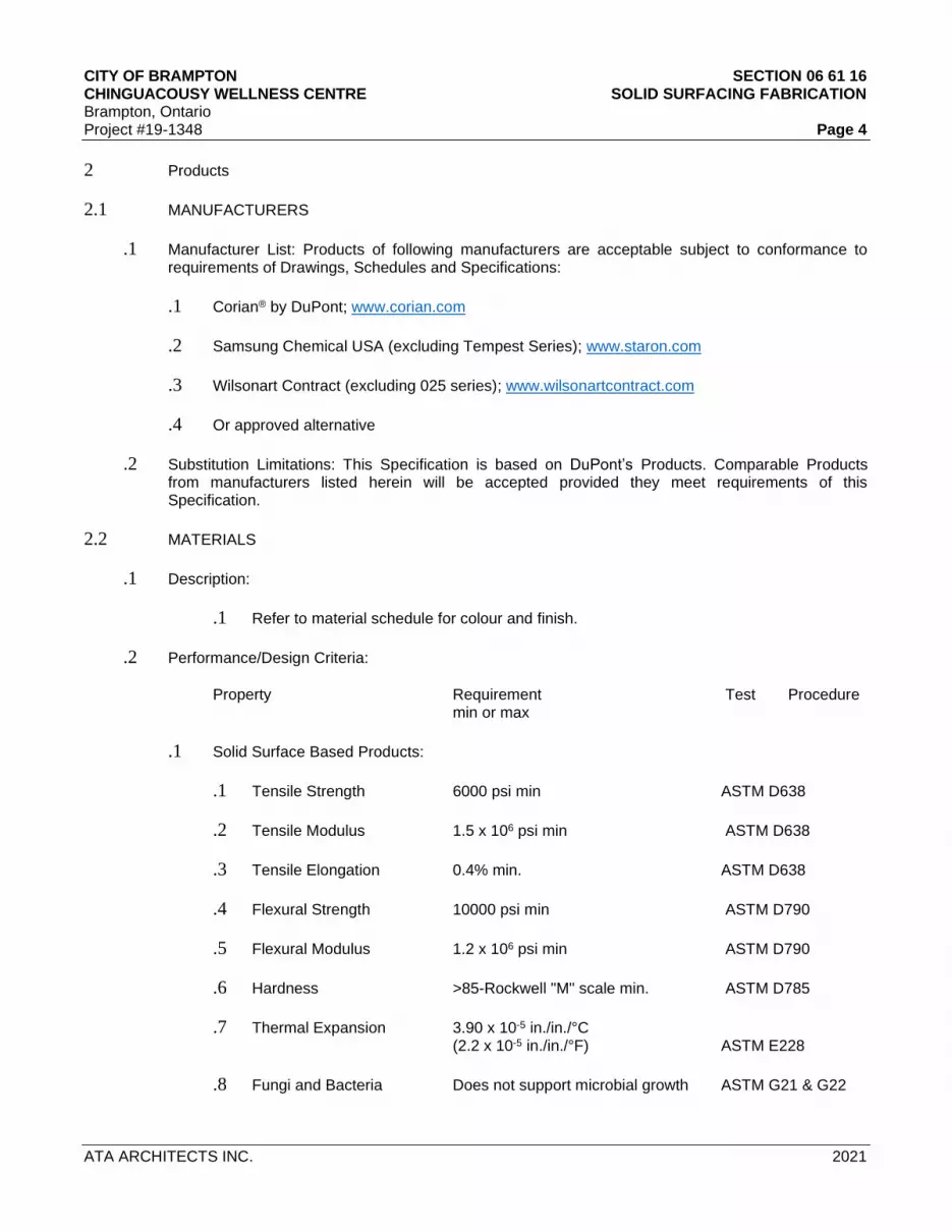
CITY OF BRAMPTON SECTION 06 61 16 CHINGUACOUSY WELLNESS CENTRE SOLID SURFACING FABRICATION Brampton, Ontario Project #19-1348 Page 4
ATA ARCHITECTS INC. 2021
2 Products
2.1 MANUFACTURERS
.1 Manufacturer List: Products of following manufacturers are acceptable subject to conformance to requirements of Drawings, Schedules and Specifications:
.1 Corian® by DuPont; www.corian.com
.2 Samsung Chemical USA (excluding Tempest Series); www.staron.com
.3 Wilsonart Contract (excluding 025 series); www.wilsonartcontract.com
.4 Or approved alternative
.2 Substitution Limitations: This Specification is based on DuPont’s Products. Comparable Products from manufacturers listed herein will be accepted provided they meet requirements of this Specification.
2.2 MATERIALS
.1 Description:
.1 Refer to material schedule for colour and finish.
.2 Performance/Design Criteria:
Property Requirement Test Procedure min or max
.1 Solid Surface Based Products:
.1 Tensile Strength 6000 psi min ASTM D638
.2 Tensile Modulus 1.5 x 10⁶ psi min ASTM D638
.3 Tensile Elongation 0.4% min. ASTM D638
.4 Flexural Strength 10000 psi min ASTM D790
.5 Flexural Modulus 1.2 x 10⁶ psi min ASTM D790
.6 Hardness >85-Rockwell "M" scale min. ASTM D785
.7 Thermal Expansion 3.90 x 10⁻⁵ in./in./°C (2.2 x 10⁻⁵ in./in./°F) ASTM E228
.8 Fungi and Bacteria Does not support microbial growth ASTM G21 & G22
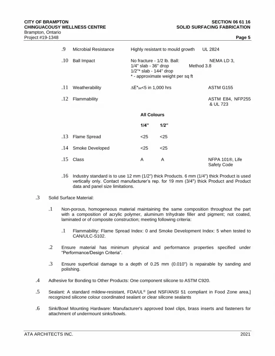
CITY OF BRAMPTON SECTION 06 61 16 CHINGUACOUSY WELLNESS CENTRE SOLID SURFACING FABRICATION Brampton, Ontario Project #19-1348 Page 5
ATA ARCHITECTS INC. 2021
.9 Microbial Resistance Highly resistant to mould growth UL 2824
.10 Ball Impact No fracture - 1/2 lb. Ball: NEMA LD 3, 1/4" slab - 36" drop Method 3.8 1/2"* slab - 144" drop * - approximate weight per sq ft
.11 Weatherability ∆E*94<5 in 1,000 hrs ASTM G155
.12 Flammability ASTM E84, NFP255 & UL 723
All Colours
1/4” 1/2”
.13 Flame Spread <25 <25
.14 Smoke Developed <25 <25
.15 Class A A NFPA 101®, Life Safety Code
.16 Industry standard is to use 12 mm (1/2") thick Products. 6 mm (1/4") thick Product is used vertically only. Contact manufacturer’s rep. for 19 mm (3/4") thick Product and Product data and panel size limitations.
.3 Solid Surface Material:
.1 Non-porous, homogeneous material maintaining the same composition throughout the part with a composition of acrylic polymer, aluminum trihydrate filler and pigment; not coated, laminated or of composite construction; meeting following criteria:
.1 Flammability: Flame Spread Index: 0 and Smoke Development Index: 5 when tested to CAN/ULC-S102.
.2 Ensure material has minimum physical and performance properties specified under “Performance/Design Criteria”.
.3 Ensure superficial damage to a depth of 0.25 mm (0.010") is repairable by sanding and polishing.
.4 Adhesive for Bonding to Other Products: One component silicone to ASTM C920.
.5 Sealant: A standard mildew-resistant, FDA/UL® [and NSF/ANSI 51 compliant in Food Zone area,] recognized silicone colour coordinated sealant or clear silicone sealants
.6 Sink/Bowl Mounting Hardware: Manufacturer's approved bowl clips, brass inserts and fasteners for attachment of undermount sinks/bowls.

CITY OF BRAMPTON SECTION 06 61 16 CHINGUACOUSY WELLNESS CENTRE SOLID SURFACING FABRICATION Brampton, Ontario Project #19-1348 Page 6
ATA ARCHITECTS INC. 2021
2.3 COMPONENTS
.1 Counter Perimeter Frame: Ensure 12 mm (1/2") [19 mm (3/4")] thick, moisture resistant [cores for counter tops in wet areas having sinks or lavatories are 19 mm (3/4") thick exterior grade plywood with waterproof adhesive, CSA O115-M (G/SO) Fir or Poplar plywood, veneer core only.] [Moisture Resistant MDF core conforming to ANSI/NPA A208.2 balanced design, manufactured from recycled materials, meeting ANSI Standards for emissions, of minimum density of 770 kg/m3, (48 lb/cu ft) and surface character to match sample approved by Consultant. Ensure fire retardant Product contains fire-retardant chemicals injected with raw materials during manufacturing and achieves a maximum flame-spread rating of 25 with a maximum smoke development of 200 when tested to ASTM E84. Acceptable Product by Uniboard Canada or The Canfibre Group Limited.]
.2 of solid surfacing material with a bowl made from solid surfacing material, cast to desired profiles and sizes having edge details as indicated on Drawings conforming to CSA B45.5/IAPMO Z124, complete with seamed “S” undermount bowl. Provide countertops complete with backsplashes of size shown on Drawings. Ensure countertop and backsplash is colour; greylite [maximum 2, 3 or 4 colours] as selected by Consultant. Ensure bowls are omni -deck model. Select desired colour from manufacturer’s latest catalogue or indicate colour(s) will be selected later by Consultant. (Verify if any cost implication due to variation in colours.)
.3 Lavatory Tops with Integral Bowls: Moulded countertop of solid surfacing material 560 mm (22"), complete with integrally molded bowl[s] of 100% acrylic solid surface material; edge details as indicated on Drawings. As shown on Drawings. Provide Omni-deck model and Graylite counter top
.4 Fabrication:
.1 Fabricate components in shop to greatest extent practical to sizes and shapes indicated, in accordance with approved Shop Drawings and solid surface manufacturer requirements. Form joints between components to create inconspicuous seams, using manufacturer’s standard joint adhesive. Provide factory cutouts for plumbing fittings and bath accessories as indicated on Drawings.
.2 Where indicated, thermoform corners and edges or other objects to shapes and sizes indicated on Drawings, prior to seaming and joining. Cut components larger than finished dimensions and sand edges to remove nicks and scratches. Heat entire component uniformly prior to forming.
.3 Ensure no blistering, whitening and cracking of components during forming.
.4 Fabricate backsplashes from solid surfacing material with optional radius cove where counter and backsplashes meet as indicated on Drawings. Backsplashes for most colours may be fabricated by traditional means discussed in K-25294 Backsplashes. Colours with metallic/mica particle or veined colours creating directional aesthetics (K-26833 Directional Aesthetics) may require the techniques in Technical Bulletin K-28235 Thermoformed Backsplash.
.5 Fabricate joints between components using manufacturer’s standard joint adhesive. Ensure joints are inconspicuous in appearance and without voids. Attach 50 mm (2") wide reinforcing strip of solid surface material under each joint. Reinforcing strip of solid surface material is not required when using DuPont™ Joint Adhesive 2.0.
.6 Provide holes and cutouts for plumbing and bath accessories as indicated on Drawings.

CITY OF BRAMPTON SECTION 06 61 16 CHINGUACOUSY WELLNESS CENTRE SOLID SURFACING FABRICATION Brampton, Ontario Project #19-1348 Page 7
ATA ARCHITECTS INC. 2021
.7 Rout and finish component edges to a smooth, uniform finish. Rout cutouts, then sand edges smooth. Repair or reject defective or inaccurate work.
.8 Finish: Ensure surfaces have uniform finish:
.1 Semi-gloss, with a 60° gloss rating of 25 - 50.
.9 Fabrication Tolerances:
.1 Variation in Component Size: +/-3 mm (+/-1/8").
.2 Location of Openings: +/-3 mm (+/-1/8") from indicated location.
3 Execution
3.1 EXAMINATION
.1 Verification of Conditions:
.1 Examine substrates and conditions, with fabricator present for compliance with requirements for installation tolerances and other conditions affecting performance of work. Proceed with installation only after unsatisfactory conditions have been corrected.
.2 Verify actual site dimensions and location of adjacent materials prior to commencing work.
.3 Examine cabinets upon which counter tops are to be installed. Verify cabinets are level to within 3 mm in 3 m (1/8" in 10' - 0").
.4 Notify Consultant in writing of any conditions which would be detrimental to installation.
.2 Evaluation and Assessment: Commencement of work implies acceptance of previously completed work.
3.2 INSTALLATION
.1 Install components plumb, level, rigid, scribed to adjacent finishes in accordance with reviewed Shop Drawings and Product installation details.
.2 Fabricate field joints using manufacturer's recommended adhesive, with joints being inconspicuous in finished work. Exposed joints/seams are not permitted. Keep components and hands clean when making joints. Reinforce field joints as specified herein. Cut and finish component edges with clean, sharp returns.
.3 Route radii and contours to template. Anchor securely to base component or other supports. Align adjacent components and form seams to comply with manufacturer’s written recommendations using adhesive in colour to match work. Carefully dress joints smooth, remove surface scratches and clean entire surface.

CITY OF BRAMPTON SECTION 06 61 16 CHINGUACOUSY WELLNESS CENTRE SOLID SURFACING FABRICATION Brampton, Ontario Project #19-1348 Page 8
ATA ARCHITECTS INC. 2021
.4 Install countertops with no more than 3 mm (1/8") sag, bow or other variation from a straight line.
.5 Adhere undermount/submount/bevel mount sinks/bowls to countertops using manufacturer's recommended adhesive and mounting hardware.
.6 Adhere topmount sinks/bowls to countertops using manufacturer recommended adhesives and colour-coordinated silicone sealant. [Secure seam mount bowls and sinks to counter tops using colour-coordianted joint adhesive.]
.7 Seal between wall and components with joint sealant as specified herein and in Section 07 92 00, as applicable.
.8 Provide backsplashes and endsplashes as indicated on Drawings. Adhere to countertops using a standard colour-coordinated silicone sealant. Adhere applied sidesplashes to countertops using a standard colour-coordinated silicone sealant. Provide coved backsplashes and sidesplashes at walls and adjacent millwork. Fabricate radius cove at intersection of counters with backsplashes to dimensions shown on reviewed Shop Drawings. Adhere to countertops using manufacturer’s standard colour-coordinated joint adhesive.
.9 Keep components and hands clean during installation. Remove adhesives, sealants and other stains. Ensure components are clean on date of Substantial Performance of the Work.
.10 Coordinate connections of plumbing fixtures with [Division 22] [Plumbing]. Make plumbing connections to sinks in accordance with [Division 22] [Plumbing].
3.3 REPAIR
.1 Repair minor imperfections and cracked seams and replace areas of severely damaged surfaces in accordance with manufacturer’s “Technical Bulletins”.
3.4 SITE QUALITY CONTROL
.1 Non-Conforming Work: Replace damaged work which cannot be satisfactorily repaired, restored or cleaned, to satisfaction of Consultant at no cost to Owner.
3.5 CLEANING
.1 Remove excess adhesive and sealant from visible surfaces.
.2 Clean surfaces in accordance with manufacturer’s “Care and Maintenance Instructions”.
3.6 PROTECTION
.1 Provide protective coverings to prevent physical damage or staining following installation for duration of Project.
.2 Protect surfaces from damage until date of Substantial Performance of the Work.
END OF SECTION

CITY OF BRAMPTON SECTION 07 26 00 CHINGUACOUSY WELLNESS CENTRE VAPOUR RETARDERS Brampton, Ontario Project #19-1348 Page 1
ATA ARCHITECTS INC. 2021
PART 1 GENERAL 1.1 SECTION INCLUDES .1 Continuous vapour retarder membranes used throughout building envelope 1.2 RELATED SECTIONS .1 Section 03 30 00 - Cast-In-Place Concrete .2 Section 07 21 00 - Thermal Insulation .3 Section 07 27 00 - Air Barrier .4 Section 07 92 00 - Sealant/Caulking 1.3 REFERENCES .1 Canadian General Standards Board (CGSB)
.1 CAN/CGSB-51.33-[M89], Vapour Barrier Sheet, Excluding Polyethylene, for Use in Building Construction.
.2 CAN/CGSB-51.34-[M86], Vapour Barrier, Polyethylene Sheet, for Use in Building Construction. .2 American Society for Testing and Materials International (ASTM) .1 ASTM E96/E96M-05: Standard Test Methods for Water Vapour Transmission of Materials. .2 ASTM E1643-98 (05): Standard Practice for Installation of Water Vapour Retarders Used in Contact with Earth or Granular Fill under Concrete Slabs. .3 ASTM E1745-97 (04): Standard Specification for Water Vapour Retarders Used in Contact with soil or granular fill under concrete slabs-on-grade. 1.4 SUBMITTALS .1 Provide submittals in accordance with Section 01 33 00 - Submittal Procedures. .2 Product Data: .1 Submit manufacturer's printed product literature, specifications and datasheet and include: .1 Product characteristics. .2 Performance criteria. .3 Limitations. 1.5 QUALITY ASSURANCE .1 Applicators: company or individual specializing in applying the work of this Section, with minimum five (5) years documented experience. 1.5 DELIVERY, STORAGE AND HANDLING .1 Refer to Section 01 61 00 - Common Product Requirements .2 Protect Products from rain and damage .3 Store materials cartons on pallets and cover if left outside. PART 2 PRODUCTS

CITY OF BRAMPTON SECTION 07 26 00 CHINGUACOUSY WELLNESS CENTRE VAPOUR RETARDERS Brampton, Ontario Project #19-1348 Page 2
ATA ARCHITECTS INC. 2021
2.2 MATERIALS .1 Above Grade Retarders: .2 Polyethylene film: to CAN/CGSB-51.34, 0.15 mm (6mil) thick. .3 Adhesive: compatible with sheet barrier and substrate, permanently non-curing. .4 Joint sealing tape: air resistant pressure sensitive adhesive tape, type recommended by vapour
barrier manufacturer, 50 mm wide for lap joints and perimeter seals, 25 mm wide elsewhere. .2 Roof Vapour Retarders: as specified. .3 Below Grade Retarders:
.1 Vapour Seal Membrane: 0.38 mm thick resin-based single-ply sheet membrane to ASTM E1745; 3.66 M wide rolls, maximum water vapour transmission of 0.018 perms when tested to ASTM E96/96M. eg. Perminator 15 by W.R. Meadows of Canada Ltd.
.2 Lapping Tape: 100mm wide, as recommended by vapour seal membrane manufacturer. PART 3 EXECUTION 3.1 PREPARATION
.1 Ensure surfaces to receive vapour retarder are clean, dry and free of oil, grease, dirt, excess mortar or other contaminants.
.2 Ensure surfaces are unfrozen, clean, dry, smooth and free of voids. .3 Level, tamp or roll granular fill base materials 3.2 INSTALLATION .1 Above Grade Installation: .1 Apply vapour retarder in accordance with manufacturer’s instructions. .2 Ensure services are installed and inspected prior to installation of retarder. .3 Install sheet vapour retarder on warm side of exterior wall assemblies prior to installation of
sheathing board to form continuous retarder. .4 Use sheets of largest practical size to minimize joints. .5 Cut sheet vapour retarder to form openings and ensure material is lapped and sealed to frame. .6 Inspect for continuity. Repair punctures and tears with sealing tape before work is concealed. .2 Below Grade Installation: .1 Ensure services are installed and inspected prior to installation of retarder. .2 Apply membrane to ASTM E1643 and in accordance with manufacturer’s instructions. .3 Provide a permanent, monolithic vapour seal without voids or open seams, and completely covering the pour area.
.4 Place membrane collar around protrusions through concrete slab, including sewer pipes, water lines, and utility outlets to create a positive seal between protrusions and membrane. Seal in place with lapping tape.
.5 Seal membrane to vertical surfaces with lapping tape. 3.3 PERIMETER SEALS .1 Seal perimeter of sheet vapour barrier as follows: .1 Apply continuous bead of sealant to substrate at perimeter of sheets. .2 Lap sheet over sealant and press into sealant bead.

CITY OF BRAMPTON SECTION 07 26 00 CHINGUACOUSY WELLNESS CENTRE VAPOUR RETARDERS Brampton, Ontario Project #19-1348 Page 3
ATA ARCHITECTS INC. 2021
3.4 LAP JOINT SEALS .1 Seal lap joints of sheet vapour barrier as follows: .1 Attach first sheet to substrate. .2 Apply continuous bead of sealant over solid backing at joint. .3 Lap adjoining sheet minimum 150 mm and press into sealant bead. 3.6 CLEANING .1 Proceed in accordance with Section 01 74 11 – Cleaning and Waste Management. .2 Upon completion and verification of performance of installation, remove surplus materials, excess materials, rubbish, tools and equipment.
END OF SECTION

CITY OF BRAMPTON SECTION 07 55 10
CHINGUACOUSY WELLNESS CENTRE MODIFIED BITUMINOUS MEMBRANE ROOFING REPAIR
Brampton, Ontario
Project #19-1348 Page 1
ATA ARCHITECTS INC. 2021
PART 1 GENERAL 1.1 RELATED SECTIONS .1 Section 01 11 00 – Summary and Staging of Work .2 Section 07 92 00 – Sealants and Caulking 1.2 REFERENCES .1 The latest edition of all listed references shall apply:
.1 ASTM D41 – Asphalt Primer Used in Roofing, Damp-proofing, and Waterproofing. .2 ASTM D2822 – Asphalt Roof Cement. .3 ASTM D4601 – Standard Specification for Asphalt-Coated Glass Fibre Base Sheet Used in Roofing. .4 ASTM D6162 – Styrene Butadiene Styrene (SBS) Modified Bituminous Sheet Materials Using a
Combination of Polyester and Glass Fibre Reinforcements .5 ASTM D6163 – Styrene Butadiene Styrene (SBS) Modified Bituminous Sheet Materials Using Glass
Fibre Reinforcements .6 ASTM D6164 – Styrene Butadiene Styrene (SBS) Modified Bituminous Sheet Materials Using
Polyester Reinforcements .7 CGSB 37-GP-9Ma – Primer, Asphalt, Unfilled, for Asphalt Roofing, Damp-proofing and Waterproofing. .8 FM (Factory Mutual) – Roof Assembly Classifications. .9 Ontario Roofing Contractors Association – Roofing Specifications Manual. .10 NRCA (National Roofing Contractors Association) – Roofing and Waterproofing Manual. .11 ULC (Underwriters Laboratories of Canada) – List of Equipment and Materials for Building Materials,
Fire Resistance, and Fire-stop Systems and Components. .12 Conform to National Plumbing Codes and requirements of Provincial and Municipal Authorities. Most stringent requirements shall govern where in conflict.
1.4 SUBMITTALS .1 Provide initial schedule within ten (10) working days after Contract award, showing anticipated progress
stages and final completion of work. Work shall not commence before work schedule is provided. .2 Sample copy of Contractor's warranty. .3 Certifications by manufacturers of roofing and insulating materials that all materials supplied comply with all
requirements of the identified ASTM and other industry standards or practices. .4 Certification from the Contractor that the system specified meets all identified code and insurance
requirements as required by the Specification. 1.5 CONTRACTOR QUALIFICATION .1 Contractor and his staff must be certified by the membrane manufacturer. .2 Contractor must be a member in good standing with the Ontario Roofing Contractors Association (OIRCA)
and have a minimum ten (10) years relevant experience with similar roof materials. 1.6 QUALITY ASSURANCE .1 Perform Work in accordance with manufacturer's written instructions. .2 There shall be no deviation made from the Project Specification or the approved shop drawings without prior
written approval by the Owner, the Owner's Representative, and the manufacturer.

CITY OF BRAMPTON SECTION 07 55 10
CHINGUACOUSY WELLNESS CENTRE MODIFIED BITUMINOUS MEMBRANE ROOFING REPAIR
Brampton, Ontario
Project #19-1348 Page 2
ATA ARCHITECTS INC. 2021
1.7 REGULATORY REQUIREMENTS .1 Conform to applicable local code for roof assembly fire hazard requirements. .2 UL: Class B Fire Hazard Classification. .3 FM: Roof Assembly Classification, of Class 1 Construction, wind uplift requirement of I-90, in accordance
with FM Construction Bulletin 128. 1.8 SPECIAL SITE INSTRUCTIONS .1 Interior Protection for work to be provided by Contractor. .2 Minimize disruptions to regular building activities. Noisy Work to be performed outside of regular
office/operating hours. Arrange special access and times to project site with Designee. .3 Staging area to be determined on site with Consultant and Building Owner. .4 All salvaged copper flashings, cleats, and hook strips from the designated roof replacement areas to be
recycled and subsequent value credited to the Building Owner. .5 No asphalt kettles on site. Project to be free of mopping and torching applications. All roof elements to be
mechanically fastened, adhered in bonding agent, or cold applied. All membranes to be self adhering or cold applied.
1.9 DELIVERY, STORAGE, AND HANDLING .1 All work to be conducted from the exterior using swing-stage, hoist, etc. .2 Site storage is limited. Location of storage to be coordinated with Owner. .3 All materials shall be delivered and stored in their original packaging bearing the manufacturers label, grade
and product weight, including all other related standards, specifications, and the like. .4 All materials shall be adequately protected from inclement weather conditions and stored in a dry, well
ventilated and weather protected location. .5 Only materials to be installed on the same day shall be removed from the protected location to the work site. .6 During extreme temperature, materials shall be stored in a heated location with a 40°F (4.4 C) minimum
temperature and removed only as needed. .7 All materials in a rolled configuration shall be stored on end, elevated off the ground on a pallet or skid, to
protect the bottom surface from foreign debris and moisture. .8 When possible, the Contractor should restrict stock piling of material in one location on the roof surface to
prevent exceeding the specified deck live load capacity. .9 Handle and store products in a manner to prevent damage and deterioration. .10 Remove and replace damaged products at own expense and to the satisfaction of the Consultant. 1.10 ENVIRONMENTAL REQUIREMENTS

CITY OF BRAMPTON SECTION 07 55 10
CHINGUACOUSY WELLNESS CENTRE MODIFIED BITUMINOUS MEMBRANE ROOFING REPAIR
Brampton, Ontario
Project #19-1348 Page 3
ATA ARCHITECTS INC. 2021
.1 Do not apply roofing membrane to damp or frozen deck surface. .2 Do not expose materials vulnerable to water or sun damage in quantities greater than can be
weatherproofed during same day. .3 Only as much of the new roofing as can be made weather-tight each day, including all flashing and detail
work, shall be installed. All seams shall be heat welded with hot air gun before leaving the job site that day. .4 All work shall be scheduled and executed without exposing the interior building areas to the effects of
inclement weather. The existing building and its contents shall be protected against all risks. .5 All new and temporary construction, including equipment and accessories, shall be secured in such a
manner as to preclude wind blow-off and subsequent roof or equipment damage. .6 Uninterrupted water-stops shall be installed at the end of each day's work and shall be completely removed
before proceeding with the next day's work. Water-stops shall not emit dangerous or unsafe fumes and shall not remain in contact with the finished roof as the installation progresses. Contaminated membrane shall be replaced at no cost to the Owner.
.7 Prior to and during application, all dirt, debris and dust shall be removed from surfaces by vacuuming,
sweeping, blowing with compressed air, and/or similar methods. .8 The Contractor shall follow all safety regulations as required by OHSA (Occupational Health and Safety Act)
and any other applicable authority having jurisdiction. .9 All roofing, insulation, flashings and metal work removed during construction shall be immediately taken off
site to a legal dumping area authorized to receive such materials. Hazardous materials, such as materials containing asbestos, are to be removed and disposed of in strict accordance with applicable Municipal, Provincial, Federal, and Vaughan requirements.
.10 All new roofing waste material (i.e., scrap roof membrane, empty cans of adhesive) shall be immediately
removed from the site by the Contractor and properly transported to a legal dumping area authorized to receive such material.
.11 The Contractor shall take precautions that storage and/or application of materials and/or equipment does
not overload the roof deck or building structure. .12 Flammable adhesives and deck primers shall not be stored and not be used in the vicinity of open flames,
sparks and excessive heat. .13 All rooftop contamination that is anticipated or that is occurring shall be reported to the manufacturer to
determine the corrective steps to be taken. .14 The Contractor shall verify that all roof drain lines are functioning correctly (not clogged or blocked) before
starting work. Contractor shall report any such blockages in writing to the Owner's Representative for corrective action prior to the installation of the roof system.
.15 The Contractor shall immediately stop work if any unusual or concealed condition is discovered and shall
immediately notify Owner of such condition in writing for correction at the Owner's expense. .16 Site cleanup, including both interior and exterior building areas that have been affected by construction,
shall be completed to the Owner's satisfaction.

CITY OF BRAMPTON SECTION 07 55 10
CHINGUACOUSY WELLNESS CENTRE MODIFIED BITUMINOUS MEMBRANE ROOFING REPAIR
Brampton, Ontario
Project #19-1348 Page 4
ATA ARCHITECTS INC. 2021
.17 All landscaped areas damaged by construction activities shall be repaired at no cost to the Owner. .18 Precautions shall be taken when using adhesives at or near rooftop vents or air intakes. Adhesive odours
could enter the building. Coordinate the operation of vents and air intakes in such a manner as to avoid the intake of adhesive odour while ventilating the building. Keep lids on unused cans at all times.
.19 Protective wear shall be worn when using solvents or adhesives or as required by job conditions. 1.11 EXAMINATION
.1 Examine the Drawings and Specifications to determine the extent of the work involved, together with other necessary data affecting the work, as in no circumstances will any claims against the Owner be allowed resulting from failure to ascertain the extent of such work herein described or implied.
1.12 QUALITY OBSERVATION ASSURANCE .1 An Independent Quality Assurance Observation Consultant retained by the testing and inspection allowance
will be appointed to observe the installation. .2 Arrange site meeting with the Observer no more than three weeks prior to commencement of work on site.
Obtain the Observer’s instructions with reference to procedures to be followed. Contractor to provide Observer with the following at this meeting:
.1 Notice of Project .2 A sample copy of the Warranty .3 A copy of the letter and completed project warranty form sent to the “Warranty Holder” advising them of
the project starting .4 Bonds and Insurance in the Owner’s Name .5 WSIB Clearance Certificate .6 A Contact List complete with 24-hour emergency phone numbers .7 A Work Schedule listing start date, number of working days and manpower for the project shop
drawings for tapered insulation, if applicable .8 A complete Material List .9 MSDS information pertaining to ALL materials being used on site .10 The appropriate securement patterns for mechanically fastening of the insulation, if applicable .11 A list of the “Trained and Carded Membrane Approved Applicators” who will be working on site .3 Cooperate with the Observer and afford all facilities necessary to permit full QA observation of the work. Act
immediately on instructions given by the Observer. .4 Make cut-outs when required and make good roofing without additional costs to the Owner. 1.13 SAFETY AND PROTECTION .1 The latest edition of all listed references shall apply: .1 CAN/CSA S269.2M – Access Scaffolding for Construction Purposes. .2 FCC No. 301 – Standard for Construction Operations. .2 Solvents, adhesives and membranes
.1 Store only enough solvents and adhesives on the roof for the same day's use, do not leave adhesives on roof overnight. Manufacturer supplied adhesives should be stored in their overnight containers. Minimum temperature for solvent based adhesive and primers is -5 C.
1.14 WARRANTY

CITY OF BRAMPTON SECTION 07 55 10
CHINGUACOUSY WELLNESS CENTRE MODIFIED BITUMINOUS MEMBRANE ROOFING REPAIR
Brampton, Ontario
Project #19-1348 Page 5
ATA ARCHITECTS INC. 2021
.1 Contractor shall supply the Owner with a two (2) year Contractor OIRCA Warranty for workmanship. In the
event any work related to roofing, flashing, or metal is found to be within the Contractor warranty term, defective or otherwise not in accordance with the Contract Documents, the Contractor shall repair that defect at no cost to the Owner. The Applicator’s warranty obligation shall run directly to the Owner.
.2 Owner shall notify both the membrane manufacturer and the Contractor of any leak that occurs during the
time period when both warranties are in effect. PART 2 PRODUCTS 2.1 GENERAL .1 Contractor to carry Nortex for all roof penetration, patch and repair. Roof is currently under warranty. . 2 Note all membrane materials are to be supplied by one manufacturer: Siplast or Soprema, meeting
manufacturer’s respective material compatibility requirements to achieve the required System Warranty. .3 Roof patch and repair to match existing .4 Components to be used that are other than those supplied or manufactured by the membrane manufacturer
may be submitted for review and acceptance by the membrane manufacturer. .5 The membrane manufacturer's acceptance of any other product is only for a determination of compatibility
with the products and not for inclusion in the manufacturer’s warranty. .6 The specifications, installation instructions, limitations, and/or restrictions of the respective manufacturers
must be reviewed by the Owner's Representative for acceptability for the intended use with the membrane manufacturer’s products.
2.2 N.V.S. REPAIR COMPOUND .1 N.V.S. Repair Compound: NVS Premix by Siplast 2.3 MEMBRANE & MEMBRANE FLASHING .1 Venting Base Sheet:
.1 Mechanically secured fibreglass, asphalt coated fibreglass base sheet meeting ASTM D4601, Type II; Parabase FS by Siplast or Sopraglass 100 by Soprema.
.2 Base Sheet:
.1 Adhesive grade modified bitumen, minimum thickness 3.0mm, with minimum 180g/m2, random fibre glass mat or non-woven polyester, impregnated and coated with SBS modified bitumen, and conforming to CGSB 37-GP-56M; Paradiene 20 HV by Siplast or Colply Base 410 by Soprema.
.3 Base Sheet Flashing: .1 Self-adhering grade modified bitumen, minimum 3.0mm thick, with random fibre glass mat
impregnated and coated with SBS modified bitumen, and coated with self-adhesive bitumen layer and polyolefin release film on bottom surface, and conforming to CGSB 37- GP-56M; Paradiene 20 EG SA by Siplast or Sopralene Stick Adhesive by Soprema.
OR

CITY OF BRAMPTON SECTION 07 55 10
CHINGUACOUSY WELLNESS CENTRE MODIFIED BITUMINOUS MEMBRANE ROOFING REPAIR
Brampton, Ontario
Project #19-1348 Page 6
ATA ARCHITECTS INC. 2021
.2 Adhesive grade modified bitumen, minimum thickness 3.0mm, with minimum 180g/m2, random fibre glass mat or non-woven polyester, impregnated and coated with SBS modified bitumen, and conforming to CGSB 37-GP-56M; Paradiene 20 HV by Siplast or Sopralene Stick Adhesive by Soprema.
.4 Cap Sheet:
.1 Adhesive grade modified bitumen, minimum thickness 3.6mm, with minimum 250g/m2, fibreglass scrim/polyester composite impregnated and coated with SBS modified bitumen, and conforming to CGSB 37-GP-56M; Paradiene 30 by Siplast or Colply Traffic Cap 460 by Soprema.
.5 Cap Sheet Flashing:
.1 Adhesive grade modified bitumen, minimum thickness 3.6mm, with minimum 250g/m2, fibreglass scrim/polyester composite impregnated and coated with SBS modified bitumen, and conforming to CGSB 37-GP-56M; Parafor 30 by Siplast or Colply Traffic Cap 460 by Soprema.
.6 Membrane Primer:
.1 Solvent based primer to prepare surfaces before the installation of membranes, PA-1125 Primer by Siplast or Elastocol Stick by Soprema.
.7 Membrane Adhesive:
.1 Solvent based adhesive; PA-311 adhesive by Siplast or Colply Adhesive Brush for horizontal surfaces and Colply Adhesive Trowel Grade for sloped surfaces by Soprema.
2.4 LIQUID APPLIED RESIN FLASHING MEMBRANE
.1 Polymethylmethacrylate (PMMA) Primers: as recommended by the membrane manufacturer.
.2 PMMA Roofing Flashing (Soprema): .1 Resin for flashing applications: a one-component polyurethane/bitumen resin for use in combination
with fleece fabric to form a monolithic, reinforced flashing membrane; Alsan Flashing from Soprema. .2 Fleece for flashing reinforcement: A woven, 100 g/m², polyester fabric reinforcement as supplied by the
membrane system manufacturer; Flashing Reinforcement by Soprema. .3 PMMA Roofing Flashing (Siplast):
.1 Catalyst: Pro Catalyst by Siplast.
.2 Resin for flashing applications: A flexible, polymethylmethacrylate (PMMA) based resin combined with a thixotropic agent for use in combination with fleece fabric to form a monolithic, reinforced flashing membrane; Parapro 123 Flashing Resin by Siplast.
.3 Resin for field membrane: A flexible, polymethylmethacrylate (PMMA) based resin for use in combination with fleece fabric to form a monolithic, reinforced roofing membrane; Parapro Roof Resin by Siplast.
.4 Fleece for membrane and flashing reinforcement: A non-woven, 110 g/m², needle- punched polyester fabric reinforcement as supplied by the membrane system manufacturer; Pro Fleece by Siplast.
.5 Clear finish resin: A clear, flexible, polymethylmethacrylate (PMMA) based resin for use as a wearing coat over colored quartz; Pro Clear Finish by Siplast.
.6 Thixotropic agent: A liquid additive used to increase the viscosity of the PMMA-based resin products, allowing the resins to be applied over vertical or sloped substrates; Pro Thixo by Siplast.
.4 Anti-Skid Surfacing: .1 Ceramic granules: No. 11 grade specification ceramic granules suitable for broadcast into the PMMA based wearing layer; No. 11 Granules by Siplast or approved equal from Soprema.
.5 PMMA Accessories: .1 Cleaning solution/solvent: A clear solvent used to clean and prepare transition areas of in-place catalyzed resin to receive subsequent coats of resin and to clean substrate materials to receive resin; Pro Prep by Siplast or approved equal from Soprema.

CITY OF BRAMPTON SECTION 07 55 10
CHINGUACOUSY WELLNESS CENTRE MODIFIED BITUMINOUS MEMBRANE ROOFING REPAIR
Brampton, Ontario
Project #19-1348 Page 7
ATA ARCHITECTS INC. 2021
.2 Tape: A white, flexible, coated cotton cloth tape designed for treatment of insulation panel joints, deck/wall transitions and joints in flashing substrates; Pro Tape by Siplast or approved equal from Soprema.
2.5 ROOF ACCESSORIES
.1 Concrete Pavers: MPA air entrained precast concrete with maximum absorption 5% with formed pedestals. 24" x 24" x 2" PEDSLABS by Brooklin Concrete.
.2 Pourable Sealer: Elastomeric pourable sealer as supplied by Siplast or Soprema. .3 Sheet Metal Flashings and Trim: As per Section 07620. .4 Sealants: As per Section 07900.
2.6 FASTENERS AND PLATES
.1 Insulation to steel and wood deck: .1 Tru-Fast Ultra Solid Stainless Steel fastener to penetrate substrate by 3/4" (19mm). Plates to be 3"
diameter. Tru-Fast Galvalume stress plate.
.2 Wood to steel, wood to wood or steel to steel: .1 Tru-Fast Ultra Solid Stainless Steel fastener to penetrate substrate by minimum 3/4" (19mm). .3 Wood/steel to concrete or concrete block:
.1 Perma-Grip Tap Grip H.D. Truss Head fastener with Perma-Coat Z3 corrosion protection to penetrate substrate by 1 1/4" (32mm).
.2 Tru-Fast Tap Grip H.D. Truss Head fastener with Perma-Coat Z3 corrosion protection to penetrate substrate by 1 1/4” (32mm).
.4 Steel/aluminum to aluminum:
.1 Tru-Fast DP with Trucote PC-3 corrosion protection fastener c/w EPDM galvanized steel sealing washers to penetrate substrate by 3/4" (19mm).
.5 Termination bar for membrane:
.1 Extruded aluminum, 0.060" thick x 1" wide x 10' long with 1/4" x 3/8" slotted holes on 8" (203mm) o/c. Acceptable material: TB-120 aluminum termination bar by Tru-Fast.
.6 Termination bar fastener for wood, steel or aluminum:
.1 Tru-Fast Ultra Solid Stainless Steel fastener to penetrate substrate by 3/4" (19mm) c/w EPDM galvanized steel sealing washers or Construction Fasteners Inc. Woodgrip #14 screw complete with Sentri coating on threads, Chromagard colour match head and EPDM washer
.7 Termination bar fastener for concrete or masonry:
.1 Tru-Fast Tap Grip Truss Head fastener with Perma-Coat Z3 corrosion protection to penetrate substrate by 1 1/4" (32mm) c/w EPDM galvanized steel sealing washers.
.8 Pre-painted metal flashing to steel or wood:
.1 Construction Fasteners Inc. Woodgrip #14 screw complete with Sentri coating on threads, Chromagard colour match head and EPDM washer or approved equal. Fastener to penetrate substrate by minimum 3/4".
.9 Membrane to wood: Galvanized round top nails with minimum 1" diameter heads to penetrate the substrate
a minimum 1 1/4" (32mm).

CITY OF BRAMPTON SECTION 07 55 10
CHINGUACOUSY WELLNESS CENTRE MODIFIED BITUMINOUS MEMBRANE ROOFING REPAIR
Brampton, Ontario
Project #19-1348 Page 8
ATA ARCHITECTS INC. 2021
.10 Venting Sheet Membrane to Lightweight Concrete:
.1 NVS fasteners as manufactured by Siplast or Soprema. Specialty fasteners are as specified in the scope of work or as required in drawings.
.11 All fasteners and plates to meet the requirements of Factory Mutual 4470 Standard for wind uplift and
corrosion resistance. PART 3 EXECUTION 3.1 WORKMANSHIP
.1 Execute roofing work which is not specifically covered by these Specifications in accordance with applicable standards in Canadian Roofing Contractors Association (CRCA) and the National Roofing Contractors Association Roofing Specification Manual, in accordance with the Canadian Modified Bitumen Manufacturer’s Association’s recommendations, in accordance with the manufacturer’s pre-printed and published specifications and to ULC Design No. S-107, to FM 1-28 and 1.49 criteria, compliance with local fire insurance requirements and/or local building codes, except where specified otherwise.
.2 Do priming for asphalt roofing in accordance with CAN/CGSB 37-GP-15M and as recommended by
membrane manufacturer. .3 Procedures for application of materials should be in accordance with manufacturer’s recommendations;
otherwise the Consultant should be notified if any conflict with this Specification arises. .4 All work shall be carried out in accordance with drawings, specifications, and contract documents. .5 Adhesives or sealants and liquid primers will not be applied until surfaces are dry. .6 Inspect the underside of roof deck when installing fasteners, where possible, to avoid accidental damage. .7 While work is in progress, all steps must be taken to safeguard the building from damage due to the
elements. .8 Consultant must be notified of adjustments to specified roofing procedures recommended by the
Manufacturer or due to site conditions. Written approval from the independent Consultant is required to make any adjustments to the specified procedures.
3.2 EXAMINATION OF SITE CONDITIONS
.1 Inspect existing conditions and substrates upon which work of this section is dependent. Report to the Consultant in writing any defects or discrepancies. Commencement of work implies acceptance of existing conditions and assuming full responsibility for the finished condition of the work.
.2 Defective work resulting from application to unsatisfactory conditions will be considered the responsibility of
those performing the work of this section. 3.3 PREPARATION .1 Examine all site conditions to ensure that they are in satisfactory condition for the commencement of the
work of this section. .2 Examine work of other trades for defects and discrepancies and report them to the owner/consultant in
writing. Do not proceed with work until surfaces are satisfactory.
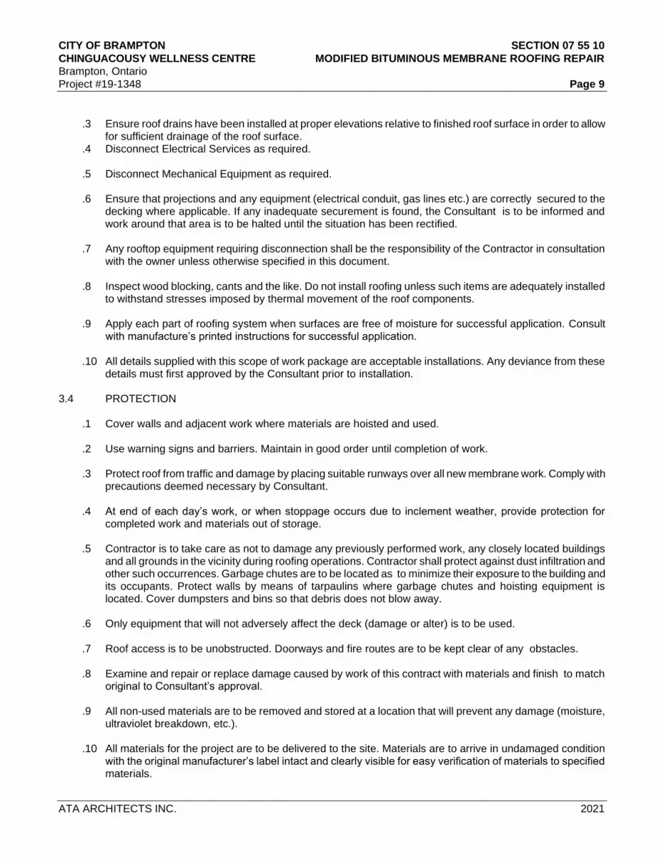
CITY OF BRAMPTON SECTION 07 55 10
CHINGUACOUSY WELLNESS CENTRE MODIFIED BITUMINOUS MEMBRANE ROOFING REPAIR
Brampton, Ontario
Project #19-1348 Page 9
ATA ARCHITECTS INC. 2021
.3 Ensure roof drains have been installed at proper elevations relative to finished roof surface in order to allow
for sufficient drainage of the roof surface. .4 Disconnect Electrical Services as required. .5 Disconnect Mechanical Equipment as required. .6 Ensure that projections and any equipment (electrical conduit, gas lines etc.) are correctly secured to the
decking where applicable. If any inadequate securement is found, the Consultant is to be informed and work around that area is to be halted until the situation has been rectified.
.7 Any rooftop equipment requiring disconnection shall be the responsibility of the Contractor in consultation with the owner unless otherwise specified in this document. .8 Inspect wood blocking, cants and the like. Do not install roofing unless such items are adequately installed
to withstand stresses imposed by thermal movement of the roof components. .9 Apply each part of roofing system when surfaces are free of moisture for successful application. Consult
with manufacture’s printed instructions for successful application. .10 All details supplied with this scope of work package are acceptable installations. Any deviance from these
details must first approved by the Consultant prior to installation. 3.4 PROTECTION .1 Cover walls and adjacent work where materials are hoisted and used. .2 Use warning signs and barriers. Maintain in good order until completion of work. .3 Protect roof from traffic and damage by placing suitable runways over all new membrane work. Comply with
precautions deemed necessary by Consultant. .4 At end of each day’s work, or when stoppage occurs due to inclement weather, provide protection for
completed work and materials out of storage. .5 Contractor is to take care as not to damage any previously performed work, any closely located buildings
and all grounds in the vicinity during roofing operations. Contractor shall protect against dust infiltration and other such occurrences. Garbage chutes are to be located as to minimize their exposure to the building and its occupants. Protect walls by means of tarpaulins where garbage chutes and hoisting equipment is located. Cover dumpsters and bins so that debris does not blow away.
.6 Only equipment that will not adversely affect the deck (damage or alter) is to be used.
.7 Roof access is to be unobstructed. Doorways and fire routes are to be kept clear of any obstacles. .8 Examine and repair or replace damage caused by work of this contract with materials and finish to match
original to Consultant’s approval. .9 All non-used materials are to be removed and stored at a location that will prevent any damage (moisture,
ultraviolet breakdown, etc.). .10 All materials for the project are to be delivered to the site. Materials are to arrive in undamaged condition
with the original manufacturer’s label intact and clearly visible for easy verification of materials to specified materials.

CITY OF BRAMPTON SECTION 07 55 10
CHINGUACOUSY WELLNESS CENTRE MODIFIED BITUMINOUS MEMBRANE ROOFING REPAIR
Brampton, Ontario
Project #19-1348 Page 10
ATA ARCHITECTS INC. 2021
.11 When temperatures fall below 40°F, any materials such as membrane, adhesives and sealants that are
affected by cool temperatures are to be stored in heated storage areas. .12 Protect rolls from flattening by storing on ends on skids. .13 Moisture sensitive products and exposed building substrates are to be protected with all work being halted
during inclement weather including but not limited to rain fall, snow, drizzle, fog and hail. .14 Protect all openings and safeguard all vents, stacks, and drains from weather and contamination from
debris. .15 Defective work resulting from application of material on unsatisfactory surface will be considered the
responsibility of the Contractor. 3.5 N.V.S. INSULATION SYSTEM REPAIRS
.1 Areas with damaged concrete substrate must be repaired before any further work can take place on that particular roof section.
.2 Dry out any areas of the existing lightweight concrete surfaces that are damp or wet. Repair any sections of
the concrete substrates that are spalled or flaking with specified compound. .3 At the repair section, remove the existing lightweight concrete to a minimum depth of 1” (25mm) or to sound
concrete, whichever is greater. .4 Prior to application of patching compound, remove debris from the repair area and remove deteriorated
concrete material down to a sound substrate. .5 Moisten the surface of the repair area with water. .6 Following the manufacturer’s instructions for mixing product preparation and application. .7 Finish the surface of the patch area to a smooth surface. .8 Trowel finish any edges to provide a smooth transition to the surface of the existing substrate.
3.6 MODIFIED BITUMEN MEMBRANE REPAIRS
.1 Modified bitumen membrane repairs to be carried out with new materials using the same type of membrane and bitumen already installed in the existing membrane system. All supplied roof materials to be compatible with the existing roof system components.
.2 Cut out damaged and deteriorated existing membrane sections in logical rectangular segments as required.
Dispose of all debris and dirt to an appropriate site. .3 Use two (2) plies of new specified modified bitumen base sheet and cap sheet membrane with an
attachment method appropriate for existing building and installation. .4 Cap sheet membrane to have granulated surface where left exposed. Colour to match existing as close as
possible. .5 Install new modified bitumen base sheet across repair area and extend minimum 4" (102mm) past edge, on
to existing modified bitumen membrane. Ensure a good bond to existing membrane. Self-adhering base sheet flashings to be installed with membrane primer as specified.

CITY OF BRAMPTON SECTION 07 55 10
CHINGUACOUSY WELLNESS CENTRE MODIFIED BITUMINOUS MEMBRANE ROOFING REPAIR
Brampton, Ontario
Project #19-1348 Page 11
ATA ARCHITECTS INC. 2021
.6 Carry new modified bitumen cap sheet over new base sheet and extend a minimum of 4" (102mm) past
edge, on to existing modified bitumen membrane. Ensure a good bond to existing membrane. .7 ALL SIDE AND END LAPS OF THE BASE SHEET AND CAP SHEET SHALL BE HEAT WELDED WITH
HOT AIR GUN TO THE SATISFACTION OF THE CONSULTANT. 3.7 MODIFIED BITUMEN FLASHING MEMBRANE REPAIRS
.1 All modified bitumen membrane flashing repairs to be carried out with new modified bitumen flashings. All new roof materials to be compatible with the existing roof system components.
.2 Modified bitumen membrane flashing repairs are to consist of two (2) plies of new specified modified
bitumen membrane using attachment method appropriate for existing building and installation. .3 Extend new base sheet flashings a minimum 4" (102mm) past the existing repair area. Self- adhering base
sheet flashings to be installed with membrane primer as specified. .4 Carry new cap sheet flashing a minimum of 4" (102mm) past the base sheet flashing. Ensure a good bond
between the modified bitumen flashings. .5 ALL SIDE AND END LAPS OF THE BASE SHEET FLASHING AND CAP SHEET FLASHING SHALL BE
HEAT WELDED WITH HOT AIR GUN TO THE SATISFACTION OF THE CONSULTANT. 3.8 ROOF PENETRATION REPAIRS
.1 Install roof penetration flashings and seal with membrane in accordance with the manufacturer's recommendations and as indicated on detail drawings.
.2 Prime all metal flanges and allow to solvents to flash off prior to installation. .3 Set metal flange in full layer of rubberized sealing compound ensuring a positive bond. .4 Install an additional ply of base sheet membrane over the flange as per the manufacturer’s written
instruction prior to installing the field cap sheet membrane. The additional ply of membrane to extend a minimum of 6” (152mm) past the edge of the flange.
.5 Install cap ply to the base ply flashing ensuring a full bond to the base ply and apply bead of sealing
compound at the termination point. 3.9 METAL FLASHINGS
.1 After the installation of the roof membrane and membrane flashings, new perimeter metal and metal flashings shall be installed as detailed in Section 07620 and as indicated on detail drawings.
3.10 SEALANTS
.1 As per Section 07 90 00 – Sealants. 3.11 TEMPORARY WATER CUT-OFFS
.1 Temporary waterproof seals will be placed on daily work. Only areas which can be made watertight in the same day will be removed to ensure protection of the interior. Temporary seals will be removed before proceeding with the remaining work.

CITY OF BRAMPTON SECTION 07 55 10
CHINGUACOUSY WELLNESS CENTRE MODIFIED BITUMINOUS MEMBRANE ROOFING REPAIR
Brampton, Ontario
Project #19-1348 Page 12
ATA ARCHITECTS INC. 2021
.2 All flashings shall be installed concurrently with the roof membrane in order to maintain a watertight condition as the work progresses.
.3 All temporary water-stops shall be constructed to provide a 100% watertight seal. The stagger of the
insulation joints shall be made even by installing partial panels of insulation. .4 The new membrane shall be carried into the water-stop. The water-stop shall be sealed to the deck and/or
substrate so that water will not be allowed to travel under the new or existing roofing. .5 The edge of the membrane shall be sealed in a continuous heavy application of sealant. .6 When work resumes, the contaminated membrane shall be cut out. All sealant, contaminated membrane,
insulation fillers, etc. shall be removed from the work area and properly disposed of offsite. None of these materials shall be used in the new work.
.7 If inclement weather occurs while a temporary water-stop is in place, the Contractor shall provide the labour
necessary to monitor the situation to maintain a watertight condition. .8 If any water is allowed to enter under the newly-completed roofing, the affected area shall be removed and
replaced at the Contractor's expense. 3.12 CLEAN-UP
.1 Clean up and remove from job site on a daily basis, all rubbish and surplus materials resulting from this work.
END OF SECTION

CITY OF BRAMPTON SECTION 07 85 00 CHINGUACOUSY WELLNESS CENTRE FIRE STOPPING AND SMOKE SEAL Brampton, Ontario Project #19-1348 Page 1
ATA ARCHITECTS INC. 2021
PART 1 GENERAL 1.1 SECTION INCLUDES .1 Labour, Products, equipment and services necessary for Firestopping and smoke seals through penetrations at wall, floor and roof openings. 1.2 RELATED SECTIONS .1 Section 07 92 00 - Joint Sealants .2 Section 09 21 16 – Interior Board Assemblies 1.3 REFERENCES
.1 Underwriter's Laboratories of Canada (ULC) .1 ULC-S115-1995, Standard Method of Fire Tests of Fire Stop Systems. .2 CAN/ULC-S702-97, Standard for Thermal Insulation, Mineral Fibre, for Buildings.
.2 American Society for Testing Materials (ASTM)
.1 ASTM E119.07a, Standard Test Methods for Fire Tests of Building Construction and Materials.
.2 ASTM E814-06, Standard Test Method for Fire Tests of Through-Penetration Fire Stops.
.3 Canadian Government Standards Board (CGSB) .1 CAN/CGSB-19.13-M87, Sealing Compound, One Component, Elastomeric, Chemical Curing. .2 CAN/CGSB-19.24-M90, Multicomponent, Chemical Curing Sealing Compound.
1.4 DEFINITIONS
.1 Fire Separation: A construction assembly, plane or device, either vertical or horizontal, which is required to prevent the passage of fire and smoke for a prescribed period of time. Proof of compliance to required time rating shall be by ULC, Warnock Hersey (or similar approved) certification or shall be as listed in the Ontario Building Code Supplementary Standard SB-2.
.2 Smoke Separation: A construction assembly, plane or device, either vertical or horizontal, which is not required to prevent the passage of fire for a prescribed period of time but is required to prevent the passage of smoke. A "Smoke Separation" is also known as a "Fire Separation with No Rating" or a "Zero Hour Rated Separation".
.3 Non-Rated Separation: A construction assembly, plane or device, either vertical or horizontal, which is not required to prevent the passage of fire for a prescribed period of time and is not required to prevent the passage of smoke.
.4 Fire Stop Material: device intended to close off opening or penetration during fire or materials that fill
openings in wall or floor assembly where penetration is by cables, cable trays, conduits, ducts and pipes and poke-through termination devices, including electrical outlet boxes along with their means of support through wall or floor openings.
.5 Single Component Fire Stop System: fire stop material that has Listed Systems Design and is used
individually without use of high temperature insulation or other materials to create fire stop system. .6 Multiple Component Fire Stop System: exact group of fire stop materials that are identified within Listed
Systems Design to create on site fire stop system.
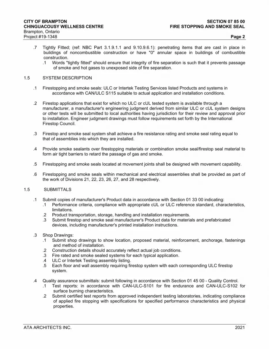
CITY OF BRAMPTON SECTION 07 85 00 CHINGUACOUSY WELLNESS CENTRE FIRE STOPPING AND SMOKE SEAL Brampton, Ontario Project #19-1348 Page 2
ATA ARCHITECTS INC. 2021
.7 Tightly Fitted; (ref: NBC Part 3.1.9.1.1 and 9.10.9.6.1): penetrating items that are cast in place in buildings of noncombustible construction or have "0" annular space in buildings of combustible construction. .1 Words "tightly fitted" should ensure that integrity of fire separation is such that it prevents passage
of smoke and hot gases to unexposed side of fire separation. 1.5 SYSTEM DESCRIPTION
.1 Firestopping and smoke seals: ULC or Intertek Testing Services listed Products and systems in accordance with CAN/ULC S115 suitable to actual application and installation conditions. .2 Firestop applications that exist for which no ULC or cUL tested system is available through a
manufacturer, a manufacturer's engineering judgment derived from similar ULC or cUL system designs or other tests will be submitted to local authorities having jurisdiction for their review and approval prior to installation. Engineer judgment drawings must follow requirements set forth by the International Firestop Council.
.3 Firestop and smoke seal system shall achieve a fire resistance rating and smoke seal rating equal to that of assemblies into which they are installed. .4 Provide smoke sealants over firestopping materials or combination smoke seal/firestop seal material to form air tight barriers to retard the passage of gas and smoke. .5 Firestopping and smoke seals located at movement joints shall be designed with movement capability. .6 Firestopping and smoke seals within mechanical and electrical assemblies shall be provided as part of the work of Divisions 21, 22, 23, 26, 27, and 28 respectively.
1.5 SUBMITTALS
.1 Submit copies of manufacturer's Product data in accordance with Section 01 33 00 indicating: .1 Performance criteria, compliance with appropriate cUL or ULC reference standard, characteristics, limitations. .2 Product transportation, storage, handling and installation requirements. .3 Submit firestop and smoke seal manufacturer's Product data for materials and prefabricated devices, including manufacturer's printed installation instructions.
.3 Shop Drawings:
.1 Submit shop drawings to show location, proposed material, reinforcement, anchorage, fastenings and method of installation.
.2 Construction details should accurately reflect actual job conditions.
.3 Fire rated and smoke sealed systems for each typical application.
.4 ULC or Intertek Testing assembly listing.
.5 Each floor and wall assembly requiring firestop system with each corresponding ULC firestop system.
.4 Quality assurance submittals: submit following in accordance with Section 01 45 00 - Quality Control. .1 Test reports: in accordance with CAN-ULC-S101 for fire endurance and CAN-ULC-S102 for
surface burning characteristics. .2 Submit certified test reports from approved independent testing laboratories, indicating compliance
of applied fire stopping with specifications for specified performance characteristics and physical properties.

CITY OF BRAMPTON SECTION 07 85 00 CHINGUACOUSY WELLNESS CENTRE FIRE STOPPING AND SMOKE SEAL Brampton, Ontario Project #19-1348 Page 3
ATA ARCHITECTS INC. 2021
.3 Certificates: submit certificates signed by manufacturer certifying that materials comply with specified performance characteristics and physical properties.
.4 Manufacturer's Instructions: submit manufacturer's installation instructions and special handling criteria, installation sequence, cleaning procedures and waste management.
.5 Manufacturer's Field Reports: submit to manufacturer's written reports within 3 days of review, verifying compliance of Work, as described in PART 3 - FIELD QUALITY CONTROL.
1.6 QUALITY ASSURANCE
.1 Installers qualifications: Perform work of this Section by a company that has a minimum of five years proven experience in the installation of firestopping and smoke seal work of a similar size and nature and that is approved by manufacturer. Submit to Consultant, applicator’s current certificate of approval by the material manufacturer as proof of compliance.
.2 Manufacturer's direct representative and/or fire protection specialist shall be on-site during initial
installation of firestop systems to train appropriate contractor personnel in proper selection and installation procedures conforming to manufacturer's written recommendations published in their literature and drawing details.
.3 Pre-construction meetings: Arrange with manufacturer's representative, Contractor, Consultant and
Field Engineer to determine responsibility for handling such issues as FT rated partitions, firestop custom details, compatibility, mixed penetrations, and to review installation procedures 48 hours in advance of installation.
.4 Site Meetings: as part of Manufacturer's Services described in PART 3 - FIELD QUALITY CONTROL,
schedule site visits, to review Work, at stages listed. .1 After delivery and storage of products, and when preparatory Work is complete, but before installation begins. .2 Twice during progress of Work at 25% and 60% complete. .3 Upon completion of Work, after cleaning is carried out.
1.7 DELIVERY, STORAGE AND HANDLING
.1 Packing, shipping, handling and unloading: .1 Deliver, store and handle materials in accordance with Section 01 61 00. .2 Deliver, store and handle materials in accordance with manufacturer's written instructions. .3 Deliver materials to the site in undamaged condition and in original unopened containers, marked
to indicate [brand name], [manufacturer], [ULC markings].
.2 Storage and Protection: .1 Store materials in dry location and in accordance with manufacturer's recommendations in clean,
dry, well-ventilated area. .2 Replace defective or damaged materials with new.
.3 Waste Management and Disposal: .1 Separate waste materials for reuse and recycling in accordance with Section 01 74 11.
1.8 SITE CONDITIONS
.1 Conform to manufacturer's requirements and maintain a minimum temperature of 50 C for a minimum period of 24 h before application, during, and until application is fully cured.
.2 Maintain sealant at a minimum 18°C for best workability.

CITY OF BRAMPTON SECTION 07 85 00 CHINGUACOUSY WELLNESS CENTRE FIRE STOPPING AND SMOKE SEAL Brampton, Ontario Project #19-1348 Page 4
ATA ARCHITECTS INC. 2021
PART 2 PRODUCTS 2.1 MANUFACTURERS
.1 Manufacturers of firestop sealants have Product considered acceptable for use: .1 3M .2 AD Fire Protection .3 Hilti Canada .4 Tremco .5 Nuco Inc.
2.2 GENERAL SYSTEM REQUIREMENTS .1 All materials under work of this Section, including but not limited to, primers and sealants are to have low VOC content limits. .2 Do not use Products containing asbestos. .3 Firestopping components shall not contain volatile solvents or require special application to protect plastic pipe from firestopping compound. .4 Provide smoke seal sealant in following colours: .1 Grey or white in finished areas. .2 Red in unfinished areas. .5 Smoke sealant for overhead and vertical joints for floor to be self-levelling and non- sagging sealant. .6 Smoke sealant at vertical through penetrations in areas with floor drains shall be waterproof type. 2.3 MATERIALS
.1 Fire stopping and smoke seal systems: in accordance with CAN-ULC-S115. .1 Asbestos-free materials and systems capable of maintaining effective barrier against flame, smoke and gases in compliance with requirements of CAN- ULC-S115 and not to exceed opening sizes for which they are intended.
.2 Fire stop system rating: as indicated on Drawings. .3 Pre-Installed firestop devices for use with non-combustible and combustible pipes, conduit and/or cable
bundles penetrating concrete floors and walls. .1 Cast-in place firestop device complete with aerator adaptor when used in conjunction with aerator
system. Model CP 680-P by Hilti or approved alternative. .2 Cast-in place firestop device for use with noncombustible penetrants. Model CP 680-M by Hilti or
approved alternative. .3 Speed sleeve for use with cable penetrations. Model CP 653 by Hilti or approved alternative. .4 Firestop block. Model CFS-BL by Hilti or approved alternative. .4 Re-penetrable, round cable management devices for use with new or existing cable bundles penetrating
walls: .1 Speed sleeve with integrated smoke seal fabric membrane. Model CP 653 by Hilti or approved
alternative. .2 Firestop Sleeve. Model CFS-SL SK by Hilti or approved alternative.

CITY OF BRAMPTON SECTION 07 85 00 CHINGUACOUSY WELLNESS CENTRE FIRE STOPPING AND SMOKE SEAL Brampton, Ontario Project #19-1348 Page 5
ATA ARCHITECTS INC. 2021
.3 Retrofit sleeve for use with existing cable bundles. Model CFS-SL RK by Hilti or approved alternative.
.4 Gangplate for use with multiple cable management devices. Model CFS-SL GP by Hilti or approved alternative.
.5 Gangplate Cap for use at blank openings in gangplate for future penetrations. Model CFS-SL GP CAP by Hilti or approved alternative.
.5 Firestop insulation: to CAN/ULC S702, Type 2; mineral fibre manufactured from rock or slag, suitable for manual application. .1 Density: Minimum 64 kg/m3 when tested to ASTM C303. .2 Combustibility: Noncombustible to CAN/ULC S114. .3 Melt temperature: >1175 degrees C. .4 Surface burning characteristics: to CAN/ULC S102, maximum flame spread of 0, smoke developed of 0. .5 Moisture Absorption: 0.04 percent when tested to ASTM C1104. .6 Smoulder Resistance: 0.01 percent when tested to CAN/ULC S129.
.6 Primer: As recommended by firestopping sealant manufacturer. .7 Water (if applicable): potable, clean and free from injurious amounts of deleterious substances.
.8 Damming and backup materials supports and anchoring devices: to manufacturer's recommendations,
and in accordance with tested assembly being installed as acceptable to authorities having jurisdiction. .9 Sealants for vertical joints: non-sagging.
PART 3 EXECUTION 3.1 EXAMINATION
.1 Verify condition and dimensions of previously installed Work upon which this Section depends. Report defects to Consultant. Commencement of work of this Section means acceptance of existing conditions.
.2 Verify that substrates and surfaces to receive firestopping and smoke seals are clean, dry, and frost free.
3.2 PREPARATION
.1 Examine sizes and conditions of voids to be filled to establish correct thicknesses and installation of materials.
.2 Ensure that substrates and surfaces are clean, dry and frost free. .3 Prepare surfaces in contact with fire stopping materials and smoke seals to manufacturer's instructions. .4 Maintain insulation around pipes and ducts penetrating fire separation [without interruption to vapour
barrier]. .5 Mask where necessary to avoid spillage and over coating onto adjoining surfaces; remove stains on
adjacent surfaces. 3.3 INSTALLATION

CITY OF BRAMPTON SECTION 07 85 00 CHINGUACOUSY WELLNESS CENTRE FIRE STOPPING AND SMOKE SEAL Brampton, Ontario Project #19-1348 Page 6
ATA ARCHITECTS INC. 2021
.1 Install firestopping and smoke seal systems in accordance with reviewed Shop Drawings, manufacturer's instructions and fire rated assembly to establish continuity and integrity of fire separations.
.2 Install firestop insulation in compacted thicknesses required by ULC design. Compress insulation
approximately 50 percent. .3 Install primers as recommended by firestop and smoke seal Product manufacturers. .4 Install temporary forming, damming, back-up as required, remove after materials have achieved initial
cure and will resist displacement. .5 Install firestop and smoke seal filler in horizontal joints providing 25% compression fit. .6 Use resilient, elastomeric firestopping and smoke seal systems in following locations: .1 Openings and sleeves for future use. .2 Penetration systems subject to vibration or thermal movement. .3 Penetration systems in acoustical containment enclosures. .7 Seal holes or voids made by through penetrations, poke-through termination devices, and unpenetrated
openings or joints to ensure continuity and integrity of fire separation are maintained. .8 Trowel and tool exposed firestop and smoke seal. Product surfaces to uniform, smooth finish. .9 Seal joints to ensure an air and water resistant seal capable of withstanding compressions and
extensions due to thermal wind or seismic joint movement. .10 Taped joints will not be acceptable. .11 Repair damaged firestopped and smoke sealed surfaces to acceptance of Consultant. .12 Identify each firestop and smoke seal penetration assembly with permanent label listing following: .1 Assembly and rating in hours. .2 Date of installation. .3 Installing company's name and telephone number. .13 Do not cover materials until full cure has taken place. .14 Remove excess compound promptly as work progresses and upon completion.
3.4 SEQUENCES OF OPERATION
.1 Proceed with installation only when submittals have been reviewed by Consultant. .2 Install floor fire stopping before interior partition erections. .3 Metal deck bonding: fire stopping to precede spray applied fireproofing to ensure required bonding. .4 Mechanical pipe insulation: certified fire stop system component.
.1 Ensure pipe insulation installation precedes fire stopping. 3.5 FIELD QUALITY CONTROL

CITY OF BRAMPTON SECTION 07 85 00 CHINGUACOUSY WELLNESS CENTRE FIRE STOPPING AND SMOKE SEAL Brampton, Ontario Project #19-1348 Page 7
ATA ARCHITECTS INC. 2021
.1 Inspections: notify Consultant when ready for inspection and prior to concealing or enclosing fire stopping materials and service penetration assemblies.
.2 Inspection of through-penetration firestopping shall be performed in accordance with ASTM E2174 to
ensure that firestopping and smoke seals have been installed in accordance with Contract documents and to tested and listed firestop system.
.3 Manufacturer's Field Services:
.1 Obtain written report from manufacturer verifying compliance of Work, in handling, installing, applying, protecting and cleaning of product and submit Manufacturer's Field Reports as described in PART 1 - SUBMITTALS. .2 Provide manufacturer's field services consisting of product use recommendations and periodic site visits for inspection of product installation in accordance with manufacturer's instructions. .3 Schedule site visits, to review Work, as directed in PART 1 - QUALITY ASSURANCE.
3.6 CLEANING
.1 Proceed in accordance with Section 01 74 11 – Cleaning and Waste Management. .2 On completion and verification of performance of installation, clean all surfaces adjacent to sealed holes
and joints to be free of excess firestop materials and soiling as work progresses. Remove surplus materials, excess materials, rubbish, tools and equipment.
.3 Remove temporary dams after initial set of fire stopping and smoke seal materials.
3.7 SCHEDULE .1 Following firestop and smoke seal location schedule is included for convenience and may not be complete. Examine Contract Drawings and other specification sections and determine entire extent of work of this Section. Generally, provide systems with required fire and smoke ratings at following locations:
.1 Penetrations through fire-resistance rated masonry, concrete, and gypsum board partitions and walls.
.2 Top of fire-resistance rated masonry and gypsum board partitions.
.3 Intersection of fire-resistance rated masonry and gypsum board partitions.
.4 Control and sway joints in fire-resistance rated masonry and gypsum board partitions and walls.
.5 Penetrations through fire-resistance rated floor slabs, ceilings and roofs including but not limited to mechanical and electrical services and openings and sleeves for future use.
.6 Openings and sleeves installed for future use through fire separations.
.7 Around mechanical and electrical assemblies penetrating fire separations.
.8 Rigid ducts: greater than 129 cm²: fire stopping to consist of bead of fire stopping material between retaining angle and fire separation and between retaining angle and duct, on each side of fire separation.
.9 Where indicated on drawings.
.10 At non-rated assemblies that require a smoke seal.
.11 Where required by Ontario Building Code.
END OF SECTION

CITY OF BRAMPTON SECTION 07 92 00 CHINGUACOUSY WELLNESS CENTRE SEALANT / CAULKING Brampton, Ontario Project #19-1348 Page 1
ATA ARCHITECTS INC. 2021
PART 1 GENERAL 1.1 SECTION INCLUDES
.1 Labour, Products, equipment and services necessary for sealant work in accordance with the Contract Documents. .2 Work of this Section does not include sealants in firestopping and smoke sealed assemblies. .3 Work of this Section does not include sealant work identified in individual specification sections.
1.2 REFERENCES
.1 American Society for Testing and Materials International, (ASTM) .1 ASTM C 919- [02], Standard Practice for Use of Sealants in Acoustical Applications. .2 ASTM C834, Specification for Latex Sealants. .3 ASTM C920, Specification for Elastomeric Joint Sealants. .4 ASTM C1330, Specification for Cylindrical Sealant Backing for Use with Cold Liquid Applied
Sealants.
.2 Canadian General Standards Board (CGSB) .1 CGSB 19-GP-5M- [1984], Sealing Compound, One Component, Acrylic Base, Solvent Curing
(Issue of 1976 reaffirmed, incorporating Amendment No. 1). .2 CAN/CGSB-19.13-[M87], Sealing Compound, One-component, Elastomeric, Chemical Curing. .3 CGSB 19-GP-14M- [1984], Sealing Compound, One Component, Butyl-Polyisobutylene Polymer
Base, Solvent Curing (Reaffirmation of April 1976). .4 CAN/CGSB-19.17-[M90], One-Component Acrylic Emulsion Base Sealing Compound. .5 CAN/CGSB-19.24-[M90], Multi-component, Chemical Curing Sealing Compound.
1.3 SUBMITTALS
.1 Product data: Submit copies of Product data in accordance with Section 01 33 00 describing type, composition and recommendations or directions for surface preparation, material preparation and material installation.
.2 Manufacturer's product to describe.
.1 Caulking compound.
.2 Primers.
.3 Sealing compound, each type, including compatibility when different sealants are in contact with each other.
.3 Samples: .1 Submit following samples in accordance with Section 01 33 00: .1 Two samples of sealant/caulking, for colour selection. .2 Two samples of back-up material and primer for physical characteristics. 1.4 QUALITY ASSURANCE .1 Qualifications: Work of this Section shall be executed by trained applicators approved by sealant manufacturer and having a minimum of 5 years proven experience. 1.5 SITE CONDITIONS

CITY OF BRAMPTON SECTION 07 92 00 CHINGUACOUSY WELLNESS CENTRE SEALANT / CAULKING Brampton, Ontario Project #19-1348 Page 2
ATA ARCHITECTS INC. 2021
.1 Do not install materials when ambient air temperature is less than 5°C, when recesses are wet or damp, or to manufacturer's recommendations. 1.6 DELIVERY, STORAGE, AND HANDLING
.1 Deliver, handle, store and protect materials in accordance with Section 01 61 00 .2 Deliver and store materials in original wrappings and containers with manufacturer's seals and labels,
intact. Protect from freezing, moisture, water and contact with ground or floor.
1.7 CONDITIONS
.1 Environmental Limitations: .1 Do not proceed with installation of joint sealants under following conditions:
.1 When ambient and substrate temperature conditions are outside limits permitted by joint sealant manufacturer or are below 4.4 degrees C. .2 When joint substrates are wet.
.2 Joint-Width Conditions:
.1 Do not proceed with installation of joint sealants where joint widths are less than those allowed by joint sealant manufacturer for applications indicated.
.3 Joint-Substrate Conditions:
.1 Do not proceed with installation of joint sealants until contaminants capable of interfering with adhesion are removed from joint substrates.
1.8 EXTENDED WARRANTY .1 Submit an extended warranty for sealant work in accordance with General Conditions, except that warranty period is extended to 2 years from date of Substantial Performance of the Works. .1 Warrant against leakage, cracking, crumbling, melting, shrinkage, running, loss of adhesion and staining adjacent surfaces. .2 Coverage: Complete replacement including affected adjacent work. PART 2 PRODUCTS 2.1 SEALANT MATERIALS
.1 Do not use caulking that emits strong odours, contains toxic chemicals or is not certified as mould resistant in air handling units.
.2 When low toxicity caulks are not possible, confine usage to areas which offgas to exterior, are contained
behind air barriers, or are applied several months before occupancy to maximize offgas time. 2.2 SEALANT MATERIAL TYPES
.1 TYPE A - Exterior Weatherseal Sealant: to CAN/CGSB-19.24-M, Type II, three-part epoxidized polyurethane, chemically curing, accommodating joint movement of plus or minus 50%; DYmeriac 240FC by Tremco or Sonneborn MP2 by BASF. Colour as selected by Consultant.
.2 TYPE B - Glazing Sealant: one part, moisture curing, acetoxy sealant, to CAN/CGSB-19.13-M, Type
MG-2-25-A-L; Tremco Proglaze or Dow Corning 999A. Clear colour.

CITY OF BRAMPTON SECTION 07 92 00 CHINGUACOUSY WELLNESS CENTRE SEALANT / CAULKING Brampton, Ontario Project #19-1348 Page 3
ATA ARCHITECTS INC. 2021
.3 TYPE C - Mildew-Resistant Interior Sealant for Washroom Areas: to ASTM C920, Type S, Grade NS, Class 25, Use NT, one-part, fungicidal silicone rubber; Dow Corning 786. White colour.
.1 ‘786 Mildew Resistant Silicone Sealant’ by Dow Corning Inc. .2 ‘Sikasil GP Mildew Resistant' by Sika. .3 ‘Tremsil 200 Silicone Sealant’ by Tremco Ltd. .4 TYPE D - Acoustical and General Purpose Interior Sealant: to CAN/CGSB-19.17-M, one-part,
siliconized acrylic laytex, mildew-resistant, accommodating joint movement of plus or minus 12 ½ %; Tremco Tremflex 834. White colour
.5 TYPE E: ASTM C920, Type M, Grade P, Class 25; Multi-component polyurethane sealant with self
levelling properties, in standard colours selected. .1 ‘THC-901' by Tremco Ltd., or approved alternative. .6 Type F: ASTM C834; Pure acrylic siliconized sealant; in standard white colour (paintable). .1 ‘950A Siliconized Acrylic Latex Caulk’ by Sherwin Williams. .2 ‘Tremflex 834 Silconized Sealant’ by Tremco Ltd.
2.3 ACCESSORIES
.1 Primer: non-staining type, Type recommended by material manufacturers for various substrates, primers to prevent staining of adjacent surfaces encountered on project .2 Joint Cleaner: non-corrosive and non-staining type, recommended by sealant manufacturer, compatible
with joint forming materials. .3 Joint Backing: ASTM C1330; Round, solid section, closed cell, skinned surface, soft polyethylene foam
gasket stock, compatible with primer and sealant materials, 30 to 50% oversized, Shore A hardness of 20, tensile strength 140 to 200 kPa. Bond breaker type surface.
.4 Bond Breaker: pressure sensitive tape recommended by sealant manufacturer to suit application. .5 Void filler around the frames to be one part expanding polyurethane foam.
2.4 SEALANT SELECTION
.1 A partial list of locations is specified in the following paragraph.
.1 Perimeters of exterior openings where frames meet exterior facade of building (i.e. brick, block, precast masonry): Sealant Type A.
.2 Control and expansion joints in exterior surfaces of unit masonry walls: Sealant Type A. .3 Seal interior perimeters of exterior openings as detailed on drawings: Sealant Type A. .4 Control and expansion joints on the interior of exterior surfaces of unit masonry walls: Sealant Type
A. .5 Perimeters of interior frames, as detailed and itemized: Sealant Type D.

CITY OF BRAMPTON SECTION 07 92 00 CHINGUACOUSY WELLNESS CENTRE SEALANT / CAULKING Brampton, Ontario Project #19-1348 Page 4
ATA ARCHITECTS INC. 2021
.6 Interior masonry vertical control joints (block-to-block, block-to-concrete, and intersecting masonry walls): Sealant Type D.
.7 Perimeter of fixtures (e.g. sinks, tubs, urinals, stools, waterclosets, basins, vanities): Sealant Type
C. .8 Exposed interior control joints in drywall: Sealant Type D.
2.5 MIXING .1 Follow manufacturers instructions on mixing, shelf and pot life. PART 3 EXECUTION 3.1 EXAMINATION .1 Verify condition and dimensions of previously installed Work upon which this Section depends. Report defects to Consultant. Commencement of work of this Section means acceptance of existing conditions. 3.2 PROTECTION
.1 Protect installed Work of other trades from staining or contamination.
3.3 SURFACE PREPARATION
.1 Examine joint sizes and conditions to establish correct depth to width relationship for installation of
backup materials and sealants. .1 Protect adjacent exposed surfaces to prevent smearing, staining or other damage, by masking or other means, prior to performing work. Make good any damage caused by sealant application. Remove protection upon completion and clean adjacent, exposed surfaces of any compound deposited upon such surfaces. .2 Prepare joints to receive sealants to manufacturer's instructions. Ensure that joints are clean and dry and ferrous surfaces are free from rust and oil. .3 Clean recesses to receive sealant, to be free of dirt, dust, loose material, oil, grease, form release agents and other substances detrimental to sealant's performance. .1 Remove lacquer or other protective coatings from metal surfaces, without damaging metal finish, using oil-free solvents. Remove rust, mill scale and coatings from ferrous metals by wire brush, grinding or sand blasting. .2 Ensure recess is dry. .3 Do not apply sealants to joint surfaces treated with sealer, curing compound, water repellent, or other coatings. Remove incompatible coatings as required. .4 Ensure that all materials in contact with sealant are compatible. Test substrate for adhesion. .5 Depth of recess: Maintain depth to ½ joint width up to a maximum of 1/2" and not less than 1/4" at centre of joint. For greater depth, use joint backing under. Where recess is less than specified depth, cut back surface of recess to specified recess depth. .6 Install polyethylene backing rod in joints 1/4" or more in width. Roll backing rod into joint. Do not stretch or bend backing rod. Install bond breaker to back of recess.

CITY OF BRAMPTON SECTION 07 92 00 CHINGUACOUSY WELLNESS CENTRE SEALANT / CAULKING Brampton, Ontario Project #19-1348 Page 5
ATA ARCHITECTS INC. 2021
.7 Prime sides of recess, in accordance with sealant manufacturer's instructions. .8 Prime all surfaces to ensure proper bond to tile, to eliminate potential staining of porous surfaces, and as required by sealant manufacturer. .9 Condition products for use in accordance with manufacturer’s recommendations. 3.3 PRIMING
.1 Where necessary to prevent staining, mask adjacent surfaces prior to priming and caulking. .2 Prime sides of joints in accordance with sealant manufacturer's instructions immediately prior to
caulking.
3.4 BACKUP MATERIAL
.1 Apply bond breaker tape where required to manufacturer's instructions. .2 Install joint filler to achieve correct joint depth and shape, with approximately 30% compression.
3.6 INSTALLATION .1 Apply sealant immediately after adjoining work is in condition to receive such work. Apply sealant in continuous bead using gun with correctly sized nozzle. Use sufficient pressure to evenly fill joint. .2 Ensure sealant has full uniform contact with, and adhesion to, side surfaces of recess. Superficial painting with skin bead is not acceptable. Tool sealant to smooth surface, free from ridges, wrinkles, sags, air pockets, embedded impurities, dirt, stains or other defects. .1 At recesses in angular surfaces, finish sealant with flat profile, flush with face of material at each side. .2 At recesses in flush surfaces, finish compound with concave face, flush with face of material at each side. .3 Make sealant bead uniform in colour. .4 Cure sealants in accordance with sealant manufacturer's instructions. Do not cover up sealants until proper curing has taken place. .5 Immediately remove excess compound or droppings which would set up or become difficult to remove from adjacent finished surfaces, using recommended cleaners, as work progresses. Do not use scrapers, chemicals or other tools which could damage finished surfaces. Remove defective sealant. .6 Clean recesses and re-apply sealant. .7 Remove masking tape immediately after joints have been sealed and tooled.
.8 Sealant. .1 Apply sealant in accordance with manufacturer's written instructions. .2 Mask edges of joint where irregular surface or sensitive joint border exists to provide neat joint. .3 Apply sealant in continuous beads. .4 Apply sealant using gun with proper size nozzle. .5 Use sufficient pressure to fill voids and joints solid.

CITY OF BRAMPTON SECTION 07 92 00 CHINGUACOUSY WELLNESS CENTRE SEALANT / CAULKING Brampton, Ontario Project #19-1348 Page 6
ATA ARCHITECTS INC. 2021
.6 Form surface of sealant with full bead, smooth, free from ridges, wrinkles, sags, air pockets, embedded impurities.
.7 Tool exposed surfaces before skinning begins to give slightly concave shape.
.8 Remove excess compound promptly as work progresses and upon completion.
.9 Curing. .1 Cure sealants in accordance with sealant manufacturer's instructions. .2 Do not cover up sealants until proper curing has taken place.
.10 Cleanup.
.1 Clean adjacent surfaces immediately and leave Work neat and clean.
.2 Remove excess and droppings, using recommended cleaners as work progresses.
.3 Remove masking tape after initial set of sealant. 3.4 CLEANING .1 Clean surfaces adjacent to joints, remove sealant smears or other soiling resulting from application of sealants. At metal surfaces, remove residue. Do not mar or damage finishes on materials adjacent to joints. Repair or replace marred or damaged materials. 3.5 SCHEDULE OF LOCATIONS .1 Following sealant location schedule is included for convenience and may not be complete. Examine Contract Drawings and other specification sections and determine entire extent of work of this Section. Generally seal following locations: .1 Concrete, masonry, wood and stone to metal. .2 Wood to masonry, concrete and stone. .3 Metal to metal. .4 All dissimilar materials. .5 Where ‘sealant’ or ‘caulking’ in indicated on drawings. .2 Sealant Type C: .1 Control joints in vertical tiled areas. .2 Between vanity and tile. .3 Between vanity and mechanical fixtures/fittings. .4 Between access panels and tile. .5 Between tiles and adjacent materials. .3 Sealant Type E: .1 Control joints in horizontal tiled areas. .4 Sealant Type F: .1 Perimeter of door frames. .2 Junction between drywall and masonry.
END OF SECTION

CITY OF BRAMPTON SECTION 08 11 00 CHINGUACOUSY WELLNESS CENTRE METAL DOOR AND FRAMES Brampton, Ontario Project #19-1348 Page 1
ATA ARCHITECTS INC. 2021
PART 1 GENERAL 1.1 SECTION INCLUDES .1 Labour, Products, equipment and services necessary for the metal door and framework in accordance with the Contract Documents. .2 Section 07 92 00 – Sealant/Caulking .3 Section 08 71 00 – Finish Hardware .4 Section 08 80 50 – Glazing .5 Section 09 91 23 – Interior Painting 1.2 DEFINITION .1 Hollow Metal Door and Frames = Metal Doors and Frames 1.3 REFERENCES .1 ASTM A653M-11 Standard Specification for Steel Sheet, Zinc-Coated (Galvanized) or Zinc-Iron Alloy-Coated (Galvannealed) by the Hot-Dip Process .2 ASTM A792 / A792M - 10 Standard Specification for Steel Sheet, 55 % Aluminum-Zinc Alloy-Coated by the Hot-Dip Process .3 ASTM C1289-07 Standard Specification for Faced Rigid Cellular Polyisocyanurate Thermal Insulation Board .4 CAN/CSA-S157-2005, Strength Design in Aluminum. .5 CAN/CSA W59.2-M1991 (R2003), Welded Aluminum Construction. .6 CAN/CGSB -12.1-Tempered or Laminated Safety Glass .7 CAN/CGSB-12.8-M90 Insulating Glass Units .8 CAN/ULC-S770-09 Standard Test Method for Determination of Long-term Thermal Resistance of Closed-Cell Thermal Insulating Foams .9 CSA S478-95(R2001), Guidelines on Durability in Buildings. .10 The Canadian Steel Door Manufacturers Association (CSDMA) .11 Recommended Dimensional Standards for Commercial Steel Doors and Frames, 2000 .12 Selection and Usage Guide for Steel Doors and Frames, 1990 .13 Recommended Specifications for Commercial Steel Door and Frame Products, 2006. 1.4 SYSTEM DESCRIPTION .1 Design Requirements: .1 Design exterior frame assembly to accommodate expansion and contraction when subjected to minimum and maximum surface temperature of -35 degrees C to 35 degrees C. .2 Steel fire rated doors and frames: labelled and listed by an organization accredited by Standards Council of Canada in conformance with CAN4-S104 [NFPA 252] for ratings specified or indicated. .2 Provide fire labelled frames for openings requiring fire protection ratings. Test products in conformance with [CAN4-S104], [ASTM E 152] [or] [NFPA 252] and listed by nationally recognized agency having factory inspection services. 1.5 SUBMITTALS .1 Product data: Submit manufacturer's Product data in accordance with Section 01 33 00 indicating door and frame construction. .2 Provide shop drawings: in accordance with Section 01 33 00 - Submittal Procedures.
CITY OF BRAMPTON SECTION 08 11 00 CHINGUACOUSY WELLNESS CENTRE METAL DOOR AND FRAMES Brampton, Ontario Project #19-1348 Page 2
ATA ARCHITECTS INC. 2021
.1 Submit drawings stamped and signed by professional engineer registered or licensed in Province of Ontario, Canada.
.2 Indicate each type of door and frame: .1 Thickness and type of steel. .2 Thickness and type of core. .3 Thickness and type of steel stiffeners and location of them within the door. .4 Thickness and type of metal facing on edges of door and method of fastening. .5 Location of mortises, reinforcement, anchorages, joining, welding, sleeving, exposed
fasteners, openings and arrangement for hardware, fire rating and finishes. .3 Indicate each type frame material, core thickness, reinforcements, glazing stops, location of
anchors and exposed fastenings reinforcing and fire rating finishes. .4 Include schedule identifying each unit, with door marks and numbers relating to numbering on
drawings and door schedule. .3 Do not fabricate until Shop Drawings have been reviewed by the Consultant and returned. 1.6 QUALITY ASSURANCE .1 Acceptable manufacturers: Member of The Canadian Steel Door & Frame Manufacturers’ Association. .2 Reference Standards: Unless otherwise specified, meet requirements of “Canadian Manufacturing Specification for Steel Door and Frames”, published by the Canadian Steel Door & Frame Manufacturers’ Association. .3 Fire protection requirements: fire rated doors, frames and screens shall bear ULC Labels. Protect labels from damage; cover with heavy tape or other method acceptable to Consultant, until completion of work. 1.7 WORK SUPPLIED BUT NOT INSTALLED .1 Supply frames and anchors to other Sections where it is necessary to build frames in to work of other Sections. .2 Supply instructions required for accurate positioning and proper installation of components supplied to other Sections. 1.8 MEASUREMENTS .1 Where work is to be built into existing opening, measurements shall be taken on site at the actual location of the work. The work shall be fabricated to job site measurements. 1.9 DELIVERY, STORAGE AND HANDLING .1 Deliver, store and handle materials in accordance with Section 01 61 00 .2 Store hollow metal frames to HMMA 840. .3 Tag doors and frames at shop with identification marks indicating proper location for installation. 1.10 WARRANTY .1 At no cost to Owner, remedy any defects in the work of this Section due to faulty materials and/or
workmanship appearing within three (3) years from Substantial Performance.

CITY OF BRAMPTON SECTION 08 11 00 CHINGUACOUSY WELLNESS CENTRE METAL DOOR AND FRAMES Brampton, Ontario Project #19-1348 Page 3
ATA ARCHITECTS INC. 2021
PART 2 PRODUCTS 2.1 ACCEPTABLE MANUFACTURERS .1 Daybar Industries Limited .2 Fleming Doors Products. .3 Steel-Craft Door Products Ltd. 2.2 MATERIALS .1 General: All materials under work of this Section, including but not limited to, primers are to have low VOC content limits. .2 Steel Sheet – Commercial grade hot rolled steel to ASTM-A526 with “wiped coated” zinc finish to
ASTM-A525,0.25 oz. per sq. ft. .3 Reinforcing Steel – To CAN/CSA-G40.21-M92 Grade 300W, hot dip galvanized to CAN/CSA-G164- M92. .4 Core Materials: .1 Fire rated doors: in accordance with fire test requirements. .2 Exterior doors: rigid polyurethane or rigid mineral fibre. .3 Interior doors, except fire rated doors: honeycomb core of rigid, pre-expanded resin impregnated
paper with maximum 25mm hexagonal shaped cells. .5 Door Bumpers – Black neoprene. .6 Primer – Zinc rich to CGSB-1-GP-181M. 2.3 METAL THICKNESS Ga. Inches mm .1 Frames & Framing 16 .060 1.6 Exterior Frames Corridor Frames Stair Frames and Screens .2 Exterior Doors 16 .060 1.6 Corridor Doors Stair Doors Top & bottom end channels
Ga. Inches mm .3 Interior Doors 18 .048 1.2 Top & bottom end channels .4 Accessories: - lock and strick reinforcement 16 .060 1.6 - hinge reinforcement 10 .135 3.5 - flush bolt reinforcement 16 .060 1.6 - surface applied hardware reinforcement 12 .105 2.8 - mortar guard boxes 20 .039 0.9

CITY OF BRAMPTON SECTION 08 11 00 CHINGUACOUSY WELLNESS CENTRE METAL DOOR AND FRAMES Brampton, Ontario Project #19-1348 Page 4
ATA ARCHITECTS INC. 2021
- jamb floor anchors 16 .060 1.6 - jamb spreaders 18 .048 1.2 .5 Anchors ‘T’ strap type 16 .060 1.6 Stirrup-strap type (50 x 250 mm) 16 .060 1.6 ‘L’ strap type 18 .048 1.2 2.3 HARDWARE PREPARATION .1 Templated hardware: prepare work in accordance with templates supplied in Section 08 71 00. ANSI standards will not necessarily be used. Drill and tap doors for templated hardware. Provide door latch guide. .2 Blank, reinforce, drill and tap doors and frames for concealed and mortised hardware where required.
Reinforce doors and frames for surface mounted hardware. Provide door closer reinforcement at all steel doors and frames whether closer is required by hardware list or not. Provide exterior doors and frames to receive alarm system contact switches where required.
2.4 DOORS .1 All hollow metal doors shall be 45mm (1 ¾”) thick unless noted otherwise. .2 Construct fire rated doors in accordance with fire test requirements. Double doors shall be labelled
without need for mullions, astragals or coordinating devices. Doors with transom panels shall be labelled with rebated interlocking head condition.
.3 Provide all doors of seamless construction with no visible seams or joints on faces. .4 Exterior doors and interior high traffic doors shall be of hollow steel construction with all spaces filled with Polyisocyanurate Core: CAN/ULC S705 rigid foam, closed celll type, 32 kg/cu. m minimum density, thermal value RSI 1. 9.. Skins shall be 1.5mm thick. Join door faces at vertical door edges by continuous weld, extending full height of door; grind, full and dress smooth. .5 Interior doors except high traffic doors shall be of honeycomb core construction. Skins shall be 1.2mm thick. Join door faces at vertical door edges with tight fitting mechanical interlock joints. .6 Provide flush end closures made of steel at top edge of exterior doors and where required for attachment of hardware and weatherstripping. .7 Hardware reinforcements shall be minimum 3.4mm thick exclusive of door skin thickness. Provide continuous reinforcement for full height hinges. .8 Surround openings in flush doors with minimum 1.2mm thick steel edge channels, welded to both face sheets. .9 Provide removable glazing stops of zinc coated steel channels mitred at corners, accurately fitted into
position and fastened with countersunk tamperproof screws. .10 Glazing stops at exterior doors shall be located on the interior side of doors and frames. .11 Construct oversized doors to sizes indicated; frame and reinforce doors as required to maintain shape.

CITY OF BRAMPTON SECTION 08 11 00 CHINGUACOUSY WELLNESS CENTRE METAL DOOR AND FRAMES Brampton, Ontario Project #19-1348 Page 5
ATA ARCHITECTS INC. 2021
.12 Door Fabrication: Insulation stiffened cores insulated with foam core laminated under pressure to each min. 1.6 mm base metal thickness face sheet; longitudinal edges mechanically interlocked, edge seams spot welded and filled with auto body filler and sanded flush. Mortised, blanked, reinforced, drilled and tapped for templated hardware. Make provisions in doors for electrical supply and electrified hardware. Reinforce for surface mounted hardware, continuous hinges, anchor hinges, thrust pivots, pivot reinforced hinges, or non-templated hardware.
.13 Top and Bottom Channels: Inverted, recessed, welded steel channels and flush steel top and bottom caps. Provide flush PVC top caps. .14 Removable Glazing Stops: Formed from galvanized steel channel, type to suit glass type and thickness, accurately fitted, and screw fastened on the interior. .15 Panels: Same materials, construction and finish as indicated for doors. 2.5 FRAMES .1 Provide welded frames of 1.6 mm thick sheet steel to profiles shown on Drawings, and as required to suit wall conditions. Provide T-style centre mullions. .2 Assemble components with accurately cut joints. Mitre outside corner joints of frames. Weld joints on inside of profile; grind welds flush and sand to smooth uniform finish. .3 Fit and assemble work in the shop wherever possible, eliminating field joints. .4 Glazing Stops: rolled steel shape, 0.9 mm thick steel, mitred at corners, drilled and secured with
countersunk tamperproof screws. .5 Side light and transom framing shall be of same thickness metal as adjacent door frame. .6 Drill interior door frames for rubber bumpers. Drill strike jamb of each single door frame for 3 bumpers. Drill head member of double door frames for 2 bumpers. .7 Provide angle or channel door head reinforcement for doors wider than 915 mm. .8 Tack weld two removable minimum 1.2 mm thick steel spreader channels to inside face of door frames at base. .9 Provide adjustable base clips for anchorage to floor at bottom of each door jamb. .10 Protect hardware reinforcements at frames located in masonry elements with 0.9 mm thick guard boxes. .11 Hardware reinforcements shall be minimum 3.4 mm thick exclusive of frame thickness. Provide continuous reinforcement for doors with full length hinges. .12 Where indicated, provide removable mullions. .13 Make provisions to accommodate door intrusion alarm equipment at all interior and exterior door locations where required. Coordinate with alarm system supplier, and Division 16. .14 Make provisions to accommodate automatic door openers where required. Coordinate with Division 16. .15 Provide welded on metal drip at heads of exterior doors.

CITY OF BRAMPTON SECTION 08 11 00 CHINGUACOUSY WELLNESS CENTRE METAL DOOR AND FRAMES Brampton, Ontario Project #19-1348 Page 6
ATA ARCHITECTS INC. 2021
.16 Frame: Provide one piece, mitred, fully welded corners, welded continuously along inside profile with flush filled and smooth finished faces; min. 1.98 mm with frame, throat and frame width to suit wall construction. Provide thermally broken frames where FRR is not required. Insulating Glass Units for Exterior Glazed Door: CAN/CGSB-12.8, double glazed, hermetically sealed, argon filled insulating glass units with low conductance stainless steel warm edge spacer. .1 Outer lite: 6 mm clear tempered glass with low-E coating. .2 Inner lite: 6 clear tempered glass. .3 Transparent Vision Glass: CAN/CGSB-12.1. 2.6 THERMALLY BROKEN FRAMES .1 All exterior hollow metal doors and frames are to be thermally broken. .2 Interior and exterior sections of thermally broken frames shall be separated by a continuous PVC
thermal break. .3 Thermally broken sections shall not be assembled by means of screws, grommet or other fasteners. .4 Welds shall not cause thermal transfer between interior and exterior surfaces of the frame sections. .5 Closed sections (mullions and center rails) of thermally broken frames shall be factory insulated with 24 kg/m³ loose batt type fiberglass material. 2.7 FINISHES .1 Fill seams, corner joints and other depressions with filler and sand smooth. .2 Clean and remove all traces of oil, grease and other foreign substances to ensure proper bond of touch
up after fabrication .3 Wipe coated steel frames: touch up areas where wipe coating has been removed using zinc rich paint. .4 Wipe coated steel doors: touch up areas where wipe coating has been removed using zinc rich paint and apply one full coat of rust inhibitive primer to CGSB-1-GP-105M. .5 Uncoated Steel: apply one coat rust inhibitive primer conforming to CGSB-1-GP-105M. .6 Insulate, where necessary to prevent electrolysis, metal surfaces in contact with dissimilar metals or
cementitious materials. 2.3 FABRICATION .1 General .1 Fabricate doors and frames in accordance with reviewed shop drawings. .2 Welding: CSA W59-M to produce a finished unit with no visible seams or joints, square, true and free of distortion. .3 Welding: Continuous unless specified otherwise. Execute welding by a firm fully acceptable to the Canadian Welding Bureau to requirements of CSA W47.1. .4 Form profiles accurately to details shown on Contract Drawings. .5 Ream and remove burrs from drilled and punched holes. .6 Grind welded corners and joints to a flat plane and fill with metallic filler and sand to a uniform smooth finish. Apply one coat of primer.

CITY OF BRAMPTON SECTION 08 11 00 CHINGUACOUSY WELLNESS CENTRE METAL DOOR AND FRAMES Brampton, Ontario Project #19-1348 Page 7
ATA ARCHITECTS INC. 2021
.7 Unless otherwise indicated, overall door thickness to be 1-13/16". .2 Frames: .1 Fabricate frames of welded construction. Cut mitres and joints accurately and weld continuously on inside of frame profile. .2 Construct large frame sections with provision for on Site assembly to suit Site conditions. .3 Blank, reinforce, drill and tap frames for mortised, templated hardware. Protect mortised cut-outs with guard boxes. .4 Reinforce frames where required for surface mounted hardware. .5 Reinforce frames over 4 ft. wide with roll formed steel channels or hollow structural sections specified in Section 05 50 00 and as indicated on drawings. .6 Prepare each door opening for single stud rubber door silencers, 3 for single door openings located in strike jamb, and 2 for double door openings located in head. .7 Install 2 channel or angle spreaders per frame, to ensure correct frame alignment. Install stiffener plates or spreaders between frame trim where required, to prevent bending of trim and to maintain alignment when setting in place. .3 Anchorage: .1 Anchor units to floor and wall construction. Locate each wall anchor immediately above or below each hinge reinforcement on hinge jamb and directly opposite on strike jamb, minimum number of anchors for each jamb: .1 Frames up to 7.5 ft 3 anchors. .2 Frames from 7.5 ft to 8 ft 4 anchors. .2 Where frames are to be set in masonry or concrete, supply adjustable anchors to trade installing frame. 3 Fabricate frames for installation in steel stud partitions with steel anchors of suitable design, minimum number of anchors for each jamb : .1 Frames up to 7.5 ft height 4 anchors. .2 Frames 7.5 ft to 8 ft 5 anchors. .4 Frames in previously placed concrete, masonry, precast or structural steel: Anchors located at 6" maximum from top and bottom of each jamb, and intermediate anchors at maximum 36" o.c. .4 General Door Requirements: .1 Hollow steel construction, flush swing type, of sizes to conform to details, schedules and reviewed shop drawings with provisions for cut-outs for grilles and reinforced to receive hardware fastenings. .2 Blank, reinforce, drill and tap doors for mortised, templated hardware. Where required, reinforce doors for surface mounted hardware and door closers. .3 Where openings are required, form integral cut-outs with framing. .4 Install grilles to fit tight and secure into openings. .5 Bevel both stiles of single doors 1 in 16. .6 Reinforce doors with galvanized metal stiffeners at 6" o.c. .5 Interior Doors: .1 Supply and install inverted, recessed, fully welded channels at top and bottom of doors. .2 Fabricate doors with joints between front and back panels meeting on stile edges. Make joints continuously welded for entire height of door. After welding has been completed, grind joints smooth to match metal. Ensure that no filler is used in joints. .3 Fill hollow space within door and vertical stiffeners from top to bottom with mineral fibre batt insulation. PART 3 EXECUTION 3.1 EXAMINATION

CITY OF BRAMPTON SECTION 08 11 00 CHINGUACOUSY WELLNESS CENTRE METAL DOOR AND FRAMES Brampton, Ontario Project #19-1348 Page 8
ATA ARCHITECTS INC. 2021
.1 Verify condition and dimensions of previously installed Work upon which this Section depends. Report defects to Consultant. Commencement of work of this Section means acceptance of existing conditions. 3.2 FRAME AND SCREEN INSTALLATION .1 In general, setting of frames shall be executed by the General Contractor, to HMMA 840 specifications. .2 Installation of steel frames in masonry or gypsum board wall systems shall be set by that Trade whose work requires such installations. Steel frames in masonry to be filled solid with non-shrink grout or mortar as specified in Section 04 05 12. .3 Install all Georgian Wired Glass to doors and screens as indicated on Drawings, with proper glazing strips and required fasteners. .4 Install insulated glazing panels as detailed with proper glazing stops and required fasteners. .5 Allowable limit of distortion shall be 1.5 mm out of plumb at each jamb, measured on face of frame, resulting in maximum twist of frame of 3 mm measured from upper corner to lower diagonal corner. .6 Generally, anchorage of frames shall be by means of standard anchors. Where standard anchors cannot be used, provide special anchors to ensure proper installation. Method of anchorage shall not be visible when frames are installed. .7 Provide minimum 3 anchors at each jamb. At frames exceeding 2150 mm in height, provide one
additional anchor for each additional 600 mm, or part thereof. .8 Anchor intermediate vertical frame members to structure above as required to ensure stability. Where
required, provide steel frame extensions. Provide flexible connection at structure to allow for deflection. .9 Brace frames solidly in position while being built in. .10 Remove spreader channels only after frames are securely anchored in place. .11 Seal openings between frames and walls as specified in Section 07 92 00. 3.3 DOORS .1 Install steel doors and panels to HMMA 840, ANSI/DHI A115.IG and CSDGMA standards. .2 Install hardware in accordance with hardware supplier’s instructions. .3 Adjust operable parts to ensure proper operation. 3.4 ADJUSTING AND CLEANING .1 Adjust doors for smooth and balanced door movement. .2 Clean doors and frames.
END OF SECTION

CITY OF BRAMPTON SECTION 08 31 00 CHINGUACOUSY WELLNESS CENTRE ACCESS DOORS AND PANELS Brampton, Ontario Project #19-1348 Page 1
PART 1 GENERAL 1.1 SECTION INCLUDES .1 Labour, Products, equipment and services necessary for wall access panels, fire rated and non- fire rated type in accordance with the Contract Documents. 1.2 RELATED SECTIONS .1 Section 09 21 16 – Interior Board Assemblies .2 Section 09 30 00 – Porcelain and Ceramic Tiles .3 Section 09 91 23 – Interior Painting .4 Division 20-25 - Mechanical Systems 1.3 REFERENCES .1 ASTM E119-07a: Standard Test Methods for Fire Tests of Building Construction and Materials. .2 NFPA 80-2007: Fire Doors and Other Opening Protectives. .3 Underwriters Laboratories of Canada: List of Equipment and Materials. 1.4 SUBMITTALS .1 Product data: Submit manufacturer’s Prodcut date in accordance with Section 01 33 00 indicating
access doors and Panel construction. .1 Submit Shop Drawings and certification reports as specified in section 01 33 00. .2 Shop Drawings: Indicate profiles, accessories, location, and dimensions. .3 Fire Test Certification Report: certifying performance within specified fire rating requirements. 1.5 QUALITY ASSURANCE .1 Installed access doors and panels to conform to National Fire Protection Association
requirements for fire rated class indicated in schedule. .2 Meet requirements of CSA 0132.2-M1977 except where specified otherwise. .3 Fire rated doors shall bear ULC label. 1.6 PRODUCT DELIVERY, STORAGE & HANDLING .1 Arrange for delivery after work causing high humidity has been completed, and store Products in
a dry, protected, and well-vented area. .2 Protect doors from scratches, handling marks and other damage. Individually package doors in
scuff and water resistant wrappings. .3 Label each door with manufacturer’s name, product identification, door size and type.
CITY OF BRAMPTON SECTION 08 31 00 CHINGUACOUSY WELLNESS CENTRE ACCESS DOORS AND PANELS Brampton, Ontario Project #19-1348 Page 2
.4 Remove Protective wrapping immediately after installation. 1.7 WARRANTY .1 At no cost to Owner, remedy any defects in work, including work of this and other Sections, due
to defects in doors provided under this Section appearing within a period of 5 years from the date of Substantial Performance.
.2 Defects covered under warranty shall include warp exceeding 3 mm. .3 Warranty shall cover all costs for replacement of defective doors including hanging, fitting and
finishing. .4 Manufacturer’s Extended Warranty: for a period of five years, covering parts against defects. .5 Submit an extended warranty in accordance with the General Conditions of the Contract. PART 2 PRODUCTS 2.1 MANUFACTURERS .1 Manufacturers of wall access panels having Product considered acceptable for use:
.1 Acudor Access Doors .2 Bilco Canada .3 Weyerhauser Canada Ltd. .2 Substitutions: refer to Instructions to Bidders and Section 01 25 00. 2.2 MANUFACTURED UNITS .1 Gypsum Board Wall Access Panel – Fire-Rated: 1-1/2-hour B-label with maximum temperature
rise of 110 degrees C (250 degrees F); suitable for both horizontal or vertical installation; and meeting the following characteristics:
.1 Door: minimum 48 mm deep, fabricated from 1.2 m thick steel, insulated. .2 Insulation: non-rigid mineral fibre, from rock or slag to CAN/ULC S702, Type 1; filling
door cavity. .3 Box Frame: minimum 1.5 mm thick sheet steel, complete 25 mm wide perforated flange
of 0.61 mm thick galvanized steel for mounting purposes in gypsum board enclosures. .4 Closer: Automatic, spring-type. .5 Hinge: fully concealed, 170 degree opening pivot-type. .6 Latch: self-latching direct-action lock opposite hinge; lock designed to accept both key
and knurled knob included with each door. .7 Manufacturer and Product Name: eg. Model WB-FR Standard Fire Rated Access Door
With Drywall Bead by The Williams Brothers Corporation. .2 Gypsum Board Wall Access Panel – Non-Rated: suitable for both horizontal or vertical installation
in gypsum board partitions or bulkheads; and meeting the following characteristics: .1 Door: 1.9 mm thick sheet steel. .2 Box Frame: minimum 1.5 mm thick sheet steel, complete 25 mm wide perforated flange
of 0.61 mm thick galvanized steel for mounting purposes in gypsum board enclosures. .3 Hinge: fully concealed, piano type. .4 Latch: flush, stainless steel cam designed to be operated with a screwdriver.

CITY OF BRAMPTON SECTION 08 31 00 CHINGUACOUSY WELLNESS CENTRE ACCESS DOORS AND PANELS Brampton, Ontario Project #19-1348 Page 3
.5 Manufacturer and Product Name: eg. Model WB-DW Access Door for Drywall Surfaces
by The Williams Brothers Corporation. .3 Masonry Wall Access Panel – Fire-Rated: 1-1/2 hour B-label with maximum temperature rise of
110 degrees C (250 degrees F); suitable for both horizontal or vertical installation; and meeting the following characteristics:
.1 Door and Trim: minimum 48 mm deep, fabricated from 1.9 mm thick sheet steel, insulated; with rolled safety edge on inside of door.
.2 Insulation: non-rigid mineral fibre, from rock or slag to CAN/ULC S702, Type 1; sandwiched between two layers of 0.76 mm thick steel.
.3 Return Frame: minimum 1.5 mm thick sheet steel, complete with four masonry strap anchors for mounting purposes in masonry enclosures.
.4 Closer: Automatic, spring-type. .5 Hinge: Continuous piano hinge, 180-degree piano. .6 Latch: self-latching keyed cylinder paddle latch, opposite hinge. .7 Manufacturer and Product Name: eg. Model WB-FR Premium Ultra Fire-Rated Access
Door by The Williams Brothers Corporation. .4 Masonry Wall Access Panel – Non-Rated: suitable for both horizontal or vertical installation in
masonry or concrete partitions or bulkheads; and meeting the following characteristics: .1 Door: 1.9 mm thick sheet steel. .2 Return Frame: minimum 1.2 mm thick sheet steel, complete with minimum 4 masonry
anchor straps. .3 Hinge: fully concealed, piano type. .4 Latch: flush, stainless steel cam designed to be operated with a screwdriver. .5 Manufacturer and Product Name: eg. Model WB-GP Premium General Purpose Access
Door by The Williams Brothers Corporation. 2.3 FINISHING .1 Aluminum: Factory finish shall be mill finish aluminum with bituminous coating applied to the
exterior of the frame. .2 Steel: electrostatically applied baked grey enamel primer over rust-inhibiting phosphate
treatment. Refer to Schedule “F” for paint finishing. PART 3 EXECUTION 3.1 PREPARATION .1 Coordinate installation of masonry wall access panels with Section 04 22 00. .2 Coordinate installation of gypsum board wall access panels with Section 09 21 16. .3 Coordinate locations of access panels with mechanical and electrical Subcontractors. 3.2 INSTALLATION .1 Install Product in accordance with manufacturer’s instructions. .2 Install Product for long life under hard use.
END OF SECTION

CITY OF BRAMPTON SECTION 08 33 00 CHINGUACOUSY WELLNESS CENTRE OVERHEAD COILING DOORS AND GRILLES Brampton, Ontario Project #19-1348 Page 1
ATA ARCHITECTS INC. 2021
1. GENERAL
1.1 Summary:
1.1.1 Work included
Supply and install model Roll-Guard by MobilFlex (1-800-501-3539) rolling security closure, aluminum overhead rolling security grille.
1.1.2 Submittals
Submit manufacturer's product data, specifications, installation instructions, shop drawings with layout, fabrication and installation details and samples, including finish.
1.1.3 Quality assurance
1.1.3.1 Provide components from a single manufacturer with resources to
provide consistent quality in appearance.
1.1.3.2 Use manufacturer-approved installers.
1.1.3.3 1 year guarantee on parts and labor.
1.1.4 Site requirement:
1.1.4.1 A 6" (152mm) opening, 7" (178mm) for closures over 22’0" (6,7m), shall be made in the ceiling to allow easy operation. 24" x 24" (610mm x 610mm) access panel shall be supplied by other trade in the ceiling, one under motor and one under charging wheel.
1.1.4.2 Building structure shall be accessible to allow support structure installation.
PART – 2 PRODUCTS
2.1 Manufacturer:
.1 MobilFlex Folding & Rolling Closures inc Tel: 1-800-501-3539 Fax: 1-800-470-3539 www.mobilflex.com
.2 Approved others
2.2. Rolling security closure
Roll-Guard (open style, rods & links) model by MobilFlex (1-800-501-3539). Curtain shall be constructed of horizontal sections of full width, concealed 5/16” (8mm) diameter rods spaced at 1 ¼” (32mm) high on center by 5/8” (16mm) x 3 1/8” (79mm) vertical links spaced at 9” (229mm) intervals. All horizontal rods are covered by 7/16" (11mm) diameter aluminum horizontal spacer tubes leaving 13/16" (21mm) spacing between tubes.

CITY OF BRAMPTON SECTION 08 33 00 CHINGUACOUSY WELLNESS CENTRE OVERHEAD COILING DOORS AND GRILLES Brampton, Ontario Project #19-1348 Page 2
ATA ARCHITECTS INC. 2021
2.2.1 Support Structure:
2.2.1.1 Supports: 3” (76mm) x 3” (76mm) structural tubes with 1/8” (3mm) wall
thickness supplied by MobilFlex to be pre-drilled and tapped for guides and end plates. Tubes to be attached to the floor slab and joists above. Attachment at top is for lateral support only.
2.2.1.2 Provide 2” (51mm) x 3” (76mm) steel or aluminum angles for face of wall
installation. (instead of steel tubes). 2.2.1.3 4” (102mm) x 4” (102mm) structural tubes (for openings over 250 sq.ft
(23m2)).
2.2.2 End Plates:
Provide steel plates not less than 3/16” (5mm) thick (with dimensions appropriate to coil size) to support the ends of the barrel assembly with sealed, self-aligning shaft bearings. End plates bolted to support tubes.
2.2.3 Barrel:
Minimum 6 5/8” (168mm) diameter x 0.188” (5mm) wall steel pipe barrel will be designed to carry curtain load with a maximum allowable deflection of 0.03” per foot of closure width (2.5mm per linear meter in width). Barrel to house a torsion spring counter-balance assembly to counter-balance the curtain.
2.2.4 Counter Balance:
Oil tempered, helical torsion spring(s) pre-lubricated and secured around a continuous, solid, cold rolled steel inner shaft will act as counter balance within barrel. Shaft will bear on self-aligning, permanently lubricated ball bearing assemblies. Counterbalance assembly to be designed for a minimum life of 20,000 cycles. Spring to be site tensioned by attached, accessible charging wheel.
2.2.5 Manually Operated:
Standard closure to be manually operated push up, pull down with removable retrieval rod. The effort to raise or lower the closure shall not exceed 15 pounds (7kg) force. (Optional but not recommended, hand chain hoist or hand crank with removable crank handle). Motorized operation is recommended for closures with an area greater than 150 sqft (14m2).
2.2.6 Guides:
Vertical curtain guides are to be of extruded aluminum 1 5/8” (41mm) wide x 2 ¾”
(70mm) deep with nylon brush seal to allow smooth operation. Top stoppers to be installed on each guide to stop upward movement of curtain at secured position.
2.2.7 Bottom Bar:
Heavy duty extruded aluminum section, bell-shaped to provide reinforcement. Bottom bar to house lock mechanism. Center lock mechanism to be 2-point deadlock which
CITY OF BRAMPTON SECTION 08 33 00 CHINGUACOUSY WELLNESS CENTRE OVERHEAD COILING DOORS AND GRILLES Brampton, Ontario Project #19-1348 Page 3
ATA ARCHITECTS INC. 2021
activates 7/16” (11mm) steel lock bars at each end. Standard MobilFlex cylinders operable from both sides. Removal of bottom bar not necessary to change the cylinders. For counter closures, bottom bar is to be of extruded aluminum 1 ¼” (32mm) wide x 3” (76mm) high.
2.2.8 Cylinders:
Locking bottom bar to be equipped with MobilFlex 1” (2.5mm), 5 pin mortise cylinder. .1 2 cylinders.
2.2.9 Material & finish:
Standard aluminum 6063-T5 shall be clear anodized finish or acrylic paint white or black.
2.2.10 Hood:
Supply a 4 sides 0.040” (1mm) aluminum clear anodized hood to cover barrel and rolling grille.
3 EXECUTION
3.1 Inspection
The installer shall verify that the opening dimensions are as shown on MobilFlex’s shop drawing(s) prior to proceeding with the installation. Check condition of vertical grille guides for damage or pinching by recessing materials or other trade’s fasteners driven into guide extrusions. The installation will be completed as soon as the site conditions respect the manufacturer’s recommendations.
3.2 Installation of rolling security closure:
3.2.1 Installation shall be by an installer approved and trained by the manufacturer in strict
accordance with installation instructions.
3.2.2 Explain and review the correct locking, operation and maintenance of the rolling security closure.
3.2.3 Installation of any motor operators, control switches and related wiring shall be by a locally
certified electrician and shall be in strict accordance with local building codes. Electric wiring shall be excluded from this section.
END OF SECTION
CITY OF BRAMPTON SECTION 08 43 13 POOL CHANGE ROOM RENOVATION INTERIOR CORRIDOR GLAZING Brampton, Ontario Project # 19-1348 Page1
ATA ARCHITECTS INC. 2021
PART 1 GENERAL 1.1 SUMMARY
.1 Related Documents: Conditions of the Contract, Division 1 - General Requirements, and Drawings apply to Work of this Section.
.2 Section Includes:
1. Entrances and Storefront Systems complete with reinforcing, fasteners, anchors, and attachment devices.
2. Aluminum doors complete with hardware, and welded corners. 3. Accessories necessary to complete work.
1.2 REFERENCES
.1 Aluminum Association (AA):
1. DAF-45 Designation System for Aluminum Finishes. .2 American Architectural Manufacturers Association (AAMA):
1. 503.1 Test Method for Condensation Resistance of Windows, Doors and Glazed Wall Systems. 2. 605.2-92 Voluntary Specification for High Performance Organic Coatings on Architectural
Extrusions and Panels. 3. 607.1 Specifications and Inspection Methods for Clear Anodic Finishes for Architectural
Aluminum. 4. 608.1 Specification and Inspection Methods for Electrolytically Deposited Color Anodic Finishes
for Architectural Aluminum. 5. 701.2 Specifications for Pile Weatherstripping. 6. Manual #10 Care and Handling of Architectural Aluminum from Shop to Site. 7. SFM-1 Aluminum Storefront and Entrance Manual.
.3 American National Standards Institute (ANSI):
1. A117.1 Safety Standards for the Handicapped. .4 American Society for Testing and Materials (ASTM):
1. A36 Structural Steel. 2. B209 Aluminum and Aluminum - Alloy Sheet and Plate. 3. B221 Aluminum-Alloy Extruded Bars, Rods, Wire, Shapes and Tubes. 4. B308 Aluminum-Alloy 6061-T6 Standard Structural Shapes, Rolled or Extruded. 5. C509 Cellular Elastomeric Pre-formed Gasket and Sealing Material. 6. C864 Dense Elastomeric Compression Seal Gaskets, Setting Blocks and Spacers. 7. E283 Test Method for Rate of Air Leakage Through Exterior Windows, Curtain Walls and Doors. 8. E330 Test Method for Structural Performance of Exterior Windows, Curtain Walls and Doors by
Uniform Static Air Pressure Difference. 9. E331 Test Method for Water Penetration of Exterior Windows, Curtain Walls and Doors by
Uniform Static Air Pressure Difference. .5 Federal Specifications (FS):
1. TT-P-645A Primer, Paint, Zinc Chromate, Alkyd Type. .6 Steel Structures Painting Council (SSPC):
1. Paint 12 Cold-Applied Asphalt Mastic (Extra Thick Film). 1.3 SYSTEM REQUIREMENTS

CITY OF BRAMPTON SECTION 08 43 13 POOL CHANGE ROOM RENOVATION INTERIOR CORRIDOR GLAZING Brampton, Ontario Project # 19-1348 Page2
ATA ARCHITECTS INC. 2021
.1 Design Requirements: 1. Drawings are diagrammatic and do not purport to identify nor solve problems of thermal or
structural movement, glazing, anchorage or moisture disposal. 2. Requirements shown by details are intended to establish basic dimension of units, sight lines
and profiles of members. 3. Provide concealed fastening. 4. Provide entrance and storefront systems, including necessary modifications, to meet specified
requirements and maintaining visual design concepts. 5. Attachment considerations are to take into account site peculiarities and expansion and
contraction movements so there is no possibility of loosening, weakening or fracturing connection between units and building structure or between units themselves.
6. Anchors, fasteners and braces shall be structurally stressed not more than 50% of allowable stress when maximum loads are applied.
7. Provide for expansion and contraction without detriment to appearance or performance. 8. Assemblies shall be free from rattles, wind whistles and noise due to thermal and structural
movement and wind pressure.
9. Not Permitted: Vibration harmonics, wind whistles, noises caused by thermal movement, thermal movement transmitted to other building elements, loosening, weakening, or fracturing of attachments or Components of system.
.2 Performance Requirements:
1. Air infiltration: Air leakage through fixed light areas of storefront shall not exceed 0.06 cfm per square foot (0.0003 m3/sm2) of surface area when tested in accordance with ASTM E283 at differential static pressure of 6.24 psf (300 Pa).
2. Water infiltration: No uncontrolled water penetration when tested in accordance with ASTM E 331 at test pressure of 8.0 psf (384 Pa).
3. Deflection: As per manufacturer’s requirements. .2 Testing Requirements: Provide components that have been previously tested by an independent
testing laboratory. 1.4 SUBMITTALS
.1 General: Submit in accordance with Section 01 33 00. .2 Product Data:
1. Submit manufacturer's descriptive literature and product specifications. 2. Include information for factory finishes, hardware, accessories and other required components.
.3 Shop Drawings:
1. Submit shop drawings covering fabrication, installation and finish of specified systems. 2. Include following:
a. Fully dimensioned plans and elevations with detail coordination keys. b. Locations of exposed fasteners and joints.
3. Provide detailed drawings of: a. Composite members. b. Joint connections for framing systems and for entrance doors. c. Anchorage. d. System reinforcements. e. Expansion and contraction provisions. f. Hardware, including locations, mounting heights, reinforcements and special installation
provisions. g. Glazing methods and accessories.

CITY OF BRAMPTON SECTION 08 43 13 POOL CHANGE ROOM RENOVATION INTERIOR CORRIDOR GLAZING Brampton, Ontario Project # 19-1348 Page3
ATA ARCHITECTS INC. 2021
h. Internal sealant requirements as recommended by sealant manufacturer. 4. Schedule of finishes.
.4 Samples:
1. Submit samples indicating quality of finish, in required colors, on alloys used for work, in sizes as standard with manufacturer.
2. Where normal texture or color variations are expected, include additional samples illustrating range of variation.
.5 Test Reports:
1. Standard Systems: Submit certified copies of previous test reports substantiating performance of system in lieu of re-testing. Include other supportive data as necessary.
.6 Certificates:
1. Submit manufacturer's certification stating that systems are in compliance with specified requirements.
.7 Qualification Data:
1. Submit installer qualifications verifying years of experience. 2. Include list of projects having similar scope of work identified by Brand name, location, date,
references, contact, and phone number. .8 Manufacturer's Instructions: Submit manufacturer's printed installation instructions.
1.5 QUALITY ASSURANCE
.1 Single Source Responsibility: 1. To ensure quality of appearance and performance, obtain materials for each system from either
a single manufacturer or from manufacturer approved by each system manufacturer. .2 Installer Qualifications: Certified in writing by Contractor as qualified for installation of specified
systems. .3 Perform Work in accordance with AAMA SFM-1 and manufacturer's written instructions. .4 Conform to requirements of ANSI A117.1 and local amendments.
1.6 MOCK-UPS
.1 Visual Mock-up: Provide mock-up to demonstrate visual features and workmanship; refer to Section 01 45 00 for requirements.
.2 Test Mock-up: Provide mock-up for laboratory testing; refer to Section 01 45 00 for requirements. Architect shall have approved sample mock prior to construction of test
mock-up. 1.7 DELIVERY, STORAGE AND HANDLING
.1 Comply with requirements of Section 01 61 00. .2 Protect finished surfaces as necessary to prevent damage. .3 Do not use adhesive papers or sprayed coatings that become firmly bonded when exposed to sun.
CITY OF BRAMPTON SECTION 08 43 13 POOL CHANGE ROOM RENOVATION INTERIOR CORRIDOR GLAZING Brampton, Ontario Project # 19-1348 Page4
ATA ARCHITECTS INC. 2021
.4 Do not leave coating residue on any surfaces. .5 Replace damaged units.
1.8 WARRANTY
.1 Provide warranties in accordance with Section 01 77 00. .2 Provide written manufacturer's warranty, executed by company official, warranting against defects in
materials and products for 2 years from date of Substantial Completion. .3 Provide written installer's warranty, warranting work to be watertight, free from defective materials,
defective workmanship, glass breakage due to defective design, and agreeing to replace components that fail within 2 years from ship date. 1. Warranty shall cover following:
a. Complete watertight and airtight system installation within specified tolerances. b. Completed installation will remain free from rattles, wind whistles and noise due to
thermal and structural movement and wind pressure. c. System is structurally sound and free from distortion. d. Glass and glazing gaskets will not break or "pop" from frames due to design wind,
expansion or contraction movement. e. Glazing sealants and gaskets will remain free from abnormal deterioration or dislocation
due to sunlight, weather or oxidation.
PART 2 PRODUCTS 2.1 MANUFACTURERS AND PRODUCTS
.1 Subject to compliance with requirements indicated, provide products by one of the following: 1. U.S. Aluminum 2450 E. Vernon Ave Los Angeles, California 90058-1802 Toll Free Phone: (800) 262-5151 Phone: (323) 268-4230 Toll Free Fax: (866) 262-3299 Email: [email protected] www.usalum.com 2. Kawneer - https://www.kawneer.com/ 3. Alumicor - https://www.alumicor.com 4. Or approved equal
.3 Acceptable Storefront Framing Systems: 1. CRL U-Channel Channels for 19mm tempered glass Colour Polished Stainless steel 2. To match existing. 2.2 FRAMING MATERIALS AND ACCESSORIES
A. Stainless Steel
B. Anchorage Devices:

CITY OF BRAMPTON SECTION 08 43 13 POOL CHANGE ROOM RENOVATION INTERIOR CORRIDOR GLAZING Brampton, Ontario Project # 19-1348 Page5
ATA ARCHITECTS INC. 2021
1. Manufacturer's standard formed or fabricated steel or aluminum assemblies of shapes, plates, bars or tubes.
C. Fasteners:
1. Aluminum, non-magnetic stainless steel or other materials warranted by manufacturer to be non-corrosive and compatible with components being fastened.
2. Do not use exposed fasteners, except where unavoidable for application of hardware. 3. For exposed locations, provide countersunk Phillips head screws with finish matching items
fastened. 4. For concealed locations, provide manufacturer's standard fasteners. 5. Provide nuts, washers of design having means to prevent disengagement; deforming of fastener
threads is unacceptable.
D. Expansion Anchor Devices: Lead-shield or toothed-steel, drilled-in, expansion bolt anchors. E. Protective Coatings: Cold-applied asphalt mastic complying with SSPC-Paint 12, compounded for 30
mil (0.77 mm) thickness for each coat; or alkyd type zinc chromate primer complying with FS TT-P-645. F. Glazing Gaskets:
Compression type design, replaceable, molded or extruded, of neoprene or ethylene propylene diene monomer (EPDM). 1. Conform to ASTM C509 or C864. 2. Profile and hardness as required to maintain uniform pressure for watertight seal. 3. Provide in manufacturer's standard black color.
G. Internal Sealants: Types recommended by sealant manufacturer.
Anti-Walk" Edge Blocking: "W" shaped EPDM blocks for use in keeping glazing material stationary under vibration or seismic loading.
J. Baffles (at weep holes): Type as recommended by system manufacturer and shown in published installation instructions.
K. End Dams: Types recommended by system manufacturer and shown in the installation instructions 2.5 FABRICATION
A. Coordination of Fabrication: 1. Check actual frame or door openings required in construction work by accurate field measurements
before fabrication. 2. Fabricate units to withstand loads that will be applied when system is in place.
B. General:
1. Conceal fasteners wherever possible. 2. Reinforce work as necessary for performance requirements and for support to structure. 3. Separate dissimilar metals and aluminum in contact with concrete utilizing protective coating or pre-formed separators that will prevent contact and corrosion. 4. Comply with Section 08 81 00 for glazing requirements.
C. Aluminum Framing:
1. Supply size of members, shape, and profile designed to provide design intentions. 2. Fabricate frame assemblies with joints straight and tight fitting. 3. Reinforce internally with structural members as necessary to support design loads. 4. Maintain accurate relation of planes and angles, with hairline fit of contacting members. 5. Seal horizontals and direct moisture accumulation to exterior.

CITY OF BRAMPTON SECTION 08 43 13 POOL CHANGE ROOM RENOVATION INTERIOR CORRIDOR GLAZING Brampton, Ontario Project # 19-1348 Page6
ATA ARCHITECTS INC. 2021
6. Provide flashings and other materials used internally or externally that are corrosive resistant, non-staining, non-bleeding and compatible with adjoining materials. Provide manufacturer's extrusions and accessories to accommodate expansion and contraction due to temperature changes without being detrimental to appearance or performance. Make provisions in framing for minimum edge clearance, nominal edge cover and nominal pocket width for thickness and type of glazing or infill used in accordance with recommendations of manufacturer and FGMA glazing Manual.
4. Provide tight fitting, injection molded, water deflectors at all intermediate horizontals. D. Welding:
1. Comply with recommendations of the American Welding Society. 2. Use recommended electrodes and methods to avoid distortion and discoloration. 3. Grind exposed welds smooth and flush with adjacent surfaces; restore mechanical finish.
E. Flashings: Form from sheet aluminum with same finish as extruded sections. Apply finish after
fabrication. Material thickness as required to suit condition without deflection or "oil-canning".
2.6 FINISH
B. Clear Anodized: 1. Conforming to AA-M12C22A31 and AAMA 607.1. 2. Architectural Class II, etched, medium matte, clear anodic coating, 0.4 mil (0.010 mm) minimum
thickness. PART 3 EXECUTION 3.1 EXAMINATION
.1 Examine existing conditions. .2 Verify dimensions, tolerances and method of attachment with other Work.
3.2 INSTALLATION
A. Erection Tolerances: 1. Limit variations from plumb and level:
a. 1/8 inch (3 mm) in 10 feet (3 M) vertically. b. 1/8 inch (3 mm) in 20 feet (6 M) horizontally.
2. Limit variations from theoretical locations: 1/4 inch (6 mm) for any member at any location. 3. Limit offsets in theoretical end-to-end and edge-to-edge alignment: 1/16 inch (2 mm) from flush
surfaces not more than 2 inches (51 mm) apart or out-of-flush by more than 1/4 inch (6 mm). B. Install doors and hardware in accordance with manufacturer's printed instructions. C. Set units plumb, level and true to line, without warp or rack of frame. D. Anchor securely in place, allowing for required movement, including expansion and contraction. E. Separate dissimilar materials at contact points, including metal in contact with masonry or concrete
surfaces, with bituminous paint or pre-formed separators to prevent contact and corrosion. F. Seal perimeter members as shown on manufacturer’s installation instructions or as required for unique
job conditions. Set other members with internal sealants and baffles as called for in manufacturer’s installation instructions. Use sealants as recommended by sealant manufacturer.

CITY OF BRAMPTON SECTION 08 43 13 POOL CHANGE ROOM RENOVATION INTERIOR CORRIDOR GLAZING Brampton, Ontario Project # 19-1348 Page7
ATA ARCHITECTS INC. 2021
G. Coordinate installation of perimeter sealant and backing materials between assemblies and adjacent construction in accordance with requirements of Section 07920.
H. Glazing: Refer to requirements of Section 08 81 00. Utilize "anti-walk" edge blocking on all vertical edges of glazing.
3.4 ADJUSTING
A. Test door operating functions. Adjust closing and latching speeds and other hardware in accordance with manufacturer's instructions to ensure smooth operation. A heavy duty overhead stop integral to the system is required in the quiet study area door.
3.5 CLEANING
A. Clean surfaces in compliance with manufacturer's recommendations; remove excess mastic, mastic smears, foreign materials and other unsightly marks.
B. Clean metal surfaces exercising care to avoid damage.
END OF SECTION

CITY OF BRAMPTON SECTION 08 71 00 CHINGUACOUSY WELLNESS CENTRE FINISH HARDWARE Brampton, Ontario Project #19-1348 Page 1
ATA ARCHITECTS INC. 2021
PART 1 GENERAL 1.1 SUMMARY .1 This section includes the supply and installation of the mechanical and electrified finish hardware for hollow metal swinging doors. 1.2 RELATED WORK .1 Metal Doors and Frames Section 08 11 00 .2 Low Voltage Electrical Transmission Section 26 20 00 .3 Rough Carpentry Section 06 10 00 1.3 REFERENCE .1 Use the following references to estimate, detail, schedule, and provide hardware specified. .2 CAN/ULC CAN4-S104-M80 Standard Method for Fire Tests of Door assemblies .3 CAN/ULC CAN4-S105-M85 Standard Specification for Fire Door Frames Meeting the Performance Required by CAN4-S104 .4 Underwriters Laboratories (UL) .5 American National Standards Institute / Builders Hardware Manufacturers Association (ANSI/BHMA) A156.18 Materials and Finishes .6 ANSI/BHMA A156.28 Recommended Practices for Keying Systems .7 Door and Hardware Institute (DHI) Sequence and Format for the Hardware Schedule .8 DHI Abbreviations and Symbols .9 DHI Recommended Procedures for Processing Hardware Schedules and Templates .10 DHI Keying Systems and Nomenclature .11 DHI/BHMA A115.IG Installation Guide for Doors and Hardware .12 DHI Recommended Locations for Architectural Hardware for Standard Steel Doors & Frames .13 National Fire Protection Association (NFPA) 80 Standard for Fire Doors and Other Opening Protective .14 National Fire Protection Association (NFPA) 101 Life Safety Code 1.5 SUBMITTALS .1 General Requirements: Furnish finish hardware submittals in accordance with Division 1. .2 Hardware schedules

CITY OF BRAMPTON SECTION 08 71 00 CHINGUACOUSY WELLNESS CENTRE FINISH HARDWARE Brampton, Ontario Project #19-1348 Page 2
ATA ARCHITECTS INC. 2021
.1 Furnish finish hardware schedule in vertical format in reference with DHI’s “Sequence and Format for the Hardware Schedule” and DHI’s “Abbreviations and Symbols”. Schedule each door under each heading number with specification hardware group number, keying symbol, door quantity, single door or pair of doors, door number, door location, degree of door swing, hand of door, door size, door type, and material, door rail, and stile size, door undercut size, frame material, jamb depth, face, stop, soffit, important door and frame information such as cased opening, and delayed egress door, and hardware details. Indicate complete designations of each hardware required for each door, List hardware with quantity, unit of measurement, description as listed in manufacturer’s “How to Order” configuration, including model, options, hand, and manufacturer’s name abbreviation. Explain all abbreviations, symbols, and codes contained in schedule. .2 Furnish hardware schedule with cover page that includes project’s name, and location address, general contractor’s name, and contact details, architect’s name, and contact details, supplier’s name, and contact details, and date of submittal. .3 Furnish hardware schedule with door index, list door numbers in the same order as in the door schedule with heading numbers, single door or pair of doors, locations, degree of swing, hand, size, materials, fire ratings, and special details relevant to hardware. .4 Furnish hardware schedule with operational descriptions of electrified openings Include descriptions of how the door will normally operate on ingress, egress, and fire/smoke alarm connection. .3 Product Data: Furnish hardware catalog cuts with the hardware schedule identifying hardware features, functions, designs, applications, fasteners, accessories, and options. .4 Templates: After receipt of approved hardware schedule, furnish templates to doors and frame manufacturers so that doors and frames can be cut, and reinforced to receive hardware. Use DHI’s “Recommended Procedures for Processing Hardware Schedules and Templates” for reference. .5 Wiring Diagrams: Furnish elevation drawings with the hardware schedule. Include electrical components’ legend, symbols, and approximate locations, gage, and quantity of wires, dimensions for locating manual switches, power supply, controller, and operational descriptions in elevation drawings. Furnish point-to-point wiring diagrams after approval of the finish hardware schedule, and operational descriptions of electrified doors. .6 Keying Schedule: Conduct keying conference with the Owner, and certified Architectural Hardware
Consultant (AHC) upon the approval of the finish hardware schedule to determine keying requirements. Furnish 3 copies of keying schedule for review, prepared and detailed, in accordance with DHI's "Key Systems and Nomenclature" and ANSI/BHMA A156.28 "Recommended Practices for Keying Systems". Include schematic keying diagram and index each key to unique door designations. Furnish keying schedule index with door number, keyset, hardware heading number, cross keying instructions, and special key stamping instructions.
.7 Samples .1 Furnish, upon request, to the Owner and Consultant, 1 each type of hanging devices, securing devices, control devices, door pulls, stops, and any additional requested sample within the hardware schedule. Label each sample with the same product description as in the hardware schedule and location for use proposed. .2 Furnish, upon request, to the Owner and Consultant, 1 finish sample of each type of finish required for hanging devices, securing devices, control devices, and door pulls.
CITY OF BRAMPTON SECTION 08 71 00 CHINGUACOUSY WELLNESS CENTRE FINISH HARDWARE Brampton, Ontario Project #19-1348 Page 3
ATA ARCHITECTS INC. 2021
.8 Operations and Maintenance: Furnish to the Owner, 2 sets of binders containing approved final hardware schedule, elevation drawings, point-to-point wiring diagrams, approved keying schedule, hardware installation, and maintenance instructions, warranty information, catalog cuts, hardware parts manual of locks, exit devices, closers, pivots, and overhead stops, and manufacturers’ local representative’s name, address, and phone number. Include fire rated openings index for Owner’s reference in regular annual fire door inspections. 1.3 QUALITY ASSURANCE .1 Supplier: Have a hardware supplier with a minimum ten-year experience in supplying hardware on similar projects. Suppliers shall have in their employ a certified AHC and who is registered in continuing education program administered by DHI. A recognized hardware supplier that has a record of successful in-service performance and coordination for preparing detailed hardware schedule, elevation drawings for electrified openings, keying schedule, and supplying hardware similar in quantity, type, and quality to that indicated for this project. .2 Installer: Have hardware installers that are qualified tradesmen, skilled in the application of commercial grade hardware that has a record of successful in-service performance for installing door hardware similar in quantity, type, and quality to that indicated for this project. .3 Pre-Installation Meeting: Conduct conference at project site. Review and finalize construction schedule and verify availability of materials, installer's personnel, equipment, and facilities needed to make progress and avoid delays. Inspect and discuss preparatory work performed by other trades. Inspect and discuss electrical rough-in for electrified door hardware. Review operational descriptions for each type of electrified door openings. Review required testing, inspecting, and certifying procedures. .4 Fire Rated Openings: Provide hardware for fire rated openings that comply with the requirements of NFPA 80 and authorities having jurisdiction. For fire-rated doors and frames, provide only hardware, which is labeled or listed by Underwriters Laboratories (UL), CAN/ULC S104-M, CAN/ULC S105-M, or Intertek Testing Services (ITS) for the required fire-resistance ratings and complies with the label requirements of the doors and frames. .5 Meet requirements of Ontario Building Code and other applicable regulations. .6 Upon completion of finish hardware installation, hardware supplier shall inspect work and shall certify in
writing that all items and their installation are in accordance with requirements of Contract Documents and are functioning properly. This document to be included in maintenance manuals.
1.4 HARDWARE SUBCONTRACT .1 Supply and install of finish hardware as per the requirements listed. Contractor is required to retain a
hardware consultant and provide a hardware schedule. 1.6 PRODUCT DELIVERY, STORAGE AND HANDLING .1 Supply scheduled hardware to the place of the work. .2 Marking and Packaging: Package and label each of hardware separately. Tag each of hardware with
door, and heading numbers, in accordance with the approved hardware schedule. Tag each cylinder with application type for locks, exit devices, and key switch. Individually pack hardware in manufacturer’s original packaging with appropriate fasteners, installation instructions, and templates.

CITY OF BRAMPTON SECTION 08 71 00 CHINGUACOUSY WELLNESS CENTRE FINISH HARDWARE Brampton, Ontario Project #19-1348 Page 4
ATA ARCHITECTS INC. 2021
.3 Jobsite Delivery: Deliver hardware as and when required for each opening. Package hardware separately for each opening in a package which contains all the hardware for that opening and bears the number of the opening. Supply hardware to those who are to install it, complete with keys, templates and installation instructions together with all required screws, expansion shields, anchors, jigs and other related accessories for satisfactory attaching or installing hardware.
.4 Storage: Store hardware at jobsite, in clean, dry, and lock space, above the ground level to protect
hardware from loss and damages. Arrange hardware in accordance to jobsite requirements. 1.7 GENERAL REQUIREMENTS .1 All door closers shall have back checking features and shall be of proper size to operate door efficiently. .2 Confirm all kick plate and threshold sizes before ordering them. .3 Exposed screws for installing hardware shall have Phillips or Robertson heads. .4 Rim panic device strikes shall be mortise type application. .5 Confirm degree of swing for door holders, closers, etc. 1.8 KEYING .1 All locks shall be keyed as required to Grand Master keying system as later provided by Owner. 1.9 FIELD QUALITY CONTROL .1 Check all hardware when it has been installed and notify Consultant of any cases where it has been
improperly installed, is defective or is not as specified. .2 The door closer supplier shall review installation and operation of all door closers on Site and issue a
written report to the Consultant. 1.10 WARRANTY .1 Furnish written warranty, 10 years for closers, 1 year for electrified hardware, 2 years for all other hardware except lifetime for butt hinges, in form stipulated by the Owner, agreeing to repair or replace hardware, which has failed as a result of defects in materials or workmanship including making good any work damaged by this work. Upon notification of such defects, within the warranty period, make necessary repairs or replacement at no expense to the Owner. 1.11 MAINTENANCE .1 EXTRA MATERIALS .1 Screws and Fasteners: Furnish, upon request by the Owner, screw and fastener types used to install hardware. .2 Extra Materials: Furnish 1 of each type, function and finish for typical locksets, closer arms and overhead stops. Furnish same model and manufacturer as installed in the Work. .3 Tools for Maintenance: Prior to date of substantial performance, supply a complete set of specialized tools as needed for Owner's continued adjustment, maintenance and removal and replacement of hardware.

CITY OF BRAMPTON SECTION 08 71 00 CHINGUACOUSY WELLNESS CENTRE FINISH HARDWARE Brampton, Ontario Project #19-1348 Page 5
ATA ARCHITECTS INC. 2021
PART 2 PRODUCTS 2.1 MANUFACTURERS .1 Acceptable Manufacturers: The following manufacturers are approved and acceptable for use on this project. Stanley - Butt Hinges Rixson - Overhead Stops Sargent - Mortise Locksets Hunter - Automatic Door Operators Canadian Builders Hardware - Protection Plates, Door Pulls and Wall Stops Altronix - Power Supplies Camden Door Controls - Door Activation Devices and Relays .2 Substitutions: Above manufacturers and specified product model numbers are to establish a standard of quality. Similar items by approved manufacturers that are equal in design, function and quality will be accepted upon prior approval of the Consultant. Submit requests for substitution with required product data sheets and physical samples in accordance with product substitution procedures of Division 1. 2.2 FINISH HARDWARE - GENERAL .1 Contractor is required to retain a hardware consultant and provide a hardware schedule. 2.3 MATERIALS .1 Contractor to provide hardware schedule as required for the project. Refer to drawings for additional details. Below is a list of acceptable products to be used at a minimum: .1 Screws and Fasteners: Provide complete manufacturer’s fasteners manufactured of material and finish matching the hardware items to be fastened. Furnish fasteners in lengths required for secure thread engagement. Provide screws with oval head or flat head as suitable to countersink flush with surrounding surfaces and undercut when necessary to accommodate the thickness of material. Provide wood screws full threaded to the head. Metal and aluminum doors and frames shall have machine screws. Wood doors and frames shall have wood screws. Provide sheet metal screws for all protection plates. .2 Hinges .1 Butt Hinges: Provide ball bearing, 5 knuckles, and flat button tip butt hinges where indicated in the hardware sets. Provide stainless steel base material hinges for exterior, washrooms, shower rooms, tub rooms doors and doors in corrosive areas. Provide heavy weight hinges for high traffic, stair, corridor, and exterior doors. Provide hinges with non-rising pins for in- swinging doors and non-removable pins (NRP) for out-swinging exterior doors and out- swinging interior security access doors. Provide sufficient number of concealed wires to accommodate electric function of the door where indicated in the hardware sets. Sizing and Number of Hinge: Provide 114 mm (4-1/2 inch) hinge height for 914 mm (36 inch) door width or less and 127 mm (5 inch) hinge height for over 914 mm (36 inch) to 1219 mm (48 inch) door width. Provide correct width of hinges as recommended by the manufacturer. Provide 2 hinges per leaf for doors up to 1524 mm (60 inch) in height and additional 1 hinge per leaf for every additional 762 mm (30 inch) of door height or fraction of that. Stanley FBB168, FBB199, FBB179 Series

CITY OF BRAMPTON SECTION 08 71 00 CHINGUACOUSY WELLNESS CENTRE FINISH HARDWARE Brampton, Ontario Project #19-1348 Page 6
ATA ARCHITECTS INC. 2021
.3 Mortise Locksets .1 Provide heavy duty, mortise locksets where indicated in the hardware sets. Provide locks with field reversible, stainless steel, anti-friction latch bolt of 19 mm (3/4 inch) minimum throw and handing without opening the lock case. Auxiliary dead latch shall be non-handed and stainless steel. Provide locks with stainless steel deadbolt of a minimum 25.4 mm (1 inch) throw where indicated in the hardware sets. Provide locks with armored and field adjustable fronts from flat to beveled. Provide locks with proper strikes of proper lip length to protect trim but not to project more than 3 mm (1/8 inch) beyond trim, frame or inactive leaf to suit opening conditions. Provide locks with solid lever and rose trims, design as specified. Trims shall have concealed through bolt mounting for better alignment. Locks shall have construction cylinders with proper collars, cams and tailpieces where applicable. Coordinate keyed locks with the Owner’s Key Control representative for the compatibility with their existing cylinder types. Sargent 8200 LNL Series, Sargent 4800 Series No Substitutes Allowed .4 Electric Strikes .1 Provide stainless steel, non-handed electric strikes with adjustable keeper allowing it to work with the locking devices where indicated in the hardware sets. Provide electric strikes designed to prevent from heating up. Coordinate electric requirements including operational voltage with electrical trades. HES 1500 Series .5 Door Pulls .1 Provide stainless steel door pulls where indicated in the hardware sets. Provide offset door pulls where the cylinder mounting location is within the pull mounting location. CBH 300 Series with 305 mm (12 inch) CTC .6 Cylinder Pulls .1 Provide cylinder pulls where indicated in the hardware sets. Coordinate cylinder pulls with the Owner’s Key Control representative for the compatibility with their existing cylinder types. CBH 350, 354 Series .7 Door Closers .1 Provide heavy duty, surface door closers where indicated in the hardware sets. Closers shall have cast bodies. Provide closers with independent regulating valves to control separately the closing (sweep) speed, latch speed, adjustable hydraulic back check, and delayed action. Closers sized as recommended by the manufacturer. Provide closers with heavy duty arms for pull and push side mountings. Closers arms shall have dead stops where auxiliary stop is not applicable on door openings. Provide appropriate arms and mounting plates where required suitable to door opening conditions. Provide closers with manufacturer’s special templates for use with overhead stops where required. Closers with metal covers shall match corresponding door hardware finishes. Sargent 1431 Series .8 Automatic Door Operators .1 Provide automatic door operators with door activation devices where indicated in the hardware sets. Provide operators with adjustable opening and closing speeds and signage in accordance with ANSI/BHMA A156.19. Provide operators available in different configurations, features, and sizes suitable to the door opening conditions. Operators shall reverse the swing of the door when

CITY OF BRAMPTON SECTION 08 71 00 CHINGUACOUSY WELLNESS CENTRE FINISH HARDWARE Brampton, Ontario Project #19-1348 Page 7
ATA ARCHITECTS INC. 2021
there is a swinging obstruction. The operators shall function as manual closers when there is no electrical power. Coordinate electric requirements including operational voltage with electrical trades. Ditec HA-8-SP Series .9 Push and Kick Plates .1 Provide stainless steel protection plates where indicated in the hardware sets. Provide for all protection plates 1.27 mm (0.050 inch) thick, stainless steel materials, countersunk holes, radiused corners, and beveled 4 edges. Provide widths of the kick plates as follows; 25.4 mm (1 inch) less door width at pull side of the doors of no edge guards and 38 mm (1-1/2 inch) less door width at push side of the doors of no edge guards. Size all push plates at 254 mm (10 inch) wide by 406 mm (16 inch) high and kick plates at 203 mm (8 inch) high. CBH 943, CBH 903 .10 Door Stops .1 Overhead Stops: Provide heavy duty concealed or surface overhead stops where indicated in the hardware sets. Overhead stops sized as recommended by the manufacturer. Ensure overhead stops do not interfere with other hardware on the same door. Install all overhead stops to the maximum allowable stop position. Rixson 6 and 9 Series. .2 Wall Stops: Provide door stops where indicated in the hardware sets. Provide wall stops with concealed tamper proof mounting. CBH 140 Series .11 Key Switches .1 Provide key switches where indicated in the hardware sets. Provide key switches with stainless steel faceplate. Key switches shall have construction cylinders with proper cams where applicable. Coordinate key switches with the Owner’s Key Control representative for the compatibility with their existing cylinder types. Camden 180 Series .12 Door Position Switches .1 Provide door position switches to indicate the open and close door positions and are UL listed to use on fire rated door assemblies where indicated in the hardware sets. Door contacts shall be of a colour to match the colour of the door frame where possible. Sentrol 1070 Series .13 Power Supplies .1 Provide power supplies, 24VAC input voltage, where indicated in the hardware sets. Ensure output voltage of power supplies is the same as the required input voltage of the electrified devices. Ensure output amperes of power supplies is 50 percent more than the required total amperes of the electrified devices on the same door. Provide power supplies that interface to fire alarm systems. Coordinate electric requirements including operational voltage with electrical trades. Altronix UL125ULB Series

CITY OF BRAMPTON SECTION 08 71 00 CHINGUACOUSY WELLNESS CENTRE FINISH HARDWARE Brampton, Ontario Project #19-1348 Page 8
ATA ARCHITECTS INC. 2021
.14 Door Activation Devices .1 Provide push plate switches where indicated in the hardware sets. Mount the devices flush or surface on the wall to suit opening and wall conditions where required. Coordinate electric requirements including operational voltage with electrical trades. Camden CM-330, CM-45, CM-400 Series 2.4 FINISHES .1 The required hardware finishes are scheduled by BHMA standard finish codes as defined by ANSI/BHMA A156.18 2006, “Materials and Finishes” and designated in the hardware schedule. 2.5. KEYING .1 Master keyed cylinders are to be supplied and installed by the Owner. Coordinate keyed locking devices with the Owner’s Key Control representative for the compatibility with their existing cylinder types and keying system. .2 Supply and coordinate construction cylinders and construction keys with the Owner’s Key Control representative for the compatibility with their existing keying system procedure. 2.6 KEY CONTROL SYSTEM .1 Coordinate with the Owner’s Key Control representative for the key control system and capacity requirements. Where required, provide complete key control system consisting of Two-Tag Key System including key tags, duplicate tags, drawer key panels with key hook labels, key receipts cards, key collection envelopes and book index with numerical, alphabetical and key change number index. The supplier shall arrange complete cross index system. MMF Two-Tag Key System Series PART 3 EXECUTION 3.1 EXAMINATION .1 Prior to installation of finish hardware on each door opening, examine the areas and conditions under which the installation would be performed. Identify conditions that will cause improper and untimely completion of the installation. Do not proceed with installation until unsatisfactory conditions have been corrected. Verify doors and frames locations, types, materials dimensions, fire ratings and hands are as indicated on the shop drawings. Verify frames are installed with level heads, plumb jambs, and securely anchored. Verify doors and frames are reinforced, and properly prepped to receive finish hardware. Verify 120 Voltage source is available for electrified door openings. Examine roughing-in for electrical systems to verify actual locations of wiring connections for electrified hardware. Correct defects before proceeding to installation of finish hardware. 3.2 INSTALLATION .1 Install hardware in accordance with the manufacturer’s installation instructions and DHI/BHMA publication A115.IG, Installation Guide for Doors and Hardware. Set hardware level, plumb and true to line and location. Adjust and reinforce the attachment substrate as necessary for proper installation and operation. Do not install surfaced mounted hardware until finishes have been completed on the substrate.

CITY OF BRAMPTON SECTION 08 71 00 CHINGUACOUSY WELLNESS CENTRE FINISH HARDWARE Brampton, Ontario Project #19-1348 Page 9
ATA ARCHITECTS INC. 2021
.2 Install hardware on each door opening in accordance with approved hardware schedule and using manufacturer’s recommended fasteners. Drill and countersink hardware that is not factory prepared for anchorage fasteners. Space fasteners and anchors in accordance with industry standards. .3 Coordinate hardware mounting locations with door and frame manufacturers. Use templates furnished by hardware manufacturer. Comply with DHI’s recommended hardware mounting locations. .4 Wiring Terminations: Coordinate electrified hardware installation requirements with hardware installer and electrical contractor in accordance with Division 26. Verify voltage requirements are as indicated in approved hardware schedule and manufacturer’s electrical requirements. Provide point to point wiring diagrams, manufacturer’s elevation wiring diagrams and installation instructions to hardware installer and electrical contractor. .5 Surface Mounted Door Closers - Install door closers on room side, away from the corridor side. For stair doors, install door closer at stairwell side. For exterior doors, install door closer on room side. Install door closers with appropriate arms and mounting accessories in accordance with manufacturer’s template. Set door closer power size and degree of swing as indicated in the approved hardware schedule. .6 Protection Plates - Install kick plates on both sides of the door. Install kick plates 6 mm (1/4 inch) from the bottom edge of the door and centered in door width. .7 Wall Stops - Install wall stops using manufacturer’s supplied toggle bolts fasteners on proper wall conditions such as block or masonry or properly blocked gypsum board walls, a minimum of 19mm (3/4 inch) wide by 305 mm (12 inch) high plywood backing installed between studs. Locate wall stop mounting in contact with lock levers or lower part of door pulls. .8 Confirm locations and mounting heights of finish hardware with Consultant. .9 Install finish hardware in accordance with hardware supplier’s directions. Ensure that hardware is
installed correctly. Issue instructions if required to Sections concerned. .10 Unless otherwise directed by Consultant, or otherwise dictated by glass height or rail heights and
location, install finish hardware at the following heights, above finish floor: Locksets / Latchsets 1025 mm to centre of strike (40”) Deadlocks 1200 mm to centre of strike (48”) Panic Bolts 1055 mm to centre of strike (41.5”) Push Plates 1015 mm to centre of plate (40”) Guard Bars 1065 mm to centre of bar (42”) Door Pulls 965 mm to centre of pull (36.5”) 3.3. FIELD QUALITY CONTROL .1 After completion of hardware installation, utilize the services of certified AHC, who is registered in continuing education program administered by DHI, to inspect and report in writing the following: all hardware on each opening is in accordance with this specification, approved hardware schedule, and keying schedule; hardware installations are in accordance with article 3.02 of this specification section; and hardware is in proper operation, function, and adjustment. Ensure AHC’s written report includes identification of installed hardware not as specified, not properly installed, and not functioning properly. Replace or repair non-conforming hardware, defective hardware at no cost to Owner.

CITY OF BRAMPTON SECTION 08 71 00 CHINGUACOUSY WELLNESS CENTRE FINISH HARDWARE Brampton, Ontario Project #19-1348 Page 10
ATA ARCHITECTS INC. 2021
.2 Utilize the services of Certified Fire + Egress Door Assembly Inspector (CFDAI) to conduct and record in writing the inspections of the fire-rated door assemblies and egress door assemblies in accordance with the inspection requirements by NFPA 80, NFPA 101, and the project’s building code. Have the CFDAI to ensure that the Owner and the Authority Having Jurisdiction (AHJ) clearly understand the inspection process, documentation, and how to follow through with the necessary corrective corrections in order to improve and maintain life-safety in their facilities. The costs of this inspection and report is by this section. 3.4. DEMONSTRATION .1 At the substantial completion of the project, present to the Owner or his representative operational demonstration of each opening with installed electrified hardware and access control. Ensure application and function of each operating hardware is well demonstrated and as understood by the Owner or his representative. Present to the Owner or his representative actual operation of master keys and control keys. Ensure that the scope of each master key understood by the Owner or his representative. Conduct training for the Owner’s maintenance personnel to adjust, operate, and maintain finish hardware reference to Division 1 for demonstration and training. 3.5. ADJUSTING AND CLEANING .1 At the completion of the project, adjust operating hardware on each door opening, to ensure its proper operation and function. Adjust door control devices to compensate for final operation of heating and ventilating equipment. Remove markings and adhesive tapes used during installation from surfaces of frames, doors and hardware. Clean hardware in accordance to hardware manufacturers’ product maintenance manual to restore finish of hardware and free from disfigurement. Use only cleaning products as recommended by the hardware manufacturers. 3.6. PROTECTION .1 After the execution of article 3.5 of this specification section, provide plastic bubble wraps on installed exit devices and its outside trims, locks lever handles, and hospital latch handles. Provide plastic cover on other installed exposed hardware including signage, fire labels and listings of frame, doors, and hardware. Close openings in conduits and boxes to prevent the entrance of foreign materials. Remove, store, and re-install surface mounted hardware prior staining, touch-up painting, and finishing of door and frame surfaces. Reapply surface protections after the finishing work. Do not remove specified surface protections until the Owner accepts the project as complete. 3.7. SCHEDULES .1 Contractor to provide schedule to be reviewed by the consultant. .2 The following attached hardware group schedule is intended to establish type and standard of quality when used together with this section requirement. Examine drawings, and specifications to furnish proper hardware for door openings.
END OF SECTION

CITY OF BRAMPTON SECTION 08 80 00 CHINGUACOUSY WELLNESS CENTRE GLAZING Brampton, Ontario Project # 19-1348 Page1
ATA ARCHITECTS INC. 2021
PART 1 GENERAL 1.1 SECTION INCLUDES .1 Design, labour, Products, equipment, tools, and services necessary for glass and glazing work in accordance with the Contract Documents. 1.2 RELATED SECTIONS .1 Section 01 33 00 - Submittal Procedures. .2 Section 01 45 00 - Quality Control. .3 Section 01 78 00 - Closeout Submittals. .4 Section 07 92 00 - Joint Sealants .5 Section 08 11 00 – Metal Doors and Frames .6 Section 13 24 16 – Sauna 1.3 REFERENCES .1 American National Standards Institute (ANSI). ANSI/ASTM E330-[02], Test Method for Structural Performance of Exterior Windows, Doors, Skylights and Curtain Walls by Uniform Static Air Pressure Difference. .2 For glass laminate, and tempered finish: American Society for Testing Materials (ASTM): .1 ASTM C920-11, Standard Specification for Elastomeric Joint Sealants .2 ASTM C1503, Standard Specification for Silvered Flat Glass Mirror. .3 ASTM D882-12, Standard Test Method for Tensile Properties of Thin Plastic Sheeting. .4 ASTM D412-06e2, Standard Test Methods for Vulcanized Rubber and Thermoplastic Elastomers Tension. .5 ASTM D624-00(2012), Standard Test Method for Tear Strength of Conventional Vulcanized Rubber and Thermoplastic Elastomers .6 ASTM D1004-09, Standard Test Method for Tear Resistance (Graves Tear) of Plastic Film and Sheeting .7 ASTM D1044-08e1, Standard Test Method for Resistance of Transparent Plastics to Surface Abrasion .8 ASTM D2240-05(2010), Standard Test Method for Rubber Property Durometer Hardness .9 ASTM D2582-09, Standard Test Method for Puncture-Propagation Tear Resistance of Plastic Film and Thin Sheeting .10 ASTM D5895-03(2008), Standard Test Methods for Evaluating Drying or Curing During Film Formation of Organic Coatings Using Mechanical Recorders

CITY OF BRAMPTON SECTION 08 80 00 CHINGUACOUSY WELLNESS CENTRE GLAZING Brampton, Ontario Project # 19-1348 Page2
ATA ARCHITECTS INC. 2021
.11 ASTM E84-12b, Standard Test Method for Surface Burning Characteristics of Building Materials .12 ASTM E308-12, Standard Practice for Computing the Colors of Objects by Using the CIE System .13 ASTM E903-12, Standard Test Method for Solar Absorbance, Reflectance and Transmittance of Materials Using Integrating Spheres. .14 ASTM F1642-12, Standard Test Method for Glazing and Glazing Systems Subject to Airblast Loadings .15 ASTM F291-11, Standard Specification for Glazing and Glazing Systems Subject to Airblast Loadings. .16 Glass Association of North America (GANA) Glazing Manual.
.17 NFPA 80, Standard for Fire Doors and Other Opening Protectives. .2 Canadian General Standards Board (CGSB). .1 CAN/CGSB-12.1-[M90], Tempered or Laminated Safety Glass. .2 CAN/CGSB-12.2-[M91], Flat, Clear Sheet Glass. .3 CAN/CGSB-12.3-[M91], Flat, Clear Float Glass . .4 CAN/CGSB-12.5-[M86], Mirrors, Silvered. .5 CAN/CGSB-12.8-[97], Insulating Glass Units. .6 CAN/CGSB-12.9-[M91], Spandrel Glass. .7 CAN/CGSB-12.10-[M76], Glass, Light and Heat Reflecting. .8 CAN/CGSB-12.11-[M90], Wired Safety Glass. .3 Flat Glass Manufacturers Association (FGMA). .1 FGMA Glazing Manual - [1997]. .4 Laminators Safety Glass Association (LSGA). .1 LSGA Laminated Glass Design Guide [2000]. 1.4 DESIGN REQUIREMENTS .1 Design the entire sigle glazed system, including framing and support as required. .2 Prevent deflection and permanent or progressive glazing displacement. .3 Design anchorage inserts for installation as part of other Sections of Work. 1.5 SUBMITTALS

CITY OF BRAMPTON SECTION 08 80 00 CHINGUACOUSY WELLNESS CENTRE GLAZING Brampton, Ontario Project # 19-1348 Page3
ATA ARCHITECTS INC. 2021
.1 Shop drawings:
.1 Submit shop drawings in accordance with the Conditions of the Contract indicating as a minimum: .1 Fabrication and erection of glazing elements indicating materials, thicknesses, finishes, connections, joints, method of anchorage, number of anchors, supports, reinforcement, details, and accessories. .2 To sealant manufacturer for their review and approval of tensile bead contact/bite dimension and thickness. .2 Samples: .1 Submit following samples in accordance with the Conditions of the Contract. .2 Submit one sample of each type of glass. .1 300 x 300 mm of mirror (Refer to Section 08 83 00) .2 300 x 300 mm of glass & film. .3 Certificates: Submit manufacturer's certification that glass and glazing materials are compatible. .3 Submit compatibility and adhesion test reports from sealant manufacturer indicating that glazing materials were tested for compatibility and adhesion with glazing sealants. Include sealant manufacturer’s interpretation of test results relative to sealant performance and recommendations for primers and substrate preparation needed for adhesion. .4 Compatibility test report from manufacturer of insulating glass edge sealant, indicating that glass edge sealants were tested for compatibility with other glazing materials including sealants, setting blocks, edge blocks and any other material that contacts or can affect the edge seal. .5 IGMA Compliance Audit: Submit in accordance with the Conditions of the Contract, a written certification of successful completion of a Compliance Audit within the last six months. .6 Closeout Submittals: .1 Provide maintenance data including cleaning instructions for incorporation into manual specified in Section 01 78 00 - Closeout Submittals. 1.6 QUALITY ASSURANCE .1 Installers qualifications: Perform work of this Section by a company that has a minimum of five years proven experience in the installation of glazing units of a similar size and nature. .2 Conform to glazing installation methods and quality standards specified in: .1 FGMA Glazing Manual. .2 IGMAC Quality Standard Specification. .3 IGMAC Glazing Recommendations for Sealed Insulated Glass Units 1.7 SITE CONDITIONS .1 Environmental Requirements: .1 Glaze with compounds, sealants, or tapes only when glazing surfaces are at temperatures over 4°C, and when positive that no moisture is accumulating on them from rain, mist, or condensation. .2 When temperature of glazing surfaces is below 4°C obtain from Consultant and material manufacturer approval of glazing methods and protective measures which will be used during glazing operations.

CITY OF BRAMPTON SECTION 08 80 00 CHINGUACOUSY WELLNESS CENTRE GLAZING Brampton, Ontario Project # 19-1348 Page4
ATA ARCHITECTS INC. 2021
.2 Maintain minimum ambient temperature before, during and 24 hours after installation of glazing compounds. 1.8 EXTENDED WARRANTY .1 Provide a 5 year warranty, commencing from date of Substantial Performance, against defects in interior glazing work and warrant them to be free from: .1 Cracked or scratched glass, shrinking, cracking, staining, hardening, sagging of glazing materials; loosening or rattling of glass; All will be considered defective work. .2 Warranty to include the removal of defective Products, replacement with new Products conforming to the specifications, and restoration of work damaged by removal and replacement including labour and installation costs. 1.9 WASTE MANAGEMENT AND DISPOSAL .1 Separate and recycle waste materials in accordance with Section 01 74 11 – Cleaning and Waste Management. .2 Divert metal cut-offs from landfill by disposal into on-site Metal recycling bin. .3 Divert unused caulking and sealant materials from landfill through disposal at special wastes depot. .4 Unused or damaged glazing materials are not recyclable and must not be diverted to municipal recycling programs. .5 Remove form site and dispose of packaging materials at appropriate recycling facilities. .6 Dispose of packaging material in appropriate on-site bin for recycling in accordance with site waste management program. PART 2 PRODUCTS 2.1 MANUFACTURERS .1 Manufacturers of glass having Product considered acceptable for use: .1 AGC Flat Glass. .2 Cardinal Glass Industries. .3 Guardian Industries. .4 Viracon Inc. .5 Vitro Architectural Glass (formerly PPG Industries Ltd.) 2.2 MATERIALS .1 Glazing selection having Product considered acceptable for use as indicated in Architectural Drawings: .1 Tempered glass: CAN/CGSB-12.1-M, Type 2, Class B, Category II, clear, minimum 6 mm thick. .1 M351 6mm/10mm (as required by sauna manufacturer) – Tinted, Tempered, Laminated with decal signage – TBD Note: refer to sauna manufacture for recommended manufacturer. Saunacore, Sauna4Less by Homecraft or approved equal 2.4 GLAZING ACCESSORIES

CITY OF BRAMPTON SECTION 08 80 00 CHINGUACOUSY WELLNESS CENTRE GLAZING Brampton, Ontario Project # 19-1348 Page5
ATA ARCHITECTS INC. 2021
.1 Setting blocks: neoprene, Shore ‘A’ durometer hardness of 70 to 90 points; spacer shims, 40 to 50 points, as recommended by glass manufacturer. .2 Glazing compound: non-hardening modified oil type meeting requirements of CAN/CGSB-19.2-M87. .3 Glazing sealant: one-part polysulphide to CAN/CGSB-19.13-M87 or one part silicone to CAN/CGSB- 19.18-M87. .4 Glazing tape: polyisobutylene tape Tremco 440 tape or acceptable equal. .5 Glazing gasket: Tremco Vision Strip .6 Dual Seal: polyisobutylene primary seal with a secondary seal comprised of either silicone, butyl, polysulphide or urethane, as recommended by sealed insulating glass unit manufacturer for each particular glazing application. .7 Low-E Coating: sputtered coating, eg. PPG Solarban 60 Solar Control Low-E (sputtered). .8 Glazing Splines: resilient pvc extruded shape, black in colour. 2.5 FABRICATION .1 Verify glazing dimensions on Site. .2 Clearly label each glass lite with maker's name and glass type. Ensure labels are easily removable, non-residue depositing type. Do not remove labels until after Work is accepted by Consultant. .3 Fabricate glazing not less than 3 mm smaller than rebate size in either dimension; allow for edge spacers, shims, and setting blocks as necessary. .4 Work shall have smooth finished surfaces free from distortion and defects detrimental to appearance and performance. .5 Carefully make and fit details. Take special care with exposed finished work to produce a neat and correct appearance to the Consultant's acceptance. .6 Grind and polish a 1.5 mm arris to both edges of exposed glazing at locations where glazing is not encapsulated in framing and where edges are exposed to occupants. PART 3 EXECUTION 3.1 MANUFACTURER'S INSTRUCTIONS .1 Compliance: Comply with manufacturer's written data, including product technical bulletins, product catalogue installation instructions, product carton installation instructions, and data sheets. 3.2 EXAMINATION .1 Verify condition and dimensions of previously installed Work upon which this Section depends. Report defects to Consultant. Commencement of work of this Section means acceptance of existing conditions.

CITY OF BRAMPTON SECTION 08 80 00 CHINGUACOUSY WELLNESS CENTRE GLAZING Brampton, Ontario Project # 19-1348 Page6
ATA ARCHITECTS INC. 2021
.2 Verify that openings for glazing are correctly sized and within tolerance.
.3 Verify that surfaces of glazing channels or recesses are clean, free of obstructions, and ready to receive glazing. 3.3 PREPARATION .1 Clean contact surfaces with solvent and wipe dry. .2 Seal porous glazing channels or recesses with substrate compatible primer or sealer. .3 Prime surfaces scheduled to receive sealant. 3.4 INSTALLATION: EXTERIOR WET/DRY METHOD (PREFORMED TAPE AND SEALANT) .1 Perform work in accordance with FGMA Glazing Manual IGMAC and Laminators Safety Glass Association - Standards Manual for glazing installation methods. .2 Cut glazing tape to length and set against permanent stops, 6 mm below sight line. Seal corners by butting tape and dabbing with sealant. .3 Apply heel bead of sealant along intersection of permanent stop with frame ensuring full perimeter seal between glass and frame to complete continuity of air and vapour seal. .4 Place setting blocks at 1/4 points, with edge block maximum 150 mm from corners. .5 Rest glazing on setting blocks and push against tape and heel head of sealant with sufficient pressure to attain full contact at perimeter of light or glass unit. .6 Install removable stops with spacer strips inserted between glazing and applied stops 6 mm below sight line. .7 Fill gap between glazing and stop with sealant to depth equal to bite of frame on glazing, maximum 9 mm below sight line. .8 Apply cap head of sealant along void between stop and glazing, to uniform line, flush with sight line. Tool or wipe sealant surface smooth. 3.5 INSTALLATION: INTERIOR - DRY METHOD (TAPE AND TAPE) .1 Perform work in accordance with FGMA Glazing Manual IGMAC and Laminators Safety Glass Association - Standards Manual for glazing installation methods. .2 Cut glazing tape to length and set against permanent stops, projecting 1.6 mm above sight line. .3 Place setting blocks at 1/3 points, with edge block maximum 150 mm from corners. .4 Rest glazing on setting blocks and push against tape for full contact at perimeter of light or unit. .5 Place glazing tape on free perimeter of glazing in same manner described. .6 Install removable stop without displacement of tape. Exert pressure on tape for full continuous contact.

CITY OF BRAMPTON SECTION 08 80 00 CHINGUACOUSY WELLNESS CENTRE GLAZING Brampton, Ontario Project # 19-1348 Page7
ATA ARCHITECTS INC. 2021
.7 Knife trim protruding tape. 3.6 INSTALLATION: MIRRORS .1 Set mirrors with adhesive, applied in accordance with adhesive manufacturer's instructions. .2 Set mirrors with [clips] [rosettes]. Anchor rigidly to wall construction. .3 Set in frame. .4 Where indicated, provide continuous metal trim along all mirror edges, with mitred corners and concealed fastenings. .5 Place plumb and level. 3.7 CLEANING .1 Perform cleaning after installation to remove construction and accumulated environmental dirt. .2 Remove traces of primer, caulking. .3 Remove glazing materials from finish surfaces. .4 Remove labels after work is complete. .5 Do not wash glass film for 30 days after installation.
.6 Do not use bristle brushes on glass film. .7 Clean glass and mirrors using approved non-abrasive cleaner in accordance with manufacturer’s instructions. .8 Upon completion of installation, remove surplus materials, rubbish, tools and equipment barriers. 3.8 PROTECTION OF FINISHED WORK .1 After installation, mark light with an "X" by using removable plastic tape or paste.
END OF SECTION

CITY OF BRAMPTON SECTION 08 83 00 CHINGUACOUSY WELLNESS CENTRE MIRRORS Brampton, Ontario Project # 19-1348 Page1
ATA ARCHITECTS INC. 2021
PART 1 GENERAL 1.1 SECTION INCLUDES
.1 Design, labour, Products, equipment, tools, and services necessary for mirror work in accordance with the Contract Documents. 1.2 REFERENCES .1 ASTM C1503, Standard Specification for Silvered Flat Glass Mirror.
.2 GANA Glazing Manual. 1.3 SUBMITTALS .1 Product data:
.1 Submit copies of manufacturer's Product data in accordance with Section 01 33 00 indicating: .1 Performance criteria, compliance with appropriate reference standard, characteristics, limitations. .2 Product transportation, storage, handling and installation requirements. .2 Shop drawings: .1 Submit shop drawings in accordance with Section 01 33 00 indicating as a minimum: .1 Fabrication and erection of mirror elements indicating materials, thicknesses, method of anchorage, number of anchors, supports, reinforcement, details, and accessories. .3 Samples: .1 Submit following samples in accordance with Section 01 33 00. .2 Submit one 12" x 12" of mirror sample. 1.4 QUALITY ASSURANCE .1 Perform work in accordance with GANA Glazing Manual for glazing installation methods and the ‘Tips for the Professional on the Care and Handling of Mirrors’. 1.5 EXTENDED WARRANTY .1 Submit an extended warranty for washroom accessories work in accordance with the General Conditions, except that the warranty period is extended to 10 years. .1 Against cracked or scratched mirrors, spoiling or deterioration of silvering or backing, loosening of fastenings or adhesive .2 Coverage: complete replacement including effected adjacent work. PART 2 PRODUCTS 2.1 ACCEPTABLE MANUFACTURERS .1 Glass manufacturers: .1 AGC Flat Glass. .2 Cardinal Glass Industries. .3 Guardian Industries. .4 Viracon Inc. .5 Vitro Architectural Glass (formerly PPG Industries Ltd.) 2.2 MATERIALS

CITY OF BRAMPTON SECTION 08 83 00 CHINGUACOUSY WELLNESS CENTRE MIRRORS Brampton, Ontario Project # 19-1348 Page2
ATA ARCHITECTS INC. 2021
.1 All materials under work of this Section, including but not limited to, primers, coatings, sealers, sealants, adhesives and cleaners are to have low VOC content limits. .2 Silvered mirror glass: .1 to ASTM C1503, 1/4" thick, laminated safety mirror glass fabricated with polished plate or float glass. Mirror backing shall be resistant to sulphur and hydrogen sulphide fumes. Polish and round all corners of mirrors. .2 Dimensions: Sizes as indicated on Contract Drawings. .3 Locations: Custom mirrors above sinks at multi-stall washrooms as shown on Contract Drawings. .4 Mirror attachment accessories: .1 Mirror adhesive: Chemically compatible with mirror coating and wall substrate. .2 Mirror trims: Stainless steel edge trim, continuous at all exposed mirror edges, depth as required to suit mirror thickness. ‘Schiene-E’ by Schluter Systems or approved alternative. .3 Stainless steel clips. .3 Glazing adhesive and cleaners: Compatible with each other. Type as recommended by glass manufacturer. .4 Glass presence markers: Easily removable, non-residue depositing. .5 Screws, bolts and fasteners: Type 304 stainless steel. 2.3 FABRICATION .1 Verify glazing dimensions on Site. .2 Work shall have smooth finished surfaces free from distortion and defects detrimental to appearance and performance. .3 Carefully make and fit details. Take special care with exposed finished work to produce a neat and correct appearance to the Consultant's acceptance. 3 EXECUTION 3.1 EXAMINATION .1 Verify condition and dimensions of previously installed Work upon which this Section depends. Report defects to Consultant. Commencement of work of this Section means acceptance of existing conditions. 3.2 INSTALLATION .1 Install mirrors in accordance with reviewed shop drawings, manufacturer's written instructions and GANA recommendations. .2 Mirrors: .1 Install mirrors in one single piece in sizes indicated without joints. .2 Set mirrors with adhesive and clips, applied in accordance with manufacturer's instructions. .3 Where indicated, provide continuous stainless-steel trim along all mirror edges, with mitred corners and concealed fastenings. 3.3 CLEANING .1 Clean mirror surfaces with cleaning agents and methods in accordance with manufacturer’s written instructions.
END OF SECTION

CITY OF BRAMPTON SECTION 08 87 00 CHINGUACOUSY WELLNESS CENTRE WINDOW FILM Brampton, Ontario Project # 20-1401 Page1
ATA ARCHITECTS INC. 2021
PART 1 GENERAL 1.1 SECTION INCLUDES
.1 Architectural Window Film: .1 Single patterned film 3M CRYSTAL Glass Finishes. Dusted
1.2 REFERENCES
.1 ANSI Z97.1 - American National Standard for Safety Glazing Materials Used in Buildings - Safety Performance Specifications and Methods of Test.
.2 ASHRAE - American Society for Heating, Refrigeration, and Air Conditioning Engineers; Handbook of Fundamentals.
.3 ASTM International (ASTM):
.1 ASTM D 882 - Standard Test Method for Tensile Properties of Thin Plastic Sheeting.
.2 ASTM D 412 - Standard Test Methods for Vulcanized Rubber and Thermoplastic Elastomers -- Tension.
.3 ASTM D 624 - Standard Test Method for Tear Strength of Conventional Vulcanized Rubber and Thermoplastic Elastomers
.4 ASTM D 1004 - Standard Test Method for Tear Resistance (Graves Tear) of Plastic Film and Sheeting.
.5 ASTM D 1044 - Standard Method of Test for Resistance of Transparent Plastics to Surface Abrasion (Taber Abrader Test).
.6 ASTM D 2240 - Standard Method for Rubber Property - Durometer Hardness.
.7 ASTM D 2582 - Standard Test Method for Puncture-Propagation Tear Resistance of Plastic Film and Thin Sheeting.
.8 ASTM D 5895 - Standard Test Methods for Evaluating Drying or Curing During Film Formation of Organic Coatings Using Mechanical Recorders.
.9 ASTM D 4830 - Standard Test Methods for Characterizing Thermoplastic Fabrics Used in Roofing and Waterproofing.
.10 ASTM E 84 - Standard Method of Test for Surface Burning Characteristics of Building Materials.
.11 ASTM E 308 - Standard Recommended Practice for Spectrophotometry and Description of Color in CIE 1931 System.
.12 ASTM E 903 - Standard Methods of Test for Solar Absorbance, Reflectance and Transmittance of Materials Using Integrating Spheres.
.13 ASTM E 1886 - Standard Test Method for Performance of Exterior Windows, Curtain Walls, Doors, and Impact Protective Systems Impacted by Missile(s) and Exposed to Cyclic Pressure Differentials.
.14 ASTM E 1996 - Standard Specification for Performance of Exterior Windows, Curtain Walls, Doors and Impact Protective Systems Impacted by Windborne Debris in Hurricanes.
.15 ASTM F1642 - Standard Method of Test for Glazing and Glazing Systems Subject to Airblast Loadings
.16 ASTM F2912 - Standard Specification for Glazing and Glazing Systems Subject to Airblast Loadings.
.4 Consumer Products Safety Commission 16 CFR, Part 1201 - Safety Standard for Architectural Glazing
Materials. .5 GSA-TS01 - Standard Test for Glazing and Glazing Systems Subject to Airblast Loadings. .6 NFRC 100/200 (Formerly ASTM E903) - Standard Methods of Test for Solar Absorbance, Reflectance
and Transmittance of Materials Using Integrating Spheres. .7 IES LM-83-12: IES Spatial Daylight Autonomy (sDA) and Annual Sunlight Exposure.

CITY OF BRAMPTON SECTION 08 87 00 CHINGUACOUSY WELLNESS CENTRE WINDOW FILM Brampton, Ontario Project # 20-1401 Page2
ATA ARCHITECTS INC. 2021
.8 ISO 16933, International Standard for Glass in Building: Explosion-resistant security glazing - Test and classification for arena air-blast testing.
.9 Underwriters Laboratories Inc. (UL): UL 972 - Burglary Resisting Glazing Material.
.10 Window 6.3 - A Computer Tool for Analyzing Window Thermal Performance; Lawrence Berkeley Laboratory.
1.3 SUBMITTALS
.1 Submit under provisions of Section 01 30 00.
.2 Product Data: Manufacturer's current technical literature on each product to be used, including:
.1 Manufacturer's Data Sheets.
.2 Preparation instructions and recommendations.
.3 Storage and handling requirements and recommendations.
.4 Installation methods.
.3 Verification Samples: For each film specified, two samples representing actual film color and pattern. .4 Performance Submittals: Provide laboratory data of emissivity and calculated window U-Factors for
various outdoor temperatures based upon established calculation procedure defined by the ASHRAE Handbook of Fundamentals, Chapter 29, or Lawrence Berkeley Laboratory Window 5.2 Computer Program.
1.4 QUALITY ASSURANCE
.1 Manufacturer Qualifications: All primary products specified in this section will be supplied by a single
manufacturer with a minimum of ten years experience. .1 Provide documentation that the adhesive used on the specified films is a Pressure Sensitive
Adhesive (PSA).
.2 Installer Qualifications: All products listed in this section are to be installed by a single installer with a minimum of five years demonstrated experience in installing products of the same type and scope as specified. .1 Provide documentation that the installer is authorized by the Manufacturer to perform Work
specified in this section. .2 Provide a commercial building reference list of 5 properties where the installer has applied window
film. This list will include the following information: .1 Name of building. .2 The name and telephone number of a management contact. .3 Type of glass. .4 Type of film and/or film attachment system. .5 Amount of film and/or film attachment system installed. .6 Date of completion.
.3 Mock-Up: Provide a mock-up for evaluation of surface preparation techniques and application
workmanship. .1 Finish areas designated by Architect. .2 Do not proceed with remaining work until workmanship, color, and sheen are approved by
Architect. .3 Refinish mock-up area as required to produce acceptable work.
1.5 DELIVERY, STORAGE, AND HANDLING

CITY OF BRAMPTON SECTION 08 87 00 CHINGUACOUSY WELLNESS CENTRE WINDOW FILM Brampton, Ontario Project # 20-1401 Page3
ATA ARCHITECTS INC. 2021
.1 Follow Manufacturer's instructions for storage and handling. .2 Store products in manufacturer's unopened packaging until ready for installation. .3 Store and dispose of hazardous materials, and materials contaminated by hazardous materials, in
accordance with requirements of local authorities having jurisdiction. 1.6 PROJECT CONDITIONS
.1 Maintain environmental conditions (temperature, humidity, and ventilation) within limits recommended by manufacturer for optimum results. Do not install products under environmental conditions outside manufacturer's recommended limits.
1.7 WARRANTY
.1 At project closeout, provide to Owner or Owners Representative an executed current copy of the manufacturer's standard limited warranty against manufacturing defect, outlining its terms, conditions, and exclusions from coverage.
.2 In order to validate warranty, installation must be performed by an Authorized 3M dealer and according
to Manufacturer's installation instructions. Verification of Authorized 3M dealer can be confirmed by submission of active 3M dealer code number.
PART 2 PRODUCTS 2.1 MANUFACTURERS
.1 Acceptable Manufacturer: 3M Commercial Solutions, which is located at: 3M Center Bldg. 220-12-E-04; St. Paul, MN 55144-1000; Toll Free Tel: 888-650-3497; Tel: 651-737-1081; Fax: 651 737 8241;
.2 Substitutions: As per Section 01 25 00.
2.2 ARCHITECTURAL FINISH FILMS
.1 Single patterned film .1 To be determined by Owner/Client. Allow for 1 standard type for all glazing windows.
PART 3 EXECUTION 3.1 EXAMINATION
.1 Film Examination: .1 If preparation of glass surfaces is the responsibility of another installer, notify Architect in writing of
deviations from manufacturer's recommended installation tolerances and conditions. .1 Glass surfaces receiving new film should first be examined to verify that they are free from
defects and imperfections, which will affect the final appearance. .2 Do not proceed with installation until glass surfaces have been properly prepared and deviations
from manufacturer's recommended tolerances are corrected. Prepare surfaces using the methods recommended by the manufacturer for achieving the best result under the project conditions.
.3 Commencement of installation constitutes acceptance of conditions. 3.2 PREPARATION
.1 Clean surfaces thoroughly prior to installation.

CITY OF BRAMPTON SECTION 08 87 00 CHINGUACOUSY WELLNESS CENTRE WINDOW FILM Brampton, Ontario Project # 20-1401 Page4
ATA ARCHITECTS INC. 2021
.2 Prepare surfaces using the methods recommended by the manufacturer for achieving the best result for the substrate under the project conditions.
.3 Refer to Manufacturer's installation instructions for methods of preparation for Impact Protection
Adhesive or Impact Protection Profile film attachment systems. 3.3 INSTALLATION
.1 Film Installation, General:
.1 Install in accordance with manufacturer's instructions.
.2 Cut film edges neatly and square at a uniform distance of 1/8 inch (3 mm) to 1/16 inch (1.5 mm) of window sealant. Use new blade tips after 3 to 4 cuts.
.3 Spray the slip solution, composed of one capful of baby shampoo or dishwashing liquid to 1 gallon of water, on window glass and adhesive to facilitate proper positioning of film.
.4 Apply film to glass and lightly spray film with slip solution.
.5 Squeegee from top to bottom of window. Spray slip solution to film and squeegee a second time.
.6 Bump film edge with lint-free towel wrapped around edge of a 5-way tool.
.7 Upon completion of film application, allow 30 days for moisture from film installation to dry thoroughly, and to allow film to dry flat with no moisture dimples when viewed under normal viewing conditions.
.8 If completing an exterior application, check with the manufacturer as to whether edge sealing is required.
3.4 CLEANING AND PROTECTION
.1 Remove left over material and debris from Work area. Use necessary means to protect film before,
during, and after installation. .2 Touch-up, repair or replace damaged products before Substantial Completion. .3 After application of film, wash film using common window cleaning solutions, including ammonia
solutions, 30 days after application. Do not use abrasive type cleaning agents and bristle brushes to avoid scratching film. Use synthetic sponges or soft cloths.
END OF SECTION

CITY OF BRAMPTON SECTION 09 21 16 CHINGUACOUSY WELLNESS CENTRE INTERIOR BOARD ASSEMBLIES Brampton, Ontario Project #19-1348 Page 1
ATA ARCHITECTS INC. 2021
PART 1 GENERAL 1.1 SECTION INCLUDES .1 Design, labour, Products, equipment and services necessary for gypsum board work. 1.2 RELATED SECTIONS .1 Section 01 33 00 - Submittal Procedures. .2 Section 01 74 11 – Cleaning and Waste Management. .3 Section 06 10 00 – Rough Carpentry .4 Section 07 92 00 – Sealant/Caulking .5 Division 15 – Mechanical Equipment .6 Division 16 – Electrical Fixtures 1.3 REFERENCES
.1 Aluminum Association .1 Designation for Aluminum Finishes- [1997].
.2 American Society for Testing and Materials International, (ASTM)
.1 ASTM C 36/C 36M- [01], Specification for Gypsum Wallboard.
.2 ASTM C 442/C 442M- [01], Specification for Gypsum Backing Board, Gypsum Coreboard, and Gypsum Shaftliner Board.
.3 ASTM C 475- [01], Specification for Joint Compound and Joint Tape for Finishing Gypsum Board.
.4 ASTM C 514- [01], Specification for Nails for the Application of Gypsum Board.
.5 ASTM C 840- [01], Specification for Application and Finishing of Gypsum Board.
.6 ASTM C 954- [00], Specification for Steel Drill Screws for the Application of Gypsum Panel Products or Metal Plaster Bases to Steel Studs From 0.033 in. (0.84 mm) to 0.112 in. (2.84 mm) in Thickness.
.7 ASTM C 1002- [01], Specification for Steel Self-Piercing Tapping Screws for the Application of Gypsum Panel Products or Metal Plaster Bases to Wood Studs or Steel Studs.
.8 ASTM C 1047- [99], Specification for Accessories for Gypsum Wallboard and Gypsum Veneer Base.
.9 ASTM C 1280- [99], Specification for Application of Gypsum Sheathing Board.
.10 ASTM C 1177- [01], Specification for Glass Mat Gypsum Substrate for Use as Sheathing.
.11 Abuse Resistant Gypsum Board: ASTM C 1396 Section 5; Type X; fire resistive type, ITS rated; minimum 16 mm thick, maximum available length in place; ends square cut, tapered edges; .1 Surface Abrasion: Level 2 Tested in accordance with ASTM C 1629 and ASTM D 4977. .2 Indentation Resistance: Level 1 Tested in accordance with ASTM C 1629 and ASTM D 5420. .3 Soft-body Impact: Level 1 Tested in accordance with ASTM C 1629 and ASTM E 695.
.3 Association of the Wall and Ceilings Industries International (AWEI) .4 Canadian General Standards Board (CGSB)
.1 CAN/CGSB-71.25-[M88], Adhesive, for Bonding Drywall to Wood Framing and Metal Studs. .5 Underwriters' Laboratories of Canada (ULC)

CITY OF BRAMPTON SECTION 09 21 16 CHINGUACOUSY WELLNESS CENTRE INTERIOR BOARD ASSEMBLIES Brampton, Ontario Project #19-1348 Page 2
ATA ARCHITECTS INC. 2021
.1 CAN/ULC-S102-[1988(R2000)], Surface Burning Characteristics of Building Materials and Assemblies.
.6 Canadian Gypsum Company: CGC Gypsum Construction Handbook. 1.4 DESIGN REQUIREMENTS .1 Design wall and ceiling systems to meet requirements of authorities having jurisdiction and remedial work as required for the Project. .2 Design ceiling suspension system in accordance with manufacturer's printed directions and ASTM C754. .3 Design ceiling system for adequate support of electrical fixtures as required by the current bulletin of the Electrical Safety Authority. .4 Design hanger anchor and entire suspension system static loading not to exceed 25% of their ultimate capacity including lighting fixture dead loads. .5 Design suspension system to support weight of mechanical and electrical items such as air handling boots and lighting fixtures, and with adequate support to allow rotation/relocation of light fixtures. .6 Design subframing as necessary to accommodate, and to circumvent, conflicts and interferences where ducts or other equipment prevent the regular spacing of hangers. .7 Design wall framing system and reinforce as necessary to accommodate and support items attached to and supported by wall framing system. .8 Design wall framing system for wall assemblies with a height greater than 10 ft. and those assemblies incorporating non-standard gypsum board assemblies including, but not limited to, large format tile applications, etc. 1.5 REGULATORY REQUIREMENTS .1 Provide fire protection and remedial work as required to match existing assemblies. Verify that work specified in other Sections, as a part of the entire assembly, meets applicable validating test design specification. 1.6 SUBMITTALS .1 Product data: .1 Submit copies of manufacturer's Product data in accordance with Section 01 33 00 indicating: .1 Performance criteria, compliance with appropriate reference standard, characteristics, and limitations. .2 Product transportation, storage, handling and installation requirements. .2 Shop Drawings: .1 Submit Shop Drawings in accordance with Section 01 33 00 indicating: .1 Wall assemblies, suspension systems, adjacent construction, elevations, sections and details, dimensions, thickness, finishes and relationship to adjacent construction. .2 Framing and blocking for items being supported of wall systems.
CITY OF BRAMPTON SECTION 09 21 16 CHINGUACOUSY WELLNESS CENTRE INTERIOR BOARD ASSEMBLIES Brampton, Ontario Project #19-1348 Page 3
ATA ARCHITECTS INC. 2021
.3 Certifications: Submit written certification stating that suspended ceiling system is designed for adequate support of electrical fixtures as required by the current bulletin of the Electrical Safety Authority. 1.7 QUALITY ASSURANCE .1 Qualifications: Execute the work of this Section by skilled, qualified, and experienced workers trained in the installation of the work of this Section. .2 Retain a Professional Engineer, licensed in Province of Ontario, with experience in work of comparable complexity and scope, to perform following services as part of work of this Section: .1 Design of wall systems with height greater than 10 ft. and at non-standard gypsum board assemblies including, but not limited to, assemblies incorporating large format tile applications, etc. .2 Design of suspended gypsum board assemblies. .3 Review, stamp, and sign Shop Drawings and design calculations. .4 Conduct shop and on-site inspections, prepare and submit written inspection reports verifying that this part of Work is in accordance with Contract Documents and reviewed Shop Drawings. 1.8 DELIVERY, STORAGE AND HANDLING
.1 Deliver materials in original packages, containers or bundles bearing manufacturers brand name and identification.
.2 Store materials inside, level, under cover. Keep dry. Protect from weather, other elements and damage
from construction operations and other causes. .3 Handle gypsum boards to prevent damage to edges, ends or surfaces. Protect metal accessories and
trim from being bent or damaged. .4 Allow panels to acclimate to the temperature and humidity conditions prior to installation. .5 Framing shall be designed not to exceed L/360 deflection for tile applications. For fire-resistant or
abuse-resistant construction, steel framing must be 20-gauge or heavier with corrosion-resistant metal coating equivalent to G40 hot-dipped galvanized.
1.9 SITE CONDITION
.1 Maintain temperature minimum 10 degrees C, maximum 21 degrees C for 48 hours prior to and during application of gypsum boards and joint treatment, and for at least 48 hours after completion of joint treatment.
.2 Apply board and joint treatment to dry, frost free surfaces. .3 Ventilation: Ventilate building spaces as required to remove excess moisture that would prevent drying
of joint treatment material immediately after its application. 1.10 INSTALLATION PRACTICES
.1 Cement board should be cut to size with carbide-tipped knife and straight edge. Power saw should be
used only if equipped with a dust-collection device and a NIOSH/MSHA-approved respirator is worn. .2 Sheetrock gypsum panels can be cut to size with a standard utility knife in a score-and-snap manner.

CITY OF BRAMPTON SECTION 09 21 16 CHINGUACOUSY WELLNESS CENTRE INTERIOR BOARD ASSEMBLIES Brampton, Ontario Project #19-1348 Page 4
ATA ARCHITECTS INC. 2021
.3 Fiberock panels should be cut to size using a knife and a straight edge. Power saw should only be used if it isequipped with a dust-collection device.
.4 Contractors installing tile and tile-setting materials should always follow current ANSI specifications and
TCNA guidelines.
1.11 WASTE MANAGEMENT AND DISPOSAL
.1 Separate and recycle waste materials in accordance with Section 01 74 11 – Cleaning and Waste Management.
.2 Remove from site and dispose of packaging materials at appropriate recycling facilities. .3 Divert unused gypsum from landfill to gypsum recycling facility for disposal. .4 Divert unused metal materials from landfill to metal recycling facility.
PART 2 PRODUCTS 2.1 MANUFACTURERS .1 Manufacturers of gypsum board having Product considered acceptable for use: .1 G-P Gypsum Corporation .2 Canadian Gypsum Company .3 Certain Teed Gypsum, Canada Inc. 2.2 MATERIALS .1 General: All materials under work of this Section, including but not limited to, sealants, adhesives, and primers are to have low VOC content limits. .2 Steel framing: ASTM C754; ASTM A653/A653-M, Z275; cold rolled, galvanized steel sheet. .1 Bailey Metal Products Limited. .2 Corus Metal Profiles. .3 Steel studs and track runners: ASTM C645; Galvanized steel studs and runners, 1-1/4" wide x depth as indicated on Contract Drawings. Formed from galvanized steel sheet, thicknesses as follows: .1 Studs less than 10 ft: Minimum 0.02" (25 ga.). .2 Studs greater than 10 ft. and non-standard assemblies: Minimum 0.04" (20 ga.), unless stud thickness of greater thickness is required to accommodate intended loading, spans, or conditions. .3 Track runners and ancillary components to match stud thickness. .4 Main carrying channels: ASTM C645; Formed from galvanized steel sheet, 1-1/2" x 3/4" cold rolled, channels. .5 Resilient channel: ASTM C645; 0.02" (25 ga.) thick galvanized metal, 2-1/4" wide x 1/2" deep for walls and ceiling to reduce sound transmission. .6 Furring channels: ASTM C645; Formed from galvanized steel sheet, 7/8" winged flange type, cold rolled. .7 Furring channels (hat type): ASTM C645; 0.02" (25 ga.) base steel thickness, galvanized. 2-3/4" wide x 7/8" deep hat shaped channel. .8 Heavy duty furring channels: ASTM C645; 0.04" (20 ga.) steel thickness, galvanized hat shaped channel with a wider and deeper size as required by manufacturers. .9 Hanger wires: 0.16" (8 ga.) minimum diameter galvanized pencil rod. .10 Tie wire: 0.06" (16 ga.) thick minimum diameter, soft annealed, galvanized steel wire.

CITY OF BRAMPTON SECTION 09 21 16 CHINGUACOUSY WELLNESS CENTRE INTERIOR BOARD ASSEMBLIES Brampton, Ontario Project #19-1348 Page 5
ATA ARCHITECTS INC. 2021
.11 Corner bead, casing bead, and special shapes: Formed from 0.6 mm thick minimum, galvanized steel sheet, designed to be concealed by joint compound. .12 Control joint strip: Roll formed from galvanized steel sheet, with a tape protected recess, 1/4" wide x 7/16" deep. .13 Screw fasteners: ASTM C1002 Type S; Corrosion resistant. .14 Concrete anchors: tie wire sleeve anchors, ‘Redi-Drive Anchors' by ITW Red Head or approved alternative. .15 Batt insulation (fire-rated/acoustic): ASTM C665, Paperless, semi-rigid, spun stone wool fibre mats, of thickness as indicated on Contract Drawings, ‘MinWool SAFB’ by Johns Manville, ‘SAFB Thermafiber’ by Owens Corning Inc. or ‘Roxul AFB’ by Rockwool. .16 Sealants: .1 Acoustic sealant (non-rated): Non-hardening acoustic sealant for use at non- rated assemblies, ASTM C834; Acrylic, mould resistant sealant, paintable. ‘Smoke and Acoustic Sealant CP506' by Hilti or approved alternative. .2 Sealant (fire-rated): Non-hardening sealant for use at fire-rated assemblies: ASTM E84; Acrylic based firestop sealant, colour: red or white as selected by Consultant. ‘Flexible Firestop Sealant CP606' by Hilti or approved alternative. .3 Standard sealants: In accordance with Section 07 92 00. .17 Required materials: .1 CGC Durock Cement Board with Edgeguard for wall areas supporting tile and in the ceiling of wet areas (or approved equal) .2 CGC Fiberock VHI Aquatough for ceiling areas as shown in drawings (or approved equal) .3 Refer to wall schedule on drawings for additional details .18 Tile Backer (GB-4): Water resistant tile backer board meeting ASTM C1178 or ASTM C1278, 15.9 mm thick. ‘Diamondback Tile Backer’ by Certainteed Gypsum Canada, ‘Fiberock Aqua-Tough Underlayment’ by CGC Inc. or ‘Dens Shield’ by Georgia- Pacific Canada LP. .19 Moisture and mould resistant board: .1 1/2" and 5/8" thicknesses, unless otherwise indicated, of maximum practical lengths to minimize end joints, unless indicated otherwise; ‘M2Tech Moisture and Mould Resistant' by Certainteed Gypsum Canada, ‘Sheetrock Mold Tough’ by CGC Inc. or ‘DensArmor Plus High Performance Interior Panel’ by Georgia- Pacific Canada LP. .2 Furnish Type X version of specified product where indicated or required by authorities having jurisdiction. .20 Fire rated gypsum board (GB-2): ASTM C1396; gypsum board 15.9 mm thick of maximum practical lengths to minimize end joints, unless indicated otherwise. Furnish Type X Board by Certainteed Gypsum Canada, CGC Inc., or Georgia-Pacific Canada LP. .21 Gypsum board: ASTM C1396; gypsum board of maximum practical lengths to minimize end joints, unless indicated otherwise. Furnish Board by Certainteed Gypsum Canada, CGC Inc., or Georgia- Pacific Canada LP. Thickness as follows: 1. GB-1: 15.9 mm. 2. GB-6: 10 mm. 3. GB-8: 12.7 mm. .22 Special trim pieces: to include, but not limited to, the following: 1. Gypsum reveal trim (T-2): Formed from extruded aluminum alloy 6063 T5. ‘D300’ manufactured by Bailey Metal Products or approved alternative.

CITY OF BRAMPTON SECTION 09 21 16 CHINGUACOUSY WELLNESS CENTRE INTERIOR BOARD ASSEMBLIES Brampton, Ontario Project #19-1348 Page 6
ATA ARCHITECTS INC. 2021
2. L trim (T-3): Formed from extruded aluminum alloy 6063 T5. ‘D200' by Bailey Metal Products or approved alternative. 3. Suspended ceiling trim (T-5): Formed from extruded aluminum alloy 6063 T5. ‘DMEC-200’ manufactured by Fry Reglet, Gordon Trims, or approved alternative. Finish: Factory primed. 4. Door frame/wall end trim (D-6).‘558-5/8' by Gordon Trims, Fry Reglet or approved alternative. 5. Square reveal trim (D-7): ‘358-5/8' by Gordon Trims, Fry Reglet or approved alternative. .23 Primer: Where indicated by board manufacturer, provide primer as required to achieve finishes as defined in ASTM C840. .24 Joint reinforcing tape: ASTM C475; fibreglass mat joint tape as recommended by board manufacturer to suit location. .25 Bonding adhesive: Type for purpose intended and as recommended and approved by manufacturer. .26 Joint and patching compound: ASTM C475; Asbestos-free, supplied by manufacturer of gypsum board used. .22 Fast setting patching compound: ASTM C475; Asbestos-free, Sheetrock or Durabond by CGC Inc., ‘Moisture and Mold Resistant Setting Compound with M2Tech’ by Certainteed Gypsum Canada or approved alternative. .23 Plywood sheathing: In accordance with Section 06 10 00. .24 Access doors: In accordance with Section 08 31 00.
PART 3 EXECUTION 3.1 EXAMINATION .1 Verify condition and dimensions of previously installed Work upon which this Section depends. Report defects to Consultant. Commencement of work of this Section means acceptance of existing conditions. 3.2 SUSPENSION FRAMING
.1 Do application and finishing of gypsum board in accordance with ASTM C 840 except where specified
otherwise. .2 Do application of gypsum sheathing in accordance with ASTM C 1280. .3 Erect hangers and runner channels for suspended gypsum board ceilings in accordance with ASTM C
840 except where specified otherwise. .4 Support light fixtures by providing additional ceiling suspension hangers within 150 mm of each corner
and at maximum 600 mm around perimeter of fixture. .5 Install work level to tolerance of 1:1200. .6 Frame with furring channels, perimeter of openings for access panels, light fixtures, diffusers, grilles. .7 Install 19 x 64 mm furring channels parallel to, and at exact locations of steel stud partition header track. .8 Furr for gypsum board faced vertical bulkheads within and at termination of ceilings.
CITY OF BRAMPTON SECTION 09 21 16 CHINGUACOUSY WELLNESS CENTRE INTERIOR BOARD ASSEMBLIES Brampton, Ontario Project #19-1348 Page 7
ATA ARCHITECTS INC. 2021
.9 Furr above suspended ceilings for gypsum board fire and sound stops and to form plenum areas as indicated.
.10 Install ceiling systems in accordance with reviewed Shop Drawings and manufacturer's written instructions. .12 Install hanger wires plumb and securely anchored to the building structural framing, independent of walls, pipes, ducts, and metal deck; install additional framing and hangers to bridge interference items. .13 Install vibration isolation hangers at all locations where indicated in strict accordance with manufacturer's printed instructions. .14 Install hanger wires at 1200 mm maximum centres along carrying channels, not less than 25 mm, and not more than 150 mm from channel ends. .15 Install additional hangers at lighting fixture and ductwork locations. Do not attach hanger wires to mechanical or electrical equipment. Do not support mechanical and electrical fixtures and fitting on ceiling without the ceiling manufacturer's written acceptance. .16 Install main carrying channels transverse to structural framing members. Lap main carrying channels 200 mm minimum at splices and wire each end with two loops and prevent clustering or lining-up of splices. .17 Install furring channels at 400 mm o.c., not less than 25 mm, and not more than 150 mm from perimeter walls, at openings, at interruptions in ceiling continuity, and at change in plane. Install furring channels to a tolerance of 3 mm maximum in 3600 mm. .18 Install additional main carrying and furring channels to frame and to reinforce openings such as recessed lighting fixtures, access hatches, ceiling grilles, outlet boxes, ventilating outlets and similar items. 3.3 STEEL STUDS AND FURRING .1 Install steel studs and furring in accordance with reviewed Shop Drawings and manufacturer's written instructions.
.2 Install wall furring for gypsum board wall finishes in accordance with ASTM C 840, except where
specified otherwise. .3 Furr openings and around built-in equipment, access panels, on four sides. Extend furring into reveals.
Check clearances with equipment suppliers. .4 Furr duct shafts, beams, columns, pipes and exposed services where indicated.
.5 Provide 1.2 MM (18 ga.) thick galvanized sheet blocking for locations as indicated on Contract Drawings. .6 Install steel stud partitions to underside of structure unless indicated otherwise. .7 Install track runners at floors, ceilings, and underside of structure; align track runners accurately and secure to structure at 600 mm centres maximum. .8 Install double top track runner assembly to prevent the transmission of structural loads to steel studs.

CITY OF BRAMPTON SECTION 09 21 16 CHINGUACOUSY WELLNESS CENTRE INTERIOR BOARD ASSEMBLIES Brampton, Ontario Project #19-1348 Page 8
ATA ARCHITECTS INC. 2021
.9 Install steel studs vertically at 400 mm o.c., unless otherwise indicated, and not more than 50 mm from abutting walls, at openings, and at each side of corners. Install studs securely to track runners. .10 Schedule and coordinate steel framing installation with mechanical and electrical services installation. .11 Install full height, double studs at door and service openings, fastened together and stiffened back to the structure to prevent vibration when doors close. .12 Provide double studs boxed together at all openings, sill, head and jambs and at door jambs, fastened together and stiffened back to the structure to prevent vibration. At each opening exceeding 900 mm in width, double studs shall be 20 ga. extending to structure above, and adequately anchored at each end. Provide steel studs above and below openings spaced at 400 mm oc maximum. All metal stud partitions above doors and screens over 1220 mm wide shall be secured to structure over and reinforced with sway bracing to stabilize walls to prevent lateral movement. .13 Erect three studs at corner and intermediate intersections of partitions. Space 50 mm apart and brace together with wired 19 mm channels. .14 Stiffen partitions over 2440 mm high or 3000 mm long, or both, with horizontal bracing extended for full length of partitions. Provide one line of bracing in partitions. Space lines to provide equal unbraced panels. Provide bracing for portions of partitions over door openings in partitions over 3000 mm high, and bracing both above and below openings in partitions located no greater than 150 mm from top and bottom of opening, and extending two stud spaces beyond each edge of opening for both doors and windows. Wire tie or weld bracing to studs. .15 Frame control joints using back to back double studs at abutting structural elements, at dissimilar backup interface, at dissimilar walls and ceilings, at structural expansion and control joints, at door and other openings, and at 9000 mm maximum spacing in continuous runs. Install control joint strips and secure in place. .16 Install additional support framing at openings and cutouts for built-in equipment, upper cabinet support, access panels and similar items. .17 Attach to framing adequate steel reinforcing members or an 1.2 MM (18 ga.) steel stud mounted horizontally and notched around furring members to support the load of, and to withstand the withdrawal and shear forces imposed by, items installed upon the work of this Section. Such items include, but are not restricted to, miscellaneous metals, coat hooks, washroom accessories, grab bars, wall-hung cabinets and fitments, shelving, curtain and drape tracks, miscellaneous specialties; Owner supplied equipment; and minor mechanical and electrical work. Heavy mechanical and electrical equipment shall be self-supporting in Divisions 21, 22, 23 and 26. .18 Provide for support and incorporation of flush-mounted and recessed mechanical and electrical equipment and fixtures only after consultation and verification of methods with those performing the work of Divisions 21, 22, 23 and 26. .20 Install cross bracing in accordance with the steel stud manufacturer's recommendations. 3.4 FIRE RATED ASSEMBLIES .1 Install Products in fire rated assemblies in strict accordance with applicable ULC tested and approved designs.

CITY OF BRAMPTON SECTION 09 21 16 CHINGUACOUSY WELLNESS CENTRE INTERIOR BOARD ASSEMBLIES Brampton, Ontario Project #19-1348 Page 9
ATA ARCHITECTS INC. 2021
.2 Stiffen fire rated walls over 3.66 m high, where linear length of wall is greater than 2.44 m between perpendicular wall supports, with diagonal bracing above the ceiling extending perpendicular to wall at a 45° angle to structure above. Locate diagonal bracing at maximum 2.44 m o.c. .3 Where double layers of gypsum board are shown, and required for fire rating, screw first layer to studs and furring and laminate the second layer to the first using joint filler as an adhesive. Stagger joints between first and second layers. 3.5 BATT INSULATION .1 Install non-rated and fire-rated/acoustic insulation as required for Work of this Project in accordance with Section 07 21 00. 3.6 ACOUSTICAL SEALANT .1 Install acoustical sealant to acoustically insulated partitions in accordance with the manufacturer's instructions and Contract Drawings. .2 Install acoustical sealant under floor runner track, at partition perimeter both sides and at openings, cut outs, and penetrations, concealed from view in the final installation. .3 Install firestop fill material behind fire rated acoustical sealant and provide firestop identification tag. .4 Smooth acoustical sealant with trowel prior to skin forming. 3.7 GYPSUM BOARD .1 Comply with ASTM C840. Install gypsum board in accordance with reviewed Shop Drawings and manufacturer's written instructions. .2 Install gypsum board vertically or horizontally, whichever results in fewer end joints. Locate end joints over supporting members. .3 Install gypsum board in lightly butted contact at edges and ends and with 1.6 mm maximum open space between boards; do not force gypsum board into place. Do not install imperfect, damaged or damp boards. .4 Install gypsum board butting paired tapered edge joints, and mill-cut or field-cut end joints; do not place tapered edges against cut edges or ends. .5 Install vertical joints minimum 300 mm from the jamb lines of openings and stagger vertical joints over different studs on opposite sides of partitions. .6 Do not locate joints within 200 mm of corners or openings, except where control joints occur at jamb lines or where openings occur adjacent to corners. Where necessary, place a single vertical joint over the centre of wide openings. .7 Install gypsum board over concrete and concrete masonry units with adhesive as recommended by gypsum board manufacturer where indicated on Drawings. .8 Cut, drill and patch gypsum board as may be necessary to accommodate the work of other trades. 9. Fire Separations:

CITY OF BRAMPTON SECTION 09 21 16 CHINGUACOUSY WELLNESS CENTRE INTERIOR BOARD ASSEMBLIES Brampton, Ontario Project #19-1348 Page 10
ATA ARCHITECTS INC. 2021
1. Construct gypsum board assemblies, where located, in accordance with tested assemblies to obtain required or indicated fire rated assemblies. As a minimum fire separations shall consist of metal framing covered on both sides by fire-rated gypsum board. 2. Install assemblies tightly to enclosing constructions to maintain integrity of the separations. Install casing beads at all perimeter edges. 3.8 CORNER, CASING BEADS AND TRIM .1 Corner reinforcing bead: Install along all external angles, erect plumb, level and with a minimum of joints. Secure with screws at 225 mm o.c. apply filler over flanges flush with nose of the bead and extending at least 75 mm onto surface of board each side of corner. When filler dries, apply a thin coat of topping cement and blend onto adjoining surfaces. .2 Casing bead: Install where wallboard butts against a surface having no trim concealing the juncture and where shown on drawings. Erect casing beads plumb or level, with minimum joints, and secure with screws at 300 mm o.c. apply filler over flange flush with bead and extending at least 75 mm onto surface of board. When dry, apply a thin coat of topping cement and blend onto adjoining surfaces. .3 Recess channels and trim: Install recess channels and special metal trim where shown. Secure to substrate. Provide casing beads full height on wallboard edges at recess channels and metal trim. 3.9 JOINT TAPING AND FINISHING .1 Install reinforcing tape and a minimum of 3 coats of joint compound over gypsum board joints, metal trim and accessories, and screw fasteners in accordance with the gypsum board manufacturer's instructions. .2 Fill gaps between ,and any imperfections in, gypsum boards with joint compound, allow to dry, and sand smooth ready for painting. .3 Install finished gypsum board work smooth, seamless, plumb, true, flush, and with square, plumb, and neat corners. .4 Finish gypsum board in accordance with ASTM C840 to the following grades: 1. Level 0: No taping, finishing, or accessories required. Use above suspended ceilings and within other concealed spaces, unless the assembly is fire rated, sound rated, sound or smoke controlled, or unless the space serves as an air plenum. 2. Level 1: At joints and interior angles embed tape in joint compound. Leave surface free of excess joint compound. Tool marks and ridges are acceptable. Use above suspended ceilings and within other concealed spaces if the gypsum board assembly is fire rated, sound rated, sound or smoke controlled, or the space serves as an air plenum. 3. Level 2: At joints and interior angles embed tape in joint compound with one separate coat of joint compound applied over joints, angles, fastener heads, and accessories. Use for water resistant gypsum board indicated for use as a substrate for ceramic tile. .4 Level 4: At joints and interior angles embed tape in joint compound with three separate coats of joint compound applied over all joints, angles, fastener heads, and accessories. Apply joint compound smooth and free of tool marks and ridges. Use for all locations except those indicated for other finish levels. 3.10 ACCESS DOORS .1 Install access doors, supplied as part of other parts of the work, in accordance with manufacturer’s written instructions.
CITY OF BRAMPTON SECTION 09 21 16 CHINGUACOUSY WELLNESS CENTRE INTERIOR BOARD ASSEMBLIES Brampton, Ontario Project #19-1348 Page 11
ATA ARCHITECTS INC. 2021
3.11 SITE TOLERANCES .1 Install metal support systems to ensure that, within a tolerance of +3 mm and -1.5 mm for plaster thickness, finish surfaces will be flat within 3 mm under a 3 m straightedge, and with no variation greater than 1.5 mm in any running 300 mm, and that surface planes shall be within 3 mm of dimensioned location. 3.12 WORK IN EXISTING AREAS .1 In existing areas, where existing gypsum board work has been demolished and/or damaged and repair work is required, provide new gypsum board finish. .2 Thoroughly prepare areas to be repaired. Provide neat, clean and straight cuts. .3 Finish all repair work as specified for new work. .4 In existing areas where existing openings are to be filled in with gypsum board, provide new gypsum board wall and ceiling construction. Ensure new board faces are flush with faces of abutting existing walls and ceilings. 3.13 REPAIR 1. Make good cut-outs for services and other work, fill in defective joints, holes and other depressions with joint compound. 2. Make good defective work, and ensure that surfaces are smooth, evenly textured and within specified tolerances to receive finish treatments.
END OF SECTION

CITY OF BRAMPTON SECTION 09 30 00 CHINGUACOUSY WELLNESS CENTRE PORCELAIN & CERAMIC TILING Brampton, Ontario Project #19-1348 Page 1
ATA ARCHITECTS INC. 2021
PART 1 GENERAL 1.1 SECTION INCLUDES .1 Labour, Products, equipment and services necessary for tile work in accordance with the Contract Documents. .2 Tile and Accessories: .1 Porcelain Wall Tile. .2 Ceramic Wall Tile .3 Porcelain Floor Tile 1.2 RELATED SECTIONS .1 Section 06 10 00 - Rough Carpentry .2 Section 06 20 00 - Finish Carpentry .3 Section 07 92 00 - Sealant/Caulking 1.3 REFERENCES .1 American National Standards Institute (ANSI): .2 ANSI A108/A118/A136.1 - Specifications for the Installation of Ceramic Tile. .3 ANSI A137.1 - Specifications for Ceramic Tile. .4 American International (ASTM): .5 ASTM C 144 - Standard Specification for Aggregate for Masonry Mortar. .6 ASTM C 150 - Standard Specification for Portland Cement. .7 ASTM C 207 - Standard Specification for Hydrated Lime for Masonry Purposes. .8 ASTM C 615 - Specification for Granite Dimension Stone. .9 ASTM C 629 - Specification for Slate Dimension Stone. .10 ASTM C 847 - Standard Specification for Metal Lath. .11 ASTM C 1028 - Standard Test Method for Determining the Static Coefficient of Friction or Ceramic Tile and Other Like Surfaces by the Horizontal Dynamometer Pull-Meter Method. .12 ASTM D 4397 - Specification for Polyethylene Sheeting for Construction, Industrial, and Agricultural Applications. .13 Tile Council of North America (TCNA): TCA Handbook for Ceramic Tile Installation, 2007. 1.4 SUBMITTALS .1 Product data: .1 Submit copies of manufacturer's Product data in accordance with Section 01 33 00 indicating:

CITY OF BRAMPTON SECTION 09 30 00 CHINGUACOUSY WELLNESS CENTRE PORCELAIN & CERAMIC TILING Brampton, Ontario Project #19-1348 Page 2
ATA ARCHITECTS INC. 2021
.1 Performance criteria, compliance with appropriate reference standard, characteristics, limitations and warranties. .2 Product transportation, storage, handling and installation requirements. .2 Shop drawings: .1 Submit shop drawings in accordance with Section 01 33 00 indicating: .1 Tile layout, patterns, and colour arrangement. .2 Perimeter conditions, junctions with dissimilar materials. .3 Setting details. .3 Samples: .1 Submit following sample panels in accordance with Section 01 33 00. .1 Each colour, texture, size, and pattern of tile. .2 Adhere tile samples to 16" x 16" x 1/2" thick cement board complete with selected grout colour in joints. .3 Two 6" long samples of each floor divider trim and wall protection edge for the Consultant’s approval of material, colour and finish. .4 Certificates: Submit manufacturer's certificates stating that materials supplied are in accordance with this specification. .5 Closeout submittals: Submit recommended maintenance instructions and listing of recommended maintenance Products for incorporation into Operations and Maintenance Manuals in accordance with Section 01 33 00. 1.5 QUALITY ASSURANCE .1 Installer Qualifications: Company specializing in performing the work of this section with minimum two years’ experience. .2 Perform work of this Section by a company that is a member in good standing of the Terrazzo Tile and Marble Association of Canada with proven, acceptable experience on installations of similar complexity and scope. .3 Single Source Responsibility: Obtain each type and color of tile from a single source. Obtain each type and color of mortar, adhesive and grout from the same source. .4 General: Provide tile that complies with ANSI A137.1 where applicable for types, compositions and other characteristics indicated. Provide tile in the locations and of the types colors and pattern indicated on the Drawings. .5 Factory Blending: For tile exhibiting color variations within the ranges selected under Submittal of samples, blend tile in the factory and package so tile taken from one package shows the same range of colors as those taken from other packages. .6 Mounting: For factory mounted tile, provide back or edge mounted tile assemblies as standard with the manufacturer, unless otherwise specified. .7 Factory Applied Temporary Protective Coatings: Where indicated under tile type, protect exposed surfaces of tile against adherence of mortar and grout by precoating with a continuous film of petroleum paraffin wax applied hot. Do not coat unexposed tile surfaces.
CITY OF BRAMPTON SECTION 09 30 00 CHINGUACOUSY WELLNESS CENTRE PORCELAIN & CERAMIC TILING Brampton, Ontario Project #19-1348 Page 3
ATA ARCHITECTS INC. 2021
1.6 DELIVERY, STORAGE, AND HANDLING .1 Packing, shipping, handling and unloading: .1 Deliver, store and handle materials in accordance with Section 01 61 00 – Products and Workmanship. .2 Handle and store tiles in a manner to avoid chipping, breakage or the instruction of foreign matter. Take precautions to protect the mortar and grout admixtures from freezing or from excessive heat. .2 Waste Management and Disposal: .1 Separate waste materials for reuse and recycling in accordance with Section 01 74 11 - Cleaning and Waste Management. 1.7 SITE CONDITIONS .1 Do not install adhesives in an unventilated environment. .2 Do not install work of this Section outside of the following environmental ranges without the Consultant's and Product manufacturer's written acceptance: .1 Ambient air and surface temperature: 150C to 450C. .2 Precipitation: None. .3 Install temporary protection and facilities to maintain the Product manufacturer's, and specified, environmental requirements for 7 Days before, during, and 7 Days after installation. 1.8 PERFORMANCE REQUIREMENTS .1 Static Coefficient of Friction: Tile on walkway surfaces shall meet or exceed the following values as determined by testing in conformance with ASTM C 1028. .1 Level Surfaces: Minimum of 0.6 (Wet). .2 Step Treads: Minimum of 0.6 (Wet). .3 Ramp Surfaces: Minimum of 0.8 (Wet). 1.9 MAINTENANCE .1 Submit extra tile amounting to 3% of gross area covered, allowing proportionately for each pattern and type specified and which are part of the same Production run as installed Products. Store maintenance Products as directed by the Consultant. 1.10 EXTRA MATERIALS .1 Extra Materials: .1 Provide maintenance materials in accordance with Section 01 78 00 - Closeout Submittals. .2 Provide minimum 2% of each type and colour of tile required for project for maintenance use. Store where directed. .3 Maintenance material same production run as installed material. PART 2 PRODUCTS 2.1 MATERIALS .1 General: .1 All materials under work of this Section, including but not limited to, sealants, adhesives, and sealers are to have low VOC content limits.

CITY OF BRAMPTON SECTION 09 30 00 CHINGUACOUSY WELLNESS CENTRE PORCELAIN & CERAMIC TILING Brampton, Ontario Project #19-1348 Page 4
ATA ARCHITECTS INC. 2021
.2 Provide all components and accessories as required for installation over all existing floor substrate conditions. .3 Refer to Material schedule as well as Wall Detail Layout 2.2 MANUFACTURERS .1 Stone Tile International Inc. Beth Braithwaite / [email protected] 416-515-9000x290 Manufacturers of tile setting accessories having Product considered acceptable for use, Schlüter Systems (Canada) Inc., as distributed by Centura. .2 Requests for substitutions will be considered in accordance with provisions of Section 01 25 00 – Substitution Procedures. 2.3 TILE .1 Tile and base: .1 Ceramic and porcelain tile: To ANSI A137.1. .2 Refer to material schedule for type, colour, series and location. 2.4 GROUT .1 Colouring Pigments – Refer to material schedule for colour and location.: .1 Pure mineral pigments, limeproof and nonfading, complying with ASTM C 979. .2 Colouring pigments to be added to grout by manufacturer. .3 Job coloured grout are not acceptable. .4 Use in Commercial Cement Grout, Dry-Set Grout, and Latex Cement Grout. .2 Cement Grout: to ANSI A108.1. .1 Use one part white cement to one part white sand passing a number 30 screen. .3 Commercial Cement Grout: to CTI A118.6. .4 Dry-Set Grout: to CTI A118.6. .5 Latex Cement Grout: to ANSI A108.1, fast curing, high early strength, polymer-modified, stain resistant, sanded mix for floors, unsanded mix for walls and floors with polished tiles commercial tile grout. 2.5 TRIM SHAPES .1 Divider strips, trims, wall edge protection and movement joint profiles: .1 Floor divider strip/base trim: .1 Stainless steel edge with a brushed finish, continuous at all exposed tile edges, depth as required to suit tile thickness. ‘Schiene-E’ by Schluter Systems or approved alternative. .2 Provide strip/trim for conditions where existing tile is being removed and replaced with new tile and providing a flush transition and for use as base trim. .1 Wall edge protection: Stainless steel edge protection with a trapezoid-perforated anchoring leg and squared outer corner, with a brushed finish, continuous at all exposed tile edges, depth as required to suit tile thickness. ‘Quadec’ by Schluter Systems or approved alternative. 2.6 ACCESSORIES

CITY OF BRAMPTON SECTION 09 30 00 CHINGUACOUSY WELLNESS CENTRE PORCELAIN & CERAMIC TILING Brampton, Ontario Project #19-1348 Page 5
ATA ARCHITECTS INC. 2021
.1 Cement: CAN/CSA A3000, Type GU. .2 Sand: ASTM C144. .3 Water: Potable and free of minerals and other contaminants which are detrimental to mortar and grout mixes. .4 Polymer additive: Keralastic by Mapei Inc or approved alternative by Ardex, Flextile Ltd. or Laticrete International. .5 Patching and crack filling compound: Cementitious trowel-grade compound for filling and repairing areas of existing terrazzo flooring and existing concrete substrate conditions, Manufactured by ‘Planipatch’ by Mapei or approved alternative by Ardex, Flextile Ltd. or Laticrete International Inc. .6 Cementitious topping: In accordance with Section 03 51 13, for locations where removed existing tile flooring requires self-leveling topping. .7 Medium bed mortar (large format tile): to ANSI A118.4: .1 ‘4-XLT’ by Laticrete International, ‘Ultraflex LFT’ by Mapei Inc., or approved alternative by Ardex or Flextile Ltd. .2 White coloured mortar shall be provided at appropriate tile types including, but not limited to; glass tile, light coloured marble, green marble and light coloured granite. .8 Primer: To meet specified requirements of tile manufacturer. .9 Cleaner: In accordance with TTMAC’s requirements and as recommended by tile manufacturer. .10 Crack-isolation system: Flexible, thin, fabric-reinforced, peel and stick membrane meeting ANSI A118.12 cut into strips to suit joints. ‘Mapeguard 2' by Mapei Inc., or approved alternative by Ardex or Laticrete International Inc. Provide manufacturer approved primer. .11 Waterproofing membrane/bonding agent: Single component, self curing liquid rubber polymer. ‘Hydro Ban’ by Laticrete or approved alternative by Mapei. For use at washroom floor drains over existing epoxy terrazzo conditions. .12 Epoxy grout: .1 ANSI A108/A118/A136.1, Non-sag additive for work on vertical surfaces, Epoxy grout material shall be non-toxic, low odour, water cleanable and stain resistant. ‘Ardex WA’ by Ardex, ‘110 flex’ by Flextile Ltd., ‘Kerapoxy CQ’ by Mapei Inc., ‘Spectralock’ by Laticrete International. .2 Grout colour: Refer to Materials and Finishes Schedule for selected grout colours. .13 Sealer: CAN/CGSB-25.20, penetrating, type as recommended by tile manufacturer. .14 Tile sealant: In accordance with Section 07 92 00. .15 Access doors: In accordance with Section 10 80 00. 2.7 TILE SETTING MATERIALS .1 Tile Setting Materials: Comply with ANSI A108/A118/A136.1 as applicable to the installation methods referenced in Part 3 of this Section.

CITY OF BRAMPTON SECTION 09 30 00 CHINGUACOUSY WELLNESS CENTRE PORCELAIN & CERAMIC TILING Brampton, Ontario Project #19-1348 Page 6
ATA ARCHITECTS INC. 2021
.2 Silicone Sealant: Silicone sealant, moisture and mildew resistant type, white; use for shower floors and shower walls. .3 Patching and Leveling Compound: As recommended by tile manufacturer and compatible with both substrate and setting materials. .4 Cleavage Membrane at Floors: Polyethylene film, ASTM D 4397, 4.0 mil thickness. .5 Membrane at Walls: Polyethylene film, ASTM D 4397, 4.0 mil thickness. .6 Cementitious Backer Board: High density, cementitious, glass fiber reinforced with 2 inch (50 mm) wide coated glass fiber tape for joints and corners .1 Thickness: 5/8 inch (16 mm). 2.8 ONE-COMPONENT WATERPROOFING & CRACK ISOLATION COMPOUND .1 Acceptable Products: 1. ARDEX S 1-K; Manufactured by ARDEX Engineered Cements: 400 Ardex Park Drive, Aliquippa, PA, 15001, USA; (724) 203-5000; www.ardexamericas.com .2 Performance and Physical Properties: Meet or exceed the following values for material cured at 70° F+/-3°F (21° C+/-3°C) and 50% +/-5% relative humidity: 1. Working time: Unlimited. Seal unused portion to prevent product from drying out. 2. Coats: 2 SECTION 09 30 00 - 3 MODIFIED 08/13/18 TILE & STONE INSTALLATION ARDEX ENGINEERED CEMENTS 3. Dry Time: 1 – 2 hours – coat 1, 12 – 16 hours – coat 2 4. Meets or Exceeds ANSI A 118.12 and ANSI A 118.10 2.9 PORTLAND CEMENT-BASED SUBFLOOR PREPARATION MATERIALS .1 Portland Cement-based Self-Leveling Underlayment 1. Acceptable Products: a. ARDEX Liquid BackerBoard™; Manufactured by ARDEX Engineered Cements: 400 Ardex Park Drive, Aliquippa, Pa 15001 USA, (724) 203-5000, www.ardex.com i. Primer: ARDEX P 51™ Primer 2. Performance and Physical Properties: Meet or exceed the following values for material cured at 70° F+/-3°F (21° C+/-3°C) and 50% +/-5% relative humidity: .1 Application: Barrel Mix .2 Flow Time: 10 minutes .3 Initial Set: Approx. 30 minutes .4 Final Set: Approx. 60 minutes .5 Compressive Strength: 3000 psi at 28 days, ASTM C109M. .6 Flexural Strength: 700 psi at 28 days, ASTM C78. .2 Portland Cement-based Pre-Tile Repair Mortar 1. Acceptable Products: a. ARDEX AM 100™; Manufactured by ARDEX Engineered Cements: 400 Ardex Park Drive, Aliquippa, Pa 15001 USA, (724) 203-5000, www.ardex.com .1 Primer: ARDEX P 51™ Primer .2 Performance and Physical Properties: Meet or exceed the following values for material cured at 70° F+/-3°F (21° C+/-3°C) and 50% +/-5% relative humidity: .1 Application: Trowel .2 Open Time: 10 minutes .3 Pot Life: 30-45 minutes

CITY OF BRAMPTON SECTION 09 30 00 CHINGUACOUSY WELLNESS CENTRE PORCELAIN & CERAMIC TILING Brampton, Ontario Project #19-1348 Page 7
ATA ARCHITECTS INC. 2021
.4 Working Time: 30 minutes SECTION 03 54 16 - 4 MODIFIED 12/27/12 SUBFLOOR PREPARATION MATERIALS ARDEX ENGINEERED CEMENTS 2.10 MIXES .1 Cement: .1 Scratch coat: 1 part cement, 1/5 to 1/2 parts hydrated lime to suit job conditions, 4 parts sand, 1 part water, and latex additive where required by TTMAC Detail. Adjust water volume depending on water content of sand. .2 Slurry bond coat: cement and water mixed to creamy paste. Latex additive may be included. .3 Mortar bed for floors: 1 part cement, 4 parts sand, 1 part water. Adjust water volume depending on water content of sand. Latex additive may be included to TTMAC Detail. .4 Mortar bed for walls and ceilings: 1 part cement, 1/5 to 1/2 parts hydrated lime to suit job conditions, 4 parts sand and 1 part water. Adjust water volume depending on water content of sand. Latex additive may be included to TTMAC Detail. .5 Levelling coat: 1 part cement, 4 parts sand, minimum 1/10 part latex additive, 1 part water Including latex additive. .6 Bond or setting coat: 1 part cement, 1/3 part hydrated lime, 1 part water. .7 Measure mortar ingredients by volume. .2 Dry set mortar: mix to manufacturer's instructions. .3 Mix bond and levelling coats, and grout to manufacturer's instructions. .4 Adjust water volumes to suit water content of sand. 2.11 CLEANING COMPOUNDS .1 Specifically designed for cleaning masonry and concrete and which will not prevent bond of subsequent tile setting materials including patching and leveling compounds and elastomeric waterproofing membrane and coat. .2 Materials containing acid or caustic material are not acceptable. PART 3 EXECUTION 3.1 EXAMINATION .1 Verify condition and dimensions of previously installed Work upon which this Section depends. Report defects to Consultant. Commencement of work of this Section means acceptance of existing conditions. .2 Acceptability of Surfaces: Inspect surfaces to be tiled to ensure proper bonding can be achieved, and to verify that surfaces are free of curing membranes, oil, grease, wax and dust. .3 Substrate Tolerances: Before tiling, inspect surfaces to be tiled to verify that the following tolerances are not exceeded. If tolerances are exceeded, provide specified leveling coat to achieve specified tolerances. .1 Walls: 1/8 inch in 8 feet (3 mm in 2.4 m) for dry-set mortar, epoxy and organic adhesives. .2 Floors: Ensure concrete slabs have been finished with a maximum permissible variation of 3 mm in 3 m from the required plane and not more than 1.5 mm in 305 mm whenmeasured from high points in the surface. 3.2 PREPARATION

CITY OF BRAMPTON SECTION 09 30 00 CHINGUACOUSY WELLNESS CENTRE PORCELAIN & CERAMIC TILING Brampton, Ontario Project #19-1348 Page 8
ATA ARCHITECTS INC. 2021
.1 Prepared existing substrates for installation of new floor tiles in accordance with TTMAC requirements and manufacturer’s written instructions. .2 Existing floor substrate applications shall include the following conditions: .1 Preparation work over existing terrazzo floor substrate over which new tiles will be installed; .2 Preparation work of existing concrete floor substrate over which new tiles will be installed; and .3 Preparation work over existing concrete floor substrate where existing tile has been removed and will be replaced by new tiles. If resulting surface requires leveling and smoothing out of floor substrate prior to application of new floor tile, provide self-levelling cementitious topping in accordance Section 03 51 13. .3 Clean and dry surfaces thoroughly. Remove oil, wax, grease, dust, dirt, paint, tar, primers, form release agents, curing compound, and other foreign material from substrate surfaces which may prevent or reduce adhesion. .4 Neutralize any trace of strong acids or alkali from the substrate. .5 Patch and fill any cracks in the existing floor substrate conditions as required and in accordance with TTMAC recommendations, manufacturer’s written instructions and to the Consultant’s satisfaction. .6 Seal substrate surface cracks with filler. Level existing substrate surfaces to acceptable flatness tolerances. .7 Install cementitious backer board in accordance with ANSI A108.11 and board manufacturer's instructions. Tape joints and corners, cover with skim coat of dry-set mortar to a feather edge. .8 Layout: Determine locations of control and expansion joints before starting tile work. Layout tile work to minimize cuts less than one-half tile in size. 3.3 CONTROL JOINTS .1 Provide control, expansion and isolation joints in accordance with TTMAC specification 301MJ, additional relevant TTMAC details applicable to application over existing floor substrates and as indicated on drawings. .2 Continue control, construction, and cold joints in the structural substrate up through the tile finish and align with mortar joints where possible. Review joint locations on Site with the Consultant. .3 Install joint widths to match grout joint widths, except where a minimum width is indicated. .4 Install control joints in the following typical locations: .1 Aligned over changes in type of substrate. .2 At the restraining perimeters such as walls and columns. .3 Interior areas (not subject to sunlight): 1/4" minimum width, at 24 ft. o.c. maximum. .4 Interior areas (subject to sunlight): 1/4" minimum width, at 12 ft. o.c maximum. .5 As indicated on the Contract Drawings. .5 Seal control joints in accordance with Section 07 92 00. 3.4 LEVELLING BED .1 Install a levelling bed on uneven substrate surfaces, level and plumb substrates in accordance with the following tolerances:

CITY OF BRAMPTON SECTION 09 30 00 CHINGUACOUSY WELLNESS CENTRE PORCELAIN & CERAMIC TILING Brampton, Ontario Project #19-1348 Page 9
ATA ARCHITECTS INC. 2021
.1 Vertical surfaces: 1/8" in 8 ft. maximum. .2 Horizontal surfaces: 1/4" in 10 ft. from finished levels of the surface, or better. .2 Clean structural substrate control joints and blow-clean with compressed air. Grout fill control joints flush to slab with levelling bed. 3.5 CRACK ISOLATION .1 Apply crack-isolation system over shrinkage and non-structural hairline cracks and "spiderwebbing" cracks in structural concrete floor slabs or in concrete topping on structural concrete floor slabs. .2 Apply liberal coat of primer with brush or roller over cracks, slightly wider than width of membrane. Roll out enough membrane to cover crack; cut and imbed while liquid is wet. Roll membrane to ensure adhesion. 3.6 WATERPROOFING MEMBRANE .1 Provide minimum slopes to drains for tile installation as indicated. .2 Apply specified waterproofing membrane at all drains in washrooms to a total dry film thickness of 0.8 mm in accordance with manufacturer’s written directions. 3.7 GENERAL INSTALLATION REQUIREMENTS .1 Install tiles in accordance with manufacturer's instructions and TTMAC Specification Guide 09300 Tile Installation Manual. Manufacturer's installation instructions govern over TTMAC Installation Manual. .2 Access panels: Coordinate with Section 10 80 00 as required for access panel requiring for sizing and installation tile inserts to required panels. .3 Build up system where necessary to ensure positive slopes to drain. .4 Lay out work to produce a symmetrical pattern with minimum amount of cutting. Ensure cut tile at room perimeter and at joints is not less than ½ full size. .5 Install trim to be placed under tile in locations indicated on Drawings. .6 Set tiles in place and rap or beat with a beating block as necessary to ensure a proper bond and to level surface. Align tile for uniform joints and allow to set until firm. Clean excess mortar from surface of tile with a wet cloth or sponge while mortar is fresh. .7 Ensure minimum 98% mortar contact coverage to back of tiles. Contact must be evenly distributed to give full support of the tile. .8 Adjust joints between units uniform, plumb, straight, even, and true, with adjacent tile flush. Align grout joints in both directions unless indicated otherwise. .9 Align floor, base and wall grout joints. .10 Install tile accessory fittings for a complete and fully coordinated tile assembly. .11 Install wall tile full height unless indicated otherwise.

CITY OF BRAMPTON SECTION 09 30 00 CHINGUACOUSY WELLNESS CENTRE PORCELAIN & CERAMIC TILING Brampton, Ontario Project #19-1348 Page 10
ATA ARCHITECTS INC. 2021
.12 Do not place tile, trim, and accessories over control, expansion, or isolation joints. Stop materials in either side on joints and provide control, expansion and isolation joints as specified. .13 Cut and fit tile neatly around piping, fittings, joints, projections and around recesses items e.g. washroom accessories. Where surface mounted equipment and accessories are installed on tile surfaces, extend tile over surfaces. Cut edges smooth, even, and free from chipping; chipped and broken edges are not acceptable. .14 Do not proceed with grouting until minimum 48 hours after tile has set, to prevent displacement of tiles. .15 Apply grout in accordance with grout manufacturer's directions to produce watertight, filled joints without voids, cracks and excess grout. Thoroughly compact and tool floor grout. Finish grout flush to edge thickness of tile and remove excess grout with soft burlap or sponge moistened with clean water. 3.8 CLEANING .1 Clean off excess grout with soft burlap or sponge moistened with clean water. .2 Polish floor and wall tile after grout has cured in accordance with TTMAC recommendations in the Maintenance Guide; do not use acid for cleaning. .3 Apply 2 coats of sealer to unglazed floor tile in accordance with sealer manufacturer’s printed directions. .4 Re-point joints after cleaning as required to eliminate imperfections, then re-clean as necessary. Avoid scratching tile surfaces. 3.9 PROTECTION .1 Prevent traffic over tiled areas, and protect tiled assemblies from weather, freezing, and water immersion, for 72 hours minimum, after final installation. .2 Prevent direct impact, vibration and heavy hammering on adjacent and opposite walls for 24 hours minimum, after final installation. .3 Cover work temporarily with building paper properly lapped and taped at joints until work has been approved by Consultant.
END OF SECTION

CITY OF BRAMPTON SECTION 09 30 50
CHINGUACOUSY WELLNESS CENTRE TILE SETTING AND ACCESSORIES
Brampton, Ontario
Project #19-1348 Page 1
ATA ARCHITECTS INC. 2021
1 GENERAL
1.1 SECTION INCLUDES
1.1.1 Edge-protection and transition profiles for floors.
1.1.2 Finishing and edge-protection profiles for walls and countertops.
1.1.3 Uncoupling membrane.
1.1.4 Waterproofing Membrane.
1.1.5 Floor drain, with integrated bonding flange.
1.2 RELATED SECTIONS
1.2.1 Section 06 10 00 - Rough Carpentry.
1.2.2 Section 09 21 16 – Interior Board Assemblies
1.2.3 Section 09 30 00 – Porcelain & Ceramic Tiling
1.2.4 Division 20-25 – Mechanical
1.3 REFERENCES
1.3.1 CSA B79-08: Floor, Area, and Shower Drains, and Cleanouts for Residential Construction.
1.3.2 IAPMO IGC 195: Interim Guide Criteria for Floor Drain with Integrated Bonding Flange.
1.3.3 Tile Council of North America (TCNA) Handbook for Ceramic Tile Installation.
1.3.4 Terrazzo, Tile and Marble Association of Canada (TTMAC) Specification Guide 09300 Tile Installation Manual.
1.3.5 American National Standard Specifications for the installation of ceramic tile A108 / A118 / A136.1.
1.4 SUBMITTALS
1.4.1 Submit under provisions of Section 01 30 00.
1.4.2 Product Data: Manufacturer's data sheets on each product to be used, including: 1.4.2.1 Preparation instructions and recommendations. 1.4.2.2 Storage and handling requirements and recommendations. 1.4.2.3 Installation methods.
1.4.3 Verification Samples: For each finish product specified, two samples, minimum size 6 inches (150 mm) long, representing actual product, color, and finish.
1.4.4 Manufacturer's Certificates: Certify products meet or exceed specified requirements.
1.5 QUALITY ASSURANCE
1.5.1 Installer Qualifications: Company specializing in performing the work of this section with minimum five years experience.
1.5.2 Source Limitations for Setting Materials and Accessories: Obtain product of a uniform quality for each application condition from a single manufacturer.
1.5.3 Mock-Up: Provide a mock-up for evaluation of surface preparation techniques and application workmanship. 1.5.3.1 Finish areas designated by Architect.

CITY OF BRAMPTON SECTION 09 30 50
CHINGUACOUSY WELLNESS CENTRE TILE SETTING AND ACCESSORIES
Brampton, Ontario
Project #19-1348 Page 2
ATA ARCHITECTS INC. 2021
1.5.3.2 Do not proceed with remaining work until workmanship, color, and sheen are approved by Architect.
1.5.3.3 Refinish mock-up area as required to produce acceptable work.
1.5.4 Preinstallation Conference: Conduct conference at the Project site. 1.5.4.1 Convene one week prior to commencing work of this section. 1.5.4.2 Require attendance of installation material manufacturer, tile supplier, tile installer and installers of
related work. Review installation procedures and coordination required with related work. 1.5.4.3 Meeting agenda includes but is not limited to:
1.5.4.3.1 Surface preparation. 1.5.4.3.2 Tile and installation material compatibility. 1.5.4.3.3 Edge protection, transition and pre-fabricated movement joint profiles. 1.5.4.3.4 Waterproofing techniques. 1.5.4.3.5 Crack isolation techniques.
1.6 DELIVERY, STORAGE, AND HANDLING
1.6.1 Store products in manufacturer's unopened packaging until ready for installation.
1.6.2 Protect materials from exposure to moisture. Do not deliver until after wet work is complete and dry.
1.6.3 Store materials in a dry, warm, ventilated weathertight location.
1.7 PROJECT CONDITIONS
1.7.1 Maintain environmental conditions (temperature, humidity, and ventilation) within limits recommended by manufacturer for optimum results. Do not install products under environmental conditions outside manufacturer's absolute limits.
1.8 COORDINATION
1.8.1 Coordinate Work with other operations and installation of floor finish materials to avoid damage to installed materials.
2 PRODUCTS
2.1 MANUFACTURERS
2.1.1 Acceptable Manufacturer: Schluter Systems (Canada) Inc., 21100 Chemin Ste-Marie, Ste-Anne-de-Bellevue, QC H9X 3Y8. Tel: (800) 667-8746. Fax (514) 336-2410. E-mail:[email protected]. Web:www.schluter.ca.
2.1.2 Requests for substitutions will be considered in accordance with provisions of Section 01 25 00.
2.2 EDGE-PROTECTION AND TRANSITION PROFILES FOR FLOORS AND WALLS (refer to drawings for locations)
2.2.1 Schluter-SCHIENE 2.2.1.1 Description: L-shaped profile with 1/8 inch (3.2 mm) wide visible surface integrated trapezoid-
perforated anchoring leg, and integrated grout joint spacer. 2.2.1.2 Anchoring Leg:
2.2.1.2.1 Provide with straight anchoring leg. 2.2.1.3 Material and Finish:
2.2.1.3.1 EB - Brushed Stainless Steel Type 304 = V2A. 2.2.1.3.1.1 Height as required to coordinate with tile selection and setting system selected.
2.3 INTERCONNECTING EDGE-PROTECTION
2.3.1.1 Where edge protection intersects or terminates, apply appropriate Schluter cap-ends and fittings, 180 degree joints to ensure a seamless transition between edge protection details.
CITY OF BRAMPTON SECTION 09 30 50
CHINGUACOUSY WELLNESS CENTRE TILE SETTING AND ACCESSORIES
Brampton, Ontario
Project #19-1348 Page 3
ATA ARCHITECTS INC. 2021
2.4 FINISHING AND EDGE-PROTECTION PROFILES FOR WALLS (refer to drawings for locations)
2.4.1 Schluter-QUADEC 2.4.1.1 Description: profile with square visible surface, integrated trapezoid-perforated anchoring leg, and
integrated grout joint spacer. 2.4.1.2 Corners:
2.4.1.2.1 Provide with matching inside corners. 2.4.1.2.2 Provide with matching outside corners. 2.4.1.2.3 Provide with internal connectors.
2.4.1.3 Material and Finish: 2.4.1.3.1 EB - Brushed Stainless Steel Type 304 = V2A.
2.4.1.3.1.1 Height as required to coordinate with tile selection and setting system selected.
2.5 UNCOUPLING MEMBRANE
2.5.1 Schluter-DITRA-XL (For use throughout the changerooms) 2.5.1.1 Description: 9/32 inch (7 mm) thick, orange, high-density polyethylene membrane with a grid
structure of 1/2 inch by 1/2 inch (12 mm by 12 mm) square cavities, each cut back in a dovetail configuration, and a polypropylene anchoring fleece laminated to its underside. Conforms to definition for uncoupling membranes in the Tile Council of North America Handbook for Ceramic Tile Installation and listed by cUPC to meet or exceed the requirements of the "American national standard specifications for load bearing, bonded, waterproof membranes for thin-set ceramic tile and dimension stone installation A118.10 and is listed by cUPC, and is evaluated by ICC-ES (see Report No. ESR-2467).
2.5.1.2 Waterproofing seaming membrane: 2.5.1.2.1 Provide KERDI BAND Seams and Corners material 0.004 inch (0.1 mm) thick, orange
polyethylene membrane, with polypropylene fleece laminated on both sides.
2.6 WATERPROOFING MEMBRANE (For use in the showers)
2.6.1 Schluter-KERDI-DS 2.6.1.1 Description: 0.020 inch (20. mils) thick, orange polyethylene membrane, with polypropylene fleece
laminated on both sides, which is listed by cUPC to meet or exceed requirements of the "American national standard specifications for load bearing, bonded, waterproof membranes for thin-set ceramic tile and dimension stone installation" A118.10 and is listed by cUPC, and is evaluated by ICC-ES (see Report No. ESR-2467).
2.6.1.2 Corners and seals: 2.6.1.2.1 Provide matching preformed inside corners. 2.6.1.2.2 Provide matching preformed outside corners. 2.6.1.2.3 Provide matching preformed pipe seals.
2.6.2 Schluter-KERDI-BAND 2.6.2.1 Description: Seams and Corners material 0.004 inch (0.1 mm) thick, orange polyethylene
membrane, with polypropylene fleece laminated on both sides. 2.6.2.2 Width:
2.6.2.2.1 Width as required.
2.7 FLOOR DRAIN WITH INTEGRATED BONDING FLANGE
2.7.1 Schluter-KERDI-DRAIN, Stainless Steel: 2.7.1.1 Description: stainless steel floor drain 9-27/32 inch (250 mm) diameter integrated bonding flange
with 3 inch (75 mm) no-hub outlet, and grate assembly. Grate assembly includes stainless steel grate, height adjustment collar, and lateral adjustment ring with trapezoid perforations.
2.7.1.2 Drain listed by UPC to meet requirements of "International Association of Plumbing and Mechanical Officials Interim Guide Criteria for Floor Drain with Integrated Bonding Flange" (IGC 195), listed by CSA to meet requirements of the Canadian Standards Association standard, "Floor, Area, and Shower Drains, and Cleanouts for Residential Construction" (CSA B79), Drain detail as referenced in method B422 and B422C of the Tile Council of North America Handbook for Ceramic Tile Installation.
2.7.1.3 Drain Housing Material:

CITY OF BRAMPTON SECTION 09 30 50
CHINGUACOUSY WELLNESS CENTRE TILE SETTING AND ACCESSORIES
Brampton, Ontario
Project #19-1348 Page 4
ATA ARCHITECTS INC. 2021
2.7.1.3.1 Stainless Steel. 2.7.1.4 Grate Material and Finish:
2.7.1.4.1 Curve - Alternating arc-shaped openings 2.7.1.4.1.1 EB -Stainless Steel Type 304, Brushed
2.7.1.5 Nominal Grate Size: 2.7.1.5.1 4 inch (100 mm) by 4 inch (100 mm) square.
2.7.1.6 Drain Outlet: 2.7.1.6.1 3 inch (75 mm) outlet or match existing pipe size.
2.7.2 Schluter-KERDI-DRAIN ADAPTER KIT 2.7.2.1 Description:
2.7.2.1.1 Floor drain adaptor kit consisting of stainless steel adaptor ring with over-molded santoprene gasket, 11-13/16 inch (300 mm) diameter sloped integrated bonding flange with thermally laminated polypropylene fleece, and grate assembly. Grate assembly includes grate, height adjustment collar, and lateral adjustment ring with trapezoid perforations. Drain detail as referenced in method B422 and B422C of the Tile Council of North America Handbook for Ceramic Tile Installation.
2.7.2.1.2 Drain type as referenced in methods B422 and B422 STONE in the Tile Council of North America Handbook for Ceramic, Glass, and Stone Tile Installation.
2.7.2.2 Drain Housing Material: 2.7.2.2.1 ABS.
2.7.2.3 Grate Material and Finish: 2.7.2.3.1 Curve - Alternating arc-shaped openings
2.7.2.3.1.1 EB -Stainless Steel Type 304, Brushed 2.7.2.4 Nominal Grate Size:
2.7.2.4.1 4 inch (100 mm) by 4 inch (100 mm) square. 2.7.2.5 Bonding Flange Length:
2.7.2.5.1 3-41/64 inch (92.4 mm).
3 EXECUTION
3.1 EXAMINATION
3.1.1 Do not begin installation until substrates have been properly prepared.
3.1.2 If substrate preparation is the responsibility of another installer, notify Architect of unsatisfactory preparation before proceeding.
3.2 PREPARATION
3.2.1 Clean surfaces thoroughly prior to installation.
3.2.2 Prepare surfaces using the methods recommended by the manufacturer for achieving the best result for the substrate under the project conditions.
3.3 INSTALLATION
3.3.1 Install in accordance with manufacturer's instructions.
3.4 PROTECTION
3.4.1 Protect installed products until completion of project.
3.4.2 Touch-up, repair or replace damaged products before Substantial Completion.
END OF SECTION

CITY OF BRAMPTON SECTION 09 51 13 CHINGUACOUSY WELLNESS CENTRE ACOUSTIC PANEL CEILING Brampton, Ontario Project #19-1348 Page 1
PART 1 GENERAL 1.1 SECTION INCLUDES .1 Design, labour, Products, equipment and services necessary for acoustical ceiling work in accordance with the Contract Documents. 1.2 RELATED SECTIONS .1 Section 01 33 00 - Submittal Procedures. .2 Section 01 35 43 - Environmental Procedures. .3 Section 01 45 00 - Quality Control. .4 Section 01 74 11 – Cleaning and Waste Management. .5 Section 01 78 00 - Closeout Submittals. .6 Section 09 91 23 - Interior Painting and Coating .7 Division 15 - Mechanical Fixtures .8 Division 16 - Electrical Fixtures 1.3 REFERENCES .1 American Society for Testing and Materials International (ASTM) .1 ASTM E 1264-[98], Standard Classification for Acoustical Ceiling Products. .2 ASTM A653/A653M, Specification for Steel Sheet, Zinc-Coated (Galvanized) or Zinc-Iron Alloy- Coated (Galvanealed) by the Hot-Dip Process. .3 ASTM C635, Specification for the Manufacture, Performance, and Testing of Metal Suspension Systems for Acoustical Tile and Lay-in Panel Ceilings. .4 ASTM C636, Practice for Installation of Metal Ceiling Suspension Systems for Acoustical Tile and Lay-in Panels. .5 ASTM C645, Specification for Non-Load Bearing (Axial) Steel Studs, Runners (Tracks), and Rigid .6 Furring Channels for Screw Application of Gypsum Board. .7 ASTM E84, Standard Test Method for Surface Burning Characteristics of Building Materials. .2 Underwriter's Laboratories of Canada (ULC) .1 CAN/ULC-S102-[2003], Surface Burning Characteristics of Building Materials and Assemblies. .3 Ceiling & Interior Systems Construction Association (CISCA): Ceiling Systems Handbook. 1.4 DESIGN REQUIREMENTS .1 Design ceiling suspension systems in accordance with ASTM C636 and manufacturer's printed directions. .2 Design tile ceiling system for adequate support of electrical fixtures as required by the current bulletin of the Electrical Safety Authority. Acoustic panel system is not designed to carry the weight of electrical equipment. .3 Design hanger anchor and entire suspension system static loading not to exceed 25% of their ultimate capacity including lighting fixture dead loads. .4 Design tile suspension system to support weight of mechanical and electrical items such as air handling boots and lighting fixtures, and with adequate support to allow rotation/relocation of light fixtures. Acoustic panel system is not designed to carry the weight of mechanical and electrical equipment. .5 Design subframing as necessary to accommodate, to avoid conflicts and interferences where ducts or equipment prevent regular spacing of hangers.

CITY OF BRAMPTON SECTION 09 51 13 CHINGUACOUSY WELLNESS CENTRE ACOUSTIC PANEL CEILING Brampton, Ontario Project #19-1348 Page 2
1.5 SUBMITTALS .1 Shop drawings: .1 Submit shop drawings in accordance with Section 01 33 00 indicating: .1 Suspension system layout including hangers and supports for acoustic tile system. .2 Acoustic panel system including suspension system, hangers, supports and panel sizes and locations. .3 Conditions at abutting, intersecting, and penetrating construction. .4 Dimensioned locations of lighting fixtures, diffusers, sprinkler heads and other items that pierce the ceiling plane. .2 Samples: .1 Submit following samples in accordance with Section 01 33 00: .1 One full-size sample of tile panel to be used. .2 One of each type of suspension system members. .3 Any samples required to be replaced due to ceiling alteration work. .3 Certificates: Submit written certification stating that suspended ceiling system is designed for adequate support of electrical fixtures as required by the current bulletin of the Electrical Safety Authority. 1.6 QUALITY ASSURANCE .1 Regulatory Requirements: .1 Fire-resistance rated floor/ceiling and roof/ceiling assembly: certified by Canadian Certification Organization accredited by Standards Council of Canada. .2 Installers: company specializing in installing or applying the work of this Section with a minimum of three (3) years documented experience. .3 Mock-up: .1 Construct one 25 ft2 mock-up for each type of ceiling system incorporating typical light fixture and other typical mechanical and electrical fixtures. .2 Test the adequacy of the suspension system to support the fixtures without deflection of ceiling or failure of hanging wire anchorage. Supply copy of Test Results to Consultant. .3 Change materials and installation methods if tests indicate proposed system is inadequate and re- test as necessary until system approved. .4 Give early notice to Consultant and Mechanical and Electrical Trades and co-operate with them in selecting suitable location for sample ceiling and timing of installation and test. .5 Do not commence general installation work until sample ceiling approved, then install ceiling to conform with approved samples. .6 Mock-up may form part of final Work, if acceptable to Consultant. Remove and dispose of mockups which do not form part of Work. 1.7 DELIVERY, STORAGE AND HANDLING .1 Transport, handle and store material in manner to prevent warp, twist, damage to panel edges and surfaces in accordance with Manufacturer's recommendations. .2 Any warped and/or damaged panels and trim shall be rejected and be replaced by new, straight, undamaged and acceptable material at no cost to Owner.

CITY OF BRAMPTON SECTION 09 51 13 CHINGUACOUSY WELLNESS CENTRE ACOUSTIC PANEL CEILING Brampton, Ontario Project #19-1348 Page 3
.3 Bent, twisted or otherwise damaged Tee grid suspension components shall not be used under any circumstances. Replace such damaged items with new undamaged material at no additional cost to Owner. .4 Store material in warm, dry place away from water and the elements. Protect against undue loading stresses and shock. .5 All packaged material shall be delivered in original manufacturers wrappers and containers with labels and seals intact. All cartons shall bear U.L. label. 1.8 SITE CONDITIONS .1 Do not install the work of this Section until: .1 Mechanical and electrical work above the ceiling is complete. .2 Relative humidity is below 80 %. .3 Ventilation is adequate to remove excess moisture. .4 Areas are closed and protected against weather, and maintained at no less than 10°C. .2 Install temporary protection and facilities to maintain Product manufacturer's, and above specification, environmental requirements 24 h before, during, and after installation. 1.9 WARRANTY
.1 Acoustical Panel: Submit a written warranty executed by the manufacturer, agreeing to repair or replace panels that fail within the warranty period. Failures include, but are not limited to the following: 1. Acoustical Panels: Sagging and warping 2. Grid System: Rusting and manufacturer's defects
.2 Warranty Period: 1. Acoustical panels: Ten (10) years from date of substantial completion 2. Suspension: Ten (10) years from date of substantial completion 3. Ceiling System: Thirty (30) years from date of substantial completion
.3 The Warranty shall not deprive the Owner of other rights the Owner may have under other provisions of
the Contract Documents and will be in addition to and run concurrent with other warranties made by the Contractor under the requirements of the Contract Documents.
1.10 MAINTENANCE
.1 Extra Materials: Deliver extra materials to Owner. Furnish extra materials described below that match products installed. Packaged with protective covering for storage and identified with appropriate labels. 1. Acoustical Ceiling Units: Furnish quality of full-size units equal to 5.0 percent of amount installed. 2. Exposed Suspension System Components: Furnish quantity of each exposed suspension
component equal to 2.0 percent of amount installed. 1.8 EXTRA MATERIALS .1 Supply extra materials as specified in Section 01 78 00. .2 Extra Materials: minimum two (2) full bundles of each lay-in ceiling tile specified, in original packaging clearly marked to identify: .1 Manufacturer’s name .2 Products name
CITY OF BRAMPTON SECTION 09 51 13 CHINGUACOUSY WELLNESS CENTRE ACOUSTIC PANEL CEILING Brampton, Ontario Project #19-1348 Page 4
.3 Product colour and pattern. .3 Store bundles in original undamaged packages, in a warm, dry area, as directed by Consultant or Owner. PART 2 PRODUCTS 2.1 MANUFACTURERS .1 Manufacturers of acoustic lay-in tile who have Product considered acceptable for use: .1 Armstrong World Industries .2 Certainteed .3 Canadian Gypsum Company .2 Manufacturers of Suspension system who have Product considered acceptable for use: .1 Armstrong World Industries .2 Certainteed .3 Canadian Gypsum Company
.3 Manufacturers of perimeter system who have Product considered acceptable for use: .1 Armstrong World Industries .2 Certainteed .3 Canadian Gypsum Company 2.2 MATERIALS .1 Galvanized steel sheet: ASTM A653/A653-M, Z275; cold rolled, galvanized steel sheet. .2 Main carrying channels: ASTM C645; Channels formed from galvanized steel sheet, 1-1/2" x 3/4" cold rolled. .3 Subframing: ASTM C645; Channels formed from galvanized steel sheet, dimensions and spans as required. .4 Hangers: 0.10" (12 ga.) minimum diameter, galvanized steel wire. .5 Tie wire: 0.06" (16 ga.) minimum diameter, soft annealed galvanized steel wire. .6 Concrete anchors: tie wire sleeve anchors, ‘Redi-Drive Anchors' by ITW Red Head or approved alternative. .7 Wall mouldings and accessories, including but not limited to, corner caps, edge mouldings, panel hold over clip, metal closures, and trim. Finish and colour: same as main tees. .1 Refer to Material Schedule for trim – Armstrong World Industries Inc. .2 Or approved alternative by CGC Inc. or Certainteed Ceilings Canada.
.8 Acoustical Ceiling Units (refer to material and ceiling schedule) .1 Acoustical Panels Type AP 1. Surface Texture: Smooth 2. Composition: Fibreglass 3. Color: Various Colours – noted on RCP 4. Size: Various Shapes – DesignFlex Pattern SH8 5. Edge Profile: Tegular shapes for interface with Suprafine XM 9/16" Exposed Tee grid.

CITY OF BRAMPTON SECTION 09 51 13 CHINGUACOUSY WELLNESS CENTRE ACOUSTIC PANEL CEILING Brampton, Ontario Project #19-1348 Page 5
6. Noise Reduction Coefficient (NRC): ASTM C 423; Classified with UL label on product carton
0.95 7. Ceiling Attenuation Class (CAC): N/A 8. Sabin: N/A 9. Articulation Class (AC): ASTM E 1111; Classified with UL label on product carton 190 10. Flame Spread: ASTM E 1264; Class A (HPVA) 11. Light Reflectance (LR) White Panel: ASTM E 1477; 0.88 12. Dimensional Stability: HumiGuard Plus 13. Recycle Content: Post-Consumer - 12% Pre-Consumer - 59% 14. Material Ingredient Transparency: Health Product Declaration (HPD); Declare Label 15. Life Cycle Assessment: Third Party Certified Environment Product Declaration (EPD)
16. Acceptable Product: DesignFlex Lyra Shapes Pattern SH8 - No added formaldehyde as manufactured by Armstrong World Industries
.9 Acoustical Ceiling Units (refer to material and ceiling schedule)
.1 Acoustical Panels Type AP 1. Surface Texture: Smooth 2. Composition: Mineral Fibre 3. Color: White 4. Size: 24 in x 24 in 5. Edge Profile: Square Tegular 9/16 in for interface with SUPRAFINE XL 9/16" Exposed Tee
grid. 6. Noise Reduction Coefficient (NRC): ASTM C 423; Classified with UL label on product carton
0.80 7. Ceiling Attenuation Class (CAC): 38 8. Sabin: N/A 9. Articulation Class (AC): ASTM E 1111; Classified with UL label on product carton 170 10. Flame Spread: ASTM E 1264; Class A (UL) 11. Light Reflectance (LR) White Panel: ASTM E 1477; 0.85 12. Dimensional Stability: HumiGuard Plus 13. Recycle Content: Post-Consumer - 1% - 3% Pre-Consumer - 7% - 75% 14. Material Ingredient Transparency: Health Product Declaration (HPD); Declare Label 15. Life Cycle Assessment: Third Party Certified Environment Product Declaration (EPD) 16. Acceptable Product: Calla Health Zone, 2232 No added formaldehyde as manufactured by
Armstrong World Industries
.10 Metal Suspension Systems (refer to material and ceiling schedule) .1 Components:
Main beams and cross tees, base metal and end detail, fabricated from commercial quality hot dipped galvanized steel complying with ASTM A 653. Main beams and cross tees are double-web steel construction with type exposed flange design. Exposed surfaces chemically cleansed, capping prefinished galvanized steel in baked polyester paint. Main beams and cross tees shall have rotary stitching.
a. Structural Classification: ASTM C 635 Intermediate Duty b. Color: White and match the actual color of the selected ceiling tile, unless noted otherwise. c. Sustainability: Environmental Product Declaration (EPD), Health Product Declaration (HPD) d. Acceptable Product: SUPRAFINE XM 9/16" Exposed Tee as manufactured by Armstrong
World Industries .2 Attachment Devices: Size for five times design load indicated in ASTM C 635, Table 1, Direct Hung
unless otherwise indicated.

CITY OF BRAMPTON SECTION 09 51 13 CHINGUACOUSY WELLNESS CENTRE ACOUSTIC PANEL CEILING Brampton, Ontario Project #19-1348 Page 6
.3 Wire for Hangers and Ties: ASTM A 641, Class 1 zinc coating, soft annealed, with a yield stress
load of at least time three design load, but not less than 12 gauge. .4 Edge Moldings and Trim: Optional 4” Axiom Classic Trim, or 4” Axiom Transition Moulding
.4 Metal Suspension Systems (refer to material and ceiling schedule)
.1 Components: Main beams and cross tees, base metal and end detail, fabricated from commercial quality hot dipped galvanized steel complying with ASTM A 653. Main beams and cross tees are double-web steel construction with type exposed flange design. Exposed surfaces chemically cleansed, capping prefinished galvanized steel in baked polyester paint. Main beams and cross tees shall have rotary stitching. a. Structural Classification: ASTM C 635 Intermediate Duty b. Color: White and match the actual color of the selected ceiling tile, unless noted otherwise. c. Sustainability: Environmental Product Declaration (EPD), Health Product Declaration (HPD) d. Acceptable Product: SUPRAFINE XL 9/16" Exposed Tee as manufactured by Armstrong
World Industries
.2 Attachment Devices: Size for five times design load indicated in ASTM C 635, Table 1, Direct Hung unless otherwise indicated.
.3 Wire for Hangers and Ties: ASTM A 641, Class 1 zinc coating, soft annealed, with a yield stress
load of at least time three design load, but not less than 12 gauge. PART 3 EXECUTION 3.1 EXAMINATION .1 Verify condition and dimensions of previously installed Work upon which this Section depends. Report defects to Consultant. Commencement of work of this Section means acceptance of existing conditions. 3.2 SUSPENSION SYSTEM .1 Coordinate locations and openings of mechanical and electrical services support, and penetration through the acoustical ceilings. Coordinate field conditions, clearances, measurements, and mechanical and electrical services testing and commissioning, above the acoustical ceilings. .2 Install hanger wires plumb and securely anchored to the building structural framing, independent of walls, pipes, ducts, and metal deck; install additional framing and hangers to bridge interference items. .3 Install acoustical ceiling systems in accordance with manufacturer's written instructions, reviewed shop drawings, and ASTM C636, listed in order of precedence. .4 Install hanger wires at 4 ft. maximum centres along carrying channels, not less than 1", and not more than 6" from channel ends. .5 Install additional hangers at lighting fixture and air distribution ductwork locations. Do not attach hanger wires to mechanical or electrical equipment. Do not support mechanical and electrical fixtures and fitting on ceiling without the ceiling manufacturer's written acceptance. .6 Install acoustical ceiling suspension system to a tolerance of 1:1200 of span and 0.02" maximum between adjacent metal members. Tolerances are not cumulative. Refer to Electrical Contract Drawings for fixture layout.

CITY OF BRAMPTON SECTION 09 51 13 CHINGUACOUSY WELLNESS CENTRE ACOUSTIC PANEL CEILING Brampton, Ontario Project #19-1348 Page 7
.7 Do not bend or twist hangers as a means of levelling. Form double loops tightly and lock to prevent vertical movement or rotation within the loop. .8 Install edge moulding at intersection of ceiling and vertical surfaces. .9 Centre acoustical ceiling suspension systems on room axis; install equal border pieces. Install hangers onto the ends of main tee runners at not more than 6" from ends of runners, adjacent and perpendicular to walls. .10 Support the suspension system independently of walls, columns, ducts, pipes and conduits. .11 Install main runners in maximum available lengths. Layout joints in suspension members to avoid the perimeters of recessed fixtures. Lock grid members to form a rigid assembly. Install additional tee, suspension system framing around recessed fixtures, diffusers, grilles and other items for a complete assembly. 3.3 ACOUSTIC LAY-IN TILES .1 Install acoustic tile in new and modified grid systems in accordance with reviewed shop drawings and manufacturer’s written instructions. .2 Install acoustic tile in grid system openings supported by bottom flanges of members. Provide special shapes and sizes to provide a complete installation by cutting tile to fit into openings. Fit tile moderately tight between upright legs of members. .3 Carefully cut and trim acoustic tiles to accommodate items piercing the finished ceiling plane. .4 Remove and replace acoustic tiles with broken edges, or damaged, marked, discoloured, soiled, or stained faces. 3.4 INTERFACE WITH OTHER WORK .1 Co-ordinate with Section 09 53 00.01 - Acoustical Suspension. .2 Co-ordinate ceiling work to accommodate components of other sections, such as light fixtures, diffusers, speakers, sprinkler heads, to be built into acoustical ceiling components. 3.5 ADJUSTMENTS AND CLEANING .1 Clean soiled or discoloured surfaces of exposed work on completion of work. .2 Replace components which are visibly damaged, marred or uncleanable.
END OF SECTION

CITY OF BRAMPTON SECTION 09 54 26 CHINGUACOUSY WELLNESS CENTRE LINEAR WOOD CEILINGS Brampton, Ontario Project #19-1348 Page 1
PART 1 GENERAL 1.1 SUMMARY
A. Labour, Products, equipment and services necessary for Wood Grille Ceiling work in accordance
with the Contract Documents.
B. Section includes:
1. Concealed suspension system for Wood Grille ceiling panels.
2. Wood Grille ceiling panels for concealed suspension system.
3. Trim and accessories.
4. Seismic restraints for suspended ceiling system.
1.2 RELATED WORK IN OTHER SECTIONS:
A. Division 1 – “General Conditions” for substitution requests, submittals, etc.
B. Division 9 – “Acoustic Ceilings.”
C. Division 13 – “Integrated Assemblies.”
D. Division 15 – “Mechanical” for work to be coordinated with ceiling.
E. Division 16 – “Electrical” for light fixture coordination.
1.3 REFERENCES
A. ASTM A 641: Standard Specification for Zinc Coated (Galvanized) Carbon Steel Wire; 1992.
B. ASTM C 423: Standard Test Method for Sound Absorption and Sound Absorption Coefficients by
the Reverberation Room Method; 1990.
C. ASTMC C 635: Standard Specifications for Metal Suspension Systems for Acoustical Tile and Lay-
In Panel Ceilings.
D. ASTM C 636: Standard Practice for Installation of Metal Ceiling Suspension Systems for Acoustical
Tile and Lay-in Panels; 1992.
E. ASTM E 84: Standard Test Method for Surface Burning Characteristics of Building Materials; 1991.
F. ASTM E 580: Standard Practice for Application of Ceiling Suspension Systems for Acoustical Tile
and Lay-in Panels in Areas Requiring Seismic Restraint; 1991.
G. AWI (QSI): Architectural Woodwork Quality Standards Illustrated; 2003.
H. CISCA: Ceiling Systems Handbook.
1.4 QUALITY ASSURANCE
A. Manufacturer Qualifications: Manufacturers other than those listed in Paragraph 2.1 are required to
submit for approval.
B. Installer Qualifications: Engage an experienced Installer, approved by wood ceiling manufacturer,
who has completed panel ceilings similar in species, design, and extent to that indicated for this
Project and with a record of successful in-service performance.
C. Inspection: All work must pass inspection and approval of architect, as well as the local codes and
regulations or authorities having jurisdiction.
D. Single-Source Responsibility for Wood Ceiling System: Obtain each type of Wood Grille ceiling
panels from a single fabricator, with in-house Shop Drawing capabilities, in-house assembly and
finishing capabilities, and with resources to provide products of consistent quality in appearance
and physical properties without delaying the project.
E. Single-Source Responsibility for Suspension System: Obtain each type of suspension system from
a single source with resources to provide products of consistent quality in appearance and
physical properties without delaying project.

CITY OF BRAMPTON SECTION 09 54 26 CHINGUACOUSY WELLNESS CENTRE LINEAR WOOD CEILINGS Brampton, Ontario Project #19-1348 Page 2
F. Pre-Installation Conference: Conduct conference at Project site to comply with requirements of
Division 1 Section "Project Meetings."
1.5 SUBMITTALS
A. General: Submit each item in this Section according to the Conditions of the Contract and Division
1 Specification Sections.
B. Product Data: For each type of product specified.
C. Samples: For verification of each type of exposed finish required, prepared on samples of size
indicated below. Where finishes involve normal color and texture variations, include sample sets
showing the range of variations expected.
1. 12” x 18” samples of each panel type, pattern, and color.
1.6 SHOP DRAWINGS & COORDINATION WITH OTHER TRADES
A. Shop Drawings: Provide Shop Drawings/Coordination Drawings for all ceilings, which should
include RCP and product details. Coordinate Wood Grille ceiling panels layout and installation of
wood panels and suspension system components with other construction elements that
penetrates ceilings or is supported by them, including light fixtures, HVAC equipment, fire-
suppression system components, partition assemblies and all perimeter conditions.
1.7 PROJECT CONDITIONS
A. Space Enclosure and Environmental Limitations: Do not install wood panel ceilings until spaces are
enclosed and weatherproof, wet-work in spaces is completed and dry, work above ceilings is
complete, and ambient temperature and humidity conditions are being maintained at the levels
indicated for Project when occupied for its intended use.
1.8 DELIVERY, STORAGE, AND HANDLING
A. Delivery & Unloading: Coordinate crate sizes, weights, unloading options, and delivery schedule
with manufacturer prior to fabrication. Deliver wood panels and suspension system components
to Project site in original, unopened packages and store them in a fully enclosed space where
they will be protected against damage from moisture, direct sunlight, surface contamination, and
other mistreatment.
B. Acclimatization: Before installing wood panels, permit them to reach room temperature and a
stabilized moisture content (at least 72 hours) per AWI standards.
C. Handling: Handle Wood Grille ceiling panels carefully to avoid chipping edges or damaging units in
any way.
D. Protection:
1. Personnel: Follow good safety and industrial hygiene practices during handling and
installing of all products and systems, with personnel to take necessary precautions and
wear appropriate protective equipment as needed. Read related literature for important
information on products before installation. Contractor to be solely responsible for all
personal safety issues during and subsequent to installation; architect, specifier, owner,
and manufacturer will rely on contractor’s performance in such regard.
2. Existing completed work: Protect completed work above suspension system from
damage during installation of suspension system components.
1.9 EXTRA MATERIALS/WARRANTIES
CITY OF BRAMPTON SECTION 09 54 26 CHINGUACOUSY WELLNESS CENTRE LINEAR WOOD CEILINGS Brampton, Ontario Project #19-1348 Page 3
A. Extra Materials: Furnish extra materials described below that match products installed, are
packaged with protective covering for storage, and are identified with labels clearly describing
contents.
1. Wood Grille ceiling panels: Furnish quantity of full-size units equal to 2.0 percent of
amount installed.
2. Suspension System Components: Furnish quantity of each component equal to 2.0
percent of amount installed.
B. Warranties: Provide owner with a (1) year warranty for material and workmanship on all installed
products.
1. Manufacturers: All materials, wood ceiling and grid, shall be warranted for (1) one year
for material and workmanship.
2. Installer: All work shall be warranted for (1) year from final acceptance of completed
work.
PART 2 PRODUCTS 2.1 WOOD GRILLE CEILING PANELS AND SUSPENSION SYSTEM
A. General: The following manufacturer is basis of design:
.1 9Wood, Inc. (www.9wood.com): 1100 Cross Piece Backer.
.2 Armstrong Ceiling: Woodworks Grille
B. Or equal, as prior approved by consultant.
2.2 WOOD GRILLE CEILING PANELS
A. Basis of Design: 9Wood, Inc. Wood Grille, Series 1000
1. Wood Panels: see material schedule
2.3 METAL SUSPENSION SYSTEMS, GENERAL
A. Metal T-Grid Suspension System: Provide standard interior Metal Heavy Duty 15/16” , 1 ½
suspension T-Grid system using Main Runners, Cross-tees, Wall Angle or Shadow Moldings of
types, structural classifications, and finishes indicated and that comply with applicable ASTM C
635 requirements. Comply with all applicable codes and ordinances.
B. Attachment Devices: Size for 3 times the design load indicated in ASTM C 635, Table 1, Direct
Hung unless otherwise indicated.
C. Wire, Braces, Ties, Hanger Rods, Flat Hangers and Angle Hangers: Provide wires, rods and
hangers that comply with applicable ASTM specifications.
PART 3 EXECUTION 3.1 EXAMINATION
A. General: Examine substrates and structural framing to which ceilings attach or abut, with installer
present, for compliance with requirements specified in this and other sections that affect ceiling
installation and anchorage. Do not proceed with installation until unsatisfactory conditions have
been corrected.
3.2 PREPARATION
A. Coordination: Furnish layouts for cast-in-place anchors, clips, and other ceiling anchors whose
installation is specified in other Sections.

CITY OF BRAMPTON SECTION 09 54 26 CHINGUACOUSY WELLNESS CENTRE LINEAR WOOD CEILINGS Brampton, Ontario Project #19-1348 Page 4
B. Layout: Measure each ceiling area and establish the layout of Wood Grille Panel to balance border
widths at opposite edges of each ceiling. Avoid using less-than-half-width panels at borders, and
conform to the layout shown on reflected ceiling plans in accordance with wood ceiling
manufacturer’s approved Shop Drawings.
3.3 INSTALLATION
A. General: Install 9Wood, Inc. Interior Wood Grille Style 1100 to comply with manufacturer's
instructions and CISCA "Ceiling Systems Handbook."
B. Attachments: Suspend ceiling hangers from building's structural members per manufacturer’s
instructions and in compliance with all local codes and regulations.
C. Installation of Metal T-Bar Grid: Install, align, brace, tie-off, mount, handle interferences, and space
suspension T-Grid in accordance with suspension manufacturer’s instructions and in compliance
with all local codes and regulations.
D. Installation of Wood Grille (Series 1000): Install Wood Grille ceiling panels in accordance with
manufacturer’s installation instructions and in compliance with all local codes and regulations.
Install with undamaged edges and fitted accurately to suspension system runners and edge
moldings. Scribe and cut panels at borders and penetrations to provide a neat, precise fit, as
required.
E. Suspension Runners: Install suspension system runners so they are square and securely
interlocked with one another. Install number and use on-center spacing per wood ceiling
manufacturer’s instructions, as indicated on approved Shop Drawings and in compliance with all
local codes.
3.4 CLEANING
A. General: Clean exposed wood surfaces of 9Wood, Inc. Style 1100 Wood Grille ceiling panels.
Comply with manufacturer's instructions for cleaning and touchup of minor finish damage.
Remove and replace wood ceiling components that cannot be successfully cleaned and repaired
to permanently eliminate evidence of damage.
END OF SECTION

CITY OF BRAMPTON SECTION 09 65 66 CHINGUACOUSY WELLNESS CENTRE RESILIENT ATHLETIC FLOORING Brampton, Ontario Project #19-1348 Page 1
PART 1 GENERAL
1.1 SUMMARY
1.1.1 Section Includes:
A. Flooring and accessories as shown on the drawings and schedules and as indicated by the requirements of this section.
1.1.2 Related Documents
A. Drawings and General Provisions of the Contract (including General and Supplementary Conditions and Division 1 sections) apply to the work of this section.
B. Related Sections:
1. Section 03 30 00 Cast-In-Place Concrete 2. Section 03 35 00 Concrete Finishing 3. Section 03 54 00 Cementitious Underlayment 4. Section 06 40 00 Architectural Woodwork 5. Section 07 92 00 Sealant/Caulking 6. Section 09 30 00 Porcelain & Ceramic Tiling
1.2 REFERENCES
1.2.1. Mondo Technical Manuals
1.2.2. ASTM International:
A. ASTM D412: Standard Test Methods for Vulcanized Rubber and Thermoplastic Elastomers—Tension.
B. ASTM D2240: Standard Test Method for Rubber Property (Durometer Hardness).
C. ASTM D3389: Standard Test Method for Coated Fabrics Abrasion Resistance (Rotary Platform Abrader).
D. ASTM E648: Standard Test Method for Critical Radiant Flux of Floor Covering Systems Using a Radiant Heat Energy Source.
E. ASTM E1643: Standard Practice for Selection, Design, Installation, and Inspection of Water Vapor Retarders Used in Contact with Earth or Granular Fill Under Concrete Slabs.
F. ASTM E1745: Standard Specification for Water Vapor Retarders Used in Contact with Soil or Granular Fill under Concrete Slabs.
G. ASTM F387: Standard Test Method for Measuring Thickness of Resilient Floor Covering With Foam Layer.
H. ASTM F710: Standard Practice for Preparing Concrete Floors to Receive Resilient Flooring.
I. ASTM F925: Standard Test Method for Resistance to Chemicals of Resilient Flooring.
J. ASTM F1514: Standard Test method for Measuring Heat Stability of Resilient Flooring by Color Change.
K. ASTM F1515: Standard Test Method for Measuring Light Stability of Resilient Flooring by Color Change.

CITY OF BRAMPTON SECTION 09 65 66 CHINGUACOUSY WELLNESS CENTRE RESILIENT ATHLETIC FLOORING Brampton, Ontario Project #19-1348 Page 2
L. ASTM F1869: Standard Test Method for Measuring Moisture Vapor Emission Rate of Concrete Subfloor
Using Anhydrous Calcium Chloride.
M. ASTM F2170: Standard Test Method for Determining Relative Humidity in Concrete Floor Slabs Using in situ Probes.
1.2.3. National Fire Protection Association (NFPA):
A. NFPA 253 Standard Method of Test for Critical Radiant Flux of Floor Covering Systems Using a Radiant Heat Energy Source
B. NFPA 258 Standard Test Method for Measuring the Smoke Generated by Solid Materials
1.2.4. Canadian Standards
A. CAN/ULC-S102.2 Surface Burning Characteristics of Flooring, Floor Covering and Miscellaneous Materials and Assemblies
1.3 SYSTEM DESCRIPTION
1.3.1. Performance Requirements: Provide flooring which has been manufactured, fabricated and installed to performance criteria certified by manufacturer without defects, damage, or failure.
1.3.2. Administrative Requirements
A. Pre-installation Meeting: Conduct an on-site pre-installation meeting to verify project requirements, substrate conditions, manufacturer’s installation instructions and manufacturer’s warranty requirements. Comply with Division 1 Project Management and Coordination (Project Meetings) Section.
B. Pre-installation Testing: Conduct pre-installation testing as follows: moisture tests, bond test, pH test,
1.3.3. Test Installations/ Mock-ups: Install at the project site a job mock-up using acceptable products and manufacturer approved installation methods, including concrete substrate testing. Obtain Owner’s and Consultant’s acceptance of finish color, texture and pattern, and workmanship standards.
A. Mock-Up Size: 600 x 600
B. Maintenance: Maintain mock-up during construction for workmanship comparison; remove and legally dispose of mock-up when no longer required.
C. Incorporation: Mock-up may be incorporated into the final construction with Owner's approval.
1.3.4. Sequencing and Scheduling
A. Install flooring and accessories after the other finishing operations, including painting, have been completed. Close spaces to traffic during the installation of the flooring.
B. Do not install flooring over concrete slabs until they are sufficiently dry to achieve a bond with the adhesive, in accordance with the manufacturer's recommended bond, moisture tests and pH test.
1.4 SUBMITTALS
1.4.1. Submit shop drawings, seaming plan, coving details, and manufacturer's technical data, installation and maintenance instructions (latest edition of Mondo Tracking Guaranteed Installation Systems) for flooring and accessories.

CITY OF BRAMPTON SECTION 09 65 66 CHINGUACOUSY WELLNESS CENTRE RESILIENT ATHLETIC FLOORING Brampton, Ontario Project #19-1348 Page 3
1.4.2. Submit the manufacturer's standard samples showing the required colors for flooring and applicable
accessories.
1.4.3. Submit Safety Data Sheets (SDS) available for adhesives, moisture mitigation systems, primers, patching/leveling compounds, floor finishes (polishes) and cleaning agents and Material Information Sheets for flooring products.
1.4.4. If required, submit the manufacturer's certification that the flooring has been tested by an independent laboratory and complies with the required fire tests.
1.4.5. Closeout Submittals: Submit the following:
A. Operation and Maintenance Data: Operation and maintenance data for installed products in accordance with Division 1 Closeout Submittals (Maintenance Data and Operation Data) Section. Include methods for maintaining installed products, and precautions against cleaning materials and methods detrimental to finishes and performance.
B. Warranty: Warranty documents specified herein
1.5 QUALITY ASSURANCE
A. Manufacturer must be certified ISO 9001.
B. Manufactured Product must have undergone a vulcanization process; factory lamination should not be accepted as equivalent.
C. Manufacturer must have a minimum of fifteen (15) years of experience in the manufacturing of refabricated rubber athletic flooring.
D. Surfacing Contractor to be recognized and approved by the Manufacturer.
E. Surfacing Contractor shall be fully acquainted with the existing facility and utilities and shall fully understand the difficulties and restrictions attending the execution of the work under contract. Surfacing Contractor to advise the Owner of any restrictions or anticipated difficulty.
F. Surfacing Contractor to have completed at least ten (10) multipurpose/track and field facilities in North America that have been properly certified (when applicable) to meet specified Association requirements for desired level of competition.
G. Installer must be approved by the Surfacing Contractor and must have performed installations of the same scale in the last three (3) years.
H. Surfacing Contractor must ensure that a designated Project Manager/Superintendent be on site every day to supervise the installation of the Manufactured Product. Substitution of Project Manager/ Superintendent shall not be permitted.
I. Surfacing Contractor shall submit an affidavit attesting that the Manufactured Product to be installed meets the requirement defined in the Manufacturer’s currently published specifications and any modifications outlined herein, prior to the commencement of any work.
J. If line marking is specified, the Line Marker shall be approved by the Surfacing Contractor. Painting must be done by professionals with proper experience and qualifications to effectively perform the work; Line Marker to have painted a minimum of twenty (20) multipurpose/track and field facilities in North

CITY OF BRAMPTON SECTION 09 65 66 CHINGUACOUSY WELLNESS CENTRE RESILIENT ATHLETIC FLOORING Brampton, Ontario Project #19-1348 Page 4
America that have been properly certified (when applicable) to meet specified Association requirements for desired level of competition.
Specifier Note: Specify mock‐up dimensions as instructed by Owner or Consultant.
Installation of mock‐up is highly recommended and must be deemed acceptable by Owner and Consultant.
1.6 DELIVERY, STORAGE AND HANDLING
A. Products Supplied must be delivered in Manufacturer’s original, unopened and undamaged packaging with identification labels intact.
B. Products Supplied must be protected from exposure to harmful weather conditions and must be safely stored on a clean, dry, flat surface. Store all rolls of resilient athletic flooring upright.
C. Climate controlled storage is recommended. Storage temperature must not be below 55oF (13oC) and must not exceed 100oF (38oC).
D. Avoid storing resilient athletic flooring for extended periods of time or additional material trimming may be required.
E. Products Supplied need not suffer damage during handling (i.e. dents/scratches, edge chipping, excessive warping, etc.).
1.7 PROJECT CONDITIONS
A. The General Contractor shall be responsible for ensuring all site conditions meet the requirements of the Manufacturer, as referenced herein at sections 3.2 and 3.3.
B. Concrete slabs, on or below grade, must be installed over a permanent effective vapor retarder, respecting current versions of the standard practice ASTM E1643 and the standard specification ASTM E1745. The vapor retarder must be placed directly underneath the concrete slab, above the granular fill, as per Manufacturer’s instructions. The vapor retarder must have a perm rating of 0.1 or less and must have a minimum thickness of 10 mil (0.010 in). If it is an existing slab the material is being installed over, the manufacturer must review and approve the appropriate installation details and methods prior to installation.
C. No sealers or curing compounds are applied to or mixed into the concrete
D. Installation of the resilient athletic flooring to be carried out no sooner than the specified curing time of the concrete (normal density concrete curing time is approximately 28 days for development of design strength, having a minimum 3500 psi in compressive strength). Refer to current version of ASTM F710 for additional information.
E. Concrete surface must be free of all contaminants that can inhibit bond (paint, wax, dust, oil or grease, sealer, curing compound, solvent, asphalt, old adhesive residues, etc.). All contaminants must be removed from the surface via mechanical abatement. Use of abatement chemicals is not recommended.
F. Concrete must have a smooth finish, proper density and be highly compacted with a tolerance of 1/8th of an inch in a 10-foot radius (3.2 mm in 3.05 m radius). Floor Flatness (FF) and Floor Levelness (FL) numbers are not recognized.

CITY OF BRAMPTON SECTION 09 65 66 CHINGUACOUSY WELLNESS CENTRE RESILIENT ATHLETIC FLOORING Brampton, Ontario Project #19-1348 Page 5
G. Moisture and alkalinity tests must be performed on all concrete substrates, under in‐service
conditions. It is recommended to turn on the HVAC unit prior to performing moisture testing, in order to ensure stable testing conditions and accurate results. The concrete’s surface pH should be between 7 and 10. Relative humidity of the concrete slab must not exceed 85%, in accordance with ASTM F2170 (in situ probes). Moisture vapor emissions from the concrete slab must not exceed the tolerance of the adhesive specified, in accordance with ASTM F1869 (anhydrous calcium chloride).
H. If installing over a wood base, ensure exterior grade plywood with at least one good side, such as: APA (Engineered Wood Association) Exterior grade plywood (A‐A Exterior, A‐B Exterior or A‐C Exterior) and CANPLY (Canadian Plywood Association) Exterior certified plywood (Canada: Grade G2S A‐A or G1S A‐C. USA: G2S A‐A, A‐B, B‐B, or G1S A‐C, B‐C). There must be proper underfloor ventilation, plywood must be dry and should have a moisture content ranging between 6 and 12%, when measured with a quality wood moisture meter (electronic hygrometer).
I. Room and concrete temperature must be maintained within the recommended range of 65oF to 86oF (18oC to 30oC), 48 hours prior to installation, during the installation, and 48 hours after the installation. Recommended ambient humidity control level is between 35 to 55%.
J. Installation of resilient athletic flooring will not commence until the building is enclosed and all other trades have completed their work. It is the General Contractor or Construction Manager’s responsibility to maintain a secure and clean working area before, during and after the installation of the resilient athletic flooring.
1.8 LIMITED WARRANTY
A. The resilient athletic flooring is warranted to be free from manufacturing defects for a period of one (1) year from the date of shipment from the Manufacturer.
B. The resilient athletic flooring is warranted against excessive wear under normal usage for a period of ten (10) years from the date of shipment from the Manufacturer.
C. Refer to current copy of Manufactured Product’s Limited Warranty for all terms and conditions
1.9 MAINTENANCE
Extra Materials: Deliver extra materials to Owner. Furnish extra materials from same production run as products installed. Packaged with protective covering for storage and identified with appropriate labels.
A. Quantity: Furnish quantity of flooring units equal to 10 % of amount installed.
B. Delivery, Storage and Protection: Comply with Owner's requirements for delivery, storage and protection of extra material.
PART 2 – PRODUCTS
2.1 MANUFACTURER
.1 Mondo S.p.A., 2655 Francis Hughes, Laval (Quebec) H7L 3S8, Canada, Tel. +1 450 967 5800,
Fax +1 450 663 7927 [email protected]
.2 Or approved alternative

CITY OF BRAMPTON SECTION 09 65 66 CHINGUACOUSY WELLNESS CENTRE RESILIENT ATHLETIC FLOORING Brampton, Ontario Project #19-1348 Page 6
2.2 RESILIENT TRACK FLOORING MATERIALS
A. Sportflex M is prefabricated rubber athletic flooring, calendered and vulcanized with a particular closed cell structure, based on special isoprenic rubbers, mineral fillers, stabilizing agents and pigmentation, highly resistant to UV rays and atmospheric agents, with system of differential elasticity between top surface and base, as manufactured by Mondo S.p.A. or approved equal.
B. Manufactured in two layers which are vulcanized together. The shore hardness of the top layer will be greater than that of the bottom layer; shore hardness of layers to be recommended by the Manufacturer and the limits specified.
C. Thickness: 0.394 in. (10 mm).
D. Colors: Provided in standard, solid background colors. Consult available colors for indoor applications.
E. Surface Texture: ATS embossing.
2.4 WALL BASE MATERIALS
2.4.1. See the drawings.
2.5 ADHESIVES
2.5.1. For Tile High-Moisture Installation Warranty, Full Spread: Provide Armstrong S-515 Floor Tile Adhesive under the tile as recommended by the flooring manufacturer. Flooring manufacturer is to review and approve existing floor prior to installation.
2.6 ACCESSORIES
A. Line marking is required – see the material schedule.
PART 3 – EXECUTION
3.1 MANUFACTURER’S INSTRUCTIONS
A. Refer to section 1.5 of this document for information on installers.
3.2 EXAMINATION
A. Ensure that concrete slabs, on or below grade, are installed over a permanent effective vapor retarder, respecting current versions of the standard practice ASTM E1643 and the standard specification ASTM E1745. The vapor retarder must be placed directly underneath the concrete slab, above the granular fill, as per Manufacturer’s instructions. The vapor retarder must have a perm rating of 0.1 or less and must have a minimum thickness of 10 mil (0.010 in).
B. Installation of the resilient athletic flooring to be carried out no sooner than the specified curing time of the concrete (normal density concrete curing time is approximately 28 days for development of design strength, having a minimum 3500 psi in compressive strength). Refer to current version of ASTM F710 for additional information.
C. Ensure that no sealers or curing compounds have been applied to or mixed into the concrete (refer to Section 03 05 00 – Common Work Results for Concrete of Division 3).

CITY OF BRAMPTON SECTION 09 65 66 CHINGUACOUSY WELLNESS CENTRE RESILIENT ATHLETIC FLOORING Brampton, Ontario Project #19-1348 Page 7
D. Ensure that concrete surface is free of any contaminant that could inhibit bond (paint, wax, dust, oil or
grease, sealer, curing compound, solvent, asphalt, old adhesive residues, etc.). All contaminants must be removed from the surface via mechanical abatement. Use of abatement chemicals is not recommended.
E. Confirm concrete has a smooth finish, proper density and is highly compacted with a tolerance of 1/8th of an inch in a 10-foot radius (3.2 mm in 3.05 m radius). Floor Flatness (FF) and Floor Levelness (FL) numbers are not recognized.
F. Moisture and alkalinity tests must be performed on all concrete substrates, under in‐service conditions. It is recommended to turn on the HVAC unit prior to performing moisture testing, in order to ensure stable testing conditions and accurate results. The concrete’s surface pH should be between 7 and 10. Relative humidity of the concrete slab must not exceed 85%, in accordance with ASTM F2170 (in situ probes). Moisture vapor emissions from the concrete slab must not exceed the tolerance of the adhesive specified, in accordance with ASTM F1869 (anhydrous calcium chloride).
G. If installing over a wood base, ensure exterior grade plywood with at least one good side, such as: APA (Engineered Wood Association) Exterior grade plywood (A‐A Exterior, A‐B Exterior or A‐C Exterior)
and CANPLY (Canadian Plywood Association) Exterior certified plywood (Canada: Grade G2S A‐A or G1S A‐C. USA: G2S A‐A, A‐B, B‐B, or G1S A‐C, B‐C). There must be proper underfloor ventilation, plywood must be dry and should have a moisture content ranging between 6 and 12%, when measured with a quality wood moisture meter (electronic hygrometer).
H. Ensure room and concrete temperature are maintained within the recommended range of 65oF to 86oF (18oC to 30oC), 48 hours prior to installation, during the installation, and 48 hours after the installation. Recommended ambient humidity control level is between 35 to 55%.
I. Installation of resilient athletic flooring will not commence until the building is enclosed and all other trades have completed their work. Ensure a secure and clean working area before, during and after the installation of the resilient athletic flooring.
3.3 PREPARATION
The surface of the concrete is to be prepared according to Manufacturer’s current printed guidelines which can be obtained from the Technical Department at Mondo America, Inc. The guidelines are considered common practice for the preparation and verification of base surfaces that will receive resilient athletic flooring, and as such should not be omitted or altered in any case.
3.4 INSTALLATION OF FLOORING
A. Manufacturer is to review the state of the existing concrete prior to installation. Install rolls of resilient athletic flooring following Manufacturer’s current printed guidelines.
B. Install all accessories following Manufacturer’s current printed guidelines.
C. Line Marker to paint all lines following Manufacturer’s current printed guidelines, respecting Association requirements for the sport(s), the drawing(s) and the Master Specification.
D. All lines markings shall be spray‐applied.
END OF SECTION

CITY OF BRAMPTON SECTION 09 77 00 CHINGUACOUSY WELLNESS CENTRE SPECIAL WALL SURFACES Brampton, Ontario Project #19-1348 Page 1
ATA ARCHITECTS INC. 2021
PART 1 GENERAL 1.1 SECTION INCLUDES
.1 Labour, Products, equipment and services for washroom accessories work in accordance with the Contract Documents.
1.2 SUBMITTALS
.1 Product data: Submit Product data to requirements of Section 01 33 00 including: 1. Preparation instructions and recommendations. 2. Storage and handling requirements and recommendations. 3. Installation methods. .2 Closeout submittals: .1 Submit for each Product operation and maintenance instructions for incorporating into the
Operations and Maintenance Manuals in accordance with Section 01 33 00. .3 Quality Assurance: Certified test results from independent testing laboratory substantiating specified
performance characteristics and physical properties. 4. Design Drawings: Submit shop drawings showing layout, profiles and product components, including
anchorage, accessories, and finish colors. 5. Samples: Submit two complete sets of color swatches representing manufacturer’s full range of
available colors, grain patterns, vein contrast and materials for each panel finish specified. 6. Installer Qualifications: Certification stating that installer is experienced in the installation of the specified
products, and who has completed installations similar in extent and design with a record of successful performance.
1.3 DELIVERY, STORAGE, AND HANDLING .1 Delivery: Deliver Materials to site in Manufacturer's original, unopened packaging, with labels clearly identifying product name and manufacturer. .2 Panel Storage: Place inspected panels in a climate-controlled enclosed space. Horizontal Storage: Lay panels on an elevated flat surface with max .3 24” between supports to ensure even distribution of loads. Storage Time: Cannot exceed five months as of factory dispatch date. Protective peel-off sheet must be removed immediately after panel is installed. .4 Handling: Open crate within 72 hours of material delivery. Remove extra top panel and inspect contents by lifting each panel vertically to prevent chafing of the decorative face. Protect materials during handling prevent damage. PART 2 PRODUCTS 2.1 ACCEPTABLE MANUFACTURER
.1 FunderMax Distributed in Canada by: Modern Architectural Products - 85 Burford Rd. Hamilton, ON L8E 3C6. Tel (905) 661-9714 www.modernap.ca Contact: Dan Okraszewski / Email: [email protected]

CITY OF BRAMPTON SECTION 09 77 00 CHINGUACOUSY WELLNESS CENTRE SPECIAL WALL SURFACES Brampton, Ontario Project #19-1348 Page 2
ATA ARCHITECTS INC. 2021
.2 Prodema Distributed in Canada by: Sound Solution, Inc – 389 Deerhurst Drive, Brampton, ON L6T 5K3. Tel 800-667-2776, or 416-740-
0303. www.soundsolutions.ca Contact: Ed Makarchuk / Email: [email protected] Contact: Jadranka Maradin / Email: [email protected]
2.2 MATERIALS
.1 FunderMax a high-pressure composite panel 1. Composite Interior Wall Panel 2. Fire Rating: Class A: Flame Spread: 10 / Smoke Density: 45 3. Nature Collection: As selected from manufacturer's standard selection. 4. Panel Dimensions: 2800 mm long x 1300 mm wide x 8 mm thick 5. Mounting: Concealed Clip System .2 Neptuno- Prodema a high pressure composite panel, with a natural wood veneer and abrasion resistant
coating. 1. Composite Wood Veneer Interior Wall Panel 2. Fire Rating: Class A: Flame Spread: 10 / Smoke Density: 45 3. Natural Wood: As selected from manufacturer's standard selection. 4. Panel Dimensions: 96" (2440 mm) long x 48" (1220 mm) wide x 8 mm thick 5. Mounting: Concealed Clip System
PART 3 EXECUTION 3.1 EXAMINATION .1 Do not begin installation until substrates have been properly prepared. .1 If substrate preparation is the responsibility of another installer, notify Architect of unsatisfactory preparation before proceeding. .2 Verify compatibility of different metallic surfaces in contact with each other to protect against electro-chemical 3.2 PREPARATION .1 Prepare surfaces using the methods recommended by the manufacturer for achieving the best result for the substrate under the project conditions. .1 If using wood furring: A closed cell membrane must be employed as a barrier between the furring and the panel. .2 If using metal furring: (minimum recommended thickness) Aluminum - .080”, Steel - .060” .3 Protect metal surfaces in contact with concrete, masonry mortar, plaster or other cementitious surface with isolation coating. .4 DO NOT use caulking, gaskets or sealants on panel face or edges. 3.3 INSTALLATION
.1 A minimum unobstructed airspace of 1-0” is required between the structural wall and the back surface of the panels. A minimum gap of 5/32” between panels is also required along all perimeter edges. Refer to manufacturer's guide.

CITY OF BRAMPTON SECTION 09 77 00 CHINGUACOUSY WELLNESS CENTRE SPECIAL WALL SURFACES Brampton, Ontario Project #19-1348 Page 3
ATA ARCHITECTS INC. 2021
.2 All panels must be mounted onto vertical furring and must maintain a minimum 1-0” unobstructed vertical airspace to ensure proper air circulation. .3 All ventilated facades must maintain an opening of .8” (20mm) at base and top to promote proper airflow (i.e. convection). .4 Gap (Joint space) along all panel edges: > .156” (4mm). Consult manufacturer for special gap conditions. .5 Cutting: Using a static circular saw with moving blade at 4000 – 6000 RPM is strongly recommended. .1 A sharp tungsten carbide or diamond edge blade must be used to prevent splintering and affecting the face of the panel. .2 Circular Saw: Cut panels with finished face up at a rate of approximately 20-60 ft./min. .3 You may lightly sand cut edges to ensure a clean, crisp edge to the protective coating.Do not sand panel face. .4 No finishing or sealing required after cutting. .6 Prior to mounting, pre-drill .32” (8mm) diameter holes when using metal furring and .29” (7.40mm) diameter holes when using wood furring to install panels with the approved screws. .1 Holes must be within .6” to 1.5” from the panel edge. .2 Do not over tighten fasteners as this can damage the outer coating and inhibit thermal expansion. Screws placement must be respected using the following matrix: These measurements represent the maximum distances between fasteners. Distance Between Fasteners (Flat Wall) All panels in excess of 12” wide must be supported by a minimum of three vertical furring.
Panel Thickness (mm) Distance Between Fasteners .125" (3mm) 12" (300mm) .25" (6mm) 16" (400mm)
.32" (8mm), .40 (10mm) 24" (600mm) .5" (12mm) 32" (800mm)
.55" (14mm), .63" (16mm),
.71" (18mm), .79" (20mm), .87" (22mm)
40" (1000mm)
3.4 MAINTENANCE .1 Important: The relevant safety guidelines must be observed when using solvents and chemical cleaning products. .2 The only maintenance the panels require is cleaning, if necessary. The panels do not require any other wood-preservation treatment. Recommended guidelines for regular cleaning: .1 Always use NON-ABRASIVE neutral soap dissolved in water. .2 Never use abrasive cleaning powders or pastes as they may scratch the surface of the panels.

CITY OF BRAMPTON SECTION 09 77 00 CHINGUACOUSY WELLNESS CENTRE SPECIAL WALL SURFACES Brampton, Ontario Project #19-1348 Page 4
ATA ARCHITECTS INC. 2021
.3 Always rinse with plenty of clean water to prevent the appearance of rings. The panels do not need to be dried afterwards.
4. To prevent damage to the surface use soft, clean cloths and sponges. .5 Never use steel wool or Scotch Brite scouring pads as they may scratch the surface.
END OF SECTION

CITY OF BRAMPTON SECTION 09 91 23 CHINGUACOUSY WELLNESS CENTRE INTERIOR PAINTING Brampton, Ontario Project #19-1348 Page 1
ATA ARCHITECTS INC. 2021
PART 1 GENERAL 1.1 SECTION INCLUDES .1 Labour, Products, equipment and services necessary for painting work in accordance with the Contract Documents. 1.2 REFERENCES .1 CAN/CGSB-85.100-93: Painting .2 Health Canada / Workplace Hazardous Materials Information System (WHMIS) .1 Material Safety Data Sheets (MSDS). .3 Ontario Painting Contractors Association (OPCA): Architectural Painting Specification Manual. .4 Master Painters Institute (MPI), Painting Specification Manual. .5 SSPC Steel Structures Painting Council, Standards. 1.6 SUBMITTALS .1 Product data: .1 Submit copies of manufacturer's Product data in accordance with Section 01 33 00 indicating: .1 Performance criteria, compliance with appropriate reference standard, characteristics, limitations. .2 Product transportation, storage, handling and installation requirements. .2 Submit listing of manufacturer's Product types, Product codes, and Product names, number of coats, and dry film thicknesses, corresponding to each Painting Schedule code; submit listing minimum of 8 weeks before materials are required. .2 Samples: .1 Submit following samples in accordance with Section 01 33 00. .1 Three 12" x 6" draw downs of each colour minimum 4 weeks before paints are required. .2 Sample stencil/template of each intended painted graphic for Consultant’s review of size, shape and artwork. .3 Identify each sample with Contract number and title, colour reference, sheen, date, and name of applicator. .3 Certificates: .1 Submit certification from paint manufacturer, on company letterhead, indicating each product proposed for use is Manufacture's premium grade, first line Product. .2 Submit certified documentation to confirm each airless spray painter has minimum of 5 years’ experience on applications of similar complexity and scope. .3 Submit certified documentation to confirm each worker has Provincial Tradesman Qualification certificate of proficiency. .4 Reports: .1 Submit written field inspection and test report results after each inspection. .2 Submit Field Quality Control test result reports for alkali content, substrate moisture, and dry film thickness. .3 Submit electronic moisture meter manufacturer's specifications including tolerances. Submit record of latest meter calibration to meet manufacturer's recommendations.

CITY OF BRAMPTON SECTION 09 91 23 CHINGUACOUSY WELLNESS CENTRE INTERIOR PAINTING Brampton, Ontario Project #19-1348 Page 2
ATA ARCHITECTS INC. 2021
1.3 QUALITY ASSURANCE .1 Finishing work: Perform work to MPI requirements for premium grade .2 Supervision: Have work supervised by a full-time qualified foreperson who has 10 years minimum experience on Contracts of similar complexity and scope. .3 Mock-up: .1 Construct two 25 ft2 mock-ups of different Paint Schedule code systems, selected by Consultant, in locations acceptable to Consultant to demonstrate installation workmanship, colour, and hiding power of Products. .2 Construct full size mock-up of painted graphics on gypsum wallboard in location acceptable to Consultant, demonstrating colour, finish and workmanship. .3 Construct full size mock-up of painted graphics on a hollow metal door in location acceptable to Consultant, demonstrating colour, finish and workmanship. .4 Obtain Consultant's acceptance in writing before proceeding with the work of this Section. .5 Mock-ups may remain as part of the Work if acceptable to Consultant and will serve as a standard for similar code systems. .6 Repaint over mock-ups which do not form part of the Work. 1.4 SUSTAINABLE DESIGN REQUIREMENTS .1 Use ECOLOGO paints and coatings with volatile organic compound (VOC) contents less than 150 g/L for non-flat sheen coatings and 50 g/L for flat sheen coatings. 1.5 SCHEDULING .1 Submit work schedule for various stages of painting to Consultant for review. Submit schedule minimum of 48 hours in advance of proposed operations. .2 Obtain written authorization from Consultant for changes in work schedule. .3 Schedule painting operations to prevent disruption of occupants. 1.7 MAINTENANCE .1 Extra Materials: .1 Deliver to extra materials from same production run as products installed. Package products with protective covering and identify with descriptive labels. Comply with Section 01 78 00 - Closeout Submittals. .2 Quantity: provide one (1), four (4) litre can of each type and colour of primer stain finish coating. Identify colour and paint type in relation to established colour schedule and finish system. .3 Delivery, storage and protection: comply with Consultant and Owners requirements for delivery and storage of extra materials. 1.8 DELIVERY, STORAGE AND HANDLING .1 Install correct, safe temporary storage for paint, thinner, solvents, and other volatile, corrosive, hazardous, and explosive materials in accordance with requirements of authorities having jurisdiction. .2 Post hazard warning signage in areas of storage and mixing. Install and maintain sufficient CO2 fire extinguishers of minimum 9 kg capacity, accessible in each storage mixing and storage areas.

CITY OF BRAMPTON SECTION 09 91 23 CHINGUACOUSY WELLNESS CENTRE INTERIOR PAINTING Brampton, Ontario Project #19-1348 Page 3
ATA ARCHITECTS INC. 2021
.3 Packing, Shipping, Handling and Unloading: .1 Pack, ship, handle and unload materials in accordance with Section 01 61 00 and manufacturer's written instructions. .4 Acceptance at Site: .1 Identify products and materials with labels indicating: .1 Manufacturer's name and address. .2 Type of paint or coating. .3 Compliance with applicable standard. .4 Colour number in accordance with established colour schedule. .5 Remove damaged, opened and rejected materials from site. .6 Storage and Protection: .1 Provide and maintain dry, temperature controlled, secure storage. .2 Store materials and supplies away from heat generating devices. .3 Store materials and equipment in well ventilated area with temperature range 7° C to 30° C. .7 Store temperature sensitive products above minimum temperature as recommended by manufacturer. .8 Keep areas used for storage, cleaning and preparation clean and orderly. After completion or operations, return areas to clean condition. .9 Remove paint materials from storage only in quantities required for same day use. .10 Fire Safety Requirements: .1 Provide one, 9 kg Type ABC dry chemical fire extinguisher adjacent to storage area. .2 Store oily rags, waste products, empty containers and materials subject to spontaneous combustion in ULC approved, sealed containers and remove from site on a daily basis. .3 Handle, store, use and dispose of flammable and combustible materials in accordance with National Fire Code of Canada requirements. .11 Waste Management and Disposal: .1 Separate waste materials for reuse and recycling in accordance with Section 01 74 11 - Cleaning and Waste Management. .2 Remove from site and dispose of packaging materials at appropriate recycling facilities. .3 Collect and separate for disposal packaging material in appropriate on-site bins for recycling. .4 Place materials defined as hazardous or toxic in designated containers. .5 Unused paint and coating materials must be disposed of at official hazardous material collections site. .12 To reduce the amount of contaminants entering waterways, sanitary/storm drain systems or into ground follow these procedures: .1 Retain cleaning water for water-based materials to allow sediments to be filtered out. .2 Retain cleaners, thinners, solvents and excess paint and place in designated containers and ensure proper disposal. .3 Return solvent and oil soaked rags used during painting operations for contaminant recovery, proper disposal, or appropriate cleaning and laundering. .4 Dispose of contaminants in approved legal manner in accordance with hazardous waste regulations. .5 Empty paint cans are to be dry prior to disposal or recycling (where available).

CITY OF BRAMPTON SECTION 09 91 23 CHINGUACOUSY WELLNESS CENTRE INTERIOR PAINTING Brampton, Ontario Project #19-1348 Page 4
ATA ARCHITECTS INC. 2021
1.9 SITE CONDITIONS .1 Heating, Ventilation and Lighting: .1 Ventilate enclosed spaces in accordance with Section 01 50 00. .2 Provide heating facilities to maintain ambient air and substrate temperatures above 10° C for 24 hours before, during and after paint application until paint has cured sufficiently. .3 Provide continuous ventilation for seven days after completion of application of paint. .4 Coordinate use of existing ventilation system with Owner and ensure its operation during and after application of paint as required. .5 Provide temporary ventilating and heating equipment where permanent facilities are not available or supplemental ventilating and heating equipment if ventilation and heating from existing system is inadequate to meet minimum requirements. .6 Provide minimum lighting level of 323 Lux on surfaces to be painted. .2 Temperature, Humidity and Substrate Moisture Content Levels: .1 Unless pre-approved written approval by product manufacturer, perform no painting when: .1 Ambient air and substrate temperatures are below 10° C. .2 Substrate temperature is above 32° C unless paint is specifically formulated for application at high temperatures. .3 The relative humidity is under 85% or when the dew point is more than 3° C variance between the air/surface temperature. Paint should not be applied if the dew point is less than 3° C below the ambient or surface temperature. .4 Rain or snow are forecast to occur before paint has thoroughly cured or when it is foggy, misty, raining or snowing at site. .5 Ensure that conditions are within specified limits during drying or curing process, until newly applied coating can itself withstand 'normal' adverse environmental factors. .2 Perform painting work when maximum moisture content of the substrate is below: .1 Allow new concrete and masonry to cure minimum of 28 days. .2 15% for wood. .3 12% for plaster and gypsum board. .4 Test for moisture using calibrated electronic Moisture Meter. Test concrete floors for moisture using "cover patch test". .5 Test concrete, masonry and plaster surfaces for alkalinity as required. .3 Surface and Environmental Conditions: .1 Apply paint finish in areas where dust is no longer being generated by related construction operations or when wind or ventilation conditions are such that airborne particles will not affect quality of finished surface. .2 Apply paint to adequately prepared surfaces and to surfaces within moisture limits. .3 Apply paint when previous coat of paint is dry or adequately cured. .4 Additional interior application requirements: .1 Apply paint finishes when temperature at location of installation can be satisfactorily maintained within manufacturer's recommendations. .2 Apply paint in occupied facilities during silent hours only. Schedule operations to approval of Owner, such that painted surfaces will have dried and cured sufficiently before occupants are affected. 1.10 WARRANTY .1 At no cost to Owner, remedy any defects in the work of this Section due to faulty materials and/or workmanship appearing within two (2) years of Substantial Performance.

CITY OF BRAMPTON SECTION 09 91 23 CHINGUACOUSY WELLNESS CENTRE INTERIOR PAINTING Brampton, Ontario Project #19-1348 Page 5
ATA ARCHITECTS INC. 2021
PART 2 PRODUCTS 2.1 MANUFACTURERS .1 Where OPCA code numbers are not referenced, use Products from one of the following manufacturers: .1 Benjamin Moore & Co. Ltd. .2 Sherwin-Williams Company 2.2 MATERIALS .1 Materials shall be "top line quality" products and shall be supplied by a single manufacturer except for specialty products not available from paint manufacturer. .2 Paints shall be factory mixed unless otherwise specified, except any coating in paste or powder form, or to be field-catalysed, shall be field-mixed in accordance with manufacturer’s directions. .3 Primers shall be as specified by manufacturer and fully compatible with finish coats. .4 Thinners, cleaners: as manufactured by paint manufacturer. 2.3 FINISHES
.1 A variety of colours may be used. Consultant may select different colours for different elements such as door frames, doors, glazed steel screen, window frames ductwork, bulkheads, exposed decks, slabs and structural steel.
.1 Refer to material schedule, to be selected from manufacturer’s full range of colours (allow for up to 3 colour with these spaces, 5 samples of each)
.2 Confirm gloss levels for all surfaces with Consultant before starting work. Unless otherwise indicated, allow for semi-gloss finish. .3 Paint exposed piping, ductwork and conduits to match walls. .4 All visible surfaces in interior spaces and/or rooms shall be painted unless specifically indicated otherwise. .5 Prefinished manufactured specialties pre painted in factory as selected by the Consultant shall not be painted unless specifically indicated otherwise. 2.5 MIXING AND TINTING .1 Perform colour tinting operations prior to delivery of paint to site. Obtain written approval from Consultant for tinting of painting materials. .2 Mix paste, powder or catalyzed paint mixes in accordance with manufacturer's written instructions. .3 Use and add thinner in accordance with paint manufacturer's recommendations. Do not use kerosene or similar organic solvents to thin water-based paints. .4 Thin paint for spraying in accordance with paint manufacturer's instructions.

CITY OF BRAMPTON SECTION 09 91 23 CHINGUACOUSY WELLNESS CENTRE INTERIOR PAINTING Brampton, Ontario Project #19-1348 Page 6
ATA ARCHITECTS INC. 2021
.5 Re-mix paint in containers prior to and during application to ensure break-up of lumps, complete dispersion of settled pigment, and colour and gloss uniformity. PART 3 EXECUTION 3.1 MANUFACTURER'S INSTRUCTIONS .1 Compliance: comply with manufacturer's written recommendations or specifications, including product technical bulletins, handling, storage and installation instructions, and data sheet. 3.2 GENERAL 1 Perform preparation and operations for interior painting in accordance with OPCA Architectural Painting Specifications Manual except where specified otherwise. .2 Apply paint materials in accordance with paint manufacturer's written application instructions. 3.3 EXAMINATION .1 Verify condition of previously installed Work upon which this Section depends. Report defects to Consultant. Commencement of work of this Section means acceptance of existing conditions. .1 Investigate existing substrates for problems related to proper and complete preparation of surfaces to be painted. Report to Consultant damages, defects, unsatisfactory or unfavourable conditions before proceeding with work. .2 Conduct moisture testing of surfaces to be painted using properly calibrated electronic moisture meter, except test concrete floors for moisture using simple "cover patch test". Do not proceed with work until conditions fall within acceptable range as recommended by manufacturer. .3 Maximum moisture content as follows: .1 Stucco, plaster and gypsum board: 12 %. .2 Concrete: 12 %. .3 Clay and Concrete Block/Brick: 12 %. .4 Wood: 15 %. 3.4 PREPARATION .1 Protection: .1 Protect existing building surfaces and adjacent structures from paint spatters, markings and other damage by suitable non-staining covers or masking. If damaged, clean and restore surfaces as directed by Consultant. .2 Protect items that are permanently attached such as Fire Labels on doors and frames. .3 Protect factory finished products and equipment. .4 Protect building occupants and general public in and about the building. .2 Surface Preparation: .1 Remove electrical cover plates, light fixtures, surface hardware on doors, bath accessories and other surface mounted equipment, fittings and fastenings prior to undertaking painting operations. Identify and store items in secure location and re-installed after painting is completed. .2 Move and cover furniture and portable equipment as necessary to carry out painting operations. Replace as painting operations progress. .3 Place "WET PAINT" signs in occupied areas as painting operations progress. Signs to approval of Consultant

CITY OF BRAMPTON SECTION 09 91 23 CHINGUACOUSY WELLNESS CENTRE INTERIOR PAINTING Brampton, Ontario Project #19-1348 Page 7
ATA ARCHITECTS INC. 2021
.3 Clean and prepare surfaces in accordance with OPCA Painting Specification Manual requirements. Refer to OPCA Manual in regard to specific requirements and as follows: .1 Remove dust, dirt, and other surface debris by vacuuming, and wiping with dry, clean cloths. .2 Wash surfaces with a biodegradable detergent and bleach where applicable and clean warm water using a stiff bristle brush to remove dirt, oil and other surface contaminants. .3 Rinse scrubbed surfaces with clean water until foreign matter is flushed from surface. .4 Allow surfaces to drain completely and allow to dry thoroughly. .5 Prepare surfaces for water-based painting, water-based cleaners should be used in place of organic solvents. .4 Prevent contamination of cleaned surfaces by salts, acids, alkalis, other corrosive chemicals, grease, oil and solvents before prime coat is applied and between applications of remaining coats. Apply primer, paint, or pretreatment as soon as possible after cleaning and before deterioration occurs. .5 Where possible, prime non-exposed surfaces of new wood surfaces before installation. Use same primers as specified for exposed surfaces. .1 Apply vinyl sealer over knots, pitch, sap and resinous areas. .2 Apply wood filler to nail holes and cracks. .3 Tint filler to match stains for stained woodwork. .6 Sand and dust between coats as required to provide adequate adhesion for next coat and to remove defects visible from a distance up to 1000 mm. .7 Clean metal surfaces to be painted by removing rust, loose mill scale, welding slag, dirt, oil, grease and other foreign substances in accordance with OPCA requirements. Remove traces of blast products from and corners to be painted by brushing with clean brushes, blowing with clean dry compressed air or vacuum cleaning. .8 Touch up of shop primers with primer as specified. .9 Do not apply paint until prepared surfaces have been accepted by Consultant. 3.5 APPLICATION .1 Method of application to be as approved by Consultant. Apply paint by brush, or roller. Conform to manufacturer's application instructions unless specified otherwise. .2 Brush and Roller Application: .1 Apply paint in uniform layer using brush and/or roller type suitable for application. .2 Work paint into cracks, crevices and corners. .3 Paint surfaces and corners not accessible to brush using spray, daubers and/or sheepskins. Paint surfaces and corners not accessible to roller using brush, daubers or sheepskins. .4 Brush and/or roll out runs and sags, and over-lap marks. Rolled surfaces free of roller tracking and heavy stipple. .5 Remove runs, sags and brush marks from finished work and repaint. .3 Spray application (where approved by Consultant): .1 Provide and maintain equipment that is suitable for intended purpose, capable of atomizing paint to be applied, and equipped with suitable pressure regulators and gauges. .2 Keep paint ingredients properly mixed in containers during paint application either by continuous mechanical agitation or by intermittent agitation as frequently as necessary. .3 Apply paint in uniform layer, with overlapping at edges of spray pattern. Back roll first coat application.

CITY OF BRAMPTON SECTION 09 91 23 CHINGUACOUSY WELLNESS CENTRE INTERIOR PAINTING Brampton, Ontario Project #19-1348 Page 8
ATA ARCHITECTS INC. 2021
.4 Brush out immediately all runs and sags. .5 Use brushes and rollers to work paint into cracks, crevices and places which are not adequately painted by spray. .4 Use dipping, sheepskins or daubers only when no other method is practical in places of difficult access. .5 Apply coats of paint continuous film of uniform thickness. Repaint thin spots or bare areas before next coat of paint is applied. .6 Allow surfaces to dry and properly cure after cleaning and between subsequent coats for minimum time period as recommended by manufacturer. .7 Sand and dust between coats to remove visible defects. .8 Finish surfaces both above and below sight lines as specified for surrounding surfaces, including such surfaces as tops of interior cupboards and cabinets and projecting ledges. 3.6 MECHANICAL/ELECTRICAL EQUIPMENT .1 Paint finished area exposed conduits, piping, hangers, ductwork and other mechanical and electrical equipment with colour and finish to match adjacent surfaces, except as indicated. .2 Boiler room, mechanical and electrical rooms: paint exposed conduits, piping, hangers, ductwork and other mechanical and electrical equipment. .3 Other unfinished areas: leave exposed conduits, piping, hangers, ductwork and other mechanical and electrical equipment in original finish and touch up scratches and marks. .4 Touch up scratches and marks on factory painted finishes and equipment with paint as supplied by manufacturer of equipment. .5 Do not paint over nameplates. .6 Keep sprinkler heads free of paint. .7 Paint inside of ductwork where visible behind grilles, registers and diffusers with primer and one coat of matt black paint. .8 Paint fire protection piping red. .9 Paint disconnect switches for fire alarm system and exit light systems in red enamel. .10 Paint natural gas piping yellow. .11 Paint both sides and edges of backboards for telephone and electrical equipment before installation. Leave equipment in original finish except for touch-up as required, and paint conduits, mounting accessories and other unfinished items. 3.7 PRIMING AND BACKPRIMING .1 Verify, by review of other Sections of the Specifications, the extent of surfaces primed by other Sections. Priming of unprimed surfaces shall be provided by thisSection.

CITY OF BRAMPTON SECTION 09 91 23 CHINGUACOUSY WELLNESS CENTRE INTERIOR PAINTING Brampton, Ontario Project #19-1348 Page 9
ATA ARCHITECTS INC. 2021
.2 Backprime exterior and interior woodwork, fitments and similar wood installations as soon as it is delivered and before it is installed. Use exterior primer compatible to finish coat for exterior surfaces, and enamel undercoater for interior surfaces to receivepaint or enamel finishes. Prevent primer from running over faces. .3 Backprime wood receiving clear finishes with gloss varnish reduced 25% by mineral spirits. .4 Prime tops and bottoms of clear finished doors with gloss varnish. When doors are stained, apply varnish after staining. .5 Remove doors to prime and finish. .6 Prime alkaline surfaces with alkali resistant primer. .7 Brush out and force primers into grain of wood, and into crevices, cracks and joints in all materials. .8 Sand grind and fill existing wood, metal or drywall surfaces to create a smooth constant finish. Wood surfaces in particular must be filled to remove existing scratches, holes and gouges. 3.8 STAINING .1 Pad filler well into pores of open-grained wood with a circular rubbing motion. Clean surplus off by rubbing across the grain before filler dries. .2 Tint filler to match wood. .3 Stain wood to obtain a uniformity of colour over entire stained surfaces. Adjust stain colours as necessary to obtain the same colour over variations between wood pieces. The stain colour on all pieces, shall match. 3.9 LIGHT AND DARK STAIN FINISH .1 Stain wood to obtain a uniformity of colour over entire wood surfaces as demonstrated to Consultant for his approval. Ensure that colour variations between laminations of members, finger jointed pieces, and veneered pieces are matched to the darkest component of the installation. 3.10 FINISH SCHEDULE .1 FORMULA .1 The finish called for is eggshell, semi gloss or gloss may be ordered for specific applications at no additional charge. On drywall eggshell shall be mixed with flat to provide low sheen to hide imperfections to Consultant's approval or method agreed between Consultant and material manufacturer's representative. .2 INTERIOR WORK Drywall 1 Coat alkyd primer. Apply alkyd primer to walls to 2 Coats alkyd paint (where paint noted). Prime all walls whether paint scheduled at this time or not Concrete Block 1 Coat block filler. Apply at maximum coverage of 80 sq.ft. per gallon. 2 Coats alkyd paint.

CITY OF BRAMPTON SECTION 09 91 23 CHINGUACOUSY WELLNESS CENTRE INTERIOR PAINTING Brampton, Ontario Project #19-1348 Page 10
ATA ARCHITECTS INC. 2021
Cast in Place Concrete 1 Coat alkali resistant primer 2 Coats alkyd paint Woodwork (Opaque Finish) 1 Coat wood primer 2 Coats alkyd trim enamel Woodwork (Stain Finish) 2 Coat varnish 2 Coats stain Acoustic Ceiling Ties 1 Coat primer 2 Coats latex matt finish Ferrous Metal 1 Coat metal primer 2 Coats enamel Shop Primed Ferrous Metal Touch Up prime coat where damaged 2 Coats enamel Galvanized Metal 1 Coat zinc rich primer to touch up galvanizing only. 1 Coat galvanized iron primer 2 Coats enamel Insulation on Pipes & Ducts 1 Coat block filler at minimum rate of 80 sq.ft. per gal. 2 Coats enamel Mechanical Equipment 1 Coat alkyd enamel undercoat 2 Coats enamel, gloss Piping, Conduit & Ductwork 1 Coat metal primer (uncoated) 2 Coats enamel, gloss Surfaces behind grilles, 2 Coats vinyl latex matt black within l2" of grille NOTE: Use heat resistant paint where required. Refer to appendix for colours. 3.11 RESTORATION .1 Clean and re-install hardware items removed before undertaken painting operations. .2 Remove protective coverings and warning signs as soon as practical after operations cease. .3 Remove paint splashing on exposed surfaces that were not painted. Remove smears and spatter immediately as operations progress, using compatible solvent. .4 Protect freshly completed surfaces from paint droppings and dust to approval of Consultant. Avoid scuffing newly applied paint. .5 Restore areas used for storage, cleaning, mixing and handling of paint to clean condition as approved by Consultant.

CITY OF BRAMPTON SECTION 09 91 23 CHINGUACOUSY WELLNESS CENTRE INTERIOR PAINTING Brampton, Ontario Project #19-1348 Page 11
ATA ARCHITECTS INC. 2021
3.12 CLEANING .1 Proceed in accordance with Section 01 74 11 – Cleaning and Waste Management, supplemented as follows: .1 Remove paint where spilled, splashed, splattered or sprayed as work progresses using means and materials that are not detrimental to affected surfaces. .2 Keep work area free from unnecessary accumulation of tools, equipment, surplus materials and debris. .3 Remove combustible rubbish materials and empty paint cans each day and safely dispose of same In accordance with requirements of authorities having jurisdiction.
.4 Clean equipment and dispose of wash water used for water borne materials, solvents used for oil-based materials as well as other cleaning and protective materials (e.g. rags, drop cloths, and asking papers), paints, thinners, paint removers/strippers in accordance with safety requirements of authorities having jurisdiction and as noted herein.
.5 Clean painting equipment in leak-proof containers that will permit particulate matter to settle out and be collected. Sediment remaining from cleaning operations to be recycled or disposed of in manner acceptable to authorities having jurisdiction. .6 Recycle paint and coatings in excess of repainting requirements as specified. 3.13 PROTECTION .1 Post Wet Paint signs during drying and restrict or prevent traffic where necessary. .2 Post sign, after Consultant's inspection and acceptance of each room, reading: PAINTING COMPLETE - NO ADMITTANCE WITHOUT CONTRACTOR'S PERMISSION.
END OF SECTION

CITY OF BRAMPTON SECTION 10 21 00 CHINGUACOUSY WELLNESS CENTRE COMPARTMENTS AND CUBICLES Brampton, Ontario Project #19-1348 Page 1
ATA ARCHITECTS INC. 2021
PART 1 GENERAL 1.1 SECTION INCLUDES .1 Labour, Products, equipment and services necessary for compartment and cubicle work in accordance with the Contract Documents. 1.2 REFERENCES .1 ASTM A167, Specification for Stainless Steel and Heat-Resisting Chromium-Nickel Steel Plate, Sheet, and Strip. .2 CAN/CSA B651-M, Accessible Design for the Built Environment. 1.3 SUBMITTALS .1 Shop drawings: Submit shop drawings in accordance with Section 01 33 00 indicating fabrication and erection details, plans, elevations, hardware, and installation details. .2 Samples: .1 Submit samples in accordance with Section 01 33 00. .1 Submit 12" x 12" samples for each colour. .2 Submit samples of each hardware item, including brackets, fastenings, and trim. .3 Closeout submittals: Provide maintenance data for maintenance of finished work for incorporation into Maintenance Manual in accordance with Section 01 33 00. 1.4 QUALITY ASSURANCE .1 Source limitations: Obtain toilet partitions and urinal screens from single source from single manufacturer. 1.5 PROTECTION .1 Cover finished surfaces with heavy Kraft paper or put in cartons during shipment. Protect installed surfaces by approved means. Do not remove until immediately prior to final inspection. 1.6 WARRANTY .1 Provide manufacture’s standard warranty PART 2 PRODUCTS 2.1 MANUFACTURERS .1 Floor anchored overhead braced, high privacy phenolic toilet partitions and wall hung urinal screens: .1 Acceptable Manufacture: Bobrick Washroom Equipment
.2 ASI Global Partitions .3 Bradley Corporation
.2 Floor to ceiling mounted, high privacy phenolic changing stall partition .1 Acceptable Manufacture: Bobrick Washroom Equipment
.2 ASI Global Partitions .3 Bradley Corporation

CITY OF BRAMPTON SECTION 10 21 00 CHINGUACOUSY WELLNESS CENTRE COMPARTMENTS AND CUBICLES Brampton, Ontario Project #19-1348 Page 2
ATA ARCHITECTS INC. 2021
.3 Alternatives will be considered provided they meet minimum requirements of this Section and are approved by the Consultant. 2.2 MATERIALS .1 All materials under work of this Section, including but not limited to, adhesives are to have low VOC content limits. .2 Phenolic toilet partitions and changing stalls:
.1 Solid Phenolic Duraline Series .1 Integral bonded black phenolic-resin core consisting of solidly fused plastic laminate with
matte- finish coloured melamine surface sheets, fused at high temperature. Edges are black. No brown core permitted.
.3 Urinal screens:
.1 Integral bonded black phenolic-resin core consisting of solidly fused plastic laminate with matte- finish coloured melamine surface sheets, fused at high temperature. Edges are black. No brown core permitted.
.4 Colour and finish of surface sheet: To refer to material schedule .5 Hardware: .1 Standard hardware as required. Contractor to provide schedule for review. .6 Leveling device: 3/16" thick, corrosion-resistant, chromate-treated, double zinc-plated steel angle leveling bar bolted to stile; furnished with 3/8'' diameter threaded rods, hex nuts, lock washers, flat washers, spacer sleeves, expansion anchors, and shoe retainers. .7 Stainless steel sheet metal: ASTM A167, Type 304 with No. 4 satin finish. .8 Fasteners: Stainless steel tamperproof type screws and bolts. .9 Metal support framing: In accordance with Section 05 50 00. 2.2 COMPARTMENTS AND SCREENS .1 Toilet Compartments: Floor anchored/overhead braced. .1 Compartment Depth and Width: As scheduled and indicated on Drawings. .2 Door Width: 24 inches (610 mm), minimum; at ADA accessible compartments 36 inches (915 mm) minimum. .3 Door Width: As scheduled and indicated on Drawings. .4 Height Above Floor: 12 inches (305 mm). .5 Door/Panel Height: 58 inches (1473 mm). .2 Privacy and Urinal Screens: Wall hung. .1 Screen Panel Size: As scheduled and indicated on Drawings. .2 Gap-free interlocking design with no sight line feature 2.3 BLACK CORE PHENOLIC TOILET COMPARTMENTS

CITY OF BRAMPTON SECTION 10 21 00 CHINGUACOUSY WELLNESS CENTRE COMPARTMENTS AND CUBICLES Brampton, Ontario Project #19-1348 Page 3
ATA ARCHITECTS INC. 2021
.1 Doors, Panels, Screens, and Pilasters: Decorative surface sheet with phenolic core of melamine resin impregnated kraft paper fused under high temperature and pressure; edges machine sanded with a 45- degree radius edge. Manufacturer's standard. .1 Doors and Pilasters: 3/4 inch (19 mm) thick. .2 Panels and Screens: 1/2 inch (13 mm) thick. .3 Edges: Black core. .4 Edges: Color-thru. .5 Fire Rated Material: Class B, ASTM E 84. .6 Fire Rated Material: Class A, ASTM E 84. .2 Finish: See the material schedule .3 Door Hardware: Spring piano hinge.
.1 Compliance: Operating force of less than 5 lb (2.25kg)
.2 Emergency Access: Hinges, latch allow door to be lifted over keeper from outside compartment on inswing doors
.3 Materials: Stainless Steel 18-8, Type 304, heavy-gauge stainless steel with satin finish
.4 Doorstops: Prevents in swinging doors from swinging out beyond stile; on outswing doors, doorstop prevents door from swinging in beyond stile
.5 Fastening: Hardware secured to door and stile by through-bolted, theft-resistant, pin-in-head Torx stainless steel machine screws into factory-installed, threaded brass inserts. Fasteners secured directly into core not acceptable
.6 Threaded Brass Inserts: Factory-installed; withstand direct pull force exceeding 1500 lb (680 kg) per insert
.7 Clothes Hooks: Projecting no more than 1-1/8" (29 mm) from face to door
.8 Hardware Options: Institutional hardware, Heavy Duty Full-Height Stainless Steel Brackets, Occupancy Indicator Latch
.9 Hinges: 16 gauge (1.6 mm) stainless steel, self-closing, 4 section hinges
.10 Mounting Brackets: 18 gauge (1.2 mm) stainless steel and extend full height of panel
.11 U-Channels: Secure panels to stiles
.12 Angle Brackets: Secure stiles-to-walls and panels to walls .13 Collapsible hook: accessible stall .4 Mounting Brackets: Provide stainless steel continuous bracket Type 304 stainless steel, No. 4 satin finish, with stainless steel theft-resistant fasteners. .5 Pilaster Shoes: Type 304 Stainless Steel, No. 4 satin finish. Minimum 5 inches (127 mm) high. .6 Headrail: Manufacturer's standard anodized aluminum rail with anti-grip profile. .7 Pilaster Anchors, Floor Anchored/Overhead Braced: 1/4 by 1 inch (6 by 25 mm) steel mounting bar secured to pilaster with 3/8 inch (9.5 mm) steel fasteners. Pilaster to be secured to floor with 3/8 inch (9.5 mm) studs and nuts. Leveling adjustment to be concealed by pilaster shoe after installation. 2.3 FABRICATION .1 Toilet partitions: .1 Toilet partitions shall be floor anchored / overhead braced .2 Fabricate stiles and doors of 3/4" thick solid phenolic core and panels of 1/2" thick solid phenolic core with decorative plastic laminate facing. Multiple resin- impregnated kraft and surface sheets shall be fused at high temperature and pressure with all edges finished and polished. .3 Unless otherwise indicated or required, doors shall be nominal 24" wide. Doors to meet barrier-free requirements shall be nominal 36" wide, with 34-7/16" clear opening when door is in open position.

CITY OF BRAMPTON SECTION 10 21 00 CHINGUACOUSY WELLNESS CENTRE COMPARTMENTS AND CUBICLES Brampton, Ontario Project #19-1348 Page 4
ATA ARCHITECTS INC. 2021
.4 Fabricate 4" high pilaster boot assembly for both top and bottom, of 0.06" (16 ga.) die formed stainless steel. Fabricate assembly in size to suit pilaster. .2 Urinal screens: Fabricate wall hung screen panel same as toilet partitions, except size shall be 30" deep by 42" high unless indicated otherwise. PART 3 EXECUTION 3.1 EXAMINATION .1 Verify condition and dimensions of previously installed Work upon which this Section depends. Report defects to Consultant. Commencement of work of this Section means acceptance of existing conditions. .2 Verify there is adequate supports and/or blocking in gypsum board assemblies prior to installation of toilet partitions and urinal screens. .3 Metal support framing: In accordance with Section 05 50 00. Coordinate with noted Section as required for installation of metal support framing with toilet partitions. 3.2 INSTALLATION .1 Install compartments and cubicles in accordance with reviewed shop drawings, manufacturer's written instructions and to provide a gap-free (no sightline) installation meeting the satisfaction of the Consultant. .2 Install compartments and cubicles for a secure, plumb, square, and rigid installation. .3 Install doors with gap-free design with adjoining pilasters and stiles for a gap-free (no- sight installation). .4 Install continuous channels/brackets at panel/pilaster to wall juncture to provide a gap- free installation. .5 Install hardware in accordance with manufacturers' instructions and CAN/CSA B651-M. .6 Make compartments adjustable with screw jack through steel saddles made integral with pilaster. Conceal fixings with stainless steel shoes. .7 Provide for adjustment of floor and ceiling variations with screw jack through steel saddles made integral with pilaster. Conceal floor and ceiling fixings with stainless steel boot assemblies. .8 Install door tops edges aligned parallel with top edges of side partitions; determine alignment when doors are in closed position. .9 Set panels and doors level and in line, raised above finished floor as follows: .1 Toilet partition (PH-1 - men’s and women’s washrooms): 9" above finish floor. .2 Toilet partition (PH-2 - gender neutral washrooms): 4-5/16" above finish floor. .10 Hang doors to remain stationary at open position. .11 Equip each door with hardware. Adjust and align hardware for easy, proper function. .12 Provide closure pilasters, as required, at end units of compartment bank. .13 Remove and replace damaged components not acceptable to Consultant.

CITY OF BRAMPTON SECTION 10 21 00 CHINGUACOUSY WELLNESS CENTRE COMPARTMENTS AND CUBICLES Brampton, Ontario Project #19-1348 Page 5
ATA ARCHITECTS INC. 2021
3.3 SCREEN ERECTION .1 Provide urinal stall screens consisting of panel and framing/supports as specified for toilet compartments. .2 Anchor screen panels to walls with wall hung urinal screen brackets at height as indicated. 3.4 ADJUSTING .1 Adjust operating hardware to work smoothly and without force. Adjust hinges of compartment doors so that all doors remain open to the same degree when unlatched, except doors at handicapped cubicles shall close automatically.
END OF SECTION

CITY OF BRAMPTON SECTION 10 28 10 CHINGUACOUSY WELLNESS CENTRE WASHROOM ACCESSORIES Brampton, Ontario Project #19-1348 Page 1
ATA ARCHITECTS INC. 2021
PART 1 GENERAL 1.1 SECTION INCLUDES
.1 Labour, Products, equipment and services for washroom accessories work in accordance with the Contract Documents.
1.2 RELATED SECTIONS
.1 Section 01 33 00 - Submittal Procedures. .2 Section 01 74 11 – Cleaning and Waste Management .3 Section 06 10 00 – Rough Carpentry
1.3 REFERENCES
.1 American Society for Testing and Materials (ASTM) .1 ASTM A 167-99, Standard Specification for Stainless and Heat-Resisting Chromium-Nickel Steel
Plate, Sheet, and Strip. .2 ASTM B 456-03, Standard Specification for Electrodeposited Coatings of Copper Plus Nickel Plus
Chromium and Nickel Plus Chromium. .3 ASTM A 653/A 653M-99, Standard Specification for Steel Sheet, Zinc-Coated (Galvanized) or Zinc-
Iron Alloy-Coated (Galvannealed) by the Hot-Dip Process. .4 ASTM A 924/A 924M-99, Standard Specification for General Requirements for Steel Sheet,
Metallic-Coated by the Hot-Dip Process. .5 ASTM A312, Specification for Seamless and Welded Austenitic Stainless Steel Pipes. .6 ASTM F2285, Standard Consumer Safety Performance Specification for Diaper Changing Tables
for Commercial Use.
.2 Canadian General Standards Board (CGSB) .1 CAN/CGSB-12.5-[M86], Mirrors, Silvered.
.3 Canadian Standards Association (CSA)
.1 CAN/CSA-B651-95, Barrier-Free Design.
.2 CAN/CSA-G164-M92 (R2003), Hot Dip Galvanizing of Irregularly Shaped Articles. 1.4 SUBMITTALS
.1 Product data: Submit Product data to requirements of Section 01 33 00 indicating each washroom accessory describing size, finish, details of function, attachment methods, hardware and locks, description of rough-in frame, and building-in details of anchors for grab bars.
.2 Closeout submittals: .1 Submit for each Product operation and maintenance instructions for incorporating into the
Operations and Maintenance Manuals in accordance with Section 01 33 00. .1 Supply 2 keys for each lockable washroom accessory to Consultant. .2 Master key washroom accessories which are keyed. .3 Indicate size and description of components, base material, surface finish inside and out, hardware and
locks, attachment devices, description of rough-in-frame, building-in details of anchors for grab bars.
1.5 WASTE MANAGEMENT AND DISPOSAL

CITY OF BRAMPTON SECTION 10 28 10 CHINGUACOUSY WELLNESS CENTRE WASHROOM ACCESSORIES Brampton, Ontario Project #19-1348 Page 2
ATA ARCHITECTS INC. 2021
.1 Separate and recycle waste materials in accordance with Section 01 74 11.
1.5 EXTENDED WARRANTY .1 Submit an extended warranty for washroom accessories work in accordance with the General
Conditions, except that the warranty period is extended to 10 years. .1 Against cracked or scratched mirrors, spoiling or deterioration of silvering or backing, loosening of
fastenings or adhesive .2 Coverage: complete replacement including effected adjacent work. 1.7 EXTRA MATERIALS
.1 Maintenance tools: Provide special tools necessary for accessing, assembly/disassembly or removal of toilet, bath and cleaning accessories in accordance with the Conditions of the Contract.
PART 2 PRODUCTS 2.1 MANUFACTURERS
.1 Manufacturers of washroom accessories having Product considered acceptable for use: .1 See material schedule on drawings
.2 Substitutions: refer to Instruction to Bidders, and Section 01 25 00.
2.2 MATERIALS
.1 Sheet steel: to ASTM A 653/A 653M with [ZF001] designation zinc coating. .2 Stainless steel sheet metal: to ASTM A 167, Type 304, with No. 4 - brushed finish. .3 Stainless steel tubing: ASTM A269, Type 304, commercial grade, seamless welded, 1.2 mm wall
thickness. .4 Fasteners: concealed screws and bolts hot dip galvanized, exposed fasteners to match face of unit.
Expansion shields fibre, lead or rubber as recommended by accessory manufacturer for component and its intended use.
2.3 ACCESSORIES
.1 Refer to drawings for quantity and location of washroom accessories and material schedule on drawings.
.2 Owner Supplied and Contractor Installed items: In accordance with Section 11 32 00
2.4 FABRICATION
.1 Weld and grind joints of fabricated components flush and smooth. Use mechanical fasteners only where approved.
.2 Wherever possible form exposed surfaces from one sheet of stock, free of joints. .3 Brake form sheet metal work with 1.5 mm radius bends. .4 Form surfaces flat without distortion. Maintain flat surfaces without scratches or dents.

CITY OF BRAMPTON SECTION 10 28 10 CHINGUACOUSY WELLNESS CENTRE WASHROOM ACCESSORIES Brampton, Ontario Project #19-1348 Page 3
ATA ARCHITECTS INC. 2021
.5 Back paint components where contact is made with building finishes to prevent electrolysis. .6 Hot dip galvanize concealed ferrous metal anchors and fastening devices to CSA G164. .7 Shop assemble components and package complete with anchors and fittings. .8 Deliver inserts and rough-in frames to job site at appropriate time for building-in. Provide templates,
details and instructions for building in anchors and inserts. .9 Provide steel anchor plates and components for installation on studding and building framing. .10 Manufactured units shall not have attached plates; nor shall they be imprinted or labelled with
manufacturer's name or trademark.
PART 3 EXECUTION 3.1 EXAMINATION .1 Verify condition and dimensions of previously installed Work upon which this Section depends. Report defects to Consultant. Commencement of work of this Section means acceptance of existing conditions. 3.1 INSTALLATION
.1 Install and secure accessories rigidly in place as follows:
.1 Stud walls: install steel back-plate to stud prior to plaster or drywall finish. Provide plate with threaded studs or plugs.
.2 Hollow masonry units or existing plaster/drywall: use toggle bolts drilled into cell/wall cavity.
.3 Solid masonry, marble, stone or concrete: use bolt with lead expansion sleeve set into drilled hole.
.2 Verify and coordinate templates, inserts, and rough-in frames and verify exact location of washroom accessories for installation.
.3 Verify there is adequate supports and/or blocking in gypsum wall assemblies prior to installation of
washroom accessories. .4 Provide fastening and mounting kits for washroom accessories. .5 Provide exposed tamper-proof screws of stainless steel to match units. .6 Locate washroom accessories where indicated on Drawings and where directed by Consultant. .7 Install washroom accessory fixtures, accessories, and items in accordance with reviewed shop
drawings, manufacturer's written instructions, AODA requirements and CAN/CSA B651-M; where a contradiction occurs, the most stringent requirements shall apply.
.8 Install washroom accessories plumb, level, and securely and rigidly anchored to substrate surfaces and
framing. Adjust accessories for proper operation and verify mechanisms function smoothly. .9 Install grab bars to withstand minimum load of 1.3 kN applied vertically or horizontally.Provide
necessary reinforcements as required. .10 Clean and polish exposed surfaces and fill accessories with necessary supplies prior to acceptance by
Consultant.

CITY OF BRAMPTON SECTION 10 28 10 CHINGUACOUSY WELLNESS CENTRE WASHROOM ACCESSORIES Brampton, Ontario Project #19-1348 Page 4
ATA ARCHITECTS INC. 2021
.11 Use tamper proof screws/bolts for fasteners. .12 Fill units with necessary supplies shortly before final acceptance of building.
3.2 SCHEDULES
.1 Locate accessories where indicated and as follows. Exact locations determined by Consultant. See the material schedule on the drawings.
END OF SECTION

CITY OF BRAMPTON SECTION 10 51 29 CHINGUACOUSY WELLNESS CENTRE PHENOLIC LOCKERS Brampton, Ontario Project #19-1348 Page 1
ATA ARCHITECTS INC. 2021
PART 1 GENERAL 1.1 SECTION INCLUDES .1 Labour, Products, equipment and services necessary for phenolic lockers work in accordance with the Contract Documents. 1.2. REFERENCES .1 External References: .1 ADAAG - Americans with Disabilities Act, Accessibility Guidelines. .2 ASTM A 1008 - Standard Specification for Steel, Sheet, Cold-Rolled, Carbon, Structural, High- Strength Low- Alloy and High-Strength Low-Alloy with Improved Formability. .3 ASTM D523 – Standard test method for specular gloss (similar to ISO 2813) .4 ADA parallel reach requirements. (for maximum accessibility) .5 ADA forward reach requirements. (for narrow reach areas) .2 Related Sections .1 Section 06 10 53 - Miscellaneous Rough Carpentry for securing lockers to bases and walls. .2 03 30 53 - Miscellaneous Cast-in-Place Concrete for locker bases. 1.3. SUBMITTALS .1 Submit copies of manufacturer's Product data in accordance with Section 01 33 00 indicating: .1 Performance criteria, compliance with appropriate reference standard, characteristics, limitations. .2 Provide manufacturer’s product data .3 Shop drawings showing plan and elevation with clearance requirements, accessories and anchoring detail .4 Provide numbering system and lock control chart .5 Samples: Provide three manufacturer’s standard color charts suitable for color from full range of colour. 1.4. DELIVERY, HANDLING, AND STORAGE .1 Storage: Store materials in clean, dry, indoor areas. .2 Handling: Protect materials and finish during handling and installation to prevent damage to lockers or adjacent work. 1.5 FIELD MEASUREMENTS .1 To ensure proper fits, make field measurements prior to the preparation of drawings and fabrication. Verify correct location. 1.6. QUALITY ASSURANCE .1 Provide lockers from a manufacturer with a minimum of 10 years experience with a similar product and with an eight (8) year warranty. Install by a crew with a minimum of 10 years experience with a similar product and with a one year warranty.

CITY OF BRAMPTON SECTION 10 51 29 CHINGUACOUSY WELLNESS CENTRE PHENOLIC LOCKERS Brampton, Ontario Project #19-1348 Page 2
ATA ARCHITECTS INC. 2021
1.7 WARRANTY .1 Provide manufacture’s standard warranty. PART 2 PRODUCTS 2.1. MANUFACTURER .1 C + P Möbelsysteme GmbH & Co. KG, Breidenbach, Germany with US Headquarter, CP Furniture Systems, Inc., 222 Merchandise Mart Plaza, Suite 10-166, Chicago, IL 60654 .2 Contact: Travis Rumney, Spacesaver Solutions Inc. 115 Engelhard Drive, Aurora, ON, L4G 3V1 647 654 6795 / 905 726 3933 .3 or approved alternative 2.2. MATERIAL .1 Phenolic HPL sheet doors, bodies, and accessories to be as per manufacture. Fundermax- colour refer to material schedule. .2 Zinc plated bolts, rivets, nuts, and interior equipment. 2.3. BODIES .1 Tops and bottoms with three sides formed 90 degrees for strength, the front offset formed to be flush with horizontal frame member. .2 Shelves with four sides formed to 90 degrees .1 All parts on assembled lockers shall be secured. .3 Tops and bottoms are to be a single piece for the entire locker grouping with three sides formed at 90 degrees .4 Backs are to be a single piece for the entire group of lockers. .5 Fully framed lockers shall provide structural resistance to force in all three planes. .6 Body, Frame & Door colors refer to material schedule. 2.4. DOOR CONSTRUCTION .1 Cambio Locker Doors to be constructed from Phenolic HPL Panel. .2 Door to be fitted with limiter to be set to 90 degrees angle and stop silencer .3 Door opening to the right with door integrated hinges 2.5. FRAME .1 Cambio Locker is available in Full height and half height. Refer to drawings for details and dimensions. Standard dimension is used. 2.6. DOOR LOCKS

CITY OF BRAMPTON SECTION 10 51 29 CHINGUACOUSY WELLNESS CENTRE PHENOLIC LOCKERS Brampton, Ontario Project #19-1348 Page 3
ATA ARCHITECTS INC. 2021
.1 Turning bolt latch for Padlocks 2.8. LOCKER FINISH/OPTIONS .1 Door material Phenolic HPL .2 Hinge Type: Soft self closing overlay hinge with a 90 degree limiter .3 Levelers/Feet: Integrated leveling feet included on bases .4 Top: Flat top lockers .5 Base: 4” base high base .6 Finish: Phenolic PHL .7 Accessories: One Coat Road and 4 hooks per locker. High-pressure laminate face plates included. .8 Number plates: Vinyl numbering PART 3 EXECUTION 3.1. EXAMINATION .1 Do not begin installation until substrates and bases have been properly prepared. .2 Substrate and bases are the responsibility of another installer; notify Architect of unsatisfactory preparation before proceeding. 3.2. INSTALLATION .1 Install metal lockers and accessories at locations shown in accordance with manufacturer's instructions. .2 Install lockers plumb, level, and square. .3 Anchor lockers to floor and wall according to manufacturer’s recommendation. .4 Secure adjoining locker units together to provide rigid installation. .5 Install sloping tops and metal fillers using concealed fasteners. Provide flush hairline joints against adjacent surfaces. .6 Install front bases between legs without overlap or exposed fasteners. Provide end bases on exposed ends. .7 Install benches by fastening bench tops to pedestals and securely anchoring to the floor using appropriate anchors for the floor material. 3.3. ADJUSTING AND CLEANING .1 Adjust doors and latches to operate without binding. Verify that latches and locks are operating satisfactorily. Verify that ADA lockers operate according to code.

CITY OF BRAMPTON SECTION 10 51 29 CHINGUACOUSY WELLNESS CENTRE PHENOLIC LOCKERS Brampton, Ontario Project #19-1348 Page 4
ATA ARCHITECTS INC. 2021
END OF SECTION

CITY OF BRAMPTON SECTION 10 95 00 CHINGUACOUSY WELLNESS CENTRE MISCELLANEOUS SPECIALTIES Brampton, Ontario Project #19-1348 Page 1
ATA ARCHITECTS INC. 2021
PART 1 GENERAL 1.1 SECTION INCLUDES .1 Labour, Products, equipment and services necessary for miscellaneous specialties work in accordance with the Contract Documents. 1.3 REFERENCES .1 Refer to references as outlined in products as specified below. 1.4 SUBMITTALS .1 Provide submittals in accordance with Section 01 33 00 .2 Product Data: .1 Submit manufacturer's printed product literature for toilet partitions or components, specifications
and datasheet and include product characteristics, performance criteria, physical size, finish and limitations.
.3 Shop Drawings:
.1 Shop drawings: submit drawings stamped and signed by professional engineer registered or licensed in Province of Ontario, Canada.
.2 Indicate fabrication details, plans, elevations, hardware, and installation details. .4 Samples: .1 Submit duplicate 300 x 300 mm samples of panel showing finish on both sides, two finished edges
and core construction. .2 Submit duplicate representative samples of each hardware item, including brackets, fastenings and
trim. .5 Closeout Submittals: .1 Provide maintenance data for plastic laminate for incorporation into manual specified in Section 01
78 00 1.5 DELIVERY, STORAGE AND HANDLING .1 Deliver, store and handle materials in accordance with Section 01 61 00 .2 Protect finished laminated plastic surfaces during shipment and installation. Do not remove until
immediately prior to final inspection. PART 2 PRODUCTS 2.1 MANUFACTURED UNITS .1 Access doors (non-fire rated walls and ceilings): .1 Seamless access panel for gypsum board with concealed aluminum frame with continuous factory installed perimeter EPDM gasket, galvanized steel hardware, pivoting hinge and steel safety cable with clip for ceiling operation. .2 Provide concealed mechanical touch-latch for ceiling access doors and screwdriver operated cam latch locks for wall applications. .3 Door size as approved by the Consultant for intended applications. .4 Access doors, ‘Bauco Plus II' by Access Panel Solutions Inc. or approved alternative.

CITY OF BRAMPTON SECTION 10 95 00 CHINGUACOUSY WELLNESS CENTRE MISCELLANEOUS SPECIALTIES Brampton, Ontario Project #19-1348 Page 2
ATA ARCHITECTS INC. 2021
.2 Access doors (tiled insert - walls): .1 Recessed, zinc coated 0.06" (16 ga.) thick access door and press bent frame to accept tile and grout, capable of blending in with surrounding wall finish, complete with continuous concealed heavy duty hinge and screwdriver operated cam latch lock. Metal components to consist of manufacturer’s standard powder coat finish. .2 Coordinate with Section 06 20 00 as required for MDF or plywood infill and adhesive for door and Section 09 30 00 as required for sizing and installation of intended tile. .3 Door size as approved by the Consultant for intended applications. .4 Access doors, ‘Model TD-5025' by Acudor Access Doors or approved alternative. PART 3 EXECUTION 3.1 EXAMINATION .1 Verify condition and dimensions of previously installed Work upon which this Section depends. Report defects to Consultant. Commencement of work of this Section means acceptance of existing conditions. 3.1 MANUFACTURER'S INSTRUCTIONS .1 Compliance: comply with manufacturer's written recommendations or specifications, including product
technical bulletins, handling, storage and installation instructions, and datasheets. 3.2 PREPARATION
.1 Verify substrate surfaces are solid, free from surface water, dust, oil, grease, projections and other foreign matter detrimental to performance.
.2 Items to be built-in: Provide information and templates required for installation of work of this Section,
and assist or supervise, or both, the setting of anchorage devices, and construction of other work incorporated with products specified in this Section in order that they function as intended.
.3 Verify there is adequate supports and/or blocking in gypsum wall assemblies prior to installation of
miscellaneous specialty items as required. 3.3 INSTALLATION .1 Install miscellaneous specialties level and securely and rigidly anchored to substrate in accordance with authorities having jurisdiction, reviewed shop drawings, and manufacturer's written instructions. .2 After installation, adjust miscellaneous specialties in accordance with manufacturer’s written instructions. 3.4 CLEANING
.1 Clean and polish exposed surfaces prior to acceptance by Consultant. 3.5 WARRANTY .1 All installation will be guaranteed for one (1) year from date of handover to the Owner. Material warranty
will be according to manufacturer.
END OF SECTION

CITY OF BRAMPTON SECTION 11 32 00 CHINGUACOUSY WELLNESS CENTRE OWNER SUPPLIED AND CONTRACTOR INSTALLED ITEM Brampton, Ontario Project #19-1348 Page 1
ATA ARCHITECTS INC. 2021
PART 1 General 1.1 SECTION INCLUDES
.1 Labour, Products, equipment and services necessary for supplied and installed equipment work in accordance with the Contract Documents.
1.2 SUBMITTALS .1 Product data:
.1 Submit copies of manufacturer's Product data in accordance with Section 01 33 00 indicating: .1 Performance criteria, compliance with appropriate reference standard, characteristics,
limitations and warranties. .2 Product transportation, storage, handling and installation requirements.
.2 Certificates: Submit manufacturer's certificates stating that products are in accordance
with this specification. .3 Closeout submittals: Submit recommended maintenance instructions and listing of recommended
maintenance Products for incorporation into Operations and Maintenance Manuals in accordance with Section 01 33 00.
1.3 QUALITY ASSURANCE
1. Regulatory Requirements: All electrical equipment shall have attached labels attesting to CSA or Electrical Safety Authority approval, and shall have magnetic starters for motors, transformers, and overload protection.
1.4 DELIVERY, STORAGE AND HANDLING
1. Package or crate, and brace products to prevent damage or distortion of equipment in shipment and handling. Label packages and crates, and protect finish surfaces by sturdy wrappings or equivalent protection. Provide temporary skids under large or heavy units.
2. Do not deliver products to site until conditions are such that no damage will occur to them while in
storage. 3. Store equipment at site in a manner to prevent damage to equipment. 4. Uncrate equipment only before installation. 1.5 SCHEDULING
1. Provide equipment or its parts ready for installation in accordance with construction schedule. Verify required delivery date sufficiently before delivery to ensure that construction is not delayed.
PART 2 PRODUCTS 2.1 EQUIPMENT
.1 Provide reinforcing and anchorage for built-in products.
.2 Insulate between dissimilar metals, and metal and masonry, to prevent electrolysis.
.3 Equipment shall include all electrical components required by jurisdictional authorities, and to protect the equipment from damage during operation.

CITY OF BRAMPTON SECTION 11 32 00 CHINGUACOUSY WELLNESS CENTRE OWNER SUPPLIED AND CONTRACTOR INSTALLED ITEM Brampton, Ontario Project #19-1348 Page 2
ATA ARCHITECTS INC. 2021
.4 Equipment shall include all components, connections, devices and controls required to make it fully and safely operable.
2.2 FABRICATION
.1 Fit joints and junctions between components tightly, in true planes, and to prevent entry of water to collect in component voids. Cap open ends of sections exposed to view.
.2 Fabricate Work with materials and component sizes, metal gauges, reinforcing anchors, and fastenings
of adequate strength to ensure that it will remain free of warping, buckling, opening of joints and seams, and distortion within limits of intended and specified use. Conceal and weld connections wherever possible.
.3 Cleanly and smoothly finish exposed edges of materials including holes and cutouts. .4 Provide reinforcing and attached anchorage for built-in products.
.5 Provide holes and connections for Work installed under other Sections.
PART 3 EXECUTION 3.1 EXAMINATION
.1 Verify condition and dimensions of previously installed Work upon which this Section depends. Report defects to Consultant. Commencement of Work means acceptance of existing conditions.
.2 Before installation commences, ensure that mounting devices, members and surfaces are satisfactory
for fitting, and adequate for securing of Work.
.3 Take site measurements of construction to which Work of this Section must conform, and through which access must be made, before Work is delivered to site, to ensure that adaptation is not required which would result in construction delay.
3.2 INSTALLATION
1. Obtain from manufacturer or supplier, anchorage information, roughing-in dimensions, templates and service requirements for installation of Work of this Section. Also obtain assistance from manufacturer or supplier, for the setting of anchorage devices, and construction of other Work incorporated with equipment specified in this Section in order that they function as intended.
2. Install Work to meet manufacturer's recommended specifications, true, tightly fitted, and level or flush to
adjacent surfaces, as suitable for installation.
3. Work shall include rough hardware, fastenings and other items necessary for secure installation.
4. Use only fastenings suitable for materials. Do not use through fastening at floors or walls.
5. Install work straight, plumb, level, and secured to prevent distortion or displacement, or both. Shim as necessary with concealed shims. Where required, use grout on which iron oxide deposits will not form.
6. Secure fixed equipment to building structure or construction as required to maintain it permanently in
place, and so that it functions properly with no damaging vibration to the building or itself.
7. Install equipment with connections provided as required for plumbing and electrical services.

CITY OF BRAMPTON SECTION 11 32 00 CHINGUACOUSY WELLNESS CENTRE OWNER SUPPLIED AND CONTRACTOR INSTALLED ITEM Brampton, Ontario Project #19-1348 Page 3
ATA ARCHITECTS INC. 2021
8. Mechanical:
.1 Provision of mechanical services and connection of equipment to mechanical Work is specified in Division 22.
.2 Obtain and pay for all permits, heat calculations, and connection fees as per authorities having jurisdiction.
9. Electrical:
.1 Provision of electrical service and connections of equipment to the services is specified in Division 26.
.2 Obtain electrical permit and connection fees as required by authorities having jurisdiction. 3.3 REPAIR
1. Refinish damaged or defective Work so that no variation in surface appearance is discernible. Refinish Work at site only if approved by Consultant.
3.4 ADJUSTING
1. Verify under work of this Section that installed products function properly and adjust them accordingly to ensure satisfactory operation.
2. Lubricate equipment as specified by equipment manufacturer. 3.5 CLEANING
1. Clean and polish all surfaces that are exposed to view from any location on completion of installation.
2. Remove packaging materials and debris from installation from the site. 3.6 DEMONSTRATION
1. After start-up, adjusting and cleaning, demonstrate operation of equipment to Owner and Consultant, prior to Substantial Performance of the Works. Demonstrations shall be made: .1 When the Work is certified complete by the Consultant. .2 When the Work is turned over to the Owner.
2. Knowledgeable representatives of the manufacturers and installers of the equipment being
demonstrated shall be present at time of demonstrations. 3.7 OWNER SUPPLIED/CONTRACTOR INSTALLED ITEMS
1. Owner supplied and Contractor installed items: .1 Soap dispensers .2 Toilet paper dispensers .3 Signage .4 Additional items as indicated by the Consultant/ Owner
END OF SECTION

CITY OF BRAMPTON SECTION 13 24 16 CHINGUACOUSY WELLNESS CENTRE SAUNA Brampton, Ontario Project #19-1348 Page 1
ATA ARCHITECTS INC. 2021
PART 1 GENERAL 1.1 SECTION INCLUDES .1 Labour, Products, equipment and services necessary for Sauna work in accordance with the Contract Documents. 1.3 REFERENCES .1 ASTM E 774 - Standard Specification for the Classification of the Durability of Sealed Insulating Glass Units 1.4 SUBMITTALS .1 Provide submittals in accordance with Section 01 33 00 .2 Product Data: .1 Submit manufacturer's printed product literature for toilet partitions or components, specifications
and datasheet and include product characteristics, performance criteria, physical size, finish and limitations.
.3 Shop Drawings:
.1 Shop drawings: submit drawings stamped and signed by professional engineer registered or licensed in Province of Ontario, Canada.
.2 Indicate fabrication details, plans, elevations, hardware, and installation details. .4 Samples: For each finish product, provide two colour chips representing manufactuer’s full range of available colours and patterns .5 Certificates: Submit manufacturer's certificates stating that materials supplied are in accordance with this specification. .6 Closeout Submittals: .1 Provide maintenance data for plastic laminate for incorporation into manual specified in Section 01
78 00 1.5 QUALITY ASSURANCE .1 Manufacturer Qualifications: All primary products specified shall be supplied by a single manufacturer with a minimum of 10 years documented experience. .2 Installer Qualifications: A single installer with a minimum of 5 years demonstrated experience installing products of the same type and scope as specified. .3 Mock-Up: Provide a mock-up for evaluation of surface preparation techniques and application workmanship. 1. Finish areas designated by Architect. 2. Do not proceed with remaining work until workmanship, color, and sheen are approved by Architect. 3. Refinish mock-up area as required to produce acceptable work. 1.6 DELIVERY, STORAGE AND HANDLING .1 Deliver, store and handle materials in accordance with Section 01 61 00

CITY OF BRAMPTON SECTION 13 24 16 CHINGUACOUSY WELLNESS CENTRE SAUNA Brampton, Ontario Project #19-1348 Page 2
ATA ARCHITECTS INC. 2021
.2 Protect finished laminated plastic surfaces during shipment and installation. Do not remove until
immediately prior to final inspection. 1.7 PROJECT CONDITIONS .1 Maintain environmental conditions (temperature, humidity, and ventilation) within limits recommended by manufacturer for optimum results. Do not install products under environmental conditions outside manufacturer's absolute limits. 1.8 WARRANTY .1 Provide an executed copy of the manufacturer's standard limited warranty against manufacturing defect, outlining its terms, conditions, and exclusions from coverage. PART 2 PRODUCTS 2.1 MANUFACTUERS .1 Acceptable manufacturer – Saunacore Products .2 Or approved equal .3 Requests for substitutions will be considered in accordance with provisions of Section 01 25 00 - Substitution Procedures. 2.2 SAUNA MATERIALS .1 Provide manufacturer's standard interior finishes, pre-hung door, and trim; designed to be constructed as a permanent part of the structure. 1. Rooms must be prepared ahead of sauna installation, including studding, insulation, and plywood for attaching paneling .2 Vapor Barrier - Vapor Barrier on all walls and ceilings refer to drawings for details. .3 Insulfoil and 1x3” Spruce strapping of the entire sauna room interior .4 Interior Wall and Ceiling Paneling:
1. Western Red Cedar: WCLIB or WWPA; Clear; 1x4 tongue-and-groove wood boards; kiln-dried to no more than 12 percent moisture content. Attached to wall vertically. Standard vertical pattern.
.5 Door: Manufacturer's standard, solid core, prehung door with glass vision panel as follows:
1. Western Red Cedar: Framed Glass door with cedar jamb, casing, stop , (3) heavy duty hinges and door handles.
2. Glass Vision Panel: Refer to Sauna Manufacture for requirements of the glass. Provide jamb and casing of western red cedar and complying with ASTM E 774 for Class CBA units.
.6 Benches: .1 Clear 2x4 benches for two tier level of benches as per layout shown on drawing with adequate supports and bracing. AODA compliant. All shape edges have been broken, bench top board have .125” fillet on corners, fasteners are hidden. Exposed bench ends are covered with End Caps. .2 Clear Western Red Cedar backrest along top tier benches for back support. .7 Heater Guard:

CITY OF BRAMPTON SECTION 13 24 16 CHINGUACOUSY WELLNESS CENTRE SAUNA Brampton, Ontario Project #19-1348 Page 3
ATA ARCHITECTS INC. 2021
.1 Western Red Cedar: Heater guard full height to ceiling to protect bathers .8 Accessories: .1 Western Red Cedar: louvers for ventilation system (interior of sauna only) .9 Heater: .1 4Kw 21 Ultimate C6+1 Commercial floor mount stove with New MERCURI electronic controls, 208V 3PH, contactor & electrical enclosure .10 Light fixture – recommended by manufacture - Standard UL Listed Shatter-proof, water-proof light, hardwired. 2.3 FABRICATION .1 Fabricate saunas to dimensions, profiles, and details indicated. Sand boards smooth and ease edges .2 Complete fabrication of Modular sauna panels, including assembly and hardware application, to maximum extent possible, before shipment to Project site. Disassemble components only as necessary for shipment and installation. .3 Shop cut openings, to maximum extent possible, to receive hardware, electrical work, and similar items. Locate openings accurately and use templates or roughing-in diagrams to produce accurately sized and shaped openings. Sand edges of cutouts to remove splinters and burrs. .4 Nail or screw bench components together from bottom side. Countersink fasteners. .5 Secure glass in wood frames with removable stops. .6 Flush mount junction boxes for heater, control panel, and light fixtures, with concealed connecting electrical conduit. PART 3 EXECUTION 3.1 EXAMINATION .1 Verify condition and dimensions of previously installed Work upon which this Section depends. Report defects to Consultant. Commencement of work of this Section means acceptance of existing conditions. 3.2 MANUFACTURER'S INSTRUCTIONS .1 Compliance: comply with manufacturer's written recommendations or specifications, including product
technical bulletins, handling, storage and installation instructions, and datasheets. 3.3 PREPARATION
.1 Verify substrate surfaces are solid, free from surface water, dust, oil, grease, projections and other foreign matter detrimental to performance.
.2 Items to be built-in: Provide information and templates required for installation of work of this Section,
and assist or supervise, or both, the setting of anchorage devices, and construction of other work incorporated with products specified in this Section in order that they function as intended.
.3 Verify there is adequate supports and/or blocking in gypsum wall assemblies prior to installation of
miscellaneous specialty items as required.

CITY OF BRAMPTON SECTION 13 24 16 CHINGUACOUSY WELLNESS CENTRE SAUNA Brampton, Ontario Project #19-1348 Page 4
ATA ARCHITECTS INC. 2021
3.4 INSTALLATION .1 Install in accordance with manufacturer's instructions. .2 Rough-In and Connections of any plumbing and electrical, along with the supply and install of any tile, batt & spray foam insulation, waterproofing, and rough framing is not included. .3 ALL sauna doors must swing outwards from the sauna room. .4 AS per sauna society and CSA standards, sauna height for best efficiency and performance must be 84 inches (7ft) in height. .5 SAUNA TO BE INSULATED USING R12 .6 Sauna heater/controls are supplied only & all electrical to be roughed-in and connected by other trades. LED lighting to be supplied and installed by others. .7 Supply and installation of light fixtures, speakers, and other accessories not included to be supplied and installed by others. 3.5 CLEANING
.1 Clean and polish exposed surfaces prior to acceptance by Consultant.
3.6 PROTECTION .1 Protect installed products until completion of project. .2 Touch-up, repair or replace damaged products before Substantial Completion.
END OF SECTION

The Corporation of the City of Brampton 2 Wellington Street West, City Hall – West Tower 8th Floor Brampton, Ont. L6Y 4R2
ASPHALT PAVEMENT REPLACEMENT, CONCRETE REPAIR AND SITE LIGHTING Chinguacousy Wellness Centre 995 Peter Robertson Blvd., Brampton, Ont. May, 2021 SUBMITTED BY:
Phone: 905 274-7556 Fax: 905 274-5382 2902 S. Sheridan Way, Ste. 300, Oakville, ON. L6J 7L6 www.moon-matz.com

TABLE OF CONTENTS CITY OF BRAMPTON ASPHALT PAVEMENT REPLACEMENT PAGE 1 OF 2 CONCRETE REPAIR AND SITE LIGHTING CHINGUACOUSY WELLNESS CENTRE MAY 2021
DIVISION 1 – GENERAL REQUIREMENTS Section 01 10 00 Summary of Work Section 01 35 43 Environmental Protection Section 01 41 00 Regulatory Requirements Section 01 43 00 Quality Assurance Section 01 73 30 Cutting and Patching Section 01 78 40 Maintenance Requirements Section 01 89 13 Site Protection
DIVISION 2 – EXISTING CONDITIONS Section 02 41 13 Asphalt Pavement Removal Section 02 41 13.01 Site Preparation, Demolition and Removals
DIVISION 3 – CONCRETE Section 03 10 00 Concrete Formwork Section 03 31 00 Cast‐in‐Place Concrete
DIVISION 26 – ELECTRICAL Section 26 05 00 General Instructions for Electrical Section 26 05 10 Electrical Basic Materials Section 26 24 10 Electrical Distribution Section 26 51 13 Lighting Equipment
Division 31 – EARTHWORK Section 31 23 16 Excavation Section 31 23 23.13 Backfill Section 31 66 00 Pole Base Foundations
Division 32 – EXTERIOR IMPROVEMENTS Section 32 12 16 Asphalt Paving Section 32 16 15 Concrete Walks, Curbs and Gutters Section 32 17 23 Painted Traffic Lines and Markings Section 32 91 19.13 Topsoil Placement and Grading
DRAWING LIST
C1 – Key Plan & Site Plan, Notes, Typ. Tree Protection Fence and Modular Fence Detail
C2 – Work Area 1: Demolition & Proposed Plans Typical Asphalt Pavement, Conc. Curb & Walkway Details
C3 – Work Area 2: Demolition & Proposed Plans, Traffic Sign Post Detail
C4 – Work Area 3: Demolition & Proposed Plans, Notes
C5 –Work Area 4: Typ. C.B. Repair Layout & Notes, Work Area 5 & 6: Repair Plans and Notes
C6 – Work Area 7: Ex. Weeping Tile Replacement Layout and Details
E1 – Key Plan, Legend, Notes, Schedule and Single Line Diagram

TABLE OF CONTENTS CITY OF BRAMPTON ASPHALT PAVEMENT REPLACEMENT PAGE 2 OF 2 CONCRETE REPAIR AND SITE LIGHTING CHINGUACOUSY WELLNESS CENTRE MAY 2021
E2 – Part Site Plan Demolition/Proposed Lighting Layout and Detail
E3 – Electrical Room Layout, Entrance gate Demolition Plan and Hydro Transformer Layout
E4 – Detail and Diagrams
E5 ‐ Details and Bollard Specifications

SUMMARY OF WORK
CITY OF BRAMPTON SECTION 01 10 00 ASPHALT PAVEMENT REPLACEMENT PAGE 1 OF 4 CONCRETE REPAIR AND SITE LIGHTING CHINGUACOUSY WELLNESS CENTRE MAY 2021
PART 1 ‐ General
1.1 SECTION INCLUDES
(a) Documents
(b) Description of the Work.
(c) Contract method.
(d) Documents provided.
(e) Performance of the Work.
(f) Work sequence.
(g) Phasing
1.2 RELATED SECTIONS
(a) Section 01 78 10 ‐ Closeout Submittals.
(b) This section describes requirements applicable to all Sections and including any specifications on drawings.
1.3 RELATED DOCUMENTS
(a) Agreement, General Conditions, and Supplementary Conditions.
(b) Other Division 1 specification sections.
(c) This section describes requirements applicable to all Sections within Divisions 02 through to 28.
1.4 WORDS AND TERMS
(a) Refer to and acknowledge other words, terms, and definitions in CCDC 2 Definitions.
1.5 COMPLEMENTARY DOCUMENTS
(a) Drawings, specifications, and schedules are complementary each to the other and what is called for by one to be binding as if called for by all. Should any discrepancy appear between documents which leaves doubt as to the intent or meaning, abide by Precedence of Documents article below or obtain direction from the Consultant.

SUMMARY OF WORK
CITY OF BRAMPTON SECTION 01 10 00 ASPHALT PAVEMENT REPLACEMENT PAGE 2 OF 4 CONCRETE REPAIR AND SITE LIGHTING CHINGUACOUSY WELLNESS CENTRE MAY 2021
(b) Drawings indicate general location and route of conduit and wire/conductors. Install conduit or wiring/conductors not shown or indicated diagrammatically in schematic or riser diagrams to provide an operational assembly or system.
(c) Install components to physically conserve headroom, to minimize furring spaces, or obstructions.
(d) Locate devices with primary regard for convenience of operation and usage.
(e) Examine all discipline drawings, specifications, and schedules and related Work to ensure that Work can be satisfactorily executed. Conflicts or additional work beyond work described to be brought to attention of Consultant.
1.6 DESCRIPTION OF THE WORK
(a) Work to be carried out under this contract includes removal of existing concrete island and curbs, bollards and driveway asphalt pavement, cast‐in‐place concrete pad.
(b) Removal of existing patio paver stripes and damaged/deteriorated concrete pads and part of driveway deteriorated asphalt pavement along north‐west side existing building main entrance walkway.
(c) Cut to remove part of damaged, cracked, deteriorated, and shifted concrete walkway at north‐east side of existing building main entrance walkway.
(d) Removal of part of damaged existing concrete curbs along existing garbage pick area driveway.
(e) Removal existing asphalt pavement and base soil around existing catch basin for preparation of resetting existing sunken catch basin.
(f) Fixing and resetting of existing sunken catch basins in the parking lot including asphalt pavement restoration around repaired catch basin areas.
(g) Supply and installation of new lighting poles/concrete bases and LED lighting fixtures, photocell control, associated conduit, wiring, accessories and hardware.
(h) Supply and installation of circuit breakers in existing panelboards.
(i) Removal of existing concrete direct buried lighting poles and lighting fixtures, existing lighting control, associated conduit, wiring, accessories and hardware.
(j) All trenching of electrical conduits including excavation and backfill.
(k) Restore all disturbed areas by construction works including repainting of pavement markings and replanting vegetation.
(l) Removal of existing damaged concrete curbs, damaged driveway asphalt pavement, cast‐in‐place concrete walkway, and resetting sunken catch basins.

SUMMARY OF WORK
CITY OF BRAMPTON SECTION 01 10 00 ASPHALT PAVEMENT REPLACEMENT PAGE 3 OF 4 CONCRETE REPAIR AND SITE LIGHTING CHINGUACOUSY WELLNESS CENTRE MAY 2021
(m) Removal of part of damaged, cracked, deteriorated, and shifted concrete walkway at south and west side of existing building.
(n) Removal of part of damaged existing concrete curbs.
(o) Supply and installation of new cast‐in‐place concrete walkway and asphalt pavement to restore existing walkway and driveway associated to above removal works including part of existing concrete curb restoration.
(p) Supply and installation of new cast‐in‐place concrete curbs associated to above removal works.
(q) Removal of existing gate control conduits c/w accessories at parking exit.
(r) Secondary feeder work at the Main Electrical Room and Hydro Transformer as indicated on the drawings.
(s) Excavation of existing grade to remove and dispose of part existing weeping tile and foundation wall waterproofing system along north‐west building exterior wall. Supply and installation of new weep tile and foundation wall waterproofing system including restoration of all disturbed areas as indicated on the drawings.
(t) Supply and installation of concrete pad and bollards for future EV charging stations as indicated on the drawings.
(u) Supply and installation of handhole as indicated on the drawings.
(v) Separate Price No.1 work as follows:
(i) Demolition of existing wall mounted lighting fixtures, salvage existing circuit, patch/repair existing wall to match existing.
(w) Separate Price No.2 work as follows:
(i) Removal of existing concrete direct buried lighting poles and lighting fixtures, existing lighting control, associated conduit, wiring, accessories and hardware.
(x) Separate Price No.3 work as follows:
(i) Supply and installation of wall mounted lighting fixtures c/w electrical connections.
(ii) Supple and installation of conduit and wiring systems.
(y) Separate Price No.4 work as follows:
(i) Supply and installation of new lighting poles/concrete bases and LED lighting fixtures, photocell control, associated conduit, wiring, accessories and hardware.
(ii) Supply and installation of wall mounted lighting fixtures c/w electrical connections.

SUMMARY OF WORK
CITY OF BRAMPTON SECTION 01 10 00 ASPHALT PAVEMENT REPLACEMENT PAGE 4 OF 4 CONCRETE REPAIR AND SITE LIGHTING CHINGUACOUSY WELLNESS CENTRE MAY 2021
(iii) Supple and installation of conduit and wiring systems.
(iv) Supply and installation of circuit breakers in existing panelboards.
(v) All trenching of electrical conduits including excavation and backfill.
1.7 WORK SEQUENCE
(a) Construct Work in stages during the construction period, coordinate construction schedule and operations with Owner and Consultant.
(b) Maintain fire access and control of fire protection equipment.
(c) During the course of work, the residence must remain Safe, Clean, secure for occupants, and must be protected from vandalism, fire and damage.
(d) Contractors to schedule deliveries during times that will not interrupt day to day operations (coordinate with owner).
END OF SECTION

ENVIRONMENTAL PROTECTION
CITY OF BRAMPTON SECTION 01 35 43 ASPHALT PAVEMENT REPLACEMENT PAGE 1 OF 3 CONCRETE REPAIR AND SITE LIGHTING CHINGUACOUSY WELLNESS CENTRE MAY 2021
PART 1 ‐ General
1.1 DESCRIPTION
(a) This section specifies the environmental protection controls and devices required by the Work.
1.2 RELATED WORK
(a) Site Preparation, Demolition and Removals: Section 02 41 13
(b) Site Protection: Section 01 89 13
(c) Cleaning and Waste Processing: Section 01 74 00
(d) Topsoil Placement and Grading: Section 32 91 19.13
1.3 REFERENCES
(a) Management and Disposal of Waste: OPSS 180
1.4 SCOPE OF WORK
(a) Providing environmental protection is considered incidental to the Work and is the Contractor’s responsibility. All costs associated with abiding by these requirements shall not be paid for separately and shall be included in the prices bid for the Work.
(b) Should the Contractor be negligent of his duties as required herein, or should the Consultant deem that the controls emplaced by the Contractor are insufficient to provide the sufficient environmental protection and City forces are required to satisfactorily provide environmental protection, the cost of performing these obligations on behalf of the Contractor will be deducted from the monies owing the Contractor.
1.5 FIRES
(a) Fires and burning of rubbish or cleared materials on site is not permitted.
1.6 DISPOSAL OF WASTES
(a) Do not bury rubbish and waste materials on site.
(b) Do not dispose of waste or volatile materials, such as mineral spirits, oil or paint thinner into waterways, storm or sanitary sewers.
1.7 DRAINAGE
(a) Provide temporary drainage and pumping as necessary to keep excavations and site free from water at all times.

ENVIRONMENTAL PROTECTION
CITY OF BRAMPTON SECTION 01 35 43 ASPHALT PAVEMENT REPLACEMENT PAGE 2 OF 3 CONCRETE REPAIR AND SITE LIGHTING CHINGUACOUSY WELLNESS CENTRE MAY 2021
(b) Do not pump water containing suspended materials into sewer, drainage systems or waterways.
(c) Organize and carry out all operations to keep the site dewatered and prevent construction delays.
(d) Any damage to earth surfaces, subgrade or finished areas as a result of inadequate site de‐watering or site drainage, will be rectified by the Contractor at no additional cost to the contract.
1.8 SITE CLEARING AND PLANT PROTECTION
(a) Protect trees on site and adjacent properties where indicated.
(b) Wrap in burlap trees adjacent to construction work and storage areas, and encase with protective fencing or as per OPSD 220.01 and 971.101. Layout as directed by the Consultant.
(c) Protect roots of designated trees to remain to dripline during excavation and site grading to prevent disturbance or damage. Avoid unnecessary traffic, dumping and storage of materials over root zones.
1.9 POLLUTION CONTROL
(a) Control emissions from equipment and plant to local authorities emission requirements.
(b) Cover or wet down dry materials and rubbish to prevent blowing dust and debris. Provide dust control for temporary roads and all site construction. Monitor sites and provide post control to avoid construction interruptions and delays.
1.10 SEDIMENT CONTROL
(a) Take precautions as required by the City of Brampton, the Ministry of the Environment, or other jurisdictional agency, with respect to filling or grading, planting and other silt causing, and around the existing storm sewer systems, existing drainage courses, wetlands and waterways. Erect and maintain approved sediment control systems as per the construction details to the approval of above agencies and City of Brampton Representative, if required to protect sediment from being deposited into storm sewer systems, existing drainage courses, wetlands and waterways.
(b) Maintain sediment control systems during construction and remove accumulated deposits until completion of the Contract. Flush and clean any contamination to storm sewer systems including catch basins and manholes to the approval of the City of Brampton Representative prior to completion of the contract. Notify the Consultant upon completion of finishing for inspection.
(c) Remove sediment control systems by the completion of the contract.
1.11 MUD TRACKING ONTO EXISTING ROADS

ENVIRONMENTAL PROTECTION
CITY OF BRAMPTON SECTION 01 35 43 ASPHALT PAVEMENT REPLACEMENT PAGE 3 OF 3 CONCRETE REPAIR AND SITE LIGHTING CHINGUACOUSY WELLNESS CENTRE MAY 2021
(a) The Contractor is required to control vehicles leaving the Place of the Work and accessing
existing roads adjacent to the Place of Work such that no mud, soils or other deleterious materials are tracked onto existing roads. The Contractor is responsible to ensure that all vehicles hauling excavated material, cement, sand, stone, topsoil, fill granulars or other loose materials from or to the Place of the Work, have their loads trimmed and their bodies tight to ensure that no spillage of loads occur on existing roads.
END OF SECTION

REGULATORY REQUIREMENTS
CITY OF BRAMPTON SECTION 01 41 00 ASPHALT PAVEMENT REPLACEMENT PAGE 1 OF 2 CONCRETE REPAIR AND SITE LIGHTING CHINGUACOUSY WELLNESS CENTRE MAY 2021
PART 1 ‐ General
1.1 SECTION INCLUDES
(a) Laws, notices, permits and fees.
(b) Discovery of hazardous materials.
1.2 RELATED SECTIONS
(a) This section describes requirements applicable to all Sections and including any specifications on drawings
1.3 LAWS, NOTICES, PERMITS AND FEES
(a) The laws of the Place of the Work shall govern the Work.
(b) The Owner shall obtain and pay for the building permit, permanent easements and rights of servitude. The Contractor shall be responsible for permits, licenses or certificates necessary for the performance of the Work which were in force at the date of executing the Agreement.
(c) Give the required notices and comply with the laws, ordinances, rules, regulations or codes which are or become in force during the performance of the Work and which relate to the Work, to the preservation of the public health and to construction safety.
(d) If the Contractor knowingly performs or allows work to be performed that is contrary to any laws, ordinances, rules, regulations or codes, the Contractor shall be responsible for and shall correct the violations thereof; and shall bear the costs, expenses and damages attributable to the failure to comply with the provisions of such laws, ordinances, rules, regulations or codes. Determine detailed requirements of authorities having jurisdiction.
(e) Pay construction damage deposits levied by municipality in connection with the issuance of a building permit.
1.4 HAZARDOUS MATERIAL DISCOVERY
(a) Asbestos: If material resembling asbestos is encountered in course of demolition work, immediately stop work and notify Consultant.
(b) Asbestos and PCB: Any materials, equipment or fixtures encountered that are suspect as to containing PCB's shall be disposed according to Ontario Regulation 362 – Waste Management ‐ PCBs.

REGULATORY REQUIREMENTS
CITY OF BRAMPTON SECTION 01 41 00 ASPHALT PAVEMENT REPLACEMENT PAGE 2 OF 2 CONCRETE REPAIR AND SITE LIGHTING CHINGUACOUSY WELLNESS CENTRE MAY 2021
1.5 PERSONNEL SMOKING
(a) Smoking is not permitted within the work area. Comply with regulatory and Owner imposed smoking restrictions during execution of the Work within or outside the premises.
END OF SECTION
QUALITY ASSURANCE
CITY OF BRAMPTON SECTION 01 43 00 ASPHALT PAVEMENT REPLACEMENT PAGE 1 OF 1 CONCRETE REPAIR AND SITE LIGHTING CHINGUACOUSY WELLNESS CENTRE MAY 2021
PART 1 ‐ General
1.1 RELATED SECTIONS
(a) Section 01 45 00 ‐ Quality Control.
(b) This section describes requirements applicable to all Sections and including any specifications on drawings
1.2 QUALITY ASSURANCE
(a) Cooperate with testing organization services as specified in Section 01 45 00 ‐ Quality Control.
(b) Testing organization: Current member in good standing of their respective professional or industry organization and certified to perform specified services.
(c) Comply with applicable procedures and standards of the certification sponsoring association.
(d) Perform services under direction of supervisor qualified under certification requirements of sponsoring association.
(e) Qualifications:
(i) Provide adequate workforce training through meetings and demonstrations.
(ii) Have someone on site with deconstruction experience throughout project for consultation and supervision purposes.
END OF SECTION

CUTTING AND PATCHING
CITY OF BRAMPTON SECTION 01 73 30 ASPHALT PAVEMENT REPLACEMENT PAGE 1 OF 3 CONCRETE REPAIR AND SITE LIGHTING CHINGUACOUSY WELLNESS CENTRE MAY 2021
PART 1 - General
1.1 SECTION INCLUDES
(a) Requirements and limitations for cutting and patching of Work.
1.2 RELATED SECTIONS
(a) Section 01 10 00 - Summary of Work.
(b) Section 01 61 00 - Product Requirements.
(c) Section 01 25 00 - Product Exchange Procedures: Product options and substitutions.
(d) Individual Product Specification Sections:
(i) Cutting and patching incidental to work of the section.
(ii) Advance notification to other sections of openings required in Work of those sections.
(iii) Limitations on cutting structural members.
1.3 SUBMITTALS
(a) Submit written request in advance of cutting or alteration which affects:
(i) Structural integrity of any element of Project.
(ii) Integrity of weather exposed or moisture resistant element.
(iii) Efficiency, maintenance, or safety of any operational element.
(iv) Visual qualities of sight exposed elements.
(v) Work of Owner or separate contractor.
(b) Include in request:
(i) Location and description of affected Work.
(ii) Necessity for cutting or alteration.
(iii) Description of proposed Work and Products to be used.
(iv) Alternatives to cutting and patching.

CUTTING AND PATCHING
CITY OF BRAMPTON SECTION 01 73 30 ASPHALT PAVEMENT REPLACEMENT PAGE 2 OF 3 CONCRETE REPAIR AND SITE LIGHTING CHINGUACOUSY WELLNESS CENTRE MAY 2021
(v) Effect on work of Owner or separate contractor.
(vi) Written permission of affected separate contractor.
(vii) Date and time work will be executed.
PART 2 - Products
2.1 MATERIALS
(a) Primary Products: Those required for original installation.
(b) Product Substitution: For any proposed change in materials, submit request for substitution described in Section 01 62 00.
PART 3 - Execution
3.1 EXAMINATION
(a) Examine existing conditions prior to commencing Work, including elements subject to damage or movement during cutting and patching.
(b) After uncovering existing Work, assess conditions affecting performance of work.
(c) Beginning of cutting or patching means acceptance of existing conditions.
3.2 PREPARATION
(a) Provide temporary supports to ensure structural integrity of the Work. Provide devices and methods to protect other portions of Project from damage.
(b) Provide protection from elements for areas which may be exposed by uncovering work.
3.3 CUTTING
(a) Execute cutting and fitting including excavation and fill to complete the Work.
(b) Uncover work to install improperly sequenced work.
(c) Remove and replace defective or non-conforming work.
(d) Remove samples of installed work for testing when requested.
(e) Provide openings in the Work for penetration of mechanical and electrical work.
(f) Employ original installer to perform cutting for weather exposed and moisture resistant elements, and sight exposed surfaces.

CUTTING AND PATCHING
CITY OF BRAMPTON SECTION 01 73 30 ASPHALT PAVEMENT REPLACEMENT PAGE 3 OF 3 CONCRETE REPAIR AND SITE LIGHTING CHINGUACOUSY WELLNESS CENTRE MAY 2021
(g) Cut rigid materials using masonry saw or core drill. Pneumatic tools not allowed without prior
approval.
3.4 PATCHING
(a) Execute patching to complement adjacent Work.
(b) Fit Products together to integrate with other Work.
(c) Execute work by methods to avoid damage to other Work, and which will provide appropriate surfaces to receive patching and finishing.
(d) Employ original installer to perform patching for weather exposed and moisture resistant elements, and sight-exposed surfaces.
(e) Restore work with new Products in accordance with requirements of Contract Documents.
(f) Fit work air tight to pipes, sleeves, ducts, conduit, and other penetrations through surfaces.
(g) At penetrations of fire rated walls, partitions, ceiling, or floor construction, completely seal voids with fire rated material, to full thickness of the penetrated element.
(h) Refinish surfaces to match adjacent finish. For continuous surfaces, refinish to nearest intersection or natural break. For an assembly, refinish entire unit.
END OF SECTION

MAINTENANCE REQUIREMENTS
CITY OF BRAMPTON SECTION 01 78 40 ASPHALT PAVEMENT REPLACEMENT PAGE 1 OF 3 CONCRETE REPAIR AND SITE LIGHTING CHINGUACOUSY WELLNESS CENTRE MAY 2021
PART 1 ‐ General
1.1 SECTION INCLUDES
(a) Equipment and systems.
(b) Materials and finishes.
(c) Spare parts.
(d) Maintenance manuals.
(e) Special tools.
(f) Storage, handling and protection.
1.2 RELATED SECTIONS
(a) Section 01 45 00 ‐ Quality Control.
(b) This section describes requirements applicable to all Sections and including any specifications on drawings.
1.3 EQUIPMENT AND SYSTEMS
(a) Each Item of Equipment and Each System: include description of unit or system, and component parts. Give function, normal operation characteristics, and limiting conditions. Include performance curves, with engineering data and tests, and complete nomenclature and commercial number of replaceable parts.
(b) Panel board circuit directories: provide electrical service characteristics, controls, and communications.
(c) Include installed colour coded wiring diagrams.
(d) Operating Procedures: include start‐up, break‐in, and routine normal operating instructions and sequences. Include regulation, control, stopping, shut‐down, and emergency instructions. Include summer, winter, and any special operating instructions.
(e) Maintenance Requirements: include routine procedures and guide for trouble‐shooting; disassembly, repair, and reassembly instructions; and alignment, adjusting, balancing, and checking instructions.
(f) Provide servicing and lubrication schedule, and list of lubricants required.
(g) Include manufacturer's printed operation and maintenance instructions.

MAINTENANCE REQUIREMENTS
CITY OF BRAMPTON SECTION 01 78 40 ASPHALT PAVEMENT REPLACEMENT PAGE 2 OF 3 CONCRETE REPAIR AND SITE LIGHTING CHINGUACOUSY WELLNESS CENTRE MAY 2021
(h) Include sequence of operation by controls manufacturer.
(i) Provide original manufacturer's parts list, illustrations, assembly drawings, and diagrams required for maintenance.
(j) Provide installed control diagrams by controls manufacturer.
(k) Provide Contractor's coordination drawings, with installed colour coded piping diagrams.
(l) Provide charts of valve tag numbers, with location and function of each valve, keyed to flow and control diagrams.
(m) Provide list of original manufacturer's spare parts, current prices, and recommended quantities to be maintained in storage.
(n) Additional requirements: As specified in individual specification sections.
PART 2 ‐ Products
2.1 MATERIALS AND FINISHES
(a) Building Products, Applied Materials, and Finishes: include product data, with catalogue number, size, composition, and colour and texture designations. Provide information for re‐ordering custom manufactured products.
(b) Instructions for cleaning agents and methods, precautions against detrimental agents and methods, and recommended schedule for cleaning and maintenance.
(c) Additional Requirements: as specified in individual specifications sections.
2.2 SPARE PARTS AND MATERIALS
(a) Provide spare parts or materials, in quantities specified in individual specification sections.
(b) Provide items of same manufacturer and quality as items in Work.
(c) Receive and catalogue all items. Submit inventory listing to Consultant. Include approved listings in Maintenance Manual.
(d) Obtain receipt for delivered products and submit prior to final payment.
2.3 MAINTENANCE MATERIALS
(a) Provide maintenance and extra materials, in quantities specified in individual specification sections.
(b) Provide items of same manufacturer and quality as items in Work.
MAINTENANCE REQUIREMENTS
CITY OF BRAMPTON SECTION 01 78 40 ASPHALT PAVEMENT REPLACEMENT PAGE 3 OF 3 CONCRETE REPAIR AND SITE LIGHTING CHINGUACOUSY WELLNESS CENTRE MAY 2021
(c) Receive and catalogue all items. Submit inventory listing to Consultant. Include approved listings
in Maintenance Manual.
(d) Obtain receipt for delivered products and submit prior to final payment.
2.4 SPECIAL TOOLS
(a) Provide special tools, in quantities specified in individual specification section.
(b) Provide items with tags identifying their associated function and equipment.
(c) Receive and catalogue all items. Submit inventory listing to Consultant. Include approved listings in Maintenance Manual.
PART 3 ‐ Execution
3.1 DELIVER TO SITE
(a) Deliver to site; place and store.
(b) Deliver to location as directed, with inventory list; place and store.
3.2 STORAGE, HANDLING AND PROTECTION
(a) Store spare parts, maintenance materials, and special tools in manner to prevent damage or deterioration.
(b) Store in original and undamaged condition with manufacturer's seal and labels intact.
(c) Store components subject to damage from weather in weatherproof enclosures.
(d) Store paints and freezable materials in a heated and ventilated room.
(e) Remove and replace damaged products at own expense and to satisfaction of Consultant. End of Section
END OF SECTION

SITE PROTECTION
CITY OF BRAMPTON SECTION 01 89 13 ASPHALT PAVEMENT REPLACEMENT PAGE 1 OF 3 CONCRETE REPAIR AND SITE LIGHTING CHINGUACOUSY WELLNESS CENTRE MAY 2021
PART 1 ‐ General
1.1 DESCRIPTION
(a) This Section specifies the requirements for site protection systems as required by the Work and to protect existing environment vegetation and trees to be incorporated into the Work.
1.2 RELATED WORK
(a) Environmental Protection: Section 01 35 43
(b) Site Preparation, Demolition and Removals: Section 02 41 13
(c) Cleaning and Waste Processing: Section 01 74 00
(d) Topsoil Placement and Grading: Section 32 91 19.13
1.3 REFERENCES
(a) General Specifications for Management and Disposal of Waste: OPSS 180
(b) Construction Specification For The Protection of Trees: OPSS 565
(c) City of Brampton Tree Preservation Bylaw 317‐2012
1.4 SCOPE OF WORK
(a) Co‐ordinate work in this section with work in all other sections.
(b) Furnish all labour, materials and equipment necessary to install and maintain site protection systems as required by the Work and the Consultant. This work includes the installation and maintenance of temporary specified hoarding fencing around all woodlots, greenbelts, parks and natural areas to be preserved, structures to be preserved, and around all areas of construction prior to the initiation of any construction activities on site
(c) City of Brampton, Public Works Department requirements are to be met regarding sedimentation and siltation protection.
PART 2 ‐ Products
2.1 MATERIALS
(a) Stakes: new T‐bar steel stakes, 40mm x 40mm x 5mm x 2,440mm.
(b) Wire: 2.5 mm steel wire.

SITE PROTECTION
CITY OF BRAMPTON SECTION 01 89 13 ASPHALT PAVEMENT REPLACEMENT PAGE 2 OF 3 CONCRETE REPAIR AND SITE LIGHTING CHINGUACOUSY WELLNESS CENTRE MAY 2021
(c) Plastic orange safety fence complete with T‐bars steel stakes spaced at 2438mm (8ft) on centre
buried at a minimum of 1m (3ft) into the ground.
(d) All other materials/installations as per detail drawings and City requirements.
PART 3 ‐ EXECUTION
3.1 INSTALLATION
(a) Contractor shall stake‐out the location of the site protection hoarding for approval by the Consultant prior to installation.
(b) Confine activities to a minimum of 3.0 metres away from all existing trees and shrubs unless approved by City. Notify the Consultant of all areas where encroachment of work within 3.0 metres is required.
(c) Protect roots of trees to be preserved to beyond dripline during excavation and site grading to minimize disturbances or damage. Any traffic, dumping, and storage of materials over root zones of trees designated to remain is strictly prohibited.
(d) Restrict tree removal to areas indicated on plans or designated by Consultant. Tree removal can only be initiated once the Consultant has approved the installation of the protective fencing and the City’s Tree Permit (if required) has been issued to the Contractor.
3.2 PROTECTION
(a) Maintain specified hoarding in good repair at all times. Inspect and repair on a daily basis to maintain the integrity of the system, protect the site and public safety.
(b) No vehicles, construction materials or equipment shall be stored or temporarily placed beyond the limit of fencing, or below the dripline of existing trees to be preserved.
(c) No soil removal or placement of fill will be accepted below the dripline of existing trees to be preserved.
(d) Removal of existing trees to be preserved will not be accepted. Pruning of existing trees to be preserved must be approved by the Consultant prior to the pruning taking place and will be completed in accordance with standard horticultural practices.
3.3 RE‐INSTATEMENT
(a) Protective fencing shall be removed upon final acceptance of the work by the Community
(b) Services Representative unless otherwise directed.

SITE PROTECTION
CITY OF BRAMPTON SECTION 01 89 13 ASPHALT PAVEMENT REPLACEMENT PAGE 3 OF 3 CONCRETE REPAIR AND SITE LIGHTING CHINGUACOUSY WELLNESS CENTRE MAY 2021
(c) Where directed by the Consultant, the Contractor shall replace all existing plant material
damaged or destroyed during the course of construction to the satisfaction of the City of Brampton.
END OF SECTION

ASPHALT PAVEMENT REMOVAL
CITY OF BRAMPTON SECTION 02 41 13 ASPHALT PAVEMENT REPLACEMENT PAGE 1 OF 2 CONCRETE REPAIR AND SITE LIGHTING CHINGUACOUSY WELLNESS CENTRE MAY 2021
PART 1 ‐ General
1.1 WASTE MANAGEMENT AND DISPOSAL
(a) Excavated asphalt paving is to be removed and delivered to asphalt plant, capable of recycling material. Provide name of asphalt recycling facility to be utilized within five (5) days of award of contract. Do not change recycling facilities without prior approval of Owner Representative.
PART 2 ‐ Products
2.1 EQUIPMENT
(a) Keying in to existing pavement
(b) Use cold milling, planning or grinding equipment with automatic grade controls capable of removing part of pavement surface to depths or grades indicated.
2.2 REMOVAL
(a) Use equipment capable of stripping off existing asphalt paving without contaminating with underlying materials.
PART 3 ‐ Execution
3.1 PREPARATION
(a) Prior to beginning removal operation, inspect and verify with Consultant / Owner, depths and lines of asphalt pavement to be removed.
3.2 PROTECTION
(a) Protect existing pavement not designated for removal in addition to surrounding structures and features. In event of damage, immediately replace or make repairs to approval of Owner’s Representative at no additional cost.
3.3 REMOVAL
(a) Remove existing asphalt pavement as indicated.
(b) Use equipment and methods of removal and hauling which do not damage or disturb underlying pavement and granular.
(c) Prevent contamination of removed asphalt pavement by topsoil, underlying gravel or other materials.
(d) Provide for suppression of dust generated by removal process.

ASPHALT PAVEMENT REMOVAL
CITY OF BRAMPTON SECTION 02 41 13 ASPHALT PAVEMENT REPLACEMENT PAGE 2 OF 2 CONCRETE REPAIR AND SITE LIGHTING CHINGUACOUSY WELLNESS CENTRE MAY 2021
3.4 DISPOSAL OF MATERIAL
(a) Dispose of removed asphalt pavement to approved facility capable of recycling asphalt material.
(b) Provide weigh bills of material delivered for recycling as proof of conformance.
3.5 SWEEPING
(a) Sweep remaining asphalt pavement surfaces clean of debris resulting from removal operations using rotary power brooms and hand brooming as required.
END OF SECTION

SITE PREPARATION, DEMOLITION AND REMOVALS
CITY OF BRAMPTON SECTION 02 41 13.01 ASPHALT PAVEMENT REPLACEMENT PAGE 1 OF 4 CONCRETE REPAIR AND SITE LIGHTING CHINGUACOUSY WELLNESS CENTRE MAY 2021
PART 1 ‐ General
1.1 DESCRIPTION
(a) This Section specifies the requirements for preparing the site of the work demolishing, salvaging, removing and disposing wholly or in part various items designated to be removed in advance of the new work or partially removed and for backfilling resulting trenches, holes, pits and excavations.
1.2 RELATED WORK
(a) Environmental Protection: Section 01 35 43
(b) Site Protection: Section 01 89 13
(c) Cleaning and Waste Processing: Section 01 74 00
(d) Topsoil Placement and Grading: Section 32 91 19.13
1.3 REFERENCES
(a) General Specifications for Management and Disposal of Waste: OPSS 180
1.4 SCOPE OF WORK
(a) Co‐ordinate work in this section with work in all other sections.
(b) The Contractor shall clear the site of all rubbish, rocks, boulders, and all useless materials and shall remove and dispose of material off‐site to a location arranged and paid for by the Contractor.
(c) Any trees which must be removed will be as shown on the drawings or will be marked on site by the Consultant prior to commencement of site works.
(d) The Contractor shall excavate existing materials designated for removal or not required by the new work including pavements, concrete curbing, granular base and sub‐base and remove all materials from site to a location arranged and paid for by the Contractor.
(e) Comply with all provincial regulations and the requirements of the MOE, MTO, the City of Brampton, the applicable Conservation Authority and any other authority having jurisdiction over the Work.
(f) Do not burn or bury any debris.

SITE PREPARATION, DEMOLITION AND REMOVALS
CITY OF BRAMPTON SECTION 02 41 13.01 ASPHALT PAVEMENT REPLACEMENT PAGE 2 OF 4 CONCRETE REPAIR AND SITE LIGHTING CHINGUACOUSY WELLNESS CENTRE MAY 2021
(g) All existing site services (Hydro, Gas, Cable, Bell, Water and Sanitary and Storm) within the
contract limit, and shown as existing on the Drawings are to remain, unless otherwise indicated on the drawings.
1.5 SITE CONDITION
(a) The Contractor is responsible to establish the location of all underground services, sewers and utility lines before commencing any excavation or demolition work. Approximate locations for known underground sewer and utility lines are indicated on the drawings and must be confirmed and verified in the field by the Contractor.
(b) All existing site services (Hydro, Bell, Water and Sanitary and Storm) within the contract limit, and shown as existing on the Drawings are to remain, unless otherwise indicated on the drawings.
1.6 SITE PERIMETER SAFETY FENCING
(a) In accordance with the plan drawings install and maintain highway fencing as per OPSD detail number 971.101 and to the approval of the Consultant or plastic orange safety fence around the perimeter of the park during the length of the contract. Safety fence to include ‘T’ bars minimum 2438 spacing (8 ft.) buried at least 1m (3 ft.) into the ground. Secure safety fencing to ‘T’ bars. Replace and repair safety fencing on a daily basis to maintain integrity of the system.
1.7 SITE PREPARATION, EXCAVATION AND DISPOSAL OF MATERIALS
(a) In preparation for new construction, dispose of off the site of the Work to an approved waste disposal site all vegetable materials (sod, trees, bushes and plants), bituminous pavements, timber, pressure treated timber metal/plastic, polystyrene products, debris, concrete, rubble, granular not suitable for re‐use or any other material not required by the new work and to the depths and profiles as required by the new work in accordance with the drawings and details.
(b) The Contractor may dispose on site:
(c) Suitable fill only, granular material encountered meeting the requirements of imported suitable fill.
(d) Any existing material excavated as part of the work of this section and designated for re‐use shall be certified as compliant with the specifications by the Geotechnical consultant.
(e) Remove all surplus material from the site.
1.8 PROTECTION
(a) Protect in accordance with Environmental Protection ‐ Section 01 35 43 and Site Protection ‐ Section 01 89 13.
(b) Protect existing items designated to remain. In event of damage to such items, immediately replace or make repairs to approval of Consultant and at no cost to Owner.

SITE PREPARATION, DEMOLITION AND REMOVALS
CITY OF BRAMPTON SECTION 02 41 13.01 ASPHALT PAVEMENT REPLACEMENT PAGE 3 OF 4 CONCRETE REPAIR AND SITE LIGHTING CHINGUACOUSY WELLNESS CENTRE MAY 2021
1.9 ANTIQUITIES
(a) If antiquities, artefacts or building remains are encountered during the performance of the Work, the Contractor is required to immediately contact the Consultant to review and assess the find. Immediately suspend work until an assessment has been made including the City of Brampton’s Heritage Division. Protecting cultural heritage items within the contract limits is the responsibility of the Contractor and all his forces. The Contractor shall not be allowed to claim compensation as a result of delays due to uncovering cultural heritage resources.
PART 2 ‐ Products Not Used
PART 3 ‐ Execution
3.1 PREPARATION
(a) Inspect site and verify with Consultant items designated for removal, disposal, salvage, re‐use and items to remain.
(b) Locate and protect utility lines. Preserve in operating condition active utilities traversing site.
(c) Notify utility companies before starting demolition.
3.2 STORM AND SANITARY DRAINS
(a) Storm and sanitary mains to be abandoned or removed from operation shall be done so in a manner to suit the existing construction or as indicated on the drawings.
(b) If removal is specified all materials shall be fully excavated removed and disposed of offsite. Restoration, backfill and compaction shall be in accordance with the specifications.
(c) All services to be abandoned shall have all points of connection capped and securely plugged to form a watertight seal.
(d) All maintenance holes or catch basins shall be removed and or filled in as indicated on the drawings.
3.3 REMOVAL
(a) Remove and dispose of items as indicated on drawings, as required by the Work and as identified by the review with the Consultant.
(b) Store salvage or re‐use items for re‐installation as indicated on the drawings or the individual technical specifications.
(c) Do not disturb adjacent items designated to remain in place.
3.4 BACKFILL

SITE PREPARATION, DEMOLITION AND REMOVALS
CITY OF BRAMPTON SECTION 02 41 13.01 ASPHALT PAVEMENT REPLACEMENT PAGE 4 OF 4 CONCRETE REPAIR AND SITE LIGHTING CHINGUACOUSY WELLNESS CENTRE MAY 2021
(a) Backfill all resulting holes, pits and trenches in accordance with appropriate individual
specification sections.
3.5 RESTORATION
(a) On completion of removals grade areas in an even grade preparation for the new work as shown on the drawings.
(b) Restore all damaged areas to original condition to the approval of the Consultant.
3.6 SITE CLEANUP
(a) Upon completion of work, remove debris, trim surfaces and leave work site clean.
END OF SECTION

CONCRETE FORMWORK
CITY OF BRAMPTON SECTION 03 10 00 ASPHALT PAVEMENT REPLACEMENT PAGE 1 OF 3 CONCRETE REPAIR AND SITE LIGHTING CHINGUACOUSY WELLNESS CENTRE MAY 2021
PART 1 ‐ General
1.1 DESCRIPTION
(a) The work described in this Section consists of the supply and installation of concrete formwork.
1.2 RELATED WORK SPECIFIED ELSEWHERE
(a) Section 03 31 00 – Cast‐in‐Place Concrete
(b) Section 32 16 15 – Concrete Walks, Curbs and Gutters
1.3 STANDARDS CODES AND ACTS
(a) Conform with the requirements of the Ontario Building Code, latest edition, and the following:
(b) CAN/CSA‐A23.1‐ Concrete Materials and Methods of Concrete Construction, Canadian Standards Association.
(c) CAN/CAS‐086.1‐ Engineering Design in Wood (Limit States Design), Canadian Standards Association.
(d) Where there are differences between the specifications, codes standards or acts, the most stringent shall govern.
1.4 TOLERANCES
(a) Perform forming operations and place hardware so that finished concrete will be within the tolerances set out in CAN/CAS‐A23.1 as listed below:
(b) These tolerances are acceptable with regard to visual and structural requirements. Interfacing tolerances may not be compatible with the above. Review and coordinate interfacing tolerances so that the various elements come together properly.
1.5 DESIGN OF FORMS AND RESHORING
(a) Design forms and shoring to safely support vertical and lateral loads until they can be supported by the structure.
(b) Design formwork for loads and lateral pressures recommended in ACI 347. Wood design to conform to CAN/CAS‐086.1.
PART 2 ‐ Products
2.1 MATERIALS
CONCRETE FORMWORK
CITY OF BRAMPTON SECTION 03 10 00 ASPHALT PAVEMENT REPLACEMENT PAGE 2 OF 3 CONCRETE REPAIR AND SITE LIGHTING CHINGUACOUSY WELLNESS CENTRE MAY 2021
(a) Forms:
(i) Formwork lumber: plywood and wood formwork materials to CAN/CAS‐A23.1.
PART 3 ‐ Execution
3.1 QUALITY CONTROL
(a) Provide a system of quality control to ensure that the minimum standards specified herein are attained.
(b) Bring to the attention of Consultant any defects in the work or departure from the Contract Documents which may occur during Construction. The Consultant will decide upon corrective action and state his recommendations in writing.
3.2 NOTIFICATION
(a) Prior to commencing significant segments of the work, give the Consultant and independent inspection and testing agencies appropriate notification so as to afford them reasonable opportunity to review the work. Failure to meet this requirement may be cause for the Consultant to classify the work as defective.
3.3 CONSTRUCTION REVIEW
(a) The Consultant’s general review during construction and inspection and testing by independent inspection and testing agencies reporting to the consultant are both undertake the Contractor’s performance and shall in no way augment the contractor’s quality control or relieve him of contractual responsibility.
3.4 DEFECTIVE MATERIALS AND WORKMANSHIP
(a) Where factual evidence exists that defective workmanship has occurred or that work has been carried out incorporating defective materials, the Consultant may have tests, inspections or surveys performed, analytical calculation of structural strength made, and the like, in order to help determine whether the work must be replaced. Tests, inspections or surveys carried out under these circumstances will be made at the Contractor’s expense, regardless of their results, which may be such that, in the Consultant’s opinion, the work may be acceptable.
(b) All testing shall be conducted in accordance with the requirements of the Ontario Building Code, except where this would in the consultant’s opinion cause undue delay or give results not representative of the rejected material in place. In this case, these tests shall be conducted in accordance with the standards given by the Consultant.
(c) Materials or workmanship which fails to meet specified requirements may be rejected by the Consultant whenever found at any time prior to final acceptance of the work regardless of previous inspection. If rejected, defective materials or work incorporating defective materials or

CONCRETE FORMWORK
CITY OF BRAMPTON SECTION 03 10 00 ASPHALT PAVEMENT REPLACEMENT PAGE 3 OF 3 CONCRETE REPAIR AND SITE LIGHTING CHINGUACOUSY WELLNESS CENTRE MAY 2021
workmanship shall be promptly removed and replace or repaired to the satisfaction of the Consultant.
3.5 FORMS
(a) General
(i) Design, erect, support, brace and maintain formwork to safely support vertical and lateral loads until they can be supported by the structure.
(ii) Where necessary ensure licensed professional engineer to design all shoring and forming systems.
(b) Construction
(i) Form footing sides unless footings are shown to be placed against undisturbed soil.
(ii) Set anchor bolts, templates, steel connection units or other inserts into the forms and secure them rigidly so that they do not become displaced during concreting. Set and secure these items to the tolerances specified and required in the appropriate Sections.
(c) Sleeves, Chases and Formed Openings
(i) All openings, sleeves, recesses are not necessarily shown on the structural drawings nor are their sizes or locations shown. Refer to architectural, mechanical and electrical drawings for openings and sleeving requirements not show, located and dimensioned on the structural drawings.
(ii) No sleeves, chases and openings through structural members shall be formed without the Consultant’s approval.
(iii) Where pipes or services pass throng walls or slabs, from the openings by an approved sleeve or form as necessary, except where such openings are specified to be formed or sleeved by the appropriate trade. Form chases or recesses as shown or required.
3.6 CONSTRUCTION JOINTS
(a) Obtain approval from the Consultant for location and details of construction joints not shown.
END OF SECTION

CAST‐IN‐PLACE CONCRETE
CITY OF BRAMPTON SECTION 03 31 00 ASPHALT PAVEMENT REPLACEMENT PAGE 1 OF 8 CONCRETE REPAIR AND SITE LIGHTING CHINGUACOUSY WELLNESS CENTRE MAY 2021
PART 1 ‐ General
1.1 GENERAL REQUIREMENTS
(a) Read and conform to General Requirements Division, which applies to and forms part of the work.
1.2 SCOPE
(a) Provide all materials, labour and equipment as necessary to complete the concrete work as shown on the drawings and described herein including supply and placement of all concrete materials, reinforcement, formwork, protection, finishing and curing.
(b) Co‐ordinate work with all other sections and trades.
1.3 STANDARDS AND REFERENCES
(a) Except where modified by the plans and/or the specifications, all concrete and reinforcing steel work shall conform to the current editions of CSA Standard CAN‐A23.1‐M and RSIO ‐ Reinforcing Steel Manual of Standard Practice and all referenced standards and publications therein.
PART 2 ‐ Products
2.1 CEMENT
(a) Cement shall be normal Portland cement (Type 10) conforming to CSA Standard CAN3‐A5‐M.
2.2 WATER
(a) Mixing water shall be from a municipal supply, clear and free from deleterious substances and salts causing efflorescence.
2.3 AGGREGATE
(a) Fine Aggregate: Natural sand conforming to CSA Standard CAN‐A23.1‐M90.
(b) Coarse Aggregate: Crushed stone or gravel, 20 mm maximum size, conforming to CSA Standard CAN‐A23.1‐M. Maximum size of coarse aggregate for concrete delamination repairs to be 10 mm unless specified otherwise.
2.4 AIR – ENTRAINING ADMIXTURE
(a) Air‐entraining admixture shall conform to the requirements of CSA Standard CAN3‐A266.1‐M.
2.5 WATER REDUCING ADMIXTURE

CAST‐IN‐PLACE CONCRETE
CITY OF BRAMPTON SECTION 03 31 00 ASPHALT PAVEMENT REPLACEMENT PAGE 2 OF 8 CONCRETE REPAIR AND SITE LIGHTING CHINGUACOUSY WELLNESS CENTRE MAY 2021
(a) Water‐reducing admixture shall conform to the requirements of CSA Standard CAN3‐A266‐M and
shall be non‐retarding Type WN.
2.6 FORMWORK
(a) Plywood and formwork materials shall conform to CAN‐A23.1‐M and associated references thereto.
(b) For surfaces that are exposed to view, use new overlaid plywood, or steel forms.
2.7 REINFORCEMENT
(a) New deformed reinforcing steel bars shall conform to CSA Standard G30.12‐M., Grade 400.
(b) Welded wire fabric shall conform to CSA Standard G30.5‐M.
2.8 CURING COMPOUND
(a) Curing compound shall be a resin based, white pigmented (Type 2) curing compound conforming to the requirements of ASTM Standard D1309 and CGSB Standard 90‐GP‐1a. The compound shall not react deleteriously with Portland cement concrete and it shall be compatible with and not impair the bond of any material to be laid over it. It shall be applied as directed by the manufacturer.
2.9 OTHER MATERIALS AND PRODUCTS
(a) All other materials and products shall be supplied, to the extent as listed, in accordance with the current edition of the Designated Sources for Materials as published by the Ministry of Transportation of Ontario.
2.10 CONCRETE MIX PROPORTIONS
(a) Portland cement concrete for use on this project shall be ready‐mixed, air‐entrained, water‐reduced concrete delivered to the Contractor in a plastic state by the Supplier who has an Approved Ready Mix Concrete Operation acceptable to the Owner.
(b) Water/Cement Ratio:
(i) The maximum water/cement ratio, by mass, shall be 0.40.
(c) Cement Content:
(i) For concrete mixes requiring 20 mm maximum size coarse aggregate, the following minimum cement content shall apply:
28 Day Strength Minimum Cement Content (20 mm Aggregate)

CAST‐IN‐PLACE CONCRETE
CITY OF BRAMPTON SECTION 03 31 00 ASPHALT PAVEMENT REPLACEMENT PAGE 3 OF 8 CONCRETE REPAIR AND SITE LIGHTING CHINGUACOUSY WELLNESS CENTRE MAY 2021
28 Day Strength Minimum Cement Content (20 mm Aggregate)
15 MPa 250 kg/m3
20 MPa 310 kg/m3
25 MPa 325 kg/m3
30 MPa 355 kg/m3 (d) For concrete mixes requiring 10 mm maximum size coarse aggregate, the following minimum
cement content shall apply:
28 Day Strength Minimum Cement Content (10 mm Aggregate)
15 MPa 290 kg/m3
20 MPa 335 kg/m3
25 MPa 390 kg/m3 (e) For concrete strengths greater than that listed herein, the cement content shall be determined by
concrete tests as that content required to produce durable concrete of the specified strength.
(f) Control of Slump and Air Content
(g) When a truck mixer or agitator is used for mixing or delivery of the concrete, no water from the truck water system or elsewhere shall be added after the initial introduction of the mixing water to the batch except when, at the start of discharge, the measured slump of the concrete is less than that specified. In this case water may be added so as to obtain the specified slump. Water shall not be added to the batch at any later time.
(h) Air entraining admixture may be added to the mixed concrete prior to discharge to increase the measured air content to the specified amount. The use of detraining admixtures to lower the air content of concrete is prohibited.
(i) When additional water or air entraining admixture is added to the concrete, the batch shall be mixed for an additional 30 revolutions at the designated mixing speed, or more if necessary, so that the uniformity requirements of the concrete are achieved.
(j) Adjustments to the slump and air content of the concrete, by the addition of water and air entraining admixture, are the responsibility of, and shall be made by, the Contractor.
(k) Other Admixtures:
(i) If in the opinion of the Contractor other admixtures are also desirable for the production of the required properties, then the Owner's written approval must be obtained prior to

CAST‐IN‐PLACE CONCRETE
CITY OF BRAMPTON SECTION 03 31 00 ASPHALT PAVEMENT REPLACEMENT PAGE 4 OF 8 CONCRETE REPAIR AND SITE LIGHTING CHINGUACOUSY WELLNESS CENTRE MAY 2021
their inclusion in the concrete mix. The use of such additional admixtures shall be at the sole expense of the Contractor.
2.11 READY MIX CONCRETE
(a) Ready Mix Concrete Operation shall have:
(b) Materials meeting the requirements in Contract Drawings
(c) A batching plant with facilities for handling, stockpiling, storage, and measurement of materials meeting the requirements of this specification. Volume batching will not be permitted under any circumstances.
(d) Mixing equipment for central mixed plants and/or mixing trucks that meet the requirements of this specification.
(e) Agitating trucks for delivery of the concrete that meet the requirements of this section.
(f) An approved concrete mix design for each class of concrete required in the work.
(g) Be able to demonstrate an ability to consistently produce, deliver and discharge concrete of the required quality, and at the required rate for the work.
(h) In addition, each Approved Ready Mixed Concrete Operation shall have the facilities and equipment needed to take standard concrete test cylinders, to determine moisture content and gradation of aggregates, and to determine the slump, unit mass, air content, and temperature of the concrete mix.
(i) Each plant shall carry out and record sufficient quality control tests on the concrete materials, the plastic concrete, and the hardened concrete so as to ensure that concrete of the specified quality is delivered to the work.
(j) Delivery of Ready Mix Concrete
(k) After completion of mixing, concrete shall be transported to the site by means of agitating or mixing trucks. The equipment shall be operated at the speed of rotation designated by the Manufacturer of the truck as the agitating speed.
(l) The concrete shall be delivered to the site, without segregation, in a thoroughly mixed and uniform mass.
(m) When concrete is transported to the site by means of agitating or mixing equipment, discharge of the concrete shall be completed within 1.5 hours after introduction of the mixing water to the cement and aggregates.
(n) Where the temperature of the concrete exceeds 27°C, the time shall not be greater than 1 hour.
(o) Control of Slump and Air Content

CAST‐IN‐PLACE CONCRETE
CITY OF BRAMPTON SECTION 03 31 00 ASPHALT PAVEMENT REPLACEMENT PAGE 5 OF 8 CONCRETE REPAIR AND SITE LIGHTING CHINGUACOUSY WELLNESS CENTRE MAY 2021
(p) When a truck mixer or agitator is used for mixing or delivery of the concrete, no water from the
truck water system or elsewhere shall be added after the initial introduction of the mixing water to the batch except when, at the start of discharge, the measured slump of the concrete is less than that specified. In this case water may be added so as to obtain the specified slump. Water shall not be added to the batch at any later time.
(q) Air entraining admixture may be added to the mixed concrete prior to discharge to increase the measured air content to the specified amount. The use of detraining admixtures to lower the air content of concrete is prohibited.
(r) When additional water or air entraining admixture is added to the concrete, the batch shall be mixed for an additional 30 revolutions at the designated mixing speed, or more if necessary, so that the uniformity requirements of the concrete are achieved.
(s) Adjustments to the slump and air content of the concrete, by the addition of water and air entraining admixture, are the responsibility of, and shall be made by, the Contractor.
PART 3 ‐ Execution
3.1 FORMWORK AND REINFORCING
(a) Install formwork plumb and suitably braced to prevent movement during placing of concrete. Seal all joints to prevent seepage.
(b) Place reinforcing with correct spacing and coverage using plastic support chairs, and other necessary accessories. Steel support chairs are not permitted.
3.2 TEMPERATURE CONTROL
(a) Temperatures referred to are ambient air temperatures in the shade.
(b) Extreme rapid or severe drying conditions are those conditions when the rate of evaporation of surface moisture from the concrete exceeds 0.7 kg/m2/hr.
(c) Insulation materials mean wood fibre, mineral wool, glass fibre, plastic foam or other suitable material, having a thermal conductivity (k) not exceeding 0.038W/M/1°C per 25 mm. of thickness.
(d) Cold weather means those conditions when the air temperature is at or below 5°C or when the air temperature is likely to fall below 5°C within 24 hours.
(e) Hot weather means those conditions when the air temperature is at or above 27°C or when the air temperature is likely to rise above 27°C within 24 hours.
(f) Cold Weather Concreting:
(g) When cold weather concreting is carried out

CAST‐IN‐PLACE CONCRETE
CITY OF BRAMPTON SECTION 03 31 00 ASPHALT PAVEMENT REPLACEMENT PAGE 6 OF 8 CONCRETE REPAIR AND SITE LIGHTING CHINGUACOUSY WELLNESS CENTRE MAY 2021
(h) Provide temporary plant and equipment for heating concrete materials and forms. Protect,
insulate and maintain the proper temperature and humidity of the concrete during curing in compliance with CSA Standard CAN3‐A23.1‐M90.
(i) Equipment shall be available, installed and tested ready for use at least one week before it is proposed to produce heated concrete.
(j) Where the specified concrete temperature is achieved by pre‐heating, the concrete materials before batching shall not exceed 65°C.
(k) Water over 40°C shall not be brought into direct contact with the cement.
(l) Frozen lumps of aggregate shall not be added to the concrete. The method of heating aggregate stockpiles shall be such as to produce uniform conditions without local hot spots.
(m) The concrete temperature at the time of placing shall be between 10°C and 30°C.
(n) Cold weather concreting shall be inclusive to the price tendered and no further or separate payment will be made.
(o) Hot Weather Concreting:
(p) When hot weather concreting is carried out
(q) The maximum concrete temperature at the time of placing shall be:
(r) 30°C for high strength concrete
(s) 35°C for other concrete
(t) Where ice is added to achieve the above conditions it shall be completely melted by the time concrete mixing is completed.
(u) Protect and cure in accordance with Section 21 of CSA Standard CAN3‐A23.1M.
(v) Hot weather concreting will be inclusive to the price tendered and no further or separate payment will be made.
(w) Concrete placed under normal temperature conditions shall be deposited within the temperature range of 10°C and 30°C.
3.3 EXAMINATION
(a) Examine surfaces, conditions, and preparations upon which work of this Section depends. Clean, adjust, and supply as required.
(b) Do not place any concrete until Owner has inspected and reviewed formwork and reinforcing and given written permission to pour.

CAST‐IN‐PLACE CONCRETE
CITY OF BRAMPTON SECTION 03 31 00 ASPHALT PAVEMENT REPLACEMENT PAGE 7 OF 8 CONCRETE REPAIR AND SITE LIGHTING CHINGUACOUSY WELLNESS CENTRE MAY 2021
(c) Commencement of work will denote acceptance of surfaces and conditions.
3.4 PLACING CONCRETE
(a) Notify Owner before scheduled placing of concrete.
(b) Concrete shall be homogeneous, uniformly workable readily placeable into corners and angles of form and around reinforcements without permitting materials to segregate or excessive free water to collect on the surface.
(c) Methods of conveying and placing are to be such that concrete components do not segregate.
(d) Deposit concrete as close as possible to its final position. Lateral movement of concrete shall be avoided.
(e) When concrete is to be dropped more than 1.5 metres in height, fully enclosed vertical drop chutes or "elephant trunks" shall be used.
(f) Concrete placing shall proceed as a continuous operation until the full section planned for concreting has been completed.
(g) Concrete shall be placed in approximately horizontal layers at a rate such that each successive lift can be vibrated into the previous lift. The total depth of plastic concrete shall not exceed the depth dictated by the design of the forms.
(h) Compact concrete with general purpose vibrators so that concrete is evenly and adequately distributed around and between reinforcing and against formwork, without honeycombing. Vibrators shall not be used in a manner which will cause segregation of the plastic concrete mix. External vibrating of forms is not permitted.
3.5 CURING AND PROTECTION
(a) Beginning immediately after placement, protect concrete from premature drying, sunshine, excessively hot or cold temperatures, and mechanical injury. Maintain at a relatively constant temperature for as long as is required for hydration of the cement and curing of the concrete. Keep moisture loss to a minimum.
(b) Cure horizontal surfaces by covering with polyethylene sheets with edges taped for at least 4 days. Lap edges 100 mm minimum. The use of curing compounds shall be permitted but only with the written approval of the Owner.
(c) It is the Contractor's responsibility to take all additional and necessary procedures and precautions to ensure the proper curing of the concrete.
3.6 TREATMENT OF FORMED SERVICES
(a) No formwork shall be removed without the permission of the Owner.

CAST‐IN‐PLACE CONCRETE
CITY OF BRAMPTON SECTION 03 31 00 ASPHALT PAVEMENT REPLACEMENT PAGE 8 OF 8 CONCRETE REPAIR AND SITE LIGHTING CHINGUACOUSY WELLNESS CENTRE MAY 2021
(b) Immediately after the removal of forms, all bolts, ties, nails, or other metal not specifically
required for construction purposes, shall be removed or cut back to a minimum depth of 15 mm from the concrete surface. Such areas shall have their edges as nearly perpendicular to the surface as possible and be sufficiently deep to hold a patching mortar.
(c) All cut‐out areas and cavities shall be saturated with water and repaired. Scrub the surfaces to be patched with neat cement paste and fill with a finishing cement mortar using the same sand and cement as that used in the concrete.
(d) On exposed formed surfaces, blend with white cement to obtain finish colour to match surrounding concrete surfaces.
(e) In areas of honeycomb and where the repair is approved by the Owner, the Contractor shall, at his expense, remove the defective areas and fill with polymer modified mortar placed in strict accordance with the Manufacturer's recommendations.
(f) Additional finish requirements, where required by the Owner, shall be as specified on the drawings.
END OF SECTION

GENERAL INSTRUCTION FOR ELECTRICAL
CITY OF BRAMPTON SECTION 26 05 00 ASPHALT PAVEMENT REPLACEMENT PAGE 1 OF 13 CONCRETE REPAIR AND SITE LIGHTING CHINGUACOUSY WELLNESS CENTRE MAY 2021
PART 1 ‐ General
1.1 GENERAL REQUIREMENTS
(a) Comply with the City of Brampton General Conditions, Invitation to Tender and Division 26.
1.2 APPLICATION
(a) This Section applies to and is an integral part of all succeeding Sections of this Division of the specification.
1.3 DEFINITIONS
(a) The following are definitions of words found in Sections of this Specification and on associated drawings:
(b) "Concealed" ‐ hidden from normal sight in furred spaces, shafts, crawl spaces, ceiling spaces, walls and partitions;
(c) "Exposed" ‐ all work normally visible to building occupants;
(d) "Provide" (and tenses of "Provide") ‐ supply, install and connect complete.
(e) "Install" (and tenses of "install") ‐ install, and connect complete;
(f) "Supply" ‐ Supply only.
(g) "Work" ‐ all equipment, permits, materials and labour to provide a complete electrical installation as required and detailed in Drawings and Specification.
(h) "Authorities" or "Authorities Having Jurisdiction" ‐ any and all current laws and/or by‐laws of any federal, provincial or local authorized agencies having jurisdiction over the sum total or parts of the work including, but not restricted to the Municipal Planning and Building Department, Municipal Fire Department, Labour Canada, The Provincial Fire Marshall, The Local Hydro Supply Authority, The Ontario Building Code, The Construction Safety Act, Municipal Public Works Department, the Canadian Electrical Code with Ontario Supplement, hereinafter referred to as the "Code", the Electrical Safety Authority and all Inspection Bulletins.
(i) "Drawings and Specifications" ‐ "the Contract Drawings and Specifications".
(j) "Consultant" shall mean the firm of Moon Matz Ltd., or other person authorized to act on their behalf.
1.4 WORK INCLUDED
(a) Provide all labour, materials, equipment and services to complete the Work of the Electrical Division as further specified and as shown on the Contract Drawings.

GENERAL INSTRUCTION FOR ELECTRICAL
CITY OF BRAMPTON SECTION 26 05 00 ASPHALT PAVEMENT REPLACEMENT PAGE 2 OF 13 CONCRETE REPAIR AND SITE LIGHTING CHINGUACOUSY WELLNESS CENTRE MAY 2021
1.5 SCHEDULING OF PRODUCT DELIVERY
(a) Every effort must be made to ensure delivery of all materials and products in the Contract Documents on time. At commencement of Contract, assist Contractor in preparation of schedule of order dates for items requiring long delivery periods.
1.6 EXAMINATION OF SITE
(a) Prior to submitting a bid carefully examine conditions at the site, which may or will affect the work. Refer to and examine all Contract documents, including room finish schedules to determine finished, partially finished and unfinished areas of the building.
(b) Ensure that materials and equipment are delivered to the site at the proper time and in such assemblies and sizes so as to enter into the building and to be moved into the spaces where they are to be located without difficulty. Be responsible for any cutting and patching involved in getting assemblies into place.
1.7 QUALITY ASSURANCE:
(a) General Codes and Standards:
(i) Comply with the Ontario Building Code and Canada Labour Code, Part 4.
(ii) Where provisions of pertinent codes or local by‐laws conflict with these Specifications and Drawings or each other, comply with the more stringent provisions.
(iii) Operating voltages shall comply with CAN3‐C235‐83 (R2015).
(iv) Ground system shall comply with CSA Standard C22.1.
(v) Abbreviations for electrical terms: to CSA Z85‐1983
(b) Provide new materials bearing certification marks or labels acceptable under Ontario Electrical Safety Code.
(i) Equipment must bear, on manufacturer's label, certification mark or label acceptable under Electrical Safety Authority.
(c) Provide units of same manufacture where two or more units of same class or type of equipment are required.
(d) Manufacturer's names are stated in this Specification to establish a definite basis for bid submission and to clearly describe the quality of product that is desired for the work.
(e) Standard Specifications
(i) Ensure that the chemical and physical properties, design, performance characteristics and methods of construction of all products provided comply with latest issue of applicable

GENERAL INSTRUCTION FOR ELECTRICAL
CITY OF BRAMPTON SECTION 26 05 00 ASPHALT PAVEMENT REPLACEMENT PAGE 3 OF 13 CONCRETE REPAIR AND SITE LIGHTING CHINGUACOUSY WELLNESS CENTRE MAY 2021
Standard Specifications issued by authorities having jurisdiction, but such Standard Specifications shall not be applied to decrease the quality of workmanship, products and services required by the Contract Documents.
(f) Electrical Codes and Permits:
(i) The work shall be bid on and shall be carried out in accordance with these Drawings and Specifications and shall comply with the essential requirements of the latest editions of the Canadian Electrical Code C. 22.1 and the Electrical Safety Code (together with applicable bulletins issued by the Inspection Department of Electrical Safety Authority). In no instance, however, shall the standards established by the Drawings and Specifications be reduced by any of the codes referred to above. In the event of conflicting requirements, the codes shall take precedence over these Contract Documents and the Engineer's decision shall be final.
(ii) Arrange for and obtain all necessary permits, inspection and approvals from authorities having jurisdiction, and also pay all applicable fees. The Contractor shall conform with all Municipal Codes and By‐laws which affect the work.
(iii) Applicable Codes
(a) Ontario Electrical Safety Code
(b) Canadian Electrical Code with applicable regional amendments
(c) Ontario Building Code
(d) National Building Code
(e) Ontario Fire Code
(f) National Fire Code and Fire Commissioner Canada requirements
(iv) Before starting any work, submit the required number of copies of Drawings and Specifications to the Electrical Safety Authority and the local authority for approval and comments. Comply with any changes requested as part of the Tender, but notify the Engineer immediately of such changes for proper processing of these requirements. Prepare and furnish any additional Drawings, details or information as may be required by the Engineer.
(v) On or before the completion of this Contract, obtain at own expense, the necessary certificate of inspection from the Inspection Branch of the Electrical Safety Authority of Ontario and forward same to the Engineer.
(vi) Equipment and material must be acceptable to Electrical Safety Authority.
(vii) Where materials are specified which require special inspection and approval, obtain such approval for the particular installation with the co‐operation of the material supplier.

GENERAL INSTRUCTION FOR ELECTRICAL
CITY OF BRAMPTON SECTION 26 05 00 ASPHALT PAVEMENT REPLACEMENT PAGE 4 OF 13 CONCRETE REPAIR AND SITE LIGHTING CHINGUACOUSY WELLNESS CENTRE MAY 2021
(viii) Supply and install warning signs, nameplates and glass covered Single Line Diagrams as
required by Electrical Safety Authority.
(ix) Submit required Documents and shop drawings to authorities having jurisdiction in order to obtain approval for the Work. Copies of Contract Drawings and Specifications may be used for this purpose.
1.8 REQUIREMENTS OF DRAWINGS:
(a) Contract:
(i) The Drawings for electrical work are essentially performance drawings, partly schematic, intended to convey the scope of work and extent of work. They only indicate general arrangement and approximate location of apparatus, fixtures and general typical sizes and locations of equipment and connections. The Drawings do not intend to show architectural, structural or mechanical details.
(ii) Do not scale Drawings, but obtain information involving accurate dimensions to structure from those shown on Architectural and Structural Drawings, or by site measurements of existing areas. Follow the Electrical Drawings in laying out the work but consult general Construction Drawings as well as detail Drawings to become familiar with all conditions affecting the work, and verify spaces in which the work will be installed and structures to which it will be attached.
(iii) Make, at no additional cost, any changes or additions to materials, and/or equipment necessary to accommodate structural conditions (runs around beams, columns, etc.). Alter, at no additional cost, the location of materials and/or equipment up to 3m, or as directed, provided that the changes are made before installation and do not necessitate additional material or labour.
(iv) Leave space clear and install work to accommodate future materials and/or equipment as indicated and to accommodate equipment and/or material supplied by other trades. Verify all equipment sizes in relation to space allowed and check all clearances.
(v) Confirm on the site, the exact location and mounting elevation of equipment and fixtures as related to Architectural or Structural details. Confirm location of outlets and/or connection points for equipment supplied by other trades.
1.9 SHOP DRAWINGS:
(a) Pay careful attention to all shop drawings and review comments and ensure that all requirements are fully complied with.
(b) Submit prior to commencement of work for review, manufacturer's or vendor's drawings for all products being furnished except cable (up to 1000V), wire and conduit. Include rating, performance, specification sheets, descriptive literature, schematic and wiring diagrams, dimensional layouts and weights of components as well as complete assembly .

GENERAL INSTRUCTION FOR ELECTRICAL
CITY OF BRAMPTON SECTION 26 05 00 ASPHALT PAVEMENT REPLACEMENT PAGE 5 OF 13 CONCRETE REPAIR AND SITE LIGHTING CHINGUACOUSY WELLNESS CENTRE MAY 2021
(c) Carefully examine Work and Drawings of all related trades and thoroughly plan the Work so as to
avoid interferences. Report defects which would adversely affect the Work. Do not commence installation until such defects have been corrected.
(d) Submit prior to commencement of work for review, properly identified shop drawings showing in detail the design and construction of all equipment and materials as requested in sections of the specification governed by this Section.
(e) Obtain and comply with the manufacturer's installation instructions.
(f) Endorse each shop drawing copy "CERTIFIED TO BE IN ACCORDANCE WITH ALL REQUIREMENTS", stamp each copy with your company name, date each copy with the submittal date, and sign each copy. Shop drawings which are received and are not endorsed, dated and signed will be returned for re‐submittal.
(g) The Consultant will stamp shop drawings as follows:
(i) Drawing: Reviewed ( )
(ii) Reviewed as Modified ( )
(iii) Revise and Resubmit ( )
(iv) Not Reviewed ( )
(h) If "REVIEWED" is checked‐off, the shop drawing is satisfactory. If "REVIEWED AS MODIFIED" is checked‐off, the shop drawing is satisfactory subject to requirements of remarks put on shop drawing copies. If "REVISE AND RE‐SUBMIT" is checked‐off, the shop drawing is entirely unsatisfactory and must be revised in accordance with comments written on shop drawing copies and resubmitted. If "NOT REVIEWED' is checked‐off, the shop drawing is in error of submission, not applicable for this project.
(i) This review by the Consultant/Engineer is for the sole purpose of ascertaining conformance with the general design concept. This review shall not mean that the Consultant/Engineer approved the detail design inherent in the shop drawings, responsibility for which shall remain with the Contractor and such review shall not relieve the Contractor of responsibility for errors or omissions in the shop drawings or of responsibility for meeting all requirements of the Contract documents. Be responsible for dimensions to be confirmed and correlated at the job site, for information that pertains solely to fabrication processes or to techniques of construction and installation, and for co‐ ordination of the work as well as compliance with codes and inspection authorities such as C.S.A., etc.
(j) Coordinate Work of this Division such that items will properly interface with Work of other Divisions.
(k) Architectural Drawings, or in the absence of Architectural Drawings, Mechanical Drawings govern all locations.

GENERAL INSTRUCTION FOR ELECTRICAL
CITY OF BRAMPTON SECTION 26 05 00 ASPHALT PAVEMENT REPLACEMENT PAGE 6 OF 13 CONCRETE REPAIR AND SITE LIGHTING CHINGUACOUSY WELLNESS CENTRE MAY 2021
1.10 SUBSTITUTIONS
(a) When only one manufacturer's catalogued trade name is specified, provide only that catalogued trade name, material or product.
(b) When more than one manufacturer's trade name is specified for a material or product, the choice is the bidders.
(c) No substitution is allowed upon award of Tender.
1.11 DIMENSIONS AND QUANTITIES
(a) Dimensions shown on Drawings are approximate. Verify dimensions by reference to shop drawings and field measurement.
(b) Quantities or lengths indicated in Contract Documents are approximate only and shall not be held to gauge or limit the Work.
(c) Make necessary changes or additions to routing of conduit, cables, and the like to accommodate structural, mechanical and architectural conditions. Where raceways are shown diagrammatically run them parallel to building column lines.
1.12 EQUIPMENT LOCATIONS
(a) Devices, fixtures and outlets may be relocated, prior to installation, from the location shown on the Contract Drawings, to a maximum distance of 3 m without adjustment to Tender price.
(b) Switch, control device and outlet locations are shown diagrammatically.
1.13 WORKING DRAWINGS AND DOCUMENTS
(a) Contractor may be required to prepare working detail drawings supplementary to the Contract drawings, when deemed necessary by the Consultant, for all areas where a multiplicity of materials and or apparatus occur, or where work due to architectural and structural considerations involves special study and treatment. Such drawings may be prepared jointly by all trades affected, or by the one (1) trade most affected with due regard for and approval of the other trades, all as the Consultant will direct in each instance. Such drawings must be reviewed by the Consultant before the affected work is installed.
(b) Carry out all alterations in the arrangement of work which has been installed without proper study and approval, even if in accordance with the Contract documents, in order to make such work come within the finished lines of walls, floors and ceilings, or to allow the installation of other work, without additional cost. In addition, make any alterations necessary in other work required by such alterations, without additional cost.

GENERAL INSTRUCTION FOR ELECTRICAL
CITY OF BRAMPTON SECTION 26 05 00 ASPHALT PAVEMENT REPLACEMENT PAGE 7 OF 13 CONCRETE REPAIR AND SITE LIGHTING CHINGUACOUSY WELLNESS CENTRE MAY 2021
1.14 INSTALLATION DRAWINGS
(a) Prepare installation drawings for equipment, based upon approved Vendor drawings, to check required Code clearances, raceway, busway and cable entries, sizing of housekeeping pads and structure openings. Submit installation drawings to Consultant for review.
1.15 "AS BUILT" RECORD DRAWINGS
(a) Maintain a set of Contract Drawings on site and record all deviations from the Contract Documents. As a mandatory requirement, recording must be done on the same day deviation is made. Be responsible for full compliance with this requirement.
(b) Mark locations of feeder conduits, junction and terminal boxes and ducts or conduits run underground either below the building or outside the building.
(c) Where conduit and wiring are underground or underfloor, furnish field dimension with respect to building column lines and inverts with respect to finished floor levels or grades.
(d) Record deviations from branch circuit numbers shown on Drawings.
(e) Prepare diagrams of interconnecting wiring between items of equipment including equipment supplied by Owner and under other Specification Sections.
1.16 TEST REPORTS
(a) For each check and test performed prepare and submit a Test Report, signed by the Test engineer, and where witnessed, by the Consultant.
(b) Include record of all tests performed, methods of calculation, date and time of test, ambient conditions, names of testing company, test engineer, witnesses, also calibration record of all test instruments used together with manufacturers name, serial number and model number.
(c) Include calibration record, percentage error and applicable correction factors.
(d) Submit a Certified Test Report from each manufacturer, signed by the certifying inspector, confirming correct installation and operation of each product and part of Work. Include name of certifying inspector, date and times of inspection, ambient conditions.
1.17 FACTORY WITNESS TESTS
(a) Prior to Consultant attendance at factory for witness testing, perform the following:
(i) Successfully pre‐factory test.
(b) Following successful testing, inform the Consultant, in writing, that tests to be witnessed have been successfully performed.

GENERAL INSTRUCTION FOR ELECTRICAL
CITY OF BRAMPTON SECTION 26 05 00 ASPHALT PAVEMENT REPLACEMENT PAGE 8 OF 13 CONCRETE REPAIR AND SITE LIGHTING CHINGUACOUSY WELLNESS CENTRE MAY 2021
1.18 FIRE BARRIERS
(a) Where electrical material or devices pass through fire rated separations, make penetrations and provide fire barrier seals with a fire resistance rating equivalent to the rating of the separation.
(b) Prior to installation, submit for review, proposed fire barrier seal materials, method of installation and ULC system number.
(c) Acceptable Manufacturers:
(i) A/D Fire Protection Systems
(ii) Dow Corning
(iii) Fire Stop Systems
(iv) IPC Flamesafe Firestop
(v) Nelson Electric
(vi) 3M
(vii) Tremco
1.19 MISCELLANEOUS METAL FABRICATIONS
(a) Provide miscellaneous structural supports, platforms, braces, brackets and preformed channel struts necessary for suspension, attachment or support of electrical. All supports, platforms, brackets and channel struts shall be made of stainless steel material.
1.20 SLEEVE AND FORMED OPENING LOCATION DRAWINGS
(a) Prepare and submit to the Consultant for review and forwarding to the appropriate Sub‐trade, drawings indicating all required sleeves. Such drawings shall be completely and accurately dimensioned and shall relate sleeves, recesses, and formed openings to suitable grid lines and elevation datum. Begin to prepare such drawings immediately upon notification of acceptance of bid and award of Tender. Make all modifications to locations as directed by Structural Engineer at no extra cost to Tender price.
1.21 SUPERINTENDENCE
(a) Maintain at the job site, at all times, competent personnel and supporting staff, experienced in erecting, supervising, testing and adjusting projects of comparable nature and complexity.
1.22 PATENTS
(a) Pay all royalties and licence fees, and defend all suits or claims for infringement of any patent right, and save the Owner and Consultant harmless of loss or annoyance on account of suit, or

GENERAL INSTRUCTION FOR ELECTRICAL
CITY OF BRAMPTON SECTION 26 05 00 ASPHALT PAVEMENT REPLACEMENT PAGE 9 OF 13 CONCRETE REPAIR AND SITE LIGHTING CHINGUACOUSY WELLNESS CENTRE MAY 2021
claims of any kind for violation of infringement of any letters, patent or patent rights, by this Subcontractor or anyone directly or indirectly employed by him or by reason of the use by him or them of any part, machine, manufacture or composition of matter on the work, in violation or infringement or such letters, patent or rights.
1.23 RIGHTS RESERVED
(a) Rights are reserved to furnish any additional detail drawings, which in the judgment of the Consultant may be necessary to clarify the work and such drawings shall form a part of this Tender.
1.24 METALS
(a) Steel construction required solely for the work of electrical trades and not shown on architectural or structural drawings shall be provided by this trade in accordance with applicable code requirements.
1.25 FLASHING
(a) Flash electrical parts passing through or built into a roof, an outside wall, or a waterproof floor.
(b) Provide sleeves passing through outside walls with lead or copper flashing as directed.
1.26 WORKMANSHIP
(a) Install equipment, ductwork, conduit and cables in a workmanlike manner to best suit space, to present a neat appearance and to function properly to the satisfaction of the Consultant.
(b) Install equipment and apparatus requiring maintenance, adjustment or eventual replacement with due allowance therefore.
(c) Include in the work all requirements of manufacturers shown on the shop drawings or manufacturers installation instruction.
(d) Replace work unsatisfactory to the Consultant without extra cost.
(e) Make provision to accommodate future plant and equipment indicated on drawings.
(f) Protect from damage all equipment delivered to the site and during installation. Any damage or marking of finished surfaces shall be made good to the satisfaction of the Consultant.
1.27 MOUNTING HEIGHTS
(a) Mounting height of equipment is from finished floor to centreline of equipment unless specified or indicated otherwise.
(b) If mounting height of equipment is not indicated verify before proceeding with installation.

GENERAL INSTRUCTION FOR ELECTRICAL
CITY OF BRAMPTON SECTION 26 05 00 ASPHALT PAVEMENT REPLACEMENT PAGE 10 OF 13 CONCRETE REPAIR AND SITE LIGHTING CHINGUACOUSY WELLNESS CENTRE MAY 2021
1.28 OWNER RIGHT TO RELOCATE ELECTRICAL ITEMS
(a) The Owner reserves the right to relocate electrical items (light fixtures, battery pack) during construction, but prior to installation, without cost, assuming that the relocation per item does not exceed 3 m (10'‐0") from the original location. No credits shall be anticipated where relocation per item of up to and including 3m reduces materials, products and labour.
(b) Should relocations per item exceed 3m from the original location the Tender price will be adjusted accordingly.
(c) Necessary changes, due to lack of co‐ordination, and as required and when approved, shall be made at no additional cost, to accommodate structural and building conditions. The location of pipes and other equipment shall be altered without charge to the Owner, if approved, provided the change is made before installation.
1.29 OPERATING AND MAINTENANCE INSTRUCTION MANUALS
(a) Each copy of the manual shall include:
(i) A set of as‐built prints;
(ii) Letters of Owners Instructions;
(iii) Final Electrical Safety Authority Certificate of Inspection;
(iv) Verification Certificates for all systems as specified hereinafter;
(v) A copy of "reviewed" shop drawings;
(vi) Complete explanation of operation principles and sequences;
(vii) Complete part lists with numbers;
(viii) Recommended maintenance practices and precautions;
(ix) Parts manual and repair manuals
(x) Complete wiring and connections diagrams;
(xi) Certificates of guarantee;
(xii) Single Line Diagram
(b) Ensure that operating and maintenance instructions are specific and apply to the models and types of equipment provided.
1.30 TRIAL USAGE

GENERAL INSTRUCTION FOR ELECTRICAL
CITY OF BRAMPTON SECTION 26 05 00 ASPHALT PAVEMENT REPLACEMENT PAGE 11 OF 13 CONCRETE REPAIR AND SITE LIGHTING CHINGUACOUSY WELLNESS CENTRE MAY 2021
(a) The Consultant/Engineer reserves the right to use any system, piece of equipment, device, or
material for such reasonable lengths of time and at such times as may be required to make a complete and thorough test of the same, or for the purpose of learning operational procedures, before the final completion and acceptance of the work. Such tests shall not be construed as evidence of acceptance of the work, and it is agreed and understood that no claim for damage will be made for injury or breakage to any part or parts of the above due to the aforementioned tests, where such injuries or breakage are caused by a weakness or inaccuracy of parts, or by defective materials or workmanship of any kind. Supply all labour and equipment required for such tests.
(b) Perform and pay for all costs associated with any testing required on the system components where, in the opinion of the Consultant/ Engineer the equipment manufacturer's ratings or specified performance is not being achieved.
1.31 INSTRUCTION TO OWNERS
(a) Instruct the Owner's designated representatives in all aspects of the operation and maintenance of all systems and equipment.
(b) Arrange for, and pay for services of service engineers and other manufacturer's representatives required for instruction in the operation of systems and equipment.
(c) Submit to the Consultant at the time of final inspection a complete list of systems stating for each system:
(i) Date instruction were given to the Owner's staff.
(ii) Duration of instruction.
(iii) Name of persons instructed.
(iv) Other parties present (manufacturer's representative, consultants, etc.)
(d) Obtain the signature of the Owner's staff verifying that they properly understood the system installation, operation and maintenance requirements, and that they have received the specified manuals and "as‐built" drawings.
1.32 SYSTEM ACCEPTANCE
(a) Submit original copies of letters from the manufacturers of all systems indicating that their technical representatives have inspected and tested the respective systems and are satisfied with the method of installation, connection and operation.
(b) These letters shall state the names of persons present at testing, the methods used, and a list of functions performed with location and room numbers where applicable.
1.33 CLEANING

GENERAL INSTRUCTION FOR ELECTRICAL
CITY OF BRAMPTON SECTION 26 05 00 ASPHALT PAVEMENT REPLACEMENT PAGE 12 OF 13 CONCRETE REPAIR AND SITE LIGHTING CHINGUACOUSY WELLNESS CENTRE MAY 2021
(a) Before energizing any systems, inspect and clean the inside of panel boards, switchgear, and
cabinets to ensure that they are completely free from dust and debris.
(b) Clean all polished, painted and plated work bright.
(c) Remove all debris, surplus material and all tools
(d) Carry out additional cleaning operating of systems as specified in other sections of this Division.
1.34 PAINTING WORK SUPPLIED UNDER DIVISION 26
(a) Touch up minor chips or damage to electrical equipment, installed in this Division, with standard, factory supplied, enamel finish.
(b) Colour code, as specified herein, outlet boxes, pull boxes, junction boxes by applying a small dab of paint to inside of each item during installation.
(c) Colour code, as specified herein, all exposed ducts, conduits, outlet boxes, and similar items by applying a 25 mm (1") wide band of paint around ducts and conduits adjacent to boxes described in above paragraph and on both sides of wall penetration.
1.35 REMOVALS
(a) Co‐ordination between New and Existing Installations
(i) Provide interfacing components between new and existing systems as necessary for proper performance and operation.
(b) Existing Services
(i) Ensure existing services remain undisturbed and energized except where indicated.
(ii) Disconnect and remove abandoned wiring materials and devices.
(c) Modifications to Existing Structures
(i) Provide new electrical equipment to existing structures as detailed on drawings. Remove existing devices as shown and as required. Salvage existing circuits for reuse as noted.
(d) Interruption of Services
(i) Maintain existing systems in existing school at all times during construction.
(ii) Obtain Consultant's written approval before interrupting any service. Long outages are not acceptable.
(iii) Provide temporary services (i.e. temporary generator) to maintain continuity in the event that services must be interrupted at contractors expense.

GENERAL INSTRUCTION FOR ELECTRICAL
CITY OF BRAMPTON SECTION 26 05 00 ASPHALT PAVEMENT REPLACEMENT PAGE 13 OF 13 CONCRETE REPAIR AND SITE LIGHTING CHINGUACOUSY WELLNESS CENTRE MAY 2021
(e) Premium Time
(i) Power shutdowns to the site will only be allowed on weekends between the hours of Friday 12.00 midnight to Sunday 12.00 midnight. Include all costs for this overtime work in the contractor’s bid.
(ii) Include cost of premium time in bid price for work during nights, weekends or other time outside normal working hours necessary to do the work and maintain electrical services in operation.
(iii) Premium time is to include work by local hydro authority, ESA and any other authorities having jurisdiction as required.
(f) Use of Existing Material And Equipment
(i) Unless noted otherwise, do not use any existing panels, boxes and wiring materials unless shown on drawings.
(g) Demolition
(i) Demolish existing work, where indicated, and remove from site.
(ii) Execute all demolition work so as to create minimum vibration or dust within and outside the building. Obtain Consultant's approval of methods before proceeding.
PART 2 ‐ Products
Nil
PART 3 ‐ Execution
Nil
END OF SECTION

ELECTRICAL BASIC MATERIALS
CITY OF BRAMPTON SECTION 26 05 10 ASPHALT PAVEMENT REPLACEMENT PAGE 1 OF 17 CONCRETE REPAIR AND SITE LIGHTING CHINGUACOUSY WELLNESS CENTRE MAY 2021
PART 1 ‐ General
1.1 GENERAL REQUIREMENTS
(a) Comply with the City of Brampton General Conditions, Invitation to Tender and Division 26.
1.2 SCOPE OF WORK
(a) Supply all labour, tools, service and equipment and provide all the materials required to complete the electrical work specified in Division 26.
1.3 SHOP DRAWINGS
(a) Shop drawings need not be submitted for standard manufactured items and materials provided they are as specified.
1.4 SUBMITTALS
(a) Submit the following to the Consultant for review prior to commencement of work:
(i) A sample of lamicoid nameplates and list of proposed nameplate legends.
1.5 QUALITY ASSURANCE
(a) All components shall be C.S.A. and/or U.L.C approved listed and labelled.
PART 2 ‐ Products
2.1 CONDUIT AND RACEWAYS
(a) Conduits and Fittings
(i) Rigid Steel Conduit:
(a) To CAN/CSA C22.2 No. 45‐M.
(b) Rigid thickwall steel threaded conduit
(ii) EMT
(a) To CSA C22.2 No. 83‐M
(b) EMT galvanized cold rolled steel tubing
(iii) Liquid Tight Flexible Steel Conduit Fittings.
(a) To CSA 22.2 No. 56.

ELECTRICAL BASIC MATERIALS
CITY OF BRAMPTON SECTION 26 05 10 ASPHALT PAVEMENT REPLACEMENT PAGE 2 OF 17 CONCRETE REPAIR AND SITE LIGHTING CHINGUACOUSY WELLNESS CENTRE MAY 2021
(b) Liquid‐tight flexible steel conduit with PVC cover.
(c) Watertight connectors with nylon insulated throat.
(iv) Rigid PVC Conduit
(a) To CSA C22.2 No. 211.2‐M
(b) Rigid PVC conduit
(v) Non‐Metallic Flexible Conduit
(a) Non‐metallic extra flexible PVC conduit
(vi) Rigid Steel Conduit Fittings
(a) To CAN/CSA C22.2 No. 18
(b) Steel cast fittings
(c) Expansion fittings, watertight with integral bonding jumper suitable for linear expansion and 19 mm¾" deflection in all directions
(d) Sealing condulets for hazardous areas
(e) Corrosive resistant coated cast steel fittings for corrosive resistant conduit
(vii) Rigid PVC Conduit Fittings
(a) To CSA C22.2 No. 85‐M
(b) Rigid PVC fittings of same manufacture as rigid PVC conduit
(viii) Liquid Tight Flexible Steel Conduit Fittings
(a) Watertight connectors with nylon insulated throat
(ix) EMT Fittings
(a) Compression type, steel (cast fittings not acceptable).
i) Gland compression connectors with insulated throats
ii) Compression couplings
(x) Minimum size conduit will be 21mm diameter.
(xi) All conduit shall contain a separate dedicated ground conductor.

ELECTRICAL BASIC MATERIALS
CITY OF BRAMPTON SECTION 26 05 10 ASPHALT PAVEMENT REPLACEMENT PAGE 3 OF 17 CONCRETE REPAIR AND SITE LIGHTING CHINGUACOUSY WELLNESS CENTRE MAY 2021
(xii) All conduit must have adequate support systems complete with approved fittings, outlet
boxes, junction boxes, sealing fittings and drains as indicated or as required. Provide hot dipped galvanized steel beam clamps, hot dipped galvanized steel channel type supports where required. Provide six (6)mm threaded galvanized steel rods to support suspended channels and provide all necessary galvanized steel spring loaded bolts, nuts, washers and lock washers. Support systems shall be Thomas & Betts Superstrut or equal.
(xiii) Provide all conduit, fittings and ducts necessary to complete the distribution of all power, lighting and control conductors to electrical equipment specified under the corresponding Section. Include that necessary for connecting to mechanical heating and ventilating equipment, also equipment specified under other Divisions.
(xiv) Fasten conduit with malleable PVC coated galvanized steel two‐hole straps at intervals to suit code requirements and job conditions.
2.2 FASTENINGS, SUPPORTS AND SLEEVES
(a) Galvanized steel, size and load rating to suit application.
(b) One hole steel straps to secure surface mounted conduits or surface mounted cables 50 mm dia. and smaller. Two hole steel straps for conduits and cables larger than 50 mm.
(c) Beam clamps to secure conduits to exposed steel work.
(d) Channel type supports for two or more conduits.
(e) 6 mm minimum dia. threaded rods to support suspended channels.
(f) 6 mm minimum dia. U‐bolts.
(g) Sleeves ‐ schedule 40 steel pipe minimum I.D. 13 mm larger than O.D. of conduit or cable passing through.
(h) Strut
(i) Continuous slotted channel
(ii) 12 gauge pre‐galvanized steel
(iii) 41.2 mm x 41.2 mm minimum
(iv) Acceptable manufacturers:
(a) B‐Line
(b) Pilgrim
(c) Pursley

ELECTRICAL BASIC MATERIALS
CITY OF BRAMPTON SECTION 26 05 10 ASPHALT PAVEMENT REPLACEMENT PAGE 4 OF 17 CONCRETE REPAIR AND SITE LIGHTING CHINGUACOUSY WELLNESS CENTRE MAY 2021
(d) Unistrut
(e) Or approved equal
(i) Acceptable Manufacturers: Burndy, Electrovert, Unistrut.
2.3 JUNCTION BOXES
(a) Galvanized steel EEMAC Type 12 size as required by code for number and size of conduits, conductors and devices, complete with covers, corrosion resistant screws, terminal blocks and mounting rails.
(b) Screw‐on sheet steel covers to match enclosure for surface mounting boxes.
(c) Covers with 25 mm minimum extension around for flush‐mounted junction boxes.
(d) Galvanized steel barriers as required.
2.4 PULL BOXES
(a) Galvanized sheet steel welded construction, EEMAC Type 12.
(b) Screw‐on galvanized sheet steel covers for surface mounting boxes.
(c) Covers with 25mm minimum extension around, for flush mounted pull boxes.
(d) Galvanized steel barriers as required.
2.5 CONDUIT BOXES ‐ GENERAL
(a) Size boxes in accordance with latest edition of Electrical Safety Authority (ESA) Electrical Safety Code.
(b) Code gauge, galvanized pressed steel for EMT.
(c) Galvanized cast or pressed steel, for rigid thickwall threaded conduit.
(d) Corrosive resistant coated: cast boxes for corrosive resistant coated rigid steel conduit with same finish as conduit.
(e) 200 mm square or larger outlet boxes as required for special devices.
(f) Gang boxes where wiring devices are grouped except in classified hazardous areas.
(g) Blank cover plates for boxes without wiring devices.
(h) 50 mm x 100 mm outlet boxes for devices, ganged for grouped devices, barriers where required by code.

ELECTRICAL BASIC MATERIALS
CITY OF BRAMPTON SECTION 26 05 10 ASPHALT PAVEMENT REPLACEMENT PAGE 5 OF 17 CONCRETE REPAIR AND SITE LIGHTING CHINGUACOUSY WELLNESS CENTRE MAY 2021
(i) Rigid PVC boxes for rigid PVC conduit.
2.6 SPLITTER BOXES
(a) Code gauge (galvanized) sheet steel enclosure EEMAC Type‐12 welded corners and formed hinged cover suitable for locking in closed position.
(b) Copper or aluminum main and branch lugs to match required size, type and number of incoming and outgoing conductors.
(c) At least three spare terminals on each set of lugs in splitters less than 400A.
2.7 OUTLET BOXES – SHEET STEEL
(a) Pressed steel single and multi‐gang flush device boxes for flush installation, minimum size 100 mm × 50 mm × 38 mm. 100 mm square outlet boxes where more than one conduit enters one side, with extension rings as required.
(b) 100 mm square or octagonal outlet boxes for lighting fixture outlets.
(c) 119 mm square outlet boxes with extension and plaster rings as necessary for flush mounting devices in gypsum board, plaster or panelled walls.
2.8 OUTLET BOXES ‐ FITTINGS
(a) Bushings and connectors with nylon insulated throats.
(b) Knock‐out fillers to prevent entry of foreign materials.
(c) Conduit outlet bodies for conduit up to 32 mm and pull boxes for larger conduits.
(d) Double locknuts and insulated bushings for sheet steel metal boxes.
2.9 RIGID CONDUIT BOXES
(a) Zinc electroplate and polymer enamelled cast FS boxes with factory‐threaded hubs and mounting feet for surface mounted switches and receptacles, with gasketted coverplate for exterior work and wet areas.
2.10 BRANCH CIRCUIT CONDUCTORS
(a) Conductors
(i) ASTM Class B, soft drawn, electrolytic copper
(ii) Stranded
(b) Insulation

ELECTRICAL BASIC MATERIALS
CITY OF BRAMPTON SECTION 26 05 10 ASPHALT PAVEMENT REPLACEMENT PAGE 6 OF 17 CONCRETE REPAIR AND SITE LIGHTING CHINGUACOUSY WELLNESS CENTRE MAY 2021
(i) CSA type RW90 XLPE (‐40C)
(a) Heat and moisture resistant
(b) Low temperature, chemically cross‐linked thermosetting polyethylene material
(c) 600V rated
(d) For maximum 90C conductor temperature
(e) For installation at minimum ‐40C temperature
(f) To CSA C22.2 No. 38
(ii) CSA type RWU90 XLPE (‐40C):
(a) Heat and moisture resistant
(b) Low temperature, chemically cross‐linked thermosetting polyethylene material
(c) 1000V rated
(d) For maximum 90C conductor temperature
(e) For installation at minimum ‐40C
(f) To CSA C22.2 No. 38
(c) Branch circuit conductors up to and including #12 AWG shall be solid. Branch circuit conductors in sizes larger than #12 AWG shall be stranded. All branch circuit conductors shall be constructed of 90% conductive copper, unless otherwise noted, and shall be approved for 600 volts.
(d) Electric service, distribution and special conductors are specified in this Section and/or on the drawings.
2.11 WIRE AND CABLE CONNECTORS
(a) Copper compression type wire and cable terminations for #8 AWG and larger conductors, colour keyed, sized to suit. Long barrel NEMA 2 hole lugs for sizes #1/0 AWG and larger.
(i) Acceptable Manufacturers: Thomas & Betts series 54000, Ideal Powr‐Connect, Burndy Hylug.
(b) Twist type splicing connectors, copper, sized to suit, with black nylon or plastic shroud for tee connections in #10 AWG and smaller conductors.
(i) Acceptable Manufacturers: Thomas & Betts spring type, Ideal Twister, Marr Marrette.

ELECTRICAL BASIC MATERIALS
CITY OF BRAMPTON SECTION 26 05 10 ASPHALT PAVEMENT REPLACEMENT PAGE 7 OF 17 CONCRETE REPAIR AND SITE LIGHTING CHINGUACOUSY WELLNESS CENTRE MAY 2021
(c) Conductor compression splice for #10 AWG or smaller.
(i) Acceptable Manufacturers: Thomas & Betts STA‐Kon series, Ideal Splices, Burndy
2.12 HEAT SHRINKABLE TUBING INSULATION, HEAVY WALL
(a) Acceptable Manufacturers: Thomas & Betts, Shrink‐Kon series, Ideal Thermo‐Shrink, TS‐46, Raychem tubing WCSM, 3M cable sleeve ITCSN.
2.13 SLEEVES
(a) In concrete slabs, except as noted below, sleeves shall be #24 gauge galvanized steel or factory fabricated plastic sleeves, each with an integral flange to secure the sleeve to form work construction.
(b) In waterproof concrete slabs and in other slabs where waterproof sleeves are required sleeves shall be Schedule 40 mild steel galvanized.
2.14 ESCUTCHEON PLATES
(a) One‐piece chrome plated steel sized to completely cover sleeves and complete with set screws to secure the plates to the conduit. Split plates will not be acceptable.
2.15 INSERTS, BEAM CLAMPS FASTENERS, EQUIPMENT HANGERS AND SUPPORTS
(a) Inserts for concrete formwork shall be Crane Canada type, #4‐M Unistrut, or approved equal cast iron inserts, multiple type where required.
(b) Inserts for precast concrete and existing concrete shall be lead cinch anchors of "WEJ‐IT" or self‐drilling "STARR" or "PHILLIPS" anchors.
(c) Beam clamps for hanging and support to structural steel shall be Crane Canada Ltd., or equal.
2.16 ACCESS DOORS
(a) Minimum #12 gauge prime coat painted bonderized steel flush access doors, each complete with a heavy frame and anchor, heavy duty rust‐resistant concealed hinges, a positive locking screwdriver lock, and mounting and finishing provisions to suit the particular construction in which it is installed. Access door sizes shall suit the concealed work for which they are supplied. Access doors in fire rated ceilings, walls, partitions, structures, etc., shall be U.L.C. listed and labelled and of a rating to maintain the fire separation integrity.
(b) Where access doors are located in surfaces where special finishes are required, they shall be of a recessed door type capable of accepting the finish in which they are to be installed so as to maintain the final building surface appearance throughout.
(c) Access doors shall be, wherever possible, of a standard size, for all applications. Confirm exact dimensions with the Consultant, prior to ordering.

ELECTRICAL BASIC MATERIALS
CITY OF BRAMPTON SECTION 26 05 10 ASPHALT PAVEMENT REPLACEMENT PAGE 8 OF 17 CONCRETE REPAIR AND SITE LIGHTING CHINGUACOUSY WELLNESS CENTRE MAY 2021
(d) Submit a sample of each proposed type of access door to the Consultant for approval.
2.17 WATER RESISTANT PROTECTION
(a) Where the area is sprinklered and electrical distribution equipment is located in sprinklered areas, enclosures shall be louvred and gasketed and provided with water‐tight roof assemblies with overhanging drip shields. The equipment shall be fabricated by the manufacturer in such a way as to prevent sprinkler fluid from entering the equipment and/or interfering with its operation as per the requirements of C.S.A. C22.1 Rule 26‐006.
(b) Weatherproof equipment where noted in the specifications and or drawings shall have EEMAC 4X enclosures in accordance with the requirements of C.S.A. C22.2 No. 94 Standard.
2.18 FINISH
(a) Equipment enclosure finish: baked grey enamel, ANSI 49 or ANSI 61.
PART 3 ‐ Execution
3.1 GENERAL CONDUIT AND CONDUCTOR INSTALLATION REQUIREMENTS
(a) Install conduit and conductors concealed in all finished areas, and concealed to the degree made possible by finishes in partially finished and unfinished areas. Conduit may be exposed in unfinished area such as Electrical Rooms and Mechanical Rooms, unless otherwise noted on the drawings or specified herein. Refer to and examine the architectural drawings and room finish schedules to determine finished, partially finished and unfinished areas of the building.
(b) Where conduit and/or conductors are exposed, arrange same to avoid interference with other work and parallel to the building lines, where horizontal conduits and/or conductors are exposed, install as high as possible. Do not install conduit and/or conductors within 150mm of flue or heating pipes or equipment.
3.2 CONDUIT AND EMT ‐ GENERAL
(a) Run parallel or perpendicular to building lines.
(b) Group raceways wherever possible. Support on channels.
(c) Install expansion joints as required.
(d) Run raceways in web portion of structural steel columns and beams.
(e) Do not drill structural members to pass through.
(f) Locate raceways not less than 125 mm clear where parallel to steam or hot water lines with a minimum of 75 mm at crossovers.

ELECTRICAL BASIC MATERIALS
CITY OF BRAMPTON SECTION 26 05 10 ASPHALT PAVEMENT REPLACEMENT PAGE 9 OF 17 CONCRETE REPAIR AND SITE LIGHTING CHINGUACOUSY WELLNESS CENTRE MAY 2021
(g) Use metallic raceway where temperatures exceed 75C or where enclosed in thermal insulation.
(h) All conduits to contain insulated green ground wire.
(i) Install 6 mm diameter nylon pull cord in empty raceways.
(j) EMT and non‐metallic conduits to contain insulated green ground wire.
(k) Install 6 mm¼" diameter nylon pull cord in empty raceways.
3.3 CONDUIT AND FITTINGS
(a) Minimum conduit sizes:
(i) Surface installation 21mm trade size conduit
(ii) Directly buried 53mm trade size conduit
(b) Conduit application and type:
(i) Application Type
(ii) Outdoor areas rigid steel
(iii) Embedded in concrete, other than grade slab rigid PVC
(iv) In or below grade slab rigid PVC
(v) Indoor dry areas above grade not exposed to mechanical injury EMT
(c) Exposed in unfinished areas up to 3m above finished floor, use rigid steel, above 3m use EMT.
(d) Connection to motors and equipment subject to vibration use liquid tight flexible steel conduit.
(e) Use field threads on rigid conduit of sufficient length to draw conduits up tight.
(f) Do not bend coated steel conduit. Use elbows for deflections.
(g) Do not install conduit in or under slab.
(h) Use factory "ells" where 90 bends are required for 27mm trade size and larger conduits.
(i) Bend conduit offsets cold. Do not install crushed or deformed conduits and avoid trapped runs in damp or wet locations. Prevent the entrance of water and lodging of concrete, plaster, dirt, or trash in conduit, boxes, fittings, and equipment during course of construction.
ELECTRICAL BASIC MATERIALS
CITY OF BRAMPTON SECTION 26 05 10 ASPHALT PAVEMENT REPLACEMENT PAGE 10 OF 17 CONCRETE REPAIR AND SITE LIGHTING CHINGUACOUSY WELLNESS CENTRE MAY 2021
(j) Where conduit joints occur in damp or wet locations, make joints watertight by applying an
approved compound on the entire thread area before assembling. Draw up all conduit joints as tightly as possible.
(k) Cap exposed empty conduits which do not terminate in outlets, panels, cabinets, etc., with standard galvanized plumber's pipe caps.
(l) Plug empty conduits which terminate flush with floors or walls with flush coupling and brass plug.
(m) Install conduit sleeves for all exposed conduits and cables passing through walls, ceilings, or floors, and fill void between sleeve and conduit with caulking. If fire‐rated caulking is required by code, use same class as walls, ceilings or floors.
(n) Terminate conduit stubbed up through concrete floor for connection to free standing equipment with a coupling flush with finish floor, and extend rigid conduit to equipment, except where required, use flexible conduit from a point 150 mm above floor.
(o) Install double locknuts and bushings on all rigid conduit terminations into threadless openings. Increase length of conduit threads at terminations sufficiently to permit bushing to be fully seated against end of conduit.
(p) Mechanically bend steel conduit.
(q) Install sealing condulets in conduits at hazardous area boundaries.
3.4 FASTENINGS AND SUPPORTS
(a) Provide supports and fastenings for the Work of this Division. Do not use supports or equipment provided by other Trades.
(b) Equipment fastenings and supports shall conform to manufacturers recommendations.
(c) Do not attach to, or suspend any electrical product or service from the roof deck, mechanical ductwork or piping.
(d) Do not use wire lashing or perforated strap to support or secure raceways or cable.
(e) Support rods for any suspended item must not be attached to or extended through steel pan type roofs or through concrete slab roofs.
(f) For surface mounting of two or more raceways or cables use channels.
(g) Where there is no wall support for raceways and cables dropped vertically to equipment, provide channel properly secured to floor and structure.
(h) Hang supports from structural members. Where location does not permit direct support from structure provide necessary brackets, frames, channels secured to structural members.

ELECTRICAL BASIC MATERIALS
CITY OF BRAMPTON SECTION 26 05 10 ASPHALT PAVEMENT REPLACEMENT PAGE 11 OF 17 CONCRETE REPAIR AND SITE LIGHTING CHINGUACOUSY WELLNESS CENTRE MAY 2021
(i) Fasten exposed conduit and cables to building construction or support systems using straps. Use
beam clamps on exposed steelwork.
(j) Masonry, tile and plaster surfaces: use lead anchors.
(k) Poured concrete: use expandable inserts. Low velocity powder activated fastenings may be used only in poured concrete.
(l) Steel structures: use clips, spring loaded bolts, cable clamps, designed as accessories to basic channel members.
(m) Do not use powder activated fasteners in, tile, precast concrete or steel structure.
(n) Do not install conduits or cables on the bottom chord of joists or trusses.
(o) Use beam clamps of the 2‐bolt design and of such type that the rod load is transmitted only concentrically to the beam web centreline. The use of "C" and "I" beam side clamps will not be allowed.
3.5 EMT AND FITTINGS
(a) Minimum EMT size: ¾ (21) trade size conduit.
(b) EMT Application
(i) Exposed in unfinished areas, above truss level and for drops in column web to 3m above finished floor. Use rigid steel conduit below 3m.
(ii) In block walls and stud partitions.
3.6 SPLITTER BOXES
(a) Install splitters as indicated and mount plumb, true and square to the building lines.
(b) Extend splitters full length of equipment arrangement.
3.7 JUNCTION BOXES
(a) Install junction boxes in inconspicuous but accessible locations. Secure to structure.
(b) Install terminal blocks on mounting rails, for termination of each wire and cable regardless of size.
(c) Only one voltage source is permitted in a junction box.
(d) Install barriers to separate different auxiliary systems
3.8 PULL BOXES

ELECTRICAL BASIC MATERIALS
CITY OF BRAMPTON SECTION 26 05 10 ASPHALT PAVEMENT REPLACEMENT PAGE 12 OF 17 CONCRETE REPAIR AND SITE LIGHTING CHINGUACOUSY WELLNESS CENTRE MAY 2021
(a) Install pull boxes in inconspicuous but accessible locations. Secure to structure.
(b) Install pull boxes so as not to exceed 30 m of conduit run between pull boxes.
(c) Only one voltage source is permitted in a pull box.
(d) Install barriers to separate different auxiliary systems.
3.9 OUTLET AND CONDUIT BOXES
(a) Install conduit outlet boxes for conduit up to 32 mm and pull boxes for larger conduits.
(b) Support boxes independently of connecting conduits.
(c) Seal boxes during construction to prevent entry of debris, dust and dirt.
(d) For flush installations mount plaster rings to box, flush with wall surface to permit wall finish to come within 6 mm of opening.
(e) Provide correct size of openings in boxes for conduit, armoured cable connections. Reducing washers will not be acceptable.
(f) Install switches and other controls close to door lock or latch jambs and other openings, maintaining a minimum of 100 mm from trims of doors (except where installed in door frames of metal partitions) check door swings.
3.10 INSTALLATION OF BRANCH CIRCUIT CONDUCTORS
(a) Install wiring in raceways unless noted otherwise.
(b) Minimum wire sizes:
(i) Power and lighting ‐No. 12 AWG
(ii) Control ‐No. 14 AWG
(c) Wire and cable application and type:
(i) Branch circuits other than those covered above use RW90
(ii) Equipment feeders and circuits use RW90
(iii) Underground and under slab raceways, duct banks, direct burial use RWU90.
(d) Use lubricant when pulling wires into conduit. Ensure that wires are kept straight and are not twisted or abraded.
(e) Neatly secure exposed wire in apparatus enclosures with approved supports or ties.

ELECTRICAL BASIC MATERIALS
CITY OF BRAMPTON SECTION 26 05 10 ASPHALT PAVEMENT REPLACEMENT PAGE 13 OF 17 CONCRETE REPAIR AND SITE LIGHTING CHINGUACOUSY WELLNESS CENTRE MAY 2021
(f) Junctions of all conductors shall be done with Ideal Wing nut #450 Series (Black) for conductors
from #14 AWG to #8 AWG.
(g) For all conductors larger that #8 AWG junctions shall be done with Burndy Servit connectors wrapped with 3 M #33 Scotch tape.
3.11 INSTALLATION OF CONTROL CABLES
(a) Install all control cables recessed in conduit.
(b) Ground control cable shield.
3.12 CONNECTORS
(a) Install compression terminations and splices in accordance with manufacturer's written instructions.
(b) Make splices in junction boxes.
(c) Make connections in lighting circuits with twist type splicing connectors.
(d) Terminate and splice conductors No. 8 and larger at terminal blocks in junction boxes.
(e) Seal terminations and splices exposed to moisture, corrosive conditions or mechanical abrasions with heavy wall heat shrinkable insulation.
3.13 FUSES
(a) Store fuses in a moisture free location until ready to energize.
(b) Install fuses, in accordance with manufacturer's printed instructions, immediately prior to energization, only of circuits which fuses protect.
(c) Prior to acceptance of the Work, clearly mark manufacturer's labels on inside cover of each fusible unit, with ampere rating and catalogue symbol of replacement fuses to be used.
3.14 INSTALLATION OF ESCUTCHEON PLATES
(a) Provide escutcheon plates over all exposed conduit passing through walls, floors, ceilings, partitions, furrings etc., in finished areas.
3.15 FIELD FABRICATED METAL WORK
(a) Clean and prime paint field fabricated metal work.
(b) After fabrication deburr, scrape, grind smooth, wire brush with power brush and degrease metal work.

ELECTRICAL BASIC MATERIALS
CITY OF BRAMPTON SECTION 26 05 10 ASPHALT PAVEMENT REPLACEMENT PAGE 14 OF 17 CONCRETE REPAIR AND SITE LIGHTING CHINGUACOUSY WELLNESS CENTRE MAY 2021
(c) Prime paint steel with 1 coat of CISC/CPMA 2.75 oil alkyd primer.
(d) Prime paint aluminum as follows: wash with detergent solution and wipe down with SSPC‐SP1 solvent. Apply Glidden #Y‐5229 primer to 1.5 mils DFT.
(e) For brass and bronze alloy materials, prepare as for aluminum but apply 1 coat of CAN/CGSB‐1.40‐M zinc chromate primer.
3.16 CUTTING AND PATCHING
(a) Inform other trades in time concerning required openings. In work already finished, cutting and patching shall be done by the trades installing the affected work at the expense of Division 26. Obtain the approval of the Consultant, before doing any cutting.
3.17 INSTALLATION OF SLEEVES
(a) Where conduits, raceways and conductors pass through structural poured concrete, install sleeves, to suit structural details.
(b) Size sleeves, unless otherwise noted, to leave 12mm clearance around the conduit, raceway, etc. Pack and seal the void between the sleeves and the conduit, raceway, conductor etc. for the length of the sleeves as follows:
(i) Pack sleeves set in interior concrete slabs, masonry walls, fire rated partitions, etc., with a U.L.C. and C.S.A. approved fire barrier caulk equal to 3M #CP25.
(ii) Pack sleeves set in exterior walls with lead wool or oakum and seal the ends of the sleeves water‐tight with an approved non‐hardening sealant compound. Co‐ordinate with the waterproofing trade.
(iii) Submit to the concrete reinforcement detailed at the proper times, drawings, indicating all required sleeves, recesses and formed openings in poured concrete work. Such drawings shall be completely and accurately dimensioned and shall relate sleeves, recesses and formed openings to suitable grid lines and elevation datum.
(iv) Install sleeves of a water protecting type in the following locations:
(a) In Mechanical Room floor slabs except where on grades.
(b) In slabs over Mechanical, Fan, Electrical and Telephone equipment rooms or closets.
(c) In all floors equipped with waterproof membranes.
(d) In the roof.
(v) "Gang" type sleeving will be permitted only with the Consultant's approval. All sleeves locations in precast slabs shall be approved by structural Engineer.

ELECTRICAL BASIC MATERIALS
CITY OF BRAMPTON SECTION 26 05 10 ASPHALT PAVEMENT REPLACEMENT PAGE 15 OF 17 CONCRETE REPAIR AND SITE LIGHTING CHINGUACOUSY WELLNESS CENTRE MAY 2021
(vi) Terminate sleeves for work which will be exposed so that the sleeve is flush at both ends
with the wall, partition or slab surface so that the sleeves may be completely covered by escutcheon plates.
(vii) Openings for multiple conduit or conductor runs, etc., will be provided by the Division responsible for the particular construction in which the opening is required. Carefully co‐ ordinate the opening locations with the particular Division and ensure that openings are suitably sized and located. Seal the space between the opening and the conduit, conductors, etc., for the length of the opening as for sleeves above.
(viii) Where a round or formed opening is required, where placement of a sleeve has been missed, or where provision of an opening has not been properly, coordinated with the Concrete Division, neatly cut a suitably sized hole or opening using proper tools to the approval of the Consultant. Prior to cutting any such hole or openings, determine whether or not any reinforcing steel or services, are concealed behind the surface where the holes or opening is to be cut and be responsible for all costs incurred for correcting any damage caused to the structure or services due to cutting holes or openings without prior study and approval.
3.18 INSTALLATION OF INSERTS, BEAM CLAMPS, FASTENERS, HANGERS AND SUPPORTS
(a) Install all inserts, beam clamps, fasteners, and similar hardware required for conduit, duct, raceway, conductor, etc., and equipment hanger and/or support materials to best suit structural details.
(b) Accurately and properly set concrete inserts in the concrete framework.
(c) For runs of three (3) or more conduits, raceways, or conductors in concrete formwork, use multiple type inserts used for the smallest conduit in the group.
(d) Where inserts are required in precast concrete and in concrete work where concrete inserts have not been installed, drill a neat hole of the proper diameter and depth in the concrete and insert an anchor to accept the hanger rod, bolt, etc., or where concrete mass permits, use self‐drilling concrete anchors.
(e) Fasten hangers and support provisions to brick or masonry with expansion shields and machine bolts, or for light loads, use plugs, and screws.
(f) In cavity walls and/or ceilings use two (2) wing toggles and for heavy loads, provide steel anchor plates with two (2) or more toggles to spread the load.
(g) Provide beam clamps for attaching, hanging and/or support provisions to the Consultant, weld the hanging and support provisions to the structural steel.
(h) Explosive power actuated fasteners will not be permitted unless specific approval for their use has been obtained from the Consultant.

ELECTRICAL BASIC MATERIALS
CITY OF BRAMPTON SECTION 26 05 10 ASPHALT PAVEMENT REPLACEMENT PAGE 16 OF 17 CONCRETE REPAIR AND SITE LIGHTING CHINGUACOUSY WELLNESS CENTRE MAY 2021
(i) Securely mount plywood backboards to structure or use independent mounting channels,
secured to floor.
3.19 STANDARD IDENTIFICATION
(a) Identify electrical work as specified below.
(b) For each piece of electrical equipment and for any other piece of equipment where specified in this Section, provide engraved lamacoid identification nameplates. Nameplates shall generally be lamacoid black with white letters and with bevelled edges, secured to apparatus with stainless steel screws. Warning signs, if and when required, shall be red with white lettering.
(c) Exact nameplate wording and sizes must be approved by and confirmed by the Consultant prior to manufacture.
(d) Clearly identify main pull or junction boxes (excluding obvious outlet boxes) by painting the outside of the covers. Paint colours shall be in accordance with the following schedule:
(e) Colour code conductors, throughout to identify phases, neutrals and grounds by means of self‐laminating coloured tape, coloured conductor insulation, or properly secured coloured plastic discs. Colours shall be as follows:
(i) Phase A ‐ Red
(ii) Phase B ‐ Black
(iii) Phase C ‐ Blue
(iv) Ground ‐ Green
(v) Neutral ‐ White
3.20 INSTALLATION OF ACCESS DOORS
(a) Install access doors to give access to all junction boxes, pullboxes, conductor joints and other similar electrical work which may need maintenance or repair but which is concealed in inaccessible construction except as otherwise specified herein or on the drawings.
(b) Before commencing installation of electrical work, prepare on a set of reflected ceiling plans with complete layouts of all ceiling access door which will be required. Submit these layouts to the Consultant for approval and show the exact sizes and locations of such ceiling access doors. Locate access doors in walls and partitions to the Consultant's approval, and arrange electrical work to suit.
(c) Access doors will be installed by the Division responsible for the particular type of construction in which the access doors are required. Supply the access doors to the Division installing same at the proper time.

ELECTRICAL BASIC MATERIALS
CITY OF BRAMPTON SECTION 26 05 10 ASPHALT PAVEMENT REPLACEMENT PAGE 17 OF 17 CONCRETE REPAIR AND SITE LIGHTING CHINGUACOUSY WELLNESS CENTRE MAY 2021
(d) Access doors shall be, wherever possible, of a standard size, for all applications. Confirm exact
dimensions with the Consultant, prior to ordering.
(e) Submit a sample of each proposed type of access door to the Consultant for approval.
3.21 PAINTING AND FINISHES
(a) Provide all painting and patching to match existing services as required.
(b) All exposed electrical fittings, supports, hangers, frames conduit, racks, boxes, raceways and similar material and apparatus shall be galvanized or finished with corrosion resistant primer ready to accept paint. Take special care when priming work exposed to the elements or in wet areas to prevent rust or corrosion from damaging adjacent surfaces.
(c) Touch up and/or repaint any factory finished equipment that has been scratched or otherwise damaged during installations.
(d) Provide for all patching and painting for all removals and as required. Painting shall be completed to the approval of the Consultant and Owner. Paint shall match adjacent surfaces. Include all costs.
(e) Where cutting, patching, fire stopping and construction involves painted surfaces these must be painted to match the surrounding surfaces or as directed by Consultant.
3.22 PROVISIONS FOR SERVICES CROSSING BUILDING EXPANSION JOINT
(a) Wherever services (conduit, cables, etc.) cross building expansion joints, install the services in such an manner to permit free movement without imposing additional stress or loading upon the support system, and to prevent excessive movement at joints and connections.
3.23 TESTS
(a) Branch circuit balancing.
(b) Connect all new branch power circuits to existing panelboards so as to balance the actual loads (wattage) within 5%.
END OF SECTION

ELECTRICAL DISTRIBUTION
CITY OF BRAMPTON SECTION 26 24 10 ASPHALT PAVEMENT REPLACEMENT PAGE 1 OF 4 CONCRETE REPAIR AND SITE LIGHTING CHINGUACOUSY WELLNESS CENTRE MAY 2021
PART 1 ‐ General
1.1 GENERAL REQUIREMENTS
(a) Comply with the City of Brampton General Conditions, Invitation to Tender and Division 26.
1.2 REFERENCES
(a) Section 26 05 00 General Instruction for Electrical also applies to and is a part of this Section of the Specification.
(b) Conform to latest issues, amendments and supplements of following standards:
(i) CSA C22.2 No. 5.1M Moulded Case Circuit Breakers
(ii) CSA C22.2 No.39‐M1987 (R2007), Fuseholder Assemblies.
(iii) CSA C22.2 Number 106‐M HRC Fuses
(iv) UL 60950 Standard for Information Technology Equipment
(v) NFPA 75 Standard for the Protection of Information Technology Equipment
(vi) NFPA 70E Electrical Safety in the Workplace
(vii) ANSI Z535.4 Product Safety Signs and Labels
(viii) CSA C22.2 Number 4 Enclosed Switches
(ix) CSA Z462 Workplace Electrical Safety
1.3 SCOPE OF WORK
(a) Supply all labour, tools, services and equipment and provide all materials and equipment required to complete service and distribution work in accordance with this section of the specification and the drawings.
1.4 QUALITY ASSURANCE
(a) All low voltage distribution work shall be executed by skilled tradesperson fully experienced in the installation of electrical power systems.
(b) All equipment shall be constructed to EEMAC standard and shall carry the CSA label or the contractor shall obtain Electrical Safety Authority approval.
(c) All equipment shall be suitably noted for the system available fault and HRC fuses shall comply with CSA C22.2 No. 106.

ELECTRICAL DISTRIBUTION
CITY OF BRAMPTON SECTION 26 24 10 ASPHALT PAVEMENT REPLACEMENT PAGE 2 OF 4 CONCRETE REPAIR AND SITE LIGHTING CHINGUACOUSY WELLNESS CENTRE MAY 2021
1.5 SUBMITTALS
(a) Refer to Division 1 General Requirements and submit shop drawings for the following:
(i) Breakers
PART 2 ‐ Products
2.1 REFERENCES
(a) Refer to Section 26 05 10 Electrical Basic Materials. This Section also applies to and is part of this section of the specifications.
2.2 BREAKERS GENERAL
(a) Bolt‐on moulded case circuit breaker, quick‐make, quick‐break type, for manual and automatic operation with temperature compensation for 40°C ambient.
(b) Common trip breakers with single handle for multipole applications.
(c) Magnetic instantaneous trip elements in circuit breakers, to operate only when the value of current reaches setting. Trip settings on breakers with adjustable trips to range from 3 ‐10 times current rating.
(d) Circuit breakers with interchangeable trips as indicated.
(e) Short circuit rating of 120V breakers to be 22kA rms. sym.
(f) Manufacturers:
(i) Schneider Electric
(ii) Eaton Cutler‐Hammer
(iii) Siemens
(iv) Or approved equal
2.3 GROUNDING EQUIPMENT
(a) Clamps for grounding of conductor: size as required to electrically conductive underground water pipe.
(b) Grounding conductors: bare stranded copper, soft annealed, size as indicated.
(c) Insulated grounding conductors: green, type RWU.
(d) Ground bus: copper, size as indicated, complete with insulated supports, fastenings, connectors.
ELECTRICAL DISTRIBUTION
CITY OF BRAMPTON SECTION 26 24 10 ASPHALT PAVEMENT REPLACEMENT PAGE 3 OF 4 CONCRETE REPAIR AND SITE LIGHTING CHINGUACOUSY WELLNESS CENTRE MAY 2021
(e) Non‐corroding accessories necessary for grounding system, type, size, material as indicated,
including but not necessarily limited to:
(f) Grounding and bonding bushings.
(g) Protective type clamps.
(h) Bolted type conductor connectors.
(i) Thermit welded type conductor connectors.
(j) Bonding jumpers, straps.
(k) Pressure wire connectors.
PART 3 ‐ Execution
3.1 GENERAL
(a) Protect equipment from dust, debris, moisture, and physical damage, with sealed envelope of plastic or other impervious material until building is enclosed and cleaned and equipment is energized.
(b) Protect from condensation by maintaining at suitable temperature above 0C.
(c) Finish equipment enclosures to ANSI 49 or ANSI 61, baked grey enamel.
3.2 INSTALLATION OF BREAKERS
(a) Install breakers per the manufacturer’s recommendations and the Contract Drawings.
3.3 GROUNDING INSTALLATION GENERAL
(a) Install complete permanent, continuous grounding system including, conductors, connectors, accessories and connect to the existing building ground system. Where EMT is used, run ground wire in conduit.
(b) Install connectors in accordance with manufacturer's instructions.
(c) Protect exposed grounding conductors from mechanical injury.
(d) Make buried connections, and connections to conductive water main, electrodes, using copper welding by thermit process.
(e) Use mechanical connectors for grounding connections to equipment provided with lugs.
(f) Soldered joints not permitted.

ELECTRICAL DISTRIBUTION
CITY OF BRAMPTON SECTION 26 24 10 ASPHALT PAVEMENT REPLACEMENT PAGE 4 OF 4 CONCRETE REPAIR AND SITE LIGHTING CHINGUACOUSY WELLNESS CENTRE MAY 2021
(g) Install bonding wire for flexible conduit, connected at one end to grounding bushing, solderless
lug, clamp or cup washer and screw. Neatly cleat bonding wire to exterior of flexible conduit.
(h) Make grounding connections in radial configuration only, with connections terminating at single grounding point. Avoid loop connections.
(i) Bond single conductor, metallic armoured cables to cabinet at supply end, and provide non‐metallic entry plate at load end.
3.4 SYSTEM AND CIRCUIT GROUNDING
(a) Install system and circuit grounding connections to neutral of secondary 120/208V system.
3.5 GROUNDING FIELD QUALITY CONTROL
(a) Perform tests in accordance with Section 26 05 00 – General Instruction for Electrical.
(b) Perform ground continuity and resistance tests using method appropriate to site conditions and to approval of local authority having jurisdiction over installation.
(c) Perform tests before energizing electrical system.
3.6 TESTING AND INSPECTION OF POWER DISTRIBUTION SYSTEM
(a) Include in the Tender price the cost of on‐site inspection and testing of the following main distribution equipment.
(i) Distribution Equipment
(ii) Grounding System
(b) This engineering inspection and testing shall be done prior to the system being energized and shall include the following items where applicable:
(i) Testing, cleaning and where necessary, calibrating all relays and circuit breaker trip devices.
(ii) Function test of protection and control devices.
(iii) Megger test interconnecting cables.
(iv) Replacement of fuses destroyed or damaged during the start‐ up or testing;
(c) Acceptance tests shall be conducted in the presence of and to the satisfaction of the Consultant.
(d) Make good any defects indicated in the equipment and in the installation by the tests.
END OF SECTION

LIGHTING EQUIPMENT
CITY OF BRAMPTON SECTION 26 51 13 ASPHALT PAVEMENT REPLACEMENT PAGE 1 OF 5 CONCRETE REPAIR AND SITE LIGHTING CHINGUACOUSY WELLNESS CENTRE MAY 2021
PART 1 ‐ General
1.1 RELATED WORK
(a) Submittal Procedures Section 01 33 00
(b) General Instructions for Electrical Section 26 05 00
1.2 REFERENCES
(a) American National Standards Institute (ANSI)
(b) American National Standards Institute/Institute of Electrical and Electronics Engineers (ANSI/IEEE)
(i) ANSI/IEEE C62.41‐ 1991, Recommended Practices for Surge Voltages in Low‐Voltage AC Power Circuits.
(c) American Society for Testing and Materials (ASTM)
(i) ASTM F1137‐ 11, Specification for Phosphate/Oil and Phosphate/Organic Corrosion Protective Coatings for Fasteners.
(d) United States of America, Federal Communications Commission (FCC)
(i) FCC (CFR47) EM and RF Interference Suppression.
(e) CSA C22.2 No. 9‐96 (R2011) ‐ Luminaires
(f) CSA C22.2 No. 43‐08(R2013) ‐ Lampholders
(g) CSA C22.2 No. 66‐1988(R2001) ‐ Specialty Transformers
(h) CSA C22.2 No. 141‐15 ‐ Unit Equipment for Emergency Lighting
(i) ANSI/IEEE C62.41 ‐ Guide for Surge Voltages in Low Voltage AC Power Circuits
1.3 SHOP DRAWINGS AND PRODUCT DATA
(a) Submit Shop Drawings in accordance with section 01 33 00 Submittal Procedures.
(b) Submit certified copies of photometric test data, for each luminaire type, prepared by independent testing laboratory. Photometric data to include total input watts, candlepower summary, candlepower distribution, zonal lumen summary, luminaire efficiency, coefficient of utilization table, lamp type, ballast type and manufacturer, and lumen rating in accordance with IESNA testing procedures.
(c) Photometric data to include spacing criterion.

LIGHTING EQUIPMENT
CITY OF BRAMPTON SECTION 26 51 13 ASPHALT PAVEMENT REPLACEMENT PAGE 2 OF 5 CONCRETE REPAIR AND SITE LIGHTING CHINGUACOUSY WELLNESS CENTRE MAY 2021
(d) Provide lamps for all interior, exterior, portable and hardwired lighting that have a mercury
content of less than 70 picograms per lumen‐hour.
(e) Lamps containing no mercury may be installed only if the lamp’s lumen per watt is equal to or less than their mercury‐containing counterparts.
(f) Provide photometric calculations for all areas inside, outside buildings and on platform and parking lots with proposed fixtures with the shop drawing submission.
1.4 SUBMITTALS
(a) Provide to Consultant a copy of all fixture cut sheets.
(i) Provide to Consultant cut sheets for all lamps, both interior, exterior, portable and hardwired, indicating their mercury content, lumen output and lamp life.
PART 2 ‐ Products
2.1 LUMINAIRES GENERAL
(a) Lamps: New, best quality type, compatible with lighting fixtures and driver, if applicable. LEDs shall be manufactured in compliance with Energy Efficiency Act (EEACT) regulations, as applicable.
(b) Provide lamps for all interior, exterior, portable, and hardwired lighting, that have a mercury content of less than 70 picograms per lumen‐hour.
(c) Lamps containing no mercury may be installed only if the lamp’s lumen per watt is equal to or less than their mercury‐containing counterparts.
2.2 OUTDOOR LED LUMINAIRES:
(a) Luminaire to have an internal label per ANSI C136.22.
(b) Nominal luminaire input wattage shall account for nominal applied voltage and any reduction in driver efficiency due to sub‐optimal driver loading.
(c) Luminaires to start and operate in ‐40°C to +40°C ambient.
(d) Luminaires to be designed for ease of component replacement and end‐of‐life disassembly.
(e) Construction of the luminaire to be a single piece die cast aluminum housing (exclusive of an electrical access door) with integral heat sinking provisions.
(f) Access door to the main compartment to be a single piece die cast aluminum part.
(g) Light engines to use lenses comprised of molded acrylic with UV inhibitors.

LIGHTING EQUIPMENT
CITY OF BRAMPTON SECTION 26 51 13 ASPHALT PAVEMENT REPLACEMENT PAGE 3 OF 5 CONCRETE REPAIR AND SITE LIGHTING CHINGUACOUSY WELLNESS CENTRE MAY 2021
(h) Light engines to use a metal core printed circuit board.
(i) Driver’s rated case temperature to be suitable for operation in the luminaire operating in the ambient temperatures indicated above, with an expected service life of 100,000 with less than 5 per cent failure rate.
(j) Driver to accept the voltage or voltage range indicated on drawings at 60 Hz, and to operate normally for input voltage fluctuations of plus or minus 10 per cent.
(k) Driver to have a minimum Power Factor (PF) of 0.90 at full input power and across specified voltage range.
(l) Driver to be mounted in direct contact with the luminaire housing to promote low operating temperature.
(m) Luminaires to have a maximum Total Harmonic Distortion (THD) of 20 per cent at full input power and across specified voltage range.
(n) Luminaire to be listed for wet locations.
(o) Luminaires to be CSA approved.
(p) Mechanical design of protruding external surfaces (heat sink fins) to facilitate hose down cleaning and discourage debris accumulation.
(q) Liquids, fans or other moving parts integrated for the purpose of cooling the luminaire are not allowed.
(r) Minimum Color Rendering Index (CRI) to be 75.
(s) The Contractor shall provide a warranty against loss of performance and defects in materials and workmanship for the Luminaires for a period of ten (10) years after the date of substantial performance of the Work. Replacement Luminaires shall be provided promptly after receipt of Luminaires that have failed at no cost to the Owner. All warranty documentation shall be provided to the owner.
2.3 12M OCTAGONAL STEEL POLES
(a) Steel poles: to NEMA SH5 designed for underground wiring and:
(i) Mounting on concrete anchor base.
(b) Style: monotube, minimum 3.0 mm wall thickness, straight for one luminaire mounting bracket.
(c) Height: 12 m.
(i) Access handhole above pole base for wiring connections, with welded‐on reinforcing frame and bolted‐on cover.

LIGHTING EQUIPMENT
CITY OF BRAMPTON SECTION 26 51 13 ASPHALT PAVEMENT REPLACEMENT PAGE 4 OF 5 CONCRETE REPAIR AND SITE LIGHTING CHINGUACOUSY WELLNESS CENTRE MAY 2021
(ii) Size: as shown on the drawings.
(d) Anchor bolts: four 190 mm steel with shims, nuts and covers.
(e) Finish: hot dip galvanized
(f) Grounding lug.
(g) Manufacturer: Dynapole, Powco or Spina's Steel Workers Co. Ltd. or approved equivalent.
PART 3 ‐ Execution
3.1 GENERAL
(a) Provide supports for luminaires. Support single units from luminaire studs in outlet boxes. For continuous row fluorescent type, provide support for each end plus at least one for each channel section, or additional as required. Swivel mount stems. Provide concrete inserts at points of luminaire support in unfinished areas where a concrete slab serves as ceiling. Provide support from concrete floor and roof steel above ceiling as applicable.
(b) Align luminaires in rows, maintain required heights, and install luminaires clear of other Work.
(c) Keep luminaires covered and protected from construction dust and debris until building is broom clean and free of suspended dust clouds.
(d) Do not lamp luminaires until ready for testing and use. Obtain Owner's approval before lamping. Install lamps in lampholders.
(e) When installation is complete, demonstrate operation to satisfaction of Owner.
(f) Support luminaires in an approved manner to comply with the Ontario Electrical Safety Code and the Ontario Building Code.
(g) Provide steel luminaire studs, brackets and hangers. Where luminaires are hung on chain hangers, Provide chain of closed link type capable of supporting ten times luminaire weight. Use U‐bolts for chain ends; S‐hooks are not acceptable.
3.2 INSTALLATION OUTDOOR LIGHTING POLES
(a) Install poles true and plumb, complete with brackets in accordance with manufacturer's instructions.
(b) Install luminaires on pole and install lamps.
(c) Identify poles with lamicoid nameplates according to designation on the layout Drawing (e.g. P25)
(d) Check luminaire orientation, level and tilt.
LIGHTING EQUIPMENT
CITY OF BRAMPTON SECTION 26 51 13 ASPHALT PAVEMENT REPLACEMENT PAGE 5 OF 5 CONCRETE REPAIR AND SITE LIGHTING CHINGUACOUSY WELLNESS CENTRE MAY 2021
(e) Connect luminaire to lighting circuits and associated lighting controls.
(f) Perform tests in accordance with section 26 05 00 General Instructions for Electrical.
END OF SECTION

EXCAVATION
CITY OF BRAMPTON SECTION 31 23 16 ASPHALT PAVEMENT REPLACEMENT PAGE 1 OF 2 CONCRETE REPAIR AND SITE LIGHTING CHINGUACOUSY WELLNESS CENTRE MAY 2021
PART 1 ‐ General
1.1 SECTION INCLUDES
(a) Excavation for trenching.
1.2 RELATED SECTIONS
(a) Section 31 23 23.13 ‐ Backfill.
1.3 PROTECTION
(a) Protect trees, shrubs, and lawns, remaining as a portion of final landscaping.
(b) Protect above and below grade utilities which are to remain.
(c) Protect excavations by a method required to prevent cave‐in and excessive water from building up in the excavation.
(d) Protect bottom of excavations and soil adjacent to and beneath foundation from frost.
(e) Grade excavation top perimeter to prevent surface water run‐off into excavation.
PART 2 ‐ Products
(a) Not Used.
PART 3 ‐ Execution
3.1 PREPARATION
(a) Identify required lines, levels, contours, and datum.
(b) Identify known underground, above ground, and aerial utilities. Stake and flag locations.
(c) Protect above and below grade utilities which are to remain.
(d) Protect plant life, lawns, and other features remaining as a portion of final landscaping.
(e) Protect bench marks, existing structures, fences, sidewalks, paving, and curbs from excavation equipment and vehicular traffic.
3.2 EXCAVATION
(a) Excavate subsoil required to accommodate trenching construction operations.

EXCAVATION
CITY OF BRAMPTON SECTION 31 23 16 ASPHALT PAVEMENT REPLACEMENT PAGE 2 OF 2 CONCRETE REPAIR AND SITE LIGHTING CHINGUACOUSY WELLNESS CENTRE MAY 2021
(b) Machine slope banks.
(c) Excavation cut not to interfere with normal 45 degree bearing splay of foundation.
(d) Grade top perimeter of excavation to prevent surface water from draining into excavation.
(e) Hand trim excavation. Remove loose matter.
(f) Remove lumped subsoil, boulders, and rock.
(g) Correct areas over excavated by error.
(h) Stockpile excavated material in area designated on site and remove excess material not being reused, from site.
3.3 PROTECTION
(a) Protect excavations by methods required to prevent cave‐in or loose soil from falling into excavation.
(b) Protect bottom of excavations and soil adjacent to and beneath foundation, from freezing.
END OF SECTION

BACKFILL
CITY OF BRAMPTON SECTION 31 23 23.13 ASPHALT PAVEMENT REPLACEMENT PAGE 1 OF 2 CONCRETE REPAIR AND SITE LIGHTING CHINGUACOUSY WELLNESS CENTRE MAY 2021
PART 1 ‐ General
1.1 SECTION INCLUDES
(a) Fill under slabs‐on‐grade and paving.
1.2 RELATED SECTIONS
(a) Section 31 23 16 ‐ Excavation.
1.3 SAMPLES
(a) Submit samples to requirements of Section 01 33 00.
1.4 TESTING
(a) Test and analysis of fill materials will be performed in accordance with ASTM D698 and D1557.
PART 2 ‐ Products
2.1 FILL MATERIALS
(a) Type A – Crushed Gravel: Pit run, washed natural stone; free of shale, clay, friable material, sand, debris.
(b) Type B ‐ Pea Gravel: Natural stone; washed, free of clay, shale, organic matter; graded as follows:
(i) Minimum Size: 6 mm. Maximum Size: 16 mm
(ii) Type C ‐ Sand: Natural river or bank sand; washed; free of silt, clay, loam, friable or soluble materials, or organic matter.
(c) Subsoil: Reused, free of gravel larger than 75 mm size, and debris.
2.2 ACCESSORIES
(a) Geotextile Fabric:
PART 3 ‐ Execution
3.1 EXAMINATION
(a) Verify foundation perimeter drainage installation has been inspected.
3.2 PREPARATION

BACKFILL
CITY OF BRAMPTON SECTION 31 23 23.13 ASPHALT PAVEMENT REPLACEMENT PAGE 2 OF 2 CONCRETE REPAIR AND SITE LIGHTING CHINGUACOUSY WELLNESS CENTRE MAY 2021
(a) Generally, compact subgrade to density requirements for subsequent fill materials.
(b) Cut out soft areas of subgrade not capable of compaction and compact.
(c) Remove water, ice or soggy material from excavated area before backfilling.
3.3 BACKFILLING
(a) Backfill areas to contours and elevations with unfrozen materials.
(b) Systematically backfill to allow maximum time for natural settlement. Do not backfill over porous, wet, frozen or spongy subgrade surfaces.
(c) Granular Fill: Place and compact materials in continuous layers not exceeding 150 mm compacted depth.
(d) Soil Fill: Place and compact material in continuous layers not exceeding 200 mm compacted depth.
(e) Employ a placement method that does not disturb or damage foundation perimeter drainage, foundation dampproofing, foundation waterproofing and protective cover and utilities in trenches.
(f) Slope grade away from building minimum 150 mm in 3 m, unless noted otherwise.
(g) Make grade changes gradual. Blend slope into level areas.
3.4 FIELD QUALITY CONTROL
(a) Tests and analysis of fill material will be performed in accordance with ASTM D698.D1557.
(b) If tests indicate Work does not meet specified requirements, remove Work, replace and retest at no cost to Owner.
END OF SECTION

POLE BASE FOUNDATION
CITY OF BRAMPTON SECTION 31 66 00 ASPHALT PAVEMENT REPLACEMENT PAGE 1 OF 2 CONCRETE REPAIR AND SITE LIGHTING CHINGUACOUSY WELLNESS CENTRE MAY 2021
PART 1 ‐ General
1.1 SCOPE OF WORK
(a) Concrete light pole foundations and associated hardware, and buried conduits, as shown on the Drawings.
1.2 RELATED WORK
(a) Excavating Section 31 23 16
(b) Cast‐in‐Place Concrete Section 03 31 00
1.3 REFERENCE STANDARDS
(a) Ontario Electrical Safety Code, 23rd Ed. 2002.
(b) Concrete Materials and Methods of Construction, CAN/CSA‐A23.1.
(c) Concrete Reinforcement and cast in place concrete as per OPSS 904.
PART 2 ‐ Products
2.1 CONCRETE FOUNDATIONS
(a) Concrete: 30 MPa concrete to meet the requirements of OPSS 904.
(b) Reinforcement: Grade 400, to meet the requirements of OPSS 904. All reinforcing steel to be epoxy coated.
(c) Concrete pole bases shall be complete with anchorage assemblies, reinforcing and sleeves as detailed on the Drawings. Include wobble joint and loose styrofoam bedding at sleeve.
(d) Provide clear anti‐salt coating for portion of the concrete bases above the ground.
(e) Penetrating Sealer:
(i) Penetrating sealer shall be 40% by weight of Isobutyl Trimethoxy Silane in solution with Ethyl Alcohol, or shall be oligomeric alkylalkoxy siloxane in hydrocarbon solvent. (Chemtrete BSM 40, Nitocote SN502, or approved equivalent).
2.2 CONDUITS
(a) PVC conduit: rigid PVC thickwall.
2.3 CONDUIT FITTINGS

POLE BASE FOUNDATION
CITY OF BRAMPTON SECTION 31 66 00 ASPHALT PAVEMENT REPLACEMENT PAGE 2 OF 2 CONCRETE REPAIR AND SITE LIGHTING CHINGUACOUSY WELLNESS CENTRE MAY 2021
(a) As recommended by the conduit manufacturer.
2.4 OTHER FITTINGS
(a) Ground rods and clamps: as shown on the drawings.
(b) Ground wire: #6 tinned stranded copper cable.
(c) Anchor bolt assemblies: sizes as shown on the Drawings. Provide Shop Drawings or manufacturer's catalogue information in accordance with section 01300 Shop Drawings and Other Submittals.
(d) Anchor bolt/conduit template: present proposed templates to the Consultant for inspection prior to setting up forms.
PART 3 ‐ Execution
3.1 FOUNDATION INSTALLATION
(a) Auger hole for pole foundation form. Case excavation if so directed by the Consultant.
(b) Install reinforcing, conduits and anchor bolts as shown on the drawings. Located with template, centred on foundation. Ensure correct orientation of conduits.
(c) Place concrete in one pour. Pour breaks are not permitted. Strike form to correct elevation, and hand trowel finish. Protect concrete during curing in accordance with CAN‐A23.1‐M90.
3.2 CONDUIT INSTALLATION
(a) Install conduits to the correct line and level and connect as shown on the Drawings.
(b) Centre conduits in 300 x 300 clean sand bedding layer.
3.3 GROUNDING
(a) Provide separate ground rod for every second light pole foundation. Clamp ground wire to rod. Provide 1.0 m slack in ground wire for future pole connection.
(b) Obtain approval of grounding system from Electrical Supply Authority.
END OF SECTION

ASPHALT PAVING
CITY OF BRAMPTON SECTION 32 12 16 ASPHALT PAVEMENT REPLACEMENT PAGE 1 OF 5 CONCRETE REPAIR AND SITE LIGHTING CHINGUACOUSY WELLNESS CENTRE MAY 2021
PART 1 ‐ General
1.1 SCOPE OF WORK
(a) The work under this section shall comprise the supply of labour, materials and equipment for mixing, hauling, spreading, jointing and compaction of hot mix, hot laid asphaltic concrete to the lines and levels as indicated on the drawings.
(b) Coordinate work in this section with work in all other sections.
1.2 GUARANTEE
(a) The contractor shall guarantee all material and workmanship for a period of two (2) years from the date of Preliminary Acceptance by the Owner.
PART 2 ‐ Products
2.1 MATERIALS
(a) Asphalt used on this project shall consist of the following types:
(b) HL3 Surface Course ‐ Asphalt Cement 5.0% to 7.0% by weight to be used on asphalt pathway and as top coat layer on parking area.
(c) HL8 Base Course ‐ Asphalt Cement 4.5% to 6.5% by weight to be used as base course on parking area.
(d) Asphalt Emulsion ‐ SS‐1 Emulsion to OPSS 1103.
(e) The various materials for these types of asphalt shall be selected to conform to the latest Ontario Provincial Standards Specifications (OPSS) Forms 1001, 1003, 1101 and 1150.
(f) The contractor shall forward to the Owner in writing, his proposed job mix formula for the specific type of asphalt to be used indicating:
(g) Source and location of all materials;
(h) The proportions of all materials;
(i) The single definite percentage for each sieve fraction.
(j) The job mix formula, as noted above, must be corroborated by the contractor, by supplying to the Owner representative at least a three‐point Marshall Mix Design proposed by an accredited testing firm acceptable to the Consultant / Owner. The mix design shall have been carried out during the calendar year of the submission of the job mix formula. Adequate samples of the materials proposed to be used shall be made available for acceptance tests upon request by the

ASPHALT PAVING
CITY OF BRAMPTON SECTION 32 12 16 ASPHALT PAVEMENT REPLACEMENT PAGE 2 OF 5 CONCRETE REPAIR AND SITE LIGHTING CHINGUACOUSY WELLNESS CENTRE MAY 2021
Consultant / Owner. No mix shall be supplied until the proposed job mix formula has been approved by the Consultant / Owner. The contractor shall accept full responsibility for the supply of a uniform product.
(k) The submission of the job mix formula shall, upon approval, bind the contractor to supply a mixture not only within the limiting requirements of the specification, but as a further requirement, also meeting the exact formula established, subject to the following tolerances:
Permissible Tolerances
Aggregates Passing Nos.
26.5 mm to 4.75 mm ± 5%
2.36 mm ± 4%
1.18 mm ± 4%
600 µm ± 4%
300 µm ± 4%
150 µm ± 2%
75 µm ± 2%
Asphalt Cement Content ± 0.3% (l) Failure of test samples to meet the job mix formula shall be sufficient cause for the Owner
representative to prohibit shipment of any material from the plant until such time as the contractor has satisfactorily demonstrated the ability to consistently supply an approved product.
(m) Granular Base: sound, hard, durable 19 mm and 50 mm crusher run limestone, free from clay or organic matter meeting OPSS Standards 1001, 1004 and 1010; installed to the compacted depths indicated on the drawings.
(n) Line Paint: yellow lines and yellow handicapped, regular dry traffic paint meeting OPSS 1710 Standard.
PART 3 ‐ Execution
3.1 PLACEMENT
(a) The equipment, methods of heating materials, hauling, spreading, jointing and compaction procedures shall conform to the latest OPSS Form 310 for HL3 and HL8. The granular base on which hot mix is placed shall be firm and stable, and shaped to proper contour and grade,

ASPHALT PAVING
CITY OF BRAMPTON SECTION 32 12 16 ASPHALT PAVEMENT REPLACEMENT PAGE 3 OF 5 CONCRETE REPAIR AND SITE LIGHTING CHINGUACOUSY WELLNESS CENTRE MAY 2021
compacted to 98% Standard Proctor Maximum Dry Density. Receive approval of granular base from the Owner representative prior to placement of asphalt.
(b) Class "R1" or Class "S1" roller (as defined in OPSS Form 310, Table V) as an intermediate roller for compaction shall be used at the discretion of the Owner’s representative. The rolling sequence shall be as follows:
(c) Breakdown roller: 9‐11 mg Steel Tandem ‐ 5‐7 passes
(d) Intermediate roller: Pneumatic Tire ‐ 13 passes
(e) Finishing roller: 7‐9 mg Steel Tandem ‐ 3 passes
(f) The roller shall be operated by competent and experienced operators. To prevent adhesion of asphalt mixture to the roller, it shall be kept moistened, but excess water shall not be permitted. The mixture shall be compacted to a density not less than 98% of the density of the laboratory compacted mixture, and after compaction shall not contain more than 6% voids.
(g) The surface of the finished pavement shall be free from depressions exceeding 3 mm as measured with a 3 metre straight‐edge paralleling the centerline of the roadway or walkway. Any finished pavement not meeting these requirements will be removed and replaced to the satisfaction of the Consultant / Owner. Patching will not be acceptable.
3.2 JOINTS
(a) All joints shall be cleaned of dirt or other foreign material and shall be painted with a thin, uniform and continuous coating of SS‐1 asphalt emulsion which complies with OPSS Form Number 1103. The joints shall be carefully made and in such a manner as to ensure a thorough and continuous band, and to provide a smooth riding surface.
(b) Requirements for Longitudinal Joints:
(c) Where the existing pavement comprises a single course, it shall be cut back to a straight vertical face.
(d) Where the existing pavement comprises two or more courses, it shall be cut back approximately 100 mm to a straight vertical face, and to its full depth. The existing surface course shall then be cut back a further 150 mm to a straight vertical face and the 150 mm width of surface course removed by burning, if necessary, to form a stepped joint.
(e) Requirements for Transverse Joints:
(f) Except when a board is used to form transverse joints, the edge of previously laid course shall be cut back to its full depth to a straight vertical face. All joints between the surface course and existing bituminous pavement shall be butt joints. These joints shall be prepared by cutting the existing surface course to a straight vertical face. Where the existing pavement comprises two or more courses, the new surface course shall overlap the existing binder course across the full

ASPHALT PAVING
CITY OF BRAMPTON SECTION 32 12 16 ASPHALT PAVEMENT REPLACEMENT PAGE 4 OF 5 CONCRETE REPAIR AND SITE LIGHTING CHINGUACOUSY WELLNESS CENTRE MAY 2021
width of the pavement for a longitudinal distance of not less than 1.0 m and that at no point shall the depth of the new surface course be less than 25 mm.
3.3 TEMPERATURE
(a) No surface asphalt shall be placed unless the air temperature at the surface of the parking lot is a minimum of 7°C.
(b) Hot mix asphalt can be placed when the minimum temperature is greater than 2°C when:
(c) Any frost or moisture from previous inclement weather has evaporated to leave a dry surface;
(d) Base asphalt is laid on a granular grade;
(e) Compacted lifts are greater than 75 mm in thickness;
(f) A single course pavement is laid on a granular grade.
(g) The temperature of the mixture immediately after spreading and prior to rolling shall not be less than 120°C and not more than 160°C.
3.4 FIELD QUALITY CONTROL
(a) At edges of curb and interfaces with concrete surfaces ensure that asphalt is flush and smooth. Remove spilled or soiled areas to leave tidy appearance.
(b) Edges of asphalt paths must be hand tamped at 45° to ensure a clean angled edge. Ensure that width and depth of path remains consistent as indicated on the drawings.
3.5 LINE PAINTING
(a) Apply line paint 100 mm wide to dimensions shown on the drawings.
(b) Paint is to be applied on a smooth, clean, dust free, dry surface with an approved spray applicator.
(c) Paint shall be applied according to manufacturer's recommendations.
(d) Use template to the dimensions as detailed on drawings for the handicapped symbols.
3.6 PROTECTIONS AND TESTING
(a) Protect and maintain completed paving from time of installation until acceptance of work.
(b) Keep areas clean and neat at all times. Mud tracking and cleaning of roads and walkways both on and off the site shall be the responsibility of the contractor.

ASPHALT PAVING
CITY OF BRAMPTON SECTION 32 12 16 ASPHALT PAVEMENT REPLACEMENT PAGE 5 OF 5 CONCRETE REPAIR AND SITE LIGHTING CHINGUACOUSY WELLNESS CENTRE MAY 2021
(c) Inspection and compaction tests of subbase, granular and asphalt as well as finished thickness
and composition tests of asphalt, in accordance with item 2.1.5 of this section, shall be carried out by an independent testing laboratory. Costs of tests shall be paid for by the Contractor. Subbase tests shall be submitted to the Consultant / Owner for approval prior to the installation of the granular material. Granular compaction tests will be submitted to the Consultant / Owner for approval prior to the installation of asphalt.
END OF SECTION

CONCRETE WALKS, CURBS AND GUTTERS
CITY OF BRAMPTON SECTION 32 16 15 ASPHALT PAVEMENT REPLACEMENT PAGE 1 OF 4 CONCRETE REPAIR AND SITE LIGHTING CHINGUACOUSY WELLNESS CENTRE MAY 2021
PART 1 ‐ General
1.1 RELATED REQUIREMENTS
(a) Section 03 31 00 – Cast‐In‐Place Concrete
(b) Section 31 23 16 – Excavation
(c) Section 31 23 23.13 – Backfill
1.2 REFERENCES
(a) American Society for Testing and Materials International (ASTM)
(b) ASTM C 117‐04, Standard Test Method for Materials Finer than 0.075 mm (No. 200) Sieve in Mineral Aggregates by Washing
(c) ASTM C 136‐05, Standard Test Method for Sieve Analysis of Fine and Coarse Aggregates
(d) ASTM D 698‐00ae1, Standard Test Method for Laboratory Compaction Characteristics of Soil Using Standard Effort (12,400ft‐lbf/ft3) (600 kN‐m/m3)
(e) Canadian Standards Association (CSA International)
(f) CSA‐A23.1‐04/A23.2‐04, Concrete Materials and Methods of Concrete Construction/Methods of Test and Standard Practices for Concrete
(g) Ontario Provincial Standard Specification (OPSS) by the Ontario Ministry of Transportation:
(h) OPSS 351 – Construction Specification for Concrete Sidewalk, November 2010
(i) OPSS 353 – Construction Specification for Concrete Curb and Gutter Systems, November 2010
(j) OPSS 1315 – Material Specification for White Pigmented Curing Compounds for Concrete, November 2008
(k) OPSS.MUNI 1350 – Material Specification for Concrete – Materials and Production, November 2014.
1.3 ACTION AND INFORMATIONAL SUBMITTALS
(a) Submittals in accordance with Section 01 33 00 – Submittal Procedures
(b) Inform Consultant of proposed source of materials and provide access for sampling at least four (4) weeks prior to commencing work.
CONCRETE WALKS, CURBS AND GUTTERS
CITY OF BRAMPTON SECTION 32 16 15 ASPHALT PAVEMENT REPLACEMENT PAGE 2 OF 4 CONCRETE REPAIR AND SITE LIGHTING CHINGUACOUSY WELLNESS CENTRE MAY 2021
PART 2 ‐ Products
2.1 MATERIALS
(a) Concrete mixes and materials: in accordance with Section 03 31 00 – Cast‐in‐Place Concrete.
(b) Granular base: Type 1 fill as per Section 31 23 23.13 – Backfill.
(c) Non‐staining mineral type form release agent: chemically active release agents containing compounds that react with free lime to provide water‐soluble soap.
(d) Concrete curing blankets:
(e) Terrafix 270R non‐woven geotextile (white) or approved equal.
(f) Expansion joint material: bituminous fibre, 12 mm thick.
(g) Insulation: 50mm thick extruded Polystyrene foam, minimum compressive strength 275 kPa as per ASTM D1621‐73. Approved products:
(h) D.O.W. HI‐40
(i) Owens Corning Foamular 400
(j) 2.1.6.3 Highload 100
PART 3 ‐ Execution
3.1 GRADE PREPARATION
(a) Do grade preparation work in accordance with Section 31 23 16 – Excavation.
(b) Construct embankments using excavated material free from organic matter or other objectionable materials.
(c) Dispose of surplus and unsuitable excavated material off‐site.
(d) Place fill in maximum 150 mm layers and compact to at least 95% of Standard Proctor Density to ASTM D 698.
3.2 GRANULAR BASE
(a) Obtain Consultant's approval of subgrade before placing granular base.
(b) Place granular base material to lines, widths, and depths as indicated.
(c) Compact granular base in maximum 150 mm layers to at least 100% of Standard Proctor Density to ASTM D 698.

CONCRETE WALKS, CURBS AND GUTTERS
CITY OF BRAMPTON SECTION 32 16 15 ASPHALT PAVEMENT REPLACEMENT PAGE 3 OF 4 CONCRETE REPAIR AND SITE LIGHTING CHINGUACOUSY WELLNESS CENTRE MAY 2021
3.3 INSULATION
(a) Insulate sidewalks at all exit doors as shown on drawings.
3.4 CONCRETE
(a) Obtain Consultant's approval of granular base prior to placing concrete.
(b) Do concrete work in accordance with Section 03 31 00 – Cast‐in‐Place Concrete.
(c) Immediately after floating, give sidewalk surface uniform broom finish to produce regular corrugations not exceeding 2 mm deep, by drawing broom in direction normal to centre line.
(d) Provide edging as indicated with 10 mm radius edging tool.
(e) Slip‐form pavers equipped with string line system for line and grade control may be used if quality of work acceptable to Consultant can be demonstrated. Hand finish surfaces when directed by Consultant. Slip formed curbs must be saw‐cut immediately after placing concrete and when concrete has cured enough to allow for a neat cut. In all cases joints must be cut within 24 hours of placing concrete.
3.5 TOLERANCES
(a) Finish surfaces to within 3 mm in 3 m as measured with 3 m straightedge placed on surface.
3.6 EXPANSION AND CONTRACTION JOINTS
(a) Install tooled transverse contraction joints after floating, when concrete is stiff, but still plastic, at intervals of 1.5m.
(b) Install expansion joints on drawings.
(c) When sidewalk is adjacent to curb, make joints of curb, gutters and sidewalk coincide.
(d) Monolithic curb and sidewalk will not be allowed.
3.7 ISOLATION JOINTS
(a) Install isolation joints around manholes and catch basins and along length adjacent to concrete curbs, catch basins, buildings, or permanent structure.
(b) Install joint filler in isolation joints in accordance with Section 03 31 00 – Cast‐in‐Place Concrete.
(c) Seal isolation joints with sealant approved by Consultant.
3.8 CURING
(a) For concrete work on site:

CONCRETE WALKS, CURBS AND GUTTERS
CITY OF BRAMPTON SECTION 32 16 15 ASPHALT PAVEMENT REPLACEMENT PAGE 4 OF 4 CONCRETE REPAIR AND SITE LIGHTING CHINGUACOUSY WELLNESS CENTRE MAY 2021
(b) When the air temperature is less than 27°C, two layers of damp Terrafix 240R shall be carefully
laid on the surface of the concrete. Strips shall overlap by 75 mm and shall be held down as required against displacement. The Terrafix 240R shall be maintained in place and kept thoroughly wet for a minimum of 24 hours.
(c) When the air temperature at any time during the day will exceed 27°C, two layers of Terrafix 240R will be required as described above, but for a four day period.
(d) During hot weather, the Contractor must cool down the forms and aggregate as outlined in OPSS.MUNI 904.
(e) At no time will water or air entrainment be added to the concrete on site. Concrete which is unworkable or that is too stiff to provide a satisfactory product is to be discarded.
3.9 BACKFILL
(a) Allow concrete to cure for seven (7) days prior to backfilling.
(b) Backfill to designated elevations with material as directed by Consultant.
(c) Compact and shape to required contours.
3.10 CLEANING
(a) Leave Work area clean at the end of each day.
(b) On completion and verification of performance of installation, remove surplus materials, excess materials, rubbish, tools and equipment.
END OF SECTION

PAINTED TRAFFIC LINES AND MARKINGS
CITY OF BRAMPTON SECTION 32 17 23 ASPHALT PAVEMENT REPLACEMENT PAGE 1 OF 3 CONCRETE REPAIR AND SITE LIGHTING CHINGUACOUSY WELLNESS CENTRE MAY 2021
PART 1 ‐ General
1.1 SECTION INCLUDES
(a) Provide labour, materials, products, equipment and services to complete painted traffic lines and marking Work in accordance with the Contract Documents.
1.2 REFERENCES
(a) CAN/CGSB 1.74, Alkyd Traffic Paint
(b) FED‐STD 595B, Standard Paint Colours
(c) OPSS 1712, Material Specification for Organic Solvent Based Traffic Paint
(d) OPSS 1713, Material Specification for Thermoplastic Pavement Marking Material
(e) OPSS 1714, Material Specification for Field Reacted Polymeric Pavement Marking Material
(f) OPSS 1750, Material Specification for Traffic Paint Reflectorizing Glass Beads
(g) Manual of Uniform Traffic Control Devices for Ontario, MUTCD
1.3 SUBMITTALS
(a) Product data:
(i) Submit copies of manufacturer's Product data in accordance with Section 01 33 00, indicating:
(a) Performance criteria, compliance with appropriate reference standard, characteristics, limitations and trouble‐shooting protocol.
(b) Product transportation, storage, handling and installation requirements.
1.4 QUALITY ASSURANCE
(a) Applicator's qualifications: Perform Work of this Section by a company approved by manufacturer and having specialized equipment suitable for type of work specified.
1.5 SITE CONDITIONS
(a) Do not install Work of this Section outside of following environmental requirements without Commission’s Representative and Product manufacturer's written acceptance:
(b) Durable pavement marking material: Minimum 0°C and no forecast of rain within 4 h of start of application.

PAINTED TRAFFIC LINES AND MARKINGS
CITY OF BRAMPTON SECTION 32 17 23 ASPHALT PAVEMENT REPLACEMENT PAGE 2 OF 3 CONCRETE REPAIR AND SITE LIGHTING CHINGUACOUSY WELLNESS CENTRE MAY 2021
(c) Traffic paint: Ambient air and surface temperature minimum 5°C and maximum 43°C. Maximum
relative humidity 85%, wind speed is less than 60 km/h and no forecast of rain within 4 h of start of application.
PART 2 ‐ Products
2.1 MATERIALS
(a) Durable Paint:
(i) Cold applied plastic pavement marking material: Flexible two‐component, solvent free and lead free, cold curing acrylic or methacrylate road marking material to OPSS 1714, [with glass beads OPSS 1750], colour to FED‐STD 595B, System 400 Road Markings Materials by Lafrenz Road Services Ltd.
(b) Traffic Paint:
(i) Organic solvent based, lead‐free to OPSS 1712 or CAN/CGSB 1.74.
PART 3 ‐ Execution
3.1 EXAMINATION
(a) Verify pavement surface is properly cured. Report defects to City’s Representative. Commencement of Work means acceptance of existing conditions.
3.2 INSTALLATION
(a) Traffic paint to be used for all other parking areas.
3.3 PREPARATION
(a) Clean pavement surface and remove loose material.
(b) Verify pavement surface is free from ponding water, frozen matter, dust, oil, grease, scaling or laitance and other foreign matter detrimental to performance.
(c) Prohibit traffic in work area, until Work of this Section is complete.
3.4 APPLICATION
(a) Lay out traffic lines and markings as indicated on the Drawings and in accordance with manufacturer’s instructions.
(b) Apply durable pavement marking material using marking machine. Minimum 1.90 mm ±0.40 mm measured dry film thickness.

PAINTED TRAFFIC LINES AND MARKINGS
CITY OF BRAMPTON SECTION 32 17 23 ASPHALT PAVEMENT REPLACEMENT PAGE 3 OF 3 CONCRETE REPAIR AND SITE LIGHTING CHINGUACOUSY WELLNESS CENTRE MAY 2021
(c) Apply traffic paint to achieve uniform colour and density. Coverage shall be 3 m2/L (150
sq.ft./gal).
(d) Provide adequate shielding or masking during spray application of traffic paint.
(e) Make lines 100 mm wide unless otherwise indicated.
(f) Lines shall be parallel and have neat, straight, clean sharp edges. Lines shall be of uniform colour and density.
(g) Paint markings to be within plus or minus 12 mm of dimensions indicated.
(h) Refinish ragged edges or lines incorrectly laid out. Remove incorrect lines. Make inconspicuous.
3.5 PROTECTION OF COMPLETED WORK
(a) Supply and install temporary barricades and traffic cones to protect freshly painted line work from being marked or otherwise disturbed until after paint is dry.
(b) Remove temporary barricades and traffic cones when work is complete and ready for traffic.
END OF SECTION

TOPSOIL PLACEMENT AND GRADING
CITY OF BRAMPTON SECTION 32 91 19.13 ASPHALT PAVEMENT REPLACEMENT PAGE 1 OF 2 CONCRETE REPAIR AND SITE LIGHTING CHINGUACOUSY WELLNESS CENTRE MAY 2021
PART 1 ‐ General
1.1 WASTE MANAGEMENT AND DISPOSAL
(a) Divert unused soil amendments from landfill to official hazardous material collections site.
(b) Do not dispose of unused soil amendments into sewer systems, into lakes, streams, onto ground or in locations where it will pose health or environmental hazard.
PART 2 ‐ Products
2.1 TOPSOIL
(a) Topsoil for seeded areas: mixture of particulates, microorganisms and organic matter that provides suitable medium for supporting intended plant growth.
(b) Soil texture based on “The Canadian System of Soil Classification”, to consist of 20 to 70% sand, minimum 7% clay, and contain 2 to 10% organic matter by weight.
(c) Contain no toxic elements or growth inhibiting materials.
(d) Finished surface free from:
(i) Debris and stones over 50 mm diameter
(e) Course vegetative material, 10 mm diameter and 100 mm length, occupying more than 2% of soil volume.
(f) Consistence: Friable when moist
(g) Site Excavated Topsoil:
(i) Topsoil excavated from site, screened to remove debris and stones over 50 mm diameter.
2.2 SOURCE QUALITY CONTROL
(a) Advise Owner's Representative / Consultant of sources of topsoil to be utilized.
(b) Contractor is responsible for amendments to supply topsoil as specified.
PART 3 ‐ Execution
3.1 PREPARATION OF EXISTING GRADE
(a) Verify that grades are correct. If discrepancies occur, notify Consultant and do not commence work until instructed by the Consultant.

TOPSOIL PLACEMENT AND GRADING
CITY OF BRAMPTON SECTION 32 91 19.13 ASPHALT PAVEMENT REPLACEMENT PAGE 2 OF 2 CONCRETE REPAIR AND SITE LIGHTING CHINGUACOUSY WELLNESS CENTRE MAY 2021
(b) Grade soil, eliminating uneven areas and low spots, ensuring positive drainage
(c) Remove debris, roots, branches, stones in excess of 50 mm diameter and other deleterious materials. Remove soil contaminated with calcium chloride, toxic materials and petroleum products. Remove debris that protrudes more than 75 mm above surface. Dispose of removed material off site.
(d) Cultivate entire area which is to receive topsoil to minimum depth of 100 mm. Cross cultivate those areas where equipment used for hauling and spreading has compacted soil.
3.2 PLACING AND SPREADING OF TOPSOIL
(a) Place topsoil after Departmental Representative has accepted sub grade.
(b) Spread topsoil as indicated to following minimum depths after settlement.
(c) 150 mm for seeded areas
(d) 150 mm for sodded areas
3.3 FINISH GRADING
(a) Grade to eliminate rough spots and low areas and ensure positive drainage. Prepare loose friable bed by means of cultivation and subsequent raking.
(b) Consolidate topsoil to required bulk density using equipment approved by Owner's Representative / Consultant. Leave surfaces smooth, uniform and firm against deep foot printing.
3.4 ACCEPTANCE
(a) Consultant will inspect topsoil in place and determine acceptance of material, depth of topsoil and finish grading.
3.5 SURPLUS MATERIAL
(a) Dispose of materials except topsoil not required off‐site
3.6 CLEANING
(a) Upon completion of installation, remove surplus materials, rubbish, tools and equipment barriers.
END OF SECTION


CITY OF BRAMPTON CHINGUACOUSY WELLNESS CENTRE APPENDIX Brampton, Ontario Project #19-1348 Page 1
ATA ARCHITECTS INC. 2021
APPENDIX

G.K. Bell & Associates
ENGINEERING
805 Ridge Road Stoney Creek, ON L8J 2Y3 Tel: (647) 588-8544 [email protected]
PRELIMINARY GEOTECHNICAL
INVESTIGATION
PARKING LOT LIGHTING
995 PETER ROBERTSON
BOULEVARD,
BRAMPTON, ON
Project No. 1976
October 17, 2019

Parking Lot Lighting, 995 Peter Robertson Blvd, Brampton, ON - Preliminary Geotechnical Investigation TOC1
G . K . B e l l & A s s o c i a t e s
Project No. 1976, October 17, 2019
TABLE OF CONTENTS
1. INTRODUCTION ............................................................................................................................... 1
2. SITE AND PROJECT DESCRIPTIONS ......................................................................................... 1
3. FIELD AND LABORATORY WORK ............................................................................................. 2
4. SUBSOIL CONDITIONS................................................................................................................... 2
5. GROUNDWATER CONDITIONS ................................................................................................... 3
6. FOUNDATION CONSIDERATIONS .............................................................................................. 3
6.1 AUGUR CAST PILES ....................................................................................................................... 4
6.2 SPREAD FOOTINGS FOUNDED ON NATIVE SOIL ........................................................................... 4
6.3 GENERAL COMMENTS ABOUT FOOTING CONSTRUCTION ............................................................ 5
7. EARTHQUAKE CONDITIONS ....................................................................................................... 6
8. DEWATERING .................................................................................................................................. 6
9. EXCAVATION AND BACKFILL .................................................................................................... 7
10. GENERAL COMMENTS .............................................................................................................. 8
APPENDIX A – SITE LOCATION, GEOLOGY AND SITE PLAN .................................................... 9
APPENDIX B – LOG OF BOREHOLES ............................................................................................... 10

Parking Lot Lighting, 995 Peter Robertson Blvd, Brampton, ON - Preliminary Geotechnical Investigation Page 1
G . K . B e l l & A s s o c i a t e s
Project No. 1976, October 17, 2019
1. INTRODUCTION
G. K. Bell & Associates (Bell) was commissioned by Mr. Chris Moneco of Moon-Matz Ltd., on
behalf of the City of Brampton to carry out a Preliminary Geotechnical Investigation for the
Parking Lot Lighting at 995 Peter Robertson Boulevard, (Chinguacousy Well Centre), Brampton,
ON, hereinafter referred to as the ‘Site’.
The purpose of this geotechnical investigation was to provide a geotechnical report in regards to
the subject site’s subsurface soil and groundwater conditions and to outline geotechnical
parameters and recommendations for the design of the proposed development. It was noted
that the existing Parking Lot Lighting poles were not all vertical.
The discussion of the findings and results of the geotechnical investigation is in accordance with
the general terms of reference. This report was prepared specifically and solely for the purpose
of assessing geotechnical conditions as they relate to the development of the site with respect
to the proposed structures as detailed to Bell at the time of the investigation.
2. SITE AND PROJECT DESCRIPTIONS
The subject Site is located on the south east side of Peter Robertson Boulevard approximately
300 m south west of the intersection of Peter Robertson Boulevard and Sunny Meadows
Boulevard. The Site is bounded by residential buildings to the north, and west, by the hospital
to the south, and east. The Site has an area of approximately 1.8 hectares.
At the time of investigation, a one (1) storey building occupied by the Chinguacousy Well Centre
was located on the east portion of the Site. The rest of the Site was asphalt covered and utilized
for parking.
Specific details pertaining to the proposed Parking Lot Lighting were not available and the
locations of the investigation borehole locations were located approximately as shown.
Therefore, this investigation and the recommendations presented herein should be considered
preliminary.

Parking Lot Lighting, 995 Peter Robertson Blvd, Brampton, ON - Preliminary Geotechnical Investigation Page 2
G . K . B e l l & A s s o c i a t e s
Project No. 1976, October 17, 2019
3. FIELD AND LABORATORY WORK
Site drilling work for the geotechnical investigation was carried out on October 7, 2019 and
consisted of the advancement of four (4) boreholes (BH1 to BH4) to a depth of 3.66 m. The
boreholes were advanced at the locations as shown in the Site Plan, Figure 3, in Appendix A.
The drilling was impeded by the constant vehicle and pedestrian traffic.
During the borehole investigation works soil samples were collected at regular intervals using a
split–spoon sampler advanced by means of the Standard Penetration Test (SPT). Sampling was
conducted in general accordance with ASTM specification D1586.
All recovered soil samples were placed in clear, sealable plastic bags in the field and were
transported back to the laboratory for further examination, characterization and laboratory
analyses.
A description of the subsurface conditions encountered at each borehole location is presented
in Appendix B - Log of Boreholes.
A total of twenty (20) soil samples from boreholes BH1, BH2, BH3 and BH4 were submitted to
the laboratory for moisture content analysis and the results are shown in the borehole logs in
Appendix B.
The ground surface elevations at each borehole and existing monitoring well location were
surveyed by Bell on October 7, 2019. Elevations obtained by Bell were based on the elevation
of the “east threshold of the pedestrian cross walk as shown in Figure 3” having an assumed
elevation of 238.45m.
The soil samples recovered during the investigation will be stored in the laboratory for a period
of thirty (30) days after submitting this report and will be discarded thereafter unless otherwise
instructed by the client.
4. SUBSOIL CONDITIONS
Subsoil encountered at borehole locations are shown in Appendix B - Log of Boreholes, and are
summarized as follows:

Parking Lot Lighting, 995 Peter Robertson Blvd, Brampton, ON - Preliminary Geotechnical Investigation Page 3
G . K . B e l l & A s s o c i a t e s
Project No. 1976, October 17, 2019
ASPHALT AND GRAVEL – A layer asphalt about 75 to 140mm thick was underlain by 150
to 355 mm thick layer of gravel. The gravel was supported on moist silty sand in boreholes
BH2 and BH4.
SILTY CLAY TILL – A moist silty clay till was encountered in boreholes BH1, BH3, and BH4
underneath the surficial asphalt and granular fill. The reddish brown to grey silty clay till
contained a trace of pebbles and gravel and was in a very stiff to hard state.
The moist content varied from 7.6% in sample 1 in BH3 to 21.7% in sample 4 in BH3. The
Standard Penetration Value varied from 19 blows per 0.3 m in borehole 3 at a depth of
0.15m to 50 blows per 150 mm penetration in boreholes BH1 and BH2. The Humbolt
penetrometer readings were generally 3.0 to 4.5 indicating a very stiff to hard consistency.
SAND – Moist, brown, dense sand was encountered in boreholes BH1, and BH2 underneath
the silty clay till. The sand graded to silt in borehole 2 and the sand contained some gravel.
The moist content varied from 3.7% in sample 3 in BH2 to 6.6% in sample 4 in BH2. The
Standard Penetration Value varied from 50 blows per 125 mm penetration 50 blows per 90
mm penetration in borehole BH2.
5. GROUNDWATER CONDITIONS
At the completion of drilling, groundwater measurement was carried out in each open borehole.
All the boreholes were dry upon completion with no caving.
It is noted that groundwater levels are subject to seasonal fluctuations. Consequently, definitive
information on the long-term groundwater level could not be obtained at the present time.
6. FOUNDATION CONSIDERATIONS
Based on the information provided to Bell, the proposed preliminary site development will
consist of replacing the existing Parking Lot Lighting poles.
Based on the encountered subsoil conditions and proposed structures, two foundation
alternatives are currently recommended including: (1) Augur Cast Piles and (2) Spread Footings
Founded on Native Soil.

Parking Lot Lighting, 995 Peter Robertson Blvd, Brampton, ON - Preliminary Geotechnical Investigation Page 4
G . K . B e l l & A s s o c i a t e s
Project No. 1976, October 17, 2019
6.1 Augur Cast Piles
Subject to design loads and soil conditions, auger cast piles can be considered. For cost
estimating purposes, an assumed 3m long pile with a diameter of 0.62 m installed into dense
sand or hard silty clay till below the existing grade may be used. The auger cast pile may
sustain a total load of 240 kN and the factored load after applying the reduction coefficient of 0.5
will be 120 kN.
A driven pile alternative is not normally recommended due to vibrations and noise levels
typically associated with pile driving in urban areas.
It should be noted, that the maximum depth of borehole drilling completed within this
investigation was 3.66m (12 feet) bsg. The encountered subsurface soils within the investigated
depth generally consisted of a very stiff to hard cohesive soil and dense cohesionless soil.
6.2 Spread Footings Founded on Native Soil
For the proposed Parking Lot Lighting, the structure may be supported on conventional
spread/strip footings founded on the native undisturbed very stiff to hard silty clay till or dense
sand.
The modulus of subgrade reaction for the hard silty clay till is conservatively estimated to be
48,000 kN/m3 (300 kcf).
Recommended approximate founding depths / elevations and corresponding bearing resistance
for limit states (SLS and ULS) are presented in the table, below.
Table 1: Foundation Design for Conventional Footings
Building/Borehole
Elev. of B.H.
Ground
(m)
Approx.
Depth
of Footings
at or below
(m)
Approx.
Elevation
of Footings
at or below
(m)
Bearing
Resistance
at SLS
(KPa)
Bearing
Resistance
at ULS
(KPa)
Proposed
Parking Lot
Lighting
BH1
No Basement
238.48 1.2 237.28 300 450
BH2 236.75 1.2 235.55 300 450
BH3 238.38 1.2 237.18 300 450
BH4 238.89 1.2 237.69 300 450

Parking Lot Lighting, 995 Peter Robertson Blvd, Brampton, ON - Preliminary Geotechnical Investigation Page 5
G . K . B e l l & A s s o c i a t e s
Project No. 1976, October 17, 2019
6.3 General Comments about Footing Construction
It should be noted that the as-built vertical/horizontal alignment and conditions of the existing
underground services should be established prior to the design/construction stage.
In the area of the existing structure footings/service trenches, the proposed footings should be
established below the existing footings and inverts of the service in native undisturbed soils, or
alternatively could potentially be bridged over the trench backfill (subject to review by a
structural engineer). Adjacent footings, founded at different elevations, should be stepped at 10
horizontal to 7 vertical.
During construction, should areas of less competent soil be encountered at the design grade,
over excavations may be advanced until suitable soil conditions are achieved. The resulting
over excavation may be returned to proposed design grade through the placement of a low
strength concrete (~2 MPa). This should be conducted under the direct supervision of
geotechnical personnel from Bell.
For frost protection requirements, all exterior footings and footings in unheated basement must
have a minimum soil cover of 1.2m.
Footings designed to the above specified bearing pressure values are expected to settle less
than 25 mm total and 19mm differential.
It should also be noted that till soil and interbedded sand, in the Southern Ontario are
glacial/interglacial in origin and as such contain cobbles, boulders and other erratic rock, the
precise placement and location of which cannot be determined without comprehensive
excavation. Therefore, a construction contract provision including the unit pricing for excavation
and foundation installations into such soil should be provided to minimize potential unexpected
extra costs.
All foundations and foundation trenches should be backfill with granular materials and placed in
150 mm thick lifts and compacted to 98% SPMDD using hand plate vibration compactor.
Furthermore, the recommended bearing resistance and foundation elevations have been
calculated from the limited borehole information, and are intended for design purposes only.
More specific information, with respect to soil conditions between and beyond the boreholes, will
be available when the proposed construction is underway. To ensure that the subsoil conditions

Parking Lot Lighting, 995 Peter Robertson Blvd, Brampton, ON - Preliminary Geotechnical Investigation Page 6
G . K . B e l l & A s s o c i a t e s
Project No. 1976, October 17, 2019
at footing founding levels meet the design criteria, inspections should be conducted by
engineering staff from Bell prior to the placement of concrete.
7. EARTHQUAKE CONDITIONS
The building must be designed to resist a minimum earthquake force. The Ontario Building
Code (2012) specifies that the building be designed to withstand a minimum lateral seismic
force v, which is assumed to act non-currently in any direction on the building as per the
following expression:
𝑽 = 𝑺(𝑻𝒂)𝑴𝒗𝑰𝑬𝑾/(𝑹𝒅𝑹𝒐)
Where S (Ta) should be calculated by Sa(Ta)Fa or Sa(Ta)Fv, depending on fundamental lateral
period Ta. The term, which is relevant to the geotechnical conditions at the Site, are
acceleration- based Site coefficient Fa and velocity –based Site coefficient Fv.
For the subject Site, the Site Classification for Seismic Site Response is determined using
penetration resistance test (SPT) as set out in Table 4.1.8.4A of the OBC.
Boreholes drilled/sampled at this time were advanced to a maximum depth of 5.18m. Blow
counts recorded in penetration resistance test (SPT) in all the boreholes were generally 19 to
125 mm penetration for 50 blows. For seismic design purposes the weighted average
penetration resistance can be identified between the range of 15 - 50 blows per 300mm for the
upper 30 meters and the subject site can be designated as Class D or site shear wave velocity
measurements will be required for site C classification.
8. DEWATERING
Groundwater levels were not observed in the open boreholes at the completion of drilling and
the boreholes were dry within the investigated depths. Significant quantities of groundwater are
not expected to be encountered within the estimated depths of the footings excavation.
It is noted that groundwater levels are subject to seasonal fluctuations. Consequently, definitive
information on the long-term groundwater level could not be obtained at the present time.
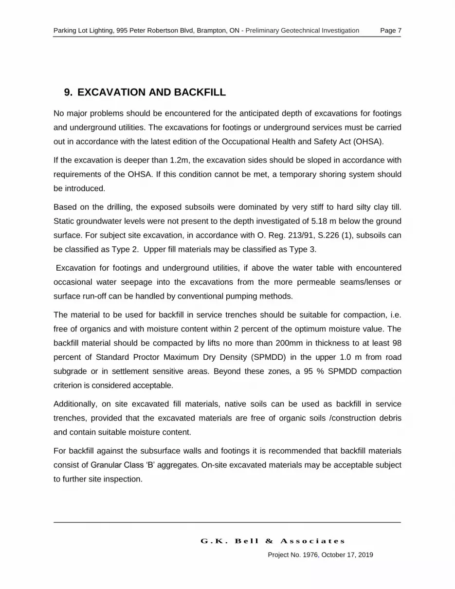
Parking Lot Lighting, 995 Peter Robertson Blvd, Brampton, ON - Preliminary Geotechnical Investigation Page 7
G . K . B e l l & A s s o c i a t e s
Project No. 1976, October 17, 2019
9. EXCAVATION AND BACKFILL
No major problems should be encountered for the anticipated depth of excavations for footings
and underground utilities. The excavations for footings or underground services must be carried
out in accordance with the latest edition of the Occupational Health and Safety Act (OHSA).
If the excavation is deeper than 1.2m, the excavation sides should be sloped in accordance with
requirements of the OHSA. If this condition cannot be met, a temporary shoring system should
be introduced.
Based on the drilling, the exposed subsoils were dominated by very stiff to hard silty clay till.
Static groundwater levels were not present to the depth investigated of 5.18 m below the ground
surface. For subject site excavation, in accordance with O. Reg. 213/91, S.226 (1), subsoils can
be classified as Type 2. Upper fill materials may be classified as Type 3.
Excavation for footings and underground utilities, if above the water table with encountered
occasional water seepage into the excavations from the more permeable seams/lenses or
surface run-off can be handled by conventional pumping methods.
The material to be used for backfill in service trenches should be suitable for compaction, i.e.
free of organics and with moisture content within 2 percent of the optimum moisture value. The
backfill material should be compacted by lifts no more than 200mm in thickness to at least 98
percent of Standard Proctor Maximum Dry Density (SPMDD) in the upper 1.0 m from road
subgrade or in settlement sensitive areas. Beyond these zones, a 95 % SPMDD compaction
criterion is considered acceptable.
Additionally, on site excavated fill materials, native soils can be used as backfill in service
trenches, provided that the excavated materials are free of organic soils /construction debris
and contain suitable moisture content.
For backfill against the subsurface walls and footings it is recommended that backfill materials
consist of Granular Class ‘B’ aggregates. On-site excavated materials may be acceptable subject
to further site inspection.
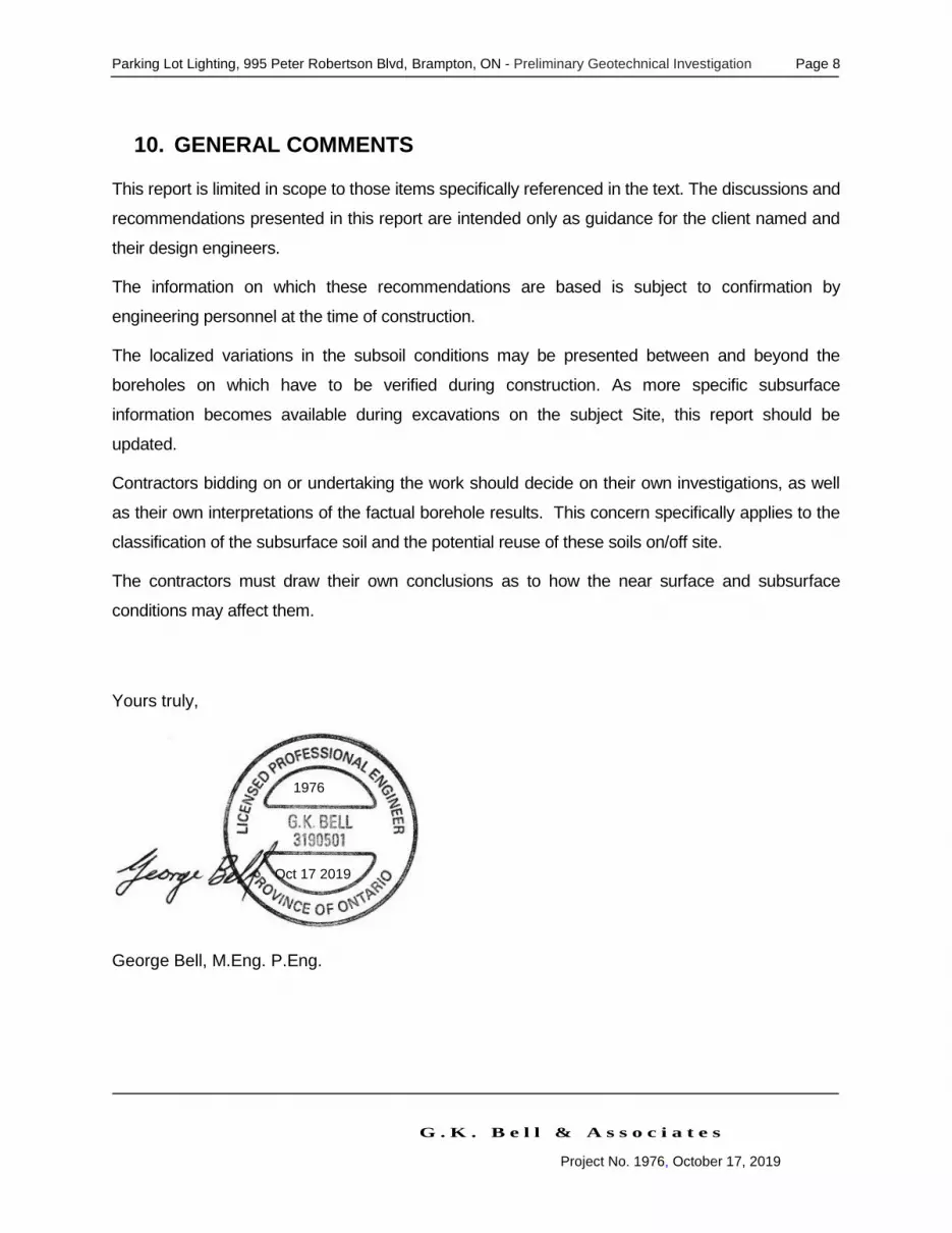
Parking Lot Lighting, 995 Peter Robertson Blvd, Brampton, ON - Preliminary Geotechnical Investigation Page 8
G . K . B e l l & A s s o c i a t e s
Project No. 1976, October 17, 2019
10. GENERAL COMMENTS
This report is limited in scope to those items specifically referenced in the text. The discussions and
recommendations presented in this report are intended only as guidance for the client named and
their design engineers.
The information on which these recommendations are based is subject to confirmation by
engineering personnel at the time of construction.
The localized variations in the subsoil conditions may be presented between and beyond the
boreholes on which have to be verified during construction. As more specific subsurface
information becomes available during excavations on the subject Site, this report should be
updated.
Contractors bidding on or undertaking the work should decide on their own investigations, as well
as their own interpretations of the factual borehole results. This concern specifically applies to the
classification of the subsurface soil and the potential reuse of these soils on/off site.
The contractors must draw their own conclusions as to how the near surface and subsurface
conditions may affect them.
Yours truly,
George Bell, M.Eng. P.Eng.
1976
Oct 17 2019

Parking Lot Lighting, 995 Peter Robertson Blvd, Brampton, ON - Preliminary Geotechnical Investigation Page 9
G . K . B e l l & A s s o c i a t e s
Project No. 1976, October 17, 2019
APPENDIX A – SITE LOCATION, GEOLOGY AND SITE PLAN


Parking Lot Lighting, 995 Peter Robertson Blvd, Brampton, ON - Preliminary Geotechnical Investigation Page 10
G . K . B e l l & A s s o c i a t e s
Project No. 1976, October 17, 2019
APPENDIX B – LOG OF BOREHOLES


SURVEY FOR DESIGNATED SUBSTANCES
AND HAZARDOUS MATERIALS
Chinguacousy Wellness Centre 995 Peter Robertson Blvd
Brampton, Ontario
Prepared For:
City of Brampton 41 George Street West
Brampton, Ontario
Presented by:
ECOH 75 Courtneypark Drive West
Mississauga, Ontario
Building Code: S-024-01 ECOH Project No.: 14963
February 18th, 2016

TABLE OF CONTENTS
1.0 INTRODUCTION ...............................................................................................................1
2.0 METHODOLOGY AND SCOPE .......................................................................................1
3.0 FINDINGS ...........................................................................................................................1
4.0 RECOMMENDATIONS .....................................................................................................3
5.0 LIMITATIONS OF ASSESSMENT ...................................................................................3
6.0 CLOSURE ...........................................................................................................................4
APPENDICES
Appendix I Survey Drawings
Appendix II Inventory of Identified Hazardous Materials
Appendix III Observation Report
Appendix IV Results of Bulk Sample Analysis
Appendix V Inventory of Underground/Aboveground Storage Tanks (UST/AST)

CITY OF BRAMPTON DESIGNATED SUBSTANCES SURVEY CHINGUACOUSY WELLNESS CENTRE 995 PETER ROBERTSON BLVD, BRAMPTON, ONTARIO ECOH PROJECT NO. 14963 FEBRUARY, 2016
ECOH Page 1
1.0 INTRODUCTION
ECOH Management Inc. (ECOH) was retained by the City of Brampton to conduct a designated substances survey of Chinguacousy Wellness Centre (hereby referred to as the “facility” or “project area”) located at 995 Peter Robertson Boulevard, Brampton, Ontario. The assessment was performed to establish the location and type of hazardous building materials incorporated in the facility’s structure(s) and its finishes, and to provide recommendations as necessary to fulfil requirements set forth under the Ontario Occupational Health and Safety Act and associated regulations.
Tanya Stanisic and Brittanie Semper of ECOH performed the fieldwork on January 26th, 2016.
This designated substance assessment was performed for the purposes of long-term management of designated substances and hazardous materials contained within building materials, and not for construction or renovation purposes. An additional pre-
renovation/pre-demolition assessment for designated substances and hazardous materials should be conducted prior to any future demolition, renovation or maintenance activities that may disturb building materials that potentially contain designated materials or hazardous substances.
2.0 METHODOLOGY AND SCOPE
The methodology and scope of the Designated Substances Survey completed at this site are detailed in the overview document titled “Designated Substances Survey Scope of Work and Methodology Report”, dated October 2014, prepared by ECOH Management Inc. A copy of this document is available from the City of Brampton, and forms part of this report by reference.
3.0 FINDINGS
Material Findings
Asbestos Assumed ACM were identified in the facility as follows:
Roofing materials, mechanical gaskets, internal components of boilers/water heaters or other mechanical systems were not sampled and should be assumed to be asbestos-containing if present. All assumed ACM materials observed were found to be in GOOD condition at the time of the survey.

CITY OF BRAMPTON DESIGNATED SUBSTANCES SURVEY CHINGUACOUSY WELLNESS CENTRE 995 PETER ROBERTSON BLVD, BRAMPTON, ONTARIO ECOH PROJECT NO. 14963 FEBRUARY, 2016
ECOH Page 2
Material Findings
Lead Unsampled paints and surface coatings were observed to be in good condition and should be treated as lead-based until sampled.
No other major sources of lead or lead-containing products were identified during the survey; however, lead may be present in:
Ceramic tiles,
Wiring connectors and electric cable sheathing, and
Piping and solder joints/bell-and-spigot joints on piping
Mould Visible mould growth was not observed within this facility.
Mercury Minor quantities are present as a vapour within fluorescent tubes lights and as a possible constituent of paints and adhesives.
Silica Present in all concrete and masonry products.
Polychlorinated Biphenyls (PCBs)
Assumed to be present as a component of ballasts for fluorescent lights/high-intensity discharge (HID) lights. Approximately 60 light fixtures are present within the facility.
Assumed to be present as a component of one (1) electrical transformer found in Locations EC-10 (Electrical/Boiler Room).
Benzene Chlorobenzene is assumed to be present as a component of electrical transformers.
Other Designated Substances and Hazardous Materials
Acrylonitrile, Arsenic, Coke Oven Emissions, Ethylene Oxide, Isocyanates, and Vinyl Chloride Monomer were not noted in significant quantities or forms, if at all.
Underground/Aboveground Storage Tanks (UST/AST)
UST/AST were not observed within the facility.
Further findings are presented in attached Appendices:
Appendix I – Survey Drawings, depicting the location of presumed and assumed asbestos-containing materials and room location numbers referenced throughout the report.
Appendix II – Inventory of Hazardous Materials, providing a general description of the quantity or nature of the designated substance identified in each location within the facility.
Appendix III – Observation Report, documenting instances of damaged hazardous materials and/or mould growth.
Appendix IV – Results of Bulk Sample Analysis, providing a summary of all bulk sampled collected as well as laboratory chain of custodies and certificates of analyses.
Appendix V – Inventory of Underground/Aboveground Storage Tanks (UST/AST).

CITY OF BRAMPTON DESIGNATED SUBSTANCES SURVEY CHINGUACOUSY WELLNESS CENTRE 995 PETER ROBERTSON BLVD, BRAMPTON, ONTARIO ECOH PROJECT NO. 14963 FEBRUARY, 2016
ECOH Page 3
4.0 RECOMMENDATIONS
General recommendations for compliance with applicable regulations have been provided in the overview document, “Designated Substances Survey Scope of Work and Methodology Report”, dated October 2014, prepared by ECOH Management Inc. The following details are specific recommendations for the facility.
All designated substances and hazardous materials identified on-site during this assessment are present in good condition and no other immediate action is required.
Detailed recommendations regarding the remediation of the above noted materials have been provided in overview document titled “Designated Substances Survey Scope of Work and Methodology Report”, dated October 2014, prepared by ECOH Management Inc. A copy of this document is available from the City of Brampton.
Prior to future construction or renovation projects, additional assessments will be required to confirm the presence of designated substances and hazardous materials that have been assumed to be on-site and/or that may be present in concealed areas (such as above solid ceilings, within bulkheads, pipe chases, etc.). The impact to designated substances and hazardous materials during future demolition, renovation or maintenance activities should be assessed on a project-by-project basis.
5.0 LIMITATIONS OF ASSESSMENT
Due to the nature of building construction and on-going building activities, some limitations exist as to the possible thoroughness of a building survey. The field observations, measurements and analysis are considered sufficient in detail and scope to form a reasonable basis for the findings and conclusions presented in this report. The findings and conclusions drawn by ECOH Management Inc. (ECOH) are limited to the specific scope of work for which ECOH was retained and are based solely on information generated as a result of the specific scope of work authorized by the City of Brampton. The results of the assessment are limited to visual inspection of areas made accessible to ECOH personnel and information obtained from facility personnel, when obtained.
ECOH warrants that the findings and conclusions contained herein have been made in accordance with generally accepted evaluation methods in the industry and applicable regulations at the time of the performance of the assessment. However, there is no warranty, expressed or implied, that this assessment has uncovered all environmental concerns on the subject site. In addition, ECOH cannot guarantee the completeness or accuracy of information supplied by a third party.

CITY OF BRAMPTON DESIGNATED SUBSTANCES SURVEY CHINGUACOUSY WELLNESS CENTRE 995 PETER ROBERTSON BLVD, BRAMPTON, ONTARIO ECOH PROJECT NO. 14963 FEBRUARY, 2016
ECOH Page 4
This report was prepared by ECOH for the City of Brampton. The material in it reflects ECOH’s professional interpretation of information available at the time of report preparation. Any use which a third party makes of this report, or any reliance on or decisions to be made based on it, are the responsibility of such third parties. ECOH accepts no responsibility for damages, if any, suffered by any third party as a result of decisions made or actions based on this report. Should additional information become available that suggests other environmental issues of concern beyond that described in this report, ECOH retains the right to review this information and modify conclusions and recommendations
presented in this report accordingly.
6.0 CLOSURE
Should there be any questions regarding the contents of this report, please contact the
undersigned at 905-795-2800.
ECOH Environmental Consulting Occupational Health
Prepared by: Reviewed by:
Brittanie Semper, B.E.S. Zafar Iqbal, B.Eng.(Civil) Environmental Scientist Senior Project Manager

APPENDIX I SURVEY DRAWINGS

09B
09A
09C
01F
11C
03A-C
13A-C
02E05C
05A 06B
08A-C
01C
02C
04A-C
02D
06C
01E
05B
11A
07B,C
04A 02A
02B01D12A-C
07A01G11B
01B
06A10A-C
CLIENT: City of BramptonPROJECT NUMBER:
CAD FILE:
DATE:
SCALE:
DRW BY:
CHK BY:
14963-S-024-01 January 2016 MM
MBNot to ScaleFIG1 P14963-S-024-01 DSUB Ground
Figure 1
Legend
NEnvironmental ConsultingOccupational Health
ECOH
Ground Floor PlanLocations of Designated Substances and
Hazardous Materials
BUILDING NAME:
LOCATION:
1001 Location Numbers
Non-Friable Asbestos-Containing Material
Friable Asbestos-Containing Material
01AAsbestos Bulk Sample Location(14963-S-024-01 ASB-XX)
Pb-01Lead Bulk Sample Location(14963-S-024-01 Pb-XX)
995 Peter Robertson Blvd,Brampton, Ontario
Chinguacousy Wellness Centre

APPENDIX II INVENTORY OF IDENTIFIED HAZARDOUS MATERIALS

The Corporation of the City of BramptonSurvey Summary Table
Location Number Location Name Building
System Material ObservedPotential
Hazardous Material
Sample ID Analytical Result
Qua
ntity
Con
ditio
n
Acc
ess
Aba
tem
ent
Prio
rity
Notes or Other Observations
0000 Exterior Roof Roofing Material Asbestos Not Sampled ACM Assumed 40000 SF Good C 30000 Exterior Walls Caulking Asbestos Not Sampled ACM Assumed 100 EA Good A 3
1001 Lobby Ceiling Drywall Joint Compound AsbestosVisually Consistent with 14963-S-024-01-ASB-02
None Detected - - - -
1001 Lobby Other White Caulking Asbestos 14963-S-024-01-ASB-11C None Detected - - - -
1002 Bikes - - - - - - - -
No suspect ACM identified. Other hazardous materials or designated substances were not noted in any significant quantities or forms.
1003 Snack Bar - - - - - - - - -No Access to Location during 2016 ECOH Survey.
1004 Women's Washroom Ceiling Ceiling Tile 01 AsbestosVisually Consistent with 14963-S-024-01-ASB-05
None Detected - - - - CT-01 - 2'x4' Cloudlike Pinholes
1004 Women's Washroom Other White Caulking AsbestosVisually Consistent with 14963-S-024-01-ASB-11
None Detected - - - -
1005 Men's Washroom Ceiling Ceiling Tile 01 AsbestosVisually Consistent with 14963-S-024-01-ASB-05
None Detected - - - - CT-01 - 2'x4' Cloudlike Pinholes
1005 Men's Washroom Other White Caulking AsbestosVisually Consistent with 14963-S-024-01-ASB-11
None Detected - - - -
JC-10 Janitor Closet Floor Vinyl Floor Tile 01 AsbestosVisually Consistent with 14963-S-024-01-ASB-04
None Detected - - - -VFT-01 - 12"x12" Grey with White/Grey Flecks
JC-10 Janitor Closet Ceiling Drywall Joint Compound Asbestos 14963-S-024-01-ASB-02A None Detected - - - -
JC-10 Janitor Closet Other White Caulking AsbestosVisually Consistent with 14963-S-024-01-ASB-11
None Detected - - - -
1006 Reception Wall Drywall Joint Compound Asbestos 14963-S-024-01-ASB-01F None Detected - - - -
1006 Reception Ceiling Drywall Joint Compound AsbestosVisually Consistent with 14963-S-024-01-ASB-02
None Detected - - - -
1006 Reception Ceiling Ceiling Tile 02 AsbestosVisually Consistent with 14963-S-024-01-ASB-06
None Detected - - - -CT-02 - 2'x4' Big & Small Random Shaped Pinholes
1006 Reception Other White Caulking AsbestosVisually Consistent with 14963-S-024-01-ASB-11
None Detected - - - -
1007 Admin Office Ceiling Ceiling Tile 02 AsbestosVisually Consistent with 14963-S-024-01-ASB-06
None Detected - - - -CT-02 - 2'x4' Big & Small Random Shaped Pinholes
1007 Admin Office Other White Caulking AsbestosVisually Consistent with 14963-S-024-01-ASB-11
None Detected - - - -
1008 Admin Office Ceiling Ceiling Tile 02 AsbestosVisually Consistent with 14963-S-024-01-ASB-06
None Detected - - - -CT-02 - 2'x4' Big & Small Random Shaped Pinholes
1008 Admin Office Other White Caulking AsbestosVisually Consistent with 14963-S-024-01-ASB-11
None Detected - - - -
EC-10 Electrical Ceiling Ceiling Tile 01 AsbestosVisually Consistent with 14963-S-024-01-ASB-05
None Detected - - - - CT-01 - 2'x4' Cloudlike Pinholes
EC-10 Electrical Other White Caulking AsbestosVisually Consistent with 14963-S-024-01-ASB-11
None Detected - - - -
Project Number:
Building Name:
Building Address:
14963-S-024-01
Chinguacousy Wellness Centre
995 Peter Robertson Blvd
January 26, 2016
ECOH Management Inc.
Chris Travers
Date(s) of Current Survey:
Organization Completing Survey:
Facilty Coordinator:
Appendix II - Inventory of Identified Hazardous Materials Page 1 of 7

The Corporation of the City of BramptonSurvey Summary Table
Location Number Location Name Building
System Material ObservedPotential
Hazardous Material
Sample ID Analytical Result
Qua
ntity
Con
ditio
n
Acc
ess
Aba
tem
ent
Prio
rity
Notes or Other Observations
Project Number:
Building Name:
Building Address:
14963-S-024-01
Chinguacousy Wellness Centre
995 Peter Robertson Blvd
January 26, 2016
ECOH Management Inc.
Chris Travers
Date(s) of Current Survey:
Organization Completing Survey:
Facilty Coordinator:
1009 Office Ceiling Ceiling Tile 02 AsbestosVisually Consistent with 14963-S-024-01-ASB-06
None Detected - - - -CT-02 - 2'x4' Big & Small Random Shaped Pinholes
1009 Office Other White Caulking AsbestosVisually Consistent with 14963-S-024-01-ASB-11
None Detected - - - -
1010 Office Ceiling Ceiling Tile 02 AsbestosVisually Consistent with 14963-S-024-01-ASB-06
None Detected - - - -CT-02 - 2'x4' Big & Small Random Shaped Pinholes
1010 Office Other White Caulking AsbestosVisually Consistent with 14963-S-024-01-ASB-11
None Detected - - - -
1013 Pre-School Room Floor Vinyl Floor Tile 01 AsbestosVisually Consistent with 14963-S-024-01-ASB-04
None Detected - - - -VFT-01 - 12"x12" Grey with White/Grey Flecks
1013 Pre-School Room Wall Drywall Joint Compound AsbestosVisually Consistent with 14963-S-024-01-ASB-01
None Detected - - - -
1013 Pre-School Room Ceiling Ceiling Tile 01 AsbestosVisually Consistent with 14963-S-024-01-ASB-05
None Detected - - - - CT-01 - 2'x4' Cloudlike Pinholes
1013 Pre-School Room Ceiling Ceiling Tile 04 AsbestosVisually Consistent with 14963-S-024-01-ASB-08
None Detected - - - - CT-04 - 2'x4' Random Pinholes & Fissures
1013 Pre-School Room Ceiling Ceiling Tile 02 AsbestosVisually Consistent with 14963-S-024-01-ASB-06
None Detected - - - -CT-02 - 2'x4' Big & Small Random Shaped Pinholes
1013 Pre-School Room Other White Caulking AsbestosVisually Consistent with 14963-S-024-01-ASB-11
None Detected - - - -
1014 Children's Washroom Wall Drywall Joint Compound AsbestosVisually Consistent with 14963-S-024-01-ASB-01
None Detected - - - -
1014 Children's Washroom Ceiling Ceiling Tile 01 AsbestosVisually Consistent with 14963-S-024-01-ASB-05
None Detected - - - - CT-01 - 2'x4' Cloudlike Pinholes
1014 Children's Washroom Other White Caulking AsbestosVisually Consistent with 14963-S-024-01-ASB-11
None Detected - - - -
1015 Storage Floor Vinyl Floor Tile 01 AsbestosVisually Consistent with 14963-S-024-01-ASB-04
None Detected - - - -VFT-01 - 12"x12" Grey with White/Grey Flecks
1015 Storage Wall Drywall Joint Compound AsbestosVisually Consistent with 14963-S-024-01-ASB-01
None Detected - - - -
1015 Storage Ceiling Ceiling Tile 01 AsbestosVisually Consistent with 14963-S-024-01-ASB-05
None Detected - - - - CT-01 - 2'x4' Cloudlike Pinholes
1016 Daycare Floor Vinyl Floor Tile 01 AsbestosVisually Consistent with 14963-S-024-01-ASB-04
None Detected - - - -VFT-01 - 12"x12" Grey with White/Grey Flecks
1016 Daycare Wall Drywall Joint Compound Asbestos 14963-S-024-01-ASB-01C None Detected - - - -1016 Daycare Ceiling Drywall Joint Compound Asbestos 14963-S-024-01-ASB-02C None Detected - - - -1016 Daycare Ceiling Ceiling Tile 01 Asbestos 14963-S-024-01-ASB-05A None Detected - - - - CT-01 - 2'x4' Cloudlike Pinholes
1016 Daycare Ceiling Ceiling Tile 04 Asbestos 14963-S-024-01-ASB-08A-C None Detected - - - - CT-04 - 2'x4' Random Pinholes & Fissures
1016 Daycare Ceiling Ceiling Tile 02 Asbestos 14963-S-024-01-ASB-06B None Detected - - - -CT-02 - 2'x4' Big & Small Random Shaped Pinholes
1016 Daycare Other White Caulking AsbestosVisually Consistent with 14963-S-024-01-ASB-11
None Detected - - - -
Appendix II - Inventory of Identified Hazardous Materials Page 2 of 7

The Corporation of the City of BramptonSurvey Summary Table
Location Number Location Name Building
System Material ObservedPotential
Hazardous Material
Sample ID Analytical Result
Qua
ntity
Con
ditio
n
Acc
ess
Aba
tem
ent
Prio
rity
Notes or Other Observations
Project Number:
Building Name:
Building Address:
14963-S-024-01
Chinguacousy Wellness Centre
995 Peter Robertson Blvd
January 26, 2016
ECOH Management Inc.
Chris Travers
Date(s) of Current Survey:
Organization Completing Survey:
Facilty Coordinator:
1017 Children's Washroom Wall Drywall Joint Compound AsbestosVisually Consistent with 14963-S-024-01-ASB-01
None Detected - - - -
1017 Children's Washroom Ceiling Drywall Joint Compound Asbestos 14963-S-024-01-ASB-02E None Detected - - - -1017 Children's Washroom Ceiling Ceiling Tile 01 Asbestos 14963-S-024-01-ASB-05C None Detected - - - - CT-01 - 2'x4' Cloudlike Pinholes
1017 Children's Washroom Other White Caulking AsbestosVisually Consistent with 14963-S-024-01-ASB-11
None Detected - - - -
1018 Meeting Room 3 Floor Vinyl Floor Tile 01 Asbestos 14963-S-024-01-ASB-04A-C None Detected - - - -VFT-01 - 12"x12" Grey with White/Grey Flecks
1018 Meeting Room 3 Ceiling Ceiling Tile 01 AsbestosVisually Consistent with 14963-S-024-01-ASB-05
None Detected - - - - CT-01 - 2'x4' Cloudlike Pinholes
1018 Meeting Room 3 Other White Caulking AsbestosVisually Consistent with 14963-S-024-01-ASB-11
None Detected - - - -
1019 Closets Floor Vinyl Floor Tile 01 AsbestosVisually Consistent with 14963-S-024-01-ASB-04
None Detected - - - -VFT-01 - 12"x12" Grey with White/Grey Flecks
1019 Closets Wall Drywall Joint Compound AsbestosVisually Consistent with 14963-S-024-01-ASB-01
None Detected - - - -
1019 Closets Ceiling Ceiling Tile 01 AsbestosVisually Consistent with 14963-S-024-01-ASB-05
None Detected - - - - CT-01 - 2'x4' Cloudlike Pinholes
1020 Closets Floor Vinyl Floor Tile 01 AsbestosVisually Consistent with 14963-S-024-01-ASB-04
None Detected - - - -VFT-01 - 12"x12" Grey with White/Grey Flecks
1020 Closets Wall Drywall Joint Compound AsbestosVisually Consistent with 14963-S-024-01-ASB-01
None Detected - - - -
1020 Closets Ceiling Ceiling Tile 01 AsbestosVisually Consistent with 14963-S-024-01-ASB-05
None Detected - - - - CT-01 - 2'x4' Cloudlike Pinholes
1021 Closets Floor Vinyl Floor Tile 01 AsbestosVisually Consistent with 14963-S-024-01-ASB-04
None Detected - - - -VFT-01 - 12"x12" Grey with White/Grey Flecks
1021 Closets Wall Drywall Joint Compound AsbestosVisually Consistent with 14963-S-024-01-ASB-01
None Detected - - - -
1021 Closets Ceiling Ceiling Tile 01 AsbestosVisually Consistent with 14963-S-024-01-ASB-05
None Detected - - - - CT-01 - 2'x4' Cloudlike Pinholes
1022 Meeting Room 2 Floor Vinyl Floor Tile 01 AsbestosVisually Consistent with 14963-S-024-01-ASB-04
None Detected - - - -VFT-01 - 12"x12" Grey with White/Grey Flecks
1022 Meeting Room 2 Wall Drywall Joint Compound Asbestos 14963-S-024-01-ASB-01E None Detected - - - -1022 Meeting Room 2 Ceiling Drywall Joint Compound Asbestos 14963-S-024-01-ASB-02D None Detected - - - -
1022 Meeting Room 2 Ceiling Ceiling Tile 01 AsbestosVisually Consistent with 14963-S-024-01-ASB-05
None Detected - - - - CT-01 - 2'x4' Cloudlike Pinholes
1022 Meeting Room 2 Ceiling Ceiling Tile 02 Asbestos 14963-S-024-01-ASB-06C None Detected - - - -CT-02 - 2'x4' Big & Small Random Shaped Pinholes
1022 Meeting Room 2 Other White Caulking AsbestosVisually Consistent with 14963-S-024-01-ASB-11
None Detected - - - -
Appendix II - Inventory of Identified Hazardous Materials Page 3 of 7
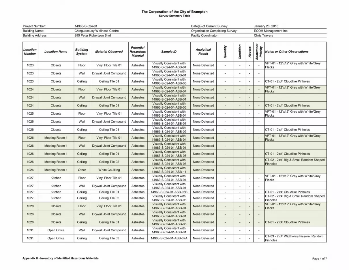
The Corporation of the City of BramptonSurvey Summary Table
Location Number Location Name Building
System Material ObservedPotential
Hazardous Material
Sample ID Analytical Result
Qua
ntity
Con
ditio
n
Acc
ess
Aba
tem
ent
Prio
rity
Notes or Other Observations
Project Number:
Building Name:
Building Address:
14963-S-024-01
Chinguacousy Wellness Centre
995 Peter Robertson Blvd
January 26, 2016
ECOH Management Inc.
Chris Travers
Date(s) of Current Survey:
Organization Completing Survey:
Facilty Coordinator:
1023 Closets Floor Vinyl Floor Tile 01 AsbestosVisually Consistent with 14963-S-024-01-ASB-04
None Detected - - - -VFT-01 - 12"x12" Grey with White/Grey Flecks
1023 Closets Wall Drywall Joint Compound AsbestosVisually Consistent with 14963-S-024-01-ASB-01
None Detected - - - -
1023 Closets Ceiling Ceiling Tile 01 AsbestosVisually Consistent with 14963-S-024-01-ASB-05
None Detected - - - - CT-01 - 2'x4' Cloudlike Pinholes
1024 Closets Floor Vinyl Floor Tile 01 AsbestosVisually Consistent with 14963-S-024-01-ASB-04
None Detected - - - -VFT-01 - 12"x12" Grey with White/Grey Flecks
1024 Closets Wall Drywall Joint Compound AsbestosVisually Consistent with 14963-S-024-01-ASB-01
None Detected - - - -
1024 Closets Ceiling Ceiling Tile 01 AsbestosVisually Consistent with 14963-S-024-01-ASB-05
None Detected - - - - CT-01 - 2'x4' Cloudlike Pinholes
1025 Closets Floor Vinyl Floor Tile 01 AsbestosVisually Consistent with 14963-S-024-01-ASB-04
None Detected - - - -VFT-01 - 12"x12" Grey with White/Grey Flecks
1025 Closets Wall Drywall Joint Compound AsbestosVisually Consistent with 14963-S-024-01-ASB-01
None Detected - - - -
1025 Closets Ceiling Ceiling Tile 01 AsbestosVisually Consistent with 14963-S-024-01-ASB-05
None Detected - - - - CT-01 - 2'x4' Cloudlike Pinholes
1026 Meeting Room 1 Floor Vinyl Floor Tile 01 AsbestosVisually Consistent with 14963-S-024-01-ASB-04
None Detected - - - -VFT-01 - 12"x12" Grey with White/Grey Flecks
1026 Meeting Room 1 Wall Drywall Joint Compound AsbestosVisually Consistent with 14963-S-024-01-ASB-01
None Detected - - - -
1026 Meeting Room 1 Ceiling Ceiling Tile 01 AsbestosVisually Consistent with 14963-S-024-01-ASB-05
None Detected - - - - CT-01 - 2'x4' Cloudlike Pinholes
1026 Meeting Room 1 Ceiling Ceiling Tile 02 AsbestosVisually Consistent with 14963-S-024-01-ASB-06
None Detected - - - -CT-02 - 2'x4' Big & Small Random Shaped Pinholes
1026 Meeting Room 1 Other White Caulking AsbestosVisually Consistent with 14963-S-024-01-ASB-11
None Detected - - - -
1027 Kitchen Floor Vinyl Floor Tile 01 AsbestosVisually Consistent with 14963-S-024-01-ASB-04
None Detected - - - -VFT-01 - 12"x12" Grey with White/Grey Flecks
1027 Kitchen Wall Drywall Joint Compound AsbestosVisually Consistent with 14963-S-024-01-ASB-01
None Detected - - - -
1027 Kitchen Ceiling Ceiling Tile 01 Asbestos 14963-S-024-01-ASB-05B None Detected - - - - CT-01 - 2'x4' Cloudlike Pinholes
1027 Kitchen Ceiling Ceiling Tile 02 AsbestosVisually Consistent with 14963-S-024-01-ASB-06
None Detected - - - -CT-02 - 2'x4' Big & Small Random Shaped Pinholes
1028 Closets Floor Vinyl Floor Tile 01 AsbestosVisually Consistent with 14963-S-024-01-ASB-04
None Detected - - - -VFT-01 - 12"x12" Grey with White/Grey Flecks
1028 Closets Wall Drywall Joint Compound AsbestosVisually Consistent with 14963-S-024-01-ASB-01
None Detected - - - -
1028 Closets Ceiling Ceiling Tile 01 AsbestosVisually Consistent with 14963-S-024-01-ASB-05
None Detected - - - - CT-01 - 2'x4' Cloudlike Pinholes
1031 Open Office Wall Drywall Joint Compound AsbestosVisually Consistent with 14963-S-024-01-ASB-01
None Detected - - - -
1031 Open Office Ceiling Ceiling Tile 03 Asbestos 14963-S-024-01-ASB-07A None Detected - - - -CT-03 - 2'x4' Widthwise Fissure, Random Pinholes
Appendix II - Inventory of Identified Hazardous Materials Page 4 of 7

The Corporation of the City of BramptonSurvey Summary Table
Location Number Location Name Building
System Material ObservedPotential
Hazardous Material
Sample ID Analytical Result
Qua
ntity
Con
ditio
n
Acc
ess
Aba
tem
ent
Prio
rity
Notes or Other Observations
Project Number:
Building Name:
Building Address:
14963-S-024-01
Chinguacousy Wellness Centre
995 Peter Robertson Blvd
January 26, 2016
ECOH Management Inc.
Chris Travers
Date(s) of Current Survey:
Organization Completing Survey:
Facilty Coordinator:
1031a Washroom Wall Drywall Joint Compound Asbestos 14963-S-024-01-ASB-01D None Detected - - - -1031a Washroom Ceiling Drywall Joint Compound Asbestos 14963-S-024-01-ASB-02B None Detected - - - -
1031a Washroom OtherWhite Caulking on
CountersAsbestos 14963-S-024-01-ASB-12A-C None Detected - - - -
1035 Office Wall Drywall Joint Compound Asbestos 14963-S-024-01-ASB-01A None Detected - - - -
1035 Office Ceiling Ceiling Tile 03 Asbestos 14963-S-024-01-ASB-07B-C None Detected - - - -CT-03 - 2'x4' Widthwise Fissure, Random Pinholes
1035 Office Other White Caulking Asbestos 14963-S-024-01-ASB-11A None Detected - - - - On Door
1036 Classroom Wall Drywall Joint Compound AsbestosVisually Consistent with 14963-S-024-01-ASB-01
None Detected - - - -
1036 Classroom Ceiling Ceiling Tile 03 AsbestosVisually Consistent with 14963-S-024-01-ASB-07
None Detected - - - -CT-03 - 2'x4' Widthwise Fissure, Random Pinholes
1038 Closet Wall Drywall Joint Compound AsbestosVisually Consistent with 14963-S-024-01-ASB-01
None Detected - - - -
1038 Closet Ceiling Ceiling Tile 03 AsbestosVisually Consistent with 14963-S-024-01-ASB-07
None Detected - - - -CT-03 - 2'x4' Widthwise Fissure, Random Pinholes
1039 Closet Wall Drywall Joint Compound AsbestosVisually Consistent with 14963-S-024-01-ASB-01
None Detected - - - -
1039 Closet Ceiling Ceiling Tile 03 AsbestosVisually Consistent with 14963-S-024-01-ASB-07
None Detected - - - -CT-03 - 2'x4' Widthwise Fissure, Random Pinholes
1040 Office Wall Drywall Joint Compound AsbestosVisually Consistent with 14963-S-024-01-ASB-01
None Detected - - - -
1040 Office Ceiling Ceiling Tile 03 AsbestosVisually Consistent with 14963-S-024-01-ASB-07
None Detected - - - -CT-03 - 2'x4' Widthwise Fissure, Random Pinholes
1040 Office Other White Caulking AsbestosVisually Consistent with 14963-S-024-01-ASB-11
None Detected - - - -
1041 Office Wall Drywall Joint Compound Asbestos 14963-S-024-01-ASB-01G None Detected - - - -
1041 Office Ceiling Ceiling Tile 03 AsbestosVisually Consistent with 14963-S-024-01-ASB-07
None Detected - - - -CT-03 - 2'x4' Widthwise Fissure, Random Pinholes
1041 Office Other White Caulking Asbestos 14963-S-024-01-ASB-11B None Detected - - - -1042 Meeting Room Wall Drywall Joint Compound Asbestos 14963-S-024-01-ASB-01B None Detected - - - -
1042 Meeting Room Ceiling Ceiling Tile 01 AsbestosVisually Consistent with 14963-S-024-01-ASB-05
None Detected - - - - CT-01 - 2'x4' Cloudlike Pinholes
1042 Meeting Room Ceiling Ceiling Tile 02 Asbestos 14963-S-024-01-ASB-06A None Detected - - - -CT-02 - 2'x4' Big & Small Random Shaped Pinholes
1042 Meeting Room Other White Caulking AsbestosVisually Consistent with 14963-S-024-01-ASB-11
None Detected - - - -
1043 Meeting Room Wall Drywall Joint Compound AsbestosVisually Consistent with 14963-S-024-01-ASB-01
None Detected - - - -
1043 Meeting Room Ceiling Ceiling Tile 01 AsbestosVisually Consistent with 14963-S-024-01-ASB-05
None Detected - - - - CT-01 - 2'x4' Cloudlike Pinholes
1043 Meeting Room Ceiling Ceiling Tile 02 AsbestosVisually Consistent with 14963-S-024-01-ASB-06
None Detected - - - -CT-02 - 2'x4' Big & Small Random Shaped Pinholes
1043 Meeting Room Other White Caulking AsbestosVisually Consistent with 14963-S-024-01-ASB-11
None Detected - - - -
Appendix II - Inventory of Identified Hazardous Materials Page 5 of 7
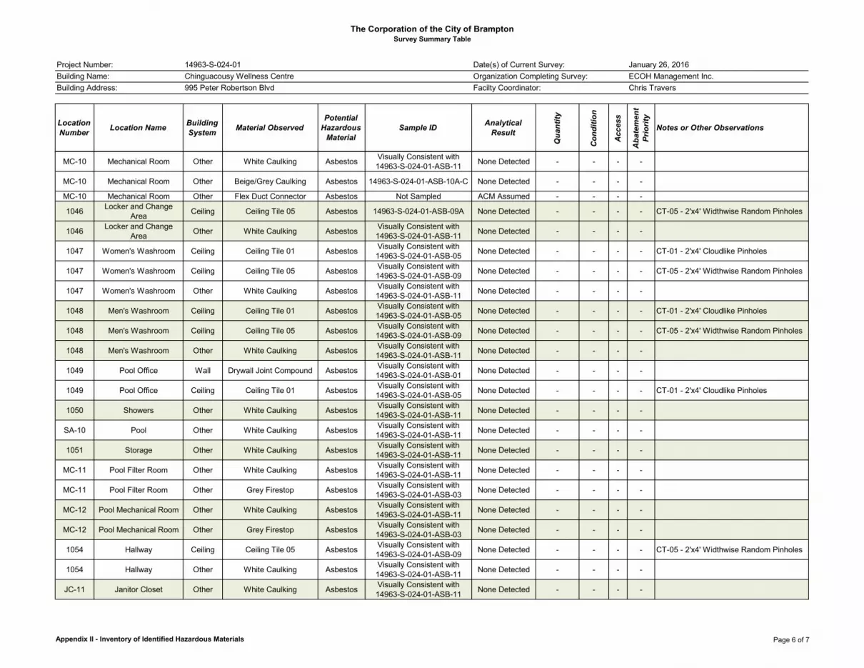
The Corporation of the City of BramptonSurvey Summary Table
Location Number Location Name Building
System Material ObservedPotential
Hazardous Material
Sample ID Analytical Result
Qua
ntity
Con
ditio
n
Acc
ess
Aba
tem
ent
Prio
rity
Notes or Other Observations
Project Number:
Building Name:
Building Address:
14963-S-024-01
Chinguacousy Wellness Centre
995 Peter Robertson Blvd
January 26, 2016
ECOH Management Inc.
Chris Travers
Date(s) of Current Survey:
Organization Completing Survey:
Facilty Coordinator:
MC-10 Mechanical Room Other White Caulking AsbestosVisually Consistent with 14963-S-024-01-ASB-11
None Detected - - - -
MC-10 Mechanical Room Other Beige/Grey Caulking Asbestos 14963-S-024-01-ASB-10A-C None Detected - - - -
MC-10 Mechanical Room Other Flex Duct Connector Asbestos Not Sampled ACM Assumed - - - -
1046Locker and Change
AreaCeiling Ceiling Tile 05 Asbestos 14963-S-024-01-ASB-09A None Detected - - - - CT-05 - 2'x4' Widthwise Random Pinholes
1046Locker and Change
AreaOther White Caulking Asbestos
Visually Consistent with 14963-S-024-01-ASB-11
None Detected - - - -
1047 Women's Washroom Ceiling Ceiling Tile 01 AsbestosVisually Consistent with 14963-S-024-01-ASB-05
None Detected - - - - CT-01 - 2'x4' Cloudlike Pinholes
1047 Women's Washroom Ceiling Ceiling Tile 05 AsbestosVisually Consistent with 14963-S-024-01-ASB-09
None Detected - - - - CT-05 - 2'x4' Widthwise Random Pinholes
1047 Women's Washroom Other White Caulking AsbestosVisually Consistent with 14963-S-024-01-ASB-11
None Detected - - - -
1048 Men's Washroom Ceiling Ceiling Tile 01 AsbestosVisually Consistent with 14963-S-024-01-ASB-05
None Detected - - - - CT-01 - 2'x4' Cloudlike Pinholes
1048 Men's Washroom Ceiling Ceiling Tile 05 AsbestosVisually Consistent with 14963-S-024-01-ASB-09
None Detected - - - - CT-05 - 2'x4' Widthwise Random Pinholes
1048 Men's Washroom Other White Caulking AsbestosVisually Consistent with 14963-S-024-01-ASB-11
None Detected - - - -
1049 Pool Office Wall Drywall Joint Compound AsbestosVisually Consistent with 14963-S-024-01-ASB-01
None Detected - - - -
1049 Pool Office Ceiling Ceiling Tile 01 AsbestosVisually Consistent with 14963-S-024-01-ASB-05
None Detected - - - - CT-01 - 2'x4' Cloudlike Pinholes
1050 Showers Other White Caulking AsbestosVisually Consistent with 14963-S-024-01-ASB-11
None Detected - - - -
SA-10 Pool Other White Caulking AsbestosVisually Consistent with 14963-S-024-01-ASB-11
None Detected - - - -
1051 Storage Other White Caulking AsbestosVisually Consistent with 14963-S-024-01-ASB-11
None Detected - - - -
MC-11 Pool Filter Room Other White Caulking AsbestosVisually Consistent with 14963-S-024-01-ASB-11
None Detected - - - -
MC-11 Pool Filter Room Other Grey Firestop AsbestosVisually Consistent with 14963-S-024-01-ASB-03
None Detected - - - -
MC-12 Pool Mechanical Room Other White Caulking AsbestosVisually Consistent with 14963-S-024-01-ASB-11
None Detected - - - -
MC-12 Pool Mechanical Room Other Grey Firestop AsbestosVisually Consistent with 14963-S-024-01-ASB-03
None Detected - - - -
1054 Hallway Ceiling Ceiling Tile 05 AsbestosVisually Consistent with 14963-S-024-01-ASB-09
None Detected - - - - CT-05 - 2'x4' Widthwise Random Pinholes
1054 Hallway Other White Caulking AsbestosVisually Consistent with 14963-S-024-01-ASB-11
None Detected - - - -
JC-11 Janitor Closet Other White Caulking AsbestosVisually Consistent with 14963-S-024-01-ASB-11
None Detected - - - -
Appendix II - Inventory of Identified Hazardous Materials Page 6 of 7

The Corporation of the City of BramptonSurvey Summary Table
Location Number Location Name Building
System Material ObservedPotential
Hazardous Material
Sample ID Analytical Result
Qua
ntity
Con
ditio
n
Acc
ess
Aba
tem
ent
Prio
rity
Notes or Other Observations
Project Number:
Building Name:
Building Address:
14963-S-024-01
Chinguacousy Wellness Centre
995 Peter Robertson Blvd
January 26, 2016
ECOH Management Inc.
Chris Travers
Date(s) of Current Survey:
Organization Completing Survey:
Facilty Coordinator:
1055Maintenance Storage
RoomCeiling Ceiling Tile 05 Asbestos
Visually Consistent with 14963-S-024-01-ASB-09
None Detected - - - - CT-05 - 2'x4' Widthwise Random Pinholes
1055Maintenance Storage
RoomOther White Caulking Asbestos
Visually Consistent with 14963-S-024-01-ASB-11
None Detected - - - -
1056Maintenance Lunch
RoomCeiling Ceiling Tile 05 Asbestos 14963-S-024-01-ASB-09C None Detected - - - - CT-05 - 2'x4' Widthwise Random Pinholes
1056Maintenance Lunch
RoomOther White Caulking Asbestos
Visually Consistent with 14963-S-024-01-ASB-11
None Detected - - - -
1057Men's Changeroom
(Sauna/Hot Tub Area)Ceiling Drywall Joint Compound Asbestos
Visually Consistent with 14963-S-024-01-ASB-02
None Detected - - - -
1057 Men's Changeroom Ceiling Ceiling Tile 02 AsbestosVisually Consistent with 14963-S-024-01-ASB-06
None Detected - - - -CT-02 - 2'x4' Big & Small Random Shaped Pinholes
1057 Men's Changeroom Ceiling Ceiling Tile 05 AsbestosVisually Consistent with 14963-S-024-01-ASB-09
None Detected - - - - CT-05 - 2'x4' Widthwise Random Pinholes
1057 Men's Changeroom Other White Caulking AsbestosVisually Consistent with 14963-S-024-01-ASB-11
None Detected - - - -
1058Women's Changeroom (Sauna/Hot Tub Area)
Ceiling Drywall Joint Compound AsbestosVisually Consistent with 14963-S-024-01-ASB-02
None Detected - - - -
1058 Women's Changeroom Ceiling Ceiling Tile 02 AsbestosVisually Consistent with 14963-S-024-01-ASB-06
None Detected - - - -CT-02 - 2'x4' Big & Small Random Shaped Pinholes
1058 Women's Changeroom Ceiling Ceiling Tile 05 Asbestos 14963-S-024-01-ASB-09B None Detected - - - - CT-05 - 2'x4' Widthwise Random Pinholes
1058 Women's Changeroom Other White Caulking AsbestosVisually Consistent with 14963-S-024-01-ASB-11
None Detected - - - -
1059 Fitness Area - - - - - - - -
No suspect ACM identified. Other hazardous materials or designated substances were not noted in any significant quantities or forms.
EC-11 Electrical Room Other Yellow Caulking AsbestosVisually Consistent with 14963-S-024-01-ASB-13
None Detected - - - -
EC-11 Electrical Room Other Grey Firestop AsbestosVisually Consistent with 14963-S-024-01-ASB-03
None Detected - - - -
MC-13 Mechanical Room Other Yellow Caulking Asbestos 14963-S-024-01-ASB-13A-C None Detected - - - -
MC-13 Mechanical Room Other Grey Firestop Asbestos 14963-S-024-01-ASB-03A-C None Detected - - - -
1060 Aerobics/Dance Studio Other White Caulking AsbestosVisually Consistent with 14963-S-024-01-ASB-11
None Detected - - - -
Appendix II - Inventory of Identified Hazardous Materials Page 7 of 7

APPENDIX III OBSERVATION REPORT
(NO INFORMATION TO REPORT)

APPENDIX IV RESULTS OF BULK SAMPLE ANALYSIS

TABLE 1 Summary of Analysis - Collected Asbestos Bulk Samples
Sample Number Sample Location Sample Description Results
14963-S-024-01-ASB-01A
Loc. 1035 - Office Drywall Joint Compound - Wall None Detected
14963-S-024-01-ASB-01B
Loc. 1042 – Meeting Room
Drywall Joint Compound - Wall None Detected
14963-S-024-01-ASB-01C
Loc. 1016 - Day care Drywall Joint Compound - Wall None Detected
14963-S-024-01-ASB-01D
Loc. 1051-01 - Washroom
Drywall Joint Compound - Wall None Detected
14963-S-024-01-ASB-01E
Loc. 1022 – Meeting Room 2
Drywall Joint Compound - Wall None Detected
14963-S-024-01-ASB-01F
Loc. 1006 - Reception Drywall Joint Compound - Wall None Detected
14963-S-024-01-ASB-01G
Loc. 1041 - Office Drywall Joint Compound - Wall None Detected
14963-S-024-01-ASB-02A
Loc. JC-10 – Janitor’s Closet
Drywall Joint Compound - Ceiling
None Detected
14963-S-024-01-ASB-02B
Loc. 1051-01 - Washroom
Drywall Joint Compound - Ceiling
None Detected
14963-S-024-01-ASB-02C
Loc. 1016 – Day care Drywall Joint Compound -
Ceiling None Detected
14963-S-024-01-ASB-02D
Loc. 1022 – Meeting Room 2
Drywall Joint Compound - Ceiling
None Detected
14963-S-024-01-ASB-02E
Loc. 1017 – Children’s Washroom
Drywall Joint Compound - Ceiling
None Detected
14963-S-024-01-ASB-03A
Loc. MC-13 – Mechanical Room
Firestop - Grey None Detected
14963-S-024-01-ASB-03B
Loc. MC-13 – Mechanical Room
Firestop - Grey None Detected
14963-S-024-01-ASB-03C
Loc. MC-13 – Mechanical Room
Firestop - Grey None Detected
14963-S-024-01-ASB-04A
Loc. 1018 – Meeting Room 3
Vinyl Floor Tile 1- VFT1 - 12"x12" Grey with White/Grey
Flecks None Detected
14963-S-024-01-ASB-04B
Loc. 1018 – Meeting Room 3
Vinyl Floor Tile 1- VFT1 - 12"x12" Grey with White/Grey
Flecks None Detected
14963-S-024-01-ASB-04C
Loc. 1018 – Meeting Room 3
Vinyl Floor Tile 1- VFT1 - 12"x12" Grey with White/Grey
Flecks None Detected

TABLE 1 Summary of Analysis - Collected Asbestos Bulk Samples
Sample Number Sample Location Sample Description Results
14963-S-024-01-ASB-05A
Loc. 1016 - Daycare Ceiling Tile 01-CT01 - 2'x4'
Cloudlike Pinholes None Detected
14963-S-024-01-ASB-05B
Loc. 1027 - Kitchen Ceiling Tile 01-CT01 - 2'x4'
Cloudlike Pinholes None Detected
14963-S-024-01-ASB-05C
Loc. 1017 – Children’s Washroom
Ceiling Tile 01-CT01 - 2'x4' Cloudlike Pinholes
None Detected
14963-S-024-01-ASB-06A
Loc. 1042 – Meeting Room
Ceiling Tile 02-CT02 - 2'x4' Big & Small Random Shaped
Pinholes None Detected
14963-S-024-01-ASB-06B
Loc. 1016 – Day care Ceiling Tile 02-CT02 - 2'x4' Big
& Small Random Shaped Pinholes
None Detected
14963-S-024-01-ASB-06C
Loc. 1022 – Meeting Room
Ceiling Tile 02-CT02 - 2'x4' Big & Small Random Shaped
Pinholes None Detected
14963-S-024-01-ASB-07A
Loc. 1031- Open Office
Ceiling Tile 03-CT03 - 2'x4' Widthwise Fissure, Random
Pinholes None Detected
14963-S-024-01-ASB-07B
Loc. 1035 - Office Ceiling Tile 03-CT03 - 2'x4' Widthwise Fissure, Random
Pinholes None Detected
14963-S-024-01-ASB-07C
Loc. 1035 - Office Ceiling Tile 03-CT03 - 2'x4' Widthwise Fissure, Random
Pinholes None Detected
14963-S-024-01-ASB-08A
Loc. 1016 - Daycare Ceiling Tile 04-CT04 - 2'x4' Random Pinholes & Fissures
None Detected
14963-S-024-01-ASB-08B
Loc. 1016 - Daycare Ceiling Tile 04-CT04 - 2'x4' Random Pinholes & Fissures
None Detected
14963-S-024-01-ASB-08C
Loc. 1016 - Daycare Ceiling Tile 04-CT04 - 2'x4' Random Pinholes & Fissures
None Detected
14963-S-024-01-ASB-09A
Loc. 1046 – Men’s Washroom
Ceiling Tile 05-CT0 - 2'x4' Widthwise Random Pinholes
None Detected
14963-S-024-01-ASB-09B
Loc. 1058 – Women’s Changeroom
Ceiling Tile 05-CT0 - 2'x4' Widthwise Random Pinholes
None Detected
14963-S-024-01-ASB-09C
Loc. 1056 – Maintenance Lunchroom
Ceiling Tile 05-CT0 - 2'x4' Widthwise Random Pinholes
None Detected
14963-S-024-01-ASB-10A
Loc. MC-10 – Electrical Room
Beige/Grey Caulking None Detected

TABLE 1 Summary of Analysis - Collected Asbestos Bulk Samples
Sample Number Sample Location Sample Description Results
14963-S-024-01-ASB-10A
Loc. MC-10 – Electrical Room
Beige/Grey Caulking None Detected
14963-S-024-01-ASB-10A
Loc. MC-10 – Electrical Room
Beige/Grey Caulking None Detected
14963-S-024-01-ASB-11A
Loc. 1035 - Office White Caulking None Detected
14963-S-024-01-ASB-11B
Loc. 1041 - Office White Caulking None Detected
14963-S-024-01-ASB-11C
Loc. 1001 - Lobby White Caulking None Detected
14963-S-024-01-ASB-12A
Loc. 1051-01 - Washroom
White Caulking on Counters None Detected
14963-S-024-01-ASB-12A
Loc. 1051-01 - Washroom
White Caulking on Counters None Detected
14963-S-024-01-ASB-12A
Loc. 1051-01 - Washroom
White Caulking on Counters None Detected
14963-S-024-01-ASB-13A
Loc. MC-13 - Mechanical &
Sprinkler Room Yellow Caulking None Detected
14963-S-024-01-ASB-13A
Loc. MC-13 - Mechanical &
Sprinkler Room Yellow Caulking None Detected
14963-S-024-01-ASB-13A
Loc. MC-13 - Mechanical &
Sprinkler Room Yellow Caulking None Detected
Pink highlighted rows, if present, indicate asbestos-containing materials

EMSL Canada Inc.2756 Slough Street Mississauga, ON L4T 1G3
Tel/Fax: (289) 997-4602 / (289) 997-4607
http://www.EMSL.com / [email protected]
551600972EMSL Canada Order:
Customer ID: 55ECOH45
Customer PO: 14963
Project ID: 14963
Attention: Phone:Tanya Stanisic (905) 795-2800
Fax:ECOH Management, Inc. (905) 795-2870
Received Date:75 Courtneypark Drive West 01/29/2016 5:00 PM
Analysis Date:Unit 1 02/05/2016
Collected Date:Mississauga, ON L5W 0E3
Project: 14963 CITY OF BRAMPTON-995 PETER ROBERTSON BLVD- CHINGUACOUSY WELLNESS CENTRE
(S-024-01) (14963)
Test Report: Asbestos Analysis of Bulk Materials via EPA 600/R-93/116 Method using Polarized
Light Microscopy
Sample Description Appearance % Fibrous % Non-Fibrous
Non-Asbestos Asbestos
% Type
14963-S-024-01-ASB-0
1A
551600972-0001
White
Non-Fibrous
Homogeneous
None DetectedLOC.1035- OFFICE -
DRYWALL JOINT
COMPOUND- WALL
100% Non-fibrous (Other)
14963-S-024-01-ASB-0
1B
551600972-0002
White
Non-Fibrous
Homogeneous
None DetectedLOC.1042- MEETING
ROOM - DRYWALL
JOINT COMPOUND-
WALL
100% Non-fibrous (Other)
14963-S-024-01-ASB-0
1C
551600972-0003
White
Non-Fibrous
Homogeneous
None DetectedLOC.1016-
DAYCARE -
DRYWALL JOINT
COMPOUND- WALL
100% Non-fibrous (Other)
14963-S-024-01-ASB-0
1D
551600972-0004
White
Non-Fibrous
Homogeneous
None DetectedLOC.1051-01-
WASHROOM -
DRYWALL JOINT
COMPOUND- WALL
100% Non-fibrous (Other)
14963-S-024-01-ASB-0
1E
551600972-0005
White
Non-Fibrous
Homogeneous
None DetectedLOC.1022- MEETING
ROOM 2 - DRYWALL
JOINT COMPOUND-
WALL
100% Non-fibrous (Other)
14963-S-024-01-ASB-0
1F
551600972-0006
White
Non-Fibrous
Homogeneous
None DetectedLOC.1006-
RECEPTION -
DRYWALL JOINT
COMPOUND- WALL
100% Non-fibrous (Other)
14963-S-024-01-ASB-0
1G
551600972-0007
White
Non-Fibrous
Homogeneous
None DetectedLOC.1041- OFFICE -
DRYWALL JOINT
COMPOUND- WALL
100% Non-fibrous (Other)
14963-S-024-01-ASB-0
2A
551600972-0008
White
Non-Fibrous
Homogeneous
None DetectedLOC. JC-10-
JANITOR'S CLOSET
- DRYWALL JOINT
COMPOUND-
CEILING
100% Non-fibrous (Other)
14963-S-024-01-ASB-0
2B
551600972-0009
White
Non-Fibrous
Homogeneous
None DetectedLOC.1051-01-
WASHROOM -
DRYWALL JOINT
COMPOUND-
CEILING
100% Non-fibrous (Other)
14963-S-024-01-ASB-0
2C
551600972-0010
White
Non-Fibrous
Homogeneous
None DetectedLOC.1016-
DAYCARE -
DRYWALL JOINT
COMPOUND-
CEILING
100% Non-fibrous (Other)
14963-S-024-01-ASB-0
2D
551600972-0011
White
Non-Fibrous
Homogeneous
None DetectedLOC.1022- MEETING
ROOM 2 - DRYWALL
JOINT COMPOUND-
CEILING
100% Non-fibrous (Other)
Initial Report From: 02/05/2016 16:40:04
Page 1 of 5PLM - 1.67 Printed: 2/5/2016 4:40 PM
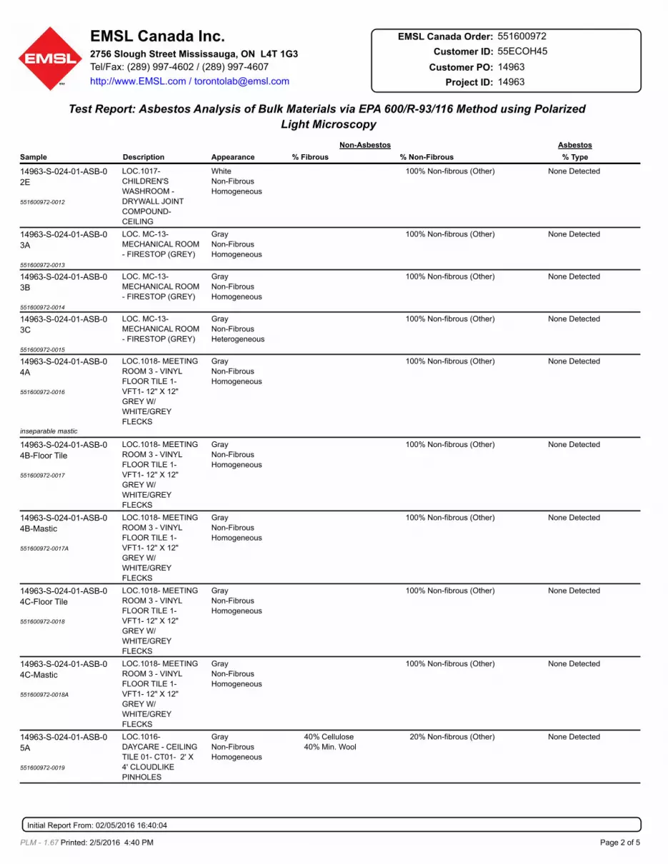
EMSL Canada Inc.2756 Slough Street Mississauga, ON L4T 1G3
Tel/Fax: (289) 997-4602 / (289) 997-4607
http://www.EMSL.com / [email protected]
551600972EMSL Canada Order:
Customer ID: 55ECOH45
Customer PO: 14963
Project ID: 14963
Test Report: Asbestos Analysis of Bulk Materials via EPA 600/R-93/116 Method using Polarized
Light Microscopy
Sample Description Appearance % Fibrous % Non-Fibrous
Non-Asbestos Asbestos
% Type
14963-S-024-01-ASB-0
2E
551600972-0012
White
Non-Fibrous
Homogeneous
None DetectedLOC.1017-
CHILDREN'S
WASHROOM -
DRYWALL JOINT
COMPOUND-
CEILING
100% Non-fibrous (Other)
14963-S-024-01-ASB-0
3A
551600972-0013
Gray
Non-Fibrous
Homogeneous
None DetectedLOC. MC-13-
MECHANICAL ROOM
- FIRESTOP (GREY)
100% Non-fibrous (Other)
14963-S-024-01-ASB-0
3B
551600972-0014
Gray
Non-Fibrous
Homogeneous
None DetectedLOC. MC-13-
MECHANICAL ROOM
- FIRESTOP (GREY)
100% Non-fibrous (Other)
14963-S-024-01-ASB-0
3C
551600972-0015
Gray
Non-Fibrous
Heterogeneous
None DetectedLOC. MC-13-
MECHANICAL ROOM
- FIRESTOP (GREY)
100% Non-fibrous (Other)
14963-S-024-01-ASB-0
4A
551600972-0016
Gray
Non-Fibrous
Homogeneous
None DetectedLOC.1018- MEETING
ROOM 3 - VINYL
FLOOR TILE 1-
VFT1- 12" X 12"
GREY W/
WHITE/GREY
FLECKS
100% Non-fibrous (Other)
inseparable mastic
14963-S-024-01-ASB-0
4B-Floor Tile
551600972-0017
Gray
Non-Fibrous
Homogeneous
None DetectedLOC.1018- MEETING
ROOM 3 - VINYL
FLOOR TILE 1-
VFT1- 12" X 12"
GREY W/
WHITE/GREY
FLECKS
100% Non-fibrous (Other)
14963-S-024-01-ASB-0
4B-Mastic
551600972-0017A
Gray
Non-Fibrous
Homogeneous
None DetectedLOC.1018- MEETING
ROOM 3 - VINYL
FLOOR TILE 1-
VFT1- 12" X 12"
GREY W/
WHITE/GREY
FLECKS
100% Non-fibrous (Other)
14963-S-024-01-ASB-0
4C-Floor Tile
551600972-0018
Gray
Non-Fibrous
Homogeneous
None DetectedLOC.1018- MEETING
ROOM 3 - VINYL
FLOOR TILE 1-
VFT1- 12" X 12"
GREY W/
WHITE/GREY
FLECKS
100% Non-fibrous (Other)
14963-S-024-01-ASB-0
4C-Mastic
551600972-0018A
Gray
Non-Fibrous
Homogeneous
None DetectedLOC.1018- MEETING
ROOM 3 - VINYL
FLOOR TILE 1-
VFT1- 12" X 12"
GREY W/
WHITE/GREY
FLECKS
100% Non-fibrous (Other)
14963-S-024-01-ASB-0
5A
551600972-0019
Gray
Non-Fibrous
Homogeneous
None DetectedLOC.1016-
DAYCARE - CEILING
TILE 01- CT01- 2' X
4' CLOUDLIKE
PINHOLES
40%
40%
Cellulose
Min. Wool
20% Non-fibrous (Other)
Initial Report From: 02/05/2016 16:40:04
Page 2 of 5PLM - 1.67 Printed: 2/5/2016 4:40 PM

EMSL Canada Inc.2756 Slough Street Mississauga, ON L4T 1G3
Tel/Fax: (289) 997-4602 / (289) 997-4607
http://www.EMSL.com / [email protected]
551600972EMSL Canada Order:
Customer ID: 55ECOH45
Customer PO: 14963
Project ID: 14963
Test Report: Asbestos Analysis of Bulk Materials via EPA 600/R-93/116 Method using Polarized
Light Microscopy
Sample Description Appearance % Fibrous % Non-Fibrous
Non-Asbestos Asbestos
% Type
14963-S-024-01-ASB-0
5B
551600972-0020
Gray
Fibrous
Homogeneous
None DetectedLOC.1027- KITCHEN
- CEILING TILE 01-
CT01- 2' X 4'
CLOUDLIKE
PINHOLES
40%
40%
Cellulose
Min. Wool
20% Non-fibrous (Other)
14963-S-024-01-ASB-0
5C
551600972-0021
Gray/White
Fibrous
Homogeneous
None DetectedLOC.1017-
CHILDREN'S
WASHROOM -
CEILING TILE 01-
CT01- 2' X 4'
CLOUDLIKE
PINHOLES
35%
45%
Cellulose
Min. Wool
20% Non-fibrous (Other)
14963-S-024-01-ASB-0
6A
551600972-0022
Gray
Fibrous
Homogeneous
None DetectedLOC.1042- MEETING
ROOM - CEILING
TILE 02- CT02- 2' X
4' BIG & SMALL
RANDOM SHAPED
PINHOLES
40%
40%
Cellulose
Min. Wool
20% Non-fibrous (Other)
14963-S-024-01-ASB-0
6B
551600972-0023
Gray
Fibrous
Homogeneous
None DetectedLOC.1016-
DAYCARE - CEILING
TILE 02- CT02- 2' X
4' BIG & SMALL
RANDOM SHAPED
PINHOLES
40%
40%
Cellulose
Min. Wool
20% Non-fibrous (Other)
14963-S-024-01-ASB-0
6C
551600972-0024
Gray/White
Fibrous
Homogeneous
None DetectedLOC.1022- MEETING
ROOM 2 - CEILING
TILE 02- CT02- 2' X
4' BIG & SMALL
RANDOM SHAPED
PINHOLES
35%
45%
Cellulose
Min. Wool
20% Non-fibrous (Other)
14963-S-024-01-ASB-0
7A
551600972-0025
Gray
Non-Fibrous
Homogeneous
None DetectedLOC.1031- OPEN
OFFICE - CEILING
TILE 03- CT03- 2' X
4' WIDTHWISE
FISSURE, RANDOM
PINHOLES
40%
40%
Cellulose
Min. Wool
20% Non-fibrous (Other)
14963-S-024-01-ASB-0
7B
551600972-0026
Gray
Fibrous
Homogeneous
None DetectedLOC.1035- OFFICE -
CEILING TILE 03-
CT03- 2' X 4'
WIDTHWISE
FISSURE, RANDOM
PINHOLES
40%
40%
Cellulose
Min. Wool
20% Non-fibrous (Other)
14963-S-024-01-ASB-0
7C
551600972-0027
Gray/White
Non-Fibrous
Homogeneous
None DetectedLOC.1035- OFFICE -
CEILING TILE 03-
CT03- 2' X 4'
WIDTHWISE
FISSURE, RANDOM
PINHOLES
35%
45%
Cellulose
Min. Wool
20% Non-fibrous (Other)
14963-S-024-01-ASB-0
8A
551600972-0028
Gray
Fibrous
Homogeneous
None DetectedLOC.1016-
DAYCARE - CEILING
TILE 04- CT03- 2' X
4' RANDOM
PINHOLES &
FISSURES
40%
40%
Cellulose
Min. Wool
20% Non-fibrous (Other)
14963-S-024-01-ASB-0
8B
551600972-0029
Gray
Fibrous
Homogeneous
None DetectedLOC.1016-
DAYCARE - CEILING
TILE 04- CT0- 2' X 4'
RANDOM PINHOLES
& FISSURES
40%
40%
Cellulose
Min. Wool
20% Non-fibrous (Other)
Initial Report From: 02/05/2016 16:40:04
Page 3 of 5PLM - 1.67 Printed: 2/5/2016 4:40 PM

EMSL Canada Inc.2756 Slough Street Mississauga, ON L4T 1G3
Tel/Fax: (289) 997-4602 / (289) 997-4607
http://www.EMSL.com / [email protected]
551600972EMSL Canada Order:
Customer ID: 55ECOH45
Customer PO: 14963
Project ID: 14963
Test Report: Asbestos Analysis of Bulk Materials via EPA 600/R-93/116 Method using Polarized
Light Microscopy
Sample Description Appearance % Fibrous % Non-Fibrous
Non-Asbestos Asbestos
% Type
14963-S-024-01-ASB-0
8C
551600972-0030
Gray/White
Fibrous
Homogeneous
None DetectedLOC.1016-
DAYCARE - CEILING
TILE 04- CT0- 2' X 4'
RANDOM PINHOLES
& FISSURES
35%
45%
Cellulose
Min. Wool
20% Non-fibrous (Other)
14963-S-024-01-ASB-0
9A
551600972-0031
Gray
Fibrous
Homogeneous
None DetectedLOC.1046- MEN'S
WASHROOM -
CEILING TILE 05-
CT0- 2' X 4'
WIDTHWISE
RANDOM PINHOLES
70% Min. Wool 30% Non-fibrous (Other)
14963-S-024-01-ASB-0
9B
551600972-0032
Gray
Fibrous
Homogeneous
None DetectedLOC.1058-
WOMEN'S
CHANGEROOM -
CEILING TILE 05-
CT0- 2' X 4'
WIDTHWISE
RANDOM PINHOLES
70% Min. Wool 30% Non-fibrous (Other)
14963-S-024-01-ASB-0
9C
551600972-0033
Gray
Non-Fibrous
Homogeneous
None DetectedLOC.1056-
WMAINTENANCE
LUNCH ROOM -
CEILING TILE 05-
CT0- 2' X 4'
WIDTHWISE
RANDOM PINHOLES
70% Min. Wool 30% Non-fibrous (Other)
14963-S-024-01-ASB-1
0A
551600972-0034
Gray
Non-Fibrous
Homogeneous
None DetectedLOC.MC-10-
ELECTRICAL ROOM
- BEIGE/GREY
CAULKING
100% Non-fibrous (Other)
14963-S-024-01-ASB-1
0B
551600972-0035
Gray
Non-Fibrous
Homogeneous
None DetectedLOC.MC-10-
ELECTRICAL ROOM
- BEIGE/GREY
CAULKING
100% Non-fibrous (Other)
14963-S-024-01-ASB-1
0C
551600972-0036
Gray
Non-Fibrous
Homogeneous
None DetectedLOC.MC-10-
ELECTRICAL ROOM
- BEIGE/GREY
CAULKING
100% Non-fibrous (Other)
14963-S-024-01-ASB-1
1A
551600972-0037
White
Non-Fibrous
Homogeneous
None DetectedLOC.1035- OFFICE -
WHITE CAULKING
100% Non-fibrous (Other)
14963-S-024-01-ASB-1
1B
551600972-0038
White
Non-Fibrous
Homogeneous
None DetectedLOC.1041- OFFICE -
WHITE CAULKING
100% Non-fibrous (Other)
14963-S-024-01-ASB-1
1C
551600972-0039
White
Non-Fibrous
Homogeneous
None DetectedLOC.1001- LOBBY -
WHITE CAULKING
100% Non-fibrous (Other)
14963-S-024-01-ASB-1
2A
551600972-0040
White
Non-Fibrous
Homogeneous
None DetectedLOC.1051-01-
WASHROOM -
WHITE CAULKING
ON COUNTERS
100% Non-fibrous (Other)
14963-S-024-01-ASB-1
2B
551600972-0041
White
Non-Fibrous
Homogeneous
None DetectedLOC.1051-01-
WASHROOM -
WHITE CAULKING
ON COUNTERS
100% Non-fibrous (Other)
14963-S-024-01-ASB-1
2C
551600972-0042
White
Non-Fibrous
Homogeneous
None DetectedLOC.1051-01-
WASHROOM -
WHITE CAULKING
ON COUNTERS
100% Non-fibrous (Other)
Initial Report From: 02/05/2016 16:40:04
Page 4 of 5PLM - 1.67 Printed: 2/5/2016 4:40 PM

EMSL Canada Inc.2756 Slough Street Mississauga, ON L4T 1G3
Tel/Fax: (289) 997-4602 / (289) 997-4607
http://www.EMSL.com / [email protected]
551600972EMSL Canada Order:
Customer ID: 55ECOH45
Customer PO: 14963
Project ID: 14963
Test Report: Asbestos Analysis of Bulk Materials via EPA 600/R-93/116 Method using Polarized
Light Microscopy
Sample Description Appearance % Fibrous % Non-Fibrous
Non-Asbestos Asbestos
% Type
14963-S-024-01-ASB-1
3A
551600972-0043
Yellow
Non-Fibrous
Homogeneous
None DetectedLOC. MC-13-
MECHANICAL RM &
SPRINKLER RM -
YELLOW CAULKING
100% Non-fibrous (Other)
14963-S-024-01-ASB-1
3B
551600972-0044
Yellow
Non-Fibrous
Homogeneous
None DetectedLOC. MC-13-
MECHANICAL RM &
SPRINKLER RM -
YELLOW CAULKING
100% Non-fibrous (Other)
14963-S-024-01-ASB-1
3C
551600972-0045
Yellow
Non-Fibrous
Homogeneous
None DetectedLOC. MC-13-
MECHANICAL RM &
SPRINKLER RM -
YELLOW CAULKING
100% Non-fibrous (Other)
Analyst(s)
John Biesiadecki (30)
Jon Delos Santos (17)
Matthew Davis
or Other Approved Signatory
EMSL maintains liability limited to cost of analysis . This report relates only to the samples reported and may not be reproduced, except in full, without written approval by EMSL. EMSL bears no
responsibility for sample collection activities or analytical method limitations. Interpretation and use of test results are the responsibility of the client. This report must not be used by the client to claim
product certification, approval, or endorsement by NVLAP, NIST or any agency of the federal government . Non-friable organically bound materials present a problem matrix and therefore EMSL
recommends gravimetric reduction prior to analysis. Samples received in good condition unless otherwise noted. Estimated accuracy, precision and uncertainty data available upon request. Unless
requested by the client, building materials manufactured with multiple layers (i.e. linoleum, wallboard, etc.) are reported as a single sample. Reporting limit is 1%
Samples analyzed by EMSL Canada Inc. Mississauga, ON NVLAP Lab Code 200877-0
Initial Report From: 02/05/2016 16:40:04
Page 5 of 5PLM - 1.67 Printed: 2/5/2016 4:40 PM

APPENDIX V INVENTORY OF UST/AST STORAGE TANKS
(NO INFORMATION TO REPORT)


