Embed Size (px)
Citation preview
Table of Contents
Project Title...........................................................................................................................................3
Problem identification...........................................................................................................................3
Background information........................................................................................................................3
Aim and Objective................................................................................................................................3
1. Introduction.......................................................................................................................................4
Operation of a transfer switch...........................................................................................................5
Types.................................................................................................................................................6
Voltage Sensing.................................................................................................................................8
Switching...........................................................................................................................................9
Programming...................................................................................................................................12
Communication...............................................................................................................................13
2 Materials and Methods Used...........................................................................................................16
2.1 Mechanism of Operation of Electric Power Generators............................................................17
2.2 Standby Generators...................................................................................................................18
2.3 Transfer Switches.......................................................................................................................18
2.4 The Proposed Switching System................................................................................................19
3. Results and Discussion.....................................................................................................................25
4 Conclusions and Recommendations.................................................................................................27
4.1 Conclusions................................................................................................................................27
4.2 Recommendation......................................................................................................................28
References...........................................................................................................................................29

Acknowledgement
I have taken efforts in this project. However, it would not have been possible without the kind
support and help of many individuals and organizations. I would like to extend my sincere
thanks to all of them.
I am highly indebted to ICBT Campus & Mr. Manasir Munafdeen for their guidance and
constant supervision as well as for providing necessary information regarding the project &
also for their support in completing the project.
I would like to express my gratitude towards my parents & friends of ICBT Campus for their
kind co-operation and encouragement which help me in completion of this project.
I would like to express my special gratitude and thanks to industry persons for giving me
such attention and time.
My thanks and appreciations also go to my colleague in developing the project and people
who have willingly helped me out with their abilities.

Project Title
Automatic Transfer Switching System for a Standby Electric Generator
Problem identification
In the industry and hospitals power breaks is very harmful. In hospitals power break can
damage human life. In industry it can damage the productions.
Background information
This device mainly work with PIC Microcontrollers. This unit have three power inputs. When
one source is break it will switch to other power source automatically without dropping
current. A LCD shows what source is using now. If get any error automatically send SMS
using GSM.
Aim and Objective
Give a solution for that energy resources are simply inadequate. Most manufacturing
industries and firms have to contend with insecure and unreliable power supply coupled with
its attendant negative impacts on productivity and cost of production.

1. Introduction
Reliable and secure uninterruptible power supply is a sine qua non for virtually all industrial
operations. The reality, however, especially in most developing countries, is that energy
resources are simply inadequate. Most manufacturing industries and firms have to contend
with insecure and unreliable power supply coupled with its attendant negative impacts on
productivity and cost of production.
The quest for secure and reliable power supply remains a dream yet to be attained, especially
in most developing countries. This is as a result of population growth, industrialisation and
urbanisation (Aguinaga, 2008; Akparibo, 2011; Fuller, 2007; Kolo, 2007) and improper
planning by service providers and governments. Most manufacturing industries, firms and
institutions such as hospitals and healthcare facilities, financial institutions, data centres and
airports to mention but a few require constant power supply all year round. Power instability
generally retards development in public and private sectors of any economy (Kolo, 2007;
Anon., 2010; Chukwubuikem, 2012). Any instance of power failure could lead to prohibitive
consequences ranging from loss of huge amounts of money to life casualties (Aguinaga,
2008). The spate of frequent power outages without an effective back-up system is truly a
disincentive to investors in any developing economy like Ghana (Kolo, 2007).
Indeed, the ravages of power instability have equally necessitated automation of the
switching system between national grid energy system and standby generators used as
backup. In the last decade, different equipment and configurations have been used in order to
cope with this problem (Aguinaga, 2008). An automatic changeover system makes use of
sensors and transducers to realise the changeover in a shorter time while eliminating human
interference and its attendant errors (Chukwubuikem, 2012).
The main problems associated with a manual switching system are as follows: interrupted
power supply, device damage due to frequent commutations, possible causes of fire outbreak
due to switching sparks and frequent high maintenance cost due to changeover action and
wear and tear of mechanical parts. In this paper, we demonstrate how to surmount these
problems by the design of a Microcontroller-Based Automatic Transfer Switching System
(MBATSS). We have also performed a simulation to test the workability of the controller
using appropriate simulation software.
Operation of a transfer switch
As well as transferring the load to the backup generator, an ATS may also command the
backup generator to start, based on the voltage monitored on the primary supply. The transfer
switch isolates the backup generator from the electric utility when the generator is on and
providing temporary power. The control capability of a transfer switch may be manual only,
or a combination of automatic and manual. The switch transition mode (see below) of a
transfer switch may be Open Transition (OT) (the usual type), or Closed Transition (CT).
For example, in a home equipped with a backup generator and an ATS, when an electric
utility outage occurs, the ATS will tell the backup generator to start. Once the ATS sees that
the generator is ready to provide electric power, the ATS breaks the home's connection to the
electric utility and connects the generator to the home's main electrical panel. The generator
supplies power to the home's electric load, but is not connected to the electric utility lines. It
is necessary to isolate the generator from the distribution system to protect the generator from
overload in powering loads in the house and for safety, as utility workers expect the lines to
be dead.
When utility power returns for a minimum time, the transfer switch will transfer the house
back to utility power and command the generator to turn off, after another specified amount
of "cool down" time with no load on the generator.
A transfer switch can be set up to provide power only to critical circuits or to entire electrical
(sub)panels. Some transfer switches allow for load shedding or prioritization of optional
circuits, such as heating and cooling equipment. More complex emergency switchgear used
in large backup generator installations permits soft loading, allowing load to be smoothly
transferred from the utility to the synchronized generators, and back; such installations are
useful for reducing peak load demand from a utility.
Types
Open transition
An open transition transfer switch is also called a break-before-make transfer switch. A
break-before-make transfer switch breaks contact with one source of power before it makes
contact with another. It prevents backfeeding from an emergency generator back into the
utility line, for example. One example is an open transition automatic transfer switch (ATS).
During the split second of the power transfer the flow of electricity is interrupted. Another
example is a manual three position circuit breaker, with utility power on one side, the
generator on the other, and "off" in the middle, which requires the user to switch through the
full disconnect "off" position before making the next connection.
Closed transition
A closed transition transfer switch (CTTS) is also called a make-before-break transfer switch.
A typical emergency system uses open transition, so there is an inherent momentary
interruption of power to the load when it is transferred from one available source to another
(keeping in mind that the transfer may be occurring for reasons other than a total loss of
power). In most cases this outage is inconsequential, particularly if it is less than 1/6 of a
second.
There are some loads, however, that are affected by even the slightest loss of power. There
are also operational conditions where it may be desirable to transfer loads with zero
interruption of power when conditions permit. For these applications, closed transition
transfer switches can be provided. The switch will operate in a make-before-break mode
provided both sources are acceptable and synchronized. Typical parameters determining
synchronization are: voltage difference less than 5%, frequency difference less than 0.2 Hz,
and maximum phase angle between the sources of 5 electrical degrees. This means the engine
driving the generator supplying one of the sources generally must be controlled by an
isochronous governor.
It is generally required that the closed transition, or overlap time, be less than 100
milliseconds. If either source is not present or not acceptable (such as when normal power
fails) the switch must operate in a break-before-make mode (standard open transition
operation) to ensure no backfeeding occurs.
Closed transition transfer makes code-mandated monthly testing less objectionable because it
eliminates the interruption to critical loads which occurs during traditional open transition
transfer.
With closed transition transfer, the on-site engine generator set is momentarily connected in
parallel with the utility source. This requires getting approval from the local utility company.
Typical load switching applications for which closed transition transfer is desirable include
data processing and electronic loads, certain motor and transformer loads, load curtailment
systems, or anywhere load interruptions of even the shortest duration are objectionable. A
CTTS is not a substitute for a UPS (uninterruptible power supply); a UPS has a built-in stored
energy that provides power for a prescribed period of time in the event of a power failure. A
CTTS by itself simply assures there will be no momentary loss of power when the load is
transferred from one live power source to another.

Soft loading
A soft-loading transfer switch (SLTS) makes use of a CTTS, and is commonly used to
synchronize and operate onsite generation in parallel with utility power, and to transfer loads
between the two sources while minimizing voltage or frequency transients.
Static transfer switch (STS)
A static transfer switch uses power semiconductors such as Silicon-controlled
rectifiers (SCRs) to transfer a load between two sources. Because there are no mechanical
moving parts, the transfer can be completed rapidly, perhaps within a quarter-cycle of the
power frequency. Static transfer switches can be used where a reliable and independent
second source of power is available and it is necessary to protect the load from even a few
power frequency cycles interruption time, or from any surges or sags in the prime power
source.
Voltage Sensing
In this case to measure the voltage using a microcontroller that had an input range of 0 to 5
volts, and needed to measure voltages from 200V -280V.
To convert this large, alternating voltage range to something compatible with the micro, Most
do something along the lines of rectifying the AC voltage before feeding it into the micro.
While that may be fine for some, it creates ambiguity between low and high voltages. It need
something better. It would be great to have a circuit that multiplies the input voltage by a
constant, then adds half the supply voltage of the micro. It can do that with a op-amp.
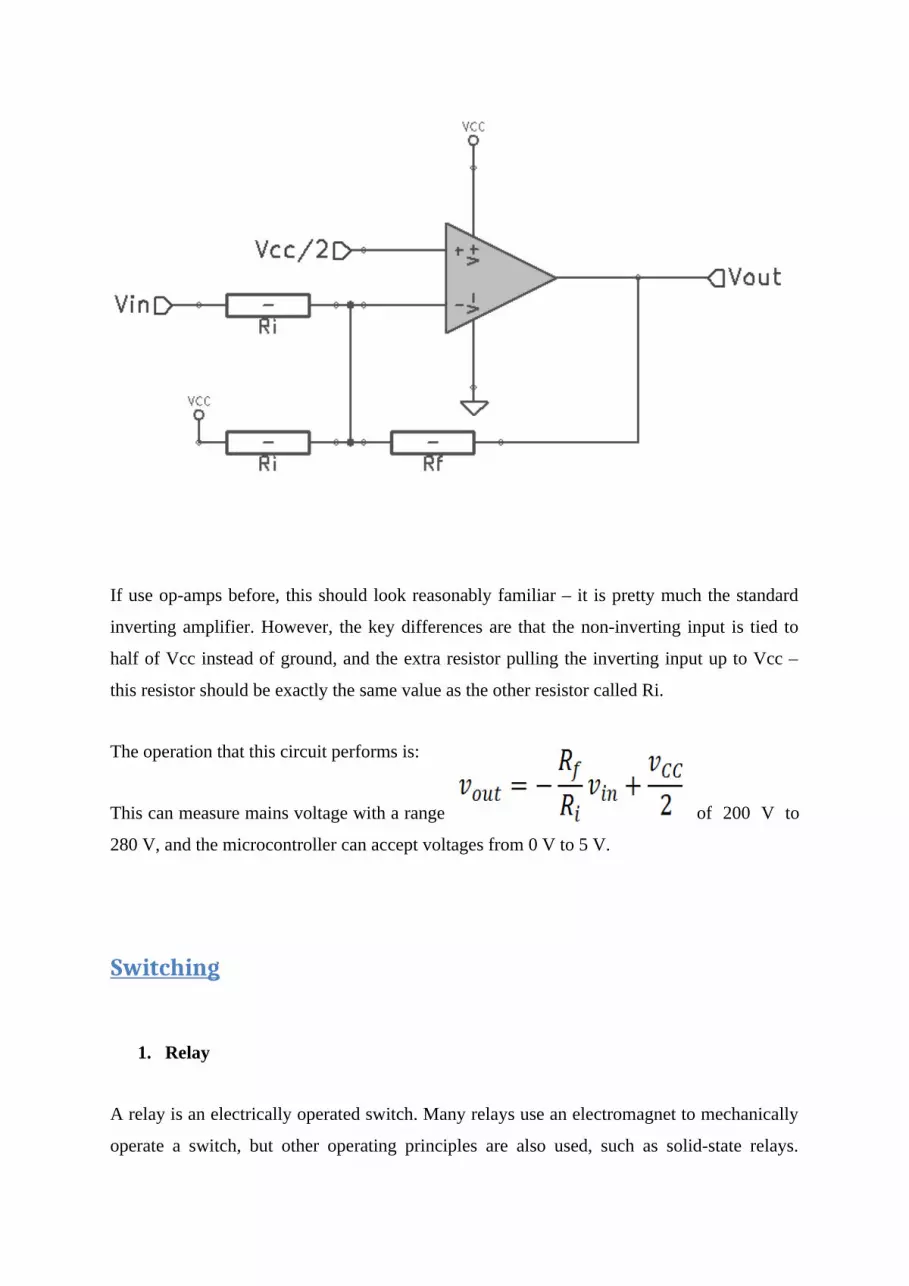
If use op-amps before, this should look reasonably familiar – it is pretty much the standard
inverting amplifier. However, the key differences are that the non-inverting input is tied to
half of Vcc instead of ground, and the extra resistor pulling the inverting input up to Vcc –
this resistor should be exactly the same value as the other resistor called Ri.
The operation that this circuit performs is:
This can measure mains voltage with a range of 200 V to
280 V, and the microcontroller can accept voltages from 0 V to 5 V.
Switching
1. Relay
A relay is an electrically operated switch. Many relays use an electromagnet to mechanically
operate a switch, but other operating principles are also used, such as solid-state relays.
Relays are used where it is necessary to control a circuit by a low-power signal (with
complete electrical isolation between control and controlled circuits), or where several
circuits must be controlled by one signal. The first relays were used in long distance telegraph
circuits as amplifiers: they repeated the signal coming in from one circuit and re-transmitted
it on another circuit. Relays were used extensively in telephone exchanges and early
computers to perform logical operations.
A type of relay that can handle the high power required to directly control an electric motor
or other loads is called a contactor. Solid-state relays control power circuits with no moving
parts, instead using a semiconductor device to perform switching. Relays with calibrated
operating characteristics and sometimes multiple operating coils are used to protect electrical
circuits from overload or faults; in modern electric power systems these functions are
performed by digital instruments still called "protective relays".
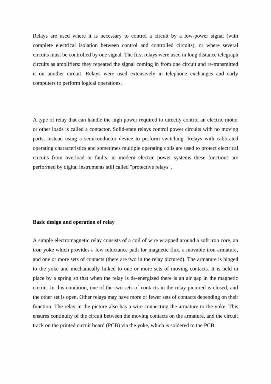
Basic design and operation of relay
A simple electromagnetic relay consists of a coil of wire wrapped around a soft iron core, an
iron yoke which provides a low reluctance path for magnetic flux, a movable iron armature,
and one or more sets of contacts (there are two in the relay pictured). The armature is hinged
to the yoke and mechanically linked to one or more sets of moving contacts. It is held in
place by a spring so that when the relay is de-energized there is an air gap in the magnetic
circuit. In this condition, one of the two sets of contacts in the relay pictured is closed, and
the other set is open. Other relays may have more or fewer sets of contacts depending on their
function. The relay in the picture also has a wire connecting the armature to the yoke. This
ensures continuity of the circuit between the moving contacts on the armature, and the circuit
track on the printed circuit board (PCB) via the yoke, which is soldered to the PCB.
When an electric current is passed through the coil it generates a magnetic field that activates
the armature, and the consequent movement of the movable contact(s) either makes or breaks
(depending upon construction) a connection with a fixed contact. If the set of contacts was
closed when the relay was de-energized, then the movement opens the contacts and breaks
the connection, and vice versa if the contacts were open. When the current to the coil is
switched off, the armature is returned by a force, approximately half as strong as the
magnetic force, to its relaxed position. Usually this force is provided by a spring, but gravity
is also used commonly in industrial motor starters. Most relays are manufactured to operate
quickly. In a low-voltage application this reduces noise; in a high voltage or current
application it reduces arcing.
When the coil is energized with direct current, a diode is often placed across the coil to
dissipate the energy from the collapsing magnetic field at deactivation, which would
otherwise generate a voltage spike dangerous to semiconductor circuit components. Some
automotive relays include a diode inside the relay case. Alternatively, a contact protection
network consisting of a capacitor and resistor in series (snubber circuit) may absorb the
surge. If the coil is designed to be energized with alternating current (AC), a small copper
"shading ring" can be crimped to the end of the solenoid, creating a small out-of-phase
current which increases the minimum pull on the armature during the AC cycle.
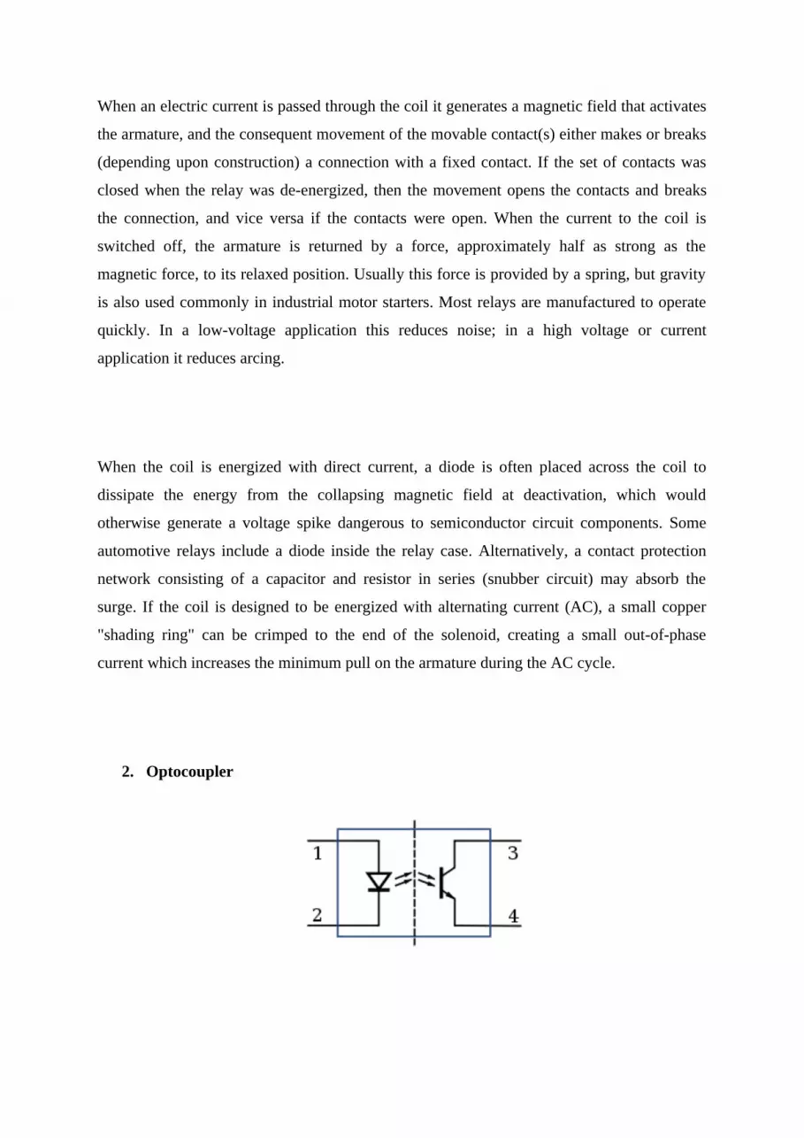
2. Optocoupler

In electronics, optocoupler, or optical isolator, is a component that transfers electrical signals
between two isolated circuits by using light. Opto-isolators prevent high voltages from
affecting the system receiving the signal. Commercially available opto-isolators withstand
input-to-output voltages up to 10 kV and voltage transients with speeds up to 10 kV/μs.
A common type of opto-isolator consists of an LED and a phototransistor in the same opaque
package. Other types of source-sensor combinations include LED-photodiode, LED-LASCR,
and lamp-photoresistor pairs. Usually opto-isolators transfer digital (on-off) signals, but some
techniques allow them to be used with analog signals.
The value of optically coupling a solid state light emitter to a semiconductor detector for the
purpose of electrical isolation was recognized in 1963 by Akmenkalns,et al. Photoresistor-
based opto-isolators were introduced in 1968. They are the slowest, but also the most linear
isolators and still retain a niche market in audio and music industry. Commercialization of
LED technology in 1968–1970 caused a boom in optoelectronics, and by the end of the 1970s
the industry developed all principal types of opto-isolators. The majority of opto-isolators on
the market use bipolar silicon phototransistor sensors. They attain medium data transfer
speed, sufficient for applications like electroencephalography. The fastest opto-isolators use
PIN diodes in photoconductive mode.
Programming
PIC Microcontrollers
PIC for switching

Relay is used when we need to handle high voltages and currents through microcontroller
operated system. Relay coil's current requirement is usually more than 100mA (for small
relay about 100mA) and microcontroller cant supply this much of current to relay by it self.
So as shown in following schematic diagram, we have to use transistor to handle this current
requirement. Base pin of NPN transistor used here is connected to ground pin via resistor to
make sure that relay will stay off when microcontroller does not output +5V to transistors
base. This will make sure only logic 1 on microcontroller pin will activate relay. It is better to
use Darlington transistor to handle current requirement for relay, because darlington
transistor can handle more current than single transistor.
It is essential to connect a diode across relay coil in reverse bias to protect transistor form
back EMF created when relay is released from energized or ON state. If this diode is not
used, transistor and/or microcontroller which is driving relay may be damaged upon releasing
energized relay. The diode will short out the back EMF produced by coil when it turned OFF
from ON state.
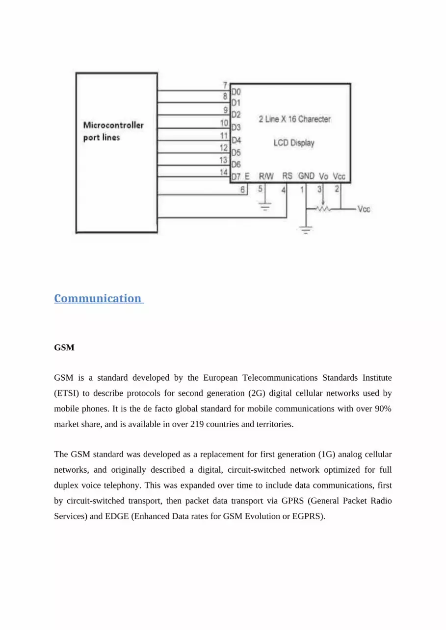
Interfacing LCD with PIC Microcontroller
The 2x16 character LCD interface card with supports both modes 4-bit and 8-bit interface,
and also facility to adjust contrast through trim pot. In 8-bit interface 11 lines needed to
create 8-bit interface; 8 data bits (D0 – D7), three control lines, address bit (RS), read/write
bit (R/W) and control signal (E).
Communication
GSM
GSM is a standard developed by the European Telecommunications Standards Institute
(ETSI) to describe protocols for second generation (2G) digital cellular networks used by
mobile phones. It is the de facto global standard for mobile communications with over 90%
market share, and is available in over 219 countries and territories.
The GSM standard was developed as a replacement for first generation (1G) analog cellular
networks, and originally described a digital, circuit-switched network optimized for full
duplex voice telephony. This was expanded over time to include data communications, first
by circuit-switched transport, then packet data transport via GPRS (General Packet Radio
Services) and EDGE (Enhanced Data rates for GSM Evolution or EGPRS).
Radio frequency (RF)
Radio frequency (RF) is a rate of oscillation in the range of around 3 kHz to 300 GHz, which
corresponds to the frequency of radio waves, and the alternating currents which carry radio
signals. RF usually refers to electrical rather than mechanical oscillations; however,
mechanical RF systems do exist (see mechanical filter and RF MEMS).
Although radio frequency is a rate of oscillation, the term "radio frequency" or its
abbreviation "RF" are also used as a synonym for radio – i.e. to describe the use of wireless
communication, as opposed to communication via electric wires.
To receive radio signals an antenna must be used. However, since the antenna will pick up
thousands of radio signals at a time, a radio tuner is necessary to tune into a particular
frequency (or frequency range). This is typically done via a resonator – in its simplest form, a
circuit with a capacitor and an inductor form a tuned circuit. The resonator amplifies
oscillations within a particular frequency band, while reducing oscillations at other
frequencies outside the band. Another method to isolate a particular radio frequency is by
oversampling (which gets a wide range of frequencies) and picking out the frequencies of
interest, as done in software defined radio.
The distance over which radio communications is useful depends significantly on things other
than wavelength, such as transmitter power, receiver quality, type, size, and height of
antenna, mode of transmission, noise, and interfering signals. Ground waves, tropospheric
scatter and skywaves can all achieve greater ranges than line-of-sight propagation. The study
of radio propagation allows estimates of useful range to be made.
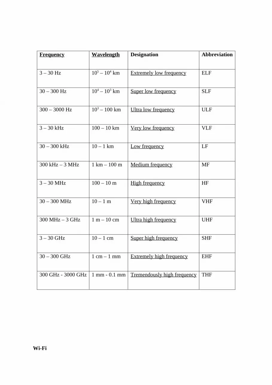
Frequency Wavelength Designation Abbreviation
3 – 30 Hz 105 – 104 km Extremely low frequency ELF
30 – 300 Hz 104 – 103 km Super low frequency SLF
300 – 3000 Hz 103 – 100 km Ultra low frequency ULF
3 – 30 kHz 100 – 10 km Very low frequency VLF
30 – 300 kHz 10 – 1 km Low frequency LF
300 kHz – 3 MHz 1 km – 100 m Medium frequency MF
3 – 30 MHz 100 – 10 m High frequency HF
30 – 300 MHz 10 – 1 m Very high frequency VHF
300 MHz – 3 GHz 1 m – 10 cm Ultra high frequency UHF
3 – 30 GHz 10 – 1 cm Super high frequency SHF
30 – 300 GHz 1 cm – 1 mm Extremely high frequency EHF
300 GHz - 3000 GHz 1 mm - 0.1 mm Tremendously high frequency THF
Wi-Fi
Wi-Fi is the name of a popular wireless networking technology that uses radio waves to
provide wireless high-speed Internet and network connections. A common misconception is
that the term Wi-Fi is short for "wireless fidelity," however this is not the case. Wi-Fi is
simply a trademarked phrase that means IEEE 802.11x.
Wi-Fi works with no physical wired connection between sender and receiver by using radio
frequency (RF) technology, a frequency within the electromagnetic spectrum associated with
radio wave propagation. When an RF current is supplied to an antenna, an electromagnetic
field is created that then is able to propagate through space.
The cornerstone of any wireless network is an access point (AP). The primary job of an
access point is to broadcast a wireless signal that computers can detect and "tune" into. In
order to connect to an access point and join a wireless network, computers and devices must
be equipped with wireless network adapters.
2 Materials and Methods Used
The materials and methods used to integrate the electric generator as an alternative power
source to the grid is very important in determining how secure and reliable the power supply
to load can be. The switching system could be manual, where a person switches the generator
set on when the grid supply is lost and switches the generator off when the grid power is
restored or alternatively, automatic switching, where the electric generator switches on and
off when the grid is restored (Chukwubuikem, 2012). outage because switching is effected on
the basis of energising and de-energising of the relay coils.

2.1 Mechanism of Operation of Electric Power Generators
Electric power generators could produce Direct Current (DC) or Alternating Current (AC).
AC power generators consist of armature windings placed in stator slots into which an AC
voltage is induced, and a rotor coupled to a prime mover. Mechanical rotation of the prime
mover cuts the magnetic flux produced in the stator field by an exciter. This induces an
alternating electromotive force in the stator windings. Any load connected to the stator
windings completes the external circuit and current flows through the load. Fig. 1 shows a
schematic diagram of a practical three-phase alternator.
Prime Mover Rotor 3-Phase Supply to Load Rf DC Exciter Alternator Slip BY R Stator
Fig. 1 A Practical Three-Phase Alternator
2.2 Standby Generators
Standby generators Anon. (2011) also known as backup or alternate generators, are secondary
sources of electric power usually kept at the premises of consumers to provide electrical
power in the event of failure of power supply from a power service provider. Standby
generators are installed at the consumer’s premises and run in parallel with the utility power
supply in order to augment the utility supply, when power is lost Anon. (2012a).
There are other electric generator switching automation systems using electromechanical
relays, contactors and timers which comes with some shortcomings, notably: poor sensing
ability to fluctuations due to the fact that relays do not function optimally at very low
voltages; and slow switching time in the event of mains power supply outage because
switching is effected on the basis of energising and de-energising of the relay coils.
2.3 Transfer Switches
Transfer switches, also known as changeover switches, are electrical devices designed to
power an electric load from multiple sources. They are mainly used with generator sets in
applications where the loads need, if not a fully continuous, at least a steady supply of electric
power (Aguinaga, 2008). Transfer switches could be manually or automatically operated. A
manual transfer switch box separates the utility supply from the standby generator. Whenever
there is power failure, changeover is done manually by humans and the same happens when
the public utility power is restored and this is usually accompanied with loud noise and
electrical sparks (Chukwubuikem, 2012). An Automatic Transfer Switch (ATS) is used with
standby systems. It includes a control circuit that senses mains voltage. When mains power is
interrupted, the control circuit starts up the generator set, disconnects the load from the utility
and connects it to the generator set. It then continues to monitor the mains status. When
mains power is restored, it commutes the load from the generator back to the utility within a
threshold time Anon. (2012a).
When the generator is disconnected, it goes through a cool-down process and then
automatically shuts down (Chukwubuikem, 2012). Fig. 2 shows a schematic diagram of a
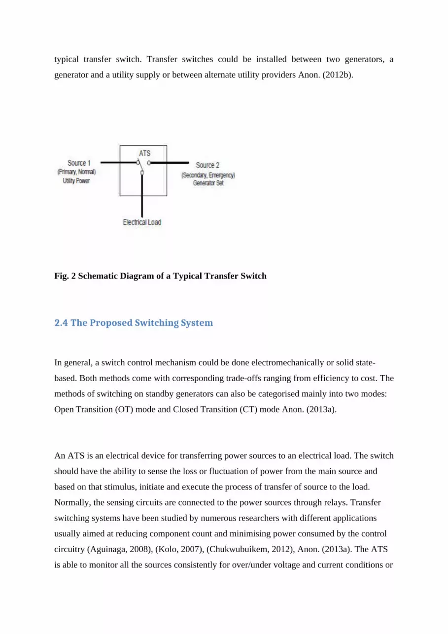
typical transfer switch. Transfer switches could be installed between two generators, a
generator and a utility supply or between alternate utility providers Anon. (2012b).
Fig. 2 Schematic Diagram of a Typical Transfer Switch
2.4 The Proposed Switching System
In general, a switch control mechanism could be done electromechanically or solid state-
based. Both methods come with corresponding trade-offs ranging from efficiency to cost. The
methods of switching on standby generators can also be categorised mainly into two modes:
Open Transition (OT) mode and Closed Transition (CT) mode Anon. (2013a).
An ATS is an electrical device for transferring power sources to an electrical load. The switch
should have the ability to sense the loss or fluctuation of power from the main source and
based on that stimulus, initiate and execute the process of transfer of source to the load.
Normally, the sensing circuits are connected to the power sources through relays. Transfer
switching systems have been studied by numerous researchers with different applications
usually aimed at reducing component count and minimising power consumed by the control
circuitry (Aguinaga, 2008), (Kolo, 2007), (Chukwubuikem, 2012), Anon. (2013a). The ATS
is able to monitor all the sources consistently for over/under voltage and current conditions or

total loss of power and issue an appropriate command for the transfer of load to an alternate
power source.
This paper reports on the design of an efficient microcontroller-based ATS making use of
relays, voltage and current sensing circuitry, a display unit and an alarm unit in order to
reduce the circuit’s power consumption, operate fast, reduce component count and
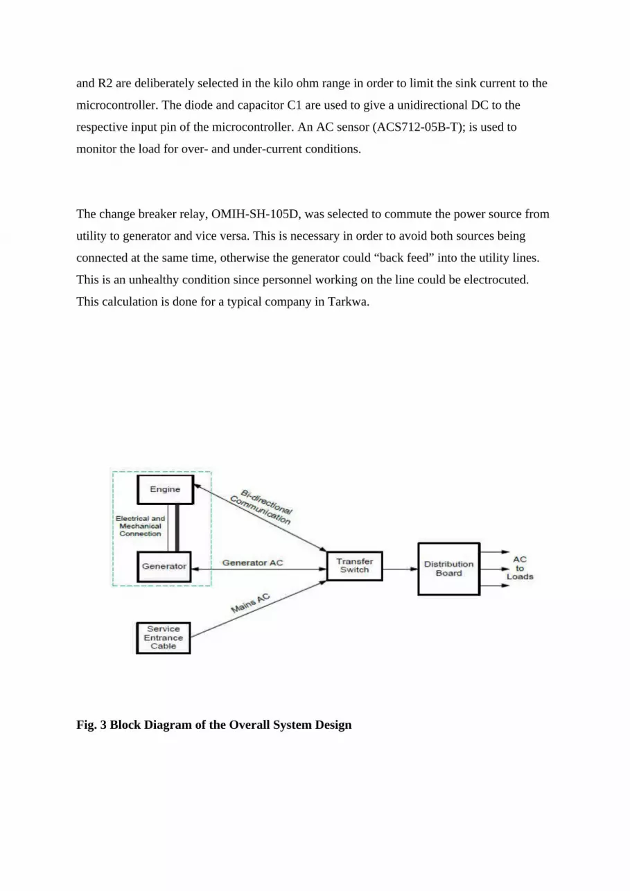
considerably reduce cost. Fig. 3 and Fig. 4 show a block diagram of the overall system design
and the block diagram of the ATS respectively (Anderson, 2003).
The system hardware consists mainly of a Transfer Switch (TS) microcontroller serving as
the main controlling device to which all other devices are connected. The AC voltage sensing
circuits sense the status of the AC power from the mains and generator and communicate it to
the TS microcontroller
A Hall Effect current sensor feeds the load current to the TS controller. A source change
relay acts as switchgear to switch power sources between mains and generator to the load.
Fuel flow and starter relays are used to start the fuel flow pump and engine respectively. All
the relays are driven by a relay driver (ULN2003A). The TS microcontroller monitors the
charging state of a battery that supplies power to the entire control circuitry.
Voltage Sensing Circuits
Two AC voltage sensing circuits continuously monitor the state of the utility supply,
generator and communicate it to the TS microcontroller. The voltage sensor, as shown in the
circuit diagram in Fig. 5, is made up of a 240/3.4 V step down transformer, two resistors, a
diode and a capacitor. To ensure that 5 V TTL requirement of the microcontroller is not
violated, a voltage divider circuit, consisting of R1 and R2 is used to output about 5 V to the
controller. This is achieved by setting the ratio of R1 to R2 to be 10 is to 5. The values of R1
and R2 are deliberately selected in the kilo ohm range in order to limit the sink current to the
microcontroller. The diode and capacitor C1 are used to give a unidirectional DC to the
respective input pin of the microcontroller. An AC sensor (ACS712-05B-T); is used to
monitor the load for over- and under-current conditions.
The change breaker relay, OMIH-SH-105D, was selected to commute the power source from
utility to generator and vice versa. This is necessary in order to avoid both sources being
connected at the same time, otherwise the generator could “back feed” into the utility lines.
This is an unhealthy condition since personnel working on the line could be electrocuted.
This calculation is done for a typical company in Tarkwa.
Fig. 3 Block Diagram of the Overall System Design
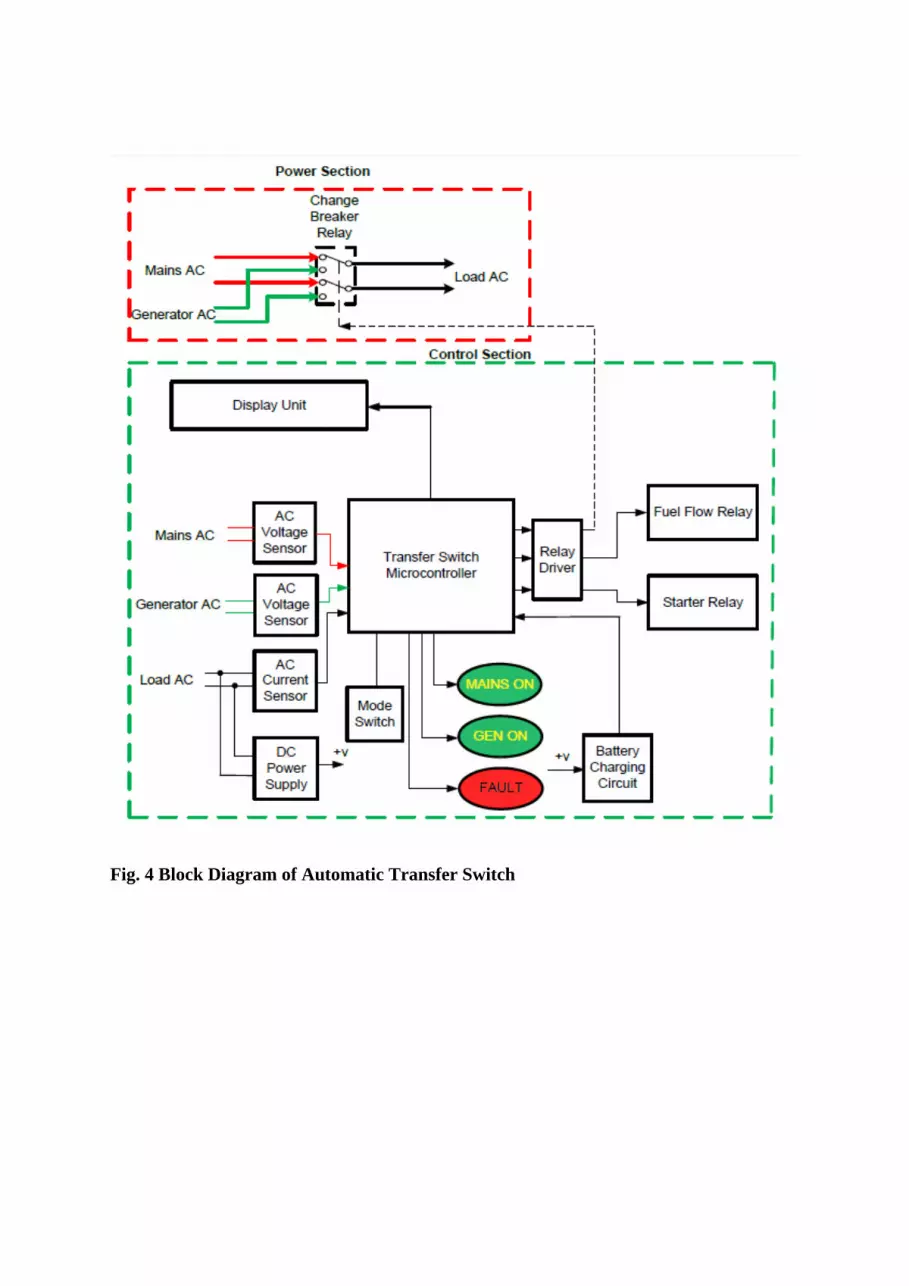
Fig. 4 Block Diagram of Automatic Transfer Switch
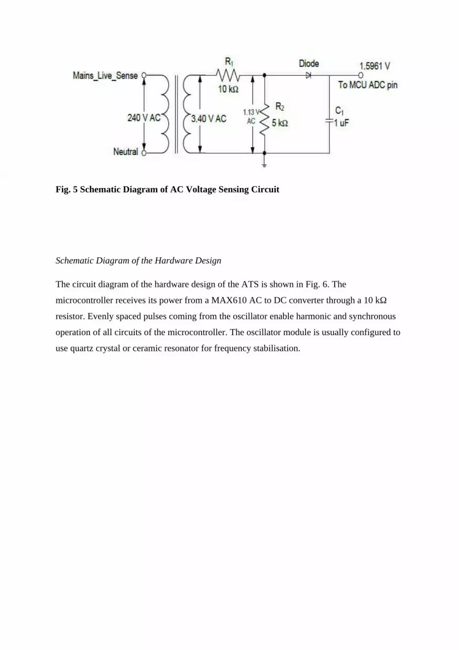
Fig. 5 Schematic Diagram of AC Voltage Sensing Circuit
Schematic Diagram of the Hardware Design
The circuit diagram of the hardware design of the ATS is shown in Fig. 6. The
microcontroller receives its power from a MAX610 AC to DC converter through a 10 kΩ
resistor. Evenly spaced pulses coming from the oscillator enable harmonic and synchronous
operation of all circuits of the microcontroller. The oscillator module is usually configured to
use quartz crystal or ceramic resonator for frequency stabilisation.
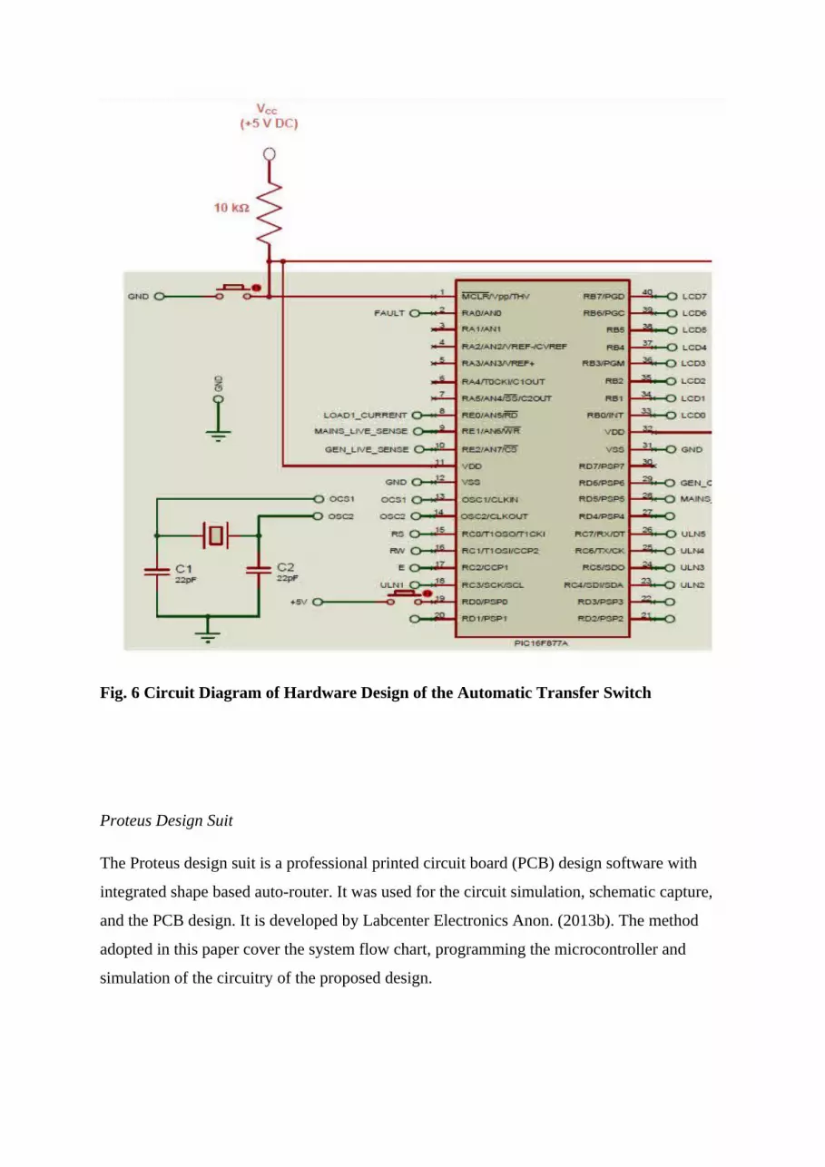
Fig. 6 Circuit Diagram of Hardware Design of the Automatic Transfer Switch
Proteus Design Suit
The Proteus design suit is a professional printed circuit board (PCB) design software with
integrated shape based auto-router. It was used for the circuit simulation, schematic capture,
and the PCB design. It is developed by Labcenter Electronics Anon. (2013b). The method
adopted in this paper cover the system flow chart, programming the microcontroller and
simulation of the circuitry of the proposed design.
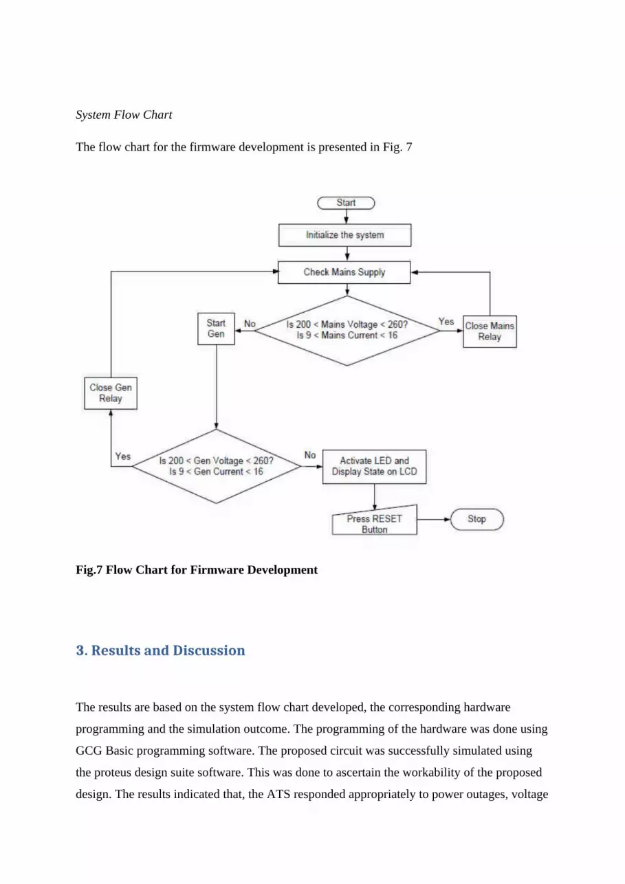
System Flow Chart
The flow chart for the firmware development is presented in Fig. 7
Fig.7 Flow Chart for Firmware Development
3. Results and Discussion
The results are based on the system flow chart developed, the corresponding hardware
programming and the simulation outcome. The programming of the hardware was done using
GCG Basic programming software. The proposed circuit was successfully simulated using
the proteus design suite software. This was done to ascertain the workability of the proposed
design. The results indicated that, the ATS responded appropriately to power outages, voltage
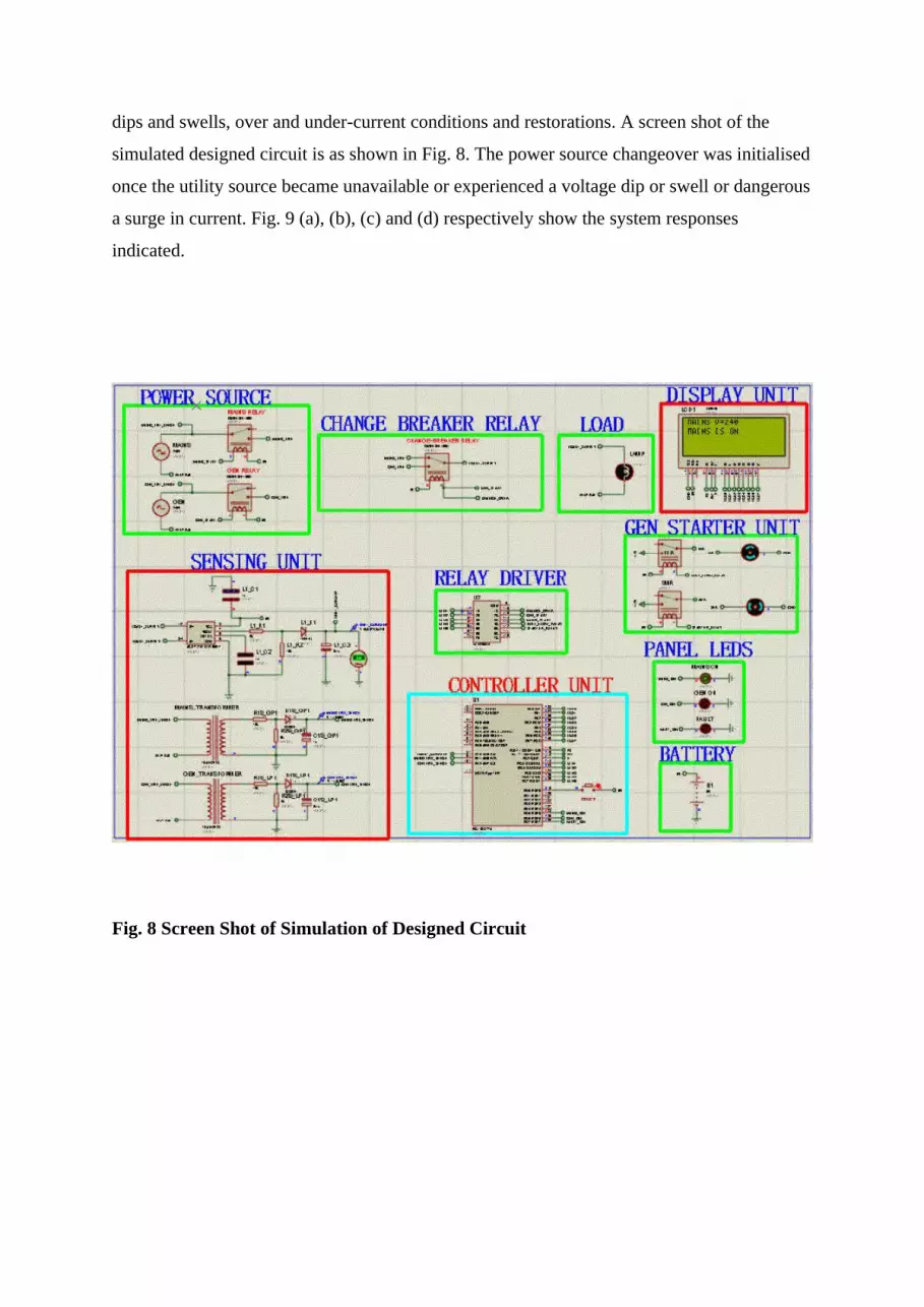
dips and swells, over and under-current conditions and restorations. A screen shot of the
simulated designed circuit is as shown in Fig. 8. The power source changeover was initialised
once the utility source became unavailable or experienced a voltage dip or swell or dangerous
a surge in current. Fig. 9 (a), (b), (c) and (d) respectively show the system responses
indicated.
Fig. 8 Screen Shot of Simulation of Designed Circuit
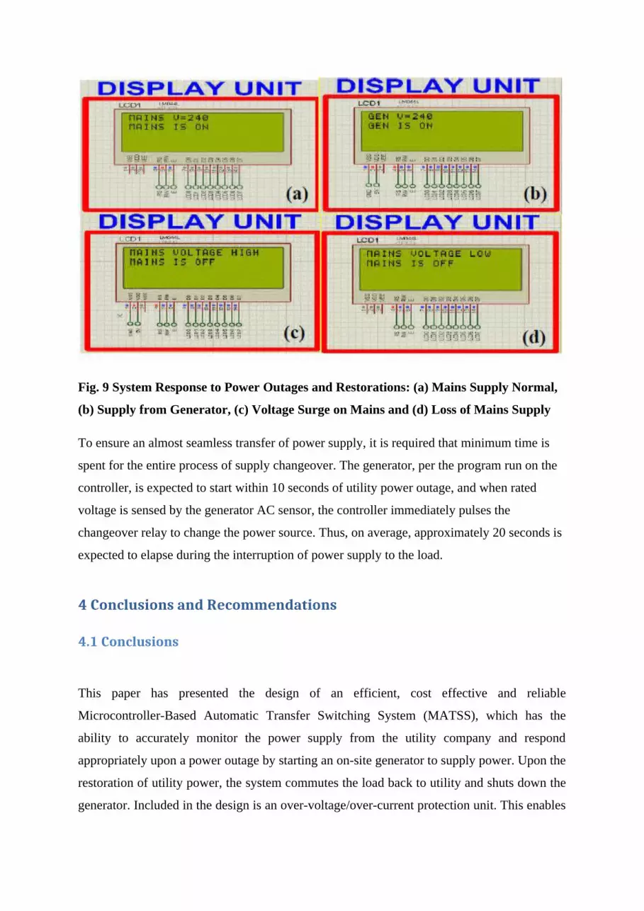
Fig. 9 System Response to Power Outages and Restorations: (a) Mains Supply Normal,
(b) Supply from Generator, (c) Voltage Surge on Mains and (d) Loss of Mains Supply
To ensure an almost seamless transfer of power supply, it is required that minimum time is
spent for the entire process of supply changeover. The generator, per the program run on the
controller, is expected to start within 10 seconds of utility power outage, and when rated
voltage is sensed by the generator AC sensor, the controller immediately pulses the
changeover relay to change the power source. Thus, on average, approximately 20 seconds is
expected to elapse during the interruption of power supply to the load.
4 Conclusions and Recommendations
4.1 Conclusions
This paper has presented the design of an efficient, cost effective and reliable
Microcontroller-Based Automatic Transfer Switching System (MATSS), which has the
ability to accurately monitor the power supply from the utility company and respond
appropriately upon a power outage by starting an on-site generator to supply power. Upon the
restoration of utility power, the system commutes the load back to utility and shuts down the
generator. Included in the design is an over-voltage/over-current protection unit. This enables
the system to automatically changeover when the voltage or current rises above its rating, to
protect equipment from damage. The cost of the MBATSS is approximately 330.87 USD to
construct and install. This new system thus offers considerable operational advantages and
cost saving over the manual system currently used by many companies in Ghana. The switch
transition mode used (open transition mode) eliminates the problem of standby power
generators “back-feeding” into the utility lines.
4.2 Recommendation
It is recommended that hospitals, financial institutions, internet service providers, mining and
allied companies , which require constant power supply should use the MBATSS.

References
Aguinaga, J. (2008), “Study of Transfer Switches”, Unpublished MSc Thesis Report, Helsinki
University of Technology, Espoo, Finland, 102 pp.
Akparibo, R. A. (2011), “A Solar Radiation Tracker for Solar Energy Optimisation”,
Unpublished BSc Project Report, University of Mines and Technology, Tarkwa, pp. 20 - 32.
Anderson, W. J. (2003), “Automatic Transfer Switches and Engine Control”, www.file-ee-
patents.com.
Anon. (2010), “Low Voltage Automatic Transfer Switch System”, www.asco.com.
Anon. (2011), “Olympian GEH220-4 Diesel Generator Set Manual”, www.olympianpower
.com/cda/files/2851633/7/LEHF0174-01.pdf.
Anon. (2012a), “Automatic Transfer Switches International”, www.cumminspower.com.
Anon. (2012b), Automatic Transfer Switch-Owner’s Manual, Generac Power Systems Inc.,
Whitewater, USA, pp. 1 - 20.
Anon. (2013a), “Automatic Transfer Switch”, www.wikipedia.org/wiki/Transfer_switch.
Anon. (2012c), “Proteus PCD Design Package”,
www.labcenter.com/products/pcb_overview.cfm.
Anon. (2013b), “Electrical and Electronic Components”, www.getprice.com.au/electronic-
components.htm.
Anon. (2013c), “Electronic Components”, www.futurlec.com/Components.shtml.
Anon. (2013d), “Electronics Component Search by Top Distributors”, www.findchip.com.
Chukwubuikem, N. M., Ekene, M. S. and Uzedhe, G. (2012), “A Cost Effective Approach to
Implementing Changeover System”, Academic Research International, Vol. 2, No. 2, pp. 62 -
72.
Fuller, R. (2007), “Electrical Currents”, Newsletter from the office of the Chief Electrical
Inspector, Vol. 10, No. 6. pp. 1 - 4.
Kolo, J. G. (2007), “Design and Construction of an Automatic Power Changeover Switch”,
Assumption University Journal of Technology, Vol. 11, No. 2, pp. 1- 6.