Embed Size (px)
Citation preview
TULSA COUNTY
PURCHASINGDEPARTMENT
DATE:
FROM:
TO:
SUBJECT:
October 24, 2018
MatneyM. EllisPurchasing Director
Board of County Commissioners
Addendum 2 - Tulsa County Maintenance Facilities - Districts 1 & 3
On September 17, 2018, the Notice to Bidders was mailed for construction of the TulsaCounty Maintenance Facilities - Districts 1 8s 3. This bid is set to open on the 13th dayof November, with bids to be received by the County Clerk's Office until November 9th,2018at4:OOpmCST.
This addendum is to provide clarifications to specifications and answers to vendorsubmitted questions and substitution requests. This addendum is respectfullysubmitted for your approval.
MME
ORIGINAL: Michael WiUis, County Clerk, for the October 29, 2018 agenda.
TUKfl (OUnTV
Purchasing Department
A Department of the
Tulsa County Budget BoardTulsa County Administration Bldg.500 South Denver
Tulsa, Oklahoma 74103-3832P: 918. 596. 5022F: 918. 596. 4647
Matney M. EllisPurchasing Director October 29, 2018
Board of County CommissionersTulsa County Administration BuildingTutsa, Oklahoma 74103
On September 17, 2018, the Notice to Bidders was mailed for construction of the TulsaCoun Maintenance
Facilities - Districts 1 & 3. This bid is set to open on the 13th day of November, with bids to be received bythe County Clerk's Office until November 9th, 2018 at 4:00pm CST.
This letter is to serve as notice that Addendum 2 has been issued for this solicitation. This addendum is to
provide clarifications to specifications and responses to vendor submitted questions and substitution requests.Addendum 2 is available for review and/or download at the following:
. Tulsa County Purchasing Department
. htt ://wwwtulsacoun .or / urchasin vendors
Respectfully Yours,
^
Matney M. EllisPurchasing Director
/ ENGINEERS|ARCH17ECTS/
/
/
^iiim"m^^^,/1("<"^0^"'\
REEVE188
TULS
^ OKLAH' ^^ws^</-»
<^ESS^' WESLEY
-f1 3 5
0/24/18
'^ss( ^
^ AHO^
BKL, Incorporated1623 East 6th Street
Tulsa, Oklahoma 74120(918) 835-
<? StocLo
58
v
2»)
^'
&5'u
"^
George D.Rochelle
13821
^z^
5'
,24/18O/TLAHO^
0/24/18
ADDENDUM NO. 2
Tulsa County Maintenance Facilities
Districts 1 and 3
BKLJnc. -Project #633
October 24, 2018
NOTICE TO BIDDERS
This Addendum is issued to all registered plan holders pursuant to the Instructions to Bidders andConditions of the Contract. This Addendum serves to clarify, revise, and supersede information in theProject Manual, Drawings, and previously issued Addenda. Portions of the Addendum affecting theContract Documents will be incorporated into the Contract by enumeration of the Addendum in theOwner/Contractor Agreement. The date for receipt of bids is unchanged by this Addendum and is atsame time and location. The Bidder shall acknowledge receipt of this Addendum in the appropriate spaceon the Bid Form.
CHANGES/CLARIFICATIONS TO SPECIFICATIONS
1. SPECIFICATION 088000 GLAZING
. Revise Section 3.6 B. to be:
B. Glass Type [GL-2]: insulating glass.
1. Overall Unit Thickness: 1 inch.
2. Fully tempered float glass.
3. Vision glass made up of Visteon %" Versalux Grey over %" clear with " air space.2. SPECIFICATION 083323 OVERHEAD COILING DOORS
. Revise Section 2. 2. L. Door Finish to be:
1. Architect to select from Manufacturer's standard colors.
ADDENDUM NO. 2October 24, 2018
Page 1 of 12
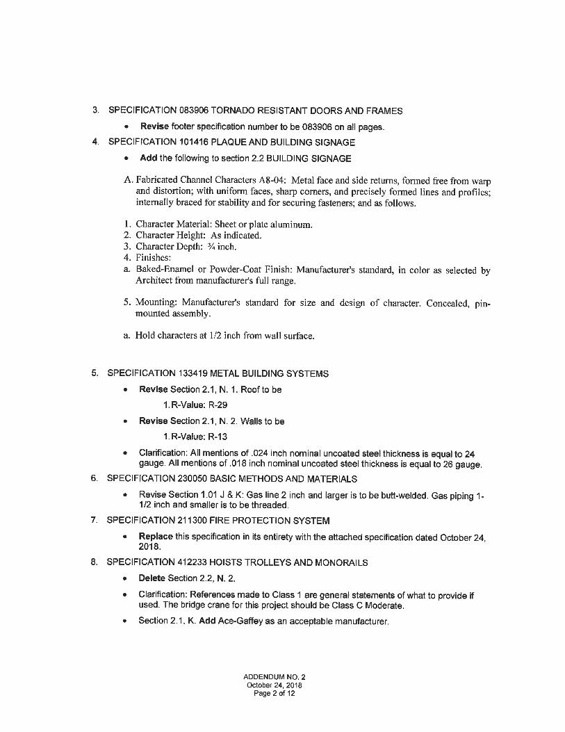
3. SPECIFICATION 083906 TORNADO RESISTANT DOORS AND FRAMES
. Revise footer specification number to be 083906 on all pages.4. SPECIFICATION 101416 PLAQUE AND BUILDING SIGNAGE
. Add the following to section 2. 2 BUILDING SIGNAGE
A. Fabricated Channel Characters A8-04: Metal face and side returns, formed free from warpand distortion; with uniform faces, sharp corners, and precisely formed lines and profiles;internally braced for stability and for securing fasteners; and as follows.
1. Character Material: Sheet or plate aluminum.2. Character Height: As indicated.3. Character Depth: % inch.4. Finishes:
a. Baked-Enamel or Powder-Coat Finish: Manufacturer's standard, in color as selected byArchitect from manufacturer's full range.
5. Mounting: Manufacturer's standard for size and design of character. Concealed, pin-mounted assembly.
a. Hold characters at 1/2 inch from wall surface.
5. SPECIFICATION 133419 METAL BUILDING SYSTEMS
. Revise Section 2. 1, N. 1. Roof to be
1. R-Value:R-29
. Revise Section 2. 1, N. 2. Walls to be
1. R-Value:R-13
. Clarification: All mentions of .024 inch nominal uncoated steel thickness is equal to 24gauge. All mentions of .018 inch nominal uncoated steel thickness is equal to 26 gauge.
6. SPECIFICATION 230050 BASIC METHODS AND MATERIALS
. Revise Section 1.01 J & K: Gas line 2 inch and larger is to be butt-welded. Gas piping 1-1/2 inch and smaller is to be threaded.
7. SPECIFICATION 211300 FIRE PROTECTION SYSTEM
. Replace this specification in its entirety with the attached specification dated October 24,2018.
8. SPECIFICATION 412233 HOISTS TROLLEYS AND MONORAILS
. Delete Section 2.2, N. 2.
. Clarification: References made to Class 1 are general statements of what to provide ifused. The bridge crane for this project should be Class C Moderate.
. Section 2. 1, K. Add Ace-Gaffey as an acceptable manufacturer.
ADDENDUM NO. 2October 24, 2018
Page 2 of 12
CHANGES/CLARIFICATIONS TO DRAWINGS
1. SHEET COVER:
. Revise District 1 address to be 11456 N. Yale Sperry, OK.
. Revise District 3 address to be 4959 E. 1 71st St S. Bixby, OK.2. SHEET GO-02:
. Add sheet A8-04 SITE SIGNAGE
. Revise sheet title E2-02 to ELECTRICAL FLOOR PLAN - STORAGE AND SANDERBUILDINGS
3. SHEET C2-05:
. Add dimensions at mechanical yard. 31'-0" x 31'-6"
4. SHEET C3-01:
. Add General Note: "SEPARATOR FABRIC IS TO BE A NON-WOVEN FABRIC FORBASE COURSE SEPARATION IN ACCORDANCE WITH AASHTO M 288"SEPARATION GEOTEXTILE PROPERTY REQUIREMENTS" WITH A CLASS 2DEGREE OF SURVIVABILITY."
5. SHEET S1-02:
. Add dimension of 50'-0" at trench drain in Maintenance Bays, located 20'-0" from gridline6.
. Add dimension of 48'-0" at trench drain in Wash Bay-M105.6. SHEET S3-01:
. Clarification: Fueling canopy including all details on this sheet are now by owner and notto be bid in this contract.
7. SHEET S3-02:
. Clarification: Fueling canopy including details 1 and 2 on this sheet are now by ownerand are not to be bid in this contract.
8. SHEET S9-01:
. Add note at plan detail 2: "3 KIP HORIZONTAL LOAD APPLIED TO PEMB COLUMN,TfPICAL."
9. SHEET S9-03:
. Details 2 and 3, revise dimensions at aggregate base to be "VARIES, 1 '-0" MAX"
10. SHEET A1-01:
. Add to notes "Welding curtain: AKON 12oz Canvas Duck, must meet CPAI-84 section 6,Certified Flame Retardant with Pyrosnuff water and mildew resistant treatment. Providemanufacturer's 16 ga. galvanized steel freestanding track support system for openingsshown. 12' height."
11 SHEET A2-02:
. Add to note "Industrial Wash Bay Curtain: AKON 18oz vinyl reinforced with polyestermesh scrim. 16 ga. Galvanized steel curtain track and chain or cable mount from purlins.(Or equal. ) Architect to choose from manufacturer's full range of colors."
ADDENDUM NO. 2October 24, 2018
Page 3 of 12
12. SHEET A3-01:
. Delete Glass Type 3 Polycarbonate Translucent Panels.
. Revise glass at window H10 to type 2.
13. SHEET A4-02:
. Replace this sheet in its entirety with attached sheet. Revisions and new details areclouded and dated 10-24-18.
14. SHEET A4-03:
. Revise note at detail 3 to read, "FIRE-STOPPING MATERIAL TO FILL ALL GAPS. FIRESTOPPING SYSTEM TO BE LISTED IN THE UL "FIRE RESISTANCE DIRECTORY"
15. SHEET A5-01:
. Add callout TA-17 to enlarged plan detail 1 at the shower seat in Shower-117A.
16. SHEET A8-04:
. Revise note at Tulsa County font logo to be "TULSA COUNP»r FABRICATEDALUMINUM PANEL"
. Clarification: The "Tulsa County" panel portion of the site signage is to be fabricated tomatch the building signage. Refer Specification 101416, 2.2. A. Fabricated Panel.
17. SHEET M1-01:
. Replace this sheet in its entirety with attached sheet. Revisions are clouded and dated10-24-18.
18. SHEET M2-01:
. Replace this sheet in its entirety with attached sheet. Revisions are clouded and dated10-24-18.
19. SHEET M4-01:
. Replace this sheet in its entirety with attached sheet. Revisions are clouded and dated10-24-18.
20. SHEET M4-02:
. Replace this sheet in its entirety with attached sheet. Revisions are clouded and dated10-24-18.
21. SHEET E3-01:
. Replace this sheet in its entirety with attached sheet. Revisions are clouded and dated10-24-18.
22. SHEET E3-02:
. Replace this sheet in its entirety with attached sheet. Revisions are clouded and dated10-24-18.
23. SHEET E3-03:
ADDENDUM NO. 2October 24, 2018
Page 4 of 12
Replace this sheet in its entirety with attached sheet. Revisions are clouded and dated10-24-18.
24. SHEET E6-02:
. Replace this sheet in its entirety with attached sheet. Revisions are clouded and dated10-24-18.
25. SHEET P1-01:
Replace this sheet in its entirety with attached sheet. Revisions are clouded and dated10-24-18.
26. SHEET P1-02:
Replace this sheet in its entirety with attached sheet. Revisions are clouded and dated10-24-18.
27. SHEET P2-01:
Replace this sheet in its entirety with attached sheet. Revisions are clouded and dated10-24-18.
28. SHEET P4-01:
Replace this sheet in its entirety with attached sheet. Revisions are clouded and dated10-24-18.
QUESTIONS/RESPONSES
1. QUESTION: Can you please clarify the bridge crane classification. There are references made inthe bridge crane spec to Class 1, Division 1 or 2. My crane suppliers are telling me that thisclassification should not be needed but if it is desired it will double the cost of the crane. Pleaseclarify the desired classification.
RESPONSE: References made to Class 1 are general statements of what to provide if used. Thebridge crane for this project should be Class C Moderate.
2. QUESTION: P1-01
1) Drawing shows a DCW loop with hose bib drops, it does not show it being tied into anywater source or is it sized.
2) Drawing does not show gas going to the Gas Fired Air Handler.
3) Need locations and any details available on hook up of "Oil Tanks" and "Air Compressor".4) Drawing shows two EEW, there is no information on what an EEW is or line sizes to hook
up.
5) Natural gas spec 230050-4 J & K states to butt weld all gas pipe. Is this correct?
6) Drawing shows a "Fire Line" with note to route to county water main. Need location andsizes or county mains along with the size of the fire line.
RESPONSE: Refer attached P1-01 revisions and specification 230050 revisions above.
3. QUESTION: P1-02
1) Drawings shows natural gas going to condensing units but not the furnaces.
ADDENDUM NO. 2October 24, 2018
Page 5 of 12
2) Drawing shows a septic tank, there is no detail on it anywhere and I would need howdeep the inlet & outlet are.
3) Note for trench drains, "See Trench Drain Detail", there is not a trench drain detail.
RESPONSE: Refer attached P1-02 revisions. Refer S2-01 for trench drain detail.
4. QUESTION: P2-01
1) Drawing shows DCW entering 1 1/2" but the fixture schedule is calling for a 2"BFP.
2) Drawing note for DCW "To Water Meter", need location and line size of county main, sizeof meter, detail, etc.
RESPONSE: Refer attached P2-01 revisions. Contractor is responsible for utilities up to 5'outside of buildings.
5. QUESTION: P3-01: Detail for gas regulator does not give any information on what regulator isneeded.
RESPONSE: Site Utilities are per the County. The gas utility company typically sizes theregulators.
6. QUESTION: P4-01: Fixture schedule has SSI-1 sediment interceptor. It is not on prints and willbe excluded.
RESPONSE: Refer attached P1-02 and P4-01 revisions.
7. QUESTION: Will the County be supplying and installing all storm utilities?
RESPONSE: The County will be installing ALL site utilities, including storm. The GC isresponsible for all building utilities up to 5' outside the buildings. The GC is responsible for alltemporary utility service needed during construction.
8. QUESTION: On S9-01 detail 2, the reference to 7/S2-01 appears to be incorrect. Please clarify.RESPONSE: There is no reference to 7/S2-01 on this sheet.
9. QUESTION: The finish schedule on A8-01 shows sealed concrete in the shower floors but thefinish legend says epoxy resin. Please clarify.
RESPONSE: Refer to previously issued Addendum 1.
10. QUESTION: On A8-01 the solid surface note indicates there are SDS1 restroom modesty panelswhich appears to be incorrect. Please clarify.
RESPONSE: Solid surface is correct. Reference detail 7/A5-04.
11. QUESTION: Could you put out a spec section on the industrial wash bay curtain?
RESPONSE: Manufacturer and product data note was added to the drawings. Refer A2-02drawing revision above.
12. QUESTION: We need specs and more detail on the salt barn open span arch structure.
RESPONSE: Refer to previously issued Addendum 1 and further salt barn questions below.
13. QUESTION: On M1-01 note #3 it says the owner is providing the plymovent system. Will it befurnished complete including installation? It appears this is not the intent of the plans. Pleaseclarify.
RESPONSE: The vehicle exhaust system is by the GC. Refer to attached M1-01 revisions.
14. QUESTION: Does the slab really have to pour in the sequence shown?
RESPONSE: Yes. Refer Slab Pouring Sequence notes on S1-02.
ADDENDUM NO. 2October 24, 2018
Page 6 of 12
15. QUESTION: Do we really need column blackouts with the columns sitting on top of the slab?RESPONSE: Yes.
16. QUESTION: Will the County be picking up/waiving the building permit fees? Or will the contractorneed to cover this?
RESPONSE: The building permits will be in place per BKL and the County. The contractor will beresponsible for building construction inspections.
17. QUESTION: Sheet C2-01 reflects an existing structure on the property. Assuming that the Countyis taking care of dirt work, is the County going to handle demolition/removal of this structure?
RESPONSE:Yes.
18. QUESTION: Sheet C2-01 reflects that there is no existing fence on the east side of this property.Sheet C2-02 reflects a fence down the east side of the property and around the sewer lagoon.However, the fencing is not identified. Should we be including fencing in our proposals for thesetwo areas and if so, what should we include?
RESPONSE: Unless otherwise noted, all fencing at perimeter and lagoon is 6'-0" chainlink perdetail 1/C3-02.
19. QUESTION: 2/S9-03 shows an open span arch structure designed by engineer registered in thestate of Oklahoma. Is the GC responsible for hiring an engineer? Are we to include the fee in thebid amount?
RESPONSE: Reference Addendum 1 for further information on open span arch structure andfabric. Manufacturer is responsible for submitting drawings by a registered engineer during thesubmittal phase prior to construction.
20. QUESTION: Type 10 window has the Type 3 polycarbonate Translucent panels, I do not see theType 3 in the glazing specs. I need to know the thickness they require.
RESPONSE: Refer to A3-03 revisions listed above.
21. QUESTION: Will County provide final grade and top soil as well as back filling of curbs?
RESPONSE: The contractor is responsible for final grade and sodding at sodding locations only.Reference Addendum 1 and Alternate 6.
22. QUESTION: Is the County installing storm water piping and headwalls as part of their dirtwork oris it the responsibility of the contractor?
RESPONSE: The County will be installing ALL site utilities, including storm. The GC isresponsible for all building utilities up to 5' outside the buildings. The GC is responsible for alltemporary utility service needed during construction.
23. QUESTION: Per C2-05 district 3 appears to show a walled/fenced in mechanical/electrical yard &dumpster pad. Please clarify dimensions and type of wall? Mech/Elec yard not shown on district 1site plan, is it not required at district 1? If so please provide location, as location shown at district3 would interfere with district 1 parking lot.
RESPONSE: Wall is to be privacy fence per Addendum 1 . Dimension are shown above at C2-05revisions. Mechanical yard is not required at District 1.
24. QUESTION: Is County supplying and installing oil compressor, storage tanks, and equipment?RESPONSE: Yes.
25. QUESTION: Is there a preferred fuel canopy manufacturer if so please provide manufacturersname?
ADDENDUM NO. 2October 24, 2018
Page 7 of 12
RESPONSE: Fueling canopies are now by owner and not to be bid in this contract. Refer S3-01and S3-02 drawing revisions above.
26. QUESTION: Is truck lift provided and installed by County? If not, please provide specification andapproved manufacturers.
RESPONSE: Yes, the truck lift is provided and installed by the County. Power is to be installed bythe GC per the documents.
27. QUESTION: The Radiant Tube Heating Equipment Schedule shows 9 units (RTH 1 through 9),but we only see 5 on the M1-01 HVAC plan. Is the Schedule correct?
RESPONSE: Refer to revised sheet M4-02.
28. QUESTION: The Key notes 3, 4, & 5 on M1-01 refer to a Plymovent vehicle exhaust system.Note 3 says it is by owner, but Note 4 & 5 do not indicate those parts to be by owner. A companycalled Air Cleaning Technologies is the supplier for Plymovent and they normally quote furnishingand installing this brand of system. Who furnishes and installs the whole vehicle exhaust system?
RESPONSE: Refer to revised key notes on attached sheet M1-01. The GC is responsible forfurnishing and installing the vehicle exhaust system.
29. QUESTION: Also, there is no ductwork shown from the hose reels (Note tag 4) to the exhaust fan(Note tag 3). It needs to be shown and sized if we are to quote the connecting ductwork for thevehicle exhaust system.
RESPONSE: Refer to revised sheet M1-01.
30. QUESTION: Will the building pads be certified?
RESPONSE: The building pads will be compacted by owner and compaction test documentationcan be provided.
31. QUESTION: Who is providing the select fill layer under the building pads?
RESPONSE: The County.
32. QUESTION: Who is providing and installing the utilities including water service, sanitary sewerand storm drainage?
RESPONSE: The County will be installing ALL site utilities, including storm. The GC isresponsible for all building utilities up to 5' outside the buildings. The GC is responsible for alltemporary utility service needed during construction.
33. QUESTION: Who provides and installs the erosion control?
RESPONSE: The County will have erosion control in place as part of the dirtwork.
34. QUESTION: Please provide a specification for the structure over the salt storage area?
RESPONSE: Refer to previously issued Addendum 1.
35. QUESTION: Please provide details of the mech/elec yards at district 3 location.
RESPONSE: Refer to C2-05 revisions above for size of mechanical yard at District 3.
36. QUESTION: Is the fuel canopy to have SSR of just 1. 5" metal decking?
RESPONSE: Fueling canopy are now by owner and not to be bid in this contract. Refer S3-01and S3-02 revisions above.
37. QUESTION: Please provide a specification for the wash bay curtain.
RESPONSE: Manufacturer and product data note was added to the drawings. Refer A2-02 sheetrevision above.
ADDENDUM NO. 2October 24, 2018
Page 8 of 12
38. QUESTION: Please provide size of generator pads.
RESPONSE: Refer to C2-05 revisions above for size of mechanical yard at District 3. District 1has an electrical pad with dimensions noted on C1-02.
39. QUESTION: Can a standard R-25 or R-30 (roof) and R-13 or R-19 (walls) insulation be providedin lieu of R-26 in the roof and R-14 in the walls?
RESPONSE: Refer to 133419 specification revisions above.
40. QUESTION: Is there to be metal liner panel along the entire interior perimeter of the sander andstorage buildings?
RESPONSE: Yes, as shown on A9-01 and A9-03.
41. QUESTION: The Type B doors, are those coming pre-glazed or do you need us to pick up theglass? If so, do they get 1/4" clear?
RESPONSE: This is not a decision to be made by the architect. As long as the final result is perthe specifications, we do not care how the GC orders it.
42. QUESTION: As per specification 412233-6 section 3.3 is calling for a 10 ton crane. The runwaybeams are calling for a W24x104 bridge crane beam and W8x31 support columns. The structurecan be made more economical by removing the support columns and use a bracket off the metalbuilding columns. Would this be acceptable? PEMB can also redesign the runway beams to amore economical size to support a 10 ton crane. Would this be acceptable?
RESPONSE: For bidding purposes, contractors are to bid the design that is shown on the biddocuments. During construction phase we can assess any value engineering for the bridge cranedesign in coordination with the PEMB contractor and the owner.
43. QUESTION: One of our crane suppliers has requested clarification as to if these facilities areclassified as non-hazardous facilities. Could you please answer this in an addendum?
RESPONSE: The office and maintenance bays (where the bridge crane is located) are a non-hazardous classification. They are both use group B. The small oil storage room is use group S-1,Moderate Hazardous Storage. This information is located on Sheet GO-03.
44. QUESTION: Alternates 2 and 3 cannot be completed without Alternate 4 being completed due tothe power of Alternates 2 and 3 being fed from the panel in Alternate 4.
RESPONSE: ALL electrical panels shall be provided in the base bid.
45. The Fire Protection specification makes several mentions of an existing gym as well as 6 differentphased systems. There are references to fire line meters, pits, and related equipment and firehydrants, etc. There are no mentions of these items shown on the drawings. Also, only district 3shows any existing water mains capable of handling a new fire service. All the items listed abovecould make a significant difference in pricing for this project. If there is any way to clarify exactlywhat is expected for this scope of work it will help the contractors provide the most accurate andcompetitive pricing for this project.
RESPONSE: Refer to attached revised specification dated October 24, 2018. Utilities outside of 5feet from the building will be provided and installed by the owner.
46. QUESTION: Regarding the ground signs on sheet A8-04, are the aluminum letters on the groundsign meant to be illuminated? Are the letters on the ground sign to be pin-mounted or flush-mounted?
RESPONSE: The letters are not illuminated. Refer to the revisions to Specification 101416 andSheet A8-04 above.
ADDENDUM NO. 2October 24, 2018
Page 9 of 12
47. QUESTION: Who is picking the welding curtain? There is no spec for this.
RESPONSE: Refer A1-01 drawing revisions above.
48. QUESTION: Who is picking up the wash bay curtain? There is no spec for this.RESPONSE: Refer to Question 37 above and A2-02 sheet revision above.
49. QUESTION: Drawing A8-04, do we know where these signs will be located yet?
RESPONSE: At District 1, the sign will be located just inside the chainlink fence at the entry AtDistrict 3, the sign will be located in the grass area at the Southwest corner of the site.
50. QUESTION: I am unable to find a spec on the separator fabric.
RESPONSE: Refer to Sheet C3-01 revision above.
51. QUESTION: Can you confirm the drawing C3-01 typical asphalt section is correct?
RESPONSE: It is correct.
52. QUESTION: Please point out which building are sander buildings and which are storagebuildings?
RESPONSE: District 1 locations are called out on Sheet C1-03. At Distict 3, the far West buildingis the Sander building. The two on the East side of the Salt Barn are Storage Buildings.
53. QUESTION: The plans call for water repellant sealer but there is no specification on drawings orplans on what they would like to use. Please clarify.
RESPONSE: On the Finish Legend (Sheet A8-01) the Water Repellent Coating is listed underSpecification 099100 for Concrete Sealer. In the specification, refer to section 3. 7 Floor SealerSchedule.
54. QUESTION: After reviewing the bid documents there doesn't seem to be any drawings on wherethe fuel tanks, pumps, etc will be installed. How do we submit a bid for the equipment? Wherecan we find where the tanks are to be buried, what kind of tanks, what kind of piping, how far fromthe buildings, pump islands, etc?
RESPONSE: Refer to Fueling Station Notes on sheets A1-03 and S3-01. All fueling equipment,tanks, and pumps are by owner and not included in this bid.
55. QUESTION: It has been brought to our attention that the plumbing drawings show no circulatingpump, hot water return lines, mixing valve for shower/eye wash, or hot water supply or hot waterreturns for the shower/eye wash.
RESPONSE: Refer to attached revised plumbing sheets.
56. QUESTION: At the fueling area we need to know how many tanks, what size, steel or fiberglass,distance from pumps to tanks, how many smart cards for the fuel master, and how will itcommunicate with the PC?
RESPONSE: Refer to Fueling Station Notes on sheets A1-03 and 83-01. All fueling equipment,tanks, and pumps are by owner and not included in this bid.
57. QUESTION: We cannot locate where, or if, the interior exposed steel structures are to be painted.There is a specification for a structural steel paint but it appears all of the exposed structural steelon the exterior of the building is to receive paint. This shows up in quite a few areas within thedrawings but the interior exposed steel is not addressed. Please clarify this for the maintenancebuildings, the sander buildings, the salt buildings, and the storage buildings.
ADDENDUM NO. 2October 24, 2018
Page 10 of 12
RESPONSE: You are correct in that the exterior exposed steel receives paint per specification.The interior exposed structural steel at ALL buildings is to be factory primed, not painted.
58. QUESTION: Can the slab pour key plan be revised? Currently the plan shows cold joints in thetrench drain. Additionally, with all of the exposed concrete the construction joints may not give thedesired look.
RESPONSE: The slab pour key plan will not be revised at this time.
59. QUESTION: The plumbing slab plan calls out a premade trench drain, and the structural planshows a formed drain. Please clarify.
RESPONSE: The plumbing plans call for 4" FD-3 and TD-1 as specified in the fixture schedule.The structural plans call for a formed trench with fixture TD-1 embedded.
60. QUESTION: Please provide a specification for the separator fabric.
RESPONSE: Refer to Sheet C3-01 revision above
61. QUESTION: It is assumed that there is no insulation on the sander or storage buildings, ifincorrect please specify.
RESPONSE: Only the Indoor Storage Room S101 is insulated. Refer detail 3 on A9-03 andspecification 133419 revisions above.
62. QUESTION: Please provide the kip load for the structural steel that ties into the PEMB for thesander building.
RESPONSE: 3 kips. Refer to S9-01 Sheet revisions above.
63. QUESTION: Is the crane structure being attached to the PEMB in any way so that the buildingwill have to be reinforced to brace it?
RESPONSE: Yes, Refer to A4-02 Sheet revisions above.
64. QUESTION: What are the kip loads that wilt be applied to the PEMB columns in the sanderbuilding where the structural steel framing by others attaches to them?
RESPONSE: 3 kips. Refer to S9-01 Sheet revisions above.
65. QUESTION: In Division 13 specs 2. 1. M. 1. calls for "FM Windstorm Classification: Class 1A-105."I believe that is only related to the uplift rating on the roof, and is that the maximum value of allthe different zones on the roof (which would be in the corner zones)?
RESPONSE: The FM Windstorm Classification, Class 1A-105 is for all panels.
66. QUESTION: Please state the wall and roof panel thicknesses in "gauge" as this can be open forinterpretation depending on the chart being referenced for different types of steel sheet.
RESPONSE: Refer to 133419 Specification revisions above.
SUBSTITUTION REQUEST ATTACHMENTS
The following substitution requests have been approved provided they meet or exceed all specificationrequirements and basis of design:
083323 CHI 6000 Series OH Door Substitution Request
083906 Curries StormPro 361 Substitution Request
083906 Tornado Shelter Hardware Substitution Request
087100 Corbin Russwin ED5000 Series Substitution Request
ADDENDUM NO. 2October 24, 2018
Page 11 of 12
087100 Corbin Russwin ML2000 Series Substitution Request
087100 McKinney & Pemko Hinges Substitution Request
087100 Norton 9500 Door Closer Substitution Request
087100 Rockwood Stops & Holders Substitution Request
087100 Rockwood Trim & Kickplates Substitution Request
095113 Certainteed CashmierACT Substitution Request
105126 Summit HDPE Lockers Substitution Request
133419 Insulation Substitution Request
230000 Pottorff Substitution Request
230000 Krueger Substitution Request
230000 Twin City Substitution Request
235871 Monoxivent Vehicle Exhaust Substitution Request
265100 Smith Lighting Substitution Request
283131 Siemens Substitution Request (Cooley)
283131 Siemens Substitution Request (JE Systems)
The following substitution requests are approved as noted and provided they meet or exceed allspecification requirements and basis of design:
265100 Eclipse/Eaton Substitution Request
265100 Eclipse/Deco Substitution Request
The following substitution requests are not approved for bidding:
283131 Notifier NFW System Substitution Request
312000 Tensar Geogrid Substitution Request
OTHER ATTACHMENTS
SHEETS: A4-02, M1-01, M2-01, M4-01, M4-02, E3-01, E3-02, E3-03, E6-02, P1-01,P1-02, P2-01, P4-01.
SPECIFICATIONS: 283111 FIRE PROTECTION SYSTEM
END
ADDENDUM NO. 2October 24, 2018
Page 12 of 12
AdvancemontalConslmclianTcchnafagy
Print Form
I'rnjcct:
. I'u:
Re:
\S^. fA^-v^ ^0.^:^5 Sllbsiitution Request N'br:
Kroin:
Date:
AA: I'roject Number
Coninict For:
SUBSTITUTIONREQUEST
(During The Bidding Phase)
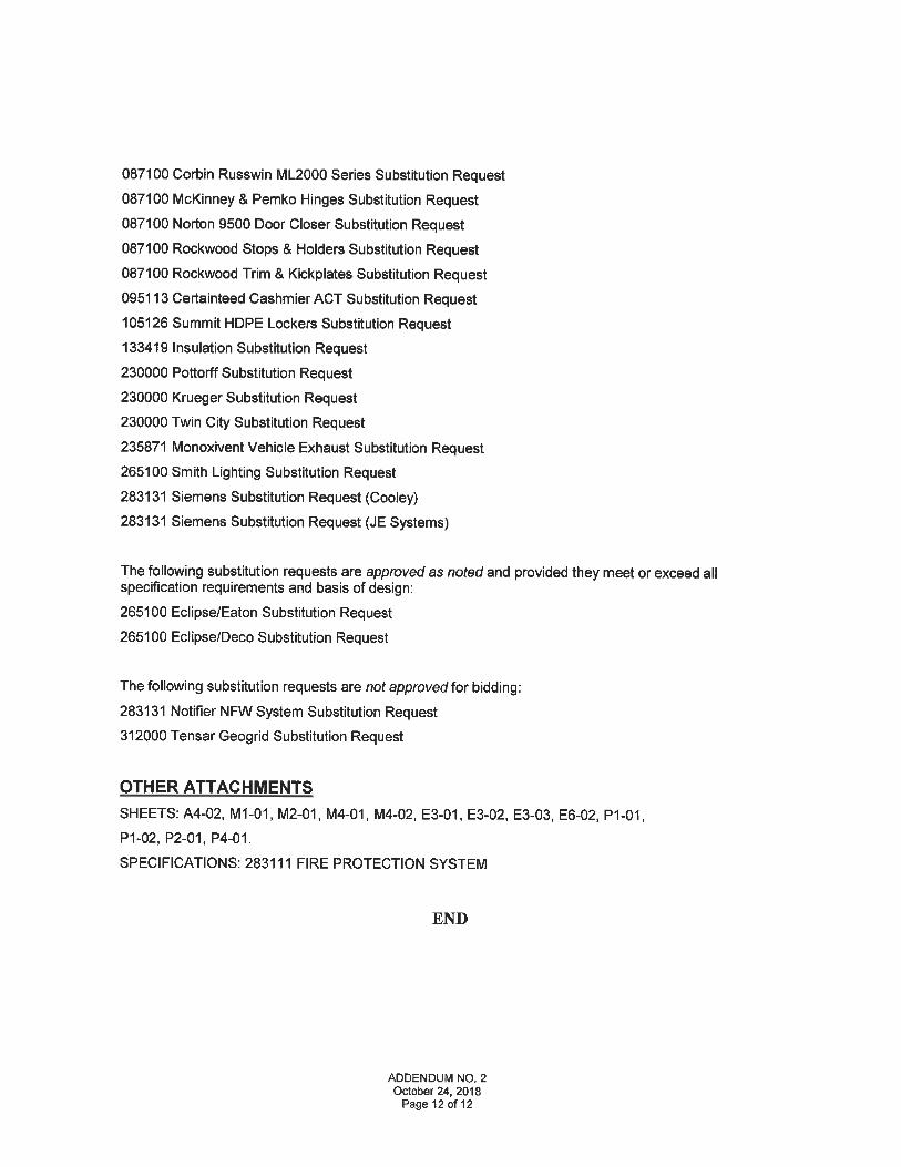
Specificaiion Title. (\fp^'^'-^\ ^^^^\ C.^. ^5 Dcscriprion:Sech-oii: ^ .%, p^,, Article/Parayraph:
Proposed Subslitiition:
Maiiufaciura:
'I'ratlc Nanic:
C ^^. r^<-«S '>a> <>< '4a-c^S-Z2Address: Phone: 8<y0-'2. 31^- Q
^LOVS^C'a. f\C T Model Ny: COS- "2-'?^^:^'^3^eSc aTions- drawlngs- photographs- and pcrfonnancc and tust dam a<ie^ ^ -- ^ ^ ^
Attached dat. also includes a descn'ption of chafes 10 .he Contract Docunients that the proposed substitution will require to,, its proper installationTlic Undersigned ccnittes:
PZOW^bst'"^o^bl:Mwy 'nvcstig"tedMld dctermmed to bcKiuai superior in all respects to specified product.Same warraniy will be furnished for proposed substitution as w specified product'""" '" "" ""''""" lu °lw""'u IJI"u"t:1'Same maintenance service and source ot replacement parts, as applicable, is available.Proposed sutelirtition will have. no adverse effect on otlier trades and will not affect o'r delay progres;
not affect dimensions aiid ftmctional clearances.
Pnymcnr will be made for cl, anges to building design, including A/E design, detailing, and construction COSTS caused by ihe sub.stitution.X^s ee^^ -^. 'AA 'S "^^ ^AVP^ 3, oo^'-' ^y Viv^'.K
Siibiiiittcil Bv:
Siyiied By:
l-'irnr
Address:
"£c\^j^ -^OK(*
£<w h> '> CU C
0 ^. L^ LU^'T sJC.
0 b
Tulepliunc: l - a-)-^5</
A/E's REVIEW AND ACTION
jSubslititiion apiiroved - Make submittals in acconlaiice with Specification Section 01250
QSubstitution approved as noted - Make subinitlals in accordance with Specit'ication Section 01250QSubstirution rejected - Use specified inatcriats.
QSiil;stitution Request received too late - Use specified materials.
Signed By: C.WEBER Date: 10-22-18
Supporting Diuu Attached: |-Inr.,,,, ;,,,,. toT n..,,, i...., n..... I-]o-..._, -. i-]".rawings |t<]pro<<"ci Data | jSninples IITUSB
', Copyriyhl 1996, Constitictinn Specifications Instimie,W Caiial Center Mava, Suite 300 Alexundriil. VA 22;! 14
Pag.ScQof
r~]l<cpurts
Supreinbcr IWhCSI l-'nrm 1.5C
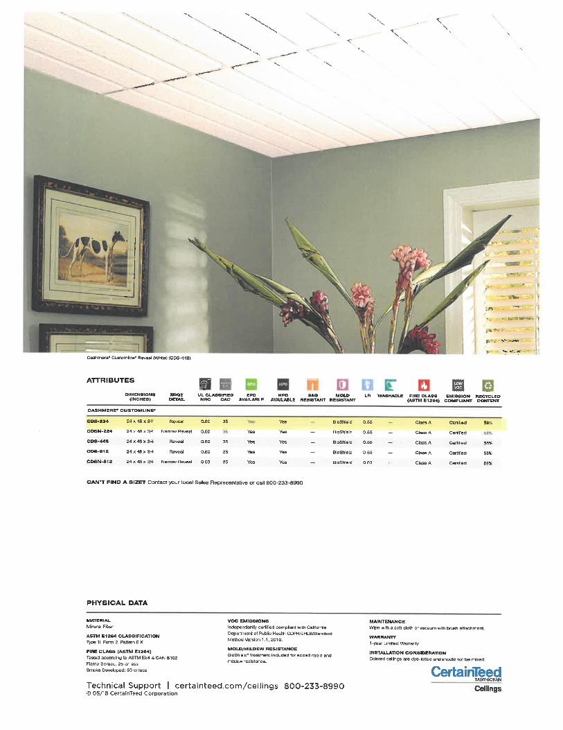
CertainTeedEAINT.SQBAIN
Ceilings
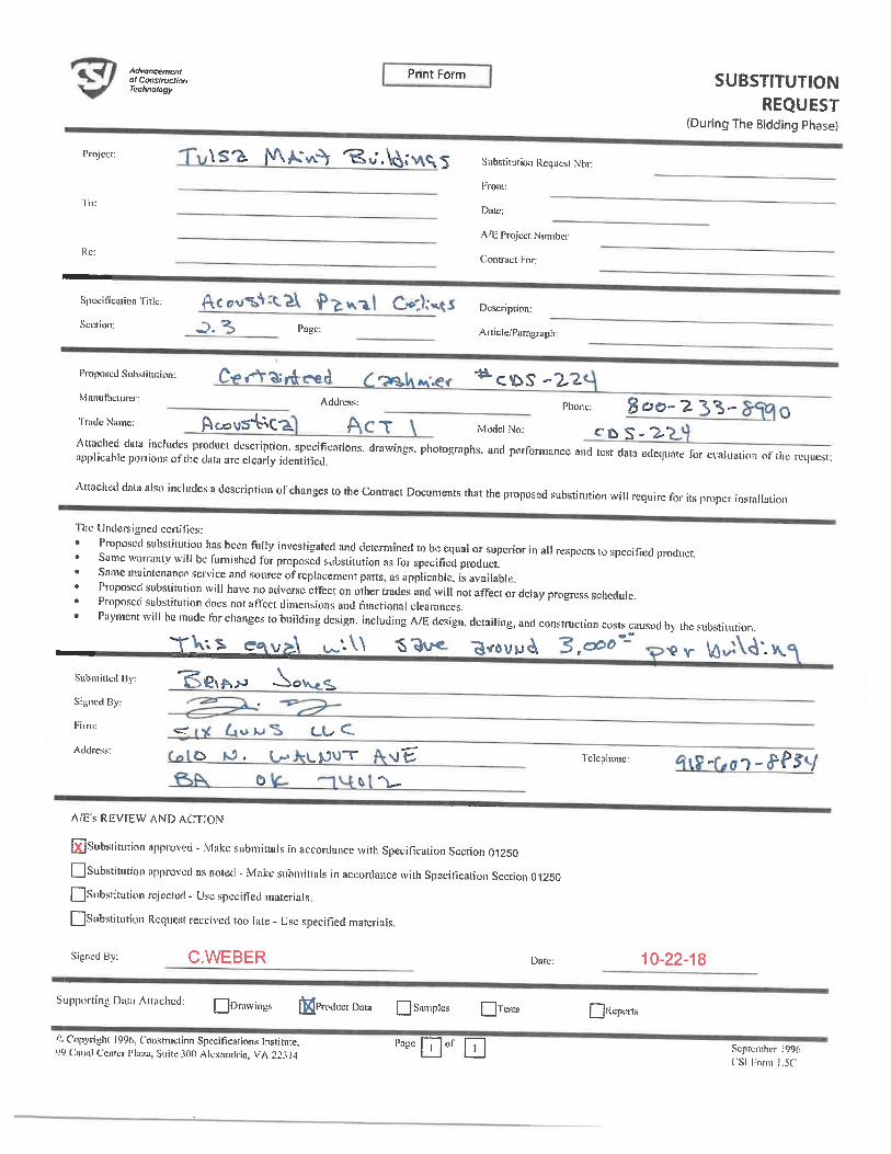
Cashmere® Customline"Mineral Fiber Ceilings
''"-.;* ': / '. ;'. " /-. -.. "". ' ,.^! .. . ;".'. '< . ' ii. -- '" ,;' ^' '...
^ MR: Envjronmentel ProductDeclarations (EPDs)
;. MR: Sourcing Raw Materials
MR: Material Ingredients(HPDs)
;. IEQ: Daylight
'. IEQ: Low-Emitting Materials
IEQ: Prereq. Min. AcousticPerformance (Schools)
IEQ: Acoustic Performance
MR: PBT Source Reduction(Healthcare)
IEQ: Interior Lighting
EA: Prereq. Min EnergyPerformance
EA: Optimize EnergyPeri'ormance
Recycled ContentPre 70% | rest. 0%
TOOLS
Visit CertaInTeed.com/CelllngsDownload HPDs and EPDs
LEED* Information / BIM Objects
3-Part Specs / Data Pages
'.. -.. * ., '. '- * ». .. "''^ ., - ..... \"\ . ^"". ''.. '.'.V. ...
;;. :'."^.. '-'7.^^. \^'. ;:,^^' . '- .',,.- ^^-^ y^ ..^^^&-f :"'... ; - ^
, . \ . -*-w ".;.. ', --":"/, . .. . ' - -
^^:r^~', ;'-»^^^:. ^.:^^^;- ;^^^ ';.^j^.^V3<^.^ '. !'.^;'":^. ... ^ll^' ^ f;. ^'- -v?:"^^ .::;-. ^'^^"< ^. -'-^ '""I ''-^ ^. ^ -. ^ ' \^ Y ' ^\ . :'\. ^' . : . -;. " ".' ^ l^'- ^ . . '.. '. ^^/". ':" "^" ". . " '
^..'^^^- --....'.. -' \,.^<j.. \. ^;. . ". -. - :;^^';*'" . ''*< . ... ^^ . :-. ;-<
. v*<^>?-. ' . ; ^:/
- \ -.^,. >^,. ?<^ y. '"' ^ y ^-. f':. "' . *~'.. '. ~v. -"^ -. <, .'^ , - {, 'Y. :- *>. .v'^.": ^ . /' . '. ^ ^^^^':':^. :^ "!. '. ' -.:
., : '^\: r'--:~':*x--^!'iS'; ^^^ ^. * <:' >^;^ ^ '^^ ~. :; .-^^' \^y:~^_ ^ - ,.-.. .
. -» . '. '\\-'i- . ' <.^' ^. ^^. .^.''.. ^r '..'.-. -.':''-: s. '.?-. ', ;. ' ^.. '-^:. ';< ':. -'..' ..^'^ .:
.
^\^^':. ^:'^i^/^'^.^."^ ' -'^ /: ''-^ :^":'^:':"'^^'--^-v^'?-:.l
. '-. -. . '"..-'. ;;', ;.."''" "..'"":. ; '..». . ?'. * ^:'' .v ".'." ^';;-.. ' . /<'. : "^ ^";-^: ^- / "^.. '".. ^ '", '.
" -' .. . "' ^ t\ . '.. - "' "- ./. . ". '* -"'-'. ' ^,. :: -'^v.'.. ; ',1.;-.'/ ^. " ^ ^'^ ^'^ ^^'^': ^^-^. :"- ~ .. "!.. "' /"^^ ":;?,.. <. ^, --r
FEATURES & BENEFITS
- Upscale appearance
- Finely textured
- Clean, linear scoring
- Cuts cleanly, leading to quicker installation andlower installation costs
- Third-party verified Environmental Product
Declaration (EPD) available for this product
- Health Product Declaration (HPD) availablefor this product
APPLICATIONS
- Offices
- Conference Rooms
Healthoare
- Retail / Department
Stores
- Hospitality Areas
- Other Commercial
Buildings / Space
Applications
Carbon FootprintReduction
Rapidly RenewableResource Content
Recycled Conlent
EPD Available
hpdHPD Available
AVAILABLE EDGE DETAILS
A ARevealBeveled15/16Grtd
Narrow Reve&lBeveled9/16 Grid
SCORING OPTIONS
24x48234
24x48448
24x48812
CertainTeed Ceilings | Acoustic Ceilings & Suspension Systems
\\
v.\
J
S'* -..rt»
.* *.:. aS
Cashmers* Customllne* Reveal (White) (CDS-448)
ATTRIBUTES
DIMENSIONS(INCHESl
CASHMERE* CUSTOMLINE'
008-224
CDSN-224
CDS-448
CD6-812
COSN-812
24 x 1B x 3"
24xdBx3/4
24x48x3/4
24x48x3/4
24 X 48 x 3/4
EDGEDETAIL
Rcvca'
Narrow Reveal
Reveal
Reveal
Narrow Reveal
UL CLAS81HEDNRC CAC
o.ec
0.60
0. 60
D. BO
0.60
35
35
35
35
EPDAVAILABLE
YBS
Yes
Yes
YS3
HPCAVAtLA
Yea
Yes
Yes
Yea
Yes
LR WASHABLE FIRE CLASS EMISSION RECYCLED(ASTM El 264) COMPLIANT CONTENT
BoShield
BIOSNeld
BloSNeld
BioShield
BiaShiBld
0, 85
0.83 -
0.83 -
0,83 -
0.83 -
Clail
ClBN
Clasi
Class
Clasi
IA
iA
iA
>A
iA
Certif. sd
Certified
Certified
CertiTiad
cmmed
SSi;
58%
58%
68*
CAN'T FIND A SIZE? Contact your local Sales Representative or call 800-233-8990
PHYSICAL DATA
MATERIAL
Mineral Flbe'
AS1W E1864 CLASSIFICATIONType III. Form 2, Pattern E K
FIRE CLASS (ASTM El 264)Tested according to ASTM E84 & CAN St 02
Flame Spread: 25 or less
Smoke Dsvaloped: 50 or less
VOC EMISSIONS
Independentiy certified compliant with California
Department of Public Health CDPWEHLB/StnndTdMethod Version 1. 1, 2010.
MOLD/MILDEW RESISTANCEBioShield" treatment included for added mold and
mitelew resistance.
Technical Support I certainteed.com/ceilings 800-233-8990© 05/18 CertainTeed Corporation
MAINTENANCEWipe with a soft cloth or vacuunn with brush attachment.
WARRANTY1-year Umited Warranty
INSTALLATION CONSIDERATIONColored ceilings are dye-lotted and should not be mbod.
CertainTeedSAlitI-SOiUIN
Ceilings
Project:
To:
Ro:
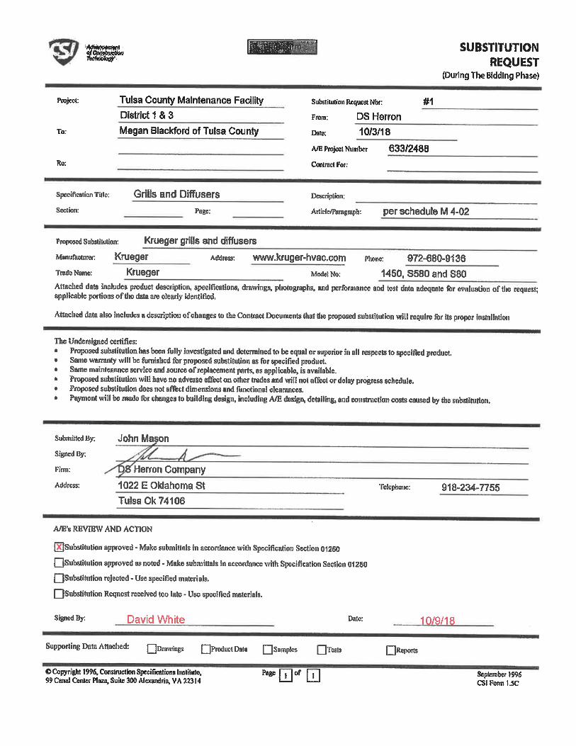
Tulsa County Maintenance FacilityDistrict 1 & 3
Megan Blackford of Tulsa County
SUBSTITUTIONREQUEST
(During The Bidding Phase)
Substitution RtqucstNbr: #1
From: DS Herron
Date 10/3/18
Affi Project Number 633/2488
Conlract For:
Specification Title:
Section:
Grills and Diffusers
Page:
Description:
AriiclB/Paragiaph: per schedule M 4-02
proposed Substitution: Krueger grills and diffusers
ManuTaciurer: Krueger Address: www.kruger-hvac. com phone: 972-680-9136
TradcName: Krueger ModetNo: 1450, S580 and S80Attached data includes product description, specifications, drawings, photographs, and performance and test data adequate for evaluation oftlie reqiiiisl;applicable portions of the data are clearly identified.
Attached data also includes a description ofchaiiges to the Contract Documents that tire proposed substitution wll require for its proper instnllatioii
The Undersigned certifies:Proposed substitutitm has been ftilly investigated and determined to be equal or superior ill all respects to specified product,Same warranty will be famished for proposed substitution as for specified productSame maintenance service aiid source ofieplacement parts, as applicable, is available.Proposed substitution will have no adverse effect on other trades and will not nnecl or delay piogress schedule.Proposed substitutfon docs not affect dimensions and fnnclionai clearances.
Payment will be made for changes to building design, including A/E desipi, detailing, and couslruction costs caused by the substitution.
Submitted By:
Signed By:
Firm:
Address:
John Ma on
Herron Company
1022 E Oklahoma StTuisa0k74106
Telephone: 918-234-7755
A ,'s REVIEW AND ACTION
[XJSubstihilion approved . Make submittals in accordance with Specification Section 01260
Qsubsdtution approved as noted - Make submittals in accordance with Specification Section 01260QSubstitution rejected - Use specified materials.
QSubstitution Request received too late - Use specified materiats.
David White Date:
Supporting Data Attached: QDiawings QP«wiuctData QSamples QTKite
Page m of© Copyright 1996, Constroction Specifications Instituta,99 Canal Center Plaza, Suite 300 Alexandria, VA 22314
10/9/18
QReports
September (996CSI Fonn 1.5C

AitvameinwtofConstructooTedwokigy
Print Form
Project:
To:
Re:
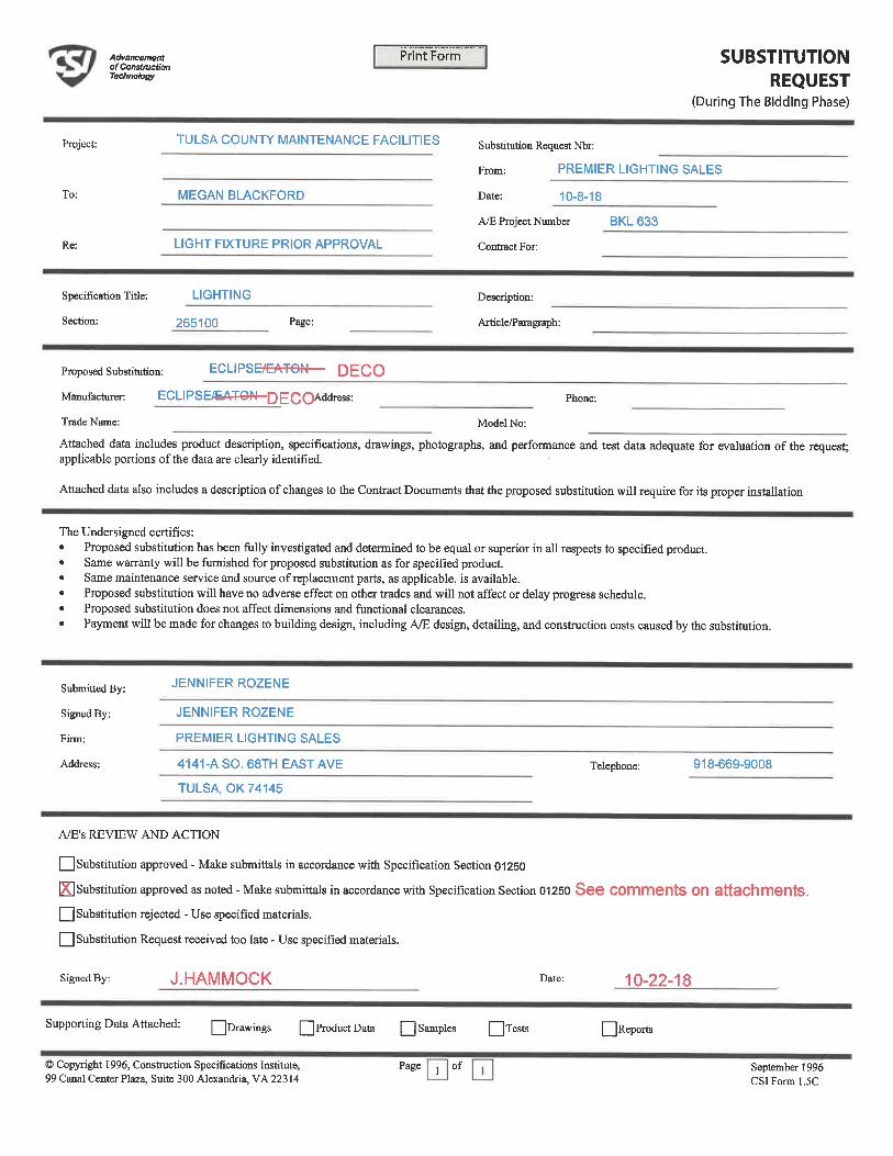
TULSA COUNTY MAINTENANCE FACILITIES
MEGAN BLACKFORD
LIGHT FIXTURE PRIOR APPROVAL
SUBSTITUTIONREQUEST
(During The Bidding Phase)
Substihition Request Nbr:
From: PREMIER LIGHTING SALES
Date: 10-8-18
A/E Project Number BKL 633
Contract For:
Specification Title:
Section:
LIGHTING
265100 Page:
Description:
Article/Paragraph:
Proposed Substitution: ECLIPSE/EATON
Manufacturer: ECLIPSE/EATON Address:
Trade Name:
Phone:
Model No:
Attached data includes product description, specifications, drawings, photographs, and performance and test data adequate for evaluation of the request;applicable portions of the data are clearly identified.
Attached data also includes a description of changes to the Contract Documents that the proposed substitution will require for its proper installation
The Undersigned certifies:
Proposed substitution has been fully investigated and determined to be equal or superior in all respects to specified product.Same warranty will be furnished for proposed substitution as for specified product.Same maintenance service and source of replacement parts, as applicable, is available.Proposed substitution will have no adverse effect on other trades and will not affect or delay progress schedule.Proposed substitution does not affect dimensions and functional clearances.
Payment will be made for changes to building design, including A/E design, detailing, and consfruction costs caused by the substitution.
Submitted By:
Signed By:
Finn:
Address:
JENNIFER ROZENE
JENNIFER ROZENE
PREMIER LIGHTING SALES
4141-A SO. 68TH EAST AVE
TULSA, OK 74145
Telephone: 918-669-9008
A/E's REVIEW AND ACTION
|_] Substitution approved - Make submittals in accordance with Specification Section 01250
[3 Substitution approved as noted - Make submittals in accordance with Specification Section 01250 See Comments OR attachmentsQ Substitution rejected - Use specified materials.
[__| Substitution Request received too late - Use specified materials.
Signed By: D. Rizik/J.Hammock Date: 10-19-18
Supporting Data Attached: QDrawmgs QProductData Q Samples QTests
Page | 1 | of
I[Reports
© Copyright 1996, Construction Specifications Institute,99 Canal Center Plaza, Suite 300 Alexandria, VA 22314
September 1996CSIForml. 5C
PREMIERLIGHTINGSACKS
Date: Oct 8, 2018
Premier Lighting Sales4141-A South 68th East Ave.Tulsa OKPhone:(918)669-9008Fax:(918)669-9018
Job NameTULSA COUNTY MAINTENANCE FACILITIES
PLSTUL18-17183TULSA OK
Bid DateOct 19, 2018
Submittal DateOct 8, 2018
Engineer:WARREN SMITH & ASSOCIATES
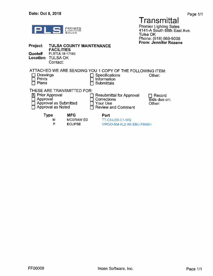
Date: Oct 8, 2018
PREMIERLIGHTINGSALES
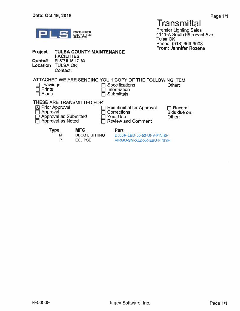
Project TULSA COUNTT MAINTENANCEFACILITIES
Quote# PLSTUL18-17183Location TULSAOK
Contact:
TransmittalPremier Lighting Sales4141-A South 68th East Ave.Tulsa OKPhone:(918)669-9008From: Jennifer Rozene
Page 1/1
ATTACHED WE ARE SENDING YOU 1 COPY OF THE FOLLOWING ITEM:DrawingsPrintsPlans
THESE ARE TRANSMITTED FOR:Prior ApprovalApprovalApproval as SubmittedApproval as Noted
SpecificationsInformationSubmittals
Resubmittal for ApprovalCorrectionsYour UseReview and Comment
TypeM
p
MFGMCGRAW EDECLIPSE
Other:
Recordiids due on:
Other-
PartTT-C3-LED-E1-WQVIRGO-SM-XL2-XK-EBU-FINISH
FF00009 Ingen Software, Inc. Page 1/1
Submitted b Premier Li htin
PLS ^k
Sales
Job Name:TULSA COUNTl' MAINTENANCEFACILITIESEngineer: WARREN SMITH & ASSOCIATES
Catalog Number:TT-C3-LED-E1-WQ
Notes:
Type:
PLSTUL18-17183
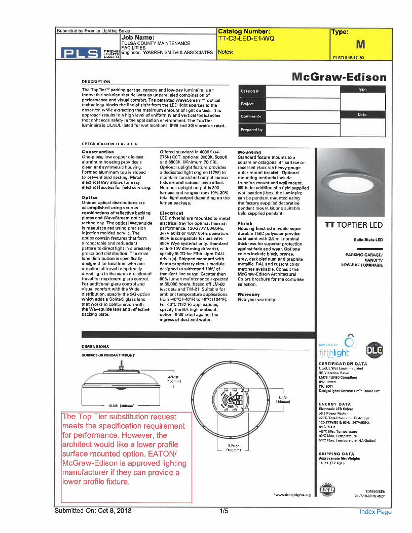
DESCRIPTION
The TopTierT parking garage, canopy and low-bay luminaire is an
innovative solution that delivers an unparalleled combination ofperformance and visual comfort. The patented WaveStreamT opticaltechnology blocks the line of sight from the LED light sources to theobserver, while extracting the maximum amount of light on task. Thisapproach results in a high level of uniformity and vertical footcandlesthat enhances safety in the application environment. The TopTierluminaire is UL/cUL listed for wet locations, IP66 and 3G vibration rated.
Catalog #
Project
Prepared by
cGraw-EdisonType
Date
SPECIFICATION FEATURES
Conatruction
One-piece, low copper die-castaluminum housing provides aclean and symmetric housing.Formed aluminum top is slopedto prevent bird nesting. Metalelectrical tray allows for easyelectrical access for field servicing.
OpticsUnique optical distributions areaccomplished using variouscombinations of reflective backingplates and WaveStream opticaltechnology. The optical Waveguideis manufactured using precisioninjection molded acrylic. Theoptics contain features that forma repeatable and redundantpattern to direct light in a preciselyprescribed distribution. The drivelane distribution is specificallydesigned for locations with onedirection of travel to optimallydirect light in the same direction oftravel for maximum glare control.For additional glare control andvisual comfort with the Widedistribution, specify the SG optionwhich adds a Solite® glass lensthat works in combination withthe Waveguide lens and reflectivebacking plate.
Offered standard in 4000K (+/-275K) CCT, optional 3000K, 5000Kand 6000K. Minimum 70 CRI.Optional uplight feature providesa dedicated light engine (17W) tomaintain consistent output acrossfixtures and reduces cave effect.Nominal uplight output is 800lumens and ranges from 10%-30%total light output depending on thelumen package.
ElectricalLED driver(s) are mounted to metslelectrical tray for optimal thermalperformance. 120-277V 50/60Hz,347V 60Hz or 480V 60Hz operation.480V is compatible "for use with4BOV Wye systems only. Standardwith 0-10V dimming driver(s),specify 5LTD for Fifth Light DALIdriver(s). Shipped standard withEaton proprietary circuit moduledesigned to withstand 10kV oftransient line surge. Greater than90% lumen maintenance expectedat 60,000 hours, based off LM-80test data and TM-21. Suitable for
ambient temperature applicationsfrom -40°C |-40°F) to 40»C (104°F).For 50°C (122°F) applications,specify the HA high ambientoption. IP66 rated against theingress of dust and water.
MountingStandard fixture mounts to asquare or octagonal 4" surface orrecessed j-box via heavy-gaugequick mount bracket. Optionalmounting methods includetrunnion mount and wall mount.With the addition of a field suppliedwet location j-box, the luminairecan be pendant mounted usingthe factory supplied decorativependant mount kit or a suitablefield supplied pendant.
FinishHousing finished in white superdurable TGIC polyester powdercoat paint with 2. 5 mil nominalthickness for superior protectionagainst fade and wear. Optionalcolors include black, bronze,grey, dark platinum and graphitemetallic. RAL and custom colormatches available. Consult theMcGraw-Edison ArchitecturalColors brochure for the completeselection.
WarrantyFive-year warranty.
TOPTIER LED
Solid State LED
PARKING GARAGE/CANOPY/
LOW-BAY LUMINAIRE
DIMENSIONS
SURFACE OR PENDANT MOUNT
18.3/8" 1466mm]
4-7/16"[106mm]
J
The Top Tier substitution requestmeets the specification requirementfor performance. However, thearchitect would like a lower profilesurface mounted option. EATON/McGraw-Edison is approved lightingmanufacturer if they can provide alower profile fixture.
5-1/2"1140mm]
7-7/16-[IBSmiri)
powered by
i '-lightCERTIFICATION DATAUUcUL Wet Location Liatad3G Vibration RatedLM79/LM80 CompliantIP66 RatedISO 9001DesignLights Consortium"" Qualified*
ENERGY DATAElectronic LED Driver>0.9 Power Factor<20% Total Harmonic Distortion120-277V/50 8l eOHz, 347V/60HZ.480V/60HZ-40°C Min. Temperature40BC Max. Temperature50°C Max. Temperature (HA Option)
SHIPPING DATAApproximate Net Weight:16 Ibs. (7. 2 kgs.)
.www. designlights. orgTD515005EN
2017.10.0909:45:31
Submitted On: Oct 8, 2018 1/5 Index Page
Submitted b Premier Li htin Sales
Job Name:TULSA COUNTi' MAINTENANCE
Ci^EiM!i Engineer: WARREN SMITH & ASSOCIATES Notes:BALE; fci
Catalog Number:TT-C3-LED-E1-WQ
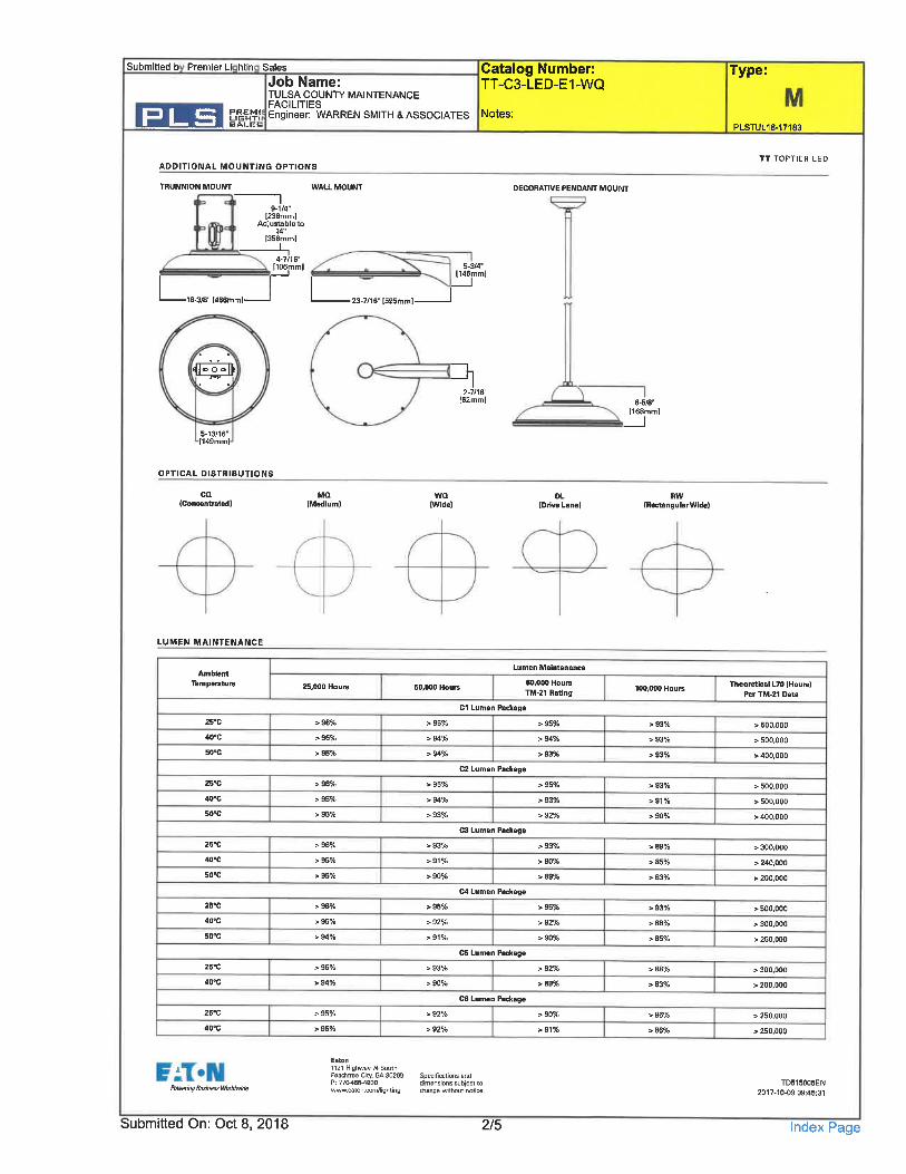
ADDITIONAL MOUNTING OPTIONS
TRUNNION MOU^^. WALL MOUNT
L.18-3»" 1466mm] 23-7/16" [595mm]-
5-3/4"1146mm]
DECORATIVE PENDANT MOUNT
Type:
PLSTUL18-17183
TT TQPTIER LED
5.13/16"[149mm]
OPTICAL DISTRIBUTIONS
LUMEN MAINTENANCE
2.7/16"[62mm] 6-5/8"
[168mm]
ca(Concentrated)
MQ(Medium)
WQ(Wide)
DL(Drive LBI
RW(RectangularWidel
AmbientTemperature
25'C
40«C
50-C
25-C
we
50'C
zs'c
40'C
50-C
2B«C
40'C
50"C
25'C
40-C
25'C
40-C
25, 000 Hours
> 96%
> 96%
> 95%
> 96%
> 95%
> 95%
> 95%
s. 94%
> 95%
> 95%
Lumen Maintenance
^1°sCl Lumen Package
> 95% > 95%
> 94% > 94%
> 94% > 93%
C2 Lumen Package
> 95% > 95%
> 94% > 93%
> 93% > 92%
C3 Lumen Package
> 93% > 93%
> 91% > 90%
> 90% > 89%
C4 Lumen Package
> 35% > 95%
> 92% > 92%
> 91% > 90%
C5 Lumen Package
> 93% > 92%
> 90% > 89%
C6 Lumen Package
> 92% > 90%
> 92% > 91%
100, 000 Hours
> 93%
> 93%
>S3%
> 93%
>91%
> 90%
Theoretical L70 (Hours)Per TM-21 Data
> sao.ooo
> 500, 000
> 400,000
> 500,000
> 500.000
> 400,000
> 300,000
> 240, 000
> 200,000
> 500,000
> 300, 000
> 260, 000
> 300,000
> 200, 000
> 250,000
> 250,000
Powering Btisifiess WorldMdB
Eaun1121 Highwy » SouthReachtree City. GA 30269 Specificstions andP; 77CM86-4800 dimensions subject towww.eaton.com/lighting change witiiout nolioe.
TD515005EN2017-100 09:45:31
Submitted On: Oct 8, 2018 2/5 Index Page
Submitted b Premier Li htin Sales
Job Name:ULSA COUNT/ MAINTENANCE
^E|M,'; Engineer: WARREN SMITH & ASSOCIATES
Catalog Number:TT-C3-LED-E1-WQ
Notes:
Type:
PLSTUL18-17183
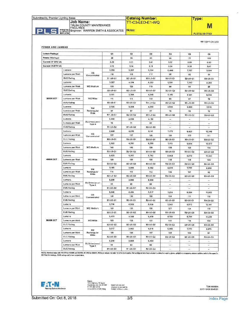
POWER AND LUMENS
TTTOPTIER LED
Lumen Package
Power (Wattage)
Current ® 120V (A|
Current @ 277V (A)
Lumens
Lumens per Watt
BUG Rating
Lumens
Lumens per Watt
BUG Rating
Lumens
3000K CCT Lumens per Watt
BUG Rating
Lumens
Lumens per Watt
BUG Rating
Lumens
Lumens per Watt
JG Rating
Lumens
Lumens per Watt
ati ng
Lumens
Lumens per Watt
BUG Rating
Lumens
4000K CCT Lumens per Watt
BUG Rating
Lumens
Lumens per Watt
BUG Rating
Lumens
Lumens per Watt
BUG Rating
Lumens
Lumens per Watt
BUG Rating
Lumens
Lumens per Watt
BUG Rating
Lumens
5000K CCT Lumens per Watt
ing
Lumens
Lumens per Watt
Rating
Lumens
Lumens per Watt
BUG Rating
NOTE; Nomlntl du« with 70 CRI tor 4000K and 5000K. 80 CRI for 3000K. Wa«ag« vluu not valid for dm hn« opUe. For configurattons that Includ. th«IES files for wattage, BUG rating and lumen output data.
CQConcentrated
MQMadium
WQ Wide
RWRectangular
Wide
DL Drive Lane/Type 4
coConcentrated
MQ Medium
WQ Wide
RW
RectangularWide
DL Drive Lane/Type 4
CQConcentrated
MQ Medium
WQ Wide
RWRectangular
Wide
DL Drive Lane/Type 4
C1
28
0. 26
0.13
3, 293
118
B1-UO-G1
3, 357
120
B2-UO-G1
3.101
111
B2-UO-G1
2,726
97
B2. UO. G1
2, 440
73
B1. UO. G2
3, 848
137
B2-UO-G1
3, 922
140
B2-UO-S1
3, 623
129
B2-UO-G2
3,165
1W
B2-UO-G2
3, 235
98
B1-UO-Q2
3, 645
130
B1-UO-G1
3,716
133
B2-UO-G1
3, 433
123
B2-UO-G2
3,017
108
B2-UO-G2
3. 205
96
B1-UO-G2
cz
34
0. 31
0.14
3, 997
118
B2-UO-G1
4.074
120
B2-UO-G1
3,764
111
B2. UO. G2
3. 308
97
B2-UO-G2
2, 938
71
B1. UO-G2
4, 670
137
B2-UO-G1
4.760
140
B2-UO-G2
4, 337
129
B2-UO-G2
3, 865
114
B2-UO-G2
3,895
35
B1-UO-G2
4,424
130
B2-UO. G1
4, 509
133
B2-UO-G2
4,166
123
B2-UO. Q2
3.662
108
B2-UO-G2
3.858
93
B1-UO-G2
C3
45
0.41
0. 1 S
5. 256
117
B2. UO. G1
5, 357
119
B2-UO.G2
4, 949
110
B3-UO-G2
4, 350
97
B3-UO-62
4, 152
62
B2-UO-G3
6, 141
136
B2-UO.G1
6, 259
138
B3-UO. G2
5,762
128
B3-UO-G2
5.082
113
B3-UO. G2
5. B06
83
B2-UO.G3
5, 817
130
B2-UO.G1
5, 928
132
B3-UO. G2
5.476
122
B3-UO.Q2
4. 815
107
B3. UO. G2
6, 454
82
B2.UO-G3
c<
58
0. 52
0.24
5.486
95
B2-UO-G1
5, 591
96
B2-UO-S2
5, 165
89
B3-UO-G2
4, 540
78
B3.UO-G2
7, 273
126
B2-UO-G1
7,413
128
B3.UO-G2
6. 848
118
B3-UO. G2
6, 019
104
B3-UO.G2
7, 204
124
B2-UO-G1
7, 343
127
B3-UO-G2
6, 783
117
B3-UO-G2
5, 962
103
B3-UO-G2
C5
77
0. 69
0.30
7,107
92
B2-UO-G1
7, 243
94
B3.UO-G2
6. 691
87
B3-UO-S2
5.882
76
B3-UO. G2
3,423
123
B3. UO. G1
9, 604
125
B3-UO-G3
8.S72
115
B3-UO-G3
7,799
101
B3-UO-G3
9, 334
121
B3-UO-G1
9, 513
124
B3-UO-G3
8,788
114
B3-UO-G3
7,725
100
B3-UO-G3
C6
108
0.95
0.41
9.084
84
B3-UO-G1
9, 259
86
B3-UO. G2
8. 554
79
B3-UO-G3
7,519
70
B3-UO-G3
12, 046
111
B3-UO-G2
12, 277
1M
B3-UO-G3
U. 342
105
B4-UO-G3
9, 969
92
B3-UO-G3
11. 932
1W
B3. UO. G2
12, 161
113
B3-UO-G3
11,235
104
E3-UO. G3
9, 875
91
B3.UO.G3
drive lane optic, glass, uplighl or occupancy sensor options rsfar to the specific
Eaton1121 Highway 74 SouthPeactitree City, GA 30269P: 77M864800www.eaton.conVlighting
Specifications anddimensions subject tochange without notice.
TD515005EN2017-10-0909:45:31
Submitted On: Oct 8, 2018 3/5 Index Page
Submitted b Premier Li htin Sales
Job Name:TULSA COUNPl' MAINTENANCE
AGILITIES
Catalog Number:TT-C3-LED-E1-WQ
PLS ^3k
Type:
gineer: WARREN SMITH & ASSOCIATES Notes:PLSTUL18-17183
TT TOPTIER LED
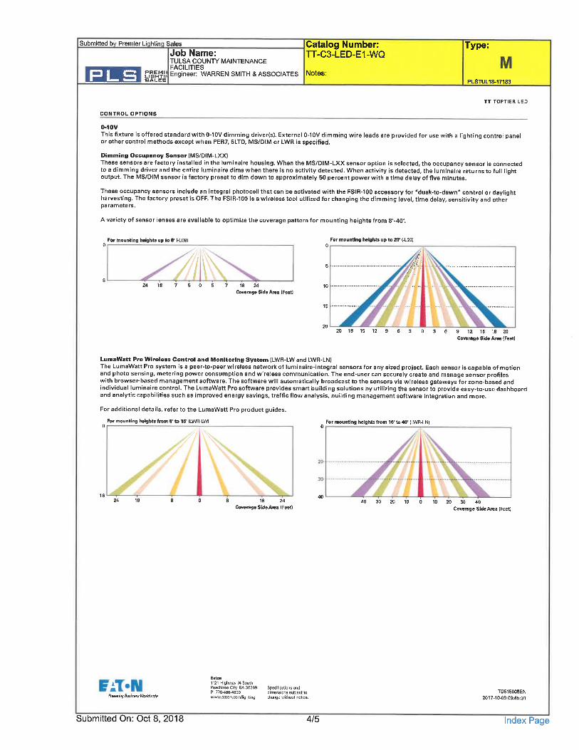
CONTROL OPTIONS
0-10VThis fixture is offered standard with 0-10V dimming driver(s). External 0-10V dimming wire leads are provided for use with a lighting control panelor other control methods except when PER7, 5LTD, MS/DIM or LWR is specified.
Dimming Occupancy Sensor (MS/DIM-LXX)These sensors are factory installed in the luminaire housing. When the MS/DIM-LXX sensor option is selected, the occupancy sensor is connectedto a dimming driver and the entire luminaire dims when there is no activity detected. When activity is detected, the luminaire returns to full lightoutput. The MS/DIM sensor is factory preset to dim down to approximately 50 percent power with a time delay of five minutes.
These occupancy sensors include an integral photocell that can be activated with the FSIR-100 accessory for "dusk-to-dawn" control or daylightharvesting. The factory preset is OFF. The FSIR-100 is a wireless tool utilized for changing the dimming level, time delay, sensitivity and otherparameters.
A variety of sensor lenses are available to optimize the coverage pattern for mounting heights from 8'-40'.
For mounting heights up to ff (-L08)
J^2418 7 505 7 1824
Coverage Side Area (Feet)
For mounting heights up to 20' (-L20)
^;./:
15 -.-.--
20 18 15 12 9 12 15 IS 20
Coverage Side Area (Feet)
LumaWatt Pro Wirslass Control and Monitoring System (LWR-LWand LWR-LN)The LumaWatt Pro system is a peer-to-peer wireless network of luminaire-integral sensors for any sized project. Each sensor is capable of motionand photo sensing, metering power consumption and wireless communication. The end-user can securely create and manage sensor profileswith browser-based management software. The software will automatically broadcast to the sensors via wireless gateways for zone-based andindividual luminaire control. The LumaWatt Pro software provides smart building solutions by utilizing the sensor to provide easy-to-use dashboardand analytic capabilities such as improved energy savings, traffic flow analysis, building management software integration and more.
For additional details, refer to the LumaWatt Pro product guides.
For mounting heights from 8' to 16' (LWR-LWI For mounting heights from 16' to 40' ILWR-LNI
18 24Coverage Side Area (Feet)
10 20 30 40Coverage Side Area (Feet)
fbwering Busmesa Wariiiwide
Submitted On: Oct 8, 2018
1121 Highway M SouthPeachtree City. GA 30269 Specifications andP: 770^8&4800 dimensions subject towww. saton. com/lighting change without notice.
TD515005EN2017-10-0909:45:31
4/5 Index Page
Submitted b Premier Li htin Sales
Job Name:TULSA COUNTY MAINTENANCEFACILITIES
CSEIM! Engineer: WARREN SMITH & ASSOCIATESSAl^RB
PLS
Catalog Number:TT-C3-LED-E1-WQ
Notes:
Type:
PLSTUL16-17183
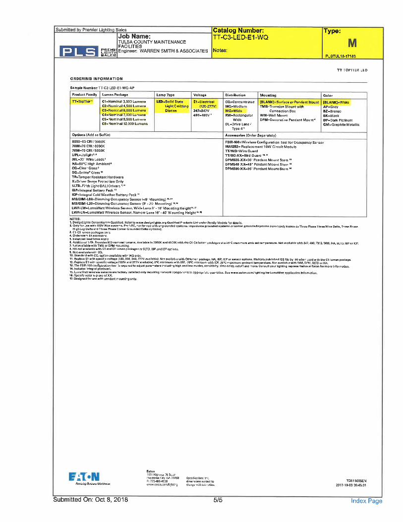
ORDERING INFORMATION
TTTOPTIER LED
Sample Number: TT-C2-LED-E1-WQ-AP
Product Family Lumen Package
TT=TopTier1 C1=Nominal 3, 500 Lumens
C2=Nominal 4, 500 Lumens
C3=Nominal 6, 000 LumensCd=Nominal 7, 500 LumensC5= Nominal 9,500 LumensCB=Nominal 12,000 Lumens
Mounting
[BLANK]=Surface or Pendant MountTMB=Trunnion Mount with
Connection BoxWM-Wall MountDPM=DBcorative Pendant Mount *
LampTVpe Voltage Distribution Mounting Color
LED. Solid Stato E1=Electrical Ca-ConcentratedLight Emitting (120-277V) MQ-MediumDiodes 347.347V Wa=Wide
4B0.480V RW-RectangularWide
DL=Drive Lane/Type 4"
Accessories (Order Separately)
FSIR-100=Wirel8SS Configuration Tool for Occupancy SensorMA125Z- Replacement 10kV Circuit ModuleTT/WG=Wire GuardTT/BG-XX. Bird Guard " "DPMS36-XX-36" Pendant Mount Stem "DPMS48-XX. 48" Pendant Mount Stem "DPMS96-XX=96" Pendant Mount Stem "
[BLANK]=WhiteAP-GreyBZ=BronzeBK=BlackDP-Dark PlatinumGM=Sraphit« Metallic
Options (Add as Suffix)
8030=80 CRI/3000K7060=70 CRI/6000K7050=70 CRI/5000KUPL=Uplighf.'30L.30" Wire Leads'HA-50°C High Ambient"CG=Clear Glass"SG.Solite* Glass"TR=Tamper Resistant HardwareX=Driver Surge Pratectfon OnlyBLTD. Fifth Light DALI Drivers'-"IBP=lntegral Battsry Pack"ICP=lntegral Cold Weather Battery Pack "MS/DIM-L08=Dimming Occupancy Sensor (<9' Mounting) '*."MS/DIM-L20=Dimming Occupancy Sensor (9' - 20' Mounting) 1*'uLWR-LW=LumaWatt Wireless Sensor, Wide Lens 8'-16' Mounting Height"-'5LWR.LN=LumaWatt Wireless Sensor, Narrow Lens 16' -40' Mounting Height"'"
NOTES;1, DesignLights ConsortiumT Qualified. Refflr to www. designlights. org Qualified Products List under Family Models for details.
2. Only for use with 4BOVWya systems. Par NEC, not for use with ungrounded systems, impedance grounded systems or corner grounded syfitams (commonly known as Three Phase Three Wire Delta, Three PhasaHigh Leg Delta and Three Phase Corner Groundfld Delta syG tems).
3. C1-C3 lumen packages only.4. Order stem kit accessory.5. Extended lead timss apply.9. Additional 17W. Provides 800 nominal lumans. Available in 3000K: and 4000K with the C1-C4 lumen packages at a 25'C maximum ambient tamparature. Not available with 347, 480. TMB. WM. HA. 5LTD. IBP or ICP.7. Not availeble with TMB or DFM mounting.8. HA not svailabta with C5 and C6 lumen packagss or 6LTD, IBP and ICP options.9. Not available with CQ.10. Standard with CO, option availsbla with WQ only.
n, Raptace El with specffic voltagn 1120. 208, 24_D, 277V . vaillbl^. Not avilable with C8 lumen package. HA. IBP, ICP or sensor optionB. Multiply publlshld IES file by .96 when used with the C5 lumen pickage.12. Replace E1 with specific voltage (IZOV and 277V available}. O'C minimum with IBP, -20flC mlntmum with tCP, 25'C maximum Bmbiant temperature. NDt available with WM, DPM, 6LTD or HA.13. The FSIR-100 configuration tool is requirad to adjust paramefters including high and low modes. sensitivity, time delay, cutoff and more. Consult your lighting representative at Eaton for more information.14. Includes integral photocell.
15. LumaWaH wireless sensors are factory installed only requiring network components in appropriate quantities. See www.eaton.com/lighting far LumaWatt application information.K. SpenfvcolorlnplaceofXX. ~ ' .... . ^ . ^. -. ^-^.... -^_^... -^.. -.. -...... -.... _......17. Designed for use with pendant mounting only.
Powering Business Worliiwide
Eaton1121 Highway 74 SouthPeachtree City. GA 30269 Spocifications andP; 771MSM800 dimensions sub|ect towww.eaton.com/lishting change without notice.
TDE15005EN2B17-10. 09 09:45:31
Submitted On: Oct 8, 2018 5/5 Index Page
Submitted b Premier Li htin Sales
Job Name:TULSA COUNTl' MAINTENANCEFACILITIES
CSE|M!; Engineer: WARREN SMITH & ASSOCIATES Notes:
Catalog Number:VIRGO-SM-XL2-XK-EBU-FINISH
Type:
PLSTUL18-17183
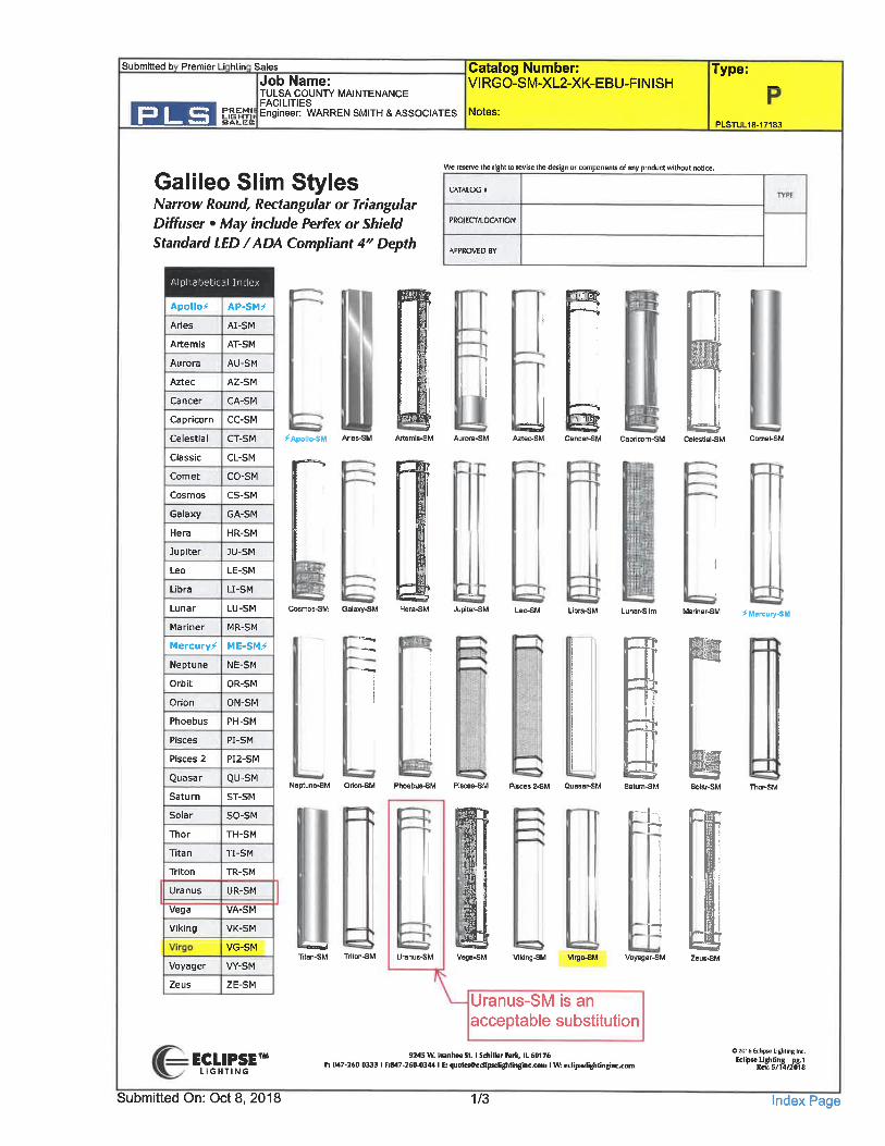
Galileo Slim StylesNarrow Round, Rectangular or TriangularDiffuse/- . May include Perfex or ShieldStandard LED /ADA Compliant 4" Depth
We reserve the right to revise the design or components of any product without notice.
CATALOG I
PROJECr/LOCATION
Zeus ZE-SM
Alphabetical Index
Apollo^
Aries
Artemis
Aurora
Aztec
Cancer
Capricorn
Celestial
Classic
Comet
Cosmos
Galaxy
Hera
Jupiter
Leo
Libra
Lunar
Mariner
Mercury^
Neptune
Orbit
Orion
Phoebus
Pisces
Pisces 2
Quasar
Saturn
Solar
Thor
Titan
Triton
Uranus
Vega
Viking
-r
AP-SM?-
AI-SM
AT-SM
AU-SM
A2-SM
CA-SM
CC-SM
CT-SM ^Apollo^M
CL-SM y-~.CO-SM
CS-SM
GA-SM
HR-SM
JU-SM
LE-SM
LJ-SM
LU-SM Cosmos-SM
MR-SM
ME-SM^
NE-SM
OR-SM
ON-SM
PH-SM
PI-SM
PI2-SM
QU-SMNeptune^M
ST-SM
SO-SM
TH-S M
TI-SM
TR-SM
UR-SM
VA-SM
VK-SM
VG-SM
VY-SMan-SM
F^
Capricorn-SM
Gala»y-SM Jupiter-SM < Mercuiy-SM
J I
®s
Pisces 2-SM Quasar-SM
!-
Vega-SM Viking-SM Viigo-SM
n
Voyager-SM
Uranus-SM is an
acceptable substitution
ECLIPSETLIGHTING
Submitted On: Oct 8, 2018
92<5 W. Ivanhot St. I Schiller Rirk, IL 60176
P; B47-260-0333 I F:8<7. 260. 0344 I E: quoteseedipselighfinglnc. com I Wfc eclip«clighlmBnc. Ti
1/3
OZOISEdipseLightinBlnc.EdipH -J. lghlitig jig.1
«ev. 5/14rio"18
Index Page
Submitted b Premier Li htin
PLS
Sales
Job Name:TULSA COUNTC MAINTENANCEFACILITIESEngineer: WARREN SMITH & ASSOCIATES
Catalog Number:VIRGO-SM-XL2-XK-EBU-FINISH
Notes:
Type:
PLSTUL18-17183
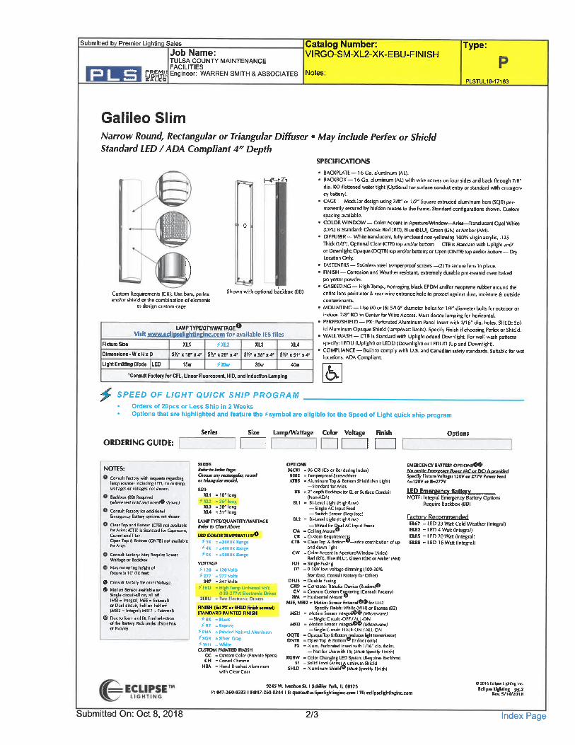
Galileo SlimNarrow Round, Rectangular or Triangular Diffuser . May include Perfex or ShieldStandard LED /ADA Compliant 4" Depth
SPECIFICATIONS
1-4"
II.
Custom Requirements (CR): Use bars, perfexand/or shield or Ihe combination of elements
to design custom cage
Shown with optional backbox (BB)
LAMP nPE/QTYIWATTAGE0Visit www.eclin8eliBhtineinc.rnm for available IES files
RrtureSlze
Dimenrions. WxHxD
Ught Emitting Diode LED
XL1 ^XU5y2-X18-»4- 5II-X26-X4-
15w ^2Dw
XL3 XL4
5K-X38-X4" 5K'x5rx4-
30w 40W.Consult Factoiy for CFL, Unear Fluoreacent, HID, and Indudion Lamping
^
' BACKPLATE - 16 Ca. aluminum (AL).
1 BACKBOX - 16 Ga. aluminum (AL) with wire access on four sides and back through 7/8"dla. KO flattened water tight (Optional for surface conduit entry or standard with emcrgen-cy battery).
' CAGE - Modular design using 3/B" or 1/2" Square extruded aluminum bars (SQB) per.manentty secured by hidden means to the frame. Standard configurations shown. Customspacing available.COLOR WINDOW - Color Accent in ApertureAIVindow-^Aries-Translucent Opal White(OPL) is Standard; Choose: Red (RD), Blue (BLU), Green (CN) or Amber (AM).DIFFUSER - White Iranslucent, fully enclosed non-yellowing 100% virgin aciylic, .125nick (1/B"). Optional Clear (CTB) top and/or bottom - CTB is Standairi wilh Uplight and/or Downl ight; Opaque (OQTTB) top and/or bottom; or Open (ONTB) top and/or bottom - DryLocation Only.FASTENERS - Stainless steel tamperproof screws -(2) To secure lens in place.FINISH - Corrosion and Weather resistant, extremely durable pre-treated oven bakedpolyester powder.CASKETING - High Temp., non-aging black EPDM and/or neoprene rubber amund theentire lens perimeter & rear wire entrance hole to protect against dust, moislure & outsidecontaminants.
MOUNTING - Use (4) or (6) 5/16" diameter holes for U4" diamelei bolts hr outdoor or
indoor. 7/8" KG in Center for Wire Access. Must derate lamping for horizontal.PERFEXffiHIELD- PX: Perforated Aluminum Panel Insert with 1/16" dia. holes. SHLD: So]-id Aluminum Opaque Shield (lamp/waa limits). Specify Finish if choosing Perfex or Shield.
. WALL WASH-CTB is Standard with Uplightor/and Downlight. For wall wash panernsspecify: LEDU (Uplight) or LEDD (Downlight) or LEDUD (Up and Downlight).
' COMPLIANCE - Built to comply with U.S. and Canadian safety standards. Suitable for wetlocations. ADA Compliant.
SPEED OF LIGHT QUICK SHIP PROGRAMOrders of ZOpcs or Less Ship in 2 WeeksOptions that are highlighted and feature the symbol are eligible for the Speed of Light quick ship program
ORDERING GUIDE:Series Size Lamp/Wattage Color Voltage
a[Finish Options
NOTES:
Consult Factory with requests regardinglamp sources including LED, color lemp,wattages or voltages not shown.
Backbox<BB) Required[where text bold and note#0 shown^
Consult Factory for additionalEmergency BaHery options not shown
ClearTop and Bottom (CTB1 not availablefor Aries; (CTB) is Standard for Capricorn,Comet and TlanOpen Top i Bonom (ONTBI nnt .vallablefar A has
Consult Factory: May Require LowerWattage or Backbox
Max mounting height offixture is 10'(IDfeel)
® Consult Factory for other Voltage
© Motion Sensor available as-Single circull-all on, all off(MSI . Integral, MSE . Ealemal)ill Dual circull, half on half off(MS12 = Integral; MSEZ = External)
® Due to forni and fit, final selwlinnof the Battery fack under discrelronof Factory
SERIESBefcr to Index ft(ge:Choose any ivclangular, roundor triangular model.
SIZEXL1 =18" long
^XL2 =2«-longXL3 . 38'longXL4 . 51 "long
LAMP TYPE/QUANTITV/WATIACEHefer to Chart Above
LED COLOR TEMPERATURE®f3K =±3000K Range^4K -±400DK Range^5K = ASOOOK Range
VOITAGE
^120 =120Volbf 177 =277Volh
347 . 347 VotefCBU -High Temp Unkcrnl Volt
(120-277») Electronic DTIVEI
HNISH (list FX or SHLD flni* Muind)STANDABD PAINTED FINISHfSK -Black^82 = Bronze
^ PNA = fainted Natural Aluminum^SCR -Silver Cray^WH = WhiteCUSTOM PAINTED FINISH
CC - Custom Color tProvide Specs)CH - Corucl Chrome
NBA = Hand Brushed Aluminumwith Clear Coal
OPTIONS96CR] . 96 C81 (Color Rendering Index)9002 = Tamperproaf ScrewdriverATBS = Aluminum Top & Bottom Shield (No Light)
-Standard for Aries
BB . 2- deplh Backbox for EL or Surface Conduit(Non-ADlA)
BL1 = Bi-LevelLight(Highfl. ow)-Single AC Input Feed- Switch Sensor [Required)
BL2 - Bi-Lim.lLighKHighAoui)- Wired for Q^al AC Inpulfeeds
CM -Celling Mount®CR = Custom Requiremer
CTB = ClearTop & 8oHomw-adds contribution of upand down light
CW = Color Accent in Aperture/Window (Aries)Red (RD), Blue |BIU), Green (CN) or Amber (AMI
FUS » Single FusingD7 =0-10Vlow-voltage dimming (100-30%
Standard, Consult Fartory far Other)DFUS -Double FusingGTD = Generator Transfer Device (Badine)O
CV = Gravura Custom Ei^raving (Consult Factory)HM . Horizontal Mount'
MSE, M5E2 = MDtion Sensor ExternalO® for LEDSpecify Finiih: Whit^lWH; or Bronze IBZ)
MSI1 = Motion Sensor Inlegral®"® (Microwave)-Single Circuit:-OFF /ALL. ON
MSB - Molion Senior Inlegral®® fMtoou-ar;-Single Cireuit- HALF-ON /ALL-ON
OQTB = OpaqueTop & BotfDm^reduces Ifghl transmisskm]ONTB = Open Top & Bottom" (indoor only]
PX = Alum. Perforated Insert with 1/16" dla. holes.
- Not for Uif with T5; [Mua Specify Finiih)RC8W = Color Changing LED System (Requires Backbox)
SF - Solid Fmnl lAriEslAluminum ShieldSHLD . Aluminum Shield® (Must Specify Finish)
EMEBCENCY BATTEBV OPTIONS®®A/o onshe fmenfencv ftower fACor DCUiomvidsd
Specify R»tur« Voltage; 120V or 277V Puurr In-dA=120V 0> B=277V
LED Emeroencv Batterv
NOTE: Integral Emergency Battery OptionsRequire Backbox (BB)
Factory RecommendedEL67 = LED 23 Watt Cold Weather (Integral)E182 = LED 4 Watt (Integral)EUS = LED 20 Watt (Integral)E188 - LED 16 Wan (Integral)
9245 W. Ivanhot St. I Schiller Pilk, IL 60176P: 847-260.0333 I r:B47-261M)344 I E: suotMeecli|Bclightmginc.mm I Wt edipM. liehtmglnc.com
02016 Eclipse Lighting Inc.
Edlp"IK%^
Submitted On: Oct 8, 2018 2/3 Index Page

Submitted b Premier Li htin Sates
Job Name:TULSA COUNTC MAINTENANCE
: Engineer: WARREN SMITH & ASSOCIATES Notes:
Test#LLI-16162-J-R01Test Hate. 07/7/2016
Catalog Number: Type:VIRGO-SM-XL2-XK-EBU-FINISH
PLSTUL18-171B3
CT-SM-XL2-LED20-5K-EBU-BZ
rested in accordance with tM-79-SOThe results contained in this summaryreport pertain only to the tested sample
Electrical Test Condiotions
Temp Voltage Current Power Power Factor Current THD Bug Rating25'C(±1'IC) 120. 0 0. 134A 15. 2W 0. 941 9. 60% BO-U3^31
Summa of Results
Total Lumen Output 986 Lumens
Efficacy rim^ 64.9 Lmnw
CCTDuv
4930K0.000<
Legend: CD/dSO.Solid, C45/C225-Dashed, CM/C270^3rey (cd)
150
X.
<^v<\\\
\_ , "..-..,.. --^. ^;
.-+-
",'"-i -
---c"'-^ .>. <.
\
f0;'
N//
- y' \~r-f'\aB\/ /
<V-H4\'\3.0"/ ' ..<
C180-C270
iso /
/
-,/
\.
u^-'.. \''
^^-^.
,teo
>. .
, ;;..,....I
\ \
\'w..
>'
i, -'"v
i \ 30.. '.<
(Asymmetric) CO-C9S
0.9
0.8
0.7
o.e
0.5
0.4
0.3
0.2
0.1
D
380 400 420 440 460 480 500 520 540 560 580 600 620 640 660 6SO 700 720 740 760 780Wavetength (nm)
. Pie spectral power distribution combines Ihe weighted spectral power OistribuUons of all spatial m«asur«ni«nts.
Zonal Lumen SummaryZone
0-30
0-40
&.60
0-90
40-90
90-180
0-180
Lumens
28
191
492
428
301
494
986
%luminaire
2.8
6.5
19.4
49.9
43.5
30.5
50.1
100.0
Chromaticity CoordinatesChromatlcay (x)
Chromaticity (y)
Chromaticity (u^
Chromaticity W
0347
0.354
0. 212
0.486
ECLIPSETLIGHTING
92<5 W. Ivanhoc St. I Schiller Fark, 1160176f: B47.260.0333 I F;847.260-0344 I E: quotlsBedipl tlighlinginc^iim I W: cdipselighlinginc.com
0 2016 Eclipse Ughling Inc.cdvKS^^
Submitted On: Oct 8, 2018 3/3 Index Page
AtfvaneementofConsbuelionTechnology
Print Form
Project:
To:
Re:
TULSA COUNTS MAINTENANCE FACILITIES
MEGAN BLACKFORD
LIGHT FIXTURE PRIOR APPROVAL
SUBSTITUTIONREQUEST
(During The Bidding Phase)
Substitution Request Nbr:
From: PREMIER LIGHTING SALES
Date: 10-8-18
Am Project Number BKL 633
Conto^ct For:
Specification Title: LIGHTING
Section: 265100 Page:
Description:
Article/Paragraph:
Proposed Substitution: ECLIPSDCATON DECO
Manufacturer: ECLIPSE/EATON DECOAddress:
Trade Name:
Phone:
Model No:
Attached data includes product description, specifications, drawmgs, photographs, and performance and test data adequate for evaluation of the request;applicable portions of the data are clearly identified.
Attached data also includes a description of changes to the Contract Documents that the proposed substitution will require for its proper installation
The Undersigned certifies:Proposed substitution has been fully investigated and determined to be equal or superior in all respects to specified product.Same warranty will be furnished for proposed substitution as for specified product.Same maintenance service and source of replacement parts, as applicable, is available.Proposed substitution will have no adverse effect on other trades and will not affect or delay progress schedule.Proposed substitution does not affect dimensions and functional clearances.
Payment will be made for changes to building design, including A/E design, detailing, and construction costs caused by the substitution.
Submitted By:
Signed By:
Finn:
Address:
JENNIFER ROZENE
JENNIFER ROZENE
PREMIER LIGHTING SALES
4141-A SO. 68TH EAST AVE
TULSA, OK 74145
Telephone: 918-669-9008
A/E's REVIEW AND ACTION
[_] Substitution approved - Make submittals in accordance with Specification Section 01250
K] Substitution approved as noted - Make submittals in accordance with Specification Section 01250 See Comments OR attachments.
[_] Substitution rejected - Use specified materials,
[_] Substitution Request received too late - Use specified materials.
Signed By: J.HAMMOCK Date: 10-22-18
Supporting Data Attached: Qorawings QProductData Q Samples QTests II Reports
© Copyright 1996, Construction Specifications Institute,99 Canal Center Plaza, Suite 300 Alexandria, VA 22314
Page , of September 1996CSIForml. 5C
PREMIERLIGHTINBSALES
Date: Oct 19, 2018
Premier Lighting Sales4141-A South 68th East Ave.Tulsa OKPhone:(918)669-9008Fax:(918)669-9018
Job NameTULSA COUNTY MAINTENANCE FACILITIES
PLSTUL18-17183TULSA OK
Bid DateOct 19, 2018
Submittal DateOct 8, 2018
Engineer:WARREN SMITH & ASSOCIATES
Date: Oct 19, 2018
PREMIERUBHTINiGsAues
Project TULSA COUNTS MAINTENANCEFACILITIES
Quote# PLSTUL18-17183Location TULSAOK
Contact:
TransmittalPremier Lighting Sales4141-A South 68th East Ave.Tulsa OKPhone:(918)669-9008From: Jennifer Rozene
Page 1/1
ATTACHED WE ARE SENDING YOU 1 COPY OF THE FOLLOWING ITEM:DrawingsPrintsPlans
THESE ARE TRANSMITTED FOR:Prior ApprovalApprovalApproval as SubmittedApproval as Noted
Type MFGM DECO LIGHTINGP ECLIPSE
SpecificationsInformationSubmittals
Resubmittal for ApprovalCorrectionsYour UseReview and Comment
Other:
Record?ids due on:
Other:
PartD533R-LED-50-50-UNV-FINISHVIRGO-SM-XL2-XK-EBU-FINISH
FF00009 Ingen Software, Inc. Paqe 1/1
Submitted b Premier Li htin Sales
Job Name:TULSA COUNTY MAINTENANCE
C|^EIM!> Engineer: WARREN SMITH & ASSOCIATES Notes:
/ >
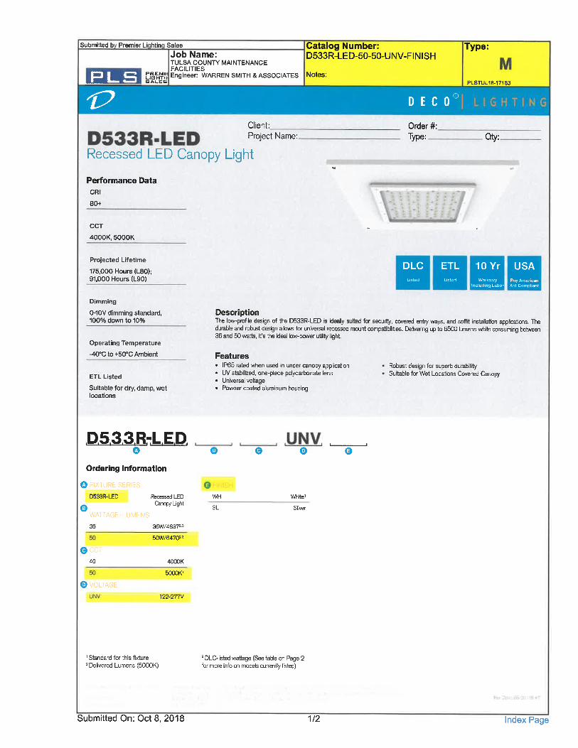
Catalog Number:D533R-LED-50-50-UNV-FINISH
D E C 0
Type:
PLSTUL18-17183
©
Client:Project Name:
Recessed LED Canopy Light
Performance Data
CRI
80+
CCT
4000K, 5000K
Order #:
Type: Qty:
Projected Lifetime
175,000 Hours (L80);91, 000 Hours (L90)
Dimming
0-10V dimming standard,100% down to 10%
Operating Temperature
-40°C to+50°C Ambient
ETL Listed
Suitable for dry, damp, wetlocations
DLC ETL 10Yr USAListfid Listed Wnmnty Btiy American
Includincj L-ibor Act Compliant
DescriptionThe low-profile design of the D533R-LED is ideally suited for security, covered entiy ways, and soffit installation applications. Thedurable and robust design allows for universal recessed mount compatibilities. Delivenng up to 65CU lumens while consuming between36 and 50 watts, it's the ideal low-power utility light.
Features. IP65 rated when used in under canopy application. UV stabilized, one-piece polycarbonate lens. Universal voltage. Powder coated aluminum housing
Robust design for superb durabilitySuitable for Wet Locations Covered Canopy
D533R-LED~0^
Ordering Information
0
0 FIX) URE SERIES
D533R-LED Recessed LEDCanopy Ught
WA1TAGE/LUMENS36 36W/4B372'3
50W/6470"
OCCT40 4000K
5000K'
0 VOLTAGE
122-277V
WH
SL
® 0
White'
Sliver
'Standard for this fixture2 Delivered Lumens (5000K)
s DLC-listed wattage (See fable on Page 2for more info on models currently listed)
Submitted On: Oct 8, 2018 1/2 Index Page
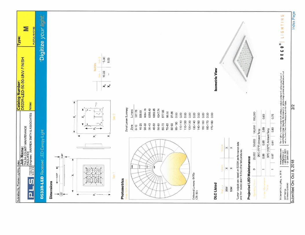
.&
s
s,s
u
z
<3
sI
^
0)0 H§
I
>z=>
:sI?3 Qzy0>-iio'a:15C2
coSsU)
Is I
i I
lllli ill!
I
5
U]J1
x'x"
x' xf
_!__
CM
-g.^
IE
Is
" ^ s° ?^?''- m ^r (dm E-f- 00 CD IOGO . ?!-id u5 0 COB5 C< g8g8888888
CMOOOOOOOOO
>f-
oSSSSgSSS0000
S9"?mmcrmCTY666666666SgS?g8gSS^^2ro?"ms
s:
IQ
y's
c7)Ut
sw
c£Q
3 s11s s
s
I£ 2
I'&
s0
I- s
8 .1I-p
s p^
8 ^
0)
o c oCT
0)0
0)0
s
s
'sI
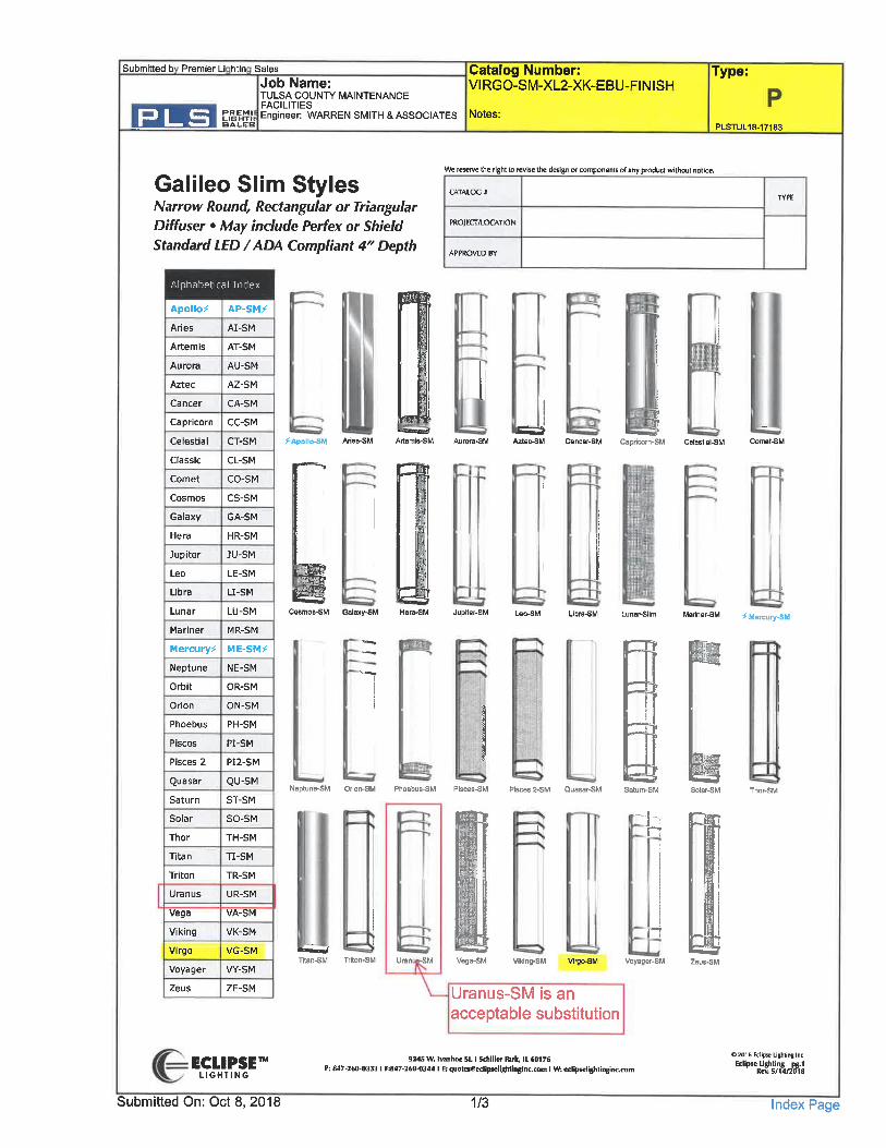
Submitted b Premier Li htin Sales
Job Name:TULSA COUNTS MAINTENANCE
rSEiM!; Engineer: WARREN SMITH & ASSOCIATESBAt. EB
Catalog Number:VIRGO-SM-XL2-XK-EBU-FINISH
Notes:
Type:
PLSTUL18.171B3
Galileo Slim StylesNarrow Round, Rectangular or TriangularDiffuser . May include Perfex or ShieldStandard LED /ADA Compliant 4" Depth
We reserve the right to revise the design or components of any product without notice.
CATALOG *
PROJECT/LOCATION
APPROVED BY
Alphabetical Index
Apollo^
Aries
Artemis
Aurora
Aztec
Cancer
Capricorn
Celestial
Classic
Comet
Cosmos
Galaxy
Hera
Jupiter
Leo
Libra
Lunar
Mariner
Mercury^
Neptune
Orbit
Orion
Phoebus
Pisces
Pisces 2
Quasar
Saturn
Solar
Thor
Titan
Triton
Uranus
Vega
Viking
Virgo
.r
AP-SM^
AI-SM
AT-SM
AU-SM
AZ-SM
CA-SM
CC-SM
CT-SM
CL-SM
CO-SM
CS-SM
GA-SM
HR-SM
JU-SM
LE-SM
LI-SM
LU-SM
MR-SM
ME-SM^
NE-SM
OR-SM
ON-SM
PH-SM
PI-SM
PI2-SM
QU-SM
ST-SM
SO-SM
TH-SM
TI-SM
TR-SM
UR-SM
VA-SM
VK-SM
VG-SM
VY-SM
^Apollo^M Aries-SM
Cosmos-SM Galaxy-Sk
I
Neptune-SM Orion-SM
Rtan-SM Triton-SM
^Si
JCancer-SM Capricorn-SM Cetestial-SM
Jupiter-SM Mariner-SM ^Mercury-SM
T
Phoebus-SM Pisces-SM PiacasS-SM Quasar-SM
Vega-SM Viking-SM Virgo-SM
n
Voyager-SM
Zeus ZE-SM Uranus-SM is an
acceptable substitution
ECLIPSETLIGHTING
Submitted On: Oct 8, 2018
9245 W. Ivmhoe Sl. I Sdliller fsik, IL 60176P; 847-260-0333 I F:847-260.03<4 I E; iiuoteseeclipselightinginc.com I W: edipK -lighlmgii
1/3
02016 Ed ipse Lighting Inc.
Edipse^%/^
Index Page
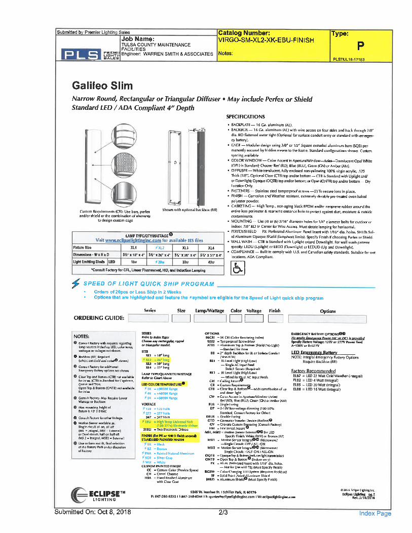
Submitted b Premier Li htin Sales
Job Name:TULSA COUNPl' MAINTENANCE
r^EF?! Engineer: WARREN SMITH & ASSOCIATESBAI.RB
Catalog Number:VIRGO-SM-XL2-XK-EBU-PINISH
Notes:
Type:
PLSTUL18-17183
Galileo SlimNarrow Round, Rectangular or Triangular Diffuser . May include Perfex or ShieldStandard LED/ADA Compliant 4f/ Depth
SPECIFICATIONS
1-4--. -i
Cuttom Requirements (CR): U5E bars, perfexand/or shield or the combination of elements
to design custom cage
Shown with optional backbox (BB)
LAMP TYPE/QPTIWATTAGE0Visit www.eclinseliehtinEijs&Gan for available IES files
Fixture Size
Dimensions-WxHx D
UgM Emitting Diode LED
XL1 ^XL2 XL3 XL4
5K-X18-X4- 5K-126-X4- 514-X38-X4- 5K-X5TX4-15w ^20w 30w 40w
.Consult Factniy for CFL, Unear Fluorescent, HID, and InducUon Lamping
^^ SPEED OF LIGHT QUICK SHIP PROGRAM
. BACKPLATE - 16 Ca. aluminum (AL).
. BACKBOX - 16 Ga. aluminum (AL) with wire access on four sides and back through 7/8'dia. KO flattened water tight (Optional for surface conduit entry or standard with emngen-cy battery).
. CAGE - Modular design using 3/8" or 1/2" Square extruded aluminum bars (SQB) per-manently secured by hidden means to the frame. Standard configurations shown- Customspacing available.
. COLOR WINDOW - Color Accent in AperturaWiiidow-Aries-Translucent Opal WhileIOPL) is Standard; Choose- Red (RD), Blue (BLU), Green (GN) or Amber (AM).
. DIFFUSER-White translucent, fully enclosed non-yellowing 100% virgin acrylic, .125Thick (1/8"1. Optional Clear (CTTB) top and/or boltoin - CTB Is SGndard with Uplight and/or Downllght; Opaque (OQTB) top and/or bottom; or Open (ONTB) top and/or bottom - DryLocation Only.
FASTENERS - Stainless steel tamperproof screws -(2) To secure lens in place.FINISH - Corrosion and Weather resistant, extremely durable pre-treated oven bakedpolyester powder.CASKETINC - High Temp., ncn-aging black EPDM and/or neoprene rubber around theentire lens perimeter & rear wire entrance hole to protect against dust, moisture & outsidecontaminants.
MOUNTING - Use (4) or (6) S/16" diameter holes for 1/4" diameter bolts far outdoor or
indoor. 7/8" KO in Center for Wire Access. Must derate lamping for horizontal.PERFEX/SHIELD - PX: Perforated Aluminum Panel Insert with 1/16'dia. holes. SHLD: Sol-id Aluminum Opaque Shield llamp/wan limits). Specify Finish if choosing Perfex or Shield.WALL WASH - CTB is Standard with Uplight or/and Downlight. For wall wash patternsspecify: LEDU (Upllght) or LEDD (Downlight) or LEDUD (Up and Downlight).
. COMPLIANCE - Built to comply with U. S. and Canadian safety standards. Suitable for wetlocations. ADA Compliant.
Orders of 20pcs or Less Ship in 2 WeeksOptions that are highlighted and feature the symbol are eligible for the Speed of Light quick ship program
ORDERING GUIDE:Series Size Lamp/Wattage Color Voltage Finish Options
NOTES:
Consult Factory with requests regardinglamp sources including LED, color temp,wallagcs or voltages nol shown.
0 Backfaox (BB] Required{where text bold and noteiifO .shown;
Consult Factory for additionalEmerEency BaHery options not shown
Clear Tqp and Bottom (CTB) not availablefor Aries; (CTB) is Standard for Capricorn,Comet and Titan
Open Top & Bottom (ONTB] not availablefor Aries
Consult Factory, May Require LowerWattage or Backbox
Max mounting height offixture is 10' (10 feel]
® Consult FactoiyforolherVollage.® Motion Sensor available as.
Single ciicuit-all on. alt off(MSI = Integral, MSE = External]or Dull circull, half on half off{MS12 = Integral; MSE2 = External)
Dtie In form and fit. final selectionof Ihe Battery Pack under discretionof Factory
SEIilESSdw lo Index RSC:CAoose any ivctangular, roundortnangularaiodel.
SIZEXL1 -18" long
=26" longXL3 =38" longXL4 =51 "long
IAMF TTPE/QUANTITT/WATTACEllefcr to Chart Aiove
LED COLOB TEMPERATURE0^3K =±30BOK Range^4K = ±<OOOK Bange^5K = ±SOOOK Bangs
VOITACE^12C =120Volb^277 =277 Volte
347 =347Volts
^EBU .. High Temp Univiinl Vailfl2B.277v) HtctTonic Dllver
2EBU = Two Electronic Drivers
FINISH (lilt PX or SHLD finish iecond)STANDARD PAINTED FINISH
^BK -Black^BZ = Bronze
^ PNA = fainted Natural Aluminum
^SCR = Silver GrayfWH -While
CUSTOM PAINTED FINISHCC = Cusiom Color (Provide Specs)CH = Corvel Chrome
HBA = Hand Brushed Aluminumwith Clear Coal
OPTIONS96CR1 - 96 CRIIColor Rendering I ndexl9002 - Tamperproaf Screwdrn/erATBS = Aluminum Tap & Bottom Shield (No Light)
-Standard for AriesHB - 2" depth Backhax for EL or Surface Conduit
INon.AM)BL1 = Bi-Leval Light (High/Low)
-Single AC Input Feed- Switch Sensor (Required)
812 = Bl Level Llghl (High/Low)- Wired far Qlial AC Input Feedi
CM - Ceiling MountCR = Custom
CTB = Clear Tap & Bottomw-adds contribution of upand down light
CW = Color Accent in AperturaAIVindow (Aries)Red (RD), Blue (BLU), Green (GN) or Amber (AM)
FUS - Single FuilngD7 - 0-10V low.voltage dimming (100-30%
Standard, Consult Factory for Other]DFUS . Double FuiingCTD . Generator Tranifei De«ice IBodlnelO
CV = Gravura Custom EiHM -HoriionlalMounl'
USE, MSE2 . Mollon Sensor ExlemalO® foi LED
Specify Finish: White (WH) or Bronze (82]MS11 = Motion Sensor Integral®® fMicrowave;
-Single Clicull;.OFF /ALL-ONMS12 = Motion Sensor Integral®® (Microwavel
-Single Circuit: HAIF-ON/ALL-ONOQTB =OpaqueTop&Botton^reduces light transmissnn)ONTB = Open Top &Boftomw(indcMr only)
FX = Alum. Perforated Insert with 1 /16" dia. holes.
- Not for Use wilh TS; IMun Specify Finiih)RCBW = Color Changing LED System (Requires Backbox)
Sf . Solid Fronl (Aiicil^luminum ShieldSHLD . Aluminum Shield" (Must Spacify Flnlih)
EMEBCENCY BAnEBY OmONsG®No onsite fmeresnty Power fAC or OCt Is nrftfjWprf
Specify HxtunVolbjr: 120V or 277V Pow«r FurfA=120VorB«277V
LED EmereenCT BatteryNOTE: Integral Emergency Battery Options
Require Bacttbox (BB)
Fartnrv Rprnrnmpnrlp'"!EL67 = LED 23 Watt Cold Weather (Integral)EL82 = LED 4 WaH (Integral)EL85 = LED 20 Wan (Integral)tlSS = LED 16 Wan (Integral)
ECLIPSETLIGHTING
9245 W. Ivanhoe St. I Sdiiller Park, II 60176
P: 847. 260. 0333 I F:a47. 26(>-0344 I E: quotuieedipselightinginc. com I Wi cclipselightinginc. cum
02016 Eclipse lighting Inc.
Edlp"«%V<Fii
Submitted On: Oct 8, 2018 2/3 Index Page
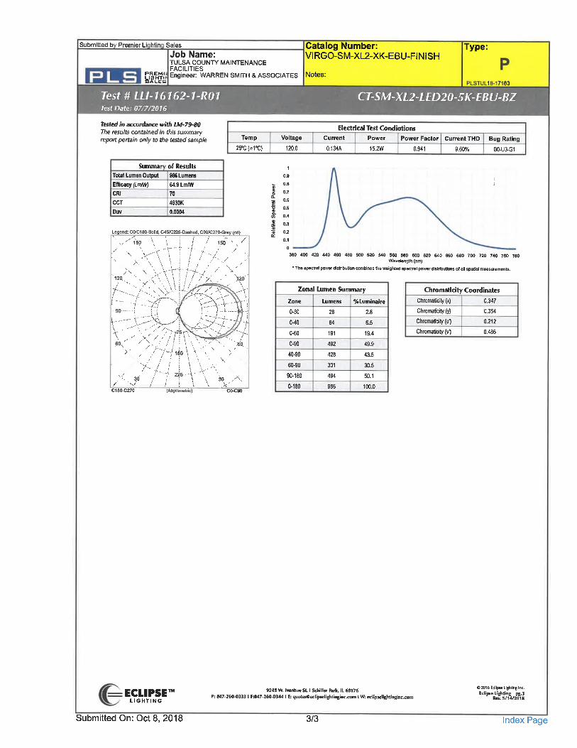
Submitted b Premier Li htin Sales
Job Name:TULSA COUNT)' MAINTENANCEFACILITIES
^E,h?,1; Engineer: WARREN SMITH & ASSOCIATES Notes:il. Ck.
Test #LLI-16162-1-R01Test Date: 07/7/2016
Catalog Number: Type:VIRGO-SM-XL2-XK-EBU-FINISH
1 7 83
CT-SM-XL2-LED20-5K-EBU-BZ
Tested in accordance with 1M-79-80The results contained in this summaryreport pertain only to the tested sample
Electrical Test Condiotions
Temp Voltage Current Power Power Factor Current THD Bug Rating25'C(*1°C) 120.0 0. 134A 15.2W 0.941 9.60% BO-U3-G1
Summa of Results
Total Lumen Output 986 Lumens
Efficacy ftmAO 64.9 LmlWCRI 70CCT 4930KDuv 0.0001
Legend: CO/C180-Sol]d, C45»C225-Dashe[l. C90/C270.Srey (cd)
1501
J 156
x
12tt.->'\T"H7-
-. y;x:.. \\7""-^-:. :.^'/.-. - 7-.. -y'-^"IA ./f""".. -":?
.6°.;'>'
</, --// ";... ,.'
/;"^>wr-
.. /;<-'//
?//^.. - >-
^^. ^..---v~<... '\
.-4-... ;,1.,...,.
. JiS^:?-i"'^
~'e'o,
/'.^C1SO-C270
7"--*-225--f "\ \. "/ ! ~T \ \ 30 , -\
0.9
O.B
0.7
0.6I °'5S' 0.4
I °-3I 0.2
0.1
0
380 400 420 440 460 480 500 520 540 560 580 600 620 640 660 680 700 720 740 760 780Wa»alenglh (nm)
. The spectral power dlstributton comblnea the weighted spectral power distributions of all spaBd nrasurements.
Zonal Lumen SummaryZone Lumens %Luminaire
0-30 28 2.8
(Asymmetric)
0-40
0^0
0-90
40-90
60-90
90-180
0-180
64
191
492
428
301
494
986
6.5
19.4
49.9
43.5
30.5
50.1
100.0
Chromatidty CoordinatesChromaticity(x)
Chromaticityfy)
Chromaticity(u')
ChromaticityM
0. 347
0. 354
0.212
0.486
ECLIPSETLIGHTING
9245 W. Iranhoe St. I Schiller hrk, IL 60176P: 847-260-0333 I 1:847.260-0344 I E: quotuieeclipt eliglilinginc. com I TO edipselighlinglnc.com
02D16 Eclipse Lighting Inc.
Ec'T!»%8,^
Submitted On: Oct 8, 2018 3/3 Index Page
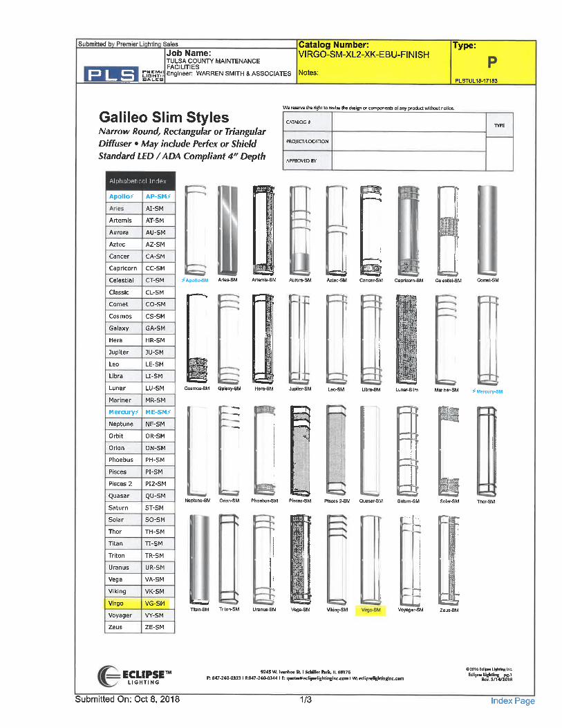
Submitted b Premier Li htin Sales
Job Name:TULSA COUNPl' MAINTENANCE
r^EiM;i Engineer: WARREN SMITH & ASSOCIATESBALES
Catalog Number:VIRGO-SM-XL2-^K-EBU-FINISH
Notes:
Type:
PLSTUL18-17183
Galileo Slim StylesNarrow Round, Rectangular or TriangularDiffuser . May include Perfex or ShieldStandard LED /ADA Compliant 4V Depth
We reserve the right to revise the design or components of any product without notice,
G\TAIOC »
PROJECT/LOCATION
APPROVED BV
Alphabetical Index
ApO llO^
Artemis
Aurora
Aztec
Cancer
Capricorn
Celestial
Classic
Comet
Cosmos
Galaxy
Hera
Jupiter
Leo
Libra
Lunar
Mariner
Mercury^
Neptune
Orbit
Orion
Phoebus
Pisces
Pisces 2
Quasar
Saturn
Solar
Thor
Titan
Triton
Uranus
Vega
Viking
Virgo
Voyager
Zeus
AP-SM^-
AI-SM
AT-SM
AU-SM
AZ-SM
CA-SM
CC-SM
CT-SM ^Apollo^M
CL-SMCO-SM
CS-SM
GA-SM
HR-SM
JU-SM
LE-SM
U-SM
LU-SM Cosmos-SM
MR-SM
ME-SM^
NE-SM
OR-SM
ON-SM
PH-SM
PI-SM
PI2-SM
QU-SMNeptune-SM
ST-SM
SO-SM
TH-SM
TI-SM
TR-SM
UR-SM
VA-SM
VK-SM
VG-SMTtan-SM
VY-SM
ZE-SM
Oalaiiy-SM
^Ml
^3
Artemls-SM
J
Jupiter-SM
P3
Phoebus-SM Pisces-SM Pisces 2-SM Quasar-SM
Ss
Vega-SM Vlklng-SM
^Voyager-SM
n?
II4u
Marlner-SM ^Mercury^M
^K
ECLIPSETLIGHTING
Submitted On: Oct 8, 2018
9245 W. Ivaiihoe St. I Schiller hrfl, IL 6»176
F: 8d7.2t0.0333 I 1:847.260.0344 I E: l)uolBeecliplielightinginc.coni I Mk Bclipstlightinginc.c
1/3
02016 Eclipse lighting Inc.
EC"P^R%^
Index Page
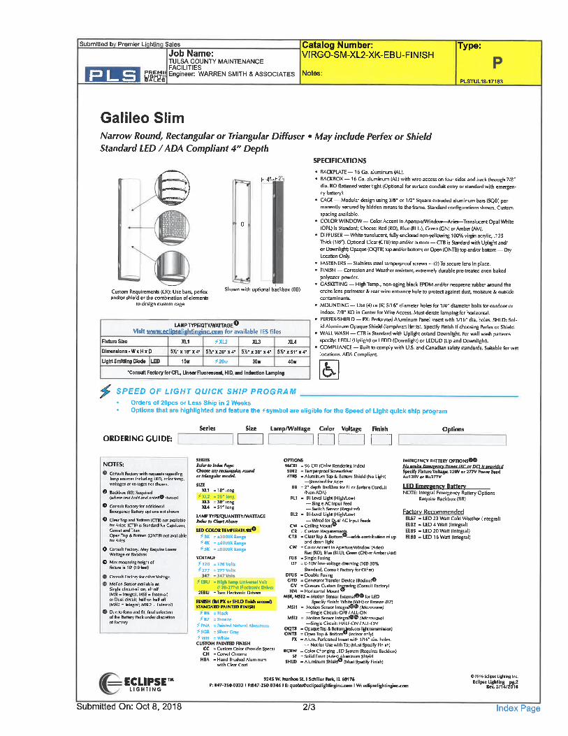
Submitted b Premier Li htin Sales
Job Name:TULSA COUNT. ' MAINTENANCEFACILITIES
i&w Engineer: WARREN SMITH & ASSOCIATES Notes:
Catalog Number:VIRGO-SM-XL2-XK-EBU-FINISH
Type:
PLSTUL18-17183
Galileo SlimNarrow Round, Rectangular or Triangular DiffuserStandard LED /ADA Compliant 4" Depth
May include Perfex or Shield
1-4--'-
I
Custom Requirements (CR): Use bars, perfexand/or shield or the combination of elements
to design custom cage
Shown with optional backbox (BB)
LAMP TYPBQnfWAn-AGE0Visit www.eclinseliBhtiiiEimLfflnm for available IES files
Rxture Size
Dimensions -Wx H x D
UghtEmitUng Diode LED
5)4-
XL1
»18'«4-
15w
5K-
^. XL2
X26-»4-
^20w
5V,-
XL3
X3B-X4-
30w
5S-
XL4
X 51-
40w
x4"
SPECIFICATIONS
. BACKPLATE - 16 Ga. aluminum (AD.
. BACKBOX - 16 Ga. aluminum (AL) with wire access on four sides and back through 7/8ffdia. KO flattened water tight (Optional for surface conduit entry or standard with emergen-cy battery).
. CAGE- Modular design using 3/8" or 1/2" Square extruded aluminum bare (SQB) per-manently secured by hidden means to the frame. Standard configurations shown. Customspacing available.
' COLOR WINDOW - Color Accent in ApeiturertlVilldovi^Aries-Translucent Opal While(OPL) is Standard; Cheese: Red (RD), Blue (GLU), Green (CN) nr Amber (AM).
. DIFFUSER - White translucent, fully enclosed non-yellowing 100% virgin acrylic, .125Thick d/8'). Optional Clear (CTB) top and/or bottom - CTB is Standard with Uplight and/or Downligh; Opaque (OQTB) top and/or bottom; or Open (ONTB) top and/or boltom - DiyLocation Only.
. FASTENERS - Stainless steel tamperproof screws -(2) To secure lens in place.
. FINISH - Corrosion and Weather resistant, extremely durable pre-treated oven bakedpolyester powder.
. GASKETING - High Temp., non-aging black EPDM and/or neoprene rubber around theentire lens perimeter & rear wire entrance hole to protect against dust, moisture & outsidecontaminants.
. MOUNTING - Use (4) or (6) 5/16" diameter holes for 1/4' diameter bolts for outdoor or
indoor. 7/6" KO in Center for Wire Access. Must derate lamping for horizontal-. PERFEX/SHIELD - PX: Perforated Aluminum Panel Insert with 1/1 6" dia. holes. SHLD: Sol-
id Aluminum Opaque Shield (lamp/watt limits). Specify Finish if choosing Perfex or Shield.. WALl WASH - CTB is Standard with Uplight or/and Downllght. ftir wall wash panerns
specify: LEDU (Uplight) or LEDD (Downlight) or LEDUD (Up and Downlight).. COMPLIANCE - Built to comply with U. S. and Canadian safety standards. Suitable for wet
locations. AD^ Compliant.
.Consult Factory for CFL, Unear Fluorescent, HID, and Induction Lamping
^
6.SPEED OF LIGHT QUICK SHIP PROGRAM
Orders of 20pcs or Less Ship in 2 WeeksOptions that are highlighted and feature the symbol are eligible for the Speed of Light quick ship program
ORDERING GUIDE:Series Size Lamp/Wattage Color Voltage Finish Options
NOTES:Consull Factory with requests regardinglamp sources including LED, color temp,wattages or voltages no! shown.
0 Backbox (BB) Required(wAe lexf bold and noteffO shown)
0 Cansull Factory for additionalEmergency Battery options nol shown
0 Clca> Top and Bonom (CTB) no] amllablefor Aries; (CTB) is Standard for Capricorn,Cornel and Titan
Open Top & Bottom (ONTB) not availablefor Aries
0 Consult Faclwy. May Require LowerWattage or Backbox
® Max mounting heighl offixture is 10' (10 feet)
Consul) Factory for other Voltage
Malion Sensor available as
Singl" clrcuil-all on, all off(MS) = Integral, MSE = External)or Dual circuit hall on hall off(MS12 = Integral; MSE2 = External]
® Diie to fnnn and fit, filial selectionof the Batteiy fack under discretionof Factory
SERIESIItfu-tofndufiige;Choose any redangufar/ raum/or triangular mode/.
SIZEXL1 =18'long
^XL2 -2t" longXU =38'longXU =51" long
LAMP TYPE/QUANTITVnVAnACESekr la Chart Atiwe
UD COLOBTEMPE11ATU8E*1^3K =±3000K«ange^<K =±4000K«»ngB^5K =±5000K Range
VOLTAGE
fiia . 120 Vote^277 -277Volb
ftSU = High T«mp Universal Volt1120.277V) Electronic Drivei
2EBU - Two Electronic Driven;
FINISH (list PX or SHID finish iecond)STANDARD PAINTED FINISH
^BK = Black^ BZ = Bronze
^PNA =FSiinted Natural Aluminum^SCR = Silver Gray^WH = White
CUSTOM PAINTED FINISHCC = Custom Color (Provide Specs)CH =Corvel Chrome
HBA = Hand Brushed Aluminumwith Clear Coat
OPTIONS96C81 . 96 CRI (Color Rendering Indn)9002 = Tamperproof ScrewdriverATBS . Aluminum Top S, Bollom Shield (No Lighl)
-Standard far AriesBB = 2" deplh BacUlta for EL or Suihce Conduil
(NonADA)BU . Bi-LevelLlghKHighAow)
-Single AC I npul Final- Switch Sensor (Required)
BL2 . Bi.Ln.el Llghl (High/Low)- Wired far Qiial AC Input feeds
CM . Celling MDUICR = Custom Requiremi
CTB = Clear Top & Bottomw-adds contribution of upand dawn light
CW = Color Accent In Aperture/Window (Aries)Red [RD), BluelBLU), Green (ON) or Amber (AM)
FUS - Single FuiingD7 = 0-1 OVIow-voltage dimming (100-30%
Standard, Consult Factory for Other)DFUS . Double FuingCTD = Generator Transfer Device (Bodine)O
CV = Gravura Custom Eq^raving (Consult Factory)HM . Horizonlal Mounl'
MSE, MSE2 . «*>lion Senior External®® for LEDSpecify Finish: White (WH) or Bronze (BZ]
MS11 = Motion Sensor Integral®® fMfuoware;-Single Circuil;-OFF /ALL-ON
MS12 = Motion Sensor Integral®® fArffuowawJ^Single Circuit: HALF. ON / ALL. ON
OQTB = Opaque Top & BaftDni^iaIuces light transmissun)ONTB = Open Top & Bottom® (indooronly)
PX = Alum. Perforated Insert with 1/16" dia. holes.
- Nat far Use with T5; (Must Specify Finish]RCBW = Color Changing LED System (Requires Backbox)
SF = Solid Front (Arleslj Muminum Shield
SHLD = Aluminum Shield" (Must Specify Finish)
EMEBCiNCY BATTERY OPTIONS®®MuMufte_6nereency Power fAC or DCt fe omvided
Specify Klture Voltage 120V or 277V PBWer fctdA=120V or B=277V
LED Emereencv Batterv
NOTE: Integral Emergency Battery OptionsRequire Backbox (BB)
Factory RecommendedEL67 = LED 23 Wan Cold Weather (Integral)EL82 = LED 4 Watt (Integral)E185 = LED 20 Wan (Integral)EL88 -LED 16 Watt (Integral)
ECLIPSETLIGHTING
9245 W. Ivanhoe St. I Schiller fark, IL 60176P: 847-260.0333 I F;847.261)-»344 I E: qu<>lKeedipsellgMinginc. Tm I W: edipi clighlinginc. com
OZD16Edipse Lighting Inc.Eclipse lighting pg.2
Vtn. '.lfvfSis
Submitted On: Oct 8, 2018 2/3 Index Page

Submitted b Premier Li htin Sales
Job Name:TULSA COUNTf MAINTENANCEFACILITIES
SSNil Engineer: WARREN SMITH & ASSOCIATES Notes:BAIZES
Test #LLM6162-1-R01Test Date: 07/7/2016
Catalog Number:VIRGO-SM-XL2-XK-EBU-FINISH
Type:
PLSTUL18-17183
CT-SM-XL2-LED20-5K-EBU-BZ
Tested in accordance with tM-79-80
The results contained in this summaryrt pertain only to the tested sample
Summa
Total Lumen Ou4>ut
Efficacy (Lm/W)
CRICCTDuv
of Results986 Lumens
64.9 Lmm
4930K0.0004
Temp
25'C(±1'C)
II
Voltage
120.0
1
0.9
0.8
0.7
0.6
0.5
Legend: CO/CISO-Solid, C45»C225-Dashed, C90/C270^rey (cd)
v'''150 '. \ I i / 150''', /v^-rt'T-A/ ./'. 'v-
>' ,
>Y \12.0.^ .. ~<\'\u
L:' ^rT'i;w-:j. :. :,B |
-/'I
/"v^C180-C270
./.!7-... / \-
;:120
f^<5. ^\y
^-^3..:::iA..!
\. """". ;''''-. ' 9 /776r^:C^:s, ~''<... 'yi-?i..\. -" ".\/ //iW^^^-.r?b</ '^^/i^\~^'^M-
>' , ' .'"7-J15oV \". \ ')\
\ . -^ \'/-H-vV'C.
Electrical Test Condiotions
Current Power Power Factor Current THD Bug Rating
0. 134A 15.2W 0.941 9.60% BO-U3-G1
0.4
0.3
0.;
0.1
,1
380 400 420 440 460 480 500 520 540 560 580 600 620 640 660 680 700 720 740 760 780Wa»elength (nm)
. The Bpachl power distribulton combines the weighted s[«drBl power dlsWbutlons of all spatial measurements.
Chromatidty CoordinatesCliromaticity (x) 0.347
ChromaticNyfy) 0. 354
Chromafcily (u'1 0. 212
Chromaticityfr') 0.486
Zonal Lumen Summary
0-30
0-40
0-60
0-90
40-90
60-90
90-180
Lumens
28
64
191
492
428
301
494
%Luminaire
2.8
6.5
19.4
49.9
43.5
30.5
50.1
(Asymmetric) C(K:900-180 100.0
ECLIPSETLIGHTING
9245 W. Ivmhoe St. I Schiller hit, IL 60176f: 8<7-260.0333 I F;847-260-0344 I E: quoteteedipliclighlingmc.com I W edipielightinginc.com
02016 Eclipse Lighting Inc.
Submitted On: Oct 8, 2018 3/3 Index Page
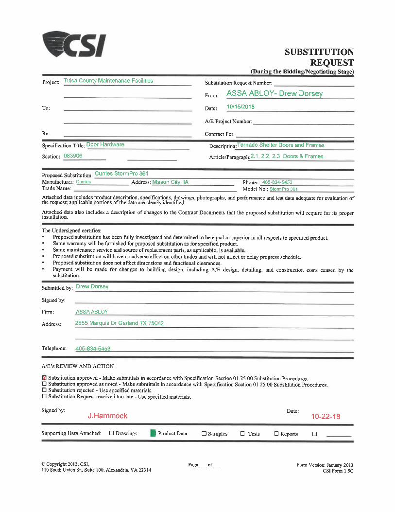
Project: Tutea County Maintenance Facilities
To:
Re:
Specification Title: Door Hardware
Section: 083906
SUBSTITUTIONREQUEST
(Durin theBiddin /Ne otiatin Sta e)
Substitution Request Number:
From: ASSA ABLOY- Drew Dorsey
Date: 10/15/2018
A/E Project Number:
Contract For;
Description:Tornado Shelter Doors and Frames
Article/Paragraph:2. 1, 2. 2, 2. 3 Doors & Frames
Proposed Substitution: cumes StormPro 361Manufacturer: Curries Address: Mason Ci , IA Phone: 405-834-5453Trade Name: Model No. : StormPro 361
Attached data includes product description, specifications, drawings, photographs, and performance and test data adequate for evaluation ofthe request; applicable portions ofthe'data are clearly identified.
Attached data also includes a description of changes to the Contract Documents that the proposed substitution will require for itsinstallation.
The Undersigned certifies:. Proposed substitudon has been fully investigated and determined to be equal or superior in all respects to specified product.
Same warranty will be famished for proposed substitution as for specified product.. Same maintenance service and source of replacement parts, as applicable, is available.. Proposed substitution will have no adverse effect on other trades and will not affect or delay progress schedule.. Proposed substitution does not affect dimensions and functional clearances.. Payment will be made for changes to building design, including A/E design, detailing, and construction costs caused by the
substitution.
Submitted by: Drew Dorsey
Signed by:
Firm: ASSAABLOY
Address: 2855 Marquis Dr Garland TX 75042
Telephone: 405-834-5453
A/E's REVIEW AND ACTION
Kl Substitution approved - Make submittals in accordance with Specification Section 01 25 00 Substitution Procedures.D Substitution approved as noted - Make submittals in accordance with Specification Section 01 25 00 Substitution Procedures.D Substitution rejected - Use specified materials.D Subsdtution Request received too late - Use specified materials.
Signed by:J. Hammock
Date:10-22-18
Supporting Data Attached: D Drawings Product Data D Samples D Tests D Reports
©Copyright 2013, CSI,110 South Union St., Suite 100, Alexandria, VA 223 14
Page _ of, Form Version: January 2013CSIForml.5C
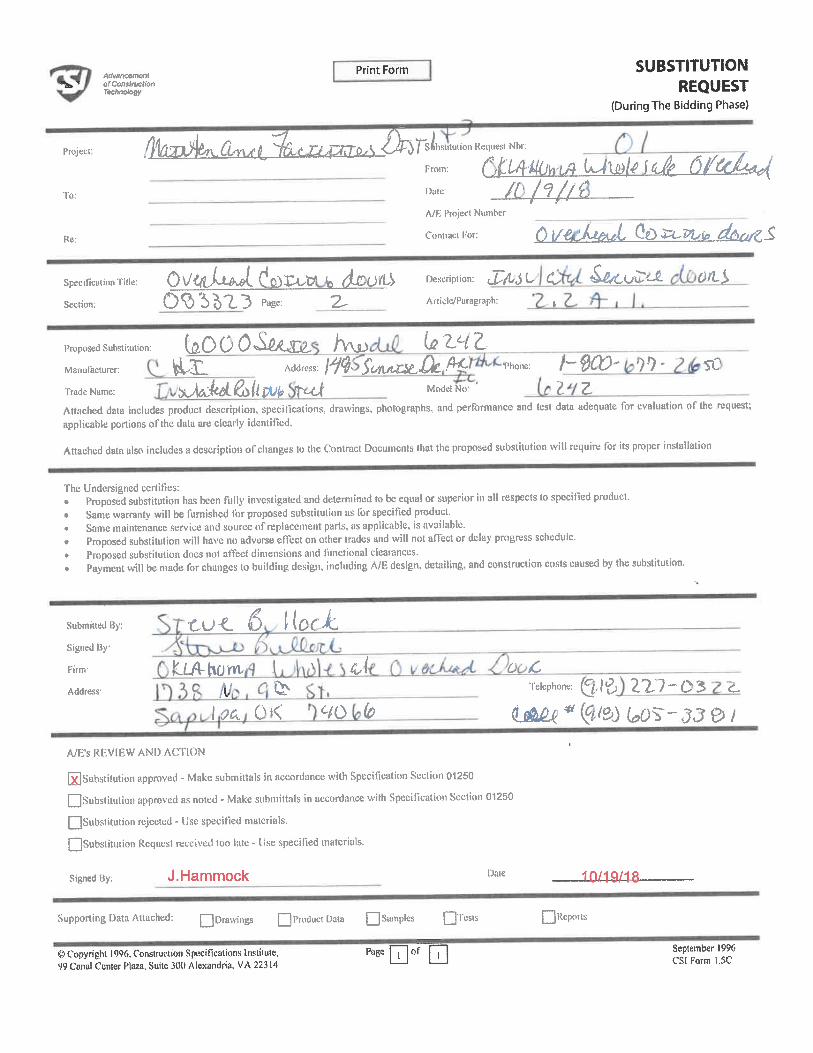
Mvswemenl«lbT ofConalfuetion
rec/KTOtogy
Print Form SUBSTITUTIONREQUEST
(During The Bidding Phase)
Project:
To:
Re:
fl'i&n^. CL^ij ^-.CTT^S ArsLtuuon Re^tNbr:F-: C, tLW^A^\^^^ fitf d^(
//?/v/^Date-
A/E Project Number
Contracl For: ^ [/C-J^ffJL GO 4^VU(e ^^/g_S
Specificatinn Title: Q\/<^LL ^I (?C)3^y (a (^CO^ Description: J:^ t^ C ^iOu't-fi. 6)/L^
Section: 0<&'S>b'Z. 3 pa§e: 2- Article/Paragraph: »
Proposed Substitution: k.OOOA^C?/ h\t)Manufacturer: ^.21 Address. W ^^t^^ . ^one: /" 0(Z)- ')T) ' SC-Trade Name: ^MJ^L^ilSV^ Tt-^ Model No: ' 2 2.Attached data includes product description, specifications, drawings, photographs, and performance and test data adequate for evaluation of the request;applicable portions oFthe data are clearly identified.
Attached data also includes a description ofclianges to the Contract Documcnls that the proposed substitution will require for its proper installation
The Undersigned ecrlit'ies:Proposed substitution has been fully investigated and delenninud to be equal or superior in all respects to specil'ied product.Same warranty will be famished for proposed substitution as for specified productSame maintenance service and source of replacement parts, as applicable, is available.Proposed substitution will have 110 adverse enect on other trades und will not afTect or delay progress schedule.Proposed substitution does not affect dimensions and functional clearances.Payment will be made for changes to building design, including A/E design, detailing, and construction costs caused by the substitution.
Submitted By:
Signed By
Firm-
Address-
.tlAlwwA/i^
^
OK
uI
6/0 fc
0 CTelephone: Q, }^ ZZ7-05 Z-
(U^</^/gOC90S~-JJ0/
A/E's REVIEW AND ACTION
SlS ubstitution approved - Make submitlals in accordance with Specilication Section 01250
QSubstitution approved as noted - Make submiHals in accordance with Specification Section 01250QSubstitution rejected - Use specified materiuls.
QSubslitution Request received too late - Dse specified materials.
Signed By: J. Hammock Date 10/19/18
Supporting Data Attoched: Q Drawings Q Product Dala Q.Sainples QTCSIS
© Copyright 1996. Construction Specifications Inslilutc,99 Canal Center Plaza, Suite 3(X) Alexandria. VA 22314
Page | | | of
QRepons
September 1996CSI Form 1.5C
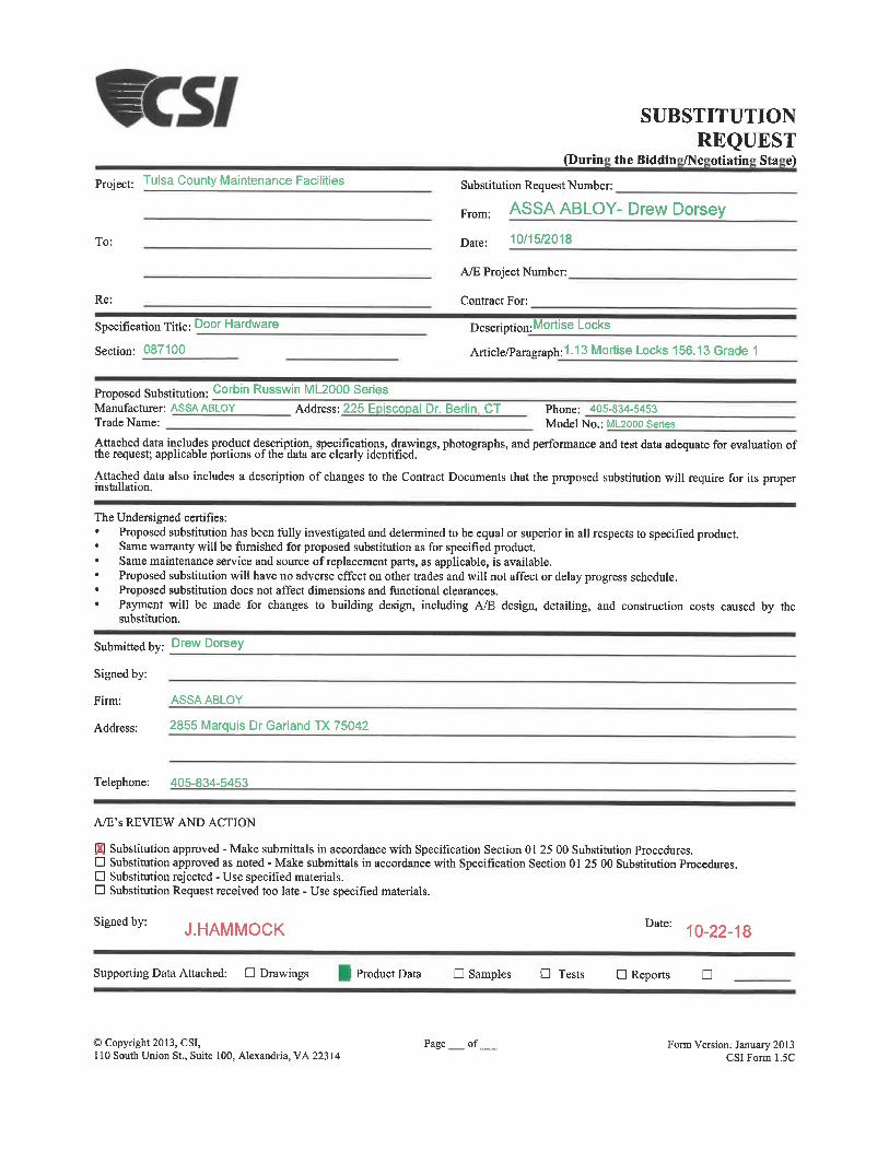
Project: Tulsa County Maintenance Facilities
To:
Re:
Specification Title: Door Hardware
Section: 087100
SUBSTITUTIONREQUEST
(Durin theBiddin /Ne otiatin Sta e)
Substitution Request Number:
From: ASSA ABLOY- Drew Dorsey
Date: 10/15/2018
A/E Project Number:
Contract For:
Description:Mortise Locks
Artic)e/Paragraph:1. 13 Mortise Locks 156. 13 Grade 1
Proposed Substitution: cort)in Russwin ML2000 SeriesManufacturer: ASSA ABLOY Address: 225 E isco al Dr. Berlin CTTrade Name:
Phone: 405-834-5453Model No. : ML2000 Series
Attached data includes product description, specifications, drawings, photographs, and performance and test data adequate for evaluation ofthe request; applicable portions of the data are clearly identified.
Attached data also includes a description of changes to the Contract Documents that the proposed substitution will require for itsinstallation.
The Undersigned certifies:Proposed substitution has been fully investigated and determined to be equal or superior in all respects to specified product.Same warranty will be famished for proposed substitution as for specified product.Same maintenance service and source of replacement parts, as applicable, is available.Proposed substitution will have no adverse effect on other trades and will not affect or delay progress schedule.Proposed substitution does not affect dimensions and functional clearances.Payment will be made for changes to building design, including A/E design, detailing, and constmction costs caused by thesubstitution.
Submitted by: Drew Dorsey
Signed by:
Firm: ASSAABLOY
Address: 2855 Marquis Dr Garland TX 75042
Telephone: 405-834-5453
A/E's REVIEW AND ACTION
Kl Substitution approved - Make submittals in accordance with Specification Section 01 25 00 Substitution Procedures.D Substitution approved as noted - Make submittals in accordance with Specification Section 01 25 00 Substitution Procedures.D Substitution rejected - Use specified materials.D Substitution Request received too late - Use specified materials.
Signed by: J. HAMMOCK Date: 10-22-18
Supporting Data Attached: D Drawings Product Data D Samples D Tests D Reports D
©Copyright 2013, CSI,110 South Union St., Suite 100, Alexandria, VA 22314
Page_of. Form Version: January 2013CSIForml.5C
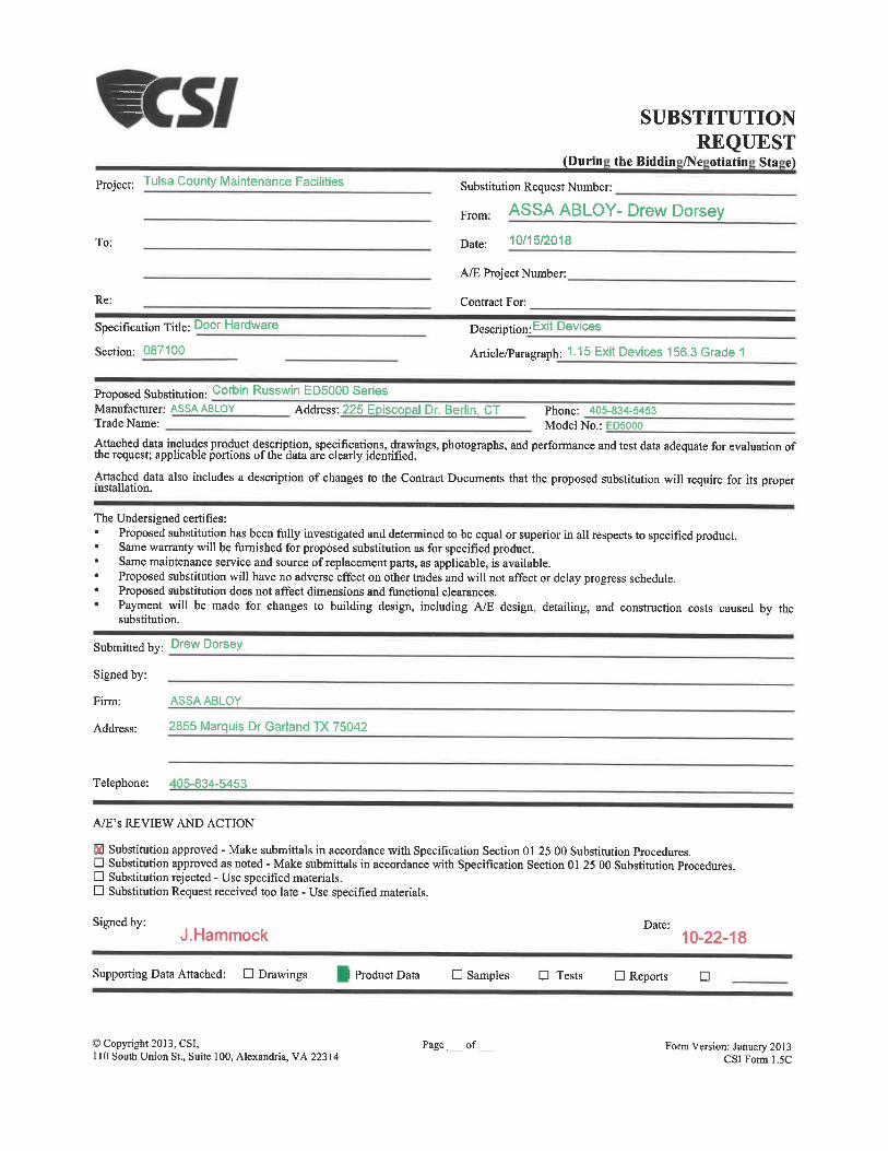
Project: Tulsa County Maintenance Facilities
To:
Re:
Specification Title: Door Hardware
Section: 087100
SUBSTITUTIONREQUEST
(Durin theBiddin /Ne otiatin Sta e)
Substitution Request Number:
From: ASSA ABLOY- Drew Dorsey
Date: 10/15/2018
A/E Project Number:
Contract For:
Description: Exit Devices
Article/Paragraph: 1-15 Exit Devices 156.3 Grade 1
Proposed Substitution: corbin Russwin ED5000 SeriesManufacturer: ASSAABLOY Address: 225 E isco al Dr. Berlin CTTrade Name:
Phone: 405-834-5453Model No. : ED5000
Attached data includes product description, specifications, drawings, photographs, and performance and test data adequate for evaluation ofthe request; applicable portions ofthe'dataare clearly identified.
Attached data also includes a description of changes to the Contract Documents that the proposed substitution will require for itsinstallation.
The Undersigned certifies:
Proposed substitution has been fally investigated and determined to be equal or superior in all respects to specified product.Same warranty will be famished for proposed substitution as for specified product.Same maintenance service and source of replacement parts, as applicable, is available.Proposed substitution will have no adverse effect on other trades and will not affect or delay progress schedule.Proposed substitution does not affect dimensions and functional clearances.
Payment will be made for changes to building design, including A/E design, detailing, and constmction costs caused by thesubstitution.
Submitted by: Drew Dorsey
Signed by:
Firm: ASSAABLOY
Address: 2855 Marquis Dr Garland TX 75042
Telephone: 405-834-5453
A/E's REVIEW AND ACTION
Kl Substitution approved - Make submittals in accordance with Specification Section 01 25 00 Substitution Procedures.D Substitution approved as noted - Make submittals in accordance with Specification Section 01 25 00 Substitution Procedures.D Substitution rejected - Use specified materials.D Substitution Request received too late - Use specified materials.
Signed by:J.Hammock
Date:10-22-18
Supporting Data Attached: D Drawings Product Data D Samples D Tests D Reports a
©Copyright 2013, CSI,110 South Union St., Suite 100, Alexandria, VA 22314
Page _ of Form Version: January 2013CSIForml. 5C
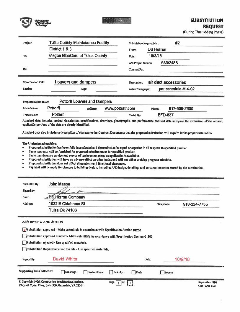
SUBSTITUTIONREQUEST
(During The Bidding Phase)
Project:
To;
Re:
Tulsa County Maintenance FacilityDistrict 1 & 3
Megan Blackford ofTulsa County
Substitution Request Nbr: #2
From: DS Herron
Date 10/3/18
Affi Project Number 633/2488
Contract For:
Spedficalion Title:
Section:
Louvers and dampers air duct accessories
Articie/paragmph: per schedule M 4-02
proposed substitution: Pottorff Louvers and DampersManufacturer: Pottorff Address: WWW. pOttOrff. COm
Trade Name: Pottorff Model No:
Phone: 817-509-2300EFD-637
Attached data includes prodiict descriptioii, specifications, drawings, pliotogiqahs, and perlbnnance and test data adequate for evaluatiou of the requesl;applicable portions of the data are clearly identified.
Attached data also includes a description of changes to the Contract Documents fliat die proposed substitution will require for its proper installation
The Undersigned certifies:Proposed substitution has been fully investigated and determined to be equal or superior in ati respects to specified product.Same wanaitty will be furnished for proposed substitution as for specified product.Same maintenance service and source of replacement parts, as applicable, is available.Proposed substitution will have no adverse effect on other trades and vtll not affect or delay progress schedule.Proposed substitution does not affect dimensions and functional clearances.Payment will be made for changes to building design, including A/E design, detailing, and construciion costs caused by the substihition.
Submitted By:
Firm:
Address;
John Mason
erron Company
1022 E Oklahoma StTulsa0k74106
Telephone; 918-234-7755
A/E's REVIEW AND ACTION
QSubstitution approved - Make subniittals hi accordance with Specification Section 01250
QSubstitution approved as noted . Make submiltais in accordance with Specification Section 01260
QSubstilution rejected - Use specified materials.
QSubstitutian Request received too late - Use specified materials.
Signed By: David White Date: 10/9/18
Supporting Data Attached: QDrawiiigs QProductData QSamptM QTests QReports
©Copyright 1996, Construction SpeciHcations Institute,99 Canal Center Plaza, Suite 300 Alexandria, VA 22314 u September 1996
CS1 Fonn 1.5C

Project: Tulsa County Maintenance Facilities
To:
Re:
Specification Title: Door Hardware
Section: 087100
SUBSTITUTIONREQUEST
(Durin theBiddin /Ne otiatin Sta e)
Substitution Request Number:
From: ASSA ABLOY- Drew Dorsey
Date: 10/15/2018
A/E Project Number:
Contract For:
Description:Trim & Kickplates
Article/Paragraph:1. 18 Trim & Kickplates
Proposed Subsdturion: RockwoodManufacturer: Rockwood Address: 300 Main Street Rockwood PATrade Name:
Phone: 814-926-2026Model No.:
Attached data includes product description, specifications, drawings, photographs, and performance and test data adequate for evaluation ofthe request; applicable portions ofthe'dataare clearly identified.
Attached data also includes a description of changes to the Contract Documents that the proposed substitution will require for itsinstallation.
The Undersigned certifies:Proposed substitution has been fally investigated and determined to be equal or superior in all respects to specified product.Same warranty will be furnished for proposed substitution as for specified product.Same maintenance service and source of replacement parts, as applicable, is available.Proposed substitution will have no adverse effect on other trades and will not affect or delay progress schedule.Proposed substitution does not affect dimensions and functional clearances.Payment will be made for changes to building design, including A/E design, detailing, and construction costs caused by thesubstitution.
Submitted by: Drew Dorsey
Signed by:
Firm: ASSAABLOY
Address: 2855 Marquis Dr Garland TX 75042
Telephone: 405-834-5453
A/E's REVIEW AND ACTION
81 Substitution approved - Make submittals in accordance with Specification Section 01 25 00 Substitution Procedures.D Substitution approved as noted - Make submittals in accordance with Specificarion Section 01 25 00 Substitution Procedures.D Substitution rejected - Use specified materials.D Substitution Request received too late - Use specified materials.
Signed by:J.Hammock
Date:10-22-18
Supporting Data Attached: D Drawings Product Data D Samples D Tests D Reports D
©Copyright 2013, CSI,110 South Union St., Suite 100, Alexandria, VA 22314
Page_of Form Version: January 2013CSIForml.5C

Project: Tulsa County Maintenance Facilities
To:
Re:
Specification Title: Door Hardware
Section: 087100
SUBSTITUTIONREQUEST
Durin theBiddin /Ne otiatin Sta e
Substitution Request Number:
From: ASSA ABLOY- Drew Dorsey
Date: 10/15/2018
A/E Project Number:
Contract For: Door Hardware
Description: Hinges
Article/Paragraph: 1. 11 Hinges-ANS1156. 7 Grade 1
Proposed Substitution: Butt Hinges: McKinney Continuous Hinges: PemkoManufacturer: Pemko, McKinneyTrade Name:
Address: 225 E isco al Road Berlin C Phone: 800-346-7707
Model No. : McKinnevTA2714. Pemko FM Sa
Attached data includes product description, specifications, drawings, photographs, and performance and test data adequate for evaluation ofthe request; applicable portions ofthe'dataare clearly identified.
Attached data also includes a description of changes to the Contract Documents that the proposed substitution will require for its properinstallation.
The Undersigned certifies:Proposed substitution has been fally investigated and determined to be equal or superior in all respects to specified product.Same warranty will be famished for proposed substitution as for specified product.Same maintenance service and source of replacement parts, as applicable, is available.Proposed substitution will have no adverse effect on other trades and will not affect or delay progress schedule.Proposed substitution does not affect dimensions and functional clearances.Payment will be made for changes to building design, including A/E design, detailing, and constmction costs caused by thesubstitution.
Submitted by: Drew Dorsey
Signed by:
Firm: ASSAABLOY
Address: 2855 Marquis Dr Garland TX 75042
Telephone: 405-834-5453
A/E's REVIEW AND ACTION
IS Substitution approved - Make submittals in accordance with Specification Section 01 25 00 Substitution Procedures.D Substitution approved as noted - Make submittals in accordance with Specification Section 01 25 00 Substitution Procedures.D Substitution rejected - Use specified materials.D Substitution Request received too late - Use specified materials.
Signed by: J.HAMMOCK Date: 10-22-18
Supporting Data Attached: D Drawings Product Data D Samples D Tests D Reports
© Copyright 2013, CSI,110 South Union St., Suite 100, Alexandria, VA 22314
Page _ of Form Version: January 2013CSIForml. 5C
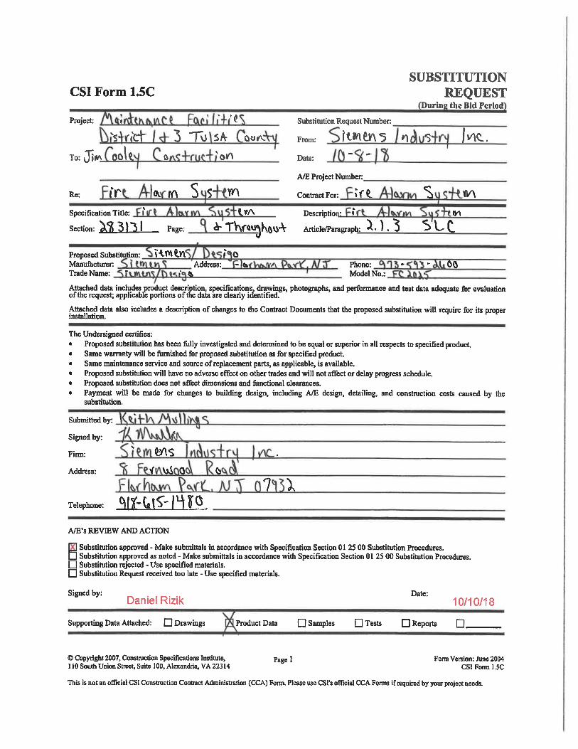
CSI Form 1.5C
Project: »
SUBSTITUTIONREQUEST
urin the Bid Period
' . ' Substitution Request Number:
's rlct 3 Tv) s/^ of From: |t»n^\<5 n <3 I^CL.To: jjin OOlt. & <k01<\ Date: ~ "
Re: (Y
Specification Title: I' (.VA
A/E Project Number:
Contract For: tf^.
Descriptio
fl^fA S S W
Section: 31'S I Page: A-TV\r<t^Ko^'V AiticleTaragraph: ^-) .
Proposed Substitution: I "^.W -A
n^\
y\
Manufacturer:
Trade Name:
»' 0Address: - te Phone:
Model No.:60
Attached data includes product description, specifications, drawmgs, photographs, and peribranance and test data adequate for evaluationof the request; applicable portions of the data are clearly identified."
Attached data also includes a description of changes to the Contract Documents that the proposed substitution will require for itsinstallation.
The Undersigned certifies:Proposed substitution has been fully investigated and detennined to be equal or superior in all respects to specified product.Same warranty will be fumished for proposed substitution as for specified product.Same maintenance service and source of replacement parts, as applicable, is available.Proposed substitution will have no adveise effect on other trades and will not affect or delay progress schedule.Proposed substitution does not affect dimensions and functional clearances.Payment will be made for changes to building design, including A/E design, detailing, and construction costs caused by thesubstitution.
Submitted by:
Signed by:
Firm:
Address:
ws
^ ViA 0
Telephone: M^lllt0.
A^'s REVffiW AND ACTION
7 ).
Substitution approved - Make submittals in accordance with Specification Section 01 25 00 Substitution Procedures,Substitution approved as noted - Make submittals in accordance with Specification Section 01 25 00 Substitution Procedures.Substitution rejected - Use specified materials.Substihition Request received too late - Use specified materials.
Signed by: r, __, _. , _,,Daniel Rizik
Supporting Data Attached: D Drawings
Date:10/10/18
Product Data Q Samples D Tests D Reports Q.
© Copyright 2007, Construction Specifications Institute,110 South Union Street, Suite 100, Alexandria, VA 22314
Page 1 Form Version: June 2004
CSIForml.SC
This is not an official CSI Construction Contract Administration (CCA) Fonn. Please use CSI's official CCA Fonns if required by your project needs.
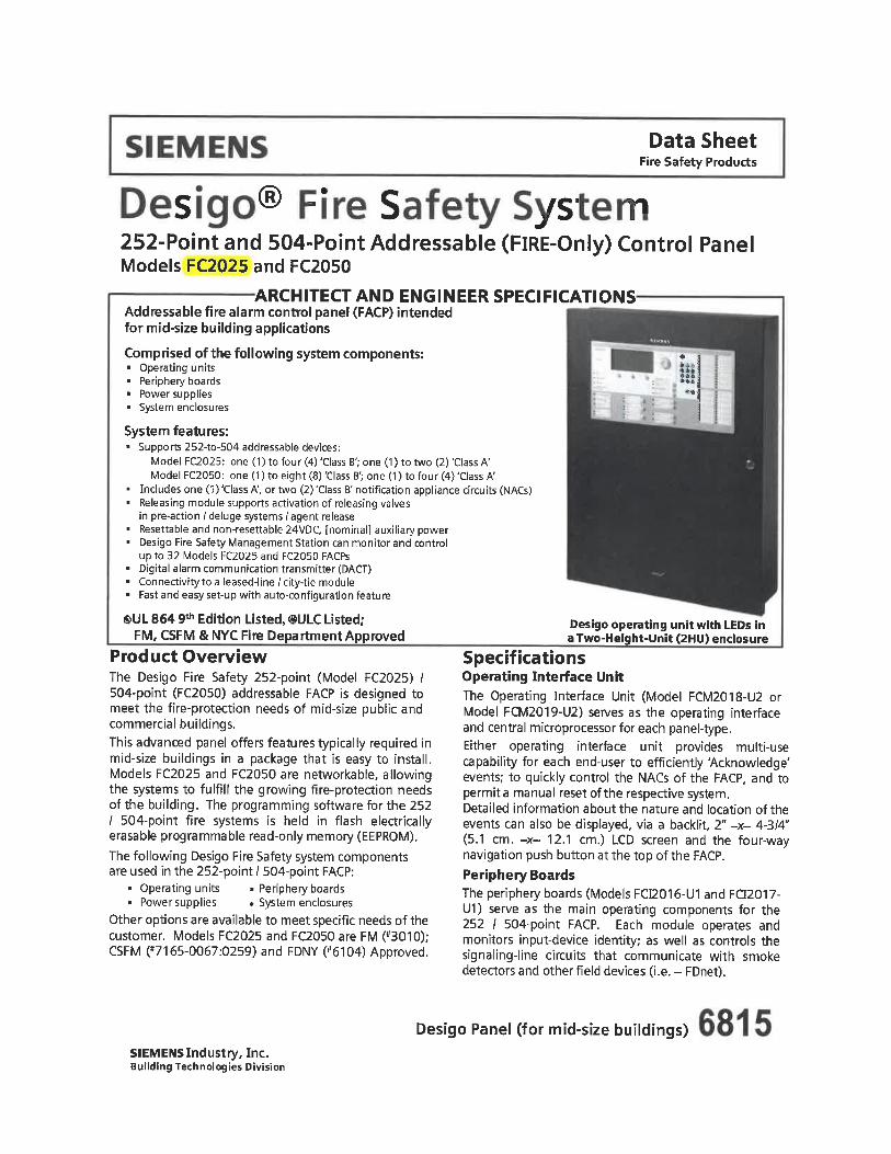
Data SheetFire Safety Products
- s ys- - p252-Point and 504-Point Addressable (FlRE-Only) Control PanelModels FC2025 and FC2050
ARCHITECT AND ENGINEER SPECIFICATIONSAddressable fire alarm control panel (FACP) intendedfor mid-size building applications
1'tMfo
Comprised of the following system components:. Operating units. Periphery boards. Power supplies. System enclosures
System features:. Supports 252-to-504 addressable devices:
ModelFC2025: one (1) to four (4) 'Class B'; one (1) to two (2) 'Class A'ModelFC2050: one (1) to eight (8) 'Class B'; one (1) to four (4) 'Class A'
. Includes one (1) 'Class A', or two (2) 'Class B' notification appliance circuits (NACs)
. Releasing module supports activation of releasing valvesin pre-action / deluge systems / agent release
. Resettable and non-resettable 24VDC, [nominal] auxiliary power
. Desigo Fire Safety Management Station can monitor and controlup to 32 Models FC2025 and FC2050 FACPs
. Digital alarm communication transmitter (DACT)
. Connectivity to a leased-line /dty-tie module
. Fast and easy set-up with auto-configuration feature
®UL 864 9th Edition Listed, ®ULC Listed;FM, CSFM & NYC Fire Department Approved
Product OverviewThe Desigo Fire Safety 252-point (Model FC2025)/504-point (FC2050) addressable FACP is designed tomeet the fire-protection needs of mid-size public andcommercial buildings.
This advanced panel offers features typically required inmid-size buildings in a package that is easy to install.Models FC2025 and FC2050 are networkable, allowingthe systems to fulfill the growing fire-protection needsof the building. The programming software for the 252/ 504-point fire systems is held in flash electricallyerasable programmable read-only memory (EEPROM).The following Desigo Fire Safety system componentsare used in the 252-point / 504-point FACP:
. Operating units . Periphery boards
. Power supplies . System enclosures
Other options are available to meet specific needs of thecustomer. Models FC2025 and FC2050 are FM (*3010);CSFM ("7165-0067:0259) and FDNY (»6104) Approved.
Desigo operating unit with LEDs ina Two-Height-Unit (2HU) enclosure
SpecificationsOperating Interface UnitThe Operating Interface Unit (Model FCM2018-U2 orModel FCM2019-U2) serves as the operating interfaceand central microprocessor for each panel-type.Either operating interface unit provides multi-usecapability for each end-user to efficiently 'Acknowledge'events; to quickly control the NACs of the FACP, and topermit a manual reset of the respective system.Detailed information about the nature and location of theevents can also be displayed, via a backlit, 2" -x- 4-3/4"(5. 1 cm. -x- 12. 1 cm. ) LCD screen and the four-waynavigation push button at the top of the FACP.Periphery BoardsThe periphery boards (Models FCI2016-U1 and FCI2017-U1) serve as the main operating components for the252 / 504-point FACP. Each module operates andmonitors input-device identity; as well as controls thesignaling-line circuits that communicate with smokedetectors and other field devices (i.e. - FDnet).
Desigo Panel (for mid-size buildings)SIEMENS Industry, Inc.Building Technologies Division
Specifications - (continued)Power SuppliesAll functions are supported by the 170W (ModelFP2016-U1) or 300W (Model FP2012-U1) powersupplies, which therefore eliminate the need forexternal power supplies.
Additionally, Models FP2016-U1 and FP2012-U1provide primary, 24VDC nominal power for normaloperation to Models FC2025 and FC2050.Both power supplies are filtered and regulated.Model FP2016-U1 is rated at 6.5 Amps, whilethe rating of Model FP2012-U1 is 11.5A.The 170-Watt power supply incorporates a 4.0A,non-resettable slow-blow fuse on the primary input,and includes a built-in AC-line filter for surge andnoise suppression. Model FP2016-U1 mounts in thepanel's enclosure, and there are no serviceableDesigo Fire Safety parts to be maintained.
The 300-Watt power supply incorporates two (2) 6.3Areplaceable, non-resettable slow-blow fuses on theprimary input and includes a built-in AC line filter forsurge and noise suppression. Model FP2012-U1mounts in the panel's enclosure, and there are noserviceable Desigo Fire Safety parts to be maintained.
System EnclosuresThe Desigo fire-alarm enclosures and their accessoriesprovide a complete set of hardware for mounting allDesigo main-system and remote terminal cards, as wellas Desigo modules that are housed in each enclosure.
The hardware allows this Desigo system to beconfigured for a variety of applications, as well as forfuture system upgrades. Included in the enclosureseries are back box and door sets; removable mountingplates and clear lenses; and blank plates for use withthe enclosure doors.
All enclosures come with ground straps for the innerand outer doors, shield termination lugs, groundinglugs, and tie wrap lances for securing wire. All Desigotwo height-unit (2HU) enclosures can also mountsystem back-up batteries up to 33AH in capacity.Models FC2025 and FC2050 utilize a two-height-unitenclosure. The following components comprise acomplete two-height-unit enclosure:
. One (1) back box, (Model FHB2002-U1 ; R1)
. One (1) or two (2) inner doors,(Models FHD2004-U1 orFHD2005-U1)
. One (1) outer door,(Model FHD2002-U2 / R2, or FHD2003-U2 / R2)
. One (1) or two (2) clear windows, (Model FHD2006-U1)
Note: One (1) window is installed for Model FHD2002-U2; R2outerdoor, and two (2) windows are required forModelFHD2003-U2/R2.
The approximate size for each two-height-unit enclosureis: 27.5" (70cm.) high; 21.5" (54.6cm.) wide, and 5.75"(14.6cm.) deep. The weight, without connectedcomponents, is approximately 6.3 Lbs. (2858 g).
Additionally, the two-height-unit enclosure supportsthe following components:
. Enclosure trim kit (for flush-mounting)
. Battery bracket (to comply with seismic certification)
. DIN rail kit (provides connection betweeninternal-system wiring and field wiring)
Optional AccessoriesDigital Alarm Communication Transmitter (DACT)
The DACT is used to provide communication betweenModels FC2025 and FC2050 and with either a central orremote monitoring station.
The Model FCA2015-U1 module mounts directly on theback enclosure and connects to the periphery boards.The DACT enables remote transmission of alarms andevents via a public telephone line.
Releasine Module
The releasing module (Model XCI2001-U1) supportsactivation of releasing valves in pre-action / delugesystems (including double-interlock pre-action systems,or Sinorbc® Engineered Fire Suppression systems).Activation can be event-controlled or performed byaddressable manual pull stations.
When installed on Models FC2025 / FC2050, thereleasing module contains an integral manual-disconnect switch for releasing circuits. This essentialfeature protects the releasing circuits from accidentaldischarge during maintenance.
Battery Disconnect Module
The Battery Disconnect Module (Model FCA2032-U1)is specifically designed to disconnect the backupbattery on the Desigo Fire Safety 252 / 504-pointaddressable FACP when its voltage drops below19VDC. The cut-off function of Model FCA2032-U1
prevents the battery from operating beyond its normalpower level for basic system operation.
The battery-disconnect module remains disconnecteduntil AC power is restored to a Desigo 252 / 504 FACP.
Migration Hardware Kit
Model FHA2056-series kits are specifically designed forthe seamless transition of an existing Siemens FS-250(FireSeeker) control panel into a fully operational 252 or504-point addressable Desigo Fire Safety fire-alarmFACP, [FC2025 or FC2050, respectively].Each shipment of the Model FHA2056-series kitscontains the following pieces of equipment:. One (1) outer door. One (1) inner door. One (1) hinge-assembly bracket. One (1) back plate. One (1) inner-door bracket
Note: The five (5) items that comprise one (1)Model FHA2056-series hardware-migration kitcannot be ordered individually.
SIEMENS Industry, Inc.Building Technologies Division
Specifications - (continued)Network Module
The SafeDLlNK network module (Model FN2001-U1) is usedto network up to 16 FACPs or fire terminals, via the FCnetsystem bus. Model FN2001-U1 is plugged into the OperatingUnit (Models FCM2018-U2 / R2 and FCM2019-U2 / R2).
Model FN2001-U1, which connects to system input / outputbus, has ground-fault monitoring, as well as an integrateddegrade-mode feature. Redundant networking isaccomplished with one (1) network module per panel[Simple-Loop Trouble]. There is electrical isolation betweenthe system bus and the FACP.Remote DjspJ^Y TerminalsThe Remote Display Terminals (Models FT2014-U2 / R2and FT2015-U2 / R2) are remote annunciators that showthe existing status of Models FC2025 /FC2050.
Light-emitting diodes (LEDs) will illuminate for any givenA/orm, Supervf"soryand Trouble Desigo-system event.A LCD screen will give details of the event in alphanumericform. The display screen can be scrolled, via the four-waynavigation button, to reveal additional events.
Model R2014 is a display-only, remote annunciator thathas one (1) button used to silence the local sounder.Model FT2015 has three (3) control buttons for'acknowledging' events, 'silencing' audible circuits and'resetting' the system. Additionally, there are three (3)user-programmable buttons available. Model FT2015 hasa key switch that enables the control buttons to operate.
The remote display terminals are remotely connected toModels FC2025 and FC2050, via the RS-485 interface.Models FC2025 and FC2050 require the Model FCA2016-U1 RS-485 interface module to provide communication tothe remote display terminals. Model FCA2016-U1supports Style 4 or Style 6 wiring. Up to eight (8) modulescan be supported on a RS-485 bus.
The remote displayterminals require 24VDC [nominal] power,and the necessa ry power can be provided from the DesigoFACP or from another <S>UL Listed, 24VDC power source.Note: A Model FHD2012-U1 inner doorcan be optionally
purchased in ®UL markets. The inner door mounts with theoptional Model FT201x-series Remote Display terminals.Having a Model FHD2012-U1 inner doorinstalled can assistin preventing unauthorized access to the RDT.
S-senes License Key
The S1 license key (Model FCA2033-A1) allows for virtualmonitoring and control between a Desigo 252 / 504-pointaddressable fire-only panel and a personal computer.The S2 license key (Model FCA2034-A1) is a BACnetoutput, and is used for monitoring-only purposes by a3rd-party system for life-safety objects.The S3 license key (Model FCA2035-A1) is a combinationlicense key that allows for virtual monitoring and control,as well as for distribution of BACnet (monitoring-only)communications. A four-digit personal identificationnumber (PIN) must be used in order to preventunauthorized access.
Tabular Annunciators
The Desigo tabular annunciators allow system eventssent from Desigo addressable panels to be displayedremotely in real-time. The Model FT2008 series oftabular annunciators has 16 zones, and the Model
FT2009 series uses 96 LEDs for 32 zones. Up to two (2)light-emitting diodes (LEDs) can be used per zone.Tabular annunciators provide outputs for system andzone status, and are orderable in either black or red.
LED Annunciator DriverThe Model FT2007-U1 LED Annunciator Driverprovides custom graphic annunciators on addressableDesigo FACPs. This optional system module provides96 highly programmable outputs to drive LEDindicators.
There are 16 inputs to accommodate user-systemcommands: Silence, Unsilence, Reset, Acknowledgeand Lamp Test. Model FT2007-U1 is supervised via aRS-485 interface. A maximum eight (8) modules areallowed on each RS-485 communication bus.
NAC Expansion Module
The NAC expansion module (Model FCI2011-U1)provides either of the following additional NACs to aDesigo Fire Safety 252 / 504-point FACP:
. one (1) 'Class A', or
. two(2)'ClassB'NACs
Each NAC is rated at 3 Amps. Each NAC expansionmodule is monitored for open-line and short-circuitconditions.
Related DocumentationProduct
Desigo operatin unitsDesigo periphery boardsDesi o fire terminals
Desigo DACTSafeDLtNK /FCnet module
Power suppliesDesigo enclosures
expansion moduleBesigo releasing moduleLeased-Line / city-tie moduleemote periphery module
. esigo Remote displayterminals^n Ie/multi-mode fiber modulesLED /Blank option modulesBattery disconnect module'S'-series license keyMarine-specific equipmentLED annunciator driver
16-and-32-zone tabular annunciators
Hardware Migration Kit
Data Sheet Number6801680268036804680568066807680868096810681168126814681668196820682268246825
6826
SIEMENS Industry, Inc.Building Technologies Division
-3-
Details for Ordering
Model PartNumber Description
Desigo Periphery Board(for 252- oints stem}Desigo Periphery Boardfor 504- oint s stem
Desigo Operating Interface Unit
Operating Interface Unit w/ LEDs
1HU Back Box, Black
1HU Back Box, Red
2HU Back Box, Black2HU Back Box, Red1HU Outer Door, Black
1HU Outer Door, Red
2HU Outer Door w/1 Window, Black
2HU Outer Door w; 1 Window, Red
2HU Outer Door w/2 Windows. Black
21-IU Outer door w/ 2 windows. Red
Inner Door. Black
Inner Door, Black (full plate)Clear-Lens Window
^0-Watt Power Supply
. i-Watt Power Supply
FQ2016-U1 S54400-A55-A1
FQ2017-U1 S54400-A56-A1
FCM2018-U2 S54400-C40-A1
FCM2019-U2 S54400-C41-A1
FHB2001-U1 S54400-B47-A1
FHB2001-R1 S54400-B47-A2
FHB2002-U1 S54400-B48-A1FHB2002-R1 S54400-B48-A2
FHD2001-U2 S54400-B49-A1
FHD2001-R2 S54400-B49-A2
FHD2002-U2 S54400-B50-A1
FHD2002-R2 S54400-B50-A2
FHD2003-U2 S54400-B51-A1FHD2003-R2 S54400-B51-A2FHD2004-U1 S54400-B52-A1FHD2005-U1 S54400-B53-A1
FHn^nnft-lll ?;C>4400-C46-A1
FP2011-U1 TTM50222
FP2012-U1 £C.4400-Z60-A1
Optional Accessories
Model Number DescriptionFCA2015-U1 S54400-A63-A1 Di ital Alarm Comm. Transmitter [mcr]FCA2016-U1 S54400-A39-A1 RS-485 Interface ModuleFCA2018-U1 S54400-A65-A1 Remote Peri heral ModuleFCA2032-U1 S54400-B145-A1 Batter Disconnect ModuleFCA2033-U1 S54400-P154-A1 Si License KeFCA2034-U1 S54400-P155-A1 Sz License Ke : BACnet monitorinFCA2035-U1 S54400-P156-A1 SsLicenseKe : Rem. View w; BACnetFQ2011-U1 S54400-A54-A1 NACEx ansion ModuleFQ2020-U1 S54400-A57-A1 Leased-Line/Cit-Tie Module
Blank 0 tion Module
LED Option Module:RED/GREEN brmllir LED; one 1 YELLOW LED
LED Option Module:RED/VELLOf bi-cdorLED;one(1)yE U. O'.VL£D
Desigo Fire Safety HardwareMi ration Kit, BlackDesigo Fire Safety HardwareMi ration Kit, Red
S54400-C145-A1 Inner Door, Black (o tional)s'i4400-A60-A1 SafeDLINK I FCnet Network Module
. I-A61-A1 Sngle-ModeFiber-«»tic Module. . r»-A62-A1 Uulti-Mode Fiber-ORtic Module
1-A142-A1 LED Annundator Driver
'-A143-A1 16-Zone Tabular Annunciator, Black
-A144-A1 16-Zone Tabular Annunciator, Red.-A145-A1 > ie Tabular Annunciator, Black
-A146-A1 32-Zone Tabular Annunciator, Red
.-F67-A1 Remote Dis la Terminal, Black
. 3-B75-A1 Remote Dis la Terminal, Red
S544IOF68-A1 Dis la Terminal with ke , BlackS544«»I15-A1 Dis la Terminal with ke RedS54400-A58-A1 Fire Terminal BoardS5440Q-A69-A1 Releasin Module
FCM2022-U2 S54400-C44-A1
FCM2023-U2 S54400-C45-A1
FCM2034-U2 S54400-C137-A1
FHA2056-U1 S54400-B18-A1
FHA2056-R1 S54400-B19-A1
FHD2012-U1
FN7nni-ui
1
1
. 2008-U1T2008- 1T2009-U1
FT2009-R1FT2014-U2FT2014-R2FT2015-U2FT2015-R2FTI2001-U1XCI2001-U1
S5-S54
Fire Safety8 Fernwood Road
SIEMENS Industry, Inc. Florham Park, NJ 07932Building Technologies Division Tel: (973) 593-2600
FAX: (908) 547-6877URL: www.USA.SIemens.coi
Model
FC2025-U
FC2050-U
FC2025-U
FC2050-U
FT2050-US
FT2050-UE
FC2025-U
FC2050-U
FC2025-UF
c
FC2050-UF
PartNumber
S54400-C4-A1
S54400-C5-A1
S54400-C6-A1
S54400-C7-A1
S54400-C8-A1
: S54400-C9-A1
S54400-C10-A1
S54400-C11-A1
S54400-C12-A1
S54400-C13-A1
Electronics Packages
Description
252-Point Fire System with 170 Watt PowerSu I and standard o erator interfaces
FP2016-U1 (1 Qty.)Includes: FC12016-U1 (1 Qty.)
FCM2018-U2 (1 Qt .)504-Point Fire System with 1 70 Watt PowerSu I and standard o erator interfaces
FP2016-U1 (1 Qty.)Includes: FC12017-U1 (1 Qty.)
FCM2018-U2 (1 Qty.)252-Point Fire System with 1 70 Watt PowerSupply and standard operator interfaces
with 24-zone LEDs
FP2016-U1 (1 Qty.)Includes: FCI2016-U1 (1 Qty.)
FCM2019-U2 (IQty.)504-Point Fire System with 1 70 Wan PowerSupply and standard operator interfaces
with 24-zone LEDs
FP2016-U1 (1 Qty.)Includes: FCI2017-U1 (1 Qty.)
FCM2019-U2 1 t .)Network Terminal wl standard o erator interface
FT12001-U1 (1 Oty.)FCM2018-U2 (1 Qt,..)
Network Terminal wl standard operator interfacewith24-zoneLEDs)
Includes:
Includes:FTI2001-U1 (1 Qty.)FCM2019-U2 (1 Qty.)
252-Point Fire System with 300 Watt PowerSu , :iv and standard o erator interfaces
FP2012-U1 (1 Qty.)Includes; FCI2016-U1 (1 Qty.)
FCM2018-U2 (1 Q .)504-Point Fire System with 300 Watt PowerSu ly and standard operator interfaces
FP2012-U1 (1 Qty.)Includes: FCI2017-U1 (1 Qty.)
FCM2018-U2 (1 Qt .)252-Point Fire System with 300 Watt PowerSupply and standard operator interfaces
(with 24-zone LEDs)FP2012-U1 (1 Qty.)
Includes: FCI2016-U1 (1 Qty.)FCM2019-U2 (1 Q .)
504-Point Fire System with 300 Watt PowerSupply and standard operator interfaces
with 24-zone LEDs
FP2012-U1 (1 Qty.)Includes: FCI2017-U1 (1 Qty.)
FCM2019-U2 (1 Q .)
Temperature and Humidity RangeDesigo Fire Safety 252 / 504-point addressable systemsare ®UL 864 9th Edition Listed for indoor dry locationswithin a temperature range of 120 +/-3°F (49 +/- 2°C) to32 +/- 3°F (0 +/- 2°C) and a relative humidity of 93 +/- 2%ata temperature of 90 +/-3°F (32 +/-2°C).
Notice: This marketing data sheet is not intended to beused for system design or installation purposes.For the most up-to-date information,refer to each product's installation instructions.
ISII-FS)Printed in U.S .A.
i-Flre-Safetv
Fire Safety1577 North Service RoadEast Oakville, OntarioL6H OH6 / CanadaTel: [905] 465-8000URL: www.Siemens.CA
January 2018Supersedes sheet dated 4/2016
(Rev. 6)
Data SheetFire Safety Products
yRemote Display Terminals (with RS-485 interface)Models FT2014-U2/ R2 and FT2015-U2/ R2 (with Model FCA2016-U1)
ARCHITECT AND ENGINEER SPECIFICATIONSModels FT2014-U2 / R2 and FT2015-U2 / R2:. 2"-x-4-3A" backlit LCD screen
. Event and audible status LEDs
. Supports Style 4 or Style 6 wiring
. Built-in transient protection
. Mounts in its own enclosure
. Optional system controlModelFT2015-U2
. Downloadable firmware. Built-in flash electrically erasable programmable
read-only memory (EEPROM)
. Scroll buttons to view additional events
. Local sounder
. ®UL 864 9*h Edition Listed, ®ULC Listed;FM, CSFM & NYC Fire Dept. Approved
Product OverviewThe Remote Display Terminals (Models FT2014-U2 / R2and FT2015-U2 / R2) are remote light-emitting diode(LED) / liquid-crystal display (LCD) units that show theexisting status of a Desigo 252 / 504-point system.
A LED will illuminate for any given Alarm. Gas Alarm.Supervisory and Trouble Desigo-system event.A 2" -x- 4-3/4" LCD screen will give details of theevent in alphanumeric form. The display screen canbe scrolled to reveal additional events. Optionalremote-system-control capabilities are also available.
The Remote Display Terminals (as well as ModelFCA2016-U1) are FM (#3010); FDNY (#6104) andCSFM (*7165-0067:0259) Approved.
SpecificationsThe remote display terminals have separate LEDs forAlarm, Gas Alarm, Supervisory, and Trouble events ona Desigo FACP. Each LED will flash when'unacknowledged' events are present. The LED willchange to 'steady', upon acknowledgment of the event.
ModelFCA2016-U1
Model FCA2016-U1:
. RS-485 module providescommunication to Remote DisplayTerminals (Models FT2014, FT2015)
. Dual, standardized RS-485 interface
. Supports 'Class B' (Style 4) and 'Class A'(Style 6) wiring configurations
. Electrical isolation between the RS-485interface and Desigo panel
. Ground-fault monitoring
. up to eight (8) devices on the RS-485Style 6 loop Universal Fire Protocol(UFP) limitation
. ®UL 864 9th Edition Listed, ®ULC Listed;FM, CSFM & NYC Fire Dept. Approved
Additionally, the remote display terminals have an LEDto indicate system power; a separate ground-fault LED,and four (4) additional user-programmable LEDs.There are also two (2) LEDs that indicate thestate of audible circuits on the system:
. One (1) LED to indicate that the circuits are 'active'
. One (1) LED to indicate the circuits have been 'silenced'
When the Desigo FACP is in 'normal'state (with noevents present), the screen will annunciate the dateand time-of-day.When an event has been triggered to the Desigopanel, the LCD display will show the following:
. Event type and zone
. Custom message for that zone
. Usage of the zone
. 'Unacknowledged' or 'Acknowledged' event
In addition to the aforementioned features, the displaywill show the total number of all types of eventspresent on the system. The display has a backlightfeature that operates upon receiving any event statusor when any operator buttons are pressed.
Desigo Remote Display Terminals (with RS-485 module)SIEMENS Industry, Inc.Building Technologies Division
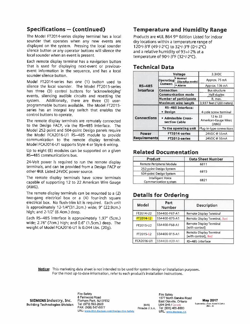
Specifications - (continued)The Model FT2014-series display terminal has a localsounder that operates when any new events aredisplayed on the system. Pressing the local soundersilence button or any operator buttons will silence thelocal sounder when an event is present.
Each remote display terminal has a navigation buttonthat is used for displaying next-event or previous-event information in the sequence, and has a localsounder silence button.
Model FT2014-series has one (1) button used tosilence the local sounder. The Model FT2015-serieshas three (3) control buttons for 'acknowledging'events, silencing audible circuits and resetting thesystem. Additionally, there are three (3) user-programmable buttons available. The Model FT2015-series has an integral key switch that enables thecontrol buttons to operate.
The remote display terminals are remotely connectedto the Desigo FACP, via the RS-485 interface. TheModel 252-point and 504-point Desigo panels requirethe Model FCA2016-U1 RS-485 module to providecommunication to the remote display terminals.Model FCA2016-U1 supports Style 4 or Style 6 wiring.Up to eight (8) modules can be supported on a givenRS-485 communications bus.
24-Volt power is required to run the remote displayterminals, and can be provided from a Desigo FACP orother ®UL Listed 24VDC power source.
The remote display terminals have screw terminalscapable of supporting 12 to 22 American Wire Gauge(AWG).The remote display terminals can be mounted to a (2)two-gang electrical box or a (4) four-inch squareelectrical box. No flush-trim kit is required. Each unitis approximately 12-1/4"(31. 2cm. ) wide; 9" (22. 9cm.)high; and 2-112" (6.4cm. ) deep.
Each RS-^1.85 interface is approximately 1.97" (5cm.)wide; 2. 76" (7cm. ) high; and 0. 6" (1. 5cm. ) deep. Theweight of Model FCA2016-U1 is 0.044 Lbs. (20g).
Temperature and Humidity RangeProducts are ®UL 864 9th Edition Listed for indoordry locations within a temperature range of120+/-3°F (49+/-2°C) to 32+/-3°F (0+/-2°C)and a relative humidity of 93+/-2% at atemperature of 90+/-3°F (32+/-2°C).
Technical Data
RS-485Interface
Connections
PowerRequirements
J>eratin3LS^"!odecu"ent: l^anT""""ConnectionCommunication mode
Number of artici antsMaximum wire len th
RS-485 Interface:. Desi n
. Admissible Cross-section Cable
To the operating unit
FT2014-series
FT2015-series
3. 3VDC
Approx. 75 mA
Approx. 136mABus structure
Half-duplex8, max,
3, 937 feet (1200 meters)
4- ole screw terminal
12 to 22American-Gauge Wires
(AWG)'ug-in-type connections
24VDC @ 55mA
24VDC @ 55mA
Related DocumentationProduct Data Sheet Number
Remote Peripheral Module
252-point Desigo System504-point Desigo System
Intelligent VoiceCommunication s stem
6811
6815
6821
Details for Ordering
Model
FT2014-U2
FT2014- 2
FT2015-U2
FT2015-R2
FCA2016-U1
PartNumber
S54400-F67-A1
S54400-B75-A1
S54400-F68-A1
S54400-B15-A1
Description
Remote Display Terminal
Remote Display Terminal, Red
Remote Display Terminal[with control]
Remote Display Terminal[with control]. Red
RS-485 Interface
Notice: This marketing data sheet is not intended to be used for system design or installation purposes.For the most up-to-date information, refer to each product's installation instructions.
SIEMENS Industry, Inc.Building Technologies Division
Fire Safety8 Femwood RoadFlorham Park, NJ 07932Tel: (973) 593-2600FAX: (908) 547-6877URL: www. USA. Siemens. com Desi o-Ftre-Safe
(SII-FS)Printed in U. S.A.
Fire Safety1577 North Sen/ice RoadEast Oakville, OntarioL6HOH6/CanadaTel: [905] 465-8000URL: www. Siemens. CA
May 2017Supersedes sheet dated 8/2013
(Rev. 4)

Data SheetFire Safety Products
PAD-4 Distributed Power Supply Unit [for®UL markets]Notification Appliance Circuit ExtenderModels PAD-4-ENCL, PAD-4-MB (with FP2011-U1, FP2012-U1 power supplies)
ARCHITECT AND ENGINEER SPECIFICATIONS. Four (4) 'Class B', power-limited notification appliance circuits (NACs)
. 'Class A', field-selectable wiring. Each unit can support an optional module (Model PAD-4-CLSA) that
converts two (2) built-in 'Class A' NACs into four (4) 'Class A' NACs
. Up to 3 Amps of auxiliary-power output
. Optional built-in strobe synchronization. Supports coded audible signals, including Temporal 3, Temporal 4 patterns
. Battery supervision and control
. 'Form C general Trouble /AC Fail monitoring contact
. Power supplies support NAC power. Up to 6A used with Model FP2011-U1. Up to 9A used with Model FP2012-U1
. 24VDC output voltage
'Class A'Adapter Card[Model PAD-4-CLSA]
Main Board[Model PAD-4-MB]
Unit Enclosure[Model PAD-4-ENCL]
. Ground-fault detection
. Advanced microprocessor control
. Uses Flash memory-based system firmware. Optional system-diagnostic and firmware-upgrade tool
Product OverviewUsed with Siemens - Fire Safety fire alarm controlpanels (FACPs), the Distributed Power Supply PAD-4Unit is a NAC expander with a built-in, auxiliary-power output. Each PAD-4 unit distributesadditional power in buildings for audible and visualindicators that conform to the Americans withDisabilities Act (ADA). PAD-4 also has thefollowing features:
NACsSignal-input circuitsBattery-charging circuitTrouble relays for remote monitoringDiagnostic light-emitting diodes (LEDs)Alternating Current (AC) power connection
The Siemens NACs, which connect with alarmsignaling devices, have been designed to providethe highest level of reliability and performance.Signal coding on the circuits is accomplishedthrough integrated circuits (rather than relays),which eliminates mechanical wear on the outputcircuits.
. Multi-module mounting in System 3T enclosures. Multiple modules share battery set
. ADA Compliant
. ®UL864 9<r Edition Listed, ®UL 1481 Listed;FM (*3010), CSFM (*7315-0067:0268) Approved
The PAD-4 unit provides constant 24VDC outputvoltage to each NAC - independent of voltagefluctuations on the primary or secondary powersource. As a result, a larger voltage drop and agreater wire length for each NAC are supported byeach PAD-4.
SpecificationsThis version of the Siemens Distributed Power SupplyUnit can be configured in the following manner thatmakes the outputs easily programmable:
. 'STEADY'outputs. Synchronized strobe outputs. American National Standards Institute (ANSI) Temporal 3. ANSI Temporal 4 [for carbon monoxide (CO) alarm signal]
There are also two (2) inputs used to control theactivation of the four (4) outputs. Programming canbe set so one (1 ) input will silence the audible signalon Siemens Models 'AS'-series, 'NS'-series, or 'ZH'-series horn and horn-strobes while the strobesremain active.
Distributed Power Supply - NAC Extender (Model PAD-4 series)SIEMENS Industry, Inc.Building Technologies Division
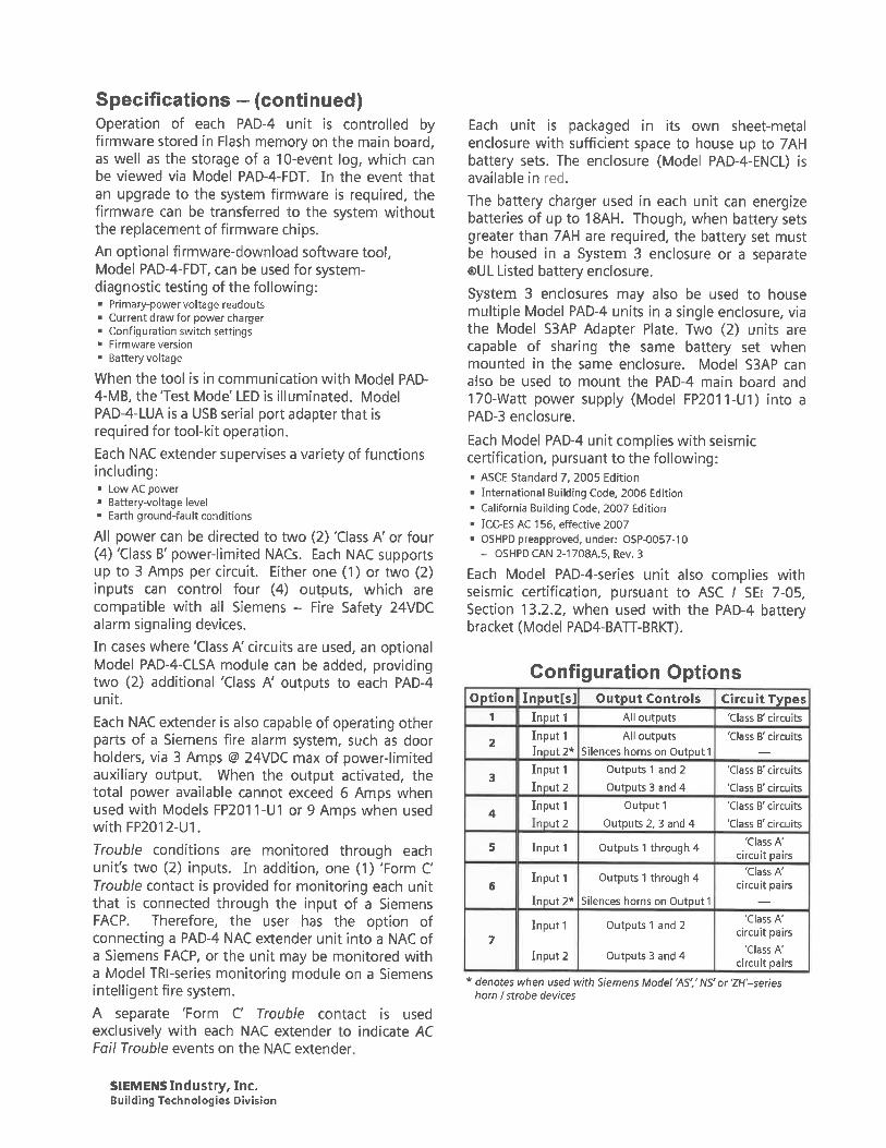
Specifications - (continued)Operation of each PAD-4 unit is controlled byfirmware stored in Flash memory on the main board,as well as the storage of a 10-event log, which canbe viewed via Model PAD-4-FDT. In the event thatan upgrade to the system firmware is required, thefirmware can be transferred to the system withoutthe replacement of firmware chips.An optional firmware-download software tool,Model PAD-4-FDT, can be used for system-diagnostic testing of the following:
Primary-power voltage readoutsCurrent draw for power chargerConfiguration switch settingsFirmware version
Battery voltage
When the tool is in communication with Model PAD-4-MB, the Test Mode' LED is illuminated. ModelPAD-4-LUA is a USB serial port adapter that isrequired for tool-kit operation.
Each NAC extender supervises a variety of functionsincluding:. Low AC power. Battery-voltage level. Earth ground-fault conditions
All power can be directed to two (2) 'Class A' or four(4) 'Class B' power-limited NACs. Each NAC supportsup to 3 Amps per circuit. Either one (1) or two (2)inputs can control four (4) outputs, which arecompatible with all Siemens - Fire Safety 24VDCalarm signaling devices.
In cases where 'Class A' circuits are used, an optionalModel PAD-4-CLSA module can be added, providingtwo (2) additional 'Class A' outputs to each PAD-4unit.
Each NAC extender is also capable of operating otherparts of a Siemens fire alarm system, such as doorholders, via 3 Amps @ 24VDC max of power-limitedauxiliary output. When the output activated, thetotal power available cannot exceed 6 Amps whenused with Models FP2011-U1 or 9 Amps when usedwithFP2012-U1.
Trouble conditions are monitored through eachunit's two (2) inputs. In addition, one (1) 'Form CTrouble contact is provided for monitoring each unitthat is connected through the input of a SiemensFACP. Therefore, the user has the option ofconnecting a PAD-4 NAC extender unit into a NAC ofa Siemens FACP, or the unit may be monitored witha Model TRl-series monitoring module on a Siemensintelligent fire system.
A separate 'Form C Trouble contact is usedexclusively with each NAC extender to indicate ACFo// Trouble events on the NAC extender
Each unit is packaged in its own sheet-metalenclosure with sufficient space to house up to 7AHbattery sets. The enclosure (Model PAD-4-ENCL) isavailable in red.
The battery charger used in each unit can energizebatteries of up to 18AH. Though, when battery setsgreater than 7AH are required, the battery set mustbe housed in a System 3 enclosure or a separate®UL Listed battery enclosure.
System 3 enclosures may also be used to housemultiple Model PAD-4 units in a single enclosure, viathe Model S3AP Adapter Plate. Two (2) units arecapable of sharing the same battery set whenmounted in the same enclosure. Model S3AP canalso be used to mount the PAD-4 main board and170-Watt power supply (Model FP2011-U1) into aPAD-3 enclosure.
Each Model PAD-4 unit complies with seismiccertification, pursuant to the following:
ASCE Standard 7, 2005 EditionInternational Building Code, 2006 EditionCalifornia Building Code, 2007 EditionICC-ES AC 156, effective 2007OSHPD preapproved, under: OSP-0057-10- OSHPD CAN 2-1708A.5, Rev. 3
Each Model PAD-4-series unit also complies withseismic certification, pursuant to ASC / SEi 7-05,Section 13. 2. 2, when used with the PAD-4 batterybracket (Model PAD4-BATT-BRKT).
Configuration OptionsOption
1
5
6
7
Input[s]
Input 1Input 1In ut2*
Input 1In ut2
Input 1
" 'Jt2
Input 1
Input 1
In ut2*
Input 1
Input 2
Output Controls
All outputs
All outputsSilences horns on Output!
Outputs 1 and 2
Outputs 3 and 4
Output 1
Outputs 2, 3 and 4
Outputs 1 through 4
Outputs 1 through 4
Silences horns on Output!
Outputs 1 and 2
Outputs 3 and 4
' denotes when used with Siemens Model 'AS'. 'N5'
Circuit Types'Class B' circuits
'Class B' circuits
'Class B" circuits
'Class B'circuits
'Class B'circuits
'Class B'circuits
'Class A'circuit pairs
'Class A'circuit pairs
'Class A'circuit pairs
.Class A-circuit pairs
or 'ZH'-series
horn / strobe devices
SIEMENS Industry, Inc.Building Technologies Division
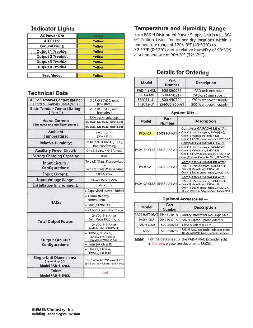
Indicator LightsAC Power ON:
AUX / PS:Ground Fault:
Output 1 Troub/e:Output 2 Trouble:
Output 3 Trouble:
Out ut4Troubfe:
Test Mode:
Yellow
Yellow
Yellow
Yellow
Yellow
Yellow
Yellow
Technical DataAC Fof/ Trouble Contact Rating:
{'Form A' - Normall Closed (N. C)}
Basic Trouble Contact Rating:{-Form C }
Alarm Current:{ for NACs and auxiliary power }
AmbientTern rature:
Relative Humidity:
Auxiliary Power Circuit:
Battery Charging Capacity:
In put Circuits/Configurations:
In ut Current:
In utVolta e Ran e:
Installation Environment:
NACs:
Total Output Power:
Output Circuits /Configurations:
Single-Unit Dimensions:{ W -x- H -x- D }
Model PAD-4-ENCL
Color:Model PAD-4-ENCL
2.0A @ 30VDC, max.[resistive]
2.0A @> 30VDC, max.[resistive]
3.0A er circuit, max.
6A, max. {via Model FP2011-U1}
9A, max. {via Model FP2012-U1)
32°-120° F(0°-49°C)
Upto93%@86° F(30"C);non-condensi
One (1) circuit @>3A max.
18AH
Two (2) 'Class B' supervisedor
Two 2 'Class A' su ervised
7.0mA, max.
16-33VDC/VFW
Indoor, dry
o Supervised, power-limited
o 1. 0mA standbycurrent, max.
o Four (4) circuits
o 2K ohms (+), 8K ohms (-)
24VDC @> 6 Amps(with Model FP2011-U1);
24VDC @ 9 Amps(with Model FP2012-U1)
o Two (2)'Class A';- Up to four (4) "Class A'
(via Model PAD-4-CLSA
o Four(4)'Class B';
o One (1) Class A,Two (2) Class B;
13.5"-x-18.75"-x-3.25"(34. 3 cm. -x- 47. 6 cm. -x- 8. 3 cm.)
Red
Temperature and Humidity RangeEach PAD-4 Distributed Power Supply Unit is ®UL 8649th Edition Listed for indoor dry locations within atemperature range of 120+/-3°F (49+/-2°C) to32+/-3°F (0+/-2°C) and a relative humidity of 93+/-2%at a temperature of 90+/-3°F (32+/-2°C).
Details for Ordering
Model
PAD-4-ENCLPAD-4-MBFP2011-U1FP2012-U1
Model
PartNumber
500-050081500-650217500-450222
S54400-Z60-A1
Description
PAD-unit enclosurePAD-unit main board
170-Watt owersu I300-Watt owersu I
-System Kits-Part
Number Description
Complete 6A PAD-4 kit with:PAD4-6A S54339-A1 -At - one ur"t Encl°sure, PAD-4-ENCL
- One (1) Main Board, PAD-4-MB-One(1)170Woower5i:T'v, FP20n-U1
Complete 6A PAD-4 kit with:- One (1) Unit Enclosure, PAD-4-ENCL
PAD4-6A-CLSA S54339-A2-A1 - One (1) Main Board, PAD-4-MB- One (1) 170W power supply, FP201 1 -U1- One (1) -Class A' Ada ter Card, PAD-4-CLSA
Complete 9A PAD-4 kit with:PAD4-9A S54339-A3-A1 - One 0) Unit Enclosure, PAD-4-ENCL
- One (1) Main Board, PAD-4-MB- One(1)300W power supply, FP2012-U1
Complete 9A PAD-4 kit with:- One (1) Unit Enclosure, PAD-4-ENCL
PAD4-9A-CLSA S54339-A4-A1 - One (1) Main Board, PAD-4-MB- One(1) 300W power supply, FP2012-U1- One (1)'Class A'Ada ter Card, PAD-4-CLSA
- Optional Accessories -
Model Number DescriptionPAD4-BATT-BRKT S54430-B4-A1 Battery bracket for NAC expander
PAD-4-LUA S54389-C1-A1 PAD-4 Laptop-Upload AdapterPAD-4-CLSA 500-850254 'Class A'Adapter Card
S3AP 500-650257 ' PAD-4 NAC expander adapter plate(for use with PAD-3 and Si stem 3 enclosures)
Note: For the data sheet of the PAD-4 NAC Extender soldin Canada, please see document, 3363C.
SIEMENS Industry, Inc.Building Technologies Division

Notice: This marketing data sheet is not intended to be used for system design or installation purposes.For the most up-to-date information, refer to each product's installation instructions.
SIEMENS Industry. Inc.Building Technologies Division
Fire Safety8 Fernwood Road
Florham Park, NJ 07932Tel: (973) 593-2600FAX: (908) 547-6877URL; www.usa.Siemens.comfFire
ISII-FS]Printed in U. S.A.
June 2017Supersedes sheet dated 11/2015
(Rev. 6)
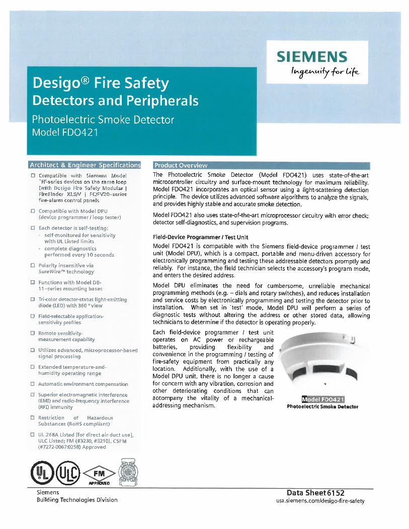
Desigo® Fire SafetyDetectors and PeripheralsPhotoelectric Smoke DetectorModel FD0421
/(^.^fct^Mify -fo r- 6t*^e-0
Architect & En ineer Specification
D Compatible with Siemens ModelH'-series devices on the same loop
;with Desigo Fire Safety Modular |FireFinder XLS/V | FC/FV20-series''ire-alarm control panels
a Compatible with Model DPU(device programmer / loop tester)
D Each detector is self-testing:self-monitored for sensitivitywith UL Listed limits
- complete diagnosticsperformed every 10 seconds
D Polarity insensitive viaSureWireT technology
D Functions with Model DB-
11-series mounting base-.
d Tri-color detector-status light-emittingdiode (LED) with 360 ° view
a Field-selectableapplication-sensitivity profiles
d Remote sensitivity-measurement capability
a Utilizes advanced, micropro . essor-basi.dsignal processing
D Extended temperature-and-humidity operating range
D Automatic environment compensation
D Superior electromagnetic interference(EMI) and radio-frequency interference(RFI) immunity
D Restriction of Hazardous
Substances (RoHS compliant)
a UL 268A Listed [for direct air-duct use],ULC Listed; FM (#3230, #3210). CSFM(#7272-0067:0258) Apptoved
FMAPPROVED
Siemens
Building Technologies Division
roduct Overview
The Photoelectric Smoke Detector (Model FD0421) uses state-of-the-artmicrocontroller circuitry and surface-mount technology for maximum reliability.Model FD0421 incorporates an optical sensor using a light-scattering detectionprinciple. The device utilizes advanced software algorithms to analyze the signals,and provides highly stable and accurate smoke detection.
Model FD0421 also uses state-of-the-art microprocessor circuitry with error check;detector self-diagnostics, and supervision programs.
Field-Device Programmer / Test Unit
Model FD0421 is compatible with the Siemens field-device programmer / testunit (Model DPU), which is a compact, portable and menu-driven accessory forelectronically programming and testing these addressable detectors promptly andreliably. For instance, the field technician selects the accessor/s program mode,and enters the desired address.
Model DPU eliminates the need for cumbersome, unreliable mechanicalprogramming methods (e. g. - dials and rotary switches), and reduces installationand service costs by electronically programming and testing the detector prior toinstallation. When set in 'test' mode. Model DPU will perform a series ofdiagnostic tests without altering the address or other stored data, allowingtechnicians to determine if the detector is operating properly.
Each field-device programmer / test unitoperates on AC power or rechargeablebatteries, providing flexibility andconvenience in the programming / testing offire-safety equipment from practically anylocation. Additionally, with the use of aModel DPU unit, there is no longer a causefor concern with any vibration, corrosion andother deteriorating conditions that canaccompany the vitality of a mechanical- ^ _ FD0421addressing mechanism. Photoelectric Smoke Detector
DataSheet6152usa. siemens. com/desigo-fire-safety
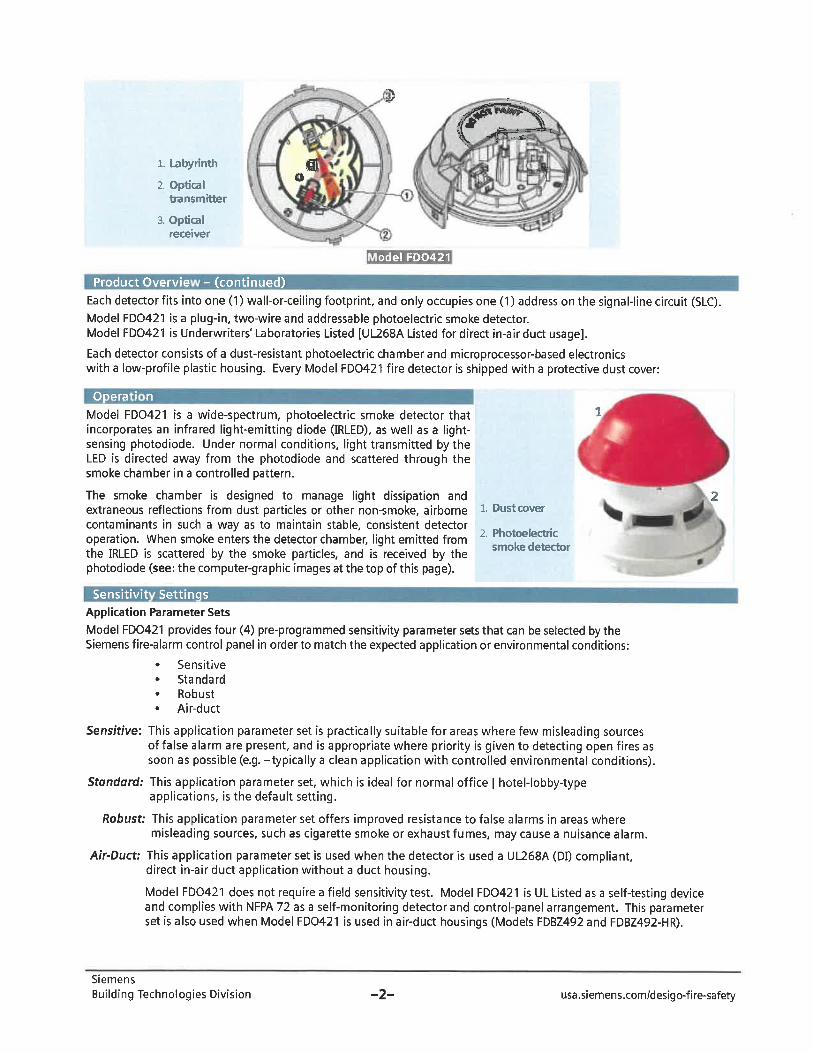
-^-^
1. Labyrinth
2. Opticaltransmitter
3. Opticalreceiver
odelFD0421
Product Overvie - (continued)
Each detector fits into one (1) wall-or-ceiling footprint, and only occupies one (1) address on the signal-line circuit (SLC).Model FD0421 is a plug-in, two-wire and addressable photoelectric smoke detector.Model FD0421 is Underwriters' Laboratories Listed [UL268A Listed for direct in-air duct usage].
Each detector consists of a dust-resistant photoelectric chamber and microprocessor-based electronicswith a low-profile plastic housing. Every Model FD0421 fire detector is shipped with a protective dust cover:
Opera i n
Model FD0421 is a wide-spectrum, photoelectric smoke detector that ^incorporates an infrared light-emitting diode (IRLED), as well as a light-sensing photodiode. Under normal conditions, light transmitted by theLED is directed away from the photodiode and scattered through thesmoke chamber in a controlled pattern.
The smoke chamber is designed to manage light dissipation andextraneous reflections from dust particles or other non-smoke, airbornecontaminants in such a way as to maintain stable, consistent detectoroperation. When smoke enters the detector chamber, light emitted fromthe IRLED is scattered by the smoke particles, and is received by thephotodiode (see: the computer-graphic images at the top of this page).
1. Dust cover
2. Photoelectricsmoke detector
Sensitivit Settinqs
Application Parameter Sets
Model FD0421 provides four (4) pre-programmed sensitivity parameter sets that can be selected by theSiemens fire-alarm control panel in order to match the expected application or environmental conditions:
. Sensitive
. Standard
. Robust
. Air-duct
Sensitive: This application parameter set is practically suitable for areas where few misleading sourcesof false alarm are present, and is appropriate where priority is given to detecting open fires assoon as possible (e.g. -typically a clean application with controlled environmental conditions).
Standard: This application parameter set, which is ideal for normal office | hotel-lobby-typeapplications, is the default setting.
Robust; This application parameter set offers improved resistance to false alarms in areas wheremisleading sources, such as cigarette smoke or exhaust fumes, may cause a nuisance alarm.
Air-Duct: This application parameter set is used when the detector is used a UL268A (DI) compliant,direct in-air duct application without a duct housing.
Model FD0421 does not require a field sensitivity test. Model FD0421 is UL Listed as a self-testing deviceand complies with NFPA 72 as a self-monitoring detector and control-panel arrangement. This parameterset is also used when Model FD0421 is used in air-duct housings (Models FDBZ492 and FDBZ492-HR).
Siemens
Building Technologies Division -2- usa. siemens. com/desigo-fire-safety
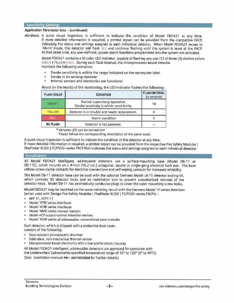
Sensitivit Settin s
Application Parameter Sets - (continued)
Air-Duct: A quick visual inspection is sufficient to indicate the condition of Model FD0421 at any time.If more detailed information is required, a printed report can be provided from the compatible FACP,indicating the status and settings assigned to each individual detector. When Model FD0421 moves to'Alarm' mode, the detector will flash RED and continue flashing until the system is reset at the FACP.At that same time, any user-defined, system-alarm functions programmed into the system are activated.Model FD0421 contains a tri-color LED indicator, capable of flashing any one (1) of three (3) distinct colors:GREEN I YELLOW | RED. During each flash interval, the microprocessor-based detectormonitors the following scenarios:
Smoke sensitivity is within the range indicated on the nameplate labelSmoke in its sensing chamber
. Internal sensors and electronics are functional
Based on the results of the monitoring, the LED indicator flashes the following:
FLASH COLOR
GREE
CONDITION
Normal supervisory operation.Smoke sensitivity is within rated limits.
FLASH INTERVAL[in seconds]
10
YELLGW: Detector is in trouble a nd needs replacement. 4
RSD: 'Alarm' condition 1
NO FLASH: Detector is not powered. -
* denotes LED can be turned OFFPlease follow the corresponding description of the panel used.
A quick visual inspection is sufficient to indicate the condition of the detector at any time.If more detailed information is required, a printed report can be provided from the respective Fire Safety Modular |FireFinder XLS/V | FC/FV20-series FACP that indicates the status and settings assigned to each individual detector.
Installation
All Model FD0421 intelligent, addressable detectors use a surface-mounting base (Model DB-11 orDB-11E), which mounts on a 4-inch (10. 2 cm. ) octagonal, square or single-gang electrical back box. The baseutilizes screw-clamp contacts for electrical connections and self-wiping contacts for increased reliability.The Model DB-11 detector base can be used with the optional Siemens Model LK-1 1 detector locking kit,which contains 50 detector locks and an installation tool to prevent unauthorized removal of thedetector head. Model DB-11 has aesthetically conducive plugs to cover the outer mounting-screw holes.
Model FD0421 may be installed on the same initiating circuit with the Siemens Model 'H'-series detectors[when used with Desigo Fire Safety Modular | FireFinderXLS/V | FC/FV20-series FACPs] -. HFP-11. HFPT-11. Model 'XTRI'-series interfaces. Model 'HTRI'-series interfaces. Model 'HMS'-series manual stations. Model HCP output-control detection devices. Model 'HZM'-series of addressable, conventional zone modules
Each detector, which is shipped with a protective dust cover,consists of the following:. Dust-resistant photoelectric chamber. Solid-state, non-mechanical thermal sensor
. Microprocessor-based electronics with a low-profile plastic housing
All Model FD0421 intelligent, addressable detectors are approved for operation withthe Underwriters' Laboratories-specified temperature range of 32° to 120° (0° to 49°C).(See: installation manual P/N-A6V10323928 for further details)
Siemens
Building Technologies Division -3- usa.siemens.com/desigo-fire-safety
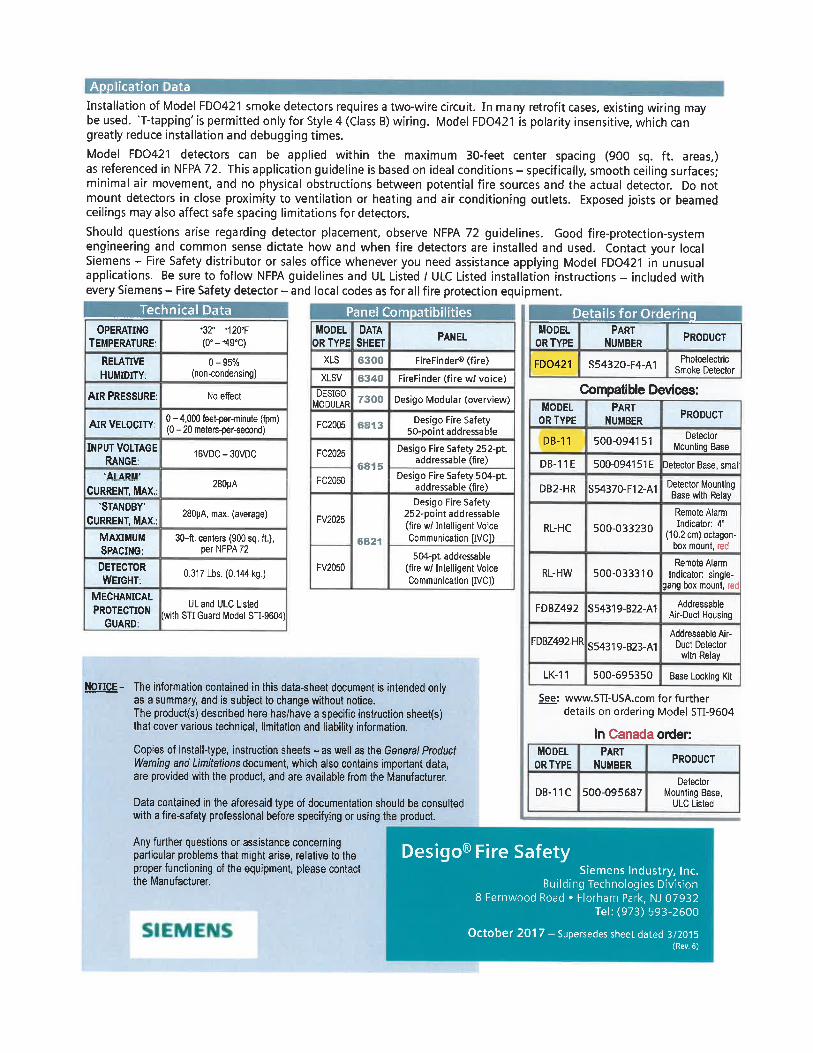
ApDlication ata
Installation of Model FD0421 smoke detectors requires a two-wire circuit. In many retrofit cases, existing wiring maybe used. 'T-tapping' is permitted only for Style 4 (Class B) wiring. Model FD0421 is polarity insensitive, which cangreatly reduce installation and debugging times.
Model FD0421 detectors can be applied within the maximum 30-feet center spacing (900 sq. ft. areas,)as referenced in NFPA 72. This application guideline is based on ideal conditions - specifically, smooth ceiling surfaces;minimal air movement, and no physical obstructions between potential fire sources and the actual detector. Do notmount detectors in close proximity to ventilation or heating and air conditioning outlets. Exposed joists or beamedceilings may also affect safe spacing limitations for detectors.
Should questions arise regarding detector placement, observe NFPA 72 guidelines. Good fire-protection-systemengineering and common sense dictate how and when fire detectors are installed and used. Contact your localSiemens - Fire Safety distributor or sales office whenever you need assistance applying Model FD0421 in unusualapplications. Be sure to follow NFPA guidelines and UL Listed / ULC Listed installation instructions - included withevery Siemens - Fire Safety detector - and local codes as for all fire protection equipment.
Technical Data
OPERATINGTEMPERATURE
RELATIVEHUMIDHY.
AIR PRESSURE:
AIR VELOCITY:
INPUT VOLTAGERANGE:
. Al ARM'
CURRENT, MAX.:. STANDBY-
CURRENT, MAX.;
MAXIMUMSPACING;
DETECTORWEIGHT:
MECHANICALPROTECTION
GUARD:
"32°-*120°F(0°-*490 C)
0-95%(non-condensing)
No effect
0 - 4,000 feet-per-minute (fpm)(0 - 20 meters-per-second)
16VDC-30VDC
280|jA
280pA, max. (average)
30-ft. centers (900 sq. ft. ),perNFPA72
0. 317 Lbs. (0. 144 kg.)
UL and ULC Listed(with STI Guard Model STI-9604)
Panel Corn atibilities
MODEL DATAOR TYPE SHEET
L Details for Ordering
PANELMODEL
OR TYPEPART
NUMBER
XLS
XLSV
DESIGOMODULAR
6300 FireFinder® (fire)
6340 FireFinder (fire w; voice)
7300 Desigo Modular (overview)
FD0421 S54320-F4-A1
PRODUCT
PhotoelectricSmoke Detector
Compatible Devices:
FC2005 3813
FC2025
FC2050
FV2025
FV2050
68-5
6821
Desigo Fire Safety50-point addressable
Desigo Fire Safety 252-pt.addressable (fire)
Desigo Fire Safety 504-pt.addressable (fire)
Desigo Fire Safety252-point addressable(fire w/ Intelligent VoiceCommunication [IVC])
504-pt. addressable(fire w/ Intelligent VoiceCommunication [IVC])
MODELOR TYPE
PARTNUMBER
DB-11 500-094151
PRODUCT
DetectorMounting Base
DB-11E 500-094151 E Detector Base, small
NOTICE- The information contained in this data-sheet document is intended onlyas a summary, and is subject to change without notice.The product(s) described here has/have a specific instruction sheet(s)that cover various technical, limitation and liability information.
Copies of install-type, instruction sheets - as well as the General ProductWarning and Limitafions document, which also contains important data,are provided with the product, and are available from the Manufacturer.
Data contained in the aforesaid type of documentation should be consultedwith a fire-safety professional before specifying or using the product.
Detector MountingBase with Relay
Remote AlarmIndicator: 4"
(10.2cm)octagon-box mount, red
Remote AlarmIndicator: single-
gang box mount, red
AddressableAir-Duct Housing
Addressable Air-Duct Detector
with Relay
LK-11 500-695350 Base Locking Kit
See: www. STI-USA. com for furtherdetails on ordering Model STI-9604
DB2-HR S54370-F12-A1
RL-HC 500-033230
RL-HW 500-033310
FDBZ492 S54319-B22-A1
FDBZ492-HR S54319-B23-A1
MODELOR TYPE
In Canada order.PART
NUMBER PRODUCT
DB-11 C 500-095687Detector
Mounting Base,ULC Listed
Any further questions or assistance concerningparticular problems that might arise, relative to theproper functioning of the equipment, please contactthe Manufacturer.
Desigo®Fire SafetySiemens Industry, Inc.
Building Technologies Division8 Femwood Road . Florham Park, NJ 07932
Tel: (973) 593-2600
October 2017-Supersedes sheet dated 3/2015(Rev. 6)
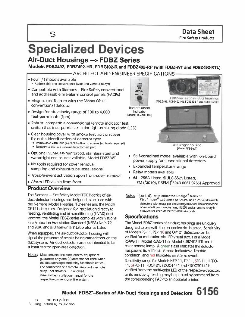
Data SheetFire Safety Products
Air-Duct Housings -> FDBZ SeriesModels FDBZ492, FDBZ492-HR, FDBZ492-R and FDBZ492-RP (with FDBZ-WT and FDBZ492-RTL)
ARCHITECT AND ENGINEER SPECIFICATIONS. Four (4) models available
. Addressable and conventional (with and without relays)
. Compatible with Siemens- Fire Safety conventionaland addressable fire-alarm control panels (FACPs)
. Magnet test feature with the Model OP121conventional detector
. Design for air-velocity range of 100 to 4, 000feet-per-minute (fpm)
. Robust, compatible conventional remote indicator testswitch that incorporates tri-color light-emitting diode (LED)
. Clear housing cover with smoke test port on coverfor quick identification of detector type. Removable with four (4) captive-thumb screws (no tools required). Includes a smoke/aerosol detector test port
. Optional NEMA4X-reinforced, stainless-steel andwatertight enclosure available, Model FDBZ-WT
. No tools required for cover removal,sampling and exhaust-tube installations
. Troub/e-event activation upon front-cover removal
. Alarm LED visible from front
Product Overview
iR!S«
.Bi's..
Remote alarmindicator
(Model FDBZ492-RTL)
(FDBZ492, FDBZ492-HR, FDBZ492-Rand
Watertight housing(Model FDBZ-WT)
Self-contained model available with 'on-board'power supply for conventional detectors
Expanded temperature rangeRelay models available®UL268A Listed, ©ULC-S529 Listed;
FM (#3010), CSFM ("3240-0067:0265) Approved
The Siemens- Fire Safety Model 'FDBZ'-series ofair-duct-detector housings are designed to be used withthe Siemens Model 'H'-series, 'FD'-series and the ModelOP121 detectors. Designed for installation directly toheating, ventilating and air-conditioning (HVAC) ductsystems, the Model 'FDBZ'-series complies with NationalFire Protection Association Standard (NFPA) No.'s 72and 90A, and is Underwriters' Laboratories Listed.
When equipped, the air-duct detector housing willsignal the presence of smoke being carried through theduct system. Air-duct detectors are not intended to besubstituted for open-area detection.
Notes: Most conventional time-control equipmentguarantee only one (1) detector per zone whenthe detector's operated relay function is critical.The connection of a remote lamp and a remoterelay-per detector- is allowed.Refer to the installation manual for the
respective conventional fire system.
Notes - (cont'd): With either the Desigo® series orFireFinderXLS series of FACPs, up to 252-addressabledetectors with relays percircuit maybe used. The connectionof an intelligent remote lamp (ILED) and a remote relay isallowed for each detector simultaneously.
SpecificationsThe Model 'FDBZ'-series of air-duct housings are uniquelydesigned to use with the photoelectric detector. Sensitivityof Models PE-11, PE-11 C and OP1 21 detectors can beverified for calibration via LED visual status or a ModelRSAW-11, Model RSAC-11 or Model FDBZ492-RTL multi-color remote lamp. A green flash indicates the detectorhas passed its self test. Amber indicates a Troublecondition, and red indicates an Alarm event.
Sensitivity range for Models HFP-1 1, FP-11, SFP-11, HFPO-11, SFPO-11 , FD0421, FDOOT441 and FDOOTC441 is
verified from the multi-color LED of the respective detector,or its sensitivity reading may be printed by command fromthe corresponding FACP to an optional printer.
Model TDBZ'-Series of Air-Duct Housings and Detectorss Industry, Inc.
Building Technologies Division
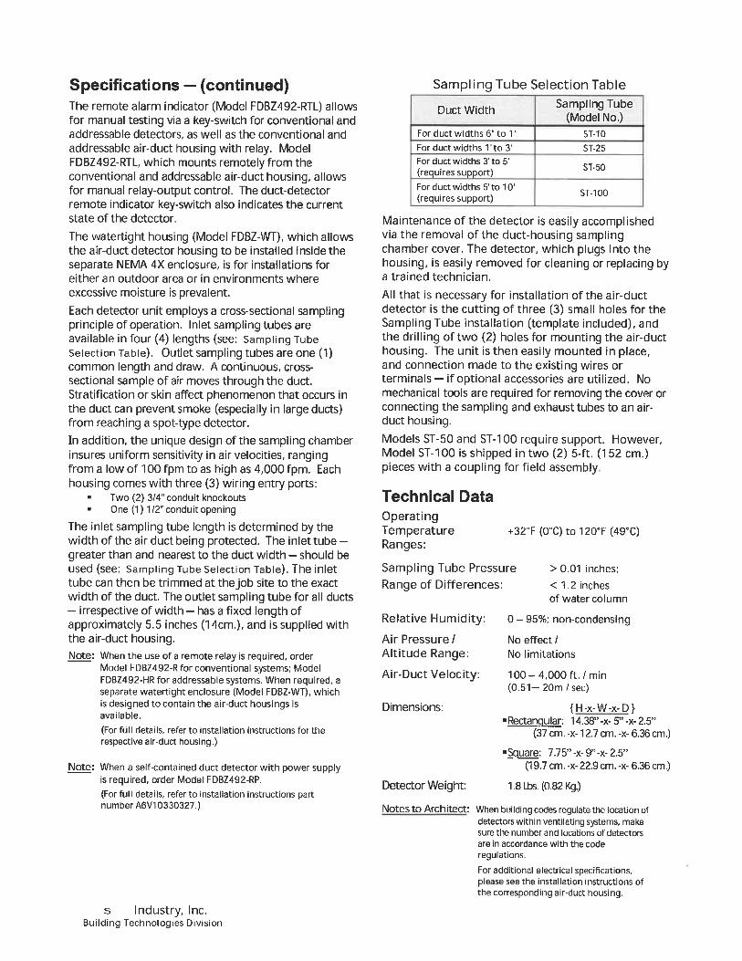
Specifications - (continued)The remote alarm indicator (Model FDBZ492-RTL) allowsfor manual testing via a key-switch for conventional andaddressable detectors, as well as the conventional and
addressable air-duct housing with relay. ModelFDBZ492-RTL, which mounts remotely from theconventional and addressable air-duct housing, allowsfor manual relay-output control. The duct-detectorremote indicator key-switch also indicates the currentstate of the detector.
The watertight housing (Model FDBZ-WT), which allowsthe air-duct detector housing to be installed inside theseparate NEMA 4X enclosure, is for installations foreither an outdoor area or in environments whereexcessive moisture is prevalent.
Each detector unit employs a cross-sectional samplingprinciple of operation. Inlet sampling tubes areavailable in four (4) lengths (see: Sampling TubeSelection Table). Outlet sampling tubes are one (1)common length and draw. A continuous, cross-sectional sample of air moves through the duct.Stratification or skin affect phenomenon that occurs inthe duct can prevent smoke (especially in large ducts)from reaching a spot-type detector.
In addition, the unique design of the sampling chamberinsures uniform sensitivity in air velocities, rangingfrom a low of 1 00 fpm to as high as 4, 000 fpm. Eachhousing comes with three (3) wiring entry ports:
. Two (2) 3/4" conduit knockouts
. One (1) 1/2" conduit opening
The inlet sampling tube length is determined by thewidth of the air duct being protected. The inlet tube -greater than and nearest to the duct width - should beused (see: Sampling Tube Selection Table). The inlettube can then be trimmed at the job site to the exactwidth of the duct. The outlet sampling tube for all ducts- irrespective of width - has a fixed length ofapproximately 5. 5 inches (14cm. ), and is supplied withthe air-duct housing.Note: When the use of a remote relay is required, order
Model FDBZ492-R for conventional systems; ModelFDBZ492-HR for addressable systems. When required, aseparate watertight enclosure (Model FDBZ-WT), whichis designed to contain the air-duct housings isavailable.
(For full details, refer to installation instructions for therespective air-duct housing.)
Note: When a self-contained duct detector with power supplyis required, order Model FDBZ492-RP.(For full details, refer to installation instructions partnumber A6V10330327.)
Sampling Tube Selection Table
Duct Width
For duct widths 6" to T
For duct widths T to 3'
For duct widths 3' to 5'
(requires support)For duct widths 5' to 10'
(requires support)
Sampling Tube(Model No.)
ST-10
ST-25
ST-50
ST-100
Maintenance of the detector is easily accomplishedvia the removal of the duct-housing samplingchamber cover. The detector, which plugs into thehousing, is easily removed for cleaning or replacing bya trained technician.
All that is necessary for installation of the air-ductdetector is the cutting of three (3) small holes for theSampling Tube installation (template included), andthe drilling of two (2) holes for mounting the air-ducthousing. The unit is then easily mounted in place,and connection made to the existing wires orterminals - if optional accessories are utilized. Nomechanical tools are required for removing the cover orconnecting the sampling and exhaust tubes to an air-duct housing.
Models ST-50 and ST-100 require support. However,Model ST-100 is shipped in two (2) 5-ft. (152 cm.)pieces with a coupling for field assembly
Technical DataOperatingTemperatureRanges:
+32°F(0°C)to120°F(49°C)
Sampling Tube PressureRange of Differences:
> 0.01 inches;
< 1. 2 inchesof water column
Relative Humidity: 0-95%; non-condensing
Air Pressure/ No effect/Altitude Range: No limitations
Air-Duct Velocity:
Dimensions:
Detector Weight:
100-4,000 ft. /min(0. 51-20m/see)
{H-x-W-x-D}. Rectangular: 14. 38" -x- 5" -x- 2.5"
(37 cm. -x-12.7 cm. -x- 6.36 cm.)
. Square: 7.75"-x-9"-x-2. 5"(19. 7 crn. -x- 22,9 cm. -x- 6.36 cm.)
1.8LLs. (0.82Kg.)
Notes to Architect: When building codes regulate the location ofdetectors within ventilating systems, makesure the number and locations of detectorsare in accordance with the coderegulations.
For additional electrical specifications,please see the installation instructions ofthe corresponding air-duct housing.
s Industry, Inc.Building Technologies Division
OperationBased on the monitoring results, the LED indicatorflashes the following colors based on the followingconditions:
Details for Ordering - (continued)
FlashColor
r rn- .
Yellow:
ed:
Condition
Normal supervisory operation.Smoke sensitivity is withinrated limits.Detector is in Troublecondition, and needs eitherre air or re lacement.
Afarm condition.
FlashInterval
(in seconds)
10
1
No Flash: Detector is not powered. - -* LED can be turned OFF.
Please follow the corresponding description of the panel used.
Products included with the air-duct housing- (1) short-return (outlet) tube- (1) stopper- (2) #12 + 3/4" sheet-metal screws- (1) mounting template
Note: Detector and sampling tube to be purchased separately.Minimum hardware required is: one (1) air-duct housingassembly; one (1) sampling tube and one (1) detector.
Details for Ordering
ModelPart
Number
FDBZ492 S54319-B22-A1
FDBZ492-HR
S54319-B23-A1
Description
A two-wire addressable or conventional
duct detector (without relays) designed fordirect use on heating, ventilating and air-conditioning (HVAC) a ir-duct systems.When equipped, the air-duct detectorhousing will signal the presence of smokebeing carried through the duct system.For use with the following Models:- HFP-11 - FD0421- SFP-11 - FDOOT441- HFPO-11 - FDOOTC441- SFpo-n - Fp-n
A two-wire addressable duct detector (withrelays) designed for direct use to HVAC air-duct systems and works with the RemoteTest Switch (FDBZ492-RTL). This part has aprogrammable relay base, and whenequipped, the addressable air-duct detectorhousing will signal the presence of smokebeing carried through the duct system.For use with the following Models:
- FD0421 - FP-11- FDOOT441 - HFP-11- FDOOTC441 - HFPO-11
- OP121- pE.n- PE-nc
Model
FDBZ492-R
PartNumber
S54319-B24-A1
FDBZ492-
S54319-B25-A1
FDBZ492-RTL S54319-
S27-A1
FDBZ-WTS54319-B26-A1
ST-10 500-649710ST-25 500-649711ST-50 500-649712ST-100 500-649713
Description
A two-wire conventional duct detector withrelays designed for direct use on HVAC air-duct systems. This detector has a relaybase, and when equipped with conventionalair-duct housing, will signal the presence ofsmoke being carried through the ductsystem.
For use with the following Models:- OP1Z1- PE-11 -PE.11CA four-wire conventional duct detector with
relays and a built-in power supply. Housingis designed for direct use to HVAC air-ductsystems. It has a relay base with a built-inpower source. When equipped withconventional air-duct housing, this ductdetector will signal the presence of smokebeing carried through the duct system.For use with the following Models:- OP121- PE-11 -PE-11CDevice is used for manual testing via a key-switch for duct-housing Models FDBZ492-R, FDBZ492-RP and FDBZ492-HR. Devicemounts remotely from the conventionaland addressable air-duct housing, allowingfor manual relay-output control. The duct-detector remote key-switch also indicatesthe current state of the detector.
For use with the following Models:- FDBZ492-R- FDBZ492-RP - FDBZ492-HRAn optional, separate watertight NEMA 4Xenclosure (Model FDBZ-WT) that providesadded watertight protection for any of theModel FDBZ492-series duct housings. Theduct housing fits into the separate 4Xenclosure. This part allows the air-ductdetector housing to be installed in theseparate enclosure, and can be used ineither an outdoor area or in environments
where excessive moisture is prevalent.
For use with the following Models:- FDBZ492 - FDBZ492-R- FDBZ492-HR - FDBZ492-RP
Sam I in tube for Ducts 6" to T
Sampling tube for Ducts over T to 3'Sampling tube for Ducts 3" to 5'Sampling tube for Ducts 5' to 10'
SFp-n- SR'0-11
s Industry, Inc.Building Technologies Division

Notice: This marketing data sheet is not intended to be used for system design or installation purposes.For the most up-to-date information, refer to each product's installation instructions.
s Industry, Inc.Building Technologies Division
Fire Safety8 Fernwood Road
Florham Park, NJ 07932Tel: (973) 593-2600FAX: (908) 547-6877URL: www.usa.Siemens.com/Fire
(SII-F5)Printed inU.SA.
Fire Safety1577 North Service RoadEast Oakville. Ontario
L6HOH6/CanadaTel: [905] 465-8000URL: www.Siemens.CA
September 2014Supersedes sheet dated 8/13
(Rev. 4)
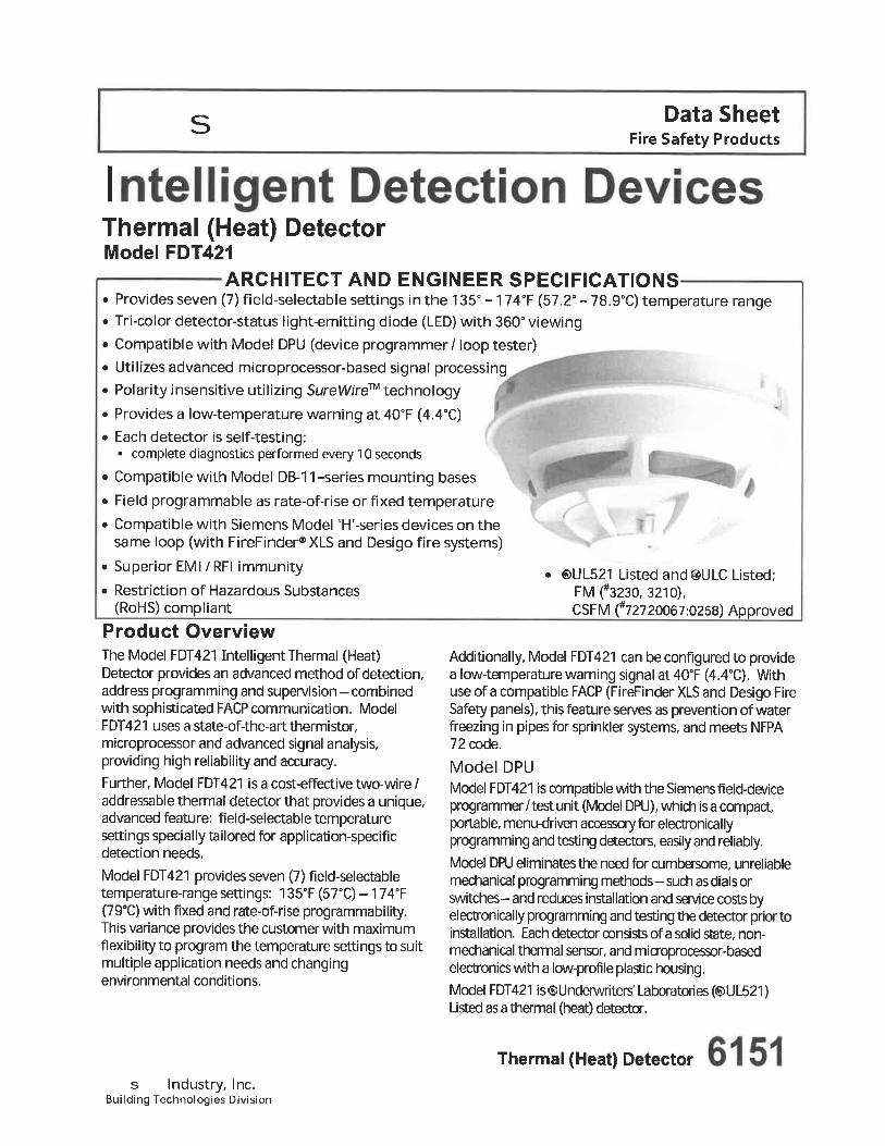
Data SheetFire Safety Products
Thermal (Heat) DetectorModel FDT421
ARCHITECT AND ENGINEER SPECIFICATIONS. Provides seven (7) field-selectable settings in the 135°-174°F (57. 2°-78. 9°C) temperature range. Tri-color detector-status tight-emitting diode (LED) with 360" viewing. Compatible with Model DPU (device programmer/ loop tester). Utilizes advanced microprocessor-based signal processing. Polarity insensitive utilizing SureWireT technology
. Provides a low-temperature warning at 40°F (4. 4°C)
. Each detector is self-testing:. complete diagnostics performed every 10 seconds
. Compatible with Model DB-11-series mounting bases
. Field programmable as rate-of-rise or fixed temperature
. Compatible with Siemens Model 'H'-series devices on thesame loop (with FireFinder®XLS and Desigo fire systems)
. Superior EMI/RFI immunity
. Restriction of Hazardous Substances(RoHS) compliant
Product OverviewThe Model FDT421 Intelligent Thermal (Heat)Detector provides an advanced method of detection,address programming and supervision-combinedwith sophisticated FACP communication. Model
<S)UL521 Listed and®ULC Listed;FM(#3230, 3210),CSFM (#72720067:0258) Approved
FDT421 uses a state-of-the-art thermistor,microprocessor and advanced signal analysis,providing high reliability and accuracy.Further, Model FDT421 is a cost-effective two-wire /
addressable thermal detector that provides a unique,advanced feature: field-selectable temperaturesettings specially tailored for application-specificdetection needs,
Model FDT421 provides seven (7) field-selectabletemperature-range settings: 135°F (57°C) -174°F(79°C) with fixed and rate-of-rise programmability,This variance provides the customer with maximumflexibility to program the temperature settings to suitmultiple application needs and changingenvironmental conditions,
Additionally, Model FDT421 can be configured to providea low-temperature warning signal at 40°F (4. 4°C). Withuse of a compatible FACP (FireFinder XLS and Desigo FireSafety panels), this feature serves as prevention of waterfreezing in pipes for sprinkler systems, and meets NFPA72 code.
ModelDPUModel FDT421 is compatible with the Siemens field-deviceprogrammer/test unit (Model DPU), which is a compact,portable, menu-driven accessory for electronicallyprogramming and testing detectors, easily and reliably.Model DPU eliminates the need for cumbersome, unreliable
mechanical programming methods-such as dialsorswitches- and reduces installation and service costs byelectronically programming and tesdng the detector prior toinstallation. Each detector consists of a solid state, non-
mechanical thermal sensor, and microprocessor-basedelectronics with a low-profile plasdc housing,Model FDT421 is®Underwriters' Laboratories (®UL521)Listed as a thermal (heat) detector.
s Industry, Inc.Building Technologies Division
Thermal (Heat) Detector
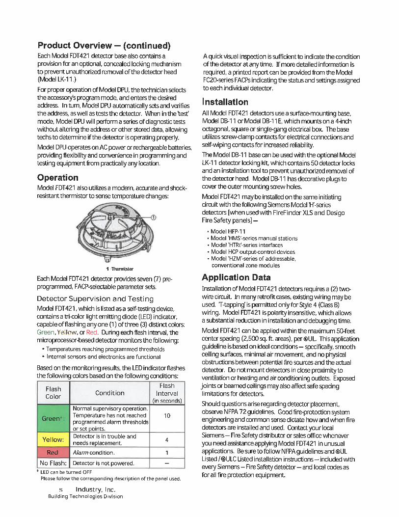
Product Overview - (continued)Each Model FDT421 detector base also contains a
provision for an optional, concealed locking mechanismto prevent unauthorized removal of the detector head(Model LK-11.)
For proper operation of Model DPU, the technician sdectsthe accessory's program mode, and enters the desiredaddress. In turn. Model DPU automatically sets and verifiesthe address, as well as tests the detector, When in the test'
mode, Model DPU will perform a series of diagnostic testswithout altering the address or other stored data, allowingtechsto determine if the detector is operating properly.Model DPU operates on AC power or rechargeable batteries,providing flexibility and convenience in programming andtesdng equipment from practically any location.
OperationModel FDT421 also utilizes a modern, accurate and shock-
resistant thermistor to sense temperature changes:
1 Thermisier
Each Model FDT421 detector provides seven (7) pre-programmed, FACP-selectable parameter sets.
Detector Supervision and TestingModel FDT421, which is listed as a self-testing device,contains a tri-color light emitdng diode (LED) indicator,capable of flashing anyone (1) of three (3) distinct colors:Green, Yellow, or Red. During each flash interval, themicroprocessor-based detector monitors the following:
. Temperatures reaching programmed thresholds
. Internal sensors and electronics are functional
Based on the monitoring results, the LED indicator flashesthe following colors based on the following conditions:
FlashCondition Interval
(in seconds)Normal supervisory operation.Temperature has not reached 1 0programmed alarm thresholdsor set oints.
Detector is in trouble andneeds replacement.
Red' A/ann condition. 1
FlashColor
Yellow:
No Flash: Detector is not powered. -* LED can be turned OFF.
Please follow the corresponding description of the panel used.
s Industry, Inc.Building Technologies Division
A quick visual inspection is sufficient to indicate the conditionof the detector at any time. If more detailed information isrequired, a printed report can be provided from the ModelFC20-series FACPs indicating the status and setdngs assignedto each individual detector,
InstallationAll Model FDT421 detectors usea surface-mounting base,Model DB-11 or Model DB-11 E, which mounts on a 4-inchoctagonal, square or single-gang electrical box. The baseutilizes screw-clamp contacts for electrical connections andself-wiping contacts for increased reliability.The Model DB-11 base can be used with the optional ModelLK-11 detector locking kit, which contains 50 detector locksand an installation tool to prevent unauthorized removal ofthe detector head. Model DB-1 1 has decorative plugs tocover the outer mounting screw holes.
Model FDT421 may be installed on the same initiatingcircuit with the following Semens Model IH'-seriesdetectors [when used with FireFinder XLS and DesigoFire Safety panels] -
Model HFP-11Model 'HMS'-series manual stationsModel 'HTRl'-series interfacesModel HCP output-control devicesModel 'HZM'-series of addressable,conventional zone modules
Application DataInstallation of Model FDT421 detectors requires a (2)two-wire circuit. In many retrofit cases, existing wiring may beused. T-tapping' is permitted only for Style 4 (Class B)wiring. Model FDT421 is polarity insensitive, which allowsa substantial reduction in installation and debugging time.Model FDT421 can be applied within the maximum 50-feetcenter spacing (2, 500 sq. ft. areas), per<S>UL TTiis applicationguideline is based on ideal conditions - specifically, smoothceiling surfaces, minimal air movement, and no physicalobstructions between potential fire sources and the actualdetector. Do not mount detectors in close proximity toventilation or heating and air conditioning outlets, Exposedjoints or beamed ceilings may also affect safe spacinglimitations for detectors,
Should questions arise regarding detector placement,observe NFPA 72 guidelines. Good fire-protection systemengineering and common sense dictate how and when firedetectors are installed and used, Contact your localSiemens- Fire Safety distributor or sales office wheneveryou need assistance applying Model FDT421 in unusualapplications. Be sure to follow NFPA guidelines and (S)ULListed /®ULC Listed installation instrucdons - included with
every Siemens - Fire Safety detector- and local codes asfor all fire protection equipment.
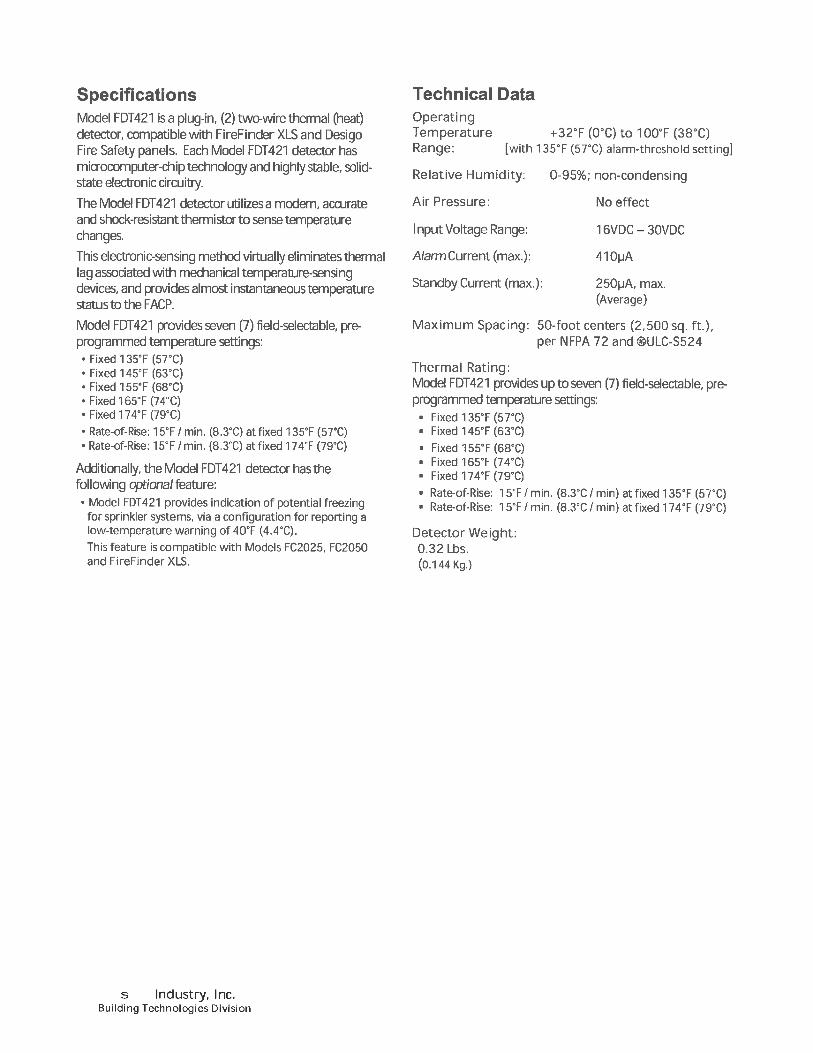
SpecificationsModel FDT421 isaplug-in, (2) two-wire thermal (heat)detector, compatible with FireFinder XLS and DesigoFire Safety panels. Each Model FDT421 detector hasmicrocomputer-chip technology and highly stable, solid-state electronic circuitry.
The Model FDT421 detector utilizes a modern, accurate
and shock-resistant thermistor to sense temperaturechanges.
This dectronic-sensing method virtually eliminates thermallag assodated with mechanical temperature-sensingdevices, and provides almost instantaneous temperaturestatus to the FACP.
Model FDT421 provides seven (7) field-selectable, pre-programmed temperature settings:
Fixed 135°F (57°C)Fixed 145T (63°C)Fixed 155°F(68°C)Fixed 165°F(74°C)Fixed 174°F(79°C)Rate-of-Rise: 15°F/ min. (8. 3°C) at fixed 135T (57°C)Rate-of-Rise: 15°F/min. (8. 3°C) atfixed174°F (79°C)
Additionally, the Model FDT421 detector has thefollowing optf'ona/feature:
. Model FDT421 provides indication of potential freezingfor sprinkler systems, via a configuration for reporting alow-temperature warning of 40°F (4. 4'C).This feature is compatible with Models FC2025, FC2050andFireFinderXLS.
Technical DataOperatingTemperature +32T (0°C) to 1 00°F (38°C)Range: [with 135°F (57''C) alarm-threshold setting]
Relative Humidity:
Air Pressure:
Input Voltage Range:
A/ami Current (max. ):
Standby Current (max. ):
0-95%; non-condensing
No effect
16VDC-30VDC
410|jA
250^iA, max.(Average)
Maximum Spacing: 50-foot centers (2, 500 sq. ft),per NFPA 72 and (&ULC-S524
Thermal Rating:Model FDT421 provides up to seven (7) field-selectable, pre-programmed temperature settings:
Fixed 135°F (57°C)Fixed 145°F(63''C)Fixed 155°F(68°C)Fixed 165°F(74°C)Fixed 174°F(79°C)
Rate-of-Rise: 15°F / min. (8.3°C / min) at fixed 135°F (57°C)Rate-of-Rise: 15°F / min. (8. 3°C / min) at fixed 174°F (79°C)
Detector Weight:0. 32 Lbs.(0. 144 Kg.)
s Industry, Inc.Building Technologies Division
Mounting DiagramDimensions
Details for Ordering
4,<3" (10.5 an.)
I Dt.ss"a.»<».>
t.W"ff.Tt. -R.t
Compatible FACPsData
Model SheetNumber
6300
FC2005 6813
FC2025 6815
FC2050 6815
Description
FireFinderXLS
50-point addressable FACP
252-point addressable FACP
504-point addressable FACP
Model
FDT421
DB-11DB-11E
DB2-HR
RL-HC
RL-HW
LK-n
STI-9604
PartNumber Description
S54320-F5-A1 Thermal (Heat) Detector500-094151 Detector Mounting Base
500-094151 E Detector Base (small)
S54320-F12. A1 Relay BaseRemote Alarm Indicator:
4" octagon-box mount, red
Remote Alarm Indicator:
Single-gang box mount, red
500-695350 Base Locking Kit
500-033230
500-033310
STI Mechanical Protection Guard
See: www.STl-USA.com for further details on orderingModel STI-9604.
In Canada, order-
PartModel Number Description
DB-11C 500-095687 Detector Mounting Basefor Series 11 Detectors (i&ULC Listed)
Notice: This marketing data sheet is not intended to be used for system design or installation purposes.For the most up-to-date information, refer to each product's installation instructions.
s Industry, Inc.Building Technologies Division
Fire Safety8 Femwood Road
Florham Park, NJ 07932Tel: (973) 593.2600FAX: (908) 547-6877URL: www. usa. Siemens. com/Fire
(SII. FS)Printed in U.S A.
Fire Safety1577 North Service RoadEast Oakville, Ontario
L6HOH6/CanadaTel: [905] 465-8000URL: www. Siemens. CA
April 2014Supersedes sheet dated 11/13
(Rev. 4)
Data SheetFire Safety Products
u_ SIEMENS
Model HMS-DDual-Action Station
_u u
H S-SeriesModels HMS-D, HMS-S
ARCHITECT AND ENGINEER SPECIFICATIONS. Durable design
. Shock-and-vibration resistant
. Single-action (Model HMS-S) and double-action(Model HMS-D) stations
. Pull-down lever is down, until manually reset. Reset with Alien Key. No break rods necessary
. Custom microcomputer-chip technology
. Polarity insensitive via SureWireT technology
. Dynamic supervision to the fire-alarm control panel(FACP)
. Device Programmer Unit (Model DPU) programs andverifies address and tests functionality of each device. Electronic-address programming (EEPROM) is easier, as well
as more efficient, dependable
. Surface or semi-flush installation
. Two-wire operation
Product OverviewThe Siemens intelligent manual fire-alarm boxes (ModelsHMS-S and HMS-D) provide the most advanced method ofaddress programming and supervision. Each Model HMS-series manual box achieves the state of an 'intelligent-initiating device' by incorporating custom microcomputer-chiptechnology with sophisticated, bi-directional communicationcapabilities with the panel, which include Siemens 50-point,252-pointand 504-point addressable FACPs.
SIEMENS IIModel HMS-S
Single-Action Station
SpecificationsModels HMS-S and HMS-D are constructed of durable, moldedpolycarbonate material that is matte finished in red withraised white lettering. The housing accommodates a 'pull-down' lever, which - when operated - locks into position;indicating the fire-alarm box has been activated.
The pull down lever remains down / in the 'locked' position,until the fire-alarm box is manually reset. The manual firealarm box can only be reset by opening the hinged housingcover with an Alien key; followed by closing and locking thecover. Models HMS-S and HMS-D operate with Siemens -Fire Safety FACPs. The microcomputer chip to the manualfire-alarm box has the capacity of storing - in memory -identification and important operating-status data.
. Americans with Disabilities Act (ADA) Compliant
. <S>UL Listed;FM ("3015946 & 3052621), CSFM ("7150-0067:0036)and NYC Fire Dept. (#202-l2E, Vol. 1) Approved
Models HMS-S and HMS-D are fitted with screw terminals forconnection to an addressable circuit, and can be eithersurface or semi-flush mounted.
The Model HMS-series manual fire-alarm boxes derive theirpower, communicate information and receive commandsover a single pair of wires. Each box is compatible on thesame circuit with all Model 'H'-series detectors, interfaces oraddressable, conventional zone modules.
Device / Programmer Tester - Model DPUInnovative technology from Siemens - Fire Safety also allowsall Model HMS-series intelligent manual fire-alarm boxes to beprogrammed via the Device Programmer / Test Unit (ModelDPU). The programmer / tester is a compact, portable andmenu-driven accessory that makes programming and testingof a manual fire-alarm box device faster, easier and moredependable than previous methods.
Model DPU eliminates the need for mechanical-addressingmechanisms of a device because Model DPU electronicallysets the address of the manual fire-alarm box into itsmicrocomputer chip, non-volatile memory. Therefore,vibration, corrosion and other conditions - which cancompromise the functionality of mechanical-addressingmechanisms - are no longer an issue.
HMS Series Intelligent Initiating DevicesSIEMENSlndustry, Inc.Building Technologies Division
Technical DataElectrical:
Current Draw
(Active or Standby)
Indoor / Dry Conditions:
OperatingTemperature Range
OperatingHumidity Range
32°--100°F(0°-38°C)
0-93%,non-condensing
Details for OrderingModel
HMS-D
HMS-S
LTP
SB-5R
PartNumber
500-033400
500-033200
500-620490
310-019860
Description
Addressable Manual FireAlarm Box, Dual Action
Addressable Manual FireAlarm Box, Single Action
Reset Tool Package[contains two (2) tools]
Surface-Mounting Box
ShippingWei ht
2.5Lbs.2.0Lbs.0.5Lb.1.5Lbs.
1. 13Oz.0.9Oz.
0. 23Oz.0.7Oz.
4 in
Mounting Diagram
SURF - (IU 6E CLOSUIIE^. ^
HOUSING _ ".__.. __ N<rr^HrNMDTO NAMEPLATE N ^BAGKPLATE^^ ^/ UVA-^T-yi ein.
"
- |\ o^ 5-V^in,
SB-5R
I
. -\'
's
^USINQLOCKINGSCREW BAG PLATE
^-^ ^'^^o"'3 in.
3-^Jn DEEP.
SWITCtfBOX,(USER SUPPLIED)
Notice: This marketing data sheet is not intended to be used for system design or installation purposes.For the most up-to-date information, refer to each product's installation instructions.
Fire Safety8 Fernwood Road
SIEMENS Industry, Inc. Florham Park, NJ 07932Building Technologies Division Tel: (973) 593-2600
FAX: (908) 547-6877URL: www.usa.Siemens.com/Fire
(SII-FS)Printed in U. S.A.
September 2016Supersedes sheet dated 7/2015
(Rev. 7)
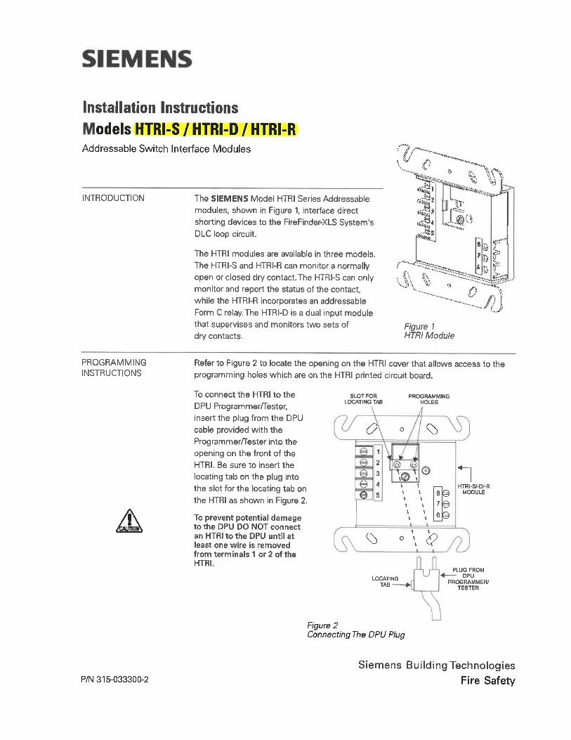
Installation Instructions
odels HTRI-S / HTRI-D / HTRI-RAddressable Switch Interface Modules
INTRODUCTION The SIEMENS Model HTRI Series Addressable
modules, shown in Figure 1, interface directshorting devices to the FireFinder-XLS System'sDLC loop circuit.
The HTRI modules are available in three models.
The HTRI-S and HTRI-R can monitor a normallyopen or closed dry contact. The HTRI-S can onlymonitor and report the status of the contact,while the HTRI-R incorporates an addressableForm C relay. The HTRI-D is a dual input modulethat supervises and monitors two sets ofdry contacts.
v
'.'... ^ ~--^1 ^-^^1^.>°.^ tl.^
^-t
^
6 s r^i:
^^^-.... i T^ t
^s5?^..-... '<-/
Figure 1HTHI Module
PROGRAMMINGINSTRUCTIONS
Refer to Figure 2 to locate the opening on the HTRI cover that allows access to theprogramming holes which are on the HTRI printed circuit board.
To connect the HTRI to the
DPU Programmer/Tester,insert the plug from the DPUcable provided with theProgrammer/Tester into theopening on the front of theHTRI. Be sure to insert the
locating tab on the plug intothe slot for the locating tab onthe HTRI as shown in Figure 2.
To prevent potential damageto the DPU DO NOT connectan HTRI to the DPU until atleast one wire is removedfrom terminals 1 or 2 of theHTRI.
SLOT FORLOCATING TAB
^
1
2
e 3e 4e 5
PROGRAMMINGHOLES
^)
I
I I\ II \I I
LOCATINGTAB
^ ° \ ^
HTRI-S/-D/-RMODULE
PLUG FROMDPU
PROGRAMMER/TESTER
Figure 2Connecting The DPU Plug
P/N 315-033300-2Siemens Building Technologies
Fire Safety
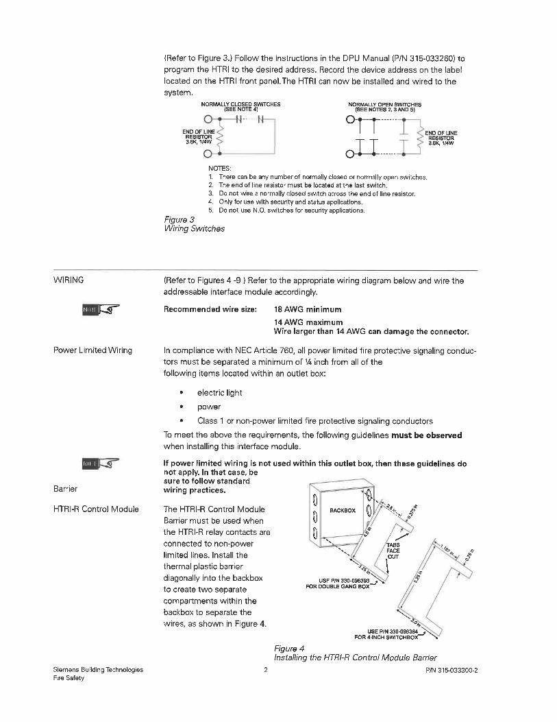
(Refer to Figure 3.) Follow the instructions in the DPU Manual (P/N 315-033260) toprogram the HTRI to the desired address. Record the device address on the labellocated on the HTRI front panel. The HTRI can now be installed and wired to thesystem.
NORMALLY CLOSED SWITCHES(SEE NOTE 4)
END OF LINERESISTOR3.6K, 1/4W
NORMALLY OPEN SWITCHES(SEE NOTES 2, 3 AND 5)
0^-......oU^
END OF LINERESISTOR3.6k,-1/4W
NOTES:1. There can be any number of normally closed or normally open switches.2. The end of line resistor must be located at the last switch.
3. Do not wire a normally closed switch across the end of line resistor.4. Only for use with security and status applications.5. Do not use N. O. switches for security applications.
Figure 3Wiring Switches
WIRING
Ml I! r,r
Power Limited Wiring
f'illll
Barrier
HTRI-R Control Module
Siemens Building TechnologiesFire Safety
(Refer to Figures 4 -9 ) Refer to the appropriate wiring diagram below and wire theaddressable interface module accordingly.
Recommended wire size: 18 AWG minimum
14AWG maximumWire larger than 14AWG can damage the connector.
In compliance with NEC Article 760, all power limited fire protective signaling conduc-tors must be separated a minimum of 14 inch from all of thefollowing items located within an outlet box:
. electric light
. power
. Class 1 or non-power limited fire protective signaling conductors
To meet the above the requirements, the following guidelines must be observedwhen installing this interface module.
If power limited wiring is not used within this outlet box, then these guidelines donot apply. In that case, besure to follow standardwiring practices.
The HTRI-R Control Module
Barrier must be used when
the HTRI-R relay contacts areconnected to non-powerlimited lines. Install the
thermal plastic barrierdiagonally into the backbox
to create two separate
compartments within the
backbox to separate thewires, as shown in Figure 4.
000
BACKBOX % .?
^
Y
/
TABSFACE
.OUT
'. '^
.^USE P/N 330.096393
FOR DOUBLE GANG BOX~
"^USE P/N 330-096384
Figure 4Installing the HTRI-R Control Module Barrier
P/N 315-033300-2
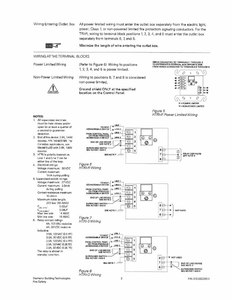
Wiring Entering Outlet Box
Mil
All power limited wiring must enter the outlet box separately from the electric light,power, Class 1, or non-powered limited fire protection signaling conductors. For theTRI-R, wiring to terminal block positions 1, 2, 3, 4, and 5 must enter the outlet boxseparately from terminals 6, 7, and 8.
Minimize the length of wire entering the outlet box.
WIRING ATTHETERMINAL BLOCKS
Power Limited Wiring (Refer to Figure 5) Wiring to positions1, 2, 3, 4, and 5 is power limited.
WIRES CONNECTED TO TERMINALS 1 THROUGH 5TO ENTEWEXIT ELECTRICAL BOX OPPOSITE SIDEFROM WIRES CONNECTED TO TERMINALS 6THROUGH 8.
^ ^)Non-Power Limited Wiring Wiring to positions 6, 7, and 8 is considered
non-power limited.
Ground shield ONLY at the specifiedlocation on the Control Panel.
NOTES:1. All supervised switches
must be held closed and/or
open for at least a quarter ofa second to guaranteedetection.
2. End of line device: 3. 6K, 1/4Wresistor, P/N 140-820185. ForCanadian applications, useModel EL-33 with 3. 6K, 1/4Wresistor.
3. HTRI is polarity insensitive.Line 1 and Line 2 can be
either line of the loop.4. Electrical ratings:
Voltage maximum: 30VDCCurrent maximum:
1mA during polling5. Supervised switch ratings:
Voltage maximum: 27VDCCurrent maximum: 3. 5mA
during pollingContact resistance maximum:
10 ohms
Maximum cable length:200 feet (18 AWG)
Cu«.,n. 0.02UF0. 04uF14AWG
Min line size: 18AWGRelay contact ratings:
4A. 125VAC resistive4A, 30VDC resistive
Inductive:
3.5A. 120VAC(0.6RR)3.0A, 30VDC (0. 6 PR)2.0A, 120VAC(0.4RR)2.0A, 120VAC(0.35Pf:|2.0A, 30VDC (0.35 PR)
The relay is shown instandby condition.
'Llnetoshcld-Max line size:
Siemens Building TechnologiesFire Safety
TO NEXTADDRESSABLE DEVICE
FROM CONTROL PANEL < Lll<OR FROM PREVIOUS -I
ADDRESSABLE DEVICE I UN
END OF LINE DEVICESEE NOTE 2
SUPERVISED SWITCHSEE NOTES 1 AND 6
SEE NOTE 7
Figure 6HTRI-R Wiring
_TOJIIEXT-1ADDRESSABLE DEVICE |^
FROM CONTROL PANEL /OR FROM PREVIOUS -I
ADDRESSABLE DEVICE I
END OF LINE DEVICESEE NOTE 2
SUPERVISED SWITCHSEE NOTES 1 AND 5
LINE 1
LINE 2
LINE 1
SEE NOTE 7
Figure 7HTRI-S Wiring
TO NEXTADDRESSABLE DEVICE
FROM CONTROL PANEL fOR FROM PREVIOUS -I
ADDRESSABLE DEVICE I
END OF UNE DEVICESEE NOTE 2
SUPERVISED SWITCHSEE NOTES 1 AND 5
LINE 1
I 2
LINE 1
LINE 2
Figure 8HTRI-D Wiring
.<-p
.<-p
.<-p<-p<-p
p
N
1
2
a
4
s e
-a-s
la!
7|
lei
^ ° <?
N-».N-».N-^
= POWER LIMITED
= NON-POWER LIMITED
Figure 5HTRI-R Power Limited Wiring
@ ©
RELAY CONTACTSSEE NOTE 6
}.
NOT USED
END OF LINE DEVICESEE NOTE 2
SUPERVISED SWITCHSEE NOTES 1 AND 5
P/N 315-033300-2
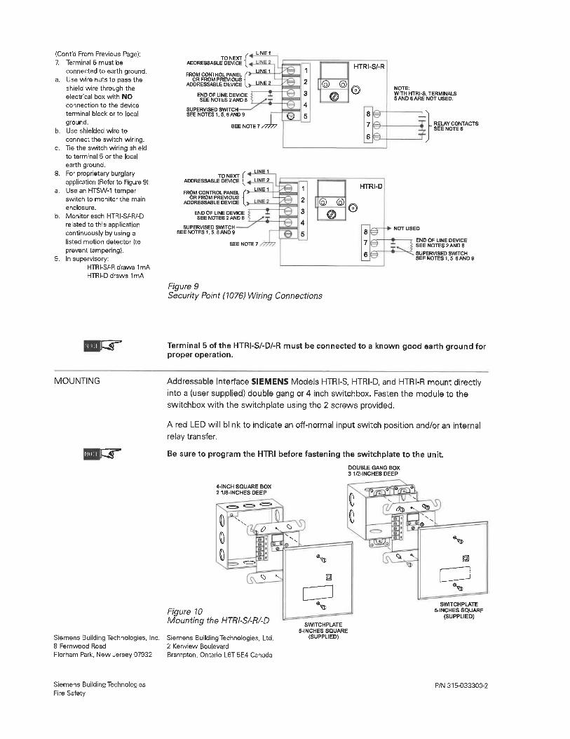
(Cont'd From Previous Page):7. Terminal 5 must be
connected to earth ground.a. Use wire nuts to pass the
shield wire through theelectrical box with NO
connection to the device
terminal block or to local
ground.b. Use shielded wire to
connect the switch wiring.c. Tie the switch wiring shield
to terminal 5 or the local
earth ground.8. For proprietary burglary
application (Refer to Figure 9):a. Use an HTSW-1 tamper
switch to monitor the main
enclosure.b. Monitor each HTRI-S/-R/-D
related to this applicationcontinuously by using alisted motion detector (to
prevent tampering).9. In supervisory:
HTRI-S/-R draws 1mAHTRI-D draws 1mA
JO^IEXT^ACDRESSABLE DEVICE [^FROM CONTROL PANEL <
OR FROM PREVIOUS -IADDRESSABLE DEVICE I
END OF LINE DEVICESEE NOTES 2 AND 8
SUPERVISED SWITCHSEE NOTES 1. 5, BAND 9
LINE 1
LINE 2
SEE NOTE 7 ,7777
SEE NOTE 7
u
TO NEXT JADDRESSABLE DEVICE (^
FROM CONTROL PANELOR FROM PREVIOUS
ADDRESSABLE DEVICE
END OF LINE DEVICESEE NOTES 2 AND 6
SUPERVISED SWITCHSEENOTES1, 5, 8AND9
LINE 1
LINE 2
LINE 1 1
2
3
4
5
Figure 9Security Point (1076) Wiring Connections
HTRI-S/-R
HTRI-D
NOTE:WITH HTRI-S. TERMINALS5 AND 6 ARE NOT USED.
L RELAY CONTACTSSEE NOTE 6
END OF LINE DEVICESEE NOTES 2 AND 8
SUPERVISED SWITCHSEE NOTES 1. 5. BAND 0
N1111 Terminal 5 of the HTRI-S/-D/-R must be connected to a known good earth ground forproper operation.
MOUNTING Addressable Interface SIEMENS Models HTRI-S, HTRI-D, and HTRI-R mount directlyinto a (user supplied) double gang or 4 inch switchbox. Fasten the module to theswitchbox with the switchplate using the 2 screws provided.
A red LED will blink to indicate an off-normal input switch position and/or an internalrelay transfer.
Be sure to program the HTRI before fastening the switchplate to the unit.
DOUBLE GANG BOX3 1/2-INCHES DEEP
4. 1NCH SQUARE BOX2 1/8-INCHES DEEP
%>0
Ql .-
^
Figure 10Mounting the HTRI-S/-R/-D
Siemens Building Technologies, Inc. Siemens Building Technologies, Ltd.8 Fernwood Road 2 Kenview Boulevard
Florham Park, New Jersey 07932 Brampton, Ontario L6T 5E4 Canada
SWITCHPLATE5-INCHES SQUARE
(SUPPLIED)SWITCHPLATE
5-INCHES SQUARE(SUPPLIED)
Siemens Building TechnologiesFire Safety
P/N 315-033300-2
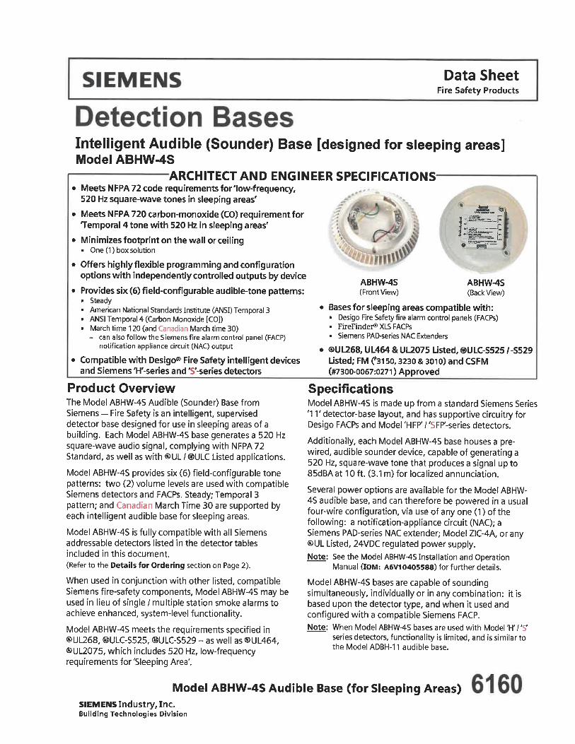
Data SheetFire Safety Products
ABHW-4S(Front View)
^^^.! -,i^s^_j.;
-^-l:i:^^i:
ABHW-4S(Back View)
Intelligent Audible (Sounder) Base [designed for sleeping areas]Model ABHW-4S
ARCHITECT AND ENGINEER SPECIFICATIONS. Meets NFPA 72 code requirements for 'low-frequency,
520 Hz square-wave tones in sleeping areas'
. Meets NFPA 720 carbon-monoxide (CO) requirement forTemporal 4 tone with 520 Hz in sleeping areas'
. Minimizes footprint on the wall or ceiling. One (1) box solution
. Offers highly flexible programming and configurationoptions with independently controlled outputs by device
. Provides six (6) field-configurable audible-tone patterns:. Steady. American National Standards Institute (ANSI) Temporal 3. ANSI Temporal 4 (Carbon Monoxide [CO]). March time 120 (and Canadian March time 30)
- can also follow the Siemens fire alarm control panel (FACP)notification appliance circuit (NAC) output
. Compatible with Desigo® Fire Safety intelligent devicesand Siemens 'H'-series and 'S'-series detectors
Product OverviewThe Model ABHW-4S Audible (Sounder) Base fromSiemens - Fire Safety is an intelligent, superviseddetector base designed for use in sleeping areas of abuilding. Each Model ABHW-4S base generates a 520 Hzsquare-wave audio signal, complying with NFPA 72Standard, as well as with ®UL /®ULC Listed applications.
Model ABHW-4S provides six (6) field-configurable tonepatterns: two (2) volume levels are used with compatibleSiemens detectors and FACPs. Steady; Temporal 3pattern; and Canadian March Time 30 are supported byeach intelligent audible base for sleeping areas.
Model ABHW-4S is fully compatible with all Siemensaddressable detectors listed in the detector tablesincluded in this document.(Refer to the Details for Ordering section on Page 2).
When used in conjunction with other listed, compatibleSiemens fire-safety components. Model ABHW-4S may beused in lieu of single / multiple station smoke alarms toachieve enhanced, system-level functionality.
Model ABHW-4S meets the requirements specified in®UL268, ©ULC-S525, ©ULC-S529 - as well as ®UL464,©UL2075, which includes 520 Hz, low-frequencyrequirements for 'Sleeping Area'.
. Bases for sleeping areas compatible with:. Desigo Fire Safety fire alarm control panels (FACPs). FireFinder®XLSFACPs. Siemens PAD-series NAC Extenders
. ®UL268, UL464 & UL2075 Usted. ©ULC-S525 /-S529Listed; FM C'3150, 3230 & 3010) and CSFM(#7300-0067:0271) Approved
SpecificationsModel ABHW-4S is made up from a standard Siemens Series'1 T detector-base layout, and has supportive circuitry forDesigo FACPs and Model 'HFP' / 'SFP'-series detectors.
Additionally, each Model ABHW-4S base houses a pre-wired, audible sounder device, capable of generating a520 Hz, square-wave tone that produces a signal up to85dBA at 10 ft. (3. 1 m) for localized annunciation.
Several power options are available for the Model ABHW-45 audible base, and can therefore be powered in a usualfour-wire configuration, via use of any one (1)of thefollowing: a notification-appliance circuit (NAC); aSiemens PAD-series NAC extender; Model ZIC-4A, or any®UL Listed, 24VDC regulated power supply.Note: See the Model ABHW-4S Installation and Operation
Manual (IOM: A6V10405588) for further details.
Model ABHW-4S bases are capable of soundingsimultaneously, individually or in any combination: it isbased upon the detector type, and when it used andconfigured with a compatible Siemens FACP.Note: When Model ABHW-4S bases are used with Model 'H' / 'S'
series detectors, functionality is limited, and is similar tothe Model ADBH-11 audible base.
Model ABHW-4S Audible Base (for Sleeping Areas)SIEMENS Industry, Inc.Building Technologies Division
SpecificationsModel ABHW-4S is a ®UL/@ULC Listed supplementarysmoke-detection device that meets or exceeds the 85dBat 10 ft. (3. 1 m) audibility requirement specified in®UL268, ©ULC-S525, ©ULC-S529 - as well as ®UL464 /®UL2075, including the low-frequency requirement of520 Hz for 'Sleeping Areas'.
Application DataThe smoke detectors used with Model ABHW-4S aresubject to the maximum 30 ft. center spacing(900 sq. ft. ) as referred to in the National FireProtection Association Standard 72. This spacing,however, is based on ideal conditions-namely,smooth ceiling; no air movement, and no physicalobstructions between the fire source and the detector.
The aforementioned center-spacing format should bereferred to as a guide fordetector-installation layout.Do not mount detectors in areas close to ventilating orair-conditioning outlets. Exposed joists or beamedceilings may also effect safe spacing limitations fordetectors.
It is mandatory for NFPA 72 guidelines and goodengineering judgment be applied to detectorplacements and spacing.
Compatibility with SIEMENS FACPsModel ABHW-4S works with the following panels:
FACP
FireFinder9 XLS
ModelFC2005
Models FC2025 / FC2050
Technical DataPhysical:
OperatingTemperature:
Operating Humidity:
Sound Output:(max)
Tones:
Mounting Box:
S stem T pePerson Machine Interface (PMI)
v10. 02 (or later
Zeus Custom-Configuration Softwarev10.02 or later)
Device Loop Card (Model DLC)v6.01 or later)
Desigo 50-point addressable FACPV01. 04. 20 (24),
Software-toolv01.02. 16 53)
Software-tool v6.0.0R1 (or later)
32°-120°F(0°-49°C)
10-95%,non-condensing
High: ^85dBLow: >:75dB
Steady; Temporal 3;Temporal 4; Temporal 4 - low power;
March Time 120;Canadian March Time 30
(10. 2 crn. ) 4-inch-square gang box
Note: A 4" (i 0.2 cm.) octagon box is not compatible with Model ABHW-4S.
Technical DataConnections:
Admissible Cross-Section Cable:
Design:
12-18AWG(American Wire Gauge)
Two (2) back-end blocks of up to four(4) screw terminals on each side
Electrical:
Operating Voltage:
Supervisory Current:(max)
Alarm Current:(RMS max)
Loop Power: 16-33 VDC
External Power: 16-33 VDC
From SLC Loop: 250 (JAFrom External Source: 1. 0 mA
High dBA: 65mA@33VDC
High dBA: 90mA@24VDC
High dBA: 165mA@16VDC
External High dBA: 0. 85 mA (from loop)LowdBA: 28mA@33VDC
Low dBA: 33 mA @ 24VDC
Low d BA: 45mA@16VDCLow dBA: 1. 6 mA (from loop)
Power:
Details for Ordering
Model PartNumber Description
ABHW-4S S54320-F14-A1
ABHW-4SZ S54320-F14-A2
Audible (Sounder) Base[desi nedforslee in areas
Sleeping-Room Version (520 Hz)Audible Base, COO - USA
Compatible Intelligent Detectors
PartNumber
S54320-F4-A1S54320-F5-A1S54320-F6-A1S54320-F7-A1S54320-F8-A1
Model
FD0421FDT421
FDOT421FDOOT441
FDOOTC441
Description
0 tical DetectorHeat Detector0 tica I / Heat DetectorDualO tical Heat DetectorDual 0 tical Heat (w/ CO) Detector
Description
Compatible Remote Lamps
Model ., part,Number
RL-HW 500-033310 Remote Alarm Lam . WallRL-HC 500-033230 Remote Alarm Lamp, Ceiling
Compatible 'H' / 'S' Series Detectors
PartNumber500-033290500-033800500-034800
500-033290C500-033800C
Model Description
HFp-nHFPT-11HFPO-11SFP-11
SFPT-11SFPO-11 500-034800C
Notes: Models SFP-11, SFPO-11 and SFPT-11 detectors are approvedexclusively in Canadian installations. Model 'H7 'S'-series basesare limited in audible-base functionality.Contact Technical Support at 1-800-248-7976 for more details.
'H'-Series 0 tical / Heat Detector'H'-Series Heat Detector'H'-Series 0 tical Detector'S'-Series 0 tical / Heat Detector'S'-Series Heat Detector'S'-Series 0 tical Detector
Notice: This marketing data sheet is not intended to be used for system design or installation purposes.For the most up-to-date information, refer to each product's installation instructions.
Fire Safety Fire Safety8 Fernwood Road 1577 North Service Road
SIEMENS Industry, Inc. Florham Park, NJ 07932 East Oakville, OntarioBuilding Technologies Division Tel: (973) 593-2600 (SII-FS) L6H OH6/Canada
FAX: (908) 547-6877 Printed in U.S.A. Tel: [905] 465-8000URL: www.usa.Siemens.comfFire URL: www.Siemens.CA
March 2016Supersedes sheet dated 3/2015
(Rev. 4|
Data SheetFire Safety Products
^^.
ZH ZR - Strobes, Horns, & Horn / Strobes A plication: Indoor
Ft^E
ZHSeries
Product Overview
ZRSeries
FIREZR&ZH '
(for mounting)
Strobes can be synchronized using the Siemens DSC sync modules, the Siemens 50-point,252-point and 504-Doint addressable fire alarm control panels (FACPs), as well as with:. FireFinder® XLS and MXL® FACPs. PAD-3 or PAD-4T NAC Extenders with built-in sync protocolSelectable Continuous Horn or Temporal (Code-3) Tones with 90 or 95 dBAselectable setting (Series 'ZH')Ceiling-mount models feature field-selectable Candela settings of 15/30/75/95cd and 115/177cdWall-mount models feature field-selectable Candela settings of 15/30/75/11 Ocd and 135/185cdBase plate is protected by a disposable cover, and the appliances can quickly snap onto the baseafter the walls are paintedStrobes produce one (1) flash per second"Special Applications" listed with Siemens panelsEZ Mount Universal Mounting Plate (Model ZB Series) - uses single platefor ceiling and wall mount installationsEZ Mount design - with separate base plate - provides ability to pre-wire the baseand test the circuit wiring before the walls are covered®UL Listed & ®ULC Listed, FM (»3028994) Approved;
CSFM Approved (Series 'ZH': '7125-0067:0248 -> Fire Alarm Devices For The Hearing Impaired)CSFM Approved (Series'ZR': '7125-0067:0252-> Fire Alarm Devices For The Hearing Impaired)
ADA/NFPA compliant
SpecificationsGeneral
Audible/Visual notification appliances are listed for indoor use onlyAppliances are listed under ®UL Standard 1971 (Standard for Safety Signaling Devicesfor Hearing Impaired) and ®UL Standard 464 (Fire Protective Signaling)Appliances use a universal back plate, which allows mounting to asingle-gang, double-gang, 4-inch-square (10. 2 cm. ), 4"-octal (10. 2 cm. ), or a 3-1/2" (8. 9 cm. ) octal backboxTwo-wire configurations allows capability for directly connecting appliances to the mounting back plateContinuity check will occur for entire NAC circuit prior to attaching any audible / visual-notification appliancesA cover fits over the mounting plate for protection to dust and other outside elements. Cover is easily removed when the appliance is installed over the back plateRemoval of an appliance will result in a Trouble condition by the Siemens Fire Alarm Control Panel (FACP)
'Z' Series Notification Appliances 8SIEMENS Industry. Inc.Building Technologies Division
Specifications - (continued)Strobes and Audible Strobe Combinations
Strobe appliances produce a minimum flash rate of 60 flashes per minute(one [1 ] flash per second) over the Regulated Input Voltage Range, andincorporate a Xenon flashtube enclosed in a rugged Lexan® lensStrobes are available with two (2) or four (4) field-selectable settingsin one (1) unit, and are rated - per ®UL 1971 - for up to:
. 15/30/75/110cd for wall mounted
. 135/185cd for wall mounted
. 15/30/75/95cd for ceiling mounted
. 115/177cd for ceiling mounted
Strobes operate over an extended temperature range of 32°F to 120°F(0°C to 49°C), and be listed for maximum humidity of 95% RHStrobe inputs are polarized for compatibility with standard reverse-polaritysupervision of circuit wiring by a Siemens FACP
Audible and Audible / Strobe CombinationsHorns and horn / strobes are listed for Indoor use under ®UL Standard 464
Horns are able to produce continuous synchronized output or aTemporal Code-3 synchronized output
Horns have at least two (2) sound-level settings of 90 and 95 dBA
Synchronization Modules
The strobe portion, when synchronization is required, is compatible with theSiemens DSC sync modules; the Siemens 50-point, 252-point and 504-pointaddressable FACPs, as well as with:
. FireFinder® XLS and MXL® FACPs
. PAD-3 or PAD-4T NAC Extenders with built-in sync protocol
The strobes will not drift out of synchronization at any time during operationAudibles and strobes are able to synchronize on a two-wire circuit with the capabilityto silence the audible, if required
Strobes revert to a non-synchronized flash-rate, if the sync module orpower supply should fail to operate (i.e. - contacts remain closed)
All notification appliances are listed for Special Applications:. Strobes are designed to flash at 1 -flash-per-second
minimum over their "Regulated Input Voltage Range"
> Note: NFPA-72 specifies a flash rate of 1-to-2 flashes per second,and ADA Guidelines specify a flash rate of 1-to-3 flashes per second
. All candela ratings represent minimum-effective Strobe intensity, based on ®UL Standard 1971
. Series ZH Strobe products are listed under ®UL Standards 1971 and 464 for indoor usewith a temperature range of 32°F to 120°F (0°C to 49°C) and maximum humidity of 93% (± 2%)
. Series ZH horns are listed under (SOUL Standard 464 for audible signal appliances (Indoor use only)
Mounting Diagram
SIEMENS Industry, Inc.Building Technologies Division
(Shown In Inches)
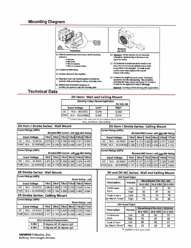
Mounting Diagram
<t»
llt^\
*>-wnowu.STCUHSS
SCREWS
^...s' -"-/InattllaUon
1.) With the provided pan head scam, install mountlna
- iInglttMit;- <toublfrB»iB:
-4'(tUcm. )»|u»tt;- 4" (IU un.) cctagon badihu
2.) Connect the field wiring.
3.) Address wires back into baclAox.
4.) Place dust covef over awuntlng plate to protect (lietemlnals while pertonning the wlring-contlnulty check.
5.) RenovB dust c<nr«f before snapping wInstalling the appliance onto the mounting plate
Removal '"^,aesre-B)
6.) BBiSfliBl: Dwteeonly has one(1) mountingorieniaion. Batch Die top of Ure base to thetopolthedmice.
7. ) nitlsdeslrtdtotunhersecurethedevteetotliebase, then use UIB two (2) optional screws whichare provided in the sllipmeirt. To Install, punchout the screw holes located at the top andbottom of the dwlra.
8.) To femove the appliance, push a Email, flAbladedscrewdriiw into tha side opening. Thescrewdrinfmust dear the snap release opening by 1/4 "(O.Btan.),in ortw for the applianm'a snap to diwngagB.BBpaiteDl: Do not piy off the houBmg wth a screw drtver.
Technical Data
ZH Horn: Wall and Ceiling MountOperating Voltage (Special Application)
Per WL 464
Input Voltage Low* High*
DC 16. 0-33. 0VDC 0. 018 0. 044RA/R 16. 0-33. 0VRMS 0. 045 0. 075
Current draw is the same for the Continuous Horn, Code 3Horn, and March Time settings
ZH Horn / Strobe Series: Wall Mount
Current Ratings (AMPs)MAXIMUM RMS Current-wilh High dBA Selling
Input Voltage IScd 30cd 75cd 110cd 135cd 185cdDC 16.0-33.0VDC 0.078 0. 113 0. 195 0.259 0.371 0.506
R/VR 16.0-33.0VRMS 0. 141 0.200 0.302 0.406 0.521 0.722
Current Raling$(AMPs)MAXimw RMS Current-with Low dBA Setting
Input Voltage 15cd 30cd 75cd 95cd 13Scd 185cdDC 16.0-33.0VDC 0.070 0. 107 0. 188 0.246 0.324 0.455
RA/R 16.0-33.0VRMS 0. 123 0. 179 0.290 0.391 0.497 0.699
ZR Strobe Series:Current Ratings (AMPs)
Input Voltage
DC 16. 0-33. 0VDC
R/VR 16.0-33.0VRMS
ZR Strobe Series:
Current Ratings {AMPs)
Input Voltage
DC 16. 0-33. 0VDCRA/R 16. 0-33. 0VRMS
Wall Mount
Strobe Setting-(cd)
1 Bcd 30cd 75cd 110cd 135cd 185cd
0.064 0. 098 0. 175 0.233 0.318 0. 445
0. 108 0. 164 0.268 0.368 0.482 0.684
Ceiling Mount
Strobe Setting-(cd)
15cd 30cd 75cd 95cd 115cd 177cd
0. 069 0. 111 0. 200 0.264 0.318 0.445
0. 117 0. 180 0.297 0.398 0.482 0.684
ZH Horn / Strobe Series: Ceiling MountCurrent Ratings (AMPs)
MAXIMUM RMS Current- with Hjgh dBA Setting
Input Voltage 15cd 30cd 75cd 95cd 115cd 177cd
DC 16. 0-33. 0VDC 0.087 0. 131 0.222 0.292 0. 371 0.506RA/R 16.0-33.0VRMS 0. 149 0.216 0.331 0.436 0.521 0.722
Current Ratings (AMPs)MAXIMUM RMS Current- w Low dBA Setting
Input Voltage 15cd 30cd 75cd 95cd 115cd 177cd
DC 16.0-33.0VDC 0.075 0. 121 0.213 0.277 0.324 0.455R/VR 16.0-33.0VRMS 0. 131 0. 195 0.3190.421 0.497 0.699
ZH and ZH-MC Series: Wall and Ceiling Mount
QULC Directional Characteristics
-3 dBA 35 degrees left; 40 degrees right. 6dBA 55 degrees left; 65 degrees right
SIEMENS Industry, Inc.Building Technologies Division
dBA Sound Output
Description
ContinuousHorn
Code 3 Hornor March Time)*
Volume
Low
HighLow
' High
dBA Sound Output
Description
ContinuousHorn
Code 3 Horn
Volume
Low
HighLow
Reverberant Per ®UL 464
16. 0VDC 24. 0 VDC 33. 0 VDC77
837279
81
877682
83
907986
Reverberant Per ®ULC-S525-99
20. 0 VDC 24. 0 VDC 31. 0VDC889388
909590
919691
(or March Time)* High 93 95
'' Available only in sync mode.
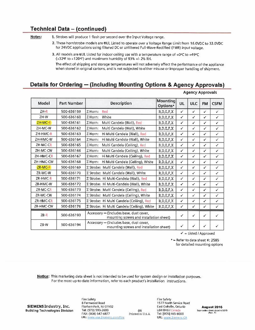
Technical Data - (continued)Notes: 1. Strobes will produce 1 flash per second over the Input Voltage range.
2. These horn/strobe models are®UL Listed to operate over a Voltage Range Limit from 1 6. 0VDC to 33. 0VDCfor 24VDC applications using filtered DC or unfiltered Full-Wave-Rectified (FWR) input voltage.
3. All models are <8UL Listed for indoor ceiling use with a temperature range of +0°C to +49°C(+32°F to +120°F) and maximum humidity of 93% +/- 2% RH.
The effect of shipping and storage temperatures will not adversely affect the performance of the appliancewhen stored in original cartons, and is not subjected to either misuse or improper handling of shipment.
Details for Ordering - (Including Mounting Options & Agency Approvals)Agency Approvals
Model
ZH-R
ZH-W
ZH-MC-
ZH-MC-W
ZH-HMC-R
ZH-HMC-W
ZH-MC-CR
ZH-MC-CW
ZH-HMC-CR
ZH-HMC-CW
ZR-MC-
ZR-MC-W
ZR-HMC-R
ZR-HMC-W
ZR-MC-CR
ZR-MC-CW
ZR-HMC-CR
ZR-HMC-CW
ZB-R
ZB-W
Part Number
500-636159
500-636160
500-636161
500-636162
500-636163
500-636164
500-636165
500-636166
500-636167
500-636168
500-636169
500-636170
500-636171
500-636172
500-636173
500-636174
500-636175
500-636176
500-636193
500-636194
Desc"P«10" MO°pSZ Horn: Red B, D, E,F,X
Z Horn: White B. D.E.F.X
Z Horn: Multi Candela (Wall), Red B,D,E,F,X
Z Horn: Multi Candela (Wall), White B,D,E,F,X
Z Horn: Hi Multi Candela (Wall), Red B,D,E,F,X
Z Horn: Hi Multi Candela (Wall), White B,D,E,F,X
Z Horn: Multi Candela (Ceiling), Red B,D,E,F,X
Z Horn: Multi Candela (Ceiling), White B, D,E,F,X
Z Horn: Hi Multi Candela (Ceiling), Red B, D,E,F,X
Z Horn: Hi Multi Candela (Ceiling), White B, D, E,F,XZ Strobe: Multi Candela (Wall), Red B,D,E,F,X
Z Strobe: Multi Candela (Wall), White B,D,E,F,XZ Strobe: Hi Multi-Candela (Wall), Red B,D,E,F,X
Z Strobe: Hi Multi-Candela (Wall), White B,D,E,F,X
Z Strobe: Multi Candela (Ceiling), Red B,D,E,F,X
Z Strobe: Multi Candela (Ceiling), White B, D,E,F,X
Z Strobe: Hi Multi Candela (Ceiling), Red B, D,E,F,X
Z Strobe: Hi Multi Candela (Ceiling), White B, D,E,F,X
Accessory-(Includes base, dust cover,mountin screws and installation sheet)
Accessory-(Includes base, dust cover,mounting screws and installation sheet)
UL ULC FM CSFM
^
.'
^
Y
.-
^
^
^
^
^
^
./
./
.
^
.
^
./
^
^
.
.
.
.
.
v
.
^
^
./
^
.
^
./
^
^
^
^
^
^
v^
^
./
^
^
./
./
^
^
^
^
^
^
^
^
^
./
^
./
V'
.
^
.
./
.
^
^
^
^
^
^
^
./
^
y
^
./
^
<^ = Listed/Approved
Refer to data sheet #: 2585for detailed mounting options
Notice: This marketing data sheet is not intended to be used for system design or installation purposes.For the most up-to-date information, refer to each product's installation instructions.
SIEMENS Industry, Inc.Building Technologies Division
Fire Safety8 Fernwood RoadFlorham Park, NJ 07932Tel: (973) 593-2600FAX: (908) 547-6877URL: www. usa. Siemens. com/Fire
(SillPrinted in U.S.A.
Fire Safety1577 North Service RoadEast Oakville, Ontario
L6HOH6; CanadaTel: [905] 465-8000URL: www. Siemens. CA
August 2016Supersedes sheet dated 6/2015
(Rev. 5)
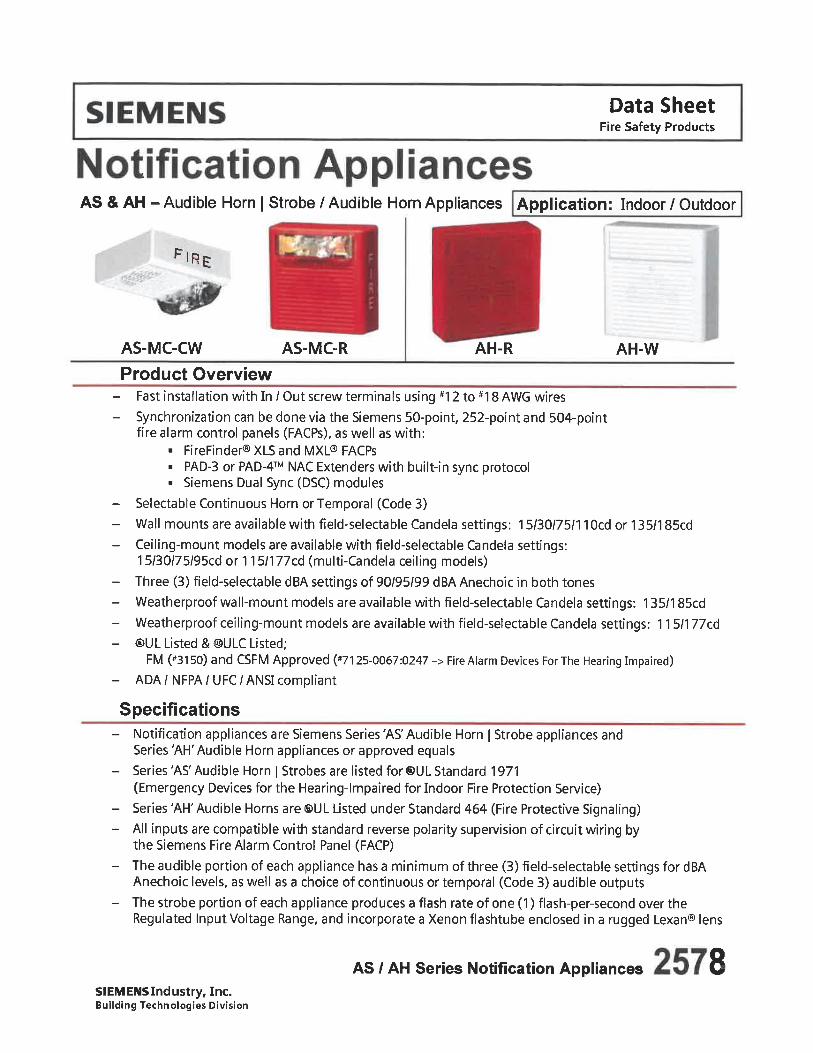
Data SheetFire Safety Products
AS & AH - Audible Horn | Strobe / Audible Horn Appliances Application: Indoor / Outdoor
I RE
AS-MC-CW AS-MC-R AH-R AH-W
Product OverviewFast installation with In / Out screw terminals using #1 2 to #18 AWG wiresSynchronization can be done via the Siemens 50-point, 252-point and 504-pointfire alarm control panels (FACPs), as well as with:
. FireFinder® XLS and MXL® FACPs
. PAD-3 or PAD-4T NAC Extenders with built-in sync protocol
. Siemens Dual Sync (DSC) modulesSelectable Continuous Horn or Temporal (Code 3)
Wall mounts are available with field-selectable Candela settings: 15/30/75/1 10cd or 135/185cdCeiling-mount models are available with field-selectable Candela settings:15/30/75/95cd or 115/177cd (multi-Candela ceiling models)Three (3) field-selectable dBA settings of 90/95/99 dBA Anechoic in both tonesWeatherproof wall-mount models are available with field-selectable Candela settings: 1 35/185cdWeatherproof ceiling-mount models are available with field-setectable Candela settings: 1 15/177cd®UL Listed &@ULC Listed;
FM (#3150) and CSFM Approved (*7125-0067:0247 -> Fire Alarm Devices For The Hearing Impaired)ADA / NFPA / UFC / ANSI compliant
SpecificationsNotification appliances are Siemens Series'AS'Audible Horn | Strobe appliances andSeries 'AH' Audible Horn appliances or approved equalsSeries'AS'Audible Horn | Strobes are listed for ®UL Standard 1971(Emergency Devices for the Hearing-lmpaired for Indoor Fire Protection Service)
Series 'AH' Audible Horns are ®UL Listed under Standard 464 (Fire Protective Signaling)All inputs are compatible with standard reverse polarity supervision of circuit wiring bythe Siemens Fire Alarm Control Panel(FACP)
The audible portion of each appliance has a minimum of three (3) field-selectable settings for dBAAnechoic levels, as well as a choice of continuous or temporal (Code 3) audible outputsThe strobe portion of each appliance produces a flash rate of one (1) flash-per-second over theRegulated Input Voltage Range, and incorporate a Xenon flashtube enclosed in a rugged Lexan® lens
AS / AH Series Notification AppliancesSIEMENSIndustry, Inc.Building Technologies Division
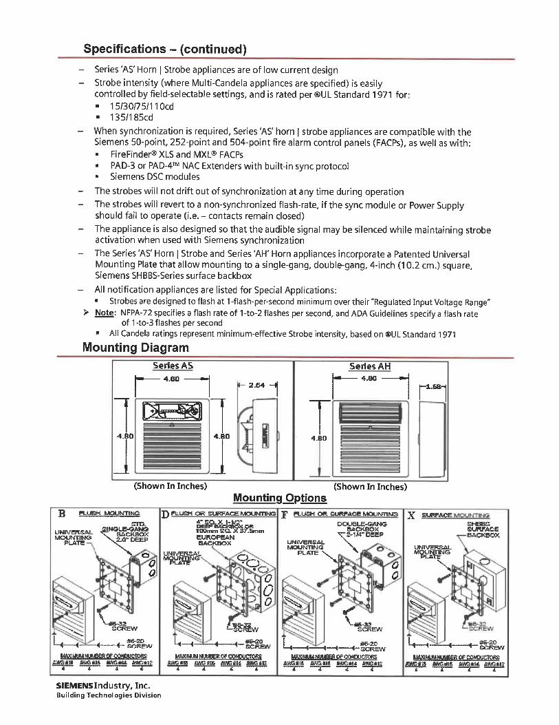
Specifications - (continued)
Series 'AS' Horn | Strobe appliances are of low current designStrobe intensity (where Multi-Candela appliances are specified) is easilycontrolled by field-selectable settings, and is rated per ®UL Standard 1971 for-. 15/30/75/110cd. 135/185cd
When synchronization is required. Series'AS' horn | strobe appliances are compatible with theSiemens 50-point, 252-point and 504-point fire alarm control panels (FACPs), as well as with:. FireFinder® XLS and MXL® FACPs. PAD-3 or PAD-4T NAC Extenders with built-in sync protocol. Siemens DSC modules
The strobes will not drift out of synchronization at any time during operationThe strobes will revert to a non-synchronized flash-rate, if the sync module or Power Supplyshould fail to operate (i. e. - contacts remain closed)
The appliance is also designed so that the audible signal may be silenced while maintaining strobeactivation when used with Siemens synchronizationThe Series 'AS' Horn | Strobe and Series 'AH' Horn appliances incorporate a Patented UniversalMounting Plate that allow mounting to a single-gang. double-gang, 4-inch (10.2 cm. ) square,Siemens SHBBS-Series surface backbox
All notification appliances are listed for Special Applications:. Strobes are designed to flash at 1-flash-per-second minimum over their "Regulated Input Voltage Range"
> Note: NFPA-72 specifies a flash rate of 1-to-2 flashes per second, and ADA Guidelines specify a flash rateof 1 -to-3 flashes per second
. All Candela ratings represent minimum-effective Strobe intensity, based on ®UL Standard 1971
Mounting DiagramSeries AS Series AH
4.BO --\ . I-- 4.fl0. i _l I rai
2.54
4.80
;4.80
(Shown In Inches)
Mounting Options(Shown In Inches)
B FLUSH MOUNTINGETD-
UNn/EKSALMOUNT1MS
PLATE
BAOtBOXJiSFDEB'
J) RLUSM OR SURFACE MOUNTING ?
eUKOPCANBACKBOX
FLUSH OR SURKACE MDUhmNe ^ SURFACEDOUSLE-SANG.
BAOKBOX. S-WDBSP
00
^
1^-
V,T^i
-<- ^-
EEW
*6-20-<-!SCREW
PCATC
^
L.-
^
UNIVERSALMOUN71NS
PLATE
0 -\
. 2-VA
SKBSa^FACEB.ACKBOX
0
g s.
00
l^S
s.
^g
-<-
MAXIMUM NUMSBi OF COWXJCTQRS;»» flWSM
SIEMENSlndustry, Inc.Building Technologies Division
-^-f^^wMMMUMNUBBEJOF CONDUCiORS
e»GUt ttweiii
-,-(-
;EW
A6-20. SCREW
^.-<- .
S&-30SCREW
UtMMUM NUUBHi OP (MUBUCniRS
ffAGtU" WnSliM aUG«* <lWS*t2 AWGmB
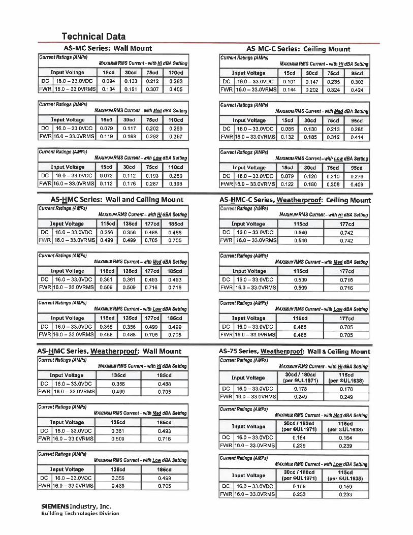
Technical DataAS-MC Series: Wall Mount
Current Ratings (AMPs)MAXIWMRMS Current-w/ttWdBA Selling
Input Voltage 15cd 30cd 75cd IIOcd
DC 16.0-33.0VDC 0.094 0.133 0.212 0.283FWR 16.0-33.0VRMS 0.134 0. 191 0.307 0.405
AS-MC-C Series: Ceiling MountCurrent Ratings (AMPs)
MAXIMUMRMS Current-with WdBA Sett/ng
Input Voltage 15cd 30cd 75cd 95cd
DC 16. 0-33. 0VDC 0. 101 0. 147 0. 235 0. 303
FWR 16.0-33.0VRMS 0. 144 0.202 0.324 0.424
Current Ratings (AMPs)MAXIMUM RMS Current - with Med dBA Setting
Input Voltage IScd 30cd 75cd 110cd
DC 16. 0-33. 0VDC 0. 079 0. 117 0. 202 0. 269
RA/R 16. 0-33. 0VRMS 0. 119 0. 183 0. 292 0. 397
Current Ratings (AMPs)M/WMMRMS Current - with Med dBA Selling
Input Voltage IScd 30cd 75cd 95cd
DC 16.0-33.0VDC 0.085 0.130 0.213 0.285FWR16.0-33.0VRMS 0. 132 0.185 0.312 0.414
Current Ratings (AMPs)MAXimimRMS Current-wftft ^owtfBA Setdng
Input Voltage 15cd 30cd 75cd 110cdDC 16.0-33.0VDC 0.073 0. 112 0.193 0.260
FWR16. 0-33. 0VRMS 0. 112 0. 176 0.287 0. 393
AS-HMC Series: Wall and Ceiling Mount^urret Ratings (AMPs)
MAXIMUMRMS Current-with HI dBA Setting
Input Voltage 115cd 135cd 177cd 185cd
DC 16.0-33.0VDC 0.356 0.356 0.488 0.488R 16.0-33.0VRMS 0.499 0.499 0.705 0.705
Current Ratings (AMPs)MAXIHUMRMS Currwt-with Low dBA Setting
Input Voltage 15cd 30cd 75cd 95cd
DC 16.0-33.0VDC 0.079 0. 120 0.210 0.279
FWR16. 0-33. 0VRMS 0. 122 0. 180 0.308 0.409
AS-HMC-C Series, Weatherproof: Ceiling Mount. Ratings <AMPs)
MAXIMUMRMS Currenl-withHidBA Setting
Input Voltage 115cd 177cd
DC [ 16. 0-33. 0VDC 0.546 0.742
rWR 16.0-33.0VRMS 0.546 0.742
Cumnt Ratings {AMPsjMAXIHUMRMS Current - with Mad dBA Setting
Input Voltage 115cd 135cd 177cd 18Scd
DC 16.0-33.0VDC 0.361 0.361 0.493 0.493FWR16.0-33.0VRMS 0.509 0.509 0.716 0.716
Current Ratings (AMPs)MAXIHUMRMS Current - with Med dBA Setting
Input Voltage 115cd 177cd
DC 16.0-33.0VDC 0.509 0.716FWR 16.0-33.0VRMS 0.509 0.716
Current Ratings (AMPs)MAXIMUM RMS Current-with Low dBA Setting
Input Voltage 115cd 135cd 177cd 185cd
DC 16.0-33.0VDC 0.356 0.356 0.499 0.499FWR16.0-33.0VRMS 0.488 0.488 0.705 0.705
Current Ratings (AMPs)MAXIMUMRMS Current-with LsvadBA Setting
Input Voltage 115cd 177cd
DC 16.0-33.0VDC 0.488 0.705FWR 16.0-33.0VRMS 0.488 0.705
AS-HMC Series, Weatherproof: Wall MountCurrent Ratings (AMPs)
MAXIMUM RMS Current- with Hi dBA Setting
Input Voltage 135cd 185cdDCI16.0-33.0VDC 0.356 0.488
FWR 16. 0-33. 0VRMS 0.499 0. 705
Current Ratings (AMPs)MAXIMUM RMS Current-with Mgd dBA Setting
Input Voltage 135cd IBScd
DC 16.0-33.0VDC 0.361 0.493R/VR 16.0-33.0VRMS 0.509 0.716
Current Ratings (AMPs)MAXIMUMRMS Current-wlth LowdBA Setting
Input Voltage 135cd 185cd
DC 16.0-33.0VDC 0.356 0.499FWR 16.0-33.0VRMS 0.488 0.705
SIEMENSIndustry, Inc.Building Technologies Division
AS-75 Series, Weatherproof: Wall & Ceiling MountCurrent Ratings (AMPs)
MAXIMUMRMS Current- with m dBA Setting
30cd/180cd 115cdInput Voltage (per®UL1971) (per ®UU638)
DC 16.0-33.0VDC 0. 178 0. 178FWR 16.0-33.0VRMS 0.249 0.249
Current Ratings (AMPs)MAXIMUM RMS Current - with Med dBA Setting
30cd/180cd 115cd(per®UL1971) (per®UL1638)
DC 16. 0-33. 0VDC 0. 164 0. 164RA/R 16. 0-33. 0VRMS 0.239 0.239
Input Voltage
Current Ratings (AMPs)MAXIWMRMS Cumnt-with Low dBA Setting
30cd/180cd 115cdInput Voltage (per'®UL197"1) (per ®UL^38)
DC 16.0-33.0VDC 0. 159 0. 159FWR 16.0-33.0VRMS 0.233 0.233
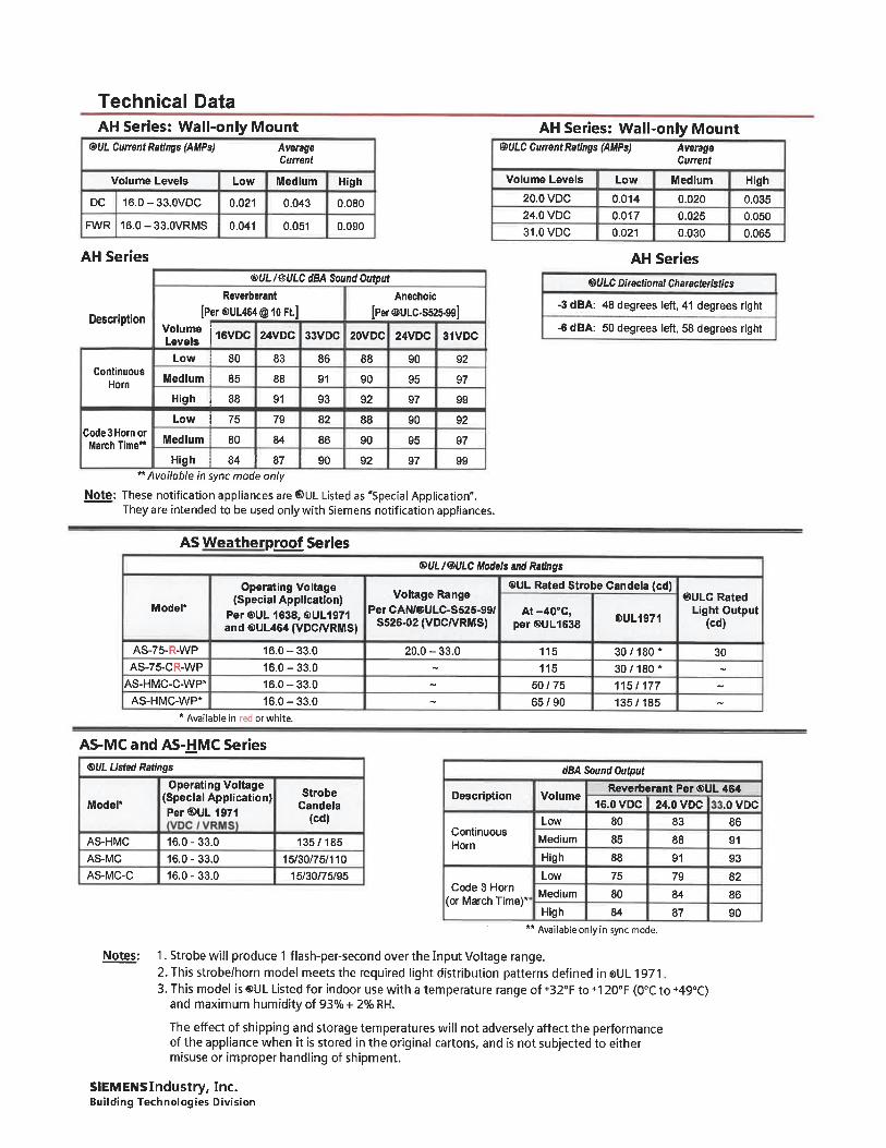
Technical Data
AH Series: Wall-only Mount®1/L Current Ratings (AMPs)
AH Series: Wall-only Mount
Volume Levels
DC 16.0-33.0VDC
FWR 16. 0-33. 0VRMS
AH Series
Low
0.021
0.041
Current
Medium
0.043
0. 051
High
0. 080
0. 090
®UL /@ULC dBA Sound Output
Reverberant Anechoic
[Per ®UL464 @ 10 Ft.] [Per ®ULC.S525-99]
^'^le J1 6VDC 24VDC 33VDC 20VDC 24VDC 31VDC
Low 80 83 86 88 90 92
Description
ContinuousHorn
Code 3 Horn or
March Time**
"Available in sync mode only
Note: These notification appliances are ©UL Listed as "Special Application".They are intended to be used only with Siemens notification appliances.
Volume Levels
20. 0 VDC24. 0 VDC
31.0VDC
Low
0. 0140. 017
0.021
AverageCurrent
Medium High0.020 0.0350.025 0.050
0.030 0. 065
AH Series
WLC Directional Characteristics
-3 dBA:
-6dBA:
48 degrees
50 degrees
left, 41 degrees right
left, 58 degrees right
Medium
High ,
Low i
Medium
85
88
75
80
84 !
88
91
79
84
87 i
91
93
82
86
90
90
92
88
90
92
95
97
90
95
97
97
99
92
97
99
AS Weatherproof Series
Model*
AS-75-R-WP
AS-75-CR-WPAS-HMC-C-WP*
AS-HMC-WP*
Operating Voltage(Special Application)
Per ®UL 1638, I&UL1971and®UL464(VDC/VRMS)
16.0-33.0
16. 0-33.016. 0-33.0
16.0-33.0
®UL /®UIC Modefs and Ratings
®UL Rated Strobe Candela (cd)Voltage Range
Per CAN/®ULC-S525-99/S526-02 (VDC/VRMS)
20. 0-33.0
At-40°C,per®UL1638
115
11550/75
65/90
®UL1971
30, 180*
30, 180*115/177
135/185
®ULC RatedLight Output
(cd)
30
* Available in red or white.
AS-MC and AS-HMC Series
®ULUsted Ratings
Operating Voltage(Special ApplicationlPer ®UL 1971
dBA Sound Output
Model*Strobe
Candela(cd)
AS-HMCAS-MCAS-MC-C
Notes:
16. 0 - 33.0
16. 0 - 33.016. 0-33.0
135/185
15/30/75/11015/30/75/95
Description Volume
ContinuousHorn
Code 3 Horn(or March Time)*
Low
Medium
High
Low
Medium
80
85
88
75
80
84
Reverberant Per ®UL 464
16. 0VDC 24. 0 VDC . OVDC
83 86
88 91
91 93
79 82
84 86
87 90
** Available only in sync mode.
1. Strobe will produce 1 flash-per-second over the Input Voltage range.2. This strobe/horn model meets the required light distribution patterns defined in sUL 19713. This model is ®UL Listed for indoor use with a temperature range of +32°F to +120°F (0°C to +49°C)
and maximum humidity of 93% + 2% RH.
The effect of shipping and storage temperatures will not adversely affect the performanceof the appliance when it is stored in the original cartons, and is not subjected to eithermisuse or improper handling of shipment.
SIEMENS Industry. Inc.Building Technologies Division
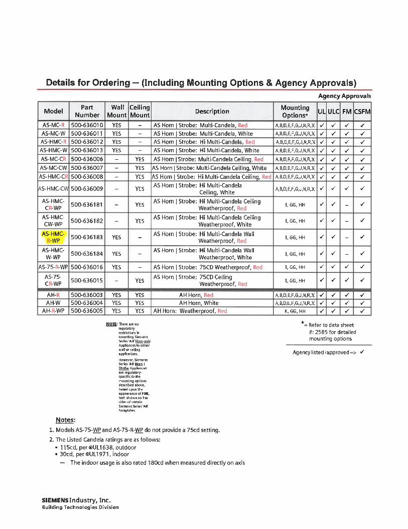
Details for Ordering - (Including Mounting Options & Agency Approvals)
Model
AS-MC-RAS-MC-WAS-HMC-RAS-HMC-WAS-MC-CR
AS-MC-CW
AS-HMC-CR
S-HMC-C
AS-HMC-CR-WP
AS-HMC-CW-WP
AS-HMC--WP
AS-HMC-W-WP
AS-75-R-WP
AS-75-CR-WP
AH-RAH-W
AH-R-WP
PartNumber
500-636010500-636011
500-636012500-636013
500-636006
500-636007
500-636008
500-636009
500-636181
500-636182
500-636183
500-636184
500-636016
500-636015
500-636003500-636004500-636005
WallMount
YESYES
YES
YES
YES
YES
YES
YESYESYES
CeilingMount
YES
YESYES
YES
YES
YES
YES
YESYES
Description
AS Horn | Strobe: Multi-Candela, RedAS Horn | Strobe: Multi-Candela, WhiteAS Horn | Strobe: Hi Multi-Candela, RedAS Horn | Strobe: Hi Multi-Candela, White
AS Horn | Strobe: Multi-Candela Ceiling, Red
AS Horn | Strobe: Multi-Candela Ceiling, White
AS Horn | Strobe: Hi Multi-Candela Ceiling, RedAS Horn | Strobe: Hi Multi-Candela
Ceiling, White
AS Horn | Strobe: Hi Multi-Candela CeilingWeatherproof, Red
AS Horn | Strobe: Hi Multi-Candela CeilingWeatherproof, White
AS Horn | Strobe: Hi Multi-Candela WallWeatherproof, Red
AS Horn | Strobe: Hi Multi-Candela WallWeatherproof, White
AS Horn | Strobe: 75CD Weatherproof, Red
AS Horn | Strobe: 75CD CeilingWeatherproof, Red
AH Horn, Red
AH Horn, WhiteAH Horn; Weatherproof, Red
NOTE: There are noregulatoryrestrictions in
mounting SiemensSeries 'AH' Hom-onlvAppliances to eitherwall or ceilingapplications,
However, SiemensSeries'A? Horn IStrobe Appliancesare regulatory-specific to themounting optionsdescribed above,based upon theappearance of FIRE,text shown on thesides of certainSiemens Series'AS'faceplates.
Notes:
1. Models AS-75-WP and AS-75-R-WP do not provide a 75cd setting.
2. The Listed Candela ratings are as follows:. 115cd, per®UL1638, outdoor. 30cd, per ®UL1971, indoor
- The indoor usage is also rated ISOcd when measured directly on axis
Agency Approvals
MountingOptions*
A, B, D, E, F, G, J, N, R,X .. -/
A,B,D,E, F,G,J,N,R,X ./ ^
A,B,D,E,F,G,J,N, R,X ./ ./
A,B,D, E, F,G,J,N,R,X ^ ^
A, B, D, E,F,G,J,N,R,X ^ ^
A, B, D, E, F, G, J, N, R, X ^ ^
A, B, D, E, F, G, J, N, R,X ./ ^
A, B, D, E, F,G, J, N, R,X ^ ^ ^ ^
UL ULC FM CSFM
./
^
^
^
^
^
^
^
^
^
^
^
y
.
I, GG, HH
I, GG, HH
^ ^ -
^ ^ -
I, GG, HH ^ </ -
I. GG. HH ^ ^ -
I, GG, HH ^ ^ ^
I. GG. HH . / ^ ^
.
.
./
^
./
^
A, B, D, E, F,G,J,N,R,X ^ ^ ^ ^
A, B, D, E, F,G, J, N,R, X ^ ^ ^ ~/
K, GG, HH ^ ^ '/ ./
*= Refer to data sheet#: 2585 for detailedmounting options
Agency listed fapproved=> ^
SIEMENS Industry, Inc.Building Technologies Division

Notice: This marketing data sheet is not intended to be used for system design or installation purposes.For the most up-to-date information, refer to each product's installation instructions.
SIEMENSIndustry, Inc.Building Technologies Division
Fire Safety8 Fernwood Road
Florham Park, NJ 07932Tel: (973) 593-2600FAX: (908) 547-6877URL: www.usa.Siemens.com/Fire
|SI)Printed in U.SA.
Fire Safety1577 North Service RoadEastOakville, OntarioL6HOH6/CanadaTel: [905] 465-8000URL: www. Siemens. CA
September 2015Supersedes sheet dated 5/2015
(Rev. 5)

Project: Tulsa County Maintenance Facilities
To:
Re:
Specification Title: Door Hardware
Section: 087100
SUBSTITUTIONREQUEST
Durin theBiddin /Ne otiatin Sta e)
Substitution Request Number:
From: ASSA ABLOY- Drew Dorsey
Date: 10/15/2018
A/E Project Number:
Contract For:
Description: overhead Stops & Holders
Article/Paragraph:1. 17 Overhead Stops & Holders
Proposed Substitution: RockwoodManufacturer: Rockwood Address: 300 Main Street Rockwood PATrade Name;
Phone: 814-926-2026
Model No.:
Attached data includes product description, specifications, drawings, photographs, and performance and test data adequate for evaluation ofthe request; applicable portions ofthe'dataare clearly identified.
Attached data also includes a description of changes to the Contract Documents that the proposed substitution will require for itsinstallation.
The Undersigned certifies:Proposed substitution has been fully investigated and determined to be equal or superior in all respects to specified product.Same warranty will be famished for proposed substitution as for specified product.Same maintenance service and source of replacement parts, as applicable, is available.Proposed substitution will have no adverse effect on other trades and will not affect or delay progress schedule.Proposed substitution does not affect dimensions and functional clearances.Payment will be made for changes to building design, including A/E design, detailing, and construction costs caused by thesubstitution.
Submitted by: Drew Dorsey
Signed by:
Firm: ASSAABLOY
Address: 2855 Marquis Dr Garland TX 75042
Telephone: 405-834-5453
A/E's REVIEW AND ACTION
VS Substitution approved - Make submittals in accordance with Specification Section 01 25 00 Substitution Procedures.D Substitution approved as noted - Make submittals in accordance with Specification Section 01 25 00 Substitution Procedures.D Substitution rejected - Use specified materials.D Substitution Request received too late - Use specified materials.
Signed by:J. Hammock
Date:10-22-18
Supporting Data Attached: D Drawings Product Data d Samples D Tests d Reports D
©Copyright 2013, CSI,110 South Union St., Suite 100, Alexandria, VA 22314
Page _ of. Form Version: January 2013CSIForml. 5C
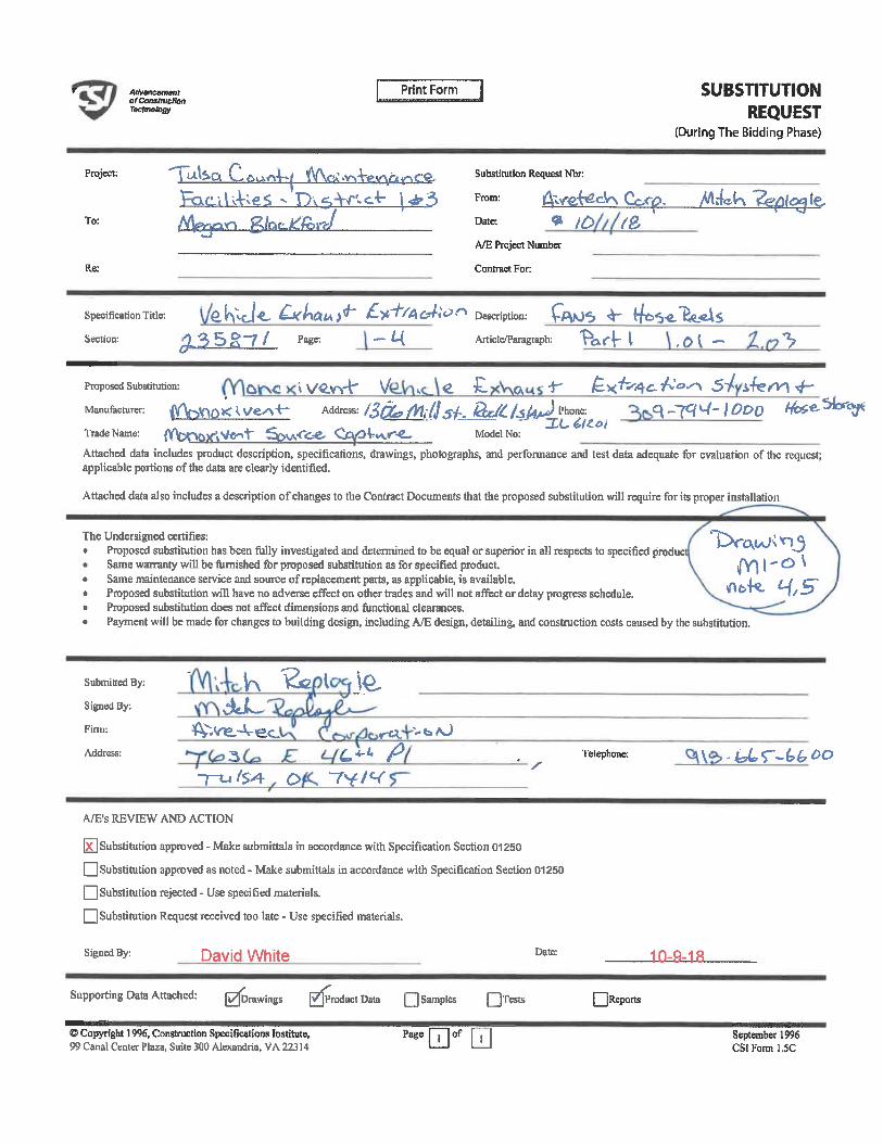
Ailvanewnmlo/Consbucttoftnclmolcgf
Print Form
Project:
To:
Re:
a LL &ij>.<ni^f ((V\<''A'. Y\A-«»Ariv~>c'e.
iFbic. il^&s -'Dv^-Vr. c-l- \^~51/V^yi ^ g/CK-^&rt/
SUBSTITUTIONREQUEST
(During The Bidding Phase)
Substitution Request Ntar:
From: A-.<^ecV\ Corp. X4»(-l ?6i(0(<^l&Date: ^ tC> /fi
A/E Project Number
Contract For:
Specification Tide: ' e. ^cJ-C. £-K^ai\^ £-^'^C^'^'^ Description: Q^J<S ^ (^^. e-'S&'^SSection: jl35§~7/ pa6e: - ^-( Anicleffaragraph: T^r^ I , 0 I - ^
Proposed Substitution: & C » \/^. w(T
Manufacturer: ff\^\QX i, \/e-^+-Trade Name:
c\
Address: /3C^/^ilS S-t-. Q^/4f4^i^w:_(Ybr»ox'>'<rt>n1' '^>iA<'<L-e-Qsyo^^-e- Model No:
.*- ^x+y^e-^^ s^ ^^y\^-q _7cr / ODO ^?<'sfar<y!
Attached data includes product description, specifications, drawings, photographs, and performance and test data adequate for evaluation of the request;applicable portions of the data are clearly identified.
Attached data also includes a description of changes to the Contract Documents that the proposed subsritudon will require for its proper installation
The Undersigned certifies:Proposed substitution has been fully investigated and detemiined to be equal or superior in all respects to specified producSame warranty will be famished for proposed substitution as for specified product.Same maintenance service and source of replacement parts, as applicable, is available.Proposed substitution will have no adverse effect on other trades and will not affect or delay progress schedule.Proposed substitution does not affect dimensions and functional clearances.Payment will be made for changes to building design, including A/E design, detailing, and construction costs caused by the substihttion.
T>T(\(Aj«T5<mi'o\
^^. ^5'
Submitted By:
Signed By:
Finn;
Address:
~ \ ^ ^dU-
^.^.-^ec-3
-r^/?4 o
i te-
y<L -OAj
^. ^ ^~7^l^
/-
A/E's REVffiW AND ACTION
|x| Substitution approved - Make submittals in accoidance with Specification Section 01250
Q Substitution approved as noted - Make submittals in accordance with Specification Section 01250
[_] Substitution rejected - Use specified materials.
[_) Substitution Request received too late - Use specified materials.
Telephone: \ -u'r-^^0
Signed By: David White Date: in-Q-iff
Supporting Data Attached: I Drawings
© Copyright 1996, Congtruction Specifications Institute,99 Canal Center Plaza, Suite 300 Alexandria. VA 22314
]ProductOata Q Samples Q'l'wis
Page Q of Q
QReports
^SSy^^^^.K'.iSt.^
September 1996CSIFonnl.SC
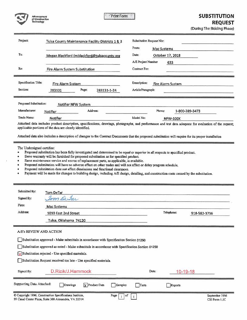
AdvancsimMofConslmcffonTscfuiotogy
. PrJntyFormi SUBSTITUTIONREQUEST
(During The Bidding Phase)
Project:
To:
Re:
Tulsa Coun Maintenance Facilit Districts 1 & 3
Meean Blackford (mblackfordOtulsacountv.ore
Fire Alarm S stem Substitution
Substitution Reqiiest Nbr
From: MgcS stems
Date: October 17, 2018
A/E Project Number 533
Contract For:
Specification Tide:
Section:
Fire Alarm S stem
283131 283131-1-24
Description: f^ larm S stemAnicle/Paragraph:
Proposed Substitution: Notifier NFW S Stem
Manufacturer: Notifier Address: Phone: 1-800-289-3473
Trade Name: Notlfier Model No: NRA/-100X
Attached data includes product description, specifications, drawings, photographs, and perfonnance and test data adequate for evaluation of the request;applicable portions of the data are clearly identified.
Attached data also includes a description of changes to the Contract Documents that the proposed substitation will require for its proper installation
The Undersigned certifies:Proposed substitution has been fully investigated and determined to be equal or superior in all respects to specified product.Same warranty will be furnished for proposed subsdturion as for specified productSame maintenance service and source of replacement parts, as applicable, is available.Proposed substitution will have no adverse effect on other trades and wUI not affect or delay progress schedule.Proposed substihition does not affect dimensions and functional clearances.Payment will be made for changes to building design, including A/E design, detailing, and construction costs caused by fhe substitution.
Submitted By;
Signed By:
Firm:
Address:
Tom DeTar
^TD^JA^MacS stems
1010 East 2nd Street
Tulsa Oklahoma 74120
Telephone: 918-582-3736
A^E's REVIEW AND ACTION
Q Substitution approved - Make submittals in accordance with Specification Section 01250
[_] Substitution approved as noted - Make submittals in accordance with Specification Secdon 01250
Q Substitution rejected - Use specified matenals.
Q Substitution Request received too late - Use specified materials.
Signed By: D. Rizik/J. Hammock Date: 10-19-18
Supporting Data Attached: Qorawings EProductData Q Samples QTests
©Copyright 1996, Construction Specifications Institute, Page of99 Canal Center Plaza, Suite 300 Alexandria, VA 22314
r~| Reports
September 1996CSIFonnl. SC
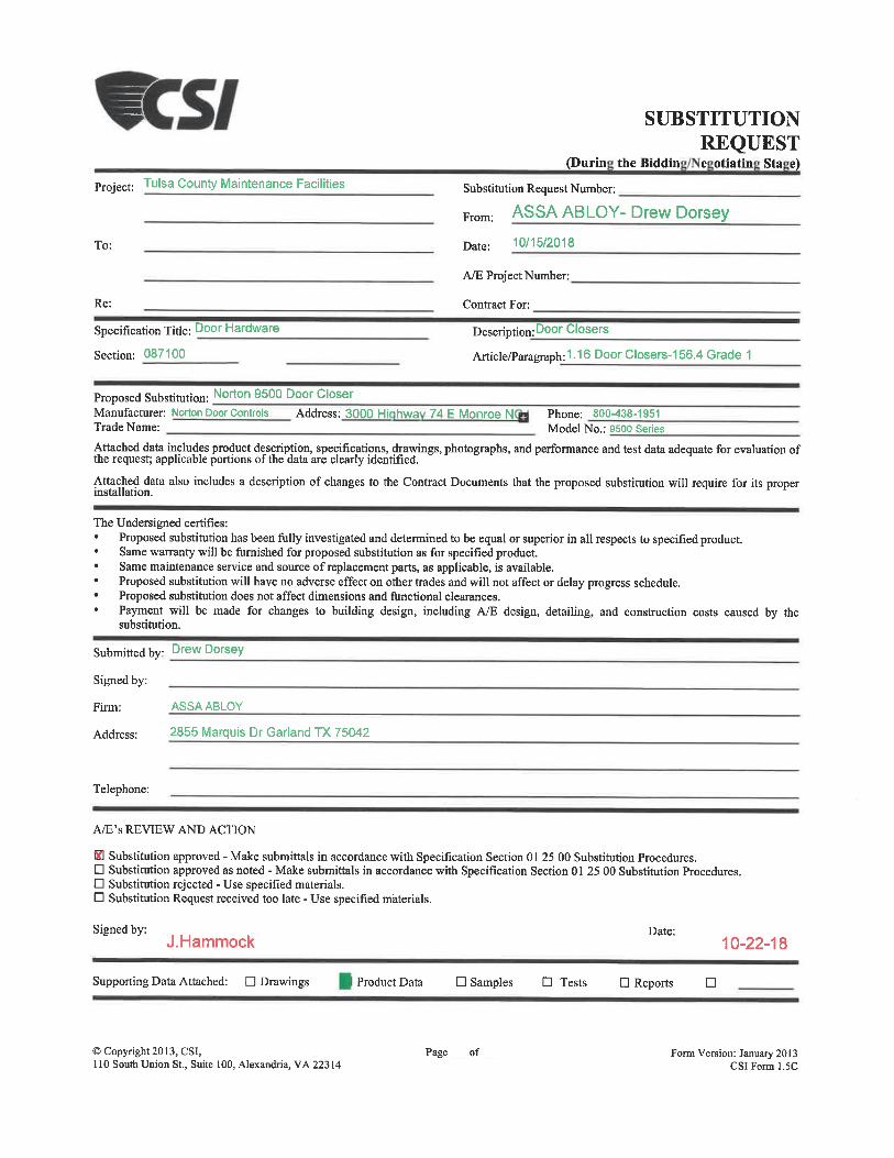
Project: Tulsa County Maintenance Facilities
To:
Re:
Specification Title: Door Hardware
Section: 087100
SUBSTITUTIONREQUEST
(Durin theBiddin e otiatin Sta e)
Substitution Request Number:
From: ASSA ABLOY- Drew Dorsey
Date: 10/15/2018
A/E Project Number:
Contract For:
Description: Door Closers
Article/Paragraph:1. 16 Door Closers-156. 4 Grade 1
Proposed Substitution: Norton 950° Door CloserManufacturer: Norton Door Controls Address: 3000 Hi hwa 74 E Monroe NTrade Name:
Phone: 800-438-1951Model No. : 9500 Series
Attached data includes product description, specifications, drawings, photographs, and performance and test data adequate for evaluation ofthe request; applicable portions ofthe'data are clearly identified.
Attached data also includes a description of changes to the Contract Documents that the proposed substitution will require for itsinstallation.
The Undersigned certifies:Proposed substitution has been fully investigated and determined to be equal or superior in all respects to specified product.Same warranty will be furnished for proposed substitution as for specified product.Same maintenance service and source of replacement parts, as applicable, is available.Proposed substitution will have no adverse effect on other trades and will not affect or delay progress schedule.Proposed substitution does not affect dimensions and functional clearances.Payment will be made for changes to building design, including A/E design, detailing, and constmction costs caused by thesubstitution.
Submitted by Drew Dorsey
Signed by:
Firm: ASSAABLOY
Address: 2855 Marquis Dr Garland TX 75042
Telephone:
A/E's REVIEW AND ACTION
1B Substitution approved - Make submittals in accordance with Specification Section 01 25 00 Substitution Procedures.D Substitution approved as noted - Make submittals in accordance with Specification Section 01 25 00 Substitution Procedures.D Substitution rejected - Use specified materials.d Substitution Request received too late - Use specified materials.
Signed by:J. Hammock
Date:10-22-18
Supporting Data Attached: D Drawings Product Data D Samples D Tests D Reports D
©Copyright 2013, CSI,110 South Union St., Suite 100, Alexandria, VA 223 14
Page_of _ Form Version: January 2013CSIForml. 5C
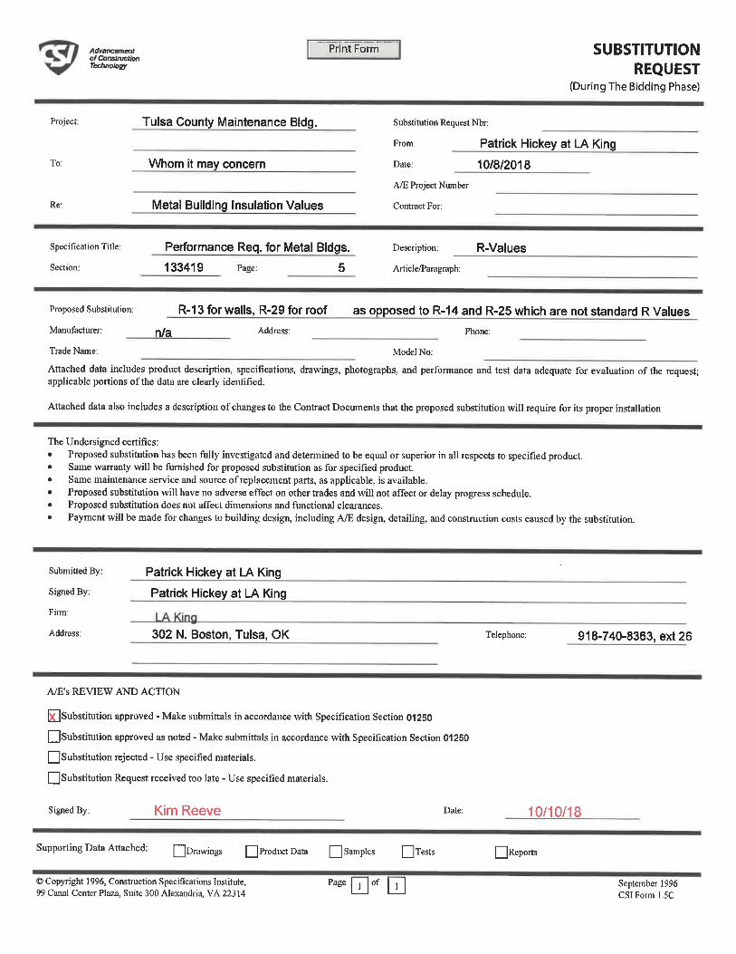
AdvancanantotConslfucSonTechnology
Print Form SUBSTITUTIONREQUEST
(During The Bidding Phase)
Project;
To:
Re:
Tulsa County Maintenance Bldg.
Whom it may concern
Metal Building Insulation Values
Substitution Request Nbr:
From: Patrick Mickey at LA King
Date: 10/8/2018
A/E Project Number
Conti'act For:
specification Title: Performance Req. for Metal Bldgs.
Section: 133419 Page: 5
Description; R-ValUCS
Article/Paragraph:
Proposed Substitution: R-13 for walls, R-29 for roof as opposed to R-14 and R-25 which are not standard R Values
Manufacturer: ^/g Address: Phone:
Trade Name; Model No:
Attached data includes product description, specifications, drawings, photographs, and performance and test data adequate for evaluation of the request;applicable portions of the data are clearly identified.
Attached data also includes a description of changes to the Contract Documents that the proposed substitution will require for its proper installation
The Undersigned certifies:
Proposed substitudon has been fully investigated and determined to be equal or superior in all respects to specified product.Same warranty will be famished for proposed substitution as for specified product.Same maintenance service and source of replacement parts, as applicable, is available.Proposed substitution will have no adverse effect on other trades and will not affect or delay progress schedule.Proposed substitution does not affect dimensions and functional clearances.
Payment will be made for changes to building design, including A/E design, detailing, and constmction costs caused by the substitution.
Submitted By:
Signed By:
Firm:
Address:
Patrick Hickey at LA King
Patrick Hickey at LA King
302 N. Boston, Tulsa, OK Telephone: 918-740-8363, ext 26
A/E's REVIEW AND ACTION
S] Substitution approved - Make submittals in accordance with Specification Section 01250
Q Substitution approved as noted - Make submittals in accordance with Specification Section 01250Q Substitution rejected - Use specified materials.
Q Substitution Request received too late - Use specified materials.
Signed By: Kim Reeve Date: 10/10/18
Supporting Data Attached: [""[Drawings
© Copyright 1996, Construction Specifications Institate,99 Canal Center Plaza, Suite 300 Alexandria, VA 22314
jProductData [_] Samples QTests
Page | i | of
II Reports
September 1996CSIForml.5C
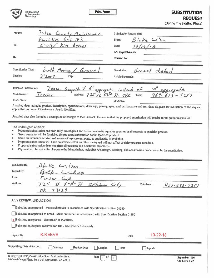
tWvamanwnlol ConstructionTeemmlogy
Print Form
Project:
To:
Re:
'>-/ ^ ^<L .' . ^^
^ ^( ^:^
ti. 1 ff/tCt^lC^
,^3s
SUBSTITUTIONREQUEST
(During The Bidding Phase)
Substitution Request Nbr:
From: le^ke. ^. ^/i
Date: Qf f
A/E Project Number
Contract For:
Specification Tide: [^-k /^^ ^Section: 3 J,QC?O Page:
Description: ^-fv^i^e. ci&. <.Article/Paragraph:
Proposed Substitution: T^^ . ^ / ^ 4^ ^ e A <?/' ^il <- ^ ^/<£.Manufacturer '~ S Address: 7ZT/'<< ^?^ ^- 0/06 Ph°^ ^^^7^- f2-Q~Trade Name: Model No:
Attached data includes product description, specifications, drawings, photographs, and performance and test data adequate for evaluation of the request:applicable portions of the data are clearly identified.
Attached data also includes a description of changes to the Contract Documents that the proposed substitution will require for its proper installation
The Undersigned certifies:
Proposed suhstitution has been fully investigated and determined to be equal or superior in all respects to specifred product.Same warranty will be famished for proposed substitution as for specified product.Same maintenance service and source of replacement parts, as applicable, is available.Proposed substitution \vill have no adverse effect on other trades and will not affect or delay progress schedule.Proposed substitution does not affect dimensions and functional clearances.Payment will be made for changes to building design, including A/E design, detailing, and constmction costs caused by the substitution.
Submitted By:
Signed By:
Finn:
Address:
(^
7-e-ri^<ts~
c>
<^^ils»
a
rf^-, 2.
OA-f.F«i '»«- <-c^ Telephone: Ll^f-67S- ^ZS-r
A/E's REVIEW ANT> ACTION
Q Substitution approved - Make submittals in accordance with Specification Section 01250[_]Substitution approved as noted - Make submittals in accordance with Specification Section 01250[^Substitution rejected - Use specified materials.
QSubstitution Request received too late - Use specified materials.
Signed By: K.REEVE Date: 10-22-18
Supporting Data Attached: Qorawings DProductDam QSamph
0 Copyright 1996, Construction Specifications Institute, Page99 Canal Center Plaza, Suite 300 Alexandria, VA 22314
[Tests QReports
of September 1996CSI Form 1.5C
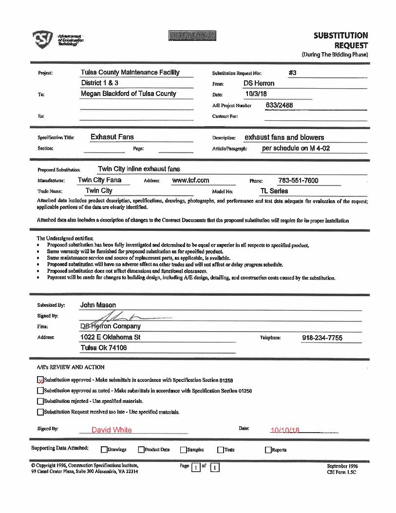
MWWMf
'^^nSUBSTITUTION
REQUEST(During The Bidding Phase)
Project:
To;
Re:
Specification Tide:
Section:
Tulsa County Maintenance FacilityDistrict 1 & 3
Megan Blackford ofTulsa County
Exhasut Fans
Substitution Request Nbr #3
From: DS Herron
Date; 10/3/18
A^ Project Number 633/2488
Contract Foi:
Dcscripiion: exhaust fans and blowers
Artieicffaraeraph: per schedule on M 4-02
proposed Substiiutinn: Twin City inline exhaust fans
Manufaehirer: Twin City Fana Address: www.tcf. com
Trade Name: Twin City Model No.
Phone: 763-551-7600
TL Series
Attached data iucludes product description, specifications, drawings, photographs, and performance and test data adequate for evaluation of the request;applicable portions of the data are clearly Identified.
Attached data also includes a description of changes to (he Contract Documents that (lie proposed substitution will require for its proper installation
The Undersigned cenifies:Proposed substitution has been fully investigsted and determined to be equal or superior ill all respects to specified product.Same wanauty will be famished for proposed substitution as for specified product.Same maintenance service aiid souice of replacement parts, as applicable, is available.Proposed substitution will have no adverse effect oil other trades and will not affect or delay progress schedule.Proposed substitution does not afftct dimensions and functional cleatances,Payment will be made for changes to building design, including A/E design, detailing, and construction costs caused by the substitution.
SubmiUedBy:
Signed By:
Finn:
Address:
John Mason
ron Company
1022 E Oklahoma StTulsa Ok 74106
Tttephotie: 918-234-7755
A/E's REVIEW AND ACTION
[xJSubstitution approved - Make submittats in accordance with SpeciHcation Section 01260QSubstitulion approved as noted - Make submittals in accordance with Specification Section 01250QSubstitution rejected- Use specified materials.
QSiibslitution Request received too late - Use specified materials.
Signed By: David White Date: in/in/ift
Supporting Data Attached; Qorawinga QProductData Qsamples QTcsts QRcports
© Copyright 1996. Constfuction Specifications Institute,99 Canal Center Plaza, Suite 300 Alexandria, VA 22314 EofLLi Septerobtr 1996
CSIFonnl. SC
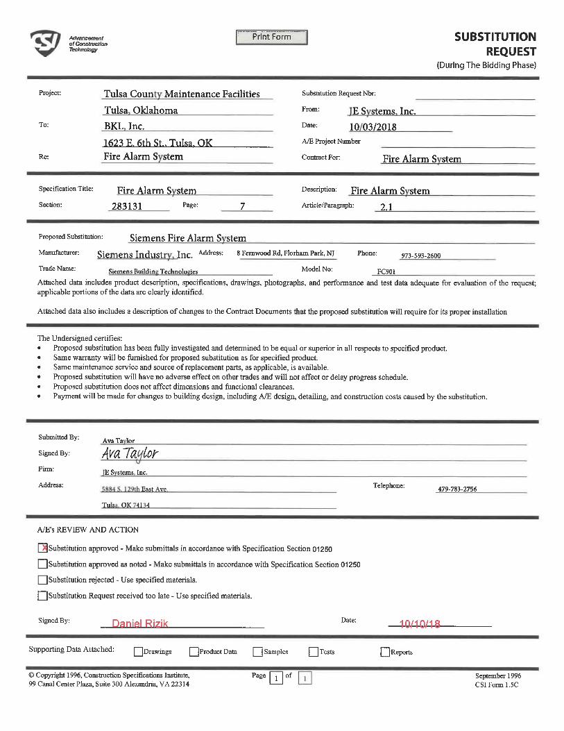
AcfrancemsnlofConstnucti'ooTechnology
Print Form SUBSTITUTIONREQUEST
(During The Bidding Phase)
Project:
To:
Re:
Tulsa Coun Maintenance Facilities
Tulsa Oklahoma
BKL Inc.
1623 E. 6th St.. Tulsa. OKFire Alarm S stem
Substitution Request Nbr:
From: E S stems Inc.
Date: 10 03/2018A/E Project Number
contract For: Fire Alarm S stem
Specification Title:
Section:
Fire Alarm S stem
283131 Paee:
Description: Fire Alarm S stem
Arricle/Paragraph: ^ ^
proposed substitution: Siemens Fire Alarm S stem
Manufacuirer: Siemens Indust Inc. Address: 8 Femwood Rd, Florham Park, NJ Phone: 973-593-2600
Trade Name: Model No:Siemens Buildin Technolo ies ivioaei no: FC901
Attached data includes product description, specifications, drawings, photographs, and performance and test data adequate for evaluation of the request;applicable portions of the data are clearly identified.
Attached data also includes a description of changes to the Contract Documents that the proposed substitution will require for its proper installation
The Undersigned certifies:Proposed substitution has been fully investigated and detemiined to be equal or superior in all respects to specified product.Same warranty will be furnished for proposed substitution as for specified product.Same maintenance service and source ofrqilacement parts, as applicable, is available.Proposed substitution will have no adverse effect on other trades and will not affect or delay progress schedule.Proposed substitution does not affect dimensions and functional clearances.Payment will be made for changes to building design, including A/E design, detailing, and construction costs caused by the substitution.
Suhmined By:
Signed By:
Finn:
Address:
AvaTa lor
A^Ta U>^ES stems Inc.
East ve
Tus OK 41 4
Telephone: 479-783-2756
A/E's REVIEW AND ACTION
Q Substitution approved - Make submittals in accordance with Specification Section 01250
QSubstitution approved as noted - Make submittals in accordance with Specification Section 01250
Q Substitution rejected - Use specified materials.
[_] Substitution Request received too late - Use specified materials.
Signed By: Daniel Rizik Date:
Supporting Data Attached: |-Inrawn
© Copyright 1996, Construction Specifications Institute,99 Canal Center Plaza, Suite 300 Alexandria, VA 22314
]ProductData Q Samples [[Tests
Page | i | of
10/10/18
I[Reports
September 1996CSIForml. 5C
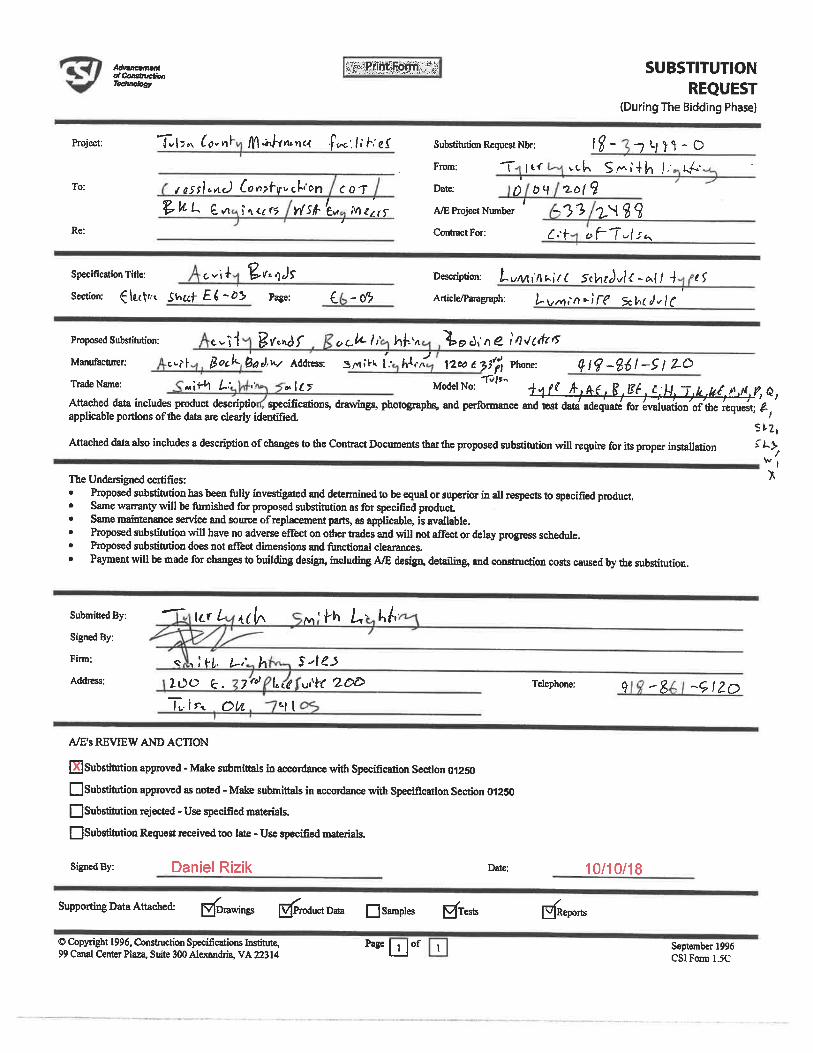
AdvsnewamlafConslmeSwftetookw
SUBSTITUTIONREQUEST
(During The Bidding Phase)
Project:
To:
Re:
Tv|3n ^<l<'n^ l^-^h^Wi -ft^-. li h'e^ Substitution Request Nbr: 1^- -)^}'}-0
From: T |t< vck S.^i'+h J," (^'
/S5{]t-^c) 6on?f'yvc(*l'C-n COT Date: C) 0 4 '2-61 S-3^ ^^
r.-<- yf-T-l-r^
^. it-L e, ^ ?<\t(r5 ^rf-£v» Mzzrf A/EPtoject Number/
Contract For:
Specification Title; t-vi^- ^. Vt/tJs'
Section: ^IttU-t. S^tlt^i'0^ Page: ^. - (f?Description: t-uM\!\^f(. 5tV, i^l<-. i>()-^ <!
Artide^aragnaph: ^^//vi,'/}»-)'ft? $c^^/;(;
Proposed Substitution: C. ^'^-l ^. \/'^f ^L. i<-ll' h^-'n ^>£> "/> & t*'/?^rfr^'
Manufacturer: t.,-|- ^Ot^-6d a'-^ Address: S/<1;^ I-h-1.-^ 1-Zco ('^ Phone: ^ i<?-%il-S ) 2-QTrade Name: <Mll-t1 ^..- . Ky Model No:
-P//T--<-^ ^-. A. ?^ r^ £ M -J. k. ^/. lt. y, d,
Attached data includes product descriptio specifications, drawings, photographs, and perfonnance and test data adequate for evaiuation/of'the requMt: ,applicable portions of die data are clearly identified. ~ . /
St. 2,Attached data also includes a description of changes to the Contract Documents tfiatthe proposed substitution will require for fts proper installation £L\
wlThe Undersigned certifies: ^
Proposed substitution has been fully invesdgated and detenniued to be equal or superior in aU respects to specified product.Same warranty will be finnished for proposed substitution as for specified produrt.Same maiirtenance service and source of replacement parts, as applicable, is available.Proposed substitution will have no adverse effect on other trades and wil} not affect or delay progress schedule.Proposed substitution does not affect dimensions and fimctional clearances.
Payment wiU be made for changes to building design, including A/E design, detailing, and construction costs caused by the subsdtution.
Submitted By:
Signed By:
Firm:
Address:
\<-rL ^ M'^ ^' ^A-
<? , ;K,. /-. h ^-^^ZOO k. 7ral f«<f u-'h- -2£>£>
It. I 0^ t-|l
Telephone: ^ -g --(?^0
A/E's REVIEW AND ACTION
ibstftution approved - Make submittals in accordance with Specification Section 01250
Q Substitution approved as noted - Make submittals in accordance with Specification Section 01250QSubstitution rejected - Use specified materials.
QSubstitution Request received too late - Use specified materials.
Signed By: Daniel Rizik Date: 10/10/18
Supporting Data Attached: [Drawings
© Copyright 1996, Construction Specifications Institute,99 Canal Center Plaza, Suite 300 Alexandria, VA 22314
]ProductData [~] Samples
paBELJ°f
iTests JReports
September 1996CSlFonn 1.5C
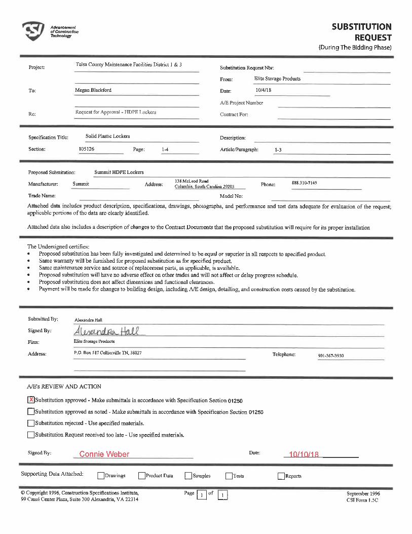
Adrancemenlof ConslnicttonTechnotogy
SUBSTITUTIONREQUEST
(During The Bidding Phase)
Project:
To:
Re:
Tulsa County Maintenance Facilities District 1 & 3
Megan Black&rd
Request for Approval - HDPE Lockers
Substitution Request Nbr:
From: Elite Storage Products
Date: 10/4/18
A/E Project Number
Contract For:
Specification Tide: sohd Plastic Lockers
Section: 105126 Page: 1-4
Description:
Article/Paragraph: 1-3
Proposed Substitution: Summit HDPE Lockers
Manufacturer: Summit Address: ^tel^Lo lina 29203 Phone: 888.310-7149
Trade Name: Model No:
Attached data includes product description, specifications, drawings, photographs, and performance and test data adequate for evaluation of the request;applicable portions of the data are clearly identified.
Attached data also includes a description of changes to the Contract Documents that the proposed substitution will require for its proper installation
The Undersigned certifies:Proposed substitution has been fully investigated and determined to be equal or superior in all respects to specified product.Same warranty will be furnished for proposed substitution as for specified product.Same maintenance service and source of replacement parts, as applicable, is available.Proposed substitution will have no adverse effect on other ftrades and will not affect or delay progress schedule.Proposed substitution does not affect dimensions and functional clearances.Payment will be made for changes to building design, including A/E design, detailing, and constmction costs caused by the substitution.
Submitted By:
Signed By:
Firm:
Address:
Alexandra Hall
Elite Storage Products
P.O. Box 517 Colliemlle TN, 38027 Telephone: 901-367-3930
A/E's REVIEW AND ACTION
^Xj Substitution approved - Make submittals in accordance with Specification Section 01250
QSubstitution approved as noted - Make submittals in accordance with Specification Section 01250
[_] Substitution rejected - Use specified materials.
[__] Substitution Request received too late - Use specified materials.
Signed By: Connie Weber Date: 10/10/18
Supporting Data Attached: QDrawings QProductData Q Samples QTests
© Copyright 1996, Constmcrion Specifications Institute,99 Canal Center Plaza, Suite 300 Alexandria, VA 22314 paee[jjof |jJ
[I Reports
September 1996CSIFonnl.5C
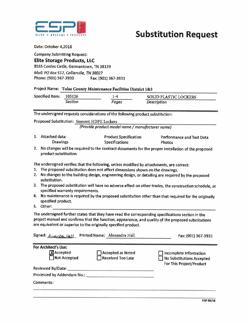
I
ELITE . STOIIAGE . PRODUCTS
Date: October 4, 2018
Company Submitting Request:
Elite Storage Products, LLC8555 Cordes Circle, Germantown, TN 38139
Mail: PO Box 517, Collierville, TN 38027Phone: (901) 367-3930 Fax: (901) 367-3931
Project Name: Tulsa County Maintenance FacUities District 1&3
Substitution Request
Specified Item: 105126Section
1-4
PagesSOLID PLASTIC LOCKERSDescription
The undersigned requests considerations of the following product substitution:
Proposed Substitution: Summit HDPE Lockers(Provide product model name / manufacturer name)
1. Attached data: Product Specification Performance and Test DataDrawings Specifications Photos
2. No changes will be required to the contract documents for the proper installation of the proposedproduct substitution.
The undersigned verifies that the following, unless modified by attachments, are correct:1. The proposed substitution does not affect dimensions shown on the drawings.2. No changes to the building design, engineering design, or detailing are required by the proposed
substitution.
3. The proposed substitution will have no adverse effect on other trades, the construction schedule, orspecified warranty requirements.
4. No maintenance is required by the proposed substitution other than that required for the originallyspecified product.
5. Other:
The undersigned further states that they have read the corresponding specifications section in theproject manual and confirms that the function, appearance, and quality of the proposed substitutionsare eauivalent or superior to the originally specified product.
Signed: ^|,^Lnrffi^4u?J' Printed Name: Alexandra Hall Fax: (901) 367-3931
For Architect's Use:[AcceptedI Not Accepted
Reviewed By/Date:
Processed by Addendum No.
Comments:
[_| Accepted as NotedD Received Too Late
Q Incomplete InformationNo Substitutions AcceptedFor This Project/Product
ESP 08/18
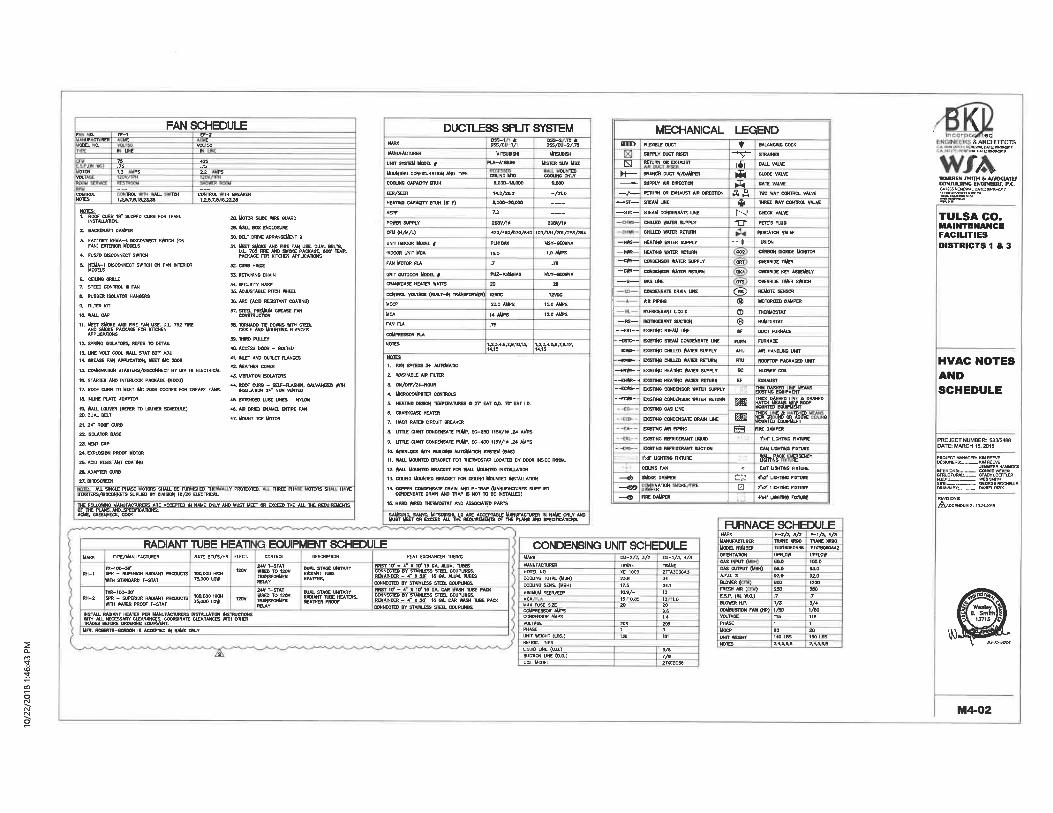
FAN SCHEDULE
1Ah7.Sl,1&23L3B
2. BACKORAFT DAMPER
4, FUSED DISCONNECT SWTCH
6. CEIUNG GRIUE7. SPEED CONTROL 0 FAN
B. RUBBER ISOLATOR HANCERS
S. RLTER MT
Id. WALL CAP
11. MEET SUDKE WO nRE FAK USE. U.L 76Z FTC" Wi5'diJU('E'PAa(AaE''FQR'fd'T5iEN"
APPLJCATIONS
12. SPRING ISOLATORS. REFER TO DETAI.
11 UHE WLT COOL WALL S7AT BOT ADJL14. GRUSE FAN APPUCATUN. UEET iMC 2006
11 COMHNATON STARTERS/USCOHHECT BY UV 16 ELECTRICAL
16. STARTER AND INTERLOCK PACKAGE (HOOD)
17. ROOF CURB TO MEET lUC 2006 CODDES FOR GREASE FAHSL
18. INUNE PLATE ADAPTOR
18, VfAU. LOUVER (REFER TD LOUVER SCHEDULE)2D, DUAL BELT
21. 24" ROOF CURB
22. ISOLATDfi BASE
2a, WNT CkP
24, EWLOSOK PROOF MOTOR
26. AQD RESISTANT COATIHO
2BL ADAPTER CUSB
27. KROSCTEEN
ALL SINGLE PHASE OTORS SHALL BE FUR ISHED THSTARTCRS/hSCOKXETS SUPLJED BY DIVISON IB/SB ELECTRICAL
S. MOTOR SUDE ftRE GUARD
a, WALL BOX ENCLOSURE
B, BELT DfflVC ARRWGEUENT 9
'. %%F'&W, W&.PACKAa'niRKITCHCT''APPLIUT»oiNS"' '""'
L CURB HMGE
S. RETAINING CHAIN
t. SECURITV HASP5. ADJUSTABl£ PriCH WHEEL
B. ARC (ACID RESSTANT COATNO)
UUE-AND'
B. THIRD PUL1EY
a. ACCES3 DOOR - BOLTED
1, INLTT AND OUTLET FIANCES
1 ttEA-THEB COVER
S. VIBRATION ISOLATORS
4. ROOF CUfig - SEtF-FLASHIN.INSULATON 24' NON VEhTCD
ii. EXTENDED LUBE UNES - WUM
S. *B OWED ENAMEL ENTIRE FAN
7. UOUNT TCF UOTDR
lijEjauam IjiNUFtmnEBSME mmEp IN NJUUBU"COOK
Y PROTECTEO. THREE PH. OTORS SH H VE
AND UU5T MECT OR DCCEED THE ALL THE REBUIREUENTS
DUCTLESS SPUT SYSTEMMARK
WAKUFACTURER
UNIT SYSTEM UCOCL I
UOUNTIHC CONFIGURATION A TWE
COOUNC CWACm B7UH
EEK/SEER
HUT1NO CAPAOTY BTUH (S- F)
HSPF
POWER SUPPtY
CfU(H/UA)
UNFT INDOOR UOOEL I
WWW LIN1T MCA
FW UOTOR Ft*
UNIT OUTDOOR UDDEL §
CRANKCASE MUTER WATTS
CONTROL VOLTAGE (BUILT-IN TOWSFORUER)
UOCP
UCA
FAN FU
COUFRESSOR FU
MOTES
DSS/CU-1/1
UlTSUUSHI
PLA-A18BA6
CBtlNB UTDa^ao-lB, ooo
14^/ZIU
a,o(»-2aoo&
7^
20BV/1»
420/480/870/640
PLH1BAK
15i0
.7
PUZ-U8KHM
20
UVDC
20. 0 AMPS
14AUPS
.75
SS/S.S/'hktTSUBISHI
MISTER SLJU USZ
OU 70)COOUNe'QN'LY
9.000
-/21.D
2oav/l»
I OB/134/ZD1 fteS/SS*
USY-CEOBNA
I.OAUPS
.76
MUTf-CEOCNA
20
t2VDC
15. 0 AMPS
IZOAtiPS
14, 15 14^15
1. FAN SPEEDS K- AUTOUATiC
2. WASHABLE AIR HLTCR
3. ON/t)FF/24-HOUR
4, litlCROCOMPUTER CONTOOLS
S, HEATNC DESIGM TEUPERATWES . 27- EAT O.D. TD* EAT 1,D.
6. CRAKKCUE HEATER
7. HACK RATED QRCUIT BREWER
a, UTII£ aw COKDENSATE PUMP. EC-250 115V/t» 3.* AUP5
9. UTIl£ aWT CONDENSATC PUMP. EC-400 116V/1^ . 24 AUPS
la INTERLOCK Wm BUILDING AUTOUATIOW SYSTEM (BAS)
11. WUJL UOUNTO BRkCttET FOR THERUtBTAT LOCATED BY DOOR tNSDE ROOM.
1Z WU1. MQUNTCD BRkCKET FOR WM1. UOUNTCD INSTAULATION
11 CEILKQ MOUKlED BRACKET FOR CBUNa MOUNTED INSTALLATION
16, HARD WRED IHERMOOTAT AND ASSOCIATED PARTS
5Msa'!ISTSmS?'!RH lE°«S£.>SSi^ffi'ffiSS*SSI S^fflw'
MECHANICAL LEGEND
--EST-.
-ESTC--
-ECttS-
--ECWH-
njEXIBLE DUCT
SUPPLY DUCT RISER
RE1UW OR EXHAUST
BRANCT DUCT W/bAWPm
SUPPLY AIR DfRECTCN
RETURN OR DOfAUST AIR DIRECTION
STEAM UHE
STEAM CONDEHSATC LINE
CHILXED WATCR SUPPLY
CH111ED WTCR RETURN
HEATNC #ATER SUPPLY
HEAT1KC WATOl REnjRN
CTNDCNSOR WATER SUPPLY
CONDEN50R WATER RCTURN
GAS UNE
COHDEMSATC DRAIN WE.
AIR fVWG
REFRIGERANT UQUID
RETOCCTANT SUCTON
EWSTHC STEAM UKE
EXISTING STEAM COhDEhSATE UNE
EXISDKB CHIUfD ftATER SUPPLY
EMSDHG CHILLED WATER RETURN
DaSTHB KEA71KC ftATDt SUPPLY
EMSTHC HEATING WATCB RCTURM
EMSTHG CONDENSOR ttATER SUPPLY
EXISTING COtilGEHSOR ttkTER RETUtN
EXISTING GAS UNE
DOCTHO CQNOENSATC DRAIN LJNE
DOSTNO Alff PIWG
EiOSIiNB REFRIGERAHT UOUID
DOSIINl; nEFRieERANT SUCTION
1'xff UGH11HO niCIURE
CGUNQ FAN
SUOKEDUfrER
I g^LJlw WE EFIRE DAUPER
BALANONB CDCX
STRAINER
BALL VALVE
GLOBE VALVE
GATE VALVE
A ffi TW) WAY COMTROL VALVE
THREE WAY CONTROL VALVE
CHEEK VALVE
PETTS PLJUO
INDICATOR VALVE
UNION
CARBON DIOBODE UONITOR
OVERRIDE TUER
OVERRIDE KEY ASSEU9LY
OVERRIDE TIMER SWTCH
REUOTC SENSOR
MOTOftCED DAUPEft
THERMOSTAT
HUUIDISTAT
DUCT RJRNACE
njRKACE
AIR HANDUNG UNIT
ROOFTOP PACKAGED UNIT
BLEMteR COIL
EXHAUST
gS.S^SAw""5
®
PRE DAMPER
l'N4* UGHTING FIXTURE
CAN UGHTINS FIXTURE
f-^B
EMT UBHTMG nxTURE
4x2" LJGHTNG FIXTURE
2'xZ' UGHT1NC FIXTURE
4'wt' UGHTN6 FIXTURE
- ced
& ARCHITECTS
WARREN JMITH d AftW. lMffCONIULIING ENGINEEM, F,C.CM26SRENDIVALI
sr-sss"" ^
TULSA CO.MAINTENANCEFACILITIESDISTRICTS 1 & 3
HVAC NOTESANDSCHEDULE
STRLffinfftAk.-_ STftCYLOEFR.ER
ORA^BY:,_"" UWELRtZ
^ADDENDUM Z. 1[U<-201B
RJRNACE SCHEDULE
RADIANT TUBE HEATI -, EQUIPMENT SCHB3ULE CONDENSING UNFT SCHEDULETWE/MANUFACTURER RATE BTU'S/HR ELECT.
120V
T EXCHANGER 1UBINC
.p<-loo_3orRH-1 SPR - SUPHlrOR RACIAHT PRODUCTS 100000 HIGH
WM STANDARB T-STAT 7&000 LOW
Wi-IOO-M-
""-2 ^-.^m,c£;"^"muCT5 '^^aS<!iu."S^«,"S^l, ^"S§S4'TRADES BETOftE ORDERING
Unt. ROaERTS-GORDON IS ACCCP1ED IN HAWE ONLY
24V T-STATWRED TO 120VTRAKSFonUER
DUAL STAGE UNITARYRADIANT Tl«EHEATERS,
1B BA. ALUU. TUBESSTEEL COUPUItCS,
- 4- X 20f 1C OA. ALUU. TUBESCOKNECTED Wf STAIHLESS STEEL COUPUNCS.
IS GA. CAR ASH TUBE PACKCOKNKTCD BY STAINLESS STEEL COUPUHCSLREMAINDER - 4" X 20' IS CA. CAR WSH TUBE PACKCONNECTCD BY STAIIMSS SIEEL COUPUKCS.
MARKMANUFACTURERMODEL NO.COOUNC TOTAL <UBH)CODUNG SENS. (UBH)UIKIUUM SEER/EERUCAMAX FUSE SIZECOMPRESSOR AMPSCONOENSOR AMPSVOLTAGEPHASEUNIT WEIGHT <LBS.)
UOUID LINE (a.D.)SUCTION UNE (O.D.SCOIL MODEL
CU-2/2. S/7.TRANEXE-100023.H17.510, 9,-15,. 0. 8S20
208
lie
CU-lA 4TRANE2TTA3036A.1424.1u
13 '1.0209.G1.4208
IB1
3/87/8
MARKUANUFACTORERMODEL WfMBERORIENTATtCKC*S INPUT (GAS OUTPUT (MBH)A.F.U. XBU) t( )FRE&1 AIR ( )E. S. P. W. WC.)BLOWER HJ>,COMBUSfnON FAK (HP)VOLTAGEPHASEUOCPUNITttOCHTNOTE
F-2A 3/2TRANEXRBOTUX1BOBOA38UPFLOW601.056.082.0BOD250.7
1/S1/50115
ZD
2.4A6.B
F-1A 4/3TRANE XS90TUXtBOBOA42tfPFLOtt100.0aa.aa2.o1200350,7
3,*1/50115
201BO LBS
2.4.5, B,B
§ M4-02
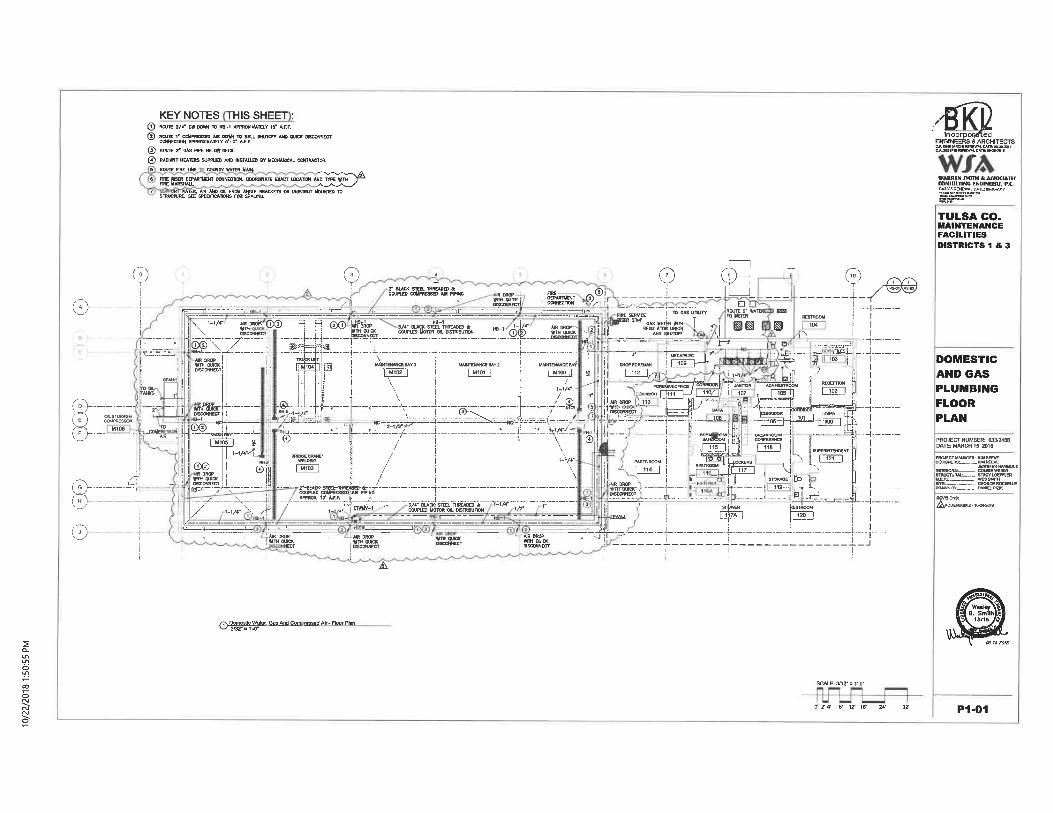
KEYNOTES THIS SHEET :© ROUTE 3/4- CW DOW TO HB-1 APPROXIMATELY 18- AJ-. F,1.2] ROUTE 1' COMPRESSED AIR DOWN TO BALL SHUTCIFF AND OUICK DISCONNECT
COKNEC'IIOH APPRDMUATCLY 6'-0' A. F. F-
@ ROUTE 2' GAS PIPE BELOff DECK.© RADIANT HEATERS 5UPPUED AND INSTALLED BY UECHAWCAL OONTRACTOR.
ROUTE FIRE UHE COUNTY WATER WAIH.
(GT LOCATION AND TTPE WIH
^s"-"'
TULSA CO.MAINTENANCEFACILITIESDISTRICTS 1 & 3
(7>-.
%:
G>-(^y(7^-
0 (?^ss . ®®k
9 cb
i--/<- y:'Q® " H @® V4' BL*"< -STEEL THREADED ACOUPLB) MOTOR | OIL OISTOIBUT10N
"'!l
\
'|, M1[12 |
^^agr^, fir-r
r- l-UE-CiiiE-LEC-ll-1' ^
I D IWUTC-2'-WATCT-: '^~T --------[---.1JD UEIER ;
m\1_MAINTENANCE BA^ i . |
n"T7' ^ \ \:/\ \-' i:
'-'/<"- i i ;1/ !r
.
' -s ^ -' -4- -Bf- ET. '^'i-.r-1
ii .^ 3 I °3 i'!
.'--"Nt:
' .aS!T'----- ^^-Tr'-'----i---"-\zzi:^®s. ::'":trr7--" '. R'-'1.
^-^-^s-^'-f^^i ®@
R DROPttfTH QUICKniSCONNECT
. uiCf-
-i/«--/L,
®i
! . ,il I / ,-,/r ^i '"!:,L:._. . __' "-
.-_-_-J. -_-_- - "-i ^ -
I
I
I
I
/_APPRO<1C^A.F.F^_^ '_______ ___^1- 3/4'.BL*aSi"IEEL..
1- 4* I E71mv-1 ' COUPLED MtiTOR OIL WSTOflBUTON
<-t/4-
"?.
^jUR DROP! wT O"LO<_
.NECT
'AIR DROP, BiH'niicK
DISCONNECT
A
SH°SST»QISCQNNECT
?'I"r()tnor<'-'-1---' ' i - j-j------r -'-.>'-S"XMK'. ).._.....
M-.- :.. -1-:
- a3....
--.--L.
-....._ : Bj_^
-r~T!T-7:-
DOMESTICAND GASPLUMBINGFLOORPLAN
^-Er^^""
Gas And Corn wssad Air - Ftoor Pten
SCALE: 3/32- = T-D-
^ Q, 2, 4. y -|y is. 24. 32' Pl-01
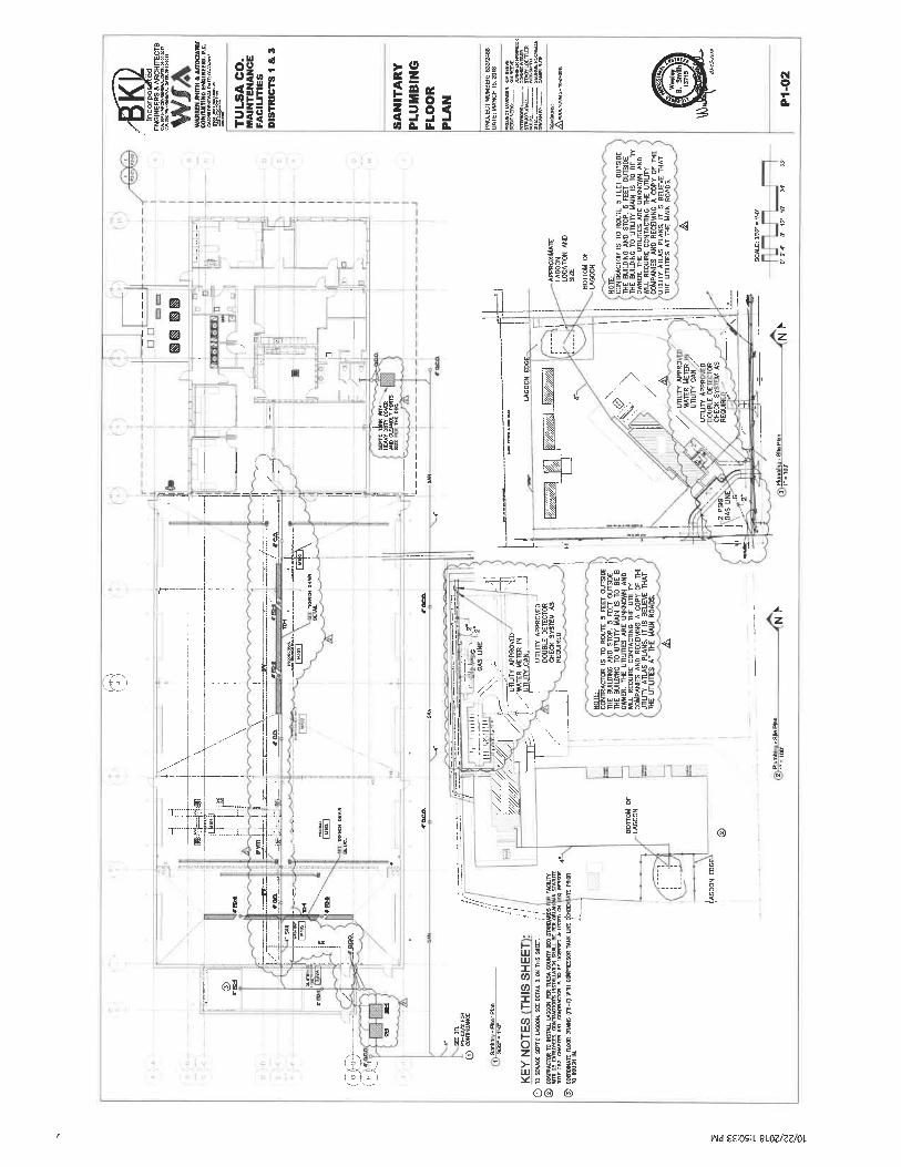
n
.a
ulii II.11§=Its;(0 fc E &
!IE!i 11111s5ii ITIITlUJ
?E
^ijl
iou-SS?<ma:
^o||||5^,»5gg8e5 '!<sll^:
Jliss!i§li^Jil§^
":::3(r^- 4^ I+.r- ;
11 f^ p
Ij 2| ; g
i^
®g
^11!.t
tiSB
CD-^.)>--'><-
-^_==Ii
! I.ll'"-S »iI :i:§
glsIllilliIII!
IL--1
!1! li?;<<:. -1il! '1^^ "-'
' iii -¥
III!
Is!"Ill
s:
Q
iiilw^lls:ii illill!i I It2 's J£l 1^
Q® ©
-T-_-_-_^r--'; . 1
'^.-
^ogS
SK'°e S!;
ineiS?<ffi§
S5?|8g^S
!^113§^
- . §"."
-r
©
-3
Is
Wd££:OS:L8lOZ/ZZ/OL
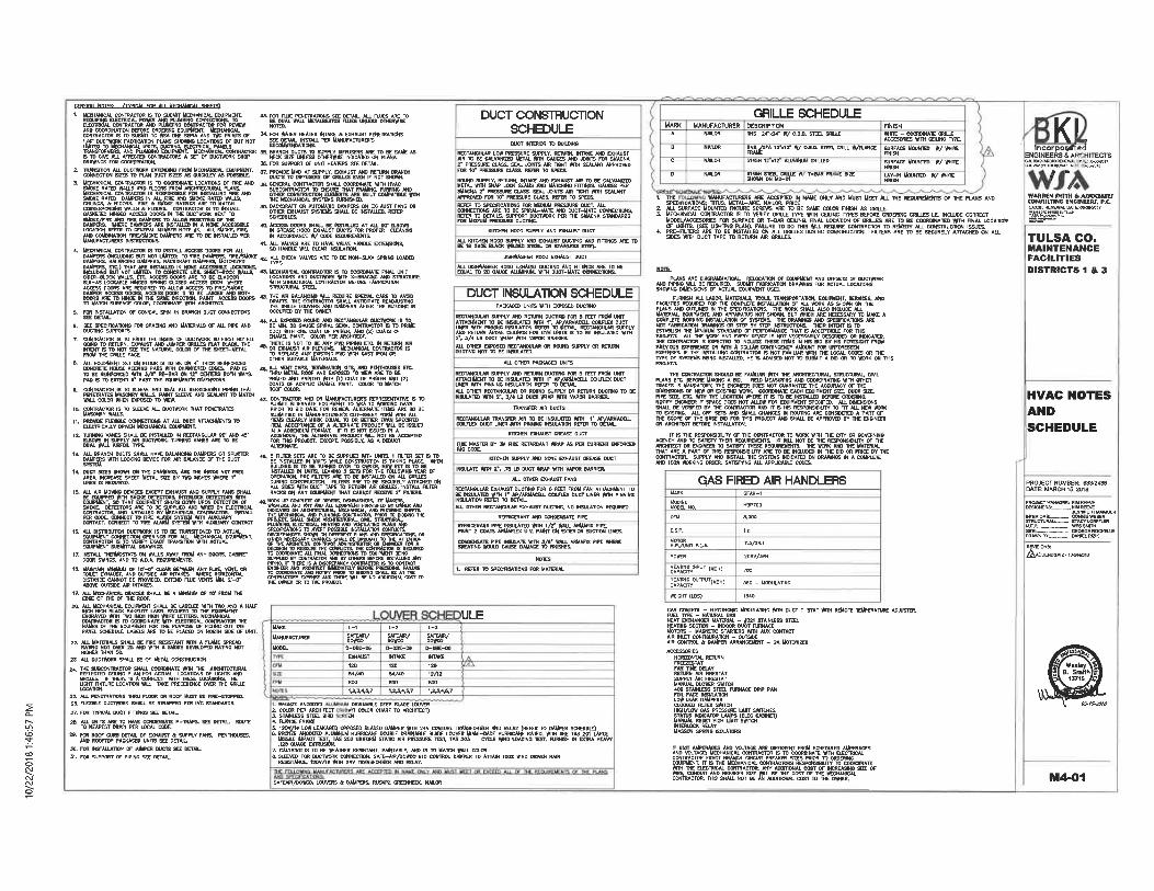
GENERAL NOTES- /TfftCAL FBR ALL UECHANICAL SHEETS^
I
^^a<sy«wo"^@ag;CI%s£^E*ikCTOR IS TO SUBMIT TO ttSA OWE SEPIA AND T<10 PRINTS OF
a^^^%s8Nmc'°8s *SET" ["JCTW'K ww \z sa!a^5'%n3. iS°S&8mS'i£3S':&^S". £T' ;1 ^CHM41CAl_co'!l.TRACT°n ls TP-COOI?*<A'!ELOCAJ1WS OF .nftE * ;[;KM-i%&^jS"^&~i«T °
SUOKE RATED DAMPERS IN AU-.FmE ANO SUOKE RATSSD %^FcMg%w£ -CASKFIED HINGED ACCESS DOORS M THE DUCTttQRK NEXT TO
-
SKSiSSSg3'SSS^'*m "ETO BE INST<t'B '.B' ,4> UECHMICAL CONTRACTOR IS TO IHS7AU. ACCESS DOORS FOR ALL
(INCLUDMC BUT NOT UMTTED: TO PRE DAUPERSi, FKE/SMOKEBALANaNB DAUPERS, BACKDRAFT
5U(-A5 LOCKABLE HlKffiD 5PmNG CtaSED ACCESS_ DOOIl. WHERE
TD MATCH SURFACE COLOR, COORDINATE WIN ARCMITECT.
1. FOR frATDt HEATER INTAKE * EXHAUST PEHETOATIOttS
sEcffly<i!£L"RM"u""'"°'sL SStS^S^WS^"I. FOR SUPPORT OF UNIT HEATERS SEE DETAIL
'. K°E,."Sl,&5r«Y'<i.''!£SS«g!°iF'iE«y»S!!m
'. S5§. "T*^?sS)i'L^^gEi'%?SS "'. s^s°&«a^&'gs^J»^sr ss&
IN ACCORDANCE */ CODE REBUIREMENTS.
41 UECHAKKAL CONTIIACTDR IS TO COORDINATE RIAL UNIT
.%>?%ci!S^S!S5"£SSE m&!S&, g?ium'"eSTRUCTURAL STEEL
u S^, 5Sfi.,"^E%|ft^3»S;£^g^o!a?g«g, '""""" TE"U""'ls
GOING TO RETURN, DWAUST AND JUUPER^ GRILlfS HAI Bl. ACK. _THEIS TO NOT SEE THE NATURAL OOLOfi OF THE SHEET-1
THE CTlLtf FACT.S. ALL EQUIPMENT SET ON njOOR IS TO BE OH-t' THICK REIHFDRCED
DGNOSTE HOUSE KEEFIHG PADS #TH CHAUFERED EDGES. PAD ISTO BE RBNFORCEO WTH 3/T RE-BAR ON 12- CEHTCRS BOTH WAYS.PAD IS TO EXTCHO B' PAST THE EQUPUENrs D*(ENSOKS.
WAU. COLOR WEN EXPOSED TO VIEff.10. CONTRACTOR IS TO SUEEVE AU. DUCTttORK THAT PENETRATES
WAU. S.11. PROVCE Fl£MBt£ CCT{NECTONS AT_ALL_?>UCT AmCHWENTC TO" EiEcrarMu??'Bmv5i'TMECHUi'iu£'E5ui>»i5iT.12. TURNING VANES SHAL1. BE lNSTiUl£D IN RECTANCULAR W / 4S'
ME EQUIPMENT TO tBA 10 WRMKS DAYSPfflOR TO BID DATE FOR REVIEft. ALTERNATE ITEMS ARE TO BE
a^«'TUK£"SS°^'S?-, S% 'S& S?Tl,!all^!!ias t. 'LywScw?:S5WK '!s"s
14. DUCT SCES SHOW) OH THE DRAWNCS. ARE THE WSIOE NET FREEAREA. IHCREA5E SHEET-MEJAL SZE BY TfrO INCHES *HERE I*UNEH IS REQUIRED.
PER CODE. CONNECT TO FIRE ALARM SYSTEM ftTti AUWUARVCONTACT. CCMHECT TO FIRE ALARM SYSTiU WITH AUXUARV CDKTACT
K ^?a'asg%s^TassL"sti^T.
" ^M^^^?KSS>'. 'S"JIS"^"?BS.S,g%,^°, «"«TFS!SB >-"""'FIUE <ENTC 1""' 2'-°"
FOR THIS PRCUECT. EXCEPT. POSSIBLY. AS A DEDUCT
Z"l&?B".iS?t, «ftLT»&T°*, F^^fe'SB. ';"nSE,n'
RACKS ON ANY EQUIPMENT THAT CANNOT RECEIVE 2' FILTERSL
PROJECT. SHAU. CHECK ARCHITECIURAL, OVL.
^WMHioiBCiSc-
WW Tft) INCH HIGH ttHITE LETIER& MECHANI'IE^^S'^E^^S"^PANEL SCHEDULE. LABELS ARE TD BE PLACED ON tWRIH SIDE OF UNIT.
a SiT *S5'SSF. %"'SgS!HICHDl THAN 501,
23. W. DUCTWORK SHALL BE OF htTW. CONSTRUCTION.
25. ALL PENE-TOATIONS THRU fUXft OR ROOT MUST BE RRE-STOPPED.28. FLDOBl£ DUCTWDRK SHAU. BE STRAPPED PER iMC STANDARDS.
37. FOR TWIUU. OUCT FITTINGS SEE DETAIL
2'lw<&T*'»»a"^tSaEEgi?p-m"'isEEDET- "°"E
a-F<S^Sm.S%0°;«^£^n'VF*NS- "NTHaj sES'
30. FOR INSTAILATOK OF AlUPER DUCTS SEE DETAIL31. FOR SUPPORT OF PIPING SEE OCTAIL.
DUCT CONSTOUCT10NSCHEDULEDUCT WTERIOR TO BUILDIHG
RECTANGULAR LOW PHESSURE SUPPLY. RETURN, INTAKE AKD EXHAUSTAIR TO BE CALVANIZED METAL ttTH GAUGES AND JOINTS TOR SMACNA2" PRESSURE CLASS. SEAL JUNfTS AIR TIGHT WTH SEALANT APPROVEDFOR 10T PRESSURE CLASS. REFER TO SPECS.
BEST SiGpa*p"E»^WiiKS n<S,N^K£&w'g'SUACHA 2' PRESSURE CLASS. SEN. JOINTS AIR TIGHT WTH SCAUWTAPPROVED FOR W PRESSURE CLASS. REFER TO SPECS.
PRESSURE DUCTIHCL
KTICMEN HOOD SUPPLY AND E»1AUST DUCT
D1SHIUSHER HOOD EXHAUST DUCT
DUCT INSULATION SCHEDULEPACKAGED UNOS WTH EXPOSED OUCTINO
RECTAN6ULAR SUPPLY AND RETURN DUCT1HO FOR 5 FEET FROU UNrT
2', 3/4 LB DUCT WRAP WITH VAPOR BARRIER.AU. OTHER EXPOSED RECTAKCULAR OR ROUKD SUPPLY OR RFIUR1DUCTMC NOT TO BE IHSILATED.
AU. OTHER PAOtACED UNITS
RECTANGULAR SUPPLY AND REIURtf DUCTINO FOR 5 FEET FROM UNrTATTACHMENT TO BE INSULA1BB WTH_r_AP/ARMACOL COIUUX DUCTUNDl WTH'PINKIW INSULATON REFER TOAIL OTHER RECTAKCUUW OR ROUND SUPPLY OR RETURN BUCIINO TO BEKSULATED WTH r. 3/4 LB DUCT *P W7H VAPOR BARRIER.
TRANSFER AIR DUCTS
KITCHEN EXHAUST CREASE DUCT
3M PRE RETWtDAKT WRAP AS PER CURREDT
UTCHEN SUPPLY AND NDhE EXHAUST OREASE DUCT
INSULATE ttTH 2', .-B LB DUCT KR WTH VAPOR BARRIER,
ALL OTHER EXHAUST FANS
RECTANeULAR EXHAUST DUCTIHC FOR 6 FEET FSOU FAN ATTACHMENT TO.NEsa«mE&"',o'£is?"CEU"T °UCT LINE" *'" PIN>""6AU. DTOER RECTAHCUUUt EXHAUST DUCT1N?, NO INSULATON REOURED
REFRICOiANT AND CONOEMSATE PIPE
SlKATNG t»OUU) CAUSE
NOTES
1. REFER TO BPECIFICATIQNS FOR MATERIAL
GRILLE SCHEDULE
UARK
MANUFACTURER
MODEL
L-1
ISSVO-DBE-06
EXHAUST
L-2
%^/D-DBE-D6
INTAKE
L-3
%syD-DBE-06tHTAKE
ULE
I DRAIHABLE DEEP BLAOE LOUVER2. COtOR PER ARCHITECT Uff COLOR CHART T3 ARCHITECT)3. STARLESS STEEL BIRD EX4. FLANGE FRAkfc
i^sa's'if.' ESS ffiSS?%5'TS3"2")2"uu8lSSE 5SS'u"VSS^Sil°Sy~S& S«mEfilE]N"c*'Br."]'BN"£ Ti!5tiSAUSSEw.125 GUAGE EyiRUSION.
7. CAUlKIXe IS TO BE WATHER RESISTANT, PAIIfTABLE. AND IS TO UATCH WAU. mLGfta. SLEEVED FOR DUCTktoR K COHMECI1DN. SAFE-AlR/UOWO 610 CWWOL DAUPER . TO ATTAM lOOX ttlND DRIVEh RAIN
RESISTANCE, 12DV/K W-TH 24V TRAKSFWlitDt AND RELAY.
5»(FEAIR/TOWCO. LOUVERS * DAMPERS, RUSKW. CREENHECK. NULOR
MANUFACTURER DESCRIPTIONKAIQR RNS 24'K24- ff/ O.B.Ot. STEEL ORtUX
HJULOR
NAI.OR
NAIOR
^^DPA 12-X12- ft/ Q.B.D. STEEL GRILL tt/FLAHCE SWFME UOUKTED #/ WITC5145H 1 >12 ALU IMU GRILIED
FIHISISURFACE UOUNTED #/ W"E
IncorpiENGINEERS S^ICHITECTSass'sssass "ssss"'
11<.%SSSB ),?«U£" T-"""i Em fr
'; y^^S^SSi^^'<UK. W':'M°.. u'5\um'iL mE "E°""'alE °F "Fws *>'°2. ALL SURFACE MOUNTED FtXIURE SCREVfS'ARE TO BE SAME COLOR nNISH AS GRILLE.3. MECHANICAL COKTCACTOR IS TO VERIFY GRILLE TVPE ft7H CEIUNG PrPES BEFORE ORDERING GRIUES LE, tHOJUDE CORRECT
MODEL/ACCESORIE3 FOR SURFACE OR T-BAR CEIUNG. nNAL LOCATION OF GRILLES ARE TB BE COORDINATED WTH HNAL LOCATION
PLANS ASE DIAGRAUMATICAL RE10CAT10N OF EOUPUmT AND OFFSETS OF DUCIWRKMS!S&£%!SS§UA§SS%<Egss!NES ss SSSS5 1SA°U<5?*"
m«nmTNsf»tunioi<"c«-~sisias:"T KAmS'wsSSSATiiiiis AK'KOT FAmcAIIDK DRAVmGS OR SIEP BY SIEP INS-TRUCTONS. THEIR INTENT tS TO
ESTMUSH THE UlWMuU STANDARD OF _P_EnFORMJU(CE THAT IS ACCEPTABl£ FW THISPROJECT. ALL THE WORK AND EVERY DEVICE IS NOT WCESSAmLT DESCRIBED OR INUCATCD.THE COH1RACTOB IS DtPECTEO TO INOJUOE THESE ITEMS IN HIS HD GV HIS FORESIGHT FROMPRCVICXJS EXPERCNCE OR WTH A DOUJUt CONTNGENCY AMOUNT FOR UW-ORESEEKEXPENSES. F THE IHSTAUJKfi CONTflACTDR IS NOT FAUlUAR WIH THE LOCAL CODES OR THE7WE OF SWIEMS BBNC INSTALLED, HE IS ADVISED NOT T& SUBMIT A BIB OR TO WRK OK THIS
THE COM7RACTDR SHOUtfl BE FAUlUAFt ItlTH THE ARCHnECTUftAl, STOUCTURAL, OVILPIANS ETC. BEFORE lllAKWC A HD. RElfl UEASURIKC AHD CDOROtKfA'nNG WTH OTHERTRADES IS MANDATORY. THE ENQNEER DOES NOT WWWTtE THE ACCURACY OF THEMUEWICKC OF NEW OR EOSTWG WRK, COORDINATE EACH EQUIPMENT SZE. DUCT SBE>PIPE SIZE. ETC. WTH THE LOCATDlf WHERE mS TO BE lh|STAU£D BEFWE ORDEfflNG.><OTIFY_OIGIh!BmJF_5f>ACE DOE:s_N<":. *LU>tt FUR. EWIPUEMT SPECIFIED. ALL DtyENStONSSHAU- BE VERIREB BY THE CONTRACTOR AND IT IS HIS RESPOKSBIUTf TO OT ALL NEW WW,TO EMSTIHCL AU. OFF-SCTS AND SMAU. CHANGES IN ROVTNC ARE CONgDDlED A PART OFTHE SCOPE OF THE BASE BID FOR THIS PRQkECT AND SHALL BE APPROVED BY THE ENGINEEROR ARCHITECT BEFORE iKSTAlUTON.
_IT S THE ffiSPOWSIMJTf CF THE CONTCACTOR. TO NORK 1MTH THE OTf OR GOVERNWOAGENCY AND TO SATSTlT WBR REOUlREUtNTS. IT ttU. HOT BE THE RESPOHSIBUTY OF THEARCHnECT OR WSHQK TO SATINY WESE REOUIRfflaiTS: 1HE W3RK-AK6 THE-UATCftlALTHAT ARE A PART OF THIS RESPONSIBIUTV ARE TO BE INCLUDED W THE BtD OR PRICE BY THE
S8^"£.KSiiSPS»5D5a?'E*^^&£E"^E" ">'"<°s"'"
as?-
TULSA CO.MAINTENANCEFACILITIESDISTRICTS 1 & 3
HVAC NOTESANDSCHEDULE
GAS FIRED AIR HANDLERS
SSg?LE»^CFU
E. S. P.
H,P./UNIT F,LA.
POWER
"STSerl""T <"'"'HEATING OUTPUT(. uBHlCAPACITT
WEIGHT (LBS)
CFAH-1
H9PTOO
a.ooo
1.0
7. 5/2*.!
20BV/5PH
700
S60 - MODULATING
1&40
°~""::-:-li^""»;?::5Sfc::^S?SlS?S«^SS.iTn^rr: S5S^mELI'
/^ADDENDUM 2.
GAS CCW1RCL - E1ECIROMIC UODUlJtTIMC WTH DUCT T-STAT WIH REMOTE TEMPERATURE ADJUSTCR.FUEL TYPE - NATURAL GASHEAT EXCHAKGER MATCRIAL - f3ZI STAINLESS SIEEL
I^S^^_WR CONTROL & DAMPER ARRANCEUEHT - &A UOTQRIZED
ACCESSORIES
ESSft"T"1FW^lBE DELAY^"iESRli»"Tags"s£%. »*cE«,, p*«BtEgSS^rS^*FS"SS"E"''J».T"SSKSil'^MKS"""'INTERLOCK REUYUASSON SPRING ISOLATORS
r..u".*!ffi^E."fi..<P"*!S.SE."i"5?<I.iS2'..a'T"B *.£"'"'.|S%?ES^%K^^BSff^aM-:;
iT. IT IS THE MECHANICAL CONTOACTORS RESPONSIBaJTC TO" COORDIKATEftTH THE El£CTOICAL_U»r!RACTDR. Wf ADOmWAL COST OF ,IMCREAS»(C SIZE OF
M4-01
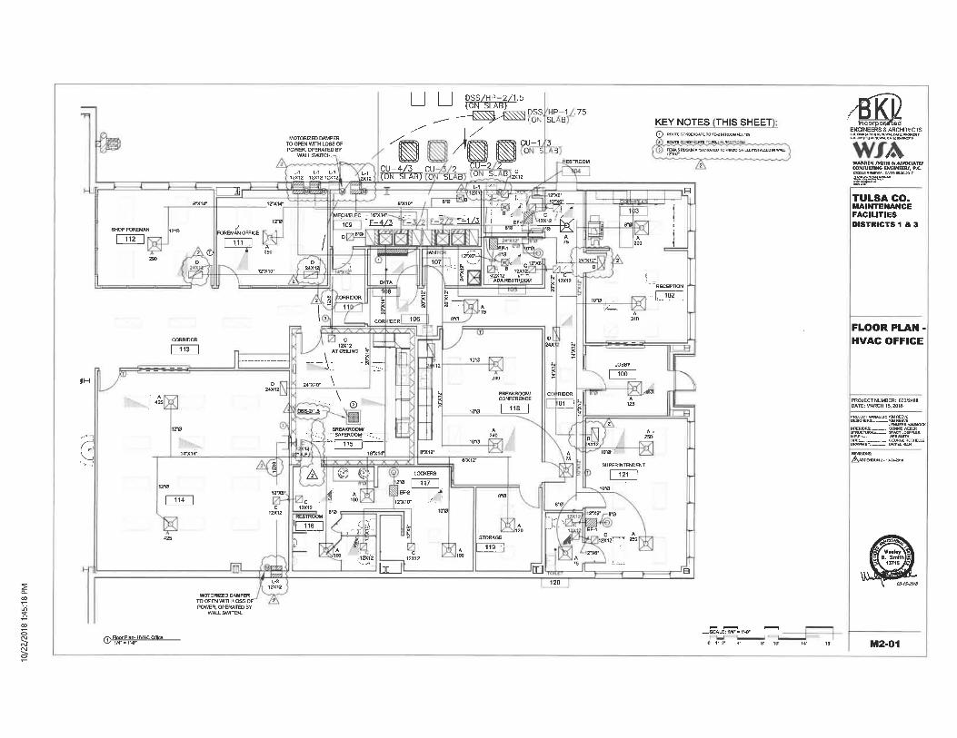
DSS/HP-2/1.5(ON SLAB)
DSS HP-1 .75(Ll^ SUB -
MOTORIZED DAMPERTO OPEN WTTH LOSS OFPOWER, OPERATED BY
WALL SWrCH.
L.1 L.1 L-1 L-112X12 12X12 1ZX12 »(12
^12'X14"
12-0
SHOP FOREMAN 12^
112
<H
FOREMAN OFFICE
111
2 © ~S~ 290
ORRIDOR
11
KEYNOTES THIS SHEET(T) ROUTECONDENSATETOHMWnoOMNO. IOB
MECH^LEC-16-X14" , . -,-:-
RECEmON
102
CORRIDOR
113
^-.t^.X10-
\©
24X wx
h
BREAKROOM/ C RIDOR
c°Nre,RENCE d^ [
BREAKROOM/"^SAFEROOM: ^
lira
6-X12-
A
10(
LOCKERS
re ^~m~EM J
12-X10- -i-
SUPERINTENDENT
121
RESTROOM
rr-Ti6- -4^s'."
..nx<2
STORAGE
119 '
2-X8- 6-0
:J:^ EM. .!^k imi°=r .£.
D
MOTORIZED DAMPERTO OPEN WITH LOSS OFPOWER, OPERATED BY
WALL SWITCH.
Floor Plan-1-i/4-=r^r
Floor Plan- KVAC Offtaa.=:iM-=r-o-
O- I' 2- 4' ff 10-
icorpoiENGINEERS S, ARCHITECTS
I (AIICH) HeNeffiK. WTE: OWO^OIT
/\>/MIIHING Eh INEEW,
RENEWAL
^5S!.~-
TULSA CO.MAINTENANCEFACILITIESDISTRICTS 1 & 3
FLOOR PLAN -HVAC OFFICE
A-tAODENOUM2.1M*a>1B
M2-01
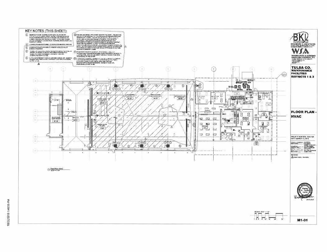
KEYNOTES THIS SHEET :
COMBUSTIBLES BEFORE KSTALUNG. VEnFY Wim OTHER TRADESAND OTHER MATERIALS S EOUIPMEHT MEmiGWD n DOCUMENTS. I.BLWASH BAY CURTWI.
COOOTRWTC irems nxTUREs LOCATIONS wrm WATERS AND FANS.
COOROfftoTEEWCTLOCftTION PLTMOVEWTVeHICLEEXKWSrSYSTEM UWM OWNER.
® ElSS^SS'S'TS'.SSSp'ESSSSifnSflES""" ®?t'"o^iT.J.TT«. «MBL. «T»B, umT. tnFn
S;g?E'«»To"U"CEK'ilSo'E»%;.PS^^SE°S«"ES° ^'";S£.T.T;^5>T^IS:5i;"S^?5. °.".
. 6 JPROVIDE AND IMSTALL STRUCTURE MOUNTED FW), MODEL-BB AS3 FAKS
'S^1^Sffij«"«^^£EZP SSS»"uFILTER. UNIT IS TO BE COHTOOL1ED WTTH DIGITAL WM-L MOUWTED
INTERLOCK WITH FIRE ALflRM SYSTEML FAM IS TO BE WATER RESISTANT.MOUNT WITM EXTENSION TO LEVEL FAN WITH UOHTS AHD MISSSTRUCTURE. WCLUOE APPROPRIATE MOUI^TOIO SYSTEM FOR STRUCTURE,LN5TALLAS.PSlwANlr?c1UR_ERReauiReMewT^HUWTOWi°wcroAIR
FANS eEARlESS DIRECT DRIVE FANS ARE ACCEPTED W WME ONLf ANDMUST BE ACCEPTCD BV OWNER.
OPERATIONAL AS PART OF BID.® SK^F!.SSSS«°«"^'S';SE;,n.f2SSSS;S!!m ®°l"B.1"l°;"E:a'.s£"us55
^^. KO?IS^ ".st;UHNtu' - iiTSI fcM 15 I U Ht 1DUI Un:KAI IUNHI. ^/ DLCT TO^BE ROLTren BiBI^EMWULAMDl
A
?-_-i-_-. l-_-_-
®.
r'y'wTv^ '^'^ "y y^-^y ' ,©7-^7±^1-4V:'<3^. a-''-i// / /ir&&@f/Li///"(%©
l^^i^^(. yj^f -^^.y / //0 . fs^'/ A /. ' wm ' / u
y//?/// ^ /"\y y /u/
t!z_^'. /^/^ ./^-^7. -^- -^1-
M106
§
3 t
f ,!
'" 01
u/_®/_Az '^ ®
^^^--F- s»r'3 B3 iJSi '" .
j3 ^-3 [3 (Si
^_4^^:±^:T-~~T-
incorpoi^fted
IKii^^s!^CA SKS(PE)RENEWAL OMi; ilWM01S-
TULSA CO.MAINTENANCEFACILITIESDISTRICTS 1 & 3
FLOOR PLAN -HVAC
I i'BE"T:'. --;-
DESIGNERS-. -:
imERIOR&_-,._iTTOCTUWI. ;;-;.^
KIM REEVE. KiMREVEJENNfERN.MXOCKCONWE WEBERiTACYLOBFFLER
GEORGE KOCHELLEDANIELRizJk'
?SCALE: 3/32'=r^r
^ 0' 2'4> S' 12' 16' 24' 32' M1-01
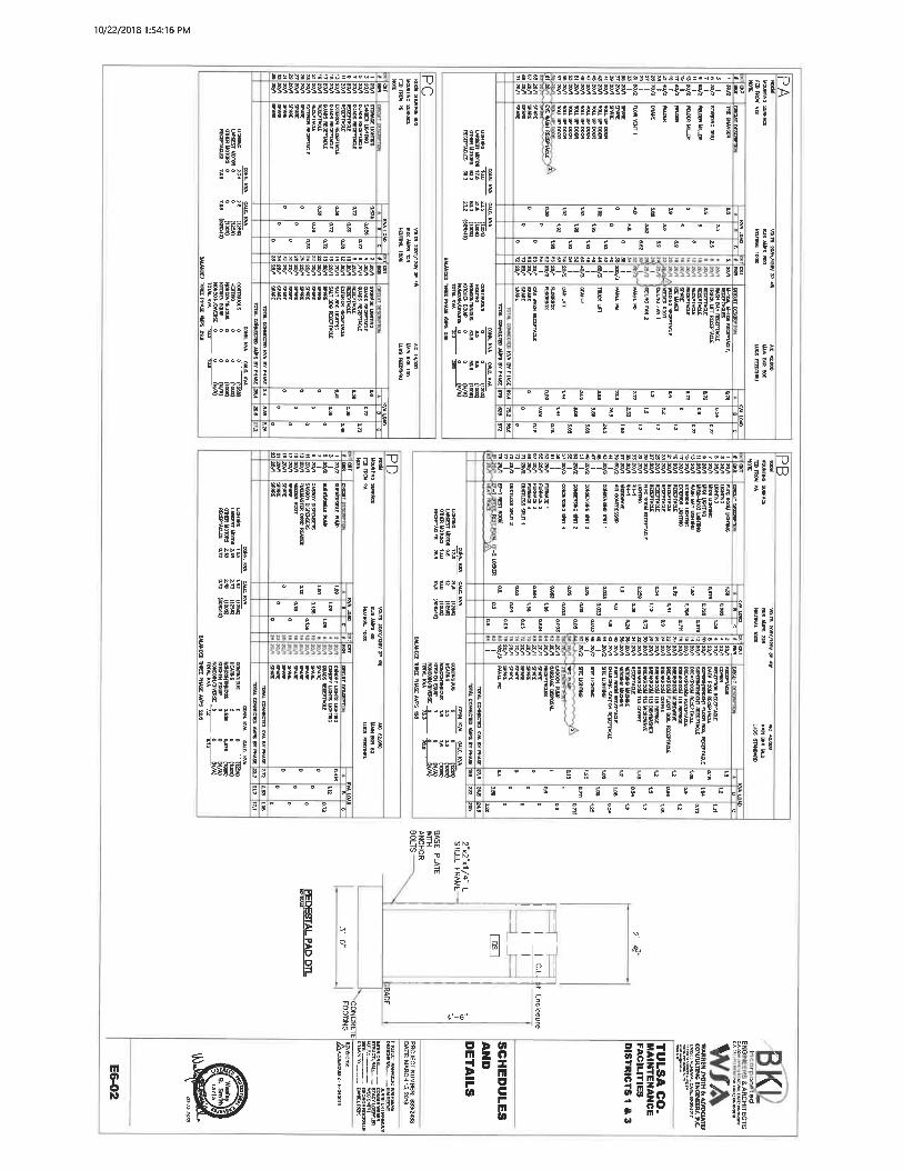
10/22/2018 1:54:16 PM
l«8B>!>IB8aS3S53--""-
^^J§S§SS§5§I^I|(1(^mm
Sg
asss 2 g8Btssi!fis&»yit!ays9BBti»^uti, t=">~'
^S s il^i^^-|-K-M-^-§331||^>III! i !!!!!!!!!^11 S I
iifS^fSi""" jill
I al sl
S"S|
r°Ki« 8 S
S 3 § !-!« a isa "
i8i',"3S. ':8S.;;S3'>-*"-_
!!!!PI^el°°°°°l
|§!|"ggs
^15 3
ISg
IIs|3j
ilsSE ° °° £g S
gs°° °s s §
Bss. isas. -. ^-
^^^_^, gjjj|^
II
§B BB°S gS-S SIjjl5 ° °«Sg°ig s -. a I
S5 s s °aaaass?efcsssstlsssiee
^^^-gs-s-i-i-f-
e s . sill
;33
!i!is
5 s ' 311|
p-gj^r^iiii
IllIIs
^i3.! ° i S e§g°S t S 83g° S Sg; S
8 S S °5 ^
8s a S5 g
^yBia=i838a28a88B6SjtSfigs!ByaByt?yh is^u;i;=:<ft«
SSSell|i
§S3g||° S B S
S3
IJgijSj
rriiiUHi
3s
Eii'
ili
'ISIjl
-§-^5^-§-§-g-Ks§^§§§§§^^S§^§ " jl js ro
1'i | S U| j I | |J|
§
gg5£|
sesg|slls
I Will
EijlS S|e|S SejSeSS. i g|s ! SE a I l. l^g
5 ^g| |e| s^ ge ij 5|"si^SStStS6SSiSSS^VC-ss-i.. s-"-\-f Ig
-p^ssfssss s-T|!i§^§§sl§IJI51§sssi3 » "^t
aitl!i°e8°|III
sg S °Ss s °SS5 ° °
"I?"
S SSG ^CCg gSISs!si ss e
Sblcs'tSgs
SESIllI?'
SEIS
§lj! |g^ 3<
A.
I If!!ESiSi
III!:iPIII:
Ei11 11!11
I118° m
^11-
til,.s
ill
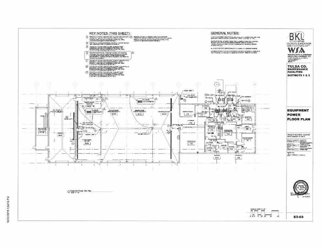
KEYNOTES THIS SHEET® 3SSS«m°5SSHU'p«'. SS:?S-^aSEK'"""° ® S^S^.SSSSSSi^SS^^
®
©
®!
UECONWECT EWTTCH,
fSSSSSSSSSiSSUSCOWIECT SWTTCH
DI^QMNECTSWTCH.njSESSI^K'&TmSKLIFT
kWIUFACTURER WSTALL'ACCESSJBli AS PER'NEC. 'nNALP&"'""A'I. ;<-'B . : ' . r
I SHALL BE EQUIPPED
^^^SSS^SiK-SS^^'HEM<t3RFUSEO
LOGATIOH TO BE COOROmATE IN THE BEU).
ESS8e«??f5Sfg,LS.'Sa%,1,,SK"n'E°LOGATIOH TO BE OOOTOINATE IN THE FIELD.
E^££ET?^ST3iLfsSE?S£5S'^'«'S£2§?'ESS,liS£'Tl.Rg'S,Sii,«"gf»%t«".PE'
LOCATION TO BE COOROINATE IN THE FIELO.
GENERAL NOTES:
'^sss. 'ss'xssyss^ii'sss^.CGKDUCTDRS, ETC,
AU. BUSSMO IS TO BE COPPER. MCLUDING NEUTOU- AND OROUHD BUSSING.
] r ed& ARCHrECTS
WABREN tMITH t. AWOtUmCON/ULTINO EN6INEERT. P.C.CA128S RENEWAL [M7.fflissss.a-w^'
TULSA CO.MAINTENANCEFACILITIESDISTRICTS 1 & 3
GFAH-t _©."_TRUCK UFT-*
- WASH BAY
M 105
-Y^"^--^TRUCK LffT
'.;!< , \t^"°«~?;, -I-,1-*A-24^B;pg(ioN,»i
CRAMPiNANCE BAY 2
M101
d)^
PA-31. 33 -| TSrcD-t/3- 9-57, 5fl,M3A-UMOG | p,_,^
'0 ©D5;
MECWELEC PB-71.73
F-4/ - /F<JR E>. -raFFe?E
9-S1 PB-43. 4S.47
CU-1/3(a)
-' ^=lr
wr^ ^^""^ "^
"".;w^cauNB. rAN 2 .
-4I^E ---
SHOWER117A
EQUIPMENTPOWERFLOOR PLAN
DRAWN BY:.--.- DAWH. RiaK
REVISIONS:/^ADDENDUM 2.
Q>^
SCALE: 3/32-. 1'-0"
I OT 2' 4- 8- 12- 16- 24' 32- E3-03
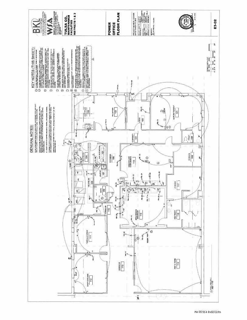
ll,
^^. Jll.8
n
" <
Ill, 1111lliii PS S 3
Jni S" tt
IllS. 0 IL,
ii if
Ill
lili11111
li
S !<!
I
11 lii II ill
I- jS 3.ES! i5i Sei
ill Js
III!ill B!
il^ilii ill
QQ © Q ©QQ^lQffl tE
J8II iliiII III
^ II III I II I
^ II III!' I II IIs !1 I II 1§
g1 "
^
©I
E
s
'-L,KS
B
G
* ®
I @.-S
^' ^^!n?Sll
©.
®
I®
Q
l^n^i -s ^'
nil
?
s-
8|'~
|?| s
r^1@ -\f1\/
©
u46,
-^
|A|d Z£:SS:t 8LOZ/ZZ/01.
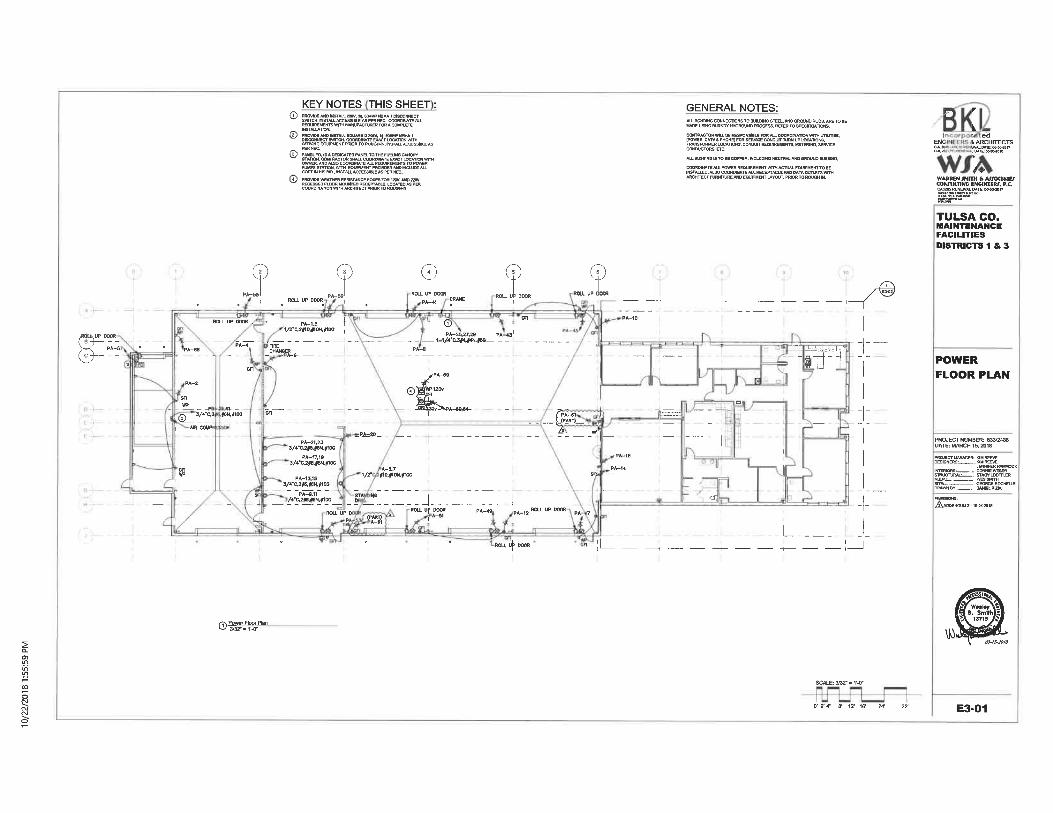
KEYNOTES THIS SHEET :® PROy!DE_ANO. MSTALL_20By. 3*.-anAW'-''IEfcll*_1_DISCOMHECT
335&Bg%L»SSS;S&"wS!,'gii.cSSSS;?"
DISCOWECT SWITCH. COORDINATE BWCT LOCATION uvm?"s>?©
® PAMU FO._IS A DEUCATCD PANEL TO THE FUELING CAHOPYSS^^^^jy^SCOSTINHISaD.IHSTWJ.-
GENERAL NOTES:
lU-LCOoaDiNATiQNwnw unLmEs,[POWER, CATV B PHONE) FOR SERVICE CONDUITTURN UP LOCATIONS.TRWSroRMER LOCATIONS. CONaulTREOWtEWIENTB. METERIHO. SERVICECONDUCTORS, ETC.
ALL BUSEINO IS TO BE COPPER. MCLUDWO NEUTRAL AND GROUND BU3SWQ..
COORDINATE AU. POWER REQUIREMENT WTIH ACTUAL EOUIPMEWT TO BEINSTftLUED. ALSO COORDINATE ALL REGEPTACLE AND DATA Oim.ETS WTTHARCnrrecT
i ARCHFTECTS
^
ROLL UP DOOR
©ROLL Uf DOOR
©ROLL Uf DOOR
TULSA CO.MAINTENANCEFACILITIESDISTRICTS 1 & 3
/ROUs, UP DOOR( B-)- - -
PA-6(^. "--
®_ 3/4"C^ f6N. if10G
1^:Z'
_PA=20_ _ _
^-!
PA-81
-T-
POWERFLOOR PLAN
ISSS".'""" S!" BE"JENNIFER HftMMOCI
^^= ;S^"E"
/«^^__iK j1^ _____!_
~-~~^r~^^L.
RGU. UP DOOR
_-L . __
AADDEI:NOUM2-1M«-201fl
SCALE: 313Z- = V-V
D- 2-4- 8' 12' 16' E3-01
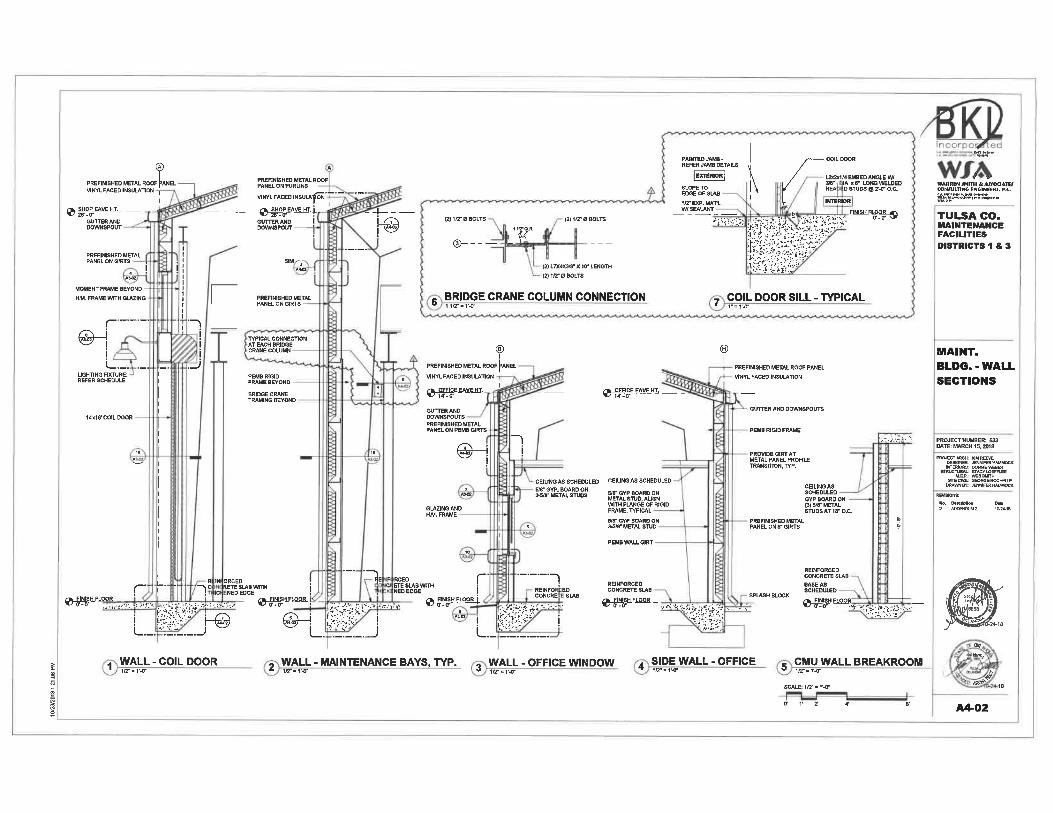
PBEFIN15HED METAL ROOF |>ANELVINYL FACED INSULATION
VINYL FACED INSULA1
^^eWVEHT.,.GUTTER ANDDOWNSPOUT
PREFIMISHED METALPANEL ON G1RTS
A»4H
MOMENT FRAME BEYOND
H.M. FRAME WITH 6UCING
(----
\>_._. . _.
UGHTING FDUURE;REFER SCHEDULE
i
.nI
IJ
GLTTTERANDDOWNSPOUT -
SIM/-
.AWO
PREFIMISHED METALPANEL ON GIRTS -
TTPICAL CONNECTIONAT EACH BRIDGECRANE COLUMN
PEMB RIGIDFRAME BEYOND -
BRIDOE CRANEFRAMING BEYOND
14'xie'COIL DOOR
<I>-- -s(2) L7X4X3ffl" X W LENGTO
(2) Iff- 0 BOLTS
BRIDGE CRANE COLUMN CONNECTIONliar-r<"
PREFIN18HED METAL ROOF 1-ANEL
VINYL FACED INSUIATION
L2x2x1/4 EMBED ANGLE W/31V IA X 6" LONG WELDEDHEA, 0 STUDS ® 'Z-V O.C.
y^WBeEK __ _GUTTER ANDDOWNSPOUTSPREFINISHED METALPANEL ON PEMB GIRTS
n
CEILING AS SCHEDULEDSB" GYP. BOARD ONMffi" METAL STUDS
CEIUN6 AS SCHEDULED
sr_evp BOARD ONMETAL STUD, AU6NWITH FLANGE OF RIGIDFRAME, TOPICAL
FINISH F^[^^.K; . .^. S\i/s, -^;;SY;:S;^ T;?-'w'iwssi^
^y-y^^y:^?A^-1^^^^1^^w^
COIL DOOR SILL - TYPICAL
TPREFINISHED METAL ROOF PANEL
VirfYL FACED INSULATION
GUTTER AND DOWNSPOUTS
PEMB RIGID FRAME
PROVIDE GtRT ATMETAL PANEL PROFILETRANSmON, TVP.
CEILING ASSCHEDULEDGYP BOARD ON(3) 5/8- METALSTUDS AT IF O. C.
^ssstsssysr-,-
TULSA CO.MAINTENANCEFACILITIESDISTRICTS 1 & 3
MAINT.BLDG. - WALLSECTIONS
PROJECT ARCH: WM REEVE
PEMB WALL GIRT
r-R IN ORCED
, C RETESLAB^1C NED EDGE
:.,,. -.... -^-:- y'^:^:^'-^-^ v-s^--^ - .! t^u ^ @-|
-^B,
L._. "i:_._.J
WALL-COIL DOOR}ir ' r-v
RCEO
c^^m"r .--n
iHFLOOR.!V-V ' ^-. ''^ . ^-^ ^:t-^
i^^:::A-- ;.^^^ I
L':!:_. J! ^My'
SPLASH BLOCK
''Vs^^-i.^-. ^. ;»^^ ......
. ^.'. '^''?
WALL-MAINTENANCE BAYS, TYP. , WALL - OFFICE WINDOW A SIDE WALL - OFFICE e CMU WALL BREAKROOM1C-. M- d lu-. r^r "' ic-'iw " iiz-. r<-
SCALE: ira-»r<"
ff r 2
OK
BEK^,
^
A4-02
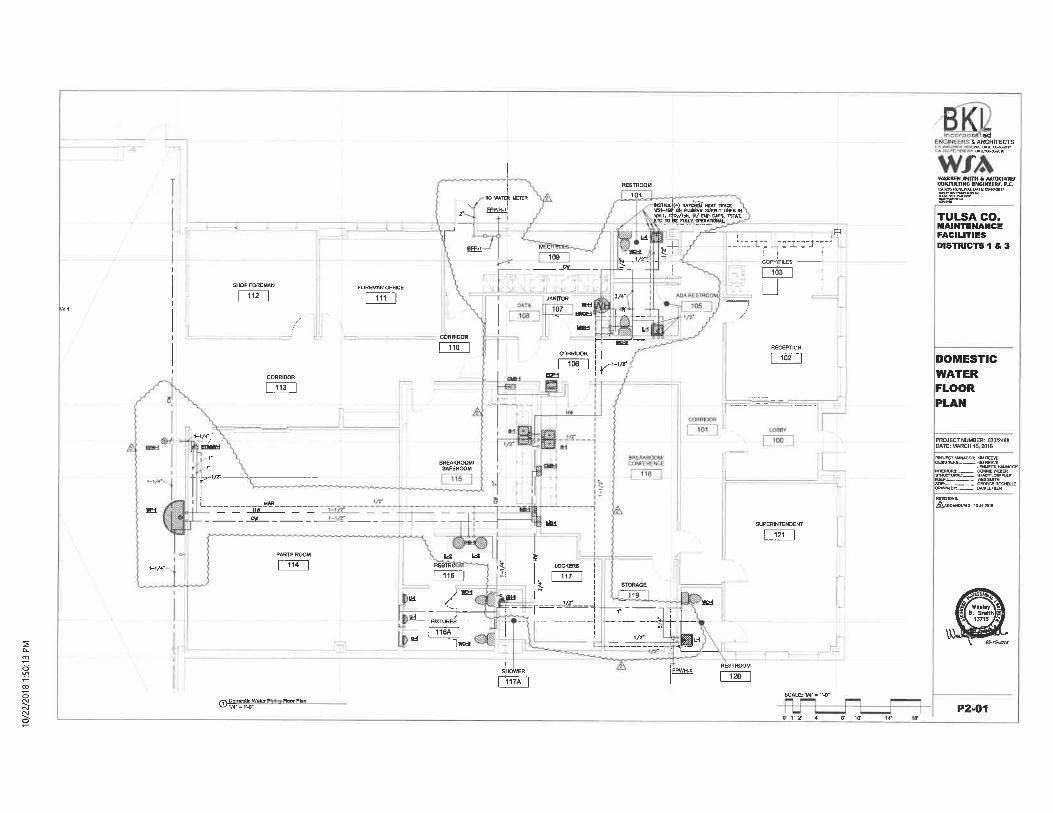
r ed& ARCHFTECTS
SHOP FOREMAN
112FOREMAN OFFICE
111
r
TO WATER MCTER
FPWH-1;
RESTROOM
104
!^(A"^S5^7^,.^^S/&^&. 1W
dT
^s=;,-i-
TULSA CO.MAINTENANCEFACILITIESDISTRICTS IS, 3
r"RECEPTION
102 DOMESTICWATERFLOORPLAN
eriilKM
..^/- EEiS""6AAODEHDUMI-
I ; Water P. 1/4- = r-o-
IU
id
u
RESTRO
116
/FOTTURES
LI
aia
SUPERINTENDEm-
121
T--^-^ ,. --
SCALE: 1/4"-1'-0-
v r 2' 4'
P2-01
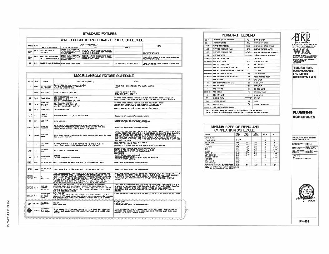
STANDARD RXTURES
WATER CLOSETS AND URINALS FIXTURE SCHEDULE
WATER CLOSEI/URINAL
UANUFACTURER/UOOEL f
FLUSH VALVE/SUPPLY SEAT
a*:
K-2 m^,T^T1CM. TUBE
^^(A. D. A. APPROVED HBGHD
KUtBi K-06U-ET l*]iDOK SUMN IBCM. IB8-1. I BT
BOLT CAPS WTH CUPS
2URN Z-1222-ae OR SUlTH B37-Z S?ES"»jW^m°ESEU"ml"c"*5E*M'
MISCELLANEOUS RXTURE SCHEDULE
srMeoL
t
T
.
.
.
0
0
r^j^j
rft
UARK
FFWH-1
HB-1
ro-i
FD-2
FD-3
CD-1
CGT-1
BFP-t
SOV-1
FIXTURE
FREEZE-PROGIWALL HYDRANT
HOSE BIB8
FLOOR WWN
ss°wRJNNEL
RJOOR DRAIN
gg%
^sat
®%
SHUT-OFTVALVE
UrtlUFACTUREIt/UOOEl /
2UW Z-13U-WC-34EL ECOLOTROL CGRAUtC
ZURN Z-1341-PC-Ut WJUJ. FAUCET
ZH-^f 5-7B-ZN329-7-VP
ZURN ZN-415G-BS-Y
INSINKERWOR WOOEL 77. 3/4 HP AUTOMATIC REV
WTTS SERIES f FAE-908-CfT-S-Htt OR ZURN 87fii)B.-U-5 PBt LINE
^ig'SSi'^SSS&'SS'^SS-""""-
WWTS SERCS DCT OPWSION TANK
lMB-1 ICE MAKER BOX OMEf 38689 METAL BE MAKER BOX WTH 1/4 TURN
1^._Z-11B7-HD-VAC *CO_RESI. STWT CCATO INIODOR A DtTERIOR
STEEL SXND WO SEDIUEW IWERCEFTOR. RELD VERIFV'CU. FT.
S[nLn"-!»T_°^<:..°u!£..-4"-!""E"°'.i"'.<ND. »u!!n_rou»_2-
-K.EyCHROlUte. HNBH
INCLUDE SCREEN OVER DOME SIRIUNER AND SEDl W BUCKET,
IHSTAU. PER MWUFACTURER'S REOOMMENMTIDNS
INSTAU. PER UWFACTURER'S REEOUUENIUTBte.
ar"<S'^3£l£KS""»F.°""FUSHING IS TO BE PER STANUKG SEAU UANUFACIURER'S REQUREUEHIS
ss5&rss'saw«''sszs"&°ss-FREE STWBIHC MOOEIS, SIZE PER UAHUFACTURER'S
n£xisuE HOSE, asr SUDE BAR
INSTML PER UWMTUR£»rs VECOWtEHWmOHS.
CUB-1 ^FEE UAKER CATET 38889 UETAL ICE UAKER BOX WITM 1/4 TUR'N BRASS UUJ. VALVE
gS;»z. ',%SSi5/5m^E i%£MD iS?l?&°Sa. !S°£Sc"S.OIL VISIBLE DOUBLE #*U, TR >_ SEM,. REUfWABLE OOUBIWTOK PRESSURE EOUUJZWV
°" °"ncEra>" iisA^^i^^tg^w^^'^^^?mn^. WB&»g,-u£^i!M5Ai6N''"L
INSTALL PER MWFACIURERTS RECOMWENMnONS.
|Sg|B,Kra^a^pK*sa'si&sM s5;»i''
ssam£is%NamK c;iiKm'*mr"a" -"""^
FW&E^ 2 x 2 1/2)<1/4 ANGl£- 80 LJOHR CAHBOH STCEL FRAME ASSEMBLY. 1/4 X 3ORATE" STUDS WD_COMBINATlMI_AI<CHOR TABS/lfVEUNC DEVICES AT MVWIPSWf. UXWOWM'"~ FOR EUaEDOIHG KTO SURROUtlDHG cdMCRETE COUPLETE WTH CLASS C DUCTILE
INSTALL PER kUNLFACTURERS RECOltUEHMIlOKS *NO IKSTAUATION INSIRUCTOKS. UNIT IS TB
SUPPLY AND INSTAU. FRUilE AND CfyTC IN CONCRETE TOENCH DWUM. OOOROttttTC ftIM DETAIL
PLUMBING LEGENDOEAKOUT (GRACE OH FLOOR)
CIEANOUT (WAIL)
NEW SAMTARY SCWR
NE# AUO ftESfSTAHT DIUUK
NEW *QQ REStSTAHT VENT
NEW ROOF DRAIN
NE# OVER FLO# DRAIN
NE# SimU OXAiN
NEW CCU) WATER UKE
NEW HOT WATER UNE - DOMESTIC
ME* HOT #ATER RETURN UHE - DOMESTIC
NEW TCUPERED WATER UNE
- NE# TEUPERED WATER RETURN UNE
NWGASUWE
NE# CONBENSA7E DRAIN LINE
HE* AIR PIPINC
KEtt PRE UNE
NEW SLEEVE
NEW VENT UNE
EMST1NO STORM
EXtSDKS SAHITARY
EW5T1NC OA5
NEW UTIUTIES UNDER GROUKD
AU. ITEUS SHOW OK LEGEW ARE HOTY ENGINEER IF HEMS NOTED OH PLANS ARE HOT
-EW-- EXISTING WATER
-EHW- DOSTINC HOT WATER
-EHttt- EMSTlNG HOT WATER REWRK
-CTtt- ESaSTING TEMPERED WATER
-ET#R- EMSTlKB TEMPERED WATER RETURN
DEMOUTION (TO BE REMOVED)
Ct CASTRCK
WT vnneous CLAY n£
WH WU1 HWRANT
TH YARD HWRANT
MB HOSE B1HB
VTR VENT THRU ROOF
ATF ABOVE RNISHEO FLOOR
BALL VALVE
VALVE
/ -.^
WMBEN mmi & WnKUTlICONJULTING ENGINEERf. P.C.UUiiiREMEWALI.SSSiSSS'"
TULSA CO.MAINTENANCEFACILITIESDISTRICTS 1 & 3
PLUMBINGSCHEDULES
MINIMUM SIZES OF PIPING ANDCONNECTION SCHEDULE
HIOURE
WATER CLOSET-R^ISH VALVE-FLUSH TAWURWALLAVATORYSINK
SERVICE SINKUOP SHK BASNDRtlBW FOUNTAINHOSE BB8*ALL HYDRANTYARD HTORADT
RESID T1AL AT1C CLOTHES ASHER 3 4"(10T& *U. ITEMS SHOW ON THIS SCHEDULE ARE
NOT NECESSARILY » THE PBOiECT/
1-1/4-
1/2-v<-1/2- 1 .
1
i/r1/2-1/2-1A-
AwDEHDUMi.W - -
iisvy
RJRNISH WH HOKEVWU. AQUASTAT L600aC1(>18
EY^%' iws. coljBntnuj DRE>i:H_simBV_EiE_«UH_um_MoDEi m»-8»«, nm "H^TJ^FS"c. 'Jm^^!!^J'?^. >E5!^.. u!F'l!!. ii<*s.. 8S7.EE*S~' SSSBiiBi s?i28s"SrsSo«a"HE»B";1B'"m»:iD"S5Sr"c!im""«l?iSi®'sia ^^y.^s^^°^l^mrjM*''^"'TCIil"T'«"°'i'>("Ni''iiuE''nXTURE
P4-01
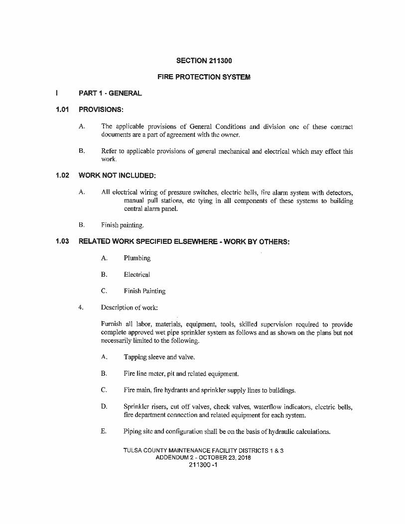
SECTION 211300
FIRE PROTECTION SYSTEM
I PART 1 - GENERAL
1.01 PROVISIONS:
A. The applicable provisions of General Conditions and division one of these contractdocuments are a part of agreement with the owner.
B. Refer to applicable provisions of general mechanical and electrical which may effect thiswork.
1.02 WORK NOT INCLUDED:
A. All electrical wiring of pressure switches, electric bells, fire alarm system with detectors,manual pull stations, etc tying in all components of these systems to buildingcentral alarm panel.
B. Finish painting.
1.03 RELATED WORK SPECIFIED ELSEWHERE - WORK BY OTHERS:
A. Plumbing
B. Electrical
C. Finish Painting
4. Description of work:
Furnish all labor, materials, equipment, tools, skilled supervision required to providecomplete approved wet pipe sprinkler system as follows and as shown on the plans but notnecessarily limited to the following.
A. Tapping sleeve and valve.
B. Fire line meter, pit and related equipment.
C. Fire main, fire hydrants and sprinkler supply lines to buildings.
D. Sprinkler risers, cut off valves, check valves, waterflow indicators, electric bells,fire department connection and related equipment for each system.
E. Piping site and configuration shall be on the basis of hydraulic calculations.
TULSA COUNT/ MAINTENANCE FACILITf DISTRICTS 1 & 3ADDENDUM 2 - OCTOBER 23, 2018
211300-1
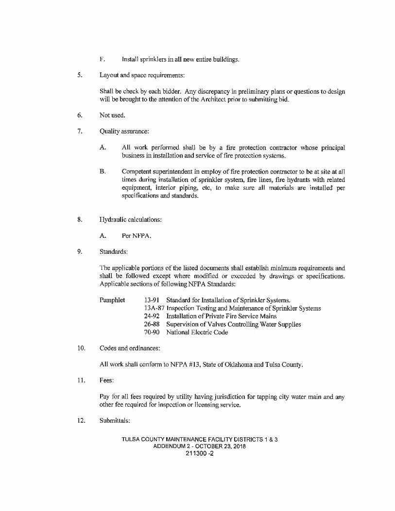
F. Install sprinklers in all new entire buildings.
5. Layout and space requirements:
Shall be check by each bidder. Any discrepancy in preliminary plans or questions to designwill be brought to the attention of the Architect prior to submitting bid.
6. Not used.
7. Quality assurance:
A. All work perfomied shall be by a fire protection contractor whose principalbusiness in installation and service of fire protection systems.
B. Competent superintendent in employ of fire protection contractor to be at site at alltimes during installation of sprinkler system, fire lines, fire hydrants with relatedequipment, interior piping, etc, to make sure all materials are installed perspecifications and standards.
8. Hydraulic calculations:
A. PerNFPA.
9. Standards:
The applicable portions of the listed documents shall establish minimum requirements andshall be followed except where modified or exceeded by drawings or specifications.Applicable sections of following NFPA Standards:
Pamphlet 13-91 Standard for Installation of Sprinkler Systems.13A-87 Inspection Testing and Maintenance of Sprinkler Systems24-92 Installation of Private Fire Service Mains
26-88 Supervision of Valves Controlling Water Supplies70-90 National Electric Code
10. Codes and ordinances:
All work shall conform to NFPA #13, State of Oklahoma and Tulsa County.
11. Fees:
Pay for all fees required by utility having jurisdiction for tapping city water main and anyother fee required for inspection or licensing service.
12. Submittals:
TULSA COUNTY MAINTENANCE FACILITY DISTRICTS 1 & 3ADDENDUM 2 - OCTOBER 23, 2018
211300-2
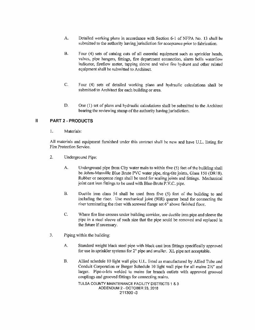
A. Detailed working plans in accordance with Section 6-1 ofNFPA No. 13 shall besubmitted to the authority having jurisdiction for acceptance prior to fabrication.
B. Four (4) sets of catalog cuts of all essential equipment such as sprinkler heads,valves, pipe hangers, fittings, fire department connection, alarm bells waterflowindicator, fireflow meter, tapping sleeve and valve fire hydrant and other relatedequipment shall be submitted to Architect.
C. Four (4) sets of detailed working plans and hydraulic calculations shall besubmitted to Architect for each building or area.
D. One (1) set of plans and hydraulic calculations shall be submitted to the Architectbearing the reviewing stamp of the authority having jurisdiction.
PART 2 - PRODUCTS
1. Materials:
All materials and equipment furnished under this contract shall be new and have U.L. listing forFire Protection Service.
2. Underground Pipe:
A. Underground pipe from City water main to within five (5) feet of the building shallbe Johns-Manville Blue Bmte PVC water pipe, ring-tite joints, Glass 150 (DR18).Rubber or neoprene rings shall be used for sealing joints and fittings. Mechanicaljoint cast iron fittings to be used with Blue-Bmte P.V.C. pipe.
B. Ductile iron class 54 shall be used from five (5) feet of the building to andincluding the riser. Use mechanical joint (90R) quarter bend for connecting theriser terminating the riser with screwed flange set 6" above finished floor.
C. Where fire line crosses under building corridor, use ductile iron pipe and sleeve thepipe in a steel sleeve of such size that the pipe sould be removed and replaced inthe future if necessary.
3. Piping within the building:
A. Standard weight black steel pipe with black cast iron fittings specifically approvedfor use in sprinkler systems for 2" pipe and smaller. XL pipe not acceptable.
B. Allied schedule 10 light wall pipe U.L. listed as manufactured by Allied Tube andConduit Corporation or Berger Schedule 10 light wall pipe for all mains 21/2" andlarger. Pipe-o-lets welded to mains for branch outlets with approved groovedcouplings and grooved fittings for connecting mains.TULSA COUNTi' MAINTENANCE FACILITf DISTRICTS 1 & 3
ADDENDUM 2 - OCTOBER 23, 2018211300-3
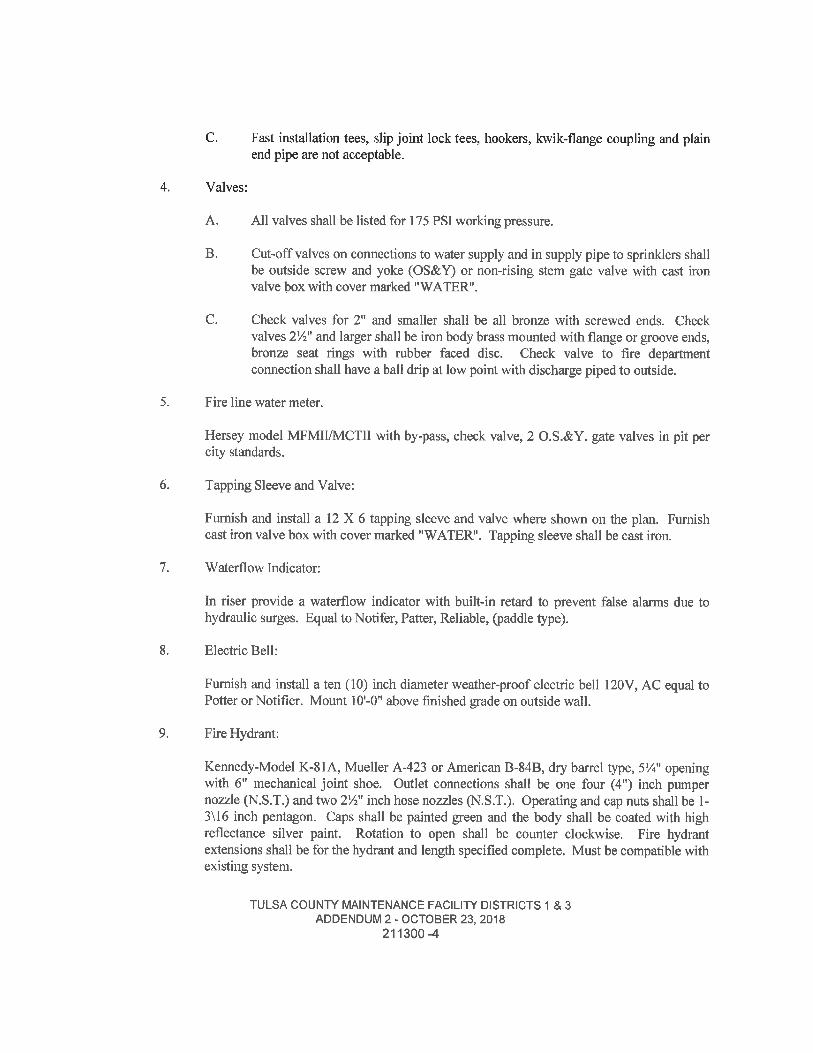
C. Fast installation tees, slip joint lock tees, hookers, kwik-flange coupling and plainend pipe are not acceptable.
Valves:
A. All valves shall be listed for 175 PSI working pressure.
B. Cut-off valves on connections to water supply and in supply pipe to sprinklers shallbe outside screw and yoke (OS&Y) or non-rising stem gate valve with cast ironvalve box with cover marked "WATER".
C. Check valves for 2" and smaller shall be all bronze with screwed ends. Checkvalves 2'/2" and larger shall be iron body brass mounted with flange or groove ends,bronze seat rings with rubber faced disc. Check valve to fire departmentconnection shall have a ball drip at low point with discharge piped to outside.
Fire line water meter.
Hersey model MFMII/MCTII with by-pass, check valve, 2 O.S.&Y. gate valves in pit percity standards.
Tapping Sleeve and Valve:
Furnish and install a 12X6 tapping sleeve and valve where shown on the plan. Furnishcast iron valve box with cover marked "WATER". Tapping sleeve shall be cast iron.
Waterflow Indicator:
In riser provide a waterflow indicator with built-in retard to prevent false alarms due tohydraulic surges. Equal to Notifer, Patter, Reliable, (paddle type).
Electric Bell:
Furnish and install a ten (10) inch diameter weather-proof electric bell 120V, AC equal toPotter or Notifier. Mount lO'-O" above finished grade on outside wall.
Fire Hydrant:
Kennedy-Model K-81A, Mueller A-423 or American B-84B, dry barrel type, 5'/4" openingwith 6" mechanical joint shoe. Outlet connections shall be one four (4") inch pumperno2zle (N.S.T.) and two 21/2" inch hose nozzles (N.S.T.). Operating and cap nuts shall be 1-3\16 inch pentagon. Caps shall be painted green and the body shall be coated with highreflectance silver paint. Rotation to open shall be counter clockwise. Fire hydrantextensions shall be for the hydrant and length specified complete. Must be compatible withexisting system.
TULSA COUNT*' MAINTENANCE FACILIT/ DISTRICTS 1 & 3ADDENDUM 2 - OCTOBER 23, 2018
211300-4
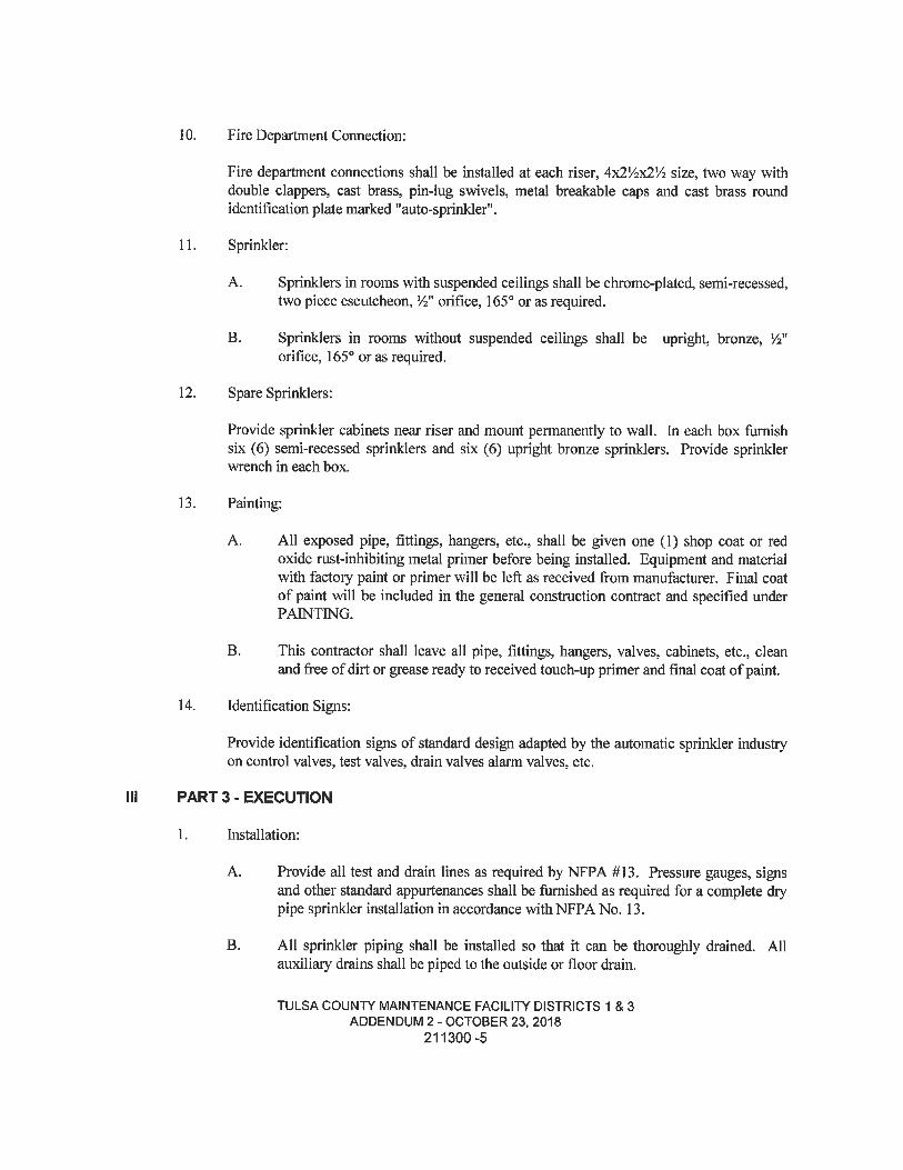
10. Fire Department Connection:
Fire department connections shall be installed at each riser, 4x2'/2x2'/2 size, two way withdouble clappers, cast brass, pin-lug swivels, metal breakable caps and cast brass roundidentification plate marked "auto-sprinkler".
11. Sprinkler:
A. Sprinklers in rooms with suspended ceilings shall be chrome-plated, semi-recessed,two piece escutcheon, W orifice, 165° or as required.
B. Sprinklers in rooms without suspended ceilings shall be upright, bronze, ',2"orifice, 165° or as required.
12. Spare Sprinklers:
Provide sprinkler cabinets near riser and mount permanently to wall. In each box furnishsix (6) semi-recessed sprinklers and six (6) upright bronze sprinklers. Provide sprinklerwrench in each box.
13. Painting:
A. All exposed pipe, fittings, hangers, etc., shall be given one (1) shop coat or redoxide rust-inhibiting metal primer before being installed. Equipment and materialwith factory paint or primer will be left as received from manufacturer. Final coatof paint will be included in the general construction contract and specified underPAINTING.
B. This contractor shall leave all pipe, fittings, hangers, valves, cabinets, etc., cleanand free of dirt or grease ready to received touch-up primer and final coat of paint.
14. Identification Signs:
Provide identification signs of standard design adapted by the automatic sprinkler industryon control valves, test valves, drain valves alarm valves, etc.
PART 3 - EXECUTION
1. Installation:
A. Provide all test and drain lines as required by NFPA #13. Pressure gauges, signsand other standard appurtenances shall be furnished as required for a complete drypipe sprinkler installation in accordance with NFPA No. 13.
B. All sprinkler piping shall be installed so that it can be thoroughly drained. Allauxiliary drains shall be piped to the outside or floor drain.
TULSA COUNTY MAINTENANCE FACILIPf' DISTRICTS 1 & 3ADDENDUM 2 - OCTOBER 23, 2018
211300-5
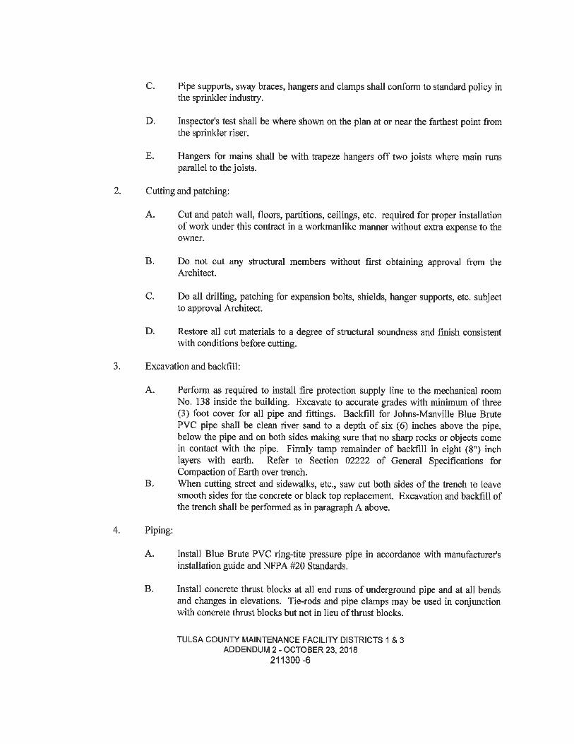
C. Pipe supports, sway braces, hangers and clamps shall conform to standard policy inthe sprinkler industry.
D. Inspector's test shall be where shown on the plan at or near the farthest point fromthe sprinkler riser.
E. Hangers for mains shall be with trapeze hangers off two joists where main runsparallel to the joists.
Cutting and patching:
A. Cut and patch wall, floors, partitions, ceilings, etc. required for proper installationof work under this contract in a workmanlike manner without extra expense to theowner.
B. Do not cut any structural members without first obtaining approval from theArchitect.
C. Do all drilling, patching for expansion bolts, shields, hanger supports, etc. subjectto approval Architect.
D. Restore all cut materials to a degree of structaral soundness and finish consistentwith conditions before cutting.
Excavation and backfill:
Perform as required to install fire protection supply line to the mechanical roomNo. 138 inside the building. Excavate to accurate grades with minimum of three(3) foot cover for all pipe and fittings. Backfill for Johns-Manville Blue BmtePVC pipe shall be clean river sand to a depth of six (6) inches above the pipe,below the pipe and on both sides making sure that no sharp rocks or objects comein contact with the pipe. Firmly tamp remainder of backfill in eight (8") inchlayers with earth. Refer to Section 02222 of General Specifications forCompaction of Earth over trench.When cutting street and sidewalks, etc., saw cut both sides of the trench to leavesmooth sides for the concrete or black top replacement. Excavation and backfill ofthe trench shall be performed as in paragraph A above.
B.
Piping:
A. Install Blue Brute PVC ring-tite pressure pipe in accordance with manufacturer'sinstallation guide and NFPA #20 Standards.
B. Install concrete thrust blocks at all end runs of underground pipe and at all bendsand changes in elevations. Tie-rods and pipe clamps may be used in conjunctionwith concrete thrust blocks but not in lieu of thrust blocks.
TULSA COUNTY MAINTENANCE FACILITY DISTRICTS 1 & 3ADDENDUM 2 - OCTOBER 23, 2018
211300-6
5. Flushing fire main:
Sprinkler fire main into building shall be flushed as outlined in NFPA #13 Standards A-8-2. 1. Pipe or hose shall be used to get water from the building to prevent water damage tothe site. Flushing must be witnessed by Architect or his designated representative and arecord made of the time and date.
6. Testing:
A.
B.
The newly laid underground pipe shall be hydrostatic tested to a pressure of 200p.s.i. for a period of two (2) hours without any leaks or drop in pressure. Architector his designated representative shall witness the test and a record made of the timeand date.
All interior piping shall be hydrostatically tested to a pressure of 200 p. s. i. for aperiod of two (2) hours without any leaks or drop in pressure. Architect ordesignated representative shall witness test and a record made of the time and date.
Hydrants:
Set hydrants on flat concrete slab three (3) feet square and four (4) inches thick. Place 1/2cubic yard of 3" cmsher run rock around bottom of hydrant to insure quick drainage.Install hydrant so that distance between 2'/2" outlet and finished grade is between 15 and 18inches. Hydrant must be plumb. Any deviations from theses dimensions will require priorapproval by Architect or the hydrant will be re-set at expense of Fire Protection Contractor.
Sleeves:
A. Make all sleeves through walls, floors, etc., black iron pipe flush with wall,ceilings, et., of size to accommodate pipe or pipes. Caulk sleeves through outsidewalls with approved caulking.
B. Sleeve all outside walls where pipe penetrates wall with steel sleeves of size ofallow '/4" clearance around the pipe. Caulk with approved caulking. Escutcheonsshall be Elcen ceiling and floor flange Type I, cast iron, figure 268 with set screw.NO SUBSTITUTE.
C. Sleeve floor where sprinkler riser enters building with steel sleeve of diameter togive 3/4" clearance around pipe, extend sleeve 3/4" above finished floor. Caulkaround pipe with oakum. See riser detail "R" on drawing.
9. Pipe-Trim-Escutcheons:
Shall be installed at all points where piping pierces wall, ceiling or partitions so as to bevisible from finished space. Ceiling and wall plates shall be Elcen ceiling and floor flangetype 1, cast iron, figure 268 with set screw or Grinnell figure 395.
TULSA COUNTS MAINTENANCE FACILITl' DISTRICTS 1 & 3ADDENDUM 2 - OCTOBER 23, 2018
211300-7
10. Coordination with other trades:
The sprinkler contractor shall coordinate the work with mechanical and electricalcontractor before starting layout. In cases where interference develops. Architect will statewhich equipment, piping, etc. is to be regardless of which equipment was installed first.
11. Cleaning:
Maintain premises reasonably clear of all surplus materials, mbbish, debris throughoutperformance of work. Upon completion of work, remove all dirt, grease, stains and leaveunfinished materials ready for painting. Clean and polish finished materials, surfaces, etc.,ready for use. Leave all pipe, fittings, hangers, valves, alamis, cabinets, etc. clean and freeof dirt or grease ready to receive touch-up primer and final coat of paint.
12. Operating Instmctions:
After completion of installation and tests, etc., the Fire Protection contractor shall instructthe owner's representative in the operation and maintenance of the sprinkler system.Special care shall be taken to make sure owner's representative:
A. Will recognize whether main valves are OPEN or CLOSED.B. Will know how to drain the system.C. Will know where all auxiliary dry pipe drains areD. Will know how to test the system.E. Provide owner with brochures of the backflow preventer, waterflow indicator, etc.
13. Final Inspection and Test:
Fire Protection Contractor shall obtain final inspection from the Architect at completion ofjob. Final payment will not be made until all deficiencies have been corrected to thesatisfaction of the Architect or Engineer.
14. Guarantee:
B.
Nothing herein contained may be construed to relieve Fire Protection Contractorfrom making good and perfect work in all details of construction or installation andhe shall held responsible to provide and furnish necessary materials and to performall necessary labor and to bear all expenses incidental to the satisfactorycompletion of the work embraced herein.
Contractor shall guarantee labor, materials and equipment furnished under thiscontract against any defects developing from faulty, poor workmanship ormaterials for a period of one (1) year from date of final acceptance. Any defectTULSA COUNTS MAINTENANCE FACILIT/ DISTRICTS 1 & 3
ADDENDUM 2 - OCTOBER 23, 2018211300-8

appearing within that time shall be remedied by the Fire Protection Contractorwithout extra charge to the Owner and within a reasonable time after notice. Theterm defect as used herein shall not be constmed as embracing such imperfectionsas would naturally follow improper treatment, accident or the wear and tear ofnormal use.
END
TULSA COUNFi' MAINTENANCE FACILITl' DISTRICTS 1 & 3ADDENDUM 2 - OCTOBER 23, 2018
211300-9