Embed Size (px)
Citation preview
Quick Language Description
on
SCL (structured control language)
and
Analog Signal Handling
Fakultät f. Maschinenbau und Mechatronik
Prof. Dr.-Ing. Hans-Werner Dorschner
Inhalt |2
Hochschule Karlsruhe Technik und Wirtschaft Automatisierungstechnik Fakultät für Maschinenbau und Mechatronik WS 2013/14 Prof. Dr.-Ing. Hans-Werner Dorschner
Content
Content ________________________________________________________________________________ 2
1. Design of a Structured S7-SCL Program ________________________________________________ 5
1.1 Defining the Interfaces between Blocks _________________________________________________ 6
1.2 Defining the Input/Output Interface ____________________________________________________ 7
1.3 User Interface _____________________________________________________________________ 8
1.4 Creating and Handling an S7-SCL Source File____________________________________________ 9
1.5 Using Symbolic Addresses ___________________________________________________________ 9
2. Compiling the Program _____________________________________________________________ 10
2.1 Debugging the Program after Compilation ______________________________________________ 10
2.2 Using the S7-SCL debugging functions ________________________________________________ 10
3. S7-SCL Basics ___________________________________________________________________ 11
3.1 Blocks in S7-SCL Source Files _______________________________________________________ 11
3.1.1 Structure of a Function Block (FB) _______________________________________________ 15
3.1.2 Structure of a Function (FC) ____________________________________________________ 16
3.1.3 Structure of an Organization Block (OB) __________________________________________ 16
3.2 Basic Terms _____________________________________________________________________ 17
3.2.1 Syntax Rule _________________________________________________________________ 17
3.2.2 Character Set and reserved Words ______________________________________________ 17
3.2.3 Address Identifiers ___________________________________________________________ 19
3.3 Values __________________________________________________________________________ 20
3.3.1 Integers ____________________________________________________________________ 20
3.3.2 Real Numbers _______________________________________________________________ 20
3.3.3 Character Strings _____________________________________________________________ 20
3.4 Data Types ______________________________________________________________________ 21
3.5 User-Defined Data Type ____________________________________________________________ 22
3.6 Constants ________________________________________________________________________ 22
3.7 Comments _______________________________________________________________________ 23
3.8 Variables ________________________________________________________________________ 23
3.8.1 Local Data __________________________________________________________________ 23
3.8.2 Variable Declaration and Initialization ____________________________________________ 25
3.8.3 Shared Data _________________________________________________________________ 26
4. Basic Operations __________________________________________________________________ 27
5. Control Statements ________________________________________________________________ 32
5.1 Selective Statements _______________________________________________________________ 32
Inhalt |3
Hochschule Karlsruhe Technik und Wirtschaft Automatisierungstechnik Fakultät für Maschinenbau und Mechatronik WS 2013/14 Prof. Dr.-Ing. Hans-Werner Dorschner
5.2 Loops __________________________________________________________________________ 33
5.3 Program Jump ____________________________________________________________________ 34
6. Calling of Functions and Function Blocks ______________________________________________ 37
7. Analog Signal Handling ____________________________________________________________ 40
7.1 Analog Input Reading ______________________________________________________________ 40
7.2 Analog Output Writing _____________________________________________________________ 41
8. Example for a signal processing ______________________________________________________ 41
Inhalt |4
Hochschule Karlsruhe Technik und Wirtschaft Automatisierungstechnik Fakultät für Maschinenbau und Mechatronik WS 2013/14 Prof. Dr.-Ing. Hans-Werner Dorschner
Copyright
This script was written by Prof. Dr.-Ing. Hans-Werner Dorschner, HS Karlsruhe – Uni-versity of Applied Sciences. It is only for internal use for the semester student of MSST at VGU in HCMC.
It is expressly forbidden to document on paper or electronically to third parties or use information for training purposes or other commercial or noncommercial purposes. Violators will be prosecuted with all legal means necessary.
Prof. Dr.-Ing. H.-W. Dorschner
Design of a Structured S7-SCL Program Defining the Interfaces between Blocks 5/42
Hochschule Karlsruhe Technik und Wirtschaft Automatisierungstechnik Fakultät für Maschinenbau und Mechatronik WS 2013/14 Prof. Dr.-Ing. Hans-Werner Dorschner
1. Design of a Structured S7-SCL Program
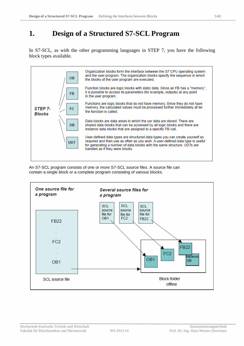
In S7-SCL, as with the other programming languages in STEP 7, you have the following block types available.
An S7-SCL program consists of one or more S7-SCL source files. A source file can contain a single block or a complete program consisting of various blocks.
Design of a Structured S7-SCL Program Defining the Interfaces between Blocks 6/42
Hochschule Karlsruhe Technik und Wirtschaft Automatisierungstechnik Fakultät für Maschinenbau und Mechatronik WS 2013/14 Prof. Dr.-Ing. Hans-Werner Dorschner
1.1 Defining the Interfaces between Blocks
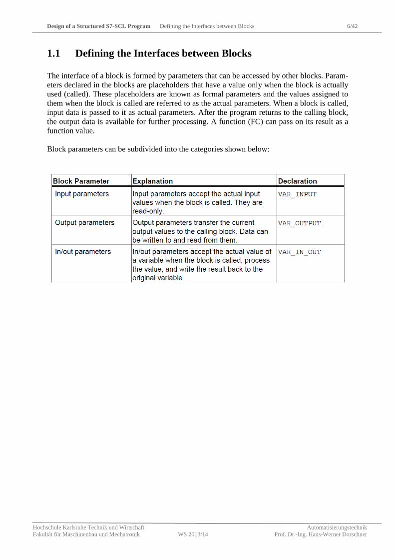
The interface of a block is formed by parameters that can be accessed by other blocks. Param-eters declared in the blocks are placeholders that have a value only when the block is actually used (called). These placeholders are known as formal parameters and the values assigned to them when the block is called are referred to as the actual parameters. When a block is called, input data is passed to it as actual parameters. After the program returns to the calling block, the output data is available for further processing. A function (FC) can pass on its result as a function value. Block parameters can be subdivided into the categories shown below:
Design of a Structured S7-SCL Program Defining the Input/Output Interface 7/42
Hochschule Karlsruhe Technik und Wirtschaft Automatisierungstechnik Fakultät für Maschinenbau und Mechatronik WS 2013/14 Prof. Dr.-Ing. Hans-Werner Dorschner
1.2 Defining the Input/Output Interface
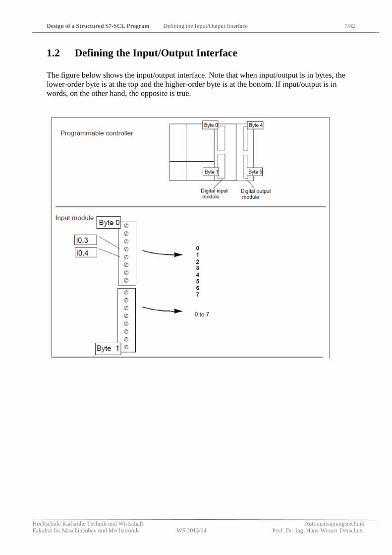
The figure below shows the input/output interface. Note that when input/output is in bytes, the lower-order byte is at the top and the higher-order byte is at the bottom. If input/output is in words, on the other hand, the opposite is true.
Design of a Structured S7-SCL Program User Interface 8/42
Hochschule Karlsruhe Technik und Wirtschaft Automatisierungstechnik Fakultät für Maschinenbau und Mechatronik WS 2013/14 Prof. Dr.-Ing. Hans-Werner Dorschner
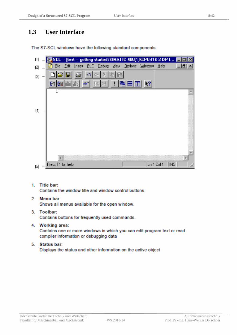
1.3 User Interface
Design of a Structured S7-SCL Program Creating and Handling an S7-SCL Source File 9/42
Hochschule Karlsruhe Technik und Wirtschaft Automatisierungstechnik Fakultät für Maschinenbau und Mechatronik WS 2013/14 Prof. Dr.-Ing. Hans-Werner Dorschner
1.4 Creating and Handling an S7-SCL Source File
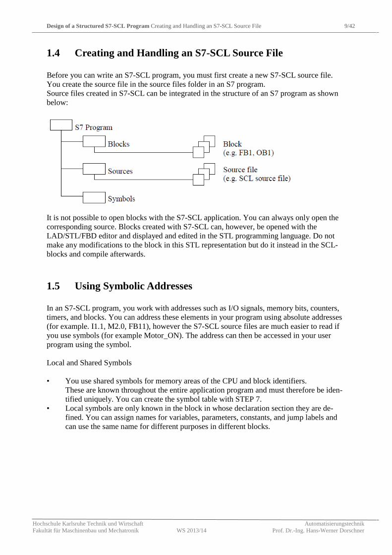
Before you can write an S7-SCL program, you must first create a new S7-SCL source file. You create the source file in the source files folder in an S7 program. Source files created in S7-SCL can be integrated in the structure of an S7 program as shown below:
It is not possible to open blocks with the S7-SCL application. You can always only open the corresponding source. Blocks created with S7-SCL can, however, be opened with the LAD/STL/FBD editor and displayed and edited in the STL programming language. Do not make any modifications to the block in this STL representation but do it instead in the SCL-blocks and compile afterwards.
1.5 Using Symbolic Addresses
In an S7-SCL program, you work with addresses such as I/O signals, memory bits, counters, timers, and blocks. You can address these elements in your program using absolute addresses (for example. I1.1, M2.0, FB11), however the S7-SCL source files are much easier to read if you use symbols (for example Motor_ON). The address can then be accessed in your user program using the symbol. Local and Shared Symbols • You use shared symbols for memory areas of the CPU and block identifiers.
These are known throughout the entire application program and must therefore be iden-tified uniquely. You can create the symbol table with STEP 7.
• Local symbols are only known in the block in whose declaration section they are de-fined. You can assign names for variables, parameters, constants, and jump labels and can use the same name for different purposes in different blocks.
Compiling the Program Debugging the Program after Compilation 10/42
Hochschule Karlsruhe Technik und Wirtschaft Automatisierungstechnik Fakultät für Maschinenbau und Mechatronik WS 2013/14 Prof. Dr.-Ing. Hans-Werner Dorschner
2. Compiling the Program
Before you run can run or test your program, you must first compile it. Once you start compi-lation, the compiler is started automatically. To make sure that you always compile the latest version of your S7-SCL source file, it is ad-visable to select the menu command Options > Customize and to select the option "Save be-fore compiling" in the "Editor" tab. The menu command File > Compile then implicitly saves the S7-SCL source file.
2.1 Debugging the Program after Compilation
All the syntax errors and warnings that occur during compilation are displayed in the "Errors and Warnings" window. If an error occurs, the block cannot be compiled, whereas if only warnings occur, an executable block is compiled. You may still, nevertheless, encounter prob-lems running the block on the PLC. To correct an error:
1. Select the error and press the F1 key to display a description of the error and instruc-tions on correcting the error.
2. If a line number and column number are displayed, you can locate the error in the source text as follows:
• Click the error message in the "Errors and Warnings" window with the right mouse button and then select the Display Errors command.
• Double-click the error message to position the cursor on the point reported (line, column). 1. Find out the correct syntax in the S7-SCL Language Description. 2. Make the necessary corrections in the source text. 3. Save the source file. 4. Compile the source file again.
2.2 Using the S7-SCL debugging functions
You can check the execution of a program on the CPU and locate any errors in the program. Syntax errors are indicated by the compiler. Runtime errors occurring during the execution of the program are also indicated, in this case, by system interrupts. You can locate logical pro-gramming errors using the debugging functions. In S7-SCL, you can start the following test functions:
1. Monitor
With this function, you can display the names and current values of variables in the S7-SCL source file. During the test, the values of the variables and the parameters are displayed in
S7-SCL Basics Blocks in S7-SCL Source Files 11/42
Hochschule Karlsruhe Technik und Wirtschaft Automatisierungstechnik Fakultät für Maschinenbau und Mechatronik WS 2013/14 Prof. Dr.-Ing. Hans-Werner Dorschner
chronological order and updated cyclically. 2. Debug with Breakpoints/Single Step
With this function, you can set breakpoints and then debug in single steps. You can execute the program algorithm, for example statement by statement and can see how the values of the variables change.
3. S7-SCL Basics
3.1 Blocks in S7-SCL Source Files
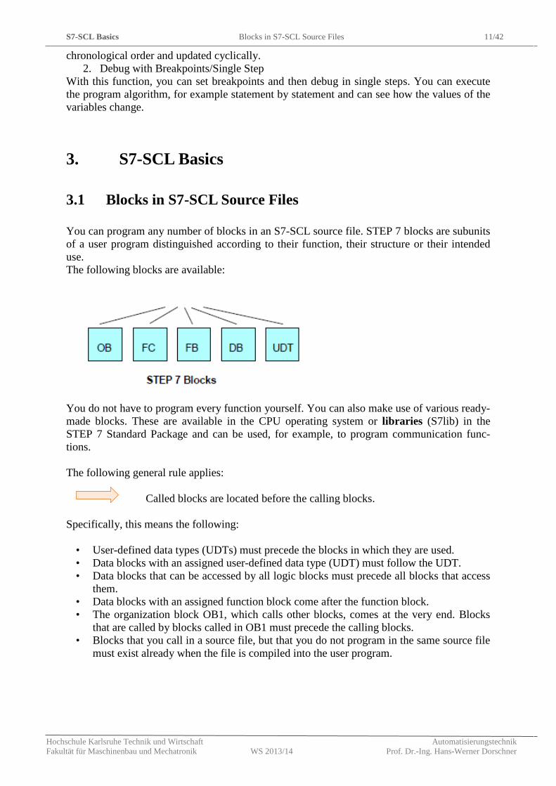
You can program any number of blocks in an S7-SCL source file. STEP 7 blocks are subunits of a user program distinguished according to their function, their structure or their intended use. The following blocks are available:
You do not have to program every function yourself. You can also make use of various ready-made blocks. These are available in the CPU operating system or libraries (S7lib) in the STEP 7 Standard Package and can be used, for example, to program communication func-tions. The following general rule applies:
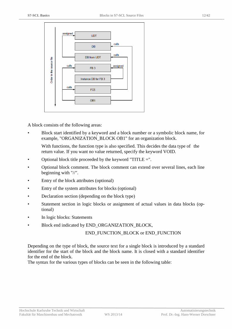
Called blocks are located before the calling blocks. Specifically, this means the following:
• User-defined data types (UDTs) must precede the blocks in which they are used. • Data blocks with an assigned user-defined data type (UDT) must follow the UDT. • Data blocks that can be accessed by all logic blocks must precede all blocks that access
them. • Data blocks with an assigned function block come after the function block. • The organization block OB1, which calls other blocks, comes at the very end. Blocks
that are called by blocks called in OB1 must precede the calling blocks. • Blocks that you call in a source file, but that you do not program in the same source file
must exist already when the file is compiled into the user program.
S7-SCL Basics Blocks in S7-SCL Source Files 12/42
Hochschule Karlsruhe Technik und Wirtschaft Automatisierungstechnik Fakultät für Maschinenbau und Mechatronik WS 2013/14 Prof. Dr.-Ing. Hans-Werner Dorschner
A block consists of the following areas:
• Block start identified by a keyword and a block number or a symbolic block name, for example, "ORGANIZATION_BLOCK OB1" for an organization block.
With functions, the function type is also specified. This decides the data type of the return value. If you want no value returned, specify the keyword VOID.
• Optional block title proceeded by the keyword "TITLE =".
• Optional block comment. The block comment can extend over several lines, each line beginning with "//".
• Entry of the block attributes (optional)
• Entry of the system attributes for blocks (optional)
• Declaration section (depending on the block type)
• Statement section in logic blocks or assignment of actual values in data blocks (op-tional)
• In logic blocks: Statements
• Block end indicated by END_ORGANIZATION_BLOCK,
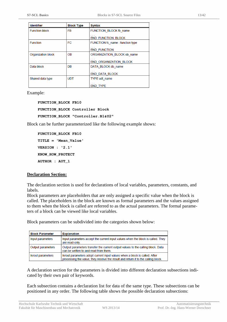
END_FUNCTION_BLOCK or END_FUNCTION Depending on the type of block, the source text for a single block is introduced by a standard identifier for the start of the block and the block name. It is closed with a standard identifier for the end of the block. The syntax for the various types of blocks can be seen in the following table:
S7-SCL Basics Blocks in S7-SCL Source Files 13/42
Hochschule Karlsruhe Technik und Wirtschaft Automatisierungstechnik Fakultät für Maschinenbau und Mechatronik WS 2013/14 Prof. Dr.-Ing. Hans-Werner Dorschner
Example:
FUNCTION_BLOCK FB10
FUNCTION_BLOCK Controller Block
FUNCTION_BLOCK "Controller.B1&U2"
Block can be further parameterized like the following example shows:
FUNCTION_BLOCK FB10
TITLE = 'Mean_Value'
VERSION : '2.1'
KNOW_HOW_PROTECT
AUTHOR : AUT_1
Declaration Section: The declaration section is used for declarations of local variables, parameters, constants, and labels. Block parameters are placeholders that are only assigned a specific value when the block is called. The placeholders in the block are known as formal parameters and the values assigned to them when the block is called are referred to as the actual parameters. The formal parame-ters of a block can be viewed like local variables. Block parameters can be subdivided into the categories shown below:
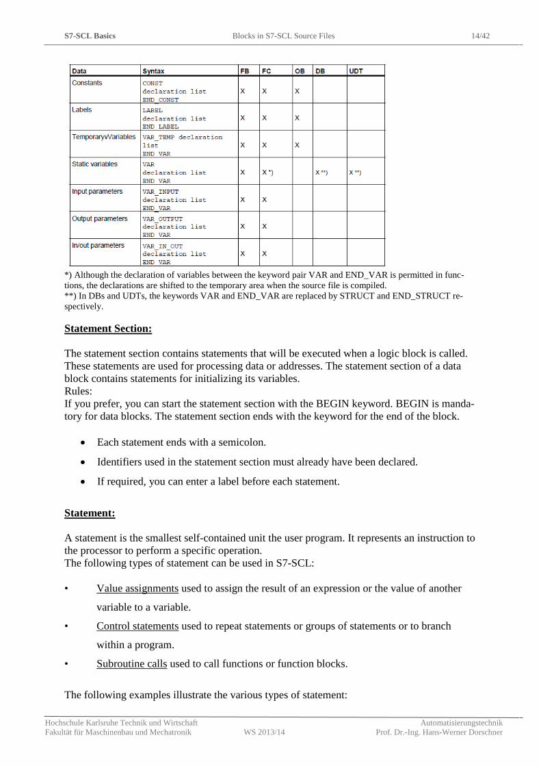
A declaration section for the parameters is divided into different declaration subsections indi-cated by their own pair of keywords. Each subsection contains a declaration list for data of the same type. These subsections can be positioned in any order. The following table shows the possible declaration subsections:
S7-SCL Basics Blocks in S7-SCL Source Files 14/42
Hochschule Karlsruhe Technik und Wirtschaft Automatisierungstechnik Fakultät für Maschinenbau und Mechatronik WS 2013/14 Prof. Dr.-Ing. Hans-Werner Dorschner
*) Although the declaration of variables between the keyword pair VAR and END_VAR is permitted in func-tions, the declarations are shifted to the temporary area when the source file is compiled. **) In DBs and UDTs, the keywords VAR and END_VAR are replaced by STRUCT and END_STRUCT re-spectively. Statement Section: The statement section contains statements that will be executed when a logic block is called. These statements are used for processing data or addresses. The statement section of a data block contains statements for initializing its variables. Rules: If you prefer, you can start the statement section with the BEGIN keyword. BEGIN is manda-tory for data blocks. The statement section ends with the keyword for the end of the block.
• Each statement ends with a semicolon.
• Identifiers used in the statement section must already have been declared.
• If required, you can enter a label before each statement.
Statement: A statement is the smallest self-contained unit the user program. It represents an instruction to the processor to perform a specific operation. The following types of statement can be used in S7-SCL: • Value assignments used to assign the result of an expression or the value of another
variable to a variable.
• Control statements used to repeat statements or groups of statements or to branch
within a program.
• Subroutine calls used to call functions or function blocks.
The following examples illustrate the various types of statement:
S7-SCL Basics Blocks in S7-SCL Source Files 15/42
Hochschule Karlsruhe Technik und Wirtschaft Automatisierungstechnik Fakultät für Maschinenbau und Mechatronik WS 2013/14 Prof. Dr.-Ing. Hans-Werner Dorschner
Example 1:
// Example of a value assignment
MEASVAL:= 0 ;
// Example of a subroutine call
FB1.DB11 (TRANSFER:= 10) ;
// Example of a control statement
WHILE COUNTER < 10 DO..
.......
END_WHILE;
3.1.1 Structure of a Function Block (FB)
A function block (FB) is a logic block that contains part of a program and that has a memory area assigned to it. Whenever an FB is called, an instance DB must be assigned to it. You specify the structure of this instance DB when you define the FB declaration section. The function block is identified by a symbol or the block identifier as the following example shows:
FUNCTION_BLOCK FB10
FUNCTION_BLOCK MOTOR1
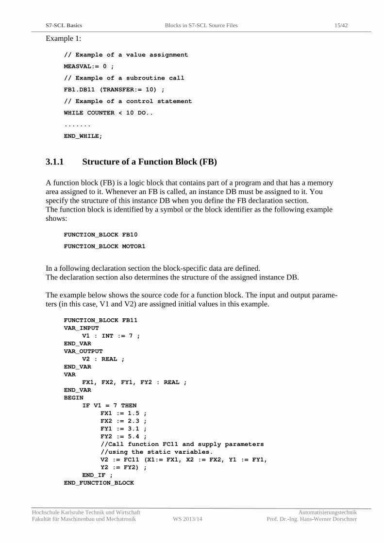
In a following declaration section the block-specific data are defined. The declaration section also determines the structure of the assigned instance DB. The example below shows the source code for a function block. The input and output parame-ters (in this case, V1 and V2) are assigned initial values in this example.
FUNCTION_BLOCK FB11 VAR_INPUT
V1 : INT := 7 ; END_VAR VAR_OUTPUT
V2 : REAL ; END_VAR VAR
FX1, FX2, FY1, FY2 : REAL ; END_VAR BEGIN
IF V1 = 7 THEN FX1 := 1.5 ; FX2 := 2.3 ; FY1 := 3.1 ; FY2 := 5.4 ; //Call function FC11 and supply parameters //using the static variables. V2 := FC11 (X1:= FX1, X2 := FX2, Y1 := FY1, Y2 := FY2) ;
END_IF ; END_FUNCTION_BLOCK
S7-SCL Basics Blocks in S7-SCL Source Files 16/42
Hochschule Karlsruhe Technik und Wirtschaft Automatisierungstechnik Fakultät für Maschinenbau und Mechatronik WS 2013/14 Prof. Dr.-Ing. Hans-Werner Dorschner
3.1.2 Structure of a Function (FC)
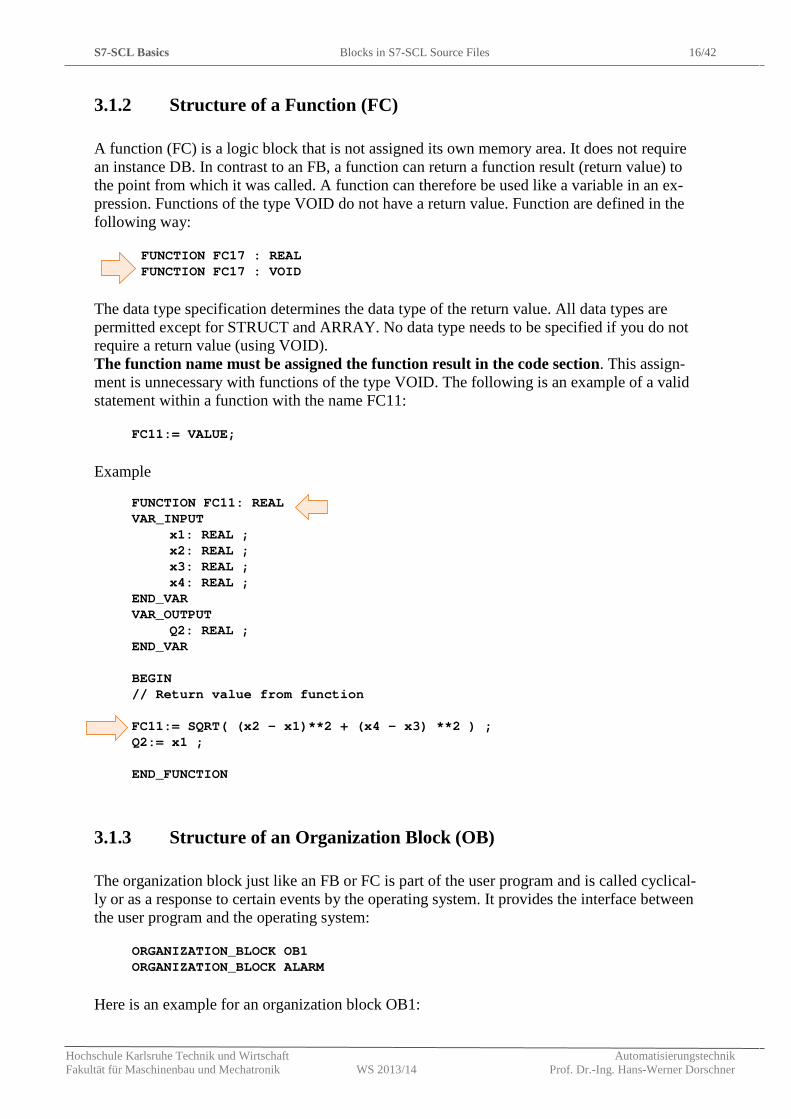
A function (FC) is a logic block that is not assigned its own memory area. It does not require an instance DB. In contrast to an FB, a function can return a function result (return value) to the point from which it was called. A function can therefore be used like a variable in an ex-pression. Functions of the type VOID do not have a return value. Function are defined in the following way:
FUNCTION FC17 : REAL FUNCTION FC17 : VOID
The data type specification determines the data type of the return value. All data types are permitted except for STRUCT and ARRAY. No data type needs to be specified if you do not require a return value (using VOID). The function name must be assigned the function result in the code section. This assign-ment is unnecessary with functions of the type VOID. The following is an example of a valid statement within a function with the name FC11:
FC11:= VALUE;
Example
FUNCTION FC11: REAL VAR_INPUT
x1: REAL ; x2: REAL ; x3: REAL ; x4: REAL ;
END_VAR VAR_OUTPUT
Q2: REAL ; END_VAR BEGIN // Return value from function FC11:= SQRT( (x2 - x1)**2 + (x4 - x3) **2 ) ; Q2:= x1 ; END_FUNCTION
3.1.3 Structure of an Organization Block (OB)
The organization block just like an FB or FC is part of the user program and is called cyclical-ly or as a response to certain events by the operating system. It provides the interface between the user program and the operating system:
ORGANIZATION_BLOCK OB1 ORGANIZATION_BLOCK ALARM
Here is an example for an organization block OB1:
S7-SCL Basics Basic Terms 17/42
Hochschule Karlsruhe Technik und Wirtschaft Automatisierungstechnik Fakultät für Maschinenbau und Mechatronik WS 2013/14 Prof. Dr.-Ing. Hans-Werner Dorschner
ORGANIZATION_BLOCK OB1 VAR_TEMP HEADER : ARRAY [1..20] OF BYTE ; //20 bytes END_VAR BEGIN FB17.DB10 (V1 := 7) ; END_ORGANIZATION_BLOCK
3.2 Basic Terms
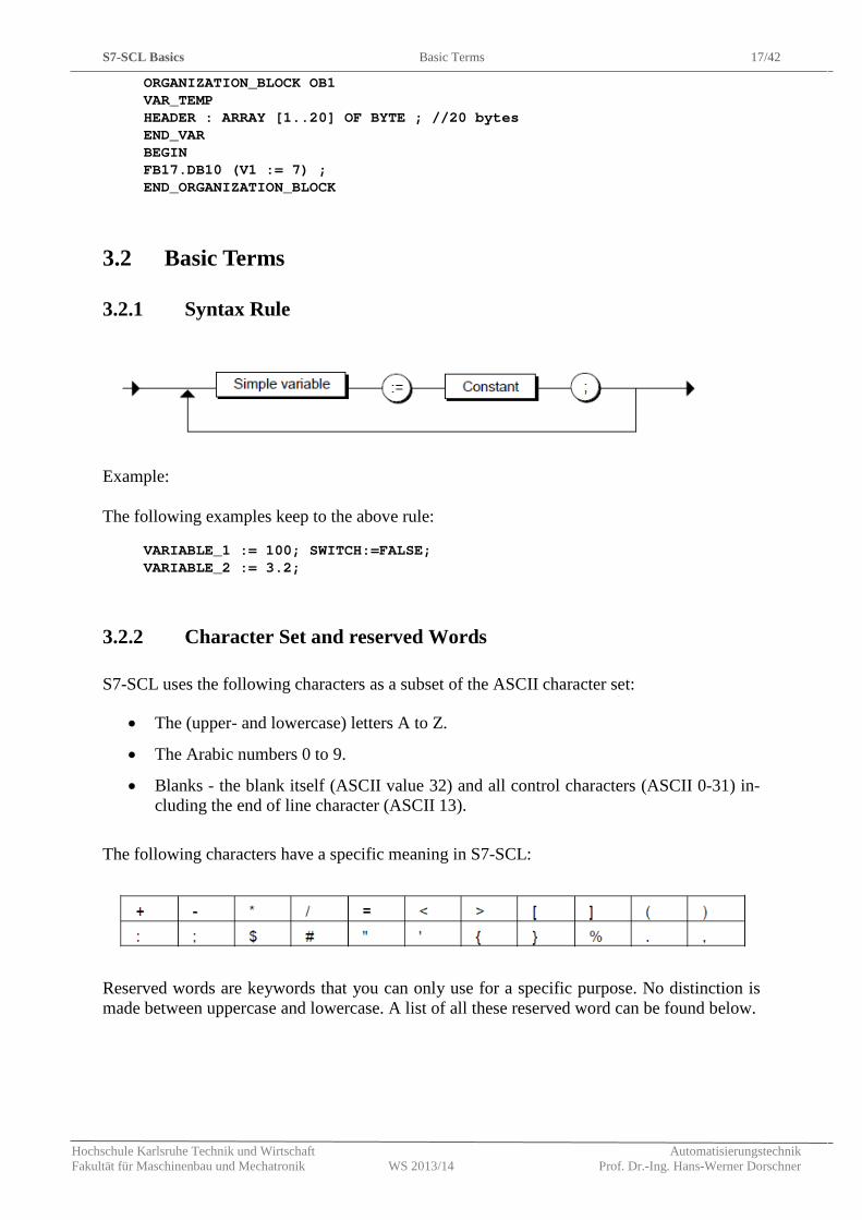
3.2.1 Syntax Rule
Example: The following examples keep to the above rule:
VARIABLE_1 := 100; SWITCH:=FALSE; VARIABLE_2 := 3.2;
3.2.2 Character Set and reserved Words
S7-SCL uses the following characters as a subset of the ASCII character set:
• The (upper- and lowercase) letters A to Z.
• The Arabic numbers 0 to 9.
• Blanks - the blank itself (ASCII value 32) and all control characters (ASCII 0-31) in-cluding the end of line character (ASCII 13).
The following characters have a specific meaning in S7-SCL:
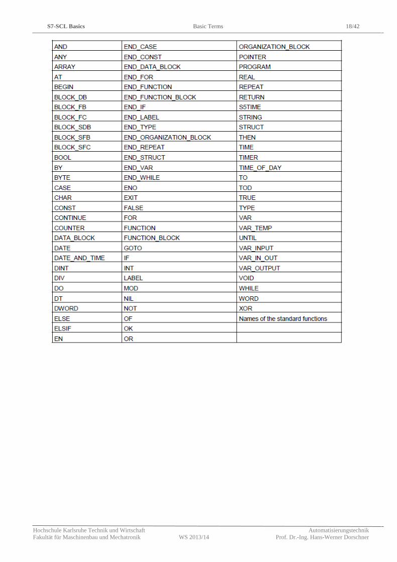
Reserved words are keywords that you can only use for a specific purpose. No distinction is made between uppercase and lowercase. A list of all these reserved word can be found below.
S7-SCL Basics Basic Terms 18/42
Hochschule Karlsruhe Technik und Wirtschaft Automatisierungstechnik Fakultät für Maschinenbau und Mechatronik WS 2013/14 Prof. Dr.-Ing. Hans-Werner Dorschner
S7-SCL Basics Basic Terms 19/42
Hochschule Karlsruhe Technik und Wirtschaft Automatisierungstechnik Fakultät für Maschinenbau und Mechatronik WS 2013/14 Prof. Dr.-Ing. Hans-Werner Dorschner
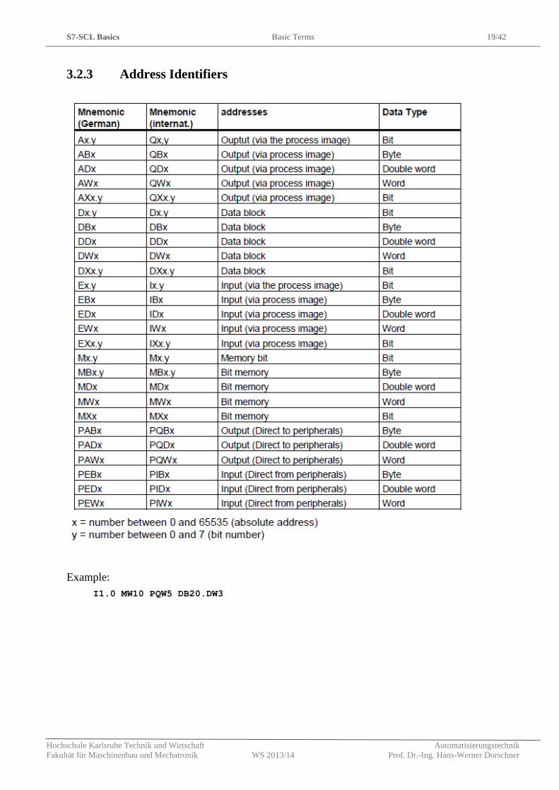
3.2.3 Address Identifiers
Example: I1.0 MW10 PQW5 DB20.DW3
S7-SCL Basics Values 20/42
Hochschule Karlsruhe Technik und Wirtschaft Automatisierungstechnik Fakultät für Maschinenbau und Mechatronik WS 2013/14 Prof. Dr.-Ing. Hans-Werner Dorschner
3.3 Values
3.3.1 Integers
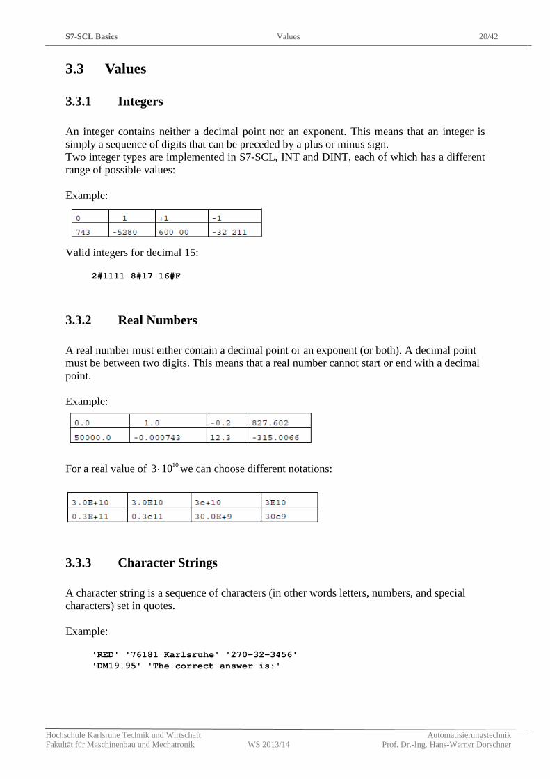
An integer contains neither a decimal point nor an exponent. This means that an integer is simply a sequence of digits that can be preceded by a plus or minus sign. Two integer types are implemented in S7-SCL, INT and DINT, each of which has a different range of possible values: Example:
Valid integers for decimal 15:
2#1111 8#17 16#F
3.3.2 Real Numbers
A real number must either contain a decimal point or an exponent (or both). A decimal point must be between two digits. This means that a real number cannot start or end with a decimal point. Example:
For a real value of 103 10⋅ we can choose different notations:
3.3.3 Character Strings
A character string is a sequence of characters (in other words letters, numbers, and special characters) set in quotes. Example:
'RED' '76181 Karlsruhe' '270-32-3456' 'DM19.95' 'The correct answer is:'
S7-SCL Basics Data Types 21/42
Hochschule Karlsruhe Technik und Wirtschaft Automatisierungstechnik Fakultät für Maschinenbau und Mechatronik WS 2013/14 Prof. Dr.-Ing. Hans-Werner Dorschner
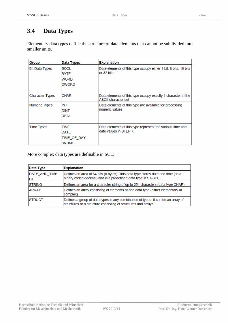
3.4 Data Types
Elementary data types define the structure of data elements that cannot be subdivided into smaller units.
More complex data types are definable in SCL:
S7-SCL Basics User-Defined Data Type 22/42
Hochschule Karlsruhe Technik und Wirtschaft Automatisierungstechnik Fakultät für Maschinenbau und Mechatronik WS 2013/14 Prof. Dr.-Ing. Hans-Werner Dorschner
3.5 User-Defined Data Type
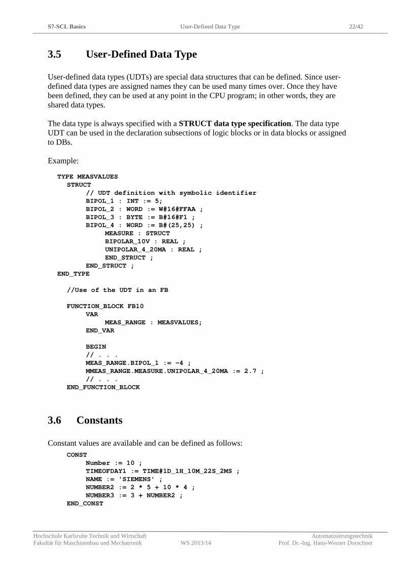
User-defined data types (UDTs) are special data structures that can be defined. Since user-defined data types are assigned names they can be used many times over. Once they have been defined, they can be used at any point in the CPU program; in other words, they are shared data types. The data type is always specified with a STRUCT data type specification. The data type UDT can be used in the declaration subsections of logic blocks or in data blocks or assigned to DBs. Example:
TYPE MEASVALUES STRUCT
// UDT definition with symbolic identifier BIPOL_1 : INT := 5; BIPOL_2 : WORD := W#16#FFAA ; BIPOL_3 : BYTE := B#16#F1 ; BIPOL_4 : WORD := B#(25,25) ;
MEASURE : STRUCT BIPOLAR_10V : REAL ; UNIPOLAR_4_20MA : REAL ; END_STRUCT ;
END_STRUCT ; END_TYPE
//Use of the UDT in an FB FUNCTION_BLOCK FB10
VAR MEAS_RANGE : MEASVALUES;
END_VAR BEGIN // . . . MEAS_RANGE.BIPOL_1 := -4 ; MMEAS_RANGE.MEASURE.UNIPOLAR_4_20MA := 2.7 ; // . . .
END_FUNCTION_BLOCK
3.6 Constants
Constant values are available and can be defined as follows: CONST
Number := 10 ; TIMEOFDAY1 := TIME#1D_1H_10M_22S_2MS ; NAME := 'SIEMENS' ; NUMBER2 := 2 * 5 + 10 * 4 ; NUMBER3 := 3 + NUMBER2 ;
END_CONST
S7-SCL Basics Comments 23/42
Hochschule Karlsruhe Technik und Wirtschaft Automatisierungstechnik Fakultät für Maschinenbau und Mechatronik WS 2013/14 Prof. Dr.-Ing. Hans-Werner Dorschner
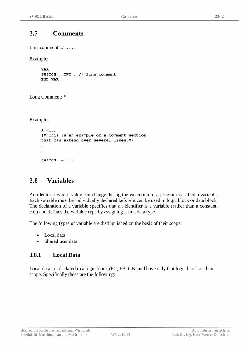
3.7 Comments
Line comment: // …… Example:
VAR SWITCH : INT ; // line comment END_VAR
Long Comments * Example:
A:=10; (* This is an example of a comment section, that can extend over several lines.*) . . SWITCH := 3 ;
3.8 Variables
An identifier whose value can change during the execution of a program is called a variable. Each variable must be individually declared before it can be used in logic block or data block. The declaration of a variable specifies that an identifier is a variable (rather than a constant, etc.) and defines the variable type by assigning it to a data type. The following types of variable are distinguished on the basis of their scope:
• Local data • Shared user data
3.8.1 Local Data
Local data are declared in a logic block (FC, FB, OB) and have only that logic block as their scope. Specifically these are the following:
S7-SCL Basics Variables 24/42
Hochschule Karlsruhe Technik und Wirtschaft Automatisierungstechnik Fakultät für Maschinenbau und Mechatronik WS 2013/14 Prof. Dr.-Ing. Hans-Werner Dorschner
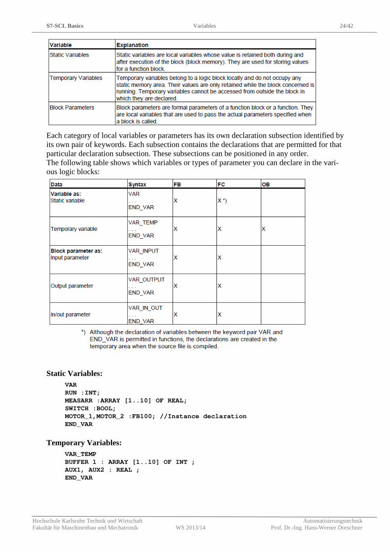
Each category of local variables or parameters has its own declaration subsection identified by its own pair of keywords. Each subsection contains the declarations that are permitted for that particular declaration subsection. These subsections can be positioned in any order. The following table shows which variables or types of parameter you can declare in the vari-ous logic blocks:
Static Variables:
VAR RUN :INT; MEASARR :ARRAY [1..10] OF REAL; SWITCH :BOOL; MOTOR_1,MOTOR_2 :FB100; //Instance declaration END_VAR
Temporary Variables:
VAR_TEMP BUFFER 1 : ARRAY [1..10] OF INT ; AUX1, AUX2 : REAL ; END_VAR
S7-SCL Basics Variables 25/42
Hochschule Karlsruhe Technik und Wirtschaft Automatisierungstechnik Fakultät für Maschinenbau und Mechatronik WS 2013/14 Prof. Dr.-Ing. Hans-Werner Dorschner
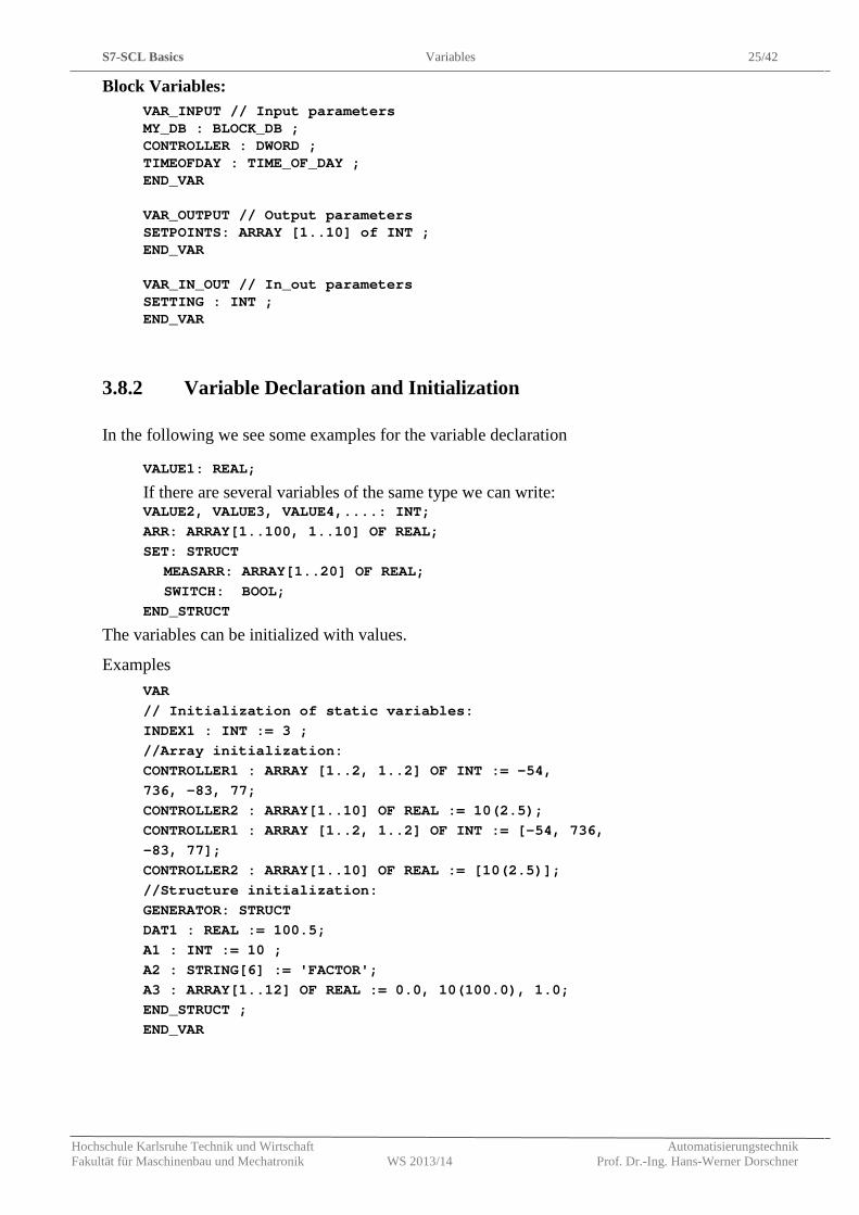
Block Variables: VAR_INPUT // Input parameters MY_DB : BLOCK_DB ; CONTROLLER : DWORD ; TIMEOFDAY : TIME_OF_DAY ; END_VAR VAR_OUTPUT // Output parameters SETPOINTS: ARRAY [1..10] of INT ; END_VAR VAR_IN_OUT // In_out parameters SETTING : INT ; END_VAR
3.8.2 Variable Declaration and Initialization
In the following we see some examples for the variable declaration
VALUE1: REAL;
If there are several variables of the same type we can write: VALUE2, VALUE3, VALUE4,....: INT; ARR: ARRAY[1..100, 1..10] OF REAL; SET: STRUCT
MEASARR: ARRAY[1..20] OF REAL; SWITCH: BOOL;
END_STRUCT
The variables can be initialized with values.
Examples VAR // Initialization of static variables: INDEX1 : INT := 3 ; //Array initialization: CONTROLLER1 : ARRAY [1..2, 1..2] OF INT := -54, 736, -83, 77; CONTROLLER2 : ARRAY[1..10] OF REAL := 10(2.5); CONTROLLER1 : ARRAY [1..2, 1..2] OF INT := [-54, 736, -83, 77]; CONTROLLER2 : ARRAY[1..10] OF REAL := [10(2.5)]; //Structure initialization: GENERATOR: STRUCT DAT1 : REAL := 100.5; A1 : INT := 10 ; A2 : STRING[6] := 'FACTOR'; A3 : ARRAY[1..12] OF REAL := 0.0, 10(100.0), 1.0; END_STRUCT ; END_VAR
S7-SCL Basics Variables 26/42
Hochschule Karlsruhe Technik und Wirtschaft Automatisierungstechnik Fakultät für Maschinenbau und Mechatronik WS 2013/14 Prof. Dr.-Ing. Hans-Werner Dorschner
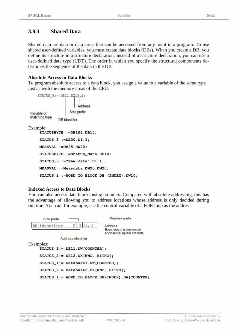
3.8.3 Shared Data
Shared data are data or data areas that can be accessed from any point in a program. To use shared user-defined variables, you must create data blocks (DBs). When you create a DB, you define its structure in a structure declaration. Instead of a structure declaration, you can use a user-defined data type (UDT). The order in which you specify the structural components de-termines the sequence of the data in the DB. Absolute Access to Data Blocks To program absolute access to a data block, you assign a value to a variable of the same type just as with the memory areas of the CPU.
Example:
STATUSBYTE :=DB101.DB10;
STATUS_3 :=DB30.D1.1;
MEASVAL :=DB25.DW20;
STATUSBYTE :=Status_data.DB10;
STATUS_3 :="New data".D1.1;
MEASVAL :=Measdata.DW20.DW20;
STATUS_1 :=WORD_TO_BLOCK_DB (INDEX).DW10;
Indexed Access to Data Blocks You can also access data blocks using an index. Compared with absolute addressing, this has the advantage of allowing you to address locations whose address is only decided during runtime. You can, for example, use the control variable of a FOR loop as the address.
Examples:
STATUS_1:= DB11.DW[COUNTER];
STATUS_2:= DB12.DX[WNO, BITNO];
STATUS_1:= Database1.DW[COUNTER];
STATUS_2:= Database2.DX[WNO, BITNO];
STATUS_1:= WORD_TO_BLOCK_DB(INDEX).DW[COUNTER];
Basic Operations Variables 27/42
Hochschule Karlsruhe Technik und Wirtschaft Automatisierungstechnik Fakultät für Maschinenbau und Mechatronik WS 2013/14 Prof. Dr.-Ing. Hans-Werner Dorschner
Structured Access to Data Blocks In the case of a structure we get access to the sub-data by a dot as shown in the following ex-ample: In the declaration section of FB10:
VAR Result: STRUCT
RES1 : INT; RES2 : WORD; END_STRUCT
END_VAR
Function block with the following accesses:
.. FB10.DB10(); RESWORD_A := DB10.Result.RES2;
4. Basic Operations
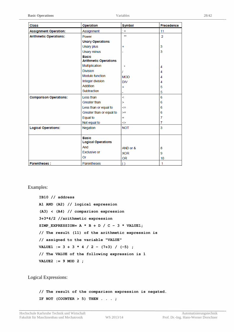
Expressions consist of operations and addresses. Most S7-SCL operations combine two ad-dresses and are therefore termed binary operators. The other operations involve only one ad-dress and are called unary operators. Binary operations are written between the addresses (for example, A + B). A unary operation always stands immediately before its address (for example, -B). The precedence of the operations listed in the table below governs the order of evaluation. `1' represents the highest precedence. The following basic operations are available for expressions in SCL:
Basic Operations Variables 28/42
Hochschule Karlsruhe Technik und Wirtschaft Automatisierungstechnik Fakultät für Maschinenbau und Mechatronik WS 2013/14 Prof. Dr.-Ing. Hans-Werner Dorschner
Examples:
IB10 // address
A1 AND (A2) // logical expression
(A3) < (A4) // comparison expression
3+3*4/2 //arithmetic expression
SIMP_EXPRESSION= A * B + D / C - 3 * VALUE1;
// The result (11) of the arithmetic expression is
// assigned to the variable "VALUE"
VALUE1 := 3 + 3 * 4 / 2 - (7+3) / (-5) ;
// The VALUE of the following expression is 1
VALUE2 := 9 MOD 2 ;
Logical Expressions:
// The result of the comparison expression is negated.
IF NOT (COUNTER > 5) THEN . . . ;
Basic Operations Variables 29/42
Hochschule Karlsruhe Technik und Wirtschaft Automatisierungstechnik Fakultät für Maschinenbau und Mechatronik WS 2013/14 Prof. Dr.-Ing. Hans-Werner Dorschner
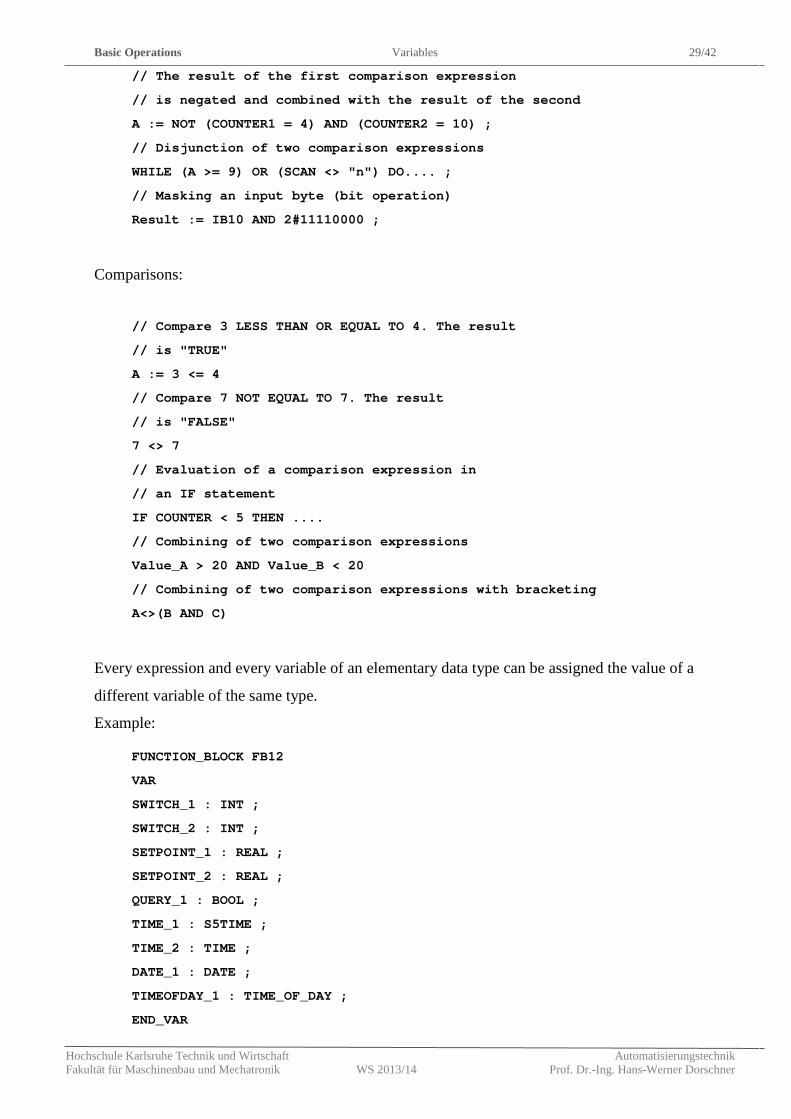
// The result of the first comparison expression
// is negated and combined with the result of the second
A := NOT (COUNTER1 = 4) AND (COUNTER2 = 10) ;
// Disjunction of two comparison expressions
WHILE (A >= 9) OR (SCAN <> "n") DO.... ;
// Masking an input byte (bit operation)
Result := IB10 AND 2#11110000 ;
Comparisons:
// Compare 3 LESS THAN OR EQUAL TO 4. The result
// is "TRUE"
A := 3 <= 4
// Compare 7 NOT EQUAL TO 7. The result
// is "FALSE"
7 <> 7
// Evaluation of a comparison expression in
// an IF statement
IF COUNTER < 5 THEN ....
// Combining of two comparison expressions
Value_A > 20 AND Value_B < 20
// Combining of two comparison expressions with bracketing
A<>(B AND C)
Every expression and every variable of an elementary data type can be assigned the value of a
different variable of the same type.
Example:
FUNCTION_BLOCK FB12
VAR
SWITCH_1 : INT ;
SWITCH_2 : INT ;
SETPOINT_1 : REAL ;
SETPOINT_2 : REAL ;
QUERY_1 : BOOL ;
TIME_1 : S5TIME ;
TIME_2 : TIME ;
DATE_1 : DATE ;
TIMEOFDAY_1 : TIME_OF_DAY ;
END_VAR
Basic Operations Variables 30/42
Hochschule Karlsruhe Technik und Wirtschaft Automatisierungstechnik Fakultät für Maschinenbau und Mechatronik WS 2013/14 Prof. Dr.-Ing. Hans-Werner Dorschner
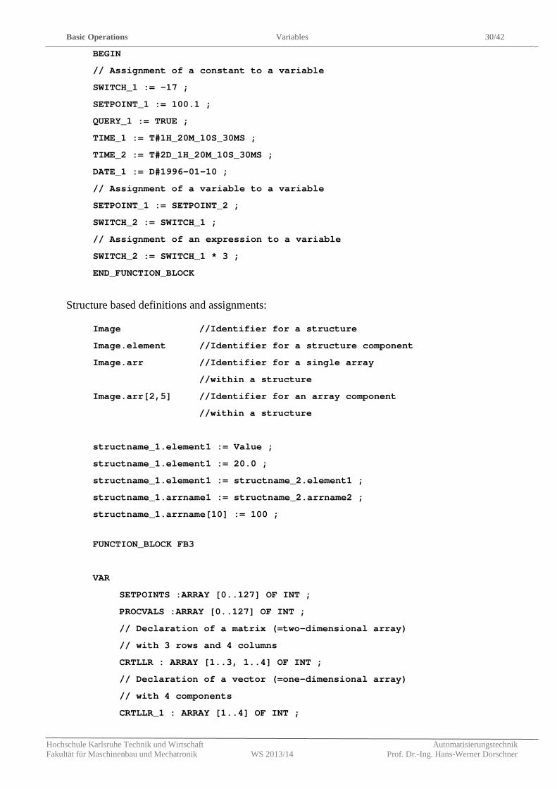
BEGIN
// Assignment of a constant to a variable
SWITCH_1 := -17 ;
SETPOINT_1 := 100.1 ;
QUERY_1 := TRUE ;
TIME_1 := T#1H_20M_10S_30MS ;
TIME_2 := T#2D_1H_20M_10S_30MS ;
DATE_1 := D#1996-01-10 ;
// Assignment of a variable to a variable
SETPOINT_1 := SETPOINT_2 ;
SWITCH_2 := SWITCH_1 ;
// Assignment of an expression to a variable
SWITCH_2 := SWITCH_1 * 3 ;
END_FUNCTION_BLOCK
Structure based definitions and assignments:
Image //Identifier for a structure
Image.element //Identifier for a structure component
Image.arr //Identifier for a single array
//within a structure
Image.arr[2,5] //Identifier for an array component
//within a structure
structname_1.element1 := Value ;
structname_1.element1 := 20.0 ;
structname_1.element1 := structname_2.element1 ;
structname_1.arrname1 := structname_2.arrname2 ;
structname_1.arrname[10] := 100 ;
FUNCTION_BLOCK FB3
VAR
SETPOINTS :ARRAY [0..127] OF INT ;
PROCVALS :ARRAY [0..127] OF INT ;
// Declaration of a matrix (=two-dimensional array)
// with 3 rows and 4 columns
CRTLLR : ARRAY [1..3, 1..4] OF INT ;
// Declaration of a vector (=one-dimensional array)
// with 4 components
CRTLLR_1 : ARRAY [1..4] OF INT ;
Basic Operations Variables 31/42
Hochschule Karlsruhe Technik und Wirtschaft Automatisierungstechnik Fakultät für Maschinenbau und Mechatronik WS 2013/14 Prof. Dr.-Ing. Hans-Werner Dorschner
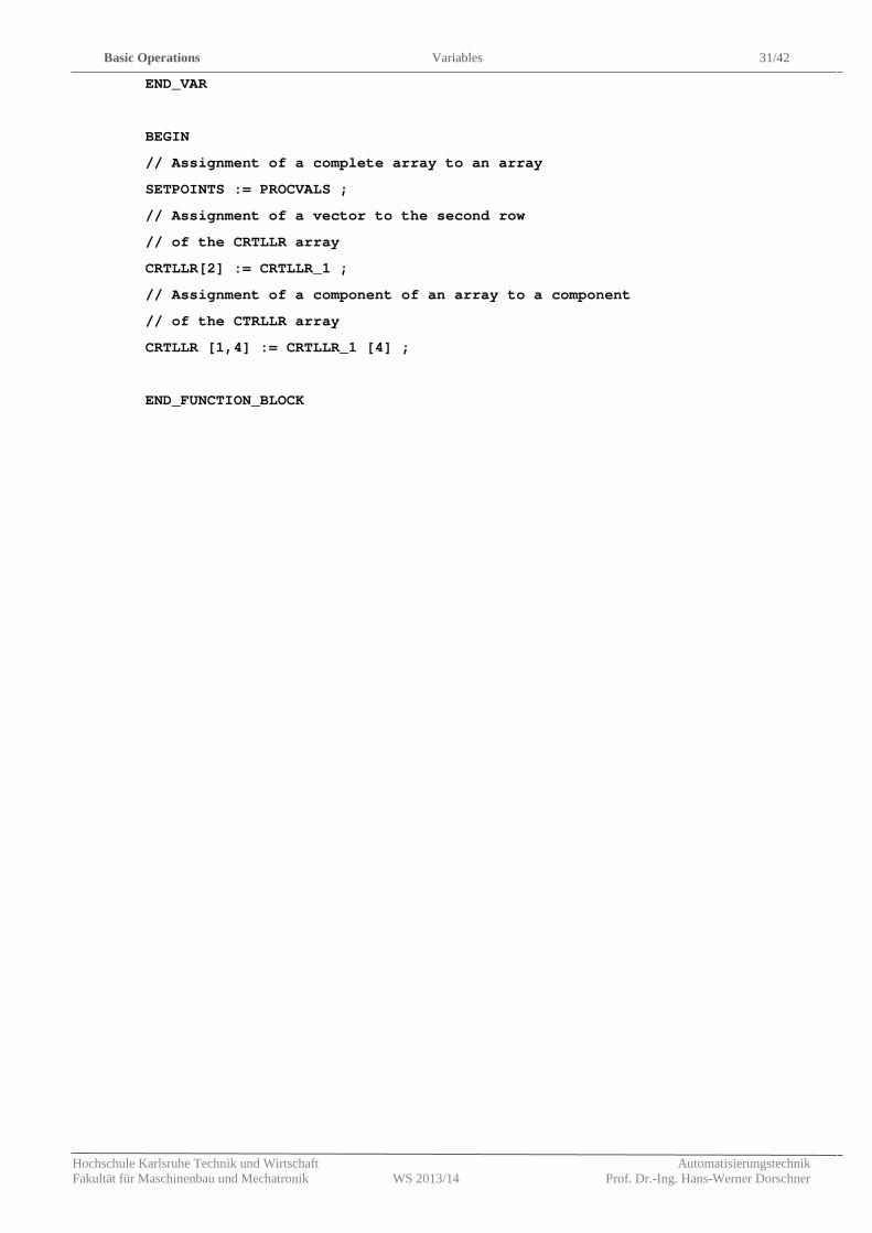
END_VAR
BEGIN
// Assignment of a complete array to an array
SETPOINTS := PROCVALS ;
// Assignment of a vector to the second row
// of the CRTLLR array
CRTLLR[2] := CRTLLR_1 ;
// Assignment of a component of an array to a component
// of the CTRLLR array
CRTLLR [1,4] := CRTLLR_1 [4] ;
END_FUNCTION_BLOCK
Control Statements Selective Statements 32/42
Hochschule Karlsruhe Technik und Wirtschaft Automatisierungstechnik Fakultät für Maschinenbau und Mechatronik WS 2013/14 Prof. Dr.-Ing. Hans-Werner Dorschner
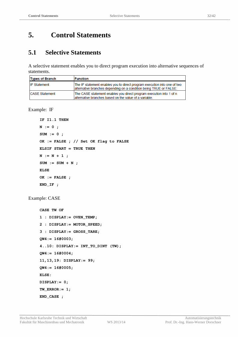
5. Control Statements
5.1 Selective Statements
A selective statement enables you to direct program execution into alternative sequences of statements.
Example: IF
IF I1.1 THEN
N := 0 ;
SUM := 0 ;
OK := FALSE ; // Set OK flag to FALSE
ELSIF START = TRUE THEN
N := N + 1 ;
SUM := SUM + N ;
ELSE
OK := FALSE ;
END_IF ;
Example: CASE
CASE TW OF
1 : DISPLAY:= OVEN_TEMP;
2 : DISPLAY:= MOTOR_SPEED;
3 : DISPLAY:= GROSS_TARE;
QW4:= 16#0003;
4..10: DISPLAY:= INT_TO_DINT (TW);
QW4:= 16#0004;
11,13,19: DISPLAY:= 99;
QW4:= 16#0005;
ELSE:
DISPLAY:= 0;
TW_ERROR:= 1;
END_CASE ;
Control Statements Loops 33/42
Hochschule Karlsruhe Technik und Wirtschaft Automatisierungstechnik Fakultät für Maschinenbau und Mechatronik WS 2013/14 Prof. Dr.-Ing. Hans-Werner Dorschner
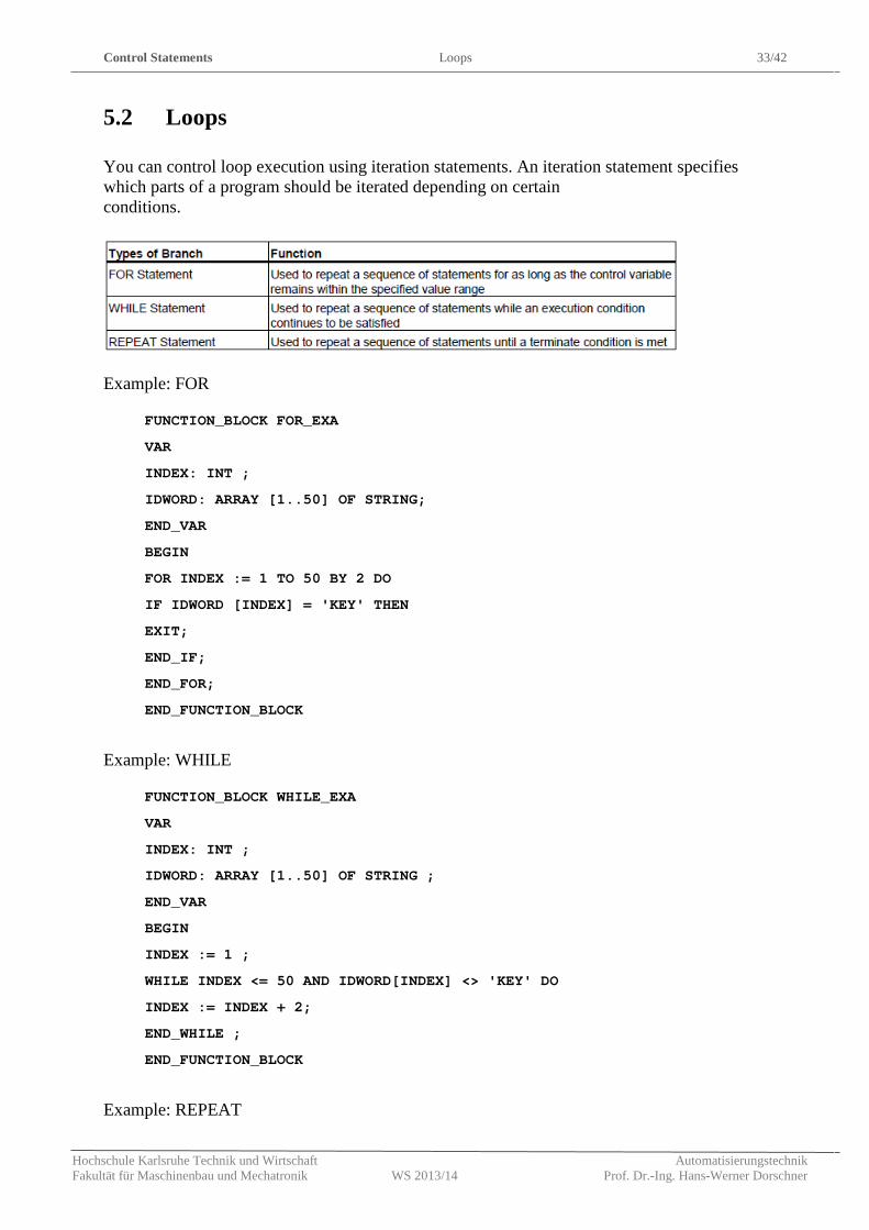
5.2 Loops
You can control loop execution using iteration statements. An iteration statement specifies which parts of a program should be iterated depending on certain conditions.
Example: FOR
FUNCTION_BLOCK FOR_EXA
VAR
INDEX: INT ;
IDWORD: ARRAY [1..50] OF STRING;
END_VAR
BEGIN
FOR INDEX := 1 TO 50 BY 2 DO
IF IDWORD [INDEX] = 'KEY' THEN
EXIT;
END_IF;
END_FOR;
END_FUNCTION_BLOCK
Example: WHILE
FUNCTION_BLOCK WHILE_EXA
VAR
INDEX: INT ;
IDWORD: ARRAY [1..50] OF STRING ;
END_VAR
BEGIN
INDEX := 1 ;
WHILE INDEX <= 50 AND IDWORD[INDEX] <> 'KEY' DO
INDEX := INDEX + 2;
END_WHILE ;
END_FUNCTION_BLOCK
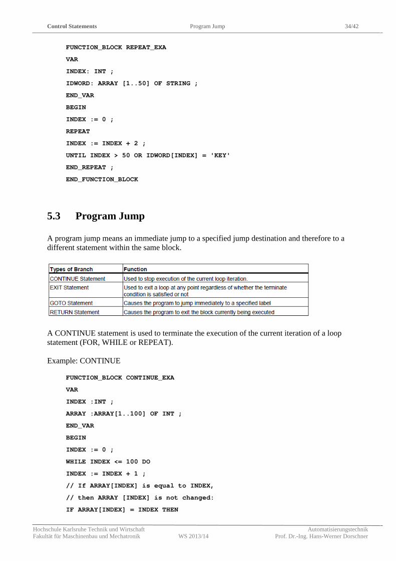
Example: REPEAT
Control Statements Program Jump 34/42
Hochschule Karlsruhe Technik und Wirtschaft Automatisierungstechnik Fakultät für Maschinenbau und Mechatronik WS 2013/14 Prof. Dr.-Ing. Hans-Werner Dorschner
FUNCTION_BLOCK REPEAT_EXA
VAR
INDEX: INT ;
IDWORD: ARRAY [1..50] OF STRING ;
END_VAR
BEGIN
INDEX := 0 ;
REPEAT
INDEX := INDEX + 2 ;
UNTIL INDEX > 50 OR IDWORD[INDEX] = 'KEY'
END_REPEAT ;
END_FUNCTION_BLOCK
5.3 Program Jump
A program jump means an immediate jump to a specified jump destination and therefore to a different statement within the same block.
A CONTINUE statement is used to terminate the execution of the current iteration of a loop statement (FOR, WHILE or REPEAT). Example: CONTINUE
FUNCTION_BLOCK CONTINUE_EXA
VAR
INDEX :INT ;
ARRAY :ARRAY[1..100] OF INT ;
END_VAR
BEGIN
INDEX := 0 ;
WHILE INDEX <= 100 DO
INDEX := INDEX + 1 ;
// If ARRAY[INDEX] is equal to INDEX,
// then ARRAY [INDEX] is not changed:
IF ARRAY[INDEX] = INDEX THEN
Control Statements Program Jump 35/42
Hochschule Karlsruhe Technik und Wirtschaft Automatisierungstechnik Fakultät für Maschinenbau und Mechatronik WS 2013/14 Prof. Dr.-Ing. Hans-Werner Dorschner
CONTINUE ;
END_IF ;
ARRAY[INDEX] := 0 ;
// Further statements
END_WHILE ;
END_FUNCTION_BLOCK
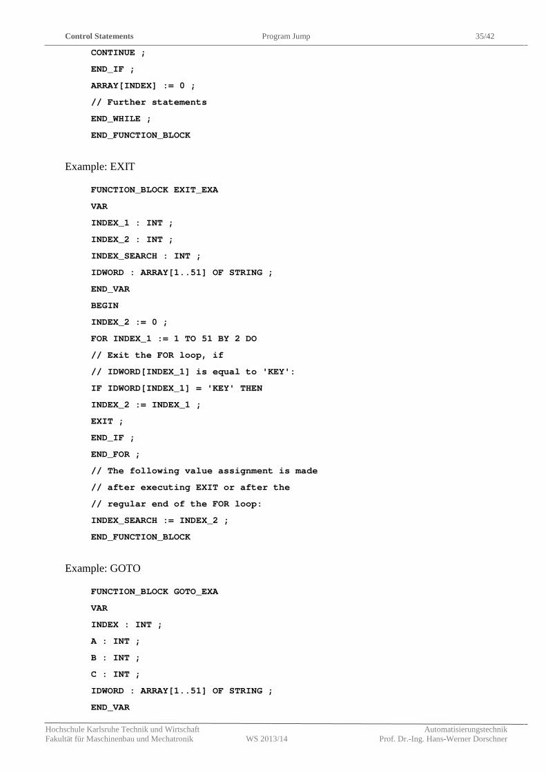
Example: EXIT
FUNCTION_BLOCK EXIT_EXA
VAR
INDEX_1 : INT ;
INDEX_2 : INT ;
INDEX_SEARCH : INT ;
IDWORD : ARRAY[1..51] OF STRING ;
END_VAR
BEGIN
INDEX_2 := 0 ;
FOR INDEX_1 := 1 TO 51 BY 2 DO
// Exit the FOR loop, if
// IDWORD[INDEX_1] is equal to 'KEY':
IF IDWORD[INDEX_1] = 'KEY' THEN
INDEX_2 := INDEX_1 ;
EXIT ;
END_IF ;
END_FOR ;
// The following value assignment is made
// after executing EXIT or after the
// regular end of the FOR loop:
INDEX_SEARCH := INDEX_2 ;
END_FUNCTION_BLOCK
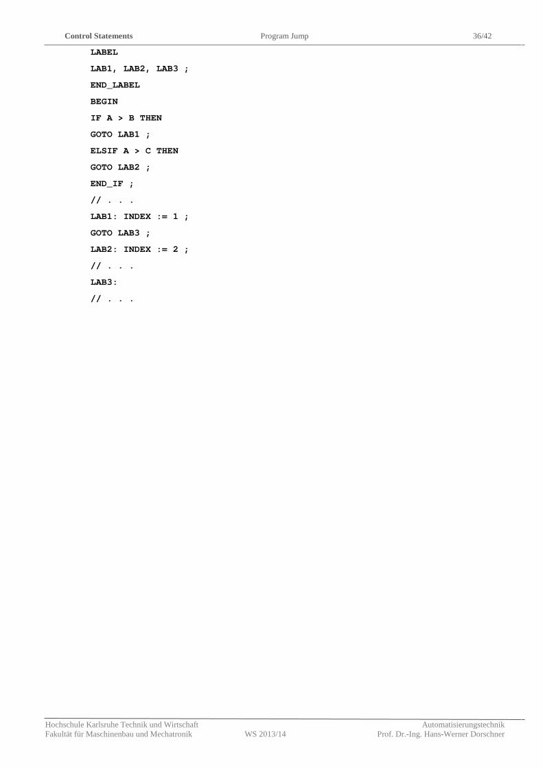
Example: GOTO
FUNCTION_BLOCK GOTO_EXA
VAR
INDEX : INT ;
A : INT ;
B : INT ;
C : INT ;
IDWORD : ARRAY[1..51] OF STRING ;
END_VAR
Control Statements Program Jump 36/42
Hochschule Karlsruhe Technik und Wirtschaft Automatisierungstechnik Fakultät für Maschinenbau und Mechatronik WS 2013/14 Prof. Dr.-Ing. Hans-Werner Dorschner
LABEL
LAB1, LAB2, LAB3 ;
END_LABEL
BEGIN
IF A > B THEN
GOTO LAB1 ;
ELSIF A > C THEN
GOTO LAB2 ;
END_IF ;
// . . .
LAB1: INDEX := 1 ;
GOTO LAB3 ;
LAB2: INDEX := 2 ;
// . . .
LAB3:
// . . .
Calling of Functions and Function Blocks Program Jump 37/42
Hochschule Karlsruhe Technik und Wirtschaft Automatisierungstechnik Fakultät für Maschinenbau und Mechatronik WS 2013/14 Prof. Dr.-Ing. Hans-Werner Dorschner
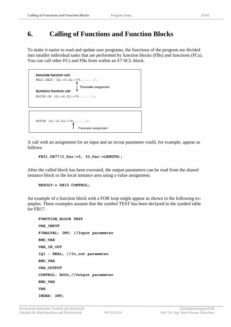
6. Calling of Functions and Function Blocks
To make it easier to read and update user programs, the functions of the program are divided into smaller individual tasks that are performed by function blocks (FBs) and functions (FCs). You can call other FCs and FBs from within an S7-SCL block.
A call with an assignment for an input and an in/out parameter could, for example, appear as follows:
FB31.DB77(I_Par:=3, IO_Par:=LENGTH);
After the called block has been executed, the output parameters can be read from the shared instance block or the local instance area using a value assignment.
RESULT:= DB10.CONTROL;
An example of a function block with a FOR loop might appear as shown in the following ex-amples. These examples assume that the symbol TEST has been declared in the symbol table for FB17.
FUNCTION_BLOCK TEST
VAR_INPUT
FINALVAL: INT; //Input parameter
END_VAR
VAR_IN_OUT
IQ1 : REAL; //In_out parameter
END_VAR
VAR_OUTPUT
CONTROL: BOOL;//Output parameter
END_VAR
VAR
INDEX: INT;
Calling of Functions and Function Blocks Program Jump 38/42
Hochschule Karlsruhe Technik und Wirtschaft Automatisierungstechnik Fakultät für Maschinenbau und Mechatronik WS 2013/14 Prof. Dr.-Ing. Hans-Werner Dorschner
END_VAR
BEGIN
CONTROL :=FALSE;
FOR INDEX := 1 TO FINALVAL DO
IQ1 :=IQ1*2;
IF IQ1 > 10000 THEN
CONTROL := TRUE;
END_IF;
END_FOR;
END_FUNCTION_BLOCK
To call the FB, you can choose one of the following variants. It is assumed that VARIABLE1 has been declared in the calling block as a REAL variable.
//Absolute function call, shared instance:
FB17.DB10 (FINALVAL:=10, IQ1:=VARIABLE1);
//Symbolic call, shared instance:
TEST.TEST_1 (FINALVAL:=10, IQ1:= VARIABLE1);
After the block has executed, the value calculated for the in/out parameter IQ1 is available in VARIABLE1 . The two examples below illustrate the two possible ways of reading the output parameter CONTROL.
// The output parameter is accessed
//by:
RESULT:= DB10.CONTROL;
//You can also use the output parameter
//directly in another FB call to
//supply an input parameter:
FB17.DB12 (INP_1:=DB10.CONTROL);
You call a function by specifying the function name (FC, SFC IDENTIFIER) and the parame-ter list. You can specify the function name that identifies the return value in absolute or sym-bolic form:
FC31 (X1:=5, Q1:=Checksum) ; // Absolute
DISTANCE (X1:=5, Q1=:Checksum) ; // Symbolic
In contrast to function blocks, functions supply a result known as the return value. For this reason, functions can be treated as addresses (exception: functions of the type VOID). The function calculates the return value that has the same name as the function and returns it to the calling block. There, the value replaces the function call.
Calling of Functions and Function Blocks Program Jump 39/42
Hochschule Karlsruhe Technik und Wirtschaft Automatisierungstechnik Fakultät für Maschinenbau und Mechatronik WS 2013/14 Prof. Dr.-Ing. Hans-Werner Dorschner
In the following value assignment, for example, the DISTANCE function is called and the re-sult assigned to the LENGTH variable:
LENGTH:= DISTANCE (X1:=-3, Y1:=2);
Besides specific programmed functions and function blocks there are several library functions and function blocks available. They are specified in the respective programming handbook.
Analog Signal Handling Analog Input Reading 40/42
Hochschule Karlsruhe Technik und Wirtschaft Automatisierungstechnik Fakultät für Maschinenbau und Mechatronik WS 2013/14 Prof. Dr.-Ing. Hans-Werner Dorschner
7. Analog Signal Handling
7.1 Analog Input Reading
Analog signal come from the periphery and are identified as PIx (process input words). Ac-cording to the accuracy of the input signal can be either word or double word, so we get an PIW or PID.
If we consider an input word we have a digital representation of the analog reading which comes from the internal analog to digital converter (ADC) of the IO-Module of the PLC.
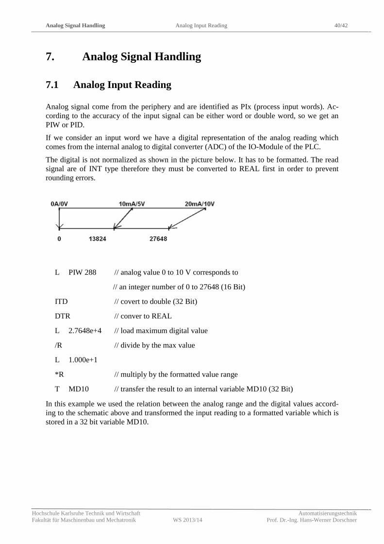
The digital is not normalized as shown in the picture below. It has to be formatted. The read signal are of INT type therefore they must be converted to REAL first in order to prevent rounding errors.
L PIW 288 // analog value 0 to 10 V corresponds to
// an integer number of 0 to 27648 (16 Bit)
ITD // covert to double (32 Bit)
DTR // conver to REAL
L 2.7648e+4 // load maximum digital value
/R // divide by the max value
L 1.000e+1
*R // multiply by the formatted value range
T MD10 // transfer the result to an internal variable MD10 (32 Bit)
In this example we used the relation between the analog range and the digital values accord-ing to the schematic above and transformed the input reading to a formatted variable which is stored in a 32 bit variable MD10.
Example for a signal processing Analog Output Writing 41/42
Hochschule Karlsruhe Technik und Wirtschaft Automatisierungstechnik Fakultät für Maschinenbau und Mechatronik WS 2013/14 Prof. Dr.-Ing. Hans-Werner Dorschner
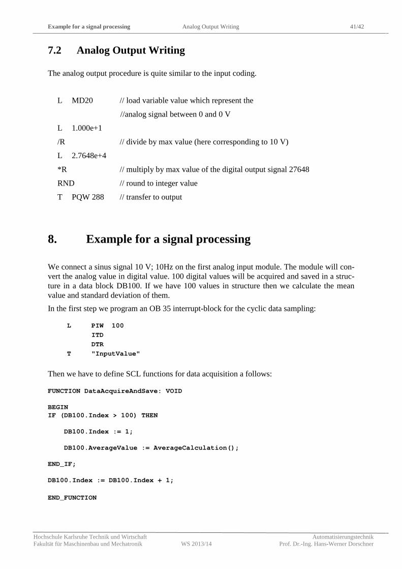
7.2 Analog Output Writing
The analog output procedure is quite similar to the input coding.
L MD20 // load variable value which represent the
//analog signal between 0 and 0 V
L 1.000e+1
/R // divide by max value (here corresponding to 10 V)
L 2.7648e+4
*R // multiply by max value of the digital output signal 27648
RND // round to integer value
T PQW 288 // transfer to output
8. Example for a signal processing
We connect a sinus signal 10 V; 10Hz on the first analog input module. The module will con-vert the analog value in digital value. 100 digital values will be acquired and saved in a struc-ture in a data block DB100. If we have 100 values in structure then we calculate the mean value and standard deviation of them. In the first step we program an OB 35 interrupt-block for the cyclic data sampling:
L PIW 100 ITD DTR T "InputValue"
Then we have to define SCL functions for data acquisition a follows: FUNCTION DataAcquireAndSave: VOID BEGIN IF (DB100.Index > 100) THEN DB100.Index := 1; DB100.AverageValue := AverageCalculation(); END_IF; DB100.Index := DB100.Index + 1; END_FUNCTION
Example for a signal processing Analog Output Writing 42/42
Hochschule Karlsruhe Technik und Wirtschaft Automatisierungstechnik Fakultät für Maschinenbau und Mechatronik WS 2013/14 Prof. Dr.-Ing. Hans-Werner Dorschner
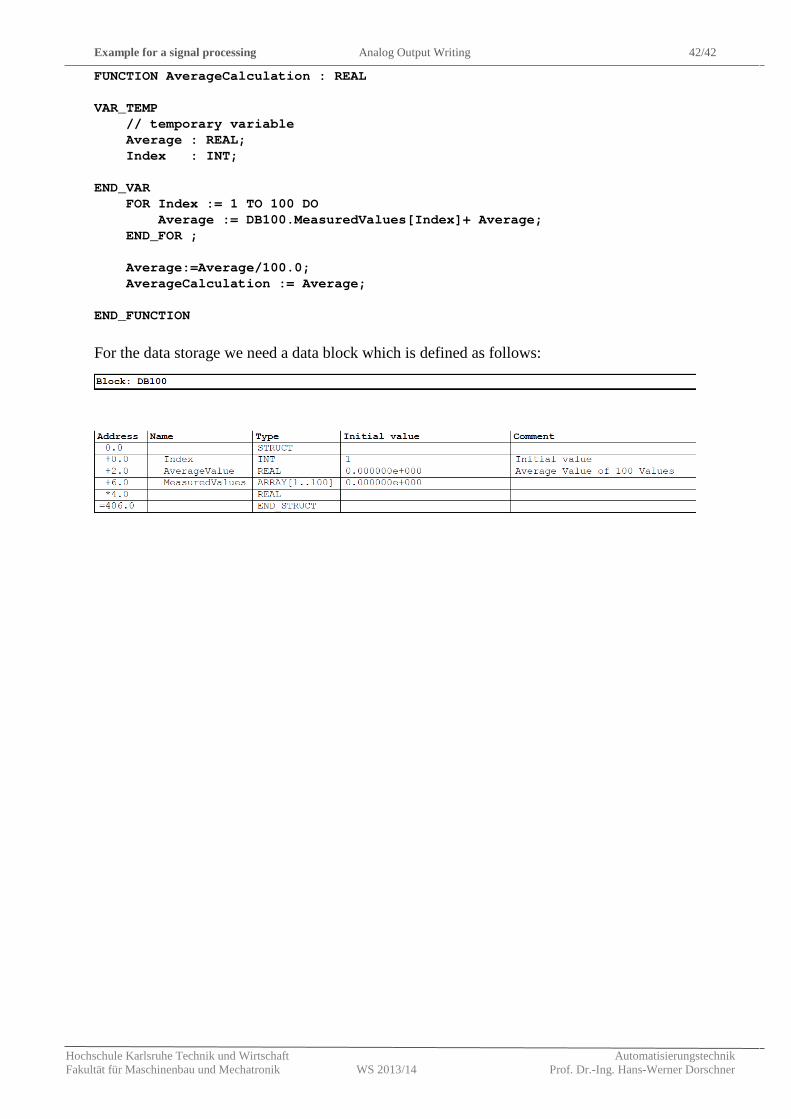
FUNCTION AverageCalculation : REAL VAR_TEMP // temporary variable Average : REAL; Index : INT; END_VAR FOR Index := 1 TO 100 DO Average := DB100.MeasuredValues[Index]+ Average; END_FOR ; Average:=Average/100.0; AverageCalculation := Average; END_FUNCTION
For the data storage we need a data block which is defined as follows:


