Embed Size (px)
Citation preview

1
Abstract— This project has been carried out in order to
provide better service and ensure mobile cellular coverage in the
areas of Batan Batan Bajo and Alto in the north of Quito; through
the Design and Implementation of a Node_B, allowing solve the
low levels of cellular signal in these sectors.
During the development of this project, the definition of 3G /
UMTS network as well as its architecture and main services are
analyzed; the drive RF test was performed to determine the
current state of the low levels of cellular signal in the two
aforementioned sectors, thus allowing select the physical space,
building or structure in which the Node_B was implemented, same
site prediction nominal performed with software design and
management traffic map Genex U-net; turn the respective Node_B
testing was performed under the requirements and needs in
delivering the site to the cellular mobile operator.
I. INTRODUCTION
he company DI TELECOM conjunction with Huawei
Technologies Co., Ltd to provide solutions in ICT, provide the
CNT EP fulfilling its objectives are: to provide quality services to
its customers and fill gaps in coverage that prevent cellular mobile
access users; presented as a solution for expanding demand for 3G /
UMTS network, which will provide service to areas or sectors which
is limited cellular coverage, specifically in the areas of Batan Batan
Alto and Bajo in the north of Quito.
The realization of this project will contribute in providing optimal
communication services to its users and to optimize the use of radio
spectrum. This proposal was presented to support the lack of coverage
in the aforementioned sectors; this offer focuses on the design and
implementation of a Node_B, which is oriented in the project for the
expansion demand for 3G / UMTS CNT EP network, this proposal
presents a great benefit because the equipment used in this type Node;
provide great flexibility to adhere adjacent technologies such as LTE
and 4G-enabling interoperability between users.
Documento recibido en junio del 2016. Esta investigación se realizó como
proyecto previo para obtener el título profesional en la carrera de Ingeniería en
Electrónica y Redes de Comunicación de la Facultad de Ingeniería en Ciencias Aplicadas (FICA) de la Universidad Técnica del Norte. Av. 17 de Julio sector
II. THEORETICAL FUNDAMENT
3G / UMTS technology brings important aspects such as: definition
of 3G technology, evolution of mobile technology over standard 3GPP
main aspects of UMTS services can provide UMTS spectrum used in
this type of Node_B, architecture UMTS network, WCDMA
modulation type, protocols and elements of the radio access network
(UTRAN), equipment installation and introduction to the Node_B
smart antennas used for this type of network.
A. Definition of the Third Generation (3G)
3G is a cellular technology that allows voice, video and data
at high speeds and allows services like web browsing and
video. In turn are third generation mobile systems under the
name IMT-2000.
3G / UMTS mobile technology is wideband is fully
standardized, ie, non-proprietary. It runs on a licensed
spectrum and a general service delivery as well as absolute
mobility. 3G networks offer greater capacity than GSM
networks as they provide support with acceptable quality
video.
3G technology manifests the next evolutionary leap in
mobile systems which aims to make progress in relation to the
first and second generation; on the other hand the 3G standard
is strongly tied to the first standards 2G (GSM, GPRS,
EDGE).
B. IMT-2000
The world standard for wireless networks Third Generation
(3G) developed and approved by the ITU's IMT-2000. Defined
as a set of interdependent recommendations is the framework
for worldwide access and allows you to connect various
terrestrial or satellite systems.
The objectives of IMT-2000 are:
El Olivo, Ibarra-Ecuador. R.J. Cuchala, egresado de la Carrera de Ingeniería en
Electrónica y Redes de Comunicación (teléfono 5932-950-968; e-mail: [email protected]).
Design and Implementation of a Node B
Guanguiltagua - Quito Request for
Expansion by 3G / UMTS Network
for CNT E.P.
Ricardo J. Cuchala
Carrera de Ingeniería en Electrónica y Redes de Comunicación, Universidad Técnica del Norte
Ibarra, Ecuador [email protected]
T

2
Provide worldwide coverage enabling mobile units
changing systems and networks.
Using mobile terminals, with long-range capability and
ability to access multimedia services.
Increased compatibility of radio interfaces in order to
operate in different environment or media such as cars,
people moving and offices, thus allowing to use a
common network.
High speed data transmission, capable of supporting both
circuit switched and packet and multimedia systems. The
minimum specific capabilities are:
Vehicle Environment: 144kbps
pedestrian environment: 384 kbps
Environment inside office: 2.048 Mbps
Satellite Environment: 9.6 kbps
spectral efficiency, flexibility in the use and cost
reduction as a result of the use of new technologies.
C. Evolution of 3G Standard
While it is true that 3G technology is an enhancement to it later
generations; It is also flexible in admitting superior technology as 4G
LTE is, that through the standardization group 3GPP and 3GPP2,
which indicate the evolutionary process of cellular mobile network as
displayed in Figure 1.
1) 3GPP: The agent group standardization of UMTS technology. It
was created in December 1998 with the main objective to develop
technical specifications for third generation mobile networks from
GSM existing system. SITA 3GPP mobile systems such as UMTS
third generation; to promote the use of Radio Access Network UMTS
(UTRAN) in the IMT-2000.
2) 3GPP2: It is the commission of the evolution of CDMA to the
third generation in charge, technically CDMA aware that different
radios share the mimas frequencies and may be active for a long time,
since the capacity of the network does not directly limit the number of
active radios.
Fig. 1. Time diagram of the mobile technology evolution and what would
future.
D. Key features of UMTS
UMTS is based directly on the Internet protocol IP telephony offers
users high-quality transmit images, video communications as well as
voice and data services.
Coverage is limited because it depends on the conditions in which
the user is states that transmission speeds vary depending on mobility:
Up to 10 km / h (users without mobility) = 2 Mbps.
Over 100 km / h (limited mobility) = 384 Kbps
From 500 km / h (fast mobility) = 144 Kbps
With these speeds there is compatibility with GPRS and
EDGE networks in areas with UMTS coverage and capacity
change cell to increase coverage and load alancing, through
switching based largely on packages, therefore
communications are less expensive.
3G networks offer greater security compared to the previous
2G technologies by allowing the EU to authenticate the
network you are connecting to and there is integration of
different services over a single connection.
E. UMTS cell types
Three types of cells UMTS picocells, microcells and macrocells,
each with certain characteristics, such as shown in Figure 2.
1) Macrocells: provide cellular coverage in large open areas,
between 1 and 40 km at a transmission speed of 114 kbps data.
2) Microcells: provide cellular coverage in urban areas and
highways, a range of 50 to 1000 meters, with speeds of 384 kbps.
3) Picocells: Its use is in residential and indoor office environments,
lower spokes 50 meters, with speeds of the order of 2 Mbps.
Fig. 2. Classification of cells for UMTS.
F. UMTS Network Architecture
The common core network uses the same network elements that
GPRS and GSM, and related to a next generation network, 3G / UMTS
network is made by a user equipment, access network and the core
network. As it is shown in Figure 3.
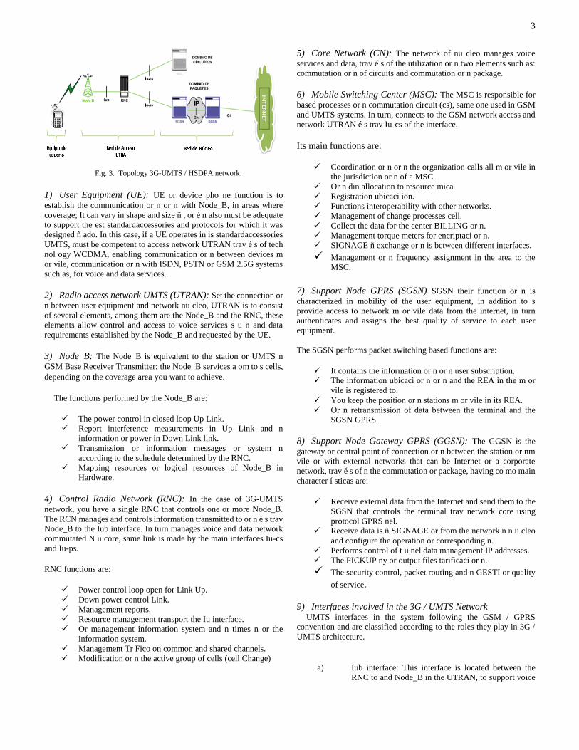
3
Fig. 3. Topology 3G-UMTS / HSDPA network.
1) User Equipment (UE): UE or device pho ne function is to
establish the communication or n or n with Node_B, in areas where
coverage; It can vary in shape and size ñ , or é n also must be adequate
to support the est standardaccessories and protocols for which it was
designed ñ ado. In this case, if a UE operates in is standardaccessories
UMTS, must be competent to access network UTRAN trav é s of tech
nol ogy WCDMA, enabling communication or n between devices m
or vile, communication or n with ISDN, PSTN or GSM 2.5G systems
such as, for voice and data services.
2) Radio access network UMTS (UTRAN): Set the connection or
n between user equipment and network nu cleo, UTRAN is to consist
of several elements, among them are the Node_B and the RNC, these
elements allow control and access to voice services s u n and data
requirements established by the Node_B and requested by the UE.
3) Node_B: The Node_B is equivalent to the station or UMTS n
GSM Base Receiver Transmitter; the Node_B services a om to s cells,
depending on the coverage area you want to achieve.
The functions performed by the Node_B are:
The power control in closed loop Up Link.
Report interference measurements in Up Link and n
information or power in Down Link link.
Transmission or information messages or system n
according to the schedule determined by the RNC.
Mapping resources or logical resources of Node_B in
Hardware.
4) Control Radio Network (RNC): In the case of 3G-UMTS
network, you have a single RNC that controls one or more Node_B.
The RCN manages and controls information transmitted to or n é s trav
Node_B to the Iub interface. In turn manages voice and data network
commutated N u core, same link is made by the main interfaces Iu-cs
and Iu-ps.
RNC functions are:
Power control loop open for Link Up.
Down power control Link.
Management reports.
Resource management transport the Iu interface.
Or management information system and n times n or the
information system.
Management Tr Fico on common and shared channels.
Modification or n the active group of cells (cell Change)
5) Core Network (CN): The network of nu cleo manages voice
services and data, trav é s of the utilization or n two elements such as:
commutation or n of circuits and commutation or n package.
6) Mobile Switching Center (MSC): The MSC is responsible for
based processes or n commutation circuit (cs), same one used in GSM
and UMTS systems. In turn, connects to the GSM network access and
network UTRAN é s trav Iu-cs of the interface.
Its main functions are:
Coordination or n or n the organization calls all m or vile in
the jurisdiction or n of a MSC.
Or n din allocation to resource mica
Registration ubicaci ion.
Functions interoperability with other networks.
Management of change processes cell.
Collect the data for the center BILLING or n.
Management torque meters for encriptaci or n.
SIGNAGE ñ exchange or n is between different interfaces.
Management or n frequency assignment in the area to the
MSC.
7) Support Node GPRS (SGSN) SGSN their function or n is
characterized in mobility of the user equipment, in addition to s
provide access to network m or vile data from the internet, in turn
authenticates and assigns the best quality of service to each user
equipment.
The SGSN performs packet switching based functions are:
It contains the information or n or n user subscription.
The information ubicaci or n or n and the REA in the m or
vile is registered to.
You keep the position or n stations m or vile in its REA.
Or n retransmission of data between the terminal and the
SGSN GPRS.
8) Support Node Gateway GPRS (GGSN): The GGSN is the
gateway or central point of connection or n between the station or nm
vile or with external networks that can be Internet or a corporate
network, trav é s of n the commutation or package, having co mo main
character í sticas are:
Receive external data from the Internet and send them to the
SGSN that controls the terminal trav network core using
protocol GPRS nel.
Receive data is ñ SIGNAGE or from the network n n u cleo
and configure the operation or corresponding n.
Performs control of t u nel data management IP addresses.
The PICKUP ny or output files tarificaci or n.
The security control, packet routing and n GESTI or quality
of service.
9) Interfaces involved in the 3G / UMTS Network UMTS interfaces in the system following the GSM / GPRS
convention and are classified according to the roles they play in 3G /
UMTS architecture.
a) Iub interface: This interface is located between the
RNC to and Node_B in the UTRAN, to support voice

4
and data services offered to users or subscribers
UMTS.
b) Iu interface: This interface connects the nu cleo
network with UTRAN, which is considered as a
reference point and m to main s for 3GPP concept. The
Iu interface can have two types of instances f í SICAS
to connect to two different network elements of nu
cleo, all depending on whether it refers to a network -
based: commutation circuits or n or n or commutation
of packages.
c) Interface Iu-cs: This interface is involved in the link
between the UTRAN and the MSC, is u solely for
commutation or n circuit, same that is used for trasmisi
or n voice service to the user equipment.
d) Iu-ps interface: This interface is responsible for
connecting the UTRAN with the SGSN, it is u solely
for commutation or packet n, same that is used for
trasmisi or n data service to the user equipment.
10) MAP interface: The interfaces between some elements of nu
core network are called MAP interfaces and are used as protocols are
ñ SIGNAGE ion, such as:
a) Gn interface: This interface is located between
SGSN and GGSN, same interface is used to support
mobility between SGSN and GGSN. In this interface
protocol t u nel IP - based GPRS is used to carry user
data and ñ SIGNAGE or n. It can have different
configurations for channels f í musicians associated
Gn interface such as Ethernet, ATM, and others.
b) Gi interface: This interface is to only present in the
GGSN. It is the interface through which you access the
external data networks and specification defined the
following protocols: IPv4, IPv6 and X25.
G. Technical characteristics of the Media Access WCDMA
Within this WCDMA they are:
Support high - rate data transmission or n: 384 Kbps with
wide area coverage, and 2 Mbps with local coverage.
High service flexibility: With support multiple parallel m u
variable rate services on each connection or n.
Built - in support for future capacity and enhanced coverage,
as technology í as with adaptive antennas, advanced
structures ny diversity reception or transmission or n.
Efficient packet access and support FDD and TDD.
H. WCDMA specification
The chip rate may be extended to two or three times the standard
3.84 Mbps to accommodate speeds greater than 2 Mbps data. That is
why detailed below in Table 1 the technical specifications of
WCDMA. Tab.1 Technical specifications of WCDMA
MÚLTIPLE ACCESS SCHEME DS-CDMA
DUPLEXING SHEME FDD/TDD
DUAL MODE ACCESS
PACKAGE
Combined cannel dedicated
MULTI RATE SHEME RATE /
VARIABLE
Spreading factor variable and
expanded milti-code
CHIP RATE 3.84 Mbps
SPACED CARRIER 4.4 – 5.2 MHz (200 KHz portador)
FRAME LEGTH 4.4 – 5.2 MHz (200 KHz portador)
SINCRONIZACIÓN INTER
BASE ESTACIÓN
FDD: No synchronization is required
TDD: synchronization necessary
I. Return Loss (RL) The return loss is a measure of the reflected energy of a
transmitted signal and is expressed in dB, the higher the value, the
better. Reflections occur due to mismatching of impedances in the
connector, a defective condition of the cable, or a bad
manufacturing misfuelling. It is also produced by power loss in
the signal reflected by a discontinuity in the transmission line or
fiber optic.
J. Voltage ratio reflected wave (VSWR) In a transmission line is a parameter indicating the relationship
between the maximum and minimum values of a reflected wave
voltage pattern. The VSWR is a special value of the SWR, which is
also known as ROE (SWR). The VSWR is a measurement of
impedance mismatch between the transmission line and its load. The
higher the VSWR, the greater the discrepancy. The minimum value of
VSWR, is the condition that the impedances of the transmission line
and the load are joined perfectly, is equal to 1.
The VSWR loss being reflected wave is analyzed as a measure of
impedance mismatch between the transmitter and antenna, it is why if
there is a higher VSWR is worse adaptation. By taking into account
the losses in transmission lines is analyzed that the absence of reflected
wave (| Γ | = 0), this means that there is a perfect match, resulting in a
VSWR = 1.
III. ENGINEERING PROJECT
For the execution of the engineering project has been to follow a
diagram, which shows each process involved in the development and
completion of the project, as shown in Figure 4.
Fig. 4. Diagram forward for the Development of Engineering.

5
A. Allocation of frequency bands for the CNT EP
Taking into account that radio spectrum is a natural resource of the
Ecuadorian government has formed a National Frequency Plan, which
is responsible for organizing and distributing better the radio spectrum
in order to provide greater benefit to users. According to the National
Frequency Plan ARCOTEL it has been distributed to the operator CNT
EP according to Table 2.
Tab. 2. Bandas de frecuencia para la CNT E.P.
Band (MHz)
Frecuency
Up Link (MHz) Down Link (MHz)
1900 1890.0–1910.0 1970.0–1990.0
850 835.0–849.0 880.0–894.0
The frequency ranges that are allocated in the bands of 850 to 1900
MHz are divided into two bands: the frequency Down Link (DL)
corresponding to the highest frequency, used to download data to the
mobile device; and frequency Up Link (UL) that is less valuable and
used on the mobile device for sending data to the base station. There
fore the frequency to be used in the thesis project is with 1900MHz
UMTS carrier.
By resolution ARCOTEL-2015-000100 October 2015, the
allocation of the 1900MHz frequency band for cellular cooperators
CNT EP and OTECEL SA According to resolution 738-26-
CONATEL-TEL-2014 is maintained, remains the extension of the
Rental Agreement Radio Spectrum under the same conditions
authorized by CONATEL, as stipulated in the following articles:
"ARTICLE ONE.- In order to ensure continuity and quality in
service delivery and based on the provisions of Resolution TEL-738-
26-CONATEL-2014, extend the validity of Rental Agreements and
Radio Spectrum National roaming signed between CNT EP. and
OTECEL SA, with the same technical, economic and commercial
agreed to the CNT EP and OTECEL SA on April 30, 2014, for a period
of six months from the expiration of the period granted by CONATEL
in the aforementioned resolution .
ARTICLE TWO.- The extension of the validity of the contracts may
be terminated if there is an agreement or arrangement of National
Roaming automatic in the case of National Roaming Agreement and
when OTECEL SA stop using the spectrum that rents to the CNT EP
if the lease of Radio Spectrum. In exercising their powers and
competences, the Superintendency has made the monitoring and
verification respective frequencies in blocking cc` (1905-1910 MHz
and 1985-1990 MHz) for the purpose of determining the 1900 MHz
Radio Bases OTECEL SA. who are making use of the leased to the
CNT EP spectrum., determined that the operator OTECEL SA., at the
national level has 270 base stations operating in the indicated bands,
and therefore continues to use the spectrum that was leased to the CNT
EP. "(ARCOTEL, 2015)
B. Drive Test de RF
Test Drive tests are performed in order to optimize coverage of the
mobile network, and in this way to solve problems reported by
customers due to cuts or drops calls made in a given area.
The elements involved in the drive test RF are displayed in Figure
5, which are:
1. Computer software useful to port sampling
2. Two 3G phones
3. Modem 3G
4. Scanner with:
a. RF Antenna
b. GPS
Figura 5. Elements for Drive Test RF
C. Location Area Analysis
The sectors of Batan Alto and Batan Bajo are located in the province
of Pichincha, in the north of the city of Quito, as shown in Figure 6,
the areas of Batan Alto and Batan Bajo not have the presence of any
Node_B therefore a drive RF test is performed throughout the area to
display clearly the current state of the network including the possible
location of Node_B.
Fig. 6. Analysis of coverage in areas of high and low Batan Batan..
D. Road Test Test Drive RF
To set the coverage area of proposed Node_B Gualguiltahua the RF
test drive, same as to determine the relevant routes, the same as is
defined within the coverage area of proposed Node_B and its
neighbors Node_B used. In Figure 7 routes shown to follow,
considering for sector 1 North-South and South-North direction for the
sector 2, through the appropriate channels to Sector 1 belonging to
Batan Alto such as via Eloy Alfaro, Fernando Ayala, Portugal, José
Queri, Thomas Bermont, Guangüiltahua, Granados, among others
which covers a distance of 830m to the first strategic point
corresponding to the Peugeot dealership and the corresponding ways
to sector 2 belonging to Batan Bajo as: via Switzerland , Holland,
6
Czechoslovakia, Portugal, El Universo, Pasaje the Sun, Gaspar de
Villarroel, Republic of El Salvador, among others which covers a
distance of 430m to the second strategic point corresponding to an
Educational Unit; this distance of 430 m is less than the sector 1, due
to the existence of a mountainous area.
Fig. 7. Road Drive Test RF.
E. Search Radio, Nominal Site and Location Options
To obtain the location of the site as a first step is taken into account
using the Google Earth tool because it allows us to visualize
geographically the sectors that will provide coverage, placing the most
strategic points to cover hue cos coverage given in the sectors of Batan
Alto and Batan Bajo in the north of Quito, along with the support of a
team of people that make up the four important areas such as: Radio
frequency or RF, Transmission, Civil Works , Energy and additionally
negotiator which performs the necessary documentation for renting the
physical space where the installation of equipment for the new Node_B
be possible; taking into account the criterion RF is dominant in
meeting coverage goals, which is to solve the low levels of cellular
signal.
In Figure 8 you can see the OPC1 and OPC2, which were chosen
by having an area or space available for installation of equipment, in
addition to meeting the objectives of RF coverage.
Fig. 8. Radio search nominal site and location options
F. Nominal choice Site
The OPC1 was chosen; since there is no problem with the choice of
site, since its goal is to improve coverage in the areas of Batan Batan
Alto and Bajo in the north of Quito; It is therefore recommended to
install two sector antennas with azimuth angles of 80 ° and 160 °;
which they were chosen because they meet with line of sight and allow
fully cover strategic points; for sector 1 (Peugeot) and sector 2
(Education Unit).
This process predictions of coverage for each selected option
selected in the search process, they are done with the help of software
GENEX U-NET, same to simulate the behavior of each chosen option,
so you can select which of the two options is the best installation point.
1) Tilt Mechanic It is the physical antenna tilt, ie has an inclination on a shaft where
the radiating element, which is technically called erraje rests. It has
positive tilt and negative tilt.
2) Tilt Electrical It is nonphysical inclination, ie a variation of the phase of the
transmitted signal. It is characterized by concentrating the energy
transmitted to the center of radiation and only have Downtilt. The
inclination angle of the phase of the transmitted signal is the change
manually the sty located at the bottom of the antenna, as well
depending on the strategic points requested by the operator, in the first
case is sector 1 the strategic point is the Peugeot dealership and in the
second case it is the sector 2, the strategic point is an educational
institution.
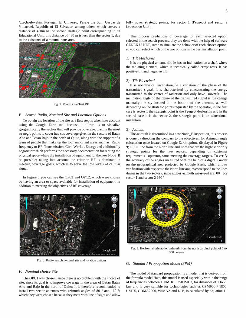
3) Azimuth The azimuth is determined in a new Node_B inspection, this process
is done by directing the compass to the objectives; for Azimuth angle
calculation once located on Google Earth options displayed in Figure
9; OPC1 line from the North line and lines that are the highest priority
strategic points for the two sectors, depending on customer
requirements - operator, same meeting the coverage targets. To verify
the accuracy of the angles measured with the help of a digital Grader
on the geographical area projected by Google Earth, which allows
verification with respect to the North line angles correspond to the lines
drawn in the two sectors, same angles azimuth measured are: 80 ° for
sector 1 and sector 2 160 °.
Fig. 9. Horizontal orientation azimuth from the north cardinal point of 0 to
360 degrees
G. Standard Propagation Model (SPM)
The model of standard propagation is a model that is derived from
the formula model Hata, this model is used especially within the range
of frequencies between 150MHz ~ 3500MHz, for distances of 1 to 20
km, and is very suitable for technologies such as GSM900 / 1800,
UMTS, CDMA2000, WiMAX and LTE, is calculated by Equation 1:

7
𝑃𝑅 = 𝑃𝑇𝑥 + 𝐺𝑇𝑥 − (𝐾1 + 𝐾2 log(𝑑) + 𝐾3 log(𝐻𝑇𝑥𝑒𝑓𝑓) +
𝐾4𝐷𝑖𝑓𝑓𝑟𝑎𝑐𝑡𝑖𝑜𝑛 𝑛𝐿𝑜𝑠𝑠 + 𝐾5 log(𝑑) log(𝐻𝑇𝑥𝑒𝑓𝑓) + 𝐾6 𝐻𝑅𝑥𝑒𝑓𝑓 +
𝐾7 log(𝐻𝑅𝑥𝑒𝑓𝑓) + 𝐾𝑐𝑙𝑢𝑡𝑡𝑒𝑟𝑓(𝑐𝑙𝑢𝑡𝑡𝑒𝑟) + 𝐾ℎ𝑖𝑙𝑙,𝐿𝑂𝑆 (Ec.1)
This model uses the terrain profile, diffraction mechanisms and
takes into account the kinds of land use (Clutter) and effective antenna
heights in order to calculate the path loss (path loss). SPM model
accuracy is generally based around K_n modifying factors, which are
defined by the prediction tool GNEX U-net, Table 2 shows some
possible values for the constants used in the model formula SPM.
Tab.2. SPM values multiplicative factors (Thick Urbano)
Parámeters Mínimum Tipical Value Máximum
K1 Variable Variable Variable
K2 20 44.9 70
K3 -20 5.83 20
K4 0 0.5 0.8
K5 -10 -6.55 0
K6 -1 0 0
K7 -10 0 0
K1 is a constant and its value depends on the radio frequency. Its
value has great influence on the values given to clutter losses as seen
in Table 3 and Table 4.
Tab.3. Description of clutter losses
Frecuencia
(MHz)
K1
935 12.5
1805 22
1930 23
2110 23.8
1900 23
2300 24.7
2500 25.4
2700 26.1
3300 27.8
3500 28.3
Tab.4. Description of clutter losses
Pérdidas de Clutter fclutter
Denso Urbano
(Edificios mayores a 7 pisos)
4 a 5 (Valor a
considerar 4)
Bosque 2 a 3
Urbano
(Edificios más pequeños con
calles pequeñas y medianas)
0
Suburbano
(Con pequeños edificios)
-5 a -3
Industrial -5 a -3
Abierto en zonas urbanas -6 a -4
Abierto -12 a -10
Agua -14 a -12
Substituting the values,
𝑃𝑇𝑥 = −91 − 18 + (23 + 44.9 log(1000) +
5.83 log(30) + 0.5 (0) − 6.55 log(1000) log(30) + 0 (2) +
0 log(2) + 1 (4) + 0)
𝑃𝑇𝑥 = −91 − 18 + (23 + 134.92 + 8.95 + 0 − 29.02 +
0 + 0 + 4 + 0)
𝑃𝑇𝑥 = −91 − 18 + 141,85
𝑃𝑇𝑥 = 32.85 ≈ 33 dBm
For conversion to 33dBm watts, it is performed through Equation
2:
P(W) = 1W · 10(33dBm/ 10) / 1000 = 1.99 W ≈ 2 W (Ec.2)
𝑃𝑇𝑥 = 33 𝑑𝐵𝑚 = 2 𝑊
H. Area Calculation Cell Coverage of Node_B
To check the coverage area having the cell Node_B raised,
the propagation model SPM therefore according to Equation 1,
the parameter "d", which represents the radius of coverage of
the cell is cleared is used. The procedure for clearance of the
variable "d" and replacing the values obtained are presented
below:
d = 10^{(−33 − 18 − (−91) + 23 − 8.61 − 0.5 (0) − 0.5 (0)
− 1 (4) − 0)/(44.9 + 9.67)}
𝑑 = 10^{0.92}
𝑑 = 8.31 𝐾𝑚; Radio coverage of the cell Node_B
Therefore, the coverage area of the cell Node_B is calculated
through Equation 3, and displayed in Figure 10.
Fig.10. Coverage Area for Cellular Cell
Área = 2.5981*R2 (Ec.3)
Substituting the calculated radius of the proposed Node_B cell, we
have::
Área = 2.5981*8.312
Área = 21.59 Km2; Coverage area of the cell Node_B
I. Results Link Budget
Link Budget are the initial parameters for the new station that enters
the network engages and can work with your environment, the cell
parameters of the new Node_B, power parameters and CPICH are
those that are set in the prediction tool .
It is a way to qualify the transmission performance is summarized
as accounting for all profits and losses incurred through the

8
transmission medium it indicates the performance that the new radio
system will perform when implemented on stations existing bases
designed under UMTS / HSPA + technology. Resultados Link Budget
The results in Table 5 are basically the requirements requested by
the mobile cellular operator, to design 3G network so that the design
process will be based on this information.
Tab.5. Link Budget results in the 1900 MHz band.
LINK BUDGET
Stage THICK URBAN
Tecnology UMTS
Type of Environment OUTDOOR
Banwidth (MHz) 5
USER EQUIPMENT
Receiving Power -90 dBm
Antenna Gain 0 dBi
Body Losses 3 dB
Receiver Sensitivity -110,43 dBm
NODE_B
Power Transmission
Channel CPICH
33 dBm
Maximum Power
Transmission Node_B
43 dBm
Noise factor 4 dB
Thermal noise power -81,86 dBm
Charge factor 50 %
Interference margin 3,01 dB
Background noise -74,85 dBm
Requirements Eb / No 4.50 dB
EIRP 50,2 dBm
Gain Process 37,07 dB
Antenna Gain 18 dBi
Cable and Connector
Loss
0.8 dB
Fading margin 10.3 dB
Multipath fading 1.45 dB
SHO gain 4 dB
standard deviation or
standard deviation
composite shadow
compuesta
8
dB
Penetration Loss 15 dB
Load Fluctuation 0,5 dB
Then these values will be taken directly prediction software that
interprets us through graphical planning that will cover for 3G / UMTS
network of our design.
J. RF coverage prediction UMTS OPC1
For OPC1 you have determined the values in Table 5, values that
are optimal for meeting the coverage targets in the areas of Batan Batan
Alto and Bajo in the north of Quito.
Figure 11 shows the behavior of Node_B coverage levels, without
the presence of the coverage areas of neighboring Node_B. The
interpretation depends on the graph legend obtained in RSCP coverage
analysis performed in the drive test RF for which; indicates that the
color green is the area of most optical coverage in signal reception,
both the received power level RSCP, the quality of Ec / Io and
minimum error rate BLER signal, the blue color determines the signals
very acceptable where voice and data acceptable to the EU, determines
levels of reception power of the minimum EU blue color, but if you
provide quality voice services and data, the yellow color determines
unacceptable levels in the signal reception, causing loss of coverage
and failure to access voice and data services; finally the red color
determines degraded signals; which they are total loss of signal, and
the color lead is exclusion zone 1 where a mountainous area,
determined by the irregularity of the terrain and lack of line of sight is
identified.
Fig.11. Coverage levels Node_B.
Figure 12 represents the behavior of coverage levels including
neighboring Node_B, as also displayed and determines that there is no
over-lapamiento between neighboring cells Node_B.
Fig.12. Coverage levels included Node_B neighbors.
K. Implementation of Nodo_B
For a better understanding of the requirements for the
implementation of the new Node_B, it has made a diagram or flow
chart displayed in Figure 13; content starts with a plan UMTS network
that is according to the requirements of mobile cellular operator, which
is identified with 3G cells for mobile devices or EU; whereas coverage
analysis is performed through RF drive test, which determines
coverage holes in areas with low levels of cellular signals. Allowing to
establish the search for a site or option where the implementation of
the new Node_B that meets the objectives RF and net agreement
between all areas of interest to the project possible. If the analysis in
site is best suited to engineering level it is appropriate in the
preparation of a Technical Site Survey (TSS), through which shows
the data obtained in the field inspection, allowing verify the
dimensions of the structural elements as well as the state in which the
building is located, which has good conditions.
Studies by civil works, we find that the structure if it has sufficient
capacity to withstand the gravitational loads and overloads from the

9
installation of telecommunications equipment such as: Mini Shelter,
RF Antennas and corresponding RRU, which are supported in two
masts 3m, which are fixed and located in the columns of the terrace or
top tier of the building structure, and mainly fulfilling the objectives of
coverage and line of sight, taking into account the use of three types of
height masts ranging from 3, 6 and 9 meters, the height requirement to
use and mainly depends on the line of sight exists in the area of
coverage to be achieved; analysis is verified on the photo shoot on the
deck every 30 °, therefore to have line of sight is only 3m masts used.
Considering that the structure has sufficient capacity to withstand an
equivalent seismic load 10% of its own weight, and further winds of
120 km / h applied on the structure, including the positioning of
equipment according to the resistance Floor terrace, this analysis are
applied based on the structure as described in the ANSI / TIA Standard
222F, which constitutes the greatest horizontal load that could be
applied to it. In the case of installing new equipment must perform a
new structural analysis.
When installing all telecommunications equipment, commissioning
and integration of the new Node_B, which allows communication with
the RNC, the MPLS 3G operator, the transmission and reception of
cellular signals corresponding to the 3G / UMTS cells is carried out;
to complete the process of commissioning the delivery of the site is
done through a Aceptance Test Protocol (ATP), a document in which
all equipment installed and operating telecommunications, with their
respective performance tests are analyzed; if this process is not
delivering according to operator requirements, the site does not accept
an extension resulting delivery 15 days; by re-commissioning of
Node_B and verifying whether each of the installed equipment is
faulty. By verifying all the problems presented in the first visit, a return
visit in which the operator confirms whether the Node_B meets the
requirements for delivery is made, if successful is determined as
requirements of the new Node_B achieved.
Fig.13. Flow chart of the requirements for the implementation of a Node_B
IV. FUNCIONALITY TEST
In the Rack Huawei Minishelter the Aceptance Test Protocol (ATP)
commissioning and integration and Aceptance Test Protocol (ATP)
installation, same as the respective settings made in the equipment
shown in the following sections was performed; later in the masts as
supports of sector antennas the Aceptance Test Protocol (ATP) of the
radiant system was performed.
A. Address Verification IP
As a first test IP addresses configured in the ports of Fast Ethernet
transmission is verified, this process is done by executing the
command DEVIP LST.
When performing this procedure configured IP addresses on port
FE / GE of BBU3900 directly in WMPT / UTRP card, subrack 0, slot
0 and port 0 is displayed.
To verify that Ping tests are successful run from the LMT software,
within which the following successful connections between verified:
1) The IP service with the RNC, is found that there is connectivity
between the Node_B and the RNC, it means that the RNC must be
registered with the IP Node_B.
2) The IP Gateway service , it is found that the way from the
Node_B towards MPLS is enabled .
3) The IP Management with M2000 manager, will check that the
Node_B is registered in the management or n Operator.
4) The IP service with IPCLOCK, indicates the synchronism
between the RNC and Node_B.
B. Changing Cell ID on a call from 3G to 3G
Within these tests is shown that by making a call within the
coverage area there is a change between cells without interference, this
process is called Soft Handover, same as evidenced through the
application G-NETtrack Lite, which It allows me to evaluate the types
of cells within the coverage area Node_B, as shown in Figure 14.
Capture CELLID
Identification of Sector 1.
Capture CELLID
Identification of Sector 2.
Fig.14. Soft Handover Fig.14.Visualización through EU. G-NetTrack Lite
.
C. Test VSWR
In this measurement process as a first point of VSWR maximum
value obtained on-site installation time of Jumper (Antenna / RRU) is
verified. We must take into account that the range of frequencies used
for measurement is 1850 MHz to 2000 MHz, as the measuring
equipment (SITEMASTER), you get the exact values of VSWR
defining the operating frequency of Node_B is 1900 MHz.
As a fundamental part of these tests all graphs obtained and
recorded in the test equipment must have the following nomenclature
to identify the site, sector and antenna port: SITE NAME - SECTOR
(1, 2, 3) - PUERTO (0 , 1), as displayed in Figure 15.

10
In Figure 15; the first measurement indicates the sector VSWR (1-
0), taking into account the scoreboard with the highest peak loss
reflected wave; maximum value of 1.16 VSWR
Fig.15. VSWR 1-0.
V. CONCLUSIONES
Upon completion of the analysis made in the design of the new
Node_B, initial results were obtained through the RF drive test, which
checked with the manual calculations that were made for the
propagation model and link budget; where the results vary depending
on each parameter as transmission power CPICH (2W), maximum
power in the Node_B (20W) operates, carrier frequency (1900 MHz),
bandwidth (5 MHz), gain RF antenna (18dBi), coverage area of the
cell Node_B (21.59 km 2 ), among others, which are admitted to the
U-Net software for creating traffic maps analyzing the coverage levels
and nonexistence of on-lapamiento between cells, and thus set the
nominal prediction site where the new Node_B implemented.
Design embodied 3G / UMTS network; by reporting technical
inspection of the site or Technical Site Survey (TSS), the gathering of
information in the field and the projection of the site was made; with
which the installation and adjustment of Node_B was made, taking
into account studies by civil works, as to the ability of the structure to
withstand the gravitational loads and overloads of telecommunications
equipment, under the ANSI / TIA 222F , indicating that the structure
has sufficient capacity to withstand seismic loading equivalent to 10%
of its own weight, and further winds of 120 km / h applied on the
structure,
Under recommendations of the supplier of telecommunications
equipment, specified that in the three types of masts with heights
ranging from 3, 6 and 9 meters, the requirement of height to use only
depends and mainly line of sight exists in the coverage area to be
covered; analysis is verified on the photo shoot on the deck every 30
°, therefore to have line of sight is only 3m masts used.
Commissioning and integration of Node_B Guangüiltahua was
carried out by the platform internal management Local mantenance
Terminal (LMT), which verifies the following parameters: versions of
the BBU, Ethernet ports in state UP, remote activation measurements
of VSWR with manager M2000, IP addresses Management and
Service configured, sizing channel voice traffic (6 channels),
dimensioning traffic channel data (16 channels) and alarm status,
parameters found according to the requirements of cellular mobile
telephone operator.
The Node_B acceptance testing was performed by the CNT EP;
This process is effected by using functional tests through a document
called Protocol Acceptance Testing or ATP, in tests to consider
evidence Ping were performed verifying connectivity and
synchronization between the Node_B with manager M2000 and the
RNC which were successful. One of the most demanding for the
delivery of site tests is to verify the loss or VSWR reflected wave in
each sector, satisfactory results for the operator since they are within
the range of minor losses to 1.3 VSWR.
REFERENCES
Henne , I., & Thorvaldsen, P. (2002). Planificación de radioenlaces.
Bergen: Segunda edición, Nera 2002, 1999.
Navarro Giovanetti, J. A. (2008). Evolución de 3G y su Convergencia
a 4G en Comunicaciones Móviles. Valdivia.
3GPP. (2005). 3rd Generation Partnership Project; Technical
Specification Group Radio Access Network; Physical layer
- Measurements (FDD);(Release 1999). © 2004, 3GPP
Organizational Partners (ARIB, ATIS, CCSA, ETSI, TTA,
TTC). All rights reserved.
Aguirre Álvarez, J. M., & Chávez González, L. A. (2010). Estudio y
Diseño de Transmisores y Receptores UMTS. Guayaquil -
Ecuador.
ARCOTEL. (13 de Febrero de 2015). Resolución ARCOTEL-2015-
000100. Quito, Pichincha, Ecuador.
Calderón, M., & Escandón, J. (2010). Introducción a WCDMA para
UMTS. Recuperado de:
http://dspace.ups.edu.ec/bitstream/123456789/186/3/Capitu
lo%202.pdf.
CEDEÑO, E. F. (Octubre, 2015). DISEÑO E INSTALACIÓN DE UN
NODO B ADICIONAL EN UNA ZONA DE ALTO
TRÁFICO DE LA CIUDAD DEL COCA PROVINCIA DE
ORELLANA PARA AUMENTAR CAPACIDAD Y
COBERTURA DE LA RED UMTS. Quito.
Cerquides, D. R. (Enero 2010). Comunicaciones Móviles 2G y 3G+.
Trabajo Personal Diapositivas.
Chimbo Rodríguez, M. C. (2012). Analisis a la Propuesta de
Evolución de Redes 3G y su Convegencia a la Tecnologìa
4G para Redes de Telefonía Móvil. Cuenca - Ecuador.
Correia, L. M. (March 2009). A View of the COST 231-Bertoni-
Ikegami Model. EuCAP 2009. Berlin: 3rd European
Conference on Antennas and Propagation.
Cruz, F. A., Ortega Romero, S. R., & Andrade Mora, R. (2010).
ESTUDIO DE FACTIBILIDAD DE LA
IMPLEMENTACION DE UNA RED UMTS EN LA
CIUDAD DE GUAYAQUIL. Guayaquil - Ecuador.
Cueva Vargas, O. X., & Santacruz Paz, D. V. (2010).
AUTOMATIZACIÓN DE HERRAMIENTAS DE POST
PROCESAMIENTO DE LA INFORMACIÓN DE DRIVE-
TEST QUE PERMITAN DETERMINAR LOS
PARÁMETROS DE QoS DE LAS REDES
GSM/GPRS/UMTS DE LOS SISTEMAS MÓVILES
AVANZADOS. Quito-Ecuador.
Dans, E. (jueves 11 de noviembre de 2004). UMTS La ceguera
intencionada. Avance de las Nuevas Tecnologías.
Donate Prieto, F. (2012). GPRS. Recuperado de:
http://bibing.us.es/proyectos/abreproy/11980/fichero/CAP
%CDTULO+3+-
+FUNDAMENTOS+GSM+Y+UMTS%252F3.4+GPRS.pd
f.
Fernández Orozco, G. P. (2013). ANÁLISIS DE LAS MEDICIONES
DE DRIVE TEST REALIZADAS POR LA SUPERTEL EN LA
RED DE SERVICIO MÓVIL AVANZADO DE LA CIUDAD
DE RIOBAMBA PARA PROPONER MEJORAS EN LOS

11
NIVELES DE COBERTURA Y CALIDAD DE SERVICIO.
Riobamba - Ecuador.
Forks. (Febrero 2011). User Manual LTE. Telecomunicaciones.
Chicago.
Gaibor, C. G. (2005). DISEÑO DE UNA RED TELEFÓNICA
CELULAR PARA LA CIUDAD DE AMBATO UTLIZANDO
TECNOLOGÍA 3G. Ambato- Ecuador: Recuperado:
http://repositorio.uta.edu.ec/handle/123456789/395.
Gallegos Rodríguez, E. D., & Galindo Hidalgo, W. J. (2006). Diseño
y Planificación de Cobertura Celular CDMA2000 1x
mediante un Sistema Repetidor(es)-BTS(s) para la
Carretera Aloag-Santo Domingo. Quito.
García Cogorro, J., Carro, A., Soto, J., Shulte-Bockum, J., Van Doorn,
P., & Páez, J. M. (2004). 3G/UMTS Una realidad
impaciente. Fundación de la Innovación Bankinter ;
Recuperado de:
https://www.fundacionbankinter.org/documents/11036/162
11/Publicacion+PDF+ES+FTF_3G/da82222c-8d3a-417e-
984a-d99b6808be26.
G-NetTrack Lite. (26 de febrero de 2015). Obtenido de
https://play.google.com/store/apps/details?id=com.gyokovs
olutions.gnettracklite&hl=es_419
Guachilema Valencia, I. J., & León Drouet, I. A. (Enero, 2010).
Calidad de Servicio (QoS) de la Red UMTS en la Ciudad de
Durán. Duran - Ecuador: Recuperado de:
http://www.ultratelcomunicaciones.com.
Herradón Diez,, R. (Marzo, 2010). Comunicaciones Móviles 3G:
UMTS,. Recuperado de: http://ocw.upm.es/teoria-de-la-
senal-ycomunicaciones-.
Herrera, J. L. (Mayo, 2009). Tecnologías Celulares de Tercera
Generación y su Evolución. Lima.
Huawei Technologies Co., L. (08 Enero, 2014). WCDMA Nodo_B
DBS3900 - Guía de Instalación de Hardward (Mini Shelter
). Quito - Ecuador.
HUAWEI TECHNOLOGIES CO., L. (2011). Long Term Evolution
(LTE), Radio Access Network Planning Guide.
Huawei Technologies CO., L. (2012-09-30.). DBS3900 Product
Description.
Huawei Technologies CO., L. (s.f.). Base Station Antenna Catalogue.
Huawei Technologies CO., L. (s.f.). LTE Hardware Introduction.
Lin Guangpu, D. F. (2011). Long Term Evolution (LTE) Radio Access
Network Planning Guide.
Martínez Rodríguez, R. O. (8 Enero de 2004). Estudio sobre las
prestaciones de Antenas Inteligentes en Sistemas de
Comunicaciones Móviles de Tercera Generación (UMTS).
Madrid - España.
Mayorga, L. A. (2001). IMT-2000 - Comunicaciones móviles de
tercera generación y su implementación en Chile. Chile.
Montes de Oca, E., Egel Bello, M., & Rodríguez Medrano, N. (2012).
UMTS(Universal Mobile Telecomunication System).
Murguet, R. (2004). Comunicaciones Móviles, GSM, GPRS, EDGE.
Cuenca - Ecuador: Recuperado de:
http://slideplayer.es/slide/1101555/.
O. S. Roig, J. L. (2003). Principios de Comunicaciones Móviles.
Barcelona: Politext: Primera Edición.
Qualcomm. (May 2006). WCDMA Network Planning. 80-W0853-1
Revision B,.
Ricaurte Zambrano, B. E., & Delgado Arechúa, R. F. (2010). Diseño
de una red UMTS para brindar el servicio de intenet en la
vía a la costa de la Ciudad de Guayaquil desde el Km. 10
hasta el Km. 25. Guayaquil - Ecuador.
Sáenz Medina, J. S. (2009). DEFINICIÓN, DISEÑO Y SIMULACIÓN
DE ANTENA FRACTAL MONOPOLO DE SIERPINSKI.
Lima: Recupedado de:
http://cybertesis.urp.edu.pe/handle/urp/68.
Sevilla, E. S.-U. (2010). Diseño y parametrización de una estación de
telefonía móvil 2G/3G. Sevilla.
Technologies, H. (Enero, 2010). WCDMA RAN Fundamental ISSUE
1.0. Recuperado de: www.huawei.com/support.
Telecomunicaciones, U. (Enero, 2010). Network Planning - Initial
Tuning - Optimización. Recuperado de:
http://www.ultratelcomunicaciones.com.
Vielma, M. (2005). Introducción a las Antenas, edición 2010.
Ricardo J. Cuchala was born on
September 27, 1988, he completed his
primary studies at the Model School
President Velazco Ibarra. In 2006 he
earned his bachelor's degree in physical
sciences specialization mathematics at
the Experimental Education Unit
"Teodoro Gomez de la Torre".
Currently, he graduated from the School
of Engineering in Electronics and
Communication Networks Technical University North of the
city of Ibarra. Work experience in the company Highspeed
Telecommunication Systems, performing the duties of
Inspector for Telefonica in the areas: Overseer of sites 3G
Second Carrier 1900 MHz, Inspector of sites on 3G, 4G,
Inspector Preventive Maintenance of Bases Radio adjustments
and has attended courses such as Computer Maintenance,
Integration Methods, Labview, Network and Internet and work
at heights Telecommunications towers.


