Embed Size (px)
Citation preview
Combined Syllabus Specification V1.4 - Part 1 Page 1.1
2020-07-30
Radio Amateur Examinations
Specification
For Examinations held from 1 August 2020
Publication date: July 31 2020
Document EX2019-1 V1.4
Combined Syllabus Specification V1.4 - Part 1 Page 1.2
2020-07-30
Contents
Part Page
1 Introduction 1.3
2 Syllabus
1 Licensing
2 Technical aspects
3 Transmitter and receivers
4 Feeders and Antennas
5 Propagation
6 Electro Magnetic Compatibility
7 Operating Practices and Procedures
8 Safety
9 Measurements and Construction
10 Practical Assessments
2.1
2.2
2.9
2.22
2.34
2.40
2.44
2.51
2.56
2.64
2.68
3 Foundation Licence Examination material 3.1
4 Intermediate Licence Examination material 4.1
5 Full Licence Examination material 5.1
Document changes
Issue 1 December 2018 First issue to 2019 syllabus
Issue 1.1 February 2019 Minor revisions
Issue 1.2 July 2019 Minor revisions
Issue 1.3 July 2019 Minor revisions
Issue 1.4 July 2020 Minor revisions
Issue 2 Expected Jan 2021 Major revisions, consultation to be announced.
Minor revisions are examinable immediately as no new learning points are added
Major revisions are examinable after 6 months following publication
Combined Syllabus V1.4a document shows all changes from previous version
Combined Syllabus Specification V1.4 - Part 1 Page 1.3
2020-07-30
Section 1
Introduction The Radio Amateur Examinations Specification comprises a structured suite of three examinations designed to give access to the amateur radio bands. All prospective radio amateurs must demonstrate a suitable level of competence and proficiency as a pre-requisite to holding a licence.
The Foundation Licence is the entry level to amateur radio. Foundation training and examination is intended to provide an exciting introduction to the hobby whilst requiring an acceptable minimum level of skill and experience of on-air operating.
The Intermediate Licence and examination continue the theoretical training to provide additional on-air privileges including the ability to build a transmitter and use it on-air. It also provides a firm base from which to study for the Full level examination.
The Full level examination gives access to the Amateur Radio (Full) Licence which offers all licence privileges and is recognised internationally.
The aim of the suite of examinations is to verify and assure the regulator that successful candidates have
• knowledge of the legal and ethical requirements of amateur radio,
• an understanding of safe working practices and are mindful of the safety of others,
• a secure foundation for further study of radio science and technology,
• knowledge of good operating practices and procedures,
• an understanding of basic electronic components and systems relevant to amateur radio,
to a standard appropriate to the level of amateur radio licence addressed by each of the three
examinations.
Key Features
• A progressive system of learning designed to promote an understanding of radio communications science, technology, and practice sufficient to allow the licensed operator to work safely on the amateur radio bands.
• Clear presentation of content for easy reference.
• The examination suite provides a backbone of theoretical knowledge whilst at the same time requiring ‘on-air’ experience and practical skills.
• A course book is available at each level.
• Can be used within schools to enrich the Science and Technology curriculum.
The Assessment
Foundation Level uses two methods of assessment. A Practical Assessment detailed in sections 10a and 10b of the syllabus requires demonstration of setting up a radio transmitter/receiver and operating correctly on-air. Candidates have a choice of a simple introduction to Morse code or demonstrating a data mode contact. These items must be assessed by a Registered Assessor, who may also be the tutor. This is followed by an examination comprising 26 questions, lasting 60 minutes, covering the remainder of the syllabus.
The Practical Assessment must be completed prior to sitting the Foundation examination which should normally be sat within 12 months of completing the Practical Assessment.
Combined Syllabus Specification V1.4 - Part 1 Page 1.4
2020-07-30
Intermediate Level assessment consists of an examination comprising 46 questions, lasting 1 hour 30 minutes.
Full Level assessment consists of an examination comprising 58 questions lasting 2 hours.
All examinations must be carried out in accordance with RSGB approved procedures.
Examinations will normally be taken on-line or, if this is not possible due to special educational
needs or technical issues at the examination centre, on paper with an Optical Mark Sheet.
If the examination is taken on-line, the candidate receives their provisional result immediately at the end of the examination. Unless any exam irregularities are reported, this result will normally be officially confirmed after 6 working days. Exams taken on paper are centrally marked and results issued by post 6 clear working days after the papers are received1. The results will also be uploaded to the Ofcom licensing database. Candidates will use their candidate number and password to apply for their licence on-line on the Ofcom web site. A postal application option is available.
Prior Learning and Progression
There is no prior learning required at Foundation level and there are no set age limits to holding an Amateur Radio Licence. Some competence in mathematics will be required to sit the examination. Candidates may already be sufficiently proficient, or some aspects may need to be covered during the course. Details are given on page 7 under Prior Requirements.
Examinations must be sat in ascending order having achieved a pass at the previous level.
Training may commence at any time and students’ progress through the three levels at their own pace. Candidates are encouraged to attend a suitable course but there is no obligation to do so.
There is no formal route of progression beyond Full level however there are many informal and academic opportunities for advancement and progression both in amateur radio and electronics generally. Possession of a Full Amateur Radio Licence is recognised as an advantage for entry into undergraduate training and many careers.
1 Candidates should allow 10 days from the examination to allow for postal delays.
Combined Syllabus Specification V1.4 - Part 1 Page 1.5
2020-07-30
Candidates with disabilities
Arrangements can be made for candidates with disabilities to demonstrate skills and knowledge by whatever means is judged appropriate. Where critical skills, such as on-air operation, are involved the requirement can be modified to reflect the candidate's preferred method of working2.
Applications for special arrangements should be made well in advance of the examination to the Radio Society of Great Britain (RSGB) and will normally require a medical or other professional certificate advising the appropriate method of assessment or examination. Any waiver granted will be shown on the Register and Assessment Sheet (RAS) issued by the RSGB Examination Department.
Appeals after the examination citing disabilities or learning difficulties not previously declared cannot be considered.
Examination Department Radio Society of Great Britain 3 Abbey Court Fraser Road Priory Business Park Bedford MK44 3WH
The Syllabus
The syllabus is presented in three-column format showing the progression of each topic across all three examination levels. Separate documents for each level are available for ease of reference during any particular course.
The key words Recall and Understand are used to denote differing levels of comprehension.
Recall indicates the need to remember a fact and apply it fairly directly to a question or situation. A thorough understanding of why the fact is so and the full range of circumstances in which it is applicable is not required, but questions will expect a basic understanding of its meaning and implications.
Understand indicates the need for a more detailed knowledge of the subject, fully comprehending the reasons why point is correct and the range of circumstances in which it is relevant and applicable. Typically, this will be where the candidates will find themselves having to make judgements or apply a practice to a wider range of circumstances.
These terms should be read in the context of the level of the examination concerned.
At Foundation level there are more ‘recall’ syllabus items than ‘understand’ whereas at Full level the majority are of an ‘understand’ nature. That will expect the candidate to know the background to the topic and the implications of not adopting the accepted practice.
For example, at Foundation level the syllabus requires knowledge of the formula 𝑃 = 𝑉 × 𝐼, what the letters stand for and the ability to perform a calculation given any two of the factors. The question will not normally require the use of a calculator since no useful purpose is served by making the question arithmetically difficult. Alternatively, the question may ask the effect of, for example, of doubling or halving one of the factors.
At any level of licence, particularly Full level, incorrect operation of a relatively powerful transmitter can cause quite widespread interference to other radio users. Candidates at all levels will be expected to know in some detail how to operate correctly, what the effects of not doing so are and how to diagnose what might be wrong given such effects are occurring.
2 The RSGB Examination Department must be consulted in advance to agree the required change.
Combined Syllabus Specification V1.4 - Part 1 Page 1.6
2020-07-30
A statement of the mathematical abilities required to satisfactorily complete training at each level is shown in the Mathematics and Symbols paragraphs below. If candidates do not possess that level of skill at the outset, then its early acquisition is essential. Training courses need to recognise that need.
Examination Questions
At each level examination questions may assume background knowledge of the basic principles from all parts of any lower level syllabus and the current one although questions themselves will be clearly aimed at the relevant syllabus item.
It will be assumed that the candidate has some familiarity with operating practices and procedures covered in the practical assessments at that and all prior levels.
Some time spent on-air either as a listener or as an amateur operator at Foundation or Intermediate level will be clearly advantageous in understanding the purpose and context of syllabus items and examination questions.
Allocation of Questions
Each item in the Syllabus is uniquely identified in its Heading e.g. 1A1. On the same line is the question number to which it is allocated in the examination. More than one syllabus item may be allocated to the same question number and the syllabus item chosen will be randomly selected when that examination is compiled. The actual question will be randomly selected from those in the question bank under the syllabus item concerned.
Pass Mark
The Foundation level Pass Mark is 73% or 19 correct answers out of a total of 26 questions.
The Intermediate level Pass Mark is 61% or 28 correct answers out of a total of 46 questions.
The Full level Pass Mark is 60% or 35 correct answers out of a total of 58 questions.
Feedback
A feedback sheet will be produced for each candidate showing the question number, the selected syllabus item and the mark, correct or incorrect, for that question.
Formulae
At Foundation level it is important that candidates understand the fundamental principles behind the theoretical topics discussed. For that reason, no formula sheet is provided.
At Intermediate level some of the more complex formulae are provided but may need to be transposed.
At Full level, all formulae will be provided. They will not be titled or explained, and candidates will be expected to recognise which formula is appropriate and may need to transpose it depending on the parameter to be calculated.
Language
The language of assessment will be English.
Training
Attendance at a training course is not compulsory but is very strongly advised. Many of the practical activities on-air require the presence of a tutor holding a Full Licence to guide the
Combined Syllabus Specification V1.4 - Part 1 Page 1.7
2020-07-30
candidate and correct errors as they occur. This is not readily achievable with reading material alone although multi-media distant learning materials will be of considerable benefit.
The practical assessments are intended to be interactive, so a candidate who is obliged to be self-taught may demonstrate his or her skills and receive guidance should that be necessary. Once the candidate has demonstrated these skills on their own, without guidance, the desired standard has been reached.
For the Foundation exam, candidates who are not on a training course are advised to check whether any particular examination session includes the practical assessments. The onus is on such candidates to ensure they have completed the practical assessments prior to sitting the examination. The requirement for practical assessments can be suspended by the Examinations Standards Committee during times of national emergency where this is appropriate.
The requirements for the practical assessments are online at
http://rsgb.org/main/clubs-training/tutor-resources-2/syllabus/
Specimen Examination Question papers are available from the RSGB (www.rsgb.org).
Updates
Updates to this syllabus will be made from time to time and the latest version can be obtained from the RSGB website. Where the update involves a significant change to the syllabus content, the date from which the syllabus is valid for examinations will be amended to show the new period of validity of the syllabus. A minimum of three months’ notice will be given. Minor syllabus changes, where the learning points have not been added are examinable immediately.
Tutors should note that all examinations will be in accordance with the syllabus which is current at the time of examination. Candidates must use only the information which will be provided in the examination, such as the licence schedule and band plan.
Any external changes, such as those affecting the licence will not be examinable until they have been formally announced as examinable. It should also be noted that the examination band plan is a specimen plan and not the live IARU/RSGB plan for on-air use.
Mathematics and Symbols
Some knowledge of mathematics will be required during any course and prior to the relevant
examination. Tutors and candidates should address this requirement as necessary.
Foundation Licence
The following levels of knowledge and ability are needed by the time candidates are ready to take
the Foundation Licence Examination.
Mathematical:
• Addition, subtraction, multiplication, and division.
• Simple fractions and their decimal equivalents.
• Multiple and sub-multiple units from micro to Giga.
• Conversion of numbers from 10-3 to 109 to/from decimal.
• Understanding of simple formulae, e.g. 𝐼 = 𝑉/𝑅, and rearrange them to make any parameter the subject of the formula.
Circuit Symbols and Diagrams:
• The symbols shown in Table 1 and the diagrams in Table 2 may be used in any examination item as required.
Combined Syllabus Specification V1.4 - Part 1 Page 1.8
2020-07-30
Intermediate Licence
The following levels of knowledge and ability as well as those at Foundation level are needed by
the time candidates are ready to take the Intermediate Licence Examination.
Mathematical:
• Requirements of Foundation plus:
• Multiple and sub-multiple prefixes from Pico to Giga.
• Calculations with quantities from 10-12 to 10+12 recognising that interim stages may go outside those limits.
• Use of simple formulae containing brackets, squared or square root operators
e.g. 𝐼 = √(𝑃
𝑅) or 𝑃 = 𝑉2/𝑅
Circuit Symbols;
• The symbols shown in Table 3 may be used in any examination item as required. Full Licence
The following levels of knowledge and ability as well as those at Foundation and Intermediate
levels are needed by the time candidates are ready to take the Full Licence Examination.
Mathematical:
• Requirements of Intermediate plus:
• Use and transposition of more complex formulae for example 𝑓 = 1
(2𝜋√𝐿𝐶)
Syllabus details - all levelsRevision 1.4
Combined Syllabus Specification V1.4 20 August 2020 Page 2.1
Foundation licence syllabus Intermediate licence syllabus Full licence syllabus
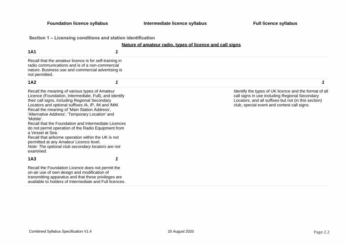
Section 1 – Licensing conditions and station identification
Nature of amateur radio, types of licence and call signs
1A1 1
Recall that the amateur licence is for self-training in radio communications and is of a non-commercial nature. Business use and commercial advertising is not permitted.
1A2 1 1
Recall the meaning of various types of Amateur Licence (Foundation, Intermediate, Full), and identify their call signs, including Regional Secondary Locators and optional suffixes /A, /P, /M and /MM. Recall the meaning of 'Main Station Address', 'Alternative Address', 'Temporary Location' and 'Mobile'. Recall that the Foundation and Intermediate Licences do not permit operation of the Radio Equipment from a Vessel at Sea. Recall that airborne operation within the UK is not permitted at any Amateur Licence level. Note: The optional club secondary locators are not examined.
Identify the types of UK licence and the format of all call signs in use including Regional Secondary Locators, and all suffixes but not (in this section) club, special event and contest call signs.
1A3 1
Recall the Foundation Licence does not permit the on-air use of own design and modification of transmitting apparatus and that these privileges are available to holders of Intermediate and Full licences.
Combined Syllabus Specification V1.4 20 August 2020 Page 2.2
Foundation licence syllabus Intermediate licence syllabus Full licence syllabus
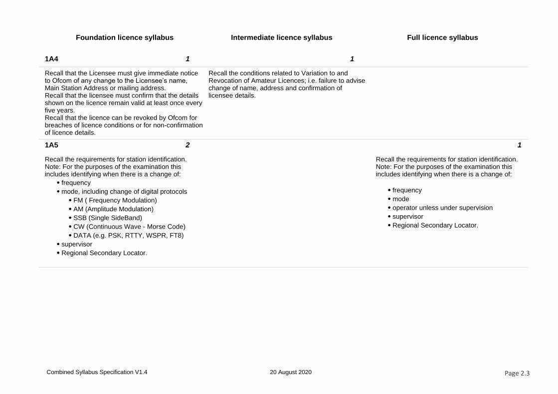
1A4 1 1
Recall that the Licensee must give immediate notice to Ofcom of any change to the Licensee’s name, Main Station Address or mailing address.Recall that the licensee must confirm that the details shown on the licence remain valid at least once every five years.Recall that the licence can be revoked by Ofcom for breaches of licence conditions or for non-confirmation of licence details.
Recall the conditions related to Variation to and Revocation of Amateur Licences; i.e. failure to advise change of name, address and confirmation of licensee details.
1A5 2 1
Recall the requirements for station identification.Note: For the purposes of the examination this includes identifying when there is a change of:
⦁ frequency
⦁ mode, including change of digital protocols
⦁ FM ( Frequency Modulation)
⦁ AM (Amplitude Modulation)
⦁ SSB (Single SideBand)
⦁ CW (Continuous Wave - Morse Code)
⦁ DATA (e.g. PSK, RTTY, WSPR, FT8)
⦁ supervisor
⦁ Regional Secondary Locator.
Recall the requirements for station identification.Note: For the purposes of the examination this includes identifying when there is a change of:
⦁ frequency
⦁ mode
⦁ operator unless under supervision
⦁ supervisor
⦁ Regional Secondary Locator.
Combined Syllabus Specification V1.4 20 August 2020 Page 2.3
Foundation licence syllabus Intermediate licence syllabus Full licence syllabus
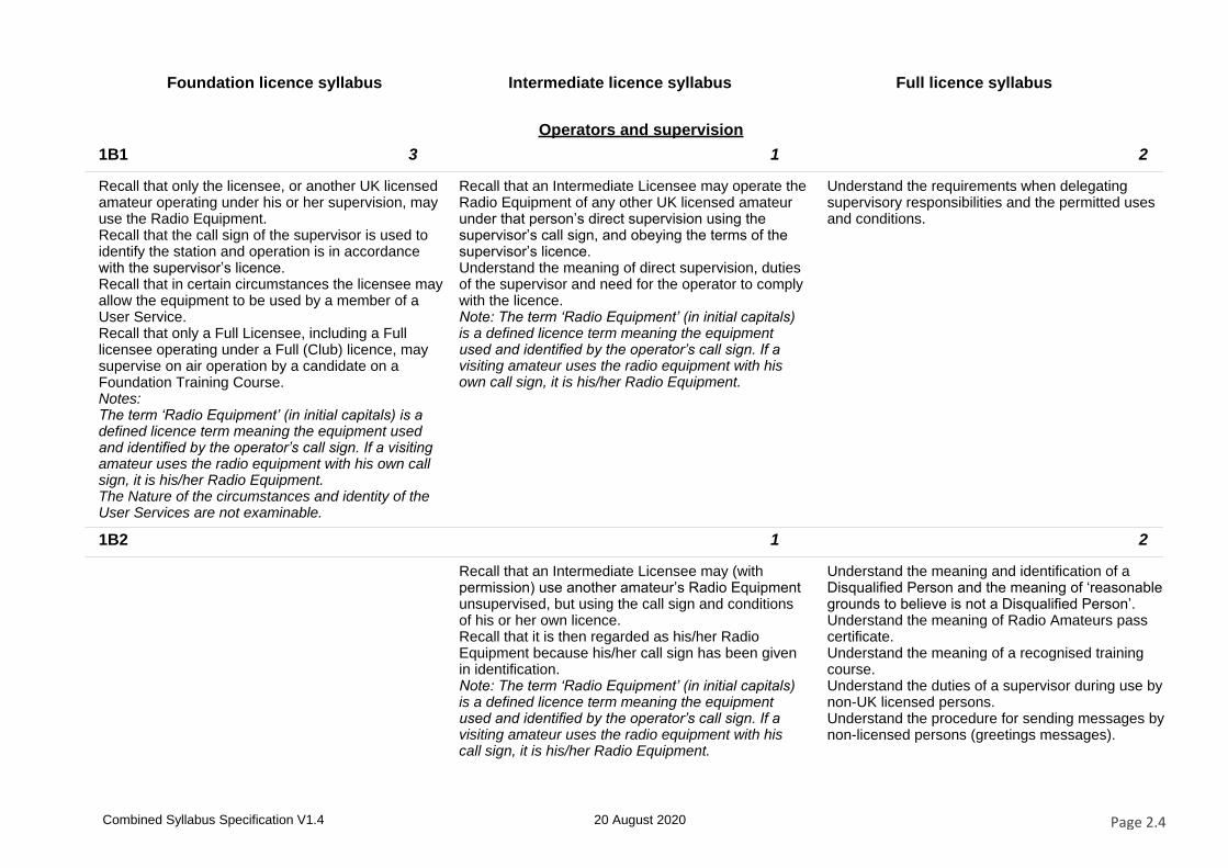
Operators and supervision
1B1 3 1 2
Recall that only the licensee, or another UK licensed amateur operating under his or her supervision, may use the Radio Equipment.Recall that the call sign of the supervisor is used to identify the station and operation is in accordance with the supervisor’s licence.Recall that in certain circumstances the licensee may allow the equipment to be used by a member of a User Service.Recall that only a Full Licensee, including a Full licensee operating under a Full (Club) licence, may supervise on air operation by a candidate on a Foundation Training Course.Notes:The term ‘Radio Equipment’ (in initial capitals) is a defined licence term meaning the equipment used and identified by the operator’s call sign. If a visiting amateur uses the radio equipment with his own call sign, it is his/her Radio Equipment.The Nature of the circumstances and identity of the User Services are not examinable.
Recall that an Intermediate Licensee may operate the Radio Equipment of any other UK licensed amateur under that person’s direct supervision using the supervisor’s call sign, and obeying the terms of the supervisor’s licence.Understand the meaning of direct supervision, duties of the supervisor and need for the operator to comply with the licence.Note: The term ‘Radio Equipment’ (in initial capitals) is a defined licence term meaning the equipment used and identified by the operator’s call sign. If a visiting amateur uses the radio equipment with his own call sign, it is his/her Radio Equipment.
Understand the requirements when delegating supervisory responsibilities and the permitted uses and conditions.
1B2 1 2
Recall that an Intermediate Licensee may (with permission) use another amateur’s Radio Equipment unsupervised, but using the call sign and conditions of his or her own licence.Recall that it is then regarded as his/her Radio Equipment because his/her call sign has been given in identification.Note: The term ‘Radio Equipment’ (in initial capitals) is a defined licence term meaning the equipment used and identified by the operator’s call sign. If a visiting amateur uses the radio equipment with his call sign, it is his/her Radio Equipment.
Understand the meaning and identification of a Disqualified Person and the meaning of ‘reasonable grounds to believe is not a Disqualified Person’.Understand the meaning of Radio Amateurs pass certificate.Understand the meaning of a recognised training course.Understand the duties of a supervisor during use by non-UK licensed persons.Understand the procedure for sending messages by non-licensed persons (greetings messages).
Combined Syllabus Specification V1.4 20 August 2020 Page 2.4
Foundation licence syllabus Intermediate licence syllabus Full licence syllabus
Messages
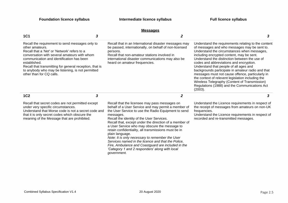
1C1 3 2 3
Recall the requirement to send messages only to other amateurs.Recall that a 'Net' or 'Network' refers to a conversation with several amateurs with whom communication and identification has been established.Recall that transmitting for general reception, that is to anybody who may be listening, is not permitted other than for CQ calls.
Recall that in an International disaster messages may be passed, internationally, on behalf of non-licensed persons.Recall that non-amateur stations involved in international disaster communications may also be heard on amateur frequencies.
Understand the requirements relating to the content of messages and who messages may be sent to.Understand the circumstances when messages, including encrypted content, may be sent.Understand the distinction between the use of codes and abbreviations and encryption.Understand that people of all ages and backgrounds participate in amateur radio and that messages must not cause offence, particularly in the context of relevent legislation including the Wireless Telegraphy (Content of Transmission) Regulations (1988) and the Communications Act (2003).
1C2 3 2 3
Recall that secret codes are not permitted except under very specific circumstances.Understand that Morse code is not a secret code and that it is only secret codes which obscure the meaning of the Message that are prohibited.
Recall that the licensee may pass messages on behalf of a User Service and may permit a member of the User Service to use the Radio Equipment to send messages.Recall the identity of the User Services.Recall that, except under the direction of a member of a User Service who may obscure the message to retain confidentiality, all transmissions must be in plain language.Note: It is only necessary to remember the User Services named in the licence and that the Police, Fire, Ambulance and Coastguard are included in the ‘Category 1 and 2 responders’ along with local government.
Understand the Licence requirements in respect of the receipt of messages from amateurs on non-UK frequencies.Understand the Licence requirements in respect of recorded and re-transmitted messages.
Combined Syllabus Specification V1.4 20 August 2020 Page 2.5
Foundation licence syllabus Intermediate licence syllabus Full licence syllabus
Apparatus, inspection and closedown
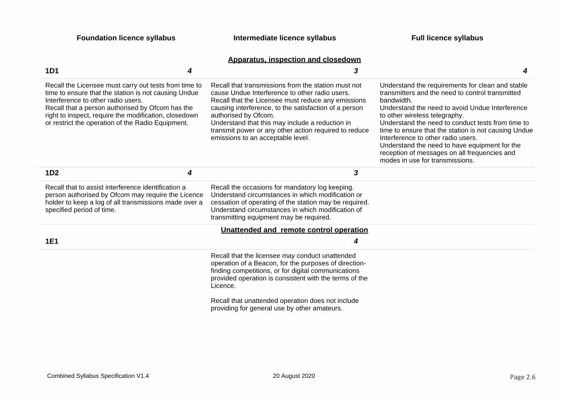
1D1 4 3 4
Recall the Licensee must carry out tests from time to time to ensure that the station is not causing Undue Interference to other radio users.Recall that a person authorised by Ofcom has the right to inspect, require the modification, closedown or restrict the operation of the Radio Equipment.
Recall that transmissions from the station must not cause Undue Interference to other radio users.Recall that the Licensee must reduce any emissions causing interference, to the satisfaction of a person authorised by Ofcom.Understand that this may include a reduction in transmit power or any other action required to reduce emissions to an acceptable level.
Understand the requirements for clean and stable transmitters and the need to control transmitted bandwidth.Understand the need to avoid Undue Interference to other wireless telegraphy.Understand the need to conduct tests from time to time to ensure that the station is not causing Undue Interference to other radio users.Understand the need to have equipment for the reception of messages on all frequencies and modes in use for transmissions.
1D2 4 3
Recall that to assist interference identification a person authorised by Ofcom may require the Licence holder to keep a log of all transmissions made over a specified period of time.
Recall the occasions for mandatory log keeping.Understand circumstances in which modification or cessation of operating of the station may be required.Understand circumstances in which modification of transmitting equipment may be required.
Unattended and remote control operation
1E1 4
Recall that the licensee may conduct unattended operation of a Beacon, for the purposes of direction-finding competitions, or for digital communications provided operation is consistent with the terms of the Licence.
Recall that unattended operation does not include providing for general use by other amateurs.
Combined Syllabus Specification V1.4 20 August 2020 Page 2.6
Foundation licence syllabus Intermediate licence syllabus Full licence syllabus
1E2 4 5
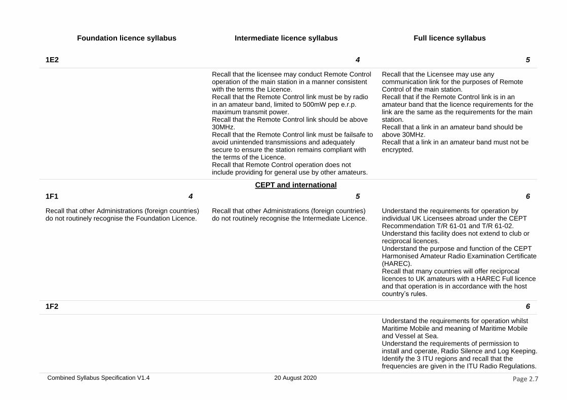
Recall that the licensee may conduct Remote Control operation of the main station in a manner consistent with the terms the Licence.Recall that the Remote Control link must be by radio in an amateur band, limited to 500mW pep e.r.p. maximum transmit power.Recall that the Remote Control link should be above 30MHz.Recall that the Remote Control link must be failsafe to avoid unintended transmissions and adequately secure to ensure the station remains compliant with the terms of the Licence.Recall that Remote Control operation does not include providing for general use by other amateurs.
Recall that the Licensee may use any communication link for the purposes of Remote Control of the main station.Recall that if the Remote Control link is in an amateur band that the licence requirements for the link are the same as the requirements for the main station.Recall that a link in an amateur band should be above 30MHz.Recall that a link in an amateur band must not be encrypted.
CEPT and international
1F1 4 5 6
Recall that other Administrations (foreign countries) do not routinely recognise the Foundation Licence.
Recall that other Administrations (foreign countries) do not routinely recognise the Intermediate Licence.
Understand the requirements for operation by individual UK Licensees abroad under the CEPT Recommendation T/R 61-01 and T/R 61-02.Understand this facility does not extend to club or reciprocal licences.Understand the purpose and function of the CEPT Harmonised Amateur Radio Examination Certificate (HAREC).Recall that many countries will offer reciprocal licences to UK amateurs with a HAREC Full licence and that operation is in accordance with the host country’s rules.
1F2 6
Understand the requirements for operation whilst Maritime Mobile and meaning of Maritime Mobile and Vessel at Sea.Understand the requirements of permission to install and operate, Radio Silence and Log Keeping.Identify the 3 ITU regions and recall that the frequencies are given in the ITU Radio Regulations.
Combined Syllabus Specification V1.4 20 August 2020 Page 2.7
Foundation licence syllabus Intermediate licence syllabus Full licence syllabus
Licence schedule
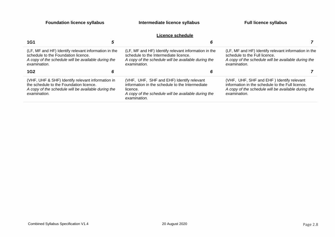
1G1 5 6 7
(LF, MF and HF) Identify relevant information in the schedule to the Foundation licence.A copy of the schedule will be available during the examination.
(LF, MF and HF) Identify relevant information in the schedule to the Intermediate licence.A copy of the schedule will be available during the examination.
(LF, MF and HF) Identify relevant information in the schedule to the Full licence.A copy of the schedule will be available during the examination.
1G2 6 6 7
(VHF, UHF & SHF) Identify relevant information in the schedule to the Foundation licence.A copy of the schedule will be available during the examination.
(VHF, UHF, SHF and EHF) Identify relevant information in the schedule to the Intermediate licence.A copy of the schedule will be available during the examination.
(VHF, UHF, SHF and EHF ) Identify relevant information in the schedule to the Full licence.A copy of the schedule will be available during the examination.
Combined Syllabus Specification V1.4 20 August 2020 Page 2.8
Foundation licence syllabus Intermediate licence syllabus Full licence syllabus
Section 2 – Technical aspects
Fundamental theory
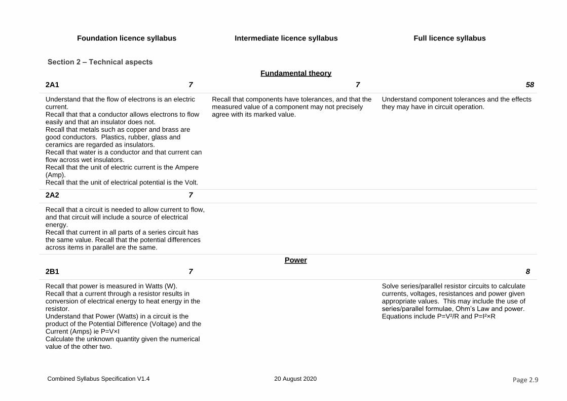
2A1 7 7 58
Understand that the flow of electrons is an electric current.Recall that that a conductor allows electrons to flow easily and that an insulator does not.Recall that metals such as copper and brass are good conductors. Plastics, rubber, glass and ceramics are regarded as insulators.Recall that water is a conductor and that current can flow across wet insulators.Recall that the unit of electric current is the Ampere (Amp).Recall that the unit of electrical potential is the Volt.
Recall that components have tolerances, and that the measured value of a component may not precisely agree with its marked value.
Understand component tolerances and the effects they may have in circuit operation.
2A2 7
Recall that a circuit is needed to allow current to flow, and that circuit will include a source of electrical energy.Recall that current in all parts of a series circuit has the same value. Recall that the potential differences across items in parallel are the same.
Power
2B1 7 8
Recall that power is measured in Watts (W).Recall that a current through a resistor results in conversion of electrical energy to heat energy in the resistor.Understand that Power (Watts) in a circuit is the product of the Potential Difference (Voltage) and the Current (Amps) ie P=V×ICalculate the unknown quantity given the numerical value of the other two.
Solve series/parallel resistor circuits to calculate currents, voltages, resistances and power given appropriate values. This may include the use of series/parallel formulae, Ohm’s Law and power. Equations include P=V²/R and P=I²×R
Combined Syllabus Specification V1.4 20 August 2020 Page 2.9
Foundation licence syllabus Intermediate licence syllabus Full licence syllabus
Resistance
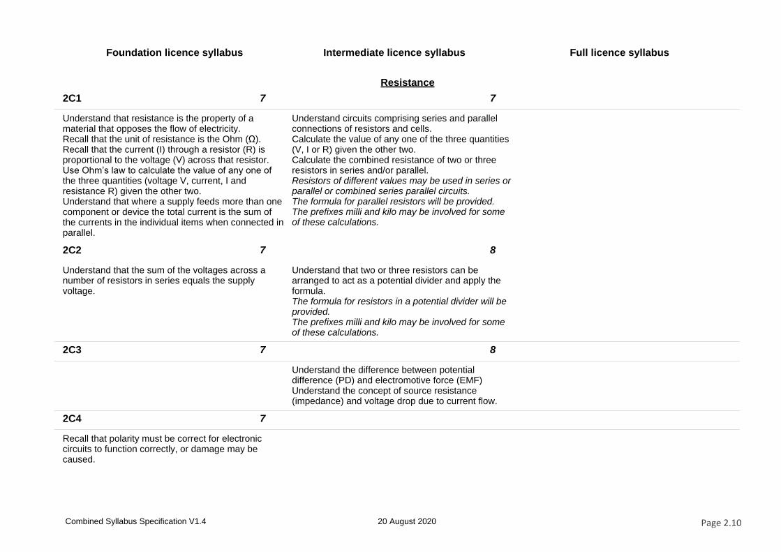
2C1 7 7
Understand that resistance is the property of a material that opposes the flow of electricity.Recall that the unit of resistance is the Ohm (Ω).Recall that the current (I) through a resistor (R) is proportional to the voltage (V) across that resistor.Use Ohm’s law to calculate the value of any one of the three quantities (voltage V, current, I and resistance R) given the other two.Understand that where a supply feeds more than one component or device the total current is the sum of the currents in the individual items when connected in parallel.
Understand circuits comprising series and parallel connections of resistors and cells.Calculate the value of any one of the three quantities (V, I or R) given the other two.Calculate the combined resistance of two or three resistors in series and/or parallel.Resistors of different values may be used in series or parallel or combined series parallel circuits.The formula for parallel resistors will be provided.The prefixes milli and kilo may be involved for some of these calculations.
2C2 7 8
Understand that the sum of the voltages across a number of resistors in series equals the supply voltage.
Understand that two or three resistors can be arranged to act as a potential divider and apply the formula.The formula for resistors in a potential divider will be provided.The prefixes milli and kilo may be involved for some of these calculations.
2C3 7 8
Understand the difference between potential difference (PD) and electromotive force (EMF)Understand the concept of source resistance (impedance) and voltage drop due to current flow.
2C4 7
Recall that polarity must be correct for electronic circuits to function correctly, or damage may be caused.
Combined Syllabus Specification V1.4 20 August 2020 Page 2.10
Foundation licence syllabus Intermediate licence syllabus Full licence syllabus
Reactive components
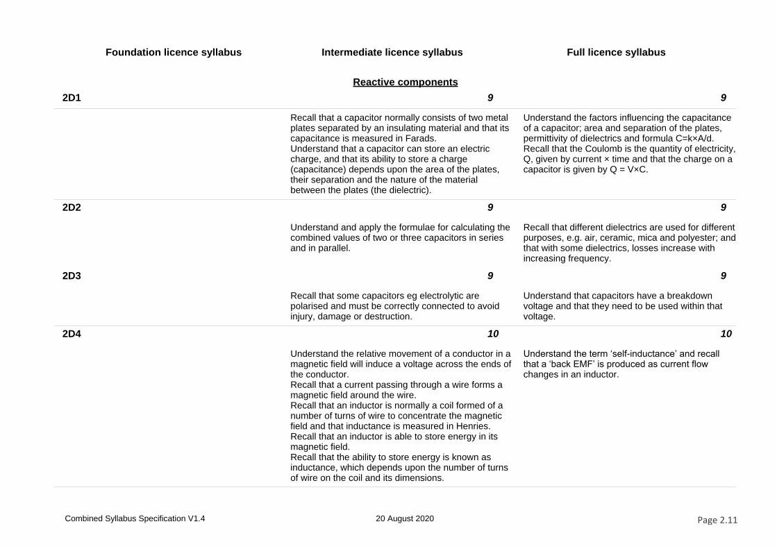
2D1 9 9
Recall that a capacitor normally consists of two metal plates separated by an insulating material and that its capacitance is measured in Farads.Understand that a capacitor can store an electric charge, and that its ability to store a charge (capacitance) depends upon the area of the plates, their separation and the nature of the material between the plates (the dielectric).
Understand the factors influencing the capacitance of a capacitor; area and separation of the plates, permittivity of dielectrics and formula C=k×A/d.Recall that the Coulomb is the quantity of electricity, Q, given by current × time and that the charge on a capacitor is given by Q = V×C.
2D2 9 9
Understand and apply the formulae for calculating the combined values of two or three capacitors in series and in parallel.
Recall that different dielectrics are used for different purposes, e.g. air, ceramic, mica and polyester; and that with some dielectrics, losses increase with increasing frequency.
2D3 9 9
Recall that some capacitors eg electrolytic are polarised and must be correctly connected to avoid injury, damage or destruction.
Understand that capacitors have a breakdown voltage and that they need to be used within that voltage.
2D4 10 10
Understand the relative movement of a conductor in a magnetic field will induce a voltage across the ends of the conductor.Recall that a current passing through a wire forms a magnetic field around the wire.Recall that an inductor is normally a coil formed of a number of turns of wire to concentrate the magnetic field and that inductance is measured in Henries.Recall that an inductor is able to store energy in its magnetic field.Recall that the ability to store energy is known as inductance, which depends upon the number of turns of wire on the coil and its dimensions.
Understand the term ‘self-inductance’ and recall that a ‘back EMF’ is produced as current flow changes in an inductor.
Combined Syllabus Specification V1.4 20 August 2020 Page 2.11
Foundation licence syllabus Intermediate licence syllabus Full licence syllabus
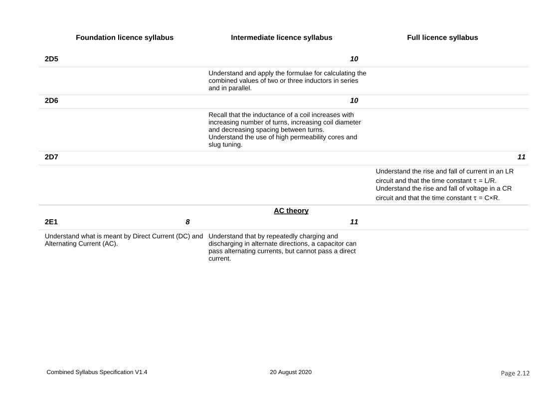
2D5 10
Understand and apply the formulae for calculating the combined values of two or three inductors in series and in parallel.
2D6 10
Recall that the inductance of a coil increases with increasing number of turns, increasing coil diameter and decreasing spacing between turns.Understand the use of high permeability cores and slug tuning.
2D7 11
Understand the rise and fall of current in an LR
circuit and that the time constant = L/R.Understand the rise and fall of voltage in a CR
circuit and that the time constant = C×R.
AC theory
2E1 8 11
Understand what is meant by Direct Current (DC) and Alternating Current (AC).
Understand that by repeatedly charging and discharging in alternate directions, a capacitor can pass alternating currents, but cannot pass a direct current.
Combined Syllabus Specification V1.4 20 August 2020 Page 2.12
Foundation licence syllabus Intermediate licence syllabus Full licence syllabus
2E2 8 11
Identify the sine wave as a graphical representation of the rise and fall of an alternating current or voltage over time.Recall the frequency of the mains supply – 50Hz.Recall the range of frequencies for normal hearing –20Hz -15kHz.Recall the range of frequencies for audio communication – 300Hz - 3kHz.Recall that radio frequencies can range from below 30kHz to beyond 3000MHz.Recall the frequency bands for HF, VHF and UHF radio signals.Understand the meaning of the abbreviations RF and AF.
Understand the sinusoidal curve as a graphical representation of the rise and fall of an alternating current or voltage over time and that both the frequency and the amplitude must be specified.Recognise the graphical representation of a square wave.Recall that the time in seconds for one cycle is the Periodic Time (T) and the formula T=1/f and f= 1/T where f = frequency in Hertz and T = time interval in seconds.Recall the concept of phase difference between two signals, and that it can be expressed in degrees.
2E3 11 12
Recall that the potential difference across and current through a resistor are in phase.Recall that the power dissipated in a resistive circuit varies over the cycle.Recall that the RMS current or voltage in an AC circuit is equal to the current or voltage of a DC supply that would result in the same power dissipation.Recall that the RMS value of a sinusoidal waveform, Vrms = 0.707×Vp (peak Voltage). Perform relevant calculations.Recall that the term ‘Reactance’ describes the opposition to current flow in a purely inductive or capacitive circuit where the phase difference between V and I is 90°.
Understand that current lags potential difference by 90° in an inductor and that current leads by 90° in a capacitor.Understand the formulae for the reactance of a capacitor or inductor in terms of the frequency and component value. Calculate the unknown term given the other two.
Combined Syllabus Specification V1.4 20 August 2020 Page 2.13
Foundation licence syllabus Intermediate licence syllabus Full licence syllabus
2E4 12 12
Recall that the ratio of the RMS potential difference to the RMS current as the capacitor stores energy in its electric field is called the reactance of the capacitor and is measured in ohms.Understand that the reactance of a capacitor depends on the frequency of the alternating current and that the reactance falls as the frequency rises.Identify the graph of reactance against frequency for the capacitor.
Understand the use of capacitors for AC coupling (DC blocking) and decoupling AC signals (including RF bypass) to ground.
2E5 12 12
Recall that an inductor will take time to store or release energy in its magnetic field.Recall that the ratio of the RMS potential difference to the RMS current as the inductor stores energy in its magnetic field is called the reactance of the inductor and is measured in ohms.Understand that the reactance of an inductor depends on the frequency of the alternating current and that the reactance rises as the frequency rises.Identify the graph of reactance against frequency for the inductor.
Understand the use of inductors for DC decoupling (AC blocking).
2E6 12 12
Recall that in a circuit comprising resistors and capacitors or inductors (or both) a current will result in energy transfer into heat in the resistors and energy storage and release in the capacitors or inductors.Recall that in such a circuit the ratio of the overall potential difference to current is termed ‘impedance’ and that this name denotes an opposition to both energy transfer and energy storage in the circuit.Recall impedance is measured in ohms.Note: Phase and vector notation is NOT included at this level.
Understand that impedance is a combination of resistance and reactance and apply the formula for impedance and current in a series CR or LR circuit.
Combined Syllabus Specification V1.4 20 August 2020 Page 2.14
Foundation licence syllabus Intermediate licence syllabus Full licence syllabus
2E7 8 13
Understand the relationship between frequency (f) and wavelength (λ). Recall the units for frequency (Hz) and wavelength (m).
Both the f graph and the velocity of radio waves will be given in the Reference Booklet.
Recall and manipulate the formula v = f × λCalculate frequency or wavelength given the other parameter.The velocity of radio waves will be given in the Reference Booklet.
2E8 13
Understand that where a conductor is carrying an RF signal which has a wavelength comparable to the length of the conductor that the magnitude and direction of the current and voltage at any point in time will vary in a sinusoidal manner along the length of the conductor.
Digital signals
2F1 9 14 13
Recall that analogue signals are constantly changing in amplitude, frequency or both.Recall that digital signals are a stream of finite values at a specific sampling interval.Recall that digital signals can be processed by a computing device with suitable software.
Recall that digital signals with more bits and/or increased sampling rate enables a more accurate representation of the analogue signal.Recall that the error introduced by sampling the analogue signal to produce the digital signal is a form of distortion.Recall that the minimum sampling rate needs to be greater than twice the frequency of the analogue signal to adequately capture the detail of the analogue signal being sampled.Recall that the minimum sampling rate is known as the Nyquist rate.
Understand that analogue to digital conversion can generate a false image of the signal if frequencies are present above the frequency which is half the sampling (Nyquist) rate.Recall that these false images are known as aliases.Understand that anti-aliasing filters are used to avoid this occurring.
Combined Syllabus Specification V1.4 20 August 2020 Page 2.15
Foundation licence syllabus Intermediate licence syllabus Full licence syllabus
2F2 9 13
Recall that an Analogue to Digital Convertor (ADC) is a device used to sample an analogue signal and produce a digital representation of it.Recall the meaning of the term ADC.Recall that a computing device is required to process digital signals.Recall that a Digital to Analogue Convertor (DAC) is a device used to represent a digital signal in analogue format.Recall the meaning of the term DAC.
Recall that digital signals in the time domain can be depicted in the frequency domain by using a mathematical operation known as a Fourier Transform (FT).Recall that a Fourier Transform takes digital signals in the time domain and calculates the amplitudes and the frequencies which comprised the original signal.
Transformers
2G1 15 14
Understand that a simple transformer consists of two coils of wire sharing the same magnetic field.Recall that it may have an iron core to concentrate the field.Understand that at higher frequencies (e.g. RF and IF) a ferrite core, rather than an iron core, is used for improved efficiency.Understand that energy is transferred from one coil to the other by changes in the field when alternating current is used, and that this does not happen with constant direct current. Understand that an alternating potential difference (such as the mains) can be stepped down using fewer turns of wire on the secondary coil than the primary and can be stepped up using more turns on the secondary than on the primary.Understand that the output from a transformer will always be an alternating current.Note: Appreciation of the impedance change is not required.
Understand the concept of mutual inductance.Understand and apply the formulae relating transformer primary and secondary turns to primary and secondary potential differences and currents.Understand the impedance change in a transformer and apply the formula relating transformer primary and secondary terms to primary and secondary impedances.Recall that different magnetic materials used as cores for inductors and transformers perform best over different frequency ranges and affect their efficiency.Recall that losses in the material will cause heating which affects power handling and the required physical size of the core for the power concerned.
Combined Syllabus Specification V1.4 20 August 2020 Page 2.16
Foundation licence syllabus Intermediate licence syllabus Full licence syllabus
Tuned circuits and resonance
2H1 16 15
Recall that a series or parallel circuit of a capacitor and inductor together forms a tuned circuit.Recall, using graphical methods, that at resonance the reactance of the capacitance will equal the
reactance of the inductance, XC = XL.
Apply the formula for the resonant frequency of a tuned circuit to find values of f, L or C from given data.
2H2 16 15
Recall that, at their resonant frequencies, series tuned circuits present a low impedance, whereas parallel tuned circuits present a high impedance.Identify the response curves of impedance vs frequency for series and parallel resonant circuits.
Recall the equivalent circuit of a crystal and that it exhibits series and parallel resonance.Recall that crystals are manufactured for either series or parallel operation and will only be stable and correct on the marked frequency when used in the intended manner.
2H3 16
Recall that the energy stored in the capacitor and inductor in a tuned circuit can transfer from one to the other at a particular frequency, known as the resonant frequency.Recall how the resonant frequency depends on the value of capacitance and inductance.Note that candidates must know that increasing L or C reduces the resonant frequency and vice-versa. Knowledge of the resonant frequency formula is not required.
Combined Syllabus Specification V1.4 20 August 2020 Page 2.17
Foundation licence syllabus Intermediate licence syllabus Full licence syllabus
2H4 16 15
Recall that selectivity of a tuned circuit is the ratio of the bandwidth of the circuit (that is the range of frequencies the circuit will accept) to the resonant frequency.Recall that the Q factor of a tuned circuit is an indication of the selectivity of the tuned circuit.
Understand the concept of the magnification factor Q as applied to the voltages and currents in a resonant circuit.Recall that voltages and circulating currents in tuned circuits can be very high and understand the implications for component rating.Apply the formula for Q factor given circuit component values.Recall the definitions of the half power point and the shape factor of resonance curves.Apply the equation for Q given the resonant frequency and the half power points on the resonance curve.
2H5 16 15
Identify the circuits of simple low pass, high pass, band pass and band stop (notch) filters and their response curves.Recall, using graphical methods, the concept of the cut-off frequency.
Understand the meaning of dynamic resistance,
RD.
Apply the formula for RD given component values.Understand the effect of damping resistors in a tuned circuit.
Semiconductor devices
2I1 17 16
Recall that a diode will conduct current in one direction only.Recall that a diode junction has a depletion layer and that a voltage must be applied to overcome this and allow current to flow (forward bias).Understand the use of a diode to produce direct current from an alternating current is known as rectification.
Recall that a Zener diode will conduct when the applied reverse bias potential is above its designed value and identify its V/I characteristic curve.
2I2 17
Recall that a variable capacitance diode behaves like a capacitor when reverse biased and that the capacitance of a reverse biased diode depends on the magnitude of the reverse bias.
Combined Syllabus Specification V1.4 20 August 2020 Page 2.18
Foundation licence syllabus Intermediate licence syllabus Full licence syllabus
2I3 17 16
Understand that a bipolar junction transistor is a three terminal device (emitter, base, collector) in which a small base current will control a larger collector current and this enables the transistor to be used as an amplifier.Understand that the ratio of the collector current to
the base current (IC/IB) is the current gain β or hFE of the transistor.Understand that if the variation in the base current is large enough the collector current can be turned on and off and the transistor behaves as a switch.Note: It is not required to recall transistor configurations. Circuits shown will use an NPN transistor connected in common emitter mode.
Understand the basics of biasing NPN and PNP bipolar transistors and field effect transistors (FET) (including dual gate devices).
Note: Circuits shown will use an NPN transistor connected in common emitter/common source mode.
2I4 18 17
Recognise the circuit of a simple common emitter amplifier.Calculate the value of the collector resistor to set the collector voltage midway between V supply and 0V given the base current and transistor gain β.Recall that semiconductors must be provided with the correct DC voltages and currents to allow them to function and that this is termed biasing.Understand in simple terms how a (current) signal at the base causes a larger current signal at the collector and resulting change in instantaneous collector voltage.
Identify different types of small signal amplifiers (e.g. common emitter (source), emitter follower and common base) and explain their operation in terms of input and output impedances, current gain, voltage gain and phase change.
Recall the characteristics and typical circuit diagrams of different classes of amplifiers (i.e. A, B, A/B and C).
2I5 18 17
Recall that a transistor can be used to generate audio and radio frequencies by maintaining the oscillations in a tuned or frequency selective circuit.Distinguish between a crystal oscillator and a variable frequency oscillator (VFO) based on a tuned circuit.Diagrams will show the Colpitts oscillator with the transistor in emitter follower mode. Candidates are not expected to recognise other types of oscillator.
Understand the feedback requirements to sustain oscillations in an oscillator.
Combined Syllabus Specification V1.4 20 August 2020 Page 2.19
Foundation licence syllabus Intermediate licence syllabus Full licence syllabus
2I6 20
Recall that many individual semiconductor devices may be built on a common substrate and packaged as an integrated circuit (IC).Recall that ICs may provide complete circuit functions, including, amplifiers, oscillators, voltage regulators and digital processing chips in a single package.Questions will be limited to the IC applications shown above.
Cells and power supplies
2J1 8 19
Understand that a battery is a combination of cells (usually in series). Recall that a battery provides electrical energy from stored chemical energy and has a Potential Difference across its terminals.Recall that a non-rechargeable (primary) battery, once discharged, or any unwanted battery, must be properly disposed of.Understand that a rechargeable (secondary) battery has a reversible chemical process.
Recall that different technologies used in cells give different terminal voltages.Recall that battery capacity (stored energy) is measured in Ampere-hours (Ah).
2J2 19 18
Recall the circuit diagrams and characteristics of different types of rectifier and smoothing circuits (i.e. half wave, full wave and bridge).
Understand the function of stabilising circuits and identify different types of stabilising circuits (i.e. Zener diode/pass transistor and IC).Note: questions on the characteristics of individual components are covered in other parts of this syllabus.This subsection is on complete circuits.
Combined Syllabus Specification V1.4 20 August 2020 Page 2.20
Foundation licence syllabus Intermediate licence syllabus Full licence syllabus
2J3 19 18
Understand that in a rectifier circuit a capacitor can store a charge during the conducting part of the cycle and release it during the non-conducting part, providing a smoothing effect and a smoother DC output.Identify the AC and rectified (pulsed DC) waveforms.
Understand the need for rectifier diodes to have a sufficient peak inverse voltage (PIV) rating and calculate the PIV in diode/capacitor circuits.
2J4 20 18
Identify discrete component and integrated circuit linear power supplies and understand the basic principle of their operation.Recall the relative merits of linear and switched mode power supplies: size, efficiency, heat, input and output voltage, RFI, cost and weight.
Understand the basic principles and operation of a switch mode power supply, at block diagram level.
Combined Syllabus Specification V1.4 20 August 2020 Page 2.21
Foundation licence syllabus Intermediate licence syllabus Full licence syllabus
Section 3 – Transmitters and receivers
Transmitter concepts
3A1 10
Recall that the function of a radio transmitter is to send information from one place to another using electromagnetic radiation/wireless technology.Recall that the process of adding information to a radio frequency carrier is known as modulation.
3A2 10 21 19
Recall that the audio (or data) signal is modulated on to the radio frequency carrier in the modulation stage of the transmitter.Recall that modulation is achieved by varying the amplitude or frequency of the carrier, resulting in AM or FM modulation modes.Recall that information can be carried by AM, SSB or FM.Recall that data may be transmitted by modulating the carrier using suitable audio tones, commonly two or more, generated by an audio interface such as a computer sound card.
Recall the meaning of depth of modulation for amplitude modulation.Recall the meanings of wide band and narrow band frequency modulation.Recall the meaning of the term Peak Deviation.
Recall the meaning of Modulation Index and its effect on the number of FM sidebands.
Combined Syllabus Specification V1.4 20 August 2020 Page 2.22
Foundation licence syllabus Intermediate licence syllabus Full licence syllabus
3A3 10 21
Recall that when radio frequencies are modulated (mixed) with an audio frequency the new frequencies that are generated are called sidebands.Recall that amplitude modulated signals contain two sidebands and the carrier.Recall that a SSB modulated signal contains only one sideband.
Understand that single sideband (SSB) is a form of amplitude modulation where one sideband and the carrier have been removed from the transmitted signal.Understand that SSB is more efficient than AM or FM because power is not used to transmit the carrier and the other sideband.Understand that a second advantage is that the transmitted signal takes up only half the bandwidth, e.g. 3kHz not 6kHz.Recall that :
⦁ AM uses less bandwidth than FM
⦁ SSB uses less bandwidth than AM
⦁ CW uses less bandwidth than SSB.
⦁ Digital modes may use less bandwidth than any of the above.
3A4 10
Identify diagrams representing audio, an RF carrier, amplitude modulated, frequency modulated and CW radio signals. Understand the terms carrier, audio waveform and modulated waveform.Note: Table 2 shows appropriate diagrams.
Transmitter architecture
3B1 11 21 19
Identify the items in a simple transmitter block diagram and recall their order of interconnection:Microphone, audio (microphone) amplifier stage, frequency generation stage, modulator stage, RF power amplifier stage, feeder and antenna.
Understand the block diagrams of CW, AM, SSB and FM transmitters.
Understand the block diagram of an SSB transmitter employing mixers to generate the final frequency.Understand the block diagram of an FM transmitter employing either frequency multipliers or mixers to generate the final frequency.
Combined Syllabus Specification V1.4 20 August 2020 Page 2.23
Foundation licence syllabus Intermediate licence syllabus Full licence syllabus
Oscillators
3C1 11 21 20
Recall that the oscillator in a simple transmitter sets the frequency on which the transmitter operates.Recall that incorrect setting of this stage can result in operation outside the amateur band and interference to other users.
Recall and understand the relative advantages and disadvantages of a crystal oscillator and a VFO.Recall that the resonant frequency of the tuned circuit in a VFO determines the frequency of oscillation.
Recall the effect and the importance of minimising drift.
3C2 21
Recall that the frequency stability of an oscillator can be improved by rigid mechanical construction, screening the oscillator enclosure, a regulated DC supply and a buffer amplifier immediately after the oscillator circuit.Understand that a lack of stability (drift) may result in operation outside the amateur bands.Recall that most modern oscillators are digital synthesisers, which are very stable and are based on a crystal reference.
3C3 21 21
Recall that digital signals can be used to generate audio and RF signals by Direct Digital Synthesis (DDS).Recall the meaning of DDS.Recall that a Direct Digital Synthesiser generates audio and RF signals from pre-set digital values held in a memory, or Lookup Table.
Recall the block diagram of a Phase Locked Loop (PLL) frequency synthesiser and the functions of the stages (i.e. oscillator, fixed divider, phase detector, LPF, voltage controlled oscillator and programmable divider).Recall how sinusoidal waves may be produced by direct digital synthesis and the block diagram of a simple synthesiser.Recall that increasing the number of bits in the synthesiser will increase the purity of the signal.Recall the function of the Clock, Lookup Table, DAC and LPF in a DDS block diagram.
Combined Syllabus Specification V1.4 20 August 2020 Page 2.24
Foundation licence syllabus Intermediate licence syllabus Full licence syllabus
Frequency multipliers
3D1 22
Understand that frequency multipliers use harmonics to generate frequencies above an oscillator’s fundamental frequency (e.g. in a microwave transmitter).
Microphone amplifiers and modulators
3E1 11 22 22
Recall that the microphone amplifier amplifies the signal from the microphone to the level required to drive the modulator and limits the audio frequencies to those required for communication.Recall the need to ensure that the microphone gain control (where fitted) is correctly adjusted.
Recall that a Balanced Modulator is used to produce two sidebands whilst suppressing the carrier.
Understand the operation of AM, SSB and FM modulators.Calculate the bandwidth of such transmissions.
3E2 22 22
Understand that an SSB filter is a Band Pass Filter that will only allow one sideband to pass to the Power Amplifier.Recall that in an analogue transmitter, SSB filters are normally constructed from a number of quartz crystals or other resonators.
Identify typical sideband filter circuits and calculate relevant frequencies.
3E3 22
Recall that a variable capacitance diode can be used in an oscillator to produce frequency modulation (FM).
Combined Syllabus Specification V1.4 20 August 2020 Page 2.25
Foundation licence syllabus Intermediate licence syllabus Full licence syllabus
RF power amplifiers
3F1 11 22
Recall that the RF power amplifier stage increases the power of the modulated RF signal to the final output level.
Understand the concept of the efficiency of an amplifier stage and estimate expected RF output power for a given DC input power, given the stage’s efficiency.
3F2 23
Understand the need for linear amplification and identify which forms of modulation require a linear amplifier.Identify simple RF transmitter PA circuits. Understand the meaning of linearity as applied to a circuit or amplifier.Understand how distortion of a single frequency signal can produce harmonics of that frequency.Understand how distortion of two (or more) frequencies can produce harmonics and intermodulation products of the input frequencies.
3F3 11 23
Recall that the RF power amplifier output must be connected to a correctly matched load to work properly and that use of the wrong antenna can result in damage to the transmitter.
Recall the function of the main components of a PA circuit, i.e. collector load, bias, input circuit, output filter and matching.
3F4 23
Understand the implications for PA rating of different types of modulation and the effects of speech processing, with particular regard to peak to average power ratios.
Combined Syllabus Specification V1.4 20 August 2020 Page 2.26
Foundation licence syllabus Intermediate licence syllabus Full licence syllabus
3F5 23
Recall the function of automatic level control within the power amplifier circuit and when using an external power amplifier.Recall the function and use of a manual RF power control.
Transmitter interference
3G1 11 24
Recall that excessive amplitude modulation causes distorted output and interference to adjacent channels.Recall that excessive frequency deviation will cause interference to adjacent channels.
Understand that over-modulation distorts the modulating signal resulting in harmonics of the audio which causes excessive transmitted bandwidth.
3G2 23 24
Recall that oscillators, mixers and amplifiers can produce harmonics which are multiples of the fundamental frequency.Recall that harmonics can cause interference to other amateur bands and other radio users.
Understand that over-drive of the RF power amplifier can also result in excessive transmitted bandwidth.Understand the need to drive external power amplifiers with the minimum power required for full output and how overdriving may cause harmonics and/or spurious intermodulation products.
3G3 23 24
Recall that a filter is a device that blocks some frequencies and passes others.Understand the effects of low-pass, bandpass and high-pass filters.Understand that a low-pass filter, a band-pass filter and a band stop (notch) filter can minimise the radiation of harmonics. Recall that RF power amplifiers can produce harmonics of the wanted signals and that suitable filtering is required to avoid harmonic radiation.
Understand ways to avoid generating harmonics e.g. use of push-pull amplifiers, and avoiding high drive levels.Recall that transmitters may radiate unwanted mixer products and identify suitable remedies.Understand the use of low pass, band pass and band stop (notch) filters in minimising the radiation of unwanted harmonics and mixer products.
Combined Syllabus Specification V1.4 20 August 2020 Page 2.27
Foundation licence syllabus Intermediate licence syllabus Full licence syllabus
3G4 23 24
Understand that too fast a rise and fall time of the transmitted RF envelope of a CW transmitter may cause excessive bandwidth (key clicks) and that this can be minimised by suitable filters in the keying stage. Recognise a diagrammatic representation of rise and fall time.
Recall that unwanted emissions may be caused by parasitic oscillation and/or self-oscillation and identify suitable remedies.
3G5 23 24
Recall the cause and effect of ‘chirp’ and identify suitable remedies.
Understand how frequency synthesisers may not produce the intended frequency. Identify appropriate measures to prevent off-frequency transmissions.
Receiver concepts
3H1 12
Recall that the function of a radio receiver is to recover information sent from one place to another using electromagnetic radiation/wireless technology.Recall that the process of recovering information from a modulated radio frequency signal is known as demodulation.
3H2 12 24
Identify the items in a simple receiver block diagram and recall their order of interconnection:Antenna, feeder, wanted signal selection and RF amplification, demodulation/detection, audio amplification and loudspeaker or headphones.See table 2.
Understand the block diagrams of the crystal diode receiver, and direct conversion receiver.Understand the functions of the RF amplifier, demodulator (detector), and audio amplifier as used in an analogue receiver.
Combined Syllabus Specification V1.4 20 August 2020 Page 2.28
Foundation licence syllabus Intermediate licence syllabus Full licence syllabus
3H3 24 25
Recall that a receiver’s ability to detect weak signals is known as its sensitivity.Recall that very strong signals can overload a receiver and cause distortion to the audio output.
Understand that overloading a receiver causes intermodulation products and that those close to or within the wanted signal bandwidth limit the ability of the receiver to detect weak signals.Recall that the dynamic range of a receiver is the difference between the minimum discernible signal and the maximum signal without overload.Recall that dynamic range is expressed in decibels.
3H4 24
Recall that a receiver’s ability to reject frequencies outside the wanted signal bandwidth is known as its selectivity.Understand the limitations of tuned circuits in selecting wanted frequencies and the effect of the Q factor of tuned circuits.See also Section 2H4.
Superheterodyne concepts
3I1 25 25
Understand the need for and advantages of the superheterodyne architecture.
Note: A diagram of the Single Conversion Superhet diagram is provided in section 4.
Understand the block diagram of superheterodyne and double superheterodyne receivers and the functions of each block.
3I2 25 26
Recall that the intermediate frequency is the sum of or difference between the RF and local oscillator frequencies, and is produced by a mixer.
Understand the function of a mixer, the generation of the Intermediate Frequency (IF) and other mixer products.
Combined Syllabus Specification V1.4 20 August 2020 Page 2.29
Foundation licence syllabus Intermediate licence syllabus Full licence syllabus
3I3 25 26
Recall that a superheterodyne receiver uses a fixed IF stage to enable good selectivity and that mixing ahead of the IF enables multi-band reception.Understand that tuned circuits in RF and IF amplifiers select the wanted signal.Identify the tuned circuits in the circuit of an IF amplifier.
Understand the advantages and disadvantages of high and low intermediate frequencies and the rationale for the double and triple superhet.Understand that for given RF and IF frequencies, there is a choice of two possible local oscillator (LO) frequencies.Understand the reasons for the choice and calculate the frequencies.Understand the origin of the image frequency and calculate the frequency from given parameters.
3I4 26
Understand the operation of an IF amplifier and the IF transformer.Understand the concept of two LC tuned circuits utilising transformer coupling.Identify critical and over-coupled response curves.Understand how the gain of an IF amplifier can be varied, how this may cause distortion and how the effects of the distortion are avoided.
3I5 26
Recall the source and effects of phase noise.Recall the unit of measurement is dBc/Hz.
RF amplifiers and external preamplifiers
3J1 27
Recall the operation of the RF amplifier.Understand that external RF preamplifiers do not always improve overall performance and will reduce the dynamic range. Understand why, at HF, this loss can be as much as the gain of the preamp but that at VHF and above a low noise preamplifiers is beneficial.Understand why most benefit is gained by locating the preamplifiers at the antenna.
Combined Syllabus Specification V1.4 20 August 2020 Page 2.30
Foundation licence syllabus Intermediate licence syllabus Full licence syllabus
Demodulation
3K1 12 26 28
Recall that the detector/demodulator stage recovers the original information from the modulated signal.Recall that the audio amplifier ensures the recovered modulation is strong enough to drive headphones or a loudspeaker.
Understand how a diode detector will recover the audio from amplitude modulated signals.Understand that to generate the audio from CW signals a Beat Frequency Oscillator (BFO) is used; for the recovery of single sideband audio a carrier insertion oscillator (CIO) and product detector are used and for the recovery of FM audio a discriminator is used.Identify the waveforms produced in a diode AM detector.
Understand the operation of basic analogue AM, CW, SSB and FM demodulator circuits and the function of the limiter for FM.
Automatic gain control (AGC)
3L1 26 28
Understand that the automatic gain control (AGC) of a receiver operates by sensing the strength of the received signals at the detector and adjusting the gain of the IF and sometimes the RF amplifiers to keep the audio output level fairly constant.Recall that the AGC signal can also drive a signal strength meter (S-meter).
Understand the source and use of an AGC voltage.Recall that the speed of the AGC response can be adjusted on both attack and decay.
Combined Syllabus Specification V1.4 20 August 2020 Page 2.31
Foundation licence syllabus Intermediate licence syllabus Full licence syllabus
SDR transmitters and receivers
3M1 12 27 29
Recall that the SDR receiver takes in all electromagnetic signals from the antenna and digitises this input for processing in software.Recall that a mathematical operation enables all the signals to be sifted into separate frequency components.Recall that the required signal is selected using a filter defined in software.Recall that demodulation is carried out in software.Recall that Software Defined Radio (SDR) receivers convert incoming signals to digital format and then perform filtering and demodulation on the signal using software and that SDR transmitters generate modulated radio signals using software
Recall that SDR software uses a mathematical function called a Fourier transform which sifts the composite signal into its constituent independent frequencies for processing.Recall that this can also be used to provide a spectrum or waterfall display.Recall that digital filters can be much more selective than analogue filters.
Recall that analogue and digital signals are transmitted by some form of amplitude and/or frequency/phase modulation.Recall that amplitude and frequency/phase modulation can be portrayed on a phasor diagram.Understand that to fully capture the information contained in the amplitude and phase of the signal that the position of the phasors must be resolved as the values on two axes at right angles.
3M2 27 29
Recall the meaning of the time domain and the frequency domain.Understand how signals in the time domain may also be viewed in the frequency domain.Identify for some simple harmonic waves, the spectrum obtained using the Fourier transform.(Waves composed of one and two Harmonics will be examined).
Recall that mixing the RF or IF signal with two local oscillator signals 90 degrees different in phase will produce an in-phase (I) and quadrature (Q) component which can be digitised allowing all forms of modulation to be demodulated entirely by mathematical processes in a PC or using dedicated hardware.Recall that this technique is the basis of SDR (software defined radio) receivers.Recall that these techniques can also be used to create complex modulations for use in transmitters.Recall that if sampling is carried out directly on the RF signal the extraction of I and Q components and subsequent demodulation may be carried out entirely by mathematical processes.
3M3 27
Recall the different elements that make up the functions of an SDR (block diagram).
Combined Syllabus Specification V1.4 20 August 2020 Page 2.32
Foundation licence syllabus Intermediate licence syllabus Full licence syllabus
Transceivers
3N1 30
Understand that transceivers normally share oscillators between the transmitter and receiver circuits; and they may use common IF filters to limit both the transmitter and receiver bandwidths and that they also use common changeover circuits.Recall the function and use of the RIT control.
3N2 30
Understand that using a transverter enables operation on frequency bands not covered by the primary transceiver equipment.Calculate appropriate frequencies used in trasnsverter operation.Recall that transverters generally require low power drive. Understand the need for extra care to avoid transmitting out of band when using a transverter.Recall that transverters require the correct interfacing with the primary equipment to control sequencing and prevent hot switching.Understand the techniques of RF sensing and PTT (Push-To-Talk) transmit receive switching.
Combined Syllabus Specification V1.4 20 August 2020 Page 2.33
Foundation licence syllabus Intermediate licence syllabus Full licence syllabus
Section 4 – Feeders and antennas
Feeders
4A1 13 28
Recall the correct cable types to use for RF signals and that coaxial cable is most widely used because of its screening properties.Identify Twin Feeder & Coaxial as types of feeder.Understand that twin feeder is balanced having equal and opposite signals in the two wires.Understand that coaxial feeder is unbalanced with the signal on the centre conductor surrounded by a screen.
Understand the equal and opposite currents flowing in a balanced feeder cause equal and opposite fields around the two conductors.Understand that these fields cancel out, but that nearby objects can cause an imbalance that makes the feeder radiate RF energy.Recall that a rectangular waveguide must have its larger dimension greater than λ/2 for the signal to travel.
4A2 13 28
Recall that some RF energy is converted to heat in feeders so they exhibit loss.Recall that feeders cause loss of signal strength on both transmit and receive; the longer the cable, the greater the loss.Recall that feeder loss increases with frequency and that low loss feeders (lowest dB per unit length) should be used at VHF and UHF.
Recall that twin feeder usually has lower loss than coaxial cable.Recall that loss is measured in dB.Understand the relationship between RF output power, feeder loss and power delivered to the antenna.Calculate the unknown quantity given the other two.Feeder loss will be in multiples of 3dB and 10dB.
4A3 28 31
Recall that feeders have a characteristic impedance which depends upon the diameter and spacing of the conductors.Recall that this impedance determines the ratio of the RF RMS potential difference to the RF, RMS current in a correctly terminated feeder.Recall that for amateur use 50Ω coaxial feeder is normally used; that coaxial cable for TV and satellite receivers has a different impedance of 75Ω.Recall that balanced feeder is commonly available from 75Ω to 600Ω.Recall that correctly terminated means correctly connected with a resistive load equal to the cable characteristic impedance.
Understand that the velocity factor of a feeder is the ratio of the velocity of radio waves in the feeder to that in free space and that the velocity factor is always less than unity.Recall that the velocity factor for coaxial feeder with a solid polythene dielectric is approximately 0.67 or 2/3.Perform calculations involving velocity factor, physical length, electrical length and frequency.
Combined Syllabus Specification V1.4 20 August 2020 Page 2.34
Foundation licence syllabus Intermediate licence syllabus Full licence syllabus
Baluns
4B1 13 28 31
Recall the difference between balanced and unbalanced antennas and that a balun should be used when feeding a dipole with coaxial cable (which is unbalanced).
Recall the construction and use of choke type baluns. Recall the construction and use of transformer, sleeve and choke type baluns.Identify the circuits of 1:1 and 4:1 transformer baluns.
Antenna concepts
4C1 14
Recall that the purpose of an antenna is to convert electrical signals into radio waves (and vice-versa) and that these are polarised according to the orientation of the antenna, e.g. a horizontally oriented antenna will radiate horizontally polarised waves.
4C2 14 29
Understand the concept of an antenna radiation pattern.Identify the polar diagrams for the half wave dipole and Yagi antennas.Identify the directions of maximum and minimum radiation.Understand that half-wave dipoles (mounted vertically), λ/4 (quarter wavelength) ground planes and 5/8 λ antennas are omni-directional.Note – only dipole and Yagi antennas will be examined for radiation pattern.
Understand the front-to-back ratio of an antenna.Understand the beam width of an antenna.Understand that radiation patterns exist in three dimensions.
Combined Syllabus Specification V1.4 20 August 2020 Page 2.35
Foundation licence syllabus Intermediate licence syllabus Full licence syllabus
4C3 14 29
Understand that antenna gain is due to its ability to focus radiation in a particular direction.Recall that a Yagi antenna typically has a higher gain because of its improved focussing ability.Recall the gain of an antenna is normally expressed relative to a half-wave dipole and measured in dB (Higher dB value is a higher gain).Recall that the directional power is expressed as Effective Radiated Power (ERP) and that this apparent power increase is known as gain.Recall that ERP is calculated by multiplying the power applied to the antenna feed point by the gain of the antenna.Calculate ERP given antenna input power and antenna gain.Note: dB conversion table (3, 6 & 10) will be provided.
Recall that an isotropic radiator is a theoretical antenna that radiates equally in all directions.Recall the Effective Isotropic Radiated Power (EIRP) is based on an isotropic antenna reference rather than a dipole and is expressed in dBi.Recall that a half-wave dipole has a gain, in its optimum direction, of 2.15dBi.
4C4 14 29
Recall that VHF and UHF signals will normally be received most effectively when the transmitter and the receiver have the same antenna polarisation and that this is less important at HF because the polarisation may change during ionospheric reflection.
Recall that the angle at which the radio wave leaves the antenna is known as the angle of radiation and that longer distances normally requires a lower angle of radiation.Recall the effect of the ground on the angle of radiation.
4C5 14 29
Recall that the connection point of the feeder to the antenna is called the feed point.Recall that at the design frequency the feed point has an impedance that should match the impedance of the feeder and the transmitter.Recall that the feed point impedance of an antenna is related to the dimensions of the antenna and the wavelength of the applied signal.Recall that if the feed point impedance of the antenna does not match that of the feeder, energy will be reflected back down the feeder; the proportion reflected depending upon the degree of mismatch.
Recall that the current flowing into an antenna is related to the feed point impedance and the potential difference of the applied signal.Recall that an antenna will only present the correct feed point impedance when fed with the frequency for which it is designed.Recall that a centre fed half-wave dipole has a feed point impedance of 73Ω in free space and that under practical conditions (e.g. due to ground proximity effects) this will be approximately 50Ω when used at its designed frequency.
Combined Syllabus Specification V1.4 20 August 2020 Page 2.36
Foundation licence syllabus Intermediate licence syllabus Full licence syllabus
Types of antenna
4D1 14 30 32
Identify the half-wave dipole, λ/4 (quarter wavelength) ground plane, Yagi, end-fed wire and 5/8 λ (five eighths wavelength) antennas.Understand that the sizes of HF and VHF antennas are different because they are related to wavelength, though they operate on the same basic principles.Understand that the λ/2 (half wavelength) dipole has a physical length approximately equal to a half wavelength of the correct signal.
Recall that a three-element Yagi has a half-wave driven element, a reflector that is slightly longer than the driven element and a director that is slightly shorter than the driven element. Recall that Yagi antennas may have more than one director.
Recall the equation for calculating wavelengths and apply an end factor correction when calculating the approximate physical lengths of simple dipoles and end fed antennas.
4D2 30 32
Recall that an antenna trap is a parallel tuned circuit and understand how it enables a single antenna to be resonant and have an acceptable feed-point impedance on more than one frequency.Recall that this technique may be extended to multi-element antennas such as Yagis.
Recall the current and voltage distribution on the centre fed dipole and λ/4 ground plane antennas.Recall the feed point impedances of centre fed half-wave dipoles, quarter-wave and loaded 5/8 λverticals, folded dipoles, full-wave loops and end feed λ/4 and λ/2 antennas.Recall the effect of passive antenna elements on feed point impedance and the use of folded dipoles in Yagi antennas.
Standing waves
4E1 15 31 33
Recall that the antenna system must be suitable for the frequency of the transmitted signal.Recall that if an antenna is not correctly designed for the frequency it will not match the transmitter and will not work effectively.Recall that if the antenna does not match the feeder that some power from the transmitter will be reflected back towards the transmitter causing Standing Waves.
Understand that the signal reflected back down the feeder will combine with the waves travelling up the feeder from the transmitter leading to the formation of standing waves.Recall that both forward and reflected signals are subjected to feeder loss.Recall that the reflected signal will change the input impedance of the feeder so that it is no longer the characteristic impedance and the feeder will not then present the correct impedance to the transmitter.
Understand that the Standing Wave Ratio (SWR) is a measure of the signal travelling back down the feeder expressed in terms of the standing waves caused by the reflected signal voltage (or current).
Combined Syllabus Specification V1.4 20 August 2020 Page 2.37
Foundation licence syllabus Intermediate licence syllabus Full licence syllabus
4E2 15 33
Recall that an SWR meter shows whether an antenna presents the correct match to the transmitter and is reflecting minimum power back to the transmitter.Recall that a high SWR, measured at the transmitter, is an indication of a fault in the antenna or feeder and not the transmitter.Recall that the transmitter may be damaged in the presence of a high SWR much greater than 2:1.
Recall that return loss is the ratio of the forward signal power to the return signal power; normally expressed in dB.Understand that a low SWR equates to a high return loss and a high SWR equates to a low return loss.
4E3 33
Understand that the loss in the feeder will reduce the SWR and increase the return loss as measured at the transmitter and that the SWR at the antenna is unaffected.Recall that Return Loss at transmitter = Return Loss at antenna + 2x (feeder loss).
Antenna matching units
4F1 15 31 34
Recall that where an antenna has not been designed for the frequency being used, the feed resistance will change resulting in a mismatch and that an Antenna Matching Unit (AMU), also sometimes referred to as an ATU, can correct the mismatch and is used to ensure that the transmitter can supply energy to the antenna without damage to the transmitter.
Recall that a transmitter is designed to transfer energy into a specific impedance. Understand that an Antenna Matching Unit (AMU) can change the impedance presented to the transmitter and that an AMU does not tune the feeder or the antenna to resonance.Understand that if the AMU is located at the transmitter, it will have no effect on the actual SWR on the feeder between the AMU and antenna.
Understand that Antenna Matching Units (AMUs) can cancel reactive components of the antenna system feed point impedance (before or after the feeder) and can transform impedances to an acceptable resistive value.Identify typical AMU circuits i.e. T, Pi and L circuits.
4F2 34
Understand that a quarter-wave length of feeder can be used as an impedance transformer. Apply simple examples of the formula Zₒ² = Zin×Zout.
Combined Syllabus Specification V1.4 20 August 2020 Page 2.38
Foundation licence syllabus Intermediate licence syllabus Full licence syllabus
Plugs and Sockets
4G1 15 31
Recall that the plugs and sockets for RF should be of the correct type and that the braid of coaxial cable must be correctly connected to minimise RF signals getting into or out of the cable.Identify BNC, N, SMA and PL259 plugs as shown in Table 2.
Recall that in a correctly connected and terminated coaxial cable the RF field only exists within the cable and is not affected by objects outside the cable.Note that correctly connected means screen and inner conductor continuity through any plug and socket.
Combined Syllabus Specification V1.4 20 August 2020 Page 2.39
Foundation licence syllabus Intermediate licence syllabus Full licence syllabus
Section 5 – Propagation
Radio propagation: key concepts
5A1 16 35
Recall that radio waves normally travel in straight lines.Recall that they can be refracted, diffracted and reflected.Recall that radio waves get weaker as they spread out.
Recall that under free space conditions electromagnetic waves spread out according to an inverse square law of power flux density and that the electric field strength, measured in volts/metre, drops linearly with distance.Note: Numerical calculations required at item 6E1 only
5A2 16 32
Recall that VHF and UHF signals normally pass through the ionosphere and at these frequencies propagation is within the troposphere situated below the ionosphere.
Understand the meaning of ground wave, tropospheric (space) wave, sky wave, skip distance and skip zone (dead zone).
5A3 32
Recall that the ground wave has a limited range due to absorption of energy in the ground and that the loss increases with increasing frequency.
5A4 32 35
Recall that electromagnetic radiation comprises both an electrical field and a magnetic field.Recall that the two fields are always at right angles to each other and that the direction of propagation is at right angles to both fields.Recall that it is the plane of polarisation of the electric field that defines the polarisation of the electromagnetic wave.
Recall that an electromagnetic wave comprises electrical (E) and magnetic (H) fields in phase, at right angles and at right angles to the direction of travel.Recall that in circular polarisation, the polarisation of the wave rotates as it propagates, with either a right-handed (clockwise from behind) or left handed polarisation.Recall that this is often used for satellite communication where the orientation of the satellite is indeterminate.Recall that the transmit and receive antennas should have the same polarisation.
Combined Syllabus Specification V1.4 20 August 2020 Page 2.40
Foundation licence syllabus Intermediate licence syllabus Full licence syllabus
Ionosphere
5B1 16 33 36
Recall that the ionosphere comprises layers of ionised gases at heights between 70 and 400km above the earth.Understand that ionisation is caused mainly by ultraviolet rays from the sun.
Understand that the ionosphere comprises layers of ionised gases and that the ionisation is caused by solar emissions including ultra-violet radiation and charged solar particles.Recall the ionospheric layers (D, E, F1 and F2) and approximate heights.
Understand the effects of Solar flares and sun spots on propagation.
5B2 16 33 36
Recall that on HF most communication relies on the waves being refracted in the ionosphere.Recall that HF can provide world-wide propagation depending on how well the ionosphere refracts the waves back to the earth.Recall that this varies with frequency, time of day, season and solar activity.Recall that a band is said to be ‘open’ when it supports skywave propagation.
Recall that the level of ionisation changes with the time of day, the time of year, and according to the, approximately, 11-year sunspot cycle.Understand that the sunspot number is an indicator of solar activity and that more sunspots give better HF propagation as a result of increased ionisation.Recall that the highest frequency that will be refracted over a given path is known as the Maximum Usable Frequency (MUF).
Recall that the highest frequency that will be refracted back to the transmitter is known as the Critical Frequency of Vertical Incidence (critical frequency).Recall that the Maximum Usable Frequency (MUF) will be higher than the critical frequency.Recall, in general terms how the MUF varies over the 24 hour cycle and the variation in MUF from summer to winter.
5B3 33 36
Recall that the F2 layer provides the furthest refractions for HF signals (about 4000km) and that the F layers combine at night.Recall that multiple hops permit worldwide propagation.Understand how fading occurs and its effect on the received signal.Recall that Short Path ionospheric propagation of HF signals is the most direct route around the earth.Recall that Long Path ionospheric propagation is where HF signals are received via the opposite route around the earth to the Short Path.
Recall that propagation where the signals are reflected vertically back from the ionosphere is known as Near Vertical Incidence Sky wave (NVIS).Recall that NVIS is a technique employed on some low frequency bands (e.g. 5MHz) to make contacts over relatively short distances.
Combined Syllabus Specification V1.4 20 August 2020 Page 2.41
Foundation licence syllabus Intermediate licence syllabus Full licence syllabus
5B4 34 36
Recall that the D layer tends to absorb the lower radio frequencies during daylight hours and that it tends to disappear at night.Recall that the lowest frequency that can pass through the D-layer without significant absorption is the Lowest Usable Frequency (LUF).Understand that if the D-layer absorption (LUF) occurs at frequencies higher than the MUF then no ionospheric propagation can occur.
Recall that the ionosphere can change the polarisation of a radio wave.
5B5 34
Recall that in addition to VHF, waves in the in the 24 MHz and 28 MHz upper HF band can also occasionally be significantly increased by refraction from highly ionised areas in the E layer (Sporadic E).Recall that the height of the E layer will support a single hop of up to about 2000km and that multi-hop propagation can occur.
VHF and above
5C1 17
Recall that hills cause radio shadows and that signals become weaker as they penetrate buildings. Recall that at VHF/UHF, range decreases as frequency increases and that in general VHF/UHF waves have a range not much beyond line of sight.Recall that sporadic E and atmospheric ducting can increase the range of VHF and/or UHF signals.
5C2 17
Recall that snow, ice and heavy rain can attenuate signals at UHF and above.
Combined Syllabus Specification V1.4 20 August 2020 Page 2.42
Foundation licence syllabus Intermediate licence syllabus Full licence syllabus
5C3 17 34 37
Recall that the range achieved at VHF/UHF is dependent on antenna height, antenna gain,a clear path and transmitter power. Understand that higher antennas are preferable to higher power as they improve both transmit and receive performance. Recall that outdoor antennas will perform better than indoor antennas.
Recall that at VHF and above, multipath propagation can occur where signals are reflected off objects (such as a buildings or aircraft) and the reflected signal is received in addition to the direct, un-reflected, signal.
Recall that contacts at VHF and above can be made by reflecting signals off the lunar surface and that this is known as Earth-Moon-Earth (EME) propagation.Understand that as the moon is a poor reflector of radio frequency signals and is a long way from earth, EME contacts generally need high power and high gain antennas accurately pointed at the moon, and very sensitive, low noise receivers or the use of special low-signal strength modes to overcome the path loss.Recall that it is possible to make contacts on the VHF bands by reflecting signals off the ionised gases created during an Aurora and that this occurs at high Northerly and Southerly latitudes and that this is known as Auroral propagation.Recall that auroral ionised curtains form vertically in the ionosphere and that movement of these curtains cause rapid flutter on the signals.
Other features
5D1 37
Recall the Galactic Noise is random noise originating outside the earth’s atmosphere.
5D2 37
Recall the factors affecting a link budget; transmitter power, feeder losses, antenna gains and path loss.Recall that path loss includes spreading loss and obstruction losses.
Combined Syllabus Specification V1.4 20 August 2020 Page 2.43
Foundation licence syllabus Intermediate licence syllabus Full licence syllabus
Section 6 – Electro magnetic compatibility (EMC)
EMC concepts
6A1 18 35
Recall that electromagnetic compatibility (EMC) is the avoidance of interference between various pieces of electronic equipment.
Understand that all electronic equipment is capable of radiating and absorbing radio frequency energy.Recall that the basic principle of electromagnetic compatibility is that apparatus should be able to function satisfactorily in its electromagnetic environment and without causing undue electromagnetic disturbance to other apparatus in that environment.
6A2 18 35 38
Recall that the ability of any piece of electronic or radio equipment to function correctly in the presence of strong RF signals is known as immunity.
Recall that the immunity of a device can often be improved by screening and filtering power, signal and control leads.
Understand that the immunity of a device is affected by the nature of its installation and that poor installation of an otherwise good item of equipment can compromise its safe and compliant operation.
6A3 18 35
Recall that radio transmitters can cause interference to nearby electronic and radio equipment.
Understand that transmitters in domestic environments may give rise to RF fields stronger than the agreed limits.Understand that transmitters in domestic environments are not normal situations and special measures may have to be taken.
6A4 18 35 39
Recall that radio receivers can also suffer from interference from local and other sources.
Understand that new electronic equipment should meet the British Standards Institute immunity requirements but that existing equipment and poorly installed equipment may not.
Recall that radio amateurs are not required to demonstrate compliance with EMC standards for equipment they put into service but remain responsible for complying with licence requirements regarding interference.
Combined Syllabus Specification V1.4 20 August 2020 Page 2.44
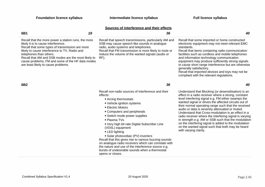
Foundation licence syllabus Intermediate licence syllabus Full licence syllabus
Sources of interference and their effects
6B1 19 36 40
Recall that the more power a station runs, the more likely it is to cause interference.Recall that some types of transmission are more likely to cause interference to TV, Radio and telephones than others.Recall that AM and SSB modes are the most likely to cause problems, FM and some of the HF data modes are least likely to cause problems.
Recall that speech transmissions, particularly AM and SSB may cause speech like sounds in analogue radio, audio systems and telephones.Recall that FM transmission is more likely to mute or reduce the volume of the wanted signals (audio or RF).
Recall that some imported or home constructed electronic equipment may not meet relevant EMC standards.Recall that items containing radio communication facilities such as cordless and mobile telephones and information technology communication equipment may produce sufficiently strong signals to cause short range interference but are otherwise generally satisfactory.Recall that imported devices and toys may not be compliant with the relevant regulations.
6B2 36 40
Recall non-radio sources of interference and their effects:
⦁ Arcing thermostats
⦁ Vehicle ignition systems
⦁ Electric Motors
⦁ Computers and peripherals
⦁ Switch mode power supplies
⦁ Plasma TVs
⦁ Very high bit rate Digital Subscriber Line (VDSL) equipment
⦁ LED lighting
⦁ Solar photovoltaic (PV) invertersRecall that this gives rise to various buzzing sounds on analogue radio receivers which can correlate with the nature and use of the interference source e.g. bursts of undesirable sounds when a thermostat opens or closes.
Understand that Blocking (or desensitisation) is an effect in a radio receiver where a strong, constant level interfering signal e.g. FM either swamps the wanted signal or drives the affected circuits out of their normal operating range such that the received audio or data is severely attenuated or muted.Understand that Cross-modulation is an effect in a radio receiver where the interfering signal is varying in strength e.g. AM or SSB such that the modulation on the interfering signal is added to the modulation on the wanted signal such that both may be heard with varying clarity.
Combined Syllabus Specification V1.4 20 August 2020 Page 2.45
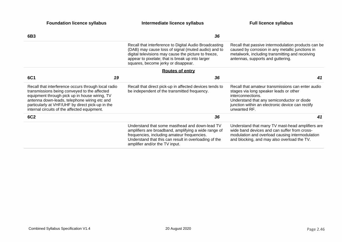
Foundation licence syllabus Intermediate licence syllabus Full licence syllabus
6B3 36
Recall that interference to Digital Audio Broadcasting (DAB) may cause loss of signal (muted audio) and to digital televisions may cause the picture to freeze, appear to pixelate; that is break up into larger squares, become jerky or disappear.
Recall that passive intermodulation products can be caused by corrosion in any metallic junctions in metalwork, including transmitting and receiving antennas, supports and guttering.
Routes of entry
6C1 19 36 41
Recall that interference occurs through local radio transmissions being conveyed to the affected equipment through pick up in house wiring, TV antenna down-leads, telephone wiring etc and particularly at VHF/UHF by direct pick-up in the internal circuits of the affected equipment.
Recall that direct pick-up in affected devices tends to be independent of the transmitted frequency.
Recall that amateur transmissions can enter audio stages via long speaker leads or other interconnections.Understand that any semiconductor or diode junction within an electronic device can rectify unwanted RF.
6C2 36 41
Understand that some masthead and down-lead TV amplifiers are broadband, amplifying a wide range of frequencies, including amateur frequencies.Understand that this can result in overloading of the amplifier and/or the TV input.
Understand that many TV mast-head amplifiers are wide band devices and can suffer from cross-modulation and overload causing intermodulation and blocking, and may also overload the TV.
Combined Syllabus Specification V1.4 20 August 2020 Page 2.46
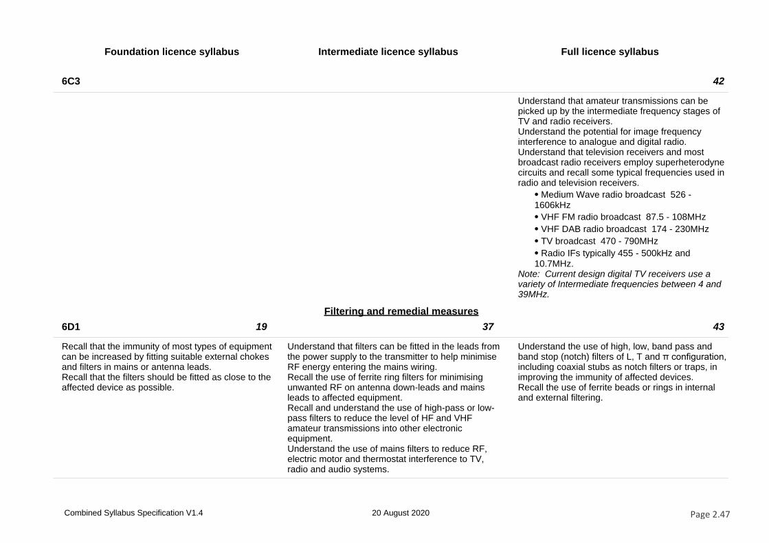
Foundation licence syllabus Intermediate licence syllabus Full licence syllabus
6C3 42
Understand that amateur transmissions can be picked up by the intermediate frequency stages of TV and radio receivers.Understand the potential for image frequency interference to analogue and digital radio.Understand that television receivers and most broadcast radio receivers employ superheterodyne circuits and recall some typical frequencies used in radio and television receivers.
⦁ Medium Wave radio broadcast 526 -1606kHz
⦁ VHF FM radio broadcast 87.5 - 108MHz
⦁ VHF DAB radio broadcast 174 - 230MHz
⦁ TV broadcast 470 - 790MHz
⦁ Radio IFs typically 455 - 500kHz and 10.7MHz.
Note: Current design digital TV receivers use a variety of Intermediate frequencies between 4 and 39MHz.
Filtering and remedial measures
6D1 19 37 43
Recall that the immunity of most types of equipment can be increased by fitting suitable external chokes and filters in mains or antenna leads.Recall that the filters should be fitted as close to the affected device as possible.
Understand that filters can be fitted in the leads from the power supply to the transmitter to help minimise RF energy entering the mains wiring.Recall the use of ferrite ring filters for minimising unwanted RF on antenna down-leads and mains leads to affected equipment.Recall and understand the use of high-pass or low-pass filters to reduce the level of HF and VHF amateur transmissions into other electronic equipment.Understand the use of mains filters to reduce RF, electric motor and thermostat interference to TV, radio and audio systems.
Understand the use of high, low, band pass and band stop (notch) filters of L, T and π configuration, including coaxial stubs as notch filters or traps, in improving the immunity of affected devices.Recall the use of ferrite beads or rings in internal and external filtering.
Combined Syllabus Specification V1.4 20 August 2020 Page 2.47
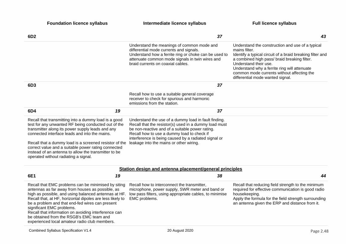
Foundation licence syllabus Intermediate licence syllabus Full licence syllabus
6D2 37 43
Understand the meanings of common mode and differential mode currents and signals.Understand how a ferrite ring or choke can be used to attenuate common mode signals in twin wires and braid currents on coaxial cables.
Understand the construction and use of a typical mains filter.Identify a typical circuit of a braid breaking filter and a combined high pass/ braid breaking filter. Understand their use.Understand why a ferrite ring will attenuate common mode currents without affecting the differential mode wanted signal.
6D3 37
Recall how to use a suitable general coverage receiver to check for spurious and harmonic emissions from the station.
6D4 19 37
Recall that transmitting into a dummy load is a good test for any unwanted RF being conducted out of the transmitter along its power supply leads and any connected interface leads and into the mains.
Recall that a dummy load is a screened resistor of the correct value and a suitable power rating connected instead of an antenna to allow the transmitter to be operated without radiating a signal.
Understand the use of a dummy load in fault finding.Recall that the resistor(s) used in a dummy load must be non-reactive and of a suitable power rating.Recall how to use a dummy load to check if interference is being caused by a radiated signal or leakage into the mains or other wiring.
Station design and antenna placement/general principles
6E1 19 38 44
Recall that EMC problems can be minimised by siting antennas as far away from houses as possible, as high as possible, and using balanced antennas at HF.Recall that, at HF, horizontal dipoles are less likely to be a problem and that end-fed wires can present significant EMC problems.Recall that information on avoiding interference can be obtained from the RSGB's EMC team and experienced local amateur radio club members.
Recall how to interconnect the transmitter, microphone, power supply, SWR meter and band or low pass filters, using appropriate cables, to minimise EMC problems.
Recall that reducing field strength to the minimum required for effective communication is good radio housekeeping.Apply the formula for the field strength surrounding an antenna given the ERP and distance from it.
Combined Syllabus Specification V1.4 20 August 2020 Page 2.48
Foundation licence syllabus Intermediate licence syllabus Full licence syllabus
6E2 19 38 45
Recall that the function of the RF earth connection in an amateur station is to provide a path to ground to minimise RF currents entering the mains earth system and causing interference to other electronic equipment.
Recall what constitutes a good RF earth, its purpose and use.
Understand good RF grounding and bonding techniques.Understand the effects of inadequate RF grounding and bonding.
6E3 38 45
Understand that siting a transmitting antenna close to mains wiring, TV or radio antennas and down-leads is a potential problem exacerbated by the use of a loft or indoor transmitting antenna
Recall that balanced antenna systems tend to cause fewer EMC problems than unbalanced antennas.Recall that balanced and unbalanced feeders should leave the antenna at right angles to minimise coupling.
Station design and antenna placement/mobile installations
6F1 19 46
Recall that it is the vehicle owner's responsibility to ensure that any radio installation is compatible with the vehicles electrical and management systems and does not affect vehicle safety.Recall that the fact of the installation may have to be disclosed to the vehicle insurers.Recall that professional advice should be sought for all vehicle installations.
Recall that advice on mobile installations is the Federation of Communication Services UK Code of Practice for the installation of mobile radio and related ancillary equipment in land based vehicles.
6F2 19 38 46
Recall that any tests following mobile radio equipment installation should be done static with all vehicle electronic systems operating before any on-road tests are carried out.
Recall that when routing RF cables and mobile radio DC power leads within vehicles they should not be routed in parallel with the vehicle wiring loom and they should not be run near electronic control units.Recall that radio frequency energy can cause interference to vehicle electronic circuits, including audio systems, navigation systems, remote locking, alarms and engine fuel management systems particularly when operating equipment with an RF output of 10W or more.
Understand how to minimise the likelihood of stray RF currents entering the vehicle wiring and electronics.
Combined Syllabus Specification V1.4 20 August 2020 Page 2.49
Foundation licence syllabus Intermediate licence syllabus Full licence syllabus
6F3 19 38
Recall that vehicle ignition and battery charging systems can cause electrical interference to reception on mobile radio equipment.
Understand that mobile antenna location can affect the radiation field strength within the vehicle; e.g. wing or boot mounted antennas are likely to produce higher exposures than roof mounted antennas.
Social aspects and testing
6G1 20 47
Recall that EMC problems have the potential for causing neighbour disputes.Recall the RSGB information leaflets on EMC and interference.Recall that advice is available from the RSGB EMC Committee and recall the role of Ofcom in dealing with cases of interference.
Recall the correct procedures for dealing with EMC complaints and the role of Ofcom in cases of undue interference.
6G2 20
Understand that the station log will be of considerable assistance in dealing with complaints of interference, and that this is a good reason to keep a log of all transmissions.Understand the merits of both the amateur and the complainant keeping a log of the instances of interference.Understand the merit of conducting tests in co-operation with the complainant in instances of interference.
Combined Syllabus Specification V1.4 20 August 2020 Page 2.50
Foundation licence syllabus Intermediate licence syllabus Full licence syllabus
Section 7 – Operating practices and procedures
Good operating practices and procedures
7A1 21 48
Understand why one should listen on a frequency before calling and then ask if the frequency is in use.
Understand the reasons why some stations may use split Tx and Rx frequencies within a frequency band.
7A2 21
Recall how to make a CQ call in SSB and FM modes.
7A3 21 39
Understand the need to move off the calling channel when on VHF/UHF once contact is established.Understand the meaning of Centre of Activity.
Recall common international call sign prefixes; EI(Eire), F(France), I(Italy), JA(Japan), PA(Netherlands), VE(Canada), VK(Australia), W(USA), ZL(New Zealand).
7A4 21 39
Recall the phonetic alphabet. Recall that there are awards available for achievements which include: working continents, countries, islands, prefixes, locator squares and that variations may include certain frequency bands or low power.Recall that amateur radio contests require the exchange of information such as signal report, serial number and location. Recall that contests often have sections for different bands, power levels and modes.
7A5 21
Understand the advisability and common practice of keeping a log.Understand why UTC is used for logging time.Recall that a log should detail the following information: date, time, mode, call sign of station worked for QSL and contest purposes.
Combined Syllabus Specification V1.4 20 August 2020 Page 2.51
Foundation licence syllabus Intermediate licence syllabus Full licence syllabus
7A6 21
Understand that the transmission of music and the use of offensive or threatening language whilst on the air are unacceptable in amateur radio.Understand how to respond to music or inappropriate language overheard or received from other stations.
Band plans
7B1 22 39 49
Recall why band plans are used.Identify items on a typical band plan (e.g. calling frequencies and recommended modes).Recall that narrow band modes are at the lower end of most bands lower sideband operation normally occurs below 10MHz and upper sideband above 10MHz.Recall that transmissions on beacon frequencies must be avoided.Note: For the purposes of the examination narrow modes are CW and data.A copy of the relevant Band Plans will be provided.The Band Plans supplied for examination purposes will be a typical plan and need not be one in current use. The Reference Booklet containing the examination plan is available on the RSGB web site.
Recall that band plans are produced by the IARU.Recall that the band plans state that:
⦁ no SSB operation should take place in the 10MHz (30m) band
⦁ no contests shall be organised in the 5MHz (60m),10MHz (30m), 18MHz (17m) and 24MHz (12m), bands
⦁ transmissions on satellite frequencies should be avoided for terrestrial contacts.
Note.The 5MHz (60m) band is NOT available to Intermediate Licence holders.Questions on beacon frequencies will be limited to the 14MHz (20m) and 144MHz (2m) bands. Questions on satellite frequencies will be limited to the 144MHz (2m) band. A copy of the relevant Band Plans will be provided.The Band Plan supplied for examination purposes will be a typical plan and need not be one in current use. The Reference Booklet containing the examination plan is available on the RSGB website.
Identify items on a typical band plan (e.g. centre of activity, band width and recommended modes).Questions will be limited to the 5MHz (60m) and 472kHz (600m) bands and a copy of the relevant Band Plans will be provided.
Note. The Band Plan supplied for examination purposes will be a typical plan and need not be one in current use. The Reference Booklet containing the examination plan is available on the RSGB web site.
Combined Syllabus Specification V1.4 20 August 2020 Page 2.52
Foundation licence syllabus Intermediate licence syllabus Full licence syllabus
7B2 22 49
Recall that frequency bands are allocated for particular use, e.g. broadcasting, aeronautical, maritime and amateur. Recall the frequency bands for HF, VHF, and UHF radio signals.Recall that some amateur bands are shared with or adjacent to other spectrum users. Identify items on a provided chart of spectrum users.
Recall that band plans in other countries and IARU regions may not align with the UK band plan.
Repeaters
7C1 22
Recall that repeaters are mainly intended to extend the range of mobile stations.Recall why a frequency offset between transmit and receive is needed.Recall why a CTCSS tone is needed to access a repeater and why different repeaters may have different tones.Recall why repeaters may have a ‘reset’ tone and a time-out facility.Recall that simplex operation on repeater frequencies should not take place.
Note: Questions may ask why particular facilities (such as frequency offset) exist, what operational issue they address or how they should be used to establish or maintain a contact.
Connecting input devices to transmitters
7D1 23
Recall that connecting anything other than the supplied microphone to the transmitter requires correct operation of the PTT line and that the audio signal levels are correct.
Combined Syllabus Specification V1.4 20 August 2020 Page 2.53
Foundation licence syllabus Intermediate licence syllabus Full licence syllabus
Codes and abbreviations
7E1 40
Recall the meaning and the reason for use of the Q codes: QRM, QRN, QRO, QRP, QRT, QSB, QSL, QSO, QSY, QTH.
7E2 23
Recall the meaning of the RST code, the number of divisions of each of the three items, and their order of merit.
Digital interfaces
7F1 23
Recall that there are Digital Voice (DV) and Digital Data (DD) modes available and that different systems may not be compatible. Recall that appropriate radio equipment is needed for each of these digital systems.Recall that DV radios may embed the call sign and this will need to be considered if using borrowed equipment.
7F2 23 40
Recall that users of Digital Voice (DV) should check that the channel is not in use by other modes.Recall that users of FM should check that the channel is not in use by other modes.Recall that such checks are not 100% reliable.
Recall that several types of transmissions can be generated and received with the use of a personal computer and a suitable interface.Recall minimal distortion can be obtained by careful adjustments between the DAC interface and the transmitter.Recall other programs running on the PC that is handling the transmitter or receiver audio may cause interference e.g. warning beeps and alerts.
Combined Syllabus Specification V1.4 20 August 2020 Page 2.54
Foundation licence syllabus Intermediate licence syllabus Full licence syllabus
Satellites
7G1 23 40
Recall that amateur satellites operate in allocated frequencies within the bands.Recall that terrestrial operation on satellite frequencies should not take place.
Recall that satellites orbit the Earth at heights above 250km, and understand that most amateur satellites are moving in relation to the Earth and will only be above the horizon at certain times.
7G2 40
Recall that the up-link and down-link frequencies are generally in different amateur bands and that details are published by amateur organisations.Recall that the transmitting station must be able to receive both the up-link and down-link signals.
7G3 40
Understand that amateur satellites can only be used when they are above the horizon at both the sending and receiving stations, and that the movement of the satellite will cause frequency variation, known as Doppler shift, on the received signal, which must be allowed for when selecting operating frequencies.
7G4 40
Understand that satellites have a very limited power supply, derived from solar panels, and that excessive up-link power may result in wasteful and unfair use of the satellite’s power.
Special events
7H1 49
Recall the purpose of special event stations and the format of their call signs.Recall the process for obtaining a special event call sign.
Combined Syllabus Specification V1.4 20 August 2020 Page 2.55
Foundation licence syllabus Intermediate licence syllabus Full licence syllabus
Section 8 – Safety
Electricity
8A1 24 41 50
Recall that high voltages carry a risk of electrocution and high currents carry a risk of overheating and fire.
Understand that large or high-voltage capacitors can store dangerous electric charges and must be discharged before working on equipment.Recall that large value resistors can be used to provide leakage paths for these stored charges.
Recall that lethal voltages can exist in equipment and that live circuits may be exposed as soon as the equipment case is removed.
8A2 24 50
Recall that where a safety earth has been fitted that it must not be removed.Recall that special care is needed with earthing arrangements and that the District Network Operator responsible for the physical supply to your premises must be consulted before making changes such as an RF earth.
Recall that in PME systems the main earth terminal is connected to the neutral of the electricity service at the consumers’ premisesRecall that under severe fault conditions PME systems have the potential to cause fatal electric shocks and/or fires in amateur radio stations.Recall that the RF earth in an amateur station should be connected to the PME bonding point in accordance with the District Network Operator’s requirements or the IET Wiring Regulations to maintain safety under fault conditions.
8A3 24
Recall the correct way to wire a 3-pin mains plug.
8A4 24 42
Recall that fuses to be fitted in accordance with manufacturer's instructions.Recall that a fuse is a thin wire designed to melt, breaking the circuit, when passing an excessive current.Recall that the reason for a blown fuse needs to be properly investigated.
Recall that equipment mains fuses may be of a special type, such as quick blow or slow blow to allow for an initial surge of current and that the specified type must be fitted.Understand that a fuse must be correctly rated for proper protection, and, in the absence of manufacturer’s instructions, to select an appropriate fuse.For mains: current = power/230 where 230 is the nominal mains voltage.
Combined Syllabus Specification V1.4 20 August 2020 Page 2.56
Foundation licence syllabus Intermediate licence syllabus Full licence syllabus
8A5 24
Understand that an RCBO (Residual Current Circuit Breaker with Overcurrent protection) will give better protection against electric shock than relying solely on a conventional fuse which only protects against excessive current.Note: The candidate should appreciate that an RCBO will detect currents to earth of about 30mA whereas a fuse will only blow at several amps and only when the fault is a short circuit (L-N or L-E).The candidate should also understand that contact with both live and neutral may case fatal injury.The mechanics of RCBO operation (differential current sensing) is not examinable.
8A6 24 41 50
Recall that work inside equipment should only be carried out with the power sources disconnected.Recall why it is important to follow manufacturer's instructions for servicing equipment.
Understand that working on live equipment must only be done if it is not practicable to do otherwise and if the risks and appropriate precautions are fully understood.
Understand that no work should be undertaken on live equipment unless it is not practicable to do otherwise.Understand that suitable precautions must be taken to avoid electric shock.
8A7 24
Understand that all equipment should be controlled by a clearly marked master switch, the position of which should be known to others in the house or club.Recall that, in the event of an accident or fire involving electricity, the first action is to switch off the power.Recall that the casualty must not be touched unless the power has been switched off.
Combined Syllabus Specification V1.4 20 August 2020 Page 2.57
Foundation licence syllabus Intermediate licence syllabus Full licence syllabus
8A8 24 42
Recall that some batteries can supply very high currents which can be hazardous if subjected to short circuit.Recall that battery charging must be in accordance with manufacturer instructions and that lithium batteries in particular can cause fire and explosion if not properly treated.Understand that different battery technologies require different charging techniques and must use the correct type of charger.
Understand that vehicle batteries are a source of very high currents which can start a fire and that battery contents are corrosive.Understand that explosive hydrogen gas can be given off when charging batteries and that ample ventilation is required.
Using tools
8B1 25
Recall that eye protection must be worn when using tools to prevent eye damage from small metal particles (swarf).
8B2 25 43
Recall that all tools, including power tools, can be hazardous and should be handled with care and appropriate precautions taken.
Understand that screwdrivers, drills, saws and files must be handled with care.Understand that fingers should always be behind the blade of hand tools.
8B3 43
Understand that any items being drilled, sawn or filed must be securely held in a vice or similar device to prevent them slipping or rotating.
8B4 43
Understand that any locking keys, and/or chuck keys, must be removed before using a power tool such as a drill to prevent the key being ejected at high speed.
8B5 43
Understand that using a centre punch will help prevent a drill bit slipping.
Combined Syllabus Specification V1.4 20 August 2020 Page 2.58
Foundation licence syllabus Intermediate licence syllabus Full licence syllabus
8B6 43
Understand the reasons why a bench-mounted pillar drill is safer than a hand-held drill.
8B7 25
Recall that eye protection must be worn when soldering to prevent solder or flux from splashing into the eyes.Recall that a soldering-iron stand must be used to avoid skin contact with the hot bit of the iron when not in use.Recall that soldering work stations must be well ventilated to avoid inhalation of solder fumes, which can cause breathing problems particularly to asthmatics.
Working at height
8C1 25
Recall that antenna erection is potentially hazardous and that it is advisable to have someone to help you.Understand the need for at least one adult to be present.
8C2 25
Recall that a ladder should be used at the correct angle (4:1 height-to-base ratio).Understand that ladders must be adequately secured to prevent them slipping.Understand why it is important not to overreach from a ladder, to prevent falling off.
8C3 25
Understand why, when working at height, a tool belt or similar device to carry tools should be used, and that it will help prevent falling objects.Understand the need to wear hard hats when working at height or when others are working at height.
Combined Syllabus Specification V1.4 20 August 2020 Page 2.59
Foundation licence syllabus Intermediate licence syllabus Full licence syllabus
Working with RF
8D1 26 51
Recall that the main health effect of exposure to electromagnetic radiation is heating of body tissue and that the eyes are particularly susceptible to damage.
Recall that the International Commission for Non Ionising Radiation Protection (ICNIRP) produces guidance for exposure to Radio Frequency fields.Understand it is not advisable to exceed the recommended safe exposure levels and that this is particularly applicable at locations open to the public.
8D2 26
Recall that guidance on safe levels of RF radiation is available from government and international bodies, Public Health England and the International Commission on Non-Ionising Radiation Protection (ICNIRP).
8D3 26
Recall what a waveguide is and why it is unwise to look down a microwave frequency waveguide or to stand close to or in front of high-gain antennas as they may be in use.
8D4 26
Recall that antenna elements and other conductors carrying RF should not be touched whilst transmitting.Recall that antennas should be mounted where people will not come into accidental contact with them.Note: this does not apply to low powered devices such as hand-held equipment.
Combined Syllabus Specification V1.4 20 August 2020 Page 2.60
Foundation licence syllabus Intermediate licence syllabus Full licence syllabus
Lightning
8E1 26 41 51
Recall that particularly high antennas may need special protection against lightning.Recall that the local authority building department will be able to offer advice.
Recall that limited protection of equipment against the build-up of static charge can be obtained from gas discharge arrestors, spark gaps and bleed resistors.
Recall that thunderstorms carry heavy static charges.Understand that the static charge from thunderclouds can ionise the air to form a low resistance path to ground, enabling a very high current to flow as a lightning strike.Understand the risks to human life, domestic property and electronic equipment associated with a direct strike and/or the build-up of static charges.Understand that there is little that can be done to protect an amateur station from a direct lightning strike, but that good static discharge systems can prevent dangerous static charges building up on antenna systems during thunderstorms.Understand that disconnecting antenna feeders from radio equipment also reduces the risks.
Working mobile and portable
8F1 26
Recall that elevated wires, masts and antennas must be suitably located and secured.Recall that antennas and feeders must not be sited close to overhead power cables.Recall that a lethal electric shock can result from antennas and ladders coming into contact with or attracting arcing from overhead lines.
8F2 26
Understand the reasons for not having wires trailing across the floor, trip hazards and the risk of frayed insulation.
8F3 26
Recall that excessive volume when wearing headphones can cause damage to hearing.
Combined Syllabus Specification V1.4 20 August 2020 Page 2.61
Foundation licence syllabus Intermediate licence syllabus Full licence syllabus
8F4 26 52
Recall that operating in temporary premises and/or outdoors can introduce new hazards e.g. temporary mains connections, trailing cables, damp ground.Recall the additional safety precautions that should be taken whilst operating in temporary premises and/or outdoors e.g. risk assessment, cable routing, protection, correct fusing, use of RCBO’s, no adjustments or repairs to live equipment.Recall that advice should be sought where you are unsure.
Understand that operating in temporary premises and/or outdoors can introduce new hazards i.e. overhead power lines, inadequate electrical supplies, trailing cables, damp ground, and excessive field strengths.Recall the additional safety precautions that should be taken whilst operating in temporary premises and/or outdoors i.e.
⦁ site survey/risk assessment,
⦁ cable routing/protection,
⦁ correct fusing,
⦁ use of Residual Current Devices (RCD's, RCBO's)
⦁ no adjustments or repairs to live equipment.
Recall that mains supplies in other countries may be of a different voltage or frequency; utilise different plugs and sockets and that UK specified equipment may not be suitable or hazardous if connected and used.
8F5 26 52
Recall that safety is everybody’s responsibility and that one must be alert to any potentially unsafe circumstance, warn others and report the matter to the appropriate person.Recall this equally applies in your own ‘shack’ and when entertaining visitors.
Understand that operating when mobile or maritime mobile can introduce new hazards i.e. insecure equipment, long/flexible antennas, accidental shorts to earth, lack of attention to driving.Recall the additional safety precautions that should be taken whilst operating mobile and/or maritime mobile i.e. secure equipment, cable routing/ protection, correct fusing, use of hands-free equipment, attention to good radio housekeeping.
Combined Syllabus Specification V1.4 20 August 2020 Page 2.62
Foundation licence syllabus Intermediate licence syllabus Full licence syllabus
8F6 53
Understand that a risk assessment should be performed when an activity could present a hazard to yourself or others.Understand that risk assessment involves identification of hazards and the measures to mitigate the risk.Recall a risk assessment needs to consider the likelihood of harm and the severity of that harm.Recall that the significant findings of risk assessments need to be recorded.Recall that risk assessment records are important in law and for insurance purposes. Risks should be expressed in understandable terms.Recall that appropriate insurances should be obtained for all amateur radio activities but in particular where the public could be involved.
8F7 53
Understand the risks associated with the use of electrical generators, earthing, fuel stowage, refilling.
Combined Syllabus Specification V1.4 20 August 2020 Page 2.63
Foundation licence syllabus Intermediate licence syllabus Full licence syllabus
Section 9 – Measurements and construction
Measurements
9A1 44 54
Recall the purpose of a multimeter and understand how to set the meter to the correct range and polarity before connecting to the circuit.
Understand the use of series multiplier resistors in analogue voltmeters and shunts in ammeters.Understand the effect of the test meter on the circuit under test.
9A2 44
Understand that voltmeters have a high internal resistance so that they draw minimal current from the circuit under test.Understand that ammeters have a low internal resistance so that they minimise the voltage loss to the circuit under test.Understand that a voltmeter is always connected in parallel with a component or circuit being tested.Understand that an ammeter is always connected in series with a component or circuit being tested.
9A3 44 54
Understand the advantages and disadvantages of analogue and digital displays, and be able to read analogue and digital values.
Understand the effect of measurement tolerance, calibration accuracy and time related drift on frequency measurements and the allowances to be made for transmission bandwidths.
9A4 55
Understand that signal generators and similar devices will have a source impedance and the effect on the signal level of attaching different load impedances.Recall that not all measuring equipment will have a 50Ω input impedance.Understand that the choice of measuring equipment may have an effect on the on the measurement result and on the object under test.
Combined Syllabus Specification V1.4 20 August 2020 Page 2.64
Foundation licence syllabus Intermediate licence syllabus Full licence syllabus
9A5 44 55
Understand the use of voltmeters and ammeters to determine the power applied to a circuit.
Understand that steady RF power may be determined by measuring the RF potential difference across a dummy load and that a steady audio signal, e.g. from an audio oscillator, will be required for AM and SSB measurements.Understand the meaning of peak envelope power (PEP) of an SSB transmission and that it may be determined using a peak reading power meter or an oscilloscope and dummy load.
9A6 56
Recall the uses and limitations of crystal calibrators, digital frequency counters and standard frequency transmissions.
9A7 56
Identify the circuit of an SWR meter using either a sense wire between the inner and outer conductors of a coaxial line or a current transformer and capacitive voltage tap.Understand in simple terms how this leads to an SWR reading on devices using a single meter, twin meters or cross-needle twin meter.
9A8 56
Understand the purpose and basic operation of an oscilloscope. Calculate the frequency and voltage of a waveform from given data.
9A9 56
Understand the purpose and basic operation of a spectrum analyser.. Identify the fundamental and harmonics on a typical spectrum analyser display.
Combined Syllabus Specification V1.4 20 August 2020 Page 2.65
Foundation licence syllabus Intermediate licence syllabus Full licence syllabus
Decibels
9B1 45 57
Recall that decibels are a logarithm of power ratio.Recall that a power gain of 3dB equates to doubling the power and 10dB equates to a power increase of times 10.Calculate the power gain or loss of various dB ratios based on 3 and 10dB and their multiples. This includes examples such as 25W is equivalent to 14dBW.Recall that dB gains and losses in a system can be added to find the total gain or loss in the system.Recall the meaning of:
⦁ dBW (comparison with 1W)
⦁ dBi (comparison with an isotropic radiator) and
⦁ dBd (comparison with a half wave dipole).
Use the equations for decibel power, dB, dBW, dBm and voltage ratios dBV.
Components
9C1 46 58
Recall the resistor colour code, colours 0 to 9 with gold as multiplier.Recall silver (10%) and gold (5%) as tolerance bands. Identify the value of a resistor between 1Ω and 9MΩfrom the E12 series.Recall how to read both 4 band and 5 band resistors.Recall how to read components with a numeric marking of the format 4R7, 3k3 or for capacitors, 103.Note: The resistor colour code will be provided and actual encoding or decoding of colours will be either 4 band or 5 band resistors.Candidates are not expected to know the values of the E12 series.
Recall that temperature has an effect on the value of components. Those with negative coefficients will reduce in value as temperature rises whereas those with positive coefficients will increase in value. Understand the effect this will have on tuned circuits and remedial measures.Questions may include simple calculations.
Combined Syllabus Specification V1.4 20 August 2020 Page 2.66
Foundation licence syllabus Intermediate licence syllabus Full licence syllabus
Construction
9D1 46
Recall that screening with thin metal sheet is effective in reducing unwanted radiation from equipment and/or between stages within equipment.
Soldering
9E1 46
Understand that soldering is a method of joining metal wires and components using solder and a hot soldering iron.
9E2 46
Recall that solder is a low melting point alloy and that many solders contain a flux to help the solder to flow and to prevent a layer of oxide forming on the surfaces to be joined.
9E3 46
Recall that some metals are easier to solder than others.
9E4 46
Understand that the tip of the soldering iron has to be cleaned to help remove any oxide and then tinned to prevent the oxide re-forming and to improve the conduction of heat to the joint.Recall the reason for tinning wires prior to soldering.
Combined Syllabus Specification V1.4 20 August 2020 Page 2.67
Foundation licence syllabus Intermediate licence syllabus Full licence syllabus
Section 10 – Practical assessments
Operating
10A1
Demonstrate the ability to make a contact using a mode other than telephony.With the exception of hand sent Morse code, this contact must be made on air and include as a minimum:
⦁ Tuning the radio and/or the computer system to the correct frequency,
⦁ Selecting the correct mode,
⦁ Setting the radio microphone gain and/or computer audio interface to correct levels and,
⦁ Two-way exchange of call sign, signal report, location.
Where data modes are used, the candidate must type and send all information in real time.Where hand sent Morse code is used:Demonstrate ability to send correctly by hand, and to receive correctly by ear, text in Morse Code.The receiving and sending test shall be conducted using text from the RSGB provided booklet.The candidate may choose the character speed and spacing.The candidate will be provided with a copy of the Morse Code both in code and alphabetical sequence during the assessment. Sufficient correct code must be exchanged for the content of the message to be understood.Receiving test:The candidate may, if desired, write down the dots and dashes for subsequent transcription and proceed one letter at a time. The tutor may re-send characters if required.Sending test: The candidate is permitted to make any necessary preparations prior to sending, including writing the Morse code for each character to be sent.
Combined Syllabus Specification V1.4 20 August 2020 Page 2.68
Foundation licence syllabus Intermediate licence syllabus Full licence syllabus
10A2
Demonstrate the ability to make a contact using SSB.The contact must be made on air and include as a minimum:
⦁ tuning the radio to the correct frequency, or section of the band;
⦁ selecting the correct mode;
⦁ setting the radio microphone gain to the correct level;
⦁ check if the frequency is in use and make a CQ call;
⦁ vacate the calling frequency if appropriate after establishing the initial contact;
⦁ the two-way exchange must include call sign, signal report and location;
⦁ ending the contact;
⦁ recording all details of the contact in a log.
10A3
Demonstrate the ability to make a contact using FM simplex.The contact must be made on air and include as a minimum:
⦁ setting the radio to the correct calling frequency;
⦁ selecting the correct mode;
⦁ correct setting of the squelch control;
⦁ make a CQ call;
⦁ vacate the calling frequency after establishing the initial contact;
⦁ check if the new (working) frequency is in use;
⦁ the two-way exchange must include call sign, signal report and location;
⦁ ending the contact;
⦁ recording all the details of the contact in a log.
Combined Syllabus Specification V1.4 20 August 2020 Page 2.69
Foundation licence syllabus Intermediate licence syllabus Full licence syllabus
10A4
Adjust the physical length of an antenna for lowest SWR.Note: The antenna elements are not to be adjusted whilst transmitting. Correct procedure for a radiating test shall be demonstrated. Assessment to be performed using a transmitter or transceiver, adjustable antenna and a SWR meter. Twin meter (fwd/rev) SWR meter or an SWR meter built into transceiver is acceptable. Alternatively, an antenna analyser displaying SWR may be used
10A5
Match an antenna system for lowest SWR in at least two bands using a transmitter or transceiver and a (manual) antenna matching unit.
Construction
10B1
Correctly connect up a station.To include as a minimum, mains PSU, amateur radio transmitter/receiver or transceiver, microphone or PC interface, external item (e.g. VSWR/Power meter, AMU, filter), feeder and antenna. Other accessories can be included as appropriate to local circumstances (e.g. external speaker).
Combined Syllabus Specification V1.4 20 August 2020 Page 2.70
Combined Syllabus V1.4 Part 3 Page 3.1 2020-07-30
Foundation Licence Examination Material
Table 1. Symbols for use in the Foundation level examination.
Description Symbol Description Symbol
Cell
Switch s.p.s.t.
Battery
Antenna
Earth
Fuse
Lamp (incandescent)
Microphone
Light Emitting Diode LED
Loudspeaker
Resistor
_________________________________________
Combined Syllabus V1.4 Part 3 Page 3.2 2020-07-30
Table 2. Diagrams for use in the Foundation level Examination.
Analogue transmitter
The block diagram shown will be used for all assessment questions. It is not intended that the blocks will relate to any particular architecture of radio, merely the basic functions that need to be performed.
The symbols for the microphone and antenna should also be known.
The block diagram shown will be used for all assessment questions. It is not intended that the blocks will relate to any particular architecture of radio, merely the basic functions that need to be performed. The loudspeaker symbol should be known.
Note different AM depths of modulation may be used.
Note different bandwidths may be used.
CW signal envelope
Digital Transmitter A to D is an analogue to digital converter D to A is a digital to analogue converter
Digital receiver
BNC PL259
amplifier
Carrieroscillator
amplifierRF power
ModulatorMicrophone
Tuner andRF amplifier or detector
Audioamplifier
Demodulator
carrier
lower sideband upper sideband
frequency0 3kHz
-3kHz 0 +3kHz
300Hz
Audiosignalamplitude
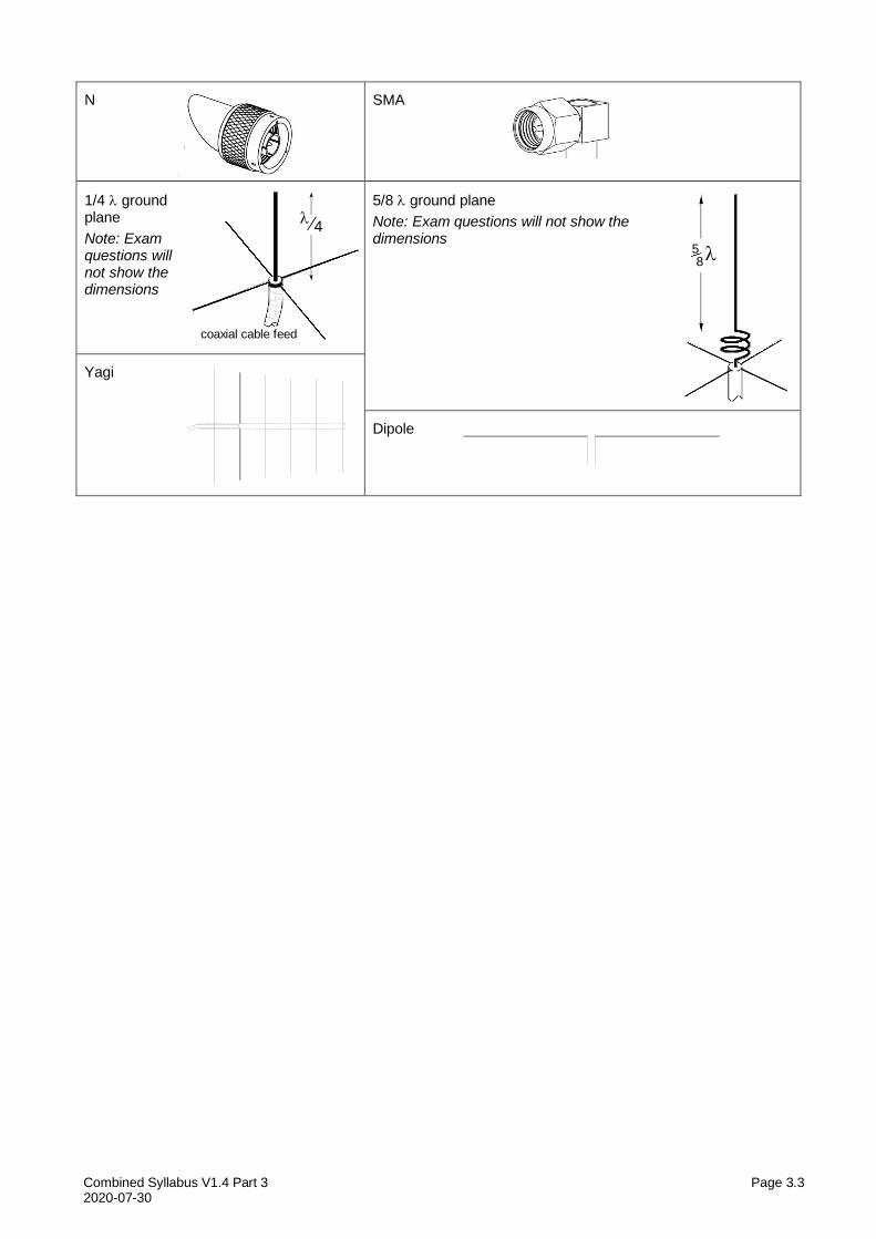
Combined Syllabus V1.4 Part 3 Page 3.3 2020-07-30
N SMA
1/4 ground plane
Note: Exam questions will not show the dimensions
5/8 ground plane
Note: Exam questions will not show the dimensions
Yagi
Dipole
58
coaxial cable feed
4
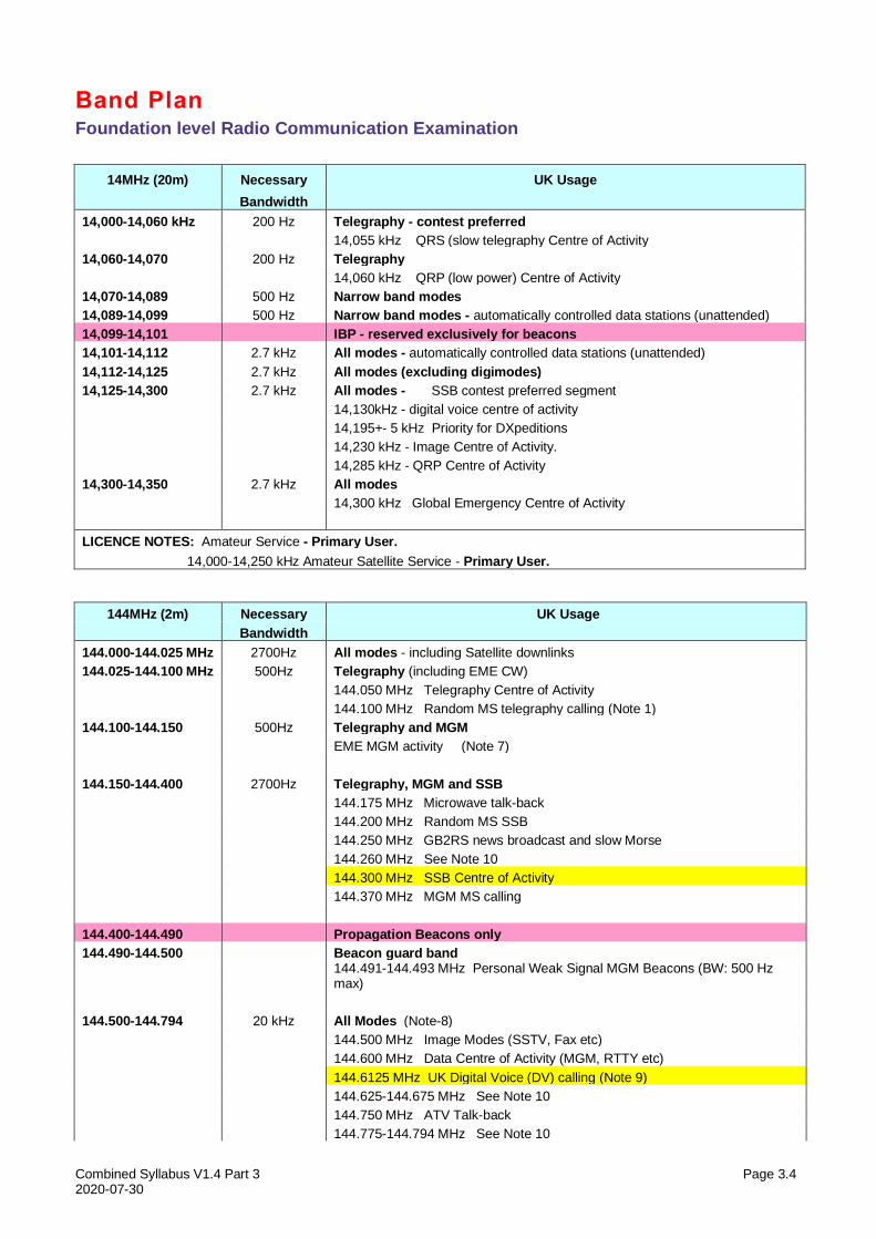
Combined Syllabus V1.4 Part 3 Page 3.4 2020-07-30
Band Plan Foundation level Radio Communication Examination
14MHz (20m) Necessary UK Usage
Bandwidth
14,000-14,060 kHz 200 Hz Telegraphy - contest preferred
14,055 kHz QRS (slow telegraphy Centre of Activity
14,060-14,070 200 Hz Telegraphy
14,060 kHz QRP (low power) Centre of Activity
14,070-14,089 500 Hz Narrow band modes
14,089-14,099 500 Hz Narrow band modes - automatically controlled data stations (unattended)
14,099-14,101 IBP - reserved exclusively for beacons
14,101-14,112 2.7 kHz All modes - automatically controlled data stations (unattended)
14,112-14,125 2.7 kHz All modes (excluding digimodes)
14,125-14,300 2.7 kHz All modes - SSB contest preferred segment
14,130kHz - digital voice centre of activity
14,195+- 5 kHz Priority for DXpeditions
14,230 kHz - Image Centre of Activity.
14,285 kHz - QRP Centre of Activity
14,300-14,350 2.7 kHz All modes
14,300 kHz Global Emergency Centre of Activity
LICENCE NOTES: Amateur Service - Primary User.
14,000-14,250 kHz Amateur Satellite Service - Primary User.
144MHz (2m) Necessary UK Usage
Bandwidth
144.000-144.025 MHz 2700Hz All modes - including Satellite downlinks
144.025-144.100 MHz 500Hz Telegraphy (including EME CW)
144.050 MHz Telegraphy Centre of Activity
144.100 MHz Random MS telegraphy calling (Note 1)
144.100-144.150 500Hz Telegraphy and MGM
EME MGM activity (Note 7)
144.150-144.400 2700Hz Telegraphy, MGM and SSB
144.175 MHz Microwave talk-back
144.200 MHz Random MS SSB
144.250 MHz GB2RS news broadcast and slow Morse
144.260 MHz See Note 10
144.300 MHz SSB Centre of Activity
144.370 MHz MGM MS calling
144.400-144.490 Propagation Beacons only
144.490-144.500 Beacon guard band
144.491-144.493 MHz Personal Weak Signal MGM Beacons (BW: 500 Hz max)
144.500-144.794 20 kHz All Modes (Note-8)
144.500 MHz Image Modes (SSTV, Fax etc)
144.600 MHz Data Centre of Activity (MGM, RTTY etc)
144.6125 MHz UK Digital Voice (DV) calling (Note 9)
144.625-144.675 MHz See Note 10
144.750 MHz ATV Talk-back
144.775-144.794 MHz See Note 10
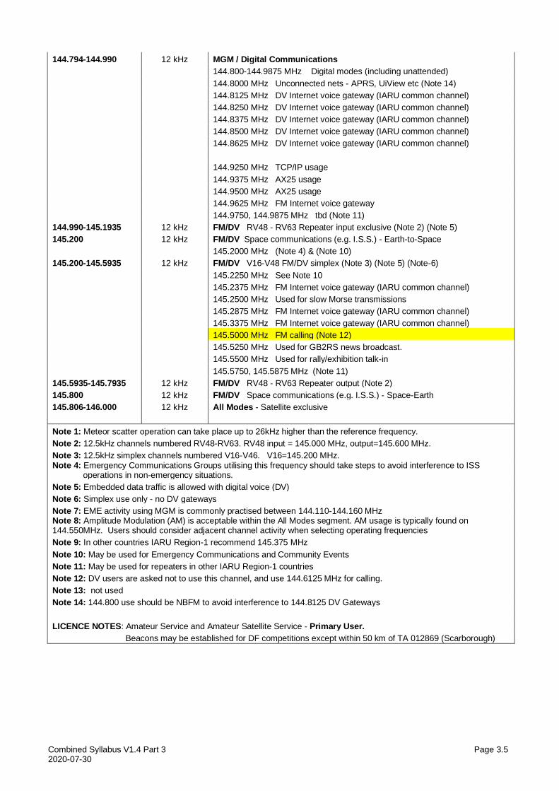
Combined Syllabus V1.4 Part 3 Page 3.5 2020-07-30
144.794-144.990 12 kHz MGM / Digital Communications
144.800-144.9875 MHz Digital modes (including unattended)
144.8000 MHz Unconnected nets - APRS, UiView etc (Note 14)
144.8125 MHz DV Internet voice gateway (IARU common channel)
144.8250 MHz DV Internet voice gateway (IARU common channel)
144.8375 MHz DV Internet voice gateway (IARU common channel)
144.8500 MHz DV Internet voice gateway (IARU common channel)
144.8625 MHz DV Internet voice gateway (IARU common channel)
144.9250 MHz TCP/IP usage
144.9375 MHz AX25 usage
144.9500 MHz AX25 usage
144.9625 MHz FM Internet voice gateway
144.9750, 144.9875 MHz tbd (Note 11)
144.990-145.1935 12 kHz FM/DV RV48 - RV63 Repeater input exclusive (Note 2) (Note 5)
145.200 12 kHz FM/DV Space communications (e.g. I.S.S.) - Earth-to-Space
145.2000 MHz (Note 4) & (Note 10)
145.200-145.5935 12 kHz FM/DV V16-V48 FM/DV simplex (Note 3) (Note 5) (Note-6)
145.2250 MHz See Note 10
145.2375 MHz FM Internet voice gateway (IARU common channel)
145.2500 MHz Used for slow Morse transmissions
145.2875 MHz FM Internet voice gateway (IARU common channel)
145.3375 MHz FM Internet voice gateway (IARU common channel)
145.5000 MHz FM calling (Note 12)
145.5250 MHz Used for GB2RS news broadcast.
145.5500 MHz Used for rally/exhibition talk-in
145.5750, 145.5875 MHz (Note 11)
145.5935-145.7935 12 kHz FM/DV RV48 - RV63 Repeater output (Note 2)
145.800 12 kHz FM/DV Space communications (e.g. I.S.S.) - Space-Earth
145.806-146.000 12 kHz All Modes - Satellite exclusive
Note 1: Meteor scatter operation can take place up to 26kHz higher than the reference frequency.
Note 2: 12.5kHz channels numbered RV48-RV63. RV48 input = 145.000 MHz, output=145.600 MHz.
Note 3: 12.5kHz simplex channels numbered V16-V46. V16=145.200 MHz. Note 4: Emergency Communications Groups utilising this frequency should take steps to avoid interference to ISS operations in non-emergency situations.
Note 5: Embedded data traffic is allowed with digital voice (DV)
Note 6: Simplex use only - no DV gateways
Note 7: EME activity using MGM is commonly practised between 144.110-144.160 MHz Note 8: Amplitude Modulation (AM) is acceptable within the All Modes segment. AM usage is typically found on 144.550MHz. Users should consider adjacent channel activity when selecting operating frequencies
Note 9: In other countries IARU Region-1 recommend 145.375 MHz
Note 10: May be used for Emergency Communications and Community Events
Note 11: May be used for repeaters in other IARU Region-1 countries
Note 12: DV users are asked not to use this channel, and use 144.6125 MHz for calling.
Note 13: not used
Note 14: 144.800 use should be NBFM to avoid interference to 144.8125 DV Gateways
LICENCE NOTES: Amateur Service and Amateur Satellite Service - Primary User.
Beacons may be established for DF competitions except within 50 km of TA 012869 (Scarborough)
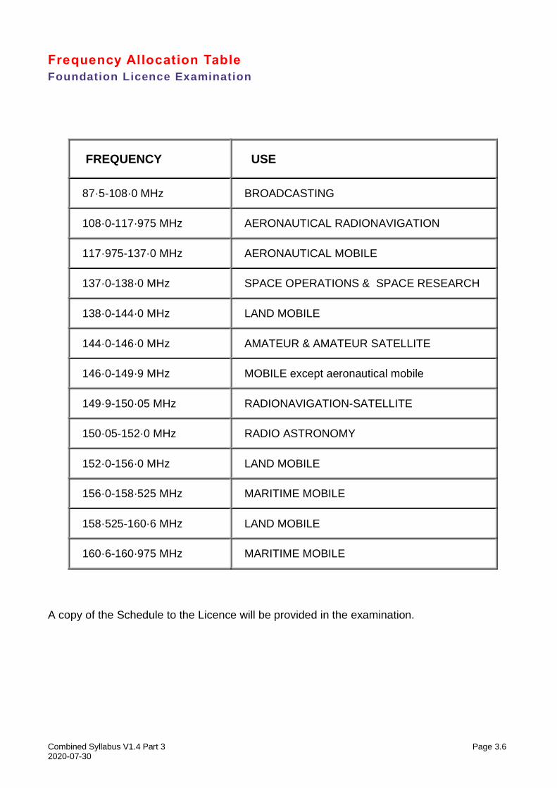
Combined Syllabus V1.4 Part 3 Page 3.6 2020-07-30
Frequency Allocation Table
Foundation Licence Examination
FREQUENCY USE
87·5-108·0 MHz BROADCASTING
108·0-117·975 MHz AERONAUTICAL RADIONAVIGATION
117·975-137·0 MHz AERONAUTICAL MOBILE
137·0-138·0 MHz SPACE OPERATIONS & SPACE RESEARCH
138·0-144·0 MHz LAND MOBILE
144·0-146·0 MHz AMATEUR & AMATEUR SATELLITE
146·0-149·9 MHz MOBILE except aeronautical mobile
149·9-150·05 MHz RADIONAVIGATION-SATELLITE
150·05-152·0 MHz RADIO ASTRONOMY
152·0-156·0 MHz LAND MOBILE
156·0-158·525 MHz MARITIME MOBILE
158·525-160·6 MHz LAND MOBILE
160·6-160·975 MHz MARITIME MOBILE
A copy of the Schedule to the Licence will be provided in the examination.
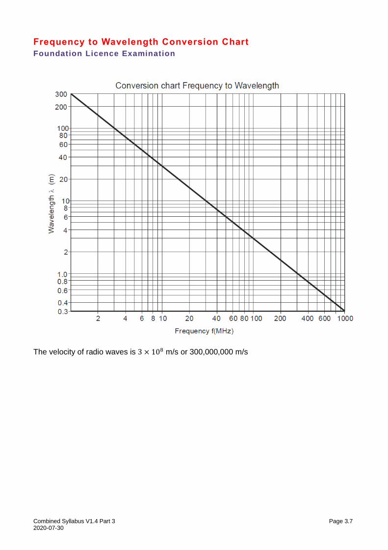
Combined Syllabus V1.4 Part 3 Page 3.7 2020-07-30
Frequency to Wavelength Conversion Chart
Foundation Licence Examination
The velocity of radio waves is 3 × 10⁸ m/s or 300,000,000 m/s
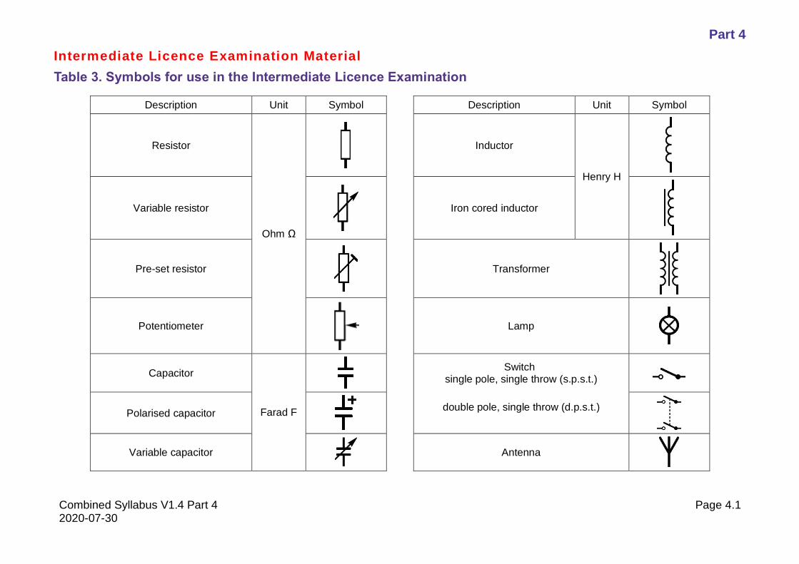
Part 4
Combined Syllabus V1.4 Part 4 Page 4.1 2020-07-30
Intermediate Licence Examination Material
Table 3. Symbols for use in the Intermediate Licence Examination
Description Unit Symbol Description Unit Symbol
Resistor
Ohm Ω
Inductor
Henry H
Variable resistor
Iron cored inductor
Pre-set resistor
Transformer
Potentiometer
Lamp
Capacitor
Farad F
Switch
single pole, single throw (s.p.s.t.)
Polarised capacitor
double pole, single throw (d.p.s.t.)
Variable capacitor
Antenna
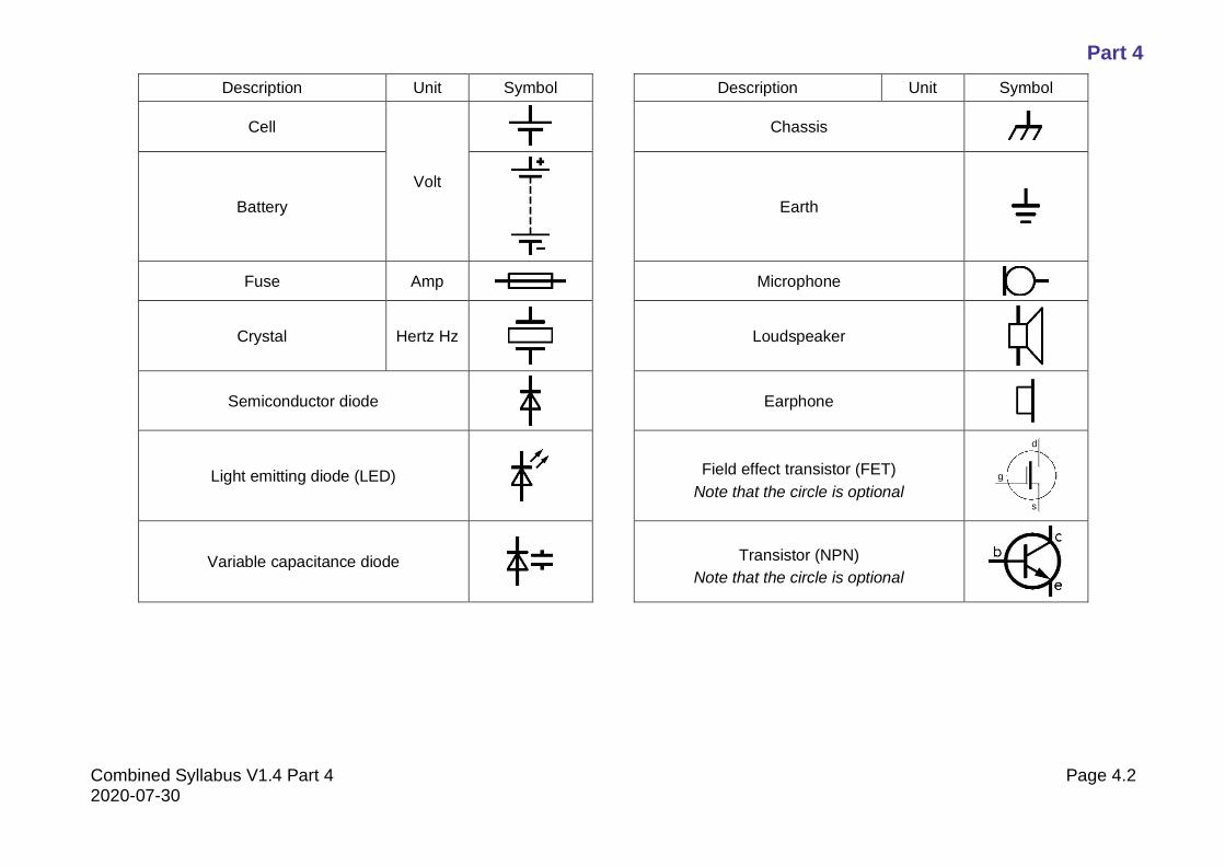
Part 4
Combined Syllabus V1.4 Part 4 Page 4.2 2020-07-30
Description Unit Symbol Description Unit Symbol
Cell
Volt
Chassis
Battery
Earth
Fuse Amp Microphone
Crystal Hertz Hz
Loudspeaker
Semiconductor diode
Earphone
Light emitting diode (LED)
Field effect transistor (FET)
Note that the circle is optional
Variable capacitance diode
Transistor (NPN)
Note that the circle is optional
s
d
g
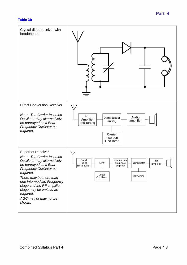
Part 4
Combined Syllabus Part 4 Page 4.3
Table 3b
Crystal diode receiver with headphones
Direct Conversion Receiver
Note: The Carrier Insertion Oscillator may alternatively be portrayed as a Beat Frequency Oscillator as required.
Superhet Receiver
Note: The Carrier Insertion Oscillator may alternatively be portrayed as a Beat Frequency Oscillator as required.
There may be more than one Intermediate Frequency stage and the RF amplifier stage may be omitted as required.
AGC may or may not be shown.
Demodulator Audioamplifier(mixer)
CarrierInsertionOscillator
RFAmplifier
and tuning
DemodulatorAF
amplifierMixer
LocalOscillator
IntermediateFrequencyamplifier
BFO/CIO
BandTuned
RF ampliier
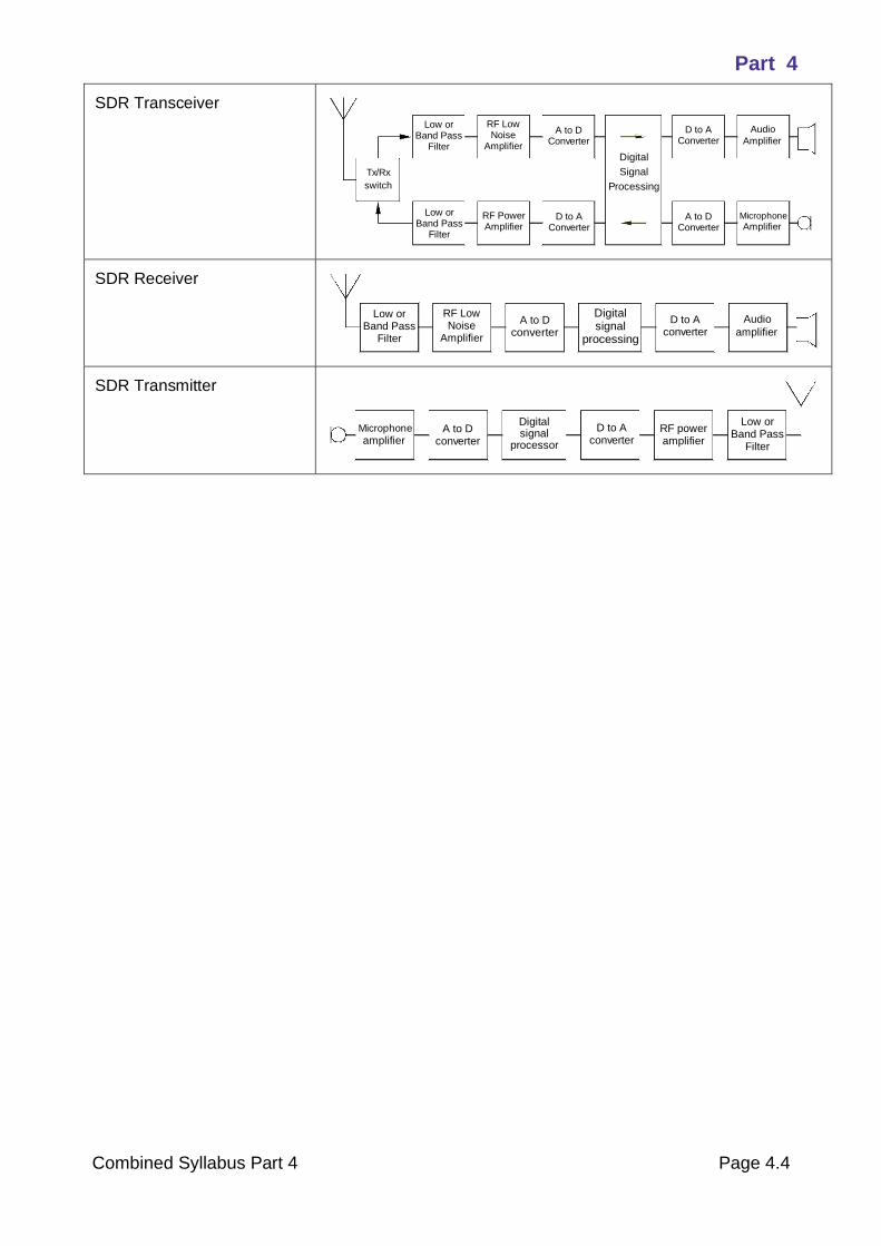
Part 4
Combined Syllabus Part 4 Page 4.4
SDR Transceiver
SDR Receiver
SDR Transmitter
Tx/Rx
switch
Low orBand Pass
Filter
RF LowNoise
Amplifier
A to DConverter
D to AConverter
D to AConverter
A to DConverter
Microphone
Amplifier
Audio
RF PowerAmplifier
Low orBand Pass
Filter
Digital
Signal
Processing
Amplifier
Low orBand Pass
Filter
RF LowNoise
Amplifier
A to Dconverter
D to Aconverter
AudioDigitalsignal
processingamplifier
D to Aconverter
A to Dconverter
Microphone
amplifierRF poweramplifier
Low orBand Pass
Filter
Digitalsignal
processor
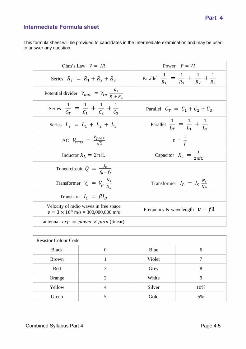
Part 4
Combined Syllabus Part 4 Page 4.5
Intermediate Formula sheet
This formula sheet will be provided to candidates in the Intermediate examination and may be used to answer any question.
Ohm’s Law 𝑉 = 𝐼𝑅 Power 𝑃 = 𝑉𝐼
Series 𝑅𝑇 = 𝑅1 + 𝑅2 + 𝑅3 Parallel 1
𝑅𝑇 =
1
𝑅1 +
1
𝑅2 +
1
𝑅3
Potential divider 𝑉𝑜𝑢𝑡 = 𝑉𝑖𝑛 𝑅2
𝑅1+ 𝑅2
Series 1
𝐶𝑇 =
1
𝐶1 +
1
𝐶2 +
1
𝐶3 Parallel 𝐶𝑇 = 𝐶1 + 𝐶2 + 𝐶3
Series 𝐿𝑇 = 𝐿1 + 𝐿2 + 𝐿3 Parallel 1
𝐿𝑇 =
1
𝐿1 +
1
𝐿2
AC 𝑉𝑟𝑚𝑠 = 𝑉𝑝𝑒𝑎𝑘
√2 𝑡 =
1
𝑓
Inductor 𝑋𝐿 = 2πfL Capacitor 𝑋𝑐 = 1
2πfC
Tuned circuit 𝑄 = 𝑓𝑐
𝑓𝑢− 𝑓𝑙
Transformer 𝑉𝑠 = 𝑉𝑝 𝑁𝑠
𝑁𝑝 Transformer 𝐼𝑃 = 𝐼𝑆
𝑁𝑠
𝑁𝑃
Transistor 𝐼𝐶 = 𝛽𝐼𝐵
Velocity of radio waves in free space
𝑣 = 3 × 10⁸ m/s = 300,000,000 m/s Frequency & wavelength 𝑣 = 𝑓𝜆
antenna 𝑒𝑟𝑝 = 𝑝𝑜𝑤𝑒𝑟 × 𝑔𝑎𝑖𝑛 (linear)
Resistor Colour Code
Black 0 Blue 6
Brown 1 Violet 7
Red 3 Grey 8
Orange 3 White 9
Yellow 4 Silver 10%
Green 5 Gold 5%
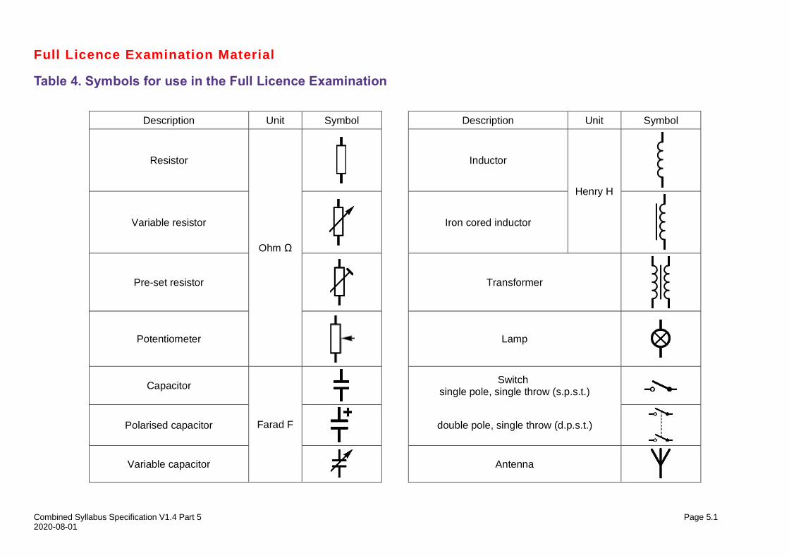
Combined Syllabus Specification V1.4 Part 5 Page 5.1 2020-08-01
Full Licence Examination Material
Table 4. Symbols for use in the Full Licence Examination
Description Unit Symbol Description Unit Symbol
Resistor
Ohm Ω
Inductor
Henry H
Variable resistor
Iron cored inductor
Pre-set resistor
Transformer
Potentiometer
Lamp
Capacitor
Farad F
Switch
single pole, single throw (s.p.s.t.)
Polarised capacitor
double pole, single throw (d.p.s.t.)
Variable capacitor
Antenna
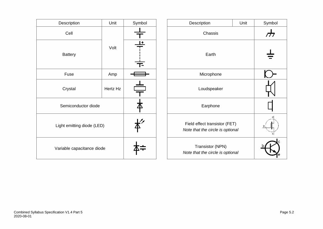
Combined Syllabus Specification V1.4 Part 5 Page 5.2 2020-08-01
Description Unit Symbol Description Unit Symbol
Cell
Volt
Chassis
Battery
Earth
Fuse Amp Microphone
Crystal Hertz Hz
Loudspeaker
Semiconductor diode
Earphone
Light emitting diode (LED)
Field effect transistor (FET)
Note that the circle is optional
Variable capacitance diode
Transistor (NPN)
Note that the circle is optional
s
d
g
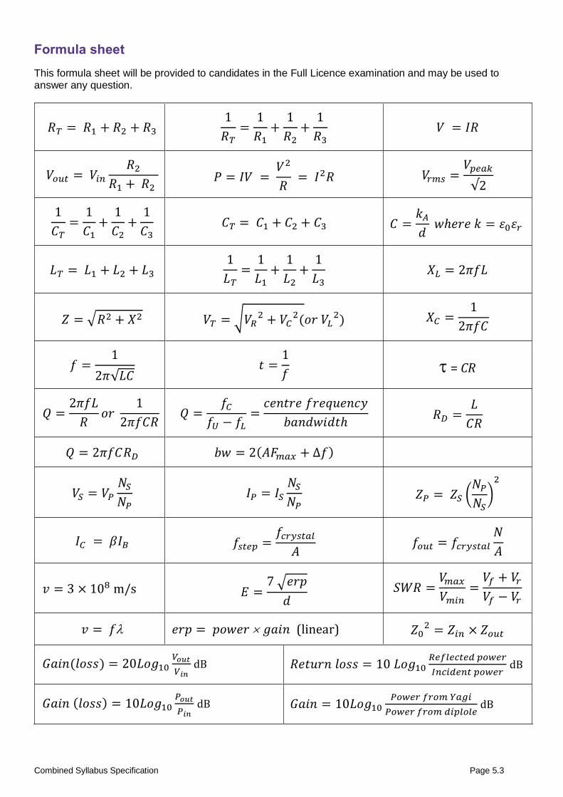
Combined Syllabus Specification Page 5.3
Formula sheet
This formula sheet will be provided to candidates in the Full Licence examination and may be used to answer any question.
𝑅𝑇 = 𝑅1 + 𝑅2 + 𝑅3 1
𝑅𝑇=
1
𝑅1+
1
𝑅2+
1
𝑅3 𝑉 = 𝐼𝑅
𝑉𝑜𝑢𝑡 = 𝑉𝑖𝑛
𝑅2
𝑅1 + 𝑅2 𝑃 = 𝐼𝑉 =
𝑉2
𝑅 = 𝐼2𝑅 𝑉𝑟𝑚𝑠 =
𝑉𝑝𝑒𝑎𝑘
√2
1
𝐶𝑇=
1
𝐶1+
1
𝐶2+
1
𝐶3 𝐶𝑇 = 𝐶1 + 𝐶2 + 𝐶3 𝐶 =
𝑘𝐴
𝑑 𝑤ℎ𝑒𝑟𝑒 𝑘 = 𝜀0𝜀𝑟
𝐿𝑇 = 𝐿1 + 𝐿2 + 𝐿3 1
𝐿𝑇=
1
𝐿1+
1
𝐿2+
1
𝐿3 𝑋𝐿 = 2𝜋𝑓𝐿
𝑍 = √𝑅2 + 𝑋2 𝑉𝑇 = √𝑉𝑅2 + 𝑉𝐶
2(𝑜𝑟 𝑉𝐿2) 𝑋𝐶 =
1
2𝜋𝑓𝐶
𝑓 =1
2𝜋√𝐿𝐶 𝑡 =
1
𝑓 = CR
𝑄 =2𝜋𝑓𝐿
𝑅𝑜𝑟
1
2𝜋𝑓𝐶𝑅 𝑄 =
𝑓𝐶
𝑓𝑈 − 𝑓𝐿=
𝑐𝑒𝑛𝑡𝑟𝑒 𝑓𝑟𝑒𝑞𝑢𝑒𝑛𝑐𝑦
𝑏𝑎𝑛𝑑𝑤𝑖𝑑𝑡ℎ 𝑅𝐷 =
𝐿
𝐶𝑅
𝑄 = 2𝜋𝑓𝐶𝑅𝐷 𝑏𝑤 = 2(𝐴𝐹𝑚𝑎𝑥 + ∆𝑓)
𝑉𝑆 = 𝑉𝑃
𝑁𝑆
𝑁𝑃 𝐼𝑃 = 𝐼𝑆
𝑁𝑆
𝑁𝑃 𝑍𝑃 = 𝑍𝑆 (
𝑁𝑃
𝑁𝑆)
2
𝐼𝐶 = 𝛽𝐼𝐵 𝑓𝑠𝑡𝑒𝑝 =𝑓𝑐𝑟𝑦𝑠𝑡𝑎𝑙
𝐴 𝑓𝑜𝑢𝑡 = 𝑓𝑐𝑟𝑦𝑠𝑡𝑎𝑙
𝑁
𝐴
𝑣 = 3 × 10⁸ m/s 𝐸 =7 √𝑒𝑟𝑝
𝑑 𝑆𝑊𝑅 =
𝑉𝑚𝑎𝑥
𝑉𝑚𝑖𝑛=
𝑉𝑓 + 𝑉𝑟
𝑉𝑓 − 𝑉𝑟
𝑣 = 𝑓 𝑒𝑟𝑝 = 𝑝𝑜𝑤𝑒𝑟 𝑔𝑎𝑖𝑛 (linear) 𝑍02 = 𝑍𝑖𝑛 × 𝑍𝑜𝑢𝑡
𝐺𝑎𝑖𝑛(𝑙𝑜𝑠𝑠) = 20𝐿𝑜𝑔10𝑉𝑜𝑢𝑡
𝑉𝑖𝑛 dB 𝑅𝑒𝑡𝑢𝑟𝑛 𝑙𝑜𝑠𝑠 = 10 𝐿𝑜𝑔10
𝑅𝑒𝑓𝑙𝑒𝑐𝑡𝑒𝑑 𝑝𝑜𝑤𝑒𝑟
𝐼𝑛𝑐𝑖𝑑𝑒𝑛𝑡 𝑝𝑜𝑤𝑒𝑟 dB
𝐺𝑎𝑖𝑛 (𝑙𝑜𝑠𝑠) = 10𝐿𝑜𝑔10𝑃𝑜𝑢𝑡
𝑃𝑖𝑛 dB 𝐺𝑎𝑖𝑛 = 10𝐿𝑜𝑔10
𝑃𝑜𝑤𝑒𝑟 𝑓𝑟𝑜𝑚 𝑌𝑎𝑔𝑖
𝑃𝑜𝑤𝑒𝑟 𝑓𝑟𝑜𝑚 𝑑𝑖𝑝𝑙𝑜𝑙𝑒 dB
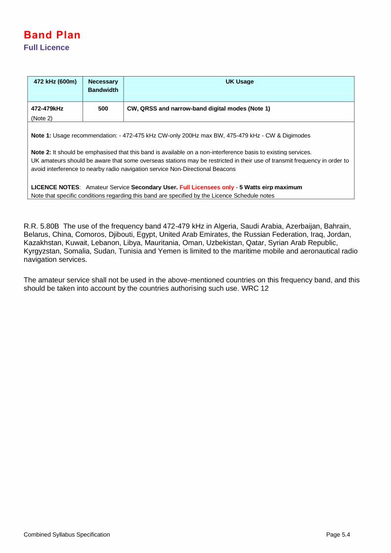
Combined Syllabus Specification Page 5.4
Band Plan Full Licence
472 kHz (600m) Necessary UK Usage
Bandwidth
472-479kHz 500 CW, QRSS and narrow-band digital modes (Note 1)
(Note 2)
Note 1: Usage recommendation: - 472-475 kHz CW-only 200Hz max BW, 475-479 kHz - CW & Digimodes
Note 2: It should be emphasised that this band is available on a non-interference basis to existing services.
UK amateurs should be aware that some overseas stations may be restricted in their use of transmit frequency in order to
avoid interference to nearby radio navigation service Non-Directional Beacons
LICENCE NOTES: Amateur Service Secondary User. Full Licensees only - 5 Watts eirp maximum
Note that specific conditions regarding this band are specified by the Licence Schedule notes
R.R. 5.80B The use of the frequency band 472-479 kHz in Algeria, Saudi Arabia, Azerbaijan, Bahrain, Belarus, China, Comoros, Djibouti, Egypt, United Arab Emirates, the Russian Federation, Iraq, Jordan, Kazakhstan, Kuwait, Lebanon, Libya, Mauritania, Oman, Uzbekistan, Qatar, Syrian Arab Republic, Kyrgyzstan, Somalia, Sudan, Tunisia and Yemen is limited to the maritime mobile and aeronautical radio navigation services.
The amateur service shall not be used in the above-mentioned countries on this frequency band, and this should be taken into account by the countries authorising such use. WRC 12
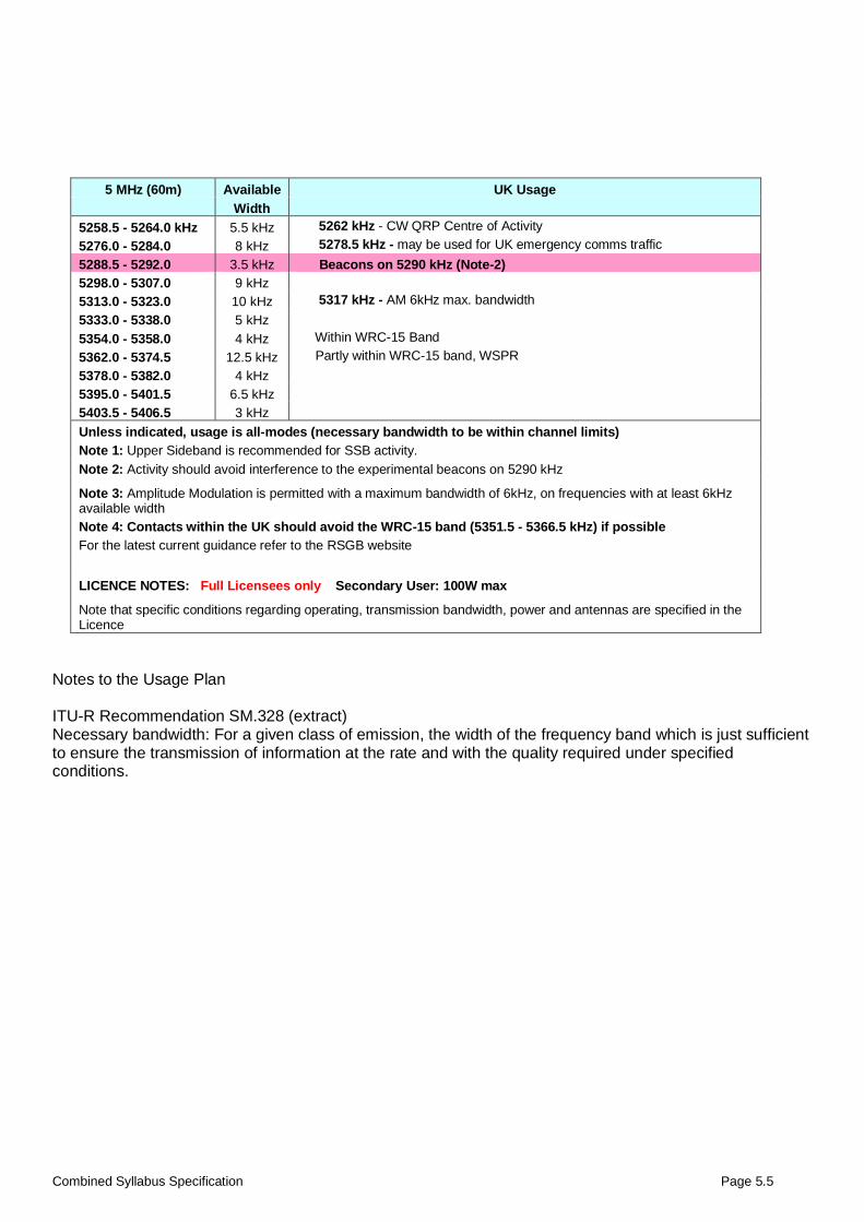
Combined Syllabus Specification Page 5.5
5 MHz (60m) Available UK Usage
Width
5258.5 - 5264.0 kHz 5.5 kHz 5262 kHz - CW QRP Centre of Activity
5276.0 - 5284.0 8 kHz 5278.5 kHz - may be used for UK emergency comms traffic
5288.5 - 5292.0 3.5 kHz Beacons on 5290 kHz (Note-2)
5298.0 - 5307.0 9 kHz
5313.0 - 5323.0 10 kHz 5317 kHz - AM 6kHz max. bandwidth
5333.0 - 5338.0 5 kHz
5354.0 - 5358.0 4 kHz Within WRC-15 Band
5362.0 - 5374.5 12.5 kHz Partly within WRC-15 band, WSPR
5378.0 - 5382.0 4 kHz
5395.0 - 5401.5 6.5 kHz
5403.5 - 5406.5 3 kHz
Unless indicated, usage is all-modes (necessary bandwidth to be within channel limits)
Note 1: Upper Sideband is recommended for SSB activity.
Note 2: Activity should avoid interference to the experimental beacons on 5290 kHz
Note 3: Amplitude Modulation is permitted with a maximum bandwidth of 6kHz, on frequencies with at least 6kHz available width
Note 4: Contacts within the UK should avoid the WRC-15 band (5351.5 - 5366.5 kHz) if possible
For the latest current guidance refer to the RSGB website
LICENCE NOTES: Full Licensees only Secondary User: 100W max
Note that specific conditions regarding operating, transmission bandwidth, power and antennas are specified in the Licence
Notes to the Usage Plan ITU-R Recommendation SM.328 (extract) Necessary bandwidth: For a given class of emission, the width of the frequency band which is just sufficient to ensure the transmission of information at the rate and with the quality required under specified conditions.