Embed Size (px)
Citation preview
The
1.
K4 ISM 1215 1300 .
• ̀a
F'ebrua.ry ieee
35e
Amateur
o
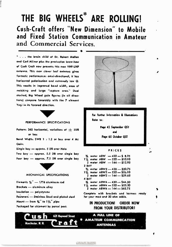
THE BIG WHEELS* ARE ROLLING! Cush- Craft offers " New Dimension" to Mobile and Fixed Station Communication in Amateur and Commercial Services.
•
• . . . the brain child of Dr. Robert Mellen
and Carl Milner plus the production know-how
of Cush Craft now presents this new VHF-UHF
antenna. This new clover leaf antenna gives
fantastic performance: omni-directional, it has
horizontal polarization and extremely low Q.
This results in improved band width, ease of
matching and large " capture area." Dual
stacked, Big Wheel gain figures (in all direc-
tions) compare favorably with the 7 element
Yogi in its favored direction.
PERFORMANCE SPECIFICATIONS
Pattern: 360 horizontal, variations of ± 2DB
or less
Band Width: SWR 1 : 1.2 or less over 4 Mc
Gain:
Single bay — approx. 5 DB over Halo
Two bay — approx. 5.5 DB over single bay
Four bay — approx. 7.5 DB over single bay
MECHANICAL SPECIFICATIONS
Elements 1/4" — 1776 aluminum rod
Brackets — aluminum alloy
Insulation — polystyrene
Fasteners — Stainless Steel and plated steel
Mount— from 3/4" to 11/2 pipe
Packaged for shipment by parcel post.
For Further Information 8 Illustrations
Refer to:
Page 42 September QST
and
Page 60 October QST
PRICES
3/4 meter ABW — 420 — $ 8.95 1 1/4 meter ABW — 220 — $ 10.95 2 meter ABW — 144 —$ 12.95
2 BAY 3/4 meter ABW2 — 430 — $20.75
114 meter ABW2 — 220 — $26.95 2 meter ABW2 — 144 — $29.65
4 BAY 34 meter ABW4 — 430 — $44.50 1 1/4 meter ABW4 — 220 — $55.50 2 meter ABW4 — 144 — $62.75
Complete with brackets and harness ready for your most and 50 ohm cable.
IN PRODUCTION! ORDER NOW
FROM YOUR DISTRIBUTOR!
rush 621 Hayward Street A FULL UNE OF t • AMATEUR COMMUNICATION
Blanchester. N. N. ( r a Ir ANTENNAS
,x
The VHF Amateur Title registered U.S. Post Office
A MONTHLY PUBLICATION
VOL. 5, No. 2 REBURY 1962
OFFICE:
Business & Editorial 87 Russell Avenue Rahway, New Jersey
editor-
Sob Prown,H2M1 Tel. 382-0870
Associate Editor
'Reelkown, K2ZSP
Circulation Manager
Pete Marksvage,MA2CMA
Production Manager
Douglas W. Clanton
Production Assistants
Blair Bohm+
Stephen Springsteel
Mike SprIngsteel
Columnists
DX Report Editor
Dan Parses, NA2DMQ
,i4rIcn,bounce Editor len Katz, K2UTH
Neter Editor
lob Higgins, W21X11
SSB Editor
Phil Oural, K2PCO
Technical Advisor Dave Heiler, KSHNP
!he III Aseteur is published monthly by Robt. N. Brown,R2ZSQ, Subscription rates: one year, 82.50, two years.$4.0, 3 years.
$5.50. Foriegn add si. ADVERTISING rate card on request. Entire contents printed in Belvidere, N.J.,USA. Telephone number for
:c- or-State direct ' g: 21-382-G879
382-A79.
Talk of Coda* Editorial
Bob Brown, K20ESO 4
I Like Two Metersl Bob Higgins, W2IXO 5
Miami Microwaves! J.W. Gregory, K4OCK & L.A. Proebsting, K4ISH 8
Author's Contest At long last - results 7
Pen Recorder Allen Katz, K2UYH 8
Mobile Transceiver Irving Math, WA2NOM 14
Sound Off! ...I8
0 R Mary 18
VHF SSB ID
Moonbouncel 20
DX Report 24 Obituary - OSCAR 25 Reader Report ........... ...................... ............. .. 2Q
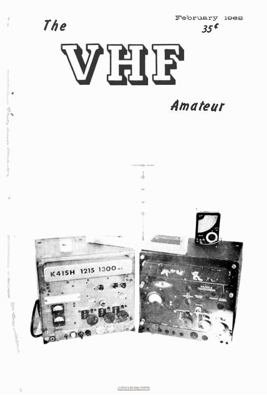
COVER PHOTO
This is the equipment used by K4ISN during his recent 1215 mc contact with K4OCK in Miami - a good 15 miles - for a Florida first !
3
EDITORIAL Bon Blown, Ik2ZSQ
Prows» Report
In our November 1961 edition we did a short
story entitled "How Are We Doing?" which
briefly described goings-on here at Rahway.
Since that time, however, much has happened
well worth mentioning. Before we get too deep
into recent affairs, though, it is only fair to tell
you that we are now employing a new printer
to do The VHF Amateur every month. As you
know only too well, your January issue was
way overdue and even this issue is a bit late.
The reason: our part-time printer decided to
take a holiday vacation without notifying us.
Copy was ready for the January issue on De-
cember 15. We didn't receive our January
magazine until January 15. So, you can see our
predicament! In any case, we now have a full-
time printer who costs a little more but prom-
ises the job quite a bit earlier.
During a part of 1960 and all of 1961 I did
a monthly VHF Column for CQ Magazine. I
only regret that at least for now continuation
of that work is impossible. I hope, though, that
our new DX Report column will more or less
fill that gap. We have long needed • DX column
in this magasine to balance out our construe-
tion and technical articles and to provide the
added service of reader participation in "mak-
ing the news." Our Reader Report is now four
months old and already a huge success. We can
guarantee that consideration will be given to
each and every "Report" received. Big plans
are ahead at Dan's DX workshop. For years
we have been fooling with the idea of a map-
ping system of Sporadic-E openings on 50 mc
and tropo and aurora conditions on 144 me.
Each major event ( such as a 144 mc aurora)
would be plotted on a map ( printed by us anff
distributed to interested readers) by you and
sent to us for country-wide correlation. The
result would be map printed in this magazine
of the United States and surrounding areas
showing the actual intensity and coverage of
in this case) the 144 me aurora. This would
show you what possibilities you missed, pat-
tern of coverage, and those most likely to be
in • fringe area next time. The possibilities of
this mapping system are vast. Within • few
month's time we could plot patterns of open-
ings, auroras, etc., and actually be able to
predict these phenomena. Let us know your
feelings on the matter, your suggestions, and
if you would be in a position to help by filling
out the map. Write to WA2DMQ at his Newark,
N. J., QTH.
Bucks for Welters!
With our March 1962 edition we will be in
a position to pay for articles ( at long last).
Since we are not on a competitive scale with
the larger general ham publications, don't ex-
pect too much. But the fact remains that from
now on we'll be able to provide fame and for-
tune ( within limits, of course) to writers who
get their articles in print. A check will be
mailed upon publication to those writers who
succeed. Why not try your hand at writing for
us? You've got nothing to lose and stand •
darned good chance of having your idea ex-
pounded before 15,000 eye.. What do we need?
Here goes: construction articles ( top on our
list). Give us the most complete write-up pos-
sible with pictures ( snapshots are OK), sche-
matic and a parts list. In this "construction"
category fall transmitters, receivers, accessory
unite ( such as linear amplifiers), and antennas.
If it hasn't been in print before, we want it!
Next on the list comes technical articles—dis-
cussions of propagation—and the like. By the
way, before I forget—we're also paying for pic-
tures ( such as the snapshots found in our col-
umns)—$1.00 for each printed. 'Nuff said.
Prices Gobiq Up
Due to the increased publication costs we are
forced to up our subscription rates 50# a year.
EFFECTIVE MARCH 3, 1962: SUBSCRIP-
TIONS $2.50 a year, $4.00 for two years, $5.50
for three years. As you can see, you save con-
siderably by subscribing for two or three years
(life subscription still only $30.00—plug plug).
You might care to renew now, before March 3
and save the increase—OK. But all those after
get the higher rates.
In closing, I might mention that we are
slowly going over to linotype printing ( like
this page). I think you'll agree that it's a lot
nicer ( also more expensive). By June or July
we hope to have The VHF Amateur completely
linotyped with a more professional touch.
73,
Bob, K2ZSQ
4
Yfice •••••••
2 meters! I• • • • • • • Robert C. Higgins, W2IXU
308 Edgar Avenue
Cranford, New Jersey
What other band can boast an 'OSCAR?" I had planned a construction article describing
how to build an inexpensive transmitter for two meters, but with the whole country turning
their receivers to our band, I think we had better say something about the big event. The
first report we received was a news release on...
DECEMBER 12. 1961: The report mentioned how and when the missile was shot off and how
the satellite was operating. The signals were being heard in Antartica by an amateur station,
presumably on the first pass. Looking to the local gang here in the northeast, I found that
the signals were copied Friday night, December 15, 1961, by several, including W3VWX, K2BNK
and W2LFO. The next day, Saturday, the boys were all set for the 11:34 EST pass. The big topic the first week was the count each received. K2BNK copied a low ot 56 Friday night;
W2LF0 copied 86 on Saturday. The count I refer to is the number of DITS counted in any one minute starting with the "H" and ending with the "I" in HI. The device that keys the trans-
mitter is temperature sensitive so as the altitude and temperature vary, so does the speed of the keying. The big surprise came at the speed of the keying; most expecteda slow speed
signal - so the fast keying was a shock even to the old CW men. Activity has been very high
on the band because of the long waiting period between passes, thus leaving time for rag chewing and comparing notes on OSCAR, even in the early morning hours.
Thanks to Herman, K2BNK, we were filled in on some important aspects of the operation
and so I'll pass them along to you. The orbit is a polar one passing over each pole at a
tilt of about 10 degrees. This means that as the earth rotates the satellite will pass over
every part of the earth at one time or another. It takes about 91.66 minutes on each orbit so each pass is moved by about 23 degrees; depending on your latitude, the distance of
each pass will be about the same distance apart. The official reports were given out stating
the crossing at the equator and all in degrees West of Greenwich, to cut down the confusion.
Herman simplified it for me by bringing out the point that since we are on one side of the earth for the first pass which is going north to south, onethe daylight pass we have rotated around to the other side by night time and the satellite now will come out ot the south
and head toward the north. This is important for beam-settings.
The signals have been copied for two consecutive passes on some days. This was done during
the day by setting the beam in the northeast for the first pass and then 91 minutes later looking to the northwest. The length of time the signals were copied varied with the maximum being about 8 to 9 minutes and minimum being about 3 minutes. The time heard is calculated on how far away it is and the altitude.(Figuring horizon to horizon). The signal strengths
varied from station to station and from each pass they ran about an S5 average. The receivers
used varied from the most elaborate low-noise converters to nset Communicators! Antennas,
from 64 elements to Halo's. When it passed overhead almost any antenna or any setting seemed to be OK, while as the distance grew, the better equipment paid off.
In conclusion, it looks as if "OSCAR" has brought a lot of new interest to the two meter band. Why not give a listen?
73, Bob, W2IXU
5
Miami Microwaves!
MOCK MISH on 1215 mc
John W. Gregory, K4OCK 3000 S.W. 103rd Court
Miami, Florida
A First!
Lloyd A. Proebsting, k'4133 310 S.W. 59th Avenue
Miami 44, Florida
Early in November, 1961 a, telephone call to K4ISH from K4OCK set in motion the
machinery and burning of "midnight oil" that was to reset in what is believed to be the first 1215 mc contact in Florida and known to be the first in Southeast Florida.
This contact was made on AM over a 15 mile path using surplus equipment to be described
later. The contact was initiated on November 30, 1961, at 2015 EST and lasted until
2130 T. Subsequent contacts occured on preceeding evenings with phone patch verifica-tions from W4NVF and W4VBQ. W4UPS was present in K4ISH's Shack during a 40 minute QS0
on November 7, 1961.
Transmitter and Receiver
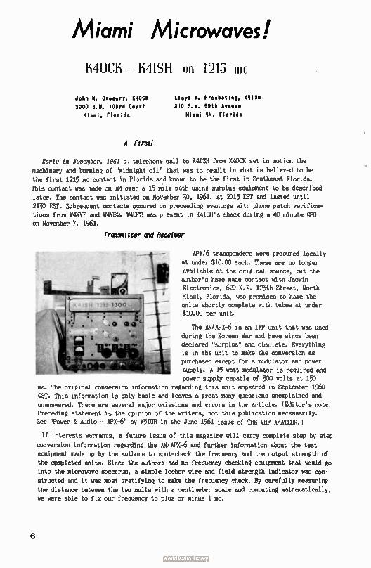
APX/6 transponders were procured locally
at under $10.00 each. These are no longer
available at the original source, but the author's have made contact with Jacwin Electronics, 620 N.E. 125th Street, North
Miami, Florida, who promises to have the units shortly complete with tubes at under $10.00 per unit.
The AN/APX-6 is an IFF unit that was used during the Korean War and have since been
declared "surplus" and obsolete. Everything is in the unit to make the conversion as purchased except for a modulator and power
supply. A 15 watt modulator is required and power supply capable of 300 volts at 150
ma. The original conversion information regarding this unit appeared in September 1960
QST. This information is only basic and leaves a great many questions unexplained and
unanswered. There are several major omissions and errors in the article. ( Editor's note:
Preceding statement is the opinion of the writers, not this publication necessarily.
See "Power & Audio - APX-6" by W5IUR in the June 1961 issue of THE VHF AMATEUR.)
If interests warrants, a future issue of this magazine will carry complete step by step
conversion information regarding the AN/APX-6 and further information about the test
equipment made up by the authors to spot-check the frequency and the output strength of
the completed units. Since the authors had no frequency checking equipment that would go
into the microwave spectrum, a simple lecher wire and field strength indicator was con-
structed and it was most gratifying to make the frequency check. By carefully measuring
the distance between the two nulls with a centimeter scale and computing mathematically, we were able to fix our frequency to plus or minus 1 mc.
6
Geographical location prohibited a telephone call to solve the many problems necessary
to get the APX-6's on the air. Therefore, it was mandatory that the authors "lived" with
these units and burnt much of that so-called "midnight oil" for a period of 10 to 15 days
and probably can now modestly state that they know what it does and does not require to result in a successful operation on 1215 mc.
Antenna
Antennas used for the initial contacts were cylindrical horns - and, for the want of
a horn, ( of approximately 1 gallon size) we chose the closest thing at hand - which just
happened to be "Ameco" 5 qt. oil cans. The driven element was constructed from 112 wire
exactly 6.15 cm long or 1/4 wave length on 1220 mc. This element is placed in the hérn
(5 qt. Ameco oil can) in the vertical plane 6.15 an from the rear of the horn. Gain of
this antenna is about 6 db. Since this type of antenna produced gain through canpression of the "E" plane, it would be of little use for DXing. The authors intended to use these
antennas for initial contacts and point-to-point local work only. Multi-band arrays are
now under construction for DXing. These arrays will be yagis or rhombics. With the present horn, K4ISH, who is a Flight Engineer with National Airlines, Miami, has heard Tampa EKE
signal across the state. Initial receiver operation was set up on the Miami EME signal, which is about 10(X) mc.
Times wire ( T4-50) cable was used at both the author's GTH's. This cable by rough
calculations exhibited about 5 db attenuation per 100 feet. All other transmission lines tried, even the so-called low-loss polyform stranded center conductor cable, was almost a perfect attenuator at 1215 mc. Radiation losses from open wire line were excessive even
though the theoretical loss would be less than coaxial cable.
With the increased capture area of larger antenna arrays, the authors hope to create DX interest in Florida.
Since the authors will most probalily not have Micro-Wave Associates "paramps" made
available to them, the moonbounce circuit is going to take a little time. However, it will be in mind for future experiments.
The authors plan to move the APX -6's to 1296 mc shortly and then begin the crystal controlled converters, etc.
Questions regarding the APX-6's will gladly be answered by the author's. Please enclose
a self-addressed-stamped-envelope if request is submitted by mail. See you on 1296!
Stolen ( with Oernission) fro.
PLORIDS SLIP, Jan. 1962
«Me' coeffer! At Zone last, here are the remits of our first 6-month AUTHOR's CONTEST! Here's how
the voting went...
FIRST PRIZE (Clegg 99'er 6 meter transceiver): Dave Heller, K3HNP, for his article " HNP' 6n2 VPD" in the September 1961 issue.
SECOND PRIZE (Gem Electronics units for 50 & 144 mc): Michael A. Czysch,
LU3ECA, for his article "Modulation Monitor", October, 1961.
VOTING PERCENTAGES
June 1961 issue: "TVI on 6 meters," K3HNP - 57.12%. July: "De UCH", W4UCE - 36.36%.
August: "100 Watts - SSB". K4RLX - 50%. September: "HNP" 6n2 VFO, K3HNP - 89.476%. October: "Modulation Monitor," LU3ECA - 87.5%. November: "Who's Got the Button?", K2OPI, 22.14 S.
Our deepest gratitude to those who took the time to vote and to the companies furnishing prizes to our winners.
7
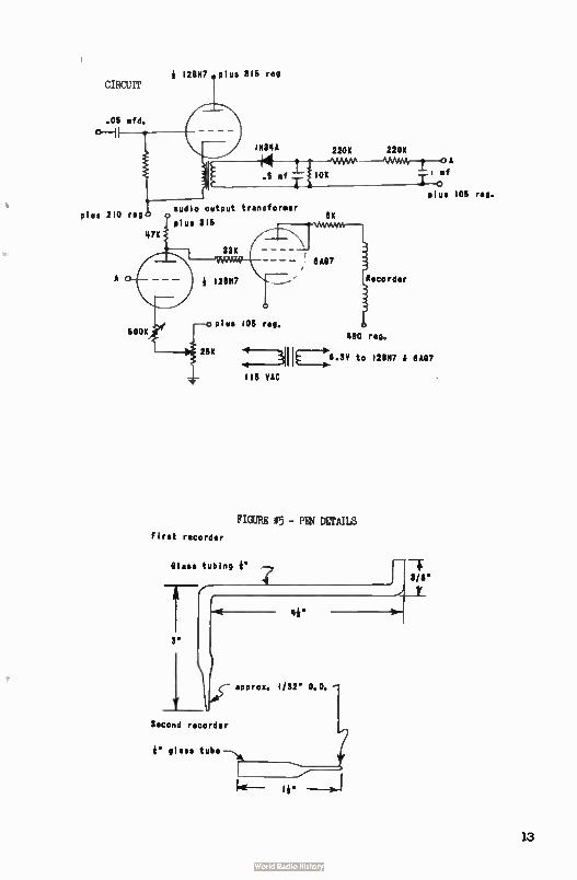
&et rife cam Pen Recorder
Allen Katz, 42UVN
MOONBOUNCE EDITOR
48 Cumberland Avenue
Verona, New Jersey
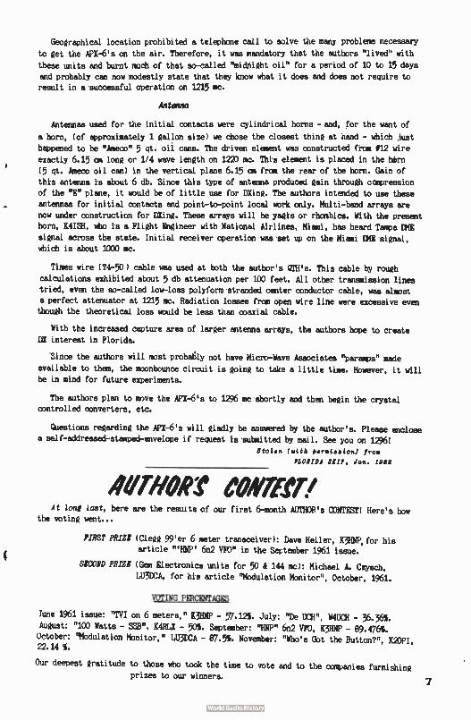
In provient a permanent record of moonbounce experiments and many other amateur
endeavors, a pen recorder has a marked advantage over a tape recorder. In moonbounce, extremely narrow bandwidths are used to obtain gain. These narrow bandwidths change the tone of the received signals, making them hard to discern with the human ear. The pen
recorder is not affected by this change.
The two pen recorders to be described were built individually, although the basic idea
is the same. An armature pivoted and spring loaded in a magnetic field will change position
as the field is varied and can move a pen which writes on a continuously moving paper.
Construction
The first recorder's armature--magnetic field arrangement is completely homebrew. The
magnetic field is produced by two 5,000 turn coils of #33 enameled wire wound about e
diameter x 2h" long ( li" shaft & 1" head) stove bolts placed as shown in Figure #1. The armature ( a i" length of it" diameter stove bolt) is supported in a li" x 2h" x 3/8" plastic
frame between the two coils. Conical bearing surfaces are drilled into the plastic frame
for pivots made from brass machine screws whose ends are tapered to a point. Tension is
applied to the frame by a spring made from approximateky 20" of piano wire. The pen is
attached to the plastic frame by a thin aluminum clamps ( see Figure #2).
The second recorder's armature-magnetic field arrangement is made from an old 3" meter
(1 ma full scale). The case is removed and the needle is cut off about 1/F from the
pivoted mil. The needle's counterbalance is bent slightly up and a 11" length of 018 copper wire is soldered to it ( see Figure #3). The pen is taped to this wire. Two ground
8
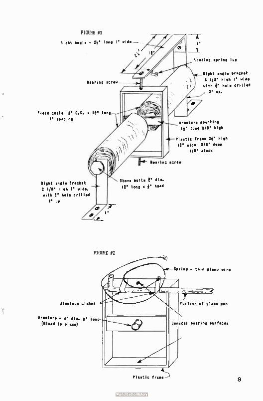
FIGURE #1
Right Angle - 23' long l" wide —
Bearing screw
Field coils le O.D. v IB" long
l' spacing
Right angle Bracket
2 1/8' high l' wide,
with B" hole drilled
2' up
FIGURE f2
Aluminum clamps
Armature - e dia, e long
(Olued In place)
AL
Plastic frame --)
Stove bolts 1" dia.
le « long a e head
I•
Loading spring lug
Right angle bracket
3 I/8' high l' wide
with e' hole drilled
, 2' up.
Armature mounting
le long 3/8" high
Plastic frame 28' high
l' wide 3/8' deep
1/8" stock
Bearing screw
Spring - thin piano wire
Portion of glass pen
Conical bearing surfaces
9
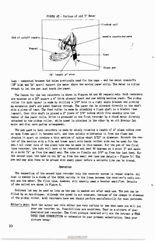
FIGURE #3 - Portion of old 3" Meter
Pivoted coil
End of cutoff needle
Magnet
le length of wire
needle counterbalance
tape
Glass pen
lugs - connected between thé holes previously used for the case - and two metal standoffs
(le. high and 34" apart) support the meter above the moving paper strip. The meter is tilted enough to let the pen just touch the paper.
The layout for the two recorders is shown in Figures 4A and 48 respectively. Both recorders are mounted on a 10" square x 4" thick plywood board and use adding machine paper. The pickup
roller ( in both types) is made by drilling a 3/8" hole in a right angle bracket and placing an extension shaft and panel bushing through. The paper can be attached directly to the shaft with a piece of tape. The feed roller is made by attaching a fixed shaft to a bracket ( see
layout). Over this shaft is placed a 2" piece of 3/8" tubing which fits snuggly into the
center of the paper rolls. Drive is produced in the first recorder by a clock motor directly attached to the pickup roller, while power is obtained in the other by an old Erector Set
motor and dial cord pulley arrangement.
The pen used in both recorders is made by slowly rotating a length of 4" glass tubing over
an open flame until it becomes soft, and then quickly withdrawing it from the flame and
drawing it apart to produce a thin section of tubing about 1/32" in diameter. Scratch the cen-
ter of the section with a file and break apart with hands ( either side may be used for the
pen.) All other cuts of the glass tube may be made in this manner. For the pen of the first
type recorder, the tube will have to be reheated and bent 90 degrees at a point 3" and again
at a point 71" up from the small end. The tube is finally cut 3/8" up from the last bend. For
the second type, the tube is cut le up from the small end ( see pen details - Figure 5): The
pen end may also have to be ground with emery paper before a suitable line can be traced.
Operation
The connection of the second type recorder into the receiver system is rather simple. All
that is needed is a diode of the 1N34A variety in the lines between the receiver's audio out-put and the meter. The first type, however, will usually need a booster amplifier. Details of one suited are shown in Figure 6.
Ordinary ink may be used as long as the pen is washed out after each use. The pen can be
filled by an eye-dropper. Although the speed is not constant, because of the change in diameter
of the pickup roller, both recorders have and should perform satisfactorily for most purposes.
Netor's Note: Both the author and this editor are very curious to see what uses you will put
your pen recorder to. Possibilities are countless. Send us a picture of your
completed pen recorder. The first picture received will win the entrant a FREE
THREE YEAR SUBSCRIPTION or extension to your present subscription. Send your picture today!
10
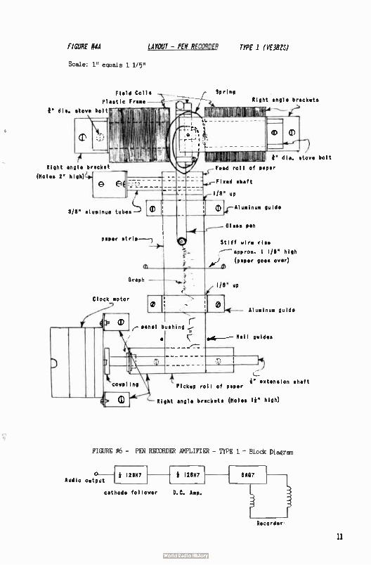
FIGURE #4A LAYOUT — PEN RECORDER TYPE 1 ( VEWS)
Scale: 1" equals 1 1/5"
Field Coils
Plastic Frame—
r dia, stove bolt
Right angle bracket
(Holes 2" high)1
G e (
318" aluminum tubes Th 0 Ar-Aluminum guide
paper strip ---1 ,
Graph --
Clock motor
Spring
Right angle brackets
8" dia, stove bolt
Feed roll of paper
Fixed shaft
1/8" up
Glass pen
Stiff wire rise
---- approx.. 1 1/8" high
(paper goes over) r74
1/8" up
0
r-panel bushing 1.;
Aluminum guide
Nail guides
coup ing Pickup roll of paper 4" extension shaft
Right angle brackets ( Holes 14' high)
FIGURE #6 - PEN RECORDER AMPLIFIER - TYPE 1 - Block Diagram
Audio output 12BH7 4 128117
cathode follower D.C. Amp.
8A137
Recordei-
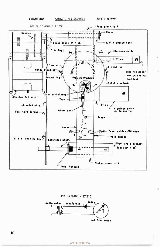
FIGURE #48 LAYOUT- PEN RECORDER TYPE 2 (K2UYN)
Scale: 1" equals 1 1/5" Feed paper roll
Gears
Metal
Erector Set motor
Fixed shaft 11" high
" pulley
meter
stand-off
Ground lug
stranded wire -Se
IDial Cord Spring-
2 dial cord pulley5e>
Washer
-- 3/8' aluminum tube
nter-balance
Tape
Glass pen
e 0,- Aluminum guide 1/8" UP
Ground log
tek Aluminum meter
tension spring
(option)
Metal stand-off
Graph
um /Aluminum Paper
guide spring
e paper e
Paper guides 818 wire
Extension shaft
Mail guides
Panel Bushing
14$ Right angle bracket
(Hole 2" HO)
Pickup Paper roll
PEN RECORDER - TYPE 2
Audio output transformer MBA
Modified meter
12
* 12887 plus 315 reg CIRCUIT
.05 mid. 0,-1
plus 210 reg
500K
iN34A
144
.5 of ,_
220K 220K
-----Wee‘-1—° A
0 Plus 106 reg.
audio output transformer
plus 315
93K
* 12887
plus 105 leg.
25K
First recorder
▪ 1▪ 15 YAC
flAC17
Recorder
480 reg.
8• .9V to 12887 8, 8A137
FIGURE #5 — PEN DETAILS
Glass tubing A"
3'
3/8'
- +We:. 1/32' 0.0.
Second recorder
11 glass tube
13
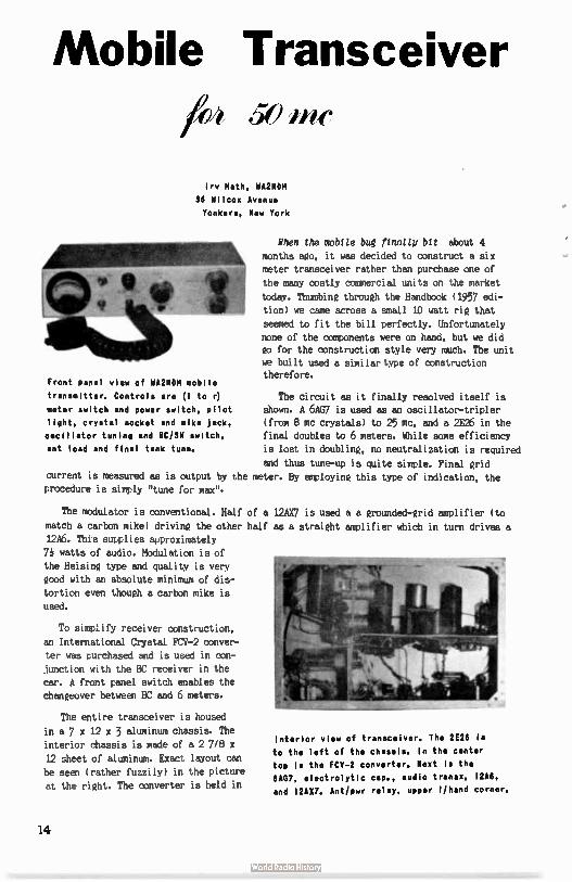
Mobile Transceiver /04 50 me
Iry Math, WA2NDM
36 Wilcox Avenue
Yonkers, New York
Front panel view of WA2NDM mobile
transmitter. Controls are ( 1 to 0
meter switch and power switch, pilot
light, crystal socket and mike jack,
oscillator tuning and 606W switch,
ant load and final tank tune.
When the mobile bug finally bit about 4
months ago, it was decided to construct a six meter transceiver rather than purchase one of
the many costly commercial units on the market
today. Thumbing through the Handbook (1957 edi-
tion) we came across a small 10 watt rig that
seemed to fit the bill perfectly. Unfortunately
none of the components were on hand, but we did to for the construction style very much. The unit we built used a similar type of construction therefore.
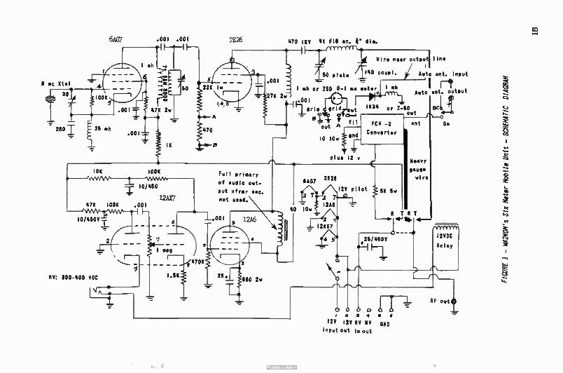
The circuit as it finally resolved itself is shown. A 6AW is used as an oscillator-tripler (from 8 mc crystals) to 25 mc, and a 2E26 in the final doubles to 6 meters. While some efficiency
is lost in doubling, no neutralization is required
and thus tune-up is quite simple. Final grid current is measured as is output by the meter. By employing this type of indication, the procedure is simply "tune for max".
The modulator is conventional. Half of a 12AX7 is used a a grounded-grid amplifier ( to
match a carbon mike) driving the other half as a straight amplifier which in turn drives a 12A6. This supplies approximately
71 watts of audio. Modulation is of the Heising type and quality is very good with an absolute minimum of dis-
tortion even though a carbon mike is
used.
To simplify receiver construction,
an International Crystal FCV-2 conver-
ter was purchased and is used in con-
junction with the BC receiver in the
car. A front panel switch enables the changeover between BC and 6 meters.
The entire transceiver is housed
in a 7 x 12 x 3 aluminum chassis. The interior chassis is made of a 2 7/8 x
12 sheet of aluminum. Exact layout can be seen ( rather fuzzily) in the picture
at the right. The converter is held in
interior view of transceiver. The 2E26 is
to the left of the chassis. In the center
top is the FCV-2 converter. Next is the
6A67, electrolytic cap., audio transit, I2A6,
and 12AX7. Antipwr relay, upper 1/hand corner.
14
8 mc Xtal
30
250 I
6AG7
25 eh
.001
.001
I soh
.001 . 001
it
P e.*
47K 2w
10/460
12AX7 476 1006 . 001
— 1\ANV-/eVenr%—n-i
10/4504,
IIV: 300-400 HOC
I meg
2E26
5 .001 22K lw
Full primary
of audio out-
put slowr sec.
not used.
-4-1.001
1.66 6802w
430 jono 4t 018 en. 0" dia.
I eh or 260
A
Wire near outputl line
140 coup!. Auto ant. Input
0-1 na meter 1 ah
n ee-en out INS4 or Z-S0
out op.-4
fil FCV -2 ant
10 lOw tend
plus 12 v
2E26 6A07
Converter
12V pilot
Heavy
gauge
wire
R TRI 4-911> 4-
4.25/460V
124 i2V 114 NY ONO
Input out In out
' I r-1 Auto ant. output
6421
Om
I2VDC
Relay
RF out
FIGURE I -
WA2NDM's
Six Meter Mobile Uni
t - SC
HEMA
TIC
DIAG
RAM
maA if a
111.1111:1111 e- • e 6. et
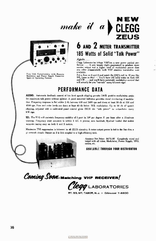
Two Unit Construction with Remote Modulator and Power Supply Conserves Spare at Operating Position
NEW p CLEGG ZEUS
6 AND 2 METER TRANSMITTER 185 Watts of Solid " Talk Power" Again . . . Clegg Laboratories brings VHF'ers a new power packed per. former . .. A new beauty that's guaranteed to produce more carrier output and a higher level of modulation power than any other commercially built VHF amateur transmitter now available. Put a Zeus on 6 and 2 and watch the DSO's roll in. If you like DX, listen to this! — You'll have 185 solid watts on both AM and CW ... and you'll have rustornatic modulation control that will actually let you "out-talk" many kilowatt rigs!
PERFORMANCE DATA AUDIO: Automatic feedback control of low level speech clipping permits 120% positive modulation peak.
for maximum talk power without splatter. A panel mounted indicator provides visual monitoring of modul•-
tion. Frequency response is flat within 2 db between 400 and 3400 cps and down at kid 18 db at 150 and
4500 cps. Hum and noise levels are down at least 40 db below 70% modulation. Up to 18 db of speech
clipping, adjusted with a calibrated panel control gives ZEUS the "talk power" to outperform many
KW rigs.
RF: The VI.0 will maintain frequency stability of 1 pad in 11:d per degree F. per hour after a 15.minute
warmup. Frequency reset accuracy is within 5 KC. A precise. sero backlash, flywheel loaded dial makes
accurate tuning easy on both 6 and 2 meters.
Maximum TVI suppression is inherent in all ZEUS circuitry. 6 meter output power is fed to the line thru •
pi network circuit. Output on 2 is link coupled to a high efficiency tank.
ewer".
Amateur Net Price: 8675.00 Completely wired and tested with all tubes, Modulator, Power Supply, VFO, cables, etc.
AVAILABLE THROUGH YOUR DISTRIBUTOR
fegi3W- Matching VHF RECEIVER!
ekle LABORATORIES PT 53, MT TABOR, N. J. • OAkwood 7-6800
16
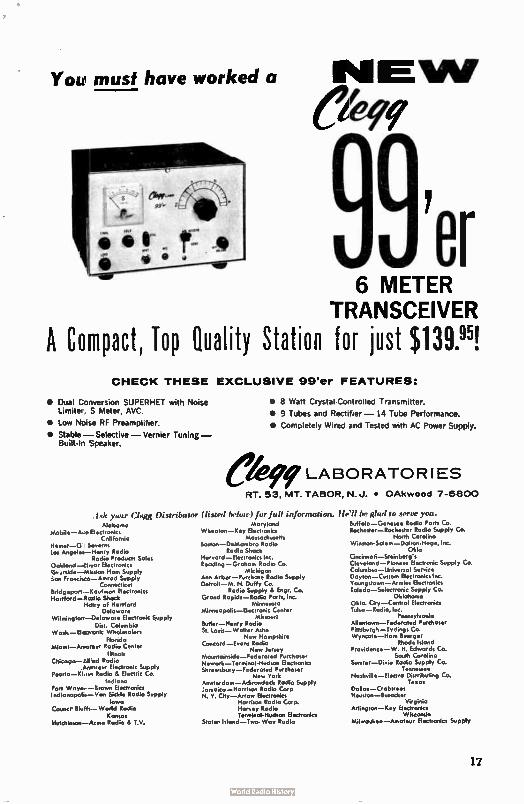
You must have worked a
6 METER TRANSCEIVER
A Compact, Top Quality Station for just $ 139.95! CHECK THESE EXCLUSIVE 99'er FEATURES:
• Dual Conversion SUPERHET with Noise Limiter, S Meter. AVC.
• Low Noise RF Preamplifier.
• Stable — Selective— Vernier Tuning — Built- In Speaker.
I :lc your Clegg Distributor Alabama
Mobile- Aro Electronics California
Hemet-G Severn, Los Angelei-Menry Radio
Rodio Products Sales Ookland-dmar Electronics Riu.,“id,s_.-miission Horn Supply don Francisco-Arrirad Supply
Connecticut Bridgeport - Kaufrnon Electronics Hartford-Rs:Hit Shock
Motry of Hartford Delaware
Wilmingtorr-Deloware Electronic Supply Dist. Columbia
Wash.-Elctronic Wholesalers Florida
Miami-A.1.mo Radio Center Illinois
Chicago-All:1,d Rodio Amateur Electronic Supply
Peoria-Klov. Rodio 8. Electric Co. Indiana
Fort Wnyn..- Brown Electronics Indionopelis- Van Skid. Radio Supply
lowo Counci Bluff,-World Rodio
Kansas Mulchinson-Ame Rodio & T.V.
Ô
• 8 Watt Crystal.Controlled Transmitter.
• 9 Tubes and Rectifier — 14 Tube Performance.
• Completely Wired and Tested with AC Power Supply.
LABORATORIES
RT. 53, MT. TABOR. N. J. • OAkwood 7-6800
(listed below) for full infortruition. Moryland
Wheaton-Key Electronics Massochusetts
Boston-DeMombro Radio Rodio Shock
Harvard-Electronics Inc. Reading- Graham Rodio Co.
Michigan Ann Arbor- Purchase Radio Supply Detroit-M. N. Duffy Co.
Radio Supply & Engr. Co. Grand Ropids-Rodio Parts, Inc.
Minnesota Minneapolis- Electronic Center
Missouri Butler- Henry Radio St. louis- Walter Mho
New Hampshire Concord-Evant Rodio
New Jersey Mountainsid•-federated Purchaser Newark-Terminal- Hudson Electronics Shrewsbury-Federated Purchaser
New York Amsterdam-Adirondack Rodio Supply Jamoico-Harrison Rodio Corp N. Y. City-Arrow Electronics
Morrison Radio Corp. Harvey Radio Terminal- Hudson dectronics
Staten Island-Two.Wav Radio
be glad to serve you. Buffalo G Rodio Parts Co. Rochester-Rochester Radio Supply Co.
North Carolina Winston-Salem - Dalton. Hege, Inc.
Ohio Cincinnoti-Steinberg's Cleveland-Pioneer Electronic Supply Co. Columbus-Universol Service Dayton-Custom Electronics Inc. Youngstown-Armies Electronics Toledo-Selectronk Supply Co.
Oklahoma Okla. City-Control Electronics Tomo-Rodio, I nc.
Pennsylvonia Allentown-Federated Purchaser Pittsburgh-Tydings Co. Wyncote-Marn Buerger
Rhode Island Providence- W. H. Edwards Co.
South Corolina Sumter-Dixie Radio Supply Co.
Tennessee Nashville- Electra Distributing Co.
Texas Dallas-Crabtree, Houston-Busacker
Virginia Arlington-Key Electronics
Wisconsin Milwaxkee-Arnoteur Electronics Supply
17
in place by small angle brackets. In
After construction, the unit should be hooked to a power supply furnishing 12 volts for
the heaters ( AC can be used) and 300 volts DC. A dummy load ( I used a 7i watt lamp with a
50 mmf trimmer in series) should be connected to the transmitter output jack. Depressing the
mike button, the oscillator plate should be tuned for maximum in the Grid position of the
meter, Switching to Output, the plate and loading controls should be adjusted for maximum
reading. The bulb should plow brightly at this point. Speaking into the microphone should
cause a noticeable flickering of the bulb.
With these adjustments complete, the transceiver can be installed in the car, all cables
connected, retuned, and your mobiling career started.
Sound Off! It's not very often that km "sound off" about anything through these pages. Most of the
time we Just restrain our frustrations saving the recezr from countless pages of strictly
editorial trivia. Today, however, the Editor tot a letter Inn New York City kMich is a
"Wet" for comma—
The letter leS from a fellow amateur in behalf of his local amateur rodio club requesting a plug for their ingenius certificate, the "Marked All Manhattan" award. Well, they're going
to get a "plug" alright. Requirements are just to war* 10 Hanhatten hams. Send a list - AND ONE DOLLAR ( to cover expenses, mast likely). Oh brother....
We've all been aware of the trend being set by well intentioned amateurs towani this
certificate-award business. OF by me - we're even willing to photograph and print the certi-
ficate in this magazine if it is in the true spirit of ham ratio. But this $1.00 "per" racket is going too far.
It is only fair that we have our editorial policies (most of Witch can be altered by
a twist of the arm and a shot of ---) but in this particular case we're going to hold our ground. Needless to say, the request was REFUSED and the certificate returned with a letter stating our feelings on the matter.
Anyone WM) thinks they can bilk $1.00 out of a fellow amateur for a tho-colorod piece
of typewriter paper is pushing things too far. Mhat sort of people are we admitting to the
hobby? How commercial can we get? I only hope this will stop now - before mare people get in on the scheme. The time will come Wien they'll be asking $5.00 for on RCC certificate if we don't watch out Heaven help us.
IFI; ellairly! Walter Shivers, K3KZT
"Sorry, OM, I missed most of your transmission." Do you say this - does it sound fami-
liar? It should. This statement can be heard on all bands, but primarily during 6 meter
openings. It seems that we forget how wide the, band is when we hear a rare one coming in. Some say, "I can't operate on the high end." Not true. I've followed the DX hounds up the band as high as 51 mc. Everyone seems to be trying to work the same fellow, forgetting
that there are fish in the ocean. And how about the "little fellow?" Have you stopped to
consider that he might want a new state also? Did you start out with a gallon - or even
100 watts? Remember when you finished calling "Ca DX" and turned it over, only to find 300 watts on frequency calling "Ca DX" ( only much louder)? It was pretty bad then, huh?
Well, the same conditions exist today, but it doesn't sound the same because the shoe is on the other foot now.
And how about the boys that figure it takes too much time to hook up that dummy load?
They tune up right on frequency to keep anyone else from snagging that rare one ' till they're good and ready. Does this apply to you? ------I hope not.
18
Phil Oural, K2PCO
204 East Northfield Road
Livingston, New Jersey
A few SSB'ers have written to me telling me what they have been working. One letter
I received is from Bob Heil, K9EID, of Marissa, Illinois. Bob mentioned that he's been
working the following stations on ground wave, 6 meters, with "Good" S,meter signals.
The approximate distance of each station is indicated in parenthesis. K9HAE, Princeville,
Illinois, ( 300 miles); W9HGE, Beloit, Wisconsin ( 450 miles); K9ZTK, Evansville, Indiana,
(175 miles); W4CSN, Henderson, Kentucky, ( 190 miles); K4GEQ, Reed, Kentucky, ( 190 miles);
and recently K42CE at Hartford, Kentucky.
Bob went on to mention that he has daily rag chews with K9ETS, W9WXR, K9K2B, and WODJG
on 50.11 at 0100 to 0130 ( CST).
Bob also mentioned that on December 2nd he worked K8NIE, K9DTB, K9Z00, KOSVT, and WOWKE on aurora. ( I also heard this aurora and only heard locals calling frantically. There seems to be a lack of SSB'ers in the New England states. Where is everybody? Please, someone in
New England write and let me know where everybody went!)
Also got a nice letter from Sam Berlin, WA2CVF, Brooklyn, New York. Sam passed along a
list of SSB'ers who sign into the East Coast SSB Net. This net meets every Sunday at 1300
(EST) on a frequency of 50.110. The stations are : K2Z8X, K2UTN, W2AXU, K2PBO, K2PXP,
K2OHF, K2YGL, K2DQT, K2OGY, W2NCF, WA2GJT, K3CZI, W2RJD, W3HFY, WA2ONB, K2PCG, W2IMB, K2VIX,
WA2SFD, WA2DWK, WA2LRO, and WA2CVF.
Bill Rhode, WA2EMA, Roseland, New Jersey, has informed me that SSB activity on 2 meters
has been slow in his area. The SSB'ers in the New York area have adopted 144.10 as the SS8 calling frequency. Also, there are a few SSB stations operating just above 145 mc.
Once again the cry goes out for more information. What is always appreciated is news,
of nets, and its members, any construction hints and articles. Since I only operate 6 meters,
SS8 news of 2 meter-variety is always appreciated. I have yet to receive mail from the West Coast. Come on fellows out there in W6 and 7 land - let me know what you have been doing
out there!
My last comment is not of a happy note. During the band opening on 6 meters on December
16th, SSE activity was pretty good. What my complaint is that there were two to four OSO's
going on within 500 cycles of each other. Being that we have more than 500 cycles, fellows,
let's not bunch on the same frequency but spread out for one or two kc - if and when possible.
During this particular opening I didn't hear any other SSE signals except on that one spot.
Let's all get together in one big QS° or spread apart so as not to fight each other. Thanks
73, Phil, K2PCG
A BUCK A PIN Starting next month, the publisher will pay the fantastic sum of $ 1.00000000
for each picture printed in THE VHF AMATEUR. We want photo's of your station, you (egad!),
or your antenna. Give us some to choose from please. Put your name & QTH on the back so we'll
know where to send that bagful of money (pennies anyway). Also write a good caption. Thank you.
19
Allen Katz, K2UYH
148 Cumberland Ave.
Calculus and Dish Construction
0 N
o Amateur Interest fn parabolfc antenna construction has
N grown enormously since the first 1296 mc moonbounce contact back in July of 1960. Along with this increase in interest, there
has been an equal increase of information on dish construction available to the VHF man. Yet, many problems still hinder the pros-
pective parabolic antenna constructer. E One question frequently asked is how to compute the length along a
parabolic curve. This problem is important no matter what method of parabola construc-tion a builder intends to use. For example, using the "stress method" ( in which stress is applied to the ends of long rods to produce an approximate parabolic curve) of con-struction, say an amateur wishes to build a dish with an eight foot focal length and
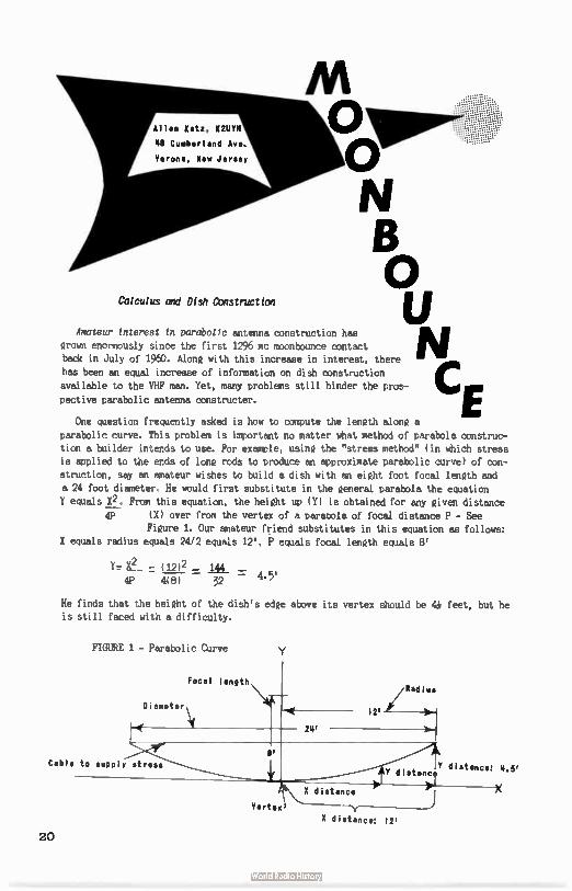
a 24 foot diameter. He would first substitute in the general parabola the equation Y equals X2. From this equation, the height up ( Y) is obtained for any given distance
4P ( X) over from the vertex of a paraoola of focal distance P - See Figure 1. Our amateur friend substitutes in this equation as follows:
X equals radius equals 24/2 equals 12', P equals focal length equals 8'
y_ e. (12)2
4P 4(8) — 32 —
He finds that the height of the dish's edge above its vertex should be ¡U feet, but he is still faced with a difficulty.
FIGURE 1 - Parabolic Curve
Focal length
Diameter \
41( 24'
/Radius
12' Jile
Cable to supply stress
Yertexe
Y distance: 4.6' Y distance
)" X / X
X distance: 12'
20
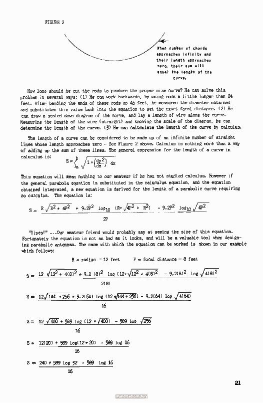
FIGURE 2
When number of chords
approaches infinity and
their length approaches
zero, their sum will
equal the length of the
carve.
How long should he cut the rods to produce the proper size curve? He can solve this problem in several ways: ( 1) He can work backwards, by using rods a little longer than 24 feet. After bending the ends of these rods up 41 feet, he measures the diameter obtained
and substitutes this value back into the equation to get the exact focal distance. ( 2) He can draw a scaled down diagram of the curve, and lay a length of wire along the curfe.
Measuring the length of the wire ( straight) and knowing the scale of the diagram, he can determine the length of the curve. ( 3) He can caluculate the length of the curve by calculus.
The length of a curve can be considered to be made up of an infinite number of straight lines whose length approaches zero - See Figure 2 above. Calculus is nothing more than a way
of adding up the sum of these lines. The general expression for the length of a curve in
caluculus is:
( V l+( dx )a dx )
This equation will mean nothing to our amateur if he has not studied calculus. However if
the general parabola equation is substituted in the caluculus equation, and the equation
obtained integrated, a new equation is derived for the length of a parabolic curve requiring
no calculus. The equation is:
S = R v/R2 + 4P2 + 9.2P2 1(410 (11* 141'2 R2) - 9,2P2 log10 v/4P2
2P
"jipes!" .., Our amateur friend would probably say at seeing the size of this equation. Fortunately the equation is not as bad as it looks, and will be a valuable tool when design-
ing parabolic antennas. The ease with which the equation can be worked is shown in our example
which follows:
S=
R = radius = 12 feet P . focal distance = 8 feet
12 1122 + 4(8) 2 + 9.2 ( 8) 2 log ( 12* \/1.22 + 4(8) 2 - 9.2(8) 2 log
2(8)
S = 12/144 + 256 • 9.2(64) log (12044+ 256) - 9.2(64) log
16
S= 12 l'",00 + 589 log (12 - 589 log
16
S = 12(20) + 589 log(12+20) - 589 log 16
16
S = 240 + 589 log 32 - 589 log 16
16
21
S= 24)+885 - 710
16
S = 26.6 feet
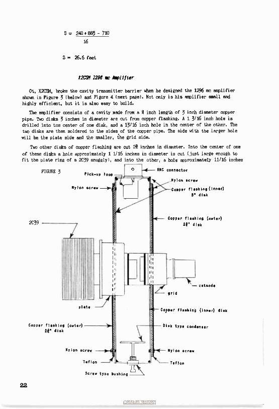
K2CSK 1296 we Amplifier
Ot, K2CSK, broke the cavity transmitter barrier when he designed the 1296 mc amplifier
shown in Figure 3 ( below) and Figure 4 ( next page). Not only is his amplifier small and
highly efficient, but it is also easy to build.
The amplifier consists of a cavity made from a inch length of 3 inch diameter copper
pipe. Tuc disks 3 inches in diameter are cut from copper flashing. A 1 3/16 inch hole is drilled into toe center of one disk, and a 13/16 inch hole in the center of the other. The
two disks are then soldered to the sides of the copper pipe. The side with the larger hole
will be the plate side and the smaller, the grid side.
Tuo other disks of copper flashing are cut 2i inches in diameter. Into the center of one
of these disks a hole approximately 1 1/16 inches in diameter is cut ( just large enough to fit the plate ring of a 2C39 snuggly), and into the other, a hole approximately 11/16 inches
2C39
FIGURE 3 Pick-up loop
Nylon screw —Is-
plat•
Copper flashing (outer)
23' disk
o
Nylon screw
Screw type bushing
• BMC connector
,Nylon screw
SlI-Copper flashing ( Inner)
3" disk
/e
Copper flashing (outer)
21" disk
-- cathode
grid
Copper flashing ( inner) disk
Disk type condenser
Nylon screw
Teflon
22
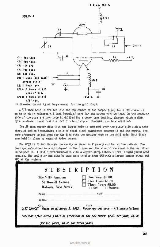
FIGURE 4
CI
8- plus, 450 V.
j. RFC'
CAviTY
CI: See text
C2: See text
C9: 100 mfd
C4: See text
RI: 500 ohms LI
tl: 1 inch ( see text) copper strip RFC2
L2: 1 inch loop RFCI: 9 turns of 018 C3
wire 4. did. RFC2: 8 turns of 818 0.3 V. „
1/8" dis.
in diameter is cut ( just large enough for the grid ring).
A 3,13 inch hole is drilled into the top center of the copper pipe, for a BNC connector
on to which is soldered a 1 inch length of wire for the output pick-up loop. On the opposite side of the pipe a * inch hole is drilled for a screw type bushing, through which a disk type condenser ( made from a inch circle of copper flashing) can be controlled.
The 2i inch copper disk with the larger hole is centered over the plate side with a thin
sheet of Teflon ( containing a hole of equal size) sandwiched between it and the cavity. The
same procedure is followed for the disk with the smaller hole on the grid side. Both disks
are held in place by means of Nylon screws.
The 2C39 is fitted through the cavity as shown in Figure 3 and fed at the cathode. The
feed system's dimentions will depend on the driver and the size of the chassis the amplifier
is mounted on. A little experimentation with a copper strap ( about 1 inch) should yield good results. The amplifier can also be used as a tripler from 432 with a larger copper strap and
BPÇ at the cathode.
SUBSCRIPTION The VHF Amateur
67 Russell Avenue
Rahway, New Jersey
• One Year $2.00 D Two Years $3.50 • Three Years $5.00
El New EJ Renewal
Name . Call
Addre...
Cit. slat, LAST CHANCE! Rates go up March 3, 1962. Renew now and save - All subscriptions
received after March 3 will be processed at the new rates: $2.50 per year, $4.00
for tap years, $5.50 for three years.
23
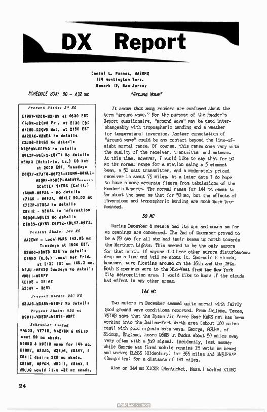
DX Report Daniel L. Parnes, WA2DMQ
184 Huntington Terr.
Newark It, New Jersey
SCHEDULE BOX: 50 - 432 mc
Present Sheds: 5, NC
KIBRY-W309-W3HHW at 0630 EST
KIJRW-K2QND Fri. at 2130 EST WIZEIO-K2QWD Wed. at 2130 EST
WA2UAK-112WEA No detalle
K2010- 1010X No details
WA2PMW-K2EW0 No details W4LZP-W6EHX-K5YTA No details
K5HK0 (Metairie, La.) CD Net at 2000 EST, Tuesdays
K6QXT-K7JTO-M6FZA-KflUMM-W6M12-116QMN-K6MCP-10,6AVV......
SCATTER SHEDS (Calif.) IMUMM-WIFZA - No details K7AAD - W6FZA, W6NLZ 50.02 mc K7EZP-K700J No details
KEINIE - W88AN No Information
KODO-OUES No details
1(01455-HOYSX-KOPSZ-KOM-MOVZJ
Present Sheds: 144 MC
WA2EWV - Local MARS 143.95 mc Tuesdays at 1900 EST.
W3W0D-K3HEC 558 No details 114105 ( 11.C.) Local Net Frld.
at 2130 EST on 146.2 mc. W7J11 -W6WSQ Sundays No details
119011-1198PV XEIOE - XEIE1E 02DHV - 068Y
Present Sheds: 22 te
MSUJO-YISARit-It3NFY No details
Present Sheds: 132 mc
119011-W9EDP-1198TI-W8PT
Schedules Wanted
114EDS, VE7IR, WA2VCM & K9E1D want 50 mc skeds.
W5UKQ & K9EID open for 144 mc.
1118HY, 14311.10, W28.10, K8AHY, &
11881E desire 220 mc skeds.
XEIOE, WOVOM, 69011, K8AHX, & W311.10 would like 432 sic skeds.
"Ground Wave"
Ti seems that many readers are confused about the term "ground wave." For the purpose of the Reader's
Report questionaire, "ground wave" may be used inter-changeably with tropospheric bending and a weather
(or temperature) inversion. Another connotation of
"ground wave" could be any contact beyond the line-of-sight normal range. Of course, this range does vary with the quality of the receiver, transmitter and antenna. At this time, however, I would like to say that for 50 mc the normal range for a station using a 5 element been, a 50 watt transmitter, and a moderately priced
receiver is about 75 miles. At a later date I do hope to have a more accurate figure from tabulations of the Reader's Reports, The normal range for 144 mc seems to
be about the same as that for 50 mc, but the effects of inversions and tropospheric bending are much more pro-nounced.
50 /IC
During December 6 meters had its ups and downs as far
as openings are concerned. The 2nd of December proved to be a FB day for all who had their beams up north towards
the Northern Lights. This seemed to be the only aurora for that month. If anyone did hear other aurora disturbances, drop me a line and tell me about it. Sporadic E clouds,
however, were floating around on the 16th and the 28th.
Both E openings were to the Mid-West from the New York City metropolitan area. I would like to know if the clouds had effect in any other areas.
144 MC
Two meters in December seemed quite normal with fairly good ground wave conditions reported. From Abilene, Texas,
W5IWB says that the Dyess Air Force Base MARS net has been working into the Dallas-Fort Worth area ( about 160 miles
east) with good signals both ways. George, G2DHV, of Sidcup, England, hears G6NB in Bucks about 50 miles away
very often with a 5x9 signal. Incidently, last summer
while George was fixed mobile running 15 watts he heard and worked DL6SS ( Oldenbury) for 365 miles and GW3JPB/P (Dangollen) for a distance of 181 miles.
Also on 144 mc KlaR ( Nantucket, Mass.) worked K1DBC
24
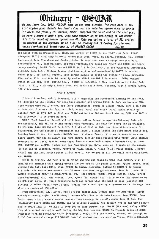
eitttarg - (0eAig On New Years Day, 1962, "OSCAR" sent us its last signals. The gang here in the
Fast copied good signals New Year's Eue, but the rate had slowed doun to counts
of 40-30 and finally 26. Herman, KaNg, supplied the count and on the last pass he merely heard a heu* signal with some Doppler shift indicating it was OSCAR.
His total count of passes copied was 46. This was out of a total of 311 orbits as counted at the equator. We will all be looking and listening for the next pbase (perhaps published reports) of PROJECT OSCAR. -W21XU.
and KlIED both in Connecticut. VE1CL was worked by K1CKR in the middle of Sept. KELQU
(Maspeth, N.Y.) with only 12 watts worked into Conn. W3SUJ in Laurel Gardens, Pa., worked
last month Into Cleveland and Canton, Ohio. He says that most evenings northern N.Y.,
northwestern Pa., eastern Ohio, and West Virginia are heard and K9UIF and K2KON are heard
every evening. K.MHS ( N. C.) worked W2ESX (N.J.) in Oct. W6UKO on SSB contacted Demopholis,
Alabama. John hears Dallas, Texas, stations anytime and occasionally W5FIZ in Menden.
W8ZOW ( Bay City, Mich.) report:, that during August he heard the states of Iowa, Nebraska,
Wisconsin, Ill., and N.Y. Ed recently worked W9AAG and W8KAY in Arkron. K8NIE worked
W8HAT in Gaylord, Mich, During Nov., K8AEM in Marshall, Mich., heard Ontario, Ohio, Ind.,
Mich., & Ill., with only a Heath 2'er. How ab ,,ut that? W9011 ( Sharon, Wisc.) worked W9BPU,
180 miles away.
NOR, 8 lafg'S
I heard from Bob, K9EID, (Harissa, Ill.) regarding the Sporadic-E opening on Dec 17th.
He listened to the opening for some back scatter and worked K9MOM in Ind. on two-way SSS.
Also worked were Phil, K2PCO, and (more backscatter) W9HGE in Beloit. Wier. Here's an item
of Interest, I'm sure: On Dec. 18, 1981, K2SUQ (N.J.) and K2QIW ( N.J.) heard ILIPOL/F19
c.iiiae "CQ" at 173 831' on 5 .0 . c. 12Q0Y called the F69 and heard ht. ,ay " Q172 th: IIJ"...
and afterward, to be heard no more.
K3HNP ( Pa.) heard on Dec.28 all of 9- land, all of ,3- land except the Dakotas, Colorado
and Minnesota, and all of 8-land except West Virginia. The only .5. heard was in Oklahoma.
By the way, Dave worked all he heard. I might ad that on this day there were reports of
double-hop.(tc the states of Washington and Idaho). I Just wonder who else heard double-hop.
Getting back to the 17th again, WA2PMW heard Alabama, Tenn., Ill., and Missouri. He also
heard KZEAQ. Ton bad he didn't nab him' KL7AUV finally made contact with VE8BY. Both signals
averaged at S9' Jack, KL7AUV, even taped Pete's transmission. When - December 3rd at meo
GMT. WA2FRW and WA2FUL, father and son from Brooklyn, N.Y., were at it again on the aurora
of the 2nd of December. WA2FUL racked up W1LZL (Mass.), WIEIZ W1AQE (Mass.), RIGHT
(N.H.) and the last choice piece of DI: VE2AIO. WA2FRW got in his two cents worth with K1GRT
and VE3RM.
XE10E in Mexico, who runs a KW on 50 mc and who was heard by many last summer, will be
looking for contacts this spring around the low end of the phone portion. IMO (Boone, Iowa)
w rked Into Salt Lake City, Utah. 1.1,7CCD in Omaha, Nebraska, talked to K9ETS/9 in Moline,
Illinois, via aurora and worked into Missouri and Iowa on gr)und wave. From St. Louis, Mc.,
WA:AOJ contacted K3111e in Newportvillc. Pa., last month. W:IGIJ, Cedar Rapids, Iowa, worked
into Gal,sburg, Ill., and PI,nona, Iowa. W,IiVA ( St. Louis, Ho.) tells me that he plans to be
on SSS real so n. All, you sidebanders look for Harmon when the hand is open! Another MK
station is NSI/PF (Wisc.) who is also looking for a band opening - because he is the only ham
within a radius of 160 miles!
From Shreveport, La., K6VMC, who is a SSS enthusiast, worked into western Texas, about
8 0 miles from his QTH. W7OUH (Oreg.) worked 600 miles north into Canada. Ken, K8PAO, from
South Lyon, Mich., made a recent contact into Lansing. He usually works into NE Ind. Ken
frequently h,ars K2ZYX and K8MMM. Due to college studies, Ken doesn't get on the air as much
has he would like t). We hope to hear you on this summer, Ken! W7LHK (Montana) using a 386'
long wire worked out quite well during the big Oct. aurora. MAO in Phoenix tells of KvIel
(Phoenix) working regularly K7OTH ( Prescott), about 1,0 miles - over, around, or through an
8, 0 foot mountain range!??? wAnoT (mobile) worked four states from Texas. From a Colorado
25
fixed mnbile QTH he worked 9 states. I'd say that's really wnrkIng nut from the mobile!
Using 2̂ nn watts P.E.P., K8QIY worked K7JTO (Ariz.) 85 miles, and W8FZA ( 280 miles) on
scatter last mnnth. K8QXY says that there are fair ground wave cnndit1nns most of the
time and lots cf trnpn scatter. K5HKO usually works into Mobile, Ala, during the evenings.
A W7 running A watt In ' phone was heard by W5JFB/5 in Baton Rnugc. Also heard was an HK5
in Call, Columbia,.CQ'ing. last month, K7OFJ, W4BCL, K4IJY, W4ER1/4, W4NQI and W4ALM
were all worked by W5FRK ( Fort Worth, Texas). Fred contacts stations in Houston, San Antonio,
and Oklahoma City, Okla., regularly. The most frequently heard foreign stations are LU3DCA,
IE10E, KP4AAN, CO3NR and CO2DL. On Dec. 29, W4LZP (Tenn.) contacted KiPUS in R.I. In addi—
tion W4LZP worked K5ORU, W5EHI & K5YTA. Ornundwave around the Nashville area has averaged
around 200 miles over the last few weeks. Big contact last month for W4AYV ( Fla.) was to
New Orleans on backscatter. W4AYV often hears W4ACT in Naples, Fla.
Chattanooga, Tenn., was worked by K4KUF (Whistler, Ala.) for a distance of 350 miles.
K4YBL ( Fla) hears mostlyvOhio on openings. K4RTO (Va.) reports hearing MOB, K8MMM, and
/MIMI regularly during skip, etc. X4EDS worked WA4AJC (Nashville), K4DBP, and W4LYT in Nov.
Often heard in Birmingham by K4EDS are: W4ZOD ( Tenn.), K4Q0E ( Ga,) and W4NYT (Mobile, Ala.).
W40AB hears consistently: W4CPH, K4HZS & W4VTW.
KEQWD ( Syracuse, N.Y.) worked WZASD (Del.) last month.
73, Dan, 1112111Q
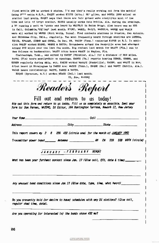
eWe«/Adeîj
Fill out and return to us today! Rip out this form and return to us today. Fill in as completely as possible. Sent your form to: Dan Parries, Wk2DNO, DX Editor; 184 Huntington Terrace, Newark 12, New Jersey
Your Name Call
Address City State
This report covers my 2 6 220 432 (circle one for the math of JANUARY 1962
Transmitter polar input Antenna AM Cil SS8 DS8 N8FN (circle)
JANUARY - FEBRUARY REPORT
What has been your furthest contact since Jan. 1? (Give call, OTH, date & time)
Any unusual band conditions since Jan 1? (Give date, popt time, what heard)
Do you presently hold (or desire to have) schedules with any DX stations? (Give call, regular shed time, date).
Are you operating (or interested in) the bands above 432 mc?
26
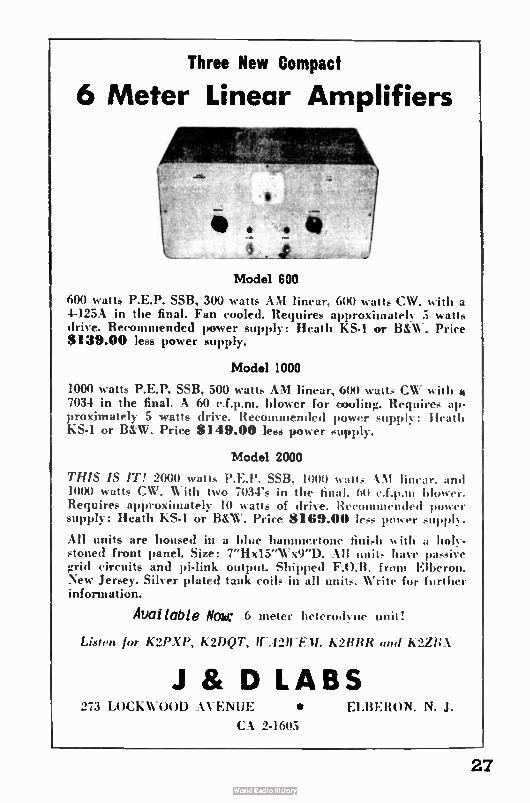
Three New Compact
6 Meter Linear Amplifiers
•
sp
Model 600
600 watts P.E.P. SSB, 300 watts AM linear, 600 watt, CW. with a 4-125A in the final. Fan cooled. Requires approximately 5 watts drive. Recommended power supply: Heath KS-1 or B&W. Price $139.00 less power supply.
Model 1000
1000 watts P.E.P. SSB. 500 watts AM linear, 600 watt, CW with e 7034 in the final. A 60 c.f.p.m. blower for cooling. Requires ap-proximately 5 watts drive. Recommended power supply: Heath KS-1 or B&W. Price $ 149.00 less power supply.
Model 2000
THIS IS IT! 2000 watts P.E.P. SSB, I000 watts ‘M linear, and 1000 watts CW. With two 7034's in the final. 60 c.f.p.tu blower. Requires approximately 10 watts of drive. Recommended mower supply: Heath KS-1 or B&W. Price $ 169.00 less power supply.
All units are housed in a blue hammertone finish w it h a holy. stoned front panel. Size: 7"Hx15"Wx9"D. All unit, have passive grid circuits and pi-link output- Shipped F.O.B. from Elberon, New Jersey. Silver plated tank coils in all units. Write for further information.
Availoble Nose 6 meter heterodyne unit!
Listen for K2PXY, K2DQT, frA2IrEM. K2RRR (ma K2ZBX
J St D LABS 273 LOCKWOOD AVENUE • CLUE RON. N. J.
CA 2-1605
27
Tecraft
Central Electronics
Iran.
E. F. JoAssn,
Wale%
Term
Hy-foon
flex
&
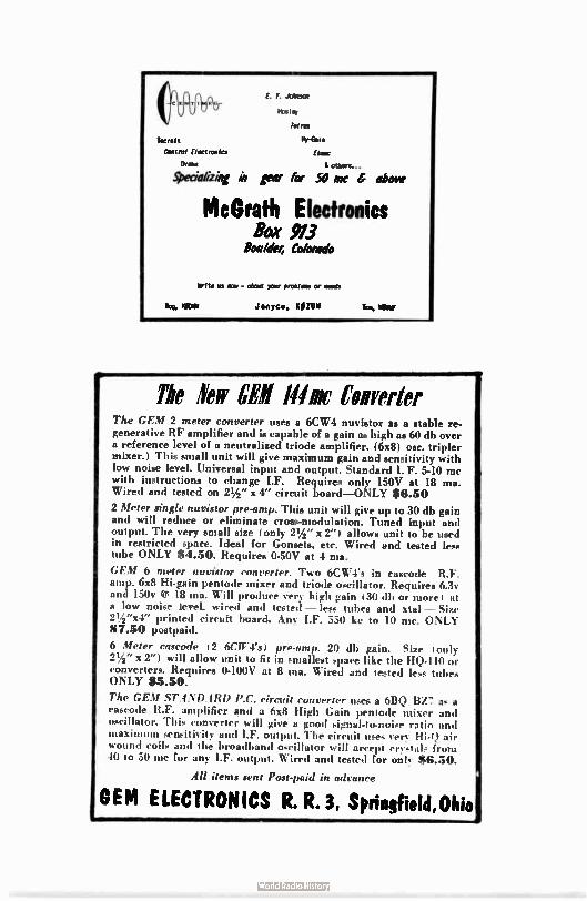
.goeciakibe ki gear for 50 Inc 4 above
McGrath Electronics Box 913
Boa/o'er, Colorado
Write us non - &art >our proelms or ands
Janyce, KOZUII Tee, IOW
The few WI N« Cavelier The GEM 2 meter converter uses a 6CW4 nuvistor as a stable re. generative RF amplifier and is capable of a gain as high as 60 db over a reference level of a neutralized triode amplifier. (6x8) osc. triplet mixer.) This small unit will give maximum gain and sensitivity with low noise level. Universal input and output. Standard I. F. 5-10 mc with instructions to change I.F. Requires only 150V at 18 ma. Wired and tested on 21/2 " x 4" circuit board—ONLY $8.50
2 Meter single nuvistor pre-amp. This unit will give up to 30 db gain and will reduce or eliminate cross-modulation. Tuned input and output. The very small size (only 21/2 " x 2"1 allows unit to be used in restricted space. Ideal for Gonsets, etc. Wired and tested less tube ONLY $4.50. Requires 0-50V at 4 ma.
GEM 6 meter nuvistor converter. Two 6CW4's in cascode--R.F. amp. 6x8 Hi-gain pentode mixer and triode oscillator. Requires 6.3v and 150v e 18 ma. Will produce very high gain 130 db or more 1 at a low noise level, wired and tested — less tubes and xtal — Size 21/2 "x4" printed circuit board. Any I.F. 550 kc to 10 mc. ONLY 87.50 postpaid.
6 Meter cascode 12 6CITies1 pre-amp. 20 dl) gain. Size ( only 21/2" x 2") will allow unit to fit in smallest space like the HQ-110 or converters. Requires 0-100V at 8 ma. Wired and tested less tubes ONLY $5.50.
The GEM ST.4NDARD P.C. circuit converter uses a 613Q. BZ7 as a rascode R.F. amplifier and a 6x8 High Gain pentode mixer and oscillator. This converter will give a good signal-to-noise ratio and maxim lllll sensitivity and 1.F. output. The circuit uses very Hi-1,1 air wound coils and the broadband oècillator will accept crv‘tals from 10 to 50 mc for any I.F. output. Wired and tested for onk $8.50.
All items sent Post-paid in advance
OEM ELECTRONICS R. R. 3, Spriadield,Ohio
a•I
SPECIALS By Direct Mail
Immediate delivery from stock!
SPECIAL: While they last-2 way "Walkie-Talkie" with 9 tran-
sistor AM radio. List price $139.95 per pair. Now $79.95 pair. SPECIAL: Clegg 99'er with crystal mike and Halo antenna for $142.95! If you don't want our "package deal," deduct $ 16.95
and send a check or money order for the 99'er alone. We'll ship immediately PREPAID.
SPECIAL: Ameco nuvistor pre-amps, 6 or 2 meters, $13.95 (we'll ship collect). OR, send us your check or money order and we'll ship PREPAID.
SPECIAL: Cesco phone patch—$14.00 now and we'll ship prer paid. Or $14.95 C.O.D.
SPECIAL: Wall industrial soldering gun—instant heat—no trantl-former. Coil type, 400 watts. $10.88.
COMING SOON: Completely transistorized 12 me VFO. 11.25
volts of RF. Very stable and will work out beautifully into a 6, 2 or 220 inc mobile rig. Power requirement: 12 VDC. Manufacturer's name must be withheld at this time. Look for announcement next month.
Prices on request for Mosley, National, Dow Key, Drake, Cush-craft, Hi-Par, etc. Used equipment, receivers, transmitters, etc. Our prices are always better. Shop Two-Way.
TWO-WAY RADIO COMMUNICATIONS Dept. IA
Mail Order Department
232-6 Hylan Boulevard, Staten Island 5, Ncw York
GIbraltar 7-3660
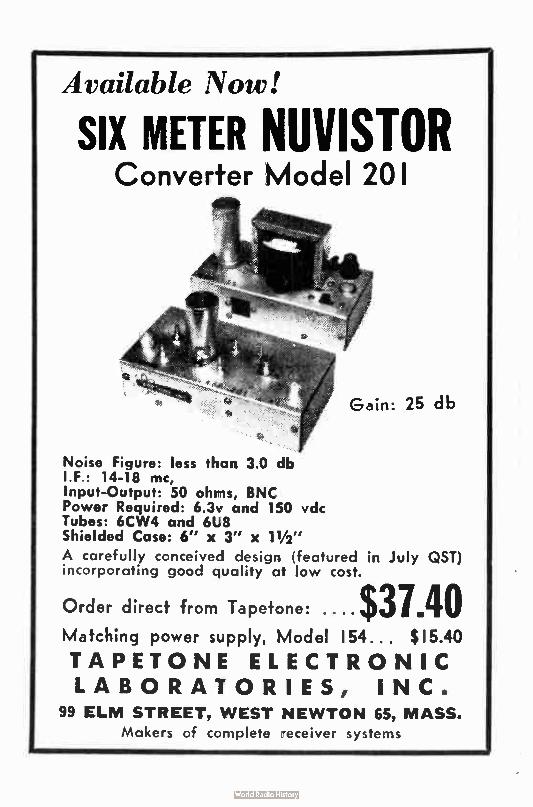
Available Now!
SIX METER NUVISTOR Converter Model 201
Gain: 25 db
Noise Figure: less than 3.0 db IF.: 14-18 mc, Input-Output: 50 ohms, BNC Power Required: 6.3v and 150 vdc Tubes: 6CW4 and 6U8 Shielded Case: 6" x 3" x 11/2"
A carefully conceived design (featured in July QST) incorporating good quality at low cost.
Order direct from Tapetone: $37.40 Matching power sLpply, Mode! 154... $ 15.40
TAPETONE ELECTRONIC LABORATORIES, INC.
99 ELM STREET, WEST NEWTON 65, MASS.
Makers of complete -eceiver systems
MtWien')
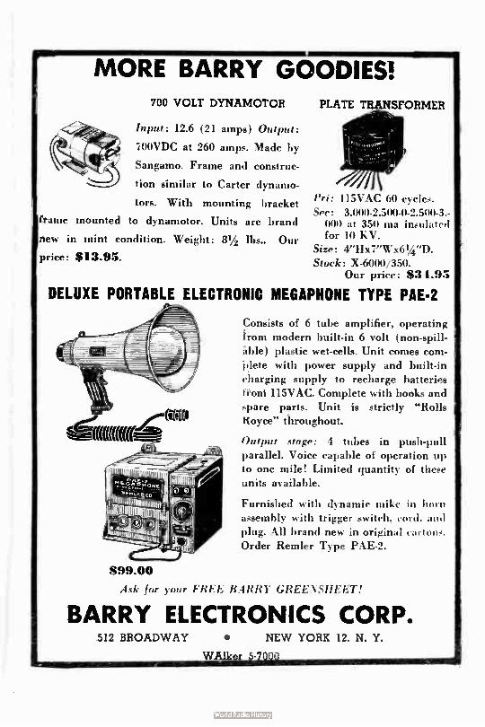
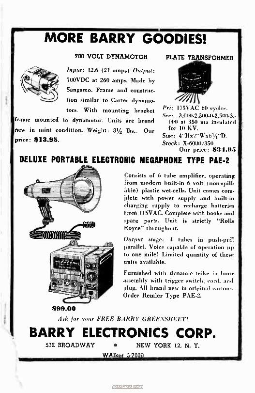
MORE BARRY GOODIES! 700 VOLT DYNAMOTOR
Input: 12.6 (21 amps) Output:
100VDC at 260 amps. Made by
Sangamo. Frame and construc-
tion similar to Carter dynamo.
tors. With mounting bracket
frame mounted to dynamotor. Units are brand
new in mint condition. Weight: 8% lbs.. Our
price: $ 13.95.
PLATE TRANSFORMER
Pri: 115VAC 60 cycles.
Sec: 3,000-2,500-0-2300-3, 000 at 350 ma insulated for 10 KV.
Size: 4"Hx7"Wx61/4"D. Stock: X-6000/350.
Our price: $3 1.95
DELUXE PORTABLE ELECTRONIC MEGAPHONE TYPE PAE-2
Consists of 6 tube amplifier, operating from modern built-in 6 volt ( non-spill-a"ble) plastic wet-cells. Unit comes com-
"plete with power supply and built-in
charging supply to recharge batteries fitoni 115VAC. Complete with books and
spare parts. Unit is strictly "Rolls Royce" throughout.
Output stage: 4 tubes in push-pull parallel. Voice capable of operation up
to one mile! Limited quantity of these units available.
Furnished with dynamic mike in horn
assembly with trigger switch, cord. and
plug. All brand new in original cartons.
Order Remler Type PAE-2.
899.00
Ask for your FREE BARRY GREENSHEET!
BARRY ELECTRONICS CORP. 512 BROADWAY • NEW YORK 12, N. Y.
WAlker 5-7
11.4 Voile) pelogalaez 67 RUSSELL
RAHWAY, NEW JERSEY
To:
U. S. POSTAGE BULK RATE
PAID Rahway, N.J. Permit No.I26
V. E. Etaca wad ,Weri3A -40 rrathews on st •
3-anal ca 34) N.Y.
1/62 a
Postmaster: Form 3547 Requested
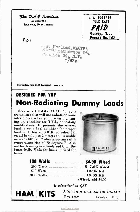
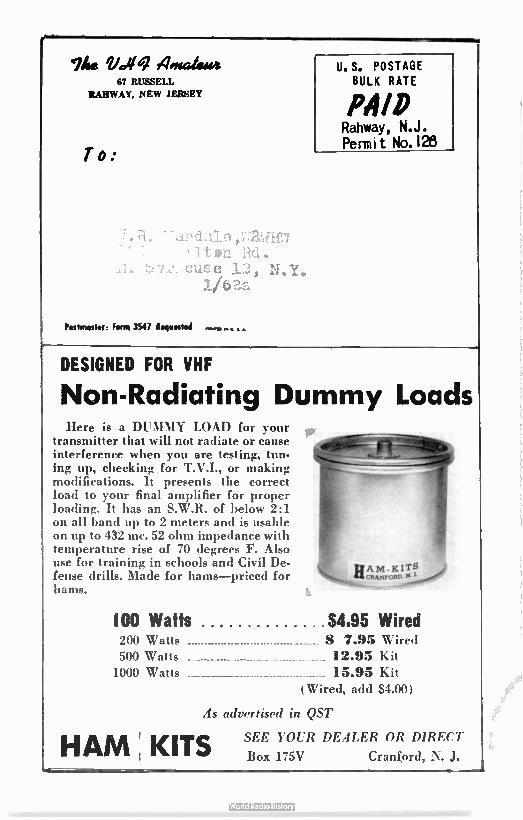
DESIGNED FOR VHF
Non-Radiating Dummy Loads Here is a DUMMY LOAD for your
transmitter that will not radiate or cause interference when you are testing, tun-ing up, checking for T.V.I., or making modifications. It presents the correct load to your final amplifier for proper loading. It has an S.W.R. of below 2:1 on all band up to 2 meters and is usable on up to 432 mc. 52 ohm impedance with temperature rise of 70 degrees F. Also use for training in schools and Civil De-fense drills. Made for hams—priced for hams.
(00 Watts $4.95 Wired 200 Watts 7.95 Wired 500 Watts 12.95 Kit
1000 Watts 15.95 Kit Wired, add $4.00)
As advertised in QST
HAM , KITS SEE YOUR DEALER OR DIRECT
Box 175V Cranford, N. J.
finagle-0
MORE BARRY GOODIES! 700 VOLT DYNAMOTOR
Input: 12.6 ( 21 amps) Output:
ç 100VDC at 260 amps. Made by
Sangamo. Frame and construc-
tion similar to Carter dynamo.
tors. With mounting bracket Ifrito' mounted to dynamotor. Units are brand
ne'.'. in mint condition. Weight: 81/2 lbs.. Our
price: S13.95.
PLATE TRANSFORMER
Pri: 115VAC 60 cycles. Sec: 3,000-2,500-0-2,500-3,-
000 at 350 ma insulated for 10 KV.
Size: 4"Hx7"Wx61/4 "D. Stock: X-6000/350.
Our price: S3 1.95
DELUXE PORTABLE ELECTRONIC MEGAPHONE TYPE PAE-2
Consists of 6 tube amplifier, operating from modern built-in 6 volt ( non-spill-able) plastic wet-cells. Unit comes com-
plete with power supply and built-in
charging supply to recharge batteries f toni 115VAC. Complete with books and
spare parts. Unit is strictly "Rolls Royce" throughout.
Output stage: 4 tubes in push-pull
parallel. Voice capable of operation up to one mile! Limited quantity of these units available.
Furnished with dynamic mike in horn assembly with trigger switch, cord. and plug. All brand new in original cartons.
Order Remler Type PAE-2.
899.00
Ask for your FREE BARRY GREENSHEET!
BARRY ELECTRONICS CORP. 512 BROADWAY • NEW YORK 12, N. Y.
WAlker 5-7
11«: 4statadee 67 RUSSELL
RAHWAY, NEW JERSEY
To:
n d ul e ,UZUE7 , 7 t en r.C1.
12, N.Y. 1/6a
Postmaster: Form 3547 Requested • •
U. S. POSTAGE BULK RATE
PAID Rahway, N.J. Permit No. 128
DESIGNED FOR VHF
Non-Radiating Dummy Loads Here is a DUMMY LOAD for your
transmitter that will not radiate or cause interference when you are testing, tun-ing up, checking for T.V.I., or making modifications. It presents the correct load to your final amplifier for proper loading. It has an S.W.R. of below 2:1 on all hand up to 2 meters and is usable on up to 432 mc. 52 ohm impedance with temperature rise of 70 degrees F. Also use for training in schools and Civil De-fense drills. Made for hams—priced for hams.
100 Watts $4.95 Wired
PAM- KITS /is CRANFORD.
200 Watts S 7.95 Wired 500 Watts 12.95 Kit 1000 Watts 15.95 Kit
(Wired, add $4.00)
As advertised in QST
HAM ; KITS SEE YOUR DEALER OR DIRECT
Box 175V Cranford, N. J.
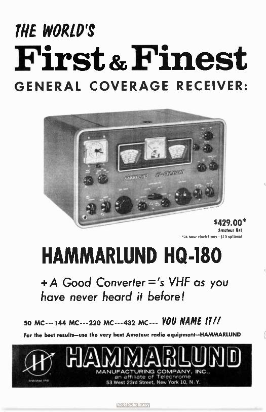
THE WORLD'S
First &Finest GENERAL COVERAGE RECEIVER:
$429.00* Amateur Net
•24 hour clock-timer-410 optional
HAMMARLUND HQ-180 + A Good Converter =-'s VHF as you have never heard it before!
50 MC--- I44 MC--- 220 MC--- 432 MC--- YOU NAME IT!! For the best results— use the very best Amateur radio equipment—HAMMARLUND
IJA nun-) MANUFACTURIN:G COMPANY, INC.,
an affiliate of Telechrome 53 West 23rd Street, New York 10, N.Y.
The VHF Amateur Title registered U.S. Post Office
A MONTHLY PUBLICATION
OFFICES:
Business ti Editorial 87 Russell Avenue Rahway, New Jersey
EDITORIAL STAFF
editor-
Bob Brown,K2ZSQ
Circulation Manager
Peter A. Narkavage, WA2CWA
Production Manager
Douglas W. Clanton Prldncti ,n Assistants:
Blair Schupp
DX Report Editor
Daniel L. Fames, WA2DMQ
Counsel
J. D. 'Red" Brown, IC2ZSP
Moonbounce Editor
Allen Ritz, X2UIT
48 Cumberland Av.Itue Verona, New Jers,11
Single Sideband Editor
Phillip Oural, Ii2PC0
204 Nast Northfield Rd.
Livingston, New Jersey
South American Editor
Michael A. Czusch
1,03DCA
ne 78? Amateur is
published monthly by
Robert N. Brown, ISZSO,
Subscription rates.
one year, 11.00, two
years, 31.60,
$6.00. Foriegn add $ l.
IDVSRTISING rate card
on request, Entire
contents printed in
Clark, N.J., U.S.A.
Telephone Number for
out-or-state direct
dialing: 201-FU 1-1284.
Local calls: Fulton 1-
use.
VOL. 5, No. 1 JANUARY 1962
Tale Oir COteitb
I Like Two Meters Bob Higgins, W2IXU 4
Eliminating Generator Noise Howard Butterfield, WA2NDL 7
Tripler for 432 mcl Don Goshay, werw 9
Four over Four for Six Vince Varnas, KBREG 12
VHF SS8I Phil Gural, K2POS 14
TRADING POST Classified 15
Mocnbounce Column Allen Katz, K2LIYH 19
DX Report Dan Parnes, WA2DMO 20
Reader's Report - Fill it out todayl 22
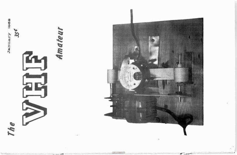
03VER FHLYTO
By reading this paragraph you will learn absolutely
nothing. There will be a big article next month on how to
ouild one of these gems. If you've been clever enough to figure out what it is, drop ye Editor a card with your guess.
Meantime, we'll enjoy your confusion.
Wice
2 meters! I• • • • • • • Robert C. Higgins, 821X0
308 Edgar Avenue
Cranford, Mew Jersey
• • • • • • • I
With this new year we are going on seventeen years old. The two meter band, I mean.
The present 144 to 148 mc band was created by the FCC after World War II to replace the
old 112 mc band. We are one of the newest bands and we boast more growth than any other
amateur band. The reasons are obvious - we have room and welcome to our frequencies all
ages and all classes of amateurs. All newcomers to the band get a welcome greeting and
a friendly fraternal companionship that no other band offers. The number of stations
operating regularly ( once you move to " two" you never leave) increases daily. The band
is not crowded, yet it is never dead. How is this possible? We are unique because of our
frequency and our population distribution in the U.S. and Canada. Depending on location,
the average station on two meters has an operating radius of about 20 miles. In or on the
outskirts of a large city, he has no trouble making aintacts because of the large numbers
of urban hams that operate on two meters.
The QRN problem is solved by the 4 megacycles that the FCC gave us. The fellow living
in the country has equal opportunity to work out or into the cities. Our country cousins
need only add a few elements to their beams ( this can be as simple as putting another
coat hanger on the boom) or raise the mast ( add 10 feet of TV type lh" mastine). Regular
'phone contacts over 100 miles are common. After the contacts are made, conversations
never drag because you'll always find someone you have a lot in common with. So you see
I Like Two Meters and so will you.
Starting in this issue of THE VHF ANATEUR you will find in this column construction
projects for a complete two meter station. It will feature low cost as a means of getting
started. Later, refinements will be added that will put you in the DX class. ( Yes, we
have a DX gang on two meters too.) This month we'll start at the top with the antenna:
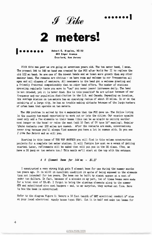
A 5 Element Bean for 144 mc - $1.17
I constructed a very strong high gain 5 element beam for use during the summer months
two years ago. It is still in excellent condition in spite of being exposed to the elements
(pun not intended) for two years. The beam can be built by almost anyone at a cost of
under two dollars. In fact, because of a mistake on my part, two of these beams were made
for a total cost of $1.40. I forgot to bring the aluminum elements along to the summer
0TH and substituted wire coat hangers - and, to my surprise, they worked out fine. Here is how the beam is constructed:
Refer to the diagram Figure 1: Secure a 10 foot length of'EMT electrical conduit e size
at your local electrical supply house ( cost 90e. Cut it in half and make two beams for
4
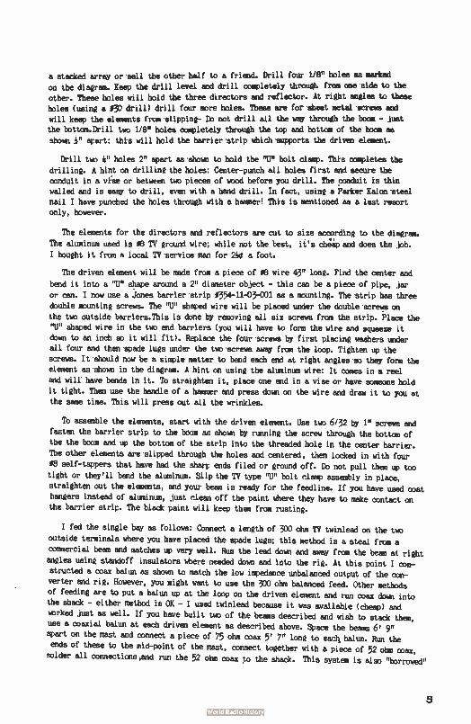
a stacked array or sell the other half to a friend. Drill four 1/8" holes ma marked
on the diagram. Keep the drill level and drill completely through from one side to the
other. These holes will hold the three directors and reflector. At right angles to these holes ( using a 03) drill) drill four more holes. These are for sheet metal screws and
will keep the elements from slipping- Do not drill all the way through the boom - just the bottom.Drill two 1/8" holes completely through the top and bottom of the boom as
shown 1" apart; this will hold the barrier strip which supports the driven element.
Drill two it" holes 2" apart as shown to hold the "U" bolt clamp. This completes the
drilling. A hint on drilling the holes: Center-punch all holes first and secure the conduit in a vise or between two pieces of wood before you drill. The conduit is thin
walled and is easy to drill, even with a hand drill. In fact, using a Parker Kalon steel
nail I have punched the holes through with a hammer! This is mentioned as a last resort
only, however.
The elements for the directors and reflectors are cut to size according to the diagram.
The aluminum used is OB TV ground wire; while not the best, it's cheap and does the job.
I bought it from a local TV service man for 210 a foot.
The driven element will be made from a piece of OB wire 43" long. Find the center and
bend it into a "U" shape around a 2" diameter object - this can be a piece of pipe, jar
or can. I now use a :Jones barrier strip 0354-11-03-001 as a mounting. The strip has three
double mounting screws. The "U" Shaped wire will be placed under the double screws on
the two outside barriers.This is done by removing all six screws from the strip. Place the "U" shaped wire in the two end barriers ( you will have to form the wire and squeeze it down to an inch so it will fit). Replace the four screws by first placing washers under
all four and then spade lugs under the two screws away from the loop. Tighten up the
screws. It Should now be a simple matter to bend each end at right angles so they form the
element as shown in the diagram. A hint on using the aluminum wire: It comes in a reel
and will have bends in it. To straighten it, place one end in a vise or have someone hold
it tight. Then use the handle of a hammer and press down on the wire and draw it to you at the same time. This will press out all the wrinkles.
To assemble the elements, start with the driven element. Use two 6/32 by 1" screws and
fasten the barrier strip to the boom as shown by running the screw through the bottom of
the the boom and up the bottom of the strip into the threaded hole in the center barrier.
The other elements are slipped through the holes and centered, then locked in with four
08 self-tappers that have had the sharp ends filed or ground off. Do not pull them up too tight or they'll bend the aluminum. Slip the TV type MU" bolt clamp assembly in place, straighten out the elements, and your beam is ready for the feedline. If you have used coat
hangers instead of aluminum, just clean off the paint where they have to make contact on the barrier strip. The black paint will keep them from rusting.
I fed the single bay as follows: Connect a length of 300 ohm TV twinlead on the two
outside terminals where you have placed the spade lugs; this method is a steal from a
commercial beam and matches up very well. Run the lead down and away from the beam at right
angles using standoff insulators where needed down and into the rig. At this point I con-structed a coax balun as shown to match the low impedance unbalanced output of the con-
verter and rig. However, you might want to use the 300 ohm balanced feed. Other methods of feeding are to put a balun up at the loop on the driven element and run coax down into the shack - either method is OK - I used twinlead because it was available ( cheap) and
worked just as well. If you have built two of the beams described and wish to stack them, use a coaxial balun at each driven element as described above. Space the beams 6' 9" apart on the mast and connect a piece of 75 ohm coax 5' 7" long to eacti, balun. Run the ends of these to the mid-point of the mast, connect together with a piece of 52 ohm coax,
solder all connections,and run the 52 ohm coax to the shack. This system is also "borrowed"
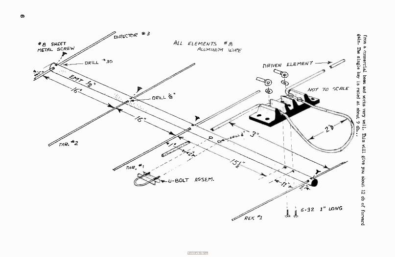
CD
* 8 smcc-r-METAL SCREW
/e.
ee-
ne.
/6-
DRILL e30
-
DIRECTOR * 3
45- •
DRILL '13
ALL EL E EA/15 * ALUM ¡Ai j7 Wier
-
U- BOLT A5SErl, -err*
REF: e1
6-32 1" wniG
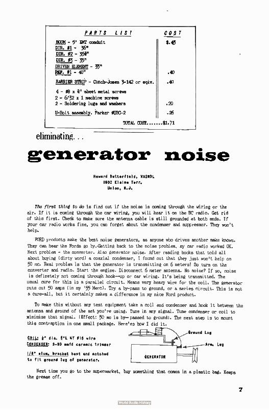
PARTS LIST
BOOM - 5' EMT conduit DIR. 11 - 36"
DIR. 02 - 35i" DIR. 03 - 35" DRIVEN ELEMENT - 35" REF. II - 40"
BARRIER STRIP - Cinch-Jones 3-142 or elev.
4 - 08 x i" sheet metal screws
2 - 6/32 x 1 machine screws 2 - Soldering lugs and washers
U-Bolt assembly. Parker OUBC-2
COST
te
.40
.40
.20
.26
TOTAL COST $1.71
eliminating...
generator noise Howard Butterfield, WA2601.
1602 Elaine Terr. Union, N.J.
The first thinl to do is find out if the noise is coming through the wiring or the
air. If it is coming through the car wiring, you will hear it on the BC radio. Get rid of this first. Check to make sure the antenna cable is still grounded at both ends. If your car radio works fine, you can forget about the condenser and suppressor. They won't help.
FORD products make the best noise generators, as anyone who drives another make knows.
They can hear the Fords go by.-Getting back to the noise problem, my car radio worked OK.
Next problem - the converter. Also generator noise. After reading books that told all about buying ( dirty word) a coaxial condenser, I found out that they just won't help on
50 mc. Real problem is that the generator is transmitting on 6 meters! So turn on the converter and radio. Start the engine. Disconnect 6 meter antenna. No noise? If so, noise is definetely not coming through hook--up or car wiring. It's being transmitted. The
usual cure for this is a parallel circuit. Means very heavy wire for the coil. The generator puts out 50 amps ( in my '55 Hem). Try a by-pass to ground, or a series circuit. This is not a cure-all, but it certainly makes a difference in my nice Ford product.
To make this without any test equipment take a coil and condenser and hook it between the antenna and ground of the set you're using. Tune in any signal. Tune condenser or coil to minimize that signal. ( Effect: 50 mc is by-- passed to ground). The next step is to mount
this contraption in one small package. Here'es how I did it.
COIL: e dia. IL 4T 018 wire CONDENSER: 3-30 mmfd ceramic trimmer
1/8 alum. bracket bent and notched
to fit ground lug of generator.
Next time you go to the supermarket, buy something that comes in a plastic bag. Keeps the grease off.
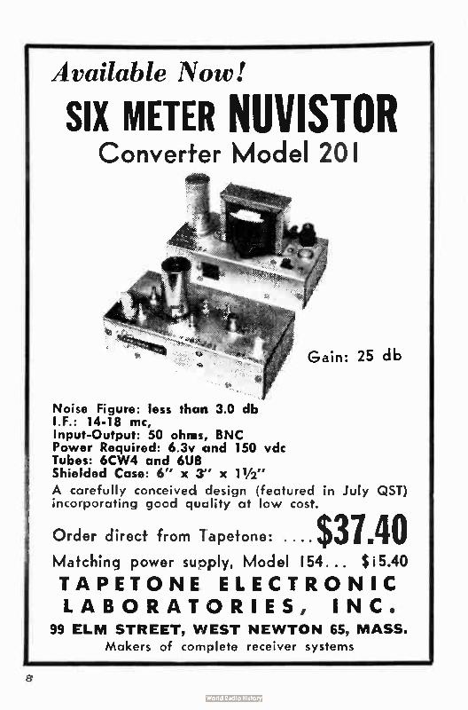
Available Now!
SIX METER NUVISTOR Converter Model 201
Gain: 25 db
Noise Figure: less than 3.0 db I.F.: 14-18 mc, Input-Output: 50 ohm!, BNC Power Required: 6.3v and 150 vdc Tubes: 6CW4 and 6U8 Shielded Case: 6" x 3" x 11/2"
A carefully conceived design ( featured in July QST) incorporating good quality at low cost.
Order direct from Tapetone: $37.40 Matching power supply, Model 154... $ i5.40
TAPETONE ELECTRONIC LABORATORIES, INC.
99 ELM STREET, WEST NEWTON 65, MASS.
Makers of complete receiver systems
8
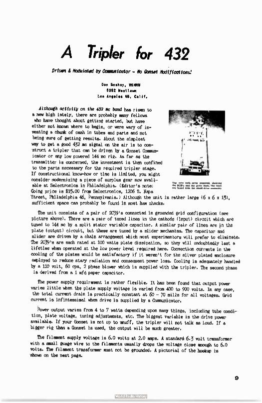
A Tripler for 432 Driten Modulated by Comunicator - MD (onset Modifications:
Don Cosh'', MOM 8962 Westlawn
Los Anooles 46, Calif.
Although activity on the 432 ma band has risen to
a new high lately, there are probably many fellows who have thought about getting started, but have either not known where to begin, or were wary of in-vesting a chunk of cash in tubes and parts and not
being sure of getting results. About the simplest
way to get a good 432 mc signal on the air is to con-
struct a tripler that can be driven by a Gonset Oammur-icator or any low powered 144 mc rig. As far as the
transmitter is concerned, the investment is than confined to the parts necessary for the required tripler stage. .
If constructional know-how or time is limited, you might
consider modernizing a piece of surplus gear now avail-Top elete with ore« tea*. show,'
able at Selectronics in Philadelphia. ( Editor's note: Ilse P.P., pee the plate It., The Peet, ere tutted et. the chain epee esethellty
Going price is $15.00 from Selectronics, 1206 S. Napa Street, Philadelphia 46, Pennsylvania.) Although the unit is rather large (6 x 6 x 15),
sufficient space can probably be found in most ham shacks.
The unit consists of a pair of 2C39's connected in grounded grid configuration ( see
picture above). There are a pair of tuned lines in the cathode ( input) circuit which are
tuned to 144 mc by a split stator variable capacitor. A similar pair of lines are in the
plate ( output) circuit, but these are tuned by a slider mechanism. The capacitor and
slider are driven by a chain arrangement which most experimentors will prefer to eliminate.
The 2C39's are each rated at 100 watts plate dissipation, so they will undoubtedly last a
lifetime when operated at the low power level required here. Convection currents in the
cooling of the plates uould be satisfactory if it weren't for the silver plated enclosure
employed to reduce stary radiation and consequent power loss. Cooling is adequately handled by a 110 volt, 60 cps, 2 phase blower which is supplied with the tripler. The second phase
is derived from a 1 mfd paper capacitor.
The power supply requirement is rather flexible. It has been found that output power
varies little when the plate supply voltage is varied from 400 to 900 volts. In any case, the total current drain is practically constant at 60 - 70 mills for all voltages. Grid current is infintessimal when drive is supplied by a Communicator.
Power output varies from 4 to 7 watts depending upon many things, including tube condi-
tion, plate voltage, tuning adjustments, etc. The biggest variable is the drive power available. If your Gonset is not up to snuff, the tripler will not talk as loud. If a
bigger rig than a Gonset is used, the output will be much greater.
The filament supply voltage is 6.0 volts at 2.0 amps. A standard 6.3 volt transformer
with a small guage wire to the filaments usually drops the voltage close enough to 6.0
volts. The filament transformer must not be grounded. A pictorial of the hookup is shown on the next page.
9
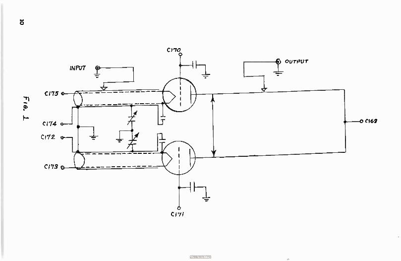
e.
C170 0
OUTPUT
INPUT f -;.-
CI75 o
CI74 0-1
CI72 0-1 1
C173
o CI71
0 CI69
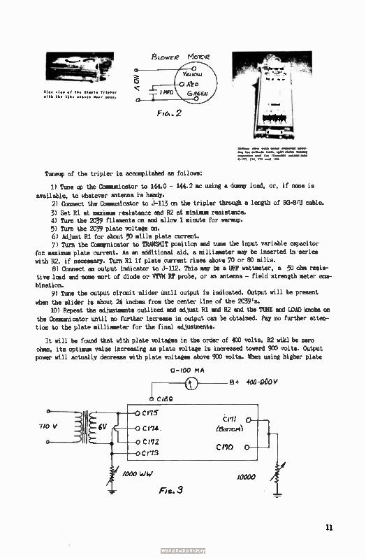
elde + lee el the 3leele Tréeler
wIth the tébe cccccc doer OF..
FlisowEre Meitie
INFO G,íw
Fte, 2
Timeup of the tripler is accomplished as follows:
1) Tune up the Communicator to 144.0 - 144.2 mc using a dummy load, or, if none is
available, to whatever antenna is handy. 2) Connect the Communicator to J-113 on the tripler through a length of RG-8/U cable.
3) Set R1 at maximum resistance and R2 ai minimum resistance. 4) Turn the 2C39 filaments on and allow 1 minute for warmup. 5) Turn the 2C39 plate voltage on. 6) Adjust R1 for about 50 mills plate current. 7) Turn the Commynicator to TRANSMIT position and tune the input variable capacitor
fot maximum plate current. As an additional aid, a milliameter may be inserted in series with R2, if necessary. Turn R1 if plate current rises above 70 or 80 mills.
8) Connect an output indicator to J-112. This may be a UHF wattmeter, a 50 ohm resis-tive load and some sort of diode or VTVM RF probe, or an antenna - field strength meter com-
bination. 9) Time the output circuit slider until output is indicated. Output will be present
when the slider is about 21 inches from the center line of the 2C39s. 10) Repeat the adjustments outlined and adjust R1 and R2 and the TUNE and LOAD knobs on
the Communicator until no further increase in output can be obtained. Pay no further atten-tion to the plate milliameter for the final adjustments.
It will be found that with plate voltages in the order of 400 volts, R2 wikl be zero
ohms, its optimum value increasing as plate voltage is increased toward 900 volts. Output power will actually decrease with plate voltages above 900 volts. When using higher plate
eetimm qr. comer swarmed Mew. 1, mere...de twee gang.. fe,mmUs avel Ihe Memo. magnet* C 114. In ad Ili
0-100 MA
400-900V
cs69
11
voltages, enough R1 must be left active to limit the static current to 100 ma or so when drive is removed. Static current values much lower than this are preffered. In this
way, the tubes are prbbeeedd and there is no necessity for cutting off the plate voltage
during receive periods.
If the tripler acts unusual, a spurious oscillation around 1500 kc may be present.
This is due to the seven power lead filters built into the unit. Its presence can be detected by placing a standard broadcast set near the rig and tuning around for the oscillation. The oscillation should be checked both during transmit and standby periods. It may be eliminated by connecting an 8 mfd capacitor directly from C-119 terminal to
ground.
Modulation of this unit is indeed unique as no modulator is required other than that
in the Communicator... .The system has been employed by the author in a 2C39 tripler for
1296 mc service for several years. Since output is primarily dependent on the drive power,
the output will faithfully follow the modulation envelope of the Communicator. This is not
a compromise system, as good quality modulation is produced. Actual modulation percentage
is much higher than can be obtained with conventional plate modulation of this unit. The modulation fidelity is aided by the audio inverse feedback provided by the unbypassed Rl.
A slight increase in output power can be obtained by exprrimenting with the output coupling link. The silver plated steel unit is stiff and difficult to bend. Further, it is tied down by a ceramic standoff insulator. The link may be replaced by a piece of No. 12
copper wire and the standoff insulator removed and discarded. Series tuning of the link may help, but the total length of wire in the link must be quite short before resonance
can be achieved. The output figure quoted aabovewas achieved without series tuning.
For the boys who crave high power, a companion unit is available at Selectronics. This unit is identical to the tripler except that the input tunes to 432 mc. The same power supply as used with the tripler can also supply the final.
The 2C39's can give 50 watts output and this output level could no doubt be reached with the drive power available from the tripler. The final would require an external plate modulator, but who needs a modulator for CW?
Vincent J. Varna*, MEG - 4929 Renwood Drive Dayton 29, Ohlo
DurInd my two years on stx meters, I have used no less than four different antennas.
The majority of these have been "long John" beams. Although it is impossible to determine whether one type of antenna will work better than another under all conditions, I am now
of the opinion that a stacked array of four or five elements on each bay will out-Perform most "Long John" antennas.
In the past couple of years, commercial manufacturers have made the beam antenna more
popular than stacked arrays. The reason for this is that many amateurs are losing their spirit of experimentation and are readily accepting whatever the commerci antenna manu-facturing have tc Jffer.
12
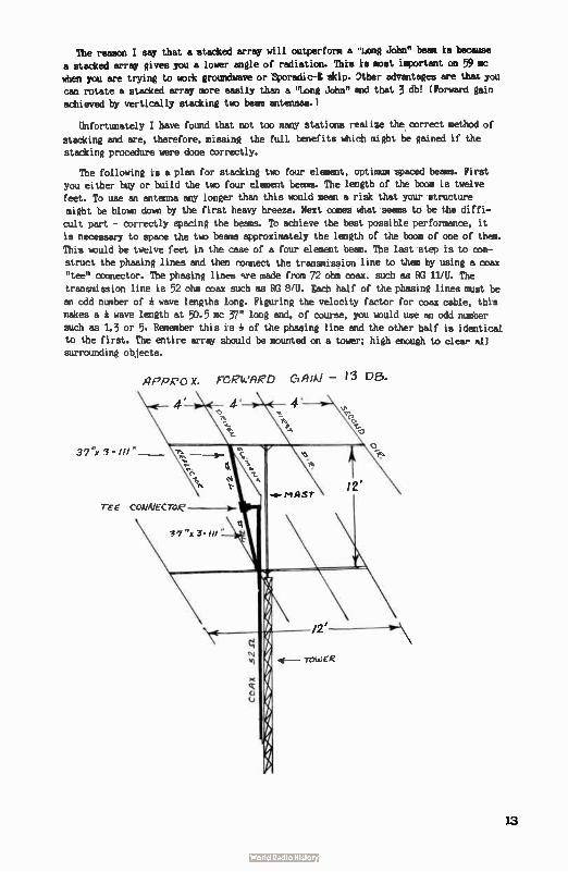
The reason I say that a stacked array will outperform a "Long John" beam is because
a stacked array gives you a louer angle of radiation. This is most important on 59 mc
when you are trying to work grounchnure or Sporadic-E skip. Other advantages are that you
can rotate a stacked array more easily than a "long John" and that 3 db! ( Forward gain
achieved by vertically stacking two beam antennas.)
Unfortunately I have found that not too many stations realize the correct method of
stacking and are, therefore, missing the full benefits which might be gained if the
stacking procedure were done correctly.
The following is a plan for stacking two four element, optimum spaced beams. First you either buy or build the two four element beams. The length of the boom is twelve
feet. To use an antenna any longer than this would mean a risk that your structure
might be blown down by the first heavy breeze. Next comes what seems to be the diffi-cult part - correctly spacing the beams. To achieve the best possible performance, it
is necessary to space the two beams approximately the length of the boom of one of then.
This uould be twelve feet in the case of a four element beam. The last step is to con-
struct the phasing lines and them connect the transmission line to them by using a coax "tee" connector. The phasing lines %re made from 72 ohm coax, such as RG 11/U. The
transmission line is 52 ohm coax such as RO 8/U. F,ach half of the phasing lines must be
an odd number of a wave lengths long. Figuring the velocity factor for coax cable, this makes a * wave length at 50.5 mc 37" long and, of course, you would use an odd number
such as 1.3 or 5. Remember this is 1 of the phasing line and the other half is identical to the first. The entire array should be mounted on a tower; high enough to clear all surrounding objects.
ArPeo X. FtewARD 4/Al — 13 Da.
13
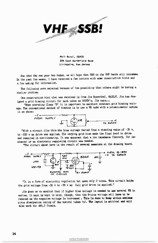
Phil Oural, K2PCO
204 East Northfield Road
Livingstnn, New Jersey
Now that the new year has begun, we all hope that SSB on the VHF bands will increase.
In the past few weeks, I have received a few letters with some construction hints and
a few asking for information.
The following were selected because of the possiblity that others might be having a
similar problem.
One construction hint that was received is from Jim Rosenthal, WA2GJT. Jim has des-
igned a grid biasing circuit for such tubes as 100TH's. Jim says... "When operating Class ' B' it is important to maintain constant grid biasing volt-
age. The conventional method of biasing is to use a VR tube with a potentiometer across
it as shown: C
Feee suppry VR • c
TO cams
"With a circuit like this the bias voltage varied from a standing
to -150 v as drive was applied. The varying grid bias made the final
and resulted in non-linearity. It was apparent that a low impedance ( stance) or an electronic regulating circuit was needad.
"The circuit shown here is the result of several sessions at the
eZeKINC, meas CR esgccun
"It is a form of electronic regulation but
the grid voltage from -30 v to -38 v as full
./ha joss on to mention that if higher bias
series. It must be kept in mind, though, that reduced as the negative voltage is increased . plate dissipation rating of the control tubes
also work for AB1,2 finals.
eel
value of -30 v,
hard to drive
battery, for in-
drawing board.
sOV. - C -re,
-65v &Rio 5
uses only 2 tubes. This circuit holds
grid drive is applied."
voltage is needed to use several VR in
the B-plus voltage will have to be This is done to keep within maximum
(s). The layout is critical and will
14
The other is a letter asking for information and is from Ernest LaBonte, K8GYM.
Ernie asks: "I would like to know if you know of a low level mixer converter for mixing
a low power 14 mc SSB signal to 144 mc."
I suaest you look in the AREL SSB Handbook. In it is a heterodyne circuit designed
by W2EWL. Also the mixer circuit of the W1CLS heterodyne circuit might be used. Or, instead
of a 5763, try a 6AK5 with inductance coupling for the 130 mc signal and no grid resistor.
After the mixer, however, you are going to need a few stages of amplification in order
to drive a 5894.
73, Phil, K2PCG
Traci irig RATE: Commercial ads - 50 per word. Free to readers - any reasonable length. Ad from
readers MUST BE SUBMITTED ON A POST CARD or QSL card. TRADING PAST, 67 Russell. Rahway, N.a.
POR SALE: Custom made ceramic ash tray ( green, brown, or white). Your handle and call
letters in gold. Only $5. Choctaw Ceramics, K5ZTH Jim, RR 1 Box 14K, Choctaw, Oklahoma.
WMTED: Skeds on the higher bands above 50 mc. Write Jerry Elmore, KOTRU, P.O. Box 261, Hiawatha, Iowa.
HAVE four 3X2500F3 tubes made by Eimac. Used but still good. Jim Overheul, KBYZP, 323
Pine, Paw Paw, Michigan.
WANTED: Any info on surplus RT-22/APX-1 and/or 1N-8/APX-1 unit. Art lebermann, K8SCD,
116 Cortland, Apt. 407, Highland Park 3, Michigan.
?OR SALE: Gonset Cojas. III, 6 meters; Knight VP): crystal mike; AC & CC power cords and mobile rack for Gonset; schematics and manuals included with all above equipment. $175.00
for everything. Mort Cohen, WA2ARS, 11 Brighton 10 Terrace, Brooklyn 35, N.Y. Or call TW 1-3125 after 6:30 PM.
SALE OR TRADE: Two new RCA 833A transmitting tubes. Gerard A. Baldauf, 175 Wernersville
Blvd., Wernersville, Penn.
CHANGE XTAL FREQUENCY, etch, safe method everything needed. Ammonium Bi-floride, con-tainers, holder, instructions, guaranteed. $1 postpaid. Ham Kits, Box 175V, Cranford,
FOR SALE: APR-4 tuning units: 1N-16, 1N-17, IN-18 and TN-19, 38 to 2200 mc. In good
condition - all for $100.00. Lavoie 105-S 375-725 mc frequency meter, $10.00. Heath VP-1 $14. Want Electronic switch and square wave generator for use with Tektronix 511A scope. Ken Schieker, Rt. 1, Box 242, Opelika, Alabama.
POR SALE: Lettine 6 meter transmitter. 45 watts with operating instructions, 6 crystals, microphone, coaxial antenna relay. Will ship C.O.D. or deliver within 75 miles. All itemF
like new - $60.00. Dwayne E. Foltz, K8T08, 1721 Grand Avenue, Dayton 7, Ohio.
FOR SALE: 1 KW finad for 2 meters, 2 meter heterodyne mixer for 2 meters with regulated
power supply. KW power supply components. 20 amp variac, brand new BC-221. 220 mc RF
amplifier, blower & 4CX250M. Write Joe Szabat, 228 Plummer Street, Oil City, Penn. W3LST.
FOR SALE: Globe Scout 680A, and Trio 9R-4 receiver with six meter converter - 160-6
meters. All in excellent condx. No reasonable offer refused. KOTRU, P.O. Box 261, Hiawatha, Iowa.
15
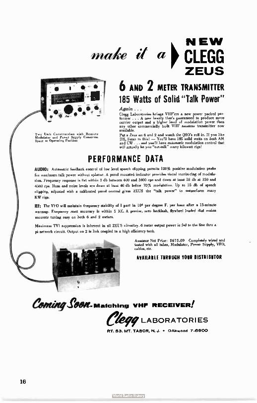
ened,e if a
f • •9 e j • •
Two Unit Construction with Remote Modulator and Power Supply Conserves Spore Id Operating Position
k NEW p CLEGG ZEUS
6 AND 2 METER TRANSMITTER 185 Watts of Solid " Talk Power" Again . . . Clegg Laboratories brings VHFen a new power packed per. former . .. A new beauty that's guaranteed to produce more carrier output and a higher level of modulation power than any other commercially built VHF amateur transmitter now available. Put a Zei13 on 6 and 2 and watch the DSO's roll in. If you like DX, listen to this! — You'll have 185 solid watts on both AM and CW and you'll have automatic modulation control that will actually let you "out4alk" many kilowatt rigs!
PERFORMANCE DATA AUDIO: Automatic feedback control of low level speech clipping permits 120% poeitive modulation peaku
for maximum talk power without splatter. A panel mounted indicator provides visual monitoring of modula.
tion. Frequency response is flat within 2 db between 400 and 3400 cps and down at meat 18 db at 150 and
4500 cps. Hum and noise levele are down at least 40 db below 70% modulation. Up to 18 db of speech
clipping, adjuisted with a calibrated panel control gives ZEUS the "talk power" to outperform many
KW rigs.
RF: The VIO will maintain frequency stability of 1 part in 106 per degree F. per hour after a 15.minute warmup. Frequency reset accuracy is within 5 KC. A precise, zero backlash, flywheel loaded dial makeo
accurate tuning easy on both 6 and 2 meters.
Maximum TVI suppression is inherent in all MUS circuitry. 6 meter output power is fed to the line thru a
pi network circuit. Output on 2 is link coupled to a high efficiency tank.
estmiWg
Amateur Net Price: $675.00 Completely wired and tested with all tubes, Modulator, Power Supply, \TO, cables, etc.
AVAILABLE THROUGH YOUR DISTRIBUTOR
..a. lga- Matching VHF RECEIVER! Ô 9 LABORATORIES RT. 53, MT. TABOR, N. J. • OAkvvood 7-6800
16
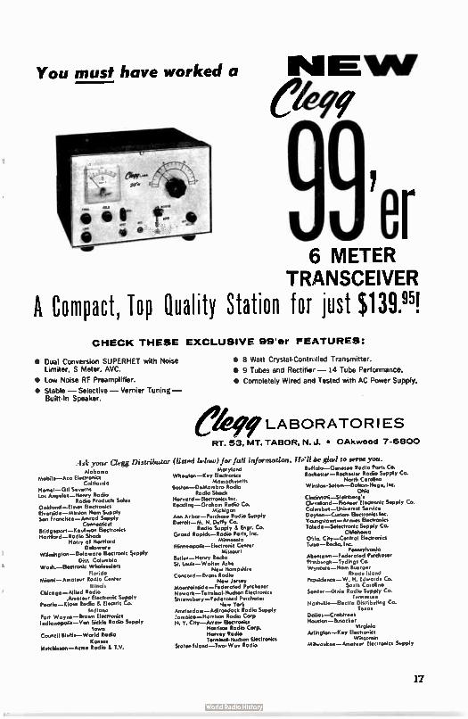
You must have worked a
6 METER TRANSCEIVER
A Compact, Top Quality Station for just $ 139..95! CHECK THESE EXCLUSIVE 99'er FEATURES:
• Dual Conversion SUPERHET with Noise Limiter, S Meter, AVC.
• Low Noise RF Preamplifier.
• Stable — Selective — Vernier Tuning — Built- In Speaker.
• 8 Watt Crystal-Controlled Transmitter.
• 9 Tubes and Rectifier — 14 Tube Performance.
• Completely Wired and Tested with AC Power Supply.
LABORATORIES
RT. 53, MT. TABOR, N. J. • OAkwood 7-6800
bk your Clegg Distributor (listed below) for full information. I
Mobarna Mobile—Aco Electronics
California Hemet Gil S Los Angeles—Henry Radio
Rodio Products Soles Oakland—Ehnar Electronics Riverside— Mission Horn Supply Son Froncisco—Amrod Supply
Connecticut Bridgeport—Koufmon Electronics Hortford—Rodio Shack
Hatry of Hartford Delaware
Wilmington—Deloware Electronic Supply Dist. Columbio
Wash.—Electronic Wholesalers Florida
Miami—Arnateur Rodio Center Illinoi‘
Chicago—Allied Rodio Amateur Electronic Supply
Peoria—Klaus Rodio & Electric Co. Indiana
Fort Wayne—brown Electronics Indianapolis—Von Sickle Rodio Supply
Iowa Council Bluffs—World Radio
Kansas Hutchinson—Acme Rodio& TV.
o y Wheaton—Key Electronics
Mossachnsetts Boston—DeMarnbro Radio
Radio Shack Honord—Electrmsics Inc. Reading —Graham Radio Co.
Michigan Ann Arbor—Purchase Radio Supply Detroit—M. N. Duffy Co.
Rodio Supply & Engr. Co. Grand Rapids—Radio Parts, Inc.
Minnesota Minneopolis—Electronk Center
Missouri Butler—Henry Rodio Sr. lovis—Walter Ashe
New Hornpshire Concord—Evons Rodio
New Jersey Mountainside—Federated Purchaser Newark—Terminal- Hudson Electronics Shrewsbury—Federosed Purchoser
New York Amsterdam—Adirondock Radio Supply Jamaica—Harrison Radio Corp N. Y. City—Arrow Electronics
Harrison Radio Corp. Harvey Radio Terminol.liudson Electronics
Staten Island—Two.Wor Radio
It.'!! be glad to serve you. Buffalo—Genesee Rodio Ports Co. RaAester—Rochester Rodio Supply Co.
North Carolino Winston-Salem—Dolton- liege, Inc.
Ohio Cincinnati—Steinberg's Clvvelond—Pioneer Electronic Supply Co. Calurnbus—Univertol Service Dayton—Custom Electronics Inc. Ya.Ingstown—Arrnies Electronics Teedo—Selectronic Supply Co.
Oklohorno Oldo. City—Control Electronics Toso—Rodio. Inc.
Pennsylvania Mentown—Federoted Purchaser Pi tsburgh—Tydings Co. Wyncote—Harn Buerger
Rhode Island Providence— W. H. Edwards Co.
South Carolina Sernter—Dixie Rodio Supply Co.
Tennessee Nashville— Electra Distributing Co.
Texas Dallos—Crabtrees Houston—Busacker
Virginia Mington—Key Electronics
Wisconsin Milwaukee— Amateur Electronics Supply
17
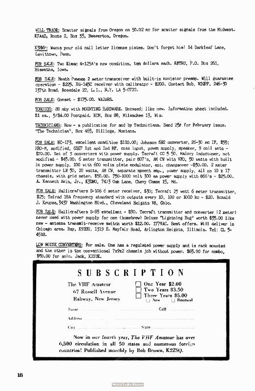
WILL TRADE: Scatter signals from Oregon on 50.02 mc for scatter signals from the Midwest.
K7AAD, Route 2, Box 35, Beaverton, Oregon.
K3HNP: Wants your old call letter license plates. Don't forget him! 14 Darkleaf Lane,
Levittown, Penn.
FOR SALE: Two Eimac 4-125A's new condition, ten dollars each. KOTRU, P.O. Box 261, Hiawatha, Iowa.
POR SALE: Heath Pawnee 2 meter transceiver with built-in nuvistor preamp. Will guarantee operation - $225. HO-145C receiver with calibrator - $200. Contact Bob, W2QPP, 246-3D 137th Road, Rosedale 22, L.I., N.Y. LA 5-0722.
FUR SALE: Gonset - $175.00. WA2ARS.
TOROIDS: 88 shy with MOUNTING HARDWARE. Uncased; like new. Information sheet included.
$1 ea., 5/$4.00 Postpaid. KCM, Box 88, Milwaukee 13, Wis.
TECHNICIANS: Now - a publication for and by Technicians. Send 25t for February issue.
"The Technician", Box 465, Billings, Montana.
POR SALE: No-173, excellent condition $110.00; Johnson 6N2 converter, 26-30 mc IF, $55;
HRO-M, modified, 6SG7 1st and 2nd RF, coax input, poweM supply, speaker, 9 coil sets - $70.00. Set of 3 converters with power supply. Tecraft CC 5 50, Malory Inductuner, not modified - $45.00. 6 meter transmitter, pair 807's, AM CW with VFO, 50 watts with built
in power supply, 100 with 600 volts plate modulator, ant. changeover -$50.00. 2 meter transmittEr LW 50, 20 watts, AM CW, separate speech amp., power supply, all on 10 x 17
chassis, with grid meter. $50.00. 750-1000 volt 300 ma power supply with 866's - $25.00. A. Kenneth Akin, Jr., K3teo, 74)3 Oak Lane, Chevy Chase 15, Md.
FOR SALE: Hallicrafters S-106 6 meter receiver, $30; Tecraft 25 watt 6 meter transmitter,
$25; Telrad 18A frequency standard with outputs every 10, 100 or 1000 kc - $20. Ronald
J. Krupsa,3437 Washington Blvd., Cleveland Heights 18, Ohio.
POR SALE: Hallicrafters S-85 excellent - $90. Tecraft transmitter and converter ( 2 meter) never used with power supply for one ( homebrew) Deluxe "Lightning Bug" worth $35.00 like
new - antenna transmit-receive switch worth $12.00. 177VAC. Best offers. Will deliver in
Chicago area. Ray, K92GU, 1319 E. Mayfair Road, Arlington Heights, Illinois. Tel: CL 5-4518.
kOW NOISE CONVERTERS: For sale. One has a regulated power supply and is rack mounted
and the other is the conventional 7x9x2 chassis job without power. $65.00 for combo, $50.00 for solo. Jack, K2IUK.
SUBSCRIPTION 't Ill' \ in:liven-
t>7 %% vino.
It allv.as. Ne‘s Jler-,ey
Name
E One Year $U11) E l'ma, Years $3.50 [I] Three Years $5.00
New [ j Renewal
Call
Now in our fourth year, The VHF Amateur has over
6,500 circulation in all 50 states and numerous fori*..1 ,
countries! Published monthly by Bob Brown, K2Z.SQ.
18
All.. Katz, KKUY11
48 Cumberland Ave.
Verona, New Jersey
o o N
o Ask the average amateur which is stronger - CW or phone.
He will probably answer "CW." Then ask: If a station trans-
mitting on phone switches to CW, will the CW signal be strong-er than the phone ( same power output). The answer is no. True,
the CW will be more coryable due to a factor called threshold N of hearing, which simply means you cannot copy a signal whose strength is equal to the noise. You need a little extra, that extra
is less for CW, than for phone.
But this is not the real advantage of CW. Noise is everywhere, E while ( most) amateur signals only occupy a small space. It is only sensible
to make your receiver sharp enough to receive just the signal without a lot of excess noise. CW has a narrower bandwidth than phone and therefore when received properly has
less noise along with it. If you don't think this makes a difference, look at the April '61 Moonbounce column and get a 15 db surprise. A broad receiver ( not even too good on AM)
will, when tuned for CW, not beitaking full advantage of this mode.(As compared to a a
sharp receiver tuned in for CW).
The Truth About Crossed Tats From a Letter by IINIV
"The type of antenna being used here is crossed yagis fed in phase quadrate; i.e. two
sets of yagis elements mounted on the same boom, one set vertical and the other horizontal,
so that each element forms a cross. If the feedline runs directly to the horizontal element
, and a quarter wave loop of transmission line connects the horizontal driver element
with vertical driven element so that, viewed from the rear, the elements at 9 o'clock and
12 o'clock are connected together, clockwise transmitted polarization will result. The
great advantage of this antenna is that during reception the polarization of the antenna is reversed, permitting reception of a counterclockwise polarized signal. This not only
permits teeeption of one's own echoes, but means that all participants need only build
one tyre of antenna." By the way, Ned's antenna consists of eight 11 element 18 foot yagis stacked 15 feet vertically and 20 feet horizontally. Many thanks Ned.
Oops Department
Boy was I red when Ott, K2OGN (not W2CSM) told me we had his call wrong in the write-up
on his excellent 1296 me converter in the October edition of THE VHF AMATEUR. However,
just to show he isn't too mad, he promised something special in the way of 1296 mc gear
for next month's column.
Acttotttes
Not much word this month in the way of activities - Fellows, you will just have to write
more. We have heard that 432 is booming with a group of old two meter operators like V3IBN,
and W3CLQ. CT3AE is on a trip, but he'll be back soon. WA6NCD wants to see more on helix
19
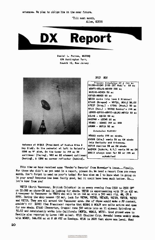
antennas. We plan to oblige him in the near future.
'Till next month, Allen, K2UYH
DX Report Daniel L. Parses, WA2DMQ
184 Huntington Tarr.
Newark 12, New Jersey
Antenna at MIRKA (President of Nashua Mike 81
Key Club). On the pedestal at left is Roland's
1298 mc 4' dish. On the tower Is 144 mc 32
collinear (facing), 452 mc 82 element collinear
(behind), & 298 mc corner reflector (behind).
SXED BOX
Present Schedules 50 A, 144 se WIZOO-K2IPID 2130 EST Wed.'s 60 mc
WSHFX-WSUJO-113ARW 220 mc
WA2UAK-W2WEA 50 mc
KI1030-WOUES 60 mc
wAcco works into lows .1 Missouri
K7AAD (Oregon) - W8F2A, IMINLZ 60.02
K7EZP (Oreg.) - 1(700J (Wash.) 50 mc
117,111 (Rev.) - 11611SQ Sunday's 144 cc
KOMSS-KBYSX-KIPSZ-KOINZ-MIVZJ 60 lac
K2J110 - K9105 60 mc
WA2PMW - K2E110 50 mc
WOWOD - MEG 144 mc SSS
KBUMN - WBFZA 60 nc
Schedules 1411101
W5U10 wants INN mc shade.
KREDS (Ala.) wants 60 mc CW sheds
into Kentucky and Arkansas.
YE71R desires 60 mc CV skeds
MUM (Auburn, N.Y.) wants 60 mc CW
89E15 always open for 50 or 144 mc
schedules!
This time we have received some ' Reader's Reports' from November's issue.., finally. For those who didn't as yet send in a report, please do. We need a report from you every month. Don't forget to send us your's today! For how else am I to know what is going on in your area? Response has been fairly good, but it could have been much better. So... let's hear from you!
VE7IR ( North Vancouver, British Columbia) is on every evening from 0300 to 0500 GMT on 50.088 mc phone-CV and is looking for skeds. VE7GR is experimenting with TV on 420 mc. A newcomer to Vancouver is VE6PQ who will be on 144 mc with a 500 watt rig, AK, Cit RTTY. During the skip season ( 50 mc), look for VE7NM, VE7ND, VE7A0D, VE7XW, VE70E, VE7KD and VE7IR. They are all around the Vancouver area. One of those would make a FB contact, wouldn't it/ K6VXI ( San Francisco) reports that K6RNQ & N6AJF are quite active and open for new skeds. K7AAD ( Beaverton, Oregon) runs 300 watts into an 11 element Spiralray on 50.02 and consistantly works into California ( W6F2A, W6NLZ, YX). Good ground wave to
Seattle also reported by Loren ( 180 miles). W7JU ( Boulder City, Nevada) keeps weekly skeds
with W6WSP, 144.006 mc at 8 AM PST on Sundays. W7JU is 2600 feet above sea level. Font
20
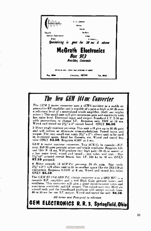
C. E. nreasson
Tern
'recta( t Hy-G.1n
Control Electronics Her
Drake à
SPecializing in gear he 50 inc above
McGrath Electronics Box 913
Boa/der, Co/orado
Write us rà. - oboirt erceisis or ends
Rog. Mt« Janyce, KOZUM Tony, ME
The few WI Illific Coverlet The GEM 2 meter converter uses a 6CW4 nuvistor as a stable re-generative RF amplifier and is capable of a gain as high as 60 dh over a reference level of a neutralized triode amplifier. (6x8) ose, tripler mixer.) This small unit will give maximum gain and sensitivity with low noise level. Universal input and output. Standard I. F. 5-10 mc with instructions to change I.F. Requires only 150V at 18 ma. Wired and tested on 21/2 " x 4" circuit board—ONLY 88.50
2 Meter single nuvistor pre-amp. This unit will give up to 30 db gain and will reduce or eliminate cross-modulation. Tuned input and output. The very small size ( only 21/2 " x 2") allows unit to be used in restricted space. Ideal for Gonsets, etc. Wired and tested less tube ONLY 84.50. Requires 0-50V at 4 ma.
GEM 6 meter nuvistor converter. Two 6CW4's in cascode—R.F. amp. 6x8 Hi-gain pentode mixer and triode oscillator. Requires 6.3v and 150v « 18 ma. Will produce very high gain I 30 elb or more ) a low noise level, wired and tested — less tubes and xtal — Size 21/2"x4" printed circuit hoard. Any I.F. 550 kc to 10 me. ONLY 87.50 postpaid.
6 Meter cascade (2 6CW4's) pre-amp. 20 di) gain. Size ( only 21/2 " x 2") will allow unit to fit in smallest space like the HQ-110 or converters. Requires 0-100V at 8 ma. Wired and tested lees tubes ONLY 85.50.
The GEM STAND.4RD P.C. circuit converter uses a 6BQ..BZ7 as a cascode R.F. amplifier and a 6x8 High Gain pentode mixer and oscillator. This converter will give u good signal-to-noise ratio and maxim uni sen.itivitv and I.F. output. The circuit uses very Hi-)) air wound coils and the broadband oscillator will accept crystals from 40 to 50 inc for any I.F. output. Wired and tested for onl, $6.50.
All items sent Post-paid in advance
OEM ELECTRONICS R. R. 3, Springfield,Ohio
„weaideiJ
Fill out and return to us today!
As an aid to both the Editor and to our new "DX Report” colter, ycur assistance is greatly make This IWO COI be moved free the magazine without damage.to the content&
If wu like, mote a facsimile. Of œurse, if u complain enough, ye rditor night be tempted to said you a new palomino if pages .3 ti 4 also fall out. Mole -Ma—.
RETURN TO: Reader Report. c/o DX COLUMN Daniel L. -Panes, WA2DMQ
184 Huntington Terr. Newark 12, N.J.
Your Nam. vat l
Address. City state.
a What bands ( VHF) do you operate? mew such power?
• eat kind of antenna do wu use? allow high above sea level?
• Do wu operate mosnr ) AN, t 1 CV. t SÎB
• What hus the furthest oentact made in the last month?
• Wien, If at all, houe there been good GROUND WIVE condftfons in your area. Also, to what extent (how far)?
▪ kbe any new states recently (or during the Sumer)?
• eat are the most frequently heard DISTANT stations?
•Do you presently hold schedules with anyone?
nhho do you knew that semis to work out exceptionally well in your am?
22
to trade Qrff's tack? K6UMN (Canoga Park) worked Késdp (San ,Jose) about 400 miles away on 50 mc. K6UMM also hears quite regularly b6FZA ( 175 miles), K6RNO ( 435 miles), K6CDC( (475 miles). K6HMS (Costa Mesa) works and hears sigs 400 miles away nightly on 144 mc. Jim Michels, K7GSR, of Sale; Oregon, works 50, 220, 432, 3500 and 5.600 mc! Jim reports
that b7BVV, bf7.JIP and W7S0 are all active on 144.18 mc. 7BVV& 7Sb have 42' Long Johns. A lot of FM activity there, also. K7EZ ( Forest Grove, Oregon) reports working MOICPJ (Norton, Kansas) during November on 50 mc. Warren also mentions that he frequently
hears KOTSD and K7ALE on skip. He's picked up 16 new states using his new Clegg 99'er.
KOMSS ( Omaha, Nebraska) works 210 miles consistently. Last month he worked into
Kansas City on 50 mc. Oh... he's 1440 feet above sea level! Like to trade eff's with you also! If you live in Hawaii_ or North Dakota, look for him because you can help him get his W.A.S. certificate. it5HPr (Bedford, Texas) hears frequently W5HTZ ( Wew*a, Okla-homa) on 144 mc. W4HHY ( Nashville, Tennessee) contacted W4NYT ( Roanoke, Alabama) for a distance of 230 miles on 50 mc. Also, Ohio, Indiana, and Illinois stations were heard by
W4HRY last month. W9HF ( Angola, Indiana) contacted last month WA4Aità ( Independence, Ky.) sad MIMIC ( Novelty, Ohio) on 50 mc. From Harissa, K9EID, Bob works and has skeds with W9HGE ( Wisc.), K4GEQ ( Ky.), K9ZTE( ( Ind.), WORMY ( Kansas City, Mo.) and kODJG ( Iowa)... NOVI
W5RUE (Belle Vernon, Pa.) worked on Oct. 1 W4WDH (N.C.). Also heard by Ted are W8TYY
(Columbus, Ohio) on 452 mc. 131110 is on 144 me. With a Halo, K3OBU ( WIlmIngten. Delaware)
worked E4208 (Chester, Va.). Also heard very frequently are Long Island, N.Y., stations.
K3IPM ( Philadelphia) hears W1BU (Mass.) and W4UCH (Va.) very regularly on 60 mc. Stan
worked Cuba, Newfoundland, Mexico, Costa Rica, Puerto Rico, and Nova Scotia this past
summer. From Md., K3DNO heard stations on October 1 at a distance of from 300-600 miles on
50 me. K3LOV (Solebury, Pa.) with only 7 watts worked into W. Orange, N.J. last month.
Mark hears KIBRY (Conn.) quite often on 8 meters. The most frequently heard distant sta-
tions at W3WOD (Baltimore, Md.) are W8KAY, MIMES, W1RJA, WiAJR, K2BNE and W4MXT - 144 me.
WIHDO is heard most often by W3I4JC ( Reading. Pa.) during aurora sessions. W3MJC Worked
K4DIO (Alexandria, Va.) on November 24 at 11:08 EST. (2 meters). WA2PMW (College Point,
N.Y.) worked on November 12 Bellport, Long Island . Lou hears K3HNP. WA2FMC, and KIM
often on 60 me.
Here's a nice contact from the N.Y.C. area: K2SWI (Huntington, L. I.) worked on November
6, K1NAY in Maine! K3L21, KUNP, K1PBE, WiALE, and KUM are heard regularly by K2SWI.
Incidentally, George has only been on 8 meters for four months. Nice going, eh! wegbmc (West Orange, N.J.) worked W3ATY (Baltimore) on November 23 and K4VNF ( Fla.) on Oct. 27... once again, 8 meters. WA2DAC ( Peru, N.Y.) runs a KW on 60 me. 30 watts on 144 me, and also
works 14 meters. He worked KP4AAN with only 9 watts AM this past summer! WA2080 (Lawnside,
N.J.) worked KIIIM/1 in New Hamshire on 50 mc. Richard frequently hears KIM and KUHR.
WA2PWI (Middlesex. N.J.) reports that he has worked N.C., Va., Md., Franklin Co.. Pa..
Mass.. and Conn., recently on 6 meters. Tom is doing real well with only 40 watts. II2JNO (Union City, N.J.) can be found on 60.018 me CW, and presently has skeds with E310Z. Walt
is looking for CW contacts - So, how about taking the dust off the key and looking for him?
K2PBP (Millburn, N.J.) hears K3KEO. K3MWV, and 131(NP with real good siga on 8. W2ALR (Lockport, N.Y.) worked MOM (Geneva, Illinois) during the aurora in October. Ni also
works MAY every night on 144.3 me. From Auburn. N.Y., WA2VCM worked KIJWK (Conn) and
E3011C/3 (Bald Eagle Mt., Pa.) John says that the longest ground wave contact recently was K3JFL (Thomasville, Pa.). .. about 250 miles. WA2UNQ (Garfield, N.J.) worked 18MMI (merlon, Ohio) on November 15 at 2130 EBT. K2RRM (near Binghamton, N.Y.) regularly works 1225Q (Rahway, N.J.) on 60 mc.
Aurora Session - Deiumoder 2; 1961
Jim Bellows, K8NIE, of Midland, Michigan, reports that Dec. 2 aurora between 1800-1900
EST as " quite a session.* Jim worked EOM, /MID, K9200, KeY1A, WOHGE, WOPFP and adds,
'Nothing really remarkable about this except it was a roundtable on 60 mc EISH via aurora - abades on 76 meters and of things to come?'
Well, fellows, that's it for this month. If your Reader Report wasn't in print this month, you can be assured it'll be in next time. Columns are written at least a month in advance - hence a delay. Keep those Reader Reports and letters coming. We love ' em!
'Till next month, Dan, WA2EMQ
23
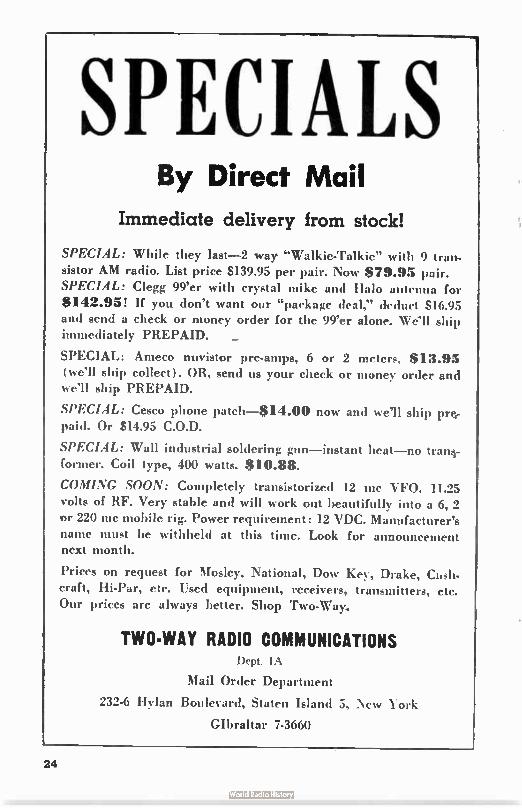
SPECIALS By Direct Mail
Immediate delivery from stock!
SPECIAL: While they last-2 way "Walkie-Talkie" with 9 tran-sistor AM radio. List price $139.95 per pair. Now $79.95 pair. SPECIAL: Clegg 99'er with crystal mike and Halo antenna for
$142.95! If you don't want our "package deal," deduct $ 16.95 and send a check or money order for the 99'er alone. Well ship immediately PREPAID. _
SPECIAL: Ameco nuvistor pre-amps, 6 or 2 meters, $13.95
(we'll ship collect). OR, send us your check or money order and we'll ship PREPAID.
SPECIAL: Cesco phone patch-814.00 now and we'll ship pre, paid. Or $14.95 C.O.D.
SPECIAL: Wall industrial soldering gun—instant heat—no tram-former. Coil type, 400 watts. $10.88.
COMING SOON: Completely transistorized 12 mc VFO. 11.25 volts of RF. Very stable and will work out beautifully into a 6, 2 or 220 inc mobile rig. Power requirement: 12 VDC. Manufacturer's name must he withheld at this time. Look for announcement next month.
Prices on request for Mosley, National, Dow Key, Drake, Cush-craft, Hi-Par, etc. Used equipment, receivers, transmitters, etc. Our prices are always better. Shop Two-Way.
TWO-WAY RADIO COMMUNICATIONS Dept. IA
Mail Order Department
232-6 HyIan Boulevard, Staten Island 5, CNV York
Gibraltar 7-3660
24
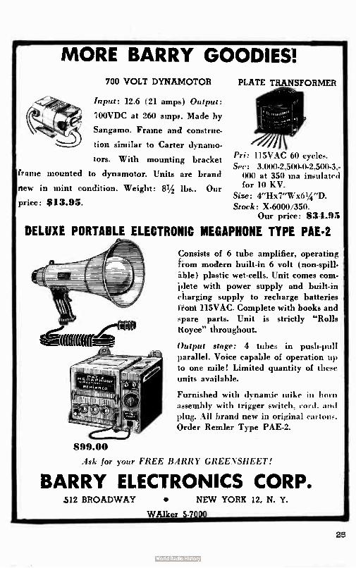
MORE BARRY GOODIES! 700 VOLT DYNAMOTOR
Input: 12.6 (21 amps) Output:
IOOVDC at 260 amps. Made by
Sangamo. Frame and construc-
tion similar to Carter dynamo.
tors. With mounting bracket
frame mounted to dynamotor. Units are brand
new in mint condition. Weight: 81/2 lbs.. Our
price: S13.95.
PLATE TRANSFORMER
Pri: 115VAC 60 cycles.
Sec: 3.000-2,500-0-2,500-3.-000 at 350 ma insulated for 10 KV.
Size: 4"Hx7"Wx61/2 "D. Stock: X-6000/350.
Our price: 3 1.95
DELUXE PORTABLE ELECTRONIC MEGAPHONE TYPE PAE-2
Consists of 6 tube amplifier, operating horn modern built-in 6 volt (non-spill-Ale) plastic wet-cells. Unit comes corn-"plete with power supply and built-in
charging supply to recharge batteries
Front 115VAC. Complete with books and spare parts. Unit is strictly "Rolls
Royce" throughout.
Output stage: 4 tubes in push-pull
parallel. Voice capable of operation up to one mile! Limited quantity of these
units available.
Furnished with dynamic mike in horn assembly with trigger switch, cord. and plug. All brand new in original cartons.
Order Remler Type PAE-2.
S99.00
Ask for your FREE BARRY GREENSHEET!
BARRY ELECTRONICS CORP. 512 BROADWAY • NEW YORK 12, N. Y.
WAlker 5-7000 •
25
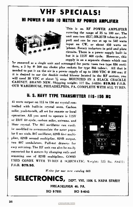
VHF SPECIALS! HI POWER 6 AND 10 METER RF POWER AMPLIFIER
'This is at. RF POWER AMPLIFIEit covering the range of 25 to 100 mc. The
111 input on CW. or about 450 watts on
0 de e pu 'phone. Rotary inductors in grid and plate '
unit use . two 1E27/ HK257B tu push-be s in
circuits. There is a power supply built in
ll anti can be run at up to 540 watts
but it is 115V 400 cycle. However, this
supply is on a separate chassis which can removed as a single unit and scrounged for parts ( uses two type 836 recti-
'fiers, a 2 by e 300 ma choke plus sockets for type 866 tubes,. All that is needed to put it on the air is a power supply of up to 1800 VDC @ 300 ma; if it is desired to use the double ended blower located in the RF section, you
will need 28 VDC at about 1/2 amp. MOUNTED IN A BLACK CRACKLE CABINET. BRAND NEW. Shipping weight: 117 lbs. S-6334: $19.95 F.O.B.
OUR WAREHOUSE, PHILADELPHIA, PA. COMPLETE WITH ALL TUBES.
U. S. NAVY TYPE TRANSMITTER 115-156 MC
45 watts output on 115 to 156 inc crystal con-
trolled with built-in crystal oven. Carbon
mike, push-to-talk, all set for remote or local
operation. All you need to operate is 115V
or 230V 60 cycle, carbon mike, antenna. and
16mc crystal. The 807 oscillator can easily
be modified to accommodate the more popu-
lar 8 me xtals. 807 oscillator, 82913 first multi-
plier, 829B second multiplier, 82913 output.
two 807 modulators. Pull-out drawers for
easy servicing. The RF unit can also he easily
converted for 6 meters by changing coils and
removing one of 8298 multipliers. GOOD
USED CONDX WITH TUBES & SCHEMATIC.
F.O.B. 179.95. Weight: à2.5 lbs.
Write for our ?WIC catalog 603
S.6411:
SELECTRONICS, DEPT. VHI, 1206 S. NAPA STREET
PHILADELPHIA 46, PA.
HO 8-7891 HO 8-4645
26
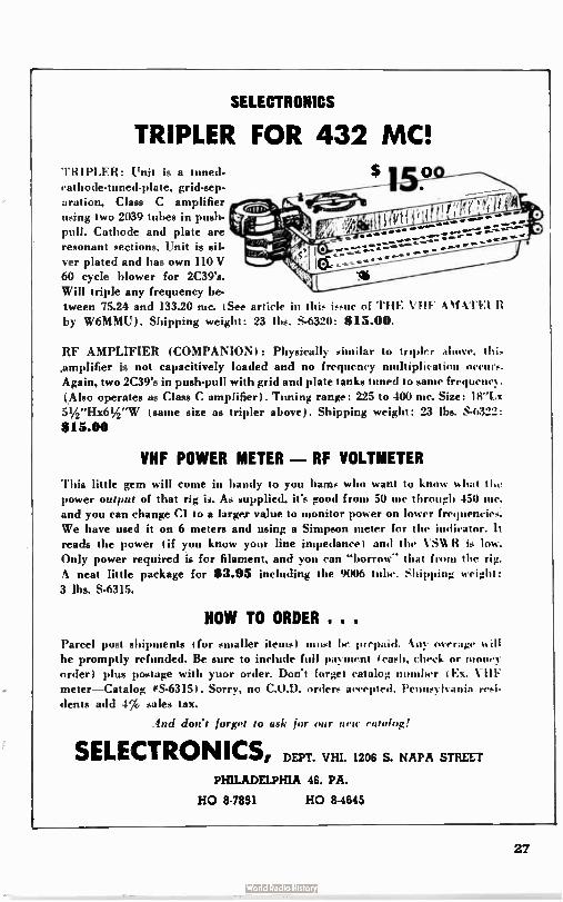
SELECTRONICS
TRIPLER FOR 432 MC! $ 1 TRIPLER: Unit is a tuned-
cathode-tuned-plate, grid-sep-aration, Class C amplifier using two 2039 tubes in push-pull. Cathode and plate are resonant sections. Unit is sil-ver plated and has own 110 V 60 cycle blower for 2C39's. Will triple any frequency be-tween 75.24 and 133.20 me. ( See article in this issue of THE VHF Vif% l'El R by W6MMU). Shipping weight: 23 His. S-6320: $ 15.00.
RF AMPLIFIER (COMPANION): Physically similar to troplcr above. this
,amplifier is not capacitively loaded and no frequency- multiplication occurs. Again, two 2C39's in push-pull with grid and plate tanks tuned to same frequeney .
(Also operates as Class C amplifier). Tuning range: 225 to 400 nic. Size: 18"Lx 51/2"Hx61/2"W ( same size as tripler above). Shipping weight: 23 lbs. S-6322:
$15.00
VHF POWER METER - RF VOLTMETER
This little gem will come in handy to you hams who want to know what the power output of that rig is. As supplied, it's good from 50 me through 450 inc. and you can change Cl to a larger value to monitor power on lower frequencies We have used it on 6 meters and using a Simpson meter for the indicator. It reads the power ( if you know your line impedance) and the VS' R is low. Only power required is for filament, and you can "borrow" that f • the rig. A neat little package for $3.95 including the 9006 tube. Shipping weight:
3 lbs. S-6315.
HOW TO ORDER . . .
Parcel post shipments for smaller items) must lic brepaid. Any overage n ill he promptly refunded. Be sure to include full payment ( cash, check or money order) plus postage with yuor order. Don't forget catalog her ( E. VI-IF meter—Catalog #S-6315 I. Sorry, no C.O.D. orders accepted. Pennsylvania resi-dents add 4% sales tax.
lnd don't forget to ask for our IIPIE catalog!
SELECTRONICS, DEPT. VHI, 1206 S. NAPA STREET
PHILADELPHIA 46, PA.
HO 8-7891 HO 8-4645
27
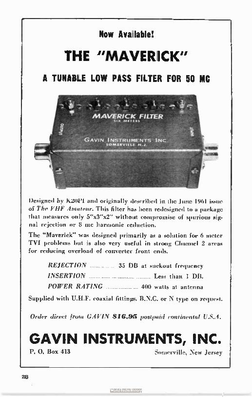
Now Aval able!
THE "MAVERICK"
A TUNABLE LOW PASS FILTER FOR 50 MC
MAVERICK FILTE,R 5124 MilTEeS
GAVIN INSTRUMil NTS INC SCINNERVISLE NJ
Designed by K20i'l and originally described in the June 1961 issue
of The VHF Amateur. This filter has been redesigned to a package
that measures only 5"x3"x2" without compromise of spurious sig-
nal rejection or 8 me harmonic reduction.
The "Maverick" was designed primarily as a solution for 6 meter TVI problems but is also very useful in strong Channel 2 areas
for reducing overload of converter front ends.
REJECTION -------------- 35 DB at suckout frequency
INSERTION Less than 1 DB.
POWER RATING 400 watts at antenna
Supplied with U.H.F. coaxial fittin:m. B.N.C. or N type on reque-t.
Order direct from GAVIN 816.95 postpaid continental S. 4.
GAVIN INSTRUMENTS, INC. P. 0. Box 413 Somerville, New Jersey
28
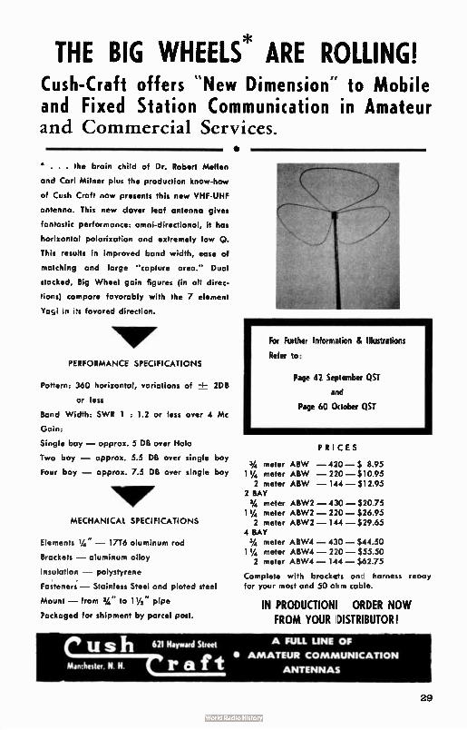
THE BIG WHEELS* ARE ROLLING! Cush- Craft offers " New Dimension to Mobile and Fixed Station Communication in Amateur and Commercial Services.
•
• . . . the brain child of Dr. Robert Mellen
and Carl Milner plus the production know-how
of Cush Croft now presents this new VHF-UHF
antenna. This new clover leaf antenna gives
fantastic performance: omni-directional, it has
horizontal polarization and extremely low Q.
This results in improved band width, ease of
matching and large "capture area." Dual
stocked, Big Wheel gain figures ( in all direc-
tions) compare favorably with the 7 element
Yayi in favored direction.
PERFORMANCE SPECIFICATIONS
Pattern: 360 horizontal, variations of ± 2DB
or less
Band Width: SWR 1 : 1.2 or less over 4 Mc
Gain:
Single bay — approx. 5 DB over Halo
Two bay — approx. 5.5 DB over single bay
Four bay — approx. 7.5 DB over single bay
MECHANICAL SPECIFICATIONS
Elements 1/4" — 1716 aluminum rod
Brackets — aluminum alloy
Insulation — polystyrene
Fasteners.— Stainless Steel and plated steel
Mount — from 3/4 " to 1'/3 pipe
Packaged for shipment by parcel post.
For Further Information & Illustrations
Refer to:
Page 42 September QST
and
Page 60 October QST
PRICES
3/4 meter ABW — 420— $ 8.95 1 1/4 meter ABW — 220 — $ 10.95 2 meter ABW — 144 — $ 12.95
2 BAY 3/4 meter ABW2 — 430— $20.75 1 I/4 meter ABW2 — 220— $26.95 2 meter ABW2 — 144 — $ 29.65
4 BAY 3/4 meter ABW4 — 430 — $44.50 11/4 meter ABW4 — 220— $55.50 2 meter ABW4 — 144 —$62.75
Complete with brackets anc harness reauy for your most and 50 ohm cable.
IN PRODUCTION! ORDER NOW FROM YOUR )ISTRIBUTOR I
Cush 621 Hayward Street A FULL LINE OF
. (• Min:hetter. N H. us t • AMATEUR COMMUNICATION ea' ANTENNAS
29
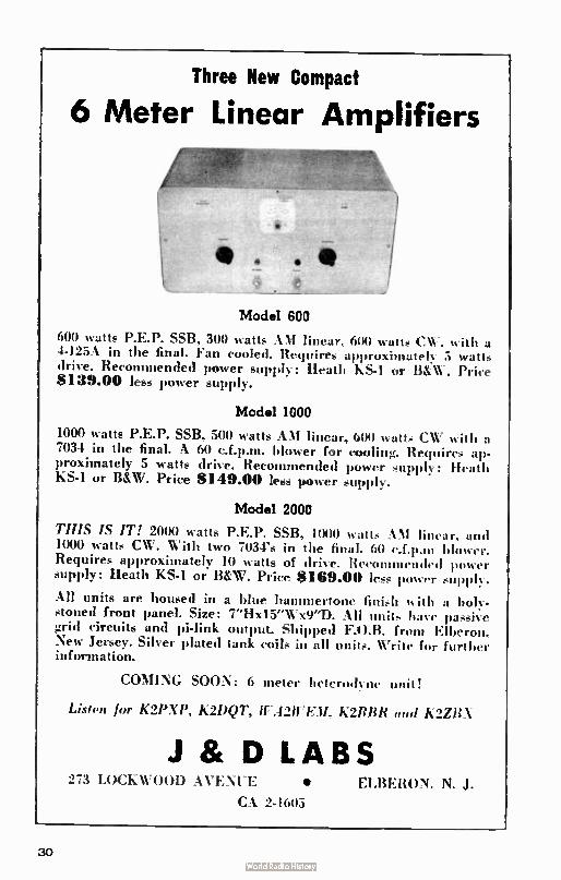
Three New Compact
6 Meter Linear Amplifiers
•
_
Model 600
600 watts P.E.P. SSB, 300 watts AM linear, 600 watts CW. with a 4-125A in the final. Fan cooled. Requires approximately 5 watts drive. Recommended power supply: Heath KS-1 or B&W. Price $139.00 less power supply.
Model 1000
1000 watts P.E.P. SSB, 500 watts AM linear, 600 watts CV' with a 7034 in the final. A 60 c.f.p.m. blower for cooling. Requires ap-proximately 5 watts drive. Recommended power supply: Heath KS-1 or B&W. Price $ 149.00 less power supply.
Model 2000
THIS IS IT! 2000 watts P.E.P. SSB, 1000 watts AM linear, and 1000 watts CW. With two 7034's in the final. 60 c.f.p.tu blower. Requires approximately 10 watts of drive. Recommended power supply: Heath KS-1 or B&W. Price $ 169.00 less power supply.
All units are housed in a blue hammertone finish ‘iit h a holy-stoned front panel. Size: 7"Hx15"Wx9"D. All units have passive grid circuits and pi-link output. Shipped F.O.B. front Elberon, New Jersey. Silver plated tank coils in all units. Write for further information.
COMING SOON: 6 meter heterodyne unit!
Listen for K2PXP, K2DQT, 117.421fE.11, K2RBR fool K2ZBX
J St D LABS 273 LOCKWOOD AVENUE • EI,BERON, N. J.
CA 2-1605
30
Directional Power Coupler
NUVISTOR PRE-AMPLIFIER COMPLETE WITH 6CW4, POWER CORD AND STAND-ARD SO- 239 RF CONNEC-TORS FOR EASY INSTALLA-TION.
$139 FEATURES!
L A% ailable tor the 6, 2 and 11/4 meter bands. When ordering, specify band.
2. A low noise and high gain pre-am-plifier that will improve your present reception.
3. 'Two tuned circuits that will match your present input and output system.
CONN. RESIDENTS ADD 3I/2% SUES TAX. POSTAGE PREPAID ON CASH ORDERS WITHIN THE U. S. A.
DESIGNERS AND MANUFACTURERS OF AMATEUR, COMMERCIAL AND MILITARY PRODUCTS IN THE SPECTRUM OF 50 TO 500 MCS
VHF-UHF ASSOCIATES P. 0. BOX 1068 V F FAIRFIELD, CONN.
MEASURE: STANDING WAVE RATIO! FIELD STRENGTH! TRANSMISSION LINE LOSS!
MONITOR: POWER OUTPUT! MODULATION!
A directional power coupler that will operate throughout the range from 50 to 500 mcs and be left permanently in the transmission line at power levels up to 1000 watts continuous. Available in 52 or 75 ohm impedance. A quar-ter wave whip type, sealed antenna and a diode coupled tuned circuit may be con-nected to the R.F. connectors to convert the coupler to a tunable field strength meter cov-ering the range of 50 to 500 mcs (accessories described in Bulletin E-5275-2, see illustra-tion below). Units supplied with SO-239 R.F. connectors, for type "N," add $1.66 to order. Direct ear phone connection is made to the audio output jack to monitor modulation. All units are adjusted to insure perfect meter cali-bration and shipped with installation instruc-tions plus handy reference chart. When order-ing specify impedance.
CONN. RESIDENTS ADD 31/2'6 SALES TAX. POSTAGE PREPAID ON CASH ORDERS WITHIN THE U. S. A.
DESIGNERS AND MANUFACTURERS OF AMATEUR, COMMERCIAL AND MILITARY PRODUCTS IN THE SPECTRUM OF 50 TO 500 MCS.
VHF-UHF ASSOCIATES P. 0. BOX 1068 FAIRFIELD. CONN.
CQ Magazine CS
300 West 43rd St. 1 year, ;5; 2 years, ;9; 3 years, ; 13 New Vork 36, N.Y. In U.S. Possessions, APO 6: FPO,
Canada & Mexico
D new Enclosed is $ for a year
D renewal subscription to CQ, to be sent to:
Name Call
Address
City Zone State Pan-America and all other foreign: I yr. $6; 2 yrs. $11; 3 yrs. $16.
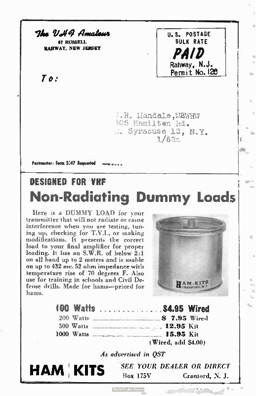
lim 14)14 ?imam* 47 RUSSELL
1RARWAY, NEW JERSEY
To:
Postmaster: Font 3347 Requested
U. S. POSTAGE BULK RATE
PAID Rahway, N.J. Permit No. 128
/ R. Liandale ,W2WHVI " 1t •n Id.
use 12,
DESIGNED FOR VHF
Non-Radiating Dummy Loads Here is a DUMMY LOAD for your
transmitter that will not radiate or cause interference when you are testing, tun-ing up, checking for T.V.I., or making modifications. It presents the correct load to your final amplifier for proper loading. It has an S.W.R. of below 2:1 on all band up to 2 meters and is usable on up to 432 mc. 52 ohm 'impedance with temperature rise of 70 degrees F. Also use for training in schools and Civil De-fense drills. Made for hams—priced for hams.
100 Watts $4.95 Wired 200 Watts $ 7.95 Wired 500 Watts 12.95 Kit 1000 Watts 15.95 Kit
(Wired, add $4.00)
As advPrtised in QST
HAM ; KITS SEE YOUR DEALER OR DIRECT
Box 175V Craniord, J.
e
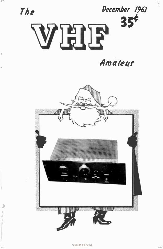
The
\vb December 1961
35e
Lki 'à Amateur
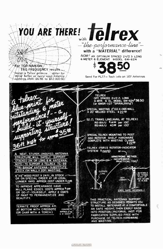
YOU ARE THERE! .w.atéirex . ,
• For TOP- MAN-ON-I , THE FR EQUEÉ1CY results ....
4n$.t..t f,•Irex‘ ,:?rbienna...4ollar for d llar Oettser / rr every way,l, Antenna ,
stfeil from $6.95 to E2.00000
6" X 6" WOOD POST X 24 ff., IN STOCK OR ON SPECIAL ORDER AT UR LOCAL LUMBER YARD. APPROX.COST UNDER flee
TO IMPROVE APPEARANCE HAVE MILL PLANE EDGES. COSTS APPROX * 5e? OR DO-IT-YOURSELF. APPLY 2 COATS OF PAINT TO PERMANENTIZE AND BEAUTIFY.
eeee e with a " MATERIAL" difference!
NOW/ AN OPTIMUM SPACED 2-1/2 LONG 6 METER 6 ELEMENT MODEL 6M-624
TELREX OPT. SPACED 2-1/2 A LONG 6 MTR, 6 EL. MODEL 6M-624438 50 (or 6MSR•1127 "SPIRALRAYe)
SPECIAL MASTING 2`0.D .X.065 WALL X 20 WELDED STEEL 22S? •
_.,TELREX 175R1S ROTATOR- INDICATOR
SYSTEM $ 19850 or
ARMSTRONG METRO() INEXPENSIVE- - , PRACTICAL TOO!
THIS PRACTICAL ANTENNA SUPPORT STRUCTURE AS DESIGNED PERMITS YOU TO INSTALL ANTENNAS AT A COMFORTABLE AN SAFE HEIGHT, THEN EASILY RAISE INTO POSITION ( PICTORIAL INST. FOR FABRICATION SUPPLIED FREE WITH PURCHASE OF TELREX HARDWARE AND MASTING.
The VHF Amateur Title registered U.S. Post Office
A MONTHLY PUBLICATION
OFFICES:
Business 8 Editorial 87 Russell Avenue Rahway, New Jersey
EDITORIAL STAFF
Bob Brown,x2zsa
Circulation Manager
Peter A. darkovaée, WA2CVA
Production Manager
Doutas W. Clanton Pr,ducti-n Assistants:
Blair Schupp
David Clatit -li
Curt laudgraf
Cotmsel
J. D. 'Red" Brown, K2ZSP Moonbounce Editor
Allen Vatz, DOM 48 Cumberland Avenue Verona, New Jeruy
Single sideband Editor
Phillip Curai, R2PCG
204 Nast Northfield Rd. Livintston, New Jersey
South American Editor
Michael A. Czysch LOON
fhe FBI Asettnur is
published monthly by
Robert N. Brown, MSG,
Subscription rates:
one year, $ 1.00, two
11.60, It years,
$6.00. Foriegn add $ I.
ADVERTISING rete card
ns request, Entire
contents printed in
Clark, N.J.. U.S. A.
Tel.phone Number for
out-of-state direct
dialing: 201-FU 1-1284.
Local calls:FUlton 1-
1284.
VOL. 4, No. 12 DECEMBER 1981
Tale Ok eintfAilfdi
120 Watts on 8 Meters — Homebrewl Ken Foster, W218D 4
NieM for the VFO Richard Huntress, K1CXX 9
More Heath Modifications — TWO& Joe Lupo, »201 [2
A Knob for that VFO dial? Staff 15
V.H.F. SS8 Column Phil Gural, K2PCG 18
Letters Page 19
Mbonbounce Column Allen Katz, K2UYN 21
DX Report Dan Parnes, WA2CMA 23
Free Ni—Pass Filters' Staff 24
Reader's Reporting Form 29
Subscriptions 25
Our Front Cover
Sleighbells are ringing, wreaths are
sparkling, and Santa brings us a new
high power sin meter rig, Who could
ask for more? For those chilly winter
night projects, see page 4:
3
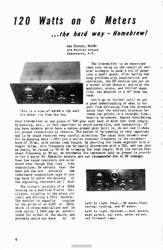
120 Watts on 6 Meters ...the hard way - Homebrew!
Ken Foster, W2IED 472 Bayview Avenue Cedarhuret, N.Y.
111111111 This is a view of 112110's 120 watt six meter rig from the top.
The transmitter to be described came into being as the result of sev-eral attempts to pack a lot of power into a small space. After having had many problems with construction and operation, the RF section was put on a normal sized chassis, and with the modulator, plate, and exciter supp-lies, was mounted in a 30" desk top rack.
Let's go no further until we get a good understanding of what to ex-pect from deviating from the accepted axiom that the shortest distance be-tween two points is a straight line.. heavily by-passed. Anyone considering
this transmitter or any piece of VHF geai must bear in mind that lead length, by-passing, etc., is very important to avoid parasitics, and instability. If you have sockets which have a center ground post built in, do not use it.ilake all ground connections te chassis. The matter of by-passing is very important and in my shack receives very careful attention. The usual disc ceramic used for by-passing here (. 001) has a series resonant frequency in the neighbor-hood of 35 mc, with normal lead length. By shorting the leads together with a copper strap, this frequency can be easily determined with a GOO, and can just as easily be raised to 50 mc by trimming the lead length. With the series res-onant frequency at 50 mc, an extremely low impedance path to ground is provid-ed for 6 meter RF. Bakelite sockets are not recommended due to RF leakage. Some low value resistors are wire-wound even though they look like composition. Be certain that the ones you use are actually low inductance composition type or you may have to solve the mystery of the exploding resistors as I did!
The circuit consists of a 6CL6 working as a modified Pierce Osc-illator, tripling in the plate cir -cuit and driving a 5763 doubler. The doubler is capacity couplet* to the grids of an 829B or 3E29, which is cross-neutralized and is rock solid. A 5894 may be substi-tuted for either of the above, and probably would not have to be
Left to right (Top)...0C aetar,fiaal toning, loading, and RF meter.
Left to right (Sottom)...xtal select, mode select, key jack, meter select, and filament lamp.
4
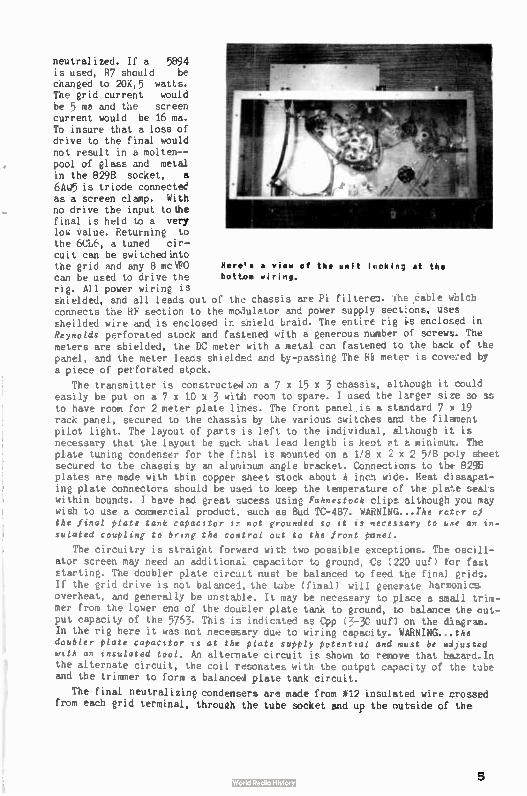
neutralized. If a 5894 is used, R7 should be changed to 20K,5 watts. The grid current would be 5 ma and the screen current would be 16 ma. To insure that a loss of drive to the final would not result in a molten--pool of glass and metal in the 829B socket, a 6AU5 is triode connected as a screen clamp. With no drive the input tothe final is held to a very low value. Returning to the 6CL6, a tuned cir-cuit can be switchedinto the grid and any 8 mcVFO Here'', a vitid of the unit luokin; at the can be used to drive the bottom wirilg. rig. All power wiring is shielded, and all leads out of the chassis are Pi filtered. ite .cable which connects the RF section to the modulator and power supply sections, uses sheilded wire and is enclosed in shield braid. The entire rig is enclosed in Reynolds perforated stock and fastened with a generous number of screws. The meters are shielded, the DC meter with a metal can fastened to the back of the panel, and the meter leads shielded and by-passing The Ri meter is coveeed by a piece of perforated stock.
The transmitter is corstructedon a 7 x 15 x 3 chassis, although it could easily be put on a 7 x 10 x 3 with room to spare. I used the larger size so as to have room for 2 meter plate lines. The front panel is a standard 7 m 19 rack panel, secured to the chassis by the various switches and the filament pilot light. The layout of parts is left to the individual, although it is necessary that the layout be such that lead length is kept et a minimum. The plate tuning condenser for the final is mounted on a 1/8 x 2 x 2 5/8 poly sheet secured to the chassis by an aluminum angle bracket. Connections to the 829E plates are made with thin copper Meet stock about incn wide. Heat dissapat-ing plate connectors should be used to keep the temperature cf the plate seals within bounds. I have had great sucess using Fahnestock clips although you may wish to use a commercial product, such as Bud TC-487. WARNING...The rcsor cl the final plate tank capacitor te not grounded so it is necessary to use an in-sulated coupling to bring the control out to the front panel.
The circuitry is straight forward with two possible exceptions. The oscill-ator screen may need an additional capacitor to ground, Cs 220 uuf) tor fast starting. The doubler plate circuit must be balanced to feed the final grids. If the grid drive is not balanced, the tube ( final) will generate harmonics overheat, and generally be unstable. It may be necessary to place a small trim-mer from the lower end of the douder plate tank to ground, to balance the out-put capacity of the 5763. This is indicated as Cpp ( 3-30 uuf) on the diagram. In the rig here it was not necessary due to wiring capacity. WARNING.. the doubler plate capacitor is at the plate supply potential and must be adjusted with an insulated tool. An alternate circuit is shown to remove that hazard.In the alternate circuit, the coil resonates with the output capacity of the tube and the trimmer to form a balanced plate tank circuit.
The final neutralizing condensers are made from # 12 insulated wire crossed from each grid terminal, through the tube socket and up the outside of the
5
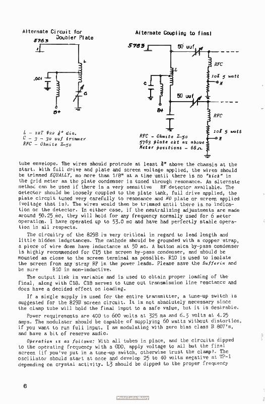
Alternate Circuit for Doubler Plate
11-763
L - 12T *22 r C - 3 - 30 uuf trimmer RFC - Ohmite 2-50
Alternate Coupling to final
5763 50 uuf
Jol 5 watt
N
50 uuf
8+
RFC
RFC - °haste 2-5o 5763 plate ckt as above Meter positions -
RFC
lot 5 watt
N
tube envelope. The wires should protrude at least a. above the chassis at the start. With full drive and plate and screen voltage applied, the wires should be trimmed EQUALLY, no more than 1/8" at a time until there is no "kick" in the grid meter as the plate condenser is tuned through resonance. An alternate methoc can be used if there is a very sensitive RF detector available. The detector should be loosely coupled to the plate tank, full drive applied, the plate circuit tuned very carefully to resonance and NO plate or screen applied (voltage that is). The wires would then be trimmed until there is no indica-tion or the detector. In either case, if the neutralizing adjustments are made around 50.25 mc, they will hold for any frequency normally used for 6 meter operation. I have operated up to 53.0 mc and have had perfectly stable opera-tion in all respects.
The circuitry of the 829B is very critical in regard to lead length and little hidden inductances. The cathode should be grounded with a copper strap, a piece of wire does have inductance at 50 mc. A button mica by-pass condenser is highly recommended for C15 the screen by-pass condenser, and should be mounted as close to the screen terminal as possible. 810 is used to isolate the screen from any stray RF in the power leads. Please save the Rufferin and be sure 810 in non- inductive.
The output link is variable and is used to obtain proper loading of the final, along with C18. C18 serves to tune out transmission line reactance and does have a decided effect on loading.
If a single supply is used for the entire transmitter, a tune-up switch is suggested for the 829B screen circuit. It is not absolutely necessary since the clamp tube will hold the final input to a safe value, but it is desirable.
Power requirements are 400 to 600 volts at 325 ma and 6.3 volts at 4.25 amps. The modulator should be capable of supplying 60 watts without distortion, if you want to run full input. I am modulating with zero bias class B 807's, and have a bit of reserve audio.
Operation is as follows: With all tubes in place, and the circuits dipped to the operating frequency with a GDO, apply voltage to all but the final screen ( if you've put in a tune-up switch, otherwise trust the clamp). The oscillator should start at once and develop 25 to 40 volts negative at TP-1 depending on crystal activity. L3 should be dipped to the proper frequency
6
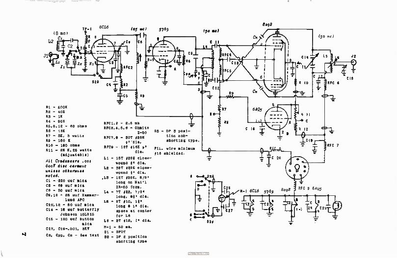
(8 mc(
,
C2 ti 2
Jib leeie:$1 A i Q 13 1,
11T—T-T --
TP-I
6
n le
324
111 - 100K
R2 - 40K
R3 - 1K
R4 - POI
R6,8,12 - 88 ohms
R8 - 18K
R7 - 6K, 6 watts
RS - 160 I
RIO - 180 ohms
R11 - 26 6,25 watts
(adjustable)
All Coud . 00l
Coe disc ceramic
unless otherwise
noted.
Ci - 220 uuf mica
CE - 88 nut ales
Ce - 50 uuf mica
Og,18 - 26 uuf Hammer-
lund APC
Cil. 1.2 - 50 uuf mica
C14 - 16 uuf butterfly
Johnson 101.516
C16 - 180 uuf button
mica
C17, C10-.001, 3KV
Cpp, Cc - See text
6CL6
C4
(65 66) 5763
RFC1,2 - 2.6 22
RFC3.4.5,8 - Ohmite
Z-60
RFC7.8 - spv oggg
4. dia.
RFCS - I8T # 16E 4.
dia.
Li - 15T #28E close-
wound I. dia.
LE - 38T #28E close-
wound 4. ells.
,1.3 - 12T /28E, 6/8.
long on Paul
IR-60 form.
L4 7T #22, 7/6.
long. 04. dia.
L6 8T / 10, 11
long 0 1. dia.
space at center
for L6
Le - ET # 12, 1. dia.
M-1 - 60 ma.
81 - 8PDT
82 - DP 2 position
shorting type
83 - DP 3 posi-
tion non-
shorting type.
Fil. wire minimum
#18 shielded.
(5e ac)
8 'b....JP e 0-2
C II
336
89
97
Re
c 6
C 16
8298
qc 20
m-1 6CL6 5763 8298
(50 mc)
RFC O 6Açc.5
RFC 6
RFC 7
J2
7.
CI8
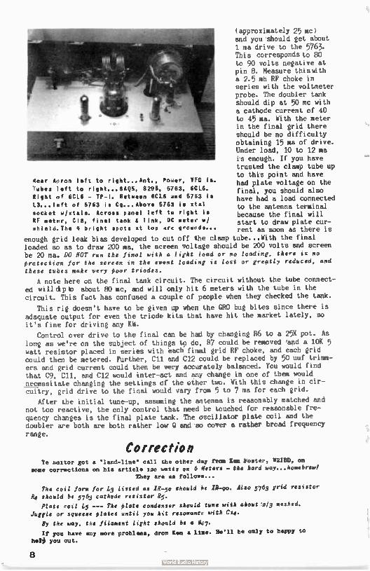
4ear Apron left to right...Ant., Power, VFO is. 7ubes left to right...6AQh, 8296, 5763. 6CL6. Right of 6CL6 - TP-I. Between 6CL6 and 5763 is L3... left of 5763 is Cg...Above 5/63 is stet socket w/stals. Across panel left to right is RF meter, C18, final tank & link, DC meter w/ uh i e I d. The II bright spots at top are grounds...
(approximately 25 mc) and you should get about 1 ma drive to the 5763. This corresponds to 80 to 90 volts negative at pin 8. Measure thiswith a 2.5 mh RF choke in series with the voltmeter probe. The doubler tank should dip at 50 mc with a cathode current of 40 to 45 ma. With the meter in the final grid there should be no difficulty obtaining 15 ma of drive. Under load, 10 to 12 ma is enough. If you have trusted the clamp tube up to this point and have had plate voltage on the final, you should also have had a load connected to the antenna terminal because the final will start to draw plate cur-rent as soon as there is
enough grid leak bias developed to cut off the clamp tube...With the final loaded so as to draw 200 ma, the screen voltage should be 200 volts and screen be 20 ma. DO NOT run the final with a light load or no loading, there is no protection for the screen in the event loading is lost or greatly reduced, and these tubes make very poor triodes.
A note here on the final tank circuit. The circuit without the tube connect-ed will dip to about 80 mc, and will only hit 6 meters with the tube in the circuit. This fact has confused a couple of people when they checked the tank.
This rig doesn't have to be given up when the GRO bug bites since there is adequate output for even the triode kits that have hit the market lately, so
it's fine for driving any KW.
Control over drive to the final can be had by changing 86 to a 25K pot. As long as we're on the subject of things to do, 87 could be removed 'and a 10K 5 watt resistor placed in series with each. final grid RF choke, and each grid could than be metered. Further, Cil and C12 could be replaced by 50 uuf trimm-ers and grid current could then be very accurately balanced. You would find that C9, E11, and C12 would inter-act and any change in one of them would necessitate changing the settings of the other two. With this change in cir-cuitry, grid drive to the final would vary from 5 to 7 ma for each grid.
After the initial tune-up, assuming the antenna is reasonably matched and not too reactive, the only control that need be touched for reasonable fre-quency changes is the final plate tank. The oscillator plate coil and the doubler are both are both rather low G and so cover a rather broad frequency range.
Correction Ye castor got a " land-line" call the other day from gem lOster, W2113D, on
some corrections on his article lao watts on 6 Aeters - the hard way...homebrewl they are as follows...
The coil form for L3 Listed as IR-50 should ne Ili-go. Also 5763 grid resistor Rq should be 5763 cathode resistor R5.
Plate coil L5 --- The plate condenser should tune with about 2/3 meshed. Juggle or squeeze plates until you hit resonance with C14-
By the way, tee filament light should be a 47.
If you have any more problems, drop leu a lime. He'll be only to happy to hele you out.
8
A Simple NBFM
for the VFO
Richard Huntress, KIM
27 Linden St.
Auburn, Maine
1r you are receutng threatenlnj phone calls at all hours of the day and if your neighbors are circulating a petition to have you removed from the air because your AM 50 mc transmitter comes in on their TV, radio, intercom, hi-fi, tape recorder, kitchen sink, etc., this article may be of interest to you. Before you give in to your neigh-bors and operate only after 2 AK, after the Late-Late Show, - why not try NBFM ( narrow band frequency modulation)? If your rig uses a VF), then this system of NBFM can be added to it quite easily. The junk box should provide most of the necessary parts and even if every part /or it is purch:ased new, it wouldn't run over a'couple of bucks, which is a small price to pay for keeping the neighbors out of your hair.
This system of NBFM was added to two different transmitters at this OTH with excellent results. Even though the tube line-up varies from one transmitter to another, it should be possible to add NBFM to most any transmitter without much difficulty.
The heart of this system is composed of a germanium diode, which is used as a voltage
controlled capacitor. This diode is one of the common types that is sold three for a buck on the surplus market. A VP)) has to be used as the frequency control of the transmitter be-cause a device like this added to a rig using crystal control would result in a small amount of phase - not frequency - modulation. A germanium diode, when it is back biased, will act as a variable capacitor, its capacity depending on the amount of bias across the diode. This variable capacity effect is quite small in the standard run of the mill diode, but it is adequate to deviate a 6 or 8 mc VP)) enough so that by the time it is mul-tiplied to 50 mc, better than 10 kc of deviation can be obtained. In the actual circuit the diode is back biased to one-half its rated peak inverse voltage ( P.I.V.). The P.I.V. rating for diodes can be obtained from the diode section in the back of the_ARRL Handbook - under the column headed "Max inverse volts." Allied Radio also gives 'the F.I.V. rating of diodes and other data in their regular catalogues in the transistor and diode seetion. A 1N48 diode was used in this job ( P.I.V. of 85 volts) and has a bias of 42 volts across it in the actual circuit. This bias voltage is obtained from a voltage divider consisting
of R2 R3 ( Figure 1). The voltage supplied to R2 R3 should be regulated, otherwise any
changes in supply voltage will shift the operating frequency of the VP)). Most VFO's use a 150 volt regulator tube to supply the voltage to the oscillator tube so R2 R3 should be supplied from this voltage source.
The VFO's that were modified for NBFM used the popular series tuned Clapp oscillator
circuit. Cl is used to couple to the VP)) and acts as part of a capacitive divider in series with the variable capacity of the diode. R1C2 is a filter used to keep the RF from the Ve from being shorted to ground and also keeps it out of the audio system. Audio is fed to the diode through R1, and C3 from the plate of the audio driver tube in the modulator section.
In my rig the audio tube line-up is 6Sj7-6C5-6V6 driving a pair of 1625's class AB2. The modulator and power supplies are mounted on one chassis with different RF units used for each band. A 6 foot power cable is 'used to connect these units to the power supply. A
patch cord, with PL55's at both ends, is used to get the audio from the modulator to the
9

TO Vice
CI
Aete
lAi
FIGURE i - The basic 11801 unit.
PARTS LIST
Cl - 5 uuf ceramic C2 - 100 uuf mica or ceramic
C3 - . 01 mfd 600 volt
R1 - 10E .5 watt R2 - 50K 1 watt
R3 - 20K 1 watt
X1 - 1Nk18 diode
VFO section. Obviously many transmitters have the RF, audio and power supplies on a single
chassis so the audio patch cord would not have to be used ( Figure 2). Even though the patch
cord was not made with shielded wire, no hum or feedback problems were encountered.
About 85 volts ( or less) peak to peak of audio should be applied to the NBFM section.
If more audio than this is applied, the diode will conduct on negative peaks and possibly
week it on positive audio peaks.
If a patch cable is used, jack Ji should be of the type that shorts to ground when the
jack is pulled out. This is done to prevent any hum on the carrier when the rig is used
on either AM or CW. The switch in section A of Figure 2 does the same thing.
----BECTIOM
AM A
•
NA FM 114/
Ne. FM Pos.
rS-- r EC-TIO N
I pi_ 55
1TH23
PL 55
• .ot I
L FROM .1
SPEECH AMR
VFO SEC1:
2 I
L._
11-6 %too 041T PUT
150 u v.R.
TUBE
MODULATOR
TUAES
FIGURE 2 - Shows how the N8FM unit is connected Into the transmitter. All parts nec sssss y
for the N8FM are shown inside the dashed lines. In section A is the method used to covole
audio from the modulator section into the IMIFM unit If everything is constructed on the
same chassis. In section 8 a patch cord Is used If the RF section of the transmitter Is
on a separate chassis away from the modulator section.
10
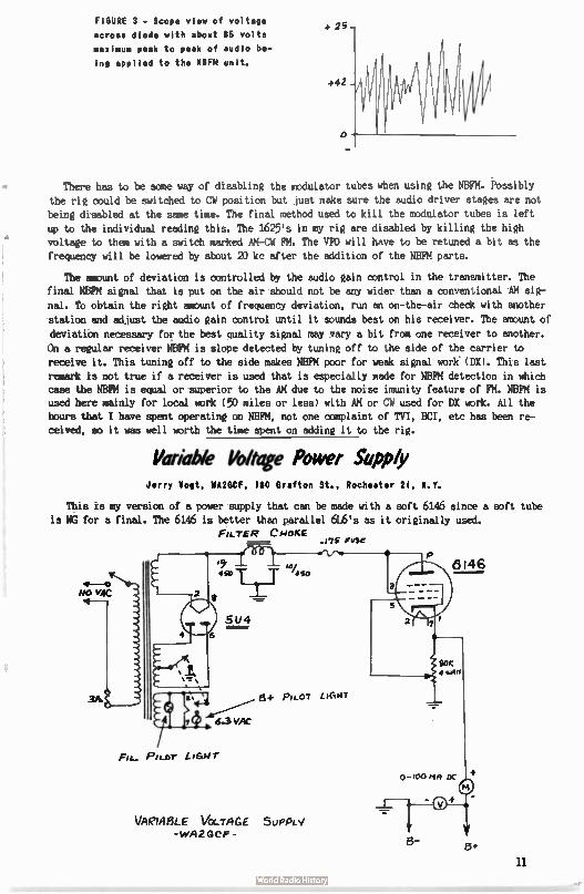
FIGURE 3 - Scope view of voltage
across diode with about 85 volts maximum peak to peak of audio be-
ing applied to the NBFM unit.
+ 26—
+42 -
o
There has to be some way of disabling the modulator tubes when using the NBFM. Possibly
the rig could be switched to CW position but just make sure the audio driver stages are not
being disabled at the same time. The final method used to kill the modulator tubes is left
up to the individual reading this. The 1625's in my rig are disabled by killing the high
voltage to them with a switch marked AM-CW FM. The VIO will have to be retuned a bit as the frequency will be lowered by about 20 kc after the addition of the NBFM parts.
The amount of deviation is controlled by the audio gain control in the transmitter. The
final NBFM signal that is put on the air should not be any wider than a conventional AM sig-
nal. To obtain the right amount of frequency deviation, run an on-the-air check with another
station and adjust the audio gain control until it sounds best on his receiver. The amount of
deviation necessary for the best quality signal may vary a bit from one receiver to another.
On a regular receiver NBFM is slope detected by tuning off to the side of the carrier to
receive it. This tuning off to the side makes NBFM poor for weak signal work ( DX). This last
remark is not true if a receiver is used that is especially made for NBFM detection in which case the NBFM is equal or superior to the AM due to the noise imunity feature of FM. NBFM is used here mainly for local work ( 50 miles or less) with AM or CW used for DX work. All the hours that I have spent operating on NBFM, not one complaint of TVI, BCI, etc has been re-
ceived, so it was well worth the time spent on adding it to the rig.
Variable Voltage Power Supply Jerry Vogt, WA2GCF, 160 Grafton St., Rochester 21, M.V.
This is my version of a power supply that can be made with a soft 6146 since a soft tube is NG for a final. The 6146 is better than parallel 616's as it originally used.
FILTER CHOKE .175 ruse
Fla_ Pti_o-r LIGHT
VAR1ABLE VOL-TA GE 5 u PPLY -viA 2 GC p -
8-
11
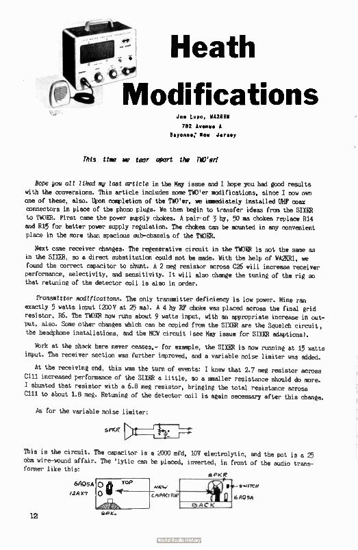
Heath
Modifications Joe Lupo, WA2GBW
792 Avenue A
Bayonne; Mew Jersey
This tine he tear apart the TWO'erl
Hope you all liked my last arttcle in the May issue and I hope you had good results
with the conversions. This article includes some Tinier modifications, since I now own
one of these, also. Upon completion of the TWO'er, we immediately installed UHF coax connectors in place of the phono plugs. We then begin to transfer ideas from the SIXER
to TWOER. First came the power supply chokes. A pair of 3 hy, 50 ma chokes replace R14
and R15 for better power supply regulation. The chokes can be mounted in any convenient place in the more than spacious sub-chassis of the TWOER.
Next came receiver changes. The regenerative circuit in the TWOER is not the same as
in the SIXER, so a direct substitution could not be made. With the help of WA2KRI, we found the correct capacitor to shunt. A 2 meg resistor across C26 will increase receiver
performance, selectivity, and sensitivity. It will also change the tuning of the rig so that retuning of the detector coil is also in order.
Transmitter modiftcations. The only transmitter deficiency is low power. Mine ran
exactly 5 watts input ( 21)0V at 25 ma). A 4 hy RF choke was placed across the final grid resistor, R6. The TWOER now runs about 9 watts input, with an appropriate increase in out-put, also. Some other changes which can be copied from the SIXER are the Squelch circuit,
the headphone installations, and the MCW circuit ( see May issue for SIXER adaptions).
Work at the shack here never ceases,- for example, the SIXER is now running at 15 watts
input. The receiver section was further improved, and a variable noise limiter was added.
At the receiving end, this was the turn of events: I knew that 2.7 meg resistor across
C111 increased performance of the SIXER a little, so a smaller resistance should do more.
I shunted that resistor with a 6.8 meg resistor, bringing the total resistance across
C111 to about 1.8 meg. Retuning of the detector coil is again necessary after this change.
As for the variable noise limiter:
selq? )2-I,
This is the circuit. The capacitor is a 2000 mfd, 10V electrolytic, and the pot is a 25
ohm wire-wound affair. The ' lytic can be placed, inverted, in front of the audio trans-former like this:
6/405A
t2AXI
o 4H1 TOP
CPI< I?
12
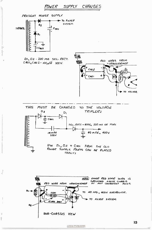
POWER SUPPLY C HA e(1 GE S
suEs -CHASSIS YIEW
i6 mfd
35IDV
PQESEI.17 rrwee SOPPLY
1 To ricrLe
Da
C40,
T.c4.2
SISTEM
Di, D2 - 200 MAI SEL. g'ECY.
cAo cac 2 - ice,wecl 2rLV.
— - — - — - — - — -
77/IS miusT 8E CI-IAVGED To THE VOLTAGE"
Da DI Tie! PLEe:
set- REct - 4e0v, 2te tisi OR ticee
40 m fci , 4cov
VSE DI, 02 1- C401 recni to-le CLI) filt.VEC SOPPLN: P14e7S CAM F3E PLACED
wor£: OTHE/0 ('Ee xffle wee is Gecomme A ficelF ci4ASSIS
ei-r) WIRE FPoin re,ws,cemf_e AT AN Y CaUktA) &Jr p,, *j
TO 40 FWD, 400V ELECI£OLVTIC.
TD Fn TER S1STEM
13
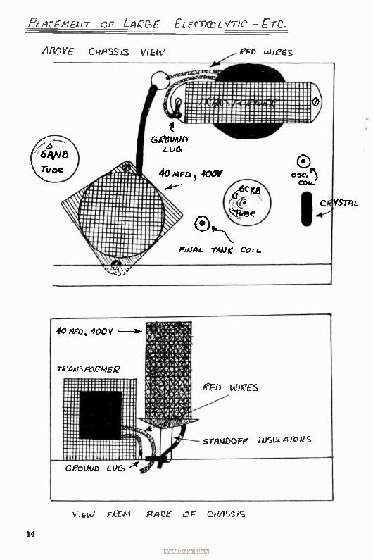
'et\
.I•SIU uIliuUb
0 1188111110118111111% OOOOO 111/661111IIMMIIIIII
11311/1111891111111111111113Milr• ‘11111111131111,331111111111113iI/ `111111/3“ 3/11111111111.11' loosen O Fiwuree;„'
OO ea, : . ... r s O IBIMP7PIINIIIIII •IMIIIIMIIIIIIMI OOOO e 13131.• iiPS 'MUM?* Mil', Pn111.43111M1111111/
ilelegge'411:11 ele;;;;iiiii
0,11..1,IttreW • WI ...%e....i.rvet. 0
tritn, ii. :1.11 é i..11.«.:ir é «,•,, ,
1.,..e.,b.emie f•
'Oree reelgt tà 'ewe:bet Ae rcanfrele 1.,5,1.•4 • 70 tValretit '11 ,4,
... OOOOOOO .••• VtalVs11.1.41KRà lia OOOOOOO in• t• • ewe moebiewe,ow, 99 O 9 OOOOO .9 • • 9 •M Me teee...,;40,,,owybilam • I OM • I IC Ma mr.e.ertee•e•o• • 1 , I k...!:.$>?...-91r..›../e .. 9•• I 1T: II I I Wm `,Vietv..•el.`e. I
in -meeyeawitepre. Illà.
II
e Ili ...........iiiij• . am ammo ' es
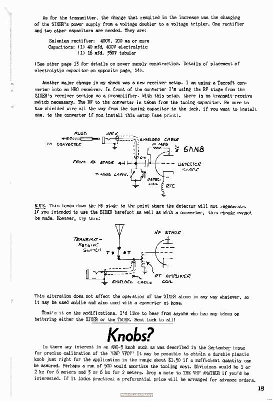
As for the transmitter, the change that resulted in the increase was the changing
of the SIXER's power supply from a voltage doubler to a voltage tripler. One rectifier
and two other capacitors are needed. They are:
Selenium rectifier: 400V, 200 ma or more Capacitors: ( 1) 40 mfd, 400V electrolytic
(1) 16 mfd, 350V tubular
(See other page 13 for details on power supply construction. Details of placement of
electrolytic capacitor on opposite page, 14).
Another major change in my shack was a new receiver setup. I am using a Tecraft con-
verter into an HRO receiver. In front of the converter I'm usine the RF stage from the
SIXER's receiver section as a preamplifier. With this setup, there is no transmit-receive
switch necessary. The RF to the converter is taken from the tuning capacitor. Be sure to
use shielded wire all the way from the tuning capacitor to the jack, if you want to install
one, to the converter if you install this setup ( see print).
PLUG JACK
.o-cu.ra=lme ‘ sHtELDED CABLE
TO canivieme lo MEG
FROei RF sTAGE
TuNINC. CRPRC.
6AN8
- neréctce ,Ç.YFIGE
PFC
NOTE: This loads down the RF stage to the point where the detector will not regenerate.
If you intended to use the SIXER barefoot as well as with a converter, this change cannot be made. However, try this:
"reAvsmfr -
REMitif
T • T
eF .srac,e
RF AMPLIFIER
SHIELDEA CABLE COIL
This alteration does not affect the operation of the SIXER alone in any way whatever, so it may be used mobile and also used with a converter at home.
That's it on the modifications. I'd like to hear from anyone who has any ideas on bettering either the SIXER or the TWOER. Best luck to all!
Knobs? Is there any interest in an ARC-5 knob such as was described in the September issue
for precise calibration of the 'HNP VFO?' It may be possible to obtain a durable plastic
knob just right for the application in the range about $1.50 if a sufficient quantity can
be assured. Perhaps a run of 500 would amortize the tooling cost. Divisions would be 1 or
2 kc for 6 meters and 3 or 6 kc for 2 meters. Drop a note to THE VHF AMATEUR if you'd be
interested. If it looks practicad a preferential price will be arranged for advance orders.
15
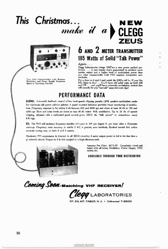
This Christmas... made it a
NEW p CLEGG ZEUS
*- • 1 6 AND 2 METER TRANSMITTER 10111.11: • • $
e e -
Two Unit Construction with Remote Modulator and Power Supply Conserve, Space at Operating Petition
185 Watts of Solid " Talk Power"
Clegg Laboratories bring• VHF'ers • new power packed per-former . . . A new beauty that's guaranteed to produce more carrier output and • higher level of modulation power than any other commercially built VHF amateur trumminer now available.
Put a Zeus on 6 and 2 and watch the DSO's roll in. If you like DX, listen to thin! — You'll bave 185 solid watt• on teals AM and CV/. and you'll have automatic modulation control that will actually let you "ont-talk" many kilowatt rigs!
PERFORMANCE DATA AUDIO: Automatic feedback control of low level speech clipping permits 120% positive modulation peaks
for maximum talk power without splatter. A panel mounted indicator provides visual monitoring of modula-
tion. Frequency response is flat within 2 db between 400 and 3400 cps and down at lean 18 db at 150 and
4500 cps. Hum and noise levels are down at least 40 db below 70% modulation. Up to 18 db of speech
clipping, adjusted with a calibrated panel control gives ZEUS the "talk power" to outperform many
KW rigs.
RF: The V1,0 will maintain frequency stability of 1 part in 10.1 per degree F. per hour after • 15-minute
warmup. Frequency reset accuracy is within 5 KC. A precise, seso backlash, flywheel loaded dial makes
accurate tuning easy on both 6 and 2 meters.
Maximum TVI suppression is inherent in all ZEUS circuitry. 6 meter output power is fed to the line thru •
pi network circuit. Output on 2 is link coupled to a high efficiency tank.
Amateur Net Price: $675.00 Completely wired and teq.41 with all tubes, Modulator, Power Supply, VFO; cable, etc
AVAILABLE THROUGH YOUR DISTRIBUTOR
editOefergeet- Matching VHF RECEIVER! eke LABORATORIES RT 53, MT TABOR, N J • OAkwood 7-61300
16
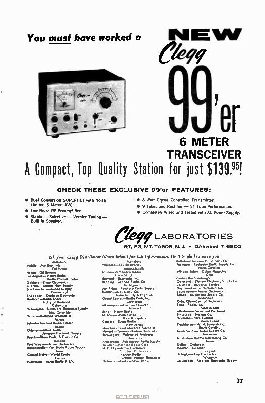
You must have worked a
war
6 METER TRANSCEIVER
A Compact, Top Qualit!l Station for just $ 139.95!
•
• •
CHECK THESE EXC:_USIVE 99'er FEATURES:
Dual Conversion SUPERHET with Noise Limiter, S Meter, AVC.
Low Noise RF Preamplifier.
Stable— Selective— Vernier Tuning — Built- In Speaker.
.-lik .your Clegg Distributor AJaborna
Mobile—Ass Eiectronics California
Hornet—Gil Sermon Los Angeles—Henry Rodio
Rodio Products Sales Oakland—Elem. Electronics Riverside—Mission Ham Simply San Fromimo—Annod Supply
Connecticut Bridgeport—Kaufman Electronics Hortford—Rodio Shock
Hairy of Hartford Delowore
Wilmington—Delaware Electronic Supply Dist. Columbia
Wadt—Elegronic Wholesaler, Florida
Miami—Amateur Radio C Illinois
Chicago—Allied Rodio .Amateur Electronic Supply
Eeoria—Klous Rodio Es Electric Co. Indiana
Fort Wayne—Brown Electronics Indionapalis--Van Sickle Rodio Supply
lowa Council bluffs— World Radio
Kansas Hutchinson —m Ace Radio T.V.
Ô
• 8 Watt Crystal- Controlled Transmitter.
• 9 Tubes and Rectifier — 14 Tube Performance.
• Completely Wired and Tested with AC Power Supply.
fe LABORATORIES
RT. 53, MT. TABOR, N. J. • OAkwood 7-6800
(listed below) for full information. Maryland
Wheaton—Key Electronics Mossochmett,
Boston—DeNtambro Rodio Radio Mack
Haryord—ElecE onics Inc. Reading—Grahom Radio Co.
Michigan Ann Arbor—A...chase Radio Supply Detroit — M. N. Duffy Co.
Radio Supply & Engr. Co. Grand Rapids—Radio Ports, Inc.
Minnesota Minneapolis— Electronic Center
Missouri ' Butler—Henry Marti° St. Loyis—Walwr Ash* ,
[few Hampshire Concord—Evans Rodio
New Jersey Mountoinside—Federated Purchaser Newark—Terminal- Hudson Electronics Shrewsbury—Federated Purchaser
New York Anuterdarn—Adirondack Rodio Supply Jamaica —Hannon Rodio Corp N. Y. City—Atrese Electronics
Harrison Rodio Corp. Harvey Radio Tewninol-Hudson Electronics
Staten Island—Two. Way Rodio
lit"!! be glad to serve you. Buffolo—Genesee Rodio Ports Co. Rochester— Rochester Rodio Supply Co.
North Carolino Winoon-Salem—Dchon.Hege, Inc.
Ohio Cincinnoti—Steinberg's Clevelond—Pioneer Electronic Supply Co. Colenb.—Uniyersol Service Daylort—Cmtom Electronic, Inc. Youngstown—Armies Electronics Toledo—Selectronic Supply Co.
Oklahoma Okla. City—Control Electronics Tulsa — Radio, Inc.
Pennsylvania Allentown—Federamd Purchoser Fittsburgh—Tydings Co. Wyncom—Hom Buerger
Rhode Island Providence— W. H. Edwards Co.
South Corolino Similar— Dixie Radio Supply Co.
Tennessee Noshvill*—Elegra Dist•ibuting Co.
Togo, Dallas—Crabtrees Houston—Smacker
Virginia Arlington—Key Electronics
Wisconsin Milwasikee—Amoteur Electronics Supply
17
Phil Garai, K2PCG
204 East Northfield Road
Livingston, New Jersey
I have received some comments from hams who have a desire to build or buy a SSB rig
for 6 or 2 meters. Most of them would like to know the answers to such questions as:
"Has SSB activity increased?" "Basic advantages?"
"What equipment is available commercially?" "What present equipment can be used?"
"How much would a food Sal station cost?"
To begin, SSB activity has picked up considerably over the past five years. I have
heard from a few SSB'ers who claim they have worked 15 or more states SSB to SSB on 6
meters. Not only has 6 meter activity increased, but 2 and 220 me as well. 220 me was
included because there are now three states represented by SSB. If there is enough inter-
est, I will start a SSB - W.A.S. listing - for details, see the SSB column in the Septem-ber issue of THE VHF AMATEUR.
The advantages have to be divided into groups: equipment, and propagation and interfer-
ence. Under equipment, there is no large modulator needed even for that kilowatt rig.
This also means one less power supply is needed. All the audio that is needed can be taken from two dual triodes or less. Only one exciter is needed. Operation on different bands
is accomplished by heterodyning the signal to the desired band and amplifying the signal through one or more linear amplifiers. What is meant by heterodyning is simply mixing of
two frequencies to obtain a third frequency. As an example, to operate on 6, using an
exciter having an output on 14 mc, a 36 me signal would be mixed with the 14 mc SSB sig-nal. ( 14 mc plus 36 mc equals 50 mc).
Using SSB, ground wave contacts will be made further than with AM. Quoting from the Radio Handbook:
A statistical study of the distribution of signals on the air the
signal strength shows that the probability of successful communication
will be the same if the 33B power is equal to one-half the power of one
of the two AM sidebands. Thus 33B can give from 0 to 9 db improvement
under various conditions when the TOTAL sideband power is equal in 3311 and AM. In general, It may be assumed that 3 db of the possible 9 db advan-
tage will be realized on the ge contact.'
Being that the signal is much narrower, there will be less possibility of interference from an AM station. Along,with this, the person who is receiving the signal can use a
narrower bandwidth which means the receiver will have a higher gain. Another point to
bring out is that all of the signal is "talk power." In other words, the person receiving
Orr, W.I., 1163AI, RADIO HANDBOOK, 16th edition, page 329.
18
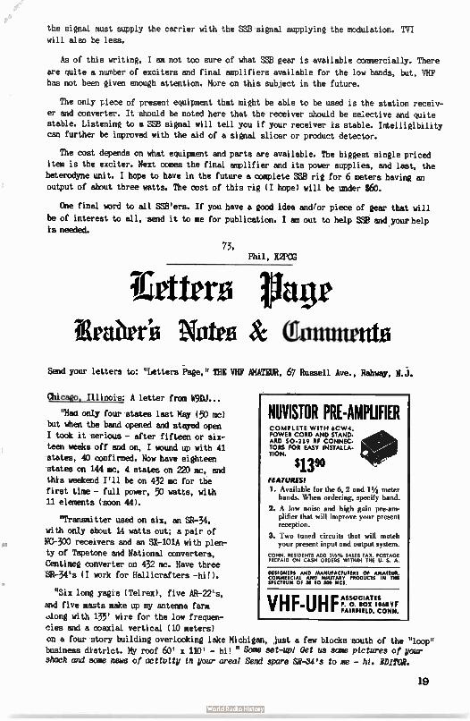
the signal must supply the carrier with the SSS signal supplying the modulation. TVI will also be less.
As of this writing, I am not too sure of what SW gear is available commercially. There
are quite a number of exciters and finad amplifiers available for the low bands, but, VHF has not been given enough attention. More on this subject in the future.
The only piece of present equipment that might be able to be used is the station receiv-
er and converter. It should be noted here that the receiver should be selective and quite stable. Listening to a SSS signal will tell you if your receiver is stable. Intelligibility can further be improved with the aid of a signal slicer or product detector.
The cost depends on what equipment and parts are available. The biggest single priced
item is the exciter. Next comes the final amplifier and its power supplies, and last, the heterodyne unit. I hope to have in the future a complete SSB rig for 6 meters having an
output of about three watts. The cost of this rig ( I hope) will be under $60.
One final word to all SSB'ers. If you have a good idea and/or piece of gear that will
be of interest to all, send it to me for publication. I am out to help SSB and your help is needed.
73, Phil, K2PCG
I'dere tinge îlraiiree %fro & (guntmento
Send your letters to: "Letters Page," THE VHF AMATEUR, 67 Russell Ave., Rahway, N.J.
Chicago, Illinois: A letter from W9DJ...
"Haa only four states last May ( 50 mc)
but when the band opened and stayed open I took it serious - after fifteen or six-
teen weeks off and on, I wound up with 41 states, 40 confirmed. Now have eighteen states on 144 mc, 4 states on 220 mc, and
this weekend I'll be on 432 mc for the
first time - full power, 50 watts, with 11 elements ( soon 44).
"Transmitter used on six, an SR-34,
with only about 14 watts out; a pair of
NC-300 receivers and an SX-101A with plen-ty of Tapetone and National converters, Centimeg converter on 432 mc. Have three
SR-34's ( I work for Hallicrafters -hi!).
"Six long yagis ( Telrex), five AR-22's,
and five masts make up my antenna farm
along with 135' wire for the low frequen-cies and a coaxial vertical ( 10 meters)
on a four story building overlooking lake Michigan, just a few blocks south of the "loop" business district. My roof 60' x 110' - hi! " Some set-up! Oet us some pictures of your shack and some news of activity in your area! Send spare SR-,34's to me - hi. EDITOR.
NUVISTOR PRE-AMPLIFIER COMPLETE WITH 6CW4, POWER CORD AND STAND-ARD SO- 239 RF CONNEC-TORS FOR EASY INSTALLA-TION.
$13" FEATURES!
1. Available for the 6, 2 and 1V4 meter bands. When ordering, specify band.
2. A kw noise and high gain pre-am-plifier that will improve your present reception.
3. Two tinted circuits that will match your present input and output system.
CONN. RESIDENTS ADD 31/2 % PLIES TAX. POSTAGE PREPAID ON CASH ORDERS WITHIN THE U. S. A.
DESIGNERS AND MANUFACTURERS OF AMATEUR, COMMERCIAL AND MILITARY PRODUCTS IN THE SPECTRUM OF SO TO 500 MCS.
VHF-UHF ASSOCIATES P. O. BOX 1068 V F FAIRFIELD. CONN.
19
Directional Power Coupler
SURPRISE!
Next Month! Three new
linear amplifiers fur
6 meters.
J D Labs 2;3 ..%‘•
lilberuai, New Jere.>
CA 24405
MEASURE: STANDING WAVE RATIO! FIELD STRENGTH! TRANSMISSION LINE LOSS!
MONITOR:
POWER OUTPUT! MODULATION!
A firectional miser I..mpler that will operate throughout th, range from 50 to 500 men and lie left permanently in the transmission line at power levels up to 1000 watts continuous. Available in 52 or 75 ohm impedance. A quar-ter wave whip type, reeled antenna and a diode coupled tuned circuit may be con-nected to the R.F. connectors to convert the coupler to • tunable field strength meter cos-tu.ing the range of 50 to 500 mat ( accestiories described in Bulletin E-5275-2, ter illustra-tion below). Units supplied with SO-239 R.F. connectors, for type "N," add Wei to order. Direct ear phone connection is made to the audio output jack to monitor modulation. All units are adjusted to insure perfect meter .13 bration and shipped with installation instruc-tions plus handy reference chart. When order-ing specify impedance.
$29"
CONN. RESIDENTS ADD 31/2 % SALES TAX. POSTAGE PREPAID ON CASH ORDERS WITHIN THE U. S. A.
DESIGNERS AND MANtlfACTURERS OF AMATEUIT. COMMERCIAL AND MILITARY PRODUCTS IN TNE SPECTRUM CIE 50 TO SOR PACS,
VHF-UHF ASSOCIATES P. O. 1101! 1011 FAIRFIELD. COMM.
zursere-lareM-9.zrez:311.-.7,. VIsts.ZrZearwc, ws,!. •
NOW APAIMBIE THE 'MAVERICK"
A TUNABLE LOW PASS FILTER - 50 MC Designed by K2OPI and originally described in the June 1961 issue of The PEP Amateur. This filter has been redesigned to a package
that measures only 5" by 3" by 2" without compromise of spurious signal rejection or 8 mc harmonic reduction.
The "Maverick" was designed primarily as a solution for 6 meter TVI problems but is also very useful in strong Channel 2 areas for reducing overload of converter front ends.
REJECTION 35 DB at suckout frequency
INSERTION LOSS Less than 1 DB
POWER RATING ........ ..... 400 watts at antenna
Supplied with U.H.F. coaxial fittings. B.N.C. or
N type on request.
Order direct from GAVIN $16.95 fob
CAPIN INSTRUMENTS, INC. P.O. Box 413 Sommerville, New Jersey
asagyae.,arireek....green. efflaugé...Pwelle...ogem. •-•••wek..
20
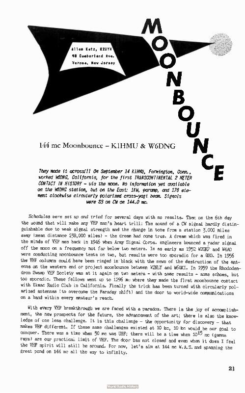
Allen Katz, K2t1Y11
48 Cumberland Ave.
Aft Olopem-0 N
o 144 mc Moonbounce - KIHNIU & \X16DNG N
CZ:They made it across/Il On September 14 Kiln, Farmington, Conn.,
worked WONG, California, for the first TRANSCONTINENTAL 2 METER
CONTACT IN HISTORY - via the mon. No information yet available on the M6ONG station, but on the East: 104 parcerp, and 176 ele-
ment clockwise circularly polarized cross-yagi berm. Signals
were S3 on CM on 144.0 mc.
Schedules were set up and tried for several days with no results. Then on the 6th day
the sound that will make any VHF man's heart trill: The sound of a CW signal hardly distin-
guishable due to weak signal strength and the change in tone from a station 3,000 miles
away ( mean distance 238,000 miles) - the dream had come true. A dream which was fired in
the minds of VHF men back in 1946 when Army Signal Corps, engineers bounced a radar signal off the moon on a frequency not far below two meters. In as early as 1952 W2GKP and W4A0
were conducting moonbounce tests on two, but results were too sporadic for a QS0. In 1956
the VHF columns could have been ringed in black with the news of the destruction of the ant-
enna on the western end or project moonbounce between W2NLY and WUKI. In 1959 the Rhododen-
dron Swamp VHF Society was at it again on two meters - with same results - some echoes, but
too sporadic. These fellows went up to 1296 mc where they made the first moonbounce contact with Eimac Radio Club in California. Finally the trick has been turned with circularly pol-
arized antennas ( to overcome the Faraday shift) and the door to world-wide communications on a band within every amateur's reach.
With every VHF breakthrough we are faced with a paradox. There is the joy of accomplish-
ment, the new prospects for the future, the advancement of the art; there is also the know-
ledge of one less challenge. It is this challenge - the opportunity for discovery - that
makes VHF different. If these same challenges existed at 10 kc, 10 kc would be our goal to
conquer. There was a time when 50 mc was UHF; there will be a time when 1015 mc ( gamma
rays) are our practical limit of VHF. The door has not closed and even when it does I feel
the VHF spirit will still be around. For now, let's aim at 144 mc W.A.S.and spanning the great pond on 144 mc all the way to infinity.
21
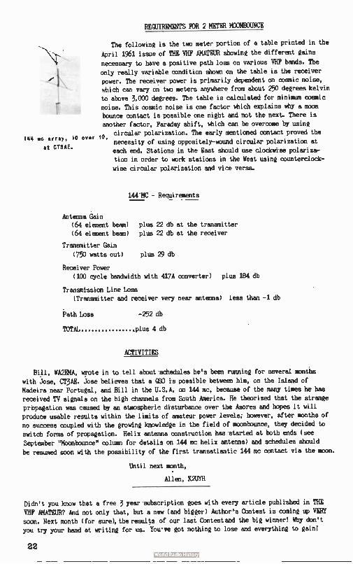
IM 4 mc array, 10
at CT3AE.
REQUIREMENTS FOR 2 METER MOONBOUNCE
The following is the two meter portion of a table printed in the
April 1961 issue of THE VHF AMATEUR showing the different gains
necessary to have a positive path loss on various VHF bands. The only really variable condition shown on the table is the receiver power. The receiver power is primarily dependent on cosmic noise, which can vary on two meters anywhere from about 250 degrees kelvin
to above 3.000 degrees. The table is calculated for minimum cosmic noise. This cosmic noise is one factor which explains why a moon bounce contact is possible one night and not the next. There is another factor, Faraday shift, which can be overcome by using
ovar circular polarization. The early mentioned contact proved the
10, necessity of using oppositely-wound circular polarization at each end. Stations in the East should use clockwise polariza-tion in order to work stations in the West using counterclock-
wise circular polarization and vice versa.
144"MC - Requirements
Antenna Gain (64 element beam) plus 22 db at the transmitter (64 element beam) plus 22 db at the receiver
Transmitter Gain
(750 watts out) plus 29 db
Receiver Power (100 cycle bandwidth with 417A converter) plus 124 db
Transmission Line Loss (Transmitter and receiver very near antenna) less than -1 db
Path Loss -252 db
TOTAL plus 4 db
ACTIVITIES
Bill, WA2EMA, wrote in to tell about schedules he's been running for several months
with Jose, CT3AE. Jose believes that a QUO is possible between him, on the Island of Madeira near Portugal, and Bill in the U.S.A. on 144 mc, because of the many times he has received TV signals on the high channels from South America. He theorized that the strange
prbpagation was caused by an atmospheric disturbance over the Azores and hopes it will produce usable results within the limits of amateur power levels; however, after months of no success coupled with the growing knowledge in the field of moonbounce, they decided to switch forms of propagation. Helix antenna construction has started at both ends ( see September lioonbounce column for details on 144 mc helix antenna) and schedules should
be resumed soon with the possibility of the first transatlantic 144 mc contact via the moon.
Until next month,
Alien, K2UVH
Didn't you know that a free 3 year subscription goes with every article published in THE
VHF AMATEUR? And not only that, but a new ( and bigger) Author's Contest is coming up VERY soon. Next month ( for sure), the results of our last Contest and the big winner! Why don't
you try your hand at writing for us. You've got nothing to lose and everything to gain!
22
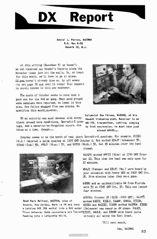
DX Report
Danlel L. Parries, WA2DMQ
P.O. Box 4132 Newark 12, N.J.
At this writing (November 5) we haven't as yet received any Reader's Reports since the November issue just hit the mails. So, at least for this month, we'll have to go it alone.
Tf y'," haven't already done so, by all means rip out page 29 and mail it today! Your support is sorely needed in this new endeavor.
The month of October seems to have been a
good one for the 144 mc gang. Many good ground
wave sessions were reported, at least in this area. One fellow snagged five new states. No specifics this month,however.
Columnist Dan Parnes, WA2DMQ, at his 50 mc activity was most unusual with excep- Newark listening post. Receiver is an
tional ground wave conditions, Sporadic-E open- 59-470. transmitter, Lettine. Judging
ings, and a never-to-be-forgotten aurora. One by that expression, he must have just thing at a time, though... missed W3ASD...
October seens to be the month of real short Sporadic-E openings. For example, K2IEZ
(N.J.) reported a quick opening at 1205 GMT October 6. Bob worked K5AJF ( Arkansas) 59, K9AAU ( Ind.) 59, W9BJP ( Wisc.) 59, and K8TGE ( Mich.) 58, but 45 minutes later the band
closed.
WA2QPC worked W9PIU ( Wise) at 1700 GMT Octo-
ber 22. This time the band was only open for
12 minutes.
WOAJX ( Kansas) and KOLFI ( Mo.) were heard by your columnist with heavy QSB at 0400 GMT Oct. 26. Five minutes later they were gone.
K4RNG and an unidentifiable W4 from Florida were 59 at 0345 GMT Oct. 27. This one lasted four minutes.
AURORA: October 28 ( 1630 -1900 ( MT). WA2F11 Meet Mark Welland, WA2TEM, also of worked K4DIG, K3GLU, K4CNF, KBUGA, K3ISH, Newark, New Jersey. Mark is 14 and runs K8UKA and WA2CEC. KlBEN worked WA2FRW. K3KED a Lettine 262 (45 watts) into a 652 meter (Delaware) was heard on AM phone. K4LHB, Finco antenna. Both converters are TenraftIOIHT, W4ULE, and K8MMM were heard quite feeding into a Lafayette NE- 10, strongly all alone the East Coast.
'Till next month,
Dan, WA2114Q 23
FREE Hi-Pass Filters!
Staff
The present day televisLA receiver is a wonderful example of American igenuity, design
and construction developed over a long period of years to its present state of perfection.
However, as is true with much mass produced apparatus it still leaves something to be des-
ired. One inherent shortcoming of most present television receivers, including the rela-
tively expensive color receivers, is their inability to reject a strong local radio signal.
These unwanted signals which the receiver permits to slip through may cause lines or streaks
either light or dark to appear on the picture screen or, in varying degrees, remove the
picture - or replace, in part or completely, the sound of the television program with that
of the amateur signal. Why? Because the TV is not designed or constructed to reject these emmissions.
In over seventy per cent of these cases the interception can be eliminated by the proper
installation of the correct High Pass Filteron the TV. In another 15% audio rectification can be solved quite inexpensively. One word of caution: There are many High Pass Filters
on the market, but not all filters will eliminate interception on frequencies between 44 and 52 mc.
If you are really interested in clearing local TV's of the problem ( with a FREE filter)
send the following information to the address given below:
1. Call of intercepted ham ( you).
2. Make ( manufacturer) of TV.
3. Request R.L. Drake TV-300-HP filter. 4. Year TV set was purchased.
5. Serial number of TV.
6. Model number of TV. 7. Type of antenna ( roof-top, rabbit ears, atic, built-in).
B. Name, address, phone number and SIGNATURE of neighbor.
It is imperative that the neighbor, not you, send a letter to the manufacturer with ALL
the above information. Especially important is the serial number and model number.
ADDRESSES OF TV MANUFACTURERS SUPPLYING FREE FILTERS
GENERAL ELECTRIC
116 Washington Street Bloomfield, New Jersey
MONTGOMERY WARD
19 Watchung Avenue
Plainfield, New Jersey c/o Mr. Plue
AEMIRAL
Admiral Distributors 497 N.J. Railroad Avenue Newark, New Jersey c/e Mr. Durante
MNITH Radio Corp. 6001 Dickens Avenue
Chicago, Illinois
B.C. A. RCA Service Co. Parkside Avenue
Trenton, N.J.
Or
RCA Service Cd.
1573 Irving Street Rahway, New Jersey
24
HOT POINT TV Service Department 254 Elizabeth Avenue Newark, New Jersey
MAGNOVOX
Magnovoz Corp.
Fort Wayne, Ind. c/o Mr. Chapman
PHIL) J.M. Otter Co. 2030 Upland Way
Philadelphia 31, Pa.
or
Fineberg's c/o Mr. Mauro 750 Dowd Avenue
Elizabeth, N.J.
EMERSDN
Emerson TV 14th and Cole Sts. Jersey City, N.J.
CAPEHART Capehart Parts Service Div.
454 William Street East Orange, New Jersey
WESTINGHOUSE Westinghouse Appliance Serv. 528 Ferry Street Newark, New Jersey Mr. Ballatine
ZENITH Zenith Radio Corp. 6001 Dickens Avenue Chicago, Illinois
DUMONT Igoe Brothers 524 W. 23rd Street New York, N.Y.
Or
Igoe Brothers
35 Halsey Street Newark, New Jersey
CBS- TV CBS Columbia 46 East 52nd Street New York, N.Y. c/o Mr. Reitano
or
Hygrade Electronics 9216 Church Avenue Brooklyn 36, N.Y.
CROSLEY BENDIX Philco Distributors -c/o Warranty Department 47-51 33rd Street Long Island City, N.Y. c/o Mr. J. Rigores
SPARTON Div. of Magnovox Corp.
c/o Mr. D.R. Barnett
Fort Wayne 4, Ind.
SYLVANIA Sylvania Electric Products, Inc. Radio & TV Division 700 Elliott Street Batavia, New York ( c/o Mr. E. Mooser)
or
Sales Service Department 1000 Huyler Avenue Teterboro, New Jersey
Although in nearly all the addresses given above the distributors are in the New York City area, we KNOW that they are reliable. They were compiled with the lists of
the Levittown TVI Committee, K2HFL, and KUSQ's TNT package. If you do have difficulty, however, give the information on the opposite page to your LOCAL agent. But first, by
all means, try our list. We've given these adresses to over 4,000 hams across the coun-try who by mail have secured free Drakes and a little sleep. Only 7 have reported diffi-culty. If you get a new address or further information, please write so we can revise our list. In the meantime, good luck!
SUBSCRIPTION The VHF Amateur
67 Russell Avenue
, Rahway. New Jersey
Name
Addmss
City
()ne Year $2.00 Two Years $3.50
fl Three Years $5.00 New fl Renewal
Sate
Call
Now in our fourth year. The UHF' Amateur has over
6,500 circulation in all 50 states and numerous foreign
countries! Published monthly by Bob Brown. K2ZSQ.
25
tee:raft
Cemtmitiertner,
Drm.e
Specializing in gear for 50 inc 6 above
Flirt
HY Gam
McGrath Electronics Box 913
Boulder, Colorado
Writer us woo - (tout wur 'retests or &reds
kg, IQ» Janyce, KOZUW Tœ, Wile
'ED AND(t11Ee RACK ISSUES FOR
SALE
25e Each Yes, he do have some old issues of THE VHF AMATEUR
available in limited quattities. We've been literally swamped with back issues requests lately, but we still hate some left.
1958 - SOLD OUT 1959 - SOLD OUT
1960 - August, September; October, and Noumeber.
1961 - January, February, Hare, April, September, Octo-ber, and November:
gr tar miner eimpiir c/u THE VHF AMATEUR
67 Russell Ave., Rahway, N.J.
26
.........,....,.,.
. 7 BE APPRECIATED!
e ¡ 1. Ou probably have several very near and dear
à friends who are also Hams...
e for whom expensive and elaborate Christmas gifts e this year are out of the question.
e ese IF SO, you're not alone! Thousands of Christmas e shoppers face the problem of what to get these friends
... while holding expenses within their budgets. V. tA SUBSCRIPTION to CQ and any of the Fine books ki! listed will be appreciated by those who receive it and
will be a reminder of your thoughtfulness throughout .1i
the year.
JaVE MONEY on your subscription as well as
your gifts.
eeeeeeeieWeieeejeeleefeedeiketeeeeeeee
CQ Magazine 300 West 43rd st. New York 36, N.Y.
One year, $5 Two years, S9 Three years, SI 3
in U.S. Possessions, APO & FPO. Canada & Mexico
co
D new Enclosed is $ for a year (3 renewal subscription to CQ, to be
sent to:
Name Call
Address
City Zone State Pan-America and all other forego: i yr. $6; 2 yrs. SU; 3 yrs. $ 16.
27
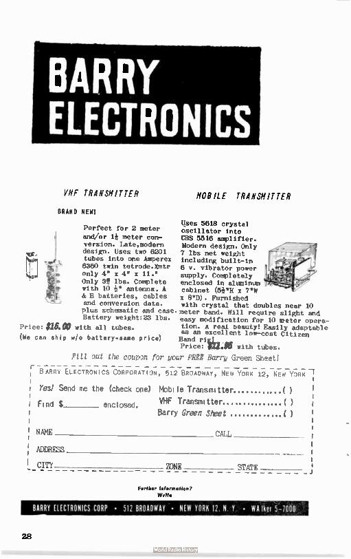
BARRY ELECTRONICS
VHF TRANSMIT TER
BRAND NEW!
Price: ;MOO (Ne can ship w/o battery- same price)
Perfect for 2 meter and/or 1* meter con-version. Late,modern design. Uses two 6201 tubes into one Amperex 6360 twin tetrode.Xmtr only 4" x 4" x 11." Only 3f lbs. Complete with 10 'le" antenna. A & B batteries, cables and conversion data. plus schematic and case. Battery weight:23 lbs.
with all tubes.
Ft11 out the coupon for you
B ARRY
I Find $
l NAME
ADDRESS
Cm
MOB ILE TRANSMITTER
Uses 5818 crystal oscillator into CBS 5518 amplifier. Modern design. Only 7 lbs net weight including built-in 6 v. vibrator power supply. Completely enclosed in aluminum cabinet (W8 x 7 "W x 8"D). Furnished with crystal that doubles near 10 meter band. Will require slight and easy modification for 10 meter opera-tion. A real beauty! Easily adaptable as an excellent low-cost Citizen Band rig.L. Price: eiiieD with tubes.
r FREE Barry Green Sheet!
ELECTRONICS CORPORATION, 512 BR1ADWAY, NEW YORK 12, NEW YORK
Ves! Send ne the (check one) Mbbile Transmitter...
VHF Transmitter.....
Barry Green Sheet enclosed.
CALL
STATE ZONE
Further Information?
Write
BARRY ELECTRONICS CORP • 512 BROADWAY • NEW YORK 12 N Y • WA her 5-100()
28
eWeadeij PWe/teet
Fill out and return to us today!
As an aid to both the Editor and to our new "DX Report" column, your assistance is
greatly needed. This page can be renovert from the magazine without damage to the contents.
If you like, make a facsimile. Of course, if you gain enough, ye Editor might
be tempted to send you a new pagazine if pages 3 & 4 also fall out. Enough trivia...
RETURN TO: Reader Report, c/o THE VHF AMATEUR
67 Russell Avenue, Rahway, N. J.
Your Name .Call
Address City State
What bands ( VHF) do you operate? mHow much power?
• What kind of antenna do you use?
'Do you operate MOSTLY ( ) AM, ( ) CW, ( I SS?
01 What was the furthest contact made in the last month?
mHow high above sea level?__
• When, if at all, have there been good GROUND WAVE conditions in your area. Also, to what
extent (how far)?
O Mork any new states recently (or during the Summer)?
• What are the most frequently heard DISTANT statIons?_
• Do you presently hold schedules with anyone?_
•Who do you know that seems to work out exceptionally kell in your area?
29
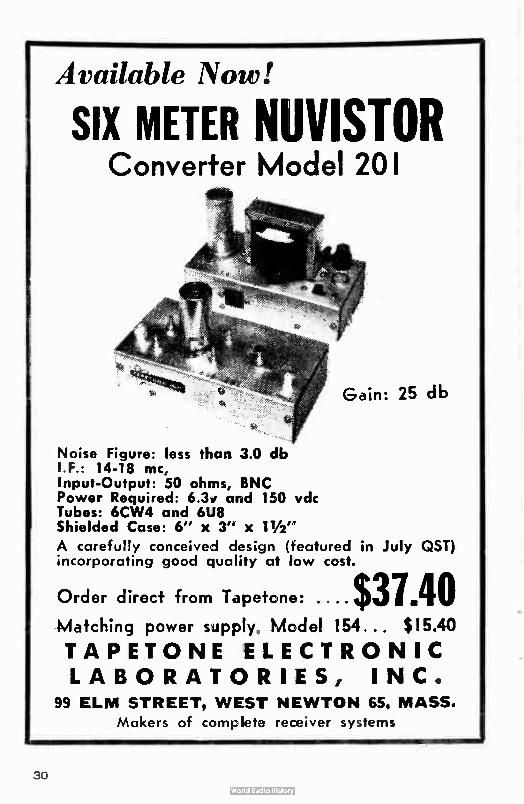
Available Now!
SIX METER NUVISTOR Converter Model 201
Gain: 25 db
Noise Figure: less than 3.0 db I F.: 14-18 mc, Input-Output: 50 ohms, BNC Power Required: 6.3i arid 150 vdc Tubes: 6CW4 and 6U8 Shielded Case: 6" x 3" x 1112"
A carefully conceived design (featured in July QST) incorporating good quality at low cost.
Order direct from Tapetcne: $31.40 Matching power seply Mcdel 154 .. $ 15.40
TAPETONE ELECTRONIC LABORATORIES, INC.
99 ELM STREET, WEST NEWTON 65. MASS.
Makers of completa receiver systems
30
Weepeeert
By Direct Mail Immediate delivery from stock!
SPECIAL: Clegg 99.cr with crystal mike and halo
antenna for $142.95! If you don't want our "package deal," deduct $16.95 and send a check or money order
for the 99'er alone. We'll ship immediately PREPAID.
SPEC/AL: Ameco nuvistor pre-amps, 6 or 2 meters,
S13.95 I we'll ship collect). OR, send us your check or money order and we'll ship PREPAID. ONE DOL-
LAR REFUND on prepaid orders.
.SPECIAL! Alliance rotor model U-98, $25.50. Alli-
ance rotor model T-12, $21.50. New matching thrust
hearing bracket, $3.50. By far the best buy in a rotor today! Send check, we ship PREPAID. 25% deposit
required on collect freight shipment.
EXTRA! Brand new National 105 receiver not yet even advertised! General coverage, "S" meter, etc.
Our price: $119.95 PREPAID for shipment from us
in early December.
TWO-WAY RADIO COMMUNICATIONS Dept. 12A
Mail Order Department 5, New 232-6 Ian Boulevard, Staten Island w York
Gibraltar 7-3660
1h• ?VI 4sgatede
67 RISSELL
RAHWAY, NEW JERSEY
T o:
U.S. POSTAGE
BULK RATE
PAID Rahway, N.J. Permit No.I26
Ilandale»ZWirl 305 Hamilton Rd.
Syracuse i?" N.Y.
Postmaster: FINIR, 3547 Requested a .
The ¡Few 111me Converter The GEM 2 meter converter uses a 6cw4 nuvistor as a stable
regenerative RF amplifier and is capable of a gain as high
as 60 db over a reference level of a neutralized triode
ampleifier.(6X8 ose. tripler mixer.) This small unit will
give maximum gain and sensitivity with low noise level.
Universal input and output. Standard I.F. 5-10 mc with in-
structions to changeI.F. Requires only 160V at 18 ma. Wir-
ed & tested on 2P' x 4" circuit board - ONLY $6.50 2 Meter stnéle nuvistor pre-amp. This unit will give up to 30 db gain & will reduce or eliminate cross-modulation.
Tuned input and output. The very small size ( only 2Pt 2") allows unit to be used in restricted space. Ideal for Gonsets, etc. Wired and tested less tube ONLY $4.50. Re-
quires 0-50V at 4ma.
6 meter caseode (2 6CW4's) pre-amp. 20 db gain. Size (only 2e x 2") will allow unit to fit in smallest space like the HQ-110 or converters. Requires 0-100V at 8 ma.
Wired and tested less tubes ONLY $5.50. The 6 meter orinted circuit converter uses a 61311/027 as a cascode R.F. amplifier
and n 6X8 High Gain oentode mixer and oscillator , This converter will give a good slg-
nal-to-nnise ratio and maximum sensitivity and I.F. outout. The circuit uses very 111-Q
air wound coils and the broadband oscillator will accept crystals from 40 to 50 mc for
any I.F. output. Wired and tested for only 16.50 All items sent Post-Paid in aâuanrc.
OEM ELECTRONICS R. R. 3, Springfield, Ohio

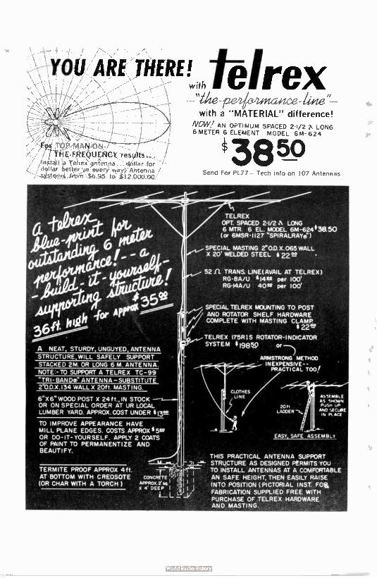
&vex epeazce-&'ie
with a "MATERIAL" difference! NOW , AN OPTIMUM SPACED 2-1/2 7% LONG 6 METER 6 ELEMENT MODEL 6M-624
For" ITOP-111AN-ON.-/
7-firiÈ:FRE(WEle4CY -
:entelVa .for bettur In everY,way,l/ Ainerma /
,,,,, tqm.a_trorli $6.95 to ez000:00/
TELREX 175R1S ROTATOR-INDICATOR SYSTEM 8198%) or —
ARMSTRONG METHOO INEXPENSIVE- - , PRACTICAL TOO!
6X6' WOOD POST X 24 f t., IN STOCK OR ON SPECIAL ORDER AT UR LOCAL LUMBER YARD. APPROX.COST UNDER 813V,
TO IMPROVE APPEARANCE HAVE MILL PLANE EDGES. COSTS APPROX * 692 OR DO-IT-YOURSELF. APPLY 2 COATS OF PAINT TO PERMANENTIZE AND BEAUTIFY.
THIS PRACTICAL ANTENNA SUPPORT - STRUCTURE AS DESIGNED PÈRMITS you
TO INSTALL ANTENNAS AT A COMFORTABLE CONCRETE AN SAFE HEIGHT THEN EASILY RAISE
APPROX INTO POSITION ( PICTORIAL INST. FoLL L g X 4. DEEP I FABRICATION SUPPLIED FREE WITH PURCHASE OF TELREX HARDWARE AND MASTING.
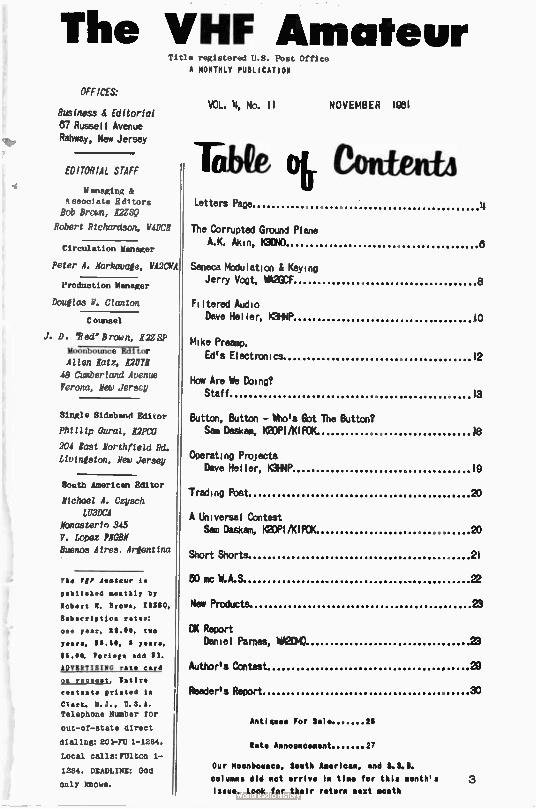
The VHF Amateur Title registered U.S. Post Office
A MONTHLY PUBLICATION
OFFICES:
Business & Editorial 87 Russell Avenue Rahway, New Jersey
EDITORIAL STAFF
Managing &
associate Editors
Bob Brown, I2ZSQ
Robert Richardson, W40C11
Circulation Manager
Peter A. Narkovale, WA2CMA
Production Manager
Douglas N. Clanton
C otmsel
J. D. 'Red" Brown, 1122SP
Moonbounce Editor
Allen Batz, 121171
48 Cumberland Avenue Verona, New Jersey
Single S1deband Editor
Phillip Oural, L2FtV
204 last Northfield Rd.
Ltviniston, New Jersey
South American Editor
Michael A. Czysch LO3DCA
Monasterin 345 F. Lopez PNGBN Buenos Aires. Argentina
The MP Amateur I.
pablIsked monthly by
Robert N. brown, ESZSQ.
Sabacripttos rat..:
pee year. SS.00, two
a , SS 60, I y ,
$6.00. Porte.. odd SI
IDVSITISING rate card
ow realest, Satire
deatests printed la
Clark. N.J.. U.S.A.
Telephone Number for
out-of-state direct
dialing: 201-FU 1-1284,
Local calls:FUlton 1-
1284. DEADLINE: God
only knows.
VOL. 4, No. 11 NOVEMBER 1951
TabQo&ContPAttA Letters Page
The Corrupted Ground Plane A.K. Akin, K3DNO
4
8
Seneca Modulation & Keying Jerry Vogt, WAUF 8
Filtered Audio Dave Heller, K3HNP JO
Mike Preamp. Ed's Electronics 12
How Are We Doing? Staff 13
Button, Button - Who's Got The Button? Sem Deskam, K2OPI/K1POK 18
Operating Projects Dave Heller, K3HNP 19
Trading Post 20
A Universal Contest Sam Daskam, K2OPI/KIFCK 20
Short Shorts. 21
50 mc W.A.S 22
New Products. 23
DX Report Daniel Parnes, W121/10
Author's Contest
23
20
Reader's Report 33
Antiques For Sale 26
Rate A nnnnn cement 27
Our Moonbounce, South American, and S.S.S.
columns did not arrive In time for this month's
Issue. Look for their return nest month
3
LETTEIZS PAGE
Address all correspondence to "Letters Page," VHF AMATEUR, 67 Russell Avenue, Rahway, N.J.
"Crystal Controlled" ... AND r.lett on frequency!
An article by ROPY appeared in the September ' 61 issue of this magazine which got my
dander up. Titling his article, 'Crystal Controlled...BUT right on frequency?' he boldly
stated that the accuracy of a crystal is based on its marked frequency. From this he con-
cluded ( from heretofore unknown mathematics) that the ' percentage of error in a rock Is mul-
tiplied by the multiplier that you use in your transmitter.' This statement is absurd.
For example, let us take a crystal for .two meters. Our mutual friend who is still opera-
ting in a special class of service buys a rock at 8.000 mc with a percentage error of .005%.
This means that the rock can be anywhere between 7.9996 mc and 8.0004 mc (neglecting temper-
ature drift, input capacitance, etc.). If the rock is exactly at 8.000 mc it will multiply to
144.000 mc ( factor of 18). If we assume the rock if off by . 005%, we will have a frequency
range of 143.9928 mc to 144.0072 mc after multiplication. This is a deviation of 7.2 mc from
the desired frequency, or 18 times the . 4 kc deviation which we had at 8 mc. BUT IT IS STILL
A PERCENTAGE ERROR OF ONLY . 005%.
7.2 kc
144,000.0 kc . .00005 = . 005% You may check the math if you wish.
Thus, while the deviation has been increased 18 times, the percentage error has remained
the same. This is because you are multiplying not only the crystal deviation, but also the
center frequency. Thus when you compute your percentage error, you will always come up with
the original percentage error of the rock, regardless of WHAT, your multiplier Is.
In conclusion, we would like to say that we are not condemning W8BPY's article ( in its
entirety). He brought out some very important points that many hams forget, such as the input
capacitance of their rigs. We just wanted to calm down the jangled nerves of the people who,
by now have multiplied . 005% by 18 and come up with the erronious deviation percentage of . 08.
So you see, Mr. Baylis, we DO know our frequency.
- Joe Fabula, WA2NSA, Bayonne, New Jersey
Fverythtng's Cooing Up Roses
-1 just received my first Issue of the VHF AMATEUR and have scanned through it.
1 do want to compliment you on the magazine. I find it much more interesting than DST be-
cause your magazine is devoted entirely to VHF while the other covers everything from soup to
nuts, and at this stage of the game I am more interested in VHF than anything else.
Wishing you all the luck in the world in your venture and with best regards to all the gang
there in Rahway, 1 am
- Sidney S. Jaffe, WAZDYC, West Orange, New Jersey
FLASH! 11.0-May nconbounce QS0 on 2 meters between KIIIMU and WONG on September 14. Details
later:
4
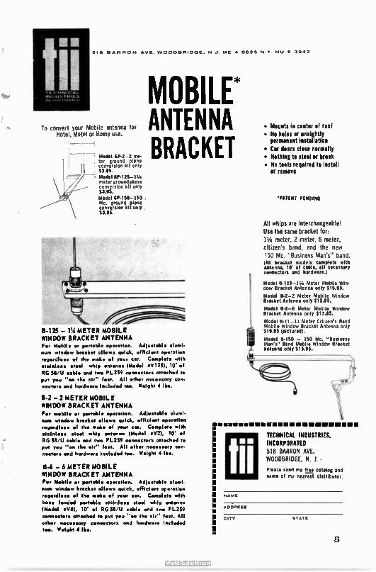
tí í 518 BARRON AVE WOODBRIDGE. N J ME 4 00,1 NY M1.1 J ,,4 1
To convert your Mobile antenna for Hotel, Motel or Home use.
M• odel GP-2-2 me-ter ground plane conversion kit only $3.95. M• odel GP-125-1 14 meter ground plane conversion kit only $3.95. Model GP- 150-150 Mc. ground plane conversion kit only $3.95.
B-125 — METER MOBILE WINDOW BRACKET ANTENNA For Mobile or portable operation. Adlustabl• alurnl-
nurn window bracket allows quick, efficient operation
regardless of tha moka of your car. Complete with
stainless ••••1 whip antenna ( Model « V125), 10' of
PG 58'U cable and two PL259 connectera attach•d to
put you " on the al." fee. All other n•ce•sary con-e's/cep, and hardware Includ•d too. Weight 4 lb..
MOBILE* ANTENNA BRACKET
B-2 — 2 METER MOBILE WINDOW BRACKET ANTENNA For mobile or portable op•ration. Adlustoble alum!.
new window bracket allows quick, toffici•nt operation
net/cordialoo of th, mak• of your car. Complet• with ',aimless steel whip antenna ( Model «V2), 10' of
PG 58'U ' able and two PL259 conn•ctors attached to
put you " on the oir" fast. All other necessary con n•ctor• and hardware Inrlud•d too. W•ight 4 lbs.
8-6 — 6 METER MOBILE WINDOW BRACKET ANTENNA For Mobil• or portable operation. Adlustabl• alumi -
num window bracket allows quick, •fficient operation
regardless of the mole• of your car. Complete with
bos• loaded portable stainless steel whip antenna
(1,4od•I eV6), 10' of PG 58 U cabl• and repo PL259
connectors attached to put you " on the air" fast. All
other n•cmary conn•ctors and hardwor• Included too. Weight 4 lb..
• Mounts in center of root
• No holes or unsightly permanent installation
• Car doors close normally • Nothing to steal or break • No too:s required to install
or remove
•PATENT PENDING
All whips are interchangeable!
Use the same bracket for:
11/4 meter, 2 meter, 6 meter, citizen's band, and the new
150 Mc. " Business Man's" band. All bracket models complete with Antenna, 10 of cable, all necessary connectors and hardware.)
Model 13-125-1 1/4 Meter Mobile Win. dow Bracket Antenna only $15.95.
Model 13-2-2 Meter Mobile Window Bracket Antenna only $15.95.
Model 13.6-6 Meter Mobile Window Bracket Antenna only $17.95.
Model B-11-11 Meter Citizen's Band Mobile Window Bracket Antenna only $19.95 (pictured).
Model B-150 — 150 Mc. " Business Man's" Band Mobile Window Bracket Antenna only $15.95.
lii MM IMIUMMBRIM
TECHNICAL INDUSTRIES,
INCORPORATED 518 BARRON AVE WOODBRIDGE, N 1 •
Please send me free catalog and name cf my nearest distributor.
NAME
ADDRESS
CITY STATE
5
The WW1,
Ground Plane A. Kenneth Akin, Jr., K3DMO
7413 Oak Lane
Chevy Chase 15, Maryland
Most of us are familiar with the ground plane and it's virtues; stacked ground planes
have been used by commercials for years to provide gain without directivity. The mechanical
problem of stacking four, eight, or more of these antennas has stopped hams from using them.
Cross-polarization is not the problem that some people say it is on 6 or 2; it may become one
on UHF, but that isn't our concern at this time. Any gain lost on VHF frequencies is made up
for by ease of assembly, economy, and trouble-free operation.
Let me state right now that the secret of the corrupted ground plane is wire, the most
common commodity in radio. No tubing, rods, or peeled back coax - just wire. The only thing
you might not have is a tall object to hang it from. If a 120 foot pine has been soaking up your power, make the tree work for you! Hang a set of stacked ground planes from it.
The basic antenna is shown in Figure 1. On the ground plane, if the radials are placed
parallel to the coax the antenna has an impedance of 72 ohms - no matching troubles with 72
ohm coax. Use at least four radials, equally spaced around the coax and all the same length.
Tape down the radials at several points, suspend the vertical element from a handy spot, and you're in business.
You can use any kind of wire that will hold the weight of the coax, but plastic covered wire is needed for the stacked models. Because you're using wire and not à inch tubing, a 4 wave length is longer than the charts would lead you to think. To find the length of a à wave
length of wire use the formula: 5905 X à. freq. in mc
..This adds up to about 2 inches on 6 meters, hence it is worthwhile.
The stacked model is best explained by Figure 2. The tops of the radials are soldered to the central wire and are completely insulated from it for the rest of their length. Tape down the radials about every foot to keep them in place.
The single section model is best suited for portable work because it can be rolled up and
tucked into a corner when not in use. When needed it can be easily be hung from any single point.
The by far most intriguing use for the stacked ground plane is Field Day. All you need is
a large weather balloon and a tank of gas. One bay at 50.5 mc is just under 10 feet; go to 20 feet and get 3 db gain, 40 feet and 6 db gain, 80 feet and 9 db, etc. A stacked ground plane
of 64 bays would be 640 feet tall and have 18 db gain. I'll stick to mp 'Lone-John' eel! -8D.
Words of caution: The higher the power, the better the insulation will have to be. Anything
higher than immediate surroundings is susceptible to lightning problems. Even on a clear day a
tremendous static can build up - Install a VHF RF choke between the center conductor and the
ground. Also, take the usual precautions ( try a Blitz Bug) for equipment protection.
6
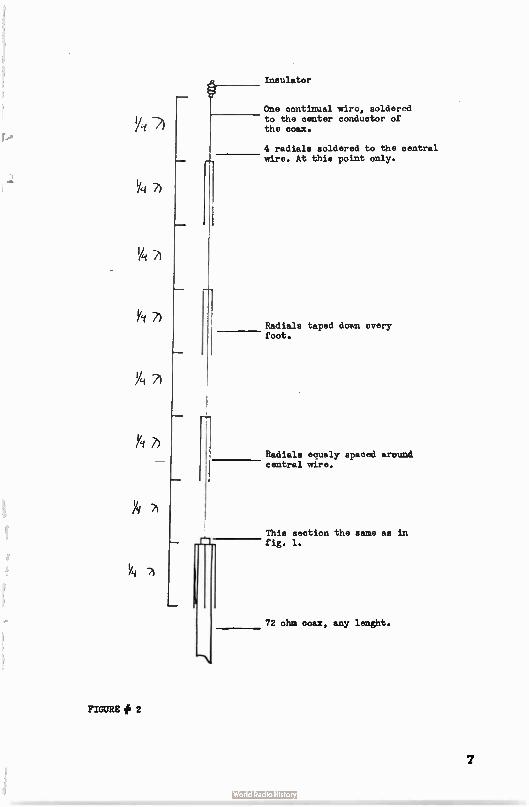
Insulator
One continual wire, soldered to the center conductor of the coax.
4 radials soldered to the central wire. At this point only.
Radials taped down every foot.
Radials equaly spaced around central wire.
This section the same as in fig. 1.
72 ohm coax, any lenght.
""\
FIGURE # 2
7
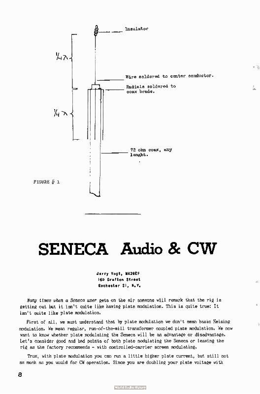
Insulator
Wire soldered to center conductor.
Radinls soldered to coax brade.
-7\
72 ohm coax, any lenght.
FIGURE e
SENECA Audio 8c CW Jerry Vogt, WA26CF
160 Grafton Street Rochester 21, N.Y.
Many times when a Seneca user gets on the air someone will remark that the rig is
getting out but it isn't quite like having plate modulation. This is quite true: It
isn't quite like plate modulation.
First of all, we must understand that by plate modulation we don't mean basic Heising
modulation. We mean regular, run-of-the-mill transformer coupled plate modulation. We now
want to know whether plate modulating the Seneca will be an advantage or disadvantage.
Let's consider good and bad points of both plate nodulating the Seneca or leaving the
rig as the factory recommends - with controlled-carrier screen modulating.
True, with plate modulation you can run a little higher plate current, but still not
m much as you would for CW operation. Since you are doubling your plate voltage with
8
100% modulation you cannot run the Seneca at as high a level of plate current as on CW because you would exceed normal plate dissipation by doing so. In practice, you can
run the 6146's at 140 watts, plate modulated, however, many tricks have been employed such as changing your final plate feed-through capacitor and usine forced-air cooling. Heath, however, frowns on this since it still exceeds published ratings on 6146's in
push-pull.
When running the Seneca with plate modulation, you can always watch the average
plate current on the meter which now would remain steady. You would also have an advantage inasmuch as your signal would always be "covering the noise level" more than with screen
modulation as Heath uses. These are a few of the reasons for using external plate modula-tion. Before running out to buy an Eico modulator, though, look at the advantages of
playing with the screen modulation Heath says is more practical... it
The major reason for leaving the screen modulation alone in the Seneca is probably
the best-money. The second reason is almost as good-time and temper, maybe even a new rig.
When using the Seneca as is, I have found that it has a certain punch to it that no amount of clipping or speech compression in a plate modulator can deliver. This is due to
the fact that you will nearly fully modulate the carrier you have at any instant during the talk cycle. That is to say that since the carrier power varies with speech, your voice will cause enough modulation of carrier available at that instant to give "solid modula-tion" of what power there is instantaneously. Since no form of clipping is employed to
get this punch, no distortion occurs as it does when a high level of speech clipping is used. This seems to me to be a definite advantage over plate modulation. This punch is
especially useful on aurora openings where the "mush" of the reflection seems to swallow the signal. The punching effect on controlled-carrier modulation will get through when no others can. This can be seen in SSB also where the carrier is not important but where the modulation pulls through because of its punch. A Seneca can be tuned in during an aurora opening as a sideband station would be and the effect is much the same. When a plate modulated station is tuned in the same way, however, the carrier is much more steady and therefore the "mushneeffect has a greater action on the modulation.
These aren't all the pros and cons on the subject, but are to be considered seriously before making a decision about it. I have been plate modulating my Seneca for about five months with an Eico model 730 modulating and have gotten the expected good results with the mess of cables, relays and the like that accompany the conversion. I might add, though,
that I've gone back to screen modulation recently and find good results with the same conditions including DX. For those interested in plate modulating the Seneca, you will be surprised how easily it may be done. In fact, if the Editor speaks up quick, I just might write up the conversion, since I am still not entirely against it.
CY FOR THE SENECA - 50 NC
For the CW man on 6, here is good news for you! A simple modification on the Seneca will give you keying which may even work...It consists of changing the key from the usual
method to keying of the triode section of the 6AN8 which acts as a multiplier. It will reduce receiver blocking and reduce the possibility of clamp tube oscillation.
The step-by-step instructions:
Refering to pictorial 015, page 42, of the manual, install a . 001 uf capacitor between lugs 01 and 04 on socket V-9. Next install a small 06 solder lug under the mounting nut adjacent to lug 04 of the same socket. Place it close to lug 0 4 and solden This will pre-vent the clamp tube oscillation which may have occurred.
Remove the lead between pin 7 of V-10 and ground lug on V-11. Install insulated lead from V-10, pin 7 to terminad strip GG-4.
Refering to pictorial 18, page 52, install . 005 uf disc capacitor between lugs 01 and 3 on terminal strip DD. Disconnect the negative lead of the 40 uf capacitor from the ground
9
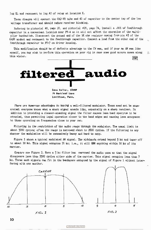
lug GL and reconnect to lug #2 of relay at location K.
These changes will connect the 0A2-VR tube and 40 uf capacitor to the center tap of the low
voltage transformer and should reduce receiver blocking.
Refering to pictorial #8, page 20, and pictorial #29, page 74, install a . 001 uf feedthrough
capacitor in a convenient location near FT-4 so it will not affect the operation of the multi-
plier bandswitch. Disccnnect the ground end of the 1K ohm resistor coming from pin #3 of the 6AN8 socket and reconnect to the feedthrough capacitor. Connect a lead from the other end of the
feedthrough capacitor to FT-7 on driver housing.
This modification should be of definite advantage to the CW man, and if your an AM man like
myself, you may wish to perform this operation on your rig in case some good aurora comes along
this winter.
filtered audio
Dave Heller, K311111, 14 Darkleaf Lane
Levittown, Penn.
.41F1
There are numerous advantages to having a well-filtered modulator. These need not be enum-
erated; everyone knows what a sharp signal sounds like, especially on a sharp receiver. In
addition to providing a cleaner-sounding signal the filter causes less band spectrum to be
occupied, thus permitting legad operation closer to the band edges and causing less annoyance
to those operating on frequencies close to your own.
Filtering is the restriction of the audio range through the modulator. The usual limit is
about 3000 cycles; often the range is narrowed about to 2600 cycles. If the filtering is any
sharper the modulation will be excessively bassy and hard to copy.
Figure 1 shows a typical modulated AM signal. The sidebands extend beyond 5 kc and taper off to about 10 kc. This signal occupies 20 kc; i.e., it will QRM anything within 10 kc of its
carrier.
Compare now Figure 2. Here a 3 kc filter has narrowed the audio pass so that the signal
disappears less than 3500 cycles either side of the carrier. This signal occupies less than 7 kc. Three such signals can fit in the bandspace occupied by the signal of rgure 1 without inter-fering with one another.
CA PPIEI?
FIG . 1
o
FIC). 2
10
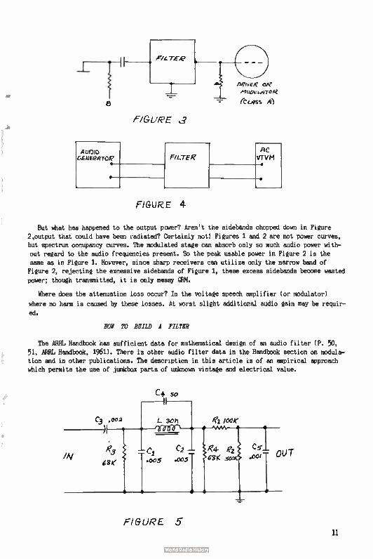
FIGURE ,1
Aunto Gamemrog,
•
•
FILTER AC VTVM •
FIGURE 4
•
But what has happened to the output power? Aren't the sidebands chopped down in Figure
2,output that could have been radiated? Certainly not! Figures 1 and 2 are not power curves, but spectrum occupancy curves. The modulated stage can absorb only so much audio power with-out regard to the audio frequencies present. So the peak usable power in Figure 2 is the
same as in Figure 1. However, since sharp receivers can utilize only the narrow band of Figure 2, rejecting the excessive sidebands of Figure 1, these excess sidebands become wasted
power; though transmitted, it is only messy Œ(M.
Where does the attenuation loss occur? In the voltage speech amplifier ( or modulator)
where no harm is caused by these losses. At worst slight additional audio gain may be requir-
ed.
BOW TO BUILD A FILM?
The ARRL Handbook has sufficient data for mathematical design of an audio filter ( P. 50,
51, ARRL Handbook, 1961). There is other audio filter data in the Handbook section on modula-tion and in other publications. The description in this article is of an empiricad approach
which permits the use of junkbox parts of unknown vintage and electrical value.
C4 50
FIGURE 5 11
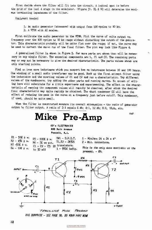
First decide where the filter will fit into the circuit. A logical spot is before the grid of the last A stage in the modulator. ( Figure 3). RL & RG will determine the maxi-
mum terminating impedances of the filter.
Equipment needed:
1. An audio generator ( sinewave) with output from 100 cycles to 10 kc.
2. A VTVM with AC scales.
First calibrate the audio generator to the VTVM. Plot the curve of volts output vs. frequency over the 100 cycles to 10 kc range without disturbing the output of the genera-
tor. This characteristic probably will be quite flat over the range; if not, the curve may
be used to correct the curve run of the final filter. The plot may look like Figure 4.
A generalized filter is shown in Figure 5. Far more parts arc shown than will be neces-
sary in any single filter. The essential components are L, Cl and C2. The remaining parts
may or may not be necessary to give the desired characteristic. The parts values shown are only starting points.
Find an iron core inductance which you suspect has an inductance between 10 and 100 henry.
One winding of a small audio transformer may be good. Hook up the first attempt filter using
the inductance and the starting values of Cl and C2 and run a characteristic. Try different
values of the condensers; try adding the other parts and running curves. No amount of writ-
ing here will substitute for a little experience and experimenting. The effect on the charac-
teristic of varying the component values will rapidly be observed, after which the desired
final characteristic may quite rapidly be obtained. The shunt condenser CC will have the
effect of reducing the peak in the curve at a frequency just before cutoff. This condenser, if used, should be quite small.
When the filter is constructed measure its overall attenuation - the ratio of generator output to filter output. A ratio of 2:1 equals 6 db; 4:1, 12 db; 8:1, 18plb, etc.
R1 - 51K w.
82 - 15K w.
R3 -51K w.
84 - 10K w.
Mike Pre-Amp ED's ELECTRONICS 935 Mein Avenue
Passaic, N.J.
VHF
R5 - 820K w. SW1 - S.P.S.T. 1 - Minibox 24 x 24 x 4"
86 - 3K ww pot. T1,T2 - 2N321 2 - Hic, connectors.
Cl - C2 - C3: 20 transistors. to 30 mfd 1 - 9V00 batty. This ts the only data available at the
present. - RD.
Ti
Cl imPUT 0
3C#ZE0:4,
SPUT C stuf
R4
Tee/Iv.,3 7.4,R Mixr fieEAme
BIG SURPRISE — SEE PAGE 30. DO YOUR PART NOW
C3
1---0 - OUTPUT
T2
R6
12
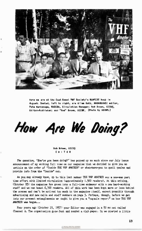
Here we are at tas East Coast VHF Society's HAMFEST back in
August. Seated, left to right, are Allen Katz, MOONBOUNCE editor,
Pete Markavage, MAUNA, Circulation Manager: Bob Brown, K2ZSQ,
Editor—fublisher: ant " Red" Brawn, K2231", ( Photo by K3HAP.)
How Are We Peke Bob Brown, K2ZSQ
EDITOR
The quest bon, "Rolo've you been doing?" has popped up so much since our July issue announcement of my working full time on our magazine that we decided to give you an article an the order of "Inside THE VHF AMATEUR' or what-have-you to quell qualms and provide info from the "Inside" out.
As you may already know, up to tais last summer THE VHF AMATEUR was a one-man part
time effort with limited circulation ( approximately 1,500 readers). At this writing, (October 15) the magazine has grown into a full-time endeavor with a new hard-working staff and we can boast 6,700 readers. All of this work has been kept more or less behind the scenes and can't be noticed too much in the magazine itself, except possibly through advertising and new calls and staff members on page 3. Perhaps, though, before we get into our present entanglements we ought to give you a "capsule report" on how THE VHF AMATEUR was begun...
Four years ago ( October 21, 1957) your Editor was engaged in a 50 mc net called
Channel A. The organization grew fast and needed a club paper. So we started a little
13
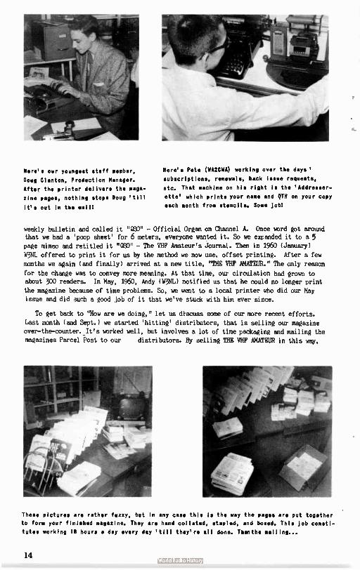
Here's our youngest staff member,
Doug Clanton, Production Manager.
After the printer delivers the maga-
zine pages, nothing stops Doug ' till
it's out in the mail!
Here's Pete ( WA2CWA) working over the days '
subscriptions, renewals, back issue requests,
etc. That machine on his right Is the ' Addresser-
ette' which prints your name and 9TH on your copy
each month from stencils. Some job!
weekly bulletin and called it "OSO" - Official Organ on Channel A. Once word got around that we had a ' poop sheet' for 6 meters, everyone wanted it. So we expanded it to a 5 page mimeo and retitled it "OSO" - The VHF Amateur's Journal. Then in 1960 ( January)
W3NL offered to print it for us by the method we now use, offset printing. After a few
months we again ( and finally) arrived at a new title, "THE VHF AMATEUR." The only reason
for the change was to convey more meaning. At that time, our circulation had grown to about 300 readers. In May, 1960, Andy ( W3NL) notified us that he could no longer print
the magazine because of time problems. So, we went to a local printer who did our May
issue and did such a good job of it that we've stuck with him ever since.
To get back to "How are we doing," let us discuss some of our more recent efforts.
Last month ( and Sept.) we started ' hitting' distributors, that is selling our magazine
over-the-counter. It's worked well, but involves a lot of time packaging and mailing the
magazines Parcel Post to our distributors. By selling THE VHF AMATEUR in this way,
These pictures are rather fuzzy, but in any case this is the way the pages are put together
to form your finished magazine. They are hand collated, stapled, and boxed. This Job consti-
tutes working 18 hours a day every day ' till they're all done. Then the mailing...
14
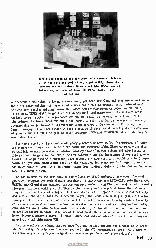
Here's our booth at the Syracuse VHF Roundup on October
7. On the left ( seated) K2ZSP, right KSHMP, along with a
beloved new subscriber. Those areAt big QSL's hanging
behind us, but some of Dave ( K3H1111's license plate
collection!
we increase circulation, enjoy more readership, get more articles, and snag new advertisers.
The distributor mailing job takes about a week and a half at present, and, combined with the one week regular mailing, means that after the printer gives us pages for an issue, it takes us THREE WEEKS to get them all in the mail. And somewhere in those three weeks we have to get another issue prepared ( which, in itself, is no easy matter) and off to the printer. He takes about two and a half weeks to print it. So, perhaps you can see why
occasionally we get behind or a September issue arrives in October - hi! Problems, prob-lems! Someday, if we ever manage to make a buck,we'll have the whole thing done proffession-ally and spend all our time getting after delinquent SSB and MOONBOUNCS editors who forget
about deadlines.
For the present, at least,we're all penny-pinchers.We have to be. :he expenses of runn-ing even a small magazine like this are sometimes insurmountable. Since we're working with
no capital, we must depend on a regular, healthy flow of subscriptions and advertising to tide us over. To give you an idea of the relationship and the importance of carrying adver-tising, if we printed this November issue without any advertising, it mould only be 5 pages total. So, you see, advertising pays for the magazine. For every new full page ad, we can
add three pages of text. So if ads drop, pages drop. Endless vicious circle. But so far we've
made it without mishap.
So far no mention has been made of our writers or staff members...here Qoes. The small
group of Rahwayans who work closely together on a day-by-day are K2:7.4!-ZSP, Pete Markavage, WA2CWA, our Circulation Manager, and our youngest member, Doug Clanton. Doug is not presently licensed, but he's working at it. This is the closely knit group that forms the nucleous (Boy do I murder the King's English!) of our staff. But, in spite of the constant activity and hustle, the whole thing still depends on you, the reader. We must give you a VHF maga-zine you like - or we're out of business. All our articles are writzen by readers ( usually who we've never met) who take the time to sit down and write about what they've been doing,
what they've built, etc. Most articles are written by fellow VHF'ers who've never written an article before in their life, but still want to do their part. So we have to add a coma here, delete a sentence there - So what! Isn't that what an Editor's for? We can always use more info - and this means YOU!
Let us conclude by adding that we love VHF, and we like putting out a magazine to serve the fraternity. Drop by sometime when you're in the NYC meteropolitan area - we'd love to meet you in person, get your suggestions, and show you ' what we've been doing'!.
CI!! 15
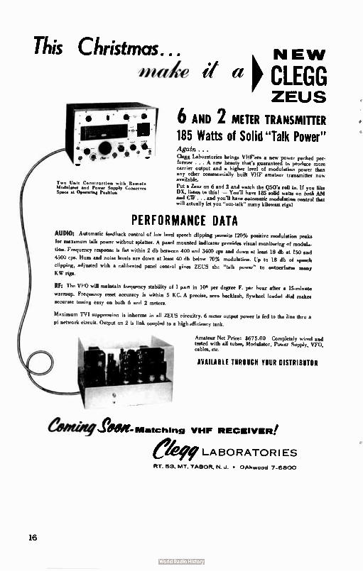
This Christmas... ma4e if a
s • lk •
.01111 -117.. sa e 111)Il 941I Wi
Two Unit Construction with Remote Modulator and Power Supply Conserves Spurr at Operating Position
k NEW p CLEGG ZEUS
6 AND 2 METER TRANSMITTER 185 Watts of Solid " Talk Power" Again . . . Clegg Laboratories brings VIIF'ers a new power packed per-former ... A new beauty that's guaranteed to produce more carrier output and a higher level of modulation power than any other commercially built VHF amateur transmitter now available.
Put a Zeus on 6 and 2 and watch the QS0's roll in. If you like DX, limes to this! — You'll have 185 solid watts on both AM and CW and you'll have automatic modulation control that will actually let you "outtalk" many kilowatt rigs!
PERFORMANCE DATA AUDIO: Automatic feedback control of low level speech clipping permits 120% positive modulation peak,
for maximum talk power without splatter. A panel mounted indicator provides vinual monitoring of modula-
tion. Frequency response is flat within 2 db between 400 and 3400 cpe and down at leu! 18 db at 150 and
4500 cps. Hum and noise level. are down at least 40 db below 70% modulation. Up to IS db of speech
clipping, adjusted with a calibrated panel control gives ZEUS the "talk power" to ontoerform many KW rige.
RF: The V1.0 will maintain frequency stability of 1 part in 106 per degree F. per hour after a 15-minute
warmup. Frequency reset accuracy is within 5 KC. A precise, zero backlash, flywheel loaded dial makes accurate tuning easy on both 6 and 2 meters.
Maximum 'FYI suppression is inherent in all ZEUS circuitry. 6 meter output power in fed to the line thru •
pi network circuit. Output on 2 in link coupled to a high efficiency tank.
Amateur Net Price: 8675.00 Completely wired and tested with all tubes. Modulator, Power Supply, VFO. cables, en
AVAILABLE THROUGH YOUR DISTRIBUTOR
aWeigeSeee- Matching VHF RECEIVER!
LABORATORIES
RT. 53, MT, TABOR, N J. • OAkwood 7-6800
16
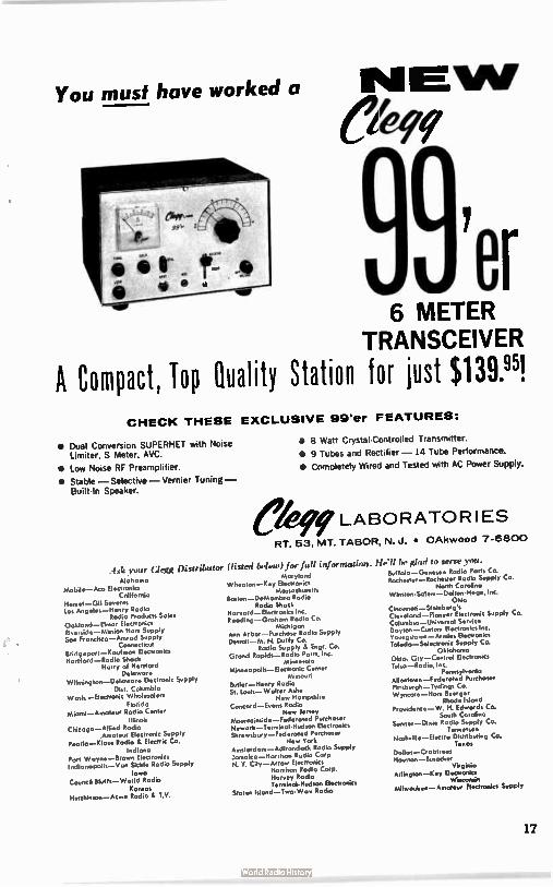
• Dual Conversion SUPERHE1 with Nu'C
Limiter, S Meter, AVC.
• Low Noise RF Preamplifier.
• Stable — Selective — Vernier Tuning — BuildIn Speaker.
You must have worked a
6 METER TRANSCEIVER
R Compact, Top Quality Station for just $139.95! CHECK THESE EXCLUSIVE 99'er FEATURES:
• 8 Watt Crystal-Controlled Transmitter.
• 9 Tubes and Rectifier — 14 Tube Performance.
• Completely Wired and Tested with AC Power Supply.
LABOR ATOR I ES
RT. 53, MT. TABOR, N. J. • OAkwood 7-6800
.44k your Clegg Distributor (listed below) for full information. be glad to serte you.
Alabama Mobile—Ana Electronics
California Hemet—Gil S Los Angeles—Henry Rodio
Radio Products Soles Ookland—Elinar Electronics Riverside— Mission Ham Supply San Froncisco—Amrad Supply
Casnecticut Bridgeport—Koufmon Electronics Hartford — Radia Shock
Hairy of Hartford Delaware
Wilmington—Delaware Electronic Supply Dist. Columbia
Wash.—Electronic Wholesalers Florida
Miami—Amateut Radio Center Illinois
Chicago—Allied Radio .Amateur Electronic Supply
Peoria—Klaus Radio ti. Electric Co. Indiana
Fort Wayne—Brown fie.... Indianapolis—Von Sickle Radio Supply
Iowa Council Bluffs—World Radio
Konsos Hutchinson—Aane Rodio I.V.
Maryland Wheaton—Key Electronics
Mossaeh.etts flosion—DeMombro Radio
Radio Shock Harvard—Electronics Inc. Reading —Grahorn Rodio Co.
Michigan Ann Arbor—Purchase Radio Supply Detroit—M. N. Duffy Co.
Radio Supply & Engr. Co. Grand Rapids—Radio Parts, Inc.
Minnesota Minneapolis— Electronic Center
Missouri Butler—Henry Radio St. louis— Wolter Ashe
Nao Hampshire
Concord—Evans Radio New Jersey
Mountainside—Federoled Purchaser Nework—Terminal-Fludson Electronics Shrewsbury—Federated Purchaser
New York Anaterdorn—Adirondock Radio Supply Jamaica—Harrison Radio Corp N. Y. City—Arrow Electronics
Harrison Radio Corp. Harvey Radio Terminal-Hudson Electronics
Staten Island—Two-Wait Radio
Buffalo—Genesee Radio Parts Co. Rochester— Rochester Radio Supply Ca.
North Carolina Winston-Solent— Dolton- Meg*, Inc.
Ohio Cincireati—Steinberg's Cleveland—Pioneer Electronic Supply Co. Columbus—Universol Service Dayton—Custom Electronics Inc. Youngstown—Armies Electronics Toledo—Seleeronic Supply Co.
Oklahoma Okla. City—Central Electronics Tulso—Radio, Inc.
Pennsylvonio Allentown—Federated Purchaser Pittsburgh—Iydings Co. Wyncote—Horn Buerger
Rhode Island Providence— W. H. Edwards Co.
South Carolina Sumter—Dixie Radio Supply Co.
Tennessee Noshville—FJectra Distributing Co.
Texas Dallos—Crobtrees Flousion—Busacker
Virginio Arlington—Key Electsonics
Wisconsin Milwaukee— Amateur Electronics Supply
17
Button, Button,
WHO's GOT TH BUTTON?
Samuel W. Daskam, KROPI/K1POK R.D. # 1
Lebanon, New Jersey
After having to build several VHF converters, preamps and just plain amplifiers, I
realized that I had been forced into using a component which I knew practically nothing about. This expensive ( except surplus, of course) but necessary item is the button capaci-tor, and its relatives, the feed-thru and stand-off capacitor. A little investigation was made and the following facts uncovered.
First let's cover the button feed-thru types. These are of the silver-mica variety.
They are usually made by stacking silvered mica plates in a brass housing which has been
silver plated. The circular design allows the RF current to be passed to ground from all points, providing the shortest possible path between the center conductor and the chassis.
This puts very little of the lead inductance in series with the RF as happens with an ordin-
ary disc capacitor. The dielectric strength is usually tested at 1250 volts DC, but the max-
imum working voltage is 350 volts AC pr 500 volts DC. The button types are generally avail-able in capacitances values from 15 to 4700 pf. Usually these units are soldered to the chassis, so it is very difficult to use these with an aluminum chassis.
The threaded-bushing and eyelet feed-thrum have about the same electrical characteristics
as the button. The main difference is the fact that no chassis soldering is needed since a
mechanical grip is made by a hex nut. The peak test voltage on these types is 1250 volts and
the DC working voltage is 500 volts. The ranges available for the threaded bushing type is
4 to 8500 pf and for the eyelet type 2 to 1550 pf. Care must be taken with these two types as too much lateral strain on the leads may break the ceramic insulation. When soldering to the
leads, use as little heat as possible to prevent damage.
The stand-off capacitors come in three varieties; the button, threaded, and push-on. These are excellent for by-passing filaments to ground and also serve as tie-points for other com-
ponents. The DC working voltage of these types is also 500 volts. The button style has values
from 15 to 4700 pf, the threaded from 1 to 2500 pf, and the push-on is obtainable in capaci-tances from 10 through 1500 pf.
Figure 1 shows the frequency characteristics of three types of capacitors previously des-
cribed. The dips occuring at the higher frequencies are due to resonances from the lead induc-
tance, etc. Although these curves were made using Erie Resistor Corporation capacitors, it is assumed that other makes would be equally as good.
A partial listing of the advantages of these types of capacitors is as follows:
1. The lead inductance is mostly in series with the DC path to ground.
2.Rigid mounting gives greater mechanical stability and avoids variations in the capacitance to ground.
18
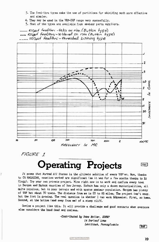
3. The feed-thru types make the use of partitions for shielding much more effective and simpler.
4. They may be used in the VHF-UHF range very succesfully.
5. Most of the types are available from amateur parts suppliers.
ieed+hrL. cu rim (8Li 4licrl -type-) ica,y_r( ecciihet. - se klerect cn rim (F5,.i-kn
/C4C441 Pee:dew-Li - tIreid iype
i
2
.5
/..L
2
5
Jo
le
5C
e* — _.... _ %
N ( ... ...e',.,••• - • • - a
• -, !:e.
.
lel
4'.- • • li‘
a 0,1 • •
1 e .
Y
•
50 2c0 roc
Fie--CLEWCy /A/ Ala
F/G -C 1
/000
Operating Projects
/0KNIC
It seems that Worked All States is the ultimate ambition of every VHF'er. Now, thanks to CQ MAGAZINE, counties worked are significant ( as it was for a few months thanks to Ed
Clegg). Try your own private project. Mine right now is to work and confirm every town
in Bergen and Hudson counties of New Jersey. Hudson has only a dozen munincipalities, all
quite populous, but in poor terrain and with sparse amateur population. Bergen has plenty
of VHF but about 70 towns. The distance from me is 65 to 85 miles. The project isn't easy, but the list is growing. The real question is whether I can work Edgewater. First, no hams. Second, at the bottom ( and away from me) of a steep cliff.
Devise a project like this. It will provide a challenge and good contacts when everyone else considers the band dead and useless.
-Contributed by Dave Heller, MHO
14 Durleaf Lane
Levittown, Pennsylvania
19
TRADING P9r. 11 RATES: Commercial ads - 5e per word. FREE to readers - any reasonable length. Ads from
readers MUST BE SUBMITTED ON A POSTCARD or QSL card. TRADING POST, 67 Russell, Rahway, N.J.
WILL TRADE: Scatter signals from Oregon on 50.02 mc for scatter signals from the Midwest.
K7AAD, Route 2, Box 35, Beaverton, Oregon.
K3H1P: Wants your old license plates. Don't forget him! 14 Darkleaf Lane, Levittown, Penn.
QSL's, SWL's, PHOTO's: NICHOLAS & SON PRINTERY, P.O. BOX 11184, PHOENIX 17, ARIZ. 2/62
BUY-SELL-TRADE: Cameras, lenses, telescopes, amateur radio equipment. Denson Electronics,
Box 85, Rockville, Conn.
FOR SALE: 850 Z-50 RF chokes. New and clean.10 for $1.50. Entire lot $85. HE-10 receiver
and 6 meter converter - $75. A. Fagans, W2SHU, 158 Jefferson Avenue, Rahway, New Jersey
FOR SALE: Zeus for sale. Write or call ( after 5 PM) Manny Forte, K2UQC, 425 Parkinson Terrace, Orange, New Jersey.
FOR SALE: DX-40, built in CW monitor - $35.00 works FB. Also JT 30 mike - $3.00. 110 VAC coax relay - $7.00. Curt Dansa, K2ZJW, 302 S. Union Avenue, Cranford, N.J. BRidge 6-8623.
MAKE AN OFFER: I have four 3X2500F3 tubes, made by Eimac. Jim Overheul, KBYZP, 323 Pine,
Paw Paw, Michigan.
WANTED: Manual for APX-6. Also information on the tubes it takes. Fred Coleman, W5UW,
703 Bull Lane, Missouri City, Texas.
SALE OR TRADE: Two RCA 833A transmitting tubes. New. Gerard A. Baldauf, W3JKH, 175
Wernersville Blvd; Wernersville, Pa.
PROJECTS& KITS WIRED! Cash only. Kit 25% of cost ( above that of unit) - wired and checked out. Projects ( custom built) materials, and prints or schematics must accompany all orders. George Kupp, K2DQT, 61 Cortlandt Street, Belleville 9, New Jersey.
WANTED: Write-ups on equipment you're building. Running short of technical articles. And,
they'll be more author's contests with more BIG prizes next month. Write NOW to: THE VHF AMATEUR, 67 Russell Avenue, Rahway, New Jersey.
A 'Universal' Contest Samuel W. Daskam, K2OPI/KIPOK
R.D. BI, Lebanon, N.J.
One of the problems with attampttne to create activity in the average club is that any one project is usually limited in interest. This is mostly due to the great spread in the frequencies worked by individual members.
Described here is a contest which was designed not only to create activity, but also to
be equally fair to every member regardless of license, power or location. In the end, it will usually turn out that the hardest working operator wins.
20
The contest is described by the rules as used by the West Jersey Radio Club:
1. Members not present at the initial drawing may draw their slips at any subsequent
meeting. 5 different counties will be picked from the slips in the box by each participa-ting member. If a member draws the county in which he resides, the slip will be returned
to the box and another slip drawn. The drawing will be such that the names of the counties
cannot be seen by the drawing member. After recording his "counties", the slips will be re-turned to the box prior to the next member drawing.
2. Contest starts immediately after the drawing of slips.
3. Only members with 2/3 or more of their current dues paid up are eligible.
4 Any or all amateur bands and modes of transmission may be used if valid under the member's license privileges.
5. All contacts must be made from the member's QIE, as stated on his license. No contacts
from or to mobile or portable stations may be counted. Exception: stations operating from a new QTH awaiting change of address from FCC.
6. The winner will be the first member who submits QSL cards to the Activities Chairman at a club meeting confirming 2-way contact with his 5 counties during the contest.
7. The member with the earliest postmarked cards will be the winner in case of a tie.
8. The contest will end at 2400 hours at the end of 90 days. In the event no member has receiv-
ed all 5 cards, the winner will be the firstest with the mostest.
9. Prizes -
M. Any possible situation not covered by these rules will be ruled upon by a committee of three chosen by the Activities Chairman.
Most of the loopholes have been plugged especially by rule 10. There are ruthless and
devious means of working your counties, but scheduling is generally frowned upon. The counties were selected by drawing a circle of 100 miles radius on a map and including all
counties which have their county seat within the circle.
It was found that up through two meters the contest will be fair to all members. The
hardest part for the low band operators is getting the contact to OSL. Another rule should be added to avoid operation during weekends when a nation-wide contest is scheduled on any band.
If you think this is a snap contest, get your club to run it and try to win. You'll
soon find that calling "CC Wayne County, Pa." is not the right bait to offer and sneakier means must be employed. The winners in the first WJRC contest were as follows:
(First) Brand A 6 & 2 meters
(Seoond) Brand B 80 meters (Third) Brand X 6 meters
The 80 meter operator would have been the winner if he could have gotten all of his
QSL cards from his contacts. Credit for help in working out the rules and plugging loop-holes goes to the club Activities Chairman - Bob Johnsen, W2SLZ.
SHORT SHORTS
This item came in to late for "Trading Post" but we still wanted to get it in...
POR SALE: Custom made ceramic ash tray ( green, brown, or white). Your handle and call letters in gold. Only $5. Choctaw Ceramics, Jim, K5ZTH, R.R. 1, Box 14K, Choctaw, Okla.
21
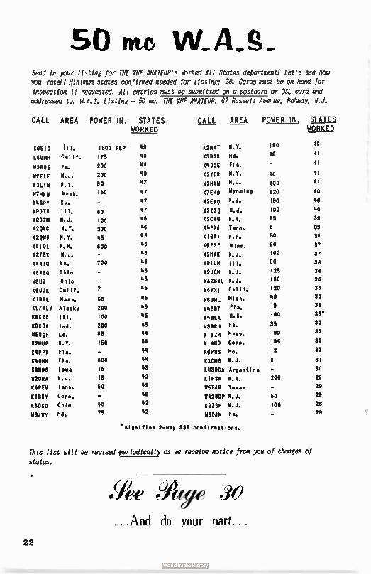
50 nie W. S. Send in your listing for THE VHF AMATEUR's Worked All States department! Let's see how you retell Minimum states confirmed needed for listing: 28. Cards must be on hand for
inspection if requested. All entries must be submitted on a postcard or 0SL card and
addressed to: W.A.S. Listing - 50 mc, THE VHF AMATEUR, 67 Russell Avenue, Rahway, N.J.
CALL AREA POWER M. STATES CALL AREA POWER M. STATES WORKED WORKED
K9E1D Ill.
K6umm Calif.
W3RUE Pa.
W2EIF N.J.
K2LTW N.T.
W7MKW Wash.
10111PY KY.
K9DT8 Ill.
K2DZM N.J.
K2QVC N.Y.
KMID N.Y.
K5IQL N.M.
K2ZEIX N.J.
K4870 Va.
K8RE6 Ohio
Ohio
K6UJL Calif.
KIBIL Maas.
KL7AUV Alaska
K91(18 Ill.
101(01 Ind.
11511QR La.
K2M1111 N.Y.
K4PPX Fia.
K41PIN Fla.
CONOS inma
W2ORA N.J. meep,/ Tenn.
Kim Conn.
Kum Ohio
W3JWY MN.
1500 PEP 49 K2MXT N.Y. 180 42
175 48 63606 Md. 40 41
200 48 11199E Fla. 41
200 48 K2VDR N.Y. 90 41
90 47 W2HVW N.J. 100 41
150 47 K7EMO Wyoming 120 40
- 47 W2EAQ N.J. 190 40
80 47 K2ZSQ N.J. 100 40
100 46 K2CV13 N.Y. 65 39
200 46 K4PXJ Tenn. 8 39
45 46 61081 N.H. 50 38
600 46 KOPSF Minn. 90 37
- 46 K2HAK N.J. 100 37
700 46 K9IUM Ill. 90 36
46 K2UGH N.J. 125 36
45 WA2BBU N.J. 160 36
7 45 xevyi Calif. 120 36
50 45 nun Mich. 40 99
200 45 K4EBT Fla. 19 33
100 45 K4RLX N.C. 100 33'
200 45 WSBRU pa. 35 32
85 44 II 1 1 21,1 Masa. MO 32
150 44 CIADO Conn. 195 32
44 KOPWS Mo. 12 32
600 44 K2C140 N.J. 8 31
16 48 LU3DCA Argentina - 30
16 42 K1PSR N.H. 200 29
50 42 W58J8 Texas 29
42 29 WA28DP N.J. 50 45 42 K2ZSP N.J. 100 28 75 42 W3DJM Pm. 28
"signifies 2-way 556 confirmations.
This list will be revised periodically as we receive notice from you of changes of
status.
Yee War 30
...And do your part...
22
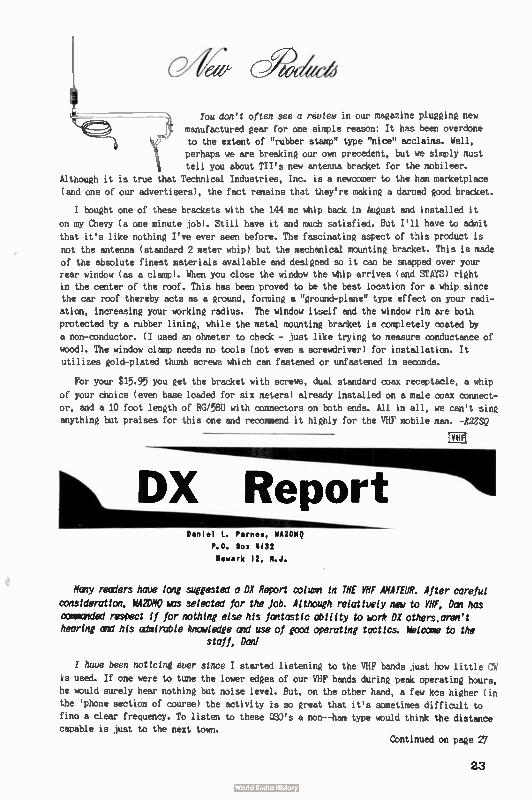
4 You don't often see a review in our magazine plugging new manufactured gear for one simple reason: It has been overdone
7 . to the extent of "rubber stamp" type "nice" acclaims. Well,
perhaps we are breaking our own precedent, but we simply must \ tell you about TII's new antenna bracket for the mobileer.
Although it is true that Technical Industries, Inc. is a newcomer to the ham marketplace
(and one of our advertisers), the fact remains that they're making a darned good bracket.
I bought one of these brackets with the 144 mc whip back in August and installed it
on my Chevy ( a one minute job). Still have it and much satisfied. But I'll have to admit
that it's like nothing I've ever seen before. The fascinating aspect of this product is
not the antenna ( standard 2 meter whip) but the mechanical mounting bracket. This is made of the absolute finest materials available and designed so it can be snapped over your rear window ( as a clamp). When you close the window the whip arrives ( and STAYS) right in the center of the roof. This has been proved to be the best location for a whip since the car roof thereby acts as a ground, forming a "ground-plane" type effect on your radi-
ation, increasing your working radius. The window itself and the window rim are both
protected by a rubber lining, while the metal mounting bracket is completely coated by
a non-conductor. ( I used an ohmeter to check - just like trying to measure conductance of
wood). The window clamp needs no tools ( not even a screwdriver) for installation. It
utilizes gold-plated thumb screws which can fastened or unfastened in seconds.
For your $15.95 you get the bracket with screws, dual standard coax receptacle, a whip
of your choice ( even base loaded for six meters) already installed on a male coax connect-
or, and a 10 foot length of RG/58U with connectors on both ends. All in all, we can't sing
anything but praises for this one and recommend it highly for the VHF mobile man. -Z2ZSQ
Daniel L. Pernee, WA2DMQ
P.O. Box 4132 Newark 12, N.J.
rF-1 1
Hany reoiers have long suggested a DX Report oolumn in THE VHF AMATEUR. After careful
consideration, NA2De was selected for the Job. Although relatively new to VHF, Dan has
commie respect if for nothing else his fantastic ability to BIDr* DX others,aren't hearing and his oimirable knowledge and use of good operating tactics. Meccas to the
staff, Dan!
I have been nottctn( ever since I started listening to the VHF bands just how little CW
is used. If one were to tune the lower edges of our VHF bands during peak operating hours,
he would surely hear nothing but noise level. But, on the other hand, a few kcs higher ( in
the ' phone section of course) the activity is so great that it's sometimes difficult to
fino a clear frequency. To listen to these QSO's a non--ham type would think the distance capable is just to the next town.
Continued on page 27
23
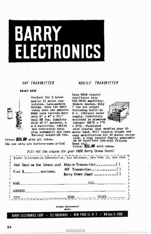
BARRY ELECTRONICS
VHF TRANSMITTER
BRAND NEW!
Perfect for 2 meter
and/or 1* meter con-version. Late,modern design. Uses two 6201 tubes into one Amperex 8360 twin tetrode.Xmtr only 4" x 4" x 11." Only 3f lbs. Complete with 10 e antenna. A & B batteries, cables and conversion data. plus schematic and case. Battery weight:23 lbs.
Price: $15.X with all tubes.
(Ne can ship w/o battery- same price)
MOBILE TRANSMITTER
Uses 5618 crystal oscillator into CBS 5518 amplifier. Modern design. Only 7 lbs net weight including built-in 6 v. vibrator power supply. Completely enclosed in aluminum cabinet (5¡"11 x 7"W x 8"D). Furnished with crystal that doubles near 10 meter band. Will require slight and easy modification for 10 meter opera-tion. A real beauty! Easily adaptable as an excellent low-cost Citizen Band ri&L. Price: f2J.40 with tubes.
Fill out the coupon for your FREE Barry Green Sheet!
BARRY ELECTRONICS CORPORATION, 512 BRADWAY, NEW YORK 12, NEW YORK 7
Yee Send me the (check one) Mobile Transmitter ...( )
Find $ enclosed. VHF Transmitter.... Barry Green Sheet ( )
NAME CALL
ADDRESS
CITY ZONE STATE
Fog-Hier Information?
Write
BARRY EtECTRONICS CORP • 512 BROADWAY • NEW YORK 12 N Y • WA her 5-1000
24
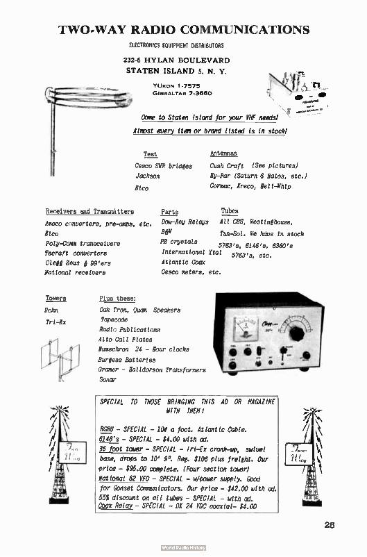
TWO-WAY RADIO COMMUNICATIONS ELECTRONICS EQUIPMENT DISTRIBUTORS
232-6 HYLAN BOULEVARD
STATEN ISLAND 5, N. Y.
YUKON 1-7575
GIBRALTAR 7-3660
Come to Staten Island for your VHF needs!
Almst every item or brand listed is in stock!
Test
Cesco SYR bridges
Jackson
Etc°
Receivers and Transmitters
Ameco canverters, pre-amps, etc.
Rico
Poly-Comm transceivers
Tecraft converters
Clegg Zeus d 99'ers
National receivers
Towers
Rohn
Tri -Ex
Parts
Dow-Xey Relays
BJW
PR crystals
Antennas
Cush Craft (See pictures)
Hy-Par (Saturn 6 Halos, etc.)
Cormac, Kreco, Hell -Whip
Tubes
All CBS, Westinghouse,
Tun-Sol. We have in stock
5763's, 6146's, 6360's International Xtal 5763's, etc.
Atlantic Coax
Cesco meters, etc.
Plus these:
Oak Tron, Quam Speakers
Tapecode
Radtn Publications
Alto Call Plates
Numechron 24 - Hour clocks
Burgess Batteries
0,-amer - Halldorson Transformers
Sonar
r-
SPECIAL TO THOSE BRINGING THIS AD OR MAGAZINE WITH
RGell - SPECIAL - loe a foot. Atlantic Cable.
6146's - SPECIAL - $4.00 with ad.
36 foot tower - SPECIAL - In-Ex crank-up, swivel
base, drops to 10' 9". Reg. $106 plus freight. Our
price - $95.00 complete. (Four section touer)
National 62 VFO - SPECIAL - u/pcndgr supply. Good for Gbnset Cómmunicators. Our price - $42.00 with ad.
55% discount on all tubes - SPECIAL - with ad. Coax Relay - SPECIAL - De 24 VDC coaxial- $4.00
25
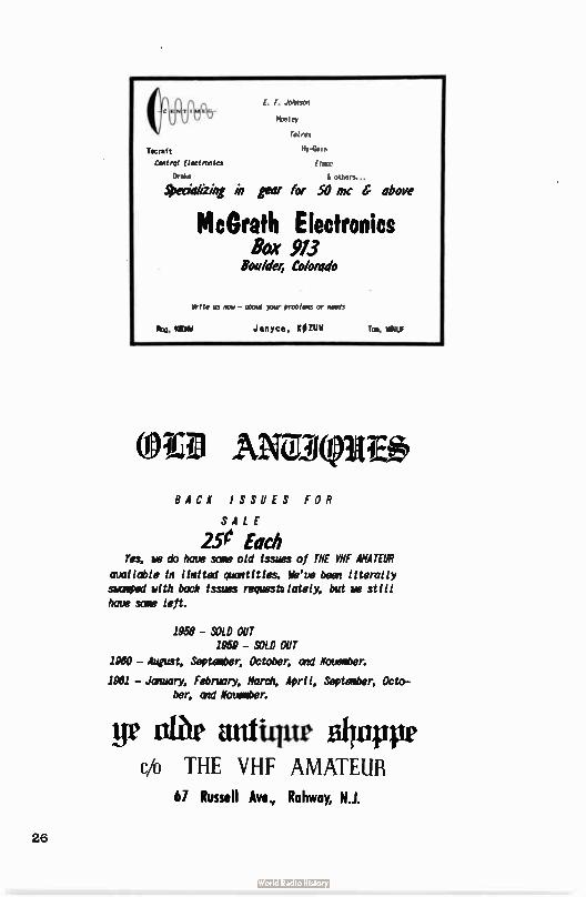
1. F. Janson
Mosley
Tal,,,
Tecraf t Hy-GaIn
Central Eitotronics Elmo
Drake &others...
Specializing in gear for 50 mc 6 above
McGrath Electronics Box 913
Boalder, Colorado
Write its «at - atout par problem or needs
kg, WM Janyce, KOZUW fat, belUf
*ID ANDX@IREe BACK ISSUES FOR
SALE
2.5e Each Yes, we do have some old issues of THE VHF AMATEUR
available in limited quaitities. We've been literally summed with back issues request» lately, but re still have some left.
1958 - SOLD OUT 1959 - SOLD OUT
1980 - August, September, October, aid November.
1981 - Jenuary, February, Marc?,, April, September, Octo-ber, and November.
ge tar antique Blirappe c/o THE VHF AMATEUR
67 Russell Ave, Rahway, N.J.
26
DX REPORT - Continued from p-23 Just why isn't CW used more often? That's hard to answer. On our bands above 50 mc
CW is by far the most practical for DX while at the same time less expensive. Al emission
is used to work DX because it can cut through Œ(M and be heard more easily even in high
noise level areas. The very few who do use CW are usually working DX stations that just
simply cannot be worked on phone ( try AM double-hop to Arizona from New Jersey and
you'll see what I mean). Our latest moonbounce record, K1HMU-W6DNG on 144 mc, couldn't
possibly have been accomplished at S3 levels on AM. Yet this and almost all our famous
VHF history-making events ( e.g. KH6UK-W6NLZ's 144, 220 and 432 mc efforts) were established on CW.
A Sporadic E 6 meter opening isn't for an instant the only time to put your key to
work. During ordinary band conditions a regular "Ce on CW might bring back some really
rare ground wave contacts. Use that first 100 kc more often, and watch your W.A.S. climb!
Leaving this subject fairly well worn, we ought well discuss another item: this
column. This is the first of a series that will appear in THE VHF AMATEUR every month.
Aside from editorial comments, this space will contain reports of what is going on
DX-wise across the country, what's being heard at your 0TH, and any news you think might
interest your fellow VHF men. To acquire all this information single-handedly would be
darned near impossible. The only way we can do a comprehensive job is to get reports and
letters from you. As per a suggestion by Earl Witt, K2OrD, of Syracuse, we talked Editor
Bob into relinquishing a page every month for you to rip out and send to him. He'll get ' em up to me after jotting down separately anV remarks that might concern the maga-
zine as a whole. SEE PAGE 30!
73 for now,
Dan.
etiffrriti &ttfielg feeeie re hed del eee
, 1er ?wed?
Effective next month: 35e a copy With next month's December issue, our single copy cost will increase from
25 to 3Ee at our 102 distributor's countereacross the country. This raise in price was necessary due to the added cost of shipping bundles and mailing
costs. But subscriptions are still the same cost. And they'll stay the same regardless. Write us about special club discounts.
[VHF!
SUBSCRIPTION The I1 I' mai eu
67 Russell 1N Milt'
\d`h Jerse
Name
()ne Year $2.00 D rr,,, Years $3.50 D Three Years $5.00
New ' Renewal
State
27
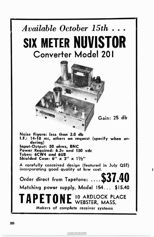
Available October 15th . . .
SIX METER NUVISTOR Converter Model 201
Noise Figure: less than 3.0 db I.E.: 14-18 mc, others on request ( specify when or-
dering) Input-Output: 50 ohms, BNC Power Required: 6.3v and 150 vdc Tubes: 6CW4 and 6U8 Shielded Case: 6" x 3" x 11/2,,
A carefully conceived design (featured in July QST) incorporating good quality at low cost.
Order direct from Tapetone: .... $31.40 Matching power supply, Model 154... $ 15.40
TAPETONE 10 ARDLOCK PLACE WEBSTER, MASS.
Makers of complete receiver systems
28
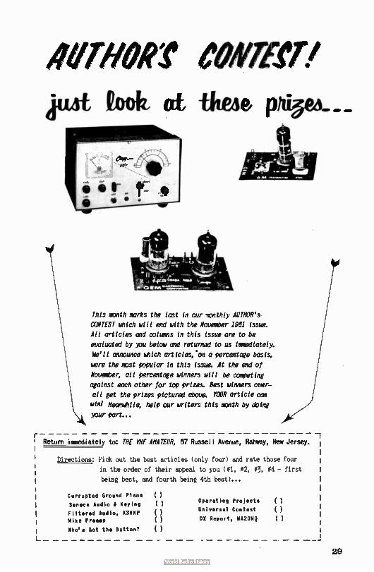
omen meet pie foolz at fbekie
This manth marks the last in our manthly AUTHOR's
CONTEST ketch will end with the November 1961 issue.
All articles and columns in this issue are to be
evaluated by you below and returned to us hymeliately.
We'll announce ketch articles:on a percentage basis,
were the mist popular in this iSSIM: At the end of
November; all percentage winners will be competing
against each other for top prizes. Best winners over-
all get the prizes pictured above. YOUR article can
win! Meanwhile; help our writers this math by doing
your part...
Return immediately to: THE VHF AMATEUR, 87 Russell Avenue, Rahway, New Jersey.
Directions: Pick out the best articles ( only four) and rate those four
in the order of their appeal to you (#1, #2, 03, 04 - first
being best, and fourth being 4th best)...
Currupted Ground Plane
Seneca Audio & Keying
Filtered Audio, K3MNP Mike Preamp
Who's Got the Button?
( ) ( ) ( ) ( ) ( )
Operating Projects ( )
Universal Contest ( )
DX Report, WA2DMQ ( )
_
29
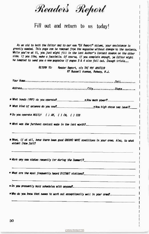
Ceadeîj PWe
Fill out and return to us today!
As an aid to both the Editor amid to our new "DX Report" color, wur assistance is greatly needed. This page can be removed frum the magazine without damage to the contents. While you'rm at it, ou Just might fill in the last Author's Contest coupon on the other staMt If you like: make a facsimile: Of course. if you complain enough, ye Editor might be tempted to send wu a new pagazine if pages 3 ti 4 also fall out. Enough trivia—.
RETURN TO: Reader Report, c/o THE VHF AMATEUR 67 Russell Avenue, Remy, N.J.
Your Nara Call
Address City State
• tat bands ( VHF) do you operate? Oar much power?
• What kind of antenna do you use? »How high aboue sea leuel?
• Do you operate MOSTLY ( JAM, ( CV. ( I SS8
• What WS the furthest contact made in the last manth?
m When, If at all, have there been pad cue WAVE conditions in )our area. Also, to lee extant (how far)?
• War* any new states recently (or during the Stemmed?
▪ eat are the most frequently heard DISTANT stations?
• Do wu presently hold schedules with crowned
•Ilho do )ou Rim that seems to mork out exceptionally well in >our area?
30
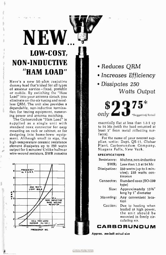
LOW- C O ST,
NON-INDUCTIVE
"HAM LOAD" Here's a new 50-ohm resistive dummy load that's ideal for all types of amateur service— fixed, portable or mobile. By switching the "Ham Load" into your antenna circuit, you eliminate on-the-air tuning and need-less QRM. The unit also provides a dependable, non-inductive termina-tion for testing equipment, measur-ing power and antenna matching. The Carborundum "Ham Load" is
supplied as a single unit with standard coax connector for easy mounting on rack or cabinet, or for designing into home-brew equip-ment. Although small in size, the high-temperature ceramic resistance element dissipates up to 250 watts output for 5 minutes! Unlike bulbs or wire-wound resistors, SWR remains
lo
9
7
6
5
_FREQUENCY es. v 5 WR
200 WATT LIGHT BOLO
50a NON IN WIRE WOUND
, RESISTOR_
Y ir
50/1 MAU LOAD GLOBAR HL -CC-i ,
lO 20 30
FREQUENCY MC
54
• Reduces QRM
• Increases Efficiency
• Dissipates 250 Watts Output
$ 75* 2 only *Suggested Retail
essentially flat at less than 1.5:1 up to 54 Mc (with the load mounted at least 5" from metal reflecting sur-faces).
For the name of your nearest sup-plier, write: Dept. QS-11, Clobar Plant, Carborundum Company, Niagara Falls, New York.
SPECIFICATIONS
Resistance:
SWR: Dissipation:
Connector:
Size:
Mounting:
Caution:
50 ohms, non-inductive Less than 1.5 at 54 Mc 250 watts (up to 5 min-utes); 150 watts con-tinuous Standard coax (SO-239 type) Approximately 13 1/2 " long by 1" diameter Any convenient loca-tion Due to heating when loaded at high power, the unit should be mounted in freely cir-culating air.
CARBORUNDUM
Approx. me-halt actual size
à
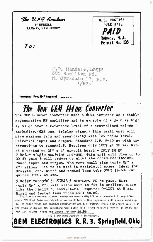
1he g/.41q 40gaiessei 67 RUSSELL
RAHWAY, NEW JERSEY
T o:
U.S. POSTAGE
BULK RATE
PAID Rahway, N.J. Permit No. I2
Handale,T,72W1T7 305 Hamilton Rd. II. Syracuse 1.73,
Postmaster: Fenn 3547 Requested
The Iew CEll Mine Converter The GEM 2 meter cnnverter uses a 6CW4 nuvist -)r as a stable
regenerative RF amplifier and is capable nf a gain as high
as 60 db over a reference level flf a neutralized tri^de
amplcifier.(6X8 ose. tripler mixer.) This small unit will
give maximum gain and sensitivity with low noise level.
Universal input and output. Standard I.F. 5-10 mc with in—
structinns to changeI.F. Requires only 150V at 18 ma. Wir—
ed & tested nn 21" x 4" circuit board — ONLY $6.50
2 Meter single nuutstor pre-amp. This unit will give up to 30 db gain & will reduce or eliminate cross—modulation.
Tuned input and nutput. The very small size ( only 2A" x
2") allows unit to be used in restricted space. Ideal for Gnnsets, etc. Wired and tested less tube ONLY $4.50. Re—
quires 0-50V at 4ma.
6 meter cascades (2 6CW4's) pre-amp. 20 db gain. Size
(only 21" x 2") will allow unit to fit in smallest space like the HQ-110 nr converters. Requires 0-100V at 8 ma.
Wired and tested less tubes ONLY $5.50. The 6 meter Printed circuit converter uses a 611q/R1.7 ms a cascode R. F. amplifier
and a 6X8 High Gain Pentode mixer and oscillator This converter will give a end slgr
1-10- to-noise ratio and maximur sensitivity and 1.F. outPut. The circuit uses very
alr wound coils and the broadband oscillator will , event crystals from 40 to 50 me for
any 1.F. output. Wired and tested for only $6.50 All Um, nent .
OEM ELECTRONICS R. R. 3, Springfield,Ohio Amem.m••••••

The Oetoter 196/
25e
4mateur
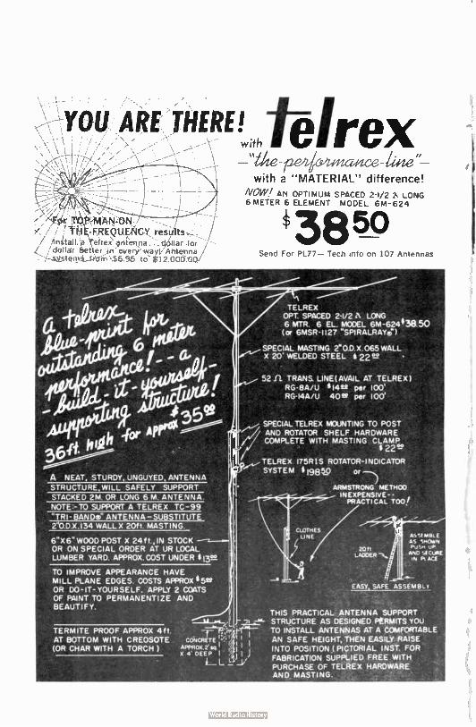
YOU ARE THERE! -t-eîrex w;th tale "
with a " MATERIAL" difference!
For
tii .E-FREQUENCY results.
install a Terre; anienoa. . d,ollar for dollar better . ¡ri every wayq. Antenna
; sy_tiv-rIAArierri $6 9.5 to S12.00000/
A NEAT, STURDY, UNGUYED, ANTENNA
STRUCTURE WILL SAFELY SUPPORT
NOTE:- TO SUPPORT A TELREX TC-99
6“X6" WOOD POST X 24f?., IN STOCK OR ON SPECIAL ORDER AT UR LOCAL LUMBER YARD. APPROX.COST UNDER $ 13. ,
TO IMPROVE APPEARANCE HAVE MILL PLANE EDGES. COSTS APPROX i5se OR DO-IT-YOURSELF. APPLY 2 COATS OF PAINT TO PERMANENTIZE AND BEAUTIFY.
TERMITE PROOF APPROX 4ft AT BOTTOM WITH CREOSOTE (OR CHAR WITH A TORCH )
NOW/ AN OPTIMUM SPACED 2-1/2 A LONG 6 METER 6 ELEMENT MODEL 6M-624
3850 Send For PL77— Tech into on 107 Antennas
TELREX OPT. SPACED 2-1/2 A LONG 6 MTR. 6 EL. MCCEL 6M-62443aso
6MSR•1127 "SPIRALRAYe")
SPECIAL MASTING 20.0.X.065 WALL X 20 WELDED STEEL t 22 •
52 fl TRANS LINE(AVAIL AT TELREX) RG•8A/U * 14 22 per 100' RG-14A/U 4Ottt per 100'
SPECIAL TELREX MOUNTING TO POST •1 ANO ROTATOR SHELF HARDWARE COMPLETE WITH MASTING CLAMP
22 °1'
TELREX 175R1S ROTATOR- INDICATOR
SYSTEM $ 19850 or —
ARMSTRONG METHOD INEXPENSIVE-- , PRACTICAL TOO!
20ft LAODER
&SU tAkILE AS SPOSAN PuSet UP AND 'a/Cunt leaPAU
EASY SAFE ASSEM L
THIS PRACTICAL ANTENNA SUPPORT STRUCTURE AS DESIGNED PERMITS YOU TO INSTALL ANTENNAS AT A COMFOR1ABLE AN SAFE HEIGHT, THEN EASILY RAISE INTO POSITION ( PICTORIAL INST. FOR FABRICATION SUPPLIED FREE WITH PURCHASE OF TELREX HARDWARE AND MASTING.
The VHF Amateur Title registered U.S. Post Office
A MONTHLY PUBLICATION
OFFICES:
Business & Editorial 67 Russell Avenue Rahway, New Jersey
EDITOÑIAL STAFF
Managing &
Associate Editors
Bob Brown, 12230
Robert Richardson, W4UCH
Circulation Manager
Peter A. Markovage, WA2CWA
Production Manager
Douglas W. Clanton
C ounsel
J. D. 'Red" Brown. Ii2ZSP
Moonbounce Editor
Allen Katz, A2DYM 48 Cumberland Avenue Verona, New Jersey
Single Sideband Editor
Phillip Curet, 1.2PCG
204 East Northfield Rd.
Livingston, New Jersey
South American Editor
Michael A. Czysch LUUCA
Monasterio 345 F. Lopez !YON Buenos Aires. Argentina
Ti. VU dsdteue is
published monthly by
Robert N. Brown, IMO,
Subscription rates.
one year, 88.00, two
y , $ 8.60, 8 yeare,
$6.00. Foriegn add SI.
ADVERTISING rate card
on request, Entire
contents printed in
Clark, N.J., U.S.A
Telepp°11e Numoer for
out-of-state direct
dialing: 201- FU 1-1284.
Local calls:FUlton 1-
1284. DEADLINE: God
only knows.
VOL. 4, No. 10 ,L-TC6ER ' 151
Tabk etrideetà lir
Modulation Monitor Michael A. Czysch, LUSDCA 5
Maverick Rides Again Sam Osaka., 1120P1 8
Mbonbouncel Allen Katz, K2UYI1 9
Short-Shorts Anonymous II
Sam's Bottle Baiter Sae Dasher, K2OP , 12
More Short-Shorts Anonymous I ii
Signal Reports Dave Heller, KSHNP 15
South American Nees Michael A. Czysch, LU3DCA 18
...between East and West
Alois Pendl, 0E8AP 19
Propagation Forecast Bob Brown, K2ZSQ, Editor 23
Fifth Monthly Author's Contest!
VOTE THIS MONTH for Pete's sake! 27
FRONT COVER
Our moonbounce editor, Allen, K2Uni, snagged a great circuit from Ot, W2C9K, on his 1296 mc converter.
See schematic and parts list on pages 10 and 11. This little converter is
really "hot" and simple to build, using only three tubes ( common ones at that), 6U8, 6AN4, and a 6DJ8. Converter output ( 1296 mcl feeds into your regular receiver at 26 to 30 mc.
Nice, eh?
3
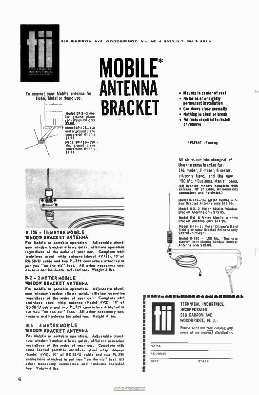
ti' I. VINIICAL
INI AI/SI HIES
51B BARRON AVE wooneRInGE NJ ME a 007, NV mu 5 10.43
To convert your Mobile antenna for Hotel, Motel or Home use.
Model GP-2-2 me-ter ground plane conversion kit only $3.95. Model GP-125-14k meter ground plane conversion kit only $3.95.
Model GP.150-150 Mc. ground plane conversion kit only $3.95.
MOBILE* ANTENNA BRACKET
peY,
B- I25 — 11/1 METER MOBILE WINDOW BRACKET ANTENNA For Mobile or portable op•ration. Adlustable alumi-
num window brockist allows quick, efficient op•ration
risoardless of th• mak• of your car. Complet. with
•tainless st•eI whip antenna (Mod•I « V125), 10' of
ROSS ' U cable and two PL259 conn•ctors ottoch•d to
put you " an th• air" fast. All oth•r n•c••sary con-n•ctor• and hardwor• included too. M•Ight 4 lbs.
B-2 — 2 METER MOBILE WINDOW BRACKET ANTENNA Fer mobile or portable operation. Adiu•table alumi-
num window brocke allows quick, •fficl•nt op•ration
r•qardlisse of tir, mak• of your cor. Completo with stainless •t•sil whip ant•nna ( Mod•I • V2), 10' of
ROSS ' U cable and two PL259 conn•ctors attached to
put you " on th• air" him. All other n•c•ssary con
n•ctors and hardwor• included too. M•Ight 4 lbs.
B-6 — 6 METER MOBILE WINDOW BRACKET ANTENNA For Mobile or portable op•ration. Adlustoble aluml
nurn window brink's, allows quick, •flicitent operation
r•gardies• of thee mak• of your car. Comploto with
ba•• loaded portable stainless steel whip onto...,
(letod•I rtV6), 10' of RG 58'U cable and two PL259
attach•d to put you " on tiro air" fast. All
other n•c•s•ary connectors and hardwor• included too. M•Ight 4 lbs.
• Mounts in center of roof
• No holes or unsightly permanent installation
• Car doors close normally
• Nothing to steal or break • No tools required to install
or remove
'PATENT PENDING
All whips are interchangeable! Use the same bracket for,
11/4 meter, 2 meter, 6 mete:-, citizen's band, and the new 150 Mc. " Bus;ness Man's" band. All bracket models complete with Antenna, 10 of cable, ah necessary connectors and hardware.)
Model 8-125-1.• Meter Moblle Wm-dow Bracket Antenna only $ 15.95.
Model 8-2-2 Meter Mobile Window Bracket Antenna only $ 15.95.
Model 841-6 Meter Mobile WIndow Bracket Antenna only $17.95.
Model B-11-11 Meter Cltuen's Band Mobile Window Bracket Antenna only 1 $19.95 (pictured).
Model B-150 — 150 Mc. " Business Man's" Band Moblle Waildow Bracket
,.e. Antenna only $15.95.
----
Iii TECHNICAL INDUSTRIES,
INCORPORATED
518 BARRON AVE WOODBRIDGE, N. J. •
Please send me free catalog and name cf my nearest distrIbutor.
NAME
ADDRESS
CITY STATE
4
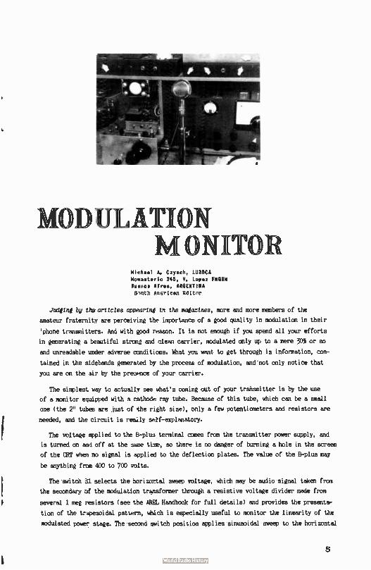
MODULATI N NIT
Michael A. Czysch, LU3DCA Monasterio 348, V. Lopez FRO8M Buenos Aires, ARGENTINA S'Inth AuLrlcan Edlt-r
Judetni by the articles cmpeartnÉ th the majazines, more and more members of the
amateur fraternity are perceiving the importance of a good quality in modulation in their
'phone transmitters. And with good reason. It is not enough if you spend all your efforts
in generating a beautiful strong and clean carrier, modulated only up to a mere 30% or so
and unreadable under adverse conditions. What you want to get through is information, con-
tained in the sidebands generated by the procese of modulation, and not only notice that
you are on the air by the presence of your carrier.
The simplest way to actually see what's coming out of your transmitter is by the use
of a monitor equipped with a cathode ray tube. Because of this tube, which can be a small
one ( the 2" tubes are just of the right size), only a few potentiometers and resistors are
needed, and the circuit is really self-explanatory.
The voltage applied to the B-plus terminal comes from the transmitter power supply, and
is turned on ami off at the Dame time, so there is no danger of burning a hole in the screen
of the CRT when no signal is applied to the deflection plates. The value of the B-plus may
be anything from 400 to 700 volts.
The switch S1 selects the horizontal sweep voltage, which may be audio signal taken from
the secondary of the modulation trunsformer through a resistive voltage divider made from
several 1 meg resistors ( see the AREL Handbook for full details) and provides the presenta-
tion of the treezoidal pattern, which is especially useful to monitor the linearity of the
modulated power stage. The second switch position applies sinusoidal sweep to the horizontal
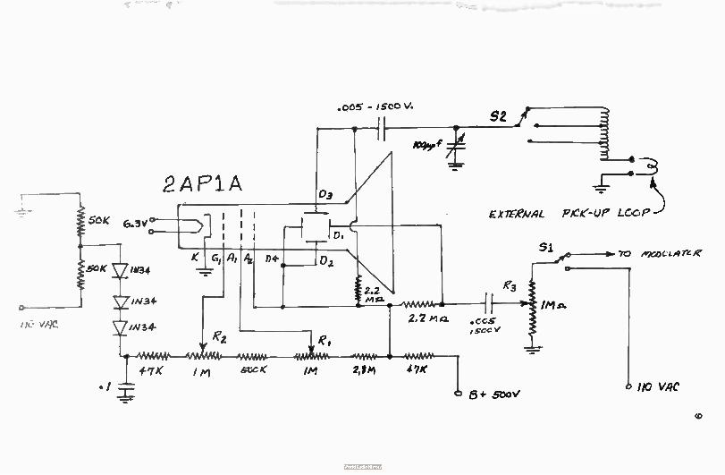
--1
5CK 6.3v,
o
50( 1àI34
in 34
2/A134-
2AP1A
.005 - igecV. S2 ir
•
E*TE-eVAL pee- U17 LGC P
SI
/M.n.
70 /e2CI)(.. LA re e
110 VAC
co
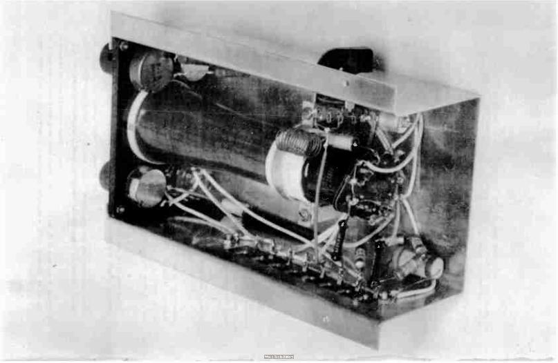
plates taken from . a small filament transformer, connected with its secondary to the 6.3
volts winding of some other power transformer, and in this way it is possible to visualize
an envelope pattern of the outgoing signal.
From this backwards-connected filament transformer was also taken the voltage for the
negative supply which allows a brightness control without bringing the cathode to a posi-
tive potential with respect to the filament of the CRT.
An RF signal of the proper value is connected to the vertical plates through the tuned
circuit formed by the tapped coil, the 100 uuf variable capacitor and the pick-up loop.
Switch S2 selects the taps for 10, 6 or 2 meter operation.
The accompanying photographs give a good idea about the construction and mounting of the
complete unit. The chassis was bent from a flat piece of aluminum and is 84" long. The front
panel was made from a piece of pertinax any insulating material will do) and is just large
enough for the picture tube. the three potentiometers and the rotary switch Sl. S2 is mount-
ed on one side of the chassis and a terminal strip on the other one.
The picture at the head of the article shows the monitor mounted in the author's station
just in front of the operating position.
This little instrument has been invaluable to control the modulation level of the differ-
ent transmitters in use at LU3DCA, and I know no other way to find the correct settings of the
controls of a modulator furnished with a speech clipper, a real necessity if you want.,to have
an effective 'phone transmitter.
11111111(k' BIDES Sig Samuel W. flask», K2OPI/K1POK
IJ
Several questions have been asked about the filter in the June issue of THE VHF AMTEUR.
I will try to answer them as they come, but please be patient.
First, some fellows are interested in the maximum power which can be handled by the fil-
ter. If a flat line ( low SWR) is used, the filter as described should handle about 450 watts.
This is power input to the filter and not d.c. power input to the final amplifier as is the
case with most commercial specs. An increase in SWR will increase the peak voltage across the
capacitors. For use at the kilowatt level, wider spaced variables such as made by E.F. John-
son or Hammarlund should be used.
Unfortunately, the tuning procedure seems to have been confusing. The reason for retuning
C2 at 50 mc after adjusting for minimum feedthru at 58 mc is that the suck-out "well" is rather
broad and its position has some effect on the attenuation at 50 mc. To insure the lowest possi-
ble insertion loss at 50 mc, the trap must be adjusted for both frequencies.
An error has been found in the schematic as it was originally published - but it will still
work OK. L3 should be in series with C2 and not C4. There is no coil on the L4 leg.But regard-less, input and output ends can be switched.
When properly adjusted, Cl and C2 are about at minimum capacitances. This may make tuning the high end of the band rather difficult. Suggested capacitors to solve this problem are the Hammarlund HF-15 or any similar type having about 2.5 pf minimum capacitance.
[VHF(
8
Allen Katz, K20.11
48 Cumberland Ave.
Verona, New Jersey
A horrified expression and a high pitched
-cry, 'TIMM" This typifies the attitude too many
hams have toward mathematics. Most of these hams
have had a good background in math, far in excess
of any necessary to master the simple equations
presented in this column. Then why all the fuss?
If one operated the low frequencies where commercially built E equipment and dress pattern construction articles prevail, possibly
ore could dispense with math, but here on the VHF frontier, where commercial
equipment is nonexistent and construction articles scarce, math is a necessity.
One has great pleasure in building his own equipment, but how much more pleasure is
gained by building and destentng your own gear? This is what mathematical applications
can do for you. It has been the policy of the column to give general construction informa-
tion along with mathematical formulas in order that its readers could build and design
equipment tailored to their own needs.
New Book - - - "VHF For The Rodio Amateur"
After hearing my friend's praise W6A ,W's book, VHF Por The Radio Amateur, I could not
help but to rush out and buy a copy. I then proceeded to read it cover to cover. Although
we were very impressed by the practical content, we would have liked to see a little more
theory. We concur with Frank's comments on collinear arrays,using a collinear here at
K2UrH. We would have been even happier if he mentioned a parabolic antenna - alas. His
transmitter section made us really light up. Never before had we seen a 1296 mc transmitter
in print, and here we hau two to cnocse from! The flat line unit really looks simple to
build. His converter section is also excellent. The tclea of running 1168's with out-forced
air cooling is sure to prove invaluable with these tubes becoming available to the general
ham public. Frank has a whole section on paramps for the fellows who's interest lies in
that direction. This is the first VHF book that deals so thoroughly with the UHF end and
truly warrants the attention of all VHF operators. A fine job, Fronk!
9
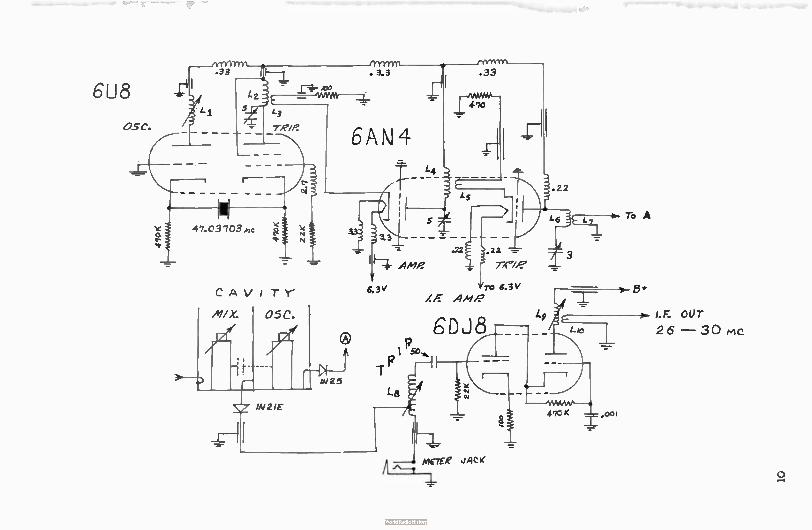
6U8 .33
CAV ITY
MX. 05C.
IN 25
. 3.3
L4
.33
.11:roe—
.0..
6 3V ro 6.3V A ml.'
.22
L5 To A
incre2 JACK
_L
47CK .00
I.F. OUT
2 6 — 3 0 Mc
o
1296 Converter
Ot, W2CSM, has sent in the following information ( see schematic on left) on a 1296 mc
converter that he has designed and built. It's a real beauty and works likewise...
PARTS LIST
Cavity: 2" x 2" x 4"
Li: 17T #28 3/16" slug
L2: 41 016 3/8" dia.
L3: 31 #16 3/8" dia,
L4: 41 #16 3/8" dia.
L54 2T #16 3/8" dia.
3/8" diameter center conductor length adj. with micrometers
form L6: Zr /16 3/8" diametec
L7: 1T 116 3/8" dia.
LB: 141 129 4" slug form. Tap at 4 turns.
L9: 26T 123 4" form.
L10: 31 #26 à" form.
ACTIVITIES
W2CSM also sent along the following list of stations active on 1296 mc in the North
Eastern area. Ot is using a 7 turn helix beam with his converter. However he has purchased
a 6 foot spun aluminum surplus dish with which he plans to work moonbounce in the future.
1296 MC STATIONS
W3ZFW W3GaM W3FEY W2PEZ W6NTW/2 - 1296.645 mc W2TTM W2CXY
K2UUR - 1296.010 mc W1BU K2G191 W2CSM W2WTY
W2WTY dropped by THE VHF AMATEUR booth at the East Coast VHF Society's Hamfest to tell
us that he has been on 1296 for more than a year and wants to know why he wasn't in the
"UHF Directory" in the April issue. I don't know, Larry, but I'm sure it won't happen again.
W18KA wrote to tell us that New Hampshire may soon be an active "Moonbounce State." He
and W1DUB are assembling a cylindrical parabola like the one in the February edition of
THE VHF AMATEUR. Good luck, Roland, - hope to hear of you soon!
Alan. VE3BZS, sent us a long letter containing a write-up on his homebrew pen recorder!
We are going to devote the column to the pen recorder in one of the up-and-coming editions
- watch for it - Alan has done a great job on his. Alan says he is headed north again, so
his moonbounce activities will be halted for a few months.
Until next month, 73, Alan, R2UYE
113111/
S NORT SNOR TS
Several recent articles ln thls and other magazines indicate that certain operators
with comparatively scarce calls or states are most unhappy about the confirmation requests
their scarcity promotes. Their solutions are, apparently, to demand postage, or even com-
pletely refuse 8SL's. Quite an attitude...
Nothing wrong with insisting on receipt of cards before sending one - or ignoring cards
with wrong time, dates, etc. But simple courtesy demands responce when these conditions are
met. Of course the one who announces "No 8SL" is a couple of steps above he who promises
- Anonymous wel and then ignores...
11
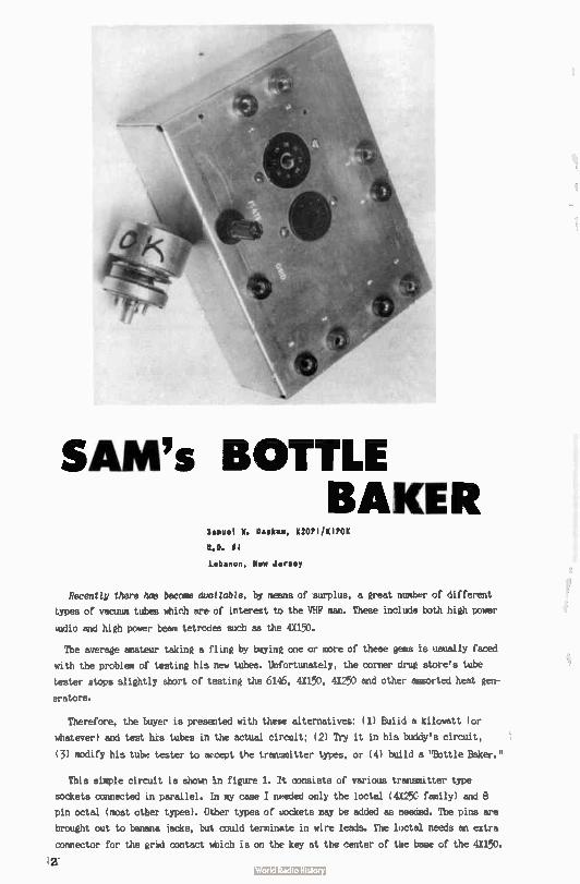
SAM's BOTTLE BAKER
Segue' W. Seek», K2OPliKIPOK
R.D. 01
Lebanon, New Jersey
Recently there has become available, by means of surplus, a great number of different
types of vacuum tubes which are of interest to the VHF man. These include both high power
tudio and high power beam tetrodes such as the 4X150.
The average amateur taking a fling by baying one or more of these gens is usually faced
with the problem of testing his new tubes. Unfortunately, the corner drum store's tube
tester stops slightly short of testing the 6146, 4X150, 4X250 and other assorted heat gen-
erators.
Therefore, the buyer is presented with these alternatives: ( 1) Buiid a kilowatt ( or
whatever) and test his tubes in the actual circuit; ( 2) Try it in his buddy's circuit,
(3) modify his tube tester to accept the transmitter types, or ( 4) build a "Bottle Baker."
This simple circuit is shown in figure 1. /t consists of various transmitter type
sockets connected in parallel. In my case I needed only the loctal ( 4I25C family) and 8
pin octal ( most otter types). Other types of dockets may be added as needed. The pins are
brought out to banana jacks, but could terminate in wire leads. The loctal needs an extra
connector for the grid contact which is on the key at the center of the base of the 4X150.
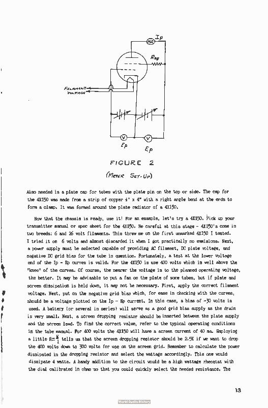
E-p
FIGURE 2
61Er(e Ser- Up)
Also needed is a plate cap for tubes with the plate pin on the top or side. The cap for
the 4X150 was made from a strip of copper e x 4" with a right angle bend at the erds to
form a clamp. It was formed around the plate radiator of a 4X150.
Now that the chassis is ready, use it! For an example, let's try a 4X150. Pick up your
transmitter manual or spec sheet for the 4X150. Be careful at this stage - 4X150's come in
two breeds: 6 and 26 volt filaments. This threw me on the first unmarked 4X150 I tested.
I tried it on 6 volts and almost discarded it when I got practically no emmisions. Next,
a power supply must be selected capable of providing AC filament, DC plate voltage, and
negative DC grid bias for the tube in question. Fortunately, a test at the lower voltage
end of the Ip - Ep curves is valid. For the 4X150 is use 400 volts which is well above the
"knee" of the curves. Of course, the nearer the voltage is to the planned operating voltage,
the better. It may be advisable to put a fan on the plate of some tubes, but if plate and
screen dissipation is held down, it may not be necessary. First, apply the correct filament
voltage. Next, put on the negative grid bias which, for ease in checking with the curves,
should be a voltage plotted on the Ip - Ep current. In this case, a bias of -30 volts is
used. A battery ( or several in series) will serve as a good grid bias supply as the drain
is very small. Next, a screen dropping resistor should be inserted between the plate supply
and the screen lead. To find the correct value, refer to the typical operating conditions
in the tube manual. For 400 volts the 4X150 will have a screen current of 40 ma. Employing
a little R..--11 tells us that the screen dropping resistor should be 2.5K if we want to drop
the 400 volts down to 300 volts for use on the screen grid. Remember to calculate the power
dissipated in the dropping resistor and select the wattage accordingly. This one would
dissipate 4 watts. A handy addition to the circuit would be a high wattage rheostat with
the dial calibrated in ohms so that you could quickly select the needed resistance. The
13
next step is to connect the plate voltage and record the plate voltage and plate current.
The meter set-up is shown in figure 2. Since exposed plate leads are employed, USE
CAUTION. After recording Ep and Ip, change the grid bias to -40 volts ( in this rasp).
Again read the plate current. It should have decreased. If it did, record the new value.
af it increased, patent it). The plate currents for one of the 4X150's which I tested were:
At Eg= -30v Ip = 195 ma
At Eg= -40v Ip = 95 ma
which values fall almost on the published curves. The fact that 195 ma was flowing in the
first case would indicate that the tube was probably good.
Now to calculate em ( transconductance - the measure of the ability of the grid voltage
to control the plate current while the plate voltage is held constant.) The gm may be cal-
culated from:
gm= 41112 ( Ep Constant) à Eg
:= 195 ma - 95 ma -- œ ma .7=10,000 umhos
40V -30 V 10V
Although the above calculation was not essential to a basic test of the tube, it was
done to bring out the significance of the test.
If you have succeeded in keeping your fingers out of the high voltage ( a suggested pro-
cedure), the plate voltage should always be removed from the tube first. Assuming that the
em is found to be within 25% or ao of the published value, the tube should be good. Reams-
ber, the acid test is in a dynamic test such as the actual circuit.
If a problem occurs in finding spec sheets for some of the larger or older tubes, write
the manufacturer and he will usually send the specs complete with curves.
Is it worth it? For two years I passed up some 4X150D's sitting in a box marked "Untested
- As Is - $1" in a surplus store in New York. Finally I decided to throw caution to the
winds and bought a pair. Upon testing them by this method, I found they were good and later
trials in a 6 and 2 meter rig showed average results. Evidently, everybody else passed them
up assuming they were no good. A quick inspection should be made of the glass for cracks
and/or a light bluish haze to see if'it is gassy. If a white powder is noticed inside the
tube - BEWARE - as it may be flakes from the cathode due to overvoltage.
Naturally, I picked up more 4X150's at a buck each the next trip to the big-town and
only one was bad. Upon further inspection, the tell-tale white powder was present inside
the glass. But even at that, it is still a good bargain. These eyeball tests do not guaran-
tee against some bad apples in the barrel, though.
SHORT SHORTS
A pair of stations were heard discussing an 00 card
for out of band operation one had received. Zeroed on
each other, they were over the edge... -Anonymous
Eli
14
e?fnee Reports...
Dave Heller, 11311NP
14 Darkleaf Lane
Levittown, Penn. WIAICW.4
These VHF operators who are either afraid to give an honest signal report or are in-
capable of doing so would learn a lot from an evening's listening on a particular fre-
quency: 3999, to be exact. This crop of sidebanders is an elite society - because they
want it to be. First of all, you don't deliberately set 1 kc from a band edge unless
you know you're good - no drift - no residual carrier, no upper sideband. But a written
description of this group tearing one of their fellows apart for a couple of cycles
drift or the least flattop or nonlinear operation doesn't tell the story - you must hear
it. -Please do - It's an education.
Contrast this with the VHF "talking" bands. A station that doesn't move a kc every few
minutes must be crystal controlled. Modulation 100% or less is reported " insufficient."
Broad signals are radiated with pride. Technically this is all a step backward, contrary
to the government's purpose in licensing radio amateurs.
Many VHF'ers don't seem to care. They reject any less-than-perfect signal report; they
tell the friendly 00 to soak his head. These characters don't read the better magazines,
so let's dismiss them from this discussion - they won't see it anyhow.
The majority don't know what to think. They receive conflicting reports - the distant
station says the signals' fine, with possibly slight drift. Most of the local's report the
same, but "broad due to overload" ( whatever that means). But a couple of critical locals
keep saying that they're overmodulating. Whom to believe?
So perhaps a discussion on how to give a signal report is in order. The receiver used
must be stable and reasonably sharp. A "sideband" receiver with steep IF skirts helps, but
it isn't mandatory. A scope on the receiver also helps. A means of attenuating signals be-
fore the receiver ( or converter, if one is used) is necessary.
Drift measurement is either simple or impossible. Use either your VFO or receiver - which
ever has better stability and calibration. My VFO reads less than one kc frequency difference
on six meters whereas the receiver can only be read to about 3 kc - so I use the VFO. Simply
measure the frequency received at intervals - and report what you read. But if your equip-
ment isn't stable, the readings, obviously, are meaningless.
Continued on paie 18
15
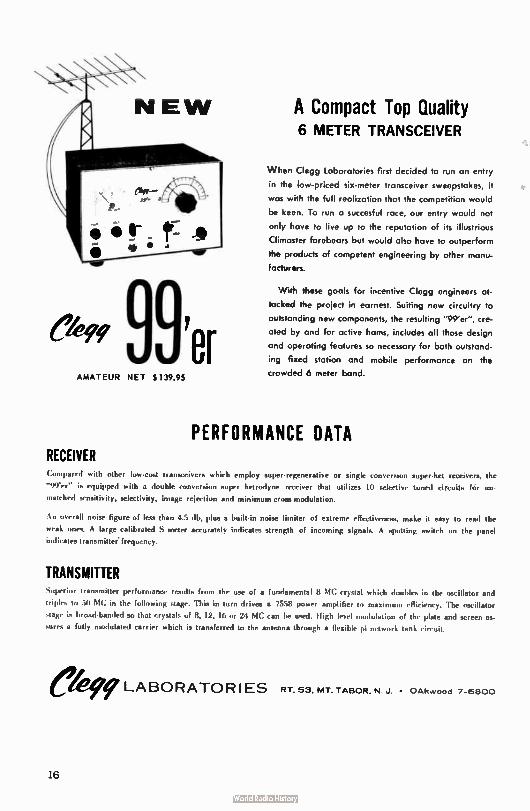
e'479 99'er AMATEUR NET $ 139.95
RECEIVER
A Compact Top Quality 6 METER TRANSCE!VER
When Clegg Laboratories first decided to run an entry
in the low-priced six-meter transceiver sweepstakes, it
was with the full realization that the competition would
be keen. To run a succesful race, our entry would not
only hove to live up to the reputation of its illustrious
Climaster forebears but would also have to outperform
the products of competent engineering by other manu-
facturers.
With these goals for incentive Clegg engineers at-
tacked the project in earnest. Suiting new circuitry to
outstanding new components, the resulting "99'er", cre-
ated by and for active hams, includes all those design
and operating features so necessary for both outstand-
ing fixed station and mobile performance on the
crowded 6 meter band.
PERFORMANCE DATA
Compared with other low-cost transceivers who-h employ super•regenerative or single conversion super-het receivers, the
"99'er" is equipped with a double conversion super hetrodyne receiver that utilizes 10 selective tuned circuits fór un-
matched sensitivity, selectivity, image rejection and minimum cross modulation.
An overall noise figure of less than 4.5 db, plus a built-in noise limiter of extreme effectiveness, make it easy to read the
weak ones. A large calibrated S meter accurately indicates strength of incoming signals. A spotting switch on the panel
indicates transmitter frequency.
TRANSMITTER "..perun tran,riuttrr performance results from the use of a fundamental 8 MC crystal which doubles in the oscillator and
triples to 50 MC in the following stage. This in turn drives a 7558 power amplifier to maximum efficiency. The oscillator
stage is broad-banded so that crystals of 8, 12, 16 or 24 MC can be used. High level modulation of the plate and screen as-
sures a fully modulated carrier which is transferred to the antenna through a flexible pi network tank circuit.
kir 9 LABORATORIES RT 53, MT. TABOR, N J. • OAkvvood 7-6800
16
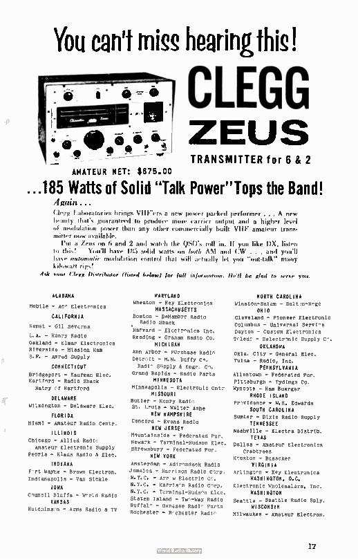
AMATEUR MET: $ 675.00
You can't miss hearingthis!
CLEGG ZEUS TRANSMITTER for 6 & 2
...185 Watts of Solid "Talk Power"Tops the Band! Again . . .
1.alairatof brings VIII--ers a new power paned performer . . . A new
beauty that's giirranlee(I to produce more rimier output and a higher level
of lulation power than any other commercially built VHF amateur trans-mitter now viva ¡ laide.
Put a Zoe on 6 and 2 and watch the ()Mrs roll in. If you like 1)X, listen
to iii is! 1(mtil have 11i5 solid walls on h(eh /1114 and (1W1 . . . and you'll lriv e auslennalic modulation rontrol that will aoirdly let you "out- talk" many
kilowatt rigs!
4,1( your Clegg Distributor (fisted Mena) for full infornudion. He'll be glad to serre you.
ALABAMA
Mobile - Ac" Electronics
CALIFORNIA
Hemet - all Severna
L.A. - Henry Radio
Oakland - Elmar Electronics Riverside - Mission Ham S.F. - Amrad Supply
CONNECTICUT
Bridgeport - Kaufman Elec. Hartford - Radio Shack Hatry of Hartford
DELAWARE Wilmington - Delaware Elec.
FLORIDA Miami - Amateur Radio Centr.
ILLINOIS Chicago - Allied Radio
Amateur Electronic Supply Peoria - Klaus Radio & glee.
INDIANA
F-rt Wayne - Brown Electron.
Indianapolis - Van Sickle
IOWA
Council Bluffs - World Radio KANSAS
Hutchins-m - Acme Radio & TV
MARYLAND Wheaton - Key Electronics
MASSACHUSETTS Boston - DeMambrr Radio
Radio Shack
'Harvard - Electronics Inc. Reading - Graham Radio Co.
MICHIGAN
Ann Arbor - Purchase Radl-Detr-it - M.N. Duffy Cm. Radi - Supply & Engr.
Grand Rapids - Radio Parts MINNESOTA
Minneapolis - Electronic cntr MISSOURI
Butler - Henry Radio St. Louis - Walter Ashe
NEW HAMPSHIRE Concord - Evans Radio
NEW JERSEY Mmuntainside - Federated Pur. Newark - Terminal-Hudson glee. Shrewsbury - Federated Pur.
NEW YORK
Amsterdam - Adirondack Radio Jamaica - Harrison Radio Corp. N.Y.C. - Arr-w Electric Co. N.Y.C. - Harris-n Radio C-rp. N.Y.C. - Terminal-Hudson Elec. Staten Island - Tv"-way Radio Butte- - Genesee Radi^ Parts Rochester - R-chester Radi-
NORTH CAROLINA Winston-Salem - Daltcn-Hoge
OHIO Cleveland - Pioneer Electronic Columbus - Universal service Dayton - Custom Electronics Toledt - Selectrnnic Supply C-.
OKLAHOMA Okla. City - General Elec. Tulsa - Radio, Inc.
PENNSYLVANIA Allentown - Federated Pur. Pittsburgh - Tydings Co. Wyncote - Ham Buerger
RHODE ISLAND Providence - W.H. Edwards
SOUTH CAROLINA Sumter - Dixie Radio Supply
TENNESSEE Nashville - Electra Distrib.
TEXAS Dallas - Amateur Electronics
Crabtrees Houston - Busacker
VIRGINIA Arlington - Key Electronics
WASHINGTON, D.C.
Electronic Wholesalers, Inc. WASHINGTON
Seattle - Seattle Radio Sply. WISCONSIN
Milwaukee - Amateur Electron.
17
Broadness may be caused bt over ulation or excessive modulation spectrum, especially
in the case of linear amplifiers, nonlinear operation. Differentiation of the type of
broadness is not always easy without an oscilloscope, but the existance of excessibe width
is simple to determine. As mentioned above, a means of attenuating the incoming. signal is
necessary. I have a coax switch to select several antennas; a spare and cliplead antenna
permits adjusting a strong signal to give almost any S-meter reading.
Pick any convenient reading as reference - say, 10 db over S9 for locals and tune in a
local with a known clean signal who preferably has a ' scope monitor). Adjust your antenna
for the reference signal strength and tune across the 100 percent modulated signal, record-
ing its apparent width. Have this same station give you a short transmission devoid of modu-
lation and again tune through it - the apparent width of the unmodulated carrier is the re-
ceiver passband for an unmodulated carrier has zero width). The difference is the bandwidth
of the station. It should be about 7 or 8 kc if the station is really sharp and clean'.
Now you know what a good signal sounds like under your test conditions. Write it all down
before you forget. Any signal that takes any more room on your receiver dial, when the
strength is adjusted to your "standard," is broad; with experience you can learn to measure
approximately how broad.
Don't be afraid to tell what you read or hear - even though the reply will often be
(charitably speaking) misinformed.
SOUTH AMERICAN
Michael A. Czysch, LU3DCA
Monasterio 345, V. Lopez ENGBM
Buenos Aires, ARGENTINA
[VHF!
NEWS Here 1 am °lain with a short notice to let you know what is happening on VHF down this
way.
After a complete absence of any openings on the six meter band during the last few months,
yesterday in the late evening, or more exactly at 0200 GMT of September 4, I heard again for
the first time a steady carrier on 49.9 mc coming in with the characteristic flutter fading
of TE propagation. You can imagine my feelings when I detected this first sign of life on a
completely deserted band, but I nearly fell off my chair when a fellow in the lab told me he
heard three W2 stations on 6 meters around 2030 GMT on Saturday, September 2. It is really
worthwhile to monitor the band closely again!
I hope this good news will also bring back some of the local activity we enjoyed in other
days, because right now nearly all 6 meter stations have migrated to other bands, to the point
that it is now easier to find someone on 144 than 50 mc, a situation not found ever before
down here!
Next month I hope to be back with some DX contacts with our many friends in W-- land!
'Till then, 73, Mtchael, LODCA
[VHF
18
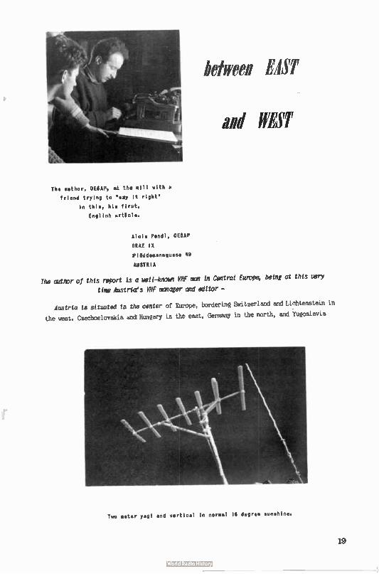
The author, 0E6AF, al the sill with a
friend trying to " say it right'
in this, his flrut,
Engliuh article.
between EAST
and WEST
Alois Pendl, 0E6AP
SRAZ IX
Ploddemanngusse 49
AUSTRIA
The author of this report is a hell —know VHF man in Central Europe, being at this very
time Austrta's VHF manager and editor —
Austria ta sttuated tu the center of Europe, bordering Switzerland and Lichtenstein in
the west. Czechoslovakia and Hungary in the east, Germany in the north, and Yugoslavia
Two meter yagi and vertical in normal 16 degree sunshine.
19
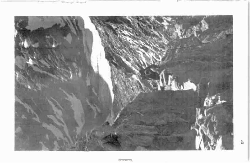
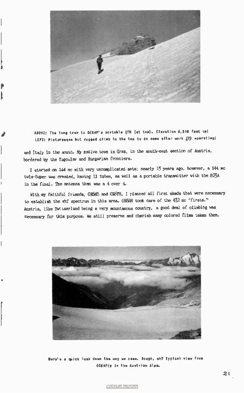
ABOVE: The 408 trek to 0E6AF's portable QTH ( at top). Elevation 9,318 feet api
LEFT: Pictyresq,ae but rugged climb to the top to do some after work ( 7) operating(
and Italy in the sou;h. My native town is Graz, in the south-east section of Austria,
bordered by the ragollav and Hungarian frontiers.
I started on 144 re with very uzvtnuplicated sets; nearly 15 years ago, however, a 144 mc
twin-Super was created, having 11 tubes, as well as a portable transmitter with the 823A
in the final. The antenna then was a 4 over 4.
With my faithful friends, 0E6MS and 0E6TH, I planned all first skeds that were necessary
to establish the vhf spectrum in this area. 0E6911 took care of the 432 mc "firsts."
Austria, like Sletzerland being a very mountanous country, a good deal of climbing was
necessary for this purpose. We still preserve and cherish many colored films taken then.
Here's a quick look down the way we came. Rough, eh? Typical view from
0E8AP/p in the Austrian Alps.
2
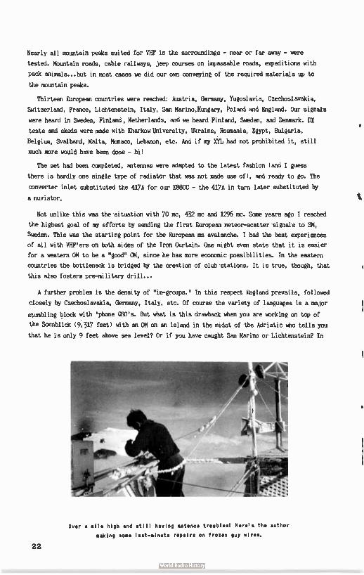
Nearly all mountain peaks suited for VHF in the surroundings - near or far away - were
tested. Mountain roads, cable railways, jeep courses on impassable roads, expeditions with
pack animals.., but in most cases we did our own conveying of the required materials up to
the mountain peaks.
Thirteen European countries were reached* Austria, Germany, Yugoslavia, Czechoslavakia,
Switzerland, France, Lichtenstein, Italy, San Marino,Hungary, Poland and England. Our signals
were heard in Sweden, Finland, Netherlands, and we heard Finland, Sweden, and Denmark. DX
tests and skeds were made with Kharkow University, Ukraine, Roumania, Egypt, Bulgaria,
Belgium, Svalbard, Malta, Monaco, Lebanon, etc. And if my XYL had not prohibited it, still
much more would have been done - hi!
The set had been completed, antennas were adapted to the latest fashion ( and I guess
there is hardly one single type of radiator that was not made use of), and ready to go. The
converter inlet substituted the 417A for our EBBCC - the 417A in turn later substituted by
a nuvistor.
Not unlike this was the situation with 70 me, 432 mc and 1296 mc. Some years ago I reached
the highest goal of my efforts by sending the first European meteor-scatter signals to SM,
Sweden. This was the starting point for the European ms avalanche. I had the best experiences
of all with VHF'ers on both sides of the Iron Curtain. One might even state that it is easier
for a western OM to be a "good" OM, since he has more economic possibilities. In the eastern
countries the bottleneck is bridged by the creation of club stations. It is true, though, that
this also fosters pre-military drill...
A further problem is the density of "in-groups." In this respect England prevails, followed
closely by Czechoslavakia, Germany, Italy, etc. Of course the variety of languages is a major
stumbling block with ' phone QSO's. But what is this drawback when you are working on top of
the Sonnblick ( 9,317 feet) with an OM on an island in the midst of the Adriatic who tells you
that he is only 9 feet above sea level? Or if you have caught San Marino or Lichtenstein? In
Over a mile high and still having antenna troubles Here's the author
making some last-minute repairs on frozen guy wires.
22
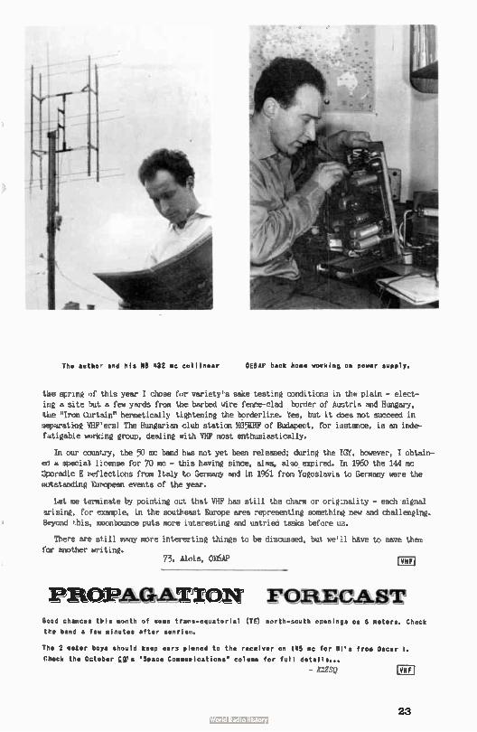
Thm author and his BB 432 um collinear OEBAP back home working on power supply.
tke spring of this year I chose for variety's sake testing conditions in the plain - elect-
jr e a site but a few yards from the barbed wire fence-clad border of Austria and Hungary, the "Iron Curtain" hermetically tightening the borderline. Yes, but it does not succeed in
separating VHF'ers! The Hungarian club station HG5KBF of Budapest, or instance, is an inde-f4tigab:e working group, dealing with VHF most enthusiastically.
In our country, the 50 mc band has not yet been released; during the IGY, however, I obtain-ed a special license for 70 mc - this having since, alas, also expired. In 1960 the 144 mc :Sporadic E reflections from Italy to Germany and in 1961 (ron Yugoslavia to Germany were the
outstanding European events of the year.
Let me terminate by pointing out that VHF has still the charm or originality - each signal
arising, for example, in the southeast Europe area representing something new and challenging.
Beyond this, moonbounce puts more iateresting and untried tasks before us.
There are still many more interesting things to be discussed, but we'll have to save them
for another writing. 73, Alois, 0E6AP COI
PRœAapATIZON FORECAST Good chances this month of some trans-equatorial (TE) north-Nouth openings or 6 meters. Check the band a few minutes after sunrise.
The 2 meter boya should keep ears pinned to the receiver on 015 mc for from Oscar I.
Check the October Us Space Communications' column for full details...
- Kr,SQ
23
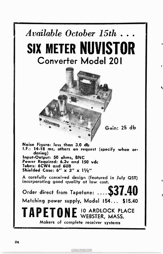
IAvailable October 15th . . .
SIX METER NUVISTOR Converter Model 201
Gain: 25 db
Noise Figure: less than 3.0 db IF.: 14-18 mc, others on request (specify when or-
dering) Input-Output: 50 ohms, BNC Power Required: 6.3v and 150 vdc Tubes: 6CW4 and 6U8 Shielded Case: 6" x 3" x 11/2"
A carefully conceived design (featured in July QST) incorporating good quality at low cost.
Order direct from Tapetone: ... • $37.40 Matching power supply. Model 154... $ 15.40
TAPETONE 10 ARDLOCK PLACE WEBSTER, MASS.
Makers of complete receiver systems
24
VHF AMATEUR PRINTED EXCLUSIVELY FOR THE VHF MAN
Now in our fourth year, The VHF Amateur has over
4,500 circulation in all 50 states and numerous foreign countries! Published monthly by Bob Brown, K2ZSQ, each
issue is packed with over 40 pages of the best VHF has to
offer:
• Moonbounce Activities
• SSB
• DX News
• Technical Articles
• Propagation
• Construction
• 50, 144, 220, 432 mc & up
• Worked All States Listings
• Free "TRADING POST"
SUBSCRIPTION The VHF Amateur
67 Russell Avenue
Rahway, New Jersey
Name
Address
City Slate
n One Year $2.00 Two Years $3.50 Three Years $5.00
New D Renewal I 1
Call
25
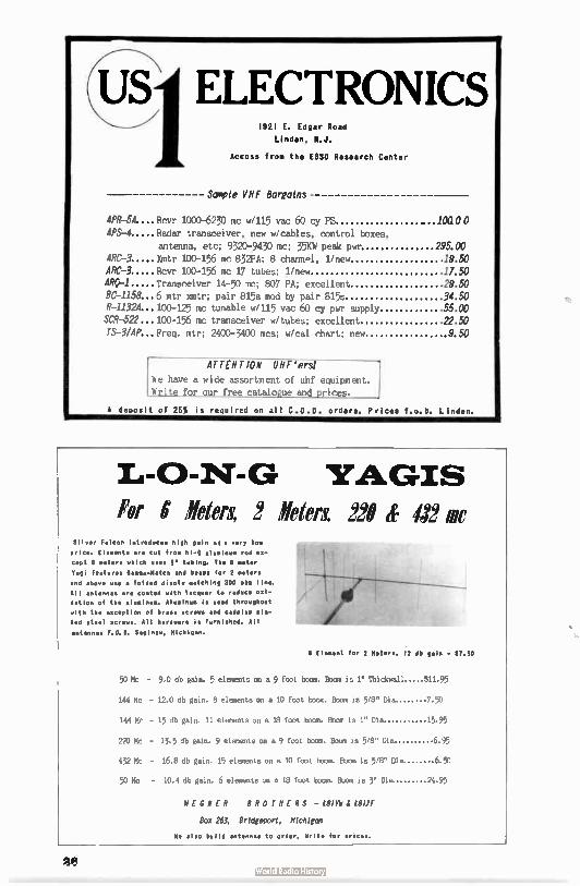
U ELECTRONICS 1921 E. Edgar Road
Linden, M.J.
Access from the ESSO Research Center
Sample VHF Bargains
APR-51....Rovr 1000.6230 mc w/115 vac 60 cy PS .. 10a00
APS-4 Radar transceiver, new w/cables, control boxes,
antenna, etc; 932079430 mc; 35KW peak pwr 295.00 ARC-3 Xmtr 100-156 mc 832PA; 8 chann.1, 1/new 19.50 ARC-3 Rovr 100-156 mc 17 tubes; 1/new 17.50 ARÇ-1 Transceiver 14-50 mc; 807 PA; excellent 29.50
BC-1158...6 mtr xmtr; pair 815s mod by pair 815s 34.50 R-1/32.4...100-125 mc tunable w/115 vac 60 cy puT supply 55.00 SCR-522...100-156 mc transceiver w/tubes; excellent 22.50
15-3/AP... Freq. mtr; 2400-3400 inca; w/ca1 chart; new 9 50
ATTENTION UBE'ersl
We have a wide assortment of uhf equipment. Write for our free catalogue and prices.
A deposit of 25% is required on all C.O.D. orders. Prices f... b. Linden.
YAGIS For 6' »ten 2 »ter& 220 tf 412 mc
Sliver Falcon introduces high gain ate very low
price. Elewents are cut fro, hi-Q alupinua rod ex-
cept 6 peters which us.. tubing. The 6 meter
Yagi feature. Gamme-Match and beep. for 2 meter.
and above use a folded dipole patching 300 oh. line.
All antennas are coated with lacquer to reduce oxi-
dation of the ai using.. Aluwin. is used throughout
with the exception of brass screws and cadplup pla-
ted steel screws. All hardware ie furnished. All
antennas F.O.B. Sabin., Michigan.
Elewent for 2 Meters, 12 db gain -
50 Mc - 9.0 db gain. 5 elements on a 9 foot boom. Boom is 1" Thickweil $11.95
144 Mc - 12.0 db gain. 8 elements on a 10 foot boom. Boom is 5/8" Dia. 7.93
144 Mc - 15 db gain. 11 elements on a 18 foot bmpm. Boom is 1" Dia. 15.95
222 Mc - 13.5 db gain. 9 elements on a 9 foot boom. Boom is 5/8" Dia. 695
432 Mc - 16.8 db gain. 15 elements on a 10 foot boom. Boom is 5/8" Dia. 6 50
50 mc - 10.4 db gain. 6 elements on a 18 foot boom. Boom is 3" &a 24.95
WEGNER BROTHERS - 6 1(811F
Box 263, Bridgeport, Michigan
We also build antennas to order. Write for prices.
2.3
ezheioge emelleTie jue fa* at -then phiya___
This month marks the fifth in our monthly AUTMOR's
CONTEST which will end with the November 1961 issue.
All articles and columns in this issue are to be
evaluated by you below and returned to us immediately.
We'll announce which articles, on a percentage basis,
were the most popular in this issue. At the end of
November; all percentage winners will be competing
against each other for top prizes. Best winners over-
all get the prizes pictured above. YOUR article can wini Meanwhile, help our writers this month by doing
your part...
, Return immediately to: THE VHF AMATEUR, 87 Russell Avenue, Rahway, New Jersey.
Pirections: Pick out the best articles ( only four) and rate those four
in the order of their appeal to you (#1, #2, #3, #4 - first
being best, and fourth being 4th Pest(...
Modulation Monitor, L(J3DCA ( ) Signal Reports, K3HNP ( )
Moonbounce! K2Uni ( ) S.A. News, LU3DCA ( )
Sam's Bottle Baker, K2OPI ( I East .4 WEST, 0E6AP ( )
L — _
27
TWO-WAY RADIO COMMUNICATIONS ELECTRONICS EQUIPMENT DISTRIBUTORS
232-6 HYLAN BOULEVARD
STATEN ISLAND 5, N. Y.
YUKON 1.7575 (7-.!BRALTAR 7-3660
Come to Staten Island for your VHF needs/
Almost every item or brand listed is in stock/
leromom Test
Cesco SYR brides
.Jackson
Hico
Receivers and Transmitters
Ameco ccnverters, pre-amps, etc.
Rico
Poly-Cnam transceivers
Tecraft converters
Cleft Zeus d 99'ers
National receivers
Towers
Rohn
Tri -Ex
Parts
Dow-Iley Relays
PR crystals 5763's, 6I46's, 6360's
International Xtal 5763's, etc. Atlantic Coax
Cesco meters, etc.
Antennas
Cush Craft (See pictures)
Hy-Par (Saturn 6 Halos, etc.)
Cormac, Ireco, Helt-Whip
Plus these:
Oak Tron, Quam Speakers
Tapecode
Rader Pub/teat/0ns
Alto Call Plates
Numechron 24 - Hour clocks
Burgess Batteries
Grauer - Halidorson Transformers
Sonar
Tubes
All CBS, Westindhouse,
Tun-Sol. We have in stock
SPECIAL TO THOSE BRINGING THIS AD OR MAGAZINE MI TY THEM I
- SPECIAL - 10t a foot. Atlantic Cable.
6146's - SPECIAL - $4.00 with at.
36 foot tower - SPECIAL - Tri-Ex crank-up, swivel
base, drops to 10' 9. Reg. $106 plus freight. Our
price - $95.00 complete. (Four section tower)
National 62 VFO - SPECIAL - wipoider supply. Good
for Cornet Caineuticators. Our price - $42.00 with at.
55% discount on all tubes - SPECIAL - with at. Coax Relay - SPECIAL - DK 24 VDC coaxial- $4.00
28
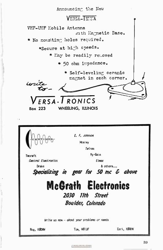
Announcinr: the New
V7IZT:Tr-7.757
VHF-UHF Mobile Antenna -.nth Macnetic Base.
* No mountin7, holes required.
*Secure at hizh speeds.
* /:ay be readily rc7_oved
* 50 ohm 32:Tedence.
* Self-levelin ceramic maismet in etch corner.
eter-
V -FRTA - RONICS Box 223 WHEELING, ILLINOIS
G
Tecraft Central Electronics
Drake
Specializing in gear for 50 mc 6 above
E. F. Johnson
Mosley
Tel res
Hy-Gat
Elmac
& others...
McGrath Electronics 2030 llth Street
Boulder, Co/orado
Write us now - about your problems or needs
Rog, Kectbi Ton, WOIUF Earl, KgRWW
29
CQ
VHF for the radio amateur. A new dynamic hand-book that covers all phases of VHF activities.
INDEX INTRODUCTION 1. VHF RADIO PROPAGATION
SO, 144, 220, 432 and 1296 MC
bonds
2. ANTENNAS
2.1 Discussion
2.2 RF Transmission Lines
2.3 Types of Antennas
2.4 SO MC Antennas
2.5 144 MC Ant
2.6 220 MC Antennas
2.7 432 MC Antennas
2.8 1296 MC Ant
3. TRANSMITTERS
3.1A 50 MC Low Powered
Transmitter
3.18 6W6GT 50 MC Transmitter
3.1C 6W6G8 50 MC Transmitter
3.1D 50 MC Exciter
3.1E High Powered SO MC
Amplifier
3.2A Low Powered 144 MC
Transmitter
3.28 144 MC Exciter
3.2C High Powered 144 MC
Amplifiers
3.3A 222 MC Exciter
3.38 High Powered 222 MC
Amplifier
3.3C Single Tube 220 MC
Amplifier
3.4A 2C39 Units on 432 MC
3.48 Coaxial Circuit Transmitter
3.4C Flat Plate Line Transmitter
3.5A 1296 MC Cavity Transmitter 2.58 1296 MC Flat Line Transmitter
4. MODULATION
4.1 6L6 Modulator
4.2 6W6 Class 8 Modulator
4.3 6Y6 Class 8 Modulator
4.4 50 Watt Modulator
4.5 Screen Grid Modulator 4.6 Frequency Modulator
4.7 Transistor Speech Amplifier
4.8 Phase Modulator
4.9 Vacuum Tube Keyer
CO MAGAZINE BOOK DEPT.
300 West 43rd St.,
New York 36, N.Y. For The Radio Amateur postpaid to:
D VHF For The Radio Amateur, $3.50
C-4
Sirs: I enclose Please send my VHF
NAME CALL
ADDRESS
CITY ZONE STATE
5. POWER SUPPLIES 5.1 Small Power Supplies
5.2 Selenium and Silicon Rectifiers
5.3 Voltage Doubler
6. CONVERTERS
6.1 C ter for 50 MC
6.2 C ter for 144 MC
6.3 Converter for 220 MC
6.4 C ter for 432 MC
6.5 Converter for 1296 MC
7. RECEIVER IF SYSTEMS
7.1 Communication Type Receivers
7.2 14 to 18 MC IF Receiver
7.3 Audio Filter
8. PREAMPLIFIERS
8.1 220 MC Tube Preamplifiers
8.2 Parametric Amplifiers
8.3 Pump Oscillators
8.4 144 MC Parametric Amplifiers
8.5 220 MC Parametric Amplifiers
8.6 432 MC Parametric Amplifiers
9. TEST EQUIPMENT
9.1 Diode AC Voltmeter
9.2 AC and DC Diode Voltmeter 9.3 F.S.-Monitors
9.4 Transistorized F.S. Meter
9.5 1296 MC Wavemeter and Noise Generator
9.6 SWR Meters
9.7A Frequency Marker
9.78 Transistor Frequency
Marker
9.7C Dual Transistor Signal
Marker
9.8 Transistor Audio Oscillator N.Y. lily re•i
30
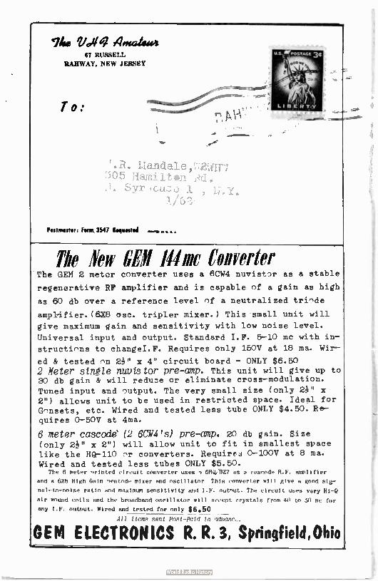
The Voliq 4.«414444 67 MUSE11.
RAHWAY, NEW JERSEY
T o:
44i
. R. Liandale , T,72Urif,7 rTIaimi 1 t
SVr u f -
Postmaster: Form 3547 Roeuestml
The leir Mme Converter The GEM 2 meter converter uses a 6CW4 nuvistor as a stable
regenerative RIF amplifier and is capable of a gain as high
as 60 db over a reference level of a neutralized triode
amplifier. (6X8 osc. tripler mixer.) This small unit will
give maximum gain and sensitivity with low noise level.
Universal input and output. Standard I.F. 5-10 mc with in-
structions to ehangeI.F. Requires only 150V at 18 ma. Wir-
ed & tested on x 4" circuit board - ONLY $6.50 2 Meter stnéle nuutstor pre-amp. This unit will give up to 30 db gain & will reduce or eliminate cross-modulation.
Tuned input and output. The very small size ( only 2P' x 2") allows unit to be used in restricted space. Ideal for Gonsets, etc. Wired and tested less tube ONLY $4.50. Re-quires 0-50V at 4ma.
6 meter cascode (2 6CW4's) pre-amp. 20 db gain. Size (only 2P1 x 2") will allow unit to fit in smallest space like the HQ-110 or converters. Requires 0-100V at 8 ma. Wired and tested less tubes ONLY $5.50.
The 6 meter nrinted circuit converter uses 1 611QiI3Z7 as a cascode R.F. amplifier
and a 6X6 High Gain nentode mixer and oscillator, This converter will give a good sig-
nal-to-noise ratio and maximum sensitivity and I.F. outnut. The circuit uses very Hi-Q
air wound coils and the broadband oscillator will accept crystals from 40 to 50 mc for
any I.F. output. Wired and tested for only $6.50 All time gent Pnet-Pntd ln ndynnrc.
OEM ELECTRONICS R. R. 3, Springfield,Ohio
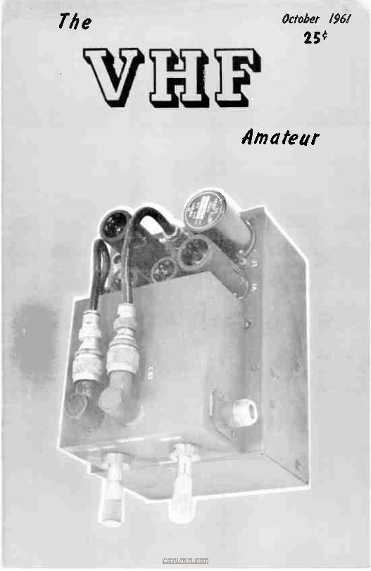
The October 196/
25e
Amateur
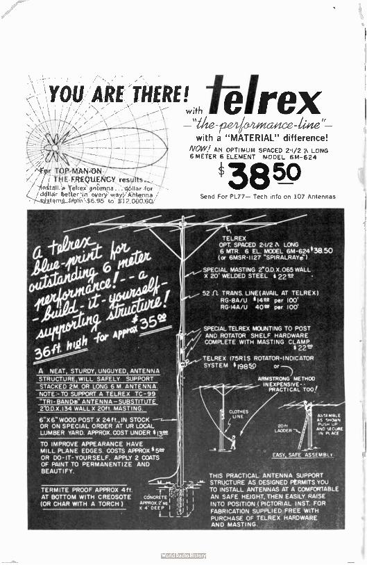
TOU ARE THERE! with
, • 'fig YO,PAIAN-0N-,• thIE-FREQU.,1(ICY
inetall a Teire)i antenna ... I:War for . dollar better In every way), Antenna
-¡-•.q...,stent_s_ledi-n $6.95 to $' 12.000.00/
A NEAT, STURDY, UNGUYED ANTENNA STRUCTURE, WILL SAFELY SUPPORT
STACKED 2M. OR LONG 6 M ANTENNA
NOTE:- TO SUPPORT A TELREX TC-99
TRI- BANDe ANTENNA - SUBSTITUTE 2 0.D.X.134 WALL X 20ft. MASTING.
6" X 6" WOOD POST X 24 ft., IN STOCK OR ON SPECIAL ORDER AT UR LOCAL LUMBER YARD. APPROX.COST UNDER tieL.
TO IMPROVE APPEARANCE HAVE MILL PLANE EDGES. COSTS APPROX 45u OR DO-IT-YOURSELF. APPLY 2 COATS OF PAINT TO PERMANENTIZE AND BEAUTIFY.
TERMITE PROOF APPROX 4ft AT BOTTOM WITH CREOSOTE (OR CHAR WITH A TORCH )
elrex lieze"
with a "MATERIAL" difference! NOW/ AN OPTIMUM SPACED 2-1/2 A LONG 6 METER 6 ELEMENT MODEL 6M-624
3850 Send For PL77— Tech info on 107 Antennas
TELREX OPT. SPACED 2-1/2 A LONG 6 MTR. 6 EL. MCOEL 6M-624 43850 (or 6MSR•1127 SPIRALRAYer)
SPECIAL TOASTING 2.. O.D.X.065 WALL X 20' WELDED STEEL 2222 •
52 TRANS. LINE(AVAIL AT TELREx ) RG•8A/U * 14 22 per 100' RG-I4A/U 40te per 100'
SPECIAL TELREX MOUNTING TO POST -1 AND ROTATOR SHELF HARDWARE COMPLETE WITH MASTING CLAMP
22"
__•TELREX 175R1S ROTATOR- INDICATOR SYSTEM 819850 or --.)
ARMSTRONG ME TF100
INEXPENSIVE - - , PRACTICAL TOO
2011 LA00ER —e,
&NS! MALE AS SNCAPN PUSH uP ANO "A CultE IN Pe. ACE
EASY SAFE ASSEMBLY
THIS PRACTICAL ANTENNA SUPPORT STRUCTURE AS DESIGNED PERMITS YOU TO INSTALL ANTENNAS AT A COMFORTABLE
AN SAFE HEIGHT, THEN EASILY RAISE INTO POSITION ( PICTORIAL INST. FOR FABRICATION SUPPLIED FREE WITH PURCHASE OF TELREX HARDWARE AND MASTING.
The VHF Amateur Title registered U.S. Post Office
A MONTHLY PUBLICATION
OFFICES:
Business & Editorial 67 Russell Avenue Rahway, New Jersey
EDITORIAL STAFF
Managing & Associate Editors
Bob Brown, I2ZSO
Robert Rtehardson, W4DCN
Circulation Manager
Peter A. Narkavage, 1112CAU
Production Manager
Douglas F. Clanton
Comae]
J. D. Ited"Brown. 12ZSP
Moonbotmsce Editor
Allen IOU, X2011 48 Cuuberland Avenue
Verona, New Jersey
Single Sideband Editor
Phillip Dural, I2PCO
304 Nast Northfield Rd.
Ltvingston, New Jersey
South American Editor
Nichael A. Czysch LII3DCA
Monasterio 345
F. Lopez 110BN Buenos Aires. Argentina
nil III Isatette is
pablisbed montkly by
Eobert W. brown, EtZ80.
Enbneription rates:
one pear. $ 11.00, two
y , si.,.. à
ASA& Parings add Al.
ADVERTISING rate card
2s_m_ememi, Entire
esa..... printed in
Clara. N. J., 0.8.1
Telepnone Muffler for
out-of-elate direct
dialing: 201-FU 1-1284.
Local callsoculton 1-
1284. DEADLINE: 00d
only knows.
IOL 4, No. 10 t£TOBER 1151
Tabit Clif
Modulation Monitor Michael A. Czysch, LUSDCA
Maverick Rides Again Sam Duncan, K2OPI
Moonbouncel Allen Katz, K2UTH 9
Short-Shorts Anonymous II
Sam's Bottle Baker Sam Dashes, K2OPI 12
More Short-Shorts Anonymous 14
Signal Reports Dave Heller, KSIIIIP 16
South /woman News Micheel A. Czysch, LUSDCA 18
...between East and West Alois Pendl, OESAP 19
Propagation Forecast Bob Brown, K2ZSQ, Editor 23
Fifth Monthly Author's Contest! VOTE THIS MONTH for Pate's sake' 27
FRONT COVER
Our moonbounce editor, Allen, K2UTH, snagged a great circuit from Ot, il2C14, on his 1296 mc converter. See schematic and parts list on pages 10 and 11. This little converter is really "hot" and simple to build, using only three tubes ( corm= ones at that), 6U8, 6AN4, and a 6DJ8. Converter output ( 1296 mc) feeds into your regular receiver at 26 to 30 mc.
Nice, eh?
3
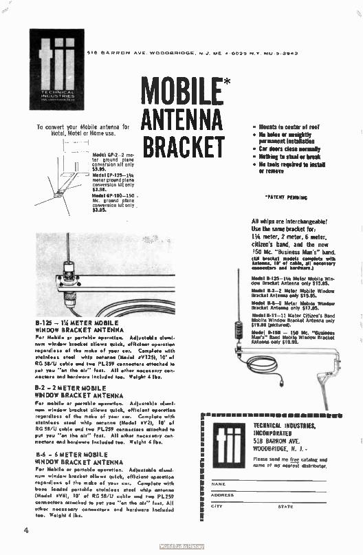
518 BARRON AVE WOOCIBRIOCIE NJ ME 4 0095 Nv MUS 3%4
TECH 'CAL. • INVUSTRIES
......
To convert your Mobile antenna for hotel, Motel or Home use.
11 Model GP-2 2 me-ter ground plane conversion kit only $3.95. Model GP-125-1 1/4 meter ground plane conversion kit only $3.95.
Model GP- 150-150 Mc. ground plane conversion kit only $3.95.
MOBILE* ANTENNA BRACKET
,
B-125 — 114 METER MOBILE WINDOW BRACK ET ANTENNA For Mobile or portable op•rotion. Adlu•table alumi-num window bracket allows quick, efficient operation
r•gardless of the mok• of your cor. Complet• with
stainle•• • triol whip antenna ( Mod•I trV125), 10' of
RG 58'U cable and two PL259 connectors attach•d to
put you ' on the air '' fem. All other ...... cry con-
n•ctor• und hardware included too. Weight 4 lbs.
B-2 — 2 METER MOBILE WINDOW BRACKET ANTENNA For mobile or portable operation. Adlustable alumi-
num window bracket allows quick, •fficient op•ration
regardless of the make of your car. Comptera with
irtainless • t••I whip antenna ( Mod•I eV2), 10' of
RG 58'U coble and two PL259 connectors attached to put you ' on the air — fast. All other necessary con
n•ctors and hardware included too. Weight 4 lbs.
B-6 — 6 METER MOBILE WINDOW BRACKET ANTENNA For Mobile or portable operation. Adiu•toble alurni
num window bracket allows quick, efficient operation
regardless of the mok• of your car. Comploto with
bese loaded portable stainless steel whip antenna
IMod•I « V6), 10' of RG 58 'U cable and two Pl_259
conn•ctors attached to put you '' on th, air' . fast. All
oth•r n•c•ssary conn•ctor• and hardware included too. Weight 4 lbs.
• Mounts in center of root
• Ne holes or unsightly permanent installation
• Car doors close normally • Nothing to steal or break • Ne tools required to install
or remove
'PATENT PENDING
All whips are interchangeable! Use the same bracket for: 11/4 meter, 2 meter, 6 mete:-,
citizen's band, and the new 150 Mc. "Business Man's•" band (All bracket models complete with
Antenna, 10' 01 cable, all necessary connectors and hardware.)
Model B-125 11/4 Meter Mobile Win-dow Bracket Antenna only $ 15.95.
Model 1$2 2 Meter Mobile Window Bracket Antenna only $15.95.
Model 13-6 6 Meter Mobile Window Bracket Antenna only 911.95.
Model 8-11 11 Meter Citizen's Band Mobile Window Bracket Antenna only 919.95 ( pictured).
Model 11-15O — 150 Mc. " Business Man's" Band Mobile Window Bracket Antenna only $15.95.
•
Iii TECHNICAL INDUSTRIES, INCORPORATED 518 BARRON AVE.
WOODBRIDGE, N. J. •
Please send me tree catalog and
name cf my nearest distributor.
NAME
CITY STATE
4
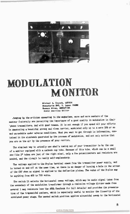
OD tILATION ONITOR
Michael A. Czysch, LU33CA Monasterio 346, V. Lopez FlIGBM Buenos Aires, ARGENTINA Snuth American EdItcr
Judging by the articles appearing in the magazines, more and more members of the
amateur fraternity are perceiving the importance of a good quality in modulation in their
'phone transmitters. And with good reason. It is not enough if you spend all your efforts
in generating a beautiful strong and clean carrier, modulated only up to a mere 30% or so
and unreadable under adverse conditims. What you want to get through is information, con-
tained in the sidebands generated by the process of modulation, and not only notice that
you are on the air by the presence cf your carrier.
The simplest way to actually see what's coming out of your transmitter is by the use
of a monitor equipped with a cathode ray tube. Because of this tube, which can be a small
one ( the 2" tubes are just of the right size), only a few potentiometers and resistors are
needed, and the circuit is really self-explanatorY.
The voltage applied to the B-plus terminal comes from the transmitter power supply, and
is turned on and off at the same time, so there it no danger of burning a hole in the screen
of the CRT when no signal is applied to the deflection plates. The value of the B-plus may
be anything from 400 to 700 volts.
The switch Si seiects the horizortal sweep voltage, which may be audio signal taken from
the secondary of the modulation trusformer throue a resistive voltage divider made from
several 1 meg resistors ( see the ARRL Handbook for full details) and provides the presenta-
tion of the trapezoidal pattern, which is especially useful to monitor the linearity of the
modulated power stage. The second switch position applies sinusoidal sweep to the horizontal
5
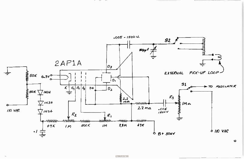
o-
.005 - iSeOV.
2AF91A
1-7K I ei seeK IM 2,f m
EXTERNAL Pee- UP LCe P
51 70 A71y. LArc e
110 VAC
co
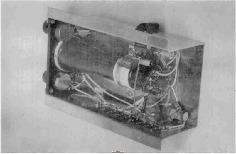
plates taken from .a small filament transformer, connected with its secondary to the 6.3
volts winding of some other power transformer, and in this way it is possible to visualize
an envelope pattern of the outgoing signal.
From this backwards-connected filament transformer was also taken the voltage for the
negative supply which allows a brightness control without bringing the cathode to a posi-
tive potential with respect UD the filament of the CRT.
An RF signal of the proper value is connected to the vertical plates through the tuned
circuit formed by the tapped coil, the 1C0 uuf variable capacitor and the pick-up loop.
Switch S2 selects the taps for 10, 6 or 2 meter operation.
The accompanying photographs give a good idea about the construction and mounting of the
complete unit. The chassis was bent from a flat piece of aluminum and is Elé" long. The front
panel was made from a piece of pertinax ( any insulating material will do) and is just large
enough for the picture tube, the three potentiometers and the rotary switch Si. S2 is mount-
ed on one side of the chassis and a terminal strip on the other one.
The picture at the head of the article shows the monitor mounted in the author's station
just in front of the operating position.
This little instrument has been invaluable to control the modulation level of the differ-
ent transmitters in use at LU3DCA, and I know no other way to find the correct settings of the
controls of a modulator furnished with a speech clipper, a real necessity if you want,to have
an effective ' phone transmitter.
PlIFERICI' RIMS Sill Samuel W. Usk», K2OPI /KIPOK
Several questions have been asked about the filter in the June issue of THE VHF AMATEUR.
I will try to answer them as they core, but please be patient.
First, some fellows are interested in the maximum power which can be handled by the fil-
ter. If a flat line (low SWR) is used, the filter as described should handle about 450 watts.
This is power input to the filter and not d.c. power input to the final amplifier as is the
case with most commercial specs. An increase in SWR will increase the peak voltage across the
capacitors. For use at the kilowatt level, wider spaced variables such as made by E.?. John-
son or Hammarlund should be used.
Unfortunately, the tuning procedure seems to have been confusing. The reason for retuning
C2 at 50 mc after adjusting for minimum feedthru at 58 mc is that the suck-out "well" is rather
broad and its position has some effect on the attenuation at 50 mc. To insure the lowest possi-
ble insertion loss at 50 mc, the trap must be adjusted for both frequencies.
An error has been found in the schematic as it was originally published - but it will still
work OK. L3 should be in series with C2 and not 04. There is no coil on the 1.4 leg.But regard-less, input and output ends can be switched.
When properly adjusted, Cl and C2 are about at minimum capacitances. This may make tuning the high end of the band rather difficult. Suggested capacitors to solve this problem are the Hammarlund HF-15 or any similar type having about 2.5 pf minimum capacitance.
8
E
Allen Katz, K21JVH
48 Cumberland Ave.
Verona, New Jersey
A horrified expression and a high pitched
cry, "MATH?" This typifies the atti.7.ude too many
hams have toward mathematics. Most of these hams
have had a good background in math, far in excess
of any necessary to master the simple equations
presented in this column. Then why all the fuss?
Aft 0 N
o N
If one operated the low frequencies where commercially built
equipment and dress pattern construction articles prevail, possibly
ore could dispense with math, but here on the VHF frontier, where commercial
equipment is nonexistent and construction articles scarce, math is a necessity.
One has great pleasure in building his own equipment, but how much more pleasure is
gained by building and destgntnt your own tear? This is what mathematical applications
can do for you. It has been the policy of the column to give general construction informa-
tion along with mathematical formulas in order that its readers could build and design
equipment tailored to their own needs.
New Book - - - "VHF For The Rudio Amateur"
After hearing my friend's praise W6Pw's book, VHF For The Radio Amateur, I could not
help but to rush out and buy a copy. I then proceeded to read it cover to cover. Although
we were very impressed by the practical content, we would have liked to see a little more
theory. We concur with Frank's comments on collinear arrays,using a collinear here at
K2UTH. We would have been even happier if he mentioned a parabolic antenna - alas. His
transmitter section made us really light up. Never before had we seen a 1296 mc transmitter
in print, and here we bao two to cnocse from! The flat line unit really looks simple to
build. His converter section is also excellent. The idea of running 11613's with out-forced
air cooling is sure to prove invaluable these tubes becoming available to the general
ham public. Frank has a whole section on parsnips for the fellows who's interest lies in
that direction. This is the first VHF book that deals so thoroughly with the UHF end and
truly warrants the attention of all VHF operators. A fine Job, Frank!
9
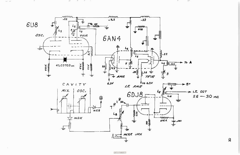
YY1 .33
6U8
05C.
.33
_rt .22
L6 ro A
3
I.F. OUT
2 6 — 30 pnc
o
epee Repo/Ai.
Dave Heller, 101111P
14 Darkleaf Lane
Levittown, Penn. klASCW.4
These VHF operators who are either afraid to give an honest signal report or are in-
capable of doing so would learn a lot from an evening's listening on a particular fre-
quency: 3999, to be exact. This crop of sidebanders is an elite society - because they
want it to be. First of all, you don't deliberately set 1 kc from a band edge unless
you 'mow you're good - no drift - no residual carrier, no upper sideband. But a written
description of this group tearing one of their fellows apart for a couple of cycles
drift or the least flattop or nonlinear operation doesn't tell the story - you must hear
it. Please do - It's an education.
Contrast this with the VHF "talking" bands. A station that doesn't move a kc every few
minutes must be crystal controlled. Modulation 100% or less is reported " insufficient."
Broad signals are radiated with pride. Technically this is all a step backward, contrary
to the government's purpose in licensing radio amateurs.
Many VHF'ers don't seem to care. They reject any less-than-perfect signal report; they
tell the friendly CO to soak his head. These characters don't read the better magazines,
so let's dismiss them from this discussion - they won't see it anyhow.
The majority don't know what to think. They receive conflicting reports - the distant
station says the signals' fine, with possibly slight drift. Most of the local's report the
same, but "broad due to overload" ( whatever that means). But a couple of critical locals
keep saying that they're overmodulating. irhom to believe?
So perhaps a discussion on how to give a signed report is in order. The receiver used
must be stable and reasonably sharp. A "sideband" receiver with steep IF skirts helps, but
it isn't mandatory. A scope on the receiver also helps. A means of attenuating signals be-
fore the receiver ( or converter, if one is used) is necessary.
Drift measurement is either simple or impossible. Use either your VFO or receiver - which
ever has better stability and calibration. My VFO reads less than one kc frequency difference
on six meters whereas the receiver can only be read to about 3 kc - so I use the VFO. Simply
measure the frequency received at intervals - and report what you read. But if your equip-
ment isn't stable, the readings, obviously, are meaningless.
Continued on page 18
15
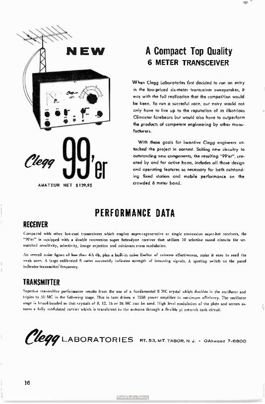
e'99997er AMATEUR NET $ 139.95
RECEIVER
A Compact Top Quality 6 METER TRANSCEIVER
When Clegg Laboratories first decided to run an entry
in the low-priced six-meter transceiver sweepstakes, it
was with the full realization that the competition would
be keen. To run a succesful race, our entry would not
only have to live up to the reputation of its illustrious
Climaster forebears but would also have to outperform
the products of competent engineering by other manu-
facturers.
With these goals for incentive Clegg engineers at-
tacked the project in earnest. Suiting new circuitry to
outstanding new components, the resulting "99'er", cre-
ated by and for active horns, includes all those design
and operating features so necessary for both outstand-
ing fixed station and mobile performance on the
crowded 6 meter band.
PERFORMANCE DATA
oh other low.cost transceivers which employ super-regent-rutise or single consersion super•het receivers, the
-99'er- is equipped with a double conversion super hetrodyne receiver that utilizes 10 selective tuned circuits for un-
matched sensitivity, selectivity, image rejection and minimum cross modulation.
An overall foime figure of less than 4.5 db, plus a built-in noise limiter of extreme effectiveness, make it easy to read the
weak ones. A large calibrated S meter accuratdy indicates strength of incoming signals. A spotting switch on the panel
indicates transmilleifrequency.
TRANSMITTER Superior transmitter performance results from the use of a fundamental 8 MC crystal which doubles in the oscillator and
triples to 50 MC in the following stage. This in turn drives a 7558 power amplifier to maximum efficiency. The oscillator
stage is broaddianded so that crystals of 8, 12, 16 or 24 MC can be used. High level modulation of the plate and screen as-
sures a fully modulated carrier which is transferred to the antenna through a flexible pi network tank circuit.
eki, LABORATORIES RT. 53, MT. TABOR, N. J. • OAkerood 7-6800
16
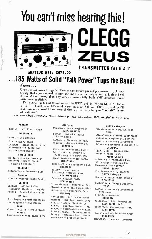
You can't miss hearingthis!
CLEGG ZEUS TRANSMITTER for 6 ee 2
...185 Watts of Solid "Talk Power"Tops the Band! Again ... Clegg Laboratories brings VIIrers a new power packed performer ... A new beauty that's guaranteed to produce more carrier output and a higher level of modulation power than any other commercially built VIII: amateur trans-mitter now available.
Put a Zeus on 6 and 2 and watch the QtiO's roll in. If you like DX, listen to this! You'll have 185 solid watts on boils AM and CW . . . and you'll hase automatic modulat• control that will actually let you "out- talk" many kilowatt rigs!
Ask row lour°, (hoed below) for full Infornuaton. He'll be glad 10 serue you.
ALABAMA
Mobile - AC Electr -nics
CALIFORNIA
Hemet - Gil Sevcrns
L.A. - Henry Radio
Oakland - Elmer Electronics Riverside - Mission Ham
S. F. - Amrad Supply
CONNECTICUT
Bridgeport - Kaufman Elec. Hartford - Radio Shack
Hatry ,f Hartford
DELAWARE
Wilmington - Delaware Elec.
FLORIDA
Miami - Amateur Radio Centr.
ILLINOIS
Chicago - Allied Radi.,7
Amateur Electronic Supply
Peoria - Klaus Radio & Elec.
INDIANA
F-rt Wayne - Brown Electron.
Indianapolis - Van Sickle
IOWA
Council Bluffs - World Radio
KANSAS
Hutchinson - Acme Radio & TV
MARYLAND
Wheaton - Key Electronics
MASSACHUSETTS
Boston - DiMambro Radio Radio Shack
'Harvard - Electronics Inc.
Reading - Graham Radio Co.
MICHIGAN
Ann Arbor - PUrchase Radin
Detroit - M.N. Duffy CA.
Radi - Supply & Engr. Co.
Grand Rapids - Radio Parts MINNESOTA
Minneapolis - Electronic Cntr MISSOURI
Butler - Henry Radio
St. Louis - Walter Ashe
NEW HAMPSHIRE
Concord - Evans Radio
NEW JERSEY
Mountainside - Federated Pur.
Newark - Terminal-Hudson Elec.
Shrewsbury - Federated Pur.
NEW YORK
Amsterdam - Adirondack Radio
Jamaica - Harrison Radio Corp.
N.Y.C. - Arrow Electric Co.
N.Y.C. - Harrison Radio Corp.
N.Y.C. - Terminal-Hudson Elec.
Staten Island - Two-Way Radio
Buffalo - Genesee Radio Parts
Rochester - Rochester Radio
NORTH CAROLINA
Winston-Salon - Dalt ,n-Hoge
OHIO
Cleveland - Pioneer Electronic
Columbus - Universal Servios
Dayton - Custom Electronics
Toledo - Selectronic Supply Co.
OKLAHOMA
Okla. City - General Elec.
Tulsa - Radio, Inc.
PENNSYLVANIA
Allentown - Federated Pur.
Pittsburgh - Tidings Co. Wyncote - Ham Buerger
RHODE ISLAND
Providence - N.H. Edwards
SOUTH CAROLINA
Sumter - Dixie Radio Surely TENNESSEE
Nashville - Electra Distrib. TEXAS
Dallas - Amateur Electronics Crabtrees
Houston - Busacker
VIRGINIA
Arlington - Key Electronics
WASHINGTON, D.C.
Electronic Wholesalers, Inc. WASHINGTON
Seattle - Seattle Radio Sply. WISCONSIN
Milwaukee - Amateur Electron.
17
Broadness may be caused bt over ulation or excessive modulation spectrum, especially
in the case of linear amplifiers, nonlinear operation. Differentiation of the type of
broadness is not always easy without an oscilloscope, but the existance of excessibe width
is simple to determine. As mentioned above, a means of attenuating the incoming. signal is
necessary. I have a coax switch to select several antennas; a spare and cliplead antenna
permits adjusting a strong signal to give almost any 0-meter reading.
Fick any convenient reading as reference - say, 10 db over S9 for locals and tune in a
local with a known clean signal ( who preferably has a ' scope monitor). Adjust your antenna
for the reference signal strength and tune across the 100 percent modulated signal, record-
ing its apparent width. Have this same station give you a short transmission devoid of modu-
lation and again tune through it - the apparent width of the unmodulated carrier is the re-
ceiver passband ( for an unmodulated carrier has zero width). The difference is the bandwidth
of the station. It should be about 7 or 8 kc if the station is really sharp and cleans.
Now you know what a good signal sounds like under your test conditions. Write it all down
before you forget. Any signal that takes any more room on your receiver dial, when the
strength is adjusted to your "standard," is broad; with experience you can learn to measure
approximately how broad.
Don't be afraid to tell what you read or hear - even though the reply will often be
(charitably speaking) misinformed.
SOUTH AMERICAN
Michael A. Czysch, LU3DCA
IVHFI
Monasterio 345, V. Lopez FNGBM
Buenos Aires, ARGENTINA PE IWV P S
Here I am again with a short notice to let you know what is happening on VHF down this
way.
After a complete absence of any openings on the six meter band during the last few months,
yesterday in the late evening, or more exactly at 0200 GMT of September 4, I heard again for
the first time a steady carrier on 49.9 mc coming in with the characteristic flutter fading
of TE propagation. You can imagine my feelings when I detected this first sign of life on a
completely deserted band, but I nearly fell off my chair when a fellow in the lab told me he
heard three W2 stations on 6 meters around 2030 GMT on Saturday, September 2. It is really
worthwhile to monitor the band closely again!
I hope this good news will also bring back some of the local activity we enjoyed in other
days, because right now nearly all 6 meter stations have migrated to other bands, to the point
that it is now easier to find someone on 144 than 50 mc,• a situation not found ever before
down here!
Next month I hope to be back with some DX contacts with our many friends in W-- land!
'Till then, 73, Michael, LU3DCA EMI
18
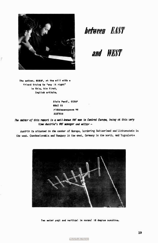
Two meter yogi and vertical In normal 14 degree sunshine.
The author, 0E6AP, at the mill with a
friend trying to ' say It right'
in this, his first,
English article.
between EAST
and WEST
Alois Pendl, 0E6AP
GRAZ IX
Plilddemanngasse 49
AUSTRIA
The author of this Import is a —Mom We man in Central Eurofe, being at this uery
tiny Austria's MVP manager and editor—
Austria is situated in the center of Europe, bordering Switzerland and Lichtenstein in
the west. Czechoelovakia and Hungary in the east, Germany in the north, and Yugoslavia
19
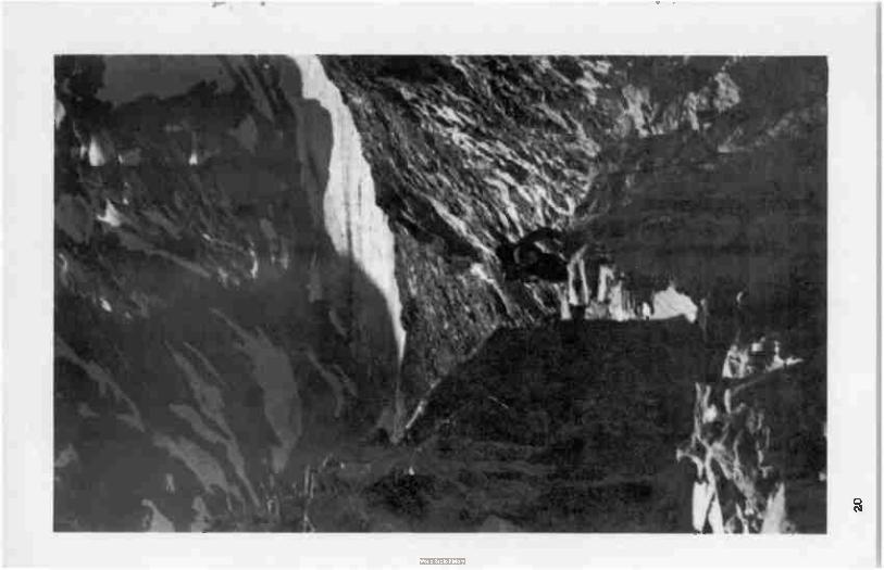
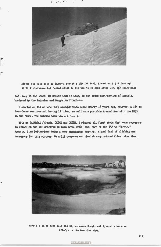
ABOVE: The long trek to 0E6AP's portable OTN ( at top). Elevation 9,318 feet uP1
LEFT: Picturesque but rugged clieb to the top to do some after work (3) operatingl
and Italy in the south. Hy native town is Graz, in the south-east section of Austria,
bordered by the Yugoslav and Hungarian frontiers.
I started on 144 mc with very uncomplicated sets; nearly 15 years ago, however, a 144 mc
twin-Super was created, having 11 tubes, as well as a portable transmitter with the 823A
in the final. The antenna then was a 4 over 4.
With My faithful friends, OEISHS and OK6TH, I planned all first skeds that were necessary
to establish the vhf wearum in this area. 0E6RH took care of the 432 mc "firsts."
Austria, like Switzerland being a very mountanDus country, a good deal of climbing was
necessary for this purpose. We still preserve and cherish many colored films taken then.
Nere's a quick look down the way we come. Rough, eh? Typical view from
BE8A8/P in the kistrian Alps.
21
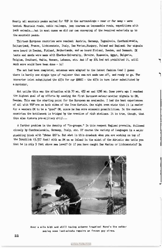
Nearly all mountain peaks suited for VHF in the surroundings - near or far away - were
tested. Mountain roads, cable railways, jeep courses on impassable roads, expeditions with
pack animals...but in most cases we did our own conveying of the required materials up to
the mountain peaks.
Thirteen European countries were reached: Austria, Germany, Yugoslavia, Czechoslavakia,
Switzerland, France, Lichtenstein, Italy, San Marino,Hungary, Poland and England. Our signals
were heard in Sweden, Finland, Netherlands, and we heard Finland, Sweden, and Denmark. DX
tests and skeds were made with Kharkov University, Ukraine, Roumania, Egypt, Bulgaria,
Belgium, Svalbard, Malta, Monaco, Lebanon, etc. And if my XYL had not prohibited it, still
much more would have been done - hi!
The set had been completed, antennas were adapted to the latest fashion ( and I guess
there is hardly one single type of radiator that was not made use of), and ready to go. The
converter inlet substituted the 417A for our E88CC - the 417A in turn later substituted by
a nuvistor.
Not unlike this was the situation with 70 mc, 432 mc and 1296 mc. Some years ago I reached
the highest goal of my efforts by sending the first European meteor-scatter signals to BM,
Sweden. This was the starting point for the European ms avalanche. I had the best experiences
of all with VHF'ers on both sides of the Iron Curtain. One might even state that it is easier
for a western OM to be a "good" OM, since he has more economic possibilities. In the eastern
countries the bottleneck is bridged by the creation of club stations. It is true, though, that
this also fosters pre-military drill...
A further problem is the density of "in-groups." In this respect England prevails, followed
closely by Czechoslavakia, Germany, Italy, etc. Of course the variety of languages is a major
stumbling block with ' phone DSO's. But what is this drawback when you are working on top of
the Sonnblick ( 9,317 feet) with an OM on an island in the midst of the Adriatic who tells you
that he is only 9 feet above sea level? Or if you have caught San Marino or Lichtenstein? In
Over a mile high and still having antenna troubles! Here's the author
leaking some last-alnute repairs on frozen guy wires.
22
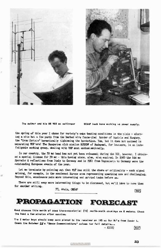
The author and his KB 432 nc collinear 0E6AP back home working en power ooPPIY.
the spring of this year I chose for variety's sake testing conditions in the plain - elect-
ing a site but a few yards from the barbed wire fence-clad border of Austria and Hungary,
the "Iron Curtain" hermetically tightening the bordertine. Yes, but it does not succeed in separating VHF'ers! The Hungarian club station HG5KBF of Budapest, for instance, is an inde-fatigable working group, dealing with VHF most enthusiastically.
In our country, the 50 mc band has not yet been released; during the IGY, however, I obtain-
ed a special license for 70 mc - this having since, alas, also expired. In 1960 the 144 mc Sporadic E reflections from Italy to Germany and in 1961 from Yugoslavia to Germany were the outstanding European events of the year.
Let me terminate by pointing out that VHF has still the charm or originality - each signal
arising, for example, in the southeast Europe area representing something new and challenging. Beyond this, rocnbounce puts more interesting and untried tasks before us.
There are still many more interesting things to be discussed, but we'll have to save them for another writing.
73, Alois, 0E6AP
PROPAGATION FORECAST Good chances thin nonth of soue trans-equatorial (TE) rorth-south o2rnings on 6 utters. Check the band • few minutes after sunrise.
Tee 2 meter boys should keep ears pinned to the receiver on 145 me fcr Hi's from Incur I.
Check the October Us "Space Communications" column for full details...
- DZSQ Era
23
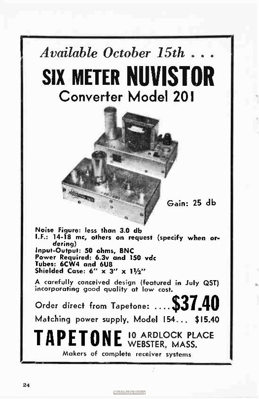
IAvailable October 15th
SIX METER NUVISTOR Converter Model 201
Gain: 25 db
Noise Figure: less than 3.0 db I.F.: 14-18 mc, others on request (specify when or-
dering) Input-Output: 50 ohms, BNC Power Required: 6.3v and 150 vdc Tubes: 6CW4 and 6U8 Shielded Case: 6" x 3" x 11/2"
A carefully conceived design (featured in July QST) incorporating good quality at low cost.
Order direct from Tapetone: $37.40 Matching power supply, Model 154... $ 15.40
TAPETONE 10 ARDLOCK PLACE WEBSTER, MASS.
Makers of complete receiver systems
24
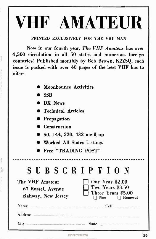
VHF AMATEUR PRINTED EXCLUSIVELY FOR THE VHF MAN
Now in our fourth year. Tite VHF Amateur has over
4,500 circulation in all 50 states and numerous foreign
countries! Published monthly by Bob Brown, K2ZSQ. each
issue is packed with over 40 pages of the best VHF has to
offer:
• Moonbounce Activities
• SSB
• DX News
• Technical Articles
• Propagation
• Construction
• 50, 144, 220, 432 mc & up
• Worked All States Listings
• Free "TRADING POST'
SUBSCRIPTION The VHF Amateur
67 Russell Avenue
Rahway, New Jersey
Na nie
Address
City
rj One Year $2.00 E Two Years $3.50 rj Three Years $5.00
Ei New I] Renewal
S:ate
25
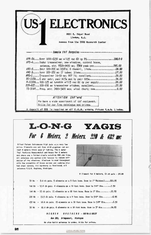
8 Element for 2 Neere, 12 db gala - PAO
220 Mc - 13.5 db gain. 9 elements on a 9 foot boom. Boom is 5/8" Dia.
432 Mc - 16.8 db gain. 15 elements on a 10 foot boom. Boom is 5/8" Dia.
50 Mc - 10.4 db gain. 6 elements on a 18 foot boom. Boom is 3" Dia
WEGNER BROTHERS - i81110 MINE
Box 263, Bridgeport, Michigan
(L7S1 ELECTRONICS 1921 E. Edgar Road
Linden, M.J.
Accoss from the ESSO R h Center
Sample VHF Bargains
APR-5A....Rcyr 1000-6230 mc w/115 vac 60 cy PS .. loa,o 0 APS-4 Radar transceiver, new w/cables, control boxes,
antenna, etc; 9320-9430 mc; 35KW peak pwr 295.00 ARC-3 Xmtr 100-156 mc 832PA; 8 channel, 1/new 19.50
ARC-3 Rcvr 100-156 mc 17 tubes; 1/new 17.50 ARG-1 Transceiver 14-50 mc; 807 PA; excellent 29.50 BC-1158...6 mtr xmtr; pair 815s mod by pair 815s 34.50 R-1132.4...100-125 mc tunable w/115 vac 60 cy pwr supply 55.00
SCR-522...100-156 mc transceiver w/tubes; excellent 22.50
7S-3/AP...Frea. mtr; 2400-3400 mcs; w/cal chart; new .9.50
ATTENTION Wirers!
We have a wide assortment of uhf equipment. Write for our free catalogue and prices.
A deposit of 25% is required on all C.O.D. orders. Prices f.o.b. Linden.
YAGIS For8 Idea 2 *ten 221 12 or
Silver Falcon introduces high gain et e very low
price. fleimente are cut fro. hi- Q elueinue rod ex-
cept 6 eaters which use. 6. tubing. The A mo 2oF
Yogi feature. 0..41-Match and beimas for 2 ttttt
and above use a folded dipole notching 300 oh. line.
All antennas are coated with lacquer to reduce oel-
dation of the alueinge. Alueinum is used throughout
with the exception of brass screws and cadelue pla-
ted steel screws. All hardware ie furnished. All
antennas F.0. A. Saginaw, Michigan.
50 Mc - 9.0 db gain. 5 elements on a 9 foot boom. Boom is 1" Thickamil $11.95
144 Mc - 12.0 db gain. 8 elements on a 10 foot bona. Boom is 5/8" Dia. 7.50
144 Mc - 15 db gain. 11 elements on a 18 foot boom. Boom is 1" Dia. 15.95
.6.95
650
24.95
We also build antennae to order. Write for prices.
203
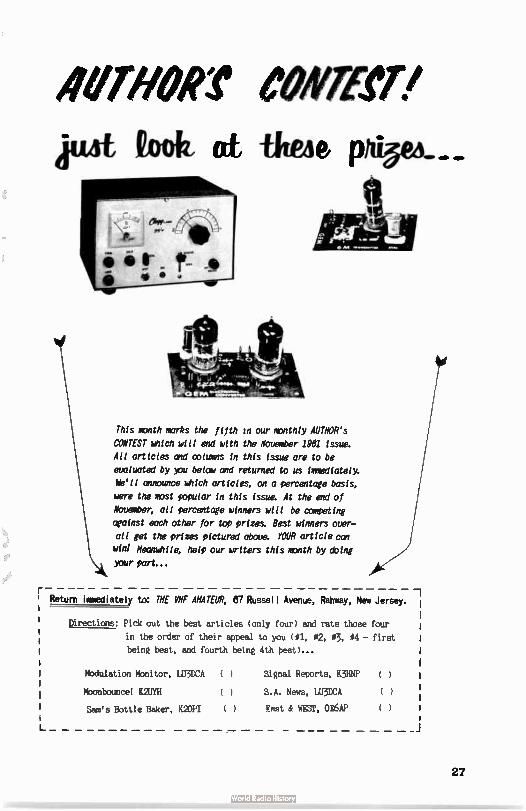
demon emeperi pie 12,,e, ai titen
11\ k This month marks the fifth vi our monthly AUTMOR's
against each other for top prizes. Best winners over-
CONTEST which will end with the November 1961 issue.
All articles and columns in this issue are to be
evaluated by you below and returned to us immediately.
We'll announce which articles, on a percentage basis,
were the most popular in this issue. At the end of
November; all percentage winners will be comeeting
all get the prizes pictured above. YOUR article can
win' Meanwhile, help our writers this month by doing your part...
—• . : ,
4 li la ks 'ee '"'""1,1S111.01 '
ems '
' Return immediately to: THE MNF MAIM 87 Russell Avenue, Rahway, New Jersey. I
I Directions: Pick out the best articles ( only four) and rate those four I
in the order of their appeal to you (#1, 02, 03, 04 - first 1 I being best, and fourth being 4th best)...
Modulation Monitor, LU3DCA
Mbonbounce! MTH
Sam's Bottle Baker, MOH
(
(
( )
Signal Reports, K3HNP
S.A. News, LU3DCA
East & WEST, OAP
-1
( )
(
(
27
TWO-WAY RADIO COMMUNICATIONS ELECTRONICS EQUIPMENT DISTRIBUTORS
232-6 HYLAN BOULEVARD
STATEN ISLAND 5. N. Y.
YUKON 1-7575 eiBRALTAR 7-3660
Come to Staten WOW for your VHF neeisI
euery item or brad listed is in stock/
folowww. Test
Cesco SW)? bridtes
.Jackson
Rico
Receivers and Transmitters
knee:, crnverters, pre-amps, etc.
rico
Poly-Comm trafflreivers
Tecraft converters
Cleft Zeus 4 99'ers
National receivers
Towers
Rohn
Tri-Ex
Antennas
Cush Craft (Sée pictures)
By-Par (Saturn 8 Solos. etc.)
Comae, Ireco, Belt-Whip
Parts Tubes
now-gey maces All CBS, Westinthouse,
Tun-Sol. Fe have in stock Fw crystals
5763 ,s, 6146'3, 6360's International Ital
Atlantic Coax
Cesco meters, etc.
Plus these:
Oak Pron, Qua, Speakers
rapecode
Sadie, Publications
Alto Call Plates
Aumechron 24 - Sour clocks
Burgess Batteries
Cramer - Balleiorson Transformers
Sonar
5783's, etc.
SPECIAL ro rmosE BRINGING THIS AD OR MAGAZINE WITH THEM(
RG6U - SPECIAL - 10g a foot. Atlantic Cable.
6148's - SPECIAL - J4.00 with al.
36 foot tower - SPECIAL - Tri-Ex cremk-up, swivel
base, drops to 10' 9". Reg. $106 plus freight. Our
price - $95.00 complete. (Four section tower(
National 62 VFO - SPECIAL - w/power supply. Good
for Ocnset Cammenicators. Our price - $42.00 with ad.
55% discount on all tubes - SPECIAL - with ad. Coax Retie - SPECIAL - DI 24 VDC coaxial- $4.00
28
Announcinr the New
V777.7.2TFIZ
VHF-127T obile Antenna
dith Magnetic Ease.
* No mouritim; holes required.
*Secure at high speeds.
* May be readily re7_oved
* 50 ohm inpedance.
* Self-levolin: ceramic ma,:net in each corner.
-
ERSA- RONICS Box 223 WHEELING, ILLINOIS
E. F. CENTI F
MOSley
lelrex
Tec raft 4-Gal n Central Electronics Elmac
Drake & others...
Specializing in gear for 50 mc & above
McGrath Electronics 2030 11th Street
Bou/der, Co/orado
Write us now - about your froblents or needs
Rs, KM* Ton, MgIUF Earl, 110-1W
29
CQ
VHF for the radio amateur. A new dynamic hand-book that covers all phases of VHF activities.
INDEX INTRODUCTION 1. VHF RADIO PROPAGATION
50, 144, 220, 432 and 1296 MC
bands
2. ANTENNAS
2.1 Discussion
2.2 RF Transmission Lines
2.3 Types of Antennas
2.4 50 MC Antennas
2.5 144 MC Antennas
2.6 220 MC Antennas
2.7 432 MC Antennas
2.8 1296 MC Antennas
3. TRANSMITTERS
3.1A 50 MC Low Powered
Transmitter
3.18 6W6GT 50 MC Transmitter
3.1C 6W6G8 50 MC Transmitter
3.1D 50 MC Exciter
3.18 High Powered 50 MC
Amplifier
3.2A Low Powered 144 MC
Transmitter
3.28 144 MC Exciter
3.2C High Powered 144 MC
Amplifiers
3.3A 222 MC Exciter
3.38 High Powered 222 MC
Amplifier
3.3C Single Tube 220 MC
Amplifier
3.4A 2C39 Units on 432 MC
3.48 Coaxial Circuit Transmitter
3.4C Flat Plate Line Transmitter
3.5A 1296 MC Cavity Transmitter
2.58 1296 MC Flat Line Transmitter
4. MODULATION
4.1 6L6 Modulator
4.2 6W6 Class El Modulator
4.3 6Y6 Class B Modulator
4.4 50 Watt Modulator
4.5 Screen Grid Modulator
4.6 Frequency Modulator
4.7 Transistor Speeds Amplifier.
4.8 Phase Modulator
4.9 Vacuum Tube Keyer
CO MAGAZINE
BOOK DEPT.
300 West 43rd St.,
New York 36, N.Y.
C-4
D VHF For The Radio Amateur, $3.50
Sirs, I enclose Please send my VHF
For The Radio Amateur postpaid to:
NAME CALL
ADDRESS
CITY ZONE STATE
eity resident , all : V; Salr.
5. POWER SUPPLIES 5.1 Small Power Supplies
5.2 Selenium and Silicon Rectifiers
5.3 Voltage Doubler
6. CONVERTERS
6.1 Converter for 50 MC
6.2 Converter for 144 MC
6.3 Converter for 220 MC
6.4 Converter for 432 MC
6.5 Converter for 1296 MC
7. RECEIVER IF SYSTEMS
7.1 Communication Type Receivers
7.2 14 to 18 MC IF Receiver
7.3 Audio Filter
8. PREAMPLIFIERS
8.1 220 MC Tube Preamplifiers
8.2 Parametric Amplifiers
8.3 Pump Oscillators
8.4 144 MC Parametric Amplifiers
8.5 220 MC Parametric Amplifiers
8.6 432 MC Parametric Amplifiers
9. TEST EQUIPMENT
9.1 Diode AC Voltmeter
9.2 AC and DC Diode Voltmeter
9.3 P.5.-Monitors
9.4 Tronsistoriced F.S. Meter
9.5 1296 MC Wovemeter and
Noise Generator
9.6 SWR Meters
9.7A Frequency Marker
9.78 Transistor Frequency
Marker
9.7C Dual Transistor Signal
Marker
9.8 Transistor Audio Oscillator
30
•
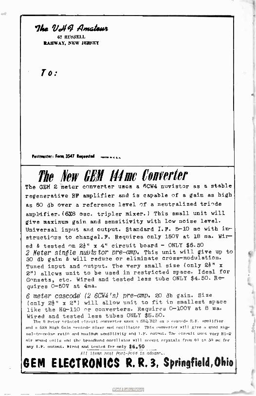
1his Vc,1 4male4i4 67 RUSSELL
RAHWAY, NEW JEFeEY
T o..
Postmaster: Form 3547 Requested
The leir WI Mine Converter The GEM 2 meter converter uses a 6CW4 nuvist -)r as a stable
regenerative RP amplifier and is capable nf a gain as high
as 60 db over a reference level nf a neutralized trinde
amplifier. (6X8 osc. tripler mixer.) This small unit will
give maximum gain and sensitivity with low noise level.
Universal input and output. Standard I.F. 5-10 mc with in—
structinns to changeI.F. Requires only 150V at 18 ma. Wir—
ed & tested on 2P' x 4" circuit board — ONLY $6.50
2 Meter stnéle nuvistor pre-amp. This unit will give up to 30 db gain & will reduce or eliminate cross—modulation.
Tuned input and output. The very small size ( only 2i" x 2") allows unit to be used in restricted space. Ideal for Gonsets, etc. Wired and tested less tube ONLY $4.50. Re—
quires 0-50V at 4ma.
6 meter cascade' (2 6CW4's) pre-amp. 20 db gain. Size (only 2e x 2") will allow unit to fit in smallest space like the HQ-110 or converters. Requires 0-100V at 8 ma. Wired and tested less tubes ONLY $5.50.
The 6 meter orinted circuit converter uses 1 6RellZ7 as a cascode R.F. amplifier
and n 6X8 High Gain oentode mixer and oscillator, This converter will give a good sig-
nal-to-noise ratio and maximum sensitivity and I.F. outnut. The circuit uses very
air wound coils and the broadband oscillator will accept crystals from 40 to 50 me for
any I.F. output. Wired and tested for only $6.50 All iteme grnt Poet-Paid in neanrc..
OEM ELECTRONICS R. R. 3, Springfield,Ohio
fè,
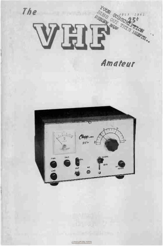
The
Amateur
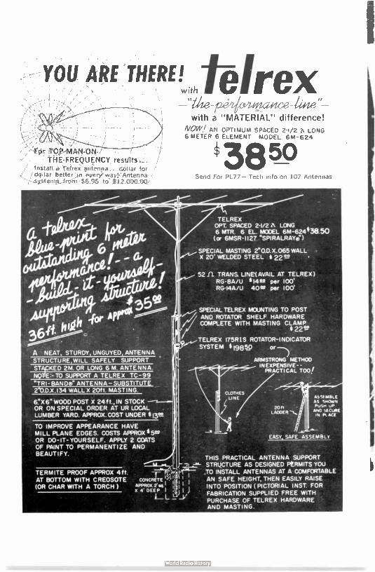
• For TOP-MAN-ON-THE-FREQUENCY results
Install a Te(ro neiina . dellar for ddllar better I n every. way. Antenna -sYstEtnla freiTi $6.95 to' $ 12.000.00
6X6" WOOD POST X 24 ft., IN STOCK OR ON SPECIAL ORDER AT UR LOCAL LUMBER YARD. APPROX.COST UNDER I3tM
TO IMPROVE APPEARANCE HAVE MILL PLANE EDGES. COSTS APPROX ¡ Ms OR DO- IT- YOURSELF. APPLY 2 COATS OF PAINT TO PERMANENTIZE AND BEAUTIFY.
/VOW/ AN OPTIMUM SPACED 2.1/2 :k LONG 6 METER 6 ELEMENT MODEL 6M-624
Send For PL77— Tech info on 107 Antennas
TELREX OPT. SPACED 2-1/2 A LONG 6 MTR. 6 EL. MODEL 6M-62438.50 (or 6MSR•1127 “SPIRALRAYe)
SPECIAL MASTING 2.0.0.X.065 WALL X 20' WELDED STEEL 22.m •
THIS PRACTICAL ANTENNA SUPPORT STRUCTURE AS DESIGNED PÈRM1TS YOU TO INSTALL ANTENNAS AT A COMFORTABLE AN SAFE HEIGHT, THEN EASILY RAISE INTO POSITION ( PICTORIAL INST. FOR
FABRICATION SUPPLIED FREE WITH PURCHASE OF TELREX HARDWARE AND MASTING.
The VHF Amateur A MONTHLY PUBLICATION
OFFICES:
Business & Editorial 87 Russell Avenue Rahway, New Jersey
EDITORIAL STAFF
Editor
Bob Brown, I2ZSQ 67 Russell Avenue
Rahway, New Jersey
Associate Editor
J.D. "Red" Brown, K2ZSP
67 Russell Ave.,
Rahway, N.J.
Moonbounce Activities
Editor
Allen Batz, 1207R
48 Cumberland Avenue
Verona, New Jersey
Single Sideband Editor
J.S. "Rusty" Bruuman
11207N
170 Schenck Avenue
Oreat Neck, New York
South American Editor
litchael A. Cyzsch
LOD*
Nonasterto 345 V. Lopez PNGBN
Buenos Aires, Artenttna
Me PEP Amateur it,
pablished monthly by
topert K. Brow., IMO,
Sublaeriptioa ..... :
oee year, $ 1.05, two
, $ 0 . 60, A year.,
11.00. Ferias, add SI.
ADVIRTISING rate card
os request Satire
contents printed in
Clark, N.J.. U.S.A.
VOL. 4, No. 7 JULY ll
To* ollir Conte* Editorial
Bob Brown, K2ZSQ 4
Possible Modes of VHF Propagation Ted Fabian, W3RUE 5
7VI...and what to do about ¡ti Bob U Red Brown, K2's ZSQ-ZSP e
Another Case for VHF 'Bud' Drobish, W9QVA 7
From the Ham Shack of K3GDA Philip J. Polito, K38QA e
De: Uncle Charlie How
A Night with WBPT Jack Woodruff, OPT li
California Ki lowatt Jerry Vogt, WA2E1CF 13
Sneak Preview - 99'er Ken Phillips, K8CHE le
8 Meters Nobile Dick DeMalignon, KOPSF J7
Mbonbouncel Allen Katz, K2UYII 26
South American VHF News Michael Czysch, LU3DCA 28
Departments-Monthly
Propagation Forecast 16
Trading Post 29
50 MC W.A S aezt m on th
Cover Photo
On our cover this month we have a new Clege 99'er. See page 15.
3
EDITORIAL
As you may already know, our editorial policy has been
only to comment on current topics of far-reaching importance.
We believe that an Editorial should NOT be a monthly monologue
or just a means of fulfilling an editor's urge to fill up
space. But, in spite of these beliefs, we would like to ex-
pound just a wee bit about THE VHF AMATEUR and what we intend
to do.
First off, though, an explanation is due re last month's
lateness. As you know, the June issue was received in July.
We are doing all we can to get back on schedule now. The reason:
Your editor faced graduation ceremonies at ye ole schoole plus
a two week tour of 13 states for business purposes. We wish to
express our appreciation to all readers who sent letters of in-
quiry and concern regarding their magazine. Although we didn't
have time to answer every letter, we trust all have their copies
by now.
Now as to the future of THE VHF AMATEUR: Your editor has de-
cided to work full-time on the magazine. In the past we had only
a few hours a week to devote. Obviously, a great deal of thought
went behind this decision. From the financial viewpoint, our
magazine never has been what some would call a " money-maker" but
we believe that in due time it may be. Over the last six or seven
months we have been astounded at the number of renewals and new
subscriptions received. In January of this year we had just about
1,000 subscribers. Now we have over 3,000. To make money, though,
we have to shoot for 10,000. This kind of success ( financial) is
not our chief concern, though. We'll get by.
Our purpose now is what it has always been: To provide the
VHF man with a magazine he can call his own. The VHF population is
growing by leaps and bounds. It won't be long before VHF will be-
come the center of amateur interest. - And we want to be there
to serve you. Well, we're running out of space. Maybe more next
month...
4 Bob Brown, K2ZSQ
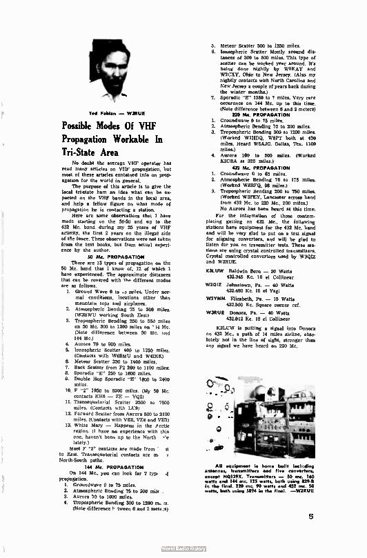
Ted Fabian - W3RUE
Possible Modes Of VHF
Propagation Workable In
Tri-State Area No doubt the average VHF operator has
read many articles on VHF propagation, but most of these articles contained info on prop-agation for the world in general.
The purpose of this article is to give the local tri-state ham an idea what can be ex-pected on the VHF bands in the local area. and help a fellow figure on what mode of propagation he is contacting a station.
Here are some observations that I have made starting on the 56-50 and up to the 432 Mc. band during my 25 years of VHF activity, the first 2 years on the illegal side of the fence. These observations were not taken from the text books, but from actual experi-ence by the author.
SO Mc. PROPAGATION There are 13 types of propagation on the
50 Mc. band that I know of, 12 of which I have experienced. The approximate distances that can be covered with the different modes are as follows.
1. Ground Wave 0 to .a miles. Under nor-mal conditions, locations other than mountain tops and airplanes.
2. Atmospheric Bending 75 to 200 miles. (W3BWU working South East)
3. Tropospheric Bending 250 to 55.1 miles on 50 Mc. 300 to 1200 miles on ' 14 Me. (Note difference between 50 Mc. ..nd 144 Mc.)
4. Aurora 70 to 900 miles. 5. Ionospheric Scatter 400 to 1250 miles.
(Contacts with W4RMU and W41KK) 6. Meteor Scatter 350 to 1400 miles. 7. Back Scatter from F2 200 to 1100 miles. 8. Sporadic "E" 250 to 1600 miles. 9. Double Hop Sporadic "E" 1800 to 2400
miles. 10. F "2" 1950 to 6500 miles. (My 50 Mc.
contacts KH6 - ZE - VQ2) 11. Transequatorial Scatter 3500 to 7500
miles. (Contacts with LU9) 12. Forward Scatter from Aurora 800 to 2100
miles. (Contacts with VE8, VE4 and VE7) 13. White Mary - Happens in the Arctic
region. (1 have no experience with this one, haven't been up to the North -oe lately.)
Most F "2" contacts are made from • st to East. Transequatorial contacts are m North-South paths.
144 Mc, PROPAGATION On 144 Mc., you can look for 7 typ.
propagation. I. Groundwave 0 to 75 miles.
2. Atmospheric Bending 75 to 200 milt . 3. Aurora 70 to 1000 miles. 4. Tropospheric Bending 300 to 1200 m. es.
(Note difference P" tween 6 and 2 mete .1)
5. Meteor Scatter 500 to 1250 mites. 6. Ionospheric Scatter Mostly around dis-
tances of 300 to 500 miles. This type of scatter can be worked year around. It's being done nightly by W8KAY and W2CXY. Ohio to New Jersey. (Also my nightly contacts with North Carolina and New Jersey a couple of years back during the winter months.)
7. Sporadic "E" 1350 to 7 miles. Very rare occurence on 144 Mc. up to this time. (Note difference between 6 and 2 mcters)
710 Mc, PROPAGATION 1. Groundwave 0 to 75 miles. 2. Atmospheric Bending 75 to 200 miles. 3. Tropospheric Bending 300 to 1200 miles.
(Worked W1HDQ, W8PT both at 450 miles. Heard W5AJG. Dallas, Tex. 1100 miles.)
4. Aurora 100 to 500 miles. (Worked K3CBA at 325 miles)
432 Mc, PROPAGATION 1. Groundwave 0 to 65 miles. 2. Atmospheric Bending 75 to 175 miles.
(Worked W8BFQ, 98 miles.) 3. Tropospheric Bending 200 to 750 miles.
(Worked W3FEY, Lancaster across band from 432 Mc. to 220 Mc., 200 miles.)
No Aurora has been heard at this time.
For the information of those contem-plating getting on 432 Mc., the following stations have equipment for the 432 Mc. band and will be very glad to put on a test signal for aligning convertors, and will be glad to listen for you on transmitter tests. These sta-tions are using crystal controlled transmitters. Crystal controlled convertors used by W3Q1Z and W3RUE.
KB- OW Baldwin Boro - 20 Watts 432.345 Kc. 16 el Collinear
W301Z Johnstown, Pa. - 40 Watts 432.480 Kc. 15 el Yagi
W3TP8M Elizabeth, Pa. - 15 Watts
432.500 Kc. Square corner ref.
W3RUE Donors, Pa. - 40 Watts 432.012 Kc. 16 el Collinear
K3LUIV is putting a signal into Donors on 432 Mc., a path of 14 miles airline, abso-lutely not in the line of sight, stronger than
any signal we have heard on 220 Mc.
Al( equipment is horne built ioak ding estenne, transmitters and five converters, except H0129X. Tr•nsrnitters - 50 mc. 160 wets sod 144 mc. 125 wets, both using 829-8 in the final. 220 inc. 90 watts and 432 ma. 50 watts, both using 5894 in the fine. -W3RUE
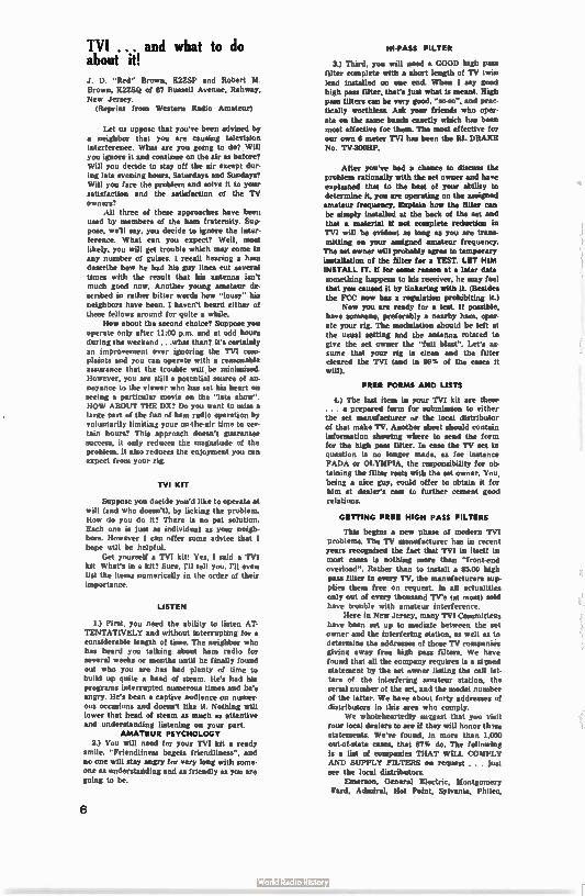
TV1 ... and what to do about it! J. D. "Red" Brown, 1C27..SP and Robert M. Brown, K2ZSQ of 67 Russell Avenue, Rahway, New Jersey.
(Reprint from Western Radio Amateur)
Let us uppose that you've been advised by a neighbor that you are causing television interference. What are you going to do? Will you ignore it and continue on the air u before? Will you decide to stay off the air except dur-ing late evening hours, Saturdays and Sundays? Will you face the problem and solve it to your satisfaction and the satisfaction of the TV owners?
All three of these approaches have been used by members of the ham fraternity. Sup-pose, we'll say, you decide to ignore the inter-ference. What can you expect? Well, most likely, you will get trouble which may come in any number of guises. I recall hearing a ham describe how he had his guy lines cut several times with the result that his antenna isn't much good now. Another young amateur de-scribed in rather bitter words how "lousy" his neighbors have been. I haven't heard either of these fellows around for quite a while.
How about the second choice? Suppose you operate only after 1100 p.m. and at odd hours during the weekend ...what then? It's certainly an improvement over ignoring the TVI com-plaints and you can operate with a reasonable assurance that the trouble will be minimized. However, you are still a potential source of an-noyance to the viewer who has set his heart on seeing a particular movie on the " late show". HOW ABOUT THE DX? Do you want to miss a large part of the fun of ham radio operation by voluntarily limiting your on-the-air time to cer-tain hours? This approach doesn't guarantee success, it only reduces the magnitude of the problem. It also reduces the enjoyment you can expect from your rig.
TVI KIT
Suppose you decide you'd like to operate at will (and who doesn't), by licking the problem. How do you do it? There is no pat solution. Each one is just as individual as your neigh-bors. However I can offer some advice that I hope will be helpful.
Get yourself a TVI kit! Yes, I said a Tv' kit What's in a kit? Sure, ni tell you. I'll even list the items numerically in the order of their importance.
LISTEN
1.) First, you need the ability to listen AT-TENTATIVELY and without interrupting for a considerable length of time. The neighbor who has heard you talking about ham radio for several weeks or months until he finally found out who you are has had plenty of time to build up quite a head of steam. He's had his programs interrupted numerous times and he's angry. He's been a captive audience on numer-ous occasions and doesn't like it. Nothing will lower that head of steam as much as attentive and understanding listening on your part.
AMATEUR PSYCHOLOGY 2.) You will need for your TVI kit a ready
smile. "Friendliness begets friendliness", and no one will stay angry for very long with some-one as understanding and as friendly as you are going to be.
6
HI-PASS FILTER
3.) Third, you will need a GOOD high pass filter complete with a short length of TV twin lead installed on one end. When I say good high pass filter, that's just what is meant. High pass filters can be very good, "so-so", and prac-tically worthless. Ask your friends who oper-ate on the same bands exactly which has been most effective for them The most effective for our own 6 meter TVI has been the RL DRAKE No. TV-3001W.
After you've had a chance to discuss the problem rationally with the set owner and have explained that to the best of your ability to determine it, you are operating on the assigned amateur frequency. Explain how the filter can be simply installed at the back of the set and that a material if not complete reduction in TVI will be evident as long as you are trans-mitting on your assigned amateur frequency. The set owner will probably agree to temporary installation of the filter for a TEST. LET HIM INSTALL IT. If for some reason at a later date something happens to his receiver, he may feel that you caused it by tinkering with it. (Besides the FCC now has a regulation prohibiting it.)
Now you are ready for a test. If possible, have someone, preferably a nearby ham, oper-ate your rig. The modulation should be left at the usual setting and the antenna rotated to give the set owner the "full blast". Let's as-sume that your rig is clean and the filter cleared the TVI (and in 99% of the cases it will).
FREE FORMS AND LISTS
4.) The last item in your TVI kit are these . . a prepared form for submission to either
the set manufacturer or the local distributor of that make TV. Another sheet should contain information showing where to send the form for the high pass filter. In case the TV set in question is no longer made, as for instance FADA or OLYMPIA, the responsibility for ob-taining the filter rests with the set owner. You, being a nice guy, could offer to obtain it for him at dealer's cost to further cement good relations.
GETTING FREE HIGH PASS FILTERS
This begins a new phase of modern TVI problems. The TV manufacturer has in recent years recognized the fact that TVI in itself in most cases is nothing more than "front-end overload". Rather than to install a $5.00 high pass filter in every TV, the manufacturers sup-plies them free on request In all actualities only out of every thousand TV's (at most) sold have trouble with amateur interference.
Here in New Jersey, many TVI Committees have been set up to mediate between the set owner and the interfering station, as well as to determine the addresses of those TV companies giving away free high pass filters. We have found that all the company requires is a signed statement by the set owner listing the call let-ters of the interfering amateur station, the serial number of the set, and the model number of the latter. We have about forty addresses of distributors in this area who comply.
We wholeheartedly suggest that you visit your local dealers to we if they will honor th ese statements. We've found, in more than 1.000 out-of-state cases, that 87% do. The following is a list of companies THAT WILL COMPLY AND SUPPLY FILTERS on request . . . just see the local distributors.
Emerson, General Electric, Montgomery Yard, Admiral, Hot Point, Sylvania, Philco,
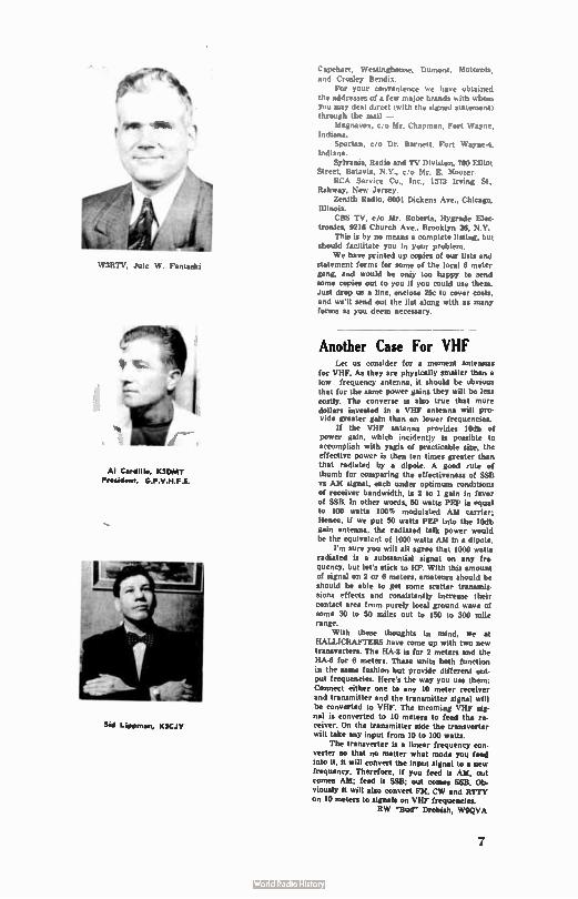
W3RTV. Jule W. Fantaski
Al C•rddlo, K3DAIT PrelAtelt GPVHF 5
Sd L.PPrn•n, K3CJV
Capehart, Westinghouse, Dumont, Motorola, and Crosley Bendix.
For your convenience we have obtained the addresses of a few major brands with whom you may deal direct (with the signed statement) through the mail —
Magnavox, c,'o Mr. Chapman. Fort Wayne, Indiana.
Spartan, c, o Dr. Barnett, Fort Wayne-4. Indiana.
Sylvania, Radio and TV Division. WO Elliot Street, Batavia. N.Y., co Mr. E. Mooser.
RCA Service Co., Inc., 1573 Irving St., Rahway, New Jersey.
Zenith Radio, 6001 Dickens Ave., Chicago, Illinois.
CBS TV, c/o Mr. Roberts, Hygrade Elec. tronics. 9216 Church Ave., Brooklyn 36, N.Y.
This is by no means a complete listing, but should facilitate you in your problem.
We have printed up copies of our lists and statement forms for some of the local 6 meter gang, and would be oniy too happy to send some copies out to you if you could use them. Just drop us a line, enclose 25e to cover costs. and we'll send out the list along with as many forms as you deem necessary.
Another Case For VHF Let us consider for a moment antennas
for VHF. As they are physically smaller than a low frequency antenna, it should be obvious that for the same power gains they will be less costly. The converse is also true that more dollars invested in a VHF antenna will pro-vide greater gain than on lower frequencies.
If the VHF antenna provides 10db of power gain, which incident!), is possible to accomplish with yagis of practicable sire, the effective power is then ten times greater than that radiated by a dipole. A good rule of thumb for comparing the effectiveness of SSB vs AM signal, each under optimum conditions of receiver bandwidth, is 2 to 1 gain in favor of SSB. In other words, 50 watts PEP is equal to 100 watts 100', modulated AM carrier: Hence, if we put 50 watts PEI' into the 10db gain antenna, the radiated talk power would be the equivalent of 1000 watts AM in a dipole.
I'm sure you will all agree that 1000 watts radiated is a substantial signal on any fre-quency. but let's stick to HF. With this amount of signal on 2 or 6 meters. amateurs should be should be able to get some scatter transmis-sions effects and consistently increase their
contact area from purely local ground wave of some 30 to 50 miles out to 150 to 300 mile range.
With these thoughts in mind, we at HALLICRAFTERS have come up with two new transverters. The 11A-2 is for 2 meters and the HA-6 for 6 meters. These units both function in the same fashion but provide different out-put frequencies. Here's the way you use them: Connect either one to any 10 meter receiver and transmitter and the transmitter signal will be converted to VHF. The incoming VHF sig. nal is converted to 10 meters to feed the re-ceiver. On the transmitter side the transverter will take any input from 10 to 100 watts.
The transverter is a linear frequency eon.
verter so that no matter what mode you feed into it, it will convert the input signal to a new frequency. Therefore, if you feed it AM, out comes AM; feed it SSB; out comes SSB. Ob-viously it will also convert FM, CW and RTTY on 10 meters to signals on VHF frequencies.
RW -Bud" Drobish, W9QVA
7
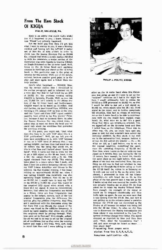
From The Ham Shack Of K3GQA
PHILIP, BELLEVUE, PA.
Here is an oddity that could really shake you if it happened to you. I know, because I was "Shook"—It actually happened.
Let me brief you first then I'll get into what I want to convey to you. It was a Monday evening and having left the tieVHF 6 meter net at 50.4 Mc. at nine o'clock in order to check into the Breeze Shooters Net on 29,000 Kc., I found that when a certain station checked in with his comments, a major portion of the disertation was with regards to hearing K3GQA on Single Sideband on the 15 meter band. Well, being on the 15 meter band isn't anything unusual in itself but just where on the 15 meter band, in this particular case is the point of interest for this article. Well, one of the points, anyway, because another good point is to dis-play just once again how a fellow Ham can help another.
Here's what happened — W3NKM, Stan, was the certain station that I mentioned in the earlier paragraph, and he informed me in a very nice way that he had heard me on SSB at 21,052 Kc. the previous evening calling K4QHN in Sarasota, Florida. Well, as you can see, 21.052 Kc. isn't exactly in the phone sec. lion of the 15 meter band, and furthermore, K4QHN wasn't to be heard on 15 either. And still further, my good friend Stan, W3NKM, was working a DX contest (CW no less) at the time and this "Loud and Clear SSB" signal couldn't possibly have added to his Key Clickin' Pleas-ure, because it had no business there. So after the Breeze Shooters Net was closed down, I asked Stan to meet me down the band and we could talk about the condition that prevailed the previous evening.
At this point, you might ask, "Just what does this have to do with VHF since this is a VHF publication?" Well, let me tell you—it does have something to do with VHF because it was on a VHF band (6 meters) that I was calling K4QHN. Just how Stan had heard me on 15 meters was the thing that shook me, so this is what Stan and I talked about "down the band". Well, it turns out that in order for me to get a SSB signal on the 50 mc. band, I mix a 29.1 mc. signal ( fixed) with a 21 mc. SSB signal obtained from my HT-32. This mixing takes place in a power mixer that I made, and then I feed the ac ditive frequency (50 mc.) into my VHF Linear Amplifier and thence to the antenna. On that Sunday evening, I was trans-mitting on approximately 50.152 mc. when t was calling K4QHN who incidently was also operating Single Sideband. Now for me to be on 50.152 mc. I would have to tune my VHF in my 11T-32 to 21.052 mc. since this would be the required SSB signal when mixed with a fixed 29.1 mc. signal. It must be remembered, however, that when two frequencies are mixed in a Mixer, there are four frequencies that appear in the output, namely, each of the two original frequencies plus the difference fre-quency, plus the additive frequency. Now Stan and I continued with the discussion along the the lines that even though the output of the mixer was tuned to the additive frequency, it could be quite possible that either one of the two originals could be getting through. Well, how were we to find out? Very simple, .ndeed, for all we had to do was to set up the original set of conditions, just as they were the evening before and make a few tests. Well, now, keep in mind that Stan and I were talking to each
PHILIP J. POLITO, K3GQA
other on the 10 meter band when this discus-
sion was going on and if 1 were to set up the "original" condition as I had it the night be-fore, I would necessarily have to utilize my HT-32 as a SSB generator on 21.052 mc. so that I would be able to put out a test signal on 50.152 mc. when mixed with the 29.1 mc. fixed signal in the mixer, and to further complicate the situation. Stan had no means of receiving me on the 6 meter band to be able to communi-cate with me (we would have worked cross. hand). So, what were we to do? (It's a good thing that there are telephones around.) Yes, we signed off on the 10 meter band and then I called Stan on the telephone. There was no other way. Oh, yes, we could have quit ano gone to bed, but that wouldn't have solved my technical problem. So Stan stuck it out with me to the not-so-bitter'end, because, believe it or not, we did correct the trouble — Hi — Hi. What we did, as I said before, was to set up the orginal condition, everything the same, even the operating frequency of 50.152 mc. Now then, when I came on the air with my test signal on 6 meters, Stan was tuning for me on 15 meters. Sure enough, he found me, exactly the same place as the night before. Well, one phase of our test was concluded. Now, the next thing we did was to find out whether he was getting me through the 6 meter set-up or from the HT-32 itself. So, whilst he is listening on 15 with one ear and to me on the other (tele-phone), I proceeded, to turn off my Linear Amplifier—he still heard me on 15, so this phase of the test proved that it was not on the 6 meter set-up that was causing the trouble. Ile was actually hearing me at about S7. So Stan asked me to rotate my Mosley Triband Beam. Sure enough, the strength of the signal as heard on 15 dropped considerably and then built right up again. So now we were sure that it was coming from the HT-32. But, just how it was getting up to the antenna posed a question because the HT-32 was not connected to the Mosley at all because its output was being fed into the 50 mc. mixer. So what we did then was to disconnect the Mosley transmission line from where it was connected to the Low Fre-quency Antenna Change Over Relay. The signal dropped as reported by Stan and then Stan said, "Now, short the transmission line". I
did, and sure enough he heard no more . . . how about that? Preceding four pages were
stolen from the G. P. V. H. F. S.
liamorama publ ication - ED.
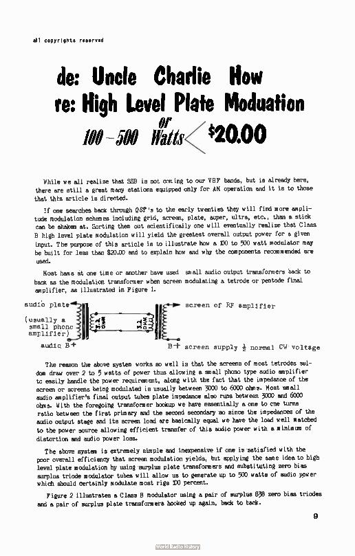
all copyrights reserved
de: Uncle Charlie How re: High Level Plate Moduation
Of - M S 420.00
While we all realize that SS8 is not coming to our VHF bands, but is already here,
there are still a great many stations equipped only for AM operation and it is to those
that this article is directed.
:f one searches back through QST's to the early twenties they will find more ampli-tude modulation schemes including grid, screen, plate, super, ultra, etc., than a stick
can be shaken at. Sorting them out scientifically one will eventually realize that Class
high level plate modulation will yield the greatest overall output power for a given
input. The purpose of this article is to illustrate how a DO to 500 watt modulator may
be built for less than $20£0 and to explain how and why the components recommended are
used.
Most hams at one time or another have used small audio output transformers back to
back as the modulation transformer when screen modulating a tetrode or pentode final
amplifier, as illustrated in Figure 1.
audib plate
(usually a small phono amplifier)
audi B+
screen of RF amplifier
B + screen supply normal CW voltage
The reason the above system works so well is that the screens of most tetrodes sel-
dom draw over 2 to 5 watts of power thus allowing a small phono type audio amplifier tc easily handle the power requirement, along with the fact that the impedance of the
screen or screens being modulated is usually between 3000 to 6000 ohms. Most small audio amplifier's final output tubes plate impedance also runs between 3000 and 6000
ohms. With the foregoing transformer hookup we have essentially a one to ene turns
ratio between the first primary and the second secondary so since the impedances of the audio output stage and its screen load are basically equal we have the load well matched
to the power source allowing efficient transfer of this audio power with a minimum of
distortion and audio power loss.
The above system is extremely simple and inexpensive if one is satisfied with the
poor overall efficiency that screen modulation yields, but applying the same idea to high level plate modulation by using surplus plate transformers and substituting zero bias
surplus triode modulator tubes will allow us to generate up to 500 watts of audio power which should certainly modulate most rigs IX) percent.
Figure 2 illustrates a Class B modulator using a pair of surplus 838 zero bias triodes
and a pair of surplus plate transformers hooked up again, back to tack.
9
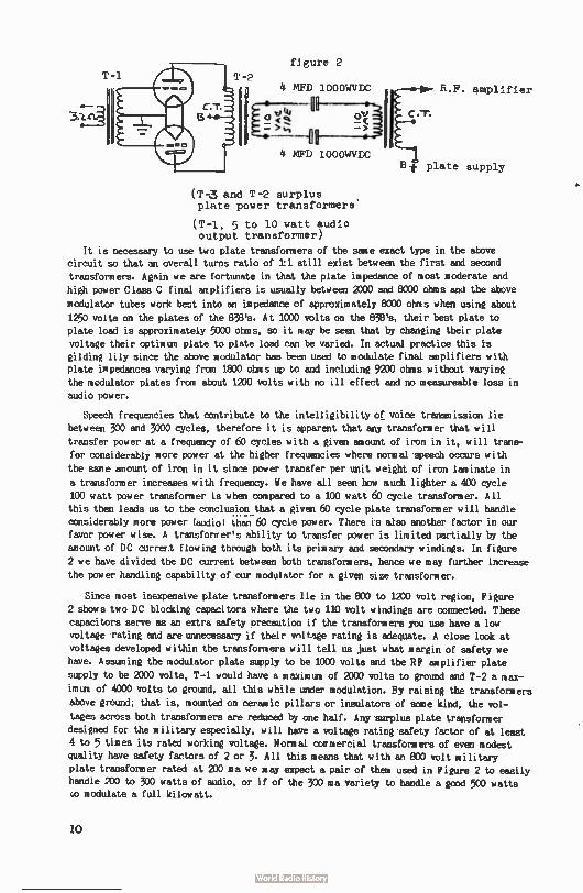
figure 2
4 MFD 1000WVDC
4 MFD 1 000WVDC
R.F. amplifier
CT.
t plate supply
(T-3 and T-2 surplus plate power transformers
(T-1, 5 to 10 watt audio output transformer)
It is necessary to use two plate transformers of the same exact type in the above
circuit so that an overall turns ratio of 11 still exist between the first and second
transformers. Again we are fortunate in that the plate impedance of most moderate and
high power Class C final amplifiers is usually between 2000 and 8000 ohms and the above
modulator tubes work best into an impedance of approximately 8C00 ohms when using about
1250 volts on the plates of the 838's. At 1000 volts on the 838's, their best plate to
plate load is approximately 5000 ohms, so it may be seen that by changing their plate
voltage their optimum plate to plate load can be varied. In actual practice this is
gilding lily since the above modulator has been used to modulate final amplifiers with plate impedances varying from 1800 ohms up to and including 9200 ohms without varying
the modulator plates from about 1200 volts with no ill effect and no raeasureable loss in
audio power.
Speech frequencies that contribute to the intelligibility of voice transmission lie
between 300 and 3000 cycles, therefore it is apparent that any transformer that will
transfer power at a frequency of 60 cycles with a given amount of iron in it, will trans-
fer considerably more power at the higher frequencies where normal speech occurs with
the same amount of iron in it since power transfer per unit weight of iron laminate in
a transformer increases with frequency. We have all seen how much lighter a 400 cycle
100 watt power transformer is when compared to a 100 watt 60 cycle transformer. All this then leads us to the conclusion ..that a given 60 cycle plate transformer will handle considerably more power (audio) than 60 cycle power. There is also another factor in our favor power wise. A transformer's ability to transfer power is limited partially by the
amount of DC currert flowing through both its primary and secondary windings. In figure
2 we have divided the DC current between both transformers, hence we may further increase
the power handling capability of our modulator for a given size transformer.
Since most inexpensive plate transformers lie in the 800 to 1270 volt region, Figure
2 shows two DC blocking capacitors where the two 110 volt windings are connected. These capacitors serve as an extra safety precaution if the transformers you use have a low
voltage rating and are unnecessary if their voltage rating is adequate. A close look at voltages developed within the transformers will tell us just what margin of safety we
have. Assuming the modulator plate supply to be 1000 volts and the RF amplifier plate
supply to be 2000 volts, T-1 would have a maximum of 2000 volts to ground and T-2 a max-
imum of 4000 volts to ground, all this while under modulation. By raising the transformers above ground; that is, mounted on ceramic pillars or insulators of some kind, the vol-
tages across both transformers are reduced by one half. Any surplus plate transformer designed for the military especially, will have a voltage rating safety factor of at least
4 to 5 times its rated working voltage. Normal commercial transformers of even modest quality have safety factors of 2 or 3. All this means that with en 800 volt military plate transformer rated at 200 ma we may expect a pair of them used in Figure 2 to easily
handle 200 to 300 watts of audio, or if of the 300 ma variety to handle a good 500 watts ce modulate a full kilowatt.
10
If over 300 watts of audio is required, another pair of 838's may be paralled to
the ones shovn. Four 838's with approximately 1300 volts on the plates will deliver
600 watts of audio and fully modulate a 1200 watt amplifier. T-1 shown in Figure 2 is a small 5 or 10 watt audio output transformer hooked up in reverse, and serves remark-
ably well as the driver transformer, giving the audio amplifier ahead of it the usual
1:1 turns ratio which adequately matches the 838 grids. When a speech amplifier and
modulator like this are being built from scratch it is best to use a low impedance driver source for this modulator such as a pair of 6N7 triodes running zero bias. A 12_AX7 and 604 will more than drive the 6N7's which will more than drive the 838's (four) to well over 600 watts output.
The ideal supply for this modulator, two 838's, would supply about 1200 to 1300 volts at 300 ma load. This supply need not be quite as strong as 300 ma if a large amount
of capacity is available in the power supply filter and three flashlight batteries series
connected together to form a four and one half volt bias supply for the 838's. This bias
will reduce the 838 plate current to about 80 ma idling which will allow the power
supply to 'bunch" the 838's with somewhat more power during voice peaks. The combination
of transformers, power supplies, and modulator tubes that may be used with this basic
circuit are limited only by the ingenuity and lack of funds of the user.It is also sug-
gested that the Barry Corp., 512 Broadway, New York, N.Y., be written and a copy of their 'Green Sheet" be obtained as it lists most every surplus transformer type ever
made and available. Barry's transformer type W80G115 should handle 200 watts of audio adequately. It is priced at $1.50 each, and fairly representative. The 838 triodes may
also be obtained from Barry at $.95 each.
One note of caution: when raising the transformers above DC ground, on insulators, remember that they may have internally shorted to the transformer case, and touching
then would be the same as touching the plate tank coil in the final when transmitting.
Enough said.
A later article may possibly cover the use of low voltage plate transformers to gen-
erate high voltage plate supplies if there is any interest in same.
73' UCH
11:01 With IFSPT Jack Woodruff, b111P7 RFD 3, Box 157
Benton H arbor, M lob.
Home from work at 5:45.P/tend on toes the btÉ swttch. Andold HRO-5 is kept tuned to 5 mc WWV and we flip it on in time, we hope, for the 5:49 propagation forecast
broadcast. More important is the flutter content of their signal because the propagation
broadcasts aren't always too accurate. Many is the time when I've been working aurora
stations like mad while they are still sending 147 or N6 ( did you ever hear an N8 or
N9?). Their signal is check intermittently throughout the evening. A second check is
made on the signal of WWI on 49.880 or thereabouts. If there is any aurora present, it
will make their signal audible. If tropo conditions are good, their direct signal is heard
weakly. W8PT does not operate six meters in this Channel 2 fringe area, so the six meter
beam is fixed permanently north. Setting to the WWI signal is easy with the 75A2 even
though they are not audible at the time. A few minutes listening will generally produce
enough meteor bursts of their signal to tell they are tuned in.
11
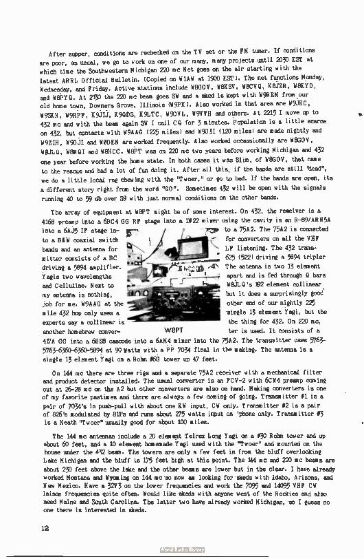
After supper, conditions are rechecked on the TV set or the FM tuner. If conditions
are poor, as usual, we go to work on one of our many, many projects until 2030 EST at
which time the Southwestern Michigan 220 roc Net goes on the air starting with the
latest ARRL Official Bulletin. ( Copied on W1AW at 1900 EST). The net functions Monday,
Wednesday, and Friday. Active stations include W8GOV, W8KSV, W8CVQ, K8JZR, W8EYD,
and W8PY Q. At 2130 the 220 mc beam goes SW and a sked is kept with W9REM from our
old home town, Downers Grove, Illinois (W9PK). Also worked in that area are W9JEC,
W9SKN, W9RPF, K9JIJ, K9QDS, K9LTC, W9OVL, W9VVH and others. At 2215 I move up to
432 mc and with the beam again SW I call CQ for 3 minutes. Population is a little scarce
on 432, but contacts with W9AAG ( 225 miles) and W9011 ( 120 miles) are made nightly and
W9ZIH, W90JI and WODEN are worked frequently. Also worked occassionally are W8GOV,
WEJJLQ, W8RQI and W8HCC. W8PT was on 220 mc two years before working Michigan and 432
one year before working the home state. In both cases it was Slim, of W8GOV, that came
to the rescue and had a lot of fun doing it. After all this, if the bands are still 'bead",
we do a little local rag chewing with the "Twoer," or go to bed. If the bands are open, its
a different story right from the word "GO". Sometimes 432 will be open with the signals
running 40 to 59 db over 59 with just normal conditions on the other bands.
The array of equipment at W9PT might be of some interest. On 432, the receiver is a
4168 preamp into a 6BC4 GG RF stage into a IN 22 mixer using the cavity in an R-89/ARN5A
into a 6AJ5 IF stage in- •-• j j to a 75A2. The 75A2 is connected
to a B&W coaxial switch
bands and an antenna for
mitter consists of a BC
driving a 5894 amplifier.
Yagis two wavelengths
and Celluline. Next to
my antenna is nothing,
job for me. W9AAG at the
mile 432 hop only uses a
experts say a collinear is
another horoebrew conver-
417A GG into a 6BS8 cascode into a 6AM4 mixer into the 75A2. The transmitter uses 5763-
5763-6360-6360-5894 at 90 Watts with a PP 7034 final in the making. The antenna is a
single 13 elament Yagi on a Rohn 16G tower up 47 feet.
On 144 mc there are three rigs and a separate 75A2 receiver with a mechanical filter and product detector installed. The usual converter is an FCV-2 with 6CW4 preamp coming
out at 26-28 mc on the A2 but other converters are also on hand. Making converters is one
of my favorite pastimes and there are always a few coming of going. Transmitter 01 is a
pair of 7034's in push-pull with about one KW input, CW only. Transmitter 02 is a pair of 826's modulated by 811's and runs about 275 watts input on ' phone only. Transmitter 03
is a Heath "Twoer" usually good for about 100 miles.
The 144 mc antennas include a 20 element Telrex Long Yagi on a 130 Rohn tower and up
about 60 feet, and a 10 element homemade Yagi used with the "Twoer" and mounted on the house under the 432 beam. The towers are only a few feet in from the bluff overlooking
Lake Michigan and the bluff is 175 feet high at this point. The 144 mc and 220 mc beams are
about 230 feet above the lake and the other beams are lower but in the clear. I have already
worked Montana and Wyoming on 144 la c so now am looking for siceds with Idaho, Arizona, and New Mexico. Have a 32V3 on the lower frequencies and work the 7095 and 14095 VHF CW
laison frequencies quite often. Would like skmis with anyone west of the Rockies and also
need Maine and South Carolina. The latter two have already worked Michigan, so I guess no
one there is interested in skeds.
e
W8PT
for converters on all the VHF
LF listening. The 432 trans-
625 ( 522) driving a 5894 tripler
The antenna is two 13 element
apart and is fed through Q bars
W8JLQ's /92 element collinear
but it does a surprisingly good.
other end of our nightly 225
single 13 element Yagi, but the
the thing for 432. On 220 mc,
ter is used. It consists of a
12
Licensed 32 years ago and active on VHF for years as W9PK ( all but Nevada ten years
ago on six), I am employed as an Inspection Foreman for the VM Corporation in Benton Harbor and am 47 years old. NY PET PEEVE: Why all those guys beat their brains out on 75 and 40 when there are plenty of QR X free kilocycles (even megacycles) on the VHF bands) Also, why the low frequency DX'ers don't try VHF DX, which takes just as much
skill and patience and is much more fun. To me there is nothing that can compare with a
successful meteor scatter contact for thrills and excitement.
I am and always have been a staunch supporter of the ARRL and hold appointments of
OBS, OES, and PAM ( Phone Activities Manager) - but prefer CW - hi!
73 Jack, il8PT
California Kilowatt
(SHALL VERSION)
Jerry Vogt, W A 2GC F 160 G ref ton
Rochester 21, N.Y.
Can
It has been quite some time since someone has built a five watt rig with a built-in
modulator. With this in mind, we decided to make up one to see how it would work out.
This rig has many features different from the run-of-the-mill job. It can be noticed that cathode modulation is used for ease of wiring. Common tubes, typical of receiver
use, are used and a small power supply are all that is needed. Most of us have a 6 meter converter or receiver working so this is just the boat for a General who doesn't want to
sink a California buck into a project. The whole thing can be built for around fifteen
dollars using the traditional junk box. It has been designed so that no fancy parts are needed and just about any external connections are easy to make. Since everyone has his own
metering and T-R switching ideas, wé ...! or:et bother discussing it.
Sorry, we didn't finish it in time for pictures, but perhaps in a future issue ( front
cover maybe, Bob?) . There may be a few details unattended to such as B-plus power and
neutralizing, but it should work well. At any rate, any improvements you fellows make would be welcome to our ears. Let's hear from you! Write me at the address above if you
want to criticize it, since the author needs lots of mail. Besides we ran out of coal and
paper works just as well. Just one final word - Good luck and don't disbelieve the who
says you sound better than the 5 KW rit next door.
PARTS LIST
L I - P turns of 80W 3003 tapped 44 turns from the cold end.
L2 - 64 turns as L 1. L3 - 74 turns as L I.
Lle - 24 turns 05 wire on 10 ohm 4 watt resistor.
L5 - 34 turns of 0 Pi wire - 4 ' diameter, 5/8' long.
L6 - 2 turns of 014 - Insulate from cold end of L5.
T 1 - Interstage with a 2 to 1 (2: I) ratio.
13
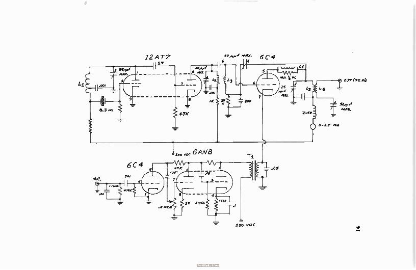
e
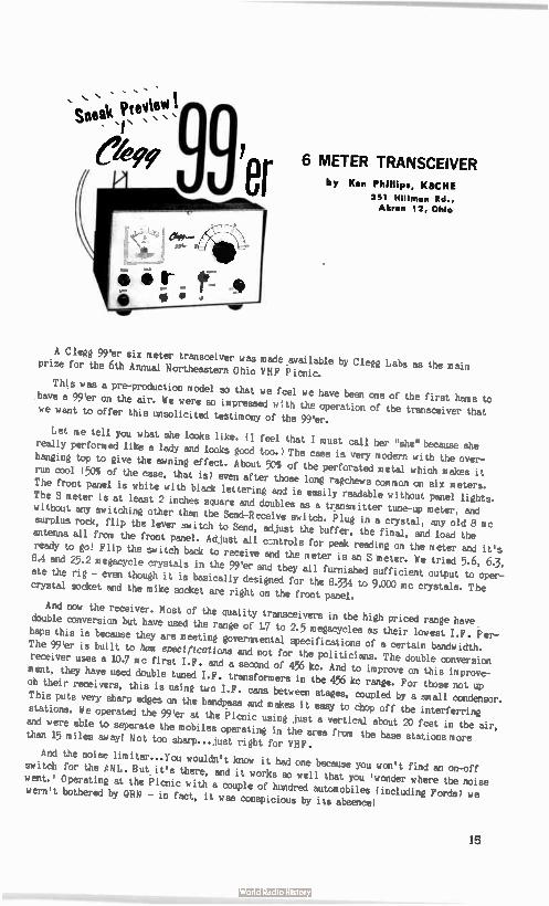
sne« Deay‘eVi • 9'er
; ék; 9 6 METER TRANSCEIVER
by Ken Phillips, K8CHE
351 Hillman Rd., Akron 12, Ohio
A Clegg 99'er six meter transceiver was made available by Clegg Labs as the main prize for the 6th Annual Northeastern Ohio VHF Picnic.
This was a pre-production model so that we feel we have been one of the first hams to
have a 99'er on the air. We were so impressed with the operation of the transceiver that we want to offer this unsolicited testimony of the 99'er.
Let me tell you what she looks like. ( I feel that I must call her "she" because she really performed like a lady and looks good too.) The case is very modern with the over-
hanging top to give the awning effect. About 50% of the perforated metal which makes it run cool ( 50% of the case, that is) even after those long ragchews common on six meters.
The front panel is white with black lettering and is easily readable without panel lights. The S meter is at least 2 inches square and doubles as a transmitter tune-up meter, and without any switching other than the Send-Receive switch. Plug in a crystal, any old 8 mc
surplus rock, flip the lever switch to Send, adjust the buffer, the final, and load the antenna all from the front panel. Adjust all cAtrols for peak reading on the meter and it's ready to go! Flip the switch back to receive and the meter is an S meter. We tried 5.6, 6.3,
8A and 25.2 megacycle crystals in the 99'er and they all furnished sufficient output to oper-ate the rig - even though it is basically designed for the 8.334 to 9.000 mc crystals. The crystal socket and the mike socket are right on the front panel.
And now the receiver. Most of the quality transceivers in the high priced range have
double conversion but have used the range of 17 to 2.5 megacycles as their lowest I.F. Per-
haps this is because they are meeting governmental specifications of a certain bandwidth.
The 99'er is built to ham specifications and not for the politicians. The double conversion receiver uses a 10.7 mc first I.F. and a second of 456 kc. And to improve on this improve-ment, they have used double tuned I.F. transformers in the 456 kc range. For those not up
oh their receivers, this is using two I.F. cans between stages, coupled by a small oondensor. This puts very sharp edges on the bandpass and makes it easy to chop off the interferring
stations. We operated the 99'er at the Picnic using just a vertical about 20 feet in the air,
and were able to separate the mobiles operating in the area from the base stations more than 15 miles away! Not too sharp.., just right for VHF.
And the noise limiter...you wouldn't know it had one because you won't find an on-off switch for the ANL. But it's there, and it works so well that you ' wonder where the noise went.' Operating at the Picnic with a couple of hundred automobiles ( including Fords) we wern't bothered by QRN - in fact, it was conspicious by its absence!
15
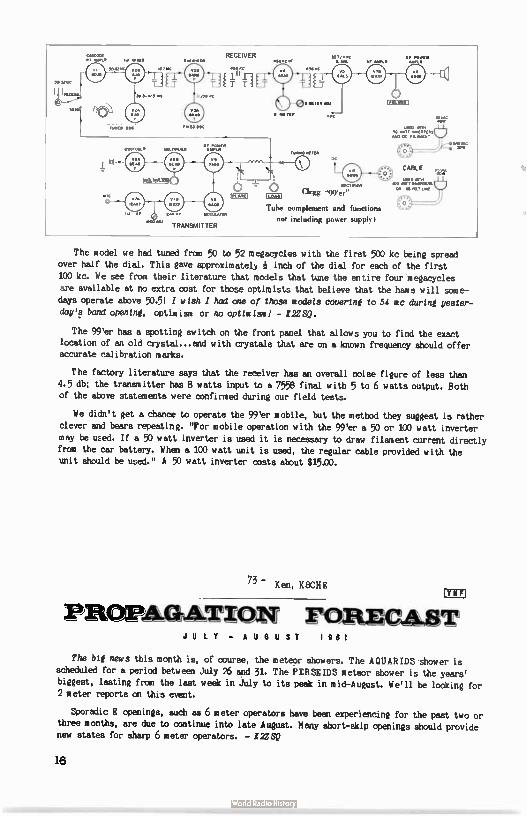
•
IRIC
ROO RDA
RECEIVER
.4«
.W11 «mum
TRANSMITTER
1:21:SLI
•• POWER •StaCIF AAA
METER
o Mr/
AV épVAC
..»mm Clegg '99'er"
Tube complement and functions not including power supply I
MO W. AO RAI, uovIRTER. AAR OC RILAVitorT
CABLE
OM A. .00 MI MAMA
OR OSMIUM
AIRVOC
The model we had tuned from 50 to 52 megacycles with the first 500 kc being spread over half the dial. This gave approximately inch of the dial for each of the first
100 kc. We see from their literature that models that tune the entire four megacycles are available at no extra cost for those optimists that believe that the hams will same-
days operate above 50.5! I wish I had one of those models *jeering to 54 mc daring yester-
day's band opening, optimism or no optimism! - I2ZSQ.
The 99'er has a spotting switch on the front panel that allows you to find the exact
location of an old crystal...and with crystals that are on a known frequency should offer accurate calibration marks.
The factory literature says that the receiver has an overall noise figure of less than
4.5 db; the transmitter has 8 watts input to a 7558 final with 5 to 6 watts output. Both of the above statements were confirmed during our field tests.
We didn't get a chance to operate the 99'er mobile, but the method they suggest is rather
clever and bears repeating. "For mobile operation with the 99'er a 50 or 100 watt inverter
may be uzed. If a 50 watt inverter is used it is necessary to draw filament current directly
from the car battery. When a 100 watt unit is used, the regular cable provided with the unit should be used." A 50 watt inverter costs about $15.00.
- Ken, K8CFIE IYHFI
PROPMILMON MRECAST JULY - AUGUST 1961
The big news this month is, of course, the meteor showers. The AQUARIDS shower is scheduled for a period between July 26 and 31. The PERSEIDS meteor shower is the years'
biggest, lasting from the last week in July to its peak in mid-August. We'll be looking for 2 meter reports on this event.
Sporadic E openings, such as 6 meter operators have been experiencing for the past two or three months, are due to continue into late August. Many short-skip openings should provide new states for sharp 6 meter operators. - 122SQ
16
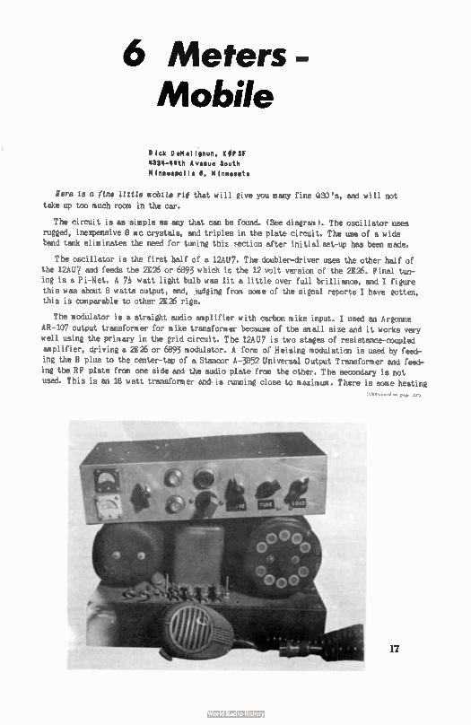
6 Meters - Mobile
Dick D eM al ' von, K OP SF 4334- 44th Avenue South
M inneapol is 6, M innesota
Here is a fine little mobile rté that will give you many fine QS0's, and will not
take up too much room in the car.
The circuit is as simple as any that can be found. ( See diagram). The oscillator uses
rugged, inexpensive 8 mc crystals, and triples in the plate circuit. The use of a wide band tank eliminates the need for tuning this :,ection after initial set-up has been made.
The oscillator is the first half of a 12AU7. The doubler-driver uses the other half of
the 12AU7 and feeds the 2E26 or 6893 which is the 12 volt version of the 2E26. Final tun-
ing is a Pi-Net. A Th watt light bulb was lit a little over full brilliance, and I figure this was about 8 watts output, and, judging from some of the signal reports I have gotten, this is comparable to other 2E26 rigs.
The modulator is a straight audio amplifier with carbon mike input. I used an Argonne
AR-107 output transformer for mike transformer because of the small size and it works very
well using the primary in the grid circuit. The 12AU7 is two stages of resistance-coupled amplifier, driving a 2E26 or 6893 modulator. A form of Heising modulation is used by feed-
ing the B plus to the center- tap of a Stancor A-3852 Universal Output Transformer and feed-ing the RF plate from one side and the audio plate from the other. The secondary is not
used. This is an 18 watt transformer and is running close to maximum. There is some heating
17
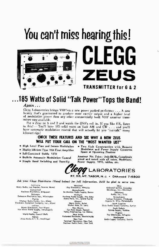
You can't miss hearingthis!
CLEGG ZEUS TRANSMITTER for 6 & 2
...185 Watts of Solid "Talk Power"Tops the Band! Again. Clegg Laboratories brings VHFers a new power packed performer ... A new beauty that's guaranteed to produce more carrier output and a higher level of modulation power than any other commercially built VHF amateur trans-mitter now available.
Put a Zeus on 6 and 2 and watch the QS0's roll in. If you like DX, listen to this! — You'll have 185 solid watts on both AM and CW . . . and you'll have automatic modulation control that will actually let you "out-talk" many kilowatt rigs!
CHECK THESE FEATURES AND SEE WHY A NEW ZEUS WILL PUT YOUR CALL ON THE "MOST WANTED LIST"
• High Level Plate and Screen Modulation
• Highly Efficient Type 7034 Final Amplifier
• Self-Contained Stable VFO
• Built-In Automatic Modulation Control
• Simple Band Switching and Tune-Up
• I o o Unit Construction with Remote Modulator and Power Supply Conserves Space at Operating Position
Amateur Net Price: Only $675. Completely wired and tested with all tubes, Modulator, Power Supply, VFO, cables, etc.
LABORATORIES
RT. 53, MT. TABOR, N. J. • OAkwood 7-6800
Ask your Clegg Distribmor (listed below) for full information. He'll be glad to serve you.
Cohlorma Henry Radio, Los Angeles, Severn,. Hemet
Connecticut Kaufman Electronics, Bridgeport
Delaware Delaware Electronics Sup., Wilmington
Florida Amateur Radio Center, Inc., Miami
Electronic Equipment Company, Inc., Miami
Indiana Brown Distributors, Fort Wayne
Van Sickle Rodio Supply, Indianapolis
Iowa World Radio, Council Blots
Konsos Acme Radio it T. V., Hutchinson
Maryland Key Electronics, Wheaton
Mossachuseth De Mornbro Rodio Supply, Boston
Michigan Purchase Radio Supply, Ann Arbor Radio Parts, Inc., Grond Rapids
Missouri Henry Rodio, Butler
Walter Ash., St. Louis
Ntve Mexico Cor Parts Depot, Roswell
Valley Engineering, Los Alamos
New Jersey Federated Purchaser, Mountoinside
New York Terminal Electronics, New York Harrison Rodio Corp., New York
Ohio Universal Service, Columbus Sternberg,, Inc., Cincinnati
Oklahoma Rodio, Inc., Tulsa
Pennsylvonia Tydings Company, Pittsburgh Eugene G. Wile, Philadelphia
South Carolina Dixie Radio Supply Company, Sumter
South Dokoto Dakoto Supply, Yankton
Virginia Key Electronics, Arlington
Washington Radio Supply Compony, Seattle
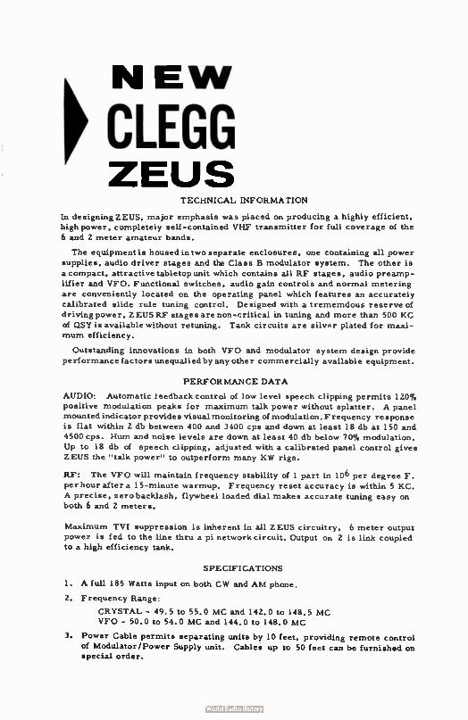
NEW p CLEGG ZEUS
TECHNICAL INFORMATION
In designing ZEUS, major emphasis was placed on producing a highly efficient,
high power, completely sell- contained VHF transmitter for full coverage of the
6 and 2 meter amateur bands.
The equipment is housed in two separate enclosures, one containing all power
supplies, audio driver stages and the Class B modulator system. The other is
a compact, attractive tabletopunit which contains all RF stages, audio preamp-
lifier and VFO. Functional switches, audio gain controls and normal metering
are conveniently located on the operating panel which features an accurately
calibrated slide rule tuning control. Designed with a trememdous reserve of
driving power, ZEUS RF stages arenon-critical in tuning and more than 500 KC
of QSY is available without retuning. Tank circuits are silver plated for maxi-
mum efficiency.
Outstanding innovations in both VFO and modulator system design provide
performance factors unequalled by any other commercially available equipment.
PERFORMANCE DATA
AUDIO: Automatic feedback control of low level speech clipping permits 120%
positive modulation peaks for maximum talk power without splatter. A panel
mounted indicator provides visual monitoring of modulation. Frequency response
is flat within 2 db between 400 and 3400 cps and down at least 18 db at 150 and
4500 cps. Hum and noise levels are down at least 40 db below 70% modulation.
Up to 18 db of speech clipping, adjusted with a calibrated panel control gives
ZEUS the " talk power" to outperform many KW rigs.
RF: The VFO will maintain frequency stability of 1 part in 106 per degree F.
per hour after a 15-minute warmup. Frequency reset accuracy is within 5 KC.
A precise, zero backlash, flywheel loaded dial makes accurate tuning easy on
both 6 and 2 meters.
Maximum TVI suppression is inherent in all ZEUS circuitry, 6 meter output
power is fed to the line thru a pi network circuit. Output on 2 is link coupled to a high efficiency tank.
SPECIFICATIONS
1. A full 185 Watts input on both CW and AM phone.
2. Frequency Range:
CRYSTAL - 49.5 to 55.0 MC and 142.0 to 148.5 MC VFO - 50.0 to 54.0 MC and 144.0 to 148.0 MC
3. Power Cable permits separating units by 10 feet, providing remote control
of Modulator/Power Supply unit. Cables up to 50 feet can be furnished on
special order.
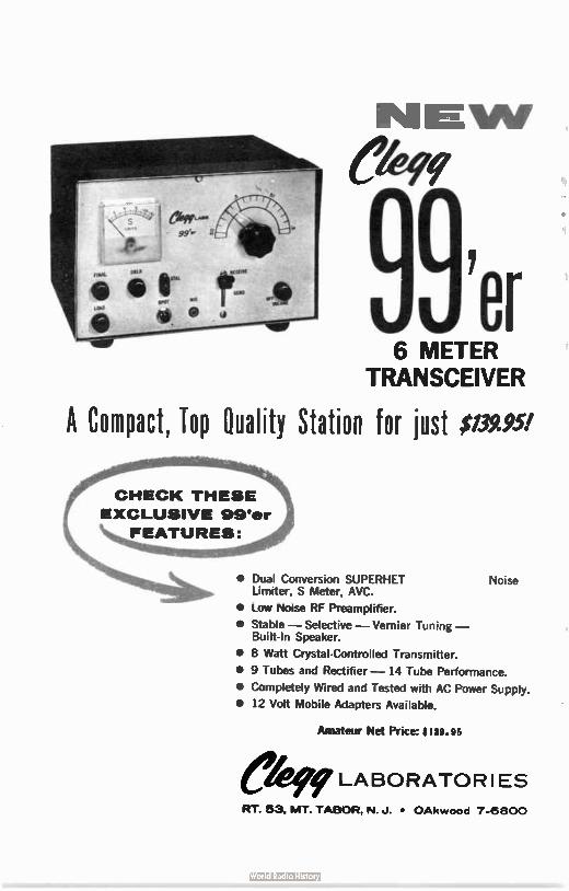
99'er 6 METER
TRANSCEIVER
A Compact, Top Quality Station for just $139.95!
CHECK THESE
EXCLUSIVE 99'er
FEATURES:
\111111ellftleeà pe • Dual Conversion SUPERHET Noise Limiter, S Meter, AVC.
• Low Noise RF Preamplifier.
• Stable — Selective— Vernier Tuning — Built- In Speaker.
• 8 Watt Crystal-Controlled Transmitter.
• 9 Tubes and Rectifier — 14 Tube Performance.
• Completely Wired and Tested with AC Power Supply.
• 12 Volt Mobile Adapters Available.
Amateur Net Price: ; 139.95
eke LABORATOR I ES RT. 53, MT. TABOR, N. J. • OAkwood 7-6800
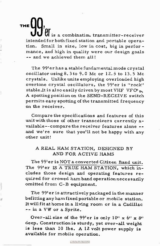
THE 99,
er is a combinatiol- transmitter- receiver
intended for both fixed station and portable opera-
tion. Small in size, low in cost, big in perfor -
mance, and high in quality were our design goals
-- and we achieved them all!
The 99'er has a stable fundamental mode crystal
oscillator using 8.3 to 9.0 Mc or 12.5 to 13.5 Mc crystals. Unlike units employing overloaded high
overtone crystal oscillators, the 99'er is " rock"
stable.It is also easily driven by most VHF VF
A spotting position on the SEND-RECEIVE switch
permits easy spotting of the transmitted frequency
on the receiver.
Compare the specifications and features of this unit with those of other transceivers currently a-
vailable-- compare the receiver features alone --
and we're sure that you'll not be happy with any
other unit!
A REAL HAM STATION, DESIGNED BY
AND FOR ACTIVE HAMS
The 99'er is NOT a converted Citizen Band unit.
The 99'er IS A TRUE HAM STATION, which in-
cludes those design and operating features re-
quired for crowed ham band operation necessarily
omitted from C- B equipment.
The 99'er is attractively packaged in the manner
befitting any ham fixed portable or mobile station.
It will fit at home in a living room or in a Cadillac
-- in a VW or a Sprite.
Over-all size of the 99'er is only 10" x 6" x 8" deep. Construction is sturdy, yet over-all weight
is less than 10 lbs. A 12 volt power supply is
available for mobile operation.
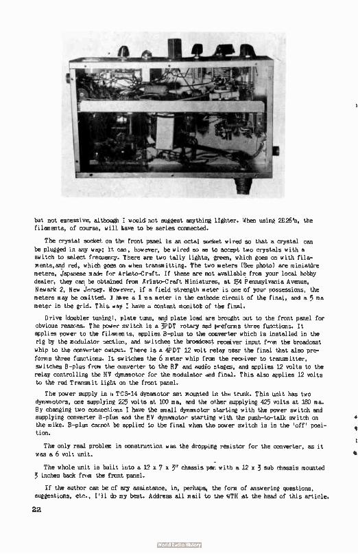
but not excessive, although would not suggest anything lighter. When using 2E26's, the
filaments, of course, w)ll Lave to be series connected.
The crystal socket on the front panel is an octal socket wired so that a crystal can
be plugged in any way; it can, flowerer, be wired so as to accept two crystals with a switch to select frecuency. There are two tally lights, green, which goes on with fila-
ments,and red, which goes on when transmitting. The two meters ( See photo) are miniatire meters, Japanese made far Aristo-Craft. If these are not available from your local hobby
dealer, they can be obtained from Aristo-Craft M iniatures, at 134 Pennsylvania Avenue,
Newark 2, New Jersey. however, if a field strength meter is one of your possessions, the meters may be omitted. J have a 1 ma meter in the cathode circuit of the final, and a 5 ma meter in the grid. This. way have a contant monitot cf the final.
Drive (doubler tunixe, ylate tune, and plate load are brought out to the front panel for obvious reascns. The power switch is a 3PDT rotary and preforms three functions. It applies power to the filaments, applies B-plus to the converter which is installed in the rie by the modulator section, and switches the broadcast receiver input Unix the broadcast
whip to the converter cuitpu:".. There is a 4PDT 12 volt relay near the final that also pre-
forms three functiona. It switches the 6 meter whip from the receiver to transmitter,
switches B-plus from the converter to the RF and audio stages, and applies 12 volts to the
relay controlling the NV dynamotor for the modulator and final. This also applies 12 volts to the red Transmit light on the front panel.
The power supply is a TCS-14 dynamotor set mounted in the trunk. This unit has two
dynamotors, one supplying 225 volts at 100 ma, and the other supplying 425 volts at 180 ma. By changing two connectons I have the small dynamotor starting with the power switch and supplying converter B-pIus and the F.V dynamotor starting with the push-to- talk switch on the mike. B-plus cannot, be applied to the final when the power switch is in the ' off' posi-tion.
The only real problem in construction was the dropping resistor for the converter, as it
was a 6 volt unit.
The whole unit is built into a 12 x 7 x 3" chassis pan with a 12 x 3 sub chassis mounted 3 inches back from the front panel.
If the author can be cf Bry assistance, in, perhaps, the form of answering questions,
suggestions, etc., I'll do my best. Address all mail to the UTH at the head of this article.
22
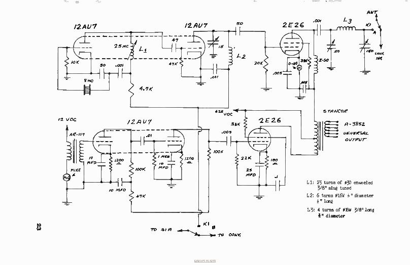
/2AU7 12AU7
Li: 23 turns of #30 enameled 3/8" slug tuned
L2: 6 turns #16W " diameter 1" long
L3: 4 turns of #EW 3/8" long
i" diameter
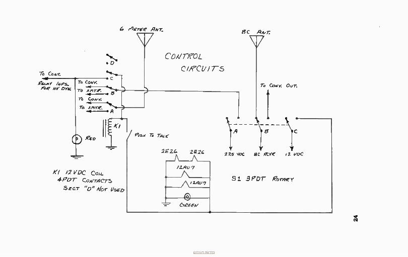
6 rIcrefe #19417. g )9Adr;
Th CoA)r.
ge.,, Y /A,Ps. PZ'. flY øY44
To x m re. -4,-. At
geD
el 12 V DC Con_
4PDT Cown9C-rs
Secr "0" Alor lisED
CD,VreoL
(Yen/IT-5
To Come,. Our.
fevse Th nut"
2E2.4 22c 225 VDC SC tY iZ vDc
C725-6A/
Si 3 PDT Roree Y
e
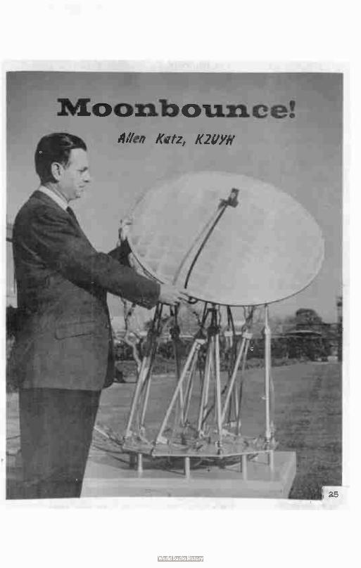
ooribcruurice. Om Katz, K21/Yll
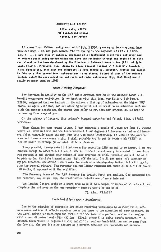
NO0111300110E Editor
Allen Katz, MTN
18. C um berl and A
Verona, New Jersey
This month our Editor really went wild! Bob, K2ZSQ, gave us quite a masthead ( see
previous page), but for good reason. The following is the caption: MOUNTAIN VIEW,
CALIF. --- A new type of antenna, composed of • lightweight rigid foam reflector and
an antenna positioning device which can move the reflector through any angle of azimuth
and elevation has been developed by the Electronic Defense Laboratories (ECIL) of Syl-vania Electric Products, Inc. Jesse R. Lien, General Manager of Sylvania's Mountain
View Operations, said that the equipment is less expensive, stronger, lighter and easier
to fabricate than conventional antennas now in existence. Potential uses of the antenna
include satellite come un icat ion and radio and radar astronomy. Boy, that thing would
really go great guns on 1296!
Skeds Listing Proposed
Any increase in activity on the UHF and microwave portion of the amateur bands will
benefit moonbounce activities. In conjunction with this idea, our Editor, Bob Brown,
K2ZSQ, suggested that we include in the column a listing of schedules on the higher VHF
bands. We agree with Bob, and are offering to print all information on schedules sent in.
With the summer months and the chance they offer to get that new antenna up, we hope to be hearing from many of you.
On the subject of letters, this column's biggest supporter and friend, Alan, VE7AIZ, writes...
"Many thanks for your recent letter. I just returned a couple of weeks ago from N. Quebec
where we lived in tents and the temperatures hit -40 degrees F! However we had snail heat-ers which naturally saved the day. The trip was quite interesting. We were in the Auroral
zone and I saw aurora every night. I shall probably try to get in touch with VE8BY at Yellow Knife to arrange 50 mc skeds if he so desires.
'1 may possibly incorporate limited means for receiving 1296 mc but to be honest, I an not
capable enough to attempt all I would like to. I shall be extremely interested to hear from you personally and through your column of your progress on 1296. Possibly you will be able
to pick up Sam Harris's transmissions right off the bat. I will get some info together on my pen recorder. Am afraid I can't make too much of a step-by-step letter, but will try to
give the general picture. The recorder had non-linear response and needs quite a bit of power (20 watts, 8 suppose) with the amplifier.
"The February issue of The VHF Amateur has brought forth two replies. One concerned the pen recorder, so, as you say, the construction details are of more interest.
"Am leaving Ottawa again on a short trip so will be a couple of weeks or so before I can
complete the write-up on the pen recorder - hope it won't be too brief.
73, Alan, VE7AIZ"
Technical Discussion - lloonbounoe
Due to the adoption of extremely low noise receiving techniques by amateur radio, ant-
enna noise and how it affects receiver power has come to the attention of many amateurs. In the April column we mentioned the formula for the gain of a perfect receiver ( a receiver
with a zero db noise level) PR r - 10 log KTe,f: where K is Boltz mares constant; T is
antenna temperature in degrees Kelvin; and Pf is receiver bandwidth. As can be seen from the formula, the two limiting factors of a perfect receiver are bandwidth and antenna
26
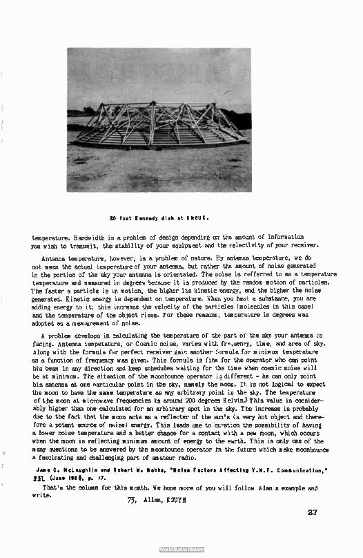
SO foot Kennedy dish at KIIKUK.
temperature. Bandwidth tu a problem of design depending (17 the amount of information
you wish to tranumit, the stability of your equipment and the selectivity of your receiver.
Antenna temperature, however, is a problem of nature. By antenna temperature, we do
not mean the actual temperature of your antenna, but rather the mncunt of noise generated in the portion of the sky your antenna is orientated. The noise is refferred to as a temperature
temperature and measured in degrees because it is produced by the random motion of particles. The faster a particle is in motion, the higher its kinetic energy, and the higher the noise
generated. Kinetic energy is dependent on temperature. When you heat a substance, you are adding energy to it; this increase the velocity of the particles ( mo:ecules in this case)
and the temperature of the object rises. For these reasons, temperuure in degrees was
adopted as a meamrement of noise.
A problem develops in calculating the temperature of the part of the sky your antenna is
facing. Antenna lempetature, or Cosmic noise, varies with fr,uency, time, and area of sky. Along with the formula for perfect receiver gain another formula fpr minimum temperature
as a function of frequency was given. This formula is fine for the operator who can point
his beam in any direction and keep schedules waiting for the time when cosmic noise will be at minimum. The situation of the mconbounce operator , u different - he can only point
his antenna at one rearticular point in the sky, namely the moon. It is not logical to expect the moon to have the sane temperature as any arbitrary point in the sky. The temperature
of the moon at microwave frequencies is around 200 degrees Kelvin.iThis value is consider-ably higher than one calculated for an arbitrary spot in the sky. The increase is probably
due to the fact that the moon acts as a reflecter of the sun's ( a very hot object and there-fore a potent sonrce of noise) energy. This leads one to qu ,..stion the possibility of having
a lower noise temperature and a better chance for a contact with a new moon, which occurs when the moon is reflecting minimum amount of energy to the earth. This is only one of the
many questions to be answered by the f000nbounce operator in the future which make moonbounce a fascinating and challenging part of amateur radio.
Jame C. McLaughlin and Robert W. Hobbs, 'Noise Factors Affecting V.H.F. Communication,'
91L (June Mg, e. 17.
That's the column for this month. We hope more of you will follow Alan s example and write.
73, Allen, K2UYH
27
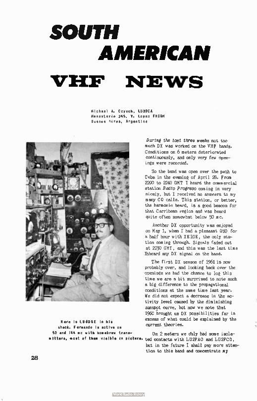
SOUTH AMERICAN
VHF NEWS
Michael A. Czysch, LU3DCA
Monasterio 345, V. Lopez FNGBM
Buenos tires, Argentine
Here is LUBDBE in his
shack. Fernando is active on
50 and 144 mc with homebrew trans-
mitters, most of then visible In picture.
28
During the last three weeks not too much DX was worked on the VHF bands.
Conditions on 6 meters deteriorated continuously, and only very few open-
ings were recorded.
So the band was open over the path to Cuba in the evening of April 28. From 2200 to 2240 GMT I heard the commercial station Radio Progreso coining in very nicely, but I received no answers to my many CO calls. This station, or better, the harmonic heard, is a good beacon for
that Carribean region and was heard quite often somewhat below 50 mc.
Another DX opportunity was enjoyed
on May 1, when I had a pleasant OSO for a half hour with XE1GE, the only sta-
tion coming through. Signals faded out at 2230 GMT, and this was the last time Ihheard any DX signal on the band.
The first DX season of 1961 is now probably over, and looking back over the openings we had the chance to log this time we are a bit surprised to note such
a big difference to the propagational conditions at the same time last year. We did not expect a decrease in the ac-
tivity level caused by the diminishing sunspot curve, but now we note that
196C .brought us DX possibilities far in excess of what could be explained by the current theories.
On 2 meters we dhly had some isola-ted contacts with LU2FAO and LU2FCD,
but in the future I shall pay more atten-tion to this band and concentrate my
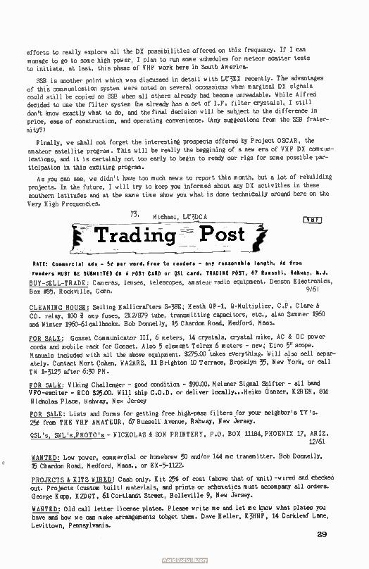
efforts to really explore all the DX possibilities offered on this frequency. If I can
manage to go to some high power, I plan to run some schedules for meteor scatter tests to initiate, at last, this phase of VHF work here in South America.
SSB is another point which was discussed in detail with LU3EX recently. The advantages of this communication system were noted on several occassions when marginal DX signals could still be copied on SSB when all others already had become unreadable. While Alfred
decided to use the filter system (he already has a set of I.F. filter crystals), I still don't know exactly what to do, and the final decision will be sub,ject to the difference in price, ease of construction, and operating convenience. (Any suggestions from the SSB frater-
nity?)
Finally, we shall not forget the interesting prospects offered by Project OSCAR, the
amateur satellite program. This will be really the beggining of a new era of VHF DX commun-
ications, and it is certainly not too early to begin to ready our rigs for some possible par-
ticipation in this exciting program.
As you can see, we didn't have too much news to report this month, but a lot of rebuilding
projects. In the future, I will try to keep you informed about any DX activities in these southern latitudes and at the same time show you what is done technically around here on the
Very High Frequencies.
73, Michael, LU3DCA
Traci irig Post VHF
RATE: Commercial ads - 5t per word. Free to readers - any reasonable length. Ad from
readers MUST BE SUBMITTED ON A POST CARD or QSL card. TRADING POST, 67 Russell, Rahway, N.J.
BUY-SELL-TRADE: Cameras, lenses, telescopes, amateur radio equipment. Denson Electronics,
Box #85, Rockville, Conn. 9/6)
CLEANING HOUSE: Selling Hallicrafters S-38E; Heath QF-1, Q-Multiplier, C.P. Clare &
CO. relay, 100 e amp fuses, A2/879 tube, transmitting capacitors, etc., also Summer 1960
and Winter 1960-61callbooks. Bob Donnelly, 15 Chardon Road, Medford, Mass.
FOR SALE: Gonset Communicator III, 6 meters, 14 crystals, crystal mike, AC & DC power
cords and mobile rack for Gonset. Also 5 element Telrex 6 meters - new; E ico 5" scope.
Manuals included with all the above equipment. $275.00 'takes everything. Will also sell separ-
ately. Contact Mort Cohen, WA2ARS, 11 Brighton 10 Terrace, Brooklyn 35, New York, or call
TW 1-3125 after 6:30 PM.
FOR SALE: Viking Challenger - good condition - $90.00. Meisner Signal Shifter - all band
VFO-exciter - ECO $25.00. Will ship C.O.D. or deliver locally...Heiko Ganzer, K2REH, 814
Nicholas Place, Hahway, New Jersey
FOR SALE: Lists and fonts for getting free high-pass filters for your neighbor's TV's.
25t from THE VHF AMATEUR, 67 Russell Avenue, Rahway, New Jersey.
QSL's, SWL's,PHOTO's - NICHOLAS & SON PRINTERY, P.O. BOX 11184, PHOENIX 17, ARIZ. 12/61
WANTED: Low power, commercial or homebrew 50 and/or 144 mc transmitter. Bob Donnelly,
15 Chardon Road, Medford, Mass., or EX-5-1122.
PROJECTS & KITS WIRED! Cash only. Kit 25% of cost ( above that of unit) -wired and checked
out. Projects ( custom built) materials, and prints or schematics must accompany all orders.
George Kupp, K2DOT, 61 Cortlandt Street, Belleville 9, New Jersey.
WANTED: Old call letter license plates. Please write me and let me know what plates you have and how we can make arrangements tobget them. Dave Heller, K3HNP, 14 Darkleaf Lane,
Levittown, Pennsylvania.
29
ileiheke MAW/
titut Wit at eat pitiede....
This month marks the second in our monthly AUTHOR's
CONTEST ketch will end with the Nouerber 1961 issue.
All articles and columns in this issue are to be
evaluated by you below and returned to us immediately.
We'll announce ketch articles, on a percentage basis,
were the mast popular in this issue. At the end of November, all percentage winners will be carpeting
against each other for top prizes. Best winners over-all get the prizes pictured above. YOUR article can
win( Heankthile, help our writers this month by doin6
your part...
- - - - - - - - - - - - - - - - - Return immediately to: THE VHF AMATEUR, 87 Russell Avenue, Rahway, New Jersey.
Directions: Pick out the best articles ( only four) and rate those four
in the order of their appeal to you (#1, #2, #3, 04 - first
being best, and fourth being 4th best)...
HODES OF PROPAGATION, W3RUE ( 1 EVENING WITH M8PT, W8PT ( J TV! - WHAT TO DO, K2ISQ-ISP ( I CALIFORNIA KILOWATT, WA2GCF ( 1 I CASE FOR VHF, W9QVA ( 1 SNEAK PREVIEW - 99'er, K8CHE ( 1 FROM THE HAM SHACK, K3GQA ( 1 6 Meter Mobile KOPSF ( I DE Uncle Charlie How ( J onBounce! K2UYII ( J I
SOUTH AMERICAN NEWS, LII3DCA - ( - _ - - - -
30
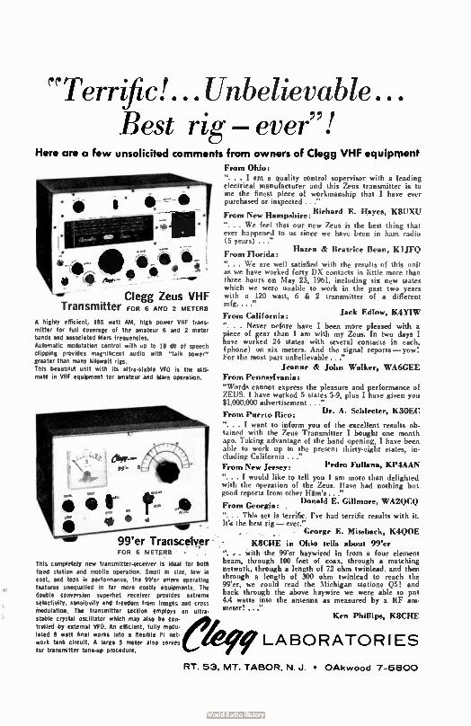
"Terrfic!...Unbelievable... Best rig — ever"!
Here are a few unsolicited comments from owners of Clegg VHF equipment From Ohio: ". . . I am a quality control supervisor with a leading electrical manufacturer and this Zeus transmitter is to me the finest piece of workmanship that I have ever purchased or inspected ..."
Richard E. Hayes, K8UXU From New Hampshire:
". . . We feel that our new Zeus is the best thing that ever happened to us since we have been in ham radio (5 years) ..."
Hazen & Beatrice Bean, K1JFQ From Florida: ". . . We are well satisfied with the results of this unit as we have worked forty DX contacts in little more than three hours on May 23, 1961, including six new states which we were unable to work in the past two years with a 120 watt, 6 & 2 transmitter of a different mfg...."
Jack Edlow, K4YIW From California:
". . . Never nefore have I been more pleased with a piece of gear than I am with my Zeus. In two days I have worked 24 states with several contacts in each, (phone) on six meters. And the signal reports — yow! For the most part unbelievable ..."
Jeanne & John Walker, WA6GEE From Pennsylvania: "Words cannot express the pleasure and performance of ZEUS. I have worked 5 states 5.9, plus I have given you $1,000,0® advertisement ..."
Dr. A. Sehleeter, K3OEC From Puerto Rico: ". . . I want to inform you of the excellent results ob-tained with the Zeus Transmitter I bought one month ago. Taking advantage of the band opening, I have been able to work up to the present thirty-eight states, in. eluding California ..." From New Jersey: Pedro Fullana, KP4AAN
". . . I would like to tell you I am more than delighted with the operation of the Zeus. Have had nothing but good reports from other Hlim's..."
Donald E. Gillmore, WA2QCQ From Georgia: . ". . . This set is terrific. I've had terrific results with it. lea the hest rig — ever." . . . George E. Missback, K4Q0E . ,
• K8CHE in Ohio tells about 99'er ". With the 99'er haywired in from a four element beam, through 100 feet of coax, through a matching network, through a length of 72 ohm twinlead. and then through a length of 300 ohm twinlead to reach the 99'er, we could read the Michigan stations Q5! and back through the above haywire we were able to put 4.4 watts into the antenna as measured by a RF am-meter! ..."
Ken Phillips, K8CHE
- - - • • e ...
Clegg Zeus VHF Transmitter FOR 6 AND 2 METERS
A highly efficient, 185 watt AM, high power VHF trans-mitter for full coverage of the amateur 6 and 2 meter bands and associated Mars frequencies. Automatic modulation control with up to 18 db of speech clipping provides magnificent audio with " talk power" greater than many kilowatt rigs. This beautiful unit with its ultra-stable VFO is the ulti-mate in VHF equipment for amateur and Mars operation.
99'er Transceiver FOR 6 METERS •
This completely new transmitter-aeceiver is ideal for both fixed station and mobile operation. Small in size, low in cost, and toys in performance, the 99'er offers operating features unequalled in far more costly equipments. The double conversion superhet receiver provides extreme selectivity, sensitivity and freedom from images and cross ntodulation. The transmitter section employs an ultra. stable crystal oscillator which may also be con-trolled by external VFO. An efficient, fully modu-lated 8 watt final works into a flexible Pi net-work tank circuit. A large S meter also serves for transmitter tune-up procedure.
f LABORATORIES
RT. 53, MT. TABOR, N. J. • OAkwood 7-6800
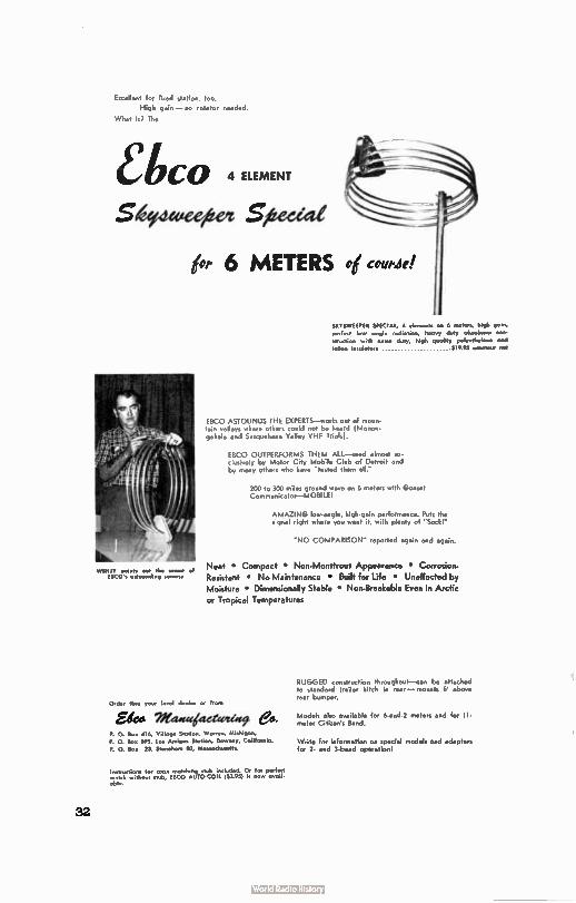
Excellent for foxed station, too. High gain— no rotator needed.
What is? The
îtC0
Seieweeitet gizeccal
4 ELEMENT
jot, 6 METERS oé maw!
SICTSWEEPER SPECIAL, 4 ammo. on 6 melees, high gain,
paled low angle ...balm, heavy day aluminum con-
struction with extra duty, high quality polyethylene ond talon insulators $10.95 um* tyst
RICO ASTOUNDS THE EXPERTS—works out of moun-tain valleys where others could not be heard ( Monon-gahela and Susguishana Valley VHF Trials).
EBCO OUTPERFORMS THEM ALL—used almost ex-clusively by Motor City Mobile Club of Detroit and by many others who have "tested them all."
200 to 300 roiles ground wave on 6 meters with Gonset Communicator—MOBILEI
AMAZING low-angle, high-gain performance. Puts the signal right where you want it, with plenty of "Soar
"NO COMPARISON- reported again and again.
Neat • Compact • Non-Monstrous Appearance • Corrosion-Resistant • No Maintenance • Built for Life • Unaffected by Moisture • Dimensionally Stable • Non-Breakable Even in Arctic or Tropical Temperatures
Order thru your local dealer or from
Ede* Wed4t4deetetlite e8.
P. 0. Sox 416, Village Station, Warren. Michigan,
P. 0. lox 095, Los Amigos Sicilia, Downey, Colifornia,
P. 0. lox 23, Stoneham 80, Mastachus.s.
Instructions for coos matching stub Included. On for perfect mach without stub, ESC° AUTO-COIL IS3.93) is now ovoil. oble.
32
RUGGED construction throughout—can be attached to standard trailer hitch in mar — mounts 6' above rear bumper.
Models also available for 6-and-2 meters and for I I-nsets,. Citisen's Band.
Write for information on spacial models and adapters for 2. and 3-band operation!
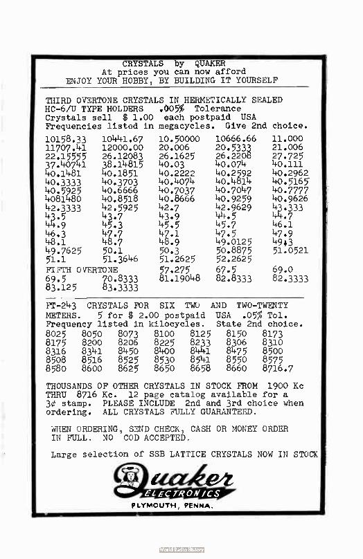
CRYSTALS by QUAKER At prices you can now afford
ENJOY YOUR HOBBY, BY BUILDING IT YOURSELF
THIRD OVERTONE CRYSTALS IN HERMETICALLY SEALED HC-6/U TYPE HOLDERS .005% Tolerance Crystals sell $ 1.00 each postpaid USA Frequencies listed in megacycles. Give 2nd choice.
10158.33 10441.67 10.50000 10666.66 11.000 11707.41 12000.00 20.006 20.5333 21.006 22.15555 26.12083 26.1625 26.2208 27.725 37.40741 38.14815 40.03 40.074 40.111 40.1481 40.1851 40.2222 40.2592 40.2962 40.3333 40.3703 40.4074 40.4814 40.5165-40.5925 40.6666 40.7037 40.7047 40.7777 4081480 40.8518 40.8666 40.9259 40.9626 42.3333 42.5925 42.7 42.9629 43.333 43.5 43.7 43.9 44.5 41+.7 44.9 45.3 45.5 45.7 46.1 46.3 47.7 47.1 47.5 47.9 48.1 48.7 48.9 49.0125 4943 49.7625 50.1 50.3 50.8875 51.0521 51.1 51.3646 51.2625 52.2625
FIFTH OVERTONE 57.275 67.5 69.0 69.5 70.8333 81.19048 82.8333 82.3333 83.125 83.3333
FT-243 CRYSTALS FOR SIX TWO AND TWO-TWENTY METERS. 5 for $ 2.00 postpaid USA .05% Toi. Frequency listed in kilocycles. State 2nd choice. 8025 8050 8073 8100 8125 8150 8173 8175 8200 8206 8225 8233 8306 8310 8316 8341 8450 8400 8441 8475 8500 8508 8516 8525 8530 8541 8550 8575 8580 8600 8625 8650 8658 8660 8716.7
THOUSANDS OF OTHER CRYSTALS IN STOCK FROM 1900 Kc THRU 8716 Kc. 12 page catalog available for a 30 stamp. PLEASE INCLUDE 2nd and 3rd choice when ordering. ALL CRYSTALS FULLY GUARANTEED.
WHEN ORDERING, SEND CHECK, CASH OR MONEY ORDER IN FULL. NO COD ACCEPTED.
Large selection of SSB LATTICE CRYSTALS NOW IN STOCK
IMP
PLYMOUTH, PENNA.
Six Thousand Eyes*
...Read this magazine every month! How can you possibly
go another day without subscribing? THE VHF AMATEUR
the thinking man's magazine!
*Most of our 3,000 readers have two eyes.
12 issues $2 Ilte Val/ pelstaiewg
67 RUSSELL RAHWAY, NEW JERSEY
(
I I
(
1 year $2.00
2 years 5 50
3 Years 5 00
NAME
ADDRESS
CITY
-
is
(()) Renewal
CALL
ZoNE STATE
gimeELECTRON/CS PLYMOUTH, PEPOtok.
Brand New Goverment Surplus At Exceptionally Low Prices
JAN TUBES
0A2WA - 600
2D21W - 500
6AG7 - 65e
6C4 - 30e
61AGAY - 60e
6SN7GT - 50e
Variable Capacitors
HF-15-X Wide Spaced
3.6 min. 15 max.
Only - 600
HF - 35, 3.2 min. 36 max. Only - 400
Ceramic Trimmer
Capacitors
NPO 3-12 mmf
only 100
NEO 3-25 mmf
only 100
Oil Condensers
2mfd 1000vdc - 450
4mfd 600 vdc - 400
Filament Transformer
Input Fri. 220 VAC
60 cycle. Output Sec. #1 - 2.5 volts CT 10amps.Sec. #2 5 volts Cl' Test 5000 volts. Only - $3.00.
THE ABOVE ITEMS ARE IN LIMITED QUANTITIES. ALL ABOYE ITEMS SHIPPED POSTPAID USA.
Be sure to watch The VHF Amateur for full pages of new bargains. Keep each issu
as a reference.
All
Tubes
Guaranteed] Filter Chokes
15 henry 50ma - only 6oe 8 henry 100 ma - only 85e 10 henry 175ma - only $1.50
5 henry 225ma - only $1.75
Dual 9 henry 100ma, 10 henry 75 ma
- only $1.75
Audio Transformers
Fri. 15000 ohms
Sec. 600 ohms
300 to 6000 cycles lma EC - only 35e
Fri. 7000 ohms
Sec. 3 ohms 100 to 5000 cycles
2 watts - - - only 350
3amps Sec.
Announcing the New
VE77-17E7 VHF-UHF Mobile Antenna
with Magnetic Base.
* No mounting holes required.
*Secure at high speeds.
* May be readily re-..oved
* 50 ohm inpedance.
* Self-leveling ceramic magnet in each corner.
•
VERSA - I RON1CS Box 223 WHEELING, ILLINOIS
E. F. Johnson G
Mosley
Tel res
Tecraft Hy-Gain
Central Electronics Elmac
Drake & others...
Specializing in gear for 50 mc 6 above
McGrath Electronics 2030 llth Street
Boulder, Co/orado
Write us now - about your problems or needs
Flog, KODIN Tom, WOIUF Earl, KORHW
READ
Western Radio Amateur
48 pU'es of construction, news, DX and DXpedi-
Lions, V.H.F. and technical articles! All these
by such famous authors as Ed Marriner, W6BLZ,
Don Stoner, W6TNS, "YB" Pyle, W70E, with Bob
Grimm, K6RNI4, heading up the V.H.F. Column!
This magazine is the third largest in the
United States - and for the money you can't
go wrong! Only $2.00 per year. Write now to:
Western Radio Amateur and West Coast Heas Ads
mmittmde:
10517 Hayed). St. El Montt, Califtimis Gilbert 8-2119
AUTO - CALL 2509 - 32nd. St., S. E., WASHINGTON 20, D. G.
'Ibis is the paper you've
heard so much about! Die fam-
ous " AUTO-CALL" that has been
quoted by almost all Han pap-
ers, including Cg magazine!
For only a dollar a year,
you'll get 32 packed pages each
month of all the best in gmeral liam liadlo material. It has a
special added feature for those
amataurs in the Washington, D.C.
area, as it covers club activ-
ities there.
Bill WM
Yes, we do have some back issues of THE VHF AMATEUR available ln limited quantities.
We've been literally swamped for favorite copies lately, and to save further confusion, here are the ones you can get now...
1960
August September October November
I 1961 I
All issues to date
25$ each from THE VHF AMATEUR, Russell Avenue, Rahway, N.J.,
11111SIBIlamms.
1 ELECTRONICS 1921 E. Edgar Road
Linden, N.J.
Accoss from the ESSO Research Center
Sample VHF Bargains
APR-5A....Rovr 1000-6230 mc w/115 vac 60 ny PS —um o o Aps-4 Radar transceiver, new w/cables, control boxes,
antenna, etc; 9320-9430 mc; 35KW peak pwr 295.00
ARC-3 Xmtr 100-156 mc 832PA; 8 channel, 1/new 19.50
ARC -3 Reim 100-156 mc 17 tubes; 1/new 17.50
AK-1 Transceiver 14-50 mc; 807 PA; excellent 29.50
BC-1158...6 mtr xmtr; pair 815s mod by pair 815s 34.50
R-1/324...100-125 mc tunable w/115 vac 60 cy pwr supply 55.00
SCR-522...100-156 mc transceiver w/tubes; excellent 22.50 TS-3/AP...Frea. mtr; 2400-3400 mcs; w/cal chart; new 9 50
ATTENTION UHF 'ersl
We have a wide assortment of uhf equipment. j
Write for our free catalogue and prices.
A deposit of 25% is required on all C.O.D. orders. Prices f.o.b. Linden.
IJ-0-1ST-G YAGIS
For 6' Ikea 2 Men: 228 f 132 tile Silver Falcon introduce, high gain at a very low
erice. flesente are Cut from hi- g alumina, rod ex-
cept 6 Peters which ueea g. tubing. The 6 outer
Yagi features Gaema-Match and beano for 2 peters and above use a folded dipole patching 300 oh. line.
All antennas are coated with lacquer to reduce oxi-
dation of the a'upinue. Alumina. is uaed throughout
with the except.on of brae. screw, and cadeium pla-
ted steel screws. All hardware is furnished. All
antennae f.0.6. Saginaw. Michigan.
8 El eeeee for S Motors, It db Pals - #7.50
50 Mc - 9.0 db gain. 5 elements on a 9 foot boom. Boom is 1" Thickwall $11.95
144 Mc - 12.0 db gain. 8 elements on a 10 foot boom. Boom is 5/8" Dia. 7.50
144 Mc - 15 db gain. 11 elements on a 18 foot boom. Boom is 1" Dia. 15.95
220 Mc - 13.5 db gain. 9 elements on a 9 foot boom. Boom is 5/8" Dia 695
432 Mc - 16.8 db gain. 15 elements on a 10 foot boom. Boom is 5/8" Dia 6 50
50 Mc - 10.4 db gain. 6 elements on a 18 foot boom. Boom is 3" Dia 24.95
WEGNER BROTHERS - eeivw K81XF
Box 263, Bridgeport, Michigan
Me alp° build antennae to order. Write for prices.
37
CQ
VHF for the radio amateur. A new dynamic hand-
book that covers all phases of VHF activities.
INDEX INTRODUCTION 1. VHF RADIO PROPAGATION
50, 144, 220, 432 and 1296 MC
bands
2. ANTENNAS
2.1 Discussion
2.2 RF Transmission Lines
2.3 Types of Antennas
2.4 50 MC Antennas
2.5 144 MC Antennas
2.6 220 MC Antennas
2.7 432 MC Antennas
2.8 1296 MC Antennas
3. TRANSMITTERS
3.1A 50 MC Low Powered
Transmitter
3.113 6W6GT 50 MC Transmitter
3.1C 6W6GB 50 MC Transmitter
3.1D 50 MC Exciter
3.1E High Powered 50 MC
Amplifier
3.2A Low Powered 144 MC
Transmitter
3.28 144 MC Exciter
3.2C High Powered 144 MC
Amplifiers
3.3A 222 MC Exciter
3.3B High Powered 222 MC
Amplifier
3.3C Single Tube 220 MC
Amplifier
3.4A 2C39 Units on 432 MC
3.4B Coaxial Circuit Transmitter
3.4C Flat Plate Line Transmitter 3.5A 1296 MC Cavity Transmitter
2.58 1296 MC Flot Line Transmitter
4. MODULATION
4.1 616 Modulator
4.2 6W6 Class B Modulator
4.3 6Y6 Class B Modulator
4.4 50 Watt Modulator
4.5 Screen Grid Modulator
4.6 Frequency Modulator
4.7 Transistor Speech Amplifier
4.8 Phase Modulator
4.9 Vacuum Tube Neyer
CO MAGAZINE BOOK DEPT. II] VHF For The Radio Amateur, $3.50
C 4
300 West 43rd St., Sirs: I enclose Please send my VHF
New York 36, N.Y. For The Radio Amateur postpaid to:
NAME CALL
ADDRESS
CITY ZONE STATE
N.Y. City rraidod , all : V; Salt, Ta,
5. POWER SUPPLIES
5.1 Small Power Supplies
5.2 Selenium and Silicon Rectifiers
5.3 Voltage Doubler
b. CONVERTERS
6.1 Converter for 50 MC
6.2 Converter for 144 MC
6.3 Converter for 220 MC
6.4 Converter for 432 MC
6.5 Converter for 1296 MC
7. RECEIVER IF SYSTEMS
7.1 Communication Type Receivers
7.2 14 to 18 MC IF Receiver
7.3 Audio Filter
8. PREAMPLIFIERS
8.1 220 MC Tube Preamplifiers
8.2 Parametric Amplifiers
8.3 Pump Oscillators
8.4 144 MC Parametric Amplifiers
8.5 220 MC Parametric Amplifiers
8.6 432 MC Parametric Amplifiers
9. TEST EQUIPMENT
9.1 Diode AC Voltmeter
9.2 AC and DC Diode Voltmeter
9.3 F.S.-Monitors
9.4 Transistorized F.S. Meter
9.5 1296 MC Wavemeter and
Noise G,nerator
9.6 SWR Meters
9.70 Frequency Marker
9.78 Transistor Frequency
Marker
9.7C Dual Transistor Signal
Marker
9.8 Transistor Audio Oscillator
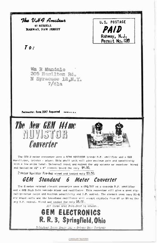
Woe Ulf /bade»: 67 RUSSELL
RAHWAY, NEW JERSEY
To:
Vita R Mandale 305 Hamilton Rd. N Syracuae 12e»Y»
7/61a
Postmaster: Form. 3547 Requested 011•111l. el Y. • •
U.S. POSTAGE
PAID Rahway, N.J. Permit No.126
The 'few CEll 111me
Converter The GEM 2 meter converter uses a 6CW4 NUVISTOR triode R.F. amplifier and a 6X8
oscillator, trinler - mixer. This small unit will give maximum gain and sensitivity
with a low noise level. Universal input and output for any antenna or receiver, Wired
and tested on 2i" x 4" circuit board for only MOO.
2 Meter Nuvistor Pre—Amp wired and tested only $3.50.
OEM Standard 6 Meter Converter The 6 meter printed circuit converter uses a 611Q/8Z7 us a cascode R.F. amplifier
and a 6X8 High Gain nentode mixer and oscillator, This converter will give a good sig-
nal-to-noise ratio and maximum sensitivity and I.F. outnut. The circuit uses very 111-Q
air wound coils and the broadband oscillator will accept crystals from 40 to 50 mc for
any output. Wired and tested for only $5.00. All tteme pent Pnet-Pnld tn advanec.
GEM ELECTRONICS R. R. 3, Springfield Ohio
7'; Chic: EYrhaner
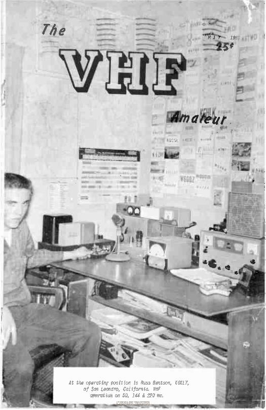
The
.111ffil MIL §.,11b111111
f
ta.Arm 1.0 t
MIN MI
111110 IMO II «a'
- e
«eirr›-
aWer
*nu
At the operating pc)sition is Russ Bentson, K6KLY, of San Leandro, California. VHF
operation on 50, 144 & 220 mc.
-11111re
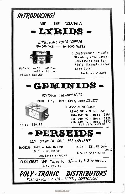
11111111»811111111.,AittiWee
INTRODUCING! VHF - UHF ASSOCIATES
Lr ) I- I ID
DIRECTIONAL POWER COUPLER 50-500 MCS --- 10-1000 WATTS
Models: L-52 - 52 flies L-75 - 75 oh%
Price: $ 24.50
4 Instruments in ONE:
Standing Wave Ratio Modulation Monitor Field Strength Meter
Line Loss
Bul/etin E-5275
Genexxx» NUVISTOR PRE-AMPLIFIER
HIGH GAIN,
-,e16nade
Price: $ 19.95
STABILITY, SENSITIVITY
4 Models to Cover:
48-60 MC - Model G50 144-150 MC - Model GI44 210-240 MC - Model G220 410-432 MC - Model G432
Bulletin E-5124
- re ) EID 417A GROUNDED GRID PRE-AMPLIFIER
MODF78: 144B - 144-150 MC
50B - 48-60 MC
Bulletin E-5144
PRICE: $21.95 (w/o tube)
$39.95 with tube
CUSH CRAFT VHF Yagis for 3/4 - I* & 2 meters... CAT. No. C1
POLY - TONIC DISTRIBUTORS POST OFFICE BOX 135- BET//EL, CONNECTICUT
The VHF Amateur A MONTHLY PUBLICATION
OFFICES:
Business & Editorial
87 Russell Avenue
Rahway, New Jersey
EDITORIAL STAFF
Editor
B,b Brqwn, I2ZSQ
67 Russell Avenue Rahway, New Jersey
Associate Editor
J,D. "Red" Br,wn, 112ZSP
67 Russell Ave., Rahway, N.J.
bloonbounce Activities
Editor
Allen Katz, IUDYR 48 Cumberland Avenue
Verona, New Jersey
Single Sideband Editor
J.S. "Rusty" Brauman ILMN
170 Schenck Avcnue
Great Neck, New rrk
South American Editor
Michael A, Cyzsch
LU3DCA
Nonastertn 345
V. Lnpez FNGBN Buenos Aires, Argenttna
?be 7fil Asatcur is
published monthly by
Robert N. Brown, EEZSD, Subscription rates:
one year, $ 2.00, two
years, $ 1.60, II years,
$ . 00. ?orie l/ a add SI.
ADVERTISING rate card
,n request. Entire
contents Printed i. Clark, N.J., U.S.A.
VOL. 4, No. " 1041
Tabk Conientà
10 Watt 8 Meter Transmitter AMATEUR RA'I0 SOCIETY 1F HARRI S1N 4
Satellite Scatter
MASSACHUSETTS INSTITUTE ,F TECHN1LT`GY, K21018. W....7
Propagation Forecast
13Ei BROWN, K2ZSC, EDITOR 9
2 Meters with an 82981
RICHARD HUNTRE SS , K1CXX 10
Customizing your SIXER
J'SEPH Lupo , WA2G8A 15
South American VHF News
MICHAEL A. CYZSCH, LU3DCA 18
Moonbounce Activities
ALLEN KATZ, K2UVH 24
VHF Combine
PETER MAREAVAGE, WA2CWA 27
Rabbit Ears for 61
TED WOODBURY, WA2BZV 32
MISCELLANEOUS
HEU-6's Available 23
Pictures ( E.C. VHF Society) ,30
50 mc W.A.S.. 26
Trading Post 31
Author's Contest , 37
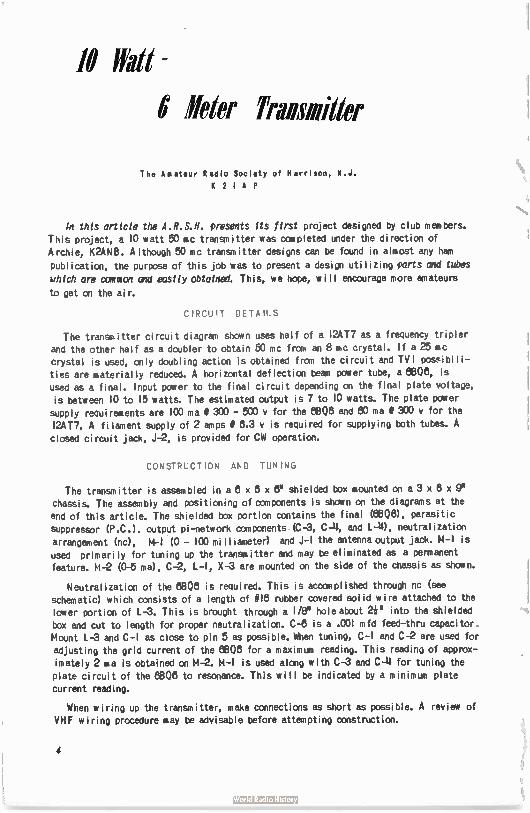
18 trati -
6' leter Transmitter
The Amateur Radio Society of Harrison, N.J. 1(21AP
In this article the A.R.S.N. presents its first project designed by club members. This project, a 10 watt 50 mc transmitter was completed under the direction of Archie, K2ANB. Although 50 mc transmitter designs can be found in almost any ham
publication, the purpose of this job was to present a design utilizing parts and tubes
which are common and easily obtained. This, we hope, will encourage more amateurs
to get on the air.
CIRCUIT DETAILS
The transm itter circuit diagram shown uses half of a 12AT7 as a frequency tripler and the other half as a doubler to obtain 50 mc from an 8 mc crystal. If a 25 mc crystal is used, only doubling action is obtained from the circuit and TV I possibi I i-ties are material ly reduced. A horizontal deflection beam power tube, a 8808, is
used as a final. Input power to the final circuit depending on the final plate voltage, is between 10 to 15 watts. The estimated output is 7 to 10 watts. The plate power
supply requirements are 100 ma I 300 - 500 v for the 8808 and 60 ma/300 y for the 12AT7. A fi lament supply of 2 amps 1 8.3 y is required for supplying both tubes. A
closed circuit jack, J-2, is provided for CW operation.
CONSTRUCT ION AND TUN ING
The transmitter is assembled in a 6 x 8 x ir shielded box mounted on a 3 x 8 x
chassis. The assembly and positioning of components is shown on the diagrams at the end of this article. The shielded box portion contains the final (ewe, parasitic
suppressor (P.C.). Output pi-network components (C-3, C-14, and L-18, neutralization arrangement (nc), M-I (0 - 100 mill iameter) and J-1 the antenna output jack. M-1 is
used primari ly for tuning up the transmitter and may be eliminated as a permanent
feature. M-2 (0-5 ma), C-2, L- I, X-3 are mounted on the side of the chassis as skein.
Neutralization of the 8806 is required. This is accomplished through nc (see schematic) which consists of a length of # I6 rubber covered solid wire attached to the
lower portion of L-3. This is brought through a I/8° hole about 2i" into the shielded box and cut to length for proper neutralization. C-8 is a .001 mfd feed-thru capacitor,
Mount L-3 and C-1 as close to pin 5 as possible. When tuning, C-I and C-2 are used for adjusting the grid current of the 8808 for a maximum reading. This reading of approx-
imately 2 ma is obtained on M-2. M-1 is used along with C-3 and C-11 for tuning the plate circuit of the 6808 to resonance. This will be indicated by a m inimum plate
current reading.
When wiring up the transmitter, make connections as short as possible. A review of VHF wiring procedure may be advisable before attempting construction.
4
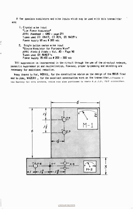
A few possible modulators and mike inputs which may be used with this transmitter are:
I. Crystal mike input "Low Power Modulator" AR R L Handbook - 1980 - page 271 Tubes used ( 1) I2AX7, ( 1) 8C11, (2) 13.405's Power supply 90 ma 0 500 vdc
2. Single button carbon mike input "Simple t,lodulator for Portable Work" ARRL Hints & K inks - Vol. tit3 - Page 118 Tubes used (2) 8V8GT's Power supply 75-100 ma 0 290 - SOO vdc
TV I suppression is incorporated in the circuit through the use of the pi-output network, parasitic suppressor pc and neutralization. However, proper by-passing and shielding are
necessary for additional reduction.
Many thanks to Hal, W2VHU, for the constructive advice on the design of the 8808 final
and to John, WA2ER I , for the excellent construction work on the transroitter.--T haike t the S•ciety tier this article, which was also published in their R.A.S.F. FH ACtwviti1.
6
6
fir.S\ ic,0
h1.4
M - 1
-3 ((Vim
M-2 3
À
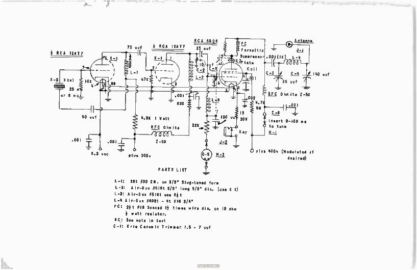
e
75 uuf
RCA 12AT7
X-3 Xtal
25 m
or 8 pn
L- I
50 uuf
RCA 12AT7
47K
.001 .00ti Z-50
▪ 6.3 vac - plue 300v
PARTS LIST
RCA 68 08
25 lie PC
Parasitic
/ Suppress°
2P late
Coil
1
L- I: 23t #30 EN. on 3/8" Slug-tuned form
L-2: Air- Duo #516t 3/8" long 5/8' dia, ( use 6 t) L-3: A ir-Dux #516t use 64 t
L—te A jr-Dun #608t - 14t # I8 3/4"
PC: 24 t # 18 Spaced 14 times wire dia. on 10 ohm
watt resistor.
NC: See note in text
C- I: Erie Ceramic Trimmer 1.5 - 7 uuf
C - 4
35 uuf
Antenna
140 uuf
RFC - 0 hin it. Z-50
1_1
C -6 1
Insert 0-100 ma to tune
M- I
Plus 400v (Modulated if
des i red)
3
2 5 4
X — 2
L-3
0.1
9
Satellite Scatter
Raphael Soifer, K2QBW
D i rector
Office of Satellite Scatter Coordination
Massachusetts Institute of Technology
77 Massachusetts Avenue
Room 10 - 206
Cambridge 39, Massachusetts
The VHF Amateur, through this initial article by K 2Q6W, is cooperating with the new Office of Satellite Scatter Coordination at M. I.T.which was opened on March 1, 1961. We urge ALL readers to carefully read the following and to cooperate by writing at once to the Director, address above, with the information requested in the article
and for further details on the subject. This is a MUST for the scatter enthusiast/
You will undoubtedly recall my OST article of July, 1960, in which I made the offer to supply all needed information to those sincerely interested in satellite scatter work.
This office has been created with the help of the Department of Electrical Engineering
as a means of supplying you with this information.
As the name implies, we exist to coordi nate research, not to conduct it ourselves. That we leave to you, the participating radio amateurs. This is as it should be, for the
most important findings in amateur history have always resulted from the personal initia-tive of the individual experimenter, rarely if ever frcm centralized planning. OSSC, (Office for Satellite Scatter Coordination) therefore, does not have a " progrem • of experi-
mentation, nor does anyone expect to have one. We are here simply to make your life
easier, by establishing frequency channels for standardization, by providing a means of
7
disseminating findings among your fellow experimentors, by acting as a information bureau through which any news which might develop out of your work can reach the
outside world, by publishing bulletins from time to time with information of interest to those in the field (namely you), by maintaining lists of amateurs involved in satel-
lite scatter together with pertinent information as to their activities, and, of course,
by attempting to supply advice to possibly help you over an obstacle. We cannot guarantee to know all the answers, but we can, by asking various sources in the Department, as well
as sane places such as Lincoln Laboratory, etc., attempt to fill in where our own know-
ledge falls short.
As is generally known, there are in excess of three dozen objects in orbit at the present
time, with the likelihood of this number increasing as time goes on. One can calculate
that, out of any given hour, one or more satellites wi II be capable of providing satellite, scatter communication over a given path for perhaps twenty mintutes, on the average. This
is simply a consequence of the large number of satellites. This would tend, of course, to
make statistical correlation between signal bursts and satellite passes quite difficult.
This is complicated by theories which have been proposed saying that a satellite need not
actually be in proximity to the two stations to produce a signal strength increase. For
example, sane say that a satellite in polar regions may produce bursts in many parts of the earth. Others feel that the ionized trail, if indeed one exists, may becane separated fran the satellite in flight, and therefore cannot be assumed to follow the tracking information
for the satellite itself. In other words, aggurn ing proper conditions, satellite proximity is a sufficient, but not necessarily a necessary , condition for burst incidence. This
brings to mind a possible new method of reasearch. Previously, one would first predict
a satellite pass, then schedule the tests to coincide with it. Today, however, it might be worth the effort to reverse the procedure, i.e., to schedule the test for a period of,
let us say, an hour, which can be arbitrarily chosen so long as the ionospheric I4JF for the• path in question is below the operating frequency. The satellites could then be correlated with the finished test results, if possible, rather than vice versa. This, of course, raises
the point that there are two other principal modes of propagation which wi II enter into the results, viz, meteor scatter and ionospheric. But why not? It might be a good idea to
see if a so-called 'multiple scatter' communications system can indeed provide useful can-munication. The strong likelihood is that any future use of the frequencies in question during periods of sunspot lull for other than local work will indeed be via sane combina-tion of the three modes, rather than via one alone. Therefore, why not use the multiple
scatter system in our tests?
This, of course, only a suggestion, but it is one which has definite potential for
amateur participation.
To facilitate experiments of the foregoing type, as well as more conventional variet-ies, OSSC hereby declares the frequencies 21.010 mc, 28.010 mc, and 50.010 Inc, to be standard frequencies for experimentation. All amateurs are requested to use one of these three channels for work, so that casual observers and others who happen to be free in order to listen wi II know where to look. Note that this request does not affect normal amateur operations, because these are conducted on these frequencies at times unsuitable
for satellite scatter work. Observers hearing experimental work are requested to get in touch with the particular station involved. If you cannot determine who the station you
hear is, submit your monitor log to OSSC. By the same token, it would be greatly appreci-ated if all stations involved in satellite scatter work would inform OSSC as to which
channel they are using and when, so that we might forward any monitor reports which may
cane i n.
Re satellite predictions: In the interest of preserving the individual initiative and
derived personal satisfaction therefrom which is necessary for truly meaningful partici-pation, it has been decided that satellite predictions and orbital correlation must re-main the responsibility.of the individual operator. In I ine with this pol icy, the fol low-ing sources wi II supply satellite orbit prediction charts, generally good for about a
8
week in advance, free of charge to all qualified observers. Complicated as they may seem
at first blush, they are really quite self-explanatory and it is well worth the afternoon it will take to get acquainted with their format. Any specific questions which you may have
will be answered by either the issuing source or 06SC. One word of advice: It is our intention that 06SC remain a non-classified project. The savings in terms of time and red
tape gained in this way are enormous. However, the price we pay for these savings is that, legally, we posses no "need to know' for obtaining classified orbital information. This
is a consequence of the necessity for our remaining unclassified and free from governmental
restriction. Therefore, orbits for Samos, some Midas, and even same Discoverer satellites, among others, will not be given us. Please do not expect these.
Sources:
Smithsonian Astrophysical Observatory, 80 Garden Street, Cambridge 38, Massachusetts.
(attn. Carlton W. Tillinghast) Headquarters, Air Force Command and Control Development Division, Laurence G. Hanscom
Field, Bedford, Massachusetts. (attn. STN)
Additionally, it would be beneficial for all those interested in satellite scatter work to register with the Volunteer Satellite Tracking Program, 828 Connecticut Avenue N.W.,
Washington 8, D.C. (attn. Norton Goodwin). This organization, an outgrowth of the le, supplies various kinds of useful information including data on expected launch times and
probable orbits for certain new satellites, and orbital data in the form of modified or-
bital elements. These, to be translated into orbit predictions, must be processed by the
observer as described in Satellite Report No. 7, which is available from them at a cost
of one dollar. All other information besides the processing manual is, of course, free.
Remember, 06SC was formed for your benefit. Make use of it. We cannot disseminate infor-
mation if you who discover it do not write and let us know what you find out, nor can we know who will best profit by this information if amateurs engaged in satellite scatter work do not write and let us know who they are and what their work involves. Similarly, we cannot coordinate unless we know what we are coordinating. Let us know times, frequencies (be sure they are the ones mentioned above for best results), and schedule partners so we
can do our best to help you.
For your information and convenience in lining up schedules, there follows a list of
amateurs who have expressed interest and ability to be active schedule partners: K2GKM,
K3HKK (write to K3I0U), K3JTE, IJEH, WgMAK, K9GDF, K9IJK, KOOFK, KeRe. The following feel they can best serve as monitors: K2BMI, WA2FFC. K2JWD has expressed interest but his
equipment is unknown. W3EQD has high power equipment, but the time factor is unknown in
Don's case.
Data on ionospheric and/or magnetic activity may be obtained weekly from Natl. Bureau
of Standards, Boulder, Colo. Ask for their CPRL-Jb' warning service.
The following back issues of periodicals contain very useful information: Proceedings of the IRE: 3/58, 8/58, 8/58, 10/58, 1/59, 8/50, 7/59, 4/80, 11/80, 12/80, 1/81. PST: 8/50, 7/80. Also Scientific American 8/59, Nature 2/80, Bulletin of the American Physical
Society 1/80, 4/80. 171-1 Fi
PR The VHF Amateur will endeavor to present propagational forcasts every month for our
reader's benefit. N A Y. 1 9 6 1
Sporadic E: Tremendous increase in activity should result in countless short-skip open-ings over a range of not more than 1350 miles on 8 meters‘ Meteor Shower: Aquarids, ex-pected first week in May. Watch 2 meters. North-South (F2): 2FM - 4F1M CST & MST from
Central U.S. to S.A. 5-7 RM PST West Coast U.S. to Islands and New Zealand. These are the best expected times for 10 meters, so look for openings on six along same schedule. 42ZSP
vrel
9
!i) AGrATI* ï ORECAST
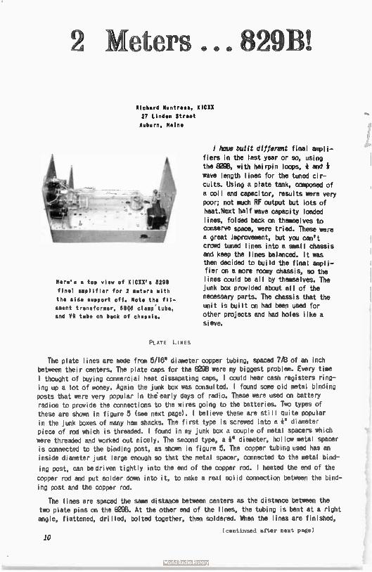
2 Meters 829B
Richard Huntress, KICXX
27 Linden Street
Auburn, Maine
Here's a top view of KICXX's 6298
final amplifier for 2 meters with
the side support off. Note the fil-
ament transformer, 68Q6 clamp'tube,
and VR tube on back of chassis.
PLATE LINES
1 houe built different final ampli-
fiers in the last year or so, using the 8298, with hairpin loops, é and
wave length lines for the tuned cir-
cuits. Using a plate tank, composed of a coil and capacitor, results were very
poor; not much RF output but lots of
heat.Next half wave capacity loaded
lines, folded back on themselves to conserve space, were tried. These were a great improvement, but you can't
crowd tuned lines into a small chassis
and keep the lines balanced. It was then decided to build the final ampli-fier on a more roomy chassis, so the lines could be all by themselves. The
junk box provided about all of the
necessary parts. The chassis that the
unit is built on had been used for other projects and had holes like a
sieve.
The plate lines are made from 5/16" diameter copper tubing, spaced 7/8 of an inch
between their centers. The plate caps for the 8298 were my biggest problem. Every time I thought of buying connercial heat dissapating caps, I could hear cash registers ring-
ing up a lot of money. Again the junk box was consulted. I found some old metal binding
posts that were very popular in the early days of radio. These were used on battery
radios to provide the connections to the wires going to the batteries. Two types of these are shown in figure 5 (see next page). I believe these are still Quite popular
in the junk boxes of many ham shacks. The first type is screwed into a é diameter
piece of rod which is threaded. I found in my junk box a couple of metal spacers which were threaded and worked out nicely. The second type, a é I diameter, hollow metal spacer
is connected to the binding post, as shown in figure 5. The copper tubing used has an
inside diameter just large enough so that the metal spacer, connected to the metal bind-
ing post, can be driven tightly into the end of the copper rod. I heated the end of the
copper rad and put solder down into it, to neke a real solid connection between the bind-
ing post and the copper rod.
The lines are spaced the same distance between centers as the distance between the
two plate pins on the 6298. At the other end of the lines, the tubing is bent at a right
angle, flattened, drilled, bolted together, then soldered. When the lines are finished,
(continued after next page)
10
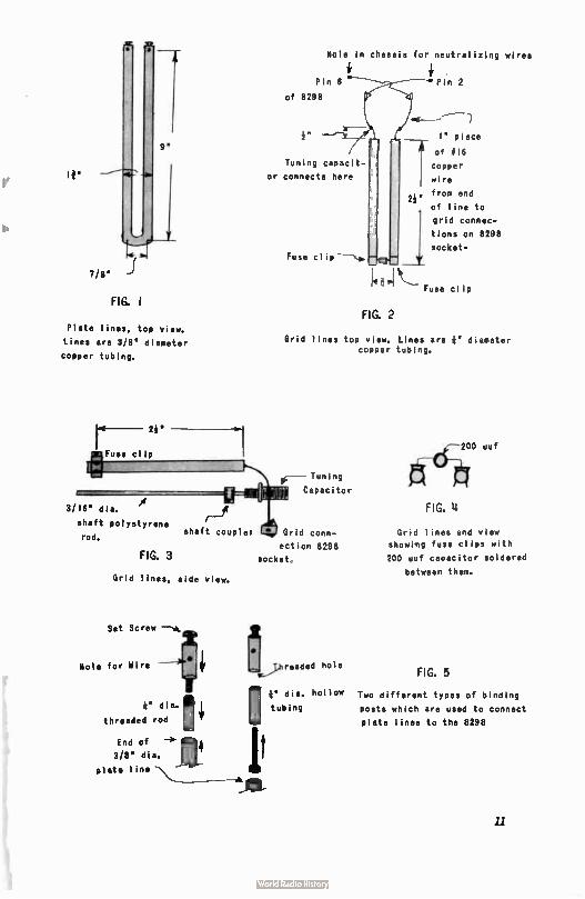
f Hole in chassis for neutralizing wires
If"
7/8"
FIG.1
9"
Plate lines, top view.
Lines are 3/8" diameter
copper tubing.
2h"
3/16" dia,
shaft polystyrene shaft couple ,
rod.
FIG.3
Grid lines, side view.
Set Screw
Pin 6
of 8299
Tuning capacit-
or connects here
Fuse Cl
FIG.2
Pin 2
- - - ---
I" piece
of Si6
copper
wire
from end
of line to
grid connec-
tions on 8298
socket-
Fuse clip
Grid lines top view. Lines are 6" diameter copper tubing.
e-- Tuning
Capacitor
Grid conn-
ection 8298
socket,
Hole for Wire L,.3hre5ded hole
I6" dia, hollow tubing e dia.
threaded rod
111 ,1,
3/8" a. jt plate line
di
End of —› 1114
200 uuf
FIG. 11
Grid lines end view
showing fuse clips with
200 uuf capacitor soldered
between them.
FIG.5
Two different types of binding
posts which are used to connect
plate lines to the 8298
11
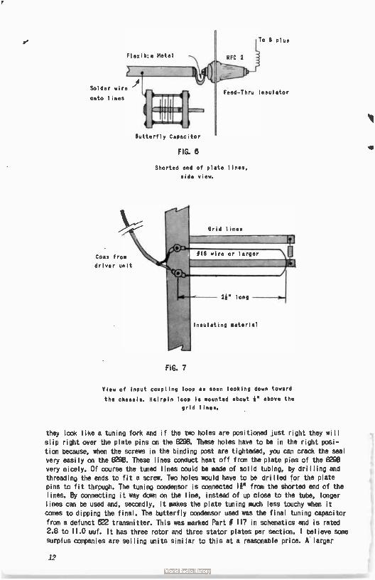
Slevib:e Metal
Solder wire
onto lines
Coax from
driver unit
FIG.7
Butterfly Capacitor
To S Plus
RFC 2
Feed-Thru Insulator
FIG.8
Shorted end of plate lines,
side view.
Grid lines
— 2k" long
Insulating material
View of input coupling loop as seen looking down toward
the chassis. Hairpin loop is mounted about *" above the
grid lines.
they look like a tuning fork and if the two holes are positioned just right they will
slip right over the plate pins on the 8298. These holes have to be in the right posi— tion because, when the screws in the binding post are tightened, you can crack the seal very easily on the 8298. These lines conduct heat off from the plate pins of the 8298 very nicely. Of course the tuned lines could be made of solid tubing, by drilling and threading the ends to fit a screw. Two holes would have to be drilled for the plate pins to fit through. The tuning condensor is connected li" from the shorted end of the lines. By connecting it way down on the line, instead of up close to the tube, longer lines can be used and, secondly, it makes the plate tuning much less touchy when it comes to dipping the final. The butterfly condensor used was the final tuning capacitor
from a defunct 522 transmitter. This was marked Part # 117 in schematics and is rated 2.8 to 11.0 uuf. It has three rotor and three stator plates per section. I believe some
surplus companies are selling units similar to this at a reasonable price. A. larger
12
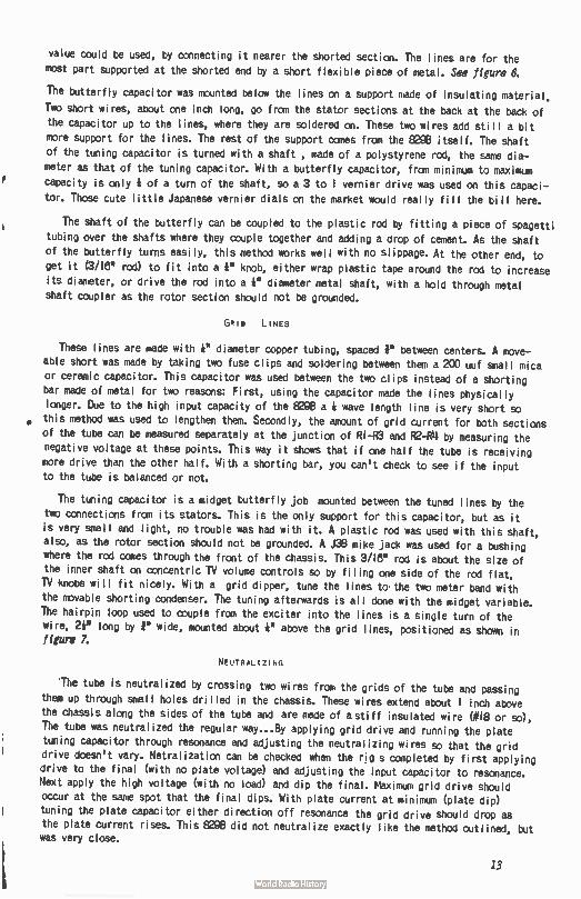
value could be used, by connecting it nearer the shorted section. The lines are for the
most part supported at the shorted end by a short flexible piece of metal. See figure 6.
The butterfly capacitor was mounted below the lines on a support nade of insulating material.
Two short wires, about one inch long, go from the stator sections at the back at the back of
the capacitor up to the lines, where they are soldered on. These two wires add still a bit
more support for the lines. The rest of the support comes from the 8298 itself. The shaft
of the tuning capacitor is turned with a shaft , made of a polystyrene rod, the same dia-
meter as that of the tuning capacitor. With a butterfly capacitor, from minimum to maximum
capacity is only é of a turn of the shaft, so a 3 to 1 vernier drive was used on this capaci-
tor. Those cute little Japanese vernier dials on the market would really fill the bill here.
The shaft of the butterfly can be coupled to the plastic rod by fitting a piece of spagetti
tubing over the shafts where they couple together and adding a drop of cement. As the shaft
of the butterfly turns easily, this method works well with no slippage. At the other end, to
get it (3/18' rod) to fit into a é" knob, either wrap plastic tape around the rod to increase
its diameter, or drive the rod into a 4" diameter metal shaft, with a hold through metal
shaft coupler as the rotor section should not be grounded.
GRIM LINES
These lines are made with e diameter copper tubing, spaced between centers. A move-
able short was made by taking two fuse clips and soldering between them a 200 uuf small mica
or ceramic capacitor. This capacitor was used between the two clips instead of a shorting
bar made of metal for two reasons: First, using the capacitor made the lines physically
longer. Due to the high input capacity of the 8298 a é wave length line is very short so
this method was used to lengthen them. Secondly, the amount of grid current for both sections
of the tube can be measured separately at the junction of RI-R3 and F2-R14 by measuring the
negative voltage at these points. This way it shows that if one half the tube is receiving
more drive than the other half. With a shorting bar, you can't check to see if the input to the tube is balanced or not.
The tuning capacitor is a midget butterfly job mounted between the tuned lines by the
two connections from its stators. This is the only support for this capacitor, but as it
is very small and light, no trouble was had with it. A plastic rod was used with this shaft, also, as the rotor section should not be grounded. A J38 mike jack was used for a bushing
where the rod comes through the front of the chassis. This 3/161 rod is about the size of
the inner shaft on concentric TV volume controls so by filing one side of the rod flat,
TV knobs will fit nicely. With a grid dipper, tune the lines to the two meter band with
the movable shorting condenser. The tuning afterwards is all done with the midget variable. The hairpin loop used to couple from the exciter into the lines is a single turn of the
wire, 2i" long by P wide, mounted about é" above the grid lines, positioned as shown in figure 7:
NEUTRALIZING
The tube is neutralized by crossing two wires from the grids of the tube and passing them up through small holes drilled in the chassis. These wires extend about I inch above
the chassis along the sides of the tube and are made of a stiff insulated wire (# I8 or so),
The tube was neutralized the regular way...By applying grid drive and running the plate
tuning capacitor through resonance and adjusting the neutralizing wires so that the grid drive doesn't vary. Netralization can be checked when the rig s completed by first applying
drive to the final (with no plate voltage) and adjusting the input capacitor to resonance. Next apply the high voltage (with no load) and dip the final. Maximum grid drive should
occur at the same spot that the final dips. With plate current at minimum (plate dip)
tuning the plate capacitor either direction off resonance the grid drive should drop as the plate current rises. This 8298 did not neutralize exactly like the method outlined, but was very close.
13
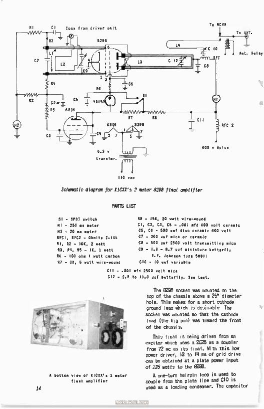
RI Cl Coax from driver unit
6.3 v
transfmr. /TIT]
110 vac
Schematic diagram for KICXX's 2 meter 8298 final amplifier
PARTS LIST
SI - SPOT switch
MI - 250 ma meter
M2 - 20 ma meter
RFC1, RFC2 - Ohmite Z- I44
RI, R2 - 10K, 2 watt
R3, P4, R5 - IK, watt
R6 - 100 ohm 1 watt carbon
R7 - 3K, 5 watt wire-wound
To RCVR
R8 - 15K, 20 watt wire-wound
CI, C2, C3, C4 - . 001 mfd 600 volt ceramic
C5, C6 - 500 uuf disc ceramic 600 volt
Cl - 200 uuf mica or ceramic
C8 - 500 uuf 2500 volt transmitting mica
C9 - 1.8 - 8.7 uuf miniatura butterfly
E.F. Johnson type 5M811
CIO - 10 uuf variable
C11 - . 001 mfd 2500 volt mica
Cl2 - 2.8 to 11.0 uuf butterfly. See text.
A bottom view of K1CXX's 2 meter
final amplifier
14
The 8296 socket was mounted on the top of the chassis above a 2i" diameter hole. This makes for a short cathode ground leau which is desirable The
socket was mounted so that the cathode lead (the big pin) was toward the front of the chassis.
This final is being driven from an exciter which uses a 2626 as a doubler from 72 mc as its final. With this low power driver, 12 to 14 ma of grid drive can be obtained at a plate power input of 125 watts to the 8296.
A one—turn hairpin loop is used to couple from the plate line and CIO is used as a loading condenser. The capacitor
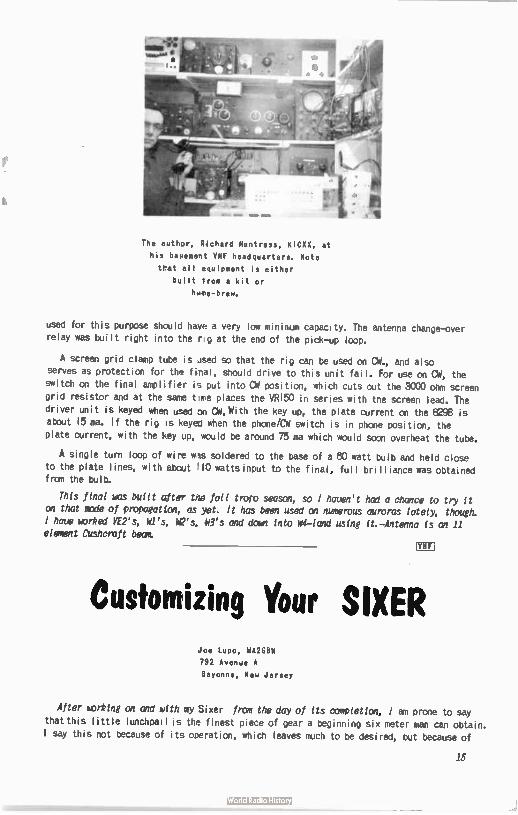
The author, Richard Huntress, K1CXX, at
his basement VHF headquarters. Note
that all equipment is either
built from a kit or
h4me-brew.
used for this purpose should have a very low minimum capacity. The antenna change-over
relay was built right into the rig at the end of the pick-up loop.
A screen grid clamp tube is Jsed so that the rig can be used on CW, and also
serves as protection for the final, should drive to this unit fail. For use on Ci',, the
switch on the final amplifier is put into CPI position, which cuts out the 3000 ohm screen grid resistor and at the same t nt places the VRI50 in series with the screen lead. The
driver unit is keyed when used cvi CPI. With the key up, the plate current on the ege is about 15 ma. If the rig is keyed when the phone/CW switch is in phone position, the
plate current, with the key up, would be around 75 ma which would soon overheat the tube.
A single turn loop of wire was soldered to the base of a 80 watt bulb and held close
to the plate lines, with about 110 watts input to the final, full brilliance was obtained from the bulb.
This final was built after the fall troto season, so i haven't had a chance to try it
on that mode of propagation, as yet. It has been used on numerous auroras lately, though.
I have worked VE2's, WI's, k's, e's and doun Into W4-land using it.-Antenna is an 11 element Cushcraft beam
ffn
Customizing Your SIXER Joe Lupo, WA2GBW
792 Avenue A
Bayonne, New Jersey
After working on and with my Sixer from the day of its completion, l am prone to say that this little lunchpai is the finest piece of gear a beginning six meter non can obtain.
I say this not because of its operation, which leaves much to be desired, but because of
15
the opportunities it gives for a green ham to experiment on his rig and learn the strings
of practical electronics. I have done all the work on my rig myself, with the aid of a neighbor's electric drill, and the ideas for conversions came from various sources other
than my own necessity for them. I have included in my rig all the changes described in K3hNP's excellent article, which appeared in The VHF Amateur; and I would personally like
to thank him for it.
Enough talk. Now let's get down to some work...
- The first change I incorporated into my rig was in the power supply filtering system. substituted 3 henry, 50 ma filter chokes for the two resistors 11401 and R402. They can
be mounted sub-chassis, one between the two audio tube sockets, 845 and 12AX7, the other is mounted to the rear of the audio volume control. These chokes can be bought for under Mt apiece in one of the small stores on Cortlandt Street, NYC, seen advertised in any of
the current ham magazines. These chokes, by the way, raise the plate voltage on the re-
ceiver and speecn amplifier resulting in higher gain.
2- Another alteration which is more than necessary in many Sixers is the elimination of transmitter instability. The reason for the drifting is the oscillator. The oscillator tank circuit uses, as a raparitor, the inter-electrode capacitance of the triode section. As the tube warms up, the frequency drifts around the center frequency and finally settles down when the tubes settle down. cured the ill by putting a 2 uuf capacitor across the
oscillator coil ( 1-201) and shorting out enough coil turns to have the tank tune six meters
again.
3- In order to facilitate tuning of your rig, two changes are in order. First, cut a hole in the case directly over the oscillator coil. Thus it can be tuned from outside the case with à tuning rod. The final can be tuned the same way, or if you wish not to fish around
in a dark box for a little screw it can be altered for front tuning; remove the final tank capacitor C-20eand the final coil slug, which screws right out. Secure a small variable and place it between the T-R switch and the end of the chassis. Mbunt this capacitor with the tuning screw coming through the chassis face. Connect the stator plates to the plate
of the tube (pin 9). The other plates - the rotors - are connected to ground. With this arrangement, the transmitter can be tuned while the case is on, and when the neon bulb can
be mora clearly observed.
- While we're onthe transmitter section, I'd like to include a change l made for work
at my summer 0TH. I have no six meter antenna there, so I am forced to use the TV antenna system. The present loading capacitor, however, does not accomodate the 300 ohm impedance setup with full output, so I replaced it with a 140 uuf air dielectric variable (screw type, also). This is neither an important nor necessary change, but if work with a variety
of antennas is anticipated, it might come in handy.
5 - 1 have found, incidentally, that a tube shield left ungrounded on the transmitter tube allows for a slight increase in input power. The heavier the shield, the larger the increase. I started out with a small tube shield and soldered over 20 pieces of # I0 wire
on it to dissipate heat, and wound up with a wierd, porcupine- looking monstrosity. However,
since ny rig draws in excess of 45 ma cathode current, unmodulated, l need it.
8 - In case anyone missed K3HNP's article, l will briefly restate the transmitter conver-sion which enabled me to raise my input from 4i watts to 10 watts' Just put a 10 micro henry 50 ma RF choke across the transmitter grid resistor, (R2013) and retune. That's about all the changes I made on the transmitter other than the next Uril.
7 - I'd like to pass along some tube changes also. The 8AU8 ransmitter tube can be
directly replaced by a higher current 8CX8, while the 12AX7 can be just as easily replaced by a 5751 Hi -Fi tube. I have found by experimentation that the 801)0 draws more current
than either the 64.18 or 8AU8A, and would reccomend it above the others.
8- About every Stxer owner I have had a OSO with has a complaint about the lack of receiver
selectivity. This can be remedied as easily as placing a 2.7 meg à watt resistor across the
16
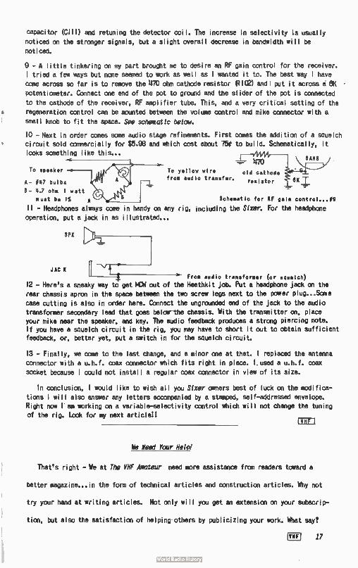
capacitor (:Iii) and retuning the detector coil. The increase in selectivity is usually
noticed on the stronger signals, but a slight overall decrease in bandwidth will be
noticed.
9 - A little tinkering on my part brought me to desire an RF gain control for the receiver.
I tried a few ways but none seemed to work as well as 1 wanted it to. The best way 1 have
come across so far is to remove the 470 ohm cathode resistor 12102) andl put it across a 8K •
potentiometer. Connect one end of the pot to ground and the slider of the pot is connected
to the cathode of the receiver, RF amplifier tube. This, and a very critical setting of the
regeneration control can be mounted between the volume control and mike connector with a
small knob to fit the space. See schematic below.
10 - Next in order comes some audio stage refinements. First comes the addition of a squelch circuit sold commercially for $5.98 and which cost about 750 to build. Schematically, it looks something like this...
70 speaker
A- 047 bulbs
8- 4.7 ohm I watt
must be I% A
ii - Headphones always come in handy on any rig, including the Men For the headphone
operation, put a jack in as illustrated...
To yellow wire from audio transfer.
SPK
JAG K
_ 470
old cathode
resistor
Schematic for RF gain control...09
From audio transformer (or squelch)
12 - Here's a sneaky way to get MCW out of the Heathkit job. Put a headphone jack on the
rear chassis apron in the space between the two scree legs next to the power plug...Some
case cutting is also in order here. Connect the ungrounded end of the jack to the audio transformer secondary lead that goes below-the chassis. With the transmitter on, place your mike near the speaker, and key. The audio feedback produces a strong piercing note. If you have a squelch circuit in the rig, you may have to short it out to obtain sufficient feedback, or, better yet, put a switch in for the squelch circuit.
13 - Finally, we come to the last change, and a minor one at that. 1 replaced the antenna
connector with a u.h.f. coax connector which fits right in place. I. used a u.h.f. coax
socket because 1 could not install a regular coax connector in view of its size.
In conclusion, 1 would like to wish all you Slxer owners best of luck on the modifica-
tions I will also answer any letters accompanied by a stamped, self-addressed envelope. Right now r am working on a variable-selectivity control which will not change the tuning of the rig. Look for my next articlell
We Need Your Help!
That's right - We at The VHF Amateur need more assistance from readers toward a
better magazine.., in the form of technical articles and construction articles. Why not
try your hand at writing articles. Not only will you get an extension on your subscrip-
tion, but also the satisfaction of helping others by publicizing your work. What say?
VHF 17
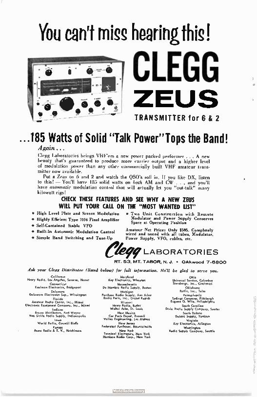
You can't miss hearingthis!
• é • OP ' gr WM,
CLEGG ZEUS TRANSMITTER for 6 & 2
...185 Watts of Solid "Talk Power"Tops the Band! Again ... Clegg Laboratories brings VHF'ers a new power packed performer . . . A ne% beauty that's guaranteed to produce more carrier output and a higher level of modulation power than any other commercially built VHF amateur trans-mitter now available.
Put a Zeus on 6 and 2 and watch the QS0's roll in. If you like DX, listen to this! — You'll have 185 solid watts on both AM and CW . . . and you'll have automatic modulation control that v, ill actually let you "out-talk" many kilowatt rig-
CHECK THESE FEATURES AND SEE WHY A NEW ZEUS WILL PUT YOUR CALL ON THE "MOST WANTED LIST"
• High Level Plate and Screen Modulation
• Highly Efficient Type 7034 Final Amplifier
• Self-Contained Stable VFO
• Built-In Automatic Modulation Control
• Simple Band Switching and Tune-Up
• Two Unit Construction with Remote Modulator and Power Supply Conserves Space at Operating Position
Amateur Net Price: Only $595. Completely wired and tested with all tubes, Modulator, Pov,er Supply, VFO, cables, etc.
ekirLABORATORIES RT. 53, MT. TABOR, N..1. • OAkwood 7-6800
Ask your Clegg Distributor (listed below) for full information.
California Henry Rodio, tos Angeles, Severn, Hemet
Connecticut Koubnan Electronics, Bridgeport
Delaware Delowore Electronics Sup., Wilmington
Florida Amateur Rodio Center, Inc., Miami
Electronic Equipment Company, Inc., Miami
Indiona Brown Distributors, Fort Wayne
Van Sickle Rodio Surely, IndionoPolif
lowo World Rodio, Council Bluffs
Kansas Acrne Radio & T. Hutchinson
Maryland Key Electronics, Wheaton
Massachusetts De Mantbro Radio Supply, Boston
Michigan Purchase Radio Supply, Ann Arbor Radio Parts, Inc., Grand Rapids
Missouri Henry Radio, Butler
Wolter Ash., St. Louis
New Mexico Cor Ports Depot, Roswell
Valley Engineering, Los Aldinos
New Jersey Federated Purchaser, Mountainside
New York Terminal Electronics, New York Harrison Rodio Corp., New York
He'll be glad to serve you.
Ohio Universal Service, Columbus Sternhergs, Inn., Cincinnati
Oklahoma Rodio, Inc., Tulsa
Pennsylvania Tydings Company, Pittsburgh Eugene G. Wile, Philodelphio
South Carolina Dixie Rodio Supply Company, Sumter
South Dakota Dakota Supply, Yankton
Virginia Key Electronics, Arlington
Washington Rodio Supply Company, Seattle
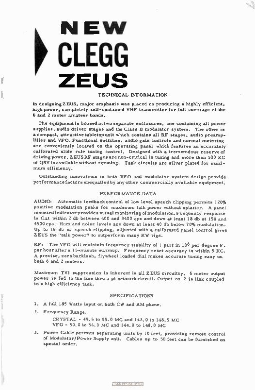
NEW p CLEGG ZEUS
TECHNICAL INFORMATION
In designing ZEUS, major emphasis was placed on producing a highly efficient,
high power, completely self-contained VHF transmitter for full coverage of the
6 and 2 meter amateur bands.
The equipment is housed in two separate enclosures, one containing all power
supplies, audio driver stages and the Class B modulator system. The other is
a compact, attractive tabletop unit which contains all RF stages, audio preamp-lifier and VFO. Functional switches, audio gain controls and normal metering
are conveniently located on the operating panel which features an accurately
calibrated slide rule tuning control. Designed with a trememdous reserve of driving power, ZEUSRF stages are non- critical in tuning and more than 500 KC
of QSY is available without retuning. Tank circuits are silver plated for maxi-mum efficiency.
Outstanding innovations in both VFO and modulator system design provide performance factors unequalled by any other commercially available equipment.
PERFORMANCE DATA
AUDIO: Automatic feedback control of low level speech clipping permits 120%
positive modulation peaks for maximum talk power without splatter. A panel
mounted indicator provides visual monitoring of modulation. Frequency response is flat within 2 db between 400 and 3400 cps and down at least 18 db at 150 and
4500 cps. Hum and noise levels are down at least 40 db below 70% modulation. Up to 18 db of speech clipping, adjusted with a calibrated panel control gives
ZEUS the " talk power" to outperform many KW rigs.
RI: The VFO will maintain frequency stability of 1 part in 10 6 per degree F.
per hour after a 15-minute warmup. Frequency reset accuracy is within 5 KC.
A precise, zero backlash, flywheel loaded dial makes accurate tuning easy on both 6 and 2 meters.
Maximum TVI suppression is inherent in all ZEUS circuitry, 6 meter output power is fed to the line thru a pi network circuit. Output on 2 is link coupled to a high efficiency tank.
SPECIFICATIONS
1. A full 185 Watts input on both CW and AM phone.
2. Frequency Range:
CRYSTAL - 49.5 to 55.0 MC and 142.0 to 148.5 MC
VFO - 50.0 to 54.0 MC and 144.0 to 148.0 MC
3. Power Cable permits separating units by 10 feet, providing remote control
of Modulator/Power Supply unit. Cables up to 50 feet can be furnished on special order.
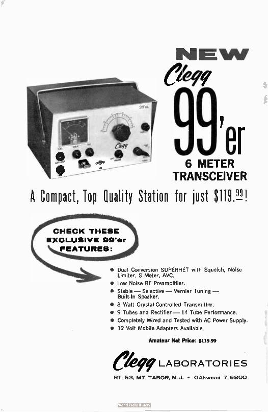
Cb99'
C. • 6 METER - TRANSCEIVER
A Compact, Top Quality Station for just $ 119.9J!
CHECK THESE
EXCLUSIVE 99'er
FEATURES:
• Dual Conversion SUPERHET with Squelch, Noise Limiter, S Meter, AVC.
• Low Noise RF Preamplifier.
• Stable — Selective — Vernier Tuning — Built- In Speaker.
• 8 Watt Crystal-Controlled Transmitter.
• 9 Tubes and Rectifier — 14 Tube Performance.
• Completely Wired and Tested with AC Power Supply.
• 12 Volt Mobile Adapters Available.
Amateur Net Price: $119.99
ek99 LABORATORIES RT. 53, MT. TABOR, N. J. • OAkwood 7-6800
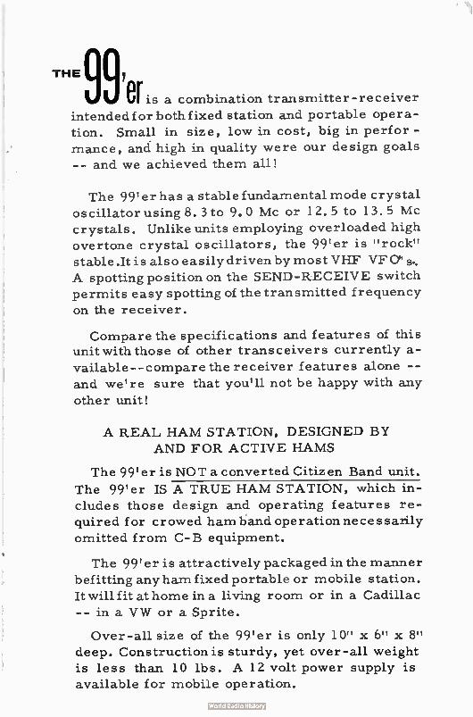
THE 997 er is a combination transmitter- receiver
intended for both fixed station and portable opera-
tion. Small in size, low in cost, big in perfor -
mance, and high in quality were our design goals
-- and we achieved them all!
The 99' er has a stable fundamental mode crystal oscillator using 8. 3 to 9.0 Mc or 12.5 to 13.5 Mc crystals. Unlike units employing overloaded high
overtone crystal oscillators, the 99'er is " rock"
stable .It is also easily driven by most VHF VFO'
A spotting position on the SEND-RECEIVE switch
permits easy spotting of the transmitted frequency
on the receiver.
Compare the specifications and features of this unit with those of other transceivers currently a-
vailable-- compare the receiver features alone --
and we're sure that you'll not be happy with any
other unit!
A REAL HAM STATION, DESIGNED BY
AND FOR ACTIVE HAMS
The 99'er is NOT a converted Citizen Band unit.
The 99'er IS A TRUE HAM STATION, which in-
cludes those design and operating features re-
quired for crowed ham band operation necessarily
omitted from C- B equipment.
The 99'er is attractively packaged in the manner
befitting any ham fixed portable or mobile station.
It will fit at home in a living room or in a Cadillac
-- in a VW or a Sprite.
Over-all size of the 99'er is only 10" x 6" x 8"
deep. Construction is sturdy, yet over-all weight
is less than 10 lbs. A 12 volt power supply is
available for mobile operation.
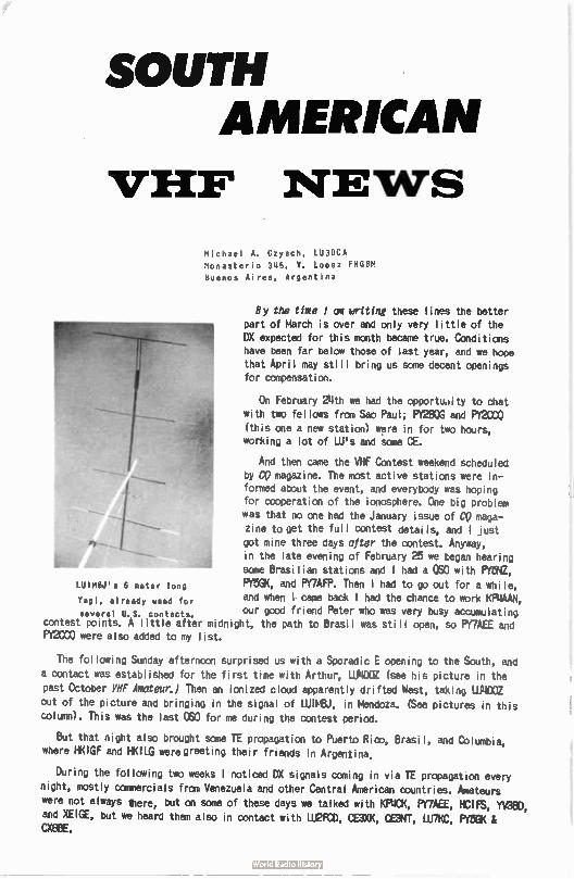
LUIMBJ's 6 meter long
SOUTH AMERICAN
VEEP NEWS
Michael A. Czysch, LU3DCA
Monasterio 345, V. Lopez FNGBM
buenos Aires, Argentina
By the time 1 am wilting these lines the better part of March is over and only very little of the DX expected for this month became true. Conditions have been far below those of last year, and we hope that April may still bring us some decent openings for compensation.
On February 24th we had the opportudity to chat with two fellows from Sao Paul; PY2BOG and PY2000 (this one a new station) were in for two hours, working a lot of ULI's and some Œ.
And then came the VHF Contest weekend scheduled by CO magazine. The most active stations were in-formed about the event, and everybody was hoping for cooperation of the ionosphere. One big problem was that no one had the January issue of CO maga-zine to get the full contest details, and I just got mine three days after the contest. Anyway, in the late evening of February 25 we began hearing some Brasilian stations and l had a QS0 with PY5NZ, PY5GK, and PY7AFP. Then I had to go out for a while,
Vagi, already used for and when I. came back l had the chance to work KP4AAN, several U.S. contacts, our good friend Peter who was very busy accumulating
contest points. A little after midnight, the path to Brasil was still open, so PYMEE and PY2000 were also added to my list.
The following Sunday afternoon surprised us with a Sporadic E opening to the South, and a contact was established for the first time with Arthur, LUNCCZ (see his picture in the past October VHF Amateur:) Then an ionized cloud apparently drifted West, taking LIJ4DOZ out of the picture and bringing in the signal of uum, in Mendoza. (See pictures in this column). This was the last OSO for me during the contest period.
But that night also brought some TE propagation to Puerto Rico, Brasil, and Columbia, where HKIGF and HKILG were greeting their friends in Argentina.
During the following two weeks I noticed DX signals coming in via TE propagation every night, mostly commercials from Venezuela and other Central American countries. Amateurs were not always there, but on some of these days we talked with KRICK, PY7AEE, HCIFS, YV3EID,
and XEIGE, but we heard them also in contact with LIJ2F0D, CE3XK, CE3NT, LU7KC, PY5GK & MBE.
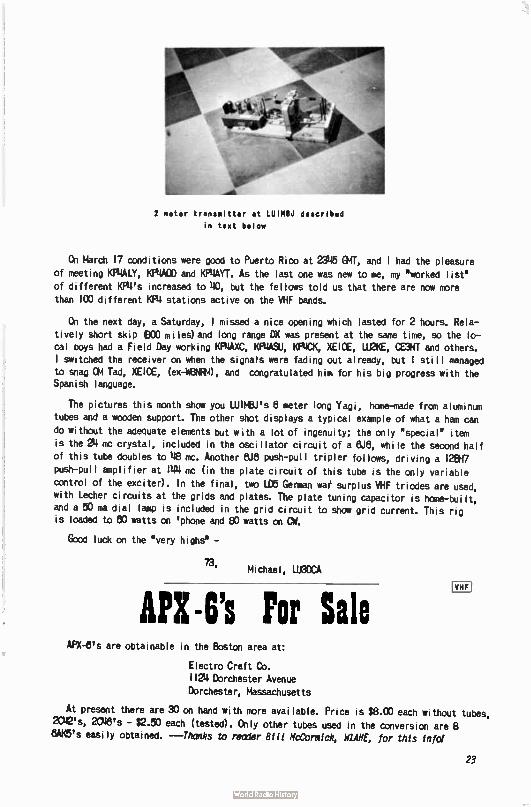
2 meter transmitter at LUIM8.1 described
in text below
On March 17 conditions were good to Puerto Rico at 2346 GMT, and 1 had the pleasure of meeting KP4ALY, KP4A0D and KNAYT. As the last one was new to me, my 'worked list' of different 04's increased to 40, but the fellows told us that there are now more than 100 different KP4 stations active on the VHF bands.
On the next day, a Saturday, I missed a nice opening which lasted for 2 hours. Rela-tively short skip eco miles)and long range DX was present at the same time, so the lo-cal boys had a Field Day working KP4AXC, KMASU, KRICK, XE1OE, 1.112KE, CENT and others. I switched the receiver on when the signals were fading out already, but I still managed to snag OM Tad, XE1OE, (ex448NRM), and congratulated him for his big progress with the Spanish language.
The pictures this month show you WIMBJ's 8 meter long Yagi, home-made from aluminum
tubes and a wooden support. The other shot displays a typical example of what a ham can
do without the adequate elements but with a lot of ingenuity; the only ' special' item is the 24 mc crystal, included in the oscillator circuit of a 8J8, while the second half of this tube doubles to 48 mc. Another 8J8 push-pull tripler follows, driving a 128H7
Push-pull amplifier at 144 mc ( in the plate circuit of this tube is the only variable control of the exciter). In the final, two LD5 German wae surplus VHF triodes are used, with Lecher circuits at the grids and plates. The plate tuning capacitor is home-built, and a 50 ma dial lamp is included in the grid circuit to show grid current. This rig is loaded to eo watts on ' phone and 80 watts on CW.
Good luck on the 'very highs' -
73, Michael, LU3DCA
API-6's Por Sale VHF
APX-8's are obtainable in the Boston area at:
Electro Craft Co. 1124 Dorchester Avenue Dorchester, Massachusetts
At present there are 30 on hand with more available. Price is $8.00 each without tubes, 2C421s, 2C48's - $2.50 each (tested). Only other tubes used in the conversion are 8 8AK5's easily obtained. ---Thanks to reader Bill McCormick, WANE, for this info!
23
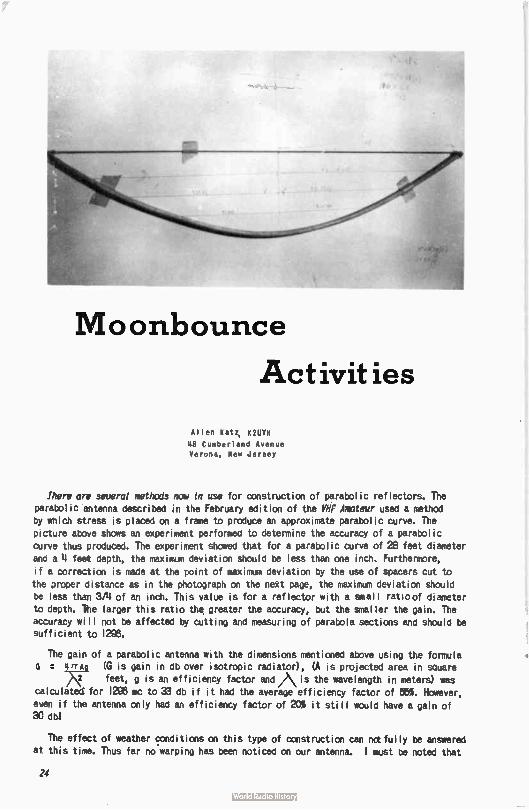
Moonbounce
Activities
Allen Kat; K2UYIl
48 Cumberland Avenue Verona, New Jersey
Ihere are seueral methods nme In use for construction of parabolic reflectors. The parabolic antenna described in the February edition of the VHF Amateur used a method by which stress is placed on a frame to produce an approximate parabolic curve. The picture above shows an experiment performed to determine the accuracy of a parabolic curve thus produced. The experiment showed that for a parabolic curve of 28 feet diameter and a 4 feet depth, the maximum deviation should be less than one inch. Furthermore,
if a correction is made at the point of maximum deviation by the use of spacers cut to the proper distance as in the photograph on the next page, the maximum deviation should be less than 3/4 of an inch. This value is for a reflector with a small ratioof diameter to depth. The larger this ratio the greater the accuracy, but the smaller the gain. The accuracy will not be affected by cutting and measuring of parabola sections and should be sufficient to 1295.
The gain of a parabolic antenna with the dimensions mentioned above using the formula 0 IPTAQ (G is gain in db over isotropic radiator), (A is projected area in square
)\2 feet, g is an efficiency factor amiAis the wavelength in meters) was calculated for 1295 mc to 33 db if it had the average efficiency factor of 55%. However, even if the antenna only had an efficiency factor of 20% it still would have a gain of 30 dbl
The effect of weather conditions on this type of construction can nctfully be answered
at this time. Thus far no warping has been noticed on our antenna. I must be noted that
24
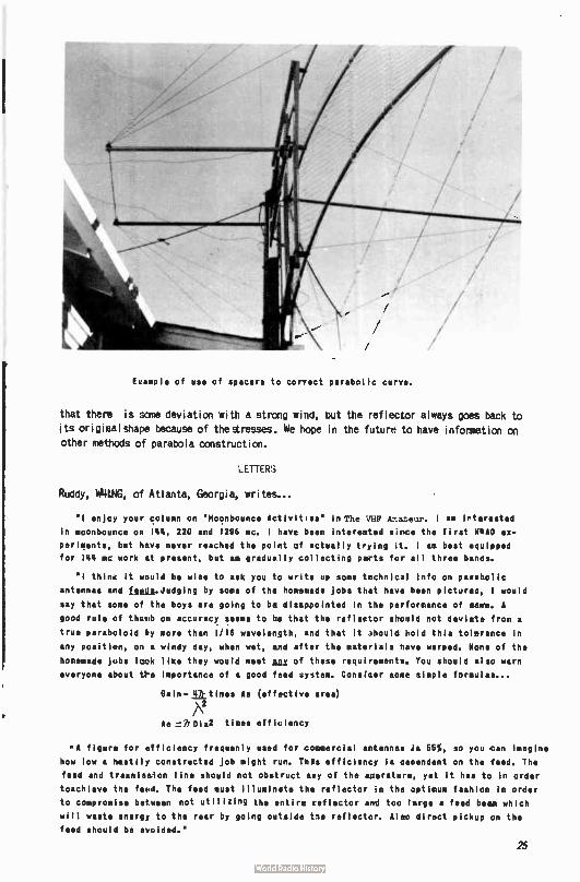
fuample of use of spacers to correct parabelic curve.
that there is some deviation with a strong wind, but the reflector always goes back to its originalshape because of thearesses. We hope in the future to have information on
other methods of parabola construction.
LETTER;
Ruddy, W4LNG, cf Atlanta, Georgia, writes...
"I enjcy your column on " Moonbounce Activities" in The VHF Arateur. 1 am irterested
in moonbounce on 144, 220 and 1296 mc. I have been interested S.M0 the first MgA0 ex.*
Per1Ments, but have never reached the po:nt cif actually tying it. 1 am best equipped
for 144 mc work at present, but am gradually collecting diets fer all three banos.
"I thine it would be wise to ask you to write up some technical Info on pireabolic
antennas and fites.Judging by some of the homemade jobs that have been pictures:, I would
say that some ot the boys are going to be disappointed in the performance of mama. A
good rule of thumb on accuracy seems to he that the reflector should not deviate from a
true paraboloid by more than 1/16 wavelength, and that it vhould eold this tolerance in
any position, on a windy day, when wet, and after the materials have warped. None of the
homemade jobs leek like they would meet lax of these requirements. You should also warn
everyone about t>e importance of a good feed uystem. Consreer some simple formulos...
0ain.lttimes Am (effective area) 7\2
Ac = h Die times efficiency
,A figure for efficiency frequenly used for commercial antennas is 55%, so you can imagine
how low a hastily constructed job might run. Tills efficiency is oredendent on the feed. The
feed and trasmIsmion line should not obstruct airy of the aperature, yet It has to in order
toachleve the feed. The feed must illuminate the reflector in the optimum fashion In order
to compromise between not utilizing the entire reflector and too large a feed beam which
will waste energy to the rear by going outside toe reflecto ,. Aleo direct pickup on the
feed should be avoided."
25
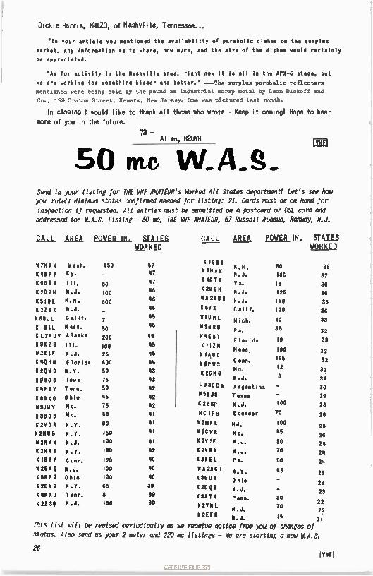
Dickie Harris, KULZO, of Nashville, Tennessee..,
'in your article you mentioned the availability of parabolic dishes on the surplus
market. Any Information as to where, how much, and the size of the dishes would certainly
be appreciated.
"As for activity in the Nashville area, right now it le all in the APX-6 stage, but
we are working for something bigger and better." --The surplus parabolic reflectors
mentioned were being said by the pound as industrial scrap metal by Leon Bickoff and
Co., lç9 Oraton Street, Newark, New Jersey. One was pictured last month.
In closing t would like to thank all those who wrote - Keep it comingl Hope to hear
more of you in the future.
- Allen, K2UYII
50 nu W.A.S. ECU
Send in your listing for THE VHF AHATEUR's Worked All States department/ Let's see how you ratan Minimum states confirmed needed for listing: 21. Cards must be on hand for
inspection if requested. All entries must be submitted on a postcard or OSL card and addressed to: W.A.S. Listing - 50 me, THE VHF AMATEUR, 67 Russell Avenue, Rahway, N.J.
CALL AREA POWER IN. STATE WORKED
W 714 K 1i Wash, 150
K 4BPY Ky.
KSDTB Ill. 80
K 2D ZM N.J. 100
K 5IQL N.H. 600
K 2Z B X N.J.
K6UJL Cal 1f• 7
K ne IL mass. 50
L7Aux Alaska 200
K9KZB Ill. 100
2E IF N.J. 25
K101111 Florida 600
K 2QWD N.Y. 50
K OH 0 S Iowa 75
KIlP EV Tenn. 50
NtiNN0 Ohio 45
W3JWY Md. 75
K 38 0 8 Md. 40
K211012 N.Y. 90
K 21411 El N.Y. 150
W 2H VW N.J. 100
K2MXT N.Y. 180
K 18 H Y Conn. 120
W 2E A Q N.J. 100
K 8REG Ohio 100
K 2CVG N.Y. 65
K XJ T enn. 8
K 2ZSQ N.J. 100
47 47
47
46
46
48
45
46
45
45
45
44
43
43
42
42
42
41
41
41
41
42
40
40
40
39
89
38
CALL AREA POWER IN. STATES WORKED
K IQ B 1
K 2H AK
K 'IR TO
K 211
WA 28 8U
K 6V XI
Ii8U M L
W38 RU
K '4E ST
K I I ZM
K IAUD
K OP W S K 2C MG
LU3DC A
K 2Z SP
NC IFS
bl3MN E
KOCWR
K 2V SE
K 2V N K
K 3K EL
W A 2AC I
K 8E U X
K 29 QT
K 3A T X
K 2V N L
K 2E F N
N.H. 50 38
N.J. 10G 37
V a„ 18 36
N.J. 125 36
N.J. 160 36
Calif. 120 36
Mich. 40 33
Pa, 35 32
Florida 19 33
Mass, 100 32
195 C onn. 32
Mo, 12 32
N.J. 8 31
Argentina - 30
Texas - 29
N.J. 100 28
Ecuador 70 26
Md.
Mo.
N.J.
N.J.
P a.
100
45
30
70
50
26
26
24
24
24
N.Y. 45 23
0 hio 23
N.J. 23 Penn. 30
22 N.J. 70 22
N.J. 14 21
This list will be revised periodically as ke receive notice from you of changes of status. Also send us your 2 meter and 220 mc listings - We are starling a new W.A.S.
26 mi
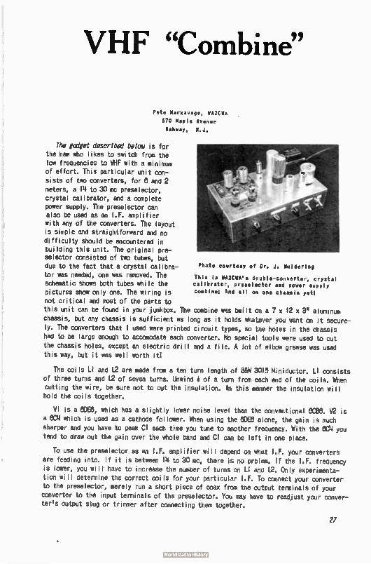
VHF "Combine"
Pete Markavage, WA2CMA 670 Maple Avenue Rahway, R.J.
The gadget described below is for the ham who likes to switch from the low frequencies to VHF with a minimum of effort. This particular unit con-sists of two converters, for 8 and 2
meters, a 14 to 30 inc preselector, crystal calibrator, and a complete power supply. The preselector can also be used as an I.F. amplifier with any of the converters. The layout is simple and straightforward and no difficulty should be encountered in building this unit. The original pre-selector consisted of two tubes, but due to the fact that a crystal calibra- Photo courtesy of Dr. J. Moldering
tor was needed, one was removed. The This is WA2CWA's deuble-converter, crystal schematic shows both tubes while the calibrator, preselector and power supply pictures show only one. The wiring is combine! Rnd all on one chassis yet! not critical and most of the parts to
this unit can be found in your junkbox. The comb;ne was built on a 7 x 12 x 3' aluminum
chassis, but any chassis is sufficient as long as it holds whatever you want on it secure-
ly. The converters that I used were printed circuit types, so the holes in the chassis had to be large enough to accomodate each converter, No special tools were used to cut
the chassis holes, except an electric drill and a file. A lot of elbow grease was used this way, but it was well worth ¡ ti
The coils LI and 12 are made from a ten turn length of 88N 3015 Miniductor. LI consists
of three turns and 12 of seven turns. Unwind * of a turn from each end of the coils. When cutting the wire, be sure not to cut the insulation. Ill this manner the insulation will hold the coils together.
VI is a eme, which has a slightly lower noise level than the conventional 6C88. V2 is
a 804 which is used as a cathode follower. When using the 80E6 alone, the gain is much sharper and you have to peak CI each time you tune to another frequency. With the 8C4 you
tend to draw out the gain over the whole band and CI can be left in one place.
To use the preselector as an I.F. amplifier will depend on what I.F. your converters
are feeding into. If it is between 14 to 30 mc, there is nc prblem. If the IF. frequency is lower, you will have to increase the number of turns on LI and 12. Only experimenta-tion will determine the correct coils for your particular I.F. To connect your converter to the preselector, merely run a short piece of coax from the output terminals of your
converter to the input terminals of the preselector. You may have to readjust your conver-ter's output slug or trimmer after connecting them together.
27
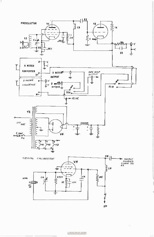
PRESELECTOR RI
C6 1 DiJrPur
COUPLED CLOSE TO 51
6 MET
OUTPUT
C ey3 rAL CAL i gRA roe
XTAL
V3
C5 lo
f3+
L4
I
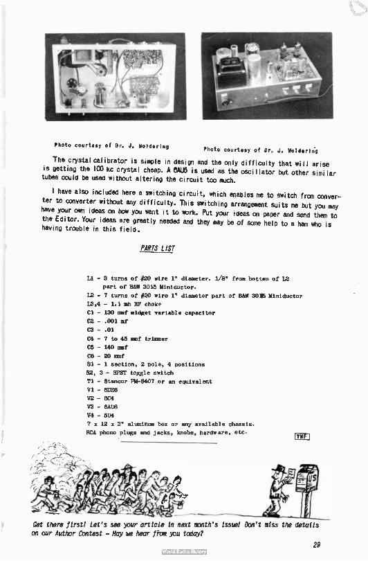
Photo courtesy of Dr. J. Moldering Photo courtesy of Dr„ J. woldevin.g
The crystal calibrator is simple in design and the only difficulty that will arise
is getting the ICO kc crystal cheap. A 6AU5 is used as the oscillator but other similar
tubes could be used without altering the circuit top much.
I have also included here a switching circuit, which enables me to switch from conver-
ter to converter without any difficulty. This switching arrangement suits me but you may
have your ern ideas on how you want it to work. Put your ideas on paper and send them to
the Editor. Your ideas are greatly needed and they may be of some help to a ham who is
having trouble in this field.
PARTS LIST
Li - 3 turns of #20 wire 1" diameter. 1/8" from bottom of L2
part of B&W 3015 Miniductor.
12 - 7 turns of #20 wire 1" diameter part of B&W 30M15 Miniductor
13,4 - 1.1 mh RF choke
Cl - 130 mmf midget variable capacitor
C2 - . 001 mf
C3 - . 01
04 - 7 to 45 mmf trimmer
C5 - 140 mmf
C6 - 20 mmf
Si - 1 section, 2 pole, 4 positions
82, 3 - SPST toggle switch
Ti - Stancor PM-8407 or an equivalent
V1 - 6E1E6
V2 - 6C4
V3 - 6AU6
V4 - 5U4
7 x 12 x 3" aluminum box or any available chassis.
RCA phono plugs and jacks, knobs, hardware, etc, 'VHF j
Get there first! Let's see your article in next minth's issue! Don't miss the details on our Author Contest - May ke hear firm you tcday?
29
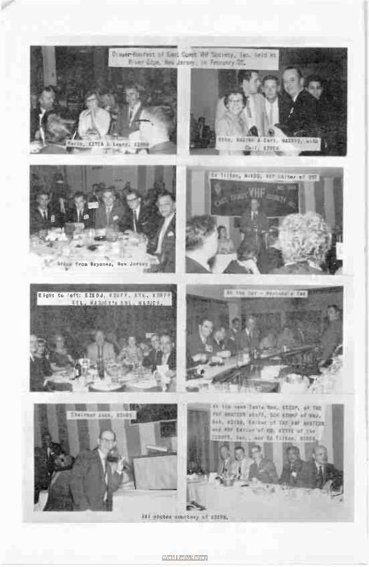
Dinler-Hamfest of East Coast VHF Society, lac. held at Rorer Edge, Nee Jersey, oh February e.
ct à .re, K2YEA Leeny, K2RNA
1--.• AN_
Right to eft: KREDJ, KelFY, XYL, K2RFP
XYL 11A2JCY'• XIL MA2J V.
,, fA
d ba1
Ot to, WA2ral i Carl WA2BY.„
Ca ,' K2TCÀ
Ed Tilton, WItDO, VhF ditor c'
At the qead Table Red, K2ZSM, at THE
VHF AMATEUR etaff, SCM K2MMF of
Bob, KUSH, Editor pf THE Vif AMATEUR
and VIIF Editor of Ce, K2YYE of .the
ECV1IFS, lec. , and Ed Tilton. WIAO
or% All photos courtesy of K2EF11.
Trading Post RATE: Commercial ads - 5t per word. Free to readers - any reasonable length. Ad from
readers MUST BE SUBMITTED ON A POST CARO or QSL card. TRADING POST, 67 Russell, Rahway, N.J.
FOR SALE: Millen HF RF Amplifier, 90811, with instruction manual, two 8298 tubes, and
coils for 8 neters. In very good operating and physical condition - $23.00. Ron Krupsa, K8KV0/9, 4542 W. Barry Avenue, Chicago 41, Illinois.
FOR SALE: nset Communicator Ill, 8 meters, 14 crystals, crystal mike, AC & DC power cords and mobile rack for Gonset. Also 5 element Telrex 8 meters - new;Eico 5" scope. Manuals included with all the above equipment. $275.00 takes everything. (Will also sell separately). Contact Mort Cohen.WA2ARS, 11 Brighton 10 Terrace, Brooklyn 35, New
York, or call TW 1/3125 after 8:30 RM.
FOR SALE: Viking Challenger - good condition - $90.00. Méissner Signal Shifter - all
band VFO-exciter-ECO - $25.00. Will ship C.O.D. or deliver locally...Heiko Gânzer, K2REH,
814 Nicholas Place, Rahway, New Jersey.
FOELSALE 1 SX-De receiver w/matching speaker, Tecraft 8 meter converter CC-50, Tecraft converter power supply. All excellent condition - Complete for $ 180.00. Gordon A. Watts,
K9POO, 521 So. 13th Street #5, Decatur, Indiana.
PROJECTS & KITS WIRED1 Cash only. Kits 25% of cost (above that of unit) - wired and
checked out. Projects (custom built), materials and prints or schematics must accompany your order. George Kupp, K2DOT, 81 Cortlandt Street, Belleville 9, New Jersey.
MCRE APX-81s1 About 15 of them here in Dayton at: Northridge Surplus, 2344 Needmore
Road, Dayton, Ohio. PRICE - $4.00 EACHI (Thanks to K8REG for your tipi)
TRADE: Keystone Twenty, 8mm movie camera and/or Stevens 58-AC, repeating bolt action 12 gauge shotgun. Both excellent condition. Write to Richard S. Smith, 13571 Rayen St.,
Pocoima. California,
For Sale: Globe Scout Deluxe 8 months old, BC-342 receiver, homebrew 8 meter converter,
VF-I VFO, Antenna tuner Globe AT-3, Western Radio all-band trap antenna, 14 novice
crystal for 40-80 meters. Entire deal - $ 150.00. Ted Woodbury, WA2BZV, 141 W. Hazelwood
Avenue, Rahway, New Jersey.
WANTED: Old call letter license plates. Please write me and let me Know what plates you have and how we can make arrangements to get them. Dave Heller, KIP, 14 Dark leaf Lane,
Levittown, Pennsylvania.
FOR SALE: Lists and forms for obtaining free high pass filters for your neighbors com-plaining of TV1. 250 from THEVHF AMATEUR, 87 Russell Avenue, Rahway, New Jersey.
DSOs: SWL's, CITIZEN BAND, SAMPLES 5e, NICHOLAS & SON PRINTERY, BOX 11164, PHOENIX,
ARIZONA.
WANTED: Construction articles for THE VHF AMATEUR! See the announcement on our AUTHOR's
CONTEST an page 37. We need your help for the success of our magazine. We are expanding now due to your support, but please don't let us down - An extension on your subscription
plus a good chance at the top prize ... A Clegg Climaster "9161'er111
31
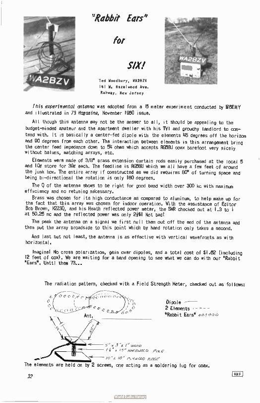
"Rabb# Ears"
for
SIX! Ted Woodbury, WA2BZV
141 W. Hazelwood Ave.
Rahway, New Jersey
This experimental antenna was adopted from a 15 meter experiment conducted by [WHY
and illustrated in 73 Magazine, November 1980 issue.
All though this antenna may not be the answer to all, it should be appealing to the
budget-minded amateur and the apartment dweller with his TVI and grouchy landlord to con-
tend with. It is basically a center-fed dipole with the elements 46 degrees off the horizon and 90 degrees from each other. The interaction between elements in this arrangement bring the center feed impedance down to 54 ohms which accepts Ret6U coax barefoot very nicely without baluns, notching arrays, etc.
Elements were made of 3/8" brass extension curtain rods easily purchased at the local 5 and ice store for 390 each. The feedline is ROBBU which we all have a few feet of around the junk box. The entire array if constructed as we did requires ECM of turning space and being bi-directional the rotation is only 180 degrees.
The 0 of the antenna shows to be right for good band width over 300 kc with maximum efficiency and no retuning necessary.
Brass was chosen for its high conductance as compared to aluminum, to help make up for the fact that this array was chosen for indoor operation. With the assistance of Editor Bob Brown, K2ZSQ, and his Heath reflected power meter, the SWR checked out at 1.3 to 1 at 50.25 mc and the reflected power was only 2e1 Not badl
The peak the antenna on a signal we first null them out off the end of the antenna and
then put the array broadside to this point which by hand rotation only takes a second.
And last but not least, the antenna is as effective with vertical wavefronts as with horizontal.
Imaginel No cross polarization, gain over dipoles, and a total cost of $ 1.62 ( including 12 feet of cox). We are waiting for a band opening to see what we can do with our Rabbit "Ears". Unttl them 73...
The radiation pattern, checked with a Field Strength Meter, checked out as follows:
(n 0
'>" 3 I1,Gt,D A /25 "Med./0C D Poc
/c IC" PC ,(c,C111)RIinC
Di pole
2 Elements - - -
"Rabbit Ears" d
The elements are held on by 2 screws, one acting as a soldering lug for max.
32 !VHF!
eirtevea. cf The WIT Amateur
(1/1:11e. yote4 «erg,/ cr/ii,
fi) deoetwie'e made e.rdmiiveiy to
ex«)«4« leas rin eetsilifuà cmeif c 5nX/f,e1 by WE DON'T WANT NO RIFF-RAFF READING OUR PAPER.
If you are an EXECUTIVE in business and Industry, you probably have a high salary. Share it with us! You are eligible to par-ticipate in our Reverse Installment Plan. Here's the way it works: Normally you get the product all at once and pay on the in-stallment pIano, But with our special Re-verse Installment Plan, (especially for executives) you pay us all at once and we send you the product in installments.
12 issues $2 llte qJq ilstalest4
67 RUSSELL ( ) 1 year $2.00 ) New RAHWAY, I,;EW JERSEY' l I 2 years 3 50 (() Renewal
(1 3 years 500
NAME CALL
ADDRESS
CITY ZONE STATE
L _
No. 5 of a Sertes This is the time each year when an interesting
but perplexing falls on the (mot so) broad shoulders of yours truly.
Clegg Laboratories maintains an active research
and development program throughout the year - devoted to designing and planning for the production of new ham equipment to keep you abreast of the vigorous growth of our hobby. Each June we endeavor to combine the results of our major projects into the next year's production.
This year the debates and great brain-storming sessions among engineers, sales personnel, produc-tion people and even the boss himself (all hams, of
course!) have resulted in an all-out drive directed toward the development of superior circuitry for a top quality line of VHF transmitters and receivers for SS8.
But, as I said, "We've got problems!'
We're trying to decide eat kind of station you want on MEL Maybe we're wrong in assuming that you even want to go on side-band next year. (We know you will someday, even if you disagree now.)
Assuming you are interested.,,, is it because of the
superior DX potential of SS8...the reduction of TVI and EICI—the delightful thrill of VOX for duplex op-
eration...or maybe because you want to keep up with the latest technical developments and progress in the field
of ham radio? Are you dedicated to six meters.. .2 meters ...or- do you work all bands?
The answers to these questions are the answers to our problem. We'd sure like to know if you'd prefer a single dial VHF-L9S8 transceiver in which the transmitter is automatically zero-beat with the station you're listen-ing to -- or is a multi-band rig with separate transmitter and receiver your dish???
Before planning next year's production we'd like to prevail upon a few of you brother hams to send us your thoughts. If enough of you do, my job will be done and I can enjoy a case of spring fever and go fishin'...(for DX!).
Ô
73
W2LOY
LABORATORIES DIVISION OF CLEGG INC
Rt. 53, Mt. Tabor, New Jersey
READ
Western Radio Amateur
48 pages of construction, news, DX and Dkedi-
tions, V.H.F. and technical articles! All these
by such famous authors as Ed Marriner, W6BLZ,
Don Stoner, W6TNS, "YB" Pyle, W70E, with Bob
Grimm, K6RNQ, heading 1.11;) the V.H.F. Column!
This magazine is the third largest in the
United States - and for the money you can't
ko wron! Only $2.00 per year. Write now to:
Western Radio Amateur and West Coast Ham Ads
publishodo.
10517 Haverty St. El Monte, California Gilbert 8-2119
A Monthly Publication
AUTO - CALL 2509 - 32nd, st.. S. E. WASHINGTON 20, D. C.
This is the paper you've
heard so much about! The fam-
ous "AUTO-CALL" that has been
quoted by almost all Ham pap-
ers, including CQ magazine!
For only a dollar a year,
you'll get 32 packed pages each
month of all. the best in general
Ham Radio material. It has a
special added feature for those
amateurs in the Washington, D.C.
area, as it covers club activ-
ities there.
,
BACI LIMES
Yes, we do have some back
issues of THE VHF AMATEUR available in limited quantities.
We've been literally swamped
for favorite copies lately, and to
save further confusion, here are
the ones you can get now...
1960
February March August
September
October
November
1961
All issues to date
25e each from THE VHF AMATEUR,
67 Russell Avenue, Railway, it•J•
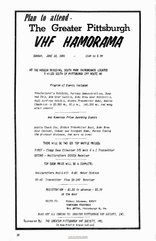
to ilitend - The Greater Pittsburgh
yllf OMM SUNDAY, JUNE 18, 1961 11Ali to 5 PH
AT THE MUSEUM BUILDING, SOUTH PARK FAIRGROUNDS LCCATED 5 MILES SOUTH OF PITTSBURGH OFF ROUTE 88
Program of Events Incluled
Nanufacturcr's Exhlbtts, Various Demonstrattnns, Swap
and Shrp, Ham Gear Aucttnn, &etc Brew Gear Exhtblttnn,
MARS Alrfnrce Exhtblt, Hidden Transmttter Hunt, Nobile
Check- ins ,n 29.360 mc, 50.4 me, 145.350 mc, And many
cthcr cuents1
And Numerous Prize Awanling Events
Nobile Check-Ins, Ridden Transmitter Bunt, Home Brew
Gear Contest, Oldest and Apnest Hams, Person Coming
the et,atest distance, And more to come!
THERE WILL BE TWO (2) TOP RAFFLE PRIZES:
FIRST - Clegg Zeus Climaster 175 Watt 6 n 2 Transmitter
SECOND - Hallicrafters SX101A Receiver
TOP DOOR PRIZE WILL BE A 01APLETE:
Hallicrafters Maui-Mit 6,80 Meter Station
HT-40 Transmitter Plus SE-140 Receiver
REGISTRATION - $1.50 in advance - $2.00
at the door
WRITE TO: Sidney Lippman, K3CJY
RAMORAMA CHAIRMAN
Box #4758, Pittsburgh 8, Pa.
NUE OUT ALL CHECKS TO: GREATER PITTSBURGH VHF SOCIETY, INC.
Sponsored By: THE GREATER PITTSBURGH VHF SOCIETY; INC. (A Non- Profit Organization)
f
36
Comitiff left 10ft/h! That's Right! Starting next month we will inaugurate an Author's Contest for The VHF Amateur. As you all know, our magazine is published at a break-even level, and we're not able to pay for articles. But starting next month we will offer an item well worth all literary efforts by readers.
Prize: Clegg Climaster "GGM'er (see ad in centerfold)
Each month we will print rating blanks to be filled out and mail-ed in by you to us. The results of these ratings will be printed
in the next possible issue of The VHF Amateur. If you feel, for example, that WAXXX's article on 220 ma converter was the best in that issue, cast your vote by filling out the blank and toting his article best. The Author's Contest will end with the November 1961 issue, at which time all readers blanks will be cross-checked on a percentage basis - and the article receiving the largest percentage of votes will be declared the winner.
The contest, as outlined above, will run for a six-month period and
will reward some lucky winner with a ".99°'erl Your cooperation in the form of good construction and technical articles will be greatly appreciated. Who knows? Try your hand at writing!
Tecraft
Central Electronics
Drake
Specializing in gear for 50 mc 6 above
E. F. Johnson
Mosley
Telrex
Hy-Gain
flux.
& others...
Met ith Electronics 2ó0 11th çtreat
Write us nol
Roç, KODNW
CQ
VHF for the radio amateur. A new dynamic hand-book that covers all phases of VHF activities.
INDEX INTRODUCTION 1. VHF RADIO PROPAGATION
50, 144, 220, 432 and 1296 MC
bands
2. ANTENNAS
2.1 Discussion
2.2 RF Transmission Unes
2.3 Types of Antennas
2.4 50 MC Antennas
2.5 144 MC Antennas
2.6 220 MC Antennas
2.7 432 MC Antennas
2.8 1296 MC Antennas
3. TRANSMITTERS
3.1A 50 MC Low Powered
Transmitter
3.113 6W6GT 50 MC Transmitter
3.1C 6W6GB 50 MC Transmitter
3.10 50 MC Exciter
3.1E High Powered 50 MC
Amplifier
3.2A Low Powered 144 MC
Transmitter
3.28 144 MC Exciter
3.2C High Powered 144 MC
Amplifiers
3.3A 222 MC Exciter
3.36 High Powered 222 MC
Amplifier
3.3C Single Tube 220 MC
Amplifier
3.4A 2C39 Units on 432 MC
3.4B Coaxial Circuit Transmitter
3.4C Flat Plate Line Transmitter
3.5A 1296 MC Cavity Transmitter
2.58 1296 MC Flat Line Transmitter
4. MODULATION
4.1 61.6 Modulator
4.2 6W6 Class El Modulator
4.3 6Y6 Class B Modulator
4.4 50 Watt Modulator
4.5 Screen Grid Modulator
4.6 Frequency Modulator
4.7 Transistor Speech Amplifier
4.8 Phase Modulator
4.9 Vacuum Tube Keyer
5. POWER SUPPLIES
5.1 Small Power Supolies
5.2 Selenium and Silicon Rectifiers
5.3 Voltage Doubler
6. CONVERTERS
6.1 Converter for SO MC
6.2 Converter for 144 MC
6.3 Converter for 220 MC
6.4 Converter for 432 MC
6.5 Converter for 1296 MC
7. RECEIVER IF SYSTEMS
7.1 Communication Type Receivers
7.2 14 to 18 MC IF Receiver .
7.3 Audio Filter
8. PREAMPLIFIERS
8.1 220 MC Tube Preamplifiers
8.2 Parametric Amplifiers
8.3 Pump Oscillators
8.4 144 MC Parametric Amplifiers
8.5 220 MC Parametric Amplifiers
8.6 432 MC Parametric Amplifiers
9. TEST EQUIPMENT
9.1 Diode AC Voltmeter
9.2 AC and DC Diode Voltmeter
9.3 F.S.-Monitors
9.4 Transistorized F.S. Meter
9.5 1296 MC Wavemeter and
Noise Generator
9.6 SWR Meters
9.7A Frequency Marker
9.78 Transistor Frequency
Marker
9.7C Dual Transistor Signal
Marker
9.8 Transistor Audio Oscillator
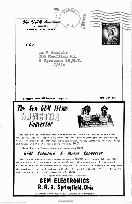
0404te
Woe UelAmetewe 1 67 RUSSELL
RAHWAY, NEW JERSEY
To:
1.15
Wm R Mandale 305 Hamilton Rd. N Syracuse 1201.Y.
7/61a
Postmaster: Form 3547 Requested THIRD Class Neil
The 'Few Oil Mine 10- JJ ell f)ia' Converter
The OEM 2 meter converter uses a 6014 NUVISTOR triode R.F. amplifier and a 61(8
oscillator, tripler - mixer. This small unit will give maximum gain and sensitivity
with a low noise level. Universal input and output for any antenna or receiver. Wired
and tested on 21" x 4" circuit board for only $8.00.
2 Meter Nuvistor Pre-Amp wired and tested only $3.50.
OEM Standard 6 Meter Converter The 6 meter orinted circuit converter uses a 613Q/BZ7 es a cascode R. F. amplifier
and a 6X8 High Gain rentode mixer and oscillator, This converter will give a good sig-
nal-to-noise ratio and maximum sensitivity and I.F. outrut. The circuit uses very Hi-O
air wound coils and the broadband oscillator will accept crystals from 40 to 50 mc for
any I.F. output. Wired and tested for only $5.00.
All tteme sent Post-Paid in advance.
GEM ELECTRONICS R. R. 3, Springfield Ohio
Telephone Terre Haute 282 - Urbana Ohto Rxchanfe_
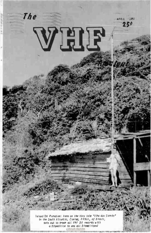
reei.
#1.
„ :• 1;;Ji.
The APR IL .S5.1
25e
•
•. • _ ,
etel t - f• >Ai
14.à 1.•
- • '
• • :;•
flee
• — '
- ,
1.--• i4b e • e. *
• P • edee ip,.; I
• e. • • * & P 4;c>41e,,:eil e •-•• I , ....Mir • , ; ks• #ti;e ,4.„„ , • ) •
/A b. • .4) • At' • ). _ •. • , 4, e
, a•s•
...4_rr.e'e.:411e.- • Z.
PP"— --
vel
Island DX Paradise: Here on the tiny iste "Ilha dos Corats" in the South A tlogtic, Conrad, PY5GX, of Brasil,
sets out to break all VHF DX records wit. a DXpedition to end all DXpeetionsl
-- "» st• • • ....OM ....a. mar» a.m.
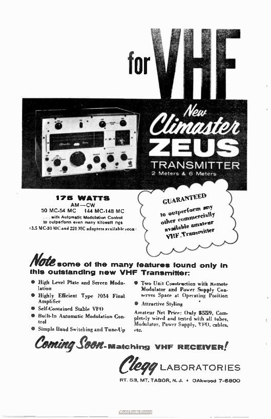
for
175 WATTS AM—CW
50 MC-54 MC 144 MC-148 MC ... with Automatic Modulation Control to outperform even many kilowatt rips
13.5 MC-30 MC and 220 MC adapters available soon:
• High Level Plate and Screen Modu-lation
• Highly Efficient Type 1034 Final Amplifier
• Self-Contained Stable VFO
• Built-In Automatic Modulation Con-trol
• Simple Band Switching and Tune-Up
"We some of the many features found only in this outstanding new VHF Transmitter:
TRANSMITTER 2 Meters & 6 Meters
GI,ft,RxNe") to nt
ontPer—r • 11 to onunerem y other c,ie amateer aN e a" sv,itter
Vie n
• Two Unit Construction with its-mote Modulator and Power Supply Can-serves Space at Operating Position
• Attractive Styling
Amateur Net Price: Only $559. Com-pletely wired and tested with all tubes, Modulator, Power Supply, VFO, cables, etc.
AM- Matching VHF RECEIVER!
LABORATOR I ES
RT. 53, MT. TABOR, N. J. • OAkwood 7-6800
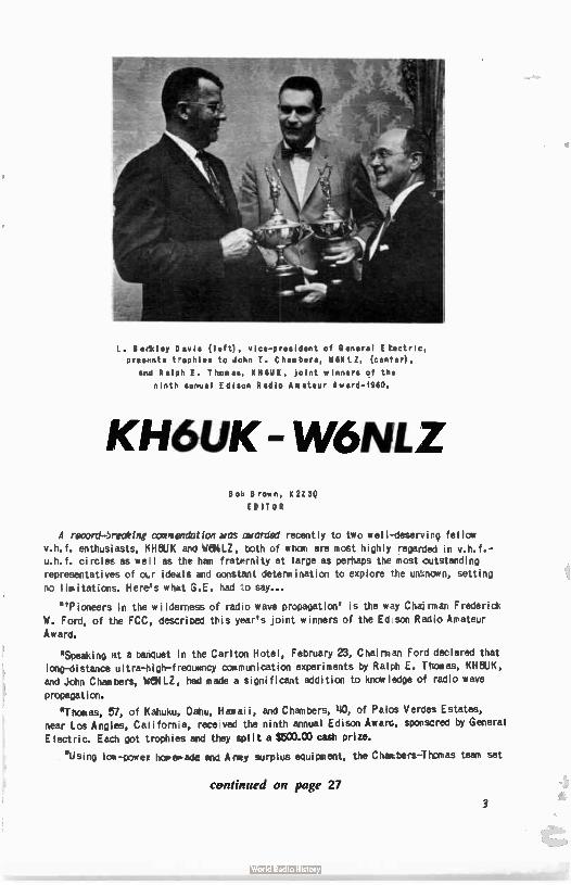
L. Berkley Davis ( left), vice-president of B I E tectric,
presents trophies to John T. C ham bers, Ii611 LZ, (center),
and Ralph E. T homes, K HOOK , joint winners of the
ninth spinal Edison Radio Amateur Award- I960.
ICH6LIK W6NLZ Bo Brown, K 2Z SQ
EDITOR
A record-Jr-eak tag cconieendct ton &OS awarded recently to two well-deservir fellow v.h.f. enthusiasts, KHOUK and WeIMLZ, tx:ith of whom are most highly regarded in v.h.f.-u.h.f. circles as we. I as the hem fraternity at large as perhaps the most outstanding representatives of otr ideals and constant determination to explore the uenown, setting
no I imitations. Here's what G.E. had to say...
"Pioneers in the wilderness of radio wave propagation' is the way Chairman Frederick
W. Ford, of the FCC, described this year's joint winners of the Ed son Radio Amateur
Award.
'Speaking at a banquet in the Carlton Hotel, February 23, Chairman Ford declared that long-distance ultra-high-frecuency communication experiments by Ralph E. Themes, KHOUK, and John Chambers, Wei LZ, had made a significant addition to knowledge of radio wave
propagation.
'Thomas, 57, of Kahuku, Oahu, Hawaii, and Chambers, 110, of Palos Verdes Estates, near Los Angles, California, rece ved the ninth annual Edison Awarc, sponscred by General
Electric. Each got trophies and they split a 11503.00 cash prize.
*Using Ice-power homemade and Arley surplus equipment, the Chambers-Thomas team set
continued on page 27
3
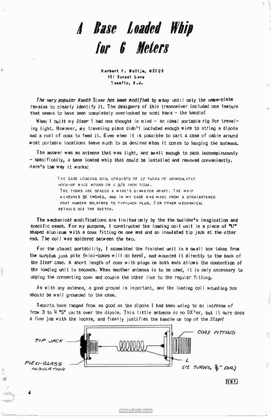
Base loaded Whip for 6 "friers
Herbert F. Holtje, 112TQS
151 Sunset Lane
Tenafly, N.J.
The very popular liendh Sixer has been modified by many until only the name-plate
remains to clearly identify it. The designers of this transceiver inctuded one feature
that seams to have been completely overlooked by most hams - the handle!
When l built my Sixer I had one thought in mind - an ideal portable rig for travel-
ing light. However, my traveling plans didn't included enough wire to string a dipole
and a roll of coax to feed it. Even when it is possible to cart a case of cable around
most portable locations leave much to be desired when it comes to hanging the antenna.
The answer was an antenna that was light, and small enough to pack inconspicuously
- specifically, a base loaded whip that could be installed and removed conveniently.
Here's the way it corks:
THE BASE LOAD ING COIL CONSISTS OF 12 TURNS OF UNINSULATED
HOOK—UP WILE WOUND ON A 3/8 INCH FILM.
THE TURNS ARE SPACED A WIRE'S DIAMETER APART. THE WHIP
MEASURES 36 INCHE S, AND IN MY CASE WAS MADE FROM A STRA IGHTENED
COAT HANGER SOLDERED TO TIP—JACK PLUG. FOR 'THER MECHAN ICAL
DETAILS SEE THE SKETCH.
The mechanical modifications are limited only by the the builder's imagination and
specific needs. For my purpose, l constructed the loading coil unit in a piece of "U" shaped aluminum' with a coax fitting on one end and an insulated tip jack at the other
end. The coil was soldered between the two.
For the utmost portability, I assembled the finished unit in a small box taken from
the surplus junk pile (ni mi -boxes will do here), and mounted it directly to the back of
the Sixer case. A short length of roas with plugs on both ends allows the connection of
the loading unit in seconds. When another antenna is to be used, it is only necessary to
unplug the connecting coax and couple the other line to the regular fitting.
As with any antenna, a good ground is important, and the loading coil mounting box
should be well grounded to the case.
Reports have ranged from as good as the dipole I had been using to an increase of
from 3 to 4 "S" units over the dipole. This little antenna is no DX'er, but it sure does
a fine job with the locals, and finally justifies the handle on top of the Sized
Pie xi- 6 LASS rio
CO/JX F/77M/6
(/2 WRNS., 1" 0/.9.)
Ern
4
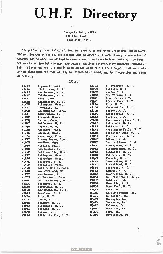
U. H. E Directory George Gadbois, 113FEY
858 Eden Road
L ancaster, P enn.
The following is a list of stations believed to be active on the amateur bands above
220 mc. Because of the devious methods used to gather this information, no guarantee of
accuracy can be made. An attempt has been made to exclude stations that may have been
active at one time but who now have become inactive; however, many stations included on
this list may not really classify as being active at this time. I suggest that you contact
any of these stations that you may be interested in scheduling for frequencies and times
of activity.
220 nic
KIAII
W1AJR
K1API
W1AZK
K1CXX
K1CIG W1CTW
W1EXZ
W1FOM
W1FZ
W1HDF
W1HDQ
W1HMT
WlIQD
MUM
K1JIX
W1JZA
W1MFT
WI OOP
W1OSQ
WIPZU
W1QVF
W1QXX
W1RFU
W1UHE
W1USF
W1VNH
W1WAS
W1WYZ
W1YDS
W2AGK
W2A0C
K2AXQ
K2BVC
W2BVJ
K2CBA
WA2DEC
K2DIG
W2DWJ
W2DZA
K2DZM
W2EJO
Plymouth, Mass.
Middletown, R. I.
Manchester, N. H.
Chichester, N. H.
Auburn, Me.
Manchester, N. H. Arlington, Mass.
Danville, Vt.
Southington, Conn.
Farmington, N. H.
Elmwood, Conn.
Canton, Conn.
Goffstown, N. H.
Goshen, N. H.
Marlboro, Mass.
Harvard, Mass.
Waterbury, Conn.
Greens Farms, Conn.
Needham, Mass.
Milford, Conn
Manchester, N. H.
Collinsville, Conn
Arlington, Mass
Wilbraham, Mass.
Tiverton, R. I.
Fairfield, Conn.
Feeding Hills, Mass.
So. Portland, Me.
Manchester, N. H.
W Hartford, Conn.
So. Plainfield, N. J.
Brooklyn, N. Y.
Rivervale, N. J.
New Rochelle, N. Y.
Roseland, N. J.
Troy, N. Y.
Union, N J.
Tenafly, N. J.
Elizabeth, N. J.
Teaneck, N. J
Rahway, N J.
Ellicottville, N. Y.
K2CGA
K2CUG
K2HAZ
W2HBC
K2HIL
W2HVI K2ISA
W2JDU
K2JLN
W2KFC
K2KIB
W2LBK
W2LKP
W2LRJ
W2LWI
K2LYR
K2MEH
W2MCF
W2NTY
K2PCG
W2PEZ
K2PPZ
K2QJQ
K2QWE
K2RIA
K2RMD
W2SEU
W2SHU
W2SLZ
W2SMJ
K2SE1.2
K2VDK
W2WOF
K2AAX
W3AHQ
W3AJD
W3AkIX
W3ARW
W3ATL
K3BBO
W3BJG
K3BPP
N. Syracuse, N. Y.
Buffalo, N. Y.
Wayne, N. J.
Mt. Vernon, N. Y
Orangeburg, N.Y.
Little Neck, N. Y.
Troy, N. Y.
Warrenville, N. J.
Edison, N. J.
Haddonfield, N. J.
Newark, N. J.
Port Washington, N. Y.
Rhinebeck, N. Y.
Bellport, N. Y.
Wappingers Falls, N. Y.
Packanack Lake, N. J.
Plattsburgh, N. Y.
Edison, N. J.
Saddle Rivver, N. J.
Livingston, N. J.
Bloomingdale, N. J.
Elizabeth, N. J.
Patchogue, N. Y.
Passaic, N. J.
Somerville, N. J.
Plainfield, N. J.
Freeport, N. Y.
Rahway, N. J.
Somerville, N. J.
So. Plainfield, N. J.
Oaklyn, N. J.
Manville, N. J.
Glen Head, N. Y.
York, Pa.
Silver Springs, Md.
E. Berlin, Pa.
Carnegie, Pa.
Scranton, Pa.
Palmyra, Pa.
Bradford, Pa.
York, Pa.
Doylestown, Pa.
5
W3BPZ
W3BYF
W3CAJ
K3CEZ W3CGV
W3FEY
W3HFY
W3HIX
K3HQC W3HZU
K3IUV W3JYL
W3JZI
W3IŒN
W3LCC
W3LZD W3M1JM
W3QFM W3RUE
W3SNM
W3TIF
W3UJG W3VIR W3ZFA
W3ZRF
W3ZRR
W4FWH K4KLD K4QAB
K4RAY W4RFR W4RMU W4SEQ
K4TFU
K4IFY W4TLC
W4UBY
K4UKQ
W4Ule
W4UML W4VIW
W4VSN
W4ZXI
W5AJG
K5BDD W5BFH
W6AJF K5UNK
IUMGF W6AJF W6ASH
W6BJI W6FZA
K6GKX K6GTG K6IBY
W6IEY
K6JTC W6MMU
W6NLZ
W6NZV
W6OKR
K6RNQ
K6UZC
W7AMH W7FGG
W7HBH
K7HID
Allentown, Pa. Allentown, Pa.
Lewisherry, Pa. Greenbelt, Md. Wilmington, Del.
Lancaster, Pa. Havertown, Pa.
Quakertown, Pa.
Bareville, Pa. York, Pa.
Philadelphia, Pa. E. Petersburg, Pa.
College Park, Md. Willowgrove, Pa.
Kensington, Md. Scranton, Pa.
Hanover, Pa. York, Pa.
Belle Vernon, Pa.
Fleetwood, Pa.
Johnstown, Pa. Rockville, Md.
Willowgrove, Pa. Bradford, Pa.
Catonsville, Md.
Philadelphia, Pa.
Doraville, Ga. Hoschton, Ga. Auburn, Ga. Alexandria, Va.
Nashville, Tenn. Jacksonville, Fla.
Fairfax, Va. Falls Church, Va.
Decatur, Ga.
Greenville, S.C. Annandale, Va. Woodbridge, Va.
Falls Church, Va.
Athens, Ga. Greenville, S.C. Oak Ridge, Tenn.
Greensboro, N.C. Dallas, Tex. Arlington, Tex. Albuquerque, N. Mex.
Marks, Miss. Socorro, N. Mex. Albuquerque, N. Mex.
Sonoma, Calif.
Los Altos
Fresno Porterville
Long Beach Arlington
Costa Mesa La Masa
Sunnyvale Los Angeles
Palos Verdes Estates
Mill Valley
Larkspur
Oakland
Oxnard
Tucson, Ariz. Tucson, Ariz.
Portland, Oreg.
Tucson, Ariz.
K7HJD
K7ICW W7LEE
W7RT W7RUX
K8AOM K8AXU
W8BAX W8BMO
W8CSW W8CVQ W8DX
W8GHX
W8GOV
W8IJG
K8JZR
W8KSZ
W8LGI W8LPD
W8NEE
W8N011
W8NRM
W8PT
K8PUT W8PYQ
W8SFG
W8SVI W8SZN W8VIX
W8VIY W8WRN WSZCV
W9AAG K9AHG
K9AQP K9BDJ
W9BOD W9BQC
K9CXV W9DJ
K9DOE
K9DWR
W9EQC K9HWC K9ILH
W9JC5
W9JEC W9JFP W9JGN
K9JIJ W9JIY
K9KIP K9MXR
K9ONW K9OTE
W9OVL
W9REM
W9ROS
W9RPF W9RWQ
W9RYN
W9SKR W9ULH
W9VVH
W9WOY
W9ZIH WODDX
KODGU
Tucson, Ariz. Las Vegas, Nev. Parker, Nev.
Seattle, Wash. Phoenix, Ariz.
Wheeling, W. Va. Elkins, W. Va.
Columbus, Ohio
Dayton, Ohio Powell, Ohio
Kalamazoo, Mich. Detroit, Mich.
Tipp City, Ohio Kalamazoo, Mich.
W. Richfield, Ohio
Ostimo, Mich.
Kalamazoo, Mich.
Summit Station, Ohio
Cincinnati, Ohio
Dayton, Ohio Grand Rapids, Mich.
Lakewood, Ohio
Benton Harbor, Mich.
Cincinnati. Ohio
Battle Creek, Mich.
Hubbard, Ohio
Fairboin, Ohio Youngstown, Ohio Detroit, Mich. Youngstown, Ohio
Columbus, Ohio Waynesville, Ohio
Woodhull, Ill. Skokie, Ill. Valpariso, Ind.
Skokie, Ill.
Skokie, Ill. Rockford, Ill.
Huntertown, Ind.
Chicago, Ill. Lake Zurich, Ill. Glen Ellyn, Ill.
Aurora, Ill. Wheaton, Ill. Wheaton, ill.
Chicago, Ill.
So. Holland, Ill
Milwaukee, Wis. Berwyn, 111.
Chicago, Ill. Indianapolis, 'lid.
Norwood Park, Ill. Aurora, Ill.
Aurora, Ill.
Chicago, Ill
Hammond, Ill.
Downers Grove, Ill. Roselle, Ill
Napeville, Ill
Lincolnwood, Ill.
Paxton, Ill. Oswego, Ill.
Portland, Ind.
Griffith, Ind.
E. Chicago, Ind.
Chicago, Ill. Roscoe, Mo. Raytown, Mo.
• 6
WOIFC
KOITF
WOITO
KOJZL
WOLRC WOOFY
KOTZN WOYZV
WOYZZ
KA6UR VE3AIB VE3BQN
W1AJR
W1F2
WI HOP
WHO
It1JIX W1MFT
K1NXI W100P
W1UHE
W1VNH
W1 WAS
W1ZPV W2A0D
K2ASI
R2AZT
W2BLV
W2RQK K2CBA K2DIG
W2DWJ
W2DZA K2DZM
W2FQK
K2GRI
K2HAC
W2HBC
W2HEK
K2ISA
W2KDE
K2KIB W2LEJ
W2NTY W2OTA
W2PPT W2SCG
K2UUR W2VCG
W2VSA
W2VYF W2WOF
K3AAX W3AJD
W3ARW
W3BSV
W3CGV
W3CRL
K3EH
K3EOF
W3FEY W3FLX
W3GGR
W3IMW W3IVL
Jennings, No.
Prairie Village, Kan.
Kansas City, Kan. Kansas City, Kan.
Belton, Mo. Toddville, Ia.
Belton, Mo. Omaha, Neb. Overland, Kan.
Kanuku, Oahu Toronrn, Ont_
Toronto, Ont.
432 MC
Middletown, R. I.
Farmington, N. H. Elmwood, Conn.
Danvers, Mass.
Harvard, Mass. Greens Farms, Conn.
Farmington, N. H.
Needham, Mass.
Tiverton, R. I.
Feeding Hills, Mass. So. Portland, Me.
Niantic, Conn. Flushing, N. Y.
Hicksville, N. Y.
Baldwin, N. Y.
Haddon Hgts., N. J.
Bergenfield, N. J. Troy, N.Y.'
Tenafly, N.J. Eliazbeth, N.J.
Teaneck, N.J.
Rahway, N.J. Woodstown, N.J. Porter Corners, N.Y.
Somerville, N.J.
Mt. Vernon, N.Y.
Woodstown, N.J.
Troy, N.Y.
Bernardsville, N.J.
Newark, N.J.
Bellport, N.Y.
Rochelle Park, N.J. Wantagh, N.Y.
Richmond Hill, N. Y. Babylon, N. Y.
Parlin, N. J.
Pennington, N. J. Elmhurst, N. Y.
Bloomfield, N. J.
Glen Head, N. Y. York, Pa.
E. Berlin, Pa.
Scranton, Pa. Salisbury, Md.
Wilmington, Del.
Dallastown, Pa.
Levittown, Pa. Penndel, Pa.
Lancaster, Pa.
Philadelphia, Pa.
Pleasant Hill, Md. Perkasie, Pa. Perkasie, Pa.
W3JOC W3LCC W3MAG W3MMW W3RE
W3RQT W3RUE W3SAP W3SST W3UJG
W3VIR W3WHZ
K4ALH W4BSJ
W4HHK
W4HJQ W4NRB
W4RFR
W4SCJ
W4TLV
W4VVE W4ZVX
W5AJG
W5HTZ
W5JWL
W5KTD
W5RCI
W6AJF WA6BFC
W6BUT W6GTG K6GWE
K6HCP W6HP11
K6IBY W6NLZ
W6NTV W6OHQ
W6OKR
W6PIV W6SDM
K7GGJ
W7HBH
K7JSJ
W7IHL W7RUX KBAGO
KBAIY W8ARR
W8BAX
W8DMR W8DX
W8GVG
W8HBB W8HCC
W8HRC
W8HTD
W8IPH W8JIQ
W8NRM
W8PQ0
W8PT W8ILLT
W8RQI
W8TTY W8TWT
W8TYY
Bethlehem, Pa. Kensington, Md.
Sellersville, Pa. York, Pa. Silver Springs, Md.
Newark, Del. Belle Vernon, Pa. Bethlehem, Pa. York, Pa. Rockville, Md. Willow Greve, Pa. Newark, Del.
Hampton, Va.
Chamblee, Ga. Collierville, Tenn.
Glendale, Ky.
Newport News, Va.
Nashville, Tenn.
Hampton, Va.
Demopolis, Ala.
Phoebus, Va.
Norfolk, Va.
Dallas, Tex.
Wewoka, Okla.
Gurdon, Ark.
Shreveport, La. Marks, Miss.
Sonoma, Calif.
Arcadia
Taft Highlands
Berkeley San Jose Camarillo
Costa Mesa Palos Verdes Estates
Turlock
Oakland Larkspur Sacramento
Oxnard
Yakima, Wash. Portland, Ore.
Corvallis, Ore.
Kirkland, Wash. Phoenix, Ariz.
Columbus, Ohio
Detroit, Mich. Detroit, Mich Columbus, Ohio
Columbus, Ohio
Detroit, Mich Dayton, Ohio
Detroit, Mich. Sandusky, Ohio
Detroit, Mich. Dayton, Ohio
Berkley, Mich.
Toledo, Ohio Lakewood, Ohio
Saginaw, Mich.
Benton Harbor, Mich.
Livonia, Mich.
Toledo, Ohio Toledo, Ohio
Plymouth, Mich. Columbus, Ohio
7
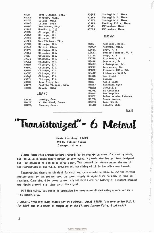
WBUB
W8UCT
W8UST
W8VCO W8VOZ W9AAG
W9AGM W9ALE
W9AYM
W9DRN
W9FHS
W9GAB
W9ITL
W9KKU
W9LX
W90JI W9OKB W9PBP
W9PV0 W9PWH
W9QVO W9SQE W9ZIII WODEN
KOITF
KH6UK
K1CJX W1CUT W1HDQ
Port Clinton, Ohio
Inkster, Mich.
Toledo, Ohio
Toledo, Ohio Van Buren, Ohio
Woodhull, Ill.
Chicago, Ill. Chicago, Ill. Chicaen 711
Des Plaines, Ill.
Chicago, Ill.
Beloit, Wisc. Chicago, Ill.
Chicago, Ill.
Chicago, Ill.
Wheaton, Ill.
Chicago, Ill. Chicago, Ill.
Chicago, Ill. Chicago, Ill.
Chicago, Ill.
Chicago, Ill. Chicago, Ill.
Iowa City, Ia.
Prairie Village, Kan.
Kanuku, Oahu
1215 MC
Granby, Conn.
W. Hartford, Conn. Canton, Conn.
Thom
W1QWJ
W1RVW
W1STR W1VNH W1WFL
W1YDS
W1BU W100P
K2CBA
K2GRI
K2ISA
K2TKN
W3ARW
W3CGV W3FEY
W3GGR
K6AXN
W6BLK
W6DQJ
W6HB
W6HIT W6HPH
W6JRK W6MMU W6NLZ
W6PCQ
W6SSB W8LIO
Springfield, Mass.
Springfield, Mass.
Springfield, Mass.
Feeding Hills, Mass.
Wilbraham, Mass.
Wilbraham, Mass.
1296 MC
Medfield, Mass.
Needham, Mass.
Troy, N. Y. Porter Corners, N. Y.
Troy, N. Y.
Pluckemin, N. J.
Scranton, Pa.
Wilmington, Del.
Lancaster, Pa.
Pleasant Hill, Md. Richmond, Calif. San Diego
Rivera
Menlo Park Panorama City
Camarillo
La Cresenta Los Angeles
Palos Verdes Estates
Santa Monica Long Beach Dorset, Ohio
"- 6 Metem! David Thornburg, K9SEW
443 W. Webster Avenue
Chicago, Illinois
have found this transistorized transmitter to operate on more of a novelty basis,
but its value in basic theory cannot be overlooked. No modulator has yet been designed
but l am considering a Hiesing circuit now. The transmitter demonstrates the use of
semi-conductors at the v.h.f. frequencies, something which is too often overlooked.
Construction should be straight forward, and care should be taken to use the correct
battery polarity. As you can see, the power supply is keyed since no warm up time is
required. Care should be taken to use only batteries and not battery eliminators because
any ripple present will show upon the signal.
DX? Not Quite, but one mile operation has been accomplished using a receiver with
1 mv sensitivity.
(Editor's Comment: Many thanks for this circuit, Dave! K9SRW is a very active O.E.S.
for ARRL and this month is competing in the Chicago Science Fairs. Good luck()
8
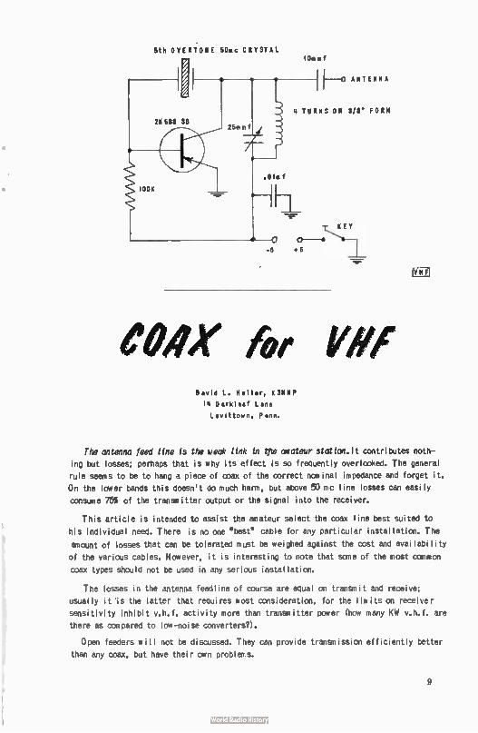
5th OVERT.011E 5011c CRYSTAL lOasef
-6
4 TURNS ON 3/8' FORM
eux for ke#, David L. Heller, K3HNP
14 Darkleaf Lane
Levittown, Penn.
The antenna feed line is the weak link in tpe awateur station.lt contributes noth-
ing but losses; perhaps that is why its effect is so frequently overlooked. The general
rule seems to be to hang a piece of coax of the correct nominal impedance and forget it.
On the lower bands this doesn't do much harm, but above 50 mc line losses can easily
consume 755 of the transmitter output or the signal into the receiver.
This article is intended to assist the amateur select the coax line best suited to
his individual need. There is no one " best" cable for any particular installation. The
amount of losses that can be tolerated must be weighed against the cost and availability
of the various cables. However, it is interesting to note that sane of the most canmon
coax types should not be used in any serious installation.
The losses in the antenna feedline of course are equal on transmit and receive;
usually it is the latter that requires most consideration, for the limits on receiver
sensitivity inhibit v.h.f. activity more than transmitter power (how many KW v.h.f. are
there as compared to low-noise converters?).
Open feeders will not be discussed. They can provide transmission efficiently better
than any coax, but have their own problens.
9
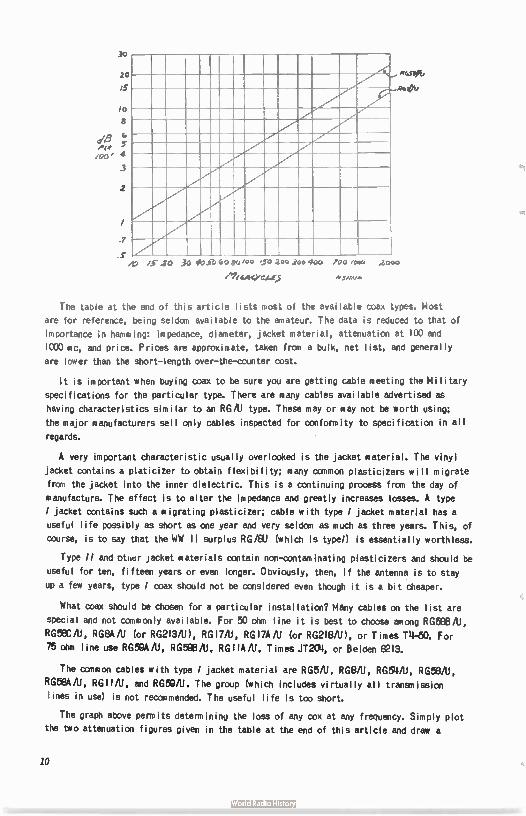
20
.7
.S
/me
R6/11b
/5 20 3o 4o S6 60 to i*. joe 400
/1% GACY
700 /0•0
dreeve
.2000
The table at the end of this article lists most of the available coax types. Most
are for reference, being seldom available to the amateur. The data is reduced to that of
importance in hamming: impedance, diameter, jacket material, attenuation at 100 and
10:0 mc, and price. Prices are approximate, taken fran a bulk, net list, and generally
are lower than the short- length over-the-counter cost.
It is important when buying coax to be sure you are getting cable meeting the Mi litary
specifications for the particular type. There are many cables available advertised as
having characteristics similar to an RG/11 type. These may or may not be worth using;
the major manufacturers sell only cables inspected for conformity to specification in all
regards.
A very important characteristic usually overlooked is the jacket material. The vinyl
jacket contains a platicizer to obtain flexibility; many common plasticizers wi II migrate
from the jacket into the inner dielectric. This is a continuing process from the day of
manufacture. The effect is to alter the impedance and greatly increases losses. A type
I jacket contains such a migrating plasticizer; cable with type / jacket material has a
useful life possibly as short as one year and very seldom as much as three years. This, of
course, is to say that the WW 11 surplus RG/EIU (which is type!) is essentially worthless.
Type // and otner jacket materials contain non-contaminating plasticizers and should be
useful for ten, fifteen years or even longer. Obviously, then, if the antenna is to stay
up a few years, type I coax should not be considered even though it is a bit cheaper.
What coax should be chosen for a particular installation? Many cables on the list are
special and not commonly available. For 50 ohm line it is best to choose among RGE8B/(1,
RG58C/U, RG8A/U (or RG213/11), RGIVU, RGI7A/11 (or RG218/11), or Times .111-50. For
75 ohm line use RG521A/U, RG58B/U, RGIIA/11, Times JT23), or Belden 8213.
The canmon cables with type / jacket material are RG5/11, RG8/U, RG54/11, RG58/11,
RG58A/11, RG11/U, and RG50/U. The group (which includes virtually all transmission
lines in use) is not recommended. The useful life is too short.
The graph above permits determining the loss of any cox at any frequency. Simply plot
the two attenuation figures given in the table at the end of this article and draw a
10
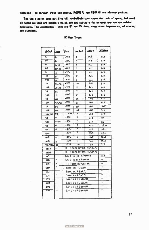
straight line through these two points. ROBB/U and REiSkitl are already plotted.
The table below does not list all avaiadbble OD« types for lack of space, but most
of those omitted are specials which are not suitable for amateur use and are seldom
available. The impedances listed are 50 and 75 ohms; many other impedances, of course,
are standard.
50 Ohs Types
RC/U Cost Cie. Jacket 10Orc 1000ac
5 tn. .332 1 2.6 9.5
59 24 .32, - 2.4 8.8
e 9.50 • 405 1 2.1 9.0
8A 12.50 .405 ; ;.I 9.0
9 23 .42. 2 2.0 8.5
96 30 .421 2 2.3 8.6
913 30 .420 ;-. 2.3 8.6
10 19.50 .4'75 26 2.3 9.0
10A 20.50 .475 2 2.1 9.0
14 23 • 545 2 1.4 (.2
14A 21 • 545 2 1.4 C.2
17 48 .810 2 .85 1.2
17A 52.50 • 870 2 .85 4.2
18 65 .948 2A .85 4.2
18A 68 .945 2A .85 4.2
19.19A 83 1.1ÇO 2 .68 ?••• 5
54 - .275 I 3.1 12
54A 7.50 .250 5 3.1 12
55 8 .236 3 4.2 16.0
58 4 .195 1 4.2 16.0
5eA - .195 1 .7..3 22.0
588 - • 195 2 4.2 16.0
586 5 • 195 2 5.3 2:;.0
74.746 40 .615 2A 1.4 6.2
141A - H I-T EMPERATU..E P6 586/U -
142A - H I-TEMPERATURE 0 G 55A/U -
149 - SAME AS 19 01 / ARMOR 3.5
148 - SAME AS 8 W/MMA'R -
159 - HI-TEMPERATURE 55 -
212 - SAME AS R 6 58/U -
213 - SAME AS RGeA/U
214 - SAME AS RG913/11 -
215 - SAME AS RS 10A/U -
218 - SAME AS 0 G l'7A /U -
223 - SAME AS RG 55A/U -
224 - SAME AS RG74A/U -
11
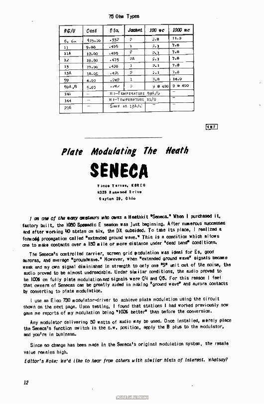
75 Ohm Types
RC/U Cost D ia. Jacket 100 ea 1000 oc
0, 0m 415. -,i0 .332 2 ;,.8 11.0
11 9.00 .405 1 2.1 7.8
11A 12.00 .405 2 2.1 7.8
12 19.00 .475 '4' 2.1 7.8
13 17.00 .420 1 2.1 7. 8
13A 18.0:. .42C 2 ;..1 7.8
59 4.00 .242 7 3. 8 14.0
59 41B 5.00 • 2 9 0 400 9 8 400
140 — HI—TEMPE4ATIeE 594/b _
144 HI—TEMPERATURE 11/U _
216 SAME AS 13A/ I —
CCU
Plate Modulating The Neath
SENECA V ince V ernes, 8REG
4329 Renwood Drive Dayton 29, Ohio
I ir one of the many aioteurs who owns a Heathkit 'Seneca.' When I purchased it,
factory built, the 1980 Spooadic E season was just beginning. After numerous successes
and after working 110 states on six, the DX subsided. To take its place, I realized a
formob. propagation called 'extended ground wave.' This is a condition which allows
one to make contacts over a 150 mi le or more distance under 'dead band' conditions.
The Seneca's controlled carrier, screen grid piodulation was ideal for Es, good auroras, and average "grcundmiave." However, when 'extended ground wave' signals became
weak and my own signal diminished in strength to only one 'S' unit out of the noise, the audio proved to be almost undreadable. Under simi lar conditions, the audio proved to
be ICO% on fully plate modulationand signals were 014 and 05. For this reason I feel that owners of Senecas can be greatly aided in making 'ground wave' and aurora contacts
by converting to plate modulation.
I use an E ico 730 modulator-driver to achieve plate modulation using the circuit shown on the next page. Upon testing, I found that stations I had worked previously now gave nie reports of my modulation being ' 100% better" than before the conversion.
Any modulator delivering 50 watts of audio may be used. Once installed, merely place
the Seneca's function switch in the c.w. position, apply the B plus to the modulator,
and you're in business.
Since no change has been made in the Seneca's original modulation system, the resale
value remains high.
Editor's Note: We'd like to hear from others with similar hints of Interest. Whatsay?
12
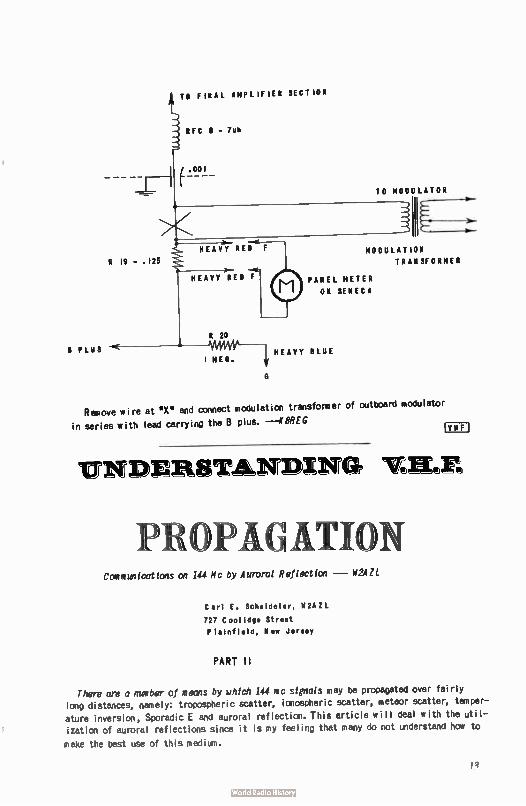
R PLUS
ii-
R 19 - . 125
TO FINAL AMPLIFIER SECTION
RFC 8 - 7uh
(.001
HEAVY RED F
R 20
HEAVY BLUE I MEG.
TO MODULATOR
MODULATION
TRANSFORMER
PANEL METER
ON SENECA
Remove Wire at "X" and connect modulation transformer of outboard modulator
in series with lead carrying the 8 plus. --K8REG
UNDERSTANDING IF.H.E
OPACATIO Ccoveurtications on 144 Mc by Auroral Reflection — W2A
Carl E. Scheideler, W2AIL
727 Coolidge Street
Plainfield, New Jersey
PART II
There are a number of means by which 144 mc signals may be propagated over fairly
long distances, namely: tropospheric scatter, ionospheric scatter, meteor scatter, temper-
ature inversion, Sporadic E and auroral reflection. This article will deal with the util-ization of auroral reflections since it is my feeling that many do not understand how to
make the best use of this medium.
Il
The largest nimber of auroras occur in the spring and fall of the year although one
may occur at any time. There are manyways of determining when an aurora is in progress or about to commence. Listen on the lower frequencies 3.5 through 114 mc for hollow
sounding signals and the lack of DX. Sane of the gang who live in a TV or FM fringe
area have an extra antenna pointed north and look for the appearance of stations fran
long distances. Another help is to take advantage of the CRPL Radio Warning Service,
Boulder, Colorado. This can be obtained by writing the National Bureau of Standards
CRPL Radio Warning Service, Boulder, Colorado, and requesting the CRPL-JB forecasts.
They are mailed from Boulder each Wednesday with ¡Predictions for the following week.
Listen to WWV on 2.5, 5.0, or 10.0 mc at 19 after and II before the hour will give an
idea of the present possibilities of an aurora. If WWV is sending W5, U5 or less, look for aurora on 11114 mc. This is not foolproof, however, since the broadcast is only changed every six hours and conditions may change rapidly during that time. If the lower frequency
bands drop out due to a "SID' (sudden ionospheric disturbance), look for an aurora approxi-mately 27 hours later. If an aurora is observed, mark the date in your log and look for a
reoccurance 27 days later plus or minus a few days.
Possibly one of the least understood parts of communication by auroral reflection is
which way to point the beam. The usual practice is to point it in a northerly direction.
This may work for short haul contacts up to distances of 500 mi les or less with a fairly
broad beam. The antenna at my station has a 15 degree beamw idth to the half power points
and the best direction for the WI, W2, VE I, VE2 i s slightly east of north. The W8's peak at about 30 degrees west of north and the W9's 30 degrees west of north. The el's in Virginia and Kentucky peak at 30 degrees west of north and the more southerly WI4's peak
progressively further toward the west until the beam is almost directly west for Florida. The W5's arid southern WO's peak almost due west. In the case of some of the southern
stations it was found possible to improve the signal strength by tilting the beam. It
would appear from these observations that if a station in Nebraska wanted to work a stat-ion in New Jersey, he would point his beam in a northeasterly direction and the station in New Jersey would point to the northeast. All of the above is pointed out merely to illus-
trate the fact that one may get auroral reflections from other than a northerly direction
arid advantage should be taken of this fact to work stations at longer distances.
Sane observations made at this station in the past 12 years may be of help. The best or longest haul contacts are made during a red aurora. This is because the red aurora occurs at a higher elevation than the green or white. The best auroras seem to coincide with a
high pressure area centered over or below the Great Lakes region so that most of the country is in a high pressure area. This would suggest that sane help is needed frcxn tropos-pheric bending and scattering. Usually a good aurora will last for as many as five or six
hours without fading. When the aurora fades, don't shut down; it may be back in a few min-utes. If not, check the band in half-hour intervals - you may be pleasantly surprised. Usually if an aurora fades at 8 to 9 PM it will be back around midnight. Auroras have
been observed as far south as F lorida, so don't think your location is too far south. While
sane contacts have been made usi ng ' phone, these are few and far between. B low the dust
off that old brass key and I'll be seeing you on 144 me during the next auroral - W2AZL
FLASH! News has Just broke on another 1296 mc first- A RTTY two-way contact on February 11,
19611 W6TPJ, of Rosemead, California worked first W6CG (of Temple City) and then K6OWO (also of Temple City) for the first 1215 RTTY contacts/
For further details, check the April 1961 CP VHF Cohan. News break. via Byron
Ilretzmcri, KØWIIR, CO's RTTY Editor... Fir
14
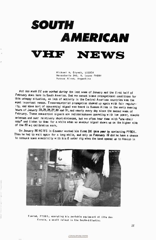
Conrad, PY5GK, operating his portable equipment at Ilha dos
Corais, a small island in the South- Atlantic.
SOUTH AMERICAN
VHF NEWS
Michael A. Czysch, LU3DCA
Monasterio 345, V. Lopez FNGBM
buenos Aires, Argentina
Not too such DX was worked during the last week of January and the first half of
February down here in South America. Bet we cannot blame propagational conditions for
this unhappy situation, as lack of activity in the Central American countries was the mpst important reason. Trans-eduatorial propagation showed up again with fair regular-
ity, and sane sort of cornmercil signal was heard in Buenos Aires in the early evening hours of January 23,25,26,27,30 and 31, and nearly every day since the second week of
February. These commercial signals are radiotelephones operating with low paver, simple
antennas and over relatively short distances, but we often hear them with 'arm-chair
copy* and listen to them for a while when no amateur signal shows up on the higher side of the 50 mc calibration mark.
On January 30 HC IFS in Ecuador worked his first DX this year by contacting PY5GK. Then he had to wait again for a long while, and only on February 19 did he have a chance
to consume sane electricity with his 8 meter rig when the band opened up to Mexico in
15
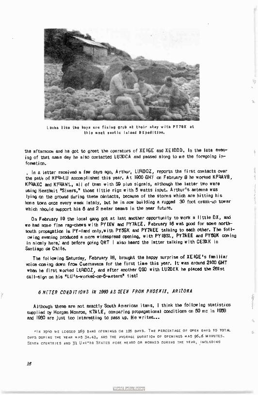
locks like the boys are fixing grub at their stay with PY7GX at
this most exotic Island OXpedition.
the afternoon and he got to greet the operators of XEIGE and XEIDDD. In the late even-
ing of that same day he also contacted LU3DCA and passed along to me the foregoing in-
forget ion.
, In a letter received a few days ago, Arthur, LUIIDOZ, reports the first contacts over the pat4 of KPii-LU accomplished this year. At 1900 GMT on February 8 he worked KP11AVB,
KPI1AXC and KPIIAWL, all of than with S9 plus signals, although the latter two were using H-eathicit "Sixers,* those little rigs with 5 watts input. Arthur's antenna was lying on the ground during these onntacts, because of the storms which are hitting his home town once every week lately, but he is now bui lding a rugged 30 foot crank-up tower which shouid support his 8 ano 2 meter beams in the near future.
On February 10 the local gang got at last another opportunity to work a little DX, and
we had sane fine rag-chews with PY1XW and PY7AEE. February 18 wa good for sane north-south propagation in PY-land only,with PY5GK and PY7AEE talking to each other. The foll-owing evening produced a more widespread opening, with PYIBSL, PY7AEE and PY5GK caning in nicely nere; and before going ORT I also heard the latter talking with CE3XK in Santiago de Chi le.
The fo: low ing Saturday, February 18, brought the happy surprise of XE IGE 's fam i liar
voice can ,ng down from Cuernavaca for the first time this year. It was around 2100 GMT when he first worked LUI4DOZ, and after another OSO with LU2DEK he placed the 2151st
cal I-sign on his • LU's-worked-on-8-meters' I istl
6 NETER CONDITIONS IN 1960 AS SEEN FROM PHOENIX. ARIZONA
Although these are not exactly South American items, 1 think the following statistics supp: ied by Morgan Monroe, K7ALE, comparing propagational conditions on 50 mc in IMO and 1980 are just too interesting to pass up. He writes...
lN 1960 WE LOGGED 169 SAND OPENINGS CS 126 DAYS. THE PERCENTAGE OF OPEN DAYS TO TOTAL
DAYS DUPING THE YEAR WAS 34.43, AND THE AVERAGE DURATION OF OPENINGS HAS 96.6 MINUTES.
SEVEN COUNTRIES AND 31 UNI'ED STATES WERE HEARD OR WORKED DURING THE YEAR, . INCLUDING
18
AUSTRAL IA ( HEARD ONLY), ARGENT INA, MEXI CO, ECUADOR, URUGUAY, CHILE ( HEARD ONLY), AND
CANADA (VE6 AND VE/)•
"Am INTERESTING CONDITION IS APPARENT BY COMPARISON OF THE FINDINGS ABOVE WITH THOSE
FOR 1959. IN THAT YEAR WE LOGGED 121 OPENINGS ON 99 DAYS, — THE PERCENTAGE OF OPEN DAYS
TO TOTAL DAYS WAS 29.55, AND THE AVERAGE DURAT ION OF OPEN INGS WAS 122.3 MINUTES. Six
COUNTRI ES AND 42 STATES WERE HEARD OR WORKED.
"Titus IT APPEARS THAT 1960 WAS BETTER THAN 1959 IN NUMBER OF 50 MC OPENINGS AND IN DAY S
OPEN, BUT 1960 OPENINGS WERE SHORTER AND NOT AS WIDE SPREAD (AT LEAST WITH IN THE UN ITED
STATES) AS IN 1959. AL SO, THE GENERAL QU ALI TY OF SPORADIC E PROPAGATION LAST YEAR WAS BELOW
THAT OF 1959 —MORE QSB , LE SS SIGNAL STRENGTH, ETC. — AL THOUGH SOME OF THE F2 OPENINGS
OF LAST FALL WERE IONS THE BEST WE HAVE EVER WORKED."
Such accurate observations as those which permitted the foregoing analysis will certainly
be a valuable aid in explaining some day what actually are the mysteries of propagation on
50 mc. Congratulations, Morgan!
The pictures displayed this month were taken during a DXpedition to the •Ilha dos Corais,•
a small island in the South-Atlantic, accomplished by PY5GK with the help of two friends. This was a •VHF-only' effort worthy of imitation, especially in the Carribbean area.
By the time this appears in print you may be contacting Conrad, PY5GK, from his home
shack pictured two months ago in these pages...
73 - Michael. L el 3DCA
Moonbounce
Activities
Allen Kat;
48 Cumberland Avenue Verona, New Jersey
au
The true moonbounce operator differs from other v.h.f. men because he is looking for
a tond on which a particular propagation can be best used, not for a propagation which can te used best on a certain band. He must make this decision for himsellf and from incomplete
information. Theoretically he can accanplish mcontounce on any band, if he can muster
enough gain to overcane the path loss.
The path loss for a moatounce system can be obtained from the formula loss db is equal to 10 log l.e2 x 10-26 x?. 2. I The transmitter used will have a gain according to thefforrnula gtxx equals 10log P (gtx equals gain in db, while P is the power out in watts).
The gain of most receiving and transmitting antennas can be obtained from various handbooks. The gain of a parabolic antenna, however, is not too frequently seen in amateur publications and given by the formula Ga equals 10 log (Go is the gain In db over isotropic radiator, A is projected area of thé reflector iesquare feet, g is efficiency factor which is approximately 55% for most antennas andA is the wavelength in meters). 3 The gain of
17
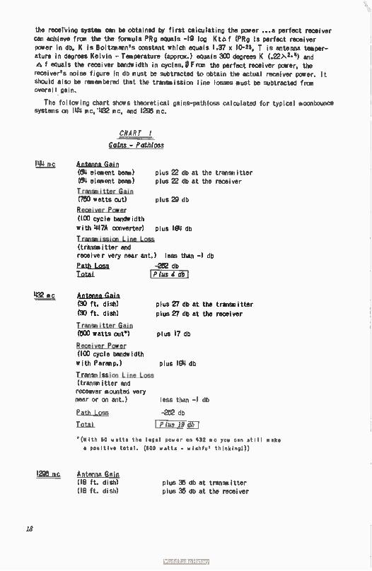
the receiving system can be obtained by first calculating the power ...a perfect receiver can achieve from the the formula PRg equals -19 log Kto f (PRg is perfect receiver power in db, K is Boltzmann's constant which equals 1.37 x 10⁻²³, T is antenna temper-ature in degrees Kelvin - Temperature (approx.) equals 300 degrees K (.22)•2-4) and f equals the receiver bandwidth in cycles.V From the perfect receiver power, the
receiver's noise figure in db must be subtracted to obtain the actual receiver power. It should also be remembered that the transmission line losses must be subtracted from overall gain.
The following chart shows theoretical gains-pathloss calculated for typical mconbounce systems on 144 mc, ' 432 mc, and 1295 mc.
CHART I
Gains - Pathloss
Antenna Gain (94 element beam) (54 element beam)
Transmitter Gain (750 watts out) plus 29 db
Receiver Parer
(100 cycle bandwidth with 417A converter) plus 184 db
Transmission Line Loss (transe i tter and receiver very near ant.) less than -1 db
Path Loss -262 db total
432 MC Antenna Gain (30 ft. dish)
(30 ft. dish)
T ransm i tter Gain (500 watts outs) plus 17 db
Receiver Power (100 cycle bandwidth
with Paramp.) plus 194 db
Transmission Line Loss (transmitter and receever mounted very near or on ant.) less than -1 db
Path Loss -252 db
Total I Plus 19 db!
'(rith 50 watts the legal power on 432 mc you can still make
a positive total. (500 watts - wishfu ) thinking1))
plus 22 db at the transmitter plus 22 db at the receiver
P lus 4 db
$295 mc Antenna Gain (18 ft. dish) (18 ft. dish)
18
plus 27 db at the transmitter
plus 27 db at the receiver
plus 36 db at transmitter plus 35 db at the receiver
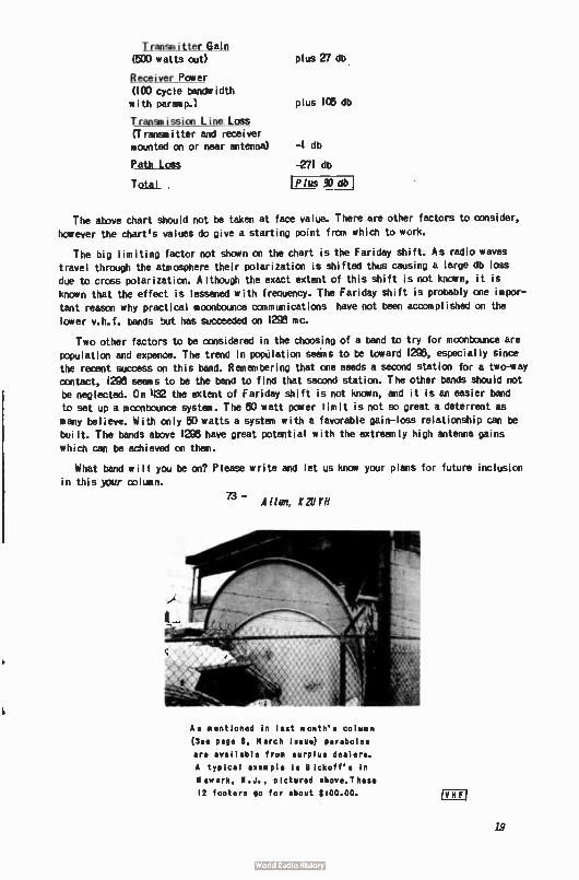
Transmitter Gain (500 watts out) plus 27 db
Receiver Power (100 cycle bandwidth with parmep.) plus 106 db
Transmission Line LCGS (Transmitter and receiver mounted on or near antenna) -1 db
Path Loss -271 db
TtL Plus 30 db
The above chart should not be taken at face value. There are other factors to consider,
however the chartes values do give a starting point from which to work.
The big limiting factor not shown on the chart is the Fariday shift. As radio waves
travel through the atmosphere their polarization is shifted thus causing a large db loss due to cross polarization. Although the exact extent of this shift is not known, it is
known that the effect is lessened with frequency. The Fariday shift is probably one impor-
tant reason why practical moonbounce comniunications have not been accomplished on the
lower v.h.f, bands but has succeeded on 1293 mc.
Two other factors to be considered in the choosing of a band to try for moonbounce are
population and expence. The trend in population sains to be toward 1296, especially since the recent ucuss on this band. Remembering that one needs a second station for a two-way contact, 1293 seems to be the band to find that second station. The other bands should not
be neglected. On 432 the extent of Fariday shift is not known, and it is an easier band
to set up a moonbounce system. The 50 watt power limit is not so great a deterrent as many believe. With only 50 watts a system with a favorable gain- loss relationship can be
built. The bands above 1298 have great potential with the extreamly high antenna gains
which can be achieved on them.
What band will you be on? Please write and let us know your plans for future inclusion
in this yaur oplumn.
73 - Allen, A2UYN
As mentioned in last month's column
(See page 8, March issue) parabolas
are available from surplus dealers.
A typical example is eickoff's in
Newark, N.J., pictured above.These
12 footers go for about 8100.00. F
19
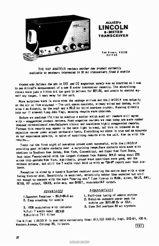
ALLJED's
LINCOLN 6-METER
TRANSCEIVER
Bob Brown, K 2Z SQ ED IT 0 R
THE VHF AMATEUR reviews another new product currently
available to amateurs interested in 50 mc trrinsceivers fixed .1 mobile
Anxvie who follows the ads in OST and CO magazines surely was as startled as I was to see A I lied's announcement of anew 8 meter transceiver recently. The advertising claims were just a little bit too good to believe for $57.50, and unable to control my-
self any longer, I sent away for the unit.
More surprises were in store when the package arrived and the LINCOLN was actually
on the air in five minutes! - The unit canes complete, already wired and tested, with mike ( an Astatic, by the way) and a 50.2 mc third overtone crystal. Running directly into our I I element Long John Vagi, amazing results were obtained.
Before we continue I'd like to mention a matter which most all readers will agree with - exaggerated product reviews. Most magazine reviews we read today are mere rubber stamped reiteratiorsof manufacturers claims and sometimes highly exaggerated reports.
Perhaps this reports may appear in the sane light to many, but this is intended as an objective review under actual ai-the-ai r tests. Everything we state is true and as accurate as our experience permits, in spite of surprising results with the unit. Nola on with the
results...
Tests run the first night of operation proved most successful, with the L INCOLN providing good reliable contacts over a surprising range.Sane contacts were made with
stations in Southern New Jersey, New York, Connecticut, and Upper New York State,
(and later Pennsylvania) with the longest distance from Rahway (NNJ) being about 270 miles into upstate New York. Admittedly, ground wave conditions were good, and the antenna optimum, but still the 7 watts input held up with an ese-e report over that dis-tance.
Reception is aided by a tunable Superhet receiver covering the entire band with a slow tuning Vernier dial. Sensitivity is excellent, selectivity better than expected but sti II not enough to canpare with the home 'hearing aid." Tube line-up is BUM, mixer, CALS, ANL,
eCX8, RF output, I2AX5, mike amp, and 8VAGT, modulator/AF output.
ADVANTAGES
I.Superhet Receiver - 50.041.0 mc 2. Easy mounting for mobile
3. 100% modulation with indicator 11.Ful I 7 watts input (8CX8) 5.Bui It- in TV! filter
The Allied LINCOLN is available exclusively fran: ALLIED RADIO, Dept. 212-8 1, 100 N.
Western Avenue, Chicago 83, Illinois.
DISADVANTAGES
I. Half-inch tuning of usable portion 2. Requires outboard pager pack for
mobile use ($ 10.95 8v or 12v). 3. Uses 3rd overtone 50 mc crystals
!VII Fi
20
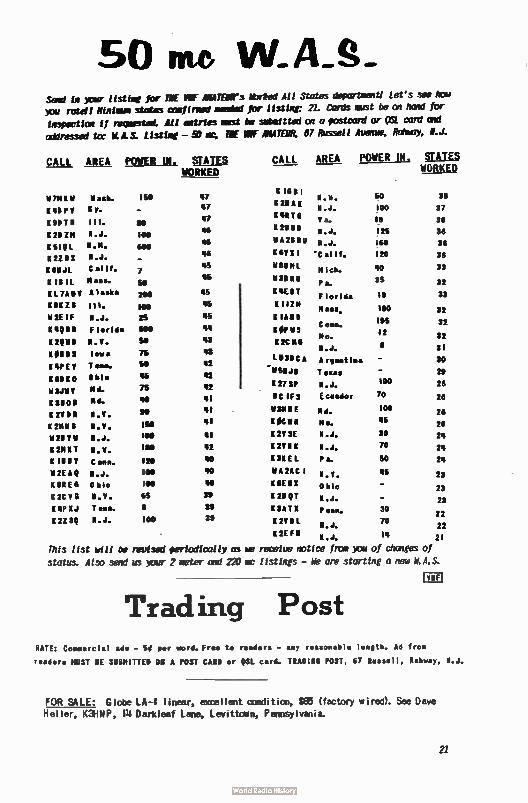
50 me Said in ictir listing for ME IMF AMATFOR's kbrked All States department! Let's see how
you retell Minimum states confirzed needed for listing: 21. Cards must be on hand for
inspection if reçuested. All entries oust be submitted on a postcard or ()St card and
addressed to: ILLS. Listing - 50 lc, THE- IMF AMATEUR, 67 Russell Avenue, Rahbay, N.J.
CALL AREA POWER IN . STATES CALL AREA POWER IN . STATES WORKED WORKED
11 7MEV 11 aslt 150
K 48P Y K.
K DDT 8 III. 00
K 2D M N.J. 100
K 5101_ N- K• 600
K 27 8 X ICA-
K 6UJL Calif. 7
KIBIL Mass- 50
K L 7A V 0, task', 200
K 91 Z11 W. 100
If 2E IF N.J. 25
K WIN Florida 600
K29110 N.Y. 50
K 0110 S Iowa 75
KPEV T end- 50
ENDEO Ohio
b13.111Y Nd- 75
K 360 B Md. 40
K 2V D R N.Y. 90
K 2M118 N.Y. IS
211V11 N.J.
K 211XT N.Y. 180
K IBN Y Conn. 120
M2EAQ N.J. 100
K 8R El3 O boo POO
K2CVG N.Y. 65
K 41, X J T enn. 8
K 2Z SQ N.J. 100
47
47
47
46
46
46
48
45
45
45
45
44
43
43
42
42
41
41
41
41
42
40
40
40
39
39
311
K IS B1
K 211 A K
'CUT 6
K 21164
NAURU
68 X I
d8UML
W3N RU
KIEBT
K 11711
K IAUD
K OP 11 S
1 2C NS
LU3DC A
"vsere
127 SP
NC IFS
1131111 E
KOCNR
K 28 SE
K 2V N K
K 3K EL
VA 211C 1
K 8E U
K 2D QT
K 3A T X
K 2V M L
K 2E F N
N.H. 50 38
N.J. 100 37
V a. 18 36
N.J. 125 36
X . J. 160 36
Calif. 120 36
M ch. 40 33
35 P a. 32
Florida 19 33
Mass. 100 32
195 C onn. 32 12 Mo. 32
N.J. 8 31
A rgent ' ma 30
Texas 29
N.J. 100 28
Ecuador 70 26
Md. 100 26
Mo. 45 26
N.J. 30 24
N.J. 70 24
P a. 50 24
N.Y. 45 23
0 hio _ 23
N.J. - 23
Penn. 30 22
70 N.J. 22 N.J. 14 21
This list will be revised periodically am receiue notice fron )ou of changes of
status. Also send us wur 2 meter and 220 mc listings - We are starling a new N.A.S.
Trading Post RATE: Commercial ads - Si per word. Free to readers - any reasonable length. Ad from
readers MUST BE SUBMITTED ON A POST CARD or QSL card. TRADING POST, 67 Russell, Rahway, N.J.
FOR SALE : Globe LA-I linear, excellent conch tiro, $E6 ( factory wired). See Dave
Heller, K3FINP , 111Darkleaf Lane, Levittown, Pennsylvania.
21
Leaving 8 Meters: complete station up for grabs. 120 W, written up in the June 1950 VHF Amateur.Send for list. Ken Foster, W21BD, 1187 Oceanpoint Avenue, Cederhurst, N.Y.
WANTED: Tower and/or rotator. Local deal only.... New England and New York. I will take down and move tower. Nick Sheer, KIPSR, P.O. Box 1132, Amherst, New Hampshire.
FOR SALE: Gonset Communicator II, 8 meters, ns crystals, crystal mike, AC & DC power cords and mobi le rack for Gonset. Also 5 element Tel rex 8 meters - new; E ico 5" scope.
Manuals included with all above equipment. $275.00 takes everything. (Will also sell separately). Contact Mort Cohen, WA2ARS, II Brighton 10 Terrace, Brooklyn 35, New
York, or call TW 1-3125 after 8:30 PM.
FOR SALE: Johnson Viking 842 converter, 28-30 mc. New, never used - Bargain. Call
YU 11-2a7- now!
OSL's: SWL's,CITIZEN BAND, SAMPLES 50. NICHOLAS & SON PRINTERY, BOX me, PHOEN IX, AR IZONA. (6/61)
FOR SALE: Viking Challenger - good condition - $00.00. Meissner Signal Shifter - al 1-band v. f.o.-exci ter-e.c.o. - $215.01 Will ship C.O.D. or del iver local ly....Heiko Ganzer, K2REH, 8111 Nicholas Place, Rahway, New Jersey.
FREE HIGH PASS FILTERS: Every major TV manufacturer will supply TV I fi lters (usually Drake 3W-HP's) to TVI recipients upon request! Il Send for the lists of these canpanies and proper forms to be filled out by canplainees. 25( to cover printing, paper, envelops, and postage to TV I Dept., The VHF Amateur, 87 Russell Avenue, Rahway, N.J.
WANTED-WANTED-WANTED! Construction articles on v.h.f. - u.h.f. gear for this maga-
zine. Also need pictures of your station, you (horrors!), or your antenna. Write us nowl The VHF Amateur, 87 Russell Avenue, Rahway, N.J.
READ FLORIDA St IP1 Everyone in the country is jumping on the Florida bandwagon for this real dandy publication edited and publ ished by Andy Clark, ellYT, S.E.C. F lorida. It's loaded with news, general and v.h.fl Some of the staff: W11RMU, VP7BH, K11EUJ, K11RNS, K1IPPX (CO contest 2million pointer - 1950), K11LLG, and many, many more. Whether or not you live in the heart of Sunny W11- land, you'll like FLORIDA SK IP. And it only cost $2.00 a year for a full supply of the best the Sunshine State has to offer. Don't pass this one up! Send your 18 bits to FLORIDA SK IP, P.O. Box 501, Miami Springs,
F lorida.
K3HNP, the license plate collector, is sti II looking. Please - your used ham plates. Can the LU-land friends help? 114 Darkleaf, Levittown, Pa.
TRADE: Any surplus 811's for swap? K3HNP.
Si le Sideband J.S. "RuS,'Yn B;7AVMAN, K2l1TN
170 Schenck Avenue
C re•t N.ck, N.Y.
IVHF)
This month we were delighted to attend the East Coast VHF Society dinner, on February 25, and even more so to meet many of those with whom we have exchanged RST's
22
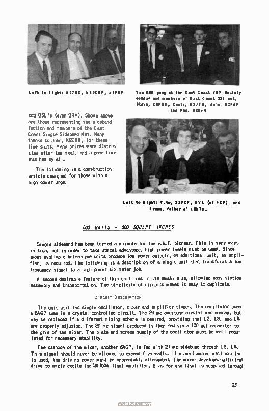
Left to 11 52Z1X, WAKCYF, 1UPX1
cre OSL's (even ORM). Shown above are those representing the sideband
faction and members of the East
Coast Single Sideband Net. Many thanks to John, K2ZBX, for these fine shots. Many prizes were distrib-
uted after the meal, and a good time
was had by all.
The following is a construction
article designed for those with a
high power urge.
T be Ill yin at tie East C oast VHF Soo I ety Ilea« and tubers of out Coast SSS net, Steve, 52P10, Rusty, E2015, lens, 112RJD
and D on, W2NFQ
Lett to light: V Ito, K2PXP, KYL (of PEP), and F reek, fattier o' K241T11.
500 WATTS - 500 SQUARE INCHES
Single sideband has been temed a miracle for the v.h.f. pioneer. This in many ways
is true, but in order to take utmost advantage, high power levels must be used. Since most available heterodyne units produce low power outputs, an additional unit, an ampli-
fier, is required. The following is a description of a single unit that transforms a low
frequency signal to a high power six meter job.
A second desirable feature of this unit lies in its small size, allowing easy station assembly and transportation. The simplicity of circuits makes it easy tc duplicate.
CIRCUIT DESCRIPTION
The unit utilizes single oscillator, mixer and aotplifier stages. The osci,lator uses a 8AG7 tube in a crystal controlled circuit. The 29.mc overtone crystal was chosen, but
may be replaced if a different mixing scheme is desired, provAing that L2, L3, and oe are properly adjusted. The 20 mc signal produced is then fed via a IGO uuf capacitor to
the grid of the mixer. The plate and screen supply of the oscillator must be well regu-lated for necessary stability.
The cathode of the mixer, another 8AG7, is fed with 21 roc sideband throegh 1_3, 114. This signal should never be allowed to exceed five watts. If a one hundred watt. exciter is used, the driving power must be appreciably attenuated. The mixer develops. sufficient drive to amply excite the 19(150A final amplifier. Bias for the final is supplied througt
23
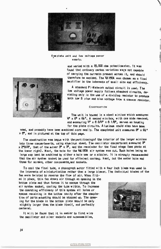
Complete unit and low voltage power
supply.
and varied with a 15,C00 ohm potentiometer. It was
found that ordinary carbon varieties were not capable
should of carrying the currents present across it, an
therefore be avoided. The 14X 150A was chosen as a final
ampli f ier in the interests of srnal I size and efficiency.
A standard Pi-Network output circuit is used. The
law voltage power supply fol lows standard circuits, de-
viating only in the use of a dividing resistor to produce
both low B plus and bias voltage from a common resistor.
U SSTRUCTICN
The unit is housed in a steel m ini box which measures
14" x x gh". A second minibox, with one side removed,
and measuring le x 8 3/14' x 8 I/8", serves as howling
for the plate circuits. A lum inum could also have been
used, and probably have been machined more easily. The ccmpleted unit measures 8" x 9#
x ee, and is pictured at the top of this page.
The construction was begun with the parti tioningof the interior of the larger minitox
into three compartments, using aluminum sheet. The osci llator compartment measured 3'
x 2113 /411 , that of the mixer 3" x 3, and the remainder for the final stage (see photo at
the lower right). Next, the hole for the 414( 150A air system was cut. Such holes being so
large may best be machined by either a hole saw or a nibbler. It is strongly recommended
that the air system socket be used for efficient cooking. Next, cut the meter hole and
those for screws, other canponents,and sockets.
To cool the final tube, a phonograph motor fitted with a four inch blade was used in
the interests of miniaturization rather than a large blower. The individual blades of the
fan were twisted to reverse the flow of air. When fitt-
ed in place, this fan draws air through an opening in the
bottom plate and thus forces it to escape through the
air system socket, cooling the tube within. To increase
the operating efficiency of this system all holes or
spaces remaining in the bottom cavity after the comple-
tion of parts mounting should be stopped up. The open-ing for the blade in the bottan plate should be only
slightly larger than the blade itself, and perfectly
centered.
It wilt be found that it is easier to first wire
the oscillator and mixer sockets and subassemblies,
24
and then insert them into their respective cavities. Final connections may then be made rather than attempt to complete the entire wiring in such a cramped space.
When wiring the 11X150A socket be sure to make all ground and bypass connections extremely short.
PLATE COMPARTMENT
Contact to the anode cooler of the 11X150A is accomplished by means of a strip of copper 3/8* wide, that is bent into a circle and fastened together with a screw. Tightening this screw causes the copper band to grip the anode bore firmly. The
plate blocking and bypass capacitors are of the TV doorknob variety. Several vent holes
ahould be drilled into the plate canpartrnent to allow adequate escape of the forced air.
ADJUSTMENTS
Upon canpleting the construction and carefully checking the wiring, it is recommended
that a grid dip meter be used to approximate the coil settings and make any adjustments that prove necessary.
Begin by applying fi lament voltage. The fan should begin to force air through the
tubes's anode cooler, and out the top. After a few minutes the 6AG7's should begin to feel warm. Now B plus voltage and bias may be applied. It is highly advisable to start with about six hundred volts on the plate of the final. Adjust the bias so that the static plate current is about 50 milliamperes. This setting must be readjusted at a higher plate
voltage. Provision has been made for the antenna relay to apply full bias during receive periods to cut off the tube.
After completing the above tests, apply drive, and peak the oscillator and mixer con-
trols for maximum output. Then dip the plate tuning control and load to the desired power level. If all goes well, apply the full MOO volts to the plate and readjust.
TVI
TV I, almost synonanous with five hundred watts, is minimized with proper shielding, and the use of a low-pass filter. In a few cases this may not be sufficient, since sane have TV I difficulties at the 50 watt level even under the above precautions.
This raft has been in operation here for several months, bringing mot); wore pleasures to u. h. f. operating. Happy DX hunt(ng!
SSS SSS SSS SU SSS SSS SSS SSS SSS SSS SSS
LETTERS
Fran John Webb, W7MAH, IMO Buena Vista Avenue, Reno, Nevada, a note letting us
know about his work on six and two SSB. He's trying for the K2UTN WAS-SSB cup. We'll wish you best of luck, John, - It's getting dusty already.
The next canes fran Henry Savage, WIIRFR...
"I HAVE JUST RECEIVED MY FIRST COPY OF THE VHF AMATEUR AND WAS VERY HAPPY TO FIND
A SSB VHF SECTION. I HAVE OPERATED 6 P. 2 METERS ON SSB FOR OVER A YEAR. THERE ARE SEVERAL
5 METER SSB DOTS HERE BUT NOT A SINGLE Am, CW, OR SSB STATION ON 2 METERS.
"THE RIG HERE IS A 4X150 FINAL WITH A 6Y6 CLAMPER TUD.E RUNNING ABOUT 203 WATTS PEP.
THE TRANSM ITTING CONVERTER IS AS FOLLOW S: 32.5 MC XTAL IN AN OVEN INT ) A 6U8 OSCILLATA
AND 111.11LER, 5'153 DOUDLER TO 130 MC INTO GRIDS OF A 5524. THE .2,S1R AT 14 MC IS FED INTO
THE SCREEN OF THE 6524. THE 6524 PLATE ARE IN PUSH—PULL. ANTIBNA HERE IS 32 "L '15' HIGH.
25
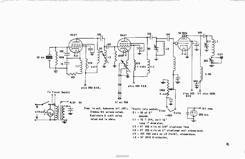
03A0 7 100 • 8A0 7
29 Ric eaM
100
To Power Supply
0-41 . *
I I7V AC
4,
o
L 2
plus SOO REO.
21 mc SSS
Cap. In ouf, bypass.. all . 001.
Choke', MM unless noted.
Rosistors * watt units
noted and in ohms.
100
plus 300 REO
1500
100
4 wat
"'Built into socket. 8 iis \,.......,
CI — 20 uf *" Relay
spaced. -100V
L 1 - 7* T fI4, coil l*"
long 1" diameter.
L2 - 91 032 wire on 3/8" slugtuned form
L3 - 31 022 wire on It " slugtuned coil closewound.
LIP - IOT 022 same as L3 ( form), closewound. L5 - 4T 3010 Miniductor.
142 150A 500
-
Z - 50
L I
plus 900 H V plus 2000 REO
11 V neg.
300 ea.
OUT
n
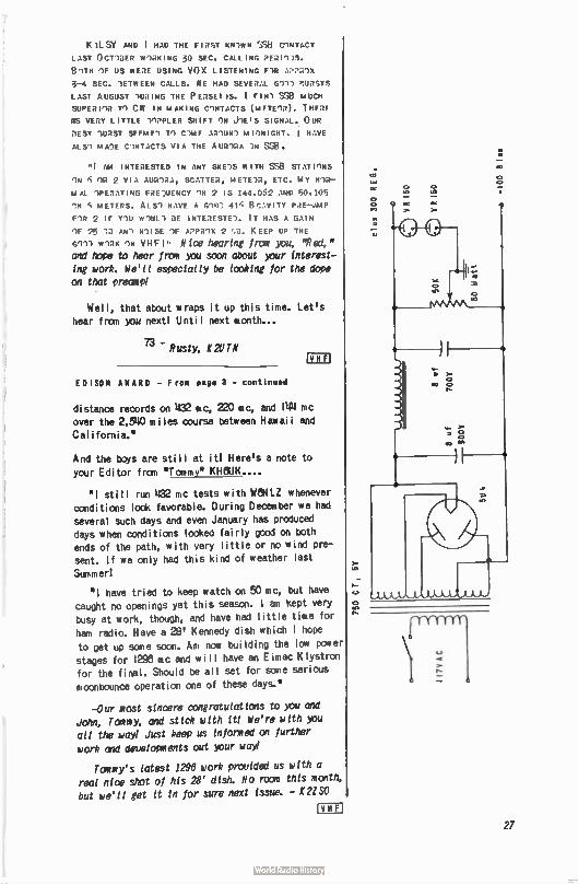
K it. SY AND I HAD THE FIRST KII1WN C1NTbCT
LAST 0 CTIDER W1I2KI NG 30 SEC. CALL ING prai-;•Is. BITH IF US WERE USING VOX LISTENING F 1R AI,I1R1X
3-4 SEC. lETWEEN CALLS. WE HAD SE VER AL G11) nURSTS
LAST AUGUST 'WRING THE P EasE Ds. I FIN') We MUCH SUPER 11.1 CW IN MAKING C1NTACTS (ME TE IR). THERE
WS VEST LITTLE 1IPPLER SHIFT ON J1E S SIGNAL. OUR
REST 1URST SEEM El TI ClIAE AR1UN1 M IINIGHT. I HAVE AIS') MAU C1NTACTS VIA THE A UR1RA 111 SSEi.
HI AM INTERESTED IN ANY SKE1S WITH SSI3 STAT I1N S
IN 5 OR 2 VI A AuGi.a.1, SCATTER , METE ;. I , ETC. MY WIR— M AL IPERATING FREWENCY '1N 2 IS 144.052 AND 50.105 ^N 5 METERS. AL S1 HAVE A G'1•1; 41 G Br:. V ITY PRE—AMP FIR 2 IF Y111 W1UL1 GE INTE RESTE 1. IT HAS A GAI N IF 25 AN 1 N1 I SE IF AI.P.I1X 2 ,.0. K EEP UP THE
WIRK IN VHF ! Nice hearing from you, "Red," and hope to hear from you soon about your interest-
ing work. We'll especially be looking for the dope on that precise
Well, that about wraps it up this time. Let's hear fran you next! Until next month...
73 - Rusty, K2UTN
ED ISOM AWARD - F room page 3 - continued
distance records on 422 mc, 220 mc, and 1104 mc over the 2,5110 mi les course between Hawaii and
California.'
And the boys are still at it! Here's a note to
your Editor fran "Tommy" KH6UK....
'1 still run 1132 mc tests with WIN LZ whenever
conditions look favorable. During December we had several such days and even January has produced
days when conditions looked fairly good on both ends of the path, with very little or no wind pre-sent. If we only had this kind of weather last
Summer!
I have tried to keep watch on 50 mc, but have caught no openings yet this season. I am kept very
busy at work, though, and have had little time for ham radio. Have a 28' Kennedy dish which I hope
to get up sane soon. Am now building the low power stages for 122•5 mc and will have an E imac Klystron for the final. Should be all set for sane serious
moonbounce operation one of these days."
-Our most sincere congratulations to you and John, Tommy, and stick with it! We're with you all the way! Just keep us informed on further
work and developments out your way!
Tommy's latest 1296 work provided us with a real nice shot of his 28' dish. No room this month,
but we'll get it in for sure next issue. - K2ISO
tlf
27
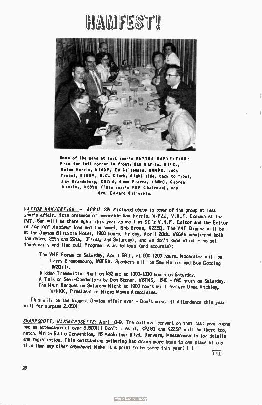
Soon of the gang at last year's DAYTON NAMVEN TIRO: F roe far left to frost, Sea Harris, MIFZ.1,
Helen Harris, WINDY, Ed Gillespie, KONDX, Jack
Probst, KileD11, R.C. Clark. Right side, back to front,
Kay B randeburg, K SlYW, Gene P farce, K 85MO, Georg• Hansley, WBSVW (T his year's THE C hair@ an), and
Mrs. Edward Gillespie.
DAYTON MAYVENT ION - APRIL 29: Pictured above is sane of the group at last year's affair. Note presence of honorable Sam Harris, W1FZJ, V.H.F. Columnist for OST. Sam will be there again this year as well as CO's V.H.F. Editor and the Editor of The VHF Amateur (one and the same), Bob Brown, K2ZSO. The VHF Dinner will be at the Dayton Biltmore Hotel, 19C0 hours, Friday, April 28th. WEISVW mentioned both the dates, 28th and 29th, (Fr;day and Saturday), and we don't know which - so get there early and find outl Program is as follows (and accurate):
The VHF Forum on Saturday, April 29th, at 933-1200 hours. Moderator will be Larry Brandenburg, W8TEK. Speakers will be Sam Harris and Bob Gooding (W30 II).
Hidden Transmitter Hunt on 122 mc at 1300-1330 hours on Saturday.
A Talk on Senii-Conductors by Don Stoner, WHTNS, 1540 -lee hours on Saturday. The Main Banquet on Saturday Night at 1900 hours will feature Dana Atchley,
WIHKK, President of Micro Waves Associates.
This will be the biggest Dayton affair ever - Don't miss ¡ ti Attendance this year will far surpass 2,0001
SWAMPSCOTT, MASSACHUSETTS: April 8-0. The col losai convention that last year alone
had an attendance of over 3,500111 Don't miss it. K2ZS0 and K2ZSP will be there too, natch. Write Radio Convention, 15 MacArthur Blvd, Danvers, Massachusetts for detai Is and registration. This outstanding gathering has drawn more hams to one place at one time than ay other anytrherel Make it a point to be there this year! I I
28
READ
Western Radio Amateur
48 pages of construction, news, DX and DXpedi-
Lions, V.H.F. and technical articles! All these
by such famous authors as Ed Marriner, W6BLZ,
Don Stoner, W6TNS, "YB" Pyle, W70E, with Bob
Grimm, K6RNO, heading up the V.H.F. Column!
This magazine is the third largest in the
United States - and for the money you can't
go wrong! Only $2.00 per year. Write now to:
Western Radio Amateur end West Coast Heel Ads
pebbled*:
10517 Haverty St. El Moat., CeWends Gilbert 0-21111
A Meet.* PubDottie@
AUTO - CALL 2509 - 32nd. St., S. E. WASHINGTON 20, D. G.
This is the paper you've
heard so much about! The Fam-
ous "AUTO-CALL" that has been
quoted by almost all Ham pap-
ers, including CQ magazine!
For only a dollar a year,
you'll get 32 packed pages each
month of all the best in general
Ham Radio material. It has a
special added feature for those
amateurs in the Washington, D.C.
area, as it covers club activ-
ities there.
MCI ISHIES
Yes, we do have some back issues of THE VHF AMATEUR
available in limited quantities.
We've been literally swampid for favorite copies lately, and to
save further confusion, here are the ones you can get now...
1960
February March A ugust
September
October November
1961
All issues to date
250 each from THE VHF AMATEUR, Russell Avenue, Rahway, N.J.
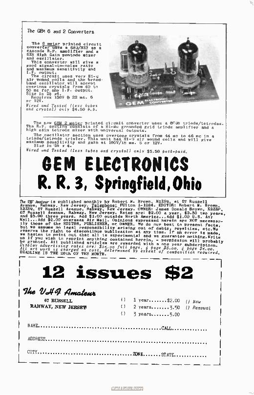
The GEM 8 and 2 Converters
The 6 meter printed circuit converter uses a OBU/BZ7 as a cascode R.F. amplifier and a 6X8 High Gain pentode mixer and oscillator. This converter will give a
good signal-to-noise ratio and maximum sensitivity and I.F. output. The circuit uses very 111-u
air wound coils and thé broad-band oscillator will accent overtone crystals from 40 to 50 mc for any I.F. output. Size is 2 w4. Reouires 150V é 22 ma. 6
or I2V. Wired and Tested ( less tubes and crystal) only $4.50 t.e.
The new GEM 2 meter printed ci:cult converter uses a erei triode/tetrodes. The R.F. section consists of a Ri-Mu grounded grid triode amplifier and a high gain tetrode mixer with universal outputs.
The oscillator section uses overtone crystals from 44 mc to 46 mc in a triode/tetrode triplet. This unit has H1-0 air wound coils and will give maximum sensitivity and gain at 100V/1n ma. 6 or 12V.
Size is 24 s 4.
Wired und Tested ( less tubes and crystal) only $5.50 bost-bald.
GEM ELECTRONICS R. R. 3, Springfield, Ohio
The IIFAmgraris published monthly by Robert M. Brown, H2ZSQ, at 67 Russell Avenue, Rahway, New Jersey. Tenbeng: FUlton 1-1284. EDITOR: Robert M. Brown, KUSQ, 67 Russell Avenue. Rahway, em Jersey. OWNER: James Donald Brown, K2ZSP, 67 Russell Avenue, Rahway, New Jersey. Rates are: $2.00 a year, $3.50 two years, and $5.00 three years. Add $ 1.00 outside North America...Add $ 1.00 U.S. Air Mail...Add $2.00 overseas Air Wall. Opinions expressed herein are NOT necessar-ily those of the EDITOR, PUBLISHER, or OWNER. We do our best to present facts, but we assume no legal responsibility arising out of debts, royalties, etc.We reserve the right to discontinue publication at any time. If an error is made, we hasten to point out that all is experimental and we guarantee nothing.Write us if you wish to reprint anything contained herein, - permission will probably be granted. All published articles are rewarded with a one year subscription.
DIsblay advertising rates are: $15.00 full oaffe, 4 page $8 00 4 eaffe $5 00 All art work is charged at cast. determined by exten t of cOmiositton required. DEADLINE IS THE 20th OF THE MONTH.
— 1 12 issues $2 i
1 ihe vc.eq 67 RUSSELL () 1 year $2.00 (J New 1
PJURVUY,NEW JERSEY' () 2 years 3.50 0 Renewal I
() 3 Years 500 I
l NAME CALL
ADDRESS
CITY 'TAT
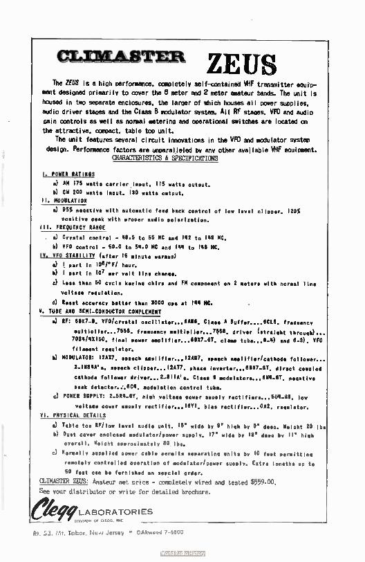
ceLimmiTER ZEUS The ZEUS is a high performance. ccmpletely self-contained VHF transmitter equip-
ment desioned primarily to cover the 8 meter and 2 meter amateur bands. The unit is
housed in two separate enciceures, the larger of which houses all power supplies,
audio driver stages and the Class B modulator system. All RF stapes. VFO and audio
gain controls as well as normal metering and operational switches are located on
the attractive. compact. table top unit.
The unit features several circuit innovations in the VFO and modulator system
design. Performance factors are unparalleled by any other available VHF equipment. CHARACTERISTICS & SPECIFICATIONS
1. POWER RATINGS
a) AM 175 watts carrier input. 118 watts output.
b) CH 200 watts input. 130 watts output.
II. MODULATION
a) 95% negative with automatic feed back control of low level clipper. 120%
Positive peak with proper audio polarization.
Ill. FREQUENCY RANGE
a) Crystal control - 48.5 to 55 MC and 142 to 140 MC.
b) VFO control - 50.0 to 54.0 MC and 144 to 148 MC.
1Y. VFO STABILITY (after 18 minute «roue/
! part in 10 11eF/ hour.
b) 1 oart in 107 per volt line change.
c) Less than 50 cycle keying chirp and FM component on 2 meters with normal line
voltage regulation.
d) Reset accuracy better than 3000 COS at 144 MC.
Y. TUBE AND SEMI-CONDUCTOR COMPLEMENT
a) RF: UV-B. VFOicrystal oscillator-8 8NC Class A Buffer....00L8. frequency
«Moller...7558. frequency multiplier...7858. driver ( straight through)...
7034/43150, final power amplifier...8827-8T, clamo tube... 8-4) and 8-3). VFO
filament regulator.
h) MODULATOR: 121017, speech amplifier...12W. speech amplifier/cathode follower...
2.11134N'5. speech clionnr...12AT7. phase Inverter...6(1X7-GT. direct coupled
cathode follower driver... 2-81 IA's. Class 8 modulators...6W4-GT. negative
peak detector..'.8C4. modulation control tube.
n) POWER SUPPLY: 2-5R4-GY. high voltage mower supply rectifiers...804-0B. low
voltage power supply rectifier...18Y1. bias rectifier...0N2. regulator.
VI. PHYSICAL DETAILS
a) Table too RFilow level audio unit. 15' wide by O' high by ee' deep. Weight 20 lbs
b) Dust cover enclosed modulator/power supply. 17' wide by 13' deep by 11 high
overall. Weight approximately 80 lbs.
c) Normally supplied power cable permits separating units by 10 feet permitting
remotely controlled operation of modulator/power supply. Extra lengths uo to
50 feet can be furnished on soeclal order.
CLIMASTER ZEUS: Amateur net price - completely wired and tested $559.00,
See your distributor or write for detailed brochure.
ekffLABORATORIES t ON Of ClIGO. INC
Rt. 53. rd. Tabor, e:e ,/ Jersey * OAkvioad 7-6800
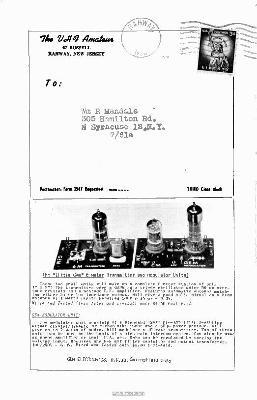
Wm Vc,47 telmahuvi 67 RUSSELL
RAHWAY, NEW JERSEY
To:
R Mandale 305 Hamilton Rd. N Syracuse 12.N.Y.
7/61a
Postmaster: Form 3547 Requested THIRD ( loss MeII
The " Little Gem" 6 meter Transmitter and Moaulator Units'
These two small units will make un a complete 6 meter station of only 4" x 5"! The transmitter uses a 6A68 as a triode oscillator using 50 mc over-tone crystals and a pentode R.F. amplifier. Features automatic antenna match-ing either hi or low Impedance output. Will give a good solid signal on a beam antenna at q watts Input! Reouires 200V 15 ma - 6.3V.
Wlred and Tested ( less tubes and crystal) only $4.50 / st -Paid.
GEN MODULATOR UNIT:
The modulator unit consists of a standard 12AX7 pre- amplifier featuring either crystal/dynamic or carbon mike innut and a 685 power pentode. Will give un to 7 watts of audio. Will modulate a 15 watt transmitter. Two of these units can be used as the basis of a high gain intercom system. Can also be use as phono amplifier or small P.A. set. Gain can be regulated by varying the voltage input. Requires one 8-8 mmf filter canicitor and output transformer. 100/250V - 6.3V. Nlred and Tested only $3.50 4-st-Aatd.
GEM ELECTRGNICS, Saringtield,Uhio
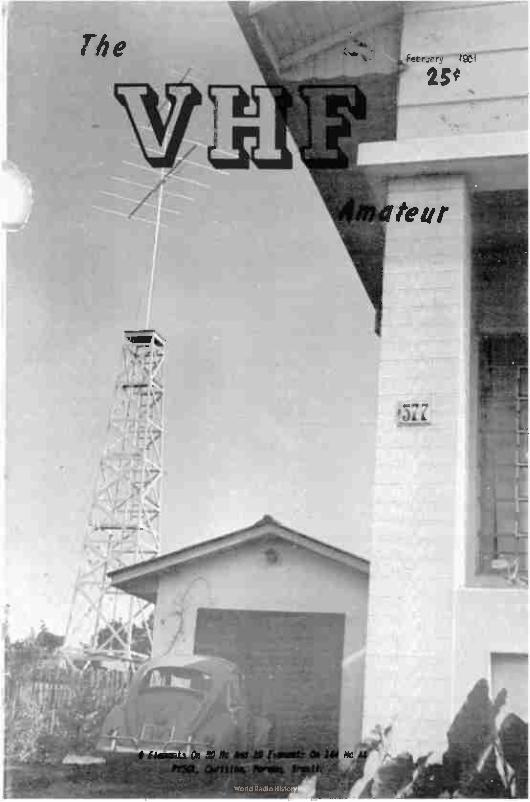
The
, à.
a
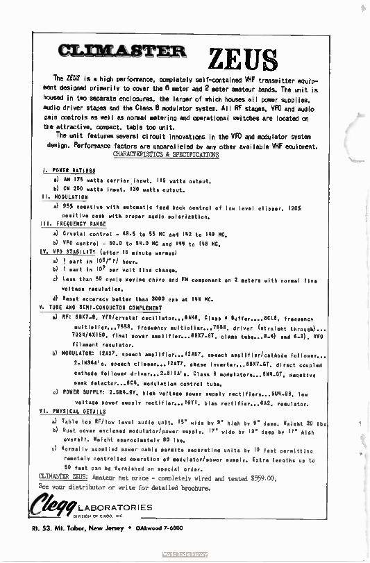
aLniAtagrER ZEUS The ZEUS is a hioh performance. completely self-contained VHF transmitter equip-
ment desioned primarily to cover the 8 meter and 2 meter amateur bands. The unit is
housed in two separate enclosures, the laroer of which houses all power supplies.
audio driver staoes and the Class 8 modulator system. All RF stapes. VFO and audio Gain controls as well as normal metering and operational switches are located on
the attractive. compact. table too unit.
The unit features several circuit innovations in the VFO and modulator system design. Performance factors are unparalleled by any other available VHF equipment.
CHARACTERISTICS & SPECIFICATIONS
I. POWER RATINGS
a) AM 175 watts carrier input. 115 watts outout.
h) Cw 200 watts input. 130 watts output.
II. MODULATION
a) 95% negative with automatic feed back control of low level clipper. 120%
Positive peak with proper audio polarization.
Ill. FREQUENCY RANGE
a) Crystal control - 48.5 to 55 MC and 142 to 146 MC.
b) VFO control - 50.0 to 54.0 MC and 144 to 148 MC.
IV. VFO STABILITY ( after 15 minute warmup)
a) 1. part in 108eF/ hour.
b) 1 part in 107 per volt line change.
..;) Less than 50 cycle keying chirp and FM component on 2 meters with normal line
voltage regulation.
d) Reset accuracy better than 3000 cps at 144 MC.
V. TUBE AND SEMI-CONDUCTOR COMPLEMENT
a) RF: BBK7-0. VFO/crystal oscillator— OAHU. Class A Buffer....6CL6. freguency
multiplier... 7558. freguency multiplier... 7556. driver ( straight through)...
7034/4X150, final power amplifier...68X7-GT. clamp tube.. . 8_11) and 6-3). VFO
filament regulator.
b) MODULATOR: 12AX7, speech amplifier...12AU7. speech amplifier/cathode follower...
2.1N34A'5. speech clipPer... 12 AT7. phase laverter... 6BX7-GT. direct coupled
cathode follower driver...2-81IA's. Class 8 modulators...6W4-GT. negative
Peak detector...604. modulation control tube.
c) POWER SUPPLY: 2-5124-GY, high voltage power supply rectifiers...5114-6B. low
voltage power supply rectifier...16T1. bias rectifier...0A2. regulator.
VI. PHYSICAL DETAILS
a) Table top RE/low level audio unit. 16" wide by 8' high by 6" deep. Weight 20 lbs
b) Dust cover enclosed modulator/power supply. 17' wide by 13' deep by 11 high
overall. Weight approximately 80 lbs.
c) Normally supplied power cable permits separating units by 10 feet permitting
remotely controlled operation of modulator/power supply. Extra lengths up to
50 feet can be furnished on special order.
CLIMASTER ZEUS: Amateur net price - completely wired and tested $559.00,
See your distributor or write for detailed brochure.
ekifeLABORATORIES DIVISION Of ClEGG INC
Rt. 53. Mt. Tabor, New Jersey • OAkwood 7-6800
"You Will Never Be Lonesome"
Randolph Blodgett, WA20EW
372 Essex Avenue
Bloomfield, New Jersey
One often hears the expression that there are radio amateurs wherever one travels, and
that friendships are quickly made.
Such was the case as we took time out fnan the pleasure - business trip through the
Caribbean to look up a few of the fellows and being pleasantly surprised to encounter
others along the route. To be sure, we were limited in our travel this time but neverthe-
less the few places we visited were well populated with hams.
In St. Thomas, Virgin Islands (U.S.A.) we again visited our friend Dick Spencerley and
his charming XYL. KVLIAA probably has his OSL card in nearly every ham shack in the world,
or so it would seem after reading the log for even one day's operation. The greater por-
tion of the pictures of the amateur radio magazines have ham shack pictures where invariably
his Q61. is on display. Dick is a hard worker, the latch string is always out, and he deserves a lot of credit for his contributions (both money and time) in furthering DX'peditions and
amateur radio as a whole.
Saw John Newman, KVUBN, on the street with the back of his sporty convertible filled with
gear. It seems as everything needed fixing - he sure had a tough day.. Look for him, too,
on the air soon.
By the way, the very best martini south of New York will be found at The Galleon House
bar operated by the Yates; his rig for the moment was dismantled and from his comments 1
think he will be back on the air soon. It just seems that everyone is awfully busy damn there
in the land of love, rum, and sunshine in spite of the delightfully moderate pace of every-
day living. Mànanna? To be surel
To relax, we took the Harman Safari over to St. John, a neighboring isle. Although we
have been there before, we never tire of the marvelous mountain views. The van-hued blue
waters dotted with what seems like hundreds of islands and cays - truly a sight worth seeing again and again. Ch this island of 12,CCO acree or thereabouts, Lawrence Rockefeller has
established a National Park covering about 9,000 of these acres. Its development are pro-
gressing and eventually it will be the mecca for the deluxe tourist as well as to provide
facilities for the happy families who will inhabit the camp sites or rent a tent and gear for their own safari into the hills.
I must mention here that our guide was Nora Ellington, a near authority on the flowers
and trees of the island and who, when she heard that I wanted to meet a ham, conducted me
to KV1.180, John Dunham, currently attached to the staff of the Cancel Bay Plantation. John
was busy doctoring a motor but we had time for a nice chat. His XYL and harmonic met us on
the beach later and we learned more about his ham activities.
Did I say the beach? There are many, many, beautiful beaches on these islands; white
(Continued on page 22)
3
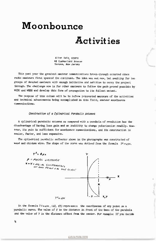
Moonbounce
Activities
Allen Katz, K2UYFI
48 Cumberland Avenue Verona, New Jersey
This past year the greatest amateur communications break-dimugh occurred since
radio amateurs first spanned the continent. The idea was not new, but awaiting for two
groups of devoted amateurs with enough initiative and ambition to carry the project
through. The challenge now is for other amateurs to fellow the path proved possible by
WIBU and W6BH and develop this form of propagation to its fUllest extent.
The purpose of this column will be to inform interested amateurs of the activities
and technical advancements being accomplished in this field, amateur moonbotnce
communications.
Construction of a Cylindrical Parabolic Antenna
A cylindrical parabolic antenna as compared with a parabola of revolution has the
disadvantage of having less gain and an inability to change polarization readily. How-
ever, its gain is sufficient for mocnbounce communications, and its construction is
easier, faster, and less expensive.
The cylindrical parabolic reflector shown in the photographs was constructed of
wood and chicken wire. The shape of the curve was derived from the formula Y2.0x,
Yee deice'
= Foe24A. ervicre
X*YeitQam. f_cciZOW•97&-S emei eeev r c ne Tee
Y
X
Y2=4Px
X
In the formula Ye,..0x, (41, 67) represents the coordinates of any point on a
parabolic curve. The value of / is the distance in front of the base of the parabola
and the value of Y is the distance offset from the center. For example: If you decide
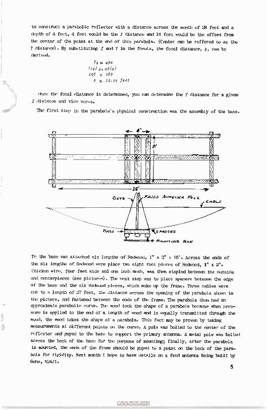
to construct a parabolic reflector with a distance across the mouth of 28 feet and a
depth of 4 feet, 4 feet would be the X distance and 14 feet would be the offset from
the center of the point at the end of this parabola. (Center can be reffered to as the
Y distance). By substituting X and Y in the forula, the focal distance, p, can be
derived.
Y2 415x (14) 2-.44(4) 196 = 16p
p = 12.25 feet
Once the focal distance is determined, you can determine the y distance for a given X distance and vice versa.
aor The first step in the parabola's physical construction was the assembly of the base.
4— 4'
N \ t
\
eli----
« t. ttttittaett ti t/
i \
r-, j. ,r,7,7,,,,,, /7,4,,-7,,,, , - - ZE
To the base was attached six lengths of Redwood, 1" x 2" x 16'. Across the ends of
the six lengths of Redwood were place two eight foot pieces of Redwood, 1" x 2".
Chicken wire, four feet wide and one inch mesh, was then stapled between the outside
and centerpieces (see pictures). The next step was to place spacers between the edge
of the base and the six Redwood pieces, which make up the frame. Three cables were
cut to a length of 27 feet, the distance across the opening of the parabola shown in
the picture, and fastened between the ends of the frame. The parabola then had an
approximate parabolic curve. The wood took the shape of a parabola because when pres-
sure is applied to the end of a length of wood and is equally transmitted through the
wood, the wood takes the shape of a parabola. This fact may be proven by taking
measurements at different points on the curve. A pole was bolted to the center of the
reflector and guyed to the base to support the primary antenna. A metal pole was bolted
across the back of the base for the purpose of mounting; finally, after the parabola
is mounted, the ends of the frame should be guyed to a point on the back of the para-
bola for rigidity. Next month I hope to have details on a feed antenna being built by
Gene, X2XlI. 5
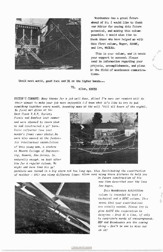
Moohbounce has a great future
ahead of it. I would like to thank
our Editor for seeing this future
potential, and making this column
posible. I would also like to
thank those who have helped me with
this first column, Roger, K2SMN,
and Irv, WA2LKA.
This is your column, and it needs
your support to succeed. Please
send in information regarding your
projects, accomplishments, and plans
in the field of moonbounce communica-
tions.
Until next month, good luck and DX on the higher bands...
73, Allen, K2U111
EDITOR'S COMMENT: Many thanks for a job well done, Allen! I'm sure our readers will do
their utmcst to make your job more enjoyable (-I know what it's like to try to put
something together every month, pounding away at the mill ' till all hours of the night). We first ,mit dllen at the
East Cbast V.R.F. Society
Picnic and Hairiest last summer
and were stunned to learn that
he had constructed a qo' para-
bolic reflector ( see last
month's front cever photo).We
were also amazed at the fantas-
tic intellectual capabilities
of tiis young man, a student
at Newark College of Engineer-
ing, Newark, New Jersey. So.
naturally enough, we kept after
him for a regular column. We
might add here that his 3o'
parabola was ruined in a big storm not too long ago, thus facilitating the construction
of ahother - thi. one along different lines. Allen sent along these pictures to help you in future construction of his
new item described over the last
few pages.
This Moonbounce Activities
column is intended as both a
technical and a NEWS column. This
means that your contributions
are vitally needed. Please try to
give I2lJYH the cooperation he
deserves - Drop Al a line, if only
to contribute words of encouragement.
YU and Noonbounce are the coming
thing - Don't be one to miss out
on it!
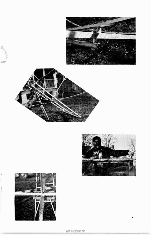
2 Helen
Propagation Walt Bain, WWITU RFD I, Box 27-M Springfield, Va.
The Geminids meteor shower put in its argue show on December 10 through 14 and
the usual number of 144 mc fanatics were in there barging away for new states. Final
results are not available at present but several QS0's are known to have resulted.
MIER in Iowa worked MAID in South Carolina, while K2IMG in Ithaca, New York, put it across with WMSJ in North Dakota, a 1000 mile path. WOTSJ also worked VE3DIR
in Toronto. In addition, VE3DIR made it with WINS in Georgia for what Tony described
as his easiest meteor contact ever; it took only 15 minutes. Your correspondent was in
there trying, but in vain. We came very close to making it with WOTSJ, a real near miss
over a 1120 mile path. Some signals were heard from WASP in South Dakota but nil from
WOMOX in Colorado, a tentilizing 1450 mile path. NONOX indicated by postcard, however,
that he had heard on December 11 an extremely weak but continuous sequence of signals!
This could be something other than meteor and certainly bears looking into.
Aurora has been flirting in and out during the last month with the most spectacular,
and disappointing, event being the big disturbance of Nova-miter 12 through 14. Although
a record-breaker as far as its disruption of things ionospheric, it apparently failed
to prochice any v.h.f. auroral DX of similar sort or proportion. It has been shown
that excessive absorbtion can cause auroral reflections to be much weaker on 50 mc
than on 144 mc. Perhaps it was so bad this time it effectively took out all bands. Did
anyone try 220 mc? Lesser auroras appeared on Nove-lleer 30, December 7, and December
15. On the latter W4LTU worked WREGH briefly with Mac reporting no activity to the
west of him so its full extent is not known. Tropo ducting got in one more lick before
winter set in with W4SHE near Memphis coming in S9 at WSKAY, Akron, on November 26.
The column this month is even shorter than usual and there are two reasons for
this. One is that your correspondent has been tied up with business for a considerable
portion of the time and the other is that, as usual, no one has had any contributions
to make to the column. It appears likely that both of these situations will persist,
but we will do the best we can. --Stolen, as usual, from the AUTO-CALL. You have
undoubtedly noticed our ad for this dandy públication and this W4LTU item should give
you an idea of the caliber and appeal of its text to the avid v.h.f. man. Although
this is not a v.h.f. magazine, it deem have Walt's monthly column plus additional
features concerning the v.h.f. world...A worthwhile investment -.Editor.
8
Meteor
Shower Geminids Meteor Show,' - December 9-14th, 1960
Ernie Brown, W5FYZ Minden, Louisiana
144.15 NC
*IC, Denver, Colorada: On December llth I received my call and many short bursts. Sig-
nal level high, - Thanks for the fine QS0 on the 12th; signals peaking 58 with several
long bursts. Glad we could make it, Claude. Your signals were copied by other stations
in this area during our skeds.
IOW', Albuquerque, New Mexico: Thanks for my first New Mexico contact and state #26,
lel'ed. I was rather pessimistic about our chances, but your signals were very good and
were copied by other stations in this area, including one in Texas - hi! On the 19th I
heard a few pings and letters; same on the 11th. On the 12th identification was made
early on a tan second burst, and the QS0 wrapped up just as sked time ended. In fact,
we had to borrow a few minutes from the next sked, hi!
WASMIX, Burbank, California: Can't say I heard a thing, Don. Sure want to keep trying,
so let's get together before the next shower. Apparently this shower was too low. Thanks
for the effort.
WellF, Boulder, Colorado: Pings and short bursts with parts of calls on the 9th and 10th;
nil on the 11th. Good solid QS0 on the 12th, with several 10-15 second bursts, and QS°
completed in 13 minutes of the second sked. Nice going, Tom.
W3BYF, Allentown, Pennsylvania: Two short bursts on the 13th, rest of the skeds nil.
Sorry we cauldn't make it, Pros, but will be only too happy to try again.
WIAZK, Chichester, New Hampshire: Nil from your direction, Don. Apparently the shower
just wasn't high enough. I'll be glad to try again any time.
ElISY, Sudbury, Massachusetts: Same comments as to Don. I notice too that my voice gives
out before I finish an hour MS sked on SSB - hi! Maybe we can make it first an c.w., then
switch to SSB.
K1CRN, Cumberland, Rhode Island: Sorry you had to cancel rest of skeds after first one,
Walt, but sure did appreciate the land-line call to let me know. The way conditions turned
out, I don't think you missed anything.
MEW, Chester, Virginia: Few pings and short bursts on the 10th and llth and 12th. On the
13th I heard my "S2" and a few pings and short bursts but no identification. On the Flth
I received my S1 report and both calls, but no "R" of confirmation. Sorry, Sam, this makes
twice we missed by a whisker. I'm still game to try again.
WIJDF, Methuen, Massachusetts: Thanks for trying on the two peak days, Sumner. Nil from
your direction at all. Will be glad to try again.
In conclusion---Shower peaked from iopm to 12N CST, night of 12th. All QS0's were about
Boo miles from here in a WNW to NW direction. NE condx very Poor -----Ernie, Fen.
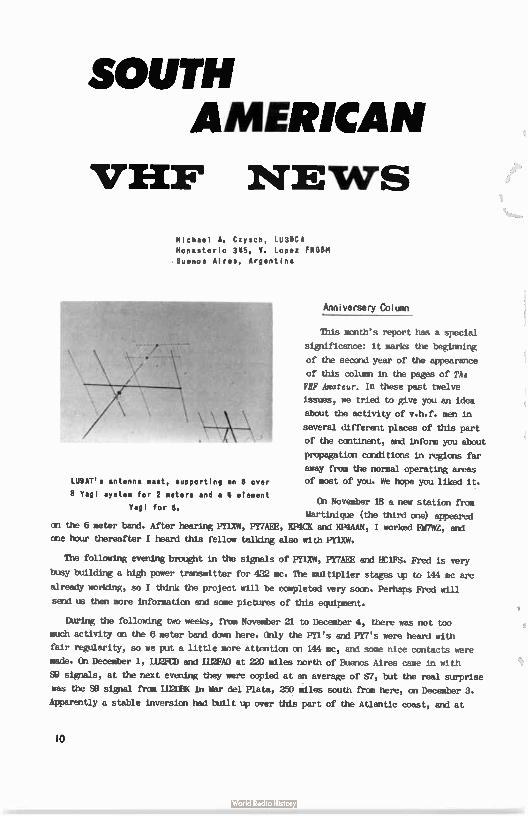
SOUTH AMERICAN
VHF NEWS
Michael A. Czysch, LU3OCA Monasterio 345, V. Lopez FlIGBM .Buenos Aires, Argentina
LUOAT's antenna mast, supporting an 8 over
8 Yagl system for 2 meters and a 4 element
Vagi for 8.
Anniversery Column
This month's report has a special
significance: it marks the beginning
of the second year of the appearance
of this column in the pages of The
VHF Amateur. In these past twelve
issues, we tried to give you an idea
about the activity of v.h.f. men in
several different places of this part
of the continent, and inform you about
propagation conditions in regions far
away from the normal operating areas
of most of you. We hope you liked it.
On November 18 a new station from
Martinique ( the third one) appeared on the 6 meter band. After hearing FT1XW, PY7AEE, KP4CK and EDIAAN, I worked FM7WZ, and
one hour thereafter I heard this fellow talking also with PY1XW.
The following evening brought in the signals of PY1XW, PY7AEE and HC1FS. Fred is very
busy building a high power transmitter for 432 mc. The multiplier stages up to 144 mc are
already working, so I think the project will be completed very soon. Perhaps Fred will
send us then more information and some pictures of this equipment.
During the following two weeks, from November 21 to December 4, there was not too
much activity an the 6 meter band down here. Only the PY1's and PY7's were heard with
fair regularity, so we put a little more attention on 144 mc, and some nice contacts were
made. On December 1, LU2FCD and 112FAO at 220 miles north of Buenos Aires came in with
S9 signals, at the next evening they were copied at an average of Si, but the real surprise
was the S9 signal from LU2DBK in Mar del Plata, 250 miles south from here, on December 3.
Apparently a stable inversion had built up over this part of the Atlantic coast, and at
10
Meteor
Shower Gemintds Meteor Shower - December 9-14th, 1960
mu/ Ernie Brown, WSFYZ Minden, Louisiana
144.15 Nc
WIC, Denver, Colorado: On December llth I received my call and many short bursts. Sig-nal level high, - Thanks for the fine WO on the 12th; signals peaking SS with several
long bursts. Glad we could make it, Claude. Your signals were copied by other stations
in this area during our skeds.
K5TUP. Albuquerque, New Mexico: Thanks for my first New Mexico contact and state #26,
Fred. I was rather pessimistic about our chances, but your signals were very good and
were copied by other stations in this area, including one in Texas - hi! On the 10th I
heard a few pings and letters.; same on the 11th. On the 12th identification was made
early on a ten second burst, and the QS0 wrapped up just as sked time ended. In fact,
we had to borrow a few minutes from the next sked, hi!
WA6MIX, Burbank, California: Can't say I heard a thing, Don. Sure want to keep trying,
so let's get together before the next shower. Apparently this shower was too low. Thanks
for the effort.
WIDF, Boulder, Colorado: Pings and short bursts with parts of calls on the 9th and 10th; nil on the 11th. Good solid QS0 on the 12th, with several 10-15 second bursts, and QS0
completed in 13 minutes of the second sked. Nice going, Tom.
W3BYF, Allentown, Pennsylvania: Two short bursts on the 13th, rest of the skeds nil.
Sorry we cduldn't make it, Pres, but will be only too happy to try again.
W1AZK, Chichester, New Hampshire: Nil from your direction, Don. Apparently the shower
just wasn't high enough. I'll be glad to try again any time.
KlISY, Sudbury, Massachusetts: Same comments as to Don. I notice too that my voice gives
out before I finish an hour MS sked on SSE - hi! Maybe we can make it first on c.w., then
switch to SSS.
K1CRN, Cumberland, Rhode Island: Sorry you had to cancel rest of skeds after first one,
Walt, but sure did appreciate the land-line call to let me know. The way conditions turned
out, I don't think you missed anything.
K4EUS, Chester, Virginia: Few pings and short bursts on the R)th and llth and 12th. On the
13th I heard my "S2" and a few pings and short bursts but no identification. On the 14th
I received my S1 report and both calls, but no "R" of confirmation. Sorry, Sam, this makes
twice we missed by a whisker. I'm still game to try again.
WIIDF, Methuen, Massachusetts: Thanks for trying on the two peak days, Sumner. Nil from
your direction at all. Will be glad to try again.
In conclusion---Shower peaked from lopm to 12N CST, night of 12th. All 00's were about
800 miles from here in a WNW to NW direction. NE condx very Poor --Ernie, W5FYZ.

SOUTH AMERICAN
VHF NEWS
Michael A. Czysch, LU3OCA Monasterio 345, B. Lopez FNGEIM .Buenos Aires, Argentina
LUBAT's antenna mast, supporting an 8 over
Vagi system for 2 meters and a 4 element
Vagi for B.
Anniversary Column
This month's report has a special
significance: it marks the beginning
of the second year of the appearance
of this column in the pages of The
VHF Amateur. In these past twelve
issues, we tried to give you an idea
about the activity of v.h.f. men in
several different places of this part
of the continent, and inform you about
propagation conditions in regians far
away from the normal operating areas
of most of you. We hope you liked it.
On November 18 a new station from
Martinique (the third one) appeared on the 6 meter band. After hearing PT1XW, PY7AEE, !TeX and EP4AAN, I worked FM7WZ, and
one hour thereafter I heard this fellow talking also with PY1XW.
The following evening brought in the signals of PY1XW, PY7AEE and HC1FS. Fred is very
by building a high power transmitter for 432 mc. The multiplier stages up to 144 mc are
already working, so I think the project will be completed very soon. Perhaps Fred will
send us than more information and some pictures of this equipment.
During the following two weeks, from NoveMber 21 to December 4, there was not too
much activity on the 6 meter band down here. Only the PT1's and PY7's were heard with
fair regularity, so we put a little more attention on 144 mc, and some nice contacts were
made. On December 1, LU2FCD and MEAD at 220 miles north of Buenos Aires came in with
SO signals, at the next evening they were copied at an average of si, but the real surprise
was the S9 signal from LU2DBK in Mar del Plata, 250 miles south from here, on December 3.
Apparently a stable inversion had built up over this part of the Atlantic coast, and at
10
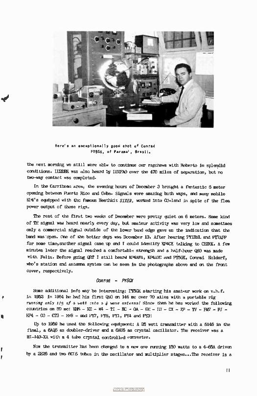
Here's an eaceptionally good shot of Conrad
PY5OK, of Parana', Brasil.
the next morning we still were able to continue our rage...hews with Roberto in splendid
conditions. LU2DBK was also heard by MEW over the 470 miles of separation, but no
two-way contact was completed.
In the Carribean area, the evening hours of December 3 brought a fantastic 6 meter
Waling between Puerto Rico and Cuba. Sigpals were amazing both ways, and many mobile
KP4's equipped with the famous Heathkit SHER, worked into CO.-land in spite of the flea
power output of those rigs.
The rest of the first two weekn of December were pretty quiet on 6 meters. Some kind
of TE signal was heard nearly every day, but amateur activity was very low and sometimes
only a commercial signal outside of the lower band edge gave us the indication that the
band was open. One of the better days was December 13. Alter hearing PYIBBL and PY7AFP
for some time,another signal came up and I could identity XP4CK talking to CE3XII. A few
minutes later the signal reached a comfortable strength and a half-hour Q$01 was made
with Felix. Before going QRT I still heard 1614AFA, EP4dXC and PY50K, Conrad Holdorf,
who's station and antenna system can be seen in the photographs above and on the front
cover, respectively.
Conrad - PY5GX
Some additional info maybe interesting: MGR startInghis amateur work on v.h.f.
in 1952 In 1954 he had his first WO on 144 mc over 70 miles with a portable rig
running only 113 of a watt :nto a 4 wave ant,nna! Since then he has worked the following
countries on sp mc: 106 - XE - W4 - TI - BC - OA - CE - LU - CX - ZP - YV - FM7 - FU -
KP4 - CO - CT3 - FFB - and PY7, P16, PY1, PY4 and PY3!
Up to 1959 he used the llowing equipment: A 25 watt transmitter with a 6146 in the
final, a 6AQ5 as doitibler-driver and a 6AU6 as crystal oscillator. The receiver was a
H1-140-XA with a 4 tdhe crystal controlled converter.
Now the transmitter has teen changed to a new one ruining 150 watts to a 4,65A driven
by a 2126 and two 6CL6 tubes in the oscillator and multiplier stages...The receiver is a
homebrew double conversion job with 18 tubes.
On 144 mc the TX runs 15 watts and the BX is also of the double conversion type,
with 21 tubes. All the transmitters, receivers, converters, antennas and even the 35
foot tower are HOMEMADE --- An impressive job really well done!!
Next month I will tell you about some DX-poditicroultwork done also by PG5Œ, the
most active v.h.f. man in Brasil's fifth call area.
73,
Michael, LU3DCA
Message From The Publisher
You have, undoubtedly, noticed subtle changes in the
format of THE VHF AMATEUR over the past year - improve-
ments, ke hope, that here to your satisfaction.
No doubt you also relnembera SURVEY that i.e ron in
a two-month period early last summer: The returns on that survey àere most encouraging and informative. Hundreds of readers returned the survey page filled out with such
information as changes that you would like to see in THE
VHF AMATEUR, type of articles that interest you most (DX, neme, activities reports, construction articles, technical
data, propagation explanation, etc). In general, the correl-
ation of this information resulted in the following: ( listed according to their interest and importance to you)
1. Construction articles 2: Propagation Explanation 3. Technical data of new concepts and ideas 4. DX nee and Activities reports
(This includes "Letters to the "Editor", etc. 5. Announcements of Hamfests, etc.
6. Full page pictures (collection of stations, operators, antennas, etc.)
7. TRADING POST and Worked All „States listings
This may or may not fully represent your views, as readers now, but it does give us something with àhich to work. BUT WE NEED YOUR HEM Our little magazine serves as a medium or get-together point where v.h.f. - u.h.f. . enthuiasts. can present their ideas to benefit each other: This means that to further improve, we need your support. We would appreciate
your °events on what YOU would like to see... But most of all,
your contributions in the form of articles, columns, and pic-
tures. The listing above can glue you an idea what we're look-
ing for - but remember one thing - No one on our staff is any
more than an average v.h.f. man getting the satisfaction of helping fellow hams through our publication. In addition, even though we can't pay, as such, for contributions, a small reword of a one, tio, or three year extension to your subscription will be given.
12
6 Meter
Moonbounce! Alan Goodaire, VE3B2S ( ex-VE7A1Z)
2211 Greenlands Road
Victoria, British Columbia
CANADA
The following article was condensed somewhat from a recent letter to the Editor.
In it Alan explains an amazing series of experiment with 50 mc moonbounce and
its results. A MUST for anyone
interested in the latest
v.h.f. develofments!
Lately, in particular, I was interested and pleased to see various letters and
references to moonbounce...
I have been 1..oerested in the idea of amateur communication via moon reflection since
I first saw the report of Ross Bateman's and other's attempts and successes with 144 mc
in 1q53.
In 1850 - 1860 Gail Allwine, MR% and I, VF7AIZ, tried some 50 mc moonbounce tests.
Out of about a dozen tries, a half dozen were unsuccessfil, mostly due to tee failures
or excessive interference, while one of these was done at moonset and was just plain
unsuccessfUl. About a half dozen showed some degree of success and I am enclosing some
of the tracings made from original records. By the way, all tries were done at moonrise
except the one mentioned.
Gail ran 800 watts (600 watts approximately into the antenna) into a 4-250A transmitter
modified by operating the crystal oscillator and buffer stage on batteries to obtain
greater frequency stability. The rig was keyed automatically to produce 1 second pulses
every 15 seconds. The antenna was a 6 over 6 Yagi array.
At VE7AIZ the antenna was a 10 element Yagi. 1be receiver was at VE7AIZ and consisted
of a 6AK5 - 6AK5 - 6J6 converter with the 6AK5's triode connected and neutralized and had
Re a measured noise figure of just under 3 db at 50 mc. The station receiver was modified
by running the H.F. oscillator and BR) an batteries to obtain good frequency stability.
Also the converter crystal oscillator and buffer stage were run on batteries for the
same reason.
The receiver output was passed Ulnae an audio filter of about 40 cps band width
then detected by a germanium diode and the output passed through an R-C filter of a
time constant of 0 second and displayed on a home made pen recorder. Receiver tuning
was done with a vernier attached to the BR) control after the main tuning control had
been roughly set. The BR) was calibrated so the receiver tuning would be corrected for
Doppler Shift.
IS
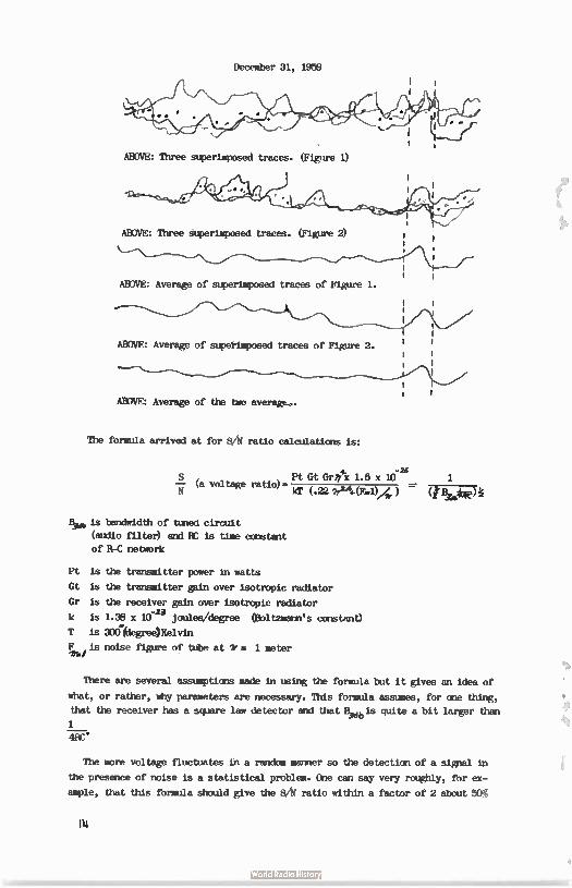
December 31, 1959
ABOVE: Three superimposed traces. (Figure 1)
ABOVE: Three superimposed traces. (Figure 2)
ABOVE: Average of superimposed traces of Figure 1.
ABOVE: Average of superimposed traces of Figure 2.
ABOVE: Average of the two average.,.
The formula arrived at for $Ai ratio calculations is:
S , a voltage ratio) t. Pt Gt Gre 1.6 x 10⁻²e 1 (.221r24.-(F.1)A;) -(«
Bee is bandwidth of tuned circuit
(audio filter) and BC is time constant
of B,C network
Pt is the transmitter power in watts
Gt is the transmitter gain over isotropic radiator
Gr is the receiver gain over isotropic radiator
k is 1.38 x 10⁻²³ joules/degree (Boltzmann's constant)
T is 300(degree)Kelvin
Fkt is noise figure of tube at le. 1 meter
There are several assumptions made in using the formula but it gives an idea of
what, or rather, why parameters are necessary. This formula assumes, for one thing,
that the receiver has a square law detector and that F db is quite a bit larger than
1
4BC .
The more voltage fluctuates in a random manner so the detection of a signal in
the presence of noise is a statistical problem. One can say very roughly, for ex-
ample, that this formula should give the 01 ratio within a factor of 2 about 50%
In
of the time whereas a detection by a factor of 10 is quite unlikely.
One point to be noticed is that for Yagis and similar arrays 9lf is proportional
to the boom length and the optimum wavelength is given by
for a 416B 1.1 optima= meter...However if a parabolic dish is used, since: g= 4it
and A = area of dish in (meters)
S - _ Pt (44.)e A72., x 1.6 x
kT (. 22 Vet, ) Elib 1
4BC
then the smallest wavelength possible should be used.
I am not positive, but believe also that an extremely narrow beamwidth can be obtained
a tremendous increase in returned signal Should be experimental because the problem
changes from one in scattering and distance to the fourth power effect to a distance to
the second power effect.
The echos obtained by the 50 mc experiments show a retardation by the ionosphere. This
is by an amount of say a 100 times that to be expected by using a simplified formula to
calculate this. However 50 mc is a bit low for the frequencies the formula is intended to
be used at. The delay is about a 10th of a second or so and indicates a terrific amount
of Faraday rotation took place. The MUF was quite close to 50 mc during most of the ex-
periments so the ionosphere no doubt had a profound effect on the signal.
Because of low 0 ratio, definete conclusions are hard to reach.
01 of individual echos averaged 1:1, I would say.
The formula neglects ground reflection gain and calculated BAi without ground re-
flection gain was about so probably some of this gain was being realized (if fórmula
correctly describes the situation).
Non- Technical Aspects
VE7AIZ looked out to the east on several miles of salt watkr,and elevation was
about 200 feet. %MOT had woods to the east but otherwise had a clear shit.
Horizon at each location was provided by the Coast Range of motntains in Washington
about 9000' high and 70-100 miles away.
I am now at VP3B7S and will be building sème new moonbounce equipment for 220 mc or
possibly 144 mc.
I feel personally that 1206 mc is impractical from a financial point of view and
believe that 220 mc moonbounce will be successfil with a much lower cost.
Boss, W4AO, has corresponded with me a lot and has been interested and very helpfil
in moonbounce problems.
Bob, K6EN., also has shown much interest and we may do some 220 mc work. We had one
tanuccessfül 50 mc try but did some meteor scatter work.
Jul.K2CBA, wants to do some 220 mc moonbounce and I hope we can try this spring or
15
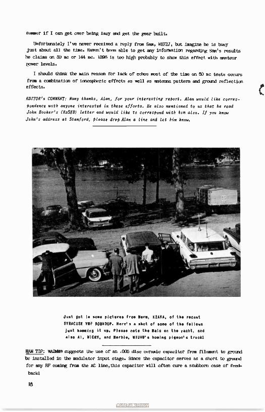
summer if I can get over being lazy and get the gear built.
Unfortunately I've never received a reply from Sam, Win', but imagine he is busy
just about all the time. Haven't been able to get any information regarding Sam's results
he claims on 50 mc or 144 mc. 1296 is too high probably to show this effect with amateur
power levels.
I should think the main reascn for lack of echos most of the time on 50 mc tests occurs
from a combination of ionospheric effects as well as antenna pattern and ground reflection
effects.
EDITOR's COMMIT: Many thanks, Alan, for your interesting rePort. Alan would like corres-
Pondence with anyone interested in these efforts. He also mentioned to us that he read
John Booker's (Wife letter and would like to corresPond with him also. If you know
John's address at Stanford. Please drop Alan a line and let him know.
Just got in some pictures from fern, K2AVA, of the recent
SYRACUSE VHF ROUNDUP. Here's a shot of some of the fellows
just hamming it up. Please note the Halo on the yacht, and
also Al, WICRV, and Herbie, W1UVB's homing pigeon's truck1
HAM TIP: WA2149Nsuggests the use of an .006 disc ceramic capacitor from filament to ground
be installed in the modulator input stage. Since the capacitor serves as a short to ground
for any RF coming from the AC line,thLs capacitor will often cure a stubborn case of feed-
back'
18
Trading Post
Rates-Commercial ads-5e per word.Free to readers-any reasonable length.Ad from readers must be submitted on a postal or 44SL card.Send to TRADING POST,67 Russell Ave.Rahway,N.J.
H-l10 with spkr & clook$189,LA-1 b80,MdMurdo-Silver exc 80-6 $18,several good G.E. FM two-way units easily modified to two meters-30 watts-less acc.$29.F.O.B. Roger McGrath,KeDNW,Box 913 Boulder ,Colorado.
Wanted-One or more approx. 3 ft. parabolic dishes-Walter Baker, W8BAX,2920 Bremen St.Columbus 24,0hio.
For Sale-Six meter Hy-gain halo with telescoping mast-$10. Six meter FCV-2 converter mounted in STP-iM1 case(IF freq . 6-4.6 sic.) 812. STP-50 six meter transmitter-$25. STP-10 matching modulator $25. SR-34 Hallicrafters transceiver-six&two meters-6,12,&110 volt with original carton and manual-$380. Viking six& two Thunderbolt with original carton and manual-factory wired-8500 David Sutherland,K4ATG,Pen Hook ,Virginia.
For Sale-Tapetone converter-6 meter XC-51-10-14 mc. output-Brand new never used-$49. Walter Taylor,K2M1T,RD 2,Hammondsport,N.Y.
For Sale -Famous BC-779B Super Pro Receiver-18 Tubes complete with matching power supply,matching 6&10 meter Tecraft deluxe converters,xtal callibrator,integrated master control box and manuals.All in excellent condition.$125.Will deliver a reasonable distance. Call Oxbow 6-1342 or write Lew Stadtmauer,W2HNE, 12 Lincoln Place, Wayne,N.J.
Wanted-Used UHF TV converter for amateut band or commercial full range UHF converter. Francis X 31ehl,K2PoP,343 Maple St. Brooklyn 25,N.Y.
For Sale-Two meter Gonset 111 in like new condition with xtals cables,and antenna. Works on 6,12 or 110. $190. Andy Clark,W4IYT, 41 Lenape Drive,Miami Springs 66, Florida.
Wanted-Six meter CW equipment-Mary Wilson,WA2JBB,308 W 22nd St. New York 11,L...
Wanted--aress of an Rast Coast supplier of preformed finger stock for 2C39B tubes. R G Lachance,WleA,48 Learned St,Nashua,N.H.
(ZSL's: "Brownie",W3CJI,3110 Lehigh,Allentown,Pennsylvania.Samples 10e,with catalog,25e. ( 3/61)
SWL's, Citizen Band, Samples 5/. Nicholas & Son Printery, Box 11184, Phoenix, Arizona. ( 3/61)
For Sale-DX-40 & D104 mike, no stand,$60. K2UqC,425 Parkinson 'ierrace, Orange,N.J. OR2-3142 after 6 PM.
For Sale-Hallicrafter SR-34, cost $495,like new at $325. Ronald Stier, Major Seminary, St. Meinrad, Indiana.
17
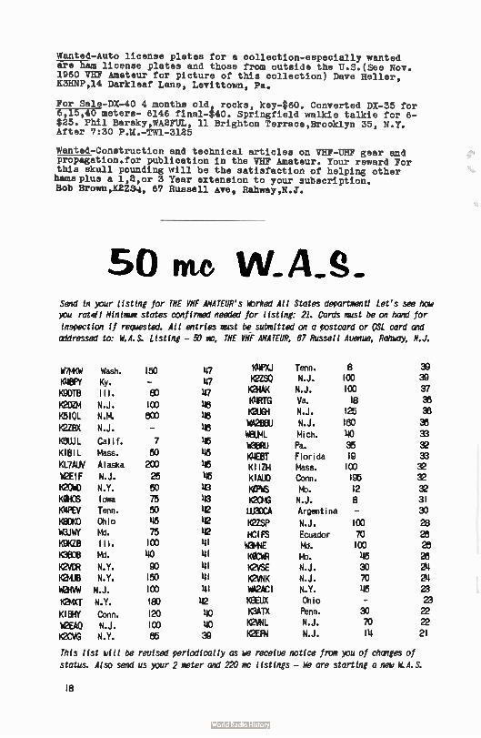
Wanted-Auto license plates for a collection-especially wanted are ham license plates and those from outside the U.S. ( See Nov. 1960 VHF Amateur for picture of this collection) Dave Heller, K3HNP,14 Darkleaf Lane, Levittown, Pa.
For Sale-DX-40 4 months old, rocks, key-$60. Converted DX-35 for 6,15,40 meters- 6146 final-$40. Springfield walkie talkie for 6-$25. Phil Barsky,WA2FUL, 11 Brighton Terrace,Brooklyn 35, N.Y. After 7:30 P.M.-TW1-3125
Wanted-Construction and technical articles on VHF-UHF gear and propagation.for publication in the VHF Amateur. Your reward For this skull pounding will be the satisfaction of helping other hams plus a 1,2,or 3 Year extension to your subscription. Bob Brown,K2ZS4,, 67 Russell Ave, Rahway,N.J.
50 me WAS_ Send in your listing for THE VHF ANATOR's WOrked All States department! Let's see how you rate!! Minimum states confirmed needed for listing: 21. Cards must be on hand for
inspection if requested. All entries must be submitted on a postcard or PSL card and addressed to: W.A.S. Listing - 50 mc, THE VHF AMATEUR, 67 Russell Avenue, Rahway, N.J.
W7MKW Wash. 150 147 K4PXJ Tenn. 8 K4BPY Ky. - 47 K2ZSO N.J. 100 K9DTB Ill. EC 47 K2HAK N.J. 100 K2DZIM N.J. 100 48 K4RTG Va. 18
K5IOL N.M. 800 48 K2UGH N.J. 125 W42Œ1 N.J. 180 K2ZBX N.J. _ 48 W8UML Mich. 40
K8UJL Calif. 7 46 WOBRU Pa. 35
KIBIL Mass. 50 46 K4EBT Florida 19 KL7AUV Alaska 200 45 KII2M Màss. 100 W2EIF N.J. 25 46 KIAUD Conn. 195
K2OWD N.Y. 50 43 Keis Mb. 12 KOHOS Iowa 75 43 K2OMG N.J. 8 K4PEV Tenn. 50 42 LU3CCA Argentina -
K8DKO Ohio 46 42 KUSP N.J. 100 %GUY Mhd. 75 42 KIFS Ecuador 70 KOKZB III. 100 41 W3MNE Md. 100 K3008 Md. 40 41 KOCWR Mo. 45 K2VDR N.Y. GO 41 K2VSE N.J. 30 K2MUB N.Y. 150 41 K2VNK N.J. 70
W2HVW N.J. 100 41 WA2ACI N.Y. 46 K2MXT N.Y. 180 42 K8EUX Ohio
KIBHY Conn. 120 uo K3ATX Penn. 30 W2EAO N.J. 100 40 K2VNL N.J. 70 K2CVG N.Y. 85 39 K2EFN N.J. 14
This list will be revised periodically as we receive notice from you of changes of
status. Also send us your 2 meter and 220 mo listings - We are starting a new W.A.S.
r-'i
sR3D
“Iww
wwww
8-)F
sito
sElo
ciit
3â4i
it3
18
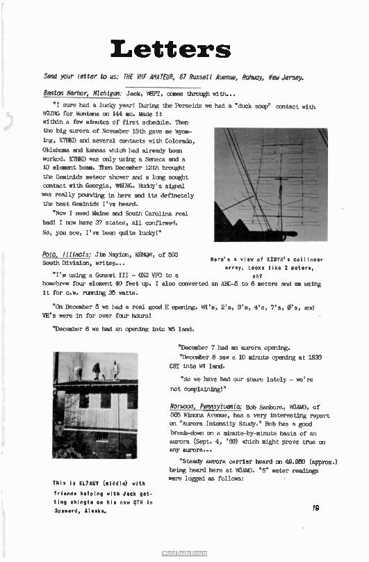
Letters Send your letter to us: THE VHF AMATEUR, 67 Russell Avenue, Rahway, New Jersey.
Benton Harbor; Michigan: Jack, WEPT, comes through with...
"I sure had a lucky year! During the Perseids we had a "duck soup" contact with
W7JRG for Montana on 144 inc. Made it
within a few minutes of first schedule. Then
the big aurora of November 13th gave me Wyom-
ing, K7HKD and several contacts with Colorado,
Oklahoma and Kansas which had already been
worked. K7HKD was only using a Seneca and a
10 element beam. Then December 12th brought
the Geminids meteor shower and a long sought
contact with Georgia, W4LNG. Ruddy's signal
was really potreiing in here and its deftnetely
the best Geminids I've heard.
"Now I need Maine and South Carolina n.al
bad! I now have 37 states, all confirmed.
So, you see, I've been quite lucky!"
Polo, Illinois: Jim Nay/on, K9HQW, of 500 Here's a view of K2UTH's collinear
South Division, writes... array. Looks like 2 meters,
"I'm using a Gonset III - 6N2 VE0 to a eh?
homebrew four element 40 feet up. I also converted an AHC-5 to 6 meters and am using
it for c.w. rusting 35 watts.
"On December 5 we had a real good E opening. Wl's, 2's, 3's, 4's, 7's, ers, and
VE's were in for over four hours!
"December 6 we had an opening intc h 5 land.
This is KL7AUV (middle) with
friends helping with Jack get-
ting shingle on his new QTH in
Spenard, Alaska.
"December 7 had an aurora opening.
"December 8 saw a 10 minute opening at 1830
CST Into K1 land.
"So we have had our share lately - we're
not complaining!"
NOniglat Pennsylvania: Bob Sanborn, WHAMO, of
565 Winona Avenue, has a very interesting report
CE "Aurora Intensity Study." Bob has a good
break-down on a minute-by-minute basis of an
aurora (Sept. 4, ' 6)) which might prove true an any aurora...
"Steady aurora carrier heard on 49.960 (approx.)
being heard here at W3AMO. "S" meter readings
were logged as follows:
19
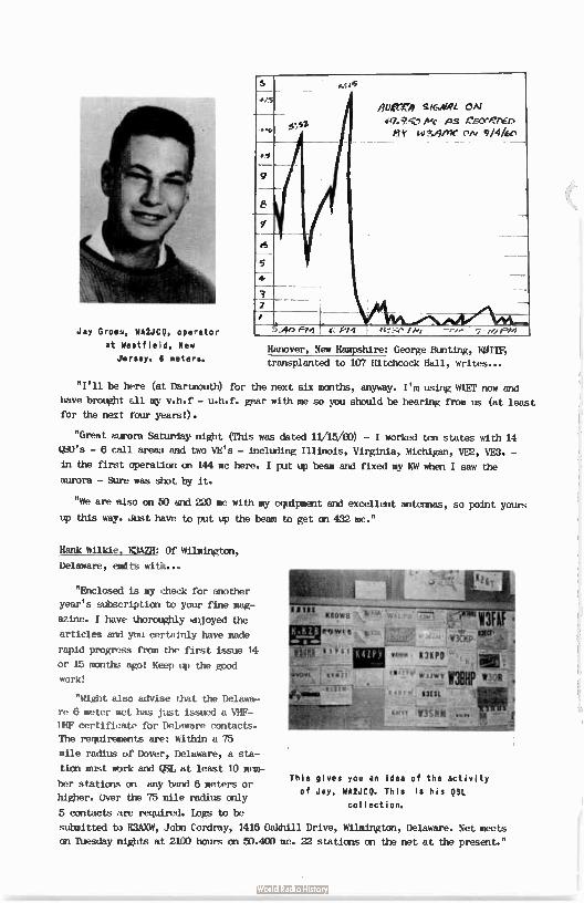
re:15
Jay Groan, WA2JCQ, operator
at Westfield, New
Jersey. 6 meters.
#15
6
5
4
/4etle4 qi6veL
9-‘7.9V Mc AS x'Kceere, Fh' eteieroc, cw
e: PM O•••, 10Pm
Hanover, New Hampshire: George Bunting, KOITF,
transplanted ta 107 Hitchcock Hall, writes...
"I'll be here (at Dartmouth) for the next six months, anyway. I'm using MIET now and
have brought all my v.h.f - u.h.f. gear with me so you should be hearing from us (at least
for the next thur years!).
"Great aurora Saturday night (This was dated 11/15/60) - I worked ten states with 14
QS0's - 6 call areaa and two VE's - including Illinois, Virginia, Michigan, VE2, VII. -
in the first operation on 144 mc here. I put up beam and fixed my KW when I saw the
aurora - Sure was shot by it.
"We are also on 50 am1220 mc with my eqtdpment and excellent antennas, so point yours
up this way. Just have to put up the beam to get no 432 mc."
Hank Wilkie, K3AZH: Of Wilmington,
Delaware, milts with...
"Enclosed is my dhack for another
year's subscription to your fine mag-
azine. I have thoroughly enjoyed the
articles and you certainly have made
rapid progress from the first issue It
or 15 months ago! Keep up the good
work!
"Might also advise that the Delawa-
re 6 meter met has just issued a VHF-
UHF certificate for Delaware contacts.
The requirements are: Within a 75
mile radius of Dover, Delaware, a sta-
tion must work and CISL at least 10 mem-This gives you an idea of the activity
ber stations on any band 6 meters or of Jay, WA2JCQ. This is his QSL
higher. Over the 75 mile radius only collection.
5 contacts are required. Loge to be
submitted to K3AXW, John Cordray, 1416 Oakhill Drive, Wilmington, Delaware. Net meets
on Tuesday nights at 2100 hours an 50.400 mc. 22 stations on the net at the present."
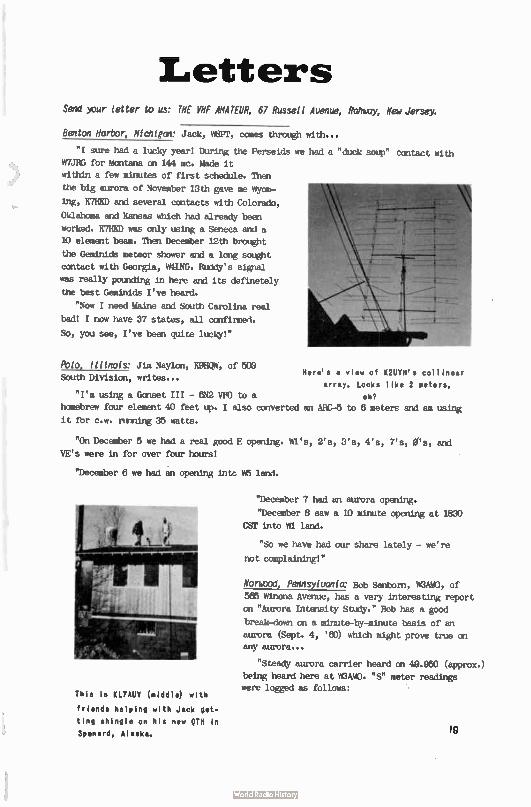
Letters Send your letter to us: THE VHF AMATEUR, 67 Russell Avenue, Rahuay, New Jersey.
Benton Harbor, Mohler': Jack, W8PT, comes through with...
"I sure had a lucky year! Curing the Perseids we had a "duck soup" cantact with
W7JRG for Montana on 144 mc. Made it
within a few minutes of first schedule. Than
the big aurora of November 13th gave me Wyom-
ing, K7HKD and several contacts with Colorado,
Oklahoma and Kansas which had already been
worked. K7HKD was only using a Seneca and a
10 element team. Then December 12th brought
the Geminids meteor shower and a long sought
contact with Georgia, MING. Ruddy's signal
was really pounding in here and its definPtPly
the best Geminids I've heard.
"Now I need Maine and South Carolina r,a1
bad! I now have 37 states, all ccnfirmed.
So, you see, I've been quite lucky!"
Polo Illinois: Jim Nay/on, K9HQW, of 508 Here's a view of K2UYH's collinear
South Division, writes... array. Looks like 2 meters,
"I'm using a Gasset III - 642 VFO to a eh?
homebrew four element 40 feet up. I also converted an ARC-5 to 6 meters and am using
it for c.w. ruming 35 watts.
"On December 5 we had a real good E opening. WI's, 2's, 3's, 4's, 7's, Ws, and
VE's were in for over four hours!
"December 6 we had an opening intc h 5 land.
This is KL7AUV (middle) with
friends helping with Jack get-
ting shingle on his new 9TH in
Spenard, Alaska.
"December 7 had an aurora opening.
"December 8 saw a 10 minute opening at 1830
CST into Wl land.
"So we have had our share lately - we're
not complaining!"
Norwood, Pennsylvania: Bob Sanborn, MAW, of
566 Winona Avenue, has a very interesting report
on "Aurora Intensity Study." Bob has a good
break-down on a minute-by-minute basis of an
aurora (Sept. 4, ' 60) which might prove true on any aurora...
"Steady aurora carrier heard on 49.950 (approx.)
being heard here at WOAMO. "S" meter readings
were logged as follows:
19
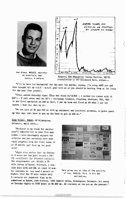
Jay Gross, eit2JCQ, operator
at Westfield, New
JeTsey. 6 meters.
4/5
41xre) ql&Abel, ON
4e,.9.1 Mc As eeeeet10, ely tewre cvti 9/444,
L.
6
5
4-
:4e) e: P/4
Hanover, New Hampshire: George Btnting, KOITF,
transplanted to 107 Hitchcock Hall, writes...
"I'll te here (at Dartmouth) for the next six months, anyway. I'm using wiEr now and have brought all my v.h.f - u.h.f. gear with me so you should be hearing from us (at least for the next four years!).
"Great aurore Saturday night (This was dated 11/15/60) - I worked ten states with 14
QS0's - 6 call areas and two VE's - including Illinois, Virginia, Michigan, VE2, VED. -
in the first operation on 144 mc here. I put up beam and fixed my KW when I saw the
aurora - Sure was shot by it.
"We are also on 50 and 220 mc with my equipment and excellent antennas, so point yours
up this way. Just have to put up the beam to get on 432 mc."
Hank Wilkie, KAM: Of Wilmington,
Delaware, emits with...
"Enclosed is my check for another
year's stibscdption to your fine mag-
azine. I have thoromghly enjoyed the
articles and you certainly have made
rapid progress from the first issue 14
or 15 months ago! Keep up the good
work!
"Might also advise that the Delawa-
re 6 meter net has just isaued a VHF-
UHF certificate for Delaware contacts.
The requirements are: Within a 75
mile radius of Dover, Delaware, a sta-
tion must work and QSL at least 10 mem-Thls gives you an idea of the activity ber stations on any band 6 meters or
of Jay, WASJCQ. This is his QSL higher. Over the 75 mile radius only collection.
5 contacts are required. Lugs to be
submitted te UMW, John Cordray, 1416 Oaldtill Drive, Wilmington, Delaware. Net meets
on Tuesday nights at 2100 hours on 50.400 mc. 12 stations on the net at the present."
10108
1./3.1WY -
snit
iai VàS1111
Single Sideband
Joseph S.• • 170 Schenck eeeeee
eeeee leek, M.P.
The hope that 1961 would bring a new summit in v.h.f. SSB seems to be coming true
already. Through the seasonal band openings, as well as local work, an ever-increasing
number of sidebanders have been heard congregating an six and two meters. There is also
much talk of 220 mc and higher.
It has been noticed that a large number of sidebanders are utilizing high power (1161, making record setting QS0's more probable over extended distances. Many stations have begun
along these lines. We are hopefUl that these efforts will help to link the v.h.f. side-
banders of the nation, and later of the world together, and shall devote a portion of this
column to serve as a score board for such endeavors.
One step toward this goal deals with the linking of sidebanders in areas of their con-
centration by a net. I am happy to annotnce the formation of a sldeband net on six meters
in the New York metropolitan area. Meetings are held at eleven AM on Sundays. Sidébanders
are invited to sign into this net. In other areas, another net may have to be organized;
if not, there's a good resolution for 1961!
All in all, 1961 looks like a great year.
Letters:
"ra/". KOLX, P.O. Box 102, Shaw Air Force Base, South Carolina, reports:
"I am on six and two meter SSB, running a 5894 final, and enjoy it immensely. On the
last band Cflerling (January 5), I chatted with about fifteen stations in WI, W2, VE2, VE3
districts, ---all on two way SSB! I am presently engaged in some "dead band" testing with
KBEID, Bob Heil, of Marissa, Illinois, and am hoping for some interesting results."
We'll be interestea in hearing how you make out, 101. By the way, Bob, AdID, is running
similar tests with other parts of the country and is scheduling some interesting work.
S/SGT Don Jorstad, VsH/L/p. Box 825, Fisher, Illinois, reports increase in six meter
sidéband in his area.
"I plan to be on SSB, as soon as I can pick up a lap. or 10B with a v.f.o. Have Seneca,
will trade.
"At present I'm ruining a Seneca, with a Sky Sweep receiver and five elements air born
fifty feet.
"WOIAKA9 and KOHAE are both on SSB in this area. K9HAE lives in Pleasantville, Illinois,
about 70 miles from here. Nightly skeds are kept with good results. WLAX/9 is rum:big a 20A, with a 4-65A linear." Nice hearing from you, Don, and be interested in future news.
Bob Boseuell, W6Nirl, 10054 Woodale Avenue, Pacoima, California, sends along some fine
west coast news.
"For about 2 years, Hal, W6NMW, has been active on two meter B. Since that time
there has been a large nunber added to that list. Fred, WSJ, is now active with low
21
power, that he intends to increase very soon.
"I am now running 2KW PEP, as is W6NMW. The rest of the SSS boys in and around the
Los Angeles area include Bob, WNW, who is on two meters for the first time with his
new heterodyner. He expects to have a ' big rig' going soon. Vern, K6PER, and Jim, W6MJC,
will be on the air with good SSB very soon. Other high power stations on two meters are:
Sam, K6VLM, Bob, KUVH, and Allen, WETIZA. It appears thát more and more amateurs are be-
coming interested in two meter single sideband in this area. If I, or any other of the
above can help anyone getting on SSS, we'll be glad to do it.
"In the near future I'll have some very interesting, and simple methods for getting
SSS on in a quick fashion." Good hearing from you, Bob. We'll be interesting in learning
some of your SSB tricks. Like to hear some of these fine California signals uf' this may!
In closing, I hope to see many of the v.h.f. sidebanders at the approaching hamfests. ultil next month...
73 --- Rusty, K2UTN
(Continued from page 3) YOU WILL NEVER BE IfeUMWE --- R. nopŒrr, « MEIN
sand, blue clear water and oh, so comfortable, with air temperatures of 70 - 85 degrees, very little surf and tide - also no sea animals to bother one. (Note: It is safer and
better swinming here than along the Jersey Coast and never anything like the crowd - in fact, a dozen people would constitute a "crowd" down here).
Another day we found it necessary to go to the British Virgin Island of Tortola, where
Road Town is the largest settlement and houses the governmental buildings.
Since air traffic to a nearby island was now about non-existant as well as the ferry
service,we took the boat Youth of Tortola frail Kings wharf at Charlotte Amalie for the
26 nil le (one way) trip.
The February 20, 1960 issue of the Saturday Evening Post printed a very descriptive story of these British Virgins and it made the trip have more meaning than it would
from the usual tourist point of view.
We travelled along the Sir Francis Drake Channel which leads like a long straight
path between the chain of large and small tropical islands and made several stops at
boat landings where a few houses nestled at the base of the steep hills and mountains to form communities.
After a most enjoyable and scenic trip we arrived at the Mùnicipal dock of Road Town,
where white helmeted and white jacketed representatives of the Crown made certain we
were well qualified to enter.
It required but a short time to consumate our business and so had a couple of hours
to sight-see and visit. The main street is probably a half mile long and has stores, P.O.,
homes and official buildings; there are many homes among .the hills where farming is the chief occupation.
We drove to "Millies" and found both Mr. and Mrs, Chris Hammersley to be charming hosts. They have a small inn or the equivalent and cottages for rent perched on a small
historic sight overlooking the entire settlement and harbor.
It was here - over refreshments - that Mrs. Roy said her OM was at work on his rig and
some fellows had dropped in to give him a hand. I introduced myself as WA2DIEW and a chap
22
across the room came back with the information that he was W,210 of Haddonfield, New
Jersey. About 1800 miles from our homes by air and water. The next stop was at Treasure Isle, The Roy's pl¡ce, where we had a delicious luncheon and their "specially prepared
house drink." ( If you go there don't miss it - WOW!). Here VP2VA, Mr. Roy introduced VP1JH of WIIIWWX and Bob Dennison of Newton, Iowa, - WONDA, Den O'Leary also of Newton,
and W3ZFF, and Earl Quay of Mechanicsburg, Pennsylvania.
Just beginning to get acquainted when the announcement came that it was departure
time. If we missed the boat, it would not be back for three days. So we reluctantly
said '73' to the gang, hopped into the waiting Impala and got to the wharf, where, you
guessed it, WA2DEW and XVI just made it as the lines were cast off.
So back to St. Thomas, silouetted against the setting sun with the deep blues of the Caribbean reflecting the changing lights of approaching night, and stored within us a
wealth of memories of a beautiful mountainous island with happy people. I say it again,
as ham to ham, wherever you go, "You will never be Loneeome."
HAM TIP: A grid dip meter can be used as a sigpal generator when peaking of the converter
and receiver for maximum weak signal reception. Used on the fundamental, 144 or 50 mc,
the grid dipper may produce too much signal, even when placed some distance away from the
receiver. This may be due to R.F. fed back through the power lines. When this was tried
recently on the 50 mc converter, it was found that even the second harmonic of 25 mc pro-
vided too much signal. The sixth harmonic of 8.3 mc was sufficiently weak that alignment
was soon accomplished. ----Credit for this item gees to THE YU AMATEUR'S "GET-THAT-RIG-
ON-THE-AIR!' Department head, "Red," le2ZSP.
HAM TIP: For those who like their radio theory "sugar-coated", the ELEMENTS OF RADIO by
MUTCUS and Marcum is highly recommended. This book is published by Prentice-Hall, Inc.,
Ehgiewood Cliff's, New Jersey at $7.00. This excellent text requires no previous knowledge
or training as a prerequisite. It is so well wEitten that it is recommended for the
beginner and as a refresher for the advanced radio amateur. --Credit is due to Department
head It2ZSP, this time, too,- but from our "EXPLAIN-IT-TO-THE-EDITOR" dtvisioh.
INTERESTING NOTES FROM EXCHANGE PAPERS
Every once in a while we run across mile general, but genuinely interesting items from
our many exchange publications. Here's one from the S.J.R.A. HARHONICS..."Here's A Xmas
Treat for Your Kiddies - Santa will be on 20 SSB starting on 12 Dec. thru 23 Dec. on 114.280 at 18DO EST to Approx. 1880 EST. Call VE8-located WP4J/VE8. 1 Now doesn't that
beat all!
Ran across this item in the "WANT ADS" section of AUTO-CALL..."FOR SALE: 8I3's, 10t,
with grid, 25e; with plate, Me, with both, 5Ct; with base, $2.00; with air pumped in, $10.00; with filaments and glass - complete, $25.00---1.M. Noughty, 12345 Crazy Place, St. Elizabeths.'
Re FLORIDA SKIP: "FROM HERE TO DX" LUBECK,Germany (UPI). A 24-year-old newsman, Jost Lehmann, was killed when he put a bottle atop his head at a party and asked
another man to shoot lt off.
CAPE TOWN (AP). ft soon will be easier to go to Hell. A paving is being made - with
good intentions - to Hell, an almost inaccessible mountain village near Prince Albert,
Cape Province - People now get to Hell mainly on donkeys.
23
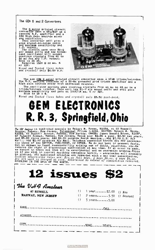
The GEM 6 and 2 Converters
The 6 meter printed circuit converter uses a 6BQ/BZ7 as a cascode R.F. amplifier and a 6A8 High Gain pentode mixer and oscillator. This converter will give a
good signal-to-noise ratio and maximum sensitivity and I.F. output. The circuit uses very Hi- II
air wound coils and the broad-band oscillator will accept overtone crystals from 40 to 50 mc for any I.F. output. Size is 2è r4. Reouires 150V § 22 ma. 6
or 12V. Wired and Tested ( Less tubes and crystal) only $4.50 t.p.
The new GEM 2 meter printed circuit converter uses a ncoe triode/tetrodes. The R.F. section consists of a Hi-Mu grounded grid triode amplifier and a high gain tetrode mixer with universal outputs.
The oscillator section uses Overtone crystals from 44 mc to 46 mc in a triode/tetrode tripler. This unit has Ii- 0 air wound coils and will give maximum sensitivity and gain at 100V/18 ma. 6 or Z2V.
Size is 2è x 4. Wired and Tested ( less tubes and crystal) only $5.50 tost-eatd.
GEM ELECTRONICS R. R. 3, Springfield Ohio
The WirAmemeis Published monthly by Robert M. Brown, KUSQ, et 67 Russell Avenue, Rahway, New Jersey. i$11DUllei FUlton 1-1284. EDITOR: Robert M. Brown, K2ZSQ, 67 Russell Avenue, Rahway, New Jersey. OWNER: James Donald Brown, K2ZSP, 67 Russell Avenue, Rahway. New Jersey. Rates are: $2.00 a year, $3.50 two years, and $5.00 three years. Add $ 1.00 outside North America...Add $ 1.00 U.S. Air Mail...Add $2.00 overseas Air Nail. Opinions expeessed herein are NOT necessar-ily those of the EDITOR, PUBLISHER, or OWNER. We do our best to Present facts, but we assume no legal responsibility arising out of debts, royalties, etc.We reserve the right to discontinue publication at any time. If an error is made, we hasten to point out that all is experimental and we guarantee nothing.Write us if you wish to reprint anything contained herein, - permission will probably be granted. All published articles are rewarded with a one year subscription. Disriny advertising rates are: $15.00 fuLl ¡wee, 4 'sage $8.00. ,age $5.00. All art work is charged at cost. determined by extent of combosition required. DEADLINE IS THE 20th OF THE MONTH. r-
12 issues $2 ilte 21.41 "Iota/emit
67 RUSSELL
RAWWAY, NEW JERSEY
() 1 year $2.00 0 () 2 years 3.50 0
() 3 Years 5.00
New
Renewal
NAMh', CALL
ADDRES
CITY
_
3RD ANNUAL DINNER AND HAMFE:ST
Neptune's Inn, located on Route 4 near River Edge, New Jersey
Saturday, February 25th starting at 7:00PM.
The program includes installation of new officers; presentation of awards to members of our society and to other distinguished radio amateurs; speakers of note; novel entertainment; door prizes, etc; all topped off with plenty of unusually good food.
Tickets at $5.00 per person are available from any member or write to:
Roy King, K2BNQ
55 Woodland Avenue, Montvale. New Jersey
Tickets will also be available from many of the radio parts distributors in the East Coast area.
Ticket deadline is Sunday, February 12th. No tickets will be sold at the door.
Requests from other radio clubs for specific groupings will receive special attention, if such orders are received early by K2BNQ. Requests of this nature can be honored only for blocks of five ( 5) or more tickets.
Motel accommodations are available nearby and there are ample parking facilities at the Inn.
THE EAST COAST VHF SOCIETY INC. (a non-profit amateur radio group)
Western Radio Amateur
48 pages of construction, news, DX and DXpedi-
tions, V.H.F. and technical articles! All these
by such famous authors as Ed Marriner, W6BLZ,
Don Stoner, W6TNS, "YB" Pyle, W70E, with Bob
Grimm, K6RNO, heading up the V.H.F. Column!
This magazine is the third largest in the
United States - and for the money NOB can't
go wrong! Only $2.00 per year. Write now to:
Western Radio Amateur and West Coast Nam Ads
pillen4 an
10S17 Have* St. II Mesta, CaWomb' «bore 11-21111
A Montt*ly Publication
/ USA DX QSL COOP- Box 5938 -----Kansas City 11, Mo.
C HEAPY
OSUs ? ? 100 QSL's $1.00 ' Each addi. 100... . 7,
Ball Point Pen .39 ? Felt Tip Pen (choice clr) . 59 ? ? KIT .1 KIT •••
100 OSL'S 1000 OSL'S 1 FELT TIP PEN 3 FELT TIP PENS
$1.49 1 BALL POINT PEN $9.39
KIT .2
250 OSL'S I FELT TIP PEN 1 BALL POINT PEN
$2.89
KIT .5
2500 05L'S 5 FELT TIP PENS 2 BALL POINT PENS
$19.95
KIT •3
500 OSL'S 2 FELT TIP PENS 1 BALL POINT PEN
$ 4 . 99
At your dietri-baton, or direct if unavailable..
READ
AUTO - CALL 2509 - 32nd, St., S. E., WASHINGTON 20, D. C.
lists is the paper you've
heard so such about! The fam-
ous "AUTO-CALL" that has been
quoted by almost all Ham pap-
ers, including CQ magazine!
For only a dollar a year,
you'll get 32 packed pages each
month of all the best in general
Hem Radio material. It has a
special added feature for those
amateurs in the Washington, D.C.
area, as it covers club activ- •
ities there.
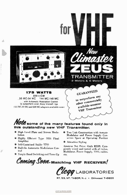
for
175 WATTS AM—CW
.50 MC-54 MC 144 MC-148 MC ... with Automatic Modulation Control to outperform even many kilowatt rips
3.5 MC.30 MC and 220 MC adapters available soon
• High Level Plate and Screen Modu-lation
• Highly Efficient Type /034 Final Amplifier
• Self-Contained Stable VFO
• Built-In Automatic Modulation Con-trol
• Simple Band Switching and Tune-lip
Albe&some of the many features found only in this outstanding new VHF Transmitter:
TRANSMITTER 2 Meters & 6 Meters
Guitgel' tverlorfn an;
to °t1 mereiabY other eel' trot available aufnaitt„ )3.1,F TTran
• TWO I nit Construction with ttemote Modulator and Power Supply Con. serves Spare at Operating Position
• Attractive Styling
Amateur Net Price: Only 8559. Com-pletely wired and tested .vitlé all tubes. Modulator. Power Suppl. VFO. cables. etc.
Seeeett-Matching VHF RECEIVER! LABORATOR I ES
RT. 53, MT. TABOR, N. J. • OAkwood 7-6800
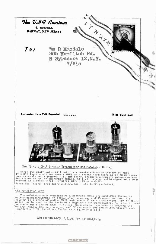
Woe Vdiq 4.0gaiewi 67 RUSSELL
RAHWAY, NEW JEleEY
T o: ¡ha RILandale 305 Hamilton Rd. N Syracuse 12,N.Y.
7/61a
Postmaster: Form 3547 Requested • • THIRD ( lass Moil
The " Little Gem" 6 meter Transmitter and Modulator Units!
These two small units will make un a complete 6 meter station of only 4" x 5"! The transmitter uses a 6AU8 as a triode oscillator using 50 mc over-tone crystals and a Pentode R.F. amplifier. Features automatic antenna match-ing either hl or low impedance output. Will give a gond solid signal on a beam antenna at 3 watts input! Renuires 200V p 15 ma - 6.3V.
Mired and Tested ( less tubes and crystal) only $4.50 test—laid.
GEM MODULATOR UNIT:
The modulator unit consists of a standard 12AX7 pre- amplifier featuring either crystal/dynamic or carbon mike input and a Glle power pentode. Will give un to 7 watts of audio. Will modulate a 15 watt transmitter. Two of these units can be used as the basis of a high gain intercom system. Can also be use as phono amplifier or small P.A. set. Gain can be regulated by varying the voltage input. Requires one 8-8 mmf filter canicitor and output transformer. 100/250V — 6.3V. Wired and Tested only $3.50 b'st—batd.
GEM ELECTRONICS, R.R.#3, Springtield,Ohio
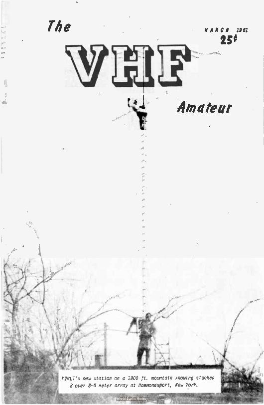
The MARCH 1981
25#
\ prei Amateur
K2nLT's new ..itation on a 1900 ft. mountain Iflowing stacked
8 over 8-6 meter array at Nammondsport, New York.
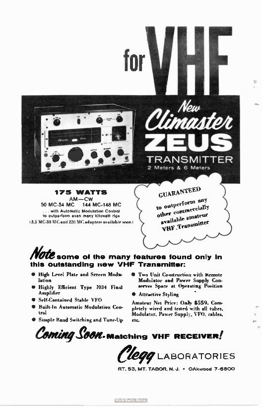
for
175 WATTS AM—CW
50 MC-54 MC 144 MC-148 MC
• with Automatic Modulation Control to outperform even many kilowatt riçpy
t. MC-30NIC and 220 \IC adlapirr aN ailable soon
Gt3X"le (Arm
outPer— • to conusercut J
othet..a..lavahl 'iWe amateur ."Tranteniner
Aleksome of the many features found on y in this outstanding new VHF Transmitter:
• High Level Plate and Screen Modu-lation
• Highly Efficient Type 7034 Final Amplifier
• Self-Contained Stable VFO
• Built-In Automatic Modulation Con-trol
• Simple Band Switching and Tune-Up
• Two Unit Construction with Kemote Modulator and Power Supply Con-serves Space at Operating Position
• • Attractive Styling
Amateur Net Price: Only $559. Com-pletely wired and tested with all tubes, Modulator, Power Supply, VFO. cables, etc.
...r9610- Matching VHF RECEIVER!
LABORATORIES
FT. 53, MT. TABOR, N. J. • OAkwDod 7-6800
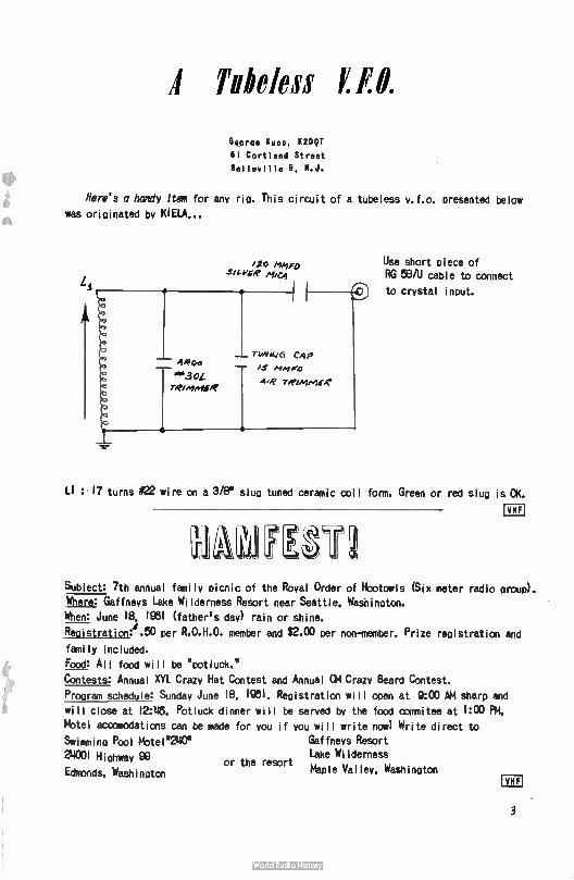
I Tubeless F.F.O.
Goorde Kul». K2DQT
61 Cortland Street
Belleville 9. N.J.
Here's a handy item for any rig. This circuit of a tubeless v.f.o. presented below was originated by KIELA...
LI
020 Atypo sane /leg
Aifgo de3OL reetem4ER
TIM144J6 CAP
/3' Alb1
Abe remimee
Use short piece of RG 58/U cable to connect
to crystal input.
LI : 17 turns #22 wire he a 3/8" slug tuned ceramic coil form. Green or red slug is OK.
Subject: 7th annual family picnic of the Royal Order of Hootowls (Six meter radio grow)). Where: Gàffneys Lake Wilderness Resort near Seattle. Washington.
When: June IS 1961 ( father's day) rain or shine.
Registration:i .50 per R.O.H.O. member and $2.00 per non-member. Prize registration and
family included.
Food: All food will be "potluck."
Contests: Annual XVI Crazy Hat Contest and Annual OM Crazy Beard Contest.
Program schedule: Sunday June 18. 1061. Registration will open at 0:00 AM sharp and
will close at 12:46. Potluck dinner will be served by the food oommitee at 1:00 Fil. Mptel accomodations can be made
Swimming Pool Motel"240"
24031 Highway 99
Edmonds. Washington or the resort
for you if you will write now' Write direct to Gaffnevs Resort Lake Wilderness
Maple Valley, Washinaton
3
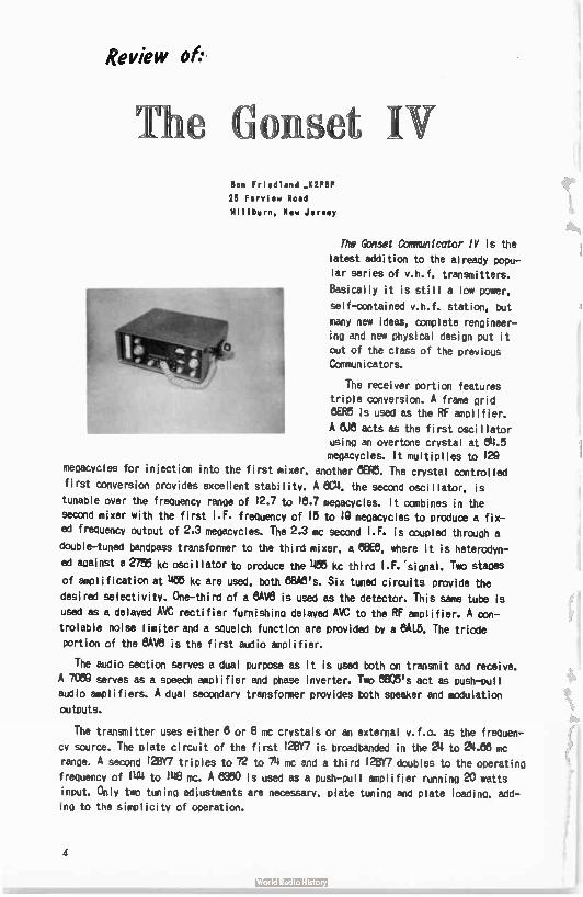
Review of:•
T1 e nset IV Ben Friedland _ K2PBP
25 Faryiew Road
Millburn, New Jersey
The Gonset Communicator IV is the
latest addition to the already popu-
lar series of v.h.f. transmitters.
Basically it is still a low power,
self-contained v.h.f. station, but
many new ideas, complete rengineer-ing and new physical design put it out of the crass of the previous Communicators.
The receiver portion features triple conversion. A frame grid 8ER5 is used as the RF amplifier.
A em acts as the first oscillator using an overtone crystal at 64.5 megacycles. It multiplies to 129
megacycles for iniection into the first mixer, another 8E. The crystal controlled
first conversion provides excellent stability. A 80,4, the second oscillator, is
tunable over the frequency range of 12.7 to 18.7 megacycles. It combines in the second mixer with the first I.F. frequency of 15 to 19 megacycles to produce a fix-
ed frequency output of 2.3 megacycles. The 2.3 mc second I.F. is coupled through a
double-tuned bandpass transformer to the third mixer, a 88E8, where it is heterodyn-
ed against a 2755 kc oscillator to produce the 455 kc third I.F. ' signal. Two stages
of amplification at 455 kc are used. both 86's. Six tuned circuits provide the
desired selectivity. One-third of a 6AV8 is used as the detector. This same tube is
used as a delayed AVC rectifier furnishing delayed AVC to the RF amplifier. A con-trolable noise limiter and a squelch function are provided by a 8AL5. The triode
portion of the am is the first audio amplifier. The audio section serves a dual purpose as it is used both on transmit and receive.
A 7050 serves as a speech amplifier and phase inverter. Two 61305's act as push-pull
audio amplifiers. A dual secondary transformer provides both speaker and modulation outputs.
The transmitter uses either 8 or 8 mc crystals or an external v.f.o. as the frequen-
cy source. The Plate circuit of the first lea is broadbanded in the 24 to 24.68 mc
range. A second 12f7 triples to 72 to 74 mc and a third 128Y7 doubles to the operating
frequency of 144 to 148 mc. A 8380 is used as a push-pull amplifier running 20 watts input. Only two tuning adjustments are necessary, plate tuning and plate loading, add-
ing to the simplicity of operation.
4
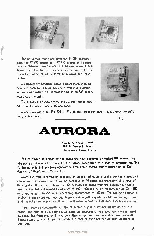
The universal power utilizes two 2NI554 transis-
tors for 12 VDC operation. 177 VAC operation is poss-ible by changing power cords. The two-way power trans-
former operates into a silicon diode bridge rectifier,
the output of which is filtered by a capacitor input
filter.
A permanently attached ceramic microphone with coil
cord and push to talk switch and a switchable meter.
either power output of transmitter or as an S. meter.
round out the unit.
The transmitter when tested with a watt meter show-
ed 10 watts output into a 50 ohm load.
A new physical size. 5 x I2i x II", as well as a new panel layout make the
very attractive.
unit
AURORA Harold P. Grace - W3HFY
108 N. Concord Street
Havertown. Pennsylvania
Di
The folladno is presented for those who have observed or worked VHF aurora, and
who may be interested in recent IGY findings concernino this mode of propagation. The
following material has been abstracted from three recent papers appearing in The
Journal of Geophysical Research...
Mono the most interesting features of aurora reflected sianals are their spectral
characteristic which results in the earl:ding of AM phone and characteristic note of
CW signals. It has been shown that Cd signals reflected from the aurora have their
spectra shifted and spread by as much as 300 - 900 C.D.S. at frequencies of 50 - 150
mc., and as much as 2.5 kc at operatino frequencies of 400 mc. The followino shows a
typical transmitted and received (aurora reflected) signals tor CM emmission, illus-
trating both the Doppler shift and the Doppler spread in frequency spectra occuring.
The frequency components of the reflected signal fluctuate in amplitude in a
noise- like fashion at a rate faster than the response of any spectrum analyser used
to date. The frequency shift may be either up or dam, and may pass from one side through zero to a shift in the opposite direction over periods of time as short as
one hour.
5
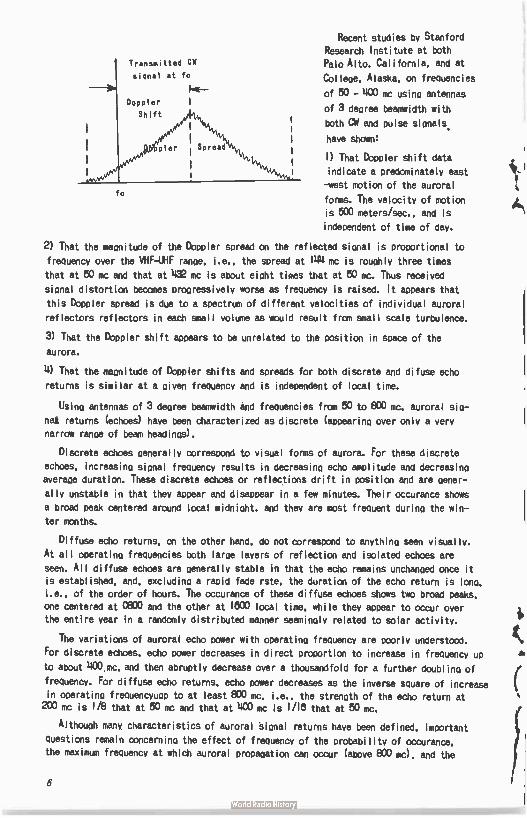
Transmitted CW
signal at fo
Dopler i Shift defn,
1)Pler Spread
fo
Recent studies by Stanford
Research Institute at both
Palo Alto. California. and at
College. Alaska. on frequencies
of 50 - 400 mc using antennas
of 3 deoree beamwidth with
both CW and pulse sionals.
have shown:
I) That Doppler shift data
indicate a predominately east
-west motion of the auroral
forms. The velocity of motion
is 500 meters/sec., and is
independent of time of day.
2) That the magnitude of the Doppler spread on the reflected sional is proportional to
frequency over the VHF-UHF range. i.e.. the spread at 144 mc is roughly three times
that at 50 mc and that at 432 mc is about eight times that at 50 mc. Thus received
signal distortion becomes progressively worse as frequency is raised. It appears that
this Doppler spread is due to a spectrum of different velocities of individual auroral
reflectors reflectors in each small volume as would result from small scale turbulence.
3) That the Doppler shift appears to be unrelated to the position in space of the
aurora.
4) That the magnitude of Doppler shifts and spreads for both discrete and difuse echo
returns is similar at a given frequency and is independent of local time.
Usina antennas of 3 degree beamwidth and frequencies from 50 to 800 mc. auroral sio-
nat returns (echoes) have been characterized as discrete (appearino over only a very
narrow ramie of beam headings).
Discrete echoes generally correspond to visual forms of aurora. For these discrete
echoes. increasino signal frequency results in decreasino echo amplitude and decreasing averaoe duration. These discrete echoes or reflections drift in position and are gener-
ally unstable in that they appear and disappear in a few minutes. Their occurance shows
a broad peak centered around local midnight. and they are most frequent during the win-
ter months.
Diffuse echo returns, on the other hand, do not correspond to anythino seen visually.
At all operating frequencies both lai-pe layers of reflection and isolated echoes are
seen. All diffuse echoes are oenerally stable in that the echo remains unchanoed once it is established, and, excludino a rapid fade rste. the duration of the echo return is lona. i.e.. of the order of hours. The occurance of these diffuse echoes shows two broad peaks. one centered at 0800 and the other at 1800 local time, while they appear to occur over the entire year in a randomly distributed manner seemingly related to solar activity.
The variations of auroral echo power with operating frequency are poorly understood.
For discrete echoes, echo power decreases in direct proportion to increase in frequency up
to about 1100 mc. and then abruptly decrease over a thousandfold for a further doublino of
frequency. For diffuse echo returns, echo power decreases as the inverse square of increase
in operating frequencvuoo to at least 800 mc, i.e.. the strenoth of the echo return at 200 ma is 1/8 that at 50 mc and that at 400 mc is 1/18 that at 50 mc.
Although many characteristics of auroral Slone' returns have been defined, important
questions remain concerning the effect of frequency of the probability of occurance,
the maximum frequency at which auroral propaoation can occur (above 800 mc), and the
6
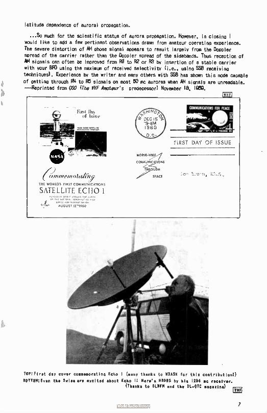
latitude dependence of auroral propagation.
...So much for the scientific status of aurora propagation. However, in closing t would like to add a few pertinent observations drawn from amateur operating experience. The severe distortion of AM phone signal appears to result largely from the Doppler sPread of the carrier rather than the Doppler spread of the sidebands. Thus reception of AM signals can often be improved from RO to R2 or R3 by insertion of a stable carrier with your FIFO using the maximum of received selectivity ( i.e.. using SS8 receiving
techniques). Experience by the writer and many others with SS'S has shown this mode capable of getting through RN to R5 signals an most 50 mc auroras when AM signals are unreadable. —Reprinted from MO (The VHF Amateur's predecessor) November 18, 1959.
First Da of Wale
ex 4 .anzeve olaeiy
THE viouris FIRST COMMUNICATIONS
SATELLITE ECHO I It.•CtO 011•.1, •NE •• /INC N•tiONA. ACRON.I1,5 •Nr.
SPACE AO.NoStRATiOM ON
AUGUST 12'1960
FiRST DAY OF ISSUE
WORLD-WIDE,1
COMMUNICATIONS
TO UGH
SPACE
ToP:Fire der cover commemorating Echo I (many thanks to M3ASK for this contribution!) BOTTOM: Even the Swiss are excited about Echo 11 Here's 118986 by his 1298 mc receiver.
(Thanks to DL3FM and the DL- OTC magaxIne)
7
Moonbounce
Activities
Allen Kat; K2UYH
48 Cumberland Avenue Verona, New Jersey
One of the many obstacles to the construction of a practical moonbounce communica-
tions system is the achievement of transmitter stability. Extreme stability is necess-
ary because of the narrow receiver bandwidths used.
Placing the oscillator crystal in an oven especially desioned to keeo the crystal
at a relatively uniform temperature has been used successfully for many years in the
v.h.f. spectrum. Crystal ovens, however, leave much to be desired on frequencies as
hioh as 1298 mc. Their inadeouacies come from a slioht variation in temperature
caused by the kickina in and out of a thermostat which controls the oven's heatino
element. These variations, while insionificant on lower bands, can mean the differ-
ence between WCODVW and "no copy" on 1298 mc where a shift of one cycle at the osc-
illator freauency can be a chanae of a kilocycle on the operatina frequency.
Sam Harris. WIFZJ, V.H.F. columnist for fer. devised a very inoenius and inexpen-
sive way to oet around this problem. Sam sunk a hole ten feet into the around where
the temperature is constant. Into the hole he placed a transistorized oscillator
sealed in a thermos bottle. Transistors were used because they add no heat to the
system. This method has an added advantaoe in beino uneffected by mechanical shocks
on the surface.
It should be remembered that these same principles should be applied to the receiv-
er. You are foolina yourself if your receiver and transmitter are not both stable. An
easy way to accomplish receiver and transmitter stability is to use one oscillator
similar to Sam's for both transmitter and receiver. With judicious choice of crystal
frequency this system will not work badly. For example: if one uses a one meoacycle
crystal in the transmitter, it can be multiplied by 1298 mc. In the receiver the one mc crystal can be multiplied by 1152 to oet a frequency of 1182 mc for a 144 mc I.F.
output.
Parobolic Antennas
It has come to my attention that parabolic antennas of various sizes are avail-
able from many surplus dealers. In the New Jersey area parabolic reflectors as larae
as twelve feet in diameter have been seen for sale - a 12 foot spun aluminum was
priced for about one hundred dollars. This price is fairly reasonable considerina
that a new ten foot dish would cost about $1,200,00, Similar buys should be possible
in other parts of the country.
Before closing. I would like to remind you that this column needs your support
to succeed. Please send information and pictures concerning your moonbounce activities.
73. Allen. len 8 ru
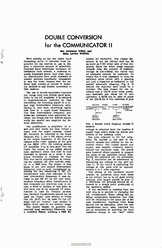
DOUBLE CONVERSION
for the COMMUNICATOR II Ben Sandberg WOW and lake LaVero WAbail
With activity on the two meter band increasing daily, it becomes more im-perative for the receiver in use to dis-play a resonabie amount of selectivity. Crowded band conditions, harmonic in-terference from aircraft, a tendency to-wards increased power and other simi-lar disturbances have made reception of weaker stations practically impossible. It was for these reasons that the au• thors, both owners of Gonset II receiv-ers decided to add double conversion to this receiver.
The use of double conversion improves the image ratio and affords good selec-tivity in the IF. amplifier. It is obtained in superheterodyne receivers by first converting the incoming signal to a ra-ther high intermediate frequency, amp-lifying it, and then converting again, this time to a much lower frequency. The first intermediate frequency pro-duces the necessary wide separation be-tween the image and the desired signal, while the second one supplies the de-sired selectivity.
The modification is simplicity in it-self and well worth the time ( about 1 hour) and the slight expense ( about $5) involved. As indicated in the block diagram, Fig. 1. the 6 MC signal which is the output frequency of the first os-cillator-mixer tube) appears at the grid of the 6BH6 ( VII). the existing second IF, amplifier. It is at this point that we inject the output of our added second local oscillator. Since this tube is now intended to operate as a mixer it was found necessary to increase its bias. This was easily accomplished by chang-ing the existing 120 ohm cathode resis-tor to a 5000 ohm. The output of this stage is our new second intermediate frequency and as such, necessitates re-placing the two remaining 6 MC IF. transformers with ones resonant to the new intermediate frequency. It was de-cided to use 455 KC as the new inter-mediate frequency since transformers of this frequency are relatively easy to ob-tain. A word of caution at this point in that since one of the replaced I.F. trans-formers is used for detector service, two identical transformers should not be used. An "Input" type similar to Miller Coil Co. 12-C1 can be used for the IT. stage and an "output" type similar to Miller 12-C2 used for the detector stage. The circuit chosen to generate the
required local oscillation frequency was a modified Pierce, utilizing a 6455 KC
crystal for excitation. The crystal fre-quency is not too critical and can be as much as 5 KC either side of that fre-quency. Since the mixer stage employs cathode bias, the amount of injection voltage is non-critical, but rather that an adequate amount be available. To insure this it was necessary to tune the oscillator plate circuit with a peaking coil and a capacitor as indicated in the partial schematic diagram, Fig. 2. If desired the capacitor used could be a trimmer. The tube chosen for the os-cillator was a 12AT6 since these partic-ular receivers are wired for 12 volt operation. A 6AT6 can be used in place of the 12AT6 for 6 volt receivers. B plus
FIG. 1 Partial block diagram Gonset II receiver
voltage is obtained from the receiver B supply buss which feeds the plates and screens of the existing tubes. The area adjacent to the R.F. amp-
lifier, VS, located at the rear of the receiver chassis was utilized for the os-cillator circuit. The crystal socket and crystal was located outboard directly behind the oscillator tube. Tie points were inserted where required to support the parts of the oscillator circuit. After wiring the oscillator per the schematic. Fig. 2. oscillation can be determined by measuring the voltage at the grid pin (pin 1). If the circuit is oscillating the voltage at this point will be approxi-mately 3 to 4 volts negative. The wiring of the oscillator should
present no problems since lead dress is not critical, but as in all good wiring practice, lead length should be kept to a minimum. All grounds should ne re. turned to a single point preferably at the oscillator socket.
If the oscillator is working then the next step is to procede to changing the I.F. transformers. When lifting the ex. !sting components remember that they will be returning to the same pin of the new transformer, therefore their dress should not be disturbed. After the new transformers have been installed the job is completed by injecting the local oscillator energy to the "new" mixer
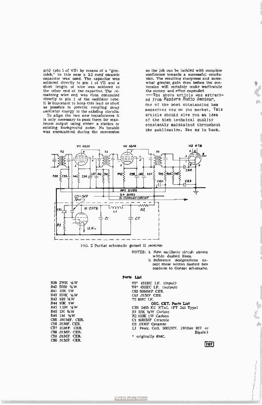
grid ( pin 1 of VII) by means of a "gim-mick," in this case a 2.2 mmf ceramic capacitor was used. The capacitor was soldered directly to pin 1 of VII and a short length of wire was soldered to the other end of the capacitor. The re. maining wire end was then connected directly to pin 1 of the oscillator tube. It is important to keep this lead as short as possible to prevent coupling stray oscillator energy to the existing circuits. To align the two new transformers it
is only necessary to peak them for max. imum output using either a station or existing background noise. No trouble was encountered during the conversion
VII G6HI VIZ 68A6
so the job can be tackled with complete confidence towards a successful conclu. sion. The resulting sharpness and some. what greater, gain then before the con. version will certainly make worthwhile the money and effort expended. --The above article was extract— ed from Western Radio Amateur,
one of the most outstanding ham
magazines now on the market. This
article should give you an idea
of the high technical quality
constantly maintained throughout
the publication. See ad in back.
VIS 578
FIG. 2 Partial schematic gonset II receiver
NOTES: 1. New oscillator circuit shown within dashed lines.
2. Reference designations ex-cept those within dashed box conform to Gonset schematic.
R39 270K %W R40 5000 % VP R41 10K 1W 1142 220K '4W R43 120 % VP 1144 10K 1W 1145 12M %)A7 R46 1M '4W R49 1M %NV C55 .001MF. CER. C56 ..
.01MF. CER. C58 .01MF. CER. C59 .01MF. CER. C60 .01MF. CER.
Parts List
r3° 455KC I.F. ( Input) Ti' 455KC IF. (output) C62 50MMF CER. C63 .01MF CER. T2 6MC IF.
OSC. CET. Parts Litt CRI 6455 KC XTAL ( FT 243 Type) RI 33E Carbon 112 100E 1W Carbon Cl 50MMF Ceramic C2 .01MF Ceramic LI Peak. Coil, 500UHY. ( Miller 617 or
Equiv.) • originally MC.
TINDERSTANDWG VH.111.
PA J.D. " Red" Brown, K2ZSP
67 Russell Ave.
Rahway, N.J.
N
This article will be the first in a series concerning the various basic elements
of propagation as it is applied to the v.h.f. man. Edited this month by the other mom-
ber of the family, K2ZSP, it might well develop into a family project - hi! This
installment covers tropospheric and Sporadic E conditions --- %MO
PART 1
Any discussion of v.h.f. propagation should properly start with tropospheric condi-
tions. Tropospheric propagation is our most common form of v.h.f. phenomena and should
be understood before moving to the study of other types. Tropospheric propagation takes
place in that part of the earth's atmosphere nearest to us - from earth to a distance
of about six miles. All of our storms, weather and atmospheric changes as we see them
affect propagation. Thus it is sometimes called the "weather layer.'
Tropospheric propagation could be truthfully called tropospheric bending. The change
in direction of a radio wave could be illustrated by a comparison with light waves.
Let's look back to the time as youngsters when we tried to hit fish in a brook and
didn't succeed. We failed not only because of poor aim but also because the fish wasn't
where we saw it. The light rays reflected from the fish were bent at the boundary be-
tween the water and air, consequently we saw the fish other than at his true location.
Lenses and prisms are also examples of the bending of light waves; consequently, just as
light waves may be reflected or bent so also may radio waves.
"Ground Waves"
The term 'ground wave is of course a misnomer and probably is a carry-over fran law
frequency work; however the term has cow, into general use on v.h.f. to denote an exten-
sion of the normal range of transmission and reception to several hundred miles, depend-
ing, of course, on frequency' Ground wave' is a form of tropospheric bending. It is
most prevalent in coastal areas, or areas adjacent to large lakes. Again, our weather element.
'Ground wave' or tropospheric bending is caused by temperature inversion, a sharp
difference in moisture content of the upper air masses, or a combination of the two.
Remember the example of the bending of light waves at the surface of the water. Here
the light waves passed from one substance to a completely different one. At that point
a bending of the light waves took place. Something similar happens during tropospheric
bending. The two dissimilar substances are of course part of our atmosphere. They are
11
different because of temperature differences, moisture differences or both. The sharer
the line of demarcation, the more pronounced the effect, Radio waves transmitted at an
angle from the surface of the earth are bent back and thus are received at a greater than the normal distance.
'Ground wave' occurs most frequently during the warmer months but does happen during
the winter. Here is a typical example - - In the early morning hours the sun's rays strike
the upper atmosphere first. Its temperature rises before the air near the ground warms.
These unlike masses cause bending of the v.h.f. wave. A similar-condition is true near
sunset and sometime continuing for several hours. As the sun sets, the lower atmosphere
cools while at higher levels the sun is still shining. Here again we have two unlike
masses. A dissimilarity in the moisture contained in each mass further increases the
tropospheric bending. It is possible for this bending to be caused by either the tempera-
ture or moisture differences individually.
Personal observation has shown 'ground wave' conditions to be more prevalent during
times of clear weather during the warm months. 'Ground wave' v.h.f. communications in
excess of 500 miles as been recorded. More commonly our range is extended over a distance
of one hundred to two hundred miles depending on the station equipment and frequency.
You as an active v.h.f. man can enjoy 'ground wave' further by arranging your time on
the air to conform to times when tropo work should be best.
Sporadic E Layer Skip
In the region of the E layer of our atmosphere, at approximately 30 to 70 miles in
altitude, frequently clouds of very high ionization are formed. These clouds (not
visible, of course) are capable of reflecting v.h.f. signals. It is thought that there
is some correlation between . aurora and E layer propagation, but this is not definetely
known. This cloud layer may be spotty, reflecting signals from a small area or an
occasion reaching continental proportions. Propagation by Sporadic E propagation is
thought to be limited to (at the highest) 144 mc and lower, however 144 mc transmissions
in excess of 1000 miles lead to some question regarding the upper limit. Only in the
last few years have any kind of Sporadic E 144 mc work been possible at all. Minimum
distance for Sporadic E skip is about 800 miles and maximum for single hop is about 1400 miles.
Somewhat related to Sporadic E type skip is that of F2, which will be covered ex-
tensively in a later part of this series. Meanwhile little enough is known about this
popular Sporadic layer. It seems to be at is best during the months of May, June and
July, but may occur in any month. It appears both during daylight and at night but tends
to peak at about four hours after sunrise and again just after sunset..
'J8,' KUM, goes about his Sporadic E OX hunting methodically. He keeps a mdpof the
U.S. available at his operating table. When an opening occurs, he may hear a W5 working
a W3. Quick check in the callbook locates the W5 in Ark, and the W3 in Pa, He draws a
line between the location in Ark, to the point in Pa. Midway between the two locations
on his line he places an 'X'. This is assumed to be the ' point of reflection.' Soon he
has an area giving an idea of the extent of the reflective layer. By locating the 'area
of reflection' he has been able to work states that he hadn't previously heard by work-
ing across this point. The idea is simple and workable. Perhaps you'd like to try it.
Check the V.H.F. Column in the February 1981 CO magazine.
12
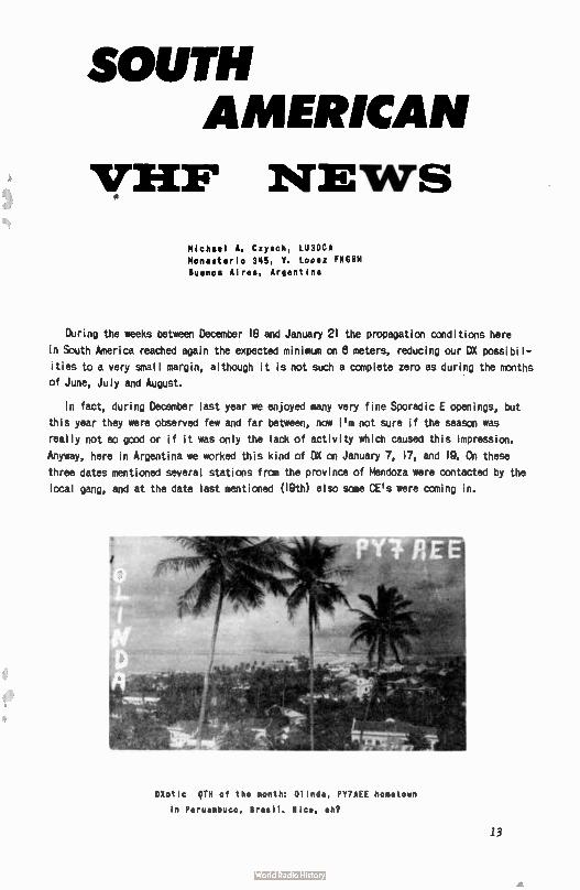
SOUTH AMERICAN
VEEP NEWS
Michael A. Czysch, LU3DCA
Monasterio 345, V. Lopez EOM
Buenos Aires, Argentina
During the weeks between December 18 and January 21 the propagation conditions here
in South America reached again the expected minimum cn 8 meters, reducing our DX possibil-
ities to a very small margin, although it is not such a complete zero as during the months
of June, July and August.
In fact, during December last year we enjoyed many very fine Sporadic E openings, but
this year they were observed few and far between, now I'm not sure if the season was
really not so good or if it was only the lack of activity which caused this impression.
Anyway, here in Argentina we worked this kind of DX on January 7, 17, and lg. Ch these
three dates mentioned several stations from the province of Mendoza were contacted by the
local gang, and at the date last mentioned (19th) also some CE's were coming in.
.11
DXotic DTH of the month: 01 inda, PY7AEE hometown
in Peruambuco, Brasil. Nice, eh?
13
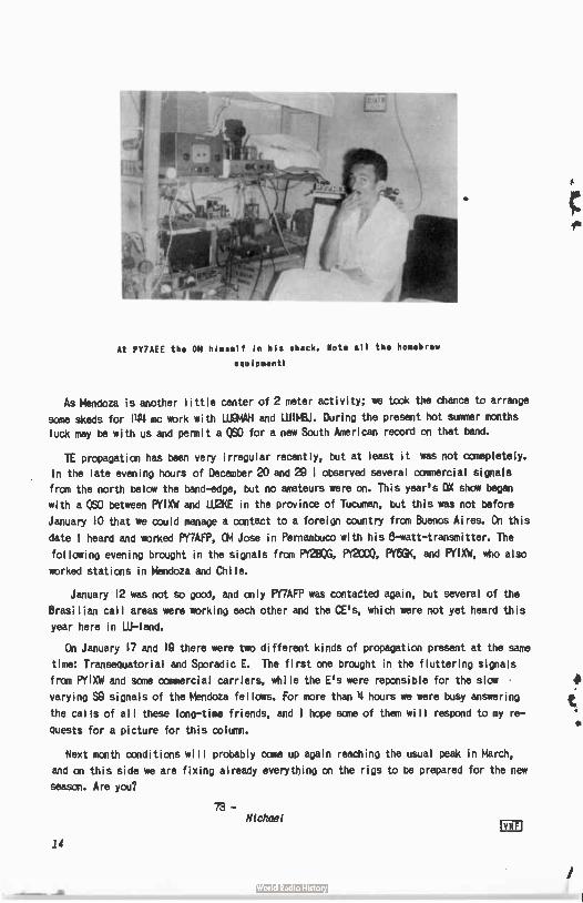
At PY7AEE the OM himself in his shack. Mote all the homebrew
equipment'
As Mendoza is another little center of 2 meter activity; we took the chance to arrange
some skeds for 144 mc work with LUWAH and LU1WEU. During the present hot summer months
luck may be with us and permit a C60 for a new South American record on that bend.
TE propagation has been very irregular recently, but at least it was not comepletely.
In the late evening hours of December 20 and 29 I observed several cannercial signals
from the north below the band-edge, but no amateurs were on. This year's DX show began
with a C60 between PYIXW and LU2KE in the province of Tucuman, but this was not before
January 10 that we could manage a contact to a foreign country from Buenos Aires. On this
date I heard and worked Pf7AFP, CM Jose in Pernambuco with his 8-watt-transmitter. The
following evening brought in the signals from PY2'80G, PY2C00, FY5e, and PYIeN, who also
worked stations in Mendoza and Chile.
January 12 was not so good, and only PY7AFP was contaèted again, but several of the
Brasilian call areas were working each other and the CE's, which were not yet heard this
year here in LU-lend.
On January 17 and 10 there were two different kinds of propagation present at the same
time: Transequatorial and Sporadic E. The first one brought in the fluttering signals
from PY1XW and scone ccmmercial carriers, while the E's were reponsible for the slow
varying 69 signals of the Mendoza fellows. For more than 4 hours we were busy answering
the calls of all these long-time friends, and 1 hope sane of them will respond to my re -
guests for a picture for this column.
Next month conditions will probably ccme up again reaching the usual peak in March,
and on this side we are fixing already everything on the rigs to be prepared for the new
season. Are you?
73 - Michael
mi
14
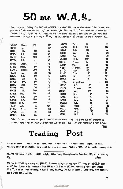
50 me W.A.S. Send in your listing for THE VHF AMATEUR's Worked All States department, Let's see how you rateil Minimum states confirmed needed for listing: 21. Cards must be on hand for inspection if requested. All entries must be submitted on a postcard or a51 card and addressed to: W.A.S. Listing - 50 mc, THE VHF AMATEUR, 67 Russell Avenue, Rattier, N.J.
WWW Wash. 150 47 KIIPXJ Tenn. S K46FY Ky. - 47 K2ZSO N.J. 100 K9DTB Ill. 80 47 K2HAK N.J. 100 K2OZM N.J. 100 48 K4RTG Va. 18 K510L N.M. 800 48 K2UGH N.J. 125
WA266U N.J. 180 K2ZBX N.J. - 48
WEIUML Mich. 40 101UJL Calif. 7 45 WORRU Pa. 35 KIB1L Mass. 50 45 K4E8T Florida 19 KL7AUV Alaska 200 45 KIIZM Mass. 100 WEIF N.J. 25 45 KIAUD Conn. 196 K2OWD N.Y. 50 43 KœtiS tio. 12 MOWS Iowa 75 43 12043 N.J. 8 K4PEV Tenn. 50 42 LU3DCA Argentina - KOOK° Ohio 45 42 K2ZSP N.J. 100 WOJWY Md. 75 42 HCIFS Ecuador 70 K9KZB Ill. 100 41 W3MNE Md. 100
K3808 Pd. uo 41 KOCWR Mo. 45 K2VDR N.Y. GO 41 K2VSE N.J. 30 KNU6 N.Y. 150 41 K2VNK N.J. 70 W2HVW N.J. 100 41 WA2AC1 N.Y. 45 K2MXT N.Y. 180 42 K8EUX Ohio - KIBHY Conn. 120 40 K3ATX Penn. 90 W2EA0 N.J. 100 40 K2VNL N.J. 70 K2CVG N.Y. 85 39 K2EFN N.J. PI
This list will be revised periodically as we receive notice from you of changes of
status. Also send us your 2 meter and 220 mc listings - We are starting o new W.A.S.
Trad ing Post
"218F8ROSWW8tpileg38?2
-R3F8F8
83R38:1838;8;Weit;
RATE: Commercial ads - 50 per word. Free to readers - any reasonable length. Ad from
readers MUST BE SUBMITTED ON A POST CARD or QSL card. TRADING POST, 87 Russell, Rahway, N.J.
QSL's: 'Brownie,' WOW', 3110 Lehigh, Allentown, Pennsylvania. Samples 100, with catalog
250. (3/ei)
RJR SALE: SX -99 and speaker, $96.00. 2 meter ground plane and ICO feet of RG-eeiu coax - $10.00. Tunable TV receiver frai 55 mc - 215 mc - $20.00. Heathkit MM-I test meter 823.00. Can deliver locally. Chuck Sizer, WA2FHC, 33 Tulip Street, Cranford, New Jersey.
ER-8-21168 (telephone).
15
FOR SALE: Viking Challenger - good condition - $90.00. Meisnner Signal Shifter - all
band v.f.o. -exciter -e.c.o. - $25.00. Will ship C.O.D....Heiko Ganzer, K2REH, 814
Nicholas Place, Rahway, New Jersey.
WANTED: K3HNP, the license plate collector, would like any additions- to the growing
collections. Much desired: ham call plates and any from outside U.S. Ordinary plates
from most states are wanted, but write first, as postage runs high. 14 Darkleaf Lane,
Levittown, Pennsylvania.
NEW TV Camera tubes: 8198 or 5527 - $50.00....W1BYX, Box #I22, clvi Ile, Connecticut.
(5/81)
WANTED: Construction articles on VHF-UHF gear for this magazine. Write us now! THE
VHF AMATEUR, 87 Russell Avenue, Rahway, New Jersey.
OSL's: 914L's, Citizen Band, Samples 5t. Nicholas & Son Printery, Box 11184, Phoenix, Arizona. (3/81)
WANTED: Address of East Coast supplier of preformed finger stock for 2(398 tubes. R.
G. Lachance, W1OKA, 49 Learned Street, Nashua, New Hampshire.
FREE HIGH PASS FILTERS: Every major TV manufacturer will supply TV! filters (usually
Drake 3Œ)-HP's) to TV1 recipients upon renuest111 Send for the lists of these ompanies
and proper forms to be filled out by complainees. 25t to cover printing, paper, en-
velops, and postage to Bob Brown, K2ZSQ, 87 Russell Avenue, Rahway, New Jersey. .
News from
West Europe George V. Haylock, G2DIIV
28, Longlands Road
Sidcup, Kent
ENGLAND
Fire my congratulations on THE VHF AMATEUR! There have been some good openings on
two meters recently (our bands are 144 to 148 mc Region I) especially during last
October and December. Many continental stations heard and worked...otherwise it has
been rather low on activity due to winter season here.
G3HBW made QS0 with OHINL...0300/0530 GMT. A very fine CSO, even R9 on bursts!
CH1NL also worked HBORG by meteor scatter of distance of 1090 miles- . last December.
Both contacts beat the old record set up in 1960 by G5NF and IIKDB for Sporadic E.
G8NB is using a transistor transmitter on 144.810 mc.
G5YV has heard signals from UA1KAW. UR2BU has also been heard. G3HOW has just made
contact with HBORG as well. LAING heard EM3BDA and OHINL.
GI3KYP/A will be active soon on 145.508 mc. GI3GXP worked HB9RG during last Octo-
ber, first time! GI5AJ works G2NY regularly every night.
16
M300 made OSO last August with F90E via the Echo I balloon,
A number of UK stations are equiped for the 14 meter band, frail 70.2 to 70.14 mc with
some active on both bands making for crossband ()SC's.
DLIfel has designed a new antenna for mobi le operation (DARC). Activity here includes
DLICK, DL8TU, DLIE1, >taw, Des, DJ8F38, 0.111PY, DUFF, DL8SS, DL9ARA, DJ5HG, DLIO<,
DL9PL, DJIZU, DJIP(J, DUI-f1, DLIR)(, DLIPS, DJ5HG. Austrian stations are: OEIWJ, 0E9IM,
OZ2AF, OZ7WA, OH1NL, and LAI1VC, LA9T, H139KH, SP8L8, SP3GZ, LA14YG, LAW, LAIIRD.
Others on v.h. f. are: Ce/IOUHF and DLOUH, DLO6G.
Here are sane more G'S: G3EGK, G3LRP, EGK, G3410,(1111_, G5YV, (2W), Get4B, G5TZ,
G21(1, G2XV, G2CIW, 0040, (113GILI, GW2H1Y, GI3KYP, 022FZC, GI5AK, 34313DA, (Y3FHH,
Git3G11, GeMFY.
Swedish stations to be active are: SM8PU, SKLICOK, SM5AAS, SMISA1f1, SVI5EIDO, SteTC,
Sle0T, SM5E1WC, 3,44FG, i7BAE. Skeds have been made with 0E3SE and OK2VCG.
Quite a number of UK hams and DL/DJ are on 2 meters with mobi le gear including
G2C4-IV/M on 11414.70 and 1145.250 mc.
Beacon stations in regular operation are GB3VHF on 144.50 and DLO Vti on 145.98 mc.
(And ON14UB on 1116.000 mc also a SM14 station).
Dresden station (TV) on 1146.250.
This should give you VEN stations the gen for cross-the-water OSO's1
73, George, G2DHV
Auk* Reporting Jack Reich, KL7AUV
Box 1048, Star Route A
Spenard, Alaska
GEE
Things are looking up around here - - especially on two meters...I have been heck-
ling the Alaskan hams for at least three years to get tooled up on six or two and set up sane knife-edge communication with Fairbanks or points north of the Range. Have
never had any luck in getting anyone on six up that way, but they have been slow ly in-
creasing their two meter work fbr the past year, and now have at least seven stations
operating at Minchumina, Tanana, Nenana, Shaw Creek, and Fairbanks, with fair results
They are mostly using beams pointed at McKinley. About a week ago, Wilbur Butler,
K L7A LA, made the first Anchorage - Minchumina contact, using only a Communicator and
Ground Plane here in Anchorage. KL71S, at 14 inchum ina, is using a Seneca, Heath Conver-
ter and Mohawk with a 22 element Telrex. Maury Wright, KL7CNN, then got his gear
cranked up and has set up a real pipeline into Minchumina using a Seneca and BC-830 in or Communicator. He has an 8 element Tel rex. KL7DJI in Nenana has a Seneca and Heath converter with a Tel rex beam, and KL7CLH in Tanana has a homebrew 50 watt rig with
a 35 element beam. Shaw Creek is using a Communicator, and in Fairbanks, KL7AEO,
and KL7CWO are on. I don't know what their gear is. Same goes for KL7CFN at North Pole.
17
Interesting development so far, is that KL7CNN, Anchorage, and KL7IS, Minchumina
get best results from vertical polarization, apparently knife edge over Mt.Foraker.
KL7DJI, in Nenana, can gear KL7CNN in Anchorage only if they use cross polarization.
Apparently this is a bounce of the side of McKinley. KL7CNN has tried a Telrex Sprral
array, which does not improve his signal to Minchumina, and Nenana cannot hear him at all using the Spiral array!
Needless to say, interest is looking up in the two meter region around here...KL7ALA
and I worked the V.H.F. Sweepstakes last weekend, and came up with totals of 20 and 28
contacts respectively. I got a few of my 28 on six meters, which ALA does not have. Our
CD net here consists of about 36 fairly active stations on 145.3, and roll call is given
or Tuesday, Wednesday, and Thursday at 7 Rk. Average check- ins per night during 1960 was 17.
I am fully back in business on six meters, with my 8 element optimum spaced Telrex
up, and am watching the bottom of the band and the two Illinois 149.8 and 40.80 mc
stations. Have heard them several times, although weakly. Haven't got the keyer tied
in yet, but hope to have it ready for use when conditions lock favorable. Still 250 watts Cet on 50.080. Am going to arrange schedule with Vale( as soon as I get time to write to him.
73, Jack
Letters Send us your letter today! We'll try to print all letters as received. Let's know
what you've been doing/ Write us nob Address? THE VHF AMATEUR, 67 Russell Avenue, Rahrzor, New Jersey.
Auburn. Maine: From the famous pen of Richard Huntress, KICXX, comes a real compre-
hensive report...
"The V.H.F. bands, as tr3udil are very dead here in the state of Maine. I keep
regular schedules with KIHAV in West Gardiner and WICFJ/1 over in Bridgeton. WEI
(Bill) is using a homebrew 4 element beam and a 40 watt v.f.o. controlled 6146 -61_6's
modulator rig that I loaned him. He has a TBS-50-D but is presently working on a
y. f.o., voice to talk, and TR antenna switching. He installed a new rotor on his
antenna system recently and added a homebrew 5 element two meter beam above the
6 meter anterm at the same time. This is a 25 mile haul as the crow flies but he
has a very nice signal on two meters, using only a Gonset Communicator.
'Walter, KlHAV has finished building a 6 meter mobile rig, using 6A(45's plate
modulating an 815 tube final at about 40 watts input. He has been receiving such
a good reporting claims with it Chat I sort of suspect he has lost interest for the
time being in putting it in the car.
-I worked Mike, K1NAT, down in Berwick recently and he informed me that he was the
only active station in that locality at present. Mike has a Gonset Communicator III
and, Berwick being in the very southern part of the state, he can work into Massachu-
setts easily, so he isn't too lonely.
18
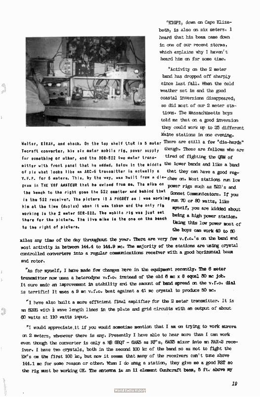
"K1GPI, down an Cape Eliza-
beth, is also on six meters. I
heard that his beam came down
in one of our recent storms,
which explains why I haven't
heard him on for some time.
"Activity on the 2 meter
tend has dropped off sharply
since last fall. When the cold
weather set in and the good
coastal inversions disappeared,
so did most of our 2 meter sta-
tions. The Massachusetts boys
told me that on a good inversion
they could work up to 25 different
¡tine stations in one evening.
Walter, RINAV, an shack. On the top shelf LtoR is 6 meter There are still a few "die-harda"
These are fellows who are. Tecraft converter, his six meter mobile rIg, power supply though
for something or other, and the SCR-522 two meter trans- tired of fighting the QBM of
sitter with front panel that he added. Below in the middle the lower banda and like a band
of pin what looks like an ARC-5 transmitter is actually a that they can have a good rae
's and
Chew V.F.P. for 6 meters. This, by the way, was built from a dia- on. Most stati low
522 gram in THE VHF AMATEUR that he swiped from me. The mike on power rigs such as
Gons the bench to the right goes the 522 ommiter and behind that et Communicators. If you
is the 522 receiver. The picture IS A PHONEY as I wat working nu 70 or 80 watts, like
m his at the time (duplex) when it was taken and the only rig yself, you are kidded about
working is the 2 meter SCR-522. The mobile rig was just set being a high power station. there fcr the picture. The live mike is the one on the bench
Using this low power most of
the boys can work 40 to 80 to the right of picture.
miles any time of the day throughout the year. There are very few v.f.o.'s on the band and
most activity is between 144.4 to 144.9 mc. The majority of the stations are using crystal
controlled converters into a regular communications receiver with a good horizontal beam
and rotor.
"As for myself, I have made few changes here in the equipment recently. The 8 meter
transmitter now uses a heterodyne v.f.o. instead of the old 8 mc x 8 equal 50 mc job.
It sure made an improvement in stability and the amount of band spread on the v.f.o. dial
is terrific! It uses a 9 mc v.f.o. beat against a 41 mc crystal to produce 50 mc.
"I have also built a more efficient final amplifier for the 2 meter transmitter. It is
an 829B with wave length lines in the plate and grid circuits with an output of about
60 watts at 110 watts input.
"I would appreciate it if you would sometime mention that I am on trying to work aurora
on 2 meters, whenever there is any. Presently I have able to hear more than I can work
even though the converter is only a AB JJ7 - 6AK5 as Res, 6AK5 mixer into an RAX,2 rece-
iver. I have two crystals, both in the seoond 100 kc of the band so as not to fight the
Kit's om the first 100 kc, but now it seems that many of the receivers can't tune above
144.1 mc for some reason or other. When I do snag a station, they give me a good BST so
the rig must be working; OK. The antenna is an 11 element Cusberaft beam, 5 ft. above my
19
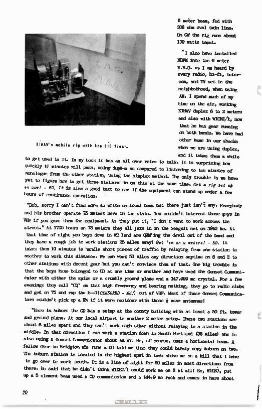
KIHAV's mobile rig with the 615 final.
6 meter beam, fed with
300 ohm oval twin line.
On CW the rig runs about
130 watts input.
"I also have installed
NMI into the 6 meter
V.F.O. as I am heard by
every radio, hi-fl, inter-
Ct, and TV set in the
neighbothood, when using
AM. I spend much of my
time an the air, working
KlHAV diplex 6 to 2 meters
and also with WICF3/1, now
that he has gear running
on both bands. We have had
other hams in our shacks
when we are using duplex,
and it takes them a while to get used to it. In my book it has an all over voice to talk. It is surprising how
quickly 10 minutes will pass, using duplex as wagered to listening to ten minutes of
monologue from the other station, using the simplex method. The only troüble is we have
yet to figure how to get three stations in on this at the same time. Get a rig set up
en 22.! - ED. It is also a good test to see if the equipment can stand up under a few hours of continuous operation. .
"Bob, sorry I can't find more to write on local news but there just isn'i any. Everybody
and his brother operate T5 meters here In the state. You couldn't interest those guys in
VHF if you gave them the equipment. As they put it, "I don't want to work across the
street." At 1700 hours on 75 meters they all join in on the Seagull net on 3940 ire. At
that time of night you boys down in W2 lend are geing the devil out of the band and
they have u roue job to work stations 25 miles away! Get ' em on 2 meters! - ED. It
takes them 10 minutes to handle short pieces of traffic by relaying from one station to
another to work this distance. We can work 50 miles any direction anytime an 6 and 2 to
other stations with decent gear bit you can't convince them of that. One big troüble is
that the boys have belonged to CD at one time or another and have used the Gonset Communi-
cator with either the spike or a cruibly ground plane and a 147.999 mc crystal. For a few
evenings they call "CQ" on that high frequency and hearing nothing, they go to radio clubs
and get on 75 and rap the 11-1(CENSORED - Ed!) out of VHF. Most of those Gonset Communica-
tors couldn't pick up a KW if it were nextdoor with those * wave antennas!
"Here in Auburn the CD has a setup at the county building with at least a 50 ft. tower
and ground plane. At our local Airport is another 2 meter setup. These two stations are
about 6 miles apart and they can't work each other without relaying to a station in the
middle. In that direction I can work a station down in South Portland (35 miles) whc is
also using e Gonset Communicator about an S7. He, of course, uses a horizontal beam. A
fellow over in Bridgton who runs a CD told me that they could barely copy Auburn an two.
The Auburn station is located in the highest spot in town above me an a hill that I have
to go over to work south. It is a line of sight for 50 miles in most directions from
there. He said that he didn't think W1CFU/1 could work me an 2 at all! He, WICBJ, put
up a 5 element beam used a CD comardcator and a 144.9 me rock and comes in here about
20
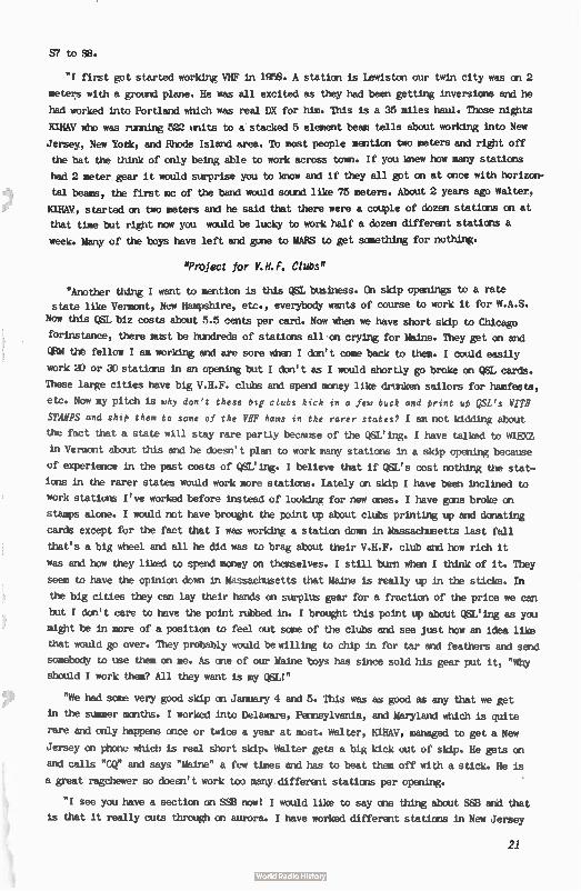
57 to SB.
"I first got started working VHF in 1958. A station is Lewiston our twin city was on 2
meters with a ground plane. He was all excited as they had been getting inversions and he
had worked into Portland which was real DX for him. This is a 35 miles haul. Those nights
HMV who was running 522 units to a'stacked 5 element beam tells about working into New
Jersey, New Yotk, and Rhode Island area. To most people mention two meters and right off
the bat the think of only being able to work across town. If you knew how many stations
had 2 meter gear it would surprise you to know and if they all got on at once with horizon-
tal beams, the first mc of the band would sound like 75 meters. About 2 years ago Walter,
H1HAV, started on two meters and he said that there were a couple of dozen stations on at
that time but right now you would be lucky to work half a dozen different stations a
week. Many of the boys have left and gone to MARS to get something for nothing.
"Project for V.H.F. Clubs"
"Another thing I want to mention is this QSL business. On skip openings to a rate
state like Vermont, New Hampshire, etc., everybody wants of course to work it for W.A.S.
Now this QSL biz costs about 5.5 cents per card. Now when we have short skip to Chicago
forinstance, there must be hundreds of stations all on crying for Maine. They get on and
QHM th è fellow I am working and are sore when I don't come back to them. I could easily
work 20 or 30 stations in an opening but I don't as I would shortly go broke on QSL cards.
These large cities have big V.H.F. ails and spend money like drunken sailors for hamfests,
etc. Now my pitch is why don't these btg clubs kick in a few buck and print up QSL's WITH
STAMPS and slit', them to some of the VHF hams in the rarer states? I am not kidding about
the fact that a state will stay rare partly because of the QSL'ing. I have talked to W1RXZ
in Vermont about this and he doesn't plan to work many stations in a skip opening because
of experience in the past costs of QSL'ing. I believe that if QSL's cost nothing the stat-
ions in the rarer states would work more stations. Lately an skip I have been inclined to
work stations I've worked before instead of looking for new ones. I have gene broke on
stamps alone. I would not have brought the point up about clubs printing up and donating
cards except for the fact that I was working a station down in Massachusetts last fall
that's a big wheel and all he did was to brag about their V.H.F. ebb and how rich it
was and how they liked to spend money on themselves. I still burn when I think of it. They
seem to have the opinion down in Massachusetts that Maine is really up in the sticks. In
the big cities they can lay their hands on surplus gear for a fraction of the price we can
but I don't care to have the point rubbed in. I brought this point up about QSL'ing as you
might be in more of a position to feel out some of the clubs and see just how an idea like
that would go over. They probably would be willing to chip in for tar and feathers and send
somebody to use them on me. As one of our Maine boys has since sold his gear put it, "Why
should I work them? All they want is my QSL!"
"We had some very good skip on January 4 and 5. This was as good as any that we get
in the summer months. I worked into Delaware, Pennsylvania, and Maryland which is quite
rare and only happens once or twice a year at most. Walter, H1HAV, managed to get a New
Jersey an phone which is real short skip. Walter gets a big kick out of skip. He gets on
and calls "CQ" and says "Maine" a few times and has to beat them off with a stick. He is
a great ragéhewer so doesn't work too many different stations per opening.
"I see you have a section on SSB now! I would like to say one thing about SSIS and that
is that it really cuts through on aurora. I have worked different stations in New Jersey
21
and New York who were using sideband on aurora and so help me they were still coming
through as the band was going out and even the CW signals were getting too weak to copy!"
San Fernando, California: Here's a real short note from Bob Adams, W3CMN, SS8 enthusiast extrodinairl...
"Have EN of SSB and CW on 50.103. Operate weekends. Bather disgusted at lack of activi-ty here.
"Rig is modified MNS-1. Receiver is Grounded Grid 6AJ4's - 75A4. Antenna 9 element
horizontally polarized.
"Hope to have 2 meter EN on soon. Will be on 144.010 mc as per TTB's suggestion."
Lynn, Hassachusetts: Terry bibddleton, WINQQ, emits with...
"Handle here is Terry. I thought I'd write to fill you in on the activity at this station.
"I'm running a Globe Hi-Bander to an 8 element Telrex yagi. The reciver is an SX-99
with a 417A converter. The Hi-Bander is a great rig! The aurora back in November netted
my 50 watter 58A and 57A reports throughout New York, Pennsylvania, and Ohio. A slight
inversion on the 6th of December netted 5X9 reports within a 250 mile radius.
"I hope you will tell the hi-power boys to look on 144.108 or 144.13 mc for my signal
on aurora or tropo openings.
"Hope to have an 829B final running an 2 meters by mid-winter, so my signal may come
up a little more."
Lethbridge, Alberta, CANADA: Regular reporter Bob Henry, mu, comes through with...
"In the way of news etc., - - - We here only heard one opening on 6 meters during
the last V.H.F. A.R.R.L. Contest. We heard K7ALE and K7RUX and managed to work K7RIIX
for a short one. This on phone which is really something for VE6 land in winter!
"Also Dave, VEOFF, and I have finally gotten on 1230 mc and are working up further
tests once we get a more portable rig. Pete, VE8BY, is also in on our tests and we have
hopes of a bit of flea "way up thar." Pete is always looking for a QS0 via aurora with
anyone on 6 meters." Nice hearing from you, Bob. Bow about a write-up on your ize mc
work and some pictures? Sure would appreciate any contributions, and I'm sure our
readers would too! Now about it? - ED.
Hinoa, New York: The secretary of the world-famous Syracuse V.H.F. Club takes tine off
from his important role of conducting essentials of a new administration to write...
"At the last meeting we held election of officiers for 1961 and the results were
asffollows...
"Charles (Charlie) Sellwood, Vi2RHO, - PRESIDENY. Howard (Larry) Lawrence, K2TXG,
VICE PRESIDENT. Richard (Dick) Benjamin, IMIFY, TREASURER. Albert (Al) Scala, K22RX,
ACTIVITIES MANAGER. Chuck Chester, K2TXX (that's me), SOUREIARY.
"I'll try to keep you informed on any pertinent happenite here at Syracuse V.H.F.
Club, Inc., and we sure will appreciate any help you can give us at the publicity end.
22
"All of us here at the Syracuse V.H.F. Club Inc., are really looking forward to a
bigger and better year coming up under the leadership of a very enthusiastic and active
president like Charlie Sellwood." ¡VHF
Message From The Publisher
In the publishing of even a small magazine such as
THE VHF AMATEUR, many problems continually croe up
that must be resolved. Most of these are small ones
with which your help is greatly desired - but this we
will cover later.
We are now mailing well over 2,000 copies out every
month to readers through Third Class Mail. We pay 3e per copy by affixing a stamp to each. This is a very
slow delivery-type mailing - we've found some readers
reporting over three weeks between the time we mail
the magazine and them actually getting it. So, we've
applied for a Second Class Mailing Permit. This will
mean you'll receive your copies within days of its
mailing. We'll probably get it before the next issue.
In the meantime, please bear with us. Thank you.
Now some of the things you can help us with: First
there is the matter of change of address. If you have
moved, or are planning to change OTH, please notify us immediately with your "old" and "new" address. We
can process the change of address stencils the same
day be hear from you. But, under the arrangements with
the Post Office, your copies will not be forwarded to
you. If you moue without letting us know, you'll miss
future issues.
Articles - Construction
This is another item wherein we depend solely on
you, the reader. We need good construction articles
on v.h.f. or u.h.f. gear; antennas, etc. This is some-
thing only you can provide. Everyone at one time or
another has built a piece of original gear, or modified
a know circuit - you hear ' em all the time on the air
talking about it. Why not write it up for THE VHF
AMATEUR? For any magazine to suceed, it needs reader
support. We are no exception to the rule. Your help
would be most appreciated.
Bob Smut K2ISQ
23
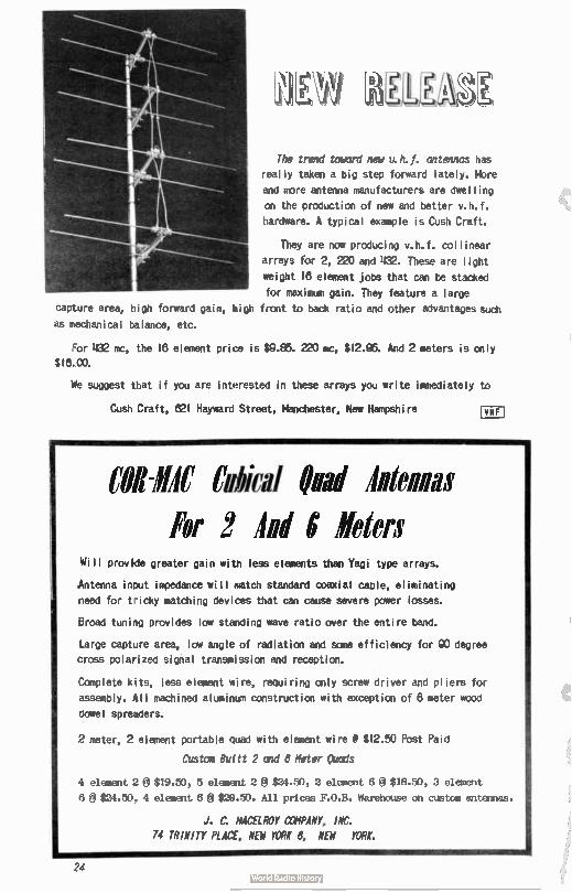
capture area,
as pechanical
giaa The trend toward new v.h.f. antennas has
really taken a big step forward lately. Mbre
and more antenna manufacturers are dwelling
on the production of new and better v.h.f.
hardware. A typical example is Cush Craft.
They are now producing v.h.f. collinear
arrays for 2, 220 and 432. These are light
*eight 18 element jobs that can be stacked
for maximum gain. They feature a large
high forward gain, high front to back ratio and other advantages such
balance, etc.
For 432 mc, the 18 element price is $9.E6. 220 mc, $ 12.95. And 2 meters is only
$18.00.
We suggest that if you are interested in these arrays you write immediately to
Cush Craft, 821 Hayward StmNDIL, nchester, New Hampshire
COR-111C Cubical bad Intends For 2 Ind g Eder:
Will provide greater gain witn less elements than Yagi type arrays.
Antenna input impedance will match standard coaxial cable, eliminating
need for tricky matching devices that can cause severe power losses.
Broad tuning provides low standing wave ratio over the entire band.
Large capture area, low angle of radiation and some efficiency for 910 degree
cross polarized signal transmission and reception.
Complete kits, less element wire, requiring only screw driver and pliers for
assembly. All machined aluminum construction with exception of 8 meter wood
dowel spreaders.
2 meter, 2 element portable quad with element wire I $ 12.50 Post Paid
*Ste! But ft 2 and 6 Meter Owls
4 element 2 @ $19.50, 5 element 2 @ $24.50, 2 element 6 $18.50, 3 element
6 â $24.50, 4 element 6 @ $29.50. All prices F.O.B. Warehouse on custom antennas.
J. C. MCELROY COMPANY, INC.
74 TRINITY PLACE, NEW YORK 6, NEW YORK.
2
Western Radio Amateur
48 pages of construction, news, DX and DXpedi-
Lions, V.H.F. and technical articles! All these
by such famous authors as Ed Marriner, W6BLZ,
Don Stoner, W6TNS, "YB" Pyle, W70E, with Bob
Grimm, K6RNO, heading up the V.H.F. Column!
This magazine is the 'third largest in the
United States - and for the money NOU can't
go wrong! Only $2.00 per year. Write now to:
Western Radio Amateur and West Coast Ham Ads
published at:
10517 Haverly St. El Monte, Califomis Gilbort 8-2119
A Monthly Publication
USA DX QSL COOP•Box 5938 Kansas City 11, Mo.
C WEAPY
OSL's 100 QSL's Each addi. 100... Ball Point Pen Felt Tip Pen (choice
$1.00 .75 .39
clr) . 59
KIT er1
100 OSL'S 1 FELT TIP PEN
$1.49
KIT »4
1000 Q5L'S 3 FELT TIP PENS 1 BALL POINT PEN
$9.39
KIT .2
250 ()SUS 1 FELT TIP PEN 1 BALL POINT PEN
$2.89
KIT a5
2500 OSL'S 5 FELT TIP PENS 2 BALL POINT PENS
$19.95
KIT .3
500 CISL'S 2 FELT TIP PENS 1 BALL POINT PEN
$4.99
At your distri-butors or direct if unavailable..
READ
AUTO - CALL 2509 - 32nd. St., S. E., WASHINGTON 20, D. C.
This is the paper you've
heard so much about! The fam-
ous "AUTO-CALL" that has been
quoted by almost all Ham pap-
ers, including CQ magazine!
For only a dollar a year,
yOu'll get 32 packed pages each
month of all the best in general
Ham Radio material. It has a
special added feature for those
amateurs in the Washington, D.C.
area, as it cevers club activ-
ities there. 40,41 .....0......444,-.40.41114sele•
The GEM 6 and 2 Converters
The 6 meter printed circuit converter uses a 6B,J/BZ7 as a cascode R.F. amplifier and a 6X8 High Gain pentode mixer and oscillator. This converter will give a
good signal-to-noise ratio and maximum sensitivity and I.F. output. The circuit uses very 111- ii
air wound coils and the broad-band oscillator will accept overtone crystals from 40 to 50 mc for any I.F. output. Size is 2è r4. Reouires 150V é 22 ma. 6
or I2V. Wired and Tested ( less tubes and crystal) only $4.50 b.*.
The new GEM 2 meter printed circuit converter uses a 817Q8 triode/tetrodes. The R.F. section consists of a Hi-Mu grounded grid triode amplifier and a high gain tetrode mixer with universal outputs.
The oscillator section uses overtone ci'ystals from 44 me to 46 me in a triode/tetrode tripler. This unit has Hi-- 1 air wound coils and will give maximum sensitivity and gain at 100V/18 ma. 6 or 12V.
Size is .24 x 4. Wired und Tested ( less tubes and crystal) only $5.50 host— bud.
GEM ELECTRONICS R. R. 3, Springfield, Ohio
The liffirAmykurfs published monthly by Robert M. Brown, K2ZSQ, at 67 Russell Avenue, Rahway, New Jersey. Telgglagng: FUltnn 1-1284. EDITOR: Robert M. Brown, K2ZSQ, 67 Russell Avenue. Rahway, New Jersey. OWNER: James Donald Brown, K2ZSP, 67 Russell Avenue, Rahway, New Jersey. Rates are: $2.00 a year. $3.50 two years, and $5.00 three years. Add $ 1.00 outside North America...Add $ 1.00 U.S. Air Mail...Add $2.00 overseas Air Mail. Opinions expressed herein are NOT necessar-ily those of the EDITOR, PUBLISHER, or OWNER. We do our best to present facts, but we assume no legal responsibility arising out of debts, royalties, etc.We reserve the right to discontinue publication at any time. If an error is made, we hasten to point out that all is experimental and we guarantee nothing.Write us if you wish to reprint anything contained herein, - permission will probabl y be granted. All published articles are rewarded with a one year subscription. y Disklay advertising rates are: $14. 00 fu ll bage, e Page $8.00. 4 *age $4.00. All art work is charged at cost, determined by extent of comkoxition required, DEADLINE IS THE 20th OF THE MONTH. r— — -------- ------- —
12 issues $2 ilte Vc,44maIesvi
67 RUSSELL () 1 year $2.00 0 New
I RAHWAY, 14E1N JERSEY () 2 years 3 50 0 Renewal
I) 5 years 500
NAME CALL
ADDRESS
CITY
L _ _ _ ZONE STATE
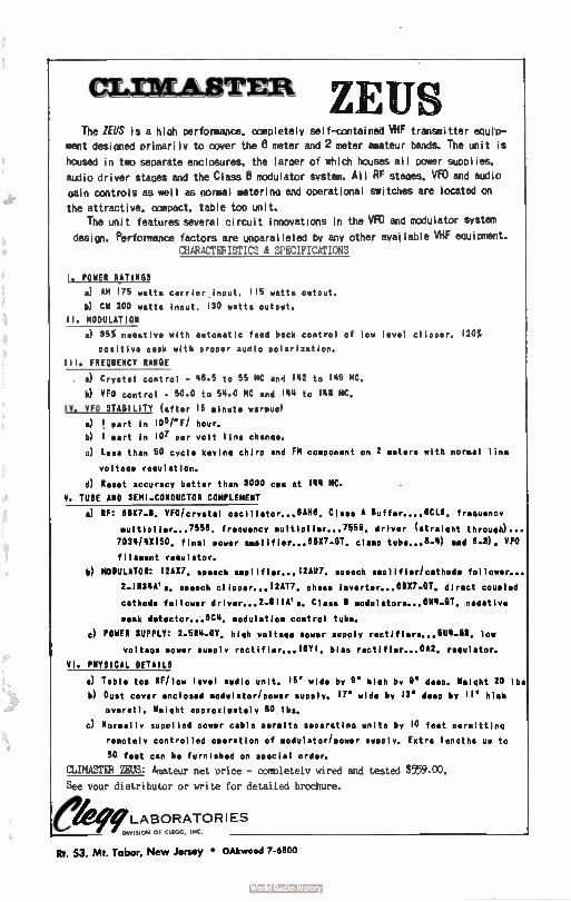
cursukserma ZEUS The ZEUS is a hioh cerformance, completely self-contained VHF transmitter ecieP-
ment designed primarily to cover the 8 meter and 2 meter amateur bands. The unit is
housed in two separate enclosures, the larger of which houses all power supplies.
audio driver stapes and the Class B modulator system. All RF stages. VFO and audio gain controls as well as normal metering and operational switches are located on
the attractive. ccmciact. table top unit.
The unit features several circuit innovations in the VFO and modulator system design. Performance factors are unparalleled by any other available VHF equipment.
CHARACTERISTICS & SPECIFICATIONS
1. POWER RATINGS
a) AM 175 watts carrier input, 115 watts output.
h) CW 200 watts input. 130 watts output.
11. MODULATION
a) 95% negative with automatic feed back control of low level clipper. 120%
positive peak with proper audio polarization.
ill. FREQUENCY RANGE
a) Crystal control - 48.5 to 55 MC and 143 to 149 MC.
h) VEO control - 50.0 to 54.0 MC and 144 to 148 MC,
IV. VFO STABILITY ( after 15 minute warmuo)
a) ! part in 1061° FI hour.
h) 1 part in 107 per volt line change.
c) Less than 50 cycle keying chirp and FM component on 2 meters with normal line
voltage regulation.
d) Reset accuracy better than 3000 cps at 144 MC.
V. TUBE ANO SEMI-CONDUCTOR COMPLEMENT
a) RF: 811(7.B. VFO/crystal oscillator... 8M. Class A Buffer....8CL8, freguencY
multiplier... 2558. freguency multiplier... 2O58. driver ( straight through)...
7034/48150. final power amPlifier...81137-0 1.. clamp tube... 8-4) and 8-3), VFO
filament regulator.
b) MODULATOR: 12A82, soeech amplifier...12W. speech amplifier/cathode follower...
2-1N34Als, speech gliaaar,,„12AT2. phase inverter...81137.8T. direct coupled
cathode follower driver... 2-81 We. Class 8 modulators...014-0T. negative
peak detector. ...8C4. modulation control tube.
c) POWER SUPPLY: 2-5R4- 0Y, high voltage slower supply rectifiers...5U4-88. low
voltage power supply bias rectifier... 0A2. regulator.
VI. PHYSICAL DETAILS
a) Table toe RF/low level audio unit. 15 wide by 9' high by 9' deep, Weleht 20 lbs
h) Dust cover enclosed modulator/power supply. 12" wide by 18' deep by 11' high
overall. Weight approximately 80 lbs.
c) Normally supplied power cable permits separating units by 10 feet permitting
remotely controlled operation of modulator/power supply. Extra lengths up to
50 feet can be furnished on special order.
CLIMASTER ZEUS: Amateur net once - completely wired and tested $559.00.
See your distributor or write for detailed brochure.
ekLABORATORIES DIVISION OF CLEGG, INC.
Rt. 53. Mt. Tabor, New Jersey • OAkwood 7-6800
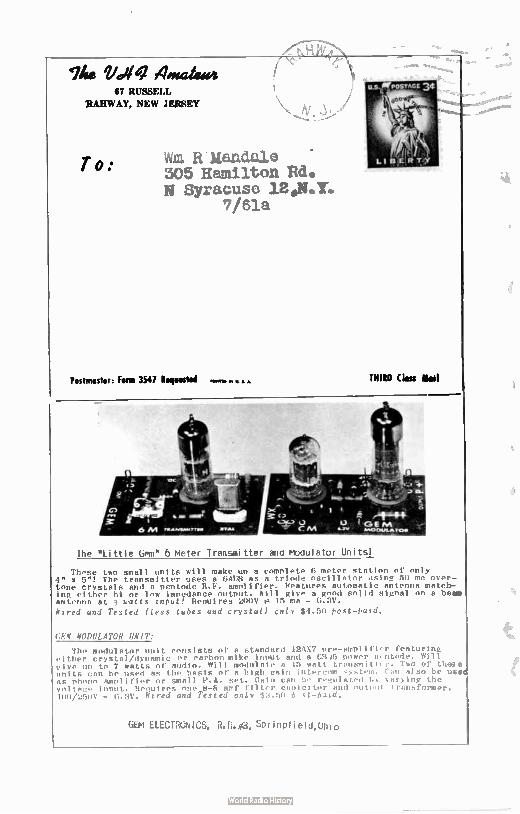
Ihis Ullq Ana 67 RUSSELL
RAHWAY, NEW JEMEY
To: W. R Mandale 505 Hamilton Rd. N Syracuse 12.N.Y.
7/61a
Postmaster: Form 3547 Reirestred THIRD Chu ail
The " Little Gen" 6 Meter Transmitter and Modulator Units!
These two small units will make un a complete 6 meter station of only 4" x 5"! The transmitter uses a 6/d18 as a triode oscillator using 50 mc over-tone crystals and a Pentode R.F. amplifier. Features automatic antenna match-ing either hl or low impedance output. Will give a good solid signal on a be antenna at 3 watts Iniudt! Requires 200V p 15 ma - 6.3V.
Wired and Tested ( less tubes and crystal) only $4.50 post-taid.
GEN MODULATOR UNIT:
The modulator unit consists of a standard 124X7 pre-amplifi.r featuring either crystal/dynamic or carbon mike input and a 611!5 power pentode. Will give un to 7 watts of audio. Will modulate n 15 watt transmitter. Two of these units can be used as the basis of a high gain intercom system. ran also be use as phono amplifier or small P.A. set. Gain can bo regulated by varying the voltage input. licouires one 8-8 mmf filter caolcitor and outunt transformer. 108/250V - 6.3V. Wired and Tested only $3.50 P-st-faid.
GEM ELECTRGNICS, R.R.#3, Springtield,Ohio


