Embed Size (px)
Citation preview
ITTC – Recommended
Procedures
7.5-02
-04-02
Page 1 of 19
Test Methods for Model Ice Properties Effective Date
2014
Revision
02
Updated Approved
Specialist Committee on Ice of the 27th
ITTC 27th
ITTC 2014
Date 02/2014 Date 09/2014
Table of Contents
1. PURPOSE OF THE PROCEDURE .... 3
1.1 General ............................................... 3
1.2 Structure of the Procedure ............... 3
1.3 Parameters ......................................... 3
2. FLEXURAL STRENGTH OF ICE ..... 4
2.1 General ............................................... 4
2.2 Cantilever Beam Tests ...................... 4
2.3 Three-Point Bending ......................... 5
2.4 Limitations and Discussion of the
Testing Methods ................................. 6
2.4.1 Material Constitution .................... 6
2.4.2 Boundary Conditions .................... 6
2.5 Quantities to be reported .................. 7
3. THE STRAIN MODULUS OF
ELASTICITY ........................................ 7
3.1 Infinite Plate on Elastic Foundation 7
3.1.1 Infinite Plate-Bending Method A . 7
3.1.2 Infinite Plate-Bending Method B . 8
3.1.3 Infinite Plate-Bending Method C
with Larger Load Radius .............. 8
3.2 Beam Bending Tests .......................... 8
3.3 Limitations and Discussion of the
Testing Methods ................................. 8
3.4 Quantities to be Reported ................. 9
3.4.1 Infinite Plate on Elastic Foundation
9
3.4.2 Beam Bending Method ................. 9
4. MODEL-ICE DENSITY ....................... 9
4.1 Measurement Approaches ................ 9
4.2 Limitations and Discussion of the
Testing Methods ............................... 10
4.3 Quantities to be Reported ............... 11
5. COMPRESSIVE STRENGTH OF ICE
............................................................... 11
5.1 Uniaxial Compression Tests ........... 11
5.2 Quantities to be reported ................ 12
5.3 Limitations and Discussion of the
Testing Methods ............................... 12
5.4 Quantities to be Reported ............... 13
6. INDENTER TEST ............................... 13
7. SHEAR STRENGTH .......................... 14
7.1 Punch Through Test ........................ 14
8. ICE- MODEL FRICTION
COEFFICIENT ................................... 14
8.1 Physical Ice-Model Friction
Coefficient ........................................ 14
8.2 Surface Roughness Related Friction
14
8.3 Limitations and Discussion of the
Testing Methods ............................... 15
8.4 Quantities to be Reported ............... 15
9. ICE THICKNESS MEASUREMENTS
............................................................... 15
ITTC – Recommended
Procedures
7.5-02
-04-02
Page 2 of 19
Test Methods for Model Ice Properties Effective Date
2014
Revision
02
10. RIDGE TESTS ..................................... 15
10.1 Ice Ridges and Ice-rubble ............... 15
10.1.1 Quantities to be reported ............ 16
10.2 Shear strength of ice-rubble ........... 16
10.2.1 Punch Test .................................. 16
10.2.2 Open Water Test ......................... 17
10.2.3 Test Analysis .............................. 17
10.3 Ridge / rubble porosity .................... 17
11. REFERENCES .................................... 18
ITTC – Recommended
Procedures
7.5-02
-04-02
Page 3 of 19
Test Methods for Model Ice Properties Effective Date
2014
Revision
02
Test Methods for Model Ice Properties
1. PURPOSE OF THE PROCEDURE
1.1 General
The purpose of this procedure is to ensure con-
sistency and comparability of measurements,
made in different facilities.
1.2 Structure of the Procedure
The sections of this procedure contain a de-
scription of acceptable test methods and proce-
dures, the test analyses, a general discussion, in-
cluding method specific limitations, and quanti-
ties to be reported. Most ice properties can be
determined by several different methods. The
discussion on limitations clarifies which method
is most appropriate for specific situations.
1.3 General Considerations
In ice testing, Froude’s scaling laws are fol-
lowed. Model testing facilities are using differ-
ent types of model-ice materials. None of the ex-
isting model-ice materials is known to scale all
aspects of natural ice. The effect of the geome-
try of the test specimen on all ice property meas-
urements must be taken into account. In most
cases, the values measured are only “indices”.
However, whether it is an index value or a fun-
damental mechanical property, the measure-
ment procedure is to be standardized. Many
measurements of the past decades refer to the
standards stated here and in previous ITTC
guidelines.
Model-ice materials are quite weak and en-
vironment dependent. To maintain good, relia-
ble results, it is recommended that property
measurements are performed in-situ in the tank
water whenever possible, without lifting the
samples out of the natural environment. The
timing and location of the measurements are im-
portant. The measurements are to be completed
as close as possible to the actual test area and
test time.
All measurement procedures are to be very
simple, the procedures are to be documented,
and the personnel performing the measurements
have to be qualified. In all measurements, equip-
ment are to be calibrated in ambient tempera-
tures.
The planning of ice model tests is strongly
dependent on the model-ice properties and their
ability to scale with respect to the modelled full-
scale scenario.
1.3 Parameters
Parameter Sym-
bol
SI-Units
Cross-sectional area A [m2]
Strain modulus of elas-
ticity
E [Pa]
Impact diameter D [m]
Loading force F [N]
Buoyancy force Fb [N]
ITTC – Recommended
Procedures
7.5-02
-04-02
Page 4 of 19
Test Methods for Model Ice Properties Effective Date
2014
Revision
02
Normal loading force Fn [N]
Tangential loading force Ft [N]
Bending Moment M [Nm]
Displaced volume Vd [m3]
Ice volume Vi [m3]
Rubble volume Vr [m3]
Total volume Vt [m3]
Void volume Vv [m3]
Section Modulus W [m3]
Beam, specimen width b [m]
Dynamic friction coeffi-
cient
cif [m]
Ice thickness h [m]
Foundation factor k [kg/
m2s2]
Gravitational accelera-
tion
g [m/s2]
Beam, specimen length l [m]
Characteristic length lc [m]
Distance from loading
point to crack
lb [m]
Ridge porosity p [1]
Cross-head speed vc [m/s]
Specimen width w [m]
Displacement [m]
Poisson’s ratio [1]
Compressive strength c [Pa]
Indentation strength i [Pa]
Flexural strength f [Pa]
Shear strength s [Pa]
Ice density [kg/m3]
Water density w [kg/m3]
2. FLEXURAL STRENGTH OF ICE
2.1 General
The flexural strength test should be con-
ducted with specimens from representative loca-
tions. At least a set of three samples is to be
tested per location to account for natural scatter
in results. The location of the samples, in rela-
tion to the later test, may be facility specific. In
long basins the tests might be conducted a cer-
tain distance from both sides of the later test
track, whereas in other basins it might be even
in the centre of the later test track.
2.2 Cantilever Beam Tests
The in-situ cantilever beam test is the most
common and best-known method to determine
the flexural strength of an ice sheet. A floating
cantilever beam having length l, and width b, is
cut in-situ. The tip of the beam is loaded at a
constant speed until the beam fails. The loading
direction can be either downward or upward,
and will correspond to the same bending direc-
tion as anticipated in the scheduled model test.
ITTC – Recommended
Procedures
7.5-02
-04-02
Page 5 of 19
Test Methods for Model Ice Properties Effective Date
2014
Revision
02
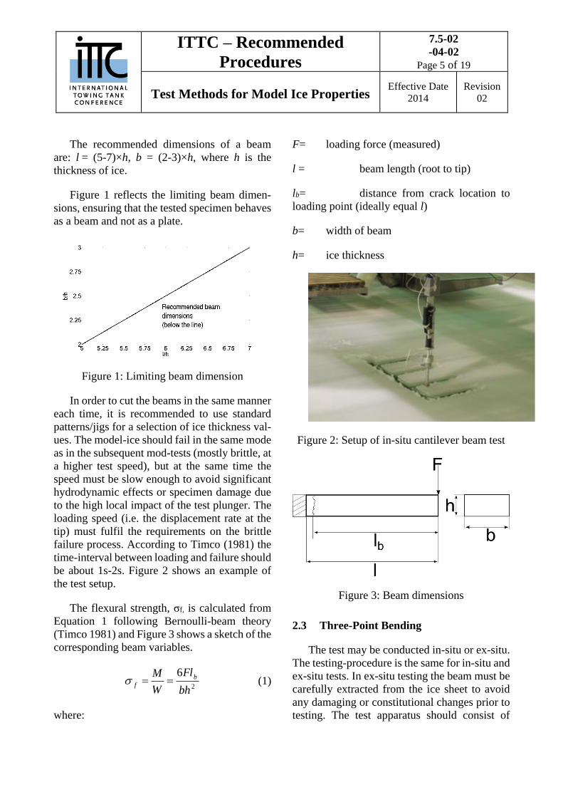
The recommended dimensions of a beam
are: l = (5-7)×h, b = (2-3)×h, where h is the
thickness of ice.
Figure 1 reflects the limiting beam dimen-
sions, ensuring that the tested specimen behaves
as a beam and not as a plate.
Figure 1: Limiting beam dimension
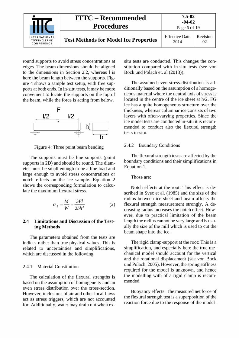
In order to cut the beams in the same manner
each time, it is recommended to use standard
patterns/jigs for a selection of ice thickness val-
ues. The model-ice should fail in the same mode
as in the subsequent mod-tests (mostly brittle, at
a higher test speed), but at the same time the
speed must be slow enough to avoid significant
hydrodynamic effects or specimen damage due
to the high local impact of the test plunger. The
loading speed (i.e. the displacement rate at the
tip) must fulfil the requirements on the brittle
failure process. According to Timco (1981) the
time-interval between loading and failure should
be about 1s-2s. Figure 2 shows an example of
the test setup.
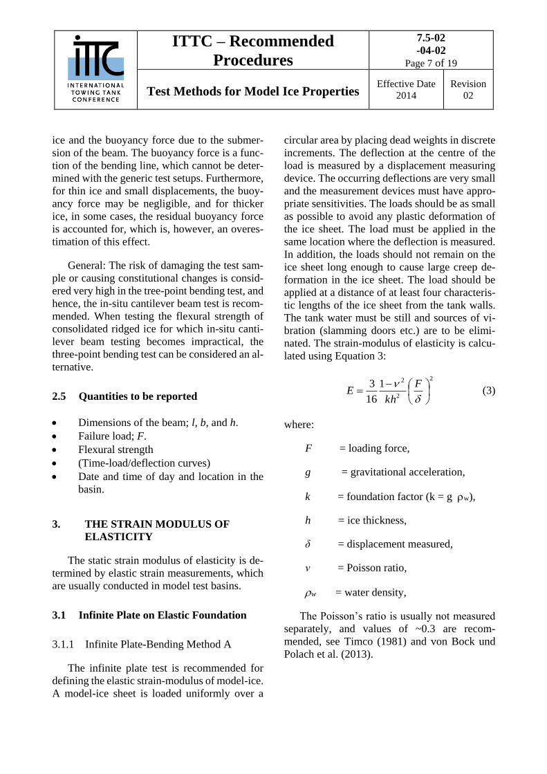
The flexural strength, σf, is calculated from
Equation 1 following Bernoulli-beam theory
(Timco 1981) and Figure 3 shows a sketch of the
corresponding beam variables.
2
6
bh
Fl
W
M b
f (1)
where:
F= loading force (measured)
l = beam length (root to tip)
lb= distance from crack location to
loading point (ideally equal l)
b= width of beam
h= ice thickness
Figure 2: Setup of in-situ cantilever beam test
Figure 3: Beam dimensions
2.3 Three-Point Bending
The test may be conducted in-situ or ex-situ.
The testing-procedure is the same for in-situ and
ex-situ tests. In ex-situ testing the beam must be
carefully extracted from the ice sheet to avoid
any damaging or constitutional changes prior to
testing. The test apparatus should consist of
ITTC – Recommended
Procedures
7.5-02
-04-02
Page 6 of 19
Test Methods for Model Ice Properties Effective Date
2014
Revision
02
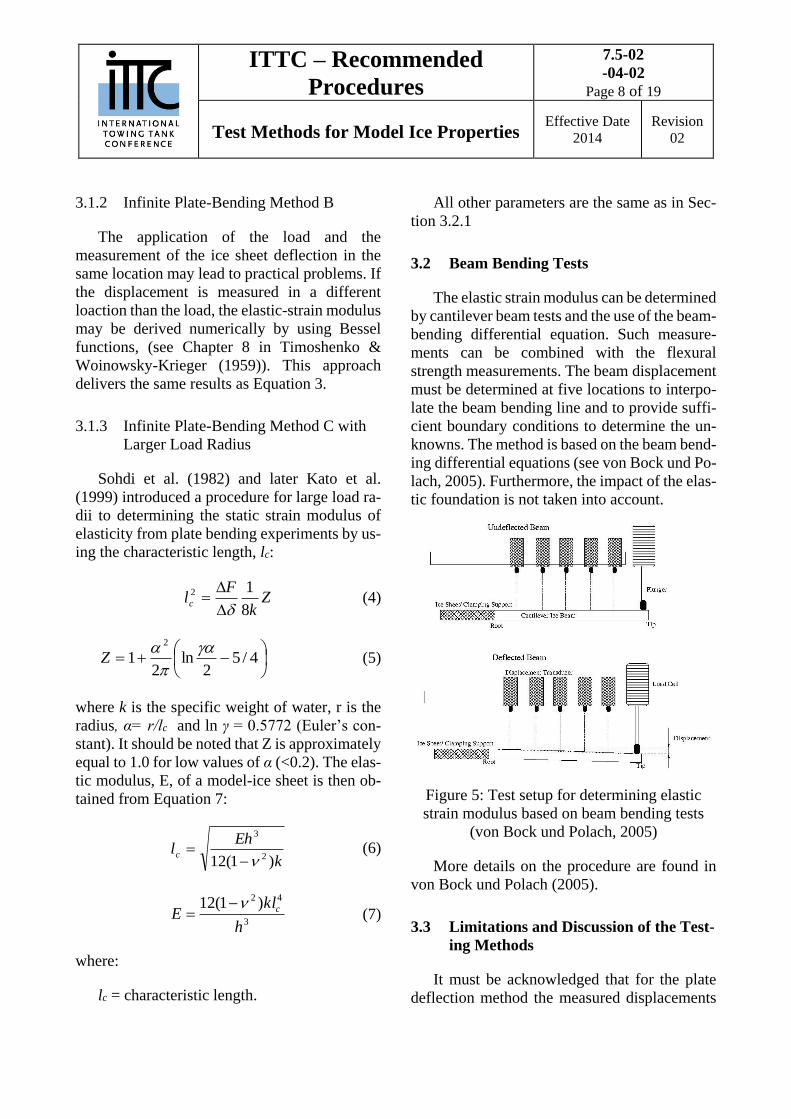
round supports to avoid stress concentrations at
edges. The beam dimensions should be aligned
to the dimensions in Section 2.2, whereas l is
here the beam length between the supports. Fig-
ure 4 shows a sample test setup, with free sup-
ports at both ends. In in-situ tests, it may be more
convenient to locate the supports on the top of
the beam, while the force is acting from below.
Figure 4: Three point beam bending
The supports must be line supports (point
supports in 2D) and should be round. The diam-
eter must be small enough to be a line load and
large enough to avoid stress concentrations or
notch effects on the ice sample. Equation 2
shows the corresponding formulation to calcu-
late the maximum flexural stress.
22
3
bh
Fl
W
Mf (2)
2.4 Limitations and Discussion of the Test-
ing Methods
The parameters obtained from the tests are
indices rather than true physical values. This is
related to uncertainties and simplifications,
which are discussed in the following:
2.4.1 Material Constitution
The calculation of the flexural strengths is
based on the assumption of homogeneity and an
even stress distribution over the cross-section.
However, inclusions of air and other local flaws
act as stress triggers, which are not accounted
for. Additionally, water may drain out when ex-
situ tests are conducted. This changes the con-
stitution compared with in-situ tests (see von
Bock und Polach et. al (2013)).
The assumed even stress-distribution is ad-
ditionally based on the assumption of a homoge-
neous material where the neutral axis of stress is
located in the centre of the ice sheet at h/2. FG
ice has a quite homogeneous structure over the
thickness, whereas columnar ice consists of two
layers with often-varying properties. Since the
ice model tests are conducted in-situ it is recom-
mended to conduct also the flexural strength
tests in-situ.
2.4.2 Boundary Conditions
The flexural strength tests are affected by the
boundary conditions and their simplifications in
Equation 1.
Those are:
Notch effects at the root: This effect is de-
scribed in Svec et al. (1985) and the size of the
radius between ice sheet and beam affects the
flexural strength measurement strongly. A de-
creasing radius increases the notch effect. How-
ever, due to practical limitation of the beam
length the radius cannot be very large and is usu-
ally the size of the mill which is used to cut the
beam shape into the ice.
The rigid clamp-support at the root: This is a
simplification, and especially here the true me-
chanical model should account for the vertical
and the rotational displacement (see von Bock
und Polach, 2005). However, the spring stiffness
required for the model is unknown, and hence
the modelling with of a rigid clamp is recom-
mended.
Buoyancy effects: The measured net force of
the flexural strength test is a superposition of the
reaction force due to the response of the model-
ITTC – Recommended
Procedures
7.5-02
-04-02
Page 7 of 19
Test Methods for Model Ice Properties Effective Date
2014
Revision
02
ice and the buoyancy force due to the submer-
sion of the beam. The buoyancy force is a func-
tion of the bending line, which cannot be deter-
mined with the generic test setups. Furthermore,
for thin ice and small displacements, the buoy-
ancy force may be negligible, and for thicker
ice, in some cases, the residual buoyancy force
is accounted for, which is, however, an overes-
timation of this effect.
General: The risk of damaging the test sam-
ple or causing constitutional changes is consid-
ered very high in the tree-point bending test, and
hence, the in-situ cantilever beam test is recom-
mended. When testing the flexural strength of
consolidated ridged ice for which in-situ canti-
lever beam testing becomes impractical, the
three-point bending test can be considered an al-
ternative.
2.5 Quantities to be reported
Dimensions of the beam; l, b, and h.
Failure load; F.
Flexural strength
(Time-load/deflection curves)
Date and time of day and location in the
basin.
3. THE STRAIN MODULUS OF
ELASTICITY
The static strain modulus of elasticity is de-
termined by elastic strain measurements, which
are usually conducted in model test basins.
3.1 Infinite Plate on Elastic Foundation
3.1.1 Infinite Plate-Bending Method A
The infinite plate test is recommended for
defining the elastic strain-modulus of model-ice.
A model-ice sheet is loaded uniformly over a
circular area by placing dead weights in discrete
increments. The deflection at the centre of the
load is measured by a displacement measuring
device. The occurring deflections are very small
and the measurement devices must have appro-
priate sensitivities. The loads should be as small
as possible to avoid any plastic deformation of
the ice sheet. The load must be applied in the
same location where the deflection is measured.
In addition, the loads should not remain on the
ice sheet long enough to cause large creep de-
formation in the ice sheet. The load should be
applied at a distance of at least four characteris-
tic lengths of the ice sheet from the tank walls.
The tank water must be still and sources of vi-
bration (slamming doors etc.) are to be elimi-
nated. The strain-modulus of elasticity is calcu-
lated using Equation 3:
2
2
21
16
3
F
khE (3)
where:
F = loading force,
g = gravitational acceleration,
k = foundation factor (k = g w),
h = ice thickness,
δ = displacement measured,
ν = Poisson ratio,
w = water density,
The Poisson’s ratio is usually not measured
separately, and values of ~0.3 are recom-
mended, see Timco (1981) and von Bock und
Polach et al. (2013).
ITTC – Recommended
Procedures
7.5-02
-04-02
Page 8 of 19
Test Methods for Model Ice Properties Effective Date
2014
Revision
02
3.1.2 Infinite Plate-Bending Method B
The application of the load and the
measurement of the ice sheet deflection in the
same location may lead to practical problems. If
the displacement is measured in a different
loaction than the load, the elastic-strain modulus
may be derived numerically by using Bessel
functions, (see Chapter 8 in Timoshenko &
Woinowsky-Krieger (1959)). This approach
delivers the same results as Equation 3.
3.1.3 Infinite Plate-Bending Method C with
Larger Load Radius
Sohdi et al. (1982) and later Kato et al.
(1999) introduced a procedure for large load ra-
dii to determining the static strain modulus of
elasticity from plate bending experiments by us-
ing the characteristic length, lc:
Zk
Flc
8
12
(4)
4/5
2ln
21
2
Z (5)
where k is the specific weight of water, r is the
radius, α= r/lc and ln γ = 0.5772 (Euler’s con-
stant). It should be noted that Z is approximately
equal to 1.0 for low values of α (<0.2). The elas-
tic modulus, E, of a model-ice sheet is then ob-
tained from Equation 7:
k
Ehlc
)1(12 2
3
(6)
3
42 )1(12
h
klE c (7)
where:
lc = characteristic length.
All other parameters are the same as in Sec-
tion 3.2.1
3.2 Beam Bending Tests
The elastic strain modulus can be determined
by cantilever beam tests and the use of the beam-
bending differential equation. Such measure-
ments can be combined with the flexural
strength measurements. The beam displacement
must be determined at five locations to interpo-
late the beam bending line and to provide suffi-
cient boundary conditions to determine the un-
knowns. The method is based on the beam bend-
ing differential equations (see von Bock und Po-
lach, 2005). Furthermore, the impact of the elas-
tic foundation is not taken into account.
Figure 5: Test setup for determining elastic
strain modulus based on beam bending tests
(von Bock und Polach, 2005)
More details on the procedure are found in
von Bock und Polach (2005).
3.3 Limitations and Discussion of the Test-
ing Methods
It must be acknowledged that for the plate
deflection method the measured displacements
ITTC – Recommended
Procedures
7.5-02
-04-02
Page 9 of 19
Test Methods for Model Ice Properties Effective Date
2014
Revision
02
might be very small. This does not only require
a high resolution displacement transducer (in
most cases a laser), but also a vibration free
mounting point. Already small oscillation am-
plitudes may disturb the measurements too
much.
The theory used for the plate on elastic foun-
dation is based on thin plate theory and plain
stress. As shown in von Bock und Polach et al.
(2013) neglecting shear stresses may lead to an
error. This error may increase for increasing
thickness. Therefore, this parameter should be
considered as an index. Furthermore, Frederking
and Timco (1983) examined various influence
factors on the elastic strain modulus measure-
ments by beam bending tests.
It must be considered that the plate bending
method Option A and B assume a point-load,
whereas Option C accounts for larger load radii
(parameter r / in Equation 5). The combined
flexural strength and strain modulus test faces
practical challenges. Especially in thin ice, the
beams are short and it may be difficult to fit all
displacement transducers onto the setup. The
beam test is the most common test used in full
scale.
The beam bending method is difficult to han-
dle in practice and the high number of measured
parameters (five displacement measurements)
may lead to a significant error accumulation.
Furthermore, the plate-bending test is the most
common test method and therefore recom-
mended to use.
3.4 Quantities to be Reported
3.4.1 Infinite Plate on Elastic Foundation
Thickness of model-ice sheet
Weights used
Location in the tank
Time-deflection curves
Calculated modulus of elasticity
Time of the day when measured
3.4.2 Beam Bending Method
Thickness of model-ice sheet
Measured bending force
Location of displacement transducers
Interpolated bending line
Location in tank
Time-deflection curves
Calculated modulus of elasticity
Time of day when measured
4. MODEL-ICE DENSITY
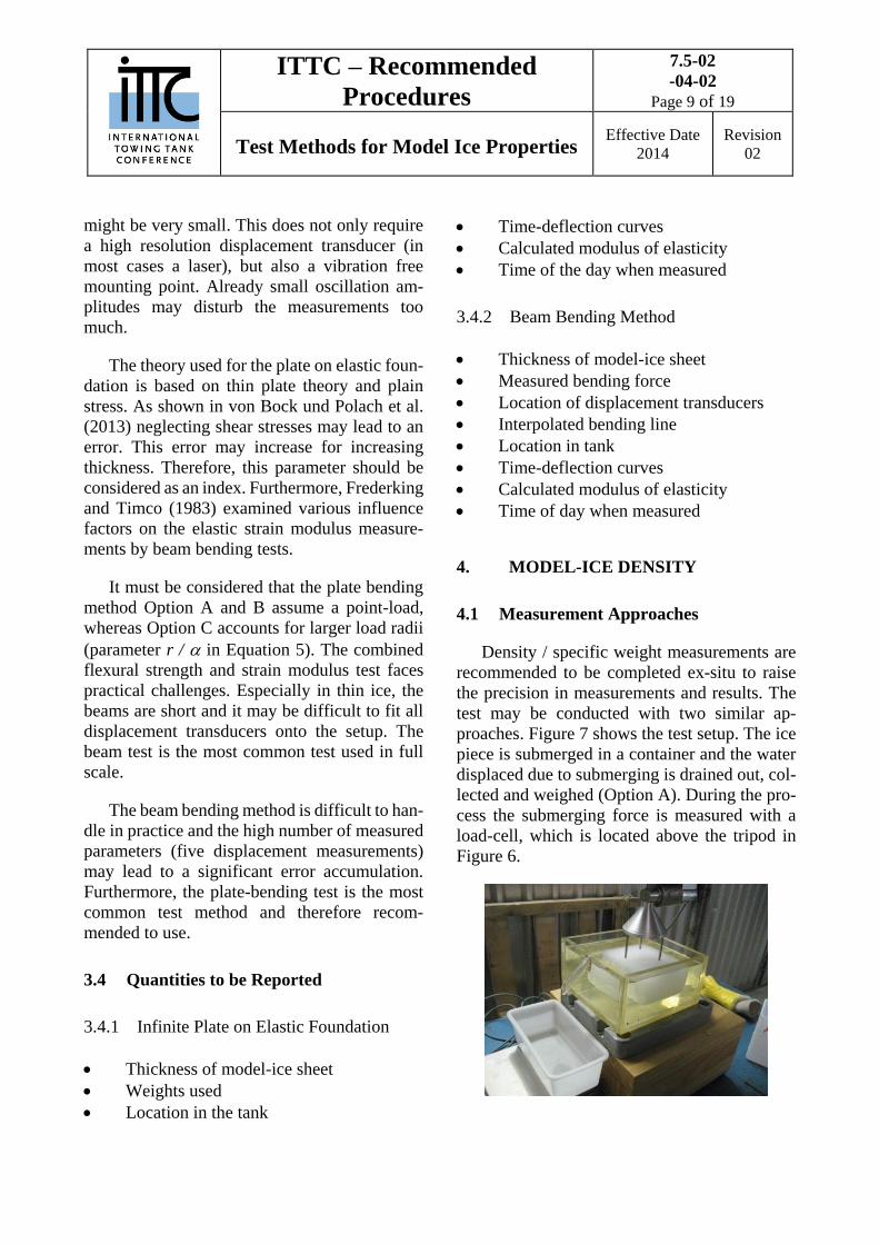
4.1 Measurement Approaches
Density / specific weight measurements are
recommended to be completed ex-situ to raise
the precision in measurements and results. The
test may be conducted with two similar ap-
proaches. Figure 7 shows the test setup. The ice
piece is submerged in a container and the water
displaced due to submerging is drained out, col-
lected and weighed (Option A). During the pro-
cess the submerging force is measured with a
load-cell, which is located above the tripod in
Figure 6.
ITTC – Recommended
Procedures
7.5-02
-04-02
Page 10 of 19
Test Methods for Model Ice Properties Effective Date
2014
Revision
02
Figure 6: Ex-situ density measurement setup
(Option A)
The density of ice is calculated using the fol-
lowing Equation 8, where Vd is the volume of
the displaced water (equal to the submerged ice
volume) and F the (buoyancy-) response force
of the submerged ice piece.
gV
F
d
wi (8)
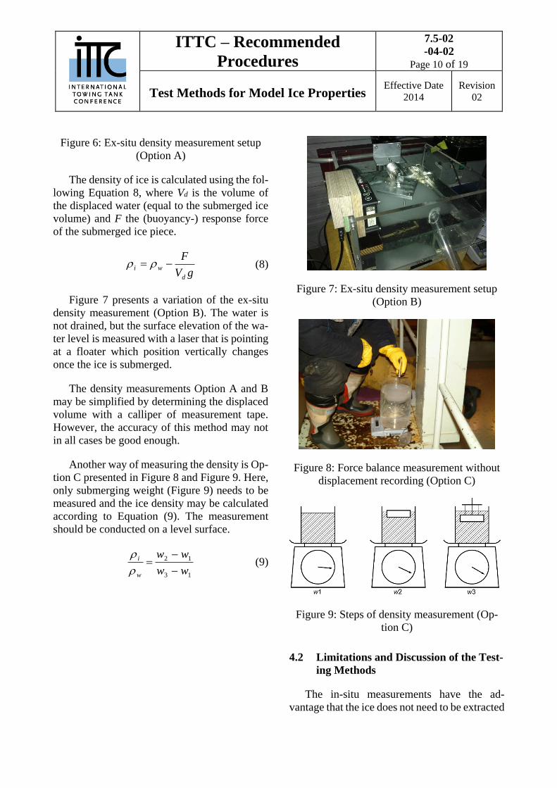
Figure 7 presents a variation of the ex-situ
density measurement (Option B). The water is
not drained, but the surface elevation of the wa-
ter level is measured with a laser that is pointing
at a floater which position vertically changes
once the ice is submerged.
The density measurements Option A and B
may be simplified by determining the displaced
volume with a calliper of measurement tape.
However, the accuracy of this method may not
in all cases be good enough.
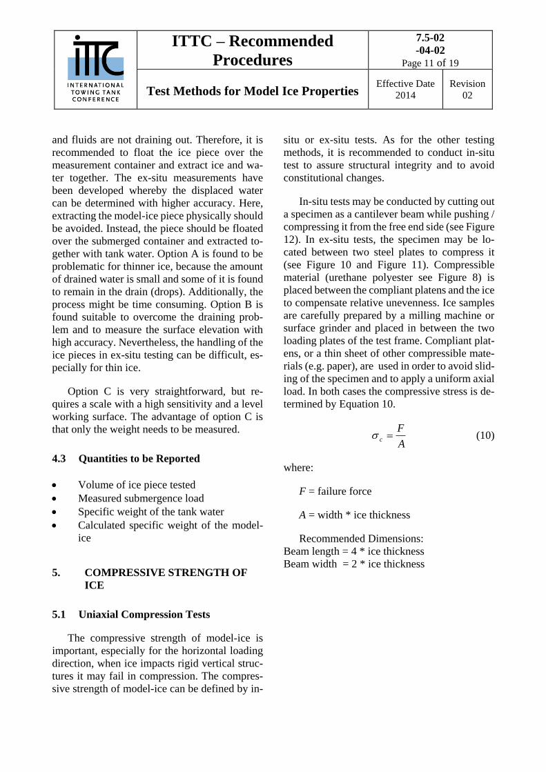
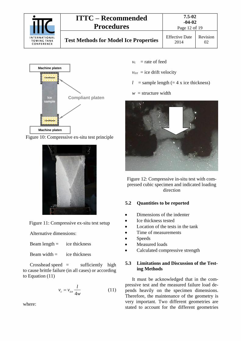
Another way of measuring the density is Op-
tion C presented in Figure 8 and Figure 9. Here,
only submerging weight (Figure 9) needs to be
measured and the ice density may be calculated
according to Equation (9). The measurement
should be conducted on a level surface.
13
12
ww
ww
w
i
(9)
Figure 7: Ex-situ density measurement setup
(Option B)
Figure 8: Force balance measurement without
displacement recording (Option C)
Figure 9: Steps of density measurement (Op-
tion C)
4.2 Limitations and Discussion of the Test-
ing Methods
The in-situ measurements have the ad-
vantage that the ice does not need to be extracted
ITTC – Recommended
Procedures
7.5-02
-04-02
Page 11 of 19
Test Methods for Model Ice Properties Effective Date
2014
Revision
02
and fluids are not draining out. Therefore, it is
recommended to float the ice piece over the
measurement container and extract ice and wa-
ter together. The ex-situ measurements have
been developed whereby the displaced water
can be determined with higher accuracy. Here,
extracting the model-ice piece physically should
be avoided. Instead, the piece should be floated
over the submerged container and extracted to-
gether with tank water. Option A is found to be
problematic for thinner ice, because the amount
of drained water is small and some of it is found
to remain in the drain (drops). Additionally, the
process might be time consuming. Option B is
found suitable to overcome the draining prob-
lem and to measure the surface elevation with
high accuracy. Nevertheless, the handling of the
ice pieces in ex-situ testing can be difficult, es-
pecially for thin ice.
Option C is very straightforward, but re-
quires a scale with a high sensitivity and a level
working surface. The advantage of option C is
that only the weight needs to be measured.
4.3 Quantities to be Reported
Volume of ice piece tested
Measured submergence load
Specific weight of the tank water
Calculated specific weight of the model-
ice
5. COMPRESSIVE STRENGTH OF
ICE
5.1 Uniaxial Compression Tests
The compressive strength of model-ice is
important, especially for the horizontal loading
direction, when ice impacts rigid vertical struc-
tures it may fail in compression. The compres-
sive strength of model-ice can be defined by in-
situ or ex-situ tests. As for the other testing
methods, it is recommended to conduct in-situ
test to assure structural integrity and to avoid
constitutional changes.
In-situ tests may be conducted by cutting out
a specimen as a cantilever beam while pushing /
compressing it from the free end side (see Figure
12). In ex-situ tests, the specimen may be lo-
cated between two steel plates to compress it
(see Figure 10 and Figure 11). Compressible
material (urethane polyester see Figure 8) is
placed between the compliant platens and the ice
to compensate relative unevenness. Ice samples
are carefully prepared by a milling machine or
surface grinder and placed in between the two
loading plates of the test frame. Compliant plat-
ens, or a thin sheet of other compressible mate-
rials (e.g. paper), are used in order to avoid slid-
ing of the specimen and to apply a uniform axial
load. In both cases the compressive stress is de-
termined by Equation 10.
A
Fc (10)
where:
F = failure force
A = width * ice thickness
Recommended Dimensions:
Beam length = 4 * ice thickness
Beam width = 2 * ice thickness
ITTC – Recommended
Procedures
7.5-02
-04-02
Page 12 of 19
Test Methods for Model Ice Properties Effective Date
2014
Revision
02
Figure 10: Compressive ex-situ test principle
Figure 11: Compressive ex-situ test setup
Alternative dimensions:
Beam length = ice thickness
Beam width = ice thickness
Crosshead speed = sufficiently high
to cause brittle failure (in all cases) or according
to Equation (11)
w
lvv icec
4 (11)
where:
vc = rate of feed
vice = ice drift velocity
l = sample length (= 4 x ice thickness)
w = structure width
Figure 12: Compressive in-situ test with com-
pressed cubic specimen and indicated loading
direction
5.2 Quantities to be reported
Dimensions of the indenter
Ice thickness tested
Location of the tests in the tank
Time of measurements
Speeds
Measured loads
Calculated compressive strength
5.3 Limitations and Discussion of the Test-
ing Methods
It must be acknowledged that in the com-
pressive test and the measured failure load de-
pends heavily on the specimen dimensions.
Therefore, the maintenance of the geometry is
very important. Two different geometries are
stated to account for the different geometries
Urethane
Machine platen
Machine platen
Ice
sample
Urethane
Compliant platen
ITTC – Recommended
Procedures
7.5-02
-04-02
Page 13 of 19
Test Methods for Model Ice Properties Effective Date
2014
Revision
02
used in the past. Larger specimens ease the han-
dling in ex-situ testing, while smaller specimens
have a higher stiffness than more slender speci-
mens do. The higher stiffness is advantageous
when impact surface and specimen surface are
not exactly parallel. In this case, the crushing
and shearing may occur in the contact interface
until the two surfaces are parallel and the actual
compression starts. Accordingly, more slender
specimens may fail by a superposition of com-
pression and other failure modes, such as buck-
ling or bending. Therefore, it is recommended to
compensate for unparallel faces with soft and
compressible material in between.
5.4 Quantities to be Reported
Measured load, F
Test specimen dimension
Test setup
Compressive strength
Photographs of failed specimens, if possi-
ble
6. INDENTER TEST
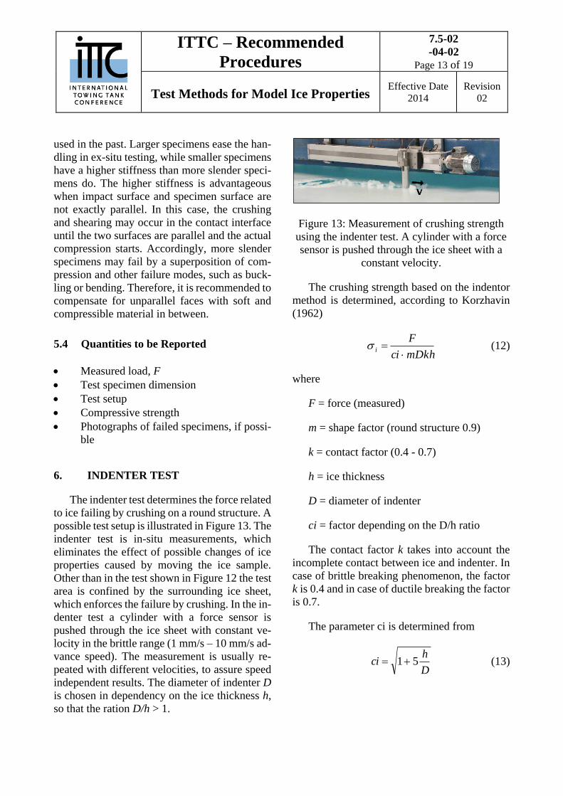
The indenter test determines the force related
to ice failing by crushing on a round structure. A
possible test setup is illustrated in Figure 13. The
indenter test is in-situ measurements, which
eliminates the effect of possible changes of ice
properties caused by moving the ice sample.
Other than in the test shown in Figure 12 the test
area is confined by the surrounding ice sheet,
which enforces the failure by crushing. In the in-
denter test a cylinder with a force sensor is
pushed through the ice sheet with constant ve-
locity in the brittle range (1 mm/s – 10 mm/s ad-
vance speed). The measurement is usually re-
peated with different velocities, to assure speed
independent results. The diameter of indenter D
is chosen in dependency on the ice thickness h,
so that the ration D/h > 1.
Figure 13: Measurement of crushing strength
using the indenter test. A cylinder with a force
sensor is pushed through the ice sheet with a
constant velocity.
The crushing strength based on the indentor
method is determined, according to Korzhavin
(1962)
mDkhci
Fi
(12)
where
F = force (measured)
m = shape factor (round structure 0.9)
k = contact factor (0.4 - 0.7)
h = ice thickness
D = diameter of indenter
ci = factor depending on the D/h ratio
The contact factor k takes into account the
incomplete contact between ice and indenter. In
case of brittle breaking phenomenon, the factor
k is 0.4 and in case of ductile breaking the factor
is 0.7.
The parameter ci is determined from
D
hci 51 (13)
ITTC – Recommended
Procedures
7.5-02
-04-02
Page 14 of 19
Test Methods for Model Ice Properties Effective Date
2014
Revision
02
7. SHEAR STRENGTH
7.1 Punch Through Test
A 200 mm x 300 mm piece of ice is removed
from an ice sheet and a 35 mm diameter hole is
punched through it. One data point is the mean
of five or six samples. The shear strength is de-
termined according to
hD
FS
(14)
where:
h = ice thickness
F = load
D = punch diameter
8. ICE- MODEL FRICTION COEFFI-
CIENT
The ice friction coefficient is a dimension-
less parameter, and, according to Froude- scal-
ing, the dynamic friction coefficient is to be the
same in model-scale as in full scale. Friction is
a lubricant phenomenon which varies with
temperature, contact pressure, and also slightly
with the relative velocity between the ice and
substrate material. The friction coefficient may
be determined on two ways. One is the physical
ice-model friction test, and another one is based
on surface roughness tests.
8.1 Physical Ice-Model Friction Coefficient
It is recommended to determine the fric-
tion coefficient by towing a block of ice
over the material surface (wet or dry depending
on the test conditions). It is important that this
surface be perfectly horizontal. The ice and ma-
terial surface should be described. The initial
peak resistance divided by the normal force rep-
resents the static friction coefficient (Schwarz et
al., 1981).
Prior to the tests, the ice sample weight must
be determined. The ice-specimen is then moved
with constant speed over the test surface, while
the horizontal force is measured. Depending on
the ice sample constitution, it may be possible to
increase the vertical load with a board and dead-
weights loaded on top. Care must be taken to en-
sure the ice is not compressed too much.
A testing apparatus should be used to deter-
mine the dynamic ice-friction coefficient. Dur-
ing the coating process of the model a plate with
the same surface characteristics is manufactured
for the fiction test. Alternatively, the test may be
conducted on the model directly (bottom sur-
face).
The tests may be conducted with a wetted
surface or a dry surface, which must be men-
tioned explicitly. It is recommended to use a wet
friction surface, as this is also encountered by
the ship models.
tif
n
Fc
F (15)
Cif = dynamic friction coefficient
Ft = mean value of measured tangential
force
Fn = normal load
8.2 Surface Roughness Related Friction
The relation of surface roughness and fric-
tion coefficient can only be established by tests
as described in 7.1 and simultaneous surface
roughness measurements. The curve-fitting re-
quires at least 5 samples whereas two have to
reflect the extremes, very rough and very
ITTC – Recommended
Procedures
7.5-02
-04-02
Page 15 of 19
Test Methods for Model Ice Properties Effective Date
2014
Revision
02
smooth. Subsequently it suffices to measure the
surface roughness on the model to determine the
friction coefficient. However, it is desirable to
conduct as many friction experiments and sur-
face roughness measurements simultaneously as
possible to improve the curve fitting and the
knowledge on impact factors such as tempera-
ture etc.
8.3 Limitations and Discussion of the Test-
ing Methods
The friction tests described can be conducted
on long boards that are painted together with the
model or on the model. The long boards have the
advantage of a long testing distance, while the
test directly on the model has a rather short test
length. Additionally it may not be feasible to
conduct the tests on the model due to a too curvy
hull shape. However, the surface roughness may
even vary over the model surface area and also
the painting of a separate board might lead to
surface differences compared to the model hull.
8.4 Quantities to be Reported
Horizontal towing forces, Ft
Total normal force, Fn
Dimensions of the ice block (length, width
and thickness)
Sample weight (prior to test)
Rear weight
Velocity
Ice specimen temperature
Wet or dry friction test
Upper or bottom side of the ice
Description of the test setup
9. ICE THICKNESS MEASURE-
MENTS
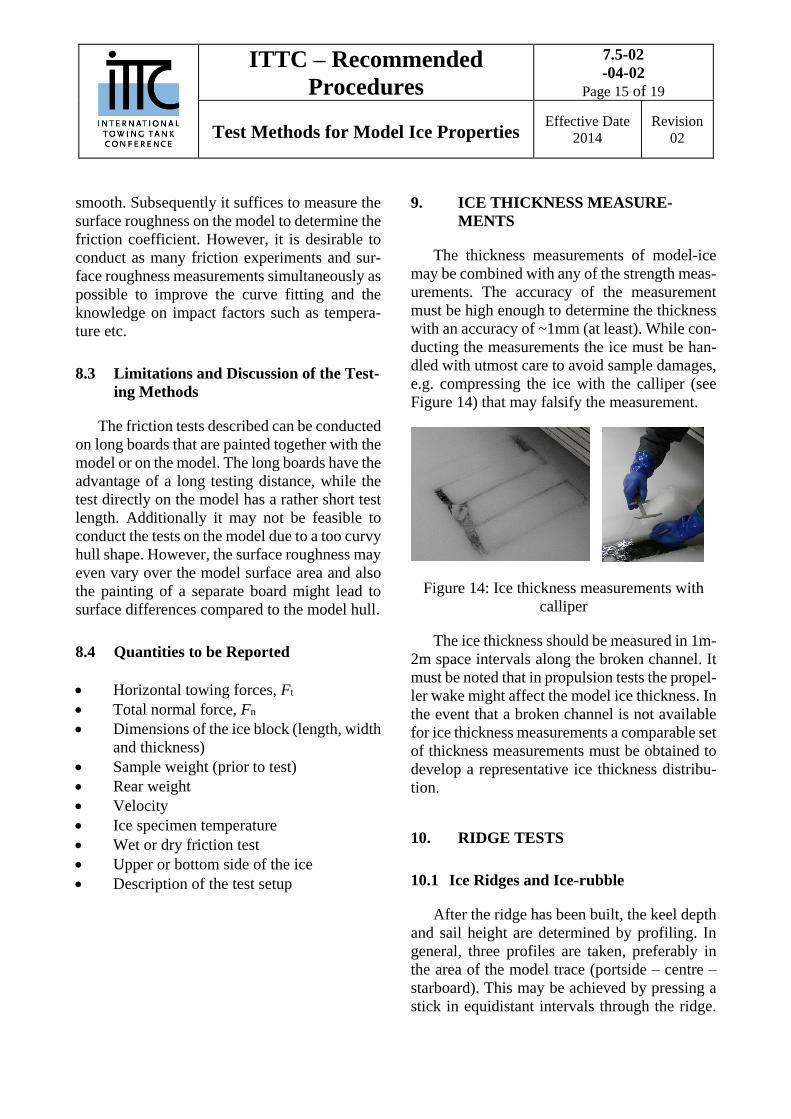
The thickness measurements of model-ice
may be combined with any of the strength meas-
urements. The accuracy of the measurement
must be high enough to determine the thickness
with an accuracy of ~1mm (at least). While con-
ducting the measurements the ice must be han-
dled with utmost care to avoid sample damages,
e.g. compressing the ice with the calliper (see
Figure 14) that may falsify the measurement.
Figure 14: Ice thickness measurements with
calliper
The ice thickness should be measured in 1m-
2m space intervals along the broken channel. It
must be noted that in propulsion tests the propel-
ler wake might affect the model ice thickness. In
the event that a broken channel is not available
for ice thickness measurements a comparable set
of thickness measurements must be obtained to
develop a representative ice thickness distribu-
tion.
10. RIDGE TESTS
10.1 Ice Ridges and Ice-rubble
After the ridge has been built, the keel depth
and sail height are determined by profiling. In
general, three profiles are taken, preferably in
the area of the model trace (portside – centre –
starboard). This may be achieved by pressing a
stick in equidistant intervals through the ridge.
ITTC – Recommended
Procedures
7.5-02
-04-02
Page 16 of 19
Test Methods for Model Ice Properties Effective Date
2014
Revision
02
At the lower end of the stick a cross-bar is acti-
vated and the, stick can be lifted upwards until a
certain resistance indicates the bottom of the
ridge. The keel depth is then read from a scale,
(see e.g. Figure 17).
Alternatively, the underwater contours of the
ridge can be profiled with an acoustic echo
sounder, and the sail topography above water by
laser level (Sutherland, J. & Evers, K.-U. ,2012).
Figure 15 Ridge-profiling device to determine
keel depth and sail height
Figure 16 Cross section profiles of an ice ridge
10.1.1 Quantities to be reported
Time of measurement
Sail height and width
Keel depth and width
Thickness of consolidated layer
10.2 Shear strength of ice-rubble
Ice-rubble in a ridge is usually considered as
a bunch of ice pieces without cohesion. A wide
scatter of values for the angle of internal friction
(φ) has been reported. A plug or a pushdown test
where the consolidated layer is pre-cut and the
rubble is loaded vertically was originally com-
pleted in-situ by Leppäranta and Hakala (1992),
and has been completed in the laboratory by
Azarnejad and Brown (1998). One problem is
the derivation of material properties from the
recorded force and displacement, as the stresses
on the failure plane are not known (Jensen et al.
2000).
10.2.1 Punch Test
In model scale, the internal shear strength of
an unconsolidated ridge is determined by a so
called “punch test”. This test should be con-
ducted immediately after the model has passed
the ice ridge. If possible, the test site of the
punch test should be a sufficient distance from
the track of the model and the ice tank walls.
Where the keel ice-rubble is covered by a
‘‘consolidated layer’’ a circular trench is cut
through this layer about 1 cm to 2 cm beyond the
punching cylinder. It is important to cut only
through the consolidated layer and not into the
rubble ice pieces below in order to keep the
ridge fragments as stable as possible. The ridge
depth should be measured clockwise at least
eight times on a circle about 5 cm beyond the
edge of the punching cylinder. The device for
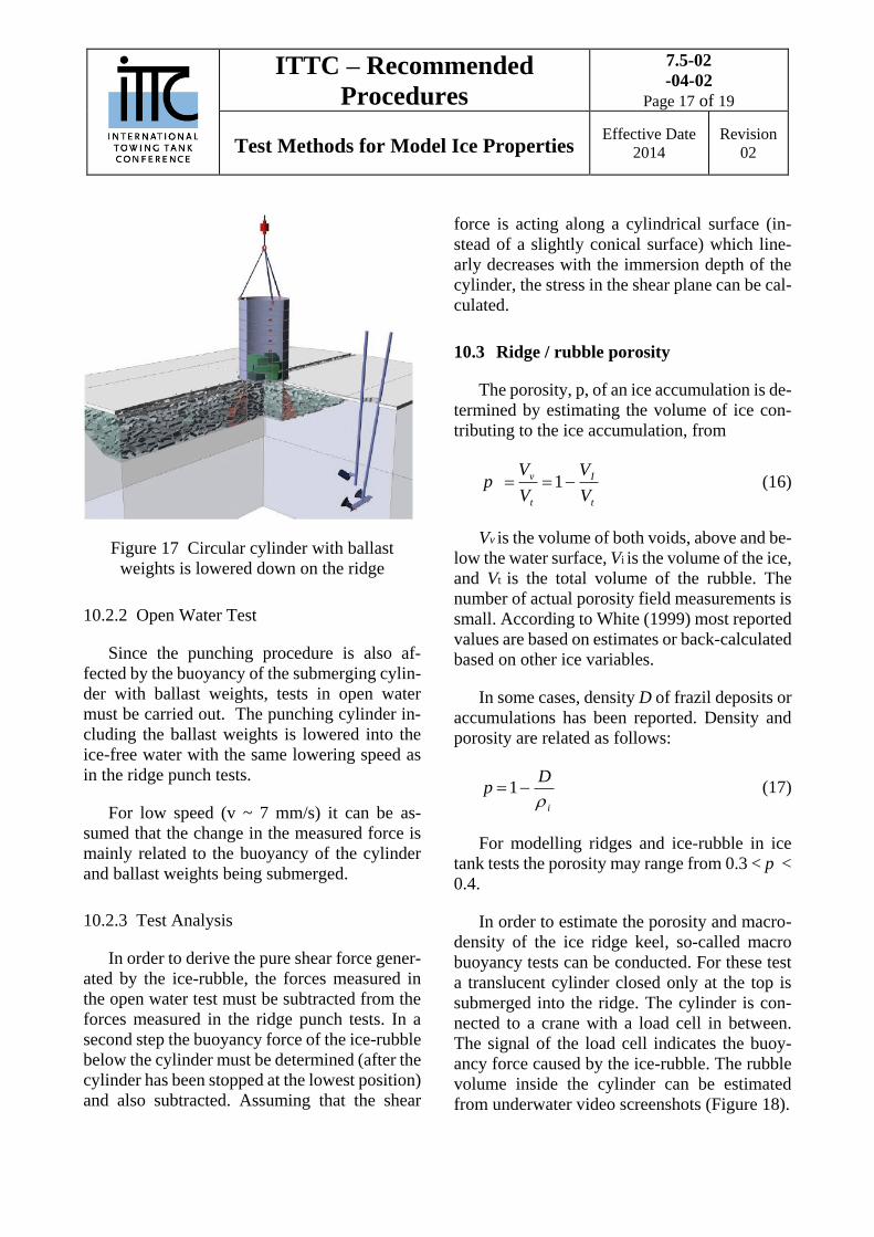
punch tests consists of a heavy steel cylinder
(~300kg). The lowering speed should be suffi-
ciently high to avoid disturbances of the ridge
structure and sufficiently low to avoid hydrody-
namic effects (good experience is made with 7
mm/s). The load is measured with a load cell be-
tween cylinder and crane hook. (see Figure 17).
HSVA
ITTC – Recommended
Procedures
7.5-02
-04-02
Page 17 of 19
Test Methods for Model Ice Properties Effective Date
2014
Revision
02
Figure 17 Circular cylinder with ballast
weights is lowered down on the ridge
10.2.2 Open Water Test
Since the punching procedure is also af-
fected by the buoyancy of the submerging cylin-
der with ballast weights, tests in open water
must be carried out. The punching cylinder in-
cluding the ballast weights is lowered into the
ice-free water with the same lowering speed as
in the ridge punch tests.
For low speed (v ~ 7 mm/s) it can be as-
sumed that the change in the measured force is
mainly related to the buoyancy of the cylinder
and ballast weights being submerged.
10.2.3 Test Analysis
In order to derive the pure shear force gener-
ated by the ice-rubble, the forces measured in
the open water test must be subtracted from the
forces measured in the ridge punch tests. In a
second step the buoyancy force of the ice-rubble
below the cylinder must be determined (after the
cylinder has been stopped at the lowest position)
and also subtracted. Assuming that the shear
force is acting along a cylindrical surface (in-
stead of a slightly conical surface) which line-
arly decreases with the immersion depth of the
cylinder, the stress in the shear plane can be cal-
culated.
10.3 Ridge / rubble porosity
The porosity, p, of an ice accumulation is de-
termined by estimating the volume of ice con-
tributing to the ice accumulation, from
t
I
t
v
V
V
V
Vp 1 (16)
Vv is the volume of both voids, above and be-
low the water surface, Vi is the volume of the ice,
and Vt is the total volume of the rubble. The
number of actual porosity field measurements is
small. According to White (1999) most reported
values are based on estimates or back-calculated
based on other ice variables.
In some cases, density D of frazil deposits or
accumulations has been reported. Density and
porosity are related as follows:
i
Dp
1 (17)
For modelling ridges and ice-rubble in ice
tank tests the porosity may range from 0.3 < p <
0.4.
In order to estimate the porosity and macro-
density of the ice ridge keel, so-called macro
buoyancy tests can be conducted. For these test
a translucent cylinder closed only at the top is
submerged into the ridge. The cylinder is con-
nected to a crane with a load cell in between.
The signal of the load cell indicates the buoy-
ancy force caused by the ice-rubble. The rubble
volume inside the cylinder can be estimated
from underwater video screenshots (Figure 18).
ITTC – Recommended
Procedures
7.5-02
-04-02
Page 18 of 19
Test Methods for Model Ice Properties Effective Date
2014
Revision
02
Figure 18 Illustration of macro-buoyancy cyl-
inder penetrated through ridge (left), sub-
merged translucent cylinder filled with ice-
rubble (right)
The macro density of ice-rubble can be cal-
culated by
r wr
r
BV gF
V g
(18)
where
r = macro-density of ice-rubble
w = water density
Vr = rubble volume in cylinder
FB = measured buoyancy force
g = gravity constant
The macro porosity can be calculated by
Equation 19.
r i
w i
(19)
where
= macro- porosity of ice-rubble
r = macro-density of ice-rubble
w = water density
i = ice density (level ice)
The macro-buoyancy and macro-porosity
tests are rather time consuming and need addi-
tional experienced personnel for these kind of
tests.
11. REFERENCES
Azarnejad A., and Brown T.G. 1998. Observa-
tions of ice-rubble behaviour in punch tests,
In Proceedings of the 14th International Sym-
posium on Ice (IAHR), Postdam, NY,USA,
589-596
Frederking, R and Timco, G (1983) On meas-
uring flexural properties of ice using cantile-
ver beams, Annals of Glaciology 4
Jensen, A., Hoyland, K. V., Evers, K.-U. 2000.
Scaling and measurement of ice-rubble
properties in laboratory tests Proceed-
ings of the 15th International Symposium on
Ice (IAHR), August 28 - September 1, 2000,
Gdansk, Poland, Vol. 1, pp. 105- 112, ISBN
83-85708-39-1
Kato, K., Nixon, W., Jones, S., Wilkmann, G.,
Izumiyama, K., Sazanov, K., 1999. The spe-
cialist committee on ice, final report and rec-
ommendations to the 22nd ittc. In: Proc. of
the 22 Int. Towing tank conference (ITTC),
Seoul, South Korea. pp. 349-373
Korzhavin, K.N., 1962.Action of Ice on Engi-
neering Structures. USSR Acad. Sci Siberian
Branch. CRREL Draft Translation No. 260,
Hanover, 1971.
Leppäranta, M. and Hakala, R.1992.The struc-
ture and strength of first-year ice ridges in
the Baltic, Cold Regions Sciences and Tech-
nology, 20, pp. 295-311
Schwarz, J., Frederking, R., Gavrillo, V., Pe-
trov, I.G., Hirayama, K.-I., Mellor, M.,
ITTC – Recommended
Procedures
7.5-02
-04-02
Page 19 of 19
Test Methods for Model Ice Properties Effective Date
2014
Revision
02
Tryde, P.and Vaudrey., K.D. 1981. Stand-
ardized Testing Methods for Measuring Me-
chanical Properties of Ice – Prepared by the
Working Group on Standardizing Testing
Methods in Ice, IAHR Section on Ice Prob-
lems, Cold Regions Science and Technol-
ogy, 4 (1981) 245-253
Sodhi, D.S., K. Kato, F.D. Haynes and K.
Hirayama, 1982. Determining the character-
istic length of model ice sheets. Cold Re-
gions Science and Technology, vol. 6, pp.
99-104
Sutherland, J. & Evers, K.-U. (Eds.). 2012.
Foresight study on laboratory modelling of
wave or ice loads on coastal and marine
structures. Report of the Hydralab Consor-
tium, EC contract no. 261520, HY-
DRALAB-IV, Deliverable D2.3
Svec, O., Thompson, J., & Frederking, R.
(1985). Stress concentrations in the root of
an ice cover cantilever: Model tests and the-
ory. Cold Regions Science and Technology .
Timco, G. (1981). On the test methods for
model-ice. Cold Regions Science and
Technology. Vol. 4 pp. 269-274
Timoshenko, S., & Woinowsky-Krieger, S.
(1959). Theory of Plates and Shells.
McGraw-Hill.
von Bock und Polach, R. F. (2005). Sea ice
characteristics and its impact on model tests
(master thesis). Berlin: Technical University
of Berlin.
von Bock und Polach, R. F., Ehlers, S., &
Kujala, P. (2013). Model Scale Ice - Part A:
Experiments. Cold Regions Science and
Technology .
White, K. D. (1999). Hydraulic and Physical
Properties Affecting Ice Jams, CRREL Re-
port 99-11, US Army Corps of Engineers
Cold Regions Research & Engineering La-
boratory, Hanover NH, USA, December
1999


