Embed Size (px)
Citation preview
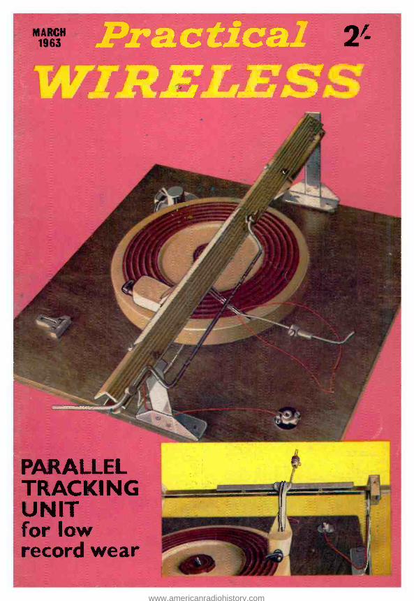
PARALLEL TRACKING UNIT for low
record wear
www.americanradiohistory.com
ADCOLPN ,,,,..........f
SOLDERING
INSTRUMENTS
AND
EQUIPMENT
DESIGNED FOR
THE AMATEUR'S RADIO STATION
ILLUSTRATED
List No. 70. k" BIT
IN
PROTECTIVE
SHIELD
List No. 68
APPLY DIRECT FOR CATALOGUE TO
Sales and Service Dept.
A DCO LA PRODUCTS LTD ADCOLA HOUSE
GAUDEN ROAD,
PRACTICAL WIRELESS March, 1963
Telephones Telegrams MACaulay 4272 & 3101 SOLJOINT LONDON SW4
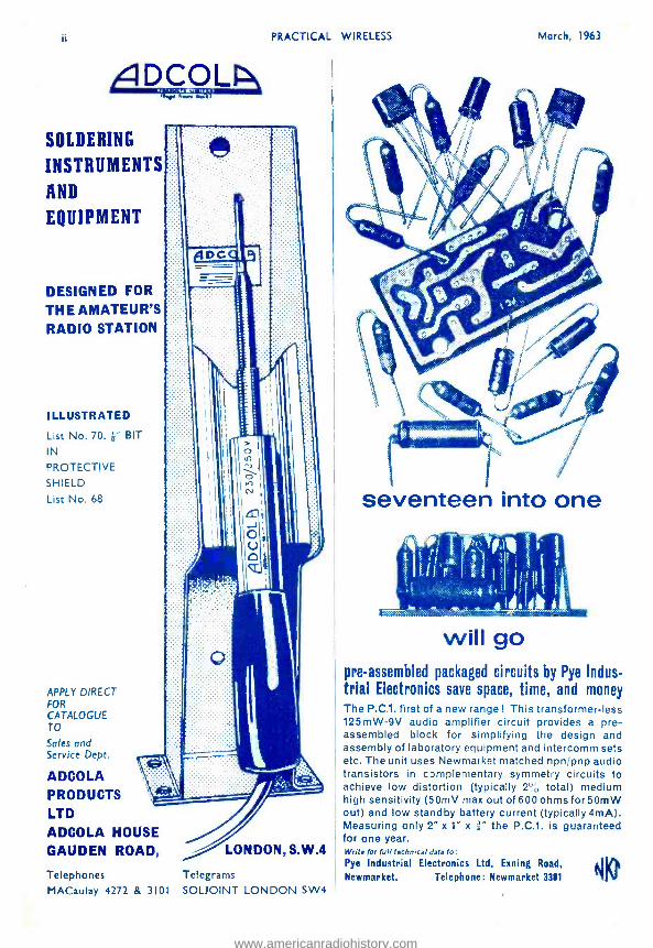
seventeen into one
' lt'`T/,] tl w. ,
tI1/ It
r I , :
i,
will go pre -assembled packaged circuits by Pye Indus- trial Electronics save space, time, and money
The P.C.1. first of a new range ! This transformer -less 125mW -9V audio amplifier circuit provides a pre - assembled block for simplifying the design and assembly of laboratory equipment and intercomm sets etc. The unit uses Newmarket matched npn /pnp audio transistors in c3mplementary symmetry circuits to achieve low distortion (typically 2 ° total) medium high sensitivity (50mV max out of 600 ohms for 50mW out) and low standby battery current (typically 4mA). Measuring only 2" x 1" x " the P.C.1. is guaranteed for one year. Write for full technical data fo: Pye Indusstrial Electronics Ltd, Exning Road,
Newmarket. Telephone: Newmarket 3381
www.americanradiohistory.com
March, 1963 PRACTICAL WIRELESS
* VALVES * THE MOST COMPREHENSIVE COMPETITIVE
VALVE LIST IN THE COUNTRY
10% DISCOUNT OFFER TO
PURCHASERS of any Slx VALVES marked in blaok type as% in dozen)- 1.1 /t: 1 valve,
NEW LOW PRICES
GUARAN- TEED 3
MONTHS
FREE TRANI
new or of fully Guaranteed ex- Govern- inept or ex- equipment origin. Satisfaction or Money hack Guarantee on Goods If returned un- used within 14 days.
014 61-6JSOT 4/- 128.1 D096 E51114 a/- T41 7/8 1ASGr 6/-1.111 4/- 1281;7 5/- D097 8/ EM88 10/- TDD4 7/8 1A7Gr 11/-6.17 8/8128117 bib 1)H63 6/ EN 31 16/- U14 8/- 10.50T 9/-8.170 4/8 128.17 5/6 D117ß EY51 7/9 1118 8/- 105 8/-(3J TOT 7/6128K7 4/9 DK32 11Ì E186 7/8 022 8/9 108
UT WS 9/8128N7GT7/9 9/9
9/9 61160T 8/61 D3 9/- DK91 11K92
6/8 E735 8/8 E1e6 6/8
U24 025
18/- 11/8
1L4 3/3 6117 b/11487 14/9 lll(96 7/ £140 8/6 1226 149 1LD5 8/8 8K70 2/6 1 AQ5 7/6 DL33 b/ £141 7/-. U31 -/- 1LN5 4/9 6K7GT 9 1 BG6 191- D1.35 E180 8/- U33 14/- 1N5GT 9/9 6K8GT 8/9 2 DI 9/8 DL63 ái 6181 6/8 U35 12/8 111,5 5/6 6K25 7/b 2 F2 9/8 DL75 FW4/5008/- U37 26/- 184 8/-6L1 12/6 2 Ll 181- D 1282 FW4/8008/- U50 6/9 185 4/6 61,80 8/5 2 P1 b/9 llL91 8/ UT1C 7/- L'52 4/9 ÍT4 8/6 f1L16 9f- SOPS 18/8 OL92 8/ 13Z3'2 8/9 U76 6/8 2A3 6/8 6L19 11/- 2 P4 18/- DL94 6/ 11134 12/6 U78 5/- 2A7 9/6 6LD3 8/- 2 PJ 15/- DL90 7/ HL41DD8/8 U191 12/8 21121 0/-6LD12 t/9 SbABG 8/- EABC80 5/ HN309 19/- 0281 9/8 aÁ4 4/9 8LD20 7/8 26L80 8/9 EAC91 8/ 111R2 10/8 U'242 15/- SAS 9/-6N7 7/6 2 LOUT 7/9 EAF42 b/ 1W4/350 7/6 U301 15/- 3116 4/8 6P1 7/8 2 YSG 6/- 8841 7/ 1W4/500 7/6 1'309 8/9 3Q4 7/-13P25 8/6 25Z4G 7/- 2E91 8/ K1.L32 8/8 U329 5/9 3Q5GT 8/- 6P28 12/8 2 'L5 8/- EBC33 4/9 K'l'32 5/910939 11/-
6Q70 8/- 2 16G e/- EBC4l 8/ K 3 C 4/8 0801 19/- IVI 8/9 6Q7GT 8/8 8001 7/- EBC87. 7/ KIN 12/5 UABC80 8/- IR4GY 12/8 687G 8/8 60C15 11/8 EBF80 7/9 KT44 7/8 UAF42 7/9 574 8/-88A7 6/6 3 05 8/- E11083 9/ KT45 8/8 UB41 7/9 804G 4/9 8807 4/9 30FL1 9/6 EBF89 8/8 KT01 8/6 UBC41 7/9 6140. 7/9 68117 8/- BOLI 8/9 EBL21 12/ KT63 6/9 UBC81 9/8 5Y3G b/9 88K7 9/- 301.15 9/8 EBL31 17/ KT76 8/8 1.111F80 8/- 5030T 6/9 68L7GT 5/9 30P4 S/6 EC91 4/ KTW61 6/917ßF89 7/8 51'40 11/-68N7GT 4/8 30012 7/8 E(X;31 7/ KTW62 6/9 UBL2I 14/8 514 11/- 68Q7 6/9 301.16 8/8 EC032 4/ KTW63 5/9 UCC84 14/8 514G 7/8 8887 3/8 30P19 17/8 EC038 4/6 KTZ83 6/8 U0082 7/- 5-L40T 11 /-6U40T 10/8 36PL1 9/6 E()C34 9/ L63 2/9 UCF80 15/- 6/30 L2 9/-8V66 b/- 3001.13 13/- ECC35 6/ LN152 7/- UCH21 12/- 6A8 4/9 6V6GT 8/- 351RGT 8/8 EC()40 14/ 81014 7/6 UCH42 7/3 6A7 11A80
6X2 7/9 3:iT 8/8 6X4 b/- 35W4
25/- 8/9
ECC81 EC1382
5/8 6/
N:0 11/- UCH81 076 13/- UCL82
8/- 9/9
1/.4807 18/6 8X50 6/- 357.4GT 5/8 ECC83 8/ 14108 18/- 1201.83 18/8 61018 7/-6XS0'P 5/8 35250T 8/- E(X;64 8/ N15'2 8/BUF41 7/8 8AC7 8/3 6Y6G 7/8 41 7/6 lìCC85 7/ P41 4/8 0F42 6/6 BAGS 3/-7A7 8/8 42 7/8 EC(%9 18/ 061 2/9 U080 7/- 9.407 7/8 7B7 9/- 5005 9/- 0.CC91 4/ PABC8011/8 U085 7/6 OAKS 5/- 707 7/9 50CD8 19/- Eel. BO 8/ PCC84 8/9 11086 14/8 GALS 3/- 7C6 7/3 5OL6GT 8/8 EC8'89 8/ PCC85 8/9 U089 7/- 8AM8 8/- 706 7/8 52KÚ 10/6 ECB21 12/ l'CC86 14/- 12L41 7/. 6AQ:5 6/- 7117 7/3 53K 11 10/8 ECH35 7/ P(Y;80 9/- ULM 11/- 6AT6 6/9 7K7 9/8 618PT 11/- ECH42 8/ P01'18918/8 UL4 9/9 IA U6 7/8 7Q7 8/8 112BT 18/6 E('H81 -/ PCF80 7/- ULM 7/- 6117 8/8 787 9/- 75 8/8 ECH83 8/ 00F82 7/3 UM80 9/6 611M0 8/- 71'7 7/9 7S 8/6 sICL80 7/ PC084 18/- URIC 8/- 1116A.1 5/9 714 6/9 80 6/9 E(`d.82 9/ m086 12/6I U1!6 12/6 611E6 b/9 724 7/- 83 9/8 ECL83 11/7 0111.52 7/3 IT 9/6 611(1611 16/- 8D8 8/- IBSBT 19/6 ECL86 10/ PCL83 10/8 UUS 17/- 6B166 8/- 1001 11/8 803 19/8 KF2'2 7/ 00I.84 7/8 17119 11/- 6B26 8/- 10C2 14/8 607(A) 6/- F.F36 8/ PCL85 11/8 UY21 11/- 611R7 9/6 10014 8/- 808 7/6 0.039 4/6 PC1.86 12/8 U141 8/- 611W6 7/8 10F1 6/9 813 66/- EF40 12/ PEN46 8/8 UY85 8/8 60W7 5/8 101,9 10/8 832 14/- EF41 8/ PEN46 5/- VP41 5/8 8131E8 4/9 10018 10/- 866A 11/6 EF42 7/8 0L38 8/3 VR105 6/6 804 2/3 10L14 7/- 954 2/- EF50.BR2/ PL36 9/8 VR350 b/- 605 6/8 1OLD3 7/9 956 2/8 EF50.U8A PL38 18/8 W61í1 11/- 6C6 8/9 10L111114/8 5763 9/6 P1.81 8/8 W70 4/9 61295 11/- 1OLD12 8/- 9001 4/- EF54 8% PL82 5/5 W81 7/3 601366 19/8 10P18 11/- 9002 4/9 EF8J 4/ PL83 6/6, X61M 11/- 6CH6 7/8 10P14 8/- ATP4 2/9 EF85 8/ 0L84 8/- X63 9/8 8D2 8/- 10P18 7/- AZ31 8/- EF86 9/ PL820 8/8 X65 11/- 6D3 9/8 12A6 1/9 AZ41 11/- 6089 8/ 0X4 12/6 x88 11/- 8158 4/3 12AH8 9/- 638 7/9 EF91 3/ PX25 9/8 X76M 11/- 8F1 4/9 12AT6 7/8 C1C 9/6 EF92 4/ PY81 9/- X78 21/- 8F6G 6/9 12AT7 5/8 CBL1 28/8 EF98 8/ P132 10/- X79 18/8 OF12- 3/- 12A176 9/8 CYL31 21/- 60183 14/ P180 6/9 XNIM 9/- 6F13 8/9 12AU7 8/- CCH35 14/- EF184 12/ PY81 6/5 163 8/3 61114 9/8 12AX7 8/8 CL33 9/6 EL82 4/ PY82 6/- Z83 4/9 6015 9/6 12BA6 7/8 CY31 9/- EL38 7/9 2Y83 7/- Z88 9/6 61116 8/- 12BE6 7/8 D77 3/8 ELM 7/ P188 9/9 Z152 4/9 6019 6/8 12B117 9/911152 5/9 EL4l 8/ PZ80 9/8 2719 4/9 6 23 8/8 1208 8/8 DAM) 12/8 EL42 8/ R18 11/- ZDI i2 7/9 624 12/- 12131 17/6 DAC32 9/9 EL8l 11/ Rl9 11/- Transistors: 6F25 18/- 12J7GT 9/- DAF91 4/8 EL83 11/ RL18 9/- 0026 16/- 82'32 8/6 1211701' 4/9 DAF96 7/8 EL84 7/ 9P41 2/8 0044 8/- 8F33 8/8 128.8 11/- DET19 2/9 EL91 4/ 3P81 2/8 0C45 6/- 625 4/3 12K8GT 9/8 DF33 9/9 E5180 7/ 81725 18/- 0081 5/8 8760 8/- 12Q7GT 6/- DF91 3/8 13681 8/ BU2150 4/8 008111 6/8
969
Tubes HIGHEST QUALITY - COMPARE OUR PRICES
Carr. &
MOST MOLLARD,
EMiTAÓlt cosrmR-
FERRANTI TYPES, PROCESSOUR ED
OWN IN
FACTORY
Ins. 12/6 GUARANTEED
8 Months 12 Months
12ín. £2. 0.0 £.3.
5.0 1 4in. £2.10.0 £3.15.0 15- 17Ín.£3. 5.0 £4.10.0 21 in. £3.15.0 £5.15.0
NEW TYPES
MW 31/74 £4 -0 -0
MW 36/24 £5 -0 -0
CRM 172 MW 43/84 £6 -0 -0
IVORY GOLD KNOBS 0 Diameter, half price 1/2, 5 for 4/8; 3 1 / -, 5 for 4/ -; top quality r sp. grub screws.
SPECIAL TEMPORARY OFFER. Due to huge Bulk Special Purchase we are offering MW 31/74 Tubes at the unrepeatable price of 29/ -. MW 36/24 ditto, 89/ -. P.Y. 12/6. The above are guaranteed for 6 mouths.
RECTIFIERS. 250 v., 80 mA, 5 / -; RM2, 8/9; 11513, 7/5; RM4, 19/6; 1616, 19/8; 14A86, 17/ -; 14.497, 19/8; 14 .4100, 19/8; 16RC1- 1-16 -1, 7/9; 18RA1.1- 1 -10 -1, 8 / -; 18RD2- 2 -8 -1, 14/ -; 14RA1.2.8 - -2, 17/ -; 1411.41.2 -S -3, 20 / -. ELECTRIC MOTORS. AC /DC 3-8 volts. Totally enclosed standard mounting, powerful. V pulley, 7I6 spare brushes, tin, x 210 V
I4in. TVs. Carr. 12/6. 13011 with CRM 141 Tubes. Absolutely complete, tested for raster. Famous make, large purchase enables us .19x. £4 to offer them at £4
CONDENSERS. Ceramic and Silver Mica. All values, 8d, ea., 5/. doz. CONDENSERS. 25 Mixed, Electrolytic. Many popular sizes. LIst Value £5, Our Price 10 / ,
TRANSISTOR SNIPS Huge reductions. Red Spot stan- dard L.F. type now only 1/6; White Spot R.F. 2 / -. Mallard Matched Output Kits (0081D and 2- 0(81x), 12/8. Receiver Kits, 01244, 0045(2), 0081D, 25/- 0081(2), six transistors.
TRANSISTOR CONDENSERS. Latest single -ended sub -miniature 5µF 3V, 1 / -; 51.10 61. 1 /8; 10µ0 3V, 1/8; 301.0 3V, 1/8; 30µ0 6V, 1 /6; 100 /10 6V, 1/8; 12011F 91, 2 / -. RESISTORS. All values, carbon 1 -2 watt, 6d. ea., 4/8 doz.
3 VALVE AMPLIFIERS. Kit of new parts, consisting chassis mains and output transformers, valves ÍP61. 606(1, 6X50) and all compo- nents. With full instrnctioae for making high gain amplifier with separate base and treble controls, negative feedback, etc. Truly un- usual value at 29/ -.
IIEW SPEAKER CABINETS. Covered in attractive Ream e, Gold Metal front 11/ -. Or complete with 7 x 4 Speaker, 19/ -. PP. 1/6.
4 -SPEED RECORD PLAYERS. Latest Turntable. together with lightweight Steer Galaxy dual sapphire crystal turnover pick -up head. Amazing value (pick -up only 19/ -1. 08.10.0. Carr. 3/,
VOLUME CONTROLS. All values, less switch, 3/ -, With switch 4/8.
N U V ISTORS Latest American, 6CW4, amazing V.H.F. performance, see Practical Television article (Dec.), 17/8.
PORTABLE RECORD PLAYERS. Takes all sizes Records, all speeds, amplifier, auto- changer, Garrard new "Slimline" Gram. In two -tone Case. 14gns. All absolutely new.
VALVE HOLDERS. B76, Sd. ea., with Screen 8d, ea., B9A 6d. ea., with Screen 1311. ea. Int. Octal Od., Mazda Octal 4d.. BSA 6d. (Ices 15% in dozens).
SILICON RECTS. 250V 500mA standard TV replace. meat. Top quality 8/8 (3 for 24/ -).
C0880ß D.B. SCOPE TUBES. Type 09D Split Beam. Ideal for building your own quality oscilloscope whilst 55/- storks last. J
TAPE AMPLIFIERS. Professional quality, famous make (li -:'1 approx. 235) very compact, t u
inputs, mixing, record /playba,k, erase. Requiring only deck, speaker, mike, grey £9.1 Os. case. 7
P.M. SPEAKERS. 311 Top Make. filin. 7/6 71x.41n. 810 8/6
VALUE! 4 watt AMPLIFIERS excellent amplifier with high gain Dreamy stage, (1013 driving 2003 output stage. complete with Sin. speaker. In attractive 2- tone case. Tone control, negative feed -back, ready for immediate use. indivi- dually tested. Amazing volume and clarity, ideal for guitars, record players, p.a. in small halls, baby alarms etc. Easily worth £b. Our price whilst 45/- stocks last. Carr. Packing etc. 7/8.
2 POTS. Popular values. fir. to Meg. Unused, mixed, pre - 4IC
et, long sp., switched, etc. 4 VV
CO -AX, low loss, 6d. yd., 25 yds., 1/8. 50 yds., 22/ -, 100 yds., 45/8.
Co -ax Plugs 1/3. Wall outlet boxes lap.
100 RESISTORS 66 Excellent. Sizes l-3 watt.
100 CONDENSERS 10/- Miniature Ceramic and Silver Mica Condensers, 3 pO to 5,000 p0. LIST VALUE OVER £5.
PORTABLE RECORD PLAYERS. E.M.I. turntable, complete in excellent modern carrying case with amplifier and 7 x 4 speaker. Amazing value. Carr. 6/-. £7.10s.
GARRARD TA MK. II PLAYERS. Latest quality deck at a £7.Í9s. most competitive price. P.V.C. CONNECTING WIRE. 100 yds. 30 mill: Special Price 7/6. 200 yds. 80 mill: special price, 12/8. 25ft. Coil, 1/. 5 Coils different colours, 4/ -. Connecting tlex. Pricesae above.
TELEPHONE C.O.D. ORDERS DISPATCHED THE SAME DAY,
Post: 2 lbs 2 / -, 4 lbs. 2/8, 7 lbs. 3/8, 15 lbs. 4/ -, etc. (C.O.D. ALL ITEMS LESS 5% AND POST FREE IN DOZENS. Send 6.1. for I
TECHNICAL TRADING CO.
of 1,000 snips,
RETAIL SHOP 350 -352 FRATTAN ROAD, PORTSMOUTH
n. ORDER ONLY DEVONIAN COURT, PARK CRESCENT PLACE, BRIGHTON 7, SUSSEX
www.americanradiohistory.com
970 PRACTICAL WIRELESS March, 1963
ARMSTRONG AF208AM FM RADIOGRAM CHASSIS
Full VHF Band (87 -108 Mc /s and Medium Band, 187 -570M) * 7 Valves * 5 Watts Output * 15dB Negative Feedback * Separate wide range Bass and Treble Controls * 2 Compensated Pick -up Inputs * Frequency Response 30- 22,000 c.p.s. t2dB * Tape Record and Playback Facilities * Conti- nental Reception of Good Programme Value * For 3, 75. and 15 ohm speakers. Send S.A.E. for leaflet.
821.4.0 Laer. Free
1963 RADIOGRAM CHASSIS THREE WAVEBANDS FIVE VALVES S.W. 16 m.-50 m. LATEST MULLARD M.W.200 m.-550 m. ECH81, EFSO, EBC81, L.W. 800 m, -2,000 m. ELM, E.280.
12 -month guarantee. A.O. 200/250 v. 4 -way Switch; Short- Medium. Long /Gram. A.V.C. and Negative feedback, 3 ohm output, 5 watts. Chasses 13} x 5} z 2 3in. Clam dial, horizontal or vertical wording, size 10ín. z 4t15. Aligned and calibrated. isolated Chassie.
I8.19.6 Carr. Sr Ina 4/8
BARGAIN SALE PRICES New Boxed VALVES 90 -day Guarantee
OZ4 6/- 6K7G 6/-EABC80 8/- PCL82 10/- 1115 6/. 6K80 6/- EB91 4/. PCL84 10/- 186 6/- 6L6G 8/- EBC41 8/- PL81 10/- 1T4 8/-6N7M 6/-EBC81 8/-PL83 8/- 2%2 2/- 6Q70 8/- EBF80 9/-1'Y33 15/- 384 7/. 65147 5/- EC1142 9/- PY80 7/- :3V4 7/-6V60 6/-ECHS1 8/-PY81 8/. 3Q3 7/- 6X4 5/- F,UL82 10/- PY82 7/-
,5114 8/- 6%5 8/- EPOS' 8/- PQ25 7/- SY3 8/- 12AT7 8/. EP89 8/. 5P41 8/- '8AÓ7
4/- 1?ÁX7 11/. /- EL84 7%.11221 7//-
IGAM6 4/.1211E17 71- F.Y51 9/- UBC41 8/. 'OATS 8/- 12K7 6/- EY86 9/- UBC81 9/- .6BA6 7/- 12E8 14/- 6240 7/- UBF89 W- 611E6 5/. 12Q7 6/- EZ80 7/- UCH81 9/- .88 W8 7/- 25Y5G 9/- E7,81 7/- UCL82 10/- .61.'4 5/. Iì5 L6 91- H ABCA010/- UCL83 12/- 1606 6/-35Z4 6/.HVR2A 5/-UF89 9/- !806 4/- 807 5/. KT330 81- LiL41 9/- 6II6 8/. 954 2/- KT76 8/- UY41 7/- 635 5/. DAF96 8/- MU14 7/. UY85 7/- ;6.16 5/- DF96 8/. PCC:84 B/. MR) ^/- '8370 8/- DK96 8/- PCF80 8/- V8150 7/- 18K8 5/- DL96 8/. PCF82 8/-IW81 8/-
LF. TRANSFORMERS 7/6 pair 485 K/s Slug Timing Miniature Can, 2 z t z fia Higb Q and good bandwidth. Data sheets.
NEW FAMOUS ELECTROLYTICS MAKES
'TUBULAR TUBULAR CAN TYPES 11350V 2/- 50/350V 6/ 18 /450V 5/. 2/350V 2/8 100/25V g/ 32/350V 4/- 4/450V 2/3 260 /2áV e/- 47/350V 8/8 8 /450V 2/3 100/270V 6/8 ó00/12V g/- 18/450V 8/- 5,000 /6V 5/. 32/430V 8/9 1,000 /12V 2/- 32 +32/350V á/- 26/25V 1/9 8 +8/450V 3/8 32 +32/450V 8/. 24/60V 2/- 84-16/450V 3/9 32+82+32/950V7/-
o+50/350V 7- 50/25V 2/- 16 +18/450V 4/8 64 +120/850V 11/8 90 /50V 2/- 32 +32/850V 4/8 100 +200 /275V 12/8
COMPLETE RADIO CHASSIS £4.19.6. post free
4 /dullard valves, 51n. speaker. Superhet Circuit. BRAND NEW. Size 9 x 8 x Min. high. Testti by us ready for use. 200 /250 v. A.C.-D.C. Mains.
DE LUXE MODEL as illustrated with illuminated dial. Fully tunable with Medium and Long Wave. 12 -month Guar- antee. Only 24.19.8 post 5/ -,
MAINS TRANSFORMERS 200/250 v. A.C. Postage 2/- earl. transformer.
STANDARD, 250.0- 230, 80 mA. 6.3 v. 3.5 a. tapped 4 v. 4 a. Rectifier, 53 v. l a. 5 v. 2 a. or 4 v. 2 a. 22/8, ditto, 350.0.330 .. 29/6 MINIATURE 200 v. 20 mA, 6.3 v. 1 a, 10/6 MIDGET, 220 v. 45 mA, 6.3 v, 2a. . 15/8 SMALL, 220 -0 -220, 50 mA, 6.3 v. 2 a... 17/6 STD., 250. 0.250, 65 mA, 8.3 v. 3.5 a. 17/6 HEATER TRANS. 6.3 v. 15 amp. 7/8 Ditto, tapped 1.4, 2, 3, 4, 6, 53 v. 8/8 Ditto, sec, 6.3 v. 4 amp. 10/8 GENERAL PURPOSE LOW VOLTAGE, 2 amp. 3, 4, 5, 6, 8, 0, 10, 1.2, 15, 18, 24, 30 v... 22/8 AUTO TRANSFORMER, 150 w, 22/8 0, 115, 200, 230, 230 v., 500 w. 82/8 MOLLARD "510" Mains transformer .. 30/- PARMEKO MAINS TRANSFORMER, Made for special contract, the ratings can safely be doubled. Guaranteed 2 years, Primary 0-110- 210- 230 -250 v, H.T. 300.0.300 v. 50 mA. LT. 53 v. 1.8 amp. Size 4 x 3t it 311n. Weight 81b. Post 17/6 MAINS POWER PACK. Size 31 x 4; x 4 in. with mains transformer, metal rectifier and condensera to provide smoothed H.T. output 220 v. 45 mA. D.C., LT. 8.3 v, 2 a. Centre
Brand Ne lw.
Bargain. built
Poet 2/6 meta..
29/8
INTERVALVE TRANSFORMERS 3:1 or 5:1, 9/., O.P. TRANSFORMERS. Heavy Duty 50 mA, 4/8. Multiretio. 7/6, Multi -ratio heavy duty push pull, 10 w., 16/6. Miniature, 384, etc., 5/9. L.F. CHOKES 15 /IO11. 60/65 mA, 5/-; 10 H., 85 mA, 10/6; 10 H., 150 mA, 14/ -, FULL WAVE BRIDGE SELENIUM RECTIFIER: 2, 6 or 12 v. 15 amp.. 8/9; 2 a., 11 /3. 1 a., 17/8. CHARGER TRANSFORMERS. Tapped input 200/ 250 v. for charging at 2, 6 or 12 v., 1t amps., 15 /S. 2 amps., 17/6; 4 amps., 22/6. Circuit included. 4 AMP CAR BATTERY CHARGER with amp. meter Leads, Fuse Case, etc for 6 v. or 12 v., 89/9. AMMETER 0 to 5 amp. 9/8.
BOOKS list S.A.E. 40 Circuits for Germanium Diodes 3/, W.W." Radio Valve Data, 6/ -. High Fidelity Speaker Enclosure, 5 / -. Valve and TV Tube Equivalents, 9/8. TV Fault Finding, 5/ -. Quality Amplifiers, 416. Radio Valve Guide, Books 1, 2, 3 or 4, 5/- each. Transistor Superhet Receivers, 7/8. Practical Radio Inside Out, 3/8, Master Colour Code Chart, 1/8. Transistor Controlled Models, 7/8.
4 TRANSISTOR PUSH -PULL AUDIO Size 8 x 1/ s I. AMPLIFIER
A ready built miniature push -pull amplifier with input and output transformers. 4 traneiatora Ideal for use with record players, intercoms, BABY ALARMS. etc. Complete with full
instructions and circuit, Pries 5L 6 9v, Batt. 2/3, 2115. Speaker 15/.
C.R.T. BOOSTER TRANSFORMERS l'or heater cathode short circuit, or tubes with failing emission- Full instructions supplied, mains input. Type A optional 25% and 50% boost, 2v. or 4v. or 6.3v. or 10.8v. or 12.8v. State voltage required. PRICE 10/8.
LOUDSPEAKERS P.M. 8 OHM. 25, 3, 4ia, 19/8, lin, Hola, 17/8; Sin. Plessey, 19/8; 715. z 41e. Rola, 10/ -; 6515. Rola, 18/6; 10 x 61n. 27/8; 1015. Rola, 30/ -; 4n Tweeter, 25/.; 121n. R.A. 30/ -. 135 x 8in., Double Cone E.M.I. 45/., STENTORIAN HF1012.101n. 3 to 15 ohms, 10w. 95/ -; 33 ohm, 7 x 4in., 25/ -; 5ìn., 22/8; 311n., 19/8,
BAKER SELHURST LOUDSPEAKERS
Detalle S.A.E. 1215. Baker 15w, stalwart 3 or 15 obma, 45- 13,000 c.p.a.
121n. Stereo, Foam Sus- pension, 12w., 35. 18,000 o.p.e. 88.17.8 12in. Baker Ultra Twelve, 20 ems. to 23 kola. 817.10,0 15in. Auditorium, 35 w., Baas. 20 c.p.a. to 1.2kc /e. 818 Details and Enclosure plane B.A.E.
TWIN GANG TUNING CONDENSERS. 365 pF, miniature lie. x lhn. x loin., 10 / -, 500pF Standard with trimmers, 9 / -; midget, 7/8; with trimmers, 9 / -; 5O0pF slow motion tuning, standard or midget, 9/.. SMALL 3 gang 500 pF, 17/-, SINGLE 366 pF 7/8. SINGLE 25 pF, 50 pF, 75 pF, 100 pF, 160 9F. 6/8. Solid dielectric 100, 300. 500 pF, 8/8. CONDENSERS. New stock. 0.001 mid. 7 5V. T.C.C., 5/6; Ditto, 20 kV, 9/8; 0.1 mid., 7 kV, 9/8. Tubular 500 v. 0.001 to 0.05 mid., Sot, 0.1, 1 / -; 0,25, 1/8; 0.5/500 v., 1/9; 0.1/350 v., 9d.; 0.1/2,000 v. 0.1 /1,000 v., 1/9; 0.1 mfd., 2,000 volts, 8/6. CERAMIC COEDS. 500 v. 0.3 pF to 0.01 mid., 9L SILVER MICA CONDENSERS, 10% 5 pF to 500 pF 9d.; 600 pF to 3,000 pF, 1 /-, Close tolerance (f1 pF) 2.2 pF to 47 pF, 1 /.. Ditto 1% 50 pF to 815 pF, 1 / -; 1,000 pF to 5,000 uF, 1 /9.
465 ke /s SIGNAL GENERATOR Price 15/ -. Uses H.F.O. Unit, ZA 30038 ready made with valve ISS. POCKET SIZE 21 x 41 x lin. One resistor to change, full Instructions supplied. Battery 8/6 extra. 69V 15V. Details S.A.E.
WAVECHANGE SWITCHES 8 p. 4-way 2 wafer long spindle 8/ 2 p. 2 -way, or 2 p. 6 -way long Spindle a/ 4 p. 2 -way or 4 p. 9 -way long spindle 5/8 3 p. 4-way, or 1 p. 12 -way long Spindle 8/8 Wavechange "MAKITS ", Wafers avail- able: 1 p. 12 way. 2 p., 6 way. 3 p. 4 way. 4 p. 3 way, 6 p, 2 way, 1 wafer switch, 8/8: 2 wafer switch, 12/6; 3 wafer switch, 16/ -; additional wafers up to 12. 3/8 each extra. Toggle Switches, s.o.. 2/ - d.p 3/6; d.p.d.t., 4/ -. Rotary sp., 3/6: d,p., 433.
CRYSTAL MIKE INSERT, 8/8 Size 1 x EIn or 1 }in. dia. ACOS MIC. 0e. insert Ian. dia 8/6 ACOS 39-1 DE LUXE STICK MIKE 35/- TSL QUALITY STICK MIKE 25/-
Valveholders. Pax- Mt, oct., 441. EA50, 8d. B12A, CRT, 1/3. Engl. and Amer. 4 5 and 7 pin, 1 / -. MOULDED Mazda and ont. oct., 8d.; B7G. BSA, MG, BOA, 8d. B7G with can, 1/8. B9A with can, 1/9. Ceramic EF50, B7G. BOA. int. oct., 137G, BOA cans, 11- each.
HI -FI AMPLIFIER Ready built. A.C. only, 200-250 v. Valves ECL86 and ER80. 3 watt quality output. Mullard tone circuits. bass boost, treble and volume controls. Separate engraved front panel with de -luxe finish. Heavy duty output transformer 3 ohm. Quality mains transformer. Stove enamelled chassis size 6in. x 51n. x 31e, Bargain Price £4.10.0. Circuit supplied.
THE ORIGINAL
RADIO COMPONENT Our written guarantee with every purchase. Bus 133 or 68 pass door NEW COMPONENT LIST 1 / -. S.R. Station Bathurst
www.americanradiohistory.com
March, 1963 PRACTICAL WIRELESS 971
Volume Controls Linear of Log Tracks. Long spindles. Midget ' K ohms to 2 Meg. L /8, 5 / -; D.P., 4/6; Stereo L/8 10/6; D. P.14 /6
80 bAIlLE COAX Semi -air spaced iin. Stranded core.
40 yds. 17/6 uu.ye 60 yds. 25/-
Fringe Quality Air spaced 1 / -yd.
TELESCOPIC CHROME AERIALS. ilin. extending to 431n., 8/6 ea. Coax Adaptor Plug, 1/6 extra. TRIPLEXERS Banda 1,1I, IIl .. 12 /6 COAX PLUir 1/- LEAD SOCKET 1/- PANEL SOCKETS 1/- OUTLET BOXES 4/- BALANCED TWIN FEEDER yd. bd. 40 or 300 ohms. DITTO SCREENED per yd. 1/6. 80 ohms only. Wirewound Ext. Speaker Control, 100 8/ -, -50 6 /0. WIRE -WOUND POTS. a WATT. Pre -set MM. TV Types. Ali values to 10 ohms to 55 K., 3/. ea. 30 K., 50 K., 4/ -. (Carbon 30 K., to 2 meg., 3/ -1. WIRE -WOUND 4 WATT Pots. Long spindle. Value. 50 ohms to 60 K., 6/6; 100 K., 7/6. PHILIPS TRIMMERS, 0 -I0 pF, 3 -30 pF. 1/ -. TRIMMERS, Ceramic. 30, 50, 70 pF, Sd.; 100 pF, 150 pF, 1/3; 200 pF, 118; 500 pF. 750 pF, 1 /9. TV etc. TRIMMER, 1400 pF, with knobs, 2/ -. RESISTORS. Preferred values. 10 ohms to 10 meg., } w., 46.; 1 w., 46.; 1 w., Sd,; 11 w., 86.; '2 w.,11-. High Stability. } w., IT, 2/ -. Preferred values 100 to 10 meg. Ditto 5 %, 100 to 22 meg., 9d. 5 watt
10 watt f WIRE -WOUND RESISTORS É 3
l5 watt 10 ohms- 10,000 ohms
12.5K to 47K 10 w. .. .. ., .. 3/-
AMERICAN "BRAND FIVE" PLASTIC RECORDING TAPE
Doable May 7in. reel, 2,400ft. 60/- lia, reel, 1,200ft. 87/8
Spare Plastic Reels
3in. 1/6 4ín. 2/- 5ín. 2/- Olin. 2/- 7ín. 2/8
Long Play 7íi. reel, 1,800ft. 35 /- 51ín. reel, 1.200ft. 23/6 bin. reel, 900ft. 18/6
Standard 71m reel, 1,200ft. 25 /. MIL reel, 600ft. 16/-
"Instant" Bulk Tape Eraser and Head Defluxer, 200 /250 v. A.C., 27/6.
Leaflet with full details. S.A.E.
CRYSTAL BET BOOKLET, 1 / -. CRYSTAL DIODE G.E.C., 2 / , GE 1184, 41 -. OAS1, 8/.. HIGH RESISTANCE PHONES. 4,000 ohms, 15/- pr. SWITCH CLEANER. Fluid squirt spout, 4/6 tin.
HIGH GAIN TV PRE- AMPLIFIERS BAND I B.B.C.
Tunable channels 1 to 5. Gain 18dB. ECC84 valve. Kit price 29/6 or 49/8 with power pack. Details ed. (PCC84 valves if preferred). Coils only 9/6
BAND III I.T.A. -Same prices. Tunable channels 8 to 13. Gain 17dB.
Circuit and Coils only, 9/6.
1 /16ín. Paxolin Panels, 10 x 8ín., 2/ , Miniature Contact Cooled Rectifiers, 250V 50mA, 7/6; 250V 60mA, 8/8: 250V 85mA, 9/6; Selenium Rect., 300V -85mA, 5/ -, 'IV etc., Silicon Sub -Min. Rectifier. 125V. 300mA. 6/8; 250V. 300mA, 14/8. RM4, RM5, 14A100, 14A116, 10 /-each FC31,20 /- ('oils Wearite "P" type, 3/- each. Osmor Midget "Q" type, adj. dust core, from 4/- each. All ranges. List S.A.E. Teletron D.W.R. L. and Med. T.R.F. with reaction, 4/.. Med. wave D.R., 3 /6. Ferrite Aerials, M., 8/9; M. and L., 12/6. Osmor Ferrite Rod Aerials, L. and M. for transistor circuits, 10/- each. Ferrite Rods, 8 x Sin 3/ -. H.F. Chokes, 2/6. Osmor QCI, 8/9. T.R.F. Coils, A /HF, 7/- pair: HAX, Repanco DRR2, 4/ , DRXI, 2/6. Radio Screwdriver, lin., 6d. Neon Mains Tester Screwdriver, 5 /-, Solder Radiograde, 4d. yd., alb. 5/ -. Black Crackle Paint. Air drying, 3/- tin.
Aluminium Chassis, 18 s.w.g. Plain undrilled. 4 sides, riveted comers, lattice fixing holes, 21ín. sides, 7 x 4M. 4/6; 9 x 7in., 5/9; 11 x 7ín., 8/£' 13 x 9in., 8/6; 14 x 1110., 10/8; 15 x 1in., 12/8; Aluminium Panels, 18 s.w.g., 12 x 121n. 4/6; 14 x lin., 4/ -; 12 x 8ín., 3/ -; 10 x lin 2/3: 8 x Sin.. 2/-,
COMPONENT SHOP
"6 + 1" TRANSISTOR RADIO MEDIUM AND LONG WAVE KIT First class components to make a 6 transistor 2 wave band superhet chassis. Ideal tor portable or table radio. All parts including BVA transistors. ferrite aerial, with car aerial coil, printed circuit, 81ín. to 2110., but EXCLUDING speaker and cabinet. Simple instruc- tions 1/6 (Free with kit). Speakers. 35 ohm. 7 to 4in. 25/- £4a5.0 5in., 2k /6. 311n.. 19/6.
BULGIN PLUGS AND SOCKETS. Non- reverslbl P74. 5 -pin, 4/1; P75, 3 -pin, 416; 1'194, 6 -piu, 5 /6, JACKS. English open circuit, 2/6. Closed circuit, 413. Grundig type, 3 pli, 1/8. Grundig lead jack, 3/8 JACK PLUGS. English, 8/ -; Screened, 4/ -; Grundig 3 pin, 3/8. ALADDIN FORMERS and cores, }in., 8d.; lin. 10d. 0.8in. FORMERS 0937 or 8 cans TV1 or 2, Sin. sq. x 2iin. or lin. sq. x 1 }in., 2/- with cores. SLOW MOTION DRIVES, 6 :1 2/8, SOLON IRON, 25W, 500V or '200V, 24/ -, ANTEX SUB -MIS IRON 15w. '200 or 240 v., 20/8. BENCH STAND for above, 12/8.
JASON FM TUNER COIL SET 29/-. H.F. coil, aerial coil. oscillator coil, two i.t. transformers 10.7 Mc /s. detector transformer and heater choke. Circuit and component book using four 6AM6. 2/8. Complete Jason FMTI Kit. Jason chassis with calibrated dial, components and 4 valves, £6.5.0. Power pack 29/6 extra. Model ENTE with new shelf cabinet, 5 valves & power pack £10.
MAINS DROPPERS. Midget adjustable sliders, 0.3A, 1,000 ohms, 5/ -; 0.2A, 1,200 ohms, 6/ -; 0.15A, 1,500 ohms, 5/ -; 0.1A, 2,000 ohms, 5 /-, MIKE TRANSFORMER. 50 -1, 3 /9. P.V.C. Covered Wire, single or stranded, 2d. yd. Sleeving, 1 or 2 mm., Bd.; 4 mm., Sd.; 6 mm., Nd, yd. SPEAKER FRET. Gold cloth, 17 x 2510., 5 / -; 25 z 35in., 10 /.. Tygaa, various colours, 52in. wide from 10/- ft.; 26ín. wide, from 5/. ft. Samples, B.A.E. Expanded Metal, Gold, 12 x Olin., 6/,
TELEVISION REPLACEMENTS Line Output Transformers from 451- each, NEW Stock
and other timebase components. Most makes available. S.A.E. with all enquiries.
WEYRAD COILS AND TRANSFORMERS FOR 2 -WAVE TRANSISTOR SUPER - BETS WITH PRINTED CIRCUIT
AND FERRITE ROD AERIAL Long and Medium Wave Aerial -RA2W On 8ín. rod, 208pF tuning, with car aerial coupling coil 12/6 Osc. Coil P50 /1AC. 176pF tuning. 5/4 1st and 2nd I.F. Trans.- P50 /2CC. 470kc /s 11 /16in. dia. by fin. 5/7 each 3rd I.F. Trans: P50 /3CC. 6/- Spare Cores Od. each Driver Transformer- LFDT4. 9/6 Wavechange Slide Switch. 3/6 Printed Circuit -PCAI. Size 21 x 8 }in. Ready drilled, and printed. 9/8 Volume Control, 5K -DP. 4/6 35 ohm Speakers, 311n., 19/6; 510., 22/6;
7 x 4in., 25/ , 24 Fixed Resistors. 10/6 16 Fixed Condensers. 21/- Tuning Gang with trimmers. 10/6 6 Mullard Transistors and diode, 42/8 Constructor's Booklet. 2/- 500MW 3 ORM MODIFICATION
KIT 12/-
NEW MULLARD TRANSISTORS 0071 6/ -, OC72 7/6, OC81D 7/6, OC81 7/8, 0C44 8/9. 0C45 8/6, 0C171 10/6, AF117 9/8 Sub Miniature Condensers. 0.1 mFd, 30 v. 1/3. 1, 2, 4, 5.8, 16.25, 30, 50, 100 m Fd. 15 volt 2/6 ea. Transistor Holders 1/3.
II.B.C. Pocket Transistor. M.W. and L.W. Radio Kit, 22/6. Miniature earpiece, 7/6. Batt. 2/3.
Circuit details, etc. S.A.F.
337 WHITEHORSE ROAD
SPECIALISTS WEST CROYDON Telephone: THO 1665
Post 1/ -, uniess otherwise stated. C.O.D. 2/- (Export welcome. Send remittance and extra postaoe).
MONARCH RECORD PLAYER
Kit with ready built amplifier, and cabin car and ins. 5I- L1 1.10.0
(
lb am.. s......
speaker
Garrarddeluxeauto- playerkit
£11.19.6 deCarr. and ins. S/
ails S.A.E.
GARRARD QUALITY AUTO - CHANGER, . 4- speed, with plug -in xtal head. Ready built S watt amplifier. Loudspeaker and contem- porary styled Portable Player Case. All items guaranteed to fit together
n menutces,
y full instructionsd upplied
MAGNAVOX -COLLARD 4 speed Stereo /Monaural Autochanger, Diamond Stylus and Reoord duet cleaning attachment .. .. 87,17.8
4 Speed Autoohanger, B.S.B., U,Á.14 68.15.0
B.S.R., U.A.12 Stereo /Mono .. .. 87.10.0
Garrard Aitoslim Changer .. .. 86.17.8
4 SPEED SINGLE PLAYERS: E.M.I. with auto stop .. 25.15.0 E.M.I. with separate pick -up .. 63.7.6
Record player cabinets with room for amplifier and speaker .. .. .. .. b5/-
2 valve 3 watt A.C. amplifier sad speaker wired and tested to fit above cabinet ,. 95/-
Replacement sapphire stylii available from 5/3,
Replacement %tall from 15/ -; Stereo loom 81/&
SINGLE PLAYER KITS £7.19.6 post 5/ -.
With ready -built, 2 stage. 3 watts out- put amplifier. High flux 5ín. speaker. Handsome portable case 13 x 10e x 7110. Collaro 4 -speed Junior motor. LP /Std. xtal pick -up for 7, 10, and llin. records.
CABY MULTIMETER Moving -coil Model M.I. 54/- Measures D.C. or A.C. 8 v., 30 V., 120 c.. 600 v., 1200 v. D.C. 30 mA, 300 mA. Ohms 0 -100K. Leaflet S.A.F.,
ARDENTE Transistor Transformers Type D3035. 7.3 CT; Push -Pull to 3 Ohms for OC72, etc., 1 x f xlIn. 9/6 Type D3034, 1.75 : 1CT. Push -Pull Driver for 0072, etc., 1 x f x fin. 9/6 Type D3058. 11.5 : 1 Output to 3 ohms for 0072, etc., 1x1x fin. C/6 Type D167, 18.2 : 1 Output to 3 ohms for 0072. etc.. f x S x ;in. 12/- Type D23% 4.5 : 1 Driver Transformer, 10/. Type D240, 8.5 : 1 Driver Transformer. 10/-
ARDENTE TRANSISTOR CONTROLS .6K or íM0 switched, dia. 0.9ín.. 5/3 Type VC1760, 5K with switch, dia. 0.7in.. 10 /6 Deaf aid earpiece xtal or magnetic, 7/6
www.americanradiohistory.com
972 PRACTICAL WIRELESS March, 1963
SURBITON PARK RADIO LTD. FOR POST HASTE -POST FREE SERVICE
MARTIN RECORDERKITS QUARTER TRACK HALF TRACK
B,S.R, TD2 Monardeek, latest model 51W. spool 19.9.0 Deposit 11,0.0 and 9 monthly 11.1.0
Tape Amplifier for B.S.R. deist, printed circuit ready wired, with E(X183, ECLe2, 015185 and E7.81. Complete with all plugs, sockets, panels, knobs, etc. The whole amplifier mounts onto the deck, making a self-contained unit.... £8,8.0 Deposit 81.0.0 and 8 monthly £1.1.0
Case with 71e, r 4in. speaker, in two tone grey £4.4.0 Complete Kit as above £22.0.0
Deposit £8,4.0 and 12 monthly £1-16.8 The above recorder can be supplied assembled, tented and com-
plete with tape and microphone for £25.0.0 Deposit 12.10.0 and 12 monthly 82.1,6
Collazo Studio Deck. Very latest model 3 speeds 710. spools 212.10.0 Deposit 61.5.0 and 12 monthly 11.0.8
Tape Amplifier for studio dealt, with ready wired printed circuit control and input panels, mane and output transformera Complete with valves, knobs, plans, ecrewa etc. EF86, ECC88, E1184, EZ81, OA81 and 2 ELw4, S watts output. Magic eye, radio sod mie. inputs, EX L/S socket, tone and monitor controls. Can be used as an amplifier 111.11.0 Deposit 11.4.0 and 12 monthly 19/.
Case for above Including gin. r nia, speaker 15.5.0 Total Kit as above £29,0.0
Deposit 12.18,0 and 12 monthly 19.8.2 We asn offer the above recorder, complete with tape and micro-
phone. in a De Lure two tone grey cabinet, assembled for 135.0.0 Deposit 83.10.0 and I2 monthly 12.18.2
This Machina is listed at 39 Ins, by makers and is a very flood buy. Building Instructions available at 2/6 each kit (refunded If kit bought)
B.B.R. TD2 111.110 Deposit 11.4.0 and 12 monthly
Tape Amplifier as over, but quarter track 2.9.0 Deposit 11.0.0 sad 9 monthly 2110
Case, two tone grey, with speaker 64.4.0 Complete Kit as above 996.0.0
Deposit 22 10.0 and 12 monthly 12.1.0 Collaro Studio Deck, 4 track 917.17 .0
Deposit 11,18.6 and 12 monthly 11.9.6 Tape Amplifier, as over, but 4 track 912.120
Deposit 61.7.0 and 12 monthly 110.8 Case with gin. r Ola. speaker £6.5.0 Complete Kit 4 track Collar," 235.0.0
Deposit 23.10.0 and 12 monthly 12,18.2 Tape Pre -amplifier for Collare deck, with power supplies, ECC83,
ECLer2, EZ80 and EM85. Radio and MM. sockets, gives an equalised output of 400 m /Volts
Hall Tract Deposit 11.0.0 and 8 monthly 611.0
Quarter Trask Deposit 11.0.0 and 9 monthly 21.1.0
Marriott Tape Heads. 4 track type L/RPS /7 and LIES /9 Record/ Playback and Erase with mounting bracket for Studio deck,
Pair Complete (Marriott list !nice Is 18.14.0) 14.4.0 Marriott 2 track type R /RP /I Record /Playback only with bracket
for Studio deck. Ideal 3rd head 21.12.6 Pressure pad (studio deck only) 4/0
Brenell Mk. 5 deck, 4 tract, 4 speeds 229,8.0 D sposlt 13.1.6 and 12 monthly 92.8.7
Brenell Mk. 5 Amplifier, with power 224,0.0 Deposit 12.20 and 11 monthly 21.19.10
19 /-
28.8.0
29.9.0
JASON F.M. TUNERS FMTL complete with valves 16.17.6
Deposit 11.1.0 and 6 monthly 91.49 rant complete with valves, Less Power 17.17.6 Deposit 61.0.0 and 7 monthly hl EL&e
FMTB, complete with valves, Sell powered 69.15.0 Deposit 21.0.0 and 9 monthly ii.18
FMT3, complete with valves. Lea power 69.12.0 Deposit 11.0.6 and 9 monthly ¿1,1.4
FMTB, complete with valves. Sell powered 81 $0.0 Deposit 11.4.0 and 12 monthly 19/10
Power pack kit ready drilled chassie for FMT1, eta 66.12.0 The Instruction books are included in all kite but are otherwise 2/0 JTV/4 switched F.M. and TV. Sound self powered. All valves., 814.140
Deposit 11.9.6 and 12 monthly 21.4.6 Mercury 2 as JT V /2 bat lea power, with all valves 110.16.0
Deposit 11.1.6 and 12 monthly 17/10 The Instruction book la again included but is otherwise 3/6 each. All the above units are available ready built and aligned. Price on request.
RADIO TUNERS Armstrong T4 C. V.H.F. Tuner, self powered 219,10.0
Deposit 82.8.6 and 12 monthly... 21.14 9 Armstrong 813 Mk. 2, AM /FM Tuner, sell powered 087.140
Deposit 12.16.8 and 12 monthly 12.0.1 Armstrong A1208 AM /FM Radio chamois, Bass and Treble
controls, P.U. Inputs, etc. 188.140 Deposit 12.8.8 and 12 monthly 11.17.9
Armstrong Jubilee Mk. 8, AM /FM with Push -poll output 230.12.0 Deposit 23.3.0 and 12 monthly 22,10.8
Armstrong Stereo 55 AM /FM Radio Chassis, Separate tone and volume controls 182.16.0
Armstrong Stereo 12, Mk. 2, AM /FM Radio chiais, Push-pull output otage, both channel. 248.10.0 Deposit 24.7.0 and 12 monthly 18.12.4
Brase dial escutcheon le available for AF208 and Jubilee. Price 7/6 Quad, F.M. Tuner 228.1.9
Deposit 12,17,9 and 12 monthly 22.8.6
AMPLIFIERS (MONO) Linear L45 Three valve amplifier 15.19.8 Linear Diatonic Five calve, Push -pull 112.12.0
Deposit 61.7.0 and 12 monthly 11.0.8 Dulci DPA15 !lain amender, Five valve, Push -pull 215.15.0
Deposit 21.11.6 and 12 monthly 11.81 Dulci DPA15 Pre Amplifier, suitable magnetic pickups 19.9.0
Deposit 91.0.0 and 9 monthly ,,,.,, 11.1.0 Leak TL12 Main amplifier only 118.18.0
Deposit 12.0.6 and 12 monthly 21.11.1 Leak Varisiope Preamplifier 215.15.0
Deposit 11.11.0 and 12 monthly 11.8.1 Quad Maio amplifier 122.10.0
Deposit 21.0.0 and 12 monthly 11.17.4
AMPLIFIERS (STEREO) .
Dalai A0902, Integrated 612.12.0 Deposit 11.7.0 and l2 monthly 11.0.8
Dalai GA505, Integrated 118.18.0 Deposit 22.0.6 and 12 monthly 11.11,1
Dale, Stereo Pin, Pre amplifier 11111.0 Deposit 61.4,0 and 12 monthly 19/-
Leak Stereo 80. Maio amplifier 930.9.0
, Deposit 94,4.6 and 12 monthly 12.10.1
Leak Varutope Stereo Pre amplifier 125.0.0 Deposit 12.10,0 and 12 monthly 12.16
Quad 22 stereo Control Unit 188.0.0 Deposit 12.10.0 and 12 monthly 22.1,8
GRAMOPHONE UNITS B.0.R. DA 14 TCe /ti £7.15.0
Deposit 21.0.0 and 7 monthly 21,2.3 Garrard TPA12 arm and shell leas cartridge 64.11,9 Garrard Autoslim with mono cartridge 88.14.6
Deposit 11.1.0 and 8 monthly 11,1.9 Garrard Autoslim De Luxe with mono cartridge 118.14.8
Deposit 21.6.8 and 12 monthly 11.1.1 Philips AG1018 with stereo cartridge 618,18,0
Deposit 11,10.0 and 12 monthly 11.4.4 Deooa Denim Pickup Arm 15.16,6 De as Cartridge transcription 66.6.0 Dacca Changer Model 14.4.0 Goldri¢g Lenco OL 58, leas cartridge 917.15,5
Deposit 11.15,11 and 12 monthly 61.9.6 Garrard 4HF with mono cartridge 118,120
Deposit 12.1.6 and 12 monthly 11.11.1 Garrard Lab.. Type "A" with mono cartridge 621.18.10
Deposit 6$7.4 and 12 monthly !110.1 Garrard 301 122.18.8
Deposit 628.9 and 12 monthly 11.17.9 Garrard 301 StroSe 684.10.8
Deposit 12.9.0 and 12 monthly 12.0.8
LOUDSPEAKERS Goodman Arlene 8 Axiom 10 27,0.0 Axiom 201
Deposit 21,1.0 and 8 monthly 61.6,9 511/2021 Wharfedale Super BIDS /AL 210.78.01. 16
Super 3 60.9.11 RS12 /DD 611.10.0
Deposit 11,7,6 and 9 monthly 11.4.9
48 SURBITON ROAD, KINGSTON- UPON -THAMES, SURREY Established over 30 Years Telephone KIN 5549 We pay all postage and insurance. All orders despatched same day. Money refund guarantee.
Hours: 9 a.m. -6 p.m. (1 p.m. Wednesday). We do not close for lunch. Open all day Saturday.
www.americanradiohistory.com
March, 1963 PRACTICAL WIRELESS 973
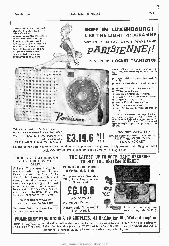
Luxembourg is guaranteed also A.F.N., plus dozens of other Continental programmes. The Complete novice will build this set in 3 hours and it will work and its volume will astound you. This Lit was specially Flown to Europe by Boeing 707 jet for testing and it never failed to pick up programmes anywhere.
ROPE IN LUXEMBOURG LIKE THE LIGHT PROGRAMME WITH THE FANTASTIC TWIN WAVE BAND
pApISIgN%TEi / A SUPERB POCKET TRANSISTOR
This amazing little set for home or car HAS TO BE HEARD TO BE BELIEVED
We will supply ALL components at a £3196 total cost of only YOU CAN'T GO WRONG !
Note: -These star items, starred be- cause they are above any other kit avail- able.
* Elegant dial graduated long and M
waves. * Built in wave change switch not pre- set. * Printed circuit for easy assembly. * "S" ferrite rod aerial. * Earphone if required, 51- extra. * Choice of colour red blue or cream. * Chrome carrying handle. * British 3" moving coil speaker. * Brand new components. * Best Mullard and Newmarket transis- tors.
A fully illustrated 30 page booklet, complete with step -by -step assembly in- structions and all other data, comes to you for only 219 extra; PP4 press -stud type battery 213; post and packing on the lot 2'6.
SO GET WITH IT ! !
and build yourself this superb little set NOW PUT THE WORLD IN
YOUR POCKET
Second -to -none after sales service and all your components factory new, plainly marked and fully guaranteed
ALL COMPONENTS SUPPLIED SEPARATELY IF REQUIRED
THIS IS THE FINEST BARGAIN EVER OFFERED ON MAIL
ORDER A Seven Transistor. Long, Med. wave superhet, by well known British manufacturer. Size only 4 x 3 x lin. Absolutely complete and tested, in genuine morocco leather case,normal price IOZgns.The most compact set you have seen made like a watch. Money back guaran- tee. Price L6.10.0. P.P. 2;6. Personal earphones, 7/- extra.
TRADE ENQUIRIES W-LCOM2D
USUAL DISCOUNT ON ANY LINES
Transistor Soldering Irons, 916, I716,
241 -, 29'6. P.P. on each I '6.
THE LATEST UP -TO -DATE TAPE RECORDER TO HIT THE BRITISH MARKET
WONDERFUL MUSIC REPRODUCTION
Complete with Batteries, Mike, Tape, Earphone and
Guaranteed.
£6.19.6 NO POSTAGE
No Hidden Extras at all.
Money Back Guarantee if Not Satisfied.
Tape recorder only lets accessories, only £4.12.6
WOLVERHAMPTON RADIO & TV SUPPLIES, 42 Darlington St., Wolverhampton Terms:- C.W.O. to avoid delay. All orders mailed by return, subject to stocks surviving the onslaught! And see us if you can. Fuller details and or prices by request, write (S.A.E.) or call. Tel: Wolverhampton 20315.
Suppliers to Forces clubs, educational authorities, schools, etc.
www.americanradiohistory.com
974 PRACTICAL WIRELESS
MULLARD DESIGNS MULLARD 3 -VALVE PRE -AMPLIFIER TONE CONTROL UNIT
Designed mainly for Mullard Range of Amplifiers, also suitable
for any Amplifier requiring input up to 250mV. incorporates 5 input
Channels, including for Tape and Magnetic Pickups. Separate Bass and Treble controls. High pass filter 20 to 160 c /s, low pass filter 5-9 Kc /s. Totally enclosed in case size 111' x 41' x 4'.
KIT OF PARTS £10.10.0 ASSEMBLED & TESTED £13.13.0 MULLARD "5 -10" MAIN AMPLIFIER
For use with MULLARD 2 -stage pre- amplifier with which an undistorted power output of up to 10 watts is obtained. SPECIFIED COMPONENTS AND MUL- LARD VALVES including PARMEKO MAINS TRANSFORMER and choice of PARMEKO or PARTRIDGE . Output Transformer.
COMPLETE KIT £1 0.0.0 A(Parmeke
Output AND) TESTED £13.10.0
ABOVE incorporating PARTRIDGE OUTPUT TRANS. £1.6.0 extra. THE MULLARD 510 /RC AMPLIFIER The popular complete "5-10" incorpora- ting Control Unit providing up to 10 watts high quality reproduction. Specified com- ponents and new MULLARD VALVES. Includes PARMEKO MAINS TRANS- FORMERS and choice Of PARMEKO or PARTRIDGE Output Transformers.
COMPLETE £12.0.0 ASSEMBLE
TESTED £16.0.0 With PARTRIDGE £1.6.0 ex.
THE MULLARD 33 /RC A HIGH QUALITY AMPLIFIER DEVEL- OPED FROM THE VERY POPULAR 3 -WATT MULLARD "3-3" DESIGN. KIT OF PARTS £8.8.0
OUTPUT TRANS.
ASSEMBLED £11.10.0 AND TESTED Complete to the MULLARD specification including PARMEKO OUTPUT TRANS- FORMER. Switched inputs for 78 and
L.P. records plus a Radio position. Extra power to drive a Radio Tuning Unit is also available.
THE "MONO- GRAM" A small Amplifier of genuine high quality performance. Incorporates new MUL- LARD ECL36 Valve, separate BASS and TREBLE controls and produces up to 3 watts undistorted output. Kft Assembled
-of Parts£4.10.0 and Tested £6.10.0 P fectly suited for Portable Installations for which purpose we offer PORTABLE CAS.: (£3.10.0), the AMPLIFIER (Kit) and 's' x SPEAKER (£1.0.0). All for £9.0.0 Alternatively with ASSEMBLED £9.10.0 AMPLIFIER The Case quoted above will accommodate some 4 7speed Single Record Units. A larger model is. available for extra 10 / -. With this a GO51PLETE PORTABLE REC- £13.10.0 ORD PLAYER can be built for
MULLARD FOUR CHANNEL MIXING UNIT
H powered Cathode follower output .
corporates two inputs for CRYSTAL CROPHONES, one for CRYSTAL PICK- S and a fourth for Radio or Tape.
KIITOF £8.8.0 ASSEMBLED MBLEED 1.i 1. i. a P. ARTS Alternative Model I/L provides Mr one input matched for moving coil Pelibbon mike £].17.0 extra.
! ! SENSATIONAL BARGAINS ! !
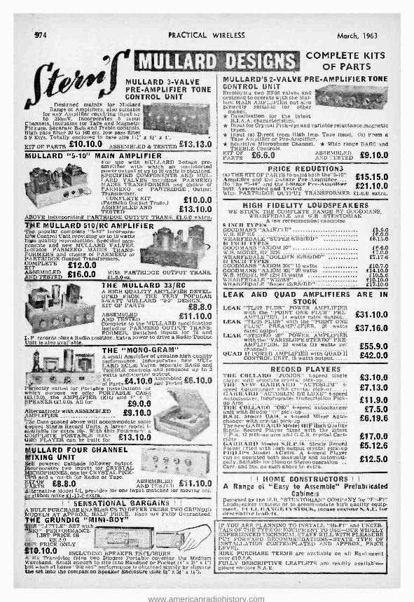
A BULK PURCHASE ENABLES US TO OFFER THESE TWO GRUNDIG MODELS AT APPROX. HALF PRICE. Each are Fully Guaranteed. THE GRUNDIG "MINI -BOY"
LITTLE" SET with . IG" PERFORMANCE
LIST PRICE IS i!. £26.5.0 SSR. PRICE ONLY
!0.10.0 INCLUDING SPEAKER ENCLOSURE A' six Transistor (plus two Diodes) Portable covering the Medium Waveband. Small enough to slip into Handbag or Pocket (4' x 21' x 1') but when at home "big set" performance is obtained simply by slipping She set into the companion Speaker Enclosure isize 91' x 31' x 11-).
-
March, 1963
COMPLETE KITS OF PARTS
MULLARD'S 2 -VALVE PRE-AMPLIFIER TONE CONTROL UNIT Employing two EF86 valves and designed to operate with the Mul- lard MAIN AMPLIFIER but also perfectly suitable for other
makes. * Equalisation for the latest
R.I.A.A. characteristics. * Input for Crystal Pick -ups and variable reluctance magnetic
types. * Input (a) Direct from High Imp. Tape Head. (b) From a
Tape Amplifier or Pre -Amplifier. * Sensitive Microphone Channel. * Wide range BASS and TREBLE Controls.
ff KIT OF PARTS £6.6.0 AND TESTED £9.1 00
PRICE REDUCTIONS (a) THE KIT OF PARTS to build both the "5 -10" £15.15.0 Amplifier and the 2 -stage Pre- Amplilter.... both Assembled and elet a;e Pre-Amplifier £21.10.0 With PARTRIDGE OUTPUT TRANSFORMER 61.6.0 extra.
HIGH FIDELITY LOUDSPEAKERS WE STOCK THE COMPLETE RANGE BY GOODMANS,
WHARFEDALE and W.B. STENTORIAN A tew recommended examples
8 INCH TYPES GOODMANS "ARIETTE" £5.6.0 W.B. HF 816 £6.0.0 WHARFEDALE "SUPER 8 /RS /DD" 66.15.0 10 INCH 'IYPIiS GOODMANS "AXIOM 10" 99.6.0 W.A. MODEL HF 1016 97.0.0 WHARFEDALE "GOLDEN 10 /RS /DD" £7.17.6 12 INCA TYPES GOODMANS "AXIOM 201" 15 watts 610.7.0 GOODMANS "AXIOM 301" M watts 214.10.0 W.B. MODEL HF 1214 15 watts £10.5.8 WHARF'EDALE "W12 /RS" 210.10.0 WHARFEDALE "Super 12/RS /DD" £17.10.0
LEAK AND QUAD AMPLIFIERS ARE IN STOCK
LEAK "TL /12 PLUS" POWER AMPLIFIER with the "POINT ONE PLUS" PRE - £31.10.0 AMPLIFIER, 14 watts rated output..
LEAK "TL /25 PLUS" with the "POINT ONE PLUS." PREAMPLIFIER, 28 watts £37.16.0 rated output
LEAK "STEREO 20" POWER AMPLIFIER with the "VARISLOPE STEREO'" PRE- AMPLIFIER. 22 watts (11 watts per channel)
QUAD II POWER AMPLIFIER with QUAD II CONTROL UNIT. 15 watts output
£55.9.0 £42.0.0
RECORD PLAYERS THE COLLAR() "JUNIOR" 4 -speed single player with senarate crystal pick -up THE NEW GAIRRARI) , AUIOSLIM" 4- speed Autochanger with crystal pick -up GARRAItD "AU'rOSLIM DE LUXE" 4 -speed Autochanger, incorporates transcription Pick- up Arm TIIE COLLAR() "C60" 4 -speed autochanger unit with Studio "O" pick -up B.S.R. Model UA14, a 4 -speed Mixer Auto- changer with crystal pick -up The new GARRARD Model 4]IF High Quality Single Record Player fitted with the latest T.P.A. 12 pick -up arm and G.C.S. crystal Cart- ridge GAItltARD Model S.R.P.10. Single Record Player l ttted with high output crystal pick -up l'IIILIIS Model AG1016. A 4 -speed Player can be operated both manually and automati- call y. Suitable tor Mono or Stereo operation Carr. and Ins. on each above 5/- extra.
£3.10.0 £7.13.0
£ 11.9.0 £7.5.0
£6.19.6
£17.0.0 £5.12.6
£12.5.0
! ! HOME CONSTRUCTORS ! !
A Range of "Easy to Assemble" Prefabricated Cabinets
Designed by the W.B. "STENTORIAN" COMPANY for "Hi -Fi" Loudspeaker systems or to accommodate high quality equip- ment. P'I'LL RANGE IN STOCK, please enclose S.A.E. for deseriptire leaflets.
IF YOU ARE PLANNING TO INSTALL "Hi -Fi" and UNCER- TAIN OF THE TYPE OF EQUIPMENT TO USE -OUR WIDELY EXPERIENCED 'I'ECHNICAI, STAFF WILL WITH PLEASURE PUT FORWARD RECOMMENDATIONS -STATE TYPE OF INSTALLATION CONTEMPLATED AND APPROX. PRICE LEVEL. HIRE PURCHASE TERMS are available on all Equipment over 010.".(7. FULLY DESCRIPTIVE LEAFLETS are readily available - please enclose S.A.E.
www.americanradiohistory.com
March, 1963
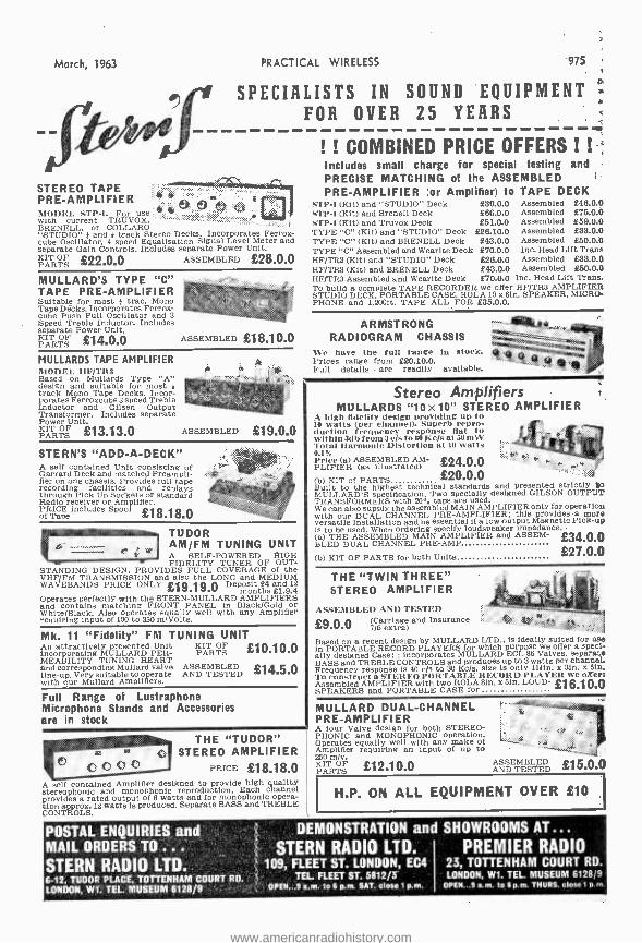
STEREO TAPE PRE -AMPLIFIER MODEL STP -l. For a >o with current TRUVOX, ' BRENELL, or COLLARD "STUDIO" ; and i track Stereo Decks. Incorporates Ferrox- cube Oscillator, 4 speed Equalisation Signal Level Meter and separate Gain Controls. Includes separate Power Unit. KIT OF PARTS £22.0.0 ASSEMBLED £28.0.0
PRACTICAL WIRELESS 975
SPECIALISTS IN SOUND EQUIPMENT FOR OVER 25 YEARS
MULLARD'S TYPE "C" TAPE PRE -AMPLIFIER Suitable for most i trac. Mono Tape Décks. Incorporates Ferrox- cube Push Pull Oscillator and 3 Speed Treble Inductor. Includes separate Power Unit. KIT OF £14.0.0 PARTS ASSEMBLED £18.10.0
MULLARDS TAPE AMPLIFIER AIODEI. IIF/TIt:3 Based on Mullards Type "A" design and suitable for most track Mono Tape Decks. Incor- porates Ferroxcube 3 speed Treble Inductor and Gilsen Output Transformer. Includes separate Power Unit. KIT OF £13.13.0 PARTS ASSEMBLED £19.0.0
STERN'S "ADD -A- DECK" A sett contained Unit consisting of Garrard Deck and matched Preampli- fier on one chassis. Provides full tape recording facilities and replays through Pick Up Sodkets or standard Radio receiver or Amplifier. PRICE includes Spool £18.18.0 of Tape
TUDOR AM /FM TUNING UNIT A SELF- POWERED HIGH FIDELITY TUNER OF OUT-
STANDING DESIGN. PitOVIDES FULL COVERAGE of the VHF /F51 TRANSMISSION and also the LONG and MEDIUM WAVEBANDS PRICE ONLY £`19.19.0 De
posit nths £1.9.4
Operates perfectly with the STERN -MULLARD AMPLIFIERS and contains matching FRONT PANEL in Black /Gold or White /Black. Also operates equally well with any Amplifier requiring input of 100 to 350 m /Volts.
Mk. 11 "Fidelity" FM TUNING UNIT An attractively presented Unit KIT OF £10.10.0 PER- MEABILITYg UNINGRHEA T-
PARTS
and corresponding Mullard valve ASSEMBLED £14.5.0 line -up. Very suitable to operate AND TESTED with our Mollard Amplifiers.
Full Range of Lustraphone Microphone Stands and Accessories are in stock
! ! COMBINED PRICE OFFERS ! ! Includes small charge for special testing and PRECISE MATCHING of the ASSEMBLED PRE -AMPLIFIER (or Amplifier) to TAPE DECK
STY -1 (Kit) and "STUDIO" Deck £39.0.0 Assembled £46.0.0 STP -t (Kit) and Brenell Deck 166.0.0 Assembled £ 75.0.0 STP -1 (Kit) and Truvox Deck £51.0.0 Assembled £59.0.0 TYPE "C" (Kit) and "STUDIO" Deck £28.10.0 Assembled £33.0.0 TYPE "C" (Kit) and BRENELL Deck £43.0.0 Assembled. £50.0.0 TYPE "C" Assembled and Wearlte Deck £70.0.0 Inc. Head Lift Trans HF /TR3 (Kit) and "STUDIO" Deck ' £26.0.0 Assembled -£33.0.0 HF /TR3 (Kit) and BRENELL Deck £43.0.0 Assembled £50.0.0 HF /TR3 Assembled and Wearlte Deck £70.0.0 Inc. Head Lift Trans. To build a complete TAPE RECORDER we offer HF /TR3 AMPLIFIER STUDIO DECK. PORTABLE CASE. ROLA 10 x 61n. SPEAKER, MICRO- PHONE and 1,200ft. TAPE ALL FOR £35.0.0.
ARMSTRONG M.Atiait.
RADIOGRAM CHASSISa We have the full range in stock. Prices range from 620.10.0. . Full details are readily available.
THE "TUDOR" STEREO AMPLIFIER
PRICE £18.18.0 A self contained Amplifier designed to provide high quality stereophonic and monophonic reproduction. Each channel provides a rated output of 6 watts and for monophonic opera- tion approx. 12 watts is produced. Separate BASS and TREBLE CONTROLS.
Stereo Amplifiers MULLARDS "10x10" STEREO AMPLIFIER
A high fidelii design providing up to 10 watts (per channel). Superb repro- duction frequency response fiat to within 3db from 8 e/s to 60 Kc /s at io m W' Total Harmonic Distortion at 10 watt.a e.1% Price (a) ASSEMBLED AM- £24.0.0 PLIFIER (as illustrated) (b) KIT of PARTS £20.0.0 Built to the highest technical standards and presented strictly W MULLARD'S specification. Two specially designed GILSON OUTPUT TRANSFORMERS with 20% taps are used. We can alsosupply the assembled MAIN AMPLIFIER only for operation with our DUAL CHANNEL PRE -AMPLIFIER: this provides a more versatile Installation and be essential if a low output Magnetic Pick -up is to be used. When ordering specify loudspeaker impedance.
BLED DUAL CHANNEL PRE- AMPLIFIER and ASSEM- £34.0.0
(b) KIT OF PARTS for both Units £27.0.0
THE "TWIN THREE" STEREO AMPLIFIER
ASSEMBLED AND TESTED (Carriage and Insurance . -.
7/6 extra) £9.0.0 Based on a recent design by MULLARD LTD., is ideally suited for use in PORTABLE RECORD PLAYERS for which purpose we offer a speci- ally designed Case:: incorporates MULLARD ECL 88 Valves. separate BASS and TREBLE CONTROLS and produces up to 3 watts per channel. Frequency response is 40 c/s to 30 Kc /s, size is only llifn. x 31n. x 510. To construct a STEREO PORTABLE RECORD PLAYER we offer: Assembled AMPLIFIER with two ROLA 61n. x 5fn. LOUD- £16.10.0 SPEAKERS and PORTABLE CASE for
MULLARD DUAL -CHANNEL PRE -AMPLIFIER A tour Valve design for both STEREO- PHONIC and MONOPHONIC operation. Operates equally well with any make of
250 Amplifier
m /v. requiring an input of up to
KIT OF PARTS £12.10.0 ññD1 FI'rED £15.0.0
H.P. ON ALL EQUIPMENT OVER £10
POSTAL ENQUIRIES and MAIL ORDERS TO ... STERN RADIO LTD. 6 -12. TUDOR PLACE, TOTTENHAM COURT RD.
LONDON, W1. TEL. MUSEUM 6128/9
DEMONSTRATION and SHOWROOMS AT... STERN RADIO LTD.
109, FLEET ST. LONDON, EC4 TEL. FLEET ST, 5812/3'
OPEN...9 a.m. to 6 p.m. SAT. close 1 p.m.
PREMIER RADIO 23, TOTTENHAM COURT RD. LONDON, W1. TEL. MUSEUM 6128/9
OPEN...9 a.m. to 6 p.m. THURS. close 1 p. rn.
www.americanradiohistory.com
976 PRACTICAL WIRELESS March, 1963
RETUIilST - OF - l'OSrl' SERVICE We offer a really efficient Mail Order Service on all items stocked. All cash orders are dealt with on the day of receipt.
* Hire purchase orders are subject to slight delay but this is kept to the absolute minimum.
ILLUSTRATED LISTS Illustrated lists are available on LOUDSPEAKERS. TAPE DECKS, TEST GEAR, GRAMOPHONE EQUIPMENT, AMPLI- FIERS. Any will be sent free upon request.
STEREO COMPONENTS Morganite ganged potentiometers as specified for the Mullara circuits. * Log /Anti -Log. 500k. 1 meg., 2 meg. * Log /Log, SOk. 250k, 1 meg., 2 meg. * Lln/Lin 250k, 500k, 1 meg. All 10 /6 each.
TRANSISTORS MULLARD. Reduced prices. Current production types. not rejects. All in makers' boxes. Postage 3d. on each. 0C44. 9/3: 0C45. 9 / -; 0070 and 0071, 6/8; 0072, 8/ -; OC72 Matched Pairs 16 / -; OC/8, 8 / -: 0081g- S /-; OC17O. 9/6: 0C171. 10 /8.
AMPLIFIER KITS We have full stocks of all components for the Mullard 510. Mullard 3-3, Mullard 2 and 3 Valve Pre -amp. Mollard Stereo. Mullard Mixer. GEC 912 Plus. Fully detailed list on any of these sent upon request. Instructional Manuals: All MuHard Audio Circuits in "Circuits for Audio Amplifiers ". 9/5. GEC912, 4/6. All post free.
TRANSISTORISE YOUR CRYSTAL SET We have two new designs for Transistor amplifiers which can be used to greatly improve the signal from any crystal set. RLD4 Kit, one stage 12/ -: RLD5 Kit, two stage 21/-: both post free. The kits are easy to build and very detailed Instructions are supplied. Leaflet available.
NEW MULLARD CONDENSERS We now stook the following- range 01 the new Mollard Miniature Foil and Polyester condensers as used in the latest TV and Transistor sets. Fully detailed list available giving full technical information and dimensions. Miniature Foil. 30 volt working for Transistor sets. .01mfd. lid. :.022mfd, 9d. :.047mfd, 9d.; .1mfd, 11d. Polyester Tubular Capacitors. Moulded outer case designed to withstand accidental contact with the soldering iron. Tolerance 10 %. 125v. range:.01mfd, .022mfd, .047mfd, all 9d. each. Amid.
22mfd, 1/3: .47mfd, 1/8; lmfd. 3/-. .0047m m fd, .01mfd..022mfd, all 9d.
55 ta. m .047mfd, 1/2, .lmfd. 1/3..22mfd. 1/6..47fd, 2/5. Postage
TAPE RECORDING EQUIPMENT TAPE DECKS Hire Purchase
ALL CARRIAGE FREE Cash Price Deposit Mthly /Pmts. B.S.R. TD2 .. £8.19.8 £1.18.6 12 of 13/7 Latest COLLARD TAPÉ Á10.19J6
22.3 .6 12 of 16/4
We now stock the Martin Recorder Kits. These are partly 'assembled kits for complete tape recorders. The Amplifier Printed Circuit panels are completely wired, but the assembly
.,,ppf this and external components Is left to the constructor. Very 'bbmolete instructions are supplied. Send for leaflet. MODEL C for Collaro Studio Deck. £11.11.0. MODEL B for BSR TD2 Deck. 28.8.0. CARRYING CASES. Smart carrying cases are available to take the above amplifiers and decks. Fitted with speaker. For Model C Amplifier and Collaro Deck. 25.5.0. For Model B Amplifier and BER Deck. 24.4.0. H.P. Terms available for amplifiers, cases and decks.
TAPE PRE -AMPLIFIERS '111ULLARD TAPE C PRE -AMPLIFIER. We stock complete ì is and all components, Send for list.
TIN. Pre -amp kit for Collard Studio Deck, £8.8.0.
"BRAND FIVE" RECORDING TAPE Poet free. Long Play: 900ft. (5'). 18/6: 1200ft. (51'). 23/8: 1800ft. (7'). 35/-.
JASON F.M. TUNER KITS Kits supplied complete with every item needed including instruct tlon manuals. Fully detailed list available. Separate items supplied, ask for price list. H.P. Terms available on any kit.
FMT1, 26.12.6; EMT? (less power), 27.15.0. -"PMT? (with power). 29.12.6; FMT3 (less power), 29.9.8.
FMT3 (with power). 211.7.6. Mercury 2. 210.14.8. .Tf V /2, 214.12.6.
P.W. STRAND, MAYFAIR & SAVOY UNITS We stock parts for the P.W. Strand Amplifier. Mayfair Pre -amp- lifier and Savoy FM Tuner. Detailed price lists are available.
"P.W. MERCURY" P.W. Mercury. (Osmor printed circuit version). including Mollard first grade transistors and Instruction manual. Com- plete set of parts 29.19.6. Instruction manual available separa- tely at 2/6 post tree. Separate components supplied. Send for list.
LATEST TEST METERS
AVO Model 8 Mark II AVO Model 8 with
leather carrying case .. 227.18.0 AVO Model 7 Mark II .. £21. 0.0 AVO Multiminor .. 29.10.0 AVO Slultirnlnor with
leather carrying case .. £11. 9.0 £2. 5.0 12 of 17/- TAYLOIt MODEL 127A .. 210.10.0 £2. 2.0 12 of 15/8 CARY A -III .. .. .. 24.17.6 £11. 7.6 3 of £1. 2.8 CARY B -24 ,. .. .. 26.10.0 22. 0.0 3 of £1.13.4 CARY M -1 £2.14.0 - - - Full details of any of the above supplied free on request. The AVO Models 7 and 8 are both latest models from current pro- duction -not to be confused with Government Surplus.
OUTPUT TRANSFORMERS GILSON: W0698A, W0696B. 50/6, post 2/6. W0710. 55/6, post 2/6. W0892, 62/3, post free; W0767. 27/ -, post 1/6. W01796A, 57/6, post 2/8. W01932. 84/ -, post free. PARTRIDGE: P3687. 75 / -; P4131. 85/ -; P5202, P5203. 25.18.6- All post free. PARMEKO: P2829. 45/8: P2642. 43/3; P2643, 458. All plus post 2/9. P2841, 28/3, post 2/ -; P2928, 15/3 post 2/ -; P2932. 39/3, post 2/6.
L ELSTONE: OT /ML, 45/ -, post 2/9; OT /3, 25/ -, post 2/8.
MAINS TRANSFORMERS GILSON: W0741AB, 63/ -, post free; W0839, 48/9, post 2/9; W01328, 58/6, post 3/6: W01268. 58/ -, post 3/6; W01566, 80 / -, post free ; W01341, Choke, 36/ -, post 2/ -. PARMEKO: P2631, 33/9, post 2/9; P2830, 52/6, post 3/3: P2644. 73/6, post free; P2930. 39/3, poet 3/ -: P2931, 54/8, post 3/3. ELSTONE: MT /MU. 45/-, post 3/3; MT3 /M, 35/-. post 3/ -; MT /510, 42/ -, post 3/3.
MARTIN STEREO AMPLIFIER KITS Printed circuit, already wired and tested. Only requires wiring to mains and output transformers. Complete kit with plastic escutcheon and full instructions. 26.6.0.
GRAMOPHONE EQUIPMENT ALL LATEST MODELS Hire Purchase ALL POST FREE Cash Price Deposit Mthly /Pmts
RECORD CHANGERS GARRARD AUTOSLIM 27.2.6 21.8.6 12 of 11/2 GARRARD AUTOSLIM
De -luxe (Mono PU) . £11.9.0 22.8.0 12 of 16/11 GARRARD AUTOSLIM
De -luxe (Stereo /Mono PU) £12.5.4 22.9.4 12 of 18 /- B.S.R.UA14(TCB Mono PU) 28.19.8 21.7.6 12 of 11/- B.S.R, UÁ14 Monarch
(TC8$ Stereo/LP/78) RECORD PLAYERS
of 12/4 RAIL TU12(PCI Mono PU) £3.17.6 21.4.8 3 of 21/- B.S.R. GUI (TC8 Mono PU) 24.18.9 21.8.3 3 of 21.6.8
TRANSCRIPTION UNITS GARRARD 41:1F (GCB PU) 216.2.6 23.4.6 12 of 21.3.8 PHILIPS AG10I8 .. .. 21,2.8.0 22.10.0 12 of 18/- Many of the above can be supplied for stereo working. See our Gramophone Equipment List for details.
LOUDSPEAKERS GOODMANS: Axiette Bin 25.5.9; Axiom 101n., 28.6.0: 121n.. Axiom 20i. 210.7.0. 12ín., Axiom 301, 214.10.0: 12ír.., Audlom SI Bass, 28.14.0; 121n., Audiom 81 Bass, 213.14.0; Trebax Tweeter, 26.4.0: X05000 Crossover unit, 21 9.0. W HITELEY, 26.4.0: 11E108 loin.. 26.19.11; HF1012 10in.. 24.7.6: HMI 8in.. 25.19.11: T8í8 8in., 25.13.7: TIO Tweeter, 24.8.3: 7:11'1 Tweeter, 21.10.0; CX3000 Crossover unit, 21.11.6: CX lauu Crossover unit, 22.0.0. H.P. Terms available on all speakers.
Hire Purchase Cash Price Deposit Mthly /Pmts.
.. 224. 0.0 £4.16.0 12 of 21.15. 2
25.12.0 12 of 22. 0.11 £4. 4.0 12 of 21.10.10 £1.19.0 12 of 14/4
TERMS OF BUSINESS Cash with order or C.O.D. We charge C.O.D. orders as follows: Up to £3, minimum of 3/2. Over £3 and under £5, 1/8. Over £5 and under £10, 1/8. Over £10 no charge. Postage extra on CASH orders under £3 except where stated. Postage extra on over- seas orders Irrespective of price.
WATTS RADIO (MAIL ORDER) LTD.
54 CHURCH ST., WEYBRIDGE, SURREY Telephone: Weybridge 47556
Please note: Postal business only from this address Callers welcome by appointment
* HIRE PURCHASE TERMS are available on any item. Re- payments may be spread over 3, 6 or 12 months. Details as fol- lows: Three months: Deposit 6/- in the L. Service charge 5 per cent. but minimum charge of 10/ -. Six and Twelve months: Deposit 4/- in the 2. Service charge 10 per cent, but minimum charge 20 /.
www.americanradiohistory.com
March, 1963 PRACTICAL WIRELESS
INCREASE
YOUR
KNOWLEDGE
CHOOSE THE RIGHT COURSE FROM: RADIO AND TELEVISION ENGINEERING, INDUSTRIAL TELEVISION, RADIO AND TELEVISION SERVICING RADIO SERVICE AND SALES VHF /FM ENGINEERING, ELEC- TRONICS, COMPUTERS AND PROGRAM- MING, ELECTRONIC TECHNICIANS, SERVOMECHANISMS, TELEMETRY, COLOUR TV, INSTRUMENTATION, AND PRINCIPLES OF AUTOMATION.
ALSO EXAMINATION COURSES FOR: A.M.Bri¢.I.R.E.; City and Guilds Telecom. Technicians, C. & G. Radio and T.V. Servicing (R.T.E.B.), and P.M.G.'s Certificates. C. & G. Radio Amateurs' Certificates.
LEARN AS YOU BUILD Practical Radio Courses: Gain a sound knowledge of Radio as you build YOUR OWN 5 -valve superhet radio receiver, Signal Generator and High -quality Multitester. At the end of the course you have three pieces of permanent and practical equipment and a fund of personal knowledge and skill. ICS Practical Radio Course opens a new world to the keen Radio amateur.
97Z
RADIO
TELEVISION
ELECTRONIC ENGINEERING
MEMBER OF THE ASSOCIATION
OF BRITISH CORRESPONDENCE COLLEGES
THERE IS AN ICS COURSE FOR YOU
Whether you need a basic grounding, tuition to corn. plete your technical qualifications, or further special. ised knowledge, ICS help you with a course individually adapted to your requirements. There is a place for you among the fully -trained men. They are the highly paid men -the men of the future. If you want to get to the top, or to succeed in your own business, put your technical training in our experienced hands. ICS Courses are written in clear, simple and direct language, fully illustrated and specially edited to facilitate individual home study. You will leans in the comfort of your own home -at your own speed. The unique ICS teaching method embodies the teacher in the text; it combines expert practical experience with clearly explained theoretical training. Let ICS help you to develop your ambitions and ensure a successful future. Invest in your own capabilities.
FILL IN AND POST THIS COUPON TODAY
You will receive the FREE ICS Prospectus listing the examinations and ICS technical course in radio, television and electronics. PLUS details of over 150 specialised subjects.
PLEASE SEND FREE BOOK ON
NAM-
ADDRESS
OCCUPATION
INTERNATIONAL CORRESPONDENCE SCHOOLS Dept. 170, I NTERTEXT HOUSE, PARKGATE RD, London SWI I
3.63
www.americanradiohistory.com
978 PRACTICAL WIRELESS March, 1963
BENTLEY ACOUSTIC CORPORATION LTD. THE VALVE SPECIALISTS 38 CHALCOT ROAD, LONDON, N.W.I Telephone: PRIMROSE 9090
EXPRESS POSTAL SERVICE! ALL ORDERS DESPATCHED SAME DAY AS RECEIVED. FOR ONLY 216 EXTRA TELE- PHONE FOR THAT URGENT ORDER TO BE DESPATCHED IMMEDIATELY BY OUR SPECIAL C.O.D. SERVICE
4INDICATES 0A2 17/8 0139 17/6 OZ4 b/- 1A3 3/-
1 121- 1C1 SI- 102 10/8 103 8/6 105 12/6 106 10/6 1D5 18/2 1136 10/6 1F1 7/6 1E2 8/- 1F3 3/- 1F7 15/- 19'09 5/- 1G6 17/6 1115 10/6 1L4 8/- ILAB 16/10 11.D3 6/- 1LN6 A/- 1E5 10/6 IPI 7/6 1910 6/- 1P1I 7/6 1E5 6/- 184 9/- 185 5/- IT2 25/11 1T4 3/- DA 12/6 106 5/6 2A7 10/8 2028 4/- $D1SC 7/8 2D21 16/- 4P 25/11 9%2 4/6 3A4 6/- 3A5 10/6 3B7 12/6 9136 5/- 3Q4 7/6 30 9/6 384 6/- 8v4 7/8 401 7/6 6R4GY 17/6 6U40 4/6 5V4Q 10/- 523 5/6 524 12/6 6Z3 19/6 654 9/. 9/80L210/- 6A7 10/6 6A8 9/- 6AB7 8/- 6AC7 4/- 6AG5 5/6 8A07 7/6
8/6 64E5 8/- 6AK6' 12/6 6AK8' 9/- 6AL3 41- GAMS 5/- 6AM6 8/6 8AQ5 7/6 6AR6' 20/- 6AT6 6/- QAU6 10/- 6AV6 12/4 6137 6B8
10/6
6BA6 6/- 613E6 6/- BBGOG 22/8 68H8' 8/- 68.16. 6/- 613Q3 7/-
VALVES 6BQ7A 22/8 68E7* 9/- 6B138' 18/2 6887 25/-
6BW8 16Ìe 68%6 6/- 6C4 SI- 605 6/0 606 6/6 6C8 12/8 809 18/6 6C10 9/6 6C12' 18/7 6C17 10/8 BCDBQ 35/8 6CH6 7/6 8CW4 24/- 6D1 21- 6D3 19/5 6D,i 6/8 6D8 15/- 6E5 12/6 6F1' 10/- 6F5 12/6 61,66 7/- 6F8GT 8/- 6F8 18/8 6F11' 17/9 OF12 8/6 6F13 101- 6F14 25/11 6F1ñ 14/11 6F'16 8/- 6F17 12/6 6F18 14/11 8F19 6/- 6918 10/8 6F`24 9/6 6F32 10/6 6F33 7/8 606 6/6 6116 3/- 6J5G 6/- 6J56T 6/- 6J6 8/- 6J70 4/e 6J7GT 10/6 638 12/6 6K6 8/- 6K7G Bi- 8K7GT 8/- 61180 6f- 6K8GT 10/6- 6E25 19/5 8L1 29/8 6L6G 7/6 6L8M 10/6 OL7GT 7/8 6L17 9/- BLIP 18/- 6L19' 22/8 6LD3 8/- 6LD13 11/8 6LD2015/7 6N7GT 8/- BPI* 18/9 6P25' 12/6 61'26' 19/5 6P28 25/11 8Q70 6/- 6Q7GT 11/- 61170 10I- 6R7GT 11/- 60A7 8/6 6807 7/6
6ßH7 8/.
- 68J7 8/- 68E7 8/- 60L7 8/- 68877 5/6 69Q7 9/- 68117 12/6
WITH 8887 8/- 6U4GT 12/6 8115G 7/6 6U7G 8/6
6V6UT 8/6 4X4 4/8 6X5 61- 6Y6 10/8 7136 20/9 7B7 8/6 705 8/- 7C6 8/- 7R7 8/- 787 84/11 7Y4 7/6 8132 8/6 8D3 8/6 9BW6 14/11 9D2 4/- 9D7 18/7 10C1' 12/6 1O02 25/11 IOD1 716 10D2 11/8 one 10/- 10E9. 11/6 10F10' 12/8 1OLD3 8/8 10LDI115/7 10P13 15/- 10P14 18/9 11E1 17/6 11E3 15/- 12M 6/- I2A8 16/6 12AC614/11 12AD618/10 12AE6 18/7 12AH7 8/- I2AR812/8 12AT8' 7/6 12AT7' 5/- 12AU6'22/8 12AU7 5/- 12AV6 12/4 12AX7' 7/- I2BA6' 8/- 12BE8 9/- 12B11720/9 12E1 80/- 12116 3/- 12J6GT 4/- 12J7GT 8/6 12K6 17/8 12K7GT 5/- 12K8GT14/- 12Q7GT 5/- 128A7 8/6 128C7 8/6 12807 7/- 128117 8/8 12SJ7 8/8 138K7 6/- 128Q7 11/8 128137 8/8 12U56 7/6 12Y4 10/6 14B6 20/9 14H7 22/8 1487 18/- 18 23/10 19 10/8 19AQ5 10/8 1913061122/8 18111 10/-
20F2' 25/11 2OL1' 25/11 2OP1 25/11 20P3 22/8 20P4 25/11 20P8" 22/8 25A8 10/8
NEW 25L6GT11/8 251.140T18/2 2525 10/6 23Y3G 19/5
25Z5U 10/6 25Z60T 8/6 279U 26/11 28D7 7/. 30C1 7/6 30015 12/- 30F5 6/- 30FL1 9/8 301,1.12 12/8 301.1 7/8 30L15' 9/- 30P4 15/- 30P12 7/6 30P16 7/6 30119 19/5 30PL1 9/6 30PL13 10/6 309L14 21/4 35A5 20/9 35L6GT 9/6 33W4 7/6 3623 18/2 35Z4GT 6/- 33Z5GT 9/- 408UA 18/2 418TH25/11 42 22/8 43 10/- 50A5 21/10 50C3 10/- 3OCD8G85/7 501.60T 10/- 52KÚ' 14/4 óBKU26/11 72 4/6 77 8/- 78 6/8 80 9/- 83 15/- 88V 19/5 85A1 85/8 85A9 16/- 90AG 87/6 90AV 87/6 9000 87/6 900V 37/6 90C1 181- 160132 16/6 15002 16/- 161 18/- 185BT88/10 186BTA
88/10 301 20/- 304 15/- 305 18/- 306 13/- 907 8/- 4033 12/6 4687 71/- 5763 7/6 7198 6/- 7475 6/- AC044 10/6 AC2PEN
19/6 AC2PENl
DD we Ac4pEN
27/2 ACBPEN/
DD 25/11 AC8PEN7/6 AC/PEN(S)
22/8 AC/PEN(7)
16/- AC/SG 22/8
TYPE CHEMICAL ACSGVM
16/- AC/TH13214 AC/TP 32/4 AC/VP115/- AC/V9222/8 AF118 20/- AT94 5/- AZL 18/9 AZ31 10/- AZ41 13/7 836 9/- 61.63 7/8 Cl 12/6 C1C 12/6 CBL1 27/2 001135 22/8 0K506 6/8 C1.4 23/10 CI.33 18/9 CVB 2/8 CV63 10/6 CV271 10/8 CY1 18/2 CYLC 18/2 CY31 11/- Dl 8/- D13 18/6 D42 10/6 163 5/- D77 4/- DAC32 10/8 DAF91 5/- DAF96 7/6 DCC90 10/8 DD4 12/6 DD41 1317 DDT4 12/6 DET25 7/6 DF33 10/6 DF86 16/- DF72 801- DB91 8/- DF96 7/8 DF'97 9/- DHSO 16/6 D1163 6/- DH76 5/- DH77 6/- DH81 25/11 D1110127/11 D11107 18/9 DK32 16/- DK40 21/10 DK91 6/- DK92 10/6 DK98 8/6 D1.83 9/6 DL35 12/6 DL63 10/- DIM6 17/8 DL63 15/- DL72 15/. DL75 301- DL92 6/- DL94 7/6 DL95 7/6 DL96 7/6 DL910 10/6 DM70 7/8 DM71 9/9 DW4/3509/6 DW4/5005/8 DY86 18/- E80F B0/- ME* E180F 34/6 E1148 2/8 EA50 2/- EA76 9/8 EABC80 9/- EAC91 4/- EAF42 9/-
CATHODE EB34 2/6 EB41 9/6 10B91 4/- EBC3 23/10
EgC41 6¡- EBC81 8/. EBC90 e/- EEC91 12/4 EBF80 8/. EBF83 18/7 EBF89 9/8 EBL21 82/8 EC31 18/7 E032 9/6 EO.53 12/8 EC54 6/- EC70 12/8 EC81 27/8 EC90 7/- EC91 10/8 E092 la/- ECC31 15/- ECC32 6/6 ECC33 8/8 ECI3423/11 ECC36 8/6 ECC40 17/e ECC81 5/- ECC82' 5/- ECC83 7/- ECC84 9/- ECC85 7/6 ECC88 23/4 ECC91 8/- ECF8010/8 ECF82 10/6 ECFH6 19/S ECF80420/- ECM 25/11 E01121 22/8 ECH33 22/8 ECH35 6/6 ECH42 9/6 ECHe1' 7/8 ECH8313/7 ECH8418/2 ECLHO 9/. ECL82' 9/6 LCL83 18/9 ECL86 14/7 EFIi 22/8 EF9 22/8. EF22 14/- EF36 4/- EF37A 8/- EF39 416 EF40 15/- EF41' 8/- 13F42 10/- EF50
Brit. 5/. Amer. 7/-
EF34 5/- EF'7:3 10/6 ENO. 5/- EF83 15/6 EF86 6/. EF86 9/- EF89 9/- EF91 3/6 EF92 4/6 EF95 8/- EF97 18/- EF98 13/- EF183' 18/2
EF804 22/8 EK2 26/11 EK32 8/8 ELI 19/8 EL32 5/- EL33 12/6 E1.34' 16/-
EL36 19/6 EL37 23/11 E439 18/6 EL41 9/-
EL81 16/2 EL83 19/b EL84 7/- EL85 10/8 EL86 16/10 EL91 5/- EL95 10/8 EL360 27/- E1820 18/2 EL821 85/11 EL822 19/6 EM4 17/9 EM34 9/8 EMU 12/- EM11 22/8 F.M80 9/. E5161 9/8 EM84 10/6 E5185 16/10 EN31 71/- EN91 15/- F.YSL 8/6 EY81 13/- EY83 16/2 EY84 18/2 EY86 7/6 EY91 7/6 EçSS 5/- EZ40" 6/6 EZ41' 7/- EZ80' 6/- 2Z81' 6/- EZ90 4/8 FC4 16/- FC13 25/11 FC13C25/11 FW4/5008/6 FW4I800818 0T1C 25/- GU50 41/8 GZ30 9/- GZ32 10/- GZ33 19/5 GZ34 14/- GZ37 19/5 1130 5/- H63 12/6 RABC80'
1816 RL2 7/8 HLI3C 7/6 11L23 14/11 HL23DD7/6 HL4l 12/6 11LI33DD
12/6 HN309 29/1 HV R2A 6/- HVR2 10/- IW3 10/- IW4/350 8/- 1W4/500
16/2 KBC32 20/5 KF35 6/8 KL33 8/6 KLL3228/11 KT2 5/- KT8 15/- KT330 8/- KT36' 32/4
KT44 290
2/6 KT61 12/6 KT63 7/- KT66 15/- KTeI 45/3 KT88 43/6 KT101 32/4
FOR EXTRA KTW81 8/8 KTW62 7/8 KTW63 6/8 KTZ41 8/-
LP? 918 ME41 18/10 ME91 12/6 51114 7/- MHD4 12/6 MUL4 7/6 MlILD612/6 ML4 8/6 ML6 6/8 518413 22/8 M894 20/- 511112/14 8/. 51X40 26/11 N37 25/11 N78 89/1 N108 89/1 N118' 22/8 N151 10/- N308' 20/1 N339 16/- N369" 18/10 P61 8/8 PABC80
13/7 PC86 16/2 PC88 18/2 PC95 18/- PC97 18/- PCC84 7/6 PCC83 9/6 PCC88 18/- PC089 8/6 PCC18919/S PCF80' 7/8 PCF82 10/6 PCF84 18/2 PCF88 9/6 PCL82 9/- PCL88' 9/6 PCL84" 7/6 PCL8510/- PCL86 16/2 PCIA8 91/4 PEN4DD
25/11 PEN26 9/6 PEN4ODD
84/- PEN45 19/6 PEN46DD
25/11 PEN46 4/8 PEN38322/8 PEN453DD
32/4 PENA422/6 PENB4
23/11 PEND])
4020 34/- PL33 18/9 PL36 16/- PL38 25/11 PL81 10/6 PL82 7/6 PL83 9/- PL84 12/4 PLS20 18/2 PM84 15/2 PT15 10/6 PX4 10/6
PY32' 17/6 PY33' 17/6 PY80 7/6 PY81 7/6 PY82 7/- PY83 7/8 9Y88 18/-
LIFE AND PY800 13/- PZ30 19/5 QP21 7l- QP22B 12/8
QS150/134fB 10/6
R10 16/- R12 8l6 Rlfi 25/11 R17 17/8 R18 18/2 R19 19/5 R32 12/6 RG1/240A
54/- RK34 7/6 8130 22/8 014B 28/10 8P130 12/8 SP41 816 8942 12/8 8P61 8/6 SU23 27/2 61.161 8/8 T4I 9/- TDD2 12/6 TDD4 12/8 TH21C 201- TH41 25/11 TH233 34/- TP22 15/. TP25 15/- TP2620 82/4 TYS6F 13/- UABC80 9/- UAF42 9/6 UB41 12/- UBC41' 8/8 UBC9111/- UBF80 9/- UBF89' 9/6 UBL21 22/8 UCC8414/3 UCC85 7/6 UCF8018/- UCH2122/8 UCH42 9/6 UCH81' 9/8 UCL813 9/6 UCL8818/9 L'F41 9/- UF42 12/6 UF80 10/6 UF85 9/- 15F86' 13/6 UF89' 8/- UL41' 10/6 UL44 25/11 1L46 14/6 UL84 8/8 U514 17/9 UM34 18/10 UMPO 14/11 URIC 18/2 UU6 8/- U116 19/5 UU7 16/2 UU8 25/11 UU9 6/6 UU10 22/8 111312 6/- UY1N WE UY21 16/2 UY41 6/6 UY85 8/-
U16114 10/- 1117 12/6 U18/20 8/8 U19 48/6 U21 15/- 022 8/- U24 29/1
RELIABILITY U25' 17/8 U26 9/- U31 11/6 U33 29/1
1137* 32%4 U41 19/6 U43 8/8 U46 16/6 U47 17/6 U50 6/6 U62 4/8 1/54 19/5 U76 6/- U78 4/6 U307 19/5 U391 16/2 U201 16/2 U251 14/- U281' 19/5 U282' 22/- U291 11/6 U301' 22/8 U320' 14/- U339 16/2 U403 18/2 U404 6/6 15001' 29/1 U4020 1812 VMP4G 15/- VM64B 16/- VP2 12/6 Vl'2B 14/6 VP4 15/- VP4A 17/8 VP4B 22/8 VP13C 7/- VP23
6/6 VP41 6/- VP133 22/8 VR75 17/8 VR105 7/- VR150 7/- VT61A 5/. VT601 6/- VU89 8/- VU111 10/- VU133 7/6 W21 12/6 W42 22/8 WB1M 27/3 W63 10/6 W76 5/- W77 4/6 W81M 8/- W101 29/1 W107' 22/8 W729 19/5 X14 12/- X18 10/6 X41 16/- X61 12/8 X63 9/- X84 7/6 X65 12/8 X66 12/6 X76M 14/- X78 29/1 X79 45/3 X817 32/4 X109 29/1 Y63 7/6 Y65 10/6 Z63 7/6 Z66 9/6 Z77 3/6
Z719 18/2
Z729 9/- 2759 86/.
Transistors and diodes GI)8 4/-
UD9 4/- OD10 4/- 0D12 4/- U1316 8/-
GET102 8/6 OET103 8/- 0ET04101- 0ET10617/6 GET113 8/- QET114 6/6 OET87210/- GET873 9/3 GET874 9/8 GEX13 3/8 GEX35 8/- GEX36 10/- GEX46 6/6 GEX64 11/6 GEX66 15/- AF102 27/6 AFI14 11/- AF115 10/6 AF916 10/- AF117 9/6 'AF118 20/- AF127 12/- MAT1O0 7/9 MAT101 8/6 MAT120 7/9 MAT121 8/6 OAS 8/- OAlO 8/- 0A70 3/- 0A73 3/- 0A79 3/- 0A81 8/-
Ól3 8/-
OA86 4/- 0A91 3/- OA96 8/6 OA210 9/6 0A211 18/8 0C16W 85/- 0C19 25/- OC22 25/- 0C26 25/- 0C28 24/6 0C29 27/8 OM 18/- 0C36 21/6 0041 9/- OC42 9/6 0C44 9/3 0C44PM 9/3 0045 9/- OC45PM 9/- 0063 22/6 0066 26/- OC70 6/8 0071 6/6 0072 8/- 0073 18/-
64.16.
OC75 8/- 0078 8/6 0077 12/- 0078 8/- OCHl 8/- OC82 101- 0083 6/- 0084 8/6 0C140 29/- 0C170 9/6 0C171 10/6 OCP71 17/8 PXC301 6/6 PXC101A
6/6 T82 12/6 T83 15/- XA104 18/-
*ETAL RECTIFIERS. DRM1B 181 -. DRM2B and DRM3B 16/8. LW7 21/ , LW16 98/ -. RMO 7/11, RMl 5/8. RM3 7/6. RM3 7/8. RM4 14/, RM3 19/8, 14A86 17/6. 14A97 25/ -. 14A100 27/ -. 14Á124 28 / -. 14A163 38/ -. 148130 36/ , 413261 11 /8. FC101 17/6. 16RC.1.1.16.1 8/6. F031 21/ -. 16R13.2.2.ß.112/ -. 1611E.2.1.8.1 6 /6. 1,11 4.1.1.`1.1 4/8. 18RA.1.2.8.1 11 / -. FC116 6 /6. FC124 15/ , FB3 10/6. K3 /49 9/ , CD 9/ -. C30 11 / , ISLECTROLYTIOS. Can types: 32 x 33 /450v. 6/9. 50 x 50/360v. 7/-. 64 x 120/360v. 8/8. 60 x 250/276v. 9 /6. 100 e 400/275v. 12/6. 100 /275v. 8/ -. 200/275v. 4 / -. 100 x .200,275v. 9/8. Tubular types: 8/450v. 1/9. 16 /450v. 2/9. 32/430v. 3/9. x 8/430v. 3 /-. 16 x 16/450v. 4/ -. 32 x 32/350v. 4/ -. 8 z 16 /450v. 3/9. Z.M. SPEAKERS. :3 ohm types: 21ín. 17 / -. 5I0. 16/8. 6 4in. 17/-. 7 x 41n. 15/, 1111¢. 27/... 121n. 29/8. 8 x 310.,15/6. 2 }in., 80 ohms. 17/6. Poet 2/- each. EULLARD midget silicon rectifiers. Tyne BY100. Output 230 volts, 4 amp. No larger than a shirt button. 8/- each. All goods brand new and actually in stock. We do not sell second -hand goods, manufacturers' rejects, or seconds, or Items from dismantled equipment.
Terms of badness: -Wash with order or C.O.D. only. Post Od. per item except where stated. Ordne over E3 poet free. C.O.D. 2/6 extra. All orders cleared same day. Any parcel loomed against damage In transit for 6d. extra. We are open for personal shoppers 8.30 -6.30 p.m. Oats. 8 -1 p.m. Complete Bet of modern and obsolete valve,, readers, condensers, transformers etc. with terms of business, 6d. Please enquire for any Item not listed with S.A.E.
www.americanradiohistory.com
March, 1963 PRACTICAL WIRELESS 979
UNIVERSAL AVOMETERS
Guaranteed perfect working order. Supplied complete with leads, batteries and instructions. Model "D" 34 range 28.19.6 Model "T 50 range 211.0.0 Registered Post 5/- extra.
MICROAMMETERS 0 -500 microamps. 251n. circular flush panel mounting. Dials en- graved. 0 -15. 0 -600 volts. BRAND NEW, BOXED. 15 / -, P.P.
7.5 K.V.A. AUTO TRANSFORMERS
0 -115 -230 volts. Brand new boxed, £15. Carriage 10 / -.
230/250 VOLT A.C. MOTORS 41 x 31n, dia.. 90 watts, 5,000 r.p.m. fin, spindle. 22/6. P.P. 1 /6.
1 K.V.A. ISOLATION TRANSFORMERS
230 v. PRI 230 v. Sec. Boxed, £5 each. Carriage 10 /, VARIAC TRANSFORMERS
24 amp., 23o volt primary. 185 to 250 volt output, 212.10.0. Carriage 10 / -.
TELEPHONES TYPE "L" Generator Bell Ringing, 2 line connection. With batteries, fully tested, 69/9 per pair. Carriage 5/ -.
100 AMP A.C. METERS Nalder Thompson 6ln, scale. Brand new, boxed, 65/ -. P.P. 3/6.
3000 WATT AUTO TRANSFORMERS
0- 115 -230 volts, step -up or step - down. Brand new, boxed ex- U.S.A. 27.10.0 each. Carr. 10 / -.
PANEL METERS 1000.A 21' F.M. D.C. 42/6 100µA 31' F.M. D.C. 62/6 1 mA 29' F.M. D.C. 25/- 30/0/30 mA 2i' F.M. D.C. 9/6 350 mA 21' F.M. D.C. 10/6 300 v. sr Proj. A.C. 19/6 300 v. 24' F.M. A.C. 25/- 500 v. 21' F.M. A.C. 25/- 120 v. 31' F.M. D.C. 32/6 1500 v. 24' Electrostatic 25/-
FIELD TELEPHONES TYPE "F"
Suitable for many applications. Generator bell ringing. 2 line connection. With batteries and wooden carrying case, fully test- ed. 24.19.6 per pair. Carr. 5/ .
WAN FLU. ALL GOOD QUALITY COMMUNI- CATION RECEIVERS AND TEST EQUIP- MENT.
R.I07 COMMUNICATION RECEIVERS Frequency coverage from 1.2 to 17.5 Mc /s continuously on three bands. Completely self contained with built -in speaker and power unit to operate from A.C. mains or 12 volt D.C. OFFERED BRAND NEW, FULLY CHECKED. 212.10.0. Carriage 30/ -.
850 -2,000 metres. P.C.R.2 RECEIVERS 190 -550 metres 6 -22 Mc /s. output for phones or 3 a speaker. As new 65.19.6. Carr. 7/6. PCR3 as PCR2 but covers 190/550 met- res, 2 -7 Mc /s, 7 -22 Mc /s, including top band. As new. £8.8.0. carr. 7/8. All above models can be supplied with internal power unit to oper- ate on 200/250 v. A.C. at 39/6 extra units are 35/ -,
JEMCO 4,000 OHM /VOLT TESTMETER
1% Precision Resistors through- out. Single control system for all ranges. Highly accurate. Sensi- tivity 4.000 Il /volt A.C. and D.C.
Ranges: D.C. volts:
0- 1050 -250- 500- 1,000v. A.C. volts: 0- 1050 -250- 500- 1,000v.
D.C. current: 0-250 vA 0- 25500mA
Resistance: 03 -0k O 0-300k 0 0-3M O Decibels: -20 to +36
dB (2 ranges). Meter sensitivity: 100 microamp.
59/6 each P.P. 2/6.
JEMCO 20,000 OHM /VOLT TESTMETER
As above but with increased sen- sitivity and extended resistance range (0-5M O). 97/6 P.P. 2/6. Either type brand new. Guaran- teed with leads, prods, batteries, instructions.
or alternatively plug -in external power
NATIONAL H.R.O. RECEIVERS
BRAND NEW! Senior model, table mounting. Complete with a full set of 9 coils covering 50 kc /s to 30 Mc /s. Supplied complete in original transit cases. £25. Carr. 20/-. Power units to operate direct from 200/250 volt. A.C. 59/6 extra.
PRECISION COMBINATION VOLTMETER /AMMETER FOR
A.C. AND D.C. Two separate instruments housed in polished wood case. 6fn. scales with knife edge pointers. Ranges: Volts A.C. and D.C. 160-300-600 v. Amps. A.C. and D.C. 25-50-150-200 A. Supplied complete with all current shunts, leads and leather carrying case. Manufactured by Elliott Bros. Supplied brand new. 29.19.6 each. Carriage 7/6.
MINE DETECTOR No. 4A Will detect all types of metal. Fully portable. Complete equip- ment supplied tested with instructions. 39/6. Carriage, 10 /6. Battery 8/6 extra.
COLLARO STUDIO TAPE TRANSCRIPTOR Brand new 1962 model, 3 speeds. 3 motors. digital counter, etc. With latest bradmatic heads and interlock button. Supplied with spare spool, instructions, fixings. 10 ans. each. Carr. pal d.
FABULOUS TAPE OFFER Famous American Brand Tapes. Brand new, fully guaranteed. 51n.- 000ft., 10/6, Sin.- 900f t., 13/6, 5in.- 1200ft., 17/ -, 71n.- 1200f t. 13/6, 71n.- 1800ft., 18/6, 71n. 2400fí., 30/-. P. & P. extra. S.A.E. for full tape list.
CT -53 SIGNAL GENERATORS Precision Instruments covering 8.9 to 15.5 Mc /s. and 20 to 300 Mc /s. on 6 bands. Variable attenuator from 1 microvolt to 100 millivolts. Opera- tion 110 /200/250 volts. A.C. Supplied in perfect working order. Complete with calibration charts. 19 gns. each. Carriage 10 /6.
PRECISION A.C. AND D.C. VOLTMETERS Two ranges, 160 and 320 volts, 8 inch mirror scale with knife edge pointer. Housed in polished wooden case. Ideal for schools, labs., etc. Supplied brand new, 25.19.6 each. P.P. 3/8. NATIONAL N,H.U.RE- CEIVERS MODEL ST
Uses metalli sed octal base valves. Few only available. BRAND NEW with 9 coils covering 50 kc /s to 30 Mc /s. £30. Carr. 20/ -. Power unit for 200 /250 v. A.C. operation, 59/6 extra.
DELCO 24 VOLT D.C. MOTORS
Shunt wound, 5,400 r.p.m. Torque 41n. oz. Double spindle. smooth running, ex- tremely powerful. Also runs on 12 volts. BRAND NEW 10/6 each. P.P. 2/ -.
MINIATURE MODEL
ACCUMULATORS Lead Acid, BRAND NEW. 2v. 1.5 A,H., 4 x 11 x lin., Ilb., 5/6, P.P. 1/3. 12v. 0.75 A.H., 4x3xIiin 216., 15/6. P.P. 1/6.
L,T. METAL RECTIFIERS All full wave, bridge connected. Brand new, guaranteed. 12/18v. 1.5A, 3/9 24/36v. 4A. 22/6 12/18v. 2.5A, 6/3 24/36v. 15A,1145/- 12/18v. 4A. 8/6 36/48v. 2A, 19/6 12/18v. 6A, 12/3 36/48v. 4A, 29/6 12/18v. 10A, 22/6 36/48v. 6A. 32/6 12/18v. 15A. 37/6 48/60v. 2A, 211 - 24/36v. 1A, 7/3 48/60v. 10A. 82/6 Please add postage.
L.T. TRANSFORMERS All primaries tapped 200 /250 volts. I Battery Charging. 3.5, 9 or 17 volt, 1 amp.. 9/9. Ditto 2 amp. 14/3. volt, 6
Ditto amp.,
4 26/ -
am. p.. 16/6. 9 or 17
2 Model Type 3, 4, 5, 6. 8, 10. 12, 15, 18, 20. 24 or 30 volt, 2 amp.. 18/6. Ditto 4 am 27/6. Ditto 5 amp., 37/6. Add Postage.
AUTO TRANSFORMERS Step -up, step -down, tapped 0 -115- 200- 230 -250 volts, 15w., 9/ -: 60w.. 12/6: 150w.. 18/6; 200w.. 27/6; 300w., 42/6; 500w.. 67/6: 1.000w. 99/6; 1.500 w.. 26.19.6. P.P. extra.
R.C.A. PLATE TRANSFORMERS
Prl, 200/250 v. sec., 2,000-0-2.000 v. 500 nsA, tapped 1,500 v. New. Boxed, £6.10.0. Carriage 15/ ,
DUMONT KI05IP1 DOUBLE BEAM C.R.T.
Twin Gun. Brand new, boxed, 59/6. P.P. 3/6.
1.2 Ohm 12 Amp RHEOSTAT Geared slider type, new boxed, 15/6 each. P.P. 3/6.
PAINTON 100KL1 3+ DIA. INSTRUMENT POTS
Fully screened, precision wire - wound. 10/6 each. P.P. 1/3.
CADMIUM SULPHIDE PHOTOCELLS
Very sensitive, full data supplied. 12/6 each. P.P. &i.
MINIATURE PANEL METERS
For lifn, dia, panel hole. 050 µA 39/6 0 -300 v. D.C. 27/6 0500µA 32/6 "S" meter 35/- 0-1 mA 27/6 "VU" meter 42/6 0-5 mA 27/6
Hours of Business: 3 LISLE STREET, 9 a.m. -6 p.m. Half Day Saturday Send S.A.E. 34 LISLE STREET. 9 a.m. -6 p.m. Half Day Thursday For Bargain Lists
1,.R'N`, , .i/,ir, CI `(RAD I O) LI M I
Phone: GERRARD 8204/9155 Cables: SMITHEX LESQUARE
-34` LISLE STREET, LONDON, W.C.2
www.americanradiohistory.com
980 PRACTICAL WIRELESS March, 1963
i&************** ** a! c*********** ***************> k************** **** * *A- MODEL TK20A 1,000 O.P.V. on AC and DC ,# Extremely compact wide range multi- tester. .
. 10,000 0.PV multi -tester In semi- assembled kit form. u 1 ° A most useful instrument for hobbyists. * AL Ranges; D.C. voltage: 0 -6-30- 120 -600 -1,000 v. (10,000 69/6 /6 i experimenters and technicians who require
o.p.v.). a reliable teeter at a budget price. Operation # AC voltage 0 .30 -120. 800 -í,2W V is extremely easy; simply plug leads into
. . * desired scale and you are ready to go. ** (10.000 o.p.v.). * ? D.C. current: 0- 120µA, 0.12 -300 inA. RANGES
D.C. volte,ge: 0 -16- 150 -1,000 v. (1.000 o.D.v.) * * Resistance: 0-201{, 0-2 Meg. (150 ohm, A.C. voltage: 0-15- 150 -1,000 v. (1,000 o.p.v.). * * r c-. 15K at centre scale). D.C. current: 0-150 mA. * * Decibels: -20 to }63dß (800 ohms 1
Resistance: 0 -100X. * * Size: 31 x 2} x ltn. /` #, mW., odbm ®O.TT6v.). Complete with battery, test leads and instructions, v
* Accuracy: D.C. voltage and current fully guaranteed. * * ±2% f.s. A.C. voltage ±4% f.s. Resia- * * .1 Lance ±3% of total scale length. LAPEL MICROPHONE BM.30R \1 # (. si , Size: 9 1ín. x 3 1tn. x í1n. Complete with precision engineered Magnetic Microphone- / * * test leads, battery and instructions, for lapel or hand use. Only liin. diameter. . * 4' Few only available, rush your order Exceptionally sensitive. Chrome plated case * * now while stocks last. and clip includes 5ft. shielded cable. Only 12/8. *
RELDA METER SENSATION!
# MINIATURE COMPONENTS * As previously advertised * LT44/700 Sub -miniature #. driver and output
transformders ck
8/- pr. * P.31 Stanard ja plug 2/8 ea. * P8.35 Sub -miniature bplue and cket 2/8 pr.
Cß.25 Tinyso" plug and socket . 2/8 Pr. * CH 385 Chrome mini-
4(_ ature plug and socket 3/8 pr. CR /5 Crystal earpiece .. 8/- ea. * MR.4 Magnetic earpiece 8/- ea. * LM.179 Crystal lapel mio.
# 88.219 ° Standard' slide 1 sitch D.P. D.T. 8/8 ea. * T.104 S.P. S.T. Toggle * switch .. . 2/8 ea, * 88.3271 Miniature slide
46. switch .. 2/6 ea. SF 20 High resistance
headphones . 14/8 ea.
"A- LA a6t r v. battery slime-
29/8 ea. * 8A7D 88afan.
double cone h1.11 92/8 ea.
Ai_ T. Tape splicer and
18/9 ea. SF 5000 Stereo " head- * phones .. 27/6 ea. * AR..13 Test lead Lit
9/6 ea, * PVC.30.5 260 ple tuning condenser .. .. 5/- ea. * ITI.7 Injection Probe 42/8 ea.
?f Please add P. & P. on above.
INTEGRATED-STEREO AMPLIFIER MODEL S.A.300 Engineered for the professional ... designed for the home.
A completely new dual 15 watt stereo ampli- fier for professional quality reproduction, remarkable versatility and new distinctive styling- worthy of a place in the finest stereo Ht -Fi system, a full range of front panel controls and switches permit adjusting volume, balance and tonal characteristics through every delicate shading of the entire audio range.
Just look at these features: * * Speaker Phasing Switch. * Hum Balance Controls. * Loudness Switch. * Rumble Filter. * Integrated Tone Controls. * *Volume-
Balance Controls. * Stereo Head- phone
Superb Styling. * IaPriefg. Output
Selector °30 W
Function 5 atts
Selector channel). 1 Frequency
tresp Outputs. Sup30
to Styling. B per Inert 30 aural cps. Controls: Selector,
channel trebrumble ul
filter, stereo
monaural channel swil monaural c 2-12 2, 1-6
loudness. speaker phasing, hum adjusters, power Value line up: upp 4-6 Bete. 1-8 CA4. d3 ,O O A.C. Mains.
and opera Size 13} x 101 x 44ía, Supplied complete with in- e
stallation and operation manual.
No. 19. 2 -8 Mc /s TRANSMITTER RECEIVER This most famous Army Trans/Receiver covers 2-8 Mc /s. (15F37 metres in two bands). Has an intercom, amplifier. Designed for 12 and 24 volt operation but supplied with P.W." Mains conversion details. Uses a 8 valve superhet receiver, I.F. being 465 Kein, and a 6 valve transmitter designed
for voice and C.W. operation. Incorporates test and tuning meter for voltages, aerial loading and current tests. Panel Controls: Frequency tuning, P.A. tuning, Gain control. MCW. CW, R/T switch. Het -tone netting. Off-on Quench aerial, AVC LT -HT -Drive tests. Supplied complete with valves and instruction book.
FEW ONLY LEFT ONLY 65/- Don't be disappointed -Order Now Carriage lOf-
# ONLY # 29/- * BOOSTER TRANSISTOR * RADIO SPEAKER. Designed * for use with transistor radios, * valve radios, car radios, ampli-
fiers, where quality reproduction of sound Is required. Plugs into * earpiece output socket of nearly * all miniature sets. The cabinet * is finished In beige leather with * contemporary gold baffles at each
* sion cordpftted with miniature * plugs, individually cartoned and * guaranteed. Size: 9}in. * diameter. * * * *
* * *
With the
T°S.38
VERNIER DIALS Precision vernier dials with approx. 8 to 1 ratio. Surface mounting. Ac- curately centred metal insert for fin. shaft. Reads counter clookwise 0-100 in 180°. Model T.501 1}' die. 12/8 Model T.502 Y' dia. 14 /- Model T.503 3' dia. 118/-
"KEW PANEL METERS 'S" Meter Model, 35/ -; DC Microammeters, 5 m/a. 27/8:
300 v., 27/8: 0 -504A. 39/8: 0-500µA. 32/8: DC M111tammeter, O-lmA, 27/8. Available in Clear Plastic or Black Bakelite. Will fit 1 }in. dfa cut out. State choice when ordering. All modele individually boxed and fully guaranteed. P. & P. 2/6 each.
A S STAGE TRANSISTOR RADIO
which can be built In one hour and will give you end- less amount of pleasure. Com- pletely portable has the appearance of sets costing considerably more and works equally well. Attractive case 5}- x 35' x 11 -, genuine 2}ín. speaker and G.E.C. transistors, tuning con- denser, volume control with switch, etc. All parts sold separately.
37'6 ONLY 37'6 P. & P. 2/8.
* * * .j(.
* * R.101 TUNING AND BAT- * TERM INDICATOR. This * ultra -miniature tuning and * battery indicator is easily mounted into portable radios * or tape recorders for indicating * tuning centre and residual * capacity of batteries. Galvan- ometer movement assures corn- * piste accuracy. Insulation re- .. , sistance between case and terminals: 20 Megohms /SWV. Sensitivity: 400 uA. Solder * terminals are provided at rear. * Plastic case cover. Complete * with example circuit for use. * Size: } x fin. Price 24/8.
SIMPLE TO BUILD ** FUNTO
OWN!!! # * * * * * * * * * * * * * * * *
CALLERS WELCOME AT 67 TOTTENHAM COURT ROAD, * LONDON, W.I. MUS 9806
* * * * * * * * * * * * * * * * * * * * *h>F
* MAIL ORDERS TO ** (DEPT. P.), 32a COPTIC STREET,
LONDON, W.C.1.
* * * * * * * * * * * * *% * * * * * **
www.americanradiohistory.com
March, 1963 PRACTICAL WIRELESS 981
INTRODUCING THE R.S.C. BASS -MAJOR 30 WATT GUITAR AMPLIFIER A MULTI -PURPOSE HIGH FIDELITY, HIGH OUTPUT UNIT
FOR VOCAL AND INSTRUMENTALIST GROUPS
Eminently suitable for bass guitar and all other musical instruments. * Incorporating two Ihn. heavy duty 25 -watt high flux (17,000 lines) loudspeakers
with 21n, diameter speech coils. Designed for efficiently handling full output of amplifier at frequencies down to 25 c.p.s.
* Sensitive tweeter unit reproduces frequencies from 3,000 c.p.s. up to 18,000 e.p.s. * Heavily made cabinet of convenient size 24 x 21 x 141n. has an exceptionally
attractive covering in two contrasting tones of Vynair. * For 200400 v. to 50 c.p.s. A.C. mains operation. * Four lack socket inputs and two independent vol. controls for simultaneous
connection of up to four instrument pick -ups or microphones. * Se ate bass and treble controls providing more than adequate `Boost" or u * LEVEL frequency response throughout the audible range. * SUPERIOR TO UNITS AT TWICE THE COST.
392 Gns S.A.E. for leaflet. OR DEPOSIT of 54.3.0 and 12 monthly payments of £3.9.11. Carr. 17/6.
R.S.C. JUNIOR GUITAR AMPLIFIER 5-watt high quality output. Separate bass and treble cut" and `boost' controls. Sensitivity 15 m,v. Two high impedance Inputs, 10in, loudspeaker. Handsome, strongly made cabinet (size 14 x 14 x 7ín. approx.) finished in attractive and durable
Or DEPOSIT gl and 9 operation.
£8.19.6 payments of £1. Carr. 7/6.
LINEAR TREMOLO /PREAMP. UNIT Designed for introducing the Tremolo effect to any ampliferDwhich is fitted with a reserve power
6. . A.C. T. This smoothed
to practically all amplifiers of our manufac- ture, and to those of several other manu- facturers. The unit plugs into power supply point and any input socket of amplifier. Controls are Speed (frequency of interrup- tions). Depth (for heavy or light effect). Volume and Switch. Three sockets are for wo inputs and Foot Switch. 4 Gns. ONLY
R.S.C. SENIOR 10 -watt GUITAR AMPLIFIER
High -fidelity push -pull Output. Separate base and treble "cut" and "boost" con- trols. Twin separately controlled Inputs so that two instruments or "mike" and pick -up can be used at the same time. Two loudspeakers are incorporated, a 121n. high flux 14 watt base unit, and a 6 x 4in. elliptical for treble. Cabinet is well made and finished as Junior Model. Size approx. 18 x 18 x 81n. Only
15 Gnf. Carr. 10/- S.A.E. for leaflet. Or DEPOSIT 34/9 and nine monthly payments of 34/8.
R.S.C. SUPER 112 -5I 15 -watt An exceptionally efficient high fidelity Guitar Amplifier incorporating a heavy
20 -watt speaker with excellent frequency response. Individual bass and treble controls give ample "boost" and "cut ". Two high impedance Jack Socket in- puts are separately controlled. If required one or two additional inputs can be provided at a cost of 7/8 per extra socket. Cabinet is of substantial con- struction and attractively fin- ished in two tones of poly- chrome. Size approx.2D x8 x 101n. Operation from 200 -250 v. 50 c.p.s. A.C. mains. Please do not com- pare this Unit with others of similar rating until you have heard the difference. S.A.E. for leaflet.
22 GnE.Or Deposit 51/6 and nine monthly payments of 51/6. Carr. 12/6.
TRANSISTOR SALE. Mullard OC71 3/9, 0045 4/11, 0C44 4/11 0072 4/9, 0081 4/1I, 0C171 8/9.
XB113 8/9 XB10493 /9.XC1O1A 3 /0. Postage 6d. for up to 3 Transistors. D.C. SUPPLY KIT. 12 v. 1 a. consisting of a partially drilled metal case, mains trans., F.W. Bridge Rectifier. 2 fuseholders and fuses. Change Direction switch, vari- able Speed regulator and circuit. For 200 -250 v. A.C. mains. Suitable for Electric Trains. Limited number available at 29/11,
SELENIUM RECTIFIERS F.W. BRIDGE 24 v.2amp .. 14/9
6/12 v. 1 a. . 3 /11 24 v 20 amp. 89/9 6/12 v, 2 a. .. 6/11 H.T. TYPES H.W. 6/12 v. 3 a. .. 9/9 150 v. 40 mA .. 3/9 6/12 v. 4 a. .. 12 /3 250 v. 50 mA .. 3/11 6 /12 v. 6 a. 15/3 250 v. 60 mA .. 4/11 6/12 v. 10 a. .. 25/9 250 v. 80 mA ,. 5 /11 812 v. 15 a. 85/9 250 v. 250 nul . 11/9 CONTACT COOLED, 250 v. 75 mA, F.W. (Bridge). 10 /11. 250 v. 50 mA, F.W. (Bridge), 8/11. H.W. 250 v. 60 mA, 5/11. LINEAR TAPE PRE -AMPLIFIER Type LP /1, Switched Negative feedback equalisation Positions for Record 111n. 35ía. 71in. and Playback. EM84 Record- ing Level Indicator. Designed primar- ily as the link between a Collaro Tape Transcrlptor and a high fidelity ampli- fier, but suitable for almost any Tape Deck. Only 9 ens. S.A.E. for leaflet.
NEW BRANCH OPENING
32 HIGH STREET, LEICESTER
LATE FEBRUARY
R CTIFOIERS 12vLIIS MP 1 (BRIDGE) F.W. ONLY 9 9
IILIGE PURCHASE OF BRAND NEW 24 v. 20 Amp. F.W. (Bridge) SELFNIFVI 5
/ 9 RECTIFIERS. each
R.S.C. GRAM. AMPLIFIER KIT. 3 watts output. Negative feedback. Controls Vol. Tone and Switch. Mains operation 200 -250 v. A.C. Fully isolated chassis. Circuit. etc., supplied. Only 39/9. Carr. 3/9.
HI -FI 10 WATT AMPLIFIERS Brand new. Manufacturer's discontinued line. Fitted latest Millard valves. Dual inputs for "mike" and gram., etc. Bass and Treble Controls. High sensitivity and quality. Output for 3 ohin or 15 ohm speaker. For 230.250 v. A. . ÿ7.18.9 Carriage 4/6. Only THE SKYFOUR T.R.F. RECEIVER A design of a 3 valve long and medium wave 200 -250 v. A.C. Mains receiver with selenium rectifier. High gain H.F. stage and low distortion detector. Valve line -up 6117, SP61, 6V6G. Selectivity and quality excellent. Simple to construct. Point -to- Point wiring diagrams, instructions and parts list, 1/9, maximum building costs 5419.6, inc. attractive Walnut veneered wood cabinet 12 x 60 x 511n,
MULTI -METERS. CABY Ml. Sensiti- vity 2,000 ohms per volt. A.C. and D.C. 54/.. A.10. Basic Meter sensitivity 155 micro -amps A.C. and D.C. ranges 54.17.6. B.20. Sensitivity up to 10,000 ohms per volt A.C. and D.C. £6.10.0.
Ex. GOVERNMENT ACCUMULA- TORS. Size 71 x 4 x 2In.. 2v. 18 A.H. -brand new, 8/9 each. 3 for 15/6.
Ex. GOVT. SMOOTHING CHOKES. 200 mA, 3-5 H, 50 ohms, Parmeko 8/9; 100 mA, 5 H, 100 ohms 3/11; 150 mA, 10 H. 50 ohms 9/9: 80 mA, 20 H, 900 ohms 5/9; 120 mA, 12 H. 100 ohms 8/9; 50 mA, 50 H, 1.000 ohms 6/9: 100 mA, 10 H, 100 ohms 6/9: 60 mA. 5 -10 H, 250 ohms 2/11.
COMPLETE POWER PACK KIT, 19/ 11 Consisting of Mains Trans., Metal Recti- fier. Double electrolytic, smoothing choke chassis and circuit. For 200 -250 v. A.C. mains. Outputs 250v. 60mA, 6.3v. 2a.
R.S.C. POWER PACK, 39/9. Louvred metal case only 8 x 50 x 2iín. Stove enamelled. For 200 -250v. A.C. mains Output at 4 pin plug and socket 260 v, 60 mA, fully smoothed and 6.3v. la. Suit- able for power requirements of almost any Pre -amp or Radio Tuner.
R.S.C. BABY ALARM or INTER - COMM. KIT. Complete set of parta with diagrams. etc. Housed in two polished walnut finished cabinets of pleasing design. High sensitivity. For 200 -250v. A.C. mains. Fully isolated. Controllable at both units. An Intercomm. of this class would normally cost £20 -£30. Only 79/6, carr. 5/- or assembled ready for use 55.15.0
R.S.0 BIRMINGHAM: SHEFFIELD: HULL: 6 Gt. Western 13 Exchange St. 51 Savile St. Arcade Castle Market Hull Birmingham Bldgs. Sheffield
No half -day I Half -day Thursday
(Manchester) MAIL ORDERS to S County Arcade, Leeds I. Terms: C.W.O. or C.O.D. No C.O.D. under EI. Ltd. Postage 219 extra under E2. 4(6 extra under ES. Trade Supplied. S.A.E. with all enquiries phrase.
BRADFORD: MANCHESTER: LEEDS: LIVERPOOL: 73 Dale St. Liverpool 2
56 Morley St. (above Alhambra Theatre) Bradford
Half -day Wednesday
8 -10 Brown St. (Market St.) Manchester 2
No half -day
s -7 County (Mecca) Arcade Briggate, Leeds
Half -day Wed.
www.americanradiohistory.com
R.S.C. PORTABLE GUITAR AMP- LIFIERS NOW ON PAGE 883. J
:982 PRACTICAL WIRELESS March, 1963
R.S.C. (Manchester) MAIL ORDERS to 5 County Arcade, Leeds I. Terms: C.W.O. or C.O.D. No C.O.D. under El Ltd. Postage 219 extra under £2. 416 extra under ES. Trade Supplied. S.A.E. with all enquiries please.
BIRMINGHAM: SHEFFIELD: HULL: LIVERPOOL: BRADFORD: LEEDS: MANCHESTER: 6 Gt. Western 13 Exchange St. 51 Savile St. 73 Dale St. (8 mins. 56 Morley St. 5 -7 County 8 -IO Brown St. Arcade Castle Market from Lime St. or (above Alhambra (Mecca) Arcade, (Market St.) (Opp Snow Hill Stn) Bldgs. Exc,ange Stations) Theatre) Briggate
Half -day Thurs. Half -day Wednesday No half -day
SENSATIONAL STEREO OFFER A complete set of parts to (4 Gns.) construct a good quality Stereo amplifier with an undistorted output total 6 watts. For A.C. mains in- put of 200 -250 v. Including pair matched %in. speakers. Sensitivity 130 m.v. Ganged Vol. and Tone Controls. Preset balance control. Full instructions and wiring diagrams supplied. Stereo Pick- up Head 19/9 extra with above only.
R.S.C. 30 -WATT ULTRA LINEAR HIGH FIDELITY AMPLIFIER A10 A highly sensitive Push -Pull high output unit with self- contained Pre -amp. Tone Control Stages. Certified performance figures compare equally with most ex- pensive amplifiers available. Hum level 70 db down. Frequency response ±3 db. 30-30,000 c /s. A specially designed sectionally wound ultra linear output transformer is used with 807 output valves. All components are chosen for reliability. Six valves are used EF86, EF86, ECC83, 807, 807, GZ39. Separate Bass and Treble Controls are provided. Minimum input required for full output Is only 12 millivolts so that ANY KIND OF MICROPHONE OR PICK -UP IS SUITABLE. The unit is designed for CLUBS, SCHOOLS, THEATRES, DANCE HALLS or OUTDOOR FUNC- TIONS, etc. For use with Electronic ORGAN, GUITAR, STRING BASS, etc. For standard or long -p laying records. OUTPUT SOCKET PROVIDES L.T. and H.T. for a RADIO FEEDER UNIT. An extra input with associated vol. control is provided so that two separate inputs such as. Gram. and "Mike" can be mixed. Amplifier operates on 200 -250 v. 50 c /s. A.C. Mains and has output for 3 and 15 ohm speakers. Compplete Kit of
I Gns. chassis and point-to punched
-point wiring diagrams and in-
Carr. 10 /- structions. If required, perforated cover with car-
rying handles can be supplied for 19/9. The amplifier can be supplied, factory built with EL34 output valves and 12 months guarantee, for 14 gns. TERMS: DEPOSIT 33/9 and 9 monthly payments of 33/9. Suitable microphones and - speakers available at competitive prices.
WE STOCK ARMSTRONG, DULCI AND JASON EQUIPMENT
GOODMANS AND W.B. SPEAKERS
GARRARD AND GOLDRIN3 T /TABLES
SUPERHET FEEDER UNIT. Design of a high quality Radio Tuner (specially suitable for use with our Amplifiers). Delayed A.V. /C. Controls are Tuning. W /Ch. and Vol. Only 250 v. 15 mA. H.T. and L.T. of 6.3 v. 1 amp. required from ampli- fier. Size approx. 9 x 6 x 7ín. high. Simple alignment procedure. Point -to -Point wiring diagrams, instructions and priced parts list with illustrations, 2/8. Total building cost 84.15.0. S.A.E. for leaflet.
Y. Vit. sec AKERS. loin. W.B. "Stentor- ian" 3 or lá ohms type HF 1012 10 watts, hi -fide Sty type. Recommended for use with our All Amplifier. £4.12.9. 121n. R.A. 3 ohms 10 watts (12,000 lines). 59/6.
TWEETERS. Plessey 311 19/9, 1561 25/9.
Jason FMTI V.H.F. /F.M. Radio Tuner de- sign. Total costs of parts including valves Tuning dial, Escutcheon. etc.. £6.19.9. Other Jason equipment in stock.
LINEAR L45 MINIATURE 4/5 WATT QUALITY AMPLIFIER. Suitable for any record playing unit, and most micro- phones. Negative feed -back 12 db. Sep- arate Bass and Treble Controls. For mains 200 -250 v. 50 c /s. Output for 2 -3 ohm speaker. Mallard valves EZ80, ECC83, EL84. Size only 75 -51ín. high. Guaranteed 12 months. Only 85.19.6. Send S.A.E. for leaflet. Terms: Deposit 22/6 and 5 monthly payments of 22/6.
12m. le S%ATC HIGH QUALITY LOUDSPEAKER In walnut veneered cabinet. Gauss 12,000 lines. Speech coil 3 ohms or 15 ohms. Only £4.19.6 Carr. 5 / -. Terms: Deposit 11/3 and 9 monthly pay- ments of 11/3. 52m. 20 WATT Iii -FI LOUD - SPEAKERS IN CABINETS. Size
18 x 18 x loin. Finish as above. Terms: Deposit 17/9 and 9 monthly payments of 17/9. Only 27.19.6. Carr. 8/6. BASS GUITAR LOUDSPEAKER IN CABINET. 151n. 50 watt. highly sensitive unit in rexine covered acoustically lined cabinet. Deposit £3.7.8 29 Gns. and 9 monthly payments of £3.7.6. Carr. 15 /-
R.S.C. 4 -5 WATT AS HIGH -GAIN AMPLIFIER A highly- sensitive 4 -valve quality amplifier for the home, small club, etc. Only 30 millivolts input Is re- quired for full output so that It is suitable for use with the latest high fidelity pick -up heads, in addition to all other types of pick -ups and practically all "mikes ". Separate Bass and Treble Controls are provided. These give full long -playing record equalisation. Hum level is negligible being 71 db. down 15 db. of Negative feedback is used. H.T. or 300 v. 25 mA. and L.T. or 6.3 v. 1.5 a. is available for the supply of a Radio Feeder Unit, or Tape -Deck pre -amplifier. For A.C. mains input of 2O0-
230-:á0 v. 50 c /s. Output for 2-3 ohm speaker. Chassis is not alive. Klt is complete in every detail and includes fully punched chassis (with base plate) with Blue hammer finish and point -to -point wiring diagrams and Instructions. Exceptional value at only £4.15.0, or assembled ready for use 25/- extra. Plus 3/6 carr., or deposit 22/8 and 5 monthly payments of 22/8 for assembled unit.
AUDIOTRINE HIGH FIDELITY REPRODUCERS THE DUO /10. Consisting of a 121n. 12,000 line Speaker with heavy four layer voice coil, the Audiotrine cross -over unit, and a 4ín. Diameter Tweeter Unit incorporated In the extremely attractive Audiotrine Senior Corner Console Cabinet as des- cribed below. Matching impedance 15 ohms. Power handling 10 watts nominal, 14 watts peak. Frequency ONLY range 40- 18,000 c.o.s. Deposit 27/9 and nine monthly pay - 12 Gns. ments of 27/9. THE DUO /20. Incorporating a 121n. High Flux 20 watt Speaker with 2ín. Diameter Speech Coil. (Total Flux 160,000 lines), the Audiotrine cross -over unit, and a highly sensitive Tweeter unit, In the Audiotrine Senior Corner Console Cabinet. Matching impedance 15 ohms. Peak Power Output 25 watts. Frequency range 30- ONLY 18,000 c.o.s. Deposit 33/9 and 14 Gns. nine monthly payments 33/9. R.S.C. JUNIOR RI -FI REPRODUCER. The very latest Goodmans Axiette 8 High Fidelity loudspeaker (retailing at approx. 5 Gns.) fitted in a specially design- ed Bass Reflex cabinet size 12ín. x 18ín. x 10 in. Acoustically lined and ported and fin- ished in polished walnut veneer. Matching impedance 15 ohms. Fre- quency range 40- 15,000 c.o.s. Power handling 6 watts $ Gns. nominal. Ideal for Stereo. Limited number. Carr. 4/6
R.S.C. BATTERY TO MAINS CONVERSION UNITS Type BM1. An all -dry battery --, eliminator. Size 51 x 41 x 2)n. --¡" approx. Completely reeler" battery supplying 1.4 v. arr. 90 v. where A.C. mains 200 -25o v. 50 c/s is available. Suitable for all battery portable receivers requiring 1.4 and 93 v. This includes low con- sumption types. Complete kit with diagrams, 39/9, or ready to use, 46/6.
Type 0112. Size 8 x 5y x 211n. upplies 120 v. 90 v. and 60 v..
40 mA. and 2 v. 0.4 a. to 1 amp. fully smoothed. Thereby completely replacing both H.T. batteries and L.T. 2 v. accumulators when con- nected to A.C. mains supply 200 -250 v. 50 c /s. SUITABLE, FOR ALL BATTERY RE- CEIVERS normally using 2 r. accumulators. Complete
kit of parts with diagrams and instruc- tions. 49/9, or ready for use. 59/6.
K.S.C. BASS REFLEX CABINETS, JUNIOR MODEL. Specially designed for W.B. HF1012 Speaker, but suitable for any good quality 10in. speaker. Acousti- cally lined and ported. Polished walnut veneer finish. Size 18 x 12 x 101n. Hand- some appearance. Ensure superb repro- duction for only 68.19.6. STANDARD MODEL. As above but for 121n. speakers. Size 20 x 15 x 13ín. Espe- cially recommended for Audiotrine Loud- speaker systems. For vertical or hori- zontal use. £5.19.6. Suitable legs with brass ferrules. 19/6 per set of 4.
R.S.C. CORNER CONSOLE CABINETS Polished walnut veneer finish. Pleas- ing design. JUNIOR MODEL. Size 20 x 11 x 8ín. for 8 x lin. or 10 x 6ín. speakers, 22.9.9. STAN- DARD MODEL. Size 27 x 18 x 121n. for 8 or 10in. speakers, £4.11.9. SENIOR MODEL. Size 30 x 20 x 15in. for 12ín. Speaker. Suitable Speaker systems below Only 7 gns.
AUDIOTRINNE HI -FI SYEAKI:It SYS- TEMS. Consisting of matched 121n. 12,000 line, 15 ohm high quality speaker; cross -over unit (consisting of choke. condenser, etc.) and Tweeter. The smooth response and extended frequency range ensure surprisingly realistic reproduction. Standard 10 watt rating £4.19.9. Carr. 5 / -. Or Senior 15 watt 7 gns. Carr. 7/6. AUDIOTRINE EQUIPMENT CABINETS Size 36 x 15 x 18ín. Beautiful walnut veneer- ed finish. Ele- gant contem- pory design. Robust con- struction. Uncut remov- able baseboard Depth above Only 12k gns. baseboard 5y-. Carr. 15/-
www.americanradiohistory.com
March, 1963 PRACTICAL WIRELESS
AUDIOTRON HI -FI TAPE RECORDER KIT REALISM AT INCREDIBLY LOW COST, CAN BE ASs i. inu.i u i \s Hui It 17/6
Incorporating the latest Collaro Studio Tape Transcriptor. The Audiotrine High Quality Tape Amplifier with negative feedback equalisation for each of 3 speeds. High Flux P.M. Speaker, empty Tape Spool, a Reel of Best Quality Tape and a Handsome Portable carrying Cabinet with latest attractive two -tone polychrome finish, size 145 x 15 x 85in. high, and circuit. Total cost if purchased individually approximately £40. Performance equal to units in the £60-£80 class. S.A.E. for leaflets. TERMS. Deposit £2.13.9 and 12 monthly payments of 441 -. Cash price if settled in 3 months.
HIGH FIDELITY 12 -14 WATT AMPLIFIER TYPE All PUSH -PULL ULTRA LINEAR OUTPUT "BUILT -IN" TONE CONTROL PRE -AMP STAGES
Two input sockets with associated controls allow mixing of "mike" and gram., as In A.10. High sensitivity. Includes 5 valves. ECC83. ECC83, EL84, EL84. EZ81. High Quality sec- tionally wound output transformer specially designed for Ultra Linear operation and reli- able small condensers of current manufac- ture. INDIVIDUAL CONTROLS FOR BASS AND TREBLE "Lift" and "Cut ". Frequency response ± 3 db. 30- 30,000 c /s. Six negative feedback loops. Hum level 60 db. down. ONLY 23 millivolts INPUT required for FULL OUTPUT. Suitable for use with all makes and types of pick -ups and microphones. Comparable with the very best designs, For STAN- DARD or LONG PLAYING RECORDS. For MUSICAL INSTRUMENTS such as STRING BASS. GUITARS, etc. OUTPUT SOCKET with plug provides 300 v. 30 mA, and 6.3 v. 1.5 a. For supply of a RADIO FEEDER UNIT. Size approx. 12 -9 -7ín. For A.C. mains 200 -250 v. 50 a /s. Output for 3 and 15 ohms speakers. Kit is complete to last nut. Chassis is fully punched. Full Instructions and point -to-point wiring diagrams supplied.. Only 6 Gn$. Carr. (Or factory built 51 /- extra.) If required louvred metal cover with 2 carrying handles can be supplied for 18/9. TERMS ON ASSEMBLED UNITS. DEPOSIT 24/9 and f monthly payments of 24/9. Send S.A.E. for illustrated leaflet detailing Ready- to-aasemble Cabinets. Speaker. Micro- phones. etc., with cash and credit terms. B.S.I5. MONARDECK TAPEDECKS. S ed 31in: per sec. With high quality recording heads. £8.19.8. Carr. 51-. Cabinets to take Deck and amplifier 39/8.
R.S.C. TRANSISTORISED GRAM. AMPLIFIER. Output 1 watt. for 3 ohm speaker. Transistors Mullard 0071, OC81D, OCel, OC81. Fitted Vol. Control with switch. Assem- bled and tested. Suitable for any normal crystal pick -up. Only 59/9.
R.S.C. STEREO /TEN HIGH QUALITY AMPLIFIER A complete set of parts for the construction 01 a stereo- phonic amplifier giving 5 watts high quality output on each channel (total 10 watts). Sensitivity is 50 milli- volts, suitable for all crystal stereo heads. Ganged Bass and Treble Control give equal variation of "lift" and "cut". Provision is made for use as straight (monaural) 10 -watt amplifier. Valve line -up ECC83. ECC83. EL84, EL84. EZ81. Outputs for 2-3 ohm speakers. Point -to -Point wiring diagrams and in- 8 Gns. structions supplied. Send S.A.E. for leaflet. Full constructional details and price list 2/6. Carr. 10/ -.
Kit can be assembled ready to use, 50/6 extra.
ONLY 3 PAIRS OF
SOLDERED JOINTS PLUS
MAINS SPECIAL NOTE. The Tape Decks we supply are latest models. Where cus- tomers already have a Deck or wish to use one of those being offered cheaply we can supply Kit less Deck at 1.3 gns. Carr. 10/ -. Or deposit 2 gns. and 12 monthly payments 23/9. Also if required we can supply in lieu of portable cabinet and
ín 7 x 4. speaker, the Equipment Cabinet illustrated at foot of app. page and a high flux 85 x 54ín. speaker for 8i gus. extra.
983
111-F1 CRYSTAL PICK -UP HEADS. (Cartridges.) Acos Standard replacement for Garrard, B.S.R. and Collaro, 19/9. Acos Stereo-Monaural 48/9. Ronette. Stereo -Monaural 59/8. B.S.R. Stereo 39/9 BRADMATIC RECORDING HEADS. High Impedance Record /Playback 29f - Low Impedance Erase. 12/8. PICK -UP ARMS. Complete and with latest Aoos /hi -fi Turnover Cartridge 29/11. CRYSTAL MICROPHONES. Hand type NP110 14/9, R.T.C. 19/9, Acos Mic 40 25 /9. Acos Min 45 2919. Stick type Acos 39 -1
3s/9itl M3 with
Lapel ck band
35/9. nd heavy table
COLLARD JUNIOR 4 -speed Single Player Unit and CrYetal Pick -up with hl-ß Turnover head. Only 13.19.8. COLLARD CONQUEST 4- SPEI ?I) AUTO -CHANGER, with high fide'" Studio pick -up. Latest model. 200 -250 v. A.C. mains. 28.19.6. Carr. .,f00
COLLARO, RC 457 4 -SPEED MIXER AUTO -CHANGERS. Turnover Studio head, for 200 -250 v. A.C. 27.19.8. Carr. 4/8. B.S.R. UA14 4-sp'd AUTO -CHANGERS with hl -fi turnover head. 26.19.8. Carr. 4/6. GL3A MINIATURE 2-3 WATT GRAM AMPLIFIER. For use with any single or auto -change unit. Output for 2-3 ohm speaker. For 200.250 v. A.C. mains. Size 114 x 25 x 21ín. Controls: Vol. and Tone with switch. Only 59/8.
R.S.C. BATTERY CHARGING EQUIPMENT HEAVY DUTY CHARGER KIT 6/12 v. 6 amps. variable output. Consisting of Mains Transformer O-200- 230 -250 v.: F.W. (Bridge) Selenium Rectifier: Ammeter, Variable Charge Rate Selector Panels, Plugs. Fuses. Fusehoider and circuit, 69/9. Carr. 4/e. CHARGER KIT. 1tv. 14 AMP or 24v. 7 amp. Consisting of mains trans. 200- 230 -250 v. F.W. (Bridge) selenium Rectifier, F Ammeter. Fuses, Vari- able Resistor and Circuit. Only 8 gns. Carr. 15/-. Please state if 1.2v. or 24 v. kit required,
SOLDERING IRONS. 230 -250 v. 30 watts. First quality. For Radio :t'.. work. 19/9. Spare elements and bits me :. available. Rea
R.S.C. MAINS TRANSFO Interleaved and Impregnated. Prim- aries f.00- 230 -2.50 V. 50 c /s. Screened TOP SHROUDED DROP THROUGH 250- 0.250v. 70mA, 6.3v. 2a, 0- 5 -6.3v. 2a 17/9 350-0-350v. 80mA, 6.3v. 2e. 5v. 2a .. 18/9 250-0-250v. 100mA, 6.3v. 2a, 6.3v. la .. 21/9 250- 0 -250v. 100mA, 6.3v. 3.5a C.T. . 19/9 250- 0 -250v. 100mA, 6.3v. 4a, Il- 5 -6.3v. 3a 25/9 300- 0-300v. 130mA, 6.3v. 4a, 6.3v. la, for
Mullard 510 Amplifier.. . 29/9 300 -0-300v. 100mA, 6.3v. 4a, 0- 5-6.3v. 3a 28/9 350 -0-350v. 100mA, 6.3v. 9a, 0- 5 -6.3v. 3a 28/9 350- 0 -350v. 150m A. 6.3v. 4a. 0- 5 -6.3v. 3a 29/9 425 -0-425v. 200mA, 6.3v 9a. 5v. 3a 49/9 FULLY SHROUDED UPRIGHT 250- 0 -250v. 60mA. 6.3v, 2a, 0- 5 -6.3v. 2a,
Midget type 25- 3 -3in. . 17/11 2.50-0-250v. 100mA, 6.3v. 4a, 05 -6.3v. 3a 27/9 300- 0 -300v. 100mA. 6.3v. 4a, 0-5.6.3v. 27/11 300- 0 -300v. 130mA, 6.3v. 45. C.T. 6.3v.
la, for Mullard Amplifier 33/9 350- 0 -350v. momA, 6.3v. 4a. 5v. 3a 27/11 350-0-350v. 150mA. 6.3v. 4e, 5v. 3a .. 35/9
Assembled 4 -5 amps. 612 v.
Fitted Ammeter and variable charge rate selector. Also selector plug for 8 v. or 12 v. charging. Louvred steel case with staved blue hammer finished. Fused and ready for use 69/9 with mains and output leads. Carr. 5/ , Terms: Deposit 13/8 and
monthly payments 13/3. 112 v. 3a.. all facilities
All for A.C. Mains 200- 250v., SO c /s. Guaranteed 12 months.
ASSEMBLED 6/12 v. 2 amps. Fitted Ammeter and selector plug for 6 v. or 12 v. Louvred metal case fin- ished attractive hammer blue. Fused, ready for use with mains and r, utput leads
49/9 Carr.
,mp.27/9
BATTERY CHARGER KITS Consisting of Mains Trans- former. F.W. Bridge, Metal Rectifier, well ventilated steel case. Fuses. Fuse -holders. Grommets. panels, Heavy Duty Clips, circuit. Carr. 3/6 extra. 6v. or 12v. 1 amp 22/9 As above. with Ammeter 28/9 6 v. 2 amps 19/9 6v. or 12v. lamps 2519 6 v. or 12 v. 2 amps, inclu- sive of Ammeter 35/9 6 v. or 12 v.4 amps 45/9 6 v. or 12 v. 4 amps. with Ammeter and variable charge
to selector 52/9 , cart. ois. rg i ura. RI Amp with variable Ginn,r rate adjust- CHARGER AMMETERS
or and strong louvred. stove ename led case. 0-1.5 a.. 0-3 a.. 0-4 a.. 0-7 a., . Only 7 gns. Carr. 10/- or to Kit Form 5 gns. 0-25 a., 0-60 a.. 8/9.
D M E 13 C / FULLY MIDGET MAINS Primaries 200 -250 v. GL'ARANTF.ED 50 c/s 250 v 55...5 6.3 v 2a 1ll9 ROUDED (continued)-
425- 0 -125v. 200mA, 6.3v. 4a, C.T. 5v. 3a 55/- 425- 0.425v. 200mA, 6.3v. 4a. C.T., 6.3v.
4a. C.T., 5v. 3a 59/9 450.0.950v. 250MA. 6.3v. 4a, C.T. 6v. 3a 89/9 OUTPUT TRANSFORMERS Midget Battery Pentode 66 : 1 for
Small Pentode. 50000 to 30 .. .. 4/8 Small Pentode 7/8.0000 to 3n .. 4/8 Standard Pentode 5,000n to 30 .. 5/9 Standard Pentode 7,0000 to 3n .. 5/9 10,0000 to 30 .. 5/9 Push -Pull 8 watts. EL84. or 6V6 to
3 or matched to 150 9/9 Push -Pull 10-12 watts to match 6V6
or EL84 to 3-5-8 ori5n.. .. 19/9 Following types for 3 and 150 speakers: Push -Pull 10 -12 watts 8V6 or EL84 .. 18/9 Push -Pull 15 -18 watts. 6L6, KT66 .. 22/9 Push -Pull Mullard 510 Ultra Linear.. 29/9 Push -Pull 20 watts, sectionally
wound, 6L6, KT66. EL34, etc. .. 49/9
250-0-250 v. 60 mA. 6.3 v. V.
. 12/11 Both above size 24 x 21 x 211ne. FILAMENT TRANSFORMERS All with 200 -250 v. 50 c /s. primaries 6.3 V. 1.5e. 5/9; 6.3 v. 2a, 7/8: 0 -4-6.3 v. 2a. 7/9: 12 v. 1 a, 7 /11: 6.3 v. 3 a. 8 /11: 6.3 v. 17/8: 12 v. 1.5 a. twice. 17/6. SMOOTHING CHOKES 150 mA, 7 -lO H H 250 ohms .. 11/9 100 mA, 10 H 200 ohms .. .. 8/9 80 mA, 10 H 350 ohms .. .. .. 519 60 mA, 10 H 400 ohrps .. 4/11 CHARGER TRANSFORMERS All with 200 -230 -250 v. 50 c/s Primaries: 0-9-15 v. 15 a. 12/9; a, 14/9: 0 -9-1', v. 3 a., 18/9' 0.9-15 v 5 a.19/9; 0-9 -15 iv.
8 a., 23/9; 0-9 -15 v. AUTO (Step up /Stop down) TRANS. 0- 110/120- 230 /250 v. 50.80 watts. 13/9. 250 watts, 39/9: 150 watts. 27/9. MICROPHONE TRANSFORMERS 120 1 high grade. clamped. 6/9: 120 : 1
Potted. Mu -metal screened. 9/9.
www.americanradiohistory.com
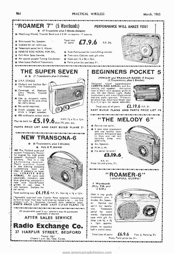
984 PRACTICAL WIRELESS March, 1963
"ROAMER 7" (5 Wavebands) * (7 Transistor plus 2 Diode designs) * Med; Long Waves, Trawler Band and 2 S.W. to approx. 17 macros.
* Rich -toned Sin. Speaker.
* Sockets for car radio use.
* Telescopic aerial for S. Waves.
* FERRITE ROD AERIAL FOR M/L. * Full After Sales Service. * Air spaced gauged Tuning Condenser. * Uses latest Mullard Transistors.
Total cost of parts
PERFORMANCE WILL AMAZE YOU!
£7.9.6 P.P. 516.
* Push -Pull output for roorrailling volume. * Two tone Cabinet with gilt trim. * Case size 12 x 8f x 3 1in. * Parts price list and data 31 -.
THE SUPER SEVEN * * (7 Transistors plus 2 Diodes)
* 2 R.F. STAGES.
* Mullard and Surface Bar- rier Transistors.
* Coverage of Medium, Lon; Waves, Trawler Band.
* Use as domestic radio, car radio or fit with strap for carry -about.
* No aerial required. * 3 -inch speaker but will drive a larger speaker. * 400 milliwatts output stage.
May be boil[ for £5 19 6 SIZE: 7f x 51 x 1 }in.
plus 316 post, etc.
PARTS PRICE LIST AND EASY BUILD PLANS 21-
NEW TRANSONA -6 * (6 Transistors, plus 2 Diodes) * M /L &T. BAND
400 Mw Mullard push -pull output Transistors, Power- ful magnet 3in. high grade speaker. Push -pull trans- formers. This is a top performing receiver. Many stations listed in one evening including. Luxembourg loud and clear. A pleasure to listen to. FERRITE ROD AERIAL. All parts sold separately, including pale blue gleaming polystyrene case with duo- diffusion grilles in red. Uses 9 volt battery. Sockets for car aerial.
Total building cost L4.19.6 P.P. 3l -. Size 6f x 4f x !fin. "Agreeably surprised with Trawler Band reception. Luxembourg as loud as local. Your easy build diagram helped a lot ... my first attempt. " -H. S., Penzance, Cornwall (poor reception area). PARTS PRICE LIST AND EASY kU:LD FLANS I'6
All components used in our receivers may be purchased separately if desired.
AFTER SALES SERVICE
Radio Exchange Co. 27 HARPUR STREET, BEDFORD
Phone: 2367 Closed I p.m. Sat. Opp. Co -op.
BEGINNERS POCKET 5 t
(MW /LW and TRAWLER BAND) (7 Staffes) (5 Transistors, plus 2 Diodes)
Designed round supersensitive FERRITE ROD AERIAL and 3in. moving coil speaker. Attractive case in black with speaker grille in red. On test Home, Light, Radio Luxembourg and many Continental stations were received. Miniatura earpiece free. Alternate larger case 6f x 4f x 144ín. for easier assembly.
Total cost of all parts £2.19.6 P.P. 31-
EASY BUILD PLANS AND PARTS PRICE LIST
"THE MELODY 6" * Ferrite rod aerial. * 6 new type transistors
and top quality com- ponents. Attractive case in blue and red and carrying strap wits gold trim.
* 3in. Speaker.
* M.W. /L.W. * No aerial require£.
£3.19.6. P.P. 3f-
Price list and plans, 21 -.
"ROAMER -6 USH-PULL OUTPU
5 Wavebands (M'L, T.B. and
2 S.W.)
Uses 6 top grade transistors plus 2
diodes. 3in. Speak- er. Ferrite rod aerial for sensiti- vity. Telescopic aerial for short waves. Handsome case with gilt fit- tings size 64 x 4f x loin. approx. Listen to stations half a world away.
Total cost of parts
7f
£6.9.6 Post a Packing 31- Plans, Parts price list 31-.
www.americanradiohistory.com
March, 1963 PRACTICAL WIRELESS 985
HARVERSON'S F.M. TUNER Mk.l F.SL tuning
bead by famou, maker.
Gus ntee,l
a,on -drip. Per-
meability tuning.
Pre - nuency coverage 88- 100 Mole. OAS1 balanced diode output. Two I.F. atases and discriminator. Attractive maroon and gold dial (7 x 310, giurat Self powered, using a good quality mains transformer and valve rectifier.
Valves used ECC83, two EF80e, and EZ80 (rectifier). Fully drilled chauds. Site of completed tuner 8 x 6 z Olin. All parte said separately. 25.19.0, plus 8/6 P.P. and im. Circuit diagram and Illustrations 1/6 poet free. Mark II Version ae above bot complete with magic eye, front panel and racket.. 28.12.8. P. A P. 5 /6. Mark III Version as Mark I but with output stage (EC1.82) and tone control. 27.7.0. P. A P. 8 /6. Handsome Metal Cabinets. Choice of Grey, Black or Green. To fit Mark 1, 25/ P. A P. 2 /6. To fit Mark Il, 17/6, P. & P. 2/6.
6 TRANSISTOR AND DIODE SUPERHET
A firet-alaes 2 waveband transistor superhet in kit form. Printed circuit panel false 8} x 211n.) 3 proaligned, 1.F. transformers.
High -gain Ferrite rod aerial. First -grade G.E.C. transistor. Car aerial winding. Peeh -pull out- put. All parte supplied with simple instruction.
All part%%%,sold separately
d4 ONLY .55.0 P28 P.
2 }i0, 35 ohms speaker, 10/6; 3 1in. 35 ohms speaker, 16/8; 35 ohms Sin. P.M., 18/6; 7 z 4th. 32 ohms speaker, 81/ -. P. & P. 1/6 per speaker.
Portable CABINET Size approx. 96 x 61 x 3 }In. Snitable for above using afin. speaker. 25 / -, P. & 1'. 2i -.
10, 14 WATT HI -FI AMPLIFIER A stylishly finished monaural amplifier with an output 0114 watts from 2 EL84a in push -pull. Super reproduction of both music and speech, with negligible bum. Separate inputs for mike and gram allow records and announcement, to follow each other. Fully shrouded ultra output transformer to match 3-13 speaker and 2 Inde- pendent volume controls. end separate base and treble controls are provided giving good lift and cut. Valve line -up 2 ELBIs, ECC83, EF86 and EZ80 rectifier. Simple Instruction booklet 1 /6. (Free with parte.)
All parts sold Separately.
KIT
ONLY E6.19.6 P.&P.8/e.
STEREO AMPLIFIER Bargain Offer
* 4 watts per channel. * lull tone and volume
controls.
* Complete with sockets, etc.
8916 P. & P. 2/6.
COIL AND TRANSFORMER SET FOR TRANSISTOR SUPERHET
3 I.P. transformers, one oscillator coil, one driver transformer and wound Ferrite aerial (med., long and aerial coupling), 88/6 complete, poet 1 /-. 6 transistor printed circuit. board to match. 8/6. poet 9d. Circuit diagram 1/6 extra.
QUALITY RECORD PLAYER AMPLIFIER
A top- quality record player amplifier. This amplifier (which le used in a 29 an. record 2I.yer) employs ECC83, E1.84, E280 valves Sass, treble and volume. On /off controls.
PRICE 6916 P. & P. 316
DITTO. Mounted on board with output trans- former and 6 }in. epeaker.
Complete at 8916, P. & P. 416
TRANSISTORS OET15 (Matched Pair) 15/-
0071 .. .. 5/. PYA101 6/6 0072 .. 8/- ILA103 .. 8/6 0(70 6/- V15/10p 12/8 Set of Mollard 6 translator. 25 / -. Bet of O.E.C. 1,874: '2873; 3, 91 or (IET114, 20 /.. All Post Free.
AMPLIFIER ON PRINTED CIRCUIT BOARD Two valve. ÚY83, UL% O.P. trans., me with 80 volt tap off motor. 89/8. P.Y. 2/8 on above. Dropper res. for filament. If required. 2/6. B.S.R. AUTO UNITS 160 v. Suitable for use with above. (Slightly soiled.) 25.5.0. P. A P. 51-.
LARGE CABINET Suitable for above two items. Complete with 3 ohm speaker. 28.9.6. Carr. 5/, Superior CABINET Similar to above to take 8 x Sin. speaker, with motor board, will accommodate BOB UA14 or UA16. 23.9.6. tsar. 0/6. Speaker 15/- extra. P. & P. 1/6 extra.
SPECIAL PURCHASE!
TURRET TUNERS by femme maker.
Brand new and unused. Complete with PCC84 and PCF80 valves. 34.38 Mc /e 1.F. Biscuits for Channels 1 to 5 and 8 and 9. Circuit diagram supplied. ONLY 25/- each. P.P. 2/6-
F.M. TUNER HEAD
A permeability tuned toner head by a famous maker, supplied without valve (ECCS5) and drum and spindle. 18/6. plue 1/9 P. & P. Valve 8/6 extra. Drum' and spindle 8/8 extra.
E. M.1. 4 -speed Player and P.U.
FURTHER HUGE }
PURCHASE enables us to, Offer these at 69/6. P. di P. 4 /e.
BRAND NEW 3 OHM LOUDSPEAKERS
21in. 12/6; 510, 12/8; 6}10, 15 / -; 101n. 21/- 121n. 27/6. Goodman 51o. tweeter -. 10/6 2.51.1. 2/in. tweeter .. .. 10/6 Goodman, IOin. x (lin. ., 22/8 E.M.I. 1311n. z Olin. high flux ,- 32/6 Bola Celestlon approx. 9in. x 61n.
middle register speaker .. 10/6 Also 15 ohm 12in., 80/- P. & P. 1/6 per speaker.
4 -SPEED PLAYER UNIT BARGAI NS
SINGLE PLAYERS TU /12, 28,15.0. Carriage 3/6.
AUTO CHANGERS B.B.R. UA14, 26.19.8, Latest B.B.R. UA16, 27.19.6. Latest Garrard "Auto- Slim" 87.15.0. Car. 51- on each.
RECORDING TAPE l'.V,C. lase, full frequency L.P. tape. 710,, 1800ft. (nor- mally 50/-) 27/6; 511n., 1,200ft. (normally 33/ -), 18/9. P. & P. 1/- per spool. Ideal for 2 or 4 track recorder.
Heavy 81in. metal turns table. Low flutter per: formante 200 /230V shaded motor with tap at 45V for amplifier value filament if required. Turnover LP/78 head.
TAPE DECKS 8.8R. Monardeek
(Single speed) 31in. per sec., simple control, uses 51in. spools, 25.16.0, plus 516 cart. and Ins. (Tapes extra on both).
COLLARD STUDIO DECK 210.10.0, plus 5/6 car. and tae.
RECORD PLAYER AMPLIFIER
2 watt output. Ready built with valves and 6 }in. speaker, tone and volume controls. Mounted on panel 13 x 74In.
75f. P. a P. 2 /..
SPECIAL OFFERS! CARBON MIRE INSERTS. Brand new. 2 11n. dia 5/ -. P. & P. 9d. GORLER F.M. TUNER HEADS. 10.7 Mc/e I.F., 15/-, plue 1 /9. P. & P. (E(A:A5 valve 8/6 extra). ELECTROSTATIC H.P. TWEETERS. Type L.B.H. 75. Size 3 z 31n., 2/6. each, plus 9d. P. & P. MIDGET 8 GANG CONDENSERS. Capacity 195 and 100 pF. Polystyrene cme with built in trimmers. Size 1 x 1 x 4in. Not used but removed from P/C Boards. Two for 9/ -, Plus 1 /-. P. & P. ACOS CRYSTAL MIKES. H) -imp., Stick type. 25 /.. P. & P. 1/6. TRABS18TOA DRIVER and 0/P TRANSFORMERS. (Tapped 3 ohms and 13 ohms output), plus 4 suitable Translators giving approx. 1 watt output. 30/ -, P. & P. 2/, MAINS TRANSFORMER'S. Tapped Primary. } wave or Bridge Rectifier Secondary 250 V. at 75 mA 6.3 volte at 2 amps. 7/8 each. P. & P. 3 /-. 3 PUSH -BUTTON- TRANSISTOR SWITCH. D.P. -D.T. Each Switch 5/6 and 1/- P. & P.
TRANSISTOR PERSONAL
RADIOS Complete with leather case, personal earphones and PP3 battery. Wilt receive Luxembourg etc4 loud and clear.
SIX TRANSISTOR TYPE Size 4 x 2} x 1 1m.
25.9.6. f
EIGHT TRANSISTOR TYPE
Size 41 x 2} x 1 /ín- 86.9.6.
Both plus P. & P. 2/6.
LOUDSPEAKER SILKS
541o. wide
Heavily woven in Ivory and gold. Originally 35/- pe4 yant length. OUR SPECIAL PRICE, 13 /6 per yard length! P. & P. 1/6. Also Red amine. Dark Grey andt Oatmeal fabrics for cabinet, covering, 341n. wide, 13 /fk per yard length. P. & P. 1 /6,
BARGAIN OFFER!
TELEFUNKEN HI-FI STEREO AMPLIFIER. 110/250 v. A.C. input. 5 watt undistorted output (10 watts nondaa0 Size 12 x 9 x tin. Weight 9 lb. Complete with epee. and instructions
ES.19.6 Carr. 5/,
Also Model 882. Similar specification but with balance control. 28.19.6. Carr. 1/ -.
HARVERSON SURPLUS CO. LTD.', 170 HIGH ST., MERTON, S.W.19. CHErrywood 3985/6.
Open all day Saturday. Early closing Wed., I p.m.
A few minutes from South Wimbledon Tube Station. Please write clear /y'
Please Note: P. & P. charges quoted apply to U.R. only. P. & P. m overseas orders charged extra.
www.americanradiohistory.com
986 PRACTICAL WIRELESS March, 1963
Complete FM (V.H.F.) AM RADIO FOR £11.11.0
(carr, paid) Brand new set, in superb walnut cabinet (size 19 8) x 141ín, high). Covering 80-100 Mc /. 16-49 M. and 200.500 M. Mains tracs. 200.250 v. with 2 tappings. Ferrite rod aerial for A.M. Controls: volume on/off, tone tuning, w /change. Cram and ext, speaker position provided Valves 12ÁT7, 12AH8, 010.6, EABC80, 68W6 and metal rectifier. Fully guaran- teed. Today's Value, 220.
TAPE -TOP QUALITY BOXED - GUARANTEED, 41n.- 600ft., 12/8; 81n.- 1200ft., 90/ -; 5 1i0.- 900ft., 15¡ -; 1.200ít., 17/8; 1800ft., 35/ -; 7111, 120016., 17/13;1800ft., 28/8; 2400ft., 45/- (all plus 1/- post, 6 or more poet free).
THE "MILAN" 6- TRANSISTOR AND DIODE PORTABLE COMPLETE KIT FOR ONLY
£6.12.6 (poet 3/6)
500mW push -pull output- Ferrite rod aeriaL Car aerial socket and coil; M.W. and L.W. full coverage. Operates on two 4.5v. cells. Printed circuit board 85 x 211n. All holes drilled and component positions marked. Instructions 2/8 for 16 p. (refunded on purchase of kit). Size 9 x If x 7in. 8 x 21in. P.M. high quality speaker. Attractive Vvnair covered cabinet, two tone. Two batteries 5/8 the pair (Eves Ready 126). Mollard transie- tore 0C44, 2 x OC45. OC81D, and 2 x 0(2.81. Top grade Weymouth Radio coil, and transformers Alignment service if required 17/8 (Inc. poet). Write for Bat of prices. All parts supplied separately. Built In two hours. -
BUILD YOUR OWN RECORD PLAYER Price £11 carr. paid
Fully built 2 -valve amplifier B.A.R. 4 -sp. autochanger, case 17 e 15 z 81in. Assembled In 15 mine. Similar cabinet for tape recorder with plain board only 68, care. paid. Attractive colour.
3 -valve amplifier 15g. extra
AUTOMATIC RECORD CHANGERS- LATEST MODELS. 4 SPEED CRYSTAL CARTRIDGE. All 5/- xtra
c are. B.S.R. ÚA14, 66,10.0.
Garrard Slimhs: , Mono 87. Stereo, 8.,5.0. Motor Board for UA8, UA20, UAI4, Slimline, 5/- (punt 1/6) or 8/0 post paid when purchased with Autochauger.
TELEFUNKEN STEREO AMPLIFIERS. 2 ECL82 -2 z 21 watt. 12 z 9 z tin, piano keys, 87, post paid. Complete with power.
SELF- POWERED VHF TUNER CHASSIS Covering 88 -95 Mc /s. Mollard permea- ability Tuner. Dime. 101 x 41 x 51n. high ECC85 and 3 -EF91 and 'l diodes. Metal Rectifier, Mains transformer. Fully wired and tested. Only 87.7.0 (care. paid). Some tarnished chassis otherwise O.K. 88.6,0. Vynair Cabinet included. Room dipole 12 /6. Feeder, 64, yd.
(normally screwed to chassis) may be Stereo version 2 x 4 w, same price.
PUSH -PULL AMPLIFIER £5.5.0
(5/- Carra Brand new 200 -240 A.C. mains. Bass, treble and vol. controls. With valves EZ80, ECC85 and 2 -EL84 giving full 8 w. Chassis. 12 x 31 x 31ín. With o.p. trans. for 2.3 ohm speaker. Front panel
removed and used as "Hying panel."
TAPE RECORDER AMPLIFIER Type TRI, Full. baht, high gain, low noise, printed circuit. Attractive grey and gold front panel 13 x Sin. Height 55in. overall. Front to back 511n,' VoL and on/off tone. Mike, radio and est. speaker Jacks. Valves (ÚC13 ECL82, EZ80. Maim trans. Ready to poll to B.B.R. Deck. Com- olete with switch water wired. Our Price ONLY 85.15.0 (6 /- Packing and Carra. Also available for Collaro Deck at 5/- extra
Translator Set Battery Eliminator. Converts your 6 translator receiver to mains operation- With Hex lead and battery charging attachment. For Miniature Sets, size 11 a 1 z tin. Price 18/8. For Larger Sets, 3 z 18 z 1m. Price 24/8.
TRANSISTOR COMPONENTS M.W. and L.W. ferrite rod aerial, with car coupling coil. For 20RoF con- denser, 8 / -; Ore. coil; 1st 2nd and 3rd I F.'s, all 5/8 ea.: Driver trans.. 7/8; min. 64mF 10v; 10mF 16v; 30n1F 6v; all 1/9 ea; Tuning cond. 2080;l1 + 176pF 8 /6; poet 0,1. on all orders.
BRAND NEW AM /FM (V.H.F.) RADIOGRAM CHASSIS AT £12.12.0 (Carriage Paid)
A.C. ONLY. Chassis size 15 s /1/ s Sims nigh. New manufacture. Dial 141 x 4)11. in 2 colours. predominantly gold. Pick -up, Ext. Speaker. Ae., E.. and Dipole Sockets. Five push buttons - OFF, L.W., M.W., F.M. and Gram. Aligned and tested. O.P. Transformer. Tone Control. 1000.1900 M.; 200.500 M,; 88 -98 Me /e. Valve. EZ80 rect.; ECH81, E F80, EABCSO, EL84, ECC85. Speaker and Cabinet to Ht chassis (table model). 47/6 (post 4/ -). 0 x bin. ELLIPTICAL SPEAKER, 20 / -, to purchasers of this chassis. TERMS: (Chassis) 83.10.0 down and 5,moothly payments of 22. Cheap Room Dipole for V.H.F., 12/8. Feeder 8d. yd. Circuit diagram 2/8.
"SCALA" 6- TRANSISTOR and DIODE KIT FANTASTIC VALUE
d6.5.0 All Brand New Parts- attractive cabinet -choice of 6 colours; ai x 2 s 51ín. high. Ferrite aerial, printed circuit, gord styling, afin. speaker, fully tunable L.W. and M.W., 400 M.W. push -pull output. All parte supplied separately. Write for Price List. l ;onetructioo Book and Circuit, 2/8 (refunded when kit purchased). Or fully built at 2:.10.8 (battery '2/61.
TABLE MODEL TRANSISTOR SET
£7.14.0 (carr. paid) 6 transistors and diode, Sin. speaker, superhet circuit. Cabinet 13 z 7I z 41in., battery included. Fully tunable L.W. and M.W. Polished walnut front. Cabinet 13 z 71 x 4ía
SUPERIOR GRAMOPHONE AMPLIFIER Valves CV85. C E80 and ÚL84. Mains trans. 500.240 a,c. Covered baffle 131 x 71in. (61ín. speaker) or 11 x 7;ín, (8 x Sin, speaker). 3 front controls bass, treble, on-o;l /vol. 74/- (post 4/ -) either type. Rexine caLlnet to rit, with carrying, handle, and Lid (detachable) 14in. or 12 x 81 18/- extra.
GRAMOPHONE AMPLIFIER. With Sin. SPEAKER Baffle 121 x 6)11. ECL82 and Rectifier, lone and Volume. On/off switch. Useful for Stereo, 67/- (post 4/ -).
5 WATT AMPLIFIER Our price ONLY 56/- (poet 41 -1; NT W MANUFACTURE; valves RF91 and E1.84 with metal rectifier; 6x 4 x 1 /in. high (sin. over EL84). Mains trans. and op. with vol. and tone controle; on-off: co -ax input.
COLLARO STUDIO TAPE TRANSCRIPTOR, 8 MOTORS, 3 SPEED. lt, 31 and 71 í.P.8. Push buttons, £10.7.0 (10/- cart.) inc. spool.
BATTERY ELIMINATOR For 4 Low Consumption Valves (96 range) 90v. 15 nn and 1.4v. I28mA, 45/- (2 /6 post). 200.250v. A.C. Also for 250nrA, 1.4v. and 90v. 15mA at same price. Two separate units to replace existing batteries.
BATTERY RADIO Valves DK96, DF98, DAF96, DLS6. Two Short Wavebands 16 to 49 M and 25 to 75 M. Size 103 x 4) x 5m. £4,.,8, cary. paid. 51.W. and B.W., £4.11.1, ,air, pail.
ALL ITEMS ARE NEW AND FULLY BUILT UNLESS OTHERWISE STATED. TESTED BEFORE DESPATCH. Terms Available on Items over £5. Bend 6d. (stamps will do) for 20 -page illustrated catalogue. Delivered by return- C.O.D. 2/- extra. ALL ITEMS GUARANTEED 12 MONTHS VALVES 3 MONTHS
GLADSTONE RADIO "SCALA ", CAMP RD., FARNBOROUGH, Hants.
(Farnborough 3371) and at 247 New Road, Copnor, Portsmouth, FARNBOROUGH CLOSED BATS.- PORTSIIOU'IH WEI18.
www.americanradiohistory.com
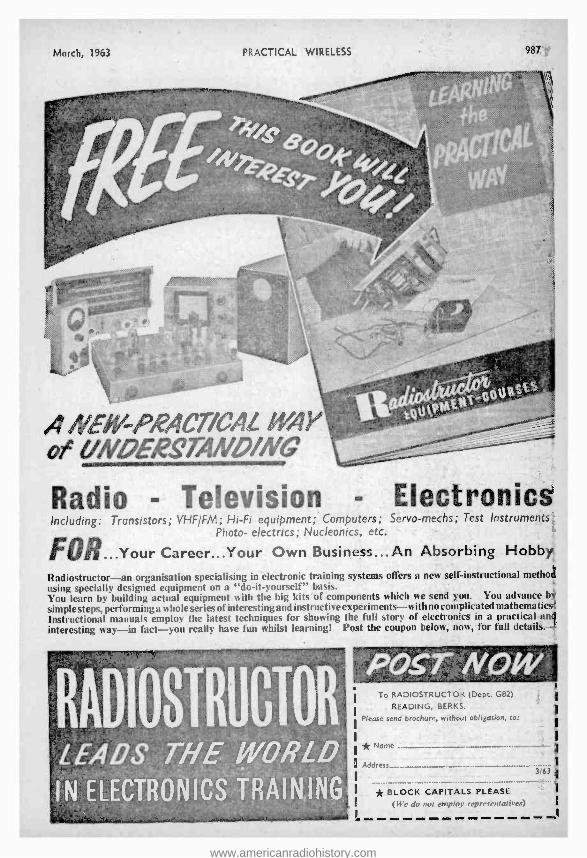
March, 1963 PRACTICAL WIRELESS 987,`
NEII-PRACT/CAL WAY UNDES'TAI!/D//I®G
Radio - Television - Electronics Including: Transistors; VHF /FM; Hi -Fi equipment; Computers; Servo -meths; Test Instruments;
Photo- electrics; Nucleonics, etc.
FOR...Your Career...Your Own Business...An Absorbing Hobby.
Radiostructor -an organisation specialising in electronic training systems offers a new self -instructional method using specially designed equipment on a "do -it- yourself" basis. You learn by building actual equipment with the big kits of components which we send you. You advance b
simple steps, performing a whole series of interesting and instructive experiments -with no complicated mathematics Instructional manuals employ the latest techniques for showing the full story of electronics in a practical and interesting way -in fact -you really have fun whilst learning! Post the coupon below, now, for full details. -
RADIOSTRUCTOR LEA 0$ .:TH'E. elORLD IN : ELECTRON ICS ,TRAI N6.I NG,
To RADIOSTRUCTOR (Dept. G82)
READING, BERKS.
Please send brochure, without obligation, to:
* Name
Address
* BLOCK CAPITALS PLEASE (We do not employ representatives)
www.americanradiohistory.com
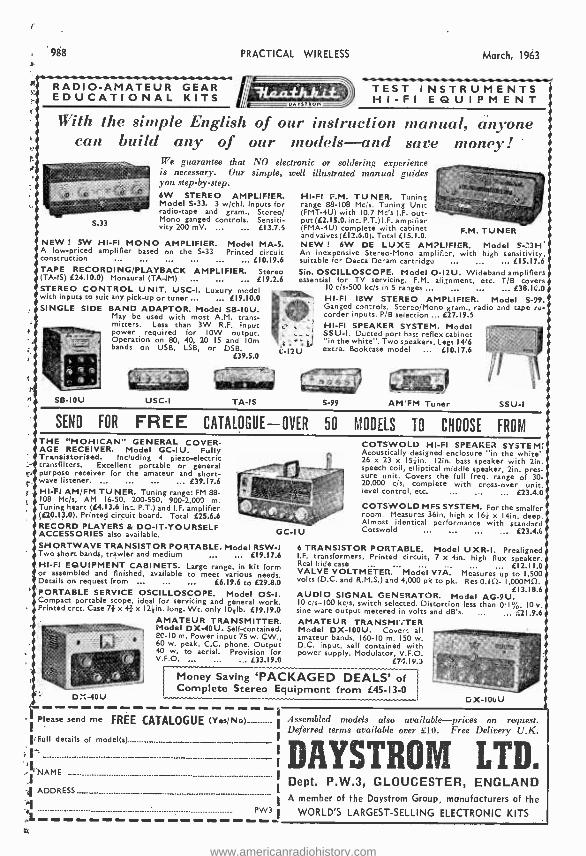
988
RADIO -AMATEUR GEAR EDUCATIONAL KITS
PRACTICAL WIRELESS March, 1963
TEST INSTRUMENTS o..zraow HI -FI EQUIPMENT
With the simple English of our instruction manual, anyone can build any of our models -and save money!
We guarantee that NO electronic or soldering experience is necessary. Our simple, well illustrated manual guides you step -by -step. 6W STEREO AMPLIFIER. Model S -33. 3 w /chl. Inputs for radio -tape and gram., Stereo/ Mono ganged controls. Sensiti- vity 200 mV. ... ... EI3.7.6
NEW ! 5W HI -FI MONO AMPLIFIER. Model MA -S. A low- priced amplifier based on the S -33. Printed circuit construction ... ... ... ... £10.19.6 TAPE RECORDING /PLAYBACK AMPLIFIER. Stereo (TA -IS) £24.10.0) Monaural (TA -IM) ... ... ... E19.2.6 STEREO CONTROL UNIT. USC -1. Luxury model with inputs to suit any pick -up or tuner ... ... E19.10.0 SINGLE SIDE BAND ADAPTOR. Model SB -10U.
May be used with most A.M. trans- mitters. Less than 3W R.F. input power required for IOW output. Operation on 80, 40, 20 15 and 10m bands on USB, LSB, or DSB.
E39.5.0
SB -10U USC -I TA-IS
HI -F1 F.M. TUNER. Tuning range 88 -108 Mt /s. Tuning Unit (FMT -4U) with 10.7 Mc's I.F. out- put (E2.15.0. inc. P.T.) I.F. ampllier (FMA -4U) complete with cabinet and valves (El 2.6.0). Total El 5.1.0. NEW ! 6W DE LUXE AMPLIFIER. Model S -23H' An inexpensive Stereo -Mono amplifier, with high sensitivity, suitable for Decca Deram cartridge ... ... ... El 5.17.6 Sin. OSCILLOSCOPE. Model O -12U. Wideband amplifiers essential for TV servicing, F.M. alignment, etc. T/B covers
10 c/s -500 kc /s in 5 ranges ... ... ... E38.11:.0
HI -F1 I8W STEREO AMPLIFIER. Model S -99. Ganged controls. Stereo /Mono gram., radio and tape re- corder inputs. P/B selection ... E27.19.5 HI -F1 SPEAKER SYSTEM. Model SSU -1. Ducted port bast reflex cabinet "in the white". Two speakers. Legs 14'6 extra. Bookcase model ... E10.17.6
F.M. TUNER
S -99 AM FM Tuner SSU -1
SEND FOR FREE CATALOGUE -OVER 50 MODELS TO CHOOSE FROM THE "MOHICAN" GENERAL COVER- AGE RECEIVER. Model GC -IU. Fully Transistorised. Including 4 pieno- electric transfilters. Excellent portable or general purpose receiver for the amateur and short- wave listener . ... ... ... ... 09.17.6 H1 -F1 AM /FM TUNER. Tuning range: FM 88- 108 Mc /s, AM 16 -50, 200 -550, 900 -2,000 m. Tuning heart (E4.13.6 inc. P.T.) and I.F. amplifier (E20.13.0). Printed circuit board. Total E25.6.6 RECORD PLAYERS & DO- IT- YOURSELF ACCESSORIES also available. GC-I U
SHORTWAVE TRANSISTOR PORTABLE. Model RSW -1 Two short bands, trawler and medium ... ... E19.17.6 HI -FI EQUIPMENT CABINETS. Large range, in kit form or assembled and finished, available to meet various needs. Details on request from ... ... ... E6.19.6 to E29.8.0 PORTABLE SERVICE OSCILLOSCOPE. Model OS -I. Compact portable scope, ideal for servicing and general work. Printed crct. Case 71 x 4 x 121in. long. Wt. only 1031b. E19.19.0
AMATEUR TRANSMITTER. Model DX -40U. Self -contained. 8C -10 re. Power input 75 w. CW., 60 w. peak, C.C. phone. Output 40 w. to aerial. Provision for
D::-40U
COTSWOLD HI -FI SPEAKER SYSTEM; Acoustically designed enclosure "in the white' 26 x 23 x 15 +in. 12ín. bass speaker with tin. speech coil, elliptical middle speaker, tin. pres- sure unit. Covers the full freq. range of 30- 20,000 t s, complete with cross -over unit, level control, etc. ... ... ... E23.4.0
COTSWOLD MFS SYSTEM. For the smaller room. Measures 36in. high x 163 x 14in. deep. Almost identical performance with standard Cotswold
6 TRANSISTOR PORTABLE. Model UXR -I. Prealigned I.F. transformers, Printed circuit, 7 x 4in. high flux speaker. Real hide case ... E12.11.0 VALVE VOLTMETER. Model V7A. Measures up to 1,500 volts (D.C. and R.M.S.) and 4,000 pk to pk. Res 0.10- I,000MS).
[13.18.6 AUDIO SIGNAL GENERATOR. Model AG -9U. 10 cts -100 kc /s, switch selected. Distortion less than 0.1 %. 10 v. sine ware output metered in volts and dB's. ... ... E21.9.6 AMATEUR TRANSMITTER Model DX -1000. Covers all amateur bands, 160 -10 m. 150 w. D.C. input, self contained with power supply. Modulator, V.F.O.
¿74.19.3
Money Saving `PACKAGED DEALS' of Complete Stereo Equipment from E45 -I3 -0
D X-106 U
Please send me i FREE CATALOGUE (Yes /No)..r.._._. Assembled models also available- prices on request. Deferred terms available over £10. Free Delivery U.K.
Full details of model(s)
DASTROM LTD B NAME
ADDRESS__ _ ..._. »__ I
1 A member of the Daystrom Group, manufacturers of the
PW3 i WORLD'S LARGEST -SELLING ELECTRONIC KITS
Dept. P.W.3, GLOUCESTER, ENGLAND
www.americanradiohistory.com
= Practical Wireless =
Vol. XXXVIII No. 673 MARCH, 1963
2111111111111111111111111111111111111111111111111111111111111g
Editorial and Advertisement Offices:
= PRACTICAL WIRELESS George Newnes Ltd., Tower House,
Southampton Street, W.C.2. _ = Q George Newnes Ltd., 1963 _
Phone: Temple Bar 4363
Telegrams: Newnes, Rand, London, E Registered at the G.P.O. for trans. E E minion by Canadian Magazine Post. E
SUBSCRIPTION RATES = including postage for one year
f 1.9.0 per annum £1.7.6 per annum E £1.5.0 per annum
E Inland Abroad Canada
Contents = Page = E Editorial ... ... ... ... 989
E Round the World of Wireless 990 = Tremolo Unit ... ... ... 992
E Short -wave Convertor ... 994
Home -movie Amplifier ... 997 E Protecting the P.A. ... ... 999
E Test Gear Techniques ... ... 1004 = Mains Superhet Receiver ... 1011
Parallel Tracking Unit ... 1016
Quality Amplifier and Pre -amp 1019 E On Your Wavelength ... ... 1022 =
E Semiconductors... ... ... 1025
Distortion ... ... ... 1033
The Auditron ... ... ... 1038
Trade News ... ... ... 1045
Club News ... ... ... 1046
1.2 Letters to the Editor ... ... 1049
= The Editor will be pleased to consider = articles of a practical nature. Such = = articles should be written on one side = of the paper only. and should contain the name and address of the Sender. =
= Whilst the Editor does not hold himself = E responsible for manuscripts. every = = erfort will be made to return them if a =
stamped and addressed envelope is = enclosed. All correspondence intended
E. for the Editor should be addressed: = The Editor, PRACTICAL WIRELESS. _
George Neurnes, Ltd., Tower House. = Southampton Street, London, W.C.2. =
Owing to the rapid progress in the E designs of wireless apparatus and to =
= our efforts to keep readers In touch E with the latest developments. we give = = no warranty that apparatus described
In our columns is not the subject of = = letters patent. _ = Copyright In all drawings, photo- _ gprraphs and articles published to
= PRACTICAL WIRELESS is specifically reserved throughout the countries E
= signatory to the Berne Convention and = = the U.S.A. Reproductions or imitations = of any of these are therefore expressly = E forbidden. PRACTICAL WIRELESS = = incorporates "Amateur Wireless." _ IIIIIIIIIIIIIIIIIIIIIIIIIIIIIUIIIIIIIIIIIIIIIIIIIIIIIIIIIIIII
Changing Pattern FROM time to time we hear the opinion expressed that radio
construction is a dying art, that the modern enthusiast is more an assembler than an experimenter, that the profusion
of easily obtainable components and sub -assemblies makes things too easy, that -in short- Fing's ain't what they used to be!
Well, of course, they are not. They never were! But we see the reasoning behind this sort of argument. In the early days, a great deal of ingenuity was necessary in order to build anything at all. The professionals knew very little more than some amateurs -often less! Parts were scarce, and so was money. In fact many constructors had to make some of their own components, either through financial or practical necessity.
As interest grew and the numbers of amateur enthusiasts increased, so did the quantity and range of components availablç. During the 30's, amateur radio was a rapidly developing market and manufacturers did their best to meet the demands. However, most enthusiasts of that time were still mainly experimenters since they usually designed their own equipment or modified published designs to suit their own personal requirements.
But in the immediate post -war years, vast quantities of -var surplus equipment flooded the market. While much of this couljf be stripped down to obtain a wealth of components at almost "give away" prices, some of it was, with slight modification, ready for use as workable items.
This claim the cynics, was the death knoll of true amateiir radio construction. For perhaps the first time, amateur trans- mitting stations, for example, went on the air using not only ready -built receivers and transmitters but also using profession- ally built accessories such as frequency meters.
In terms of convenience and economy, converted surplus equipment was a wonderful opportunity. But on the other hand it provided the temptation to take the easy way out. The trend has continued and many amateur transmitters could more ap.'ty be called operators than experimenters. {...
Although there have always been kits, the radio constructdtr of today has "never had it so good ", with a profusion of all kings of kits for specific designs and a wealth of components. This, at is suggested, leads to a more dependent attitude than that4f past years, when the constructor had to be much more sel- reliant. i
On the other hand, there are nowadays , many times more actively interested than even ten years ago. This may mask the enthusiasts who still design their own equipment and experiniient with unusual circuits and applications. .
From the hard practical viewpoint there is less incentive tese days to do things the hard way, for the amateur can no longÇr vie with the professional -highly trained and with modeiüt laboratory facilities. The days of major break- throughs..dy amateurs are, perhaps, gone for ever. fi
Nevertheless, while there will always be a great number df constructors who prefer to build from existing designs, there will always be those who like to work everything out themselves.
11111111111111111111IIIIIIIIIiIIIIIIIIIIIIlillliIIIIIIIIIIiiiIIIIIIIIIIIIIIIIIIIIIIIIIIIIIIIIIIIIIIIIIIIIIIIIIIIIIIIMik Our next issue dated April will be published on March 7th. 1
;A
www.americanradiohistory.com
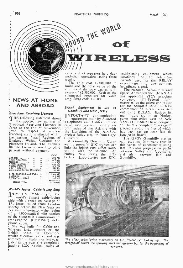
990 PRACTICAL WIRELESS March, 1963
`0`" 0\t\-
PPP
NEWS AT HOME AND ABROAD
Broadcast Receiving Licences THE following statement shows
the approximate number of Broadcast Receiving Licences in force at the end of November,
962, in respect of wireless receiving stations situated within the various Postal Regions of
ngland, Wales, Scotland and Northern Ireland. The numbers include Licences issued to blind persons without payment.
Home London .. ns Coutie .. .. Midland .. ,. ., North Eastern . ,. .. North Western .. .. South Western .. , Wales and Border Counties
Total 624,774 577,542 419,491 443.472 379,777 341,801 191,473
Total England and Wales .. .. 2,975,340 S.,otland .. .. .. 312,542 No-0,A Ireland .. .. .. 107,203
Grand Total .. .. 3,395,090
World's Fastest Cable -laying Ship THE C.S. " Mercury ", the
world's fastest cable -laying ship with a speed on passage of 17+ knots, sailed from London Shortly before the New Year on her first commission -the laying of a 1,000 -nautical -mile section of the 8.000-mile Commonwealth trans- Pacific (COMPAC) tele- phone cable.
She was built for Cable and Wireless Ltd., owners of the British share in Common- wealth telephone cable, and was completed in September last year. Later in the year she completed loading 1,200 nautical miles of
cable and 49 repeaters in a day - and -night operation lasting three weeks.
The ship cost £2,000,000 to build and the total value of the equipment she now carries is in excess of £2,500,000. Each of the submerged repeaters (or valve amplifiers) costs £20,000.
British Equipment in use at Goonhilly and New Jersey
IMPORTANT communication equipment built by Standard
Telephones and Cables Limited came into service recently on both sides of the Atlantic with the launching of the N.A.S.A. Project Relay satellite from Cape Canaveral.
At Goonhilly Downs in Corn- wall, a powerful STC transmitter links the British Post Office radio station with the satellite. At Nutley, New Jersey, the ITT - Federal Laboratories use STC
multiplexing equipment which combines the 12 telephone circuits used in the RELAY experiments into one complex broadband signal.
The National Aeronautics and Space Administration (N.A.S.A.) has appointed STC's associate company, ITT- Federal Lab- oratories, as the prime contractor for the complete series of tele- communication tests to be carried out using RELAY. Besides its main radio station at Nutley, some nine miles west of New York, ITT- Federal have designed and built a complete "packaged" ground station, the first of which has been set up near Rio de Janeiro in Brazil.
The GPO's Goonhilly station will play an important role in this series of experiments using satellite radio propagation paths between Nutley and Goonhilly, and also between Rio and Goonhilly.
The after cable -laying machinery on C.S. "Mercury" looking aft. The foreground shows the splaying stool and diverter bar for the by- passing of
repeaters.
www.americanradiohistory.com
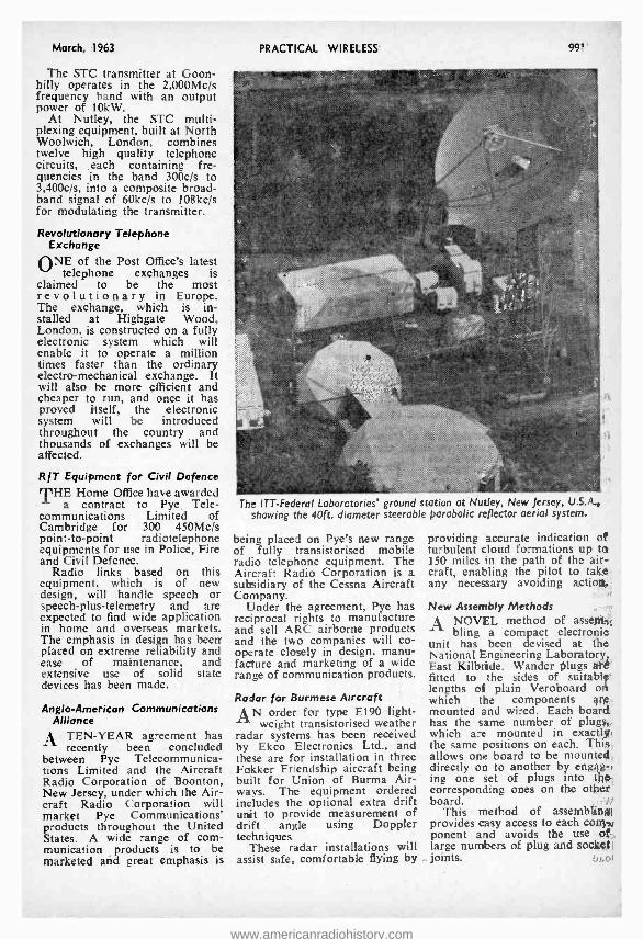
March, 1963
The STC transmitter at Goon - hilly operates in the 2,000Mc /s frequency band with an output power of 10kW.
At Nutley, the STC multi- plexing equipment, built at North Woolwich, London, combines twelve high quality telephone circuits, each containing fre- quencies in the band 300c /s to 3,400c /s, into a composite broad- band signal of 60kc /s to 108kc /s for modulating the transmitter.
Revolutionary Telephone Exchange
ONE of the Post Office's latest telephone exchanges is
claimed to be the most revolutionary in Europe. The exchange, which is in- stalled at Highgate Wood, London, is constructed on a fully electronic system which will enable it to operate a million times faster than the ordinary electro- mechanical exchange. It will also be more efficient and cheaper to run, and once it has proved itself, the electronic system will be introduced throughout the country and thousands of exchanges will be affected.
RIT Equipment for Civil Defence
THE Home Office have awarded a contract to Pye, Tele-
communications Limited of Cambridge for 300 450Mc /s point -to -point radiotelephone equipments for use in Police, Fire and Civil Defence.
Radio links based on this equipment, which is of new design, will handle speech or speech- plus -telemetry and are expected to find wide application in home and overseas markets. The emphasis in design has been placed on extreme reliability and ease of maintenance, and extensive use of solid state devices has been made.
Anglo- American Communications Alliance
A TEN -YEAR agreement has recently been concluded
between Pye Telecommunica- tions Limited and the Aircraft Radio Corporation of Boonton, New Jersey, under which the Air- craft Radio Corporation will market Pye Communications' products throughout the United States. A wide range of com- munication products is to be marketed and great emphasis is
PRACTICAL WIRELESS 99,
The ITT -Federal Laboratories' ground station at Nutley, New Jersey, U.S.A. , showing the 40ft. diameter steerable parabolic reflector aerial system.
being placed on Pye's new range of fully transistorised mobile radio telephone equipment. The Aircraft Radio Corporation is a subsidiary of the Cessna Aircraft Company.
Under the agreement, Pye has reciprocal rights to manufacture and sell ARC airborne products and the two companies will co- operate closely in design, manu- facture and marketing of a wide range of communication products.
Radar for Burmese Aircraft
AN order for type E190 light- weight transistorised weather
radar systems has been received by Ekco Electronics Ltd., and these are for installation in three Fokker Friendship aircraft being built for Union of Burma Air- ways. The equipment ordered includes the optional extra drift wit to provide measurement of drift angle using Doppler techniques..
These radar installations will assist safe, comfortable flying by
providing accurate indication of turbulent cloud formations up to 150 miles in the path of the air- craft, enabling the pilot to take any necessary avoiding action.
New Assembly Methods A NOVEL method of assent
bling a compact electronic unit has been devised at the National Engineering Laboratory East Kilbride. Wander plugs alt fitted to the sides of suitably lengths of plain Veroboard o which the components át¢. mounted and wired. Each board has the same number of plug, which are mounted in exactly the same positions on each. This allows one board to be mountred directly on to another by engag -, ing one set of plugs into thp corresponding ones on the other board.
This method of assembling; provides easy access to each corny", ponent and avoids the use of large numbers of plug and sooltl
-- joints. e,nl
www.americanradiohistory.com
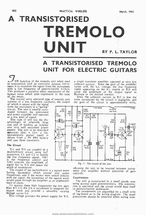
992 PRACTICAL WIRELESS March, 1963
A TRANSISTORISED
TREMOLO UNIT BY P. L. TAYLOR
A TRANSISTORISED TREMOLO UNIT FOR ELECTRIC GUITARS
5HE function of the tremolo unit when used in conjunction with an electronic musical instru- ment is to modulate the signal from the instrument with a low frequency of approximately 5- 15c /s. This produces a plaintive effect reminiscent of the human voice which adds expression to the tone of the music.
The normal valve operated type of tremolo unit consists of a low frequency oscillator, the ou put of which is mixed with the signal from the instrument in a "gating" circuit. The unit is usually intro- duced between the instrument and power amplifier and operates at a low level of signal.
This type of unit has the dis- advantages of relatively large size and of needing an Isolated and very well smoothed power supply. The unit to be described measures 51in. x 21in. x 2in, (conveniently pocket sized) is driven from a 9V PP4 battery and uses three transistors.
The Circuit
Trl and Tr2 are coupled in a multivibfator circuit using 2µF capacitors, Cl and C2 to supply the low frequency' signal. VR I
is the frequency control and VR2 controls the amplitude of signal fed to Tr3 and hence the depth of modulation.
The output of the multivibrator is a square wave having harmonics which extend into audio frequencies, and if the output were mixed directly with the signal, the harmonics of the square wave would come through the amplifier as an unpleasant train of clicks.
To remove these high frequencies the low pass filter R7, C3, R8, C4 is introduced to integrate the square wave and provide a smoothly varying voltage across C4.
This voltage provides the power supply for Tr3,
a single transistor amplifier operated at very low collector current. Since the gain of the amplifier varies with the h.t. voltage, the. low frequency ripple appearing on the h.t. supply to Tr3 will cause the amplitude of the output signal to fluctuate in the desired manner.
the collector current in Tr3 is low the noise introduced by the circuit is negligible, and the gain of the circuit is approximately unity,
-ve lines On /Off switch
Inputs
Tr2 red spot
R9 68k
cs-
2yF
-9V
Output
4) C6 0.002
35F
0V
01pF 0.1pF R5 150v 150V
VR1 10k
R11 1k
.+ve line + +ve
Fig. I: The circu t of the unit.
allowing the unit to be inserted between instru- ment and amplifier without alteration of gain controls.
Construction The unit is constructed in a small plastic case
using normal sized potentiometers. The construc- tion is uncritical and the circuit would lend itself to miniaturisation techniques.
The components are assembled on a small strip of tag -board as in the wiring diagram. The usual precautions should be observed when. wiring tran-
www.americanradiohistory.com
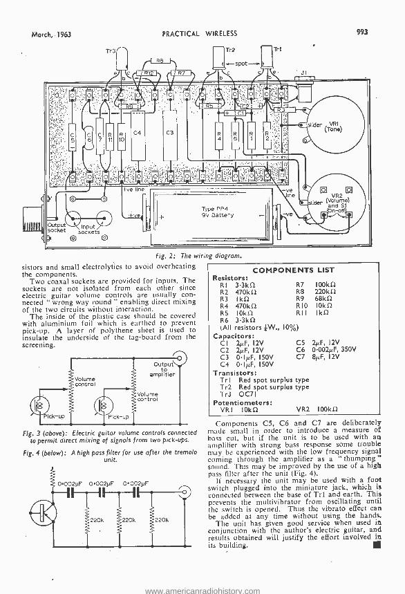
March, 1963
Tr3
PRACTICAL WIRELESS
Tr2 Tri
eJ b c d iari -.. i
N N ;A ® p ..., ,
o l +
® LE=
6
1 1
993
Input t, sockets
Fig. 2: The wiring diagram.
sistors and small electrolytics to avoid overheating the components.
Two coaxal sockets are provided for inputs. The sockets are not isolated from each other since electric guitar volume controls are usually con- nected " wrong way round " enabling direct mixing of the two circuits without interaction.
The inside of the plastic case should be covered with aluminium foil which is earthed to prevent pick -up. A layer of polythene sheet is used to insulate the underside of the tag -board from the screening.
Volume control
Volume control
Fig. 3 (above): Electric guitar volume controls connected to permit direct mixing of signals from two pick -ups.
Fig. 4 (below): A high pass filter for use after the tremolo unit.
0.002pF 0002pF 0002.uF
!220k
COMPONENTS Resistors:
LIST
Rt 3.3kû R7 100ki2 R2 470k12 R8 220kû R3 Ikû R9 68kû R4 R5
470kí2 [Oki/
RIO R I I
IOkû Ikû
R6 3.3kû (All resistors kw., 10 %)
Capacitors: CI 2µF, 12V C5 C2 2µF, 12V C6 C3 0.1µF, 150V C7 C4 0.1µF, 150V
Transistors: Trl Red spot surplus type Tr2 Red spot surplus type Tr3 0071
Potentiometers: VRI IOkû
2µF, I2V 0.002µF, 350V BµF, I2V
VR2 100kû
Components C5, C6 and C7 are deliberately made small in order to introduce a measure of bass cut, but if the unit is to be used with an amplifier with strong bass response some trouble may be experienced with the low frequency signal coming through the amplifier as a `thumping" sound. This may be improved by the use of a high pass filter after the unit (Fig. 4).
If necessary the unit may be used with a foot switch plugged into the miniature jack, which is connected between the base of Trl and earth. This prevents the multivibrator from oscillating until the switch is opened. Thus the vibrato effect can be added at any time without using the hands.
The unit has given good service when used in conjunction with the author's electric guitar, and results obtained will justify the effort involved in its building.
www.americanradiohistory.com
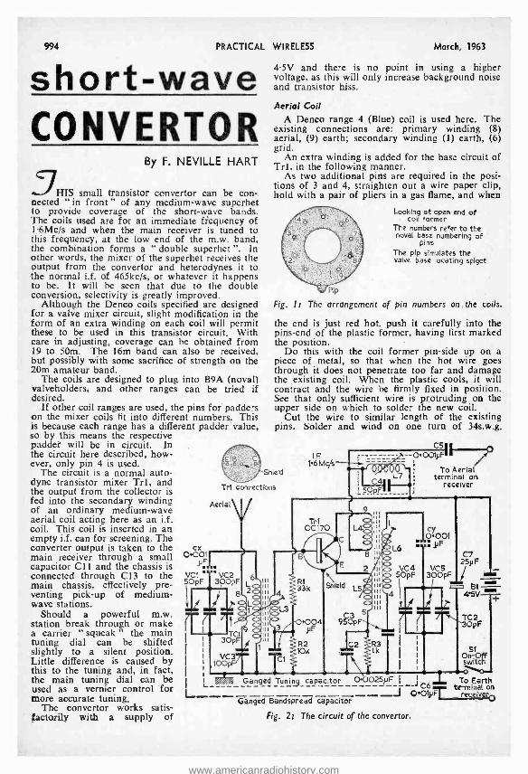
994 PRACTICAL WIRELESS March, 1%3
short -wave CONVERTOR
By F. NEVILLE HART
HIS small transistor convertor can be con -. nected " in front " of any medium -wave superhet to provide coverage of the short -wave bands. The coils used are for an immediate frequency of 1.6Mc /s and when the main receiver is tuned to this frequency, at the low end of the m.w. band, the combination forms a " double superhet ". In other words, the mixer of the superhet receives the output from the convertor and heterodynes it to the normal i.f. of 465kc /s, or whatever it happens to be. It will be seen that due to the double conversion, selectivity is greatly improved.
Although the Denco coils specified are designed for a valve mixer circuit, slight modification in the form of an extra winding on each coil will permit these to be used in this transistor circuit. With care in adjusting, coverage can be obtained from 19 to 50m. The 16m band can also be received, but possibly with some sacrifice of strength on the 20m amateur band.
The coils are designed to plug into B9A (noval) valveholders, and other ranges can be tried if desired.
If other coil ranges are used, the pins for padders on the mixer coils fit into different numbers. This is because each range has a different padder value, so by this means the respective paddet will be in circuit. In the circuit here described, how- ever, only pin 4 is used.
The circuit is a normal auto - dyne transistor mixer Tri, and the output from the collector is fed into the secondary winding of an ordinary medium -wave aerial coil acting here as an i.f. coil. This coil is inserted in an empty i.f. can for screening. The converter output is taken to the ex main receiver through a small O.0o: capacitor C11 and the chassis is y. connected through C13 to the VC1' °'VC2 main chassis, effectively pre- SOpF 300pF
venting pick -up of medium- wave ustations.
7 7 Should a powerful m.w. station break through or make a carrier " squeak " the main i
tuning dial can be shifted slightly to a silent position. Little difference is caused by this to the tuning and, in fact, the main tuning dial can be
1 L used as a vernier control for L more accurate tuning. The convertor works satis-
factorily with a supply of
4.5V and there is no point in using a higher voltage, as this will only increase background noise and transistor hiss.
Aerial Coil A Denco range 4 (Blue) coil is used here. The
existing connections are: primary winding (8) aerial, (9) earth; secondary winding (1) earth, (6) grid.
An extra winding is added for the base circuit of Trl, in the following manner.
As two additional pins are required in the posi- tions of 3 and 4, straighten out a wire paper clip, hold with a pair of pliers in a gas flame, and when
Looking at open end of coil former
The numbers refer to the noval base numbering of
pins The pip simulates the valve base locating spigot
Pip
Fig. l t The arrangement of pin numbers on, the coils.
the end is just red hot, push it carefully into the pins -end of the plastic former, having first marked the position.
Do this with the coil former pin -side up on a piece of metal, so that when the hot wire goes through it does not penetrate too far and damage the .existing coil. When the plastic cools, it will contract and the wire be firmly fixed in position. See that only sufficient wire is protruding on the upper side on which to solder the new coil.
Cut the wire to similar length of the existing pins. Solder and wind on one turn of 34s.w.g.
CSI LF 0.001yF 6M .,
To Aerial terminal on
receiver
Shield
Tri connections
Aerial
1 c/s
C4 L5OpF
L
0C170 I"
1
c
ii :. LA III ... lb ,,: yF 8 !! C7
25y F
2Ii 5ÖpF 3ÓCSpF i R1 1 .nl
8 fi ii , 33k Shield L5 Al iii 4 II . i.w r
ii 004 95ÓpF ¡ T 3Ö F P --TC1 ¡ it , yF -,--- 3OpF 1 i I
VC3 t 10k
C2 Rk I
, OSt ff I TCi T\ I switch
Ganged Tuning capacitor 0.0025iIF I I a _ To Earth
..I OO1GF t-0 y receiver Ganged Bandspread capacitor
Fig. 21 The circuit of the convertor.
www.americanradiohistory.com
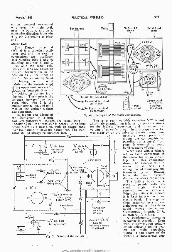
March, 1963
cotton covered enamelled wire over the main coil, near the bottom, and in a clockwise direction from pin 4 to pin 3 (looking at pins - end). Mixer Coil
The Denco range 4 (White) is a superhet oscil- lator coil and the existing connections are: oscillator grid winding pins 1 and 4; coupling coil pins 8 and 9.
As with the aerial coil, two extra pins are added to this coil former one in the position as 2, the other as pin 5. Solder on 2. turns of 34s.w.g. wire. Wind tightly on the outside (top) of the uppermost anode coil, clockwise from pin 5 to pin 2 (looking at former from pins -end). The # turn is the distance between' the two extra pins. Pin 2 is the emitter connection, and pin 5 that of the emitter resistor and capacitor.
The layout and wiring of the converter is simple and straightforward,. though the usual care in " soldering in " the transistor is needed, using long nosed pliers as a heat -sink, with an elastic band over the handle to leave the hands free. The tran- sistor should always be mounted last.
r 5%q
PRACTICAL WIRELESS
Bandspread Tuning
995
To 6 on L2 Metal front via cx panel
To 8 on Lt
To 1onL6-
r coil (L4,L5,L6)
Aerial terminal on receiver
1.1ix¢
T o
To Earth terminal on receiver.
Fig. 4: The layout of the major components.
Aerial terminal
N
3j4 q dia. hole %g M
dia. hole for Aerial for On /Off Trimmer Switch -
I.F. coil (L7)
Centre shank of C3,CIO soldered to chassis
The series earth variable capacitor VC3 is not absolutely essential, but it helps to separate stations on the highest frequencies, and to reduce the volume of powerful ones. The prototype convertor was made on an old valve set chassis. Some con -
structors may prefer - to
2 5/g
-- VC1, VC4
B¢nd fixing holes -
down
VC2, VC5 fixing holes
dia. hole for Aerial coil - holder (B9A)
3j4 dia, hole for Mixer coil -
holder (89A)
a %4 1%i
33/4
%"dia. hole for grommet
Bend down
Bend down
1/2
Fig. 3: Details of the chassis.
11/
Flange for securing I.F. toll
A 3 /2 lugs for
securing chassis to cabinet
mount the components on paxolin, but a metal front panel is essential to avoid hand capacity effects.
When used with a battery set, an earth connection to the convertor is an advan- tage, but this cònnection should be avoided with a mains set as there is a strong risk' of damaging the transistor by a.c. flowing from . the main receiver despite the series capacitors.
The battery holder is a piece of paxolin with two small angle brackets screwed on as contacts. When- the battery is inserted it is kept in place with an elastic band. The negative (long brass contact) is bent right over against the side to avoid wrong connection. Consumption is under 2mA, so battery life is long.
A bandspread, two -gang capacitor is essential. Even with a slow- motion spindle or' an epicyclic tuning gear on the main capacitor, tuning is too sharp to do without a' bandspread con-
www.americanradiohistory.com
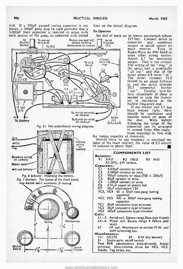
996 PRACTICAL WIRELESS
trol. If a 300pF ganged tuning capacitor is not handy, a 500pF gang may be used provided that a I,000pF fixed capacitor is inserted in series with each section of the gang, as indicated with dotted
SI On /Off Switch
To Aerial terminal
To VC2
lines on the circuit diagram.
To Operate
Points marked MC. denote earthing
connections to chassis
Set dial of main Aerial
Trimmer VC3
To VCS ! i via cy f - C ' o® Trtr C3
coil f3
Aerial
LI,L2,13) =..,. U.. MC.
C4 CS C7
Chassis securing
lugs
C2
I.F coil
To Battery
To Aerial terminal ......." on receiver
To Earth terminal on receiver
Fig. 5: The underchassis wiring diagram.
4.5 V
-we
Negative spin on battery
Elastic band
45 volt battery
Positive spring
on battery
Fig. 6 (above): Mounting the battery Fig. 7 (below): The layout of the front panel.
take marked out in wavebands On metres)
Aerial Trimmer
Mixer coil
(L4,L5,L6)
March, 1963
set to lowest wavelength (about 187.5m). Connect aerial to convertor and convertor output to aerial socket on main receiver. Tune in Radio Paris on 49m band or some other strong station. Adjust L7 for maximum output. This is not critical. The setting of the "slug" in the aerial coil is practically "all out" and that of the mixer about 6 -8 turns "in ". The mixer trimmer TC2 should be set about halfway in and the aerial trimmer TCI somewhat further " out ". Careful turn -by- turn adjustment of these is needed to keep the transis- tor in oscillation at the highest frequency end.
If the emitter coil L5 has been wound right, there should be oscillation and stations heard on most of the dial. With patient trimming the range of the convertor can be arranged to extend from. 49m (maxi- mum capacity) to 16m with
the tuning capacity at minimum. Should there be any tendency to overload the
input of the main receiver, the value of C5 should be reduced to about 50pF.
COMPONENTS LIST Resistors:
RI 33kí2 R2 I0kf2 All 20 %, kW carbon.
Capacitors: CI 4,000pF ceramic or mica C2 2,500pF ceramic or mica C3 950pF ceramic or mica (750 C4 50pF ceramic or mica C5 I,000pF ceramic or mica C6 0.01µF paper or plastic foil C7 2515F electrolytic 12V VCI, VC4 50 + 50pF two -gang
capacitor VC2, VC5 300 + 300pF two -gang tuning
capacitor TCI 30pF concentric type trimmer TC2 30pF concentric type trimmer VC3 I00pF concentric type trimmer
Coils: LI -3 Aerial coil. Denco range Blue (see 4 text) L4-6 Mixer coil. Denco range 4 White (see
text) L7 I.F. coil. Weymouth or similar M.W. coil
with screening can. Miscellaneous:
Trl OC170 BI 4.5V dry battery SI Single -pole, on /off switch Two B9A valveholders (non- skirted). Aerial terminal. Slow- motion drive for VC2, VCS. Knobs. Tag strips, etc.
R3 Ikf2
F 200pF)
tuning
www.americanradiohistory.com
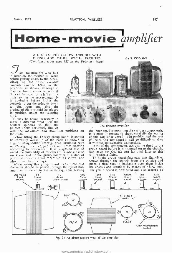
March, 1963 PRACTICAL WIRELESS 997
'Home-movi ámplifier A GENERAL PURPOSE 4W AMPLIFIER WITH MIXING AND OTHER SPECIAL FACILITIES
(Continued from page 922 of the February issue)
3OR constructors who like to complete the mechanical work before getting down to the actual wiring up the three variable controls can be fitted in the positions as shown, although it may be found easier to wire if the switched control is left until a little later in the proceedings. It is advisable before fitting the controls to cut the spindles down to lin. long and also the graduated dials should be placed in position under the securing nuts.
It may be found necessary to make a different " flat " on the ...! control spindles so that the pointer knobs accurately line up with the maximum and minimum positions on the dials.
Before fitting the 12 -way group board it should be carefully wired up at the back as shown in Fig. 3, using either 22s.w.g. p.v.c.- insulated wire or 22s.w.g. tinned copper wire and lmm sleeving according to preference. It is suggested that to avoid the possibility of mistakes it is advisable to mark one end of the group board with a dab of paint, or to cut a small " V " slot as shown, and also to number the tags.
When wiring this group board please note that the wires should be passed through the eyelet hole and then soldered to the outer tag, thus leaving
By S. COLLINS
AC. mains Input
Socket
F1 Mains fuse
T2 Mains
transformer
LS. jack
The finished amplifier
the inner one for mounting the various components. It is most important to check carefully the wiring of this part since once it is in position and the rest of the wiring completed it will be difficult to alter it without considerable dismantling.
Most of the components, can also be fitted to the group board before it is mounted on to the chassis, but leave out C6, R2 and R3 until later as this will facilitate fixing.
To fit the group board first pass two jin. 4B.A. screws through the chassis from the outside and place a thin paxolin backplate over them inside the chassis and secure it by means of 4B.A. nuts. The group board is now fitted and also secured by
VR3 Tape Gram. Tone Gram
VR2 Input Mic.
VRI
control Socket Volume socket Volume
MIc. Input
socket r
TI Output transformer
V1 V3 r EF86
EZ80 ® \ ® ,2)
)j , , / q / C9G10 ECL82
Anti-microphonlc socket
Fig. 7t An above -chassis view of the amplifier.
www.americanradiohistory.com
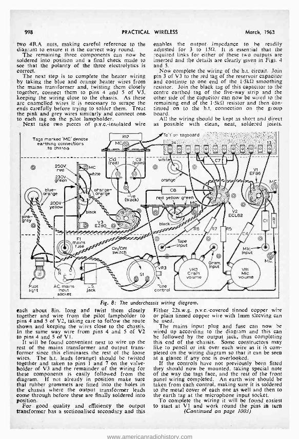
998 PRACTICAL
two 4B.A. nuts, making careful reference to the diagram to ensure it is the correct way round.
The remaining three components can now be soldered into position and a final check made to see that the polarity of the three electrolytics is correct.
The next step is to complete the heater wiring by taking the blue and orange heater wires from the mains transformer and, twisting them closely together, connect them to pins 4 and 5 of V3, keeping the wiring close to the chassis. As these are enamelled wires it is necessary to scrape the ends carefully before trying to solder them. Treat the pink and grey wires similarly and connect one . to each tag on the pilot lampholder.
Next take two pieces of p.v.c: insulated wire
Tags marked 'MC: denote earthing conneckions
to chassis
Qp 250V red
230V green
WIRELESS March, 1963
enables the output. impedance to be readily adjusted for 3 to 150. It is essential that the required links for either of these two outputs are inserted and the details are clearly given in Figs. 4 and 5.
Now complete the wiring of the h.t. circuit. Join pin 3 of V3 to the red tag of the reservoir capacitor and continue tq one end of the 1.5k0 smoothing resistor. Join the black tag of this capacitor to the centre earthed tag of the five -way strip and the other side of the capacitor can now be wired to the remaining end of the 1.5kí2 resistor and then con- tinued on to the h.t. connection on the group board.
All the wiring should be kept as short and direct as possible with clean, neat, soldered joints.
on tagboard f/ I.
o
white
blue- e
200V yellow
red yellow green MC
pink- grey
V2 ECL82
black
Tape Input
Pilot light
AC mains L.S. Input jack
socket
Tone control
Fig. 8: The underchassis wiring diagram.
each about 8in, long and twist them closely together and wire from the pilot lampholder to pins 4 and, 5 of V2, taking care to follow the route shown and keeping the wires close to the chassis. In the same way wire from pins 4 and 5 of V2 to pins 4 and 5 of VI.
It will be found convenient next to wire up the rest of the mains transformer and output trans- former since this eliminates the rest of the loose wires. The h.t. leads (orange) should be twisted together and taken to pins I and 7 on the valve - holder of V3 and the remainder of the wiring for these components is easily followed from the diagram. If not already in position make sure that rubber grommets are fitted into the holes in the chassis where the output transformer leads come through before these are finally soldered into position.
For good quality and efficiency the output transformer has a sectionalised secondary and this
Either 22s.w.g. p.v.c.- covered tinned copper wire or plain tinned copper wire with 1mm sleeving can be used.
The mains input plug and fuse can now be wired up according to the diagram and this can be followed by the output jack, thus completing this end of the 'chassis. Some constructors may like to pencil or ink over each wire as it is com- pleted on the wiring diagram so that it can be seen at a glance if any one is overlooked.
If the controls have not previously been fitted they should now be mounted, taking special note of the way the tags face, and the rest of the front panel wiring completed. An earth wire should be taken from each control, making sure it is soldered to the metal cover of each one as well and then to the earth tag at the microphone input socket.
To complete the wiring it will be found easiest to start at VI and work round the pins in turn
(Continued on page 1003)
www.americanradiohistory.com
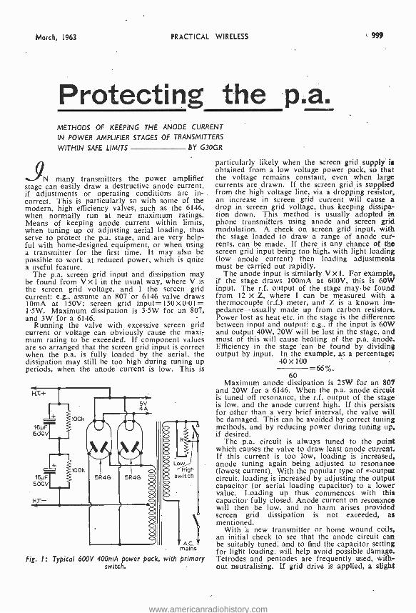
March, 1963 PRACTICAL WIRELESS 999
Protecting the p.a. METHODS OF KEEPING THE ANODE CURRENT
IN POWER AMPLIFIER STAGES OF TRANSMITTERS
WITHIN SAFE LIMITS BY G30GR
N many transmitters the power amplifier stage can easily draw a destructive anode current, if adjustments or operating conditions are .in- correct. This is particularly so with some of the modern, high efficiency valves, such as the 6146, when normally run at near maximum ratings. Means of keeping anode current within limits, when tuning up or adjusting aerial loading, thus serve to protect the p.a. stage, and are very help- ful with home -designed equipment, or when using a transmitter for the first time. It may also be possible to work at reduced power, which is quite a useful feature.
The p.a. screen grid input and dissipation may be found from V x I in the usual way, where V is the screen grid voltage, and I the screen grid current: e.g., assume an 807 or 6146 valve draws 10mA at 150V; screen grid input = 150x0.01= 1.5W. Maximum dissipation is 3.5W for an 807, and 3W for a 6146.
Running the valve with excessive screen grid current or voltage can obviously cause the maxi- mum rating to be exceeded. If component values are so arranged that the screen grid input is correct when the p.a. is fully loaded by the aerial, the dissipation may still be too high during tuning up periods, when the anode current is low. This is
16NF 500V
H.T.-
Lo High
switch
A.C. mains
Fig. I: Typical 600V 400mA power pack, with primary switch.
particularly likely when the screen grid supply is obtained from a low voltage power pack, so that the voltage remains constant, even when large currents are drawn. If the screen grid is supplied from the high voltage line, via a dropping resistor, an increase in screen grid current will cause a drop in screen grid voltage, thus keeping dissipa- tion down. This method is usually adopted in phone transmitters using anode and screen grid modulation. A check on screen grid input, with the stage loaded to draw a range of anode cur- rents, can be made. If there is any chance of the screen grid input being too high, with light loading (low anode current) then loading adjustments must be carried out rapidly.
The anode input is similarly V X I. For example, if the stage draws f00mA at 6O0V, this is 60W input. The r.f. output of the stage may be found from 12 x Z, where I can be measured with a thermocouple (r.f.) meter, and Z is a known im- pedance- usually made up from carbon resistors. Power lost as heat etc. in the stage is the difference between input and output: e.g., if the input is 60W and output 40W, 20W will be lost in the stage, and most of this will cause heating of the p.a. anode. Efficiency in the stage 'can be found by dividing output by input. In the example, as a percentage:
40 x 100 -66 %.
60 Maximum anode dissipation is 25W for an 807
and 2OW for a 6146. When the p.a. anode circuit is tuned off resonance, the r.f. output of the stage is low, and the anode current high. If this persists for other than a very brief interval, the valve will be damaged. This can be avoided by correct tuning methods, and by reducing power during tuning up, if desired.
The p.a. circuit is always tuned to the point which causes the valve to draw least anode current. If this current is too low, loading is increased, anode tuning again being adjusted to resonance (lowest current). With the popular type of rr- output circuit. loading is increased by adjusting the output capacitor (or aerial loading capacitor) to a lower value. Loading up thus commences with this capacitor fully closed. Anode current on resonance will then be low, and no harm arises provided screen grid dissipation is not exceeded, as mentioned.
With 'a new transmitter or home wound coils. an initial check to see that the anode circuit can be suitably tuned, and to find the capacitor setting for light loading, will help avoid possible damage. Tetrodes and pentodes are frequently used, with- out neutralising. If grid drive is applied, a slight
www.americanradiohistory.com
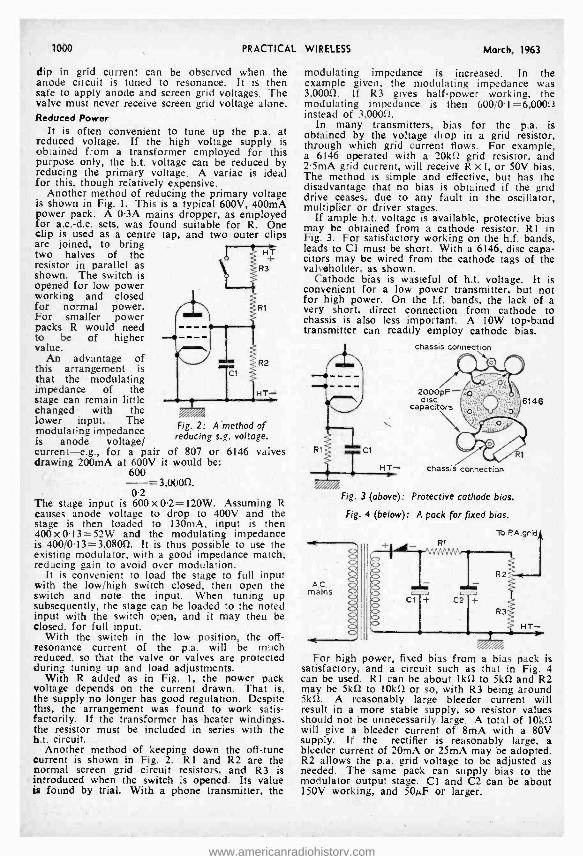
1000 PRACTICAL
dip in grid current can be observed when the anode circuit is tuned to resonance. It is then safe to apply anode and screen grid voltages. The valve must never receive screen grid voltage alone. Reduced Power
It is often convenient to tune up the p.a. at reduced voltage. If the high voltage supply is obtained from a transformer employed for this purpose only, the h.t. voltage can be reduced by reducing the primary voltage. A variac is ideal for this, though relatively expensive.
Another method of reducing the primary voltage is shown in Fig. 1. This is a typical 600V, 400mA power pack. A 0.3A mains dropper, as employed for a.c. -d.c. sets, was found suitable for R. One clip is used as a centre tap, and two outer clips are joined, to bring two halves of the resistor in parallel as shown. The switch is opened for low power working and closed for normal power. For smaller power packs R would need to be of higher value.
An advantage of this arrangement is that the modulating impedance of the stage can remain little changed with the lower input. The modulating impedance is anode voltage/ current -e.g., for a pair of 807 drawing 200mA at 600V it would
600 =3,0000.
0.2 The stage input is 600 X 0.2 =120W. Assuming R causes anode voltage to drop to 400V and the stage is then loaded to 130mA, input is then 400x 0.13=52W and the modulating impedance is 400/0.13= 3,08052. It is thus possible to use the existing modulator, with a good impedance match, reducing gain to avoid over modulation.
It is convenient to load the stage to full input with the low /high switch closed, then open the switch and note the input. When tuning up subsequently, the stage can be loaded to the noted input with the switch open, and it may then be closed, for full input.
With the switch in the low position, the off - resonance current of the p.a. will be much reduced, so that the valve or valves are protected during tuning up and load adjustments.
With R added as in Fig. 1, the power pack voltage depends on the current drawn. That is, the supply no longer has good regulation. Despite this, the arrangement was found to work satis- factorily. If the transformer has heater windings, the resistor must be included in series with the h.t. circuit.
Another method of keeping down the off -tune current is shown in Fig. 2. R1 and R2 are the normal screen grid circuit resistors, and R3 is introduced when the switch is opened. Its value is found by trial. With a phone transmitter, the
Fig. 2: A'method of reducing s.g. voltage.
or 6146 valves be:
WIRELESS March, 1963
modulating impedance is increased. In the example given, the modulating impedance was 3,00012. If R3 gives half -power working, the modulating impedance is then 600/0.1 = 6,00052 instead of 3,000[2.
In many transmitters, bias for the p.a. is obtained by the voltage drop in a grid resistor, through which grid current flows. For example, a 6146 operated with a 20k52 grid resistor, and 2.5mA grid current, will receive R x I, or 50V bias. The method is simple and effective, but has the disadvantage that no bias is obtained if the grid drive ceases, due to any fault in the oscillator, multiplier or driver stages.
If ample h.t. voltage is available, protective bias may be obtained from a cathode resistor, R1 in Fig. 3. For satisfactory working on the h.f. bands, leads to Cl must be short. With a 6146, disc capa- citors may be wired from the cathode tags of the valveholder, as shown.
Cathode bias is wasteful of h.t. voltage. It is convenient for a low power transmitter, but not for high power. On the 11. bands, the lack of a very short, direct connection from cathode to chassis is also less important. A 10W top -band transmitter can readily employ cathode bias.
chassis connection
CI
HT- chassis connection
2000pF disc
capacitors 6146
Fig. 3 (above): Protective cathode bias.
Fig. 4 (below): A pack for fixed bias.
To P. A.grid Rt
Cl + C2 +
R2
R3
HT-
For high power, fixed bias from a bias pack is satisfactory, and a circuit such as that in Fig. 4 can be used. R1 can be about iko2 to 5k52 and R2 may be 5kû to 10k52 or so, with R3 being around 5k52. A reasonably large bleeder current will result in a more stable supply, so resistor values should not be unnecessarily large. A total of 10kí2 will give a bleeder current of 8mA with a 80V supply. If the rectifier is reasonably large, a bleeder current of 20mA or 25mA may be adopted. R2 allows the p.a. grid voltage to be adjusted as needed. The same pack can supply bias to the modulator output stage. Cl and C2 can be about 150V working, and 50µF or larger.
www.americanradiohistory.com
March, 1963 PRACTICAL WIRELESS 1001
PCR COMMUNICATION RECEIVERS
Manufactured by Pye and Philips. One of the Army's most versatile and sensitive sets. RF stage and 2 of 1.F., using 8 British 1.0. type valves. Large 180 degrees illu- minating and calibrated Dial. Flywheel Tuning with locking device. Aerial Trimmer. Tone and Vol. Controls. Band Switch from panel Packs for speaker or phones. In black metal case, size 171n. L z Sin. B z 10113. D. Model PCR covers 0 -10 Mc /s. 200 -550 metres and 850.2,000 metres and has Internal 5 -1n. speaker. 88.19.0. Model PORE has similar L & M waveband coverage. Short wave 6 -22 Mc /e, but no speaker, 15.10.0. Model PORI, as PCR2 but has 2 short wave bande 2 -7 and 7.29 Mc /s, and medium wave band 190 -550 metres. ONLY 8 ens. Aid 10/8 cam all models. Designed to operate from bulky EXTER- NAL power supply, but any set can be fitted with BRAND NEW COMPONENTS INTERNAL PACK for 200 -250 v. A.C. at extra coat of £2. Ail receivers used but excellent condition and aerial tested before despatch. S.I.R. lOR ILLUSTRI TIFD
LRI FLET
TEST METERS FOR EYEßY PURPOSE & POCKET
2,000 O.P.V. MODEL TP -10. Reads A.C. & D.C. Volts up to 1,000; D.C. Current to 500mA; Resistance to 1 Meg; Capaci- tance to 1µF; Decibels from -20 to +36; Output jack for Audio Measurements. Size 3iin. a Sin. a 14ín.
28.19.6.
20,000 O.P.V. MODEL TP-3S, Read voltage up to 1,000 D.C. at 20,000 ohms per volt and A.C. at 10,000 o.p.v.: D.C. Current to 500mA: Resistance to 10 Megs.; Capacitance to 0.11.1.F; Decibels from -20 to +38. Bite 311n. z bila z Min.
25.19.6.
30,000 O.P.V. MODEL 500. Volts to LOCO: D.C. at 30,000 0 P.V. A.C. at 20.000; 12 Amps D.C. Current; 60 Megs Resistance -20 to +56 dBs: Internal buzzer short circuit warning. Size 3s. /Isla. z 65 /tefO. z SII1n.
fß.19.& All New Stock, with leads. pr oda and internal batteries. 6 months' guarantee backed by fat
service facilities. Details S.A.E.
DOUBLE BEAM OSCILLOSCOPE TUBES, TYPE CV1500. Equivalent to COSSOR 09D as used in Oscilloscopes by Cossor (339 series) and Hartley & Erskine (13 series). Listed £12. BRAND NEW IN MAKER'S CRATES. ONLY 25/- (carriage 5/ -). LAVOIE UHF WAVEMETER MODEL 105. Coverage 375/ 725 Mc /s. Complete with correct Calibration Chart. First -class condition. Battery operated and portable, size U z 8 it Thins. ONLY £3.19.6 (carriage 7/6). RHO SENIOR TABLE MODEL RECEIVERS. Complete with 9 coil sets covering 50 Eels to 30 Mc /s. Used, very good condition, aerial tested. ONLY 217.10.0 (carriage. etc., 30/ -). A few late Model IT with I.O. valves. 222.10.0., plus carriage. COMBINED VIBRATOR /MAINS UNIT. The Power Pack of the Army RI07 Receiver. Has vibrator for 12 v. D.C. operation, and mains transformer for 100/250 volts A.C. Output 12.6 volts 3 A. L.T. and 250 v. at 100 mA H.T. Complete with vibrator, 6X5G rectifier, and connecting data. Ideal for driving T.C.S. or Type 52 Receivers, etc., or mobile equipment. BRAND NEW IN MAKER'S CARTONS ONLY 45/- (carr. 5/6). RIO? RECEIVER R.F. UNIT. Brand new tuning sections of the famous R107 receiver. A 3 -stage unit, complete with 4 gang condensers and dial. Calibrated 1.2 to 17.5 Mc /s in 3 bands, coil pack and wave -change switch, aerial trimmer. Less valves. Ideal front end for constructing a superhet receiver. Complete R107 circuit supplied. BRAND NEW IN MAKER'S CARTONS, ONLY 35/, Carr. 5/ -. AVOMETER MODEL 7. Reconditioned and in perfect order with leads, internal batteries, and Instructions. ONLY £11. (Reg. post 5 / -). AVOMETER MODEL 7 LEATHER CASES, fitted with carrying handle & long strap. BRAND NEW. ONLY 32/6 (post 2/6). 20/- CONSTRUCTOR'S PARCEL. Assorted colours wiring wire, solder; resistors, condensers, volume controls, tag panel. ALL NEW. (Post 2/6). RESISTORS, 100 assorted values our choice. NEW 10/, C'OVDEVSEIt S. 100 assorted mica and sllvermiea. NRW 19/6.
"P.W." 6 TRANSISTOR PERSONAL RECEIVER
Designed by the techni- cal staff of Practical Wireless. easy to build. using printed circuit and 1st Grade ML.tched Transistors and Diode. Full Medium and Long Wave coverage to inter- nal speaker. All parts sold separately (new components only) en- abling you to buy as re- quired and full detailed price list will be sent on
request. Constructional details 1 /6. Newly designed OSMOR Cabinet and reduced price. TOTAL COST INCLUDING BATTERY and CABINET NOW £7.19.8.
"P.W. TROUBADOUR 7" Parts List. s.A.E.
THE "GOOD COMPANION" ML, II USING TRANSEILTERS, THE LATEST MANUFACTURING
TECHNIQUE TO SAVE ALIGNMENT DIFFICULTY
THE FINEST COMBINED PORTABLE and CAR RADIO YET DESIGNED FOR THE HOME CONSTRUCTDY
* 750 m output. * 6 transis- tors and diode.
* Full Medium and Long Wave coverage.
* Quality speaker.
* Brillian- tly styled 2-tone cab- inet, size Ur 8 z 31n.
* Very fine tuning with calibrated
*Latest printed circuit. * Internal high gain aerial with car aerial socket. Easy -to-follow construction data (available separately 3/6). All parts sold separately and full illustrated details will be sent on request.
Total Cost With alternative luxury cabinet using 7 z 41e. speaker, p04Á.6. Either type, plus 5/- post and ins. (Battery W6 extra,)
£9.19.6
"POCKET 4" TRANSISTOR RECEIVER Uses miniature speaker, proper tuning condenser, and volume control. Built -in aerial makes unit efficient and portable. Ideal tor the beginner. Full medium wave coverage. All components and case for only 42/6 (P. & p. 2/6). Ten -page constructional book free with parts or separately 1/6. S.A.E. for parts price list.
H A R R I S ELECTRONICS 138 Grays Inn Road, London W.C.I Phone TERminus 7937
(LONDON) LTD Please include carriage costs on all Items. (Open until 1 p.en. Saturdays). We are 2 mina. from High Hol 'w
(Chancery Lane Station) and 5 mina. by Bus from King's Crap
www.americanradiohistory.com
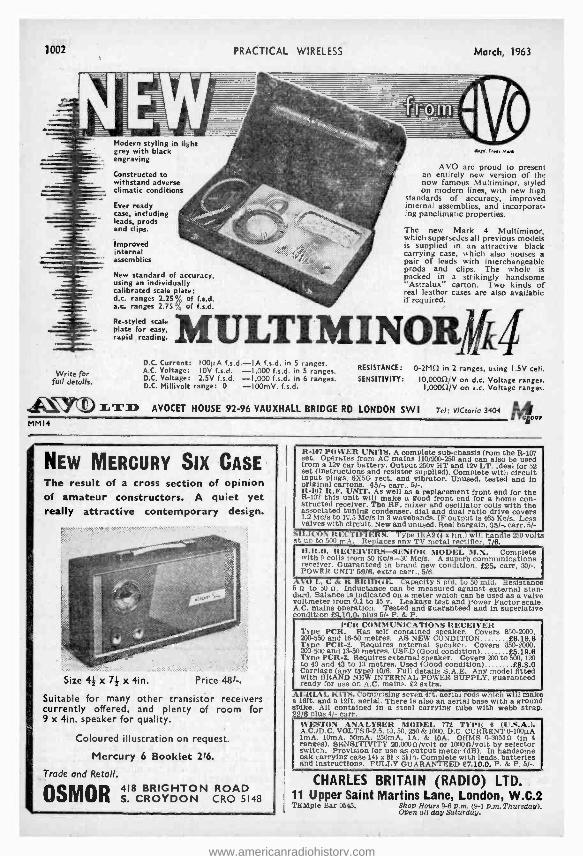
1002 PRACTICAL WIRELESS March, 1963
Modern styling in light grey with black engraving
Constructed to withstand adverse climatic conditions
Ever ready case, including leads, prods and clips.
Improved internal assemblies
Write for full details.
ay.. r,.w Mut
AVO are proud to present an entirely new version of the now famous Multiminor, styled on modern lines, with new high
standards of accuracy, improved internal assemblies, and incorporat- ing panciimatic properties.
The new Mark 4 Multiminor, which supersedes all previous models is supplied in an attractive black carrying case, which also houses a pair of leads with interchangeable prods and clips. The whole is
New standard of accuracy, ""'°% - packed in a strikingly handsome using an individually "Astralux" carton. Two kinds of calibrated scale plate: ` .@ real leather cases are also available d.c. ranges 2.25% of f.s.d. if required. a.c. ranges 2.75% of f.s.d.
MULTIMINOR#4 Re- styled scale plate for easy, rapid reading.
D.C. Current: IOO1iA f.s.d. -IA f.s.d. in 5 ranges. A.C. Voltage: 10V f.s.d. -1,000 f.s.d. in 5 ranges. D.C. Voltage: 2.5V f.s.d. -1,000 f.s.d. in 6 ranges. D.C. Millivolt range: 0 -100mV. f.s.d.
RESISTANCE: 0-2Mí1 in 2 ranges, using 1.5V cell. SENSITIVITY: 10,0000/V on d.c. Voltage ranges.
I,0000/V on a.c. Voltage ranges.
WYV LTD AVOCET HOUSE 92 -96 VAUXHALL BRIDGE RD LONDON SWI Tel: VICtoria 3404
MMI4 NP.
NEW MERCURY SIX CASE The result of a cross section of opinion of amateur constructors. A quiet yet really attractive contemporary design.
Size 4 x 7I x 4in. Price 481-.
Suitable for many other transistor receivers currently offered, and plenty of room for 9 x 4in. speaker for quality.
Coloured illustration on request.
Mercury 6 Booklet 216.
Trade and Retail.
OSMOR S.S CROYDON N CRO 5148
R -107 POWER UNITS. A complete sub -chassis from the R -107 set. Operates from AC mains 110 /200 -250 and can also be used from a 12v car battery. Output 250v HT and 12v LT. Ideal for 52 Set (instructions and resistor supplied). Complete with circuit input plugs, 6X5G rect, and vibrator. Unused, tested and in original cartons. 45/ -, carr.. 5/ -, It -107 R.F. UNIT. As well as a replacement front end for the R -107 this unit w111 make a good front end for a home con- structed receiver. The RF, mixer and oscillator colis with the associated tuning condenser, dial and dual ratio drive covers 1.2 Mc /s to 17.5 Mr /s In 3 wavebands. IF output is 465 Ke /s. Less valves with circuit. New and unused. Real bargain, 35/ -, oarr. 5/-
SILICON It ECTIFIERS. Type 1EA2 (# x tin.) will handle 250 volts at up to 500 mA. Replaces any TV metal rectifier, 7/6. D.ILO. It ECFIIYEIt4- SENIOR MODEI. M.X. Complete with 9 coils :rom 50 Kc /s -I0 Mc /s. A superb communications receiver. Guaranteed in brand new condition, £25, carr, 30/ -. POWER UNIT 59/8, extra carr., 5/6.
AYO I., C 1r. R BRIDGE. Capacity 5 pfd. to 50 mid. Resistance 5 it to 50 9. Inductance can be measured against external stan- dard. Balance is Indicated on a meter which can be used as a valve voltmeter from 0.1 to 15 v. Leakage test and Power Factor scale. A.C. mains operation. Tested and guaranteed and in superlative condition £9.10.0, glus 5/- P. & P.
PCII COMMUNICATIONS RECEIVER Type PCR. Has self contained speaker. Covers 850 -2000, 200 -550 and 16-50 metres. AS NEW CONDITION £6.19.8 Type PCII-t. Requires external speaker. Covers 850 -2000, 200 -500 and 13-50 metres. USED (Good condition) £5.19.6 Type PCR -3. Requires external speaker. Covers 200 to 500, 120 to 43 and 43 to 13 metres. Used (Good condition) £8.8.0 Carriage (any type) 10/6. Full details S.A.E. Any model fitted with BRAND NEW INTERNAL POWER SUPPLY, guaranteed ready for use on A.C. mains, f2 extra.
AERIAL KITS. Comprising seven 4ft. aerial rods which will make a loft. and a 12ft. aerial. There is also an aerial base with a ground spike. All contained in a steel carrying tube with webb strap. 22/8 plus 4/- carr.
%%ESTON ANALYSER MODEL 772 TYPE 6 (U.S.A.), A.C. /D.C. VOLTS 0-2.5, 10, 50, 250 & 1000. D.C. CURRENT 0 -100µA lmA. 10mA, 50mA, 250mA, lA, & 10A. OHMS 0-30M0 (In 4 ranges). SENSITIVITY 20,0000 /volt or 10000 /volt by selector switch. Provision for use as output meter (dB). In handsome oak carrying case 14# x 81 x 5iin. Complete with leads, batteries and instructions. FULLY GUARANTEED £7.10.0. P. & P. 5/ -.
CHARLES BRITAIN (RADIO) LTD. 11 Upper Saint Martins Lane, London, W.C.2 TEMple Bar 0545. Shop Hours 9 -6 p.m. (9 -1 p.m. Thursday).
Open all day Saturday.
www.americanradiohistory.com
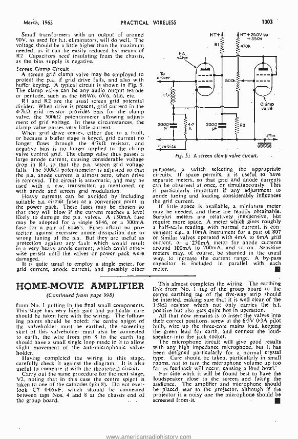
March, 1963 PRACTICAL WIRELESS
Small transformers with an output of around 90V, as used for h.t. eliminators, will do well. The voltage should be a little higher than the maximum needed, as it can be easily reduced by means of R2 Capacitors need insulating from the chassis, as the bias supply is negative. Screen Clamp Circuit
A screen grid clamp valve may be employed to protect the p.a. if grid drive fails, and also with buffer keying. A typical circuit is shown in Fig. 5. The clamp valve can be any audio output tetrode or pentode, such as the 6BW6, 6V6, 6L6, etc.
121 and R2 are the usual screen grid potential divider. When drive is present, grid current in the 4.7kS1 grid resistor provides bias for the clamp valve, the 500kD potentiometer allowing adjust- ment of grid voltage. In these circumstances, the clamp valve passes very little current.
When grid drive ceases, either due to a fault, or because a buffer stage is keyed, grid current no longer flows through the 4.7kí1 resistor, and negative bias is no longer applied to the clamp valve control grid. The clamp valve thus passes a large anode current, causing considerable voltage drop in R1, so that the p.a. screen grid voltage falls. The 500k0 potentiometer is adjusted so that the p.a. anode current is almost zero, when drive is removed. The circuit is automatic, and may be used with a c.w. transmitter, as mentioned, or with anode and screen grid modulation.
Heavy currents can be avoided by including suitable h.t. circuit fuses at a convenient point in the power pack. These fuses may be chosen so that they will blow if the current reaches a level likely to damage the p.a. valves. A 150mA fuse may be adopted for a single 6146, or a 300mA fuse for a pair of 6146's. Fuses afford no pro- tection against excessive anode dissipation due to wrong tuning of the p.a. But they are useful as protection against any fault which would result in a very heavy anode current, which could other- wise persist until the valves or power pack were damaged.
It is quite usual to employ a single meter, for grid current, anode current, and possibly other
To driver
PA. vaive
1003
HT+ HT+250V to +350V
470k R1
r
Clamp valve
2000 PF
-ve blas
Fig. 5: A screen clamp valve circuit.
purposes, a switch selecting the appropriate circuits. If space permits, it is useful to have separate meters, so that grid and anode currents can be observed at once, or simultaneously. This is particularly important if any adjustment to anode tuning and loading considerably influences the grid current.
If little space is available, a miniature meter may be needed, and these are readily obtainable. Surplus meters are relatively inexpensive, but require more space. A meter which gives roughly a half -scale reading, with normal current, is con- venient: e.g., a 10mA instrument for a pair of 807 or similar valves operated with 4mA to 6mA grid current, or a 250mA meter for anode currents around 100mA to 200mA, and so on. Sensitive meters may, of course, be shunted in the usual way, to increase the current range. A by -pass capacitor is included in parallel with each meter.
HOME -MOVIE AMPLIFIER (Continued from page 998)
from No. 1 putting in the final small components. This stage has very high gain and particular care should be taken here with the wiring. The follow- ing points should be noted: the centre spigot of the valveholder must be earthed, the screening skirt of this valveholder must also be connected to earth, the wire from pin 8 to the earth tag should have a small single loop made in it to allow slight movement of the anti -microphonic valve - holder.
Having completed the wiring to this stage, carefully check it against the diagram. It is also useful to compare it with the theoretical circuit.
Carry out the same procedure for the next stage, V2, noting that in this case the centre spigot is taken to one of the cathodes (pin 8). Do no over- look C7 0.05µF, which should be connected between tags Nos. 4 and 8 at the chassis end of the group board. ..
This almost completes the wiring. The earthing link from No. 1 tag of the group board to the centre earthing tag of the five -way strip should be inserted, making sure that it is well clear of the 1.5kí1 resistor which not only carries the h.t. positive but also gets quite hot in operation.
All that now remains is to insert the valves into their correct positions, screw in the 6.5V 0.3A pilot bulb, wire up the three -core mains lead, keeping the green lead for earth, and connect the loud- speaker into the jack socket.
The microphone circuit will give good results with any high impedance microphone, but it has been designed particularly for a normal crystal type. Care should be taken, particularly in small rooms, not to turn the microphone volume up too far as feedback will occur, causing a loud howl
For cine work it will be found best to have the loudspeaker close to the screen and facing the audience. The amplifier and microphone should be placed near to the projector, although if the projector is a noisy one the microphone should be screened fromit. u
www.americanradiohistory.com
1004 PRACTICAL WIRELESS
TEST GEAR
PART 2 - MORE ABOUT METERS
March, 1963
techniques
H. W. Hellyer
_ _ _ _ _ _ ; ;y.ti;-; ,.,.. : 1Y.Y.YY>fY t
JNDIVIDUAL volt and ampere meters are rarely found around the wireless workshop. They have their uses: mainly in specific applications, such as vehicle system testing, or in the industrial field as indicating devices, part of a static monitor. More widely employed, because of its versatility, is the multimeter, with a number of ranges for measuring volts, amperes and ohms. It may be a small pocket instrument, suitable for direct current readings only, the dozen or so ranges selected by plug- and -socket connections, or it may be a com- prehensive " bench " type, with fifty or more ranges, a.c. and d.c., a wide scope of resistance checks and additional facilities such as high - voltage, capacity and " Q" measurement.
The Multimeter Whatever the design of the multimeter, its
accuracy and its dependability as a measuring instrument rely upon the quality of the basic movement, as described in Part One. Sensitivity of the meter determines its usefulness as an indicator of correct voltage, and limits the lowest scale. A typical multirange testmeter may have a sensitivity of 20,00011 per volt on d.c., with a movement requiring only 50 micro -amperes for full scale deflection. (The same instrument would have a sensitivity of perhaps as little as 1,00011 per volt on a.c.)
The principle of using a multirange meter on the highest voltage range, where a choice is available, to obtain the most favourable ohms per volt loading of the circuit (see Part One), is correct - but another factor should be considered. That is the accuracy of the meter.
For example, a meter with a stated accuracy of 2% could indicate between 98 and 102V when exactly 100V is applied to it, on the 100V range. In other words, this is a full -scale accuracy figure, and, if half the voltage is applied, with the meter switched to the same range, a variation between 48 and 52V may be noted, which is a 4%, plus or minus, error. At the lower end of the scale, the error factor is even greater. Therefore, it is better to use a meter on the range that gives a deflection as near the upper end of the scale as possible.
From this, it can be seen that much depends on the circuit in which the meter is connected, and
its sensitivity, in interpreting the error factor. In other words, one must grow used to one's meter and allow for the inevitable discrepancies.
A.C. Measurements This is even more apparent when using a multi -
meter for a.c. tests in radio work. Here there are two more factors to consider. First, the shunting effect of the bridge rectifier and components reduces the meter sensitivity, and second, the frequency response of the instrument determines its accuracy of reading. The average multimeter is not intended to be used at much above 5kc /s for very accurate results, and is generally employed for measuring such things as heater voltage and current, at mains frequency, 50c /s. For higher frequency work, such as the measurement of stage gain in radio and audio frequency stages, an elec- tronic meter is very much more accurate and trustworthy. This type of instrument will be discussed later.
Resistance Testing An important function of the multimeter is the
ohms range, or ranges. By fitting a battery in the meter, and arranging variable resistors to bring the meter movement to full -scale deflection when the circuit is completed, i.e. terminals short - circuited, zero ohms, then introducing the unknown resistance in place of the short -circuit, the reduced current can be indicated as a proportion of full - scale deflection, and read off directly from a scale -which will now appear in reverse to the voltage and current scales.
It will also appear non -linear, the divisions be- coming progressively more cramped as maximum resistance, i.e. minimum current flow, is approached. The resistance will be zero at full - scale deflection, infinity at minimum deflection. The highest resistance reading that can usefully be indicated depends upon the sensitivity of the meter, and the battery voltage. But addition of an external battery extends the range of the instru- ment and alternative methods of connecting meter, battery and variable shunt can " open out " the lower range, enabling a reading of smaller resistance values.
This is seen more clearly in Fig. 4. Here there
www.americanradiohistory.com
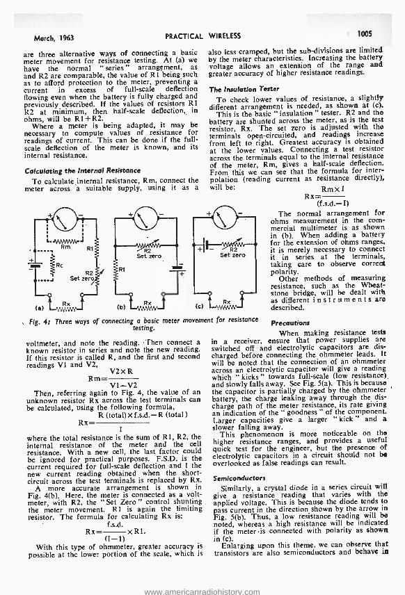
March, 1963 PRACTICAL
are three alternative ways of connecting a basic meter movement for resistance testing. At (a) we have the normal " series " arrangement, as and R2 are comparable, the value of R1 being such as to afford protection to the meter, preventing a current in excess of full -scale deflection flowing even when the battery is fully charged and previously described. If the values of resistors R1 R2 at minimum, then half -scale deflection, in ohms, will be R1 +R2.
Where a meter is being adapted, it may be necessary to compute values of resistance for readings of current. This can be done if the full - scale deflection of the meter is known, and its internal resistance.
Calculating the Internal Resistance
To calculate internal resistance, Rm, connect the meter across a suitable supply, using it as a
WIRELESS 1005
also less cramped, but the sub -divisions are limited by the meter characteristics. Increasing the battery voltage allows an extension of the range and greater accuracy of higher resistance readings.
The Insulation Tester
To check lower values of resistance, a slightly different arrangement is needed, as shown at (c).
This is the basic " insulation " tester. R2 and the battery are shunted across the meter, as is the test resistor, Rx. The set zero is adjusted with the terminals open -circuited, and readings increase from left to right. Greatest accuracy is obtained at the lower values. Connecting a test resistor across the terminals equal to the internal resistance of the meter, Rm, gives a half -scale deflection. From this we can see that the formula for inter- polation (reading current as resistance directly), will be:
Fig. 41 Three ways of connecting a basic meter movement for resistance testing.
voltmeter, and note the reading. Then connect a known resistor in series and note the new reading. If this resistor is called R, and the first and second readings V1 and V2,
V2 Rm=
V1 -V2 Then, referring again to Fig. 4, the value of an
unknown resistor Rx across the test terminals can be calculated, using the following formula,
R (total) X f.s.d. -R (total ) Rx-
I where the total resistance is the sum of RI, R2, the internal resistance of the meter and the cell resistance. With a new cell, the last factor could be ignored for practical purposes. F.S.D. is the current required for full -scale deflection and I the new current reading obtained when the short - circuit across the test terminals is replaced by Rx.
A more accurate arrangement is shown in Fig. 4(b). Here, the meter is connected as a volt- meter, with R2, the " Set Zero " control shunting the meter movement. RI is again the limiting resistor. The formula for calculating Rx is:
f.s.d. Rx= XR1.
(I -1) With this type of ohmmeter, greater accuracy is
possible at the lower portion of the scale, which is
RmXI Rx=
(f.s.d.- I) The normal arrangement for
ohms measurement in the com- mercial multimeter is as shown in (b). When adding a battery for the extension of ohms ranges, it is merely necessary to connect it in series at the terminals, taking care to observe corred polarity.
Other methods of measuring resistance, such as the Wheat- stone bridge, will be dealt with as different instruments are described.
Precautions When making resistance tests
in a receiver, ensure that power supplies are switched off and electrolytic capacitors are dis- charged before connecting the ohmmeter leads. It will be noted that the connection of an ohmmeter across an electrolytic capacitor will give a reading which " kicks " towards full -scale (low resistance). and slowly falls away. See Fig. 5(a). This is because the capacitor is partially charged by the ohmmeter battery, the charge leaking away through the dis- charge path of the meter resistance, its rate giving an indication of the " goodness " of the component. Larger capacities give a larger " kick " and a slower falling away.
This phenomenon is more noticeable on the higher resistance ranges, and provides a useful quick test for the engineer, but the presence of electrolytic capacitors in a circuit should not be overlooked as false readings can result.
Semiconductors
Similarly, a crystal diode in a series circuit will give a resistance reading that varies with the applied voltage. This is because the diode tends to pass current in the direction shown by the arrow in Fig. 5(b). Thus, a low resistance reading will be noted, whereas a high resistance will be indicated if the meter is connected with polarity as shown in (c).
Enlarging upon this theme, we can observe that transistors are also semiconductors and behave in
www.americanradiohistory.com
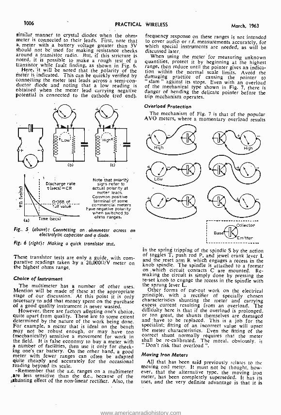
1006 PRACTICAL
similar manner to crystal diodes when the ohm- meter is connected to their leads. First, note that a meter with a battery voltage greater than 3V should not be used for making resistance checks around a transistor radio. But, if this stricture is noted, it is possible to make a rough test of a transistor while fault finding, as shown in Fig. 6.
Here, it will be noted that the polarity of the meter is indicated. This can be quickly verified by connecting the meter test leads across a semi -con- ductor diode and noting that a low reading is obtained when the meter lead carrying negative potential is connected to the cathode (red end).
(b)
Discharge rate t (secs) = C R
0.368 of full value
a) Time (secs)
(c)
Note that polarity signs refer to
actual polarity at meter leads.
Common positive terminal of some
commercial meters have negative polarity
when switched to ohms ranges.
Fig.. 5 (above): Connecting an ohmmeter across an electrolytic capacitor and a diode.
Fig. 6 (right): Making a quick transistor test.
These transistor tests are only a guide, with com- parative readings taken by a 20,0000 /V meter on the highest ohms range.
Choice of Instrument The multimeter has a number of other uses.
Mention will be made of these at the appropriate stage of our discussion. At this point it is only necessary to add that money spent on the purchase of a good quality instrument is never wasted.
However, there are factors affecting one's choice, quite apart from quality. These áre to some extent determined by the nature of the work being done. For example, a meter that is ideal on the bench may not be robust enough, or may have too (mechanically) sensitive a movement for work in the field. It is false economy to buy a meter with a number of facilities, then use it only for check- ing one's car battery. On the other hand, a good meter with fewer ranges can often be adapted quite cheaply and accurately for the occasional reading beyond its scale.
Remember that the a.c. ranges on a multimeter are less sensitive than the d.c., because of the ,are
effect of the non -linear rectifier. Also, the
WIRELESS March, 1963
frequency response on these ranges is not intended to cover audio or r.f. measurements accurately, for which special instruments are needed, as will be discussed later.
When using the meter for measuring unknown quantities, protect it by beginning at the highest range, then reduce until the pointer gives an indica- tion within the normal scale limits. Avoid the damaging practice of causing the pointer to " slam " against its stops. Even with an overload of the mechanical type shown in Fig. 7, there is danger of bending the delicate pointer before the trip mechanism operates.
Overload Protection The mechanism of Fig. 7 is that of the popular
AVO meters, where a momentary overload results
r Collector
(i)Emitter Base
in the spring tripping of the spindle S by the action of toggles T, push rod P, and jewel crank lever L and the reset arm R which engages a recess in the knob spindle. The spindle is attached to a former on .which circuit contacts C are mounted. Re- making the circuit is simply done by pressing the re -set knob to engage the recess in the spindle with the sprung lever L.
Other forms of cut -out work on the electrical principle, with a rectifier of specially chosen characteristics shunting the meter and carrying excess current resulting from an overload. The lifficitlty here is that if the overload is prolonged, or too great, the shunts themselves are damaged and have to be replaced. This is a job for the specialist; fitting of an incorrect value will upset the meter characteristics. Even the fitting of the correct shunt normally requires that the meter shall be re- calibrated. The moral, obviously. is " Don't risk that overload ".
Moving Iron Meters All that has been said previously relates to the
moving coil meter. It must not be thought, how- ever, that the alternative type, the moving iron meter, has been completely superseded. It has its uses, and the very definite advantage is that it is
www.americanradiohistory.com
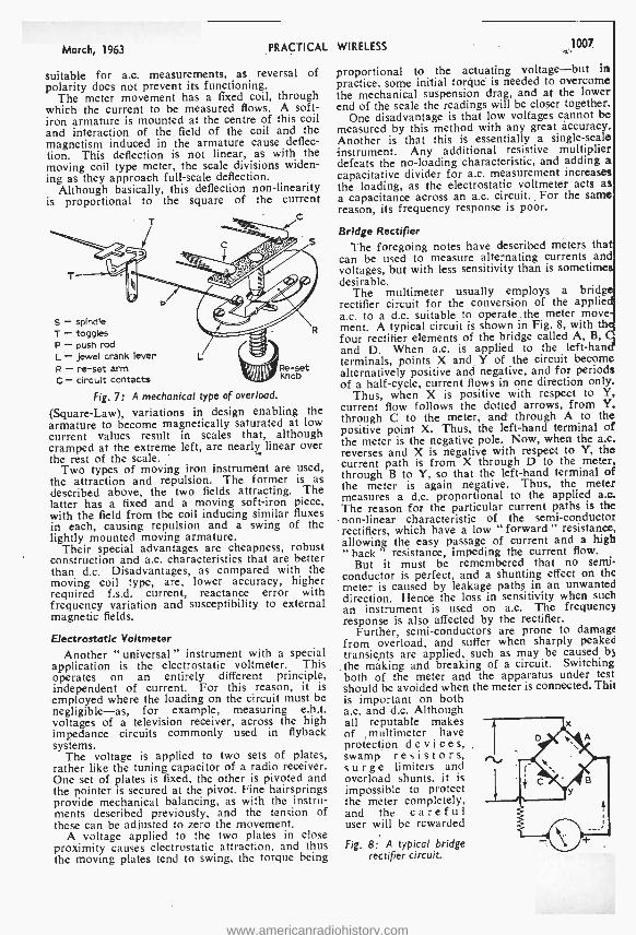
March, 1963 PRACTICAL
suitable for a.c. measurements, as reversal of polarity does not prevent its functioning.
The meter movement has a fixed coil, through which the current to be measured flows. A soft - iron armature is mounted at the centre of this coil and interaction of the field of the coil and the magnetism induced in the armature cause deflec- tion. This deflection is not linear, as with the moving coil type meter, the scale divisions widen- ing as they approach full -scale deflection.
Although basically, this deflection non -linearity is proportional to the square of the current
S - spindle T - toggles P - push rod L - jewel crank lever R - re -set arm C - circuit contacts
Fig. 71 A mechanical type of overload.
(Square -Law), variations in design enabling the armature to become magnetically saturated at low current values result in scales that, although cramped at the extreme left, are nearly linear over the rest of the scale.
Two types of moving iron instrument are used, the attraction and repulsion. The former is as described above, the two fields attracting. The latter has a fixed and a moving soft -iron piece, with the field from the coil inducing similar fluxes in each, causing repulsion and a swing of the lightly mounted moving armature.
Their special advantages are cheapness, robust construction and a.c. characteristics that are better than d.c. Disadvantages, as compared with the moving coil type, are, lower accuracy, higher required f.s.d. current, reactance error with frequency variation and susceptibility to external magnetic fields.
Electrostatic Voltmeter
Another " universal" instrument with a special application is the electrostatic voltmeter. This operates on an entirely different principle, independent of current. For this reason, it is employed where the loading on the circuit must be negligible -as, for example, measuring e.h.t. voltages of a television receiver, across the high impedance circuits commonly used in flyback systems.
The voltage is applied to two sets of plates, rather like the tuning capacitor of a radio receiver. One set of plates is fixed, the other is pivoted and the pointer is secured at the pivot. Fine hairsprings provide mechanical balancing, as with the instru- ments described previously, and the tension of these can be adjusted to zero the movement.
A voltage applied to the two plates in close proximity causes electrostatic attraction, and thus the moving plates tend to swing, the torque being
WIRELESS 1007
proportional to the actuating voltage -but in practice, some initial torque is needed to overcome the mechanical suspension drag, and at the lower end of the scale the readings will be closer together.
One disadvantage is that low voltages cannot be measured by this method with any great accuracy. Another is that this is essentially a single -scale instrument. Any additional resistive multiplier defeats the no- loading characteristic, and adding a capacitative divider for a.c. measurement increases the loading, as the electrostatic voltmeter acts as a capacitance across an a.c. circuit. For the same reason, its frequency response is poor.
Bridge Rectifier
The foregoing notes have described meters that can be used to measure alternating currents and voltages, but with less sensitivity than is sometimes desirable.
The multimeter usually employs a bridge rectifier circuit for the conversion of the applied a.c. to a d.c. suitable to operate the meter move- ment. A typical circuit is shown in Fig. 8, with the four rectifier elements of the bridge called A, B, C and D. When a.c. is applied to the left -hand terminals, points X and Y of the circuit become alternatively positive and negative, and for periods of a half -cycle, current flows in one direction only.
Thus, when X is positive with respect to Y, current flow follows the dotted arrows, from Y, through C to the meter, and through A to the positive point X. Thus, the left -hand terminal of the meter is the negative pole. Now, when the a.c. reverses and X is negative with respect to Y, the current path is from X through D to the meter, through B to Y, so that the left -hand terminal of the meter is again negative. Thus, the meter measures a d.c. proportional to the applied a.c. The reason for the particular current paths is the non- linear characteristic of the semi- conductor rectifiers, which have a low " forward " resistance, allowing the easy passage of current and a high " back " resistance, impeding the current flow.
But it must be remembered that no semi- conductor is perfect, and a shunting effect on the meter is caused by leakage paths in an unwanted direction. Hence the loss in sensitivity when such an instrument is used on a.c. The frequency response is also affected by the rectifier.
Further, semi- conductors are prone to damage from overload, and suffer when sharply peaked transients are applied, such as may be caused by
the making and breaking of a circuit. Switching both of the meter and the apparatus under test should be avoided when the meter is connected. Thit is important on both a.c. and d.c. Although all reputable makes of multimeter have protection de vi c e s, swamp resistors, surge limiters and overload shunts, it is impossible to protect the meter completely, and the careful user will be rewarded
Fig. 8: A typical bridge rectifier circuit.
www.americanradiohistory.com
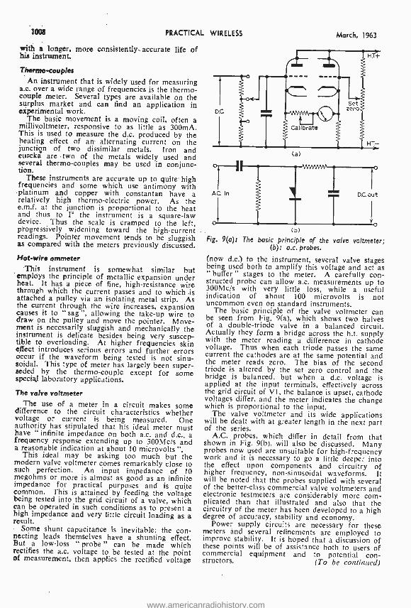
1008 PRACTICAL WIRELESS
with a longer, more consistently. accurate life of his instrument.
Thermo- couples An instrument that is widely used for measuring
a.c. over a wide range of frequencies is the thermo- couple meter. Several types are available on the surplus market and can find an application in experimental work.
The basic movement is a moving coil, often a millivoltmeter, responsive to as little as 300mA. This is used to measure the d.c. produced by the heating effect of an alternating current on the junction of two dissimilar metals. Iron and eureka are two of the metals widely used and several thermo- couples may be used in conjunc- tion.
These instruments are accurate up to quite high frequencies and some which use antimony with platinum and copper with constantan have a relatively high thermo- electric power. As the e.m.f. at the junction is proportional to the heat and thus to I' the instrument is a square -law device. Thus the scale is cramped to the left, progressively widening toward the high- current readings. Pointer movement tends to be sluggish as compared with the meters previously discussed.
Hot -wire ammeter This instrument is somewhat similar but
employs the principle of metallic expansion under heat. It has a piece of fine, high- resistance wire through which the current passes and to which is attached a pulley via an isolating metal strip. As the current through the wire increases, expansion causes it to "sag ", allowing the take -up wire to draw on the pulley and move the pointer. Move- ment is necessarily sluggish and mechanically the instrument is delicate besides being very suscep- tible to overloading. At higher frequencies skin effect introduces serious errors and further errors occur if the waveform being tested is not sinu- soidal. This type of meter has largely been super- seded by the thermo -couple except for some special laboratory applications.
The valve voltmeter The use of a meter in a circuit makes some
difference to the circuit characteristics whether voltage or current is being measured. One authority has stipulated that his ideal meter must have "infinite impedance on both a.c. and d.c., a frequency response extending up to 300Mc /s and a reasonable indication at about 10 microvolts ".
This ideal may be asking too much but the modern valve voltmeter comes remarkably close to such perfection. An input impedance of 10 megohms or more is almost as good as an infinite impedance for practical purposes and is quite common. This is attained by feeding the voltage being tested into the grid circuit of a valve, which can be operated in such conditions as to present a high impedance and very little circuit loading as a result.
Some shunt capacitance is inevitable; the con- necting leads themselves have a shunting effect. But a low -loss "probe " can be made which rectifies the a.c. voltage to be tested at the point of measurement, then applies the rectified voltage
March, 1963
(a)
(b)
Fig. 9(a)1 The basic principle of the valve voltmeter; (b)1 a.c. probes.
(now d.c.) to the instrument, several valve stages being used both to amplify this voltage and act as " buffer " stages to the meter. A carefully con- structed probe can allow a.c. measurements up to 300Mc /s with very little loss, while a useful indication of about 100 microvolts is not uncommon even on standard instruments.
The basic principle of the valve voltmeter can be seen from Fig. 9(a), which shows two halves of a double- triode valve in a balanced circuit. Actually they form a bridge across the h.t. supply with the meter reading a difference in cathode voltage. Thus when each triode passes the same current the cathodes are at the same potential and the meter reads zero. The bias of the second triode is altered by the set zero control and the bridge is balanced, but when a d.c. voltage is applied at the input terminals, effectively across the grid circuit of VI, the balance is upset, cathode voltages differ, and the meter indicates the change which is proportional to the input.
The valve voltmeter and its wide applications will be dealt with at greater length in the next part of the series.
A.C. probes, which differ in detail from that shown in Fig. 9(b), will also be discussed. Many probes now used are unsuitable for high- frequency work and it is necessary to go a little deeper into the effect upon components and circuitry of higher frequency, non -sinusoidal waveforms. It will be noted that the probes supplied with several of the better -class commercial valve voltmeters and electronic testmeters are considerably more com- plicated than that illustrated and also that the circuitry of the meter has been developed to a high degree of accuracy, stability and economy.
Power supply circuits are necessary for these meters and several refinements are employed to improve stability. It is hoped that a discussion of these points will be of assistance both to users of commercial equipment and to potential con- structors. (To be continued)
www.americanradiohistory.com
March, 1963 PRACTICAL WIRELESS 1009
l/ SEND FOR OUR 1963 COMPONENTS CATALOGUE
ALPHA 48 pages of valves and accessories. Send 1/- in stamps for your copy. /f Trade catalogue also available, for which please attach your business
hH\ letter heading.
POTENTIOMETERS A range of Ardente miniature potentio- meters is available. In the circular type adjustment of the control is made by
rotating the peripheral ring. Type VC.1041, less switch, diameter 0.680in., width less pins 0.170in., available in the following values: 5,000 ohms semi -log,
I megohm semi -log, 716. Type VC.1545, with switch, diameter 0.900in., width with pins 0.490in., available in the following values: 5 K ohm semi -log, 20 Kohm semi -log, 1 Megohm semi -log, 513.
Type VC.I760, with switch, diameter 0.720in., width with pins 0.378in., available in the following values: 5 Kohm semi -log, 20 Kohm semi -log, I Mohm semi -log, 1016.
CHASSIS Aluminium Undrilled with Reinforced Corner, available in the following sizes: 6in. x 4in. x 21in. ... ... 416 each
8in. x 6in. x 24in. ... ... 613 each
Oin. x 7in. x 21in. ... ... 713 each
2in. x Sin. x 24in. ... ... 519 each
2in. x Sin. x 2 4in. ... ... 619 each
2in. x Bin. x 21in. ... .,. 816 each
4in. x Sin. x 24in. ... ... 610 each
4in. x 9in. x Min. ... ... I21- each
6in. x 6in. x 24in. ... ... 913 each
6in. x IOin. x 24in. . 141- each
All are four -sided -ideal for radio receivers, amplifiers, power packs, etc.
OUR NEW 60 -PAGE
HI -FI CATALOGUE ib NOW AVAILABLE
SEND
2/6 PLUS 6d. POSTAGE
LOUDSPEAKERS All 3 ohm IMPEDANCE
Round Types -I }in. 1716; 24in. 1716; Sin. ISL.; 64in. 1616; 8in. 1716; 12ín. 2916.
Square Types -2 }in. 1816; Sin. 1916; 4in. Tweeter 1216.
Elliptical Types -6in. x 41n. 1516; 7in. x 4in. 1516; 8in. x 6in. 1716; 10in. x 6in. 211/-.
We also have in stock T5L Lorenz LPH65 3718; WB HF812 L4.I.3; WB HF912 L4.6.0; WB HF1012 £4.17.6; I2in. RTC 15 ohms unit 1051 -.
LOUDSPEAKERS BY WHARFEDALE
Bin. Bronze /RS. 10,500 gauss. Roll sur. round. Resonance 50/55 c /s. Impedance 10/I5 ohms. Total L4.4.6.
8in. Bronze FS /AL 10,500 gauss. Alu- minium voice coil, foam surround. Impe- dance 2/3 or 12/15 ohms. Resonance 50/55 c /s. Total L4.4.6.
Super 8 RS /DD. 14,500 gauss. Fitted roll surround and double diaphragm. Resonance 50/55 c /s. Impedance 10 /I5 ohms. Total L7.9.5.
Super I0 /RS /DD. 16,000 gauss. Fitted roll surround and double diaphragm. Impedance: 10/15 ohms only. Resonance 38/43 c /s. Total L17..3.7.
Golden 10 /RS /DD. 14,500 gauss. Fitted roll surround and double diaphragm. Impedance 10/15 ohms. only. Resonance 38/43 c/s. Total L8.15.5.
10in. Bronze /RS. 10,500 gauss. Roll surround. Resonance 35/40 c /s. Impedance 10/15 ohms only. Total 0.3.3.
IOin. Bronze /FSB. 10,500 gauss. Foam
surround. Impedance 2/3 or 12/15 ohms. Resonance 38/43 c /s. Total L5.3.3.
RECTIFIERS
Rectifiers suitable for Battery Chargers 12
volt output, 2 amp
71 -, 4 amp 1216 and
6 amp 1516.
TRANSISTORS AND DIODES Transistors 0075 81- OCP71 251-
0C35 I81- 0077 12f- Matched Prs. 0C36 2116 0078 81- 2x0072161- 0C44 6r- 0081 81- 2x0078161- 0C45 61- 0084 816 0070 616 OC170 916 Diodes 0071 51- OC171 1016 0A5 61-
0072 81. OC201 311. OAIO 8f- Sundry Types
0073 161- OC202 261- 0A70 31- PXAI02 4r-
A set of Transistors comprising 1 0C44, 2 0C45, I OCBID, 2 0081, 3216 set.
Set of Audio Transistors, I x OC81, 2 x OC81, Driver Matched Pair, 1516 set.
0A73 0A79 OA81 0A85 0A9 0A95
31. 3,9 216 31. 31- 316
GECSI Audio 316 Red
Spot 316 White
Spot GEX34 GEX35 XD20I
51- 3f.
j1- If-
ALUMINIUM PANELS
For use with our chassis, as front panels base plates, etc. Available in the following sizes:
14 x 9in. 4r- each 12 x I2in. 416 each 12 x 8in. 31- each 10 x 7in. 213 each
THORESBY BASS REFLEX CONSOLE CABINET (t.15)
This cabinet is designed for Stentorian 8in. or 10in. Loudspeakers and there is also provision for fitting tweeter unit if desired. Size: Height 31 in. x width 194in. x depth 18ín.
Price in Mahogany LI2.12.0.
Price in Walnut 716 extra.
THE "WEYRAD" SUPERHET TRANSISTOR RECEIVER FOR LONG AND MEDIUM WAVES The following components are available from stock: M.W. Oscillator Coil P50 /IAC 514. Rod Aerial RA2W 1216. 1st and 2nd I.F. Trans. P50 /2CC (2 required) 517. Driver Trans- former LFDT4 916. 3rd I.F. Transformer P50 /3CC 61 -. Printed circuit PCAI 916.
Literature for complete range of "WEY- RAD" components available on request.
THORESBY HI -FI EQUIPMENT CONSOLE (C.16)
This takes most makes of tape -deck er record player, amplifier, pre -amplifier control unit and radio tuner. Size: Height 31in. x width 194in. x depth
I Bi n.
Price in Mahogany L14.14.O.
Price in Walnut 101- extra.
LOUDSPEAKER CABINETS
Baffle type, walnut finish: - Type suitable for an 8in. unit ...
Type suitable for a 10in. unit ...
Type suitable for a 7in. x 4in. unit
211-
2516
1716
AUTOMATIC RECORD CHANGERS
BSR UAI4 ...
Collaro C60 ... Garrard Autoslim
... 46.19.6
... L7.19.6
... L7.19.6
SINGLE PLAYERS
EMT 4 -Speed with pick -up 13.15.0
... L4.19.6
Garrard TA Mk II ... ... L8.I0.0
EMI Battery Version ... L5.9.6
i 103 LEEDS TERRACE - WINTOUN STREET
LEEDS 7
TERMS: Cash with Order or C.O.D. Postage and Packing Charges extra. Single valves 9d., Minimum Parcel Post charges 2f -. Please include sufficient postage with your order. Minimum C.O.D. fees and postage 316. These Postal Rates apply to U.K. only. For full terms of business see inside cover of catalogue. Personal shoppers 9 a.m. to 5 p.m. Mon. to Friday, Saturday 10 a.m. to I p.m.
www.americanradiohistory.com
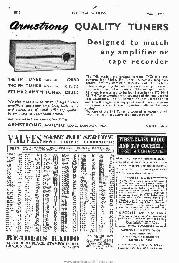
1010 PRACTICAL WIRELESS March, 1963
atootsAoft9 QUALITY TUNERS
T4B FM TUNER (illustrated) E20.8.0
T4C FM TU N E R (without case) E17.19.0
5T3 MK.2 AM /FM TUNER £25.12.0
We also make a wide range of high fidelity amplifiers and tuner -amplifiers, both mono and stereo, all of which offer top quality performance at reasonable prices.
Designed to match any amplifier or
tape recorder The T4B model (and uncased version -T4C) is a self - powered high fidelity FM Tuner. Automatic frequency control ensures complete stability and the cathode follower stage, together with the variable output control, enables it to be used with any amplifier or tape recorder. All these features are to be found also in the ST3 Mk.2 AM FM Tuner together with coverage of the medium and long wavebands. The AM section includes a ferrite aerial and two IF stages ensuring good Continental reception and there is a miniature bright -line indicator for easy tuning. The case of the T4B Tuner is covered in maroon vinyl - hide, making an attractive shelf- mounted unit.
Write for descriptive literature (quoting Dept. PMT) to
ARMSTRONG, WARLTERS ROAD, LONDON, N.7. NORTH 32Is
VALVES
SAME DA Y SERI/ICE NEW ! TESTED ! GUARANTEED !
SETS 1R5. 1S5, 1T4, 394, ,3V4, DAF 91, DF'bl, DKO1. DLM, DL94 .. Set of 4 for 19/- DAF96. DFMì, DKIs DL96 .. .. .. .. 4 Cor 26/6
IA7G r 11/- 1D5 7/6 1H5GT 9/- 1N5GT 9/-
15 1
8/-
4 3/6
2P5 22/8 3A5 9/-
3S4 6/ S -
6Ú4G 4/6 6V4G 8/- 5Y 3GT 61- 5Z4G 9/- 6AL5 3/9 6AM6 3/6 6AQ5 8/3 BATS 6/- 613A6 5/9
6 14/6 6BH6 6/3 6BJ6 5/9 6BW6 8/- 6CD6G 27/3
6E11 9/6 6F14 9/6 6K7G 1/11 6K7GT 5/- 6K8G 5/- 6K8GT 9/- 6K20 12/6 6L6G 6/6 6LI8 10 /-
6LD2u 8/- 6P2o 8/- 6P24 11/6 6Q7G 8/- 6Q7GT 8/- 6SL7GT 5/9 6SN7GT 4/9 6U4G r 9/9 SV6G 4/6 6V6GT 7/3 6X4 4/6 6X5GT 6/9 6/3UL2 9/- 7136 9/-
7C ág 7C6
7/9
7117 7/6 7S7 9/- 7Y4 6/- 10C1 12/- 1002 16/6 12AT6 ^/- 12AT7 4/9 12AU7 4/9 12AX7 4/9 12K7GT 4/9 12K8GT 9/6 12Q7GT 4/9 14S7 15/6 19BG6G 14/6 20F2 17/- 20L1 17/8 20P3 18/9 20P4 20/- 20P5 15/9 25L6GT 7/- 257.4G 7/8 27SU 17/6
30L1b 11/- 30i'4 12/6 30PL13 12/3 35A5 15/9 35L6GT 8/3 351.3 15/- 35Z4GT 5/6 50L6G 6/9 185BT 21/6 AZl 12/6 AZ31 9/6 CBL1 12/- CCH35 13/6 CL33 12/3 CYI 12/6 CY3I 8/6 DAC32 9/- DAF91 5/3 DAF96 7/6 DCC90 9/- DF33 9/- DF91 3/6 DF96 7/6 DH76 4/9 DH77 6/- D1481 9/- DK32 11/- DK91 6/- DK9z 7/6 DK96 7/6 DL33 8/- DL35 9/6 DL92 6/- DL94 7/. DL96 /8 DM70 6/6 EABC80 4/9 EAF42 8/6 EB91 3/9
LBC33 EBC41 EBFSO EBF89 EBL21 EBL31 ECC40 ECCS1 hCCd2 ECC83 ECC84 ECC8- 501,80 ECF82 ECFC35 ECH42 ECH81 ECL30 ECL82 ECLd3 EF9 EF37A EE39 EF40 EF41 EF42 EF80 EF85 EFO6 EF89 EF91 EL33 EL41 EL42 EL84 EM34 EM80 EM81 EM84
5/- 8/- 8/-
8/9 13/6 17/-
14/9 4/9 7/-
7/9
7/3 8/9 7/9 7/6 9/-
10/- 15/- 5/8
11/6 7/9 7/6 4/9 5/9 8/9
3/8 6/6 9/6
8/8 7/3 8/-
8/6 9/6
READERS RADI®
EY 1 7/6 Ula 12/- EY86 7/- 026 E/3 EZ40 6/9 11.50 F/6
EZ80 6/3 U52 U73
4/8 4/d
EZSl 6/6 U191 14/8 GZ32 8/6 U281 10/8 KT61 9/6 U282 15/- KT71 8/- U291 18/8 MUI4 6/6 U301 17/- MX40 13/6 U801 21/- vla 7/- UABC80 6/6 N37 11/- UAF42 F/3 PCC84 7/8 UBC41 7/9 PCC80 9/3 UBF80 8/3 PCF80 7/9 UBF89 8/- PCF82 8/- UBL21 14/6 PCFd6 9/6 UCC34 13/3 PCL82 9/- UCCBi 7/6 PCL83 10/6 UCF'80 14/6 PCLd4 7/- UCH21 13/6 PCLSS 10/6 UCH42 8/- PENA4 11/- UCH81 8/9 PEN36C 8I- UCL32 9/9 PL36 11/6 UCL33 13/3 PLO! 9/6 UF41 7/6 PL32 7/- UF89 ry/- PL83 7/6 UL41 8/- PL84 8/6 UL84 8/8 PL820 12/6 URIC 8/- PX4 10/- UU7 9/- PX25 9/- UY21 11/- PY32 11/6 UY41 8/8 PYd0 7/6 UY85 8/6 PY81 7/- VP4B 9/8 PY82 6/8 VP41 5/- PY83 7/9 PZ30 12/8 W776 3/9 TH21C 15/- Z77 3/6
Post 6d. por valve extra.
Any Parcel Insured 24 COLBERG PLACE, STANFORD HILL Transit 6d. extra
to
LONDON, N.16 STA. 4587 Any C. OD raParcel 3/-
FIRST -CLASS RADIO AND T/V COURSES...
GET A CERTIFICATE!
After brief, intensely interesting study - undertaken at home in your spare time -YOU can secure a recognised qualifica- tion or extend your knowledge of Radio and TV. Let us show you how.
r FREE GUIDES The New Free Guide contains 127 pager of information of the greatest impor- tance to both the amateur and the man employed in the Radio industry. N.I.E. provides first -rate postal courses for Radio Amateurs' Exam., R.T.F.B. Servicing Cert., C. & G. Telecoms., Grad. Brit. I.R.E. Guide also gives d ̂ tails of ran'e of diploma courses in .2adio /TV Servicing, Electronics and other branches of engineering, torether with particu. ars of our remarkable
Guarantee of
SUCCESS OR NO FEE Write now for your copy of this invaluable publication. It may well prove to be the
turning point in your career. FOUNDED 1885 -OVER
150,000 SUCCESSES - - NATIONAL INSTITUTE OF
ENGINEERING (Dept. 461), 148 HOLBORN
LONDON, E.C.1
S. Africa: P.O. Box 8417, Jo'burg. Australia: P.O. Box 4570, Melbourne.
www.americanradiohistory.com
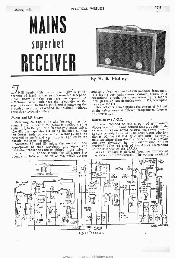
March, 1963 PRACTICAL WIRELESS
MAINS superhet
RECEIVER
HIS handy little receiver will give a good account of itself in the less favourable reception areas where simpler sets are inadequate. A directional aerial enhances the selectivity of the superhet circuit so that a good performance on the crowded medium waveband is obtained without excessive sideband cutting.
Mixer and I.F. Stages
Referring to Fig. 1, it will be seen that the signal from the ferrite rod aerial is applied via the switch SI, to the grid of a frequency changer valve, 12AH8, the capacitor Cl being included so that the lower ends of the aerial windings can be returned to earth and a.g.c. can be applied in the parallel mode to the grid.,
Switches S2 and S3 select the oscillator coil appropriate to each waveband and signal and oscillator frequencies are combined in the valve to produce in the anode circuit the difference fre- quency of 465kc /s. The valve V2, which accepts
1011
by V. E. Holley
and amplifies the signal at intermediate frequency, is a high slope variable -mu pentode, 6BA6, in a
coventional circuit, the screen receiving its supply through the voltage dropping resistor R5, decoupled by capacitor C11.
This network also supplies the screen of VI but as the valves work at different frequencies, there is no inter -action.
Detection and A.G.C.
It was intended to use a pair of germanium diodes here until it was noticed that a double diode valve and its base could be obtained ex- equipment at considerably less cost. The constructor who has diodes of the GEX34 type available, however, may substitute them directly for V3 in Fig. 1 with- out any alteration in the performance of the receiver. (The red ends of the diodes correspond to the cathodes of the 6AL5.)
A.G.C. voltage is derived from the primary of the second i.f. transformer. The voltage available
V4 R11 ECL80 220k
VR1 470k Volume
Fig. I: The circuit.
www.americanradiohistory.com
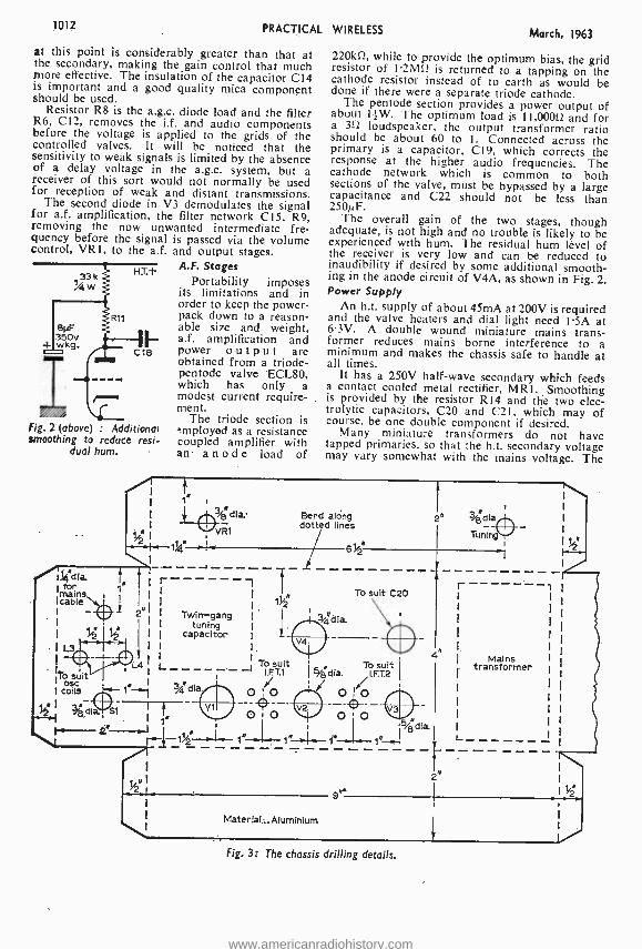
1012 PRACTICAL WIRELESS March, 1963
at this point is considerably greater than that at the secondary, making the gain control that much more effective. The insulation of the capacitor C14 is important and a good quality mica component should be used.
Resistor R8 is the a.g.c. diode load and the filter R6, C12, removes the i.f. and audio components before the voltage is applied to the grids of the controlled valves. It will be noticed that the sensitivity to weak signals is limited by the absence of a delay voltage in the a.g.c. system, but a receiver of this sort would not normally be used for reception of weak and distant transmissions.
The second diode in V3 demodulates the signal for a.f. amplification, the filter network C15, R9, removing the now unwanted intermediate fre- quency before the signal is passed via the volume control, VR1, to the a.f. and output stages.
A.F. Stages HT.-F
133 Portability imposes
ßNF 35Ov i- wkg. r
R11
1E- cia
its limitations and in order to keep the power - pack down to a reason- able size and weight, a.f. amplification and power output are
--- obtained from a triode - pentode valve 'ECL80, which has only a modest current require- ment.
The triode section is
i=1111 / : Additional Fig. 2 (above) mployed as a resistance
smoothing to reduce resi- coupled amplifier with dual hum. an anode load of
./.1j4"dla for
lc blé 1 1 rVWV
1
I L3- a v v
t 1" ,
.L.07/; dia.
1 4 VR1
`/2 i--1%q _I. \ J
r
220kí1, while to provide the optimum bias, the grid resistor of 1.2MS2 is returned to a tapping on the cathode resistor instead of to earth as would be done if there were a separate triode cathode.
The pentode section provides a power output of about 11-W. The optimum load is 11,00052 and for a 353 loudspeaker, the output transformer ratio should be about 60 to 1. Connected across the primary is a capacitor, C19, which corrects the response at the higher audio frequencies. The cathode network which is common to both sections of the valve, must be bypassed by a large capacitance and C22 should not be less than 250µF.
The overall gain of the two stages, though adequate, is not high and no trouble is likely to be experienced with hum. The residual hum level of the receiver is very low and can be reduced to inaudibility if desired by some additional smooth- ing in the anode circuit of V4A, as shown in Fig. 2. Power Supply
An h.t. supply of about 45mA at 200V is required and the valve heaters and dial light need 1.5A at 6.3V. A double wound miniature mains trans- former reduces mains borne interference to a minimum and makes the chassis safe to handle at all times.
It has a 250V half -wave secondary which feeds a contact cooled metal rectifier, MR1. Smoothing is provided by the resistor R14 and the two elec- trolytic capacitors, C20 and C21, which may of course, be one double component if desired.
Many miniature transformers do not have tapped primaries, so that the h.t. secondary voltage may vary somewhat with the mains voltage. The
Bend along dotted lines
1
2
1
I
g
i 't
u 4 To suit
lb suit l 1
i I coils t- Pj dia. OO I dla st f"
_ "-J fI I -
T-',
1 1"~ f" 1,
"I . I _
Twin-gang
capacitor
1.
To suit C20
To suit I.F.T.2
r
L
Mains transformer
Matertal_Aiuminium
Fig. 3: The chassis drilling details.
www.americanradiohistory.com
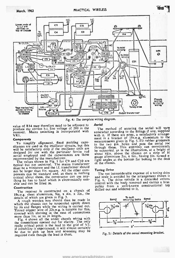
March, 1963
Lover ends of L1,L2 are
earthed On top of chassis
PRACTICAL WIRELESS 1013
Tags marked 'MG denote earthing
connerticns to chassis
Fig. 4: The complete wiring diagram.
value of R14 may therefore need to be adjusted to produce the correct h.t. line voltage of 200 in the receiver. Mains switching is incorporated with VR1. Components
To simplify alignment, fixed padding capa- citances are used in the oscillator circuits, but this will be satisfactory only if the oscillator coils are designed for use with the particular ferrite rod aerial employed and the capacitances are those recommended by the manufacturer.
The values shown in Fig. 1 for C9 and C10 are typical but not universal. The mains transformer must be a miniature and the i.f. transformer should not be larger than lin. square. All the other com- ponents can be standard and, as there is nothing critical about them, the constructor can use any- thing he has to hand which is electronically suit- able and can be fitted in. Construction
The receiver is constructed on a chassis of 18s.w.g. sheet aluminium, 9in. x 4in. x 2in., the details of which are given in Fig. 3.
A rough wooden box should then be made in which the chassis can be suspended upside down by its end flanges while the wiring is carried out. Tinned copper wire of 22s.w.g. is suitable for this, covered with sleeving in the case of connections more than lin. or so in length.
Fig. 4 shows all the under chassis wiring with the connections opened out for clarity. The only really critical point is the lead to the grid of V2; if instability is experienced, it will almost certainly be due to pick up here and screening may be required even though the lead is short.
Chassis laid flat
to clarify wiriro
Aerial The method of securing the aerial will vary
somewhat according to the fittings if any, supplied with it. If there are none, a satisfactory arrange- ment is a bracket of 18s.w.g. aluminium to the measurements given in Fig. 5. Fit rubber grommet! in the two -tin. holes and pass the aerial roe through them. This assembly can conveniently be supported, as in the illustration, at a height of
about 4 }in. above the chassis on a strip of It gauge aluminium Sin. x lin., having }in. turned a'
right angles at the bottom for bolting to the deck
of the chassis.
Tuning Drive The not inconsiderable expense of a tuning drive
and scale is avoided by the arrangement shown ii
Fig. 6. The drive spindle is a discarded volumi control with the body removed and carries a bras pulley from a well -known constructional to drilled out and soldered to it.
To suit Bend securing bolts Bend
3
Fig. 5: Details of the aerial mounting bracket.
www.americanradiohistory.com
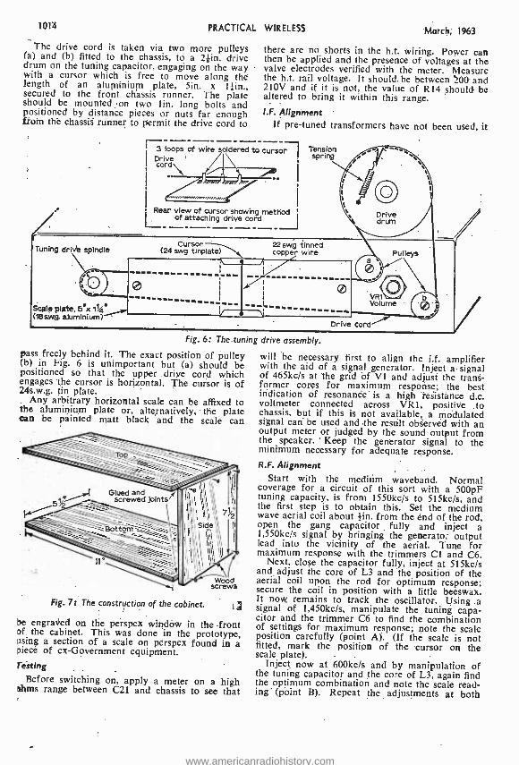
1014 PRACTICAL WIRELESS March, 1963
The drive cord is taken via two more pulleys (a) and (b) fitted to the chassis, to a 21in. drive drum on the tuning capacitor, engaging on the way with a cursor which is free to move along thé length of an aluminium plate, 5in. x secured to the front chassis runner. The plate should be mounted on two lin. long bolts and positioned by distance pieces or nuts far enough from the chassis runner to permit the drive cord to
í II
Rear view of cursor showing method of attaching drive cord
there are no shorts in the h.t. wiring. Power can then be applied and the presence of voltages at the valve electrodes verified with the meter. Measure the h.t. rail voltage. It should, be between 200 and 210V and if it is not, the value of R14 should be altered to bring it within this range. 1.F. Alignment
If pre -tuned transformers have not been used, it
3 loops of wire soldered to cursor l Drive
. - Cursor
Tension spring
Tuning drive spindle (24 awg.
Scale plate ex 11144
(18aw.g. aluminium)
Fig. 6: The tuning drive assembly.
pass freely behind it. The exact position of pulley (b) in Fig. 6 is unimportant but (a) should be positioned . so that the upper .drive cord which engages the cursor is horizontal. The cursor is of 24s.w.g. tin plate.
Any arbitrary horizontal scale can be affixed to the aluminium plate or, alternatively, the plate can be painted matt black and the scale can
Fig. 71 The construction of the cabinet. tj be engraved on the perspex window in the front of the cabinet. This was done in the prototype, using a section of a scale on perspex found in a piece of ex- Government equipment. resting
Before switching on, apply a meter on a high skims range between C21 and chassis to see that
will be necessary first to align the ii. amplifier with the aid of a signal generator. Inject a signal of 465kc /s at the grid of VI and adjust the trans- former cores for maximum response; the best itïdication of resonance is a high resistance d.c. voltmeter connected across VR1, positive to chassis, but if this is not available, a modulated signal can be used and the result observed with an output meter or judged by the sound output from the speaker. Keep the generator signal to the minimum necessary for adequate response. R.F. Alignment
Start with the medium waveband. Normal coverage for a circuit of this sort with a 500pF tuning capacity, is from 1550kc /s to 515kc /s, and the first step is to obtain this. Set the medium wave aerial coil about lin. from the end of the rod, open the gang capacitor fully and inject a 1,550kc /s signal by bringing the generatof output lead into the vicinity of the aerial. Tune for maximum response with the trimmers CI and C6.
Next, close the capacitor fully, inject at 515kc /s and adjust the core of L3 and the position of the aerial coil upon the rod for optimum response; secure the coil in position with a little beeswax. It now remains to track the oscillator. Using .a signal of 1,450kc /s, manipulate the tuning capa- citor and the trimmer C6 to find the combination of settings for maximum response; note the scale position carefully (point A). (If the scale is not fitted, mark the position of the cursor on the scale plate). -
Inject now at 600kc /s and by manipulation of the tuning capacitor and the core of L3, again find the optimum combination and note the scale read- ing- (point B). Repeat the adjustments at both
www.americanradiohistory.com
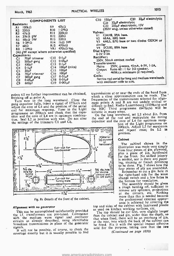
March, 1963 PRACTICAL WIRELESS 1015
COMPON Resistors:
,RI 100kí2 R2 2200 R3 47kí2 R4 33kí2 }W R5 18kû IW R6 I.2Mû R7 680 R8 I.2Mû (All }W except where
Capacitors: CI 70pF trimmer C2 500pF gang C3 I00pF C4 0.1µF C5 50pF C6 70pF trimmer C7 500pF gang C8 0.05µF C9 600pF
ENTS LIST
R9 47k0 RIO I.2M0 RII 220kí2 R12 22012 R13 2200 R14 Ik0 5W R15 47ûk0 VRI 470kû log.
otherwise specified)
CI I
Cl2 C13 C14 CI5 C16 CI7 C18 C19
0-1µF 0-05µF 0IµF I00pF (mica) I 00pF 100pF 0.01/4F 0-01µF 0.001µF
CIO 150pF C20 320F electrolytic C2I 324:F electrolytic C22 25012F electrolytic, I5V (350V wkg. unless otherwise stated)
Valves: VI I2AH8, B9A base. V2 6BA6, B8G base V3 6AL5, B7G base or two diodes GEX34 or similar V4 ECL80, B9A base
Dial Light: 6.3V 0.3A
Rectifier: 250V, 50mA contact cooled
Transformers: Mains 250V, wave, 45mA, 6.3V, I.5A. Output Ratio 6 : I for 3û speaker. I.F. 465Kc /s miniature (2 required).
Coils: Ferrite rod aerial for long and medium wavebands with oscillator coils to suit.
points till no further improvement can be obtained, finishing off at point A.
Turn now to the long waveband. Close the gang capacitor fully, inject a signal of 175kc /s and adjust the core of L4 and the position of the aerial coil for maximum response. Tune in the Light programme on 200kc /s and check that the capa- citor and the core of L4 are in optimum combina- tion. Seal L2 in position with wax. Do not alter the settings of the trimmers Cl and C6.
rJ ir,N:.y..: 8
transmissions at or near the ends of the band from which a close approximation can be made. The frequencies of the transmissions selected for align- ment points A and B are not unduly critical or difficult to find; Radio Luxembourg (1439kc /s) and the BBC Third programme (647kc /s) will be
suitable in many areas. On the long waveband, set L2 about }in. from
the end of the rod and manipulate the tuning capacitor and the core of L4 for optimum recep-
tion of the Light programme on 200kc /s. Adjust L2 for maximum and repeat once; fix L2 in position.
h r
f.,, :rs- 3
tvtáterial vg plywood
or t hardboard
3/2
,:.
5/é die. hole for
tuning drive.
5%8
3%4 3%4 --- % dia. hole for Volume control and On Off Switch,
13i;
.+L',"'. `.°...':;v..-.`,r .''"...á'S'[, 4_,¡¢.r,;:,
. ,. ,
1t% -
Fig. 8t Details of the front of the cabinet.
Alignment with no generator
This can be accomplished satisfactorily provided the i.f. transformers are pre- tuned. Commence with the medium wave signal and oscillator circuits as already described, using identifiable broadcast transmissions in place of the generator signals.
It will not be possible, of course, to check the coverage exactly but it is usually possible to find
,
{
is
Cabinet The cabinet shown in the
illustration was made very simply from four pieces of lin. plywogd, plus a piece of lin. hardboard for the front. No skilled joinery is needed, nor is there any paint- ing, staining or french pohshing to be done. Fig. 7 shows how the four pieces of ply are assembled.
Remember to cut a lin. hole in the right -hand side for the wave change switch and a few holes in the bottom for ventilation.
The assembly should be given a rough sanding off, sufficient to remove any splinters, projections at the corners, etc. Nothing more than this is needed because the professional external appear- ance is achieved by covering the
top and sides of the cabinet with laminated plastic as used on kitchen working surfaces, etc.
The top should be cut first, very slightly longer than the cabinet and lin. wider than the depth, so that when fixed, there will be an overhang of lin. at the rear, into which the back of the cabinet can be fitted. Fix it with the special impact adhesive sold for the purpose, taking care that the two
(Continued on page 1030)
www.americanradiohistory.com
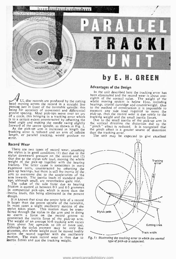
_ALL disc records are produced by the cutting head moving across the record in a straight line passing just in front of the turntable spindle; this being for accuracy of movement and differential groove spacing. Most pick -ups move over an arc of a circle, this bringing in a tracking error which is to a certain extent counteracted by offsetting the head angle and making the needle swing slightly forward of the centre spindle, as shown.in Fig. 1.
As the pick -up arm is increased in length the tracking error is reduced and an arm 'of infinite length, or parallel tracking, would produce no error.
Record Wear There are two types of record wear, assuming
the stylus is in good condition; (1) that due to the stylus downward pressure on the record and (2) that due to the stylus side load, moving the whole Weight of the pick -up together with the bearing friction. The latter cause is sometimes in more expensive units, counteracted by offsetting the pick -up bearings, but there is still the inertia of the arm to overcome due to the acceleration of the arm inwards. The inertia loads of standard pick- ups, although small, are nevertheless quite real.
The value of the side force due to bearing friction is quoted as between 0.3 and 0.5 grammes in commercial pick -ups, which is more than the
- inertia loads, this being eliminated in the present design.
It is known that since the centre hole of a record is larger than the centre spindle of the turntable, in most cases a slight oscillatory motion of the stylus takes place. This motion must be trans- ferred through the stylus to the arm and in doing so exerts a force on the record groove to counteract the inertia force of the pick -up arm. The weight of an average hi -fi tracking arm varies from about 5oz upwards to lib or more and, although the stylus pressure may be only five grammes, this whole weight must be moved bodily across the record together with the oscillatory motion. The main record wear is thus due to inertia forces and not the tracking weight.
by E. H. GREEN Advantages of the Design
In the unit described here the tracking error has been eliminated 'and the record wear is about one- eighth of the normal value. The weight of the whole moving system is below l +oz, including bearings, crystal cartridge and counterweight. Due to the method of construction it is impossible to measure any side load required to move the pick -up, thus the record wear is due solely to the tracking weight and the small inertia forces.
Due to the small inertia of the pick -up arm in the vertical direction the distortion due to the " pinch " effect is reduced. It is recognised that the pinch effect is a greater source of distortion than the tracking error.
The unit may be expected to give excellent
Tracking error
Stylus path
Cutting lines
Track width
Fig. 1 t Illustrating the tracking error to which the normal type of pick -up is subjected.
www.americanradiohistory.com
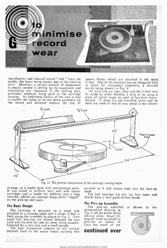
imise record wear
reproduction and reduced record " talk" from the needle, this latter being mainly due to the tracking error. However, a certain amount of adjustment is usually needed in setting up the equipment and eliminating any resonance in the moving part, particular attention being paid to the cartridge housing. An additional facility of the unit is that it enables the stylus to be put down anywhere on the record and removed without the risk of
V angle
square blocks Which are attached to the Main V -bed. One of the brackets has an elongated hole to allow for horizontal alignment, a detailed sketch being shown in Fig. 4.
All materials are light alloy and the V -bed may be made by either bending a strip or by using a piece of corner angle as used in furniture manu- facture. If these are not available brass may be used, but steel or any ferrous metal is not recom-
V angle
Foam rubber pads
1.375,
1.0° 5n
Fig. 21 The general construction of the cartridge running angle.
damage, as is easily done with conventional arms. It was found to perform very well with stereo cartridges and is useful for dubbing into a tape recorder, almost any passage being easily "logged" by the pick -up and scale.
The Basic Design
The cartridge is mounted on a small arm attached to a running angle and a larger V -bed is fixed across the turntable as shown in Fig. 2. Two small ball bearings are placed between the two units and the pick -up runs on these, being counter- balanced by a thin wire and a small weight.
The main framework consists of two vertical brackets fixed to the motor board carrying two
9.5"
mended as it will induce hum into the pick -up leads.
The ball bearings are lin. car hub types and should have a very good surface finish.
The Pick -up Assembly The pick -up assembly
'dimensioned drawing in Fig. 3, all the pieces being 20s.w.g, alloy. Small tri- angular stops are glued in position as shown to limit the travel of the
continued over
is shown in the
www.americanradiohistory.com
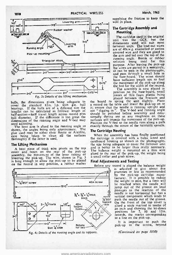
101 PRACTICAL WIRELESS
6
Running angle
Pick-up mounting
Triangular stops
0.2e
2.7" - 1.0" -
2.1" Fig. 31 Details of the lifting mechanism.
balls, the dimensions given being adequate to cover the standard 12in. l.p. with ¡in. ball bearings. If the balls are of a different size the lengths can be calculated as follows: length of half -section =half travel length across record plus ball diameter. If the difference is too great the dimensions of the running angle and V -bed may need adjusting.
The bent arm is glued to the running angle as shown, the angles being only approximate. The glue used may be either clear Bostic or Araldite, care being taken to clean all the surfaces thoroughly if the latter is used.
The Lifting Mechanism A bent piece of thick wire pivots on the top
cover and bears on the rear of the pick -up assembly, the movement of the lever raising or lowering the pick -up. The wire, shown in Fig. 3
is long enough to allow the pick -up to be placed on the record in any position, a rubber washer
_u
March, 1963
supplying the friction to keep the wire in place.
The Cartridge Assembly and Mounting The cartridge used in the original
unit was the GCS, but the dimensions used will suit most turnover units. The lead -out wires are of 40s.w.g. enamelled or cotton covered wire and they are glued to the arm and led over the top of the running angle. Bostik or rubber solution being used for this purpose. After leaving the pick -up the wires are parted in a semicircle, 27_ -.j as can be seen in the photographs, and pass through a small hole in the base- board. The wires should have sufficient length not to foul the movement of the pick -up along the bed for the width of the record.
The assembly is now placed in position on the base -board, small pieces of thin foam plastic being placed between the brackets and
the board to spring the unit slightly. Place a record on the table and lower the pick -up on to it; ensure that the needle is running upright and not " digging in ". The V -bed and running angle should be polished before assembly and occa- sionally during use as any roughness on these surfaces will impede the movement of the pick -up. Position the V -bed so the needle runs along a path exactly through the centre of the turntable spindle.
The Cartridge Housing When the assembly has been finally positioned
the cartridge is covered with a balsa wood and cardboard housing as shown in the photographs, the size being adequate to cover the turnover unit and is better to be larger than really necessary. The balance weight is mounted on a thin wire glued to the rear of the pick -up, the weight being a small collar and grub screw.
Final Adjustments and Testing Before any record is played the balance weight
is adjusted to give about five 3 grammes or less as recommended
by the pick -up cartridge manu- facturer. It is passible to reduce the weight to zero, but a limit will be reached when the needle will jump out of the groove on loud passages as the reaction of the needle is not horizontal but has a vertical component which tends to push the needle out of the groove. On the front of the top cover is glued a scale marked in tenths of an inch and showing the let -down positions for 7, 10 and 12in. records, the marks corresponding to a line on the pick -up.
It is important to push the pick -up to the centre, beyond
T 0.75"
0751-04
\":l %BSF screw -4 16 0'
4BA screw
3j4.x 34t x 1/gthlck block
0" 3 -/4 rivets 1.0' 4BA tapped
hole
4.0" Rebate
Slot %4 wide for bed
Fig. 41 Details of the running angle and its supports.
(i
1/4 "BSF tapped
hole
(Continued on page 1050)
www.americanradiohistory.com
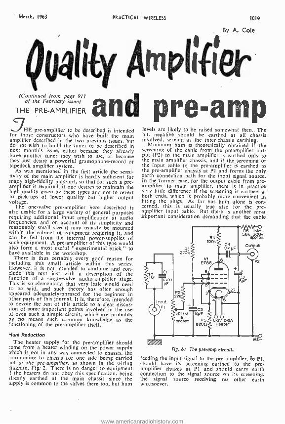
March, 1963 PRACTICAL WIRELESS 1019
By A. Cole
QuáIILy 4mplifier (Continued from page 911
of the February issue)
THE PRE -AMPLIFIER and 5HE pre -amplifier to be described is intended
for those constructors who have built the main amplifier described in the two previous issues, but do not wish to build the tuner to be described in next month's issue, either because they already have another tuner they wish to use, or because they just desire a powerful gramophone- record or tapedeck amplifier system.
As was mentioned in the first article the sensi- tivity of the main amplifier is hardly sufficient for many high- fidelity pick -ups, so that for such a pre- amplifier is required, if one desires to maintain the high quality given by these types and not to revert to pick -ups of lower quality but higher output voltage.
The one -valve pre -amplifier here described is also usable for a large variety of general purposes requiring additional input amplification at audio frequencies, and on account of its simplicity and reasonably small size it may usually be mounted within the cabinet of equipment requiring it, and can be fed from the internal power- supplies of such equipment. A pre -amplifier of this type would also form a most useful "experimental brick" to have available in the workshop.
There is thus certainly every good reason for including this small article within this series. However, it is not intended to continue and con- :hide this text just with a description of the function of a single -valve audio- amplifier stage. This is so elementary, that very little would need to be said, and such theory has often enough appeared adequately- phrased for the beginner in )ther parts of this journal. It is, therefore, intended :o devote the rest of this article to a clear discus- sion of some important points involved in the use )f even such a simple circuit, which are probably ny no means such common knowledge as the 'unctioning of the pre -amplifier itself.
4um Reduction The heater supply for the pre- amplifier should
some from a heater winding on the power supply which is not in any way connected to chassis, the ;ommoning to chassis for one side being carried nut at the pre -amplifier, as shown in the wiring liagram, Fig. 2. There is no danger to equipment f the heaters do not obey this specification, being already earthed at the main chassis since the supply is common to the valves there too, but hum
pre -amp levels are likely to be raised somewhat then.. The h.t. negative should be earthed at all chassis involved, serving as the inter -chassis earthing.
Minimum hum is theoretically obtained if the screening of the cable from the preamplifier out- put (P2) to the main amplifier is earthed only to the main amplifier chassis, and if the screening of the input cable to the pre -amplifier is earthed to the pre -amplifier chassis at Pl and forms the only earth connection path for the input signal source. In the former case, for the output cable from pre- amplifier to main amplifier, there is in practice very little difference if the screening is earthed at both ends, which is probably more convenient in fitting the plugs. As far has hum alone is con- cerned, this is usually true also for the pre - amplifier input cable. But there is another most irportant consideration demanding that the cable
RI 1M 1000
pF
Input P1
R3 270k
R2
R4 100k
C4 01pF
VI EF86
e
/ 2.7
22k
C2 VRI tM 1 81JF
lin. preset R5 6.3V 02A
8200 Heater
R6 H. 56k 300V
aPProx.
P2
C3 8NF
Fig. 6: The pre -amp circuit.
feeding the input signal to the pre -amplifier, fo Pl, should have its screening earthed to the pre- amplifier chassis at Pl and should carry earth connection to the signal source on its screening, the signal source receiving no other earth whatsoever.
www.americanradiohistory.com
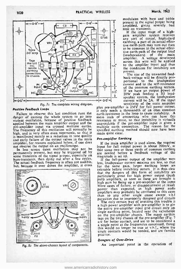
1020 PRACTICAL WIRELESS March, 1963
modulates with bass and treble O.8I - o s' - - present in the signal proper being
amplified, giving severely bad tone on transients.
If the input stage of a high - gain amplifier system receives any sort of casual, haphazard earthing, a part of its actual effec- tive earth -path may turn out then to be common to the actual effec- tive earth -path of the output load (loudspeakers) of the main amplifier. A voltage developed across this wire will be applied
t.5' to the amplifier input and thus the conditions for instability are present.
The size of the unwanted feed- back- voltage will be directly pro- portional to the loudspeaker current and to the self- resistance of the common earthing section. If we have an output power of 20W peak feeding a 5t] loud- speaker system, the loudspeaker
3.o' current will be 2A. If the input sensitivity of the main amplifies
p us pre -amplifier is 2MV for full power' output, it only needs a thousandth of an ohm common earth -resistance in the loop to cause instability. A mere. inch of connecting wire can have this resistance or more, so that instability is virtually unavoidable if the pre- amplifier input is given a
multiple earth connection. The reason for the specified earthing method should now have beer made quite clear.
Pre -amplifier Earthing If the main amplifier is used alone, the requirer
input for full output power is about 200mV, that some two or three yards of common earthing are needed before a feedback voltage of this magnitude is set up.
If the full -power output of the amplifier wen less, loudspeaker current maxima are less, so that for the same gain, larger earthing loops an tolerable before instability occurs. It is, thus Ilea: that the dangers of this form of instability an particularly great for high power output (push pull) amplifiers, as soon as these are brought t<
high gain by fixing up a pre -amplifier at the input More cases of failure, or disappointment at result poorer than expected, in high power audit amplifiers may probably be attributed to this cause than to any other single cause except v.h.f parasitics due to improperly designed grid circuits
The only certain way of avoiding this trouble ii
a high power amplifier with pre -amplifier is to giv the entire pre- amplifier input grid circuit only on single earthing point, located near the valveholde on the pre- amplifier chassis. The many earthin: tags on the tiny chassis of the pre -amplifier (Fig. 7
are for better contact, and are to be considered a a single point at the frequencies concerned, thougl this would no longer be true at v.h.f., where tru single contacts would be needed, and are familia practice.
Dangers of Over -Drive
An important point in the operation of
Side 2.0'
C2 +
000; 6
deep
M.G IIi* MG
©c
O
P2 e Outpu
Tags marked
MC. denote
earthing connections to chassis
P1 Input
MC
vi EF86
I1)
mc.r1 i 095' _L
405 - Fig. 7:
Positive Feedback Loops
Failure to observe this last condition runs the danger of causing the whole system to go into violent oscillation, because of positive feedback applied between the main amplifier output and the pre -amplifier input via crossed multiple earths. The frequency of this oscillation will normally be high, and is very often even supersonic, so that it is manifested merely as a reduction in tone quality and early failure of the output valves in the main amplifier, for reasons explained below, if one does not observe the output on an oscilloscope.
In less - severe cases oscillation may not be permanently present, but may be triggered off by some transients of the signal proper, especially on bass -transients, then dying out after a few cycles. The actual feedback frequency is often not audible, but, because it over drives the amplifier, it cross
The complete wiring diagram.
Fig. 8t The above -chassis layout of components.
www.americanradiohistory.com
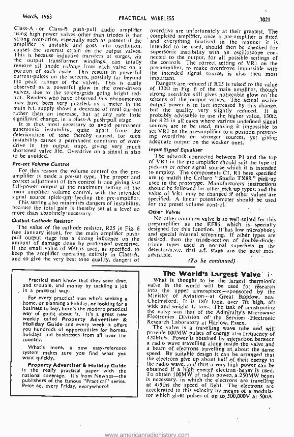
March, 1%3 PRACTICAL WIRELESS 1021
Class -A or Class -B push -pull audio amplifier using high power valves other than triodes is that strong over- drive, especially such as present if the amplifier is unstable and goes into oscillation, causes the severest strain on the output valves. This is because inductive transfers of surges, via the output transformer windings, can totally remove all anode voltage from each valve on a portion of each cycle. This results in powerful current -pulses on the screens, possibly far beyond the peak ratings of the valves. This is easily observed as a powerful glow in the over -driven valves, due to the screen -grids going bright red - hot. Readers who have observed this phenomenon may have been very puzzled, as a .meter in the main h.t. supply shows a decrease of total current rather than an increase, but at any rate little significant change, in a class -A push -pull stage.
It is thus most necessary to, avoid permanent supersonic instability, quite apart from the deterioration of tone thereby caused, for such instability causes a permanent condition of over- drive in the output stage, giving very much shortened valve life. Overdrive on a signal is also to be avoided. Pre -set Volume Control
For this reason the volume control on the pre- amplifier is made a pre -set type. The proper and correct adjustment of this control is one giving just full -power output at the maximum setting of the main amplifier volume control, with the intended signal source (pick -up :) ' feeding the pre -amplifier.
This setting also minimises dangers of instability, because the total gain is thereby set at a level no more than absolutely' necessary. Output Cathode Resistor
The value of the cathode resistor, R25 in Fig. 6 (see January issue), for the main amplifier push - pull output stage has a strong influence on the amount of damage done by prolonged overdrive. If the small value of 90û is used, as specified, to keep the amplifier operating entirely in Class -A, and so give the very best tone quality, dangers of
overdrive are unfortunately at their greatest. The completed amplifier, once a pre -amplifier is fitted and everything finalised in the manner it is intended to be used, should then be checked for supersonic instability with an oscilloscope con- nected to the output, for all possible settings of the controls. The correct setting of VR1 on the pre -amplifier, to make overdrove impossible with the intended signal source, is also then most important.
Dangers are reduced if R25 is raised to the value of 130ft in Fig. 6 of the main amplifier, though strong overdrive still gives noticeable glow on the screens of the output valves. The actual usable output power is in fact increased by this change, but the quality very slightly reduced. It is probably advisable to use the higher value, 13011, for R25 in all cases where various undefined signal sources are to be used, making it impossible to set VR1 on the pre- amplifier to a position prevent- ing overdrive on stronger sources, yet giving adequate output on the weaker ones. Input Signal Equaliser
The network connected between P1 and the top of VR1 in the pre- amplifier should suit the type of pick -up or other signal source which it is intended to employ. The components Cl, R1 here specified are to match the Collaro "Studio TX8S." pick -up used in the prototype. Manufacturers' instructions should be followed for other pick -up .types, and the value of VR1 may be changed if other values are specified. A linear potentiometer should be used for the preset volume control. Other Valves
No other common valve is so well suited for this pre -amplifier as the EF86, which is specially designed for this function. It has low microphony and special internal screening. If other types are desired, then the triode- section of double- diode- triode types used in normal superhets in the detector /a.v.c. first a.f. stage are the neXt mos advisable.
(To be continued)
Practical men know that they save time, and trouble, and money by tackling a job in a practical way.
For every practical man who's seeking a home, or planning a holiday, or looking for a business to buy, here's the modern practical way of going about it. It's a great new weekly called Property Advertiser & Holiday Guide and every week it offers you hundreds of opportunities for homes, holidays and businesses from all over the country.
What's more, a new easy- reference system makes sure you find what you want quickly.
Property Advertiser & Holiday Guide is the really practical paper with the national coverage. It's from Newnes -the publishers of the famous "Practical" series. Price 4d. every Friday, everywhere!
The World's Largest Valve What is thought to be the largest thermionic
valve in the world will be used for research into the upper atmosphere- sponsored by the Minister of Aviation -at Great Baddow, near Chelmsford. It is 18ft long, over 7ft high, 6ft wide and weighs 4f tons. The task of constructing the valve was that of the Admiralty's Microwave Electronics Division of the Services Electronic Research Laboratory at Harlow, Essex.
The valve is a travelling wave tube and will provide 100MW pulses of energy at a frequency of 420Mc /s. Power is obtained by interaction between a radio wave travelling along inside the valve and a beam of electrons travelling at about the same speed. By suitable design it can be arranged that the electrons give up about half of their energy to the radio wave, and thus a very high power can be obtained if a high energy electron beam is used. To obtain 100MW of radio power, a 250MW beam is necessary, in which the electrons are travelling at 4 /5ths the speed of light. The electrons are accelerated to this velocity by means of a modula- tor which gives pulses of up to 500,000V at 500A
www.americanradiohistory.com
1022 PRACTICAL WIRELESS March, 1963
our
IMUST commence this month's remarks by thanking all those readers who have sent me copies of the notes which I referred to in the
last issue. They had apparently written for details and after making the necessary notes had sent them on thinking I would be interested.
It was very good of them and the thought is appreciated, but as will be seen from the page I had already had details of this particular device. My main interest in this connection is, of course, with the electronic type of device which utilises the more or less standard " Yes" " No " circuits, these being so arranged that they act as switches for the various channels, and so far all those which I have seen have been terribly expensive to make up.
It will be obvious that the first circuit may consist of two relays, transistors or valve circuits only, to provide one of two channels, but then to provide any degree of selection the next channel must consist of at least three circuits, and so on, doubling up in places to provide the necessary alternative routes. This naturally leads to multiple relays or transistors, etc. and the expense steps up alarmingly.
Old Components
As I have mentioned before, this interest in electronic devices of various types has led to the need to find various components which are not apparently now available, and I become more surprised every day at the number of various bits and pieces which at one time were commonplace but which now, due apparently to the increasing use of transistors and the consequent reduction in size of components, have apparently ceased to be made.
Two items which I recently wanted for a small unit were an ordinary audio transformer and some
carbon resistors. Many of the shops which I
visited only stocked transistor type transformers, and I was informed at two or three shops that the larger "old-fashioned" component was no longer
wavelength By THERMION
.eing made! The same remarks apply to the carbon resistor.
These now all seem to be the miniature ceramic - cased component and it is impossible to modify the value slightly as one 'could do with the older corn - ponent, by filing away or scraping the component. Of course, r.c. coupling is now more or less universal in most valve equipment, as it is produc- tive of much higher quality, but the old audio transformer used to be very useful in some circuits.
Those who can remember the early Ferranti components, with their sectionalised windings will probably hold that they gave as high quality as a modern r.c. circuit, without any of the latter's drawbacks, and I wonder if the Rev. Bonavia Hunt has changed his views on this particular item?
For many test set -ups, a 3d. carbon resistor which can be changed in its value is a much more interesting proposition than a 3s. 6d. variable com- ponent -and it takes up much less room. No, the modern experimenter seems to be at a much greater disadvantage than many of us " old stagers ", who not only had to find out things for ourselves, but had the bits and pieces and the wherewithal with which to do it.
Two Hints Now to end this month with two hints which
may be found of use by some of those who find their main interest in " do it yourself experiment- ing ". The first concerns the drilling of a chassis after a set has been made up and is working - perhaps for some form of modification.
A hole may be needed in the chassis, and there is a risk of the aluminium dust or drilling swarf getting into awkward or unwanted places in the set. The problem is how to keep it all together till the drilling is completed.
I get the necessary tools together and just before drilling the new hole, put a fairly large dab of Evostik or other rubber cement on both sided of the chassis, round the punch mark where the hole is to be drilled.
Immediately start the drilling. and as the cement is not too quick drying, all the chips and dust remain held fast by the cement.
When the hole is completed leave it for the cement to dry, and then carefully lift the edge of the " dab" with a penknife and peel it off, when it will bring away all the unwanted mess with it.
The other hint is to use a rubber grommet for holding resistors and small diameter capacitors when they may have to pass through a metal screen, and this will hold them firmly (if they are chosen of suitable size) enabling wiring to be carried out to them, removing their weight from the wiring with consequent reduction in the risk of broken connections, and if needed provide all important screening in the wiring. Just small points but they can be very useful at times.
www.americanradiohistory.com
March, 1963 PRACTICAL WIRELESS 1023
R.S.T. VALVE MAIL ORDER CO Tel: MiTcham 6202
Open Daily to Callers
21 la STREATHAM ROAD, MITCHAM, SURREY. All Valves Brand New and Fully Guaranteed - Obsolete valves a speciality.
Quotations given on any type not listed. Send S.A.E. Special 24 Hour Express Mail Order Service
AC2/PEN ECC85 716 EY83 1216 PCC84 816 TDDI3C 211 ECC88 1216 EY86 71- PCC85 916 1716
AC2/PEN ECC9I 31- EY91 31- PCC88 1216 TH41 2716 DD 211- ECHO 716 EZ35 6f- PCC89 84 TY86F 12/6
AC1TP 32f- ECF82 8/6 EZ40 71- PCF83 91- U10 9/- AC/VPI-5-7 ECH3 2116 EZ41 71- PCF82 7/- U12 91- 17/6 ECH2I 211- EZ80 Gf6 PCF84 1216 U14 9/- AZ 151- ECH35 I01- EZ81 6/6 PCF86 1216 U22 81-
AZ3I I04 ECH42 9/6 EZ90 7f- PCL82 91- U24 21f- 836 91- ECH8I 8f- EI148 21- PCL83 1116 U25 12/6 CIC 101- ECH83 816 FC2 ISr- PCL84 10/6 U26 10/- CBL31 2116 ECL80 8/- FC2A 17/6 PCL85 1016 U31 91- CCI-135 211- ECL81 IOf- FC4 I51. PCL86 12/6 U35 1716 CL33 151- ECL82 9/6 FCI3 1St- PENA4 1716 U37 1716 CYI 15!- ECL83 I016 FCI3C 1716 PENB4 17/6 1143 816 CY31 151- ECL86 1016 FW4/500 91- PEN4DD 1)47 1216 D77 41- EF6 211- 91-
24/- DAC32 9/6 EF9 2116 GZ3Ó0 1016 PEN4VA U52 ¡_ DAF91 616 EF22 141- GZ32 1016 1716 U76 716 DAF96 81- EF36 41- GZ33 1913 PEN36C20/- U78 44 DCC90 1216 DF33 101-
EF37 8f- EF37A 8f-
GZ34) 1316 GZ37 1913
PEN45 10f- PEN45DD
U145 1016 U191 IS/6
DF91 4r EF39 4/- HABC86101- 251- U251 12/6 DF92 712 EF40 IS/- HL41 81- U281 151- DF96 0/_ EF41 8r- HL4IDD 8/6 PEN46 Sf_ U282 1916 DF97 1116 EF42 101- HL92 816 PEN453DD 0301 2216 DH63 61- EF50A 316 HL133DD U329 1216 DH77 71- EF50E 31- 9r6 PENDD4020 U339 IS/- DK32 1116 EF80 5f HN309 2616 201- U403 10f- DK9I 7/3 EF85 5/- 1W4/350 10r- PL33 I5/- U404 10/- DK92 8/6 DK96 816
EF86 91- EF.^J9 91-
IW4/500101- KT33C 0/-
PL36 1216 PL38 211-
U801 1919 UABC80 7/-
DL33 016 DL35 1016
EF9I 4f- Ef92 4/-
KT36 1716 KT55 17/6
PL8I 1116 PL82 8/-
UAF42 816 UB4I 716
0L91 810 EF95 Sl- KT6I :,16 PL83 10/6 UBC41 816 DL92 616 EF98 10/- K166 I5/- PL84 816 UBC81 101 DL93 710 EF183 1016 KT76 101- PL820 181- UBF80 816 DL94 7/6 EF184 I016 KT81 IS/- PM24M 1316 UBF89 716 DL96 810 EK32 816 KTW61 81- PX4 I51- UBL21 201- EA50 21- EL2 251- L63 S/- PX25 25f- UCC84 1016 EABC80 51- EL3 2116 LN 152 81- PY31 151- UCC85 716 EAC9I 41- EL6 :11- LN309 1116 PY32 1216 UCF80 13/6 EAF42 916 EL32 4/6 LZ319 12/6 PY33 1216 UCH2I 201- EB34 216 EB4I 51-
EL33 IO/- EL34 ISl-
MKT4 1716 MS4B 1716
PY80 716 PY81 716
UCH42 9/6 UC I-181 8/-
E891 41. EL35 10r- MVS/PEN PY82 71- UCL82 10/- EBC3 211- EL37 I7lS 1716 PY83 81- UCL83 1316 EBC33 416 EBC4I 8/6
EL38 1916 EL41 I0/-
MVS/PENB 1716
PY88 101- PY300 10/
11F41 716 UF42 716
EBC81 IOf- EL42 101- MU14 91- PZ30 151- UF83 7r EBF80 816 EL8I 1216 MX40 W. S95/I0101- UF35 716 EBF33 816 EL84 619 N18 81- QS150/IS UF86 1216 EBF39 81- EL05 101- N37 141. I0r- UF89 616 EBLI 211 EL90 816 N78 1716 R2 IOf- UL41 81- EBL2I 211- EL91 4r- N108 151. R3 10r- UL44 201- EBL31 2116 EL95 1016 N308 20/- R16 1716 UL46 1416 ECC35 81. EM80 816 N339 301- R19 161- UL84 71. ECC40 151- EM81 816 N369 10/6 R20 161- UL85 716 ECC81 51- EM84 916 OD3 5f- SP41 316 UM80 1316 ECC82 51- EM85 101- OZ4 516 5P61 316 URIC 151- ECC83 716 EYS I 8/6 P2 101- 141 15r- UU6 191- ECC84 816 EY8I 816 PABC80 131- TDD4 1216 UU8 IV-
METAL RECTIFIERS R M I 513 1 4A86 17/6 1 6 R D- 2-2-8- I 121-
RM2 716 14A97 251- 16RE 2 -1-8 -1 8/6 RM3 719 14A100 271- I8RA I -I-8 -I 416 RM4 141- I4RA I -2-8 -2 1716 (FC301) 18RA 1 -1 -16.1 616 (FC I16) RM5 1916 14RA I -2.8.3 19/- (FC31) I8RA I -2-8.1 II/-
16RC I- 1 -16 -1 816 I8RD 2 -2-8 -1 15/- (FC 124)
TERMS OF BUSINESS C.W.O. or C.O.D. 312 PACKING CHARGE ON ALL C.O.D. ORDERS. POSTAGE 6d. per VALVE
UU9 716 6AK8 UYIN 12/6 6AL5 0Y21 1516 6A115 UY4I 716 6A116 UY85 7r- 6AQ5 VMS4B 1216 6AQ3 VP4 15/- 6AT6 VP4A 15/- 6AU6 VP4B 15r- 6B8G VR105/307f- 68A6 VRI50/307/- 68E6 W6I Ilf- W75 5f W77 41- WBI 61- W8IM 6/- X41 IS/- X61M 10 X65 12/6 X76 12/6 X76M 1216 X78 241- X79 42/6 X81 101- Y61 101- Y63 101- Z63 7/6 Z66 101- Z77 41- Z152 5r- OZ4 51- A7 1116 C5 1016 D5 816 D6 10/- H5 9/6 L4 51- LNS 416 N5 9/6 R5 713 S4 8/- 55 616 T4 41- 115 519
27 24/9 3A4 . 51- 3A5 1016 3Q4 81- 3Q5 91- 3S4 7r- 3V4 716 5U4 41- 5V4G 719 5Y3G 71- 5Y3GT 8/6 5Z4G 916 5Z4GT 1216 6A7 91- 6A8G 8/6 6A8GT 1316 6,4C7 61+ 6AK5 51-
7f6 4/. SI- 4/- 616 93 61- 9/- 31- 6f- 6/-
6BG6G IS/- 6BH6 8/- 61316 6/- 6BQ7A 1216 6BR7 10/6 6857 12/6 6BW6 8/- 6BW7 6C4 316 6C5GT 8f- 6C6 6/6 6C9 1216 6CD6G 27/6 6CH6 10/- 602 41- 6136 516 6E5 10r- 01 10/6 6F6 619 6F12 41- 6F13 10/- SF14 101- 6F15 1216 6F19 I2/6 6F23 1016 6F25 16/6 6F26 1316 6F33 5/6 6H6 2/- 615 516 615G 4/6 615GT 5/- 647 7/6 617G 5/- 617GT 716 6K7 V6 6K7G 21- 6K7GT 716 6K8 916 6K8G 51- 6K8GT 916 6K25 181- 6L1 IOf- 6L6 7/6 6L7 10f- 6L18 10/- 6L19 154 6L34 916 6N7GT 916 6P25 1016
6P28 1216 6Q7 916 6Q7G 6/6 6Q7GT 8/6 65A7 7/- 6SC7 816 6SF5 IOf- 6SG7 7r- 651-17 61- 6517 6/6 6SK7 5r6 6SL7GT 61- 6SN7GT 516 6SQ7 816 6U4GT IOf- 6U5G 716 6V6G 4f6 6V6GT 81- 6X4 4/6 6X5G 61- 6X5GT 8/6 6/30L2 10/- 7135 1216 7B6 10/- 7137 8/6 7C5 8f- 7C6 816 705 IS'- 706 15'- 708 I Sf- 7H7, 7f6 7R7 ICI- 7S7 10/- 714 716 803 41- 9BW6 12/6 0C1 12/6 0C2 17/6 OF! IOf- 0F3 1216 OF9 1216 OLDII 1St- OP 13 IS/- 0P14 19r- 105 2316 2A6 616 2AH8 91- 2AT6 716 2AT7 2AU6 17/6 2AU7 Sf- 2AX7 51- 2BA6 716 2BE6 7/6 2BH7 101- 2C8 816 215GT 4f- 2J7GT 816 2K7GT 5/- 21C8GT IOf. 2Q7GT 6/6 2SA7 816
125J7 84 12SK7 6f- 12SL7 8f. 125N7 IOf- I2SQ7 816 I4H7 10f- 14R7 I0/- 1457 16f- 19AQ5 8f- 19BG6G 15r- 200 I I0/- 2002 21r- 20F2 17/6 20L1 24f- 20P1 . 151- 20P3 24r- 20P4 2316 20P5 244 25A6 81- 25L6 25Y5 8/- 25Y5G 81. 25Z4 716 25Z5 8/- 25Z6 816 27SU 19/6 30C I 9f- 30CI5 1216 30F5 10/- 30FLI 1016 30L1 810 30LIS llfó 30P4 204 30P12 10/- 30P16 9/- 301,19 21/- 30PL I 151- 30PL 13 12/6 30PL14 1616 35A5 1716 35L6GT 816 35W4 716 35Z3 16/- 35Z4 716 35Z5 816 40SUA 15/- 415TH 21/ 42 1216 SOCS 10f- 50CD6G27/6 50L6 816 53KU 12/6 75 8/. 78 7'6 80 91- 85 1716 85A2 1216
185BT 301- 305 13f. 807B 51. 807A 6/-
TRANSISTOR BARGAINS 0C44 6f- 0075 6f- 0082 8f- 0C45 7f- 0077 6f- 0082D 8f- OC71 51. 0081 6f- 0074 6f- 0081 D 6f-
SILICON RECTIFIERS 400 volts 350 mA ... ... ... 12/6 each
SETS OF VALVES IRS, 155, 114, 3S4, 3V4 Set of 4, 1916 DAF9I, DF9I, DK9I, DL92, DL94 Set of 4, 1916 DAF96, DF96, DK96, DL96 .. Set of 4, 2716
www.americanradiohistory.com
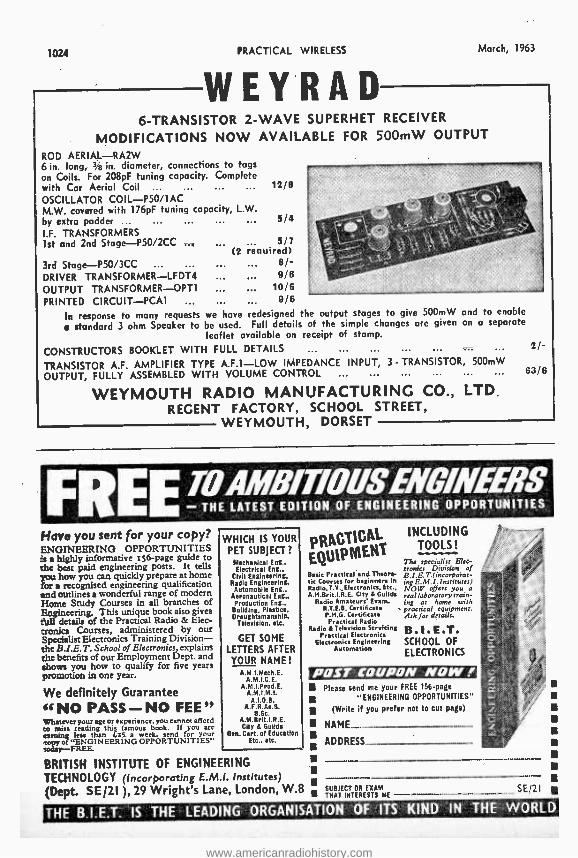
1024 PRACTICAL WIRELESS
WEYRAD March, 1963
6- TRANSISTOR 2 -WAVE SUPERHET RECEIVER
MODIFICATIONS NOW AVAILABLE FOR 500mW OUTPUT
ROD AERIAL -RA2W 6 in. long, 3i8 in. diameter, connections to tags on Coils. For 208pF tuning capacity. Complete with Car Aerial Coil ... 12/8
OSCILLATOR COIL- P50 /1AC M.W. covered with 176pF tuning capacity, L.W. by extra padder ... ... ... ... 5/4 I.F. TRANSFORMERS 1st and 2nd Stage- P50 /2CC
3rd Stage- P50 /3CC DRIVER TRANSFORMER -LFDT4 OUTPUT TRANSFORMER -OPT1 PRINTED CIRCUIT -PCA1
In response to many requests we have redesigned the output stages to give 500mW and to enable
standard 3 ohm Speaker to be used. Full details of the simple changes are given on a separate leaflet available on receipt of stamp.
CONSTRUCTORS BOOKLET WITH FULL DETAILS ...
TRANSISTOR A.F. AMPLIFIER TYPE A.F.1 -LOW IMPEDANCE INPUT, 3 - TRANSISTOR, 500mW
OUTPUT, FULLY ASSEMBLED WITH VOLUME CONTROL ...
WEYMOUTH RADIO MANUFACTURING CO., LTD. REGENT FACTORY, SCHOOL STREET,
WEYMOUTH, DORSET
5/7 (2 required)
6/- 9/8
10/6 9/6
FRE ¡O4MBfflOUSENGINEERS - THE LATEST EDITION OF ENGINEERING OPPORTUNITIES
Have you sent for your copy? ENGINEERING OPPORTUNITIES is a highly informative 156 -page guide to the best paid engineering posts. It tells you how you can quickly prepare at home for a recognised engineering qualification and outlines a wonderful range of modern Home Study Courses in all branches of Engineering. This unique book also gives full details of the Practical Radio & Elec- tronics Courses, administered by our Specialist Electronics Training Division - the B.I.E.T, School of Electronics, explains the benefits of our Employment Dept. and shows you how to qualify for five years promotion in one year.
We definitely Guarantee
46 NO PASS- NO FEE" Whatever your age or experience, you cannot afford to miss reading this famous book. If you are earning less than £25. a week, send for your
0 o("ENGINEERING OPPORTUNITIES" <oaay -FREE
BRITISH INSTITUTE OF ENGINEERING
WHICH IS YOUR PET SUBJECT?
Mechanical Eng.. Electrical Eng.,
Civil Engineering, Radio Engineering.
Automobile Eng.. Aeronautical Eng., Production Eng.,
Building, Plastics, Draughtsmanship,
Television, etc.
GET SOME
LETTERS AFTER
YOUR NAME! A.M I.Mech.E.
A.M.I.C.E. A .M.I. Prod. E.
A. M.I.M.I. Á.1.0.B.
A.F.R.Ae.S. B.Sc.
A. M. B rit.I. R.E. City 6 Guilds
Gen. Cert. of Education Etc., etc.
TECHNOLOGY (Incorporating E.M.I. Institutes) (Dept. SE /21 ), 29 Wright's Lane, London, W.8
EQUIPMENT Basic Practical'and Theore- tic Courses for beginners in Radio, T.V., Electronics, Etc., A.M.Brit.I.R.E. City 6 Guilds
Radio Amateurs Exam. R.T.E.B. Certificate P.M.G. Certificate Practical Radio
Radio 6 Television Servicing Practical Electronics
Electronics Engineering Automation
INCLUDING TOOLS!
The specialist Elee- cronies Division of B.l. E. T.(incorpoia t-
ng E.M.J. Institutes) NOW offers you a real laboratory train- ing at home with practical equipment. Ask for details.
B.1.E.T. SCHOOL OF
ELECTRONICS
POST COUPON NOW I
I ADDRESS
Please send me your FREE 156 -page
"ENGINEERING OPPORTUNITIES"
(Write if you prefer not to cut page)
NAME
SUBJECT OR EXAM THAT INTERESTS ME
THE B.I:E:T: 1S THE LEADING ORGANISATION OF ITS KIND IN THE WORLD
www.americanradiohistory.com
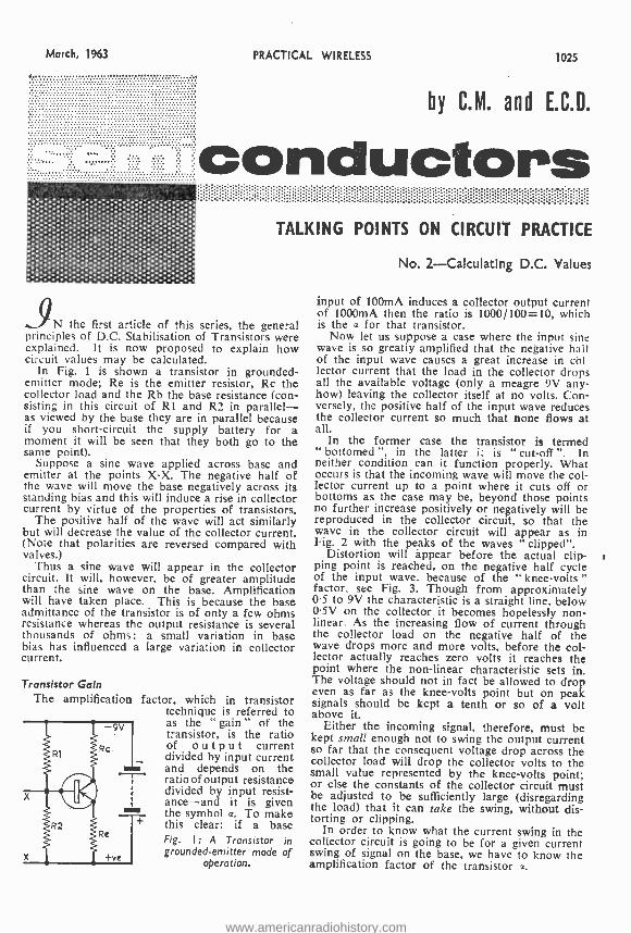
PRACTICAL WIRELESS 1025
by C.M. and E.C.D.
conductors
9
TALKING POINTS ON CIRCUIT PRACTICE
N the first article of this series, the general principles of D.C. Stabilisation of Transistors were explained. It is now proposed to explain how circuit values may be calculated.
In Fig. 1 is shown a transistor in grounded - emitter mode; Re is the emitter resistor, Rc the collector load and the Rb the base resistance (con- sisting in this circuit of Rl and R2 in parallel - as viewed by the base they are in parallel because if you short -circuit the supply battery for a moment it will be seen that they both go to the same point).
Suppose a sine wave applied across base and emitter at the points X -X. The negative half of the wave will move the base negatively across its standing bias and this will induce a rise in collector current by virtue of the properties of transistors.
The positive half of the wave will act similarly but will decrease the value of the collector current. (Note that polarities are reversed compared with valves.)
Thus a sine wave will appear in the collector circuit. It will, however, be of greater amplitude than the sine wave on the base. Amplification will have taken place. This is because the base admittance of the transistor is of only a few ohms resistance whereas the output resistance is several thousands of ohms: a small variation in base bias has influenced a large variation in collector current.
Transistor Gain The amplification factor, which in transistor
technique is referred to as the " gain " of the transistor, is the ratio of output current divided by input current and depends on the ratio of output resistance divided by input resist- ance -and it is given the symbol a. To make this clear: if a base Fig. I: A Transistor in grounded- emitter mode of
operation.
{R2
x
No. 2- Calculating D.C. Values
input of 100mA induces a collector output current of 1000mA then the ratio is 1000 /100 =10, which is the a for that transistor.
Now let us suppose a case where the input sine wave is so greatly amplified that the negative hail of the input wave causes a great increase in col lector current that the load in the collector drops all the available voltage (only a meagre 9V any- how) leaving the collector itself at no volts. Con- versely, the positive half of the input wave reduces the collector current so much that none flows at all.
In the former case the transistor is termed " bottomed " in the latter is is " cut -off ". In neither condition can it function properly. What occurs is that the incoming wave will move the col- lector current up to a point where it cuts off or bottoms as the case may be, beyond those points no further increase positively or negatively will be reproduced in the collector circuit, so that the wave in the collector circuit will appear as in Fig. 2 with the peaks of the waves " clipped ".
Distortion will appear before the actual clip- i ping point is reached, on the negative half cycle of the input wave, because of the " knee -volts " factor, see Fig. 3. Though from approximately 0.5 to 9V the characteristic is a straight line, below 0.5V on the collector it becomes hopelessly non- linear. As the increasing flow of current through the collector load on the negative half of the wave drops more and more volts, before the col- lector actually reaches zero volts it reaches the point where the non -linear characteristic sets in. The voltage should not in fact be allowed to drop even as far as the knee -volts point but on peak signals should be kept a tenth or so of a volt above it.
Either the incoming signal, therefore, must be kept small enough not to swing the output current so far that the consequent voltage drop across the collector load will drop the collector volts to the small value represented by the knee -volts point; or else the constants of the collector circuit must be adjusted to be sufficiently large (disregarding the load) that it can take the swing, without dis- torting or clipping.
In order to know what the current swing in the collector circuit is going to be for a given current swing of signal on the base, we have to know the amplification factor of the transistor a.
www.americanradiohistory.com
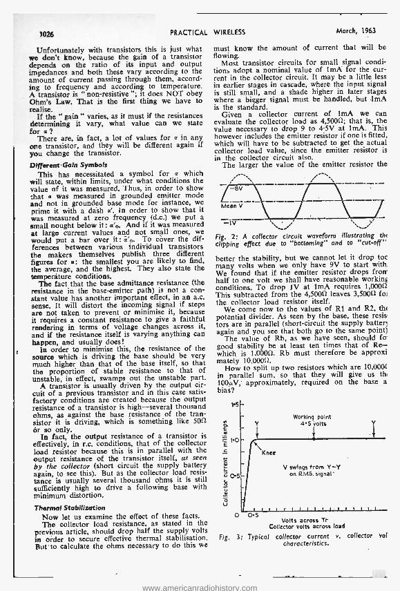
1026 PRACTICAL
Unfortunately with transistors this is just what we don't know, because the gain of a transistor depends on the ratio of its input and output impedances and both these vary according to the amount of current passing through them, accord- ing to frequency and according to temperature. A transistor is " non -resistive "; it does NOT obey Ohm's Law. That is the first thing we have to realise.
If the " gain " varies, as it must if the resistances determining it vary, what value can we state for a?
There are, in fact, a lot of values fora in any one transistor, and they will be different again if you change the transistor.
Different Gain Symbols This has necessitated a symbol for a which
will state, within limits, under what conditions the value of it was measured. Thus, in order to show that a was measured in grounded emitter mode and not in grounded base mode for instance, we prime it with a dash a'. In order to show that it was measured at zero frequency (d.c.) we put a small nought below it: a'o. And if it was measured at large current values and not small ones, we would put a bar over it: ácó. To cover the dif- ferences between various individual transistors the makers themselves publish three different figures for a: the smallest you are likely to find, the average, and the highest. They also state the temperature conditions.
The fact that the base admittance resistance (the resistance in the base -emitter path) is not a con- stant value has another important effect, in an a.c. sense. It will distort the incoming signal if steps are not taken to prevent or minimise it, because it requires a constant resistance to give a faithful rendering in terms of voltage changes across it, and if the resistance itself is varying anything can happen, and usually does!
In order to minimise this, the resistance of the source which is driving the base should be very much higher than that of the base itself, so that the proportion of stable resistance to that of unstable, in effect, swamps out the unstable part.
A transistor is usually driven by the output cir- cuit of a previous transistor and in this case satis- factory conditions are created because the output resistance of a transistor is high -several thousand ohms, as against the base resistance of the tran- sistor it is driving, which is something like 5011
or so only. In fact, the output resistance of a transistor is
effectively, in r.c. conditions, that of the collector load resistor because this is in parallel with the output resistance of the transistor itself, as seen by the collector (short circuit the supply battery again, to see this). But as the collector load resis- tance is usually several thousand ohms it is still sufficiently high to drive a following base with minimum distortion.
Thermal Stabilization Now let us examine the effect of these facts. The collector load resistance, as stated in the
previous article, should drop half the supply volts in order to secure effective thermal stabilisation. But to calculate the ohms necessary to do this we
WIRELESS March, 1963
must know the amount of current that will be flowing.
Most transistor circuits for small signal condi- tions adopt a nominal value of 1mA for the cur- rent in the collector circuit. It may be a little less in earlier stages in cascade, where the input signal is still small, and a shade higher in later stages where a bigger signal must be handled, but 1mA is the standard.
Given a collector current of ImA we can evaluate the collector load as 4,50012; that is, the value necessary to drop 9 to 4.5V at 1mA. This however includes the emitter resistor if one is fitted, which will have to be subtracted to get the actual collector load value, since the emitter resistor is in the collector circuit also.
The larger the value of the emitter resistor the
Mean V
Fig. 2: A collector circuit waveform illustrating the
clipping effect due to "bottoming" and to "cut -off"
better the stability, but we cannot let it drop toc many volts when we only have 9V to start with. We found that if the emitter resistor drops from. half to one volt we shall have reasonable workini conditions. To drop 1V at 1mA requires 1,00012 This subtracted from the 4,50012 leaves 3,5000 foi the collector load resistor itself.
We come now to the values of R1 and R2, th<
potential divider. As seen by the base, these resis tors are in parallel (short- circuit the supply batter] again and you see that both go to the same point)
The value of Rb, as we have seen, should fo good stability be at least ten times that of Re- which is 1,00012. Rb must therefore be approxi mately 10,00012.
How to split up two resistors which are 10,000f in parallel sum, so that they will give us the
100µV, approximately, required on the base a bias?
1.5
V
O U
Working point 45 volts
}
Knee
V swings from Y -Y on R.MS. signal'
ccccriccccccccicc 0 O5
Volts across Tr Collector volts across load
Fig. 3: Typical collector current v. collector vol characteristics.
www.americanradiohistory.com
March, 1963 PRACTICAL WIRELESS 1027
Brand 6AK7 61- checked 6AMS Sr-
6AM6 4r- 6AQ5 7r- VALVES 6AT6 51-
AL60 61- 6B7 51-
AR8 51- 6BM 516
ARDD5 2t. 216 6C4 2r- ARP3 3r- 6C4
ARP4 3/6 6C5 41- ARPI2 3r- 6CFG 31-
ARP21 516 6C8G 3r-
ARP24 316 6C8G Sr-
ARP34 4/- 6D6 31-
ARTF12 7r- 6F5G 513
ATP4 219 6F6G 41-
ATP7 516 6F7 51-
AU Sr- 6F5GT S/9
AU4 51- 6F8G 51-
AW3 4/- 6F12 4/6
AZ3I 71- 6F13 51- 6F33 3/6 BS4A 516 6G6G 216 BT45 IS /- 6H6M 116 BT9B 201. 6J5 316 BT83 2216 615G 31- CV54 51-
CV7I 31- 616 3/6
CVI02 II. 6J7G Sr.
CV264 201- 6K6GT 6/- CV4014 8f- 6K7G 21-
CV4015 71- 6K7GT 419
CV4025 101- 6KBG 5/9
CV4046 40 /- 6K8GT 8/3 CY31 6f- 6K8M 016
DI 116 6L5G 61-
D41 313 6L6 91-
077 413 6L6G 61.
DA30 12/6 6L7G 416
DAF70 351- DAF91 6r- DAF96 716 DD41 41- DETS 1St- DET19 316 DET20 21- DF39 41- 0172 716 DF91 41- DF96 7/6 DK96 713 0L92 6r- DL94 6f- DL95 7/6 EA50 116
new, individually and guaranteed
EABC80 713 EAC9I 316 EAC9IW716 EB34 116 EB9I 319 EBC33 71- EBC41 719 EBC90 51- EC52 8f. EC70 I0f- EC93 20r- EC9I 31- ECC8I 5'6 ECC82 616 ECC83 7r- ECC84 7r- ECC85 8r- ECC91 4f- ECF80 1016 ECF82 816 ECH8I 716 ECL80 716 ECL82 816 EF36 3f6 EF37A 71- EF39 41- EF50 116 EF54 313 EF55 Sf- EF70 41- EP73 61- EF80 516 EF85 6/6 EF86 7r- EF89 71- EF91 'r6 EF92 31- EF95 SI. EL32 319 EL33 71. EL35 61- EL41 81. EL42 81- ELB4 71. EL91 416 EM83 8r. EM84 91- EN3I 10r. EP7I 616
=P72 51- ESU208 6r- EY51 8/- EY86 8/- EY91 31- EZ40 7r- EZ4I 619 EZ80 61- EZ81 619 FW4 /5006/6 GI/236G 91- G 120, I B 9f- GL450 10r. GL464A 10f- GU20/21401- GZ32- 9/- H63 71- HK54 51- HL23 61- HL23DD 6r- HVR2 1216 KRN2A 19f. KT32 8r- KT8 22/6 KT33C 41. KT44 6/3 KT63 51- KT76 101- KTW6I 6r- KTW62 61. KTW63 616 KTZ4I 6r- KTZ63 81- MH4 3/6 MH4I 51- ML4 41-
MS /PEN 6r- 083 7r- 0C3 516 OD3 6/- OZ4 41- PCC84 71- PCC85 8/- PCF80 71- PCF82 81- PCL82 016 PCL83 101- PCL84 91-
PEN45 4/6 PEN46 51- PEN65 6r6 PEN220A 3f- PL36 1016 PL81 9r- PL82 81- PL83 8/- PT15 101- PT25H 7/6 PX4 191- PX25 9r- PY32 12r- PY80 6/9 PY81 71- PY82 7/- PY83 713 PZI-35 91- QP21 61- QP25 Sr- Q595/10 619 QV04/7 7/- R3 10- R3/10 4/- REL2I 25/- RK34 216 RX235 101- SP2 3'6 SP13C 4/6 SP41 2r6 SP61 2/- STV280/40
1216 STZ280/80
SOr- SU2150A4f9 T41 71- TP25 151. TT 3r TTI5 251 TZ20 16/- U12/14 8/- U17 51- U18 6/6 U27 8/- U52 51- UCI-142 716 UBF80 .816 UL11 Sr- UL12 51- UL41 71- UL84 716 UU9 Sf6 UY41 6/- UY85 6/6
VP23 31- VP4I 5r6 VR99 8r- VRI05/30516 VR I50/30 6r- VT4C 25/- VU39 6f- W31 71- X66 8f- Y63 51- Y65 41- Y66 8/- Z31 61- A3 3/- A5GT Sr- CSGT 716 D8GT 61- E7G 715 G6GT 6/ L4 3/- LD5 51- R5 6/- S4 51- 55 516 14 41- W4 6/-
2A3 51- 2A5 6/- 2A6 71- 2C34 2r6 2C42 25r- 2C46 30/- 2X2 4r. 3A4 Sr- 3B7 Sr- 3B24 51- 3E29 (829B) 60/-
3Q4 6r- 3Q 354 Sf- 3V4 6/- 5R4GY 91- 5T4 91- 5U4G Sf- 5V4G 8r- 5Y3G 31- 5Y3GT Lr- 5Z4 Cr6 5Z4G 71- 6AB7 4r- 6AC7 3/- 6AG5 31- 6AG7 6/- 6A37 31- 6AK5 51-
6L34 4/6 6N7G 519 6N7GT 61- 6Q7G 61- 6R7 6f- 65C7 516 6SC7GT 51- 6507 5f- 6SH7 31- 6517GT 4/9 6S17Y 6/6 65K7 51- 6SL7GT 616 65N7GT 416 6SQ7 61- 6557 3f- 6V6G 41-
AND MANY OTHERS IN STOCK, INCLUDING CATHODE RAY TUBES A below 101 -. 11- P. & P. 216 over 101 -. Orders over £3, P. & P. free. C.O.D. 216 ex BRAND NEW ORIGINAL SPARE 53 TRANSMITTER SPARES. Full PARTS FOR AR88 RECEIVERS, range. Price list on application. Please write your requirements. H.R.O. Senior. Table Model. In MARCONI RECEIVER TYPE CR excellent, fully chacked, and tested 100/2 tested and aligned 132.10.0 Carr. LI, condition (without coils and power pack), TELEPHONE HANDSET. Standard 515.13.0. As above but rack mounted G.P.O. type. New 121 -. P. & P. 21 -. model, 014.10.0. CONNECTORS FOR TCS RECEIVER, TRANSMÌTTER AND Individual frequency coils for above REMOTE CONTROL, with original LI each set or set of 9 E8. Either model plugs on both ends. New 51.17.6 each P. & P. 216. SPECIALLY BUILT POWER PACK for TCS receivers, 230 volts A.C. mains, including 6X5GT valve. E3.10.0. Carr. 5f -. R.I09 RECEIVER. Covering 2-8 Mc /s. 6 v. D.C. with set of spare valves and carrier. Brand new in original packing case. 56.18.0 including delivery in U.K. R.I09A RECEIVER. Covering 2 -12 Mc /s., 57.18.0. "CONNECT AND FORGET - CANNOT OVERCHARGE" "ESS- TRON" MARK I AUTOMATIC BATTERY CHARGER. Initial charging rate 6 -7 amps. The charging rate auto- AERIALS I Ift. long. 2ft. long when macically adjusts itself to the charge in the folded, IV-. P. & P. 2f-. battery. Automatic current and voltage control. Patented application of magnetic amplification to battery charging. Indi- cator lights show battery fully charged, receiving charge, incorrectly connected or
P C RADIO LTD. faulty cells. Mains voltage 200/250 v. Built for 6 or 12 v. batteries. Measure-
170 GOLDHAWK ROAD, W. 12 ments 7 x 5 x 5 1in. Weight 8} lb. Price 67.19.6. P. & P. 316. Shepherd's Bush 4946
carriage £1.10.0. Power pack for above. British made, A.C. 110/200/250 v., S9/6. Postage 41 -, CARBON INSET MICROPHONE, G.P.O. type, 216. P. & P. Ir6. COLLINS VARIABLE CONDEN- SERS. Size 4 x I{ x I:in. 250pF. Ideal TX Pi output circuits. 816. P. & P. 116.
80W 12V PETROL DRIVEN CHARG- ING SETS. Very compact, in fully guaranteed condition, 1E12.10.0, Carr. LI. RE- ENTRANT LOUD HAILERS. 500 ohms, approx. 20w. 16.10.0. Carr. 101-
6V6GT 6/- 6X4 Sr- 6XSGT 416 6Y6G 61- 6Z4 5/- 7B7 716 7C6 71- 7C7 51- 7H7 713 7Q7 71- 7V7 Sr- 7Y4 S/- 7Z4 4/- 802 216 9D2 3/- 2A6 216 2AH7 Sr- 2AT7 5/6 2AU6 91- 2AU7 616 2AX7 7r- 2C8 2E I 20r- 2H6 2/- 215GT 316 217GT 81. 2K7GT 4/6 2K8M 716 2Q7GT 414 2SA7 7f- 2SC7 4/- 2SG7 3f- 2SH7 3/- 2517 Sr- 2SK7, 316 2SL7 519 2SN7 519 2SR7 51. 2Y4 2/- 4L7 7/- 502 61-
20A2 1716 2186 9t- 25L6GT 719 30 Sr. 35L6GT 81- 35T 1716 35Z4GT 71- 37 41- 42 sr- 38 41- 58 61. 59 61- 75 516 76 Sf-
77 61- 78 71- 80 S/6 81 9r- 82 84 85A3 15r- 89 6r- 210VPT 7-pin 216
220TH 41- 250TH 19 350B 81- 363A Sr- 393A ISr- 705A 1,51. 7I5B 601- 717A 816 801 6r- 803 2216 805 30/- 807 (selec- ted) 516
807BR Sf- 808 810 813 815 816 829A 832 832A 843 866A 930 954 955 956 957 958A
81. 80r- 60f- 401- 301- 3C 1-
1S1- 351- 714
14r- 81. 4'- 216 21- 51- 4r-
1616 31- 1619 5'-
620 61- 1626 416 1629 4/6 4043C 1316 4063 81- 6064 lot- 6065 B/- 6120 41- 6516 81- 7193 1/9 7475 31- 8013A 251- 8020 101-
9001 31- 9002 516 9003 6/- 9004 2/6 9006 216
Cathode Ray Tubes ACRI IS/- ACRI I 1S1- ACRI3 501. CV995 CV I596
E4Ì 03/8455 - 251.
VCR97 281. VCRX258 (with scann- ing coil) 45/- VCR 138 301. VCR I 39A
351. 3FP7 251 - SBPI 3S1- 5CPI 4216 5FP7 45r- 5FP7A 25/. 7ßP7 401- 120P7 601-
Photo Tubes
CMGB 91- GSI6 1216
Special Valves
2131 45e- 3A/I481 451- 31192/E
537.10 4331 535 4150 135 5021 E3 723A/ B SOr- 725A 301- 726A 27/6 ACTE 160/ - CV193 301- CV238 70 /- CV980 3/. KR6 /3 E4 LS7B 301 - WL4I7A
151.
ND SPECIAL VALVES. All U.K. Orders ra. Overseas Postage extra a costs.
AMERICAN WIRE RECORDER/ REPRODUCER UNIT. Facilities for recording from Dynamic or Carbon microphone and radio. I knob operation for recording, rewinding and erasing Neon recording level indicator. Internal speaker. Mains 110 v. Supplied with outer transformer, carbon mike and wire magazine for I hour's operation and headphones. Price 118.0.0. P. & P. LI. Spare Wire Magazine 50f.. Dynamic mike and stand E4. R.209 RECEPTION SET. A 10 -valve high -grade Superhet Receiver with facili- ties for receiving R/T (A.M. or F.M.) and G.W. frequency I Mc /s -20 Mc /s. Hermeti- cally sealed. Built on miniature valves and incorporating its own vibrator power supply unit driven by a 6 v. battery (2 point connector included). The set pro- vides for reception from rod, open -wire or dipole aerial with built -in loudspeaker or phone output. Dimensions: Length 12ín., width 8in., depth 9in. Weight 231b. In as new, tested and guaranteed condi- tion, L23.10.0, including special head- phone and supply leads. Carr. LI. RECEIVER TYPE R.206. Frequency 0.55 Mc /s to 30 Mc /s in 6 bands. 100 -250 v. A.C. or 12 v. D.C. Loudspeaker in power supply unit. High performance super- heterodyne, eleven valves including a separate local oscillator valve, beat oscillator valve and two valves (Amplifier and Detector) in the A.B.C. system. In very good condition 520.10.0, including power pack. Carriage and Packing 151..
www.americanradiohistory.com
R.C.S. PRODUCTS (RADIO) LTD. 11 OLIVER RD., LONDON, Ell (Mail Order Only) I
1028 PRACTICAL WIRELESS March, 1%3
R.C.S. RECEIVER U U P.
1 /6.P
Covering medium wave band. Ideal for the beginner AU componente Including case (suitable headphones 9/6). Eaaliy converted to 1- transistor or 2 -otage transistor receiver.
SAME HIGH QUALITY NEW LOW PRICES
BACKED BY FULL AFTER SALES SERVICE
THE PERSONAL SET For Private Listening
An amazing little red, with built -in ferrite rod aerial bringing In medium wave at wonderful volume. Sturdy case. Blas only 11 x 3 x 4in. Fits Into the palm of the hand. Drilled chassis colour coded for easy aeeembly. Total Building Coste (Includ- ing earpiece)
32/6 P. A P. 1/..
LISTEN TO THE WORLD on "TELSTAR"
OUR EASY TO CONSTRUCT I -VALVE SHORT -WAVE RADIO
Total Building
Cons
35f- P. P.
2/ -. * Rece vee speech and music from all over the world.
Construction price includes valve and one oei covering 40-100 metres. Can be extended to cover 10 -100 metros. Can be converted to 2 or 3 valve. And all males loudspeaker operation.
R.C.S. T 25,-'11'..P. UNER Record your favourite programmes. Variable Medium wave tuning. Triple wound Super Hi -Q coil. Chassis and componente colour coded. Easily constructed. Slze 3 x 11 x lin. Alllpparts. instructions and layout plane.-
mm mm me. ami mm am
AMAZING RESULTS from OUR LATEST 5 -STAGE TRANSISTOR RECEIVER A highly sensitive receiver using top grade transistors and components. Fully tunable over medium wave. * Can be built in 1 hour. * High flux moving coil speaker. * Built in ferrite rod aerial. * Specially designed coila for maximum
signal strength. * Volume on/off
control. * E eletted clr- Total cult board.
* Racy to follow building plane.
All parts available separately Send FREE Layout plans
S.A.E. for and parts liste on any of these sets.
The 'REVI LO' S -STAGE POCKET TRANSISTOR PORTABLE
Total Building 90 '- Costs (including earpteoe)
P. is P. 2/6.
In attractive two-tone contemporary case, with gold plated speaker grille and attractive dial. Bise only 61 x 39 x 111n. No aerial or earth required - completely sels contained. Genuine 3in, high flux PM speaker. Socket for personal listening. First grade transistors. Push -pull output -250 milliwatta Volume control with on /oft switch. Condenser tuning. Easy assembly on eyeletted circuit board.
Building Coat
59 /6 l'.2 6 p.
The "BOBETTE" 5 -STAGE SUPER SENSITIVE TRANSISTOR PORTABLE
Simple to Build. AU First Grade Components. A truly portable transistor radio giving full medium wave receptivo. Incorporates tic. High Flux Speaker, pooh -pull output, erst grade transistore. High -Q fer - rita aerial, socket for car serial, pre -tagged circuit board for easy 00m- struction. Attractive two -tone Total Building 95 Costs -P. & P. 2/6
ERSIN MULTICORE SOLDERS
for a first class joint Wherever precision soldering is essential, manufacturers, eng- ineers and handymen rely on MIILTICORE.
There's a MULTICORE
SOLDER just made for the job you have in hand. Here are some of them.
every time
HOME CONSTRUCTORS
2/6 PACK
The Home Con - structora Pack contains 32 ft. of 22 s.w.g. 60/40 alloys, which is especially suit- able for printed olroultsoldering.
THE NEW HANDY DISPENSER Easy to find in the tool box -simple to use. The solder is in a continuous coil which can be used direct from the handy free -standing dispenser -1n fact, it is virtually a third band for those tricky soldering lobs. Con- taining 16 feet 5 -core 18 s.w.g. Ersin Multicore Savblt alloy. 216
BIB WIRE STRIPPER
AND CUTTER
Strips insulation ui'lf
without nicking wire, cuts wire cleanly,
nil
splits extruding flex. 3'6 each
MULTICORE SOLDERS LTD ULTICORE WORKS, HEMEL HEMPSTEAD, HERTS. (BOXMOOR 363e)
CM 018.11
££E£££££ E££££E ££ ££EE EE£E £ £ £ £ £ £ £ £ £ £ £ £ £ £ £ £ £ £ £ £ £ £ £ £ £ £ £ £
£
£ £ £ £
£ £ £ £ £ £
£
£
£ £ £ £
£
£
£
£ £££££££E££EE£E££E££E££E£
"MONEY MONEY
MONEY!"
There's bags of it in Radio and TV
if you know your stuff!
and if you don't we will teach you.
Mr. J. SYKES (M.I.E.E., M.Bric.I.R.E., M.I.N.)
Principal:
BRITISH NATIONAL RADIO SCHOOL
Red Lion Court, Stalbridge, Dorset
Britain's premier Radio School specialising in City and Guilds examinations.
* With apologies to Sinclair Lewis.
www.americanradiohistory.com
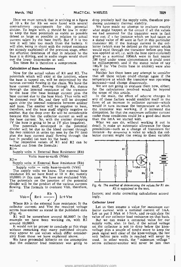
March, 1963 PRACTICA
Here we must remark that in arriving at a figure of 10 x Re for Rb we were faced with several contradictory requirements for this potential divider. To begin with, it should be low in order to keep the base potentials as stable as possible (bleed as large as possible in relation to actual current taken by the base itself). But if it is too low it will take too much from the battery. It will also, being in shunt with the output resistance (as already explained) of the previous stage, effect the effective resistance of that in relation to the base it is driving, and in audio stages would shunt out the lower frequencies as well.
Ten times Re is therefore a compromise.
Calculation of Base Resistance Now for the actual values of RI and R2. The
potentials which will exist at the junction, where the base is tapped on, will be determined by the various currents flowing in the chain. We have the base current itself, flowing through Re, thence through the internal resistance of the transistor to the base (the base leakage current plus the base current due to the base bias). Thus volts will be dropped over Re, and they will be dropped again over the internal resistance between emitter and base. The emitter will be negative to base, therefore, and the base itself slightly negative to emitter. But the drop over Re will be considerable because this has the collector current as well as the base current. So, with the emitter dropping 1V the base is going to be at 1V plus (negative).
The potentials developed in the potential divider will be due to the bleed current through the two resistors in series (as seen by the 9V line) plus the base current itself flowing through the two in parallel (as seen by the base).
The respective values of RI and R2 can be worked out from the formula: R1=
Supply volts x External Base Resistance (Rb) Volts base -to -earth (Vbb)
R2= Supply volts X External Base Resistance (Rb)
Supply volts - volts base -to -earth (Vbb) The supply volts we know. The external base
resistance Rb we have fixed at 10 x Re; namely 10,0000 in this case. We have not evaluated Vbb. The potentials on the junction of the potential divider will be the product of the various currents flowing. The formula to evaluate Vbb, therefore, is:
Rb Vbb= Re+ / lc +Vbe
d Where Rb is the external base resistance; Ic the
collector current; and Vbe the required voltage across base- emitter as stated in the published data (Fig. 4).
R1 will be somewhere around 66,0000 in the example we have been working on, with R2 around 10,0000.
It would not be proper to conclude at this stage without remarking that many published circuits may appear to use values which differ consider- ably from those we have explained above.
We have proceeded hitherto on the assumption that the collector load resistance was going to
L WIRELESS 1029
drop precisely half the supply volts, therefore pro- ducing automatic thermal stability.
We have made no attempt to evaluate exactly what might happen in the circuit if all the values we had assumed for the transistor were in fact way out; if a for instance which we had taken as a stated value of 40 were in fact in this particular transistor 80; if the leakage current in the col- lector (which may be defined as the current which would exist through the transistor before any bias was applied at all; i.e. with the base open- circuited) given as a nominal 100mA were in fact nearer 200 (and under some circumstances it could even be milliamperes); and if the stated value of say 100µV for Vbe (volts base to emitter) were also way out.
Neither has there been any attempt to consider that all these values could change again if the temperature at which the transistor was operating increased -and change disastrously.
We are not going to evaluate them now, either; for the calculations involved would be beyond the scope of this article.
In the main, the effect of adverse changes in any of these factors would manifest itself in the form of an increase in collector current -which would in turn increase the temperature at which the transistor was working, if it increased the dissipation. So that the maximum collector current under these conditions could be a good deal more than the lmA we started with.
What we can do, without working it out in detail, is make an automatic allowance for these possibilities -such as a change of transistors for instance -by assuming a value to which the col- lector current might rise owing to these variable
Fig. 4: The method of determining the va ues for RI an< R2 is explained in the text.
factors; and make correcting calculations accord ingly.
Collector Load
Let us then assume a value for maximum col- lector current, with a nominal current of lmA. Let us put I Max at 1.5mA, and re- calculate the value of our collector load resistance on that basis.
But we can make a corrected value for our supply volts, also. In fact, if the actual voltage on, the collector is not to drop below the knee - voltage plus a couple of tenths more to keep the peak signal well clear of the knee- voltage, the last volt before zero volts is reached will never be used. In other words, the "minimum voltage " across collector- emitter will never be less than
www.americanradiohistory.com
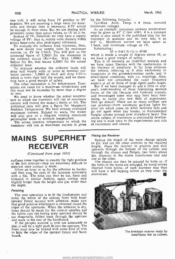
1030 PRACTICAL
one volt; it will swing from IV positive to 8V negative. We are assuming a large value for knee - volts and margin than is necessary; 0.5V would be enough in most cases. But we are dealing with principles rather than actual values, so 1V let it be.
Instead of 9V, therefore, we only have a supply voltage of 8V: that is, supply volts (battery volts) minus knee -volts plus peak -signal allowance.
To evaluate the collector load resistance, then, we now divide true supply volts by maximum current, i.e. 8V by 1.5mA. This will give us the corrected figure of 5,30012 for the resistance in the collector circuit (Rc +Re). With 1,00012 as before for Re, that leaves 4,30012 for the actual collector load.
To evaluate whether the collector loads will drop half supply volts or more at nominal col- lector current: 5,30012 at ImA will drop 5.3V- which is more than half the supply, and we there- fore have a good margin of safety.
The other calculation is for temperature. Tran- sistors are rated for a maximum temperature and this must not be exceeded by more than a degree or two.
We need to know whether the actual tempera- ture to which the transistor will rise at maximum current will exceed the maker's limits or not. The published data will give a figure for Maximum Ambient Temperature. We have already evaluated maximum current. Related to watts, the maker will also give us a diagram relating maximum permissible watts to ambient temperature.
The actual junction temperature to which the transistor will rise at maximum current is given
WIRELESS March, 1963
by the following formula: Tj =Max. Amb. Temp. + 8 (max. current)
(minimum voltage). As an example: maximum ambient temperature
may be given as 45° C (per mW). O is a constant which is also stated in the published data for the transistor in question and we may take it as 0.4° C. Maximum current we have taken as 1.5mA, and minimum voltage as 1V.
Substituting :
45 + 0.4(1.5) (1) = 45.60 which is inside a couple of degrees above 45, so we have a good margin of safety.
This is of necessity an imperfect analysis and we have taken liberties with the mathematics in the interests, of simplicity. It far from exhausts the subject, referring as it does exclusively to transistors in the grounded- emitter mode, and in small -signal conditions, with r.c. couplings. Also, we have not considered the radio frequency aspects at all or those of large signal audio stages.
But if we have managed to add a little to any- one's understanding of these fascinating modern forms of the old Hertzite and Galeium crystals, and encouraged some who may have been hesi- tating, to tackle this new field of experiment, then go ahead! There are so many artifices one can produce -from automatic parking lights for your car which come on when darkness falls and go out again when day breaks, to transistorised burglar alarms around your strawberry beds! The whole subject of transistors is continually develop- ing and is wide open to the experimenter and rich in excitement and reward.
MAINS SUPERHET RECEIVER
(Continued from page 1015)
surfaces come together in exactly the right position at the first attempt -they are extremely difficult to separate once contact is made.
Allow an hour or so for the adhesive to harden and then trim the ends of the laminate accurately with a file. The sides can then be cut, fixed and trimmed in similar fashion, again cutting very slightly longer than the height and fin. wider than the depth.
Finishing
The next operation is to fit the loudspeaker and cover the whole of the cabinet front with loud- speaker fabric secured with adhesive; make sure that good positive attachment is obtained round the edges of the apertures. When the adhesive is dry, holes should be made for the control spindles and the fabric over the tuning scale aperture should be cut diagonally, folded back through the aperture and stuck to the rear of the hardboard.
If the perspex window is now cut accurately to size, it will be a tight push fit into the aperture. The front must now be treated with some kind of trim to hide the edges of the speaker fabric and hard- board.
Fitting the Receiver Reduce the length of the wave change spindle
to fin. and cut the other controls to the required length. Place the receiver in position and drill upwards through the bottom of the cabinet and through the chassis end flanges, two holes about fin. diameter at the mains transformer end and one at the other.
The chassis can then be secured by bolts or, if the holes in the wood are enlarged, by wood screws inserted from below, of such diameter that they will have a self tapping action as they enter the aluminium.
The prototype receiver ready for installation into its cabinet.
www.americanradiohistory.com
March, 1963 PRACTICAL WIRELESS 1031
MULLARD 3 -3 HI -FI AMPLIFIER COLLARO STUDIO TAPE RECORDER KIT
,PE:CIAI. BARGAIN OFFER. Comp. Kit only £25.0.0 Carr. 12/6.
Valves. 8 watt. 3 ohm.
and 15 ohm. Out- put. A really first -class Amplifier giving Ri -Fi quality at a reasonable cost. Mullard's latest circuit. Valve line up: EF86, EL84. EZ81. Extra HT and LT available for Tuner Unit addition. This Is the ideal companion Amplifier for FM tuner units. TECHNICAL SPECIFICATION - Freq. Response: t 1dB. 40 c /a.-25 %c /s. Tone controls: Max. Treble Cut 12 dB. at 10 %c /s. Max. Bass Boost 14 dB. at 80 c /s. Sensitivity: 100 Mv. for 3 w. output. Output Power (at 400 c /e) 3 w. at 1% total harmonic distortion. Hum and Noise Level: At least 70 dB. below 3 w. COMPLETE KIT (inn. Valves, all components, wiring diagram and special quality sectional Output Trans.). ONLY 66.19.6. Carr. 5 / -. Complete wired and tested 8 gna. Bronze Escutcheon Panel, Prin- ted Vol., Treble, Bass, On-Off, iiPplied with each Kit.
Wired 0/P socket power and addi- tional smoothing for Tuner Unit, 10/6 extra. Recommended Speakers -WB HF1012 95/.. Ooodmans AXIOM 110 25, etc.
Famous mfrs. surplus offer -Listed 42 gas. A quality Tape Recor- der Kit based on Mullard famous design -EF86, ECC83, ELM. EM84 and Rectifier. Specially designed Kit for Collaro latest Studio Deck. Freq. response t 3 dB. 80 o /e-10 ke /s, Amp. and Power Pack already wired, inter unit wiring only required. Cabinf3ts size: 18 x
161 a 610, finished in contemp. 2 tone blue Rexine with gilt Speaker Escutcheon. Magic Eye indicator Circuit and Tech. H /Book, supplied free with kit. Send 2/6 now for full details of today's outstanding Tape Recorder Bargain.
Cabinet 83.15.0. P. & P. 6/8. Amplifier Kit 68.19.6. PAP. 6/ -. Speaker 7 x 4 18/6. P. & P. 2/ -. If above items are purchased
together. E 12.19. 6 P. & P.16/..
BARGAIN RECORD 4 -SPEED PLAYER PLAYER
UNITS CABINETS Single Players Carr. 3/6 Garrard 4 S.P. 68.19.8 Garrard TA Mk.2 67.19.6 Collazo "Junior" 75/- B.S.R. Latest TU12 79/6 E.M.I. Junior "985" 89/8 Auto -Changers Carr. 5/ -, Collaro "C 60" 67.15.0 B.S.R. (UA14) 68.19.6 Garrard "Auto-slim" Garrard Model RC209
67.10.0
69.19.8
Volume Controls - 5K-2 Meg-ohms, 31n. Spindles Morganite Mid- get Type 111n. diam. Guar. 1 year. LOG or LIN ratios less Sw. 3 / -. DP. Sw. 4/8. Twin Stereo less Sw. 6/8. DP Sw. 8 / ,
SPECIAL BARGAIN OFFER A self -contained Portable Unit Incor- porating latest BSR 4 speed Auto Changer Record Player and famous High Fidelity "Fui -Fi" Xtal Pick UP with Turnover Cartridge fitted with LP and 78 Sapphire ]Styli. Internal 2 valve Amplifier of modern design with variable Tone and Volume Controls. This, together with a quality P.M. Speaker ensures a high standard of reproduction. The whole- Is housed in a robust wooden Cabinet attractively styled in 2 Tone contemporary leather cloth with contrasting polka dot relief. Kit consists of 3 sub assemblies Standard already wired. Grub screw Model connections between Units only necessary -absolutely no soldering. Originally built to be sold at 17 gns.
Recommended Buy!
£12.10.0 Carr. & Ins, 7/6
Autochanger Unit -BSR Model UA20. Amplifier- valves UCL82 ÚY85 and 7 x 410. Elliptical Speaker. Cabinet size 17 x 144 x Blin.
RECORDING TAPE -Reduced Prices Famous American Columbia (CBS) Premier Quality 'tape at NEW REDUCED PRICES. A genuine recommended Quality Tape -TRY ITI Brand new, boxed and fully guaranteed. Fitted with leader and stop foils.
Standard Long Play Double Play 61n. 600ft. 13/- 900ít. 17/8 1,200ft. 31/6 Min. 900ft. 18/- 1.200ft. 19/8 1,800ft. 37/8 Tin. 1,200ft. 61/- 1.800ft. 28/6 2,400ft. 47/8 P. & P. per reel L-: 6d. on each additional reel.
SPECIAL BARGAIN. Sin. Message Tape, 150ft. 3/9. P. & P. 6d. 310. L.P. 225f t. 4/9 Sin. D.P. 30 f 6/6. Plastic Tape Reels .. 31n. 1J3, 5in, 2/ -, Sim. 2 / -, Tin. 2/3 Plastic Spool Containers .. 5i, 1/8, 511n. 2/ -, 710. 2/3
COAX 80 OHM CABLE High grade low loss Cellular air spaced Polythene -}in. diameter. Stranded cond. Famous mfrs. Now only Sd. per yard. Bargain Prices- Special Lengths -
20 yd. 9/ -. P. & P. 1/8. 40 Yd. 17/6. P. & P. 2/ -. 60 yd. 25/ -, P. & P. 3/ -.
Coax Plugs 1/ -. Sockets 1 / -. Couplers 1/3. Outlet Boxes 4/6.
Cabinet Price
83.3.0 Carr. & Ins. 5/ -.
Contemporary style, rexlne covered cabinet In two tone maroon and cream. Size 189 x 139 x ht. ;Bin., fitted with all accessories including baffle board and anodised metal fret. Space available for all modern amplifiers and autochan- mounting board 14íx 13meupplied. 2 -VALVE 2 -WATT AMPLIFIER Twin stage ECL82 with vol. and neg. feedback Tone control. A.C. 2W / 200 v, with knobs, etc.. ready wired to fit above cabinet. 62.17.8. P. & P. 1/6. Bin. S kr. & Trans., ß2J . P. & P. 2/ -. Complete Kit Including ÚA14 Unit as illustrated, 612.19.6, Carr, 7/6. JACK PLUGS. Standard 29' Igranic Type, 2/6. Screened Ditto 3/3. Miniature 19-. 2/3. Screened Ditto. 2/6. ENAMELLED COPPER WIRE - }lb. reels, 14g -20g. 2/8; 22g -28g, 3/1 30g -40g, 3/9. Other gauges Quoted for. Ersln Multleore Solder 60/40 3d. per yard. }lb. 2/6, etc.
Condensers -Silver Mica. All values, 2pF to 1,000pF, 6d. each Ditto. Ceramics 9d. Tub. 450V T.C,C., etc.. 0.001 mid. to 0.01 and 0.1/350V., 9d. 0.02- 0.1 /5001 L -. 0.26 Hunts 1/6. 0.6 T.C.Ò. 1/9, etc.. etc. Close Toi. SM leas -10% 6 F500PF 8d. 6005,000pIr 3f -. 1% 2pF- 100pF 9d. 100pF -500pF lid. 575pF-5,000pF 1/8. Resistors - Full Range 10 ohms -10 meg- ohms 20% 1 and 1 W 3d., W 5d. (Midget type modern rating) 1W Od., 2W 9d. Hi-Stab 10%
9W 45 . OW 7d. 5% tW 9d., 1%
New Boxed 1T4 IRS 186 384 314 DAF98 DF98 D1196 DL98 E0081 ECC82
VALVES 6/- ECC83 8/- 7/e ECL82 10/0 7/6 ECL80 10/6 7/6 EF80 8/- 7/8 11,86 12/8 9/- 11.84 8/8 9/- EM81 9/8 9/. -EY61 9/8 9/- EY88 10/- S/- E7.81 /8 8/- Cy.32 12/8
JASON FM TUNER UNITS Designer-approved kits of parts: FMTI, 5 Ens. 4 valves. 20/-. FMT2, 27. 5 valves. 37/8. JTV MERCURY 10 Ens. JTV2 613.19.6 4 valves, 32/6. NEW JASON FM HAND- BOOK, 2/6. 48 hr. Alignment Service 7/6. P. & P. 2/6,
TYGAN FRET (contemp. pat.) 12 x 1210, 2/ -. 12 x 18m, 3/-. 12 x 241n. 4/-. 18 x 24111. 8/- etc.
Speaker Fret - Expanded bronze anodised metal lin. x tin. diamond mesh, now 4/6 sq. ft.. Multiples of 61n, cut max. width 4 ft.
Eleetrolrtiee All Types New Stak
25/25V 1/9 50/12V 1/9 50 /50V 2/-
8 +8/450V 4/6 8 +16/408V 5/- 32 +82/275V 4/6
100/25V 2/- 60 +60/360V 6/6 8/400V 2/8 60 +250/ 16/450V 8/8 275V 12/6 le +18/45V 5/6 100 +200/ 32 +32/450V e/8 270V 111/8
Transistor Components Midget I.F.e --466 Ka/s.
9/161n. dia. 5/6 Osc. Coil -M/W, 9/1818. dia, 5/3 Oso. Coll -M. & L.W. 5/9 Midget Driver Trans. 8.6.18/9 Midget 0/Put Trans. P.P. to 3 ohms. 8/9. Ferrite Aerial M. I L.W., Car aerial coll. 9/3, Elect. Condenser - Midget Type lmfd50mfd 41 1/9. 100mfd., 2/ -; 12V wkg. Condensers- .01mfd, to .OSmfd 9d.: .O6mfd. to .1mfd. 3/ -; .ffimfd 1/3:.6mfd. 1/8. Tuning Condensers- JB "OO" 208 pF, + 176 pF 8/6, with Trim- mers 9/6. Single 3659F 7/8. Sub min. tin. J.H. Dile min. .0001, .0003 or .0006 7/- each. Midget Vol. Control -with edge control knob, 5% ohms with switch, 4 /9,less switch 3/9. Speakers P.M.-22n. Plessey 75 ohms 15/6. 2iln, Continental 8 ohms 13/6, 24In. E.M.I. 3 ohms 17/8. 7 x 418. Plessey 35 ohms, 23/6. Ear Plug Phones-Min. Con- tinental type, 31t. lead. jack Plug and socket. High Imp. 8/-. Low Imp. 7/6.
All TRANSISTOR BARGAINS Guaranteed Brand New -BVA 1st Grade POC84 9/6 0044 8/8 GET114 6/6 PCR80 9/6
OOCC881
8/- 6 000/0 7/8 PCL84 12/9
2/0081 15/8 0071 6/- 81.8.14 18/8 XA102 10 /- 0078 7/6 82
P1Á1 19/6 XA101 9/6 GEX34 2/9 PLIS ra3
9/e XB103 7/8 0A70 2/9 P 10/8 PY32 12 ¡8 XC101 8/6 OA81 2/9 PY81 9/e Special offer: One 0044, two PY82 7/8 0045e, 21/8. One 0CB1D, two 0m 12 /e OC81s (matched pair) 19/6
Send for detailed bargain liste, Id stamp. We manufacture all types Radio Mains Trend. Chokes, Quality 0/P Wane., etc. Enquiries invited for Specials, Prototypes for mall predashes rood QuMatgns by return.
RADIO COMPONENT SPECIALISTS 70 Brlgstoek Ed., Thornton Heath, Mures. Hops: 9 e.w. -e Rm., 1 fra Wed. THO 2188. Terms C.W.O. or C.O.D. Post and Pokily es M 485. 9d.; US., I/O; sii., 2/8; 019., 2/9; 819., 3/8.
www.americanradiohistory.com
1032 PRACTICAL WIRELESS
A SIMPLE EXPLANATION OF
TRANSISTOR RADIOS FOR THE APPRENTICE ENGINEER
March, 1963
Starting with a description of the basic properties of semiconductors, the action of a transistor is explained In detail and without recourse to complex mathematics. The circuits used in transistor radios are de-
scribed, and the techniques for ser- vicing these sets are considered.
CONTENTS INCLUDE: Semiconductor materials; Tran- sistor action; Transistor circuits; Servicing, etc. In all, seven chapters with the emphasis always on practi- cal considerations.
U.K. PRICE 5/- Published by Mullard Ltd. Get your copy from your radio dealer or send remittance with direct order (Postage and packing 6d. extra).
MULLARD LIMITED MULLARD HOUSE
TORRINGTON PLACE LONDON WC1
MVM1021
TOP QUALITY -LOW COST 4C /--- vvv
i6AMATEUR RADIO EQUIPMENT
THE MINI- CLIPPER THE SUPER CLIPPER 36'6 The ORIGINAL and finest one NEW LOW
valve all band receiver. Out- PRICE standing performance. New first- grade components ensure top efficiency. Low loss air spaced tuners, high gain polystyrene plug in coils. Satin Silver metal panel with engraved dials, grey pointer knobs. Provision for adding 2 transistor amplifier stage. Chassis ready punched. Total building cost, all parts, one coil 20-60 meters, wire solder full plans, 3616. P. & P. 216. Other coils 10 -2000 meters and electrical bandspread available. Parts sold separately. Plans ancUparts list, 21-.
This world -famous hybrid receiver has achieved remarkable success. Tremen- dous performance with Hi -gain valve detector PLUS two Ediswan transistor amplifiers which are supplied assembled, only 3 wires to connect. Large precision dial, 7 x 4in., with 2 pointers, bandset and bandspread, dual slow -motion drives, air spaced variables. Punched chassis 8 x 5 1in. Batteries last months. Covers 10 -2000 metres (5 coils). Total building cost including chassis, valve, 2 transistor stages, 2 coils 20-60 and 55 -190 metres. Step -by -step pictorial plans, nuts, bolts, wire 8816. P. & P. 216. Plans only, 216. THE CLIPPER. As above but one transistor stage, 7916. P. & P.
216. Optional Front Panel, Silver Hammer finish, all holes, 619.
88,6
THE NEW CR45 * NEW STYLING TOP PERFORMANCE Previously produced exclusively for Export, the de -luxe version of this famous ALL BAND receiver is now also available for the home market. Superb new styling, satin silver front panel, frequency calibrated scales, grey and silver trim knobs, perspex disc cursors. High gain circuit with ECC81 duotride, EL84 output, EZ80 full wave rectifier. Power output 3+ watts for 2/3 ohm speaker. 3 Planetary vernier slow motion drives, separate electrical bandspread. Covers 10 -2000 meters (5 Coils). World wide reception. For A.C. supply 20C -250 volts (Export version 105 -120 volts). Total building cost all parts, valves, front panel, ready punched chassis 2 coils, 20 -60 and 55 -190 meters, wire, solder, instruction manual.
f6 19 6 P. & P. 3'6. Optional extra. CR45 Cabinet 12 x 5 x 7in., slide flap for easy coil changing, Silver trey finish, 2716.
No tectuSla l knowledge required to build these fine receivers. Send 3d. stamp for illustrated learets, testimonials, etc. * Now available the NEW 1962 CR 66 A.C. SUPERM ET COMMUNICATION RECEIVER.
LODAR RADIO COMPANY, 24 CHAPEL ROAD, FISHERGATE, PORTSLADE, SUSSEX
07íR! Canadian Distributors: JAYCO ELECTRONICS, TWEED, ONTARIO. G31 PA
www.americanradiohistory.com
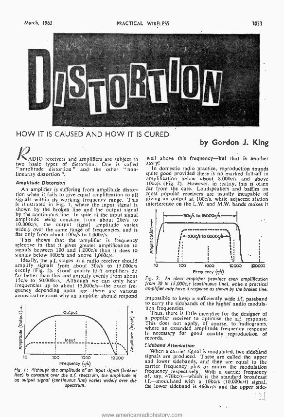
March, 1963
D
PRACTICAL WIRELESS 1033
HOW IT IS CAUSED AND HOW IT IS CURED
ADIO receivers and amplifiers are subject to two basic types of distortion. One is called " amplitude distortion " and the other " non - linearity distortion ".
Amplitude Distortion An amplifier is suffering from amplitude distor-
tion when it fails to give equal amplification to all signals within its working frequency range. This is illustrated in Fig. 1, where the input signal is shown by the broken line and the output signal by the continuous line. In spite of the input signal amplitude being constant from about 20c's to I0,000c /s, the output signal amplitude varies widely over the same range of frequencies, and is flat only from about 100c /s to 1.000c /s.
This shows that the amplifier is frequency selective in that it gives greater amplification to signals between 100 and 1,000c /s than it does to signals below 100c/s and above 1,000c /s.
Ideally, the a.f. stages in a radio receiver should amplify signals from about 30c /s to 15.000cis evenly (Fig. 2). Good quality hi -fi amplifiers do far better than this and amplify evenly from about 15c /s to 50.000c /s. Although we can only hear frequencies up to about 15,000c /s -the exact fre- quency depending upon age -there are various acoustical reasons why an amplifier should respond
10 loo 1000 Frequency (c/s)
Fig. I: Although the amplitude of an input signal (broken line) is constant over the a.f. spectrum, the amplitude of an output signal (continuous line) varies widely over the
spectrum.
10000
by Gordon J. King
well above this frequency -but that is another story!
In domestic radio practice, reproduction sounds quite good provided there is no marked fall -off in amplification below about 8,000c /s and above 100c/s (Fig. 2). However, in reality, this is often far from the case. Loudspeakers and baffles on most popular receivers are usually incapable of giving an output at 100c/s, while adjacent station interference on the L.W. and M.W. bands makes it
300 to 1500054
10 two 10000 100000 Frequency (Vs)
Fig. 2: An ideal amplifier provides even amplification from 30 to 15,0000 (continuous line), while a practical amplifier may have a response as shown by the broken line.
impossible to keep a sufficiently wide i.f. passband to carry the sidebands of the higher audio modula- tion frequencies.
Thus, there is little incentive for the designer of a popular receiver to optimise the a.f. response. This does not apply, of course, to radiograms, where an extended amplitude frequency response is necessary for good quality reproduction of records.
sideband Attenuation When a carrier signal is modulated, two sideband
signals are produced. These are called the upper and lower sidebands, and they are equal to the carrier frequency plus or minus the modulation frequency respectively. With a carrier frequency of, say, 470kc /s -which is the standard broadcast i.f.- modulated with a 10kc /s (10,000c /s) signal, the lower sideband is 460kc /s and the upper side-
www.americanradiohistory.com
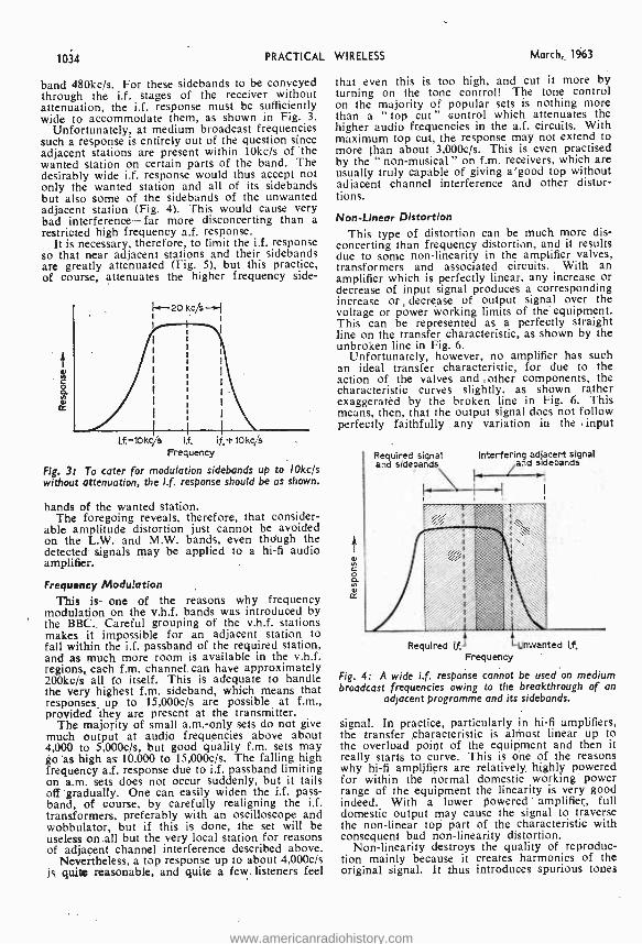
1034 PRACTICAL
band 480kc /s. For these sidebands to be conveyed through the i.f. stages of the receiver without attenuation, the i.f. response must be sufficiently wide to accommodate them, as shown in Fig. 3.
Unfortunately, at medium broadcast frequencies such a response is entirely out of the question since adjacent stations are present within 10kc /s of the wanted station on certain parts of the band. The desirably wide i.f. response would thus accept not only the wanted station and all of its sidebands but also some of the sidebands of the unwanted adjacent station (Fig. 4). This would cause very bad interference -far more disconcerting than a restricted high frequency a.f. response.
It is necessary, therefore, to limit the i.f. response so that near adjacent stations and their sidebands are greatly attenuated (Fig. 5), but this practice, of course, attenuates the higher frequency side-
k-20 kc/s-{ I
o
L,f.- 10kc /s I,f, if,tlOkc /s Frequency
Fig. 3: To cater for modulation sidebands up to 10kc /s without attenuation, the i.f. response should be as shown.
bands of the wanted station. The foregoing reveals, therefore, that consider-
able amplitude distortion just cannot be avoided on the L.W. and M.W. bands, even though the detected signals may be applied to a hi -fi audio amplifier.
Frequency Modulation This is one of the reasons why frequency
modulation on the v.h.f. bands was introduced by the BBC. Careful grouping of the v.h.f. stations makes it impossible for an adjacent station to fall within the i.f. passband of the required station, and as much more room is available in the v.h.f. regions, each f.m. channel can have approximately 200kc /s all to itself. This is adequate to handle the very highest f.m. sideband, which means that responses up to 15,000c /s are possible at f.m., provided they are present at the transmitter.
The majority of small a.m.-only sets do not give much output at audio frequencies above about 4,000 to 5,000c /s, but good quality f.m. sets may go as high as 10,000 to "15,000c /s. The falling high frequency a.f. response due to i.f. passband limiting on a.m. sets does not occur suddenly, but it tails off gradually. One can easily widen the i.f. pass - band, of course, by carefully realigning the i.f. transformers, preferably with an oscilloscope and wobbulator, but if this is done, the set will be useless on all but the very local station for reasons of adjacent channel interference described above.
Nevertheless, a top response up to about 4,000c /s is quite reasonable, and quite a few listeners feel
WIRELESS March, 1963
that even this is too high, and cut it more by turning on the tone control! The tone control on the majority of popular sets is nothing more than a " top cut" control which attenuates the higher audio frequencies in the a.f. circuits. With maximum top cut, the response may not extend to more than about 3,000c /s. This is even practised by the " non-musical" on f.m. receivers, which are usually truly capable of giving a good top without adjacent channel interference and other distor- tions.
Non- Linear Distortion This type of distortion can be much more dis-
concerting than frequency distortion, and it results due to some non -linearity in the amplifier valves, transformers and associated circuits. With an amplifier which is perfectly linear, any increase or decrease of input signal produces a corresponding increase or decrease of output signal over the voltage or power working limits of the equipment. This can be represented as a perfectly straight line on the transfer characteristic, as shown by the unbroken line in Fig. 6.
Unfortunately, however, no amplifier has such an ideal transfer characteristic, for due to the action of the valves and ;other components, the characteristic curves slightly, as shown rather exaggerated by the broken line in Fig. 6. This means, then, that the output signal does not follow perfectly faithfully any variation in the input
Required signal Interfering adjacent signal and sidebands and sidebands
.1
Required if. Unwanted Frequency
Fig. 4: A wide i.f response cannot be used on medium broadcast frequencies owing to the breakthrough of an
adjacent programme and its sidebands.
signal. In practice, particularly in hi -fi amplifiers, the transfer characteristic is almost linear up to the overload point of the equipment and then it really starts to curve. This is one of the reasons why hi -fi amplifiers are relatively, highly powered for within the normal domestic working power range of the equipment the linearity is very good indeed. With a lower powered amplifier,, full domestic output may cause the signal to traverse the non- linear top part of the characteristic with consequent bad non -linearity distortion.
Non -linearity destroys the quality of reproduc- tion mainly because it creates harmonics of the original signal. It thus introduces spurious tones
www.americanradiohistory.com
March, 1963 PRACTICAL WIRELESS 1035
THE TAPE RECORDER CONSTRUCTORS
LATEST COLLARD STUDIO TAPE TRANSCRIPTOR Latest type fncomoraP s Beds. lij 7ck,p.s., Button, spools. 3 speeds, li, 3i, 1,. takes 7ln,
PRICE Push -button controls. :SEW LOW PRICE OF 110.1,0.0 ONLY! plus 7/6 P. & P. Usual H.P. facilities. NEVI TAPE. RECORDER AMPLIFIER TYPE 8311,V.. Sub -assembled- anyone can b61ld! Printed Circuit. all components moon - tad and dip sOldered. Already tested. Each
CLYN E RADI O LTD. COMPONENT SPECIALISTS
A A
18 TOTTENHAM COURT ROAD, W.1 MUSeum 5929 /0095 f 162 HOLLOWAY ROAD, LONDON N.7 NORth 6295/6/7
9 CAMBERWELL CHURCH STREET, S.E.5 RODney 2875 10 WITHY GROVE, MANCHESTER, 4 Blackfriars 5379
All post orders, etc. to 162 HOLLOWAY ROAD, LONDON, N.7
THE NEW "CLYMAX't ! ! NEW LOW PRICE MADE POSSIBLE Through Further BULK PURCHASES
6- ^ transistor' , w.. Docket size
suDerhet for Medium and
Á - Long Wave.
All required components.
` NOM,' ONLY
99/6 Nothing more to buy, Plus 3/6 P. & P. * Completely self contained. No external aerial or earth required. * Full medium wave ^overage. plus switched Light programme on Long Wave. * Push -pull output -250 milli watts. * Matched set of latest type Mallard transistors. * Genuine Min. P.M. Speaker.l * New high -Q Coils. * Ferrite rod aerial with high selectivity. * Size: 51 x 31 x ltin Two -tone cabinet. * Precision etched printed circuit with components references clearly marked. Alignment service available. All parts available separately. Full assembly instructions and individually priced , parts list. 2/- post free.
The "AIR KING" Our new highly successful Six [ran - slsrrr luxury portable with the "SLIM LINE" look. To build your reliability Arend simplicity
chassis struction. May be used as Car Radio. with full MEDIUM wave and LONG wave coverage. Look at these features!
:. - ' f °nfibáa ' ``( Y` \ 9 `., '/`.
s ti i A yPrr" -- t q
ff,, i ,. Ay 11 J ^`t 1
=6 ,.",' 1
1% f I. W
I
y.
11
* 500 milllwatt output to high flux 7 x Min. high fidelity loudspeaker. * Six selected Mallard Transistors in latest super sensitive circuit, plus gerrpantum diode. * Compact size- only 91 x 3t x 64in. (high). * Attrac- Grey,
three -tone cabinet. Black, Dark Grey, and Sliver Grey, with gilt control knobs and all gilt fittings.
Coax * Cox socket for car aerial. *Bran d new guaranteed components. * Push pull output. * Automatic volume control. * Long life battery. * Super sensitive internal ferrite rod aerial. * Nothing more to buy. Cabinet
inclusive price for £7.19.6 ail required components. P1ua F/-,
Alignment service and individually
Flly assembly
parts details
which indare
avail- alit'
priced parts !1st, all of which are a able separately. price 1 /6. post free.
2 wt "
.. OP. , f
lead cut to length. All that is required to complete the tape recorder is for a few coin- portents to be mounted in the cabinet and the wee ends of leads soldered ed ro
everything sup
weld. are you
nee marked, eren, pliers
s D1fed, all you need is solder Iron, Allers and screwdriver. Valve line -up: EF86. ECC83, 2 x EL84. EZ81 and EM84 magic eye. Monitor- ing facilities, output socket for feeding to high quality alnpltfier, can be used as straight" amplifier for record reproduction.
EQUALISING ON TWO SPEEDS. OUTSTAN- DING VALUE AT £11.11.0 Plus 2/6 P. & P. including all necessary instructions. ATTRACTIVE TWO -TONE PORTABLE CARRYING CASE. Suitable for above amplifier and Collaro Studio deck. Fitted w,Ith 91n. x 51n. High Flux P.M. speaker for high quality reproduction. Inclusive
Fitted
£5.5.0 plus 5/- P. & P. Full list of competitively .
)'*iced mien. and stands on request. The above 8 Items purchased at one time, SUPPLIED CARß. PAID. NOW AVAILABLE! FOUR TRACK STUDIO DECK AS ABOVE FITTED WITH HIGH -FI FOUR -TRACK HEADS. PRICE. £13.18.6 plus 7 /6P. &P. Four track heads supplied separately complete
2/6 pair, plus2/2/6bracket for Studio
1ApE RECORDER AMPLIFIER 8311-4V. Exactly as 8311 -V but four track. suitable' for high -fl four -track heads. Price £12.12.0 plus 2/6 P. & P. PRE AMPLIFIER KIT TYPE 8612 -CP. Complete high quality preeck. fiir kit use with Collare Studio Deck. Price £8.8.0 plus 2/6 P. & P. N R Four -track deck and amplifier fit the above case, without any modification what- soave*.
e, 1
..
,,, osx
".
r
^ "
MODEL TK.20A Size 3i- x 21- x 1t'. Meter size 2i' x
both l
and 1.C.
o.p.v. on both A.C. A,C. and D.C. volts. 0/15, 0/150, 0 /1000 volts. D.C. Current. 0/150 mA. Resistance. 0 /100 K. Complete with teat prods, battery and ful instructions. OUT- STANDING VALUE at 42/- Plus 1/6 P. & P.
The "COURTESAN" Our 3 /" -- ---_ transistor -
diode °' pocket - ++ -.., "/
" receiver .1: with full ' r' t, - Medium f and Wave - ' ' '
t') -
Coverage. ::-z -:: ..:, } > ..,,,;_
ONLY 6.3/ Plus 2/6 P. & P. * No external aerial and earth required. * Latest 2íin. 75 ohm speaker. * First grade Mullard transistors. * Condenser tuning. * Volume control with on /off switch. * Easy assembly on pre -tagged circuit board. * Attractive red polystyrene cabinet measures 51 x 31 x litn., chrome handle, attractive gold and black dial. * Luxembourg, Hilversum, etc., guaranteed in reception areas. All parts available separately. Itemised parts list and full assembly instructions 1/6, post free.
The "HIGHWAYMAN" At last a queasy
economical Radio to build
yoorsatf, at an eeosomlcal Urice. Look sat these features:- outt * Attractive
latest yMallard transistors plus valves type EBF83 and ECH63.
No Buzz. High Output and seasi- tivity. * Printed circuit (newest type). 7- x 4' High flux p.m. speaker. * Medium and Long Waves. * Push Buttons for fingertip control. * Ex- tremely low Battery consumption (less than i amp.) * Easy to fit any make car (Positive earth only). * 12 volt operation. * Compact size measures only 7' x 7- x 2' deep. * Easy assembly. Supplied with dial and drive already mounted.
're- t
.=rte O 1- ... .n /' r- = All parts avail- able separatel but if purchased - -, ... at one time. the whole will be supplied at a special inclusive price of only £10.19.6 Plus 4/- P. & P.
Parts list and comprehensive instruction booklet 2/6. post free.
(Deducted parcel purchased later).
TAPE ! TAPE ! For the first time in this coun- / try? Canada's Hi Fi Magnet - ¡c Recording Tape. Made by ï\ °Bel- Cleer" of Canada. aD
t Following sizes available. others to follow. Brand New, NOT Sub- standard. High ,/ grade Acetate base. attrac- ti tively boxed, fitted leaders, fully guaranteed. 51n. 600 ft. 12/8; 5ín 900 ft., 15/ -; 7in. 1.200 ft.,
7in. 1,800 tt 25/ -, P. & P. 6d, per spool. re post free. (Bona fide trade inquiries
it invited). SPECIAL AME-IICAN MYLAR DUPONT. 5in. 1.200 ft. D.P. Top quality Brand New 25/ -, post free. Limited quantity onlyl PLASTIC TAPE SPOOLS. Best quality. 3in., 1/3, 41n., 2/ -, 51n., 2/ -. Min;, 2/3, 71n. 2 /6, P. & P. 6d. per spool. Orders over Cl post free. free. TELEPHONE PICK -UP COIL. Designed to feed into the microphone *input of either a tape recorder or any high gain amplifier. Easily attached to telephone by rubber sec - tion attachment. The coil is electrostatically shielded to minimise hum pick -up. When positioned on telephone this model Is more than adequate for a fully modulated tape shielded recording.
cable. ONLY 14 Post complete
r with 5 ft.
LAST CHANCE TO BUY The well -known BRAYREAD TRANS- TRONIC "SUPER g0" RADIO KIT.
A complete kit to n-, make your own
ÿ11x transistorised "1. Transmitter and R e c e i v e r. N o ' soldering required.
sit, .1 _ , 7 different circuits - to build. In origi-
nal manufacturers coloured box with instructions. Ideal
gift for the electronically minded youngster. (As nationally advertised at £5.4.8) FEW ONLY AT 49/6 P. & P. 4/-
www.americanradiohistory.com
1036 PRACTICAL WIRELESS March, 1963
The New'Picture- Book'wayof learning rELECTRICITY (5 voLS.)
ELECTRON ICS (óvoLs) You'll find-it easy to learn with this out- standingly successful new pictorial method - the essential facts are explained in the simplest language, one at a time: and each is Illustrated by an accurate, cartoon -type drawing.
The series will be of exceptional value in training mechanics and
technicians in Electri- city, Radio and Electronics.
WHAT READERS SAY I have found the manuals to be excellent publica-
tions ." D.L.D. .. I wish to congratulate you on these 'Best ever' series . . . " B.P. . I consider the manuals are truly the best I have ever studied ..." S.A.S.
A TECHNICAL PRESS PUBLICATION
The books are based on the latest research into simplified learning techniques. This has proved that the Pictorial Approach to learning is the quickest and soundest way of gaining mastery over these subjects.
._ N- N -t To Selray Book Co.,
60 Hayes Hill, Hayes, Bromley, Kent Please send me Without Obligation to Purchase, Basic Electricity/ Basic Electronics on 7 Days Free Trial. I will either return set, carriage paid, in good condition within 8 days or send down payment of 10 /- (Basic Electricity) followed by 6 monthly pay- ments of 10 / -. Down payment of 12/- (Basic Electronics) followed by 6 monthly payments of 12/ -. Alternatively, I will send 63/- (Basic Electricity -5 parts), 75/- (Basic Electronics -6 parts) post free. Tick against set required (only one set allowed on free trial). BASIC ELECTRICITY BASIC ELECTRONICS
Signature (If under 21, signature of parent or guardian)
BLOCK LETTEa9 BELOW
Name FULL POSTAL
Address
The new NOMBREX TRANSISTORISED WIDE -RANGE
SIGNAL GENERATOR 27
220 kc /s to 220 Mc /s
RETAI L £7.10.0 Pottery 2 3 s 316
36' Screened Test Lead 613 extra
CASH WITH ORDER, REGRET NO C.O.D.
IMMEDIATE DELIVERY Trade and Export Enquiries Invited
CHECK THESE
FEATURES
COMPACT Only 61' z 44'
PORTABLE Weight 2 lbs.
ACCURACY] Under 2%
ECONOMY] 9v. Battery
DIRECT Calibration
S.A.E. for lull technical
leaflet.
H.P. Terms: Bend 12 deposit pay balance
El /- per month
NOMBREX LTD. (Instruments Division 48)
Estuary House, Camperdown Terrace, Exmouth, Devon, England. Tel. 3515.
IT'S A JOY TO BUILD A
MARTIN `RECORDAKIT' VALUE AND PERFORMANCE BEYOND COMPARE
With a Martin Recordakit 'D', de - Maned for use with the Collaro 4.track Studio Deck you can build an Instru- ment of outstanding quality. AB with all Martin Reeordakite, it le on a printed circuit base and complete with valves, controls, transformers, leads, etc., down to the last screw. Even the wire supplied is out to length.
Amplifier 'D' as above, 12 gris. Speaker and Case assembly, 6 gus. With Deck Case, Speaker and Amplifier 14 Ens.
With Reoorlakits there is nothing extra to buy. Speed compensated. Designed to genuine luxury recorder standards. Other Martin Recordakit.' available toe P.S.R. and 4 -track Studio Decks. Case and Speaker assemblies available with and without decks.
rom radio and audio stoekii,. In rase of difficulty send direct. For free
leaflet, eut out 15f, ad. and send ft with your name and address.
155 High Street.
MARTIN ELECTRONICS LTD Middlesex. IHLeaort/ 6886
www.americanradiohistory.com
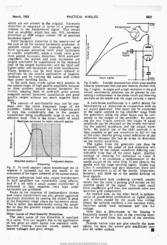
March, 1963 PRACTICAL WIRELESS
which are not present in the original. Harmonic distortion is measured in terms of a percentage relative to the fundamental signal. This means that an amplifier which has, say, 10% harmonic distortion at 10W output creates 1W of spurious harmonic signal!
Total 'harmonic distortion is the square -root of the sum of all the various harmonics produced. A pentode output valve, for example, gives most third harmonic distortion (with other harmonics at smaller amplitude), while a triode valve gives most second harmonic distortion. With push -pull amplifiers, the second and even harmonics are largely precluded by cancellation in the balanced load of the output transformer, and the third and higher -order odd harmonics are most troublesome. These, however, can be very much reduced in amplitude by the careful application of negative feedback and by running the valves well within their power handling limits.
In the early days, triode valves were popular in the output stages of high quality amplifiers, because as these produce mainly second harmonic dis- tortion, running them in push -pull gives almost complete second harmonic cancellation and good quality output without too much negative feed- back.
The amount of non -linearity may not be con- stant over the entire frequency range of the amplifier. Indeed, towards the low frequency end it may rise considerably due to the speaker transformer being insufficiently large to act as an effective load. This is the direct result of small
Response narrowed to reject adjacent station
o
Required station Adjacent station Frequency
Fig. S: To avoid adjacent station breakthrough the i.f. response is narrowed, but this also results in the attenuation of the higher sidebands of the wanted station. primary inductance (and why output transformers in hi -fi amplifiers are remarkably large affairs), and if a set with a small output transformer is enhanced in bass response, very high order harmonics are produced.
' Peaks in the response of loudspeakers, chokes and output transformers can also greatly aggravate harmonic distortion by causing the output to peak in the frequency range where the harmonics occur. This is rather like inadvertently tuning the ampli- fier so that the greatest output is obtained on the harmonics! Other causes of Non -linearity Distortion
The main cause of this distortion is overload In a valve. This can happen due to the application of too great an input signal, low emission valve, incorrect biasing, incorrect anode, screen and heater voltages and poor design.
MIlliammeter
. .'
1037
H.T.+
Input signal
Input signal HT- Fig. 6 (left): Transfer characteristic which shows perfect linearity (continuous line) and poor linearity (broken line). Fig. 7 (right): In stages with a high resistance in the grid circuit, non -linearity distortion can be gleaned by con- necting o milliammeter in the anode circuit and observing the kicks on the needle with the stage carrying a signal.
A twin -beam oscilloscope is a useful device for investigating a.f. distortion in conjunction with an a.f. signal generator. One beam can be connected to the signal applied to the amplifier stage from the generator, while the other beam can be con- nected to the output of the amplifier. By adjust- ing the two Y -gain controls two traçes of equal amplitude can be obtained on the screen represent- ing the applied waveform and the output wave- form. By careful use of the shift controls it is then possible to get one waveform to fall on top of the other, thereby giving visual indication of any difference between the two in terms of distortion on the output waveform.
The signal from the generator can then be increased, when the point of bad distortion will be evident by the output waveform differing con- siderably from that of the input signal. Another method of checking for distortion in Class A amplifiers is to introduce a milliammeter in the anode circuit of the valve (Fig. 7) and observe the needle with the stage carrying signal. Under true Class A conditions and zero distortion there will be no movement at all of the needle. Distortion, however, will show up as the needle kicking on loud signals.
A downward kick (reducing current) usually means that the valve is passing grid current on the positive peaks of the signal. This could result from insufficient grid bias, low emission valve and incorrect grid components.
An upward kick, on the other hand, is sympto- matic of anode -bend rectification on signal peaks, and is often caused by too much bias voltage (check the cathode resistor), a low emission valve, incorrect anode load resistance and low h.t. voltage.
Note that a disturbance to the biasing is frequently caused by a leak in the coupling capa- citor at the grid from the anode of the previous stage.
Pentode valves may not give exactly the same effects, for here the screen grid conditions may also be rather critical.
www.americanradiohistory.com
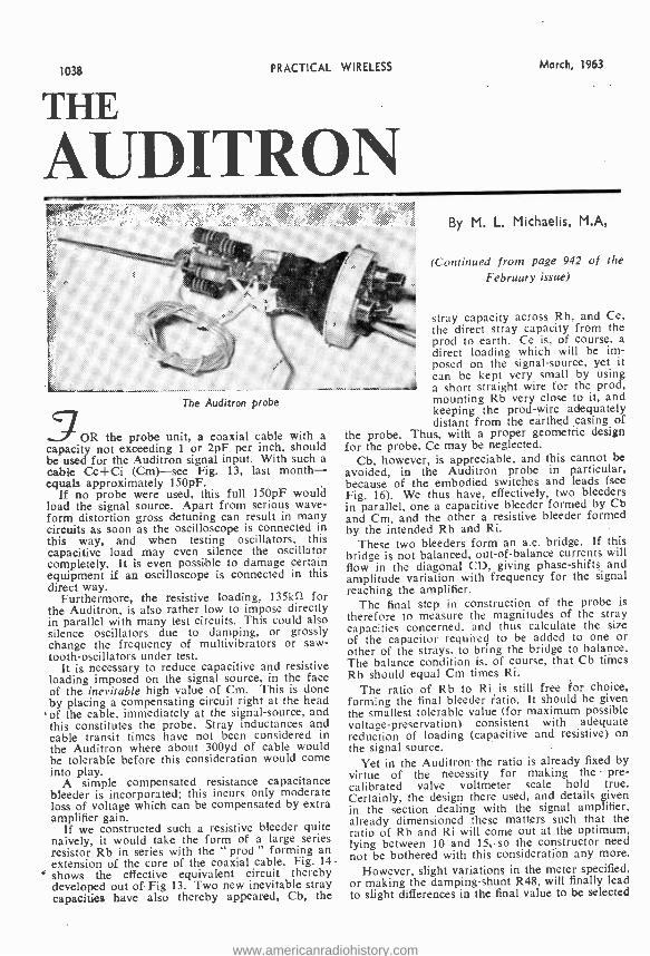
1038 PRACTICAL WIRELESS March, 1963
THE
AUDITRON
The Auditron probe
5OR the probe unit, a coaxial cable with a capacity not exceeding 1 or 2pF per inch, should be used for the Auditron signal input. With such a cable Cc +Ci (Can) -see Fig. 13, last month - equals approximately 150pF.
If no probe were used, this full 150pF would load the signal source. Apart from serious wave- form distortion gross detuning can result in many circuits as soon as the oscilloscope is connected in this way, and when testing oscillators, this capacitive load may even silence the oscillator completely. It is even possible to damage certain equipment if an oscilloscope is connected in this direct way.
Furthermore, the resistive loading, 135kí1 for the Auditron, is also rather low to impose directly in parallel with many test circuits. This could also silence oscillators due to damping, or grossly change the frequency of multivibrators or saw - tooth- oscillators under test.
It is necessary to reduce capacitive and resistive loading imposed on the signal source, in the face of the inevitable high value of Cm. This is done by placing a compensating circuit right at the head of the cable, immediately at the signal- source, and this constitutes the probe. Stray inductances and cable transit times have not been considered in the Auditron where about 300yd of cable would be tolerable before this consideration would come into play.
A simple compensated resistance capacitance bleeder is incorporated; this incurs only moderate loss of voltage which can be compensated by extra amplifier gain.
If we constructed such a resistive bleeder quite naively, it would take the form of a large series resistor Rb in series with the " prod " forming an extension of the core of the coaxial cable. Fig. 14
shows the effective equivalent circuit thereby developed out of Fig 13. Two new inevitable stray capacities have also thereby appeared, Cb, the
By M. L. Michaelis, M.A,
(Continued from page 942 of the February issue)
stray capacity across Rb, and Ce, the direct stray capacity from the prod to earth. Ce is, of course, a direct loading which will be im- posed on the signal- source, yet it can be kept very small by using a short straight wire for the prod, mounting Rb very close to it, and keeping the prod -wire adequately distant from the earthed casing of
the probe. Thus, with a proper geometric design for the probe, Ce may be neglected.
Cb, however, is appreciable, and this cannot be avoided, in the Auditron probe in particular, because of the embodied switches and leads (see Fig. 16). We thus have, effectively, two bleeders in parallel, one a capacitive bleeder formed by Cb and Cm, and the other a resistive bleeder formed by the intended Rb and Ri.
These two bleeders form an a.c. bridge. If this bridge is not balanced, out -of- balance currents will flow in the diagonal CD, giving phase- shifts and amplitude variation with frequency for the signal reaching the amplifier.
The final step in construction of the probe is therefore to measure the magnitudes of the stray capacities concerned, and thus calculate the size of the capacitor required to be added to one or other of the strays, to bring the bridge to balance. The balance condition is. of course, that. Cb times Rb should equal Cm times Ri.
The ratio of Rb to Ri is still free for choice, forming the final bleeder ratio. It should be given the smallest tolerable value (for maximum possible voltage -preservation) consistent with adequate reduction of loading (capacitive and resistive) on the signal source.
Yet in the Auditrom the ratio is already fixed by virtue of the necessity for making the pre - calibrated valve voltmeter scale hold true. Certainly, the design there used, and details given in the section dealing with the signal amplifier, already dimensioned these matters such that the ratio of Rb and Ri will come out at the optimum, lying between 10 and 15, so the constructor need not be bothered with this consideration any more.
However, slight variations in the meter specified, or making the damping -shunt R48, will finally lead to slight differences in the final value to be selected
www.americanradiohistory.com
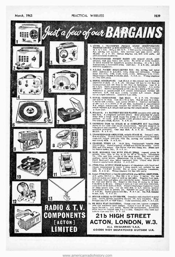
Marck, 1963 PRACTICAL WIRELESS 1039
1
r06f01ARGAINS
IlÌ1
s.s
RADIO & T. V.
COMPONENTS [ACTON]
LIMITED
L SUPER 5 TRANSISTOR POCKET RADIO INCORPORATING PRINTED CIRCUIT & MINI -EARPIECE. No Aerial or Earth required 4f r 31 x 1)in. Output 200 M.W. 5 first quality transistor. High flux moving coil speaker. M/L Internal high gain terror aerial. 12.19.6. P. & P. 3/6. Circuit diagram 1 /8, free with part.. All parts available separately.
2. TRANSISTORISED POCKET RADIO with printed circuit, mini - earpiece, high gain terror Blab aerial. No serial or earth required. To build yourself for completely personal listening. 4f x 31 x 1110. Luxembourg in favourable areas. Only 21/. P. & P. 216. All parts available separately.
8. AC. /D.C. POCKET MULTI -METER KIT. 210. moving coil meter scale, calibrated in A.C. /D.C. volts, ohms and milliamp. Voltage range A.C. /D.C. 0 -50, 0- 100, 0.250, 0400. M1lliamps 0.10, 0 -100. Ohms ranges 0- 10,000, 0. 100,000, 24/0. P. & P. 2/, Wiring diagrams 11 -, free with part.
4. SIGNAL GENERATORS. Cash 27.6.0, or 301- deposit and 6 monthly payments of 21 /8. P. & P. 5 /6. Coverage 100 Ws to 100 Mop on fundamentals and 100 Mc /e to 200 Mc /s on harmonica Case 10 x 60 x Silo. Three miniature valves and Metal Rectifier. A.C. mains 200/250 v. Internal modulation of 400 c.o.s. to a depth of 30 per cent. Modulated or unmodulated R.F. output continuously variable 100 mlllivolte. C.W. and mod. switch, variable A.F. output. Magic eye as output indicator. Accuracy 2 per cent.
5. SIGNAL GENERATORS. Cash 26.5.0. P. & P. 6 /6, Coverage 120 kc /e to 84 Mc /. Case 10 x 61 r 411n. Size of male 81 r 31m, 2 valves and rectifier. A.C. mains 230 -250 v. internal modukstloo of 400 c.p.e. to a depth of 80 per cent, modulated or unmodnlated R.F. output continuously variable 100 millivolt. C.W. and mod. switch variable A.P. output and moving coil output meter. Avowal" ± 2 per cent.
S. STAAR 45. 9 v. BATTERY RECORD PLAYER complete wtth pick -op and deck. A completely portable player. Head protected by plastic dome with is brush which cleans the stylus se It rises Into playing position. 45 r.p.m. Auto on /oft switch governed motor, attractive two tone grey finish, 59.14,8- P. & P. 2/ ,
7. CARRYING CASE tor STAAR 45 or COMPLETE KIT beautifully styled in two tone with record compartment. Specially designed to take player and emp/inel.. Just screw in and connect up. AR parts. available separately. (Use only 22/8. P. & P. 4/, Complete kit 25.10.0. P. & P. 5I ,
8. TRANSISTORISED AMPLIFIER. suitable STAAR 45. Output 1 watt. Size 41 r 21 in. Printed circuit, tone /volume controls plus 4 trasletors Push -pull output complete with ß2n. moving coil speaker. Built and tested, 49/8. P. & P. 2 / -.
9. CHANNEL TUNER I.F. 18.19 Mc /s. Continuously tunable tram 174.216 Mels. Valves required -PCF80 and PCC84 (in series). Cover BBC and ITA range. Also Police, Fire and Taxi. eta Brand saw by famous maker, 10 /-. P. & P. 3/ -.
10. B.S.R. MONARCH OA8 WITH FUL-FI HEAD. 4- speed, plays IB recorde, 121e., loin. or 710. at 16, 33, 45 or 78 r.p.m. Intermixes 7in., 1010. and 1210. recorde of the same speed. Has manual play position: colour brown. Dimensions: 125 x 10110. Space required above baseboard 4110. below baseboard 2f la Fitted with Fol -FI turnover crystal head, 56.19.6. P. & P. 516.
11. PUSH -PULL OUTPUT STAGE inclusive of trauslston with input and output transformers to match 3 ohms speech coil, suitable for nee with the POCKET RADIO. Kit of part. Including traoabtora, 19/8. P. & P. II -. Wiring diagram 1 /8, free with ports.
12. 8 -watt PUSH -PULL 4 VALVE AMPLIFIER plus METAL RECTIFIER A.C. males 200.250 v. Sloe 105 z 81 z 21in. 6 valve. For use with all makes and types of pick -up and mike. Negative feed back. Two Input, mike and gram, and controls for same. Separate controls for Bass and Treble lift. Response fist from 40 cycles to 15 kels. 2 db down to 20 kc /. Output 8 watts at 5 per cent total distortion. Noise level 40 db down all hum. Output transformer tapped for 3 and 15 ohms speech .11. For use with Std. or L.P. record. musical Instruments auch as guitars, etc. Suitable for small halls, 58.19.0. P. & P. ß /-. Crystal mike to snit 16/. P. & P. 2/ -. 81n. P.M. Speaker to suit, 12 /8. P. at P. 2 / -.
13. INDOOR AERIAL for ITV/BBC/FM. Complete with standard so-axial plug. Heavy chrome extending dipoles -7ft. folly extended. Plugs straight into T.V. or VHF Tuner. Fully directional, 10 /6. P. A P. 1 /6.
14. NO MORE FLAT BATTERIES. Charge your own battery overnight with this wonderful little charger. Output 6 and 12 volt. 2 amp. Input 200.250 v. A.C. main. Maine fuse incorporated. Attractive sliver hammer finished case, 8 x 3 r 31m. Complete with leads and battery clips only 21/-. P. P. 3/6.
21b HIGH STREET ACTON, LONDON, W.3.
ALL ENQUIRIES 'S.A.E. GOODS NOT DESPATCHED OUTSIDE U.K.
www.americanradiohistory.com
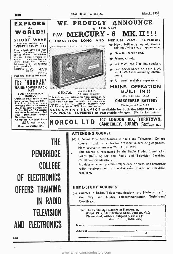
1040 PRACTICAL WIRELESS March, 1963
EXPLORE the
WORLD!! SHORT WAVE
with our exciting new
"VENTURE -1" KIT Covers both 20M and 40M bands (switched). Band spread tuning. Aluminium chassis. Three ceramic air spaced tuning condensers, valve, plugs and sockets, hardware, etc. Full building plans pro vided. COMPLET
FOR 47/6 ONLY P.P. 2'6
High Imp. Phones 1416 extra
WE PROUDLY ANNOUNCE * THE NEW
P.W. MERCURY - 6 MK. II ! ! !
6 TRANSISTOR LONG AND MEDIUM WAVE SUPERHET * New, brilliantly styled, timber
,; cabinet giving elegant appearance.
New Sin, ferrite rod. w, ..
.-:j.:4.:...''.... ;F , *, 4 3 5` ,Sçç. * Printed circuit.
- ? k. 5 f * 500 mW into 7 x 4in. speaker. 'z x, r
k ' * Fine performance on both L.W. s k . ; z' and M.W. bands including Luxem-
bourg.
* All parts available separately.
MAINS OPERATION plus 3(6 P. &P. BUILT IN!! L I0.7.ó. All parts required.
This exciting new cabinet has been acclaimed by 30f- EXTRA. Also everyone who has seen it. Existing Mercury owners may purchase it for 481 -. All components CHARGEABLE BATTERY supplied to the last washer, together with full building plans (216) Free with parts. Write for details S.A.E.
ALIGNMENT SERVICE available for both the MERCURY and P.W. POCKET SUPERHET at reasonable charges. (Write for details).
The `N O R P A H
MAINS POWER PACK KIT
FOR TRANSISTOR RADIOS
Operates your radio direct frosq mains. Miniature Size- 4 x 2 x I }in. In attractive two-tone plastic case. Assem- bled in an hour. Normal out- put 9 v. 100 mA. (Adjustable) Full Mains Transformer. Full wave germanium diodes. Cartridge fuse. Complete - it with Plans
35/. 116 P.P.
(Ready assembled 45r_), N 0 R C 0 L LTD 147 LONDON RD., YORKTOWN,
CAMBERLEY SURREY Phone; f CAMBERLEY 3743
THE
PEMBRIDGE
COLLEGE
OF ELECTRONICS
OFFERS TRAINING
IN RADIO
TELEVISION
AND ELECTRONICS
rota
ATTENDING COURSE
(A) Full -time One Year Course in Radio and Television. College
course in basic principles for prospective servicing engineers.
Next course commences 25th April, 1963.
This course is recognised by the Radio Trades Examination
Board (R.T.E.B.) for the Radio and Television Servicing
Certificate examinations. Provides excellent practical experience on valve and transistor
radio receivers and all well -known makes of television
receivers.
HOME -STUDY COURSES
(B) Courses in Radio, Telecommunications and Mathematics for
the City and Guilds Telecommunication Technicians'
Certificates.
To: The Pembridge College of Electronics. Road, (Dept. PI I), 34a Hereford L on d on, W.2
Please send, without obligation, igation, etaiI s o f A- B- (Please tick.)
Name
Address
www.americanradiohistory.com
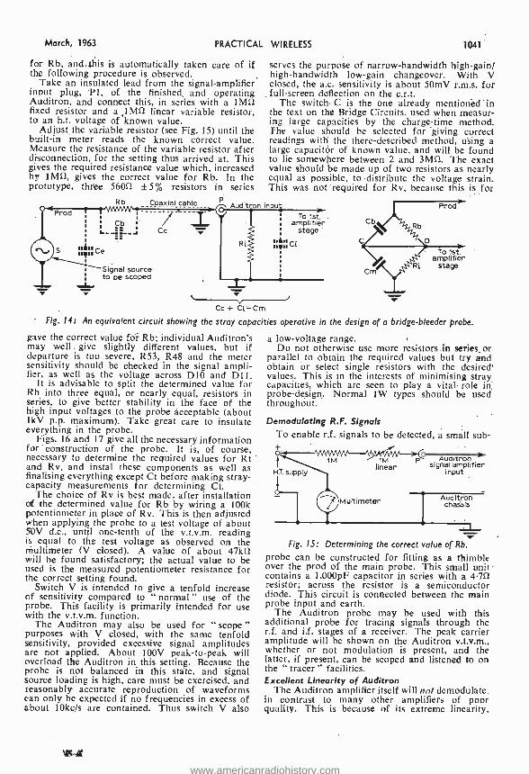
March, 1963 PRACTICAL
for Rb, and4his is automatically taken care of if the following- procedure is observed.
Take an insulated lead from the signal -amplifier input plug, Pl, of the finished and operating Auditron, and connect this, in series with a 1M5ì fixed resistor and a 1 M52 linear variable resistor, to an h.t. voltage of known value.
Adjust the variable resistor (see Fig. 15) until the built -in meter reads the known correct value. Measure the resistance of the variable resistor after disconnection, for the setting thus arrived at. This gives the required resistance value which, increased by IMO, gives the correct value for Rb. In the prototype, three 560[1 ±5% resistors in series
WIRELESS 1041
serves the purpose of narrow -bandwidth high -gain/ high- bandwidth low -gain changeover. With V closed, the a.c. sensitivity is about 50mV r.m.s. for full- screen detection on the c.r.t.
The switch ,C is the one already mentioned in the text on the Bridge Circuits, used when measur- ing large capacities by the charge -time method. The value should be selected for giving correct readings with the there- described method, using a large capacitor of known value, and will be found to lie somewhere between 2 and 3M5ì. The exact value should be made up of two resistors as nearly equal as possible, to distribute the voltage strain. This was not required for Rv, because this is for
Rb Coaxial cable Auditron in
olé. pCe Signal source
¡ to be scoped 11111
Cc
Ri
1
To 1st. .
amplifier stage -
olio
Cb Rb
D
Prod
1 To 1st.
amplifier stage
Cc + Ci =Cm
Fig. 14t An equivalent circuit showing the stray capacities operative in the design of a bridge -bleeder probe.
gave the correct value for Rb; individual Auditron's may well . give slightly different values, but if departure is too severe, R53, R48 and the meter sensitivity should be checked in the signal ampli- fier, as well as the voltage across DIO and D11.
It is advisable to split the determined value for Rb into three equal, or nearly equal, resistors in series, to give better stability in the face of the high input voltages to the probe acceptable (about 1kV p.p. maximum). Take great care to insulate everything in the probe.
Figs. 16 and 17 give all the necessary information for construction of the probe. It is, of course, necessary to determine the required values for Rt and Rv, and instal these components as well as finalising everything except Ct before making stray - capacity measurements for determining Ct.
The choice of Rv is best made, after installation of the determined value for Rb by wiring a 100k potentiometer in place of Rv. This is then adjusted when applying the probe to a test voltage of about 50V d.c., until one -tenth of the v.t.v.m. reading is equal to the test voltage as observed on the multimeter (V closed). A value of about 47k11 will be found satisfactory; the actual value to be used is the measured potentiometer resistance for the correct setting found.
Switch V is intended to give a tenfold increase of sensitivity compared to " normal" use of the probe. This facility is primarily intended for use with the v.t.v.m. function.
The Auditron may also be used for " scope " purposes with V closed, with the same tenfold sensitivity, provided excessive signal amplitudes are not applied. About 100V peak -to -peak will overload the Auditron in this setting. Because the probe is not balanced in this state, and signal source loading is high, care must be exercised, and reasonably accurate reproduction of waveforms can only be expected if no frequencies in excess of about 10kc /s are contained. Thus switch V also
a low- voltage range. Do not otherwise use more resistors .in series_ or
parallel to obtain the required values but try and obtain or select single resistors with the desired' values. This is in the interests of minimising stray capacities, which are seen to play a vital role in. probe- design. Normal 1W types should be used throughout.
Demodulating R.F. Signals
To enable r.f. signals to be detected, a small sub- +
1M
H.T. supply
1M linear
Auditron signal amplifier
input
Multimeter Auditron chassis
Fig. 15: Determining the correct value of Rb.
probe can be constructed for fitting as a thimble over the prod of the main probe. This small unit contains a 1,000pF capacitor in series with a 4.752 resistor; across the resistor is a semiconductor diode. This circuit is connected between the main probe input and earth.
The Auditron probe may be used with this additional probe for tracing signals through the r.f. and i.f. stages of a receiver. The peak carrier amplitude will be shown on the Auditron v.t.v.m., whether or not modulation is present, and the latter, if present, can be scoped and listened to on the " tracer " facilities. Excellent Linearity of Auditron
The Auditron amplifier itself will not demodulate. in contrast to many other amplifiers of poor quality. This is because of its extreme linearity,
www.americanradiohistory.com
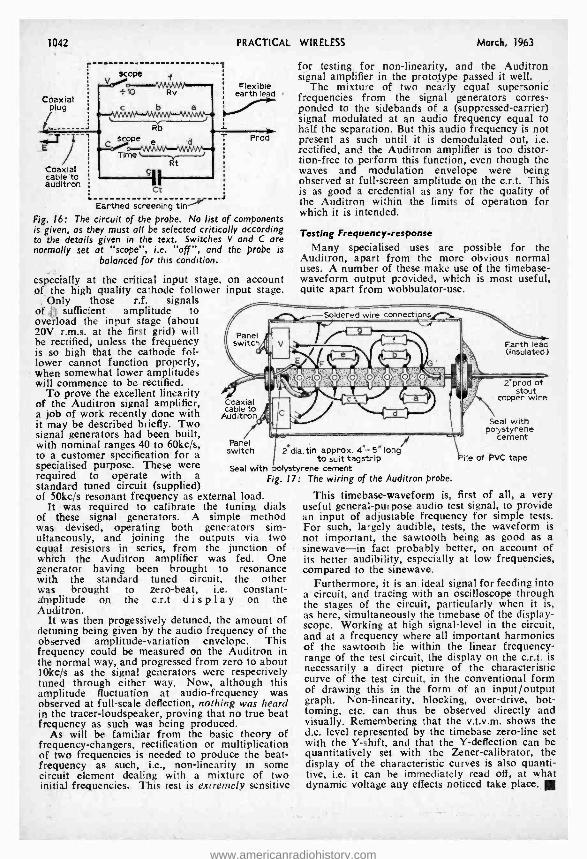
1042
r f
Z
PRACTICAL
Flexible earth leed
i Coaxial cible auditron ct
Earthed screening tinter Fig. 16: The circuit of the probe. No list of components is given, as they must all be selected critically according to the details given in the text. Switches V and C are normally set at "scope ", i.e. "or, and the probe is
balanced for this condition.
especially at the critical input stage, on account of the high quality cathode follower input stage.
Only those r.f. signals of sufficient amplitude to overload the input stage (about 20V r.m.s. at the first grid) will be rectified, unless the frequency is so high that the cathode fol- lower cannot function properly, when somewhat lower amplitudes will commence to be rectified.
To prove the excellent linearity of the Auditron signal amplifier, a job of work recently done with it may be described briefly. Two signal generators had been built, with nominal ranges 40 to 60kc /s, to a customer specification for a specialised purpose. These were required to operate with a standard tuned circuit (supplied) of 50kc /s resonant frequency as external load.
It was required to calibrate the tuning dials of these signal generators. A simple method was devised, operating both generators sim- ultaneously, and joining the outputs via two equal resistors in series, from the junction of which the Auditron amplifier was fed. One generator having been brought to resonance with the standard tuned circuit, the other was brought to zero -beat, i.e. constant - amplitude on the c.r.t display on the Auditron.
It was then progessively detened, the amount of detuning being given by the audio frequency of the observed amplitude- variation envelope. This frequency could be measured on the Auditron in the normal way, and progressed from zero to about 10kc /s as the signal generators were respectively tuned through either way. Now, although this amplitude fluctuation at audio- frequency was observed at full -scale deflection, nothing was heard in the tracer -loudspeaker, proving that no true beat frequency as such was being produced.
As will be familiar from the basic theory of frequency- changers, rectification or multiplication of two frequencies is needed to produce the beat - frequency as such, i.e., non -linearity in some circuit element dealing with a mixture of two initial frequencies. This test is extremely sensitive
WIRELESS March, 1963
for testing for non -linearity, and the Auditron signal amplifier in the prototype passed it well.
The mixture of two nearly equal supersonic frequencies from the signal generators corres- ponded to the sidebands of a (suppressed- carrier) signal modulated at an audio frequency equal to half the separation. But this audio frequency is not present as such until it is demodulated out, i.e. rectified, and the Auditron amplifier is too distor- tion -free to perform this function, even though the waves and modulation envelope were being observed at full -screen amplitude on the c.r.t. This is as good a credential as any for the quality of the Auditron within the limits of operation for which it is intended.
Testing Frequency- response Many specialised uses are possible for the
Auditron, apart from the more obvious normal uses. A number of these make use of the timebase- waveform output provided, which is most useful, quite apart from wobbulator -use.
Earth lead (Insulated)
Coaxial cable to
Auditron
Panel switch 2 dia.tln approx. 4 "- 5" long
to suit tagstrip Seal with polystyrene cement
Fig. 17: The wiring of the Auditron probe.
2'prod of stout
copper wire
Seal with polystyrene
cement
Pile of PVC tape
This timebase -waveform is, first of all, a very useful general- purpose audio test signal, to provide an input of adjustable frequency for simple tests. For such, largely audible, tests, the waveform is not important, the sawtooth being as good as a sinewave -in fact probably better, on account of its better audibility, especially at low frequencies, compared to the sinewave.
Furthermore, it is an ideal signal for feeding into a circuit, and tracing with an oscilloscope through the stages of the circuit, particularly when it is, as here, simultaneously the timebase of the display - scope. Working at high signal -level in the circuit, and at a frequency where all important harmonics of the sawtooth lie within the linear frequency - range of the test circuit, the display on the c.r.t. is necessarily a direct picture of the characteristic curve of the test circuit, in the conventional form of drawing this in the form of an input /output graph. Non -linearity, blocking, over -drive, bot- toming, etc. can thus be observed directly and visually. Remembering that the v.t.v.m. shows the d.c. level represented by the timebase zero -line set with the Y- shift, and that the Y- deflection can be quantitatively set with the Zener- calibrator, the display of the characteristic curves is also quanti- tive, i.e. it can be immediately read off, at what dynamic voltage any effects noticed take place. II
www.americanradiohistory.com
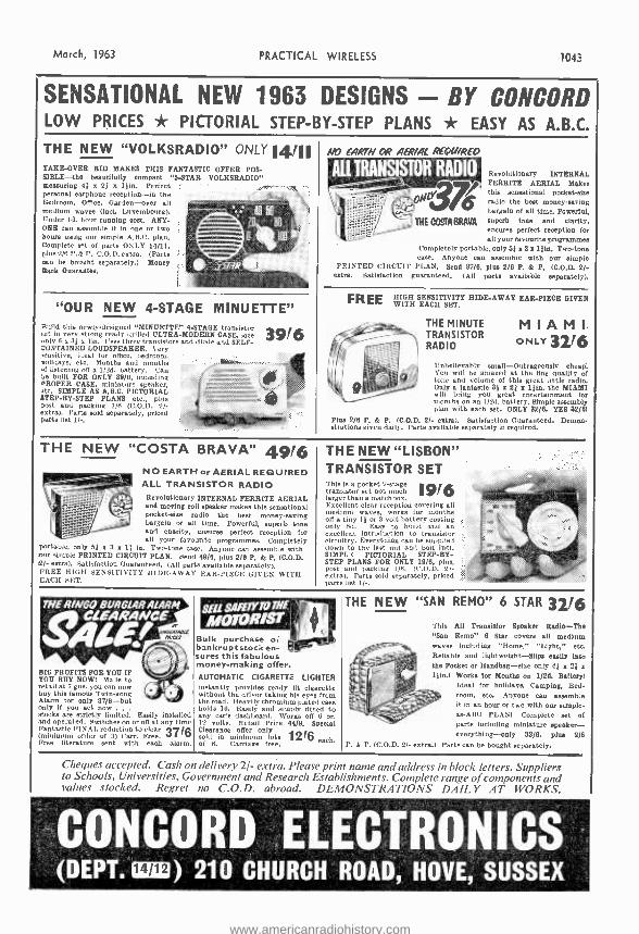
March, 1963 PRACTICAL WIRELESS 1043
SENSATIONAL NEW 1963 DESIGNS - BY CONCORD LOW PRICES * PICTORIAL STEP -BY -STEP PLANS *e EASY AS A.B.C.
THE NEW "VOLKSRADIO" ONLY 14111 TAKE -OVER BID MAKES THIS FANTASTIC OFFER POS- SIBLE -the beautifully compact "5 -STAR VOLKSRADIO" measuring 41 x 21 x l ;in. Perfect personal earphone reception -in the Bedroom, Office, Garden -over all medium waves (incl. Luxembourg). Under Id. hour running cost. ANY- ONE can assemble it in one or two hours using our simple A.B.C. plan. Complete set of parts ONLY 14/11, plus 2/6 P.& P. C.O.D. extra (Parts mo be bought separately.) Money Hack Guarantee.
NO EAR7N ü? AER/AL REWIRED
All IRANSISTOR RADIO
"OUR NEW 4 -STAGE MINUETTE" Build this newly -designed "MINUETTE" 4 -STAGE transistor stet in very strong ready drilled ULTRA- MODERN CASE, size
ly 6 x 31 x lin. f eee three transistors and diode and SELF - CONTAINED LOUDSPEAKER. 'cry ensitive, ideal for office, bedroom, xolidays, etc. Months and months ,f listening off a 1/2d. battery. Can ,e built FOR ONLY 39/6, including
PROPER CASE, miniature speaker, -Cc. SIMPLE AS A.B.C. PICTORIAL STEP-BY-STEP PLANS etc, plus Post and packing 1/6 (C.O.D. 2/- extra). Parte mid separately, priced parte list 11 -,
39/6
Revolutionary INTERNAL , FERRITE AERIAL Makes
OS this sensational pocket -size
radio the beet money -saving bargain of all time. Powerful,
THE DOM BRAVA superb tone and clarity, ensures perfect reception for all your favourite programmes
Completely portable, only 55 x 3 z lfin. Two -tone case. Anyone can assemble with our simple
PRINTED CIRCUIT PLAN. Send 37/6, plus 2/8 P. & P. (C.O.D. 2/- extra Satisfaction guaranteed. (All parts available separately).
FREE WITH EACH SETTY HIDE -AWAY EAR -PIECE GIVEN
THE MINUTE TRANSISTOR RADIO
MIAMI s ONLY 3216
Unbelievably small- Outrageously cheap: You will be amazed at the line quality of tone and volume of this great little radio. Only a fantastic 31 x 21 x llfn, the MIAMI will bring you great entertainment for months on an 1 /2d. battery. Simple assembly plan with each set. ONLY 32/6. YES 32/e1
Plus 2/6 P. & P. (C.O.D. 2)- extra). Satisfaction Guaranteed. Demon- strations given daily. Parts available separately if required.
THE NEW "COSTA BRAVA" 49/6 NO EARTH or AERIAL REQUIRED ALL TRANSISTOR RADIO Revolutionary INTERNAL FERRITE AERIAL and moving coil speaker makes this sensational pocket -size radio the beet money- saving bargain of all time. Powerful, superb tone and charity, ensures perfect reception for all your favourite programmes. Completely
portable, only 55 x 3 x I3 in, Two-tone case. Anyone can assemble with our simple PRINTED CIRCUIT PLAN. Send 49/6, plus 2/6 P. & P. (C.O.D. 2/- extra). Satisfaction Guaranteed. (All parta available separately). FREE HIGH SENSITIVITY H1 DE -AWAY EARPIECE GIVEN WITH EACIf sliT.
THE NEW "LISBON" TRANSISTOR SET This is a pocket 2 -stage
1916 transistor set not much larger than a matchbox. Excellent clear reception cover loo nil medium waves, works for months off a tiny 11 or 3 volt battery costino only bd. Easy to build and an excellent introduction to transistor circuitry. Everything can be supplieh down to the last not and bolt SIMPL3 PICTORIAL STEP -BY- STEP PLANS FOR ONLY 19/6, plus, poet and packing 1 /6. (C.O.D. _1- extra). Parts sold separately, price) parts list 1 /--
7 ï /E R / N G O BURGLAR ALARM Sä EË
uNa[ n.
BIG PROFITS FOR YOU IF YOU BUY NOWT Made to retail at 7 ans. you can now buy this famous Twin -gong Alarm for only 37 /6-but only if you act now . .
stocks are strictly limited. Easily installed and operated. Switches on or o8 at any t Ime Fantastic FINAL reduction to clear (minimum order of 3) Carr. Free. 37 Free literature sent with each alarm.
THE NEW "SAN REMO" 6 STAR 3216
Bulk purchase o; bankruptstock en- sures this fabulous money- making offer. AUTOMATIC CIGARETTE LIGHTER instantly provides ready lit cigarette without the driver taking his eyes from the road. Heavily chromium plated case holds 10. Easily and simply fitted to any car's dashboard. Works off 6 or. 12 volts. Retail Price 44/9. Secoial Clearance offer only (xl sold in minimum lots 12 6 each of 6. Carriage free.
This All Transistor Speaker Radio -The "San Remo" 6 Star covers all medium waves including "Home," "Light," etc, Reliable and lightweight -Slips easily into the Pocket or Handbag -else only 41 o 21 o
liin,l Works for Months on 1 /2d, Battery) Ideal for holidays, Camping, Bed- room, etc. Anyone can assemble it in an hour or two with our simple - as -ABC PLANT Complete set of parts Including miniature speaker - everything -only 32/6, plus 2/6
P. k P. (C.O.D. 2f- extra.) Parts can be bought separately.
Cheques accepted. Cash on delivery 2/- extra. Please print name and address in block letters. Suppliers to Schools, Universities, Government and Research Establishments. Complete range of components and values stocked. Regret no C.O.D. abroad. DEMONSTRATIONS DAILY AT WORKS.
CONCORD ELECTRONICS (DEPT. 14/12) 210 CHURCH ROAD, HOVE, SUSSEX
www.americanradiohistory.com
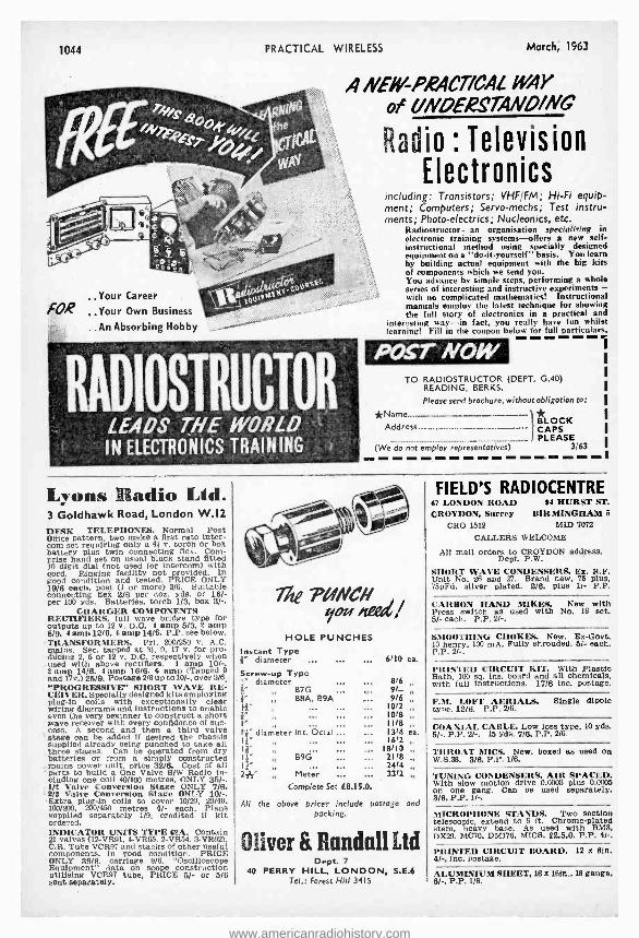
1044 PRACTICAL WIRELESS March, 1963
ANEfY-PRACT/CAL 1444Y
of UNDERSTAND/NG
Your Career
FOR .Your Own Business
.. An Absorbing Hobby _.
RADIOSTRUCTOR LEADS THE WORLD IN ELECTRONICS TRAINING
Radio : Television Electronics
including: Transistors; VHF /FM; Hi -Fi equip- ment; Computers; Servo -meths; Test instru- ments; Photo -electrics; Nucleonics, etc.
Radiostructor -an organisation specialising in electronic training systems -offers a new self - instructional method using specially designed equipment on a "do -it- yourself" basis. You learn by building actual equipment with the big kits of components which we send you. You advance by simple steps, performing a whole series of interesting and instructive experiments - with no complicated mathematics! Instructional manuals employ the latest technique for showing the full story of electronics in a practical and
interesting way -in fact, you really have fun whilst learning! Fill in the coupon below for full particulars.
POST NOW TO RADIOSTRUCTOR (DEPT. G.40)
READING, BERKS.
Please send brochure, without obligation to:
*Name BLOCK
CAPS ...._ PLEASE
(We do not employ representatives) 3/63
Lyons radio Lid. 3 Goldhawk Road, London W.I2 DESK TELEPHONES. Normal Post Office pattern. two make a first rate inter- com set requiring only a 41 v. torch or box battery plus twin connecting flex. Com- prise hand set on usual black stand fitted 10 digit dial (not used for intercom) with cord. Ringing facility not provided. In good condition and tested. PRICE ONLY 19/8 each, post (1 or more) 3/6. Suitable oonnecting flex 2/8 per doz. yds. or 16/- per 100 yds. Batteries, torch 1/3. box 3 / -.
CHARGER COMPONENTS RECTIFIERS, full wave bridge type for outputs up to 12 v. D.C. 1 amp 5/3. 2 amp 8/9. 4 amp 12l6. a amp 14/6. P.P. see below. TRANSFORMERS. Prl. 200 /250 v. A.C. mains. Sec. tapped at 35, 9, 17 v. for pro- ducing 2, 6 or 12 v. D.C. respectively when used with above rectifiers. I amp 10/ -. Y amp 14/6. 4 amp 18 /8. 6 amp (Tapped 9 and 17v.) 25/9. Postage 2/8 up to 10/ -, over 3/6. "PROGRESSIVE" SHORT WAVE RE- CEIVER. Specially designed kits employing plug -in coils with exceptionally clear wiring diagrams and instructions to enable even the very beginner to construct a short wave receiver with every confidence of suc- cess. A second and then a third valve stage can be added if desired the chassis supplied already being punched to take all three stages. Can be operated from dry batteries or from a simply constructed mains power unit, price 32/8. Cost of all parts to build a One Valve S/W Radio in- cluding one coil 40 /100 metres, ONLY 35/ -. 1/2 Valve Conversion Stage ONLY 7/8. 2/3 Valve Conversion Stage ONLY 10 / -. Extra plug -In coils to cover 10/20. 20/40,
200/450 metres 4/- each. Plans supplied separately 1/9, credited if kit ordered. INDICATOR UNITS TYPE 63A. Contain 21 valves (12 -VR91. 4 -VR65, 2 -VR54, 3- VR92), C.R. Tube VCR97 and stacks of other useful components. In good condition. PRICE ONLY 39/8, carriage 9/6. "Oscilloscope Equipment" iliingCR97 tube,
scope o5/ -or t5/6
sent separately.
The noel/ HOLE PUNCHES
Instant Type (j" diameter ...
Screw -up Type diameter
a" B7G 68A. B9A
h}" diameter Ist. Octal ...
14"
} Meter
6110 ea
816 91- 9/6
1012 1018 1118 1314 1612
18110 2118 2414 3312
ea.
Complete Set [8.15.0.
All the above prices include postage and packing.
Oliver & Randall Ltd Dept. 7
40 PERRY HILL, LONDON, S.E.6 Tel.: Forest Hill 3415
FIELD'S RADIOCENTRE 67 LONDON ROAD H HURST ST.
CROYDON, Surrey BIRMINGHAM 6
CRO 1512 MID 7072
CALLERS WELCOME
All mall orders to CROYDON address, Dept. P.W.
SHORT WAVE CONDENSERS. Ex. R.F. Unit No. 26 and 27. Brand new. 75 plus, 75pFd, silver plated. 2/0. plus 1!- P.P.
CARBON HAND MIKES. New with Press switch as used with No. 18 set. 5/- each. P.P. 2/ -.
SMOOTHING CHOKES. New. Ex -Govt. 10 henry, 100 mA. Fully shrouded, 5/- each. P.P. 2/ -.
PRINTED CIRCUIT KIT. With Plastic Bath, 100 sq. ins. board and all chemicals, with full instructions. 17/8 inc. postage.
F.M. LOFT AERIALS. Single dipole type. 12/8. P.P. 216.
COAXIAL CABLE. Low loss type, 10 yds, 5 / -. P.P. 2/ -. 15 yds. 7/8. P.P. 2/8.
THROAT MICS. New. boxed as used on W.S.38. 3/6, P.P. 1/6.
TUNING CONDENSERS, AIR SPACED. With slow motion drive 0.0003 plus 0.0005 on one gang. Can be used separately. 3/0. P.P. 1 /-.
MICROPHONE STANDS. Two section telescopic, extend to 8 ft. Chrome -plated stem, heavy base. As used with BM3, DX20. MC70. DM176. MICE. 22.5.0. P.P. 4/ -.
PRINTED CIRCUIT BOARD. 12 x ein. 4/ -, inc. postage.
ALUMINIUM SHEET, 16 x 1e1n., 18 gauge, 8/ -, P.P. 1/8.
www.americanradiohistory.com
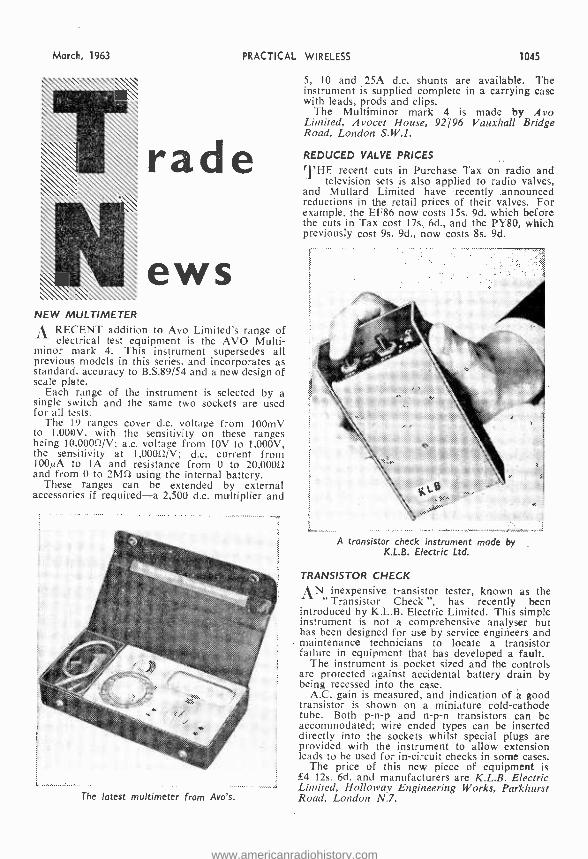
MarcF, 1963 PRACTICAL WIRELESS 1045
rade
ews NEW MULTIMETER
t\ RECENT addition to Avo Limited's range of electrical test equipment is the AVO Multi -
minor mark 4. This instrument supersedes all previous models in this series, and incorporates as standard, accuracy to B.S.89/54 and a new design of scale plate.
Each range of the instrument is selected by a single switch and the same two sockets are used for all tests.
The 19 ranges cover d.c. voltage from 100mV to 1,000V, with the sensitivity on these ranges being 10.00052 /V; a.c. voltage from 10V to 1,000V, the sensitivity at 1,00052 /V; d.c. current from 100µA to lA and resistance from 0 to 20,000i2 and from 0 to 2MS2 using the internal battery.
These ranges can be extended by external accessories if required -a 2,500 d.c. multiplier and
The latest multimeter from Avo's.
5, 10 and 25A d.c. shunts are available. The instrument is supplied complete in a carrying case with leads, prods and clips.
The Multiminor mark 4 is made by Avo Limited, Avocet House, 92196 Vauxhall Bridge Road, London S.W.1.
REDUCED VALVE PRICES
l' HE recent cuts in Purchase Tax on radio and television sets is also applied to radio valves,
and Mullard Limited have recently .announced reductions in the retail prices of their valves. For example, the EF86 now costs 15s. 9d. which before the cuts in Tax cost 17s. 6d., and the PY80, which previously cost 9s. 9d., now costs 8s. 9d.
A transistor check instrument made by K.L.B. Electric Ltd.
TRANSISTOR CHECK
AN inexpensive transistor tester, known as the " Transistor Check ", has recently been
introduced by K.L.B. Electric Limited. This simple instrument is not a comprehensive analyser but has been designed for use by service engineers and maintenance technicians to locate a transistor failure in equipment that has developed a fault.
The instrument is pocket sized and the controls are protected against accidental battery drain by being recessed into the case.
A.C. gain is measured, and indication of a good transistor is shown on a miniature cold - cathode tube. Both p -n -p and n -p -n transistors can be accommodated; wire ended types can be inserted directly into the sockets whilst special plugs are provided with the instrument to allow extension leads to be used for in- circuit checks in some cases.
The price of this new piece of equipment is £4 12s. 6d. and manufacturers are K.L.B. Electric Limited, Holloway Engineering Works, Parkhurst Road, London N.7.
www.americanradiohistory.com
1046 PRACTICAL WIRELESS March, 1963
ews::::: II. MI E PR III . Fil 0.
REPORTS OF CURRENT ACTIVITIES
COVENTRY AMATEUR RADIO SOCIETY Hon. Sec.: Alan J. Wilkes, G3PQQ, 141 Overslade Crescent, Coundon, Coventry, Warwickshire.
The aim of the Society in 1963 is to be even more active than last year, and much of this activity should materialise in the use of the newly acquired 150W transmitter for the Club station.
January 7th was devoted to a committee meeting. At the film show given on January 21st, the three films shown were "The Manufacture of Radio Valves ", "Mirror in the Sky" and "The Principles of Transistors ". On the 28th of the same month a
lecture was given on 70 cm.
EXETER AMATEUR RADIO SOCIETY Hon. Sec.: Stuart Line, 46 Roseland Crescent, Heavitree, Exitr, Devonshire.
This Society meets on the first Tuesday of each month, and in January the Annual General Meeting was held.
I:ICHFIELD AMATEUR RADIO SOCIETY Hoh. Sec.: V. Hickman, G3LXR, 143 Main Street, Stonnall, near Walsall, Staffordshire.
The Society's Annual Dinner and Dance which was held on January 11th, provided members with an enjoyable start to the New Year.
MITCHAM AND DISTRICT RADIO SOCIETY Hon. Sec.: B. Blandford, 1 Biggin Avenue, Mitcham, Surrey.
At the first meeting in January- Friday the 4th -Robin Sykes (G3NFV) gave a talk on the "Ham Hop Club ".
On January 18th members gathered to discuss arrangements for National Field Day. This was the second N.F.D. meeting, and
topics on the agenda included reports on an alternative site and
also the possibility of the Society operating only one station this year.
Future Event: February 15th -Annual General Meeting.
NORTHERN HEIGHTS AMATEUR RADIO SOCIETY
Hon. Sec.: A. Robinson, G3MDW, Candy Cabin, Ogden, Halifax, Yorks.
On January 30th, Mrs. Shaw (G30MM) gave a very interesting talk and exhibition on the subject of "Radio on Stamps ".
Future Event: February 13th -Ragchew.
PURLEY AND DISTRICT RADIO CLUB Hon. Sec.: E. R. Honeywood, G3GKF, IOS Whytecliffe Road, Purley, Surrey.
At the meeting on January 4th, members had the chance to have their queries and problems solved at a lecture on constructional hints.
RODING BOYS' SOCIETY (RADIO SECTION) R. Marchant, 154 Essex Road, Leyton, London, E.IO
This Society was formerly the Junior Section of the Wanstead and Woedford Radio Society, but now exists as an independent group. Regular activities include films, constructional projects and lectures on various topics. Work for the R.A.E. and morse proceeds as the demand arises.
Recently six members passed the R.A.E. out of the eight who sat it. Enquiries from any young people in the Roding Valley area who are interested will be welcomed.
"GO ,NORTH, YOUNG
HAM"
...HE population drift from North to South continues, following industry and work in the unarrested influx into and around the metropolis, ever increasing the hold London has not only on the country's economy, but also on its arts and sciences, its fashions and habits. No one can remain free from the influence of the big city, where all forms of entertainments and pastimes centre. The music and drama lover homes on to the West End like a pigeon to its pigeonry; the soccer fan must inevitably find that Wembley is his goal; and no one seems exempt from the grip of London.
Yet it is our experience that at least the North of England remains the active nucleus of the world of amateur radio, when all other interests centre on the South -East.
It is difficult to imagine the reason for this situation, but the Club reports that we receive show clearly that as far as amateur radio enthusiasts are concerned, England is top- heavy. These reports also suggest that the Northern club member is far more conscientious when it comes to attending club- nights, as quite a few of the Southern clubs' newsletters seem to make a regular feature of scolding members for not turning out for the last meeting and pleading with them to come to the next. This, of course, is
a generalisation, there being many South of England clubs with regular support from all their members, but this overall impres- sion is one gained by reading the hundreds of reports, from clubs all over the country, which yearly reach the PRACTICAL WIRELESS offices. and is therefore one very hard to dispute.
Yorkshire seems particularly well represented, with clubs in most of the major towns. Societies in Scotland also seem to be flourishing, and ir. the Midlands, Derbj+ sets a very good example of efficiency in club organisation.
And so " go North, young ham " seems the best advice we can give to any frustrated radio enthusiast who is finding insufficient vitality in his Southern club; and, who knows, he might one day be regarded as a pioneer of a general reversion to the North.
www.americanradiohistory.com
March, 1963 PRACTICAL WIRELESS 1047
MAILPLAN Immediate Despatch Service! Best Value for Money!
Dept. PW 138 Lewisham Way, New Cross, London, S.E.I4. TiDeway 6667
Terms of business -Cash with order or C.O.D.
TWO SENSATIONAL TRANSISTORISED INTERCOMS
HANDY INTERPHONE For Home, Workshop. Office, two -way calling. Consumes current only when talking or calling. Housed in attrac- tive plastic cabinets with chrome stands. Completely MAILPLAN PRICE portable. Master and sub - Incl. PP3 battery, and 25 station, Replacement battery 89/6 yds, lead with plugs. only 2/6. P. & P. 3/-.
(Today's value 8 gns.)
7 Station De Luxe
Transistorised Intercom The very latest in Office and Factory communication, Call- ing is audio and visual. Battery operated but consumes current only. when calling or. talking. Neat compact attractive units, up to 6 extensions supplied sep- arately. Battery life 300 hours.
Master 14 GNS. Post free. Extension 2 gns. Post free.
HALF THE PRICE OF OTHER MAKES
Construct your own Record Player, Intercom, Tape Recorder, etc., with the
PK.543 SUBMINIATURE 4- TRANSISTOR PUSH -PULL AUDIO AMPLIFIER 52/6
An assembled and wired miniature amplifier incorporating output transformer, and , 4 transistors, class B, 200 m. watts. All connec- Lion.) for battery, speaker and volume control. The quality is
amazing. Complete with instructions and circuit P217A. Size 3 x 1° /,, x
8d ohm speaker to suit above, 21-. Flux 16/6 P. & P. density, 7,800 gauss, Power, 200 mW. 1/-
M178 CRYSTAL LAPEL MIKE 17/6 100 -9,000 cps. lain. diam., 5ft. lead. P. & P. 1 / -.
SLIM CRYSTAL 3 -way MICROPHONE * Hand held. * Stand mounted.
or * Suspended by lavalfer cord.
MODEL 100C 39/6 Fráé Check the spec. and judge for yourself. Response 60- 10,000 cps. Built -in ON -OFF Switch. Output Level -52 dB. Omni -directional. Termination above 500 K ohms. Satin Chrome Finish. Accessory Table Too Stand, 818.
AU items advertised have been approved by our technical team of Qualified engineers.
A HIGH QUALITY PROFESSIONAL MIKE UM.II- MICROPHONE with Base. A flex- ible, newly designed, dynamic microphone integrated with a matching desk stand. Professional quality, ideal for tape record- ing, public address, broadcasting and com- munications. Ruggedly constructed, re- movable base for desk or hand use. 360° swivel ball joint allows tilting in any direc- tion. 9' high, body dia. 2' tapering to r. Base 5' die. Magnificently finished in mist blue with chrome trimming. Complete with shielded cable stand. Fully guaranteed.
AT LOW COST
_ S GNS.
The
the
SERVICE ENGINEERS! most useful tool that money can buy , . .
D900 TRANSISTOR TESTER POWER SUPPLY
LABOUR SAVING SPEEDY SIMPLE
ONLY Ask for full tech - £10 mo fts! specica-
Checks Alpha gain (Current gain -AC) Checks Beta gain (Current gain under DC conditions). M Leakage currents between Collector /Base and Collector /Emitter at any voltage between zero and 2.5 V. Specially designed for all receivers using PNP Transistors. Size 5i x 3 x 21in. NOW you can carry out fast testing of transistors and miniature transistor receivers without removing transistors from circuit. Self- contained signal tracing oscillator. self -contained varia- ble power supply.
Miniature Clear Plastic Panel Meters FOR YOUR HOME BUILT TEST EQUIPMENT
DC MICROA III SI ETERS Model MR.25 0 to 50 µA .. 39/6 Model MR.250 0 to 500 µA .. 32/6
DC MILLIAMMETER Model MR,210 to 1 mA .. 27/6 All models Individually Boxed and Fully Guaranteed. P. & P. 2/6 each. "S" METER MODEL SR.LP. Standard "Ham" Signal strength indicator. Cali- brated in "S" units from 0-9 with scale terminating in +10 to +30 dB calibra- tions. Additional full scale calibrations of 0-5 +0-10 in linear scale divisions, 35/-, VU METER MODEL VR. IP. Cali- brated and damped in accordance with standard VU Meter Practice, Upper scale reads -20 to +3VU. Lower scale 0 -100 °' modulation. Uses precision carbon film and full wave rectifiers. 42/6.
multiplier - resistor
SKANTEST -THE LOWEST PRICED L.O.P.T. TESTER
Tests TV Windings for shorting turns by unique pulse method. This compact instrument can save you pounds, It detects a single shorting turn In a line output transformer, deflector coil or other Windings. The pulses provided by the instrument detect intermittent faults. In position one, the continuity of the Windings is checked; in position two, high Impedance coils, and in position three, low Impedance coils, Once you have used the Skantest you will regard it as a must in TV Servicing, Exclusive Mailplan Offer 99/6 P'2/gP'
MULLARD TAPE RECORDER AMPLIFIER Printed circuit board and set of 27 capacitors plus 1/6 ranging from 50 +50µF at 350 v. to 47 pF. 28I- P.P.
PORTABLE SOLDERING IRON Model SPI 30 Watt 230 Volts
(Size IOtin. 4in. when not in use.) Designed on an entirely new principle for light-weight applications. Highly stable heat characteristics ensure long life. Removable handle permits iron to be carried safely even while hot. Supplied complete with Vinyl bag, lead and plug. Spares. available. Element 4/6. P. & P. 6d.
18/9p v_
MODEL V -7A /F VALVE VOLTMETER Equal to many higher priced instrumente. Gold -plated printed -circuit, High input im- pedance (11 meg- ohms), The V -7A measures A.C. volts (0 -1.5, 5, 15:50, 150, 500, 1,500)- R.A,8. and A.C. volts (0A 14, 40. 140, 400, 1,400 and 4,000) pk: to -pk, D.C. volts (0 -1.5, 5, 15; 50, 150, 500, 1,500) Ohms (with 10 ohms centre) XI, X10, X100. X1000, X1OK, X100K, and X1 megohm, £19.18.6 Complete with 32 -page handbook,
.IODLE V -7A (In kit form). £13.18.6
www.americanradiohistory.com
1048 PRACTICAL WIRELESS
ACKNOWLEDGED TO BE THE BEST
COMPONENT CATALOGUE A
MUST for every
radio enthusiast
March, 1963
i
NOW 172 Pages
Over 600 illustrations
¡4 Over 5,000 components listed
This is today's most up -to -date. most comprehensive component catalogue t,, for the radio constructor, CAP, in-tenter, engineer and Hi -Fi enthusiast.
2/6 PLUS 9d POST
P POST
COUPON TODAY
Write CATALOGUE on top left of envelope
Enclose P.O. 3/3
Name ....... ............................... Address ......... , .
Home Radio Ltd. (PW) 187 London Rd., Mitcham, Surrey
Crystals it Components Ltd 2-4 EARLHAM STREET, LONDON W.C.2 Tel: TEMple Bar 1189
Near CAMBRIDGE CIRCUS. A few minutes' walk from Leicester Square or Tottenham Court Road. Underground Stations.
(tours of business to 6. Saturdays 1 p.m. OPEN ALL DAY THURSDAY until 6.30 p.m.
TYPE 46 WALKIE-T'ALKIES. Best buy inM'X/RX units in years. Complete with
accessories at give -away price. '33-- channel cryttal controlled TX and R /X. Supplied complete with one pair of crys- tals, coil box, rod aerials, leads and plugs. valves, balanced armature head set with tisroat-mike. Coverage: 3.6 to 4.3 Mc/s- orr 6.7 to 7.6 Mo/ by. means of plug-in coil Wok. (State which frequency preferred when ordering.) Requires only 150 v., 15 v., and 3 v. dry batteries. Range over 10 miles under good conditions. Full instructions supplied. As. new. We offer this fine unit as listed above with all accessories,
stag an packing cpacking
6/6. Set of batterwfes 24/- per set.
SPECIAL OFFER TYPE 46 WALKIE- TALKIES
As described above with valves, crystals and coil box but having had the original send /receive switch removed. Without other accessolies. This set is supplied with a substitute switch and full wiring details at 18 /6 each or 35/- per pair. P. & P. 5/6.
BRAND NEW TAPE RECORDING HEADS. For single, centre track record- ing. With leads and 4 -pin plug, 12/6. Postage 1/6.
DIODES. 0A81, 2/9 ea.. OC71. 0072 substitutes, 3/6 ea.
TEST INSTRUMENT BARGAINS Sangamo Weston, brand new (not boxed), 0-750 micro amps flush, round. 31ín. dia. 49/6 Sangamo Weston, brand new (not boxed), 0-1 micro amps flush, round 311n. die. 47/6 0-5 micro amps M.C. projecting 61n. dia. steel case 39/8 each 0-15 micro amps M.C. projecting din. dia. steel case 39/6 each 0-50 micro amps 54.0. projecting bin. dia. steel case 27/6 each 0-100 micro amps M.C. projecting bin. dia. steel case 27/6 each
P. & P. 2/- per instrument.
LATEST MODEL BRAND NEW 'GUNFIRE' TIME SWITCHES
Self starting, non reversing synchronous motor operating on 200/2.50 v. A.C. contin- uous rating 20 amps. at 250 v. Special insulated switching device switching on and off in 24 -hour cycle automatically, also incorporates manual switching should normal sequence need to be inter- rupted. Takes extra pair switch arms to give 2 "ons "- and 2 "offs ". Perspex cover. Ideal for all domestic and electronic circuits. Price 79/6. Extra arms 2/6 per pair.
SILICON ItECTII'IERS. Miniature power diodes at the right price. Leading makes. 400 P.I.V. at 650 mA, 6/- each. 500 P.I.V. at 200 mA. 3/6 each. 860 P.I.V. at 550 mA, 7/6 each. 1,000 P.I.V. at 500 mA. 8/6 each.
CRYSTALS!!! LARGE RANGE OF 10X, 1OXJ, FT243, FT241 CRYSTALS ALWAYS
IN STOCK.
Send stamped and addressed envelope for our free, comprehensive list.
BC6I0 TUNING UNITS Choice of 5 -8.35 or 6.35-8 Mc /s. These compact units (9 x 4 x 2in.) were used as plug -in tuning boxes with the BC610 TX. Containing miniature variable condensers of 140 pFd, 100 pFd and a standard size 50 pFd. A 0.100 graduated knob dial Din. dia. D.P.D.T. toggle switch and several others components. Price 6/6 ea. P.P. 3/ -.
HELIPOTS. Brand new and boxed, 2,000 ohms, 10 turns, ±0.1% linearity. 18/6 ea. P. & P. 1/6.
50 VOLT 10 AMPS OUTPUT TRANS - FORMERS. 230 v. primary. Conser- vatively rated. Brand new in maker's cartons. 55/- each. Carriage 7/6.
TEI1SIS OF BUSINESS CASH WITH ORDER. Handling cita rye of 1/6 on all orders under 20/- where P.1' is not otherwise stated.
www.americanradiohistory.com
March, 1963 PRACTICAL WIRELESS 1049
Letters to the Editor The Editor does not necessarily agree with the opinions expressed by,his correspondents
Whilst we are always pleased to assist readers with Cher technical difficulties, we regret that we are unable to supply diagrams or provide instructions for modifying commercial or surplus equipment. We cannot supply alternative details for receivers described in these pages. WE CANNOT UNDERTAKE TO ANSWER QUERIES OVER THE TELE- PHONE. If a postal reply is required a stamped an addressed envelope must be enclosed with the coupon from page iii of the cover.
THE CHANGING WORLD OF WIRELESS
SIR, -When I look at the original Newnes Wireless Constructors' Encyclopaedia, a' copy
of which I still have, I can't help but wonder at the great steps which have been made in Wireless . since those early days. I. can remember the. first. radio valve, the first bright emitter and the first screen grid valve. .
What marvels have now become commonplace things, which not so long ago were 'mere' pipe dreams! We indeed should be thankful to all those " backroom boys " who did so much to make our lives the more enjoyable. And who knows what is to come in the future with satellite communica- tions and colour television already here?
My regards to the staff of P.W. who have given many of us radio amateurs such interesting articles, blueprints, etc., and thank you for making my life, at least, more enjoyable. -H. T. ROLLER (London S.W.6.) (Member of the Radio Amateur Invalid and Bedfast Club).
LOCAL COMMERCIAL RADIO '
SIR,- Having read with interest recent letters'in P.W. concerning local radio stations, I find
myself agreeing with the sympathies expressed by your correspondent, Mr. P. Robinson, in . the November' 1962 issue.
Commercial. stations, running at low power, and situated in the major towns, would, I feel, make a welcome change to the programmes put out by the BBC.
The opinion of Mr. Dent (January issue) that these stations would be cluttering up the wave- bands is nonsense, as two or three low power stations, if displaced widely apart and equipped with beam antenna, could easily operate on the same channel. -W. B. MooN (Hull, Yorkshire).
HI -FI FANATICS
SIR, Mr. D. R. Davenport's criticism of, his friend's hi -fi system (December issue) surprised
me. Fingermarks on record grooves attract dust, and if a record is played without first having such
dust removed, a great deal of surface noise will be apparent. Extra wear and tear on both the stylus and the record will also result.. ..
As to fiddling about with the controls for about twenty'niinutes, I'find this difficult to believe. How- ever, Mr., Davenport's friend may purpdsely have taken. his time,. solely to 'impress him; apparently without success. ,
' As'a'closing word, I suggest that Mr. Davenport listens'. to one of his .own records over a, high quality system. The surface noise will be unbear- able; and it Will, f hope; make hiin reconsider his "cheap record player -E. W. SKEEN. (Johan - nesburg, South Africa).
SIR; -If. Mr: Davenport and ,Mr Nicholls are of the opinion that hi -fi enthusiasts are self -styled,
thenI am afraid they are sadly mistaken. Mr. Nicholls considers - that such terms as
"frequency . response " _ and. " negative, feedback tone circuits " are merely tagged on to articles to impress the buyer, and so it seems to me that he cannot read P.W. very carefully.
Also if Mr. Davenport has never heard the terrible effects caused by fingers carelessly rubbed across the groove of a record, then I suggest that his friend had better demonstrate this to him (with one of Mr. Davenport's own records!). -A. FERGUSON (Eastbourne, Sussex).
SIR, -May I be allowed to ,support Mr. D. R. Davenport in his criticism of hi -fi enthusiasts?
I.agree that it is a boreanda trial to-be victimised by the enthusiasm of others.
With regard to the letters of Messrs. J. D. Maitland and D. L. Miller, 'surely, if one has to have the skill of a jeweller or of a dental technician to handle,modern gramophone records correctly, it is high time to find and apply a better system of sound recording ? -W. F. FANSHAWE (Chesham. Buckinghamshire).
LANGUAGE BARRIER
SIR, -As a newcomer to shortwave_ listening, I
find it very annoying when tune into a foreign amateur station only to find that I cannot understand the, language of the operator. This language barrier., problem could very easily, be solved by the use of Esperanto. So, why.not make it the 'accepted language for- radio amateurs -the world over? If any help is needed, there is, an Esperanto Society of Great Britain to assist those interested, as I am sure many amateurs would be. A. JAMESON. (Wigan, Lancashire)..
www.americanradiohistory.com
1050 PRACTICAL WIRELESS March, 1963
COMPONENTS WANTED
SIR, -I wonder if any of your readers could assist me in getting hold of an item of equipment
not obtainable in this locality. It is the coil pack and switch assembly of the
R208 reception set (10- 60Mc /s). The existing component in my set has been damaged beyond repair, and therefore if any reader knows of a source of supply for this part, I would be very much obliged if they would get in touch with me. -W. C. STEPHENSON (10 Plungington Road, Preston, Lancashire).
SERVICE SHEET WANTED
SIR, -Apart from constructing radios in my spare time, I am also the Troop Leader of our local
Boy Scout troop. We obtain most of our funds from hiring out our hall for dances, etc. and in connection with this we have a rather elderly m.w. receiver /p.a. amplifier, the Ambassador type PA.145.
For a long time, we have had trouble with microphony and intermittent distortion, but this has become so bad lately that the equipment is almost unusable. I have tried without success to obtain a service sheet and I would therefore be very grateful if one of your readers could give me the valve line -up or preferably loan or sell me the circuit diagram or service sheet. -7. B. McGtrita (13 Hunters Chase, South Godstone, Surrey).
PARALLEL TRACKING UNIT
(Continued from page 1018)
the run -out groove, and then out again to the 7, 10 or 12in. mark before placing the pick -up on the run -in groove. The unit is pushed with the first finger behind the cartridge, during this time the pick -up sliding on the lowering arm back portion, and by depressing the lowering arm the needle will be brought down on to the record. At the completion of the record the arm is raised, and the pick -up pushed away from the centre, allowing the record to be removed.
If on certain passages the unit resonates, either a slightly greater tracking weight is needed or the cartridge housing needs stiffening up by adding extra struts of balsa wood. An error of only *in. in the needle run each side of the centre spindle will increase the distortion considerably. Further distortion will arise if the needle does not, run exactly upright in the groove and a careful sight along the record at right -angles to the needle path will show any error. The table and V -bed must be horizontal when the unit is working, a small spirit level being useful for this purpose. The V -bed may be adjusted by means of the elongated hole in the left -hand bracket.
These adjustments may take several hours, but the time will be well spent in ensuring optimum results from the equipment.
At- a- glance
PARALLEL RESISTOR
and
,410,/ in/ , -.o.:.,.. ,M
0°15.L4 im.,+
SERIES
CAPACITOR CALCULATOR
Plus - Colour Code
4.7
1.9
igtÁCTICAL o WIRELESS C PARCttEt
__-- 8
CAPACryC,y CAICCtq7 ÁSER/t Guide
i;
DON'T MISS IT! - ORDER YOUR COPY TODAY!
www.americanradiohistory.com
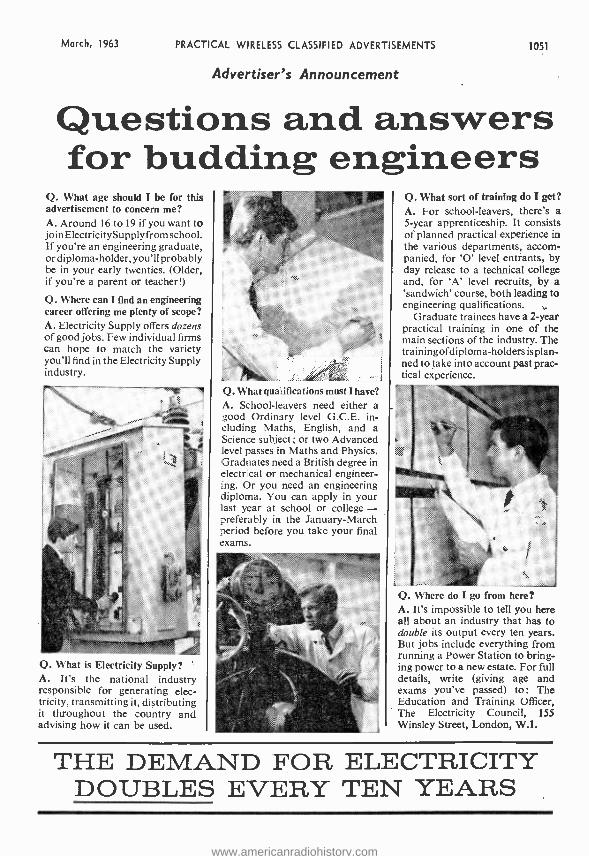
March, 1963 PRACTICAL WIRELESS CLASSIFIED ADVERTISEMENTS 1051
Advertiser's Announcement
Questions and answers for budding engineers
Q. What age should I be for this advertisement to concern me? A. Around 16 to 19 if you want to join Electricity Supplyfrom school. If you're an engineering graduate, or diploma-holder, you'll probably be in your early twenties. (Older, if you're a parent or teacher!)
Q. Where can I find an engineering career offering me plenty of scope? A. Electricity Supply offers dozens of good jobs. Few individual firms can hope to match the variety you'll find in the Electricity Supply industry.
Q. What qualifications must I have? A. School -leavers need either a good Ordinary level G.C.E. in- cluding Maths, English, and a Science subject; or two Advanced level passes in Maths and Physics. Graduates need a British degree in electrical or mechanical engineer- ing. Or you need an engineering diploma. You can apply in your last year at school or college - preferably in the January-March period before you take your final exams.
.... .. .. {::
Q. What sort of training do I get? A. For school -leavers, there's a 5 -year apprenticeship. It consists of planned practical experience in the various departments, accom- panied, for 'O' level entrants, by day release to a technical college and, for 'A' level recruits, by a 'sandwich' course, both leading to engineering qualifications.
Graduate trainees have a 2 -year practical training in one of the main sections of the industry. The trainingofdiploma -holders is plan- ned to take into account past prac- tical experience.
Q. What is Electricity Supply? A. It's the national industry responsible for generating elec- tricity, transmitting it, distributing it throughout the country and advising how it can be used.
Q. Where do I go from here? A. It's impossible to tell you here all about an industry that has to double its output every ten years. But jobs include everything from running a Power Station to bring- ing power to a new estate. For full details, write (giving age and exams you've passed) to: The Education and Training Officer, The Electricity Council, 155 Winsley Street, London, W.I.
THE DEMAND FOR ELECTRICITY DOUBLES EVERY TEN YEARS
www.americanradiohistory.com
1052 PRACTICAL WIRELESS CLASSIFIED ADVERTISEMENTS March, 1963
RECEIVERS & COMPONENTS METAL WORK RATES: 7/3 per Une or part thereof, average five words to line, minimum 2 Unes. Box No. 1/- extra. Advertisements must be prepaid and addressed to Advertisement Manager, "Practical Wireless," Tower House, Southampton St.,
London W.C.2.
PARTS for OUTS to this issue. IFT's 3/- and all the latest Service Sheets. Stamp for lists. AJAX ELECTRONICS, 572 Fulham Road, London SW6.
NEW VALVES, 12 months' guarantee ECC81 /2 3, EF80, E891 4/11 EZ80 /I, íL84, EM84, ECL86, ECL80 716 ECL82, PCL82, PL8I, U25, PCF80 9111
P. BEARMAN (Tubes) 3 PANK AVENUE, NEW BARNET
HERTS. Tel: BARnet 1934/3185
EXCEPTIONAL VALUE: Picture Tubes, brand new, Mazda 19in., CME1901, Mullard 19in., AW47- 90/91, £4 /10 /'; Mullard 23in., AW59/90. £61101 -; carriage (insured) paid. 12 months' guarantee. Note, all brand new. We also supply most other sizes completely regunned at £4/17/8. guaranteed 12 months. TOMI, Lewisham Way, New CrossN SE14. TID 3857.
ALL TYPES LINE OUTPUT TRANS - FORMERS SUPPLIED (RETAIL AND TRADE). Finest service in the country. Send S.A.E. for return of post service. Tertres C.W.O. or C.O.D. Trade enquires invited. D. AND B. TELEVISION (WIMBLEDON) LTD., 131 Kingston Road, Wimbledon, 8W19. CHErrywood 3955.
NEW VALVES, guaranteed: EY88, 7/9; EZ40, 6/6; PC084, 7/': PCF82, 7í; PCL84, 7/3; PL81, 8 /8; PY81, 7/.; 6X4, 5 / -; plus 6d. p. and p. each. B.A.E. for lists. LEWIS, 46 Woodford Avenue, Ilford, Essex. Telephone CRE 5685.
DATA TRANSISTOR POCKET KITS
NO SOLDERING OR DRILLING, COMPLETELY
SELF CONTAINED NO AERIAL REQUIRED - MEDIUM & LONG WAVE - ASSEMBLY TOOL
PROVIDED - CAN BE BUILT BY
ANYONE DATA 55 6 SEMI- CONDUCTORS 5 STAGES MOVING COIL SPEAKER.
55!- Pez 2/9
tra.
Battery 2 /3extra. 55 s i x tiles
DATA 427, 4 TRANSISTORS. 2 7n DIODES. 7 STAGES. MOVING COIL
SPEAKER Battery 2/9 extra. P.P. 2/9 extra
DATA 880 3 TRAN- SISTORS 2 DIODES 6 STAGES PERSONAL EARPIECE
. 6J 3/
P.Pex.
Batt. 1/- ex. 41x21, x1 }la.
All Parts Supplied Separately
DATA ELECTRONICS LTD.
6 HILLSIDE GDNS., EDGWARE, Middlesex
RECEIVERS & COMPONENTS (continued)
Al POST-FREE BARGAINS. First grade TRANSISTORS: 0044 8/9, 0045 7/3, OC70 0071 5/3, 0072 0074 0078 0081 7/-, 00170 8/9, 00171 9/3. All other Mallard types stocked. VALVES set tested: EB91 EF91 E050 EF80 9d., 611. 10F1 1/ -, L63 2001 E 1.80 3/., PY81 PZ30 B36 4/- PCF80 PL82 PL83 PY80 PY82 KT3/3C 4/3, PL38 3437 KT36 4/9, POL83 8 / - PY32 6K25 5 /9, 185BT 27817 1725 9/8.
,
10% discount on six, 25% on 12, any com- bination. Ready -made Transistor Set 32/ -, Al RADOO COMPONENTS. 14 The Borough, Canterbury, Kent.
ULTRA LINEAR AMPLIFIERS High Fidelity. 15 watts. Valves ECC83, ECC83, EL84. EL84, EZ81. Two in- puts. Sensiti- vity 10 milli- volts. Bass & Treble controls. 3 & 15 ohms. output. Kit, 26.10.0, plus 6/-
carr. Factory built. £9, Plus 5/- cary. Sim- ilar 30 watt £12. plus 7/6 cary. Leaflet free. Same day despatch.
STROUD AUDIO Bath Road, Stroud, Glos.
Tel, Stroud 788.
HALF PRICE Transistors. Mullard 0044, 0045, 0081, 00810, 00170, all 4/8 each; Min } doz. lots; 0026 12/0 each. Post 9d. C.W.O. RADIOMEX 184 Kingston Road, Portsmouth,
" HEATHK ITS " can now be seen in London and purchased on easy terms. Free brochure. DIRECT TV REPLACE- MENTS LTD., Dept. P.W. 7/9, 138 Lewisham Way, 3E14. Tideway 6666.
SPEAKER REPAIRS. Cones/Fields fitted. Clock coils wound. L. S. REPAIRS, Pluckley, Ashford, Kent.
TRANSISTORS. Marked and tested, packets of 10; unmarked but tested, packets of 16; unmarked and untested packets od, of 40.
of 80. suitable as
20/- each. Any two packets 37/8. C.W.O. K. R. WHISTON, Dept. TPW, New Mills, Stockport.
CANADIAN MARCONI 52
RECEIVERS
An excellent Communications Receiver covering 1.75 to 16 mc/s in 3 bands. 1 R.F., 2 I.F. stages. 10 valves plus 3 valve crystal calibrator, 10, 100 and 1,000 kc /s. Crash Limiter, Broad /Sharp Selectivity, 500 Mk/ amp. valve check /Signal Level meter. 8 in. speaker phone jacks, power required 150 v. H.T. 12 v. a.c. or d.c. L.T. PRICES Receiver only £5.10., carriage £1. Receiver in steel cabinet with installation kit com- prising power unit ZE12 for a.c. mains 230 or 115 v. or 12 v. D.C., all connecting cables and spares, two pairs padded Head- phones and aerial wire. £9.10., carriage £1. Send S.A.E. for detailed leaflet.
G.W.M. RADIO LIMITED 40/42 Portland Road, Worthing, Sussex,
METALWORK. All types cabinets, chassis, racks, etc., to your specifica- tions. PHILPOTT'S METALWORKS LTD., Chapman St., Loughborough.
FOR SALE
EXCEPTIONAL Transistor Portable Tape Recorder, value £611916. corn. plete with crystal microphone, earphone, spools, tape, batteries, instructions, presentation box (extra tapes 100 4/8). Ideal gift, £811916. Satisfaction guaranteed. Postage.
W packing
2 /6. Ts L E, 156 Lewisham
Way,
ASK your dealer for American Ferro - dynamics. " Brand Five " Recording Tapes -the best tape value!
GRUNDIG MAI Transistor Tape Pre- amplifiers suitable for use as micro - phone transformer, pick -up and tape head booster. Listed at 44 gns., offered at £2/17/8. Send for full details and free lists. LEE ELEC- TRONICS, 400 Edgware Road, W2. (Paddington 5521.)
AMATEUR LICENCE Morse Course. The new Rhythm Method of teaching takes the drudgery out of learning Morse and is the quickest known! For full explanatory booklet: S.A.E. 03CHS, 45 Green Lane, Purley, Surrey.
SUPERHET RADIO CHASSIS These well -made sets were made for the Government for Forces' entertainment, using 6K8, 6K7, 6Q7, 6V6. Slow motion tuning, Choke smoothing, 200 -550 meters, size II x5 x lin., printed scale. BRAND NEW only 5716, post 51 -. Case, with
speaker to fit, 2716. 12 Volt Vibrator Unit (P.C.R. series), 100 mA output to 250 volts, double choke smoothed, bridge rectified, spare vibrator, indicator bulbs, battery clips, fusewire. BRAND NEW in makers' cartons, case size 6 x 8 x 10in., 22/6, carr. 516.
Clearance Offer, R107 Sets, 9 valves 1.2 -17.5 Mc /s, internal speaker and power unit for 12 volts, 100 -250 A.C. 69.15.0. Air tested, realigned, 62.10.0 extra. Carr. 301 -. R107 in maker's crates, Brand New. 617.10.0. CR.200, 15 -560 Kc /s. Brand New, 612.10.0, carr. 301 -. RI09(A). 2 -I2 Mc /s, 5 spare valves, 2 pairs headphones, HT -LT voltmeter, manual, circuit, Brand New in maker's boxes, £6.15.0, carr. 101-. 1466 Receivers, 30-40 Mc /s, 6 valves,12716, Carr. 516. 19 Mkt TX -RX. With 12 -volt power unit. New, 64.10.0, carr. 101 -.
J. T. SUPPLY (Dept.N), 309 MEANWOOD ROAD : LEEDS 7
VALVE and Semiconductor Hand- books, Mazda /AEI (2V); G.E.C. (8V); Ferranti (2V) ; Mullard 1, 2, 4, £4. R. H17TCHESON, Kersehill, Dalderse Avenue, Falkirk, Stlrlingshire.
BARGAIN, EIGHT 45 rev /min Brand New Pop singles (value over 50 / -) for £1. S.A.E. for details to: R. PLETCHER (P.W.) 24 Old Hall St.. Burnley, Lanai.
www.americanradiohistory.com
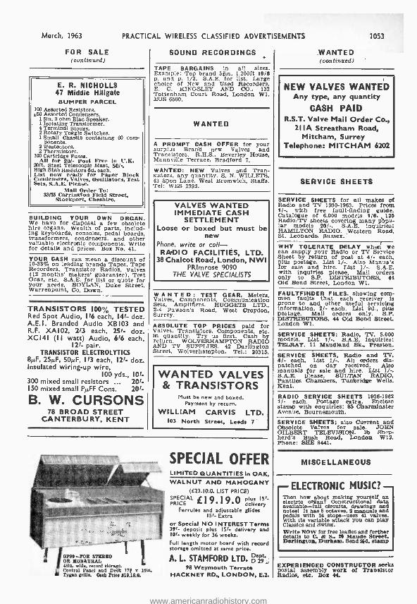
March, 1963 PRACTICAL WIRELESS CLASSIFIED ADVERTISEMENTS
FOR SALE (continued)
E. R. NICHOLLS 47 Middle Hillgate
BUMPER PARCEL 100 Assorted Resistors. a50 Assorted Condensers.
1 510. 3 ohm Elac Speaker. 1 Isolating Transformer. 4 Terminal Blocks. 2 Rotary Toggle Switches, I Small Chassis containing 60 com-
ponents. 2 Westectors. 2 Thermistors.
100 Cartridge Fuses. All for 20 /- Post Free In U.K.
20ft. Steel Telescopic Mast, 50/-. High Stab Resistors 6d. each. List now ready for Paper Block Condensers, Valves, Oscillators, Test Sets, S.A.E. Please.
Mali Order To: 33/35 Carrington Field Street,
Stockport, Cheshire.
BUILDING YOUR OWN ORGAN. We have for disposal a few obsolete hire organs. Wealth of parts, includ ing keyboards, consoles, pedal boards, transformers, condensers, and other valuable electronic components. Write for details and prices. Box No. 41.
YOUR CASH can mean a discount of 10 -33% on leading brands Tapes, Tape Recorders, Transistor Radios, Valves (12 months' makers' guarantee), Test
Gear, etc. S.A.E. for list or quote for your needs. BOYLAN, Duke Street, Warrenpoint, Co, Down.
TRANSISTORS 100% TESTED Red Spot Audio, 116 each, 14f- doz. A.E.I. Branded Audio XB103 and R.F. XAI02, 213 each, 25f- doz. XCI4I (I1 watt) Audio, 6f6 each,
12f- pair. TRANSISTOR ELECTROLYTICS
8µF, 25µF, 501/F, 113 each, 12f- doz. Insulated wiring -up wire,
100 yds., IOf- 300 mixed small resistors ... 20í- 150 mixed small PµFF Cons. 20f-
B. W. CURSONS 78 BROAD STREET
CANTERBURY, KENT
SOUND RECORDINGS
TAPE BARGAINS in all sizes. Example: Top brand 53ín. 1,200ft 19/S p. and p. 1/3. S.A.E. for list. Large choice of New and Used Recorders. E. C. KINGSLEY AND CO., 132 Tottenham Court Road, London WI. EUS 6500.
WANTED
A PROMPT CASH OFFER for your surplus Brand new Valves and Transistors. R.H.S., Beverley House, Mannville Terrace, Bradford 7.
WANTED: NEW Valves and Tran- sistors, any quantity. S. N. WILLETS, 43 Sport Lane, West Bromwich, Staffs. Tel: WES 2392.
VALVES WANTED IMMEDIATE CASH
SETTLEMENT Loose or boxed but must be
new Phone, write or call -
RADIO FACILITIES, LTD. 38 Chalcot Road, London, NWI
PRImrose 9090 THE VALVE SPECIALISTS
WANTED: TEST GEAR, Meters, Valves, Components, Communication Sets, Amplifiers. HUGGETS LTD., 2 -4 Pawson's Road, West Croydon, Surrey.
ABSOLUTE TOP PRICES paid for Valves, Transistors, Components, etc. in quantity. Try us first. Cash by return. WOLVERHAMPTON RADIO AND TV SUPPLIES, 42 Darlington Street, Wolverhampton. Tel.: 20315.
WANTED VALVES & TRANSISTORS
Must be new and boxed. Payment by return.
WILLIAM CARVIS LTD. 103 North Street, Leeds 7
OPIO -POR STE OR MONAURAL 48in. wide, record storage.
L Control Panel and Deck 17f e loin, It Tygan grille. Ooh Price 519.10.0.
SPECIAL OFFER LIMITED QUANTITIES in OAK, WALNUT AND MAHOGANY
([23.10.0. LIST PRICE) SPECIAL £ 19. 19.0 plus 15i- PRICE delivery
Ferrules and adjustable glides 15i- Extra
or Special NO INTEREST Terms 39i- deposit plus ISl- delivery and I0í. weekly for 36 weeks. Full length motor board with record storage omitted at same price.
A. L. STAMFORD LTD. gel's,`
98 Weymouth Terrace HACKNEY RD., LONDON, E.2.
1053
WANTED (continued)
NEW VALVES WANTED Any type, any quantity
CASH PAID R.S.T. Valve Mail Order Co.,
2I I A Streatham Road, Mitcham, Surrey
Telephone: MITCHAM 6202
SERVICE SHEETS
SERVICE SHEETS for all makes of Radio and TV 1930 -1863. Prices from 1/ -, with free fault- finding guide. Catalogue of 6,000 models 1/S. 125 Radio /TV sheets covering many popu- lar models 20/ -. S.A.E. inquiries: HAMILTON RADIO. Western Road, St. Leonardo, Sussex.
WHY TOLERATE DELAY wheci' we can supply your Radio or TV Service Sheet by return of post at 4/- each. plus postage. List 1 / -. Also Manuals for sale and hire. List 1 / -. S.A.E. with inquiries please, Mail orders only to S.P. DISTRIBUTORS, 44 Old Bond Street, London Wl.
FAULTFINDER FILES, showing com- mon faults that each receiver is prone to and other useful servicing information, 2/. each. List 9d., plus postage. Mail orders only. S.P. DISTRIBUTORS, 44 Old Bond Street. London WI.
SERVICE SHEETS: Radio, TV, 5,000 models. List 11 -. S.A.E. Inquiries: TELRAY, 11 Maudland Bk., Preston.
SERVICE SHEETS. Radio and TV. 4/- each, List 1 / -. All orders dis- patched on day received. Also manuals for sale and hire. List 1 / -. S.A.E. please. SULTAN RADIO, Pantiles Chambers, Tunbridge Wells, Kent.
RADIO SERVICE SHEETS 1936 -1962 1/- each. Postage extra. Enclose stamp with enquiries: 85 (Ibarminster Avenue, Bournemouth.
SERVICE SHEETS; also Current and Obsolete Valves for sale. JOHN GILBERT TELEVISION, lb Shep- herd's Bush Road, London W12. Phone: SHE 8441.
MISCELLANEOUS
ELECTRONIC MUSIC? Then how about making yourself an electric organ? Constructional data available -full circuits, drawings and notes! It has 5 octaves, 2 manuals and pedals with 24 stops -uses 41 valves. With its variable attack you can play Classics and Swing. Write NOW for free leaflet and further details to C. & S., 20 Maude Street, Darlington, Durham. Send 2id. stamp
EXPERIENCED CONSTRUCTOR seeks postal assembly work of Transistor Radios, etc. Box 44.
www.americanradiohistory.com
1054 PRACTICAL WIRELESS CLASSIFIED ADVERTISEMENTS March, 1963
SITUATIONS VACANT
Fly as an Air Electronics
Officer in the R.A.F.
'The domain of the Air Electronics Officer is the whole range of electrical and electronics equipments in an operational aircraft. This covers high frequency long range communication equipment (both voice and wireless telegraphy), VHF communications (short range radio telephone), ASV (air to surface vessel) radar, and the 'black boxes' for the electronic defence of the aircraft.
Having completed your highly- specialised training courses- during which you do about 123 hours flying, including two flights abroad -you fly in the V- bombers of Bomber Command or on Coastal Command re- connaissance.
You are a key man doing a key job -where success depends entirely on your own skill, training and flexi- bility. There is nothing run -of -the -mill about it. You have a career you can be proud of -and there lies satisfaction.
You are well paid from the very beginning -you earn £976 as a Flying Officer of z I. At 25 as a Flight Lieutenant, drawing full allowances, you could earn over £1,800. You travel the world, meeting old friends on almost every airfield, making new friends wherever you go. You live well in the Officers Mess, and have the opportunity of taking part in almost any sport you can name.
If you are under 26, fit, and hold or expect to gain G.C.E. at 'O' level (or equivalent) in 5 acceptable subjects including mathematics and English language, you are eligible for a Direct Entry commission. Write for further details, giving date of birth and educational qualifications to Group Captain J. A. Crockett, R.A.F., Air Ministry (PW906B) Adastral House, London, W.C.I.
THE FUTURE IS WITH THE R.A.F.
The,Róyal Air Force
A.M.LMeCh.E. A.M.Brit.I.R.E., City and Guilds, G.C.E., etc. brings high pay and security. "No pass -no pay" terms. Over 95% successes. For details of exams and courses in all branches of Engineering, Building, Electronics, etc, write for 148 -page handbook, free. B.I.E.T. (Dept. 242B), London W8.
TV AND RADIO, A.M.Brit.I.R.E. City and Guilds. R.T.E.B. Cert., etc. on "No pass -no fee" terms. Over 95% successes. For details of exams and courses (including practical apparatus) in all branches of Radio, TV and Electronics, write for 148 - page handbook free. B.I.E.T. (Dept 242G). 29 Wright's Lane, London W8.
CITY AND GUILDS (Electrical, etc.) on " No pass -no fee" terms. Over 95% success. For details of Electri- cal Engineering, Applied Electronics, Automation. etc., send for our 148 - page handbook, free and post free. B.I.E.T. (Dept. 242A), 29 Wright's Lane, London W8.
PUBLIC APPOINTMENTS
RADIO TECHNICIANS required for Ocean Weather Ships with a sound knowledge of at least three of the following types of equipment: Single Side -band Transmitter, Radar Navi- gational, Radar Height -finding Echo Sounders and Radio Receivers. Auto- matic d.f., v.h.f. and m.f., Low volt- age Servo Recorders, Digital Tele- metering Equipment. Salary scale £617- £1,007 per annum plus £120 per annum overtime allowance. Free food and accommodation provided on board ship. Applicants must be natural born British subjects. Full details from: Shore Captain, Ocean Weather Ship Base, Great Harbour, Greenock.
EDUCATIONAL
THE Incorporated Practitioners In Radio and Electronics (I.P.R.E.) Ltd. Membership Conditions booklet 'II-. Sample copy of I.P.R.E. Official Journal 2/- post free. Secretary. 20 Fairfield Road, London NB.
BECOME "TECHNICALLY QUALI FIED" in your spare time. Guaran- teed Diploma and Exam. Home -study Courses in Radio, TV, Servicing and Maintenance, R.T.E.B., City and Guilds, etc. Highly informative 120 page Guide -FREE! N.I.E. (Dept. 363), 148 Ho:born, London ECl.
_-b±b2-4ac 2a
DON'T FUMBLE with Formulae. Master Mathema- tics quickly and easily the Under- standable Way.
The Dryden School of UNDERSTANDABLE MATHEMATICS
II F3 Dryden Chambers, Oxford St., London, W.I.
Name Address- S®
www.americanradiohistory.com
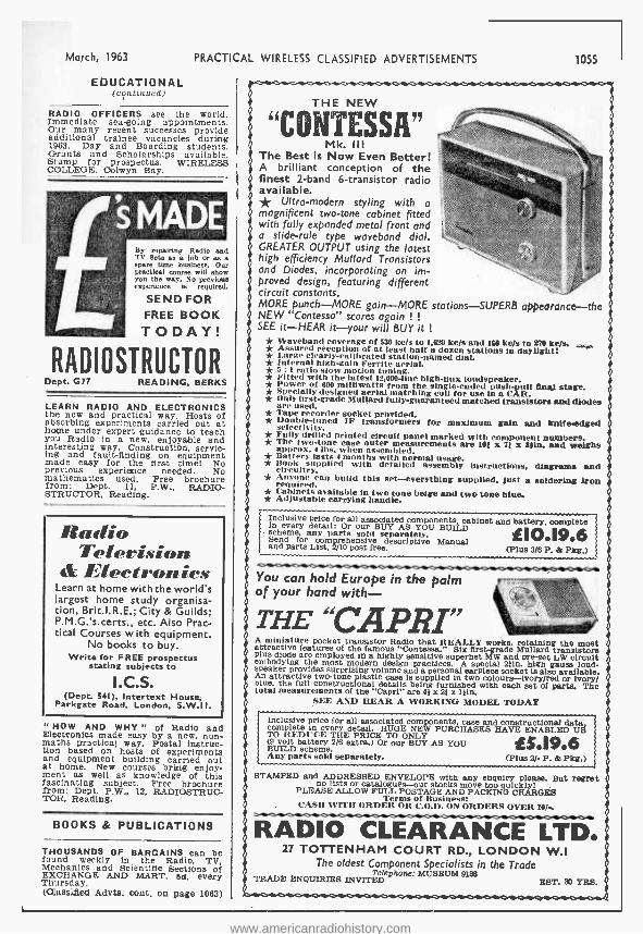
March, 1963 PRACTICAL WIRELESS CLASSIFIED ADVERTISEMENTS
EDUCATIONAL (coutinued)
RADIO OFFICERS see the world. Immediate sea -going appointments. Our many recent successes provide additional trainee vacancies during 1963. Day and Boarding students. Grants and Scholarships available. Stamp for prospectus. WIREI.P' -S.S COLLEGE, Colwyn Bay.
By repairing Radio and TV Bets as a job or as a spare time business. Our practical course will show you the way. No previous experience le required.
SEND FOR FREE BOOK TODAY!
RADIOSTRUCTOR Dept. G77 READING, BERKS
LEARN RADIO AND ELECTRONICS the new and practical way. Hosts of absorbing experiments carried out at home under expert guidance to teach you Radio in a new, enjoyable and interesting way. Construction, servic- ing and fault -finding on equipment made easy for the first time! No previous experience needed. No mathematics used. Free brochure from: Dept. 11, P.W., RADIO - STRUCTOR, Reading.
Radio Television
(t Electronics Learn at home with the world's largest home study organisa- tion, Brit.I.R.E.; City & Guilds; P.M.G.'s certs., etc. Also Prac- tical Courses with equipment.
No books to buy. Write for F REE prospectus
stating subjects to
I.C.S. (Dept. 541), Intertext House;
Parkgate Road, London, S.W.II.
" HOW AND WHY " of Radio and Electronics made easy by a new, non - maths practical way. Postal instruc- tion based on hosts of experiments and equipment building carried out at home. New courses bring enjoy- ment as well as knowledge of this fascinating subject. Free brochure from: Dept. P.W., 12, RADIOSTRUC- TOR, Reading.
BOOKS & PUBLICATIONS
THOUSANDS OF BARGAINS can be found weekly in the Radio, TV Mechanics and Scientific Sections of EXCHANGE AND MART, 5d. every Thursday. (Olaaseißed Advts. cont. on page 1063)
1055
THE NEW
"CONTESSA 7!
Mk. III The Best is Now Even Better! A brilliant conception of the finest 2 -band 6- transistor radio available. * Ultra- modern styling with a magnificent two -tone cabinet fitted with fully expanded metal front and a slide -rule type waveband dial. GREATER OUTPUT using the latest high efficiency Mullard Transistors and Diodes, incorporating an im- proved design, featuring different circuit constants. MORE punch -MORE gain -MORE stations- SUPERB appearance -the NEW "Contessa" scores again ! !
SEE it -HEAR it -your will BUY it ! * Waveband coverage of 530 kc /s to 1,620 ke /s and 160 ke/s to 270 kegs,
- * Assured reception of at least half a dozen stations In daylight! * Large clearly -calibrated station -named dial. * Internal high -gain Ferrite aerial. * 5 : I ratio slow motion tuning. * Fitted with the latest 12,000 -line high -flux loudspeaker. * Power of 600 mllliwatts from the single -ended push -pull final stage. * Specially designed aerial matching coil for use in a ('AR. * Only first -grade dullard fully- guaranteed matched transistors and diodes are used. * Tape recorder socket provided. * Double -tuned IF transformers for maximum gain and knife -edged selectivity. * Fplly drilled printed circuit panel marked with component numbers. * The two -tone case outer measurements are 101 st 7f it Min. and weighs aPprox. 4 1hs. when assembled. * Battery lasts 4 months with normal usage, * Book supplied with detailed assembly Instructions, diagrams and circuitry. * Anyone can build this set -everything supplied, just a soldering Iron required. * Cabinets available In two tone beige and two tone blue. * Adjustable carrying handle.
Inclusive price for all associated components, cabinet and battery, complete in every detail: Or our BUY AS YOU BUILD scheme, any parts sold separately. Send for comprehensive descriptive Manual and parts List, 2/10 post free. (Plus 3/6 P. & Pkg.)
IE1O.19.6
You can hold Europe in the palm of your hand with-
THE "CAPRI" A miniature pocket transistor Radio that REALLY works, retaining the most attractive features of the famous " Contessa." Six first -grade Mullard transistors plus diode are employed in a highly sensitive superhet MW and pre -set LW circuit embodying the most modern design practices. A special 21in. high gauss loud- speaker provides surprising volume and a personal earpiece socket is also available. An attractive two -tone plastic case is supplied In two colours -Ivory /red or Ivory/ blue, the full constructional details being furnished with each set of parts. The total measurements of the "Capri" are 41 x 21 x 111n.
SEE AND HEAR A WORKING MODEL TODAY
Inclusive price for all associated components case and constructional data, complete in every detail. HUGE NEW PURCHASES HAVE ENABLED US TO REDUCE THE PRICE TO ONLY (9 volt battery 2/6 extra,) Or our BUY AS YOU BUILD scheme. Any parts sold separately. (Plus 2/- P. & Pkg.)
1E5.19.6
STAMPED and ADDRESSED ENVELOPE with any enquiry please. But regret no lists or catalogues -our stocks move too quickly! PLEASE ALLOW FULL POSTAGE AND PACKING CHARGES Terms `t CAS WITH ORDER
C.O ON ORDERS
OVER 10 /-.
RADIO CLEARANCE LTD. 27 TOTTENHAM COURT RD., LONDON W.I
The oldest Component Specialists in the Trade TRADE ENQUIRIES INVITED
MUSEUM 9180 EST. 30 YRS.
www.americanradiohistory.com
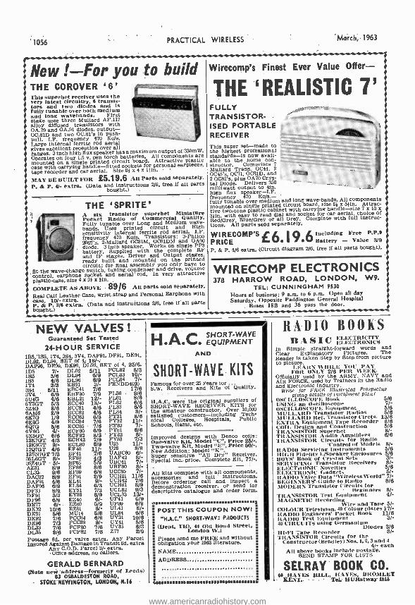
1056 PRACTICAL WIRELESS March, 1963
New ! -For you to build THE COROVER 6' This superhet receiver uses the very latest circuitry, a transis- tors and two diodes and Is fully tunable over both medium and long wavebands. First stage uses three Mullard AF.117 alloy diffused transistors with OA.79 and OA.91 diodes, output - OC.81D and two OC.81's in push - pull. I.F. frequency 470 Kc /s. Large internal ferrite rod aerial gives excellent reception over all ranges. 3 Inch high flux speaker has a maximum output of 330mW. Operates on four 1.5 v. pen torch batteries. All components are mounted on a single printed circuit board. Attractive plastic case with carrying handle -fitted sockets for personal earpieces, tape recorder and car aerial. Size 61 x 4 x lila.
MAY BE BUILT FOR p55.Ì 9.6 All Parts sold separately. P. & P. 4/- extra. (Data and instructions 2/6. free. if all parts
THE `SPRITE' Pocket Radio
s of Comemercialul Miniature
Fully tunable over Long and Medium wave- bands. Us printed circuit
ferrite rod aerial. High
frequency 470 Kc/s. Transistors: 3- Philco 2067's.
ode. 3 inch speaker. 0C81DM
on single OPAP battery. Supplied with the Complete RF and IF stages, Driver and Output stages, ready built and mounted on the printed circuit: for final assembly you only have to
fit -the wave -change switch, tuning, condenser and drive, volume control, earphone socket and aerial rod. In very attractive plastic case, size 4 x 21 x lin. ,
COMPLETE AS ABOVE - Ó9I6 Au parts sold separately. Real Calf Leather Case, wrist strap and Personal Earphone with case. 10 /- extra. P. & P. 3/6 extra. (Data and instructions 2/6, free if all parts bought.
NEW VALVES ! Guaranteed Set Tested
24-HOUR SERVICE 155,'155, 1T4. 3S4. 3V4. DAF91, DF91, DK91, DL92, DL94. SET of 4, 18/ -. -
DAF96. DF96, DK96, DL96, SET of 4. 25/6. 1115 77/- DL92 5 /11 PCL82 8/3 1R5 5/8 DL94 8/9 PCL83 10/- 155 418 DL96 8/9 PCL84 7/- 1T4 3/3 1,1391 3/- PENDD4020 384 5 /11 EBC41 7/6 17/6 3V4, 6/9 EBF80 7/9 PL36 - 9/8 504G 4/6 EBL21 12 /- PL81 8/6 5Y3GT 5/3 ECC40 13/- PL82 8/6 5Z4G 8/6 ECC81 4/6 PL83 8/6 8AM6 2/9 ECC82 4/6 PL84 8/- 610G 1/9 ECC83 6/3 PY31 8/8 61E8G 4/9 ECC84 7/6 PY32 11/- 6Q7G 5/6 ECC85 7/6 PY80 7/- 6V6G 4/- ECF80 6/9 PY81 6/6 6X5GT 6/6 ECF82 8/3 PY82 8/- 12K7GT 4/3 ECH42 7/9 PY83 7/3 12K2GT 9/- ECL80. 6/9 025 11 /- 12Q7GT 4/8 EF40 11/- 026 8/9 12SN7GT 7/3 EF41 7/6 UABC80 6/- 35L8GT 8/- EF80 4/3 UArF42 8/-
40T - 5/- - EF85 - 5/9 UBC41 7/-
31 8/9 EF86 8/6 UBF80 8/- C - 9/6 EF89 6/9 UCC85 7/- DAC32 8/9 EF91 2/9 UCH21 11/6 DAF91 4/6 EL41 9/- 001442 7/6 DAF96 6/9 EL84 6/3 UCH81 8/9 DF33 8/9 EY51 7/3 UCL82 9/3 DF91 3/3 EY86 6/9 -
UCL83 13/ -- DF96 6/9 EZ40 6/- UF41 6/9 DH77 6/- EZ80 5/9 ' UF89 6/9 DK32 10/6 EZ81 8/- ÚL41 8/- 0E91 5/6 MÚ14 5/8 ÚL84 6/6 DE92 7/6 PCC84 6/9 ÚY21 10/6 DK96 7/3 PCC89 9/- ÚY41 5/8
DLL 35 9/6 PPCF82 7/6 Z77 2(9
Postage 6d. per valve extra. Any Parcel Insured Against Damage in Transit 6d. extra
Any C.O.D. Parcel 3/- extra. Office address, no callers.
GERALD BERNARD (Vote new address -formerly of Leeds)
83 OS8ALDESTON ROAD, STOKE NEWINGTON, LONDON, 5.16
Wirecomp's Finest Ever Value Offer-
THE `REALISTIC 7' FULLY TRANSISTOR- ISED PORTABLE RECEIVER This super set -made to the highest professional standards -is now avail- able to the home con- structor. Comprises 7
Mullard Trans. 0044. 2 0C45's, OC71, OC91D and 2 0081's, plus 0A70 Crys- tal Diode. Delivers 350 milliwatt output to 41n. high flux speaker-I.F. frequency 470 Kc /s.- -
fully tunable over medium and long wave -bands. All components mounted
two. -tone plastic cabinet with carrying handle -size 7 xt10 x 311n. with easy to read dial and socket for car aerial, choice of Red /Grey. Blue /Grey or all Grey. Complete with full instruc- tions. All parts sold separately.
WIRECOMP'S £6 19 ó Including Free P.P.!
PRICE Battery - Value 3/9
P. & P. 4/6 extra. (Circuit diagram 2/6. tree if all parts bought).
WIRECOMP ELECTRONICS 378 HARROW ROAD, LONDON, W9.
TEL: CUNNINGHAM 9530
Hours of business: 9 a.m. to 6 p.m. Open all day Saturday, Opposite Paddington General Hospital
Buses 18B and 36 pass the door.
/ r SHORT -WAVE HAv EQUIPMENT AND
SHORT -WAVE KITS Famous for over 25 years for .. , S.W. Receivers and Kits of Quality.
were the original suppliers of SHORT-WAVE RECEIVER KITS for the amateur constructor. Over 10,000 satisfied customers -including Tech- nical nical Colleges, Hospitals, Public Schools. Hams. etc.
Improved designs with Denco coils: One -valve Kit, Model "C ", Price 25/ , Two -valve Kit, Model "E ", Price 50/ -. New Addition: Model "K ". Super Specials inc.. price.. Complete .Kite 77/ -.
All kits complete with all components, accessories ordering call and
instructions.
demonstration receiver, or send for descriptive catalogue and order form.
POST THIS COUPON NOW! "H.A.C." SHORT -WAV2 P,IODUCTS
(Dept. THadO W ld
nd Street,
Please send me FREE and without obligation your 1963 literature. NAME
ADDRESS
RADIO BOOKS BASIC }±ECCTRIOWCYS ELECTRONICS
in Simple straight- forward words and Clear Explanatory Pictures, The Reader is taken Step by Step from picture to picture.
LEARN WHILE YOU PAY FOR ONLY 2/6 PER WEEK'
Officially used by the ARMY, NAVY and AIR FORCE, used by Trainees in the Radio and Electronic Industry.
Write for FREE Illustrated Prospectus [riving details of instalment plan!
OSCILLOSCOPE Book 518 USING an Oscilloscope 711-
OSCILLOSCOPE Equipment 5 6 MOLLARD Transistor Radios 5/6 MOLLARD Ref. Transistor ['frets. 13/8 EXTRA Equipment Tape Recorder 6/8 COIL. Design and Construction 5/6 TRANSISTOR Superhet 8/- TRANSISTOR Audio Amplifiers 6/6 TRANSISTOR Circuits
Control of Models 8/- RADIO Servicing Instruments 5/6 IIIGH Fidelity L /Speaker Enclosures 5/8 BOYS' Book of Crystal Sets 3/- SERVICING Transistor Receivers 8/- ELECTRONIC Novelties 5/6 ELECTRONIC Gadgets 5/- RADIO Valve Data "Wireless World" 7/- BEGINNERS' -Guide to Radio 8/6 MODERN Transistor Circuits for
Beginners 8/- TRANSISTOR Test Equipment 4/- MAGNETIC Recording
Wire and Tent. 5/- COLOUR Television. 40 Colour plates 17/- RADIO Engineers' Pocket Book 11/6 RADIO Test Equipment 3/- 40 CIRCUITS using Germanium
mlodes 3/6 HI -FI Tape Recorder 3/- TRANSISTOR Circuits for the
Constructor (Bradley) Nos. I,1, 3 and 4 each
All above books Include postag4/e- . SEND STAMP FOR LISTS -
SELRAY BOOK CO. GO.11Al'ES RILL, RAILS, BROMLEY
KENT.- . . - Tel. HIJltatway 1810
www.americanradiohistory.com
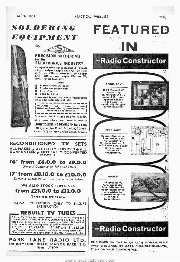
March, 1963 PRACTICAL WIRELESS
SOLDERING EQUIPMENT
by
PRECISION SOLDERING for the ELECTRONICS INDUSTRY Comprehensive range- Robust & reliable - Light weight - Rapid heating - Bit sizes 3/32in. to 3 /8in. - 'Permabit' or Copper bits - All voltage ranges 6/7v. to 230/ 250v. - Prices from 2I / -.
Also Q Plastic Cable Strippers
Miniature Solder Pots Heat Guards Long Life Bits
Illustrated is the 25w. 3/I6in. replaceable bit model with safety shield.
r ADAMIN- new range of pre- I I cision micro -soldering instruments-
Have you had details? a
Brochure No. SIO sent free on request. Sole proprietors and manufacturers:
LIGHT SOLDERING DEVELOPMENTS LTD. 28 Sydenham Road, Croydon, Surrey
Phone. CROydon 8589 Grams: Litesold Croydon
RECONDITIONED TV SETS ALL MAKES * ALL FULLY SERVICED* ALL GUARANTEED * NOT EARLY CONVERTED
MODELS
14" from 16.O.0 to 19.0.0 3 -month Guarantee on Tube and Valves
17" from 111.10.0 to í20.O.0 I2 -mcnth Guarantee on Tube, 3 -month on Valves
WE ALSO STOCK SLIM -LINES
from í23.O.0 to 133.O.0 These sets are as new
PERSONAL COLLECTION ONLY TO ENSURE SATISFACTION
REBUILT TV TUBES All our TV Tubes are reprocessed to a high standard and are coverec by a 12 MONTHS' GUARANTEE. Each tube is fitted with a new, top -grade electron gun, which is identical with the original, ensuring exact plug -in replacement. 21", í6. I7 ", L5.10.0. 12 ", 14" and 15 ", (4.10.0 * Personal collection advised, carriage by arrangement only. LI refunded from the above price if you return your old tube.
PARK LANE RADIO LTD. 548 ROMFORD ROAD, MANOR PARK, E.12
Phone: ILF 6044
1 057
FEATURED IN
-Radio Constructor
FEBRUARY
20 -50 Metre S.W. Mains 2 by
R. Morgan. A two valve A.C. mains operated short- wave receiver
specifically designed for the beginner.
FEBRUARY
Crystal -Controlled F.M. Tuner. The "Crystella" by
Sir John Holder, Bt. A 5 -Valve F.M. Tuner
for the more advanced
constructor.
MARCH
208 Booster by A. S. Carpenter
Especially for the home constructor
who wishes to improve reception
of Radio Luxembourg.
-Radio Constructor PUBLISHED ON THE Ist OF EACH MONTH, PRICE TWO SHILLINGS, BY DATA PUBLICATIONS .LTD0, 57 MAIDA VALE, LONDON W.9.
www.americanradiohistory.com
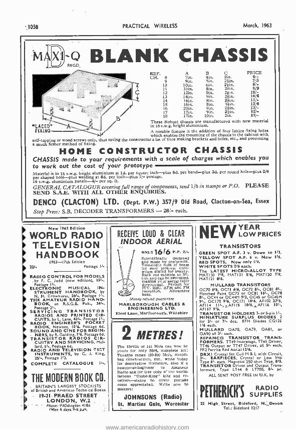
1058 PRACTICAL WIRELESS March, 1963
w9-2 BLANK CHASSIS
C
"LACED" `A FIXING
REP. A B C PRICE CH. 8 lin. 4in. 2in. 6/-
9 9in. 5in. 2 }in. 7/3 10 loin. 6in. 24in. 8/- 11 10in. Bin. 24in. 8/9 12 12ín. 9in. 24in. 10 /- 13 14in. 9in. 24in. 10/6 14 16in. Bin. 24in. 11 /- 15 16in. Bin. 34in. 12/6 16 20in. 9in. 24in. 13/- 17 17in. 9in. 2,än. 12/- 18 17ín. 10in. 2in. 12/-
These Robust chassis are manufactured with new material in 16 s.w.g. bright aluminium. A notable feature is the addition of four lattice fixing holes which enables, the mounting of the chassis to the cabinet with
self- tapping or wood screws only, thus saving the constructor a lot of time making brackets and holes, etc., and presenting a much fumer method of fixing.
HOME CONSTRUCTOR CHASSIS CHASSIS made to your requirements with a scale of charges which enables you
to work out the cost of your prototype - Material is in 16 s.w.g. bright aluminium at Id. per square inch -plus 6d. per bend -plus 3d. per round hole -plus 2/6
per shaped hole -plus welding at 6d. per inch -plus 2/- postage. 16 s.w.g. aluminium panels -4/- per sq. ft.
GENERAL CATALOGUE covering full range of components, send 1/6 in stamps or P.O. PLEASE SEND S.A.E. WITH ALL OTHER ENQUIRIES.
DENCO (CLACTON) LTD. (Dept. P.W.) 357/9 Old Road, Clacton -on -Sea, Essex
Stop Press: S.B. DECODER TRANSFORMERS - 26/- each.
New 1963 Edition
WORLD RADIO TELEVISION HANDBOOK
1963 -17th Edition 221. Postage If-
1
RADIO CONTROL FOR MODELS by F. C. Judd (new edition), 15 -. Postage II -.
ELECTRONIC MUSICAL IN- STRUMENT HANDBOOK, by N. H. Crowhurst 201 -. Postage 11 -.
THE AMATEUR RADIO HAND- BOOK, an R.S.G.B, Pub., 341, Postage 21,
SERVICING TRANSISTOR RADIOS AND PRINTED CIR-
IL CUITS, by L. Lane, 421, Postage 11-.
RADIO ENGINEER'S POCKET lik BOOK, Newnes, 1016. Postage 6d.
SOUND AND CINE FOR BEGIN- NERS, by R. Golding, 716. Postage 6d.
TRANSISTOR RADIOS CIR- CUITRY AND SERVICING, Mal- lard, 51 , Postage 6d.
RADIO AND TELEVISION TEST INSTRUMENTS, by G. J. King,
'251-, Postage 113.
COMPLETE CATALOGUE II -.
THE MODERN BOOK CO BRITAIN'S LARGEST STOCKISTS
of British and American Technical Books
19.21 PRAED STREET LONDON, W.2 Phone: PADdington 4185
(glen 6 days 9-6 p.m.
RECEIVE LOUD & CLEAR
INDOOR AERIAL ()NIA 1616 P.P. 2 / -.
Scientifically designed and made by craftsmen. Telescopic rods of brass for easy pick- up.chro- mlum plated for beauty. Each rod extends to 3ft. 6in. and can be swivelled, making your aerial fully directional. Perfect for ITV, BBC, AFM and FM reception. Attractive base.
Money refund guarantee MARLBOROUGH CABLES &
ENGINEERING LTD. Eleot Lane, Marlborough. Vs iltshire
2 METRES! The thrills of 144 Mc /s can now be yours for only 39/6, complete kit! Tunable range 150 -100 Mc /s, simpli- fied construction, etc., write today for descriptive literature, also if a newcomer -beginner to Amateur Radio ask for free copy of the world - famous "Globe- King" kits and re- ceivers- stamp to cover postage costs appreciated. Write now to makers:
JOHNSONS (Radio) St. Martins Gate, Worcester
NEW YEAR LOW PRICES
TRANSISTORS GREEN SPOT A.F. 3 v. Down to 113.
YELLOW SPOT A.F. 6 v. Now 116.
RED SPOTS. Now only 119.
WHITE SPOTS 216 each. The LATEST MICRO -ALLOY TYPE MAT I O0 719, MAT I O I 816, MAT I20 719, MATI21 816.
MULLARD TRANSISTORS 0070 616, 0071 616, 0072 81 -, OC81 81 -. Matched Pairs 0072 or OC81 I61 -, 0078 8l -, 0C44 or 0C44M 913, 0C45 or 0C45M 91 -, 0C170 916, 0C171 1016, AF102 2716, AFII4 I I1 -,1AFI 15 1016, ,AFT l6 101 -, AFI 17 916. TRANSISTOR HOLDERS 3 -or5 -pin 11 -. MINIATURE SURPLUS DIODES 3 for 21- or 71- doz. BTH Diodes CGI2E 116 each. MULLARD 0A70, 0A79, OABI, or 0A90 all 31- each. REPANCO TRANSISTOR TRANS- FORMERS. TT49 lnterstage, TÎ45 Driver, TT46 Output or TT47 Driver, all 51- each. FR2 Ferrite Rod Aerial 1216.
DRXI Crystal Set Coil M & L with Circuit, 31 -. EARPIECES, Crystal or Low Imp Type 61- each. Magnetic 250 ohm Type, 816. TRANSISTOR Driver and Output Trans- formers, Type LT44 & LT700, 81- pr.
ALL SENT POST FREE IN U.K. by
PETHERICH'S SUPPLIES 22 High_ Street, Bideford, N._Devon
Tel.: Bideford 1217
www.americanradiohistory.com
March, 1963 PRACTICAL WIRELESS
REGUNNED T.V.TUBES 21 in. 99/6 17 in. 90/-
15, 14 and 12in. -70l- TERMS AVAILABLE
GUARANTEED ONE YEAR Ins. and Carr. 12/6
Add 101- refundable on OLD TUBE 110° Tubes in Stock
7/9 1 t Ns
each ` 4
SPEAKERS 6in., kin., /in. x tin. Money back guaranteed.
35f_ 36/24, 14K1-4, I -:I. Carr. Enquire for other sizes.
5 f- Ex. mid. salvage. P.P. 213. I 5f- 121, 31/74 and others.
Ex- Rental Stock. EXTENSION TELEPHONE HANDSETS SPEAKERS 19 9
1516 Pair In cabinet complete with G.P.O. standard pattern. House to flex. P. & P. 3/9. Also Workshop, garage, inter -office, etc.
Works Slim -line De Luxe, 29/9. off any battery. P. & P. 4'6. p & p 3/3,
ILFord 6001/3 VALVES 9d. EACH DUKE & CO. (LONDON) Ltd. 4.-f I
6211" ROMFORD RD. Thousands of Valves available. P. & P. on MANOR PARK E12 1-4 6d., 12 116.
Liverpool Stn., Manor Park, 10 mins. Stamp for List . COMPLETE TELEVISIONS r, 14 INCH 17 INCH
£7.10.0 £11.10.0 * Guaranteed 12 months. Tubes, i ' Valves, Components. ¡, * Ex Rental and repossessed tele-
visions. C1 -?' * Two channels more, 7115 extra. * All channels available. * Demonstrations daily. * Legs -3916 per set.
u * Part exchange allowance on Radios, TV's, etc.
1 Personal collection advised, or In- sured Carr., 14ín., 20/ -; 17in., 30/ -.
EXPRESS ELECTRONICS ROSEDENE LABORATORIES
KINGSWOOD WAY, SELSDON, SURREY
VALVES NEW TESTED GUARANTEED FOR THREE MONTHS
1C1 7/6 88116 5/9 12AX7 6/9 UH77 6/- F091 4/- 1C3 8/- 613J11 0/8 MEd 8/6 D1114'L 8/8 P,1:r1 6/8 LFl 8/- 614E7 8/9 12R117 10/6 DH150 10/- 11.41 8/6 1F3 7/8 6uW6 6/6 12Khu711/- DK91 7/6 EL84 '/- 1FD1 8/- 0üW7 -/- 12Q7UT 7/6 UK96 ^/_ 1.M84 101- 1F1).) 7/6 61/2 4/- 128N7 6/- 1)1.92 5/8 F.5185 10/- 1Pt 8/- 6F12 4/- 16A5 W- 1)1.94 6/6 EY51 776 INO 7/6 61160T 2/. I9AQ5 9/6 DL96 8/- EY81 10/- ,iP11 7/6 OJ7GT 7/6 ?RAW 7/S EB91 4/. 67.40 7/6 1R5 6/- 61/70 5/6 25L80T 7/6 EBC41 10/- F.Z80 6/- 186 6/- 868á 6/- 26Z40 9/- 611880 8/6 67,81 6/9 1T4 2/9 WIG 6/8 30C1 7/6 E0081 6/- JIVES 9/6 11.12 6/6 68L70T 6/- 301.1 7/6 ECC83 6/9 61330 6/- 3Q4 8/. 68N70T 6/- 351.1101 7/6 60083 0/9 KT66 11/6 384 5/9 MG 7/6 35W4 8/8 F.Q^.84 7/61417 8/9 394 6/6 6X4 b/- 35Z4OT 8/- E0080 8/6 N18 8/. 51301 5/- 0X31) 5/9 5703 716 ECF82 8/- N19 7/6 5Z4G 7/8 787 1/6 80 61- ECH42 9/. N709 7/- BAKB 6/6 4133 4/. DAF91 7/6 60118110/-P(X84 7/6 BALS 4/- 9127 9/6 DAF96 8/- 601.80 8/6 PCF80 7/6 6AM6 4/- 12A1)6 11/6 DIX190 12/6 601.62 9/- PCF82 7/6 6AT6 6/. 12AH8 10/- DF91 8/- EF41 9/- PCL82 8/- 6BA0 5/. 12AT7 6/- 1/F06 8/- EF80 8/- PCL84 9 - 611E0 7/. 12AU7 6/9 DH76 7/6 6E86 9/- 01,81 12 6
PL82 7/- P1.83 7/6 P181 8/9 P182 7/0 PY1113 7/8 R19 10/6 85A1 9/8 U52 7/6 076 7/6 U78 5/- U142 7/6 UBC41 8/6 UCH42 9/6 UF41 8/6 UT41 8/6 UY41 7/6 W17 7/6 W76 4/6 W142 8/6 117 7/6 1142 9/- E1b0 4/- 277 4/- 21)17 7/8
High Stabili y Resistors 4W 5% 60 G to 111, 9d, Midget Ceram es 500 V. 5d. Coax. Soper quality fin., 6d. yd. Plugs 9d. Sockets 9d. Silicon H.T. Rests. 250v. 300 MA lie. x ;Is. 8/8. Contact Cooled 250v. 50 MA 8/6. 86 MA 8/6
NEW TRANSISTORS BY MULLARD. 0019, 0026, O06á, 25/ -; 0014, 0C42, S / -; 0070, 0071, 8 /.; 0072, 7/6; 0072 watched ai pre. IN-; 0074, 0C95, 01778. 0081, 7/6; 0082 00170 9/6.
VALVES MATCHED IN PAIRS 61,34 27/6, 61.84 16/ -, 14708 16/., 6160 15 / -. 6BW6 14 /- per pair. Push Pull O.P. Transformer for above 3 15 ft 14/6, P. & P. 1 /6. 121n. P.M. Speakers 3 0 24/6. Baker's "Belhurnt" 12.n. 15 11 15W, 80/ -, 12M. Stereo Model, 67.7.0.
SETS OF VALVES DR91, 0091. DAF91, 1)1,92 or DL94, 19/8 ECH42, EF41, 50041, ÚK96, DF96, DAM, DIM 27/6 6141: E7 .40 37/6 103, 1F1, 1FD1, 1PI 07/6 1101142, 0F41, (711041, 1E5, 114. 185. 384, or 314 19/6 CL41. 01'41 35/- Postage and packing 94. Over el post free. C.O_D. 28,
1059
Make Your "'ay PAY
r UNLIMITED OPPORTUNITIES exist today for "getting on" .. but only for the fully trained man. Let I.C.S. tuition develop your talents and help you to success.
STUDY IS EASY with I.C.S. guidance. The courses sre thorough. Printed manuals, fully illustrated, make study simple and progress sure.
YOUR ROAD TO SUCCESS can start from here - today. Complete this coupon and post it to us, for full particulars of the course which interests you. MODERATE FEES INCLUDE A1LL BOOKS.
Take the right course now ADVERTISING Gen. Advertising, Retail & Dept. More Copywriting. ART Oil k Water Colour Commercial Illustrating BD11.DINO Architecture, Clerk of Wks., Builds. Constr. & Allied Trades, Quantity Surveys.
CIVIL ENGINEERING Highway Eng., StrucL Engrg., Concrete Eagireering COMMERCE Bookkeeping, Accountancy, Office Training, Costing, Secretaryship, Storekeeping Shorthand & Typewriting DRADGWISMANBHIP Architectural, Mechanical, Maths.
Machine Drawing Drawing Office Practice Structural Drawing RLEC'TRONH* Industrial Electronics Computers & Maintenance FARMING Amble & Livestock Farm Machinery Malnt. Pig & Poultry Keeping Market Urrdepiag
FIRE ENGINEERING D.F.E. Examinations Fire Service Promotion
GENERAL EDUCATION Good Eng., Foreign Lange. G.C.E. ubjects at ordinary advanced level
HORTICULTURE Complete Gardening Flower & Veg. Growing
MANAGEMENT Business Management Hotel Management Office Management Industrial Management Personnel Management Work Study, Foremanship
MECHANICAL & MOTOR EN- GINEERING Engineering Maths., Weldg. Diesel Engines and Locos. Inspection. Workshop Freet. Refrigeration, Motor Mech. Running and Maintenance (many other subjects)
PHOTOGRAPHY Practical Photography P.D.A. Examination
POLICS Police Entrance Exam.
RADIO, T.V. & BLECTL. Radio Servicing & Engrg. Radio Conte,,. (with kite)
SELLING Commercial Traveller. Sales Rangnt, Ret. Belling
WRITING FOR PROFIT Short Story Writing Free -Lance Journalism
or And many other subjects
INTENSIVE COACHING for all principal examinations including C.I.S., A.C.C.A., I.C.W.A., B.I.M., A.M.I.Mech.E. Brit.I.R.F., I.Q.S., City & Guilds of London Institute, R.H.S., P.M.G. Certificates in Radioteleeraphy, etc.
r INTERNATIONAL CORRESPONDENCE SCHOOLS I
(Dept. 172) Intertext House, Parkgate Rd., London, S.W,II
Name I
Address I
Occupation 3.63 I
INTERNATIONAL CORRESPONDENCE SCHOOLS
www.americanradiohistory.com
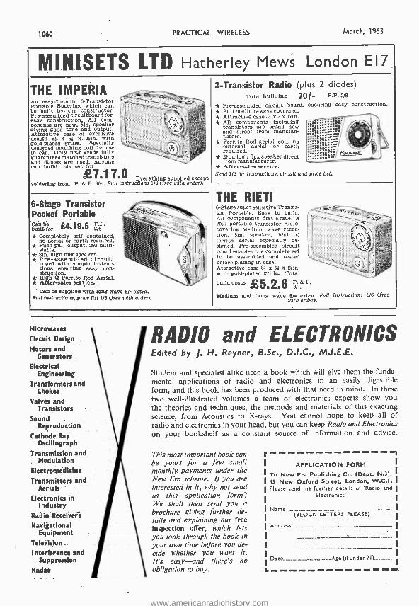
1060 PRACTICAL WIRELESS March, 1963
MINISETS LTD Hatherley Mews London E17
THE IMPERIA An easy -to -build 6- Transistor e
Portable Superhet which can .... . be built by the constructor. Pre -assembled circuitboard for easy construction. All com- ;(
,` g' ?F" -.r ponants are new 51n. speaker , ",yyµv",';,;?;;
giving good tone .and output. a. Attractive case of exclusive .
<65!íi, desl 131 x 5 x 2 41n. with -; .)r,
- gold-plated designed matching
grille. Specially - ,J '.: designed matching coal for use ` ° - in car. Only first grade fully -',_1.', }''ç and
e used. Anyone
transistors . i : '
and diodes are used. A can build this set for
£7.1 % -O Everything supplied except
soldering Iron. P. & P. 3/ -. Full instructions 1/8 (free with order).
3- Transistor Radio (plus Total building 7Q'-
* Pre -assembled circuit board, * Full medium -wave coverage. *Attractive case 5} x 3 x 13 m. * All components including
transistors are brand new and direct from manufac- Curers. Ferrite Rod aerial coil, no external aerial or earth required.
* 2 11n. high flux speaker direct from manufacturer.
* After -sales service. Send 1/6 for instructions, circuit and
2 diodes) P.P. 2/6
ensuring easy construction.
X1`1: " . "'> mmmo..
,I
-pi,,,r C:¢ price list.
ti . .
ÿi $ ti eo ,, t
`
P.
Full instructions 1/6 (free
6 -Stage Transistor b - Pocket Portable Caribe i 19 6 ` - built fer 7Ve1).7.6 2/6 1C,.+ * Completely self contained,
no aerial or earth required. _
Push -pull output, 250 milli- -
Watts * 3}n. high flux speaker. * Pre- assembled circuit board with simple fastruc- tlone ensuring easy con- struotion.
- -
* Alter -sales service. Aerial.
Can be supplied with long -wave 6/- extra. Full Instructions. price list 116 (free with order).
i
'' li
' Id
hhi
!I
I
THE RIETI 6 -Stage super sensitive Transis- for Portable. Easy to build
real l
portable wavers
radio. hale
transistor covl portable transistor radio
fion. 51n. speaker, high @
ferrite aerial especially de- signed. Pre -assembled circuit board enables the complete set
before be assembled and tested
before placing in case. Attractive case 8} x 54 x 25in, with gold- plated grille. Total
build costs i G A. C & oV d ` {/
Medium and Long wave 81- extra. with order).
Microwaves
Circuit Design
Motors and Generators
Electrical Engineering
Transformers and Chokes
Valves and Transistors
Sound Reproduction
Cathode Ray Oscillograph
Transmission and Modulation
Electromedicine Transmitters and
Aerials
Electronics in Industry
Radio Receivers
Navigational Equipment
Television
Interference and Suppression
Radar
RADIO and ELECTRONICS Edited by J. H. Reyner, B.Sc., D.I.C., M.I.E.E.
Student and specialist alike need a book which will give them the funda- mental applications of radio and electronics in an easily digestible form, and this book has been produced with that need in mind. In these two well -illustrated volumes a team of electronics experts show you the theories and techniques, the methods and materials of this exacting science, from Acoustics to X -rays. You cannot hope to keep all of radio and electronics in your head, but you can keep Radio and Electronics on your bookshelf as a constant source of information and advice.
This most important book can be yours for a few small monthly payments under the New Era scheme. If you are interested in it, why not send us this application form? We shall then send you a brochure giving further de- tails and explaining our free inspection offer, which lets you look through the book in your own time before you de- cide whether you want it. It's easy -and there's no obligation to buy. r
APPLICATION FORM
To New Era Publishing Co. (Dept. N.3), I
45 New Oxford Street, London, W.C.I. I Please send me further details of 'Radio and I
Electronics
Name_.........___._ ..................... ..._..._......_....._...__._... (BLOCK LETTERS PLEASE)
Address
Date .. -.Age (if under
www.americanradiohistory.com
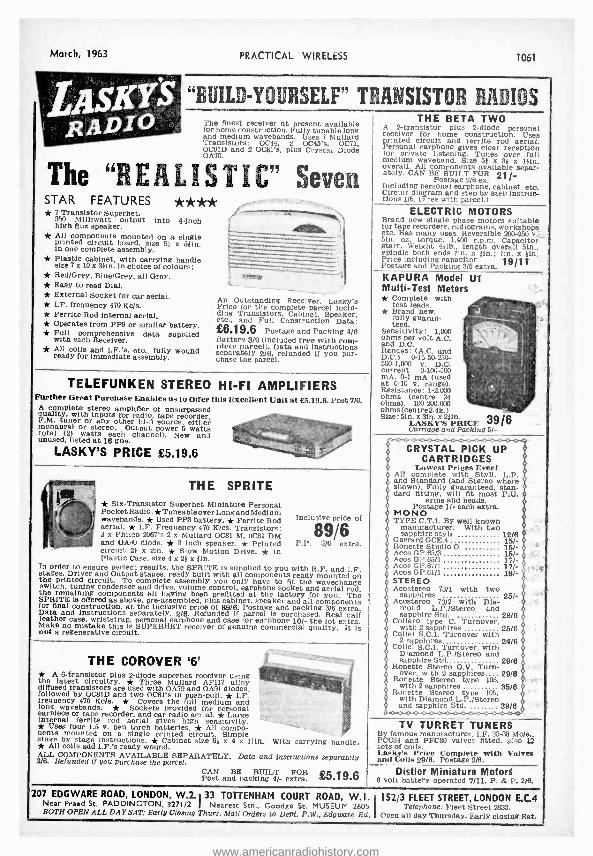
March, 1963 PRACTICAL WIRELtSS 1061
"BUILD- YOURSELF" TRANSISTOR RADIOS The finest receiver at present available tor home construction. Fully tunable long and medium wavebands. Uses 7 Mullard Transistors: 0C44, 2 0C45's, 0071, OC81D and 2 OCal's, plus Crystal Diode 0A70.
The "REALISTIC" Seven STAR FEATURES * * ** * 7 Transistor Superhet,
350 Milliwatt output Into 4 -inch high flux speaker. * All components mounted on a single printed circuit board, size 51 x 511n. in one complete assembly. * Plastic cabinet, with carrying handle size 7 x 10 x 311n. in choice of colours: * Red /Grey. Blue /Grey, all Grey. * Easy to read Dial. * External Socket for car aerial. * I.F. frequency 470 Kc /s. * Ferrite Rod internal aerial, * Operates from PP9 or similar battery, * Full comprehensive data supplied with each Receiver. * All coils and I.F.'s, etc fully wound ready for immediate assembly.
:::
An Outstanding Recela -cr. Lasky's Price for the complete parcel inclu- ding Transistors. Cabinet, Speaker, etc., and Full Construction Data: 26.19.6 Postage and Packing 4/6 Battery 3/9 (included free with com- plete parcel). Data and instructions separately 2/6, refunded if you pur- chase the parcel,
TELEFUNKEN STEREO HI -FI AMPLIFIERS Further Great Purchase Enables us to Offer this Excellent Unit at 25.19.6. Post 7/6.
A complete stereo amplifier of unsurpassed quality, with inputs for radio, tape recorder, F.M. tuner or any other hi-ii source, either monaural or stereo. Output power 5 watts total (21 watts each channel). New and unused, listed at 16 ans. LASKY'S PRICE £5.19.6
THE SPRITE 1 * Six -Transistor Superhet Miniature Personal
Pocket Radio.* Tuneable over Long and Medium wavebands. * Used PP3 battery. * Ferrite Rod aerial. * LF. Frequency 470 K /cs. Transistors: J x Philco 2067's 2 x Mallard 0081 M, 0081 DM and OA40 diode. * 3 inch speaker. * Printed circuit 21 x 2m. * Slow Motion Drive. * In Plastic Case, size 4 x 21 x tin.
In order to ensure perfect results, the SPRITE Is supplied to you with R.F, and I.F. stages. Driver and Output stages, ready built with all components ready mounted on tile printed circuit. To complete assembly you only have to fit the wavechange switch, tuning condenser and drive, volume control, earphone socket and aerial rod. the remaining components all having been prefltted at the factory for you. The SPRITE Is offered as above, pre -assembled, plus cabinet, speaker and all components for final construction, at the inclusive price of 89/6. Postage and packing 3/6 extra. Data and Instructions separately. 2/6. Refunded if parcel Is purchased. Real calf leather case. wriststrap, personal earphone and case for earphone 10/- the lot extra. Make no mistake this is SUPERHET receiver of genuine commercial quality. It is not a regenerative circuit.
Inclusive price of
89/6 P.P. 3/6 extra.
THE COROVER `6' * A 6- transistor plus 2 -diode superhet receiver using the latest circuitry. * Three Mullard AF117 alloy diffused transistors are used with 0A79 and OA91 diodes. followed by OC8ID and two 0081's in push -pull. * I.F. frequency 470 Kols. * Covers the full medium and long wavebands. * Sockets provided for personal earpiece or tape recorder, and car radio aerial. * Large internal ferrite rod aerial gives high sensitivity. * Uses four 1.5 Y. pen torch batteries. * All compo- nents mounted on a single printed circuit. Simple stage by stage instructions. * Cabinet size 68 x 4 x Clio. * All coils add I.F.'s ready wound. ALL COMPONENTS AVAILABLE SEPARATELY. Data and instructions separately 2/6. Refunded if you purchase the parcel.
With carrying handle.
CAN BE 66.19.6 anpacring 4/- extra.
THE BETA TWO A 2- transistor plus 2 -diode personal receiver for home construction. Uses printed circuit and ferrite rod aerial. Personal earphone gives clear reception for private listening. Tunes over full medium waveband. Size 51 x 31 x 1iin overall. All components available separ- ately. CAN BE BUILT FOR 21/.
Postage 2/6 ex. Including personal earphone, cabinet. etc. Circuit diagram and step by step lnstruo- Lions 1 /6. (Free with parcel.)
ELECTRIC MOTORS Brand new single phase motors suitable for tape recorders, radiograms, workshops etc. Has many uses. Reversible 200 -250 v... 1)10. oz. torque. 1.400 r.p.m. Capacitor Start. Weight 411b length overall 51n., spindle both ends fin. x lin.: lin. x ;in. Price including capacitor 19/11 Postage and Packing 3/6 extra. KAPURA Model U1 Multi -Test Meters * Complete with
test leads. * Brand new. fully guaran- teed.
Sensitivity: 1,000 ohms per volt A.C. and D.C. Ranges: (A.C. and D.C.) 0- 1550.250- 500 -1.000 v. D.C. current 0- 100500 mA. 0-1 mA (used at 0-10 v. range). Resistance: 1 -2.000 ohms (centre 24 ohms). 100 -200,000 ohms( centre 2.4k.) Size: binAxSKS
PRICE 39/6 Carriage and Parking 5/-
CRYSTAL PICK UP CARTRIDGES
Lowest Prices Ever! All complete with Styli, L.P. and Standard (and Stereo where shown). Fully guaranteed, stan- dard fitting, will fit most P.U.
arms and heads. Postage 1/- each extra.
MONO TYPE C.T,1. By Well known
manufacturer. With two sapphire styli 12/6 Garrard GCE.4 15 /- Ronette Studio O 15/-
Acos GP.65/3 15 /- Acos GP.65 /1 17/- Acoe GP.67/1 17/- Acos GP.61 /1 18/- STEREO Acostereo 73/1 with two
sapphires 25/- Acostereo 73/2 with Dia-
mond L.P. /Stereo . and sapphire Std. 28/6 Collaro type C. Turnover,
with 2 sapphires 25/6 Collel S.C.1. Turnover with
2 sapphires 24/6 Collel S.C.1. Turnover, with
Diamond L.P. /Stereo and sapphire Std 29/6 Ronette Stereo O.V. Turn- over, with 2 sapphires 29/6 Ronette Stereo type 105 with 2 sapphires 35/6 Ronette Stereo type 105, with Diamond L.P. /Stereo and sapphire Std. 39/6
TV TURRET TUNERS By famous manufacturer, I.F. 33-38 Mc /s., PCC84 and PFC80 valves fitted. also 12 sets of coils. Lasky's Price Complete with Valves and Coils 29/6. 'Postage 2/6.
Distler Miniature Motors 6 volt battery operated 7/11. P. & P. 2/6,
207 EDGWARE ROAD, LONDON, W.2 33. TOTTENHAM COURT ROAD, W.I. 152/3 FLEET STREET, LONDON E.C.4 Near Praed St. PADDINGTON, 3271/2 I Nearest Stn., Goodge St. MUSEUM 2605 Telephone: Fleet Street 2833. BOTH OPEN ALL DAY SAT: Early Closing Thurs. Mail Orders to Dept. P.W., Edgware Rd. Open all day Thursday. Early closing Sat.
www.americanradiohistory.com
1062 PRACTICAL WIRELESS
NOW ANYONE CAN AFFORD TO
TRAIN TO BE AN EXPERT IN
RADIO and ELECTRONICS
EVEN QUALIFY FOR A
CERTIFICATE
It's the most exciting news of the year! Just imagine. You can get 35 large, fact- packed lessons for little more than 1/- per lesson! The lessons are crystal clear, practical, easy to master and use. Early lessons make fundamentals clear even to the beginner, while other lessons will give you the practical "know -how" of an expert. Compares favourably with some courses coating ten times as much. Yon save because you receive ail the lessons at one time and are not required to purchase equipment you do not need. This is a real home -study course that has been bound into one giant 8 z llin. 216 page manual. Each page is divided into two columns. A.
wide column features the text, while a narrow column at the aide has the instructor's com- ments, helpful suggestions and additional pictures to simplify the difficult parte.
Everyone eau benefit from this practical course. No old taahioned (or pattedo modern) methods need here, just straight forward, easy to understand explanations to help you make more money in electronics.
As an optional extra, you may pay a further fee if you wish to take the Sim -Tech radio and electronic, examination. Students who attain a minimum of 60% correct answers can qualify for a certificate of proficiency in basic radio and electronics. Details sent with each course ordered. You most be convinced that this is the best value you have ever seen in electronic training, otherwise you can return the manual for have your money refunded it sent with order) after you have examined it in your own home tor a period of seven days.
The price? Only 38 / -, plus postage.
FREE TRIAL
OFFER! To SIM -TECH TECHNICAL BOOKS, Dept. I WA9, Hater's Mill, West End, Southampton,
Hants.
D RUSH Radio and Electronics Course for seven days examination. If I keep the I course I can either pay 37/6d. cash or 12/6d. deposit oher seven days and two payments of 12/6d. monthly. Otherwise I will return the course post -paid and owe nothing.
D SAVE! Bend only 36/- it paying cash with I order. (We pay postage.) Same 7 -day money -back guarantee.
Name I
Address I
County_
PADGETTS RADIO STORES OLD TOWN HALL, KNO WEER HILL,
I.I VERSEDGE, YORKS. Phone: Cleckheaton 2866
Type 46. RX -TX. Complete with two ARP12, one ABS, one ARTP2, one APT4, one APP37, less crystals. coils and send - receive switch, but otherwise complete. These sets are in new condition. 8 /6. Post 3/9. Grade two store soiled, 4/6. Post 3/9.
Bomb Computors in new condition. Full of gears, motors. etc. 30/ -. Carr. B.R.S. 10/ -.
P.M. Speakers, all 3 ohms. Removed from TV sets, perfect condition. Rola 6 x 41n., 5/ -. Goodmans 7 x 41n., 6 / -- Philips Sin. round, 5/ -. Rola R and A round, 3/6. bin, dish, 5/ -. 81n. round, 6 / -. Post extra on any speaker 2/ -. Up to six can be sent for 3/6.
Germanium Diodes. 4/6 per doz. Post free. Grade 1 Transistor Type X.A. post free, 30/- per doz.
New Boxed Valves. Post free. ARP12, 1/6, 6 for 5/6. Box of 50.20/ -. 6F6, 2/9,61D, 2/ -. 6L6 Metal 7/ -, 6V6GT 5/ -. VR150 /30 3/6, 6C4
9d., ex-units, 9 9new valves EF1 1/9. EB91 1/9,
5Z4 5/6. MS. PEN 2/6, 12A6 Metal 2/6, 5U4 2/6,
/2 pen 41 -.8155 2 6, EF50 6/- per doz.. 1/9 each, 1T4 2/ -.
Valves removed from TV sets, all post free, all tested on a Mullard valve tester and are 100% as new. They carry a three months Guarantee. We also have a large stock of old type radio valves and other TV valves not listed.
EL38 4/-, EY51 2/6, E80 4/-, E 5/ -, EBF 80 4/8. EB 9d EF91 8d., 6F1 1 / , 6F13 2/ -, 6F14 5/ -, 6LD20 5/ -, 65N7 2/9, 6Y6 2/6, 606 2/6, 6SS7 2/ -, 10C2 5/ -, 10F1 L -, 10P13 5 / -, 10P14 5 / -, 20D1 3/ -, 20P1 5/ -, 20L1 5/ -, 18BT 8/6, U281 5/ -, 17282 5/ -, 1.1329 5/ -, KT36 5 / -, PL81 5/-, PL82 5/ -, PY81 4 / -, PY82 5/ -, PY80 5/ -, PZ30 4/ -, PCF80 4/6, PCC84 4/6, PL83 5 / -, PL33 4/ -, BM 4/ -, N37 5/ -, E63 3/ -, 6J5 3/ -, 27SU 5/ -, U12 4/ -, EF80 1/6. 10 /- per doz. Grade 2 ed., 4/- per doz.
Perfect Reclaimed Tubes. 6 months guarantee. 12ín., 171 -, 141n.. 30/ -. Carr. and Ins.. 7/6.
TV Tubes Complet elv Rebuilt and refaced. 12 months guarantee. Old glass not re- quired,
special trade 1price lof any 3.15.0.
make. arr.
and Ins., 7/6.
} H.P. Motors 1400 R.M.P. 230 -250 volts. Re- moved from washing machines. 25/ -, carr. 7/-
BBC ITV F.M F.M. AERIALS
2 B.B.C. (BAND D. Tele- scopic loft, 19/6. External, S /D, 26/3. I.T.V. (BAND 3). 3 Ele- ment loft array, 24/ -. 5 Element, 32/6. Wall mounting, 3 Element. 33/9. 5 Element. 41/3. COMBINED B.B.C. + I.T.V. Loft 1 +3 Element. 41/3. 1+5 Element, 48/9. Wall mounting. 1 +3 Ele- ment. 56/3. 1 +5 Element. 63/9. Chimney and most
mounting units also available. F.M. (HAND 2). Loft "H ", 28 / -. 3 Ele- ment loft, 58/6. S/D loft, 12 /P. External S /D. 28/3. State channel when ordering. C.W.O. or C.O.D. P.P. 216. Coaxial cable. 8d. yd. Coaxial plugs. 1/3. Send ed. stamps for illustrated lists. K.V.A. ELECTRONICS (Dept.P.W.) 3B, Godstone Road, Kenley, Surrey.
RES/CAP. BRIDGE 39ís
2,6
Checks all types of resistors, condensers 6 RANGES
Built in I hour. Direct reading. READY CALIBRATED
Stamp for details of this and other kits. RADIO MAIL (Dept. PJ)
Raleigh Mews, Raleigh Street, Nottingham
March,1963
JIIIIIIIIIIIIIIIIIIIIIIIIIIIIIIIIIIIIIIIIIIIIIIIIIIIIIIIIIU
=Lewis =have the Cabinet
= IIIIIIIIIIIIIIIIIIIIIIIIIIIII IIIIIIIIIIIIIIIIII
for you = We can supply any cabinet
to your own specification This is only one example of-
__ THE LARGEST RANGE OF CABINETS IN THE E
= COUNTRY Equipment is also our
E speciality.
The Lowboy Price 24 gns.
M- illi 1111111111 IIIIIIIIII 1111111111 IIIllIIIlIl 1111114
LEWIS radio = I00(P33)Chase Side, Southgate, _
London, N.I4. Pal 3733/9666 - Send today for the two new
= Lew:s Catalogues E Designed to assist your choice of E
= cabinet and equipment. _ E THE New Lewis Radio Cabinet Cata- E
Pogue -the most comprehensive ever = prepared. THE unique 64 page equip- = ment catalogues. --
Please send your two new catalogues = - enclosed is P.O. for 3/6 which will be = = credited against any purchase I make. =
E Name _ ç Address
IIII IIIIIIIIII 1111111111 111111114 IIIIIIIII IIIIIr
www.americanradiohistory.com
March, 1963 PRACTICAL WIRELESS 1063
D. & B. TELEVISION (Wimbledon) LIMITED
131 at 1314t, Kingston Road, South Wimbledon, London, S.W,19 PRONE: CHErrywood 3956 Open MONDAY to OATU RDA Y, 10 a.m. to 7 p.m.
Nearer) (Except
u : outh Wimbledon (North Line) COMPARE OUR PRICES
For the Finest in the Country YOUR PROBLEMS ARE OUR BUSINESS MOST LINE- OUTPUT TRANSFORMERS T.V. TUBES. ALL TUBES ARE REGUNNED
WITH FULL 12 MONTHS' GUARANTEE 121e. MOLLARD TYPE AS 15 0 141,,. NULLARD TYPE g4 5 0
24 5 0 24 15 0 84160 88 15 0 M 5 0 54 16 0 84 16 0
Ibin, MAZDA TYPE 16in. MOLLARD TYPE 171n. MAZDA TYPE 121a MAZDA TYPE 141e. MAZDA TYPE 161e. 0.2.0. TYPE 171e. MOLLARD TYPE 171e. á.E.C. TYPE 84 15 0 171n. BRIMAR TYPE 84 15 0 90° and 110° TUBES ON EXCHANGE BASIS ONLY Add 6/- for Electrostatic Tubes, Add 10/- for
90° and 110° Tubes. Carr. and Ins. 12/6 C.W.O. or C.O.D.
CY31 DF91 DF98 DAF91 DAF96 DH77 DK91 DK92 DK96 DL92 DL94 DL96 EABC80 EAF42 EB91 EBC33 EBC41 EBF80 EBF89 ECC81 ECC82 ECC83 ECC84 ECC85 ECF80 ECF82 ECH42 EC/181 ECL80 ECL82 EF36 EF39 EF80 EF85 EF88 EF89 EF91 EF92 ELBA EL33 EL84 E6134 EM80 EY51 E Y86
14/8 5/8
5%
4/8 7/-
8%-
7%
7/8 9/- 8/9 4/8 9/- 8/.
é- 7/8
7%8
7/8
9%-
8%8 9/-
4%-
8
9/- 88 8%9
4/ 43 7/8
8/9 8/8 8/8
VALVE LIST EZ40 5/8 E241 8/S EZ80 8/- E281 8/- G239 8/8 0234 18/8 KT39C 8/- PCC84 8/8 FCC85 8/2 PCC89 8/9 PCF80 8/8 PCF82 8/8 PCF86 10/8 PCL82 8/S PCI.88 10/9 PCIA14 9/- POLSI 14/8 P1.38 12/- PL38 18/8 PI.81 10/8
PL83 80 P1.84 8/- PY31 19/- PY32 10/8 PY80 8/. PY81 7/8 PY82 6/. PY83 8/- 024 10/- 025 11/8 U26 9/- U31 7/. U87 12/8 U60 8/. 0191 12/- 0301 19/8 U801 25/- UAF42 8/. UBC41 8/. UCF80 10/8 1.11.41 8/. 01.46 8/- UU8 17/5 UY4I 5/9
384 7/- 2V4 7/- 6046 7/- 5Y3 8/- 5240 9/8 BATO 8/- 6F1 8/- 6F13 8/8 6E15 11 /8 OL1 10/- 6L18 9/8 6E4 4/3 615 5/6 OVO 6/. 68E7 5/6 6Q70 8/8
71377 8/6 703 5/- 706 8/8 7H7 10(72 15 /- 10E1 5/6 101.13 8/9 10P14 12/9 12A177 5/8 12AT7 5/3 1_AX7 5/8 12K7GT 5/. 12Q70T 6/8 2001 8/8 20E2 12 /3 9011 19/8 201.1 12/6 20P3 19/8 20P4 22/- 20P6 19/6 30FL1 10/- 30P4 18 /8 30P12 9/6 38L60T 8/3 3624 6/6 181ST 22 /. 807 7/8
We pride ourselves that we can obtain and supply any T.V. spare. Please ask ne for ANY com- ponent, you may require we are almost certain to have them. TERMS: 8.A.8. all inquiries C.O.D. 3/. extra.
C.W.O. Postage on Valves lid. each. O.R,T.e 12/6 1nc. Insurance.
SATISFACTION ASSURED. Return Poet Berries,
PIN -POINT TV TROUBLES IN TEN MINUTES. The title can be imitated, but the contents never! The book that really tells you how to fix televisions. Over 340 Cross indexed pages. MUST be able to earn you more than its cost within two weeks rae Price incl. postage.
refunded! ritffr e trial to
SIM -TECH BOOKS, West End, South- ampton, Hants, AUDIO. America's foremost journal. 'Year's subscription 35/ -; specimen copy 4/-, ' All American radio Journals supplied -list free. WILLEN (Dept. 40), 818 Broadway, London Elb. FIND TV SET TROUBLES IN MINUTES from that great book, "The Principles of TV Receiver Servicing ". 10/6 all book houses and radio whole- salers. If not in stock from Secretary, I.P.R.E., 20 Fairfield Rd., London 918.
LISTEN TO YOUR FAVOURITE PROGRAMME "208" ETC. YOURSELF ON THE V.E.I.
PERSONAL TRANSISTOR RADIO
456 Ina P.T, P. &P.1 /8
Battery 2/8 extra Not Toy, but a ready built radio for personal listening to give you hours of delight. No aerial or earth required, tunable over the Medium Wave Band, complete with Earpiece. Self contained battery, plastic case with gold dial The Ideal gift. (For those
who wish to build, we can supply the componente separately for 28/6 plus 1/6 P.
SUPER CRYSTAL DIODE RECEIVER
12'6 Inc. P.T. P. & P. 1/-
Headphones 12/8 pr. This crystal receiver will delight many a boy, and even a grown up. Completely built ready to go (or for those who wish to build themselves, we can supply all the parts separately for a total cost 01 9/8. phis P. & P. 1 / -). Parts for either receiver are obtainable from us separately.
"SUCCESS ASSURED BY SUPER AFTER SALES SERVICE"
Send B.A.E. for Free layout plans.
REDISERVICE LTD. (P.w.) 44 BROADWAY MARKET, LONDON, E,8
PERSONAL CALLERS WELCOME
TRANSISTORS TSI 3/6; 0C44 IL; OC45 7f.; 0070 61-; 0071 6/-; OC72 7/. (14/6 pr.); 0076 6 / - OC8ÌD or OC81 6/- (13f- pr.); OCP71 25f.; all other MULLARD VALVES, TRANSISTORS, DIODES, CRT'S, etc. at list price. CRYSTAL DIODES STILL ONLY If- ea. ELECTROLYTICS - Guaranteed. 450v wkg., wire ended. 32mfd. 3f.; 16mfd. 2/6; 8mfd. 1/9; Imfd. 2 /S; 8+8 mid. 2fII; 8+16mfd, 3/.; 16 +16mfd. 3f4; 24-1- 24mfd. 350v. (P.; SOmfd. I2v. 1/6; IOOmfd. 6v. IIS; SUB MIN. 2, 8, 16 mid. 212 each. PW Simple Transistor Two.Complete Kit 57/6. Case to suit 7/6. S.A.E. for parts list. -all prices post paid -
OAKFIELD RADIO 121 MACCLESFIELD ROAD, HAZEL GROVE,
STOCKPORT, CHESHIRE MAIL ORDER ONLY
WORLD RADIO & T.V. HANDBOOK 1963 22/-
By JOHANSEN. Postage 1/ , Radio I)ata Reference Book by R.S.G.B., 12/6, postage 1 / -, The Amateur Handbook by R.S.G.B., 34/-, postage 2/6. The Amateur Radio Call Book 1988 by R.S.G.B., 4/6, postage 6d.
BG Ainners' Guide to Radio by Camm.
The Oscilloscope Book by Bradley, postage ed. Muliard Transistor Radios, circuitry and servicing, 5 / -, postage 6d. Modern Transistor Circuits for Beginners by Sinclair, 7/8, postage 6d. Radio Valve Data by W,W 8/ -, postage 9d.
UNIVERSAL BOOK CO. 12 Little Newport Street, London, W.C.2
(adjoining Lisle Street)
SOUTHERN RADIO SUPPLY LTD.
I I LITTLE NEWPORT STREET LONDON W.C.2. GER 6653
All goods still available as previously advertised
ULTRA VIOLET BULBS Easy to use source of UV for dozens of prac- tical and experimental uses. 12 volt 36 watt AC /DC BBC 8/6. P. & P. 1 / -. 12 volt 80 watt AC /DC BBC 8/& P. & P. 1 / -. Transformer to suit the above: Input 20- 240 A.C. Output 12 volt A.C. 36 watt 16/6. P. & P. 2/6. Input 200-240 A.C. 12 volt A.C. 60 watt. 22/6. P. & P. 3/8. Set of 4 colours FLUORESCENT Paint. Red. Yellow, Green and Blue In 4 os, tins Ideal for use with the above Ultra Violet Bulbs. 9 /6. P. & P. 1/6. BUILD AN EFFICIENT STROBE UNIT FOR ONLY 37/8. The ideal instrument for workshop. lab. or factory. This wonderful device enables you to "freeze" motion and examine moving Parts of stationery. We supply a simple circuit diagram and all electrical parts in eluding the NSP2 Strobe tube which will enable you to easily and quickly construct a unit for infinite variety of speeds, from 1 flash in several seconds to several thousands per minute. New modified circuits bring price down to 37/8 Plus 3/- P. & P. NSP2 CV2296 STROBOTRON FLASH - TUBE made by Ferranti, brand new, I.O. base. Price 15 / -. P. & P. 1 /-,
MAGNETIC COUNTERS 10 IMPULSES PER SECOND
Very latest High Speed type ex P.O., guaranteed perfect, type No. 10013, coil 2,300 ohms for 48 volt D.C. operation (will work on 38 volt). overall size 4 x 1 x lin. Also available, type 101A which can be used as an Interesting accessory, with our Strobe unit. Either type price 15 / -. P. & P. 118.
' Voltage Transformer Variable
Input 230 v. A.C. Output 0-280 v. at 2.5 amp. Fully shrouded. New. 65,19.6 inc. carriage. Also available from stock 6. 8, 10 and 20 amp2Wrlte for details.
ORP 60 MULLARD CADMIUM SULPHIDE PHOTOCELLS
With mounting and leads including circuit for making light sensitive switches,' 7/6. Post paid. SIEMENS H.S, RELAY. Very latest type. sealed. H96E. 1.700 ohms plus 1,700 ohms, single C/O contacts, Price 16/6 each. plus 1/- P. & P. Miniature LEDEX Switch. 24 volt D.C. operation. Two bank 11 position plus Homing Contact. A miniature and compact form of uniselector. Ex brand new equip- ment, 32/6. P. & P. 2/ -. 7 R.P.M. Geared Motor. 12 volt D.C. Double Gearbox. Consumption 4 amp. size 3) x 21 X 2in. Weight 15 oz. Small and extremely powerful, 32/6. P. & P. 2/6.
230 VOLT A.C. GEARED MOTORS Type 516G 80 r.p.m., .28 lb. inch £1.19.8.. P.P. 2/ -. Type 1316G 5 r.p.m., 1./ lb. Inch, 22.9.6., P.P. 2/6. Type D38G, 13 r.p.m., 1.45 lb. inch. 22.12.6. P.P. 2¡8.
12 v. D.C. Reversible Motor with tremendous power weight ratio. 3 position switch. Weight 2.1 ounces. Size 11 x fila. dia. Speed 7,000 R.P.M. Self lubricating. 15/ -, plus 1 / -, P. & P.
AVO METER MODEL 7. Individually tested on all ranges and guaranteed. In- clusive of Test Leads. 811.0.0 each. P. & P. 5/-. Case 20 /, SPEAKER
A beautifully made Speaker and Control Unit for the famous Collins TCS com- munication equipment. Can be used with any top -grade communication setup. Comprising a super 51n. 3 to 5 ohm speaker 600 ohm matching transformer, constant impedance type volume control. 3 control switches. Fitted in robust crackle finished case. 29/6. P. & P. 4/-.
SERVICE TRADING CO. All Mall Orders also callers.
47-49 High Street, Kingston on Thames Tel.: KINgston 5450 Personal callers only
9 Little Newport Street, London W.C.2 (off Leicester Square) Tel.: GERrard 0576
www.americanradiohistory.com
1064 PRACTICAL WIRELESS March, 1963
E8.19.6 30,000 ohms per Volt
Model 500 8 Ranges D.C. volts to I kV 7 Ranges A.C. volts to I kV. 5 Ranges D.C. current to 12
amps. 3 Range resistance to 60 meg. Short circuit buzz test. Output meter dB, etc., etc. S'ze 6} x 4} x 2 1in. With Leads, Batteries and Instruc- tions.
and Instructions.
MODEL TPSS
A.C. /D.C. vol- tage up to 1,000 in 5 ranges. D.C. current 4 ranges up to 500mA.4range resistanceto 10 megs. Capacity dB scales, etc.
20,000 ohms /volt
Fully Guaranteed
£5.19.6 With Test Leads, Battery
Size S} x 3# x
MODEL ITI -2 as previously advertised £5.5.0.
CABY MI 54,-.
Full details of all types in our New Catalogue If -.
A SELECTION FROM OUR STOCKS
I. 2,000 ohm Head Phones ... 12,6 4,000 ohm Head Phones ... 141- 1,000 ohm "Amplivox" ... 451 - Stireo Phones 2 x 8 ohm ... 2916
2. Make your own printed circuits. Full details with boards, etc.... ... 1916
3. Crystal Microphones (P.P. 116). Aces 39 -1 Stick Microphone ... Aces 40 Desk Microphone .. Acos 45 Hand Microphone Lapel /Hand Microphone MC 24 Stick Microphone IOOC Stick with Stand ... BM3 Stick with Stand ...
49/6 1,000 ohms per volt
Model PT34
0/10/50/250/500 /1,000 volts A.C. /D.C. 0/1 /100 /500 mA D.C. Resistance 0 /100k ohm.
Ideal pocket sized multi - tester for all radio and domestic work. Size 3} x 2} x Ihim with battery, leads and instruc- tions.
All Meters Fully Guar- anteed for 6 months. Full Service Facilities.
75/- 2,000 ohms per Volt
Model THL33 0/10/50/250/500 /1,000 volts D.C. 0/10/50/250/500 /1,000 volts A.C. 0 /500µA / I0/250mA., D.C.
Resistance0 /10K /IOOK /I Meg
Capacity and dB ranges, etc. Size 5 x 31 x 1 }in. with batteries, test leads and instructions.
3216 151 - 251- 15r- 25r- 3916 52/6
4. Transistor Megaphone £12.I0.0.
S. 250 mW 4- Transistor Amplifier, built ready to use ... 52r6 P.P. 116
6. Complete Test Lead Kits ... 8,6
7. Miniature Vernier Dial 8 : I, reduction marked 0/100 ... ... ... 14r-
8. 931A Photomultiplier. Brand new with base 601-
DEAC RECHARGEABLE BATTERIES
(a) 18 volt 100 mA 4 x lin. diameter. Brand new sleeved, 30, -.
(b) As above but 150 mA, Both types easily split into any multiple of 1.2 volt. Brand new.
9. CV2886 (MRH) Liquid Sampling Geiger Tube, 370 volts. 22/6. P.P. 11 -.
10. Antex Miniature Mains Soldering Iron, Ain. bit. 2916. P.P. I, -. Pocket Iron with Pouch, 30 watt, 220/250 volt. 18/6. P.P. If -.
11. Pocket Radio Booster Unit, for any radio. Improves output and quality. 30, -. P.P. 1, -.
12. 125 mW 9 volt Sub -min. 3- Transistor Amplifier. 2 x 1 x lin. 451 -.
TRANSISTOR PORTABLE SIGNAL GENERATOR
PRICE
£7.10.0 P.P. 216
A 1st class Signal Genera -
:ä cor covering x`- 220 Kc /s to
200 Mc /s in 8 ranges. Radio broadcasts and I.F., Amateur, VHF, Shipping, TV, etc. R.F., I.F., A.F., modulated R.F. outputs. Easy to read and use with full details. Within 2% accuracy. Size 6: x 4; x tin.
12 MONTHS' GUARANTEE Leaflet on Request.
RUN YOUR RADIO OR AMPLI- FIER FROM MAINS
BATTERY ELIMINATORS AND CHARGERS
I. For PP3 or equivalent 9 volt Pocket Radio Battery. 18r6. P.P. I1 -. 2. For PP4, PP7, PP9, PPIO, 9 volt Portable Radio and Equipment Supplies up to 300 mA. 49,6. P.P. 2, -. 3. De Luxe version of No. I, also charges PP3 type batteries. 29,6. P.P. 1, -. 4. Rechargeable PP3 battery. Runs as
long as 100 batteries. Complete with charger unit, 25, -. P.P. Ir -.
METER BARGAINS 50 Microamp tin. square MC, 351 -. I mA 2in. square MC, 25, -. 1 mA 2 }in. Flush Round, 30f -. 2 4in. Moving Coil double range Voltmeter centre zero. 30 -0 -30 and 3 -0 -3 volts. Ideal for transistor tester or voltage measurements. 1216. Post free. 0 /500 microamp, 2 4in., flush- mounting. D.C. ..
2}- 0 -2 }mA, 24in. flush. D.C. ... 1216
TRANSISTORS, VALVES, QUARTZ CRYSTALS
We stock the largest range of transistors, valves and quartz crystals and components for the home constructor. Fully detailed and illustrated Catalogue I,- plus 6d. post.
13. Telephone Coil for any amplifier or Recorder, 12/6.
14. Crystal Contact Microphone for guitars, etc., 12,6.
IS. Personal Earphones: 600 ohm 10 /6, 1,000 ohm 12/6, Crystal 84, 8/10 ohm 9/6. Fitted leads, jack plugs and sockets.
16. 2 pole 2 way Miniature Honeywell Micro Switches, 716.
17. Transistor Baby Alarm, as previously advertised, 65.10.0. P.P. 21 -. Also Tele- phone Amplifier 65.13.0. P.P. 21 -.
18. Intercomm., 2 -way, 8916. P.P. 116.
De Luxe 4- Transistor Version with more power, 67.10.0.
19. Miniature Multi- section Telescopic Aerials: 14ín. 316; 38in. 616; 42in. 1016; 64m. 1716.
20. Miniature 3 -Press Button Switches, 6 pole 2 -way and on /off, 51 -. P.P. 9d.
21. Transistor Signal Injector, 4216.
MINIATURE LEt1EX SWITCHES
24 volt D.C. rotating switches, fitted switch at each end of bank of contacts. Uses standard switch wafers.
5 Bank 451 -. 8 Bank 50, -.
22.8in. 15 ohm double cone Hi -Fi Speaker, 92,6. Complete range of Speakers stocked.
23.12 -way Selector Tube,GS 12C (CV 1740), 251- each.
24. Tape Deck or Record Player Motor, 9 volt, latest type, 1216.
25. Quartz Fibre Pocket Dosimeters 0/150R and 0/5008, 12/6 each.
Henry's Radio Ltd PADdington 1008/9
5 HARROW ROAD, LONDON W.2 Open Monday to Sat. 9 -6, Thurs.- I o'clock
PLEASE TURN TO BACK PAGE
www.americanradiohistory.com
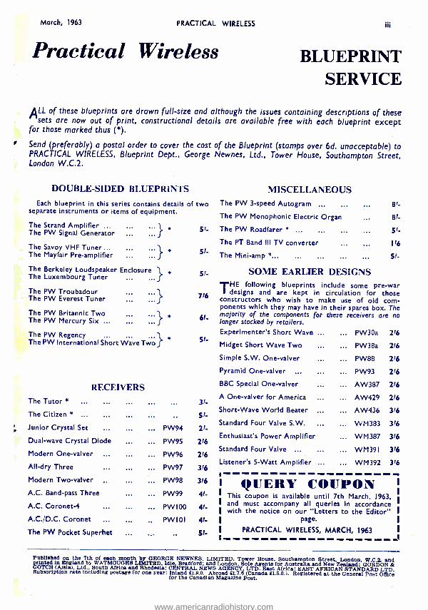
March, 1963 PRACTICAL WIRELESS iii
Practical Wireless BLUEPRINT SERVICE
ALL of these blueprints are drawn full -size and although the issues containing descriptions of these sets are now out of print, constructional details are available free with each blueprint except
for those marked thus (*). F Send (preferably) a postal order to cover the cost of the Blueprint (stamps over 6d. unacceptable) to
PRACTICAL WIRELESS, Blueprint Dept., George Newnes, Ltd., Tower House, Southampton Street, London W.C.2.
DOUBLE -SIDED BLUEPRINTS
Each blueprint in this series contains details of two separate instruments or items of equipment.
The Strand Amplifier ... The PW Signal Generator
The Savoy VHF Tuner ... The Mayfair Pre -amplifier
The Berkeley Loudspeaker Enclosure The Luxembourg Tuner
... *
I
The PW Troubadour The PW Everest Tuner
The PW Britannic Two The PW Mercury Six ... ... ...
The PW Regency ... ... The PW International Short Wave Two
RECEIVERS The Tutor *
The Citizen * ...
Junior Crystal Set ...
Dual -wave Crystal Diode
Modern One -valver
All -dry Three
Modern Two -valver
A.C. Band -pass Three
A.C. Coronet -4
A.C. /D.C. Coronet
The PW Pocket Superhet
PW94
PW95
PW96
PW97
PW98
PW99
PW I00
PW 101
31-
51- 21.
216
216
316
316
4,- 4,-
q,- 51.
MISCELLANEOUS The PW 3 -speed Autogram ... ... 81-
The PW Monophonic Electric Organ 81-
The PW Roadfarer * ... 51-
The PT Band Ill TV converter 116
The Mini -amp *... ... 5/.
SOME EARLIER DESIGNS THE following blueprints include some pre -war
designs and are kept in circulation for those constructors who wish to make use of old com- ponents which they may have in their spares box. The majority of the components for these receivers are no longer stocked by retailers. Experimenter's Short Wave ...
Midget Short Wave Two
Simple S.W. One -valver
Pyramid One -valver
BBC Special One -valver
A One -valver for America
Short -Wave World Beater
Standard Four Valve S.W.
Enthusiast's Power Amplifier
Standard Four Valve ...
Listener's 5 -Watt Amplifier ...
PW30a
PW38a
PW88
PW93
AW 387
AW429
AW436
WM383
WM387
WM391
WM392
216
216
216
216
216
216
316
316
316
316
316
QUERY COUPON This coupon is available until 7th March, 1963, and must accompany all queries in accordance with the notice on our "Letters to the Editor"
page.
PRACTICAL WIRELESS, MARCH, 1963 .116
Published on the 7th of each month by GEORGE NEWNES. LIMITED. Tower House. Southampton Street, London, W.0 2. and Printed ln England by WATMOUGHS LIMITED, Idle. Bradford: and London. Sole Agents for Australia and New Zealand: GORDON & GOTCH (A /ela). Ltd., South Africa and Rhodesia; CENTRAL NEWS AGENCY. LTD. East Africa: EAST AFRICAN STANDARD LTD. Subscription rate including postage for one year: Inland E1.9.0. Abroad £1.7.6 (Canada £1.5.0.). Registered at the General Post Office for the Canadian Magazine Post.
www.americanradiohistory.com
iv PRACTICAL WIRELESS March, 1963
TO BUILD YOURSELF * PRINTED CIRCUIT RADIO DESIGNS * ALL PARTS SOLD SEPARATELY * FULL AFTER SALES SERVICE AND GUARANTEE * FULL DETAILS AND PRICES OF ANY MODEL FREE ON REQUEST
JI
y /'
home miniature Supplied two or components clearly used structions. a "CAPRI"
"CAPRI" POCKET -6 6- TRANSISTOR SUPERHET - - -- Size only
44 x 2} x I }in.
REALLY 31 r s POCKET
i Jr c) SIZE! ..g T h e m o s t s, = compact 6-
transistor and diode radio with speaker available to the
constructor. Features the latest in components and circuitry.
with Mullard transistors and -tone moulded cabinets in red /white blue /white with gold fittings. All
are supplied in packets and identified. A printed circuit is
with fully illustrated building in- Push -pull output coupled with
sensitive and selective circuit make the hard to beat. Fitted Earphone/
"CONTESSA" III * COMBINED PORTABLE AND CAR RADIO *
AMAZING SENSITIVITY AND SELEC- TIVITY ON MEDIUM AND LONG
WAVEBANDS * The easiest Superhec Radio to build on the market. Features clearly marked ,::
`` eSty
printed circuit and packaged components with full illustrated building instructions Full tuning of medium and long wave bands with unbeatable sensitivity and -
selectivity. Excellent tone and volume with over 600MW push -pull output. * Clearly marked horizontal station dial with slow motion tuning. Two colour Blue or Beige cabinets with Gold handles, grilles and fittings. Size 10} x 71 x 3 -in., include car aerial socket, recording sockets. * 6- Mullard Transistors and 2- Diodes. -
Guaranteed the Best Obtainable Attractive Appearance -Reliable Design -Quality Performance
NEW TOTAL e 9
A COST . 9.6 P.P. P316
Record Socket. Full tuning on medium waves with long wave Light.
TOTAL IC I al A COST P.P. 21- Slip it into your Pocket
"MINI- RANGER" PERSONAL POCKET RADIO
3- TRANSISTORS 2- DIODES g . Size only 3 x 2 x sin. fl t
A new printed circuit 5 -stage personal pocket radio 1. fully tunable on medium waves and top band, including r Radio Luxembourg. A tiny but powerful radio de- I =
signed to fit into your jacket top pocket. No external
ó WATT 4 TRANSISTOR AMPLIFIER
1\ Improved -(',- Version
1
- I }watt peak `, et output. -,- 3d870ç1s co 12 kc: s.
- Output to 3
aerial or earth. Full station separation with amazing sensitivity and volume. Fully illustrated instructions free on request with clearly marked pre -tinned ''p, + printed circuit and 1st grade components make this radio Easy to Build and use. Fitted volume control and calibrated dial. All parts sold separately. After . -+. sales service and guarantee. .. Y
TOTAL 59 6 COST / P.P. 116
Built and Kit of Tested Parts
59f6 OR 5216 P.P. 1'6 P.P. 1,6
ohm speaker 9 volt oper- aced.
Details on request.
"QUINTET" Mk. II BATTERY RECORD PLAYERS C,.
6 -71 volt Garrard turntable with crystal pick -up. Plays 45 r.p.m. ) Ideal for above amplifier.
:1:77.. 551- P.P. 116.
!), Suitable cabinet for amplifier and player, 1716. P.P. 21 -. - --
B.S.R. 9 Volt 4 -Speed "Hi- Grade' Turntable with turn -over Crystal Pick -up. L6.5.0. P.P. 216.
POCKET RADIO Improved 5- transistor with diode 7 -stage medium
and long wave pocket radio. Now features more °` output, greater sensitivity and quality. Printed circuit clearly marked with component positions, carded tom- - ponencs and matched transistors. Features full volume A`-e s'-ß.7 li_
control, marked dial, airspaced tuning, push -pull -y^_° speaker output, car aerial socket, phone, record socket.
Guaranteed results, with no station overlap, including Radio Luxembourg. Simple to build with carded tom- ponents and fully detailed illustrated instru tuons .. (free on request).
TOTAL COST 9976 P.P. 21 -. OF ALL PARTS Amazing Performance
44 PAGE 101 x 7 *in. FULLY ILLUSTRATED AND
DETAILED CATALOGUE NOW READY
SEND 1 /- for Your Copy
'TRANSFIYE' PORTABLE r
1y RADIO 4.
Total Cost °= = ® of all Parts
'' E5.19.6 P.P. 2163
7 -stage push -pull output printed portable radio of attractive
Features Sin. speaker, clearly marked printed circuit panel, ferrite
fully
"RANGER 3" Size 41 x 3 x I }in. A Three -Transistor
Two -Diode Personal Radio for Medium Waves and Amateur top band and ship- pins. Quality output . on personal phone. Fitted air spaced tuner, vol. control. No aerial or earth.
5916 PjP. L u x e m b o u r g 16 guaranteed.
Ltd. Henry's Radio Ltd. 5 HARROW ROAD, LONDON W2
PADdington 1008¡9
Open Monday to Sot. 9 -6. Thurs. I o'clock
A circuit appearance.
aerial, carded components and 4----PLEASE TURN PAGE detailed and illustrated building instruc-
tions. Size 8+ x 61 x 3 +in. COMPONENT SPECIALISTS * Plans Free on Request *
- - - - - - - - - - - A- - - - + - ---..
P.W. -6 SUPERHET E7.19.6. P.P. 21 -. P.W. "MERCURY" E9.10.0. P.P. 2'6.
And all other P.W. Designs.
- - ..., a -
www.americanradiohistory.com


