Embed Size (px)
Citation preview
Project
REHABILITATION BUILDING
Job Ref.
005
Section
Sheet no./rev.
1
Calc. by
Eng.
NTEZIYARE
MYE
DIEUDONNE
Date
11/20/2017
Chk'd by
Date
App'd by
Date
1
REINFORCEMENT CALCULATION
NOTE
OWNER: NTEZIRYAYO DIDAS
NOVEMBER 2017.
Project
REHABILITATION BUILDING
Job Ref.
005
Section
Sheet no./rev.
2
Calc. by
Eng.
NTEZIYARE
MYE
DIEUDONNE
Date
11/20/2017
Chk'd by
Date
App'd by
Date
2
Contents Pad footing analysis & design (BS8110) ............................................................................................................................................... 3
Pad footing analysis and design (BS8110-1:1997) ............................................................................................................................ 3
RC column design (BS8110) ................................................................................................................................................................. 9
RC column design (Bs8110:Part1:1997) ............................................................................................................................................ 9
Note ................................................................................................................................................................................................. 11
RC beam analysis & design (BS8110) ................................................................................................................................................ 16
RC beam analysis & design BS8110 ............................................................................................................................................... 16
Support A ..................................................................................................................................................................................... 20
Mid span 1 .................................................................................................................................................................................... 21
Mid span 2 .................................................................................................................................................................................... 22
Mid span 3 .................................................................................................................................................................................... 23
Mid span 4 .................................................................................................................................................................................... 25
Mid span 5 .................................................................................................................................................................................... 26
RC slab design (BS8110) .................................................................................................................................................................... 27
RC Slab design (BS8110:Part1:1997) ............................................................................................................................................. 27
Continuous One Way Spanning Slab Definition ............................................................................................................................... 27
Transverse bottom steel - inner ....................................................................................................................................................... 28
Transverse Top steel - inner ............................................................................................................................................................ 29
Shear Resistance of Concrete Slabs (Cl 3.5.5) ............................................................................................................................... 30
Punching shear at concentrated loads (cl 3.7.7) .............................................................................................................................. 30
Concrete Slab Deflection Check (cl 3.5.7) ...................................................................................................................................... 31
RC stair design (BS8110) .................................................................................................................................................................... 32
RC stair designRC stair design (BS8110-1:1997) ............................................................................................................................ 32
Mid span design ........................................................................................................................................................................... 34
Upper landing support design ...................................................................................................................................................... 34
Lower landing support design ...................................................................................................................................................... 35
Project
REHABILITATION BUILDING
Job Ref.
005
Section
Sheet no./rev.
3
Calc. by
Eng.
NTEZIYARE
MYE
DIEUDONNE
Date
11/20/2017
Chk'd by
Date
App'd by
Date
3
PAD FOOTING ANALYSIS & DESIGN (BS8110)
PAD FOOTING ANALYSIS AND DESIGN (BS8110-1:1997)
TEDDS calculation version 2.0.07
Library item: Pad footing analysis title
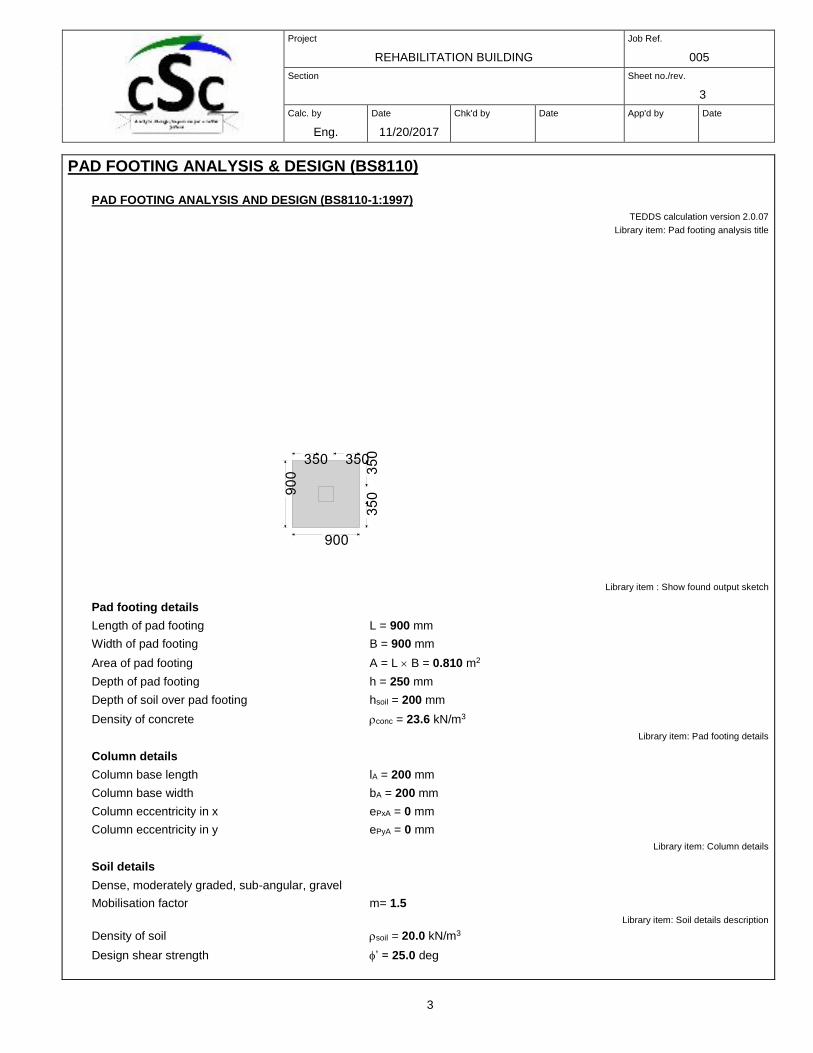
Library item : Show found output sketch
Pad footing details
Length of pad footing L = 900 mm
Width of pad footing B = 900 mm
Area of pad footing A = L B = 0.810 m2
Depth of pad footing h = 250 mm
Depth of soil over pad footing hsoil = 200 mm
Density of concrete conc = 23.6 kN/m3
Library item: Pad footing details
Column details
Column base length lA = 200 mm
Column base width bA = 200 mm
Column eccentricity in x ePxA = 0 mm
Column eccentricity in y ePyA = 0 mm
Library item: Column details
Soil details
Dense, moderately graded, sub-angular, gravel
Mobilisation factor m= 1.5
Library item: Soil details description
Density of soil soil = 20.0 kN/m3
Design shear strength ’ = 25.0 deg

Project
REHABILITATION BUILDING
Job Ref.
005
Section
Sheet no./rev.
4
Calc. by
Eng.
NTEZIYARE
MYE
DIEUDONNE
Date
11/20/2017
Chk'd by
Date
App'd by
Date
4
Design base friction = 19.3 deg
Allowable bearing pressure Pbearing = 340 kN/m2
Library item: Soil details
Axial loading on column
Dead axial load on column PGA = 78.0 kN
Imposed axial load on column PQA = 38.0 kN
Wind axial load on column PWA = 0.0 kN
Total axial load on column PA = 116.0 kN
Library item: Axial load column
Foundation loads
Dead surcharge load FGsur = 1.000 kN/m2
Imposed surcharge load FQsur = 1.400 kN/m2
Pad footing self weight Fswt = h conc = 5.900 kN/m2
Soil self weight Fsoil = hsoil soil = 4.000 kN/m2
Total foundation load F = A (FGsur + FQsur + Fswt + Fsoil) = 10.0 kN
Library item: Foundation load on pad
Calculate pad base reaction
Total base reaction T = F + PA = 126.0 kN
Eccentricity of base reaction in x eTx = (PA ePxA + MxA + HxA h) / T = 0 mm
Eccentricity of base reaction in y eTy = (PA ePyA + MyA + HyA h) / T = 0 mm
Check pad base reaction eccentricity
abs(eTx) / L + abs(eTy) / B = 0.000
Base reaction acts within middle third of base
Library item: Calculate pad base reaction
Calculate pad base pressures
q1 = T / A - 6 T eTx / (L A) - 6 T eTy / (B A) = 155.510 kN/m2
q2 = T / A - 6 T eTx / (L A) + 6 T eTy / (B A) = 155.510 kN/m2
q3 = T / A + 6 T eTx / (L A) - 6 T eTy / (B A) = 155.510 kN/m2
q4 = T / A + 6 T eTx / (L A) + 6 T eTy / (B A) = 155.510 kN/m2
Minimum base pressure qmin = min(q1, q2, q3, q4) = 155.510 kN/m2
Maximum base pressure qmax = max(q1, q2, q3, q4) = 155.510 kN/m2
PASS - Maximum base pressure is less than allowable bearing pressure
Library item: Calculate pad base pressures
Project
REHABILITATION BUILDING
Job Ref.
005
Section
Sheet no./rev.
5
Calc. by
Eng.
NTEZIYARE
MYE
DIEUDONNE
Date
11/20/2017
Chk'd by
Date
App'd by
Date
5
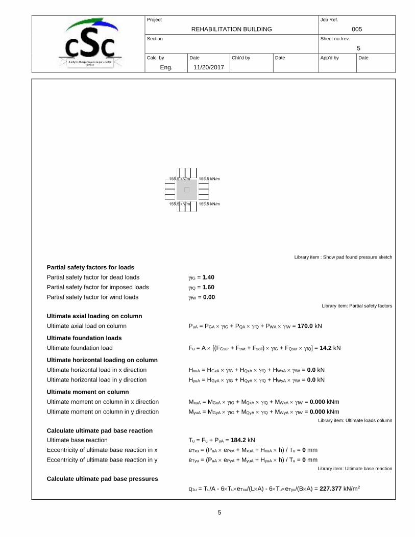
Library item : Show pad found pressure sketch
Partial safety factors for loads
Partial safety factor for dead loads fG = 1.40
Partial safety factor for imposed loads fQ = 1.60
Partial safety factor for wind loads fW = 0.00
Library item: Partial safety factors
Ultimate axial loading on column
Ultimate axial load on column PuA = PGA fG + PQA fQ + PWA fW = 170.0 kN
Ultimate foundation loads
Ultimate foundation load Fu = A [(FGsur + Fswt + Fsoil) fG + FQsur fQ] = 14.2 kN
Ultimate horizontal loading on column
Ultimate horizontal load in x direction HxuA = HGxA fG + HQxA fQ + HWxA fW = 0.0 kN
Ultimate horizontal load in y direction HyuA = HGyA fG + HQyA fQ + HWyA fW = 0.0 kN
Ultimate moment on column
Ultimate moment on column in x direction MxuA = MGxA fG + MQxA fQ + MWxA fW = 0.000 kNm
Ultimate moment on column in y direction MyuA = MGyA fG + MQyA fQ + MWyA fW = 0.000 kNm
Library item: Ultimate loads column
Calculate ultimate pad base reaction
Ultimate base reaction Tu = Fu + PuA = 184.2 kN
Eccentricity of ultimate base reaction in x eTxu = (PuA ePxA + MxuA + HxuA h) / Tu = 0 mm
Eccentricity of ultimate base reaction in y eTyu = (PuA ePyA + MyuA + HyuA h) / Tu = 0 mm
Library item: Ultimate base reaction
Calculate ultimate pad base pressures
q1u = Tu/A - 6TueTxu/(LA) - 6TueTyu/(BA) = 227.377 kN/m2
Project
REHABILITATION BUILDING
Job Ref.
005
Section
Sheet no./rev.
6
Calc. by
Eng.
NTEZIYARE
MYE
DIEUDONNE
Date
11/20/2017
Chk'd by
Date
App'd by
Date
6
q2u = Tu/A - 6TueTxu/(LA) + 6Tu eTyu/(BA) = 227.377 kN/m2
q3u = Tu/A + 6TueTxu/(LA) - 6TueTyu/(BA) = 227.377 kN/m2
q4u = Tu/A + 6TueTxu/(LA) + 6TueTyu/(BA) = 227.377 kN/m2
Minimum ultimate base pressure qminu = min(q1u, q2u, q3u, q4u) = 227.377 kN/m2
Maximum ultimate base pressure qmaxu = max(q1u, q2u, q3u, q4u) = 227.377 kN/m2
Library item: Ultimate pad base pressures
Calculate rate of change of base pressure in x direction
Left hand base reaction fuL = (q1u + q2u) B / 2 = 204.639 kN/m
Right hand base reaction fuR = (q3u + q4u) B / 2 = 204.639 kN/m
Length of base reaction Lx = L = 900 mm
Rate of change of base pressure Cx = (fuR - fuL) / Lx = 0.000 kN/m/m
Library item: Ultimate pad base reactions in x
Calculate pad lengths in x direction
Left hand length LL = L / 2 + ePxA = 450 mm
Right hand length LR = L / 2 - ePxA = 450 mm
Library item: Calculate pad lengths in x
Calculate ultimate moments in x direction
Ultimate moment in x direction Mx = fuL LL2 / 2 + Cx LL
3 / 6 - Fu LL2 / (2 L) = 19.125 kNm
Library item: Ultimate moment in x direction
Calculate rate of change of base pressure in y direction
Top edge base reaction fuT = (q2u + q4u) L / 2 = 204.639 kN/m
Bottom edge base reaction fuB = (q1u + q3u) L / 2 = 204.639 kN/m
Length of base reaction Ly = B = 900 mm
Rate of change of base pressure Cy = (fuB - fuT) / Ly = 0.000 kN/m/m
Library item: Ultimate pad base reactions in y
Calculate pad lengths in y direction
Top length LT = B / 2 - ePyA = 450 mm
Bottom length LB = B / 2 + ePyA = 450 mm
Library item: Calculate pad lengths in y
Calculate ultimate moments in y direction
Ultimate moment in y direction My = fuT LT2 / 2 + Cy LT
3 / 6 - Fu LT2 / (2 B) = 19.125 kNm
Library item: Ultimate moment in y direction
Material details
Characteristic strength of concrete fcu = 30 N/mm2
Characteristic strength of reinforcement fy = 500 N/mm2
Characteristic strength of shear reinforcement fyv = 500 N/mm2
Nominal cover to reinforcement cnom = 30 mm
Library item: Material details
Moment design in x direction
Diameter of tension reinforcement xB = 12 mm
Depth of tension reinforcement dx = h - cnom - xB / 2 = 214 mm
Design formula for rectangular beams (cl 3.4.4.4)
Kx = Mx / (B dx2 fcu) = 0.015
Project
REHABILITATION BUILDING
Job Ref.
005
Section
Sheet no./rev.
7
Calc. by
Eng.
NTEZIYARE
MYE
DIEUDONNE
Date
11/20/2017
Chk'd by
Date
App'd by
Date
7
Kx’ = 0.156
Kx < Kx' compression reinforcement is not required
Lever arm zx = dx min([0.5 + (0.25 - Kx / 0.9)], 0.95) = 203 mm
Area of tension reinforcement required As_x_req = Mx / (0.87 fy zx) = 216 mm2
Minimum area of tension reinforcement As_x_min = 0.0013 B h = 293 mm2
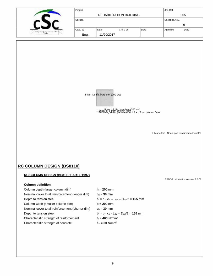
Tension reinforcement provided 5 No. 12 dia. bars bottom (200 centres)
Area of tension reinforcement provided As_xB_prov = NxB xB2 / 4 = 565 mm2
PASS - Tension reinforcement provided exceeds tension reinforcement required
Library item - Output tension design in x
Moment design in y direction
Diameter of tension reinforcement yB = 12 mm
Depth of tension reinforcement dy = h - cnom - xB - yB / 2 = 202 mm
Design formula for rectangular beams (cl 3.4.4.4)
Ky = My / (L dy2 fcu) = 0.017
Ky’ = 0.156
Ky < Ky' compression reinforcement is not required
Lever arm zy = dy min([0.5 + (0.25 - Ky / 0.9)], 0.95) = 192 mm
Area of tension reinforcement required As_y_req = My / (0.87 fy zy) = 229 mm2
Minimum area of tension reinforcement As_y_min = 0.0013 L h = 293 mm2
Tension reinforcement provided 5 No. 12 dia. bars bottom (200 centres)
Area of tension reinforcement provided As_yB_prov = NyB yB2 / 4 = 565 mm2
PASS - Tension reinforcement provided exceeds tension reinforcement required
Library item - Output tension design in y
Calculate ultimate shear force at d from top face of column
Ultimate pressure for shear qsu = (q1u - Cy (B / 2 + ePyA + bA / 2 + dy) / L + q4u) / 2
qsu = 227.377 kN/m2
Area loaded for shear As = L (B / 2 - ePyA - bA / 2 - dy) = 0.133 m2
Library item: Output ult shear pressure
Ultimate shear force Vsu = As (qsu - Fu / A) = 27.956 kN
Library item: Output max shear force
Shear stresses at d from top face of column (cl 3.5.5.2)
Design shear stress vsu = Vsu / (L dy) = 0.154 N/mm2
From BS 8110:Part 1:1997 - Table 3.8
Design concrete shear stress vc = 0.79 N/mm2 min(3, [100 As_yB_prov / (L dy)]1/3) max((400 mm /
dy)1/4, 0.67) (min(fcu / 1 N/mm2, 40) / 25)1/3 / 1.25 = 0.540 N/mm2
Allowable design shear stress vmax = min(0.8 N/mm2 (fcu / 1 N/mm2), 5 N/mm2) = 4.382 N/mm2
PASS - vsu < vc - No shear reinforcement required
Library item: Output shear stress
Calculate ultimate punching shear force at face of column
Ultimate pressure for punching shear qpuA = q1u+[(L/2+ePxA-lA/2)+(lA)/2]Cx/B-[(B/2+ePyA-bA/2)+(bA)/2]Cy/L =
227.377 kN/m2
Library item: Ultimate punching shear pressure
Average effective depth of reinforcement d = (dx + dy) / 2 = 208 mm
Project
REHABILITATION BUILDING
Job Ref.
005
Section
Sheet no./rev.
8
Calc. by
Eng.
NTEZIYARE
MYE
DIEUDONNE
Date
11/20/2017
Chk'd by
Date
App'd by
Date
8
Area loaded for punching shear at column ApA = (lA)(bA) = 0.040 m2
Length of punching shear perimeter upA = 2(lA)+2(bA) = 800 mm
Ultimate shear force at shear perimeter VpuA = PuA + (Fu / A - qpuA) ApA = 161.605 kN
Effective shear force at shear perimeter VpuAeff = VpuA = 161.605 kN
Library item: Output punching shear force
Punching shear stresses at face of column (cl 3.7.7.2)
Design shear stress vpuA = VpuAeff / (upA d) = 0.971 N/mm2
Allowable design shear stress vmax = min(0.8N/mm2 (fcu / 1 N/mm2), 5 N/mm2) = 4.382 N/mm2
PASS - Design shear stress is less than allowable design shear stress
Library item: Output punching shear face
Calculate ultimate punching shear force at perimeter of 1.5 d from face of column
Ultimate pressure for punching shear qpuA1.5d = q1u+[L/2]Cx/B-[(B/2+ePyA-bA/2-1.5d)+(bA+21.5d)/2]Cy/L =
227.377 kN/m2
Library item: Ultimate punching shear pressure
Average effective depth of reinforcement d = (dx + dy) / 2 = 208 mm
Area loaded for punching shear at column ApA1.5d = L(bA+21.5d) = 0.742 m2
Length of punching shear perimeter upA1.5d = 2L = 1800 mm
Ultimate shear force at shear perimeter VpuA1.5d = PuA + (Fu / A - qpuA1.5d) ApA1.5d = 14.356 kN
Effective shear force at shear perimeter VpuA1.5deff = VpuA1.5d 1.25 = 17.944 kN
Library item: Output punching shear force
Punching shear stresses at perimeter of 1.5 d from face of column (cl 3.7.7.2)
Design shear stress vpuA1.5d = VpuA1.5deff / (upA1.5d d) = 0.048 N/mm2
From BS 8110:Part 1:1997 - Table 3.8
Design concrete shear stress vc = 0.79 N/mm2 min(3, [100 (As_xB_prov / (B dx) + As_yB_prov / (L dy)) /
2]1/3) max((800 mm / (dx + dy))1/4, 0.67) (min(fcu / 1 N/mm2, 40) / 25)1/3 /
1.25 = 0.531 N/mm2
Allowable design shear stress vmax = min(0.8N/mm2 (fcu / 1 N/mm2), 5 N/mm2) = 4.382 N/mm2
PASS - vpuA1.5d < vc - No shear reinforcement required
Library item: Output punching shear stress
Project
REHABILITATION BUILDING
Job Ref.
005
Section
Sheet no./rev.
9
Calc. by
Eng.
NTEZIYARE
MYE
DIEUDONNE
Date
11/20/2017
Chk'd by
Date
App'd by
Date
9
Library item : Show pad reinforcement sketch
RC COLUMN DESIGN (BS8110)
RC COLUMN DESIGN (BS8110:PART1:1997)
TEDDS calculation version 2.0.07
Column definition
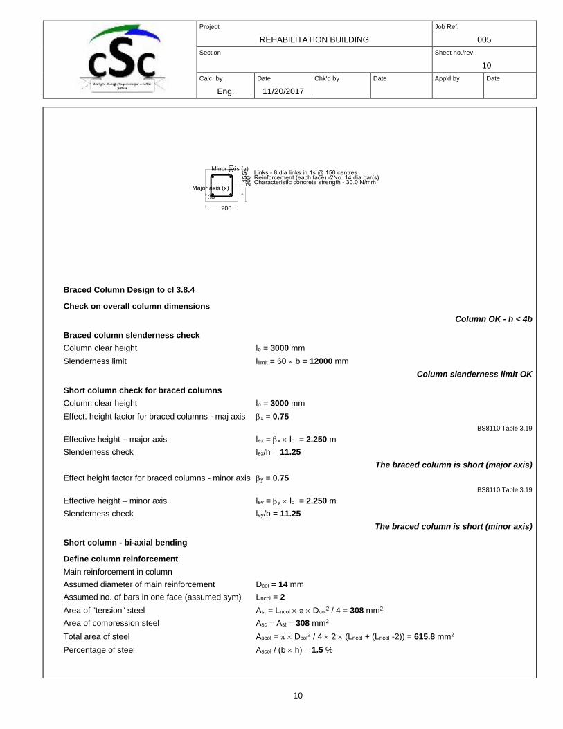
Column depth (larger column dim) h = 200 mm
Nominal cover to all reinforcement (longer dim) ch = 30 mm
Depth to tension steel h' = h - ch – Ldia – Dcol/2 = 155 mm
Column width (smaller column dim) b = 200 mm
Nominal cover to all reinforcement (shorter dim) cb = 30 mm
Depth to tension steel b' = b - cb - Ldia – Dcol/2 = 155 mm
Characteristic strength of reinforcement fy = 460 N/mm2
Characteristic strength of concrete fcu = 30 N/mm2
Project
REHABILITATION BUILDING
Job Ref.
005
Section
Sheet no./rev.
10
Calc. by
Eng.
NTEZIYARE
MYE
DIEUDONNE
Date
11/20/2017
Chk'd by
Date
App'd by
Date
10
Braced Column Design to cl 3.8.4
Check on overall column dimensions
Column OK - h < 4b
Braced column slenderness check
Column clear height lo = 3000 mm
Slenderness limit llimit = 60 b = 12000 mm
Column slenderness limit OK
Short column check for braced columns
Column clear height lo = 3000 mm
Effect. height factor for braced columns - maj axis x = 0.75
BS8110:Table 3.19
Effective height – major axis lex = x lo = 2.250 m
Slenderness check lex/h = 11.25
The braced column is short (major axis)
Effect height factor for braced columns - minor axis y = 0.75
BS8110:Table 3.19
Effective height – minor axis ley = y lo = 2.250 m
Slenderness check ley/b = 11.25
The braced column is short (minor axis)
Short column - bi-axial bending
Define column reinforcement
Main reinforcement in column
Assumed diameter of main reinforcement Dcol = 14 mm
Assumed no. of bars in one face (assumed sym) Lncol = 2
Area of "tension" steel Ast = Lncol Dcol2 / 4 = 308 mm2
Area of compression steel Asc = Ast = 308 mm2
Total area of steel Ascol = Dcol2 / 4 2 (Lncol + (Lncol -2)) = 615.8 mm2
Percentage of steel Ascol / (b h) = 1.5 %
Project
REHABILITATION BUILDING
Job Ref.
005
Section
Sheet no./rev.
11
Calc. by
Eng.
NTEZIYARE
MYE
DIEUDONNE
Date
11/20/2017
Chk'd by
Date
App'd by
Date
11
Design ultimate loading
Design ultimate axial load N = 160 kN
Design ultimate moment (major axis) Mx = 7 kNm
Design ultimate moment (minor axis) My = 4 kNm
Minimum design moments
Min design moment (major axis) Mxmin = min(0.05 h, 20 mm) N = 1.6 kNm
Min design moment (minor axis) Mymin = min(0.05 b, 20 mm) N = 1.6 kNm
Design moments
Design moment (major axis) Mxdes = max (abs(Mx), Mxmin) = 7.0 kNm
Design moment (minor axis) Mydes = max (abs(My) , Mymin) = 4.2 kNm
Simplified method for dealing with bi-axial bending:-
h' = 155 mm b' = 155 mm
Approx uniaxial design moment (Cl 3.8.4.5)
= 1 - 1.165 min(0.6, N/(bhfcu)) = 0.84
Design moment
Mdesign = if(Mxdes/h' < Mydes/b' , Mydes + b'/h' Mxdes , Mxdes + h'/b' Mydes ) = 10.5 kNm
Set up section dimensions for design:-
Section depth D = if(Mxdes/h' < Mydes/b' , b, h) = 200.0 mm
Depth to "tension" steel d = if(Mxdes/h' < Mydes/b' , b', h') = 155.0 mm
Section width B = if(Mxdes/h' < Mydes/b' , h, b) = 200.0 mm
Library item - Calcs – short col N+Mmaj+Mmin
Check of design forces - symmetrically reinforced section
NOTE
Note:- the section dimensions used in the following calculation are:-
Section width (parallel to axis of bending) B = 200 mm
Section depth perpendicular to axis of bending) D = 200 mm
Depth to "tension" steel (symmetrical) d = 155 mm
Tension steel yields
Determine correct moment of resistance
NR =ceiling(if(xcalc<D/0.9, NR1 , NR2 ),0.001kN) = 160.0 kN
MR = ceiling(if(xcalc<D/0.9, MR1 , MR2 ) ,0.001kNm) = 24.2 kNm
Applied axial load N = 160.0 kN
Check for moment Mdesign = 10.5 kNm
Moment check satisfied
Check min and max areas of steel
Total area of concrete Aconc = b h = 40000 mm2
Area of steel (symmetrical) Ascol = 616 mm2
Minimum percentage of compression reinforcement kc = 0.80 %
Minimum steel area Asc_min = kc Aconc = 320 mm2
Project
REHABILITATION BUILDING
Job Ref.
005
Section
Sheet no./rev.
12
Calc. by
Eng.
NTEZIYARE
MYE
DIEUDONNE
Date
11/20/2017
Chk'd by
Date
App'd by
Date
12
Maximum steel area As_max = 6 % Aconc = 2400 mm2
Area of compression steel provided OK
Major axis Shear Resistance of Concrete Columns - (cl 3.8.4.6)
Column width b = 200 mm
Column depth h = 200 mm
Effective depth to steel h' = 155 mm
Area of concrete Aconc = b h = 40000 mm2
Design ultimate shear force (major axis) Vx = 3 kN
Characteristic strength of concrete fcu = 30 N/mm2
Is a check required? (3.8.4.6)
Axial load N = 160.0 kN
Major axis moment Mx = 7.0 kNm
Eccentricity e = Mx / N = 43.7 mm
Limit to eccentricity elimit = 0.6 h = 120.0 mm
Actual shear stress vx = Vx / (b h') = 0.1 N/mm2
Allowable stress vallowable = min ((0.8 N1/2/mm) (fcu ), 5 N/mm2 ) = 4.382 N/mm2
No shear check required
Define Containment Links Provided
Link spacing sv = 150 mm Link diameter Ldia = 8 mm No of links in each group Ln = 1
Minimum Containment Steel (Cl 3.12.7)
Shear steel
Link spacing sv = 150 mm
Link diameter Ldia = 8 mm
Column steel
Diameter Dcol = 14 mm
Min diameter Llimit = max( (6 mm), Dcol/4) = 6.0 mm
Link diameter OK
Max spacing slimit = 12 Dcol = 168.0 mm
Link spacing OK
Crack Control in columns - is a check required? (Cl 3.8.6)
Column design ultimate axial load N = 160.0 kN
Column dimensions
Column depth (larger column dimension) h = 200 mm
Column width (smaller column dimension) b = 200 mm
Column area Ac = h b = 40000 mm2
Limit for crack check Nlimit = 0.2 fcu Ac = 240.0 kN
Column should be checked as a beam for cracking
Serviceability Limit State - Cracking in Columns
Bent about the major axis
(BS8110:Pt 2, Cl. 3.8 & BS8007 Cl 2.6 & Appendix B)
The following calculations ignore the presence of compression steel and axial load.
Project
REHABILITATION BUILDING
Job Ref.
005
Section
Sheet no./rev.
13
Calc. by
Eng.
NTEZIYARE
MYE
DIEUDONNE
Date
11/20/2017
Chk'd by
Date
App'd by
Date
13
Design serviceability moment about the major axis MX_SLS = 0 kNm
Column dimensions, depth to steel (assumed symmetrical)
Column depth (larger column dimension) h = 200 mm
Depth to steel h' = 155 mm
Column width (smaller column dimension) b = 200 mm
Characteristic strength of concrete fcu = 30 N/mm2
Characteristic strength of reinforcement fy = 460 N/mm2
BS8110:Pt 1:Table 3.1
Diameter of links Ldia = 8 mm
Diameter of tension reinforcement Dcol = 14 mm
Number of tension reinforcement bars Lncol = 2
Area of tension reinforcement Ast = Dcol2 /4 Lncol = 308 mm2
Nominal cover to reinforcement cnom = h - h' - Dcol/2 - Ldia = 30 mm
Cover to tension reinforcement cten = cnom + Ldia = 38.0 mm
Effective depth to tension reinforcement h' = 155.0 mm
Tension bar centres barcrs = (b - 2(cnom + Ldia) - Dcol ) / (Lncol - 1) = 110.0 mm
Modular Ratio
Modulus of elasticity for reinforcement Es = 200 kN/mm2
BS8110:Pt 1:Cl 2.5.4
Modulus of elast for conc (half the instanteneous) Ec = ((20 kN/mm2) + 200fcu) / 2 = 13 kN/mm2
BS8110:Pt 2:Equation 17
Modular ratio m = Es / Ec = 15.385
Neutral Axis position
For equilibrium Fst equates Fc
Therefore: m Ast [ fc(h'-x)/x ] equates to 0.5 fc b x
Solving for x gives the position of the neutral axis in the section:-
x = h' [ -1EsAst/(Ecbh') + ( EsAst/(Ecbh') (2+EsAst/(Ecbh')))] = 65.2 mm
Depth of concrete in compression x = 65.2 mm
Concrete and Steel stresses
The serviceability limit state moment MX_SLS = 0 kNm
Taking moments about the centreline of the reinforcement:-
Moment of resistance of concrete is 0.5 fc b x (h' - x/3)
Solving for concrete stress fc gives fc = 2 MX_SLS / ( b x (h' - x/3)) = 0.23 N/mm2
Allowable stress 0.45 fcu = 13.50 N/mm2
Concrete stress OK
Taking moments about the centre of action of the concrete force:-
Moment of resistance of steel is fst As (h' - x/3)
Solving for steel stress fst gives fst = MX_SLS / ( Ast (h' - x/3)) = 4.87 N/mm2
Concrete and Steel strains
Strain in the reinforcement s = fst / Es = 24.3710-6
Allowable steel strain 0.8 fy / Es = 1.84010-3
Steel strain OK
BS8007:App B.4
Project
REHABILITATION BUILDING
Job Ref.
005
Section
Sheet no./rev.
14
Calc. by
Eng.
NTEZIYARE
MYE
DIEUDONNE
Date
11/20/2017
Chk'd by
Date
App'd by
Date
14
Strain in the concrete at the level at which crack width is required
Level of crack a' = h = 200 mm
1 = s (a' - x)/(h' - x) = 36.5910-6
Strain in the concrete at the level at which crack width is required adjusted for stiffening of the concrete tension zone
Allowable crack width CrackAllowable = 0.2 mm
BS8007:Cl 2.2.3.3
Factor for stiffening based on limitiing crack width factor = 1.0 N/mm2
Breadth of tension face bt = b = 200 mm
m = min( 1 ,max(0, 1 - [ factor bt (h - x) (a' - x) / (3Es Ast (h' - x))])) = 0.0000
BS8007:App B.3
Distance from tension bar to crack in tension face between tension bars
acr1 = ( (barcrs/2)2 + (cnom + Ldia + Dcol/2)2) - Dcol/2 = 64.1 mm
Distance from tension bar to crack in tension face at corner of column
acr2 = (2) (cnom + Ldia + Dcol/2 ) - Dcol/2 = 56.6 mm
Critical distance from tension bar acr = max(acr1, acr2 ) = 64.1 mm
Design crack width Crackdesign = 3 acr m /(1 + 2(acr - cten)/(h - x)) = 0.000 mm
BS8007:App B.2
Max allowable crack width CrackAllowable = 0.20 mm
BS8007:Cl 2.2.3.3
Serviceability Limit State - Cracking in Columns
Bent about the minor axis
(BS8110:Pt 2, Cl. 3.8 & BS8007 Cl 2.6 & Appendix B)
The following calculations ignore the presence of compression steel and axial load.
Design serviceability moment about the minor axis MY_SLS = 0 kNm
Column dimensions, depth to steel (assumed symmetrical)
Column depth (larger column dimension) h = 200 mm
Column width (smaller column dimension) b = 200 mm
Depth to steel b' = 155 mm
Characteristic strength of concrete fcu = 30 N/mm2
Characteristic strength of reinforcement fy = 460 N/mm2
BS8110:Pt 1:Table 3.1
Diameter of links Ldia = 8 mm
Diameter of tension reinforcement Dcol = 14 mm
Number of tension reinforcement bars Lncol = 2
Area of tension reinforcement Ast = Dcol2 /4 Lncol = 308 mm2
Nominal cover to reinforcement cnom = b - b' - Dcol/2 - Ldia = 30 mm
Cover to tension reinforcement cten = cnom + Ldia = 38.0 mm
Effective depth to tension reinforcement b' = 155.0 mm
Tension bar centres barcrs = (h - 2(cnom + Ldia) - Dcol ) / (Lncol - 1) = 110.0 mm
Modular Ratio
Modulus of elasticity for reinforcement Es = 200 kN/mm2
BS8110:Pt 1:Cl 2.5.4
Modulus of elasticity for conc (half instanteneous) Ec = ((20 kN/mm2) + 200fcu) / 2 = 13 kN/mm2
BS8110:Pt 2:Equation 17
Modular ratio m = Es / Ec = 15.385
Project
REHABILITATION BUILDING
Job Ref.
005
Section
Sheet no./rev.
15
Calc. by
Eng.
NTEZIYARE
MYE
DIEUDONNE
Date
11/20/2017
Chk'd by
Date
App'd by
Date
15
Neutral Axis position
For equilibrium Fst equates Fc
Therefore: m Ast [ fc(b'-x)/x ] equates to 0.5 fc h x
Solving for x gives the position of the neutral axis in the section:-
x = b' [ -1EsAst/(Echb') + ( EsAst/(Echb') (2+EsAst/(Echb')))] = 65.2 mm
Depth of concrete in compression x = 65.2 mm
Concrete and Steel stresses
The serviceability limit state moment MY_SLS = 0 kNm
Taking moments about the centreline of the reinforcement:-
Moment of resistance of concrete is 0.5 fc h x (b' - x/3)
Solving for concrete stress fc gives fc = 2 MY_SLS / ( h x (b' - x/3)) = 0.23 N/mm2
Allowable stress 0.45 fcu = 13.50 N/mm2
Concrete stress OK
Taking moments about the centre of action of the concrete force:-
Moment of resistance of steel fst As (b' - x/3)
Solving for steel stress fst gives fst = MY_SLS / ( Ast (b' - x/3)) = 4.87 N/mm2
Concrete and Steel strains
Strain in the reinforcement s = fst / Es = 24.3710-6
Allowable steel strain 0.8 fy / Es = 1.84010-3
Steel strain OK
BS8007:App B.4
Strain in the concrete at the level at which crack width is required
Level of crack a' = b = 200 mm
1 = s (a' - x)/(b' - x) = 36.5910-6
Strain in the concrete at the level at which crack width is required adjusted for stiffening of the concrete tension zone
Allowable crack width CrackAllowable = 0.2 mm
BS8007:Cl 2.2.3.3
Factor for stiffening based on limitiing crack width factor = 1.0 N/mm2
Breadth of tension face ht = h = 200 mm
m = min( 1 , max(0, 1 - [ factor ht (b - x) (a' - x) / (3Es Ast (b' - x))])) = 0.0000
BS8007:App B.3
Distance from tension bar to crack in tension face between tension bars
acr1 = ( (barcrs/2)2 + (cnom + Ldia + Dcol/2)2) - Dcol/2 = 64.1 mm
Distance from tension bar to crack in tension face at corner of column
acr2 = (2) (cnom + Ldia + Dcol/2 ) - Dcol/2 = 56.6 mm
Critical distance from tension bar acr = max(acr1, acr2 ) = 64.1 mm
Design crack width Crackdesign = 3 acr m /(1 + 2(acr - cten)/(b - x)) = 0.000 mm
BS8007:App B.2
Max allowable crack width CrackAllowable = 0.20 mm
BS8007:Cl 2.2.3.3
Project
REHABILITATION BUILDING
Job Ref.
005
Section
Sheet no./rev.
16
Calc. by
Eng.
NTEZIYARE
MYE
DIEUDONNE
Date
11/20/2017
Chk'd by
Date
App'd by
Date
16
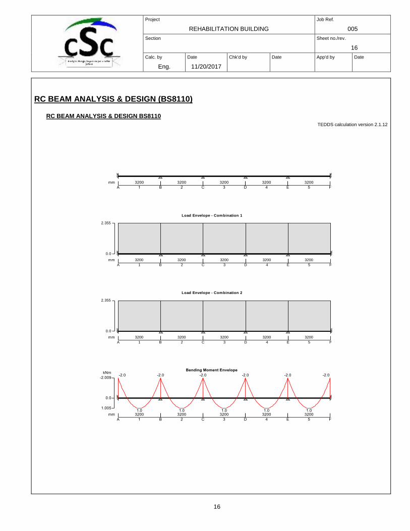
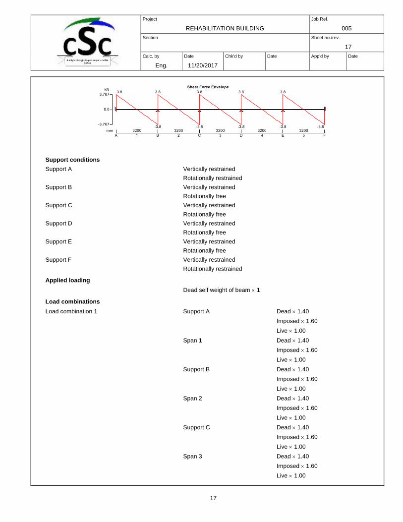
RC BEAM ANALYSIS & DESIGN (BS8110)
RC BEAM ANALYSIS & DESIGN BS8110
TEDDS calculation version 2.1.12
Load Envelope - Combination 1
0.0
2.355
mm 3200
1A
3200
2B
3200
3C
3200
4D
3200
5E F
Load Envelope - Combination 2
0.0
2.355
mm 3200
1A
3200
2B
3200
3C
3200
4D
3200
5E F
Project
REHABILITATION BUILDING
Job Ref.
005
Section
Sheet no./rev.
17
Calc. by
Eng.
NTEZIYARE
MYE
DIEUDONNE
Date
11/20/2017
Chk'd by
Date
App'd by
Date
17
Support conditions
Support A Vertically restrained
Rotationally restrained
Support B Vertically restrained
Rotationally free
Support C Vertically restrained
Rotationally free
Support D Vertically restrained
Rotationally free
Support E Vertically restrained
Rotationally free
Support F Vertically restrained
Rotationally restrained
Applied loading
Dead self weight of beam 1
Load combinations
Load combination 1 Support A Dead 1.40
Imposed 1.60
Live 1.00
Span 1 Dead 1.40
Imposed 1.60
Live 1.00
Support B Dead 1.40
Imposed 1.60
Live 1.00
Span 2 Dead 1.40
Imposed 1.60
Live 1.00
Support C Dead 1.40
Imposed 1.60
Live 1.00
Span 3 Dead 1.40
Imposed 1.60
Live 1.00
Project
REHABILITATION BUILDING
Job Ref.
005
Section
Sheet no./rev.
18
Calc. by
Eng.
NTEZIYARE
MYE
DIEUDONNE
Date
11/20/2017
Chk'd by
Date
App'd by
Date
18
Support D Dead 1.40
Imposed 1.60
Live 1.00
Span 4 Dead 1.40
Imposed 1.60
Live 1.00
Support E Dead 1.40
Imposed 1.60
Live 1.00
Span 5 Dead 1.40
Imposed 1.60
Live 1.00
Support F Dead 1.40
Imposed 1.60
Live 1.00
Load combination 2 Support A Dead 1.40
Imposed 1.60
Live 1.00
Span 1 Dead 1.40
Imposed 1.60
Live 1.00
Support B Dead 1.40
Imposed 1.60
Live 1.00
Span 2 Dead 1.40
Imposed 1.60
Live 1.00
Support C Dead 1.40
Imposed 1.60
Live 1.00
Span 3 Dead 1.40
Imposed 1.60
Live 1.00
Support D Dead 1.40
Imposed 1.60
Live 1.00
Span 4 Dead 1.40
Imposed 1.60
Live 1.00
Support E Dead 1.40
Imposed 1.60
Live 1.00
Project
REHABILITATION BUILDING
Job Ref.
005
Section
Sheet no./rev.
19
Calc. by
Eng.
NTEZIYARE
MYE
DIEUDONNE
Date
11/20/2017
Chk'd by
Date
App'd by
Date
19
Span 5 Dead 1.40
Imposed 1.60
Live 1.00
Support F Dead 1.40
Imposed 1.60
Live 1.00
Analysis results
Maximum moment support A MA_max = -2 kNm MA_red = -2 kNm 15%
Maximum moment span 1 at 1600 mm Ms1_max = 1 kNm Ms1_red = 1 kNm 27%
Maximum moment support B MB_max = -2 kNm MB_red = -2 kNm 12%
Maximum moment span 2 at 1600 mm Ms2_max = 1 kNm Ms2_red = 1 kNm 27%
Maximum moment support C MC_max = -2 kNm MC_red = -2 kNm 15%
Maximum moment span 3 at 1600 mm Ms3_max = 1 kNm Ms3_red = 1 kNm 25%
Maximum moment support D MD_max = -2 kNm MD_red = -2 kNm 10%
Maximum moment span 4 at 1600 mm Ms4_max = 1 kNm Ms4_red = 1 kNm 25%
Maximum moment support E ME_max = -2 kNm ME_red = -2 kNm 15%
Maximum moment span 5 at 1600 mm Ms5_max = 1 kNm Ms5_red = 1 kNm 30%
Maximum moment support F MF_max = -2 kNm MF_red = -2 kNm 15%
Maximum shear support A VA_max = 4 kN VA_red = 4 kN
Maximum shear support A span 1 at 306 mm VA_s1_max = 3 kN VA_s1_red = 3 kN
Maximum shear support B VB_max = -4 kN VB_red = 4 kN
Maximum shear support B span 1 at 2900 mm VB_s1_max = -3 kN VB_s1_red = -3 kN
Maximum shear support B span 2 at 300 mm VB_s2_max = 3 kN VB_s2_red = 3 kN
Maximum shear support C VC_max = -4 kN VC_red = 4 kN
Maximum shear support C span 2 at 2900 mm VC_s2_max = -3 kN VC_s2_red = -3 kN
Maximum shear support C span 3 at 300 mm VC_s3_max = 3 kN VC_s3_red = 3 kN
Maximum shear support D VD_max = -4 kN VD_red = 4 kN
Maximum shear support D span 3 at 2900 mm VD_s3_max = -3 kN VD_s3_red = -3 kN
Maximum shear support D span 4 at 300 mm VD_s4_max = 3 kN VD_s4_red = 3 kN
Maximum shear support E VE_max = -4 kN VE_red = 4 kN
Maximum shear support E span 4 at 2900 mm VE_s4_max = -3 kN VE_s4_red = -3 kN
Maximum shear support E span 5 at 300 mm VE_s5_max = 3 kN VE_s5_red = 3 kN
Maximum shear support F VF_max = -4 kN VF_red = -4 kN
Maximum shear support F span 5 at 2900 mm VF_s5_max = -3 kN VF_s5_red = -3 kN
Maximum reaction at support A RA = 4 kN
Unfactored dead load reaction at support A RA_Dead = 3 kN
Maximum reaction at support B RB = 8 kN
Unfactored dead load reaction at support B RB_Dead = 5 kN
Maximum reaction at support C RC = 8 kN
Unfactored dead load reaction at support C RC_Dead = 5 kN
Maximum reaction at support D RD = 8 kN
Unfactored dead load reaction at support D RD_Dead = 5 kN
Maximum reaction at support E RE = 8 kN
Unfactored dead load reaction at support E RE_Dead = 5 kN
Project
REHABILITATION BUILDING
Job Ref.
005
Section
Sheet no./rev.
20
Calc. by
Eng.
NTEZIYARE
MYE
DIEUDONNE
Date
11/20/2017
Chk'd by
Date
App'd by
Date
20
Maximum reaction at support F RF = 4 kN
Unfactored dead load reaction at support F RF_Dead = 3 kN
Rectangular section details
Section width b = 200 mm
Section depth h = 350 mm
Concrete details
Concrete strength class C25/30
Characteristic compressive cube strength fcu = 30 N/mm2
Modulus of elasticity of concrete Ec = 20kN/mm2 + 200 fcu = 26000 N/mm2
Maximum aggregate size hagg = 20 mm
Reinforcement details
Characteristic yield strength of reinforcement fy = 460 N/mm2
Characteristic yield strength of shear reinforcement fyv = 460 N/mm2
Nominal cover to reinforcement
Nominal cover to top reinforcement cnom_t = 30 mm
Nominal cover to bottom reinforcement cnom_b = 30 mm
Nominal cover to side reinforcement cnom_s = 30 mm
Support A
Rectangular section in flexure (cl.3.4.4)
Design bending moment M = abs(MA_red) = 2 kNm
Depth to tension reinforcement d = h - cnom_t - v - top / 2 = 306 mm
Redistribution ratio b = min(1 - mrA, 1) = 0.850
K = M / (b d2 fcu) = 0.003
K' = 0.546 b - 0.18 b2 - 0.1896 = 0.144
K' > K - No compression reinforcement is required
Lever arm z = min(d (0.5 + (0.25 - K / 0.9)0.5), 0.95 d) = 291 mm
Depth of neutral axis x = (d - z) / 0.45 = 34 mm
Area of tension reinforcement required As,req = M / (0.87 fy z) = 15 mm2
Tension reinforcement provided 2 12 bars
Area of tension reinforcement provided As,prov = 226 mm2
Minimum area of reinforcement As,min = 0.0024 b h = 168 mm2
Maximum area of reinforcement As,max = 0.04 b h = 2800 mm2
PASS - Area of reinforcement provided is greater than area of reinforcement required
Rectangular section in shear
Design shear force span 1 at 306 mm V = max(VA_s1_max, VA_s1_red) = 3 kN
Design shear stress v = V / (b d) = 0.050 N/mm2
Design concrete shear stress vc = 0.79 min(3,[100 As,prov / (b d)]1/3) max(1, (400 /d)1/4) (min(fcu,
40) / 25)1/3 / m
vc = 0.515 N/mm2
Allowable design shear stress vmax = min(0.8 N/mm2 (fcu/1 N/mm2)0.5, 5 N/mm2) = 4.382 N/mm2
PASS - Design shear stress is less than maximum allowable
Value of v from Table 3.7 v < 0.5vc
Project
REHABILITATION BUILDING
Job Ref.
005
Section
Sheet no./rev.
21
Calc. by
Eng.
NTEZIYARE
MYE
DIEUDONNE
Date
11/20/2017
Chk'd by
Date
App'd by
Date
21
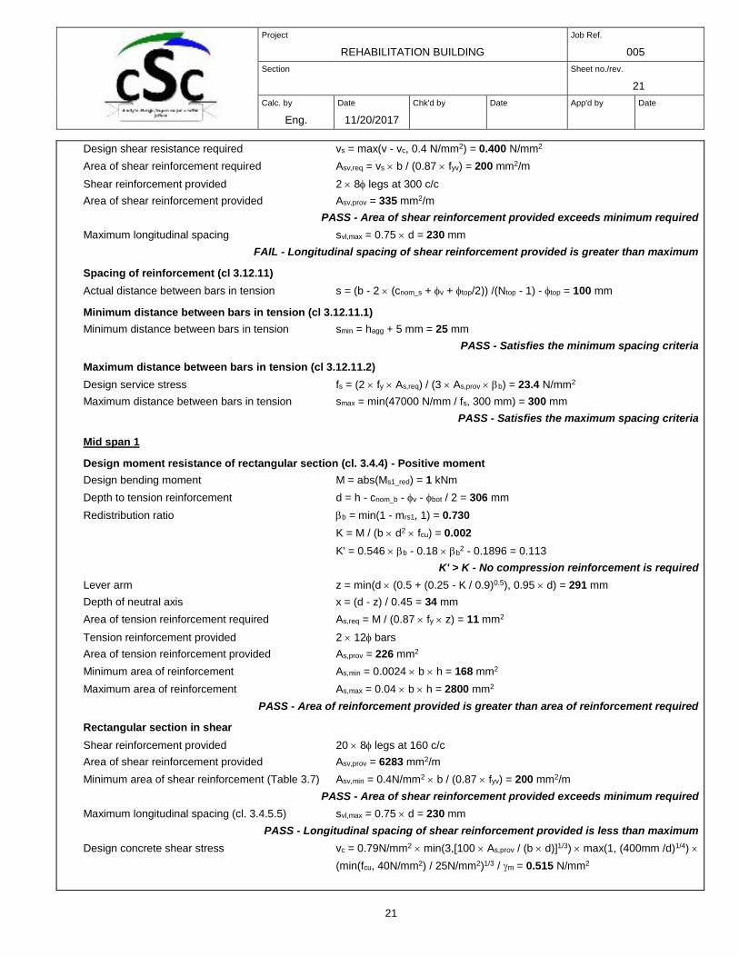
Design shear resistance required vs = max(v - vc, 0.4 N/mm2) = 0.400 N/mm2
Area of shear reinforcement required Asv,req = vs b / (0.87 fyv) = 200 mm2/m
Shear reinforcement provided 2 8 legs at 300 c/c
Area of shear reinforcement provided Asv,prov = 335 mm2/m
PASS - Area of shear reinforcement provided exceeds minimum required
Maximum longitudinal spacing svl,max = 0.75 d = 230 mm
FAIL - Longitudinal spacing of shear reinforcement provided is greater than maximum
Spacing of reinforcement (cl 3.12.11)
Actual distance between bars in tension s = (b - 2 (cnom_s + v + top/2)) /(Ntop - 1) - top = 100 mm
Minimum distance between bars in tension (cl 3.12.11.1)
Minimum distance between bars in tension smin = hagg + 5 mm = 25 mm
PASS - Satisfies the minimum spacing criteria
Maximum distance between bars in tension (cl 3.12.11.2)
Design service stress fs = (2 fy As,req) / (3 As,prov b) = 23.4 N/mm2
Maximum distance between bars in tension smax = min(47000 N/mm / fs, 300 mm) = 300 mm
PASS - Satisfies the maximum spacing criteria
Mid span 1
Design moment resistance of rectangular section (cl. 3.4.4) - Positive moment
Design bending moment M = abs(Ms1_red) = 1 kNm
Depth to tension reinforcement d = h - cnom_b - v - bot / 2 = 306 mm
Redistribution ratio b = min(1 - mrs1, 1) = 0.730
K = M / (b d2 fcu) = 0.002
K' = 0.546 b - 0.18 b2 - 0.1896 = 0.113
K' > K - No compression reinforcement is required
Lever arm z = min(d (0.5 + (0.25 - K / 0.9)0.5), 0.95 d) = 291 mm
Depth of neutral axis x = (d - z) / 0.45 = 34 mm
Area of tension reinforcement required As,req = M / (0.87 fy z) = 11 mm2
Tension reinforcement provided 2 12 bars
Area of tension reinforcement provided As,prov = 226 mm2
Minimum area of reinforcement As,min = 0.0024 b h = 168 mm2
Maximum area of reinforcement As,max = 0.04 b h = 2800 mm2
PASS - Area of reinforcement provided is greater than area of reinforcement required
Rectangular section in shear
Shear reinforcement provided 20 8 legs at 160 c/c
Area of shear reinforcement provided Asv,prov = 6283 mm2/m
Minimum area of shear reinforcement (Table 3.7) Asv,min = 0.4N/mm2 b / (0.87 fyv) = 200 mm2/m
PASS - Area of shear reinforcement provided exceeds minimum required
Maximum longitudinal spacing (cl. 3.4.5.5) svl,max = 0.75 d = 230 mm
PASS - Longitudinal spacing of shear reinforcement provided is less than maximum
Design concrete shear stress vc = 0.79N/mm2 min(3,[100 As,prov / (b d)]1/3) max(1, (400mm /d)1/4)
(min(fcu, 40N/mm2) / 25N/mm2)1/3 / m = 0.515 N/mm2
Project
REHABILITATION BUILDING
Job Ref.
005
Section
Sheet no./rev.
22
Calc. by
Eng.
NTEZIYARE
MYE
DIEUDONNE
Date
11/20/2017
Chk'd by
Date
App'd by
Date
22
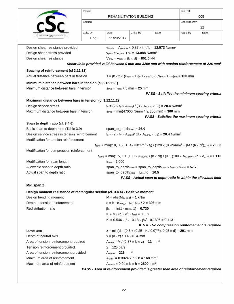
Design shear resistance provided vs,prov = Asv,prov 0.87 fyv / b = 12.573 N/mm2
Design shear stress provided vprov = vs,prov + vc = 13.088 N/mm2
Design shear resistance Vprov = vprov (b d) = 801.0 kN
Shear links provided valid between 0 mm and 3200 mm with tension reinforcement of 226 mm2
Spacing of reinforcement (cl 3.12.11)
Actual distance between bars in tension s = (b - 2 (cnom_s + v + bot/2)) /(Nbot - 1) - bot = 100 mm
Minimum distance between bars in tension (cl 3.12.11.1)
Minimum distance between bars in tension smin = hagg + 5 mm = 25 mm
PASS - Satisfies the minimum spacing criteria
Maximum distance between bars in tension (cl 3.12.11.2)
Design service stress fs = (2 fy As,req) / (3 As,prov b) = 20.4 N/mm2
Maximum distance between bars in tension smax = min(47000 N/mm / fs, 300 mm) = 300 mm
PASS - Satisfies the maximum spacing criteria
Span to depth ratio (cl. 3.4.6)
Basic span to depth ratio (Table 3.9) span_to_depthbasic = 26.0
Design service stress in tension reinforcement fs = (2 fy As,req)/ (3 As,prov b) = 20.4 N/mm2
Modification for tension reinforcement
ftens = min(2.0, 0.55 + (477N/mm2 - fs) / (120 (0.9N/mm2 + (M / (b d2))))) = 2.000
Modification for compression reinforcement
fcomp = min(1.5, 1 + (100 As2,prov / (b d)) / (3 + (100 As2,prov / (b d)))) = 1.110
Modification for span length flong = 1.000
Allowable span to depth ratio span_to_depthallow = span_to_depthbasic ftens fcomp = 57.7
Actual span to depth ratio span_to_depthactual = Ls1 / d = 10.5
PASS - Actual span to depth ratio is within the allowable limit
Mid span 2
Design moment resistance of rectangular section (cl. 3.4.4) - Positive moment
Design bending moment M = abs(Ms2_red) = 1 kNm
Depth to tension reinforcement d = h - cnom_b - v - bot / 2 = 306 mm
Redistribution ratio b = min(1 - mrs2, 1) = 0.730
K = M / (b d2 fcu) = 0.002
K' = 0.546 b - 0.18 b2 - 0.1896 = 0.113
K' > K - No compression reinforcement is required
Lever arm z = min(d (0.5 + (0.25 - K / 0.9)0.5), 0.95 d) = 291 mm
Depth of neutral axis x = (d - z) / 0.45 = 34 mm
Area of tension reinforcement required As,req = M / (0.87 fy z) = 11 mm2
Tension reinforcement provided 2 12 bars
Area of tension reinforcement provided As,prov = 226 mm2
Minimum area of reinforcement As,min = 0.0024 b h = 168 mm2
Maximum area of reinforcement As,max = 0.04 b h = 2800 mm2
PASS - Area of reinforcement provided is greater than area of reinforcement required
Project
REHABILITATION BUILDING
Job Ref.
005
Section
Sheet no./rev.
23
Calc. by
Eng.
NTEZIYARE
MYE
DIEUDONNE
Date
11/20/2017
Chk'd by
Date
App'd by
Date
23
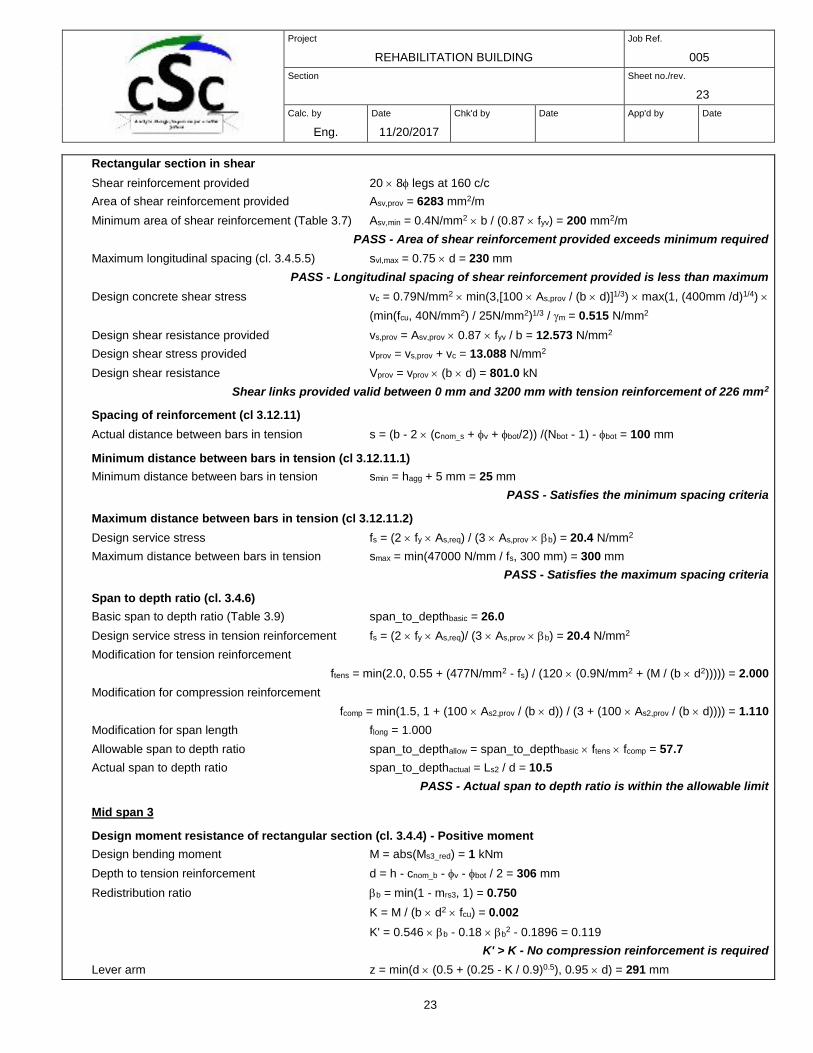
Rectangular section in shear
Shear reinforcement provided 20 8 legs at 160 c/c
Area of shear reinforcement provided Asv,prov = 6283 mm2/m
Minimum area of shear reinforcement (Table 3.7) Asv,min = 0.4N/mm2 b / (0.87 fyv) = 200 mm2/m
PASS - Area of shear reinforcement provided exceeds minimum required
Maximum longitudinal spacing (cl. 3.4.5.5) svl,max = 0.75 d = 230 mm
PASS - Longitudinal spacing of shear reinforcement provided is less than maximum
Design concrete shear stress vc = 0.79N/mm2 min(3,[100 As,prov / (b d)]1/3) max(1, (400mm /d)1/4)
(min(fcu, 40N/mm2) / 25N/mm2)1/3 / m = 0.515 N/mm2
Design shear resistance provided vs,prov = Asv,prov 0.87 fyv / b = 12.573 N/mm2
Design shear stress provided vprov = vs,prov + vc = 13.088 N/mm2
Design shear resistance Vprov = vprov (b d) = 801.0 kN
Shear links provided valid between 0 mm and 3200 mm with tension reinforcement of 226 mm2
Spacing of reinforcement (cl 3.12.11)
Actual distance between bars in tension s = (b - 2 (cnom_s + v + bot/2)) /(Nbot - 1) - bot = 100 mm
Minimum distance between bars in tension (cl 3.12.11.1)
Minimum distance between bars in tension smin = hagg + 5 mm = 25 mm
PASS - Satisfies the minimum spacing criteria
Maximum distance between bars in tension (cl 3.12.11.2)
Design service stress fs = (2 fy As,req) / (3 As,prov b) = 20.4 N/mm2
Maximum distance between bars in tension smax = min(47000 N/mm / fs, 300 mm) = 300 mm
PASS - Satisfies the maximum spacing criteria
Span to depth ratio (cl. 3.4.6)
Basic span to depth ratio (Table 3.9) span_to_depthbasic = 26.0
Design service stress in tension reinforcement fs = (2 fy As,req)/ (3 As,prov b) = 20.4 N/mm2
Modification for tension reinforcement
ftens = min(2.0, 0.55 + (477N/mm2 - fs) / (120 (0.9N/mm2 + (M / (b d2))))) = 2.000
Modification for compression reinforcement
fcomp = min(1.5, 1 + (100 As2,prov / (b d)) / (3 + (100 As2,prov / (b d)))) = 1.110
Modification for span length flong = 1.000
Allowable span to depth ratio span_to_depthallow = span_to_depthbasic ftens fcomp = 57.7
Actual span to depth ratio span_to_depthactual = Ls2 / d = 10.5
PASS - Actual span to depth ratio is within the allowable limit
Mid span 3
Design moment resistance of rectangular section (cl. 3.4.4) - Positive moment
Design bending moment M = abs(Ms3_red) = 1 kNm
Depth to tension reinforcement d = h - cnom_b - v - bot / 2 = 306 mm
Redistribution ratio b = min(1 - mrs3, 1) = 0.750
K = M / (b d2 fcu) = 0.002
K' = 0.546 b - 0.18 b2 - 0.1896 = 0.119
K' > K - No compression reinforcement is required
Lever arm z = min(d (0.5 + (0.25 - K / 0.9)0.5), 0.95 d) = 291 mm
Project
REHABILITATION BUILDING
Job Ref.
005
Section
Sheet no./rev.
24
Calc. by
Eng.
NTEZIYARE
MYE
DIEUDONNE
Date
11/20/2017
Chk'd by
Date
App'd by
Date
24
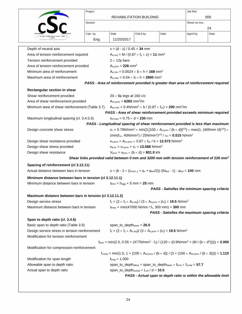
Depth of neutral axis x = (d - z) / 0.45 = 34 mm
Area of tension reinforcement required As,req = M / (0.87 fy z) = 11 mm2
Tension reinforcement provided 2 12 bars
Area of tension reinforcement provided As,prov = 226 mm2
Minimum area of reinforcement As,min = 0.0024 b h = 168 mm2
Maximum area of reinforcement As,max = 0.04 b h = 2800 mm2
PASS - Area of reinforcement provided is greater than area of reinforcement required
Rectangular section in shear
Shear reinforcement provided 20 8 legs at 160 c/c
Area of shear reinforcement provided Asv,prov = 6283 mm2/m
Minimum area of shear reinforcement (Table 3.7) Asv,min = 0.4N/mm2 b / (0.87 fyv) = 200 mm2/m
PASS - Area of shear reinforcement provided exceeds minimum required
Maximum longitudinal spacing (cl. 3.4.5.5) svl,max = 0.75 d = 230 mm
PASS - Longitudinal spacing of shear reinforcement provided is less than maximum
Design concrete shear stress vc = 0.79N/mm2 min(3,[100 As,prov / (b d)]1/3) max(1, (400mm /d)1/4)
(min(fcu, 40N/mm2) / 25N/mm2)1/3 / m = 0.515 N/mm2
Design shear resistance provided vs,prov = Asv,prov 0.87 fyv / b = 12.573 N/mm2
Design shear stress provided vprov = vs,prov + vc = 13.088 N/mm2
Design shear resistance Vprov = vprov (b d) = 801.0 kN
Shear links provided valid between 0 mm and 3200 mm with tension reinforcement of 226 mm2
Spacing of reinforcement (cl 3.12.11)
Actual distance between bars in tension s = (b - 2 (cnom_s + v + bot/2)) /(Nbot - 1) - bot = 100 mm
Minimum distance between bars in tension (cl 3.12.11.1)
Minimum distance between bars in tension smin = hagg + 5 mm = 25 mm
PASS - Satisfies the minimum spacing criteria
Maximum distance between bars in tension (cl 3.12.11.2)
Design service stress fs = (2 fy As,req) / (3 As,prov b) = 19.5 N/mm2
Maximum distance between bars in tension smax = min(47000 N/mm / fs, 300 mm) = 300 mm
PASS - Satisfies the maximum spacing criteria
Span to depth ratio (cl. 3.4.6)
Basic span to depth ratio (Table 3.9) span_to_depthbasic = 26.0
Design service stress in tension reinforcement fs = (2 fy As,req)/ (3 As,prov b) = 19.5 N/mm2
Modification for tension reinforcement
ftens = min(2.0, 0.55 + (477N/mm2 - fs) / (120 (0.9N/mm2 + (M / (b d2))))) = 2.000
Modification for compression reinforcement
fcomp = min(1.5, 1 + (100 As2,prov / (b d)) / (3 + (100 As2,prov / (b d)))) = 1.110
Modification for span length flong = 1.000
Allowable span to depth ratio span_to_depthallow = span_to_depthbasic ftens fcomp = 57.7
Actual span to depth ratio span_to_depthactual = Ls3 / d = 10.5
PASS - Actual span to depth ratio is within the allowable limit
Project
REHABILITATION BUILDING
Job Ref.
005
Section
Sheet no./rev.
25
Calc. by
Eng.
NTEZIYARE
MYE
DIEUDONNE
Date
11/20/2017
Chk'd by
Date
App'd by
Date
25
Mid span 4
Design moment resistance of rectangular section (cl. 3.4.4) - Positive moment
Design bending moment M = abs(Ms4_red) = 1 kNm
Depth to tension reinforcement d = h - cnom_b - v - bot / 2 = 306 mm
Redistribution ratio b = min(1 - mrs4, 1) = 0.750
K = M / (b d2 fcu) = 0.002
K' = 0.546 b - 0.18 b2 - 0.1896 = 0.119
K' > K - No compression reinforcement is required
Lever arm z = min(d (0.5 + (0.25 - K / 0.9)0.5), 0.95 d) = 291 mm
Depth of neutral axis x = (d - z) / 0.45 = 34 mm
Area of tension reinforcement required As,req = M / (0.87 fy z) = 11 mm2
Tension reinforcement provided 2 12 bars
Area of tension reinforcement provided As,prov = 226 mm2
Minimum area of reinforcement As,min = 0.0024 b h = 168 mm2
Maximum area of reinforcement As,max = 0.04 b h = 2800 mm2
PASS - Area of reinforcement provided is greater than area of reinforcement required
Rectangular section in shear
Shear reinforcement provided 20 8 legs at 160 c/c
Area of shear reinforcement provided Asv,prov = 6283 mm2/m
Minimum area of shear reinforcement (Table 3.7) Asv,min = 0.4N/mm2 b / (0.87 fyv) = 200 mm2/m
PASS - Area of shear reinforcement provided exceeds minimum required
Maximum longitudinal spacing (cl. 3.4.5.5) svl,max = 0.75 d = 230 mm
PASS - Longitudinal spacing of shear reinforcement provided is less than maximum
Design concrete shear stress vc = 0.79N/mm2 min(3,[100 As,prov / (b d)]1/3) max(1, (400mm /d)1/4)
(min(fcu, 40N/mm2) / 25N/mm2)1/3 / m = 0.515 N/mm2
Design shear resistance provided vs,prov = Asv,prov 0.87 fyv / b = 12.573 N/mm2
Design shear stress provided vprov = vs,prov + vc = 13.088 N/mm2
Design shear resistance Vprov = vprov (b d) = 801.0 kN
Shear links provided valid between 0 mm and 3200 mm with tension reinforcement of 226 mm2
Spacing of reinforcement (cl 3.12.11)
Actual distance between bars in tension s = (b - 2 (cnom_s + v + bot/2)) /(Nbot - 1) - bot = 100 mm
Minimum distance between bars in tension (cl 3.12.11.1)
Minimum distance between bars in tension smin = hagg + 5 mm = 25 mm
PASS - Satisfies the minimum spacing criteria
Maximum distance between bars in tension (cl 3.12.11.2)
Design service stress fs = (2 fy As,req) / (3 As,prov b) = 19.5 N/mm2
Maximum distance between bars in tension smax = min(47000 N/mm / fs, 300 mm) = 300 mm
PASS - Satisfies the maximum spacing criteria
Span to depth ratio (cl. 3.4.6)
Basic span to depth ratio (Table 3.9) span_to_depthbasic = 26.0
Design service stress in tension reinforcement fs = (2 fy As,req)/ (3 As,prov b) = 19.5 N/mm2
Modification for tension reinforcement
Project
REHABILITATION BUILDING
Job Ref.
005
Section
Sheet no./rev.
26
Calc. by
Eng.
NTEZIYARE
MYE
DIEUDONNE
Date
11/20/2017
Chk'd by
Date
App'd by
Date
26
ftens = min(2.0, 0.55 + (477N/mm2 - fs) / (120 (0.9N/mm2 + (M / (b d2))))) = 2.000
Modification for compression reinforcement
fcomp = min(1.5, 1 + (100 As2,prov / (b d)) / (3 + (100 As2,prov / (b d)))) = 1.110
Modification for span length flong = 1.000
Allowable span to depth ratio span_to_depthallow = span_to_depthbasic ftens fcomp = 57.7
Actual span to depth ratio span_to_depthactual = Ls4 / d = 10.5
PASS - Actual span to depth ratio is within the allowable limit
Mid span 5
Design moment resistance of rectangular section (cl. 3.4.4) - Positive moment
Design bending moment M = abs(Ms5_red) = 1 kNm
Depth to tension reinforcement d = h - cnom_b - v - bot / 2 = 306 mm
Redistribution ratio b = min(1 - mrs5, 1) = 0.700
K = M / (b d2 fcu) = 0.002
K' = 0.546 b - 0.18 b2 - 0.1896 = 0.104
K' > K - No compression reinforcement is required
Lever arm z = min(d (0.5 + (0.25 - K / 0.9)0.5), 0.95 d) = 291 mm
Depth of neutral axis x = (d - z) / 0.45 = 34 mm
Area of tension reinforcement required As,req = M / (0.87 fy z) = 11 mm2
Tension reinforcement provided 2 12 bars
Area of tension reinforcement provided As,prov = 226 mm2
Minimum area of reinforcement As,min = 0.0024 b h = 168 mm2
Maximum area of reinforcement As,max = 0.04 b h = 2800 mm2
PASS - Area of reinforcement provided is greater than area of reinforcement required
Rectangular section in shear
Shear reinforcement provided 20 8 legs at 160 c/c
Area of shear reinforcement provided Asv,prov = 6283 mm2/m
Minimum area of shear reinforcement (Table 3.7) Asv,min = 0.4N/mm2 b / (0.87 fyv) = 200 mm2/m
PASS - Area of shear reinforcement provided exceeds minimum required
Maximum longitudinal spacing (cl. 3.4.5.5) svl,max = 0.75 d = 230 mm
PASS - Longitudinal spacing of shear reinforcement provided is less than maximum
Design concrete shear stress vc = 0.79N/mm2 min(3,[100 As,prov / (b d)]1/3) max(1, (400mm /d)1/4)
(min(fcu, 40N/mm2) / 25N/mm2)1/3 / m = 0.515 N/mm2
Design shear resistance provided vs,prov = Asv,prov 0.87 fyv / b = 12.573 N/mm2
Design shear stress provided vprov = vs,prov + vc = 13.088 N/mm2
Design shear resistance Vprov = vprov (b d) = 801.0 kN
Shear links provided valid between 0 mm and 3200 mm with tension reinforcement of 226 mm2
Spacing of reinforcement (cl 3.12.11)
Actual distance between bars in tension s = (b - 2 (cnom_s + v + bot/2)) /(Nbot - 1) - bot = 100 mm
Minimum distance between bars in tension (cl 3.12.11.1)
Minimum distance between bars in tension smin = hagg + 5 mm = 25 mm
PASS - Satisfies the minimum spacing criteria
Project
REHABILITATION BUILDING
Job Ref.
005
Section
Sheet no./rev.
27
Calc. by
Eng.
NTEZIYARE
MYE
DIEUDONNE
Date
11/20/2017
Chk'd by
Date
App'd by
Date
27
Maximum distance between bars in tension (cl 3.12.11.2)
Design service stress fs = (2 fy As,req) / (3 As,prov b) = 21.7 N/mm2
Maximum distance between bars in tension smax = min(47000 N/mm / fs, 300 mm) = 300 mm
PASS - Satisfies the maximum spacing criteria
Span to depth ratio (cl. 3.4.6)
Basic span to depth ratio (Table 3.9) span_to_depthbasic = 26.0
Design service stress in tension reinforcement fs = (2 fy As,req)/ (3 As,prov b) = 21.7 N/mm2
Modification for tension reinforcement
ftens = min(2.0, 0.55 + (477N/mm2 - fs) / (120 (0.9N/mm2 + (M / (b d2))))) = 2.000
Modification for compression reinforcement
fcomp = min(1.5, 1 + (100 As2,prov / (b d)) / (3 + (100 As2,prov / (b d)))) = 1.110
Modification for span length flong = 1.000
Allowable span to depth ratio span_to_depthallow = span_to_depthbasic ftens fcomp = 57.7
Actual span to depth ratio span_to_depthactual = Ls5 / d = 10.5
PASS - Actual span to depth ratio is within the allowable limit
RC SLAB DESIGN (BS8110)
RC SLAB DESIGN (BS8110:PART1:1997)
TEDDS calculation version 1.0.04
CONTINUOUS ONE WAY SPANNING SLAB DEFINITION
Overall depth of slab h = 165 mm
Sagging steel
Cover to tension reinforcement resisting sagging csag = 30 mm
Trial bar diameter Dtryx = 10 mm
Depth to tension steel (resisting sagging)
dx = h - csag - Dtryx/2 = 130 mm
Hogging steel
Cover to tension reinforcement resisting hogging chog = 30 mm
Trial bar diameter Dtryxhog = 10 mm
Depth to tension steel (resisting hogging)
dxhog = h - chog - Dtryxhog/2 = 130 mm
Materials
Characteristic strength of reinforcement fy = 460 N/mm2
Characteristic strength of concrete fcu = 30 N/mm2
Project
REHABILITATION BUILDING
Job Ref.
005
Section
Sheet no./rev.
28
Calc. by
Eng.
NTEZIYARE
MYE
DIEUDONNE
Date
11/20/2017
Chk'd by
Date
App'd by
Date
28
ONE WAY SPANNING SLAB (CL 3.5.4)
MAXIMUM DESIGN MOMENTS IN SPAN
Design sagging moment (per m width of slab) msx = 13.0 kNm/m
CONCRETE SLAB DESIGN – SAGGING – OUTER LAYER OF STEEL (CL 3.5.4)
Design sagging moment (per m width of slab) msx = 13.0 kNm/m
Moment Redistribution Factor bx = 1.0
Area of reinforcement required
Kx = abs(msx) / ( dx2 fcu ) = 0.026
K'x = min (0.156 , (0.402 (bx - 0.4)) - (0.18 (bx - 0.4)2 )) = 0.156
Outer compression steel not required to resist sagging
Slab requiring outer tension steel only - bars (sagging)
zx = min (( 0.95 dx),(dx(0.5+0.25-Kx/0.9)))) = 124 mm
Neutral axis depth xx = (dx - zx) / 0.45 = 14 mm
Area of tension steel required
Asx_req = abs(msx) / (1/ms fy zx) = 263 mm2/m
Tension steel
Provide 10 dia bars @ 75 centres outer tension steel resisting sagging
Asx_prov = Asx = 1050 mm2/m
Area of outer tension steel provided sufficient to resist sagging
TRANSVERSE BOTTOM STEEL - INNER
Inner layer of transverse steel
Provide 10 dia bars @ 150 centres
Asy_prov = Asy = 524 mm2/m
MAXIMUM DESIGN MOMENTS OVER SUPPORT
Design hogging moment (per m width of slab) msxhog = 23.0 kNm/m
CONCRETE SLAB DESIGN – HOGGING – OUTER LAYER OF STEEL (CL 3.5.4)
Design hogging moment (per m width of slab) msxhog = 23.0 kNm/m
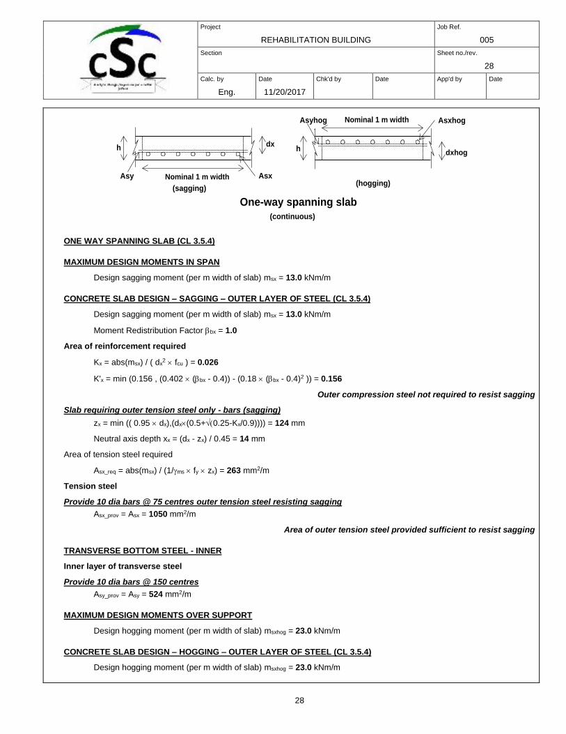
One-way spanning slab
Nominal 1 m width
dxh
AsxAsy
Nominal 1 m width
dxhogh
AsxhogAsyhog
(continuous)
(hogging)(sagging)
Project
REHABILITATION BUILDING
Job Ref.
005
Section
Sheet no./rev.
29
Calc. by
Eng.
NTEZIYARE
MYE
DIEUDONNE
Date
11/20/2017
Chk'd by
Date
App'd by
Date
29
Moment Redistribution Factor bx = 1.0
Area of reinforcement required
Kxhog = abs(msxhog) / ( dxhog2 fcu ) = 0.045
K'x = min (0.156 , (0.402 (bx - 0.4)) - (0.18 (bx - 0.4)2 )) = 0.156
Outer compression steel not required to resist hogging
Slab requiring outer tension steel only - bars (hogging)
zxhog = min (( 0.95 dxhog),(dxhog(0.5+0.25-Kxhog/0.9)))) = 123 mm
Neutral axis depth xxhog = (dxhog - zxhog) / 0.45 = 15 mm
Area of tension steel required
Asxhog_req = abs(msxhog) / (1/ms fy zxhog) = 467 mm2/m
Tension steel
Provide 10 dia bars @ 100 centres outer tension steel resisting hogging
Asxhog_prov = Asxhog = 785 mm2/m
Area of outer tension steel provided sufficient to resist hogging
TRANSVERSE TOP STEEL - INNER
Inner layer of transverse steel
Provide 10 dia bars @ 100 centres
Asyhog_prov = Asyhog = 785 mm2/m
Check min and max areas of steel resisting sagging
Total area of concrete Ac = h = 165000 mm2/m
Minimum % reinforcement k = 0.13 %
Ast_min = k Ac = 215 mm2/m
Ast_max = 4 % Ac = 6600 mm2/m
Steel defined:
Outer steel resisting sagging Asx_prov = 1050 mm2/m
Area of outer steel provided (sagging) OK
Inner steel resisting sagging Asy_prov = 524 mm2/m
Area of inner steel provided (sagging) OK
Check min and max areas of steel resisting hogging
Total area of concrete Ac = h = 165000 mm2/m
Minimum % reinforcement k = 0.13 %
Ast_min = k Ac = 215 mm2/m
Ast_max = 4 % Ac = 6600 mm2/m
Steel defined:
Outer steel resisting hogging Asxhog_prov = 785 mm2/m
Area of outer steel provided (hogging) OK
Inner steel resisting hogging Asyhog_prov = 785 mm2/m
Project
REHABILITATION BUILDING
Job Ref.
005
Section
Sheet no./rev.
30
Calc. by
Eng.
NTEZIYARE
MYE
DIEUDONNE
Date
11/20/2017
Chk'd by
Date
App'd by
Date
30
Area of inner steel provided (hogging) OK
SHEAR RESISTANCE OF CONCRETE SLABS (CL 3.5.5)
Outer tension steel resisting sagging moments
Depth to tension steel from compression face dx = 130 mm
Area of tension reinforcement provided (per m width of slab) Asx_prov = 1050 mm2/m
Design ultimate shear force (per m width of slab) Vx = 1 kN/m
Characteristic strength of concrete fcu = 30 N/mm2
Applied shear stress
vx = Vx / dx = 0.01 N/mm2
Check shear stress to clause 3.5.5.2
vallowable = min ((0.8 N1/2/mm) (fcu ), 5 N/mm2 ) = 4.38 N/mm2
Shear stress - OK
Shear stresses to clause 3.5.5.3
Design shear stress
fcu_ratio = if (fcu > 40 N/mm2 , 40/25 , fcu/(25 N/mm2)) = 1.200
vcx = 0.79 N/mm2 min(3,100 Asx_prov / dx)1/3 max(0.67,(400 mm / dx)1/4) / 1.25 fcu_ratio1/3
vcx = 0.83 N/mm2
Applied shear stress
vx = 0.01 N/mm2
No shear reinforcement required
SHEAR PERIMETERS FOR A CIRCULAR CONCENTRATED LOAD (CL 3.7.7)
Diameter of loaded circle DL=3 mm
Depth to tension steel dx = 130 mm
Dimension from edge of load to shear perimeter lp = kp dx = 195 mm where kp = 1.50
For punching shear cases not affected by free edges or holes:
Total length of inner perimeter at edge of loaded area u0_gen = DL = 8 mm
Total length of outer perimeter at lp from loaded area ugen = 4 DL + 8 lp 1570 mm
PUNCHING SHEAR AT CONCENTRATED LOADS (CL 3.7.7)
Tension steel resisting sagging
Total length of inner perimeter at edge of loaded area u0 = 8 mm
Total length of outer perimeter at dimension lp from loaded area u = 1570 mm
Depth to outer steel dx = 130 mm
Depth to inner steel dy = 12 mm
Average depth to "tension" steel dav = (dx + dy)/2 = 71.0 mm
Area of outer steel per m effective through the perimeter Asx_prov = 1050 mm2 /m
Area of inner steel per m effective through the perimeter Asy_prov = 524 mm2 /m
Project
REHABILITATION BUILDING
Job Ref.
005
Section
Sheet no./rev.
31
Calc. by
Eng.
NTEZIYARE
MYE
DIEUDONNE
Date
11/20/2017
Chk'd by
Date
App'd by
Date
31
Max shear effective across either perimeter under consideration Vp = 12 kN
Characteristic strength of concrete fcu = 30 N/mm2
Applied shear stress
Stress around loaded area vmax = Vp / (u0 dav) = 21.520 N/mm2
Stress around perimeter v = Vp / (u dav) = 0.108 N/mm2
Check shear stress to clause 3.7.7.2
vallowable = min ((0.8 N1/2/mm) (fcu ), 5 N/mm2 ) = 4.382 N/mm2
Shear stress - Fail
Shear stresses to clause 3.7.7.4
Design shear stress
fcu_ratio = if (fcu > 40 N/mm2 , 40/25 , fcu/(25 N/mm2)) = 1.200
Effective steel area for shear strength determination: As_eff =524 mm2/m
vc = 0.79 N/mm2 min( 3, 100( As_eff / dav ) )1/3 max(0.67, (400 mm / dav )1/4) / 1.25 fcu_ratio1/3
vc = 0.935 N/mm2
No shear reinforcement required
CONCRETE SLAB DEFLECTION CHECK (CL 3.5.7)
Slab span length lx = 0.200 m
Design ultimate moment in shorter span per m width msx = 13 kNm/m
Depth to outer tension steel dx = 130 mm
Tension steel
Area of outer tension reinforcement provided Asx_prov = 1050 mm2/m
Area of tension reinforcement required Asx_req = 263 mm2/m
Moment Redistribution Factor bx = 1.00
Modification Factors
Basic span / effective depth ratio (Table 3.9) ratiospan_depth = 20
The modification factor for spans in excess of 10m (ref. cl 3.4.6.4) has not been included.
fs = 2 fy Asx_req / (3 Asx_prov bx ) = 76.9 N/mm2
factortens = min ( 2 , 0.55 + ( 477 N/mm2 - fs ) / ( 120 ( 0.9 N/mm2 + msx / dx2))) = 2.000
Calculate Maximum Span
This is a simplified approach and further attention should be given where special circumstances exist. Refer to clauses 3.4.6.4
and 3.4.6.7.
Maximum span lmax = ratiospan_depth factortens dx = 5.20 m
Check the actual beam span
Actual span/depth ratio lx / dx = 1.54
Span depth limit ratiospan_depth factortens = 40.00
Span/Depth ratio check satisfied
Project
REHABILITATION BUILDING
Job Ref.
005
Section
Sheet no./rev.
32
Calc. by
Eng.
NTEZIYARE
MYE
DIEUDONNE
Date
11/20/2017
Chk'd by
Date
App'd by
Date
32
CHECK OF NOMINAL COVER (SAGGING) – (BS8110:PT 1, TABLE 3.4)
Slab thickness h = 165 mm
Effective depth to bottom outer tension reinforcement dx = 130.0 mm
Diameter of tension reinforcement Dx = 10 mm
Diameter of links Ldiax = 0 mm
Cover to outer tension reinforcement
ctenx = h - dx - Dx / 2 = 30.0 mm
Nominal cover to links steel
cnomx = ctenx - Ldiax = 30.0 mm
Permissable minimum nominal cover to all reinforcement (Table 3.4)
cmin = 30 mm
Cover over steel resisting sagging OK
CHECK OF NOMINAL COVER (HOGGING) – (BS8110:PT 1, TABLE 3.4)
Slab thickness h = 165 mm
Effective depth to bottom outer tension reinforcement dxhog = 130.0 mm
Diameter of tension reinforcement Dxhog = 10 mm
Diameter of links Ldiaxhog = 0 mm
Cover to outer tension reinforcement
ctenxhog = h - dxhog - Dxhog / 2 = 30.0 mm
Nominal cover to links steel
cnomxhog = ctenxhog - Ldiaxhog = 30.0 mm
Permissable minimum nominal cover to all reinforcement (Table 3.4)
cmin = 30 mm
Cover OK over steel resisting hogging
RC STAIR DESIGN (BS8110)
RC STAIR DESIGNRC STAIR DESIGN (BS8110-1:1997)
TEDDS calculation version 1.0.04
Project
REHABILITATION BUILDING
Job Ref.
005
Section
Sheet no./rev.
33
Calc. by
Eng.
NTEZIYARE
MYE
DIEUDONNE
Date
11/20/2017
Chk'd by
Date
App'd by
Date
33
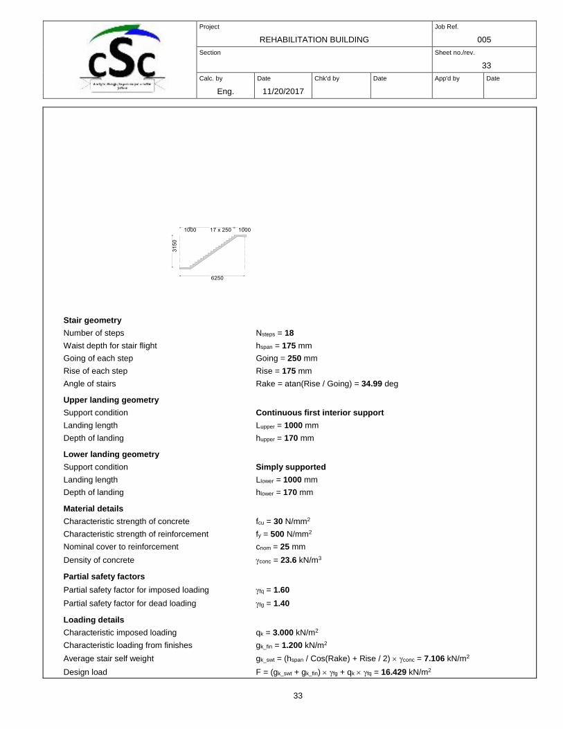
Stair geometry
Number of steps Nsteps = 18
Waist depth for stair flight hspan = 175 mm
Going of each step Going = 250 mm
Rise of each step Rise = 175 mm
Angle of stairs Rake = atan(Rise / Going) = 34.99 deg
Upper landing geometry
Support condition Continuous first interior support
Landing length Lupper = 1000 mm
Depth of landing hupper = 170 mm
Lower landing geometry
Support condition Simply supported
Landing length Llower = 1000 mm
Depth of landing hlower = 170 mm
Material details
Characteristic strength of concrete fcu = 30 N/mm2
Characteristic strength of reinforcement fy = 500 N/mm2
Nominal cover to reinforcement cnom = 25 mm
Density of concrete conc = 23.6 kN/m3
Partial safety factors
Partial safety factor for imposed loading fq = 1.60
Partial safety factor for dead loading fg = 1.40
Loading details
Characteristic imposed loading qk = 3.000 kN/m2
Characteristic loading from finishes gk_fin = 1.200 kN/m2
Average stair self weight gk_swt = (hspan / Cos(Rake) + Rise / 2) conc = 7.106 kN/m2
Design load F = (gk_swt + gk_fin) fg + qk fq = 16.429 kN/m2
Project
REHABILITATION BUILDING
Job Ref.
005
Section
Sheet no./rev.
34
Calc. by
Eng.
NTEZIYARE
MYE
DIEUDONNE
Date
11/20/2017
Chk'd by
Date
App'd by
Date
34
Mid span design
Midspan moment per metre width Mspan = 0.086 F L2 = 55.191 kNm/m
Diameter of tension reinforcement span = 12 mm
Depth of reinforcement dspan = hspan - cnom - span / 2 = 144 mm
Design formula for rectangular beams (cl 3.4.4.4)
Moment redistribution ratio b = 1.25
Kspan = Mspan / (dspan2 fcu) = 0.089
K’span = 0.402 (b - 0.4) - 0.18 (b - 0.4)2 = 0.212
Kspan < K'span compression reinforcement is not required
Lever arm zspan = dspan min([0.5 + (0.25 - Kspan / 0.9)], 0.95) = 128 mm
Area of tension reinforcement required As_span_req = Mspan / (0.87 fy zspan) = 991 mm2/m
Minimum area of tension reinforcement As_span_min = 0.13 hspan / 100 = 228 mm2/m
Tension reinforcement provided 12 dia.bars @ 160 centres
Area of tension reinforcement provided As_span_prov = 707 mm2/m
FAIL - Tension reinforcement provided is less than tension reinforcement required
Basic span/effective depth ratio (cl 3.4.6.3)
From BS8110 : Part 1 : 1997 – Table 3.9
Basic span/effective depth ratio ratiobasic = 26.0
Modification of span/effective depth ratio for staircases without stringer beams (cl 3.10.2.2)
Modification factor for stairs without stringers factorflight = 1.15
Modification of span/effective depth ratio for tension reinforcement (cl 3.4.6.5)
From BS8110 : Part 1 : 1997 – Table 3.10
Design service stress fs = 2 fy As_span_req / (3 As_span_prov b) = 373.839 N/mm2
Modification factor for tension reinforcement factortens = 0.55 + (477 N/mm2- fs)/(120 (0.9 N/mm2+ (Mspan / dspan2)))
factortens = 0.791
Check span/effective depth ratio (cl 3.4.6.1)
Allowable span/effective depth ratio ratioadm = ratiobasic factorflight factortens = 23.662
Actual span/effective depth ratio ratioact = L / dspan = 43.403
FAIL - Span/effective depth ratio is not adequate
Upper landing support design
Upper support moment per metre width Mupper = 0.086 F L2 = 55.191 kNm/m
Diameter of tension reinforcement upper = 12 mm
Depth of reinforcement dupper = hupper - cnom - upper / 2 = 139 mm
Design formula for rectangular beams (cl 3.4.4.4)
Moment redistribution ratio b = 0.80
Kupper = Mupper / (dupper 2 fcu) = 0.095
K’upper = 0.402 (b - 0.4) - 0.18 (b - 0.4)2 = 0.132
Kupper < K'upper compression reinforcement is not required
Lever arm zupper = dupper min([0.5 + (0.25 - Kupper / 0.9)], 0.95) = 122 mm
Area of tension reinforcement required As_upper_req = Mupper / (0.87 fy zupper) = 1038 mm2/m
Minimum area of tension reinforcement As_upper_min = 0.13 hupper / 100 = 221 mm2/m
Project
REHABILITATION BUILDING
Job Ref.
005
Section
Sheet no./rev.
35
Calc. by
Eng.
NTEZIYARE
MYE
DIEUDONNE
Date
11/20/2017
Chk'd by
Date
App'd by
Date
35
Tension reinforcement provided 12 dia.bars @ 160 centres
Area of tension reinforcement provided As_upper_prov = 707 mm2/m
FAIL - Tension reinforcement provided is less than tension reinforcement required
Shear stress in beam (cl 3.4.5.2)
Design shear force Vupper = 0.600 F L = 61.608 kN/m
Design shear stress vupper = Vupper / dupper = 0.443 N/mm2
Allowable design shear stress vmax = min(0.8N/mm2 (fcu / 1 N/mm2), 5 N/mm2) = 4.382 N/mm2
PASS - Design shear stress does not exceed allowable shear stress
From BS 8110:Part 1:1997 - Table 3.8
Design concrete shear stress vc_upper = 0.698 N/mm2
PASS - Design shear stress does not exceed design concrete shear stress
Lower landing support design
Diameter of tension reinforcement lower = 12 mm
Depth of reinforcement dlower = hlower - cnom - lower / 2 = 139 mm
Area of tension reinforcement required As_lower_req = 0.4 As_span_req = 396 mm2/m
Minimum area of tension reinforcement As_lower_min = 221 mm2/m
Tension reinforcement provided 12 dia.bars @ 160 centres
Area of tension reinforcement provided As_lower_prov = 707 mm2/m
PASS - Tension reinforcement provided exceeds tension reinforcement required
Shear stress in beam (cl 3.4.5.2)
Design shear force Vlower = 0.400 F L = 41.072 kN/m
Design shear stress vlower = Vlower / dlower = 0.295 N/mm2
Allowable design shear stress vmax = min(0.8N/mm2 (fcu / 1 N/mm2), 5 N/mm2) = 4.382 N/mm2
PASS - Design shear stress does not exceed allowable shear stress
From BS 8110:Part 1:1997 - Table 3.8
Design concrete shear stress vc_lower = 0.698 N/mm2
PASS - Design shear stress does not exceed design concrete shear stress
Done by:
Eng. Dieudonne NTEZIYAREMYE, MBA.