Embed Size (px)
Citation preview
A Materials Technology Institute Publication
G L O B A L C H A L L E N G E S / T R U S T E D S O L U T I O N S
2022, ISSUE 1
MTI-GLOBAL.ORG
Page 8
Renewable DieselA Hot Industry Topic
ABOUT THIS PUBLICATION:MTI CONNECT is published by the Materials Technology Institute, Inc. (MTI). MTI is a unique, cooperative research and development organization representing private industry. Its objective is to conduct generic, non- proprietary studies of a practical nature on the selection, design, fabrication, testing, inspection, and performance of materials and equipment used in the process industries.
The contents of articles and any opinions expressed therein are those of the authors and do not represent those of MTI. Any products and/or services advertised in this publication carry no real or implied endorsement or recommendation by MTI.
Copyright © 2022 Materials Technology Institute, Inc. All rights reserved.
CONTACT:Submit all correspondence regardingMTI CONNECT to:Materials Technology Institute, Inc.1001 Craig Road, Suite 490 St. Louis, MO 631461-314 - 567- 4111 (telephone)[email protected]
MTI CONNECT EDITORIAL BOARD:Heather Allain, MTI Mike Anderson, SyncrudeDavid Barber, DowByron Keelin, MTIJeremy Nelson, Koch IndustriesDaniel Rasmussen, MTIKirk Richardson, MTI
Editor: Lindsey Skinner, MTI
SUBSCRIPTIONS:For a free subscription, write to MTI or contact [email protected]
WEBSITE:http://www.mti-global.org
Please contact us at 1-314 - 567- 4111 or [email protected] for more information or to find out how your company can become a member.
CALENDAR OF EVENTS:
EuroTAC Spring Meeting May 19-20, 2022 Germany
AmeriTAC & Biofuels Roundtable June 21-23, 2022 Kansas City, MO
AsiaTAC Fall Meeting September 2022 China
Inside This Issue
3 Allain Transitions to MTI Executive Director
4 Whitcraft Retires as Executive Director
6 MTI Welcomes Phillips 66 to Membership
7 FRP & Dual Laminate Training Course
8 Renewable Diesel
12 Failure Analysis of Natural Gas Compressor Turbine Blades
20 Predicting the Internal Corrosion Rate of a Free Water Knockout Vessel In Support of the Integrity Programs of a SAGD Facility
24 MTI Board Approves Funding of Four Projects
26 MTI Draws In-Person Attendance for Symposium 2022
28 Member Accomplishments a Highlight at MTI Awards Ceremony
32 MTI Announces 2022 Scholarship Recipients
34 Technical Bulletins Available for Public Download
40 MTI Website Updates Coming Soon
2022, ISSUE 1
A familiar face at MTI has taken on a new role with the organi-zation. Heather Allain, former
Associate Director (AD), officially stepped into the Executive Director (ED) position at a special reception on March 1, 2022, during AmeriTAC 137 and the Global Solutions Symposium in Orlando, Florida. She replaces Paul Whitcraft, who retired at the end of March (see accompanying story).
With more than 25 years in the materials engineering field, 13 as an AD for MTI, Allain’s background and experience have prepared her to lead MTI into the future. Her efforts have been focused primarily on delivering successful, well thought through projects to the members in a timely manner — the cornerstone of MTI’s value — and she plans to continue building upon the organization’s 44-year foundation.
“I intend to leverage my expe-rience to support the Associate Directors in delivering high quality projects and strengthening the organization’s abilities to deliver them well,” Allain remarks. “There are additional strategic decisions MTI has considered over the years, which I think can be addressed with the Board of Directors to improve
our agility and responsiveness to the materials challenges in the Chemical Processing Industry.”
In addition, she hopes to draw upon the positive aspects of remote cooperation during COVID-19, especially the increased participa-tion and project work among the three Technical Advisory Councils (TACs) — AmeriTAC, AsiaTAC and EuroTAC.
“The Global Pandemic challenged and stretched us all, and while we are all enjoying the benefits of in person meetings again, there were advantages that the disruption caused that we may be able to retain as we go forward,” Allain states. “We have been having discussions
about ongoing virtual meetings — in a short meeting format — that would maintain the global project collab-oration and conversations we were able to have while operating virtually.”
As an AD supporting EuroTAC since 2013, Allain worked closely with Patrice Houlle (Associate Director – Europe) and their Euro-pean member colleagues to continue strengthening the group. They have developed several successful projects in EuroTAC in recent years, which Allain highlights as some of the most rewarding aspects of her time with MTI. Now she hopes to offer stra-tegic direction in a new capacity to continue building upon that success in all three TACs.
“It [EuroTAC] has grown into a group of highly technical individuals willing to share non-proprietary failures and develop technical proj-ects to address those problems and give engineers additional tools to assess and evaluate existing assets,” explains Allain. “MTI’s current projects on HTHA, Stress Relaxation Cracking (SRC), Duplex Stainless Steels at Short Term Elevated Temperatures, and PSA Structural Integrity have all come out of European member presentations
> CONTINUED ON PAGE 5
ALLAIN TRANSITIONS TO MTI EXECUTIVE DIRECTORPLANS TO CONTINUE BUILDING UPON MTI’S CORE VALUES
“I INTEND TO LEVERAGE
MY EXPERIENCE TO
SUPPORT THE ASSOCIATE
DIRECTORS IN DELIVERING
HIGH QUALITY PROJECTS
AND STRENGTHENING THE
ORGANIZATION’S ABILITIES
TO DELIVER THEM WELL”
PEOPLE
3PROVIDING GLOBAL LEADERSHIP IN MATERIALS TECHNOLOGY2022, ISSUE 12
Paul Whitcraft, MTI’s Executive Director (ED) since October 2016, retired at the end of
March. MTI recognized his years of service at a ceremony during the MTI Global Solutions Symposium 2022 reception on March 1, in Orlando, Florida. Whitcraft has been involved with MTI for more than 30 years in multiple roles, including Designated Representative for member company Rolled Alloys and Chair of the MTI Board of Directors (BOD).
“My involvement with MTI for so many years assisted my career in the specialty metals industry so I was motivated to give back what I could to advance MTI,” Whitcraft recalls. “I was fortunate to have Maria Jose Oestergaard as the Chair when I began as the Executive Director. Maria Jose established regular meetings to facilitate clear commu-nications between me and the Board Chair and Vice Chair. Under
zation with composure and acted quickly to determine a plan to hold meetings, keep members engaged and continue project work.
“Not surprisingly, I believe that dealing with the pandemic was the single most concerning factor during my five-plus years,” Whitcraft observes. “I think my greatest contri-bution was probably in coordinating staff efforts and navigating between finding the ideal replacement for face-to-face meetings and what was possible or practical.”
He credits the staff, particularly in St. Louis, for the swift adjustment to operating virtually, including the implementation of meeting plat-forms — another innovation along with the virtual technical showcases.
“We learned on the fly. I, and many of the MTI Staff, participated in each and every virtual TAC (Tech-nical Advisory Council) meeting or
her leadership the Board identified goals and a strategy to achieve those goals. MTI Staff was able to use those goals as a guide to develop programs and procedures to make them a reality.”
Whitcraft has been instrumental in the continued progress of MTI with 63 projects completed and a number of innovations introduced while in the ED role. Most notably, he supported and helped establish the MTI Global Solutions Symposium, webinars, the Chair’s Leadership and Distinguished Service Awards, a Designated Professional partici-pant program (invitation only), and a five-year financial plan to manage memberships and projects.
According to Oestergaard (Topsoe), MTI BOD Chair 2016-2019, Whitcraft demonstrated extraordi-nary organizational experience to strengthen MTI operations.
“One of his first priorities was to
roundtable that was convened in an attempt to maintain contact with our members,” he explains. “We also worked with the Finance Committee to develop a dues discount in response to the financial impact on members. But most importantly, we maintained an emphasis on projects with 14 projects completed over the two-year period and 17 new projects approved over that same time.”
Whitcraft notes that he learned a lot and received advice from a wide range of sources, but it’s important to listen to your instincts and draw on your experience. As for the future of MTI, he offers some thoughts:
“I believe that for MTI to remain successful we must balance main-taining the atmosphere and collegi-ality unique to our organization with the need to attract new members and finance larger, more complex projects while the business commu-
ensure the financial sustainability of our organization and was the driver for exploring multiple alterna-tives that not only added value but also would contribute to additional revenue,” she remembers.
David Barber, BOD Chair, echoes Oestergaard’s comments. He says he is particularly appreciative of Whit-craft’s dedication and attention to detail as Executive Director.
“Paul’s diligent work on financials reduced administrative costs ending eight consecutive years of losses, and the three percent annual dues increase also ended under his reign,” Barber remarks. “MTI is financially sound now, even while offering dues discounts during the pandemic, which I think is an outstanding accomplishment.”
The challenges resulting from the COVID-19 pandemic presented significant complications for MTI; however, Whitcraft led the organi-
nity is changing rapidly. If you’re staying the same, you’re falling behind.”
As Whitcraft leaves it in the capable hands of MTI veteran Heather Allain (see story on page 3), he has one final comment.
“I will miss seeing the many friends and colleagues all around the world that I have met at MTI meet-ings,” he closes, while also noting one task he’s quite happy to be relieved of: “I will not miss trying to adhere to Robert’s Rules of Order.”
Next up for Whitcraft is retirement with plans to frequent the beach in New Jersey where he lives, play golf, go cycling and possibly get back into a past hobby of tennis, which he clarifies he’ll have to fit in between requests to child sit his six grandchildren.
Best wishes from MTI and thank you for your dedication, Paul! n
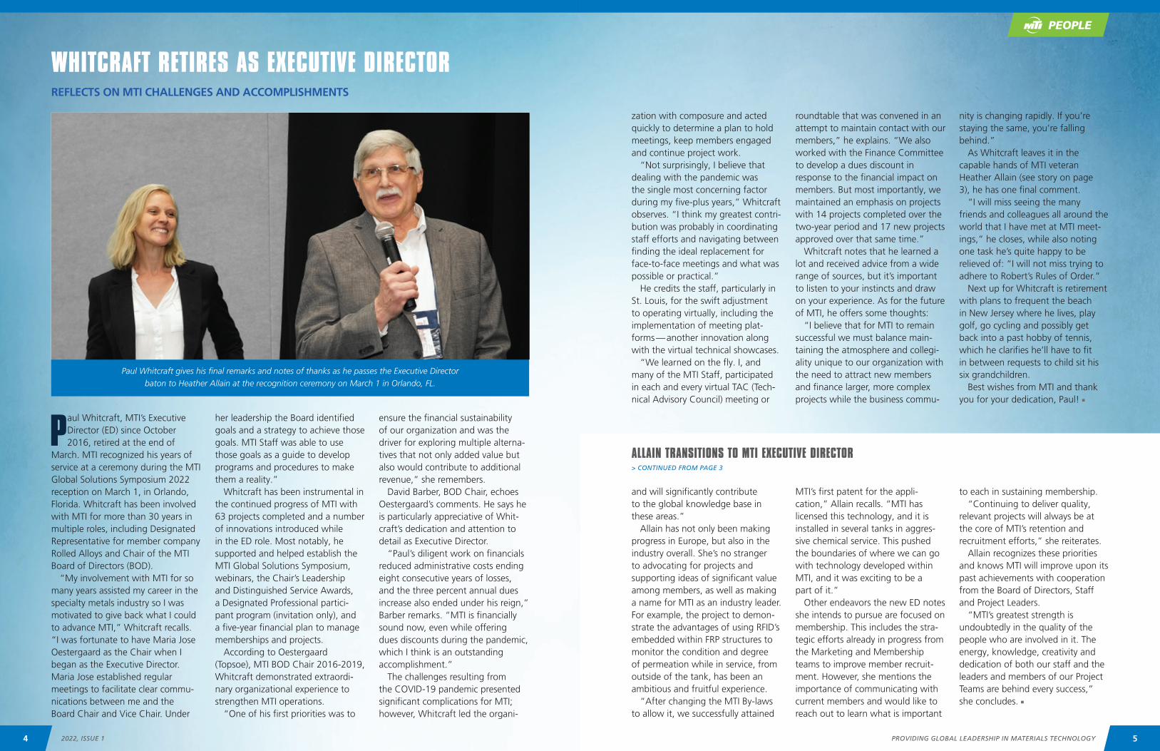
WHITCRAFT RETIRES AS EXECUTIVE DIRECTORREFLECTS ON MTI CHALLENGES AND ACCOMPLISHMENTS
Paul Whitcraft gives his final remarks and notes of thanks as he passes the Executive Director baton to Heather Allain at the recognition ceremony on March 1 in Orlando, FL.
and will significantly contribute to the global knowledge base in these areas.”
Allain has not only been making progress in Europe, but also in the industry overall. She’s no stranger to advocating for projects and supporting ideas of significant value among members, as well as making a name for MTI as an industry leader. For example, the project to demon-strate the advantages of using RFID’s embedded within FRP structures to monitor the condition and degree of permeation while in service, from outside of the tank, has been an ambitious and fruitful experience.
“After changing the MTI By-laws to allow it, we successfully attained
MTI’s first patent for the appli-cation,” Allain recalls. “MTI has licensed this technology, and it is installed in several tanks in aggres-sive chemical service. This pushed the boundaries of where we can go with technology developed within MTI, and it was exciting to be a part of it.”
Other endeavors the new ED notes she intends to pursue are focused on membership. This includes the stra-tegic efforts already in progress from the Marketing and Membership teams to improve member recruit-ment. However, she mentions the importance of communicating with current members and would like to reach out to learn what is important
to each in sustaining membership.“Continuing to deliver quality,
relevant projects will always be at the core of MTI’s retention and recruitment efforts,” she reiterates.
Allain recognizes these priorities and knows MTI will improve upon its past achievements with cooperation from the Board of Directors, Staff and Project Leaders.
“MTI’s greatest strength is undoubtedly in the quality of the people who are involved in it. The energy, knowledge, creativity and dedication of both our staff and the leaders and members of our Project Teams are behind every success,” she concludes. n
ALLAIN TRANSITIONS TO MTI EXECUTIVE DIRECTOR> CONTINUED FROM PAGE 3
PEOPLE
5PROVIDING GLOBAL LEADERSHIP IN MATERIALS TECHNOLOGY4 2022, ISSUE 1
MTI WELCOMES PHILLIPS 66 TO MEMBERSHIPREADY TO ENGAGE IN THE ORGANIZATION
matter experts, as well as access to several project reports, the TAC Forum, trainings, and bulletins on a wide range of subjects valuable to Phillips 66 operations.”
Twenty-one Phillips 66 participants currently have member access, and have been active on the Forum, joined multiple project meetings and explored the vast resources available in the MTI Technical Resource Library. In addition, current MTI projects have captured the company’s attention.
“Several ongoing projects have direct relevance and importance to what we are currently doing at Phillips 66,” he remarks. “One of the MTI projects of particular interest to Phillips 66 is an exper-imental research study about free fatty acid corrosion in bio-oils. We have an active interest in learning more about renewables corrosion
The beginning of 2022 marked the start of participation for a new producer member. MTI is
excited to welcome Phillips 66 and the company’s contributions to the organization. According to www.phillips66.com, the company manufactures energy with opera-tions in Refining, Midstream and Chemicals. In addition, the company has an Energy Research & Innovation team that operates in Bartlesville, Oklahoma at the 440-acre Phillips 66 Research Center. More than 200 researchers across 30 countries work diligently to advance the cutting-edge science that is critical for enhancing company sustainability, developing the technologies of the future, and supporting existing operations.
Lokesh Choudhary, Research Engineer and the Designated Representative for Phillips 66, says they have appreciated the first few months of access to MTI resources already.
“The corrosion and materials network professionals within Phillips 66 are well-versed with MTI’s activities, resources, and expertise through their current and past engagements,” Choudhary explains. “One of the primary reasons for Phillips 66 to join MTI was driven by the ability to interact with subject
since the announcement of our Rodeo Refinery being converted to run renewable diesel and that we are supportive of sustainable fuels research.”
The upcoming Renewable Biofuels Roundtable in June (see page 8) is also of interest. It will be an opportu-nity to share and learn on a hot topic that many members are facing.
Choudhary comments that they plan to participate in this and any other MTI projects that might be related to bio-oils and energy transition. Many of the Phillips 66 engineers are involved in #357 – Corrosion in Bio-oils to learn more and provide feedback on project direction. Further to that involve-ment, he says don’t be surprised if another project is proposed by Phillips 66 at a TAC meeting.
“Phillips 66 plans to have continuous representation during AmeriTAC meetings throughout the year,” Choudhary concludes. “We want to actively be part of ongoing and future projects of particular interest to Phillips 66. We will also be looking forward to proposing as well as championing projects that fall in line with MTI’s vision and mission.”
MTI would like to thank Phillips 66 for joining and looks forward to continued involvement within the organization! n
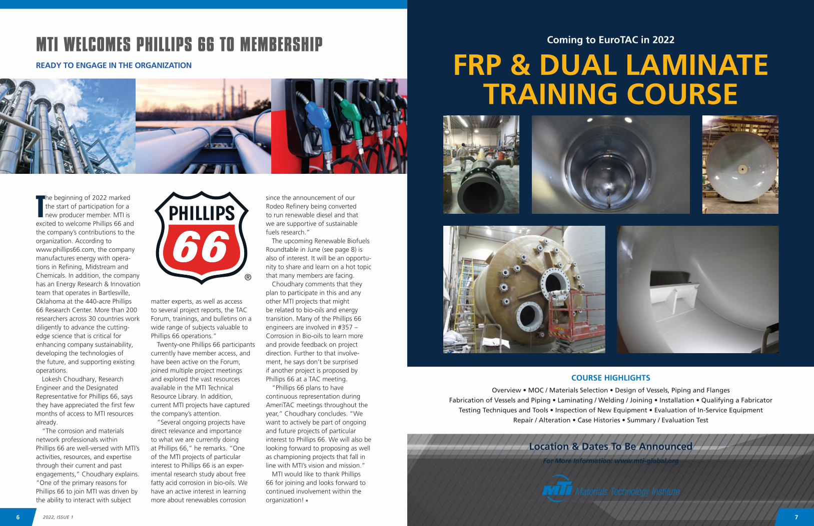
Coming to EuroTAC in 2022
Overview • MOC / Materials Selection • Design of Vessels, Piping and Flanges
Fabrication of Vessels and Piping • Laminating / Welding / Joining • Installation • Qualifying a Fabricator
Testing Techniques and Tools • Inspection of New Equipment • Evaluation of In-Service Equipment
Repair / Alteration • Case Histories • Summary / Evaluation Test
Location & Dates To Be AnnouncedFor More Information: www.mti-global.org
FRP & DUAL LAMINATETRAINING COURSE
COURSE HIGHLIGHTS
76 2022, ISSUE 1
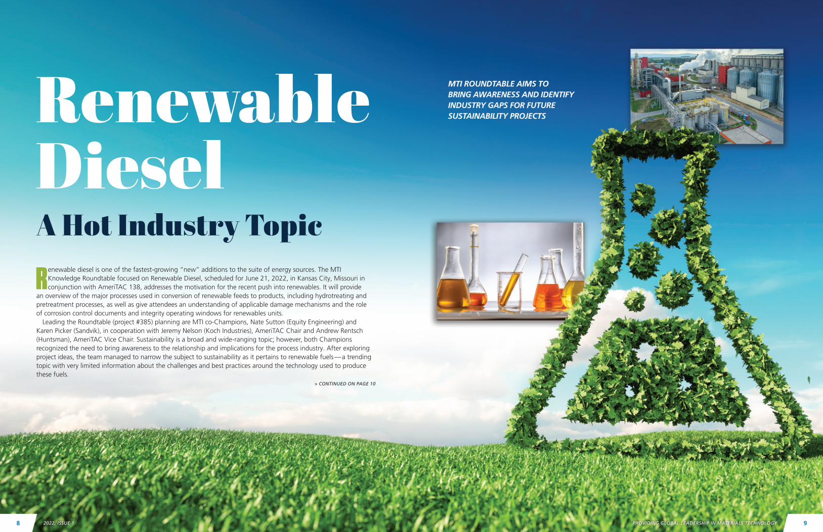
Renewable diesel is one of the fastest-growing “new” additions to the suite of energy sources. The MTI Knowledge Roundtable focused on Renewable Diesel, scheduled for June 21, 2022, in Kansas City, Missouri in conjunction with AmeriTAC 138, addresses the motivation for the recent push into renewables. It will provide
an overview of the major processes used in conversion of renewable feeds to products, including hydrotreating and pretreatment processes, as well as give attendees an understanding of applicable damage mechanisms and the role of corrosion control documents and integrity operating windows for renewables units.
Leading the Roundtable (project #385) planning are MTI co-Champions, Nate Sutton (Equity Engineering) and Karen Picker (Sandvik), in cooperation with Jeremy Nelson (Koch Industries), AmeriTAC Chair and Andrew Rentsch (Huntsman), AmeriTAC Vice Chair. Sustainability is a broad and wide-ranging topic; however, both Champions recognized the need to bring awareness to the relationship and implications for the process industry. After exploring project ideas, the team managed to narrow the subject to sustainability as it pertains to renewable fuels — a trending topic with very limited information about the challenges and best practices around the technology used to produce these fuels.
> CONTINUED ON PAGE 10
Renewable DieselA Hot Industry Topic
MTI ROUNDTABLE AIMS TO BRING AWARENESS AND IDENTIFY INDUSTRY GAPS FOR FUTURE SUSTAINABILITY PROJECTS
98 PROVIDING GLOBAL LEADERSHIP IN MATERIALS TECHNOLOGY2022, ISSUE 1
“MTI recognizes that sustainability is a priority for many companies and is on the minds of individuals at those companies,” share Sutton and Picker. “In the most basic sense, a sustainable company is one that remains a viable business in the long term, so we all want our compa-nies to be sustainable! But sustain-ability means different things to
different audiences. So, the project team decided to focus on a smaller segment of the industry directly tied to sustainability.”
According to the Champion duo, the Roundtable planning team hopes to identify industry gaps and develop projects where MTI can play a leading role on research within industry. The aim is to educate
everyone to be better equipped to make materials decisions when the time comes.
“This Roundtable will position MTI as an industry research leader because this is a relatively new topic for the industry, which is starving for new data,” remarks Picker. “This is the first of many topics we can explore on the sustainability front.”
So what can attendees expect the program to include? Sutton outlines the format for the event, which will be open to MTI members and non-members.
“This is a full day structured event with multiple presentations and will include a panel session with the opportunity for Q&A with the various speakers,” he explains. “The topics have been selected to help attendees gain a full understanding of the motivation for and imple-mentations of processing bio-oil feedstocks. Topics will cover the full range from business and market trends to governmental incentives and regulatory impacts, along with the usual robust technical content MTI attendees expect — process chemistry fundamentals, damage mechanisms, materials selection, and the role of conventional mechanical integrity tools, such as integrity oper-ating windows in renewables units.”
Sutton notes the team is still coor-dinating with potential presenters, but anticipate speakers from the US Department of Energy, major technology licensors for both bio-oil hydrotreaters and bio-oil pretreat-ment units, operating companies, EPC firms experienced with this tech-nology, as well as consultants and service providers with direct expe-rience assisting owners in running renewable feeds.
Picker and Sutton encourage everyone to attend this in-person only event to share and learn about the latest industry hot topic.
“Bring questions, experiences, and even concerns about the applications, the challenges, and the policies/drivers behind this trend,” they conclude. “The panelists are eager to discuss specific issues and network with attendees, both during the panel session and at the recep-tion to follow.”
Find more information and regis-tration at www.mti-global.org. n
Q: How long have you been involved in MTI? PICKER: I’ve been involved in MTI for about five years.
SUTTON: I started attending MTI three or four years ago but had not taken on a large role in the organization until about a year ago.
Q: How many MTI projects have you previously championed?
PICKER: I’m currently the champion of two projects and I have championed another project in the past. I’m also the co-Champion of the Knowledge Management PDC.
SUTTON: Only one so far, which is ongoing, but I’m looking forward to future opportunities to champion other projects.
Q: How did you become Champions for this Roundtable?
PICKER: As one of the Champions for the Knowledge Management PDC (Project Development Committee), we are always following industry trends and gauging the membership needs in knowledge management. The industry interest in sustainability has rapidly increased in the recent years, so we started exploring the sustain-ability trends and what it means to the materials engineers in the MTI community. After many brainstorming sessions, we identified the need to study the topic of renewable fuels more in-depth to bring awareness, identify industry gaps and to develop projects where MTI can play a role and support the industry.
SUTTON: I am a co-champion of MTI’s Project 357 for High Temperature Corrosion in Bio-Oils, and I recently became the Metals PDC Chair. Outside of MTI I’ve been involved with a lot of biofuels units through my consulting at E2G. MTI staff saw a lot of synergy between project, Metals PDC, and this Roundtable, so they asked me to get involved.
Renewable Diesel Knowledge Roundtable Topics:• Renewable Hydrocarbon Biofuels — Overview, Laws/Regulations, and U.S. Government Perspective
• Renewable Diesel in Europe — Regulatory Considerations, Market Development and Outlook
• Hydrotreating Bio-Oils — Renewable Diesel Unit Process, Catalyst, and Layout Considerations
• Pretreatment of Renewable Feedstocks — Objectives, Types of Pretreatment Units and
Downstream Implications
• Damage Mechanisms in Pretreatment Biofuels Processing Units
• Leveraging Integrity Operating Windows (IOWs) to Enhance Renewable Diesel Unit Reliability
and Profitability
• Transportation, Storage and Handling of Renewable Feeds
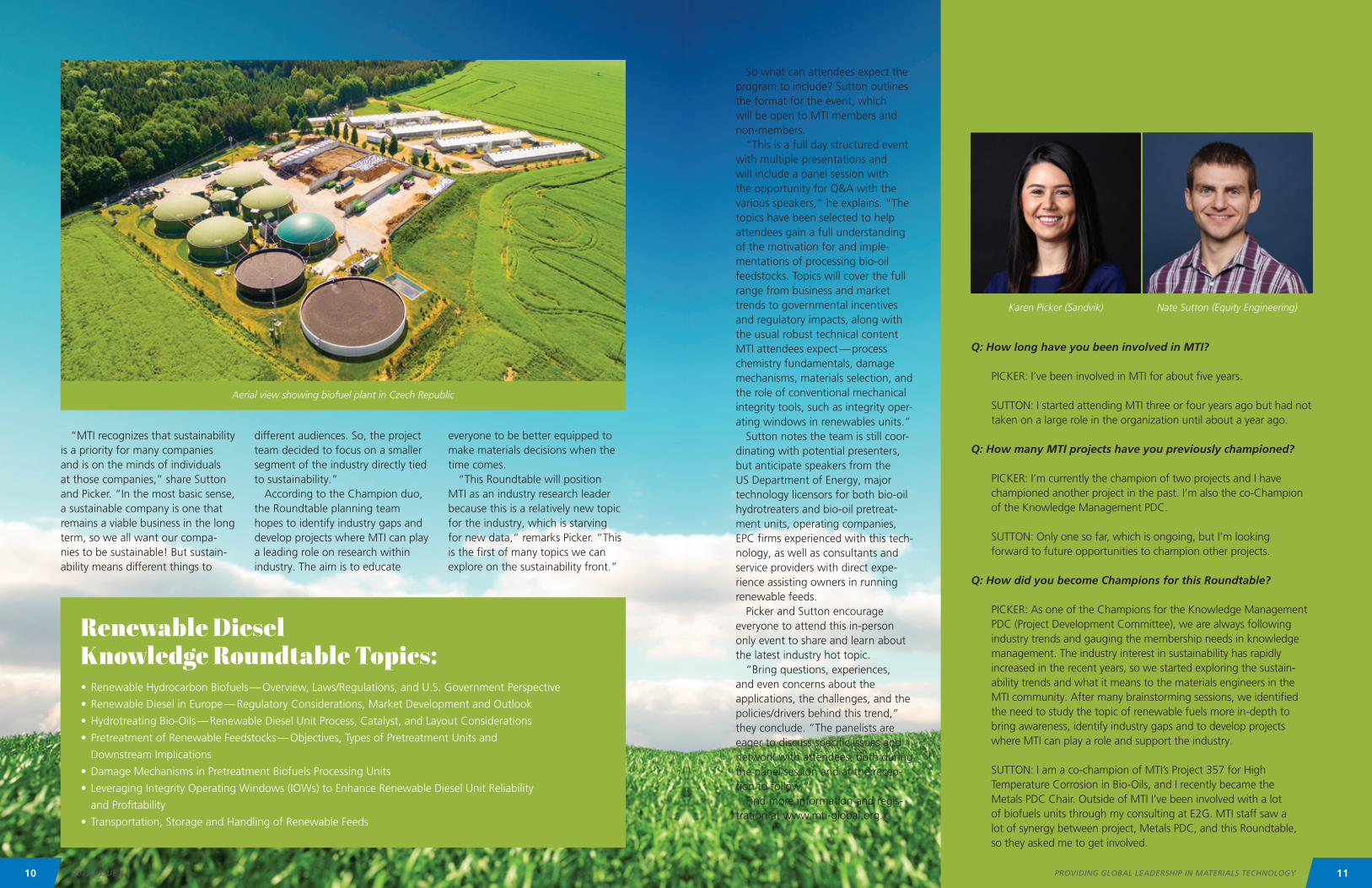
Aerial view showing biofuel plant in Czech Republic
Karen Picker (Sandvik) Nate Sutton (Equity Engineering)
Meet the Champions of Project #385
11PROVIDING GLOBAL LEADERSHIP IN MATERIALS TECHNOLOGY10 2022, ISSUE 1
ABSTRACTPrecipitation-hardened nickel-based superalloys have long been known as the material of choice for industrial gas turbine blade applications. They derive their high temperature strength from γ’ precipitates. However, exposure to elevated temperatures for long durations can lead to strain-age cracking (SAC). In this case study, we present a failure analysis performed on a fractured turbine blade retrieved from the second stage of a gas turbine, driving a three-stage natural gas centrifugal compressor. The blades were reported to be manufac-tured from Inconel 738 (IN-738) alloy and coated with an intermetallic nickel aluminide silicon-enriched outer layer. Visual examination, stereo microscopy, scanning electron microscopy (SEM), energy dispersive x-ray spectroscopy (EDS), metallography and chemical analysis were performed. It was determined that the turbine blade fracture initiated in fatigue at a high stress region (tie wire hole). However, the crack propagated in an intergranular fashion due to the formation of embrittling grain boundary precipitates (possibly generated during the coating process). The chemical composition of the turbine blade did not meet the requirements for IN-738 alloy. However, it more closely matched to another precipitation hardened nickel-based alloy — Waspaloy. The base material hardness was above the maximum prescribed for Waspaloy forgings indicating the likelihood of additional aging during service. The hardener content (aluminum + titanium = 5.5%) was also high enough
to place the material in the susceptible portion of the C-curve for SAC.
INTRODUCTIONPrecipitation-hardened nickel-based superalloys, such as GTD-222, IN-738, Nimonic 263, Waspoloy, René 41, are often used for turbine blade materials. They derive their excellent creep/hot-corrosion resistance, even at temperatures exceeding 1200°F, due to the formation of γ’ (Ni3(Ti,Al)) strengthening precipitates.1-5 However, exposure to elevated temperatures for long durations can lead to strain-age cracking (SAC).6 A fractured turbine blade retrieved from the second stage of a gas turbine was sent to the lab for failure analysis. The turbine drives a three-stage natural gas centrifugal compressor. The blades were reported to be manufactured from Inconel 738 (IN-738) alloy and coated with an intermetallic nickel aluminide silicon-enriched outer layer. The aluminide coatings are known to provide additional high tempera-ture corrosion resistance (for use above 1600°F).1 As per the client’s maintenance procedure, the turbines are rebuilt after 50,000 hours of operation. The turbine rotor is removed for refurbishment and a rebuilt rotor is installed in its place. However, the first and second stage blades (also called “buckets”) are reused until they reach 100,000 hours of operation, after which they are discarded at the next overhaul. The fractured blade was on its second campaign and had logged approximately 95,000 hours of operation.
NATURAL GAS COMPRESSOR TURBINE BLADESSUDHAKAR MAHAJANAM, SCOTT HARDING; STRESS ENGINEERING SERVICES
With respect to the driven equipment and the process within which it operates, there are three stages of compression. The first stage is supplied by the field compression at an inlet pressure of 95-160 psig. The field compression is composed of multiple compression sites taking all of the well head compression through the gathering system and pushing the natural gas to the inlet of the client’s plant.
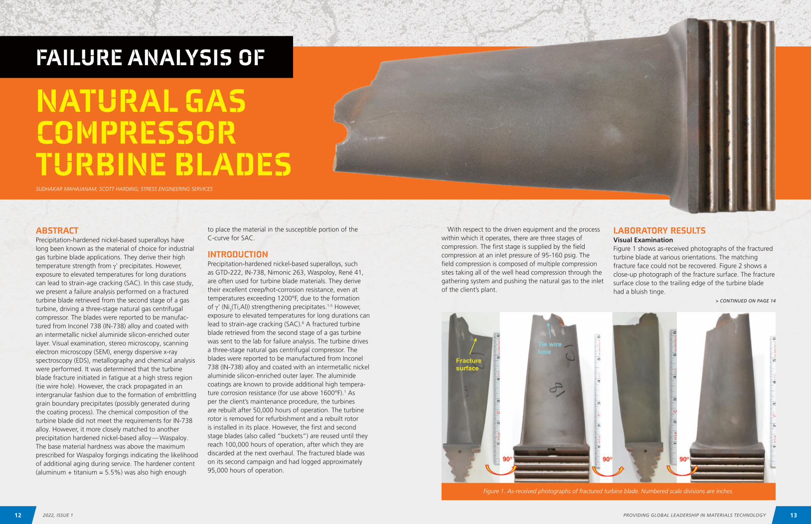
LABORATORY RESULTSVisual ExaminationFigure 1 shows as-received photographs of the fractured turbine blade at various orientations. The matching fracture face could not be recovered. Figure 2 shows a close-up photograph of the fracture surface. The fracturesurface close to the trailing edge of the turbine blade had a bluish tinge.
> CONTINUED ON PAGE 14
FAILURE ANALYSIS OF
Figure 1. As-received photographs of fractured turbine blade. Numbered scale divisions are inches.
13PROVIDING GLOBAL LEADERSHIP IN MATERIALS TECHNOLOGY12 2022, ISSUE 1

NATURAL GAS COMPRESSOR TURBINE BLADES
FAILURE ANALYSIS OF
Figure 2. Close-up photograph showing fracture surface. Numbered scale divisions are inches.
Figure 3. Close-up stereo micrographs of fracture surface. Original magnifications: 7.5X (top), 20X (bottom).
Figure 4. SEM images showing turbine fracture surface. Figure 5. SEM images at region A of fracture surface.
Figure 6. SEM images at region B of fracture surface. Figure 7. SEM images at region C of fracture surface.
Figure 5 shows higher magnification SEM images of region A indicating intergranular fracture facets.
Figure 6 shows SEM images of region B. Two types of fracture facets were observed: Intergranular fracture at the mid-wall region, and fatigue fracture at the region close to the tie wire hole on the pressure side of the turbine blade (red arrow in Figure 4). Striations indicative of fatigue (white arrows in Figure 6) were observed in the higher magnification images.
Figure 7 shows SEM images of region C. Facets indic-ative of stage 1 fatigue were observed at the tip of the trailing edge. Fatigue striations (white arrows) were also observed within some of these facets.
Figure 3 shows close-up stereo micrographs of the fracture surface at the leading and trailing edges of the turbine blade. The red arrow indicates the plane the blade was sectioned on for further metallographic analysis (following SEM fractography).
Scanning Electron Microscopy (SEM) ExaminationThe fracture surface was ultrasonically cleaned and SEM fractography was performed (Figure 4). Higher magnifi-cation images were taken at the fracture faces marked by the yellow dashed boxes: Leading edge (region A), center (region B) and trailing edge (region C) as shown in Figures 5-7 respectively.
Energy dispersive x-ray spectroscopy (EDS) analysis of the fracture surface at regions A, B and C was performed prior to ultrasonic cleaning. As shown in Figure 8, the deposits in region A primarily consisted of oxygen, magnesium and silicon.
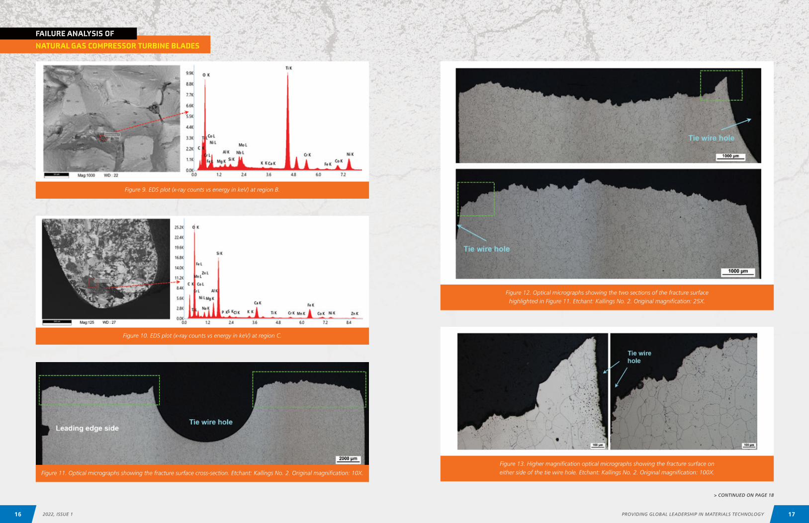
Precipitate-like particles were observed at the grain boundaries of the intergranular fracture in region B and consisted of oxygen and titanium with traces of chro-mium, cobalt and nickel (Figure 9).
The deposits in region C primarily consisted of oxygen and silicon with traces of sodium, magnesium, aluminum, calcium and iron (Figure 10).
EDS analysis of the turbine blade coating indicated that it primarily consisted of oxygen, aluminum, nickel, chro-
Figure 8. EDS plot (x-ray counts vs energy in keV) at region A.
mium with traces of cobalt, titanium and iron. Analysis of the base material indicated that it contained nickel, chromium, cobalt and aluminum with traces of titanium, molybdenum and iron.
Metallographic ExaminationA portion of the fracture surface was sectioned and prepared for metallography (Figure 11). Optical micro-graphs were recorded at the green boxed regions and are shown in Figure 12. Higher magnification micro-graphs of the fracture surface were taken at either side of the tie wire hole (Figure 13). The fracture morphology was intergranular, and the microstructure appeared to
> CONTINUED ON PAGE 16
15PROVIDING GLOBAL LEADERSHIP IN MATERIALS TECHNOLOGY14 2022, ISSUE 1
NATURAL GAS COMPRESSOR TURBINE BLADES
FAILURE ANALYSIS OF
Figure 11. Optical micrographs showing the fracture surface cross-section. Etchant: Kallings No. 2. Original magnification: 10X.
Figure 12. Optical micrographs showing the two sections of the fracture surface highlighted in Figure 11. Etchant: Kallings No. 2. Original magnification: 25X.
Figure 13. Higher magnification optical micrographs showing the fracture surface on either side of the tie wire hole. Etchant: Kallings No. 2. Original magnification: 100X.
Figure 9. EDS plot (x-ray counts vs energy in keV) at region B.
Figure 10. EDS plot (x-ray counts vs energy in keV) at region C.
> CONTINUED ON PAGE 18
17PROVIDING GLOBAL LEADERSHIP IN MATERIALS TECHNOLOGY16 2022, ISSUE 1
NATURAL GAS COMPRESSOR TURBINE BLADES
FAILURE ANALYSIS OF
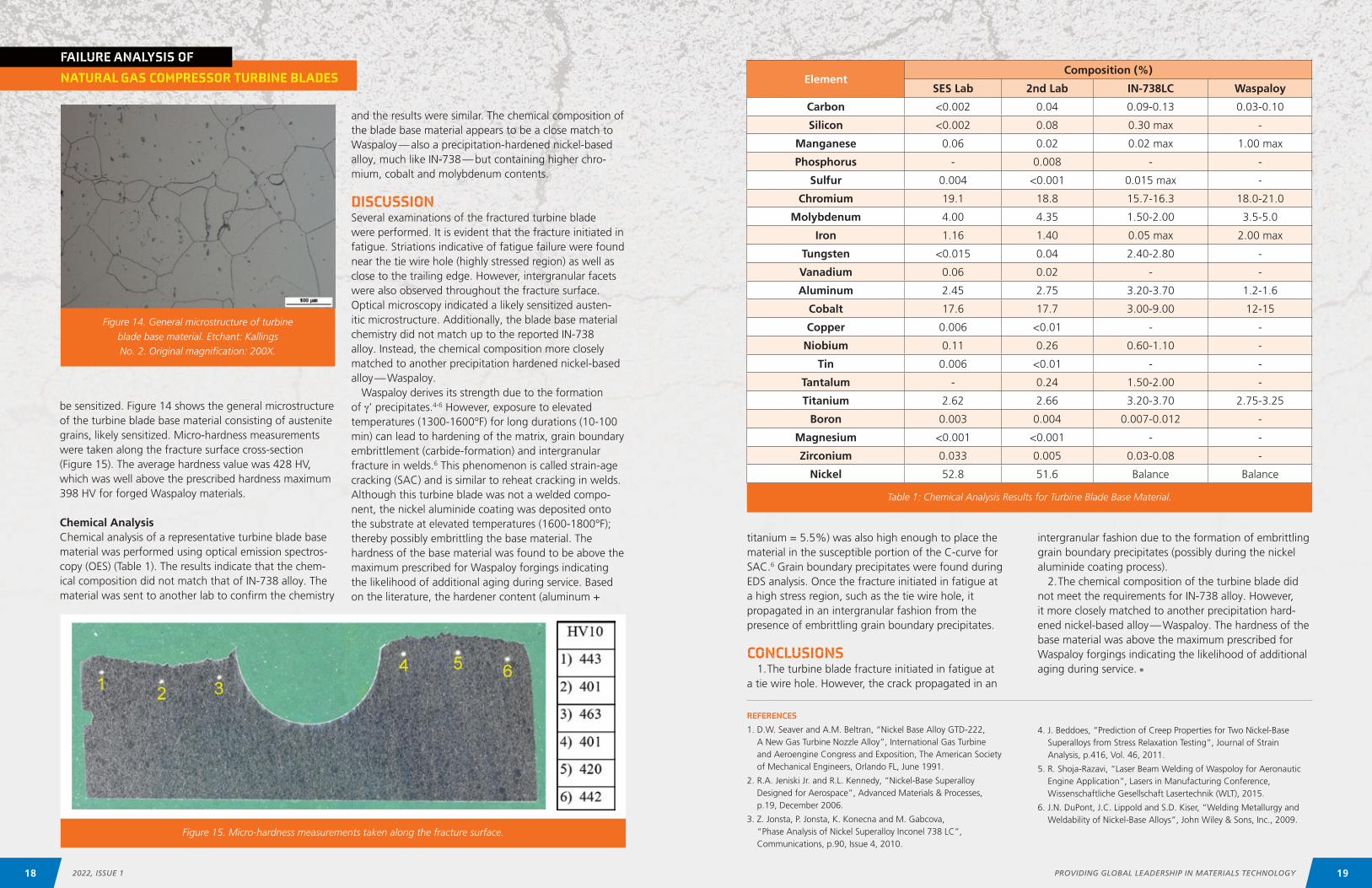
ElementComposition (%)
SES Lab 2nd Lab IN-738LC Waspaloy
Carbon <0.002 0.04 0.09-0.13 0.03-0.10
Silicon <0.002 0.08 0.30 max -
Manganese 0.06 0.02 0.02 max 1.00 max
Phosphorus - 0.008 - -
Sulfur 0.004 <0.001 0.015 max -
Chromium 19.1 18.8 15.7-16.3 18.0-21.0
Molybdenum 4.00 4.35 1.50-2.00 3.5-5.0
Iron 1.16 1.40 0.05 max 2.00 max
Tungsten <0.015 0.04 2.40-2.80 -
Vanadium 0.06 0.02 - -
Aluminum 2.45 2.75 3.20-3.70 1.2-1.6
Cobalt 17.6 17.7 3.00-9.00 12-15
Copper 0.006 <0.01 - -
Niobium 0.11 0.26 0.60-1.10 -
Tin 0.006 <0.01 - -
Tantalum - 0.24 1.50-2.00 -
Titanium 2.62 2.66 3.20-3.70 2.75-3.25
Boron 0.003 0.004 0.007-0.012 -
Magnesium <0.001 <0.001 - -
Zirconium 0.033 0.005 0.03-0.08 -
Nickel 52.8 51.6 Balance Balance
be sensitized. Figure 14 shows the general microstructure of the turbine blade base material consisting of austenite grains, likely sensitized. Micro-hardness measurements were taken along the fracture surface cross-section (Figure 15). The average hardness value was 428 HV, which was well above the prescribed hardness maximum 398 HV for forged Waspaloy materials.
Chemical AnalysisChemical analysis of a representative turbine blade base material was performed using optical emission spectros-copy (OES) (Table 1). The results indicate that the chem-ical composition did not match that of IN-738 alloy. The material was sent to another lab to confirm the chemistry
and the results were similar. The chemical composition of the blade base material appears to be a close match to Waspaloy — also a precipitation-hardened nickel-based alloy, much like IN-738 — but containing higher chro-mium, cobalt and molybdenum contents.
DISCUSSIONSeveral examinations of the fractured turbine blade were performed. It is evident that the fracture initiated in fatigue. Striations indicative of fatigue failure were found near the tie wire hole (highly stressed region) as well as close to the trailing edge. However, intergranular facets were also observed throughout the fracture surface. Optical microscopy indicated a likely sensitized austen-itic microstructure. Additionally, the blade base material chemistry did not match up to the reported IN-738 alloy. Instead, the chemical composition more closely matched to another precipitation hardened nickel-based alloy — Waspaloy.
Waspaloy derives its strength due to the formation of γ’ precipitates.4-6 However, exposure to elevated temperatures (1300-1600°F) for long durations (10-100 min) can lead to hardening of the matrix, grain boundary embrittlement (carbide-formation) and intergranular fracture in welds.6 This phenomenon is called strain-age cracking (SAC) and is similar to reheat cracking in welds. Although this turbine blade was not a welded compo-nent, the nickel aluminide coating was deposited onto the substrate at elevated temperatures (1600-1800°F); thereby possibly embrittling the base material. The hardness of the base material was found to be above the maximum prescribed for Waspaloy forgings indicating the likelihood of additional aging during service. Based on the literature, the hardener content (aluminum +
titanium = 5.5%) was also high enough to place the material in the susceptible portion of the C-curve for SAC.6 Grain boundary precipitates were found during EDS analysis. Once the fracture initiated in fatigue at a high stress region, such as the tie wire hole, it propagated in an intergranular fashion from the presence of embrittling grain boundary precipitates.
CONCLUSIONS1. The turbine blade fracture initiated in fatigue at
a tie wire hole. However, the crack propagated in an
Table 1: Chemical Analysis Results for Turbine Blade Base Material.
Figure 14. General microstructure of turbine blade base material. Etchant: Kallings No. 2. Original magnification: 200X.
Figure 15. Micro-hardness measurements taken along the fracture surface.
intergranular fashion due to the formation of embrittling grain boundary precipitates (possibly during the nickel aluminide coating process).
2. The chemical composition of the turbine blade did not meet the requirements for IN-738 alloy. However, it more closely matched to another precipitation hard-ened nickel-based alloy — Waspaloy. The hardness of the base material was above the maximum prescribed for Waspaloy forgings indicating the likelihood of additional aging during service. n
REFERENCES
1. D.W. Seaver and A.M. Beltran, “Nickel Base Alloy GTD-222, A New Gas Turbine Nozzle Alloy”, International Gas Turbine and Aeroengine Congress and Exposition, The American Society of Mechanical Engineers, Orlando FL, June 1991.
2. R.A. Jeniski Jr. and R.L. Kennedy, “Nickel-Base Superalloy Designed for Aerospace”, Advanced Materials & Processes, p.19, December 2006.
3. Z. Jonsta, P. Jonsta, K. Konecna and M. Gabcova, “Phase Analysis of Nickel Superalloy Inconel 738 LC”, Communications, p.90, Issue 4, 2010.
4. J. Beddoes, “Prediction of Creep Properties for Two Nickel-Base Superalloys from Stress Relaxation Testing”, Journal of Strain Analysis, p.416, Vol. 46, 2011.
5. R. Shoja-Razavi, “Laser Beam Welding of Waspoloy for Aeronautic Engine Application”, Lasers in Manufacturing Conference, Wissenschaftliche Gesellschaft Lasertechnik (WLT), 2015.
6. J.N. DuPont, J.C. Lippold and S.D. Kiser, “Welding Metallurgy and Weldability of Nickel-Base Alloys”, John Wiley & Sons, Inc., 2009.
19PROVIDING GLOBAL LEADERSHIP IN MATERIALS TECHNOLOGY18 2022, ISSUE 1
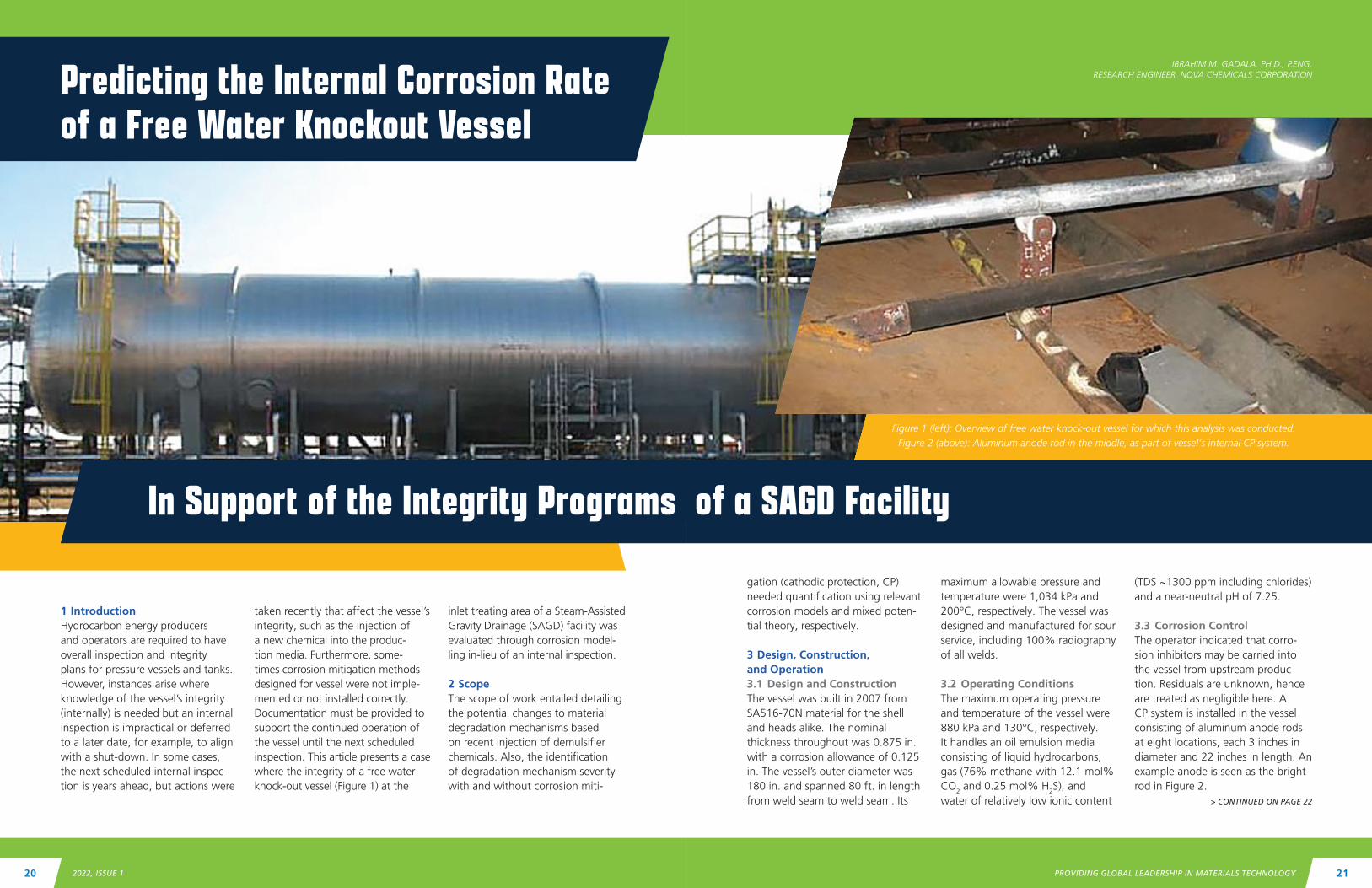
1 IntroductionHydrocarbon energy producers and operators are required to have overall inspection and integrity plans for pressure vessels and tanks. However, instances arise where knowledge of the vessel’s integrity (internally) is needed but an internal inspection is impractical or deferred to a later date, for example, to align with a shut-down. In some cases, the next scheduled internal inspec-tion is years ahead, but actions were
gation (cathodic protection, CP) needed quantification using relevant corrosion models and mixed poten-tial theory, respectively.
3 Design, Construction, and Operation3.1 Design and ConstructionThe vessel was built in 2007 from SA516-70N material for the shell and heads alike. The nominal thickness throughout was 0.875 in. with a corrosion allowance of 0.125 in. The vessel’s outer diameter was 180 in. and spanned 80 ft. in length from weld seam to weld seam. Its
taken recently that affect the vessel’s integrity, such as the injection of a new chemical into the produc-tion media. Furthermore, some-times corrosion mitigation methods designed for vessel were not imple-mented or not installed correctly. Documentation must be provided to support the continued operation of the vessel until the next scheduled inspection. This article presents a case where the integrity of a free water knock-out vessel (Figure 1) at the
maximum allowable pressure and temperature were 1,034 kPa and 200°C, respectively. The vessel was designed and manufactured for sour service, including 100% radiography of all welds.
3.2 Operating ConditionsThe maximum operating pressure and temperature of the vessel were 880 kPa and 130°C, respectively. It handles an oil emulsion media consisting of liquid hydrocarbons, gas (76% methane with 12.1 mol% CO2 and 0.25 mol% H2S), and water of relatively low ionic content
inlet treating area of a Steam-Assisted Gravity Drainage (SAGD) facility was evaluated through corrosion model-ling in-lieu of an internal inspection.
2 ScopeThe scope of work entailed detailing the potential changes to material degradation mechanisms based on recent injection of demulsifier chemicals. Also, the identification of degradation mechanism severity with and without corrosion miti-
(TDS ~1300 ppm including chlorides) and a near-neutral pH of 7.25.
3.3 Corrosion ControlThe operator indicated that corro-sion inhibitors may be carried into the vessel from upstream produc-tion. Residuals are unknown, hence are treated as negligible here. A CP system is installed in the vessel consisting of aluminum anode rods at eight locations, each 3 inches in diameter and 22 inches in length. An example anode is seen as the bright rod in Figure 2.
> CONTINUED ON PAGE 22
Predicting the Internal Corrosion Rate of a Free Water Knockout Vessel
IBRAHIM M. GADALA, PH.D., P.ENG.RESEARCH ENGINEER, NOVA CHEMICALS CORPORATION
Figure 1 (left): Overview of free water knock-out vessel for which this analysis was conducted.Figure 2 (above): Aluminum anode rod in the middle, as part of vessel’s internal CP system.
of a SAGD FacilityIn Support of the Integrity Programs
PROVIDING GLOBAL LEADERSHIP IN MATERIALS TECHNOLOGY 212022, ISSUE 120
4 Injection Chemicals and their Effects4.1 Injected Process ChemicalsAs per the operator, a chemical demulsifier and reverse demulsifier were injected into the vessel starting in mid-2018. The specific chemical mixtures are proprietary. They are referred to as Chemical {1} and {2} herein.
1. Chemical {1}: For dehydration treatment of crude oil emul-sions. Has a pH of 6.5-9.0 and a decomposition temperature of 385°C.
2. Chemical {2}: For pre-treatment of SAGD high-temperature production fluid. Also has a pH of 6.5-9.0 but a lower decom-position temperature of 180°C. Contains poly dimethyl diallyl ammonium chloride.
4.2 Effects of Injected Process ChemicalsThe influences for the injected process chemicals {1} and {2} were as follows:
a) Enhanced separation (demulsi-fying) of water and gas phases from the oil emulsion, meaning more water wetting of internal bottom surfaces. However, due to gas phase separation, this also means less mixing and dissolv-ability of acid gases therein.
b) Digression of the free water pH to acidic levels is unlikely, due to the near-neutral range of both chem-icals being injected and the water initially being around neutral pH. Also, the ratio of injected chem-icals to production media is very small, hence not expected to change the pH noticeably.
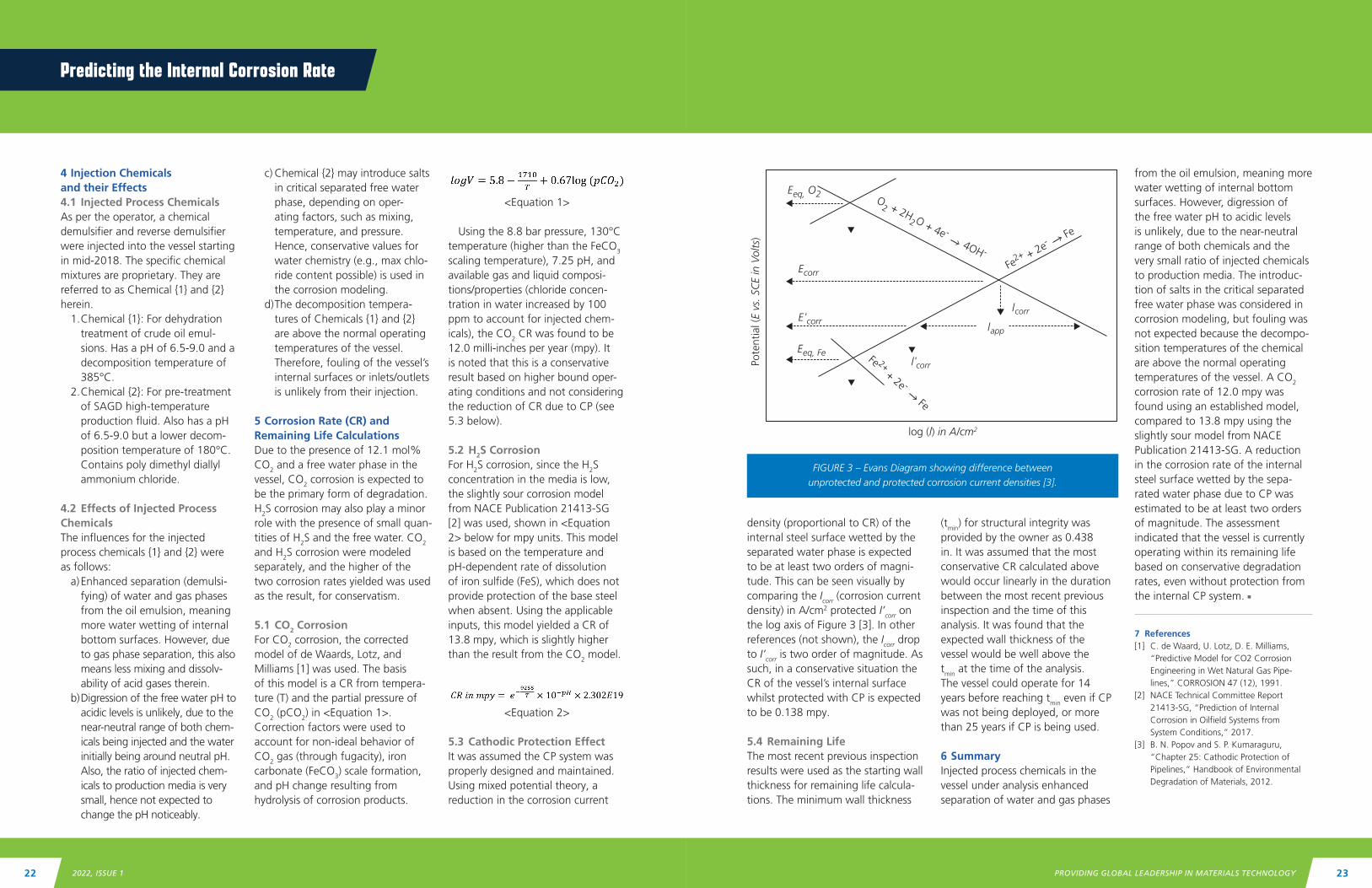
density (proportional to CR) of the internal steel surface wetted by the separated water phase is expected to be at least two orders of magni-tude. This can be seen visually by comparing the Icorr (corrosion current density) in A/cm2 protected I’corr on the log axis of Figure 3 [3]. In other references (not shown), the Icorr drop to I’corr is two order of magnitude. As such, in a conservative situation the CR of the vessel’s internal surface whilst protected with CP is expected to be 0.138 mpy.
5.4 Remaining LifeThe most recent previous inspection results were used as the starting wall thickness for remaining life calcula-tions. The minimum wall thickness
c) Chemical {2} may introduce salts in critical separated free water phase, depending on oper-ating factors, such as mixing, temperature, and pressure. Hence, conservative values for water chemistry (e.g., max chlo-ride content possible) is used in the corrosion modeling.
d) The decomposition tempera-tures of Chemicals {1} and {2} are above the normal operating temperatures of the vessel. Therefore, fouling of the vessel’s internal surfaces or inlets/outlets is unlikely from their injection.
5 Corrosion Rate (CR) and Remaining Life CalculationsDue to the presence of 12.1 mol% CO2 and a free water phase in the vessel, CO2 corrosion is expected to be the primary form of degradation. H2S corrosion may also play a minor role with the presence of small quan-tities of H2S and the free water. CO2 and H2S corrosion were modeled separately, and the higher of the two corrosion rates yielded was used as the result, for conservatism.
5.1 CO2 CorrosionFor CO2 corrosion, the corrected model of de Waards, Lotz, and Milliams [1] was used. The basis of this model is a CR from tempera-ture (T) and the partial pressure of CO2 (pCO2) in <Equation 1>. Correction factors were used to account for non-ideal behavior of CO2 gas (through fugacity), iron carbonate (FeCO3) scale formation, and pH change resulting from hydrolysis of corrosion products.
(tmin) for structural integrity was provided by the owner as 0.438 in. It was assumed that the most conservative CR calculated above would occur linearly in the duration between the most recent previous inspection and the time of this analysis. It was found that the expected wall thickness of the vessel would be well above the tmin at the time of the analysis. The vessel could operate for 14 years before reaching tmin even if CP was not being deployed, or more than 25 years if CP is being used.
6 SummaryInjected process chemicals in the vessel under analysis enhanced separation of water and gas phases
<Equation 1>
Using the 8.8 bar pressure, 130°C temperature (higher than the FeCO3 scaling temperature), 7.25 pH, and available gas and liquid composi-tions/properties (chloride concen-tration in water increased by 100 ppm to account for injected chem-icals), the CO2 CR was found to be 12.0 milli-inches per year (mpy). It is noted that this is a conservative result based on higher bound oper-ating conditions and not considering the reduction of CR due to CP (see 5.3 below).
5.2 H2S CorrosionFor H2S corrosion, since the H2S concentration in the media is low, the slightly sour corrosion model from NACE Publication 21413-SG [2] was used, shown in <Equation 2> below for mpy units. This model is based on the temperature and pH-dependent rate of dissolution of iron sulfide (FeS), which does not provide protection of the base steel when absent. Using the applicable inputs, this model yielded a CR of 13.8 mpy, which is slightly higher than the result from the CO2 model.
<Equation 2>
5.3 Cathodic Protection EffectIt was assumed the CP system was properly designed and maintained. Using mixed potential theory, a reduction in the corrosion current
from the oil emulsion, meaning more water wetting of internal bottom surfaces. However, digression of the free water pH to acidic levels is unlikely, due to the near-neutral range of both chemicals and the very small ratio of injected chemicals to production media. The introduc-tion of salts in the critical separated free water phase was considered in corrosion modeling, but fouling was not expected because the decompo-sition temperatures of the chemical are above the normal operating temperatures of the vessel. A CO2 corrosion rate of 12.0 mpy was found using an established model, compared to 13.8 mpy using the slightly sour model from NACE Publication 21413-SG. A reduction in the corrosion rate of the internal steel surface wetted by the sepa-rated water phase due to CP was estimated to be at least two orders of magnitude. The assessment indicated that the vessel is currently operating within its remaining life based on conservative degradation rates, even without protection from the internal CP system. n
7 References[1] C. de Waard, U. Lotz, D. E. Milliams,
“Predictive Model for CO2 Corrosion Engineering in Wet Natural Gas Pipe-lines,” CORROSION 47 (12), 1991.
[2] NACE Technical Committee Report 21413-SG, “Prediction of Internal Corrosion in Oilfield Systems from System Conditions,” 2017.
[3] B. N. Popov and S. P. Kumaraguru, “Chapter 25: Cathodic Protection of Pipelines,” Handbook of Environmental Degradation of Materials, 2012.
Predicting the Internal Corrosion Rate
FIGURE 3 – Evans Diagram showing difference between unprotected and protected corrosion current densities [3].
l corr
lcorr
lapp
'
Eeq, O2
Eeq, Fe
Pote
ntia
l (E
vs. S
CE
in V
olts
)
log (l) in A/cm2
Ecorr
E corr'
Fe 2+ + 2e - Fe
Fe2+ + 2e-
Fe
O2 + 2H
2 O + 4e - 4OH -
PROVIDING GLOBAL LEADERSHIP IN MATERIALS TECHNOLOGY 232022, ISSUE 122
Atlas of Microstructures for Alloy 625 #335Champions: Gary Whitaker (Nickel Institute), Alvaro Corbato Prieto (Topsoe)
This project will compile micrographs that completely characterize the microstructure of alloy 625 in plate, wrought, cast equivalent, equivalent weld metal and additively manufactured forms that have been exposed to elevated temperature during processing and fabrica-tion. Since the alloy is used in highly corrosive services,
anything that reduces corrosion resistance or changes mechanical properties poses a threat to process safety, reliability and the environment. This project will help end users, fabricators and metal suppliers better understand how processing impacts the structure of Alloy 625 and hence its performance in highly corrosive processes
Corrosion in Bio-oils #357Champions: Nate Sutton (Equity Engineering), Maricela Johnson (Chevron)
MTI member companies are seeking to convert existing Hydroprocessing (petroleum refining) facilities to process renewable feeds. When the renewable feed is heated for processing, a major damage mechanism of interest is high-temperature free fatty acid (FFA) corrosion, similar to naphthenic acid corrosion (NAC). Although FFA corro-
sion and NAC are expected to share similar features, very little applicable corrosion data exists for these higher-TAN (Total Acid Number) renewable feeds at conditions of interest. These conditions include high-pressure, hydrogen containing, potentially 2-phase flow scenarios.
Remaining Life Evaluation of Aged Alloy 20CrNi1Nb Components #375 Champions: Jeremy Nelson (Koch Industries), Jose Ramirez (Air Products)
The remaining service life of 20Cr32Ni1Nb components is a function of the component’s weld ductility, fracture toughness across the ambient to operating temperature range, tensile strength across the operating temperature range, and creep and creep crack growth rate. These mechanical properties are known to decrease over time in service at elevated temperatures. Owner-users who have made repairs to their manifolds are interested in
data about similar repaired reformer components to aid in suitability for service assessment of their own assets. Additionally, if the test techniques used on an exemplar manifold can be performed with sub-sized samples, owner-users are interested in direct measurement of the properties of in-service manifold components. This prop-erty data would be valuable for decision making during maintenance outage windows.
MTI BOARD APPROVES FUNDING OF FOUR PROJECTS
On Tuesday, February 28, 2022, four MTI projects were presented to the membership for funding at AmeriTAC 137 in Orlando, Fla. The projects include
#357 Corrosion in Bio-oils ($132,355), #379 PSA Vessel Structural Integrity and Fatigue Testing ($318,000), #375 Remaining Life Evaluation of Aged Alloy 20CrNi1Nb Components ($339,000), and #335
Atlas of Microstructures for Alloy 625 ($133,750). Following the technical review and approval of the funding requests by TAC (Technical Advisory Council), the Board convened a teleconference on March 16. The Board voted and approved each project not to exceed the amounts previously listed for a $923,105 total budget among the four projects.
PROJECT SUMMARIES
PSA Vessel Structural Integrity and Fatigue Testing #379Champion: Jader Furtado (Air Liquide)
The purpose of this testing is to establish a materials database for PSA steel in hydrogen. Knowledge gaps have been identified and a testing matrix has been proposed for obtaining fatigue data under operating conditions. All testing shall be performed according to the following ASTM standards: D638 (tensile testing),
E606 (low-cycle fatigue), E647 (fatigue crack propaga-tion), E1820 (toughness testing). This data will be used for the evaluation of the structural integrity of PSA H2 vessels used for the purification of hydrogen in accor-dance with FFS standards, such as API 579, ASME FFS-1, BS7910 and fatigue model identified in Phase I. n
NEWS
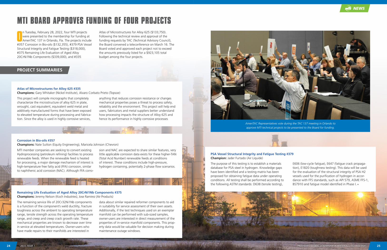
AmeriTAC Representatives vote during the TAC 137 meeting in Orlando to approve MTI technical projects to be presented to the Board for funding.
2524 2022, ISSUE 1 PROVIDING GLOBAL LEADERSHIP IN MATERIALS TECHNOLOGY
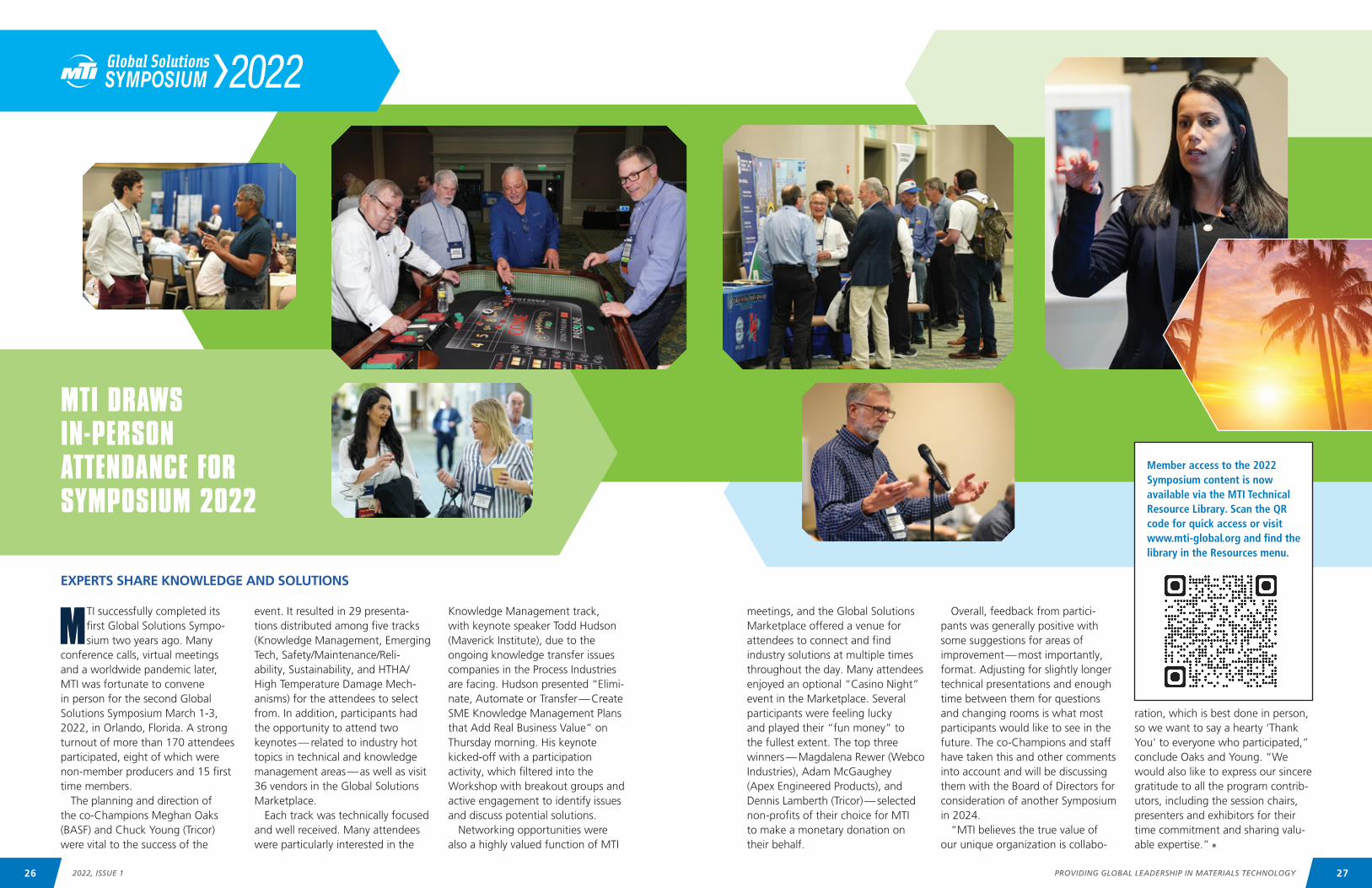
MTI successfully completed its first Global Solutions Sympo-sium two years ago. Many
conference calls, virtual meetings and a worldwide pandemic later, MTI was fortunate to convene in person for the second Global Solutions Symposium March 1-3, 2022, in Orlando, Florida. A strong turnout of more than 170 attendees participated, eight of which were non-member producers and 15 first time members.
The planning and direction of the co-Champions Meghan Oaks (BASF) and Chuck Young (Tricor) were vital to the success of the
meetings, and the Global Solutions Marketplace offered a venue for attendees to connect and find industry solutions at multiple times throughout the day. Many attendees enjoyed an optional “Casino Night” event in the Marketplace. Several participants were feeling lucky and played their “fun money” to the fullest extent. The top three winners — Magdalena Rewer (Webco Industries), Adam McGaughey (Apex Engineered Products), and Dennis Lamberth (Tricor) — selected non-profits of their choice for MTI to make a monetary donation on their behalf.
event. It resulted in 29 presenta-tions distributed among five tracks (Knowledge Management, Emerging Tech, Safety/Maintenance/Reli-ability, Sustainability, and HTHA/High Temperature Damage Mech-anisms) for the attendees to select from. In addition, participants had the opportunity to attend two keynotes — related to industry hot topics in technical and knowledge management areas — as well as visit 36 vendors in the Global Solutions Marketplace.
Each track was technically focused and well received. Many attendees were particularly interested in the
Overall, feedback from partici-pants was generally positive with some suggestions for areas of improvement — most importantly, format. Adjusting for slightly longer technical presentations and enough time between them for questions and changing rooms is what most participants would like to see in the future. The co-Champions and staff have taken this and other comments into account and will be discussing them with the Board of Directors for consideration of another Symposium in 2024.
“MTI believes the true value of our unique organization is collabo-
Knowledge Management track, with keynote speaker Todd Hudson (Maverick Institute), due to the ongoing knowledge transfer issues companies in the Process Industries are facing. Hudson presented “Elimi-nate, Automate or Transfer — Create SME Knowledge Management Plans that Add Real Business Value” on Thursday morning. His keynote kicked-off with a participation activity, which filtered into the Workshop with breakout groups and active engagement to identify issues and discuss potential solutions.
Networking opportunities were also a highly valued function of MTI
ration, which is best done in person, so we want to say a hearty ‘Thank You’ to everyone who participated,” conclude Oaks and Young. “We would also like to express our sincere gratitude to all the program contrib-utors, including the session chairs, presenters and exhibitors for their time commitment and sharing valu-able expertise.” n
EXPERTS SHARE KNOWLEDGE AND SOLUTIONS
MTI DRAWS IN-PERSON ATTENDANCE FOR SYMPOSIUM 2022
Member access to the 2022 Symposium content is now available via the MTI Technical Resource Library. Scan the QR code for quick access or visit www.mti-global.org and find the library in the Resources menu.
27PROVIDING GLOBAL LEADERSHIP IN MATERIALS TECHNOLOGY26 2022, ISSUE 1
The largest gathering of MTI members and guests in two years took place at the second
MTI Global Solutions Symposium in Orlando, Florida March 1-3. It was the perfect opportunity to celebrate member company anniversaries, Value Awards, project completions, and individual accomplishments.
In fact, one TAC Representative, Hardin Wells, Fellow – Mechanical Tech Service at Albemarle, was on stage for each of the four types of awards presented at the Symposium. Wells accepted Albemarle’s 40-year MTI Membership Anniversary plaque, MTI Value and Project Cham-pion Awards for the Best Practices in Reactive and Refractory Metals in the CPI project, and a Distinguished Service Award for the many other contributions he has made over 25-plus years of participation in the organization.
“I have to say that receiving the MTI Distinguished Service Award at the recent TAC meeting in Orlando was an incredible honor for me,” says Wells. “In fact, it is one of the highlights of my 35 years in the chemical industry and one that I am truly humbled to receive. To be recognized by your peers for your contributions over several decades is incredibly rewarding and makes my time engaged with MTI even more special. But to be sure, the years of engagement and whatever
contributions I was able to muster pale in comparison to the many learnings, amazing experiences, and new friends that I received from my MTI connections during this time. In fact, I would do it all over again in a heartbeat.”
Wells wasn’t the only individual honored during the festivities. Gary Coates of the Nickel Institute also received a Distinguished Service Award. In addition to contributing to many projects during his 24 years as a member, Coates has been very active in MTI’s forum. His first post was recorded on February 25, 1997, and he has added another 111 since then.
“Perhaps Gary’s greatest contri-butions have been in the form of training programs and presenta-tions,” according to former Executive Director Paul Whitcraft. “He is very well represented in the MTI Technical Resource Library, with more than 14 formal presentations.”
In addition to honoring long-term contributors, MTI recognizes note-worthy achievements of members who have been active for a year or more with the Chair’s Leadership Award. At the Symposium, Karen Picker, Sandvik’s Regional Technical Marketing Manager, Americas, was presented the award for her significant efforts as Co-Chair of the Knowledge Management PDC, which recently generated the Best
Practices for Working with SMEs Project. She has also championed several projects, including the current Microbiological Corrosion Project #308, an effort to generate data and an industry report on the corrosion behavior of Duplex Stain-less Steels in MIC environments.
“Winning the award was extremely uplifting for me,” shares Picker. “I enjoy participating at MTI and volunteering on as many project as I can because I know the membership respects and values my input and I know I can have a positive impact on them. The work MTI does for the industry is like no other and everyone involved shows they really care about producing meaningful data the industry needs. Although I’m a young engineer, I’ve always felt my opinions are welcomed and the more experienced crowd is willing to hear a different perspective coming from someone like me. I see the MTI family is growing and younger engineers are becoming more visible and vocal about the next generation’s approach to solve industry problems and this is exactly what the industry needs. I encourage everyone to continue to participate and contribute to the MTI community because it is a profes-sionally rewarding organization that helps you grow professionally and personally.”
> CONTINUED ON PAGE 30
MEMBERACCOMPLISHMENTS
A HIGHLIGHT AT MTI AWARDS CEREMONY
COLLABORATION AND PARTICIPATION LEAD TO RECOGNITION
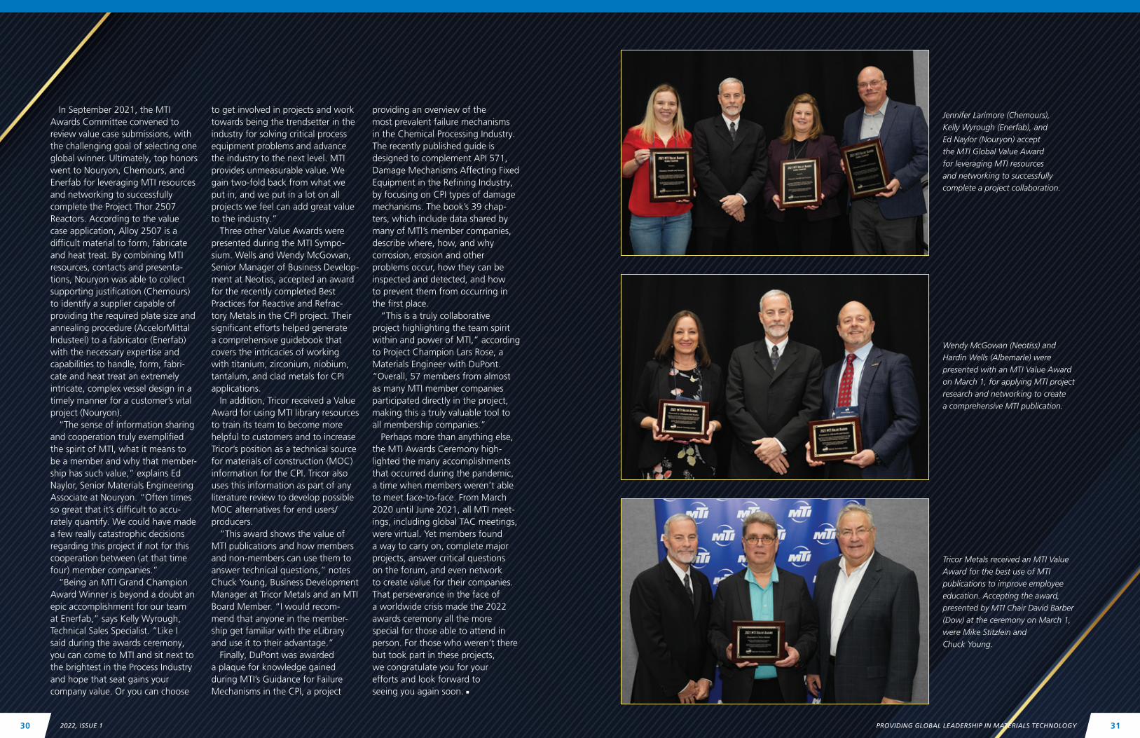
Karen Picker (Sandvik) is recognized for exemplary service, leadership and vision to advance the MTI mission during the MTI Awards Ceremony on March 1 in Orlando.
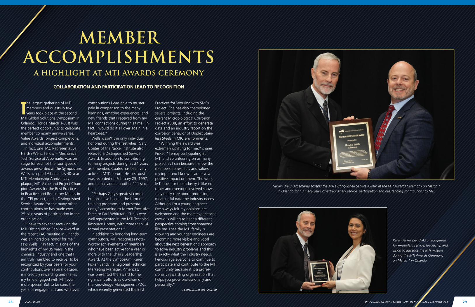
Hardin Wells (Albemarle) accepts the MTI Distinguished Service Award at the MTI Awards Ceremony on March 1 in Orlando for his many years of extraordinary service, participation and outstanding contributions to MTI.
PROVIDING GLOBAL LEADERSHIP IN MATERIALS TECHNOLOGY 292022, ISSUE 128
In September 2021, the MTI Awards Committee convened to review value case submissions, with the challenging goal of selecting one global winner. Ultimately, top honors went to Nouryon, Chemours, and Enerfab for leveraging MTI resources and networking to successfully complete the Project Thor 2507 Reactors. According to the value case application, Alloy 2507 is a difficult material to form, fabricate and heat treat. By combining MTI resources, contacts and presenta-tions, Nouryon was able to collect supporting justification (Chemours) to identify a supplier capable of providing the required plate size and annealing procedure (AccelorMittal lndusteel) to a fabricator (Enerfab) with the necessary expertise and capabilities to handle, form, fabri-cate and heat treat an extremely intricate, complex vessel design in a timely manner for a customer’s vital project (Nouryon).
“The sense of information sharing and cooperation truly exemplified the spirit of MTI, what it means to be a member and why that member-ship has such value,” explains Ed Naylor, Senior Materials Engineering Associate at Nouryon. “Often times so great that it’s difficult to accu-rately quantify. We could have made a few really catastrophic decisions regarding this project if not for this cooperation between (at that time four) member companies.”
“Being an MTI Grand Champion Award Winner is beyond a doubt an epic accomplishment for our team at Enerfab,” says Kelly Wyrough, Technical Sales Specialist. “Like I said during the awards ceremony, you can come to MTI and sit next to the brightest in the Process Industry and hope that seat gains your company value. Or you can choose
to get involved in projects and work towards being the trendsetter in the industry for solving critical process equipment problems and advance the industry to the next level. MTI provides unmeasurable value. We gain two-fold back from what we put in, and we put in a lot on all projects we feel can add great value to the industry.”
Three other Value Awards were presented during the MTI Sympo-sium. Wells and Wendy McGowan, Senior Manager of Business Develop-ment at Neotiss, accepted an award for the recently completed Best Practices for Reactive and Refrac-tory Metals in the CPI project. Their significant efforts helped generate a comprehensive guidebook that covers the intricacies of working with titanium, zirconium, niobium, tantalum, and clad metals for CPI applications.
In addition, Tricor received a Value Award for using MTI library resources to train its team to become more helpful to customers and to increase Tricor’s position as a technical source for materials of construction (MOC) information for the CPI. Tricor also uses this information as part of any literature review to develop possible MOC alternatives for end users/producers.
“This award shows the value of MTI publications and how members and non-members can use them to answer technical questions,” notes Chuck Young, Business Development Manager at Tricor Metals and an MTI Board Member. “I would recom-mend that anyone in the member-ship get familiar with the eLibrary and use it to their advantage.”
Finally, DuPont was awarded a plaque for knowledge gained during MTI’s Guidance for Failure Mechanisms in the CPI, a project
providing an overview of the most prevalent failure mechanisms in the Chemical Processing Industry. The recently published guide is designed to complement API 571, Damage Mechanisms Affecting Fixed Equipment in the Refining Industry, by focusing on CPI types of damage mechanisms. The book’s 39 chap-ters, which include data shared by many of MTl’s member companies, describe where, how, and why corrosion, erosion and other problems occur, how they can be inspected and detected, and how to prevent them from occurring in the first place.
“This is a truly collaborative project highlighting the team spirit within and power of MTI,” according to Project Champion Lars Rose, a Materials Engineer with DuPont. “Overall, 57 members from almost as many MTI member companies participated directly in the project, making this a truly valuable tool to all membership companies.”
Perhaps more than anything else, the MTI Awards Ceremony high-lighted the many accomplishments that occurred during the pandemic, a time when members weren’t able to meet face-to-face. From March 2020 until June 2021, all MTI meet-ings, including global TAC meetings, were virtual. Yet members found a way to carry on, complete major projects, answer critical questions on the forum, and even network to create value for their companies. That perseverance in the face of a worldwide crisis made the 2022 awards ceremony all the more special for those able to attend in person. For those who weren’t there but took part in these projects, we congratulate you for your efforts and look forward to seeing you again soon. n
Jennifer Larimore (Chemours), Kelly Wyrough (Enerfab), and Ed Naylor (Nouryon) accept the MTI Global Value Award for leveraging MTI resources and networking to successfully complete a project collaboration.
Wendy McGowan (Neotiss) and Hardin Wells (Albemarle) were presented with an MTI Value Award on March 1, for applying MTI project research and networking to create a comprehensive MTI publication.
Tricor Metals received an MTI Value Award for the best use of MTI publications to improve employee education. Accepting the award, presented by MTI Chair David Barber (Dow) at the ceremony on March 1, were Mike Stitzlein and Chuck Young.
PROVIDING GLOBAL LEADERSHIP IN MATERIALS TECHNOLOGY 312022, ISSUE 130
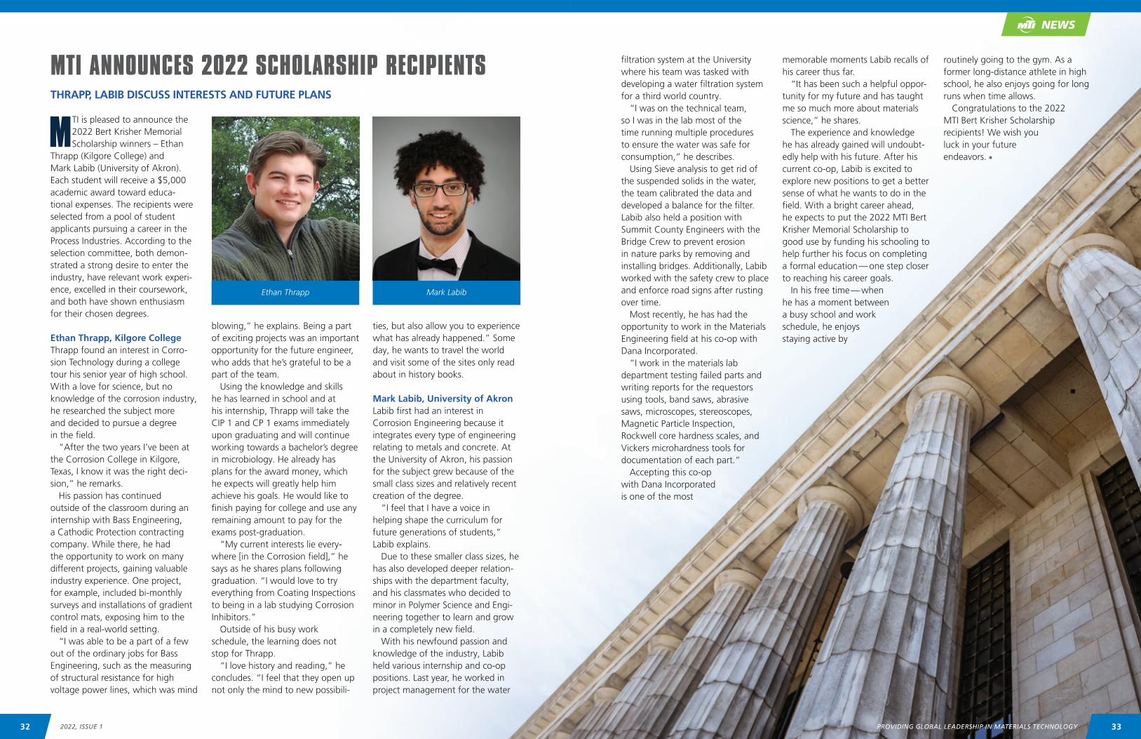
MTI is pleased to announce the 2022 Bert Krisher Memorial Scholarship winners – Ethan
Thrapp (Kilgore College) and Mark Labib (University of Akron). Each student will receive a $5,000 academic award toward educa-tional expenses. The recipients were selected from a pool of student applicants pursuing a career in the Process Industries. According to the selection committee, both demon-strated a strong desire to enter the industry, have relevant work experi-ence, excelled in their coursework, and both have shown enthusiasm for their chosen degrees.
Ethan Thrapp, Kilgore CollegeThrapp found an interest in Corro-sion Technology during a college tour his senior year of high school. With a love for science, but no knowledge of the corrosion industry, he researched the subject more and decided to pursue a degree in the field.
“After the two years I’ve been at the Corrosion College in Kilgore, Texas, I know it was the right deci-sion,” he remarks.
His passion has continued outside of the classroom during an internship with Bass Engineering, a Cathodic Protection contracting company. While there, he had the opportunity to work on many different projects, gaining valuable industry experience. One project, for example, included bi-monthly surveys and installations of gradient control mats, exposing him to the field in a real-world setting.
“I was able to be a part of a few out of the ordinary jobs for Bass Engineering, such as the measuring of structural resistance for high voltage power lines, which was mind
filtration system at the University where his team was tasked with developing a water filtration system for a third world country.
“I was on the technical team, so I was in the lab most of the time running multiple procedures to ensure the water was safe for consumption,” he describes.
Using Sieve analysis to get rid of the suspended solids in the water, the team calibrated the data and developed a balance for the filter. Labib also held a position with Summit County Engineers with the Bridge Crew to prevent erosion in nature parks by removing and installing bridges. Additionally, Labib worked with the safety crew to place and enforce road signs after rusting over time.
Most recently, he has had the opportunity to work in the Materials Engineering field at his co-op with Dana Incorporated.
“I work in the materials lab department testing failed parts and writing reports for the requestors using tools, band saws, abrasive saws, microscopes, stereoscopes, Magnetic Particle Inspection, Rockwell core hardness scales, and Vickers microhardness tools for documentation of each part.”
Accepting this co-op with Dana Incorporated is one of the most
blowing,” he explains. Being a part of exciting projects was an important opportunity for the future engineer, who adds that he’s grateful to be a part of the team.
Using the knowledge and skills he has learned in school and at his internship, Thrapp will take the CIP 1 and CP 1 exams immediately upon graduating and will continue working towards a bachelor’s degree in microbiology. He already has plans for the award money, which he expects will greatly help him achieve his goals. He would like to finish paying for college and use any remaining amount to pay for the exams post-graduation.
“My current interests lie every-where [in the Corrosion field],” he says as he shares plans following graduation. “I would love to try everything from Coating Inspections to being in a lab studying Corrosion Inhibitors.”
Outside of his busy work schedule, the learning does not stop for Thrapp.
“I love history and reading,” he concludes. “I feel that they open up not only the mind to new possibili-
memorable moments Labib recalls of his career thus far.
“It has been such a helpful oppor-tunity for my future and has taught me so much more about materials science,” he shares.
The experience and knowledge he has already gained will undoubt-edly help with his future. After his current co-op, Labib is excited to explore new positions to get a better sense of what he wants to do in the field. With a bright career ahead, he expects to put the 2022 MTI Bert Krisher Memorial Scholarship to good use by funding his schooling to help further his focus on completing a formal education — one step closer to reaching his career goals.
In his free time — when he has a moment between a busy school and work schedule, he enjoys staying active by
ties, but also allow you to experience what has already happened.” Some day, he wants to travel the world and visit some of the sites only read about in history books.
Mark Labib, University of AkronLabib first had an interest in Corrosion Engineering because it integrates every type of engineering relating to metals and concrete. At the University of Akron, his passion for the subject grew because of the small class sizes and relatively recent creation of the degree.
“I feel that I have a voice in helping shape the curriculum for future generations of students,” Labib explains.
Due to these smaller class sizes, he has also developed deeper relation-ships with the department faculty, and his classmates who decided to minor in Polymer Science and Engi-neering together to learn and grow in a completely new field.
With his newfound passion and knowledge of the industry, Labib held various internship and co-op positions. Last year, he worked in project management for the water
routinely going to the gym. As a former long-distance athlete in high school, he also enjoys going for long runs when time allows.
Congratulations to the 2022 MTI Bert Krisher Scholarship recipients! We wish you luck in your future endeavors. n
MTI ANNOUNCES 2022 SCHOLARSHIP RECIPIENTSTHRAPP, LABIB DISCUSS INTERESTS AND FUTURE PLANS
Ethan Thrapp Mark Labib
NEWS
3332 2022, ISSUE 1 PROVIDING GLOBAL LEADERSHIP IN MATERIALS TECHNOLOGY
AVAILABLE FOR PUBLIC DOWNLOAD
Technical Awareness Bulletins published by MTI are brief industry-related topics that have evergreen value and deliver quick answers to potentially save MTI members time and money. The Bulletins Committee develops ideas to produce new topics that will have an impact on MTI members and the industry as well as regularly reviews and
revises past bulletins to keep them up to date with best practices and industry standards.In this issue of CONNECT, MTI is sharing two updated bulletins – No. 25 Heat Transfer Fluids: Uses and Potential
Problems and No. 26 What is Sensitization? Technical Bulletins are available to members by logging in to the member-only Technical Resource Library. They can be downloaded to edit for individual company needs. Publicly released bulletins can be downloaded as PDFs by visiting www.mti-global.org/participate/tac-bulletins.
Technical Awareness Bulletin
Heat Transfer Fluids: Uses and Potential Problems | No. 25
What is a Heat Transfer Fluid? A heat transfer fluid is a substance used to add or remove heat from a process fluid. Cooling water, steam, ethylene glycol (anti-freeze), halogenated hydrocarbons (refrigerants such as R-22 or R-134a), and even air are examples of fluids used to transfer heat to or from a process fluid. However, this bulletin will concern itself only with the organic, proprietary fluids used for specialized applications in the CPI.
The heat transfer fluids discussed in this bulletin are organic compounds, typically aromatics, alkylated aromatics, and some high molecular weight glycols. The differences among these compounds account for the differences in their range of applicability and the potential problems that can take place when using these fluids.
They are used in place of the more commonly used fluids such as steam or cooling water because they have well defined physical and thermal properties that can be more effectively used to control the temperature of the process fluid being heated or cooled. The manufacturers of these fluids typically offer 6-10 different fluids to achieve the user’s heat transfer requirements.
Examples of the trade names for these fluids are Dowtherm, Duratherm, ExxonMobiltherm, Multitherm, Paratherm, and Therminol. References to their web sites are shown at the end of this bulletin.
How and Why are these Fluids Used?These fluids are used to control the temperature of a process fluid in a relatively precise fashion. They may be used to heat or preheat a process fluid, or they can be used to create a controlled cooling of a process fluid that cannot be overcooled.
Although these fluids may have higher initial costs than a steam system, they offer economic and performance advantages, especially at elevated operating temperatures. They do not require higher operating pressures that a steam system requires at higher temperatures. This reduces the installed cost of the system and thereby avoids the risks associated with high pressure systems. In addition, they can be free of corrosion problems that steam and steam condensate systems often suffer.
Heat transfer fluids, unfortunately, do have disadvantages. These disadvantages are primarily the problems that can develop if the system is not properly installed, operated, maintained, and taken offline. These problems are related to corrosion, deterioration of the fluid, leakage, and fire.
Corrosion The fluids typically used in heat transfer applications are generally not at all corrosive to carbon steel, stainless steel, and other alloys typically used to contain them. Three common situations lead to corrosion in heat transfer fluid systems: (1) moisture accumulation, (2) increased fluid acidity as the heat transfer fluid degrades, and (3) fluid contamination. Often, corrosion issues present themselves in the expansion tank, which operates at lower temperatures than the rest of the system. The low temperature of expansion tank may allow condensation of water or corrosive low boilers in the vapor space or the presence of a water layer in the bottom of the expansion tank. Most of these corrosion issues are exasperated during transient operations, such as cleaning or shutdowns, air and/or water can enter the system. When this happens, the heat transfer fluid can become acidic and corrosive. It is critical to develop and use proper procedures that permit transient operations to
be performed when the fluid is cool or under an inert atmosphere so that deterioration from air and/or moisture can be prevented.
Fluid DeteriorationDeterioration will occur when the heat transfer fluid is overheated or contaminated with air and/or moisture. Fluid deterioration may produce coking/sludge, high boilers that affect fluid viscosity, low boilers that accumulate in the expansion tank, and corrosive organic acids, all of which affect the integrity.
Fluid LeakageThe heat transfer fluids have low viscosity, especially at elevated temperatures. This allows them to flow more freely and to provide heat transfer more effectively. However, the low viscosity of heat transfer fluid also increases sealing difficulty. Common leakage locations are flanges, valves, and pumps with packing rings. For this reason, choosing the right seals, packing materials, and gaskets are essential to reliable plant operation.
FireThe heat transfer fluids commonly used are flammable to varying degrees when exposed to air. Accumulated heat transfer fluids can oxidize and increase in temperature. This increase in temperature can lead to a fire thus making the leakage described above a greater hazard than it might appear. Leakage becomes especially important when the insulation used around flanges, pumps, and valves absorbs and accumulates the fluids.
If the fluid is heated by a direct fire furnace, a leak in the furnace can result in a very damaging fire. This makes mechanical integrity on components within the furnace particularly important.
The recommended preventive measures to combat all of these shortcomings are described below.
How to Prevent ProblemsAlthough this bulletin has spoken about the disadvantages of heat transfer fluids, these materials can and indeed are widely and safely used. The preventive measures to be taken are shown below:1. System Cleanliness – All contamination such as
scale, weld spatter, dirt, oil, and coatings must be removed. This will prevent overheating and coking that will interfere with heat transfer.
2. Proper Design – Heat transfer systems must be fabricated from high integrity components (piping, valves, flanges, bolting, gaskets) because of high
operating temperatures, sealing challenges with low viscosity fluids, and consequences of heat transfer fluid leaks. Systems should allow for expansion, exclude air during start-ups and shutdowns as well as during operation. Valves should, where possible, have their stems mounted to the side so that leaks do not run under the insulation. Insulation adjacent to flanges and other potential leak sites should be cellular glass or other non-wicking material so that leaking fluid cannot accumulate. Some plants use non wicking insulation at potential leak sites and then install a barrier ring so that they can use other insulation remote from the potential leak site and still avoid the accumulation of heat transfer fluid.. Pumps should, when possible, be ‘seal-less’ to eliminate a potential leak source.
3. Proper Operation and Maintenance- Good design practices revolve around the need to keep the fluid clean, in the proper temperature range, and free of oxygen and moisture. Good operation and maintenance are simply the implementation of these principles. Periodic fluid condition assessment allows potential integrity and operational issues to be detected before they significantly impact the system.
Before and after start-up, the system should be charged with inert gas or blanketed in some way to stop dirt, oxygen, and water from entering the system. Also, potential leak sites should be uninsulated during start-up so that leaks can be detected. Check the system for leaks on a regular basis especially the catch container at the end of the line running from the relief valve or vent line. The catch tank should be partially filled with water to cool any leaking fluid. If there is a leak, there will be a mist. Be especially cautious if this mist contains heat transfer fluid as it may be highly flammable.
Additional Information• www.dow.com • www.globalspec.com (free registration required) • www.heat-transfer.com • www.multitherm.com • www.paratherm.com • www.therminol.com
Revised June 2021This report is subject to later revision. MTI assumes no responsibility for the contents or for results associated with implementing any recommendations.
35PROVIDING GLOBAL LEADERSHIP IN MATERIALS TECHNOLOGY34 2022, ISSUE 1
MTI TECHNICAL BULLETINS PROVIDE UNIVERSAL INDUSTRY VALUE
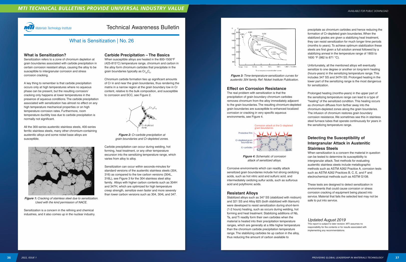
AVAILABLE FOR PUBLIC DOWNLOAD
Technical Awareness Bulletin
What is Sensitization | No. 26
What is Sensitization?Sensitization refers to a zone of chromium depletion at grain boundaries associated with carbide precipitation in certain corrosion resistant alloys, causing the alloy to be susceptible to intergranular corrosion and stress corrosion cracking.
A key thing to remember is that carbide precipitation occurs only at high temperatures where no aqueous phase can be present, but the resulting corrosion/cracking only happens at lower temperatures in the presence of aqueous conditions. The carbide precipitation associated with sensitization has almost no effect on any high temperature mechanical properties or on high temperature corrosion rates. Furthermore, room temperature ductility loss due to carbide precipitation is normally not significant.
All the 300-series austenitic stainless steels, 400-series ferritic stainless steels, many other chromium-containing austenitic alloys and some nickel base alloys are susceptible.
Figure 1: Cracking of stainless steel due to sensitization. Used with the kind permission of NACE.
Sensitization is a concern in the refining and chemical industries, and it also comes up in the nuclear industry.
Carbide Precipitation – The BasicsWhen susceptible alloys are heated in the 800-1500°F (425-815°C) temperature range, chromium and carbon in the alloy form chromium carbides that precipitate in the grain boundaries typically as Cr23C6.
Chromium carbide formation ties up significant amounts of Cr in and near the grain boundaries, thus rendering the matrix in a narrow region at the grain boundary low in Cr content, relative to the bulk composition, and susceptible to corrosion and SCC, see Figure 2.
Figure 2: Cr-carbide precipitation at grain boundaries and Cr-depleted zones.
Carbide precipitation can occur during welding, hot forming, heat treatment, or any other temperature excursion into the sensitizing temperature range, which varies from alloy to alloy.
Sensitization can occur within seconds-minutes for standard versions of the austenitic stainless steels (304, 316) as compared to the low carbon versions (304L, 316L), see Figure 3 for the 304 stainless steel alloy family. Alloys with higher carbon contents such as 304H and 347H, which are optimized for high temperature creep strength, sensitize even faster and more severely than lower carbon versions such as 304, 304L and 347.
Figure 3: Time-temperature-sensitization curves for austenitic 304 family. Ref: Nickel Institute Publication.
Effect on Corrosion ResistanceThe real problem with sensitization is that the precipitation of grain boundary chromium carbides removes chromium from the alloy immediately adjacent to the grain boundaries. The resulting chromium-depleted grain boundaries are susceptible to enhanced localized corrosion or cracking in very specific aqueous environments, see Figure 4.
Figure 4: Schematic of corrosion attack of sensitized alloys.
Corrosive environments which can readily attack sensitized grain boundaries include hot strong oxidizing acids, such as hot nitric acid and sulfuric acid, and intermediately oxidizing sulfur acids, such as sulfurous acid and polythionic acids.
Resistant Alloys Stabilized alloys such as 347 SS (stabilized with niobium) and 321 SS and Alloy 825 (both stabilized with titanium) were developed to resist sensitization during short-term (1-2 hours) heating, such as occurs during welding, hot forming and heat treatment. Stabilizing additions of Nb, Ta, and Ti readily form their own carbides when the material is heated into their precipitation temperature ranges, which are generally at a little higher temperature than the chromium carbide precipitation temperature range. The stabilizing carbides tie up carbon in the alloy, thus reducing the amount of carbon available to
precipitate as chromium carbides and hence reducing the formation of Cr-depleted grain boundaries. When the stabilized grades are given a stabilizing heat treatment, they can resist sensitization for much longer time periods (months to years). To achieve optimum stabilization these steels are first given a full solution anneal followed by a stabilizing anneal in the temperature range of 1800 to 1600 °F (982 to 871 °C).
Unfortunately, all the mentioned alloys will eventually sensitize to one degree or another on long-term heating (hours-years) in the sensitizing temperature range. This includes 347 SS and 347H SS. Prolonged heating in the lower part of the sensitizing range is the most dangerous for sensitization.
Prolonged heating (months-years) in the upper part of the sensitizing temperature range can lead to a type of “healing” of the sensitized condition. This healing occurs as chromium diffuses from farther away into the chromium-depleted zones along the grain boundaries. The infusion of chromium restores grain boundary corrosion resistance. We sometimes see this in stainless steel furnace tubes that operate continuously for years in the sensitizing temperature range.
Detecting the Susceptibility of Intergranular Attack in Austenitic Stainless SteelsWhen sensitization is a concern the material in question can be tested to determine its susceptibility to intergranular attack. Test methods for evaluating austenitic stainless steels include metallographic methods such as ASTM A262 Practice A, corrosion tests such as ASTM A262 Practices B, C, E, and F and electrochemical methods such as ASTM G108.
These tests are designed to detect sensitization in environments that could cause corrosion or stress corrosion cracking of equipment being placed into service. Material that fails the selected test may not be safe to put into service.
Updated August 2019This report is subject to later revision. MTI assumes no responsibility for the contents or for results associated with implementing any recommendations.
37PROVIDING GLOBAL LEADERSHIP IN MATERIALS TECHNOLOGY36 2022, ISSUE 1
MTI TECHNICAL BULLETINS PROVIDE UNIVERSAL INDUSTRY VALUE

MARKETPLACE
Tubular Heat Exchangers | Pressure Vessels | Columns | Piping Systems | Miscellaneous Fabrications
Titanium | Tantalum | Zirconium | Niobium | Hastelloy | High Nickel Alloys | Duplex Stainless Steels
Trusted By Industry Around the GlobeFor Corrosion-Resistant Process EquipmentTITAN METAL FABRICATORS custom designs and manufactures highly corrosion-resistant equipment – heat exchangers, vessels, piping columns, reactors – to suit the needs of industry:
�Chemical �Steel Pickling �Solar Power
�Geothermal �Oil & Gas �Bio Mass
�Pharmaceutical �Nuclear Power �Mining
�Water Desalination �Petrochemical � Liquified Natural Gas
TITAN’s reputation for exceptional fabrication using Titanium,Tantalum, Duplex Stainless Steels, Hastelloy, Zirconium, and High Nickel Alloys is established in its vast experience, proven capabilities, and high degree of personalized customer service. The company’s team of engineers, manufacturing professionals, quality control engineers, and skilled support group are dedicated to producing one thing. Excellence.
Worldwide Manufacturing Locations USA – CHINA – INDIA
Corporate Headquarters352 Balboa Circle
Camarillo, CA 93012USA
(805) 487-5050www.titanmf.com
Reach Materials Processing
Industry Engineers and Experts Worldwide
Contact Kirk Richardson for Pricing, Additional Information or to Reserve
Ad Space: [email protected]
SECURE YOUR 2022 MTI CONNECT MARKETPLACE ADS NOW
P.A.Inc.isleadingthewaywithsolutionsforspecialtyalloypipingrequirements.
6626 Gulf Freeway, Houston – Texas 77087 | USAPhone: (800) 460-7473 | +1 713-570-4900 | Fax: +1 713-570-4950Email: [email protected] | www.PAInc.com
Alloy20
Alloy200
Alloy400
Alloy600,601,625
Alloy800H/HT,803,825
AlloyC-276
Stainless304H
2205Duplex
Titanium
P IPE , F I TT INGS AND FLANGES
Backorders?
LateDeliveries?
Inaccuratedocumentation?
Specificationnon-conformanceissues?
Materialnotprotectedforshipment?
TIMEFORACHANGETOP.A.INC.
P.A.Inc.isleadingtheway
Specificationnon-conformanceissues?
Materialnotprotectedforshipment?
39PROVIDING GLOBAL LEADERSHIP IN MATERIALS TECHNOLOGY38 2022, ISSUE 1
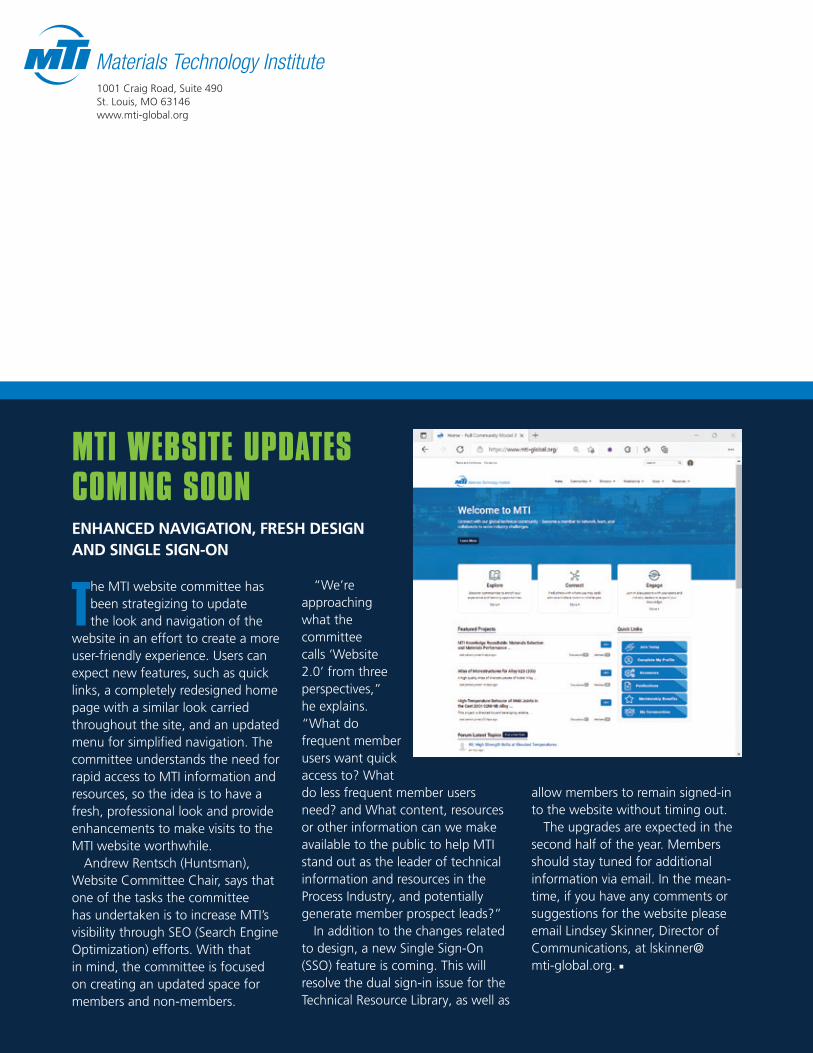
1001 Craig Road, Suite 490 St. Louis, MO 63146www.mti-global.org
The MTI website committee has been strategizing to update the look and navigation of the
website in an effort to create a more user-friendly experience. Users can expect new features, such as quick links, a completely redesigned home page with a similar look carried throughout the site, and an updated menu for simplified navigation. The committee understands the need for rapid access to MTI information and resources, so the idea is to have a fresh, professional look and provide enhancements to make visits to the MTI website worthwhile.
Andrew Rentsch (Huntsman), Website Committee Chair, says that one of the tasks the committee has undertaken is to increase MTI’s visibility through SEO (Search Engine Optimization) efforts. With that in mind, the committee is focused on creating an updated space for members and non-members.
“We’re approaching what the committee calls ‘Website 2.0’ from three perspectives,” he explains. “What do frequent member users want quick access to? What do less frequent member users need? and What content, resources or other information can we make available to the public to help MTI stand out as the leader of technical information and resources in the Process Industry, and potentially generate member prospect leads?”
In addition to the changes related to design, a new Single Sign-On (SSO) feature is coming. This will resolve the dual sign-in issue for the Technical Resource Library, as well as
MTI WEBSITE UPDATES COMING SOONENHANCED NAVIGATION, FRESH DESIGN AND SINGLE SIGN-ON
allow members to remain signed-in to the website without timing out.
The upgrades are expected in the second half of the year. Members should stay tuned for additional information via email. In the mean-time, if you have any comments or suggestions for the website please email Lindsey Skinner, Director of Communications, at [email protected]. n