Embed Size (px)
Citation preview
Mississippi Department of Transportation
REQUEST FOR PROPOSALS
A DESIGN-BUILD PROJECT
Proposed Improvements to State Route 9 From US 278/State Route 6 near Pontotoc
To US 78 near Sherman Pontotoc County, Mississippi
Project No. STP-2833-00(004) / 105094-101000
February 10, 2011
1
February 10, 2011 Project No. STP-2833-00(004) / 105094-101000
TABLE OF CONTENTS Page Number
I. PURPOSE OF REQUEST FOR PROPOSALS .............................................................1
II. OVERVIEW ......................................................................................................................1
Project Goals ...................................................................................................................... 1 Project Information ............................................................................................................ 1 Proposal Stipend ................................................................................................................ 3
III. GENERAL INSTRUCTIONS .........................................................................................3
Pre-Proposal Meeting ......................................................................................................... 3 Questions............................................................................................................................ 3 Proposal Submittal ............................................................................................................. 5
IV. PROJECT SCOPE ............................................................................................................6 V. PROPOSAL DEVELOPMENT ......................................................................................7
Volume 1 – Technical Proposal ......................................................................................... 8 Volume 2 – Contract Price Proposal ................................................................................ 12
VI. ESCROW PROPOSAL DOCUMENTS .......................................................................12 VII. EVALUATION OF PROPOSALS ................................................................................12 VIII. CRITERIA FOR SCORING .........................................................................................12
Compliance with the RFP Requirements ......................................................................... 13 Management Approach .................................................................................................... 13 Technical Solutions .......................................................................................................... 13 Quality Management Plan ................................................................................................ 13 Schedule ........................................................................................................................... 14 Selection of Contractor .................................................................................................... 14
IX. GENERAL INFORMATION ........................................................................................15 X. MILESTONE SCHEDULE ...........................................................................................16
APPENDIX Form - Request for Technical Approach Modification
Form – Sample Schedule of Values The Following are Contract Documents and are available on the Project Web Site (www.GoMDOT.com):
Section 904 Section 906 Section 907 Technical Requirements
Section 905 Section 902 and Exhibits Section 903
2
Page 1 of 16
February 10, 2010 Project No. STP-2833-00(004) / 105094-101000
I. PURPOSE OF REQUEST FOR PROPOSALS The purpose of this Request for Proposals (“RFP”) is to select a Proposer to perform the Project services described in this RFP. “Proposer,” as used here, includes a firm or firms, partnership, joint venture, or other legal entity, which has been requested by the Mississippi Transportation Commission (“Commission”) to submit a Proposal in response to this RFP. The “Contractor”, as used here, is defined as the selected Proposer with whom the Contract is executed. The Commission is requesting a Contract Price, Best Value Proposal. It is not the intention of the Commission to receive complete detailed Project analysis and design prior to the selection of a Proposer and the later execution of a Contract. Rather, the response to this RFP shall provide sufficient information to be evaluated in accordance with the specified process and criteria. The Proposal shall be specific enough on assumptions used in its preparation so as to provide the basis for determining a final Contract.
II. OVERVIEW Project Goals The following are the Commission’s goals for the Project: • Anticipated issuance of Notice to Proceed for the Contract is as specified in Section
X, Milestone Schedule; • Final Completion of all Work as documented by the Full Release of Maintenance for
all Work on the Project, as soon as possible. The Target Date for completion is listed in Section X, Milestone Schedule. The Final Completion Date shall be as described in the Contractor’s Schedule Certificate.
• Design and construction of reasonably maintainable, easily inspectable, long lasting bridges and roadways;
• Design and construction of a Project of the highest quality that is durable; • A safe Project for all parties involved and the public; • A Project that is sensitive to the environment, and the community; Project Information The proposed Project consists of the construction of a four-lane highway on new alignment, including the construction of a new interchanges and frontage roads, as further defined in the Environmental Assessment/FONSI document prepared by MDOT for this project. A copy of the Environmental Assessment/FONSI document is available on the MDOT website (http://www.gomdot.com/Home/Projects/DesignBuild/Home.aspx).
3
Page 2 of 16
February 10, 2010 Project No. STP-2833-00(004) / 105094-101000
Status of Right of Way Acquisition and Utility Relocation MDOT intends to purchase all of the required right-of-way and have all of the utilities relocated prior to the Notice to Proceed (Construction) as provided in Section X, Milestone Schedule. Construction of the Project will be within MDOT right-of-way and Notice to Proceed (Construction) may be issued earlier depending on the availability of right-of-way and potential site access. During the Procurement, MDOT will provide Proposers with an updated status of right-of-way acquisition and utility relocation. Status of Plan Development Bridge Plans - MDOT has provided the 60% bridge design plans and bridge plan quantities to the shortlisted Proposers. MDOT has contracted with Neel-Schaffer, Inc. to complete the 100% bridge design plans. The Proposer may provide final bridge plans if the Proposer has a more economical design. Any changes to the bridge plans will require that the Contractor provide revised plans, design calculations, hydraulic analysis, bridge scour computations and supporting data, stamped by a professional engineer licensed to practice in the State of Mississippi and submittal of them to MDOT for review (as per the Technical Requirements). MDOT is scheduled to release the 100% bridge design plans to the shortlisted Proposers as provided in the Section X, Milestone Schedule. Roadway Plans – MDOT has provided 60% roadway design plans (including all GEOPAK database files and digital terrain models) to the shortlisted Proposers. Proposers will have the opportunity to propose design alternatives that provide equal or better quality and/or maintenance/durability. The Contractor will be required to submit, prior to initiation of construction, final roadway design plans that have been reviewed by MDOT and Released for Construction (as per the Technical Requirements). The Contractor will also be responsible for the development of Erosion Control plans in compliance with the current regulations for storm water runoff/erosion control for construction sites. Status of Environment Permits All environmental permits within the right-of-way will be acquired by MDOT based on the potential design provided by MDOT. Compliance with all permits will be the responsibility of the Contractor. The Contractor will be responsible for acquiring and complying with any new or additional permits for any proposed project modifications. Any new or revised permits pursued by the Contractor must be obtained in MDOT’s name.
The Contractor will be responsible for completing the final design as noted above, developing an approved erosion control plan, construction inspection and testing of materials for quality control, and determining how to construct the project within the allowable timeframes and within all state and federal regulations. If the Contractor proposes a design and/or method of construction that triggers additional regulatory
4
Page 3 of 16
February 10, 2010 Project No. STP-2833-00(004) / 105094-101000
requirements, then the Contractor will be responsible for compliance with all such additional state and federal regulations. The Commission may utilize a separate Firm to provide MDOT with Project Management Assistance and independent Quality Assurance verification. The submittal of a Proposal in response to this RFP, with all required signatures, shall constitute the Proposer’s agreement to enter into a contract with the Commission for the completion of the Project under the terms set forth in the Contract. The terms of the Contract are not negotiable. The Commission values a partnering approach on projects and as such this Project will require regular Partnering Sessions. The contract for this Project contains a Disadvantaged Business Enterprise (DBE) goal of eight percent (8%) of the Contract Price. The Proposer shall submit a DBE committal sheet (OCR 485) with their response to this RFP. Proposal Stipend A stipend in the amount of $75,000.00 will be paid to each responsive Proposer not selected as the successful Proposer. The Proposer must request payment for the stipend within 60 days of the Project Award. Upon acceptance of payment of the stipend, the responsive Proposer agrees that the entire Proposal shall become the exclusive property of the Commission.
III. GENERAL INSTRUCTIONS Pre-Proposal Meeting A mandatory pre-Proposal meeting is scheduled for the date as specified in Section X, Milestone Schedules, in the Commission Room on the first floor of the MDOT Building, 401 North West Street, Jackson, MS 39201. Shortlisted Proposers are required to have a representative at the pre-Proposal meeting in order for their Proposal to be considered. The purpose of the meeting is to review the information provided in the RFP and to receive questions from the Proposers. Questions Proposers are encouraged to submit written questions at least two days prior to the mandatory Pre-Proposal Meeting. At the mandatory Pre-Proposal Meeting questions will be received from all representatives of the shortlisted Proposers. Written or verbal questions will be accepted at the meeting. Only the Project Director may submit questions or request clarifications relating to the RFP after the Pre-Proposal Meeting. These inquiries must be in writing and must be
5

Page 4 of 16
February 10, 2010 Project No. STP-2833-00(004) / 105094-101000
received by the Commission on the date and time as specified in Section X, Milestone Schedule. RFP questions shall be directed in writing to:
Chief Engineer Mississippi Department of Transportation Post Office Box 1850 Jackson, Mississippi 39215-1850
Or by e-mail to: [email protected] The list of questions received and MDOT’s written responses to these questions and any applicable addenda will be posted on the MDOT web page (www.gomdot.com). MDOT will notify the Project Director of the availability of applicable addenda via e-mail by close of business on the date as specified in Section X, Milestone Schedule or as soon as possible thereafter. Proposers are encouraged to check the website often for posting of new information. Proposers shall not rely on any responses about the RFP except written responses to questions submitted in writing in accordance with the RFP. No requests for additional information or clarification to any other MDOT office, consultant, or employee will be considered. The Commission will not be responsible for and the Proposer shall not rely on any oral or other exchange of information that occurs outside of the official process for written questions and answers specified herein. Pre-Proposal Technical Approach Modification Submittals
MDOT has made available to the Proposers information and electronic plans prepared by Neel-Schaffer to provide an overview to the Proposers of the Project, and to provide an inventory of all currently available information regarding the original design.
In order to facilitate a communicative process with MDOT and to provide a forum for Technical Approach Modifications, MDOT encourages the Proposer to suggest technical alternatives to the Project provided in the informational current plans. All proposed Technical Approach Modifications and alternatives will be required to meet the current design standards. This forum is also established to aide in uncovering opportunities for Proposers to reduce Project Costs while providing an equal or better condition. All technical questions must be submitted and will be responded to in accordance with the procedure explained below.
Specific requests for each Technical Approach Modification must be submitted by the Proposer’s designated contact and received by MDOT by the date and time set forth in Section X, Milestone Schedule utilizing Forms provided with this RFP.
6
Page 5 of 16
February 10, 2010 Project No. STP-2833-00(004) / 105094-101000
MDOT will provide responses to each request as a posting to the project website within ten (10) business days following receipt of the request. Each Proposer will be limited to the submission of a maximum of five (5) requests per week for consideration by MDOT. Each request shall contain only a single modification.
Submission of the request for each Technical Approach Modification must include the following:
1. A narrative description of the proposed modification and the proposed change to the technical requirements.
2. The locations where the proposed modification will be used on the Project.
3. A conceptual drawing of the proposed modification.
4. An explanation of why the proposed modification is of equal to or better quality.
5. A description of potential impacts or changes to the long term maintenance requirements as a result of the proposed modification.
The Proposer shall submit electronic copies of its desired Technical Approach Modification to the following e-mail address: [email protected].
MDOT will not post the Proposer’s completed Form or the request to the project website. MDOT will only post the response (either Yes or No) to each request for a Technical Approach Modification that MDOT determines to be validly submitted. Each Technical Approach Modification for which MDOT intends to post a response will be assigned a number by MDOT and MDOT will convey that number to the Proposer’s designated contact who submitted such request. Proposal Submittal Volume 1 – Technical Proposals must be received by the date and time specified in Section X, Milestone Schedule. Deliver ten (10) copies of the Volume 1 Proposal, sequentially numbered on the lower right hand cover sheet from 1 to 10, and one (1) CD containing the proposals in one (1) to five (5) PDF files to:
Contract Administration Engineer Mississippi Department of Transportation 401 North West Street P.O. Box 1850 Jackson, Mississippi 39215-1850 Phone: (601) 359-7730 Fax: (601) 359-7732
7

Page 6 of 16
February 10, 2010 Project No. STP-2833-00(004) / 105094-101000
Volume 2 – Contract Price Proposal must be received by the date and time specified in Section X, Milestone Schedule. All Responders/Proposers must visibly mark as “CONFIDENTIAL” each part of their submission that they consider to contain confidential and/or proprietary information. All submittals will be subject to disclosure in accordance with the Mississippi Public Records Act, Miss. Code Ann. § 25-61-1, et seq.
IV. PROJECT SCOPE The scope of work for this Project will include, but not be limited to, the following Design work items: Design:
• Erosion Control Plans and Erosion Control Monitoring • Final Roadway Design and Plan Preparation • Structure Design and Supporting Documentation Preparation • Traffic Control Plan • Permanent Signing Plans • Environmental Coordination • Roadway and Bridge Deck Drainage Design • Geotechnical Investigation, Testing and Report Preparation • QC for Design • Surveying
If the Proposer chooses to design different bridge structures or to modify the bridge structures as shown in the plans provided by MDOT, then the scope of services will also include, but not be limited to the following:
• Final Bridge Superstructure and Substructure Design and Plan Preparation • Bridge Hydraulic and Scour Design • Geotechnical Investigation, Testing and Report Preparation
Design of roadways and roadway features shall meet all appropriate AASHTO Policy on Geometric Design of Highways and Streets (latest edition), Manual on Uniform Traffic Control Devices (latest edition) (MUTCD) and MDOT design criteria as modified by the RFP. Microstation and Geopak shall be used in the preparation of CADD files. Structures and appurtenances will be designed, fabricated and constructed in accordance with MDOT design criteria specified in the RFP and the latest editions of AASHTO LRFD Bridge Design Specifications; AASHTO Guide Specifications for LRFD Seismic Bridge Design; MDOT Bridge Design Manual; AASHTO Standard Specifications for Structural Supports for Highway Signs, Luminaries and Traffic Signals; AASHTO/AWS D1.5M/D1.5 Bridge Welding Code; MDOT Standard Specifications for Road and Bridge
8
Page 7 of 16
February 10, 2010 Project No. STP-2833-00(004) / 105094-101000
Construction; AASHTO LRFD Bridge Construction Specifications; and AASHTO Manual on Subsurface Investigations. The scope of work for this Project will include, but not limited to, the following construction work items: Construction:
• Clearing and grubbing with debris removal and disposal • All necessary roadway and bridge work • Surveying • Drainage • Environmental coordination • Erosion and sediment control work items • Traffic control • Project management • Construction management • QC for Construction, including inspection and testing of materials
Construction shall comply with the MDOT Standard Specifications for Road And Bridge Construction 2004 Edition as modified by the RFP to accommodate specific Design/Build requirements, Manual on Uniform Traffic Control Devices (latest edition), MDOT Standard Drawings, any Special Provisions, Notice to Proposers, current MDOT publications including, but not limited to, the Construction Manual, the Materials Division Inspection, Testing and Certification Manual, and existing AASHTO, ASTM, or MDOT Test Methods. The Project Scope shall be defined in Section 904 – NTB No. 2618-D1-1 DB (Project Scope). The Proposer shall define completion schedule as indicated on the Contractor’s Schedule Certificate. The Proposer shall submit a proposed schedule and preliminary construction work plan demonstrating how major portions of the Work will be completed, the number of crews anticipated, shifts, length of work week for the Work proposed to be completed. The Proposed schedule shall include a realistic date for the Final Completion of proposed Contract Work. The Proposer will be required to certify its proposed schedule and demonstrate how it is achievable and realistic for performance of the Work.
V. PROPOSAL DEVELOPMENT The Commission is requesting a Contract Price, Best Value Proposal that includes a Project schedule commitment for the Scope of Work included in this RFP. The price and schedule shall be guaranteed by the Proposer for a minimum of 60 days after the date identified for submission of Contract Price Proposals in Section X. Responses to the RFP shall:
9
Page 8 of 16
February 10, 2010 Project No. STP-2833-00(004) / 105094-101000
• Describe the Proposal in sufficient detail that the Commission may determine its cost, scope and intent.
• Describe any assumptions used in developing cost and schedule components of the Proposal.
• Provide a breakdown of Project costs and assumptions used in determination by work phase (design, construction, Project management, construction management, and quality control (QC)).
• Identify the proposed schedule for implementing the Project, including the total number of calendar days from Notice to Proceed necessary to complete the Project.
• Describe assurances of timely completion of the Project. • Describe how Project quality will be achieved.
The Proposer is solely responsible for submitting a Proposal that meets the Requirements of the RFP. Any Proposal not meeting the requirements of this RFP, as solely determined by MDOT, may be considered non-responsive. Assumptions that are not in compliance with the RFP will not relieve the Proposer of the Requirements of the RFP. The submitted Proposal is evaluated for general conformance with the RFP requirements for the purpose of selecting the Best Value Proposal. While the Proposal becomes a part of the Contract documents, the Contractor’s Release for Construction (RFC) plans and designs must meet all the RFP Technical Requirements. In order that evaluation can be accomplished efficiently, the Proposal shall be prepared in separate volumes, as applicable, in the following sequence: Volume 1 – Technical Proposal (Marked and Sealed Separately) The document will not be longer than 50 single-sided double-spaced 8.5 inch by 11 inch pages typed on one side only, excluding appendices. Minimum font size shall be 10 point. Proposals shall use cross-referencing to reduce repetition in explaining the proposed Project. The Technical Proposal will contain the following information:
1. Cover Introductory Letter – Proposer may provide a cover letter that provides introductory information for the proposal. The Cover Letter should be limited to no more than two (2) pages and will not count toward the 50 page limit for the remainder of the Technical Proposal.
2. Executive Summary – Provide a one page summary of the overall proposal
summarizing the benefits provided in the proposal. 3. Project Scope – Describe in detail the proposed horizontal alignment and profile
including details that demonstrate Project concepts and understanding. Proposers shall submit plan/profile sheets showing the entire project layout including bridge locations, intersection layouts, and intersection geometrics. Proposers shall show the current MDOT alignment and profile (as provided in the 60% Preliminary
10
Page 9 of 16
February 10, 2010 Project No. STP-2833-00(004) / 105094-101000
Design Package) on the plan/profile sheets in “grayed-out” or “ghosted” lines so that the evaluation team can clearly see where the proposed alignment has changed from the 60% Preliminary Design. The proposal should provide some explanation as to why the plan is different from the 60% Preliminary Design (such proposed cost savings, design preference, constructability, etc.). Also, if a Technical Approach Modification (TAM) has been submitted and approved, reference the appropriate TAM that applies to a specific change from the 60% Preliminary Design.
In addition to the plan/profile sheets, the Proposer shall provide typical section sheets detailing the pavement sections proposed for the project. Proposer should provide a brief narrative regarding the pavement design and provide preliminary calculations for the pavement design which may be placed in an appendix that will not count toward the page limitation. For each bridge site where the Proposer intends to submit revised bridge plans, the Proposer shall provide in this submittal a list of bridges that will be re-designed, why a redesign is being considered, and a proposed bridge plan and elevation, bridge sections, foundation layout and other such details. For each bridge site that the Proposer proposes to use the bridge plans prepared by MDOT the Proposer shall submit the first three (3) drawings of the MDOT bridge plans with the proposal. All plan submittals shall be in a separate appendix to the Technical Proposal. The Plan Sheets, which can be 11 inch by 17 inch in size, will not count toward the page limitation.
4. Management Approach – Describe the overall approach to the Project including
a construction staging plan. Management approach shall demonstrate a plan for mobilizing key personnel, equipment and materials and how the Proposer intends to ensure that these are available to meet the Project schedule. Proposer shall identify anticipated major risks and present a plan to manage those risks. Proposer shall demonstrate a plan to manage document control and sound, proven management techniques for design management, construction management, and the integration of both for this Design-Build Project. Proposer shall describe activities that will address environmental concerns.
5. Preliminary Construction Work Plan – Provide preliminary plan for
accomplishing the proposed Work including the crews, shifts, workweeks for constructing the roadways, foundations, substructure, and superstructure. Material and equipment resources shall be addressed. Describe how the construction will be phased and the proposed plan to meet the desired schedule.
6. Key Individuals –Proposer shall include a copy of the organization chart
provided in the Statement of Qualifications and shall state that there are no modifications to Key Individuals as submitted in the Statement of Qualifications.
11
Page 10 of 16
February 10, 2010 Project No. STP-2833-00(004) / 105094-101000
If personnel changes are anticipated, then Proposer shall resubmit all Key Individual information as defined in the Request for Qualifications (RFQ) and shall present a justification for the change. Any modification will require prior MDOT approval.
Modifications to the Proposer’s Team or Key Individuals and other personnel listed in the Proposer Statement of Qualifications are discouraged. MDOT will not approve requests for modification without justification. Examples of justification include death of a team member, changes in employment status, bankruptcy, inability to perform, organizational conflict of interest, or other such significant cause. In order to secure MDOT’s approval prior to the award of the contract, a written request shall be forwarded to the person and address as shown in the Section III General Instructions, Proposal Submittal of this RFP. The request shall include: a) the nature of the desired change, b) the reason for the desired change, and c) a statement of how the desired change will meet the required qualifications for the position/responsibility. No such modification will be made without prior MDOT approval.
7. Organizational Conflict of Interest - The Proposer’s attention is directed to 23
CFR Section 636 Subpart A and in particular to Subsection 636.116 regarding organizational conflicts of interest. Subsection 636.103 defines “organizational conflict of interest” as follows:
Organizational conflict of interest means that because of other activities or relationships with other persons, a person is unable or potentially unable to render impartial assistance or advice to the owner, or the person’s objectivity in performing the contract work is or might be otherwise impaired, or a person has an unfair competitive advantage.
Proposer shall provide information concerning potential organizational conflicts of interest and disclose all relevant facts concerning any past, present or currently planned interests which may present an organizational conflict of interest. Proposer shall state how its interests or those of its chief executives, directors, Key Individuals for this Project, or any proposed consultant, contractor or subcontractor may result, or could be viewed as, an organizational conflict of interest. The Proposer is prohibited from receiving any advice or discussing any aspect relating to the Project or the procurement of the Project with any person or entity with an organizational conflict of interest, including, but not limited to URS Corporation, and any affiliates of URS Corporation or Neel-Schaffer, Inc. and any affiliates of Neel-Schaffer, Inc. Such persons and entities are prohibited from participating in a Proposer organization relating to the Project. The Proposer agrees that, if after award, an organizational conflict of interest is discovered, the Proposer must make an immediate and full written disclosure to
12
Page 11 of 16
February 10, 2010 Project No. STP-2833-00(004) / 105094-101000
MDOT that includes a description of the action that the Proposer has taken or proposes to take to avoid or mitigate such conflicts. If an organizational conflict of interest is determined to exist, MDOT may, at its discretion, cancel the Design-Build contract for the Project. If the Proposer was aware of an organizational conflict of interest prior to the award of the contract and did not disclose the conflict to MDOT, then MDOT may terminate the contract for default.
8. Technical Solutions – Proposer shall describe technical solutions that offer advantages to MDOT. Such technical solutions may include items which ease construction, address schedule or budget saving techniques, improve long term durability, improve long term maintenance, or other.
• Include the proposed solutions to manage the disposal of soils on the
project site that have a volume change greater than 60% and less than 85%.
• Address an approach to manage potential water quality discharge and overall approach to maintain compliance with water quality standards.
9. Quality Management Plan – Proposer shall demonstrate the approach to quality
management including design and construction quality management and the integration of both for this Design-Build Project. Proposer shall demonstrate controls that will be put in place to ensure overall quality of the design and how the Proposer will monitor conformance to the plans and material testing. Proposer shall provide how the team will resolve and document issues of non-conformance with the design, construction or material testing. The QC personnel responsible for quality control acceptance shall not be employees of the Contractor.
10. Schedule Summary – Proposer shall submit a summary schedule demonstrating
how the Contractor plans to complete the Project within its prescribed schedule for completion. The summary schedule shall include dates for planned start and finish of design, procurement of major items, mobilization, installation of erosion control and erosion monitoring equipment, roadway preparation, drainage structure installation, foundation installation, superstructure installation, pavement, etc. The summary schedule shall also include the total number of calendar days from the Notice to Proceed to Final Completion. The proposed number of calendar days for Final Completion shall be as shown on the Contractor’s Schedule Certificate.
Proposer shall submit a Schedule of Values detailing all quantities required for the project utilizing standard MDOT pay items. Note: Schedule of Values including prices to be submitted in Volume 2 submittal. The Schedule of Values may be submitted in the Required Forms and Certifications portion on the proposal. A sample Schedule of Values is attached to this RFP.
11. Required Forms and Certifications – The Proposer shall provide the following
completed and/or executed documents: • Contractor’s Schedule Certificate.
13
Page 12 of 16
February 10, 2010 Project No. STP-2833-00(004) / 105094-101000
• Legal Entity Forms. • Schedule of Values (quantities only).
These may be placed in an appendix and will not count against the page limitation.
Volume 2 – Contract Price Proposal (Marked and Sealed Separately as per 907.102.09) This Contract Price Proposal shall contain the following information:
1. All pages of Section 905 including acknowledgment of addenda and bid sheets
completed and signed. 2. A certified check, cashier’s check or Proposer’s Bid Bond payable to the State of
Mississippi in the principle amount of 5% of the bid that includes the project number, executed by the Proposer and signed or countersigned by a qualified Mississippi resident agent or qualified nonresident agent for the Surety with Power of Attorney attached.
3. An executed Equal Opportunity Clause Certification. 4. A signed list of all Firms submitting quotes (OCR-485). 5. The Certification regarding Non-Collusion, Debarment and Suspension, etc.
executed in duplicate. 6. A completed Schedule of Values detailing the quantities (using standard MDOT
pay items), unit prices, and extensions summing to the total value of the bid. The information obtained under this RFP of the successful Proposer shall become the exclusive property of the Commission without restriction or limitation on its use. The Commission shall have unrestricted authority to publish, disclose, distribute, or otherwise use in whole or in part any reports, data, or other materials prepared under this RFP by the successful Proposer. The Commission shall retain ownership of all plans, specifications, and related documents.
VI. ESCROW PROPOSAL DOCUMENTS Proposer is required to escrow all Proposal documents in accordance with Special Provision 907-103.06 within two (2) business days of Notification of Award. Failure to escrow documents in the allotted time may result in rescission of the award and/or forfeiture of the Proposer’s bid bond.
VII. EVALUATION OF PROPOSALS A Proposal Review Committee (“Committee”) will be appointed to evaluate the Technical Proposals on behalf of the Commission. In addition, MDOT may assemble a group of advisory members, that may include the Federal Highway Administration (FHWA), and others with various areas of expertise.
VIII. CRITERIA FOR SCORING
14

Page 13 of 16
February 10, 2010 Project No. STP-2833-00(004) / 105094-101000
The Commission has developed criteria for use in evaluating and scoring the Proposals. The Committee will use these criteria to develop a numerical score of each Proposal. Scoring will be based on a point system. The Committee will evaluate the Proposals based on meeting the technical evaluation criteria as shown below. The maximum points for each evaluation criteria will be as follows:
• Compliance with the RFP Requirements – 20 • Management Approach - 20 • Technical Solutions - 20 • Quality Management Plan – 20 • Schedule – 20
The Committee will consider the following minimum criteria: Compliance with the RFP Requirements
• How well has the Proposer complied with the design criteria? • Has the Proposer provided a description of the proposed modifications to the 60%
Preliminary Design Plans and included any applicable TAMs? Management Approach
• What is the overall Project Management Organization? How will this organization be responsive to the Commission, MDOT and public concerns/issues?
• Is the overall Project Management Plan clear and concise, not overly cumbersome and easily implementable? Has this plan been used effectively elsewhere?
• How well does the Proposal address partnering and its implementation? Technical Solutions
• Are the solutions proposed to design/construct the project based on sound principals?
• How well has maintenance and durability been considered in the proposed design?
• How has the Proposer considered innovative solutions for technical consideration and how effective could these innovations be?
• Does the Proposer present a workable solution to manage soils on the project site that have a volume change greater than 60% and less than 85%?
• Has the Proposer adequately addressed compliance with the Stormwater quality requirements, monitoring, and response?
Quality Management Plan
• What Project controls will be put in place to ensure overall Project quality (both design and construction) and how effective will these controls be?
• What assurances have been provided to verify Project quality and how effective will these assurances be?
15
Page 14 of 16
February 10, 2010 Project No. STP-2833-00(004) / 105094-101000
• Does the Proposer identify and plan on utilizing an MDOT approved lab for the tests being performed?
• How effectively will non-conformance aspects of the Project be handled?
Schedule • Does the Proposer specify the number of calendar days to complete the Project? • How well does the Proposal contain adequate assurances that the entire Project
will be completed on time? • Does the Proposer meet or beat the Commission’s desired date for completion? • How effectively does the Proposer’s schedule take into account possible schedule
impacts? • How effectively does the Proposer clearly describe the plan for delivery of the
Work? o How well does the Contractor demonstrate adequate resources to
accomplish the Work in accordance with the Proposed Schedule? o How well does the Contractor specifically outline the sources for delivery
of materials including the piling, beams, concrete and rebar? o How effective are any innovative solution proposed for the construction
schedule? • How well does the Proposer’s Schedule of Values (quantities) represent the
proposed project? The individual Technical Score by each reviewer will be the summation of the Technical Scores achieved for each of the above selection criteria. The Proposer’s Total Technical Score (maximum of 100 points) will be the summation of the individual Technical Scores from each reviewer divided by the number of reviewers. SELECTION OF CONTRACTOR The Proposal Review Committee will score the Proposals according to the evaluation criteria. Upon approval of MDOT Executive Director and immediately prior to the opening of Volume 2, MDOT will notify each Proposer of all Technical Scores. MDOT will then publicly open each of the Contract Price Proposals, all in accordance with the Milestone Schedule. The Best Value Proposal shall be determined by the following formula: Best Value Proposal = (Part A + Part B) [1 + (Technical Score / 100)] Where: Part A = Contract Price Proposal. Part B = (Number of calendar days from the Notice to Proceed up to and including Final Completion set forth by the Proposer – 549 (which is equal to the number of calendar days from July 1, 2011 to December 31, 2012)) x $50,000.
16
Page 15 of 16
February 10, 2010 Project No. STP-2833-00(004) / 105094-101000
In the event of a tie for the Best Value Proposal as determined by the above formula, the Proposer with the lowest Contract Price Proposal will be selected. The Commission intends to award and offer a Contract to the Proposer submitting the Best Value Proposal with the lowest score as determined above. However, if the parties are unable to execute a contract, MDOT may offer a contract to the Proposer that submitted the Best Value Proposal with the next lowest score, and so on, until an agreement is reached.
IX. GENERAL INFORMATION The Commission reserves the right to terminate evaluation of one or more of the Proposals if it is determined to be in its best interest. The Commission reserves the right, at its sole discretion, to proceed no further with this RFP process, and/or to re-advertise in another public solicitation. The Commission reserves the right to reject any and all Proposals and/or to discontinue contract execution with any party at any time prior to final contract execution. The Commission reserves the right to request or obtain additional information about any and all Proposals. In the event the Commission is unable to execute a Memorandum of Agreement with the Mississippi Development Authority for funding for this project, the Commission reserves the right to not award the contract. In this event, stipends will be awarded to Proposers who submit a responsive Proposal and request such stipend within 60 calendar days of notification. Except for the stipend defined in Section II, the Commission assumes no liability and will not reimburse cost incurred by firms, whether selected or not, in developing Proposals or in contract execution. Modification to the Proposer’s Team or key individuals within Teams is discouraged. MDOT will not approve requests for modification of the Proposer’s Team without justification. After award, in order to secure MDOT approval, the procedures as defined in the Technical Requirements Section 2.6 Key Personnel shall be followed. The Best Value Proposer shall submit an additional 20 sets of Volume #1 proposals within 10 days after contract award. The successful Proposer will be required to furnish a Section 903 Performance and Payment Bond, Certificates of Insurance, and W9 no later than 10 days after Contract Award.
17
Page 16 of 16
February 10, 2010 Project No. STP-2833-00(004) / 105094-101000
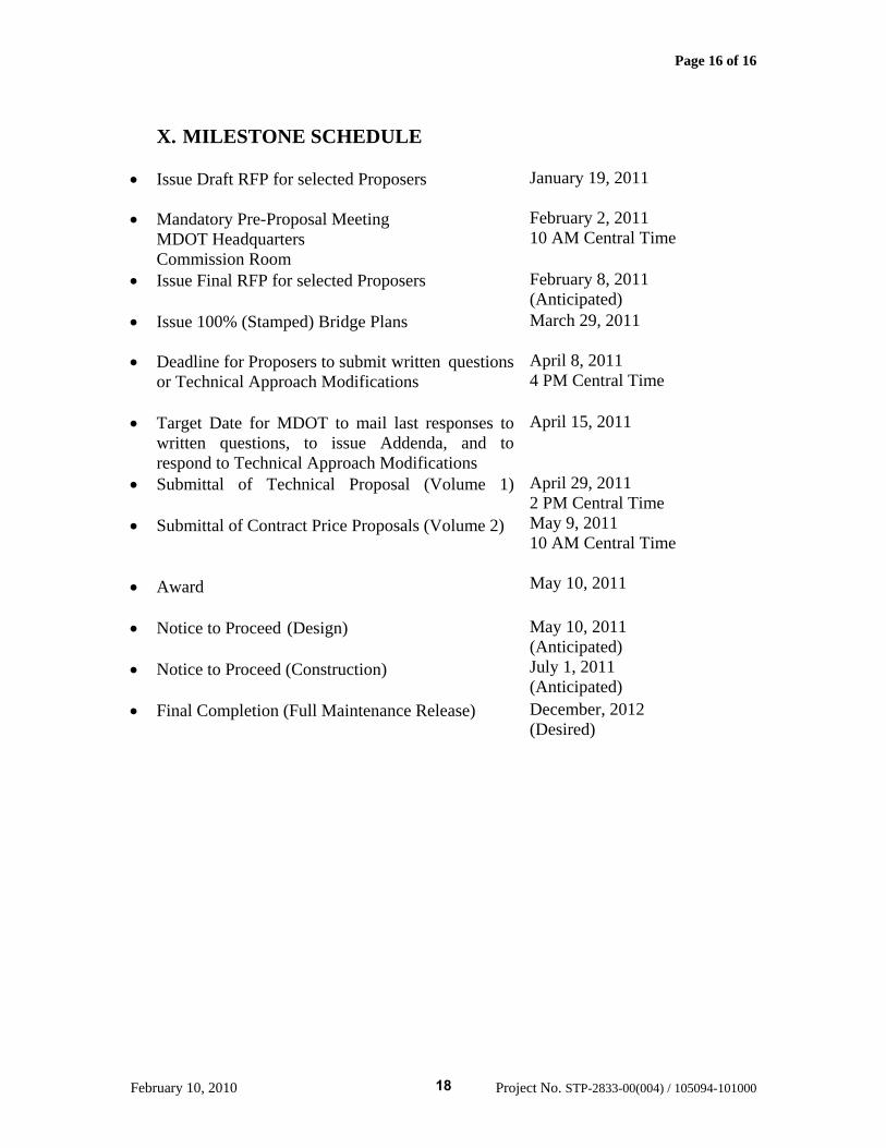
X. MILESTONE SCHEDULE
• Issue Draft RFP for selected Proposers January 19, 2011
• Mandatory Pre-Proposal Meeting
MDOT Headquarters Commission Room
February 2, 2011 10 AM Central Time
• Issue Final RFP for selected Proposers
February 8, 2011 (Anticipated)
• Issue 100% (Stamped) Bridge Plans March 29, 2011
• Deadline for Proposers to submit written questions or Technical Approach Modifications
April 8, 2011 4 PM Central Time
• Target Date for MDOT to mail last responses to written questions, to issue Addenda, and to respond to Technical Approach Modifications
April 15, 2011
• Submittal of Technical Proposal (Volume 1)
• Submittal of Contract Price Proposals (Volume 2) • Award
April 29, 2011 2 PM Central Time May 9, 2011 10 AM Central Time May 10, 2011
• Notice to Proceed (Design) • Notice to Proceed (Construction)
May 10, 2011 (Anticipated) July 1, 2011 (Anticipated)
• Final Completion (Full Maintenance Release)
December, 2012 (Desired)
18
February 10, 2010 Project No. STP-2833-00(004) / 105094-101000
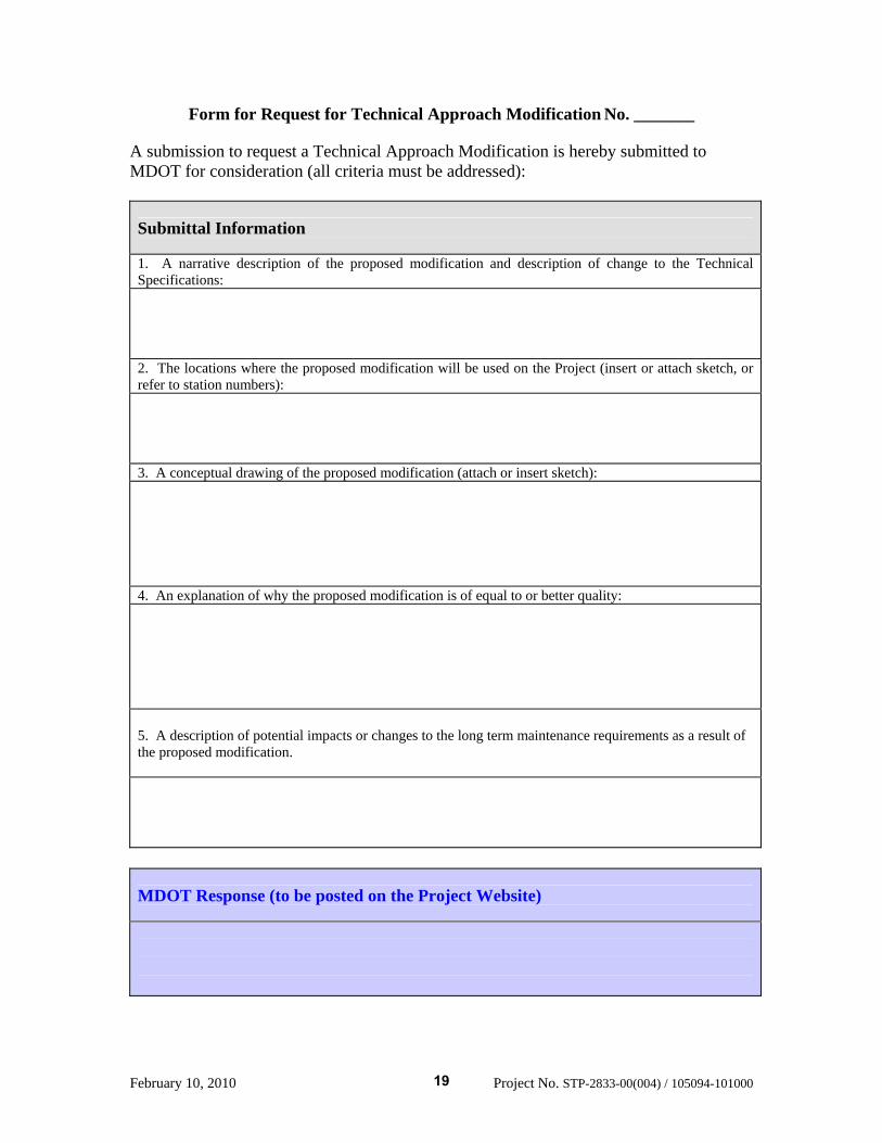
Form for Request for Technical Approach Modification No. _______
A submission to request a Technical Approach Modification is hereby submitted to MDOT for consideration (all criteria must be addressed):
Submittal Information
1. A narrative description of the proposed modification and description of change to the Technical Specifications:
2. The locations where the proposed modification will be used on the Project (insert or attach sketch, or refer to station numbers):
3. A conceptual drawing of the proposed modification (attach or insert sketch):
4. An explanation of why the proposed modification is of equal to or better quality:
5. A description of potential impacts or changes to the long term maintenance requirements as a result of the proposed modification.
MDOT Response (to be posted on the Project Website)
19
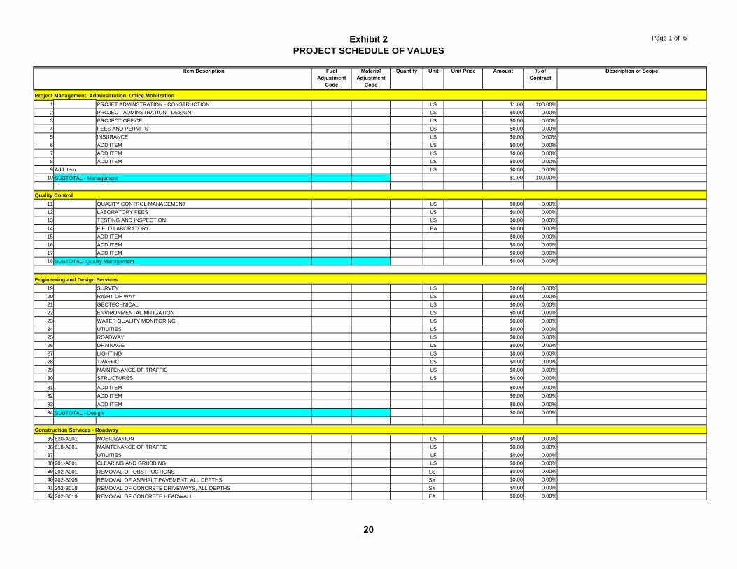
Exhibit 2PROJECT SCHEDULE OF VALUES
Page 1 of 6
Item Description Fuel Adjustment
Code
Material Adjustment
Code
Quantity Unit Unit Price Amount % of Contract
Description of Scope
1 PROJET ADMINSTRATION - CONSTRUCTION LS $1.00 100.00%2 PROJECT ADMINSTRATION - DESIGN LS $0.00 0.00%3 PROJECT OFFICE LS $0.00 0.00%4 FEES AND PERMITS LS $0.00 0.00%5 INSURANCE LS $0.00 0.00%6 ADD ITEM LS $0.00 0.00%7 ADD ITEM LS $0.00 0.00%8 ADD ITEM LS $0.00 0.00%9 Add Item LS $0.00 0.00%
10 $1.00 100.00%
11 QUALITY CONTROL MANAGEMENT LS $0.00 0.00%12 LABORATORY FEES LS $0.00 0.00%13 TESTING AND INSPECTION LS $0.00 0.00%14 FIELD LABORATORY EA $0.00 0.00%15 ADD ITEM $0.00 0.00%16 ADD ITEM $0.00 0.00%17 ADD ITEM $0.00 0.00%18 $0.00 0.00%
19 SURVEY LS $0.00 0.00%20 RIGHT OF WAY LS $0.00 0.00%21 GEOTECHNICAL LS $0.00 0.00%22 ENVIRONMENTAL MITIGATION LS $0.00 0.00%23 WATER QUALITY MONITORING LS $0.00 0.00%24 UTILITIES LS $0.00 0.00%25 ROADWAY LS $0.00 0.00%26 DRAINAGE LS $0.00 0.00%27 LIGHTING LS $0.00 0.00%28 TRAFFIC LS $0.00 0.00%29 MAINTENANCE OF TRAFFIC LS $0.00 0.00%30 STRUCTURES LS $0.00 0.00%
31 ADD ITEM $0.00 0.00%32 ADD ITEM $0.00 0.00%33 ADD ITEM $0.00 0.00%34 $0.00 0.00%
35 620-A001 MOBILIZATION LS $0.00 0.00%36 618-A001 MAINTENANCE OF TRAFFIC LS $0.00 0.00%37 UTILITIES LF $0.00 0.00%38 201-A001 CLEARING AND GRUBBING LS $0.00 0.00%39 202-A001 REMOVAL OF OBSTRUCTIONS LS $0.00 0.00%40 202-B005 REMOVAL OF ASPHALT PAVEMENT, ALL DEPTHS SY $0.00 0.00%41 202-B018 REMOVAL OF CONCRETE DRIVEWAYS, ALL DEPTHS SY $0.00 0.00%42 202-B019 REMOVAL OF CONCRETE HEADWALL EA $0.00 0.00%
Quality Control
Project Management, Adminsitration, Office Moblization
Construction Services - Roadway
SUBTOTAL - Management
SUBTOTAL- Quality Management
SUBTOTAL - Design
Engineering and Design Services
20
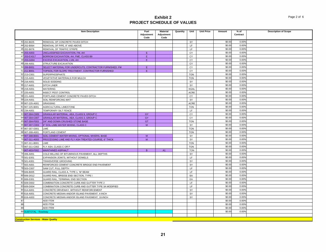
Exhibit 2PROJECT SCHEDULE OF VALUES
Page 2 of 6
Item Description Fuel Adjustment
Code
Material Adjustment
Code
Quantity Unit Unit Price Amount % of Contract
Description of Scope
43 202-B025 REMOVAL OF CONCRETE PAVED DITCH SY $0.00 0.00%44 202-B064 REMOVAL OF PIPE, 8" AND ABOVE LF $0.00 0.00%45 202-B076 REMOVAL OF TRAFFIC STRIPE LF $0.00 0.00%46 203-A003 UNCLASSIFIED EXCAVATION, FM, AH E CY $0.00 0.00%47 203-EX017 BORROW EXCAVATION, AH, FME, CLASS B9 E CY $0.00 0.00%48 203-G004 EXCESS EXCAVATION, LVM, AH E CY $0.00 0.00%49 206-A001 STRUCTURE EXCAVATION CY $0.00 0.00%50 206-B001 SELECT MATERIAL FOR UNDERCUTS, CONTRACTOR FURNISHED, FM E CY $0.00 0.00%51 211-B001 TOPSOIL FOR SLOPE TREATMENT, CONTRACTOR FURNISHED E CY $0.00 0.00%52 213-C001 SUPERPHOSPHATE TON $0.00 0.00%53 215-A001 VEGETATIVE MATERIALS FOR MULCH TON $0.00 0.00%54 216-A001 SOLID SODDING SY $0.00 0.00%55 217-A001 DITCH LINER SY $0.00 0.00%56 219-A001 WATERING KGAL $0.00 0.00%57 220-A001 INSECT PEST CONTROL ACRE $0.00 0.00%58 221-A001 PORTLAND CEMENT CONCRETE PAVED DITCH CY $0.00 0.00%59 224-A001 SOIL REINFORCING MAT SY $0.00 0.00%60 907-225-A001 GRASSING ACRE $0.00 0.00%61 907-225-B001 AGRICULTURAL LIMESTONE TON $0.00 0.00%62 234-A001 TEMPORARY SILT FENCE LF $0.00 0.00%63 907-304-C005 GRANULAR MATERIAL, AEA, CLASS 9, GROUP C GY CY $0.00 0.00%64 907-304-C007 GRANULAR MATERIAL, AEA, CLASS 3, GROUP C GY CY $0.00 0.00%65 907-304-F003 3/4" AND DOWN CRUSHED STONE BASE GT TON $0.00 0.00%66 907-307-C003 6" SOIL-LIME-WATER MIXING, CLASS C M SY $0.00 0.00%67 907-307-D001 LIME TON $0.00 0.00%68 907-308-A001 PORTLAND CEMENT TON $0.00 0.00%69 907-308-B001 SOIL-CEMENT-WATER MIXING, OPTIONAL MIXERS, BASE M SY $0.00 0.00%70 907-311-A003 PROCESSING LIME AND FLY ASH TREATED COURSE, 6" THICK M SY $0.00 0.00%71 907-311-B001 LIME TON $0.00 0.00%72 907-311-C002 FLY ASH, CLASS C OR F TON $0.00 0.00%73 907-403-F002 MAINTAINED ASPHALT B A1 TON $0.00 0.00%74 406-A001 COLD MILLING OF BITUMINOUS PAVEMENT, ALL DEPTHS SY $0.00 0.00%75 501-E001 EXPANSION JOINTS, WITHOUT DOWELS LF $0.00 0.00%76 501-K001 TRANSVERSE GROOVING SY $0.00 0.00%77 502-A001 REINFORCED CEMENT CONCRETE BRIDGE END PAVEMENT SY $0.00 0.00%78 503-C007 SAW CUT, FULL DEPTH LF $0.00 0.00%79 606-B005 GUARD RAIL, CLASS A, TYPE 1, 'W' BEAM LF $0.00 0.00%80 606-D012 GUARD RAIL, BRIDGE END SECTION, TYPE I EA $0.00 0.00%81 606-E001 GUARD RAIL, TERMINAL END SECTION EA $0.00 0.00%82 609-D002 COMBINATION CONCRETE CURB AND GUTTER TYPE 2 LF $0.00 0.00%83 609-D004 COMBINATION CONCRETE CURB AND GUTTER TYPE 3A MODIFIED LF $0.00 0.00%84 614-A001 CONCRETE DRIVEWAY, WITHOUT REINFORCEMENT SY $0.00 0.00%85 616-A001 CONCRETE MEDIAN AND/OR ISLAND PAVEMENT, 4-INCH SY $0.00 0.00%86 616-A003 CONCRETE MEDIAN AND/OR ISLAND PAVEMENT, 10-INCH SY $0.00 0.00%87 ADD ITEM $0.00 0.00%88 ADD ITEM $0.00 0.00%89 ADD ITEM $0.00 0.00%90 $0.00 0.00%
Construction Services - Water Quality
SUBTOTAL - Roadway
21
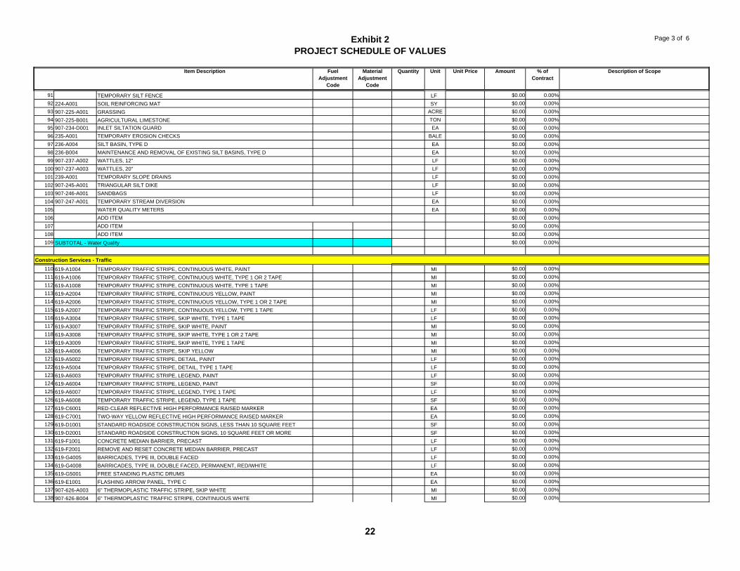
Exhibit 2PROJECT SCHEDULE OF VALUES
Page 3 of 6
Item Description Fuel Adjustment
Code
Material Adjustment
Code
Quantity Unit Unit Price Amount % of Contract
Description of Scope
91 TEMPORARY SILT FENCE LF $0.00 0.00%92 224-A001 SOIL REINFORCING MAT SY $0.00 0.00%93 907-225-A001 GRASSING ACRE $0.00 0.00%94 907-225-B001 AGRICULTURAL LIMESTONE TON $0.00 0.00%95 907-234-D001 INLET SILTATION GUARD EA $0.00 0.00%96 235-A001 TEMPORARY EROSION CHECKS BALE $0.00 0.00%97 236-A004 SILT BASIN, TYPE D EA $0.00 0.00%98 236-B004 MAINTENANCE AND REMOVAL OF EXISTING SILT BASINS, TYPE D EA $0.00 0.00%99 907-237-A002 WATTLES, 12" LF $0.00 0.00%
100 907-237-A003 WATTLES, 20" LF $0.00 0.00%101 239-A001 TEMPORARY SLOPE DRAINS LF $0.00 0.00%102 907-245-A001 TRIANGULAR SILT DIKE LF $0.00 0.00%103 907-246-A001 SANDBAGS LF $0.00 0.00%104 907-247-A001 TEMPORARY STREAM DIVERSION EA $0.00 0.00%105 WATER QUALITY METERS EA $0.00 0.00%106 ADD ITEM $0.00 0.00%107 ADD ITEM $0.00 0.00%108 ADD ITEM $0.00 0.00%109 $0.00 0.00%
110 619-A1004 TEMPORARY TRAFFIC STRIPE, CONTINUOUS WHITE, PAINT MI $0.00 0.00%111 619-A1006 TEMPORARY TRAFFIC STRIPE, CONTINUOUS WHITE, TYPE 1 OR 2 TAPE MI $0.00 0.00%112 619-A1008 TEMPORARY TRAFFIC STRIPE, CONTINUOUS WHITE, TYPE 1 TAPE MI $0.00 0.00%113 619-A2004 TEMPORARY TRAFFIC STRIPE, CONTINUOUS YELLOW, PAINT MI $0.00 0.00%114 619-A2006 TEMPORARY TRAFFIC STRIPE, CONTINUOUS YELLOW, TYPE 1 OR 2 TAPE MI $0.00 0.00%115 619-A2007 TEMPORARY TRAFFIC STRIPE, CONTINUOUS YELLOW, TYPE 1 TAPE LF $0.00 0.00%116 619-A3004 TEMPORARY TRAFFIC STRIPE, SKIP WHITE, TYPE 1 TAPE LF $0.00 0.00%117 619-A3007 TEMPORARY TRAFFIC STRIPE, SKIP WHITE, PAINT MI $0.00 0.00%118 619-A3008 TEMPORARY TRAFFIC STRIPE, SKIP WHITE, TYPE 1 OR 2 TAPE MI $0.00 0.00%119 619-A3009 TEMPORARY TRAFFIC STRIPE, SKIP WHITE, TYPE 1 TAPE MI $0.00 0.00%120 619-A4006 TEMPORARY TRAFFIC STRIPE, SKIP YELLOW MI $0.00 0.00%121 619-A5002 TEMPORARY TRAFFIC STRIPE, DETAIL, PAINT LF $0.00 0.00%122 619-A5004 TEMPORARY TRAFFIC STRIPE, DETAIL, TYPE 1 TAPE LF $0.00 0.00%123 619-A6003 TEMPORARY TRAFFIC STRIPE, LEGEND, PAINT LF $0.00 0.00%124 619-A6004 TEMPORARY TRAFFIC STRIPE, LEGEND, PAINT SF $0.00 0.00%125 619-A6007 TEMPORARY TRAFFIC STRIPE, LEGEND, TYPE 1 TAPE LF $0.00 0.00%126 619-A6008 TEMPORARY TRAFFIC STRIPE, LEGEND, TYPE 1 TAPE SF $0.00 0.00%127 619-C6001 RED-CLEAR REFLECTIVE HIGH PERFORMANCE RAISED MARKER EA $0.00 0.00%128 619-C7001 TWO-WAY YELLOW REFLECTIVE HIGH PERFORMANCE RAISED MARKER EA $0.00 0.00%129 619-D1001 STANDARD ROADSIDE CONSTRUCTION SIGNS, LESS THAN 10 SQUARE FEET SF $0.00 0.00%130 619-D2001 STANDARD ROADSIDE CONSTRUCTION SIGNS, 10 SQUARE FEET OR MORE SF $0.00 0.00%131 619-F1001 CONCRETE MEDIAN BARRIER, PRECAST LF $0.00 0.00%132 619-F2001 REMOVE AND RESET CONCRETE MEDIAN BARRIER, PRECAST LF $0.00 0.00%133 619-G4005 BARRICADES, TYPE III, DOUBLE FACED LF $0.00 0.00%134 619-G4008 BARRICADES, TYPE III, DOUBLE FACED, PERMANENT, RED/WHITE LF $0.00 0.00%135 619-G5001 FREE STANDING PLASTIC DRUMS EA $0.00 0.00%136 619-E1001 FLASHING ARROW PANEL, TYPE C EA $0.00 0.00%137 907-626-A003 6" THERMOPLASTIC TRAFFIC STRIPE, SKIP WHITE MI $0.00 0.00%138 907-626-B004 6" THERMOPLASTIC TRAFFIC STRIPE, CONTINUOUS WHITE MI $0.00 0.00%
SUBTOTAL - Water Quality
Construction Services - Traffic
22
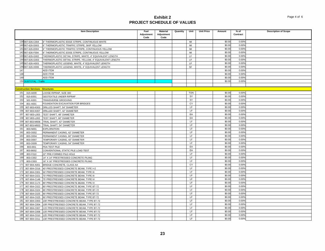
Exhibit 2PROJECT SCHEDULE OF VALUES
Page 4 of 6
Item Description Fuel Adjustment
Code
Material Adjustment
Code
Quantity Unit Unit Price Amount % of Contract
Description of Scope
139 907-626-C004 6" THERMOPLASTIC EDGE STRIPE, CONTINUOUS WHITE MI $0.00 0.00%140 907-626-D003 6" THERMOPLASTIC TRAFFIC STRIPE, SKIP YELLOW MI $0.00 0.00%141 907-626-E004 6" THERMOPLASTIC TRAFFIC STRIPE, CONTINUOUS YELLOW MI $0.00 0.00%142 907-626-F004 6" THERMOPLASTIC EDGE STRIPE, CONTINUOUS YELLOW MI $0.00 0.00%143 907-626-G002 THERMOPLASTIC DETAIL STRIPE, WHITE, 4" EQUIVALENT LENGTH LF $0.00 0.00%144 907-626-G003 THERMOPLASTIC DETAIL STRIPE, YELLOW, 4" EQUIVALENT LENGTH LF $0.00 0.00%145 907-626-H003 THERMOPLASTIC LEGEND, WHITE, 4" EQUIVALENT LENGTH LF $0.00 0.00%146 907-626-H006 THERMOPLASTIC LEGEND, WHITE, 4" EQUIVALENT LENGTH SF $0.00 0.00%147 ADD ITEM $0.00 0.00%148 ADD ITEM $0.00 0.00%149 ADD ITEM $0.00 0.00%150 $0.00 0.00%
151 815-A009 LOOSE RIPRAP, SIZE 300 TON $0.00 0.00%152 815-E001 GEOTEXTILE UNDER RIPRAP SY $0.00 0.00%153 501-K001 TRANSVERSE GROOVING SY $0.00 0.00%154 801-A001 FOUNDATION EXCAVATION FOR BRIDGES CY $0.00 0.00%155 907-803-K003 DRILLED SHAFT, 54" DIAMETER LF $0.00 0.00%156 907-803-K007 DRILLED SHAFT, 42" DIAMETER LF $0.00 0.00%157 907-803-L003 TEST SHAFT, 48" DIAMETER EA $0.00 0.00%158 907-803-L002 TEST SHAFT, 60" DIAMETER EA $0.00 0.00%159 907-803-M006 TRIAL SHAFT, 42" DIAMETER LF $0.00 0.00%160 907-803-M003 TRIAL SHAFT, 54" DIAMETER LF $0.00 0.00%161 803-N001 EXPLORATION LF $0.00 0.00%162 803-O002 PERMANENT CASING, 42" DIAMETER LF $0.00 0.00%163 803-O004 PERMANENT CASING, 60" DIAMETER LF $0.00 0.00%164 803-O007 TEMPORARY CASING, 42" DIAMETER LF $0.00 0.00%165 803-O009 TEMPORARY CASING, 54" DIAMETER LF $0.00 0.00%166 803-I001 PDA TEST PILE EA $0.00 0.00%167 803-B002 CONVENTIONAL STATIC PILE LOAD TEST EA $0.00 0.00%168 803-F010 22" PRE-FORMED PILE HOLE LF $0.00 0.00%169 803-C002 14" X 14" PRESTRESSED CONCRETE PILING LF $0.00 0.00%170 803-C003 16" X 16" PRESTRESSED CONCRETE PILING LF $0.00 0.00%171 907-804-A001 BRIDGE CONCRETE, CLASS AA CY $0.00 0.00%172 907-804-C016 40' PRESTRESSED CONCRETE BEAM, TYPE I+2 LF $0.00 0.00%173 907-804-C001 50' PRESTRESSED CONCRETE BEAM, TYPE III LF $0.00 0.00%174 907-804-C021 70' PRESTRESSED CONCRETE BEAM, TYPE III LF $0.00 0.00%175 907-804-C148 75' PRESTRESSED CONCRETE BEAM, TYPE IV LF $0.00 0.00%176 907-804-C174 80' PRESTRESSED CONCRETE BEAM, TYPE IV LF $0.00 0.00%177 907-804-C022 80' PRESTRESSED CONCRETE BEAM, TYPE BT-72 LF $0.00 0.00%178 907-804-C024 85' PRESTRESSED CONCRETE BEAM, TYPE BT-72 LF $0.00 0.00%179 907-804-C025 90' PRESTRESSED CONCRETE BEAM, TYPE BT-72 LF $0.00 0.00%180 907-804-C025 90' PRESTRESSED CONCRETE BEAM, TYPE BT-72 LF $0.00 0.00%181 907-804-C003 100' PRESTRESSED CONCRETE BEAM, TYPE BT-72 LF $0.00 0.00%182 907-804-C004 109' PRESTRESSED CONCRETE BEAM, TYPE BT-72 LF $0.00 0.00%183 907-804-C007 115' PRESTRESSED CONCRETE BEAM, TYPE BT-72 LF $0.00 0.00%184 907-804-C008 120' PRESTRESSED CONCRETE BEAM, TYPE BT-72 LF $0.00 0.00%185 907-804-C010 125' PRESTRESSED CONCRETE BEAM, TYPE BT-72 LF $0.00 0.00%186 907-804-C011 130' PRESTRESSED CONCRETE BEAM, TYPE BT-72 LF $0.00 0.00%
Construction Services - Structures
SUBTOTAL - Traffic
23
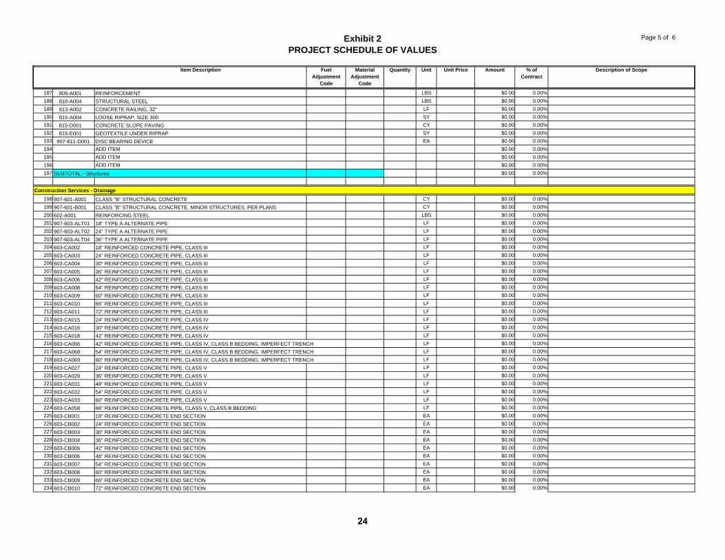
Exhibit 2PROJECT SCHEDULE OF VALUES
Page 5 of 6
Item Description Fuel Adjustment
Code
Material Adjustment
Code
Quantity Unit Unit Price Amount % of Contract
Description of Scope
187 805-A001 REINFORCEMENT LBS $0.00 0.00%188 810-A004 STRUCTURAL STEEL LBS $0.00 0.00%189 813-A002 CONCRETE RAILING, 32" LF $0.00 0.00%190 815-A004 LOOSE RIPRAP, SIZE 300 SY $0.00 0.00%191 815-D001 CONCRETE SLOPE PAVING CY $0.00 0.00%192 815-E001 GEOTEXTILE UNDER RIPRAP SY $0.00 0.00%193 907-811-D001 DISC BEARING DEVICE EA $0.00 0.00%194 ADD ITEM $0.00 0.00%195 ADD ITEM $0.00 0.00%196 ADD ITEM $0.00 0.00%197 $0.00 0.00%
198 907-601-A001 CLASS "B" STRUCTURAL CONCRETE CY $0.00 0.00%199 907-601-B001 CLASS "B" STRUCTURAL CONCRETE, MINOR STRUCTURES, PER PLANS CY $0.00 0.00%200 602-A001 REINFORCING STEEL LBS $0.00 0.00%201 907-603-ALT01 18" TYPE A ALTERNATE PIPE LF $0.00 0.00%202 907-603-ALT02 24" TYPE A ALTERNATE PIPE LF $0.00 0.00%203 907-603-ALT04 36" TYPE A ALTERNATE PIPE LF $0.00 0.00%204 603-CA002 18" REINFORCED CONCRETE PIPE, CLASS III LF $0.00 0.00%205 603-CA003 24" REINFORCED CONCRETE PIPE, CLASS III LF $0.00 0.00%206 603-CA004 30" REINFORCED CONCRETE PIPE, CLASS III LF $0.00 0.00%207 603-CA005 36" REINFORCED CONCRETE PIPE, CLASS III LF $0.00 0.00%208 603-CA006 42" REINFORCED CONCRETE PIPE, CLASS III LF $0.00 0.00%209 603-CA008 54" REINFORCED CONCRETE PIPE, CLASS III LF $0.00 0.00%210 603-CA009 60" REINFORCED CONCRETE PIPE, CLASS III LF $0.00 0.00%211 603-CA010 66" REINFORCED CONCRETE PIPE, CLASS III LF $0.00 0.00%212 603-CA011 72" REINFORCED CONCRETE PIPE, CLASS III LF $0.00 0.00%213 603-CA015 24" REINFORCED CONCRETE PIPE, CLASS IV LF $0.00 0.00%214 603-CA016 30" REINFORCED CONCRETE PIPE, CLASS IV LF $0.00 0.00%215 603-CA018 42" REINFORCED CONCRETE PIPE, CLASS IV LF $0.00 0.00%216 603-CA066 42" REINFORCED CONCRETE PIPE, CLASS IV, CLASS B BEDDING, IMPERFECT TRENCH LF $0.00 0.00%217 603-CA068 54" REINFORCED CONCRETE PIPE, CLASS IV, CLASS B BEDDING, IMPERFECT TRENCH LF $0.00 0.00%218 603-CA069 60" REINFORCED CONCRETE PIPE, CLASS IV, CLASS B BEDDING, IMPERFECT TRENCH LF $0.00 0.00%219 603-CA027 24" REINFORCED CONCRETE PIPE, CLASS V LF $0.00 0.00%220 603-CA029 36" REINFORCED CONCRETE PIPE, CLASS V LF $0.00 0.00%221 603-CA031 48" REINFORCED CONCRETE PIPE, CLASS V LF $0.00 0.00%222 603-CA032 54" REINFORCED CONCRETE PIPE, CLASS V LF $0.00 0.00%223 603-CA033 60" REINFORCED CONCRETE PIPE, CLASS V LF $0.00 0.00%224 603-CA058 66" REINFORCED CONCRETE PIPE, CLASS V, CLASS B BEDDING LF $0.00 0.00%225 603-CB001 18" REINFORCED CONCRETE END SECTION EA $0.00 0.00%226 603-CB002 24" REINFORCED CONCRETE END SECTION EA $0.00 0.00%227 603-CB003 30" REINFORCED CONCRETE END SECTION EA $0.00 0.00%228 603-CB004 36" REINFORCED CONCRETE END SECTION EA $0.00 0.00%229 603-CB005 42" REINFORCED CONCRETE END SECTION EA $0.00 0.00%230 603-CB006 48" REINFORCED CONCRETE END SECTION EA $0.00 0.00%231 603-CB007 54" REINFORCED CONCRETE END SECTION EA $0.00 0.00%232 603-CB008 60" REINFORCED CONCRETE END SECTION EA $0.00 0.00%233 603-CB009 66" REINFORCED CONCRETE END SECTION EA $0.00 0.00%234 603-CB010 72" REINFORCED CONCRETE END SECTION EA $0.00 0.00%
Construction Services - Drainage
SUBTOTAL - Structures
24
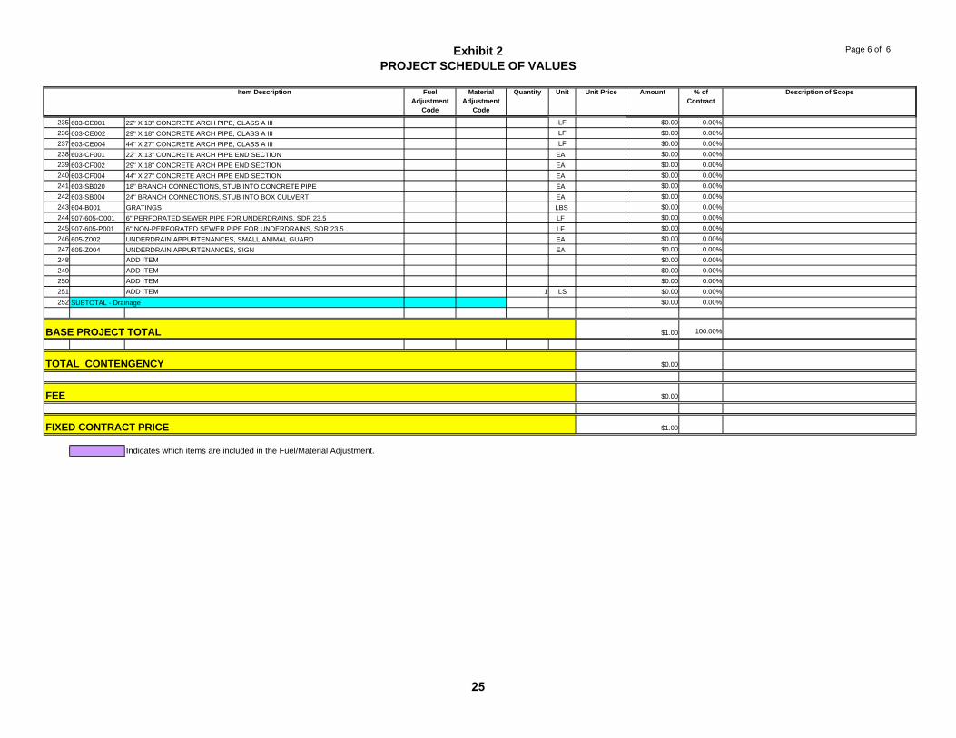
Exhibit 2PROJECT SCHEDULE OF VALUES
Page 6 of 6
Item Description Fuel Adjustment
Code
Material Adjustment
Code
Quantity Unit Unit Price Amount % of Contract
Description of Scope
235 603-CE001 22" X 13" CONCRETE ARCH PIPE, CLASS A III LF $0.00 0.00%236 603-CE002 29" X 18" CONCRETE ARCH PIPE, CLASS A III LF $0.00 0.00%237 603-CE004 44" X 27" CONCRETE ARCH PIPE, CLASS A III LF $0.00 0.00%238 603-CF001 22" X 13" CONCRETE ARCH PIPE END SECTION EA $0.00 0.00%239 603-CF002 29" X 18" CONCRETE ARCH PIPE END SECTION EA $0.00 0.00%240 603-CF004 44" X 27" CONCRETE ARCH PIPE END SECTION EA $0.00 0.00%241 603-SB020 18" BRANCH CONNECTIONS, STUB INTO CONCRETE PIPE EA $0.00 0.00%242 603-SB004 24" BRANCH CONNECTIONS, STUB INTO BOX CULVERT EA $0.00 0.00%243 604-B001 GRATINGS LBS $0.00 0.00%244 907-605-O001 6" PERFORATED SEWER PIPE FOR UNDERDRAINS, SDR 23.5 LF $0.00 0.00%245 907-605-P001 6" NON-PERFORATED SEWER PIPE FOR UNDERDRAINS, SDR 23.5 LF $0.00 0.00%246 605-Z002 UNDERDRAIN APPURTENANCES, SMALL ANIMAL GUARD EA $0.00 0.00%247 605-Z004 UNDERDRAIN APPURTENANCES, SIGN EA $0.00 0.00%248 ADD ITEM $0.00 0.00%249 ADD ITEM $0.00 0.00%250 ADD ITEM $0.00 0.00%251 ADD ITEM 1 LS $0.00 0.00%252 $0.00 0.00%
100.00%
Indicates which items are included in the Fuel/Material Adjustment.
SUBTOTAL - Drainage
FIXED CONTRACT PRICE $1.00
FEE $0.00
BASE PROJECT TOTAL $1.00
TOTAL CONTENGENCY $0.00
25
Mississippi Department of Transportation
Section 904
Proposed Improvements to State Route 9 From US 278/State Route 6 Near Pontotoc
to US 78 Near Sherman
Pontotoc County, Mississippi
Project No. STP-2833-00(004)/105094-101000
February 10, 2011
26
February 10, 2011 Project No. STP-2833-00(004)/105094-101000
MISSISSIPPI DEPARTMENT OF TRANSPORTATION SECTION 904 - NOTICE TO PROPOSERS NO. 1 DB CODE: (SP) DATE: 03/10/2009 SUBJECT: Governing Specifications The current (2004) Edition of the Standard Specifications for Road and Bridge Construction adopted by the Mississippi Transportation Commission is made a part hereof fully and completely as if it were attached hereto, except where superseded by special provisions, or amended by revisions of the Specifications contained herein. Copies of the specification book may be purchased from the MDOT Construction Division. A reference in any Contract Document to controlling requirements in another portion of the Contract Documents shall be understood to apply equally to any revision or amendment thereof included in the Contract. In the event the plans or Proposal contain references to the 1990 Edition of the Standard Specifications for Road and Bridge Construction, it is to be understood that such references shall mean the comparable provisions of the 2004 Edition of the Standard Specifications.
27
February 10, 2011 Project No. STP-2833-00(004)/105094-101000
MISSISSIPPI DEPARTMENT OF TRANSPORTATION SECTION 904 - NOTICE TO PROPOSERS NO. 3 DB CODE: (SP) DATE: 03/10/09 SUBJECT: Final Clean-Up Immediately prior to final inspection for release of maintenance, the Contractor shall pick up, load, transport and properly dispose of all litter from the entire highway right-of-way in those areas used in the construction of and maintenance of traffic of individual sites within the termini of the Project. Litter shall include, but not be limited to, solid wastes such a glass, paper products, tires, wood products, metal, synthetic materials and other miscellaneous debris.
28
February 10, 2011 Project No. STP-2833-00(004)/105094-101000
MISSISSIPPI DEPARTMENT OF TRANSPORTATION SECTION 904 - NOTICE TO PROPOSERS NO. 640 DB CODE: (SP) DATE: 03/10/2009 SUBJECT: Fiber Reinforced Concrete Proposers are hereby advised that synthetic structural fibers meeting the requirements of Subsection 907-711.04 may be used in lieu of wire mesh in some items of construction. Substitution of fibers for wire mesh will be allowed in the construction of paved ditches, paved flumes, paved inlet apron, driveways, guard rail anchors and pile encasements. Substitution in any other items of work must be approved by the State Construction Engineer prior to use.
29
February 10, 2011 Project No. STP-2833-00(004)/105094-101000
SUPPLEMENT TO NOTICE TO PROPOSERS NO. 696 DB
DATE: 03/10/2009 The goal is 8 percent for the Disadvantaged Business Enterprise. The best value Proposer is required to submit Form OCR-481 for all DBEs. Proposers are advised to check the bid tabulation link for this Project on the MDOT website (http://www.gomdot.com/home/projects/designbuild/home.aspx) for results. Bid tabulations are usually posted by 3:00 pm on Letting Day. Form OCR-481 is available at http://www.gomdot.com/Divisions/CivilRights/Resources/Forms/pdf/MDOT_OCR481.pdf or by calling 601-359-7466. All OCR-481s must be returned within 10 days following the bid letting to the MDOT Office of Civil Rights, P.O. Box 1850, Jackson, MS 39215-1850. For answers to questions, contact the MDOT Office of Civil Rights at (601) 359-7466.
30
February 10, 2011 Project No. STP-2833-00(004)/105094-101000
MISSISSIPPI DEPARTMENT OF TRANSPORTATION SECTION 904 - NOTICE TO PROPOSERS NO. 696 DB CODE: (SP) DATE: 03/10/2009 SUBJECT: Disadvantaged Business Enterprises In Federal-Aid Highway Construction This Contract is subject to the "Safe, Accountable, Flexible, Efficient Transportation Equity Act, A Legacy For Users (SAFETEA-LU)" and applicable requirements of "Part 26, Title 49, Code of Federal Regulations." Portions of the Act are set forth in this Notice as applicable to compliance by the Contractor and all of the Act, and the MDOT DBE Program, is incorporated by reference herein. The Department has developed a Disadvantaged Business Enterprise Program that is applicable to this Contract and is made a part thereof by reference. Copies of the program may be obtained from: Office of Civil Rights Mississippi Department of Transportation P. O. Box 1850 Jackson, Mississippi 39215-1850
POLICY It is the policy of the Mississippi Department of Transportation to provide a level playing field, to foster equal opportunity in all federally assisted contracts, to improve the flexibility of the DBE Program, to reduce the burdens on small businesses, and to achieve that amount of participation that would be obtained in a non-discriminatory market place. In doing so, it is the policy of MDOT that there will be no discrimination in the award and performance of federally assisted contracts on the basis of race, color, sex, age, religion, national origin, or any handicap. ASSURANCES THAT CONTRACTORS MUST TAKE: MDOT will require that each contract which MDOT signs with a sub recipient or a Contractor, and each subcontract the Prime Contractor signs with a Subcontractor, includes the following assurances: “The Contractor, sub recipient or Subcontractor shall not discriminate on the basis of race, color, national origin, or sex in the performance of this Contract. The Contractor shall carry out applicable requirements of 49 CFR 26 in the award and administration of federally assisted contracts. Failure by the Contractor to carry out these requirements is a material breach of this Contract, which may result in the termination of this Contract or such other remedy as MDOT deems appropriate.” DEFINITIONS For purposes of this provision the following definitions will apply: "Disadvantaged Business" means a small business concern: (a) which is at least 51 percent owned by one
31
February 10, 2011 Project No. STP-2833-00(004)/105094-101000
or more socially and economically disadvantaged individual(s) or in the case of any publicly owned business, at least 51 percent of the stock of which is owned by one or more socially and economically disadvantaged individual(s); and (b) whose management and daily business operations are controlled by one or more of the socially and economically disadvantaged individual(s) who own it. It is important to note that the business owners themselves must control the operations of the business. Absentee ownership or title ownership by an individual who does not take an active role in controlling the business is not consistent with eligibility as a DBE under CFR 49 Part 26.71. CONTRACTOR'S OBLIGATION
The Contractor and all Subcontractors shall take all necessary and reasonable steps to ensure that DBE firms can compete for and participate in the performance of a portion of the Work in this Contract and shall not discriminate on the basis of race, color, national origin, religion or sex. Failure on the part of the Contractor to carry out the DBE requirements of this Contract constitutes a breach of Contract and after proper notification the Department may terminate the Contract or take other appropriate action as determined by the Department. When a contract requires a zero percent (0%) DBE goal, the Contractor still has the responsibility to take all necessary and reasonable steps to ensure that DBE firms can compete for and participate in the performance of the Work in the contract. In this case, all work performed by a certified DBE firm is considered to be a “race neutral” measure and the Department will receive DBE credit towards the overall State goals when the DBE firm is paid for their work. If the Prime Contractor is a certified DBE firm, the Department can receive DBE credit only for the work performed by the Prime Contractor’s work force or any Work subcontracted to another DBE firm. Work performance by a non-DBE Subcontractor is not eligible for DBE credit. CONTRACT GOAL
The goal for participation by DBEs is established for this Contract in the attached Supplement. The Contractor shall exercise all necessary and reasonable steps to ensure that participation is equal to or exceeds the Contract goal. The percentage of the Contract that is proposed for DBEs shall be so stated on the last bid sheet of the Proposal. The apparent best value responsive Proposer shall submit to the Contract Administration Division Form OCR-481, signed by the Prime Contractor and the DBE Subcontractors, no later than the 10th day after opening of the Proposals. FORMS ARE AVAILABLE FROM THE CONTRACT ADMINISTRATION DIVISION
The OCR-481 Form must contain the following information:
The name and address of each certified DBE Contractor / Supplier; The Reference Number, percent of Work and the dollar amount of each item. If a portion of an item is subcontracted, a breakdown of that item including quantities and unit price must be attached, detailing what part of the item the DBE firm is to perform and who will perform the remainder of the item.
If the DBE Commitment shown on the last proposal sheet of the Proposal does not equal or exceed the
32
February 10, 2011 Project No. STP-2833-00(004)/105094-101000
Contract goal, the Proposer must submit, with the Proposal, information to satisfy the Department that adequate good faith efforts have been made to meet the Contract goal. Failure of the best value Proposer to furnish acceptable proof of good faith efforts, submitted with the Proposal, shall be just cause for rejection of the Proposal. Award may then be made to the next best value responsive Proposer or the Work may be re-advertised. The following factors are illustrative of matters the Department will consider in judging whether or not the Proposer has made adequate good faith effort to satisfy the Contract goal.
1. Whether the Proposer attended the pre-proposal meeting that was scheduled by the Department to inform DBEs of subcontracting opportunities;
2. whether the Proposer advertised in general circulation, trade association, and minority-
focus media concerning the subcontracting opportunities;
3. whether the Proposer provided written notice to a reasonable number of specific DBEs that their interest in the Contract is being solicited;
4. whether the Proposer followed up initial solicitations of interest by contacting DBEs to
determine with certainty whether they were interested;
5. whether the Proposer selected portions of the Work to be performed by DBEs in order to increase the likelihood of meeting the Contract goal;
6. whether the Proposer provided interested DBEs with adequate information about the
plans, specifications and requirements of the Contract;
7. whether the Proposer negotiated in good faith with interested DBEs and did not reject them as unqualified without sound reasons based on a thorough investigation of their capabilities; and
8. whether the Proposer made efforts to assist interested DBEs in obtaining any required
bonding or insurance.
DIRECTORY
Included with this Bid Proposal is a list of "Certified DBE Contractors" which have been certified as such by the Mississippi Department of Transportation and other Unified Certification Partners (UCP). The DBE firm must be on the Department's list of "Certified DBE Contractors" that is attached to this Proposal and approved by MDOT to count towards meeting the DBE goal. REPLACEMENT
If a DBE Subcontractor cannot perform satisfactorily, and this causes the OCR-481 commitment to fall below the Contract goal, the Contractor shall take all necessary reasonable steps to replace the DBE with another certified DBE Subcontractor or submit information to satisfy the Mississippi Department of Transportation that adequate good faith efforts have been made to replace the DBE. The replacement DBE must be a DBE who was on the Department's list of "Certified DBE Contractors" when the job was
33
February 10, 2011 Project No. STP-2833-00(004)/105094-101000
awarded, and who is still active. All DBE replacements must be approved by the Department. Under no circumstances shall the Prime or any Subcontractor perform the DBE's work (as shown on the OCR-481) without prior written approval from the Department. See "Sanctions" at the end of this document for penalties for performing DBE's work. When a Contractor proposes to substitute/replace/terminate a DBE that was originally named on the OCR-481, the Contractor must obtain a release, in writing, from the named DBE explaining why the DBE Subcontractor cannot perform the work. A copy of the original DBE's release must be attached to the Contractor's written request to substitute/replace/terminate along with appropriate Subcontract Forms for the substitute/replacement/terminated Subcontractor, all of which must be submitted to the DBE Coordinator and approved, in advance, by MDOT. GOOD FAITH EFFORTS
To demonstrate good faith efforts to replace any DBE that is unable to perform successfully, the Contractor must document steps taken to subcontract with another certified DBE Contractor. Such documentation shall include no less than the following:
(a) Proof of written notification to certified DBE Contractors by certified mail that their interest is solicited in subcontracting the Work defaulted by the previous DBE or in subcontracting other items of work in the Contract.
(b) Efforts to negotiate with certified DBE Contractors for specific items shall include as a
minimum:
a. The name, address, and telephone number of each DBE contacted;
b. A description of the information provided about the plans and specifications for those portions of the Work to be subcontracted; and
c. A statement of why agreements were not reached.
(c) For each DBE contacted that was rejected as unqualified, the reasons for such conclusion.
(d) Efforts made to assist each DBE that needed assistance in obtaining bonding or insurance
required by the Contractor. Failure of the Contractor to demonstrate good faith efforts to replace a DBE Subcontractor that cannot perform as intended with another DBE Subcontractor, when required, shall be a breach of Contract and may be just cause to be disqualified from further bidding for a period of up to 12 months after notification by certified mail.
34
February 10, 2011 Project No. STP-2833-00(004)/105094-101000
PARTICIPATION / DBE CREDIT
Participation shall be counted toward meeting the goal in this Contract as follows:
1. If the Prime Contractor is a certified DBE firm, only the value of the Work actually performed by the DBE Prime can be counted towards the Project goal, along with any Work subcontracted to a certified DBE firm.
2. If the Contractor is not a DBE, the Work subcontracted to a certified DBE Contractor will
be counted toward the goal.
3. The Contractor may count toward the goal a portion of the total dollar value of a contract with a joint venture eligible under the standards of this provision equal to the percentage of the DBE partner in the joint venture.
4. Expenditures to DBEs that perform a commercially useful function may be counted
toward the goal. A business is considered to perform a commercially useful function when it is responsible for the execution of a distinct element of the Work and carries out its responsibilities by actually performing, managing, and supervising the work involved.
5. The Contractor may count 100% of the expenditures for materials and supplies obtained
from certified DBE suppliers and manufacturers that produce goods from raw materials or substantially alters them for resale provided the suppliers and manufacturers assume the actual and contractual responsibility for the provision of the materials and supplies. The Contractor may count 60 percent of the expenditures to suppliers that are not manufacturers, provided the supplier performs a commercially useful function in the supply process. Within 30 days after receipt of the materials, the Contractor shall furnish to the DBE Coordinator invoices from the certified supplier to verify the DBE goal.
6. Any Work that a certified DBE firm subcontracts or sub-subcontracts to a non-DBE firm
will not count towards the DBE goal.
7. Only the dollars actually paid to the DBE firm may be counted towards the DBE goal. AWARD
Award of this Contract to the best value Proposer will be contingent upon the following conditions:
1. Concurrence from Federal Highway Administration, when applicable.
2. Proposer must submit to the Contract Administration Division for approval, Form OCR-481 (DBE Commitment) no later than the 10th day after opening of the proposals, or submit information with the bid Proposal to satisfy the Department and that adequate good faith efforts have been made to meet the Contract goal.
3. Proposer must submit with the bid Proposal a list of all firms that submitted quotes for
material supplies or items to be subcontracted. This information must be submitted on form OCR-485 in the back of the Contract Proposal.
Prior to the start of any work, the Proposer must notify the Project Engineer, in writing, of the name of
35
February 10, 2011 Project No. STP-2833-00(004)/105094-101000
the designated "DBE Liaison Officer" for this Project. This notification must be posted on the bulletin board at the Project site. DEFAULT
The Contract goal established by MDOT in this Proposal must be met to fulfill the terms of the Contract. The Contractor may list DBE Subcontractors and items that exceed MDOT's Contract Goal, but should unforeseen problems arise that would prevent a DBE from completing its total commitment percentage, the Contractor will meet the terms of the Contract as long as it meets or exceeds MDOT's Contract Goal. For additional information, refer to "Replacement" section of this Notice. DBE REPORTS
1. (1) OCR-481: Refer to "CONTRACT GOAL" section of this Notice to Proposers for
information regarding this form.
2. (2) OCR-482: At the conclusion of the Project the Contractor will submit to the Project Engineer for verification of quantities and further handling Form OCR-482 whereby the Contractor certifies to the amounts of payments made to each Contractor / Supplier. The Project Engineer shall submit the completed Form OCR-482 to the DBE Coordinator (Office of Civil Rights). Final acceptance of the Project is dependent upon Contract Administration Division's receipt of completed Form OCR-482 which they will receive from the Office of Civil Rights.
3. (3) OCR-483: The Project Engineer/Inspector will complete Form OCR-483, the
Commercially Useful Function (CUF) Performance Report, in accordance with MDOT S.O.P. No. OCR-03-09-01-483. Evaluations reported on this form are used to determine whether or not the DBE firm is performing a CUF. The Prime Contractor should take corrective action when the report contains any negative evaluations. DBE credit may be disallowed and/or other sanctions imposed if it is determined the DBE firm is not performing a CUF. This form should also be completed and returned to the DBE Coordinator (Office of Civil Rights).
4. (4) OCR-484: Each month, the Contractor will submit to the Project Engineer OCR-484
certifying payments to all Subcontractors.
5. (5) OCR-485: The Proposer must submit with the bid Proposal a list of all firms that submitted quotes for material supplies or items to be subcontracted.
6. (6) OCR-487: Only used by Prime Contractors that are certified DBE firms. This form
is used in determining the exact percentage of DBE credit for the specified project. It should be returned to MDOT with the OCR-481 form, or can also be returned with the Permission to Subcontract Forms (CAD-720 or CAD-725).
SANCTIONS
The Department has the option to enforce any of the following penalties for failure of the Prime Contractor to fulfill the DBE goal as stated on the OCR-481 form or any violations of the DBE program guidelines:
36
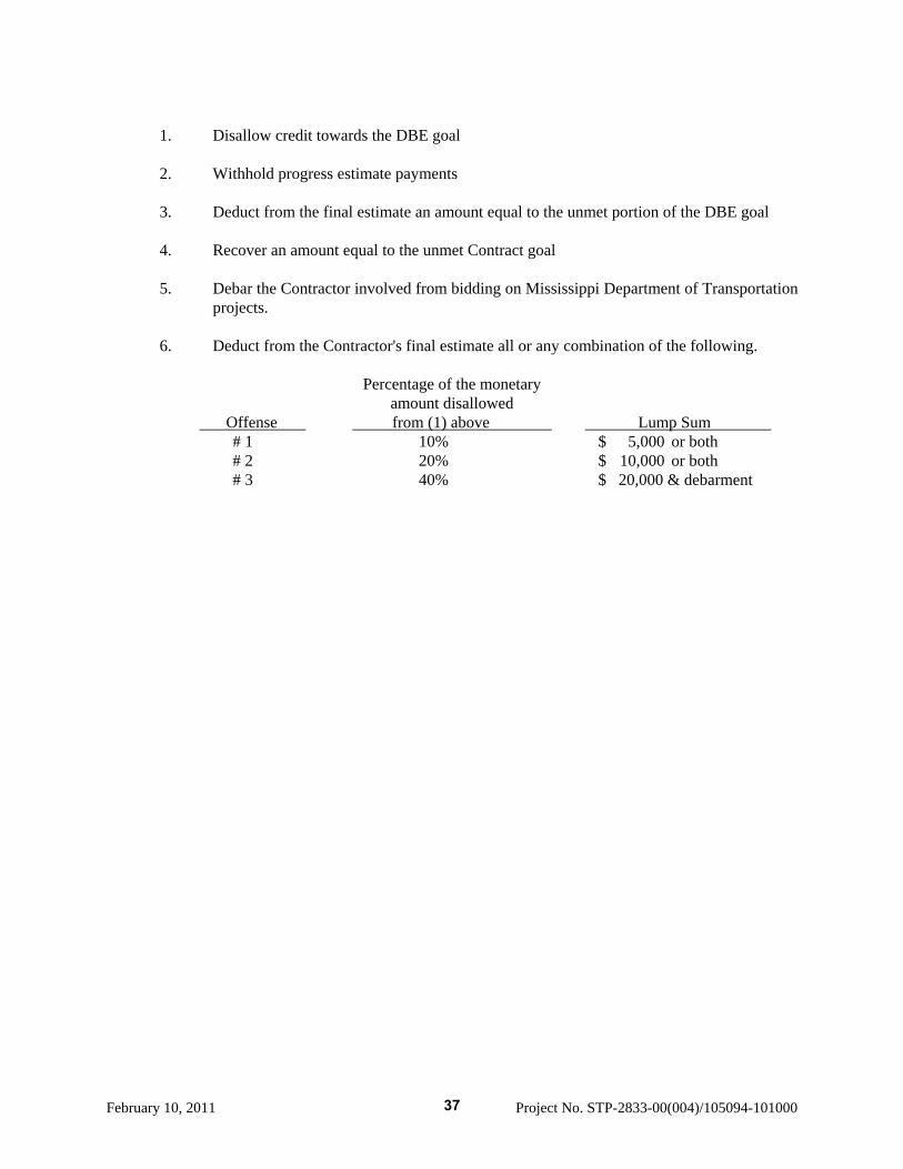
February 10, 2011 Project No. STP-2833-00(004)/105094-101000
1. Disallow credit towards the DBE goal
2. Withhold progress estimate payments
3. Deduct from the final estimate an amount equal to the unmet portion of the DBE goal
4. Recover an amount equal to the unmet Contract goal
5. Debar the Contractor involved from bidding on Mississippi Department of Transportation
projects.
6. Deduct from the Contractor's final estimate all or any combination of the following.
Percentage of the monetary amount disallowed
Offense from (1) above Lump Sum # 1 10% $ 5,000 or both # 2 20% $ 10,000 or both # 3 40% $ 20,000 & debarment
37
February 10, 2011 Project No. STP-2833-00(004)/105094-101000
MISSISSIPPI DEPARTMENT OF TRANSPORTATION SECTION 904 - NOTICE TO PROPOSERS NO. 845 DB CODE: (SP) DATE: 03/10/2009 SUBJECT: Removal and Disposal of any Structures Having lead, Lead-Based Paint
and/or Asbestos Removal and disposal of any structures, having lead, lead-based paint, and/or asbestos shall be in accordance with MDEQ & EPA guidelines. The removed materials shall be handled and deposited in a suitable upland site designated for such material(s).
38
February 10, 2011 Project No. STP-2833-00(004)/105094-101000
MISSISSIPPI DEPARTMENT OF TRANSPORTATION SECTION 904 - NOTICE TO PROPOSERS NO. 883 DB CODE: (SP) DATE: 03/10/2009 SUBJECT: Payroll Requirements Proposers are hereby advised that the Contractor and Subcontractor(s) are required to submit payroll information to the Project Engineers on a weekly basis. On Federal-Aid Projects, CAD-880, CAD-881 and certified payroll submissions are required each week the Contractor or a Subcontractor performs work on the Project. This is addressed in Section V, page 6 of Form FHWA-1273. On State-Funded Projects, CAD-880 is required each week the Contractor or a Subcontractor performs work on the Project. When no work is performed on either Federal-Aid or State-Funded Projects, the Contractor should only submit CAD-880 showing no work activities. The Contractor shall make all efforts necessary to submit this information to the Project Engineer in a timely manner. The Engineer will have the authority to suspend the Work wholly or in part and to withhold payments because of the Contractor's failure to submit the required information. Submission of forms and payrolls shall be current through the first full week of the month for the estimate period in order for the Project Engineer to process an estimate. Proposers are advised to review the requirements regarding payroll submissions in Section 110 of the Standard Specifications.
39
February 10, 2011 Project No. STP-2833-00(004)/105094-101000
MISSISSIPPI DEPARTMENT OF TRANSPORTATION SECTION 904 - NOTICE TO PROPOSERS NO. 1197 DB CODE: (SP) DATE: 03/10/2009 SUBJECT: Severe High Sulfate Areas Below Ground Level Proposers are hereby advised that this Project, or portions of this Project, is located in areas considered to be High Sulfate Areas and will require certain restrictions on the tricalcium aluminate content of the Portland cement portion of cementitious materials and sources of fly ash used for replacement of Portland cement. A geotechnical investigation has indicated the presence of high sulfate soils below the ground surface. Therefore, the cement/fly ash used in concrete mixtures for the construction of certain items of work below ground level shall not exceed eight percent (8%) tricalcium aluminate as addressed in Subsection 907-701.02 for severe sulfate exposure. Sub-surface items of work requiring restrictions on tricalcium aluminate for this Project are as follows: 1) Drilled Shafts 2) Piles No other restrictions as to maximum tricalcium aluminate content or source of fly ash used for cement replacement shall apply to concrete items or structures, other than listed above.
40

February 10, 2011 Project No. STP-2833-00(004)/105094-101000
MISSISSIPPI DEPARTMENT OF TRANSPORTATION SECTION 904 - NOTICE TO PROPOSERS NO. 1199 DB CODE: (SP) DATE: 03/10/2009 SUBJECT: Severe High Sulfate Areas Proposers are hereby advised that this Project, or portions of this Project, is located in areas considered to be High Sulfate Areas and will require restrictions on the tricalcium aluminate content of the Portland cement portion of cementitious materials and sources of fly ash used for replacement of Portland cement. With the exception of prestressed structure members, concrete pipe, concrete posts, bridge decks, intermediate caps, rails and curbs, cement/fly ash used in concrete mixtures shall not exceed eight percent (8%) tricalcium aluminate as addressed in Subsection 907-701.02 for severe sulfate exposure.
41
February 10, 2011 Project No. STP-2833-00(004)/105094-101000
MISSISSIPPI DEPARTMENT OF TRANSPORTATION SECTION 904 - NOTICE TO PROPOSERS NO. 1405 DB CODE: (SP) DATE: 03/10/2009 SUBJECT: Errata And Modifications To The 2004 Standard Specifications Page Subsection Change
101 201.01 In the second sentence of the first paragraph, change “salvable” to “salvageable”.
107 202.04 In the fourth sentence of the fourth paragraph, change “yard” to “feet”. 107 202.05 In the list of units measurements for 202-B, add “square foot”. 132 211.03.4 In the second sentence of the second paragraph, change “planted” to
“plated”. 192 306.02.4 In the first line of the first paragraph, delete the word “be”. 200 307.03.7 In the fourth sentence of the second paragraph, change “lime-fly ash” to
“treated”. 236 401.01 Change the header from “Section 403” to “Section 401”. 242 401.02.3.2 In the first sentence of the third full paragraph, add “1/8” in the blank
before the inch mark. 250 401.02.6.3 In the second sentence of the first paragraph on page 250, change
“rutting over ” ” to “rutting over 1/8" ”. 253 401.02.6.4.2 In the paragraph preceding the table, change “91.0” to “89.0”. 259 401.03.1.4 In the first paragraph, change “92.0 percent” to “the specified percentage
(92.0 or 93.0)”. 269 403.03.2 In the table at the top of page 269, change the PI requirement from “ = ”
to “ < ”. 278 404.04 In the second sentence, change the subsection from “401.04” to
“403.04”.
283 409.02.2 Change “PG 64-22” to “PG 67-22”. 294 413.02 In the first sentence of the second paragraph, change “707.02.1.3” to
“Subsection 707.02.1.3”.
340 511.04 In the second sentence of the second paragraph, change “412” to “512”.
42
February 10, 2011 Project No. STP-2833-00(004)/105094-101000
349 601.03.3 In the first sentence, change “804.03.2” to “804.03.5”. 355 603.02 Change the subsection reference for Joint mortar from “707.03” to
“714.11”. 369 604.04 In the first sentence, change “601.04” to “Subsection 601.04”. 427 619.04 Delete the second paragraph. 442 625.04 In the third paragraph, change “626.04” to “Subsection 626.04”. 444 626.03.1.2 Delete the third sentence of the first paragraph. 464 631.02 Change the subsection reference for Water from “714.01.0” to
“714.01.1”. 570 682.03 Change the subsection number from “682-03” to “682.03”. 575 683.10.4 Change the subsection number from “683.10.4” to “683.04”. 575 683.10.5 Change the subsection number from “683.10.5” to “683.05”. 596 701.02 In the table under the column titled “Cementations material required”,
change Class F, FA” to “Class F FA,”. 603 702.11 In the first sentence, change “702.12” to “Subsection 702.12”. 612 703.04.2 In the fifth paragraph, delete “Subsection 703.11 and”. 616 703.07.2 In the Percentage By Weight Passing Square Mesh Sieves table, change
the No. 10 requirement for Class 7 material from “30 - 10” to “30 - 100”. 618 703.13.1 In the first sentence of the first paragraph, change “703.09” to “703.06”. 618 703.13.2 In the first sentence, change “703.09” to “703.06”. 671 712.06.2.2 In the first sentence, change “712.05.1” to “Subsection 712.05.1”. 689 714.11.2 In the first sentence, change “412” to “512”. 709 715.09.5 In the first sentence of the first paragraph, change “guage” to “gauge”. 717 717.02.3.4 In the top line of the tension table, change “1 1/2” to “1 1/8” and change
“1 1/8” to “1 1/2”. 741 720.05.2.2 In the last sentence of this subsection, change “720.05.2.1” to
“Subsection 720.05.2.1”. 827 803.03.2.3.7.5.2 In the first sentence of the second paragraph, change “803.03.5.4” to
“803.03.2.3.4”.
43
February 10, 2011 Project No. STP-2833-00(004)/105094-101000
833 803.03.2.6 In the first sentence, change “803.03.7” to “803.03.2.5”. 854 804.02.11 In the last sentence of the first paragraph, change “automatically” to
“automatic”. 859 804.02.13.1.3 In the last sentence, change Subsection “804.02.12.1” to “804.02.12”. 879 804.03.19.3.2 In the first sentence of the third paragraph, change “listed on of
Approved” to “listed on the Approved”. 879 804.03.19.3.2 In the last sentence of the last paragraph, change “804.03.19.3.1” to
“Subsection 804.03.19.3.1”. 962 814.02.3 In the first sentence, change “710.03” to “Subsection 710.03”. 976 820.03.2.1 In the first sentence, change “803.02.6” to “803.03.1.7”. 976 820.03.2.2 In the first sentence, change “803.03.9.6” to “803.03.1.9.2”. 985 Index Change the subsection reference for Petroleum Asphalt Cement from
“702.5” to “702.05”. 985 Index Change the subsection reference for the Definition of Asphaltic Cement
or Petroleum Asphalt from “700.2” to “700.02”. 985 Index Change the subsection reference for Automatic Batchers from
“501.03.2.4” to “804.02.10.4”. 986 Index Delete “501.03.2” as a subsection reference for Batching Plant &
Equipment. 988 Index Change the subsection reference for the Central Mixed Concrete from
“501.03.3.2” to “804.02.11”. 988 Index Change the subsection reference for the Concrete Batching Plant &
Equipment from “501.03.2” to “804.02.11”. 999 Index Delete “501.03.3.3” as a subsection reference for Truck Mixers. 1001 Index Change the subsection reference for Edge Drain Pipes from “605.3.5” to
“605.03.5”. 1002 Index Change the subsection reference for Metal Posts from “713.05.2” to
“712.05.2”. 1007 Index Change the subsection reference for Coarse Aggregate of Cement
Concrete Table from “703.3” to “703.03”. 1007 Index Change the subsection reference for Composite Gradation for
Mechanically Stabilized Courses Table from “703.8” to “703.08”.
44
February 10, 2011 Project No. STP-2833-00(004)/105094-101000
1009 Index Delete “501.03.3.3” as a subsection reference for Truck Mixers and Truck Agitators.
1010 Index Delete reference to “Working Day, Definition of”.
45
February 10, 2011 Project No. STP-2833-00(004)/105094-101000
MISSISSIPPI DEPARTMENT OF TRANSPORTATION SECTION 904 - NOTICE TO PROPOSERS NO. 1808 DB CODE: (IS) DATE: 09/09/2008 SUBJECT: Safety Apparel Proposers are advised that the Code of Federal Regulations CFR 23 Part 634 final rule was adopted November 24, 2006 with an effective date of November 24, 2008. This rule requires that "All workers within the right-of-way of a Federal-Aid Highway who are exposed either to traffic (vehicles using the highway for the purposes of travel) or to construction equipment within the work area shall wear high-visibility safety apparel". High-visibility safety apparel is defined in the CFR as "personnel protective safety clothing that is intended to provide conspicuity during both daytime and nighttime usage, and that meets the Performance Class 2 or 3 requirements of the ANSI/ISEA 107-2004 publication entitled American National Standard for High-Visibility Safety Apparel and Headwear". All workers on Mississippi State Highway right-of-way shall comply with this Federal Regulation. Workers are defined by the CFR as "people on foot whose duties place them within the right-of way of a Federal-Aid Highway, such as highway construction and maintenance forces, survey crews, utility crews, responders to incidents within the highway right-of-way, and law enforcement personnel when directing traffic, investigating crashes, and handling lane closures, obstructed roadways, and disasters within the right-of-way of a Federal-Aid Highway". You can access this final rule at the following link: http://a257.g.akamaitech.net/7/257/2422/01jan20061800/edocket.access.gpo.gov/2006/pdf/E6-19910.pdf
46
February 10, 2011 Project No. STP-2833-00(004)/105094-101000
MISSISSIPPI DEPARTMENT OF TRANSPORTATION SECTION 904 - NOTICE TO PROPOSERS NO. 1918 DB CODE: (SP) DATE: 03/10/2009 SUBJECT: DBE Forms, Participation and Payment Proposers are hereby advised that the participation of a DBE Firm can not be counted towards the Prime Contractor’s DBE goal until the amount being counted towards the goal has been paid to the DBE. Form OCR-482 has been developed to comply with this requirement. Proposers are hereby advised that at the end of the job, the Prime Contractor will submit this form to the Project Engineer before the final estimate is paid and the Project is closed out. This form certifies payments to all DBE Subcontractors over the life of the Contract. Form OCR-484 has also been developed to comply with this requirement. Proposers are hereby advised that each month, the Prime Contractors will submit this form to the Project Engineer no later than the 20th of each month. This form certifies payments to all Subcontractors and shows all firms even if the Prime Contractor has paid no monies to the firm during that estimate period (negative report). The Project Engineer will attach this form to the monthly estimate before forwarding the estimate to the Contract Administration Division for processing. Proposers are also advised that Form OCR-485 will be completed by ALL PROPOSERS submitting a bid Proposal and must be signed and included in the Proposal package. Failure to include Form OCR-485 in the Proposal package will cause the Contractor's Proposal to be considered irregular. DBE Forms, including Forms OCR-482, OCR-484 and OCR-485, can be obtained from the Office of Civil Rights Division, MDOT Administration Building, 401 North West Street, Jackson, MS, or at www.gomdot.com under Business, Disadvantaged Enterprise, Applications.
47
February 10, 2011 Project No. STP-2833-00(004)/105094-101000
MISSISSIPPI DEPARTMENT OF TRANSPORTATION SECTION 904 - NOTICE TO PROPOSERS NO. 1922 DB CODE: (SP) DATE: 03/10/2009 SUBJECT: Quality Control / Quality Assurance Concrete Proposers are advised that work performed under the following sections of the specifications will not be sampled and tested based on the Quality Control / Quality Assurance (QC/QA) requirements of Section 804 of the specifications. The Contractor is required to submit mix designs to accomplish this work in accordance with Section 804 and perform normal Quality Control functions at the concrete plant. Sampling and testing will be in accordance with the requirements of 907-601, Structural Concrete, and TMD-20-04-00-000. Sections Description
221 Paved Ditches 601 Structural Concrete, Minor Structures - manholes, inlets, catch basins, junction
boxes, pipe headwalls, and pipe collars. 606 Guardrail Anchors 607 Fence Post Footings 608 Sidewalks 609 Curb and Gutter 614 Driveways 616 Median and Island Pavement 630 Sign Footings, except Overhead Sign Supports
48
February 10, 2011 Project No. STP-2833-00(004)/105094-101000
MISSISSIPPI DEPARTMENT OF TRANSPORTATION SECTION 904 - NOTICE TO PROPOSERS NO. 1928 DB CODE: (SP) DATE: 03/10/2009
SUBJECT: Federal Bridge Formula Proposers are hereby advised that Federal Highway Administration Publication No. FHWA-MC-94-007, BRIDGE FORMULA WEIGHTS, dated January 1994, is made a part of this Contract when applicable. Prior to the preconstruction conference, the Contractor shall advise the Engineer, in writing, what materials, if any, will be delivered to the jobsite via Interstate route(s). Copies of the BRIDGE FORMULA WEIGHTS publication may be obtained by contacting: Federal Highway Administration 400 7th Street, SW Washington, DC 20590 (202) 366-2212 or http://ops.fhwa.dot.gov/freight/sw/brdgcalc/calc_page.htm
49
February 10, 2011 Project No. STP-2833-00(004)/105094-101000
MISSISSIPPI DEPARTMENT OF TRANSPORTATION SECTION 904 - NOTICE TO PROPOSERS NO. 2382 DB CODE: (SP) DATE: 01/06/2011 SUBJECT: Status of Right of Way and Utility Adjustments The Proposer is hereby advised of utilities which have been discovered and/or relocated. Pontotoc Electric Power Association 12 South Main Street or 903 Hwy 21 South Pontotoc, MS 38863 662-489-3211 or 662-489-6711 East Pontotoc Water Association 505 New Hope Road or 300 President Drive Pontotoc, MS 38863 662-489-0776 Oak Hill Water Association 189 Reeder Hill Road or 4543 Hwy 9 North Pontotoc, MS 38863 662-489-3692 Water/Gas – City of Pontotoc 301 Stafford Blvd. or 116 North Main Street Pontotoc, MS 38863 662-489-3891 or 662-489-4321 Bellsouth 2070 McCullough Blvd. Tupelo, MS 662-841-8200 or 662-841-8250 or 662-840-3347 Tennessee Valley Authority 1101 Market Street Chattanooga, TN 37402 423-751-0011 Mississippi Valley Gas / ATMOS 1308 West Main Street Tupelo, MS 662-842-2441 Or 711 West Capitol Street Jackson, MS 601-961-6600 The status of encroachments and utility adjustments will be complete by July 1, 2011 and will be inserted
50

February 10, 2011 Project No. STP-2833-00(004)/105094-101000
in Section 902 as part of Exhibit 8.
51
February 10, 2011 Project No. STP-2833-00(004)/105094-101000
MISSISSIPPI DEPARTMENT OF TRANSPORTATION SECTION 904 - NOTICE TO PROPOSERS NO. 2618-D1-1 DB DATE: 12/21/2010 SUBJECT: Project Scope PROJECT: Design-Build Improvements to State Route 9 From US278/State Route 6
Near Pontotoc to US 78 Near Sherman Project No. STP -2833-00(004)-101000 Work on the project shall consist of the design and construction of a new alignment of SR 9 from US 278/State Route 6 to US 78 near Sherman. The near highway will be constructed to address the projected traffic volumes and needs as described the Environmental Assessment, all other environmental permitting and the requirements described in the request for proposals. Principal elements of the scope include the design and construction of:
1. A four lane SR 9 US278/State Route 6 near Pontotoc to US 78 near Sherman. 2. An interchange located at Endville Road. 3. Connections to local roads at Claudia Circle, Nanney Road, Russel Road
Thomas Road, Morphis Road, Dillard Road, Dozier Hill Road, Bryant Lane, Cochran Road and Eads Creek Road.
4. Crossing of Mubby Creek, Coonewah Creek, Coonewah Bottom,
Construction of the Project will be within Mississippi Department of Transportation (MDOT) Right of Way. The Commission has secured an Environmental Assessment/FONSI for the construction of the Project. Project Services shall include but are not limited to:
• Design Services – complete development of construction plans and permitting • Quality Control (QC) of design and quality control / testing of construction • Construction Services – necessary to build and ensure high quality workmanship of the
designed facility. The scope of work for this Project will include, but not be limited to, the following Design work items: Design:
• Erosion Control Plans • Final Roadway Design and Plan Preparation • Structure Design and Supporting Documentation Preparation • Traffic Control Plan • Permanent Signing Plans
52

February 10, 2011 Project No. STP-2833-00(004)/105094-101000
• Environmental Coordination • Roadway and Bridge Deck Drainage Design • Geotechnical Investigation, Testing and Report Preparation • QC for Design • Surveying
If the Contractor chooses to design different bridge structures than provided by MDOT, then the scope of services will also include, but not be limited to the following:
• Final Bridge Superstructure and Substructure Design and Plan Preparation • Bridge Hydraulic and Scour Design • Geotechnical Investigation, Testing and Report Preparation
Design shall meet all appropriate AASHTO Policy on Geometric Design of Highways and Streets (latest edition), AASHTO LRFD Bridge Design Specifications (latest edition), Manual on Uniform Traffic Control Devices (latest edition) (MUTCD) and MDOT design criteria as modified by the RFP. Microstation and Geopak shall be used in the preparation of CADD files. The scope of work for this Project will include, but not limited to, the following construction work items: Construction:
• Clearing and grubbing with debris removal and disposal • All necessary roadway and bridge work • Surveying • Drainage • Environmental coordination • Erosion and sediment control work items • Traffic control • Project management • Construction management • QC for Construction, including inspection and testing
Construction shall comply with the MDOT Standard Specifications for Road And Bridge Construction 2004 Edition as modified by the RFP to accommodate specific Design/Build requirements, Manual on Uniform Traffic Control Devices (latest edition), MDOT Standard Drawings, any Special Provisions, Notice to Proposers, current MDOT publications including, but not limited to, the Construction Manual, the Materials Division Inspection, Testing and Certification Manual, and existing AASHTO, ASTM, or MDOT Test Methods. Design and Construction Responsibilities The Contractor warrants that it will perform all services in accordance with the standards of care and diligence normally practiced by recognized engineering and construction firms in performing services and obligations of a similar nature. The Contractor warrants that the Project shall be fit for its intended
53
February 10, 2011 Project No. STP-2833-00(004)/105094-101000
purpose and that all materials and equipment furnished shall be of good quality and new unless otherwise authorized by the Commission and that the construction shall conform to the Contract requirements. The Contractor, consistent with applicable state licensing laws, shall provide the necessary design Work. The design professionals employed by Contractor or procured from qualified design consultants shall be licensed by the State of Mississippi. The Work, includes, but is not limited to, surveys, roadway design, traffic control, geotechnical work, hydraulic analyses, storm water management, erosion control, superstructure and substructure design for the preparation of the required drawings, false work, shoring, specifications and other contract documents necessary to permit the Contractor to complete the Project in accordance with the Contract.
The Contractor shall be fully and solely responsible for the accuracy of the design and compliance with specifications, standards and design criteria. The Contractor shall construct the Project in accordance with all applicable Federal, State and local Laws and the Contract. The Contractor shall provide the necessary supervision, labor, inspection, testing, material, equipment, machinery, temporary utilities and other temporary facilities to permit performance of all earthwork, drainage, foundation work, all traffic control, substructure and superstructure work, excavation, erosion and sediment control work, field layout work, design and construction management and all other work necessary to complete construction of the Project in accordance with the Contract. Contractor shall perform all construction activities efficiently and with the requisite expertise, skill and competence to satisfy the requirements of the Contract. Contractor at all times shall exercise control over the means, methods, sequences and techniques of construction. Contractor’s operations and construction methods shall comply with all applicable federal, state and local regulations including but not limited to worker safety, protection and health and protection of the environment and applicable permit requirements.
Control of Work The Contractor shall be solely responsible for determining the appropriate means, methods and scheduling necessary to complete the Work in a timely manner and in accordance with all Contract requirements. MDOT and FHWA will have the right to review and inspect the Work at any time.
1. Contract Interpretations The Engineer will decide all questions which may arise as to the quality and acceptability of materials, the Work and the progress of the Work; all questions which may arise as to the interpretation of the specifications; and all questions as to the fulfillment of the Contract. The Engineer will have the authority, but not the responsibility to suspend the Work, wholly or in part, because of the Contractor’s failure to correct conditions unsafe for workers or the general public, for failure to carry out provisions of the Contract, or for failure to carry out orders. The Engineer may also suspend Work for periods deemed necessary due to unsuitable weather conditions, for any conditions considered unsuitable for the prosecution of the Work, or for any other condition or reason deemed to be in the public interest. The Engineer may authorize, in writing, the continued prosecution of Work activities past their specified seasonal limits when it is determined that the quality of the Work will not be reduced and the public interest will be best served. The Engineer will have authority to enforce and make effective all decisions and orders relating to the Contract.
54
February 10, 2011 Project No. STP-2833-00(004)/105094-101000
2. Governmental Approvals and Permits The Contractor is responsible for obtaining all Governmental Approvals and permits, not specifically designated to be obtained by MDOT, necessary to construct the Project. Copies of all correspondence and permits shall be forwarded to MDOT within seven (7) days after the correspondence is received. The Contractor shall integrate design practices to avoid and/or minimize potential Work impacts to wetlands and water of the US. The Contractor shall bear the cost and responsibility of resolving any deviations among the Project Right-of-Way limits, drawings or other information included in the permits that would violate the intent or spirit of the permits. Any proposed changes within the permitted areas shall be coordinated with MDOT and the appropriate agency, and performed to MDOT’s satisfaction.
3. Plans for Construction Prior to the start of construction of any phase or portion of Work, the Contractors shall have plans stamped by MDOT as “Released for Construction” for that phase or portion of Work.
55

February 10, 2011 Project No. STP-2833-00(004)/105094-101000
MISSISSIPPI DEPARTMENT OF TRANSPORTATION SECTION 904 - NOTICE TO PROPOSERS NO. 2858 DB CODE: (SP) DATE: 1/5/2011 SUBJECT: Petroleum Products Base Prices Monthly petroleum products base prices will be available at the web site listed below. Current monthly prices will be posted to this web site on or before the 15th of each month. Proposers are advised to use the petroleum base prices on this web site when preparing their bids. The current monthly petroleum products base prices will be acknowledged by the Proposer and become part of the contract during the execution process. Monthly Petroleum Products Base Prices can be viewed at: http://www.gomdot.com/Applications/BidSystem/Home.aspx Payment will be in accordance with Section 109.07 with the exception that the cost adjustment will be based on the estimated quantities submitted in the Schedule of Values and the percent complete for that item of work for any month where a Petroleum Products adjustment is applicable. Adjustment for Petroleum Products will only be made for the items delineated on the Schedule of Valued with the Code B, E, M, GY or GT or with an Adjustment Code of A1. Petroleum Products Fuel Adjustment Formula Fuel Adjustment = Qm x Factor x (Pricec – Priceb) Where Qm = monthly quantity (eligible pay items for fuel adjustment) Computed as percent complete for the month x Schedule of Value Quantity Factor = Cost Adjustment Factors for Fuel Usage (Section 109.07) Pricec = Price as Posted on MDOT Website above (Current month, Pay Request)
Priceb = Price as Posted on MDOT Website above (April 2011, Base)
56

February 10, 2011 Project No. STP-2833-00(004)/105094-101000
Construction Material Adjustment Formula Material Adjustment = Qm x 2000 lbs/ton x (Pricec-Priceb) 8.43 lbs/gallon Where Qm = monthly quantity (eligible pay items for material adjustment) Computed as tons of material used x percent asphatic concrete (% AC)
Pricec and Priceb as defined above.
Method of Measurement The Contractor will develop a monthly estimate of the quantity of the allowable fuel and/or material adjustment items identified above. This quantity estimate must be substantiated by theoretical calculations, field measurements or a combination of measurements and calculations. MDOT will verify the Contractor’s monthly estimate through calculation, measurement or a combination of measurements and calculation. For the final estimate, the Contractor will be responsible for calculating the final quantities based on field verified measurements. The fuel/material adjustment will apply only to the actual field-measured quantities up to maximum of the quantity submitted in the Contractor’s Schedule of Values.
57
February 10, 2011 Project No. STP-2833-00(004)/105094-101000
MISSISSIPPI DEPARTMENT OF TRANSPORTATION SECTION 904 - NOTICE TO PROPOSERS NO. 2887 DB CODE: (SP) DATE: 12/18/2009 SUBJECT: Warm Mix Asphalt Proposers are advised that the following products and processes are approved for the production of Warm Mix Asphalt. Advera® WMA Aqua Foam Aspha-min® Evotherm™ Rediset™ WMX Sasobit® WAM Foam Astec Double Barrel® Green Terex Warm Mix System Gencor Industries Ultrafoam GX Systems
58
February 10, 2011 Project No. STP-2833-00(004)/105094-101000
MISSISSIPPI DEPARTMENT OF TRANSPORTATION SECTION 904 - NOTICE TO PROPOSERS NO. 2905 DB CODE: (SP) DATE: 03/29/2010 SUBJECT: Storm Water Discharge Associated with Construction Activity (> 5 Acres) A Construction Storm Water General NPDES Permit to discharge storm water associated with construction activity is required. The Department has acquired Certificate of Permit Coverage MSR-105892 under the Mississippi Department of Environmental Quality’s (MDEQ) Storm Water Construction General Permit. Projects issued a certificate of permit coverage are granted permission to discharge treated storm water associated with construction activity into State waters. Copies of said permit, completed Large Construction Notice of Intent (LNOI), and Storm Water Pollution Prevention Plan (SWPPP) are on file with the Department. Prior to the execution of the contract, the successful proposer shall execute and deliver to the Executive Director an original signed copy of the completed Prime Contractor Certification (Form No. 1). Failure of the proposer to execute and file the completed Prime Contractor Certification (Form No. 1) shall be just cause for the cancellation of the award. The executed Prime Contractor Certification (Form No. 1) shall be prima facie evidence that the proposer has examined the permit, is satisfied as to the terms and conditions contained therein, and that the proposer has the primary responsibility for meeting all permit including, but not limited to, the inspection and reporting requirements. For this project, the Contractor shall furnish, set up and read, as needed, an on-site rain gauge. The Contractor shall make inspections in accordance with condition No. S-4, page 14, and shall furnish the Project Engineer with the results of each weekly inspection as soon as possible following the date of inspection. A copy of the inspection form is provided with the packet. The weekly inspections must be documented monthly on the Inspection and Certification Form. The Contractor’s representative and the Project Engineer shall jointly review and discuss the results of the inspections so that corrective action can be taken. The Project Engineer shall retain copies of the inspection reports. The Engineer will have the authority to suspend all work and/or withhold payments for failure of the Contractor to carry out provisions of MDEQ’s Storm Water Construction General Permit, the erosion control plan, updates to the erosion control plan, and /or proper maintenance of the BMPs. Upon successful completion of all permanent erosion and sediment controls, accepted and documented by the full maintenance release, the Construction Division shall submit a completed Notice of Termination (NOT) of Coverage to the Office of Pollution Control. Securing a permit (s) for storm water discharge associated with the Contractor's activity on any other regulated area the Contractor occupies, shall be the responsibility of the Contractor.
59
February 10, 2011 Project No. STP-2833-00(004)/105094-101000
MISSISSIPPI DEPARTMENT OF TRANSPORTATION SECTION 904 - NOTICE TO PROPOSERS NO. 3000 DB CODE: (SP) DATE: 1/6//2011 SUBJECT: Liquidated Damages Liquidated Damages will not be assessed on this project.
60
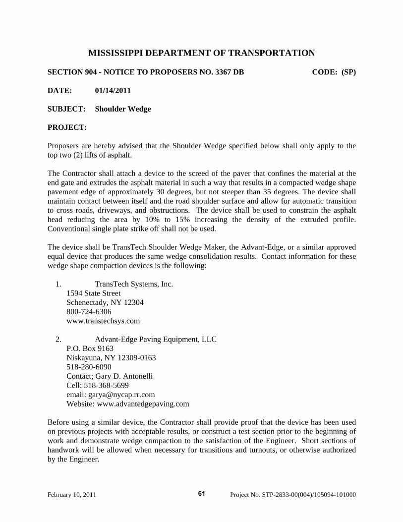
February 10, 2011 Project No. STP-2833-00(004)/105094-101000
MISSISSIPPI DEPARTMENT OF TRANSPORTATION SECTION 904 - NOTICE TO PROPOSERS NO. 3367 DB CODE: (SP) DATE: 01/14/2011 SUBJECT: Shoulder Wedge PROJECT: Proposers are hereby advised that the Shoulder Wedge specified below shall only apply to the top two (2) lifts of asphalt. The Contractor shall attach a device to the screed of the paver that confines the material at the end gate and extrudes the asphalt material in such a way that results in a compacted wedge shape pavement edge of approximately 30 degrees, but not steeper than 35 degrees. The device shall maintain contact between itself and the road shoulder surface and allow for automatic transition to cross roads, driveways, and obstructions. The device shall be used to constrain the asphalt head reducing the area by 10% to 15% increasing the density of the extruded profile. Conventional single plate strike off shall not be used. The device shall be TransTech Shoulder Wedge Maker, the Advant-Edge, or a similar approved equal device that produces the same wedge consolidation results. Contact information for these wedge shape compaction devices is the following:
1. TransTech Systems, Inc. 1594 State Street Schenectady, NY 12304 800-724-6306 www.transtechsys.com
2. Advant-Edge Paving Equipment, LLC
P.O. Box 9163 Niskayuna, NY 12309-0163 518-280-6090 Contact; Gary D. Antonelli Cell: 518-368-5699 email: [email protected] Website: www.advantedgepaving.com
Before using a similar device, the Contractor shall provide proof that the device has been used on previous projects with acceptable results, or construct a test section prior to the beginning of work and demonstrate wedge compaction to the satisfaction of the Engineer. Short sections of handwork will be allowed when necessary for transitions and turnouts, or otherwise authorized by the Engineer.
61
Mississippi Department of Transportation
Section 906
Required Contract Provisions
Proposed Improvements to State Route 9 From US 278/State Route 6 near Pontotoc
To US 78 near Sherman Pontotoc County, Mississippi
Project No. STP-2833-00(004) / 105094-10100
February 10, 2011
62
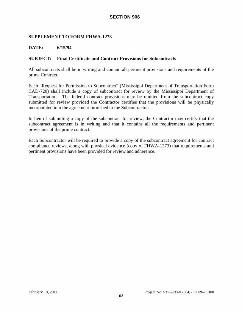
SECTION 906
February 10, 2011 Project No. STP-2833-00(004) / 105094-10100
SUPPLEMENT TO FORM FHWA-1273 DATE: 6/15/94 SUBJECT: Final Certificate and Contract Provisions for Subcontracts All subcontracts shall be in writing and contain all pertinent provisions and requirements of the prime Contract. Each “Request for Permission to Subcontract” (Mississippi Department of Transportation Form CAD-720) shall include a copy of subcontract for review by the Mississippi Department of Transportation. The federal contract provisions may be omitted from the subcontract copy submitted for review provided the Contractor certifies that the provisions will be physically incorporated into the agreement furnished to the Subcontractor. In lieu of submitting a copy of the subcontract for review, the Contractor may certify that the subcontract agreement is in writing and that it contains all the requirements and pertinent provisions of the prime contract. Each Subcontractor will be required to provide a copy of the subcontract agreement for contract compliance reviews, along with physical evidence (copy of FHWA-1273) that requirements and pertinent provisions have been provided for review and adherence.
63
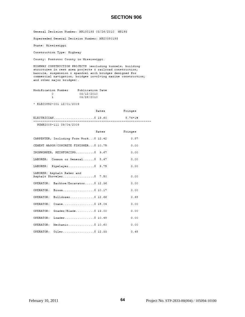
Gtrra1 li.nbe: M3C12 3/26/21: 131
3terded Gra. Deci re:3a: MiiippiCon r.on ye: .gway
Cn7 ?ntoto ont in 4iiippi.CC TJc::t PCCTS c.nt oui1drre in area ?roiec ai1rd :ltion;
pen.ior pnde1 idget sign. fooercia1 a.rigaicn bridges iro1rng
her za
.fication 1er c:ication Da1.e
c21EtC52-O0I. 12/01/2009
Fing3$ Is.6:
US2C!-Li.L 3*C42OOE
CAEtTE In:d.n !:r .$ 12.42
cti: 1oN/cc:RE FINI3MER.. $ 10.5 3.CC
zoroRFEa, IEORC ING $ . I - C C
:AEcRZR: Cot.n or Cenerj.]. $ 1C0
:AcRE: ipeL.er $ . 5 1.00
LECRZR: Ap&Lt RKe ndÀha. $ 7.51 1.00
CER?TOP.: :thoe/ca'íor $ 12.36 ICC
CERk0R: $ 10.1' 1C0
cER1::: 3LLio:er $ 12.66
cERx:oR: $ 15.14 ICC
CER?TOR: G.ade $ 13.00 1.00
czR?:oR: Lo&-i.r $ 10.45 1.11
cERx:oR: f:-ar. $ 10.61 1.00
CERAi3R: CiLer $ 12.33 3.45
SECTION 906
February 10, 2011 Project No. STP-2833-00(004) / 105094-10100
64
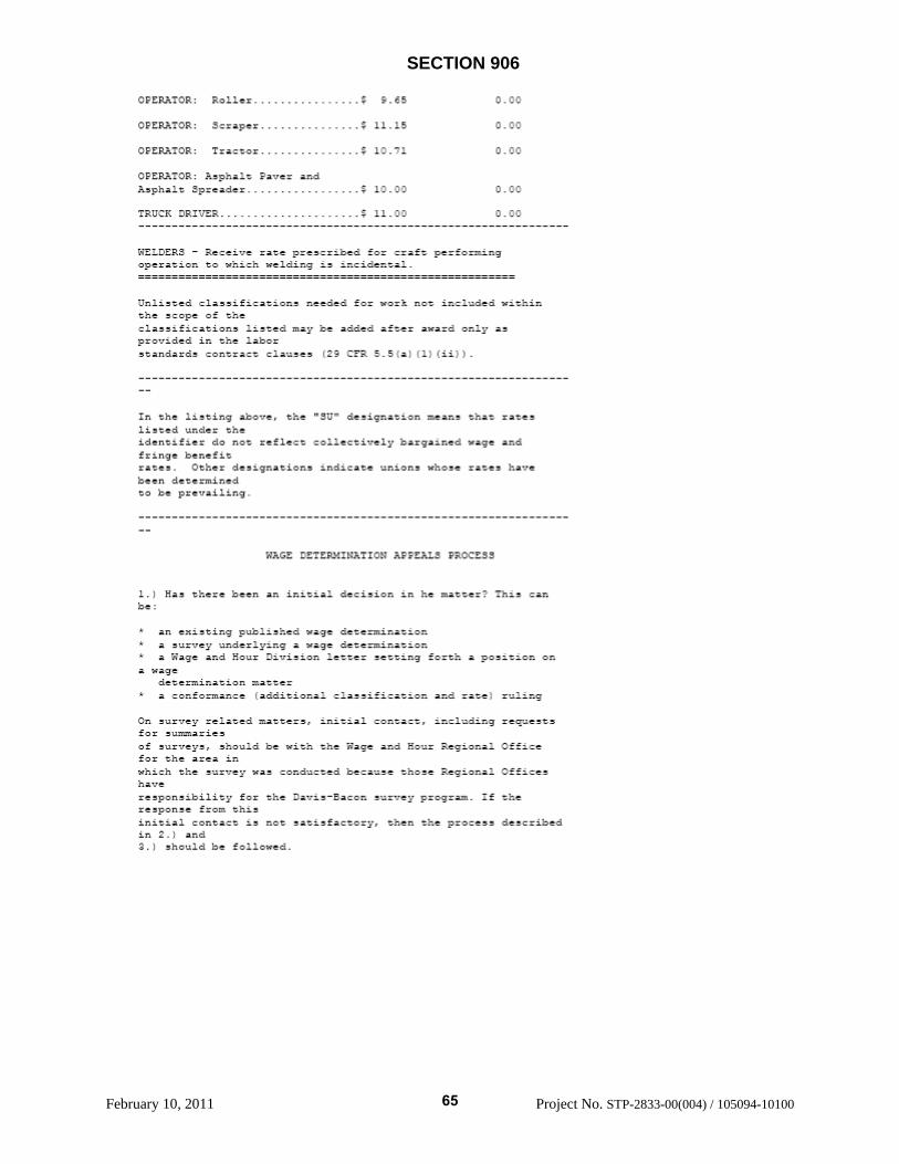
o9rx:3a: Roller 0_00
?3R :rap.r $ 11.1 3.00
ctRx:OR: rattor $ 10.']. 0.00
cR?:3R h?a:t ver endÀetha.t tea1er $ 10.00 0.00
rucI ::vR $ 11.00 0.00
- Re:e.'.e 1ae tea:r.beo. traft perort.ngtt h we.dirt iicental
Unlieted ria e.f.ration.! neeied fr trk not indei wtthir.the grope o the
;Lae,ationa 1irec may ce ado.ec) after award oni.y atrovided in the laborstandards rontract cla..es (29 CFR 5.5(a (1) (ii)).
In the tint "fU deaim:.tn nean ratitirei Ct thei.f.n.fier not reflect : erti're.y bargaec) vage and
betfit- de anona .niicata ..n.orta whcee ratee hae
jeen meerminedto be reaiiing.
WA3 ETZItATI0 PRCC33
Ha, ree a initia: o.eni,ion in e matter? Thia
an e,mting t iahec wag? demìrationa urey .mnder.ying a ae determinationa Yaga r :imiaion :ert aetring forth e poaitior. on
a wa'eiene natr rattera r ormanre ladditiona]. rla.eificatiom and rate) ruling
Oi survey related matters, initial contact. including reauester aniea
of aurey, ahould be with the Wage and Hrtr gnna Offi:efor the area inwh.:h the ar'et ae rcnd:nei bera.me thra .eg.nna. Offire
raconanbiiity for the De'riaEacon ,r'rey rrcram. If therear once from thi,innal conta:t not aatafactor then the protesa describedin ar.d
5hcm.id be followed,
SECTION 906
February 10, 2011 Project No. STP-2833-00(004) / 105094-10100
65
With regatd to any other matter not yet ripe or the fortalde:he here, initial rontact aho.1d e w.th the !ranrI. of
Wage Ce ì.ona. Wtite to:f Con tion Wage ert.nation,
Wage and ?ittr Diriciortr.z.222 Co t.tition Avenue. tLW,Waehingoon, DC 22210
2.) If the a.vr to the qeetton in L.) i vea, then arintereeted party:thae a etteâ by the Lotion) oar. reqeat review andreiietatn fromthe Wage and Hur Admiiettator 5ee 29 CR. ?att 1. and 2 CTazt
Write to:
Wage ad ?)our Acb.nttrator,S. rtm.nt tf
2:3 Co t.tutior. Avenue, NW,Waahington, :2 2:21C
The reo'..e,t ahould be arzomanied by a ful etaenent of theintereatedpartya pocition and by any nformation Lage paent data,Pr C 00
dee:r.ptton, area practire naterial, etc.) that the zecue.00rcorta ter!rele'.ar.t to the .eaue.
2. :f the deticior. of the Adtinietrator ic not favorae,inter, atecPaO ma apea1 dtre.:tly to the A uirtatrative Review !oaod:orner.v the
.a !;ari . Wttte to:
Arbiintaorative Revie.t oardzr.s. teoartment of :aor200 Conattution Avenue, ,W,Waahirtgoon, DC 22210
4.) ì..L ietistona by the Adri,trative Review Board are final.
F.1D CF GtitPAL DECISION
SECTION 906
February 10, 2011 Project No. STP-2833-00(004) / 105094-10100
66
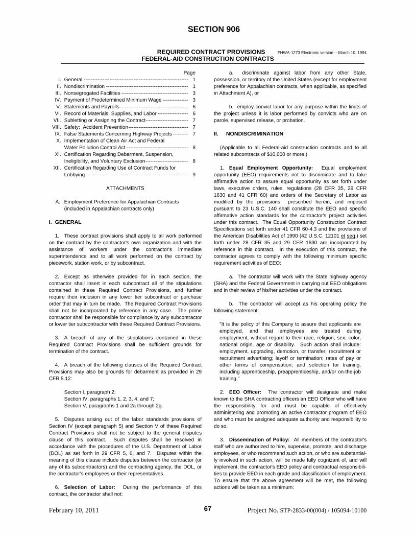
SECTION 906
February 10, 2011 Project No. STP-2833-00(004) / 105094-10100
REQUIRED CONTRACT PROVISIONS FHWA-1273 Electronic version -- March 10, 1994
FEDERAL-AID CONSTRUCTION CONTRACTS Page I. General ------------------------------------------------------------- 1 II. Nondiscrimination ------------------------------------------------ 1 III. Nonsegregated Facilities --------------------------------------- 3 IV. Payment of Predetermined Minimum Wage --------------- 3 V. Statements and Payrolls---------------------------------------- 6 VI. Record of Materials, Supplies, and Labor ------------------ 6 VII. Subletting or Assigning the Contract------------------------- 7 VIII. Safety: Accident Prevention----------------------------------- 7 IX. False Statements Concerning Highway Projects --------- 7 X. Implementation of Clean Air Act and Federal Water Pollution Control Act ------------------------------------ 8 XI. Certification Regarding Debarment, Suspension, Ineligibility, and Voluntary Exclusion------------------------- 8 XII. Certification Regarding Use of Contract Funds for Lobbying ------------------------------------------------------------ 9
ATTACHMENTS A. Employment Preference for Appalachian Contracts (included in Appalachian contracts only) I. GENERAL 1. These contract provisions shall apply to all work performed on the contract by the contractor's own organization and with the assistance of workers under the contractor's immediate superintendence and to all work performed on the contract by piecework, station work, or by subcontract. 2. Except as otherwise provided for in each section, the contractor shall insert in each subcontract all of the stipulations contained in these Required Contract Provisions, and further require their inclusion in any lower tier subcontract or purchase order that may in turn be made. The Required Contract Provisions shall not be incorporated by reference in any case. The prime contractor shall be responsible for compliance by any subcontractor or lower tier subcontractor with these Required Contract Provisions. 3. A breach of any of the stipulations contained in these Required Contract Provisions shall be sufficient grounds for termination of the contract. 4. A breach of the following clauses of the Required Contract Provisions may also be grounds for debarment as provided in 29 CFR 5.12: Section I, paragraph 2; Section IV, paragraphs 1, 2, 3, 4, and 7; Section V, paragraphs 1 and 2a through 2g. 5. Disputes arising out of the labor standards provisions of Section IV (except paragraph 5) and Section V of these Required Contract Provisions shall not be subject to the general disputes clause of this contract. Such disputes shall be resolved in accordance with the procedures of the U.S. Department of Labor (DOL) as set forth in 29 CFR 5, 6, and 7. Disputes within the meaning of this clause include disputes between the contractor (or any of its subcontractors) and the contracting agency, the DOL, or the contractor's employees or their representatives. 6. Selection of Labor: During the performance of this contract, the contractor shall not:
a. discriminate against labor from any other State, possession, or territory of the United States (except for employment preference for Appalachian contracts, when applicable, as specified in Attachment A), or b. employ convict labor for any purpose within the limits of the project unless it is labor performed by convicts who are on parole, supervised release, or probation. II. NONDISCRIMINATION (Applicable to all Federal-aid construction contracts and to all related subcontracts of $10,000 or more.) 1. Equal Employment Opportunity: Equal employment opportunity (EEO) requirements not to discriminate and to take affirmative action to assure equal opportunity as set forth under laws, executive orders, rules, regulations (28 CFR 35, 29 CFR 1630 and 41 CFR 60) and orders of the Secretary of Labor as modified by the provisions prescribed herein, and imposed pursuant to 23 U.S.C. 140 shall constitute the EEO and specific affirmative action standards for the contractor's project activities under this contract. The Equal Opportunity Construction Contract Specifications set forth under 41 CFR 60-4.3 and the provisions of the American Disabilities Act of 1990 (42 U.S.C. 12101 et seq.) set forth under 28 CFR 35 and 29 CFR 1630 are incorporated by reference in this contract. In the execution of this contract, the contractor agrees to comply with the following minimum specific requirement activities of EEO: a. The contractor will work with the State highway agency (SHA) and the Federal Government in carrying out EEO obligations and in their review of his/her activities under the contract. b. The contractor will accept as his operating policy the following statement:
"It is the policy of this Company to assure that applicants are employed, and that employees are treated during employment, without regard to their race, religion, sex, color, national origin, age or disability. Such action shall include: employment, upgrading, demotion, or transfer; recruitment or recruitment advertising; layoff or termination; rates of pay or other forms of compensation; and selection for training, including apprenticeship, preapprenticeship, and/or on-the-job training."
2. EEO Officer: The contractor will designate and make known to the SHA contracting officers an EEO Officer who will have the responsibility for and must be capable of effectively administering and promoting an active contractor program of EEO and who must be assigned adequate authority and responsibility to do so. 3. Dissemination of Policy: All members of the contractor's staff who are authorized to hire, supervise, promote, and discharge employees, or who recommend such action, or who are substantial-ly involved in such action, will be made fully cognizant of, and will implement, the contractor's EEO policy and contractual responsibili-ties to provide EEO in each grade and classification of employment. To ensure that the above agreement will be met, the following actions will be taken as a minimum:
67
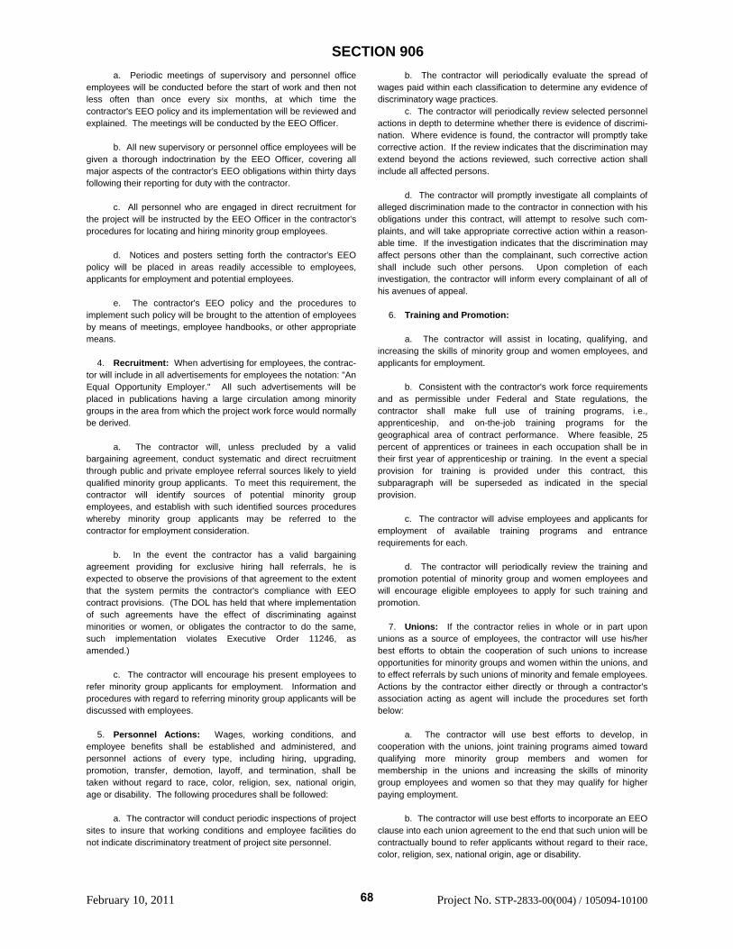
SECTION 906
February 10, 2011 Project No. STP-2833-00(004) / 105094-10100
a. Periodic meetings of supervisory and personnel office employees will be conducted before the start of work and then not less often than once every six months, at which time the contractor's EEO policy and its implementation will be reviewed and explained. The meetings will be conducted by the EEO Officer. b. All new supervisory or personnel office employees will be given a thorough indoctrination by the EEO Officer, covering all major aspects of the contractor's EEO obligations within thirty days following their reporting for duty with the contractor. c. All personnel who are engaged in direct recruitment for the project will be instructed by the EEO Officer in the contractor's procedures for locating and hiring minority group employees. d. Notices and posters setting forth the contractor's EEO policy will be placed in areas readily accessible to employees, applicants for employment and potential employees. e. The contractor's EEO policy and the procedures to implement such policy will be brought to the attention of employees by means of meetings, employee handbooks, or other appropriate means. 4. Recruitment: When advertising for employees, the contrac-tor will include in all advertisements for employees the notation: "An Equal Opportunity Employer." All such advertisements will be placed in publications having a large circulation among minority groups in the area from which the project work force would normally be derived. a. The contractor will, unless precluded by a valid bargaining agreement, conduct systematic and direct recruitment through public and private employee referral sources likely to yield qualified minority group applicants. To meet this requirement, the contractor will identify sources of potential minority group employees, and establish with such identified sources procedures whereby minority group applicants may be referred to the contractor for employment consideration. b. In the event the contractor has a valid bargaining agreement providing for exclusive hiring hall referrals, he is expected to observe the provisions of that agreement to the extent that the system permits the contractor's compliance with EEO contract provisions. (The DOL has held that where implementation of such agreements have the effect of discriminating against minorities or women, or obligates the contractor to do the same, such implementation violates Executive Order 11246, as amended.) c. The contractor will encourage his present employees to refer minority group applicants for employment. Information and procedures with regard to referring minority group applicants will be discussed with employees. 5. Personnel Actions: Wages, working conditions, and employee benefits shall be established and administered, and personnel actions of every type, including hiring, upgrading, promotion, transfer, demotion, layoff, and termination, shall be taken without regard to race, color, religion, sex, national origin, age or disability. The following procedures shall be followed: a. The contractor will conduct periodic inspections of project sites to insure that working conditions and employee facilities do not indicate discriminatory treatment of project site personnel.
b. The contractor will periodically evaluate the spread of wages paid within each classification to determine any evidence of discriminatory wage practices. c. The contractor will periodically review selected personnel actions in depth to determine whether there is evidence of discrimi-nation. Where evidence is found, the contractor will promptly take corrective action. If the review indicates that the discrimination may extend beyond the actions reviewed, such corrective action shall include all affected persons. d. The contractor will promptly investigate all complaints of alleged discrimination made to the contractor in connection with his obligations under this contract, will attempt to resolve such com-plaints, and will take appropriate corrective action within a reason-able time. If the investigation indicates that the discrimination may affect persons other than the complainant, such corrective action shall include such other persons. Upon completion of each investigation, the contractor will inform every complainant of all of his avenues of appeal. 6. Training and Promotion: a. The contractor will assist in locating, qualifying, and increasing the skills of minority group and women employees, and applicants for employment. b. Consistent with the contractor's work force requirements and as permissible under Federal and State regulations, the contractor shall make full use of training programs, i.e., apprenticeship, and on-the-job training programs for the geographical area of contract performance. Where feasible, 25 percent of apprentices or trainees in each occupation shall be in their first year of apprenticeship or training. In the event a special provision for training is provided under this contract, this subparagraph will be superseded as indicated in the special provision. c. The contractor will advise employees and applicants for employment of available training programs and entrance requirements for each. d. The contractor will periodically review the training and promotion potential of minority group and women employees and will encourage eligible employees to apply for such training and promotion. 7. Unions: If the contractor relies in whole or in part upon unions as a source of employees, the contractor will use his/her best efforts to obtain the cooperation of such unions to increase opportunities for minority groups and women within the unions, and to effect referrals by such unions of minority and female employees. Actions by the contractor either directly or through a contractor's association acting as agent will include the procedures set forth below: a. The contractor will use best efforts to develop, in cooperation with the unions, joint training programs aimed toward qualifying more minority group members and women for membership in the unions and increasing the skills of minority group employees and women so that they may qualify for higher paying employment. b. The contractor will use best efforts to incorporate an EEO clause into each union agreement to the end that such union will be contractually bound to refer applicants without regard to their race, color, religion, sex, national origin, age or disability.
68
SECTION 906
February 10, 2011 Project No. STP-2833-00(004) / 105094-10100
c. The contractor is to obtain information as to the referral practices and policies of the labor union except that to the extent such information is within the exclusive possession of the labor union and such labor union refuses to furnish such information to the contractor, the contractor shall so certify to the SHA and shall set forth what efforts have been made to obtain such information. d. In the event the union is unable to provide the contractor with a reasonable flow of minority and women referrals within the time limit set forth in the collective bargaining agreement, the contractor will, through independent recruitment efforts, fill the employment vacancies without regard to race, color, religion, sex, national origin, age or disability; making full efforts to obtain qualified and/or qualifiable minority group persons and women. (The DOL has held that it shall be no excuse that the union with which the contractor has a collective bargaining agreement providing for exclusive referral failed to refer minority employees.) In the event the union referral practice prevents the contractor from meeting the obligations pursuant to Executive Order 11246, as amended, and these special provisions, such contractor shall immediately notify the SHA. 8. Selection of Subcontractors, Procurement of Materials and Leasing of Equipment: The contractor shall not discriminate on the grounds of race, color, religion, sex, national origin, age or disability in the selection and retention of subcontractors, including procurement of materials and leases of equipment. a. The contractor shall notify all potential subcontractors and suppliers of his/her EEO obligations under this contract. b. Disadvantaged business enterprises (DBE), as defined in 49 CFR 23, shall have equal opportunity to compete for and perform subcontracts which the contractor enters into pursuant to this contract. The contractor will use his best efforts to solicit bids from and to utilize DBE subcontractors or subcontractors with meaningful minority group and female representation among their employees. Contractors shall obtain lists of DBE construction firms from SHA personnel. c. The contractor will use his best efforts to ensure subcontractor compliance with their EEO obligations. 9. Records and Reports: The contractor shall keep such records as necessary to document compliance with the EEO requirements. Such records shall be retained for a period of three years following completion of the contract work and shall be available at reasonable times and places for inspection by authorized representatives of the SHA and the FHWA. a. The records kept by the contractor shall document the following: (1) The number of minority and non-minority group members and women employed in each work classification on the project; (2) The progress and efforts being made in cooperation with unions, when applicable, to increase employment opportunities for minorities and women; (3) The progress and efforts being made in locating, hiring, training, qualifying, and upgrading minority and female employees; and (4) The progress and efforts being made in securing the services of DBE subcontractors or subcontractors with meaningful minority and female representation among their employees.
b. The contractors will submit an annual report to the SHA each July for the duration of the project, indicating the number of minority, women, and non-minority group employees currently engaged in each work classification required by the contract work. This information is to be reported on Form FHWA-1391. If on-the-job training is being required by special provision, the contractor will be required to collect and report training data. III. NONSEGREGATED FACILITIES (Applicable to all Federal-aid construction contracts and to all related subcontracts of $10,000 or more.) a. By submission of this bid, the execution of this contract or subcontract, or the consummation of this material supply agreement or purchase order, as appropriate, the bidder, Federal-aid construction contractor, subcontractor, material supplier, or vendor, as appropriate, certifies that the firm does not maintain or provide for its employees any segregated facilities at any of its establishments, and that the firm does not permit its employees to perform their services at any location, under its control, where segregated facilities are maintained. The firm agrees that a breach of this certification is a violation of the EEO provisions of this contract. The firm further certifies that no employee will be denied access to adequate facilities on the basis of sex or disability. b. As used in this certification, the term "segregated facilities" means any waiting rooms, work areas, restrooms and washrooms, restaurants and other eating areas, timeclocks, locker rooms, and other storage or dressing areas, parking lots, drinking fountains, recreation or entertainment areas, transportation, and housing facilities provided for employees which are segregated by explicit directive, or are, in fact, segregated on the basis of race, color, religion, national origin, age or disability, because of habit, local custom, or otherwise. The only exception will be for the disabled when the demands for accessibility override (e.g. disabled parking). c. The contractor agrees that it has obtained or will obtain identical certification from proposed subcontractors or material suppliers prior to award of subcontracts or consummation of material supply agreements of $10,000 or more and that it will retain such certifications in its files. IV. PAYMENT OF PREDETERMINED MINIMUM WAGE (Applicable to all Federal-aid construction contracts exceeding $2,000 and to all related subcontracts, except for projects located on roadways classified as local roads or rural minor collectors, which are exempt.) 1. General: a. All mechanics and laborers employed or working upon the site of the work will be paid unconditionally and not less often than once a week and without subsequent deduction or rebate on any account [except such payroll deductions as are permitted by regulations (29 CFR 3) issued by the Secretary of Labor under the Copeland Act (40 U.S.C. 276c)] the full amounts of wages and bona fide fringe benefits (or cash equivalents thereof) due at time of payment. The payment shall be computed at wage rates not less than those contained in the wage determination of the Secretary of Labor (hereinafter "the wage determination") which is attached hereto and made a part hereof, regardless of any contractual relationship which may be alleged to exist between the contractor or its subcontractors and such laborers and mechanics. The wage determination (including any additional classifications and wage
69
SECTION 906
February 10, 2011 Project No. STP-2833-00(004) / 105094-10100
rates conformed under paragraph 2 of this Section IV and the DOL poster (WH-1321) or Form FHWA-1495) shall be posted at all times by the contractor and its subcontractors at the site of the work in a prominent and accessible place where it can be easily seen by the workers. For the purpose of this Section, contributions made or costs reasonably anticipated for bona fide fringe benefits under Section 1(b)(2) of the Davis-Bacon Act (40 U.S.C. 276a) on behalf of laborers or mechanics are considered wages paid to such laborers or mechanics, subject to the provisions of Section IV, paragraph 3b, hereof. Also, for the purpose of this Section, regular contributions made or costs incurred for more than a weekly period (but not less often than quarterly) under plans, funds, or programs, which cover the particular weekly period, are deemed to be constructively made or incurred during such weekly period. Such laborers and mechanics shall be paid the appropriate wage rate and fringe benefits on the wage determination for the classification of work actually performed, without regard to skill, except as provided in paragraphs 4 and 5 of this Section IV. b. Laborers or mechanics performing work in more than one classification may be compensated at the rate specified for each classification for the time actually worked therein, provided, that the employer's payroll records accurately set forth the time spent in each classification in which work is performed. c. All rulings and interpretations of the Davis-Bacon Act and related acts contained in 29 CFR 1, 3, and 5 are herein incorpo-rated by reference in this contract. 2. Classification: a. The SHA contracting officer shall require that any class of laborers or mechanics employed under the contract, which is not listed in the wage determination, shall be classified in conformance with the wage determination. b. The contracting officer shall approve an additional classification, wage rate and fringe benefits only when the following criteria have been met: (1) the work to be performed by the additional classification requested is not performed by a classification in the wage determination; (2) the additional classification is utilized in the area by the construction industry; (3) the proposed wage rate, including any bona fide fringe benefits, bears a reasonable relationship to the wage rates contained in the wage determination; and (4) with respect to helpers, when such a classification prevails in the area in which the work is performed. c. If the contractor or subcontractors, as appropriate, the laborers and mechanics (if known) to be employed in the additional classification or their representatives, and the contracting officer agree on the classification and wage rate (including the amount designated for fringe benefits where appropriate), a report of the action taken shall be sent by the contracting officer to the DOL, Administrator of the Wage and Hour Division, Employment Standards Administration, Washington, D.C. 20210. The Wage and Hour Administrator, or an authorized representative, will approve, modify, or disapprove every additional classification action within 30 days of receipt and so advise the contracting officer or will notify the contracting officer within the 30-day period that additional time is necessary.
d. In the event the contractor or subcontractors, as appropriate, the laborers or mechanics to be employed in the additional classification or their representatives, and the contracting officer do not agree on the proposed classification and wage rate (including the amount designated for fringe benefits, where appropriate), the contracting officer shall refer the questions, including the views of all interested parties and the recommendation of the contracting officer, to the Wage and Hour Administrator for determination. Said Administrator, or an authorized representative, will issue a determination within 30 days of receipt and so advise the contracting officer or will notify the contracting officer within the 30-day period that additional time is necessary e. The wage rate (including fringe benefits where appropriate) determined pursuant to paragraph 2c or 2d of this Section IV shall be paid to all workers performing work in the additional classification from the first day on which work is performed in the classification. 3. Payment of Fringe Benefits: a. Whenever the minimum wage rate prescribed in the contract for a class of laborers or mechanics includes a fringe benefit which is not expressed as an hourly rate, the contractor or subcontractors, as appropriate, shall either pay the benefit as stated in the wage determination or shall pay another bona fide fringe benefit or an hourly case equivalent thereof. b. If the contractor or subcontractor, as appropriate, does not make payments to a trustee or other third person, he/she may consider as a part of the wages of any laborer or mechanic the amount of any costs reasonably anticipated in providing bona fide fringe benefits under a plan or program, provided, that the Secretary of Labor has found, upon the written request of the contractor, that the applicable standards of the Davis-Bacon Act have been met. The Secretary of Labor may require the contractor to set aside in a separate account assets for the meeting of obligations under the plan or program. 4. Apprentices and Trainees (Programs of the U.S. DOL) and Helpers: a. Apprentices: (1) Apprentices will be permitted to work at less than the predetermined rate for the work they performed when they are employed pursuant to and individually registered in a bona fide apprenticeship program registered with the DOL, Employment and Training Administration, Bureau of Apprenticeship and Training, or with a State apprenticeship agency recognized by the Bureau, or if a person is employed in his/her first 90 days of probationary employment as an apprentice in such an apprenticeship program, who is not individually registered in the program, but who has been certified by the Bureau of Apprenticeship and Training or a State apprenticeship agency (where appropriate) to be eligible for probationary employment as an apprentice. (2) The allowable ratio of apprentices to journeyman-level employees on the job site in any craft classification shall not be greater than the ratio permitted to the contractor as to the entire work force under the registered program. Any employee listed on a payroll at an apprentice wage rate, who is not registered or otherwise employed as stated above, shall be paid not less than the applicable wage rate listed in the wage determination for the classification of work actually performed. In addition, any appren-tice performing work on the job site in excess of the ratio permitted under the registered program shall be paid not less than the
70
SECTION 906
February 10, 2011 Project No. STP-2833-00(004) / 105094-10100
applicable wage rate on the wage determination for the work actually performed. Where a contractor or subcontractor is performing construction on a project in a locality other than that in which its program is registered, the ratios and wage rates (expressed in percentages of the journeyman-level hourly rate) specified in the contractor's or subcontractor's registered program shall be observed. (3) Every apprentice must be paid at not less than the rate specified in the registered program for the apprentice's level of progress, expressed as a percentage of the journeyman-level hourly rate specified in the applicable wage determination. Apprentices shall be paid fringe benefits in accordance with the provisions of the apprenticeship program. If the apprenticeship program does not specify fringe benefits, apprentices must be paid the full amount of fringe benefits listed on the wage determination for the applicable classification. If the Administrator for the Wage and Hour Division determines that a different practice prevails for the applicable apprentice classification, fringes shall be paid in accordance with that determination. (4) In the event the Bureau of Apprenticeship and Training, or a State apprenticeship agency recognized by the Bureau, withdraws approval of an apprenticeship program, the contractor or subcontractor will no longer be permitted to utilize apprentices at less than the applicable predetermined rate for the comparable work performed by regular employees until an acceptable program is approved. b. Trainees: (1) Except as provided in 29 CFR 5.16, trainees will not be permitted to work at less than the predetermined rate for the work performed unless they are employed pursuant to and individually registered in a program which has received prior approval, evidenced by formal certification by the DOL, Employment and Training Administration. (2) The ratio of trainees to journeyman-level employees on the job site shall not be greater than permitted under the plan approved by the Employment and Training Administration. Any employee listed on the payroll at a trainee rate who is not registered and participating in a training plan approved by the Employment and Training Administration shall be paid not less than the applicable wage rate on the wage determination for the classification of work actually performed. In addition, any trainee performing work on the job site in excess of the ratio permitted under the registered program shall be paid not less than the applicable wage rate on the wage determination for the work actually performed. (3) Every trainee must be paid at not less than the rate specified in the approved program for his/her level of progress, expressed as a percentage of the journeyman-level hourly rate specified in the applicable wage determination. Trainees shall be paid fringe benefits in accordance with the provisions of the trainee program. If the trainee program does not mention fringe benefits, trainees shall be paid the full amount of fringe benefits listed on the wage determination unless the Administrator of the Wage and Hour Division determines that there is an apprenticeship program associated with the corresponding journeyman-level wage rate on the wage determination which provides for less than full fringe benefits for apprentices, in which case such trainees shall receive the same fringe benefits as apprentices. (4) In the event the Employment and Training Administration withdraws approval of a training program, the contractor or subcontractor will no longer be permitted to utilize
trainees at less than the applicable predetermined rate for the work performed until an acceptable program is approved. c. Helpers: Helpers will be permitted to work on a project if the helper classification is specified and defined on the applicable wage determination or is approved pursuant to the conformance proce-dure set forth in Section IV.2. Any worker listed on a payroll at a helper wage rate, who is not a helper under a approved definition, shall be paid not less than the applicable wage rate on the wage determination for the classification of work actually performed. 5. Apprentices and Trainees (Programs of the U.S. DOT): Apprentices and trainees working under apprenticeship and skill training programs which have been certified by the Secretary of Transportation as promoting EEO in connection with Federal-aid highway construction programs are not subject to the requirements of paragraph 4 of this Section IV. The straight time hourly wage rates for apprentices and trainees under such programs will be established by the particular programs. The ratio of apprentices and trainees to journeymen shall not be greater than permitted by the terms of the particular program. 6. Withholding: The SHA shall upon its own action or upon written request of an authorized representative of the DOL withhold, or cause to be withheld, from the contractor or subcontractor under this contract or any other Federal contract with the same prime contractor, or any other Federally-assisted contract subject to Davis-Bacon prevailing wage requirements which is held by the same prime contractor, as much of the accrued payments or advances as may be considered necessary to pay laborers and mechanics, including apprentices, trainees, and helpers, employed by the contractor or any subcontractor the full amount of wages required by the contract. In the event of failure to pay any laborer or mechanic, including any apprentice, trainee, or helper, employed or working on the site of the work, all or part of the wages required by the contract, the SHA contracting officer may, after written notice to the contractor, take such action as may be necessary to cause the suspension of any further payment, advance, or guarantee of funds until such violations have ceased. 7. Overtime Requirements: No contractor or subcontractor contracting for any part of the contract work which may require or involve the employment of laborers, mechanics, watchmen, or guards (including apprentices, trainees, and helpers described in paragraphs 4 and 5 above) shall require or permit any laborer, mechanic, watchman, or guard in any workweek in which he/she is employed on such work, to work in excess of 40 hours in such workweek unless such laborer, mechanic, watchman, or guard receives compensation at a rate not less than one-and-one-half times his/her basic rate of pay for all hours worked in excess of 40 hours in such workweek. 8. Violation: Liability for Unpaid Wages; Liquidated Damages: In the event of any violation of the clause set forth in paragraph 7 above, the contractor and any subcontractor responsible thereof shall be liable to the affected employee for his/her unpaid wages. In addition, such contractor and subcontractor shall be liable to the United States (in the case of work done under contract for the District of Columbia or a territory, to such District or to such territory) for liquidated damages. Such liquidated damages shall be
71
SECTION 906
February 10, 2011 Project No. STP-2833-00(004) / 105094-10100
computed with respect to each individual laborer, mechanic, watchman, or guard employed in violation of the clause set forth in paragraph 7, in the sum of $10 for each calendar day on which such employee was required or permitted to work in excess of the standard work week of 40 hours without payment of the overtime wages required by the clause set forth in paragraph 7. 9. Withholding for Unpaid Wages and Liquidated Damages: The SHA shall upon its own action or upon written request of any authorized representative of the DOL withhold, or cause to be withheld, from any monies payable on account of work performed by the contractor or subcontractor under any such contract or any other Federal contract with the same prime contractor, or any other Federally-assisted contract subject to the Contract Work Hours and Safety Standards Act, which is held by the same prime contractor, such sums as may be determined to be necessary to satisfy any liabilities of such contractor or subcontractor for unpaid wages and liquidated damages as provided in the clause set forth in paragraph 8 above. V. STATEMENTS AND PAYROLLS (Applicable to all Federal-aid construction contracts exceeding $2,000 and to all related subcontracts, except for projects located on roadways classified as local roads or rural collectors, which are exempt.) 1. Compliance with Copeland Regulations (29 CFR 3): The contractor shall comply with the Copeland Regulations of the Secretary of Labor which are herein incorporated by reference. 2. Payrolls and Payroll Records: a. Payrolls and basic records relating thereto shall be maintained by the contractor and each subcontractor during the course of the work and preserved for a period of 3 years from the date of completion of the contract for all laborers, mechanics, apprentices, trainees, watchmen, helpers, and guards working at the site of the work. b. The payroll records shall contain the name, social security number, and address of each such employee; his or her correct classification; hourly rates of wages paid (including rates of contributions or costs anticipated for bona fide fringe benefits or cash equivalent thereof the types described in Section 1(b)(2)(B) of the Davis Bacon Act); daily and weekly number of hours worked; deductions made; and actual wages paid. In addition, for Appala-chian contracts, the payroll records shall contain a notation indicat-ing whether the employee does, or does not, normally reside in the labor area as defined in Attachment A, paragraph 1. Whenever the Secretary of Labor, pursuant to Section IV, paragraph 3b, has found that the wages of any laborer or mechanic include the amount of any costs reasonably anticipated in providing benefits under a plan or program described in Section 1(b)(2)(B) of the Davis Bacon Act, the contractor and each subcontractor shall maintain records which show that the commitment to provide such benefits is enforceable, that the plan or program is financially responsible, that the plan or program has been communicated in writing to the laborers or mechanics affected, and show the cost anticipated or the actual cost incurred in providing benefits. Contractors or subcontractors employing apprentices or trainees under approved programs shall maintain written evidence of the registration of apprentices and trainees, and ratios and wage rates prescribed in the applicable programs.
c. Each contractor and subcontractor shall furnish, each week in which any contract work is performed, to the SHA resident engineer a payroll of wages paid each of its employees (including apprentices, trainees, and helpers, described in Section IV, paragraphs 4 and 5, and watchmen and guards engaged on work during the preceding weekly payroll period). The payroll submitted required to be maintained under paragraph 2b of this Section V. This information may be submitted in any form desired. Optional Form WH-347 is available for this purpose and may be purchased from the Superintendent of Documents (Federal stock number 029-005-0014-1), U.S. Government Printing Office, Washington, D.C. 20402. The prime contractor is responsible for the submission of copies of payrolls by all subcontractors. d. Each payroll submitted shall be accompanied by a "Statement of Compliance," signed by the contractor or subcontractor or his/her agent who pays or supervises the payment of the persons employed under the contract and shall certify the following: (1) that the payroll for the payroll period contains the information required to be maintained under paragraph 2b of this Section V and that such information is correct and complete; (2) that such laborer or mechanic (including each helper, apprentice, and trainee) employed on the contract during the payroll period has been paid the full weekly wages earned, without rebate, either directly or indirectly, and that no deductions have been made either directly or indirectly from the full wages earned, other than permissible deductions as set forth in the Regulations, 29 CFR 3; (3) that each laborer or mechanic has been paid not less that the applicable wage rate and fringe benefits or cash equivalent for the classification of worked performed, as specified in the applicable wage determination incorporated into the contract. e. The weekly submission of a properly executed certification set forth on the reverse side of Optional Form WH-347 shall satisfy the requirement for submission of the "Statement of Compliance" required by paragraph 2d of this Section V. f. The falsification of any of the above certifications may subject the contractor to civil or criminal prosecution under 18 U.S.C. 1001 and 31 U.S.C. 231. g. The contractor or subcontractor shall make the records required under paragraph 2b of this Section V available for inspection, copying, or transcription by authorized representatives of the SHA, the FHWA, or the DOL, and shall permit such representatives to interview employees during working hours on the job. If the contractor or subcontractor fails to submit the required records or to make them available, the SHA, the FHWA, the DOL, or all may, after written notice to the contractor, sponsor, applicant, or owner, take such actions as may be necessary to cause the suspension of any further payment, advance, or guarantee of funds. Furthermore, failure to submit the required records upon request or to make such records available may be grounds for debarment action pursuant to 29 CFR 5.12. VI. RECORD OF MATERIALS, SUPPLIES, AND LABOR 1. On all Federal-aid contracts on the National Highway System, except those which provide solely for the installation of protective devices at railroad grade crossings, those which are constructed on a force account or direct labor basis, highway beautification contracts, and contracts for which the total final
72
SECTION 906
February 10, 2011 Project No. STP-2833-00(004) / 105094-10100
construction cost for roadway and bridge is less than $1,000,000 (23 CFR 635) the contractor shall: a. Become familiar with the list of specific materials and supplies contained in Form FHWA-47, "Statement of Materials and Labor Used by Contractor of Highway Construction Involving Federal Funds," prior to the commencement of work under this contract. b. Maintain a record of the total cost of all materials and supplies purchased for and incorporated in the work, and also of the quantities of those specific materials and supplies listed on Form FHWA-47, and in the units shown on Form FHWA-47. c. Furnish, upon the completion of the contract, to the SHA resident engineer on Form FHWA-47 together with the data required in paragraph 1b relative to materials and supplies, a final labor summary of all contract work indicating the total hours worked and the total amount earned. 2. At the prime contractor's option, either a single report covering all contract work or separate reports for the contractor and for each subcontract shall be submitted. VII. SUBLETTING OR ASSIGNING THE CONTRACT 1. The contractor shall perform with its own organization contract work amounting to not less than 30 percent (or a greater percentage if specified elsewhere in the contract) of the total original contract price, excluding any specialty items designated by the State. Specialty items may be performed by subcontract and the amount of any such specialty items performed may be deducted from the total original contract price before computing the amount of work required to be performed by the contractor's own organization (23 CFR 635). a. "Its own organization" shall be construed to include only workers employed and paid directly by the prime contractor and equipment owned or rented by the prime contractor, with or without operators. Such term does not include employees or equipment of a subcontractor, assignee, or agent of the prime contractor. b. "Specialty Items" shall be construed to be limited to work that requires highly specialized knowledge, abilities, or equipment not ordinarily available in the type of contracting organizations qualified and expected to bid on the contract as a whole and in general are to be limited to minor components of the overall contract. 2. The contract amount upon which the requirements set forth in paragraph 1 of Section VII is computed includes the cost of material and manufactured products which are to be purchased or produced by the contractor under the contract provisions. 3. The contractor shall furnish (a) a competent superintendent or supervisor who is employed by the firm, has full authority to direct performance of the work in accordance with the contract requirements, and is in charge of all construction operations (regardless of who performs the work) and (b) such other of its own organizational resources (supervision, management, and engineer-ing services) as the SHA contracting officer determines is neces-sary to assure the performance of the contract. 4. No portion of the contract shall be sublet, assigned or otherwise disposed of except with the written consent of the SHA contracting officer, or authorized representative, and such consent when given shall not be construed to relieve the contractor of any responsibility for the fulfillment of the contract. Written consent will
be given only after the SHA has assured that each subcontract is evidenced in writing and that it contains all pertinent provisions and requirements of the prime contract. VIII. SAFETY: ACCIDENT PREVENTION 1. In the performance of this contract the contractor shall comply with all applicable Federal, State, and local laws governing safety, health, and sanitation (23 CFR 635). The contractor shall provide all safeguards, safety devices and protective equipment and take any other needed actions as it determines, or as the SHA contracting officer may determine, to be reasonably necessary to protect the life and health of employees on the job and the safety of the public and to protect property in connection with the performance of the work covered by the contract. 2. It is a condition of this contract, and shall be made a condition of each subcontract, which the contractor enters into pursuant to this contract, that the contractor and any subcontractor shall not permit any employee, in performance of the contract, to work in surroundings or under conditions which are unsanitary, hazardous or dangerous to his/her health or safety, as determined under construction safety and health standards (29 CFR 1926) promulgated by the Secretary of Labor, in accordance with Section 107 of the Contract Work Hours and Safety Standards Act (40 U.S.C. 333). 3. Pursuant to 29 CFR 1926.3, it is a condition of this contract that the Secretary of Labor or authorized representative thereof, shall have right of entry to any site of contract performance to inspect or investigate the matter of compliance with the construction safety and health standards and to carry out the duties of the Secretary under Section 107 of the Contract Work Hours and Safety Standards Act (40 U.S.C. 333). IX. FALSE STATEMENTS CONCERNING HIGHWAY PROJECTS In order to assure high quality and durable construction in conformity with approved plans and specifications and a high degree of reliability on statements and representations made by engineers, contractors, suppliers, and workers on Federal-aid highway projects, it is essential that all persons concerned with the project perform their functions as carefully, thoroughly, and honestly as possible. Willful falsification, distortion, or misrepresentation with respect to any facts related to the project is a violation of Federal law. To prevent any misunderstanding regarding the seriousness of these and similar acts, the following notice shall be posted on each Federal-aid highway project (23 CFR 635) in one or more places where it is readily available to all persons concerned with the project:
NOTICE TO ALL PERSONNEL ENGAGED ON FEDERAL-AID HIGHWAY PROJECTS
18 U.S.C. 1020 reads as follows: "Whoever, being an officer, agent, or employee of the United States, or of any State or Territory, or whoever, whether a person, association, firm, or corporation, knowingly makes any false statement, false representation, or false report as to the character, quality, quantity, or cost of the material used or to be used, or the quantity or quality of the work performed or to be performed, or the cost thereof in connection with the submission of plans, maps, specifications, contracts, or costs of construction on any highway or related project submitted for approval to the Secretary of Transportation; or
73
SECTION 906
February 10, 2011 Project No. STP-2833-00(004) / 105094-10100
Whoever knowingly makes any false statement, false representation, false report or false claim with respect to the character, quality, quantity, or cost of any work performed or to be performed, or materials furnished or to be furnished, in connection with the construction of any highway or related project approved by the Secretary of Transportation; or Whoever knowingly makes any false statement or false representation as to material fact in any statement, certificate, or report submitted pursuant to provisions of the Federal-aid Roads Act approved July 1, 1916, (39 Stat. 355), as amended and supplemented; Shall be fined not more that $10,000 or imprisoned not more than 5 years or both." X. IMPLEMENTATION OF CLEAN AIR ACT AND FEDERAL WATER POLLUTION CONTROL ACT (Applicable to all Federal-aid construction contracts and to all related subcontracts of $100,000 or more.) By submission of this bid or the execution of this contract, or subcontract, as appropriate, the bidder, Federal-aid construction contractor, or subcontractor, as appropriate, will be deemed to have stipulated as follows: 1. That any facility that is or will be utilized in the performance of this contract, unless such contract is exempt under the Clean Air Act, as amended (42 U.S.C. 1857 et seq., as amended by Pub.L. 91-604), and under the Federal Water Pollution Control Act, as amended (33 U.S.C. 1251 et seq., as amended by Pub.L. 92-500), Executive Order 11738, and regulations in implementation thereof (40 CFR 15) is not listed, on the date of contract award, on the U.S. Environmental Protection Agency (EPA) List of Violating Facilities pursuant to 40 CFR 15.20. 2. That the firm agrees to comply and remain in compliance with all the requirements of Section 114 of the Clean Air Act and Section 308 of the Federal Water Pollution Control Act and all regulations and guidelines listed thereunder. 3. That the firm shall promptly notify the SHA of the receipt of any communication from the Director, Office of Federal Activities, EPA, indicating that a facility that is or will be utilized for the contract is under consideration to be listed on the EPA List of Violating Facilities. 4. That the firm agrees to include or cause to be included the requirements of paragraph 1 through 4 of this Section X in every nonexempt subcontract, and further agrees to take such action as the government may direct as a means of enforcing such require-ments. XI. CERTIFICATION REGARDING DEBARMENT, SUSPENSION, INELIGIBILITY AND VOLUNTARY EXCLUSION 1. Instructions for Certification - Primary Covered Transac-tions: (Applicable to all Federal-aid contracts - 49 CFR 29) a. By signing and submitting this proposal, the prospective primary participant is providing the certification set out below. b. The inability of a person to provide the certification set out below will not necessarily result in denial of participation in this
covered transaction. The prospective participant shall submit an explanation of why it cannot provide the certification set out below. The certification or explanation will be considered in connection with the department or agency's determination whether to enter into this transaction. However, failure of the prospective primary participant to furnish a certification or an explanation shall disqualify such a person from participation in this transaction. c. The certification in this clause is a material representation of fact upon which reliance was placed when the department or agency determined to enter into this transaction. If it is later determined that the prospective primary participant knowingly rendered an erroneous certification, in addition to other remedies available to the Federal Government, the department or agency may terminate this transaction for cause of default. d. The prospective primary participant shall provide immedi-ate written notice to the department or agency to whom this proposal is submitted if any time the prospective primary participant learns that its certification was erroneous when submitted or has become erroneous by reason of changed circumstances. e. The terms "covered transaction," "debarred," "suspended," "ineligible," "lower tier covered transaction," "participant," "person," "primary covered transaction," "principal," "proposal," and "voluntarily excluded," as used in this clause, have the meanings set out in the Definitions and Coverage sections of rules implementing Executive Order 12549. You may contact the department or agency to which this proposal is submitted for assistance in obtaining a copy of those regulations. f. The prospective primary participant agrees by submitting this proposal that, should the proposed covered transaction be entered into, it shall not knowingly enter into any lower tier covered transaction with a person who is debarred, suspended, declared ineligible, or voluntarily excluded from participation in this covered transaction, unless authorized by the department or agency entering into this transaction. g. The prospective primary participant further agrees by submitting this proposal that it will include the clause titled "Certification Regarding Debarment, Suspension, Ineligibility and Voluntary Exclusion-Lower Tier Covered Transaction," provided by the department or agency entering into this covered transaction, without modification, in all lower tier covered transactions and in all solicitations for lower tier covered transactions. h. A participant in a covered transaction may rely upon a certification of a prospective participant in a lower tier covered transaction that is not debarred, suspended, ineligible, or voluntarily excluded from the covered transaction, unless it knows that the certification is erroneous. A participant may decide the method and frequency by which it determines the eligibility of its principals. Each participant may, but is not required to, check the nonprocure-ment portion of the "Lists of Parties Excluded From Federal Procurement or Nonprocurement Programs" (Nonprocurement List) which is compiled by the General Services Administration. i. Nothing contained in the foregoing shall be construed to require establishment of a system of records in order to render in good faith the certification required by this clause. The knowledge and information of participant is not required to exceed that which is normally possessed by a prudent person in the ordinary course of business dealings. j. Except for transactions authorized under paragraph f of these instructions, if a participant in a covered transaction knowing-ly enters into a lower tier covered transaction with a person who is
74
SECTION 906
February 10, 2011 Project No. STP-2833-00(004) / 105094-10100
suspended, debarred, ineligible, or voluntarily excluded from participation in this transaction, in addition to other remedies available to the Federal Government, the department or agency may terminate this transaction for cause or default.
* * * * *
Certification Regarding Debarment, Suspension, Ineligibility and Voluntary Exclusion--Primary Covered Transactions
1. The prospective primary participant certifies to the best of its knowledge and belief, that it and its principals: a. Are not presently debarred, suspended, proposed for debarment, declared ineligible, or voluntarily excluded from covered transactions by any Federal department or agency; b. Have not within a 3-year period preceding this proposal been convicted of or had a civil judgement rendered against them for commission of fraud or a criminal offense in connection with obtaining, attempting to obtain, or performing a public (Federal, State or local) transaction or contract under a public transaction; violation of Federal or State antitrust statutes or commission of embezzlement, theft, forgery, bribery, falsification or destruction of records, making false statements, or receiving stolen property; c. Are not presently indicted for or otherwise criminally or civilly charged by a governmental entity (Federal, State or local) with commission of any of the offenses enumerated in paragraph 1b of this certification; and d. Have not within a 3-year period preceding this application/proposal had one or more public transactions (Federal, State or local) terminated for cause or default. 2. Where the prospective primary participant is unable to certify to any of the statements in this certification, such prospective participant shall attach an explanation to this proposal.
* * * * * 2. Instructions for Certification - Lower Tier Covered Transactions: (Applicable to all subcontracts, purchase orders and other lower tier transactions of $25,000 or more - 49 CFR 29) a. By signing and submitting this proposal, the prospective lower tier is providing the certification set out below. b. The certification in this clause is a material representation of fact upon which reliance was placed when this transaction was entered into. If it is later determined that the prospective lower tier participant knowingly rendered an erroneous certification, in addition to other remedies available to the Federal Government, the department, or agency with which this transaction originated may pursue available remedies, including suspension and/or debarment. c. The prospective lower tier participant shall provide immediate written notice to the person to which this proposal is submitted if at any time the prospective lower tier participant learns that its certification was erroneous by reason of changed circumstances.
d. The terms "covered transaction," "debarred," "suspended," "ineligible," "primary covered transaction," "participant," "person," "principal," "proposal," and "voluntarily excluded," as used in this clause, have the meanings set out in the Definitions and Coverage sections of rules implementing Executive Order 12549. You may contact the person to which this proposal is submitted for assistance in obtaining a copy of those regulations. e. The prospective lower tier participant agrees by submitting this proposal that, should the proposed covered transaction be entered into, it shall not knowingly enter into any lower tier covered transaction with a person who is debarred, suspended, declared ineligible, or voluntarily excluded from participation in this covered transaction, unless authorized by the department or agency with which this transaction originated. f. The prospective lower tier participant further agrees by submitting this proposal that it will include this clause titled "Certification Regarding Debarment, Suspension, Ineligibility and Voluntary Exclusion-Lower Tier Covered Transaction," without modification, in all lower tier covered transactions and in all solicitations for lower tier covered transactions. g. A participant in a covered transaction may rely upon a certification of a prospective participant in a lower tier covered transaction that is not debarred, suspended, ineligible, or voluntarily excluded from the covered transaction, unless it knows that the certification is erroneous. A participant may decide the method and frequency by which it determines the eligibility of its principals. Each participant may, but is not required to, check the Nonprocure-ment List. h. Nothing contained in the foregoing shall be construed to require establishment of a system of records in order to render in good faith the certification required by this clause. The knowledge and information of participant is not required to exceed that which is normally possessed by a prudent person in the ordinary course of business dealings. i. Except for transactions authorized under paragraph e of these instructions, if a participant in a covered transaction knowing-ly enters into a lower tier covered transaction with a person who is suspended, debarred, ineligible, or voluntarily excluded from participation in this transaction, in addition to other remedies available to the Federal Government, the department or agency with which this transaction originated may pursue available remedies, including suspension and/or debarment.
* * * * *
Certification Regarding Debarment, Suspension, Ineligibility and Voluntary Exclusion--Lower Tier Covered Transactions: 1. The prospective lower tier participant certifies, by submission of this proposal, that neither it nor its principals is presently debarred, suspended, proposed for debarment, declared ineligible, or voluntarily excluded from participation in this transaction by any Federal department or agency. 2. Where the prospective lower tier participant is unable to certify to any of the statements in this certification, such prospective participant shall attach an explanation to this proposal.
* * * * *
75
SECTION 906
February 10, 2011 Project No. STP-2833-00(004) / 105094-10100
XII. CERTIFICATION REGARDING USE OF CONTRACT FUNDS FOR LOBBYING (Applicable to all Federal-aid construction contracts and to all related subcontracts which exceed $100,000 - 49 CFR 20) 1. The prospective participant certifies, by signing and submitting this bid or proposal, to the best of his or her knowledge and belief, that: a. No Federal appropriated funds have been paid or will be paid, by or on behalf of the undersigned, to any person for influenc-ing or attempting to influence an officer or employee of any Federal agency, a Member of Congress, an officer or employee of Con-gress, or an employee of a Member of Congress in connection with the awarding of any Federal contract, the making of any Federal grant, the making of any Federal loan, the entering into of any cooperative agreement, and the extension, continuation, renewal, amendment, or modification of any Federal contract, grant, loan, or cooperative agreement. b. If any funds other than Federal appropriated funds have been paid or will be paid to any person for influencing or attempting
to influence an officer or employee of any Federal agency, a Member of Congress, an officer or employee of Congress, or an employee of a Member of Congress in connection with this Federal contract, grant, loan, or cooperative agreement, the undersigned shall complete and submit Standard Form-LLL, "Disclosure Form to Report Lobbying," in accordance with its instructions. 2. This certification is a material representation of fact upon which reliance was placed when this transaction was made or entered into. Submission of this certification is a prerequisite for making or entering into this transaction imposed by 31 U.S.C. 1352. Any person who fails to file the required certification shall be subject to a civil penalty of not less than $10,000 and not more than $100,000 for each such failure. 3. The prospective participant also agrees by submitting his or her bid or proposal that he or she shall require that the language of this certification be included in all lower tier subcontracts, which exceed $100,000 and that all such recipients shall certify and disclose accordingly.
76
SECTION 906
February 10, 2011 Project No. STP-2833-00(004) / 105094-10100
NOTICE OF REQUIREMENTS FOR AFFIRMATIVE ACTION TO ENSURE EQUAL EMPLOYMENT OPPORTUNITY (EXECUTIVE ORDER 11246)
1. The Offeror’s or Bidder’s attention is called to the “Equal Opportunity Clause” and the “Standard Federal Equal Employment Opportunity Construction Contract Specifications” set forth herein. 2. The goals and timetables for minority and female participation, expressed in percentage terms for the Contractor’s aggregate workforce in each trade on all construction work in the covered area, are as follows: Timetables Goals for female participation in each trade (percent) From April 1, 1978 until March 31, 1979 3.1 From April 1, 1979 until March 31, 1980 5.1 From April 1, 1980 until March 31, 1981 6.9 Until further notice Goals for minority participation for each trade (percent) SHSA Cities: Pascagoula - Moss Point----------------------------------------16.9 Biloxi - Gulfport -------------------------------------------------19.2 Jackson------------------------------------------------------------30.3 SMSA Counties: Desoto-------------------------------------------------------------32.3 Hancock, Harrison, Stone --------------------------------------19.2 Hinds, Rankin ----------------------------------------------------30.3 Jackson------------------------------------------------------------16.9 Non-SMSA Counties: George, Greene --------------------------------------------------26.4
Alcorn, Benton, Bolivar, Calhoun, Carroll, Chickasaw, Clay, Coahoma,Grenada, Itawamba, Lafayette, Lee, Leflore, Marshall, Monroe,Montgomery, Panola, Pontotoc, Prentiss, Quitman, Sunflower,Tallahatchie, Tate, Tippah, Tishomingo, Tunica, Union, Washington, Webster, Yalobusha-----------------------------26.5 Attala, Choctaw, Claiborne, Clarke, Copiah, Covington, Franklin, Holmes, Humphreys, Issaquena, Jasper, Jefferson, Jefferson Davis, Jones Kemper, Lauderdale, Lawrence, Leake, Lincoln, Lowndes, Madison, Neshoba, Newton, Noxubee, Oktibbeha, Scott, Sharkey, Simpson, Smith, Warren, Wayne, Winston, Yazoo -----------------------------32.0 Forrest, Lamar, Marion, Pearl River, Perry, Pike, Walthall -----------------------------------------------------------27.7 Adams, Amite, Wilkinson--------------------------------------30.4
These goals are applicable to all the Contractor’s construction work (whether or not it is Federal or federally assisted) performed in the covered area. If the contractor performs construction work in a geographical area located outside of the covered area, it shall apply the goals established for such geographical area where the work is actually performed. With regard to this second area, the contractor also is subject to the goals for both its federally involved and nonfederally involved construction. The Contractor’s compliance with the Executive Order and the regulations in CFR Part 60-4 shall be based on its implementation of the Equal Opportunity clause, specific affirmative action obligations required by the specifications set forth in 41 CFR 60-4.3(a), and its efforts to meet the goals. The hours of minority and female employment and training must be substantially uniform throughout the length of the contract, and in each trade, and the Contractor shall make a good faith effort to employ minorities and women evenly on each of its projects. The transfer of minority or female employees or trainees from Contractor to Contractor or from project to project for the sole purpose of meeting the Contractor’s goals shall be a violation of the contract, the Executive Order and the regulations in 41 CFR Part 60-4. Compliance with the goals will be measured against the total work hours performed. 3. The Contractor shall provide written notification to the Director of the Office of Federal Contract Compliance Programs within 10 working days of award of any construction subcontract in excess of $10,000 at any tier for construction work under the contract resulting from this solicitation. The notification shall list the name, address and telephone number of the subcontractor, employer identification number of the subcontractor, estimated dollar amount of the subcontract; estimated starting and completion dates of the subcontract; and the geographical area in which the subcontract is to be performed. 4. As used in this Notice, and in the contract resulting from this solicitation, the “covered area” is to the county and city (if any), stated in the advertisement. 5. The notification required in Paragraph 3 shall be addressed to the following: Contract Compliance Officer Mississippi Department of Transportation P.O. Box 1850 Jackson, Mississippi 39215-1850
77
Mississippi Department of Transportation
Section 907
Proposed Improvements to State Route 9
From US 278/State Route 6 Near Pontotoc to US 78 Near Sherman
Pontotoc County, Mississippi
Project No. STP-2833-00(004)/105094-101000
February 10, 2011
78
February 10, 2011 Project No. STP-2833-00(004)/105094-101000
MISSISSIPPI DEPARTMENT OF TRANSPORTATION SPECIAL PROVISION NO. 907-101 DB CODE: (SP) DATE: 03/10/2009 SUBJECT: Definitions and Terms Section 101, Definitions and Terms, of the 2004 Edition of the Mississippi Standard Specifications for Road and Bridge Construction is hereby amended as follows: 907-101.01--Abbreviations. Add the following to the list of abbreviations in Subsection 101.01 starting on page 1: BV Best Value CPM Critical Path Method MCIA Mississippi Concrete Industries Association PPS Project Payment Schedule QA Quality Assurance QC Quality Control RCSR Review Comment Summary and Resolution RFC Release for Construction RFI Request for Information RFQ Request for Qualifications RFR Request for Revision SOQ Statement of Qualifications SOV Statement of Values VE Value Engineering 907-101.02--Definitions. Add the following, or amend the following, to the list of definitions in Subsection 101.02 starting on page 3: Best Value Proposal – means the Proposal provided by a Proposer that the Commission determines is (a) responsive to the RFP and (b) presents the best value for the Commission and MDOT as determined by the Criteria for Scoring of the RFP. Bid – Bid is understood to mean Proposal throughout all documents. Bidder – Bidder is understood to mean Proposer throughout all documents. Daily Diaries - Daily reports, generated by Construction Manager required for reporting on weather, manpower, equipment, material deliveries, work activities, progress, problems, and whatever else is required by the Contract. Contract – The written agreement between MDOT and the Contractor setting forth the obligations of the parties thereunder, including but not limited to, the performance of the Work, and the basis of payment. The Contract shall be composed of those documents described in Section 902, I. (Contract Documents).
79

February 10, 2011 Project No. STP-2833-00(004)/105094-101000
Engineer - The Chief Engineer of MDOT, acting directly or through a duly authorized representative(s).
Engineer of Record - Engineer of Record shall be a member of Contractor's design team and shall be a licensed Professional Engineer who has responsibility for a specific area of design and shall sign and seal plan sheets that have been developed under his/her direct supervision. Engineer of Record shall be responsible for addressing the Contractor's Requests for Information (RFI's) as per Section 2.2.6 of the Technical Specification Final Completion Date – The date on which all Work specified in the Contract is complete, which is derived from adding the calendar days bid by the Contractor to the date of the Notice to Proceed.
Governmental Approval - Any authorization, consent, approval, action, license, lease, permit, certification, exemption, filing or registration by or with any Governmental Person.
Governmental Person - Any federal, state, local or foreign government, any political subdivision or any governmental, quasi-governmental, judicial, public or statutory instrumentality, administrative agency, authority, body or entity, excluding MDOT unless the context requires otherwise. Inspector - The Contractor’s or MDOT’s authorized representative assigned to make detailed inspections of Contract performance. Laboratory - The testing laboratory of the Contractor, MDOT or any other testing laboratory which may be designated by MDOT. MDOT duly authorized representative -Those individuals or firms with specific authority to act for and on behalf of MDOT. Milestone - An activity that represents a significant point in time, and may be used to indicate the start or end of a series of related activities and/or Contract accomplishment. A milestone has zero original and remaining duration, and does not increase the Contract time. Project Documents - All written instruments associated with the Project including SOQ, RFP, Proposal, Agreement, Exhibits, referenced materials, design, and all documents produced to administer the Project including, but not limited to, all correspondence, changes, RFRs, RCSR, Request for Information, Submittals, etc. Project Management Services - All planning, monitoring, controlling and reporting for Project activities and design including but not limited to, personnel, facilities, materials, computer systems and training for management of the Project as determined adequate by MDOT. Project Payment Schedule – See Subsection 907-108.03.1.4.1 of the Special Provisions. Project Scope - All responsibilities and tasks included in the RFP necessary to complete the Project and satisfy all requirements in the Contract including all associated work developed from the design, minor MDOT revisions, changed conditions, and contingencies that may be necessary for the Contractor to complete The Work not mentioned or included in the RFP. Proposal – The offer of a Proposer, on the prescribed form, to perform the Work at the price and time quoted.
80
February 10, 2011 Project No. STP-2833-00(004)/105094-101000
Proposal Date – Is the date designated in the RFP for submission of the Proposal to MDOT.
Proposal Form – The approved form on which the Department requires Proposals to be prepared and submitted for the Work.
Proposal Guaranty – A certified check, cashier’s check, or Proposal bond furnished with the Proposal to guarantee that the Proposer will enter into a Contract for the Work and furnish acceptable bond if the Contractor’s Proposal is accepted.
Proposer - Includes a firm or firms, consortia, partnerships, joint ventures and other legal entity, which has been requested by the Mississippi Department of Transportation to submit a Proposal. Review Comment Summary and Resolution (RCSR) – A written instrument to facilitate the disposition of reviewer comments of Contractor submittals. Release for Construction - The written act of MDOT advising the Contractor it is allowed to proceed with construction, installation, manufacture or procurement according to the documents so released by MDOT, provided, however, Contractor shall none the less meet all requirements of this Contract. Request for Information (RFI) - An RFI or information request is submitted by the Contractor to MDOT or duly appointed representative when information is needed concerning the Work. RFIs are answered by the appropriate party and returned to the Contractor with a response. Request for Revision (RFR) - A written instrument for the Contractor to request a change to the Project scope identified in the RFP or the design developed during each Phase of the Project by the Contractor.
Resident or Project Engineer - The Engineer assigned by the Chief Engineer and bonded to the State to have the responsibility and authority for on-the-job administration. Site – Shall mean any area within the Right-of-Way and additional areas that may designated in the Contract. Stipend - Allowance paid for unsuccessful responsive Proposers.
Work –All design, engineering, quality control, procurement, construction, labor, supervision, testing, training and other services, equipment and materials provided or to be furnished and provided by Contractor necessary to achieve Final Acceptance of the Project in regard to which Notice To Proceed have been issued and all requirements in accordance with all the requirements of this Contract. Working Drawings - Stress sheets, shop drawings, erection plans, falsework plans, framework plans, cofferdam plans, bending diagrams for reinforcing steel, or any other supplementary plans or similar data which the Contractor is required to submit. Value Engineering – Proposed change to the Project Scope or design by MDOT or the Contractor that will reduce cost, increase quality and/or expedite the schedule. 907-101.03--Presumption. Delete Subsection 101.03 on page 13 and substitute the following. 907-101.03 – Blank.
81
February 10, 2011 Project No. STP-2833-00(004)/105094-101000
MISSISSIPPI DEPARTMENT OF TRANSPORTATION SPECIAL PROVISION NO. 907-102 DB CODE: (SP) DATE: 03/10/2009 SUBJECT: Bidding Requirements and Conditions Section 102, Bidding Requirements and Conditions, of the 2004 Edition of the Mississippi Standard Specifications for Road and Bridge Construction is hereby deleted in toto and replaced as follows: 907-102. 001–Blank.
907-102.01--Prequalification of Proposers. Prospective Proposers will be required to file with the Department a list of persons authorized to bind the company in all matters. Other information may be required from time to time before issuing Proposals. The attention of prospective Proposers is directed to all fees and taxes required for the privilege of doing business within the State of Mississippi. When two or more persons, firms or corporations are submitting a joint venture, each of the persons, firms or corporations may be required to comply with the above prequalification requirements. 907-102.02--Contents of Proposal Forms. The Proposal will identify the Project, state the location, describe the Work, and state the time in which the Work must be completed. The Proposal will also include special provisions and requirements which are not contained in the Standard Specifications or required modifications thereto. All papers bound with, attached to, or designated for addition or substitution in the Proposal are considered a part thereof and must not be detached or altered when the Proposal is submitted. All documents designated in the Proposal shall be considered a part as if attached to and included in the Proposal. 907-102.03--Issuance of Proposal. The Department reserves the right to refuse to issue a Proposal to a prospective Proposer for the following reasons: (a) Lack of competency and adequate machinery, plant, or other equipment, as revealed by the
information obtained as provided in Subsection 907-102.01 or other determinations made by the Department.
(b) Uncompleted work which, in the judgment of the Department, might hinder or prevent the prompt completion of additional work if awarded.
(c) Failure to pay, or satisfactorily settle, all bills due for labor and material on former contracts in force at the time of issuance of Proposals.
(d) Unsatisfactory performance on previous contracts.
(e) Failure to promptly reimburse the Department for any overpayment that might have occurred.
(f) Debarment of a prospective Proposer or any of its corporate officers or principal owners by the Mississippi Transportation Commission.
82
February 10, 2011 Project No. STP-2833-00(004)/105094-101000
907-102.04--Interpretation of Quantities. Determination of the quantities for the Work entailed by the Project Scope is the responsibility of the Contractor. Quantities are needed to determine the frequency of materials sampling and testing for quality control. All subsections within the MDOT Standard Specifications that establish the Method of Measurement and Basis of Payment for work performed is deleted. The single lump sum Contract Price submitted by the Contractor in response to the RFP shall constitute full and complete compensation for all Work. 907-102.05--Examination of Specifications, Special Provisions, Notices to Proposers and Site of Work. The Proposer is required to examine carefully the site of the proposed Work, the Request for Proposal (RFP), specifications, special provisions, notices to Proposers and contract forms before submitting a Proposal. MDOT has made available or provided to the Contractor information that MDOT acquired prior to the date of this Contract in the course of planning for the construction of the Project, which information is hereinafter collectively called “Informational Documents.” MDOT hereby specifically disclaims any implication that it has made any such representation or warranty either express or implied, as to any matter whatsoever, by virtue of the fact that it is making the Informational Documents available to Contractor. Further, MDOT is not representing that the Informational Documents are exhaustive, complete, accurate or sufficient for design or construction of the Project. Contractor agrees that it has full responsibility for the design and construction of the Project and Contractor specifically acknowledges and agrees that the Informational Documents are preliminary and conceptual in nature. The submission of a Proposal shall be considered prima facie evidence that the Proposer has made such an examination and is satisfied as to the conditions to be encountered in performing the Work at the Project site and as to the requirements of the Informational Documents, standard specifications, Request for Proposal, special provisions, Contract, and the Federal, State, and local laws which will in any way affect the execution of the Work. All Contracts are subject to the provisions of Sections 65-1-89 and 65-1-91, Miss. Code Ann. (1972). 907-102.06--Preparation of Proposal. Proposals are to be prepared in accordance with the requirements set forth in the Request for Proposal issued by the Department. All the figures shall be in ink or typed. It is the responsibility of every Proposer to check for any addendum or modification to the Contract document(s). It shall be the Proposer’s responsibility to be sure they are in receipt of all addenda, meeting information, and/or questions and answers provided at, or subsequent to, the pre-Proposal meeting, if any are issued. Each Proposal issued will contain duplicate Certification regarding debarment, suspension, and other responsibility matters to be completed by the Proposer. The Certification must be sworn to and shall be under penalty of perjury and Proposers are cautioned to read and understand its contents in entirety before execution. The Contractor shall provide immediate written notice to the Contract Administration Engineer at any time, prior to or after award, that it is known a certification was erroneous when executed or has become erroneous by reason of changed circumstances. Failure on the part of the Proposer to execute the Certification will result in the Proposal being considered nonresponsive.
83
February 10, 2011 Project No. STP-2833-00(004)/105094-101000
The Proposer's Proposal must be signed with ink by the individual, by one or more members of the partnership, by one or more members or officers of each firm representing a joint venture, or by one or more officers of a corporation; or by an agent of the Contractor legally qualified to bind the Contractor and acceptable to the State. If the Proposal is made by an individual, the individual’s name and address must be shown; by a partnership, the name and address of each partnership member must be shown; as a joint venture, the name and address of each member or officer of the firms represented by the joint venture must be shown; by a corporation, the name of the corporation and the business address of its corporate officials must be shown. The address stated on the Proposal shall be the Proposer's permanent address until changed by written notice to the Executive Director. All notices provided for in the Contract shall be considered as delivered to the Contractor when mailed or delivered to such address.
907-102.07--Irregular Proposals. Proposals will be considered irregular and may be rejected for any of the following reasons:
(a) If the Proposal is on a form other than that furnished by the Department, or if the form is altered or any part thereof is detached, except as allowed in Subsection 907-102.06.
(b) If there are unauthorized additions, conditional or alternate Proposals or irregularities of any
kind which may tend to make the Proposal incomplete, indefinite, or ambiguous as to its meaning.
(c) If the Proposer adds any provisions reserving the right to accept or reject an award, or to enter
into a Contract pursuant to an award. (d) If the Proposal, does not contain acknowledgement of receipt and addition to the Proposal and
Contract documents of all addenda issued prior to opening of Proposals. (e) Failure to execute required affidavits, certificates, etc., and furnish Proposal guaranty. (f) The Mississippi Transportation Commission reserves the right to reject any or all Proposals, to
waive technicalities or irregularities, or to advertise for new Proposals, and the decision of the Commission to reject any Proposal shall not be cause for any liability or damage against the Commission, the Department, any of its officers, duly appointed representatives or employees.
907-102.08--Proposal Guaranty. No Volume 2 Proposal will be considered unless accompanied by certified check, cashier's check or bond, made payable to the State of Mississippi, in an amount of not less than five percent of the total amount of the Proposal offered. Proposal bond shall not be conditioned in any way to modify the minimum five percent (5%) required. Proposals that fail to include a Proposal Guaranty shall be deemed nonresponsive and will be rejected by MDOT. The guaranty shall be evidence of good faith that, if awarded the Contract, the Proposer will execute the Contract and give Contract bond as stipulated in Subsection 907- 103.05 and as required by law. The Proposal Guaranty amount should not include the dollar amount determined for the Contract Time (Part B). If a bond is offered as guaranty, the bond must be on a form approved by the Executive Director, made by a Surety acceptable to the Executive Director and signed or countersigned by a qualified Mississippi agent or qualified nonresident agent and the Proposer.
84
February 10, 2011 Project No. STP-2833-00(004)/105094-101000
907-102.08.1--Bonding. The successful Proposer shall provide MDOT with the following bond within ten (10) calendar days of being awarded the Project:
(a) A Performance Bond, or bonds in a sum equal to the full amount of the Contract. In the event of award of a joint Proposal, each individual, partnership, firm or corporation shall assume jointly the full obligations under the Contract and Contract bond. The form of the bond(s) shall be that provided by or acceptable to the Department. The bond(s) shall be negotiated for, procured from and the premium paid to a qualified Mississippi agent or qualified nonresident agent of the Surety. The bond shall be signed or countersigned by a Mississippi agent or qualified nonresident agent and also bear the signature of an “attorney-in-fact” of the surety. Reference is made to Section 31-5-51 et seq of the Mississippi Code of 1972, Annotated, and other State statutes applicable thereto.
Bond(s) must be issued by a Surety with the Best’s rating of at least “A” or better and Financial Size Category of VIII or better by A.M. Best Co. The Surety shall be registered with the Mississippi State Insurance Commissioner. 907-102.09--Delivery of Proposals. Unless otherwise specified, Volume 2 Proposals shall be submitted sealed in a special envelope furnished by the Department. The blank spaces on the envelope shall be filled in correctly to clearly indicate its contents. When an envelope other than the special one furnished by the Department is used, it shall be of the same general size and shape and be similarly marked to clearly indicate its contents. Proposal Forms are nontransferable and no name or names of interested parties may be shown other than those to whom the Proposal was issued. When sent by mail, the sealed Proposals shall be mailed to the Department at the address and in care of the official in whose office the Proposals are to be received. All Proposals shall be submitted prior to the time and place specified in the Request for Proposals (RFP). Proposals received after the time set forth in the RFP will be returned to the Proposer unopened. 907-102.10--Blank
Delete Subsections 102.11 and 102.12 on pages 20 and 21 and substitute the following:
907-102.11--Blank 907-102.12--Blank
Delete Subsection 102.13 on page 21 and substitute the following:
907-102.13--Disqualification of Proposers. In addition to those matters set forth in Section 102.07 regarding Irregular Proposals, either of the following reasons may be considered as being sufficient for the disqualification of a Proposer and the rejection of the Proposer’s submitted Proposal or Proposals:
(a) More than one Proposal for the same work from an individual, partnership, firm or corporation under the same or different name(s).
(b) Evidence of collusion among Proposers. Participants in such collusion will receive no
recognition as Proposers for any future work of the Department until reinstated as a qualified Proposer.
85
February 10, 2011 Project No. STP-2833-00(004)/105094-101000
MISSISSIPPI DEPARTMENT OF TRANSPORTATION SPECIAL PROVISION NO. 907-103 DB CODE: (SP) DATE: 03/10/2009 SUBJECT: Award and Execution of Contract Section 103, Award and Execution of Contract, of the 2004 Edition of the Mississippi Standard Specifications for Road and Bridge Construction is hereby deleted in toto and replaced as follows:
SECTION 907-103—AWARD AND EXECUTION OF CONTRACT 907-103.01--Consideration of Proposals. After the Proposals are opened and read, they will be compared on the basis of the criteria set for in the Request for Proposal (RFP). 907-103.02--Award of Contract. The award of a Contract, if awarded, will be made within 60 calendar days after the opening of Proposals to the Proposer with the Best Value Proposal and whose Proposal complies with all the requirements prescribed. The award of contracts involving the expenditure of Federal funds is contingent upon concurrence of the FHWA. The successful Proposer will be notified of the award by letter mailed to the address shown on the Proposal. 907-103.03--Cancellation of Award. The Department reserves the right to cancel the award of a contract any time prior to the execution by all parties without liability against the Commission, Department, or any of its officers or employees. 907-103.04--Return of Proposal Guaranty. The retained Proposal Guaranty of the Proposers will be returned in accordance with the following:
i. If a contract is executed with the Best Value Proposer, then the remaining Proposers will receive their Proposal Guaranty within 10 days.
ii. If the Best Value Proposer fails to execute a contract, then the Proposal Guaranty will be forfeited in accordance with Section 103.08.
iii. If the Commission elects to negotiate a contract with the next responsive Best Value Proposer(s), then the same procedure as defined above will be followed.
In the event no award is made within 30 days after the opening of the Proposals, the Executive Director may permit the Proposer to replace the certified check or cashier's check with a satisfactory Proposer's bond. Should no award be made within 60 calendar days, all Proposals will be rejected and all guaranties returned unless the Best Value Proposer, at the request of the Commission, agrees in writing to a longer delay. 907-103.05--Requirement of Contract Bond. Prior to the execution of the contract, the Best Value Proposer shall execute and deliver to the Executive Director a Contract bond or bonds in a sum equal to the full amount of the Contract. In the event of award of a joint Proposal, each individual, partnership, firm or corporation shall assume jointly the full obligations under the Contract and Contract bond. The form of the bond(s) shall be that provided by or acceptable to the Department. The bond(s) shall be
86
February 10, 2011 Project No. STP-2833-00(004)/105094-101000
negotiated for, procured from and the premium paid to a qualified Mississippi agent or qualified nonresident agent of the Surety. The bond shall be signed or countersigned by a Mississippi agent or qualified nonresident agent and also bear the signature of an "attorney-in-fact" of the Surety. Reference is made to Section 31-5-51 et seq of the Mississippi Code of 1972, Annotated, and other State statutes applicable thereto. 907-103.06—Escrow Proposal Documents. The purpose of this specification is to preserve the Proposer’s Proposal documents for the use by MDOT in the resolution of any claim or dispute between MDOT and the Contractor either during or after construction. Within two (2) business days following submittal of the Volume 2 Proposal documents, the Contractor shall have delivered into escrow the original of all documents used in preparation of its Volume 2 Proposal for the Project (the “Escrowed Proposal Documents” or “EPD”) Upon execution of the Contract, the unsuccessful Proposers will be notified by the Commission in writing the escrowing of Proposal documents will no longer be required. The EPD of the successful Proposer will be held in escrow until all of the following have occurred: (a) 180 days have elapsed from the date of the final Contract voucher certification, (b) all disputes regarding this Contract have been settled, and (c) final payment on this Contract has been made by MDOT and accepted by the Contractor. The EPD shall be available during business hours for joint review by representatives of the Contractor, FHWA and MDOT in connection with the resolution of disputes. The EPD are, and shall always remain, the property of the Contractor, subject to MDOT’s right to review the EPD as provided herein. Copies of the EPD shall be provided to the courts of the State of Mississippi and other dispute resolvers upon request of MDOT. The Contractor shall have the right to seek a protective order governing the disclosure of the EPD to parties other than MDOT. The Contractor represents and warrants that the EPD delivered into escrow prior to execution hereof constitute all of the information used in preparation of its Proposal and agrees that no other Proposal preparation information will be considered in resolving disputes or claims related thereto, including in any judicial proceeding to resolve such disputes or claims. The Contractor also agrees that the EPD are not part of this Contract and that nothing in the EPD shall change or modify this Contract. The Contractor represents and warrants that:
(a) the EPD clearly itemize the estimated costs of performing the Work required by the Contract provisions, all work is separated into sub-items as required to present a complete and detailed estimate of all costs, crews, equipment, quantities, and rates of production are detailed;
(b) estimates of costs are divided into Contractor’s usual cost categories such as direct labor, repair labor, equipment ownership and operation, expendable materials, permanent materials and subcontract costs as appropriate, plant and equipment and indirect costs are detailed in the Contractor’s usual format, and the Contractor’s allocation of plant equipment, indirect costs, contingencies, markup and other items such as overhead and profit to each direct cost item shall be clearly identified;
(c) the EPD include all assumptions, quantity takeoffs, rates of production and progress calculations, quotes for Subcontractors and suppliers, memoranda, narratives and all other information used by the Contractor to arrive at the Contract Price.
87
February 10, 2011 Project No. STP-2833-00(004)/105094-101000
It is not intended that the Contractor perform any significant extra work in the preparation of the EPD prior to delivery thereof into escrow. However, the Contractor represents and warrants that the EPD provided prior to execution of this Contract were personally examined prior to delivery to escrow by authorized officers of the Contractor and that they meet the requirements of herein and are adequate to enable a complete understanding and interpretation of how the Contractor arrived at its Proposal. Prior to execution of this Contract representatives of MDOT and the Contractor shall jointly review the EPD to determine whether it is complete, and shall organize the EPD and label each page so that it is obvious that the page is a part of the EPD and so as to enable a person reviewing a page out of context to determine where it can be found within the EPD. The representatives shall also complete an index listing each document included in the EPD and briefly describe the document and its location in the EPD. This index and document description shall be kept with the EPD. In the event that, following the initial organization, MDOT determines that the EPD is incomplete, MDOT may request the Contractor to supply data to make the EPD complete. The Contractor shall provide all such date within three business days of the request, and at that time it will be date stamped, labeled to identify it as supplementary EPD information, and added to the EPD. The Contractor shall have no right to add documents to the EPD except upon MDOT’s request.
The EPD shall at all times be treated as proprietary and confidential information and shall be used only for purposes described in herein. Failure or refusal to provide Proposal documentation shall delay execution of the Contract or may be cause for forfeit.
The cost of the escrow will be borne by the Contractor. The Contractor will provide escrow instructions to the selected repository of EPD’s or banking institution located in Jackson, Mississippi, consistent with this specification.
907-103.07--Execution and Approval of Contract. The Best Value Proposer to whom the Contract has been awarded shall sign and file with the Executive Director, the Contract and all documents required by the Contract within 10 days after the Contract has been awarded. The Contract may require certain documents be submitted at an earlier date, in which case, those documents shall be submitted within the time frame specified. No Contract is in effect until it is executed by all parties. 907-103.08--Failure to Execute Contract. Failure of the Proposer to execute the Contract and file acceptable bond and/or other required documents within 10 days shall be just cause for the cancellation of the award and forfeiture of the Proposal Guaranty which shall become the property of the Department, not as a penalty but in liquidation of damages sustained. Award may then be made to the next responsive Best Value Proposer, or the Work may be re-advertised at the discretion of the Department.
88
February 10, 2011 Project No. STP-2833-00(004)/105094-101000
MISSISSIPPI DEPARTMENT OF TRANSPORTATION SPECIAL PROVISION NO. 907-104 DB CODE: (SP) DATE: 03/10/2009 SUBJECT: Scope of Work Section 104, Scope of Work, of the 2004 Edition of the Mississippi Standard Specifications for Road and Bridge Construction is hereby amended as follows: Delete Subsection 104.01 on page 24 and substitute the following: 907-104.01--Intent of Contract. The intent of the Contract is to provide for the execution, design, construction, and completion in every detail of the Work described, and to compensate the Contractor for all acceptable work performed in accordance with the provisions of the Contract. The Contractor shall furnish all labor, materials, equipment, supplies, transportation, supervision, quality control, methods and procedures necessary to complete the Work in accordance with the terms of the Contract. 907-104.01.1--Partnering Process COVENANT OF GOOD FAITH AND FAIR DEALING: This Contract imposes an obligation of good faith and fair dealing in its performance and enforcement. The Contractor and the Department, with a positive commitment to honesty and integrity, agree to the following mutual duties:
A. Each will function within the laws and statutes applicable to their duties and responsibilities.
B. Each will assist in the other’s performance.
C. Each will avoid hindering the other's performance.
D. Each will proceed to fulfill its obligations diligently.
E. Each will cooperate in the common endeavor of the Contract. VOLUNTARY PARTNERING: The Mississippi Department of Transportation encourages the foundation of a cohesive partnership with the Contractor and its principal subcontractors and suppliers. This partnership will be structured to draw on the strengths of each organization to identify and achieve reciprocal goals. The objectives are effective and efficient Contract performance and completion within budget, on schedule, and in accordance with the Contract. This partnership will be bilateral in make-up, and participation will be totally voluntary. Any cost associated with effectuating this partnering will be agreed to by both parties and will be shared equally. To implement this partnering initiative prior to starting of the Work in accordance with the requirements of Subsection 907-108.02 Notice to Proceed and prior to the pre-construction conference, the Contractor's
89
February 10, 2011 Project No. STP-2833-00(004)/105094-101000
management personnel and MDOT’s District Engineer, will initiate a partnering development seminar/team building workshop. The Contractor working with the assistance of the District and the State Construction Engineer will make arrangements to determine attendees for the workshop, agenda of the workshop, duration, and location. Persons required to be in attendance will be the MDOT key project personnel including MDOT’s duly authorized representative, the Contractor's Key Individuals of both the prime and principal subcontractors and suppliers. The Contractor’s design engineers, MDOT design engineers and FHWA will be also be invited to attend as necessary. The Contractor and MDOT will also be required to have Regional/District and Corporate/State level managers on the Project team. Follow-up workshops may be held periodically throughout the duration of the Contract as agreed by the Contractor and MDOT. The establishment of a partnership charter on this Project will not change the legal relationship of the parties to the Contract nor relieve either party from any of the terms of the Contract.
Delete Subsections 104.02, 104.02.1, 104.02.2, and 104.02.3 beginning on page 24 and substitute the following: 907-104.02--Alterations of Plans or Character of Work. Except as may be necessary to satisfactorily complete the Contract, no alterations of the plans or the nature of the Work will involve work beyond the termini of the contemplated construction without modification of the Contract and approval by all parties concerned. The Department reserves the right to make, in writing, at any time during the Work, such alterations in the Work as are necessary to satisfactorily complete the Project. Such changes and alterations shall neither invalidate the Contract nor release the Surety, and the Contractor agrees to perform the Work as altered. Wherever in the Specifications a supplemental agreement is provided for, such supplemental agreement must be approved by the Commission and spread upon its minutes prior to execution by the Executive Director. 907-104.02.1--Blank.
907-104.02. 2--Blank 907-104.02. 3--Blank Delete Subsection 104.03 on page 27 and substitute the following. 907-104.03--Extra Work. If the Engineer determines that authorized extra work changes the Project Scope of the original Contract, an adjustment will be made to the Contract. The basis for any allowable price adjustment will be a negotiated amount or, in lieu of negotiations or other agreement, an amount based on the sum of actual labor, material, equipment, insurance, bond, tax, etc. costs computed in accordance with Section 902 Subsection III Contract Price/Contract Payments, B.1.
The basis for any allowable time adjustment will be the amount of time that the change in Project Scope
90

February 10, 2011 Project No. STP-2833-00(004)/105094-101000
affects completion of critical activities of the critical path method (CPM) in Subsection 907-108.03.1. Delete Subsection 104.04 beginning on page 27 and substitute the following: 907-104.04--Maintenance of Traffic. Unless otherwise provided, the road under construction and all other roads and entrances to adjacent property within the Project Right of Way will be kept open to through and local traffic. The Contractor shall keep the portion of the Project being used by public traffic in satisfactory condition for traffic to be adequately accommodated. The Contractor shall also provide and maintain in a safe condition temporary approaches or crossings and intersections with trails, roads, streets, businesses, parking lots, residences, garages, and farms. On any facility on which traffic is maintained, mowing shall be performed as necessary as determined by the Construction Quality Control Manager to provide reasonable appearance and safety to the traveling public. Mowing shall be performed at the direction and satisfaction of the Construction Quality Control Manager, and shall include those areas from the edge of the pavement to a minimum of five feet beyond the shoulder line. Two, minimum width of eleven (11) feet, lanes shall be open to traffic at all times except during temporary closures of small portions of the Project as deemed necessary to expedite the Work without compromising the convenience and safety of traffic. Temporary lane closures shall NOT be permitted during mandatory hurricane evacuation orders. The Contractor shall be bound by the provisions of this subsection and other applicable provisions of the Contract with regard to the safe and convenient passage of traffic. In the case of a project for improvements or construction alongside an existing roadway on which traffic is required to be maintained, no equipment, vehicles or materials will be permitted to park or be stored within the clear/safety zone of the roadway unless it is behind a lane or shoulder closure. Unless working under an approved nighttime operation, the Contractor shall not perform any work within the clear/safety zone of the roadway between sunset and sunrise. The Contractor shall not obstruct any traffic facility or connection thereto which is officially opened to public or private traffic or required under the Contract to be maintained except as permitted in writing by the Engineer on the basis that other suitable provisions have been made. The Contractor will be required to restore and/or maintain traffic caused by snow, ice, major flooding, landslide or phenomenon of nature such as an earthquake, hurricane, tornado, etc. If the Engineer orders such special maintenance of traffic for the benefit of the traveling public, the ordered work shall be accomplished as provided in Subsection 907-104.03. Unsatisfactory maintenance of traffic shall be subject to the procedures provided in Subsection 907-105.15. Delete Subsection 104.05 beginning on page 29 and substitute the following: 907-104.05--Removal and Disposal of All Materials from the Project. The Contractor shall remove and dispose of all existing structures and obstructions in accordance with the provisions of Section 202 and the Special Provisions. All existing structures and obstructions or residual portions of structures and
91
February 10, 2011 Project No. STP-2833-00(004)/105094-101000
obstructions not designated to remain are to be removed and disposed of by the Contractor. When materials are to be removed and disposed of at locations provided by the Contractor, the Contractor shall furnish the Engineer a copy of a release from each property owner for the servitude of the land. The Contractor shall also furnish the Engineer a certified letter stating that the area of disposal is not in a wetland. The State, the Commission, the Department, or any of its officers, duly appointed representatives or employees will have no ownership or liability whatsoever for materials or matter removed thus from the right-of-way. . All removals by the Contractors are to be made in accordance with the provisions of Section 201, Section 202 and Section 203. Delete Subsection 104.06 on page 30 and substitute the following: 907-104.06--Use of Materials Found in the Work. It is understood that the title to all materials found within the Project Right of Way or easements remains with State. However, the Engineer may permit the Contractor to use stone, gravel, sand and other suitable materials found within the grading limits that may be useful in fulfillment of the Contract requirements. The excavation material, so removed and needed for use in embankments, backfills, approaches, or otherwise in the Work, shall be replaced by the Contractor with other material acceptable to the Engineer all at no cost to MDOT.
Delete Subsection 104.08 beginning on page 31 and substitute the following:
907-104.08--Value Engineering Incentive. Value Engineering Incentive applies to any cost reduction proposal initiated and developed by the Contractor for the purpose of refining the Contract documents or to significantly improve the quality of the final product. This subsection does not apply unless a proposal is identified by the Contractor at the time of submission as a Value Engineering Incentive Proposal. The Department shall be the sole judge of the acceptability of any such proposal and of the estimated net savings in design and construction costs from adoption of all or any part of such proposal. Cost reduction proposals approved by the Department are to be implemented by a supplemental agreement to the Contract and must result in savings without impairing any essential functions and characteristics such as safety, service life, reliability, economy of operations, ease of maintenance, aesthetics and necessary standard design features. As a minimum, the Contractor shall submit the following information with each proposal:
(a) A statement that the proposal is submitted as a Value Engineering Incentive Proposal;
(b) Description of the proposal;
(c) Narrative on the Contract requirements which will require modification including a recommendation for each change;
(d) Estimated cost reductions;
(e) Prediction of any effects on other costs to the Department;
(f) Recommended implementation timeframe with supporting data for maximizing cost
92
February 10, 2011 Project No. STP-2833-00(004)/105094-101000
reduction during the remainder of the Contract; and
(g) A statement as to the anticipated effect on the project completion date.
The Commission, the Department or any of its officers, duly appointed representatives or employees will not be liable for any delay in acting upon a proposal. The decision of the Engineer as to acceptance of any such proposal will be final and shall not be subject to Subsection 105.17. The Department may accept the proposal, in whole or in part, by executing a supplemental agreement that will specifically state that, it is executed pursuant to these provisions. Such agreement will incorporate the necessary changes or additions to the Contract documents to permit the proposal or accepted part thereof to be put into effect. If conditional, it will include conditions upon which the Department's approval is based. The agreement will also set forth the estimated net savings attributable to the proposal and will further provide that the Contractor be paid fifty percent (50%) of said savings. For those Value Engineering proposals submitted by the Department, the Contractor will be paid fifty percent (50%) of the savings. The cost to the Department in evaluating the proposal will be considered in determining the estimated net savings. The Contractor's share of the savings shall constitute full compensation for the Value Engineering Incentive Proposal. Approval of the proposal and performance of the work thereof shall not change the Contract completion date unless specifically provided for in the supplemental agreement implementing the proposal. The Contractor may request that the Department not use or disclose the information submitted with a proposal and such request may be honored for the extent allowed by law. Such restriction must be in writing and submitted with the proposal. If the proposal is accepted, this restriction shall be void and the Department may use, duplicate or disclose any data necessary to utilize such proposal. The executed supplemental agreement implementing the proposal will become public information in the files of the Department.
93

February 10, 2011 Project No. STP-2833-00(004)/105094-101000
MISSISSIPPI DEPARTMENT OF TRANSPORTATION SPECIAL PROVISION NO. 907-105 DB CODE: (SP) DATE: 03/10/2009 SUBJECT: Control of Work Section 105, Control of Work, of the 2004 Edition of the Mississippi Standard Specifications for Road and Bridge Construction is hereby amended as follows: Delete Subsection 105.01 beginning on page 32 and substitute the following: 907-105.01--Authority of the Engineer. The Engineer will decide all questions which may arise as to the quality and acceptability of materials, the Work and the progress of the Work; all questions which may arise as to the interpretation of the plans and specifications; and all questions as to the fulfillment of the Contract. The Engineer will have the authority to suspend the Work wholly or in part and to withhold payments because of the Contractor's failure to correct conditions unsafe for the general public, for failure to carry out provisions of the Contract, or for failure to carry out orders. The Engineer may authorize, in writing, the continued prosecution of Work activities past their specified seasonal limits when it is determined that the quality of the Work will not be reduced and the public interest will be best served. The Engineer will have authority to enforce and make effective all decisions and orders relating to the Contract. Delete Subsection 105.02 on page 33 and substitute the following: 907-105.02--Plans, Shop Drawings, and Working Drawings. The Contractor shall have one copy of the Proposal and Contract documents and one half-scale copy of the plans available at all times during Work activity on the Project. Plans will generally show details of the Work to be performed and a summary of the estimated quantities. The plans will be supplemented by shop drawings or working drawings as necessary to adequately control the Work. Shop drawings or working drawings shall be furnished by the Contractor as required for the completion of the Work. Shop drawings or working drawings shall not be considered as plan changes and any conflicts on shop drawings or working drawings, shall not supersede the requirements of the Released for Construction (RFC’d) plans and specifications. If required, the Contractor shall furnish to the Engineer the original tracings of shop drawings or working plans in the format desired by the Engineer. The contract price shall include the cost of furnishing all shop drawings or working drawings including all revised drawings that may be required in the event design details of the plans are changed. Delete Subsection 105.03 beginning on page 33 and substitute the following: 907-105.03--Conformity with plans and Specifications. All work performed and all materials furnished shall be in reasonably close conformity with the lines, grades, cross-sections, dimensions, material requirements and other construction requirements shown on the plans or required by the
94
February 10, 2011 Project No. STP-2833-00(004)/105094-101000
specifications. In the event the Engineer finds the materials or the finished product in which the materials are used not within reasonably close conformity with the plans and specifications the Contractor’s Lead Design Engineer shall submit a recommendation to the Engineer as to whether the Work should be accepted and remain in place or removed and replaced. If the Engineer allows the Work to remain in place, an appropriate adjustment in the contract price for the work or materials will be made in accordance with the contract. When the materials, the finished product or the work are not in reasonably close conformity with the plans and specifications and have resulted in an inferior, unsatisfactory or unacceptable product, the work or materials shall be removed and replaced or otherwise corrected by the Contractor. When work is of a temporary nature and its use is expected to be of short duration, the Engineer may allow minor deviations, not more than five percent (5%), from specified test values. Any such allowance will not relieve the Contractor from responsibility for maintenance of the work. Delete Subsection 105.04 beginning on page 34 and substitute the following: 907-105.04--Coordination of Specifications, Supplemental Specifications, Special Provisions and Request for Proposal (RFP). The Standard Specifications, special provisions, Notice to Proposers, Request for Proposal, Contractor’s Proposals and all other supplemental documents are essential parts of the Contract, and a requirement occurring in one Contract Document is as binding as though occurring in all. They are intended to be complementary and provide for a complete Work. In case of discrepancy, calculated dimensions will govern over scaled dimensions. In case of conflict, the order of precedence of Contract documents shall be according to SECTION 902 Subsection I. CONTRACT DOCUMENTS. Any reference in the Contract documents to a particular Section or Subsection shall mean that Section or Subsection of the Mississippi Standard Specifications for Road and Bridge Construction, or that Section or Subsection as modified by the Contract. The Contractor shall not take advantage of any apparent error or omission in the Contract requirements. When the Contractor discovers an error or omission, the Engineer shall be immediately notified. The Contractor will then make corrections utilizing the RFR process described in the Technical Requirements Section 2.2.6 and interpretations deemed necessary for fulfilling the intent of the Contract. Delete Subsection 105.05 on page 35 and substitute the following: 907-105.05--Cooperation by Contractor. The Contractor shall give the Work the attention necessary to expedite its progress, and shall cooperate with the Department, its duly authorized representatives and other Contractors in every possible way. The Contractor shall have a competent and experienced full time resident Project Director who is capable of reading and understanding the plans and specifications for the particular work being performed. The Project Director shall receive instructions from the Engineer or duly authorized representative. Upon issuance of the Notice of Award, the Contractor or duly appointed agent authorized to bind the Contractor shall file with the Engineer the name and address of the Project Director who will supervise the Work. The Engineer shall be immediately notified in writing when a change is requested in the Contract's Project Director or Project Director’s address. The Project Director shall not be changed without MDOT’s approval. The Project Director shall have full authority to execute orders or directives of the
95

February 10, 2011 Project No. STP-2833-00(004)/105094-101000
Engineer without delay and to promptly supply materials, equipment, labor and incidentals as may be required. Such Project Director shall be furnished irrespective of the amount of work sublet. The Project Director shall advise the Engineer of an intended absence from the Work and designate a person to be in charge of the Work during such absence. The Contractor shall also designate a responsible person, whose primary duty shall be to monitor and maintain the effectiveness of the erosion control plan, including NPDES permit requirements. This person must be a Certified Erosion Control Person defined as a person certified in erosion control by an organization approved by MDOT. Prior to or at the pre-construction conference the Contractor shall designate to the Engineer in writing the Certified Erosion Control Person. The designated Certified Erosion Control Person shall be assigned to only one (1) project, unless the Contractor has adjoining projects or another project in close proximity. If either of these cases exist the Contractor may request in writing that the State Construction Engineer approve the use of one (1) Certified Erosion Control Person for both projects. The Contractor may request in writing that the Engineer authorize a substitute Certified Erosion Control Person to act in the absence of the Certified Erosion Control Person. The substitute must also be a Certified Erosion Control Person. A copy of the Certified Erosion Control Person’s and the substitutes’, if used, certification must be included in the Contractor’s Protection Plan as outlined in Subsection 907-107.22.1. The Engineer shall be furnished with the telephone numbers where the Contractor's responsible person and a substitute, authorized to act in the absence of the responsible person, may be reached at all times when not on the Project. Delete Subsection 105.06 on pages 35 and 36 and substitute the following: 907-105.06--Blank. Delete Subsection 105.07 beginning on page 36 and substitute the following: 907-105.07--Cooperation Between Contractors. MDOT reserves the right to award contracts for work on or near work covered by other contracts. Each contractor will be expected to cooperate with the other contractor(s) and MDOT in every reasonable manner. MDOT will make a determination as to the practicality of prosecuting an existing contract before an additional award is made for work in the same area. Insofar as is practicable, MDOT will give notice of the intent to award subsequent contracts in the same area. Failure to do so, however, shall not prejudice the rights of Commission to award additional contracts and shall not constitute grounds for claims against the State, Commission, MDOT or any of its officers or employees. When separate contracts are let for work, any part or all of which is within the same limits, each contractor’s work shall be conducted so as to cause the least interference with work being performed by the other contractor(s). When contracts are awarded to separate Contractors for concurrent construction within a common area, the Contractors, in conference with the Engineer, shall establish a written joint schedule of operations. Such schedule will set out approximate dates and sequences for work to be performed with due regard to needs and contract time imitations of each contract. The Engineer may allow modification of the schedule when mutual benefit to the Contractors and the Engineer will result. Any modification of the joint schedule shall be in writing, mutually agreeable, and signed by the Contractors. Failure of either
96
February 10, 2011 Project No. STP-2833-00(004)/105094-101000
Contractor to abide by the terms of the joint schedule or modified schedule will be justification for termination of the Contract under the provision of Subsection 907-108.08. Each Contractor’s work shall be arranged such that the placement and disposal of the materials and equipment being used shall not interfere with the operations of the other Contractor. Each contractor shall join their work with that of others in an acceptable manner and perform it in the sequence of the established schedule. Each Contractor involved shall assume all liability, financial and otherwise, in connection with each contract and shall protect and save harmless Commission, MDOT or any of its officers, duly authorized representatives, or employees from all damages or claims that may arise because of inconvenience, delay or loss experienced because of the presence and operations of the other Contractor(s) working within the same Contract limits. Delete Subsection 105.08 beginning on page 37 and substitute the following: 907-105.08--Construction Stakes, Lines and Grades. The Contractor will set construction stakes establishing lines, slopes, and profile grades in road work and establish all centerline and benchmarks for bridge work. The Contractor will also provide all necessary information relating to lines, slopes, and grades. These stakes and benchmarks shall constitute the field control by which the Contractor shall establish and maintain all necessary controls and perform the Work. Any corrective work caused by inaccurate field controls established by the Contractor will be performed in a manner satisfactory to the Engineer and at no additional cost to MDOT. Delete Subsection 105.09 on page 38 and substitute the following. 907-105.09-- Blank. Delete Subsection 105.10 on page 38 and substitute the following: 907-105.10--Duties of the Inspector. Inspectors assigned by the Engineer or duly authorized representative will be authorized to inspect all work and materials for compliance with the Contract requirements. The inspection may extend to all parts of the Work and to the preparation, fabrication or manufacture of the materials. The inspector will not be authorized to alter or waive the provisions of the Contract, to issue instructions contrary to the Contract requirements or to act as foreman for the Contractor. Delete Subsection 105.11 beginning on page 38 and substitute the following: 907-105.11--Inspection of Work. All materials and each part or detail of the Work are subject to inspection by the Engineer. The Engineer shall be allowed access to all of the Work and shall be furnished with such information and assistance by the Contractor as necessary to make a complete and detailed inspection. Prior to acceptance of the work, the Contractor shall remove and/or uncover such portions of the work as directed by the Engineer. After examination, the Contractor shall restore said portions of the work. If the work exposed or examined was acceptable, the uncovering and/or removing and the restoring of the work will be paid as Extra Work. If the work so exposed or examined was unacceptable, the cost of uncovering and/or removing and the restoring of the work will be the Contractor’s responsibility. Additional time will not be allowed for any uncovering and/or removing and restoring of the work.
97
February 10, 2011 Project No. STP-2833-00(004)/105094-101000
When any unit of government, political subdivision, Railroad Corporation or other public service is to pay a portion of the cost of the Work, its respective representative shall have the right to inspect the work. Such inspection shall in no way make said agency or corporation a party to this Contract and shall in no way interfere with the rights of either party of the Contract. Further, no inspection of the work by the Engineer or any other MDOT representative shall relieve Contractor of its responsibilities under this Contract. Delete Subsection 105.12 on page 39 and substitute the following. 907-105.12--Removal of Unacceptable and Unauthorized Work. Unless otherwise determined acceptable under the provisions of Subsection 105.03, all work which does not conform to the requirements of the contract will be considered as nonconforming work. Nonconforming Work, whether the result of poor workmanship, defective materials, damage through carelessness or any other cause, found prior to final acceptance of the Work shall be removed and replaced in an acceptable manner, without any additional cost to the Commission. Delete Subsection 105.14 beginning on page 39 and substitute the following: 907-105.14--Maintenance during Construction. The Contractor shall maintain the Work until released from maintenance. This maintenance shall constitute continuous and effective work prosecuted day by day with adequate equipment, forces and material to the end that the roadway, structures and all other features of the Work are kept in satisfactory condition at all times. Traffic shall be continuously, safely and conveniently maintained as required under the Technical Requirements. In the case of a contract for the placing of a course upon a course or subgrade previously constructed, the Contractor shall maintain the previous course or subgrade during all construction operations. All cost for maintenance of the Work shall be the responsibility of the Contractor. Delete Subsections 105.16, 105.16.1 and 105.16.2 beginning on page 40 and substitute the following. 907-105.16--Acceptance. 907-105.16.1--Partial Acceptance. When the Contractor has completed a unit of the Work such as an interchange, a structure, a portion of the road or pavement or one Project of a multi-project contract, the Contractor may request the Engineer to make a final inspection of that unit; or the Executive Director may order a final inspection of the unit if it is in the public's interest. If the Engineer finds upon inspection that the unit has been completed in compliance with the Contract and it is a complete facility which can be made available to the public or made available for the prosecution of work under another contract, the Executive Director may conditionally accept the unit. In the event items of Work covered by such release are found to be defective or deficient as evidenced by unsatisfactory test reports of materials incorporated in the Work or other engineering determination, the release shall terminate upon written notification to the Contractor. The Contractor shall make all corrections, restorations, constructions or re-constructions deemed necessary and shall resume all contractual responsibilities until all corrective measures have been made in accordance with the terms of the Contract.
98

February 10, 2011 Project No. STP-2833-00(004)/105094-101000
Partial acceptance does not constitute final acceptance of the Work, or any part thereof, nor in any way void or alter any of the terms of the Contract.
Relief from "certain contractual responsibilities" as indicated herein may, or may not, include:
(a) Further maintenance of the defined limits of the partially accepted Work.
(b) Further public liability for the defined limits of the partially accepted Work.
99
February 10, 2011 Project No. STP-2833-00(004)/105094-101000
MISSISSIPPI DEPARTMENT OF TRANSPORTATION SPECIAL PROVISION NO. 907-106 DB CODE: (SP) DATE: 03/10/2009 SUBJECT: Control of Materials Section 106, Control of Materials, of the 2004 Edition of the Mississippi Standard Specifications for Road and Bridge Construction is hereby amended as follows: 907-106.01—Source of Supply and Quality Requirements. 907-106.01.1—General. At the end of the first paragraph of Subsection106.01.1 on page 44, add the following: The Contractor is responsible for the quality control of all phases of the Work entailed by the Contract requirements including design, construction and materials incorporated. The Contractor shall provide and maintain quality control procedures and processes to continually assess the quality of all work and to verify that the quality of work performed meets the criteria and levels of performance stipulated by the Contract. The Engineer is responsible for determining the acceptability of all phases of Work entailed by the Contract requirements utilizing MDOT’s acceptance procedures. 907-106.02--Local Material Sources Delete Subsections 106.02.1 on page 45 and substitute the following. 907-106.02.1-- Blank. Delete Subsections 106.02.2 and 106.02.3 on page 45 and substitute the following: 907-106.02.2--Contractor Furnished Sources. The Contractor shall provide sources of materials meeting the requirements of the Contract and shall bear all costs involved in the inspection, sampling and testing for quality of all materials. MDOT will assume the cost of acceptance sampling and testing during production and use of the materials. 907-106.02.3--All Sources. All pits and quarry sites are subject to approval from the Mississippi Department of Environmental Quality, Office of Geology, as set forth in Subsection 107.23. All pit operations including hauling shall comply with the applicable provisions of Subsection 107.22. Unless otherwise permitted, all pits shall be drained upon completion.
100
February 10, 2011 Project No. STP-2833-00(004)/105094-101000
Delete Subsection 106.03 beginning on page 45 and substitute the following: 907-106.03--Samples, Tests, and Cited Specifications. All materials used in the Work shall conform to the general requirements of Section 700 and the specific requirements for each item of work described therein. Cited specifications of AASHTO, ASTM or Federal Specifications for materials or test methods shall be understood to mean approved pre-published or published "Standards" of ASTM, AASHTO, Federal Specifications; Interim Specifications of AASHTO denoted by the suffix "I", Tentative Specifications of ASTM denoted by the suffix "T", or amended Federal Specifications denoted by a numbered amendment, current on the date of advertisement for RFP. Unless otherwise provided, all inspection, sampling and testing for quality control of materials shall be performed in accordance with Subsection 700.03 by the Contractor. The work shall be considered incomplete until all materials used in the Work have been accepted. Any work performed prior to approval of materials will be the sole responsibility of the Contractor. MDOT reserves the right to retest all materials even though they have been tested and approved earlier and to reject all retested materials that do not meet the requirements of the Contract. Prior inspection, test and approval of material used as a component of another item of work shall in no way imply acceptance if the work in which the material is incorporated fails to meet the requirements of the Contract. Test reports will be furnished by both parties to the Contract upon request. Delete Subsection 106.04 on page 46 and substitute the following: 907-106.04--Certification of Compliance. Prior to sampling and testing by the Contractor, the Construction Quality Control Manager may permit use of certain materials or assemblies accompanied by acceptable certificates of compliance stating that such materials or assemblies fully comply with the requirements of the Contract. An approved certificate of compliance in which the lot is clearly identified must accompany each lot of such materials or assemblies delivered to the Work. Certificates of Compliance shall be prepared in accordance with Subsection 700.05. Materials and assemblies used on the basis of Certificates of Compliance and found not to be in conformity with Contract requirements are subject to rejection whether in place or not. Unless otherwise required, the original and three copies of all Certificates of Compliance shall be furnished to the Construction Quality Control Manager. Delete Subsection 106.05 on page 46 and substitute the following: 907-106.05--Plant Inspection. The Engineer may make additional quality assurance inspections at the source of material produced by a third party. In the event such plant inspection is undertaken the following conditions shall be met:
(a) The Engineer shall have the cooperation and assistance of the Contractor and the producer.
(b) The Engineer shall have full entry of the plant as may concern the manufacture or production of the materials.
101
February 10, 2011 Project No. STP-2833-00(004)/105094-101000
(c) When specified, the Contractor shall provide an approved laboratory unit conforming to the applicable requirements of Section 907-621.
Delete Subsection 106.10 on page 47 and substitute the following: 907-106.10--Unacceptable Materials. All materials not conforming to the requirements of the specifications at the time they are incorporated in the Work shall be rejected and removed immediately unless otherwise instructed by the Engineer. 907-106.10.1--Acceptance or Rejection of Materials. Following the application of the appropriate MDOT acceptance criteria, the decision of the Engineer will be final as to the acceptance or rejection of the materials. 907-106.10.2--Disposition of Materials. All material evaluated by MDOT as unsatisfactory for the use intended shall be reworked or removed and replaced and resubmitted for acceptance. Rejected materials that have been resubmitted for acceptance shall not be used until the Engineer has given written approval. When the MDOT evaluation indicates the material may satisfactorily remain in place, acceptance will be at an adjusted price as stated in the Specifications or as directed by the Engineer. Delete Subsection 106.11 on page 48 and substitute the following. 907-106.11—Blank. Delete Subsection 106.12 on page 48 and substitute the following: 907-106.12--Substitute Materials. The Contractor may request MDOT to approve the use of substitute materials for specific uses provided the requested material is on MDOT's "List of Approved Sources of Materials" or the “List of Approved Substitute Materials”. Contractors proposing to use substitute materials will be responsible for determining if the material has gained MDOT approval. When an approved substitute material is to be used, the Contractor will furnish a certification from the manufacturer that the product is the same material as approved by MDOT and that no alterations have been made. Material will be sampled and tested by MDOT as necessary for acceptance. Approved lists may be obtained from the State Materials Engineer.
102
February 10, 2011 Project No. STP-2833-00(004)/105094-101000
MISSISSIPPI DEPARTMENT OF TRANSPORTATION SPECIAL PROVISION NO. 907-107 DB CODE: (SP) DATE: 03/10/2009 SUBJECT: Legal Relations and Responsibility to Public
Section 107, Legal Relations and Responsibility to Public, of the 2004 Edition of the Mississippi Standard Specifications for Road and Bridge Construction is hereby amended as follows: Delete in toto Subsection 107.02 on page 49 and substitute the following: 907-107.02--Permits, Licenses and Taxes. The Contractor or any Subcontractor shall have the duty to determine any and all permits and licenses required and to procure all permits and licenses, pay all charges, fees and taxes and issue all notices necessary and incidental to the due and lawful prosecution of the work. At any time during the life of this contract, the Department may audit the Contractor’s or Subcontractor’s compliance with the requirements of this section. The Contractor or any Subcontractor is advised that the “Mississippi Special Fuel Tax Law”, Section 27-55-501, et seq. and the Mississippi Use Tax Law, Section 27-67-1, et seq., and their requirements and penalties, apply to any contract or subcontract for construction, reconstruction, maintenance or repairs, for contracts or subcontracts entered into with the State of Mississippi, any political subdivision of the State of Mississippi, or any Department, Agency, Institute of the State of Mississippi or any political subdivision thereof. The Contractor or any Subcontractor will be subject to one or more audits by the Department during the life of this contract to make certain that all applicable fuel taxes, as outlined in Section 27-55-501, et seq., and any sales and/or use taxes, as outlined in Section 27-67-1, et seq. are being paid in compliance with the law. The Department will notify the Mississippi State Tax Commission of the names and addresses of any Contractors or Subcontractors.
Delete Subsection 107.09 on page 56 and substitute the following: 907-107.09--Construction Over or Adjacent to Navigable Waters and Wetlands. All work on, over or adjacent to navigable waters or wetlands shall be conducted in accordance with permits issued by the appropriate Governmental Approvals. The Contractor will obtain permits for work over navigable waters and wetlands, and closely examine the provisions of such permits relative to spoil disposal and water quality considerations and the necessary construction of retention basins, settling ponds, temporary navigation lights, etc. The Contractor shall conform with all provisions and conditions of the permits. Should temporary construction be proposed for the Contractor’s convenience in the areas set out in the permits, the Contractor shall apply for and furnish a copy of the required permits to the Engineer before proceeding with the temporary construction. The coordination of obtaining or modifying any permits shall be the Contractor’s responsibility.
103

February 10, 2011 Project No. STP-2833-00(004)/105094-101000
Delete Subsection 107.10 beginning on page 56 and substitute the following: 907-107.10--Barricades, Warning Signs and Flaggers. The Contractor shall provide, erect and maintain all necessary barricades, lights, danger signals, signs and other traffic control devices; shall provide qualified flaggers where necessary to direct the traffic; and shall take all necessary precautions for the protection of the Work and the safety of the public. Highways or parts of the Work closed to through traffic shall be protected by effective barricades. Suitable warning signs shall be provided to properly control and direct traffic. The Contractor shall erect warning signs in advance of all places on the Project where operations may interfere with traffic and at all intermediate points where the Work crosses or coincides with the existing roadway. Such warning signs shall be constructed and erected in accordance with the provisions of the Contract. All barricades, warning signs, lights, temporary signals, other protective devices, flaggers and signaling devices shall meet or exceed the minimum requirements contained in the MUTCD which is current at the time Proposals are received. All traffic control devices on an existing highway, road or street are understood to be public property under the provisions of Subsection 907-107.12. On all sections of the Project which are coincident with an existing highway, road, or street and open to traffic, the Contractor shall be fully responsible for the protection, maintenance, and replacement of all existing signs, route markers, traffic control signals, and other traffic service features from the beginning of work, whichever occurs earlier, until Final Acceptance of the Work. The Contractor shall restore or replace in kind, under the provisions of Subsection 907-107.12, all devices damaged, destroyed or lost by the Contractor. On or about the effective date of the Notice of Award, the Contractor will make an inventory of all traffic control devices. The inventory shall provide an adequate description of each sign, post, message, signal and other devices as a basis for replacement in kind. A copy of the inventory, dated, identified, and signed will be forwarded to the Engineer. Near completion of the Work, the Contractor will make another inventory of the traffic control devices and distribute as indicated for the earlier inventory. A list and detail description of the traffic control devices which have been damaged, destroyed or lost and must be replaced in kind by the Contractor will be attached to the inventory. The Engineer will confirm in writing the completion of sign replacement by the Contractor. Prior to performing work on the Project, the Contractor shall make the necessary arrangements to prevent damage or loss of signs and other traffic control devices. Those that cannot be left in their existing positions shall be removed, stored, or reinstalled at locations approved by the Engineer. As soon as work that conflicted with the original position of each device has been performed, the device shall be reinstalled or replaced with new devices if needed at the original position or modified position as approved by the Engineer.
104

February 10, 2011 Project No. STP-2833-00(004)/105094-101000
The Contractor shall maintain in position only those signs that are appropriate for existing conditions and those that are not or have served their purpose shall be removed or covered as approved by the Construction Quality Control Manager. Sign coverings shall be of such material and so placed such that the information contained thereon will not be legible during day or night. The Contractor shall not allow vegetation, construction materials, equipment, etc. to obscure an applicable traffic control device(s). No change in posted regulatory speed signs may be made without the written authority of MDOT. However, advisory speed plates conforming to the current MUTCD may be used in conjunction with the other standard warning signs provided each posted advisory speed is appropriate for the individual hazard created by construction. All proposed changes in regulatory speeds shall be submitted through the Engineer. 907-107.14.2--Liability Insurance. Delete in toto Subsection 107.14.2 beginning on page 60 and substitute: 907-107.14.2.1--General. The Contractor shall carry Contractor’s liability, including subcontractors and contractual, with limits not less than: $500,000 each occurrence; $1,000,000 aggregate; automobile liability --$500,000 combined single limit – each accident; Workers’ Compensation and Employers’ Liability – Statutory & $100,000 each accident; $100,000 each employee; $500,000 policy limit. Each policy shall be signed or countersigned by a Mississippi agent or Qualified Nonresident Agent of the insurance company The Contractor shall have certificates furnished to the Department from the insurance companies providing the required coverage. The certificates shall be on the form furnished by the Department and will show the types and limits of coverage. 907-107.14.2.2--Railroad Protective. The following provisions are applicable to all work performed under a contract on, over or under the rights-of-way of each railroad shown on the plans. The Contractor shall assume all liability for any and all damages to work, employees, servants, equipment and materials caused by railroad traffic. Prior to starting any work on railroad property, the Contractor shall furnish satisfactory evidence to the Department that insurance of the forms and amounts set out herein in paragraphs (a) and (b) has been obtained. Also, the Contractor shall furnish similar evidence to the Railroad Company that insurance has been obtained in accordance with the Standard Provisions for General Liability Policies and the Railroad Protective Liability Form as published in the Code of Federal Regulations, 23 CFR 646, Subpart A. Evidence to the Railroad Company shall be in the form of a Certificate of Insurance for coverages required in paragraph (b), and the original policy of the Railroad Protective Liability Insurance for coverage required in paragraph (a). All insurance herein specified shall be carried until the contract is satisfactorily complete as evidenced by a release of maintenance from the Department. The Railroad Company shall be given at least 30 days notice prior to cancellation of the Railroad Protective Liability Insurance policy. For work within the limits set out in Subsection 107.18 and this subsection, the Contractor shall provide insurance for bodily injury liability, property damage liability and physical damage to property with coverages and limits no less than shown in paragraphs (a) and (b). Bodily injury shall mean bodily
105
February 10, 2011 Project No. STP-2833-00(004)/105094-101000
injury, sickness, or disease, including death at anytime resulting therefrom. Property damage shall mean damages because of physical injury to or destruction of property, including loss of use of any property due to such injury or destruction. Physical damage shall mean direct and accidental loss of or damage to rolling stock and their contents, mechanical construction equipment or motive power equipment.
(a) Railroad Protective Liability Insurance shall be purchased on behalf of the Railroad Company with limits of $2,000,000 each occurrence; $6,000,000 aggregate applying separately to each annual period for lines without passenger trains. If the line carries passenger train(s), railroad protective liability insurance shall be purchased on behalf of the Railroad Company with limits of $5,000,000 each occurrence; $10,000,000 aggregate applying separately to each annual period. Coverage shall be limited to damage suffered by the railroad on account of occurrences arising out of the work of the Contractor on or about the railroad right-of-way, independent of the railroad's general supervision or control, except as noted in paragraph 4 below.
Coverage shall include:
(1) death of or bodily injury to passengers of the railroad and employees of the railroad
not covered by State workmen's compensation laws, (2) personal property owned by or in the care, custody or control of the railroads, (3) the Contractor, or any of the Contractor’s agents or employees who suffer bodily
injury or death as a result of acts of the railroad or its agents, regardless of the negligence of the railroads, and
(4) negligence of only the following classes of railroad employees:
(i) any supervisory employee of the railroad at the job site (ii) any employee of the railroad while operating, attached to, or engaged on, work trains
or other railroad equipment at the job site which are assigned exclusively to the Contractor, or
(iii) any employee of the railroad not within (i) or (ii) above who is specifically loaned or
assigned to the work of the Contractor for prevention of accidents or protection or property, the cost of whose services is borne specifically by the Contractor or Governmental authority.
(b) Regular Contractor's Liability, including subcontractors, XCU and railroad contractual with limits of $1,000,000 each occurrence; $2,000,000 aggregate. Automobile with limits of $1,000,000 combined single limit any one accident; Workers' Compensation and Employer's Liability - statutory and $100,000 each accident; $100,000 each employee; $500,000 policy limit. Excess/Umbrella Liability $5,000,000 each occurrence; $5,000,000 aggregate. All coverage to be issued in the name of the Contractor shall be so written as to furnish protection to the Contractor respecting the Contractor’s operations in performing work covered by the contract. Coverage shall include protection from damages arising out of bodily injury or death and damage or destruction of property which may be suffered by persons other than the Contractor's own employees.
In addition, the Contractor shall provide for and on behalf of each subcontractor by means of a separate
106
February 10, 2011 Project No. STP-2833-00(004)/105094-101000
and individual liability and property damage policy to cover like liability imposed upon the subcontractor as a result of the subcontractor's operations in the same amounts as contained above; or, in the alternative each subcontractor shall provide same. 907-107.14.2.3-- Professional Liability. All professional engineers on the Contractor’s team shall be covered for professional liability insurance including errors and omissions with limits of $3,000,000 for each claim, and $5,000,000 aggregate limit for all claims. Evidence from the Contractor of professional liability insurance for any professional engineering firm performing services for the Contractor is acceptable as long as MDOT is named an additional insured.
The Contractor shall have certificates furnished to the Department from the insurance companies providing the required coverage. The certificates shall be on the form furnished by the Department and will show the types and limits of coverage. 907-107.15--Third Party Beneficiary Clause. In the first sentence of the first paragraph of Subsection 107.15 on page 61, change “create the public” to “create in the public”. Delete Subsection 107.17 beginning on page 62 and substitute the following: 907-107.17--Contractor's Responsibility for Work. Until release of maintenance in accordance with Subsection 907-105.16, the Contractor shall have the charge and care thereof and shall take every precaution against injury or damage by action of the elements or from any other cause, whether arising from the execution or the non-execution of the Work. The Contractor shall rebuild, repair, restore and make good, in accordance with the requirements of the Contract, all injuries or damages to the Work occasioned by any of the above causes before release of maintenance and shall bear the expense thereof.
All repairs of damage to items of construction, caused by the traveling public on a Project or section(s) of a Project open to traffic, shall be the responsibility of the Contractor.
In case of suspension of work from any cause whatsoever, the Contractor shall be responsible for the Work and shall take the precautions necessary to prevent damage to the Work, provide for normal drainage, erect necessary temporary structures, signs or other facilities; shall maintain the Work in such a manner as to fully carry out the responsibility for maintaining traffic as required under the Contract; shall properly and continuously maintain in an acceptable growing condition all living material in newly established plantings, seedings, and soddings furnished under the Contract, and shall take adequate precautions to protect new tree growth and other vegetative growth against injury. All such protection and maintenance shall be performed by the Contractor without additional cost to the Engineer. Delete in toto Subsection 107.22.1 on pages 65 and 66, and substitute the following: 907-107.22.1--Contractor's Erosion Control Plan. At the preconstruction conference or prior to starting any work on the project, the Contractor shall submit to the Project Engineer for concurrence a comprehensive erosion and siltation control plan utilizing temporary measures and permanent erosion control features to provide acceptable controls during all stages of construction. The contract time for this project has allowed 60 calendar days for the submittal and concurrence of the Contractor’s erosion control plan, MDOT’s review of the plan, and any revisions that may be necessary. The original contract time shall not be adjusted unless delays are caused solely by the Department for the submission, review, and concurrence of the Contractor’s erosion control plan. As a minimum, the plan shall include the following:
107
February 10, 2011 Project No. STP-2833-00(004)/105094-101000
1. Erosion Control Plan (ECP) sheets or the plan profile sheets, 11” x 17” or larger, of all
areas within the rights-of-way from the Beginning of the Project (BOP) to the End of the Project (EOP) showing the location of all temporary erosion control devices. Erosion control devices should be identified by exact type, temporary or permanent, configuration, and placement of each item to prevent erosion and siltation. • A detailed description, including locations (station numbers) of the Contractor’s proposed
sequence of operations including, but not limited to, clearing and grubbing, excavation, drainage, and structures.
• A detailed description, including locations, and best management practices (BMP) that will be used to prevent siltation and erosion from occurring during the Contractor’s proposed sequence of operations.
2. A copy of the certification for the Contractor’s Certified Erosion Control Person whose primary duty shall be monitoring and maintaining the effectiveness of the erosion control plan, BMPs, and compliance with the NPDES permit requirements.
3. A plan for the disposal of waste materials on the project right-of-way which shall include but not be limited to the following: • containment and disposal of materials resulting from the cleaning (washing out) of concrete
trucks that are delivering concrete to the project site. • containment and disposal of fuel / petroleum materials at staging areas on the project.
The erosion and siltation control plan shall be maintained on the project site at all times, updated as work progresses to show changes due to revisions in the sequences of construction operations, replacement of inadequate BMPs, and the maintenance of BMPs. Work shall not be started until an erosion control plan has been concurred with by the MDOT. The Engineer will have the authority to suspend all work and/or withhold payments for failure of the Contractor to carry out provisions of MDEQ’s Storm Water Construction General Permit, the erosion control plan, updates to the erosion control plan, and /or proper maintenance of the BMPs.
Delete Subsection 107.22.4 beginning on page 67 and substitute the following: 907-107.22.4--Structures, Grading, and Other Construction. The Contractor shall perform all Work required under the Contract in such manner and with such protective features to control and contain siltation within the limits of the Work. Performance in the designated or directed sequence and the providing of all erosion protection shall be considered the Contractor’s responsibility. The Contractor shall prevent or minimize undesirable siltation in connection with excavation, construction and backfill of structures. Such temporary measures as are indicated herein for clearing and grubbing or other measures such as covering of excavated materials, lining channels, constructing bulkheads or other effective measures shall be employed. The Construction Quality Control Manager will limit the areas of excavation, borrow, and embankment operations commensurate with the Contractor's capability and progress in keeping the finish grading, seeding, mulching, and other such permanent erosion control measures current. Should seasonal limitations make such coordination unrealistic, temporary erosion control measures shall be used to the extent feasible and justified. The exposed surface area of erodible material at any one time for each grading operation shall not exceed 750,000 square feet without prior approval by the Construction
108
February 10, 2011 Project No. STP-2833-00(004)/105094-101000
Quality Control Manger. The Construction Quality Control Manager may increase or decrease the areas of erodible material to be exposed at any one time by clearing and grubbing, excavation, borrow and fill operations as determined by analysis of the conditions of the Project. It is the intent of these specifications that the Work shall proceed in a manner and sequence to ensure the earliest possible establishment of permanent erosion control items. Delete Subsection 107.22.5 on page 68 and substitute the following: 907-107.22.5--Special Temporary Erosion Control. The Contractor shall perform all designated temporary and all emergency erosion control work such as fast growing grasses or other designated temporary features for problem areas during grading, paving or other construction work as directed by the Construction Quality Control Manager. The Work shall be performed at the time and in the manner deemed to provide the most effective deterrent to siltation.
109
February 10, 2011 Project No. STP-2833-00(004)/105094-101000
MISSISSIPPI DEPARTMENT OF TRANSPORTATION SPECIAL PROVISION NO. 907-108 DB CODE: (SP) DATE: 03/10/2009 SUBJECT: Prosecution and Progress Section 108, Prosecution and Progress, of the 2004 Edition of the Mississippi Standard Specifications for Road and Bridge Construction is hereby amended as follows:
907-108.01--Subletting of Contract. Delete Subsection 108.01.1 beginning on page 72 and substitute the following:
907-108.01--General. The total value of all work performed by the Contractor's own organization shall be no less than 40 percent of the Contract Price. The Contractor shall not assign, subcontract, sublet or transfer any or all of its interest in this Contract, except the furnishing of necessary materials, without prior written approval of the Executive Director. Consent by the Executive Director to any subcontract shall not relieve Contractor from any of its obligations hereunder, and Contractor is required to maintain final management responsibility with regard to any such subcontract.
The Contractor's "own organization" shall be construed to include workmen employed and paid directly, owned or rented equipment and trucks that are classed as owner-operator.
The simple expediency of carrying the workmen of one Contractor on the prime Contractor's or approved subcontractor's payroll to avoid subcontracting will not be permitted.
If evidence and investigation establish that a violation of the subcontract requirement is being attempted through subterfuge whereby one Contractor's equipment is leased to the prime Contractor or the workmen of one Contractor are placed on the payroll of the prime Contractor, the Executive Director will take such action as deemed appropriate under the provisions of the Contract. This provision does not include the lease or use of equipment from a corporation or company wholly owned by the prime Contractor.
Subcontracting does not release the Contractor of bond and Contract liability and shall not be construed to imply that a contract exists between the Department and a third party.
The Contractor must pay subcontractor(s) for satisfactory performance of their contracts no later than 15 calendar days from receipt of payment from the Department. Within 15 calendar days after receiving payment from the Department for work satisfactorily performed, the Contractor shall make prompt payment to all subcontractors or material suppliers for all monies due.
Delete Subsection 108.02 beginning on page 74 and substitute the following:
907-108.02--Notice to Proceed. The Contractor shall not begin construction on any feature of the Work before a Notice to Proceed is issued. This project will have two notices to proceed. The first Notice to Proceed will be for the design and erosion control plans for the project. The second Notice to Proceed will be for the construction of the project.
If the Department delays the issuance of either Notice to Proceed for reasons beyond the Contractor’s control, the beginning of Contract time shall be adjusted equal to the number of calendar days of the
110
February 10, 2011 Project No. STP-2833-00(004)/105094-101000
delay. Contract time shall NOT be adjusted for delays caused by the Contractor. The Notice to Proceed and the beginning of Contract time shall be the same date.
Delete Subsection 108.03.1 in toto beginning on page 75 and substitute the following:
907-108.03.1—Prosecution and Progress. Delete Subsection 108.03.1 beginning on page 75 and substitute the following:
907-108.03.1--Critical Path Method (CPM) Progress Schedules.
907-108.03.1.1--Definitions. The following definitions pertaining to construction schedules shall apply with respect to all scheduling provisions set forth in the Contract:
1. Activity: Any task, or portion of a project, that takes time to complete.
2. Baseline Schedule: The initial CPM schedule representing the Contractor's original work plan, as accepted by the Engineer.
3. Controlling Operation: The activity within that series of activities defined as the Critical Path, which, if delayed or prolonged, will delay the time of completion of the Contract.
4. Critical Path: The series of activities that determines the earliest completion of the Project (i.e., the Forecast Completion Date) in accordance with the terms and conditions of the Contract.
5. Critical Path Method: A mathematical calculation that determines the earliest completion of the Project in accordance with the terms and conditions of the Contract and that includes a graphic representation of the sequence of activities showing the interrelationships and interdependencies of the elements composing a project.
6. Current Contract Completion Date: The date for completion of the Contract based on the fixed completion date as specified for full and final completion of the Work in the Contract documents.
7. Differential Completion Time: The difference in time between the Current Contract Completion Date and the Contractor's scheduled early Forecast Completion Date as shown on the Baseline Schedule, or schedule updates and revisions thereto.
8. Final Completion: Completion of all Contract Work to the extent that the Project is open to the safe, convenient, and unimpeded use of the traveling public as determined solely by the Engineer.
9. Float: The amount of time between the early start date and the late start date, or the early finish date and the late finish date, of any activity or group of activities in the network. See Free Float and Total Float.
10. Fragnet: A section or fragment of the network diagram comprised of a group of activities.
11. Free Float: The amount of time an activity can be delayed without delaying the Early Start of a successor activity.
12. Hammock Activity: A non-critical activity added to the network to span an existing group of activities for summarizing purposes.
111
February 10, 2011 Project No. STP-2833-00(004)/105094-101000
13. Milestone: An activity that represents a significant point in time, and may be used to indicate the start or end of a series of related activities and/or Contract accomplishment. A milestone has zero original and remaining duration, and does not increase the Contract time.
14. Revision: A change in the schedule that modifies logic, revises the current Contract completion date, adds or deletes activities, or alters activities, sequences, descriptions, calendars, actual dates, or durations.
15. Tabular Listing: A report showing schedule activities, their relationships, durations, scheduled and actual dates, float, budgeted cost, and all log notes where comments are inserted for an activity.
16. Total Float: The amount of time that an activity may be delayed without affecting the total duration of the Project.
17. Update: The modification of the most current Contractor’s CPM progress schedule through a regular and periodic (at least monthly) review to incorporate actual progress to date by activity. Update shall indicate changes to the activity's percent complete, actual start and actual finish dates.
18. Recovery Schedule: A revised Baseline Schedule requested by the Engineer demonstrating how the Contractor will expedite progress to recover delays that are the responsibility of the Contractor.
907-108.03.1.2--Scheduling Conference. The Contractor shall schedule and conduct a Scheduling Conference. Mandatory attendees shall include the Contractor's Project Director, Construction Scheduler, Quality Assurance Scheduler and the Engineer. This conference shall be scheduled within 15 calendar days after award of the Contract. At this meeting, the requirements of the Special Provisions regarding scheduling will be reviewed with the Contractor.
At the Scheduling Conference, the Contractor shall furnish an Interim Baseline Schedule as discussed in Subsection 108.03.1.4 and be prepared to discuss both its proposed methodologies for fulfilling the scheduling requirements and its sequence of operations. In this meeting, the Contractor shall also supply to the Engineer a copy of the Contractor's proposed activity code dictionary that will be utilized in the sorting of the activities into phases of work, areas of work, types of work, etc. The Contractor shall be prepared to discuss requirements for all off-site material testing and submittals applicable to the Contract, discuss their respective preparation, and review durations.
907-108.03.1.3--Blank
907-108.03.1.4--Interim Baseline Schedule. This interim schedule shall provide a detailed breakdown of the activities to be performed in the initial 90 calendar days of work plus a generalized breakdown of activities for the balance of the Work that includes meeting the Contract completion dates. The Contractor shall maintain and submit monthly an updated 90 calendar day Interim Baseline Schedule until submission and Engineer’s acceptance of the Baseline Schedule.
The Engineer will be allowed 10 calendar days to review the Interim Baseline Schedule and to provide comments. The Interim Baseline Schedule does not require the Engineer's acceptance, but all comments from the Engineer with respect to the Interim Baseline Schedule are to be incorporated within the Baseline Schedule. Re-submittal of the Interim Baseline Schedule is not required. Late review of the
112
February 10, 2011 Project No. STP-2833-00(004)/105094-101000
Interim Baseline Schedule by the Engineer shall not restrain the Contractor's submittal of the Baseline Schedule.
907-108.03.1.4.1 Project Payment Schedule (PPS). The PPS is a variation of the schedules set forth in 108.03.1.4 and 108.03.1.5 that outlines the estimated payment amounts per pay period over the life of the Project. The PPS sets forth the budgeted cost, beginning date, ending date, and percent complete for each Schedule activity. Estimated pay amounts for each activity can then be developed by multiplying the percent complete for the particular activity at the end of each pay period times the budgeted cost for that same activity. The schedules shall include consideration for payments in connection with the procurement, fabrication and delivery of needed materials.
The PPS schedule shall meet all schedule requirements set forth in Subsection 108.03.1.6.
907-108.03.1.5--Baseline Schedule. Within 60 calendar days of the Contract award date, the Contractor shall submit to the Engineer a Baseline Schedule, which shall incorporate any and all comments provided by the Engineer regarding the Interim Baseline Schedule. The Baseline Schedule shall have a data date of the effective date of the Notice to Proceed and shall not include any work prior to that date. A Baseline Schedule Narrative as described in Subsection 108.03.1.9.1 and a revised PPS to reflect all changes shall accompany the Baseline Schedule.
The Baseline Schedule shall depict how the Contractor plans to complete the Work of the Contract and shall show all those activities that define the Critical Path. The Baseline Schedule shall provide for the adequate planning of the Project, as well as the Engineer's monitoring and evaluation of progress and analysis of time impacts. The Contractor shall not attribute any negative float to any activity depicted on the Baseline Schedule. The Engineer will be allowed 10 calendar days to review and accept the Contractor's submittal of the Baseline Schedule. Should the Engineer reject the Contractor's submittal of the Baseline Schedule, the Contractor shall resubmit a revised schedule within 15 calendar days of receipt of the Engineer's review comments, at which time a new 15 calendar day review period by the Engineer will begin.
907-108.03.1.6--General Requirements Regarding Schedules. All schedules submitted by the Contractor shall comply with the following requirements.
All schedules shall be created, updated and provided in the most current version of Primavera P6 Professional Project Management and shall comply with (1) any and all interim target dates and/or milestones specified by the Contract; (2) all constraints, restraints or sequences specified by the Contract; and (3) the number of days set forth in the Contract for completion of the Work
All schedules shall follow these scheduling requirements: 1) No constraints shall be included except on milestone, finish and start activities, 2) Negative lags shall not be used at any time, 3) Each activity shall have at least one predecessor and one successor, 4) All submittal, procurement and fabrication activities shall be included, 5) Highlight the critical path (<10 days float) on all applicable reports, and 6) Include milestone activities for completion of all applicable investigations, foundation design, bridge superstructure design, demolition/removal of portions of existing bridge(s), roadway, lane shifts, and full use of the bridge by the traveling public.
All schedules shall indicate the interdependence of activities (how the start of a given activity depends on the completion of preceding activities) and the sequence of work (how failure to complete a given activity may restrain the start of following activities).
Activities with duration times in excess of 15 calendar days, except for non-construction activities, shall
113

February 10, 2011 Project No. STP-2833-00(004)/105094-101000
be kept to a minimum and be subject to review by the Engineer.
All schedules shall include any coordination and cooperation requirements, construction restrictions or other requirements of the Contract. All schedules shall include sufficient work calendars to identify specific activities requiring multiple shifts/day, multiple crews/shift, extended workweeks, or work at times other than what may be considered regular days or hours.
All schedules shall include activities for all work required by the Contract, including detailed activities for preliminary and final design work plus associated review requirements, permit processes, utilities coordination, demolition, construction, quality control, subcontractors, vendors, and suppliers. In addition, all schedules shall include, as a minimum, activities for the procurement, fabrication, required testing time frames, delivery of critical or special materials and equipment, as well as all submittal activities required by the Contract.
The activities are to be described by location, phase, and sequence so that the work is readily identifiable and the progress of each activity can be measured. Activity duration shall be logical and consistent with the Contract documents and shall be based on realistic and available resources of the Contractor.
All schedules submitted to the Engineer shall be depicted graphically by network diagrams. The Contractor's network diagrams shall be time-scaled to show a continuous flow of information from left to right. The critical path shall be clearly and graphically identified on the network diagrams. All network diagrams prepared by the Contractor shall be organized in a logical fashion. The activities shown on the diagrams shall be sorted and grouped per work structure, with the Work covered by each Project Payment Schedule Item separately designated by distinct schedule activities.
The Contractor's coding for each activity shall be in accordance with the activity code dictionary supplied to the Engineer at the Scheduling Conference. The Engineer has the authority to require the Contractor to utilize additional filters, layouts or activity codes to be able to further categorize, group or summarize the activities. Furthermore, the network diagrams shall indicate all submittals and off-site material testing required by the Contract, and the submittals shall be sub-grouped by category.
All schedules shall also identify, at a minimum, the following activities:
• Identification of all subcontractor work and interfaces as separate activities, including activity description and responsibility coding that identifies the type of utility and the name of the subcontractor involved.
• Identification of Punchlist and final clean up activities (not to exceed 30 calendar days total) required by the Contractor to complete the Work
For each activity in the network, the Contractor shall determine the Contract value of the work activity. Administrative activities, MDOT activities and milestones shall have an assigned cost of zero. The summation of the costs of all activities shall be equal to the Contract price for the Project. These costs are to be incorporated into the Primavera schedule and the anticipated daily earnings computed for both early and late starts. These earnings are to be graphically displayed in a time-cost chart ("S" curve).
Float shall not be considered as time for the exclusive use of or benefit of either MDOT or the Contractor but shall be considered as a jointly owned, expiring resource available to the Project and shall not be used to the financial detriment of either party.
114
February 10, 2011 Project No. STP-2833-00(004)/105094-101000
In connection with the submittal of the Baseline Schedule and all updates thereto, the Contractor is required and shall require all of its subcontractors to submit in writing a statement certifying that the subcontractor has concurred with the schedule and that the subcontractor's related schedule has been incorporated accurately, including the duration of activities.
The Engineer's acceptance of a Contractor schedule shall not constitute a change of any portion of the Contract. Failure of the Contractor to include any element of Work required by the Contract in its schedules shall not relieve the Contractor from completing the Work within the time limit specified for completion of the Contract. If the Contractor fails to define any element of Work, activity or logic, and the omission or error is discovered by either the Contractor or the Engineer, it shall be corrected by the Contractor in regard to the next monthly update or revision of the schedule. No additional time or cost to the Contract will be allowed for this correction.
Should the Baseline Schedule or any update thereto show variances from the scheduling requirements of the Contract, the Contractor shall make specific mention of the variations in the letter of transmittal, in order that, if accepted, proper adjustments to the Project schedule can be made. Notwithstanding the foregoing, the Contractor will not be relieved of the responsibility for completing all Work required by the Contract.
In the event that the Baseline Schedule, or any updates or revisions, show completion occurring prior to the Completion Date and/or interim milestones, the Contractor must demonstrate to the Engineer that the schedule is reasonable, practical and achievable. Moreover, it is expressly understood and agreed that (1) the Contractor shall have no claim for delay, disruption, hindrance, or other impact based on any early completion indicated in the Contractor's schedule(s); (2) a delay is critical if and only if to the extent that the delay extends the completion of the entire Work to a date that is beyond the contractually specified date for full completion of the Work, regardless of the Contractor's planned early completion; and (3) the Contract price includes full compensation for all time-related costs associated with the Contractor working at the Project site for the full duration of the time set forth in the Contract, even if the Contractor represents that the Contractor plans to fully finish the Work in less than the time established by the Contract for full completion of the Work.
The Contractor shall not incorporate any changes or delays to the Work in the Baseline Schedule and in all schedules submitted thereafter without the Engineer's approval.
The submittal of all schedules shall also be accompanied by computer-generated mathematical analysis tabular reports for all activities included in the network diagrams. The tabular reports (8 l/2" x 11" size) shall consist of a report detailing the following or as directed by the Engineer:
1) Activity number and description
2) Activity Codes Line
3) Original, and remaining durations
4) Earliest start date (by calendar date)
5) Earliest finish date (by calendar date)
6) Actual start date (by calendar date)
7) Actual finish date (by calendar date)
115
February 10, 2011 Project No. STP-2833-00(004)/105094-101000
8) Latest start date (by calendar date)
9) Latest finish date (by calendar date)
10) Identify activity calendar ID
11) Total Float and Free Float, in calendar days
12) Percentage of activity complete and remaining duration for incomplete activities
13) Detailed Predecessor
14) Detailed Successor
15) Cost associated with each activity
16) Budgeted Cost
Unless otherwise specifically noted elsewhere herein, network diagrams and the tabular reports shall be submitted to the Engineer in the following quantities:
a) 2 sets of the network diagrams on "E" size (36" x 48") sheets
b) 4 sets of the network diagrams on reduced-size (11" x 17") sheets
c) 4 copies of all tabular reports (8 1/2" x 11" size)
d) 4 copies of the "S" curve
e) 2 copies of electronic files of the Primavera data and the schedule narrative report on CD-ROM or other media as directed by the Engineer.
907-108.03.1.7--Quarterly Progress Meetings. The Engineer and the Contractor shall hold quarterly progress meetings. In the event that the Contractor falls behind schedule, the Engineer may request that the meetings are held more frequently. The quarterly meetings will be held to discuss, among other things, (1) the near-term schedule activities; (2) the current status of As-Built documentation, RFI's, Contractor Daily Reports, Quality Control, submittals, correspondence, and Contract Change Orders; and (3) Jobsite safety, cleanup, traffic control, and coordination issues. Furthermore, the meeting shall address any long-term schedule issues and discussion of any relevant technical issues. The Contractor shall develop a look-ahead schedule identifying the previous month; current month and a month look ahead. The Contractor's look-ahead schedules shall provide sufficient detail to address all activities to be performed and to identify issues requiring action or input by MDOT. At least seven (7) calendar days prior to the quarterly progress meetings, the Contractor shall furnish the look-ahead schedule in hard copy and electronic format to the Engineer for review.
No later than seven (7) calendar days prior to the quarterly progress meeting, the Contractor shall furnish a list of critical items relating to the look-ahead schedule. During the meeting the parties will jointly determine whether additional items need to be listed, the priority of items, the parties responsible for resolving the critical item and the scheduled resolution date. Nothing herein shall be construed to excuse the Contractor's obligation to timely provide either a notice of delay or a notice of potential claim.
116

February 10, 2011 Project No. STP-2833-00(004)/105094-101000
The Contractor shall keep minutes of the meeting and distribute a draft of the minutes to all participants for review and comments within two (2) working days of the meeting. The final minutes of the previous quarterly meeting must be distributed at least seven (7) calendar days prior to the next meeting. The list of critical items shall be updated and distributed with the quarterly meeting minutes.
907-108.03.1.8--Monthly Update Schedules. The Contractor shall regularly update the accepted Baseline Schedule to reflect the current status of the Project. On the day following the application for payment cut-off date, the Contractor shall submit a Monthly Update Schedule to the Engineer. The update shall include all information available and status of the Project as of the payment application cut-off date, or such other date as established by the Engineer. All Monthly Update Schedules described below shall comply with the requirements indicated above.
All Monthly Update Schedules shall incorporate all changes previously approved by the Engineer.
Each Monthly Update Schedule shall reflect all as-built activities performed as of the data date of the update schedule. The Monthly Update Schedule shall include the period from the last update to the data date and for the remainder of the Project. The current period's activities shall be reported as they actually took place. In the updated schedule, the Contractor shall indicate the actual dates that activities were started and/or completed. Ongoing activities shall have an indication of the percent complete and the remaining duration to complete such activities.
Portions of the schedule on which activities are complete need not be reprinted and submitted in subsequent updates. However, the electronic file of the submitted Monthly Update Schedule and the related reports shall constitute a clear record of the actual progress of the Work from the data date of the Notice to Proceed to the effective date of the update, as well as the projected future Work up to final completion of the Project.
The Monthly Update Schedule, and any other relevant information available, will be used to determine the effect of any contemplated or actual changes or delays to the Work.
907-108.03.1.9--Schedule Narrative Reports. The Contractor shall also prepare Schedule Narrative Reports, which are to be submitted to the Engineer concurrently with each CPM submittal.
907-108.03.1.9.1—Interim Baseline and Baseline Narrative Report. These Narrative Reports shall describe, in a narrative fashion, the logic of the schedule. Each shall identify the critical path and other areas of schedule delay risk. The narratives shall include a listing of all decision/approval points in the schedule.
907-108.03.1.9.2--Progress Narrative Reports. The Progress Narrative Report shall describe the physical progress of work performed by the Contractor during the report period. In addition, the report shall indicate the Contractor's plans for continuing the Work during the forthcoming report period, actions planned to correct any negative float, and any delays or problems and their estimated impact on the Contract completion date for the Project. In addition, the Contractor shall include for consideration by the Engineer alternatives for possible schedule recovery to mitigate any potential delay. The report shall follow the outline set forth below:
1. Contractor's Transmittal Letter
2. Work completed during the report period
3. Description of the current critical path of the schedule
117
February 10, 2011 Project No. STP-2833-00(004)/105094-101000
4. List of any and all delayed activities, reasons for delay and steps taken to mitigate the delay
5. Status of the Contract Completion Date
(a.) On schedule
(b.) Ahead of schedule and number of calendar days
(c.) Behind schedule and number of calendar days
6. Listing of any changes to the schedule activities or logic
Narrative reports containing non-factual, subjective statements, judgments or opinions, which appear to assign responsibility or to make conclusions as to excusability, responsibility, or compensability for delays shall be cause for rejection of the narrative report.
On a monthly basis, and on a date to be determined by the Engineer, the Contractor shall meet with the Engineer to review the Monthly Update Schedule and the Schedule Narrative Report. The Engineer will be allowed 7 calendar days after the meeting to review and accept or reject the Monthly Update Schedule and the Schedule Narrative Report. Rejected schedules and/or reports shall be revised and resubmitted to the Engineer within 10 calendar days, at which time a new 7 calendar day review period by the Engineer will begin. All efforts shall be made between the Engineer and the Contractor to complete the review and the approval process prior to the cut-off date for the next update schedule. To expedite the process, a second meeting between the Engineer and the Contractor shall be held, as determined to be necessary by the Engineer.
907-108.03.1.10--Schedule Revisions.
907-108.03.1.10.1—Contractor Proposed Revisions. Once the Baseline Schedule is accepted by the Engineer, the Contractor shall not make any revisions to the schedule except as set forth in 108.03.1.10.2.
The above provision shall not be construed as a limitation on the Contractor's obligation to accurately reflect the as-built progress of the Work with respect to each Monthly Update Schedule. It is expressly understood and agreed that the term "revisions", as used herein shall refer to changes to the schedule with respect to work that will be prospectively performed up to completion of the Project.
907-108.03.1.10.2--Engineer Required Revisions. Within 15 calendar days of the Engineer's request, the Contractor shall submit a revised schedule whenever the Engineer determines that there is a major change in the Project scope that affects the Critical Path
If Contractor falls 15 calendar days behind on any critical path activity shown on the Baseline Schedule or it becomes apparent that the Work may not be completed as scheduled or that milestone dates may not be achieved as scheduled, Contractor shall prepare and submit a proposed revised Recovery Schedule demonstrating Contractor's proposed plan to regain lost schedule progress and to achieve Substantial Completion and all Work related thereto and Final Acceptance. After the Engineer accepts the recovery schedule, it will become a part of the Baseline Schedule. The proposed revised Recovery Schedule shall include a narrative demonstrating the resources to be employed and work activities necessary to meet the proposed revision. All costs (including any additional labor costs) to analyze, revise and to incorporate any schedule modification shall be the responsibility of the Contractor. Contractor will prepare and submit the recovery schedule within 10 calendar days after the submittal of the monthly Baseline Schedule update. The Engineer and its representatives shall review the recovery schedule and submit
118
February 10, 2011 Project No. STP-2833-00(004)/105094-101000
written comments to Contractor within ten (10) calendar days of receipt of the recovery schedule submittal
907-108.03.1.11--Measurement and Payment. An amount equal to 25 percent of the total estimated value of the Work performed during each period may be withheld if the Contractor fails to submit any of the acceptable schedules. This includes Monthly Updates and Schedule Narrative Reports, and/or failure of said schedules to conform to the requirements of this section, as determined by the Engineer.
Thereafter, on subsequent successive payment application periods, the percentage withheld may be increased at the rate of 25 percent per payment application period in which the non-conformance with this specification continues. Monies withheld for this non-conformance will be released for payment on the next monthly payment application for partial payment following the date the schedule information is brought back into compliance with this specification.
907-108.03.2—Preconstruction Conference. Prior to commencement of the Work, a preconstruction conference shall be held for the purpose of discussing with the Contractor essential matters pertaining to the prosecution and satisfactory completion of the Project. The Contractor, with the assistance of the Engineer, shall schedule the preconstruction conference.
Delete Subsection 108.03.3 on page 76 and substitute the following:
907-108.03.3—Commencement and Execution of Work. The work shall begin as set out in the Contract Documents or the approved progress schedule and shall be prosecuted at a rate necessary to insure its completion within the contract time specified by the Contractor.
All work covered by supplemental agreement shall not commence until the supplemental agreement has been executed by all parties.
Delete Section 108.04 beginning on page 77 in toto and substitute the following:
907-108.04— Blank.
Delete Section 108.06 beginning on page 79 in toto and substitute the following:
907-108.06.1.3--Extension of Time. The Contract Time may not be extended unless there is a delay to the Project caused by an event listed below.
(a) Force Majeure as that term is defined in Section 902 Subsection VI.
(b) MDOT initiated scope changes, directives or authorized extra work.
(c) Acts or omissions by MDOT or its duly appointed representative that unreasonably interfere with the Contractor’s performance and cause delay of Work on the critical path of the Project.
(d) Changes in a legal requirement or regulation that becomes effective subsequent to the date of this Contract.
(e) Discovery of hazardous materials as set forth in Section 902 Subsection V not discoverable from a reasonable investigation and analysis of the site prior to the Proposal Date.
119
February 10, 2011 Project No. STP-2833-00(004)/105094-101000
(f) Discovery of archeological or paleontological sites not previously identified as set forth in Subsection 5.5 of the Technical Requirements not discoverable from a reasonable investigation and analysis of the site prior to the Proposal Date.
Other than as noted above, the Contract Time shall not be increased for Contract time adjustments or claimed delay damages. Requests for time extensions shall be made in writing to MDOT within 20 calendar days of the event causing the delay. Requests shall include a schedule analysis fragnet demonstrating the delay is the critical path.
Delete Subsection 108.07 on page 85 in toto and substitute the following:
907-108.07— Blank.
907-108.08-- Default and Termination of Contract. At the end of Subsection 108.08 on page 87, add the following:
Upon termination for default, all Project Documents, as defined in Technical Requirements Section 2.3, shall be surrendered forthwith by Contractor to MDOT. MDOT will be authorized to use the Design documents for the sole purpose of promoting, completing, using, maintaining, upgrading or adding to the Project. This authorization includes allowing design professionals to make changes, corrections, or additions to the Design documents for these purposes.
Delete Subsection 108.09 beginning on page 87 in toto and substitute the following:
907-108.09--Termination of Contract for Reasons Other Than Default. MDOT reserves the right to cancel the Work upon ten (10) calendar days written notice to Contractor. Should the Work be so canceled by MDOT for convenience, Contractor shall be paid for the value of the Work, based upon the Project Payment Schedule, performed to the date of cancellation and demobilization together with any cancellation charges by vendors and subcontractors. The Contractor shall also be entitled to the cost of securing the Work, provided such cost is approved by MDOT. In no event, however, shall the total payment to Contractor pursuant to such a cancellation exceed the Contract Price.
Termination of all or a portion of the Contract shall not relieve Contractor of any responsibility it would otherwise have for the Work completed, or any claims arising from that work.
Upon such termination, all Project Documents, as defined in Technical Requirements Section 2.3, shall be surrendered forthwith by Contractor to MDOT. MDOT will be authorized to use the Design documents for the sole purpose of promoting, completing, using, maintaining, upgrading or adding to the Project. This authorization includes allowing design professionals to make changes, corrections, or additions to the Design documents for these purposes.
Delete Subsection 108.10 on page 88 and substitute the following: 907-108.10--Termination of Contractor’s Responsibility. The construction phase of this Contract will be considered complete when all Work has been satisfactorily completed, the final inspection made, the Work accepted by the Executive Director and the final estimate paid. When the Executive Director writes the formal letter of acceptance, the Contractor will be released from further obligation except as set forth under the warranty provisions of the Contract or as provided by law.
120
February 10, 2011 Project No. STP-2833-00(004)/105094-101000
MISSISSIPPI DEPARTMENT OF TRANSPORTATION SPECIAL PROVISION NO. 907-109 DB CODE: (SP) DATE: 03/10/2009 SUBJECT: Measurement and Payment Section 109, Measurement and Payment, of the 2004 Edition of the Mississippi Standard Specifications for Road and Bridge Construction is hereby amended as follows:
Delete Subsection 109.01 beginning on page 88 and substitute the following: 907-109.01—Measurement of Quantities. Measurement and calculations of quantities are for testing frequencies only and for this reason the units of measurement and method of measurement shall be consistent with units of measurements and methods of measurements noted in the Standard Specifications. Delete the second paragraph of Subsection 109.02 on page 91. Delete Subsection 109.03 on page 91 and substitute the following: 907-109.03--Blank Delete Subsection 109.04 beginning on page 91 and substitute the following: 907-109.04--Extra and Force Account Work. Allowable Contract adjustments in accordance with the requirements and provisions of Subsection 907-104.03 will be paid for at the unit prices or lump sum price stipulated in the agreement authorizing the Work, or the Executive Director may require the Contractor to do such work on a force account basis to be compensated in the following manner:
(a) Labor. The Contractor will receive the rate of wage or scale agreed upon in writing for each hour that the foreman in direct charge of the specific operations and labor are actually engaged in such work. An amount will be added equal to 19 percent of the sum thereof.
(b) Bond, Insurance and Tax. For property damage, liability, and workmen's compensation insurance premiums, unemployment insurance contributions and social security taxes on the force account work, the Contractor will be reimbursed actual cost only. The Contractor shall furnish satisfactory evidence of the rate or rates paid for the bond, insurance and tax.
(c) Materials. The Contractor will receive the actual cost of the materials, including transportation charges if paid by the Contractor, exclusive of machinery rentals as hereinafter set forth, plus 19 percent.
(d) Equipment. For any machinery or special equipment, other than small tools, authorized by the Engineer, the Contractor will receive the rates agreed upon in writing. In the event an agreement cannot be reached for a particular piece of equipment, the book entitled "Rental Rate Blue Book For Construction Equipment" as published by Equipment Watch® and is current at the time the force account work is authorized will be used to determine equipment ownership and operating expense rates. These rates do not include allowances for operating
121
February 10, 2011 Project No. STP-2833-00(004)/105094-101000
labor, mobilization or demobilization costs, overhead or profit, and do not represent rental charges for those in the business of renting equipment. Operating labor and overhead cost will be allowed. Subject to advance approval of the Engineer, actual transportation cost for a distance of not more than 200 miles will be reimbursed for equipment not already on the Project. The cost of transportation after completion of the force account work will be reimbursed except it cannot exceed the allowance for moving the equipment to the Work.
The hourly use rates are computed on the basis of a 40-hour workweek. When the Contractor works more than 40 hours per week, the cost for "Cost of Facilities Capital" (CFC) will be excluded from the hourly rate for those hours in excess of 40 hours per week.
No more than eight hours of standby will be paid during a 24-hour day, nor more than 40 hours per week. Standby time will not be allowed unless the equipment has been in idle status in excess of 16 hours during a 24-hour day. Likewise, standby will not be allowed during periods when the equipment would have otherwise been in idle status or when equipment could reasonably have been used on other parts of the Project. Actual operating time during a week will be credited against the 40 hours maximum standby allowance.
All equipment shall be subject to approval from day to day in accordance with the requirements of Subsection 907-108.05.
(e) Miscellaneous. No allowance will be made for general superintendence, the use of small tools, or other costs for which no specific allowance is herein provided.
(f) Compensation. No extra work on a force account basis will be paid unless unit prices for labor, materials and equipment rentals have been agreed upon in writing, or as otherwise provided for equipment in paragraph (d), before work is started. The unit prices paid shall not exceed the quoted unit price for each item stipulated in the agreement.
The Contractor, or the Contractor’s authorized representative, and the Engineer shall compare records of extra work done on a force account basis at the end of each day. Copies of these records shall be made upon the form provided for this purpose and shall be certified to by the Contractor and the Engineer. The Contractor shall furnish to the Engineer itemized statements of the cost of all force account work. The statements shall include a true copy of the payroll and the original receipt of bills and invoices for the material used and the freight charges paid. Where materials used are not specifically purchased for use on extra work but taken from the Contractor's stock, the Contractor may submit an affidavit of the quantity, price and freight on these materials.
Statements covering force account work for each specific agreement shall be submitted promptly at the end of the month in which the work was actually completed. Failure to timely submit such information shall constitute a waiver if any claim for monetary damage.
Delete Subsection 109.05 on page 93 and substitute the following:
907-109.05--Eliminated Items. The Department shall have the right to eliminate portions of the Contract relating to any of the engineering services or any of the construction services set forth therein. When the Contractor is notified of the elimination of portions of the Contract work, the Department will reimburse the Contractor for actual work done and all costs incurred prior to the notification.
122
February 10, 2011 Project No. STP-2833-00(004)/105094-101000
When a major item is eliminated, the Contractor will be reimbursed for substantiated unrecovered overhead costs but not to exceed five percent of the original contract value of the item as shown in the Escrow Proposal Documents. The Contractor shall not be entitled to nor shall the Commission, the Department, or any of its officers or employees be subjected to any liability or damages.
The Contractor upon request will be paid substantiated actual costs for materials, which are in excess of those used and paid for in the completed work that were mobilized prior to notification of elimination or reduction of a major item. Materials which otherwise would have been required prior to such notification and which are on the order that cannot be cancelled may be included in the material to be paid for by the Department. No payment will be allowed for materials in excess of the quantity required under the Contract
Points of delivery for the reimbursed materials shall be agreeable to the Department. The Contractor shall make delivery at such a point and the additional transportation cost, if any, will be reimbursed by the Department.
Mobilization of material as indicated in this provision shall be understood to be materials which qualify for partial payment under the provisions of Subsection 907-109.06 and cannot be reasonably used by the Contractor in other work under contract.
At the option of the Department, living or perishable plant material, seeds, other materials and warehouse items mobilized for the work may be purchased by the Department.
All mobilized materials for which payment is made shall become the property of the Department, and the Contractor shall furnish the Engineer satisfactory title or approved evidence of ownership.
907-109.06--Partial Payments.
Delete Subsection 907-109.06.1 beginning on page 93 and substitute the following:
907-109.06.1--General. The Contractor shall submit a Project Payment Schedule (PPS) for the contracted Work a minimum of 30 days prior to its initial application for partial payment. This schedule will provide a breakdown of values for the contracted Work aggregating the Contract price, and will be the basis for partial payments. The breakdown will demonstrate reasonable, identifiable, and measurable components of the Work. The sum of all values listed for each element shall be equal to the Contract price proposed for that element as set forth in the Contractor’s Project Payment Schedule. The Work shall be subdivided into component parts in sufficient detail to serve as the basis for progress payments and price adjustments, positive and negative. Prices will include a pro rata amount of overhead and profit applicable to each item. The Department may reject the Project Payment Schedule if it fails to provide reasonable detail, any prices are excessively unbalanced, or fails to account for the entire Contract fixed price.
The Contractor shall submit to the Engineer an application for each payment, the cut-off date for receiving submittal shall be the end (last day) of each month, unless changed by MDOT. A Construction Certificate (Attachment to SP 907-109.06.1) must be attached to each payment application. The Contractor shall include, in each application for payment, a schedule of the percentages of the various parts of the Work completed that, the quantities placed during the current pay period, a running total of all quantities placed to date, OCR-484 and all Contractor Payrolls. The Contractor shall also submit test reports and/or Manufacturer Certificates for materials not tested by the Department with each payment request. Applications for payment shall not be submitted more frequently than once per month. The applications for payment shall be submitted in a format acceptable to MDOT.
123
February 10, 2011 Project No. STP-2833-00(004)/105094-101000
The Engineer shall approve all payments based upon the Contractor’s compliance with the Project Payment Schedule, the Contract, Construction Certificate and the documented progress of Work. MDOT will make partial payments on the Contract monthly as Work progresses. In the event a submitted application for payment is completed incorrectly, contains defects or improprieties, or there is a good faith dispute, MDOT will so notify the Contractor within two (2) business days stating the reason or reasons the application for payment is defective or improper or the reasons for the dispute. The Contractor shall have two (2) business days in which to submit the corrected application for payment. If the corrected application is not submitted within two (2) business days, payment will be made on the following month’s application for payment.
Delete Subsection 109.07 beginning on page 95 and substitute the following:
907-109.07--Blank.
Delete Subsection 109.11 beginning on page 98 and substitute the following:
907-109.11--Acceptance and Final Payment. When the Executive Director has notified the Contractor of final acceptance pursuant to Subsection 907-105.16.2 a final application for payment showing the value of the work will be prepared by the Contractor. The amount of this payment, less all previous payments and deductions required under the Contract, will be paid to the Contractor as soon as practicable. Final payment will not be made until written consent of the Contractor and the Surety has been delivered to the Contract Administration Engineer of the Department. It shall be the Contractor's responsibility to have the Surety provide the consent. Delays in final payment because of non-receipt of Surety's consent shall not be cause for the payment of interest under the provisions of Section 31-5-27 of the Mississippi Code, 1972, Annotated, for the period of time occasioned by such delay.
Acceptance by the Contractor of final payment shall operate as and shall be a release to the Commission from all claims or liability under the Contract and any act or neglect of the Commission relating to or connected with the Contract.
124
February 10, 2011 Project No. STP-2833-00(004)/105094-101000
Attachment to Special Provision 907-109.06.1
CONSTRUCTION CERTIFICATE
TO: Mississippi Department of Transportation FROM: ______________________________________________________________ INVOICE REFERENCE NUMBER: _______________________________________________ PAY PERIOD COVERED BY REFERENCED INVOICE: _____________________________ PROJECT NUMBER: ___________________________________________________________ This Construction Certificate is made by (“Contractor”), in accordance with the Design/Build Contract, by and between the Contractor and the Mississippi Transportation Commission and in compliance with the requirements of that Contract. Capitalized terms used in this Construction Certificate shall have the meanings and definitions given them in the Contract. This Construction Certificate is submitted in connection with Contractor’s invoice referenced above and in order to induce Commission to make to Contractor a progress payment, pursuant to Special Provision No. 907-109.06.1 of the Contract Special provisions. To this end, Contractor hereby certifies, represents, warrants and covenants as follows: 1. Other than as set forth in writing and attached hereto and marked “Exhibit 1”, Contractor
is aware of no claim, dispute, circumstance or fact which Contractor asserts gives rise to a Supplemental Agreement for extension of time or addition to or increase in the Contract Price. If there are no such claims, disputes, circumstances or facts of which Contractor is aware, Exhibit 1 shall state “None.” If no such claims, disputes, circumstances or facts are set forth on Exhibit 1, any such claim, dispute, circumstance or fact of which Contractor is aware is hereby waived by Contractor.
2. Pursuant to Special Provision No. 907-108.03.1.9.2 Progress Narrative Report of the
Contract Special provisions, attached hereto and marked “Exhibit 2” is a description, in detail sufficient for independent verification, of the Work that has been performed and is being invoiced.
3. Pursuant to Special Provision No. 907-109.06.2 Advancement on Materials of the
Contract Special Provisions, attached hereto and marked “Exhibit 3” is a description, in detail sufficient for independent verification, of all newly stored, Stored Materials and all adjustments for Stored Materials incorporated into the Project in the then immediately preceding progress payment.
125
February 10, 2011 Project No. STP-2833-00(004)/105094-101000
4. Pursuant to Special Provision No. 907-109.6.2 Advancement on Materials of the Contract Special Provisions, Contractor certifies that all such Stored Materials to which Contractor holds title and which are described in Exhibit 3 hereto were either obtained and properly stored or removed from storage and incorporated into the Work in the immediately preceding payment period; Exhibit 3 states which such Stored Materials were obtained and properly stored and which such Stored Materials were removed form storage and incorporated into the Work.
5. Pursuant to Section V Quality Control/Quality Assurance (QC/QA) of the Contract,
Contractor certifies that the Work invoiced in connection with this Design and Construction Certificate and all Work invoiced to date has been performed in a prudent manner and in compliance with the requirements of the Contract, including the Performance Criteria that all amounts have been paid by the Contractor for Work for which Previous Certificates for Payment were issued and payments received from the Owner.
6. Contractor certifies that Contractor has complied with the requirements of Section III.C.1
Periodic Progress Payment Application on page 18 of the Contract, and that all necessary materials to perform the Work have been provided by Contractor or its Subcontractors or Vendors in accordance with the provisions of the Contract, and that Contractor holds title to all such materials included in the invoice in accordance with Section III.C.1 of the Contract.
7. The undersigned is duly authorized and empowered by Contractor to execute this
Construction Certificate. By: ________________________________________ Date: ______________________ [Type or print name of authorized agent] Its: _________________________________________ [Type or print title of authorized agent] Signature of authorized agent: _______________________________________
126
February 10, 2011 Project No. STP-2833-00(004)/105094-101000
MISSISSIPPI DEPARTMENT OF TRANSPORTATION SPECIAL PROVISION NO. 907-226 DB CODE: (SP) DATE: 03/10/2009 SUBJECT: Temporary Grassing Section 907-226, Temporary Grassing, is hereby added to and made part of the 2004 Edition of the Mississippi Standard Specifications for Road and Bridge Construction as follows:
SECTION 907-226 -- TEMPORARY GRASSING
907-226.0l--Description. This work consists of furnishing, transporting, placing, plant establishment and all work necessary to produce rapid-growing grasses, grains or legumes to provide an initial, temporary cover of grass. This work includes ground preparation, fertilizing, seeding and mulching necessary to establish a satisfactory growth of temporary grass. The Construction Quality Control Manager or the plans will designate areas to be temporarily grassed. 907-226.02--Materials. 907-226.02.1--Fertilizers. Fertilizers for purposes of these specifications shall be understood to include standard manufactured products consisting of single or combination ingredients and agricultural limestone. All fertilizer shall comply with the State fertilizer laws and the requirements of these specifications. Fertilizers shall meet the requirements of Subsection 907-715.02.2.1. 907-226.02.2--Seeds. Seeds shall meet the requirements of Subsection 715.03 and Subsection 907-715.03.2, subject to the provisions of this subsection. The Contractor shall acquire seed from persons registered with the Mississippi Department of Agriculture and Commerce. Except for the germination requirements, bags of seeds properly labeled or tagged according to law and indicating characteristics meeting or exceeding the requirements of Subsection 907-715.03.2 will be acceptable for planting. The Contractor should provide adequate dry storage facilities for seeds, and shall furnish access to the storage for sampling stored seed.
907-226.02.3--Mulching. The vegetative materials for mulch shall meet the requirements of Subsection 715.05. When used, bituminous material for mulch shall be Emulsified Asphalt, Grade SS-1, meeting the requirement of Subsection 702.07. 907-226.03--Construction Requirements. 907-226.03.1--Ground Preparation.
127
February 10, 2011 Project No. STP-2833-00(004)/105094-101000
907-226.03.1.1--General. Any equipment used for ground preparation shall be approved units suitable to perform the work and subject to the requirements of Subsection 907-108.05. Light ground preparation should be used on areas where seeding is required to improve the coverage of partially vegetated areas. 907-226.03.1.2--Light Ground Preparation. Light ground preparation consists of scratching the surface with a close-tooth harrow, disk-harrow, or similar equipment. The depth of scratching should be at least three-quarters inch but not deep enough to damage existing grasses of the type being planted. Aerating, moistening, or otherwise bringing the soil to a suitable condition for ground preparation shall be considered as incidental to the Work. 907-226.03.2--Fertilizing. The Contractor shall furnish all equipment necessary to properly handle, store, uniformly spread, and incorporate the specified application of fertilizer. The Contractor shall incorporate fertilizer at a rate of 500 pounds per acre of 13-13-13 commercial fertilizer. The equivalent rate of other type fertilizers will be allowed if the equivalent percentages of Nitrogen, Phosphorus and Potassium are obtained. Fertilization shall be applied uniformly on the areas to be planted or seeded and uniformly incorporated into the soil. Fertilizers should be applied on individual areas of not more than three acres. All fertilizer should be incorporated within 24 hours following spreading. 907-226.03.3--Seeding. 907-226.03.3.1--General. Prior to planting the seeds, ground preparation and fertilizing should have been satisfactorily performed. The required type of seeds, recommended rates of application and recommended planting dates of seeds are shown in the vegetation schedule on the plans. It is the Contractor’s responsibility to apply an ample amount of each type of seed to produce a satisfactory growth of grass and of the seed type required. Legume seeds should be treated in accordance with Subsection 715.03.4 immediately before sowing. Seeds should be uniformly sown over the entire area with mechanical seeders. Seeds of different sizes may necessitate separate sowing. When legume seeds become dry, they should be reinoculated. Seeding should not be done during windy weather or when the ground is frozen, extremely wet, or in an untillable condition. All seeds should be covered lightly with soil by raking, rolling, or other approved methods, and the area compacted with a cultipacker. 907-226.03.3.2--Plant Establishment. Plant establishment shall consist of preserving, protecting, watering, reseeding, and other work necessary to keep the seeded areas in satisfactory condition. Areas requiring reseeding should be prepared and seeded and all other work performed as if the reseeding was the initial seeding. The types and application rates of fertilizer will be at the discretion of the
128
February 10, 2011 Project No. STP-2833-00(004)/105094-101000
Contractor. 907-226.03.3.3--Growth and Coverage. It shall be the Contractor's responsibility to provide satisfactory growth and coverage of grasses, legumes, or combination produced from the specified seeding. Growth and coverage on seeded areas will be considered to be in reasonably close conformity with the intent of the Contract when the type of vegetation specified, exclusive of that from seeds not expected to have germinated and shows growth at that time, has reached a point of maturity where stems or runners overlap adjacent similar growth in each direction over the entire area. 907-226.03.4--Mulching. 907-226.03.4.1--Equipment. Mulching equipment should be capable of maintaining a constant air stream which will blow or eject controlled quantities of mulch in a uniform pattern. If asphalt is used, a jet or spray nozzle for applying uniform, controlled amounts of asphalt to the vegetative material as it is ejected should be located at or near the discharge spout. Mulch stabilizers should consist of dull blades or disks without camber and approximately 20 inches in diameter. The disks should be notched, should be spaced at approximately 8-inch intervals, and should be equipped with scrapers. The stabilizer should weigh approximately 1,000 to 1,200 pounds, should have a working width of no more than eight feet, and should be equipped with a ballast compartment, so that weight can be increased. 907-226.03.4.2--Placement of Vegetative Mulch. If required, mulching should be placed uniformly on designated areas within 24 hours following seeding unless weather conditions are such that mulching cannot be performed. Placement should begin on the windward side of areas and from tops of slopes. In its final position, the mulch should be loose enough to allow air to circulate but compact enough to partially shade the ground and reduce erosion. The baled material should be loosened and broken thoroughly before it is fed into the machine to avoid placement of unbroken clumps. 907-226.03.4.3--Rates of Application and Anchoring Mulch. The recommended rate of application of vegetative mulch shall be as shown in the vegetation schedule in the plans. The mulch should be anchored by either the use of a mulch stabilizer or by tacking with bituminous material. If a mulch stabilizer is used, the mulch should be punched into the soil for a minimum depth of one inch. If bituminous material is used, the rate of application should be 150 gallons per acre. Where steep slopes or other conditions are such that anchoring cannot be performed satisfactory with a mulch stabilizer, the Contractor may elect to use bituminous material applied at the time or immediately following the mulch placement. When mulch stabilizers are used, anchoring the mulch should be performed along the contour of the ground surface. 907-226.03.4.4--Protection and Maintenance. The Contractor should take every precaution to prevent unnecessary foot and vehicular traffic.
129
February 10, 2011 Project No. STP-2833-00(004)/105094-101000
MISSISSIPPI DEPARTMENT OF TRANSPORTATION SPECIAL PROVISION NO. 907-227 DB CODE: (SP) DATE: 03/10/2009 SUBJECT: Hydroseeding For Temporary Grassing Section 907-227, Hydroseeding, is hereby added to the 2004 Edition of the Mississippi Standard Specifications for Road and Bridge Construction as follows:
SECTION 907-227 -- HYDROSEEDING
907-227.0l--Description. This work consists of furnishing, transporting, placing, plant establishment and all work necessary to produce rapid-growing grasses, grains or legumes to provide an initial temporary cover of grass. The seeds, fertilizers, tackifier, and mulch shall be incorporated using the hydroseeding process. These items shall be combined into a mixture and force-applied to the areas to be grassed. 907-227.02--Materials. The Contractor shall, prior to application, furnish the Construction Quality Control Manager with invoices of all materials used in the grassing operation. 907-227.02.1--Fertilizers. Fertilizers for purposes of these specifications shall be understood to include standard manufactured products consisting of single or combination ingredients. All fertilizer shall comply with the State fertilizer laws and the requirements of these specifications. Fertilizers shall meet the requirements of Subsection 907-02.2.1. 907-227.02.2--Seeds. Seeds shall meet the requirements of Subsection 715.03.2, subject to the provisions of this subsection. The Contractor shall acquire seed from persons registered with the Mississippi Department of Agriculture and Commerce. Except for the germination requirements, bags of seeds properly labeled or tagged according to law and indicating characteristics meeting or exceeding the requirements of Subsection 907-715.03.2 will be acceptable for planting. The Contractor should provide adequate dry storage facilities for seeds, and shall furnish access to the storage for sampling stored seed. 907-227.02.3--Mulching. The rate of application of fiber mulch shall be as recommended by the manufacture of the fibers mulch.
907-227.02.3.1--Wood Fiber Mulch. Wood fiber mulch shall be made from wood chip particles manufactured particularly for discharging uniformly on the ground surface when dispersed by a hydraulic water sprayer. It shall remain in uniform suspension in water under agitation and blend with grass seed and fertilizer to form a homogeneous slurry. The fibers shall intertwine physically to form a strong moisture-holding mat on the ground surface and allow rainfall to percolate the underlying soil. The fiber material shall be heat processed so as to contain no germination or growth-inhibiting factors. The mulch shall be dyed an appropriate color to facilitate the application of material using non-toxic dye.
130
February 10, 2011 Project No. STP-2833-00(004)/105094-101000
907-227.02.3.2--Cellulose Fiber Mulch. Cellulose fiber mulch consist of recycled magazine stock products which are shredded into small pieces particular for application by hydraulic seeding equipment. It shall mix readily and uniformly under agitation with water and blend with grass seed and fertilizer to form a homogeneous slurry. When applied to the ground surface, the material shall form a strong moisture-holding mat, allow rainfall to percolate the underlying soil and remain in place until the grass root system is established. The material shall contain no growth inhibiting characteristic or organisms. The mulch shall be dyed an appropriate color to facilitate the application of material using non-toxic dye. 907-227.02.3.3--Wood/Cellulose Fiber Mulch. Wood/cellulose fiber mix hydroseeding mulch shall consist of a combination of the above wood and cellulose fibers at a ratio recommended by the manufacturer of the products. 907-227.03--Construction Requirements. 907-227.03.1--Ground Preparation. No ground preparation will be required. 907-227.03.2--Fertilizing. The Contractor shall furnish all equipment necessary to properly handle, store, uniformly spread, and incorporate the specified application of fertilizer. The Contractor shall incorporate bag fertilizer at a rate of 1,000 pounds per acre of 13-13-13 commercial fertilizer. The equivalent rate of other type fertilizers will be allowed if the equivalent percentages of Nitrogen, Phosphorus and Potassium are obtained. Any changes in the type or rate of application of the fertilizers shall be approved by the Construction Quality Control Manager prior to being incorporated. 907-227.03.3--Seeding. 907-227.03.3.1--General. The Contractor shall use the temporary vegetation schedule in the plan for the correct types of seed and application rates, unless otherwise noted or approved by the Construction Quality Control Manager. When a temporary vegetation schedule is not shown in the plans, the following types of seed and application rates may be used.
Spring & Summer
Browntop Millet - 20 pounds per acre - April 1 to August 31 Fall & Winter
Rye Grass - 25 pounds per acre- September 1 to March 31 Oats - 90 pounds per acre- September 1 to December 15 907-227.03.3.2--Plant Establishment. Plant establishment shall consist of preserving, protecting, watering, reseeding, mowing, and other work necessary to keep the seeded areas in satisfactory condition. Areas requiring reseeding should be prepared and seeded and all other work performed as if the reseeding was the initial seeding. The types and application rates of fertilizer will be at the discretion of the Contractor. 907-227.03.3.3--Growth and Coverage. It shall be the Contractor's responsibility to provide satisfactory
131
February 10, 2011 Project No. STP-2833-00(004)/105094-101000
growth and coverage of grasses, legumes, or combination produced from the specified seeding. Growth and coverage on seeded areas will be considered to be in reasonably close conformity with the intent of the Contract when the type of vegetation specified, exclusive of that from seeds not expected to have germinated and shows growth at that time, has reached a point of maturity where stems or runners overlap adjacent similar growth in each direction over the entire area. 907-227.03.4--Mulching. At the Contractor’s option, mulch may be wood fiber, cellulose fiber, or a mixture of wood and cellulose fibers. The mulch shall be applied at the rate of 1,500 pounds per acre in a mixture of water, seed and fertilizer. Any changes in the rate of application of the mulch shall be approved by the Construction Quality Control Manager prior to its use. 907-227.03.5--Equipment. Hydraulic equipment shall be used for the application of fertilizers, seeds and slurry of the prepared mulch. This equipment shall have a built-in agitation system with an operating capacity sufficient to agitate, suspend, and homogeneously mix slurry of the specified amount of fiber, fertilizer, seed and water. The slurry distribution lines shall be large enough to prevent stoppage. The discharge line shall be equipped with a set of hydraulic spray nozzles, which will provide even distribution of the slurry on the various areas to be seeded. The seed, fertilizer, mulch and water shall all be combined into the slurry tank for distribution of all ingredients in one operation as specified herein. The materials shall be combined in a manner recommended by the manufacturer. The slurry mixture shall be so regulated that the amounts and rates of application shall result in a uniform application of all materials at rates not less than the amounts specified. Using the color of the mulch as a guide, the equipment operator shall spray the prepared seedbed with a uniform visible coat. The slurry shall be applied in a sweeping motion, in an arched stream, so as to fall like rain, allowing the mulch to build upon each other until an even coat is achieved. 907-227.03.6--Protection and Maintenance. The Contractor should take every precaution to prevent unnecessary foot and vehicular traffic.
132
February 10, 2011 Project No. STP-2833-00(004)/105094-101000
MISSISSIPPI DEPARTMENT OF TRANSPORTATION SPECIAL PROVISION NO. 907-304 DB CODE: (SP) DATE: 06/01/2009 SUBJECT: Granular Courses Section 907-304, Granular Courses, of the 2004 Edition of the Mississippi Standard Specifications for Road and Bridge Construction is hereby amended as follows: 907-304.02--Materials. After the first paragraph of Subsection 304.02.1 on page 183, add the following: When the contract includes pay item 907-304-E, Granular Material, LVM, RAP, it shall be milled recycled asphalt pavement and shall be visually inspected by the Engineer to insure it is free from chunks and deleterious materials. Crushed concrete meeting the requirements of Subsection 907-703.04.4 may be used in lieu of other crushed courses specified in the contract. 907-304.03--Construction Requirements. 907-304.03.5--Shaping, Compacting and Finishing. Delete the sixth paragraph of Subsection 304.03.5 on page 185. Delete the first table in Subsection 304.03.5 on page 186 and substitute the following:
Granular Material Lot Individual Class Average Test 7,8,9 or 10 97.0 93.0 5 or 6 99.0 95.0 3 or 4 100.0 96.0 1 or 2 102.0 98.0 Crushed Courses* 99.0 95.0
* When placed on filter fabric on untreated subgrade, the individual tests and the average of the five (5) tests shall equal or exceed the following values:
Lot Average Individual Test 96.0 92.0
Before the last paragraph of Subsection 304.03.5 on page 186, add the following: Unless otherwise specified, density for granular material, RAP, shall be achieved by two passes of an approved roller and density tests will not be required.
133
February 10, 2011 Project No. STP-2833-00(004)/105094-101000
Delete Subsections 304.04 and 304.05 on pages 186 and 187 and substitute the following:
907-304.04--Blank.
907-304.05--Blank.
134
February 10, 2011 Project No. STP-2833-00(004)/105094-101000
MISSISSIPPI DEPARTMENT OF TRANSPORTATION SPECIAL PROVISION NO. 907-307 DB CODE: (SP) DATE: 03/10/2009 SUBJECT: Lime Treated Courses Section 307, Lime Treated Courses, of the 2004 Edition of the Mississippi Standard Specifications for Road and Bridge Construction is hereby amended as follows: 907-307.02--Materials. 907-307.02.4--Curing Seals. After “EA-1,” in the first sentence of Subsection 307.02.4 on page 195, add “AE-P,”. 907-307.02.5--Soil-Lime Design. Delete the first paragraph of Subsection 307.02.5 on page 195 and substitute the following: The design of soil-lime courses shall be performed by the Contractor’s Laboratory and reviewed by MDOT’s Central Laboratory. At least 45 days prior to the proposed use of a lime course, the Contractor shall make available materials proposed for use in the mixture for sampling and testing by MDOT as the Engineer may consider necessary for the verification of a mix design. Changes in source of lime shall not be made without approval. Approval will be based on verification of a mix design. 907-307.03--Construction Requirements. 907-307.03.2--Equipment. Delete the second paragraph of Subsection 307.03.2 on pages 196 & 197.
Delete Subsections 307.04 and 307.05 on pages 201 and 202 and substitute the following:
907-307.04--Blank.
907-307.05--Blank.
135
February 10, 2011 Project No. STP-2833-00(004)/105094-101000
MISSISSIPPI DEPARTMENT OF TRANSPORTATION SPECIAL PROVISION NO. 907-308 DB CODE: (SP) DATE: 03/10/2009 SUBJECT: Portland Cement Treated Courses Section 308, Portland Cement Treated Courses, of the 2004 Edition of the Mississippi Standard Specifications for Road and Bridge Construction is hereby amended as follows: 907-308.02.4--Curing Seals. After “EA-1,” in the first sentence of Subsection 308.02.4 on page 204, add “AE-P,”. 907-308.02.5—Soil-Cement Design. Delete in toto and substitute the following: The design of soil-cement courses shall be performed by the Contractor’s Laboratory and reviewed by MDOT’s Central Laboratory. At least 21 days prior to the proposed use of a cement course, the Contractor shall make available materials proposed for use in the mixture for sampling and testing by MDOT as the Engineer may consider necessary for the verification of a mix design. 907-308.03.2--Equipment. 907-308.03.2.1--General. Delete the second paragraph of Subsection 308.03.2.1 on page 206. Delete Subsection 308.03.7.2 on page 209 and substitute the following: 907-308.03.7.2--Weather Limitations. No cement or cement treated material shall be applied or placed when the temperature is below 45°F nor when the Construction Quality Control Manager determines, based on the latest information available from the National Weather Service, that the forecast temperature will fall below 45°F within the next five (5) days in the area in which the Project is located. No cement or cement treated material shall be placed on a frozen foundation or mixed with frozen material. 907-308.03.9.2--Density. Delete the second paragraph of Subsection 308.03.9.2 on page 213 and substitute the following: Soil Cement Treatment of Subgrade. The lot will be divided into five (5) approximately equal sublots with one (1) density test taken at random in each sublot. The average of the five (5) density tests shall equal or exceed 96.0% with no single density test below 94.0%. Sublots with a density below 94.0% shall be corrected and retested for acceptance. Each lot of work found not to meet the density requirement of 96.0% of maximum density shall be evaluated by the Lead Design Engineer for suitability. Soil Cement Treatment of Base. The lot will be divided into five (5) approximately equal sublots with one (1) density test taken at random in each sublot. The average of the five (5) density tests shall equal or exceed 97.0% with no single density test below 95.0%. Sublots with a density below 95.0% shall be corrected and retested for acceptance. Each lot of work found not to meet the density requirement of 97.0% of maximum density shall be
136
February 10, 2011 Project No. STP-2833-00(004)/105094-101000
evaluated by the Lead Design Engineer for suitability.
Soil Cement Treatment of Irregular Areas. Density of irregular areas shall be rolled to highest stability. Irregular areas shall be defined as preleveling, wedging [less than 50% of width greater than minimum lift thickness], ramp pads, irregular shoulder areas, median crossovers, turnouts, and other areas where an established rolling pattern cannot be obtained. 907-308.03.10--Protection and Curing. Delete the second paragraph of Subsection 308.03.10 on page 213 and substitute the following: When the treated course is the subgrade, a subsequent course shall not be placed on the sealed course for at least seven (7) calendar days. During this seven (7)-day period, the treated course shall not be subjected to any type of traffic and equipment. When the treated course is the base, the Contractor shall use the mix design (seven (7)-day or 14-day) as specified on the Mix Design. Depending on the specified mix design, a subsequent course shall not be placed on the sealed course for at least seven (7) or 14 calendar days. During this period, the treated course shall not be subjected to any type of traffic and equipment.
Delete Subsections 308.04 and 308.05 on pages 214 and 215 and substitute the following:
907-308.04--Blank.
907-308.05--Blank.
137
February 10, 2011 Project No. STP-2833-00(004)/105094-101000
MISSISSIPPI DEPARTMENT OF TRANSPORTATION SPECIAL PROVISION NO. 907-311 DB CODE: (SP) DATE: 03/10/2009 SUBJECT: Lime-Fly Ash Treated Courses Section 311, Lime-Fly Ash Treated Courses, of the 2004 Edition of the Mississippi Standard Specifications for Road and Bridge Construction is hereby amended as follows: 907-311.02--Materials. 907-311.02.1—Soil-Lime-Fly Ash Design. Delete the first paragraph of Subsection 311.02.1 on page 223 and substitute the following: The design of soil-lime-fly ash courses shall be performed by the Contractor’s Laboratory and reviewed by MDOT’s Central Laboratory. At least 45 days prior to the proposed use of a lime-fly ash course, the Contractor shall make available materials proposed for use in the mixture for sampling and testing by MDOT as the Engineer may consider necessary for the verification of a mix design. 907-311.02.2--Curing Seals. After “EA-1,” in the first sentence of 311.02.2 on page 223, add “AE-P,”. 907-311.03--Construction Requirements. Delete Subsection 311.03.2 on pages 223 & 224, and substitute the following: 907-311.03.2--Equipment. Equipment necessary for the proper prosecution of the Work shall meet the applicable requirements of Subsection 907-308.03.2. Delete Subsection 311.03.7 on page 225, and substitute the following: 907-311.03.7--Shaping, Compacting, and Finishing. 907-311.03.7.1--General. The mixed material shall be shaped as required immediately after mixing, or delivery to the roadbed in the case of central plant mixed material. Initial compaction shall begin immediately, and machining and compacting shall continue until the entire depth and width of the course is compacted to the required density within two (2) hours of the time of beginning mixing. Compaction shall be by equipment and methods which do not result in lamination. Areas inaccessible to rollers shall be compacted to the required density by other approved methods. The addition of thin layers of treated material in order to conform to cross sectional or grade requirements will not be permitted. Compaction by vibration shall not be performed after the lime fly-ash has taken its initial set. Vibratory compaction of a section shall be completed within one (1) hour. During compaction, a spike-tooth harrow or other suitable equipment shall be used as required to prevent lamination.
138
February 10, 2011 Project No. STP-2833-00(004)/105094-101000
The surface shall then be reshaped to the required lines, grades, and cross section, and if necessary shall be lightly scarified to remove imprints left by the compacting or shaping equipment. The surface shall then be sprinkled as necessary and thoroughly rolled with a pneumatic roller, and if the mixture contains plus No. 4 aggregate, at least one complete coverage of the section shall be made with a steel-wheel tandem roller. Surface compaction and finishing for the entire section shall be performed in a manner that will produce a smooth, closely knit surface, free from laminations, construction cracks, ridges, or loose material, and conforming to the crown, grade, and lines stipulated within four (4) hours after the beginning of mixing. Upon completion of compaction, testing will be performed in accordance with Subsections 700.03 and 700.04. 907-311.03.7.2--Density. Determination of acceptance of compaction of treated courses for required density will be performed on a lot to lot basis. Each lot will be each 2,500 linear feet per layer placed. At the discretion of the Construction Quality Control Manager, a residual portion of a lot completed during a day's operation may be considered a separate lot or may be included in the previous or subsequent lot, except that any day's operation of less than one full lot will be considered a lot. The lot will be divided into five (5) approximately equal sublots with one (1) density test taken at random in each sublot. The average of the five (5) density tests shall equal or exceed 98.0% with no single density test below 94.0%. Sublots with a density below 94.0% shall be corrected and retested for acceptance.
For treated materials other than for design soils and bases, the required density will be set out elsewhere in the Contract. 907-311.03.7.3--Width, Thickness, and Surface Requirements. For the purpose of determining reasonable conformity with the designated width of a treated course, it shall be understood that the width of a treated course shall not vary from the designated edge lines by more than plus or minus one (1) inch. For the purpose of determining reasonable conformance with the designated thickness of a treated course, it shall be understood that the depth of the treated course shall not vary from designated thickness by more than minus one-half (1/2) inch or plus one (1) inch. The finished surface of a treated course shall conform to the requirements shown on the plans, within the tolerances allowable under Section 321.
Delete Subsections 311.04 and 311.05 beginning on page 225 and substitute the following:
907-311.04--Blank.
907-311.05--Blank.
139

February 10, 2011 Project No. STP-2833-00(004)/105094-101000
MISSISSIPPI DEPARTMENT OF TRANSPORTATION SPECIAL PROVISION NO. 907-403-10 DB CODE: (SP) DATE: 01/19/11 SUBJECT: MAINTAINED ASPHALT Section 403, Hot Mix Asphalt Pavement, of the 2004 Edition of the Mississippi Standard Specifications for Road and Bridge Construction as amended as follows: SECTION 907-403 – MAINTAINED ASPHALT PAVEMENT
907-403.01.1--Description. This work will consist of the construction and maintenance of Hot Mix Asphalt (HMA) pavement and/or Warm Mix Asphalt (WMA) pavement in conformance with the lines and grades shown on the plans or as designated by the Department. The Contractor will maintain the finished roadway and ramps for a period of seven years. The 7-year maintenance period will commence on the effective date of the partial maintenance release except for growth and coverage of plant establishment when applicable, or on the effective date of the full maintenance release, as documented in writing by the State Construction Engineer. The Contractor shall have no obligation to monitor or review the finished roadway or ramp at any time during the seven (7)-year maintenance period, as set out herein. The Contractor’s only obligation is to perform required remedial work after first having been given notice by the Department of the need for such work. In all other respects, project closeout will proceed in accordance with MDOT Standard Operating Procedures. Sections 401, 702 and 703 of the Standard Specifications are deleted for this item of work.. The provisions of this Special Provision will apply to all HMA/WMA placed on the finished roadway and ramps. The maintenance work referenced in the special provision does not nor is intended to include routine maintenance work. The referenced maintenance work consists of remedial work deemed to be necessary as a result of evaluation criteria established on the basis of the Distress Identification Manual for Long-Term Pavement Performance (LTPP) Program published by Strategic Highway Research Program (SHRP). 907-403.01.2--Maintenance. Beginning on the effective date of the partial maintenance release except for growth and coverage of plant establishment when applicable, or on the effective date of the full maintenance release, as documented in writing by the State Construction Engineer, a single term 7-year maintenance bond will be in effect for the entire period. The bonding company is required to have an A.M. Best rating of “A-” or better and the Contractor will provide proof of a 7-year bond commitment before execution of the contract. The 7-year maintenance bond will be $1,750,000 for the HMA/WMA pavement. The bond will
140

February 10, 2011 Project No. STP-2833-00(004)/105094-101000
insure the proper and prompt completion of required maintenance work following the completion of the pavement, including payments for all labor performed, equipment and materials used in accordance with this specification. All remedial work will be in accordance with Subsection 907-403.01.5. At the end of the maintenance period, the Contractor will be released from further maintenance work or responsibility, provided all previous maintenance work has been completed. 907-403.01.3--Documentation. Prior to the start of construction, the Contractor shall provide the Department with a Project Management Plan which will include but not be limited to: (1) the proposed Job Mix Formula(s) (JMF), the method of developing the JMF, all JMF testing, and a list of materials to be used in the JMF and their test properties; (2) a quality control plan that lists specific limits to be maintained during production for asphalt content, total voids, VMA, and select gradations (depending upon nominal maximum aggregate size); and (3) a construction plan that includes minimum roadway density, lift thickness, and lane widths. For informational purposes, the Department may request the quality control test results. The JMF shall be signed by a Certified Mixture Design Technician (CMDT). The purpose of the Contractor’s Project Management Plan is to provide sufficient information to adequately inform the Department of proposed project activities.
Within ten (10) working days of receiving the Contractor’s Project Management Plan, the Engineer will review and comment on said plan as to meeting the requirements of this specification. If deemed necessary, the Contractor may submit a revised Project Management Plan. Prior to final inspection, the Contractor shall provide the Department with copies of records for any quality control testing of mixture properties and roadway density tests conducted during the construction of the project. 907-403.01.4--Conflict Resolution Team. The Conflict Resolution team shall consist of two Contractor representatives, two Department (one District & one Central Office) representatives, and a third party representative mutually agreed upon by both the Department and the Contractor. The cost of third party representative will be shared equally between the Department and the Contractor. The team members will be identified in writing prior to the start of paving. The Conflict Resolution Team may perform a distress survey of the pavement as defined by this special provision if necessary and will have the final authority to make decisions if conflict occurs. Prior to conducting such a survey, team members will receive the standard Department training given to pavement distress raters. Decisions rendered by the Conflict Resolution Team will require a simple majority, with a vote of all five members being required. 907-403.01.5--Remedial Work. During the maintenance period, the remedial work, if necessary, will be performed at no additional cost to the State and will be based on the results of the Department’s pavement distress survey as referenced in Subsection 907-403.01.5.1. The materials to be used for remedial work will be the joint decision of the Contractor and the Department. Should an impasse develop, the Conflict Resolution Team will render a final decision.
141

February 10, 2011 Project No. STP-2833-00(004)/105094-101000
During the maintenance period, the Contractor may, but has no obligation to, monitor the pavement in question using nondestructive procedures. All proposed remedial action(s) will be coordinated with the Department. Coring, milling or other destructive procedures may not be performed by the Contractor, without prior consent of the Department. The Contractor will not be responsible for damages as a direct result of coring, milling or other destructive procedures conducted by the Department. 907-403.01.5.1--Pavement Distress Indicators, Thresholds and Remedial Action. The Distress Identification Manual for the Long-Term pavement Performance Program (U.S. Department of Transportation Federal Highway Administration Publication No. FHWA-RD-03-031) will be used as the basis for identifying the type, quantity and severity level for each applicable pavement distress. After each distress has been identified and quantified, MDOT will utilize DEDUCT CURVE VIEWER v2.0 software application to determine the amount of deduct points produced by each quantified pavement distress. Both publication FHWA-RD-03-031 and the DEDUCT CURVE VIEWER v2.0 software application are available for distribution upon request by contacting the Department’s Research Division. MDOT will conduct pavement distress surveys on the mainline and/or ramps by dividing the project into nominal one (1) mile sections. Each section will be divided into ten approximately 500-foot long segments. Two 500-foot segments in each section will be evaluated for pavement distress at the approximate third points of the section. As a minimum, MDOT will conduct the distress surveys annually. The results will be made available to the Contractor, District, Central Office (Construction), and FHWA. If the Contractor disputes the survey findings, written notification of the dispute will be made to the Department within 15 days from the date the Contractor received the results. If any of the threshold levels are met or exceeded and the Contractor agrees to the validity of the pavement distress survey, the Contractor will remedy the distress. If the Contractor does not agree with the pavement distress survey results, the Conflict Resolution Team will resolve the dispute within 30 days from the date the Contractor received the results. Remedial action will be taken in all segments of the project where the threshold is met or exceeded. If areas outside the survey segments are suspected of meeting or exceeding a threshold level, the Department will conduct the distress survey in other randomly located 500-foot sections to see if a threshold level has been met or exceeded. Unless disputed, remedial action will be taken within 45 days of the survey that indicated the threshold is met or exceeded provided that conditions and weather are acceptable as determined by the Department. Remedial action will be applied to the entire segment(s) in which the threshold is met or exceeded unless otherwise noted under remedial action. If anytime during the maintenance period, 30 percent or more of the total project segments require or have received any remedial action, then the entire project will receive a remedial action as determined by the Contractor and the Department. If an impasse develops, the Conflict Resolution Team will make a final determination. The Contractor will perform the remedial work. If, in the opinion of the Department, the problem
142
February 10, 2011 Project No. STP-2833-00(004)/105094-101000
requires immediate attention for the safety of the traveling public, and the Contractor cannot commence the remedial work within eight hours after notification, the Department can have the remedial work performed by other forces and bill the Contractor accordingly. Remedial work performed by other forces will not alter the requirements, responsibilities, or obligations of the Contractor. If remedial work or elective/preventive action work performed by the Contractor necessitates a corrective action within the project limits to the pavement or pavement markings, then such corrective action will be the responsibility of the Contractor. The Contractor will also be responsible for any and all damage to any highway feature resulting from such action. Specific Pavement Distress - The Contractor will be responsible for the following remedial action if the threshold levels for any of the distress types are met or exceeded:
143
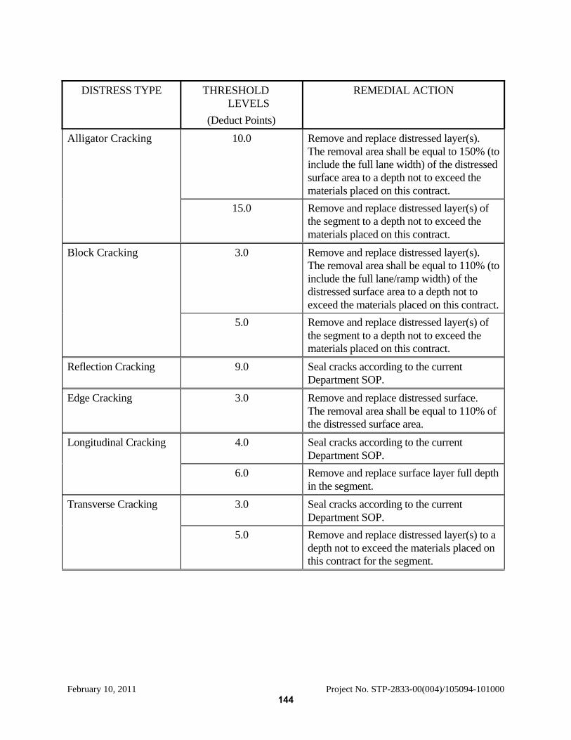
February 10, 2011 Project No. STP-2833-00(004)/105094-101000
DISTRESS TYPE THRESHOLD
LEVELS (Deduct Points)
REMEDIAL ACTION
Alligator Cracking 10.0 Remove and replace distressed layer(s). The removal area shall be equal to 150% (to include the full lane width) of the distressed surface area to a depth not to exceed the materials placed on this contract.
15.0 Remove and replace distressed layer(s) of the segment to a depth not to exceed the materials placed on this contract.
Block Cracking 3.0 Remove and replace distressed layer(s). The removal area shall be equal to 110% (to include the full lane/ramp width) of the distressed surface area to a depth not to exceed the materials placed on this contract.
5.0 Remove and replace distressed layer(s) of the segment to a depth not to exceed the materials placed on this contract.
Reflection Cracking 9.0 Seal cracks according to the current Department SOP.
Edge Cracking 3.0 Remove and replace distressed surface. The removal area shall be equal to 110% of the distressed surface area.
Longitudinal Cracking 4.0 Seal cracks according to the current Department SOP.
6.0 Remove and replace surface layer full depth in the segment.
Transverse Cracking 3.0 Seal cracks according to the current Department SOP.
5.0 Remove and replace distressed layer(s) to a depth not to exceed the materials placed on this contract for the segment.
144
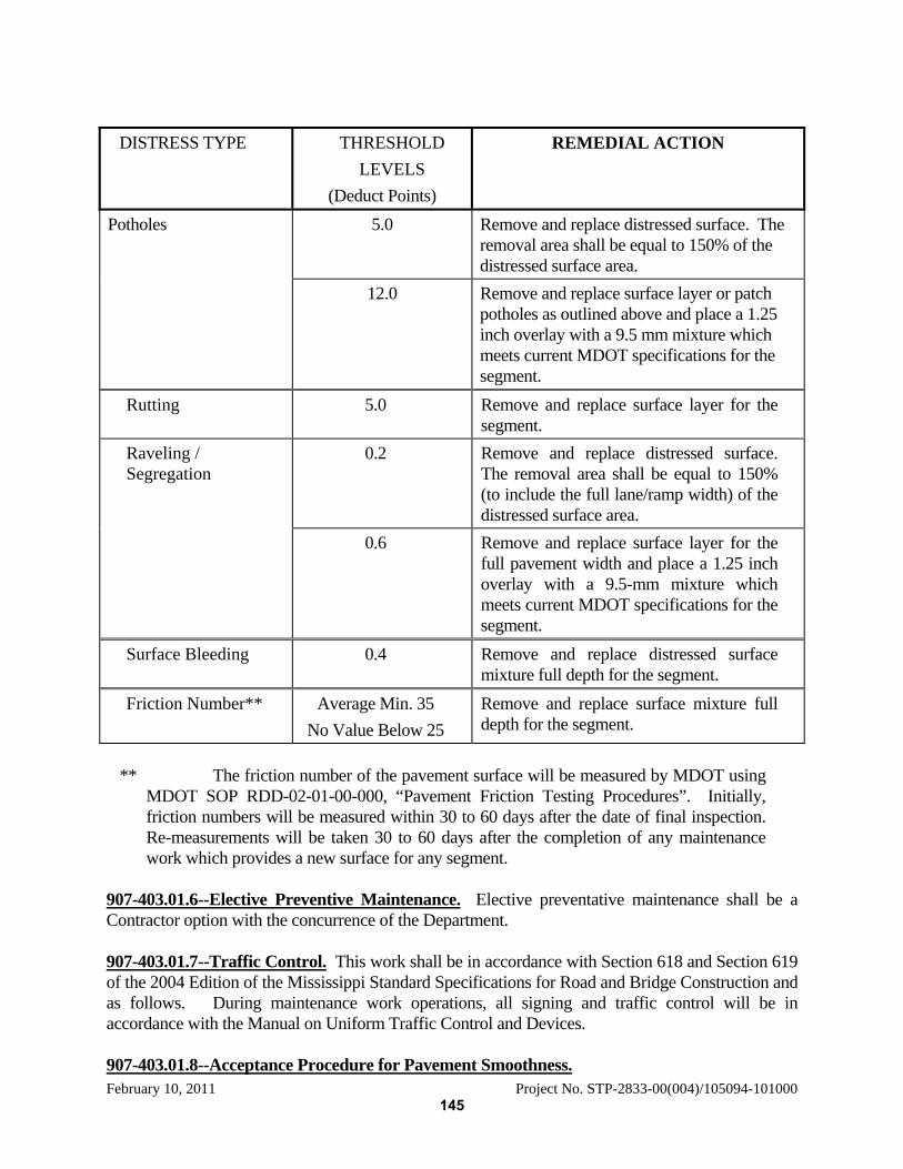
February 10, 2011 Project No. STP-2833-00(004)/105094-101000
DISTRESS TYPE THRESHOLD
LEVELS (Deduct Points)
REMEDIAL ACTION
Potholes 5.0 Remove and replace distressed surface. The removal area shall be equal to 150% of the distressed surface area.
12.0 Remove and replace surface layer or patch potholes as outlined above and place a 1.25 inch overlay with a 9.5 mm mixture which meets current MDOT specifications for the segment.
Rutting 5.0 Remove and replace surface layer for the segment.
Raveling / Segregation
0.2 Remove and replace distressed surface. The removal area shall be equal to 150% (to include the full lane/ramp width) of the distressed surface area.
0.6 Remove and replace surface layer for the full pavement width and place a 1.25 inch overlay with a 9.5-mm mixture which meets current MDOT specifications for the segment.
Surface Bleeding 0.4 Remove and replace distressed surface mixture full depth for the segment.
Friction Number** Average Min. 35 No Value Below 25
Remove and replace surface mixture full depth for the segment.
** The friction number of the pavement surface will be measured by MDOT using
MDOT SOP RDD-02-01-00-000, “Pavement Friction Testing Procedures”. Initially, friction numbers will be measured within 30 to 60 days after the date of final inspection. Re-measurements will be taken 30 to 60 days after the completion of any maintenance work which provides a new surface for any segment.
907-403.01.6--Elective Preventive Maintenance. Elective preventative maintenance shall be a Contractor option with the concurrence of the Department. 907-403.01.7--Traffic Control. This work shall be in accordance with Section 618 and Section 619 of the 2004 Edition of the Mississippi Standard Specifications for Road and Bridge Construction and as follows. During maintenance work operations, all signing and traffic control will be in accordance with the Manual on Uniform Traffic Control and Devices. 907-403.01.8--Acceptance Procedure for Pavement Smoothness.
145

February 10, 2011 Project No. STP-2833-00(004)/105094-101000
907-403.01.8.1--General. When compaction is completed, the lift shall have a uniform surface and be in reasonably close conformity with the line, grade and cross section shown on the plans. The smoothness of the final surface lift will be determined by using a profilograph to produce a profilogram (profile trace) at each designated location. The surface shall be tested and corrected to a smoothness index as described herein with the exception of those locations or specific projects that are excluded from a smoothness test with the profilograph. The profilograph, furnished and operated by the Contractor under supervision of the Engineer, shall consist of a frame at least 25 feet in length supported upon multiple wheels having no common axle. The wheels shall be arranged in a staggered pattern so that no two wheels will simultaneously cross the same bump. A profile is to be recorded from the vertical movement of a sensing mechanism. This profile is in reference to the mean elevation of the contact points established by the support wheels. The sensing mechanism, located at the mid-frame, may consist of a single bicycle-type wheel or a dual-wheel assembly consisting of either a bicycle-type (pneumatic tire) or solid rubber tire vertical sensing wheel and a separate bicycle-type (pneumatic tire) longitudinal sensing wheel. The wheel(s) shall be of such circumference(s) to produce a profilogram recorded on a scale of one (1) inch equal to 25 feet longitudinally and one (1) inch equal to one (1) inch (full scale) vertically. Motive power may be provided manually or by the use of a propulsion unit attached to the center assembly. In operation, the profilograph shall be moved longitudinally along the pavement at a speed no greater than 3 MPH so as to reduce bounce as much as possible. The testing equipment and procedure shall comply with the requirements of Department SOP. The Contractor may elect to use a computerized version of the profilograph in lieu of the standard profilograph. If the computerized version of the profilograph is used, it shall meet the requirements of Subsection 907-403.01.8.2. The smoothness of the final surface lift will be determined for traffic lanes, auxiliary lanes, climbing lane and two-way turn lanes. Areas excluded from a smoothness test with the profilograph are acceleration and deceleration lanes, tapered sections, transition sections (for width), shoulders, crossovers, ramps, side street returns, etc. Pavement on horizontal curves having a radius of less than 1,000 feet at the centerline and pavement within the superelevation transition of such curves are excluded from a test with the profilograph. The profilogram shall terminate 15 feet from each transverse joint that separates the pavement from a bridge deck, bridge approach slab or existing pavement not constructed under the contract. A profilogram will be made on the final surface lift. The measurements will be made in the outside wheel path of exterior lanes and either wheel path of interior lanes. The wheel path is designated as being located three feet from the edge of pavement or longitudinal joint. The testing will be limited to a single profilogram for each lane except that a second profilogram will be made on the lots that have been surface corrected. Other profilograms may be made only to define the limits that are out of tolerance. Acceptance will be made on a segment to segment basis for pavement smoothness. No segment
146

February 10, 2011 Project No. STP-2833-00(004)/105094-101000
of the lift with a profile index greater than 30.0 inches per mile shall be allowed to remain in place without correction. For the purpose of determining pavement smoothness and contract price adjustment for rideability, each day’s production will be sub-divided into sections which terminate at bridges, transverse joints or other interruptions. Each section will be sub-divided into segments of 528 feet. Where a segment less than 528 feet occurs at the end of a section, it will be combined with the preceding 528-foot segment for calculation of the profile index. The last 15 feet of a day's lift may not be obtainable until the lift is continued and for this reason may be included in the subsequent segment. A profile index will be determined for each segment as inches per mile in excess of the “Zero” blanking band which is simply referred to as the "Profile Index". From the profilogram of each segment, the scallops above and below the “Zero” blanking band are totaled in tenths of an inch. The totaled count of tenths is converted to inches per mile to establish a smoothness profile index for that segment. Individual bumps and/or dips that are identified on the profilogram by locating vertical deviations that exceed four tenths of an inch when measured from a chord length of 25 feet or less shall be corrected regardless of the profile index value of the segment. Scheduling will be the responsibility of the Contractor with approval of the Engineer, and the tests shall be conducted within 72 hours after each day's production unless authorized otherwise by the Engineer. The Contractor will be responsible for traffic control associated with this testing operation. 907-403.01.8.2--Computerized Profilograph. 907-403.01.8.2.1--General The computerized profilograph, furnished and operated by the Contractor under the supervision of the Engineer, shall be equipped with an on-board computer capable of meeting the following conditions. Vertical displacement shall be sampled every three (3) inches or less along the roadway. The profile data shall be bandpass filtered in the computer to remove all spatial wavelengths shorter than two (2) feet. This shall be accomplished by a third order, low pass Butterworth filter. The resulting band limited profile will then be computer analyzed according to the California Profilograph reduction process to produce the required inches per mile index. This shall be accomplished by fitting a linear regression line to each 528 feet of continuous pavement section. This corresponds to the perfect placement of the blanking band bar by a human trace reducer. Scallops above and below the blanking band are then detected and totaled according to the California protocol. Bump/Dip analysis shall take place according to the California Profilograph reduction process. The computerized profilograph shall be capable of producing a plot of the profile and a printout which will give the following data: Stations every twenty five (25) feet, bump/dip height and bump/dip length of specification (4/10 of an inch and 25 feet respectively), the blanking band width, date of measurement, total profile index in inches per mile for the measurement, total length of the measurement, and the raw inches for each tenth mile segment.
147
February 10, 2011 Project No. STP-2833-00(004)/105094-101000
907-403.01.8.2.2--Mechanical Requirements. The profilograph shall consist of a frame twenty five (25) feet long supported at each end by multiple wheels. The frame shall be constructed to be easily dismantled for transporting. The profilograph shall be constructed from aluminum, stainless steel and chromed parts. The end support wheels shall be arranged in a staggered pattern such that no two wheels cross a transverse joint at the same time. The relative smoothness shall be measured by the vertical movement of an eight (8) inch or larger diameter sensing wheel at the midpoint of the 25-foot frame. The horizontal distance shall be measured by a twenty (20) inch or larger diameter pneumatic wheel. This profile shall be the mean elevation referenced to the twelve points of contact with the pavement established by the support wheels. Recorded graphical trace of the profile shall be on a scale of one inch equals one inch (full scale) vertical motion of the sensing wheel and one inch equals 25 feet horizontal motion of the profilograph. 907-403.01.8.2.3--Computer Requirements. The computer shall have the ability to produce output on sight for verification. The computerized output shall indicate the profile index for each specified section of roadway. Variable low and high pass third-order Butterworth filtering options shall be available. The printout shall be capable of showing station marks automatically on the output. Blanking band positioning for each specified section of the roadway shall be placed according to the least squares fit line of the collected data. Variable bump and dip tests shall be available to show “must correct” locations on the printout. The computer must have the ability to display on screen “must correct” conditions and alert the user with an audible warning when a “must correct” location has been located. The computer must have the ability to store profile data for later reanalysis. The measurement program must be menu driven and IBM compatible. User selected options, identification, calibration factors, and time and date stamps shall be printed at the top of each printed report for verification. The control software must be upgradeable. A power source shall be included for each profilograph and be capable of supplying all power needs for a full days testing. 907-403.01.9--Third Party Rights. The Contractor’s duties herein extend for the benefit of the Department, and no other duties, express or implied, are created herein. No third parties shall have the right to bring any claims, causes of actions, suits, demands, civil actions or any proceedings for any breach of any duty arising hereunder unless said third party can demonstrate an express contractual relationship with or through the Contractor (as a Subcontractor of any tier) which entitles it to the benefit of the duties set out herein. 907-403.02--Blank. 907-403.03--Blank. 907-403.05--Blank.
148
February 10, 2011 Project No. STP-2833-00(004)/105094-101000
MISSISSIPPI DEPARTMENT OF TRANSPORTATION SPECIAL PROVISION NO. 907-407 DB CODE: (SP) DATE: 03/10/2009 SUBJECT: Tack Coat Section 407, Tack Coat, of the 2004 Edition of the Mississippi Standard Specifications for Road and Bridge Construction is hereby amended as follows: 907-407.02.1--Bituminous Material. Delete the second sentence of the first paragraph of Subsection 407.02.1 on page 281, and substitute the following: When not specified, the materials shall be as specified in Table 410-A on page 293. 907-407.03.3--Application of Bituminous Material. Delete the first paragraph of Subsection 407.03.3 on page 281, and substitute the following. Tack coat shall be applied with a distributor spray bar. A hand wand will only be allowed for applying tack coat on ramp pads, irregular shoulder areas, median crossovers, turnouts, or other irregular areas. Bituminous materials and application rates for tack coat shall be as specified in Table 410-A on page 293. Tack coat shall not be applied during wet or cold weather, after sunset, or to a wet surface. Emulsions shall be allowed to "break" prior to superimposed construction.
907-407.04--Blank.
907-407.05--Blank.
149
February 10, 2011 Project No. STP-2833-00(004)/105094-101000
MISSISSIPPI DEPARTMENT OF TRANSPORTATION SPECIAL PROVISION NO. 907-502 DB CODE: (SP) DATE: 03/10/2009 SUBJECT: Portland Cement Concrete Bridge End Pavement Delete the last sentence of the second full paragraph of Subsection 502.03.1 on page 329. Delete Subsection 502.04 and substitute the following: 907-502.04—Blank. Delete Subsection 502.05 and substitute the following: 907-502.05—Blank.
150
February 10, 2011 Project No. STP-2833-00(004)/105094-101000
MISSISSIPPI DEPARTMENT OF TRANSPORTATION SPECIAL PROVISION NO. 907-601 DB CODE: (SP) DATE: 03/10/2009
SUBJECT: Structural Concrete Division 600, Incidental Construction, of the 2004 Edition of the Mississippi Standard Specifications for Road and Bridge Construction is hereby amended as follows: After the heading DIVISION 600 - INCIDENTAL CONSTRUCTION, add the following: Unless otherwise specified, all testing of Portland cement concrete in Division 600 shall be in accordance with the requirements of Subsection 907-601.02.1. 907-601.02--Materials. 907-601.02.1--General. Delete the second and third sentence of the first paragraph of Subsection 601.02.1 on page 348, and substitute the following: Sampling and testing will be in accordance with TMD-20-04-00-000 or TMD-20-05-00-000, as applicable. 907-601.03.6.3--Removal of Falsework, Forms, and Housing. Delete the first paragraph, the table and second paragraph of Subsection 601.03.6.3 on pages 349 and 350, and substitute the following: The removal of falsework, forms, and the discontinuance of heating, shall be in accordance with the provisions and requirements of Subsection 907-804.03.15, except that the concrete shall conform to the following compressive strength requirements:
Wingwall and Wall Forms not Under Stress ............................. 1000 psi Wall Forms under Stress ............................................................ 2200 psi Backfill and Cover clear ............................................................ 2400 psi
In lieu of using concrete strength cylinders to determine when falsework, forms, and housings can be removed, an approved maturity meter may be used to determine concrete strengths by inserting probes into concrete placed in a structure. The minimum number of maturity meter probes required for each structural component shall be in accordance with Subsection 907-804.03.15. Procedures for using the maturity meter and developing the strength/maturity relationship shall follow the requirements of Subsection 907-804.03.15. Technicians using the maturity meter or calculating strength/maturity graphs shall meet the requirements of Subsection 907-804.03.15.
Delete Subsections 601.04 and 601.05 on pages 351 and 352 and substitute the following:
907-601.04--Blank.
907-601.05--Blank.
151
February 10, 2011 Project No. STP-2833-00(004)/105094-101000
MISSISSIPPI DEPARTMENT OF TRANSPORTATION
SPECIAL PROVISION NO. 907-605 DB CODE: (SP) DATE: 03/10/2009 SUBJECT: Underdrains Section 605, Underdrains, of the 2004 Edition of the Mississippi Standard Specifications for Road and Bridge Construction is hereby amended as follows: 907-605.03--Construction Requirements. 907-605.03.5--Edge Drain Installation. Delete the seventh paragraph of Subsection 605.03.5 on page 376 and substitute the following: When corrugated polyethylene drainage tubing is used, joints shall be made with snap-on or split couplings, corrugated to engage the pipe corrugations, and shall engage a minimum of four (4) corrugations, two (2) on each side of the pipe joint.
Delete Subsections 605.04 and 605.05 beginning on page 377 and substitute the following:
907-605.04--Blank.
907-605.05--Blank.
152
February 10, 2011 Project No. STP-2833-00(004)/105094-101000
MISSISSIPPI DEPARTMENT OF TRANSPORTATION SPECIAL PROVISION NO. 907-619 DB CODE: (SP) DATE: 03/09/2009 SUBJECT: Changeable Message Signs Section 619, Traffic Control for Construction Zones, of the 2004 Edition of the Mississippi Standard Specifications for Road and Bridge Construction is hereby amended as follows: 907-619.02--Material Requirements. After Subsection 619.02.13 on page 424, add the following. 907-619.02.14--Changeable Message Sign. This work shall consist of furnishing, testing, and maintaining a trailer-mounted electronic Portable Changeable Message Sign (PCMS) assembly. The sign display shall be a LED, full matrix sign. If more than one portable changeable message sign is required for this project, they shall all be of the same model and from the same manufacturer. All parts and materials used to construct the portable changeable message signs shall be interchangeable. The PCMS shall be a trailer-mounted, solar powered, portable changeable message sign. Each PCMS shall include the following main components:
a) Sign Housing b) LED Modules c) LED Drivers d) Battery Bank e) Sign Controller f) Trailer g) AC Charger h) Solar Panel i) Solar Panel Charger
The LED display shall be full matrix sign with a minimum of 28-pixel rows x 50-pixel columns. The pixel spacing shall be such that three (3) lines of text (5 columns x 7 rows, 8 characters) shall each have a nominal height of 18 inches. The PCMS shall include a remote communications interface as specified herein. The PCMS shall be provided with a local serial and USB connection within the sign control cabinet so that a laptop computer using the remote software can communicate directly with the sign CPU. This Special Provision incorporates normative references to other standards as outlined in Section 1 of the NEMA TS-4 standard and as listed below.
NEMA TS4-2004, Hardware Standards for Dynamic Message Signs (DMS) with NTCIP Requirements. All NEMA TS-4 requirements that are applicable to portable signs shall be used. NTCIP Standards.
153
February 10, 2011 Project No. STP-2833-00(004)/105094-101000
If a conflict between the standards referenced and this Special Provision, this Special Provision shall govern.
The definitions of the terms used within this Special Provision are as defined in Section 1 of the NEMA TS-4 standard.
If required in the contract, the PCMS shall include a speed radar unit as specified herein. 907-619.02.14.1--Mechanical Construction. Each PCMS shall meet the following minimum requirements. Weather-Tight Enclosure. The entire sign and trailer assembly, including each component / equipment exposed to weather, shall be fully protected. It shall withstand the effects of sand, dirt, dust, moisture, hose-directed water, ice, snow and UV radiation (UVA and UVB). It shall withstand the effects of high wind loading and blowing rain as specified herein with all outriggers and/or leveling jacks in place. The sign and all components shall be watertight. Space shall be provided for manuals to be stored in a weatherproof environment. Wind Loading. Wind loading requirements for the portable sign housing and trailer assembly shall be as specified in Section 3.3.2.1.2 of the NEMA TS-4 standard. Welding. All welding on all major structural components (aluminum or steel) shall be performed by certified welders and in accordance to SAE/AWS D8.8 American Welding Society. Protective Coatings. Protective coatings or processes, such as anodizing, e-coating, powder coat painting, plating, etc., shall be incorporated to protect all sign, cabinet, and trailer metal surfaces from corrosion. Any non-protected metallic fasteners shall be made of stainless steel or aluminum. All components shall be similar material, or be isolated to reduce galvanic reactions. Temperature and Humidity. Each PCMS shall be designed to operate continuously in extreme ambient temperature ranges and at high humidity levels. Operating ambient temperature range of the portable sign and trailer assembly shall be -29oF to +165oF. Storage temperature range shall be from -40oF to +185oF. The portable sign shall be capable of continued operation within the operating temperature ranges specified without the need for active systems (i.e., fans). Operating relative humidity level of the portable sign shall be up to 95% non-condensing. Sign Face. Sign face material shall be protected by a non-glaring polycarbonate material of at least ¼-inch thickness. It shall be replaceable and manufactured of material rated for outside use and resistant to UV degradation (exposure to the sun). All electronics and pixels shall be protected from damage due to moisture. Sign Housing Construction. The portable sign housing, including its front face panels, shall be designed to conform to the requirements of minimum NEMA Type 3R, as described in the latest edition of NEMA 250. It shall be comply with latest structural AASHTO requirements.
154
February 10, 2011 Project No. STP-2833-00(004)/105094-101000
It shall be constructed of aluminum sheeting which shall not be less than 1/8-inch thick with all seams continuously welded by the inert gas process. The front of the sign housing shall have a flat black matte finish. Weep holes shall be provided in the housing to allow moisture from condensation to escape. The sign housing and cabinets shall be designed to keep insects out. The sign housing shall be constructed in such a manner as to prohibit stray light from reducing legibility. All sides of the sign housing shall have a maintenance-free finish. Alignment of the sign housing shall be capable of being horizontally adjusted to position the sign a full 360 degrees. It shall be capable of rotating and locking at any selected horizontal angle up to 360 degrees. A sight alignment tube/device shall be mounted to horizontally position the sign display. A positive brake assembly with lockable control arm shall be provided to position the sign display in the desired position. It shall allow easy access to all components contained within the display housing without the removal of any external parts. Door locks shall be rigidly mounted. Gasketing shall be provided on all door openings and shall be dust-tight, permanently bonded to the door metal, and shall not stick to the mating metal surface. A gasket channel shall be provided to support the gasket on the door. Trailer. Each PCMS trailer shall meet all requirements for trailers as outlined in Section 3.3.3 of the latest NEMA TS-4 standard as well as the following minimum requirements. All trailers shall meet the requirements of FMVSS, Part 571 and SAE J684 for transport safety including, but not limited to the use of brakes, safety chains, coupling device, and lights. PCMS manufacturer shall provide instructions stating procedures necessary to insure safe transport. The structural frame shall be capable of supporting the gross vehicle weight (GVW) load of the trailer corresponding to the axle and tire ratings that shall be in accordance with FMVSS, Part 571. The tires shall be radial ST “Special Trailer” rated. The wheels shall be 15-inch steel wheels with five lug bolts per wheel. Each trailer wheel shall be equipped with one locking lug nut. A minimum of four keys for the locking lug nuts shall be supplied for each trailer. The trailer shall be provided with a minimum of four outriggers or leveling jacks. One outrigger or leveling jack shall be mounted near each corner of the trailer. The length of the leveling jacks shall be such that when the trailer is level, all four jacks and the tongue jack can be lowered into the vertical position. The jacks shall be screw type jacks with a minimum 25-inch lift. Each jack shall include a swivel mechanism that allows the jacks to be swing up to a horizontal position for towing. The swivel mechanism shall secure the jack in both vertical and horizontal positions through a lock pin. The trailer shall also be provided with a trailer stand mounted on the tongue of the trailer. The stand shall be corrosion resistant. It shall include a 6-inch wheel that allows horizontal positioning of the trailer. The stand shall be welded, not bolted, to the tongue of the trailer.
155
February 10, 2011 Project No. STP-2833-00(004)/105094-101000
The trailer shall be provided with legal tail/brake lights, signals, and license plate mounting bracket. The trailer shall be supplied with an electrical harness assembly for connection to the tow vehicle and shall be terminated in a connector type to be specified by the Engineer. The trailer shall be provided with a 2-inch “hammer blow coupler” style hitch in accordance with SAE J684 and interchangeable with a 2½-inch Pintle coupler / ring meeting SAE J847. The trailer spring leafs shall be rated at a minimum of 3500 pounds. The trailer shall be equipped with a sign display lift and control console. The lift shall be electric, hydraulic lift, or combination of both with manual backup lift. The lift shall be capable of lifting the display a minimum of seven feet (7’) above the roadway surface. A mast safety pin shall be provided to prevent the sign display from falling in the event of an electric or hydraulic system failure. The trailer shall have a minimum of 6,000-pound capacity hydraulic surge brake system along with a breakaway latch. Illumination shall be provided as an integral part of the sign or trailer assembly to change the sign controller data in darkness. The trailer shall contain batteries and photovoltaic (solar) panels as specified herein. Photovoltaic (Solar) Panel System. Each PCMS shall include solar panels. A solar bank shall be assembled using multiple solar panels. All photovoltaic panels shall be listed in accordance with UL 1703, or equivalent. The solar cell bank shall have a minimum capacity of 240 watts. The solar cell bank shall be mounted on a frame capable of being tilted at a minimum of one direction up to 61 degrees with zero degrees being horizontal. Solar cells shall be laminated between ethylene vinyl acetate and tempered glass. The solar panel shall incorporate an extruded aluminum frame. The solar battery charge controller shall include the following three state charger modes. • Bulk • Absorption • Float
Battery Requirements. Each PCMS shall include batteries for primary energy storage on trailers. The battery bank capacity shall be a minimum of 900 amp/hours at 12VDC at 20-hour rate of discharge. The batteries shall be heavy duty deep cycle type rated for 80% discharge. A battery power disconnect shall be provided. Battery enclosures shall be vented to prevent the accumulation of explosive gases. The battery cabinets must be lockable with a standard padlock. AC Charging System. Each PCMS shall have an AC battery charging sub-system. The system shall be UL listed and operate from a standard 120VAC generator meeting all NEC requirements for portable equipment. The solar battery charger shall include the following three state charger modes. • Bulk • Absorption
156
February 10, 2011 Project No. STP-2833-00(004)/105094-101000
• Float The AC battery charger shall have sufficient capacity to charge the battery bank from 80% discharged to fully charge in 24-hours, and operate the sign simultaneously. The AC battery charger shall be equipped with a male plug-in and a 50-foot long extension cord constructed of a minimum 12-guage wire for this purpose. 907-619.02.14.2--Controller to Sign Interface. Each PCMS shall meet all applicable controller to sign interface requirements as outline in Section 4 of the NEMA TS-4 standard. 907-619.02.14.3--Display Properties. Each PCMS shall have a cone of vision (viewing angle) from the center (reference axis) shall be a minimum 15 degrees with the half-power viewing angle defined such that at a given distance from the LED, luminous intensity measured at any point at an angle of 7.5 degrees from the LED's center axis is no less than half the luminous intensity measured directly on the LED's center axis. The minimum word legibility requirements shall be 1232 feet or greater under daytime light conditions and within the cone of visions as specified. Legibility is defined as the ability to discern the content of a display using a “word message”. The minimum word legibility requirement shall be documented either by a MDOT approved independent testing laboratory or by participation in the NTPEP test program. The minimum visibility requirements shall be 3000 feet or greater under daytime light conditions and within the cone of vision as specified. Visibility is defined as the ability to recognize that a display exists. The minimum visibility requirement shall be documented either by a MDOT approved independent testing laboratory or by participation in the NTPEP test program. The PCMS shall be capable of displaying standard fonts and font alphabets as specified in Sections 5.6.1 and 5.6.2.3 of the NEMA TS-4 standard and adhere to NTCIP 1203. The PCMS shall also support moving arrows. Any NTPEP test results shall be for the PCMS model being used and shall be within the last three completed test cycles. 907-619.02.14.4--Optical Components. The pixels for the PCMS shall be manufactured using Light Emitting Diodes (LED). Changes to displays shall be performed by turning the LEDs in a pixel either on or off. The discrete, LED shall be an untinted, non-diffused, solid-state lamp that uses Aluminum Indium Gallium Phosphide (AlInGap) technology manufactured by Avago Technologies (formerly Agilent Technologies), Toshiba Corporation, Nichia Corporation, or functional equivalent. Horizontal and vertical spacing between modules shall be such that the horizontal and vertical pitch between all pixels is equal. A failure of one pixel shall not effect the operation of any other pixel. All LEDs used to create a display in a single portable sign shall have a nominally rated LED life of 100,000 hours of operation under field conditions. This shall include a operating temperatures between -29oF to +165oF. LED life shall be defined as the time it takes for the LED light output to degrade to half of the LED's initial light output. Current through an LED shall be limited to the manufacturer’s recommendation under any conditions. Each LED character module shall be rated for use over the environmental range specified herein, including heat absorption due to sunlight. The LEDs shall be protected from the outside environmental conditions, including moisture, snow, ice, wind, dust, dirt, and UV rays (UVA and UVB). All LEDs shall be mounted so that they present a uniform and legible display.
157

February 10, 2011 Project No. STP-2833-00(004)/105094-101000
Pixels shall be replaceable in modular groupings (modules). All modules within a sign shall be the same size and interchangeable. The replacement of any module shall be possible with no more that simple non-vendor-specific hand tools, such as screw drivers or wrenches, without any physical modification to the module. 907-619.02.14.5--PCMS Controller and Storage Cabinets. All PCMS controller and storage cabinets shall be minimum NEMA 3R rated and be completely encased and lockable with a standard padlock as specified herein. A separate lockable storage cabinet shall be provided to house various accessories. The controller cabinet shall be manufactured to withstand all types of adverse weather conditions and shall be designed and installed to keep insects out. All components inside the controller cabinet shall be accessible without disconnecting any unassociated wires or components. The controller cabinet shall be illumination. The keyboard terminal and control panel shall be housed. Lighted keys and terminal displays are acceptable. All controls in the controller cabinet shall be labeled. The cabinet shall have a voltmeter gauge to indicate the current battery charge status. It shall have an amp gauge to indicate the current/charging status. It will be acceptable to have a display via digital readout on a control console or panel. 907-619.02.14.6--Electronics and Electrical. Each PCMS shall meet all applicable electronics and electrical requirements as outline in Section 8 of the NEMA TS-4 standard. Sign Controller. The PCMS shall include a local sign controller with firmware. The local control interface shall have a keyboard capable of allowing full programming and control of the PCMS locally. It shall have a separate serial RS-232 or USB connection to allow a laptop computer using the remote control software to communicate directly with the sign controller. Local and remote interfaces shall be password protected to safeguard against unauthorized use. It shall perform and report the following minimum sign diagnostics both through the local interface and Remote Control Subsystem. • LED brightness controls • Sign status • Communications status • Battery voltage • Photocell ambient light level.
It shall automatically report a low battery alarm to a remote user through the Remote Control Subsystem. It shall have an alarm for the controller door open and over temperature. It shall store and display both textual and graphical symbols. It shall store a minimum of 20 pre-programmed messages and graphics. It shall display preprogrammed (by manufacturer) Manual on Uniform Traffic Control Devices (MUTCD) symbolic messages and standard arrows. It shall schedule predetermined sequences of messages based on a programmed time and date. Each sequence shall display up to four (4) programmed messages (text and/or graphics). It shall display conventional one, two, or three-line messages for display with a choice of a minimum of three font sizes. Character width shall be proportional to the letter type. The one line message font size shall be capable of displaying messages in full size to utilize the maximum area of display.
158

February 10, 2011 Project No. STP-2833-00(004)/105094-101000
It shall allow for automatic and manual controls to adjust the brightness of the LEDs. Automatic control shall be capable of varying the LED brightness by sensing the ambient light level using photocells. Manual brightness control shall be password protected to safeguard against unauthorized use. It shall display a preprogrammed default message or no message at all, after a power recovery from a power failure. The sign shall shut down its LED display if internal cabinet temperatures reach a level that is determined unsafe by the manufacturer. All communications and power cabling shall be either shielded or routed within conduit to minimize potential EMI/RFI effects.
Remote Control Subsystem. The PCMS shall be supplied with all the hardware and software necessary to control the PCMS from a remote central station. It shall have a cellular phone and/or modem capable of communication using a MDOT provided cellular service provider. The Contractor shall coordinate with MDOT for cellular service provider. The Contractor shall be responsible for establishing cellular service and providing activated phone number(s) as directed and approved by the MDOT. The Contractor shall pay for cellular service for this project until the Final Maintenance Release as documented by the State Construction Engineer at which time it will be turned over to MDOT. The cellular service type shall be CDMA/1xRTT or GSM/GPRS, as directed by MDOT. It shall be capable of supporting connection and remote control, programming and diagnostics via the Internet. The subsystem shall have all necessary hardware such as external antenna, communications cables, and controller interface and NTCIP Sign controller software. The central station software meeting the following minimum requirements: • Windows XP compatible • Capable of running on any desktop or laptop. • Capable of controlling all PCMS functions through windows and GUIs (Graphical User
Interface) • NTCIP compatible as specified herein.
Communications. In addition to any protocols that may be available from the PCMS Manufacturer, each sign controller shall support NTCIP as follows. • NTCIP Protocol and Command Sets. This specification references several standards
through their NTCIP designated names and numbers. Each NTCIP Component covered by these project specifications shall implement the most recent version of the standard that is available as of project advertisement date, including any and all prepared Amendments to these standards as of the same date. Profile Implementation Conformance Specifications (PICS) for each NTCIP standard required shall be submitted for review and approval to the Department.
• RS-232 Interface. Communication interfaces using RS-232 shall conform, with the following minimum requirements.
159
February 10, 2011 Project No. STP-2833-00(004)/105094-101000
1101 – NTCIP Simple Transportation Management Framework (STMF) 1203 - NTCIP Object Definition for Portable Dynamic Message Signs 2301 - NTCIP AP-STMF 2201 - NTCIP TP-Transportation Transport Profile 2103 – NTCIP SPPPP/RS232 2104 - NTCIP SP-PMPP/RS232
• Subnet Level. For each communication interface, the NTCIP Components may support additional Subnet Profiles at the manufacturer’s option. At any time, only one Subnet Profile shall be active on a given communication interface. The NTCIP Component shall be configurable to allow the field technician to activate the desired Subnet Profile.
• Transport Level. For each communication interface, the communication interface may support additional Transport Profiles at the manufacturer's option. Response data-grams shall use the same Transport Profile used in the request. Each communication interface shall support the receipt of data-grams conforming to any of the identified Transport Profiles at any time.
• Application Level. For each communication interface, all interfaces shall comply with NTCIP 1101 and shall meet the requirements for Conformance Level 1 (NOTE -See Amendment to standard). Optionally, the NTCIP Component may support SNMP traps. A communication interface may support additional Application Profiles at the manufacturer's option. Responses shall use the same Application Profile used by the request. Each communication interface shall support the receipt of Application data packets at any time allowed by the subject standards.
Information Level. For all communication interfaces, the information level protocol shall provide Full, Standardized Object Range Support of all objects required by these procurement specifications unless otherwise indicated below. The maximum Response Time for any object or group of objects shall be 200 milliseconds. All communication interfaces shall implement all mandatory objects of all mandatory Conformance Groups as defined in NTCIP 1203 and their respective Amendments. Table 1 indicates the modified object requirements for these mandatory objects. Table 2 shows the required minimum support of messages that are to be stored in permanent memory. The sign shall blank if a command to display a message contains an invalid Message CRC value for the desired message. Table 3 specifies the support of the required MULTI tags and their ranges. It shall also implement all mandatory objects of the following optional conformance groups of NTCIP 1201.
o Time Management Conformal Group o Report Conformal Group. Table 4 indicates the modified object requirements. o Implement all objects of the Font Configuration Conformance Group, as defined in
NTCIP 1203. Table 5 indicates the modified object requirements for this conformance group. o Implement all objects of the PCMS Configuration Conformance Group, as defined in
NTCIP 1203. o Implement all objects of the Multi Configuration Conformance Group, as defined in
NTCIP 1203. Table 6 indicates the modified object requirements for this conformance group. o Implement all objects of the Multi Error Configuration, as defined in NTCIP 1203. o Implement all objects of the Illumination/Brightness. o Sign Status, as defined in NTCIP 1203.
160
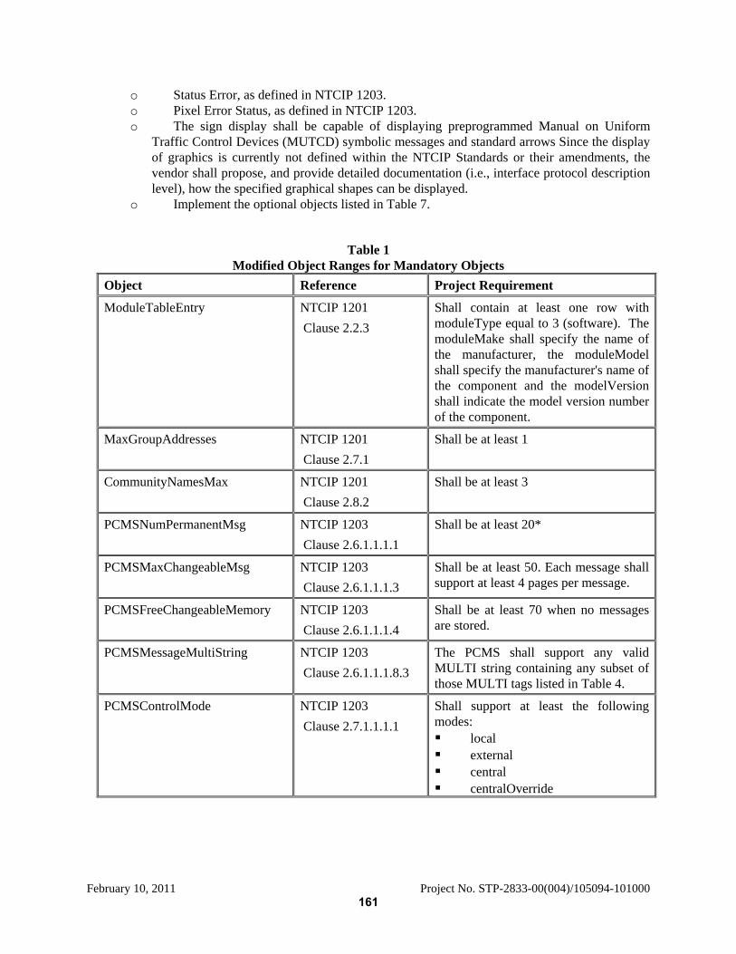
February 10, 2011 Project No. STP-2833-00(004)/105094-101000
o Status Error, as defined in NTCIP 1203. o Pixel Error Status, as defined in NTCIP 1203. o The sign display shall be capable of displaying preprogrammed Manual on Uniform
Traffic Control Devices (MUTCD) symbolic messages and standard arrows Since the display of graphics is currently not defined within the NTCIP Standards or their amendments, the vendor shall propose, and provide detailed documentation (i.e., interface protocol description level), how the specified graphical shapes can be displayed.
o Implement the optional objects listed in Table 7.
Table 1 Modified Object Ranges for Mandatory Objects
Object Reference Project Requirement
ModuleTableEntry NTCIP 1201 Clause 2.2.3
Shall contain at least one row with moduleType equal to 3 (software). The moduleMake shall specify the name of the manufacturer, the moduleModel shall specify the manufacturer's name of the component and the modelVersion shall indicate the model version number of the component.
MaxGroupAddresses NTCIP 1201 Clause 2.7.1
Shall be at least 1
CommunityNamesMax NTCIP 1201 Clause 2.8.2
Shall be at least 3
PCMSNumPermanentMsg NTCIP 1203 Clause 2.6.1.1.1.1
Shall be at least 20*
PCMSMaxChangeableMsg NTCIP 1203 Clause 2.6.1.1.1.3
Shall be at least 50. Each message shall support at least 4 pages per message.
PCMSFreeChangeableMemory NTCIP 1203 Clause 2.6.1.1.1.4
Shall be at least 70 when no messages are stored.
PCMSMessageMultiString NTCIP 1203 Clause 2.6.1.1.1.8.3
The PCMS shall support any valid MULTI string containing any subset of those MULTI tags listed in Table 4.
PCMSControlMode NTCIP 1203 Clause 2.7.1.1.1.1
Shall support at least the following modes: local external central centralOverride
161
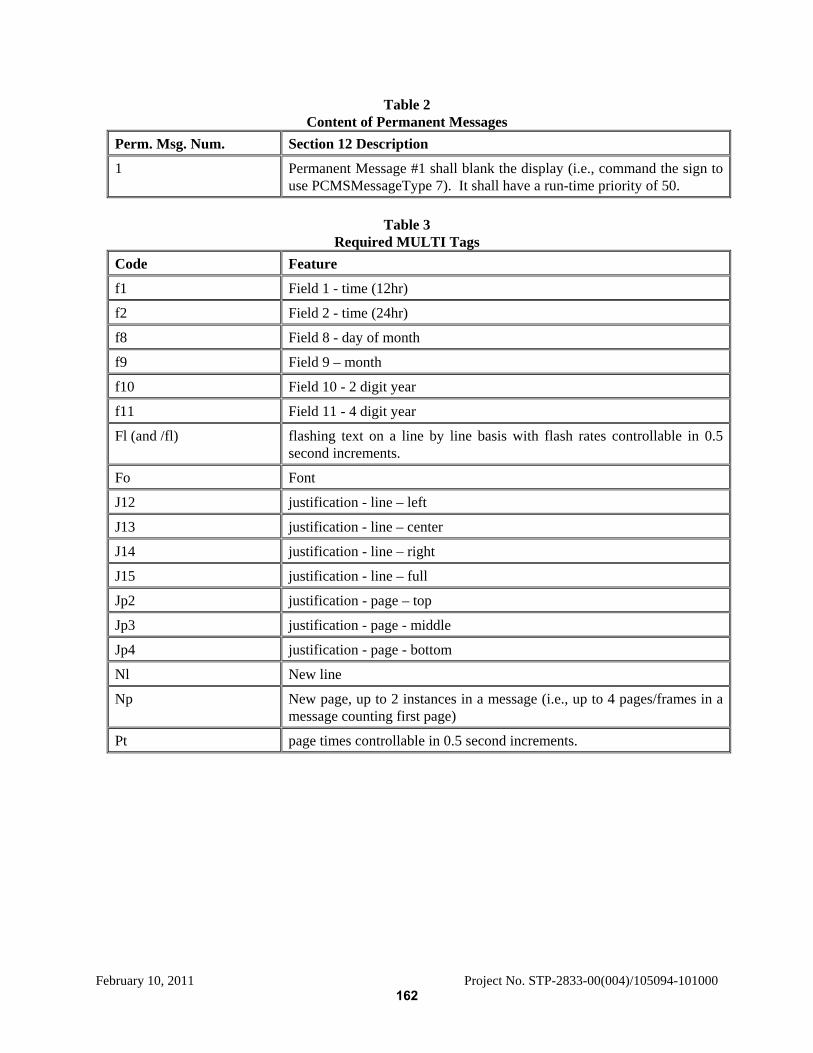
February 10, 2011 Project No. STP-2833-00(004)/105094-101000
Table 2 Content of Permanent Messages
Perm. Msg. Num. Section 12 Description
1 Permanent Message #1 shall blank the display (i.e., command the sign to use PCMSMessageType 7). It shall have a run-time priority of 50.
Table 3
Required MULTI Tags Code Feature
f1 Field 1 - time (12hr)
f2 Field 2 - time (24hr)
f8 Field 8 - day of month
f9 Field 9 – month
f10 Field 10 - 2 digit year
f11 Field 11 - 4 digit year
Fl (and /fl) flashing text on a line by line basis with flash rates controllable in 0.5 second increments.
Fo Font
J12 justification - line – left
J13 justification - line – center
J14 justification - line – right
J15 justification - line – full
Jp2 justification - page – top
Jp3 justification - page - middle
Jp4 justification - page - bottom
Nl New line
Np New page, up to 2 instances in a message (i.e., up to 4 pages/frames in a message counting first page)
Pt page times controllable in 0.5 second increments.
162
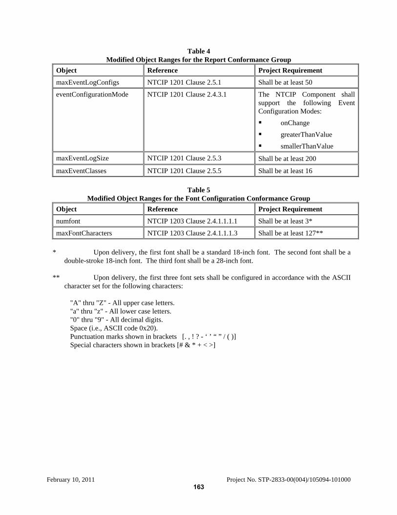
February 10, 2011 Project No. STP-2833-00(004)/105094-101000
Table 4 Modified Object Ranges for the Report Conformance Group
Object Reference Project Requirement
maxEventLogConfigs NTCIP 1201 Clause 2.5.1 Shall be at least 50
eventConfigurationMode NTCIP 1201 Clause 2.4.3.1 The NTCIP Component shall support the following Event Configuration Modes: onChange greaterThanValue smallerThanValue
maxEventLogSize NTCIP 1201 Clause 2.5.3 Shall be at least 200
maxEventClasses NTCIP 1201 Clause 2.5.5 Shall be at least 16
Table 5 Modified Object Ranges for the Font Configuration Conformance Group
Object Reference Project Requirement
numfont NTCIP 1203 Clause 2.4.1.1.1.1 Shall be at least 3*
maxFontCharacters NTCIP 1203 Clause 2.4.1.1.1.3 Shall be at least 127** * Upon delivery, the first font shall be a standard 18-inch font. The second font shall be a
double-stroke 18-inch font. The third font shall be a 28-inch font. ** Upon delivery, the first three font sets shall be configured in accordance with the ASCII
character set for the following characters:
"A" thru "Z" - All upper case letters. "a" thru "z" - All lower case letters. "0" thru "9" - All decimal digits. Space (i.e., ASCII code 0x20). Punctuation marks shown in brackets [. , ! ? - ‘ ’ “ ” / ( )] Special characters shown in brackets [# & * + < >]
163
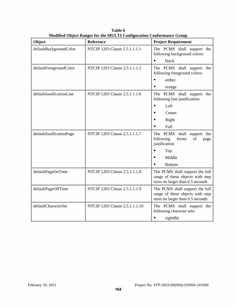
February 10, 2011 Project No. STP-2833-00(004)/105094-101000
Table 6 Modified Object Ranges for the MULTI Configuration Conformance Group
Object Reference Project Requirement
defaultBackgroundColor NTCIP 1203 Clause 2.5.1.1.1.1 The PCMS shall support the following background colors: black
defaultForegroundColor NTCIP 1203 Clause 2.5.1.1.1.2 The PCMS shall support the following foreground colors: amber orange
defaultJustificationLine NTCIP 1203 Clause 2.5.1.1.1.6 The PCMS shall support the following line justification: Left Center Right Full
defaultJustificationPage NTCIP 1203 Clause 2.5.1.1.1.7 The PCMS shall support the following forms of page justification: Top Middle Bottom
defaultPageOnTime NTCIP 1203 Clause 2.5.1.1.1.8 The PCMS shall support the full range of these objects with step sizes no larger than 0.5 seconds
defaultPageOffTime NTCIP 1203 Clause 2.5.1.1.1.9 The PCMS shall support the full range of these objects with step sizes no larger than 0.5 seconds
defaultCharacterSet NTCIP 1203 Clause 2.5.1.1.1.10 The PCMS shall support the following character sets: eightBit
164
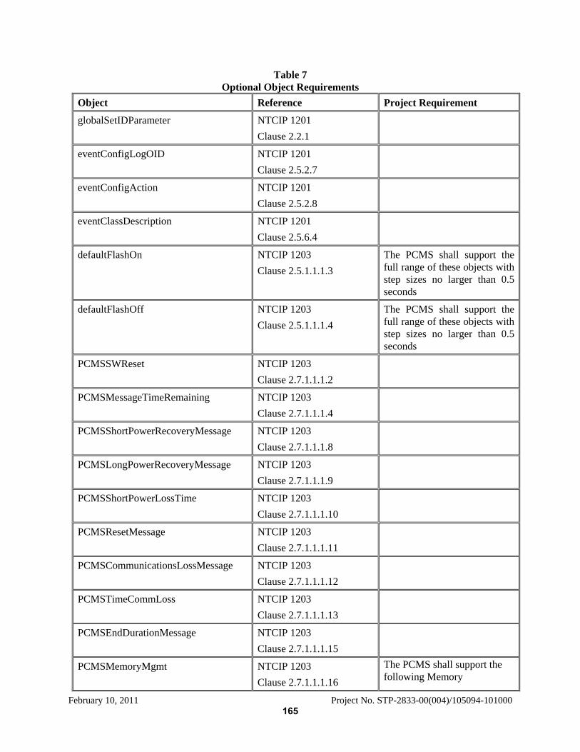
February 10, 2011 Project No. STP-2833-00(004)/105094-101000
Table 7 Optional Object Requirements
Object Reference Project Requirement
globalSetIDParameter NTCIP 1201 Clause 2.2.1
eventConfigLogOID NTCIP 1201 Clause 2.5.2.7
eventConfigAction NTCIP 1201 Clause 2.5.2.8
eventClassDescription NTCIP 1201 Clause 2.5.6.4
defaultFlashOn NTCIP 1203 Clause 2.5.1.1.1.3
The PCMS shall support the full range of these objects with step sizes no larger than 0.5 seconds
defaultFlashOff NTCIP 1203 Clause 2.5.1.1.1.4
The PCMS shall support the full range of these objects with step sizes no larger than 0.5 seconds
PCMSSWReset NTCIP 1203 Clause 2.7.1.1.1.2
PCMSMessageTimeRemaining NTCIP 1203 Clause 2.7.1.1.1.4
PCMSShortPowerRecoveryMessage NTCIP 1203 Clause 2.7.1.1.1.8
PCMSLongPowerRecoveryMessage NTCIP 1203 Clause 2.7.1.1.1.9
PCMSShortPowerLossTime NTCIP 1203 Clause 2.7.1.1.1.10
PCMSResetMessage NTCIP 1203 Clause 2.7.1.1.1.11
PCMSCommunicationsLossMessage NTCIP 1203 Clause 2.7.1.1.1.12
PCMSTimeCommLoss NTCIP 1203 Clause 2.7.1.1.1.13
PCMSEndDurationMessage NTCIP 1203 Clause 2.7.1.1.1.15
PCMSMemoryMgmt NTCIP 1203 Clause 2.7.1.1.1.16
The PCMS shall support the following Memory
165
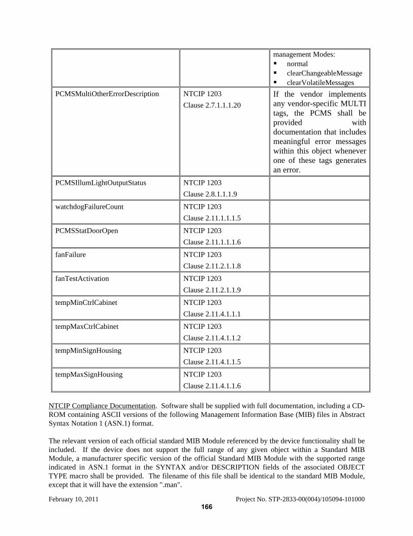
February 10, 2011 Project No. STP-2833-00(004)/105094-101000
management Modes: normal clearChangeableMessage clearVolatileMessages
PCMSMultiOtherErrorDescription NTCIP 1203 Clause 2.7.1.1.1.20
If the vendor implements any vendor-specific MULTI tags, the PCMS shall be provided with documentation that includes meaningful error messages within this object whenever one of these tags generates an error.
PCMSIllumLightOutputStatus NTCIP 1203 Clause 2.8.1.1.1.9
watchdogFailureCount NTCIP 1203 Clause 2.11.1.1.1.5
PCMSStatDoorOpen NTCIP 1203 Clause 2.11.1.1.1.6
fanFailure NTCIP 1203 Clause 2.11.2.1.1.8
fanTestActivation NTCIP 1203 Clause 2.11.2.1.1.9
tempMinCtrlCabinet NTCIP 1203 Clause 2.11.4.1.1.1
tempMaxCtrlCabinet NTCIP 1203 Clause 2.11.4.1.1.2
tempMinSignHousing NTCIP 1203 Clause 2.11.4.1.1.5
tempMaxSignHousing NTCIP 1203 Clause 2.11.4.1.1.6
NTCIP Compliance Documentation. Software shall be supplied with full documentation, including a CD-ROM containing ASCII versions of the following Management Information Base (MIB) files in Abstract Syntax Notation 1 (ASN.1) format. The relevant version of each official standard MIB Module referenced by the device functionality shall be included. If the device does not support the full range of any given object within a Standard MIB Module, a manufacturer specific version of the official Standard MIB Module with the supported range indicated in ASN.1 format in the SYNTAX and/or DESCRIPTION fields of the associated OBJECT TYPE macro shall be provided. The filename of this file shall be identical to the standard MIB Module, except that it will have the extension ".man".
166
February 10, 2011 Project No. STP-2833-00(004)/105094-101000
A MIB Module in ASN.l format containing any and all manufacturer-specific objects supported by the device with accurate and meaningful DESCRIPTION fields and supported ranges indicated in the SYNTAX field of the OBJECT-TYPE macros shall be provided. This includes a MIB containing any other objects supported by the device. Additionally, the manufacturer shall provide a test procedure that demonstrates how the NTCIP compliance of both, the data dictionaries (NTCIP 1201, 1203, and their amendments) and the communications protocols have been tested. The manufacturer shall allow the use of any and all of this documentation by any party authorized by the Procuring Agency for systems integration purposes at any time initially or in the future, regardless of what parties are involved in the systems integration effort. 907-619.02.14.7–Additional Equipment Requirements. When the contract requires the PCMS to include a speed radar unit, the radar shall operate in the "K" band, in an "approach only" mode. In conjunction with the radar, the sign shall be capable of displaying the vehicle speeds. The unit shall be programmable to allow the interruption of user-defined messages by the vehicle speed display and/or alternate messages whenever a settable speed threshold is exceeded. The radar unit shall be encased in an aluminum enclosure with a polycarbonate lens, and the metal portion shall receive the same protective coating, priming, and painting as the rest of the sign 907-619.02.14.8–System Documentation. For each PCMS, the Contractor shall provide two (2) user manuals. The user manual shall include description and samples for all operational functions, software required to operate the sign on site and remotely, all wiring diagrams, a parts lists, the sign specifications, warranty information, maintenance information and schedule, and a trouble shooting table Each copy shall be bound and shall contain laminated sheets. 907-619.03--Construction Requirements. After Subsection 619.03.9 on page 427, add the following. 907-619.03.10--Changeable Message Sign. Each changeable message sign shall be installed and continuously operated at the location selected by the Engineer on State right-of-way. The Contractor is advised that selected locations may be outside the planned indicated limits of the project. The Contractor shall perform all work necessary for preparation of the site selected and approved by the Engineer, to insure maximum safety for and sign visibility of the traveling public; and may be required to remove any temporary work at a later date as directed by the Engineer. The Contractor will also place a minimum of two plastic drums in advance of the sign and one beside the sign as long as it is in use. The Contractor shall be required to move the sign to a new location if directed by the Engineer. The Contractor may be permitted to bring electric power from outside the normal right-of-way for operation of the equipment if the Department determines that the installation operation will not be hazardous to the traveling public. The Contractor will be required to secure a permit from the Department prior to any work by the power company on the right-of-way. The entire cost of providing electrical service, power to operate the equipment, and removal of the power source from the right-of-way shall be borne by the Contractor. The changeable message sign(s) will remain the property of the Contractor after the Engineer determines that there is no further need for the sign(s) on the project.
167

February 10, 2011 Project No. STP-2833-00(004)/105094-101000
Delete Subsection 619.04 beginning on page 427 and substitute the following: 907-619.04--Blank.
Delete Subsection 619.05 beginning on page 428 and substitute the following: 907-619.05--Blank.
168
February 10, 2011 Project No. STP-2833-00(004)/105094-101000
MISSISSIPPI DEPARTMENT OF TRANSPORTATION SPECIAL PROVISION NO. 907-626 DB CODE: (SP) DATE: 03/10/2009 SUBJECT: Double Drop Thermoplastic Markings Section 626, Thermoplastic Traffic Markings, of the 2004 Edition of the Mississippi Standard Specifications for Road and Bridge Construction is hereby amended as follows: 907-626.03.1.1--Equipment. After the second paragraph of Subsection 626.03.1.1 on page 444, add the following: When edge lines are placed over rumble strips, the equipment must be able to apply the markings using the atomization method instead of extrusion / ribbon method. 907-626.03.1.2--Construction Details. After the second sentence of the first full paragraph of Subsection 626.03.1.2 on page 445, add the following: When edge lines are placed on rumble strips, the thickness of the edge line shall be 90 mils. After the last sentence of the third full paragraph of Subsection 626.03.1.2 on page 445, add the following: When double drop thermoplastic stripe is called for in the Contract, additional beads by the drop-on method shall be applied as follows:
1. Class A glass beads at a rate of not less than three (3) pounds of beads per 100 feet of six-inch (6”) stripe.
2. Class B glass beads at a rate of not less than three (3) pounds of beads per 100 feet of six-inch (6”) stripe.
3. The Class B glass beads shall be applied to the newly placed stripe first; followed by the
application of the Class A glass beads.
Delete Subsections 626.04 and 626.05 on pages 445 and 446 and substitute the following:
907-626.04--Blank.
907-626.05--Blank.
169

February 10, 2011 Project No. STP-2833-00(004)/105094-101000
MISSISSIPPI DEPARTMENT OF TRANSPORTATION SPECIAL PROVISION NO. 907-701 DB CODE: (SP) DATE: 03/10/2009 SUBJECT: Hydraulic Cement Section 701, Hydraulic Cement, of the 2004 Edition of the Mississippi Standard Specifications for Road and Bridge Construction is hereby amended as follows: Delete Subsection 701.01 on pages 595 & 596, and substitute the following: 907-701.01--General. The following requirements shall be applicable to hydraulic cement: Only hydraulic cements conforming to Section 701 shall be used. Hydraulic cements shall not be listed or designated as meeting more than one (1) AASHTO or MDOT type. Different brands of hydraulic cement, or the same brand of hydraulic cement from different mills, shall not be mixed or used alternately in any one (1) class of construction or structure, without written permission from the Engineer; except that this requirement will not be applicable to hydraulic cement treatment of design soils, or bases. The Contractor shall provide suitable means for storing and protecting the hydraulic cement against dampness. Hydraulic cement, which for any reason, has become partially set or which contains lumps of caked hydraulic cement will be rejected. Hydraulic cement salvaged from discarded or used bags shall not be used. The temperature of bulk hydraulic cement shall not be greater than 165°F at the time of incorporation in the mix. Acceptance of hydraulic cement will be based on the certification program as described in MDOT’s Materials Division Inspection, Testing, and Certification Manual and job control sampling and testing as established by MDOT SOP. Retests of hydraulic cement may be made for soundness and expansion within 28 days of test failure and, if the hydraulic cement passes, it may be accepted. Hydraulic cement shall not be rejected due to failure to meet the fineness requirements if upon retests after drying at 212°F for one (1) hour, it meets such requirements. Delete Subsection 701.02 on page 596, and substitute the following:
907-701.02--Portland Cement.
907-701.02.1--General. 907-701.02.1.1--Types of Portland Cement. Portland cement (cement) shall be either Type I or Type II conforming to AASHTO Designation: M85 or Type I (MS), as defined by the description below Table 1. Type III cement conforming to AASHTO Designation: M85 or Type III (MS), as defined by the
170
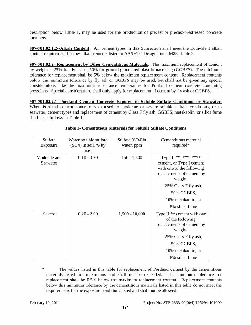
February 10, 2011 Project No. STP-2833-00(004)/105094-101000
description below Table 1, may be used for the production of precast or precast-prestressed concrete members. 907-701.02.1.2--Alkali Content. All cement types in this Subsection shall meet the Equivalent alkali content requirement for low-alkali cements listed in AASHTO Designation: M85, Table 2. 907-701.02.2--Replacement by Other Cementitious Materials. The maximum replacement of cement by weight is 25% for fly ash or 50% for ground granulated blast furnace slag (GGBFS). The minimum tolerance for replacement shall be 5% below the maximum replacement content. Replacement contents below this minimum tolerance by fly ash or GGBFS may be used, but shall not be given any special considerations, like the maximum acceptance temperature for Portland cement concrete containing pozzolans. Special considerations shall only apply for replacement of cement by fly ash or GGBFS. 907-701.02.2.1--Portland Cement Concrete Exposed to Soluble Sulfate Conditions or Seawater. When Portland cement concrete is exposed to moderate or severe soluble sulfate conditions, or to seawater, cement types and replacement of cement by Class F fly ash, GGBFS, metakaolin, or silica fume shall be as follows in Table 1.
Table 1- Cementitious Materials for Soluble Sulfate Conditions
Sulfate
Exposure Water-soluble sulfate (SO4) in soil, % by
mass
Sulfate (SO4)in water, ppm
Cementitious material required*
Moderate and Seawater
0.10 - 0.20 150 - 1,500 Type II **, ***, **** cement, or Type I cement with one of the following
replacements of cement by weight:
25% Class F fly ash, 50% GGBFS,
10% metakaolin, or 8% silica fume
Severe 0.20 - 2.00 1,500 - 10,000 Type II ** cement with one of the following
replacements of cement by weight:
25% Class F fly ash, 50% GGBFS,
10% metakaolin, or 8% silica fume
* The values listed in this table for replacement of Portland cement by the cementitious
materials listed are maximums and shall not be exceeded. The minimum tolerance for replacement shall be 0.5% below the maximum replacement content. Replacement contents below this minimum tolerance by the cementitious materials listed in this table do not meet the requirements for the exposure conditions listed and shall not be allowed.
171
February 10, 2011 Project No. STP-2833-00(004)/105094-101000
** Type I cement conforming to AASHTO Designation: M85 with a maximum 8% tricalcium aluminate (C3A) may be used in lieu of Type II cement; this cement is given the designation “Type I(MS)”. Type III cement conforming to AASHTO Designation: M85 with a maximum 8% tricalcium aluminate (C3A) may be used in lieu of Type II cement as allowed in Subsection 907-701.02.1; this cement is given the designation “Type III (MS)”.
*** Blended cement meeting the sulfate resistance requirements of Subsection 907-701.04 may be used in lieu of Type II as allowed in Subsection 907-701.04. No additional cementitious materials shall be added to or as a replacement for blended cement.
**** Class F fly ash or GGBFS may be added as a replacement for cement as allowed in Subsection 907-701.02.2.
Class C fly ash shall not be used as a replacement for cement in any of the sulfate exposure conditions listed above. 907-701.02.2.2--Cement for Soil Stabilization Exposed to Soluble Sulfate Conditions or Seawater. When Portland cement for use in soil stabilization is exposed to moderate or severe soluble sulfate conditions, or to seawater, cement types and replacement of cement by Class F fly ash or GGBFS shall meet the requirements of Subsection 907-701.02.2.1. Neither metakaolin nor silica fume shall be used to bring the cementitious materials into compliance with the requirements of Table 1. Delete Subsection 701.03 on page 596, and substitute the following: 907-701.03--Masonry Cement. Masonry cement shall conform to ASTM Designation: C 91 and shall only be used in masonry applications. Delete Subsection 701.04 on page 596, and substitute the following: 907-701.04--Blended Hydraulic Cement. 907-701.04.1--General. 907-701.04.1.1--Types of Blended Cement. Blended hydraulic cements (blended cements) shall be of the following types and conform to AASHTO Designation: M 240:
Type I(SM) – Slag-modified Portland cement Type IS – Portland blast-furnace slag cement Type I(PM) – Pozzolan-modified Portland cement Type IP – Portland-pozzolan cement
Blended cement for use in Portland cement concrete or soil stabilization exposed to the moderate soluble sulfate condition or exposure to seawater as defined in Table 1 shall meet the Sulfate resistance requirement listed in AASHTO Designation: M 240, Table 2 and the “(MS)” suffix shall be added to the type designation. 907-701.04.1.2--Alkali Content. All blended cement types in this Subsection shall meet the Mortar expansion requirements listed in AASHTO Designation: M 240, Table 2. 907-701.04.2--Replacement by Other Cementitious Materials. No additional cementitious materials, such as Portland cement, performance hydraulic cement, fly ash, GGBFS, metakaolin, or others, shall be added to or as a replacement for blended cement.
172
February 10, 2011 Project No. STP-2833-00(004)/105094-101000
907-701.04.3--Exposure to Soluble Sulfate Conditions or Seawater. When Portland cement concrete or blended cement for soil stabilization is exposed to moderate soluble sulfate conditions or to seawater, where the moderate soluble sulfate condition is defined in Table 1, the blended cement shall meet the sulfate resistance requirement listed in AASHTO Designation: M 240, Table 2. When Portland cement concrete or blended cement for soil stabilization is exposed to severe soluble sulfate conditions, where the severe soluble sulfate condition is defined in Table 1, blended cements shall not be used.
173
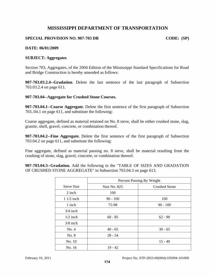
February 10, 2011 Project No. STP-2833-00(004)/105094-101000
MISSISSIPPI DEPARTMENT OF TRANSPORTATION SPECIAL PROVISION NO. 907-703 DB CODE: (SP) DATE: 06/01/2009 SUBJECT: Aggregates Section 703, Aggregates, of the 2004 Edition of the Mississippi Standard Specifications for Road and Bridge Construction is hereby amended as follows: 907-703.03.2.4--Gradation. Delete the last sentence of the last paragraph of Subsection 703.03.2.4 on page 611. 907-703.04--Aggregate for Crushed Stone Courses. 907-703.04.1--Coarse Aggregate. Delete the first sentence of the first paragraph of Subsection 703..04.1 on page 611, and substitute the following: Coarse aggregate, defined as material retained on No. 8 sieve, shall be either crushed stone, slag, granite, shell, gravel, concrete, or combination thereof. 907-703.04.2--Fine Aggregate. Delete the first sentence of the first paragraph of Subsection 703.04.2 on page 611, and substitute the following: Fine aggregate, defined as material passing no. 8 sieve, shall be material resulting from the crushing of stone, slag, gravel, concrete, or combination thereof. 907-703.04.3--Gradation. Add the following to the "TABLE OF SIZES AND GRADATION OF CRUSHED STONE AGGREGATE" in Subsection 703.04.3 on page 613.
Percent Passing By Weight Sieve Size Size No. 825 Crushed Stone
2 inch 100 1 1/2 inch 90 - 100 100
1 inch 75-98 90 - 100 3/4 inch 1/2 inch 60 - 85 62 - 90 3/8 inch
No. 4 40 - 65 30 - 65 No. 8 28 - 54
No. 10 15 - 40 No. 16 19 - 42
174
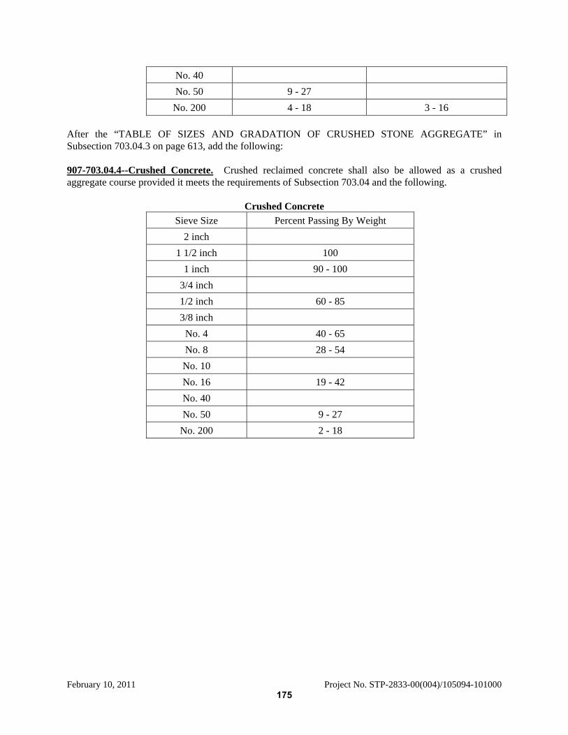
February 10, 2011 Project No. STP-2833-00(004)/105094-101000
No. 40 No. 50 9 - 27
No. 200 4 - 18 3 - 16 After the “TABLE OF SIZES AND GRADATION OF CRUSHED STONE AGGREGATE” in Subsection 703.04.3 on page 613, add the following: 907-703.04.4--Crushed Concrete. Crushed reclaimed concrete shall also be allowed as a crushed aggregate course provided it meets the requirements of Subsection 703.04 and the following.
Crushed Concrete Sieve Size Percent Passing By Weight
2 inch 1 1/2 inch 100
1 inch 90 - 100 3/4 inch 1/2 inch 60 - 85 3/8 inch
No. 4 40 - 65 No. 8 28 - 54
No. 10 No. 16 19 - 42 No. 40 No. 50 9 - 27
No. 200 2 - 18
175
February 10, 2011 Project No. STP-2833-00(004)/105094-101000
MISSISSIPPI DEPARTMENT OF TRANSPORTATION SPECIAL PROVISION NO. 907-707 DB CODE: (SP) DATE: 03/10/2009 SUBJECT: Joint Materials Section 707, Joint Materials, of the 2004 Edition of the Mississippi Standard Specifications for Road and Bridge Construction is hereby amended as follows: 907-707.02.1.3--Concrete Joint Sealer Compound - Hot-Poured Elastic Type. In the first paragraph of Subsection 707.02.1.3 on page 633, delete "AASHTO Designation: M 173" and replace with "AASHTO Designation: M 324 for Type I Joint and Crack Sealant". Delete in toto Subsection 707.02.1.5 on pages 634 and 635 and substitute: 907-707.02.1.5--Backer Rod for Use with Hot and Cold Poured Joint Sealer. The backer rod shall be a closed-cell foam rod made from polyethylene, polyolefin or similar type material, and shall conform to ASTM Designation: D 5249. The backer rod shall either be a Type 1, for use with either hot or cold poured joint sealers, or a Type 3, for use with cold poured joint sealers only. The Contractor shall furnish a three (3) linear foot sample of each shipment, and three (3) copies of the manufacturer’s certification that the backer rod meets the requirements of this specification.
176
February 10, 2011 Project No. STP-2833-00(004)/105094-101000
MISSISSIPPI DEPARTMENT OF TRANSPORTATION SPECIAL PROVISION NO. 907-711 DB CODE: (IS) DATE: 06/26/2009 SUBJECT: Synthetic Structural Fiber Reinforcement Section 711, Reinforcement and Wire Rope, of the 2004 Edition of the Mississippi Standard Specifications for Road and Bridge Construction is hereby amended as follows: After Subsection 711.03.4.3 on page 665, add the following: 907-711.04--Synthetic Structural Fiber. The synthetic structural fibers shall be approved for listing in the Department’s “Approved Sources of Materials” prior to use. The synthetic structural fibers shall be added to the concrete and mixed in accordance with the manufacturer’s recommended methods. 907-711.04.1--Material Properties. The fibers shall meet the requirements of ASTM Designation: C 1116, Section 4.1.3. The fibers shall be made of polypropylene, polypropylene/polyethylene blend, nylon, or polyvinyl alcohol (PVA). 907-711.04.2--Minimum Dosage Rate. The dosage rate shall be such that the average residual strength ratio (R150,3.0) of fiber reinforced concrete beams is a minimum of 20.0 percent when the beams are tested in accordance with ASTM Designation: C 1609. The dosage rate for fibers shall be determined by the following. The fiber manufacturer shall have the fibers tested by an acceptable, independent laboratory acceptable to the Department and regularly inspected by the Cement and Concrete Reference Laboratory of the National Institutes of Standards and Technology and approved to perform ASTM Designations: C 39, C 78, and C192. The laboratory shall test the fibers following the requirements of ASTM Designation: C 1609 in a minimum of three (3) test specimens cast from the same batch of concrete, molded in 6 x 6 x 20-inch standard beam molds meeting the requirements of ASTM Designation: C 31. The beams shall be tested on an 18-inch span. The tests for R150,3.0 shall be performed when the average compressive strength of concrete used to cast the beams is between 3500 and 4500 psi. The tests for compressive strength shall follow the requirements of ASTM Designation: C 39. The average compressive strength shall be determined from a minimum of two (2) compressive strength cylinders. The value for R150,3 shall be determined using the following equation:
1001
0.3,1500.3,150 ×=
ff
R
177

February 10, 2011 Project No. STP-2833-00(004)/105094-101000
The residual flexural strength ( 0.3,150f ) shall be determined using the following equation:
20.3,150
0.3,150 dbLP
f×
×=
where:
0.3,150f is the residual flexural strength at the midspan deflection of L/150, (psi),
0.3,150P is the residual load capacity at the midspan deflection of L/150, (lbf), L is the span, (in), b is the width of the specimen at the fracture, (in), and d is the depth of the specimen at the fracture, (in).
For a 6 x 6 x 20-inch beam, the 0.3,150P shall be measured at a midspan deflection of 0.12 inch. Additionally, 0.3,150R , 0.3,150f , and 0.3,150P may also be referred to as 150
150R , 150150f , and 150
150P respectively. At the dosage rate required to achieve the minimum R150,3 , the mixture shall both be workable and the fibers shall not form clumps. The manufacturer shall submit to the State Materials Engineer certified test reports from the independent laboratory showing the test results of each test specimen. 907-711.04.3--Job Control Requirements. The synthetic structural fibers shall be one from the Department’s “Approved Sources of Materials.” At the required dosage rate, the mixture shall both be workable and the fibers shall not form clumps to the satisfaction of the Engineer. If the mixture is determined by the Engineer to not be workable or have clumps of fibers, the mixture may be rejected.
178
February 10, 2011 Project No. STP-2833-00(004)/105094-101000
MISSISSIPPI DEPARTMENT OF TRANSPORTATION SPECIAL PROVISION NO. 907-713 DB CODE: (SP) DATE: 03/10/2009 SUBJECT: Admixtures for Concrete Section 713, Concrete Curing Materials and Admixtures, of the 2004 Edition of the Mississippi Standard Specifications for Road and Bridge Construction is hereby amended as follows: After the second paragraph of Subsection 713.01.2 on page 676, add the following. Type 1-D compound may be used on bridge rails, median barriers, and other structures requiring a spray finish. When Type 1-D compound is used, it will be the Contractor’s responsibility to assure that the compound has dissipated from the structure prior to applying the spray finish and that the spray finish adheres soundly to the structure. Delete Subsection 713.02 on pages 676 & 677, and substitute the following: 907-713.02--Admixtures for Portland Cement Concrete. Admixtures shall only be approved by MDOT for classification as a single type following the applicable types from AASTHO Designation: M 154 or M 194, or the definition of a mid-range water reducer listed below with the following exception: when requested by the manufacturer MDOT will consider classifying an admixture as both a Type A and a Type D. Admixtures shall only be used in accordance with the manufacturer’s recommended dosage range for that type. Where an admixture is classified as both a Type A and Type D, the dosage range for use as a Type A shall not overlap the dosage range for use as a Type D. Air-entraining admixtures shall comply with AASHTO Designation: M 154. Set-retarding, accelerating, and/or water-reducing admixtures shall comply with AASHTO Designation: M 194. Mid-range water-reducers are classified as water-reducing admixtures that reduce the mix water a minimum of 8% when compared to a control mix with no admixtures when tested in accordance with the requirements in AASHTO Designation: M 194. The type designation for admixtures approved by MDOT and classified as meeting the requirements of a mid-range water-reducer shall be “MR”. 907-713.02.1--Source Approval. In order to obtain approval of an admixture, the Producer/Suppliers shall submit to the Construction Quality Control Manager the following for review: certified test reports, made by an acceptable independent laboratory regularly inspected by the Cement and Concrete Reference Laboratory of the National Institutes of Standards and Technology, which show that the admixture meets all the requirements of the applicable AASHTO or MDOT Specification for the specific type and the dosage range for the specific type of admixture. 907-713.02.2--Specific Requirements. Admixtures containing chlorides will not be permitted. 907-713.02.3--Acceptance. MDOT reserves the right to sample, for check tests, any shipment or lot of admixture delivered to the Project. MDOT reserves the right to require tests of the material to be furnished, using the specific cement and aggregates proposed for use on the Project, as suggested in AASHTO Designation: M 154 and outlined in
179

February 10, 2011 Project No. STP-2833-00(004)/105094-101000
AASHTO Designation: M 194. Failure to maintain compliance with any requirement of these specifications shall be cause for rejection of any previously approved source or brand of admixture. With each new lot of material shipped the Contractor shall submit to the Construction Quality Control Manager, a notarized certification from the manufacturer showing that the material complies with the requirements of the applicable AASHTO or MDOT Specification. When an admixture is used, it shall be the responsibility of the Contractor to produce satisfactory results.
180
February 10, 2011 Project No. STP-2833-00(004)/105094-101000
MISSISSIPPI DEPARTMENT OF TRANSPORTATION SPECIAL PROVISION NO. 907-714 DB CODE: (SP) DATE: 03/10/2009 SUBJECT: Miscellaneous Materials Section 714, Miscellaneous Materials, of the 2004 Edition of the Mississippi Standard Specifications for Road and Bridge Construction is hereby amended as follows: 907-714.05--Fly Ash. Delete Subsections 714.05.1 & 714.05.2 on pages 680 & 681, and substitute the following: 907-714.05.1--General. The fly ash source must be approved for listing in MDOT’s “Approved Sources of Materials” prior to use. The acceptance of fly ash shall be based on certified test reports, certification of shipment from the supplier, and tests performed on samples obtained after delivery in accordance with MDOT’s Materials Division Inspection, Testing, and Certification Manual and MDOT SOP. Different classes of fly ash or different sources of the same class shall not be mixed or used in the construction of a structure or unit of a structure without written permission from the Engineer. The Contractor shall provide suitable means for storing and protecting the fly ash from dampness. Separate storage silos, bins, or containers shall be provided for fly ash. Fly ash which has become partially set or contains lumps of caked fly ash shall not be used. The temperature of the bulk fly ash shall not be greater than 165°F at the time of incorporation into the work. All classes of fly ash shall meet the supplementary option chemical requirement for available alkalies listed in AASHTO Designation: M 295, Table 2. Class F fly ash shall have a calcium oxide (CaO) content of less than 6.0%. Class C fly ash shall have a CaO content of greater than or equal to 6.0%. The replacement of Portland cement with fly ash shall be in accordance with the applicable replacement content specified in Subsection 907-701.02.2. In addition to these requirements, fly ash shall meet the following specific requirements for the intended use. 907-714.05.2--Fly Ash for Use in Concrete. When used with Portland cement in the production of concrete or grout, the fly ash shall meet the requirements of AASHTO Designation: M 295, Class C or F, with the following exceptions:
The loss on ignition shall not exceed 6.0%. The strength activity index with Portland cement shall be at least 55% of the control mix at seven (7) days.
181

February 10, 2011 Project No. STP-2833-00(004)/105094-101000
No additional cementitious materials, such as blended hydraulic cement, GGBFS, metakaolin, or others, shall be added to or as a replacement for Portland cement when used with fly ash. 907-714.06--Ground Granulated Blast Furnace Slag (GGBFS). Delete Subsection 714.06.1 on page 681, and substitute the following: 907-714.06.1--General. The GGBFS source must be approved for listing in MDOT’s “Approved Sources of Materials” prior to use. The acceptance of GGBFS shall be based on certified test reports, certification of shipment from the supplier, and tests performed on samples obtained after delivery in accordance with MDOT’s Materials Division Inspection, Testing, and Certification Manual and MDOT SOP. The Contractor shall provide suitable means for storing and protecting the GGBFS against dampness and contamination. Separate storage silos, bins, or containers shall be provided for GGBFS. GGBFS which has become partially set, caked or contains lumps shall not be used. The State Materials Engineer shall be notified in writing of the nature, amount and identity of any processing or other additions made to the GGBFS during production. GGBFS from different mills shall not be mixed or used alternately in any one (1) class of construction or structure without written permission from the Engineer; except that this requirement will not be applicable to cement treatment of design soils or bases.
No additional cementitious materials, such as blended hydraulic cement, fly ash, metakaolin, or others, shall be added to or as a replacement for Portland cement when used with GGBFS in the production of concrete. The replacement of Portland cement with GGBFS shall be in accordance with the applicable replacement content specified in Subsection 907-701.02.2. Delete Subsection 714.07 on page 682, and substitute the following: 907-714.07--Additional Cementitious Materials. 907-714.07.1--Metakaolin. 907-714.07.1.1--General. Metakaolin shall only be used as a supplementary cementitious material in Portland cement concrete for compliance with the requirements for cementitious materials exposed to soluble sulfate conditions. Metakaolin from different sources shall not be mixed or used alternately in any one (1) class of construction or structure without written permission from the Engineer. No additional cementitious materials, such as blended hydraulic cement, fly ash, GGBFS, or others, shall be added to or as a replacement for Portland cement when used with metakaolin in the production of concrete. The State Materials Engineer shall be notified in writing of the nature, amount and identity of any processing, or other additions made to the metakaolin during production. 907-714.07.1.2--Source Approval. The approval of each metakaolin source shall be on a case by case basis as determined by the State Materials Engineer. In order to obtain approval of a metakaolin source, the Producer/Suppliers shall submit to the State Materials Engineer the following for review: certified test reports, made by an acceptable, independent laboratory regularly inspected by the Cement and Concrete Reference Laboratory of the National Institutes of Standards and Technology, which show that
182
February 10, 2011 Project No. STP-2833-00(004)/105094-101000
the metakaolin meets all the requirements of AASHTO Designation: M295, including the Effectiveness in Contributing to Sulfate Resistance, Procedure A, listed in AASHTO Designation: M295, Table 4 for Supplementary Optional Physical Requirements, and other requirements listed herein. In order to demonstrate effectiveness in contributing to sulfate resistance, included in this test data shall be results of metakaolin from the proposed source tested in accordance with ASTM Designation: C 1012. There shall be two (2) sets of test specimens per the following: a. One (1) set of test specimens shall be prepared using a Type I Portland cement meeting the
requirements of AASHTO Designation: M85 and having a tricalcium aluminate (C3A) content of more than 8.0%.
b. One (1) set of test specimens shall be prepared using a Type II Portland cement meeting the
requirements of AASHTO Designation: M85. c. The proposed metakaolin shall be incorporated at the rate of 10% cement replacement in each set
of test specimens and shall meet both of the acceptance criteria listed below for source approval. The requirement for acceptance of the test sample using Type I Portland cement is an expansion of 0.10% or less at the end of six (6) months. The requirement for acceptance of the test sample using Type II Portland cement is an expansion of 0.05% or less at the end of six (6) months. 907-714.07.1.3--Storage. The Contractor shall provide suitable means for storing and protecting the metakaolin against dampness and contamination. Metakaolin which has become partially set, caked, or contains lumps shall not be used. 907-714.07.1.4--Specific Requirements. Metakaolin shall meet the requirements of AASHTO Designation: M 295, Class N with the following modifications:
1. The sum of SiO2 + Al2O3 + Fe2O3 shall be at least 85%. The Material Safety Data Sheet shall indicate that the amount of crystalline silica, as measured by National Institute of Occupation Safety and Health (NIOSH) 7500 method, after removal of the mica interference, is less than 1.0%.
2. The loss on ignition shall be less than 3.0%. 3. The available alkalis, as equivalent Na2O, shall not exceed 1.0%. 4. The amount of material retained on a No. 325 mesh sieve shall not exceed 1.0%. 5. The strength activity index at seven (7) days shall be at least 85%.
907-714.07.1.5--Acceptance. With each new lot of material shipped the Contractor shall submit to the State Materials Engineer a certified test report from the manufacturer showing that the material meets the requirements AASHTO Designation: M295, Class N and the requirements of this Subsection. MDOT reserves the right to sample, for check tests, any shipment or lot of metakaolin delivered to the Project. 907-714.07.2--Silica Fume. 907-714.07.2.1--General. Silica fume shall only be used as a supplementary cementitious material in Portland cement concrete for compliance with the requirements for cementitious materials exposed to soluble sulfate conditions. Silica fume from different sources shall not be mixed or used alternately in any one (1) class of construction or structure without written permission from the Engineer. No additional cementitious materials, such as blended hydraulic cement, performance hydraulic cement, fly
183
February 10, 2011 Project No. STP-2833-00(004)/105094-101000
ash, GGBFS, or others, shall be added to or as a replacement for Portland cement when used with silica fume in the production of concrete. The State Materials Engineer shall be notified in writing of the nature, amount and identity of any processing, or other additions made to the silica fume during production. 907-714.07.2.2--Source Approval. The approval of each silica fume source shall be on a case by case basis as determined by the State Materials Engineer. In order to obtain approval of a silica fume source, the Producer/Suppliers shall submit to the State Materials Engineer the following for review: certified test reports, made by an acceptable, independent laboratory regularly inspected by the Cement and Concrete Reference Laboratory of the National Institutes of Standards and Technology, which show that the silica fume meets all the requirements of AASHTO Designation: M307, Table 3, including the Sulfate resistance expansion, listed in the table for Optional Physical Requirements, and other requirements listed herein. In order to demonstrate effectiveness in contributing to sulfate resistance, included in this test data shall be results of silica fume from the proposed source tested in accordance with ASTM Designation: C 1012. There shall be two (2) sets of test specimens per the following: a. One (1) set of test specimens shall be prepared using a Type I Portland cement meeting the
requirements of AASHTO Designation: M85 and having a tricalcium aluminate (C3A) content of more than 8.0%,
b. One set of test specimens shall be prepared using a Type II Portland cement meeting the
requirements of AASHTO Designation: M85. c. The proposed silica fume shall be incorporated at the rate of 8% cement replacement in each set
of test specimens and shall meet both of the acceptance criteria listed below for source approval. The requirement for acceptance of the test sample using Type I Portland cement is an expansion of 0.10% or less at the end of six (6) months. The requirement for acceptance of the test sample using Type II Portland cement is an expansion of 0.05% or less at the end of six (6) months. 907-714.07.2.3--Storage. The Contractor shall provide suitable means for storing and protecting the silica fume against dampness and contamination. Silica fume which has become partially set, caked, or contains lumps shall not be used. 907-714.07.2.4--Acceptance. With each new lot of material shipped, the Contractor shall submit to the State Materials Engineer a certified test report from the manufacturer showing that the material meets the Chemical and Physical Requirements of AASHTO Designation: M307. MDOT reserves the right to sample, for check tests, any shipment or lot of silica fume delivered to the Project. 907-714.11.6--Rapid Setting Commercial Grouts and Concrete Patching Compounds. Delete the first sentence of the first paragraph of Subsection 714.11.6 on page 690 and substitute the following: Rapid setting commercial grouts and concrete patching compounds must be approved for listing in MDOT’s “Approved Sources of Materials” prior to use. Upon approval, a product must be recertified every four (4) years to remain on the “Approved Sources of Materials” list. Each product shall be pre-measured and packaged dry by the manufacturer.
184
February 10, 2011 Project No. STP-2833-00(004)/105094-101000
907-714.11.7--Commercial Grout for Anchoring Doweled Tie Bars in Concrete. Before Subsection 714.11.7.1 on page 691, add the following: Approved Non-“Fast Set” Epoxy anchor systems as specified below may be used for the repair of concrete pavements that do not involve permanent sustained tension applications or overhead applications. “Fast Set Epoxy” may not be used for any Adhesive Anchor Applications. Adhesive Anchor Systems (Fast Set epoxy or otherwise) shall not be used for permanent sustained tension applications or overhead applications. “Fast Set Epoxy” refers to an epoxy produced by the Sika Corporation called Sikadur AnchorFix-3 and repackaged for sale under a variety of names/companies listed at the Federal Highway Administration web site at the following link:
http://www.fhwa.dot.gov/Bridge/adhesives.cfm 907-714.11.7.4--Acceptance Procedure. After the last sentence of the first paragraph of Subsection 714.11.4 on page 691, add the following: Upon approval, a product must be recertified every four (4) years to remain on the “Approved Sources of Materials” list. 907-714.11.8--Epoxy Joint Repair System. 907-714.11.8.1--General. After the last sentence of the first paragraph of Subsection 714.11.8.1 on page 692, add the following: Upon approval, a product must be recertified every four (4) years to remain on the “Approved Sources of Materials” list. After the table at the end of Subsection 714.15 on page 701 add the following: 907-714.16--Stabilizing Fibers. 907-714.16.1--General. Stabilizing fibers shall be used in Stone Matrix Asphalt (SMA) mixtures and other mixtures, as necessary, for draindown reduction. Fibers shall be added at a minimum dosage rate of 0.30% for both cellulose and mineral fibers by weight of total mix. The produced mixture containing the fibers shall exhibit a draindown of 0.30% or less when tested in accordance with Mississippi Test Method MT-82. Either cellulose or mineral fibers may be used. A pelletized fiber comprised of either cellulose or mineral fiber may also be used. 907-714.16.2--Cellulose Fibers. Cellulose fibers shall conform to the following properties:
Property Specification Requirement Fiber Length 0.25 inch maximum Sieve Analysis
a. Alpine Air Jet Sieve Method 60 – 80 percent
185
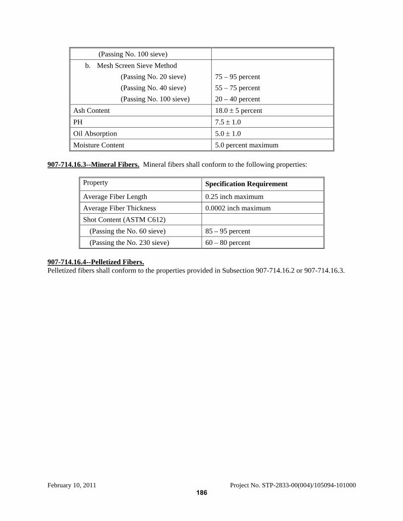
February 10, 2011 Project No. STP-2833-00(004)/105094-101000
(Passing No. 100 sieve) b. Mesh Screen Sieve Method (Passing No. 20 sieve) (Passing No. 40 sieve) (Passing No. 100 sieve)
75 – 95 percent 55 – 75 percent 20 – 40 percent
Ash Content 18.0 ± 5 percent PH 7.5 ± 1.0 Oil Absorption 5.0 ± 1.0 Moisture Content 5.0 percent maximum
907-714.16.3--Mineral Fibers. Mineral fibers shall conform to the following properties:
Property Specification Requirement
Average Fiber Length 0.25 inch maximum Average Fiber Thickness 0.0002 inch maximum Shot Content (ASTM C612) (Passing the No. 60 sieve) 85 – 95 percent (Passing the No. 230 sieve) 60 – 80 percent
907-714.16.4--Pelletized Fibers. Pelletized fibers shall conform to the properties provided in Subsection 907-714.16.2 or 907-714.16.3.
186
February 10, 2011 Project No. STP-2833-00(004)/105094-101000
MISSISSIPPI DEPARTMENT OF TRANSPORTATION SPECIAL PROVISION NO. 907-715 DB CODE: (SP) DATE: 03/10/2009 SUBJECT: Roadside Development Materials Section 715, Roadside Development Materials, of the 2004 Edition of the Mississippi Standard Specifications for Road and Bridge Construction is hereby amended as follows: 907-715-02.2.1--Agricultural Limestone. Delete the first sentence of Subsection 715-02.2.1 on page 704 and substitute the following. Agricultural limestone shall be either a hard-rock limestone material or a marl or chalk agricultural liming material as addressed in the latest amendment to the Mississippi Agricultural Liming Material Act of 1993, published by the Mississippi Department of Agriculture and Commerce. 907-715.02.2.1.1--Screening Requirements. Delete the first sentence of Subsection 715.02.2.1.1 on page 704. Delete Subsection 715.02.2.1.2 on page 704 and substitute the following: 907-715-02.2.1.2--Calcium Carbonate Equivalent. Marl or chalk liming material shall not have less than 70% calcium and magnesium carbonate calculated as calcium carbonate equivalent when expressed on a dry weight basis. 907-715-02.2.1.3--Neutralizing Values. Hard-rock limestone material shall have a minimum Relative Neutralizing Value (RNV) of 63.0%, which is determined as follows: % RNV = CCE x (% passing #10 mesh + % passing #50 mesh)/2 Where: CCE = Calcium Carbonate Equivalent 907-715.03--Seed. 907-715.03.2--Germination and Purity Requirements. Add the following to Table B on page 705.
Name (Kind) Name (Variety) Percent Germination
Percent Purity
GRASSES Rye Grass Annual 80 98
187
February 10, 2011 Project No. STP-2833-00(004)/105094-101000
MISSISSIPPI DEPARTMENT OF TRANSPORTATION SPECIAL PROVISION NO. 907-803 DB CODE: (SP) DATE: 03/10/2009 SUBJECT: Maturity Meters in Drilled Shafts Section 803, Deep Foundations, of the 2004 Edition of the Mississippi Standard Specifications for Road and Bridge Construction is hereby amended as follows: 907-803.03--Construction Requirements. 907-803.03.2--Drilled Shafts. 907-803.03.2.3.1.1--Protection of Existing Structures. Delete the fifth sentence of the first paragraph of Subsection 803.03.2.3.1.1 on page 820, and substitute the following: Advancing an uncased drilled shaft excavation or the use of a vibratory hammer to install casings within 30 feet of a newly constructed shaft will not be permitted unless the concrete in that shaft has attained a compressive strength of 2,500 psi, as determined by cylinder tests, or maturity meter probe when maturity meter readings indicate that the required concrete strength is achieved. After the first paragraph of Subsection 803.03.2.3.1.1 on page 820, add the following: If a maturity meter probe is used, it shall be located in the last concrete placed. Procedures for using the maturity meter and developing the strength/maturity relationship shall follow the requirements of AASHTO Designation: T 325 and ASTM Designation: C 1074 specifications. Technicians using the maturity meter or calculating strength/maturity graphs shall be required to have at least two (2) hours of training prior to using the maturity equipment. 907-803.03.2.7--Concrete Placement. 907-803.03.2.7.1--General. Delete the last sentence of the fifth paragraph of Subsection 803.03.2.7.1 on pages 834. 907-803.03.2.8.1--Static Load Tests. Delete the first sentence of the first paragraph of Subsection 803.03.2.8.1 on pages 836 & 837, and substitute the following: Static load testing shall not begin until the concrete has attained a compressive strength of 3,000 psi as determined from cylinder tests, or maturity meter probe in accordance with Subsection 803.03.2.3.1.1. If a maturity meter probe is used, it shall be located in the last concrete placed.
Delete Subsections 803.04 and 803.05 beginning on page 840 and substitute the following:
907-803.04--Blank.
907-803.05--Blank.
188
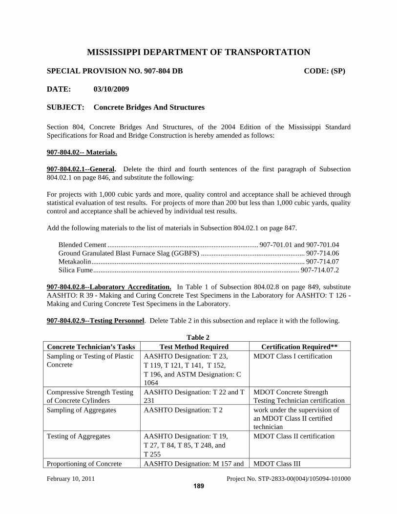
February 10, 2011 Project No. STP-2833-00(004)/105094-101000
MISSISSIPPI DEPARTMENT OF TRANSPORTATION SPECIAL PROVISION NO. 907-804 DB CODE: (SP) DATE: 03/10/2009 SUBJECT: Concrete Bridges And Structures Section 804, Concrete Bridges And Structures, of the 2004 Edition of the Mississippi Standard Specifications for Road and Bridge Construction is hereby amended as follows: 907-804.02-- Materials. 907-804.02.1--General. Delete the third and fourth sentences of the first paragraph of Subsection 804.02.1 on page 846, and substitute the following: For projects with 1,000 cubic yards and more, quality control and acceptance shall be achieved through statistical evaluation of test results. For projects of more than 200 but less than 1,000 cubic yards, quality control and acceptance shall be achieved by individual test results. Add the following materials to the list of materials in Subsection 804.02.1 on page 847.
Blended Cement .................................................................................... 907-701.01 and 907-701.04 Ground Granulated Blast Furnace Slag (GGBFS) .......................................................... 907-714.06 Metakaolin....................................................................................................................... 907-714.07 Silica Fume................................................................................................................... 907-714.07.2
907-804.02.8--Laboratory Accreditation. In Table 1 of Subsection 804.02.8 on page 849, substitute AASHTO: R 39 - Making and Curing Concrete Test Specimens in the Laboratory for AASHTO: T 126 - Making and Curing Concrete Test Specimens in the Laboratory. 907-804.02.9--Testing Personnel. Delete Table 2 in this subsection and replace it with the following.
Table 2 Concrete Technician’s Tasks Test Method Required Certification Required** Sampling or Testing of Plastic Concrete
AASHTO Designation: T 23, T 119, T 121, T 141, T 152, T 196, and ASTM Designation: C 1064
MDOT Class I certification
Compressive Strength Testing of Concrete Cylinders
AASHTO Designation: T 22 and T 231
MDOT Concrete Strength Testing Technician certification
Sampling of Aggregates AASHTO Designation: T 2 work under the supervision of an MDOT Class II certified technician
Testing of Aggregates AASHTO Designation: T 19, T 27, T 84, T 85, T 248, and T 255
MDOT Class II certification
Proportioning of Concrete AASHTO Designation: M 157 and MDOT Class III
189
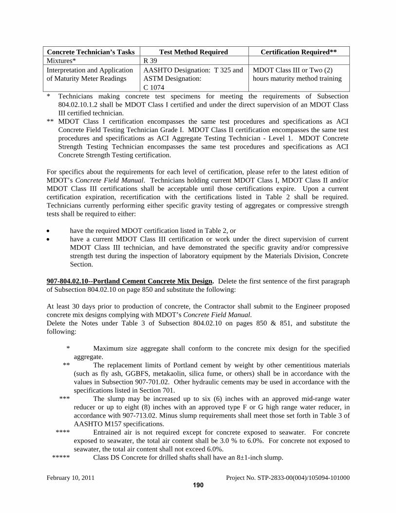
February 10, 2011 Project No. STP-2833-00(004)/105094-101000
Concrete Technician’s Tasks Test Method Required Certification Required** Mixtures* R 39 Interpretation and Application of Maturity Meter Readings
AASHTO Designation: T 325 and ASTM Designation: C 1074
MDOT Class III or Two (2) hours maturity method training
* Technicians making concrete test specimens for meeting the requirements of Subsection 804.02.10.1.2 shall be MDOT Class I certified and under the direct supervision of an MDOT Class III certified technician.
** MDOT Class I certification encompasses the same test procedures and specifications as ACI Concrete Field Testing Technician Grade I. MDOT Class II certification encompasses the same test procedures and specifications as ACI Aggregate Testing Technician - Level 1. MDOT Concrete Strength Testing Technician encompasses the same test procedures and specifications as ACI Concrete Strength Testing certification.
For specifics about the requirements for each level of certification, please refer to the latest edition of MDOT’s Concrete Field Manual. Technicians holding current MDOT Class I, MDOT Class II and/or MDOT Class III certifications shall be acceptable until those certifications expire. Upon a current certification expiration, recertification with the certifications listed in Table 2 shall be required. Technicians currently performing either specific gravity testing of aggregates or compressive strength tests shall be required to either: • have the required MDOT certification listed in Table 2, or • have a current MDOT Class III certification or work under the direct supervision of current
MDOT Class III technician, and have demonstrated the specific gravity and/or compressive strength test during the inspection of laboratory equipment by the Materials Division, Concrete Section.
907-804.02.10--Portland Cement Concrete Mix Design. Delete the first sentence of the first paragraph of Subsection 804.02.10 on page 850 and substitute the following: At least 30 days prior to production of concrete, the Contractor shall submit to the Engineer proposed concrete mix designs complying with MDOT’s Concrete Field Manual. Delete the Notes under Table 3 of Subsection 804.02.10 on pages 850 & 851, and substitute the following: * Maximum size aggregate shall conform to the concrete mix design for the specified
aggregate. ** The replacement limits of Portland cement by weight by other cementitious materials
(such as fly ash, GGBFS, metakaolin, silica fume, or others) shall be in accordance with the values in Subsection 907-701.02. Other hydraulic cements may be used in accordance with the specifications listed in Section 701.
*** The slump may be increased up to six (6) inches with an approved mid-range water reducer or up to eight (8) inches with an approved type F or G high range water reducer, in accordance with 907-713.02. Minus slump requirements shall meet those set forth in Table 3 of AASHTO M157 specifications.
**** Entrained air is not required except for concrete exposed to seawater. For concrete exposed to seawater, the total air content shall be 3.0 % to 6.0%. For concrete not exposed to seawater, the total air content shall not exceed 6.0%.
***** Class DS Concrete for drilled shafts shall have an 8±1-inch slump.
190

February 10, 2011 Project No. STP-2833-00(004)/105094-101000
Delete the last paragraph of Subsection 804.02.10 on page 851 and substitute the following: Either Type A, D, F, G or mid-range chemical admixture, shall be used in all classes of concrete. Any combinations of water reducing admixtures shall be approved by the Construction Quality Control Manager before their use. 907-804.02.10.1.1--Proportioning on the Basis of Previous Field Experience of Trial Mixtures. Delete the first sentence of the first paragraph of Subsection 804.02.10.1.1 on page 851, and substitute the following: Where a concrete production facility has a record, based on at least 10 consecutive strength tests from at least 10 different batches within the past 12 months from a mixture not previously used on MDOT projects, the standard deviation shall be calculated. 907-804.02.10.3--Field Verification of Concrete Mix Design. Delete the third sentence of the third paragraph of Subsection 804.02.10.3 on page 853, and substitute the following: If the requirements of yield, slump, or total air content are not met within three (3) production days after the first placement, subsequent field verification testing shall not be permitted on department projects, and the mix design shall not be used until the requirements listed above are met. 907-804.02.10.4--Adjustments of Mixture Proportions. Delete the paragraph in Subsection 804.02.10.4 on page 854, and substitute the following: The mixture may be adjusted by the Class III Certified Technician representing the Contractor in accordance with the allowable revisions listed in MDOT’s Concrete Field Manual, paragraph 5.7. Written notification shall be submitted to the Construction Quality Control Manager a minimum of seven (7) days prior to any source or brand of material change, aggregate size change, allowable material type change, or decrease in any cementitious material content. Any adjustments of the concrete mixture design shall necessitate repeat of field verification procedure as described in Subsection 804.02.10.3 and approval by the Construction Quality Control Manager. 907-804.02.11--Concrete Batch Plants. Delete the first three (3) paragraphs of Subsection 804.02.11 on page 854, and substitute the following: The concrete batch plant shall meet the requirements of the National Ready Mixed Concrete Association Quality Control Manual, Section 3, Plant Certification Checklist as outlined in the latest edition of MDOT’s Concrete Field Manual. The Contractor shall submit a copy of the approved checklist along with proof of calibration of batching equipment, i.e., scales, water meter, and admixture dispenser, to the Construction Quality Control Manager 30 days prior to the production of concrete. For projects with 1,000 cubic yards and more, the concrete batch plant shall meet the requirements for an automatic system capable of recording batch weights. It shall also have automatic moisture compensation for the fine aggregate. For projects of more than 200 but less than 1,000 cubic yards the plant can be equipped for manual batching with a fine aggregate moisture meter visible to the plant operator. The concrete batch plant shall have available adequate facilities to cool concrete during hot weather. Mixer trucks to be used on each Phase of the Project are to be listed in the checklist and shall meet the requirements of the checklist.
191
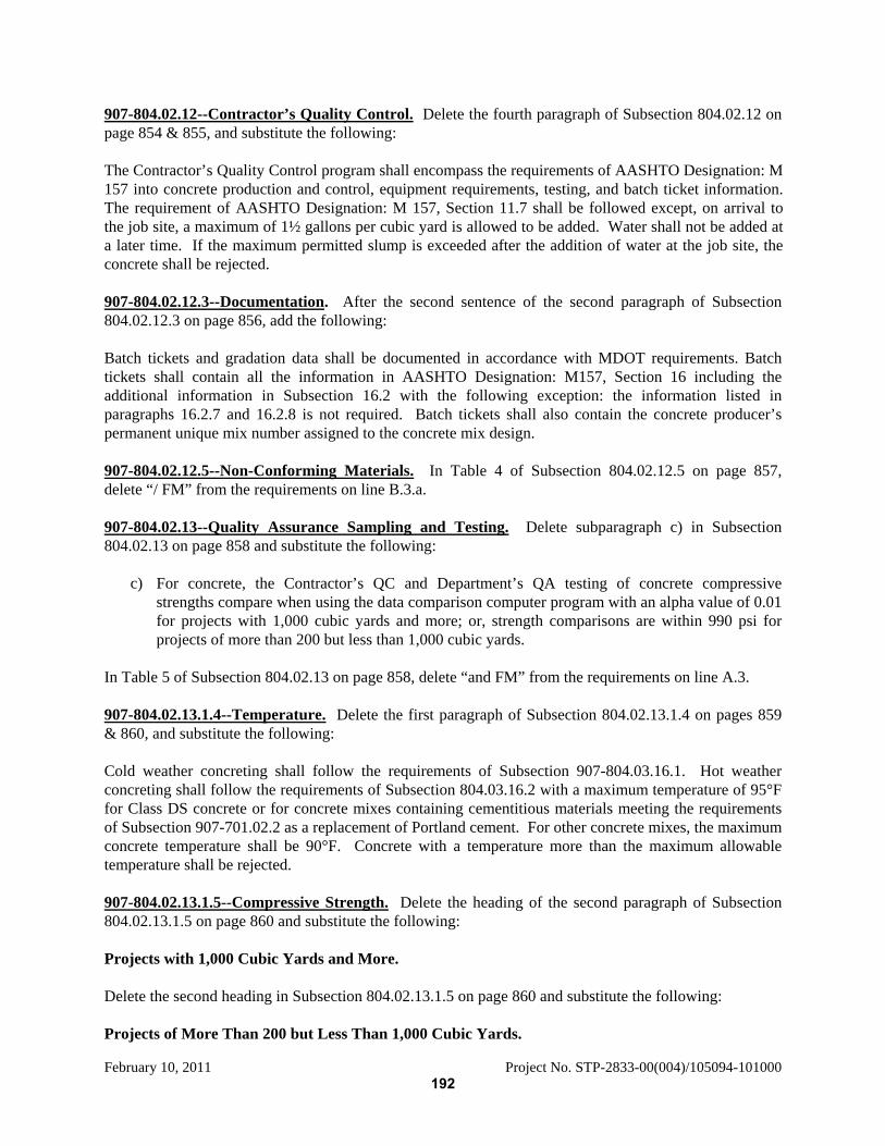
February 10, 2011 Project No. STP-2833-00(004)/105094-101000
907-804.02.12--Contractor’s Quality Control. Delete the fourth paragraph of Subsection 804.02.12 on page 854 & 855, and substitute the following: The Contractor’s Quality Control program shall encompass the requirements of AASHTO Designation: M 157 into concrete production and control, equipment requirements, testing, and batch ticket information. The requirement of AASHTO Designation: M 157, Section 11.7 shall be followed except, on arrival to the job site, a maximum of 1½ gallons per cubic yard is allowed to be added. Water shall not be added at a later time. If the maximum permitted slump is exceeded after the addition of water at the job site, the concrete shall be rejected. 907-804.02.12.3--Documentation. After the second sentence of the second paragraph of Subsection 804.02.12.3 on page 856, add the following: Batch tickets and gradation data shall be documented in accordance with MDOT requirements. Batch tickets shall contain all the information in AASHTO Designation: M157, Section 16 including the additional information in Subsection 16.2 with the following exception: the information listed in paragraphs 16.2.7 and 16.2.8 is not required. Batch tickets shall also contain the concrete producer’s permanent unique mix number assigned to the concrete mix design. 907-804.02.12.5--Non-Conforming Materials. In Table 4 of Subsection 804.02.12.5 on page 857, delete “/ FM” from the requirements on line B.3.a. 907-804.02.13--Quality Assurance Sampling and Testing. Delete subparagraph c) in Subsection 804.02.13 on page 858 and substitute the following:
c) For concrete, the Contractor’s QC and Department’s QA testing of concrete compressive strengths compare when using the data comparison computer program with an alpha value of 0.01 for projects with 1,000 cubic yards and more; or, strength comparisons are within 990 psi for projects of more than 200 but less than 1,000 cubic yards.
In Table 5 of Subsection 804.02.13 on page 858, delete “and FM” from the requirements on line A.3. 907-804.02.13.1.4--Temperature. Delete the first paragraph of Subsection 804.02.13.1.4 on pages 859 & 860, and substitute the following: Cold weather concreting shall follow the requirements of Subsection 907-804.03.16.1. Hot weather concreting shall follow the requirements of Subsection 804.03.16.2 with a maximum temperature of 95°F for Class DS concrete or for concrete mixes containing cementitious materials meeting the requirements of Subsection 907-701.02.2 as a replacement of Portland cement. For other concrete mixes, the maximum concrete temperature shall be 90°F. Concrete with a temperature more than the maximum allowable temperature shall be rejected. 907-804.02.13.1.5--Compressive Strength. Delete the heading of the second paragraph of Subsection 804.02.13.1.5 on page 860 and substitute the following: Projects with 1,000 Cubic Yards and More. Delete the second heading in Subsection 804.02.13.1.5 on page 860 and substitute the following: Projects of More Than 200 but Less Than 1,000 Cubic Yards.
192
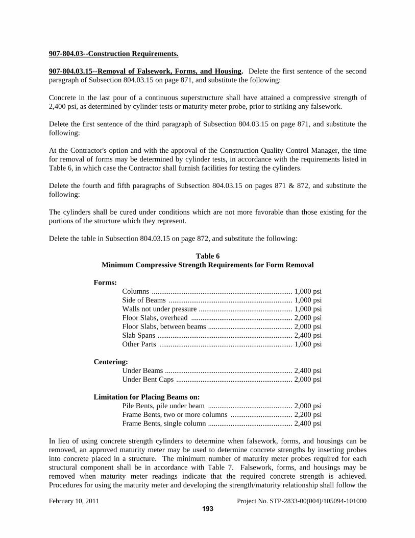
February 10, 2011 Project No. STP-2833-00(004)/105094-101000
907-804.03--Construction Requirements. 907-804.03.15--Removal of Falsework, Forms, and Housing. Delete the first sentence of the second paragraph of Subsection 804.03.15 on page 871, and substitute the following: Concrete in the last pour of a continuous superstructure shall have attained a compressive strength of 2,400 psi, as determined by cylinder tests or maturity meter probe, prior to striking any falsework. Delete the first sentence of the third paragraph of Subsection 804.03.15 on page 871, and substitute the following: At the Contractor's option and with the approval of the Construction Quality Control Manager, the time for removal of forms may be determined by cylinder tests, in accordance with the requirements listed in Table 6, in which case the Contractor shall furnish facilities for testing the cylinders. Delete the fourth and fifth paragraphs of Subsection 804.03.15 on pages 871 & 872, and substitute the following: The cylinders shall be cured under conditions which are not more favorable than those existing for the portions of the structure which they represent. Delete the table in Subsection 804.03.15 on page 872, and substitute the following:
Table 6 Minimum Compressive Strength Requirements for Form Removal
Forms: Columns ........................................................................... 1,000 psi Side of Beams .................................................................. 1,000 psi Walls not under pressure .................................................. 1,000 psi Floor Slabs, overhead ...................................................... 2,000 psi Floor Slabs, between beams ............................................. 2,000 psi Slab Spans ........................................................................ 2,400 psi Other Parts ....................................................................... 1,000 psi Centering: Under Beams .................................................................... 2,400 psi Under Bent Caps .............................................................. 2,000 psi Limitation for Placing Beams on: Pile Bents, pile under beam ............................................. 2,000 psi Frame Bents, two or more columns ................................. 2,200 psi Frame Bents, single column ............................................. 2,400 psi
In lieu of using concrete strength cylinders to determine when falsework, forms, and housings can be removed, an approved maturity meter may be used to determine concrete strengths by inserting probes into concrete placed in a structure. The minimum number of maturity meter probes required for each structural component shall be in accordance with Table 7. Falsework, forms, and housings may be removed when maturity meter readings indicate that the required concrete strength is achieved. Procedures for using the maturity meter and developing the strength/maturity relationship shall follow the
193
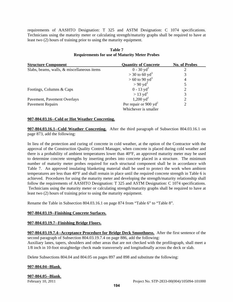
February 10, 2011 Project No. STP-2833-00(004)/105094-101000
requirements of AASHTO Designation: T 325 and ASTM Designation: C 1074 specifications. Technicians using the maturity meter or calculating strength/maturity graphs shall be required to have at least two (2) hours of training prior to using the maturity equipment.
Table 7 Requirements for use of Maturity Meter Probes
Structure Component Quantity of Concrete No. of Probes Slabs, beams, walls, & miscellaneous items 0 - 30 yd3 2 > 30 to 60 yd3 3 > 60 to 90 yd3 4 > 90 yd3 5 Footings, Columns & Caps 0 - 13 yd3 2 > 13 yd3 3 Pavement, Pavement Overlays 1,200 yd2 2 Pavement Repairs Per repair or 900 yd2 2 Whichever is smaller 907-804.03.16--Cold or Hot Weather Concreting. 907-804.03.16.1--Cold Weather Concreting. After the third paragraph of Subsection 804.03.16.1 on page 873, add the following: In lieu of the protection and curing of concrete in cold weather, at the option of the Contractor with the approval of the Construction Quality Control Manager, when concrete is placed during cold weather and there is a probability of ambient temperatures lower than 40°F, an approved maturity meter may be used to determine concrete strengths by inserting probes into concrete placed in a structure. The minimum number of maturity meter probes required for each structural component shall be in accordance with Table 7. An approved insulating blanketing material shall be used to protect the work when ambient temperatures are less than 40°F and shall remain in place until the required concrete strength in Table 6 is achieved. Procedures for using the maturity meter and developing the strength/maturity relationship shall follow the requirements of AASHTO Designation: T 325 and ASTM Designation: C 1074 specifications. Technicians using the maturity meter or calculating strength/maturity graphs shall be required to have at least two (2) hours of training prior to using the maturity equipment. Rename the Table in Subsection 804.03.16.1 on page 874 from “Table 6” to “Table 8”. 907-804.03.19--Finishing Concrete Surfaces. 907-804.03.19.7--Finishing Bridge Floors. 907-804.03.19.7.4--Acceptance Procedure for Bridge Deck Smoothness. After the first sentence of the second paragraph of Subsection 804.03.19.7.4 on page 886, add the following: Auxiliary lanes, tapers, shoulders and other areas that are not checked with the profilograph, shall meet a 1/8 inch in 10-foot straightedge check made transversely and longitudinally across the deck or slab.
Delete Subsections 804.04 and 804.05 on pages 897 and 898 and substitute the following:
907-804.04--Blank.
907-804.05--Blank.
194

February 10, 2011 Project No. STP-2833-00(004)/105094-101000
195

Mississippi Department of Transportation
Technical Requirements
Proposed Improvements to State Route 9 From US 278/State Route 6 near Pontotoc
To US 78 near Sherman Pontotoc County, Mississippi
Project No. STP-2833-00(004)/105094-101000
February 10, 2011
196
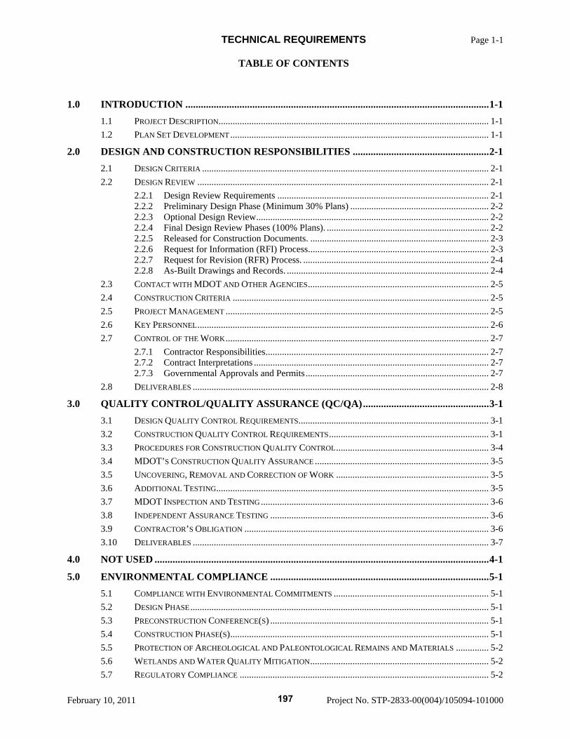
TECHNICAL REQUIREMENTS Page 1-1 TABLE OF CONTENTS
February 10, 2011 Project No. STP-2833-00(004)/105094-101000
1.0 INTRODUCTION ......................................................................................................................1-1 1.1 PROJECT DESCRIPTION................................................................................................................... 1-1 1.2 PLAN SET DEVELOPMENT .............................................................................................................. 1-1
2.0 DESIGN AND CONSTRUCTION RESPONSIBILITIES .....................................................2-1 2.1 DESIGN CRITERIA .......................................................................................................................... 2-1 2.2 DESIGN REVIEW ............................................................................................................................ 2-1
2.2.1 Design Review Requirements .......................................................................................... 2-1 2.2.2 Preliminary Design Phase (Minimum 30% Plans) ........................................................... 2-2 2.2.3 Optional Design Review................................................................................................... 2-2 2.2.4 Final Design Review Phases (100% Plans). ..................................................................... 2-2 2.2.5 Released for Construction Documents. ............................................................................ 2-3 2.2.6 Request for Information (RFI) Process............................................................................. 2-3 2.2.7 Request for Revision (RFR) Process. ............................................................................... 2-4 2.2.8 As-Built Drawings and Records. ...................................................................................... 2-4
2.3 CONTACT WITH MDOT AND OTHER AGENCIES............................................................................. 2-5 2.4 CONSTRUCTION CRITERIA ............................................................................................................. 2-5 2.5 PROJECT MANAGEMENT ................................................................................................................ 2-5 2.6 KEY PERSONNEL............................................................................................................................ 2-6 2.7 CONTROL OF THE WORK................................................................................................................ 2-7
2.7.1 Contractor Responsibilities............................................................................................... 2-7 2.7.2 Contract Interpretations .................................................................................................... 2-7 2.7.3 Governmental Approvals and Permits.............................................................................. 2-7
2.8 DELIVERABLES .............................................................................................................................. 2-8 3.0 QUALITY CONTROL/QUALITY ASSURANCE (QC/QA).................................................3-1
3.1 DESIGN QUALITY CONTROL REQUIREMENTS................................................................................. 3-1 3.2 CONSTRUCTION QUALITY CONTROL REQUIREMENTS.................................................................... 3-1 3.3 PROCEDURES FOR CONSTRUCTION QUALITY CONTROL................................................................. 3-4 3.4 MDOT’S CONSTRUCTION QUALITY ASSURANCE .......................................................................... 3-5 3.5 UNCOVERING, REMOVAL AND CORRECTION OF WORK ................................................................. 3-5 3.6 ADDITIONAL TESTING.................................................................................................................... 3-5 3.7 MDOT INSPECTION AND TESTING ................................................................................................. 3-6 3.8 INDEPENDENT ASSURANCE TESTING ............................................................................................. 3-6 3.9 CONTRACTOR’S OBLIGATION ........................................................................................................ 3-6 3.10 DELIVERABLES .............................................................................................................................. 3-7
4.0 NOT USED ..................................................................................................................................4-1 5.0 ENVIRONMENTAL COMPLIANCE .....................................................................................5-1
5.1 COMPLIANCE WITH ENVIRONMENTAL COMMITMENTS .................................................................. 5-1 5.2 DESIGN PHASE............................................................................................................................... 5-1 5.3 PRECONSTRUCTION CONFERENCE(S) ............................................................................................. 5-1 5.4 CONSTRUCTION PHASE(S).............................................................................................................. 5-1 5.5 PROTECTION OF ARCHEOLOGICAL AND PALEONTOLOGICAL REMAINS AND MATERIALS .............. 5-2 5.6 WETLANDS AND WATER QUALITY MITIGATION............................................................................ 5-2 5.7 REGULATORY COMPLIANCE .......................................................................................................... 5-2
197
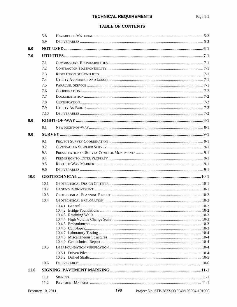
TECHNICAL REQUIREMENTS Page 1-2 TABLE OF CONTENTS
February 10, 2011 Project No. STP-2833-00(004)/105094-101000
5.8 HAZARDOUS MATERIAL ................................................................................................................ 5-3 5.9 DELIVERABLES .............................................................................................................................. 5-3
6.0 NOT USED ..................................................................................................................................6-1 7.0 UTILITIES ..................................................................................................................................7-1
7.1 COMMISSION’S RESPONSIBILITIES ................................................................................................. 7-1 7.2 CONTRACTOR’S RESPONSIBILITY................................................................................................... 7-1 7.3 RESOLUTION OF CONFLICTS .......................................................................................................... 7-1 7.4 UTILITY AVOIDANCE AND LOSSES................................................................................................. 7-1 7.5 PARALLEL SERVICE ....................................................................................................................... 7-1 7.6 COORDINATION.............................................................................................................................. 7-2 7.7 DOCUMENTATION.......................................................................................................................... 7-2 7.8 CERTIFICATION.............................................................................................................................. 7-2 7.9 UTILITY AS-BUILTS....................................................................................................................... 7-2 7.10 DELIVERABLES .............................................................................................................................. 7-2
8.0 RIGHT-OF-WAY .......................................................................................................................8-1 8.1 NEW RIGHT-OF-WAY..................................................................................................................... 8-1
9.0 SURVEY......................................................................................................................................9-1 9.1 PROJECT SURVEY COORDINATION ................................................................................................. 9-1 9.2 CONTRACTOR SUPPLIED SURVEY .................................................................................................. 9-1 9.3 PRESERVATION OF SURVEY CONTROL MONUMENTS ..................................................................... 9-1 9.4 PERMISSION TO ENTER PROPERTY ................................................................................................. 9-1 9.5 RIGHT OF WAY MARKER ............................................................................................................... 9-1 9.6 DELIVERABLES .............................................................................................................................. 9-1
10.0 GEOTECHNICAL ...................................................................................................................10-1 10.1 GEOTECHNICAL DESIGN CRITERIA .............................................................................................. 10-1 10.2 GROUND IMPROVEMENT.............................................................................................................. 10-1 10.3 GEOTECHNICAL PLANNING REPORT ............................................................................................ 10-2 10.4 GEOTECHNICAL EXPLORATION.................................................................................................... 10-2
10.4.1 General ........................................................................................................................... 10-2 10.4.2 Bridge Foundations ........................................................................................................ 10-2 10.4.3 Retaining Walls .............................................................................................................. 10-3 10.4.4 High Volume Change Soils ............................................................................................ 10-3 10.4.5 Embankments ................................................................................................................. 10-3 10.4.6 Cut Slopes....................................................................................................................... 10-3 10.4.7 Laboratory Testing ......................................................................................................... 10-4 10.4.8 Miscellaneous Structures................................................................................................ 10-4 10.4.9 Geotechnical Report ....................................................................................................... 10-4
10.5 DEEP FOUNDATION VERIFICATION .............................................................................................. 10-4 10.5.1 Driven Piles .................................................................................................................... 10-4 10.5.2 Drilled Shafts.................................................................................................................. 10-5
10.6 DELIVERABLES ............................................................................................................................ 10-6 11.0 SIGNING, PAVEMENT MARKING .....................................................................................11-1
11.1 SIGNING....................................................................................................................................... 11-1 11.2 PAVEMENT MARKING .................................................................................................................. 11-1
198
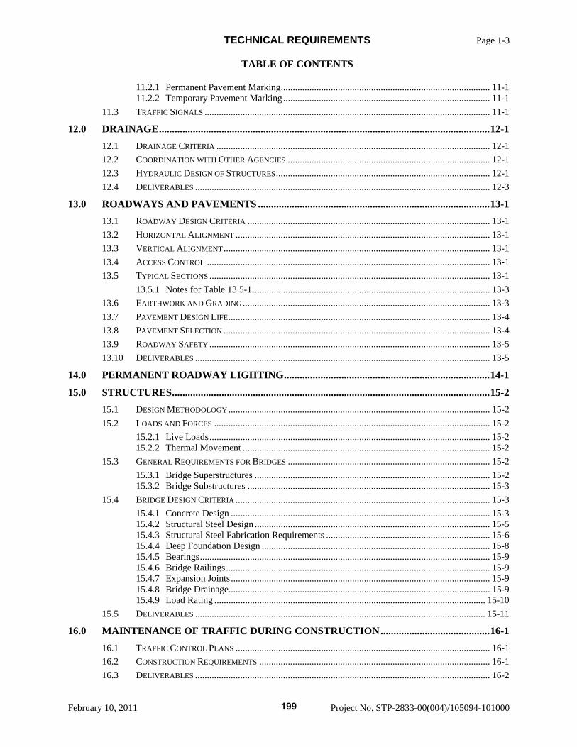
TECHNICAL REQUIREMENTS Page 1-3 TABLE OF CONTENTS
February 10, 2011 Project No. STP-2833-00(004)/105094-101000
11.2.1 Permanent Pavement Marking........................................................................................ 11-1 11.2.2 Temporary Pavement Marking....................................................................................... 11-1
11.3 TRAFFIC SIGNALS ........................................................................................................................ 11-1 12.0 DRAINAGE...............................................................................................................................12-1
12.1 DRAINAGE CRITERIA ................................................................................................................... 12-1 12.2 COORDINATION WITH OTHER AGENCIES ..................................................................................... 12-1 12.3 HYDRAULIC DESIGN OF STRUCTURES.......................................................................................... 12-1 12.4 DELIVERABLES ............................................................................................................................ 12-3
13.0 ROADWAYS AND PAVEMENTS .........................................................................................13-1 13.1 ROADWAY DESIGN CRITERIA ...................................................................................................... 13-1 13.2 HORIZONTAL ALIGNMENT ........................................................................................................... 13-1 13.3 VERTICAL ALIGNMENT................................................................................................................ 13-1 13.4 ACCESS CONTROL ....................................................................................................................... 13-1 13.5 TYPICAL SECTIONS ...................................................................................................................... 13-1
13.5.1 Notes for Table 13.5-1.................................................................................................... 13-3 13.6 EARTHWORK AND GRADING........................................................................................................ 13-3 13.7 PAVEMENT DESIGN LIFE.............................................................................................................. 13-4 13.8 PAVEMENT SELECTION ................................................................................................................ 13-4 13.9 ROADWAY SAFETY ...................................................................................................................... 13-5 13.10 DELIVERABLES ............................................................................................................................ 13-5
14.0 PERMANENT ROADWAY LIGHTING...............................................................................14-1 15.0 STRUCTURES..........................................................................................................................15-2
15.1 DESIGN METHODOLOGY .............................................................................................................. 15-2 15.2 LOADS AND FORCES .................................................................................................................... 15-2
15.2.1 Live Loads...................................................................................................................... 15-2 15.2.2 Thermal Movement ........................................................................................................ 15-2
15.3 GENERAL REQUIREMENTS FOR BRIDGES ..................................................................................... 15-2 15.3.1 Bridge Superstructures ................................................................................................... 15-2 15.3.2 Bridge Substructures ...................................................................................................... 15-3
15.4 BRIDGE DESIGN CRITERIA ........................................................................................................... 15-3 15.4.1 Concrete Design ............................................................................................................. 15-3 15.4.2 Structural Steel Design ................................................................................................... 15-5 15.4.3 Structural Steel Fabrication Requirements ..................................................................... 15-6 15.4.4 Deep Foundation Design ................................................................................................ 15-8 15.4.5 Bearings.......................................................................................................................... 15-9 15.4.6 Bridge Railings............................................................................................................... 15-9 15.4.7 Expansion Joints............................................................................................................. 15-9 15.4.8 Bridge Drainage.............................................................................................................. 15-9 15.4.9 Load Rating .................................................................................................................. 15-10
15.5 DELIVERABLES .......................................................................................................................... 15-11 16.0 MAINTENANCE OF TRAFFIC DURING CONSTRUCTION..........................................16-1
16.1 TRAFFIC CONTROL PLANS ........................................................................................................... 16-1 16.2 CONSTRUCTION REQUIREMENTS ................................................................................................. 16-1 16.3 DELIVERABLES ............................................................................................................................ 16-2
199
TECHNICAL REQUIREMENTS Page 1-4 TABLE OF CONTENTS
February 10, 2011 Project No. STP-2833-00(004)/105094-101000
17.0 TECHNICAL STANDARDS, DATA, REPORTS.................................................................17-1
200
TECHNICAL REQUIREMENTS Page 1-1 SECTION 1.0 - INTRODUCTION
February 10, 2011 Project No. STP-2833-00(004)/105094-101000
1.0 INTRODUCTION
These Technical Requirements for Design and Construction provide the technical requirements for the Project. Initially capitalized terms used herein shall have the meaning as set forth in Special Provision No. 907-101 DB or Subsection 101.02 of Mississippi Standard Specifications for Road and Bridge Construction
Wherever in this document there is a reference to FHWA, AASHTO or other technical standards it is intended to refer to the list of contract required technical documents listed in Section 17.
1.1 Project Description
The Project Scope is defined as indicated in Section 904 – NTP No. 2618-D1-1 DB and on the Contractor’s Schedule Certificate.
1.2 Plan Set Development
The development of the construction drawings for the Project shall follow MDOT’s standard format for construction plans. The Released for Construction drawings each shall be prepared so that the Released for Construction drawings will form a portion of the overall Project set of drawings.
201
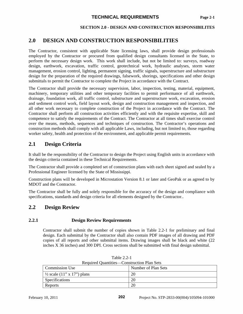
TECHNICAL REQUIREMENTS Page 2-1 SECTION 2.0 - DESIGN AND CONSTRUCTION RESPONSIBILITES
February 10, 2011 Project No. STP-2833-00(004)/105094-101000
2.0 DESIGN AND CONSTRUCTION RESPONSIBILITIES
The Contractor, consistent with applicable State licensing laws, shall provide design professionals employed by the Contractor or procured from qualified design consultants licensed in the State, to perform the necessary design work. This work shall include, but not be limited to: surveys, roadway design, earthwork, excavation, traffic control, geotechnical work, hydraulic analyses, storm water management, erosion control, lighting, permanent signing, traffic signals, superstructure and substructure design for the preparation of the required drawings, falsework, shorings, specifications and other design submittals to permit the Contractor to complete the Project in accordance with the Contract.
The Contractor shall provide the necessary supervision, labor, inspection, testing, material, equipment, machinery, temporary utilities and other temporary facilities to permit performance of all earthwork, drainage, foundation work, all traffic control, substructure and superstructure work, excavation, erosion and sediment control work, field layout work, design and construction management and inspection, and all other work necessary to complete construction of the Project in accordance with the Contract. The Contractor shall perform all construction activities efficiently and with the requisite expertise, skill and competence to satisfy the requirements of the Contract. The Contractor at all times shall exercise control over the means, methods, sequences and techniques of construction. The Contractor’s operations and construction methods shall comply with all applicable Laws, including, but not limited to, those regarding worker safety, health and protection of the environment, and applicable permit requirements.
2.1 Design Criteria
It shall be the responsibility of the Contractor to design the Project using English units in accordance with the design criteria contained in these Technical Requirements.
The Contractor shall provide a completed set of construction plans with each sheet signed and sealed by a Professional Engineer licensed by the State of Mississippi.
Construction plans will be developed in Microstation Version 8.1 or later and GeoPak or as agreed to by MDOT and the Contractor.
The Contractor shall be fully and solely responsible for the accuracy of the design and compliance with specifications, standards and design criteria for all elements designed by the Contractor..
2.2 Design Review
2.2.1 Design Review Requirements
Contractor shall submit the number of copies shown in Table 2.2-1 for preliminary and final design. Each submittal by the Contractor shall also contain PDF images of all drawing and PDF copies of all reports and other submittal items. Drawing images shall be black and white (22 inches X 36 inches) and 300 DPI. Cross sections shall be submitted with final design submittal.
Table 2.2-1
Required Quantities—Construction Plan Sets Commission Use Number of Plan Sets ½ scale (11” x 17”) plans 20 Specifications 20 Reports 20
202
TECHNICAL REQUIREMENTS Page 2-2 SECTION 2.0 - DESIGN AND CONSTRUCTION RESPONSIBILITES
February 10, 2011 Project No. STP-2833-00(004)/105094-101000
Responses to MDOT’s comments shall be returned within 10 Calendar days after the comments have been provided. MDOT comments shall be returned in the same format and software program as provided to the Contractor.
2.2.2 Preliminary Design Phase (Minimum 30% Plans)
The Contractor will prepare and submit a single preliminary design submittal for each location. Preliminary design shall include roadway plan and profile, bridge layouts (foundation plan, elevation view, and typical cross section), hydraulic bridge design and recommendations, drainage, erosion control, major signs, pavement marking, and traffic control plans. Pavement marking plans may be omitted if the lane lines are provided on the roadway plan sheets. MDOT will review preliminary design submittals within twenty-one (21) days of the submittal. MDOT will provide any review comments.
The Contractor shall submit a certification that the submittal complies with the Design Quality Control Plan.
For all hydraulic bridges designed by the Contractor, the Contractor shall stake all bridge foundation locations (centerline of abutment and piers) prior to the submittal of the preliminary design. Staking shall be a minimum of the left and right edge of deck at the centerline of the abutments and piers.
The Contractor shall schedule a meeting to be held after the review period with MDOT to review the comments. The Contractor shall incorporate the comments into the final design submittal to MDOT’s satisfaction, unless an explanation satisfactory to MDOT is provided explaining why a comment has not been addressed in the final design.
2.2.3 Optional Design Review
At the request of the Contractor, MDOT will provide optional design reviews on design packages. MDOT, as appropriate, will review optional design Submittals within fourteen (14) days. MDOT will provide any review comments.
The Contractor may schedule a meeting with MDOT to be held after the review period to review the comments. The Contractor shall incorporate the comments into the plans and specifications to MDOT’s satisfaction, unless an explanation satisfactory to MDOT is provided explaining why a comment has not been addressed in the final design
2.2.4 Final Design Review Phases (100% Plans).
1. After completion of the preliminary design, the final design may be broken down into packages (i.e. roadway, portions of bridges, drainage, etc.) as determined by the Contractor. Following completion of the design of a package, the Contractor shall prepare and submit a final design submittal for each package for review by MDOT. MDOT as appropriate will review the final design submittals within twenty-one (21) days. MDOT will provide any review comments.
2. The Contractor shall schedule a meeting to be held after the review period with MDOT to review the comments. The Contractor shall incorporate the comments into the plans and specifications to MDOT’s satisfaction, unless an explanation satisfactory to MDOT is provided explaining why a comment has not been addressed in the final design
203
TECHNICAL REQUIREMENTS Page 2-3 SECTION 2.0 - DESIGN AND CONSTRUCTION RESPONSIBILITES
February 10, 2011 Project No. STP-2833-00(004)/105094-101000
3. The final design submittal and any resubmittals required shall include drawings, details, specifications, computations, and supporting data to establish fully the intent of all construction to be accomplished. Final design submittals for bridges shall include the Bridge Load Rating Report (see 15.4.9) and independent check calculations. All material shall be prepared under the supervision of and stamped by an engineer(s), surveyor(s), or architect, as appropriate, licensed to practice in the State of Mississippi.
4. The Contractor shall submit a certification that the submittal complies with the Design Quality Control Plan.
5. Erosion Control plans will be reviewed in accordance with Special Provision 907-107-22.1.
2.2.5 Released for Construction Documents.
Following the incorporation of MDOT’s comments from the final design review phase, the Contractor shall prepare and submit a Release for Construction (RFC) submittal to MDOT for MDOT’s final review and Released for Construction stamp. Two (2) full size reproducible sets, two (2) half scale sets of plans, two (2) sets of Project specifications, two (2) sets of all reports and quantities for civil construction shall be submitted to MDOT. The Contractor shall have a Professional Engineer licensed in the State, stamp and sign each sheet of the plans. MDOT shall either stamp the plans and specifications “Released for Construction” and return one (1) full size reproducible set to the Contractor or return comments within seven (7) days. Once plans/specifications are Released for Construction, the Contractor shall provide twenty (20) copies of half scale sets of plans to MDOT within seven (7) days.
The Contractor shall submit a certification that the submittal complies with the Design Quality Control Plan.
MDOT’s stamping of drawings as “Released for Construction” does not substantiate the adequacy or acceptability of the design or relieve the Contractor of its obligation to comply with all provisions of the Contract.
2.2.6 Request for Information (RFI) Process.
Any questions concerning clarification of the plans or specifications, substitutions or alternate concepts shall be submitted to the Engineer of Record for response with a copy to the MDOT Project Engineer. The Engineer of Record is responsible for providing the response to the Contractor. If the substitution or alternate concept is not acceptable to MDOT, then MDOT is responsible for providing a comment to the Engineer of Record and Contractor within 3 working days of receipt of the completed RFI (hard copy) and associated documents (if any). MDOT will provide either the response or a schedule of when a response will be completed. If MDOT does not have an objection, and the Engineer of Record provides a clarification to the RFI then the Engineer of Record shall provide a response to the RFI and return the completed RFI to the Contractor. The Contractor will then submit the RFI to MDOT.
If the Engineer of Record agrees to a substitution or alternate concept then the RFI becomes a Request for Revision and follows the process detailed below.
The RFI shall use the attached form at the end of this Section or similar document.
204
TECHNICAL REQUIREMENTS Page 2-4 SECTION 2.0 - DESIGN AND CONSTRUCTION RESPONSIBILITES
February 10, 2011 Project No. STP-2833-00(004)/105094-101000
2.2.7 Request for Revision (RFR) Process.
Any revisions to the plans and specifications desired by Contractor or to correct deficiencies in the construction documents after the Submittal has been Released for Construction will require a Request for Revision (RFR). The Contractor shall submit a Request for Revision to MDOT. These shall be resubmitted to MDOT for review and re-release according to Section 2.2.5.
All Requests for Revision shall include the following: justification narrative, copies of pertinent correspondence, jurisdictional sign-off as necessary, any additional governmental approvals, index of impacted agencies with review comments and/or acknowledgements, preliminary drawings, engineering calculations and specifications, as necessary.
MDOT may accept or reject any Request for Revision. If MDOT accepts an RFR, the Contractor shall finalize all pertinent documentation, including final design drawings and specifications for final review and Release for Construction.
In no event shall the RFR process be used to change the Contract scope.
2.2.8 As-Built Drawings and Records.
1. Contractor Responsibilities. In addition to those documents set forth above, the Contractor shall provide to MDOT thirty (30) days after completion of a portion of the Project a complete set of record plans. Record drawings consist of the final design documents listed as follows: design plan CADD (Microstation) drawings, Geopak files and PDF files that incorporate all changes, including any adjustments, plan and profiles of relocated utilities, additions and deletions that occurred during construction. The Contractor shall certify that the record drawings are a true and correct representation of the Work as constructed.
2. Plan Revision Box. Information regarding major revisions to the plans shall be noted in a
revision box on the plans. The information listed in the revision box shall include: the initiator of the revision, a brief explanation of the nature of the revision.
3. Contents. In addition to the revisions that incorporated changes during construction, the
record drawings shall include the following information gathered during construction:
a. The final profile of each bridge constructed. The profile shall include the elevation along the centerline and a line three feet inboard of each gutter line. Points on the profile shall be taken at no greater than 25-foot intervals and shall include the beginning and end of each span.
b. For structures with pile foundations, information concerning the pile driving operation shall be listed to include pile and driving equipment data, final pile bearing (Gates Formula), elevation of pile tip when plan bearing was obtained, final pile tip elevation, penetration into the ground, and pile driving analysis or wave evaluation analysis program data. This information shall be entered on each footing or bent sheet, or be included as a new sheet inserted immediately following the pertinent footing or bent sheet.
c. For structures with drilled shaft foundations, information concerning the installation of the shaft shall be listed to include the drilled shaft report. This information shall be entered on each footing or bent sheet, or be included as a new sheet inserted immediately following the pertinent footing or bent sheet.
205

TECHNICAL REQUIREMENTS Page 2-5 SECTION 2.0 - DESIGN AND CONSTRUCTION RESPONSIBILITES
February 10, 2011 Project No. STP-2833-00(004)/105094-101000
d. The final location of all existing and relocated utility lines and electrical conduit lines & structures that are within the Project Right-of-Way.
e. The final location of all pipes, culverts, and drainage structures.
f. All shop drawings in hard copy and PDF format.
4. Submission Requirements. Record drawings shall be submitted as follows:
a. Roadway Drawings: two full size (36 inch x 22 inch) on bond paper.
b. Bridge Drawings: one full size (36 inch X 22 inch) on mylar.
c. One half-scale (Roadway and Bridge) (18” x 11”) bond paper copy and one copy on compact disc in a format acceptable to MDOT. The levels and symbology of the record CADD drawings shall conform to MDOT standard levels and symbology used to develop the design drawings for the Project.
2.3 Contact with MDOT and Other Agencies
Coordination with MDOT shall be made through the MDOT Project Manager. The Contractor shall notify the MDOT Project Manager of any coordination with local, state or federal agencies prior to making the contact. Contact includes meetings, telephone conversations and e-mails.
2.4 Construction Criteria
The Contractor shall construct the Project in accordance with all applicable Federal, State, and local Laws and the Contract.
2.5 Project Management
The Contractor shall be responsible for ensuring that the Project is constructed in conformance with the Contract, all referenced documents and specifications, and applicable Laws.
The Contractor shall provide Project management services sufficient to supervise the activities of its subcontractors. The Contractor shall provide a sufficient number of persons on Site to provide for the construction management of the Project.
Without relieving the Contractor of any of its responsibilities under the Contract, the Project Director or an approved designee must be present on Site, or within close proximity, fulltime as the Work is performed, have full authority to make the final decisions on behalf of the Contractor and have responsibility for communicating these decisions directly to MDOT.
Without relieving the Contractor of any of its responsibilities under the Contract, MDOT will provide representatives assigned to the Project to monitor the Project progress and provide necessary coordination between MDOT and the Contractor. MDOT and Federal Highway Administration (FHWA) representatives will have full and complete access to the Project, the Work in progress, the Daily Diaries, and to other technical documents and Project records associated with design, construction, materials, quality control, materials installation, and testing. MDOT representatives shall be given seventy-two (72) hours advance notice and have the opportunity to participate in any meetings that may be held concerning the Project or the relationship between the Contractor and their consultants and subcontractors when such
206

TECHNICAL REQUIREMENTS Page 2-6 SECTION 2.0 - DESIGN AND CONSTRUCTION RESPONSIBILITES
February 10, 2011 Project No. STP-2833-00(004)/105094-101000
meetings are associated with technical matters, progress, or quality of the Project. As used in this paragraph, “notice” shall require actual written notice to the Engineer.
All correspondence to MDOT from the Contractor shall be accompanied by a transmittal using a sequential document number. Each transmittal will be addressed to the Engineer and will list the Project name and Project number. This will be followed by a subject reference that will be used as the document name. All correspondence is to be signed by the Project Director. Any other form of correspondence will not be considered as binding. Emails to various team members will also be entered into document control, but will not be considered as official correspondence for purposes of direction unless backed up with a signed hard copy.
The Contractor shall provide a monthly status report with the monthly pay estimate, on all design submittals, Requests for Information and Requests for Revision.
2.6 Key Personnel
The Contractor shall maintain a directory of Key Personnel and contact numbers and shall provide at least one copy to MDOT and maintain a copy on-site. Key Personnel will include:
1. Project Director - The Project Director shall be the primary person in charge of and responsible for delivery of the Project in accordance with the contract requirements. The Project Director or an approved designee must be present on site fulltime as the work is performed, have full authority to make the final decisions on behalf of the Contractor and have responsibility for communicating these decisions directly to MDOT.
2. Lead Design Engineer – The Lead Design Engineer shall be a registered Professional Engineer licensed to practice in the State of Mississippi and in charge of and responsible for all aspects of the design of the Project.
3. Construction Manager – The Construction Manager reports directly to the Project Director and shall be responsible for the overall coordination of the Project including design and construction.
4. Environmental Manager – The Environmental Manager shall be responsible for adherence to all environmental requirements and commitments, including but not limited to erosion control inspections as required by the National Pollutant Discharge Elimination System (NPDES), the terms of the Categorical Exclusion, if any, and other environmental rules and regulations.
5. Quality Control Manager – The Quality Control Manager shall be a registered Professional Engineer licensed to practice in the State of Mississippi and shall be responsible for assuring that the design, all workmanship and materials, inspections and testing are in compliance with the Contract requirements. The Quality Control Manager shall report directly to the Project Director.
The Contractor shall not change or substitute any such Key Personnel except due to retirement, death, disability, incapacity or voluntary or involuntary termination of employment, or as otherwise approved by MDOT.
In order to obtain MDOT approval of a change to Key Personnel, a written request shall be delivered to MDOT’s Authorized Representative. The request shall include:
1. The nature of the desired change;
2. The reason for the desired change;
207
TECHNICAL REQUIREMENTS Page 2-7 SECTION 2.0 - DESIGN AND CONSTRUCTION RESPONSIBILITES
February 10, 2011 Project No. STP-2833-00(004)/105094-101000
3. A statement of how the desired change will meet the required qualifications for the
position/responsibility; and 4. A description of how the modification is proposed to be made.
No such modification will be made without prior written approval from MDOT.
2.7 Control of the Work
2.7.1 Contractor Responsibilities
The Contractor shall be solely responsible for determining the appropriate means, methods and scheduling necessary to complete the Work in a timely manner and in accordance with all Contract requirements. MDOT and FHWA will have the right to review and inspect the Work at any time.
2.7.2 Contract Interpretations
The Engineer will decide all questions which may arise as to the quality and acceptability of materials, the Work and the progress of the Work; all questions which may arise as to the interpretation of the specifications; and all questions as to the fulfillment of the Contract.
The Engineer will have the authority, but not the responsibility to suspend the Work, wholly or in part, because of the Contractor’s failure to correct conditions unsafe for workers or the general public, for failure to carry out provisions of the Contract, or for failure to carry out orders. The Engineer may also suspend Work for periods deemed necessary due to unsuitable weather conditions, for any conditions considered unsuitable for the prosecution of the Work, or for any other condition or reason deemed to be in the public interest. The Engineer may authorize, in writing, the continued prosecution of Work activities past their specified seasonal limits when it is determined that the quality of the Work will not be reduced and the public interest will be best served. The Engineer will have authority to enforce and make effective all decisions and orders relating to the Contract.
2.7.3 Governmental Approvals and Permits
The Contractor is responsible for obtaining all Governmental Approvals and permits not obtained by MDOT necessary to construct the Project. Copies of all correspondence and permits shall be forwarded to MDOT within seven (7) days after the correspondence is received.
The Contractor shall integrate design practices to avoid and/or minimize potential Work impacts to wetlands and water of the US.
The Contractor shall bear the cost and responsibility of resolving any deviations among the Project Right-of-Way limits, drawings or other information included in the permits that would violate the intent or spirit of the permits. Any proposed changes within the permitted areas shall be coordinated with MDOT and the appropriate agency, and performed to MDOT’s satisfaction.
MDOT will assist the Contractor to obtain Governmental Approvals and Permits.
208
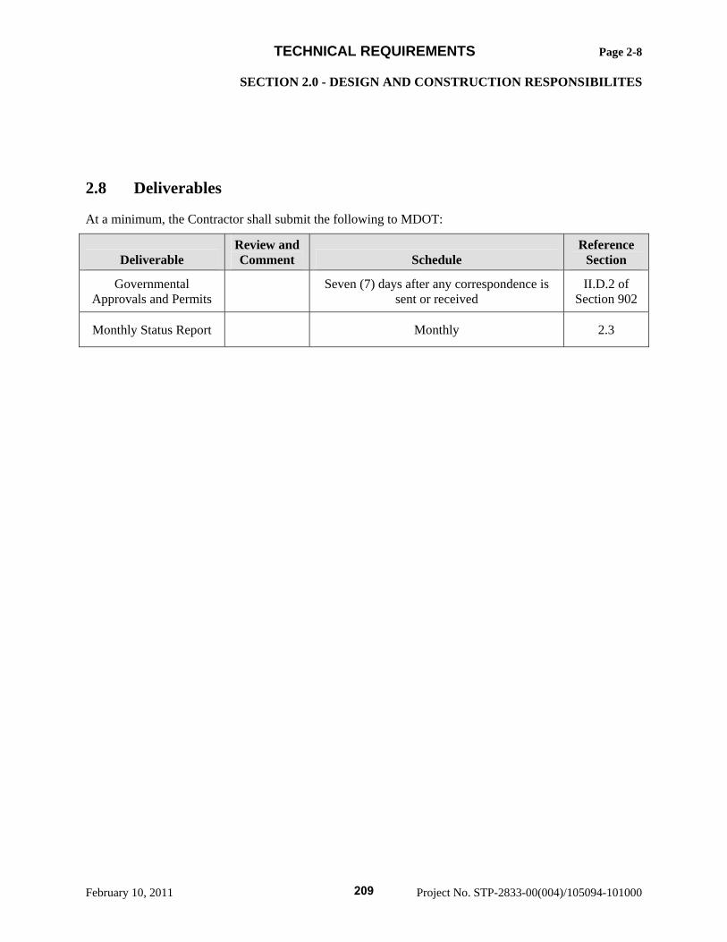
TECHNICAL REQUIREMENTS Page 2-8 SECTION 2.0 - DESIGN AND CONSTRUCTION RESPONSIBILITES
February 10, 2011 Project No. STP-2833-00(004)/105094-101000
2.8 Deliverables
At a minimum, the Contractor shall submit the following to MDOT:
Deliverable Review and Comment Schedule
Reference Section
Governmental Approvals and Permits Seven (7) days after any correspondence is
sent or received II.D.2 of
Section 902
Monthly Status Report Monthly 2.3
209
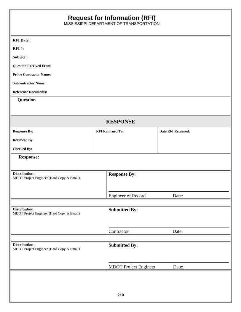
Request for Information (RFI) MISSISSIPPI DEPARTMENT OF TRANSPORTATION
RFI Date:
RFI #:
Subject:
Question Received From:
Prime Contractor Name:
Subcontractor Name:
Reference Documents:
Question
RESPONSE
Response By: RFI Returned To: Date RFI Returned:
Reviewed By:
Checked By:
Response:
Distribution: MDOT Project Engineer (Hard Copy & Email)
Response By: Engineer of Record Date:
Distribution: MDOT Project Engineer (Hard Copy & Email)
Submitted By: Contractor Date:
Distribution: MDOT Project Engineer (Hard Copy & Email)
Submitted By: MDOT Project Engineer Date:
210
TECHNICAL REQUIREMENTS Page 3-1 SECTION 3.0 - QUALITY CONTROL/QUALITY ASSURANCE (QC/QA)
February 10, 2011 Project No. STP-2833-00(004)/105094-101000
3.0 QUALITY CONTROL/QUALITY ASSURANCE (QC/QA)
The Contractor shall prepare and submit a Design Quality Control Plan and a Construction Quality Control Plan.
3.1 Design Quality Control Requirements
The Contractor shall prepare and submit for MDOT’s review and approval a Design Quality Control Plan (DQCP) for the Work. The DQCP shall be submitted to MDOT within seven (7) days from issuance of Notice to Proceed (NTP). The DQCP shall contain complete procedures for the implementation of the DQCP. The DQCP shall include the requirements specified below. No submittal for design review shall be made to MDOT until the applicable sections of the DQCP have been approved by MDOT.
Design Quality Control Manager: The Design Quality Control Manager’s responsibilities shall be limited to administering contracts with the independent firms, managing and ensuring Contractor compliance with the DQCP, resolution of quality related issues and certifying submittals comply with the Design Quality Control Plan. Note: These responsibilities cannot be delegated to another person.
1. Documentation: The Contractor shall maintain records of all independent checking of calculations and independent plan checking performed. These records shall be under the physical control of the Design Quality Control Manager in a form acceptable to MDOT. Bridge design and checking shall be completed in accordance with MDOT’s policies.
2. Reporting Functions: The Design Quality Control Manager shall furnish to MDOT a monthly
quality report. This monthly report shall include, as a minimum:
• Summary of QC activities during the month; and • Quality problems and resolutions.
3.2 Construction Quality Control Requirements
The Contractor shall be responsible for the items listed below. Construction Work shall not commence until the Contractor has met these requirements.
1. Construction Quality Control Plan (CQCP): The Contractor shall submit a CQCP that outlines how the Contractor shall assure that the materials and Work are in compliance with the Contract Documents. The initial CQCP shall be submitted to MDOT for review and approval at least thirty (30) days prior to the beginning of construction. The CQCP shall be updated as necessary prior to the start of any specific construction operation. The CQCP shall include a list of personnel responsible for management and quality control of the Project, and define the authority of each individual. The plan shall also include how the Contractor will monitor quality and correct failing materials.
2. Construction Quality Control Manager: The Construction Quality Control Manager’s responsibilities shall be limited to managing and ensuring Contractor compliance with the CQCP the approved erosion control plan, Contract documents, and resolution of quality related issues.
3. Personnel. The Contractor shall provide a sufficient number of qualified personnel to adequately
control the quality of the construction of the Project. The QC personnel responsible for quality control acceptance shall not be employees of the Contractor. All personnel responsible for
211
TECHNICAL REQUIREMENTS Page 3-2 SECTION 3.0 - QUALITY CONTROL/QUALITY ASSURANCE (QC/QA)
February 10, 2011 Project No. STP-2833-00(004)/105094-101000
obtaining samples or conducting material testing shall be certified or adequately trained and qualified through the appropriate MDOT certification programs. Training, qualification, and/or certification shall include classroom training, written testing, documented demonstration of proper inspection, sampling and testing procedures, and an on-the-job training period. The Contractor shall provide MDOT with copies of each individual’s training, qualifications, and/or certifications, in resume form, for review by MDOT. QC staff, including the inspectors and material testers, shall thoroughly monitor the Work in progress at all times.
4. Contractor Inspection: The Contractor is required to conduct Quality Control inspections of the
Work. The purpose of these inspections is to verify that all the Work is being constructed in accordance with the Contract plans and specifications.
5. Contractor Testing: The Contractor is required to conduct Quality Control sampling and testing in accordance with Mississippi Standard Specifications for Road and Bridge Construction, MDOT Materials Division Inspection, Testing and Certification Manual, and MDOT Special Provisions for all portions of the Work. The cost of these activities will be borne by the Contractor. Requirements for fabrication and inspection of structural steel components are located in Subsection 15.4.3 Structural Steel Fabrication and the Mississippi Standard Specifications for Road and Bridge Construction.
6. Testing Laboratories: Quality Control laboratories must be approved by MDOT at least thirty (30) days prior to beginning the portion of Work for which the laboratory will be performing the testing.
7. Mix Designs: Copies of all initial hot-mix asphalt mix designs and Portland cement concrete mix
designs, along with supporting data, shall be submitted to MDOT for review and comment at least thirty (30) days prior to use. All hot-mix asphalt mix designs shall be prepared by a Certified Mixture Design Technician (CMDT). The Portland cement concrete mix designs shall be prepared by a MDOT Class III Concrete Mix Design Technician. Portland Cement Concrete mix proportions given in the Mississippi Standard Specifications for Road and Bridge Construction are to be followed. The Contractor shall design the mix to obtain the minimum strength and water/cement ratios given in Table 3 of Section 804 of Mississippi Standard Specifications for Road and Bridge Construction, and to provide workability, air content, gradation and suitable set times set forth therein. MDOT will be notified of any revisions to the Contractor’s mix design. Copies of such revisions will be sent to MDOT for review and comment at least fourteen (14) days prior to use.
8. Documentation: The Contractor shall maintain current daily records of all quality control operations performed. These records shall be in a form acceptable to MDOT and include a description of subcontractors and suppliers working on the Project and the number of hours worked by each party, the number of personnel working, the weather conditions encountered, any delays encountered, identification of Nonconforming Work, and corrective action taken on current and previous Nonconforming Work. In addition, these records shall include factual evidence that the required quality control activities, including material testing and inspection, have been performed, including but not limited to the following:
• Type and number of QC tests performed;
212
TECHNICAL REQUIREMENTS Page 3-3 SECTION 3.0 - QUALITY CONTROL/QUALITY ASSURANCE (QC/QA)
February 10, 2011 Project No. STP-2833-00(004)/105094-101000
• Results of QC tests; • Material Certifications; • Inspections performed and findings; • Nonconforming Work identified; • Proposed action items to address Nonconforming Work; and • Corrective actions taken.
Such records shall address both conforming and Nonconforming Work and shall include a signed statement that all supplies and materials not identified as Nonconforming Work incorporated into the Work fully comply will all requirements of the RFC documents and the Contract. Complete, legible copies of such records shall be furnished in full to MDOT within seven (7) days of the date of the daily record.
9. Materials Certification: The Construction Quality Control Manager will be responsible for documenting, preparing and certifying that all materials meet specifications and for issuing the Statement of Estimated Final Quantities and Certified Test of Materials (TMD-725).
10. Reporting Functions: In addition to the daily reports requirements, the Contractor shall furnish to
MDOT a monthly quality report. This monthly report shall include as a minimum:
• Summary of QC staff on site during the month; • Summary of QC activities during the month; • Detailed summary of all tests performed by category; • Trend analysis of QC test results; • Log of all outstanding unresolved failing tests; • Nonconforming Work, proposed action items, and corrective actions taken; • Quality problems and resolutions; and • Summary of certificates of compliance.
Nonconforming Work: The Contractor shall identify to MDOT all Nonconforming Work. Nonconforming Work shall be evaluated in accordance with Subsection 907-106.10 of the Special Provisions. Nonconforming work shall be reported to MDOT on a Nonconforming work Report (NCR).
The NCR process shall generally conform to the following:
• Problem Identification The QC Manager should document a nonconformance with NCR form attached. The NCR form should be copied to the Contractor, the Engineer of Record and MDOT and any MDOT designee.
• Proposed Corrective Action
• The Engineer of Record and the Contractor shall propose corrective action to address the NCR. The Contractor and Engineer of Record may solicit MDOT input on the proposed action.
• If the Engineer of Record’s recommendation is to keep the nonconforming work in place or modify the nonconforming work, calculations supporting the recommendations
213
TECHNICAL REQUIREMENTS Page 3-4 SECTION 3.0 - QUALITY CONTROL/QUALITY ASSURANCE (QC/QA)
February 10, 2011 Project No. STP-2833-00(004)/105094-101000
shall be provided with the NCR at the time the NCR is provided to MDOT for concurrence.
• The Engineer of Record shall forward the proposed Corrective Action to MDOT and any designee for concurrence or rejection.
• MDOT will send either the NCR concurrence or rejection to the Contractor, Engineer of Record and the QC Manager.
• Corrective Action The Contractor shall complete the required Corrective Action in accordance with the NCR.
• Close Out
• The QC Manager shall witness the corrective action and will record completion and date on the NCR form.
• MDOT or its designee will sign the complete NCR.
• All NCR’s will be recorded and a summary of status provided monthly. All NCR’s must be resolved prior to project closeout.
The NCR shall use the attached form or similar document.
11. The Contractor shall address corrective actions for Nonconforming Work within 14 days of notice of nonconformity. The Contractor shall resolve corrective actions for Nonconforming Work within 60 days of notice of nonconformity.
12. The Project shall not be opened to traffic until Nonconforming Work is removed and replaced,
reworked, or repaired to MDOT’s satisfaction.
3.3 Procedures for Construction Quality Control
The Contractor shall use MDOT-established procedures for inspection and material testing to assess the quality of all Work and to ensure the quality of all Work meets the quality levels required by the RFC documents and the Contract. The procedures shall apply to all facets of procurement and construction. The procedures shall be implemented by the Contractor as CQCP Procedures. The procedures shall completely describe all quality control functions including all activities to be performed and shall contain information as specified herein or required by MDOT. The procedures shall utilize current MDOT publications, including but not limited to, the Materials Division Inspection, Certification and Testing Manual. The Contractor shall make the revisions necessary to satisfy MDOT’s comments and resubmit within seven (7) days for MDOT’s review. The Contractor may not make any changes to the procedures after the review process is completed without repeating the submission and review process.
The portion of the procedures for construction shall include at a minimum:
1. A description of the QC organization, including an organization chart showing lines of authority and relationships to other company organizational elements.
214
TECHNICAL REQUIREMENTS Page 3-5 SECTION 3.0 - QUALITY CONTROL/QUALITY ASSURANCE (QC/QA)
February 10, 2011 Project No. STP-2833-00(004)/105094-101000
2. The names, qualifications, resume, duties, responsibilities, and authorities of each person assigned a QC function.
3. Procedures for preparing, reviewing and presenting submittals, including those of subcontractors,
off-site fabricators and suppliers, for assuring they conform to Contract requirements. 4. For each individual RFC Package the specific tests and or certifications required, minimum
frequency of tests, and test procedures shall be in accordance with MDOT SOP TMD 20-04-00-000.
3.4 MDOT’s Construction Quality Assurance
MDOT will perform or cause to be performed Quality Assurance Testing and Inspection independent of the Contractor’s Quality Control.
All sampling and testing will be in accordance with existing AASHTO, ASTM, or test methods used by MDOT. The Contractor shall cooperate with MDOT to allow the necessary testing to be conducted prior to proceeding to the next operation.
In addition, MDOT may perform additional tests to ensure that proper sampling and testing procedures are being followed and that testing equipment is functioning properly. This testing may consist of observing Contractor and MDOT personnel, as well as taking split samples for the purposes of comparison testing.
Sampling frequency shall be as defined in the MDOT Standard Operating Procedure TMD 20-04-00-0000.
3.5 Uncovering, Removal and Correction of Work
MDOT reserves the right to direct the Contractor to remove and/or uncover portions of the Work for examination. After examination by MDOT, the Contractor shall restore the Work to the standard required by the RFC documents and the Contract. Should exposed Work fail to meet such standards, the Contractor shall continue exposing Work until the extent of the Nonconforming Work has been determined to MDOT’s satisfaction and then shall remove all such Nonconforming Work in its entirety and correctly replace the same. All costs associated with the removal and/or uncovering portions of the Work for examination, further removal if required, and restoring Work shall be at the Contractor’s expense. If the Work thus exposed or examined conforms to the requirements of this Contract, uncovering, removing and restoring the Work will be paid for by MDOT. If the Work exposed or examined is Nonconforming Work, uncovering, removing and restoring the Work shall be at Contractor’s expense. No additional time will be allowed for any uncovering, removing and restoring of the Work. The fact that MDOT does not discover the Nonconforming Work shall not constitute an acceptance of such Nonconforming Work.
3.6 Additional Testing
MDOT retains the right, but not the obligation, to direct the location and timing of additional testing to be performed at the Contractor’s expense. This additional testing shall be recorded as Owner Directed Testing (ODT) and such testing shall be in addition to that required by the CQCP. Such additional testing shall not be used by the Contractor to meet the minimum frequencies required by the CQCP. ODT shall be performed as soon as practical after direction by MDOT. If, after MDOT request for an ODT, Contractor performs work which makes the ODT more difficult or expensive, removal and subsequent replacement of Work to allow for testing where directed shall be solely at the Contractor’s expense.
215
TECHNICAL REQUIREMENTS Page 3-6 SECTION 3.0 - QUALITY CONTROL/QUALITY ASSURANCE (QC/QA)
February 10, 2011 Project No. STP-2833-00(004)/105094-101000
3.7 MDOT Inspection and Testing
All materials and every part of the Work shall be subject to MDOT’s Quality Assurance inspection and testing, as well as independent assurance testing by MDOT. MDOT, FHWA and all duly Authorized Representatives shall be allowed access to all parts of the Work and shall be furnished with information and assistance by the Contractor, as required, to make complete and detailed inspections and to do any testing that such representatives deem appropriate. All inspections and all tests conducted by MDOT and/or its duly authorized representatives are for the convenience and benefit of MDOT. These inspections and tests do not constitute acceptance of the materials or Work tested or inspected. MDOT may reject or accept any Work or materials at any time prior to any Final Acceptance Date whether or not previous inspections or tests were conducted by MDOT or its duly Authorized Representatives.
3.8 Independent Assurance Testing
MDOT personnel assigned to this Project or qualified personnel retained by MDOT will conduct sampling and testing, separate from the Contractor’s testing. The minimum number of sampling and testing shall be at the frequencies set forth in the Mississippi Standard Specifications for Road and Bridge Construction, Standard Operating Procedures (SOP) and Materials Division Inspection, Testing, and Certification Manual and the Contract. All sampling and testing will be in accordance with existing AASHTO, ASTM, or test methods used by MDOT. This testing will be used to ensure that proper sampling and testing procedures are being followed, that testing equipment is functioning properly, and to give to MDOT assurances that the materials used by the Contractor meet the plans and specifications. This testing may consist of observing sampling and testing by the Contractor personnel. It may also consist of taking split samples for the purposes of comparison testing. Independent Assurance test results will not be used for acceptance.
Requirements for fabrication and inspection of structural steel components are located in Section 15, and the Mississippi Standard Specifications for Road and Bridge Construction. Within seven days of the Notice To Proceed, the Contractor shall submit to MDOT the Structural Steel Component Fabrication Schedule. This document will show the contact information and fabrication schedule at each fabrication plant location for all structural steel components that will be fabricated or supplied on the project. The fabrication schedule will include the start date, number of weeks for complete fabrication (including coating systems) and shipping dates. These components include but are not limited to steel girders, diaphragms, crossframes, bearings, expansion finger joints, bridge drainage components (scuppers, downspouts), laminated bearing pads, structural bolts, galvanized coatings, cantilever or overhead trusses for signs or ITS components or bridge mounted sign supports.
3.9 Contractor’s Obligation
MDOT’s testing in no way relieves the Contractor of its obligation to comply with the Contract requirements. All materials incorporated into the Project shall meet or exceed Contract requirements and specifications. Further, any testing by MDOT will not relieve Contractor of any of its warranty obligations.
216
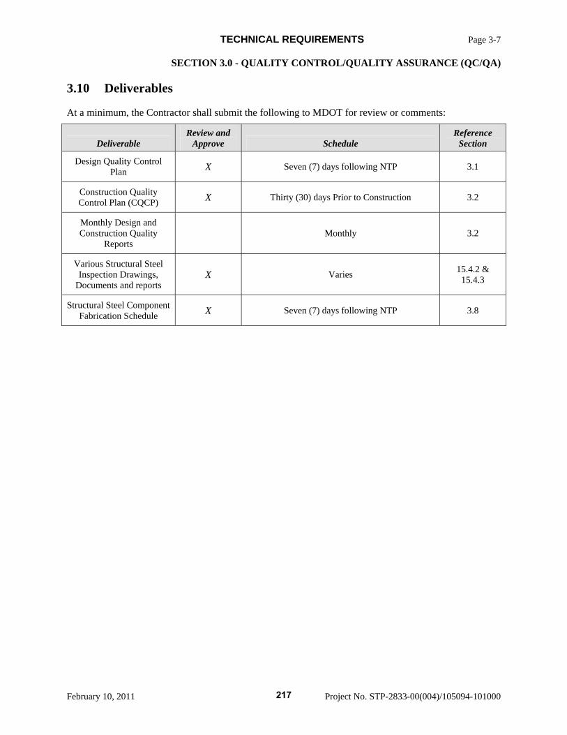
TECHNICAL REQUIREMENTS Page 3-7 SECTION 3.0 - QUALITY CONTROL/QUALITY ASSURANCE (QC/QA)
February 10, 2011 Project No. STP-2833-00(004)/105094-101000
3.10 Deliverables
At a minimum, the Contractor shall submit the following to MDOT for review or comments:
Deliverable Review and
Approve Schedule Reference
Section
Design Quality Control Plan X Seven (7) days following NTP 3.1
Construction Quality Control Plan (CQCP) X Thirty (30) days Prior to Construction 3.2
Monthly Design and Construction Quality
Reports Monthly 3.2
Various Structural Steel Inspection Drawings,
Documents and reports X Varies 15.4.2 &
15.4.3
Structural Steel Component Fabrication Schedule X Seven (7) days following NTP 3.8
217
TECHNICAL REQUIREMENTS Page 4-1 SECTION 4.0 - NOT USED
February 10, 2011 Project No. STP-2833-00(004)/105094-101000
4.0 NOT USED
218
TECHNICAL REQUIREMENTS Page 5-1 SECTION 5.0 - ENVIRONMENTAL COMPLIANCE
February 10, 2011 Project No. STP-2833-00(004)/105094-101000
5.0 ENVIRONMENTAL COMPLIANCE
5.1 Compliance with Environmental Commitments
The Contractor shall comply with all environmental commitments and requirements in the NEPA Approval including, but not limited to, the following:
1. The provisions of all environmental permits applicable to the Project, including any restrictions and agreements specifically agreed to or entered into by MDOT in obtaining permits for the Project.
2. Those stipulations and conditions under which the MTC and/or MDOT received the NEPA
Approval and any modifications resulting from the re-evaluation of the document. 3. Applicable Laws and regulations relating to potential or actual Hazardous Material that may be
encountered in the course of carrying out the Contract. 4. Carrying out all necessary social, economic and environmental studies required by regulatory
authorities in the course of the construction. 5. Updating or extending approved permits obtained by the Contractor.
5.2 Design Phase
All plans and designs are to be prepared in accordance with all of the environmental commitments/requirements outlined in the Special Provisions and Notice to Proposers of this Contract and all environmental commitments in the NEPA Approval. The Lead Design Engineer shall assure MDOT that all plans and designs have been prepared in accordance with all of the environmental commitments/requirements by certified letter at the RFC submittal.
5.3 Preconstruction Conference(s)
The Contractor shall conduct one (or more, if appropriate) pre-construction conference(s) prior to any construction activity to discuss environmental and permitting issues, which conference shall include all subcontractors, and to the extent feasible, representatives from the U.S. Army Corp of Engineers, the Mississippi Department of Natural Resources, the Mississippi Department of Environmental Quality, the FHWA, the Contractor, MDOT, and others as deemed necessary.
5.4 Construction Phase(s)
The Contractor shall be responsible for compliance with all of the environmental commitments/requirements outlined in the Special Provisions and Notice to Proposers as provided in environmental commitments contained within the NEPA Approval. The commitments/requirements shall be complied with during all phases of the construction activities. Upon completion of the Construction Work, the Contractor shall certify that all construction activities have complied with all of the environmental commitments/requirements. MDOT will have the authority to suspend all Work for non-compliance with the environmental commitments/requirements.
During the construction phase of the project, MDOT may implement a water quality discharge monitoring system, primarily located near the right-of-way line for the project of various streams and/or stormwater
219
TECHNICAL REQUIREMENTS Page 5-2 SECTION 5.0 - ENVIRONMENTAL COMPLIANCE
February 10, 2011 Project No. STP-2833-00(004)/105094-101000
discharge locations. MDOT, FHWA and all duly Authorized Representatives shall be allowed access to all parts of the Work in order to access the water quality discharge monitory system.
5.5 Protection of Archeological and Paleontological Remains and Materials
1. If archeological or paleontological remains are uncovered, the Contractor shall immediately halt operation in the area of the discovery and notify MDOT.
2. Archeological remains consist of any materials made or altered by man which remain from
historic or prehistoric times (i.e. older than 50 years). Examples include old pottery fragments, metal, wood, arrowheads, stone implements or tools, human burials, historic docks, structures or not recent (i.e. older than 100 years) vessel ruins. Paleontological remains consist of old animal remains, original or fossilized, such as teeth, tusks, bone, or entire skeletons.
3. MDOT will have the authority to suspend the Work for the purpose of preserving, documenting,
and recovering the remains and materials of archeological and paleontological importance for the State. The Contractor shall carry out all instructions of MDOT for the protection of archeological or paleontological remains, including steps to protect the Site from vandalism and unauthorized investigations, from accidental damage and from dangers such as heavy rainfall or runoff.
5.6 Wetlands and Water Quality Mitigation
1. The Contractor shall fulfill the terms and conditions of both the Clean Water Act Section 404 permit and the Section 401 Water Quality Certification, as required by the U.S. Army Corps of Engineers and the Mississippi Department of Natural Resources, respectively. The Contractor shall be responsible for all stream and/or wetland mitigation required to fulfill the permitting requirements.
2. The Contractor shall maintain the natural low flow characteristics of all stream crossings,
including temporary crossings as required in the approved permits. 3. The Contractor shall provide the following list of deliverable items when applicable:
• Wetland and stream mitigation engineering drawings; • Constructed wetland and stream mitigation that meets standards of regulating agencies; • Copy of permit applications*; • Copy of approved permits*; and • Certificate of completed mitigation.
* Permit applications and approved permits for areas outside of the Right-of-Way and for permits required due to changes in the permits obtained by MDOT due to the Contractor’s design or construction methods.
5.7 Regulatory Compliance
All environmental permits within the MDOT acquired right-of-way will be acquired by MDOT based on the potential design provided by MDOT. Compliance with all permits will be the responsibility of the Contractor. The Contractor will be responsible for acquiring and complying with any new or additional
220
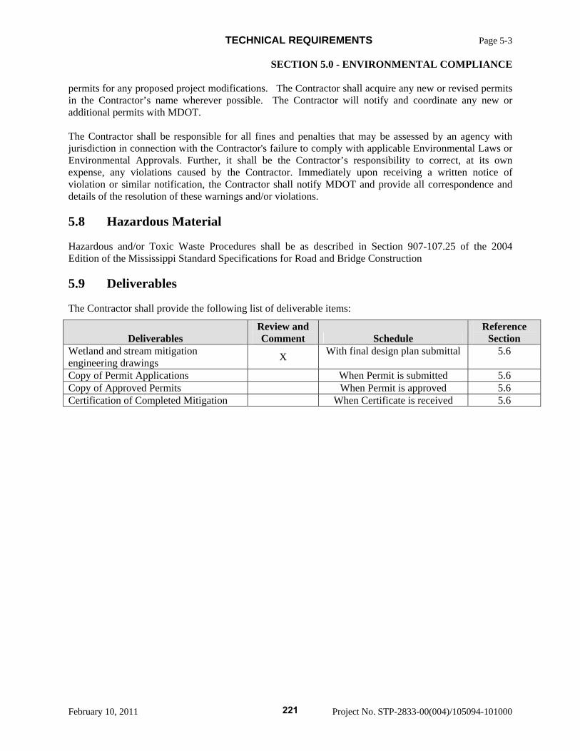
TECHNICAL REQUIREMENTS Page 5-3 SECTION 5.0 - ENVIRONMENTAL COMPLIANCE
February 10, 2011 Project No. STP-2833-00(004)/105094-101000
permits for any proposed project modifications. The Contractor shall acquire any new or revised permits in the Contractor’s name wherever possible. The Contractor will notify and coordinate any new or additional permits with MDOT. The Contractor shall be responsible for all fines and penalties that may be assessed by an agency with jurisdiction in connection with the Contractor's failure to comply with applicable Environmental Laws or Environmental Approvals. Further, it shall be the Contractor’s responsibility to correct, at its own expense, any violations caused by the Contractor. Immediately upon receiving a written notice of violation or similar notification, the Contractor shall notify MDOT and provide all correspondence and details of the resolution of these warnings and/or violations.
5.8 Hazardous Material
Hazardous and/or Toxic Waste Procedures shall be as described in Section 907-107.25 of the 2004 Edition of the Mississippi Standard Specifications for Road and Bridge Construction
5.9 Deliverables
The Contractor shall provide the following list of deliverable items:
Deliverables Review and Comment Schedule
Reference Section
Wetland and stream mitigation engineering drawings X With final design plan submittal 5.6
Copy of Permit Applications When Permit is submitted 5.6 Copy of Approved Permits When Permit is approved 5.6 Certification of Completed Mitigation When Certificate is received 5.6
221
TECHNICAL REQUIREMENTS Page 6-1 SECTION 6.0 - NOT USED
February 10, 2011 Project No. STP-2833-00(004)/105094-101000
6.0 NOT USED
Reserved for Third Party Contracts
222
TECHNICAL REQUIREMENTS Page 7-1 SECTION 7.0 - UTILTIES
February 10, 2011 Project No. STP-2833-00(004)/105094-101000
7.0 UTILITIES
7.1 Commission’s Responsibilities
The Commission has relocated all known utilities to accommodate the MDOT developed plans and has no further utility relocation responsibility for this Contract.
7.2 Contractor’s Responsibility
As part of the Project Scope, the Contractor shall have the responsibility of coordinating the Project design and construction with all utilities that may be affected as listed in Notice to Proposers 2382 DB.
For any proposed modifications to the MDOT alignment or profile, the Contractor shall be responsible for identifying the utility affected, coordinating an appropriate relocation, and shall use either the utility’s own forces to complete the work or shall complete the work utilizing a contractor approved by the utility. The Contractor will be responsible for management and coordination of any utility relocation, including the submission of new or revised permit application(s). Contractor shall include the cost of utility management in his lump sum Contract Price.
Should the Contractor encounter a utility not listed in Notice to Proposers 2382 DB, the Contractor shall notify Commission in writing immediately. The contractor shall then prepare a cost estimate in the form of utility agreement and submit the cost estimates to MDOT for review and approval by MDOT prior to work commencing on any relocation. Relocation of any utility not listed in Notice to Proposers 2382 DB shall be considered Extra Work. For those utilities requiring relocation, the Contractor shall conform with Commission’s “A Policy for Accommodating Utilities on Highway Rights of Way” and the Code of Federal Regulations, Title 23, Chapter 1, Subchapter G, part 645, subparts A and B.
7.3 Resolution of Conflicts
The resolution of any conflicts between utility companies and the construction of the Project shall be the responsibility of the Contractor. No additional compensation (time or dollars) will be allowed for any delays, inconveniences, damage sustained by Contractor or its subcontractors due to interference from utilities or the operation of relocating utilities for those utilities listed in Notice to Proposers 2382 DB. If the Contractor experiences delays with the Utility companies, MDOT shall be promptly notified and will cooperate and assist with reasonable requests from the Contractor in resolving the disputes between the parties.
7.4 Utility Avoidance and Losses
The Contractor shall design the Project to avoid conflicts with utilities where possible, and minimize impacts where conflicts cannot be avoided. Contractor will be responsible for all wastewater discharges and for water loss that occur in association with construction within the right-of-way during the term of the Contract.
7.5 Parallel Service
Contractor will maintain parallel service through out any utility relocation construction. Contractor will ensure that major service interruptions are avoided.
223
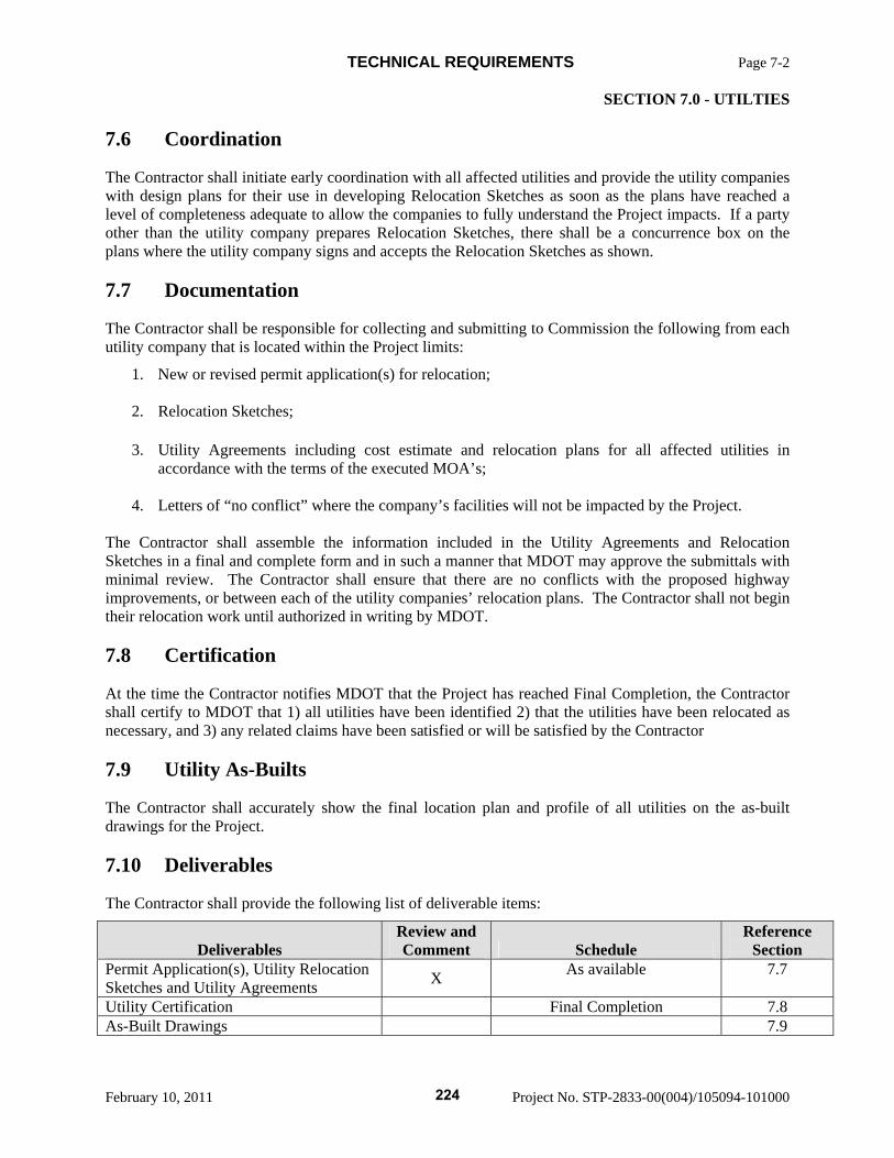
TECHNICAL REQUIREMENTS Page 7-2 SECTION 7.0 - UTILTIES
February 10, 2011 Project No. STP-2833-00(004)/105094-101000
7.6 Coordination
The Contractor shall initiate early coordination with all affected utilities and provide the utility companies with design plans for their use in developing Relocation Sketches as soon as the plans have reached a level of completeness adequate to allow the companies to fully understand the Project impacts. If a party other than the utility company prepares Relocation Sketches, there shall be a concurrence box on the plans where the utility company signs and accepts the Relocation Sketches as shown.
7.7 Documentation
The Contractor shall be responsible for collecting and submitting to Commission the following from each utility company that is located within the Project limits:
1. New or revised permit application(s) for relocation; 2. Relocation Sketches; 3. Utility Agreements including cost estimate and relocation plans for all affected utilities in
accordance with the terms of the executed MOA’s; 4. Letters of “no conflict” where the company’s facilities will not be impacted by the Project.
The Contractor shall assemble the information included in the Utility Agreements and Relocation Sketches in a final and complete form and in such a manner that MDOT may approve the submittals with minimal review. The Contractor shall ensure that there are no conflicts with the proposed highway improvements, or between each of the utility companies’ relocation plans. The Contractor shall not begin their relocation work until authorized in writing by MDOT.
7.8 Certification
At the time the Contractor notifies MDOT that the Project has reached Final Completion, the Contractor shall certify to MDOT that 1) all utilities have been identified 2) that the utilities have been relocated as necessary, and 3) any related claims have been satisfied or will be satisfied by the Contractor
7.9 Utility As-Builts
The Contractor shall accurately show the final location plan and profile of all utilities on the as-built drawings for the Project.
7.10 Deliverables
The Contractor shall provide the following list of deliverable items:
Deliverables Review and Comment Schedule
Reference Section
Permit Application(s), Utility Relocation Sketches and Utility Agreements X As available 7.7
Utility Certification Final Completion 7.8 As-Built Drawings 7.9
224

TECHNICAL REQUIREMENTS Page 8-1 SECTION 8.0 - RIGHT-OF-WAY
February 10, 2011 Project No. STP-2833-00(004)/105094-101000
8.0 RIGHT-OF-WAY
8.1 New Right-of-Way
The Project shall be designed and constructed within the existing right-of-way.
MDOT is in the process of acquiring the right-of-way for the project based on the Right-of-Way Plans provided with the Request for Proposals.
MDOT is currently scheduled to complete all right-of-way acquisition for the entire corridor by June 30, 2011.
MDOT will provide an update on the status of the right-of-way acquisition and may issue an advanced Notice to Proceed (Construction) with Restrictions identifying those properties that are yet to be acquired and thus are restricted access for the Contractor.
The Contractor shall furnish and place all right-of-way markers for the project as describe on the Right-of-Way plans.
225
TECHNICAL REQUIREMENTS Page 9-1 SECTION 9.0 - RIGHT-OF-WAY
February 10, 2011 Project No. STP-2833-00(004)/105094-101000
9.0 SURVEY
9.1 Project Survey Coordination
The Contractor shall designate a licensed Professional Surveyor as the responsible person in charge of all Contractor survey activities on the Project. The Contractor shall comply with the most recent and applicable Laws.
9.2 Contractor Supplied Survey
The Contractor shall survey the Project utilizing standard surveying practices as required to prepare preliminary plans, and final plans, and construct in accordance with applicable standards. The Contractor shall use the same survey line as the original plans.
9.3 Preservation of Survey Control Monuments
The Contractor shall preserve all survey control monuments and any governmental defined land corners located on or within MDOT right-of-way. The Contractor shall notify MDOT as soon as it becomes known that a monument is in a position that will interfere with new construction or with Contractor operations.
9.4 Permission to Enter Property
The Contractor shall notify property owners before entering any private property and each property owner shall be contacted by the Contractor and asked to sign the MDOT Survey Notification form. An explanation of the purpose, nature, and approximate duration of the proposed work may be given to the property owner, but personnel should refrain from outlining any plans or policies that might be misconstrued. If the landowner lives out of state or can not be physically contacted, the form should be mailed to the property owner. Contractor shall record all contacts carefully and accurately for future use. At a minimum, the record shall include the names of persons contacted, identifying them as owners or tenants, the date and time of conversation, telephone numbers and a summary of the conversation.
9.5 Right of Way Marker
The Contractor shall locate and preserve all Right-of-Way markers.
9.6 Deliverables
At a minimum, the Contractor shall submit the following to MDOT for review and comment:
Deliverable Review and Comment Schedule
Reference Section
None
226
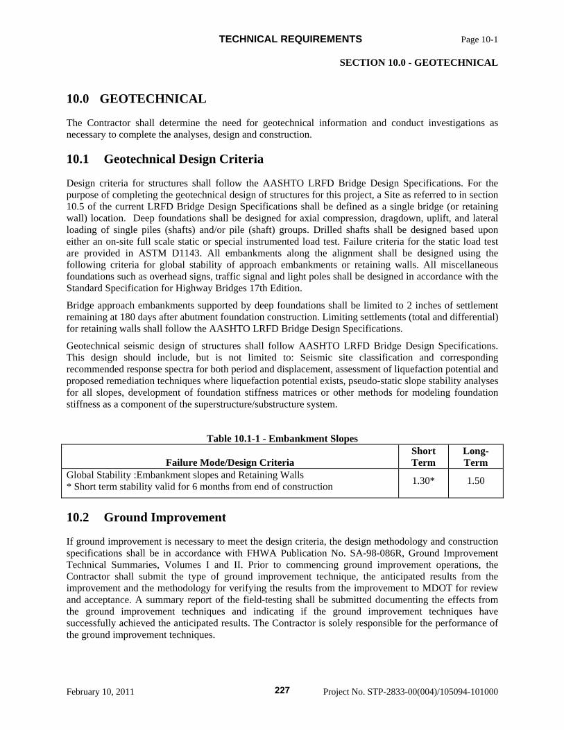
TECHNICAL REQUIREMENTS Page 10-1 SECTION 10.0 - GEOTECHNICAL
February 10, 2011 Project No. STP-2833-00(004)/105094-101000
10.0 GEOTECHNICAL
The Contractor shall determine the need for geotechnical information and conduct investigations as necessary to complete the analyses, design and construction.
10.1 Geotechnical Design Criteria
Design criteria for structures shall follow the AASHTO LRFD Bridge Design Specifications. For the purpose of completing the geotechnical design of structures for this project, a Site as referred to in section 10.5 of the current LRFD Bridge Design Specifications shall be defined as a single bridge (or retaining wall) location. Deep foundations shall be designed for axial compression, dragdown, uplift, and lateral loading of single piles (shafts) and/or pile (shaft) groups. Drilled shafts shall be designed based upon either an on-site full scale static or special instrumented load test. Failure criteria for the static load test are provided in ASTM D1143. All embankments along the alignment shall be designed using the following criteria for global stability of approach embankments or retaining walls. All miscellaneous foundations such as overhead signs, traffic signal and light poles shall be designed in accordance with the Standard Specification for Highway Bridges 17th Edition.
Bridge approach embankments supported by deep foundations shall be limited to 2 inches of settlement remaining at 180 days after abutment foundation construction. Limiting settlements (total and differential) for retaining walls shall follow the AASHTO LRFD Bridge Design Specifications.
Geotechnical seismic design of structures shall follow AASHTO LRFD Bridge Design Specifications. This design should include, but is not limited to: Seismic site classification and corresponding recommended response spectra for both period and displacement, assessment of liquefaction potential and proposed remediation techniques where liquefaction potential exists, pseudo-static slope stability analyses for all slopes, development of foundation stiffness matrices or other methods for modeling foundation stiffness as a component of the superstructure/substructure system.
Table 10.1-1 - Embankment Slopes
Failure Mode/Design Criteria Short Term
Long-Term
Global Stability :Embankment slopes and Retaining Walls * Short term stability valid for 6 months from end of construction 1.30* 1.50
10.2 Ground Improvement
If ground improvement is necessary to meet the design criteria, the design methodology and construction specifications shall be in accordance with FHWA Publication No. SA-98-086R, Ground Improvement Technical Summaries, Volumes I and II. Prior to commencing ground improvement operations, the Contractor shall submit the type of ground improvement technique, the anticipated results from the improvement and the methodology for verifying the results from the improvement to MDOT for review and acceptance. A summary report of the field-testing shall be submitted documenting the effects from the ground improvement techniques and indicating if the ground improvement techniques have successfully achieved the anticipated results. The Contractor is solely responsible for the performance of the ground improvement techniques.
227
TECHNICAL REQUIREMENTS Page 10-2 SECTION 10.0 - GEOTECHNICAL
February 10, 2011 Project No. STP-2833-00(004)/105094-101000
10.3 Geotechnical Planning Report
The Contractor shall prepare a Geotechnical Planning Report for the Project, including all Phases, and submit the Geotechnical Planning Report to MDOT within thirty (30) working days from NTP1 for review and written comment. The Geotechnical Planning Report shall include a detailed method statement describing the general philosophy and methods of design and construction and the rationale for selection of the proposed construction methods for all geotechnical and foundation aspects of the Project. The method statement shall indicate how material and design details are chosen to match selected construction methods and details, soil conditions, and groundwater environment for the Site. The Geotechnical Planning Report shall specify the method for verification of bearing capacity of the deep foundation elements at each Site.
The Geotechnical Planning Report shall define the engineering and design approach that will be followed in order to develop technically and environmentally acceptable and durable foundations, cut and fill slopes, retaining structures, pavement subgrades, and all geotechnical designs for the Project. The Geotechnical Planning Report shall discuss all aspects of the required geotechnical effort and design analysis.
The Geotechnical Planning Report shall outline the anticipated testing requirements, tests and frequency that will be necessary to implement during construction in order control the material placement on the project.
MDOT will review the Geotechnical Planning Report within twenty-one (21) days of the submittal and will provide any review comments.
The Contractor shall schedule a meeting to be held after the review period with MDOT to review the comments. The Contractor shall incorporate the comments into the final Geotechnical Planning Report submittal to MDOT’s satisfaction, unless an explanation satisfactory to MDOT is provided explaining why a comment has not been addressed in the final document.
10.4 Geotechnical Exploration
10.4.1 General
The frequency, spacing, and depth of soil test borings will depend on the anticipated variation in subsurface conditions and the type of structure to be designed. The soil borings and laboratory data included in Exhibit 1 of Section 902 are for information only. The Contractor assumes all liability/responsibility for the interpretation and use of this data for this Project. The Contractor shall obtain soil test borings needed to meet the requirements detailed in the Geotechnical Planning Report. A licensed surveyor shall locate (station and offset and GPS coordinates) and establish ground or mud line elevation at all soil test borings taken by the Contractor. The Contractor is solely responsible for the adequacy of the geotechnical information for this Project. An electronic copy of the final boring logs completed at the time of the preliminary design submittal, shall be submitted with the preliminary Geotechnical Report to MDOT in PDF or Microstation format.
10.4.2 Bridge Foundations
Borings shall extend to depths sufficient to define the subsurface profile for structures, subgrades and embankments, and geotechnical features. All soil test borings taken for deep foundations
228
TECHNICAL REQUIREMENTS Page 10-3 SECTION 10.0 - GEOTECHNICAL
February 10, 2011 Project No. STP-2833-00(004)/105094-101000
shall extend below the anticipated pile or drilled shaft tip elevation a minimum of twenty (20) feet. The Contractor shall test for sulfates as part of their geotechnical investigation. Where moderate to severe sulfates are found, pile concrete shall meet the current requirements in 907-701.02.2.1.
10.4.3 Retaining Walls
All retaining walls shall have one soil test boring performed at least every seventy-five (75) feet along the wall line, if the wall is within 500 feet of bridge abutments. Retaining walls more than 500 feet from the bridge abutment shall have one soil test boring performed at least every 200 feet along the wall line. All soil test borings performed by the Contractor shall extend to a depth of at least twice the height of the wall. Continuous flight auger borings are not acceptable. Undisturbed samples will be required for testing to determine the required strength design parameters and the expected differential settlement along the length of the retaining wall.
10.4.4 High Volume Change Soils
A high volume change soil is defined as a soil having a volume change of 85 percent or higher when determined in accordance with AASHTO T 92 using the formula.
VC = (w1 - S) R
High volume change material having a volume change of 85 percent or higher shall be removed from the project.
10.4.5 Embankments
The subgrade soils along all roadway alignments shall be evaluated by soil test borings completed by the Contractor. Slope stability analysis of all embankments, with an embankment height of 10 feet or more, shall be completed by the Contractor. Sufficient soil test borings shall be obtained to identify the existing geotechnical conditions at each site to complete the analysis.
Embankments may be construction using on site material with high volume change soils having a volume change of 85 percent or less. High Volume soils with a volume change greater than 60 percent but less than 85 percent must be mixed or blended with a mobile mechanical mixer such that the resulting material has a volume change of less than 50 percent. Mixing or blending plans/procedures shall be prepared by the Contractor and approved by MDOT prior to placing this material in the roadway prism.
10.4.6 Cut Slopes
All cuts slopes over 10 feet in height shall be analyzed for slope stability by the Contractor. Sufficient soil test borings shall be obtained to identify the existing geotechnical conditions at each site to complete the analysis.
Cut slopes shall be constructed with a 6:1 slope when the existing material has a volume change of 60 percent or greater.
229
TECHNICAL REQUIREMENTS Page 10-4 SECTION 10.0 - GEOTECHNICAL
February 10, 2011 Project No. STP-2833-00(004)/105094-101000
Existing material with a volume change greater that 60 percent shall be over excavated to three feet from the roadway surface and replaced with one of the two types of materials listed below.
(a) Granular Material, Class 1 through Class 10, Group D or E (b) Borrow Excavation, Classes B5-6, B6-6, B9-6, B15 or B16
10.4.7 Laboratory Testing
The Contractor shall perform laboratory soils tests of sufficient numbers and type to classify and ascertain the shear strength, conditions of stability, and consolidation characteristics of the material encountered.
10.4.8 Miscellaneous Structures
Miscellaneous structures shall have a minimum of one soil test boring performed per foundation location. All soil borings performed by the Contractor shall extend at least 10 feet below the anticipated tip elevation of the foundation.
10.4.9 Geotechnical Report
The Contractor shall prepare a preliminary and final geotechnical report for all bridges, retaining walls, roadway subgrades and embankments, concrete culverts and any other structures constructed for this Project, including the Initial Phase and any subsequent Phase. The preliminary geotechnical report shall provide the preliminary recommendations for the design of the selected foundation types, reproductions of the field boring logs and a generalized soil profile along the alignment. The final geotechnical report shall summarize subsurface soils, foundation design recommendations, laboratory testing results; provide a reproduction of the field boring logs and a generalized soil profile containing the location of all soil borings. In addition, the report shall indicate any special treatments of subgrades to be performed before paving. Each report shall be submitted to MDOT along with the final or preliminary plan submittal. The review of the report will be performed in accordance with the structure submittal plan review process. In addition, after construction of the foundations is complete, the Contractor shall provide a supplement to the report containing the actual field conditions encountered and as-built foundation data and information.
10.5 Deep Foundation Verification
10.5.1 Driven Piles
The Contractor shall verify the capacity of piles at each Site to substantiate the requirements of the contract. The Contractor shall provide positive demonstration that each pile has the required bearing capacity. At a minimum one abutment pile and one interior pile, but not less than 2% of the production piles for each individual bridge, shall be dynamically tested to determine the capacity and to set the driving criteria for the remaining piles. Dynamic testing requires signal matching and determination of nominal resistance shall be made from a restrike. The first pile driven at an abutment or interior bent shall be the verification pile. The Contractor shall submit the pile verification results within two (2) days after the completed driving of the verification test pile.
230
TECHNICAL REQUIREMENTS Page 10-5 SECTION 10.0 - GEOTECHNICAL
February 10, 2011 Project No. STP-2833-00(004)/105094-101000
10.5.2 Drilled Shafts
The Contractor shall verify the design capacity of the drilled shafts at each Site by means of a full-scale load test. The load test(s) shall be conducted in representative soil conditions where unit side friction capacities are measured in each soil layer which was encountered during design of the production shafts at the Site. The unit end bearing capacity shall be measured in the soil layer where the deepest shaft at the Site will be founded. The load test shall be conducted using shaft(s) constructed in a manner and of dimensions and materials identical to those planned for the production shafts. For bridges where shafts of multiple diameters are to be used, a single full-scale load test may represent production shafts with diameters within 6 inches of the test shaft diameter.
Each test shaft and production shaft shall be tested to determine verticality, diameter and volume prior to concrete placement using an acoustic measuring device such as the SoniCaliper Testing System (SCTS). Caliper testing occurs between the completion of excavation and final clean out and the installation of the reinforcing steel cage prior to concreting. At a minimum, caliper readings shall be taken every 5 feet in uncased portions, every 1 foot within 5 feet of the bottom of casing, and every 20 feet in the casing. If telescoping casing is used, take readings every 1 foot for 5 feet above and below each casing transition.
The Contractor shall prepare inspection logs documenting each shaft construction activity, including casing installation, excavation, shaft bottom inspection, reinforcement installation and concrete placement. The logs shall fully document the work performed with frequent reference to date, time and casing/excavation elevation. In addition, the Contractor shall prepare and submit the logs documenting any subsurface investigation borings or rock core holes performed for the Contract at drilled shaft foundation locations.
Records for temporary or permanent casing shall include at least the following information: diameter and wall thickness of the casing; dimensions of any casing reinforcement; top and bottom elevations for the casing; method and equipment used for casing installation; any problems encountered during casing installation; and the name of the inspector.
The shaft excavation log shall contain at least the following information: identification number, location, and surface elevation of the shaft; description and approximate top and bottom elevation of each soil or rock material encountered; seepage or groundwater conditions; type and dimensions of tools and equipment used, and any changes to the tools and equipment; type of slurry used, if any, and the results of the slurry tests; any problems encountered; elevation of any changes in the shaft diameter; and the name of the inspector and any changes in the inspector.
Concrete placement records shall included at least the following information: concrete mix used; time of start and end of concrete placement; volume and start/end time for each truck load placed; concrete test results; concrete surface elevation and corresponding tremie tip elevation periodically during concrete placement; concrete yield curve (volume versus concrete elevation, actual and theoretical); and the name of the inspector.
A full set of shaft inspection logs for an individual drilled shaft shall be submitted within 2 days of the completion of concrete placement at the shaft.
231
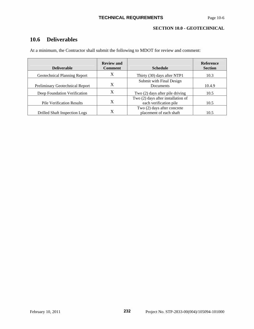
TECHNICAL REQUIREMENTS Page 10-6 SECTION 10.0 - GEOTECHNICAL
February 10, 2011 Project No. STP-2833-00(004)/105094-101000
10.6 Deliverables
At a minimum, the Contractor shall submit the following to MDOT for review and comment:
Deliverable Review and Comment Schedule
Reference Section
Geotechnical Planning Report X Thirty (30) days after NTP1 10.3
Preliminary Geotechnical Report X Submit with Final Design
Documents 10.4.9
Deep Foundation Verification X Two (2) days after pile driving 10.5
Pile Verification Results X Two (2) days after installation of
each verification pile 10.5
Drilled Shaft Inspection Logs X Two (2) days after concrete
placement of each shaft 10.5
232
TECHNICAL REQUIREMENTS Page 11-1 SECTION 11.0 - SIGNING, PAVEMENT MARKING
February 10, 2011 Project No. STP-2833-00(004)/105094-101000
11.0 SIGNING, PAVEMENT MARKING
11.1 Signing
Signage shall be designed and constructed by Contractor to include all regulatory, warning, route marker, guide and information signs, and trailblazer signs.
All regulatory, warning, route marker, guide and information signs, mounting requirements and vertical and horizontal clearances shall conform to the MUTCD and MDOT Standard Plans, and the requirements specified herein. Design and placement of signs shall consider future roadway widening.
All signs placed within Project Right-of-Way shall conform to all MDOT design policy, criteria, standards and specifications.
Sign posts and structures shall be designed and constructed in accordance with MDOT design policy, specifications and standards, and AASHTO Standard Specifications for Structural Supports for Highway Signs, Luminaries and Traffic Signals. Sign structures shall be constructed utilizing structural steel.
The Contractor’s design shall address modifications to permanent signing outside the Project Right-of-Way that are made inaccurate, ineffective, confusing or unnecessary by the Project.
All existing sign panels that require modification shall be replaced with new sign panels and supports.
11.2 Pavement Marking
11.2.1 Permanent Pavement Marking
Pavement markings shall be designed in accordance with the MUTCD and MDOT Standard Drawings. The permanent pavement marking system on MDOT owned roadways shall be according to Table 11.2.1
11.2.2 Temporary Pavement Marking
Temporary Pavement markings shall be designed in accordance with the MUTCD and MDOT Standard Drawings. The temporary pavement marking system shall be according to the Mississippi Standard Specifications for Road and Bridge Construction and Roadway Design Standard Drawings.
11.3 Traffic Signals
Contractor shall design and install traffic signals at all warranted locations. Provision for future signalization shall be made at all interchange ramp intersection terminals. Pull boxes and conduit shall be installed.
Contractor shall be responsible for the design and construction of signal control at ramp terminals at interchanges when warranted. Warrant analysis will be in accordance with MUTCD requirements.
Contractor shall prepare traffic signal warrant analyses using the Project traffic from the toll revenue study created by the Contractor or actual traffic counts taken at each location. The warrant analyses and recommendations will be presented to MDOT for its approval.
Signal design and hardware will be compatible with that used by MDOT and will be standard tapered poles and mast arms.
233
TECHNICAL REQUIREMENTS Page 11-2 SECTION 11.0 - SIGNING, PAVEMENT MARKING
February 10, 2011 Project No. STP-2833-00(004)/105094-101000
Contractor shall prepare a complete design, furnish and install a complete traffic signal system for all traffic signals to be installed as part of the Project. If MDOT has a central computerized traffic system operating on an existing crossroad or has a "progressive" signal system in place, Contractor shall coordinate its design and construction to interface with such systems.
Contractor shall install controllers at all signalized interchanges when warranted. Type of controller will be approved by MDOT.
234
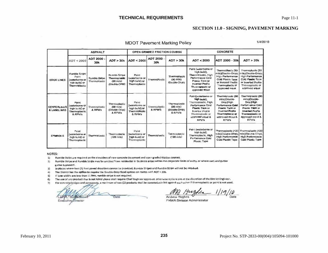
NOTI S:
Rumble Strips are required on the 5houlders of new concrete pavement and open graded friction courses.
Rumble Stripe and Rumble Strips may be omitted from residential or business areas within the corporate limits of a city, or where curb and gutter
gutter is present.
In places where two (2) foot paved shoulders cannot be provided, Rumble Stripes arid Rumble Strips will not be required.
The District has the option to require the Double-Drop Bead system on rostes with ADT< 30k
S) If lane widths are lest than 11 feet, rumble stripe is not required, The use of any product that is not listed above shall require Chief Engineer approval, otherwise options are at the discretion of the District Engineer.
For concret bridges and pave s, a minimum of two (2) products shall be cometetively bid against each other if thermoplastic or paint is not used.
La Exe
, 'B'row' Litiv- ,iirector
a Andrew Hughes ' FHWA Division Administrator
i/i/i Date
ASPHALT OPEN GRADED FRICTION COURSE CONCRETE
ADT e 2000 ADT 2000 -
30k ADT> 30k ADT <2000 ADT 2000
30k ADT > 30k ADT <2000 ADT 2000 - 30k ADT> 30k
EDGE LINES
Rumble Stripe Paint
(waterbome or high build) or
Thermoplastic
Rumble Stripe Thermoplastic
Rumble Stdpe Thermoplastic
(90 mils) (Double-Drop)
Paint (waterbome or high build) or Thermoplastic
Thermoplastic Thermoplastic
(90 mils) (Double-Drop)
Paint (walerboene or high build),
Thermoplastic, High Performance Cold
Plastic Tape or Inverted Profile
Thermoplastic or approved equal
ThermoplastIc (90 milsXoouble.Drop), High Performance Cold Plastic Tape or Inverted Profile Thermoplastic or approved equal
ThermoplastIc 190 mils)(Oouble-Drop), High Performance Cold Plastic Tape or Inverted Profile Thermoplastic or approved equal
CENTERLINES & LANELINES
Paint (waterbome or high build) or Thermoplastic
& RPM's
Themmnoplastic & RPM's
Thermoplastic (90 mIls)
(Double-Drop) & RPM's
Paint (waterbome or high build) or
Thermoplastic & RPM's
Thernnoplastic & RPM'S
Thermoplastic (90 mils)
(Double-Drop) & RPMs
Paint(walerboene or high build),
Thermoplastic, High Performance Cold
Plastic Tape or Inverted Profite
Thermoplastic or approved equal &
RPM's
Thermoplastic (BO icils))Double-
Drop)High Performance Cold
Plastic Tape or Inverted Profile
Thermoplastic or approved equal &
RPM's
Thermoplastic (90 mìlsXDouble-
Drop)I-ligti Performance Cold
Plastic Tape or Inverted Profile
Thermoplastic oc
approved equal & RPM's
SYMBOLS
Pvri (waterborne or high build) or
Thermoplastic
Thermoplastit Thermoplastic (120 mils)
Paint (waterborrie Or high build) or
Thermoplastic
Thermoplastic Thermoplastic
(120 mils)
Paint (waterbome or high build).
Thermoplastic, High Perfoimance Cd
Plastic Tape
Thermoplastic (120 mits)(Doubte.Drop), High Performance Cold Plastic Tape
ThermOplastic (120 mils)(Double-Drop), High Performance Cold Plastic Tape
MDOT Pavement Marking Pohcy 1/412010
TECHNICAL REQUIREMENTS Page 11-1
SECTION 11.0 - SIGNING, PAVEMENT MARKING
February 10, 2011 Project No. STP-2833-00(004)/105094-101000
235
TECHNICAL REQUIREMENTS Page 12-1 SECTION 12.0 - DRAINAGE
February 10, 2011 Project No. STP-2833-00(004)/105094-101000
12.0 DRAINAGE
12.1 Drainage Criteria
The Project shall include all Work for the design and construction of drainage facilities including temporary and permanent erosion control measures. Project design will be in compliance with the MDOT Roadway Design Manual, Chapter 7. All pipe culverts shall meet the requirements of MDOT Pipe Culvert Material Design Criteria.
The Contractor does not have to provide the design information below if the Contractor uses the final bridge plans provided by MDOT.
12.2 Coordination with Other Agencies
The Contractor shall coordinate all drainage issues with affected regulatory agencies that have interest or jurisdiction over the Project.
The Contractor shall include MDOT in all contacts with affected regulatory agencies.
12.3 Hydraulic Design of Structures
Hydraulic design and analysis is required for all structures that span over waterways and shall be in conformance with the COMMISSION’s Roadway Design Manual, 23 CFR 625, 630 and 650, 44 CFR Part 60.3(d)(3) and (d)(4), the Floodplain Management Regulations for the State of Mississippi (Chapter 5, General Laws of 1979, 1st Extraordinary Session of the State, as amended) and Federal Emergency Management Agency (FEMA) regulations and any other State or Federal regulations as appropriate. Freeboard shall set a minimum of two (2) ft. above the Design High Water elevation and a minimum of one (1) ft. for the 100 year flood event for most hydraulic bridges. Significant hydraulic bridges such as those over rivers where drift is a concern shall have three (3) ft. above the Design High Water elevation and a minimum of one (1) ft. for the 100 year flood. Design High Water is defined as follows:
a. 50 year flood event – Interstate, Arterials b. 25 year flood event - Collectors
Spur dike design shall be based on the FHWA Publication, Hydraulics of Bridge Waterways (HDS-1)
The determination of riprap requirements shall be based on the FHWA Publication, Bridge Scour and Stream Instability Countermeasures, Hydraulic Engineering Circular No. 23 (HEC-23). Further requirement shall be the FHWA Publication, Design of Riprap Revetment, Hydraulic Engineering Circular No. 11 (HEC-11).
Bridge deck drainage shall be based on the FHWA Publication, Design of Bridge Deck Drainage, Hydraulic Engineering Circular No. 21 (HEC-21).
Hydraulic design of box bridges and box culverts shall be based on the FHWA Publication, Hydraulic Design of Highway Culverts (HDS-5).
The flow line of box bridges and box culverts shall be set two (2) ft. below the low stream bed elevation for drainage areas greater than 1000 acres and one (1) foot below the stream bed for drainage areas equal to or less than 1000 acres.
236
TECHNICAL REQUIREMENTS Page 12-2 SECTION 12.0 - DRAINAGE
February 10, 2011 Project No. STP-2833-00(004)/105094-101000
Where bridges are recommended, the FHWA computer program WSPRO or the U.S. Army Corps of Engineers Water Surface Profile Software HEC-RAS, shall be used for determination of bridge opening requirements.
When a structure is placed in or across a FEMA Regulatory Floodway as shown on the Flood Insurance Program maps, the Contractor will obtain the input data for the US Army Corps of Engineers computer program HEC-2 or HEC-RAS from FEMA. Modification of this input data will be required to demonstrate that the proposed development will not impact the pre-Project base flood elevations, regulatory floodway elevations, or regulatory floodway widths. A “No-Rise / No-Impact” certification shall be completed, and all technical data supporting the “No-Rise / No-Impact” certifications shall be submitted to MDOT for review prior to the submission of preliminary plans.
In the event a “no-rise” is impracticable or not possible, or a longitudinal encroachment of the roadway embankment will occur within the Floodway, an application for revisions to the National Flood Insurance Program maps may be required. The Contractor shall submit to the Floodway Administrator all applications, information and supporting documentation required for a FEMA CLOMR/LOMR.
Calculations of the potential Bridge Scour shall be prepared according to the FHWA Publication, Evaluating Scour at Bridges, Hydraulic Engineering Circular No. 18 (HEC-18) and the results included on the Elevation and Foundation Layouts of the Bridge Plans.
Hydraulic Bridge Recommendations are required for each bridge, box bridge, box culvert and detour bridge. The recommendations shall be presented on the appropriate MDOT forms as required:
1. “BRIDGE RECOMMENDATIONS” 2. “RECOMMENDATIONS FOR DUAL BRIDGES” 3. “BOX BRIDGE OR BOX CULVERT LAYOUT REPORT” 4. “DETOUR BRIDGE RECOMMENDATIONS”
For hydraulic bridge locations, the bridge abutments and intermediate bents shall be established and staked in the field by the Contractor for a field inspection. The Contractor shall schedule a field inspection of the hydraulic bridge sites to be attended by the Lead Design Engineer and hydraulic engineer and MDOT’s Bridge Hydraulic Engineer prior to finalization of the hydraulic bridge recommendations. Preliminary layouts for the hydraulic bridges (except detour bridges and box bridges) shall be available for these field inspections. The Contractor shall incorporate the comments into the finalized preliminary plans and hydraulic bridge recommendations to MDOT’s satisfaction, unless an explanation satisfactory to MDOT is provided explaining why a comment has not been addressed.
The Contractor shall submit to MDOT a copy of final structure recommendations, all hydraulic computations, supporting data and documentation, including but not limited to: 1) Computer input and output (electronic); 2) Scour computations; 3) Spur Dike analysis; 4) Box bridge and box culvert computations; 5) Survey data (electronic); 6) Supporting drawings; and 7) All correspondence with governmental and regulatory agencies regarding levees and water crossings. In the event a FEMA regulatory floodway is involved, the Contractor shall also submit a copy of the following as appropriate: 1) FEMA flood study data; 2) Topographic maps showing revised floodway boundaries; 3) No-Rise certification; 4) CLOMR application; 5) LOMR; and 6) All correspondence with FEMA and the Floodway Administrator.
237
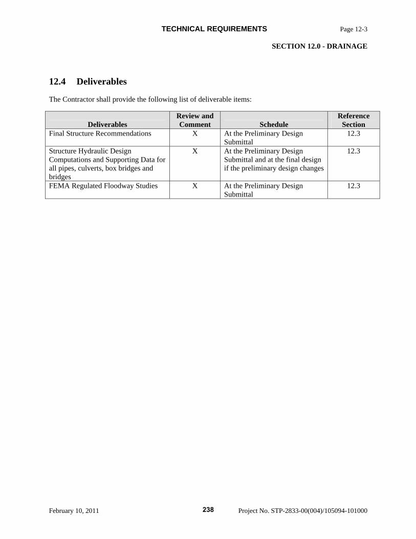
TECHNICAL REQUIREMENTS Page 12-3 SECTION 12.0 - DRAINAGE
February 10, 2011 Project No. STP-2833-00(004)/105094-101000
12.4 Deliverables
The Contractor shall provide the following list of deliverable items:
Deliverables Review and Comment Schedule
Reference Section
Final Structure Recommendations X At the Preliminary Design Submittal
12.3
Structure Hydraulic Design Computations and Supporting Data for all pipes, culverts, box bridges and bridges
X At the Preliminary Design Submittal and at the final design if the preliminary design changes
12.3
FEMA Regulated Floodway Studies X At the Preliminary Design Submittal
12.3
238
TECHNICAL REQUIREMENTS Page 13-1 SECTION 13.0 - ROADWAYS AND PAVEMENTS
February 10, 2011 Project No. STP-2833-00(004)/105094-101000
13.0 ROADWAYS AND PAVEMENTS
13.1 Roadway Design Criteria
Project design will be in compliance with the MDOT Roadway Design Manual rural arterial conditions, rolling terrain and rural setting. The design of other roadways will be accordance with Table 13.5-1
13.2 Horizontal Alignment
Contractor shall establish an initial horizontal alignment to meet numerous design considerations along the Project as part of the Proposal. Contractor may request revisions to this alignment as required to meet specific Site conditions or other constraints encountered during design and construction. The request may be accepted by MDOT at its discretion. Any alignment revisions which affect the established/existing Project Right-of-Way will require additional environmental reevaluation at Contractor’s cost and risk.
13.3 Vertical Alignment
Contractor shall establish an initial vertical alignment to meet numerous design considerations along the Project as part of the Proposal. Contractor may request revisions to this initial vertical alignment as required to meet specific Site conditions or other constraints encountered during design and construction. The request may be accepted by MDOT at its discretion. Any alignment revisions which affect the established/existing Project Right-of-Way will require additional environmental reevaluation at Contractor’s cost and risk.
13.4 Access Control
Access shall be controlled on the Project. Access shall be controlled at least 300 feet beyond the interchange ramps tapers on intersection roads where possible. The absolute minimum is 100 feet from ramp tapers.
13.5 Typical Sections
Table 2-7B, Table 14-2H and Table 14-2I of the MDOT Roadway Design Manual shall be revised as detailed in Table 13.5-1:
239
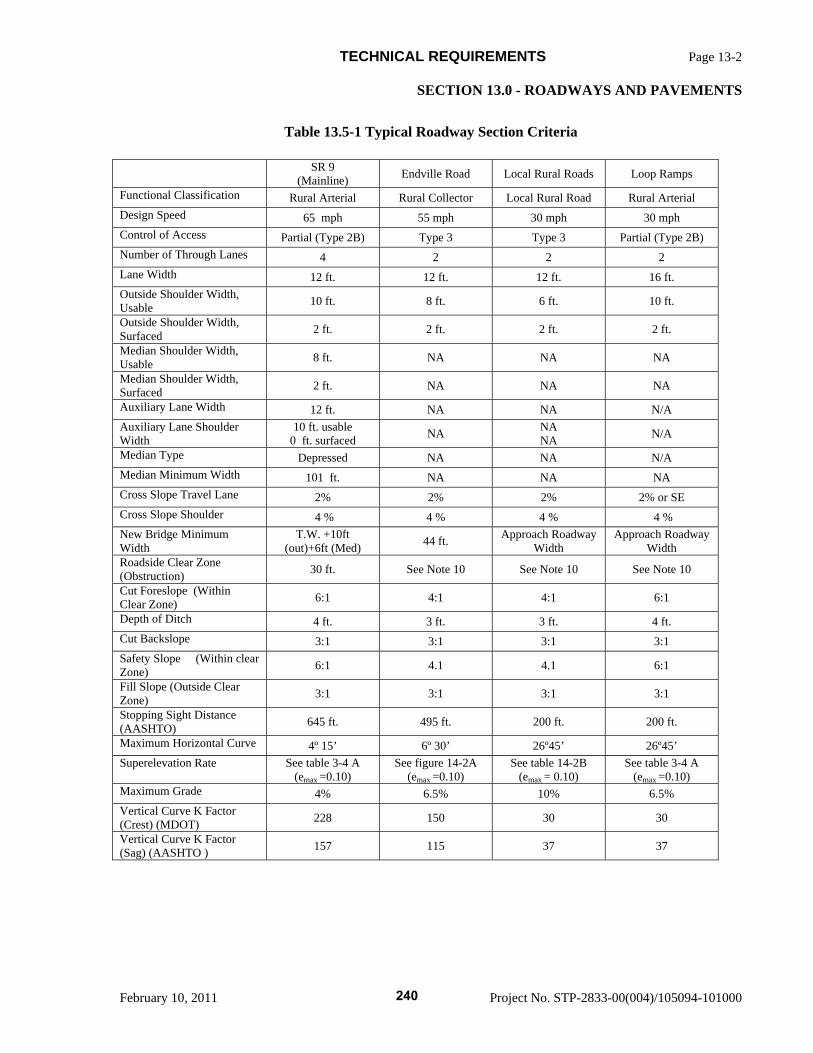
TECHNICAL REQUIREMENTS Page 13-2 SECTION 13.0 - ROADWAYS AND PAVEMENTS
February 10, 2011 Project No. STP-2833-00(004)/105094-101000
Table 13.5-1 Typical Roadway Section Criteria
SR 9 (Mainline) Endville Road Local Rural Roads Loop Ramps
Functional Classification Rural Arterial Rural Collector Local Rural Road Rural Arterial Design Speed 65 mph 55 mph 30 mph 30 mph Control of Access Partial (Type 2B) Type 3 Type 3 Partial (Type 2B) Number of Through Lanes 4 2 2 2 Lane Width 12 ft. 12 ft. 12 ft. 16 ft. Outside Shoulder Width, Usable 10 ft. 8 ft. 6 ft. 10 ft.
Outside Shoulder Width, Surfaced 2 ft. 2 ft. 2 ft. 2 ft.
Median Shoulder Width, Usable 8 ft. NA NA NA
Median Shoulder Width, Surfaced 2 ft. NA NA NA
Auxiliary Lane Width 12 ft. NA NA N/A Auxiliary Lane Shoulder Width
10 ft. usable 0 ft. surfaced NA NA
NA N/A
Median Type Depressed NA NA N/A Median Minimum Width 101 ft. NA NA NA Cross Slope Travel Lane 2% 2% 2% 2% or SE Cross Slope Shoulder 4 % 4 % 4 % 4 % New Bridge Minimum Width
T.W. +10ft (out)+6ft (Med) 44 ft. Approach Roadway
Width Approach Roadway
Width Roadside Clear Zone (Obstruction) 30 ft. See Note 10 See Note 10 See Note 10
Cut Foreslope (Within Clear Zone) 6:1 4:1 4:1 6:1
Depth of Ditch 4 ft. 3 ft. 3 ft. 4 ft. Cut Backslope 3:1 3:1 3:1 3:1 Safety Slope (Within clear Zone) 6:1 4.1 4.1 6:1
Fill Slope (Outside Clear Zone) 3:1 3:1 3:1 3:1
Stopping Sight Distance (AASHTO) 645 ft. 495 ft. 200 ft. 200 ft.
Maximum Horizontal Curve 4º 15’ 6º 30’ 26º45’ 26º45’ Superelevation Rate See table 3-4 A
(emax =0.10) See figure 14-2A
(emax =0.10) See table 14-2B
(emax = 0.10) See table 3-4 A
(emax =0.10) Maximum Grade 4% 6.5% 10% 6.5% Vertical Curve K Factor (Crest) (MDOT) 228 150 30 30
Vertical Curve K Factor (Sag) (AASHTO ) 157 115 37 37
240
TECHNICAL REQUIREMENTS Page 13-3 SECTION 13.0 - ROADWAYS AND PAVEMENTS
February 10, 2011 Project No. STP-2833-00(004)/105094-101000
13.5.1 Notes for Table 13.5-1
1. The minimum vertical clearance for all bridge over highways and streets shall be 16’ – 6”. 2. The minimum vertical clearance for all Sign Trusses shall be 17’ – 6”. 3. The minimum vertical clearance over railroads shall be 23’ – 6” or more if required by the
railroad. 4. All bridges shall be designed for a live load equal to or greater than HL-93. 5. Sag vertical curves shall be avoided if possible on bridges. 6. Horizontal Sight Distances- See Subsection 3.50 in the MDOT Roadway Design Manual for
applicable criteria. 7. T.W. refers to the travel way or the total lane width. 8. Approach Roadway width is defined by the total lane width plus the total useable shoulder. 9. Horizontal clearances at railroads shall meet the requirements of AREMA and the Railroad
Company. 10. Clear zone to be based upon speed, side slope and traffic volume. 11. Where auxiliary lanes are used along the mainline, clear zone is measured for the outside
edge of the auxiliary lane.
13.6 Earthwork and Grading
Roadway earthwork and grading design and construction will conform to the typical sections and the following specific requirements:
The minimum embankment slopes, outside of the clear zone, will be constructed using normal 3:1 slopes unless flatter slopes are determined to be necessary from the geotechnical investigation performed in accordance with MDOT SOP TMD-20-14-00-000. Embankments will be constructed with suitable material acquired from either onsite excavation or hauled from offsite borrow pits or a combination of both. Embankment material shall be placed and compacted in accordance with MDOT standards.
Safety barriers shall be used to protect motorists from obstructions.
The Contractor shall perform excavation (and undercut, if necessary) of the roadway, side slopes, ditches and channels, structures, and all other items necessary for the construction of this Project. Excavation shall include all materials above the subgrade (and undercut, if required) and the disposal of all materials not suitable for re-use in construction.
The Contractor shall be responsible for locating and obtaining all borrow material and waste material required for this Project, including all approvals, permits, and fees required for obtaining and hauling the borrow material.
241
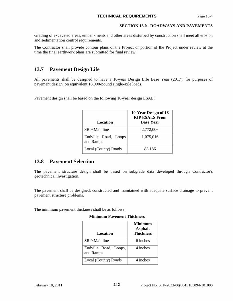
TECHNICAL REQUIREMENTS Page 13-4 SECTION 13.0 - ROADWAYS AND PAVEMENTS
February 10, 2011 Project No. STP-2833-00(004)/105094-101000
Grading of excavated areas, embankments and other areas disturbed by construction shall meet all erosion and sedimentation control requirements.
The Contractor shall provide contour plans of the Project or portion of the Project under review at the time the final earthwork plans are submitted for final review.
13.7 Pavement Design Life
All pavements shall be designed to have a 10-year Design Life Base Year (2017), for purposes of pavement design, on equivalent 18,000-pound single-axle loads.
Pavement design shall be based on the following 10-year design ESAL:
Location
10-Year Design of 18 KIP ESALS From
Base Year
SR 9 Mainline 2,772,006
Endville Road, Loops and Ramps
1,075,016
Local (County) Roads 83,186
13.8 Pavement Selection
The pavement structure design shall be based on subgrade data developed through Contractor's geotechnical investigation.
The pavement shall be designed, constructed and maintained with adequate surface drainage to prevent pavement structure problems.
The minimum pavement thickness shall be as follows:
Minimum Pavement Thickness
Location
Minimum Asphalt
Thickness
SR 9 Mainline 6 inches
Endville Road, Loops, and Ramps
4 inches
Local (County) Roads 4 inches
242
TECHNICAL REQUIREMENTS Page 13-5 SECTION 13.0 - ROADWAYS AND PAVEMENTS
February 10, 2011 Project No. STP-2833-00(004)/105094-101000
The non-surfaced shoulder width shall be designed and constructed of Class 3, Group C Granular Material to the same thickness of asphalt as the lane pavement.
13.9 Roadway Safety
All roadway guardrail and roadside barriers shall be designed according to design speed using current MDOT standards.
Concrete median barriers shall be a minimum of 42 inches tall and shall meet TL-4 crash test level criteria.
All roadway pavement sections on the Project shall incorporate rumble strips along the inside and outside shoulders.
13.10 Deliverables
At a minimum, the Contractor shall submit the following to MDOT for review / comment and approval:
Deliverable Comment Schedule Reference
Section Preliminary Plans (30%) and Cross
Sections X According to Contractor’s
Schedule 2.2.2
Final Plans (100%) and Cross
Sections X Prior to Request For Release for
Construction 2.2.4
Release for Construction Plans and Cross Sections
X According to Contractor’s Schedule
2.2.5
Record Drawings X 30 days after Completion of Construction
2.2.7
243
TECHNICAL REQUIREMENTS Page 14-1 SECTION 14.0 - PERMANENT ROADWAY LIGHTING
February 10, 2011 Project No. STP-2833-00(004)/105094-101000
14.0 PERMANENT ROADWAY LIGHTING
Permanent roadway lighting is not required for this project.
244
TECHNICAL REQUIREMENTS Page 15-2 SECTION 15.0 - STRUCTURES
February 10, 2011 Project No. STP-2833-00(004)/105094-101000
15.0 STRUCTURES
The following applies to all bridges and box bridges designed by the Contractor.
15.1 Design Methodology
All structural components of the Project shall be designed by the AASHTO Load and Resistance Factor Design methodology.
15.2 Loads and Forces
The structures contained in this Project shall be proportioned for loads and forces in accordance with the latest edition of AASHTO LRFD Bridge Design Specifications.
15.2.1 Live Loads
Live loads shall be calculated in accordance with AASHTO Bridge Design Specification Section 3. Vehicular live loading on the roadway of bridges or incidental structures shall be HL-93.
15.2.2 Thermal Movement
Thermal movement shall be calculated in accordance with AASHTO Subsection 3.12, Procedure A as modified below.
a. Median Temperature at the time of erection: 60° F
b. Design Temperature Ranges:
Steel Structures: Tmax = 120° F Tmin = 0° F
Concrete Structures: Tmax = 110° F Tmin = 10° F
15.3 General Requirements for Bridges
15.3.1 Bridge Superstructures
a. All bridges on this Project shall have cast-in-place reinforced concrete bridge decks supported by precast-prestressed concrete girders, precast-prestressed post-tensioned concrete girders, steel plate girders or steel tub girders. In no case shall the exterior girders have less carrying capacity than an interior girder.
b. Steel bridge superstructures shall be continuous over a minimum of two piers. Prestressed
concrete bridges shall be made continuous for live loads over two or more piers.
245
TECHNICAL REQUIREMENTS Page 15-3 SECTION 15.0 - STRUCTURES
February 10, 2011 Project No. STP-2833-00(004)/105094-101000
c. Stay-in-place deck forms or precast concrete deck panels shall not be used.
d. The minimum number of longitudinal girders supporting a bridge cross section shall be no less than four (4). In no case shall the maximum girder spacing be greater than 10’-0”.
e. No fracture critical members, connections, or pin and link type connections are allowed. f. Structures shall have members and details that utilize redundant load paths. g. All steel plate girder or steel tub girders spans shall be curved to match the horizontal curvature
of the alignment. Precast-prestressed concrete girder spans shall not be utilized when the horizontal curvature of the alignment results in an offset of 10-inches or more in a span measured between the chord as defined by the straight girder and the curve.
h. Bridge superstructures that have continuity over piers shall have the same number of girders in
each span of the continuous section.
15.3.2 Bridge Substructures
Bridge substructures (including abutments) shall be reinforced concrete components supported by deep foundations.
Bridge abutments shall be protected by armoring the abutment slopes. Rip rap shall be used for hydraulic bridges and concrete slope paving shall be used for grade separations.
15.4 Bridge Design Criteria
15.4.1 Concrete Design
15.4.1.1. Reinforced Concrete
All concrete shall be designed and produced in accordance with MDOT Standard Specifications Section 804 Table 3. Cement used in concrete shall meet the requirements of Section 701 of the Mississippi Standard Specifications for Road and Bridge Construction.
Cast-in-Place Concrete:
Class AA f'c = 4,000 psi
Drilled Shaft Concrete: Class DS f'c = 4,000 psi
246
TECHNICAL REQUIREMENTS Page 15-4 SECTION 15.0 - STRUCTURES
February 10, 2011 Project No. STP-2833-00(004)/105094-101000
15.4.1.2. Reinforcing Steel
a. Cast-in-place concrete shall be reinforced only with deformed bars conforming to AASHTO M31 (ASTM A 615) or A 706. Reinforcement to be welded shall conform to ASTM A 706. Reinforcing steel shall be Grade 60.
b. Cast-in-Place Concrete Clear Cover -
i. Drilled Shafts – 6” ii. Footings – Bottom Mat – 4” iii. Footings – Top Mat – 3” iv. Pedestals and Columns – 3” v. All other reinforcing steel per AASHTO
15.4.1.3. Prestressing Steel
a. Prestressing Steel shall conform to AASHTO M 203 (ASTM A 416). Prestressing Strand shall be weldless in accordance with AASHTO 203, subsection 8.1.4.
15.4.1.4. Allowable Stress, Deflection and Strength Considerations
a. Reinforced concrete structures shall be designed in accordance with AASHTO LRFD Bridge Design Specifications.
15.4.1.5. Special Considerations for Bridge Decks
a. The top one-fourth (1/4) inch of all concrete slabs shall be considered as a wearing surface and shall not be included in the nominal slab depth used for the calculation of section properties but shall be included in the dead load calculations.
b. The minimum bridge deck thickness shall be eight (8) inches. The cantilever overhang portions of the bridge deck shall have a minimum thickness as follows:
1) nine (9) inches - where 32 inch railing is used
2) ten (10) inches – where 42 inch railing is used
c. Final surface texture of a concrete bridge decks and bridge end pavements shall be mechanically transverse grooved in accordance with Sections 501 and 804 of the Mississippi Standard Specifications for Road and Bridge Construction.
15.4.1.6. Prestressed Concrete
Prestressed concrete girders shall be designed as simple spans and made continuous for live load.
All concrete shall be designed and produced in accordance with MDOT Standard Specifications Section 804 Table 3. Cement used in concrete shall meet the requirements of Section 701 of the Mississippi Standard Specifications for Road and Bridge Construction.
Prestressed Concrete Class Fx range
247
TECHNICAL REQUIREMENTS Page 15-5 SECTION 15.0 - STRUCTURES
February 10, 2011 Project No. STP-2833-00(004)/105094-101000
From a minimum of f'c = 5,000 psi To a maximum of f'c = 8,500 psi
15.4.1.7. Miscellaneous Requirements and Restrictions
a. For prestressed concrete girder spans, one cast-in-place concrete diaphragm shall be designed and constructed at mid span, or multiple cast-in-place diaphragms shall be approximately equally spaced along the girder. The diaphragm shall be a minimum thickness of nine (9) inches and extend from the deck to the top of the bottom flange.
b. For prestressed concrete girder spans, cast-in-place concrete diaphragm shall be located at all intermediate piers that are within the deck live load continuity. The intermediate pier diaphragms shall be a minimum of twelve (12) inches thick and shall extend from the deck to the top of the pier cap.
c. Cast-in-place concrete diaphragms are required at the ends of prestressed concrete girders where there is a break in deck continuity. The end diaphragms shall be a minimum of twelve (12) inches thick and shall extend from the deck to the top of the bottom flange.
d. External Post-tensioning will not be permitted.
e. All substructure caps shall have shear keys located on the cap just outside the exterior girders and shall have a minimum height of fifteen (15) inches above the bottom of the exterior girder. The minimum length as measured transversely along the cap shall be fifteen (15) inches and the minimum width shall be three (3) feet or two-thirds (2/3) of the cap width, whichever is greater. There shall be a one (1) inch gap between the shear key and either the face of the exterior girder or any bearing device, pad or plate supporting the exterior girder.
15.4.2 Structural Steel Design
Steel structures shall be designed in accordance with AASHTO LRFD Bridge Design Specifications.
15.4.2.1. Materials Structural steel for primary members shall conform to the requirements of AASHTO M 270 Grade 36, Grade 50 or Grade HPS 70W. Structural steel for secondary members shall conform to the requirements of AASHTO M 270 Grade 36 or Grade 50. Steel with a design yield strength greater than seventy (70) ksi will not be permitted. High strength bolts shall be ASTM A 325, designed for values as specified in AASHTO Subsection 6.13.2.8 with Class B contact surfaces. All field connections shall use 7/8” minimum diameter bolts. Direct tension indicators (DTIs) shall be the only acceptable method for verifying proper bolt installation.
15.4.2.2. Design and Details
a. Girders shall be I-shaped and shall be designed to act compositely with the deck slab in the positive moment region and with the reinforcing steel in the negative moment region.
b. All bolted connections shall be designed as slip critical connections having Class B contact surfaces.
248
TECHNICAL REQUIREMENTS Page 15-6 SECTION 15.0 - STRUCTURES
February 10, 2011 Project No. STP-2833-00(004)/105094-101000
c. Electroslag welding will not be permitted.
15.4.2.3. Fasteners for Steel Bridge Girders
a. High Strength Bolts shall meet the requirement of ASTM. A 325, Type 1, and shall be hot dip galvanized in accordance with the requirements of ASTM A 153, Class C Coating or galvanized by the mechanical process in accordance with the requirements of ASTM B 695, Class 50 Coating. Maximum hardness for high strength bolts shall be 33 Rockwell C (RC).
b. Nuts for high strength bolts shall be heavy hex and meet the requirements of ASTM A 563, Grade DH galvanized.
c. Hardened steel washers shall meet the requirements of ASTM F 436, galvanized.
d. Direct tension indicators shall meet the requirements of ASTM F 959 and shall be galvanized by the mechanical process meeting the requirements of ASTM B 695, Class 50 Coating.
e. Nuts for high strength bolts shall be tapped oversize the minimum amount required for proper assembly and lubricated with an acceptable lubricant containing a dye of any color that contrasts with the color of galvanizing.
f. High strength bolts, nuts, or direct tension indicators shall not be reused after tightening.
g. Mill test reports, certified test reports, and certificates of compliance are required for high strength bolts, nuts, hardened washers and direct tension indicators.
15.4.2.4. Paint System
All structural steel, except for expansion joints, and rail plates shall be painted in accordance with Section 814 of the Mississippi Standard Specifications for Road and Bridge Construction.
15.4.3 Structural Steel Fabrication Requirements
All steel plates, angles, bars, rolled shapes, finger joints and pot bearings incorporated into a bridge structure shall meet the following requirements:
All girder web plates, flange plates and splice plates shall meet the Longitudinal Charpy-V-Notch Toughness Test. The Supplementary Bend Test as described in Section 717 of the Mississippi Standard Specifications for Road and Bridge Construction is not required. Miscellaneous steel less than 1/4 inch thick shall be identified on the shop drawings. Web and flange material heat numbers shall be stenciled on each girder using low stress die stamps. The heat numbers shall be stamped on the side of the web in the upper left hand corner.
Diaphragms and crossframes for curved steel structures are primary members.
All welding shall be completed by the electric arc process and shall conform to the ANSI/AASHTO/AWS D1.5 BRIDGE WELDING CODE, and as directed herein. Certification for all welders to be used on this Project shall be submitted to the Contractor’s Construction Quality Control Manager and MDOT Bridge Engineer for review. Welding machines shall have operating, properly calibrated current meters with attached calibration stickers. Run-off tabs of adequate length shall be used to help prevent weld defects at weld edges. Material surfaces for
249
TECHNICAL REQUIREMENTS Page 15-7 SECTION 15.0 - STRUCTURES
February 10, 2011 Project No. STP-2833-00(004)/105094-101000
flange to web fillet welds shall be ground prior to fit-up for welding to remove all mill scale. This area includes the flange, near and far side web and the web edge.
Welded shop splices in webs and flanges are conditionally permissible and shall be submitted to the Contractor’s Lead Design Engineer for approval of type and location. Welded web and flange shop splices shall not occur at concurrent locations and shall be offset a minimum of five (5) feet along the girder. Welded shop splices are prohibited in the following regions in each span:
1. Top Flange Plates in the Negative Moment Region: the region of prohibition shall begin at the centerline bearing and shall extend along the span to the lesser of twenty-five (25) feet or one tenth of the span length. In no case shall this region be less than fifteen (15) feet in length.
2. Bottom Flange Plates in the Positive Moment Region: the region of prohibition shall be the lesser of forty (40) feet or on tenth of the span length. This region shall be centered about the point of maximum positive moment. In no case shall this region be less than twenty (20) feet in length.
3. Web Plates: the region of prohibition at each end of the span shall begin at centerline bearing and shall extend along the span to the greater of fifteen (15) feet or one tenth of the span length as measured from the centerline of bearing. This region need not be greater than twenty- five (25) feet in length.
With the exception of surface condition repairs to correct undercut or overlap conditions, repairs to groove welds require an approved welding repair procedure that includes supporting documentation, size and location of the repair, Non Destructive Evaluation (NDE) reports and the Fabricator's Non-Conformance Report. Approval by the Contractor’s Quality Control Manager and review by the MDOT Bridge Engineer is required prior to performing these repairs. Repairs to base metal (including flame cut edges with excessive gouges) require an approved welding repair procedure that includes supporting documentation, size and location of the repair, NDE reports and the Fabricator's Non-Conformance Report. Approval by the Contractor’s Construction Quality Control Manager and review by the MDOT Bridge Engineer is required prior to performing these repairs.
The Fabricator shall have a Certified Welding Inspector (CWI) on each work shift where welding or other significant work is performed. Quality Control inspections for acceptance shall precede Quality Assurance inspections. Quality Control shop inspection records shall be made available to MDOT QA Shop Inspection Personnel.
Camber shall be checked and recorded by the Fabricator at all points shown in the approved shop drawings.
Prior to fabrication, the Fabricator and its subcontractor(s) shall determine specific inspection procedures that include techniques and acceptance standards for NDE applications for unusual or nonstandard weld geometries
Radiography of weld transitions shall be performed by placing the film on the flat side of the transition. A floating center punch shall be placed on the base metal adjacent to the weld and shall be visible on each radiographic film in the area of interest.
Prior to fabrication, the Fabricator shall have Shop Drawings approved by the Contractor’s Lead Design Engineer. Also prior to fabrication, the Fabricator shall submit Welding Procedures, a Procedure for Storage and Handling of Welding Electrodes, Wire And Flux and A Flux Recovery Procedure (if applicable) to the Contractor’s Lead Design Engineer for approval and for review by the MDOT Bridge Engineer. The Construction Quality Control Manager shall schedule a Pre-
250
TECHNICAL REQUIREMENTS Page 15-8 SECTION 15.0 - STRUCTURES
February 10, 2011 Project No. STP-2833-00(004)/105094-101000
Fabrication Conference at each fabrication location. The Fabricator’s facilities will be inspected by the Contractor’s Construction Quality Control Manager, MDOT Bridge Engineer and MDOT QA Shop Inspection personnel during the Pre-Fabrication Conference. No fabrication shall begin prior to this inspection.
Prior to fabrication, the Fabricator and/or subcontractor shall submit their NDE procedures to the Contractor’s Construction Quality Control Manager and MDOT Bridge Engineer for review. The NDE procedure shall include a written practice, a method procedure for each inspection process and personnel certifications.
Breaks in fabrication shall require at least two weeks advance notification to the Contractor’s Quality Control Manager and MDOT Bridge Engineer prior to restarting work.
Progressive girder assembly using a minimum three girder laydown is permissible while shop assembling girders. Drilling of material for splice connections shall occur with all items in their proper location, including splice and shim plates. Parts shall be firmly drawn together prior to drilling.
The Fabricator shall furnish MDOT QA Shop Inspection Personnel with at least 140 square feet of floor space. Additional space shall be provided as required by MDOT Bridge Engineer. The office shall contain desks, chairs, file cabinets, telephone with long distance access, electric lights, power outlets, shelves and tables. The office shall be provided with adequate heating, ventilation and air conditioning. The office shall have access to convenient sanitary facilities with running water. The office shall be in good repair, located where there is not excessive noise and shall be used for MDOT QA Shop Inspection Personnel only. Convenient and adequate parking shall be provided.
The Fabricator shall provide MDOT QA Shop Inspection Personnel convenient access to a fax machine and a copy machine. Changes in office location or facilities shall be made only upon approval of MDOT Bridge Engineer.
15.4.4 Deep Foundation Design
All bridge foundations (including abutments) shall be constructed with deep foundations consisting of piles, drilled shafts or footings supported by piles or drilled shafts. All bridges over waterways shall be designed or evaluated in accordance with 23 CFR 650, FHWA Technical Advisory, “Evaluating Scour at Bridges,” October 28, 1991, Hydraulic Circular 18(HEC 18) and any other State or Federal regulations as appropriate. Scour elevations shall be shown for each bent location on the Elevation and Foundation Layout sheets of the bridge plans. Footings subject to scour shall have the tops of the footing no higher than the 100 year scour elevation. Footings not subject to scour shall have a minimum of two (2) feet of cover. Piles or drilled shafts shall be tipped a minimum of five (5) feet in “unweathered chalk” or harder soils and shall be tipped a minimum of ten (10) feet below the 500 year scour elevation. Piles or drilled shafts tipped in other soil types shall be tipped a minimum of twenty (20) feet below the 500 year scour elevation. Deep foundations are required to extend a minimum of fifteen (15) feet below any compacted fill.
251
TECHNICAL REQUIREMENTS Page 15-9 SECTION 15.0 - STRUCTURES
February 10, 2011 Project No. STP-2833-00(004)/105094-101000
All piling shall be prestressed concrete or H-pile. Prestressed concrete piles shall be a minimum size of 14”x14”. H-piles shall be a minimum size of HP12x53. For water crossing, steel H-piles, if used, shall be encased from the bottom of the pile cap to a minimum of five (5) feet below natural ground.
15.4.5 Bearings
Bearings shall be designed in accordance with AASHTO LRFD Bridge Design Specifications Section 14. Elastomeric bearings or disc bearings are preferred. Natural rubber in elastomeric bearings will not be allowed. The maximum thickness of laminated elastomeric bearings shall be 5 1/2 inches. All bearings shall be designed and detailed to be replaceable by jacking while maintaining traffic. Disc bearing anchor bolts shall be located no closer than 1 1/2 inches clear horizontally from face of bottom flange of a girder.
15.4.6 Bridge Railings
For this project, bridge railing shall be a minimum of thirty-two (32) inch tall NJ shape MDOT bridge railing.
15.4.7 Expansion Joints
Expansion joints shall be provided to accommodate the movement of the bridge. Expansion joints with a movement rating of two and one quarter (2 ¼) inches or less may be constructed as a silicone sealed open joint. Finger Joints shall be used when the movement rating of the expansion joints is greater than two and one quarter (2 ¼) inches. The design and construction of the finger joint shall be similar to the joint plans available from MDOT.
For normal geometry conditions, cellular or modular joints shall not be used. When present, curvature of the structure shall be considered in the design of the expansion joint. If it can be shown that expansion finger joints are not feasible for use due to excessive horizontal curvature of the structure, other joint types may be considered, when approved by MDOT.
Expansion joints and rail plates shall be galvanized in accordance with ASTM A 123.
15.4.8 Bridge Drainage
a. Bridge deck drainage shall be provided as necessary to keep the ten (10) year event for a five (5) minute interval from spreading into the travel lanes. Rainfall intensity – Duration – Frequency Curves are provided in MDOT Roadway Design Manual Figure 7-4f. Bridge deck drainage design shall be in accordance with FHWA Circular No.21, “Design of Bridge Deck Drainage” (HEC-21).
b. Bridge deck drainage shall be contained on the bridge deck shoulders prior to passing through the bridge deck drains. Bridge deck drainage shall not be allowed to pass through the railing.
c. Bridge deck drains shall extend below the bottom flange of steel girders or precast-prestressed post-tensioned girders. Where drainage scuppers and drain pipes are used,
252
TECHNICAL REQUIREMENTS Page 15-10 SECTION 15.0 - STRUCTURES
February 10, 2011 Project No. STP-2833-00(004)/105094-101000
pipes shall be located inside of the exterior girder (does not apply to steel tub girders). Scupper gratings shall be designed to allow safe passage of bicycle traffic.
d. Bridge deck drains for precast-prestressed concrete girder spans may utilize drain holes with a minimum opening of three (3) inches by eight (8) inches. Drain holes shall be located adjacent to the bridge barrier.
e. No bridge deck drainage shall drain onto a railroad right-of-way or onto a roadway, sidewalk, or shoulder underneath the bridge.
15.4.9 Load Rating
The Contractor shall provide load ratings of all bridges designed by the Contractor’s Engineer. The engineer performing the load rating shall be a professional engineer licensed to practice in the State of Mississippi. The load ratings shall be performed in accordance with the latest edition of the AASHTO Manual for Bridge Evaluation, the AASHTO LRFD Bridge Design Specifications and the requirements below.
The load capacity of each bridge shall be rated in terms of the AASHTO LRFD HL-93 design vehicle at both the inventory and operating levels and the Mississippi Legal Load Trucks at the legal load rating level. In no case shall the legal load rating factor for the Mississippi Legal Load Trucks be less than 1.0.
A systematic procedure shall be followed in the evaluation of bridges so that the information may be retained and utilized in the routing of permit loads. The Contractor will provide a Bridge Load Rating Report of all bridges which will include a summary showing all load ratings in a tabulated form, calculations, supporting documentation and electronic copies of computer program input files. The Bridge Load Rating Report shall be sealed/stamped by the Contractor’s professional engineer licensed to practice in the State of Mississippi.
The axle weight and spacing for each Mississippi Legal Load Truck is provided below:
HS-SHORT 12 kip -- 12 ft -- 20 kip -- 4 ft -- 20 kip -- 10 ft -- 14 kip -- 4 ft --14 kip total weight = 80 kip
HS-LONG 12 kip -- 12 ft -- 20 kip -- 4 ft -- 20 kip -- 22 ft -- 14 kip -- 4 ft --14 kip total weight = 80 kip CONCRETE TRUCK 10 kip -- 12 ft -- 25 kip -- 4 ft -- 25 kip total weight = 60 kip
TANDEM AXLE 20 kip -- 4 ft -- 20 kip total weight = 40 kip SINGLE AXLE 20 kip total weight = 20 kip
253
TECHNICAL REQUIREMENTS Page 15-11 SECTION 15.0 - STRUCTURES
February 10, 2011 Project No. STP-2833-00(004)/105094-101000
15.5 Deliverables
At a minimum the Contractor shall submit the following to MDOT:
Deliverable Review and Comment Schedule Reference Section Preliminary Design X According to
Contractor’s Schedule 2.2.2
Final Design X Prior to RFC Submittal 2.2.4 RFC Documents X Prior to Construction of
the designed portion of Project
2.2.5
Record Drawings X 30 days following Construction of the designed portion of
Project
2.2.7
Bridge Load Rating Report
X At the Final Design submittal
15.4.9
254
TECHNICAL REQUIREMENTS Page 16-1
SECTION 16.0 - MAINTENANCE OF TRAFFIC DURING CONSTRUCTION
February 10, 2011 Project No. STP-2833-00(004)/105094-101000
16.0 MAINTENANCE OF TRAFFIC DURING CONSTRUCTION
The Contractor shall develop and submit a Maintenance of Traffic (MOT) Plan for MDOT approval at least 30 Days prior to beginning the first phase or stage of construction at each location. The MOT Plan shall identify the Contractor’s strategy to provide for the safe and efficient movement of people, goods and services through and around each location while minimizing impacts to local residents, business and commuters; their approach to developing detailed Traffic Control Plans (TCP); and an access management plan and access maintenance plan for all impacted parcels (note: access to all parcels within each improvement limit shall be maintained or the Contractor shall provide alternative access). Contractor shall describe the MOT Plan with reasonable and measurable tasks and milestones.
16.1 Traffic Control Plans
The Contractor shall develop and submit Traffic Control Plans for each stage of construction on each Project Bridge that shows the Contractor’s proposed construction staging and proposed traffic control devices consistent with the MOT Plan. The TCP shall be submitted to MDOT three (3) days prior to construction of the Work shown in the TCP. Major revision to a TCP shall also be submitted to MDOT for its approval. The TCPs shall include, at a minimum, the following:
1. A detailed diagram showing the location of all traffic control devices.
2. An access maintenance plan for all properties requiring access during construction. The plan shall
also indicate the areas where equipment will be stored and vehicles parked if within the Project Right-of-Way.
3. A plan for maintaining and controlling pedestrian, bicycle and other non-vehicular traffic.
16.2 Construction Requirements
1. The Contractor shall notify MDOT of any lane closures necessary to perform work at each location prior to instituting or changing such traffic control measures. This notification shall be submitted at least 48 hours prior to the construction. Total road closures will not be permitted.
2. The Contractor shall notify MDOT of any vertical clearance reduction that provides less than
16.5’ clearance, any load capacity reductions, or any width reduction that results in a restriction of less than 20’ wide a minimum of 20 days prior to such restriction.
3. The Contractor shall provide a paved surface for all detours or bypasses. 4. The Contractor’s placement of construction equipment, materials and vehicles shall comply with
MUTCD.
255
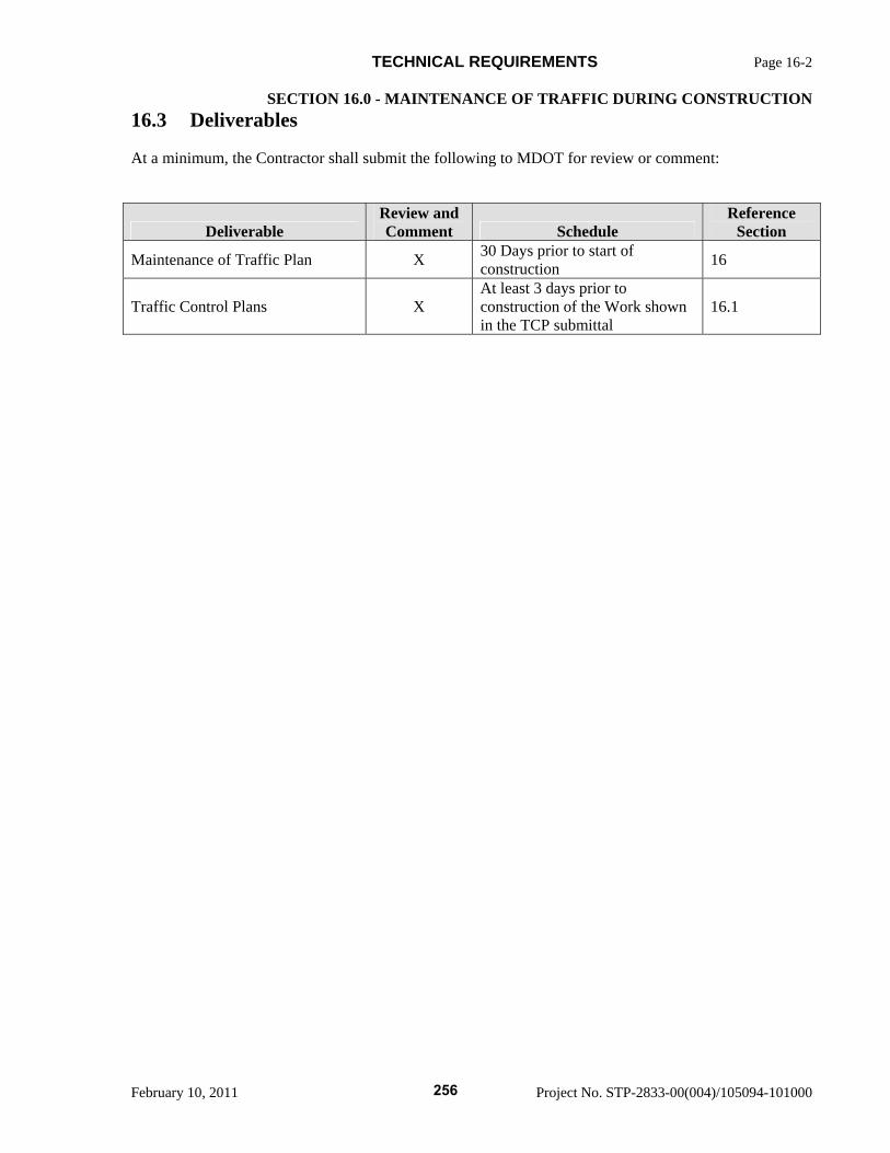
TECHNICAL REQUIREMENTS Page 16-2
SECTION 16.0 - MAINTENANCE OF TRAFFIC DURING CONSTRUCTION
February 10, 2011 Project No. STP-2833-00(004)/105094-101000
16.3 Deliverables
At a minimum, the Contractor shall submit the following to MDOT for review or comment:
Deliverable Review and Comment Schedule
Reference Section
Maintenance of Traffic Plan X 30 Days prior to start of construction 16
Traffic Control Plans X At least 3 days prior to construction of the Work shown in the TCP submittal
16.1
256
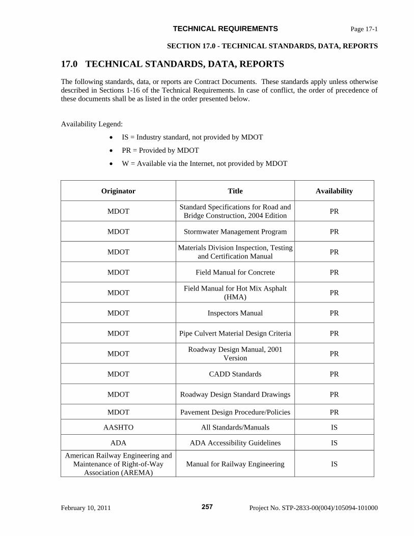
TECHNICAL REQUIREMENTS Page 17-1
SECTION 17.0 - TECHNICAL STANDARDS, DATA, REPORTS
February 10, 2011 Project No. STP-2833-00(004)/105094-101000
17.0 TECHNICAL STANDARDS, DATA, REPORTS
The following standards, data, or reports are Contract Documents. These standards apply unless otherwise described in Sections 1-16 of the Technical Requirements. In case of conflict, the order of precedence of these documents shall be as listed in the order presented below.
Availability Legend:
• IS = Industry standard, not provided by MDOT
• PR = Provided by MDOT
• W = Available via the Internet, not provided by MDOT
Originator Title Availability
MDOT Standard Specifications for Road and Bridge Construction, 2004 Edition PR
MDOT Stormwater Management Program PR
MDOT Materials Division Inspection, Testing and Certification Manual PR
MDOT Field Manual for Concrete PR
MDOT Field Manual for Hot Mix Asphalt (HMA) PR
MDOT Inspectors Manual PR
MDOT Pipe Culvert Material Design Criteria PR
MDOT Roadway Design Manual, 2001 Version PR
MDOT CADD Standards PR
MDOT Roadway Design Standard Drawings PR
MDOT Pavement Design Procedure/Policies PR
AASHTO All Standards/Manuals IS
ADA ADA Accessibility Guidelines IS
American Railway Engineering and Maintenance of Right-of-Way
Association (AREMA) Manual for Railway Engineering IS
257
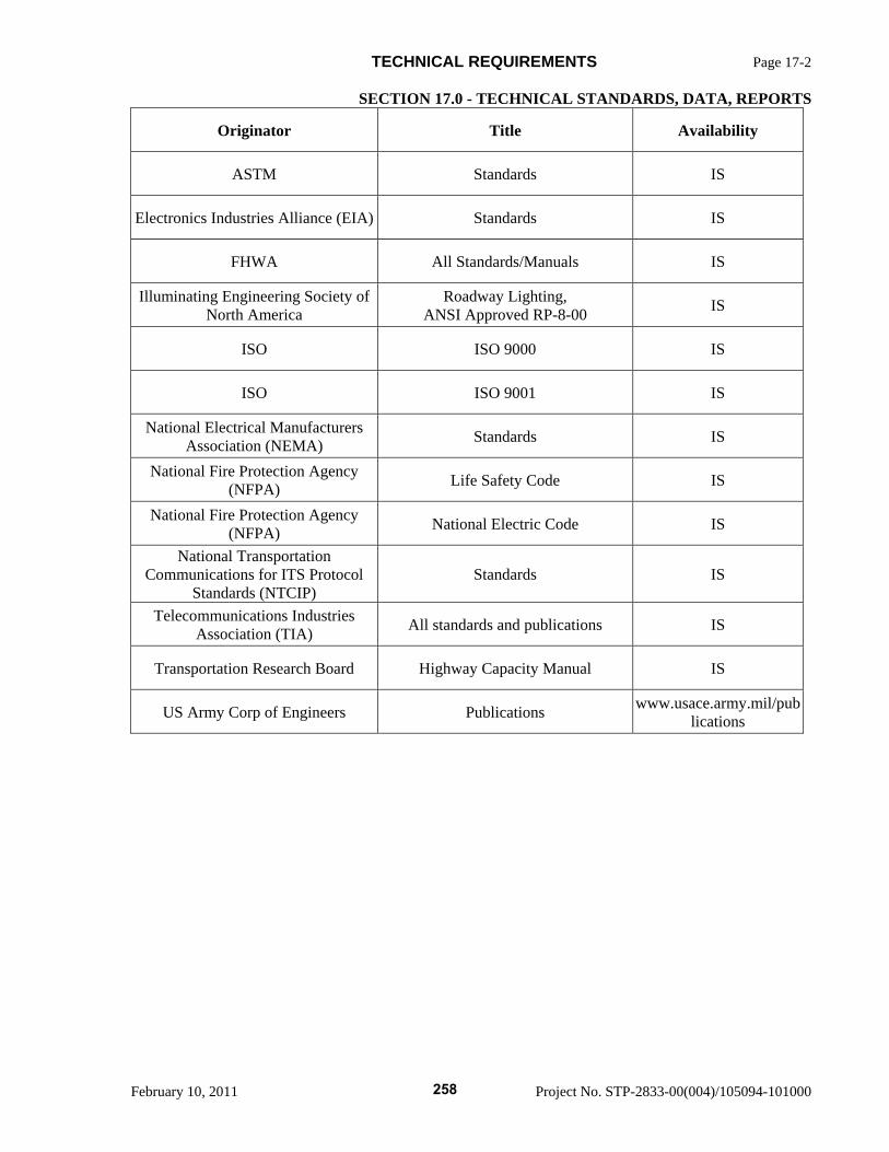
TECHNICAL REQUIREMENTS Page 17-2
SECTION 17.0 - TECHNICAL STANDARDS, DATA, REPORTS
February 10, 2011 Project No. STP-2833-00(004)/105094-101000
Originator Title Availability
ASTM Standards IS
Electronics Industries Alliance (EIA) Standards IS
FHWA All Standards/Manuals IS
Illuminating Engineering Society of North America
Roadway Lighting, ANSI Approved RP-8-00 IS
ISO ISO 9000 IS
ISO ISO 9001 IS
National Electrical Manufacturers Association (NEMA) Standards IS
National Fire Protection Agency (NFPA) Life Safety Code IS
National Fire Protection Agency (NFPA) National Electric Code IS
National Transportation Communications for ITS Protocol
Standards (NTCIP) Standards IS
Telecommunications Industries Association (TIA) All standards and publications IS
Transportation Research Board Highway Capacity Manual IS
US Army Corp of Engineers Publications www.usace.army.mil/publications
258
Mississippi Department of Transportation
Section 905
Proposal
Proposed Improvements to State Route 9 From US 278/State Route 6 near Pontotoc
To US 78 near Sherman Pontotoc County, Mississippi
Project No. STP-2833-00(004) / 105094-10100
February 10, 2011
259
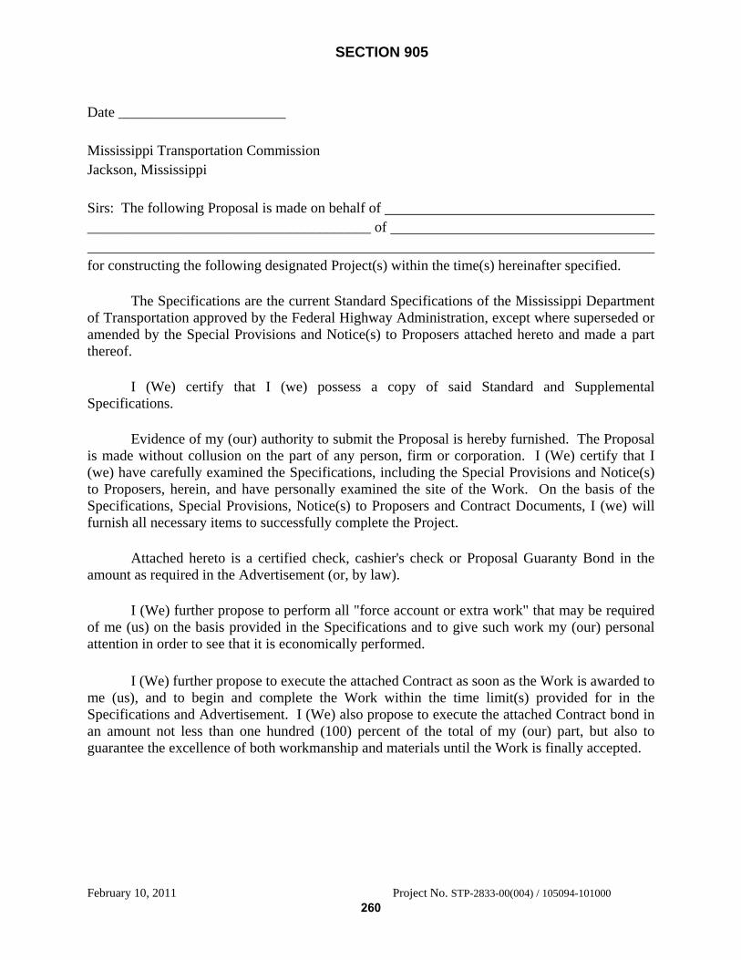
SECTION 905
February 10, 2011 Project No. STP-2833-00(004) / 105094-101000
Date _______________________
Mississippi Transportation Commission Jackson, Mississippi Sirs: The following Proposal is made on behalf of _______________________________________ of for constructing the following designated Project(s) within the time(s) hereinafter specified.
The Specifications are the current Standard Specifications of the Mississippi Department
of Transportation approved by the Federal Highway Administration, except where superseded or amended by the Special Provisions and Notice(s) to Proposers attached hereto and made a part thereof.
I (We) certify that I (we) possess a copy of said Standard and Supplemental
Specifications. Evidence of my (our) authority to submit the Proposal is hereby furnished. The Proposal
is made without collusion on the part of any person, firm or corporation. I (We) certify that I (we) have carefully examined the Specifications, including the Special Provisions and Notice(s) to Proposers, herein, and have personally examined the site of the Work. On the basis of the Specifications, Special Provisions, Notice(s) to Proposers and Contract Documents, I (we) will furnish all necessary items to successfully complete the Project.
Attached hereto is a certified check, cashier's check or Proposal Guaranty Bond in the
amount as required in the Advertisement (or, by law).
I (We) further propose to perform all "force account or extra work" that may be required of me (us) on the basis provided in the Specifications and to give such work my (our) personal attention in order to see that it is economically performed.
I (We) further propose to execute the attached Contract as soon as the Work is awarded to
me (us), and to begin and complete the Work within the time limit(s) provided for in the Specifications and Advertisement. I (We) also propose to execute the attached Contract bond in an amount not less than one hundred (100) percent of the total of my (our) part, but also to guarantee the excellence of both workmanship and materials until the Work is finally accepted.
260
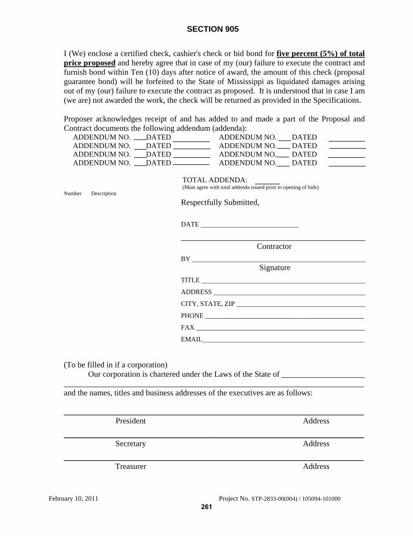
SECTION 905
February 10, 2011 Project No. STP-2833-00(004) / 105094-101000
I (We) enclose a certified check, cashier's check or bid bond for five percent (5%) of total price proposed and hereby agree that in case of my (our) failure to execute the contract and furnish bond within Ten (10) days after notice of award, the amount of this check (proposal guarantee bond) will be forfeited to the State of Mississippi as liquidated damages arising out of my (our) failure to execute the contract as proposed. It is understood that in case I am (we are) not awarded the work, the check will be returned as provided in the Specifications. Proposer acknowledges receipt of and has added to and made a part of the Proposal and Contract documents the following addendum (addenda): ADDENDUM NO. DATED ADDENDUM NO. DATED ADDENDUM NO. DATED ADDENDUM NO. DATED ADDENDUM NO. DATED ADDENDUM NO. DATED ADDENDUM NO. DATED ADDENDUM NO. DATED TOTAL ADDENDA: (Must agree with total addenda issued prior to opening of bids) Number Description
Respectfully Submitted, DATE
Contractor BY Signature TITLE
ADDRESS
CITY, STATE, ZIP
PHONE _______________________________________________
FAX __________________________________________________
EMAIL________________________________________________
(To be filled in if a corporation) Our corporation is chartered under the Laws of the State of ____________________
__________________________________________________________________________and the names, titles and business addresses of the executives are as follows: __________________________________________________________________________ President Address
__________________________________________________________________________ Secretary Address
__________________________________________________________________________ Treasurer Address
261
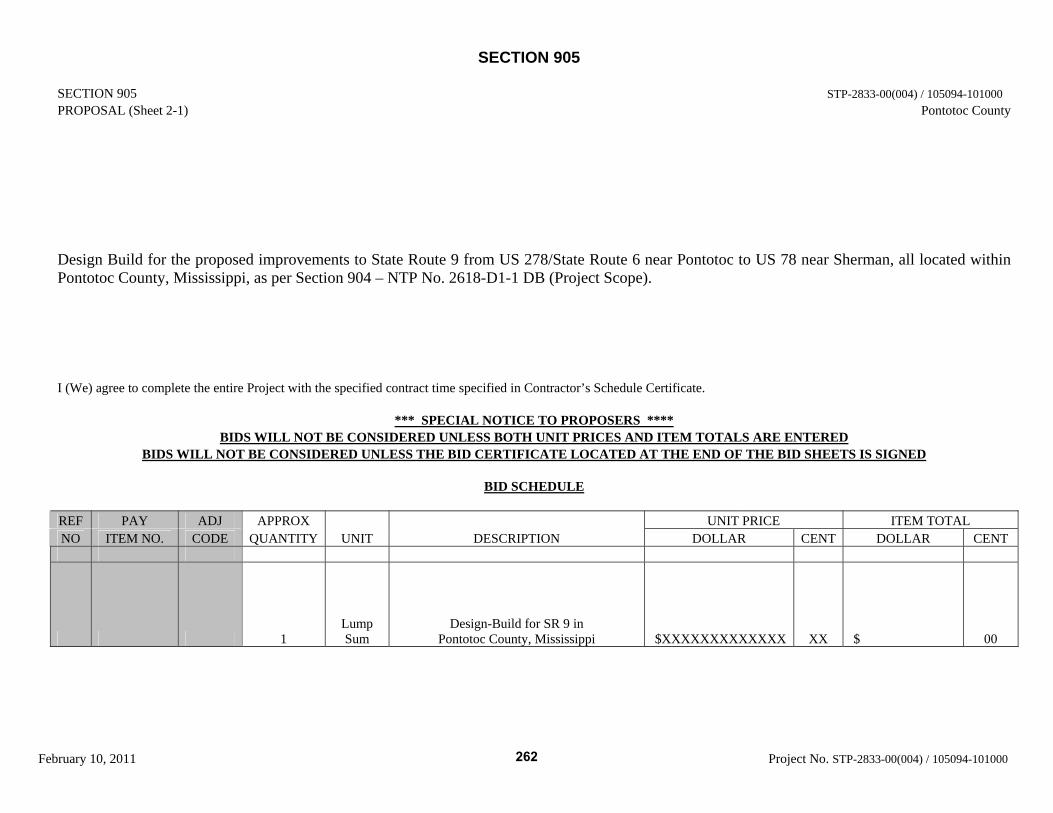
SECTION 905
February 10, 2011 Project No. STP-2833-00(004) / 105094-101000
SECTION 905 STP-2833-00(004) / 105094-101000 PROPOSAL (Sheet 2-1) Pontotoc County
Design Build for the proposed improvements to State Route 9 from US 278/State Route 6 near Pontotoc to US 78 near Sherman, all located within Pontotoc County, Mississippi, as per Section 904 – NTP No. 2618-D1-1 DB (Project Scope).
I (We) agree to complete the entire Project with the specified contract time specified in Contractor’s Schedule Certificate.
*** SPECIAL NOTICE TO PROPOSERS **** BIDS WILL NOT BE CONSIDERED UNLESS BOTH UNIT PRICES AND ITEM TOTALS ARE ENTERED
BIDS WILL NOT BE CONSIDERED UNLESS THE BID CERTIFICATE LOCATED AT THE END OF THE BID SHEETS IS SIGNED
BID SCHEDULE REF PAY ADJ APPROX UNIT PRICE ITEM TOTAL NO ITEM NO. CODE QUANTITY UNIT DESCRIPTION DOLLAR CENT DOLLAR CENT
1 Lump Sum
Design-Build for SR 9 in Pontotoc County, Mississippi $XXXXXXXXXXXXX XX $ 00
262
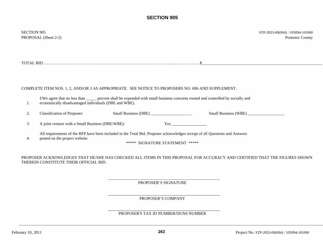
SECTION 905
February 10, 2011 Project No. STP-2833-00(004) / 105094-101000
SECTION 905 STP-2833-00(004) / 105094-101000 PROPOSAL (Sheet 2-2) Pontotoc County TOTAL BID………….………………………………………………………………………..………….. ……$___________________________________________________________ COMPLETE ITEM NOS. 1, 2, AND/OR 3 AS APPROPRIATE. SEE NOTICE TO PROPOSERS NO. 696 AND SUPPLEMENT.
1. I/We agree that no less than _____ percent shall be expended with small business concerns owned and controlled by socially and economically disadvantaged individuals (DBE and WBE).
2. Classification of Proposer: Small Business (DBE) ____________________ Small Business (WBE) __________________
3. A joint venture with a Small Business (DBE/WBE): Yes _________________
4. All requirements of the RFP have been included in the Total Bid. Proposer acknowledges receipt of all Questions and Answers posted on the project website.
***** SIGNATURE STATEMENT ***** PROPOSER ACKNOWLEDGES THAT HE/SHE HAS CHECKED ALL ITEMS IN THIS PROPOSAL FOR ACCURACY AND CERTIFIED THAT THE FIGURES SHOWN THEREIN CONSTITUTE THEIR OFFICIAL BID. PROPOSER’S SIGNATURE PROPOSER’S COMPANY PROPOSER'S TAX ID NUMBER/DUNS NUMBER
263
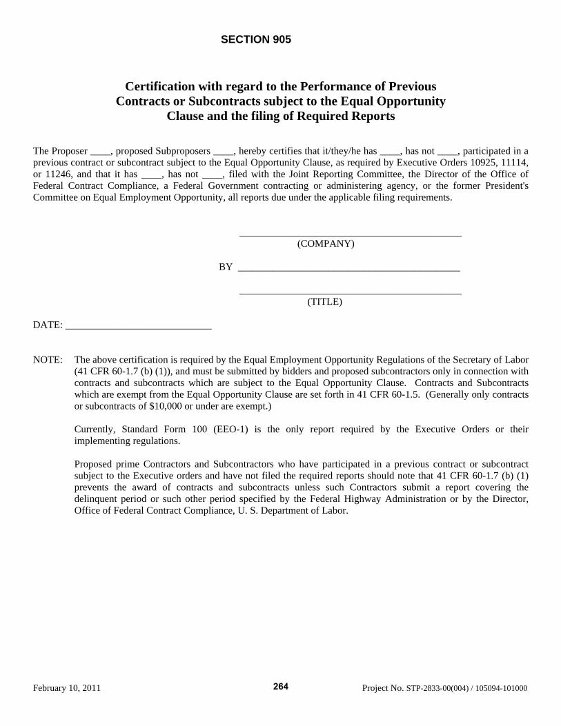
SECTION 905
February 10, 2011 Project No. STP-2833-00(004) / 105094-101000
Certification with regard to the Performance of Previous
Contracts or Subcontracts subject to the Equal Opportunity Clause and the filing of Required Reports
The Proposer ____, proposed Subproposers ____, hereby certifies that it/they/he has ____, has not ____, participated in a previous contract or subcontract subject to the Equal Opportunity Clause, as required by Executive Orders 10925, 11114, or 11246, and that it has ____, has not ____, filed with the Joint Reporting Committee, the Director of the Office of Federal Contract Compliance, a Federal Government contracting or administering agency, or the former President's Committee on Equal Employment Opportunity, all reports due under the applicable filing requirements.
____________________________________________ (COMPANY)
BY ____________________________________________
____________________________________________ (TITLE)
DATE: _____________________________ NOTE: The above certification is required by the Equal Employment Opportunity Regulations of the Secretary of Labor
(41 CFR 60-1.7 (b) (1)), and must be submitted by bidders and proposed subcontractors only in connection with contracts and subcontracts which are subject to the Equal Opportunity Clause. Contracts and Subcontracts which are exempt from the Equal Opportunity Clause are set forth in 41 CFR 60-1.5. (Generally only contracts or subcontracts of $10,000 or under are exempt.)
Currently, Standard Form 100 (EEO-1) is the only report required by the Executive Orders or their implementing regulations. Proposed prime Contractors and Subcontractors who have participated in a previous contract or subcontract subject to the Executive orders and have not filed the required reports should note that 41 CFR 60-1.7 (b) (1) prevents the award of contracts and subcontracts unless such Contractors submit a report covering the delinquent period or such other period specified by the Federal Highway Administration or by the Director, Office of Federal Contract Compliance, U. S. Department of Labor.
264
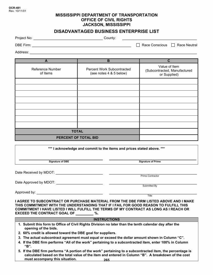
OCR-481Rev. 10/11/01
MISSISSIPPI DEPARTMENT OF TRANSPORTATION OFFICE OF CIVIL RIGHTS JACKSON, MISSISSIPPI
DISADVANTAGED BUSINESS ENTERPRISE LIST Project No: County:
DBE Firm: Race Conscious Race Neutral
Address:
A B C
Reference Number of Items
Percent Work Subcontracted (see notes 4 & 5 below)
Value of Item (Subcontracted, Manufactured
or Supplied)
TOTAL
PERCENT OF TOTAL BID
*** I acknowledge and commit to the items and prices stated above. ***
Signature of DBE Signature of Prime
Date Received by MDOT:Prime Contractor
Date Approved by MDOT:Submitted By
Approved by:Title
I AGREE TO SUBCONTRACT OR PURCHASE MATERIAL FROM THE DBE FIRM LISTED ABOVE AND I MAKE THIS COMMITMENT WITH THE UNDERSTANDING THAT IF I FAIL FOR GOOD REASON TO FULFILL THIS COMMITMENT I HAVE LISTED I WILL FULFILL THE TERMS OF MY CONTRACT AS LONG AS I REACH OR EXCEED THE CONTRACT GOAL OF %.
INSTRUCTIONS1. Submit this form to Office of Civil Rights Division no later than the tenth calendar day after the
opening of the bids. 2. 60% credit is allowed toward the DBE goal for suppliers. 3. The actual subcontract agreement must equal or exceed the dollar amount shown in Column “C”. 4. If the DBE firm performs “All of the work” pertaining to a subcontracted item, enter 100% in Column
“B”.5. If the DBE firm performs “A portion of the work” pertaining to a subcontracted item, the percentage is
calculated based on the total value of the item and entered in Column “B”. A breakdown of the cost must accompany this situation. 265

SECTION 905
February 10, 2011 Project No. STP-2833-00(004) / 105094-101000
Insert Contractor Schedule of Values
266
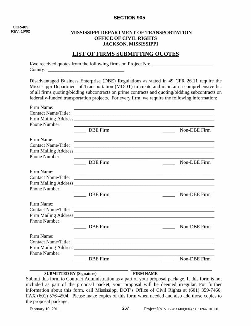
SECTION 905
February 10, 2011 Project No. STP-2833-00(004) / 105094-101000
MISSISSIPPI DEPARTMENT OF TRANSPORTATION OFFICE OF CIVIL RIGHTS
JACKSON, MISSISSIPPI
LIST OF FIRMS SUBMITTING QUOTES
I/we received quotes from the following firms on Project No: _________________________ County: _______________________________
Disadvantaged Business Enterprise (DBE) Regulations as stated in 49 CFR 26.11 require the Mississippi Department of Transportation (MDOT) to create and maintain a comprehensive list of all firms quoting/bidding subcontracts on prime contracts and quoting/bidding subcontracts on federally-funded transportation projects. For every firm, we require the following information: Firm Name: _________________________________________________________ Contact Name/Title: _________________________________________________________ Firm Mailing Address _________________________________________________________ Phone Number: _________________________________________________________ _____ DBE Firm _____ Non-DBE Firm Firm Name: _________________________________________________________ Contact Name/Title: _________________________________________________________ Firm Mailing Address _________________________________________________________ Phone Number: _________________________________________________________ _____ DBE Firm _____ Non-DBE Firm Firm Name: _________________________________________________________ Contact Name/Title: _________________________________________________________ Firm Mailing Address _________________________________________________________ Phone Number: _________________________________________________________ _____ DBE Firm _____ Non-DBE Firm Firm Name: _________________________________________________________ Contact Name/Title: _________________________________________________________ Firm Mailing Address _________________________________________________________ Phone Number: _________________________________________________________ _____ DBE Firm _____ Non-DBE Firm Firm Name: _________________________________________________________ Contact Name/Title: _________________________________________________________ Firm Mailing Address _________________________________________________________ Phone Number: _________________________________________________________ _____ DBE Firm _____ Non-DBE Firm ________________________________________ _________________________________ SUBMITTED BY (Signature) FIRM NAME
Submit this form to Contract Administration as a part of your proposal package. If this form is not included as part of the proposal packet, your proposal will be deemed irregular. For further information about this form, call Mississippi DOT’s Office of Civil Rights at (601) 359-7466; FAX (601) 576-4504. Please make copies of this form when needed and also add those copies to the proposal package.
OCR-485 REV. 10/02
267

SECTION 905
February 10, 2011 Project No. STP-2833-00(004) / 105094-101000
MISSISSIPPI DEPARTMENT OF TRANSPORTATION
DEBARMENT
CERTIFICATION
(Execute in duplicate) State of Mississippi County of _________________________________ I,___________________________________________________________________________________, (Name of person signing certification) individually, and in my capacity as ______________________________________________________of (Title) _______________________________________________________________ do hereby certify under (Name of Firm, Partnership, or Corporation) penalty of perjury under the laws of the United States and the State of Mississippi that _______________ ____________________________________________________________________________, Proposer (Name of Firm, Partnership, or Corporation) on Project No. ______________________________________________________________________, in __________________________________________________ County(ies), Mississippi, has not either directly or indirectly entered into any agreement, participated in any collusion; or otherwise taken any action in restraint of free competitive proposing in connection with this contract; nor have any of its corporate officers or principal owners. Except as noted hereafter, it is further certified that said legal entity and its corporate officers, principal owners, managers, auditors and others in a position of administering federal funds:
a) Are not presently debarred, suspended, proposed for debarment, declared ineligible, or voluntarily excluded from covered transactions by any Federal department or agency;
b) Have not within a three-year period preceding this Proposal been convicted of or had a civil
judgment rendered against them for commission of fraud or a criminal offense in connection with obtaining, attempting to obtain, or performing a public (Federal, State or local) transaction or contract under a public transaction; violation of Federal or State antitrust statutes or commission of embezzlement, theft, forgery, bribery, falsification or destruction of records, making false statements, or receiving stolen property;
c) Are not presently indicted for or otherwise criminally or civilly charged by a governmental
entity (Federal, State or local) with commission of any of the offenses enumerated in (b) above; and
d) Have not within a three-year period preceding this application/ Proposal had one or more
public transactions (Federal, State or local) terminated for cause or default. Initial here "______" if exceptions are attached and made a part thereof. Any exceptions shall address to whom it applies, initiating agency and dates of such action.
268
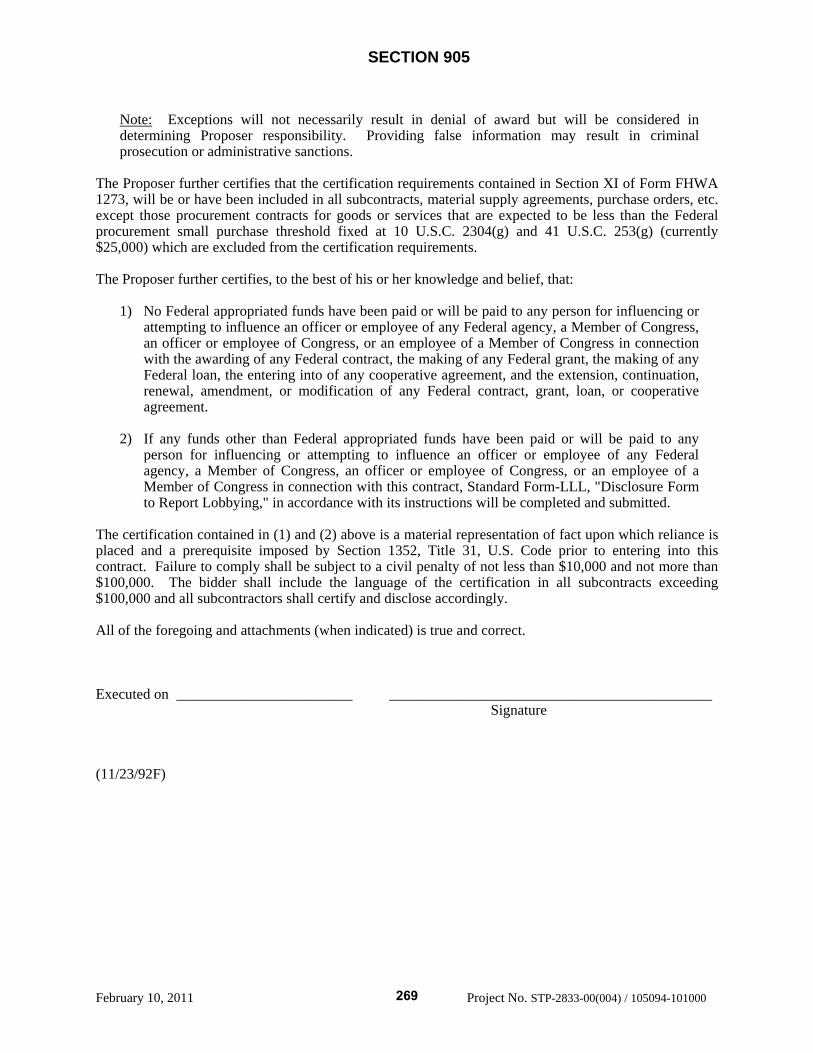
SECTION 905
February 10, 2011 Project No. STP-2833-00(004) / 105094-101000
Note: Exceptions will not necessarily result in denial of award but will be considered in determining Proposer responsibility. Providing false information may result in criminal prosecution or administrative sanctions.
The Proposer further certifies that the certification requirements contained in Section XI of Form FHWA 1273, will be or have been included in all subcontracts, material supply agreements, purchase orders, etc. except those procurement contracts for goods or services that are expected to be less than the Federal procurement small purchase threshold fixed at 10 U.S.C. 2304(g) and 41 U.S.C. 253(g) (currently $25,000) which are excluded from the certification requirements. The Proposer further certifies, to the best of his or her knowledge and belief, that:
1) No Federal appropriated funds have been paid or will be paid to any person for influencing or attempting to influence an officer or employee of any Federal agency, a Member of Congress, an officer or employee of Congress, or an employee of a Member of Congress in connection with the awarding of any Federal contract, the making of any Federal grant, the making of any Federal loan, the entering into of any cooperative agreement, and the extension, continuation, renewal, amendment, or modification of any Federal contract, grant, loan, or cooperative agreement.
2) If any funds other than Federal appropriated funds have been paid or will be paid to any
person for influencing or attempting to influence an officer or employee of any Federal agency, a Member of Congress, an officer or employee of Congress, or an employee of a Member of Congress in connection with this contract, Standard Form-LLL, "Disclosure Form to Report Lobbying," in accordance with its instructions will be completed and submitted.
The certification contained in (1) and (2) above is a material representation of fact upon which reliance is placed and a prerequisite imposed by Section 1352, Title 31, U.S. Code prior to entering into this contract. Failure to comply shall be subject to a civil penalty of not less than $10,000 and not more than $100,000. The bidder shall include the language of the certification in all subcontracts exceeding $100,000 and all subcontractors shall certify and disclose accordingly. All of the foregoing and attachments (when indicated) is true and correct. Executed on ________________________ ____________________________________________ Signature (11/23/92F)
269
SECTION 905
February 10, 2011 Project No. STP-2833-00(004) / 105094-101000
MISSISSIPPI DEPARTMENT OF TRANSPORTATION
DEBARMENT
CERTIFICATION
(Execute in duplicate) State of Mississippi County of _________________________________ I,___________________________________________________________________________________, (Name of person signing certification) individually, and in my capacity as ______________________________________________________of (Title) _______________________________________________________________ do hereby certify under (Name of Firm, Partnership, or Corporation) penalty of perjury under the laws of the United States and the State of Mississippi that _______________ ____________________________________________________________________________, Proposer (Name of Firm, Partnership, or Corporation) on Project No. ______________________________________________________________________, in __________________________________________________ County(ies), Mississippi, has not either directly or indirectly entered into any agreement, participated in any collusion; or otherwise taken any action in restraint of free competitive proposing in connection with this contract; nor have any of its corporate officers or principal owners. Except as noted hereafter, it is further certified that said legal entity and its corporate officers, principal owners, managers, auditors and others in a position of administering federal funds:
a) Are not presently debarred, suspended, proposed for debarment, declared ineligible, or voluntarily excluded from covered transactions by any Federal department or agency;
b) Have not within a three-year period preceding this Proposal been convicted of or had a civil
judgment rendered against them for commission of fraud or a criminal offense in connection with obtaining, attempting to obtain, or performing a public (Federal, State or local) transaction or contract under a public transaction; violation of Federal or State antitrust statutes or commission of embezzlement, theft, forgery, bribery, falsification or destruction of records, making false statements, or receiving stolen property;
c) Are not presently indicted for or otherwise criminally or civilly charged by a governmental
entity (Federal, State or local) with commission of any of the offenses enumerated in (b) above; and
d) Have not within a three-year period preceding this application/ Proposal had one or more
public transactions (Federal, State or local) terminated for cause or default. Initial here "______" if exceptions are attached and made a part thereof. Any exceptions shall address to whom it applies, initiating agency and dates of such action.
270

SECTION 905
February 10, 2011 Project No. STP-2833-00(004) / 105094-101000
Note: Exceptions will not necessarily result in denial of award but will be considered in determining Proposer responsibility. Providing false information may result in criminal prosecution or administrative sanctions.
The Proposer further certifies that the certification requirements contained in Section XI of Form FHWA 1273, will be or have been included in all subcontracts, material supply agreements, purchase orders, etc. except those procurement contracts for goods or services that are expected to be less than the Federal procurement small purchase threshold fixed at 10 U.S.C. 2304(g) and 41 U.S.C. 253(g) (currently $25,000) which are excluded from the certification requirements. The Proposer further certifies, to the best of his or her knowledge and belief, that:
1) No Federal appropriated funds have been paid or will be paid to any person for influencing or attempting to influence an officer or employee of any Federal agency, a Member of Congress, an officer or employee of Congress, or an employee of a Member of Congress in connection with the awarding of any Federal contract, the making of any Federal grant, the making of any Federal loan, the entering into of any cooperative agreement, and the extension, continuation, renewal, amendment, or modification of any Federal contract, grant, loan, or cooperative agreement.
2) If any funds other than Federal appropriated funds have been paid or will be paid to any
person for influencing or attempting to influence an officer or employee of any Federal agency, a Member of Congress, an officer or employee of Congress, or an employee of a Member of Congress in connection with this contract, Standard Form-LLL, "Disclosure Form to Report Lobbying," in accordance with its instructions will be completed and submitted.
The certification contained in (1) and (2) above is a material representation of fact upon which reliance is placed and a prerequisite imposed by Section 1352, Title 31, U.S. Code prior to entering into this contract. Failure to comply shall be subject to a civil penalty of not less than $10,000 and not more than $100,000. The bidder shall include the language of the certification in all subcontracts exceeding $100,000 and all subcontractors shall certify and disclose accordingly. All of the foregoing and attachments (when indicated) is true and correct. Executed on ________________________ ____________________________________________ Signature (11/23/92F)
271
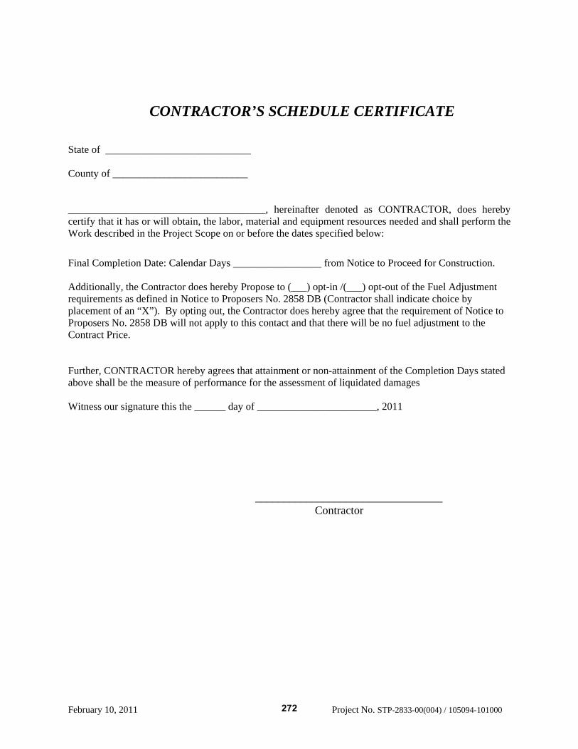
February 10, 2011 Project No. STP-2833-00(004) / 105094-101000
CONTRACTOR’S SCHEDULE CERTIFICATE State of ____________________________ County of __________________________ ______________________________________, hereinafter denoted as CONTRACTOR, does hereby certify that it has or will obtain, the labor, material and equipment resources needed and shall perform the Work described in the Project Scope on or before the dates specified below: Final Completion Date: Calendar Days _________________ from Notice to Proceed for Construction. Additionally, the Contractor does hereby Propose to (___) opt-in /(___) opt-out of the Fuel Adjustment requirements as defined in Notice to Proposers No. 2858 DB (Contractor shall indicate choice by placement of an “X”). By opting out, the Contractor does hereby agree that the requirement of Notice to Proposers No. 2858 DB will not apply to this contact and that there will be no fuel adjustment to the Contract Price. Further, CONTRACTOR hereby agrees that attainment or non-attainment of the Completion Days stated above shall be the measure of performance for the assessment of liquidated damages Witness our signature this the ______ day of _______________________, 2011
_________________________________ Contractor
272
Mississippi Department of Transportation
Section 902
Proposed Improvements to State Route 9 From US 278/State Route 6 near Pontotoc
To US 78 near Sherman Pontotoc County, Mississippi
Project No. STP-2833-00(004)105094-101000
February 10, 2010
273
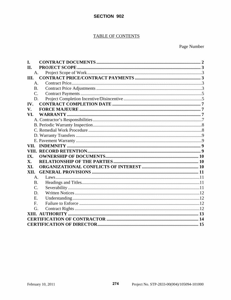
SECTION 902
February 10, 2011 Project No. STP-2833-00(004)/105094-101000
TABLE OF CONTENTS Page Number I. CONTRACT DOCUMENTS ............................................................................................ 2 II. PROJECT SCOPE ............................................................................................................. 3
A. Project Scope of Work .....................................................................................................3 III. CONTRACT PRICE/CONTRACT PAYMENTS .......................................................... 3
A. Contract Price...................................................................................................................3 B. Contract Price Adjustments .............................................................................................3 C. Contract Payments ...........................................................................................................5 D. Project Completion Incentive/Disincentive .....................................................................5
IV. CONTRACT COMPLETION DATE .............................................................................. 7 V. FORCE MAJEURE ........................................................................................................... 7 VI. WARRANTY ...................................................................................................................... 7
A. Contractor’s Responsibilities ................................................................................................7 B. Periodic Warranty Inspection................................................................................................8 C. Remedial Work Procedure ....................................................................................................8 D. Warranty Transfers ...............................................................................................................9 E. Pavement Warranty ...............................................................................................................9
VII. INDEMNITY ...................................................................................................................... 9 VIII. RECORD RETENTION.................................................................................................... 9 IX. OWNERSHIP OF DOCUMENTS.................................................................................. 10 X. RELATIONSHIP OF THE PARTIES........................................................................... 10 XI. ORGANIZATIONAL CONFLICTS OF INTEREST .................................................. 10 XII. GENERAL PROVISIONS .............................................................................................. 11
A. Laws...............................................................................................................................11 B. Headings and Titles........................................................................................................11 C. Severability ....................................................................................................................11 D. Written Notices ..............................................................................................................12 E. Understanding ................................................................................................................12 F. Failure to Enforce ..........................................................................................................12 G. Contract Rights ..............................................................................................................12
XIII. AUTHORITY ................................................................................................................... 13 CERTIFICATION OF CONTRACTOR ................................................................................. 14 CERTIFICATION OF DIRECTOR......................................................................................... 15
274
February 10, 2011 Project No. STP-2833-00(004)/105094-101000
CONTRACT FOR STP-2833-00(004) / 105094-101000 LOCATED IN THE COUNTY OF PONTOTOC STATE OF MISSISSIPPI, COUNTY OF HINDS
THIS CONTRACT IS EXECUTED BY AND BETWEEN THE MISSISSIPPI TRANSPORTATION COMMISSION, A BODY CORPORATE OF THE STATE OF MISSISSIPPI, (“COMMISSION’) AND THE UNDERSIGNED CONTRACTOR, AN ENTITY DULY AUTHORIZED TO DO BUSINESS IN THE STATE OF MISSISSIPPI, (“CONTRACTOR”) EFFECTIVE AS OF THE DATE OF LATEST EXECUTION BELOW. WITNESSETH: THAT WHEREAS, the people of the State of Mississippi will benefit from the construction of the said Proposed Improvements to State Route 9 from US 278/State Route 6 near Pontotoc to US 78 near Sherman in Pontotoc County, Mississippi (hereinafter referred to as “the Project”), due to existing roadway deficiencies that present safety concerns, access to the Toyota Plant in Blue Springs, and improvement of the local infrastructure and access; and WHEREAS, the Commission, desires the completion of this strategic Project, as it is in the best interest of the people of the State of Mississippi; and WHEREAS, the Commission, working with the people, the federal government, and other agencies of the State of Mississippi, has devised an innovative plan to allow the commencement and completion of the Project in a timely and cost-effective manner; and WHEREAS, the Commission is authorized under the provision of Section 65-1-85, Miss. Code Ann. (1972) to utilize the design/build method of procurement to design and construct the Project; and WHEREAS, after a competitive process, Contractor has been selected to participate in this venture by designing and building the Project; and WHEREAS, the Commission desires to avail itself of and rely upon Contractor’s expertise and proven track record in designing and constructing such projects, on time and within budget; and WHEREAS, the Contractor wishes to provide that expertise and to participate in this venture for the good of the people of the State of Mississippi; NOW THEREFORE, for and in consideration of the mutual promises and covenants hereinafter set forth, the Commission and the Contractor mutually agree as follows:
275
SECTION 902 Page 2 of 15
February 10, 2011 Project No. STP-2833-00(004)/105094-101000
I. CONTRACT DOCUMENTS The Contract shall be composed of all items (listed A through M) below, and any amendments thereto. Each of these documents below are an essential part of the Contract. The documents are intended to be complimentary and are intended to be read as a complete Contract. In case of conflict, ambiguity or inconsistency the order of precedence, from highest to lowest, of the Contract documents shall be: A. Section 902 B. Exhibits to Section 902 Exhibit 1 – Geotechnical Report, by MDOT Exhibit 2 – Environmental Document (EA/FONSI), by MDOT Exhibit 3 – Permits secured by MDOT Exhibit 4 – Erosion Control Standards Exhibit 5 – Bridge Plans, by MDOT Exhibit 6 – Bridge Hydraulic Reports/Data, by MDOT Exhibit 7 – Right-of-Way Maps, by MDOT Exhibit 8 – Utility Plans, by MDOT C. Section 904
Supplements to Notice to Proposers Notice to Proposers
D. Section 905 E. Section 906 Supplement to Form FHWA-1273
Minimum Hourly Wage Rates Federal-Aid Construction Contracts (Form FHWA-1273) Notice of Requirements for Affirmative Action to Ensure Equal Employment
Opportunity (Executive Order 11246) F. Section 907 Supplements to Special Provisions Special Provisions G. Contractor’s Proposal – Contractor’s Technical Proposal – Volume 1 – (Only those items
that are a higher standard than the Technical Requirements.) H. Technical Requirements for Design and Construction I. Final Design Documents (provided by Contractor) J. Section 903 Contract Bond K. Contractors Proposal Volume 1 (Except those items that are a higher standard than the
Technical Requirements.) L. Request for Proposals and Addenda, if any M. Proposer’s (Contractor’) Statement of Qualifications
276
SECTION 902 Page 3 of 15
February 10, 2011 Project No. STP-2833-00(004)/105094-101000
II. PROJECT SCOPE A. Project Scope of Work Contractor shall furnish all services, labor, materials, equipment, supplies, tools, transportation, and coordination required to perform all preliminary and final engineering, surveying, geotechnical services, scheduling, permitting, procurement, construction, quality control, material testing, traffic control, and any other services necessary to perform the Project. The Project Scope shall be as defined in Section 904 – NTP No. 2618-D1-1 DB and the Contractor’s Schedule Certificate. III. CONTRACT PRICE/CONTRACT PAYMENTS A. Contract Price The “Contract Price” shall be the amount shown on Section 905 sheet 2-2. In consideration for the Contract Price, Contractor shall perform all of its responsibilities under the Contract. The Contract Price shall include all Work identified in the Project Scope of Work. B. Contract Price Adjustments
1. Allowable adjustments The Contract Price may only be adjusted due to any of the following occurrences:
(a) Commission approved Scope changes, value engineering proposals,
directives or authorized extra work.
(b) Acts or omissions by Commission or its duly appointed representative that unreasonably interfere with the Contractor’s performance and cause delay of Work on the critical path of the Project.
(c) Changes in a legal requirement or regulation that becomes effective subsequent to the date of this Contract.
(d) Discovery of Hazardous Materials not discoverable from a reasonable
investigation and analysis of the site prior to the submission of the Proposal or as allowed in Section V below.
(e) Discovery of archeological or paleontological sites, as noted in Subsection 203.03.1 of the Standard Specifications that was not discoverable from a reasonable investigation and analysis of the Site prior to the Proposal Date.
(f) Fuel and/or material adjustment as per NTP 2858 DB.
277
SECTION 902 Page 4 of 15
February 10, 2011 Project No. STP-2833-00(004)/105094-101000
Other than as provided above, the Contract Price shall not be increased for Contract price adjustments or claimed delay damages. The basis for any allowable price adjustment will be a negotiated amount or by Force Account in accordance with Section 109.04 of the Contract.
2. Changes
(a) A “Change” shall be any deviation or variation from the Project Scope, the
Design Criteria or the Construction Criteria of the Project as originally set forth in this Contract. No Change shall be implemented prior to execution of an appropriate Supplemental Agreement. A “Change” may be an “Additive Change” or a “Deductive Change”.
(b) MDOT may initiate a Change by advising Contractor in writing of the change. Within seven (7) days, Contractor shall prepare and forward to MDOT an estimate of cost or savings, and the impact to the schedule resulting from the change. An independent cost estimate may or may not be performed by the Commission’s duly authorized representative. Parties to the Contract will then negotiate in good faith partnering efforts to agree on scope and cost impacts. MDOT will advise the Contractor in writing of its approval or disapproval of the change. If the Commission approves the change, the Contractor shall perform the Services as changed.
3. Construction Change Directive
A Construction Change Directive is a written order from MDOT directing a change prior to agreement with the Contractor on adjustment, if any, to the Contract Price or Contract Time.
4. Direct Costs for Construction Change Directive For the purpose of a Contract Price Adjustment, “Direct Costs” shall be defined as:
(a) costs of labor, including social security, unemployment insurance, fringe
benefits required by agreement or custom, and workers’ compensation insurance;
(b) costs of labor for QC, surveying and erosion control or fees paid for this
Work directly attributable to the change or event;
(c) costs of materials, supplies, and equipment, including cost of transportation, whether incorporated or consumed;
(d) depreciated time value of machinery and equipment owned by Contractor
or any affiliated or related entity exclusive of hand tools;
278
SECTION 902 Page 5 of 15
February 10, 2011 Project No. STP-2833-00(004)/105094-101000
(e) actual costs paid for rental of machinery and equipment exclusive of hand tools;
(f) costs of premiums for all bonds and insurance, permit fees, and sales, use
or similar taxes;
(g) additional costs of supervision and field office personnel directly attributable to the change or event; and
(h) Costs incurred or fees paid for design work related to the change or event.
C. Contract Payments Mobilization shall not exceed 5% of the Contract Price. MDOT will make Contract Payments in accordance with Subsection 907-109.06 and 907-109.11 of the Technical Standards, Supplements to Special Provisions, and Special Provisions. D. Project Completion Incentive/Disincentive This project was awarded to the Best Value Proposer in which part of the best value determination was based upon the Proposer’s specified completion date. The Commission desires to have the project completed by this date. The Contractor will be awarded an incentive payment for the early completion of the project in the amount of $50,000.00 per day for each day in advance of the specified completion date up to a maximum of $5,000,000.00. The Contractor will be assessed a disincentive fine for the failure to complete the project in the amount of $50,000.00 per day for each day past the specified project completion date. The parties to this contract anticipate that delays may be caused by or arise from any number of events during the course of the Contract, including but not limited to work performed, work deleted, change orders, supplemental agreements, delays, disruptions, differing site conditions, utility conflicts, design changes/revisions or defects, extra work, right-of-way issues, permitting issues, action of suppliers, subcontractors or other contractors, actions by third parties, shop drawing approval process delays, plan review and approval process delays, weather, special events, holidays, suspension of Contractor’s operations or other such events, force, or factors sometimes experienced in highway and bridge construction work. Such delays or events and their potential impact on performance by the Contractor are specifically contemplated and acknowledged by the parties in entering into this Contract and shall not extend the completion date established by the Contractor. Further, any and all costs or impacts whatsoever incurred by the Contractor in accelerating the Contractor’s work to overcome or absorb such delays or event impacts in an effort to complete the Contract by the completion date, regardless of whether the Contractor successfully does so or not shall be the sole responsibility of the Contractor in every instance.
279
SECTION 902 Page 6 of 15
February 10, 2011 Project No. STP-2833-00(004)/105094-101000
If the Contractor can not work due to right-of-way acquisition originally determined by MDOT, utility conflicts that the Contractor can not design around, archeological and/or paleontological remains or a catastrophic event or a work stoppage due to a court order occurs through no fault of the Contractor that directly and substantially affects the Contractor’s operations on the Contract, the Contractor shall provide any and all documentation to the Commission within fourteen (14) calendar days of the event. The Commission will have fourteen (14) calendar days to review the Contractor’s request to extend the project completion date. If the Contractor and Commission are unable to reach an agreement, the Commission shall unilaterally determine the number of calendar days to extend the completion date and the Contractor shall have no right whatsoever to contest such determination, save and except that the Contractor establishes that the number of calendar day determined by the Commission was arbitrary or without any reasonable basis. The Contractor shall have no rights under the Contract to make any claim arising out of this Incentive/Disincentive provision except as is expressly set forth herein. As conditions precedent to the Contractor’s entitlement to an Incentive the Contactor must:
1. Actually complete the project as stated in the Contract, as determined by the Engineer, and obtain written verification of completion and acceptance from the Engineer on or before the project completion date.
2. The Contractor shall notify the Commission in writing within thirty (30) calendar days of receiving written verification of the project completion by the Engineer, that the Contractor elects to be paid the Incentive which the Contractor is eligible to be paid based upon the actual completion date, and such written notice shall constitute full a complete waiver, release and acknowledgement of satisfaction by the Contractor of any and all claims, causes of action, issues, demands, disputes, matters or controversies, of any nature or kind whatsoever, known or unknown, against the Commission, its employees, officers, agents, representatives, consultants, and their respective employees, officers and representatives, the Contractor has or may have as to the work performed. Work deleted, change orders, supplemental agreements, delays, disruptions, differing site conditions, utility conflicts, design changes/revisions or defects, extra work, Right-of-Way issues, permitting issues, actions of suppliers, subcontractors or other Contractors, actions by third parties, shop drawing approval process delays, plan review and approval process delays, weather, special events, holidays, suspension of the Contractor’s operations, extended or unabsorbed home office or job site overhead, lost profits, prime mark-up on subcontractor work, acceleration cost, any and all direct and indirect costs, and any other adverse impacts, events, conditions, circumstance or potential damages, on or pertaining to, or as to arising out of the Contract. This waiver, release and acknowledgement of satisfaction shall be all-inclusive and absolute, save any supplemental agreements that may be pending on the Contractor specified project completion date, which will be resolved within thirty (30) calendar days and prior to the eligible payment to the Contractor of the Incentive.
The Contractor shall have not right to any payment whatsoever if:
1. the Contractor fails to complete the project requirements; or 2. the Contractor fails to obtain written verification of completion of the project from the
280
SECTION 902 Page 7 of 15
February 10, 2011 Project No. STP-2833-00(004)/105094-101000
Engineer on or before the completion date; or 3. the Contractor fails to timely request the Incentive for any reason including but not
limited to the Contractor choosing not to fully waive, release and acknowledge satisfaction as set forth in item (2) above.
For project completion date requirements, should the Incentive provision conflict with any other provision in the Contract, then the Contract shall be interpreted in accordance with this provision. As to any Contract work, the Contractor will remain responsible for all such work and the continued maintenance thereof until such date as the Commission’s final acceptance of all work in accordance with the Contract documents and without regard to whether the Commission provided written verification of completion or whether the Incentive was earned and elected hereunder. IV. CONTRACT COMPLETION DATE The Contractor shall complete the Project by the date shown on the Contractor’s Schedule Certificate, Final Completion Date. V. FORCE MAJEURE Delays or failures of performance shall not constitute breach of the Contract if and to the extent such delays or failures of performance are caused by severe and not reasonably foreseeable occurrences beyond the control of the Commission or the Contractor, including, but not limited to: Acts of God or the public enemy; expropriation or confiscation of facilities; compliance with any order of any governmental authority other than the Commission or a party in privity with it; Acts of War; rebellion or sabotage or damages resulting there from; fires, floods, hurricanes, explosions, or accidents that require stoppage of the entire Work, riots or nationwide strikes or other concerted acts of workman, whether direct or indirect, encountering rare or endangered species or any similar causes, which are not within the control of the Commission or the Contractor respectively, and which by the exercise of reasonable diligence, the Commission or the Contractor are unable to prevent. Any expense attributable to such occurrence shall not entitle the Contractor to an adjustment in the Contract Price. Dates by which performance obligations are scheduled to be met will be extended for a period of time equal to the critical path time lost due to any delay so caused. VI. WARRANTY A. Contractor’s Responsibilities The Contractor warrants that it will perform all services in accordance with the standards of care and diligence normally practiced by recognized engineering and construction firms in
281
SECTION 902 Page 8 of 15
February 10, 2011 Project No. STP-2833-00(004)/105094-101000
performing services and obligations of a similar nature. The Contractor warrants that the project shall be fit for its intended purpose and that all materials and equipment furnished shall be of good quality and new unless otherwise authorized by the Commission and that the construction shall conform to the Contract requirements. The Contractor agrees to promptly correct, at its own expense, defects or deficiencies in design, materials and workmanship that appear prior to and during a period of two (2) years after Full Release of Maintenance. This shall include all work and plant materials (i.e. aggregate, concrete, etc.). The Contractor shall promptly perform, at the written request of the Commission, made at any time within the two (2) year period, all steps necessary to satisfy the foregoing warranty and correct any element of the Project or the services that is defective or does not reflect such standards of care and diligence or does not meet the requirements of the performance criteria outlined in the Contract. The warranty period begins upon the effective date of the Full Release of Maintenance as documented in writing in accordance with Special Provision No. 907- 105. With respect to any component that is repaired or replaced pursuant to this warranty, the warranty period of that component shall be the longer of one (1) year from repair or replacement of the component, or the remainder of the original warranty period. B. Periodic Warranty Inspection MDOT will conduct periodic inspection of the project at any time during the warranty period, including a final warranty inspection during the last month of the warranty period. MDOT will give the Contractor two weeks written notice of the time and date of each such inspection, which may be attended by representatives of the Contractor. The Contractor shall promptly perform, at the written request of the Commission made at any time within the two (2) year period, all steps necessary to satisfy the foregoing warranty and correct any element of the Project or the Services that does not meet the requirements of the performance criteria outlined in the Contract. The cost of such corrective services shall be the Contractor’s responsibility. C. Remedial Work Procedure Within thirty (30) days of notification of the discovery of any defect and prior to starting any remedial work, the Contractor will submit to MDOT in writing the precise scope of and schedule for the proposed remedial work. The Contractor will repair and warranty any covered defect in a timely manner. Should the Contractor fail to respond to written notification from the Commission or its duly appointed representative and repair an item within ninety (90) days, the Commission may have the repairs made and all charges shall be billed to the Contractor for payment. This failure to respond clause may be implemented within twenty-four (24) hours for emergency repairs for MDOT’s approval. The Contractor shall commence remedial work as specified in the Contract. The Contractor shall be responsible for obtaining all necessary permits. The Contractor shall provide traffic control complying with the standards set forth in the Contract. The Contractor shall maintain at least Level of Service D for two-way traffic at all times while conducting remedial work. The Contractor shall submit traffic analysis and plan to MDOT and receive written approval of plan from MDOT prior to any lane closures. The Contractor shall provide certification to MDOT that the insurance coverage’s required by the Contract are in effect at the time of the remedial work.
282
SECTION 902 Page 9 of 15
February 10, 2011 Project No. STP-2833-00(004)/105094-101000
D. Warranty Transfers The Contractor shall take all steps necessary to transfer to the Commission any manufacturer’s or other third-party’s warranties of any materials or other services used in the construction of the Project. E. Pavement Warranty The Contractor shall warrant the pavement in accordance with Special Provision No. 907-403 10DB. VII. INDEMNITY The Contractor shall indemnify and hold harmless the Commission and all its officers, agents and employees from any claim, loss, damage, cost, charge or expense arising out of any negligent act, actions, neglect or omission by the Contractor, its agents employees, or subcontractors during the performance of this Contract, whether direct or indirect, and whether to any person or property for which the Commission or said parties may be subject, except that neither the Contractor nor any of its agents or sub-contractors will be liable under this provision for damages arising out of the injury or damage to persons or property solely caused or resulting from the negligence of the Commission or any of its officers, agents or employees. The Contractor’s obligation to indemnify, defend, and pay for the defense, or at the Commission’s option, to participate and associate with the Commission in the defense and trial or arbitration of any damage claim, lien or suit and related settlement negotiations shall be initiated by the Commission’s notice of claim for indemnification to the Contractor. The Contractor’s evaluation of liability, or its inability to evaluate liability, shall not excuse Contractor’s duty to defend. Only an adjudication or judgment after the highest appeal is exhausted specifically finding the Commission entirely responsible shall excuse performance of this provision by the Contractor. In such case, the Commission shall pay all costs and fees related to this obligation and its enforcement. Should there be a finding of dual or multiple liability, costs and fees shall be apportioned accordingly. In conjunction herewith, the Commission agrees to notify the Contractor as soon as practicable after receipt or notice of any claim involving Contractor. These indemnities shall not be limited by reason of the listing of any insurance coverage or warranties elsewhere herein. VIII. RECORD RETENTION The Contractor shall maintain all documents for a period of three (3) years after Payment of Final Voucher. During the three (3) year retention period, the Commission, the FHWA or duly authorized representatives thereof will be granted access to those documents upon reasonable notice. At any time during the period, the Commission will have the option of taking custody of the documents. The Contractor shall obtain a written release from MDOT prior to destroying the records after the three (3) year retention period.
283
SECTION 902 Page 10 of 15
February 10, 2011 Project No. STP-2833-00(004)/105094-101000
IX. OWNERSHIP OF DOCUMENTS Drawings, specifications, test data, inspection reports, QC documents, daily diaries, record drawings, shop drawings, engineering reports, survey control data, safety records and any other documents, including those in electronic form, prepared by Contractor or Contractor’s consultants for the Project are “Project Documents”. MDOT shall be the owner of the Project Documents. Upon the Effective Date of this Contract, MDOT grants Contractor and Contractor’s consultants permission to reproduce and use the Project Documents for purposes of using, maintaining, upgrading, or adding to the Project. The Contractor shall provide hard copies and electronic copies to MDOT before Final Acceptance. X. RELATIONSHIP OF THE PARTIES The relationship of the Contractor to the Commission is that of an independent contractor, and said Contractor, in accordance with its status as an independent contractor, covenants and agrees that it will conduct itself consistent with such status, that it will neither hold itself out as, nor claim to be, an officer or employee of the Commission by reason hereof. The Contractor will not by reason hereof, make any claim, demand or application or for any right or privilege applicable to an officer or employee of the Commission, including but not limited to workers’ compensation coverage, unemployment insurance benefits, social security coverage, retirement membership or credit, or any form of tax withholding whatsoever. The Commission executes all directives and orders through the Mississippi Department of Transportation. All notices, communications and correspondence between the Commission and the Contractor shall be directed to the Project Director and Commission designated agents shown in Section XI. The term MDOT and Commission as used in the Contract may be interchanged as appropriate. XI. ORGANIZATIONAL CONFLICTS OF INTEREST The Contractor’s attention is directed to 23 CFR Section 636 Subpart A and in particular to Subsection 636.116 regarding organization conflicts of interest. Subsection 636.103 defines “organizational conflict of interest” as follows:
Organizational conflict of interest means that because of other activities or relationships with other persons, a person is unable or potentially unable to render impartial assistance or advice to the owner, or the person’s objectivity in performing the contract work is or might be otherwise impaired, or a person has an unfair competitive advantage.
Contractor shall provide information concerning potential organizational conflicts of interest and disclose all relevant facts concerning any past, present or currently planned interests which may present an organizational conflict of interest. Contractor shall state how its interests or those of its chief executives, directors, key individuals for this Project, or any proposed consultant,
284
SECTION 902 Page 11 of 15
February 10, 2011 Project No. STP-2833-00(004)/105094-101000
contractor or subcontractor may result, or could be viewed as, an organizational conflict of interest. The Contractor is prohibited from receiving any advice or discussing any aspect relating to the Project or the procurement of the Project with any person or entity with an organizational conflict of interest, including, but not limited to URS Corporation, and any affiliates of URS Corporation. Such persons and entities are prohibited from participating in a Proposer’s organization relating to the Project. The Contractor agrees that, if after award, an organizational conflict of interest is discovered, the Contractor must make an immediate and full written disclosure to MDOT that includes a description of the action that the Contractor has taken or proposes to take to avoid or mitigate such conflicts. If an organizational conflict of interest is determined to exist, MDOT may, at is discretion, cancel the Design-Build contract for the Project. If the Contractor was aware of an organizational conflict of interest prior to the award of the contract and did not disclose the conflict to MDOT, MDOT may terminate the contract for default. MDOT may disqualify a Contractor if any of its major participants belong to more than one Contractor’s organization. XII. GENERAL PROVISIONS A. Laws This Contract shall be governed by and interpreted in accordance with the substantive laws of the State of Mississippi. B. Headings and Titles Headings and titles of the various parts of this Contract are for convenience of reference only and shall not be considered in interpreting the text of this Contract. Modifications or amendments to this Contract must be in writing and executed by duly authorized representatives of each party. C. Severability To the extent that this Contract may be construed as to any portion to be violative of any State, Federal or local ordinance, statute, law or executive order, now or in the future, the balance hereof shall remain in full force and effect.
285
SECTION 902 Page 12 of 15
February 10, 2011 Project No. STP-2833-00(004)/105094-101000
D. Written Notices All deliveries and notices pertaining to this Contract shall be in writing and, if to Commission, will be sufficient when sent registered or certified mail, or faxed with proof of receipt, to MDOT addressed to the MDOT Project/Resident Engineer.
___________________________ Project/Resident Engineer ___________________________ ___________________________
All notices to Contractor shall be sufficient when registered or certified mail, or faxed with proof of receipt, to Contractor addressed as follows:
___________________________
Project Director ___________________________
___________________________
E. Understanding The Contract Documents set forth the full and complete understanding of the parties as of the Effective Date defined herein, and supersede any and all agreements and representations made or dated prior thereto. F. Failure to Enforce In no event shall any failure by either party hereto to fully enforce any provision to this Contract be construed as a waiver by such party of its right to subsequently enforce, assert or rely upon such provision. G. Contract Rights Nothing in this Contract is intended to create any Contract rights for any party other than the Commission and Contractor, nor are any third-party beneficiary rights intended to be created hereby.
286
SECTION 902 Page 13 of 15
February 10, 2011 Project No. STP-2833-00(004)/105094-101000
XIII. AUTHORITY We the undersigned do hereby certify that we have the authority to execute this Contract for and on behalf of the entity listed below. WITNESS my signature in execution hereof, this the ______day of ______________, 2011. CONTRACTOR ________________________________ TITLE: _________________________ Attest: __________________________ WITNESS my signature in execution hereof, this the ____day of _____________, 2011. MISSISSIPPI TRANSPORTATION COMMMISSION, BY AND THROUGH THE DULY AUTHORIZED EXECUTIVE DIRECTOR OF THE MISSISSIPPI DEPARTMENT OF TRANSPORTATION
Executive Director Mississippi Department of Transportation Secretary to the Commission Award authorized by the Mississippi Transportation Commission in session on the ____ day of _______________________, 2011, Book ________, Page__________
287
SECTION 902 Page 14 of 15
February 10, 2011 Project No. STP-2833-00(004)/105094-101000
CERTIFICATION OF CONTRACTOR I hereby certify that I am the duly authorized representative of the Contractor and that neither I nor the above Contractor has: (a) employed or retained for a commission, percentage, brokerage, contingent fee, or other
consideration, any firm or person (other than a bona fide employee working solely for me or the above Contractor ) to solicit or secure this Contract;
(b) Agreed, as an express or implied condition for obtaining this Contract, to employ or
retain the services of any firm or person in connection with carrying out the Contract, or (c) paid, or agreed to pay, to any firm, organization or person (other than a bona fide
employee working solely for me or the above Contractor) any fee, contribution, donation, or consideration of any kind for, or in connection with, procuring or carrying out the Contract except as here expressly stated (if any);
(d) Either directly or indirectly, entered into any agreement, participated in any collusion, or
otherwise taken any action, in restraint of free competitive bidding in connection with the submitted Proposal.
I acknowledge that this certificate is to be furnished to the Department, the Federal Highway Administration, and the U. S. Department of Transportation, and is subject to applicable State and Federal laws, both criminal and civil.
By: _____________________________ Contractor
Date: _________________
288
SECTION 902 Page 15 of 15
February 10, 2011 Project No. STP-2833-00(004)/105094-101000
CERTIFICATION OF DIRECTOR
I hereby certify that I am the Executive Director of the Mississippi Department of Transportation (MDOT) of the State of Mississippi and that the above Contractor or its representative has not been required, directly or indirectly, as an express or implied condition in connection with obtaining or carrying out this Contract to: (a) employ or retain, or agree to employ or retain, any firm or person,
or
(b) pay, or agree to pay, to any firm, person, or organization, any fee, contributions, donations, or consideration of any kind, except as here expressly stated (if any).
I acknowledge that this certificate is to be furnished to the Federal Highway Administration, and U. S. Department of Transportation, and is subject to applicable State and Federal laws, both criminal and civil.
By: ________________________________ Executive Director Date: _________________
289

SECTION 902 EXHIBITS
290
Exhibit 1 Geotechnical Report (On CD Provided)
291
Exhibit 2 Categorical Exclusion
(On CD Provided)
292

Exhibit 3 Permits
293

Exhibit 4 Erosion Control Standards
294
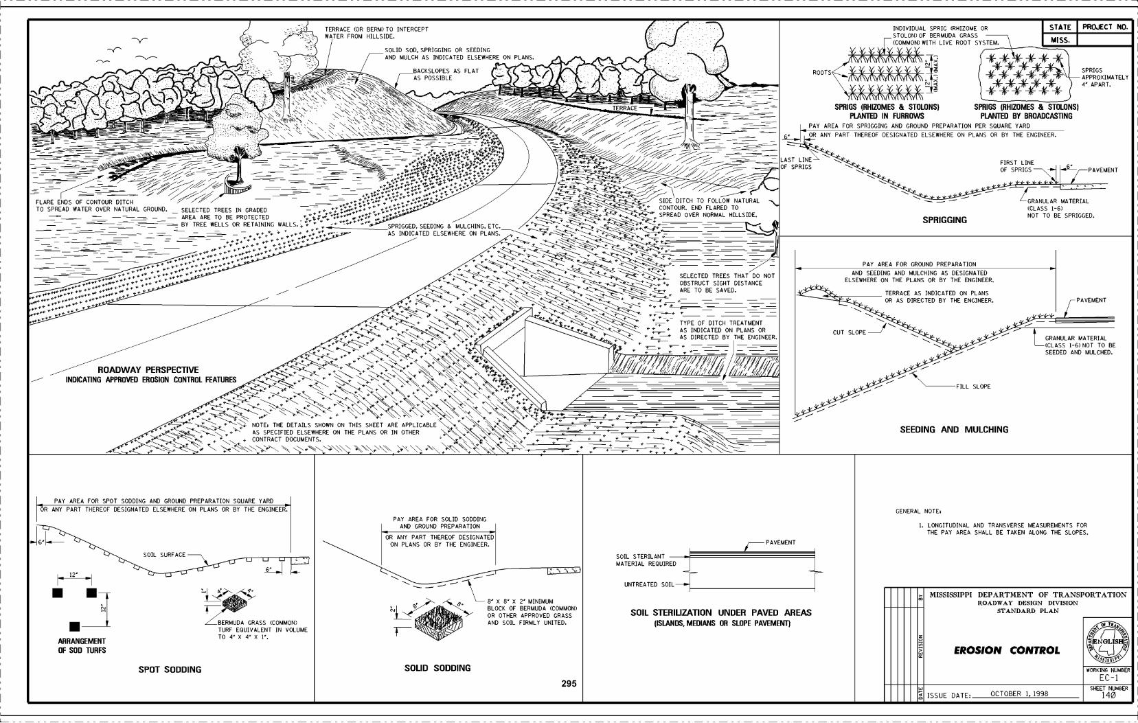
'.--
;::r t½_
'L
__y___
N''
A-----
/1(J
\:_-.----
r__
J
:
- -. ---- -
..:
'N\N
N
TERRACE (OR BERM) TO INTERCEPTWATER FROM HILLSIDE
SOLID SOD. SPRIGGING OR SEEDINGON PLANS
. . .
fTERRACE - Ii-
. .
6
PAY
INDIVIDUALSTOLON) OF(COMMON)
SPRIG (RHIZOME OR STATE PROJECT NO.BERMUDA GRASS
WITH LIVE ROOT SYSTEM MISS
SPRIGSAPPROXIMATELY'
NI
AND MULCH AS INDICATED ELSEWHERE
BACKSLOPES AS FLAT ROOTS
YYY! Y" j (-- -- --AS POSSIBLE
NN
::::: *»*STOLONS)
PAVEMENT
- SPRIGS (RHIZOMES & STOLONS)
AREA FORSPRmGING AGD
_==i::_::r SPRIGS (RHIZOMES &
PREPARATIONPEE0TING
CONTOUR.SPREAD OVER
N OR ANY PART THEREOF DESIGNATED ELSEWHERE
.
ON PLANS OR BY THE ENGINEER
FIRST LINEOF SPRIGS
-- '-= - 4ia-- , 4 4- \- ---- - - ---- ' __ ----i-- - -
END FLARED TONORMAL HILLSIDE.
SPRIGGED. SEEDING & MULCHING. ETC.
:c;:::::::
' - - Lc:ERIALTO BE
I-6)SPRIGGED.
TO SPREAD WATER OVER NATURAL-= - -GROUND. SELECTED TREES IN GRADEDAREA ARE TO BE PROTECTED
_(CLASSNOT
SPRIGGING-- - -- _r::::____= BY TREE WELLS OR RETAINING WALLS.
- 1 4--AS INDICATED ELSEWHERE ON PLANS.
::
-;::::::
-
PAY AREA FOR GROUND PREPARATION
PAVEMENT
:: :: :f:ii -i--.:
.:;
- - -
-
:ARE-
DISTANCENOT
TO BE SAVED.
ELSEWHEREON THEMULCHING
TERRAC
SEEDING
OR AS DIRECTEDBYTHEENGINEER.
DESIGNATED
----:., ..
-
__
CUT SLOPE
--------:-t:k '-> -
FEATURES
* NOTE THE DETAILS SHOWN ON THIS SHEET ARE APPLICABLENINOTHER
_±_
TYPEOFITC:TREATMENT
:-
FILL SLOPE
SLR6RLBESEEDED AND MULCHED.::_ __ 2 = _:::
'\\AND MULCHING
./::;
-1
L_ PAY AREA FOR SPOT SODDING AND GROUND PREPARATION SQUARE YARD
PAY AREA FOR SOLID SODDINGAND GROUND PREPARATION
- -
OF BERMUDA(COMMON)OTHER APPROVED GRASS
SOIL FIRMLY UNITED.
GENERAL NOTE:
1. LONGITUDINAL AND TRANSVERSE MEASUREMENTS FORTHE PAY AREA SHALL BE TAKEN ALONG THE SLOPES.
OR ANY PART THEREOF
I *61..-
DESIGNATED ELSEWHERE ON PLANS OR BY THE ENGINEER
SOIL SURFACE
OR ANY PART THEREOF DESIGNATEDON PLANS OR BY THE ENGINEER.
-L 12' j/ PAVEMENT
- - -- 0 I
-.I -<_
s í
_
VOLUME
SOIL STERILANTMATERIAL REQUIRED
UNTREATED SOIL
SOIL STERILIZATION(ISLANDS.,
- -- \ ,
I BLOCKc'J
OR UNDER PAVED AREASMEDIANS OR SLOPE PAVEMENT)
MISSISSIPPI DEPARTMENT OF TRANSPORTATIONROADWAY DESIGN DEVLSIOL'
STANDARD PLAN
EROSION CONTROL
"i*TBERMUDA GRASS (COMMON)TURFEQUIVALENT IN
SODDINGSPOT
AND ç U
ARRANGEMENT
OF SOD TURFS
f
SOLID SODDING WORKING NUMBER
EC-1SHEET NUMBER
ISSUE DATE OCTOBER 1, 1998 140295
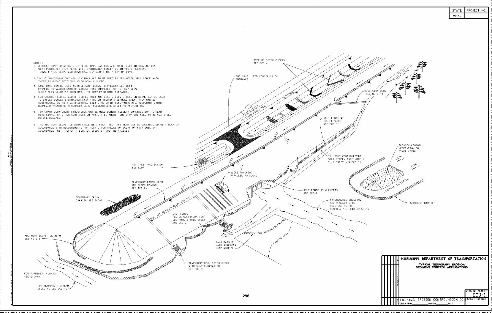
SILT FENCE"SMILE CONFIGURATION"SEE NOTE 2 THIS SHEETAND ECD-2
NOTES:1."J-HOOK" CONFIGURATION SILT FENCE APPLICATIONS ARE TO BE USED IN CONJUNCTION
WITH PERIMETER SILT FENCE WHEN STORMWATER RUNOFF IS IN TWO DIRECTIONS(DOWN A FILL SLOPE AND DOWN GRADIENT ALONG THE RIGHT-OF-WAY(.
2. "SMILE CONFIGURATION" APPLICATIONS ARE TO BE USED AS PERIMETER SILT FENCE WHENTHERE IS ONE-DIRECTIONAL FLOW DOWN A SLOPE.
3. SAND BAGS CAN BE USED AS DIVERSION BERMS TO PREVENT SEDIMENTFROM BEING WASHED ONTO OR ACROSS HARD SURFACES. OR TO HELP SLOWSHEET FLOW VELOCITY WHEN DRAINING AWAY FROM HARD SURFACES.
1. FOR SHORTER SLOPES AND/OR SLOPES THAT ARE LESS STEEP. DIVERSION BERMS CAN BE USEDTO SAFELY CONVEY STORMWATER AWAY FROM OR AROUND A DENUDED AREA. THEY CAN BECONSTRUCTED USING A MANUFACTURED SILT DIKE OR BY CONSTRUCTING A TEMPORARY EARTHBERM AND TRENCH WITH GEOTEXTILE OR POLYETHYLENE SHEETING PROTECTION.
TEMPORARY DEWATERING STRUCTURES CAN BE USED DURING CULVERT CONSTRUCTION. STREAMDIVERSIONS. OR OTHER CONSTRUCTION ACTIVITIES WHERE TURBID WATERS NEED TO BE CLARIFIEDBEFORE RELEASE.
THE ABUTMENT SLOPE TOE BERM SHALL BE 3 FEET TALL. THE BERM MAY BE CONSTRUCTED WITH ROCK INACCORDANCE WITH REQUIREMENTS FOR ROCK DITCH CHECKS ON ECD-8 OR WITH SOIL INACCORDANCE WITH TEC-2 IF BERM IS USED. IT MUST BE GRASSED
ABUTMENT SLOPE TOE BERMSEE NOTE .
FOR TURBIDITY CURTAINSEE ECD-19
FOR TEMPORARY STREAMCROSSING SEE ECD-16-
TEMPORARY BRUSHBARRIER SEE ECD-2.
FOR INLET PROTECTIONSEE ECD-1 i
TEMPORARY EARTH BERMAND SLOPE DRAINSSEE TEC-2.
SAND BAGS ONHARD SURFACES(SEE NOTE 3(
TEMPORARY ROCK DITCH CHECKWITH SUMP EXCAVATIONSEE ECD-9
TYPE OF DITCH CHECKSSEE ECD-
FOR STABILIZED CONSTRUCTIONENTRANCE.
SILT FENCE AT CULVERTSSEE ECD-2
J-HOOK" CONFIGURATIONSILT FENCE. (SEE NOTE i
THIS SHEET AND ECD-3(
DIVERSION BERM///(SEE NOTE 4(
WATERCOURSE CROSSINGTHE PROJECT SITE(SEE ECD-16 FORTEMPORARY STREAM CROSSING(
EROSION CONTROLVEGETATION OROTHER COVER
SEDIMENT BARRIER
STATE
MISS.
PROJECT NO.
MISSISSIPPI DEPARTMENT OF TRANSPORTATION
TYPICAL TEMPORARY EROSION!SEDIMENT CONTROL APPLICA11ONS
WORKING NUMBER
E CD-IFILENAME EROSION CONTROL\ECD-1.DGr SHEET NUMBER
DEStGN TEAM CHECKED DATE
296
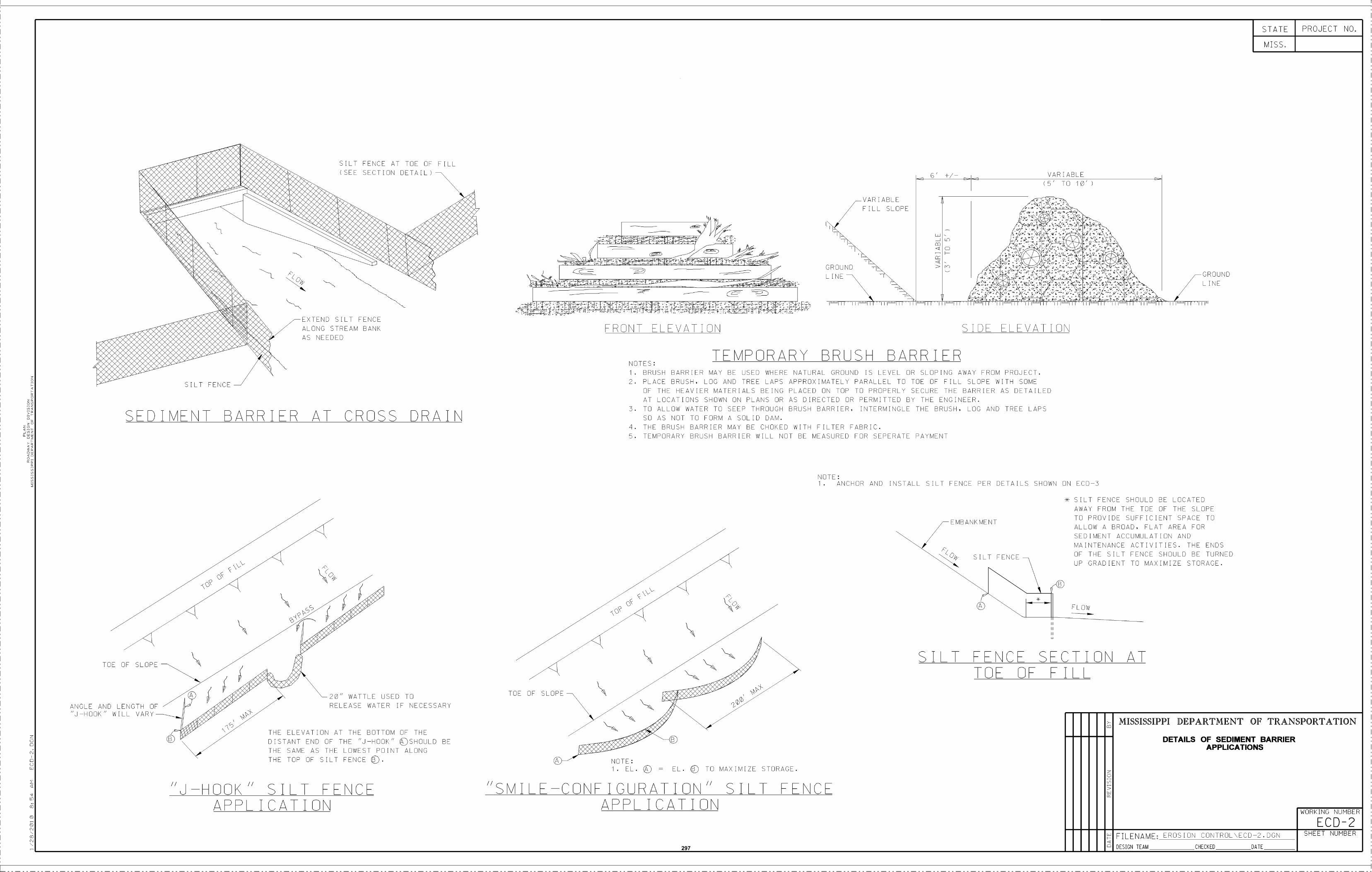
)
[LT FENCE
NT BARRI SRA
TOE O SLOPE
ANCLE AND LENGTH O I ..RELEASE WATER IF NECESSAHY
"J-HOOK" WILL VANY
APPL I CAT I ON
EYTEND SILT NANCEALONG STREAM BANKAS NEEDED
AILT FENCE AT TOE DF FILLI SEE SECT I CN DATA I L I
CROSS DRAIN
2ø" WATTLE USED TD
THE ELEVATIDN AT THE BDTTDM DF THEDISTANT END DF THE "J-HDDK" SHDLJLD BE
THE NAME AS THE LDWEAT FDINT ALDNDTHE TOP OF EILT FENCE
TOE OF ELOPE
II
M I L
F HT ELEVATION
T
IA:
I. EL. © = EL. TO MAXIMIZE STORAGE.
FICùRAIO\" SILTAPPL I CAT I ON
IIIII..IIIIII..IIIIII..IIIII
GROUNDL I NE
VAR I ABLE
FILL SLOPE
VPDRARY BRSH BARRI
6' /- VARIABLE
II IIIIII IIIIII IIIII IIIIII III
SIL
SIDE ELEVATION
NOTES:I . BRUSH BARRIER MAY BE USED WHERE NATURAL GROUND IS LEVEL OR SLOPING AWAY FROM PROJECT.
PLACE BRUSH. LOG AND TREE LAPS APPRO>(IMATELY PARALLEL TO TOE OF FILL SLOPE WITH SOMEOF THE HEAVIER MATERIALS BEING PLACED ON TOP TO PROPERLY SECURE THE HARRIER AS DETAILEDAT LOCATIONS SHOWN ON PLANS OR AS DIRECTED OR PERMITTED BY THE ENGINEER.TO ALLOW WATER TO SEEP THROUGH BRUSH BARRIER, INTERMINGLE THE BRUSH, LOG AND TREE LAPSSO AS NOT TO FORM A SOLID DAM.THE BRUSH BARRIER MAY BE CHOKED WITH FILTER FABRIC.TEMPORARY BRUSH BARRIER WILL NOT BE MEASURED FOR SEPERATE PAYMENT
NOTE:i . ANCHOR AND INSTALL SILT FENCE PER DETAILS SHOWN ON ECD-3
EMBANKMENT
F
OF FILL
SILT FENCE SHOULD BE LOCATEDAWAY FROM THE TOE OF THE SLOPETO PROVIDE JFFICIENT SPACE TOALLOW A B I FLAT AREA FORSEDIMENT HLATION ANDMAINTENANI CTIVITIES. THE ENDSOF THE SILT FENCE SHOULD BE TURNEDUP GRADIENT TO MAXIMIZE STORAGE.
SNCS SSCTION AT
FLOW
I ! ! ! I I I I II I I I I
GROUNDL I NE
STATE
MISS.
DESIGN TEAM CHECKED DATE
PROJECT NO.
MISSISSIPPI DEPARTMENT OF TRANSPORTATION
DETAILS OF SEDIMENT BARRIERAPPLICATIONS
WORKINO NUMBER
ECD-2
s DI V
NCJHDDKH SILT
SHEET NUMBERFILENAME: EROSION CONTROL\ECD2. DGN
297
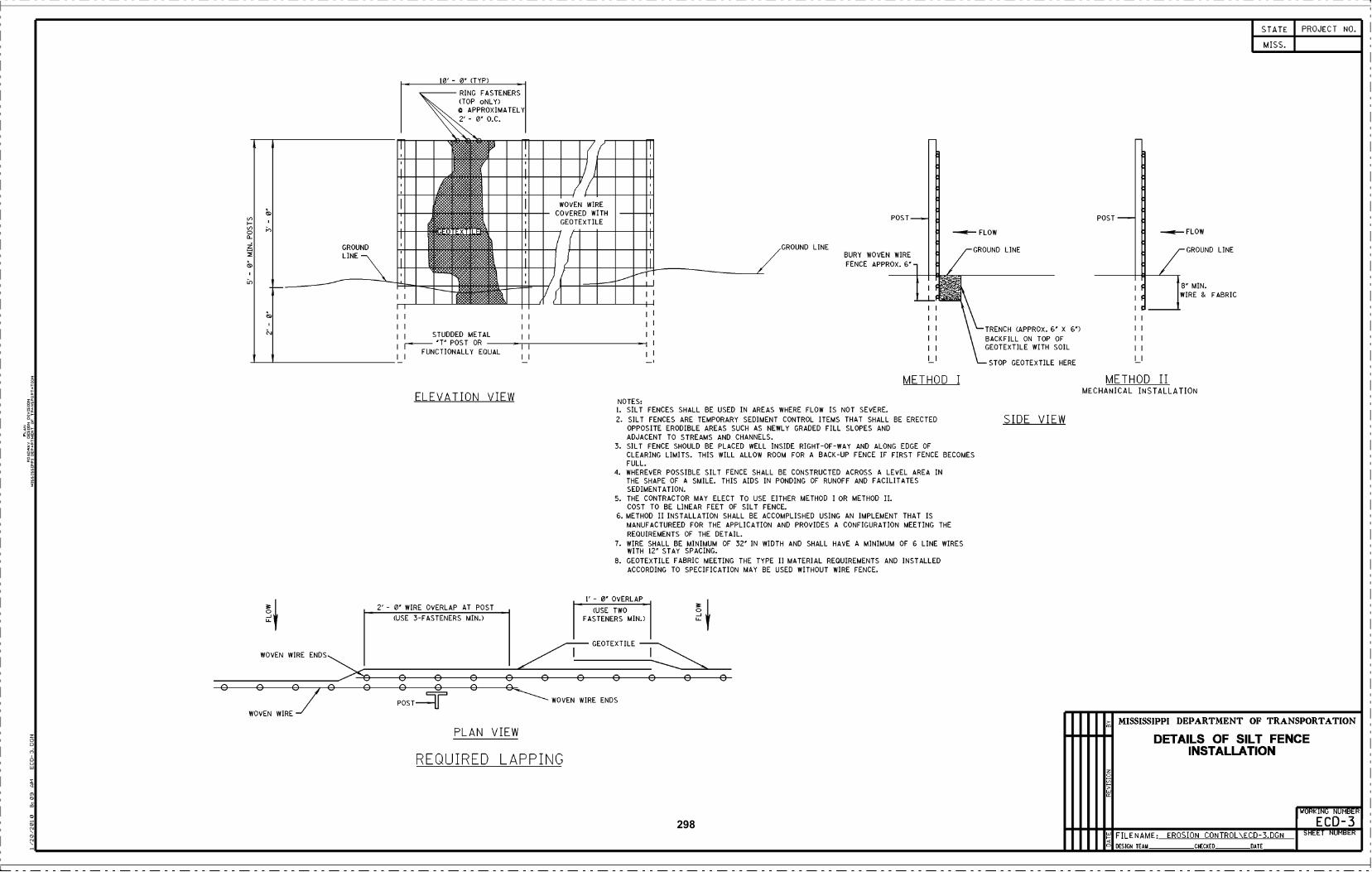
z
oJLs
WOVEN WIRE ENDS
T
n
RING FASTENERS(TOP oNLY)
APPROXIMATELY2' - ø O.C.
T (IH/1 IH
(
:IuII/ lIHlIHGROUNDLINE
o o o o o oPOST L_II__I
WOVEN WIRE
10' - ø (TYP)
STUDDED METAL'P POST OR
FUNCTIONALLY EQUAL
ELEVATION VIEW
WOVEN WIRECOVERED W THGEOTEXTILE
1' - 0' OVERLAP
(USE TWOFASTENERS MIN.)
GEOTEXTILE
oWOVEN WIRE ENDS
oJLs
GROUND LINE
POST
BURY WOVEN WIREFENCE APPROX. 6
I I TRENCH (APPROX. 6' X 6)
I I BACKFILL ON TOP OF
I IGEOTEXTILE WITH SOIL
LI STOP GEOTEXTILE HERE
NOTES:SILT FENCES SHALL BE USED IN AREAS WHERE FLOW IS NOT SEVERE.SILT FENCES ARE TEMPORARY SEDIMENT CONTROL ITEMS THAT SHALL BE ERECTEDOPPOSITE ERODIBLE AREAS SUCH AS NEWLY GRADED FILL SLOPES ANDADJACENT TO STREAMS AND CHANNELS.SILT FENCE SHOULD BE PLACED WELL INSIDE RIGHT-OF-WAY AND ALONG EDGE OFCLEARING LIMITS. THIS WILL ALLOW ROOM FOR A BACK-UP FENCE IF FIRST FENCE BECOMESFULL.
'I. WHEREVER POSSIBLE SILT FENCE SHALL BE CONSTRUCTED ACROSS A LEVEL AREA INTHE SHAPE OF A SMILE. THIS AIDS IN PONDING OF RUNOFF AND FACILITATESSEDIMENTATION.
THE CONTRACTOR MAY ELECT TO USE EITHER METHOD I OR METHOD II.COST TO BE LINEAR FEET OF SILT FENCE.METHOD II INSTALLATION SHALL BE ACCOMPLISHED USING AN IMPLEMENT THAT ISMANUFACTUREED FOR THE APPLICATION AND PROVIDES A CONFIGURATION MEETING THEREQUIREMENTS OF THE DETAIL.
WIRE SHALL BE MINIMUM OF 32' IN WIDTH AND SHALL HAVE A MINIMUM OF 6 LINE WIRESWITH 12 STAY SPACING.
GEOTEXTILE FABRIC MEETING THE TYPE II MATERIAL REQUIREMENTS AND INSTALLEDACCORDING TO SPECIFICATION MAY BE USED WITHOUT WIRE FENCE,
-- FLOW
GROUND LINE
SIDE VIEW
POST
o
>
-- FLOW
GROUND LINE
8 MIN.
WIRE & FABRIC
STATE
MISS.
PROJECT NO.
MISSISSIPPI DEPARTMENT OF TRANSPORTATION
DETAILS OF SILT FENCEINSTALLATION
WORKING NUMBER
ECD-3FILENAME EROSION CONTROL\ECD-3.DGN SHEET NUMBER
DESIGN TEAM CHECKED DATE
METHOD I METHOD IIMECHANICAL INSTALLATION
ro
G
('J
2' - ø WIRE OVERLAP AT POST
(USE 3-FASTENERS MIN.)
PLAN VIEW
REQUIRED LAPPING
298
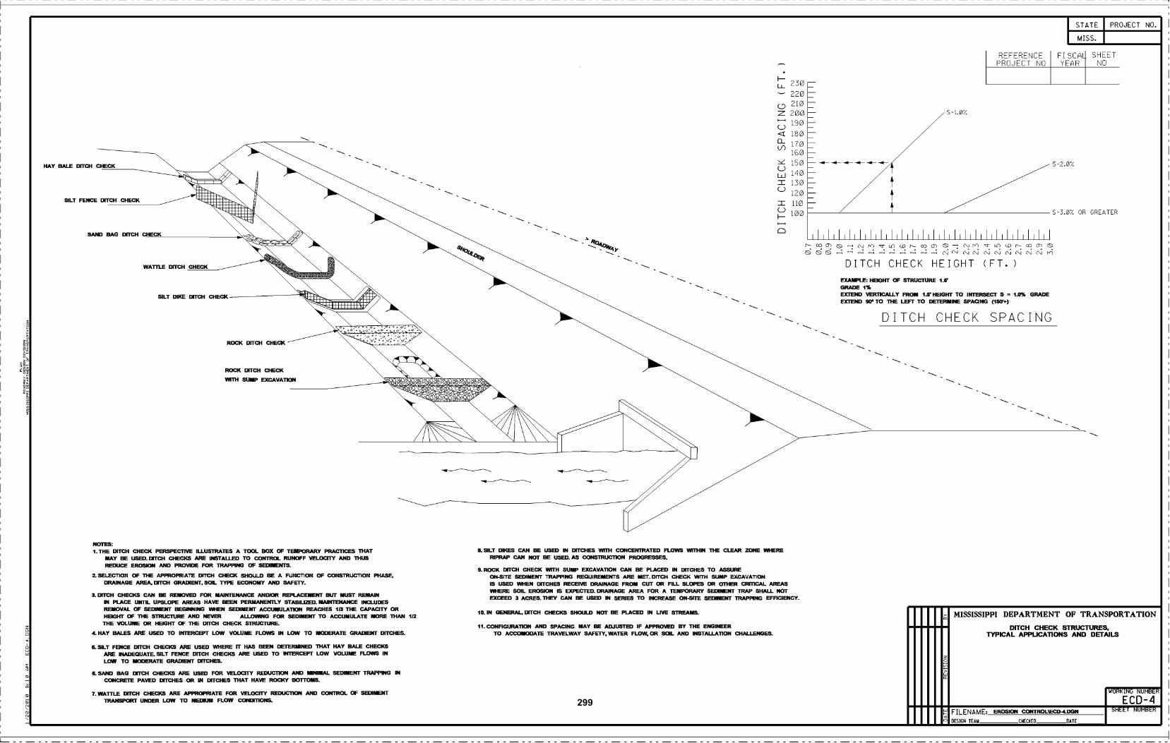
HAY BALE DffcH HEK
SILT FENCE DITCH CHECK
SAND BAG D(TcH CHECK
WATILE OucH CHECK
SILT DIKE DITCH CHECK
NOTES:THE DITCH CHECK PERSPECTIVE ILLUSTRATES A TOOL BOX OF TEMPORARY PRACTICES ThAT
MAY BE USED. UfIcH CHEcKS ARE INSTALLED TO CONTROL RUNOFF VELOGIFY AND ThUSREDUCE EROSION AND PROVIDE FOR TRAPPING OF SEDIMENIS.
SELECTION OF THE APPROPRIATE DITcH CHECK SHOULD BE A FUNCTION OF CONSTRUCTION PHASE,DRAINAGE AREA, DrIcH GRADIENI. SOIL TYPE ECONOMY AND SAFETY.
3. DITCH CHECKS CAN BE REMOVED FOR MAINTENANCE ANDIOR REPLACEMENT BUI MUST REMAININ PLACH UNIIL UPSLOPE AREAS HAVE BEEN PERMANENTLY STABILIZED. MAINIENANcE INcLUDESREMOVAL OF SEDIMENI BEGINNING WHEN SEDIMENI AUMULATIOII REAcHES 113 THE CAPAQTY ORHEIGNI OF ThE STRUCTURE AND NEVER ALLOWING FOR SEDIMENI TO AccUMULATE MORE ThAN 112
THE VOLUME OR HEIGHT OF ThE DffCH CHECK STRUCTURE.
4. HAY BALES ARE USED TO INIERCHPT LOW VOLUME FLO IN LOW TO MODERATE GRADIENI DITCHES.
5. SILT FENcE DffCH cHECKS ARE USED WHERE FI HAS BEEN DETERMINED ThAT HAY BALE CHECKSARE INADEQUATF SILT FENCK D1fCH CHECKS ARE USED TO INIERCEPT LOW VOLUME FLOV IN
LOW TO MODERATE GRADIENI DucHES.
t SAND BAG DITCH CHEcKS ARE USED FOR VELOCITY REDUCTION AND NIMAL SEDIMENT TRAPPING INCHRF1E PAVED DITCHES OR IN DucHES THAT HAVE ROCKY BOiTONS.
7. WAITLE DITCH CHECKS ARE APPROPRIATE FOR VELOCITY REDUCTION AND CONIROL OF SEDIMENITRANSPORT UNDER LOW TO MEDIUM FLOW cCIDI11ONS.
10. IN GENERAL, DffH CHECKS SHOULD NOT BE PLACED IN LIVE STREAMS.
8. SILT DIKES CAN BE USED IN DucHES Willi CCN«ENIRATED FLO WITHIN ThE cLEAR ZONE WHERERIPRAP GAN NOT BE USED. AS CONSTRUCTION PROGRESSES.
9. ROcK D1H cHEcK WIIH BUMP EXCAVA110N cAN BE PLAcED IN DucHES TO ASSUREOH-SITE SEDIMENT TRAPPF4G REQUIREMENTS ARE MET. DITCH CHECK WITH SUMP EXCAVATIONIS USED WHEN DucHES REcEIVE DRAINAGE FROM CUT OR FILL SLOPES OR OTHER CRfflCAL AREASWHERE SOIL EROSION IS EXPECTED. DRAINAGE AREA FOR A TEMPORARY SEDIMENI TRAP SHALL NOTEXcEED 3 AcRES. ThEY CAN BE USED IN SERIES TO INCHEASE ON-SITE SEDIMENI TRAPPING EFFIcIENCY.
11. CONFIGURA11ON AND SPAcING MAY BE ADJUSTED IF APPROVED BY THE ENGINEERTO AOMODATE TRAVELWAY SAFElY, WATER FLOW, OR SOIL AND INSTALLA11ON CHALLENGES.
z:(-)
o-(f)
(-)
u-
(-)
230
220210
200190
180
170160
150
140
130
120
110
100
I I I I I I I I I I I I I I I I I I I I I I I
N) Lfl (O N- 03 O C N) Lfl LO N- 03 0)Ç-: .4 c C'J çj NJ (\J C"J V)
DITCH CHECK HEIGHT (FT.EXAMPLE: HEIGHT OF STRUCTURE 1.5GRADE 1%EXTEND VERTICALLY FROM 1.5' HEIGHT TO INfERSECT S = 1.0% GRADEEXTEND 9O TO ThE LEFT TO DETERMINE SPAcING (150+)
t
DITCH CHECK SPACING
/ s-1.øz
o
>
FISCAL SHEETREFERENCEPROJECT NO YEOR NO
S-2øZ
STATE
MISS.
S-3.0Z OR GREATER
MISSISSIPPI DEPARTMENT OF TRANSPORTATION
DITCH CHECK STRUCTURES,TYPICAL APPLICA11ONS AND DETAILS
WORKING NUMBER
E CD-IFILENAME' EROSICtI COIUROUEOG-LDGN
DESIGN TEAM CHECKED DATE
PROJECT NO,
SHEET NUMBER299
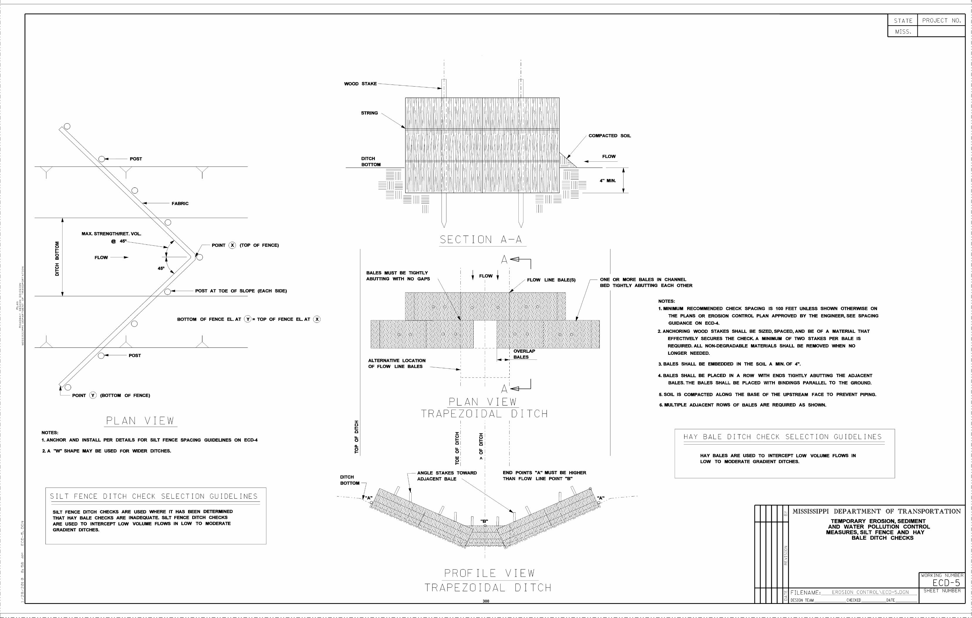
ooIn
X
o
o
MAX. STRENGTHIRET. VOL.
@450
FLOW
////OPOST
POINT ® (BOTTOM OF FENCE)
450
PLAN VIEW
2. A W SHAPE MAY BE USED FOR WIDER DITCHES.
FABRIC
POINT X) (TOP OF FENCE)
POST AT TOE OF SLOPE (EACH SIDE)
BOTIOM OF FENCE EL AT TOP OF FENCE EL AT
NOTES:
1.ANCHOR AND INSTALL PER DETAILS FOR SILT FENCE SPACING GUIDELINES ON ECD-4
SILT FENCE DITCH CHECK SELECTION GUIDELINES
SILT FENCE DITCH CHECKS ARE USED WHERE IT HAS BEEN DETERMINEDTHAT HAY BALE CHECKS ARE INADEQUATE. SILT FENCE DITCH CHECKSARE USED TO INTERCEPT LOW VOLUME FLOWS IN LOW TO MODERATEGRADIENT DITCHES.
DITCHBOTFOM
SECTION AA
BALES MUST BE TIGHTLYABU1TING WITH NO GAPS
ANGLE STAKES TOWARDADJACENT BALE
FLOW
END POINTS A MUST BE HIGHERTHAN FLOW LINE POINT B
PROFILE VIEWTRAPEZOIDAL DICH
4 MIN.
FLOW LINE BALE(S) , ONE OR MORE BALES IN CHANNELBED TIGHTLY ABUTTING EACH OTHER
NOTES:
MINIMUM RECOMMENDED CHECK SPACING IS 100 FEET UNLESS SHOWN OTHERWISE ON
THE PLANS OR EROSION CONTROL PLAN APPROVED BY THE ENGINEER, SEE SPACING
GUIDANCE ON ECD-4.
ANCHORING WOOD STAKES SHALL BE SIZED, SPACED, AND BE OF A MATERIAL THAT
EFFECTIVELY SECURES THE CHECK.A MINIMUM OF TWO STAKES PER BALE IS
REQUIRED. ALL NON-DEGRADABLE MATERIALS SHALL BE REMOVED WHEN NO
LONGER NEEDED.
BALES SHALL BE EMBEDDED IN THE SOIL A MIN. OF 4'.
BALES SHALL BE PLACED IN A ROW WITH ENDS TIGHTLY ABUTTING THE ADJACENTBALES. THE BALES SHALL BE PLACED WITH BINDINGS PARALLEL TO THE GROUND.
5_ SOIL IS COMPACTED ALONG THE BASE OF THE UPSTREAM FACE TO PREVENT PIPING.
6. MULTIPLE ADJACENT ROWS OF BALES ARE REQUIRED AS SHOWN.
HAY BALE DITCH CHECK SELECTION GUIDELINES
HAY BALES ARE USED TO INTERCEPT LOW VOLUME FLOWS INLOW TO MODERATE GRADIENT DITCHES.
MISSISSIPPI DEPARTMENT OF TRANSPORTATIONTEMPORARY EROSION, SEDIMENT
AND WATER POLLUTION CONTROLMEASURES, SILT FENCE AND HAY
BALE DITCH CHECKS
WORKING NUMBER
ECD-5FILENAME: UNCTION CONTROLUECDU.DCN SHEET NUMBER
MISS,
WOOD STAKE
STRING
oCOMPACTED SOIL
NPOST DITCH FLOW
BOTrOM
STATE PROJECT NO.
DESIGN TEAM CHECKED DATE
OVERLAP
ALTERNATIVE LOCATION _ BALES
OF FLOW LINE BALES
__PLAN VIEW
TRAPEZEIVAL DICH
300
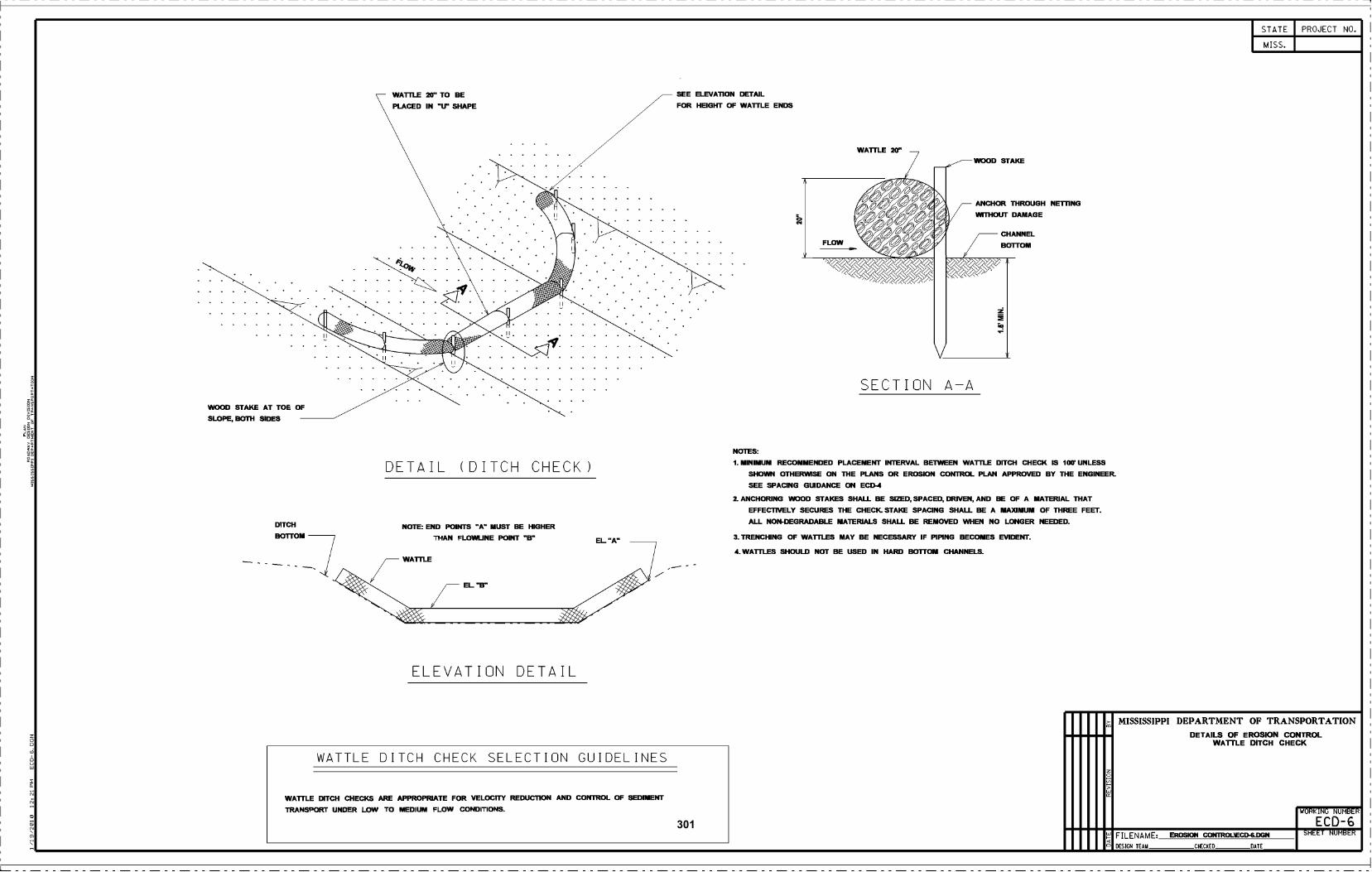
WOOD STAKE AT TOE OF
SLOPE, BOTH SIDES
DITCH
BO1TOM
WATILE 20 TO BEPLAcED IN U SHAPE
DETAIL (DITCH CHECK)
NOTE: END POINrS w MUST BE HIGHERTHAN FLOWLINE POINT B
WA1TLE
///___ EL B
ELEVATION DETAIL
SEE ELEVATION DETAIL
FOR HEIGHT OF WA1TLE ENDS
SECTION A-A
ANCHOR THROUGH MElTING
WITHOUT DAMAGE
NOTES:
MINIMUM REcOMMENDED PLAcEMENT INTERVAL BETWEEN WATILE DITCH CHECK IS 100' UNLESS
SHOWN OTHERWISE ON THE PLANS OR EROSION cONTROL PLAN APPROVED BY THE ENGINEER.SEE SPAcING GUIDANcE Oli EcD-4
ANCHORING WOOD STAKES SHALL BE SIZED, SPACED. DRIVEN. AND BE OF A MATERIAL THAT
EFFECTIVELY SEcURES THE CHEcK. STAKE SPACING SHALL BE A MAXIMUM OF THREE FEEr.
ALL NON-DEGRADABLE MATERIALS SHALL BE REMOVED WHEN NO LONGER NEEDED.
TRENCHING OF WA1TLES MAY BE NECESSARY IF PIPING BECOMES EVIDENT.
WA1TLES SHOULD NOT BE USED IN HARD BOTIOM cHANNELS.
o
>
STATE
MISS.
MISSISSIPPI DEPARTMENT OF TRANSPORTATIONDETAILS OF EROSION OONTROL
WA11LE DITCH CHECK
WORKING NUMBER
ECD-6FILENAME EROSION cONIROLiEcD-6.DGN SHEET NUMBER
DESIGN TEAM CHECKED DATE
PROJECT NO.
WATTLE DITCH CHECK SELECTION GUIDELINES
WA1TLE DITCH CHECKS ARE APPROPRIATE FOR VELOCITY REDUCTION AND CONTROL OF SEDIMENT
TRANSPORT UNDER LOW TO MEDIUM FLOW CONDITIONS.
301
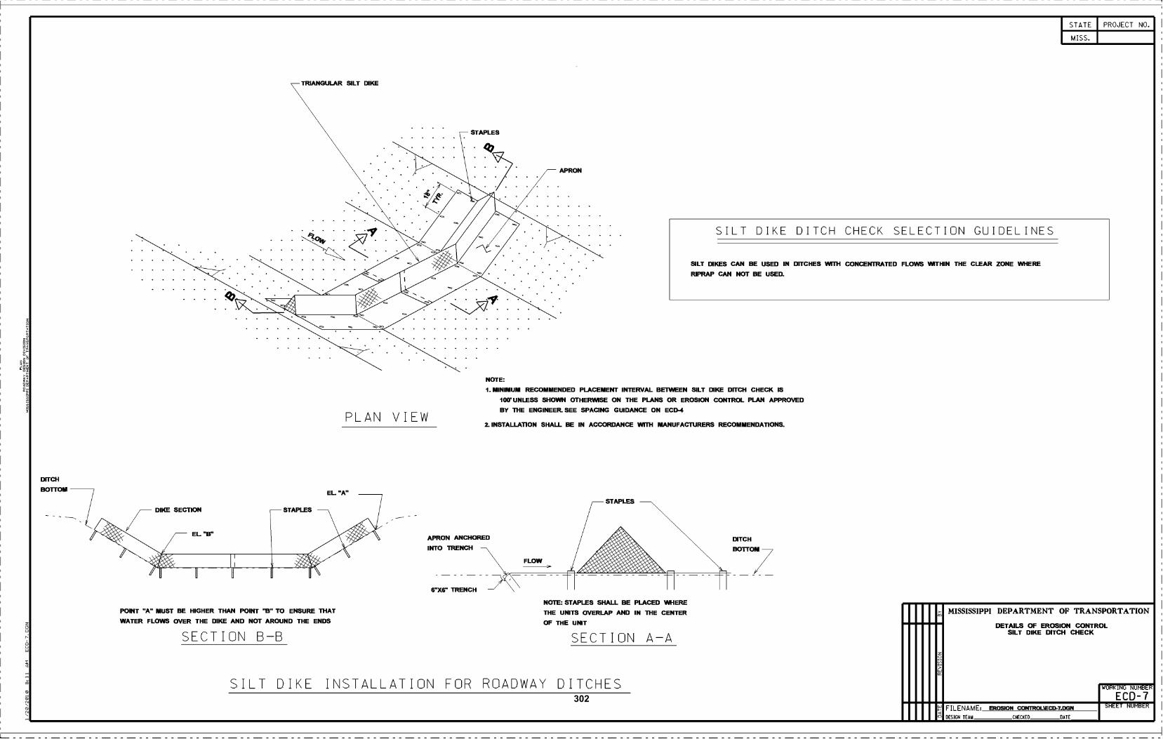
SECTION B-B
POINT "A MUST BE HIGHER THAN POINT B TO ENSURE ThATWATER FLOWS OVER THE DIKE AND NOT AROUND THE ENDS
TRIANGULAR SILT DIKE
PLAN VIEW
NOTE:
MINIMUM RECOMMENDED PLAcEMENT INTERVAL BETWEEN SILT DIKE DffCH CHECK IS
loo. UNLESS SHOWN OTHERWISE ON THE PLANS OR EROSION CONTROL PLAN APPROVED
BY ThE ENGINEER. SEE SPAcING GUIDANcE ON ECD-4
INSTALLA11ON SHALL BE IN AOCORDANcE Wifli MANUFACTURERS REcOMMENDATIONS.
NOTE: STAPLES SHALL BE PLAGED WHERE
THE UNITS OVERLAP AND IN ThE CENTER
OF THE UNIT
SILT DIKE INSTALLATION FOR ROADWAY DITCHES
SECTION A-A
DITCH
BOUOM
o
>
STATE
MISS.
PROJECT NO.
MISSISSIPPI DEPARTMENT OF TRANSPORTATION
DETAILS OF EROSION CONTROLSILT DIKE DITON CHECK
WORKING NUMBER
ECD-7
DESIGN TEAM CHECKED DATE
FILENAME EROSION coNrRoIEcD-7.DGN SHEET NUMBER
SILT DIKE DITCH CHECK SELECTION GUIDELINES
SILT DIKES CAN BE USED IN DITCHES WIIH CONCENTRATED FLOWS WITHIN THE CLEAR ZONE WHERE
RIPRAP CAN NOT BE USED.
302
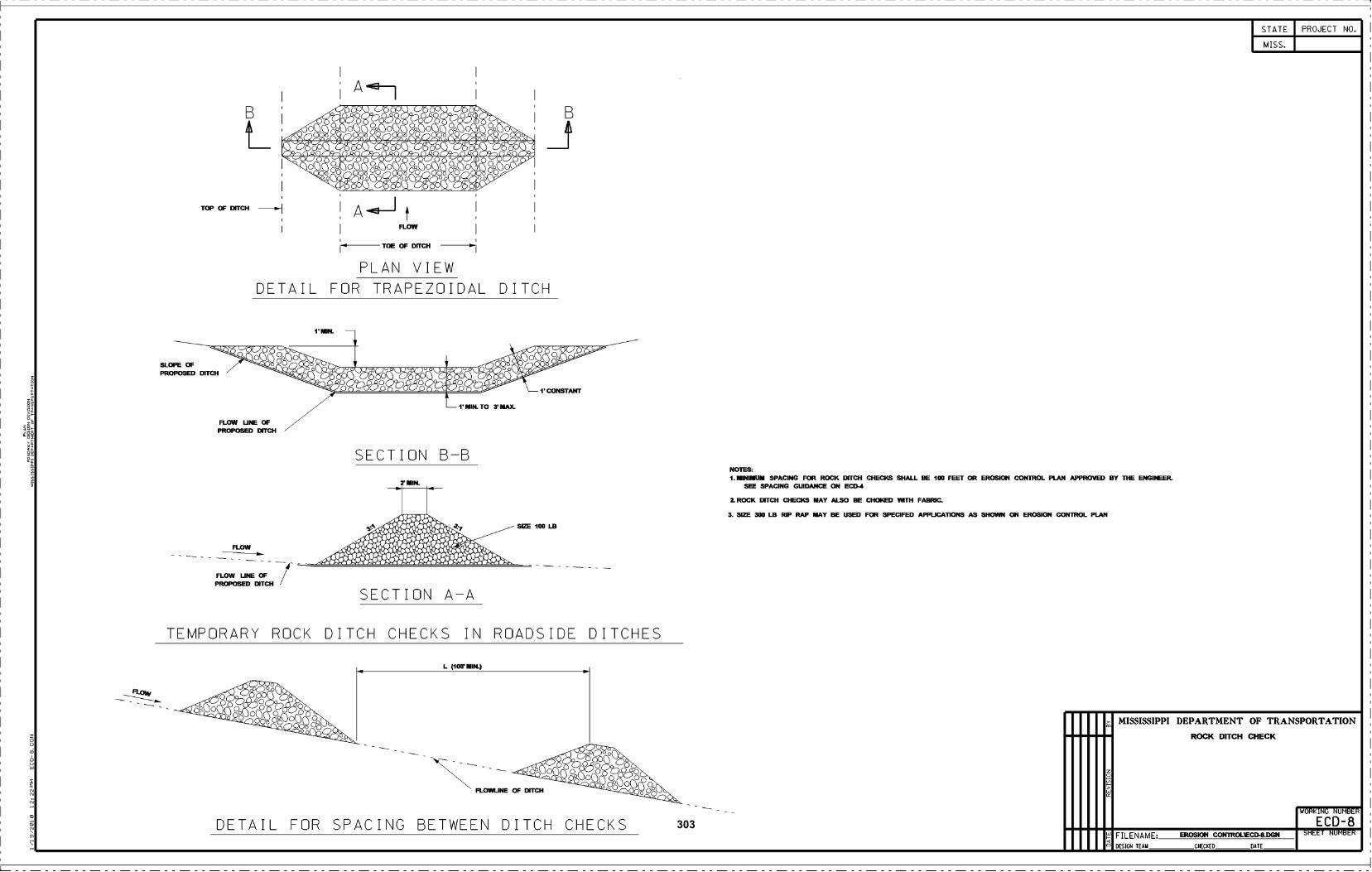
TOP OF Df1H
FLOW
FLOW UNE OFPROPOSED DITcH
SECTION A-A
Hi4 Ooc) C)OOO) (JO.'..:ô8ô8ôi8ô
a?_ s ! ! S !' SOO 'OL: O OO -oc:ç: oç..o O Oo O Oo O,oo O cAo
FLOW
TOE OF Di1H
PLAN VIEWDETAIL FOR TRAPEZOIDAL DITCH
SECTION B-B
r MIN.
,% .s.s.s.s***_. 4I,.% ,. .. % % $
TEMPORARY ROCK DITCH CHECKS IN ROADSIDE DITCHES
DETAIL FOR SPACING BETWEEN DITCH CHECKS
NOTES:1. MINIMUM SPACING FOR ROCK BlECH
SEE SPAcING GUIDANcE ON EcD-4
I ROOK BlEcH cHEcKS MAY ALSO BE
3 SIZE 300 LB RIP RAP MAY BE USED
CHEcKS SHALL BE 100 FEET CR EROSION CONTROL PLAN APPROVED BY ThE ENGINEER.
cHCED WITh FABRIc
FOR SPEcIFED APPLIGA11ONS AS SHOWN Cli EROSION cONTROL PLAN
o
>
STATE
MISS.
MISSISSIPPI DEPARTMENT OF TRANSPORTATION
ROCK DITCH QIECK
WORKING NUMBER
ECD-8
PROJECT NO.
FILENAME EROSION CONTROLiEcD-8.DGN SHEET NUMBER
DESIGN TEAM CHECKED DATE
303
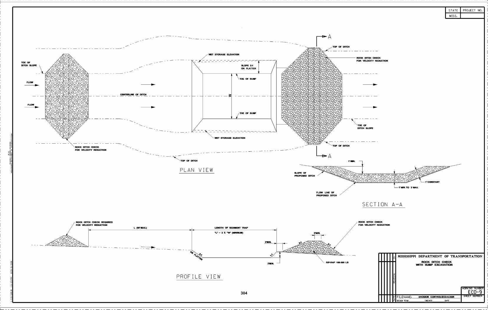
TOE OfDlTH SLOPE
FLOW
FLOW
% deIt - - ' -- :% 4'
%
SOd. 4'
%
% 4's..
e% 4'
.t '.' .( __)Sc
000.
hOu
_. -
OaO
doO
e, tTh'-J
oG3000 0C
O&ç;?c&Ooo e
Q O o°
ocdJQ ob
°(-;k' II.lo4."ç: .o4po.: ,o.',
O
(Vno°
croo.
c3Ooo o.
OOC
.'
ROcK DffcH cHEcKFOR VELOCflY REDUCTION
ROOK DffcH HEK REQUIREDFOR VELOcITY REDUCTION
cENIERUNE OF DffcH
L (W MAX.)
PLAN VIEW
PROFILE VIEW
,//// WET STORAGE ELEVATION
WET STORAGE ELEVATION
LENGTH OF SEDIMENT TRAP
-L- = 2 X (MINIMUM)
SLOPE .1
OR FLAUER
ROcK DITcH cHEcKFOR VELO1TY REDUCTION
TOE OFD11H SLOPE
SECTION A-A
ROOK DITcH HEKFOR VELOcITY REDUCTION
o
>
STATE
MISS.
MISSISSIPPI DEPARTMENT OF TRANSPORTATION
ROCK DITCH CHECKWITH SUMP EXCAVATION
WORKING NUMBER
ECD-9FILENAME EROSION cONTROLiEcD-9.DGN
PROJECT NO.
SHEET NUMBER
y
TOE Of SUMP
_ -
TOE Of SUMP
y
DESIGN TEAM CHECKED DATE
304
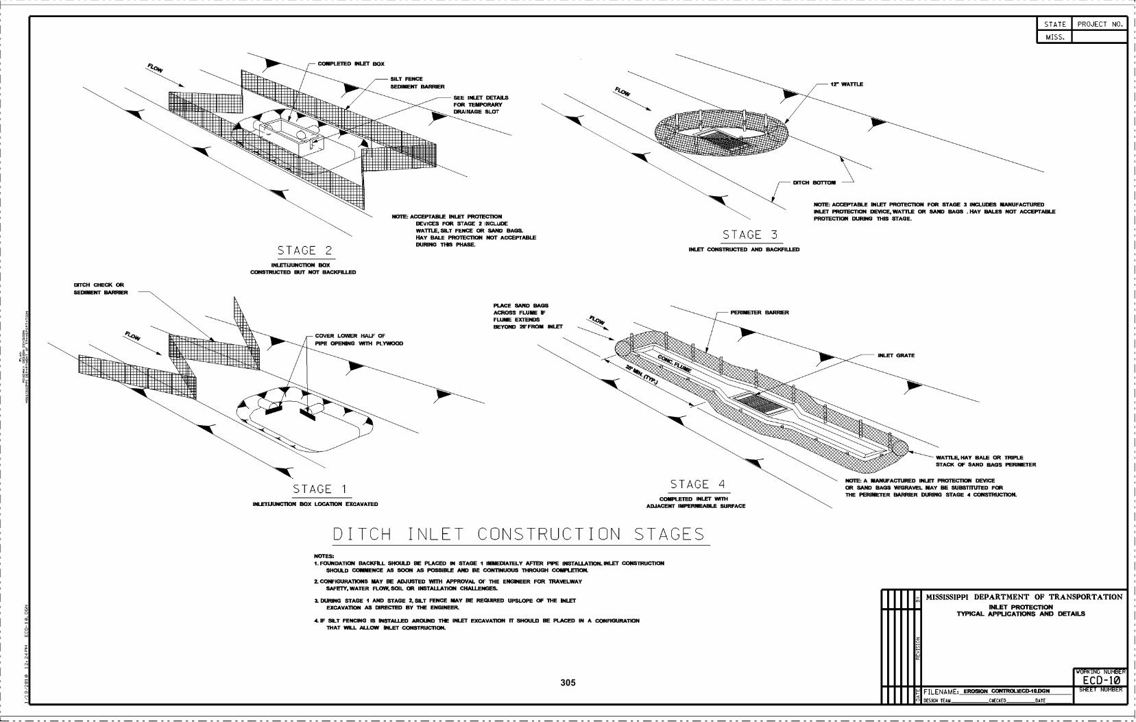
DITCH cHEcK CRSEDIMENI BARRIER
STAGE 2
cOMPLETED INLFI BOX
INLEIIJUNCTION BOXCRSTRUCTED BUT NOT BAKFILLED
COVER LOWER HALF CFPIPE OPENING WITh PLYWOOD
STAGE i
INLETIJUNCTION BOX LOCATION EXCAVATED
SILT FENcESEDIMENT BARRIER
SEE INIZI DETAILSFOR TEMPORARYDRAINAGE SLOT
NOTE: AEPTABLS INLET PROTECTIONDEVIcES FOR STAGE 2 INCLUDEWATILE. SILT FENcE OR SAND BAGS.HAY BALE PROTECÌ1CN NOT ACCEPTABLEDURING THIS PHASE.
PLAcE SAND BAGSAcROSS FLUME IFFLUME EXFENDSBEYOND 2OFROM INLET
3ITCH I\LET CO\STRUCTIO\ STAGESNOTES:
FOUNDATION BAcKFILL SHOULD BE PLAcED IN STAGE I IMMEDIATELY AFTER PIPE INSTALLAI1ON. INIZI 3NSTRUCTIONSHOULD COMMENcE AS SOON AS POSSIBLE AND BE CONTINUOUS ThROUGH COMPLETION.
CONFIGURATIONS MAY BE ADJUSTED WIfH APPROVAL OF ThE ENGINEER FOR TRAVELWAYSAFE1Y WATER FLOW, SOIL CR INSTALLATION CHALLENGES.
a DURING STAGE I AND STAGE 2, SILT FENCE MAY BE REQUIRED UPSLOPE CF ThE INLETEXCAVATION AS DIRECTED BY ThE ENGINEER.
4 IF SILT FENING IS INSTALLED AROUND THE INLET EXCAVATION ri SHOULD BE PLACED IN A CONFIGURATIONThAT WILL ALLOW INLET cONSTRUCTiON.
INLET CONSTRUCTED AND BACEFILLED
STAGE 4COMPLETED INLET WITh
ADJACENI IMPERMEABLE SURFAcE
STAGE 3
PERIMETER BARRIER
STATE
MISS.
NOTE: ACCEPTABLE INLET PROTECTION FOR STAGE 3 INCLUDES MANUFACTUREDINLET PROTECTION DEVIcE, WATfLE OR SAND BAGS . HAY BALES NOT ACCEPTABLEPROTECTiON DURING ThIS STAGE.
INLET GRATE
NOTE: A MANUFACTURED INLET PROTECTION DEVICEOR SAND BAGS WIGRAVEL MAY BE SUBSTrRJTED FORThE PERIMETER BARRIER DURING STAGE 4 CONSTRUCTION.
o>
WA1TLE, HAY BALE OR TRIPLESTAcK OF SAND BAGS PERIMETER
DESIGN TEAM CHECKED DATE
PROJECT NO.
MISSISSIPPI DEPARTMENT OF TRANSPORTATIONINLET PROTECTION
TYPICAL APPUCATIONS AND DETAILS
WORKING NUMBER
ECD-1øFILENAME EROSION GOt4TRCLEcD.1O.DGN SHEET NUMBER
305
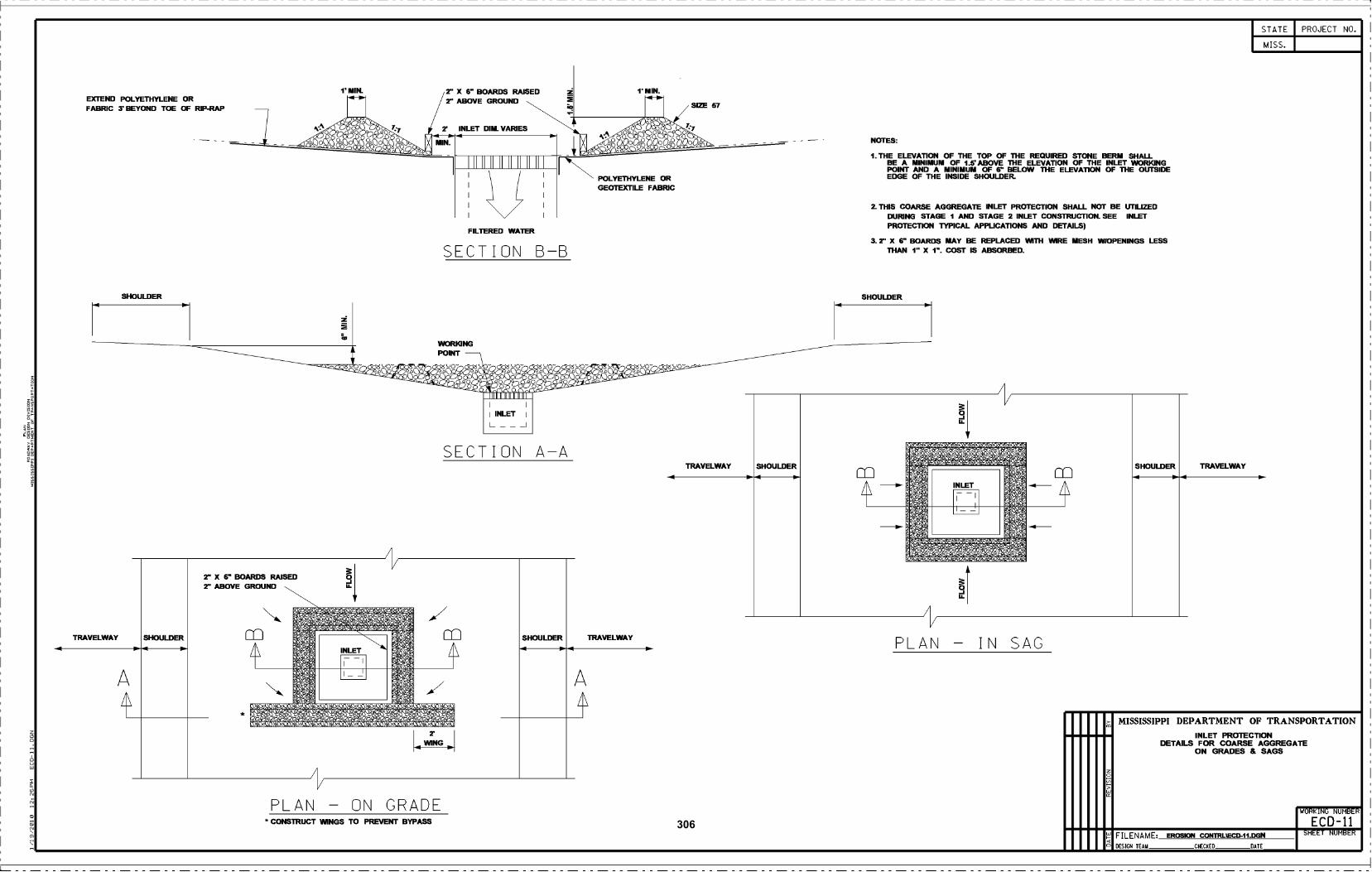
EXTEND POLYETHYLENE ORFABRIC 3 BEYOND TOE OF RIP-RAP
SHOULDER
2 X 6 BOARDS RAISED2 ABOVE GROUND
iiiiiiiiiiiiiiiii
I INLET i
L
/
1 MIN. 2 X 6 BOARDS RAISED2" ABOVE GROUND
- WORKINGA POINT
--&.;- - .&cx:. .%.# .a%.9. -
--. &_.o__. -iiiiiiuiiiuiuiiii
.4WING
PLAN - ON GRADE* cONSTRUCT WINGS TO PREVENT BYPASS
2 INLET DIM. VARIES
FILTERED WATER
SECTION B-B
SECTION A-A
SHOULDER4
A
+
POLYETHYLENE ORGEOTEXTILE FABRIC
TRAVELWAY
1 MIN.
-.4
SIZE 57
TRAVELWAY SHOULDER
-.4
NOTES:
THE ELEVATION OF THE TOP OF ThE REQUIRED STONE BERM SHALLBE A MINIMUM OF I .5 ABOVE ThE ELEVATION OF THE INLET WORKINGPOINT AND A MINIMUM OF 6" BELOW ThE ELEVATiON OF ThE OUTSIDEEDGE OF THE INSIDE SHOULDER.
THIS ARSE AGGREGATE INLET PROTECTION SHALL NOT BE UTILIZEDDURING STAGE I AND STAGE 2 INLET CONSTRUCTION. SEE INLETPROTECTION TYPICAL APPLICATIONS AND DETAILS)
2 X BOARDS MAY BE REPLAcED WITh WIRE MESH WIOPENINGS LESSThAN 1" X 1. COST IS ABSORBED.
/PLAN - IN SAG
o
>
SHOULDER TRAVELWAY
STATE
MISS.
DESIGN TEAM CHECKED DATE
PROJECT NO.
MISSISSIPPI DEPARTMENT OF TRANSPORTATIONINLET PROTECTION
DETAILS FOR COARSE AGGREGATEON GRADES S SAGS
WORKING NUMBER
E CD-IlFILENAME EROSION cONTRUEcD.11.DGN SHEET NUMBER
TRAVELWAY-.4
SHOULDER SHOULDER
306
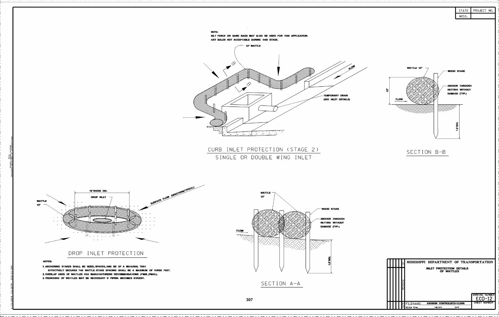
NOTES:
ANOHORING STAKES SHALL BE SIZED, SPAD, AND BE OF A MATERIAL ThATEFFECTIVELY SECURES THE WATfLE. STAKE SPAcING SHALL BE A MAXIMUM OF ThREE FEET.
OvERLAP ENDS OF WATILES PER MANUFACÌURERS RECOMMENDATIONS (VMIN.,YMAX.).
TRENcHING OF WATILES MAY BE NECESSARY IF PIPING BEcOMES EVIDENT.
u
DROP INLET PROTECTION
NOTE:
SILT FENcE OR SAND BAGS MAY ALSO BE USED FOR ThIS APPLIcATION.HAY BALES NOT ACCEPTABLE DURING ThIS STAGE.
ir WATILE
CURB INLET PROTECTION (STAGE 2)
SINGLE OR DOUBLE WING INLET
SECTION A-A
TEMPORARY DRAIN
(SEE INLET DETAILS)
ANOHOR ThROUGH
NETIING WITHOUT
DAMAGE (TYP.)
o
>
SECTION B-B
STATE
MISS.
ANcHOR THROUGH
NETI1NG WITHOUT
DAMAGE (TYP.)
PROJECT NO.
MISSISSIPPI DEPARTMENT OF TRANSPORTATION
INLET PROTECTION DETAILSOF WA11LES
WORKING NUMBER
ECD-12FILENAME EROSION cONTROLiEcD12.DGN SHEET NUMBER
DESIGN TEAM CHECKED DATE
307
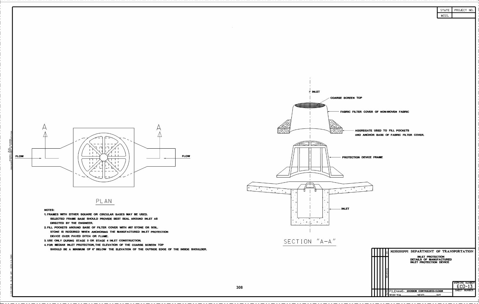
FLOW
PLAN
A/\
FLOW
NOTES:
FRAMES WflH EITHER SQUARE OR cIRcULAR BASES MAY BE USED.
SELECTED FRAME BASE SHOULD PROVIDE BEST SEAL AROUND INLET AS
DIRECTED BY ThE ENGINEER.
FILL POEKETS AROUND BASE OF FILTER COVER WflH #57 STONE OR SOILSTONE IS REQUIRED WHEN ANcHORING THE MANUFACTURED INLET PROTECTION
DEVICE OVER PAVED DITCH OR FLUME.
USE ONLY DURING STAGE 3 OR STAGE 4 INLET CONSTRUCTION.
4 FOR MEDIAN INLET PROTECTION, THE ELEVATION OF THE COARSE SCREEN TOP
SHOULD BE A MINIMUM OF 6" BELOW ThE ELEVATION OF ThE OUTSIDE EDGE OF THE INSIDE SHOULDER.
1 INLET
SECTION "A-A"
COARSE SCREEN TOP
FABRIC FILTER COVER OF NON-WOVEN FABRIC
INLET
AGGREGATE USED TO FILL POCKETS
AND ANOIIOR BASE OF FABRIC FILTER COVER.
o
>
STATE
MISS.
DESIGN TEAM CHECKED DATE
PROJECT NO.
MISSISSIPPI DEPARTMENT OF TRANSPORTATION
INLET PROTECTIONDETAILS OF MANUFACTUREDINLET PROTECTION DEVICE
WORKING NUMBER
ECD-13SHEET NUMBERF ILENAME EROSIOt cONTRCLiEcD.13.DGN
308
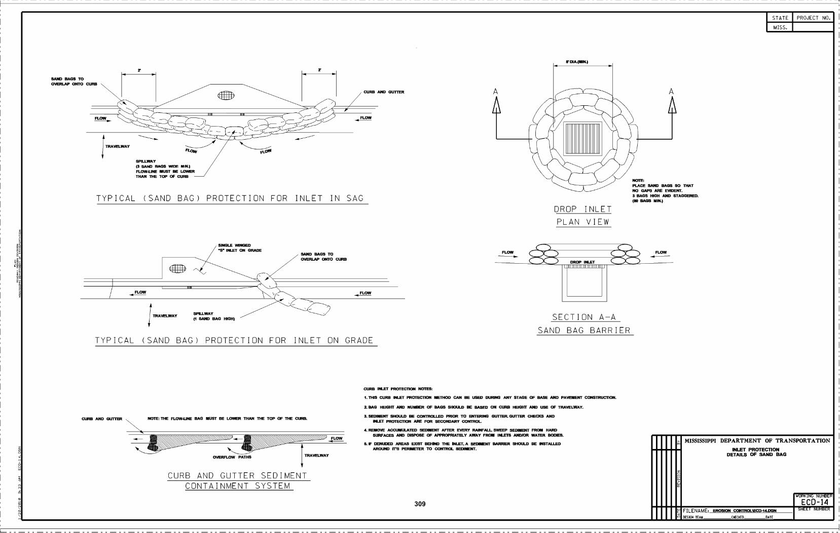
SAND BAGS TOOVERLAP OtilO cURB
-
SPILLWAY( SAND BAGS WIDE MIN.)FLOW-LINE MUST BE LOWERTHAN ThE TOP OF cURB
TYPICAL (SAND BAG) PROTECTION FOR INLET IN SAG
SINGLE WINGED-s- INLET ON GRADE
vu-
cURB AND OUTrER
FLOW
TYPICAL (SAND BAG) PROTECTION FOR INLET ON GRADE
OVERFLOW PATHS
CURB AND GUTTER SEDIMENTCONTAINMENT SYSTEM
SAND BAGS TOOVERLAP OtffO cURB
TRAVELWAY
FLOW
FLOW
SEDIMENT SHOULD BE CONTROLLED PRIOR TO ENIERING OUrlER. GU1TER HEKS ANDINLFI PROTECTION ARE FOR SEcONDARY cONIROL.
REMOVE ACcUMULATED SEDIMENT AFTER EVERY RAINFALL SWEEP SEDIMENI FR011 HARDSURFAcES AND DISPOSE OF APPROPRIATELY AWAY FROM INLEIS ANDIOR WATER BODIES.
IF DENUDED AREAS EXIST BEHIND ThE INLEI A SEDINI BARRIER SHOULD BE INSTALLEDAROUND ri-s PERIMETER TO cONIROL SEDIN1.
r DIA.(MIN.)
PLAcE SAND BAGS SO THATNOTE:
NO GAPS ARE EVIDENT.3 BAGS HIGH AND STAGGERED.(80 BAGS MIN.)
DROP INLET
PLAN VIEW
.I.I.IuI.IuIuIuI.I-
SECTION A-A
SAND BAG BARRIER
cURB INLET PROTECTION NOTES:
ThIS cURB INLET PROTECTiON METHOD CAN BE USED DURING ANY STAGE OF BASE AND PAVEMENT CONSTRUCTION.
BAG HEIGRf AND NUMBER OF BAGS SHOULD BE BASED ON CURB HEIGIfI AND USE OF TRAVELWAY.
FLOW
o
>
STATE
MISS.
PROJECT NO.
MISSISSIPPI DEPARTMENT OF TRANSPORTATIONINLET PROTECTION
DETAILS OF SAND BAG
WORKING NUMBER
ECD-14
DESIGN TEAM CHECKED DATE
FILENAME EROSION EOtUROLiEED.ItDGN SHEET NUMBER
cURB AND GLfER NOTE: ThE FLOW-UNE BAG MUST BE LOWER THAN ThE TOP OF ThE cURB
SPILLWAY(1 SAND BAG HIGH)
TRAVELWAY
309
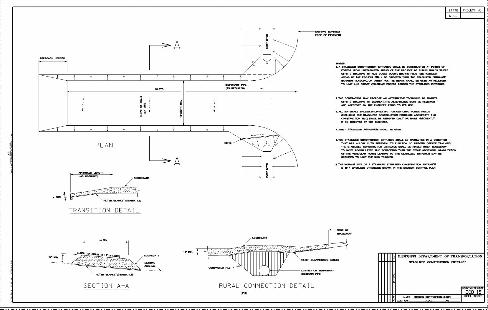
APPROAcH LENGTH
4 IMN-
12" MIN.
APPROAcH LENGTH(AS REQUIRED)
PLAN
TRANSITION DETAIL
15 MIN.
DRAIN (O1 Fy
FILTER BLANKET(GEOTEXÌ1LE)
SECTION A-A
AGGREGATE
FILTER BLANKET(GEOTEXTILE}
AGGREGATE
EXISTINGGROUND
5O STD.
A
A
M
12 MIN.
I
COMPACTED FILL
TEMPORARY PIPE(AS REQUIRED)
AGGREGATE
t111111I'IIIHHHI'NIIIIIP"Ir
RURAL CONNECTION DETAIL
EXISTING ROADWAYEDGE OF PAVEMENI
NOTES:
1_ A STABILIZED cONSTRUCTION ENTRANcE SHALL BE cONSTRUCTED AT POINTS OFEGRESS FROM UNSTABIUZED AREAS OF THE PROJECT TO PUBLIC ROADS WHEREOFFSITE TRAcKING Of MUD COULD OCCUR. TRAFFIC FROM UNSTASIUZEDAREAS OF THE PROJECT SHALL BE DIRECTED THRU THE STABiLIZED ENTRANcE.BARRIERE, FLAGGING, OR OTHER POSITIVE MEANS SHALL BE USED AS REQUIREDTO UMFI AND DIRECT VEHIcULAR EGRESS AcROSS THE STABILIZED ENTRANcE.
FILTER BLAIIKET(GEOTEXTILE)
EXISTING OR TEMPORARYSIDEDRAIN PIPE
2 THE cONTRACTOR MAY PROPOSE AN ALTERNATIVE TEcHNIQUE TO MINIMIZEOFFSITE TRAcKING Of SEDIMENT. ThE ALTERNATIVE MUST BE REVIEWEDAND APPROVED BY THE ENGINEER PRIOR TO Fr5 USE.
3_ ALL MATERIALS SPILLED, DROPPED. OR TRAcKED OPilO PUBUC ROADS(INcLUDING ThE STABILIZED cONSTRUCTION ENTRANcE AGGREGATE ANDCONSTRUC110N MUD) SHALL BE REMOVED DAILY. OR MORE FREQUENTLYIF SO DIRECTED BY THE ENGINEER.
4_ SIZE I STABILIZER AGGREGATE SHALL BE USED
5 THE STABILIZED cONSTRUCTION ENIRANOE SHALL BE MAINTAINED IN A cONDITIONTHAT WLL ALLOW IT TO PERFORM rr FUNCTION TO PREVENT OFFSITE TRAcKING.ThE STABIUZED cONSTRUCTION ENTRANcE SHALL BE RINSED WHEN NEcESSARYTO MOVE AccUMULATED MUD DOWNWARD THRU THE STONE. ADDITIONAL STABIUZATIONOF ThE VEHIJLAR ROUTE LEADING TO THE STABiLIZED ENTRANcE MAY BEREQUIRED TO LIMIT ThE MUD TRACKED.
6. THE NOMINAL SIZE OF A STANDARD STABILIZED CONSTRUCTION ENTRANCEIS 1f X 50 UNLESS OTHERWISE SHOWN IN ThE EROSION CONTROL PLAN
EDGE OFTRAVELWAY
o
>
STATE
MISS.
DESIGN TEAM CHECKED DATE
PROJECT NO.
MISSISSIPPI DEPARTMENT OF TRANSPORTATION
STABILIZED CONSTRUCTION ENTRANCE
WORKING NUMBER
ECD-15FILENAME- EROSION CNOLiECE-15DGN SHEET NUMBER
310
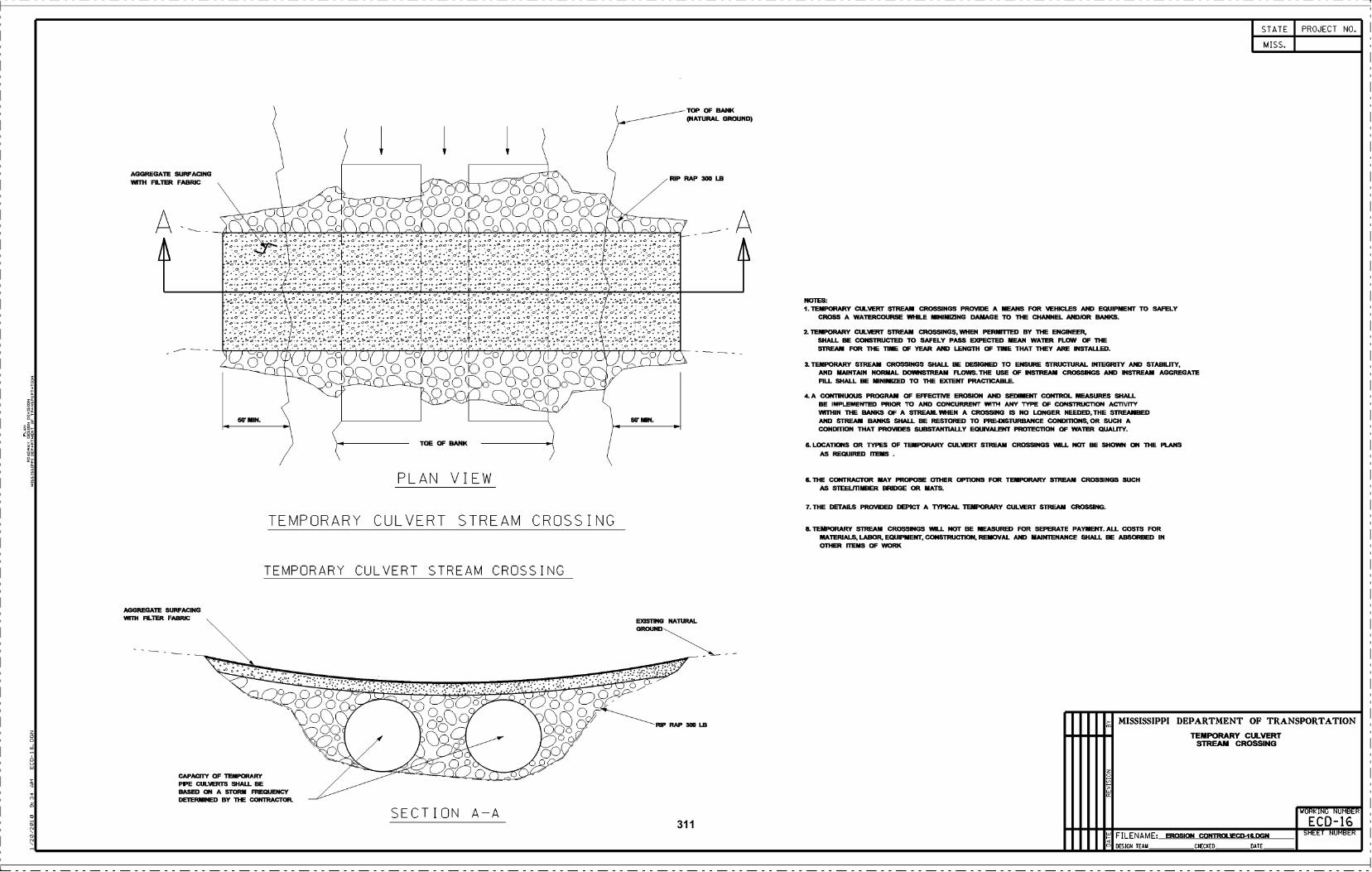
AGGREGATE StJRFAaMGVEIH FILTER FABRIC
AGGREGATE SURFAMGwiril FILTER FABRIC
CAPAHY OF TEMPORARYPIPE cIJLVERTS SHALL BEBASED ON A STORM FREQUENCYDETERMINED BY ThE CONTRACTOR
PLAN VIEW
TEMPORARY CULVERT STREAM CROSSING
TEMPORARY CULVERT STREAM CROSSING
SECTION A-A
TOP OF BAtIKOIATURAL GROUND)
A
NOTES:TEMPORARY cULVERT STREAM cROSSINGS PROVIDE A MEANS FOR VEHIclES AND EQUIPMENI TO SAFELY
cROSS A WATERcOURSE WHILE MINIMIZING DAMAGE TO ThE cHANNEL ANDIOR BANKS.
TEMPORARY cULVERT STREAM cROSSINGS. WHEN PERMITIED BY ThE ENGINEERSHALL BE CONSTRUCTED TO SAFELY PASS EXPECTED MEAN WATER FLOW OF ThESTREAM FOR ThE liME OF YEAR AND LENGTH OF liME THAT ThEY ARE INSTALLED.
3 TEMPORARY STREAM CROSSINGS SHALL BE DESIGNED TO ENSURE STRUCTURAL INIEGRITY AND STABILFIY,AND MAINTAIN NORMAL DOWNSTREAM FLOWS. THE USE OF INSTREAM CROSSINGS AND INSTREAM AGGREGATEFILL SHALL BE MINIMIZED TO ThE EXTENT PRACTICABLE.
L A CONTINUOUS PROGRAM OF EFFECTIVE EROSION AND SEDIMENT CONTROL MEASURES SHALLBE IMPLEMENTED PRIOR TO AND CONcURRENT WTH ANY TYPE OF CONSTRUCTION ACTIVITYWFfHIN ThE BANKS OF A STREABI. WHEN A cROSSING IS NO LONGER NEEDED. THE STREAMBEDAND STREAM BANKS SHALL BE RESTORED TO PRE-DISTURBANCE CONDrnONS, OR SUCH ACONDfl1ON THAT PROVIDES SUBSTAN11ALLY EQUIVALENT PROTEC110N OF WATER QUALifY.
5. LOCATIONS OR TYPES OF TEMPORARY COLVERI STREAM CROSSINGS WILL NOT BE SHOWN ON ThE PLANSAS REQUIRED nEME
ThE cONTRACTOR MAY PROPOSE OTHER OP11ONS FOR TEMPORARY STREAM cROSSINGS SUcHAS STEELII1MBER BRIDGE OR MATE.
THE DETAILS PROVIDED DEPICT A TYPICAL TEMPORARY cULVERT STREAM cROSSING.
a. TEMPORARY STREAM cROSSINGS WILL NOT BE MEASURED FOR SEPERATE PAYMENT. ALL COSTS FORMATERIALE. LABOR. EQUIPMENT. CONSTRUCTION. REMOVAL AND MAINTENANOS SHALL BE ABSORBED INOTHER 1ENS OF WORK
o
>
STATE
MISS.
PROJECT NO.
MISSISSIPPI DEPARTMENT OF TRANSPORTATIONTEMPORARY CULVERT
STREAM CROSSING
WORKING NUMBER
ECD-16
DESIGN TEAM CHECKED DATE
SHEET NUMBERF ILENAME EROSION CONTROLiEGD-16.DGN
311
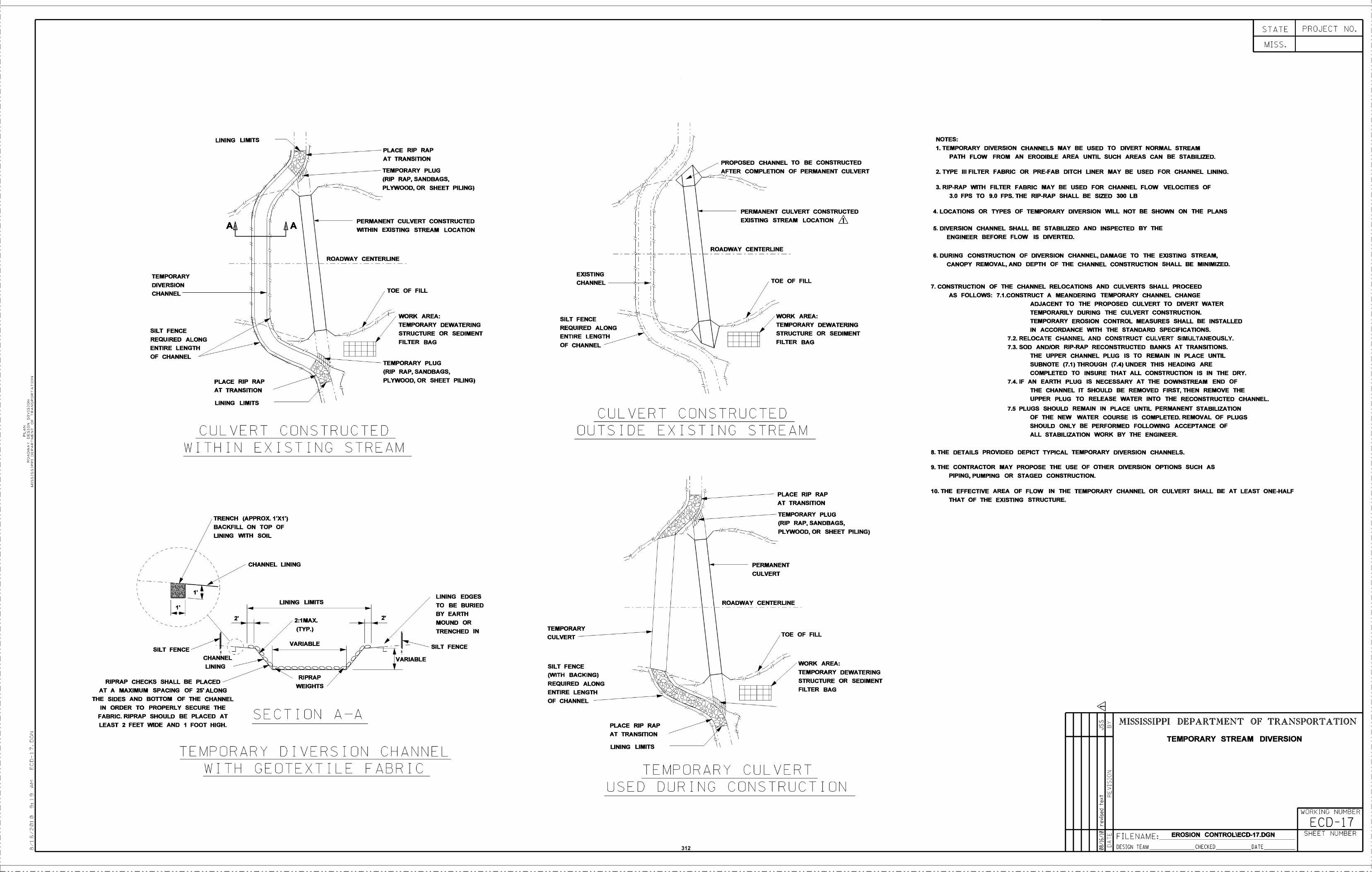
TEMPORARY
DIVERSION
CHANNEL
SILT FENCEREQUIRED ALONG
ENTIRE LENGTHOF CHANNEL
SILT FENCE
LINING LIMITS
PLACE RIP RAPAT TRANSITION
LINING LIMITS
RIPRAP CHECKS SHALL BE PLACED -AT A MAXIMUM SPACING OF 25 ALONG
THE SIDES AND BOTrOM OF THE CHANNELIN ORDER TO PROPERLY SECURE THE
FABRIC. RIPRAP SHOULD BE PLACED ATLEAST 2 FEET WIDE AND I FOOT HIGH.
CULVERT CONSTRUCTEDWIT IN EXISTING STREAM
TRENCH (APPROX. 1X1)BACKFILL ON TOP OFLINING WITH SOIL
CHANNELLINING
CHANNEL LINING
LINING LIMITS
RIPRAP
WEIGHTS
SECTION AA
ROADWAY CENTERLINE
PLACE RIP RAPAT TRANSITION
TEMPORARY PLUG(RIP RAP, SANDBAGS,PLYWOOD. OR SHEET PILING)
PERMANENT CULVERT CONSTRUCTEDWITHIN EXISTING STREAM LOCATION
TOE OF FILL
.
WORK AREA:/ TEMPORARY DEWATERING
- STRUCTURE OR SEDIMENT-r- . FILTER BAG
n TEMPORARY PLUG. (RIP RAP, SANDBAGS,
\ .1 :' PLYWOOD, OR SHEET PILING)
VARIABLE
LINING EDGESTO BE BURIEDBY EARTHMOUND ORTRENCHED IN
SILT FENCE
TEMPORARY DIVERSION CHANNELWITH CEOTEXTILE PABRIC
TEMPORARY
CULVERT
SILT FENCE(WITH BACKING)REQUIRED ALONGENTIRE LENGTHOF CHANNEL
PLACE RIP RAPAT TRANSITION
LINING LIMITS
CULVERT CONSTRUCTEDOUTSIDE EXISTINC STREAM
PERMANENT
CULVERT
ROADWAY CENTERLINE
PLACE RIP RAPAT TRANSITION
TOE OF FILL
TEMPORARY PLUG(RIP RAP, SANDBAGS,PLYWOOD, OR SHEET PILING)
'WORK AREA:TEMPORARY DEWATERINGSTRUCTURE OR SEDIMENTFILTER BAG
TEMPORARY CULVERTUSED DURING CONSTRUCTION
THE UPPER CHANNEL PLUG IS TO REMAIN IN PLACE UNTILSUBNOTE (7.1) THROUGH (7.4) UNDER THIS HEADING ARECOMPLETED TO INSURE THAT ALL CONSTRUCTION IS IN THE DRY.
7.4. IF AN EARTH PLUG IS NECESSARY AT THE DOWNSTREAM END OFTHE CHANNEL IT SHOULD BE REMOVED FIRST. THEN REMOVE THEUPPER PLUG TO RELEASE WATER INTO THE RECONSTRUCTED CHANNEL
7.5 PLUGS SHOULD REMAIN IN PLACE UNTIL PERMANENT STABILIZATIONOF THE NEW WATER COURSE IS COMPLETED. REMOVAL OF PLUGSSHOULD ONLY BE PERFORMED FOLLOWING ACCEPTANCE OFALL STABILIZATION WORK BY THE ENGINEER.
THE DETAILS PROVIDED DEPICT TYPICAL TEMPORARY DIVERSION CHANNELS.
THE CONTRACTOR MAY PROPOSE THE USE OF OTHER DIVERSION OPTIONS SUCH ASPIPING, PUMPING OR STAGED CONSTRUCTION.
THE EFFECTIVE AREA OF FLOW IN THE TEMPORARY CHANNEL OR CULVERT SHALL BE AT LEAST ONE-HALFTHAT OF THE EXISTING STRUCTURE.
STATE
MISS.
MISSISSIPPI DEPARTMENT OF TRANSPORTATION
TEMPORARY STREAM DIVERSION
WORKING NUMBER
ECD-17F I L E N A M E : EROSION CONTROLECDl7.DGN
DESIGN TEAM CHECKED DATE
PROJECT NO.
SHEET NUMBER
- PROPOSED CHANNEL TO BE CONSTRUCTEDAFTER COMPLETION OF PERMANENT CULVERT
NOTES:
1. TEMPORARY DIVERSION CHANNELS MAY BE USED TO DIVERT NORMAL STREAMPATH FLOW FROM AN ERODIBLE AREA UNTIL SUCH AREAS CAN BE STABILIZED.
2. TYPE III FILTER FABRIC OR PRE-FAB DITCH LINER MAY BE USED FOR CHANNEL LINING.
3. RIP-RAP WITH FILTER FABRIC MAY BE USED FOR CHANNEL FLOW VELOCITIES OF3.0 FPS TO 9.0 FPS. THE RIP-RAP SHALL BE SIZED 300 LB
4. LOCATIONS OR TYPES OF TEMPORARY DIVERSION WILL NOT BE SHOWN ON THE PLANSCULVERT CONSTRUCTEDEXISTING STREAM LOCATIONI
5. DIVERSION CHANNEL SHALL BE STABILIZED AND INSPECTED BY THEENGINEER BEFORE FLOW IS DIVERTED.
ROADWAY CENTERLINE
IPERMANENT
6. DURING CONSTRUCTION OF DIVERSION CHANNEL, DAMAGE TO THE EXISTING STREAM,CANOPY REMOVAL, AND DEPTH OF THE CHANNEL CONSTRUCTION SHALL BE MINIMIZED.
EXISTING
CHANNEL / TOE OF FILL7. CONSTRUCTION OF THE CHANNEL RELOCATIONS AND CULVERTS SHALL PROCEED
AS FOLLOWS: 7.1 CONSTRUCT A MEANDERING TEMPORARY CHANNEL CHANGEADJACENT TO THE PROPOSED CULVERT TO DIVERT WATER
SILT FENCEp WORK AREA:
TEMPORARILY DURING THE CULVERT CONSTRUCTION.TEMPORARY EROSION CONTROL MEASURES SHALL BE INSTALLED
REQUIRED ALONGENTIRE LENGTH
-
--
TEMPORARY DEWATERINGSTRUCTURE OR SEDIMENTn
IN ACCORDANCE WITH THE STANDARD SPECIFICATIONS.7.2. RELOCATE CHANNEL AND CONSTRUCT CULVERT SIMULTANEOUSLY.,
I1I1I1OF CHANNEL FILTER BAG7.3. SOD ANDIOR RIP-RAP RECONSTRUCTED BANKS AT TRANSITIONS.
312
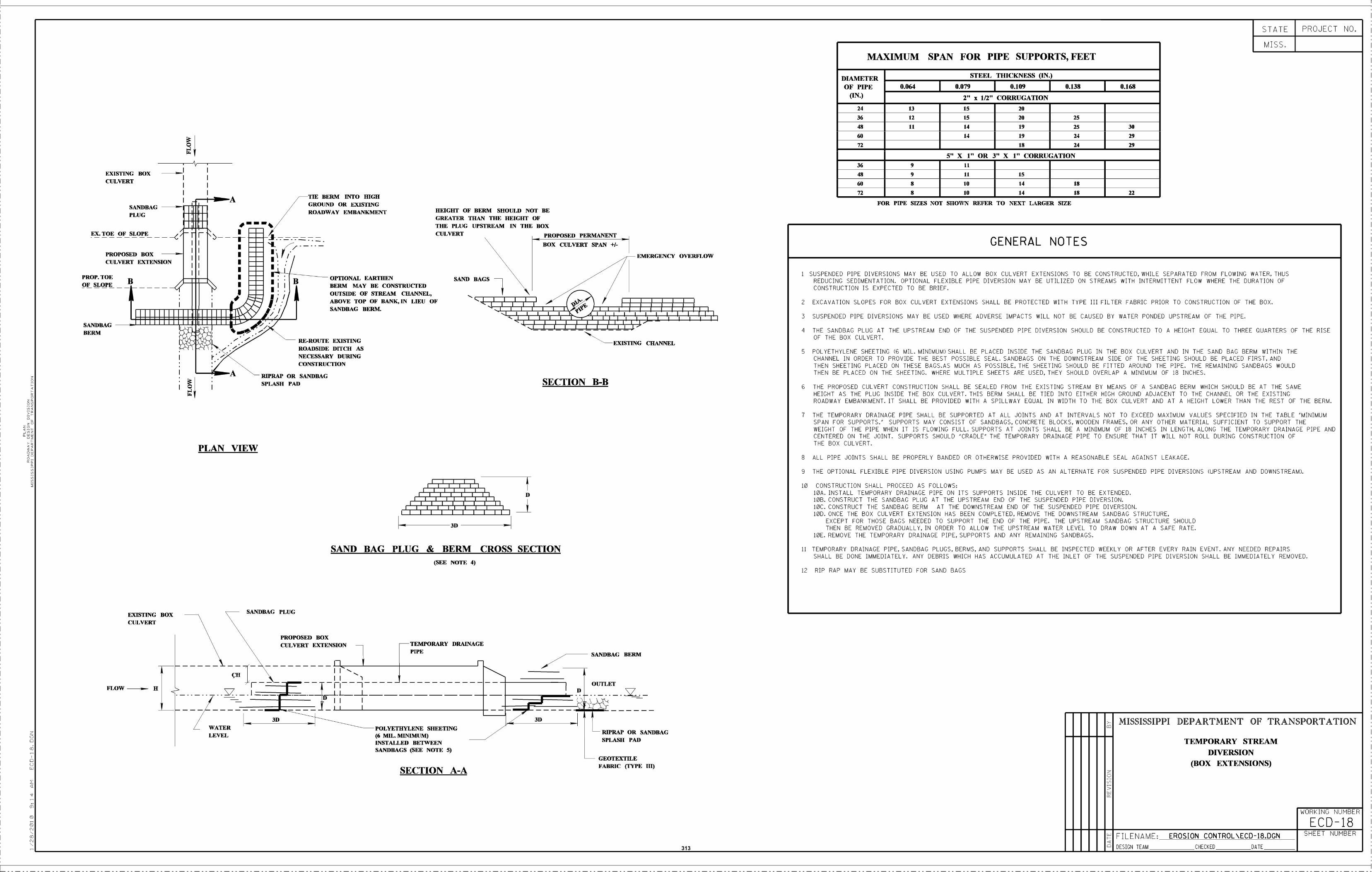
EXISTING BOXCULVERT
II II II II II II III DIIIIIIIIJ I III 'I 'I 'I R ;i
3D
SAND BAG PLUG & BERM CROSS SECTION(SEE NOTE 4)
FOR PIPE SIZES NOT SHOWN REFER TO NEXT LARGER SIZE
10 CONSTRUCTION SHALL PROCEED AS FOLLDWS10A. INSTALL TEMPORARY DRAINAGE PIPE ON ITS SUPPORTS INSIDE THE CULVERT TO BE EXTENDED.(AB. CONSTRUCT THE SANDBAG PLUG AT THE UPSTREAM END OF THE SUSPENDED PIPE DIVERSION.10C. CONSTRUCT THE SANDBAG BERM AT THE DOWNSTREAM END CF THE SUSPENDED PIPE DIVERSION.100. ONCE THE BOT CULVERT EXTENSION HAS BEEN COMPLETED, REMOVE THE DOWNSTREAM SANDBAG STRUCTURE.
EXCEPT FOR THOSE BAGS NEEDED TO SUPPORT THE END OF THE PIPE, THE UPSTREAM SANDBAG STRUCTURE SHOULDTHEN BE REMOVED GRADUALLY. IN ORDER TO ALLOW THE UPSTREAM WATER LEVEL TU DRAW DOWN AT A SAFE RATE.
10E. REMOVE THE TEMPORARY DRAINAGE PIPE. SUPPORTS AND ANT REMAINING SANDBAGS.
1) TEMPORARY DRAINAGE PIPE. SANDBAG PLUGS. BERMS, AND SUPPORTS SHALL BE INSPECTED WEEKLY OR AFTER EVERY RAIN EVENT. ANY NEEDED REPAIRSSHALL BE DONE IMMEDIATELY, ANT DEBRIS WHICH HAS ACCUMULATED AT THE INLET OF THE SUSPENDED PIPE DIVERSION SHALL BE IMMEDIATELY REMOVED.
12 RIP RAP MAY BE SUBSTITUTED FOR SAND BAGS
STATE
MISS.
DESIGN TEAM CHECKED DATE
PROJECT NO.
MISSISSIPPI DEPARTMENT OF TRANSPORTATION
TEMPORARY STREAMDIVERSION
(BOX EXTENSIONS)
WORKING NUMBER
ECD-18
MAXIMUM SPAN FOR PIPE SUPPORTS, FEET
DIAMETEROF PIPE
(IN.)
STEEL THICKNESS (IN.)
0.064 0.079 O.1O 0.138 0.168
2" x 1/2' CORRUGATION24 13 15 20
36 12 15 20 25
48 11 14 19 25 30
50 14 19 24 29
72 18 24 29
5" X 1" OR 3" X 1" CORRUGATION36 9 II48 9 11 15
60 8 10 14 18
72 8 10 14 18 22
EX. TOE OF SLOPE
PROPOSED BOX
-UI-HI
IIIII
s II
----
OPTIONAL EARTHENBERM MAY BE CONSTRUCTEDOUTSIDE OF STREAM CHANNEL,
CULVERT PROPOSED PERMANENT
EMERGENCY OVERFLOW
GENERAL NOTES------------------------
I,I,U
I
BOX CULVERT SPAiN +1-
CULVERT EXTENSION
PROP. TOEOF SLOPE I i SUSFENDED PIPE DIVERSIONS MAY BE USED TO ALLOW BOX CULVERT EXTENSIONS TO WE CONSTRUCTED. WHILE SEPARATED FROM FLOWING WATER. THUS
REDUCING SEDIMENTATION. OPTIONAL FLEXIBLE PIPE DIVERSION MAY BE UTILIZED ON STREAMS WITH INTERMITTENT FLOW WHERE THE DURATION OFCONSTRUCTION IS EXPECTED FO BE BRIEF.
ABOVE TOP OF BANK, IN LIEU OF 2 EXCAVATION SLOPES FOR BOX CULVERT EXTENSIONS SHALL BE PROTECTED WITH TYPE III FILTER FABRIC PRIOR TO CONSTRUCTION OF THE BOX.
IIIIIIIIIIII!!lIIIIII1I'4' SANDBAG BERM.3 SUSPENDED PIPE DIVERSIONS MAY BE USED WHERE ADVERSE IMPACTS WILL NOT BE CAUSED BY WATER PONDED UPSTREAM OF THE PIPE.
SANDBAG iii.-BERM 4 THE SANDBAG FLUO AT THE UPSTREAM END OF THE SUSPENDED PIPE DIVERSION SHOULD BE CONSTRUCTED TO A HEIGHT EOUAL TO THREE OUARTERS OF THE BISE
RE-ROUTE EXISTING EXISTING CHANNELOF THE BOX CULVERT.
ROADSIDE DITCH AS 5 POLTETHTLENE SHEETING (6 MIL, MINIMUM) SHALL BE PLACED INSIDE THE SANDBAG PLUG IN THE BOX CULVERT AND IN THE SAND BAG BERM WITHIN THENECESSARY DURING CHANNEL IN ORDER TO PROVIDE THE BEST POSSIBLE SEAL. SANDBAGS ON THE DOWNSTREAM SIDE OF THE SHEETING SHOULD BE PLACED FIRST, ANDCONSTRUCTION THEN SHEETING PLACED ON THESE BAGS.AS MUCH AS POSSIBLE, THE SHEETING SHOULD BE FITTED ABOUND THE PIPE. THE REMAINING SANDBAGS WOULD
RIPRAP OR SANDBAG THEN BE PLACED ON THE SHEETING, WHERE MULTIPLE SHEETS ARE USED, THEY SHOULD OVERLAP A MINIMUM OF IB INCHES.
SPLASH PAD SECTION B-BE THE PROPOSED CULVERT CONSTRUCTION SHALL BE SEALED FROM THE EVISTING STREAM BY MEANS OF A SANDBAG BERM WHICH SHOULD BE AT THE SAME
HEIGHT AS THE PLUS INSIDE THE BOX CULVERT. THIS BERM SHALL BE TIED INTO EITHER HIGH GROUND ADJACENT TO THE CHANNEL OR THE EXISTINGROADWAY EMBANKMENT, IT SHALL BE PROVIDED WITH A SPILLWAT EOUAL IN WIDTH TO THE BOX CULVERT AND AT A HEIGHT LOWER THAN THE REST OF THE BERM.
7 THE TEMPORARY DRAINAGE PIPE SHALL BE SUPPORTED AT ALL JOINTS AND AT INTERVALS NOT TO EXCEED MAXIMUM VALUES SPECIFIED IN THE TABLE "MINIMUMSPAN FOR SUPPORTS." SUPPORTS MAY CONSIST OF SANDBAGS. CONCRETE BLOCKS, WOODEN FRAMES. OR ANY OTHER MATERIAL SUFFICIENT TO SUPPORT THEWEICHT OF THE PIPE WHEN IT IS FLOWING FULL. SUPPORTS AT JOINTS SHALL BE A MINIMUM OF 18 INCHES IN LENGTH, ALONG THE TEMPORART DRAINAGE PIPE ANDCENTERED ON THE JOINT. SUPPORTS SHOULD "CRADLE" THE TEMPORART DRAINAGE RIPE TO ENSURE THAT IT WILL NOT ROLL DURING CONSTRUCTION OFTHE BOX CULVERT.PLAN VIEW
8 ALL PIPE JOINTS SHALL BE PROPERLY BANDED OR OTHERWISE PROVIDED WITH A REASONABLE SEAL AGAINST LEAKAGE.
N THE OPTIONAL FLEXIBLE PIPE DIVERSION USING PUMPS MAY BE USED AX AN ALTERNATE FOR SUSPENDED PIPE DIVERSIONS (UPSTREAM AND DOWNSTREAM).
EXISTING BOXCULVERT
PROPOSED BOXCULVERT EXIENSION TEMPORARY DRAINAGE
PIPE SANDBAG BERM
OUTLETFLOW H
-3D
WATER POLYETHYLENE SHEETINGLEVEL (6 MIL. MINIMUM) RIPRAF OR SANDBAG
INSTALLED SPLASH PADBETWEENSANDBAGS (SEE NOTE 5)
TIE BERM INTO HIGH
SANDBAG
PLUG
#__ -
GROUND OR EXIStINGROADWAY EMBANKMENT HEIGHT OP BERM SHOELD NOT BE
GREATER THAN TIlE HEIGHT OFTHE PLUG UPSTREAM IN THE BOX
'lull''lull'111111
FILENAME: EROSION CONTROL\ECD-18.06N SHEET NUMBER
GEOTEXTILE
SECTION A-A FABRIC (TYPE ifi)
313
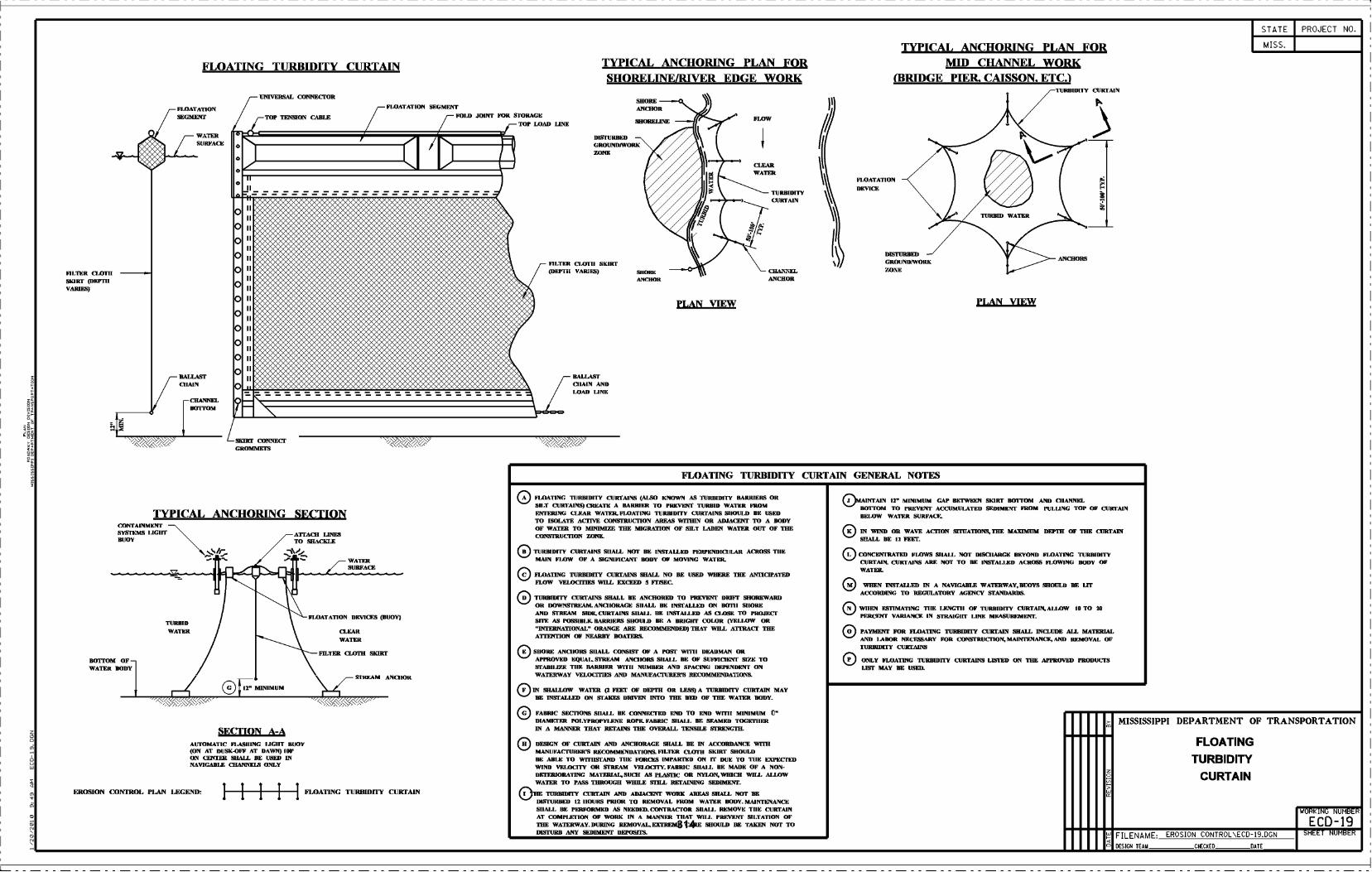
FiLTER CLOT!!SKIRT (DICI9IIVARIES)
BOTfOM OF -WATER hOOT
CONTAINMINISYSTEMS I.tGlrrBUOY
TURBID
WATER
EROSION CONTROL FLAN LEGEND
FLOATING TURBIDITY CURTAIN
I
o
o
o
oooooooooooo
II
IIII
IIIIIIIIIIIIIIIIIIII
IIII
IIIIIIII
UNIVERSAL CONNECTOR
12' MINIMUM
TOP TSNSION CABLE
TYPICAL ANCHORING SECTION
ECTLON A-AAUTOMATIC FLAShING I.IGIIT BUOY(ON AT DUSK-OFF AT DAWN) 100'ON CENTER SHALL BE USED INNAVIGABLE COANNELS ONLY
ATrACO LINESTO SRAcKLE
.d WATERSURFACE
I?LOATATION DEVICES (BUOY)
CLEARWATER
I?LOATATION SEGMENT
,- BULO JOINT FOR STORAGETOP LOAD LINE
FILTER 1AYEG ShORT
SIREAM ANCIIOI(
FLOATINC TURBIDiTY CURTAIN
BALLASTCIIAIN ANDLOAD LINE
TYPICAL ANCHORING FLAN FORSHORELINE/RiVER EDGE WORK
DIFI'URBEDGROUNDIWORKZONE
FILTER CLOTII SKIRT(DEPTh VARIFS) SHOIIE
ANCHOR
SHOREANCHOR
SHORELINE
PLAN VIEW
CLEARWATER
TURBIDITYCURTAIN
CHANIELANcHOR
(y
FLOATA11ON
DEVICE
TYPICAL ANCHORING PLAN FORMID CHANNEL WORK
(BRIDGE PIER. CAISSON. ETC.1
DISITRBEDGROIJNDIWORKZONE
PLAN VIEW
TURBIDITY CURTAIN
ANCHORS
c:D FLOATING TURBIDI1'Y CURtAINS (ALSO KNOWN AS TURBIDII'Y BARRIESE ORSILT CURTAINS CREATE A BARRIER TO PREVENT TURBID WATER FROMENTERING CLEAR WATER. FLOATING TURBIDITY CURTAINS SIIOULD BE USEDTO ISOLATE ACTIVE CONSTRUCTION AREAS WITHIN OR ARJACENT TO A BODYOF WATER TO MINIMIZE TIlE MIGRATION OF SILT LADEN WATER ChiT OF THECONSTRUCITON ZONE.
OE:CURTAINS ShALL NOT BE INSTALLED PERPENDICIJLAI1 ACROSS TIlE
MAIN FLOW OF A SIGNIFICANT BODY 01? MOVING WATER.
:D FLOATING TURBWITY CURTAINS SHALL NO BE USED WHERE THE MOIQFATEDFLOW VELOGTIES WILL EXCEED S FF!SEC.
U TURBIDITY CURTAINS SHALL BE ANCHORED TO PREVENT DRIFT SHOREWARDOR DOWNSTREAM. ANCIIORAGE ShALL BE INSTALLED ON B011I S1IOREAND STREAM SIDE.CURTAINS SIIAI.L BE INSTALLED AS ClAIRE TO PRWECFSITE AS POSSIBLE. BARRIERS SHOUI.D BE A BRIGHT COLOR (YELlOW OR"INTERNATIONAL" ORANGE ARE REcOMMENDED) THAT WILL ATTRACT TUEATTENTION OF NEARBY BOATERS.
E 511011E ANCIIORS SHALL CONSIST OF A FORI' WITII DKAUMAN ORAFFROVED EQUAL.STREAM ANCIIORS 511ML BE 0E SUFEICIETI' SIZE TOSTABIliZE TIlE RAMMER WITII NUMBER AND SPACING DEPENDENT ONWATERWAY VELOCTFIES MID MANUFACTURER'S RECOMMENDATIONS.
F IN SHALLOW WATER (2 FEET OF DEPTH OR LESS) A TTRBWITY CURTAIN MAYBE INSTALLER ON STAKES DRIVEN INTO THE BED OF THE WATER BODY.
® FABRIC SECTIONS SIIAI.L BE CONNECTED END TO END WillI MINIMUM U"DIAMETER I'OI.YPROI'YI.ENE 110FR. FABRIC SIIALI. BE SEAMED TOGFFIIERIN A MANNER THAT RETAINS THE OVERALL TENSILE STRENGTH.
fi DESIGN OF CURTAIN AND ANCHORAGE SHALL BE IN ACORDANCE WITHMANIJFACrURER'S RECOMMRNDATIONS. FILTER CLOTH SKIRT SHOULDBE AIII.II TO WITIIFI'AND TIlE FORCES IMPARTED ON IT DUE TO TIlE EXPECI'EDWIND VEI.00ITY OR STRF.AM VEI.00ITY. FABRIC SIIAI.L BE MADE OF A NON-DETERIORATING MATERIAL,SUCII AS PLASTIC OR NYLON,WIHCH WILL ALLOWWATER TO FASS THROUGH WHILE STILL RETAINING SEDIMENT.
:D1lE TURBIDITY CURTAIN AND ADJACENT WORK AREAS SHALL NOT BEDIFI'URBED 12 110UHR PRIOR TO REMOVAL FROM WATER BODY. MAINTENANCE511ML BE PERFORMED AS NEEDED. CONTRACTOR SIIAI,I. REMOVE TIlE CURTAINAT COMPI.ETION OF WORK IN A MANNER TIIAT WILL PREVENT MLTATION OFTUE WATERWAY. DURING REMOVAL,EETREME CARE SHOULD BE TAKEN NOT TODISTURB ANY SEDIMENT DEPOSFCL
.1 IRTAIN 12" MINIMUM GAP IH.IWEEN SKIRT BOTTOM AND CIIANNELBOUFOM TO PREVENT ACCUMULATED SEDIMENT FROM PULI.ING TOP OF CURTAINBEI.OW WATER SURFACE.
K IN WIND OR WAVE ACTION SLTUATIONS,TIIE MAXIMUM DEFER OF THE CURTAINSHALL BE fl FEET
I. CONCENTRATED VLOWS UlAlA. NOT DISCIIARGE BEYOND VLOXI'ING TURBIDITYCURTAIN. CURTAINS ARE NOT TO BE INSTALI.ED ACROSS FLOWING BODY OFWATER.
® WHEN INSTALLED IN A NAVIGABLE WATERWAY.BUOYS SHOULD BE LITACCORDING TO REGULATORY AGENCY STANDARDS.
N WIIEN ESTIMATING TIlE LENOTII OF TURBIDITY CURTAIN,AI.IAW 1G TO 2GPERCENT VARIANCE IN STRAIGIIT LINE MEASUREMENT.
O PAYMENT FOR GLOATING TURBWITY CURTAIN SHALL INCLUDE ALL MATERIALAND lABOR NECESSARY FOR CONEFRUCIION, MAINTENANCE, AND REMOVAL OFTURBWITY CURTAINS
® ONLY FLOATING TURBIDITY CURTAINS LISTED ON THE APPROVED PRODUCIRLIST MAY BE USED.
o>
STATE
MISS.
DESIGN TEAM CHECKED DATE
PROJECT NO.
MISSISSIPPI DEPARTMENT OF TRANSPORTATION
FLOATING
TURBIDITY
CURTAIN
WORKING NUMBER
ECD-19
_CONNECTCROMMETS
FLOATING TURBIDiTY CURTAIN GENERAL NOTES
FILENAME EROSION CONTROL\ECD-19.DGN SHEET NUMBER314
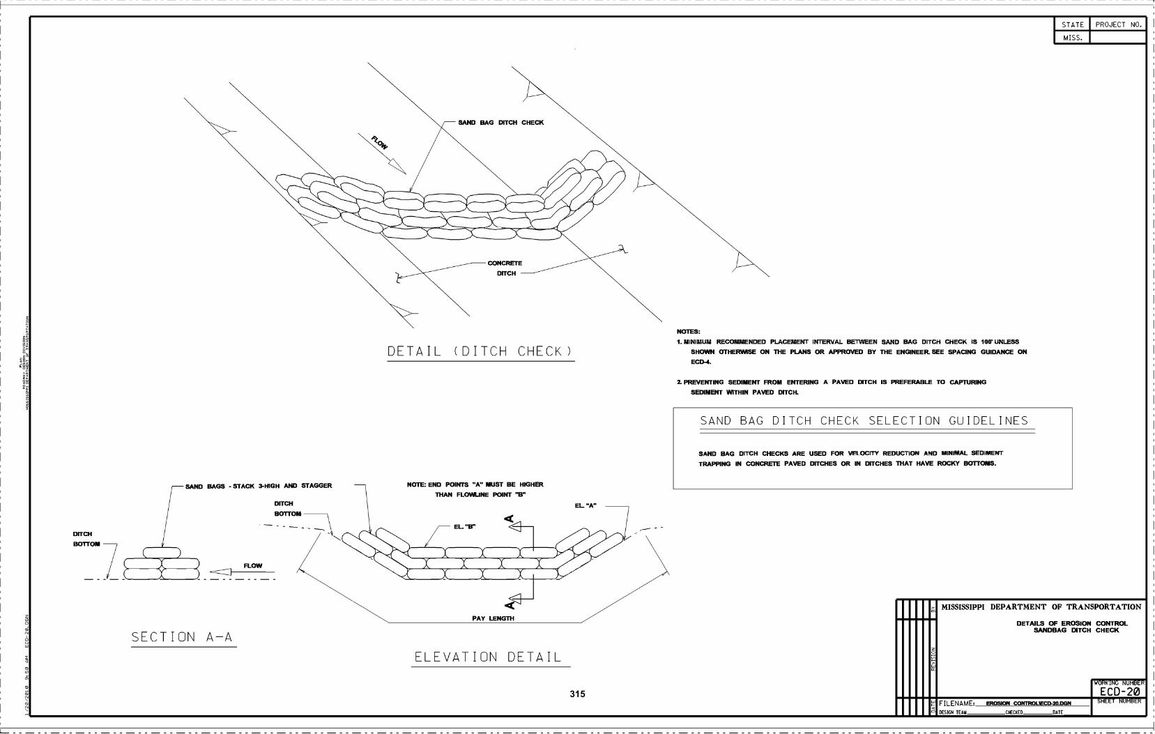
DITCH
BOTTOM
SECTION A-A
SAND BAGS - STACK 3-HIGH AND STAGGER
FLOW
DITCH
Bol-rOM
DETAIL (DITCH CHECK)
NOTE: END POINTS "A MUST BE HIGHERThAN FLOWLINE POINT "B"
ELEVATION DETAIL
NOTES:
MINIMUM RECOMMENDED PLACEMENT INTERVAL BETWEEN SAND BAG DITCH CHECK IS 100 UNLESS
SHOWN OTHERWISE ON ThE PLANS OR APPROVED BY THE ENGINEER. SEE SPAcING GUIDANcE ON
EcD-4.
PREVENTING SEDIMENT FROM ENTERING A PAVED DITCH IS PREFERABLE TO CAPTURING
SEDIMENT WITHIN PAVED DITCH.
SAND BAG DITCH CHECK SELECTION GUIDELINES
SAND BAG DITCH CHECKS ARE USED FOR VEIOCITY REDUCTION AND MINIMAL SEDIMENT
TRAPPING IN OONcRETE PAVED DITCHES OR IN DITCHES THAT HAVE ROCKY BOTIOMS.
o
>
STATE
MISS.
DESIGN TEAM CHECKED DATE
PROJECT NO.
MISSISSIPPI DEPARTMENT OF TRANSPORTATION
DETAILS OF EROSION CONTROLSANDBAG DITCH CHECK
WORKING NUMBER
E C D -20SHEET NUMBERF ILENAME EROSION cONTR0LiEcD-20.DGN
315
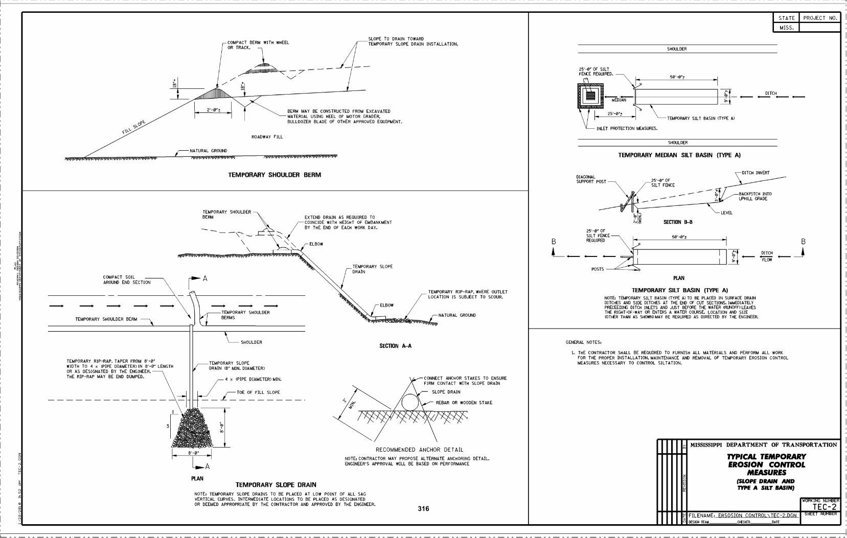
STATE PROJECT NO.
MISS.
SLOPE TO DRAIN TOWARDCOMPACT BERM WITH WHEEL TEMPORARY SLOPE DRAIN INSTALLATION.OR TRACK.
diII .
SHOULDER
4IuillllUJIIIIJllhIJIILIllthJ_ - :7'- - - -25'-ø OF SILTFENCE REDUIRED.
+o - +
r I5ø'-øj-
T
iiiiiiiiIIIIOIIIIIIIiiiiii
2'-ø± BERM MAY BE CONSTRUCTED FROM EXCAVATED
DIAN :
I I MATERIAL USING HEEL OF MOTOR GRADER.25'-ø'±
TEMPORARY SILT BASIN (TYPE A)I
o?- BULLDOZER BLADE OF OTHER APPROVED EQUIPMENT.
\\" INLET PROTECTION MEASURES.
ROADWAY FILLSHOULDER
GROUND
, , .',,"NATURAL
TEMPORARY MEDIAN SILT BASIN (UPE A)' ..........'...ç, ''' --'
TEMPORARY SHOULDER BERM DITCH INVERTDIAGONALSUPPORT POST 25'-ø' OF
r
SILT FENCE
BACKPITCH INTO
,1 - - - UPHILL GRADE
TEMPORARY SHOULDER V ILEVEL
BERM ' EXTEND DRAIN AS REQUIRED TO z¡-COINCIDE WITH HEIGHT OF EMBANKMENT ? SECTION B-B- / BY THE END OF EACH WORK DAY.- _\__- -' /\ - \
25'-ø'SILT
OF
FENCE 5ø'-ø-\\ \ ELBOW B REQUIRED h. -I B
A__ _ _ ._: :A DITCH
COMPACTSOIL
.
44&'--TEMPORARY SLOPE
rA
POSTS "dFL.PLAN
FLOW
\\ -TEMPORARY SILT BASIN (TYPE A)
NOTE: TEMPORARY SILT BASIN (TYPE A) TO BE PLACED IN SURFACE DRAIN\LOCATION IS SUBJECT TO SCOUR.
\s.4444s4 TEMPORARY RIP-RAP. WHERE OUTLET
ELBOWDITCHES AND SIDE DITCHES AT THE END OF CUT SECTIONS. IMMEDIATELYPRECEEDINGDITCH INLETSAND JUSTBEFORETHE
LOCATION SIZETEMPORARY.
SHOULDER
TEMPORARY SHOULDER BERM \ BERMS,
NATURAL GRO ND... U (OTHER THAN AS SHOWN) MAY BE REQUIRED AS DIRECTED BY THE ENGINEER.
GENERAL NOTES:\SECTION A-A
SHOULDER
I. THE CONTRACTOR SHALL BE REQUIRED TO FURNISH ALL MATERIALS AND PERFORM ALL WORK
TEMPORARY RIP-RAP. TAPER FROM 8'-ø TEMPORARYFOR THE PROPER INSTALLATION. MAINTENANCE AND REMOVAL OF TEMPORARY EROSION CONTROL
WIDTH TO 'I x (PIPE DIAMETER) IN 8'-ø LENGTHSLOPE MEASURES NECESSARY TO CONTROL SILTATION.
DRAIN (B MIN. DIAMETER)OR AS DESIGNATED BY THE ENGINEER.THE RIP-RAP MAY BE END DUMPED. 4 x (PIPE DIAMETER) MIN. CONNECT ANCHOR STAKES TO ENSURE
FIRM CONTACT WITH SLOPE DRAIN
i
_/- TOE OF FILL SLOPE SLOPE DRAIN
- , IREBAR OR WOODEN STAKE
vW! VVW3 ii :
RECOMMENDED ANCHOR DETAILMISSISSIPPI DEPARTMENT OF TRANSPORTATION-î
1 NOTE: CONTRACTOR MAY PROPOSE ALTERNATE ANCHORING DETAIL. 1YP1CAL TEMPORARY,
ENGINEER'S APPROVAL WILL BE BASED ON PERFORMANCE EROSION CONTROL
PIANMEASURES
TEMPORARY SLOPE DRAIN(SLOPE DRAIN AND
NOTE: TEMPORARY SLOPE DRAINS TO BE PLACED AT LOW POINT OF ALL SAGTYPE A SILT BASIN)
VERTICAL CURVES INTERMEDIATE LQCATIONS TQ BE PLAD AS DESIGNATEDOR DEEMED APPROPRIATE BY THE CONTRACTOR AND APPROVED BY THE ENGINEER.
WORKING NUMBER
TEC-2FILENAME ERSOSION CONTROL\TEC-2.DGN SHEET NUMBER
DESIGN TEAM CHECKED DATE
316
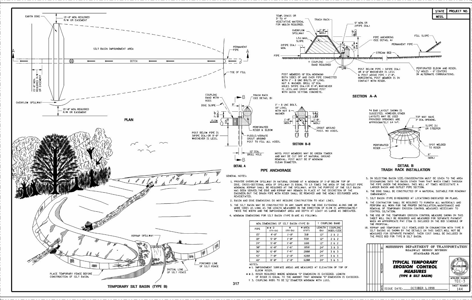
EARTH DIKE
& w
OVERFLOW SPILLWAY
I5'-ø MIN. REQUIREDR/W OR EASEMENT
u..
_f 15'-ø MIN. REQUIRED
RIW OR EASEMENT
PLACE TEMPORARY FENCCONSTRUCTION OF SILT
SILT BASIN IMPOUNDMENT AREA
PLAN
DITCH
RIPRAP SPILLWAY
TEMPORARY SILT BASIN (TYPE B)
INITIAL LINEOF SILT FENCE
COUPLINGBAND WITHRODS
DIKE SLOPE"
FLOW
POST BELOW PIPE IS3(PIPE DIA.) OR 8' 0'
WHICHEVER IS LESS
E BEFOREBASIN.
i)P/12?7/" ¡I
I/A
FINISHED LINE
OF SILT FENCE
PERMANENTPIPE
A
TOE OF FILL
DRILL HOLE12' DIA.
DETAIL A
GENERAL NOTES:
TRASH RACK(SEE DETAIL B)
PERFORATEDRISER & ELBOW
PIPE
PUDDLE/VIBRATEGROUT AROUNDPOST TO FILL ALL VOIDS.
TEMP. GRASS OR3' TO 4'VEGETATIVE MATERIALFOR MULCH REQUIRED.
1' - 8 UNC BOLT.
18' LONG,WITH NUT &WASHER
(MIN.)
PIPE ANCHORAGE
. ............................I!i1
(MIN.)
OVERFLOWSPILL WAY
2(PIPE DIA.)
MIN.
POST MEMBERS (8 DIA. MINIMUM)
BOTH SIDES OF AND OVER PIPE CONNECTEDWITH 1 - 8 UNC BOLTS. 18 LONG.
NUT & WASHER. DRILL 12 DIA.
HOLES 3(PIPE DIA.) OR 8'-ø'. WHICHEVER
IS LESS, AND GROUT AROUND POSTWITH QUICK SETTING CONCRETE.
1.5:1 MAX.
SLOPE
SECTION BB
NOTE: POST MEMBERS MAY BE GREEN TIMBERAND MAY BE CUT OFF AT NATURAL GROUNDREMOVAL. POST MUST BE 8' MINIMUMCLEAN DIAMETER.
PROVIDE OVERFLOW SPILLWAY IN NATURAL GROUND AT A MINIMUM OF l'-0' BELOW TOP OFDIKE. CROSS-SECTIONAL AREA OF SPILLWAY IS EQUAL TO 1.5 TIMES THE AREA OF THE OUTLET PIPEMINIMUM. RIPRAP SHALL BE REQUIRED AT THE SPILLWAY. AFTER THE PURPOSE OF THE SILT BASINHAS BEEN SERVED, THE DIKE AND RIPRAP MAY REMAIN IN PLACE AT THE DISCRETION OF THEENGINEER, BUT THE DRAIN PIPE WITH RISER SHALL BE REMOVED AND THE NEWLY DISTURBED AREARE VE GETAT ED.
BASIN AND DIKE DIMENSIONS DO NOT REQUIRE CONSTRUCTION TO NEAT LINES.
THE SILT BASIN MAY BE CONSTRUCTED IN ANY SHAPE WITH THE DIKE EXTENDING ALONG ONE ORMORE SIDES AS LONG AS THE LENGTH MEASURED IN THE DIRECTION OF FLOW IS APPROXIMATELYTWICE THE WIDTH AND THE IMPOUNDMENT AREA AND DEPTH AT LEAST AS LARGE AS INDICATED.
MINIMUM DIMENSIONS FOR SILT BASIN (TYPE B) ARE AS FOLLOWS:
TRASH RACK-
2'-ø'
t COUPLINGBAND REQUIRED
GROUT AROUNDPOST. NO VOIDS.
6' MIN. OR
2(PIPE DIA.)
z
POST BELOW PIPE 3(PIPE DIA.)
OR 8'-ø WHICHEVER IS LESS& POST ABOVE PIPE 2'-ø.HORIZONTAL POST MEMBER IS INCONTACT WITH RISER.
SECTION AA
4 BAR LAYOUT SHOWN ISSUGGESTED. HOWEVER, OTHERLAYOUTS MAY BE USEDPROVIDED OPENINGS AREAPPROXIMATELY 64 ¡n2.
PIPE ANCHORING(SEE DETAIL A)
PERMANENT PIPE
PERFORATEDRISER
STREAM BED
DETAIL BTRASH RACK INSTALLATION
o
zoV,>
a
FILL SLOPE
PERFORATED ELBOW AND RISER.V2 HOLES - 6' CENTERSIN ALTERNATE CORRUGATIONS.
TOP MAY HAVE3' DIA. OPENING.
SLOPE 2:1OR STEEPER
SPOT WELDEDTO RISER
(MIN.)
STATE
MISS.
ISSUE DATE OCTOBER 1, 1998
PROJECT NO.
MISSISSIPPI DEPARTMENT OF TRANSPORTATIONROADWAY DESIGN DEVLSIOL'
STANDARD PLAN
1YPICAL TEMPORARYEROSION CONTROL
MEASURES(JYPE B SILT BASIN)
O
NGLISH
18$
WORKING NUMBER
TEC-3SHEET NUMBER
144
MIN. DIMENSIONS OF SILT BASIN (TYPE B) t COUPLING BAND
PIPE D(ft-In)
H
(ft-in)
* AREA(ft2)
LENGTH(j)
COUPLINGRODS/SIDE
15' 4'-ø' 1,-0- 310 12' 2 & 2
18' 5'-0 1,-0- 550 12' 2 & 2
24 5'-ø' l'-0' 1100 12 2 & 2
30' 6'-ø' l'-6' 1850 24' 3 & 3
36 6'-ø' l'-6' 2800 24' 3 & 3
42 l'-0- 2'-ø 4200 24 3 & 3
8' 8'-ø 2'-ø 6200 24 3 & 3
NOTES:
* 1. IMPOUNDMENT SURFACEELBOW RISER.
* * 2. RISER REQUIRED WHEREOF RISER IS EQUAL TO
t 3. COUPLING RODS TO BE
MINIMUM D DIMENSION IS EXCEEDED. LENGTHTHE AMOUNT THAT MINIMUM 'D' DIMENSION IS EXCEEDED.
V2' DIAMETER MINIMUM WITH LUGS.
AREAS ARE MEASURED AT ELEVATION OF TOP OF
IN SELECTING BASIN SIZE, CONSIDERATION MUST BE GIVEN TO THE AREA
DISCHARGING INTO THE BASIN OTHER THAN THAT WHICH COMES THROUGHTHE PIPE UNDER THE ROADWAY. THIS WILL AT TIMES NECESSITATE ALARGER BASIN AND OUTLET PIPE SECTION.
THE DIKE SHALL BE CONSTRUCTED OF A MATERIAL SUITABLE FOR ROADWAYEMBANKMENT.
SILT BASIN (TYPE B) REQUIRED AT LOCATION(S) INDICATED ON PLANS.
THE CONTRACTOR SHALL BE REQUIRED TO FURNISH ALL MATERIALS ANDPERFORM ALL WORK FOR THE PROPER INSTALLATION. MAINTENANCE ANDREMOVAL OF TEMPORARY EROSION CONTROL MEASURES NECESSARY TOCONTROL SILTATION.
THE USE OF THE TEMPORARY EROSION CONTROL MEASURE SHOWN ON THISSHEET WILL ONLY BE REQUIRED AND MEASURED FOR SEPARATE PAYMENTWHEN AN APPROPRIATE PAY ITEM IS INCLUDED IN THE BID SCHEDULE OFTHE PROPOSAL.
10. RIPRAP AND TEMPORARY SILT FENCE. USED IN CONJUNCTION WITH TYPE BSILT BASINS AS SHOWN BY THE DETAILS ON THIS SHEET. WILL NOT BEMEASURED FOR SEPARATE PAYMENT. THEIR COST SHALL BE INCLUDED INTHE PRICE BID FOR TYPE B SILT BASIN.
317
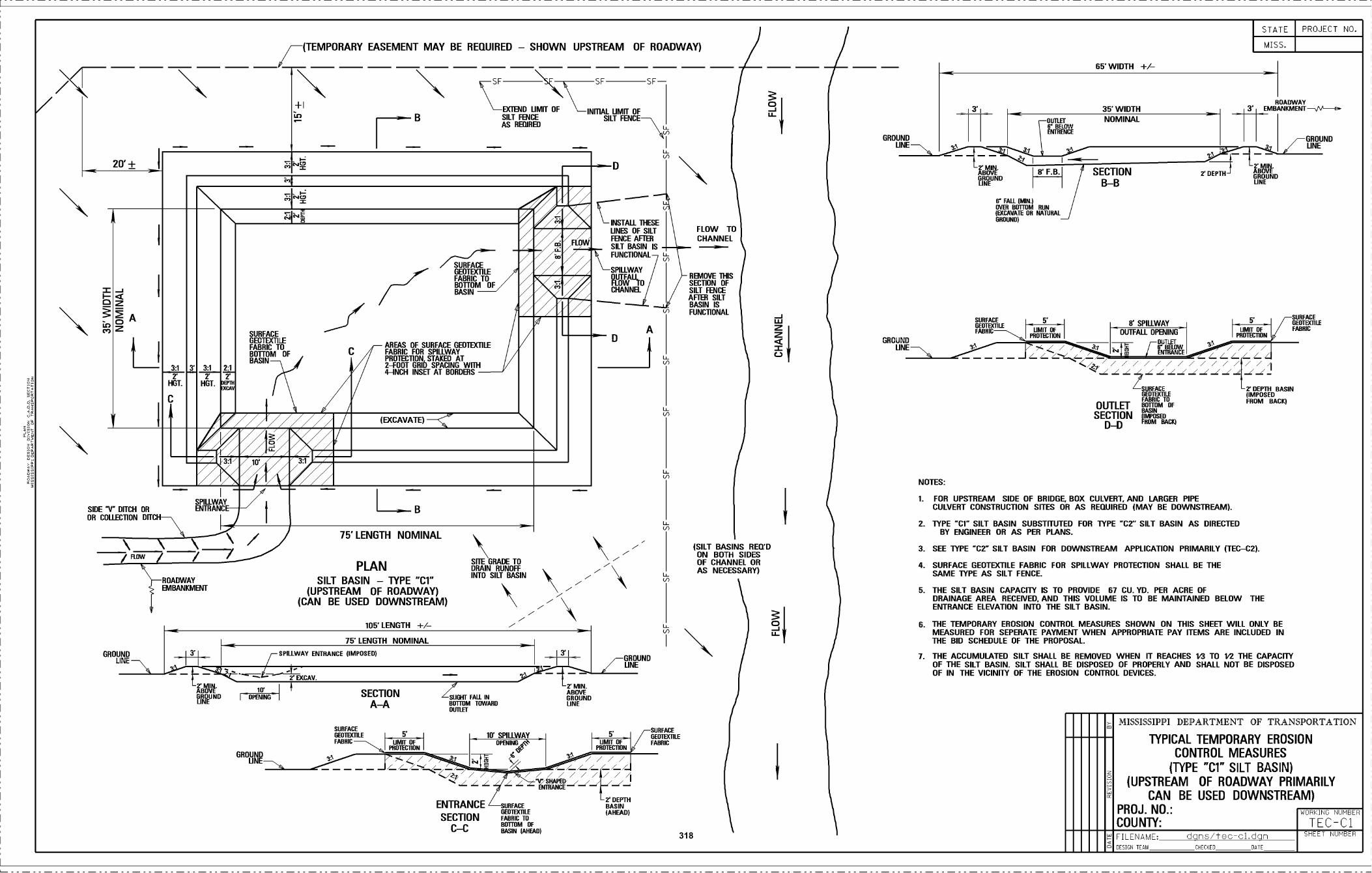
2o.+
GROUNDLINE
ROADWAYEMBANKMENT
\7 /
1ffGRUND
I OPENING
GROUNDUNE-
PLANSILT BASIN - TYPE cr
(UPSTREAM OF ROADWAY)(CAN BE USED DOWNSTREAM)
SPIUWAY ENENANCE (IMPOSED)
15 LENGTH NOMINAL
75 LENGTH NOMINAL
SURFACE
FABRIC
105' LENGTH *1-
SECTIONAA
ZNEHTFALL IN
BOSOM TOWRD01110Ff
'GBADE TODRAIN RUNOFFINTO SILT RADIN -
ENTRANCE URFACEUEOIEXIILD
SECTION FABRIC 00
CC ROTEM EFBASIN IAI)EADI
I D'IGROUND
NE
2' MIN.ABOVE
ONE
D
1ff SPILLWAY N'
OF EFOIINO OMIT SFCOON PROIFCI1O
o / / // / /'_ --- --- ...-.. / / / / /// /-;//////////
INSTALL ThESELINEO OF SILTFENCE AFTERSILT BASIN ISFUNCTIONAL
SPILLWAYDI.TIFALLFLOW TOCHANNEL
O' TEETH
/
G BUON DLINE
ABOVEBRODES
GROUND
R'F.B. SECTION BOUEUR
/ BBB' FAIL (uNI
3HOUNDI
FOR UPSTREAM SIDE OF BRIDGE. BOX COLVERT. ANO LARGER PIPECULVERT CONSTRUCTION SITES OR AS REQUIRED (MAY BE DOWNSTREAM).
TYPE 'CT" SILT BASIN SUBSTITUTED FOR TOPE C2' SILT BASIN AD DIRECTEDBY ENGINEER OR AS PER PLANS.
SEE TYPE TOO SILT BASIN FOR DOWNSTREAM APPLICATION PRIMARILY )TEC-C2).
SURFACE GEOTEX1ILE FABRIC FOR SPILLWAY PROTECTION SHALL BE THESAME TOPE AS SILT FENCE.
THE SILT BASIN CAPACITY IS TO PROVIDE 67 CU. YD. PER ACRE OFDRAINAGE AREA RECEIVED. AND THIS VOLUME IS TO RE MAINTAINED BELOW THEENTRANCE ELEVATION INTO THE SILT BASIN.
THE TEMPORARY EROSION CONTROL MEASURES SHOWN ON THIS SHEET WILL ONLY REMEASURED FOR SEPERATE PAYMENT WHEN APPROPRIATE PAY ITEMS ARE INCWDED INTHE RIO SCHEDULE OF THE PROPOSAL
THE ACCUMULATED SILT SHALL BE REMOVED WHEN IT REACHES N'I TO 1.2 THE CArACI1YOF THE SILT BASIN. SILT SHALL BE DISPOSED OF PROPERLY ANO SHALL NOT BE DISPOSEDOF IN THE VICINITY OF THE EROSION CONTROL DEVICES.
STATE PROJECT NO.
MISSISSIPPI DEPARTMENT OF TRANSPORTATTON
TYPICAL TEMPORARY EROSIONCONTROL MEASURES
(TYPE "Cl° SILT BASIN)(UPSTREAM OF ROADWAY PRIMARILY
CAN BE USED DOWNSTREAM)PROJ. NO.: WORKING NUMBER
COUNTY: TEC-Ci
3.1
HOT.
C
3' 3:1
HOT
2:1
D'
DEA
SUR
FABRICROTTDMBAS
OESTECTILEACE
TOOF
N i/CE
FABRIC TOBOTTOM DFK OEOTEXI1LE
BASIN
Elh.
IANEAS OF SURFACE OEOIEXTILE
C FABRIC FOR SPILLWAYPRDIECTIDN STAKED AT2-FOOT ORI)) SFACINO WITh4-INCH INSET AT BARBERS
r(EXCAVATE)
31 lO
SF SF SF
35' WIDTHROADWAY
3' EMBMIKMEFJTVV'--o.+1EXTEND LIMIT OF INIITAL LIMO OF
SILT FENCEGILT FENCEAS REARED I' BELOW
ENTANDE
NOMINAL
(TEMPORARY EASEMENT MAY BE REQUIRED - SHOWN UPSTREAM OF ROADWAY) MISS.
NN'WIDTH I-/-
AI ' O' EPILLWAYSERRASE
FAEBICFEIL BIN
OUTFALL OPENINO
/I=
'AIREASE 'ZDFFYDBAUIRS
OUTLET B))?)TM10EFFROM BACO
SECTION PSED
DD ROM BAIE
NOTES:
FILESAME: dÇTTU/±AS-01,AÇKT SHEET NUMBER
SIDE V DOCH OROR CDLLECTIDN DITCH
SPILLWAYENTRANCE
1-<
L
FLOW TOC HAN N E L
REMOVE 1105SEC11ON OFSILT FENCEAFIER GILTBASIN ISFUNCTIONAL
(SILT BASINS RETTOON ROTH SIDESOF CHANNEL ORAS NECESSARY)
\
318
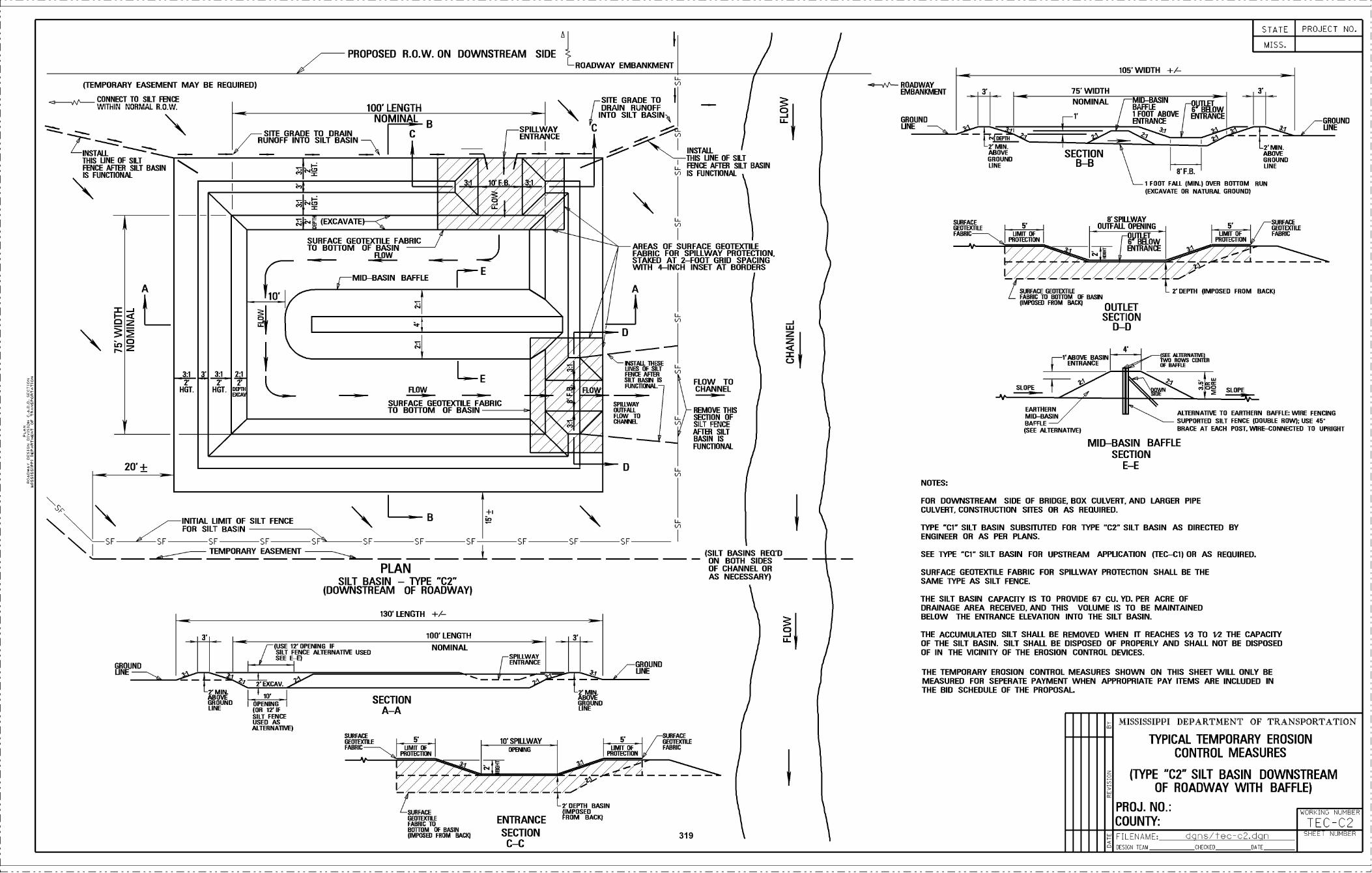
(TEMPORARY EASEMENT MAY BE REIIUIREOI
CONNECT TO SllJ FENCE
INSTALL '-':_,_,This LINE OF SILTFENCE AFTER SILT BASIN
20' +
INTEIAL LIMIT OF SILT FENCEFOR SILT BASIN
' SF SF SFTEMPORARY EASEMENT
GROUNDLINE
- SITE GRAOE TO DRAINRUNOFF INTO SILT BASIN
PROPOSED ROW. ON DOWNSTREAM SIDE
100' LENGTHNOMINALpB
\BSF
PLANSILT BASIN - TYPE "02"
(DOWNSTREAM OF ROADWAY)
130 LENGTH ±/-
(LE 5 TS'TPILLWAYBrBNINS
G BOOTH L EFABRIC TUBROOM OF BRAINIIUPOSSO FROM BASO
SFILLWAY 'CENTRANCE I
ROADWAY EMBANKMENT
\ [SITE ORAGE TO IDRAIN RUNOFF
INTO SILT BASIN
SF SF
INSTALLThIS LINE OF SILTFENCE AFTER SILT BASINIS FUNCI1ONAL
AREAS OF SURFACE OEOTEX1ILEFABRIC FOR SPILLWAY PROTECTION,STAKED AT 2-FOOT GRID SPACINGWITH 4-INCH INSET AT BORDERS
A
THESEUNES SF SILT
SILT BASIN ISFUNCTONAL-
SPIUWAY
COBIBREL
GROUNDUNE
FLOW TOCHARNEL
REMOVE ThISSECTiON OFSILT FENCEAFTER SILTBASIN ISFUNCTIONAL
zzAC
(SILT BASINS REDOON BOTH SIDESOF CHARNEL ORAS NECESSARY)
NOTES:
URBANOUNE
-B' MIN.ABOVEGROUND
SECTIONBB
105' WIDTH ±/-
B'SPILLWAY
MIT-BASINBAFFLE1 FOOT ABOVEENTRANCE
5' OUTFALL OPENINU
:F ]1NE
FABRIC TO BUUOM SF BASIN(IMPOSED FROM BACIO
OUTLETSECTION
rrND-0
MID-BASIN BAFFLESECTION
E-E
MID-BRAIN ALIEBNATIAE OR [ARIHEnN BAFFLE: WIDE FENCING
BAFFLE SUPPOBTED SILT FENCE (DOUBLE BUST. ASE AN'
(SEE ALTERNATSEI BRACE AT EACH POST. WIRE-CONNECTED TO UPRIGHT
FOR DOWNSTREAM SIDE OF BRIDGE. BOX CULVERT. ANO LARGER PIPECULVERT. CONSTRUCTION SITES OR AS REQUIRED.
THE SILT BASIN CAPACEPI' IS TO PROVIDE R7 CU. YO. PER ACHE OFDRAINAGE AREA RECEIVED. AND THIS VOLUME IS TO BE MAINTAINEDBELOW THE ENTRANCE ELEVATION INTO THE SILT BASIN.
UOTLET0 GELOWENTRANCE
0FB.B FOOT FAIL (MIN.) OVER BOTTOM BEN
LIAIT OFFROTO CORTI
STATE
MISS,
- --- 2'DEI'IH (IMPOSED FROM BAEE(
O SLOPE
TYPE 'Cr SILT BASIN SUBSITUTED FOR TYPE 'CZ' SILT BASIN AS DIRECTED BYENGINEER OR AS PER PLANS.
SEE TYPE C1' SILT BASIN FOR UPSTREAM APPLICATION ITEC-Cil OR AS REQUIRES.
SURFACE DEOTEXTILE FABRIC FOR SPILLWAY PROTEC11ON SHALL BE THESAME TYPE AS SILT FENCE
THE ACCUMULATED SILT SHALL BE REMOVED WHEN IT REACHES 5.3 TO S'S THE CAPACITYOF THE SILT BASIN. SILT SHALL RE DISPOSED OF PROPERLY AND SHALL NOT BE DISPOSEDOF IN THE VICINITY OF THE EROSION CONTROL DEVICES.
THE TEMPORARY EROSION CONTROL MEASURES SHOWN ON THIS SHEET' WILL ONLY BEMEASURED FOR SEPERATE PAYMENT WHEN APPROPRIATE PAY ITEMS ARE INCLUDED INTHE BID SCHEDULE OF TRIE PROPOSAL
2'MIN.
GROUND
SUFFAID
MISSISSIPPI DEPARTMENT OF TRANSPORTATION
TYPICAL TEMPORARY EROSIONCONTROL MEASURES
(TYPE C2" SILT BASIN DOWNSTREAMOF ROADWAY WITH BAFFLE)
PROJ. NO,: WORULNU NUMBER
COUNTY: TEC-C2FILENAME' dQs/JB-o2.dçU
PROJECT RO,
OBTUROLINE
51FB. Ji
i' (EXCAVATE
SURFACE OEOTEX1'ILE FABRIC
E
TO BOTTOM OF BASINFLOW
rMID-BASIN BAFFLE
3T3'372i\.,,_,_,_
!ViiI41LE
FLOWHUT. HOT./ SURFACE GEOTEX1'ILEOF BASIN
FABRICTO BO11'OM
THUO--- ROADWAYEM OUR KM ENT 75' WIDTH
NOMINAL
S.TOO' LENGTH
NOMINAI(USE T OPENING IF/ SILT FENCE ALIDBNATIVE OSSO
/ SEEE-E(
GROUNDUNE
SECTIONAA
ENTRANCE
SECTIONC-C
FROM BACK)
319
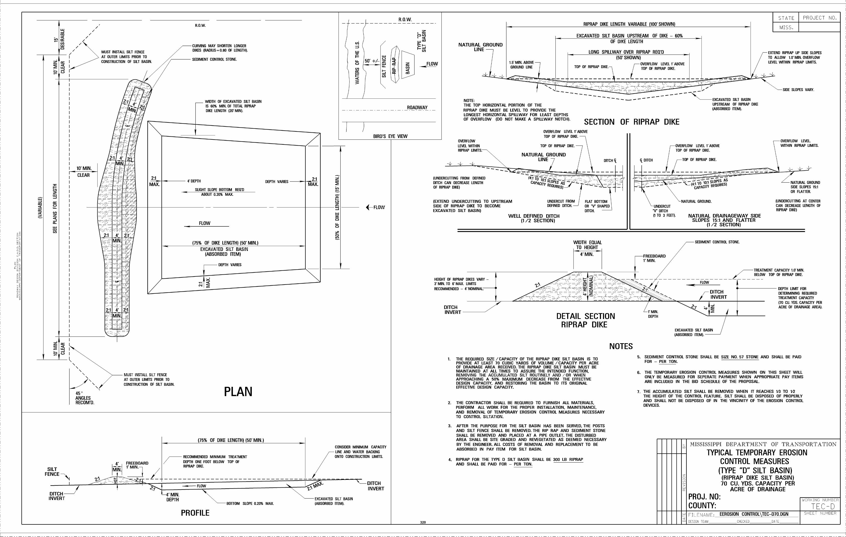
D
////
10' MIN.
CLEAR
4' DEPTH
SLIGHT SLOPE B011OM REaDABOUT 0.20% MAX.
(15% OF DIKE LENGTH) (50' MIN.)
EXCAVATED SILT BASIN(ABSORBED ITEM)
DEPTH VARIES
DEPTH VARIES
L \\)\ \\
ANGLESR EC 0M 'D
MUST INSTALL SILT FENCE
AT OUTER LIMITS PRIOR TO
CONSTRUCTION OF SILT BASIN.
MUST INSTALL SILT FENCE
AT OUTER LIMITS PRIOR TO
CONSTRUCTION OF SILT BASIN.
ROW.
CURVING MAY SHORTEN LONGERDIKES {RAOIUS=O.80 OP LENGTH).
SEDIMENT CONTROL STONE.
WIDTH OF EXCAVATED SILT BASINIS 60% MIN. OF TOTAL RIPRAPDIKE LENGTH )20' MIN).
PLAN
2:1
MAX.
BIRD'S EYE VIEW
ROADWAY
FLOW
+-FLOW
SILTFENCE
DITCHINVERT
4.
MN
FREEBOARD1' MIN.1
4'MIN.DEPTH
PROFILE
(75% OF DIKE LENGTH) (50' MIN.)
RECOMMENDEO MINIMUM TREATMENT
DEPTH ONE FOOT BELOW TOP OFRIPRAF OIKE.
FLOW
BOÌTDM SLOPE 0.20% MAX.EXCAVATED SILT BASIN
(ABSORBED ITEM).
CONSIDER MINIMUM CAPACITY
LINE AND WATER BACKING///////_ ONTO CONSTRUCTION LIMITS.
DITCHINVERT
NATURAL GROUNDLINE
OVERFLOW
LEVEL WITHINRIPRAP LIMITS.
(UNDERCU1TING FROM DEFINEDDITCH CAN DECREASE LENGThOF RIPRAP DIREI
NOTE:THE TOP HORIZONTAL PORTION OF THERIPRAP DIKE MUST BE LEVEL TO PROVIDE THELONGEST HORIZONTAL SPILLWAY FOR LEAST DEPTHSOF OVERFLOW (DO NOT MAKE A SPILLWAY NOTCH).
(EXTEND UNDERCUÌTING TO UPSTREAMSIDE OF RIPRAP DIKE TO BECOMEEXCAVATED SILT BASIN)
HEIGHT OF RIPRAP DIRES VARY -3' MIN. TO 6' MAX. LIMITS
RECOMMENDED - 4' NOMINAL
DITCHINVERT
1.5' MIN. ABOVE
GROUND LINE
OVERFLOW LEVEL 1' ABOVE
TOP OF RIPRAP DIKE. x
TOP DF RIPRAP DIRE.
NATURAL GROUNDLINE
WELL DEFINED DITCH(1 /2 SECTION)
UNDERCUT FROMDEFINED DITCH. -
TOP OF RIPRAP DIRE.
-V- -:-- -Lx:Ii
I(D
THE REQUIRED SIZE /CAPACITY OF THE RIPRAP DIKE SILT BASIN IS TOPROVIDE AT LEAST 70 CUBIC YARDS OF VOLUME I CAPACITY PER ACREOF DRAINAGE AREA RECEIVED. THE RIPRAP DIKE SILT BASIN MUST BEMAINTAINED AT ALL TIMES TO ASSURE THE INTENDED FUNCTION,REMOVING THE ACCUMULATED SILT ROUTINELY AND /OR WHENAPPROACHING A 50% MAXIMUM DECREASE FROM THE EFFECTIVEDESIGN CAPACITY. AND RESTORING THE BASIN TO ITS ORIGINALEFFECTIVE DESIGN CAPACITY.
THE CONTRACTOR SHALL BE REQUIRED TO FURNISH ALL MATERIALS,PERFORM ALL WORK FOR THE PROPER INSTAlLATION, MAINTENANCE.AND REMOVAL OF TEMPORARY EROSION CONTROL MEASURES NECESSARYTO CONTROL SILTATION.
AFTER THE PURPOSE FOR THE SILT BASIN HAS BEEN SERVED. THE POSTSAND SILT FENCE SHALL BE REMOVED. THE RIP RAP AND SEDIMENT STONESHALL BE REMOVED AND PLACED AT A PIPE OUTLET. THE DISTURBEDAREA SHALL BE SITE GRADED AND REVEGETATED AS DEEMED NECESSARYBY THE ENGINEER. ALL COSTS OF REMOVAL AND REPLACEMENT TO BEABSORBED IN PAY ITEM FOR SILT BASIN.
RIPRAP FOR THE TYPE O SILT BASIN SHALL BE 300 LB RIPRAPAND SHALL BE PAID FOR - PER TON.
RIPRAP DIKE LENGTH VARIABLE (100' SHOWN)
EXCAVATED SILT BASIN UPSTREAM OF DIKE - 60%0F DIKE LENGTH
LONG SPILLWAY OVER RIPRAP REQ'D(50' SHOWN)
OVERFLOW LEVEL 1' ABOVE
L___
TOP OF RIPRAP DIRE.
SECTION OF RIPRAP DIKE
FLAT BOTIOMOR 'V' SHAPEDDITCH.
WIDTH EQUALTO HEIGHT
4'MIN.
DITCH I
DETAIL SECTIONRIPRAP DIKE
ç. DITCH
FREEBOARD1' MIN.
2t:\: _ - -- REÜIJIRES1
UNDERCUT
'V' DITCH(1 TO 3 FEET).
SEDIMENT CONTROL STONE SHALL BE SIZE NO. 57 STONE AND SHALL BE PAIDFOR - PER TON.
THE TEMPORARY EROSION CONTROL MEASURES SHOWN ON THIS SHEEr WILLONLY BE MEASURED FOR SEPERATE PAYMENT WHEN APPROPRIATE PAY ITEMSARE INCLUDED IN THE BID SCHEDULE OF THE PROPOSAL.
THE ACCUMULATED SILT SHALL BE REMOVED WHEN IT REACHES l'3 TO l'2THE HEIGHT OF THE CONTROL FEATURE. SILT SHALL BE DISPOSED OF PROPERLYAND SHALL NOT BE DISPOSED OF IN THE VINCINITY OF THE EROSION CONTROLDEVICES.
TOP OF RIPRAP DIRE.
NATURAL GROUND.
FLOW
7
EXCAVATED SILT BASIN
UPSTREAM OF RIPRAP DIRE)ABSORBEO ITEM).
NATURAL DRAINAGEWAY SIDESLOPES 15:1 AND FLAUER
(1/2 SECTION)
SEDIMENT CONTROL STONE
7-DITCHINVERT
STATE
MISS,
SIDE SLOPES VARY.
OVERFLOW LEVEL
OVERFLOW LEVEL l'ABOVE WITHIN RIPRAP LIMITS.TOP OF RIPRAP DIRE.
/ TREATMENT CAPACITY 1.0' MIN.,,z BELOW TOP OF RIPRAP DIRE.
SILENAME: EEROSION CONTROL\TEC_D10.DGN
DESIGN TEAM CHECKED DATE
PROJECT NO.
EXTEND RIPRAP UP SIDE SLOPES
TO ALLOW 1.0' MIN. OVERFLOWLEVEL WITHIN RIPRAP LIMITS.
NATURAL GROUNDSIDE SLOPES 15:1
OR FLAUER.
IUNDERCUTHNG AT CENTERCAN DECREASE LENGTH OFRIPRAP DIREI
DEPTH LIMIT FORDETERMINING REOUIRED
TREATMENT CAPACITY
)IO CU. TUS. CAPACITY PERACRE OP DRAINAGE AREA).
MISSISSIPPI DEPARTMENT OF TRANSPO]TATION
TYPICAL TEMPORARY EROSIONCONTROL MEASURES
(TYPE "D" SILT BASIN)(RIPRAP DIKE SILT BASIN)70 CU. YDS. CAPACITY PER
ACRE OF DRAINAGE
PROJ. NO:COUNTY:
WARKINLI NUMBER
TEC-DSHEET NUMBER
EXCAVATED SILT BASIN
(ABSORBED ITEM).
NOTESD
320
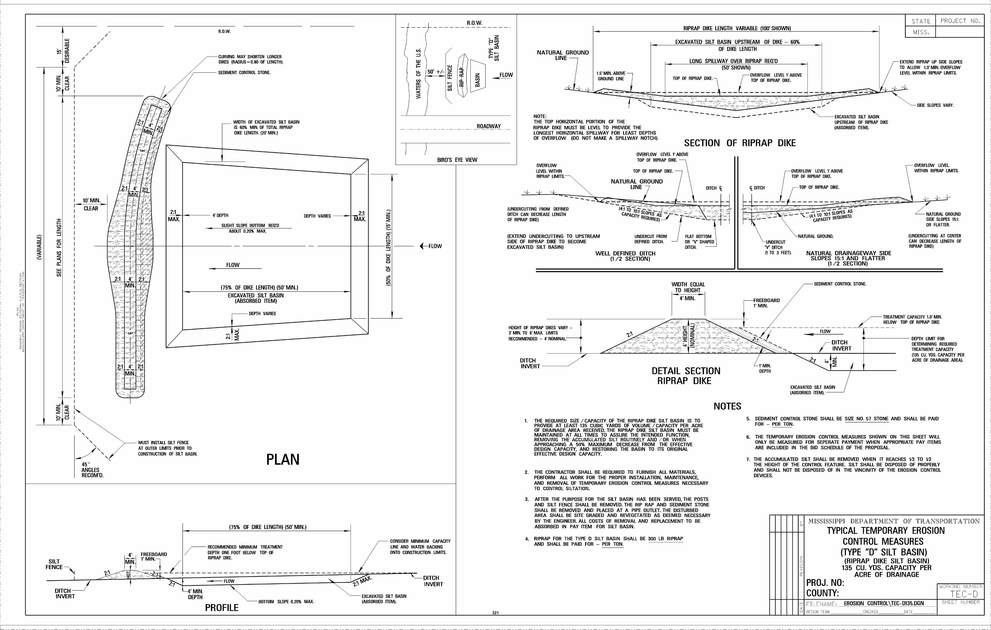
4 DEPTH
SLIGHT SlOPE B011OM REÜ'DABOUT 0.20% MAX.
(75% OF DIKE LENGTH) (50 MIN.)
EXCAVATED SILT BASIN(ABSORBED ITEM)
DEPTH VARIES
DEPTH VARIES
ç
////////
lo. MIN.
CLEAR
\ \)\
ANGLESRECOM'D.
MUST INSTALL SILT FENCE
AT OUTER lIMITS PRIOR TOCONSTRUCTION OF SILT BASIN.
ROW.
CURVING MAY SHORTEN LONGERDIKES (RADIUS=O.80 OF ftNGTH).
SEDIMENT CONTROL STONE.
WIDTH OF EXCAVATED SILT BASINIS 60% MIN. OF TOTAL RIPRAPDIKE LENGTH. {20' MIN.)
PLAN
2:1
MAX.
DD
oIn
SILTFENCE
4,
MIN.
FREEBOARD1' MIN.1
RECOMMENDED MINIMUM TREATMENT
DEPTH ONE FOOT BELOW TOP OFRIPRAP DIKE.
FLOW
4'MIN.DEPTH
PROFILE
(75% OF DIKE LENGTH) (50' MIN.)
BO1TOM SLOPE 0.20% MAX.EXCAVATED SILT BASIN(ABSORBED ITEM).
CONSIDER MINIMUM CAPACITY
LINE AND WATER BACKINGONTO CONSTRUCTION LIMITS.
DITCHIN VERT
BIRD'S EYE VIEW
ROADWAY
(FLOW
NATURAL GROUNDLINE
OVERFLOW
LEVEL WITHINRIPRAP LIMITS.
1.5' MIN. ABOVE
GROUND LINE
NOTE:THE TOP HORIZONTAL PORTION OF THERIPRAP DIKE MUST BE LEVEL TO PROVIDE THELONGEST HORIZONTAL SPILLWAY FOR LEAST DEPTHSOF OVERFLOW (DO NOT MAKE A SPILLWAY NOTCH).
OVERFLOW LEVEL 1 ABOVE
TOP OF RIPRAP DIKE. x
TOP OF RIPRAP DIKE.
NATURAL GROUNDLINE
TOP OF RIPRAP DIKE.
(UNDERCU1TING FROM DEFINEDDITCH CAN DECREASE LENGThOF RIPRAP DIKE)
(EXTEND UNDERCUÌTING TO UPSTREAMSIDE OF RIPRAP DIKE TO BECOMEEXCAVATED SILT BASIN)
HEIGHT OF RIPRAP DIKES VARY -3. MIN. TO R' MAX. LIMITS
RECOMMENDED - 4' NOMINAL
DITCHINVERT
,,-
UNDERCUT FROM
DEFINED DITCH.
WELL DEFINED DITCH(1 /2 SECTION)
FLAT BOTIOMOR V SHAPEDDITCH.
WIDTH EQUALTO HEIGHT
4'MIN.
-V- -:-- -L: -Ii
I-(D
RIPRAP FOR THE TYPE D SILT BASIN SHALL BE 300 LB RIPRAPAND SHALL BE PAID FOR - PER TON.
RIPRAP DIKE LENGTH VARIABLE (100' SHOWN)
EXCAVATED SILT BASIN UPSTREAM OF DIKE - 60%
SECTION OF RIPRAP DIKE
DITCH I
DETAIL SECTIONRIPRAP DIKE
THE REQUIRED SIZE /CAPACITY OF THE RIPRAP DIKE SILT BASIN IS TOPROVIDE AT LEAST 135 CUBIC YARDS OF VOLUME I CAPACITY PER ACREOF DRAINAGE AREA RECEIVED. THE RIPRAP DIKE SILT BASIN MUST BEMAINTAINED AT ALL TIMES TO ASSURE THE INTENDED FUNCTION,REMOVING THE ACCUMULATED SILT ROUTINELY AND /OR WHENAPPROACHING A 50% MAXIMUM DECREASE FROM THE EFFECTIVEDESIGN CAPACITY. AND RESTORING THE BASIN TO ITS ORIGINALEFFECTIVE DESIGN CAPACITY.
THE CONTRACTOR SHALL BE REQUIRED TO FURNISH ALL MATERIALS,PERFORM ALL WORK FOR THE PROPER INSTALLATION, MAINTENANCE,AND REMOVAL OF TEMPORARY EROSION CONTROL MEASURES NECESSARYTO CONTROL SILTATION.
AFTER THE PURPOSE FOR THE SILT BASIN HAS BEEN SERVED, THE POSTSAND SILT FENCE SHALL BE REMOVED. THE RIP RAP AND SEDIMENT STONESHALL BE REMOVED AND PLACED AT A PIPE OUTLET. THE DISTURBEDAREA SHALL BE SITE GRADED AND REVEGETATED AS DEEMED NECESSARYBY THE ENGINEER. ALL COSTS OF REMOVAL AND REPLACEMENT TO BEABSORBED IN PAY ITEM FOR SILT BASIN.
OF DIKE LENGTH
LONG SPILLWAY OVER RIPRAP REQ'D(50' SHOWN)
OVERFLOW LEVEL 1' ABOVE
L___
TOP OF RIPRAP DIKE.
ç. DITCH
2t:\: _- - --?°AI
RFthiIRE
UNDERCUT
V' DITCH(1 TO 3 FEET).
FREEBOARD1' MIN.
SEDIMENT CONTROL STONE SHALL BE SIZE NO. 57 STONE AND SHALL BE PAIDFOR - PER TON.
THE TEMPORARY EROSION CONTROL MEASURES SHOWN ON THIS SHEEr WILLONLY BE MEASURED FOR SEPERATE PAYMENT WHEN APPROPRIATE PAY ITEMSARE INCLUDED IN THE BID SCHEDULE OF THE PROPOSAL.
THE ACCUMULATED SILT SHALL BE REMOVED WHEN IT REACHES l'3 TO l'2THE HEIGHT OF THE CONTROL FEATURE. SILT SHALL BE DISPOSED OF PROPERLYAND SHALL NOT BE DISPOSED OF IN THE VINCINITY OF THE EROSION CONTROLDEVICES.
OVERFLOW LEVEL
OVERFLOW LEVEL lABOVE WITHIN RIPRAP LIMITS.TOP OF RIPRAP DIKE.
TOP OF RIPRAP DIKE.
NATURAL GROUND.
EXCAVATED SILT BASIN
UPSTREAM OF RIPRAP DIKE)ABSORBED ITEM).
NATURAL DRAINAGEWAY SIDESLOPES 15:1 AND FLAUER
(1/2 SECTION)
SEDIMENT CONTROL STONE
FLOW
7-DITCHINVERT
7
STATE
MISS.
PROJECT NO.
EXTEND RIPRAP UP SIDE SLOPES
TO ALLOW 1.0' MIN. OVERFLOWLEVEL WITHIN RIPRAP LIMITS.
SIDE SLOPES VARY.
/ TREATMENT CAPACITY 1.0' MIN.BELOW TOP OF RIPRAP DIKE.
CILENAME: EROSION CONTROL\TEC_D135.DGN
DESIGN TEAM CHECKED DATE
NATURAL GROUNDSIDE SLOPES 15:1
OR FLA1TER.
IUNDERCUTHNG AT CENTERCAN DECREASE LENGTH OFRIPRAP DIKEI
DEPTH LIMIT FORDETERMINING REDUIRED
TREATMENT CAPACITY
(135 CU. YDS. CAPACITY PERACRE OP DRAINAGE AREA).
MISSISSIPPI DEPARTMENT OF TRANSPO]TATION
TYPICAL TEMPORARY EROSION
CONTROL MEASURES(TYPE "D" SILT BASIN)(RIPF(AP DIKE SILT BASIN)
135 CU. YDS. CAPACITY PERACRE OF DRAINAGE
PROJ. NO:COUNTY:
WARKINLI NUMBER
TEC-DSHEET NUMBER
EXCAVATED SILT BASIN
(ABSORBED ITEM).
NOTES
321
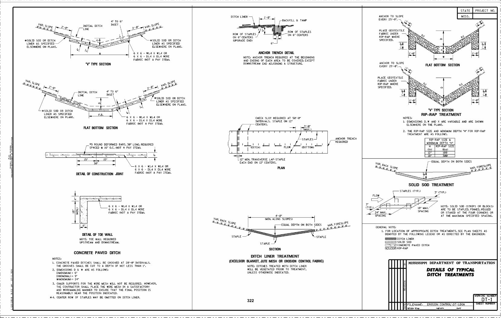
a
V4R.
*SOLID SOD OR DITCHLINER AS SPECIFIEDELSEWHERE ON PLANS.
VAR.
*SOLID SOD OR DITCHLINER AS SPECIFIEDELSEWHERE ON PLANS.
Op-
INITIAL DITCH
L INE
INITIAL DITCH
LINE
W
-V- TYPE SECTION
INSET
- TO 6
INSET \J
6 X 6 - W1A X WIA OR6 X 6 - D1.4 X D1.4 WIRE
FABRIC (NOT A PAY ITEM).
- TO 6
FLAT BOTFOM SECTION
6 X 6 - W1.4 X W1.4 OR6 X 6 - DiA X D1.4 WIREFABRIC (NOT A PAY ITEM).
5 ROUND DEFORMED BARS, 30 LONG, REQUIREDSPACED 16' O.C. (NOT A PAY ITEMX
DETAll 0F TOE WALLNOTE: TOE WALL REQUIREDUPSTREAM AND DOWNSTREAM.
CONCRETE PAVED DITCH
6 X 6 - W1.4 X W1.4 OR
6 X 6 - DIA X DIA WIREFABRIC (NOT A PAY ITEM).
NOTES:
CONCRETE PAVED DITCHES SHALL BE GROOVED AT 20'-ø' INTERVALS.THE GROOVES SHALL BE CUT TO A DEPTH OF NOT LESS THAN 1.
DIMENSIONS D & W ARE AS FOLLOWS:D(MINIMUM) 6
D(NOMINAL) 9-
W(MINIMUM) 2'V'
CHAIR SUPPORTS FOR THE WIRE MESH WILL NOT BE REQUIRED. HOWEVER,THE CONTRACTOR SHALL PLACE THE WIRE MESH IN A SATISFACTORYAND WORKMANLIKE MANNER TO ENSURE THAT THE FINAL POSITION ISREASONABLY NEAR THE POSITION INDICATED.
*4. CENTER ROW OF STAPLES MAY BE OMITTED ON DITCH LINER.
*SOLID SOD OR DITCHLINER AS SPECIFIEDELSEWHERE ON PLANS.
o
SOLID SOD OR DITCHLINER AS SPECIFIEDELSEWHERE ON PLANS.
VA/:1
DITCH LINER
ROW OF STAPLESON 6 CENTERS(UPGRADE END)
L,,
ANCHOR TRENCH DETAIL
NOTE: ANCHOR TRENCH REQUIRED AT THE BEGINNINGAND ENDING OF EACH AREA TO BE COVERED. EXCEPTDOWNSTREAM END ADJOINING A STRUCTURE.
CHECK SLOT REQUIRED AT 50'-ø'INTERVALS. STAPLE ON 12
I t CENTERS.1/ -I
IIII I I I I I I I I I
I II I
JIIILI I
\ (DITCH)
I i
- 12 MIN. TRANSVERSE LAP-STAPLEEACH END ON 12' CENTERS.
IjFLOW A(BGTTOM
PLAN
(MIN. ALONG SLOPES)
STAPLE
SEC11ON
BACKFILL & TAMP
ROW OF STAPLESON 6 CENTERS
STAPLE:..--
STAPLE
DITCH LINER TREATMENT(EXCElSIOR BLANKET. JUTE MESH OR EROSION CONTROI FABRIC)
NOTE: DITCHES TREATED WITH DITCH LINERWILL BE VEGETATED PRIOR TO TREATMENT,UNLESS OTHERWISE INDICATED.
ANCHOR TO SLOPEEVERY 25'-ø.
PLACE GEOTEXTILEFABRIC UNDERRIP-RAP WHERESPECIFIED.
, ..
tL?:t?i.ad .:Ac?i:I:9'
ANCHOR TO SLOPEEVERY 25'-ø.
PLACE GEOTEXTILEFABRIC UNDERRIP-RAP WHERESPECIFIED.
-._ ;.I'
SPACING
L
SOLID SOD TREATMENT
STAPLES (TYP.)y (TYP.)
FLOW
3. -MAX.
SPACING
jpR.
NOTE: SOLID SOD (STRIPS OR BLOCKS)ARE TO BE STAPLED. PINNED, PEGGEDOR STAKED AT THE FOUR CORNERS ORAT THE MAXIMUM SPECIFIED SPACING.
GENERAL NOTE:
1. FOR LOCATION OF APPROPRIATE DITCH TREATMENTS, SEE PLAN SHEETS ASDENOTED BY THE FOLLOWING LEGEND OR AS DIRECTED BY THE ENGINEER:
DITCH LINERSOLID SODCONCRETE PAVED DITCH
F(x-ci4 RIP-RAPI
NOTES:
DIMENSIONS D, W AND X ARE VARIABLE AND ARE SHOWNELSEWHERE ON THE PLANS.
THE RIP-RAP SIZE AND MINIMUM DEPTH H' FOR RIP-RAPTREATMENT ARE AS FOLLOWS.
o
>
FLAT BOÌTOM SECTION
-V- TYPE SECTION
RIPRAP TREATMENT
STATE
MISS.
DESIGN TEAM CHECKED DATE
PROJECT NO.
MISSISSIPPI DEPARTMENT OF TRANSPORTATION
DETNLS OF 1YPICALDITCH TREATMENTS
WORKING NUMBER
DT-1
RIP-RAP SIZE &MINIMUM DEPTHH
(in)RIP-RAP SIZE
(lbs)12 100
18 300
3,-0-
STAPLES] ANCHOR TRENCHREQUIRED
. .--z*- .
15'
3ø
15
V4jrEQUAL DEPTH ON BOTH SIDES
6 X 6 - W1.4 X W1.4 OR
6 X 6 - DIA X DIA WIREFABRIC (NOT A PAY ITEM).
DETAIL OF CONSTRUCTION JOINT
FORESLOPEEQUAL DEPTH ON BOTH SIDES
SHEET NUMBERFILENAME EROSION CONTROL\DT-1.DGN322
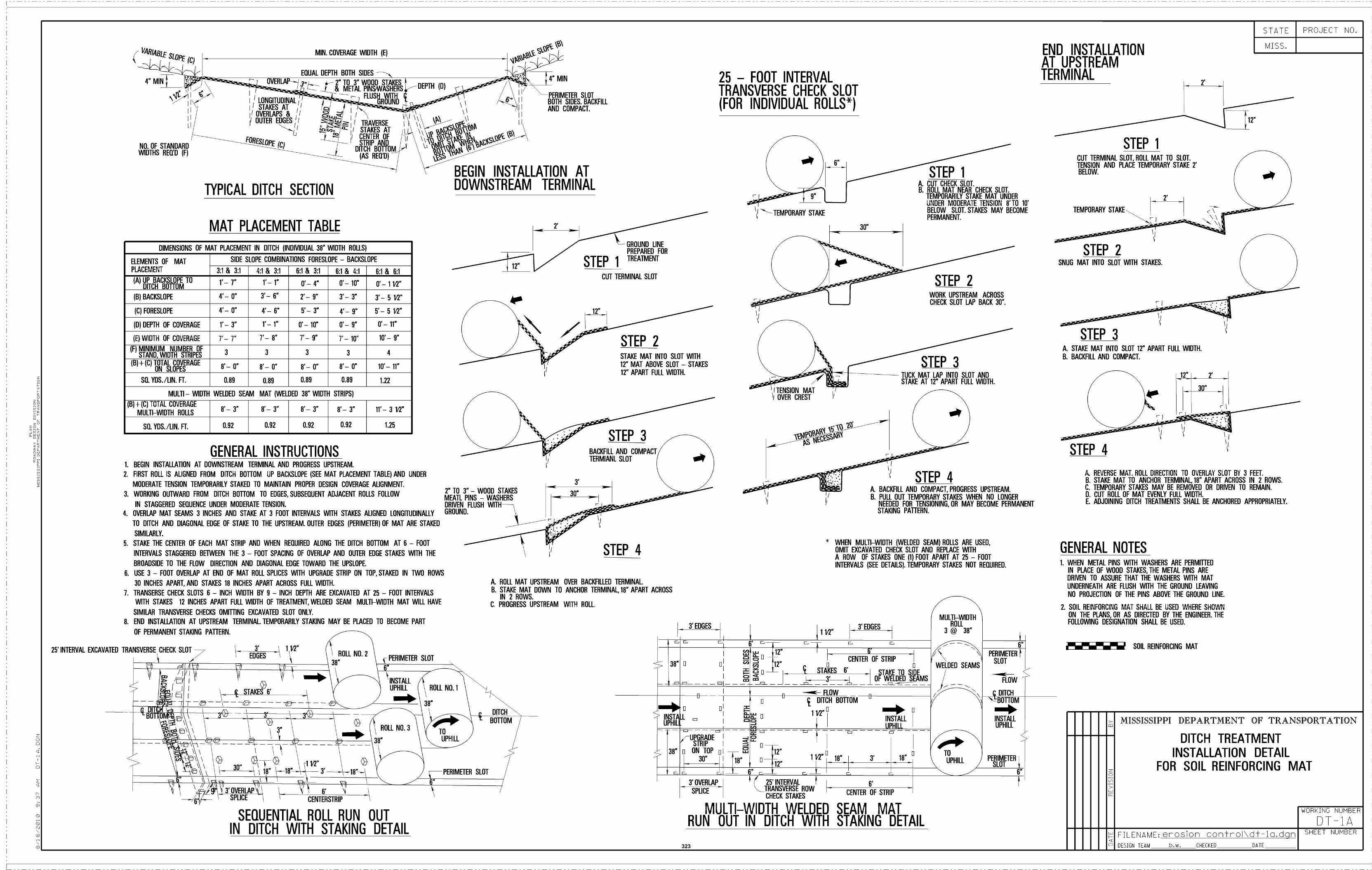
25' INTERVAL EXCAVATED TRANSVERSE CHECK SLOT
TYPICAL DITCH SECTION
MAT PLACEMENT TABLE
GENERAL INSTRUCTIONSBEGIN INSTALLATION AT DOWNSTREAM TERMINAL AND PROGRESS UPSTREAM.
FIRST ROLL IS ALIGNED FRDM DITCH BOÌTOM UP BACKSLDPE (SEE MAT PLACEMENT TABLE) AND UNDER
MODERATE TENSION TEMPORARILY STAKED TO MAINTAIN PROPER DESIGN COVERAGE ALIGNMENT.
WORKING OUTWARD FROM DITCH BQ1TOM TD EDGES, SUBSEQUENT ADJACENT ROLLS FDLLOW
IN STAGGERED SEQUENCE UNDER MODERATE TENSION.
OVERLAP MAT SEAMS 3 INCHES AND STAKE AT 3 FOOT INTERVALS WITH STAKES ALIGNED LONGITUDINALLY
TO DITCH AND DIAGONAL EDGE OF STAKE TO THE UPSTREAM. OUTER EDGES (PERIMETER) OF MAT ARE STAKED
SIMILARLY.
STAKE THE CENTER DF EACH MAT STRIP AND WHEN REQUIRED ALONG THE DITCH B011OM AT 6 - FOOT
INTERVALS STAGGERED BETWEEN THE 3 - FOOT SPACING OF OVERLAP AND OUTER EDGE STAKES WITH THE
BROADSIDE TO THE FLOW DIRECTION AND DIAGONAL EDGE TOWARD THE UPSLOPE.
USE 3 - FOOT OVERLAP AT END OF MAT ROLL SPLICES WITH UPGRADE STRIP ON TOP, STAKED IN iWO ROWS
30 INCHES APART, AND STAKES 18 INCHES APART ACROSS FULL WIDTH.
J. TRANSERSE CHECK SLOTS 6 - INCH WIDTH BY 9 - INCH DEPTH ARE EXCAVATED AT 25 - FOOT INTERVALS
WITH STAKES 12 INCHES APART FULL WIDTH OF TREATMENT, WELDED SEAM MULTI-WIDTH MAT WILL HAVE
SIMILAR TRANSVERSE CHECKS OMITIING EXCAVATED SLOT ONLY.
8. END INSTALLATION AT UPSTREAM TERMINAL. TEMPORARILY STAKING MAY BE PLACED TO BECOME PART
OF PERMANENT STAKING PA1TERN.
3'\
1\2"ROLL NO.2EDGES
\ 6'CENTERSTRIP
SEQUENTIAL ROLL RUN OUTIN DITCH WITH STAKING DETAIL
PERIMETER SLOT
12
BEGIN INSTALLATION ATDOWNSTREAM TERMINAL
GROUND LINEPREPARED FOR
S TEP i TREATMENT
CUT TERMINAL SLOT
STEP 2STAKE MAT INTO SLOT WITH
12 MAT ABOVE SLOT - STAKES
iT' APART FULL WIDTH.
TERMIANL SLOTBACKFILL AND COMPACT
2 TO 3 - WOOD STAKESMEATL PINS - WASHERSDRIVEN FLUSH WITHGROUND.
PERIMEIER SLOT
STEP 3
STEP 4
ROLL MAT UPSTREAM OVER BACKFILLED TERMINAL.STAKE MAT DOWN TO ANCHOR TERMINAL 1H" APART ACROSSIN 2 ROWS.PROGRESS UPSTREAM WITH ROLL.
3' OVERLAP
SPLICE
25 - FOOT INTERVALTRANSVERSE CHECK SLOT(FOR INDIVIDUAL ROLLS*)
I-TEMPORARY STAKE
1ITENSION MATII OVER CREST
(f 25' INTERVAL'TRANSVERSE ROW
CHECK STAKES
MULTI-WIDTH WELDEDRUN OUT IN DITCH WITH
CENTER DF STRIP
SEAM MATSTAKING DETAIL
STEP i
STEP 2WORK UPSTREAM ACROSSCHECK SLOT LAP BACK 30.
STEP 3TUCK MAT LAP INTO SLOT ANDSTAKE AT 12 APART FULL WIDTH.
CUT CHECK SLOT.ROLL MAT NEAR CHECK SLOT.TEMPORARILY STAKE MAT UNDERUNDER MODERATE TENSION 8' TO 10'BELOW SLOT. STAKES MAY BECOMEPERMANENT.
STEP 4BACKFILL AND COMPACT, PROGRESS UPSTREAM.PULL OUT TEMPORARY STAKES WHEN NO LONGERNEEDED FOR TENSIONING, DR MAY BECOME PERMANENTSTAKING PAITERN.
WHEN MULTI-WIDTH (WELDED SEAM) ROLLS ARE USED,OMIT EXCAVATED CHECK SLOT AND REPLACE WITHA ROW OF STAKES ONE (1) FOOT APART AT 25 - FOOTINTERVALS (SEE DETAILS). TEMPORARY STAKES NOT REQUIRED.
PERIMEIERSLOT-.-
FLOW
DITCH
"-BO1TOM
END INSTALLATIONAT UPSTREAMTERMINAL
CUT TERMINAL SLOT, ROLL MAT TO SLOT.TENSION AND PLACE TEMPORARY STAKE 2'BELOW.
TEMPORARY STAKE
SNUG MAT INTO SLOT WITh STAKES.
STAKE MAT INTO SLOT 12 APART FULL WIDTH.
BACKFILL AND COMPACT.
GENERAL NOTES
STEP 2
STEP 3
STEP i
.I
2'
SOIL REINFORCING MAT
2'
REVERSE MAT. ROLL DIRECTION TO OVERLAY SLOT BY 3 FEET.STAKE MAT TO ANCHOR TERMINAL, 18 APART ACROSS IN 2 ROWS.TEMPORARY STAKES MAY BE REMOVED OR DRIVEN TO REMAIN.CUT ROLL OF MAT EVENLY FULL WIDTH.ADJOINING DITCH TREATMENTS SHALL BE ANCHORED APPROPRIATELY.
WHEN MEIAL PINS WITH WASHERS ARE PERMITIEDIN PLACE OF WOOD STAKES, THE MEIAL PINS AREDRIVEN TO ASSURE THAT THE WASHERS WITH MATUNDERNEATH ARE FLUSH WITH THE GROUND LEAVING
NO PROJECTION OF THE PINS ABOVE ThE GROUND LINE.
SOIL REINFORCING MAT SHALL BE USED WHERE SHOWNON THE PLANS, OR AS DIRECTED BY ThE ENGINEER. THEFOLLOWING DESIGNATION SHALL BE USED.
12
STATE
MISS.
PROJECT NO.
MISSISSIPPI DEPARTMENT OF TRANSPORTATION
DITCH TREATMENTINSTALLATION DETAIL
FOR SOIL REINFORCING MAT
WORKING NUMMER
DT-1A
DIMENSIONS DF MAT PLACEMENT IN DITCH (INDMDUAL 38 WIDTH ROLLS)
ELEMENTS OF MATPLACEMENT
SIDE SLOPE COMBINATIONS FORESLOPE - BACKSLOPE
31 & 3:1 4:1 & 3:1 61 & 3:1 5:1 & 4:1 6:1 & 6:1
(A) UP BACKSLOPE TODITCH 00110M
'_ - i'_ r o' 4 0'- 1F 0'- 1 lT
(B) BACKSLOPE 4'- F 3'- 6 2'- 9 3'- T 3'- 5 1'7
(C) FORESLOPE 4'- F 4'- 6 5'- 3" 4'- 9" 5'- 5 12"
(D) DEPTH OF COVERAGE 1'- 3" 1'- 1" 0'- 10" 0'- 9" 0'- 11"
(E) WIDTH OF COVERAGE 7'- 7' 7'- 8" 7'- 9" 7 _ 10 10'- 9"
(F) MINIMUM NUMBER OFSTAND, WIDTH STRIPES 3 3 3 3 4
)B)+)C) TOTAL COVERAGEON SLOPES '- 0" 8'- 0" 8'- O" 8'- 0" 10'- 11"
SO. YDS./LIN. FT. 0.89 0.89 0.89 0.89 1.22
MULTI - WIDTH WELDED SEAM MAT (WELDED 38" WIDTH STRIPS)
(B) -i- (C) TOTAL COVERAGE
MULTI-WIDTH ROLLS8'- 3" 8'- 3" 8'- 3" 8'- 3" 11'- 3 12"
SQ. YOS./LIN. FE. 0.92 0.92 0.92 0.92 1.25
VAjj3SLOpE (C)
4 MIN
MIN. COVERAGE WIDTH (E)
EQUAL DEPTH BOTH SIDESç MIN
I LONGITUDINAL1li STAXESAT I
2 TO 3 WOOD STAKES& METAL PINSWASHERS DEPTh (D)
----
e--
\I 6PERIMETER SLOTBOTH SIDES. BACKFILLAND COMPACT.
I/ OVERLAPS & I
il OUTER EDGES II I_!i I TRAVERSE\\
1' I STAKES AT
LI\
FORESLOPE (C)NO. OF STANDARDWIDTHS REQ'D (F)
I CENTEROFI
I STRIP ANDI DITCH BO1TOM
(AS REQ'D)
\.
SHEET NUMBERFILENAME: enosion contno\dt-1a.dqnDESIGN TEAM bw. CHECKED DATE323

Exhibit 5 Bridge Plans, by MDOT
(On CD Provided)
324

Exhibit 6 Bridge Hydraulic Reports/Data
(On CD Provided)
325
Exhibit 7 Right-of-Way Maps (On CD Provided)
326

Exhibit 8 Utility Plans
327

328
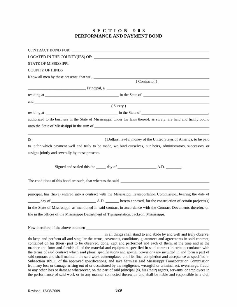
Revised 12/08/2009
S E C T I O N 9 0 3 PERFORMANCE AND PAYMENT BOND
CONTRACT BOND FOR:
LOCATED IN THE COUNTY(IES) OF:
STATE OF MISSISSIPPI,
COUNTY OF HINDS
Know all men by these presents: that we, ( Contractor )
______________________________ Principal, a
residing at ______________________________________ in the State of
and ( Surety )
residing at _____________________________________ in the State of ,
authorized to do business in the State of Mississippi, under the laws thereof, as surety, are held and firmly bound
unto the State of Mississippi in the sum of
($______________________________________) Dollars, lawful money of the United States of America, to be paid
to it for which payment well and truly to be made, we bind ourselves, our heirs, administrators, successors, or
assigns jointly and severally by these presents.
Signed and sealed this the _____ day of ____________________ A.D. ________.
The conditions of this bond are such, that whereas the said
principal, has (have) entered into a contract with the Mississippi Transportation Commission, bearing the date of
______ day of _______________________ A.D. _______ hereto annexed, for the construction of certain projects(s)
in the State of Mississippi as mentioned in said contract in accordance with the Contract Documents therefor, on
file in the offices of the Mississippi Department of Transportation, Jackson, Mississippi.
Now therefore, if the above bounden
_______________________________________ in all things shall stand to and abide by and well and truly observe, do keep and perform all and singular the terms, covenants, conditions, guarantees and agreements in said contract, contained on his (their) part to be observed, done, kept and performed and each of them, at the time and in the manner and form and furnish all of the material and equipment specified in said contract in strict accordance with the terms of said contract which said plans, specifications and special provisions are included in and form a part of said contract and shall maintain the said work contemplated until its final completion and acceptance as specified in Subsection 109.11 of the approved specifications, and save harmless said Mississippi Transportation Commission from any loss or damage arising out of or occasioned by the negligence, wrongful or criminal act, overcharge, fraud, or any other loss or damage whatsoever, on the part of said principal (s), his (their) agents, servants, or employees in the performance of said work or in any manner connected therewith, and shall be liable and responsible in a civil
329
SECTION 903 - CONTINUED
Revised 12/29/2010
action instituted by the State at the instance of the Mississippi Transportation Commission or any officer of the State authorized in such cases, for double any amount in money or property, the State may lose or be overcharged or otherwise defrauded of, by reason of wrongful or criminal act, if any, of the Contractor(s), his (their) agents or employees, and shall promptly pay the said agents, servants and employees and all persons furnishing labor, material, equipment or supplies therefor, including premiums incurred, for Surety Bonds, Liability Insurance, and Workmen's Compensation Insurance; with the additional obligation that such Contractor shall promptly make payment of all taxes, licenses, assessments, contributions, damages, any liquidated damages which may arise prior to any termination of said principal's contract, any liquidated damages which may arise after termination of the said principal's contract due to default on the part of said principal, penalties and interest thereon, when and as the same may be due this state, or any county, municipality, board, department, commission or political subdivision: in the course of the performance of said work and in accordance with Sections 31-5-51 et seq. Mississippi Code of 1972, and other State statutes applicable thereto, and shall carry out to the letter and to the satisfaction of the Executive Director of the Mississippi Department of Transportation, all, each and every one of the stipulations, obligations, conditions, covenants and agreements and terms of said contract in accordance with the terms thereof and all of the expense and cost and attorney's fee that may be incurred in the enforcement of the performance of said contract, or in the enforcement of the conditions and obligations of this bond, then this obligation shall be null and void, otherwise to be and remain in full force and virtue.
Witness our signatures and seals this the _______ day of ______________________ A.D. ______. (Contractors) Principal Surety By By (Signature) Attorney in Fact Address Title (Contractor's Seal) (Printed) MS Agent (Signature) MS Agent Address (Surety Seal) Mississippi Insurance ID Number
330
KNOW ALL MEN BY THESE PRESENTS, that we Contractor
Address
City, State ZIP as Principal, hereinafter called the Principal, and Surety a corporation duly organized under the laws of the state of
as Surety, hereinafter called the Surety, are held and firmly bound unto State of Mississippi, Jackson, Mississippi As Obligee, hereinafter called Obligee, in the sum of Five Per Cent (5%) of Amount Bid Dollars ($ ) for the payment of which sum will and truly to be made, the said Principal and said Surety, bind ourselves, our heirs, executors, administrators, successors and assigns, jointly and severally, firmly by these presents. WHEREAS, the Principal has submitted a bid for Project No. STP-2833-00(004)/105094-101000. NOW THEREFORE, the condition of this obligation is such that if the aforesaid Principal shall be awarded the contract, the said Principal will, within the time required, enter into a formal contract and give a good and sufficient bond to secure the performance of the terms and conditions of the contract, then this obligation to be void; otherwise the Principal and Surety will pay unto the Obligee the difference in money between the amount of the bid of the said Principal and the amount for which the Obligee legally contracts with another party to perform the work if the latter amount be in excess of the former, but in no event shall liability hereunder exceed the penal sum hereof. Signed and sealed this day of , 20___ (Principal) (Seal) By: (Witness) (Name) (Title) (Surety) (Seal) By: (Witness) (Attorney-in-Fact) MS Agent Mississippi Insurance ID Number
331


![[EDCF][STANDARD] Standard Request for Proposals for](https://img.pdfslide.net/doc/110x75/6358e98fdc00f5bf7b06b02a/edcfstandard-standard-request-for-proposals-for-.jpg)


