Embed Size (px)
Citation preview
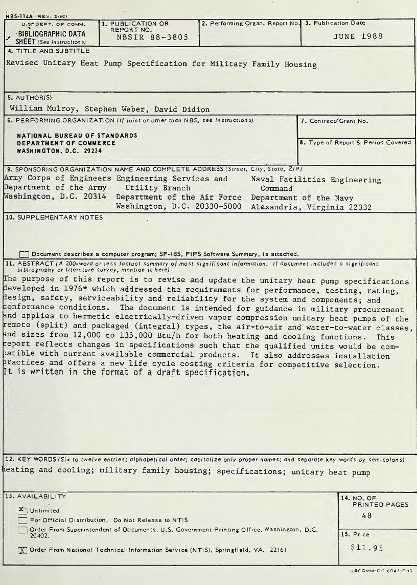
NBSIR 88-3805
Revised Unitary Heat PumpSpecification for Military FamilyHousing
William Mulroy
Stephen WeberDavid Didion
U.S. DEPARTMENT OF COMMERCENational Bureau of Standards
National Engineering Laboratory
Center for Building Technology
Gaithersburg, MD 20899
June 1988
Sponsored by:
U.S. Army Corps of Engineers
U.S. Department of the ArmyWashington, DC 20314
Engineering Services and Utility BranchU.S. Department of the Air Force
Washington, DC 20330-5000
Naval Facilities Engineering CommandU.S. Department of the NavyAlexandria, Virginia 22332
75 Years Stimulating America’s Progress
1913-1988

.
NBSIR 88-3805
REVISED UNITARY HEAT PUMPSPECIFICATION FOR MILITARY
FAMILY HOUSING
William Mulroy
Stephen WeberDavid Didion
U.S. DEPARTMENT OF COMMERCENational Bureau of Standards
National Engineering Laboratory
Center for Building Technology
Gaithersburg, MD 20899
June 1988
Sponsored by:
U.S. Army Corps of Engineers
U.S. Department of the ArmyWashington, DC 20314
Engineering Services and Utility Branch
U.S. Department of the Air Force
Washington, DC 20330-5000
Naval Facilities Engineering CommandU.S. Department of the NavyAlexandria, Virginia 22332
U.S. DEPARTMENT OF COMMERCE, C. William Verity, Secretary
NATIONAL BUREAU OF STANDARDS, Ernest Ambler, Director

Revised Unitary Heat Pump Specifications for Military Family Housing
ABSTRACT
The purpose of this report is to revise and update the unitary heat pump
specifications developed in 1976* which addressed the requirements for
performance, testing, rating, design, safety, serviceability and reliability
for the system and components; and conformance conditions. The document
is intended for guidance in military procurement and applies to hermetic
electrically-driven vapor compression unitary heat pumps of the remote
(split) and packaged (integral) types, the air-to-air and water- to-water
classes, and sizes from 12,000 to 135,000 Btu/h for both heating and
cooling functions. This report reflects changes in specifications such
that the qualified units would be compatible with current available
commercial products. It also addresses installation practices and offers
a new life cycle costing criterion for competitive selection. It is
written in the format of a draft specification.
Key Words: Heating and cooling; military family housing; specifications;
unitary heat pump
*NBSIR 76-1029

|i‘!1
*
.
.
TABLE OF CONTENTS
Page
ABSTRACT ... .................. iii
1. PURPOSE, SCOPE AND CLASSIFICATION 1
1 . 1 Purpose 1
1 . 2 Scope 1
1.3 Classification and Definition 1
2. REFERENCED SPECIFICATIONS AND STANDARDS 3
2.1 American National Standards Institute (ANSI) 3
2.2 Air-Conditioning and Refrigeration Institute (ARI) 3
2.3 American Society of Heating, Refrigerating, andAir Conditioning Engineers, Inc. (ASHRAE) 4
2.4 Underwriter's Laboratories, Inc. (UL) 4
2.5 Department of Defense (DoD) , 4
2.6 Air Conditioning Contractors of American (ACCA) ... 5
2.7 American Society for Testing and Materials (ASTM) 5
2.8 Department of Energy (DoE) 5
3. PROCUREMENT GUIDELINES 6
3.1 Prerequisite ...... 6
3.2 Instructions to Purchaser 7
3.3 Selection Criteria 9
3.4 Applicable Standards 9
4. GENERAL REQUIREMENTS FOR EQUIPMENT 11
4.1 Description 11
4.2 Standards 12
4.3 Heat Pump Cooling and Heating Capacity 12
4.4 Operational and Reliability Requirements 13
4.5 Supplemental Electric Resistance Heat 13
4.6 Refrigerant 14
4.7 Indoor Temperature Control 15
4.8 Defrost 15
4.9 Protective Mechanisms, Controls and Auxiliary Equipment .... 16
4.10 Sound Rating 16
4.11 Hermetic Motor-Compressor Units 16
4.11.1 Thermal Protection 17
4.11.2 Current Overload Protection 17
4.11.3 Crankcase Heating 17
4.11.4 Time Delay Mechanisms 18
4.11.5 Liquid Flood-Back 18
4.12 Moisture in Refrigerant 18
4.13 Strainer 18
4.14 Materials in Outdoor Unit 19
4.15 Air Filters 19
4.16 Water- to-Air Heat Pumps . 20
iii
Page
5. QUALITY ASSURANCE PROGRAMS .... ............ 21
5.1 Responsibility for Inspection and Examination ......... 21
5.2 Tests for Quality Conformance ................. 21
5.2.1 Capacity Tests .......... . 22
5.2.2. Operational Tests ................... 22
5.2.3 Reliability Tests ..... ... 23
5.3 Sampling for Capacity and Operational Tests . 23
5.4 Sampling for High Stress Reliability Tests . 24
5.5 Sampling for Life Cycle Reliability Tests ........... 24
6. PERFORMANCE TESTS . . .......... 25
6.1 Capacity and Efficiency Tests 25
6.2 Operational Tests 25
6.3 Reliability Tests ........ 26
6.3.1 High Stress Reliability Tests ..... 27
6.3. 1.1 Criteria for Acceptance ... 27
6. 3. 1.2 Test Specifications for Air Source Heat Pumps . 29
6. 3. 1.3 Test Specification for Water Source Heat Pumps. 30
6.3.2 Life Cycle Reliability Tests ....... .316. 3. 2.1 Criteria for Acceptance 31
6. 3. 2.
2
Test Specifications 33
6.3.3 Corrosion Tests 33
6. 3. 3.1 Salt Spray Test 34
6. 3. 3.
2
Indoor Unit Corrosion Test .......... 34
6. 3. 3.
3
Criteria for Acceptance ............ 35
7. LIFE CYCLE COST .......... ......... 36
8. REQUIREMENTS FOR QUALIFIED INSTALLER ................ 41
8.1 Qualification 41
8.2 Guarantee ........................... 41
1. PURPOSE. SCOPE AND CLASSIFICATION
1 . 1 Purpose
The purpose of this specification is to establish, for unitary heat pump
equipment*, the requirements for performance, testing, rating, design,
safety, serviceability and reliability for system and components and
conformance conditions. This specification is intended for guidance in
military procurement.
1 . 2 Scope
This specification applies to hermetic electrically-driven vapor-compression
unitary heat pumps of the types defined in Section 1.3 having suitable
heating and cooling capacities for military family housing.
1 . 3 Classification and Definition
The term heat pump, applied to a year-round air conditioning system,
denotes a system in which refrigeration equipment is used in such a manner
that heat is taken from a heat source and given up to the conditioned
space when heating service is desired, and heat is removed from the
conditioned space and discharged to a heat sink when cooling and
dehumidification are desired. Unitary heat pumps shall be defined as
consisting of one or more factory-made assemblies which normally include
indoor conditioning coil(s), compressor (s),outdoor coil(s) or
water- to-refrigerant heat exchanger and necessary controls to provide both
heating and cooling functions. The heating function may be supplemented
by electric resistance heaters. Unitary heat pumps within the scope of
this specification shall be classified by:
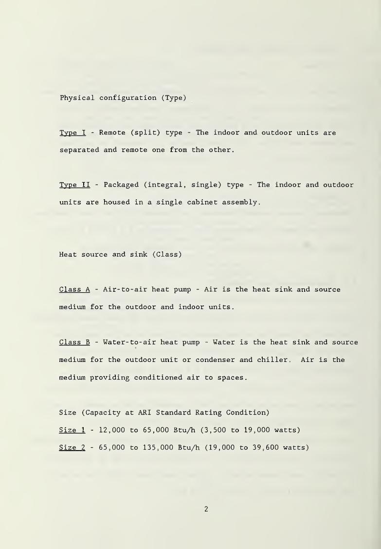
Physical configuration (Type)
Type I - Remote (split) type - The indoor and outdoor units are
separated and remote one from the other.
Type II - Packaged (integral, single) type - The indoor and outdoor
units are housed in a single cabinet assembly.
Heat source and sink (Class)
Class A - Air-to-air heat pump - Air is the heat sink and source
medium for the outdoor and indoor units
.
Class B - Water-to-air heat pump - Water is the heat sink and source
medium for the outdoor unit or condenser and chiller. Air is the
medium providing conditioned air to spaces.
Size (Capacity at ARI Standard Rating Condition)
Size 1 - 12,000 to 65,000 Btu/h (3,500 to 19,000 watts)
Size 2 - 65,000 to 135,000 Btu/h (19,000 to 39,600 watts)
2
2 . REFERENCED SPECIFICATIONS AND STANDARDS
The specifications and standards of the issue listed below (including
amendments, addenda, and errata), but referred to thereafter by designation
only, form a part of this specification to the extent required by the
reference thereto:
2 . 1 American National Standards Institute (ANSI)
ANSI/ASHRAE 15-1978 Safety Code for Mechanical Refrigeration
ANSI/ASHRAE 34-1978 Number Designation of Refrigerants
2 . 2 Air-Conditioning and Refrigeration Institute (ART)
210/240-84 Standard for Unitary Air Conditioning and Air
Source Heat Pump Equipment
240-81 Air- Source Unitary Heat Pump Equipment
260-75 Standard for Application, Installation and
Servicing of Unitary Equipment
270-84 Standard for Sound Rating of Outdoor Unitary
Equipment
275-84 Standard for Application of Sound-Rated Outdoor
Equipment
320-81 Standard for Water Source Heat Pumps
325-83 Standard for Ground Water Source Heat Pumps
520-78 Standard for Positive Displacement Refrigerant
Compressors and Condensing Units
710-80 Standards for Liquid Line Driers
3
2 .
3
American Society of Heating. Refrigerating, and Air-Conditioning
Engineers
.
36-
7237-
78
90A-1980
116-1984
GRP158
Inc. (ASHRAE)
Methods of Testing for Sound Rating Heating, Refrigerant
and Air Conditioning Equipment
Methods of Testing for Rating Unitary Air-
Conditioning and Heat Pump Equipment
Energy Conservation in New Building Design
Methods of Testing for Seasonal Efficiency of Unitary Air
Conditioners and Heat Pumps
Cooling and Heating Load Calculation Manual
2 .4 Underwriter's Laboratories. Inc. (UL)
559 Standard for Safety - Heat Pumps
984 Standard for Safety - Sealed (Hermetic Type) Motor-Compressors
2 . 5 Department of Defense (DoD)
4270.21-1970 Guide Specifications for Military Family Housing
Air Conditioning, Mechanical Division 15.16a
MIL-H-22547B(YD) Military Specification: Heat Pumps, Heating and
Cooling (Unitary) (8,400 to 300,000 Btu)
AFM 88-29 Engineering Weather Data
TM5-785
NAVFAC P-89
4
2 . 6 Air Conditioning Contractors of America (ACCA)
Manual G Selection of Distribution System
Manual J Load Calculation for Residential Winter and Summer Air
Conditioning
Manual 0 Equipment Selection and System Design Procedures
2 . 7 American Society for Testing and Materials (ASTM)
B117-64 Standard Method of Salt Spray (Fog) Testing
D1654-61 Standard Method of Evaluation of Painted or Coated
Specimens at 100 Percent Relative Humidity
D2247-68 (R80) Standard Method for Testing Coated Metal Specimens at 100%
Relative Humidity
G33-72 Standard Recommended Practice for Recording Data From
Atmospheric Corrosion Tests of Metallic-Coated Steel Specimens
2 . 8 Department of Energy (DoE)
DoE/NBS-0011 TI-59 Program for Calculating the Annual Energy Requirements
for Residential Heating and Cooling
DoE/CE-0076 Federal Energy Management Program Life Cycle Cost
Manual Update
5
3. PROCUREMENT GUIDELINES
3 . 1 Prerequisite
Prerequisite to the use of this specification for procurement it is
necessary for the purchaser to determine weather data, design heating and
cooling loads and the design for air distribution systems of the military
residential housing to be equipped with the heat pump equipment obtained
under this specification.
Weather data for outdoor design conditions should be in accordance
with Engineering Weather Data Air Force,Army and Navy Manual
.
Design sensible heating and sensible and latent cooling loads
should be determined in accordance with procedures described in
Cooling and Heating Load Calculation Manual (ASHRAE GRP 158) or
procedures given in ACCA Manual J, latest edition.
Air distribution systems should be suitable for both winter heating
and summer cooling and should conform to practices established in ACCA
Manual G, Manual D and ARI 260 for design, selection and installation
of duct system and insulation, and registers and diffusers. Sections
of DOD 4270.21 covering requirements for installation of heating and
air conditioning equipment and air distribution systems, testing of
heating and air conditioning systems, etc., should be used in preparation
of project specifications for military family housing.
6
If water-to-air heat pumps are to be considered, an adequately
proven year-round supply of water should be available. The quality
(hardness, acidity, mineral content, gas content, and bacterial
count) of the water and its temperature for both winter and summer
seasons should be determined and stated in the request for purchase.
Also, compatibility with water pollution regulations should be ensured.
3 . 2 Instructions to Purchaser
Items which must be specified by the purchaser of unitary heat pump
equipment in the contract or purchase order with reference to the provisions
referred to in this specification are as follows:
Required voltage and related electrical characteristics.
Winter and summer design indoor and outdoor conditions and the
seasonal heating hours for 5°F (2.8°C) temperature increments as
given in the Engineering Weather Data Manual.
Required heating and cooling capacities, in Btu/h (watts), at
specified winter and summer design conditions, respectively.
Type and class of heat pump required. Also size and dimension
limitations, or other special construction considerations.
Additional preproduction and/or post production capacity,
conformance and/or reliability tests as required and if any or
7
all tests are to be waived. In the area of reliability testing,
lack of data relating laboratory tests to field performance forces
some of the required operating conditions and hours of operation
to be somewhat arbitrary. If a manufacturer can demonstrate that
he is meeting the intent of the reliability tests with a testing
program of his own design (e.g. historical field reliability data),
the purchaser may choose to waive the specified reliability tests.
Specific performance data desired in addition to required test data.
Marginal cost of electricity, present value factor for life
cycle costing.
Minimum external resistance of air distribution system when
delivering the rated capacity and air quantity.
Length of warranty period. Items to be covered by warranty
(parts, labor, etc.).
When water-to-air heat pumps are specified, data covering water
quantity available in gallons per minute, summer and winter
water temperatures, water source and quality of water will be
furnished by the military services.
For geographical regions of high corrosion potential, such as
coastal regions with salt spray exposure, specify salt spray test.
8
3 . 3 Selection Criteria
The unit to be purchased shall be that which meets the purchaser specified
procurement guidelines (Section 3.2), the general requirements (Section 4)
and quality assurance provisions (Section 5) of this document and which
will result in the lowest life cycle cost (Section 7)
.
3 . 4 Applicable Standards
Throughout this document reference is made to applicable current ARI
standards. These standards are those which are used for testing and
rating for listing in the most recent edition of the appropriate ARI
directory of certified products. As this document is being written (April
1988), the current applicable ARI standard for air source heat pumps is
240-81. It is recommended that units covered by ARI 240-81 that are
greater than 65,000 Btu/h (19,000 watts) in capacity shall be tested in
the same way as those less than 65,000 Btu/h (19,000 watts) in order to
provide the necessary data for calculation of local SEER and HSPF values
to allow application of the lowest life cycle cost criterion of this
standard. This requires the performance of additional "B" cooling steady
state and heating mode frost accumulation tests and either performance of
cycling tests or use of the default value of CD .
At this time ground water source units are rated under ARI 325 and water
source heat pumps under ARI 320. It is recommended that rating under ARI
320 be allowed for units which use well water of an approximately constant
70° F (21. °C) temperature (approximately DoE zones 1 and 2) and that rating
under ARI 325 be allowed also for this application and required for all
9
other ground water source applications.
As newer Department of Energy approved methods for calculating seasonal
efficiency are developed which can be adopted to site particular energy
consumption calculations,these should be employed in lieu of the above
mentioned standards
.
For all other cited documents, the most recent revision shall be used for
procurement under this specification.
10
4. GENERAL REQUIREMENTS FOR EQUIPMENT
4 . 1 Description
Throughout this specification the term "heat pump" will be used
interchangeably with the term "unitary heat pump" as defined in Sections
1 . 2 and 1.3.
All heat pumps of a given type, class and size to be delivered under a
specific contract or purchase order shall be of the same manufacturer and
model. Remote (split) type heat pumps shall consist of a complete
packaged outdoor unit and a complete packaged indoor unit, on which the
capacity, operational, and reliability tests of this document have been
performed as a rated, matched set. Precharged factory supplied units and
tubing shall be furnished with remote type heat pumps whenever available.
Packaged (integral) type heat pumps shall consist of a single factory-assembled
sheet-metal casing complete with indoor and outdoor units piped and wired,
ready for connection to duct system and electric circuits. Electric
resistance heaters may be field installed in either type. The cooling
capacity of the system shall not be less than the cooling design load
specified in the contract or purchase order. The resistance heating coils
shall be capable of handling a minimum of 100% of the heating design load.
Unless otherwise specified, the maximum airflow and minimum external
pressure shall be as required in the current applicable ARI standard
referenced in section 2.2. Unit components shall be readily accessible
for maintenance and service. Certain requirements in this specification,
particularly current overload protection, crankcase heating, time delay
mechanisms and liquid flood-back protection are included for system
11
reliability needs . If a bidder has alternative means to accomplish these
functions, the acceptance shall be dependent on proof submitted by the
heat pump manufacturer, and acceptable to the contracting officer,, This
proof shall include written certification that the alternative means
satisfy the functional requirements.
4 . 2 Standards
Heat pumps shall conform to current applicable ARI standards, UL 559 and
ANSI/ASHRAE 15. Proof shall be submitted showing that the items furnished
under this specification conform to such requirements. The listing and
labels (together) of the ARI and a nationally recognized safety approval
agency for the manufacturer's standard model will be acceptable as
sufficient evidence that the items conform to the label- identified
standards of these organizations. In lieu of such certification, label or
listing, a written certificate from a testing laboratory or agency
adequately equipped and competent to perform such services shall be
submitted stating that the items have been tested and that the heat pump
units and assembled components conform to requirements specified in
current applicable ARI standards, UL 559 and ANSI B9.1. Description of
test methods shall accompany certificate.
4 . 3 Heat Pump Cooling and Heating Capacity
The heat pump heating and cooling (sensible and latent) capacities shall
not be less than that specified for the winter and summer outdoor design
conditions of the contract or purchase order when tested in accordance
with Section 5.2. 1.1. The minimum capacity for the supplemental heaters
12
shall be at least equal to the heating load at the winter design outdoor
temperature
.
The heat pump manufacturer shall state the rated voltage and capacity of
supplemental heaters. The heaters shall provide this capacity when tested
in accordance with Section 6.1.4. Air source heat pumps shall meet the
minimum efficiency requirements of the current ASHRAE Standard 90, or
those which may be in effect by the local civilian authority, whichever is
more stringent. This criteria is predominate in case of conflict with
life cycle cost criteria noted later in this report.
4 . 4 Operational and Reliability Requirements
Heat pumps qualified for delivery under this specification shall meet the
operational and reliability criteria of the current applicable ARI
standards and shall have been subjected to and successfully passed the
operational and reliability tests required in Section 5 of this specification
and shall conform to the requirements contained in Section 6 of this
specification.
4 . 5 Supplemental Electric Resistance Heat
If supplementary heat is needed to satisfy the heating requirements (see
Section 4.3) of this specification, supplemental electric resistance
heaters shall be provided and shall be located downstream of the indoor
coil. The electric heaters shall be electrically wired in accordance with
UL 559 and controlled in one or more steps so that they shall provide
sufficient additional heating capacity for building heat demand loads in
13
excess of the compression and indoor fan heating capacity. No single step
of supplemental heating shall produce a temperature rise in the discharge
air greater than 40°F (22.2°C). The heaters shall be controlled by means
of outdoor and indoor thermostats interlocked one with the other. The
outdoor thermostat, whose operation shall override that of the indoor
thermostat, shall prevent the supplementary heaters from operating at
outdoor temperatures above 40° F (4.4°C) except as required to offset
cooling effect during defrost operation (Section 4.8) or in the case of
emergency (e.g., compressor failure). For the heating operation, the
indoor thermostat shall operate in at least two steps. The first step
shall initiate heat pump operation for heating by compression only. The
second step (and additional step(s), if provided) shall control heating
provided by the supplemental heaters. The cut-on temperature for the
first set of supplemental heaters shall be between 0.5°F (.3°C) and 1 . 5°
F
(.8°C) below the cut-on temperature for the compression heating. Additional
steps of supplemental heating if required shall be activated for both
cut-off and cut-on, respectively in 0.5°F (.3°C) to 1.0°F (.6°C) steps
below the first step of supplemental heating by the thermostat. The total
operating temperature differential between thermostat cut-on and cut-off
of the compression heating control shall not exceed 2°F (1.1°C). All
quoted thermostat temperature differentials are as measured at the switch
(i.e., switch differential).
4 . 6 Refrigerant
The refrigerant shall be Group I Classification as described in ANSI/ASHRAE
34. The type of refrigerant to be used in the system shall be as specified
14
in the contract or purchase order. If not so specified, the refrigerant
shall be R-22.
4 . 7 Indoor Temperature Control
Temperature controls for heat pump operation shall be capable of being set
to control heating at any temperature at least from 55° F (12.8°C) up and
to control cooling at any temperature from at least 85° F (29.4°C) down.
The thermostat shall be factory locked to prevent setting below 42°F(5.6°C).
When the heat pump system is operating (except during defrost operation)
,
the temperature control shall be capable of regulating the indoor temperature
at the thermostat to within 2°F (1.1°C) of the control setting when only
compression heating is being provided and to within 3°F (1.7°C) of the
control setting when compression and supplemental heating is required.
For control of supplemental heat see Section 4.5. The thermostat shall
contain or a sub-base shall be provided containing selector switches for
COOL-OFF-HEAT and FAN-AUTO-ON.
4 . 8 Defrost
Air-source heat pumps designed to operate with a defrost cycle shall
include positive actuation and termination means for defrosting the coils
and fins of the outdoor unit automatically with suitable drain provisions
to remove condensate and meltage without freeze-up and other malfunctions
throughout the entire range of application temperatures.
15
4 . 9 Protective Mechanisms. Controls and Auxiliary Equipment
The heat pump system shall contain the necessary components, protective
mechanisms, controls and auxiliary equipment for it to meet the requirements
and tests set forth in this specification. Safety devices and protective
controls shall be used to limit or terminate abnormal operating conditions
and shall not be used to control normal heat pump operation. Also refer
to Section 4.2.
4 . 10 Sound Rating
All outdoor unitary heat pump equipment shall be sound rated and tested in
accordance with ARI 270 and shall not exceed a sound rating of 8.4 bels for
units below 38,000 Btu/h (11,100 watts), 8.6 bels for units between 38,000
Btu/h (11,100 watts) and 65,000 Btu/h (19,000 watts) and 8.8 bels for units
between 65,000 Btu/h (19,000 watts) and 135,000 Btu/h (39,600 watts) in
capacity as defined in these standards. The ARI label will be acceptable
as sufficient evidence of compliance with the test method of ARI 270. In
lieu of such certification or label, a written certificate from a testing
agency or laboratory adequately equipped and competent to perform such
services shall be submitted stating that the equipment has been tested and
conforms to requirements specified in ARI 270 and to the requirements of this
specification.
4.11 Hermetic Motor-Compressor Units
Hermetic motor-compressor units shall conform to the requirements of UL 984
with regard to construction, performance and testing. The requirements for
motor-compressor protection systems of this standard shall also apply in
16
addition to the following.
4.11.1 Thermal Protection
An internal motor-winding temperature-sensing protection device of the
automatic reset type for the compressor motor shall be provided to prevent
motor operation under excessive motor winding temperatures. The heat pump
compressor manufacturer's recommended maximum average motor winding
temperature shall not be exceeded when the heat pump is operating under
any of the tests prescribed in ARI 210/240, and in no case shall winding
temperature under any of these test conditions exceed 300°F (149°C). The
heat pump compressor manufacturer's recommended maximum average motor
winding temperature shall be stated in the bid submission.
4.11.2 Current Overload Protection
Motor running- current overload protection conforming to the National
Electric Code (refer to UL 984) ,shall be provided for the compressor
motor. If manual reset is provided it shall be readily accessible and
reset means clearly marked.
4.11.3 Crankcase Heating
Means shall be provided for heating the compressor crankcase of units with
outdoor compressors which equalize crankcase pressure to suction pressure,
so that liquid slugging as a result of liquid foaming under compressor
starting conditions is prevented. Crankcase heaters either external or
internal (except for motor windings used as heaters) shall be readily
replaceable from the exterior without breaking the refrigerant seal.
17
4 . 11.4 Time Delay Mechanism
The motor protection system shall contain a device or means that delays
operation of the compressor motor for a period of at least three but not
more than six minutes after compressor operation is called for when
shut-down for any reason, inadvertent or otherwise has occurred. (Note:
This is needed to diversify startup loads in housing areas after power
interruption and to guard against short cycling of individual units.)
4.11.5 Liquid Flood-Back
A means shall be provided for protecting the compressor of air source
units from liquid flood-back, under all design conditions of operation,
including defrost. Properly designed and sized accumulators or a
sufficiently large oil sump within the hermetic shell will satisfy this
requirement. Accumulators must provide for return of oil to the compressor.
4 . 12 Moisture in Refrigerant
The system shall contain a filter-drier conforming to ARX 710. Refrigerant
piping shall be circuited such that backwashing of the filter-drier by
reversal of refrigerant flow does not occur unless the filter is designed
for bidirectional operation. The moisture content in the refrigerant
shall not exceed 60 ppm at time of heat pump installation and 30 ppm at
conclusion of the Reliability Tests (see Section 6.3).
4 . 13 Strainer
If the heat pump system uses capillary tubes as a refrigerant expansion
device, a strainer shall be installed in the line ahead of the capillary
18
tube assembly capable of stopping passage of scale and other particulate
matter of minor dimension greater than 20% of the bore size of the
smallest tube.
4. 14 Materials in Outdoor Unit
The materials of which the components in the outdoor unit are fabricated
and the method of fabrication shall be such that when a heat pump system
is subjected to the Reliability Tests (Section 6.3) of this specification,
it shall pass the tests and retain its physical and structural integrity.
Construction methods shall be utilized which minimize or eliminate the
galvanic effect. Coils and fins of the outdoor coil shall be corrosion
resistant or treated to resist corrosion. Coils, fins and fan shall be
protected from physical damage by means of a suitable grill or other means
which do not lower the airflow through the coil enough to prevent the
specified performance of the system.
4 . 15 Air Filters
Air filters mounted on the air return to the indoor unit shall be furnished.
The air filter installation shall preferably be integral with the indoor
unit and if mounted remotely in the house duct system, the duct must be
leak tight to the unit. The air filter shall be readily accessible for
removal from the indoor unit for cleaning or replacement after residential
installation. The air filter installation shall have no unplugged holes
or cracks allowing air to bypass the filter prior to reaching the indoor
coil
.
19
4.16 Water- to-Air Heat Pumps
Water-to-air heat pumps shall be capable of meeting the following performance
requirements
.
1. The water temperature leaving the condenser during cooling
operation shall not exceed the maximum water temperature
recommended by the manufacturer.
2. The water temperature leaving the water- to-refrigerant heat
exchanger during heating operation shall not be less than 40°
F
(4.4°C) for open loop systems and the manufacturer's recommended
temperature with the manufacturer's recommended circulating
fluid (brine) for closed loop systems.
3.
A low pressure cut-out device with a manually reset lockout or a
freezestat shall be installed so as to prevent freezing during
the heating operation.
4.
Construction and/or piping for water- to-refrigerant heat
exchangers of open loop systems shall include provision for
isolation and access valving for the purposes of chemical
cleaning or physical access for mechanical cleaning of the
water side of heat exchange surfaces. Water piping and valving
may be installed.
20

5. QUALITY ASSURANCE PROCEDURES
5 . 1 Responsibility for Inspection and Examination
The contractor (supplier) shall be responsible for the fulfillment of all
inspection requirements as specified herein. The contractor shall be
responsible for insuring that the components of the system, even though
manufactured by a secondary supplier, are tested, and examined, and are
satisfactory for inclusion in the heat pump system. The supplier shall
also be responsible for the fulfillment of requirements of the referenced
applicable documents for any component of the heat pump system. Unless
otherwise specified in the contract or purchase order, the Government
(purchaser) reserves the right to perform any of the inspections to
determine if the requirements set forth in Section 4 are fulfilled. If
the Government so desires it may contract this responsibility to any
qualified commercial or Government laboratory.
5 . 2 Tests for Quality Conformance
Three types of tests required by this specification shall be performed, or
shall have been performed for each type, class, model and size to be
supplied in the contract or purchase order; namely, 1) capacity, 2)
operational and 3) reliability tests. The data required shall be obtained
from tests described in Section 6, with regard to all inspections and
capacity, operational and reliability tests. The Government reserves the
right to make any or all inspections and tests necessary in addition to
those required in the contract or purchase order to assure conformance
with specification requirements at any time prior to final acceptance. If
such additional testing indicates failure to conform, the cost of the unit
21
or component tested and the cost of testing will be borne by the supplier.
If such additional testing indicates conformance, the cost of the unit or
component tested and the cost of testing will be borne by the Government.
5.2.1 Capacity Tests
The supplier shall provide manufacturer '
s
heating and cooling data which
shall be obtained in accordance with the current applicable ARI standard
and certified as required in paragraph 4.2. Certified performance data
shall include capacity and power input at the standard rating condition
and the application rating condition as described in the current applicable
ARI standard.
For the heating and cooling capacity tests above, if, in the contract or
purchase order an air system distribution resistance or airflow different
from the values listed in the current applicable ARI standard is specified,
the performance data required shall be adjusted accordingly.
Manufacturer '
s
performance data is data based on tests of which the
accuracy is attested to by the unit manufacturer. Certified performance
data is data of which the accuracy is attested to either by an independent
testing laboratory or by a certification program such as that of ARI.
5.2.2 Operational Tests
The heat pump system shall operate satisfactorily under standard and
maximum operating conditions (refer to Section 4.4). Heat pumps scheduled
for delivery under this specification shall meet all requirements of the
22
current applicable ARI standard. The ARI label and listing in the current
ARI directory will be accepted as evidence of meeting this requirement.
In lieu of such certification and label, a written certificate from a
testing agency or laboratory adequately equipped and competent to perform
such services shall be submitted stating that the equipment conforms to
requirements specified in the current applicable ARI standard.
5.2.3 Reliability Tests
The heat pump shall be subjected by the manufacturer to either the high
stress or the life cycle reliability tests listed in Section 6.3 of this
specification (unless waived by the purchaser) and shall conform to the
listed requirements, and shall perform without damage to any part except
as permitted herein. Reliability test data shall be made available to
the purchaser by the manufacturer if requested.
5 . 3 Sampling for Capacity and Operational Tests
Unless otherwise required in the contract or purchase order, the heat pump
type, class, model and size to be provided for delivery shall have its
certified data for all listed capacity tests and operational tests and
shall satisfactorily conform to all test requirements. Units which are
identical but not necessarily the same physical units may be used for the
capacity and operational tests and the reliability tests. The heat pump
tested as representative of each type, model and size shall pass all tests
described in Section 5.2, and as specified under Sections 6.1 and 6.2.
23
5 . 4 Sampling for High Stress Reliability Tests
If the high stress reliability test option is chosen, at least one heat
pump of each type, class, model or closely related models to be provided
under this contract and picked at random shall have been subjected to and
successfully passed the reliability tests (Section 6.3.1) conducted in
accordance with the following plan. If there are no failures in this
first specimen, the type, class, model and size will be considered
satisfactory with respect to the reliability tests. If there are not
more than two failures, three additional specimens picked at random shall
undergo a test for conformance to all listed reliability requirements. If
there is not more than one failure of the same kind, or not more than
three failures altogether from that total of four specimens tested, the
lot will be considered satisfactory with respect to the reliability
tests. If there are two or more failures of the same kind, or four or
more failures altogether from the total of four specimens tested, all heat
pumps of that type, class, model and size shall be rejected. Sampling
under this option applies to each type, class, model or worst case
condition of closely related models, and worst size condition within
models which are to be provided under this contract. A failure shall be
considered to be an inability to meet any of the criteria for acceptance
of 6. 3. 1.1.
5 .
5
Sampling for Life Cycle Reliability Tests
Sampling for the life cycle reliability test option shall be at random and
shall be sufficiently large as to be statistically significant as defined
in Section 6. 3. 2.1. Sampling under this option applies to each type,
24
class, model or worst case condition of closely related models, and worst
size condition within models which are to be provided under this contract.
6. PERFORMANCE TESTS
6 . 1 Capacity and Efficiency Tests
This section describes tests of heat pumps for determination of capacity and
coefficient of performance. Testing procedures shall, where applicable, be
as described in the current applicable ASHRAE test procedure for all sizes
of heat pumps procured under this document. Unless otherwise specified, test
conditions shall be as set forth in the current applicable ARI standard. At
rating and application conditions, the efficiency of the heat pump for heating
and cooling shall be calculated from the test data in a manner as defined
by the current applicable ARI standard. This determination shall act as input
to the Life Cycle Cost procedure described in Section 7 of this document.
The heating capacity of the supplemental heaters shall be determined by the
measurement of the electrical power usage of the supplemental heater(s)
.
The electrical power usage shall be measured at specified voltage and at
room temperature of 70 F (21.1 C) with suitable instrumentation accurate
to within 2 percent of the measured value. The test data shall be used to
determine compliance with Sections 4.5 and 4.3.
6 .
2
Operational Tests
As stated in Section 5.2.2, required operational tests are the following
tests described in the Performance Requirements of the current applicable
ARI standard:
25
1. Maximum Operating Condition Test
2. Voltage Tolerance Test
3. Low Temperature Operation Test (Cooling)
4. Insulation Efficiency Test (Cooling)
5. Condensate Disposal Test (Cooling)
6 . 3 Reliability Tests
For the purpose of this specification, reliability tests for air source
heat pumps will be considered in two separate programs: (1) high stress
tests and (2) life cycle tests. The high stress test program is intended
to take the system beyond its normal operating limits to ensure that there
are adequate safety devices that will shut the system down in order to
protect the essential, more expensive components (i.e„, compressor). The
life cycle tests are designed to have the unit operate under simulated
field conditions near or slightly beyond the worst expected climatic
conditions for an extended period of time. The contractor must submit the
manufacturer's data that proves the specific model or a closely related
model to that being offered has successfully completed either one or the
other of these programs (high stress or life cycle) as defined in the
following sections.
In addition to either of these test programs the purchaser may specify one
or both of the corrosion tests described in Section 6.3.3; depending on
the climatic conditions of the installation site.
26
6.3.1 High Stress Reliability Tests
Temperature tolerances for the reliability tests shall be as specified in
performance requirements of ARI 210/240. Voltage tolerances shall be + 3
volts. All of these tests shall be performed without the indoor thermostat
in the system or with the thermostat shunted to call for continuous
operation. All manual-reset operating, protective, and limit controls/devices
shall be reactivated within 30 minutes following trip-out or similar
operation throughout each test. Supplemental heaters shall not be
operated in any of the reliability tests. Indoor unit air inlet temperature
shall be held in the range from 70°F (21.1°C) to 80°F (26.7°C) for tests.
For all tests, the portions of the tests that call for unit operation
imply continuous compressor operation except as controlled by protective/limit
devices. High stress reliability tests for water source heat pumps shall
be performed with water, not freezing inhibited brine, as the circulating
fluid.
6. 3. 1.1 Criteria for Acceptance
As applicable, the following requirements must be met for acceptance:
1. No impairing damage shall occur to any component during these tests.
2. The temperature of the oil sump remote from the suction line
inlet to the compressor shall at no time during steady-state
operation be less than 40° F (22. 2° C) warmer than that of the
suction line within 6 inches (.152 m) of the compressor shell.
During the off cycle this temperature difference may decrease
27
to 10°F (5.6°C). On start up this temperature difference must
constantly increase toward its steady state value.
3. The temperature of the discharge line within six inches (.15 m)
of the compressor shall at no time during steady state operation
be less than 20° F (11.1°C) warmer than the saturation temperature
corresponding to the discharge pressure for more than 5 minutes.
Thermocouples shall be used for these measurements, shall be
physically bonded to the respective sufaces (including at least
one inch (.025 m) of the leads) and shall be insulated from
ambient conditions.
4. No audible knocking or hammering of mechanical parts shall occur
in excess of that occurring in normal continuous operation at
standard rating conditions in the current applicable ARI standard.
5. Trip-out of operating, protective, and limit controls/devices
shall not constitute a failure.
6. Average motor winding temperature shall not exceed 300° F (149°C)
at any time during any of the reliability tests. Use of a
Seely bridge is recommended for measurement of the average
winding temperature while the motor is running.
7. Discharge refrigerant line temperature within 6 inches (.15 m)
of the compressor shall not exceed 250°F (121°C) during the
28
reliability tests.
8. Upon completion of the reliability tests, the moisture content
of the refrigerant shall be determined and the moisture content
shall not exceed 30 ppm with filter drier included in the system.
6.3. 1.2 Test Specifications for Air Source Heat Pumps
1
.
Heating and cooling test
Voltage as specified in the contract or purchase orderOutdoor air dry-bulb temperature 70° F (21.1°C) to 80° F (26. 7° C)Indoor air dry-bulb temperature 70° F (21.1°C) to 80° F (26. 7° C)100% operation - 50% cooling and 50% heatingCycle reversal every hour48 hours total test duration
2
.
High temperature test (cooling)Voltage 90% of specifiedOutdoor air dry-bulb temperature 130°F (54.4°C) to 140° F (60°C)
Indoor air dry-bulb temperature 70°F (21.1°C) to 80°F (26.7°C)
100% unit operation24 hours total test duration
3
.
Low temperature test (heating)
Voltage 110% of specifiedOutdoor air dry-bulb temperature the higher of the lowest recordedtemperature for the region or the unit cut-off temperatureIndoor dry-bulb temperature 70°F (21.1°C) to 80°F (26.7°C)Operation: Off 24 hours, On 8 hours, Off 24 hours, On 8 hours64 hours total test duration
4
.
Blocked air filter test (cooling)
Voltage as specifiedOutdoor air dry-bulb temperature 95° F (35°C) to 105° F (40. 6° C)Indoor dry-bulb temperature 70° F (21.1°C) to 80° F (26. 7° C)100% unit operation: 12 hours at 50% of normal airflow across indoorcoil, 12 hours with no airflow across indoor coil (indoor faninoperative and filter face blocked for this test)24 hours total test duration
29
5 . Low refrigerant charge test (cooling)
Voltage as specifiedOutdoor air dry-bulb temperature 95° F (35° C)
Indoor air dry-bulb temperature 70 F (21.1°C) to 80° F (26. 7° C)50% of manufacturer's recommended refrigerant charge100% unit operation24 hours total test duration
6 . Low refrigerant charge test (heating)
Conditions same as 5 above, except outdoor air temperature 20°
F
(-6 . 7°C) to 35° F ( 1 . 7° C)
6. 3. 1.3 Test Specifications for Water Source Heat Pumps
1
.
Heating and cooling test
Voltage as specified in the contract or purchase orderEntering Water temperature 70° F (21.1°C) to 50° F (10.0°C)Indoor air dry-bulb temperature 70° F (21.1°C) to 80° F (26. 7° C)100% operation - 50% cooling and 50% heatingCycle reversal every hour48 hours total test duration
2 . High temperature test (cooling)
Voltage 90% of specifiedEntering Water temperature 85°F (29.4°C) to 95°F (35.0°C)Indoor air dry-bulb temperature 70° F (21.1°C) to 80° F (26. 7° C)100% unit operation24 hours total test duration
3 . Low temperature test (heating)
Voltage 110% of specifiedOutdoor air dry-bulb temperature for split system units the higher of
the lowest recorded temperature for the region or the unit cut-offtemperature
Entering water temperature 36°F (2.2°C) to 32°F (0°C)
Indoor dry-bulb temperature 70°F (21.1°C) to 80°F (26„7°C)Operation: Off 24 hours, On 8 hours, Off 24 hours, On 8 hours64 hours total test duration
30
4
.
Blocked air filter test (cooling)
Voltage as specifiedEntering water temperature 65°F (18.3°C) to 75°F (23.9°C)Indoor dry-bulb temperature 70° F (21.1°C) to 80° F (26. 7° C)100% unit operation: 12 hours at 50% of normal airflow across indoorcoil, 12 hours with no airflow across indoor coil (indoor faninoperative and filter face blocked for this test)24 hours total test duration
5
.
Low refrigerant charge test (cooling)
Voltage as specifiedEntering water temperature 65°F (18.3°C) to 75°F (23.9°C)Indoor air dry-bulb temperature 70 F (21.1°C) to 80° F (26. 7° C)50% of manufacturer's recommended refrigerant charge100% unit operation24 hours total test duration
6
.
Low refrigerant charge test (heating)
Conditions same as 5 above, except entering water temperature 45°
F
(7 . 2° C) to 55° F ( 1 . 28° C)
6.3.2 Life Cycle Reliability Tests
Temperature tolerances for the reliability tests shall be as specified in
performance requirements of the current applicable ARI standard. Voltage
tolerances shall be +3 volts. Supplemental heaters shall not be operated
during any reliability tests.
6. 3. 2.1 Criteria for Acceptance
Criteria for acceptance shall be those of 6. 3. 1.1 with the addition that
trip-out or similar operation of any manual-reset operating, protective,
or limit control/device shall constitute a failure.
Additional criteria for acceptance for the Life Cycle Reliability Test
option shall be compressor mean time between failures of at least 38,990
31
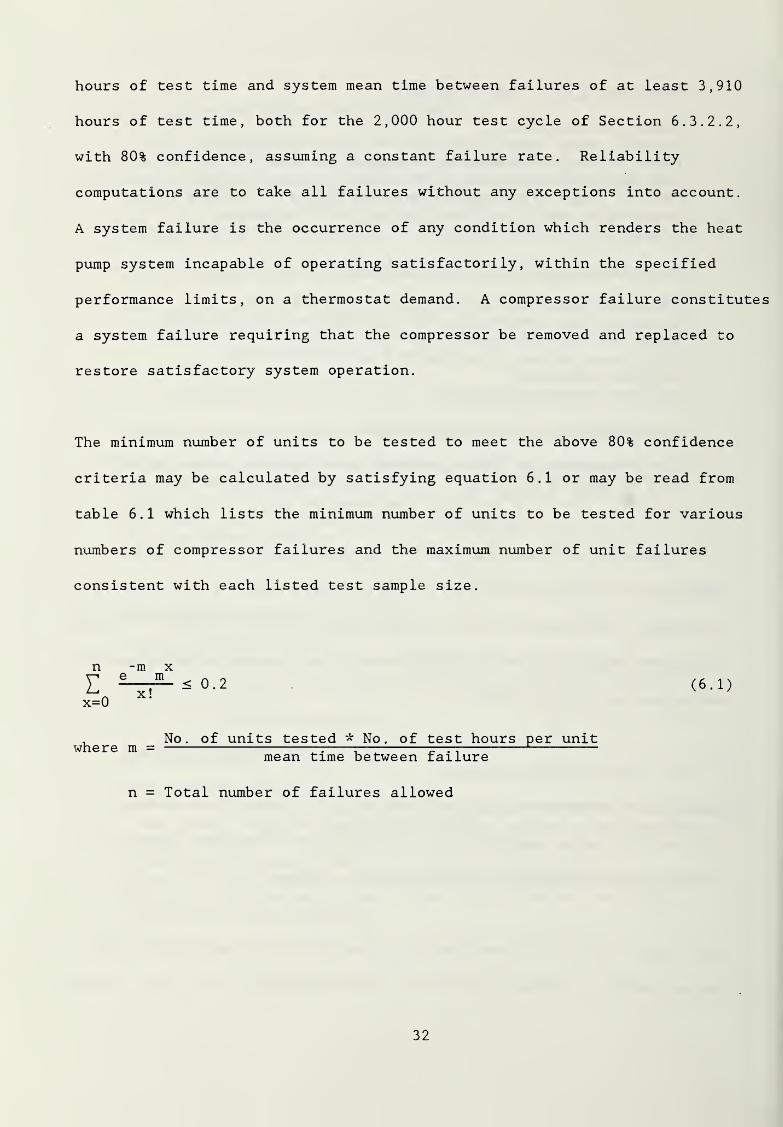
hours of test time and system mean time between failures of at least 3,910
hours of test time, both for the 2,000 hour test cycle of Section 6. 3. 2. 2,
with 80% confidence, assuming a constant failure rate. Reliability
computations are to take all failures without any exceptions into account.
A system failure is the occurrence of any condition which renders the heat
pump system incapable of operating satisfactorily, within the specified
performance limits, on a thermostat demand. A compressor failure constitutes
a system failure requiring that the compressor be removed and replaced to
restore satisfactory system operation.
The minimum number of units to be tested to meet the above 80% confidence
criteria may be calculated by satisfying equation 6.1 or may be read from
table 6.1 which lists the minimum number of units to be tested for various
numbers of compressor failures and the maximum number of unit failures
consistent with each listed test sample size.
n -m xe m
Ex=0
x!< 0.2 (6.1)
where m = No. of units tested * No. of test hours per unitmean time between failure
n = Total number of failures allowed
32
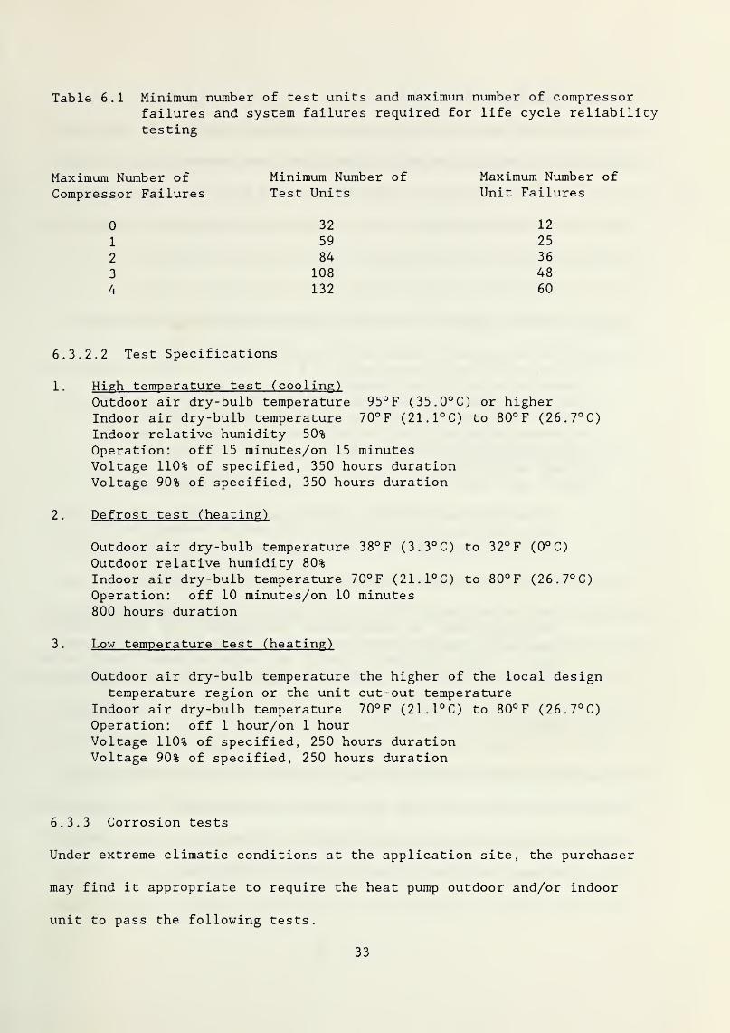
Table 6.1 Minimum number of test units and maximum number of compressorfailures and system failures required for life cycle reliabi litytesting
Maximum Number ofCompressor Failures
0
1
2
3
4
Minimum Number ofTest Units
32
59
84
108
132
Maximum Number ofUnit Failures
12
25
36
48
60
6. 3. 2.
2
Test Specifications
1 . High temperature test (cooling)Outdoor air dry-bulb temperature 95° F (35.0°C) or higherIndoor air dry-bulb temperature 70°F (21.1°C) to 80°F (26.7°C)Indoor relative humidity 50%
Operation: off 15 minutes/on 15 minutesVoltage 110% of specified, 350 hours durationVoltage 90% of specified, 350 hours duration
2 . Defrost test (heating)
Outdoor air dry-bulb temperature 38°F (3.3°C) to 32°F (0°C)
Outdoor relative humidity 80%
Indoor air dry-bulb temperature 70°F (21.1°C) to 80°F (26.7°C)Operation: off 10 minutes/on 10 minutes800 hours duration
3 . Low temperature test (heating)
Outdoor air dry-bulb temperature the higher of the local designtemperature region or the unit cut-out temperature
Indoor air dry-bulb temperature 70° F (21.1°C) to 80° F (26. 7° C)Operation: off 1 hour/on 1 hourVoltage 110% of specified, 250 hours durationVoltage 90% of specified, 250 hours duration
6.3.3 Corrosion tests
Under extreme climatic conditions at the application site, the purchaser
may find it appropriate to require the heat pump outdoor and/or indoor
unit to pass the following tests.
33
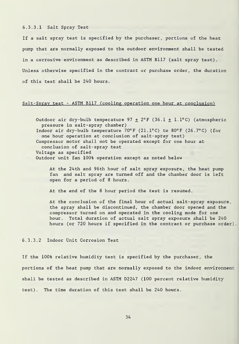
6. 3. 3.1 Salt Spray Test
If a salt spray test is specified by the purchaser, portions of the heat
pump that are normally exposed to the outdoor environment shall be tested
in a corrosive environment as described in ASTM B117 (salt spray test)
.
Unless otherwise specified in the contract or purchase order, the duration
of this test shall be 240 hours.
Salt-Spray test - ASTM B117 (cooling operation one hour at conclusion)
Outdoor air dry-bulb temperature 97 + 2°F (36.1 + 1.1°C) (atmosphericpressure in salt-spray chamber)
Indoor air dry-bulb temperature 70°F (21.1°C) to 80°F (26.7°C) (for
one hour operation at conclusion of salt-spray test)
Compressor motor shall not be operated except for one hour atconclusion of salt-spray test
Voltage as specifiedOutdoor unit fan 100% operation except as noted below
At the 24th and 96th hour of salt spray exposure, the heat pumpfan and salt spray are turned off and the chamber door is leftopen for a period of 8 hours.
At the end of the 8 hour period the test is resumed.
At the conclusion of the final hour of actual salt-spray exposure,the spray shall be discontinued, the chamber door opened and the
compressor turned on and operated in the cooling mode for one
hour. Total duration of actual salt spray exposure shall be 240
hours (or 720 hours if specified in the contract or purchase order)
.
6. 3. 3.
2
Indoor Unit Corrosion Test
If the 100% relative humidity test is specified by the purchaser, the
portions of the heat pump that are normally exposed to the indoor environment
shall be tested as described in ASTM D2247 (100 percent relative humidity
test). The time duration of this test shall be 240 hours.
34
The extent of area of indoor and outdoor exposure to salt spray/humidity
environment for corrosion testing of packaged (integral) type heat pumps
shall be determined from size, dimension and construction considerations.
100% Relative Humidity Test
Indoor air temperature 85 F (29.4 C)
Indoor fan operation 100% (no heating or cooling coil operation)
Voltage as specified
Interruption conditions at the 24th and 96th hour as specified in
test 7 above
240 hours total 100% relative humidity exposure
Flaking, perforation, or penetration of metal parts shall be
considered a failure.
6. 3. 3.
3
Criteria for Acceptance
Data to be taken before and after corrosion tests shall be recorded and
results photographed as given in Section 3.3 of ASTM G33. For painted and
all coated surfaces refer to ASTM D1654 for testing procedure where marks
shall be scribed on vertical, horizontal, external and internal painted or
coated surfaces. Rating Schedule No. 2 of ASTM D1654 shall be reported.
The rating number shall not be less than 6 and there shall be no rust
creep greater than 1/8" (3.2 mm) normal to the scribe marks for acceptance.
Blistering or flaking of paint or coating and rust creep at screw holes
shall be reported and rated as above. Oxidation and corrosion of bare
metal parts and at joints of dissimilar metals shall be reported and
photographed. Flaking, perforation, or penetration of metal parts shall
35
be considered failure. Impairing damage to any mechanical or electrical
components shall be considered failure.
7. LIFE CYCLE COST
For purposes of this heat pump specification, the definition of the Life
Cycle Cost (LCC) of a contract bid is given by the following expression:
LCC = C + P * F * E ( 1 )
where C = installed cost of the heat pump equipment based on the
contract bid ($)
;
P = current local unit price of electricity ($/kWh)
;
F = Modified Uniform Present Worth Factor, which takes into
account the discount rate and the expected increases in
electricity prices, and which assumes a fifteen year life
for the heat pumps
;
E = total annual electric energy estimated to be consumed by
the heat pump equipment for both heating and cooling (kWh/year)
.
The first term, C, on the right-hand side of expression (1) represents the
total dollar investment cost associated with installing the heat pump
equipment specified in the contract. This cost should include acquisition,
delivery, installation, start up, and initial testing of the heat pump
equipment and of the associated controls and distribution system. This
cost may be structured to include an initial or an extended period
warranty for parts and/or labor. To assure that all of the contract bids
36
are compared on an equal basis, the request for bids should specify the
same warranty period to be offered by all the bidders. Comparability
across bids also requires that the engineering specifications for the heat
pump equipment be adequate to satisfy the heating and cooling loads of the
target housing units specified in the request for bids. In this way,
comparison of bids focuses on the effects of the only two variables still
permitted to vary across bids: 1) the investment cost, C; and 2) the
seasonal heating and cooling efficiency ratings used to compute total
annual electric energy use, E.
The second term of expression (1), P, represents the current local unit
price of electricity stated in $/kWh. Given the objective of minimizing
the LCC of supplying heating and cooling to housing on a particular
military base, the theoretically correct value to be used for P is the
marginal cost savings that would result from reducing electricity consumption
one kWh below the current level of consumption on the base. Data on
current base consumption can be used to determine this marginal cost
savings from the current rate schedule of the local utility. Alternatively,
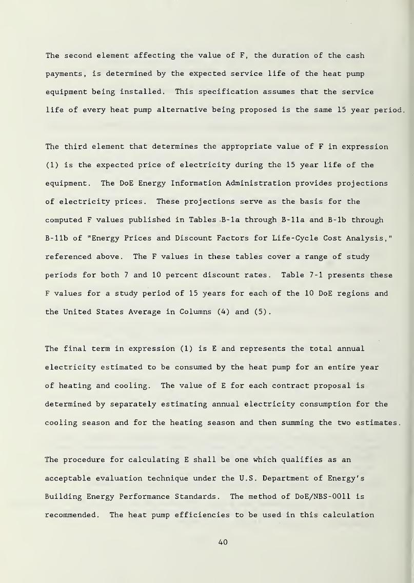
P can be approximated by using the average price given in column (3) of
Table 7-1 for the particular Department of Energy (DoE) Region in which
the military base is located. For example, if the base were in Nevada,
which is in DoE Region 9, the appropriate average price to use to approximate
P would be $0,072 per kWh. These average electricity prices for the
various regions are derived from Tables Ca-1 through Ca-11 of a report
issued annually in support of the Federal Energy Management Program of the
37

Table 7-1. Average Electric Energy Price, P, and Modified UniformPresent Worth Factors, F, for the 10 DoE Regions and theUnited States Average for 1987
RegionNumber States Included
AveragePrice($/kWh)
Modified Uniform PresentWorth Factor
(7%, 15 Years) (10%, 15 Years)
(1) (2) (3) (4) (5)
1 ME , NH , VT , MA , CT , RI 0.099 8.42 7.08
2 NY, NJ, PR, VI 0.087 8.74 7.31
3 PA , MD , WV , VA , DC , DE 0.068 8.52 7.12
4 KY,TN,NC,SC,MS,ALGA, FL, CZ
0.066 7.90 6.64
5 MN , WI , MI , IL , IN , OH 0.077 8.01 6.74
6 TX , NM , OK , AR , LA 0.064 9.62 7.99
7 KSSM0, IA,NE 0.071 8.38 7.02
8 MT , ND , SD , WY , UT , CO 0.071 8.10 6.78
9 CA , NV , AZ , HI
,
Pac . Trust Terr.
,
Samoa, Guam
0.072
)
8.10 6.79
10 WA , OR , ID , AK 0.035 9.45 7.85
11 UNITED STATES AVE. 0.071 8.41 7.04
Source
:
Barbara C. Lippiatt and Rosalie T. Ruegg, "Energy Prices; andDiscount Factors for Life Cycle Cost Analysis: Annual Supplementto NBS Handbook 135 and NBS Special Publication 709, "NBSIR 85-
3273-2 (Rev. 6/87) U.S. Dept, of Commerce, National Bureau ofStandards, Gaithersburg, MD 20899. The prices given in thereport in $/million Btu were converted to $/kWh by assuming 3413Btu/kWh
.
38
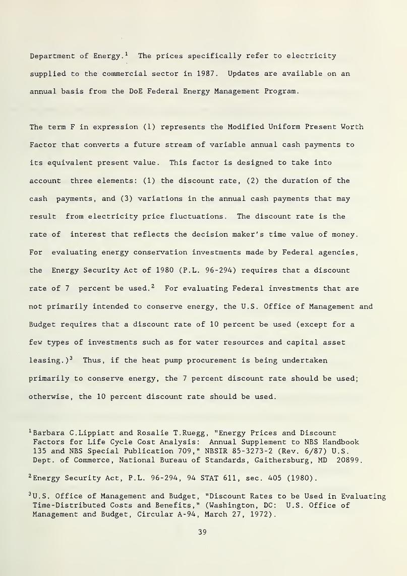
Department of Energy. 1 The prices specifically refer to electricity
supplied to the commercial sector in 1987. Updates are available on an
annual basis from the DoE Federal Energy Management Program.
The term F in expression (1) represents the Modified Uniform Present Worth
Factor that converts a future stream of variable annual cash payments to
its equivalent present value. This factor is designed to take into
account three elements: (1) the discount rate, (2) the duration of the
cash payments, and (3) variations in the annual cash payments that may
result from electricity price fluctuations. The discount rate is the
rate of interest that reflects the decision maker's time value of money.
For evaluating energy conservation investments made by Federal agencies,
the Energy Security Act of 1980 (P.L. 96-294) requires that a discount
rate of 7 percent be used. 2 For evaluating Federal investments that are
not primarily intended to conserve energy, the U.S. Office of Management and
Budget requires that a discount rate of 10 percent be used (except for a
few types of investments such as for water resources and capital asset
leasing.) 3 Thus, if the heat pump procurement is being undertaken
primarily to conserve energy, the 7 percent discount rate should be used;
otherwise, the 10 percent discount rate should be used.
1 Barbara C.Lippiatt and Rosalie T.Ruegg, "Energy Prices and DiscountFactors for Life Cycle Cost Analysis: Annual Supplement to NBS Handbook135 and NBS Special Publication 709," NBSIR 85-3273-2 (Rev. 6/87) U.S.Dept, of Commerce, National Bureau of Standards, Gaithersburg, MD 20899.
2 Energy Security Act, P.L. 96-294, 94 STAT 611, sec. 405 (1980).
3 U.S. Office of Management and Budget, "Discount Rates to be Used in EvaluatingTime-Distributed Costs and Benefits," (Washington, DC: U.S. Office ofManagement and Budget, Circular A-94, March 27, 1972).
39
The second element affecting the value of F, the duration of the cash
payments, is determined by the expected service life of the heat pump
equipment being installed. This specification assumes that the service
life of every heat pump alternative being proposed is the same 15 year period.
The third element that determines the appropriate value of F in expression
(1) is the expected price of electricity during the 15 year life of the
equipment. The DoE Energy Information Administration provides projections
of electricity prices. These projections serve as the basis for the
computed F values published in Tables .B-la through B-lla and B-lb through
B-llb of "Energy Prices and Discount Factors for Life-Cycle Cost Analysis,"
referenced above. The F values in these tables cover a range of study
periods for both 7 and 10 percent discount rates. Table 7-1 presents these
F values for a study period of 15 years for each of the 10 DoE regions and
the United States Average in Columns (4) and (5)
.
The final term in expression (1) is E and represents the total annual
electricity estimated to be consumed by the heat pump for an entire year
of heating and cooling. The value of E for each contract proposal is
determined by separately estimating annual electricity consumption for the
cooling season and for the heating season and then summing the two estimates.
The procedure for calculating E shall be one which qualifies as an
acceptable evaluation technique under the U.S. Department of Energy's
Building Energy Performance Standards. The method of DoE/NBS-0011 is
recommended. The heat pump efficiencies to be used in this calculation
40
shall be the manufacturers' values for SEER for the cooling season and
HSPF for the heating season of the DoE region in which the installation
site lies. For water source units that do not require resistance heat to
meet the building load, the SEER and the HSPF shall be equal to their
respective steady-state efficiencies for the local seasonal average ground
water temperature times a factor of 0.9 in the cooling mode and 0.85 in the
heating mode to take into account cyclic degradation. If resistance heat
is required to meet the building load with a water source unit the HSPF
shall be calculated by a bin calculation on which the steady-state efficiency
shall be degraded by a constant part load factor of 0.85 in all bins.
When published, a DoE method for water source units shall replace this method.
8. REQUIREMENTS FOR QUALIFIED INSTALLER
8 . 1 Qualification
Dealer/Installer shall be certified by the heat pump manufacturer as having
his senior mechanics successfully passed their factory sponsored installation
course in the past ten years. The Dealer/Installer shall be local; that
is, the military base shall lie within his normal radius of service.
Dealer/Installer shall guarantee that his installation and charging method
is completely in accordance with the manufacturer's procedures and provide
a demonstration of the procedure on site.
8 .
2
Guarantee
Dealer/Installer shall provide a five year service contract guaranteeing
normal preventative maintenance as well as parts and labor for repairs.
This contract shall offer the first year all parts and labor free of charge
41
and service contract for the next four years,the cost of which shall be
included in item C of equation (1) in Section 7.
42
NBS-114A (REV. 2-80
U.S.-DEPT. OF COMM.
/-BIBLIOGRAPHIC DATASHEET (See instructions)
1. PUBLICATION ORREPORT NO.
NBSIR 88-3805
2. Performing Organ. Report No. 3. Publication Date
JUNE 1983
4. TITLE AND SUBTITLE
Revised Unitary Heat Pump Specification for Military Family Housing
5. AUTHOR(S)
William Mulroy, Stephen Weber, David Didion
6. PERFORMING ORGANIZATION (If joint or other than NBS. see instructions)
NATIONAL BUREAU OF STANDARDSDEPARTMENT OF COMMERCEWASHINGTON, D.C. 20234
7. Contract/Grant No.
8. Type of Report & Period Covered
9. SPONSORING ORGANIZATION NAME AND COMPLETE ADDRESS (Street. City. State. ZIP)
Army Corps of Engineers Engineering Services and Naval Facilities EngineeringDepartment of the Army Utility Branch CommandWashington, D.C. 20314 Department of the Air Force Department of the Navy
Washington, D.C. 20330-5000 Alexandria, Virginia 2233210. SUPPLEMENTARY NOTES
Document describes a computer program; SF-185, FIPS Software Summary, is attached.
11. ABSTRACT (A 200-word or less factual summary of most significant information. If document includes a significantbibliography or literature survey, mention it here)
The purpose of this report is to revise and update the unitary heat pump specificationsdeveloped in 1976* which addressed the requirements for performance, testing, rating,design, safety, serviceability and reliability for the system and components; andconformance conditions. The document is intended for guidance in military procurementand applies to hermetic electrically-driven vapor compression unitary heat pumps of theremote (split) and packaged (integral) types, the air-to-air and water-to-water classes,and sizes from 12,000 to 135,000 Btu/h for both heating and cooling functions. Thisreport reflects changes in specifications such that the qualified units would be com-patible with current available commercial products. It also addresses installationpractices and offers a new life cycle costing criteria for competitive selection.It is written in the format of a draft specification.
12. KEY WORDS (Six to twelve entries; alphabetical order; capitalize only proper names; and separate key words by semicolon s)
leating and cooling; military family housing; specifications; unitary heat pump
13. AVAILABILITY 14. NO. OFPRINTED PAGES
xj
UnlimitedA 8
!For Official Distribution. Do Not Release to NTIS
H* O
1 Order From Superintendent of Documents, U.S. Government Printing Office, Washington, D.C.20402. 15. Price
[X-
!
Order From National Technical Information Service (NTIS), Springfield, VA. 22161 $11.95
USCOMM-DC 6043-P 80