Embed Size (px)
Citation preview
1 1
RETURN BIDS TO:RETOURNER LES SOUMISSIONS À:Scientific, Medical and Photographic Division / Division de l'équipement scientifique, des produits photographiques et pharmaceutiquesL'Esplanade Laurier140 O'Connor Street,East Tower, 7th FloorOttawaOntarioK1A 0S5
Title - SujetRFI - MF-MLSI System
Solicitation No. - N° de l'invitation
47419-184383/A
Client Reference No. - N° de référence du client
1000334383
File No. - N° de dossier
pv883.47419-184383CCC No./N° CCC - FMS No./N° VME
Time Zone
Eastern Daylight SavingTime EDT
LETTER OF INTERESTLETTRE D'INTÉRÊT
F.O.B. - F.A.B.
Plant-Usine: Destination: Other-Autre:
Address Enquiries to: - Adresser toutes questions à:
Saunders, Lynda
Telephone No. - N° de téléphone FAX No. - N° de FAX
(613) 983-2476 ( ) ( ) -
Destination - of Goods, Services, and Construction:Destination - des biens, services et construction:
CANADA BORDER SERVICES AGENCYSciences ans engineering79 Bentley aveOttawaOntariok2e6t7Canada
Fuseau horaireSolicitation Closes - L'invitation prend finat - à 02:00 PM
2019-06-14on - le
Issuing Office - Bureau de distribution
Scientific, Medical and Photographic Division / Division de l'équipement scientifique, des produits photographiques et pharmaceutiquesL'Esplanade Laurier140 O'Connor Street,East Tower, 7th FloorOttawaOntarioK1A 0S5
Comments - Commentaires
Vendor/Firm Name and Address
Raison sociale et adresse du
fournisseur/de l'entrepreneur
GETS Ref. No. - N° de réf. de SEAG
PW-$$PV-883-77172
Buyer Id - Id de l'acheteur
pv883
Date
2019-05-27
Delivery Required - Livraison exigée Delivery Offered - Livraison proposée
Vendor/Firm Name and Address
Signature Date
Name and title of person authorized to sign on behalf of Vendor/Firm
(type or print)
Nom et titre de la personne autorisée à signer au nom du fournisseur/de l'entrepreneur (taper ou écrire en caractères d'imprimerie)
Instructions: Voir aux présentes
Instructions: See Herein
See Herein
Raison sociale et adresse du fournisseur/de l'entrepreneur
Telephone No. - N°de téléphone
Facsimile No. - N° de télécopieur
Page 1 of - de 1
Solicitation No. - N° de l'invitation Amd. No. - N° de la modif. Buyer ID - Id de l'acheteur47419-184383/A pv883Client Ref. No. - N° de réf. du client File No. - N° du dossier CCC No./N° CCC - FMS No./N° VME1000334383 pv883.47419-184383
Page 1 de - of 103
BID SOLICITATION
MEDIUM FOOTPRINT - MOBILE LARGE SCALE IMAGING
(MF-MLSI) SYSTEM
Solicitation No. - N° de l'invitation Amd. No. - N° de la modif. Buyer ID - Id de l'acheteur47419-184383/A pv883Client Ref. No. - N° de réf. du client File No. - N° du dossier CCC No./N° CCC - FMS No./N° VME1000334383 pv883.47419-184383
Page 2 de - of 103
TABLE OF CONTENTS
PART 1 - GENERAL INFORMATION ............................................................................................................................. 7
1.1 Statement of Work .................................................................................................................................. 7 1.2 Optional Goods and Services ............................................................................................................... 7 1.3 Volumetric Data ....................................................................................................................................... 7 1.4 Debriefings ...............................................................................................................................................71.5 Trade Agreements .................................................................................................................................. 7 1.6 Epost Connect service ........................................................................................................................... 7
PART 2 - BIDDER INSTRUCTIONS ............................................................................................................................... 8
2.1 Standard Instructions, Clauses and Conditions ................................................................................. 8 2.2 Submission of Bids ................................................................................................................................. 8 2.3 Enquiries - Bid Solicitation ..................................................................................................................... 9 2.4 Applicable Laws ...................................................................................................................................... 9 2.5 Improvement of Requirement During Solicitation Period .................................................................. 9
PART 3 - BID PREPARATION INSTRUCTIONS ......................................................................................................... 10
3.1 Bid Preparation Instructions ................................................................................................................ 10 3.2 Section I: Technical Bid....................................................................................................................... 10 3.3 Section II: Financial Bid....................................................................................................................... 11 3.4 Section III: Certifications ..................................................................................................................... 11
ATTACHMENT 1 TO PART 3 OF THE BID SOLICITATION ...................................................................................... 12
ELECTRONIC PAYMENT INSTRUMENTS .................................................................................................................... 12
PART 4 - EVALUATION PROCEDURES AND BASIS OF SELECTION .................................................................. 13
4.1 Evaluation Procedures ......................................................................................................................... 13 4.2 Technical Evaluation ............................................................................................................................ 13 4.3 Financial Evaluation .............................................................................................................................. 15 4.4 Basis of Selection .................................................................................................................................. 15
PART 5 - CERTIFICATIONS AND ADDITIONAL INFORMATION ............................................................................ 17
5.1 Certifications Required with the Bid ................................................................................................... 17 5.2 Certifications Precedent to Contract Award and Additional Information ....................................... 17
ATTACHMENT 1 TO PART 5 OF THE BID SOLICITATION ...................................................................................... 19
FEDERAL CONTRACTORS PROGRAM FOR EMPLOYMENT EQUITY - CERTIFICATION ................................. 19
ATTACHMENT 2 TO PART 5 OF THE BID SOLICITATION ...................................................................................... 20
ATTACHMENT 3 TO PART 5 OF THE BID SOLICITATION ...................................................................................... 21
PART 6 - SECURITY, FINANCIAL AND OTHER REQUIREMENTS ......................................................................... 22
6.1 Financial Capability...............................................................................................................................22
PART 7 - RESULTING CONTRACT CLAUSES .......................................................................................................... 23
7.1 Statement of Work ................................................................................................................................ 23 7.2 Optional Goods and Services ............................................................................................................. 23 7.3 Standard Clauses and Conditions ...................................................................................................... 23 7.4 Security Requirements ......................................................................................................................... 23 7.5 Duration of the Contract ....................................................................................................................... 24 7.6 Delivery Date ......................................................................................................................................... 24 7.7 Authorities .............................................................................................................................................. 24
Solicitation No. - N° de l'invitation Amd. No. - N° de la modif. Buyer ID - Id de l'acheteur47419-184383/A pv883Client Ref. No. - N° de réf. du client File No. - N° du dossier CCC No./N° CCC - FMS No./N° VME1000334383 pv883.47419-184383
Page 3 de - of 103
7.8 Payment ................................................................................................................................................. 25 7.9 Invoicing Instructions ............................................................................................................................ 27 7.10 Certifications and Additional Information ........................................................................................... 28 7.11 Applicable Laws .................................................................................................................................... 28 7.12 Priority of Documents ........................................................................................................................... 28 7.13 SACC Manual Clauses......................................................................................................................... 29 7.14 Shipping Instructions – Delivery at Destination ................................................................................ 29
ANNEX A - STATEMENT OF WORK .......................................................................................................................... 30
1.0 GENERAL REQUIREMENTS ............................................................................................................................. 30
1.1 Mobile Large-Scale Imaging System (MF-MLSI) ............................................................................. 30 1.2 Meetings .................................................................................................................................................301.3 Documentation ...................................................................................................................................... 31 1.4 Design Documents Review and Approval ......................................................................................... 31 1.5 Product Information and Data ............................................................................................................. 31 1.6 Factory Acceptance Testing (FAT) ..................................................................................................... 31 1.7 Site Acceptance Testing (SAT) ........................................................................................................... 32 1.8 Operational Stress Testing (OST) ...................................................................................................... 32 1.9 Post Installation Close-Out Procedures ............................................................................................. 33 1.10 Post-Delivery Review ........................................................................................................................... 33
2.0 TRAINING REQUIREMENTS ............................................................................................................................. 34
2.1 MF-MLSI Operator Training ................................................................................................................. 34 2.2 MF-MLSI Train-the-Trainer Training .................................................................................................. 34 2.3 MF-MLSI System Administrator Training........................................................................................... 34 2.4 MF-MLSI Equipment Maintenance Training ..................................................................................... 35 2.5 Training Materials .................................................................................................................................. 35 2.6 Training Delivery ................................................................................................................................... 35 2.7 Instructional Design .............................................................................................................................. 35
3.0 OPERATIONAL REQUIREMENTS .................................................................................................................... 37
3.1 Imaging ................................................................................................................................................... 37 3.2 Radiation Source ................................................................................................................................... 37 3.3 Number of Operators ............................................................................................................................ 37 3.4 Push-Button Start/Shutdown ............................................................................................................... 37 3.5 Start-Up Time ........................................................................................................................................ 37 3.6 Imaging Speeds .................................................................................................................................... 37 3.7 Imaging Rate ......................................................................................................................................... 37 3.8 Imaging Full Reset Time ...................................................................................................................... 37 3.9 Bi-Directional Repeated Imaging ........................................................................................................ 37 3.10 Inspection Tunnel .................................................................................................................................. 37 3.11 Imaging Field-of-View ........................................................................................................................... 37 3.12 Imaging Multiple Objects......................................................................................................................383.13 Image Analysis Verdict ......................................................................................................................... 38 3.14 Digital Image Record of Target Objects ............................................................................................ 38 3.15 Login ....................................................................................................................................................... 38 3.16 User Tracking ........................................................................................................................................ 38 3.17 Inspection Counter ................................................................................................................................ 38 3.18 General Video Surveillance Requirements ....................................................................................... 38 3.19 Camera Viewing of Target Objects .................................................................................................... 38 3.20 Operating Environment ........................................................................................................................ 39 3.21 Storage Environment ............................................................................................................................ 39
Solicitation No. - N° de l'invitation Amd. No. - N° de la modif. Buyer ID - Id de l'acheteur47419-184383/A pv883Client Ref. No. - N° de réf. du client File No. - N° du dossier CCC No./N° CCC - FMS No./N° VME1000334383 pv883.47419-184383
Page 4 de - of 103
3.22 Driver’s and Operator’s Cabin/s Environmental Control ................................................................. 39 3.23 Scanning Manifest Documents ........................................................................................................... 39 3.24 Imaging Tools ........................................................................................................................................ 39 3.25 Real-Time Image Display..................................................................................................................... 40 3.26 Inspection Data...................................................................................................................................... 40 3.27 Summary Reports ................................................................................................................................. 40
4.0 VEHICULAR REQUIREMENTS ......................................................................................................................... 41
4.1 Certified Design ..................................................................................................................................... 41 4.2 Driver’s License Requirements ........................................................................................................... 41 4.3 Vehicle Seating and Restraints ........................................................................................................... 41 4.4 Provincial Regulations ..........................................................................................................................414.5 Total Mass Limit .................................................................................................................................... 41 4.6 Axial Load Limits ................................................................................................................................... 41 4.7 Weight Distribution ................................................................................................................................ 41 4.8 Boom Support ........................................................................................................................................ 41 4.9 Maximum Width ..................................................................................................................................... 42 4.10 Maximum Length ................................................................................................................................... 42 4.11 Maximum Height ................................................................................................................................... 42 4.12 Maximum Overhang ............................................................................................................................. 42 4.13 Number of Axles .................................................................................................................................... 42 4.14 Maximum Wheelbase ........................................................................................................................... 42 4.15 Driver’s Cabin Sun Protection ............................................................................................................. 42 4.16 Backup Camera ..................................................................................................................................... 42 4.17 Cold-Start ............................................................................................................................................... 42 4.18 Diesel Particulate Filter (DPF) Regeneration .................................................................................... 42 4.19 Flashing Warning Lights - Vehicular .................................................................................................. 42
5.0 DESIGN AND CONFIGURATION REQUIREMENTS ...................................................................................... 43
5.1 Proven Design ....................................................................................................................................... 43 5.2 Inspection Drive ..................................................................................................................................... 43 5.3 Boom Actuation ..................................................................................................................................... 43 5.4 Boom Alignment .................................................................................................................................... 43 5.5 Detector Array - Environmental Control ............................................................................................. 43 5.6 Programmable Logic Controller (PLC) - Functionality ..................................................................... 43 5.7 Protection from Dirt and Water ........................................................................................................... 43 5.8 CSA Electrical Certification .................................................................................................................. 44 5.9 Fail-safe .................................................................................................................................................. 44 5.10 Uninterruptible Power ........................................................................................................................... 44 5.11 Operator Workstations ......................................................................................................................... 44 5.12 Image Analyst’s Display ....................................................................................................................... 44 5.13 Identification of Operational Controls .................................................................................................445.14 Linguistic Requirements Signage ....................................................................................................... 45 5.15 Signs and Markings .............................................................................................................................. 45 5.16 Printer ..................................................................................................................................................... 45 5.17 Software Languages ............................................................................................................................. 45 5.18 Additional Power Outlets ...................................................................................................................... 45 5.19 On-board Storage ................................................................................................................................. 45
6.0 VIDEO SURVEILLANCE REQUIREMENTS ..................................................................................................... 46
6.1 Video Surveillance Coverage .............................................................................................................. 46 6.2 Video Camera Enclosures ................................................................................................................... 46 6.3 Video Camera Sensor and Image type .............................................................................................. 46
Solicitation No. - N° de l'invitation Amd. No. - N° de la modif. Buyer ID - Id de l'acheteur47419-184383/A pv883Client Ref. No. - N° de réf. du client File No. - N° du dossier CCC No./N° CCC - FMS No./N° VME1000334383 pv883.47419-184383
Page 5 de - of 103
6.4 Video Camera Night Capability ........................................................................................................... 46 6.5 Video Camera Dynamic Range .......................................................................................................... 46 6.6 Video Camera Exposure Settings ...................................................................................................... 46 6.7 Video Camera White Balance ............................................................................................................. 46 6.8 Video Camera Focus ............................................................................................................................ 46 6.9 Video Camera Zoom ............................................................................................................................ 46
7.0 RADIATION SAFETY REQUIREMENTS .......................................................................................................... 47
7.1 Canadian Nuclear Safety Commission (CNSC) Licensable System ............................................. 47 7.2 Nuclear Regulatory Compliance ......................................................................................................... 47 7.3 CNSC Granted License to Service ..................................................................................................... 47 7.4 Certification of Class II Prescribed Equipment .................................................................................477.5 Radiation Safety Zone (RSZ) .............................................................................................................. 47 7.6 Dose to Cargo Limit .............................................................................................................................. 47 7.7 Dose Rates within the MF-MLSI System ........................................................................................... 47 7.8 Radiological Safety System ................................................................................................................. 48 7.9 Clearance Verification System – Remote Control Operation ......................................................... 48 7.10 Beam-On Indicators .............................................................................................................................. 48 7.11 Pre-Irradiation Alarm ............................................................................................................................ 48 7.12 Emergency Stop Button - Functionality ............................................................................................. 48 7.13 Emergency Stop Button - Locations ................................................................................................... 48 7.14 Initialization Code Lock ........................................................................................................................ 48 7.15 Handheld Radiation Survey Meters.................................................................................................... 48 7.16 Fixed Radiation Survey Meters ........................................................................................................... 49 7.17 Shipping of Survey Meters ................................................................................................................... 49 7.18 Collision Prevention .............................................................................................................................. 49
8.0 INSPECTION PERFORMANCE REQUIREMENTS ......................................................................................... 50
8.1 Performance Measurement ................................................................................................................. 50 8.2 Penetration ............................................................................................................................................. 50 8.3 Spatial Resolution Horizontal .............................................................................................................. 50 8.4 Spatial Resolution - Vertical ................................................................................................................ 50 8.5 Contrast Sensitivity @ 10% ................................................................................................................. 50 8.6 Contrast Sensitivity @ 50% ................................................................................................................. 50 8.7 Contrast Sensitivity @ 80% ................................................................................................................. 50 8.8 Wire Detection - Horizontal .................................................................................................................. 50 8.9 Wire Detection - Vertical ...................................................................................................................... 50 8.10 Material Discrimination – Very Low-Z (Organics) ............................................................................. 50 8.11 Material Discrimination – Low-Z (Intermediate Inorganics) ............................................................ 51 8.12 Material Discrimination – Intermediate-Z (Metals) ........................................................................... 51
9.0 DATA MANAGEMENT REQUIREMENTS ........................................................................................................ 52
9.1 Administrator Rights .............................................................................................................................529.2 System Passwords ............................................................................................................................... 52 9.3 Instrumentation Gateway (IGW) Server ............................................................................................ 52 9.4 Communications Security Equipment ................................................................................................ 52 9.5 CBSA Information-of-Interest .............................................................................................................. 52 9.6 Provision of CBSA Information-of-Interest via Web-Service(s) ...................................................... 52 9.7 Data Compliance ................................................................................................................................... 53 9.8 IPv6 Compatible .................................................................................................................................... 53 9.9 Network Diagram and Communications ............................................................................................ 53 9.10 Data Flow Chart .................................................................................................................................... 53 9.11 File Storage ............................................................................................................................................ 53
Solicitation No. - N° de l'invitation Amd. No. - N° de la modif. Buyer ID - Id de l'acheteur47419-184383/A pv883Client Ref. No. - N° de réf. du client File No. - N° du dossier CCC No./N° CCC - FMS No./N° VME1000334383 pv883.47419-184383
Page 6 de - of 103
9.12 Hard Drive Protection ........................................................................................................................... 53 9.13 Approaching Storage Limits ................................................................................................................ 53 9.14 Automatic Data Housekeeping ........................................................................................................... 53 9.15 Manual Data Housekeeping ................................................................................................................ 53 9.16 Date and Time ....................................................................................................................................... 53 9.17 Saving Images ....................................................................................................................................... 53 9.18 Export of Images ................................................................................................................................... 54 9.19 Export of Raw Image Data ................................................................................................................... 54 9.20 Manual Retrieval of Scan Data ........................................................................................................... 54 9.21 Image Review on Universal Viewer .................................................................................................... 54
10.0 MAINTENANCE AND SUPPORT SERVICES REQUIREMENTS...................................................................55
10.1 Maintenance Service Experience ....................................................................................................... 55 10.2 Scope ...................................................................................................................................................... 55 10.3 Calibration .............................................................................................................................................. 55 10.4 Corrective Maintenance ....................................................................................................................... 55 10.5 Preventive Maintenance....................................................................................................................... 55 10.6 Technical Support ................................................................................................................................. 56 10.7 Problem Tickets ..................................................................................................................................... 56 10.8 Maintenance and Reliability Performance ......................................................................................... 58 10.9 Maintenance Reporting ........................................................................................................................ 60 10.10 Administrative Requirements .............................................................................................................. 61 10.11 Other ....................................................................................................................................................... 62 10.12 MF-MLSI Calibration Test Pieces, System Parts and Special Tools ............................................ 62 10.13 Intent to Decommission MF-MLSI System ........................................................................................ 63
ANNEX B TECHNICAL SERVICES ............................................................................................................................. 64
1.0 UNPLANNED ACTIVITIES – AS AND WHEN REQUESTED ......................................................................... 64
1.1 Step 1 – Determination of Cause........................................................................................................ 64 1.2 Step 3 – Unplanned Work Definition .................................................................................................. 64 1.3 Step 4 – Completion of Maintenance and Support Services .......................................................... 65
ANNEX C BASIS OF PAYMENT .................................................................................................................................. 66
ANNEX D UNPLANNED WORK DEFINITION ............................................................................................................ 69
ATTACHMENT 1 TO PART 4 OF THE BID SOLICITATION - TECHNICAL BID SUBMISSION DOCUMENT ..... 70
Section A - MANDATORY BID Submission REQUIREMENTS ............................................................. 70 Section B - MANDATORY INFORMATION FOR VALIDATION OF BID .............................................. 75
ATTACHMENT 2 TO PART 4 OF THE BID SOLICITATION - TECHNICAL POINT RATING EVALUATION MATRIX ............................................................................................................................................................................ 82
ATTACHMENT 3 TO PART 4 OF THE BID SOLICITATION – PRO-RATING PROCESS ...................................... 92
ATTACHMENT 4 TO PART 4 – PRICING SCHEDULE .............................................................................................. 94
ATTACHMENT 5 TO PART 4 – CUSTOMER REFERENCE QUESTIONAIRE ........................................................ 97
Section A - Warranty and maintenance services ...................................................................................... 97 Section B - Availability and corrective maintenance ................................................................................. 98 Section C - Technical support and reporting ........................................................................................... 100 Section D - Reference Experience ............................................................................................................ 101
Solicitation No. - N° de l'invitation Amd. No. - N° de la modif. Buyer ID - Id de l'acheteur47419-184383/A pv883Client Ref. No. - N° de réf. du client File No. - N° du dossier CCC No./N° CCC - FMS No./N° VME1000334383 pv883.47419-184383
Page 7 de - of 103
PART 1 - GENERAL INFORMATION
1.1 Statement of Work
The Canada Border Services Agency (CBSA) has a requirement for one Medium Footprint - Mobile Large Scale Imaging (MF-MLSI) System, hereafter referred to as the “MF-MLSI System”, for use at marine and land border ports-of-entry. The MF-MLSI System must include all equipment, Image Analysis software, sensors, peripherals, cabling and components sensors, relays and infrastructure necessary for the safe, non-intrusive inspection of target objects, delivery, installation, all training, a 1 year all-inclusive Warranty including all Maintenance and Support Services, and operator and service manuals, all as detailed in the Statement of Work at ANNEX A.
Six concurrent user licenses for the image analysis software to be used on the MF-MLSI system, and on CBSA computer systems must also be included.
1.2 Optional Goods and Services
The requirement also includes the irrevocable options to purchase the following:
1.2.1 An irrevocable option to purchase additional MF-MLSI Systems up to five (5) years after contract award.
1.2.2 An irrevocable option to purchase additional Warranty including maintenance and support services detailed in ANNEX A for each MF-MLSI System procured, for nine (9) additional one (1) year periods after expiry of the initial 1 year all-inclusive Warranty.
1.2.3 An irrevocable option to purchase additional User Licences for the Image Analysis Software
1.2.4 An irrevocable option to purchase an Entity License for the Image Analysis Software.
1.3 Volumetric Data
The following information has been provided to Bidders to assist them in preparing their bids. The inclusion of this information in this bid solicitation does not represent a commitment by Canada that Canada's future usage of theMobile Large Scale Imaging (MF-MLSI) System will be consistent with this information. It is provided purely for information purposes.
The Initial Purchase is for one (1) MF-MLSI System and an approximate estimated quantity of 5 additional MF-MLSI Systems could be required.
1.4 Debriefings
Bidders may request a debriefing on the results of the bid solicitation process. Bidders should make the request to the Contracting Authority within 15 working days from receipt of the results of the bid solicitation process. The debriefing may be in writing, by telephone or in person.
1.5 Trade Agreements
The requirement is subject to the provisions of the World Trade Organization Agreement on Government Procurement (WTO-AGP), the North American Free Trade Agreement (NAFTA), and the Canadian Free Trade Agreement (CFTA).
1.6 Epost Connect service
This bid solicitation allows bidders to use the epost Connect service provided by Canada Post Corporation to transmit their bid electronically. Bidders must refer to Part 2 entitled Bidder Instructions, and Part 3 entitled Bid Preparation Instructions, of the bid solicitation, for further information.
Solicitation No. - N° de l'invitation Amd. No. - N° de la modif. Buyer ID - Id de l'acheteur47419-184383/A pv883Client Ref. No. - N° de réf. du client File No. - N° du dossier CCC No./N° CCC - FMS No./N° VME1000334383 pv883.47419-184383
Page 8 de - of 103
PART 2 - BIDDER INSTRUCTIONS
2.1 Standard Instructions, Clauses and Conditions
All instructions, clauses and conditions identified in the bid solicitation by number, date and title are set out in the Standard Acquisition Clauses and Conditions Manual (https://buyandsell.gc.ca/policy-and-guidelines/standard-acquisition-clauses-and-conditions-manual) issued by Public Works and Government Services Canada.
Bidders who submit a bid agree to be bound by the instructions, clauses and conditions of the bid solicitation and accept the clauses and conditions of the resulting contract.
The 2003 (2018-05-22) Instructions - Goods or Services - Competitive Requirements, are incorporated by reference into and form part of the bid solicitation.
Subsection 5.4 of 2003, Standard Instructions - Goods or Services - Competitive Requirements, is amended as follows:
Delete: 60 days
Insert: 180 days
2.1.1 SACC Manual Clauses
B1000T (2014-06-26) Condition of Material - Bid
2.2 Submission of Bids
Bids must be submitted only to Public Works and Government Services Canada (PWGSC) Bid Receiving Unit at the location specified below, by the date, time and place indicated on page 1 of the bid solicitation.
Bid Receiving - PWGSCPlace du Portage, Phase III, Tower B 11 Laurier StreetGatineau, Quebec For couriers: J8X 4A6For regular mail: K1A 0S5
Telephone: (819) 420-7201Fax No.: (819) 997-9776
No bids should be sent directly to the PWGSC Contracting Authority.
For bidders choosing to submit using epost Connect for bids closing at the Bid Receiving Unit in the National Capital Region (NCR), the email address is:
tpsgc.dgareceptiondessoumissions-abbidreceiving.pwgsc@tpsgc-pwgsc.gc.ca
Bids will not be accepted if emailed directly to this email address. This email address is to be used to open an epost Connect conversation, as detailed in Standard Instructions 2003, or to send bids through an epost Connect message if the bidder is using its own licensing agreement for epost Connect.
Due to the nature of the bid solicitation, bids transmitted by facsimile to PWGSC will not be accepted.
Solicitation No. - N° de l'invitation Amd. No. - N° de la modif. Buyer ID - Id de l'acheteur47419-184383/A pv883Client Ref. No. - N° de réf. du client File No. - N° du dossier CCC No./N° CCC - FMS No./N° VME1000334383 pv883.47419-184383
Page 9 de - of 103
2.3 Enquiries - Bid Solicitation
All enquiries must be submitted in writing to the Contracting Authority no later than 10 calendar days before the bid closing date. Enquiries received after that time may not be answered.
Bidders should reference as accurately as possible the numbered item of the bid solicitation to which the enquiry relates. Care should be taken by Bidders to explain each question in sufficient detail in order to enable Canada to provide an accurate answer. Technical enquiries that are of a proprietary nature must be clearly marked "proprietary" at each relevant item. Items identified as "proprietary" will be treated as such except where Canada determines that the enquiry is not of a proprietary nature. Canada may edit the question(s) or may request that the Bidder do so, so that the proprietary nature of the question(s) is eliminated, and the enquiry can be answered to all Bidders. Enquiries not submitted in a form that can be distributed to all Bidders may not be answered by Canada.
2.4 Applicable Laws
Any resulting contract must be interpreted and governed, and the relations between the parties determined, by the laws in force in Ontario, Canada.
Bidders may, at their discretion, substitute the applicable laws of a Canadian province or territory of their choice without affecting the validity of their bid, by deleting the name of the Canadian province or territory specified and inserting the name of the Canadian province or territory of their choice. If no change is made, it acknowledges that the applicable laws specified are acceptable to the Bidders.
2.5 Improvement of Requirement During Solicitation Period
Should bidders consider that the specifications or Statement of Work contained in the bid solicitation could beimproved technically or technologically, bidders are invited to make suggestions, in writing, to the Contracting Authority named in the bid solicitation. Bidders must clearly outline the suggested improvement as well as the reason for the suggestion.
Suggestions that do not restrict the level of competition nor favor a particular bidder will be given consideration provided they are submitted to the Contracting Authority at least 10 calendar days before the bid closing date. Canada will have the right to accept or reject any or all suggestions.
Solicitation No. - N° de l'invitation Amd. No. - N° de la modif. Buyer ID - Id de l'acheteur47419-184383/A pv883Client Ref. No. - N° de réf. du client File No. - N° du dossier CCC No./N° CCC - FMS No./N° VME1000334383 pv883.47419-184383
Page 10 de - of 103
PART 3 - BID PREPARATION INSTRUCTIONS
3.1 Bid Preparation Instructions
3.1.1 If the Bidder chooses to submit its bid electronically, Canada requests that the Bidder submits its bid in accordance with section 08 of the 2003 standard instructions. The epost Connect system has a limit of 1GB per single message posted and a limit of 20GB per conversation.
The bid must be gathered per section and separated as follows:
Section I: Technical BidSection II: Financial BidSection III: Certifications
3.1.2 If the Bidder chooses to submit its bid in hard copies, Canada requests that the Bidder submits its bid in separately bound sections as follows:
Section I: Technical Bid (1 hard copy) and 3 soft copies on flash drive or portable hard-drive. All soft copies of documents must be in searchable .pdf format.
Section II: Financial Bid (1 hard copy) and 1 soft copy on flash drive or portable hard-drive.
Section III: Certifications (1 hard copy) and 1 soft copy on flash drive or portable hard-drive.
If there is a discrepancy between the wording of the soft copy and the hard copy, the wording of the hard copy will have priority over the wording of the soft copy.
3.1.3 If the Bidder is simultaneously providing copies of its bid using multiple acceptable delivery methods, and if there is a discrepancy between the wording of any of these copies and the electronic copy provided through epost Connect service, the wording of the electronic copy provided through epost Connect service will have priority over the wording of the other copies.
Prices must appear in the financial bid only. No prices must be indicated in any other section of the bid.
Canada requests that Bidders follow the format instructions described below in the preparation of their bid:
(a) use 8.5 x 11 inch (216 mm x 279 mm) paper;(b) use a numbering system that corresponds to the bid solicitation;
In April 2006, Canada issued a policy directing federal departments and agencies to take the necessary steps to incorporate environmental considerations into the procurement process Policy on Green Procurement(http://www.tpsgc-pwgsc.gc.ca/ecologisation-greening/achats-procurement/politique-policy-eng.html). To assist Canada in reaching its objectives, Bidders should:
1) use 8.5 x 11 inch (216 mm x 279 mm) paper containing fiber certified as originating from a sustainably-managed forest and containing minimum 30% recycled content; and
2) use an environmentally-preferable format including black and white printing instead of colorprinting, printing double sided/duplex, using staples or clips instead of cerlox, duo-tangs or binders.
3.2 Section I: Technical Bid
In their technical bid, Bidders should demonstrate their understanding of the requirements contained in the bid solicitation and explain how they will meet these requirements. Bidders should demonstrate their capability and describe their approach in a thorough, concise and clear manner for carrying out the work.
Solicitation No. - N° de l'invitation Amd. No. - N° de la modif. Buyer ID - Id de l'acheteur47419-184383/A pv883Client Ref. No. - N° de réf. du client File No. - N° du dossier CCC No./N° CCC - FMS No./N° VME1000334383 pv883.47419-184383
Page 11 de - of 103
The technical bid should address clearly and in sufficient depth the points that are subject to the evaluation criteria against which the bid will be evaluated. Simply repeating the statement contained in the bid solicitation is not sufficient. In order to facilitate the evaluation of the bid, Bidders must submit their Technical Bid in accordance with Attachment 1 to Part 4 of the Bid Solicitation - Technical Bid Submission Document.
In Attachment 1 to Part 4 of the Bid Solicitation - Technical Bid Submission Document: Section A - Mandatory Bid Submission Requirements, the Bidder must clearly detail how the proposed System meets each of the directly referenced requirements of Annex A.
In Attachment 1 to Part 4 of the Bid Solicitation - Technical Bid Submission Document: Section B – Mandatory Information for Validation of Bid, the Bidders must demonstrate a technical and organizational capacity to deliver a compliant system that meets the requirements of the bid solicitation. Regardless of the content of the information provided in Section B, if the Bidder is awarded a Contract, the Work must be done in accordance with Annex A.
Large data files do not need to be printed for inclusion in the hard copy; however, they must be provided with the soft copy and accessible without the need for specialized software. All appended figures, tables, and supporting data should be referenced where indicated in Attachment 1 to Part 4 of the Bid Solicitation - Technical Bid Submission Document.
3.3 Section II: Financial Bid
3.3.1 Bidders must submit their financial bid in accordance with Attachment 3 to Part 4 of Bid Solicitation –Pricing Schedule. The total amount of Applicable Taxes must be shown separately.
3.3.2 Electronic Payment of Invoices – Bid
If the Bidder is willing to accept payment of invoices by Electronic Payment Instruments, they must complete Attachment 1 to Part 3 of Bid Solicitation - Electronic Payment Instruments, to identify which ones are accepted.
If Attachment 1 to Part 3 of Bid Solicitation - Electronic Payment Instruments is not completed, it will be considered as if Electronic Payment Instruments are not being accepted for payment of invoices.
Acceptance of Electronic Payment Instruments will not be considered as an evaluation criterion.
3.3.3 Exchange Rate Fluctuation
SACC Manual clause C3011T (2013-11-06), Exchange Rate Fluctuation
3.4 Section III: Certifications
Bidders must submit the certifications and additional information required under Part 5.
Solicitation No. - N° de l'invitation Amd. No. - N° de la modif. Buyer ID - Id de l'acheteur47419-184383/A pv883Client Ref. No. - N° de réf. du client File No. - N° du dossier CCC No./N° CCC - FMS No./N° VME1000334383 pv883.47419-184383
Page 12 de - of 103
ATTACHMENT 1 to PART 3 OF THE BID SOLICITATIONELECTRONIC PAYMENT INSTRUMENTS
The Bidder accepts any of the following Electronic Payment Instrument(s):
( ) Direct Deposit (Domestic and International);
( ) Electronic Data Interchange (EDI);
( ) Wire Transfer (International Only);
( ) Large Value Transfer System (LVTS) (Over $25M)
Solicitation No. - N° de l'invitation Amd. No. - N° de la modif. Buyer ID - Id de l'acheteur47419-184383/A pv883Client Ref. No. - N° de réf. du client File No. - N° du dossier CCC No./N° CCC - FMS No./N° VME1000334383 pv883.47419-184383
Page 13 de - of 103
PART 4 - EVALUATION PROCEDURES AND BASIS OF SELECTION
4.1 Evaluation Procedures
4.1.1 Bids will be assessed in accordance with the entire requirement of the bid solicitation. The evaluation will be conducted as described below. The fact that Canada has proceeded to a later step does not mean that Canada has conclusively determined that the Bidder has successfully passed any or all other steps. Canada reserves the right to conduct steps of the evaluation in parallel or in a different sequence than they appear in this bid solicitation.
4.1.2 An evaluation team composed of representatives of Canada will evaluate the bids.
4.1.3 Canada will proceed to a preliminary review of the technical bid to ensure that all mandatory information and data required in Attachment 1 to Part 4 of the Bid Solicitation - Technical Bid Submission Document and Attachment 5 to Part 4 – Customer Reference Questionnaire has been provided. If any part of the mandatory requirements are not completed and submitted as required, the Contracting Authority will so inform the bidder and provide the bidder with a time frame within which to meet the requirement. Failure to comply with the request of the Contracting Authority and meet the requirement within that time period will render the bid non-responsive.
4.1.4 Where Canada has made a final determination that a bid has failed any individual mandatory requirementof the bid solicitation, Canada reserves the right to not proceed further in the evaluation of the bid and may deem the bid non-responsive.
4.2 Technical Evaluation
4.2.1 Mandatory Technical Evaluation
(a) The Bidder must provide in full all the information and substantiating data required in Attachment 1 to Part 4 and in Attachment 5 to Part 4.
(b) The information and data submitted will be reviewed for compliance with the mandatory technical requirement identified in Attachment 1 to Part 4 and Attachment 5 to Part 4.
4.2.2 Rated Reference Check
(a) The Bidder must provide 2 customer references who must complete the questionnaire found in Attachment 5 to Part 4. The completed questionnaire must be included with the Bid. The twocustomer references must be the same 2 customer references identified under Attachment 1 to Part 4 – Section A – M1.
(b) The two references must be from clients using Proven Design that includes similar
i. medium or high-energy X-Ray radiation source; andii. detector array and readout electronics; andiii. physical protection scheme limiting radiation emissions at the boundary of a Radiation Safety
Zone (RSZ); andiv. configuration on a road registered vehicle.
(c) The customer reference must each confirm that the Bidder has provided maintenance and support services at a comparable level of service as detailed in Section 10 of Annex A Statement of Work.
(d) The responses provided will be rated in accordance with the scoring stated in the questionnaire itself. The maximum number of points available in the reference check is 135. For reference

Solicitation No. - N° de l'invitation Amd. No. - N° de la modif. Buyer ID - Id de l'acheteur47419-184383/A pv883Client Ref. No. - N° de réf. du client File No. - N° du dossier CCC No./N° CCC - FMS No./N° VME1000334383 pv883.47419-184383
Page 14 de - of 103
checks, Canada may contact the references by e-mail in order to validate responses provided in the questionnaire. Canada will send all e-mail reference check requests to contacts supplied by all the Bidders within a 48-hour period using the e-mail address provided in the bid. The Bidderwill not meet the mandatory experience requirement (as applicable) unless the response is received within 5 working days of the date that Canada's e-mail was sent.
(e) Points will not be allocated and/or a Bidder will not meet the mandatory experience requirement (as applicable) if (1) the two reference customers are not the same 2 reference customers identified in Attachment 1 to Part 4, as per 4.2.2 (a), or (2) the reference customer states he or she is unable or unwilling to validate responses provided in the questionnaire, or (3) the customer reference is not a customer of the Bidder itself (for example, the customer cannot be the customer of an affiliate of the Bidder instead of being a customer of the Bidder itself). Nor will points be allocated or a mandatory met if the customer is itself an affiliate or other entity that does not deal at arm's length with the Bidder.
(f) A Bidder who does not meet any of mandatory reference check criteria as specified in Attachment5 to Part 4, will be deemed as not fully meeting the mandatory requirements and will be declared non-responsive.
4.2.3 Point Rated Technical Evaluation
Only Bids meeting the mandatory technical evaluation of 4.2.1- Mandatory Technical Evaluation and 4.2.2 –Rated Reference Check, will proceed to the point rated technical evaluation.
Bids will be evaluated against the rated technical evaluation criteria set out in Attachment 2 to Part 4 of the Bid Solicitation - Technical Point Rating Evaluation Matrix.
The Bidder is requested to complete Attachment 2 to Part 4 of the Bid Solicitation - Technical Point Rating Evaluation Matrix. The evaluation will be based on the information submitted in Attachment 2 to Part 4 of the Bid Solicitation, the substantiating information and data in Attachment 1 to Part 4 and Total Reference Check Points obtained assigned under Attachment 5 to Part 4.
4.2.4 Preliminary Ranking of Bidders
All responsive bids will be ranked based on the combined Technical and Reference Check Score. The combined Technical and Reference Check Score will be calculated by adding the Total Preliminary Technical Points assigned under Attachment 2 of Part 4 and the Total Reference Check Points assigned under Attachment 5 to Part 4.
4.2.5 Demonstration – Data Validation Test (DVT)
Canada may, but will have no obligation to, require that the top 2 ranked Bidders as established under 4.2.4 above, perform a Data Validation Test (DVT) on a Proven System to validate performance claims of compliance with the mandatory technical evaluation criteria as specified under a) above; and to confirm the preliminary technical scores allocated from the point rated technical evaluation as specified under b) above. Data Validation Testing will be conducted at a mutually agreed upon date/time/location between ten (10) and twenty-five (25) calendar days after notification by the Contracting Authority. The tested system must be made available for a minimum of 15 hours of testing to be conducted over the course of no more than 5 consecutive days. Only one DVT will be performed per system; CBSA personnel must be able to observe and direct the testing.
If Canada determines that the Proven System used during the DVT does not meet any of the mandatory technical evaluation criteria or does not meet the minimum threshold for point-rated mandatory criteria, the bid will fail the DVT and be declared non-responsive and will be given no further consideration. In the event of any discrepancy between the preliminary scores allocated on the basis of the information submitted in the Bidders’ Technical Point Rating Evaluation Matrix, attached as Attachment 2 to Part 4 and the DVT results, Canada will adjust the score downwards on any point rated technical evaluation criteria to reflect the demonstrated performance accordingly

Solicitation No. - N° de l'invitation Amd. No. - N° de la modif. Buyer ID - Id de l'acheteur47419-184383/A pv883Client Ref. No. - N° de réf. du client File No. - N° du dossier CCC No./N° CCC - FMS No./N° VME1000334383 pv883.47419-184383
Page 15 de - of 103
and arrive at the final point rated scores. If the Bidder's score is reduced as a result of the DVT, Canada will reassess the ranking of all Bidders. If both top 2 ranked Bidders’ scores drop below the 3rd ranked Bidder, then that Bidder will be invited to the DVT.
If only one of the top 2 ranked Bidders’ score drop below the 3rd ranked Bidder, then Canada will continue the evaluation with the 1 remaining top ranked bidder.
Canada will provide the DVT Test Plan to the top 2 ranked Bidders in advance of the DVT commencement, if Canada elects to perform a DVT
Following the completion of the DVT, if conducted, Canada will review the DVT test results with the Bidder to ensure the demonstrated performance has been correctly documented.
Where a bid has been allocated scores for any of the Point Rated Technical Evaluation Criteria found in Attachment 2 to Part 4 of the Bid Solicitation - Technical Point Rating Evaluation Matrix, these criteria will be incorporated as requirements obligations in the Resulting Contract under Annex A - Statement of Work. After Contract award, the Bidder selected by Canada must perform the work accordance with the Resulting Contract and the Statement of Work therein.
Canada will be responsible for its travel and living expenses for CBSA and PSPC personnel attending the DVT. The Bidder will be responsible for all costs to furnish the Proven System, test equipment, test fixtures, radiation survey instruments required to demonstrate systems compliance. The Bidder will be responsible for all travel and living expenses for its personnel attending/performing the DVT. Further to the DVT, a technical score will be allocated against the rated technical evaluation criteria set out in Attachment 2 to Part 4 of the Bid Solicitation -Technical Point Rated Evaluation Matrix.
For the technical evaluation criteria that will be prorated based against the best performing system, the Pro-Rating process will be conducted as described at Attachment 3 to Part 4 of the bid solicitation.
4.3 Financial Evaluation
The financial evaluation will be conducted in accordance with Attachment 4 to Part 4 of the Bid Solicitation.
4.4 Basis of Selection
The Basis of Selection will be the highest combined rating of Technical Merit and Price
4.4.1 To be declared responsive, a bid must:
(a) Comply with all the requirements of the bid solicitation; and
(b) Meet all the Mandatory Technical Evaluation criteria stated under Attachment 1 to Part 4 of the Bid Solicitation - Section A; and
(c) Pass and the Reference Check as stated under Attachment 5 to Part 4 – Reference Check Questionnaire; and
(d) Successfully pass the Data Validation Test, if the DVT is conducted.
Solicitation No. - N° de l'invitation Amd. No. - N° de la modif. Buyer ID - Id de l'acheteur47419-184383/A pv883Client Ref. No. - N° de réf. du client File No. - N° du dossier CCC No./N° CCC - FMS No./N° VME1000334383 pv883.47419-184383
Page 16 de - of 103
4.4.2 Bids not meeting either (a), or (b), (c), or (d) (if the DVT is conducted) will be declared non-responsive.)
4.4.3 The selection will be based on the highest responsive combined rating of technical merit, reference checkand price. The ratio will be 60% for the technical merit and 40% for the price.
4.4.4 To establish the technical merit score, the overall technical score for each responsive bid will be determined as follows:
Total technical points obtained X 60 = Technical Merit ScoreMaximum number of available points (135)
The Maximum number of points available in the Point Rated Technical Evaluation is 135___.
4.4.5 To establish the pricing score, each responsive bid will be prorated against the lowest evaluated Bid and the ratio of 40%. The responsive bid with the lowest Total Bid Price (TBP) is given full price points, while other bids receive a pro-rated score based on the ratio of the lowest evaluated bid to their total bid price,as follows:
Lowest Responsive TBPBidders TBP X 40 = Pricing Score
4.4.6 For each responsive bid, the technical merit score and the pricing score will be added to determine its combined rating.
4.4.7 Neither the responsive bid obtaining the highest technical score nor the one with the lowest evaluated price will necessarily be accepted. The responsive bid with the highest combined rating of technical meritand price will be recommended for award of a contract.
4.4.8 In the event that two or more responsive bids have resulted in the same highest combined rating, the responsive bid with the highest technical score will be recommended for award of a contract.

Solicitation No. - N° de l'invitation Amd. No. - N° de la modif. Buyer ID - Id de l'acheteur47419-184383/A pv883Client Ref. No. - N° de réf. du client File No. - N° du dossier CCC No./N° CCC - FMS No./N° VME1000334383 pv883.47419-184383
Page 17 de - of 103
PART 5 - CERTIFICATIONS AND ADDITIONAL INFORMATION
Bidders must provide the required certifications and additional information to be awarded a contract.
The certifications provided by Bidders to Canada are subject to verification by Canada at all times. Unless specified otherwise, Canada will declare a bid non-responsive, or will declare a contractor in default if any certification made by the Bidder is found to be untrue whether made knowingly or unknowingly, during the bid evaluation period or during the contract period.
The Contracting Authority will have the right to ask for additional information to verify the Bidder’s certifications. Failure to comply and to cooperate with any request or requirement imposed by the Contracting Authority willrender the bid non-responsive or constitute a default under the Contract.
5.1 Certifications Required with the Bid
Bidders must submit the following duly completed certifications as part of their bid.
5.1.1 Integrity Provisions - Declaration of Convicted Offences
In accordance with the Ineligibility and Suspension Policy (http://www.tpsgc-pwgsc.gc.ca/ci-if/politique-policy-eng.html), the Bidder must provide with its bid the required documentation, as applicable, to be given further consideration in the procurement process.
5.1.2 Additional Certifications Required with the Bid
Product Conformance
The Bidder certifies that all goods proposed conform, and will continue to conform throughout the period of the contract, to the requirement detailed under ANNEX A.
__________________________________ ________________
Bidder's authorized representative signature Date
5.2 Certifications Precedent to Contract Award and Additional Information
The certifications and additional information listed below should be submitted with the bid, but may be submitted afterwards. If any of these required certifications or additional information is not completed and submitted as requested, the Contracting Authority will inform the Bidder of a time frame within which to provide the information. Failure to provide the certifications or the additional information listed below within the time frame provided will render the bid non-responsive.
5.2.1 Integrity Provisions – Required Documentation
In accordance with the section titled Information to be provided when bidding, contracting or entering into a real procurement agreement of the Ineligibility and Suspension Policy (http://www.tpsgc-pwgsc.gc.ca/ci-if/politique-policy-eng.html), the Bidder must provide the required documentation, as applicable, to be given further consideration in the procurement process.
5.2.2 Federal Contractors Program for Employment Equity - Bid Certification
By submitting a bid, the Bidder certifies that the Bidder, and any of the Bidder's members if the Bidder is a Joint Venture, is not named on the Federal Contractors Program (FCP) for employment equity "FCP Limited Eligibility to Bid" list available at the bottom of the page of the Employment and Social Development Canada (ESDC) -

Solicitation No. - N° de l'invitation Amd. No. - N° de la modif. Buyer ID - Id de l'acheteur47419-184383/A pv883Client Ref. No. - N° de réf. du client File No. - N° du dossier CCC No./N° CCC - FMS No./N° VME1000334383 pv883.47419-184383
Page 18 de - of 103
Labour's website (https://www.canada.ca/en/employment-social-development/programs/employment-equity/federal-contractor-program.html# ).
Canada will have the right to declare a bid non-responsive if the Bidder, or any member of the Bidder if the Bidder is a Joint Venture, appears on the “FCP Limited Eligibility to Bid list at the time of contract award.
Canada will also have the right to terminate the Contract for default if a Contractor, or any member of the Contractor if the Contractor is a Joint Venture, appears on the “FCP Limited Eligibility to Bid” list during the period of the Contract.
The Bidder must provide the Contracting Authority with a completed Attachment 1 to Part 5 titled Federal Contractors Program for Employment Equity - Certification, before contract award. If the Bidder is a Joint Venture, the Bidder must provide the Contracting Authority with a completed annex Federal Contractors Program for Employment Equity - Certification, for each member of the Joint Venture.
5.2.3 Original Equipment Manufacturer (OEM) Certification
Any Bidder that is not the OEM for the equipment being proposed as part of its bid is required to submit the OEM's certification regarding the Bidder's authority to provide the said item, which must be signed by the OEM (not the Bidder). No Contract will be awarded to a Bidder who is not the OEM of the equipment being proposed to supply to Canada, unless the OEM certification has been provided to Canada.
Bidders are requested to use the OEM Certification Form, Attachment 2 of Part 3 included with the bid solicitation. Although all the contents of the OEM Certification Form are required, using the form itself to provide this information is not mandatory. For Bidders/OEMs who use an alternate form, it is in Canada's sole discretion to determine whether all the required information has been provided. Alterations to the statements in the form may result in the bid being declared non-responsive.
If the equipment being proposed by the Bidder originates with multiple OEMs, a separate OEM certification is required from each OEM.
For the purposes of this bid solicitation, OEM means the manufacturer of the equipment, as evidenced by the name appearing on the equipment or on all accompanying documentation.

Solicitation No. - N° de l'invitation Amd. No. - N° de la modif. Buyer ID - Id de l'acheteur47419-184383/A pv883Client Ref. No. - N° de réf. du client File No. - N° du dossier CCC No./N° CCC - FMS No./N° VME1000334383 pv883.47419-184383
Page 19 de - of 103
ATTACHMENT 1 to PART 5 OF THE BID SOLICITATION
FEDERAL CONTRACTORS PROGRAM FOR EMPLOYMENT EQUITY - CERTIFICATION
I, the Bidder, by submitting the present information to the Contracting Authority, certify that the information provided is true as of the date indicated below. The certifications provided to Canada are subject to verification at all times. I understand that Canada will declare a bid non-responsive, or will declare a contractor in default, if a certification is found to be untrue, whether during the bid evaluation period or during the contract period. Canada will have the right to ask for additional information to verify the Bidder's certifications. Failure to comply with any request or requirement imposed by Canada may render the bid non-responsive or constitute a default under the Contract.
For further information on the Federal Contractors Program for Employment Equity visit Employment and Social Development Canada (ESDC)-Labor’s website.
Date:___________(YYYY/MM/DD) (If left blank, the date will be deemed to be the bid solicitation closing date.)
Complete both A and B.
A. Check only one of the following:
( ) A1. The Bidder certifies having no work force in Canada.
( ) A2. The Bidder certifies being a public sector employer.
( ) A3. The Bidder certifies being a federally regulated employer being subject to the Employment Equity Act.
( ) A4. The Bidder certifies having a combined work force in Canada of less than 100 permanent full-time and/or permanent part-time employees.
A5. The Bidder has a combined workforce in Canada of 100 or more employees; and
( ) A5.1. The Bidder certifies already having a valid and current Agreement to Implement Employment Equity (AIEE) in place with ESDC-Labour.
OR
( ) A5.2. The Bidder certifies having submitted the Agreement to Implement Employment Equity (LAB1168) to ESDC-Labour. As this is a condition to contract award, proceed to completing the form Agreement to Implement Employment Equity (LAB1168), duly signing it, and transmit it to ESDC-Labour.
B. Check only one of the following:
( ) B1. The Bidder is not a Joint Venture.
OR
( ) B2. The Bidder is a Joint Venture and each member of the Joint Venture must provide the Contracting Authority with a completed annex Federal Contractors Program for Employment Equity - Certification. (Refer to the Joint Venture section of the Standard Instructions)
Solicitation No. - N° de l'invitation Amd. No. - N° de la modif. Buyer ID - Id de l'acheteur47419-184383/A pv883Client Ref. No. - N° de réf. du client File No. - N° du dossier CCC No./N° CCC - FMS No./N° VME1000334383 pv883.47419-184383
Page 20 de - of 103
ATTACHMENT 2 to PART 5 OF THE BID SOLICITATION
OEM Certification Form
This confirms that the original equipment manufacturer (OEM) identified below has authorized the Bidder named below to provide and maintain its products under any contract resulting from the bid solicitation identified below.
Name of OEM
Signature of authorized signatory of OEM
Print Name of authorized signatory of OEM
Print Title of authorized signatory of OEM
Address for authorized signatory of OEM
Telephone no. for authorized signatory of OEM
Fax no. for authorized signatory of OEM
Date signed
Solicitation Number
Name of Bidder

Solicitation No. - N° de l'invitation Amd. No. - N° de la modif. Buyer ID - Id de l'acheteur47419-184383/A pv883Client Ref. No. - N° de réf. du client File No. - N° du dossier CCC No./N° CCC - FMS No./N° VME1000334383 pv883.47419-184383
Page 21 de - of 103
ATTACHMENT 3 TO PART 5 OF THE BID SOLICITATION
COMPLETE LIST OF DIRECTORS
(As per Standard Instructions, Clauses and Conditions Part 2)
Name Position/Title
_______________ _______________
_______________ _______________
_______________ _______________
_______________ _______________
_______________ _______________

Solicitation No. - N° de l'invitation Amd. No. - N° de la modif. Buyer ID - Id de l'acheteur47419-184383/A pv883Client Ref. No. - N° de réf. du client File No. - N° du dossier CCC No./N° CCC - FMS No./N° VME1000334383 pv883.47419-184383
Page 22 de - of 103
PART 6 - SECURITY, FINANCIAL AND OTHER REQUIREMENTS
6.1 Financial Capability
SACC Manual clause A9033T (2012-07-16) Financial Capability

Solicitation No. - N° de l'invitation Amd. No. - N° de la modif. Buyer ID - Id de l'acheteur47419-184383/A pv883Client Ref. No. - N° de réf. du client File No. - N° du dossier CCC No./N° CCC - FMS No./N° VME1000334383 pv883.47419-184383
Page 23 de - of 103
PART 7 - RESULTING CONTRACT CLAUSES
The following clauses and conditions apply to and form part of any contract resulting from the bid solicitation.
7.1 Statement of Work
The Contractor must perform the Work in accordance with the Statement of Work at ANNEX A.
7.2 Optional Goods and Services
The Contractor grants to Canada the irrevocable option to acquire the goods, services or both described at Annex A of the Contract under the same conditions and at the prices and/or rates stated in the Contract. The option may only be exercised by the Contracting Authority and will be evidenced, for administrative purposes only, through a contract amendment.
(a) An irrevocable option to purchase additional MF-MLSI Systems up to five (5) years after contract award.
(b) An irrevocable option to purchase additional Warranty including maintenance and support services detailed in ANNEX A for each MF-MLSI System procured, for nine (9) additional one (1) year periods after expiry of the initial 1 year all-inclusive Warranty per MF-MLSI System purchased.
(c) An irrevocable option to purchase additional User Licences for the Image Analysis Software up to five (5) years after contract award.
(d) An irrevocable option to purchase one Entity License for the Image Analysis Software up to five (5) years after contract award.
The options may only be exercised by the Contracting Authority and will be evidenced, for administrative purposes only, through a contract amendment. The Contracting Authority may exercise the option for (a), (c) and (d) above by 31st March (TBD); and for (b) at any time before the expiry of the Contract by sending a written notice to the Contractor.
7.3 Standard Clauses and Conditions
All clauses and conditions identified in the Contract by number, date and title are set out in the Standard Acquisition Clauses and Conditions Manual (https://buyandsell.gc.ca/policy-and-guidelines/standard-acquisition-clauses-and-conditions-manual) issued by Public Works and Government Services Canada.
7.3.1 General Conditions
The clause 2030 (2018-06-21), General Conditions – Higher Complexity - Goods, apply to and form part of the Contract.
7.3.2 Supplemental General Conditions
4001 (2015-04-01) Hardware Purchase, Lease and Maintenance
4003 (2010-08-16) Licensed Software, and
4004 (2013-04-25) Maintenance and Support Services for Licensed Software,
apply to and form part of the Contract.
7.4 Security Requirements
There is no security requirement applicable to the Contract.
Solicitation No. - N° de l'invitation Amd. No. - N° de la modif. Buyer ID - Id de l'acheteur47419-184383/A pv883Client Ref. No. - N° de réf. du client File No. - N° du dossier CCC No./N° CCC - FMS No./N° VME1000334383 pv883.47419-184383
Page 24 de - of 103
7.5 Duration of the Contract
7.5.1 Period of the Contract
The period of the Contract is from date of Contract award to (TBD) inclusive; and the period during which the Contract is extended, if Canada chooses to exercise any options set out in the Contract
7.6 Delivery Date
7.6.1 Delivery – Firm Quantity
All the deliverables of the initial purchase of one MF-MLSI System, including 6 concurrent User Licenses for Image analysis software; and a 1-year Warranty including maintenance and support services must be received on or before (TBD).
7.6.2 Delivery - Optional Goods and Services
Deliverables for additional MF-MLSI Systems, as detailed under ANNEX A, is requested to be received within 8 months from date of the written notice.
7.6.3 Delivery Points
The delivery location for the initial ML-MLI system is identified under ANNEX C.
Delivery of optional MF-MLSI systems may be made to any CBSA office in Canada; exact location will be provided at time of order.
7.7 Authorities
7.7.1 Contracting Authority
The Contracting Authority for the Contract is:
Lynda SaundersSupply SpecialistPublic Services and Procurement Canada - Acquisitions BranchCommercial Consumer Products DirectorateL’Esplanade Laurier, East Tower, 7th Floor - 7167140 O’Connor Street, Ottawa, Ontario K1A 0R5
Telephone: 613-983-2674
E-mail address: [email protected]
The Contracting Authority is responsible for the management of the Contract and any changes to the Contract must be authorized in writing by the Contracting Authority. The Contractor must not perform work in excess of or outside the scope of the Contract based on verbal or written requests or instructions from anybody other than the Contracting Authority.
7.7.2 Technical Authority
The Technical Authority for the Contract is: (to be filled in only at contract award)
Name: Title: Canada Border Services Agency - Science and Engineering Directorate
Solicitation No. - N° de l'invitation Amd. No. - N° de la modif. Buyer ID - Id de l'acheteur47419-184383/A pv883Client Ref. No. - N° de réf. du client File No. - N° du dossier CCC No./N° CCC - FMS No./N° VME1000334383 pv883.47419-184383
Page 25 de - of 103
Address: Telephone: E-mail address:
The Technical Authority is the representative of the department or agency for whom the Work is being carried out under the Contract and is responsible for all matters concerning the technical content of the Work under the Contract. Technical matters may be discussed with the Technical Authority, however the Technical Authority has no authority to authorize changes to the scope of the Work. Changes to the scope of the Work can only be made through a contract amendment issued by the Contracting Authority.
7.7.3 Accounts Payment Contact (to be filled in only at contract award)
Name: _________Title: ___________________________Canada Border Services Agency - _______________________Address: ___________________________________________________________________
Telephone: ___ ___ _______E-mail address: ___________________________________
7.7.4 Contractor's Representative (to be filled in only at contract award)
The telephone number (with extension if applicable) of the person responsible for:
General enquiries Delivery Follow-upName: _______________________ Name: ____________________Tel. No. _________________ ext:_______ Tel. No. _____________ ext:_______E-mail address: _________________ E-mail address: _____________
7.8 Payment
7.8.1 Basis of Payment
Firm Quantity: Medium Footprint Mobile Large Scale Imaging (MF-MLSI) System
In consideration of the Contractor satisfactorily completing all of its obligations under the Contract for the MF-MLSI System as detailed under ANNEX A, the Contractor will be paid the firm, all-inclusive lot price, as specified under ANNEX C, Article 1.0, in accordance with the Breakdown of Milestone Payments identified under section7.8.6.below, DDP Delivered Duty Paid (various destinations), Incoterms 2010. Customs duties are included and Applicable Taxes extra.
7.8.2 Optional Goods and Services:
(a) Additional Purchase: MF-MLSI System
If Canada exercises this option and in consideration of the Contractor satisfactorily completing all of its obligations under the Contract for the MF-MLSI System, as detailed under ANNEX A, the Contractor will be paid the firm, all-inclusive lot price, as specified under ANNEX C, Article 2.1, in accordance with the Breakdown of Milestone Payments identified under section 7.8.6.below, DDP Delivered Duty Paid (various locations) Incoterms 2010. Customs duties are included and Applicable Taxes extra.
(b) Additional Annual Warranty including Maintenance and Support Services
If Canada exercises this option and in consideration of the Contractor satisfactorily completing all of its obligations under the Contract, the Contractor will be paid the firm lot price, per system, as specified

Solicitation No. - N° de l'invitation Amd. No. - N° de la modif. Buyer ID - Id de l'acheteur47419-184383/A pv883Client Ref. No. - N° de réf. du client File No. - N° du dossier CCC No./N° CCC - FMS No./N° VME1000334383 pv883.47419-184383
Page 26 de - of 103
under ANNEX C, Article 2.2 a) for each additional year of maintenance service, to commence after expiry of the initial 1 year Warranty and Maintenance and Support Services for each system purchased under 7.8.1 and 7.8.2 a) above, DDP Delivered Duty Paid (various destinations), Incoterms 2010. Customs duties are included and Applicable Taxes is extra.
(c) Additional User Licence for Image Analysis Software
If Canada exercises its option, and in consideration of the Contractor satisfactorily completing all of its obligations under the Contract, the Contractor will be paid the firm unit price, as specified under ANNEX C, Article 2.3 for additional license coverage per user for the image analysis software, DDP Delivered Duty Paid, Incoterms 2010. Customs duties are included and Applicable Taxes is extra.
(d) Entity License for Image Analysis Software
If Canada exercises its option, and in consideration of the Contractor satisfactorily completing all of its obligations under the Contract, the Contractor will be paid the firm lot price, as specified under ANNEX C, Article 2.4 to increase the license coverage to an Entity License for the image analysis software, DDP Delivered Duty Paid, Incoterms 2010. Customs duties are included and Applicable Taxes is extra.
7.8.3 Limitation of Price
Canada will not pay the Contractor for any design changes, modifications or interpretations of the Work, unless they have been approved, in writing, by the Contracting Authority before their incorporation into the Work.
7.8.4 SACC Manual Clauses
C2000C (2007-11-30) Taxes - Foreign-Based ContractorH1001C (2008-05-12) Multiple PaymentH3010C (2016-01-28) Milestone payment – Not subject to holdback
7.8.5 Electronic Payment of Invoices – Contract (to be identified only at contract award)
The Contractor accepts to be paid using any of the following Electronic Payment Instrument(s):
a. Visa Acquisition Card;b. MasterCard Acquisition Card; c. Direct Deposit (Domestic and International);d. Electronic Data Interchange (EDI); e. Wire Transfer (International Only);f. Large Value Transfer System (LVTS) (Over $25M)
7.8.6 Breakdown of Milestones Payment of Invoice
(a) Schedule of Milestones for Initial Purchase
For the purchase of the Firm Quantity MF-MLSI System, the schedule of milestones for which payments will be made in accordance with the Contract is as follows:
Milestone No.
Deliverables % of Firm Lot Price
Payment Due
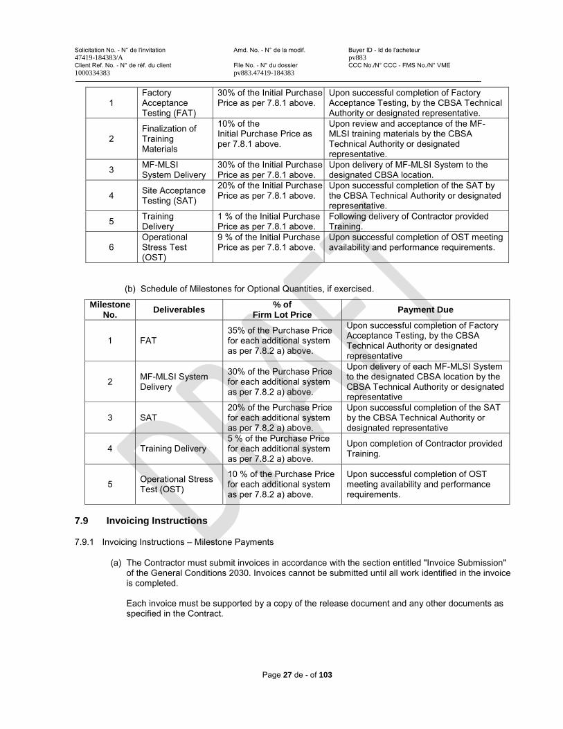
Solicitation No. - N° de l'invitation Amd. No. - N° de la modif. Buyer ID - Id de l'acheteur47419-184383/A pv883Client Ref. No. - N° de réf. du client File No. - N° du dossier CCC No./N° CCC - FMS No./N° VME1000334383 pv883.47419-184383
Page 27 de - of 103
1Factory Acceptance Testing (FAT)
30% of the Initial Purchase Price as per 7.8.1 above.
Upon successful completion of FactoryAcceptance Testing, by the CBSA Technical Authority or designated representative.
2Finalization of Training Materials
10% of theInitial Purchase Price as per 7.8.1 above.
Upon review and acceptance of the MF-MLSI training materials by the CBSA Technical Authority or designated representative.
3 MF-MLSISystem Delivery
30% of the Initial Purchase Price as per 7.8.1 above.
Upon delivery of MF-MLSI System to the designated CBSA location.
4 Site Acceptance Testing (SAT)
20% of the Initial Purchase Price as per 7.8.1 above.
Upon successful completion of the SAT bythe CBSA Technical Authority or designatedrepresentative.
5 Training Delivery
1 % of the Initial Purchase Price as per 7.8.1 above.
Following delivery of Contractor provided Training.
6Operational Stress Test (OST)
9 % of the Initial Purchase Price as per 7.8.1 above.
Upon successful completion of OST meeting availability and performance requirements.
(b) Schedule of Milestones for Optional Quantities, if exercised.
Milestone No.
Deliverables% of
Firm Lot PricePayment Due
1 FAT35% of the Purchase Pricefor each additional systemas per 7.8.2 a) above.
Upon successful completion of FactoryAcceptance Testing, by the CBSA Technical Authority or designated representative
2 MF-MLSI System Delivery
30% of the Purchase Pricefor each additional systemas per 7.8.2 a) above.
Upon delivery of each MF-MLSI System to the designated CBSA location by the CBSA Technical Authority or designated representative
3 SAT20% of the Purchase Pricefor each additional systemas per 7.8.2 a) above.
Upon successful completion of the SAT by the CBSA Technical Authority or designated representative
4 Training Delivery5 % of the Purchase Pricefor each additional systemas per 7.8.2 a) above.
Upon completion of Contractor provided Training.
5 Operational Stress Test (OST)
10 % of the Purchase Pricefor each additional systemas per 7.8.2 a) above.
Upon successful completion of OST meeting availability and performance requirements.
7.9 Invoicing Instructions
7.9.1 Invoicing Instructions – Milestone Payments
(a) The Contractor must submit invoices in accordance with the section entitled "Invoice Submission" of the General Conditions 2030. Invoices cannot be submitted until all work identified in the invoice is completed.
Each invoice must be supported by a copy of the release document and any other documents as specified in the Contract.

Solicitation No. - N° de l'invitation Amd. No. - N° de la modif. Buyer ID - Id de l'acheteur47419-184383/A pv883Client Ref. No. - N° de réf. du client File No. - N° du dossier CCC No./N° CCC - FMS No./N° VME1000334383 pv883.47419-184383
Page 28 de - of 103
7.9.2 The Contractor must submit the invoices as follows:
(a) The original invoice (in .pdf format) along with a copy of the agreed upon maintenance report (in .xlsx format) must be forwarded to the following for certification and payment.
______________
(b) One (1) electronic copy of the invoice and the quarterly maintenance report must be forwarded to the Technical Authority and Contracting Authority email address identified under the section entitled “Authorities” of the Contract.
(c) One (1) electronic copy of the invoice and the quarterly maintenance report must also be forwarded to the following CBSA email addresses:
1. ____________
7.10 Certifications and Additional Information
7.10.1 Compliance
Unless specified otherwise, the continuous compliance with the certifications provided by the Contractor in its bid or precedent to contract award, and the ongoing cooperation in providing additional information are conditions of the Contract and failure to comply will constitute the Contractor in default. Certifications are subject to verification by Canada during the entire period of the Contract.
7.10.2 Federal Contractors Program for Employment Equity - Default by the Contractor
The Contractor understands and agrees that, when an Agreement to Implement Employment Equity (AIEE) exists between the Contractor and Employment and Social Development Canada (ESDC)-Labour, the AIEE must remain valid during the entire period of the Contract. If the AIEE becomes invalid, the name of the Contractor will be added to the "FCP Limited Eligibility to Bid" list. The imposition of such a sanction by ESDC will constitute the Contractor in default as per the terms of the Contract.
7.11 Applicable Laws
The Contract must be interpreted and governed, and the relations between the parties determined, by the laws in force in Ontario, Canada.
7.12 Priority of Documents
If there is a discrepancy between the wording of any documents that appear on the list, the wording of the document that first appears on the list has priority over the wording of any document that subsequently appears on the list.
(a) the Articles of Agreement;
(b) the supplemental general conditions 4001 (2015-04-01) Hardware Purchase, Lease and Maintenance, 4003 (2010-08-16) Licensed Software, and 4004 (2013-04-25) Maintenance and Support Services for Licensed Software) as amended;
(c) the general conditions 2030 (2018-06-21) General Conditions – Higher Complexity – Goods as amended;
(d) ANNEX A, Statement of Work;
Solicitation No. - N° de l'invitation Amd. No. - N° de la modif. Buyer ID - Id de l'acheteur47419-184383/A pv883Client Ref. No. - N° de réf. du client File No. - N° du dossier CCC No./N° CCC - FMS No./N° VME1000334383 pv883.47419-184383
Page 29 de - of 103
(e) ANNEX B, Technical Services
(f) ANNEX C, Basis of Payment; and
(g) the Contractor's bid dated ___________.
7.13 SACC Manual Clauses
A9068C (2010-01-11) Government Site Regulations
A2000C (2006-06-16) Foreign Nationals (Canadian Contractor)
A2001C (2006-06-16) Foreign Nationals (Foreign Contractor)
B1501C (2018-06-21) Electrical Equipment
G1005C (2016-01-28) Insurance – No Specific Requirement
7.14 Shipping Instructions – Delivery at Destination
(a) Goods must be consigned to the destination specified in the Contract and delivered:
Delivered Duty Paid (DDP) (various destinations) Incoterms 2010 for shipments from a commercial contractor.
(b) The Contractor will be responsible for all delivery charges, administration, costs and risk of transport and customs clearance, including the payment of customs duties and taxes.
Solicitation No. - N° de l'invitation Amd. No. - N° de la modif. Buyer ID - Id de l'acheteur47419-184383/A pv883Client Ref. No. - N° de réf. du client File No. - N° du dossier CCC No./N° CCC - FMS No./N° VME1000334383 pv883.47419-184383
Page 30 de - of 103
ANNEX A - STATEMENT OF WORK
1.0 GENERAL REQUIREMENTS
1.1 Mobile Large-Scale Imaging System (MF-MLSI)
The Contractor must provide one Mobile Large Scale Imaging Systems (MF-MLSI System) including all equipment, Image Analysis software, operator and service manuals, peripherals, cabling and components sensors, relays and infrastructure necessary for the safe, non-intrusive inspection of target objects, delivery, installation, all training and a one-year Warranty including all Maintenance and Support Services, all as detailed herein.
The MF-MLSI system must also include, but is not limited to:
1.1.1 MF-MLSI imaging and supporting sub-systems used for non-intrusive radiographic inspection process, including but not limited to the controlled emission, detection, image generation, data management, radiation safety and surveillance.
1.1.2 A MF-MLSI Driver’s Cabin that includes a video monitor, radio controls, camera switches and control boxto control imaging equipment, monitor safety / surveillance systems and to direct inspection operations.
1.1.3 A MF-MLSI Operator’s Cabin that houses all computer workstations, monitors, image processing systems and any other hardware and software components to analyze scan images.
1.1.4 A Linear Accelerator (LINAC) based X-Ray System to generate high energy X-Rays of two different energy levels.
1.1.5 An L-shaped Detector Boom that is aligned with the X-Ray source and is capable of converting the X-Ray emissions produced by the accelerator into an electrical signal
1.1.6 MF-MLSI Calibration Test Pieces and Special Tools that must include the following functionalities:
1.1.6.1 all calibration test pieces necessary to adjust inspection system parameters and confirm performance levels.
1.1.6.2 all test pieces must be re-positioned and/or aligned with a standard fork-lift.1.1.6.3 all test pieces must permit angular adjustment to align with the incident radiographic beam. 1.1.6.4 any special tools necessary for maintenance of the MF-MLSI System equipment, which must be
marked to identify the equipment or system for which they are intended.
1.1.7 Six concurrent user licenses for the image analysis software to be used on the MF-MLSI system, and on CBSA computer systems. The Image Analysis Software must search available information based on “Summary Inspection Data” fields.
1.2 Meetings
1.2.1 Upon award of the contract, the Contractor must participate in a kick-off meeting in Ottawa, ON (unless otherwise agreed upon) with all designated stakeholders in attendance. The CBSA Technical Authority or designated representative will chair this initial meeting as well as prepare and distribute minutes following the meeting. An agenda for this meeting will be forwarded to the Contractor prior to the meeting.
1.2.2 The meeting must serve to introduce all the key personnel involved, clarify any matters of the contract, distribute forms and other informational materials, and review contract procedures.
1.2.3 The agenda for future meetings (if applicable) must be determined by the Contractor in consultation with the CBSA Technical Authority and must be submitted to the CBSA Technical Authority or designated representative within a minimum of two (2) working days in advance of meetings.
Solicitation No. - N° de l'invitation Amd. No. - N° de la modif. Buyer ID - Id de l'acheteur47419-184383/A pv883Client Ref. No. - N° de réf. du client File No. - N° du dossier CCC No./N° CCC - FMS No./N° VME1000334383 pv883.47419-184383
Page 31 de - of 103
1.3 Documentation
1.3.1 The Contractor must maintain, on a secure File Transfer Protocol (FTP) Server electronic server (e.g., OPROMA), electronic copies of the following documents:
1.3.1.1 Contractor’s Proposal1.3.1.2 Contract Amendments1.3.1.3 Original Equipment Manufacturer’s Installation and Application Instructions1.3.1.4 Third party reports 1.3.1.5 Configuration Options1.3.1.6 Any relevant raw data1.3.1.7 Commissioning Documents
1.4 Design Documents Review and Approval
1.4.1 The Contractor must submit complete MF-MLSI System design documents for review by the CBSA Technical Authority or designated representative within 30 days of contract award.
1.4.2 The Contractor must participate in a MF-MLSI System design review meeting(s) with the CBSA Technical Authority or designated representative within 15 calendar days of submission of the design documents as stated in Clause 1.4.1 above. The purpose of this meeting is to review the feasibility of satisfying the associated technical requirements prior to manufacture.
1.4.3 The Contractor must address all comments regarding submitted MF-MLSI System documents, to the satisfaction of the CBSA Technical Authority or designated representative.
1.4.4 The Contractor must submit revised versions of any MF-MLSI System documents deemed inadequate by the CBSA Technical Authority or designated representative for review within 15 calendar days after the review meeting with CBSA.
1.4.5 The Contractor must obtain approval to proceed, from the CBSA Technical Authority or designated representative, prior to manufacturing/assembly and testing.
1.5 Product Information and Data
1.5.1 Upon request by the CBSA Technical Authority or designated representative, the Contractor must provide any product information and data including, but not limited to the following:
1.5.1.1 original equipment manufacturer’s catalogue sheets1.5.1.2 brochures1.5.1.3 literature1.5.1.4 performance charts1.5.1.5 diagrams and1.5.1.6 environmental benefits used to illustrate standard manufactured products.
1.5.2 The Contractor must submit electronic copies of each product data to the CBSA Technical Authority or designated representative upon request.
1.5.3 The data provided by the Contractor must include all relevant information, including make, part, model, series, catalogue number and any other relevant manufacturer’s data.
1.6 Factory Acceptance Testing (FAT)
1.6.1 The CBSA must conduct Factory Acceptance Testing (FAT) after complete installation of all MF-MLSISystem, unless written exemption is provided by the CBSA Technical Authority or designated representative.
Solicitation No. - N° de l'invitation Amd. No. - N° de la modif. Buyer ID - Id de l'acheteur47419-184383/A pv883Client Ref. No. - N° de réf. du client File No. - N° du dossier CCC No./N° CCC - FMS No./N° VME1000334383 pv883.47419-184383
Page 32 de - of 103
1.6.2 The Contractor must submit the MF-MLSI FAT Plan to the CBSA Technical Authority or designated representative, for review and comment within 90 calendar days after the award of the Contract. At a minimum the FAT must demonstrate:
1.6.2.1 Imaging performance 1.6.2.2 Radiation safety and fail safes1.6.2.3 Assembly and configuration 1.6.2.4 Design robustness1.6.2.5 Data management1.6.2.6 Mobility
1.6.3 The Contractor must address all comments regarding the submitted FAT Plan, to the satisfaction of the CBSA Technical Authority or designated representative, prior to execution.
1.6.4 The Contractor must submit to the CBSA Technical Authority or designated representative all resulting FAT Documentation for review, within 7 calendar days of completion of the FAT.
1.6.5 The Contractor must address all comments regarding the submitted FAT Documentation, to the satisfaction of the CBSA Technical Authority or designated representative, within 15 calendar days after receiving feedback from the CBSA Technical Authority.
1.6.6 The Contractor must obtain written approval from the CBSA Technical Authority or designated representative, before the FAT will be deemed complete.
1.7 Site Acceptance Testing (SAT)
1.7.1 The Contractor must assist CBSA in conducting a SAT after complete installation of the MF-MLSI System.
1.7.2 The Contractor must submit the draft MF-MLSI System SAT Plan to the CBSA Technical Authority or designated representative 90 calendar days prior to planned delivery for review and comment. At a minimum the SAT should address:
1.7.2.1 Imaging performance 1.7.2.2 Radiation safety and fail safes1.7.2.3 Operational readiness
1.7.3 The finalized SAT procedures will be developed by CBSA in consultation with the Contractor.
1.7.4 Any discrepancies from the required performance or proposed componentry of the system will be noted and must be addressed to the satisfaction of CBSA prior to final acceptance.
1.7.5 The SAT will be used to satisfy regulatory requirements, validate performance claims, and confirm system compliance with the contractual requirements
1.8 Operational Stress Testing (OST)
1.8.1 The Contractor must provide on-site, technical support for a minimum duration of 45 calendar days of intensive operational use.
1.8.2 The Contractor must demonstrate during the OST that the system meets all maintenance service requirements; any discrepancies from the maintenance service requirements will be noted and must be addressed to the satisfaction of CBSA prior to final acceptance.
1.8.3 In the event the MF-MLSI System fails to meet the minimum maintenance service requirements, the duration of the OST will be extended by the greater of: one week (7 days) or the cumulative amount of time that the system was unavailable.
Solicitation No. - N° de l'invitation Amd. No. - N° de la modif. Buyer ID - Id de l'acheteur47419-184383/A pv883Client Ref. No. - N° de réf. du client File No. - N° du dossier CCC No./N° CCC - FMS No./N° VME1000334383 pv883.47419-184383
Page 33 de - of 103
1.8.4 In the event the MF-MLSI System fails to meet the minimum maintenance service requirements after 90 calendar days,
1.8.4.1 The Contractor must return the unit to the Factory:1.8.4.2 The Contractor will be granted 30 calendar days to refurbish or replace the unit;1.8.4.3 Thereafter a revised FAT and an OST will be performed by CBSA; and1.8.4.4 Failure to pass this test may result in Contract termination and the Contractor will be required to
reimburse the Government of Canada for the full value of the purchase price of the system.
1.9 Post Installation Close-Out Procedures
1.9.1 The Contractor must coordinate and perform, in concert with its subcontractors if applicable, the following:
1.9.1.1 Conduct an inspection / check of all the tasks completed on the system1.9.1.2 Identify and correct deficiencies, defects, repairs and resolve outstanding issues as required in
conformance with the Contract; and1.9.1.3 Confirm delivery and condition of all the spare parts, tools, and maintenance materials.
1.9.2 The Contractor must notify the CBSA Technical Authority in writing when all deficiencies identified during the SAT and OST have been rectified, and the work is deemed to be complete and ready for Inspection and Acceptance by the CBSA Technical Authority or designated representative.
1.9.3 The Contractor must submit all the MF-MLSI System close-out documents to the CBSA Technical Authority for review and comment. This must include at least:
1.9.3.1 a detailed checklist of installation of each component and sub component;1.9.3.2 results of the system’s performance testing conducted immediately after installation in
conformance with the Contract, and1.9.3.3 notes and comments about all testing performed on each component and on the system on the
whole, including adjustments made for smooth operation.
1.9.4 The Contractor must address all comments regarding submitted MF-MLSI close-out documents to the satisfaction of the CBSA Technical Authority and resubmit all the documents within 21 calendar days after receiving feedback on them.
1.9.5 The Contractor must provide final versions of all manuals, drawings and reports generated for the MF-MLSI System within 30 calendar days after completion of the SAT.
1.10 Post-Delivery Review
1.10.1 The Contractor must participate in a post-delivery review of the commissioned MF-MLSI System, 90 calendar days after final acceptance (unless otherwise agreed to with the CBSA Technical Authority or designated representative).
1.10.2 The Contractor must prepare a post-delivery report for review by the CBSA Technical Authority that must include post delivery operational testing results of the MF-MLSI system, technical and operational issues encountered during the system operation and mitigation measures used to correct those issues.
Solicitation No. - N° de l'invitation Amd. No. - N° de la modif. Buyer ID - Id de l'acheteur47419-184383/A pv883Client Ref. No. - N° de réf. du client File No. - N° du dossier CCC No./N° CCC - FMS No./N° VME1000334383 pv883.47419-184383
Page 34 de - of 103
2.0 TRAINING REQUIREMENTS
2.1 MF-MLSI Operator Training
2.1.1 The Contractor must provide an on-site MF-MLSI Operator Training, focused on radiation safety,functional use of all equipment and software, comprehensive non-intrusive inspection through X-Ray image analysis and trouble-shooting common problems.
2.1.2 This training must be offered in English and/or French (at the request of the CBSA Technical Authority or designated representative) for up to twenty (20) operators (in 4 classes of 5 persons), per system.
2.1.3 The MF-MLSI Operator Training must be delivered within 28 calendar days (unless otherwise agreed to with the CBSA Technical Authority or designated representative) of the completion of SAT (unless otherwise agreed to with the CBSA Technical Authority or designated representative).
2.1.4 The exact date, time and location of the training will be mutually agreed upon between the Contractor and the CBSA Technical Authority or designated representative stated herein.
2.1.5 The Operator Training must not exceed five (5) days in length or 37.5 hours of instruction.
2.1.6 The Contractor must provide a repository of reference images of common conveyances (e.g., vehicle makes/models) that can be used by officers to assist in the image analysis and adjudication process.
2.1.7 The Operator Training must include classroom and hands-on components and must be conducted by two instructors who have the knowledge/experience of the design and operation of the system, and arefamiliar with adult learning principles.
2.1.8 The Contractor must provide on-site technical support by qualified maintenance personnel during each of the Operator Training sessions. The tech support representative must be prepared to take immediate action in the event of failure or malfunction.
2.2 MF-MLSI Train-the-Trainer Training
2.2.1 The Contractor must provide on-site Train-the-Trainer Training for up to a maximum of five (5) CBSA personnel, per system, who will be trained to deliver the Basic Operator Training to other CBSA personnel.
2.2.2 The Train-the-Trainer Training must be delivered within 60 calendar days of the completion of the SAT(unless otherwise agreed to with the CBSA Technical Authority or designated representative).
2.2.3 The exact date, time and location of the training will be mutually agreed upon between the Contractor and the CBSA Technical Authority or designated representative.
2.2.4 The Train-the-Trainer Training must include classroom and hands-on components and all aspects of the training must be supervised by two instructors who have knowledge/experience with the design and operation of the device, and are familiar with adult learning principles.
2.3 MF-MLSI System Administrator Training
2.3.1 The Contractor must provide MF-MLSI System Administrator training for up to five (5) operators in English, per system.
2.3.2 The System Administrator training must include the manipulation of system parameters and alarm thresholds, calibration and sensitivity testing, performance diagnostics and data management.
2.3.3 The System Administrator training must be delivered within 90 calendar days of the completion of the SAT unless otherwise agreed to with the CBSA Technical Authority.
Solicitation No. - N° de l'invitation Amd. No. - N° de la modif. Buyer ID - Id de l'acheteur47419-184383/A pv883Client Ref. No. - N° de réf. du client File No. - N° du dossier CCC No./N° CCC - FMS No./N° VME1000334383 pv883.47419-184383
Page 35 de - of 103
2.4 MF-MLSI Equipment Maintenance Training
2.4.1 Equipment maintenance training for first and second levels of support must be offered in English for up to four (4) technicians per system.
2.4.2 The training must focus on component/subsystem/software interconnections diagnostics and replacement of modular components.
2.5 Training Materials
2.5.1 The Contractor must provide all training materials in English to CBSA for review and comment at least 90 calendar days prior to the delivery of the training (unless otherwise agreed upon by the CBSA Technical Authority).
2.5.2 The Contractor must address all comments related to the submitted training materials to the satisfaction of the CBSA Technical Authority or designated representative, within 2 weeks after receiving the feedback from the CBSA.
2.5.3 The Contractor must translate the final English version of all training materials to French and provide editable soft copies of all Training Materials in both English and French ( in a CBSA-specified template) to the CBSA for its exclusive and unrestricted use in the development of internal training packages.
2.5.4 Training materials for each training must include:
2.5.4.1 A Facilitator Guide providing clear instructions and speaking notes to the instructor as well as reflect the content of the Participant Guide.
2.5.4.2 A Participant Guide for the learner to follow along with the instruction 2.5.4.3 Job Aids for the learner to quickly reference 2.5.4.4 Presentation materials of the essential messaging and illustrated with images and examples
2.6 Training Delivery
2.6.1 The Training Delivery must include:
2.6.1.1 Structured presentation of the content tailored to learner characteristics as appropriate, i.e.,prior knowledge, experience, educational level and modality (in class, virtual classroom, etc.)
2.6.1.2 Application of the content as appropriate, with a focus on interactivity (e.g., paired and small group activities, whenever possible, written and hands-on activities, oral tests, role-play, etc.).
2.6.1.3 Oral feedback from learners that describes how their newly-developed knowledge/skillset will enhance their performance and written feedback of the content as appropriate (e.g., corrected quizzes, group discussions, personalised feedback forms, etc.).
2.7 Instructional Design
2.7.1 The Instructor must have a minimum of two (2) years of experience in the design and delivery of instructional materials for adult learners.
2.7.2 All training materials and instructional techniques must integrate:
2.7.2.1 Overall and module specific objectives aligned with the revised Bloom’s Taxonomy meeting all the six aspects of learning: Remember, Understand, Apply, Analyze, Evaluate and Create;
2.7.2.2 An associated assessment which validates that each of the objective (mentioned above) has been met.
2.7.2.3 Adult learning principles as defined below:a) Safety: Learning involves change which can cause anxiety in adult learners;b) Utilization: Adult learners come with a wide range of previous experiences, knowledge, interests,
and abilities and they appreciate when their assets are recognized and utilized;c) Choice: Adult learners are self-directed and want to be actively involved in the learning process;

Solicitation No. - N° de l'invitation Amd. No. - N° de la modif. Buyer ID - Id de l'acheteur47419-184383/A pv883Client Ref. No. - N° de réf. du client File No. - N° du dossier CCC No./N° CCC - FMS No./N° VME1000334383 pv883.47419-184383
Page 36 de - of 103
d) Relevance: Adult learners appreciate programs that address relevant challenges in their lives and provide solutions that are immediately useful and
e) Social Learning: Adult learners learn best in informal settings where they can interact socially.
Solicitation No. - N° de l'invitation Amd. No. - N° de la modif. Buyer ID - Id de l'acheteur47419-184383/A pv883Client Ref. No. - N° de réf. du client File No. - N° du dossier CCC No./N° CCC - FMS No./N° VME1000334383 pv883.47419-184383
Page 37 de - of 103
3.0 OPERATIONAL REQUIREMENTS
3.1 Imaging
The MF-MLSI System must produce radiographic transmission images of the contents of target objects within the system’s inspection volume.
3.2 Radiation Source
The MF-MLSI System X-ray radiation source must be electrically generated.
3.3 Number of Operators
The MF-MLSI System must deliver, enable and support continuous scanning operations by three (3) operators (1 Driver, 1 Image Analyst, 1 Safety Traffic Controller).
3.4 Push-Button Start/Shutdown
3.4.1 The MF-MLSI System’s main power must be initialized or disabled with the push of a single button.
3.4.2 The MF-MLSI System should start-up fully (to a ready state, not including login) and shut-down fully (to a recharging state) in sequence, at the push of a button.
3.5 Start-Up Time
The MF-MLSI System must have a start-up time to initialize all systems for imaging of less than 1200 seconds.
3.6 Imaging Speeds
3.6.1 The MF-MLSI System must inspect target objects at specific, pre-selected and constant imaging speeds> 0.4 m/s.
3.6.2 The MF-MLSI System should offer the user the option to image targets at a minimum of two (2) different speeds, through use of a toggle switch, one of which must be > 0.4 m/s.
3.7 Imaging Rate
The MF-MLSI System must provide the functionality for conducting at least 20 full-length scans per hour, at a nominal scan speed of 0.4 m/s or slower, for a minimum of ten (10) years with regular maintenance.
3.8 Imaging Full Reset Time
The MF-MLSI System must ready all subsystems for repeat imaging in less than 15 seconds.
3.9 Bi-Directional Repeated Imaging
The MF-MLSI System must have the functionality to image the same target object(s) in one direction, then promptly repeat the imaging process in the opposite direction (i.e., without the need to reset all equipment positions), followed by a third pass in the initial direction.
3.10 Inspection Tunnel
The MF-MLSI System must safely scan and generate images of target objects within an inspection tunnel size of 2.6 m (W) x 4.6 m (H).
3.11 Imaging Field-of-View
3.11.1 The MF-MLSI System must generate images from the top of the inspection volume down to 40 cm above floor/target platform (measured along the centre-line of the inspection volume), and along the entire length of the inspection volume without exhibiting image cut-off.
Solicitation No. - N° de l'invitation Amd. No. - N° de la modif. Buyer ID - Id de l'acheteur47419-184383/A pv883Client Ref. No. - N° de réf. du client File No. - N° du dossier CCC No./N° CCC - FMS No./N° VME1000334383 pv883.47419-184383
Page 38 de - of 103
3.11.2 The MF-MLSI System should generate images from the top of the inspection volume down to the bottom of target objects (as measured along the centre-line of the inspection volume) without exhibiting image cut-off.
3.12 Imaging Multiple Objects
The MF-MLSI System must deliver, enable and support scanning at least two (2) different medium-sized target objects in the inspection volume in a single pass.
3.13 Image Analysis Verdict
The MF-MLSI System must allow for and store, with the original image and dataset, an operator-selected verdict of “Suspect/Not-suspect” along with any notes, manipulations and annotations saved upon completion of analysis.
3.14 Digital Image Record of Target Objects
The MF-MLSI System must automatically capture digital images of the inspected object, along with any license plates and container/conveyance identifying marks/numbers, and integrate these into the inspection data.
3.15 Login
The MF-MLSI System must require a user login and password to be entered prior to initiating new operations, or if the unit has been inactive for a CBSA configurable period of time.
3.16 User Tracking
The MF-MLSI System must store an operator identifier for each scan within the produced dataset.
3.17 Inspection Counter
The MF-MLSI System must record and display the number of scans for the following:
3.17.1 a scanning session that can be reset by operators;
3.17.2 a scanning day that can be reset by operators; and
3.17.3 the lifetime that cannot be reset by operators or technical personnel.
3.18 General Video Surveillance Requirements
3.18.1 The MF-MLSI System must employ a multi-camera (IP-based) video monitoring system to ensure safe and secure inspection activities.
3.18.2 The MF-MLSI System surveillance equipment and positioning must satisfy the required performance and coverage areas defined in Section 6.0 VIDEO SURVEILLANCE REQUIREMENTS.
3.19 Camera Viewing of Target Objects
The MF-MLSI System video surveillance system must enable an operator to select and manipulate pan, tilt, zoom(PTZ) cameras from the Operator’s Cabin via Joystick control to:
3.19.1 conduct visual inspection of areas-of-interest on the exterior of inspected objects such as conveyance roof, door panels, windows, spare tires, external gas tanks, latching and securing devices, open-top cargo holds, truck boxes, etc.
3.19.2 ensure adequate clearance is available for the MF-MLSI System and target objects, and
3.19.3 read/confirm container or license plate identification numbers.
Solicitation No. - N° de l'invitation Amd. No. - N° de la modif. Buyer ID - Id de l'acheteur47419-184383/A pv883Client Ref. No. - N° de réf. du client File No. - N° du dossier CCC No./N° CCC - FMS No./N° VME1000334383 pv883.47419-184383
Page 39 de - of 103
3.20 Operating Environment
The MF-MLSI System must deliver, enable and support continuous operation in a Canadian environment; including ambient temperatures ranging from -30° C to +40° C, and all forms of precipitation.
3.21 Storage Environment
The MF-MLSI System must deliver, enable and support storage outside for up to 90 days in the ambient environment, without the need for any shore connections.
3.22 Driver’s and Operator’s Cabin/s Environmental Control
3.22.1 The MF-MLSI System Driver’s and Operator’s Cabin/s must employ heating and air conditioning systems capable of maintaining a comfortable work environment, with adjustable temperature settings from 20°C to 24°C, irrespective of frequent opening and closing of doors.
3.22.2 The MF-MLSI System Operator’s Cabin (or section of the cabin) lighting system must be multi-level or dimming type to allow the operator to adjust the lighting to comfortable levels.
3.22.3 The MF-MLSI System Driver’s cabin (or section of the cabin) must employ a heating and air conditioning system which can be directed partially or in full, to defrost/defog the windshield while scanning
3.23 Scanning Manifest Documents
The MF-MLSI System must be equipped with hardware to scan any manifest documents and store copies of these documents as part of the inspection dataset.
3.24 Imaging Tools
3.24.1 The MF-MLSI System must deliver, enable and support manipulation of the generated images to better identify and characterize components of the target object and its contents.
3.24.2 The image manipulation capability must include a suite of the following imaging tools (or their equivalents) which can be applied and removed during image analysis process, and should include the following basic functionalities:
3.24.2.1 Calliper Tool: to provide a means for operators to measure the approximate size of details in the scanned image.
3.24.2.2 Zoom Tool: to provide a means for operators to zoom in and out of parts of the scanned image for localized analysis.
3.24.2.3 Contrast and Brightness Tool: to provide a means for operators to modify the contrast and brightness of the scanned image.
3.24.2.4 Histogram Tool: to provide a means for operators to normalize the image (or part thereof) according to the statistical distribution of detected photons.
3.24.2.5 Image Enhancement/Sharpness Tool: to provide a means for operators to modify the image sharpness and color scheme to emphasize/discriminate between different items in the image.
3.24.2.6 Low Absorption Tool: to provide a means for operators to identify areas of an image where the source penetrability has been highly limited.
3.24.2.7 Undo/back Capability: to provide a means for operators to undo individual actions, and also to return to the original image.
3.24.2.8 Image Annotation: to provide a means for operators to highlight and type in comments about specific areas in an image for future reference and review.
3.24.2.9 Image Polarity Reversal: to provide a means for operators to reverse the video polarity (negative video mode).
3.24.2.10 Image Comparison Tool: to permit operators to search for previous images based on key parameters (e.g., truck/conveyance id., license plate, etc.) and compare the retrieved data alongside the scan currently under review.
Solicitation No. - N° de l'invitation Amd. No. - N° de la modif. Buyer ID - Id de l'acheteur47419-184383/A pv883Client Ref. No. - N° de réf. du client File No. - N° du dossier CCC No./N° CCC - FMS No./N° VME1000334383 pv883.47419-184383
Page 40 de - of 103
3.25 Real-Time Image Display
The MF-MLSI System must display scan images on the operator screen as they are generated enabling a preview for the image analyst.
3.26 Inspection Data
3.26.1 The MF-MLSI System must enable operators to enter key information about the target object into searchable data fields, including but not limited to:
3.26.1.1 Date and time3.26.1.2 Location3.26.1.3 Conveyance identifier (e.g., License plates)3.26.1.4 Entry mode (Travelers or Commercial)3.26.1.5 Conveyance type (e.g., passenger vehicle, marine container, refrigerated container, other)3.26.1.6 Load identifier 1 (e.g., marine container id, trailer license plate, etc.) 3.26.1.7 Load type 1 (e.g., marine container, refrigerated container, Unit Load Device (ULD), etc.)3.26.1.8 Load description 1 3.26.1.9 Load identifier 2 (e.g., marine container id, trailer license plate, etc.) 3.26.1.10 Load type 2 (e.g., marine container, refrigerated container, ULD, etc.)3.26.1.11 Load description 2 3.26.1.12 Image Analyst’s User Name3.26.1.13 Free-form field
3.27 Summary Reports
3.27.1 The MF-MLSI System must deliver, enable and support report generation based on the Inspection Data fields.
3.27.2 The MF-MLSI System must deliver, enable and support exportation of the report information in .xml format.
Solicitation No. - N° de l'invitation Amd. No. - N° de la modif. Buyer ID - Id de l'acheteur47419-184383/A pv883Client Ref. No. - N° de réf. du client File No. - N° du dossier CCC No./N° CCC - FMS No./N° VME1000334383 pv883.47419-184383
Page 41 de - of 103
4.0 VEHICULAR REQUIREMENTS
4.1 Certified Design
The MF-MLSI System’s vehicular design including all inspection equipment must be certified as compliant with applicable road regulations by a Professional Engineer registered in the Province to which it will be delivered.
4.2 Driver’s License Requirements
4.2.1 The MF-MLSI System must be drivable by any Operator holding a valid Class 3 Commercial license or its equivalent (in the province of usage). Please see the link below for details:
https://www.fmcsa.dot.gov/sites/fmcsa.dot.gov/files/docs/Canadian%20Driver%27s%20Licence%20Reference%20Guide%20Revised%202015.pdf
4.2.2 The MF-MLSI System should be drivable by any Operator holding a valid Class 5 license or its equivalent (in their province of residence).
4.3 Vehicle Seating and Restraints
4.3.1 All MF-MLSI System passenger seating and restraining systems must be designed to enable an Operator carrying a firearm in a hip mounted holster to enter, exit and sit comfortably.
4.3.2 The MF-MLSI System should include sufficient seating for a team of three Operators (including the driver) when configured for road travel (seats may be foldable to provide added space during scanning operations).
4.4 Provincial Regulations
It must be possible to register the MF-MLSI System in any Canadian province for driving on primary or secondary roads, year round.
4.5 Total Mass Limit
The MF-MLSI System must not exceed 22,750 kg in mass when configured for road mode.
4.6 Axial Load Limits
4.6.1 The MF-MLSI System must not exceed 7,250 kg on the front (steering) axle.
4.6.2 The MF-MLSI System must not exceed:
4.6.2.1 8,000 kg on the rear axle (if single or tandem with separation less than 1.2 m)4.6.2.2 15,500 kg on the rear axles (if tandem separated by at least 1.2 m or two axels separated by at
least 2.4 m) 4.6.2.3 11,000 kg if two axels separated by less than 2.4
4.7 Weight Distribution
4.7.1 The MF-MLSI System must bear the weight of the boom arm and accelerator on or between the front and rear axles.
4.7.2 The MF-MLSI System should not exceed 70% of the weight distributed on the rear axles when configured for road mode.
4.8 Boom Support
4.8.1 The MF-MLSI System boom arm must be secure when stowed for road travel.
Solicitation No. - N° de l'invitation Amd. No. - N° de la modif. Buyer ID - Id de l'acheteur47419-184383/A pv883Client Ref. No. - N° de réf. du client File No. - N° du dossier CCC No./N° CCC - FMS No./N° VME1000334383 pv883.47419-184383
Page 42 de - of 103
4.8.2 The MF-MLSI System boom arm should be supported by at least two (2) points of contact when stowedfor road travel, distributing its weight along the length of the vehicle.
4.9 Maximum Width
The MF-MLSI System must not exceed 2.6 m in total width when configured for road mode (and having a track width of at least 2.5 m).
4.10 Maximum Length
The MF-MLSI System must not exceed 12.5 m in total length when configured for road mode.
4.11 Maximum Height
The MF-MLSI System must not exceed 4.15 m in total height when configured for road mode.
4.12 Maximum Overhang
The MF-MLSI System overhang must not exceed 4.0 m when configured for road mode.
4.13 Number of Axles
The MF-MLSI System must not have more than three axles (i.e., 1 front and 2 rear/tandem).
4.14 Maximum Wheelbase
The MF-MLSI System must have a wheelbase less than or equal to 6.2 meters in length.
4.15 Driver’s Cabin Sun Protection
The MF-MLSI System driver’s cabin should have additional front and side window tinting to limit UV rays duringlong periods of sunlight exposure.
4.16 Backup Camera
The MF-MLSI System must have a backup camera enabling the driver to see the area behind the vehicle while driving.
4.17 Cold-Start
The MF-MLSI System must deliver, enable and support cold-starting the engine following prolonged periods of latency in the Operating Environment.
4.18 Diesel Particulate Filter (DPF) Regeneration
The MF-MLSI System must not require DPF Regeneration based on any time period during which the vehicle engine has not been running.
4.19 Flashing Warning Lights - Vehicular
4.19.1 The MF-MLSI System must be equipped with flashing yellow and amber warning lights in such a configuration that they can clearly be seen from 360 degrees around the vehicle.
4.19.2 The MF-MLSI System must be equipped with flashing blue and white warning lights in such a configuration that they can clearly be seen from 360 degrees around the vehicle.
4.19.3 The Driver must be able to turn all flashing (vehicular) lights on and off from the Driver’s Cabin.
Solicitation No. - N° de l'invitation Amd. No. - N° de la modif. Buyer ID - Id de l'acheteur47419-184383/A pv883Client Ref. No. - N° de réf. du client File No. - N° du dossier CCC No./N° CCC - FMS No./N° VME1000334383 pv883.47419-184383
Page 43 de - of 103
5.0 DESIGN AND CONFIGURATION REQUIREMENTS
5.1 Proven Design
The MF-MLSI System must be based on a Proven Design. This requires that at least two (2) systems bedeployed and operational for two years, which must be substantiated by references to be provided in the ATTACHMENT 1 TO PART 4 OF THE BID SOLICITATION - Technical Bid Submission Document. AProven Design must include, but is not limited to, the following:
5.1.1 high-energy X-ray radiation source;
5.1.2 detector array and readout electronics;
5.1.3 physical protection scheme limiting radiation emissions to 10.0 μSv/h (instantaneous) at the boundary ofthe Radiation Safety Zone (RSZ); and
5.1.4 configuration on a road registered vehicle.
5.2 Inspection Drive
5.2.1 The MF-MLSI System must be electronically driven during inspection and powered independently from the output from the vehicle’s engine.
5.2.2 The MF-MLSI System should utilize a diesel-electric powertrain.
5.2.3 The MF-MLSI System should enable mechanical drive conversion from road mode to inspection mode (and back) without the need to build pneumatic pressure with the vehicle’s engine.
5.3 Boom Actuation
5.3.1 The MF-MLSI System boom arm must be actuated independent of any air brake system.
5.3.2 The MF-MLSI System boom arm should be deployed and stowed using electrical and (or) hydraulic actuation
5.4 Boom Alignment
The MF-MLSI System boom arm alignment must be locked in place or maintained by positive pressure at all times during scanning.
5.5 Detector Array - Environmental Control
The MF-MLSI System’s detector array must be temperature and environmentally controlled by a dedicated Heating Ventilating Air Conditioning (HVAC) system and feedback sensors positioned in the boom arm.
5.6 Programmable Logic Controller (PLC) - Functionality
5.6.1 The MF-MLSI System’s principal operations (start-up, scanning and shut-down) must be automatically activated in sequence.
5.6.2 The MF-MLSI System’s principal operations should be sequenced based on a feedback loop generated by computer and sensor signals to the PLC and not based on time delays.
5.7 Protection from Dirt and Water
5.7.1 All MF-MLSI System components must be fully protected from exposure to solid particles and water that may result from projected environmental and/or operating conditions, including driving the unit on highways and secondary roads.
Solicitation No. - N° de l'invitation Amd. No. - N° de la modif. Buyer ID - Id de l'acheteur47419-184383/A pv883Client Ref. No. - N° de réf. du client File No. - N° du dossier CCC No./N° CCC - FMS No./N° VME1000334383 pv883.47419-184383
Page 44 de - of 103
5.7.2 All exterior MF-MLSI System components should have a CSA Type 4 or International Electrical Commission (IEC) Ingress Protection (IP) IP65 rating or better.
5.7.3 All MF-MLSI System cables running exterior to the primary compartments must be enclosed in rust-proof conduits.
5.7.4 The MF-MLSI System chassis and exposed components must be painted or rust-proofed.
5.8 CSA Electrical Certification
The Contractor must obtain independent CSA certification of the MF-MLSI electrical system.
5.9 Fail-safe
The MF-MLSI System must include a means for fail-safe shutdown of all system components in the case of a power loss. This functionality must ensure that radiation emission is stopped, that no data is lost, and that the MF-MLSI System may be restarted as normal when power is restored.
5.10 Uninterruptible Power
The computer system(s) must be supported by an uninterruptible power supply (UPS) to prevent the loss of data in the event of a break or interruption in the main power source. The UPS must deliver, enable and support powering all operator workstations, networking equipment and system servers, so as to enable sufficient time for data retrieval prior to shut down.
5.11 Operator Workstations
5.11.1 The MF-MLSI System Operator workstation must be configured to enable control of the radiographic system, image analysis and video surveillance for use by a single operator.
5.11.2 The MF-MLSI System Operator workstation must include dimmable task lighting designed to facilitate image analysis.
5.11.3 The MF-MLSI System Operator workstation must have a direct line for spoken communication with the driver (without the need for radios, or similar).
5.12 Image Analyst’s Display
5.12.1 Each Operator Workstation must include at least one 4K ultra-high-definition monitor (minimum 3840 x 2160 pixels) for image analysis (minimum size 27”, widescreen)
5.12.2 Each Operator Workstation must also include at least one high-definition (minimum resolution (1080p) monitor (minimum size 27”) for dedicated to the display and control of the MF-MLSI System Cameras.
5.12.3 The number of monitor(s) on the video display board must be sufficient to accommodate the camera views of the entire MF-MLSI System, with no more than 16 camera feeds per screen.
5.12.4 Each monitor must provide a wide viewing angle using In-Plane Switching (IPS) technology (or better).
5.12.5 Each monitor should support pivoting between landscape and portrait modes.
5.12.6 Each monitor should be mounted on an operator-adjustable stand to configure the height and angle for optimal viewing.
5.13 Identification of Operational Controls
All controls (switches/buttons/levers) must be clearly marked in order to identify their function(s) in both French and English or be universal icons, eliminating the need for written words.
Solicitation No. - N° de l'invitation Amd. No. - N° de la modif. Buyer ID - Id de l'acheteur47419-184383/A pv883Client Ref. No. - N° de réf. du client File No. - N° du dossier CCC No./N° CCC - FMS No./N° VME1000334383 pv883.47419-184383
Page 45 de - of 103
5.14 Linguistic Requirements Signage
All signs and instructional markings must be bilingual (French and English) on all operator controls and primary systems and satisfy any applicable Canadian regulatory requirements.
5.15 Signs and Markings
5.15.1 The MF-MLSI system must include four deployable and sturdy radiation placards (sandwich board-type) to warn personnel against entry into the Radiation Safety Zone.
5.15.2 All safety signs and instructional markings must satisfy regulatory requirements and have high resistance to mechanical abrasion, cleaning solutions and exposure to Canadian environmental conditions.
5.16 Printer
5.16.1 The MF-MLSI System must be supplied with a color laser printer, with a resolution of at least 600 x 600 DPI, a color page print rate of no less than eight (8) pages per minute (PPM), and a black and white print rate of at least 12 PPM.
5.16.2 The printer must be configured to allow printing from any device connected to the system’s network.
5.16.3 The printer must be securely attached to its mounting surface.
5.17 Software Languages
All system application software must provide the operator the choice to work in either French or English. It must be possible to toggle easily between languages (i.e., via a language icon on the operator screen) without loss of work.
5.18 Additional Power Outlets
The MF-MLSI System must include a minimum of four unused standard power sockets.
5.19 On-board Storage
5.19.1 The MF-MLSI System should include concealed storage inside the Operator’s cabin for small tools and equipment (e.g., survey meters).
5.19.2 The MF-MLSI System should include concealed refrigeration (2 cubic feet) or cooler space for foodstuffs.
Solicitation No. - N° de l'invitation Amd. No. - N° de la modif. Buyer ID - Id de l'acheteur47419-184383/A pv883Client Ref. No. - N° de réf. du client File No. - N° du dossier CCC No./N° CCC - FMS No./N° VME1000334383 pv883.47419-184383
Page 46 de - of 103
6.0 VIDEO SURVEILLANCE REQUIREMENTS
6.1 Video Surveillance Coverage
6.1.1 The MF-MLSI System must provide unobstructed video surveillance coverage of the target and surrounding area, in order to assist the driver to:
6.1.1.1 verify positioning of MF-MLSI System boom arm relative to target object during inspection. 6.1.1.2 verify the Radiation Safety Zone is clear of persons prior to and during inspection.
6.1.2 The MF-MLSI System must deliver, enable and support visual inspection of the exterior of the target object (e.g., vehicle rooftop, conveyance beds, etc.) using Pan Tilt Zoom (PTZ) capabilities.
6.2 Video Camera Enclosures
6.2.1 Video cameras must be contained in housing and securely mounted.
6.2.2 Video camera assemblies must be dustproof and waterproof by being IP66 rated or better with regard to the IP Code or International Protection Marking IEC 60529.
6.2.3 Video camera enclosures must be designed to prevent fogging and any accumulation of water in front of camera lenses (e.g., downward facing dome enclosures are not acceptable).
6.3 Video Camera Sensor and Image type
MF-MLSI System video cameras must be based on CMOS sensor technology and must render images in color.
6.4 Video Camera Night Capability
6.4.1 All MF-MLSI System video cameras must have a true automatic Day/Night camera capability with a switchable, mechanical IR cut filter.
6.4.2 Night time operation must be supported by exterior lighting to ensure good video quality.
6.5 Video Camera Dynamic Range
Any MF-MLSI System video cameras installed outdoors must have a Wide Dynamic range capability of at least 130dB.
6.6 Video Camera Exposure Settings
6.6.1 Camera(s) must have automatic and manual shutter speed and gain controls.
6.6.2 Camera(s) must allow automatic compensation of the image level with regard to various lighting conditions, such as ”Automatic Gain Control” and “Auto Iris”.
6.6.3 Camera must capture images at a shutter speed from 1/10000s to 1/30s, in both mode night and day mode.
6.7 Video Camera White Balance
The MF-MLSI System video cameras must have an automatic white balance control.
6.8 Video Camera Focus
The MF-MLSI System video cameras must have remote focus control.
6.9 Video Camera Zoom
The MF-MLSI System video cameras must support at least a 2X optical zoom.

Solicitation No. - N° de l'invitation Amd. No. - N° de la modif. Buyer ID - Id de l'acheteur47419-184383/A pv883Client Ref. No. - N° de réf. du client File No. - N° du dossier CCC No./N° CCC - FMS No./N° VME1000334383 pv883.47419-184383
Page 47 de - of 103
7.0 RADIATION SAFETY REQUIREMENTS
7.1 Canadian Nuclear Safety Commission (CNSC) Licensable System
7.1.1 The MF-MLSI System must be eligible for the following licenses: License to Construct; License to Operate for the Purpose of Commissioning, License for Routine Operation, and License to Decommission. CBSA will be responsible for obtaining all licenses.
7.1.2 The Contractor must provide the CBSA Technical Authority or designated representative with all required information, within two (2) weeks of initial request, in order to support the submission of license applications.
* Note: License types and preliminary information requirements can be reviewed in the document RD/GD-289 CNSC License Application Guide on the CNSC’s website at: http://www.nuclearsafety.gc.ca/eng/nuclear-substances/licensing-class-II-nuclear-facilities-and-prescribed-equipment/licencing-class-II-nuclear-facilities/index.cfm.
7.2 Nuclear Regulatory Compliance
The MF-MLSI System must comply with all applicable requirements of the Canadian Nuclear Safety Commission’s (CNSC) Class II Nuclear Facilities and Prescribed Regulations (CIINFPER).
7.3 CNSC Granted License to Service
7.3.1 The Contractor (or any subcontractor performing the work) must acquire (before installation) and maintain a CNSC Class II Prescribed Equipment Servicing License.
7.3.2 The Contractor must maintain this license for the duration of maintenance service contracts and is responsible for all associated costs and responsibilities (e.g., certification of a Radiation Safety Officer).
7.4 Certification of Class II Prescribed Equipment
Prior to Factory Acceptance Testing (FAT), the radiation device must be certified (Class II) by the Canadian Nuclear Safety Commissions (CNSC).
* Note: Certification requirements can be reviewed in the document RD/GD-254 Certification of Radiation Devices and Class II Prescribed Equipment at:http://www.nuclearsafety.gc.ca/eng/nuclear-substances/licensing-class-II-nuclear-facilities-and-prescribed-
equipment/certification-requirements-class-II-prescribed-equipment/index.cfm
7.5 Radiation Safety Zone (RSZ)
7.5.1 The MF-MLSI System must image target objects within a Radiation Safety Zone (RSZ) not exceeding an area of: [23 m (approx. 75’) Width x 50 m (approx.165’) Length], when inspecting any target conveyance 20 m (approx. 65’) in length.
7.5.2 The instantaneous radiation dose rate outside of the RSZ, irrespective of the location of measurement and scattering of incident radiation prior to detection, must not exceed 10 μSv/h at any time.
7.5.3 The cumulative radiation exposure at all Operator Positions must be less than 0.5 μSv during any one hour of imaging, at an inspection rate leading to the maximum possible exposure.
7.6 Dose to Cargo Limit
The cumulative radiation exposure within the target object or cargo must not exceed 100 μSv in any one scan (irrespective of any shielding provided by the conveyance).
7.7 Dose Rates within the MF-MLSI System
The cumulative radiation exposure within the MF-MLSI Driver’s and Operator’s cabins must not exceed 0.5 μSv during any one hour of imaging, at an inspection rate leading to the maximum possible exposure.
Solicitation No. - N° de l'invitation Amd. No. - N° de la modif. Buyer ID - Id de l'acheteur47419-184383/A pv883Client Ref. No. - N° de réf. du client File No. - N° du dossier CCC No./N° CCC - FMS No./N° VME1000334383 pv883.47419-184383
Page 48 de - of 103
7.8 Radiological Safety System
7.8.1 The MF-MLSI System must incorporate a Radiological Safety System (RSS) which interlocks sensors and protocols to prevent unnecessary exposure of radiation to humans.
7.8.2 The primary system components which must be integrated within the RSS are:
7.8.2.1 The warning lights/sirens and beam-on indicators;7.8.2.2 All Emergency Stops;7.8.2.3 The initialization code lock system;7.8.2.4 All fixed radiation survey meters, detectors or sensors;7.8.2.5 The collimation and/or beam alignment system;7.8.2.6 The collision avoidance system;7.8.2.7 Source control system data; and7.8.2.8 Any other sensors that could indicate a potential for unwarranted radiation exposure to humans.
7.8.3 When RSS interlock switches are opened during operation, the MF-MLSI System must automatically revert to a safe state until reset. If the interlocks are open prior to operation, the RSS must prevent radiation emission until closed.
7.9 Clearance Verification System – Remote Control Operation
The MF-MLSI System must engage an active 3-way communication protocol whereby a scan request isinitiated by one Operator and approved by a second Operator via remote control before the scanning commences.
7.10 Beam-On Indicators
All MF-MLSI System edges must be equipped with a clearly visible display that indicates the irradiation state of the equipment.
7.11 Pre-Irradiation Alarm
The MF-MLSI System must be equipped with a device that, before the irradiation begins, provides a continuous audible alarm of sufficient duration to enable a person inside the RSZ to step out of the zone oroperate one of the emergency stop buttons or other emergency stop devices if necessary.
7.12 Emergency Stop Button - Functionality
The MF-MLSI System must be equipped with emergency stop buttons or other emergency stop devices that, when operated, cause the MF-MLSI System equipment to automatically revert to a safe state until the safety circuit is reset and a reset on the control console of the equipment is operated.
7.13 Emergency Stop Button - Locations
7.13.1 The MF-MLSI System emergency stop buttons or other emergency stop devices must be unobstructed, accessible and located at a minimum on each of the following places:
7.13.1.1 the operator’s control console;7.13.1.2 all sides of the MF-MLSI System; and7.13.1.3 the Safety Traffic Controller’s Remote.
7.14 Initialization Code Lock
The MF-MLSI System must be equipped with a key switch or code-operated device that prevents unauthorized personnel from operating the equipment.
7.15 Handheld Radiation Survey Meters
Solicitation No. - N° de l'invitation Amd. No. - N° de la modif. Buyer ID - Id de l'acheteur47419-184383/A pv883Client Ref. No. - N° de réf. du client File No. - N° du dossier CCC No./N° CCC - FMS No./N° VME1000334383 pv883.47419-184383
Page 49 de - of 103
7.15.1 Two handheld radiation survey meters must be provided with each system, to perform routine surveys at the boundaries of the radiation safety zone.
7.15.2 The handheld radiation survey meters must have, but not be limited to, the following features:
7.15.2.1 The handheld survey meters must be ion chamber style that can be pre-set to power up in the appropriate (default) range and have sufficiently fast response time to accurately measure radiation dose rates (in SI units) reached during the course of a scan (i.e., Fluke 451B or similar).
7.15.2.2 The handheld survey meters must indicate whether the power level of its batteries is sufficient for its operation.
7.15.2.3 Operators must not be able to intentionally or inadvertently change the default settings of the handheld survey meters.
7.15.2.4 The handheld survey meters must provide the functionality for CBSA’s Radiation Safety Officers to adjust their alarming thresholds or other parameters, as necessary.
7.16 Fixed Radiation Survey Meters
7.16.1 At a minimum, two (2) fixed, wall mounted ion chamber style radiation survey meters must be included to monitor dose rates at key operational positions during scanning.
7.16.2 The fixed radiation survey meters must have, but not be limited to, the following features:
7.16.2.1 The fixed survey meters must be pre-set to power up in the default range and have response time that allows for accurate radiation measurement (in SI units) during the course of a scan.
7.16.2.2 The primary source of power for the fixed survey meters must not be batteries. 7.16.2.3 Operators must not be able to intentionally or inadvertently change the default settings of the
fixed survey meters.
7.16.3 At a minimum, the survey meters must be securely attached at each of the following locations:
7.16.3.1 the MF-MLSI Operator’s Cabin;7.16.3.2 the MF-MLSI Driver’s Cabin, or7.16.3.3 close to the MF-MLSI Operator’s and Driver’s work stations if both are in a single cabin.7.16.3.4 The meters must be positioned at locations most likely to detect the highest dose rates while
scanning targets.
7.16.4 The Contractor must provide one (1) additional fixed radiation survey meter to accommodate the logistics of instrument certification.
7.16.5 All fixed radiation survey meter(s) must be integrated within the radiological safety system.
7.17 Shipping of Survey Meters
All survey meters (handheld and fixed) must be of a type that can be shipped by air and do not require shipment as dangerous goods; they must also be provided with hard shelled shipping cases (similar to a Pelican).
7.18 Collision Prevention
The MF-MLSI System must incorporate collision avoidance technology to prevent any contact between the system itself and the scanned objects (or their conveyances) during scanning.
Solicitation No. - N° de l'invitation Amd. No. - N° de la modif. Buyer ID - Id de l'acheteur47419-184383/A pv883Client Ref. No. - N° de réf. du client File No. - N° du dossier CCC No./N° CCC - FMS No./N° VME1000334383 pv883.47419-184383
Page 50 de - of 103
8.0 INSPECTION PERFORMANCE REQUIREMENTS
8.1 Performance Measurement
8.1.1 For applicable metrics, imaging performance must be satisfied following the procedures outlined in theAmerican National Standard for Determination of the Imaging Performance of X-Ray and Gamma-Ray Systems for Cargo and Vehicle Security Screening (ANSI N42.46).
8.1.2 The MF-MLSI System must meet the minimum Inspection Performance Requirements at either the ½ H or ¼ H scanning height as defined in ANSI 42.46.
8.1.3 The MF-MLSI System Inspection Performance Requirements must be achieved with a scanning speed of at least 0.4 meters/second and with source emission levels set to satisfy all radiation safety requirements.
8.2 Penetration
8.2.1 The MF-MLSI System must deliver, enable and support measurement of a maximum Penetration greater than or equal to 250 mm (approx. 10.0 inches).
8.3 Spatial Resolution Horizontal
8.3.1 The MF-MLSI System must deliver, enable and support measurement of a minimum Spatial Resolution –Horizontal less than or equal to 10 mm.
8.4 Spatial Resolution - Vertical
8.4.1 The MF-MLSI System must deliver, enable and support measurement of a minimum Spatial Resolution –Vertical less than or equal to 7 mm.
8.5 Contrast Sensitivity @ 10%
8.5.1 The MF-MLSI System must deliver, enable and support measurement of a maximum Contrast Sensitivity @ 10% less than or equal to 2%.
8.6 Contrast Sensitivity @ 50%
8.6.1 The MF-MLSI System must deliver, enable and support measurement of a maximum Contrast Sensitivity @ 50% less than or equal to 3%.
8.7 Contrast Sensitivity @ 80%
8.7.1 The MF-MLSI System must deliver, enable and support measurement of a maximum Contrast Sensitivity @ 80%, measured at ¼H and ½H, must be less than or equal to 3%
8.8 Wire Detection - Horizontal
8.8.1 The MF-MLSI System must deliver, enable and support measurement of a minimum size Wire Detection, measured less than or equal to 1.628 mm (14 AWG).
8.9 Wire Detection - Vertical
8.9.1 The MF-MLSI System must deliver, enable and support measurement of a minimum size Wire Detection, measured less than or equal to 1.628 mm (14 AWG).
8.10 Material Discrimination – Very Low-Z (Organics)
The MF-MLSI System should compute and display the correct Material Discrimination – Low-Z/Organics upon imaging an assembled mass of polyvinyl toluene [100 mm x 200 mm x 470 mm] [Width, Height, Depth], where Depth is the object thickness in-line with the source beam.

Solicitation No. - N° de l'invitation Amd. No. - N° de la modif. Buyer ID - Id de l'acheteur47419-184383/A pv883Client Ref. No. - N° de réf. du client File No. - N° du dossier CCC No./N° CCC - FMS No./N° VME1000334383 pv883.47419-184383
Page 51 de - of 103
8.11 Material Discrimination – Low-Z (Intermediate Inorganics)
The MF-MLSI System should compute and display the correct Material Discrimination – Inorganics upon imaging an assembled mass of aluminum [100 mm x 200 mm x 200 mm] [Width, Height, Depth].
8.12 Material Discrimination – Intermediate-Z (Metals)
The MF-MLSI System should compute and display the correct Material Discrimination – Metals upon imaging an assembled mass of steel [100 mm x 200 mm x 76 mm] [Width, Height, Depth].
Solicitation No. - N° de l'invitation Amd. No. - N° de la modif. Buyer ID - Id de l'acheteur47419-184383/A pv883Client Ref. No. - N° de réf. du client File No. - N° du dossier CCC No./N° CCC - FMS No./N° VME1000334383 pv883.47419-184383
Page 52 de - of 103
9.0 DATA MANAGEMENT REQUIREMENTS
9.1 Administrator Rights
CBSA must be granted full “Administrator” rights to all MF-MLSI System computer systems, servers and subsystems.
9.2 System Passwords
CBSA must be provided with a list of all user account types and passwords for all MF-MLSI System computer systems, subsystems, servers and equipment.
9.3 Instrumentation Gateway (IGW) Server
The Contractor must provide a dedicated server (Dell R220 or better) mounted in the MF-MLSI System network rack, to be used by CBSA as an Instrumentation Gateway (IGW), for reading and retrieving Information-of-Interest from the system data repositories.
9.3.1 The IGW server provided must have two Network Interface Cards
9.3.2 The IGW server provided must have Gb LAN connectivity
9.3.3 The IGW server provided must have Windows Server 2012 R2
9.3.4 The IGW server provided must have at least a 300 Gb hard drive, with RAID 1 mirroring
9.3.5 The IGW server provided must have at least 16 Gb RAM
9.4 Communications Security Equipment
The Contractor must provide the following hardware, to be configured by CBSA for secure communications external systems:
9.4.1 Dell R220 1U Server
9.4.2 Fortigate 80-E UTM device, mounted in the MF-MLSI System network rack
9.4.3 APC Smart UPS 1000 1U Rack Mounted (SUA1000RM1U)
9.4.4 APC Switched Rack PDU AP7900 (Rack PDU, Switched, 1U, 15A, 100/120V, (8)5-15)
9.5 CBSA Information-of-Interest
9.5.1 The MF-MLSI System must capture the following CBSA Information-of-Interest, including, but not limited to:
9.5.1.1 All inspection data (e.g., date/time, speed, operator notes, camera images)9.5.1.2 All raw images (prior to any regularization or manipulation).9.5.1.3 All operator manipulated images and annotations 9.5.1.4 All images formatted for export 9.5.1.5 All system performance data, including hard drives and server health status.9.5.1.6 All radiological safety system data.9.5.1.7 All raw X-Ray detector data.
9.6 Provision of CBSA Information-of-Interest via Web-Service(s)
9.6.1 The MF-MLSI System must employ a web-service(s) to enable automatic (or manual) discovery of the availability of new CBSA Information-of-Interest.
Solicitation No. - N° de l'invitation Amd. No. - N° de la modif. Buyer ID - Id de l'acheteur47419-184383/A pv883Client Ref. No. - N° de réf. du client File No. - N° du dossier CCC No./N° CCC - FMS No./N° VME1000334383 pv883.47419-184383
Page 53 de - of 103
9.6.2 The MF-MLSI System must employ a web-service(s) to enable automatic (or manual) retrieval and management (if required) of CBSA Information-of-Interest.
9.7 Data Compliance
The MF-MLSI System datasets must be DHS-CPB N.25 compliant (version 1.5 or later), and must be in conformance with the National Information Exchange Model (NIEM) (version 2.1 or later).
9.8 IPv6 Compatible
All networked systems must be IPv6 compatible.
9.9 Network Diagram and Communications
The Contractor must provide a detailed network schematic of the MF-MLSI System showing all lines of communication including IP addresses and communications protocols.
9.10 Data Flow Chart
The Contractor must provide a detailed data flow chart showing the generation, temporary storage and final storage of all files and database entries generated during the MLSI process.
9.11 File Storage
The MF-MLSI System must employ a hard drive (minimum size of 1 TB) with a capacity sufficient to store all data (including all images) from a minimum of 1000 scans.
9.12 Hard Drive Protection
All MF-MLSI System computers, servers and hard-drives must have a minimum of RAID-6 mirroring redundant storage reliability.
9.13 Approaching Storage Limits
When the maximum capacity of the file storage area is approached, the operating system or system application must display an informative plain language error message, and remain functional (i.e. not crash).
9.14 Automatic Data Housekeeping
All Data housekeeping on the MF-MLSI System is the responsibility of the Contractor and all data must be maintained for a period no less than 30 days. Data Housekeeping is defined as per the attached link: http://www.contensive.com/Data-Housekeeping
9.15 Manual Data Housekeeping
CBSA supervisors must have access to the file directory in which scanned data is saved for the purpose of copying and clearing this data manually as required.
9.16 Date and Time
The MF-MLSI System must incorporate a means for Network Time Protocol (NTP) synchronization. The NTP synchronization will enable the data and time to be displayed on the graphical interface and to stamp (register) on each image file. This may be achieved by time synchronization with the CBSA’s IGW, or by a manual method (note that MF-MLSI System will not be granted any external access).
9.17 Saving Images
The MF-MLSI System must automatically save scanned images using date and time of scan as storage and retrieval file name parameters.
Solicitation No. - N° de l'invitation Amd. No. - N° de la modif. Buyer ID - Id de l'acheteur47419-184383/A pv883Client Ref. No. - N° de réf. du client File No. - N° du dossier CCC No./N° CCC - FMS No./N° VME1000334383 pv883.47419-184383
Page 54 de - of 103
9.18 Export of Images
The MF-MLSI System must support exporting scanned images, without distorting the aspect ratio, in the following standard formats: TIFF, JPEG or BMP.
9.19 Export of Raw Image Data
The MF-MLSI System must support exporting raw image data for:
9.19.1 processing on a like system;
9.19.2 returning to the same system on which the original acquisition was captured; and/or
9.19.3 displaying on a remote workstation.
9.20 Manual Retrieval of Scan Data
The MF-MLSI System must support exporting scanned images and data files by copying and saving them to standard storage devices having USB-3 connectivity. Such devices must be automatically recognized by the operating system and made available for the movement of files without the need of special computer configuration.
9.21 Image Review on Universal Viewer
It should be possible to analyze complete image data on a Universal Viewer.
Solicitation No. - N° de l'invitation Amd. No. - N° de la modif. Buyer ID - Id de l'acheteur47419-184383/A pv883Client Ref. No. - N° de réf. du client File No. - N° du dossier CCC No./N° CCC - FMS No./N° VME1000334383 pv883.47419-184383
Page 55 de - of 103
10.0 MAINTENANCE AND SUPPORT SERVICES REQUIREMENTS
10.1 Maintenance Service Experience
10.1.1 The Contractor must have a minimum of two years proven experience in the provision of full maintenance service to other clients, on a Proven Design of the MF-MLSI System and having comparable requirements as defined herein.
10.1.2 The Contractor must not sub-contract Maintenance-Service to third parties without the express written permission to do so from the CBSA Technical Authority or designated representative.
10.2 Scope
The Contractor must provide all technical services necessary to maintain the safety, operational capabilities and performance of the MF-MLSI System, including but not limited to:
10.2.1 all corrective maintenance, preventive maintenance, diagnostics, calibration, and performance verification
10.2.2 all tools and parts required in the provision of Maintenance Service activities
10.2.3 all software upgrades and patches
10.3 Calibration
The Contractor must maintain the calibration of the MF-MLSI System, including but not limited to: beam and detector alignment, emission energies and intensities, detector response, and material discrimination capabilities (as applicable).
10.4 Corrective Maintenance
10.4.1 The Contractor must provide Level 1 Maintenance as described below:
Level 1 Maintenance includes basic activities such as: cleaning, minor adjustments or changing a user setting. Under limited circumstances, this may be performed in part (or in full) by the CBSA Technical Authority or the designated representative on-site, under guidance from the Contractor’s technician.
Note: The Contractor should not plan for extensive troubleshooting to be done by CBSA at their behest.
10.4.2 The Contractor must, in addition, provide Level 2 Maintenance as described below:
Level 2 Maintenance includes replacement of a defective part, using inherent diagnostic software to identify and resolve issues, making adjustments and (or) system calibrations. This level of work is typically performed same-day by an on-site by the Contractor’s technician.
10.4.3 The Contractor must, in addition, provide Level 3 Maintenance as described below:
Level 3 Maintenance includes advanced troubleshooting (e.g., analysing error logs), use of specialized tools and (or) the replacement or repair of non-modular interconnected components. This level of work may require reach-back to the Contractor’s engineers, or sub-contracted third parties (e.g., Original Equipment Manufacturer - OEM) with subject matter expertise in the troublesome component.
10.5 Preventive Maintenance
10.5.1 The Contractor must provide Preventive Maintenance, which is defined as the care and servicing by the Contractor’s technician for the purpose of maintaining equipment in satisfactory operating condition by providing for systematic inspection, detection and correction of incipient failures either before they occuror before they develop into major defects.
10.5.2 Preventive Maintenance must include all Contractor’s recommended procedures to lessen the likelihood of the failure of the system
Solicitation No. - N° de l'invitation Amd. No. - N° de la modif. Buyer ID - Id de l'acheteur47419-184383/A pv883Client Ref. No. - N° de réf. du client File No. - N° du dossier CCC No./N° CCC - FMS No./N° VME1000334383 pv883.47419-184383
Page 56 de - of 103
10.6 Technical Support
10.6.1 The Contractor’s Help Desk must respond 24/7 to notifications of equipment trouble via phone, email, or website submitted requests.
10.6.1.1 The Contractor's immediate response to the CBSA’s Trouble Reporter must include steps to understand the nature of the problem.
10.6.1.2 The Contractor must attempt to offer suggestions that could restore the MF-MLSI System to operation by informing the Trouble Reporter of safe ways to rectify or correct the trouble reported.
10.6.1.3 At a minimum, the Contractor must give assurances that the trouble has been properly reported and that it will receive attention within the prescribed delay specified herein.
10.6.2 The Contractor must issue a Problem Ticket or Temporary Ticket Number (TTN) and reply to the Trouble Reporter and to the CBSA Help Desk confirming receipt via email within thirty (30) minutes of initial notification.
10.6.3 The Contractor must provide technical phone support, for problem identification and preliminary troubleshooting, within one (1) hour of Problem Ticket issuance.
10.6.4 The Contractor must dispatch a Technician to diagnose and resolve any open tickets within forty-eight (48) hours of Problem Ticket issuance.
10.6.5 The Contractor must coordinate and provide notice to the local CBSA contact prior to arriving for a corrective maintenance site visit.
10.6.6 The Contractor must escalate any issue to the CBSA’s Technical Authority or designated representative if a Technician’s on-site visit has been unsuccessful in rectifying a problem.
10.6.7 The Contractor must assign additional resources to be on-site within seventy-two (72) hours of the Technician’s unsuccessful site visit to diagnose a fault.
10.6.8 The Contractor’s service report must be completed and transmitted to the CBSA Help Desk within seventy-two (72) hours of the ticket closing date.
10.6.9 Remote Diagnostics Capability
The MF-MLSI System must be configured to enable remote troubleshooting and diagnostics; if future permissions were to be granted by the CBSA Technical Authority or designated representative.
This requirement in no way should be interpreted that such access will be provided and the Contractor is instructed to consider the MF-MLSI System as a stand-alone (i.e not networked) system for all maintenance and service levels.
10.7 Problem Tickets
10.7.1 The Contractor must maintain a database or log of all maintenance activities and have the ability to manage and record Problem Ticket issuance, updates and closure.
10.7.2 Problem Ticket Generation
10.7.2.1 The Contractor’s Help Desk must issue a Problem Ticket or Temporary Ticket Number (TTN) for each maintenance request made by the Trouble Reporter via email or telephone.
10.7.2.2 The Contractor’s Help Desk must accurately record the following information for each Problem Ticket generated:
Solicitation No. - N° de l'invitation Amd. No. - N° de la modif. Buyer ID - Id de l'acheteur47419-184383/A pv883Client Ref. No. - N° de réf. du client File No. - N° du dossier CCC No./N° CCC - FMS No./N° VME1000334383 pv883.47419-184383
Page 57 de - of 103
10.7.2.2.1 Full name and contact information of the Trouble Reporter10.7.2.2.2 Full name and contact information for the Shift Superintendent10.7.2.2.3 Local point-of-contact (CBSA Representative)10.7.2.2.4 Date and time of problem reported and when the outage started10.7.2.2.5 Serial number and location of the affected equipment10.7.2.2.6 Operational impact (Inoperable Condition, Limited Functionality or No Impact)10.7.2.2.7 Problem description. Details of the trouble reported including observable faults and all
event/operations preceding the trouble10.7.2.2.8 When the Trouble Reporter reports first to the Contractor's Help Desk, details of the
trouble must be taken by the Contractor's Help Desk and it must report the trouble to CBSA Help Desk and obtain a CBSA ticket number.
10.7.2.2.9 Other relevant information as required
10.7.3 Preventative Maintenance Ticket Generation
10.7.3.1 The following information must also be provided via email to the CBSA Help Desk for scheduled Preventative Maintenance visits initiated by the Service Provider:
10.7.3.1.1 Type (weekly, monthly, quarterly, annual)10.7.3.1.2 Planned start date and duration10.7.3.1.3 The CBSA Help Desk will issue a PM type ticket and provide the Problem Ticket
number to the Service Provider.
10.7.4 Problem Ticket Updates
10.7.4.1 The Contractor must provide the CBSA Technical Authority or designated representative with notification whenever a Problem Ticket is updated.
10.7.4.2 Problem Ticket messaging must be in a standardized format (e.g. email, xml, Excel, Word) jointly agreed upon with the CBSA Technical Authority or designated representative to integrate with existing equipment maintenance system.
10.7.4.3 The Contractor must inform the CBSA Technical Authority or designated representative on the status of the equipment and subsequent plan to resolve the Problem Ticket before leaving the site after performing maintenance. The Contractor must obtain a signature the local CBSA Technical Authority or designated representative on the Work Order indicating the information was communicated.
10.7.4.4 The Contractor must provide updates to the Problem Ticket within four (4) hours of the completion of any of the following activities:
10.7.4.4.1 The initial problem has been resolved10.7.4.4.2 A Technician has been dispatched to the site10.7.4.4.3 The problem has been positively diagnosed 10.7.4.4.4 Replacement parts have been ordered10.7.4.4.5 A Technician has completed on-site activities 10.7.4.4.6 There is a change in the Operational Functionality of the system (Inoperable Condition,
Limited Functionality or No Impact). 10.7.4.4.7 Additional problems have been identified10.7.4.4.8 There is a change in the projected resolution time or scheduled visit time
Solicitation No. - N° de l'invitation Amd. No. - N° de la modif. Buyer ID - Id de l'acheteur47419-184383/A pv883Client Ref. No. - N° de réf. du client File No. - N° du dossier CCC No./N° CCC - FMS No./N° VME1000334383 pv883.47419-184383
Page 58 de - of 103
10.7.4.5 For each Problem Ticket update, the Contractor must add the following details as required: 10.7.4.5.1 Technician assigned10.7.4.5.2 Problem identification (e.g., faulty component, software bug, etc.)10.7.4.5.3 Estimated Time of Arrival (ETA) of replacement part(s)10.7.4.5.4 Estimated Time of Arrival Estimated Time of Arrival (ETA) of Technician10.7.4.5.5 Current operational impact (Inoperable Condition, Limited Functionality or No Impact)10.7.4.5.6 Projected resolution date and time10.7.4.5.7 Technical notes (e.g. summary of activities, additional problems, next steps, etc.)
10.7.5 Problem Ticket Closing
10.7.5.1 The Contractor’s Technician must inform the local CBSA Technical Authority or designated representative that the equipment is available for use.
10.7.5.2 The Contractor must complete and transmit the service report (Work Order) to the CBSA Help Desk once the ticket is closed.
10.7.5.2.1 The copy must be signed by both CBSA Technical Authority or designated representative and the Contractor confirming the completion of the work performed and equipment status after the final visit.
10.7.5.2.2 A copy of the service report must be kept on file locally.10.7.5.3 For each Problem Ticket closed, the Contractor must update the initial information with the
following details: 10.7.5.3.1 Date and time of resolution10.7.5.3.2 Technician(s) engaged10.7.5.3.3 Service activities completed10.7.5.3.4 On-site arrival of replacement part(s) (Date and time)10.7.5.3.5 On-site arrival of Technician(s) (Date and time)10.7.5.3.6 Actual total time equipment was unavailable for operational use10.7.5.3.7 Replacement parts required (name(s) and serial number(s))10.7.5.3.8 Service hours required (for on-site activities)10.7.5.3.9 Design/configuration change(s)10.7.5.3.10 Technical notes (e.g. summary of activities, other problems, etc.)
10.8 Maintenance and Reliability Performance
The Contractor must maintain a high level of service while performing the various maintenance tasks described in this Statement of Work. Figure 1 is a graphical representation of key metrics. Detailed descriptions and Service Levels are described for each in the sections below.
10.8.1 Definitions
10.8.1.1 Time During Period: is the all-inclusive clock time for the given period of assessment. 10.8.1.2 Inoperable Time: includes all-inclusive total clock time that the equipment is unavailable for use
by CBSA, either as a result of Inoperable Condition or any type or level of Maintenance activities (including Preventative Maintenance).
10.8.1.3 Inoperable Condition (IC): is any fault or failure that prevents the unit from performing its functions safely and effectively, following the CBSA’s standard procedures.
10.8.1.4 Limited Functionality (LF): is any fault or failure that hinders the unit from performing its functions effectively, following the CBSA’s standard procedures.
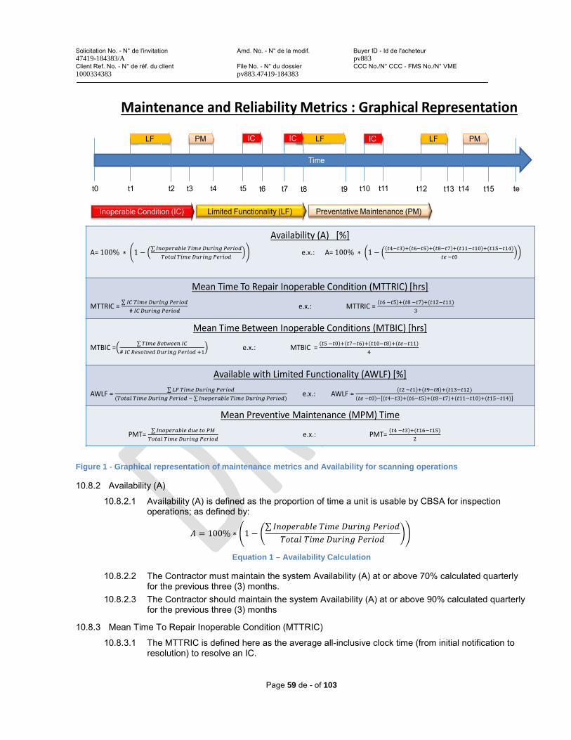
Solicitation No. - N° de l'invitation Amd. No. - N° de la modif. Buyer ID - Id de l'acheteur47419-184383/A pv883Client Ref. No. - N° de réf. du client File No. - N° du dossier CCC No./N° CCC - FMS No./N° VME1000334383 pv883.47419-184383
Page 59 de - of 103
Figure 1 - Graphical representation of maintenance metrics and Availability for scanning operations
10.8.2 Availability (A)
10.8.2.1 Availability (A) is defined as the proportion of time a unit is usable by CBSA for inspection operations; as defined by: = 100% 1
Equation 1 – Availability Calculation
10.8.2.2 The Contractor must maintain the system Availability (A) at or above 70% calculated quarterly for the previous three (3) months.
10.8.2.3 The Contractor should maintain the system Availability (A) at or above 90% calculated quarterly for the previous three (3) months
10.8.3 Mean Time To Repair Inoperable Condition (MTTRIC)
10.8.3.1 The MTTRIC is defined here as the average all-inclusive clock time (from initial notification to resolution) to resolve an IC.
Maintenance and Reliability Metrics : Graphical Representation
Time
PM
t0 te
ICLF LF IC LF PM
t2t1 t3 t4 t5 t6 t7 t8 t9 t10 t11 t12 t13 t14 t15
Availability (A) [%]
A= 100% 1 e.x.: A= 100% 1 ( ) Mean Time To Repair Inoperable Condition (MTTRIC) [hrs]
MTTRIC = # e.x.: MTTRIC = ( )Mean Time Between Inoperable Conditions (MTBIC) [hrs]
MTBIC = # e.x.: MTBIC = Available with Limited Functionality (AWLF) [%]
AWLF = ( ) e.x.: AWLF = ( ) ( )Mean Preventive Maintenance (MPM) Time
PMT= e.x.: PMT= ( )
IC
Limited Functionality (LF)Inoperable Condition (IC) Preventative Maintenance (PM)
Solicitation No. - N° de l'invitation Amd. No. - N° de la modif. Buyer ID - Id de l'acheteur47419-184383/A pv883Client Ref. No. - N° de réf. du client File No. - N° du dossier CCC No./N° CCC - FMS No./N° VME1000334383 pv883.47419-184383
Page 60 de - of 103
= # Equation 2 – Mean Time to Repair Inoperable Conditions (MTTRIC) Calculation
10.8.3.2 The Contractor must maintain MTTRIC at or below one hundred and sixty-eight (168) hours or seven (7) calendar days calculated quarterly for the previous six (6) months.
10.8.3.3 The Contractor should maintain MTTRIC at or below seventy two (72) hours or three (3) calendar days calculated quarterly for the previous six (6) months
10.8.4 Mean Time Between Inoperable Conditions (MTBIC)
10.8.4.1 The MTBIC is the average all-inclusive clock time between Inoperable Conditions, as defined by: = # + 1
Equation 3 – Mean Time Between Inoperable Conditions (MTBIC) Calculation
10.8.4.2 The Contractor must maintain MTBIC at or above seven hundred and twenty (720) hours or thirty (30) calendar days calculated quarterly for the previous six (6) months.
10.8.4.3 The Contractor should maintain MTBIC at or above seven hundred and twenty (1200) hours or thirty (50) calendar days calculated quarterly for the previous six (6) months
10.8.5 Availability With Limited Functionality (AWLF)
10.8.5.1 Availability With Limited Functionality (AWLF) is defined as the proportion of time a unit is usable by CBSA for inspection operations with outstanding issues limiting the unit’s functionality; as defined by:= ( )
Equation 4 – Availability With Limited Functionality (AWLF)
10.8.5.2 The Contractor must maintain AWLF at or below 50%, calculated quarterly for the previous six (6) months.
10.8.5.3 The Contractor must maintain AWLF at or below 10%, calculated quarterly for the previous six (6) months.
10.8.6 Preventive Maintenance
The Preventative Maintenance required to should not exceed 3.0% of the time for a given period, or two hundred sixty (260) hours, calculated for previous six (6) months unless otherwise approved by CBSA in writing.
10.8.7 Maintenance Data Reconciliation
The Contractor must reconcile with the CBSA Help Desk all Maintenance Performance and Reliability data on a bi-weekly basis (unless otherwise agreed upon with the Technical Authority or designated representative).
10.9 Maintenance Reporting
10.9.1 The Contractor must electronically submit a quarterly Maintenance Report including all Maintenance and Reliability Performance Metrics detailed in Section 10.8 along with CBSA reconciled data, to the Technical Authority or designated representative, no later than:
- July 15th for Q1 (April 1 – June 30)- October 15th for Q2 (July 1 – September 30)
Solicitation No. - N° de l'invitation Amd. No. - N° de la modif. Buyer ID - Id de l'acheteur47419-184383/A pv883Client Ref. No. - N° de réf. du client File No. - N° du dossier CCC No./N° CCC - FMS No./N° VME1000334383 pv883.47419-184383
Page 61 de - of 103
- January 15th for Q3 (October 1 – December 31)- April 15th for Q4 (January 1 – March 31)
10.9.2 If the CBSA Technical Authority or designated representative does not agree with the Maintenance Report, the Contractor will be required to correct and resubmit the Maintenance Report to the Technical Authority within 7 working days of being notified of the discrepancies.
10.9.3 The report must be accepted by the Technical Authority or a delegated representative prior to Quarterly Payment Calculation described in ANNEX C – Basis of Payment, 2.2 b) and the submission of the invoice.
10.10 Administrative Requirements
10.10.1 Site-Visit Notification
10.10.1.1 The Contractor must perform Preventive Maintenance on CBSA's preferred dates during Normal Working Hours. However, the Contractor will be allowed to reschedule Preventive Maintenance dates as necessary should an emergency call closely coincide with a forthcoming Preventive Maintenance visit.
10.10.1.2 The Contractor must coordinate and provide a notice of at least seventy-two (72) hours to the local contact prior to arriving for any preventative maintenance site visit.
10.10.1.3 When the Contractor is required to make travel arrangements to perform on-site Corrective Maintenance, the Contractor must contact the site and inform the Trouble Reporter of his/her impending visit.
10.10.2 CBSA Approval of Configuration Changes
The Contractor must obtain written approval from the CBSA Technical Authority or designated representative prior to implementing any major change(s) to MF-MLSI System hardware or software configuration.
10.10.3 Logistics
10.10.3.1 The Contractor must provide all logistic services required to maintain the equipment including, but not limited to:
10.10.3.1.1 Shipping spare/replacement parts as well as tools or calibration apparatus.10.10.3.1.2 Stocking defined critical spares in Canada. 10.10.3.1.3 Relocating/driving the equipment to offsite maintenance location for corrective or
preventive maintenance.10.10.3.2 The Contractor must maintain an inventory of critical parts in Canada.10.10.3.3 Mission-critical spare parts (whose failure would render the unit inoperable or with limited
operability) must be shipped and received at the required location within forty eight (48) hours after the need is identified.
10.10.3.4 Non-critical spare parts must be received within one hundred sixty eight (168) hours after the need is identified.
10.10.4 Replacement Parts List
The Contractor must provide a detailed list of all mission critical replacement parts as well as non-criticalparts at the time of Contract award, which must include part/model numbers, original equipment manufacturers, pricing and availability.
10.10.5 Issue Ticket Tracking
The Contractor's Help Desk must manage the Warranty including Maintenance and Support Services by means of help desk software, such as an issue tracking system that allows it to track Maintenance Service Request (Trouble Report requests), by use of a unique ticket number.
Solicitation No. - N° de l'invitation Amd. No. - N° de la modif. Buyer ID - Id de l'acheteur47419-184383/A pv883Client Ref. No. - N° de réf. du client File No. - N° du dossier CCC No./N° CCC - FMS No./N° VME1000334383 pv883.47419-184383
Page 62 de - of 103
10.10.6 Problem Ticket Information - Online access
The Contractor must provide CBSA designated maintenance personnel with online access to the most updated problem ticket status information.
10.10.7 Reporting
The Contractor must provide monthly and quarterly Warranty including Maintenance Support Services reports for each MF-MLSI System, detailing:
10.10.7.1 Operational availability. 10.10.7.2 Failure part analysis10.10.7.3 Corrective Maintenance time 10.10.7.4 Preventative Maintenance time 10.10.7.5 Non accountable downtime
10.10.8 MF-MLSI Systems Maintenance Manual(s)
10.10.8.1 The Contractor must provide all manuals necessary for the maintenance of the MF-MLSIequipment and supporting systems.
10.10.8.2 The MF-MLSI Systems Maintenance Manual(s) must include, at a minimum, sufficient information to conduct Level 1 and Level 2 Maintenance.
10.10.9 Error Log Codes and Descriptions
The Contractor must provide a complete, detailed list and description of all error codes and descriptions for the MF-MLSI System.
10.10.10 Fault Tree Diagrams
The Contractor must provide all complete fault tree diagrams of all warnings, errors failure notifications, etc. that may present themselves at any time while using the system.
10.11 Other
10.11.1 Software and Firmware Updates
10.11.1.1 The Contractor must provide all software and firmware updates necessary to maintain the advertised performance and security capabilities at or above the level of the initial contract.
10.11.1.2 The Contractor must provide all software and firmware updates for a period of no less than ten (10) years following initial acceptance, or for the duration of time the unit is under maintenance service agreement (if longer).
10.11.2 System Software
The Contractor must provide all individual software packages (including proprietary and Programmable Logic Control software) to the CBSA Technical Authority or designated representative with License numbers for installation or re-installation on system hardware.
10.11.3 Boot Image Ghosted Configuration
The Contractor must provide a bootable image disk of all final system configurations for rebuilding computer and server hard drives.
10.12 MF-MLSI Calibration Test Pieces, System Parts and Special Tools
10.12.1 The Contractor must provide all calibration test pieces necessary to adjust inspection system parameters and confirm performance levels.
10.12.1.1 All test pieces must be re-positioned and/or aligned with a standard fork-lift.10.12.1.2 All test pieces must permit angular adjustment to align with the incident radiographic beam.
Solicitation No. - N° de l'invitation Amd. No. - N° de la modif. Buyer ID - Id de l'acheteur47419-184383/A pv883Client Ref. No. - N° de réf. du client File No. - N° du dossier CCC No./N° CCC - FMS No./N° VME1000334383 pv883.47419-184383
Page 63 de - of 103
10.12.2 The Contractor must supply all system parts, calibration fixtures, software and consumables required during the Warranty for Maintenance and Support Services.
10.12.3 The Contractor must provide any special tools necessary for maintenance of the MF-MLSI System equipment, which must be marked to identify the equipment or system for which they are intended.
10.12.4 All system replacement parts used must be new and equivalent to, or better, than the original.
10.13 Intent to Decommission MF-MLSI System
10.13.1 If the MF-MLSI system is deemed no longer operationally or cost effective to maintain, Canada may terminate the maintenance and support services for the system by giving 60 calendar days notice of an intent to decommission in writing. If 60 calendar days notice is not given, Canada agrees to pay the Contractor the lesser of:
10.13.1.1 The balance of the annual payment amount for the maintenance and support services for thereferenced unit;
10.13.1.2 The annual payment amount for the maintenance and support services for the referenced unit, pro-rated for 60 calendar days, or.
10.13.1.3 Annual payment for the decommissioned unit divided by 365 x 60.
10.13.2 The Contractor will provide credited equivalent time for planned Preventative Maintenance activities (as outlined in Annex A, section 3.1) not rendered following a notice to decommission.
Solicitation No. - N° de l'invitation Amd. No. - N° de la modif. Buyer ID - Id de l'acheteur47419-184383/A pv883Client Ref. No. - N° de réf. du client File No. - N° du dossier CCC No./N° CCC - FMS No./N° VME1000334383 pv883.47419-184383
Page 64 de - of 103
ANNEX B TECHNICAL SERVICES
1.0 Unplanned Activities – As and When Requested
The Contractor must provide maintenance and support services on an “as and when requested” basis via Task Authorization, for requirements outside of the scope of those defined in Section 10: Maintenance and Support Services Requirements. This includes but is not limited to repairs, bodywork, replacement of components, decommissioning etc.
1.1 Step 1 – Determination of Cause
1.1.1 If Corrective Maintenance is required as a result of an event subject to an exclusion from maintenance services, the Contractor must submit all documentation supporting the Determination of Cause for review and approval to the CBSA’s Technical Authority.
1.1.2 The Contractor must provide any additional supporting information requested by the CBSA’s Technical Authority necessary to substantiate the Determination of Cause.
1.1.3 The Contractor must make available, upon request, an Expert Reach back Contact to address questions about the Determination of Cause.
1.2 Step 2 – Unplanned Work Definition
1.2.1 The Contractor must submit a completed Unplanned Work Definition form (outlined as ANNEX D) in accordance with the Basis of Payment (ANNEX C) and the Price List specified in the Contract, to the CBSA’s Technical Authority within:
1.2.1.1 7 calendar days for of receipt of a written request for minor corrective work.1.2.1.2 21 calendar days of receipt of a written request for major corrective work.
1.2.2 Upon written request for, and approval by the CBSA’s Technical Authority, the Contractor may be granted an additional 15 calendar days to provide detailed costing for external labour and custom built parts only.
1.2.3 The Contractor must provide all quotes in accordance with the defined Materials Price List (to be provided by the Contractor upon award of the Contract) for parts and the Basis of Payment (as outlined in ANNEX C) for labour. Specific considerations are permitted as follows:
1.2.3.1 If parts are no longer available, the Contractor must provide costing for a suitable replacement at comparable costs.
1.2.3.2 The applicable warranties associated with replacement parts is the longer of 90 days or the duration of the original manufacturer’s standard warranty (to be provided with eachreplacement part), beginning from the accepted completion of the entire authorized work package.
1.2.4 If any part is not on the Material Price List, price for that part must be provided at the time of quotation, along with requested price justification that must include one or more of the following:
1.2.4.1 a current published price list indicating the percentage discount available to Canada; 1.2.4.2 a copy of paid invoices for the like quality and quantity of the goods, services or both sold to
other customers; 1.2.4.3 a price breakdown showing the cost of direct labour, direct materials, purchased items,
engineering overheads, general and administrative overhead, transportation, etc., and profit; 1.2.4.4 price or rate certifications; 1.2.4.5 any other supporting documentation as requested by Canada.
Solicitation No. - N° de l'invitation Amd. No. - N° de la modif. Buyer ID - Id de l'acheteur47419-184383/A pv883Client Ref. No. - N° de réf. du client File No. - N° du dossier CCC No./N° CCC - FMS No./N° VME1000334383 pv883.47419-184383
Page 65 de - of 103
1.2.5 The Contractor must present any options for rendering the unit operational in advance of the complete repairs (without compromising health and safety or impacting operational processes).
1.3 Step 3 – Completion of Maintenance and Support Services
1.3.1 The Contractor (or the dispatched Technician) must coordinate with the local CBSA representative, regarding the expected timeline and any access or resource requirements.
1.3.2 The Contractor must provide confirmation when parts have been ordered and delivery tracking details via the cargo portal.
1.3.3 The Contractor must initiate repairs as specified in the individual call-ups.
1.3.4 The Contractor must advise the CBSA’s Technical Authority upon becoming aware of any potential changes to the maintenance and support services schedule for joint review on mitigating operational impacts.
1.3.5 The Contractor must also advise the CBSA’s Technical Authority upon becoming aware of any potential variations to the estimated cost of authorized work, for joint review on mitigating financial impacts.
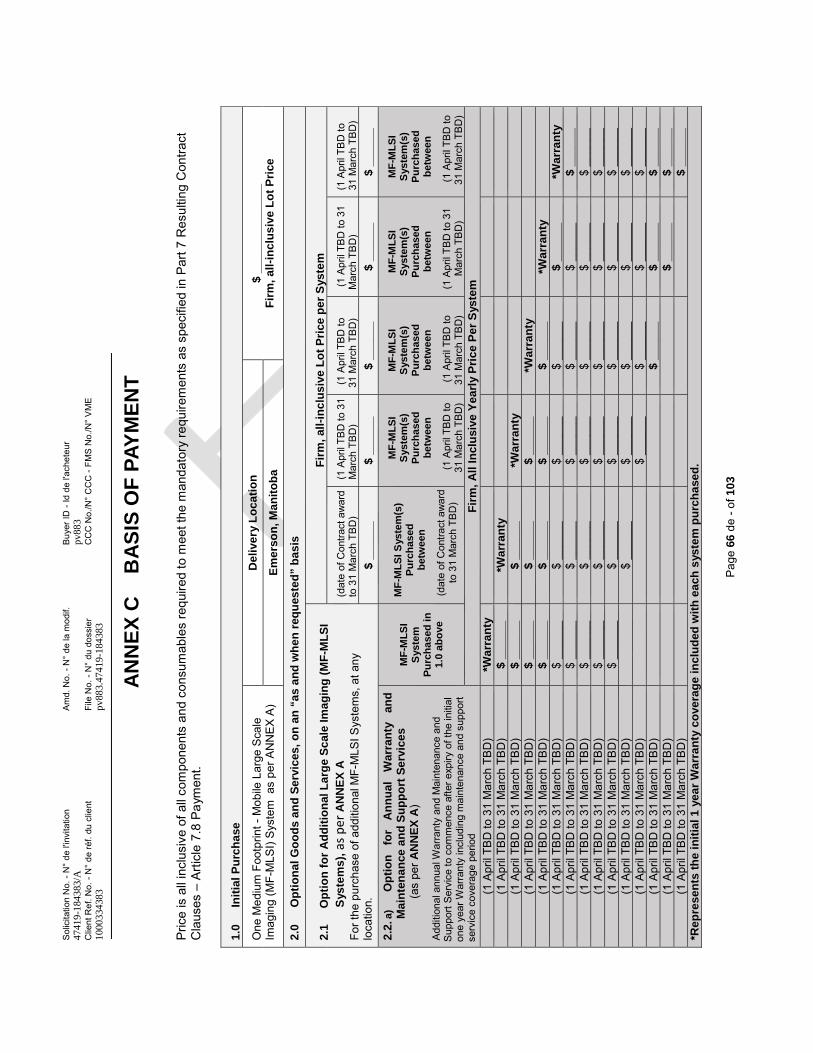
Sol
icita
tion
No.
-N
° de
l'in
vita
tion
Am
d. N
o. -
N°
de la
mod
if.B
uyer
ID -
Id d
e l'a
chet
eur
4741
9-18
4383
/Apv
883
Clie
nt R
ef. N
o. -
N°
de ré
f. du
clie
ntFi
le N
o. -
N°
du d
ossi
erC
CC
No.
/N°
CC
C -
FMS
No.
/N°
VM
E10
0033
4383
pv88
3.47
419-
1843
83
Pag
e 66
de-o
f 10
3
AN
NE
X C
B
AS
IS O
F P
AY
ME
NT
Pric
e is
all
incl
usiv
e of
all
com
pone
nts
and
cons
umab
les
requ
ired
to m
eet t
he m
anda
tory
requ
irem
ents
as
spec
ified
in P
art 7
Res
ultin
g C
ontra
ct
Cla
uses
–Ar
ticle
7.8
Pay
men
t.
1.0
Init
ial
Pu
rch
ase
One
Med
ium
Foo
tprin
t -M
obile
Lar
ge S
cale
Im
agin
g (M
F-M
LSI)
Sys
tem
as
per A
NN
EX
A)
De
live
ry L
oc
ati
on
$ _
___
__
___
___
__
F
irm
, al
l-in
clu
siv
e L
ot
Pri
ceE
me
rso
n, M
an
ito
ba
2.0
Op
tio
na
l G
oo
ds
an
d S
erv
ices
, o
n a
n “
as
an
d w
he
n r
equ
este
d”
ba
sis
2.1
Op
tio
n f
or
Ad
dit
ion
al L
arg
e S
cal
e Im
ag
ing
(M
F-M
LS
IS
yste
ms
), a
s pe
r AN
NE
X A
Fo
rthe
pur
chas
e of
add
ition
al M
F-M
LSIS
yste
ms,
at a
ny
loca
tion.
Fir
m,
all-
incl
us
ive
Lo
t P
rice
per
Sys
tem
(dat
e of
Con
tract
aw
ard
to 3
1 M
arch
TBD
)(1
Apr
il TB
Dto
31
Mar
ch T
BD
)(1
Apr
il TB
D to
31
Mar
ch T
BD
)(1
Apr
il TB
D to
31
Mar
ch T
BD
)(1
Apr
il TB
D to
31
Mar
ch T
BD
)$
__
___
_$
__
___
_$
__
___
_$
__
___
_$
__
___
_
2.2
.a)
O
pti
on
fo
r A
nn
ua
lW
arr
an
ty
an
d
Ma
inte
na
nce
an
d S
up
po
rt S
erv
ice
s
(as
per A
NN
EX
A)
Add
ition
al a
nnua
lWar
rant
y an
d M
aint
enan
ce a
ndS
uppo
rt S
ervi
ce to
com
men
ce a
fter e
xpiry
of t
he in
itial
on
eye
arW
arra
nty
incl
udin
g m
aint
enan
ce a
nd s
uppo
rt se
rvic
e co
vera
gepe
riod
MF
-ML
SI
Sys
tem
P
urc
has
ed i
n
1.0
abo
ve
MF
-ML
SIS
yste
m(s
) P
urc
has
ed
bet
wee
n
(dat
e of
Con
tract
aw
ard
to 3
1 M
arch
TB
D)
MF
-ML
SI
Sys
tem
(s)
Pu
rch
ased
b
etw
een
(1 A
pril
TBD
to
31 M
arch
TB
D)
MF
-ML
SI
Sys
tem
(s)
Pu
rch
ased
b
etw
een
(1 A
pril
TBD
to
31 M
arch
TB
D)
MF
-ML
SI
Sys
tem
(s)
Pu
rch
ased
b
etw
een
(1 A
pril
TBD
to 3
1 M
arch
TB
D)
MF
-ML
SI
Sys
tem
(s)
Pu
rch
ased
b
etw
een
(1 A
pril
TBD
to
31 M
arch
TB
D)
Fir
m,
All
In
clu
sive
Ye
arl
y P
ric
eP
er
Sys
tem
(1 A
pril
TBD
to 3
1 M
arch
TB
D)
*Wa
rra
nty
(1 A
pril
TBD
to 3
1 M
arch
TB
D)
$ _
___
__
*Wa
rra
nty
(1 A
pril
TBD
to 3
1 M
arch
TB
D)
$ _
___
__
$ _
___
__
*Wa
rra
nty
(1 A
pril
TBD
to 3
1 M
arch
TB
D)
$ _
___
__
$ _
___
__
$ _
___
__
*Wa
rra
nty
(1 A
pril
TBD
to 3
1 M
arch
TB
D)
$ _
___
__
$ _
___
__
$ _
___
__
$ _
___
__
*Wa
rra
nty
(1 A
pril
TBD
to 3
1 M
arch
TB
D)
$ __
____
$ __
____
$ __
____
$ __
____
$ _
___
__
*Wa
rra
nty
(1 A
pril
TBD
to 3
1 M
arch
TB
D)
$ __
____
$ __
____
$ __
____
$ __
____
$ __
____
$ _
___
__
(1 A
pril
TBD
to 3
1 M
arch
TB
D)
$ __
____
$ __
____
$ __
____
$ __
____
$ __
____
$ __
____
(1 A
pril
TBD
to 3
1 M
arch
TB
D)
$ __
____
$ __
____
$ __
____
$ __
____
$ __
____
$ __
____
(1 A
pril
TBD
to 3
1 M
arch
TB
D)
$ __
____
$ __
____
$ __
____
$ __
____
$ __
____
$ __
____
(1 A
pril
TBD
to 3
1 M
arch
TB
D)
$ __
____
$ __
____
$ __
____
$ __
____
$ __
____
(1 A
pril
TBD
to 3
1 M
arch
TB
D)
$ __
____
$ __
____
$ __
____
$ __
____
(1 A
pril
TBD
to 3
1 M
arch
TB
D)
$_
___
__
$ _
___
__
$ _
___
__
(1 A
pril
TBD
to 3
1 M
arch
TB
D)
$ _
___
__
$ _
___
__
(1 A
pril
TBD
to 3
1 M
arch
TB
D)
$ _
___
__
*Re
pre
se
nts
th
e i
nit
ial 1
yea
r W
arr
an
ty c
ove
rag
e i
nc
lud
ed w
ith
ea
ch s
yste
m p
urc
ha
sed
.
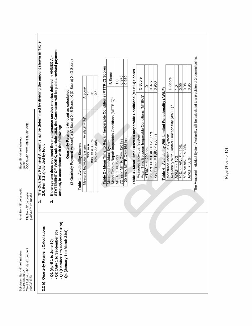
Sol
icita
tion
No.
-N
° de
l'in
vita
tion
Am
d. N
o. -
N°
de la
mod
if.B
uyer
ID -
Id d
e l'a
chet
eur
4741
9-18
4383
/Apv
883
Clie
nt R
ef. N
o. -
N°
de ré
f. du
clie
ntFi
le N
o. -
N°
du d
ossi
erC
CC
No.
/N°
CC
C -
FMS
No.
/N°
VM
E10
0033
4383
pv88
3.47
419-
1843
83
Pag
e 67
de-o
f 10
3
2.2
b)
Qu
art
erl
y P
aym
en
t C
alc
ula
tio
ns
-Q
1 (
Ap
ril
1 t
o J
un
e 3
0)
-
Q2
(J
uly
1 t
o S
ep
tem
be
r 3
0)
-
Q3
(O
cto
be
r 1
to
Dec
em
be
r 3
1s
t)
-Q
4 (
Jan
ua
ry 1
to
Ma
rch
31
st)
1.
Th
e Q
ua
rte
rly
Pa
yme
nt
Am
ou
nt
sh
all
be
de
term
ine
d b
y d
ivid
ing
th
e a
mo
un
t s
ho
wn
in
Ta
ble
2.0
, it
em
2.2
a)
div
ide
d b
y fo
ur.
2.
If t
he
sys
tem
do
es
no
t m
ee
t th
e m
ain
ten
anc
e s
erv
ice
met
ric
s d
efi
ne
d in
AN
NE
X A
–S
TA
TE
ME
NT
OF
WO
RK
, su
b-a
rtic
le 1
0.8
, th
e C
on
tra
cto
r w
ill
be
pai
d a
rev
ised
pa
yme
nt
am
ou
nt,
in a
cc
ord
an
ce
wit
h t
he
fo
llo
win
g:
Qu
art
erl
y P
aym
en
t A
mo
un
t a
s c
alc
ula
ted
=($
Qua
rterly
Pay
men
t Am
ount
) x (A
Sco
re) X
(B S
core
) X (C
Sco
re) X
(D S
core
)
Ta
ble
1-
Ava
ila
bil
ity
Sc
ore
s
T
ab
le 2
-M
ean
Tim
e t
o R
ep
air
Ino
pe
rab
le C
on
dit
ion
s (M
TT
RIC
) S
co
res
Mea
sure
dIn
divi
dual
Sys
tem
Mea
n Ti
me
to R
epai
r Ino
pera
ble
Con
ditio
ns (M
TTR
IC)*
B S
core
MTT
RIC
<=
72 h
rs
1.0
72 h
rs <
MTT
RIC
<=
120
hrs
0.97
512
0 hr
s <
MTT
RIC
<=1
68 h
rs0.
950
T
ab
le 3
-M
ean
Tim
e B
etw
ee
n In
op
era
ble
Co
nd
itio
ns
(MT
BIC
) S
co
res
Mea
sure
dIn
divi
dual
Sys
tem
Mea
n Ti
me
Bet
wee
n In
oper
able
Con
ditio
ns (M
TBIC
)*C
Sco
re
MTB
IC =
>12
00 h
rs
1.0
960
hrs
<= M
TBIC
< 1
200
hrs
0.97
572
0 hr
s <=
MTB
IC <
960
hrs
0.95
0
T
ab
le 4
-A
vail
ab
ilit
y W
ith
Lim
ite
d F
un
ctio
na
lity
(A
WL
F)
Mea
sure
dIn
divi
dual
Sys
tem
Ava
ilabi
lity
With
Lim
ited
Func
tiona
lity
(AW
LF) *
D S
core
AWLF
<=
10%
1.0
30%
<=
AWLF
< 1
0%0.
9950
% <
= AW
LF <
30%
0.98
AWLF
< 5
0%
0.95
*The
Mea
sure
d In
divi
dual
Sys
tem
Ava
ilabi
lity
will
be c
alcu
late
d to
a p
reci
sion
of 2
dec
imal
poi
nts.
Mea
sure
d In
divi
dual
Sys
tem
Ava
ilabi
lity
(A)*
A S
core
90%
<=
A1.
080
% <
= A
< 90
%0.
970
% <
= A
< 80
%0.
8
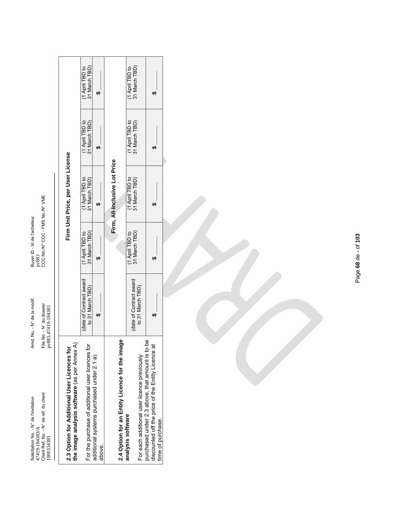
Sol
icita
tion
No.
-N
° de
l'in
vita
tion
Am
d. N
o. -
N°
de la
mod
if.B
uyer
ID -
Id d
e l'a
chet
eur
4741
9-18
4383
/Apv
883
Clie
nt R
ef. N
o. -
N°
de ré
f. du
clie
ntFi
le N
o. -
N°
du d
ossi
erC
CC
No.
/N°
CC
C -
FMS
No.
/N°
VM
E10
0033
4383
pv88
3.47
419-
1843
83
Pag
e 68
de-o
f 10
3
2.3
Op
tio
n f
or
Ad
dit
ion
al
Use
r L
ice
nc
es
fo
r th
e i
mag
e a
na
lys
is s
oft
wa
re (a
s pe
r Ann
ex A
)
For t
he p
urch
ase
of a
dditi
onal
use
r lic
ence
s fo
r ad
ditio
nal s
yste
ms
purc
hase
d un
der 2
.1 a
) ab
ove.
Fir
m U
nit
Pri
ce,
per
Use
rL
ice
nse
(dat
e of
Con
tract
aw
ard
to
31
Mar
ch T
BD
)(1
Apr
il TB
D to
31 M
arch
TB
D)
(1 A
pril
TBD
to
31 M
arch
TB
D)
(1 A
pril
TBD
to
31 M
arch
TB
D)
(1 A
pril
TBD
to31
Mar
ch T
BD
)
$ _
___
__
$ _
___
__
$ _
___
__
$ _
___
__
$_
___
__
2.4
Op
tio
n f
or
an
En
tity
Lic
en
ce
fo
r th
e i
mag
e
an
aly
sis
so
ftw
are
For e
ach
addi
tiona
l use
r lic
ence
pre
viou
sly
purc
hase
d un
der 2
.3 a
bove
, tha
t am
ount
is to
be
disc
ount
ed o
ff th
e pr
ice
of th
e E
ntity
Lic
ence
at
time
of p
urch
ase.
Fir
m,
All
-In
clu
sive
Lo
t P
rice
(dat
e of
Con
tract
aw
ard
to
31
Mar
ch T
BD
)
(1 A
pril
TBD
to31
Mar
ch T
BD
)(1
Apr
il TB
D to
31
Mar
ch T
BD
)(1
Apr
il TB
D to
31
Mar
ch T
BD
)(1
Apr
il TB
D to
31 M
arch
TB
D)
$ _
___
__
$ _
___
__
$ _
___
__
$ _
___
__
$ _
___
__
Solicitation No. - N° de l'invitation Amd. No. - N° de la modif. Buyer ID - Id de l'acheteur47419-184383/A pv883Client Ref. No. - N° de réf. du client File No. - N° du dossier CCC No./N° CCC - FMS No./N° VME1000334383 pv883.47419-184383
Page 108 of - de 108
ANNEX D UNPLANNED WORK DEFINITION
Scope and Nature of work
[Provide brief summary of the scope of work necessary to return the unit to an agreed upon condition. - List any specific exclusions from work
Type of work: [select all that apply]
Preventative (ad-hoc)
Corrective repairs
Quality
[Provide the following information pertaining to the work to be completed]:
- List the principal tasks to be complete the work (including additional diagnostic visits) - List expected parts to be replaced - List sub-contractors to be engaged and the work to be completed thereby - List any Expert Reach back required (i.e., other than local Technicians) - List where the repairs will be completed - List the verification standards/tests that will be used to confirm the work has been completed - Identify any requirements for facilitation by the CBSA
Schedule
Minor Corrective: Parts are in-stock or readily available for shipping, expertise is readily available and can be mobilised to undertake repairs promptly, and the repairs can be completed during a single visit.
[Provide a planned start and end dates for work completion]
Major Corrective: Parts have long lead times and/or expertise is not available and/or corrective repairs require specialized facility and/or significant diagnostic work is required to define scope.
[For any work provide a Gant chart schedule of tasks and milestones]
Risks
The Contractor must identify tasks that shall incur a high risk of delay
The Contractor must identify any requirements for facilitation by the CBSA to mitigate those risks
Costs
The Contractor must provide a price breakdown of the work to be undertaken in accordance with the pricing structure and costing outlined in ANNEX C and the Replacement Parts List (to be submitted by the Contractor at the time of Contract Award

Solicitation No. - N° de l'invitation Amd. No. - N° de la modif. Buyer ID - Id de l'acheteur47419-184383/A pv883Client Ref. No. - N° de réf. du client File No. - N° du dossier CCC No./N° CCC - FMS No./N° VME1000334383 pv883.47419-184383
Page 108 of - de 108
ATTACHMENT 1 TO PART 4 OF THE BID SOLICITATION - Technical Bid Submission Document
All requested information should be presented in the respective sections of this Attachment, or referenced and appended thereto.
Large data files do not need to be printed for inclusion in the hard copy; however, they must be provided with the soft copy and accessible without the need for specialized software. All appended figures, tables, and supporting data should be referenced where indicated in this Attachment.
In Section A of this attachment Bidders should clearly detail how the proposed MF-MLSI System meets each of the directly referenced requirements of Annex A. The information will be used to evaluate compliance with the referenced mandatory technical requirements.
In Section B of this attachment Bidders should demonstrate a technical and organizational capacity to deliver a compliant system that meets the requirements of the bid solicitation.
Regardless of the content of the information provided in Section B, if the Bidder is awarded a Contract, work must be done in accordance with Annex A.
SECTION A - MANDATORY BID SUBMISSION REQUIREMENTS
M.1 Customer References
REFERENCE: ANNEX A Section 5.1 Proven Design and Section 10.1 Maintenance Service Experience
i) Customer References Contact Information
The Bidder must provide 2 customer references who must complete the questionnaire found in Attachment 5 to Part 4. The completed questionnaire must be included with the Bid. The 2 customer references provided on Attachment 5 must be the same 2 customer references identified below and must be clients using similar Proven Design. The customer reference must each confirm, that the Bidder hasprovided maintenance and support services at the level of service detailed in Section 10 of Annex A Statement of Work.
For each customer reference, the Bidder must provide all of the following information:
Reference 1:Company Name: …………..….……………………………………………………………………………………...Name of Representative: …………..….…………………………………Title ……….…………………………Phone: ……………..….…………………… Email: ……………..……………..……………………………Address:……………..….………………………………………………………………..………………………………....…….…………………………………………………………………………………………..………………………Model(s) Purchased: ………………………………………………... …Number of Units ………………………
………………………………………………….. Number of Units ………………………Deployment Date: …………………………………………………………………………………….…………Deployment Location: .…………………………………………………………………………..………………Current Location: …………………………………………………………………………………………...............X-ray Source(s): ……………..….……………………………………………………………………………
X-ray Detector Type(s) and Configuration(s): ………………………………………………………………
Solicitation No. - N° de l'invitation Amd. No. - N° de la modif. Buyer ID - Id de l'acheteur47419-184383/A pv883Client Ref. No. - N° de réf. du client File No. - N° du dossier CCC No./N° CCC - FMS No./N° VME1000334383 pv883.47419-184383
Page 108 of - de 108
…..….………………………………………………..…..….……………………………………………………
Reference 2:Company Name: ……………..….……………………………………………………………………………..…...Name of the Representative: ……………………………………………Title …………………………………Phone: …………………………………………Email: ……………………..….………………………………Address: …………..………..….…………………………………………………………………………………….....…….……………………………………………………………………………………………………………………....Model(s) Purchased: ………………………………………………..…. Number of Units ………………
…………………………………………….……. Number of Units ………………Deployment Date: …………………………………………………………………………………………………...Deployment Location:.………………………………………………………………………………………………...Current Location: …….……………………………………………………………………….……………………...X-ray Source(s): ……………..….………………………………………………….…………………………………X-ray Detector Type(s) and Configuration(s): …………………………………………….…………………………..….………………………………………………..…..….……………………………………………………….Additional details appended as: ……………………………...…………………………………
ii) The questions for customer references are found in Attachment 5 to Part 4 – Customer Reference Questionnaire. Bidders must provide the completed customer reference questionnaire with their bids. It is the sole responsibility of the Bidder to ensure that it provides customer references that are knowledgeable about the services the Bidder has provided to its customer and who is willing to act as a customer reference. Crown references will not be accepted.
M.2 Proven Design
REFERENCE: ANNEX A Section 5.1 Proven Design
The Bidder must detail the following information from the two systems deployed considered as the Proven Design MF-MLSI System.
Address #1: ………………………………………………………………………………………………..…………………………………………………………………………………………………………………………………Model Number: ………………………………………………Number of Units Deployed: ……………………Model Number: ………………………………………………Number of Units Deployed: ……………………Date of first delivery: …………..……………………………………………………………...X-ray source: ………………………………………………X-ray emission energy/ energies: ……………………X-ray detector type(s): …………………………………………………………………..…………………………X-ray detector configuration: ………………………..………………………………………………………………Radiation shielding configuration: ……………………………………………………………………….…………Vehicle make/model: ……………………………………………………………………………….………………Vehicle chassis: ………………………………………………………………………………………………Differences from proposed system:……………………………………………………………………….………………………………………………………………………………………………………………….……………………………………………………………………………………………………………………………..…
Address #2 (if applicable) ……………………………………………………………………………………………………………………………………………………………………………………………………………………Model Number: …………………………………………….Number of Units Deployed: ……………………Date of first delivery: …………..……………………………………………………………………..……………...X-ray source: ………………………………………………X-ray emission energy / energies: …………….X-ray detector type(s): …………………………………………………………………..…………………………
Solicitation No. - N° de l'invitation Amd. No. - N° de la modif. Buyer ID - Id de l'acheteur47419-184383/A pv883Client Ref. No. - N° de réf. du client File No. - N° du dossier CCC No./N° CCC - FMS No./N° VME1000334383 pv883.47419-184383
Page 108 of - de 108
X-ray detector configuration: ………………………..………………………………………………………………Radiation shielding configuration: …………………………………………………………………..………………Vehicle make/model:…………………………………………………………………………….……………………Vehicle chassis:………………………………………………………………………………………..………………Differences from proposed system:……………………………………………………………………….………………………………………………………………………………………………………………………….…………Additional details appended as: ……………………………...…………………………………
The Bidder must provide the following information for each of the Proven Design MF-MLSI Systemreferenced above:
M.2.1 Photographic image(s) of the unit in inspection mode
M.2.2 Photographic image(s) of the unit in road mode
M.2.3 Sample radiographic image(s)Additional details appended as: ……………………………...…………………………………
M.3 Certification of Class II Prescribed Equipment
REFERENCE: ANNEX A Section 7.4 Certification of Class II Prescribed Equipment
The Bidder must provide one of the following:
M.3.1 A completed draft of the Canadian Nuclear Safety Commission (CNSC) - Application for Certification of Radiation Devices or Class II Prescribed Equipment http://nuclearsafety.gc.ca/eng/pdfs/Published-RD-GD/RDGD-254-Certification-of-Radiation-Devices-or-Class-II-Prescribed-Equipment-Form_e.pdf; or
M.3.2 A copy of the CNSC Certification of Radiation Devices for the MF-MLSI Source Appended as: …………………………………………………………………………………………
M.4 Radiation Safety Zone
REFERENCE: ANNEX A Section 7.5 Radiation Safety Zone (RSZ)
The Bidder must provide a radiological survey or Monte Carlo simulation of the projected dose rates in SI units (e.g., μSv/h); inside and around the MF-MLSI System during scanning of a standard commercial road conveyance. This information must include all of the following:
M.4.1 a top view scaled drawing of the proposed MF-MLSI System, outlining the projected contour lines for peak instantaneous dose rates at: 5 μSv/h, 10 μSv/h and 25 μSv/h.
M.4.2 a side view (from rear) scaled drawing of the proposed MF-MLSI System showing the source emission beam projecting onto the boom arm and the projected contour lines for instantaneous dose rates at: 5 μSv/h, 10 μSv/h and 25 μSv/h.
M.4.3 The projected dose rates in the MF-MLSI System Driver’s and Operator’s Cabins
Details appended as: …………………………………………………………………………………………
M.5 Operational Functionality
M.5.1 REFERENCE: ANNEX A Section 3.6 Imaging Speeds
Solicitation No. - N° de l'invitation Amd. No. - N° de la modif. Buyer ID - Id de l'acheteur47419-184383/A pv883Client Ref. No. - N° de réf. du client File No. - N° du dossier CCC No./N° CCC - FMS No./N° VME1000334383 pv883.47419-184383
Page 108 of - de 108
The Bidder must provide all of the following details pertaining to the configuration of imaging speeds:
Normal Speed [m/s]: ………………………………………………….……………………………………Other Speed(s) [m/s]: ………………………………………………….……………………………………
M.5.2 REFERENCE: ANNEX A Section 3.4 Push-Button Start/Shutdown
The Bidder must describe the sequence of Operator actions required to start-up and shut-down the MF-MLSI System:…………………………………………………………………….………………………………………………………………………………………………………….………………………………………………………………………………………………………….……………………………………
M.5.3 REFERENCE: ANNEX A Section 3.5 Start-Up Time
The Bidder must provide the time required to start-up the MF-MLSI System (seconds):Start-up (seconds)………………………………………………….……………………………………
Additional details appended as: ……………………………...…………………………………
M.6 Design Parameters
M.6.1 REFERENCE: ANNEX A Section 5.2 Inspection Drive
The Bidder must describe electronic drive used for locomotion during imaging: …………………………………………………………………….………………………………………………………………………………………………………….……………………………………
The Bidder must describe powertrain used for locomotion during road travel:…………………………………………………………………….………………………………………………………………………………………………………….……………………………………
The Bidder must describe the mechanism for drive conversion from road-inspection mode:…………………………………………………………………….………………………………………………………………………………………………………….……………………………………
M.6.2 REFERENCE: ANNEX A Section 5.6 Programmable Logic Controller (PLC) - Functionality
The Bidder must describe the feedback mechanism for sequencing principle operations (start-up, scanning and shut-down) controlled by the PLC. …………………………………………………………………….………………………………………………………………………………………………………….………………………………………………………………………………………………………….……………………………………
Additional details appended as: ……………………………...…………………………………
M.7 Vehicular Mobility
M.7.1 REFERENCE: ANNEX A Section 4.5 Total Mass Limit
The Bidder must provide information pertaining to the Total mass (not including driver).
Solicitation No. - N° de l'invitation Amd. No. - N° de la modif. Buyer ID - Id de l'acheteur47419-184383/A pv883Client Ref. No. - N° de réf. du client File No. - N° du dossier CCC No./N° CCC - FMS No./N° VME1000334383 pv883.47419-184383
Page 108 of - de 108
…………………………………………………………………….……………………………………
M.7.2 REFERENCE: ANNEX A Section 4.6 Axial Load Limits and Section 4.7 Weight Distribution
The Bidder must provide information pertaining to the Weight through each axle when configured for road travel (not including driver).
………………………………………………………………….……………………………………
M.7.3 REFERENCE: ANNEX A Section 4.8 Boom Support
The Bidder must provide information pertaining to the Boom support(s) when configured for road travel.………………………………………………………………….……………………………………
M.7.4 REFERENCE: ANNEX A Section 4.2 Driver’s License Requirements
The Bidder must provide information pertaining to the Canadian driving license requirements
…………………………………………………………………….………………………………………………………………………………………………………….……………………………………
Additional details appended as: ……………………………………………………………………
M.8 Imaging Performance Test Results
REFERENCE: ANNEX A Section 8.2 Penetration to Section 8.9 Wire Detection - Vertical
The Bidder must append a completed copy of the American National Standards Institute (ANSI N42.46)Determination of the Imaging Performance of X-Ray and Gamma-Ray Systems for Cargo and Vehicle Security Screening - Annex B (Cover page and Summary of results), measured from a Proven Design.
Appended as: …………………………………………………………………….……………………………
The Bidder must append .jpg (or .tiff) images of the x-ray images taken from the ANSI N42.46 tests for each of the image quality indicator metrics.
Appended as: …………………………………………………………………….……………………………
The Bidder must describe and substantiate with technical information, any system differences leading to differences between the imaging performance results demonstrated in the presented ANSI N42.46 test result and capabilities for the Proposed MF-MLSI system claimed in Attachment 2 to Part 4 of the Bid Solicitation.
Examples include but are not limited to: improved algorithms for image reconstruction, change in source output, and (or) improved detector efficiency.…………………………………………………………………….………………………………………….……………………………………………………………………………….……………………………………………….………………………………………………………………………….…………………………………………….…………………………………………………………………………….………………………………………………………………………………………………………………………….……………………………………………………
Additional details appended as: ……………………………………………………………………
M.9 Material Discrimination Test Results
Solicitation No. - N° de l'invitation Amd. No. - N° de la modif. Buyer ID - Id de l'acheteur47419-184383/A pv883Client Ref. No. - N° de réf. du client File No. - N° du dossier CCC No./N° CCC - FMS No./N° VME1000334383 pv883.47419-184383
Page 108 of - de 108
M.9.1 REFERENCE: ANNEX A Section 8.10 Material Discrimination – Very Low-Z (Organics)
The Bidder must provide the information below summarizing Material Discrimination Test results measured from a Proven Design.
Very Low-ZMaterial type and density (if other than Polyvinyl toluene): .………………………………Test Piece Size [L X W] (mm): ……….………………………………Minimum discernible thickness (mm): ……….………………………………Maximum discernible thickness (mm): ……….………………………………
Low-ZMaterial type and density (if other than Aluminum 6061): ……….………………………Test Piece Size [L X W] (mm): ……….………………………………Minimum discernible thickness (mm): ……….………………………………Maximum discernible thickness (mm): ……….………………………………
M.9.2 REFERENCE: ANNEX A Section 8.12 Material Discrimination – Intermediate-Z (Metals)
Intermediate-ZMaterial type and density (if other than Polyvinyl toluene): ……….………………………………Test Piece Size [L X W] (mm): ……….………………………………Minimum discernible thickness (mm): ……….………………………………Maximum discernible thickness (mm): ……….………………………………
The Bidder must describe in detail the technical basis for any discrepancy between the performance demonstrated in the presented Material Discrimination test result and the imaging performance capabilities claimed in …………………………………………………………………….………………………………………………………………………………………………………….………………………………………………………………………………………………………….………………………………………………………………………………………………………….……………………………………
M.10 Image Review on Universal Viewer
REFERENCE: ANNEX A Section 9.21 Image Review on Universal Viewer
The Bidder must describe any existing capabilities (if available) for analyzing complete image data on a Universal Viewer.………………………………………………………………………………………………………………………………………………………………………………………………………………………………………………………………………………………………………………………………………Appended as: …………………………………………………………………………………………
M.11 - Attachment 2 to Part 4 of the Bid Solicitation –
The Bidder must provide the completed Attachment 2 to Part 4 of the Bid Solicitation
SECTION B - MANDATORY INFORMATION FOR VALIDATION OF BID
M.12 Contact Information
Solicitation No. - N° de l'invitation Amd. No. - N° de la modif. Buyer ID - Id de l'acheteur47419-184383/A pv883Client Ref. No. - N° de réf. du client File No. - N° du dossier CCC No./N° CCC - FMS No./N° VME1000334383 pv883.47419-184383
Page 108 of - de 108
The Bidder must provide the contact information for representative responsible for the proposed MF-MLSISystem delivery:Name: ………………………………………………………….…………………………………………
Title: ………………………………………………………….…………………………………………
Telephone Number: ………………………………………………………….………………………
Mobile Number: ………………………………………………………….……………….……………
Email Address: ………………………………………………………….……….……………………
Primary Office Location: ………………………………………………………….………………………
Company Headquarters’ Location:……………………………………………….………………………
The Bidder must provide the following information in order to coordinate a Data Validation Test by Canadian evaluators (if selected):
DVT Site Location: ………………………………………………..…………….………………………………DVT Site Location: …………………………………………..…….……………………………………………DVT Site Owner: ……………………………………….………….……………………………………………DVT Site – Proven System (make/model): ……………………….…………………………………………DVT Site Point-of-Contact: ………………………………………..……………………………………………DVT Site Access Requirements for Canadians (Security, visas, etc.):………………………………………….……………………………….…………………………………………………………………………………….……………………………….…………………………………………………………………………………….……………………………….…………………………………………………………………………………….……………………………….…………………………………………
M.13 Proposed System
The Bidder must provide the following general information pertaining to the MF-MLSI System proposed.Make and Model Number (equipment): ………………………………………………………Location of Manufacture (equipment): …………………………………………………………Number of Same Units Sold and Delivered Prior to bid closing ……………………..…
Additional details appended as: ……………………………………………………………………
M.14 Radiation Device General Information
The Bidder must provide the following information on the X-ray source for the proposed MF-MLSI System:Source Emission Energy(ies): ………………………………………………….………………………Source Pulse Rate (in pulses per second (pps)) : ……………………………………………………Source pulse width/duration: …………………………………………………………………………...Source Emission Dose Rate @ 1 m (μSv/hr) : ……………………………………………………..
Additional details appended as: ……………………………………………………………………
M.15 Radiation Warning Lights
The Bidder must provide a description of the functionality of the radiation warning lights and identify their locations in the proposed MF-MLSI System.
Location Type Functional Description
Solicitation No. - N° de l'invitation Amd. No. - N° de la modif. Buyer ID - Id de l'acheteur47419-184383/A pv883Client Ref. No. - N° de réf. du client File No. - N° du dossier CCC No./N° CCC - FMS No./N° VME1000334383 pv883.47419-184383
Page 108 of - de 108
Additional details appended as: ……………………………………………………………………
M.16 Radiation Monitoring Devices
The Bidder must provide a description of the design and functions of all area radiation monitors incorporated into the facility and identify their locations in the proposed MF-MLSI System.
Location Model/Type
Additional details appended as: ……………………………………………………………………
M.17 Emergency Stops
The Bidder must provide a description of the function of the emergency stop buttons and devices and identify their locations in the proposed MF-MLSI System.
Location Type Functional Description
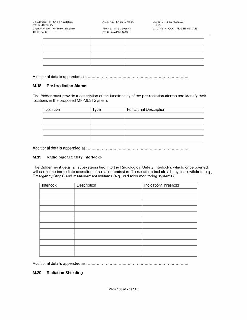
Solicitation No. - N° de l'invitation Amd. No. - N° de la modif. Buyer ID - Id de l'acheteur47419-184383/A pv883Client Ref. No. - N° de réf. du client File No. - N° du dossier CCC No./N° CCC - FMS No./N° VME1000334383 pv883.47419-184383
Page 108 of - de 108
Additional details appended as: ……………………………………………………………………
M.18 Pre-Irradiation Alarms
The Bidder must provide a description of the functionality of the pre-radiation alarms and identify their locations in the proposed MF-MLSI System.
Location Type Functional Description
Additional details appended as: ……………………………………………………………………
M.19 Radiological Safety Interlocks
The Bidder must detail all subsystems tied into the Radiological Safety Interlocks, which, once opened, will cause the immediate cessation of radiation emission. These are to include all physical switches (e.g., Emergency Stops) and measurement systems (e.g., radiation monitoring systems).
Interlock Description Indication/Threshold
Additional details appended as: ……………………………………………………………………
M.20 Radiation Shielding
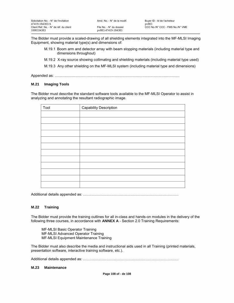
Solicitation No. - N° de l'invitation Amd. No. - N° de la modif. Buyer ID - Id de l'acheteur47419-184383/A pv883Client Ref. No. - N° de réf. du client File No. - N° du dossier CCC No./N° CCC - FMS No./N° VME1000334383 pv883.47419-184383
Page 108 of - de 108
The Bidder must provide a scaled-drawing of all shielding elements integrated into the MF-MLSI Imaging Equipment, showing material type(s) and dimensions of:
M.19.1 Boom arm and detector array with beam stopping materials (including material type and dimensions throughout)
M.19.2 X-ray source showing collimating and shielding materials (including material type used)
M.19.3 Any other shielding on the MF-MLSI system (including material type and dimensions)
Appended as: …………………………………………………………………………………………
M.21 Imaging Tools
The Bidder must describe the standard software tools available to the MF-MLSI Operator to assist in analyzing and annotating the resultant radiographic image.
Tool Capability Description
Additional details appended as: ……………………………………………………………………
M.22 Training
The Bidder must provide the training outlines for all in-class and hands-on modules in the delivery of the following three courses, in accordance with ANNEX A - Section 2.0 Training Requirements:
MF-MLSI Basic Operator TrainingMF-MLSI Advanced Operator TrainingMF-MLSI Equipment Maintenance Training
The Bidder must also describe the media and instructional aids used in all Training (printed materials,presentation software, interactive training software, etc.).
Additional details appended as: ……………………………………………………………………
M.23 Maintenance
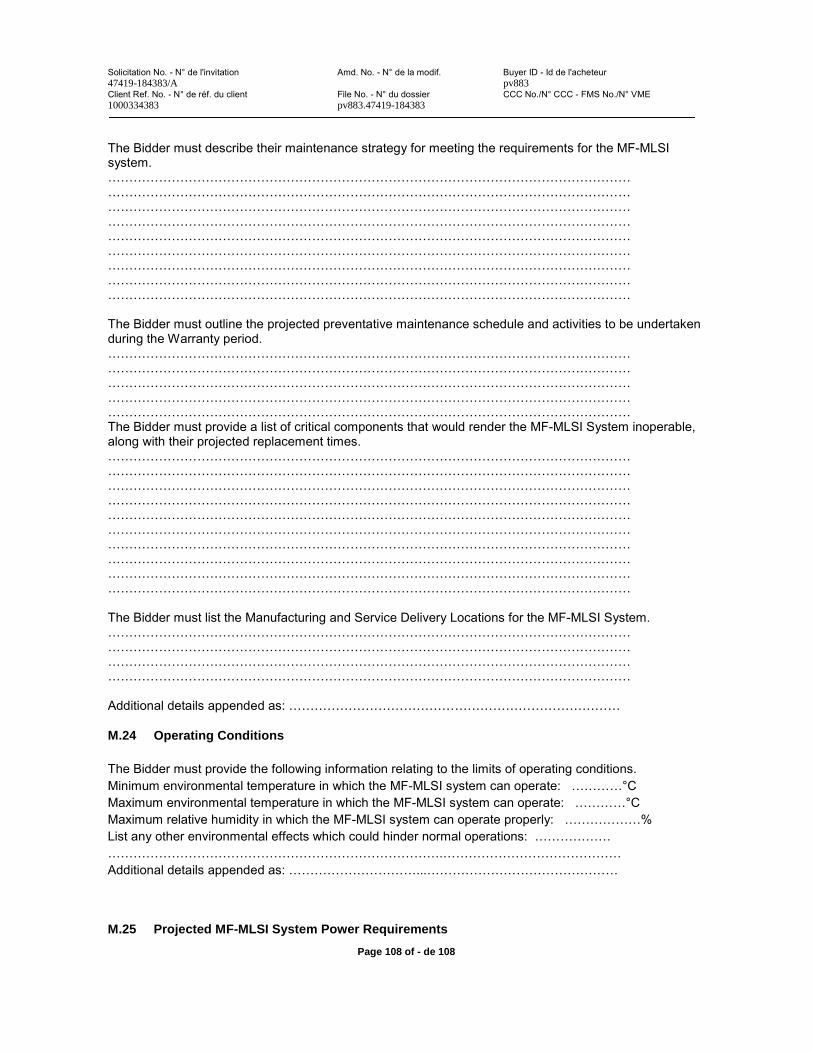
Solicitation No. - N° de l'invitation Amd. No. - N° de la modif. Buyer ID - Id de l'acheteur47419-184383/A pv883Client Ref. No. - N° de réf. du client File No. - N° du dossier CCC No./N° CCC - FMS No./N° VME1000334383 pv883.47419-184383
Page 108 of - de 108
The Bidder must describe their maintenance strategy for meeting the requirements for the MF-MLSIsystem. ………………………………………………………………………………………………………………………………………………………………………………………………………………………………………………………………………………………………………………………………………………………………………………………………………………………………………………………………………………………………………………………………………………………………………………………………………………………………………………………………………………………………………………………………………………………………………………………………………………………………………………………………………………………………………………………………………………………………………………………………………………………
The Bidder must outline the projected preventative maintenance schedule and activities to be undertaken during the Warranty period.…………………………………………………………………………………………………………………………………………………………………………………………………………………………………………………………………………………………………………………………………………………………………………………………………………………………………………………………………………………………………………………………………………………………………The Bidder must provide a list of critical components that would render the MF-MLSI System inoperable, along with their projected replacement times. ……………………………………………………………………………………………………………………………………………………………………………………………………………………………………………………………………………………………………………………………………………………………………………………………………………………………………………………………………………………………………………………………………………………………………………………………………………………………………………………………………………………………………………………………………………………………………………………………………………………………………………………………………………………………………………………………………………………………………………………………………………………………………………………………………………………………………………………………………
The Bidder must list the Manufacturing and Service Delivery Locations for the MF-MLSI System.……………………………………………………………………………………………………………………………………………………………………………………………………………………………………………………………………………………………………………………………………………………………………………………………………………………………………………………
Additional details appended as: ……………………………………………………………………
M.24 Operating Conditions
The Bidder must provide the following information relating to the limits of operating conditions.Minimum environmental temperature in which the MF-MLSI system can operate: …………°C Maximum environmental temperature in which the MF-MLSI system can operate: …………°C Maximum relative humidity in which the MF-MLSI system can operate properly: ………………% List any other environmental effects which could hinder normal operations: …………………………………………………………………………………….……………………………………Additional details appended as: …………………………...………………………………………
M.25 Projected MF-MLSI System Power Requirements

Solicitation No. - N° de l'invitation Amd. No. - N° de la modif. Buyer ID - Id de l'acheteur47419-184383/A pv883Client Ref. No. - N° de réf. du client File No. - N° du dossier CCC No./N° CCC - FMS No./N° VME1000334383 pv883.47419-184383
Page 108 of - de 108
The Bidder must detail the projected operating power requirements for the operation of the MF-MLSISystem, specifically: The projected hourly power required for normal imaging operations: ………………………….……………………………………………….……………………………………………….…………………………………………………………….……………………………………………….…………………………………………………………….……………………………………………….………………The projected power requirements for storage for support systems (e.g., heating/air conditioning/ventilation (HVAC), lighting, etc.): ……………………………………………………………………………………………………….………………………………………………….……………………………………………….…………………………………………………………….……………………………………………….………………
The peak power drawn during imaging operations: …………………………...………………………………………………………………….……………………………………………….…………………………………………………………….……………………………………………….………………
Additional details appended as: …………………………...………………………………………
M.26 Protection from Dirt and Water
The Bidder must detail the Ingress Protection (IP) or water and dust protection rating for majorsubsystems in the MF-MLSI System listed below.
MF-MLSISubsystems
Functionality IP Rating or Equivalent Protection
Source Assembly
Detector AssemblyCommunications LinesPower Lines
Cameras
Radiological Safety SystemsOther Electrical Subsystems:
Appended as: …………………………………………………………………………………………
M.27 Additional Technical Information
The Bidder may submit any additional technical information they deem to be pertinent to this document;such as, but is not limited to: test results, 3rd party reports, configuration options, or other raw data. Note that all information specifically requested in previous sections must be presented completely therein. This section must be formatted in the same manner as the rest of the document and must be properly referenced in the Table of Contents.
Additional details appended as: ……………………………………………………………………
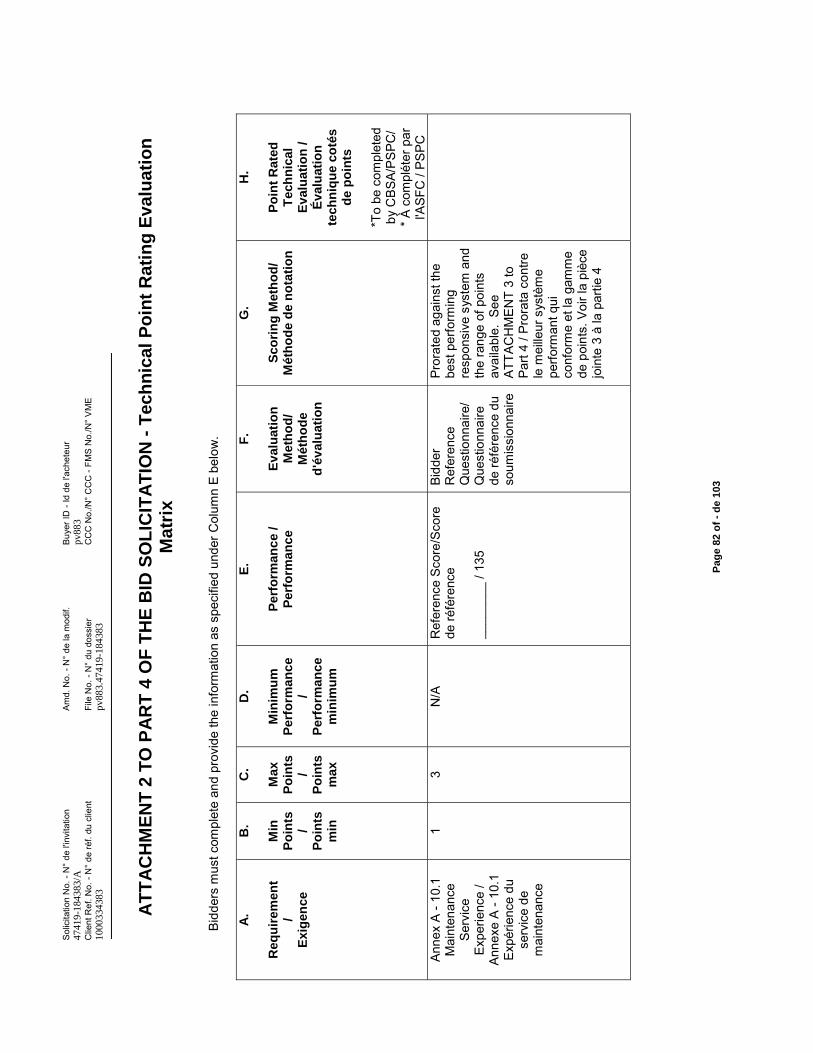
Sol
icita
tion
No.
-N
° de
l'in
vita
tion
Am
d. N
o. -
N°
de la
mod
if.B
uyer
ID -
Id d
e l'a
chet
eur
4741
9-18
4383
/Apv
883
Clie
nt R
ef. N
o. -
N°
de ré
f. du
clie
ntFi
le N
o. -
N°
du d
ossi
erC
CC
No.
/N°
CC
C -
FMS
No.
/N°
VM
E10
0033
4383
pv88
3.47
419-
1843
83
Pag
e 82
of
-d
e 10
3
AT
TA
CH
ME
NT
2 T
O P
AR
T 4
OF
TH
E B
ID S
OL
ICIT
AT
ION
-T
ech
nic
al P
oin
t R
atin
g E
valu
atio
n
Mat
rix
Bidd
ers
mus
tcom
plet
e an
dpr
ovid
e th
e in
form
atio
n as
spe
cifie
d un
der C
olum
n E
belo
w.
A.
Req
uir
emen
t/
Exi
gen
ce
B.
Min
Po
ints
/P
oin
tsm
in
C.
Max
Po
ints
/P
oin
tsm
ax
D.
Min
imu
mP
erfo
rman
ce
/P
erfo
rman
ce
min
imu
m
E.
Per
form
anc
e /
Per
form
anc
e
F.
Ev
alu
atio
n
Met
ho
d/
Mét
ho
de
d'é
val
uat
ion
G.
Sco
rin
g M
eth
od
/M
éth
od
e d
e n
ota
tio
n
H.
Po
int
Rat
ed
Tec
hn
ical
Ev
alu
atio
n /
Év
alu
atio
n
tech
niq
ue
coté
s
de
po
ints
*To
be c
ompl
eted
by
CB
SA/P
SPC
/* À
com
plét
er p
ar
l'ASF
C /
PSPC
Anne
x A
-10.
1 M
aint
enan
ce
Serv
ice
Expe
rienc
e /
Anne
xe A
-10
.1
Expé
rienc
e du
se
rvic
e de
m
aint
enan
ce
13
N/A
Ref
eren
ce S
core
/Sco
re
deré
fére
nce
____
____
/ 13
5
Bidd
er
Ref
eren
ce
Que
stio
nnai
re/
Que
stio
nnai
re
de ré
fére
nce
du
soum
issi
onna
ire
Pror
ated
aga
inst
the
best
per
form
ing
resp
onsi
ve s
yste
m a
nd
the
rang
e of
poi
nts
avai
labl
e. S
ee
ATTA
CH
ME
NT
3 to
Pa
rt 4
/ Pro
rata
con
tre
le m
eille
ur s
ystè
me
perfo
rman
t qui
co
nfor
me
et la
gam
me
de p
oint
s.Vo
ir la
piè
ce
join
te 3
à la
par
tie 4
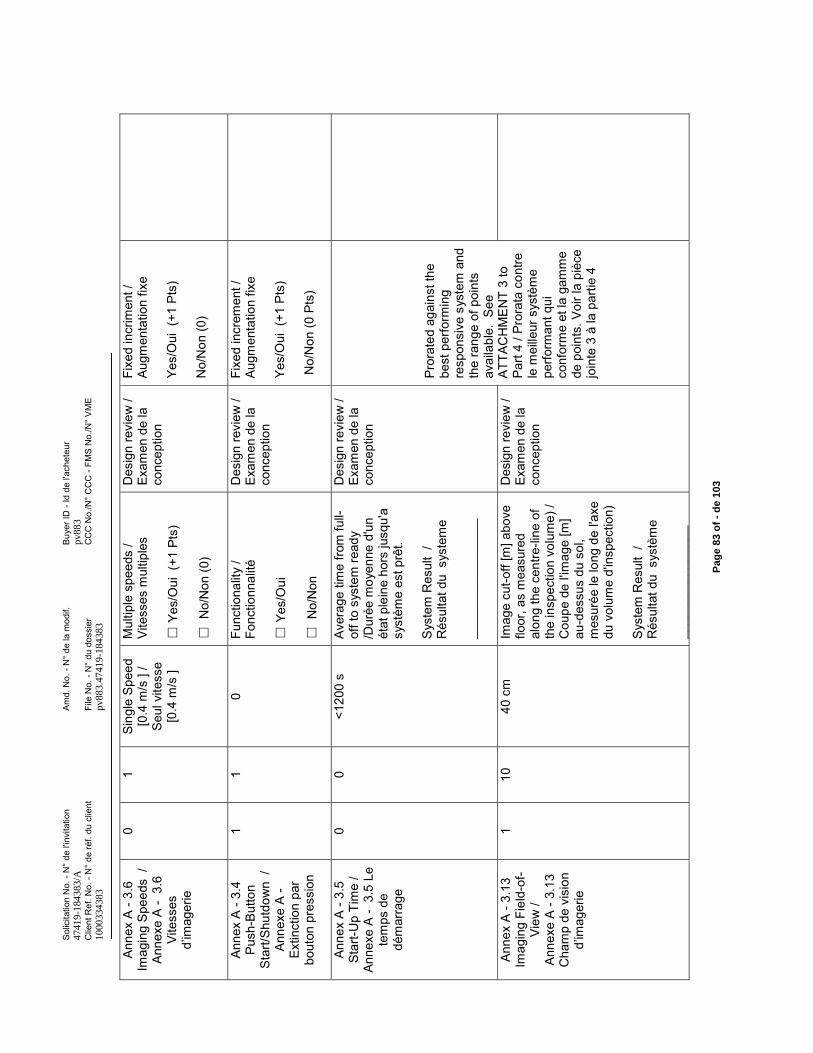
Sol
icita
tion
No.
-N
° de
l'in
vita
tion
Am
d. N
o. -
N°
de la
mod
if.B
uyer
ID -
Id d
e l'a
chet
eur
4741
9-18
4383
/Apv
883
Clie
nt R
ef. N
o. -
N°
de ré
f. du
clie
ntFi
le N
o. -
N°
du d
ossi
erC
CC
No.
/N°
CC
C -
FMS
No.
/N°
VM
E10
0033
4383
pv88
3.47
419-
1843
83
Pag
e 83
of
-d
e 10
3
Anne
x A
-3.6
Im
agin
g S
peed
s /
Anne
xe A
-3.
6 Vi
tess
es
d’im
ager
ie
01
Sing
le S
peed
[0
.4 m
/s ]
/ Se
ul v
itess
e [0
.4 m
/s ]
Mul
tiple
spe
eds
/ Vi
tess
es m
ultip
les
Yes/
Oui
(+1
Pts
)
No/
Non
(0)
Des
ign
revi
ew /
Exam
en d
e la
co
ncep
tion
Fixe
d in
crim
ent /
Au
gmen
tatio
n fix
e
Yes/
Oui
(+1
Pts
)
No/
Non
(0)
Anne
x A
-3.4
P
ush-
But
ton
Star
t/Shu
tdow
n /
Anne
xe A
-Ex
tinct
ion
par
bout
on p
ress
ion
11
0Fu
nctio
nalit
y/
Fonc
tionn
alité
Yes/
Oui
No/
Non
Des
ign
revi
ew /
Exam
en d
e la
co
ncep
tion
Fixe
d in
crem
ent /
Au
gmen
tatio
n fix
e
Yes/
Oui
(+1
Pts
)
No/
Non
(0 P
ts)
Anne
x A
-3.5
S
tart-
Up
Tim
e /
Anne
xe A
-3.
5 Le
te
mps
de
dém
arra
ge
00
<120
0 s
Aver
age
time
from
full-
off t
o sy
stem
read
y /D
urée
moy
enne
d'u
n ét
at p
lein
e ho
rs ju
squ'
a sy
stèm
e es
t prê
t.
Sys
tem
Res
ult
/ R
ésul
tatd
u s
yste
me
____
____
____
____
_
Des
ign
revi
ew /
Exam
en d
e la
co
ncep
tion
Pror
ated
aga
inst
the
best
per
form
ing
resp
onsi
ve s
yste
m a
nd
the
rang
e of
poi
nts
avai
labl
e. S
eeAT
TAC
HM
EN
T 3
to
Part
4 / P
rora
ta c
ontre
le
mei
lleur
sys
tèm
e pe
rform
ant q
ui
conf
orm
e et
la g
amm
e de
poi
nts.
Voir
la p
ièce
jo
inte
3 à
la p
artie
4
Anne
x A
-3.1
3 Im
agin
g Fi
eld-
of-
View
/An
nexe
A -
3.13
C
ham
p de
vis
ion
d’im
ager
ie
110
40 c
mIm
age
cut-o
ff [m
] abo
ve
floor
, as
mea
sure
d al
ong
the
cent
re-li
ne o
f th
e in
spec
tion
volu
me)
/ C
oupe
de
l'imag
e [m
] au
-des
sus
du s
ol,
mes
urée
le lo
ng d
e l'a
xe
du v
olum
e d'
insp
ectio
n)
Sys
tem
Res
ult
/ R
ésul
tatd
u s
ystè
me
____
____
____
____
Des
ign
revi
ew /
Exam
en d
e la
co
ncep
tion
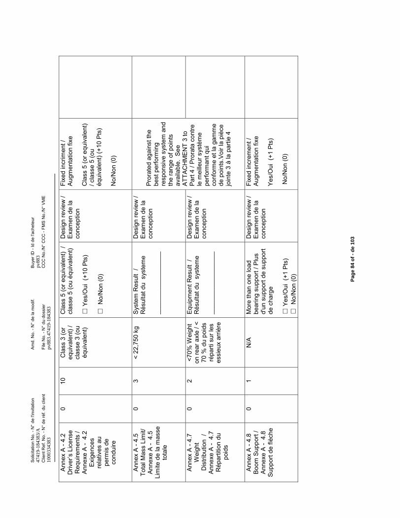
Sol
icita
tion
No.
-N
° de
l'in
vita
tion
Am
d. N
o. -
N°
de la
mod
if.B
uyer
ID -
Id d
e l'a
chet
eur
4741
9-18
4383
/Apv
883
Clie
nt R
ef. N
o. -
N°
de ré
f. du
clie
ntFi
le N
o. -
N°
du d
ossi
erC
CC
No.
/N°
CC
C -
FMS
No.
/N°
VM
E10
0033
4383
pv88
3.47
419-
1843
83
Pag
e 84
of
-d
e 10
3
Anne
x A
-4.2
D
river
’s L
icen
se
Req
uire
men
ts /
Anne
xe A
-4.
2 Ex
igen
ces
rela
tives
au
perm
is d
e co
ndui
re
010
Cla
ss 3
(or
equi
vale
nt) /
cl
asse
3 (o
u éq
uiva
lent
)
Cla
ss 5
(or e
quiv
alen
t) /
clas
se 5
(ou
équi
vale
nt)
Yes/
Oui
(+1
0 Pt
s)
No/
Non
(0)
Des
ign
revi
ew /
Exam
en d
e la
co
ncep
tion
Fixe
d in
crim
ent /
Au
gmen
tatio
n fix
e
Cla
ss 5
(or e
quiv
alen
t)
/ cla
sse
5 (o
u éq
uiva
lent
) (+1
0 Pt
s)
No/
Non
(0)
Anne
x A
-4.5
To
tal M
ass
Lim
it/
Anne
xe A
-4.
5 Li
mite
de
la m
asse
to
tale
03
< 22
,750
kg
Sys
tem
Res
ult
/ R
ésul
tat d
u s
yste
me
____
____
____
____
__
Des
ign
revi
ew /
Exam
en d
e la
co
ncep
tion
Pror
ated
aga
inst
the
best
per
form
ing
resp
onsi
ve s
yste
m a
nd
the
rang
e of
poi
nts
avai
labl
e. S
ee
ATTA
CH
ME
NT
3 to
Pa
rt 4
/ Pro
rata
con
trele
mei
lleur
sys
tèm
e pe
rform
ant q
ui
conf
orm
e et
la g
amm
e de
poi
nts.
Voir
la p
ièce
jo
inte
3 à
la p
artie
4
Anne
x A
-4.7
W
eigh
t D
istri
butio
n /
Anne
xe A
-4.
7 R
épar
titio
n du
po
ids
02
<70%
Wei
ght
on re
ar a
xle
/ <70
% d
u po
ids
répa
rti s
ur le
s es
sieu
x ar
rière
Equi
pmen
t Res
ult
/ R
ésul
tat d
u s
yste
me
____
____
____
____
__
Des
ign
revi
ew /
Exam
en d
e la
co
ncep
tion
Anne
x A
-4.8
Bo
om S
uppo
rt /
Anne
xe A
-4.
8 Su
ppor
t de
flèch
e
01
N/A
Mor
e th
an o
ne lo
ad
bear
ing
supp
ort /
Plu
s d'
un s
uppo
rt de
sup
port
de c
harg
e
Yes/
Oui
(+1
Pts
)N
o/N
on (0
)
Des
ign
revi
ew /
Exam
en d
e la
co
ncep
tion
Fixe
d in
crem
ent /
Au
gmen
tatio
n fix
e
Yes/
Oui
(+1
Pts
)
No/
Non
(0)
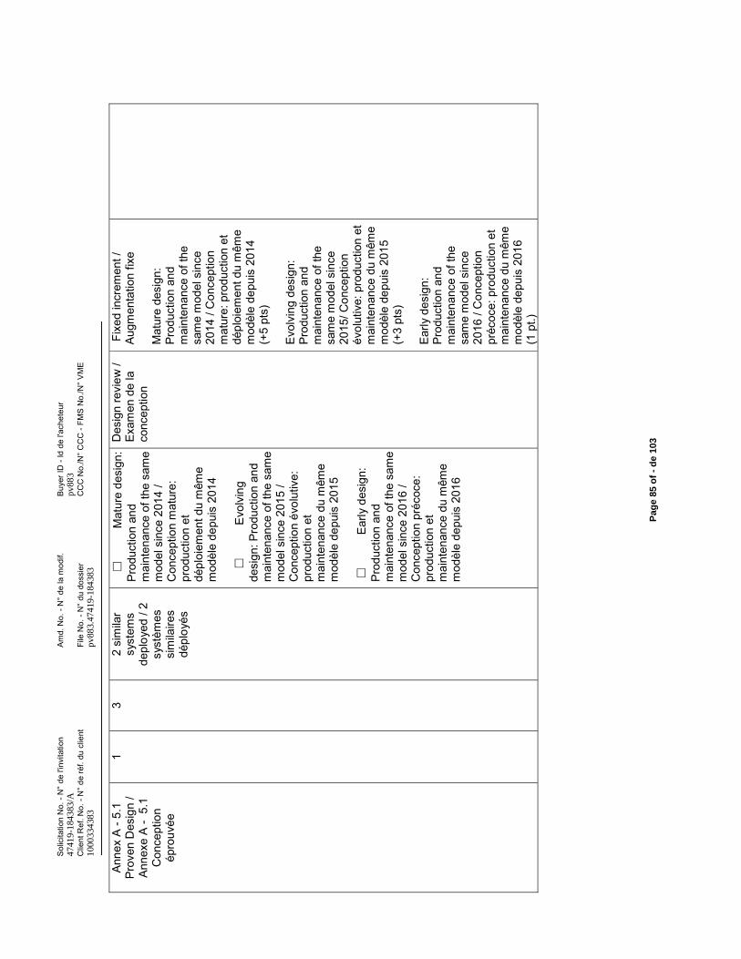
Sol
icita
tion
No.
-N
° de
l'in
vita
tion
Am
d. N
o. -
N°
de la
mod
if.B
uyer
ID -
Id d
e l'a
chet
eur
4741
9-18
4383
/Apv
883
Clie
nt R
ef. N
o. -
N°
de ré
f. du
clie
ntFi
le N
o. -
N°
du d
ossi
erC
CC
No.
/N°
CC
C -
FMS
No.
/N°
VM
E10
0033
4383
pv88
3.47
419-
1843
83
Pag
e 85
of
-d
e 10
3
Anne
x A
-5.1
Pr
oven
Des
ign
/ An
nexe
A -
5.1
C
once
ptio
n ép
rouv
ée
13
2 si
mila
r sy
stem
s de
ploy
ed /
2 sy
stèm
es
sim
ilaire
s dé
ploy
és
Mat
ure
desi
gn:
Prod
uctio
n an
d m
aint
enan
ce o
f the
sam
em
odel
sin
ce 2
014
/ C
once
ptio
n m
atur
e:
prod
uctio
n et
dé
ploi
emen
t du
mêm
e m
odèl
e de
puis
201
4
E
volv
ing
desi
gn: P
rodu
ctio
n an
d m
aint
enan
ce o
f the
sam
e m
odel
sin
ce 2
015
/ C
once
ptio
n év
olut
ive:
pr
oduc
tion
et
mai
nten
ance
du
mêm
e m
odèl
e de
puis
201
5
Early
des
ign:
Pr
oduc
tion
and
mai
nten
ance
of t
he s
ame
mod
el s
ince
201
6 /
Con
cept
ion
préc
oce:
pr
oduc
tion
et
mai
nten
ance
du
mêm
e m
odèl
e de
puis
201
6
Des
ign
revi
ew /
Exam
en d
e la
co
ncep
tion
Fixe
d in
crem
ent /
Au
gmen
tatio
n fix
e
Mat
ure
desi
gn:
Prod
uctio
n an
d m
aint
enan
ce o
f the
sa
me
mod
el s
ince
20
14 /
Con
cept
ion
mat
ure:
pro
duct
ion
et
dépl
oiem
ent d
u m
ême
mod
èle
depu
is 2
014
(+5
pts)
Evol
ving
des
ign:
Pr
oduc
tion
and
mai
nten
ance
of t
he
sam
e m
odel
sin
ce
2015
/ Con
cept
ion
évol
utiv
e: p
rodu
ctio
n et
m
aint
enan
ce d
u m
ême
mod
èle
depu
is 2
015
(+3
pts)
Early
des
ign:
Pr
oduc
tion
and
mai
nten
ance
of t
he
sam
e m
odel
sin
ce
2016
/ C
once
ptio
n pr
écoc
e: p
rodu
ctio
n et
m
aint
enan
ce d
u m
ême
mod
èle
depu
is 2
016
(1 p
t.)
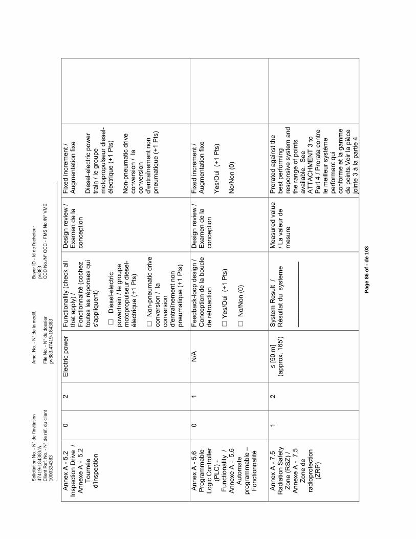
Sol
icita
tion
No.
-N
° de
l'in
vita
tion
Am
d. N
o. -
N°
de la
mod
if.B
uyer
ID -
Id d
e l'a
chet
eur
4741
9-18
4383
/Apv
883
Clie
nt R
ef. N
o. -
N°
de ré
f. du
clie
ntFi
le N
o. -
N°
du d
ossi
erC
CC
No.
/N°
CC
C -
FMS
No.
/N°
VM
E10
0033
4383
pv88
3.47
419-
1843
83
Pag
e 86
of
-d
e 10
3
Anne
x A
-5.2
In
spec
tion
Driv
e /
Anne
xe A
-5.
2
Tour
née
d’in
spec
tion
02
Elec
tric
pow
erFu
nctio
nalit
y (c
heck
all
that
app
ly) /
Fo
nctio
nnal
ité (c
oche
z to
utes
les
répo
nses
qui
s'
appl
ique
nt)
Die
sel-e
lect
ric
pow
ertra
in /
le g
roup
e m
otop
ropu
lseu
r die
sel-
élec
triqu
e (+
1 Pt
s)
Non
-pne
umat
ic d
rive
conv
ersi
on /
la
conv
ersi
on
d'en
traîn
emen
t non
pn
eum
atiq
ue (+
1 Pt
s)
Des
ign
revi
ew /
Exam
en d
e la
co
ncep
tion
Fixe
d in
crem
ent /
Au
gmen
tatio
n fix
e
Die
sel-e
lect
ric p
ower
tra
in /
le g
roup
e m
otop
ropu
lseu
r die
sel-
élec
triqu
e (+
1 Pt
s)
Non
-pne
umat
ic d
rive
conv
ersi
on /
la
conv
ersi
on
d'en
traîn
emen
t non
pn
eum
atiq
ue (+
1 Pt
s)
Anne
x A
-5.6
Pr
ogra
mm
able
Lo
gic
Con
trolle
r (P
LC) -
Func
tiona
lity
/ An
nexe
A -
5.6
Auto
mat
e pr
ogra
mm
able
–Fo
nctio
nnal
ité
01
N/A
Feed
back
-loop
des
ign
/ C
once
ptio
n de
la b
oucl
e de
rétro
actio
n
Yes/
Oui
(+1
Pts
)
No/
Non
(0)
Des
ign
revi
ew /
Exam
en d
ela
co
ncep
tion
Fixe
d in
crem
ent /
Au
gmen
tatio
n fix
e
Yes/
Oui
(+1
Pts
)
No/
Non
(0)
Anne
x A
-7.5
R
adia
tion
Safe
ty
Zone
(RSZ
) /
Anne
xe A
-7.
5
Zone
de
radi
opro
tect
ion
(ZR
P)
12
(app
rox.
165
')S
yste
m R
esul
t /
Rés
ulta
t du
sys
tem
e
____
____
____
____
__
Mea
sure
d va
lue
/ La
vale
ur d
e m
esur
e
Pror
ated
aga
inst
the
best
per
form
ing
resp
onsi
ve s
yste
m a
nd
the
rang
e of
poi
nts
avai
labl
e. S
ee
ATTA
CH
ME
NT
3 to
Pa
rt 4
/ Pro
rata
con
tre
le m
eille
ur s
ystè
me
perfo
rman
t qui
co
nfor
me
et la
gam
me
de p
oint
s.V
oir l
a pi
èce
join
te 3
à la
par
tie 4
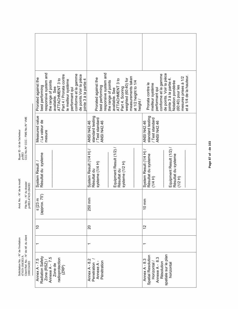
Sol
icita
tion
No.
-N
° de
l'in
vita
tion
Am
d. N
o. -
N°
de la
mod
if.B
uyer
ID -
Id d
e l'a
chet
eur
4741
9-18
4383
/Apv
883
Clie
nt R
ef. N
o. -
N°
de ré
f. du
clie
ntFi
le N
o. -
N°
du d
ossi
erC
CC
No.
/N°
CC
C -
FMS
No.
/N°
VM
E10
0033
4383
pv88
3.47
419-
1843
83
Pag
e 87
of
-d
e 10
3
Anne
x A
-7.5
R
adia
tion
Safe
ty
Zone
(RSZ
) /
Anne
xe A
-7.
5
Zone
de
radi
opro
tect
ion
(ZR
P)
110
(app
rox.
75'
)S
yste
m R
esul
t /
Rés
ulta
t du
sys
tem
e
____
____
____
____
__
Mea
sure
d va
lue
/ La
vale
ur d
e m
esur
e
Pror
ated
aga
inst
the
best
per
form
ing
resp
onsi
ve s
yste
m a
nd
the
rang
e of
poi
nts
avai
labl
e. S
ee
ATTA
CH
ME
NT
3 to
Pa
rt 4
/ Pro
rata
con
tre
le m
eille
ur s
ystè
me
perfo
rman
t qui
co
nfor
me
et la
gam
me
de p
oint
s.Vo
ir la
piè
ce
join
te 3
à la
par
tie 4
Anne
x A
-8.2
Pe
netra
tion
/
Anne
xe A
-Pé
nétra
tion
120
250
mm
Sys
tem
Res
ult (
1/4
H) /
R
ésul
tat d
u sy
stem
e (1
/4 H
)
____
____
____
____
_
Equi
pmen
t Res
ult (
1/2)
/ R
ésul
tat d
u sy
stem
e (1
/2 H
)
____
____
____
____
___
ANS
I N42
.46
stan
dard
test
ing
/ Tes
t sta
ndar
d AN
SI N
42.4
6
Pror
ated
aga
inst
the
best
per
form
ing
resp
onsi
ve s
yste
m a
nd
the
rang
e of
poi
nts
avai
labl
e. S
ee
ATTA
CH
ME
NT
3 to
Pa
rt 4.
Sco
ring
wei
ghte
d (6
0:40
) for
m
easu
rem
ents
take
n at
1/2
hei
ght t
o 1/
4 he
ight
/
Pror
ata
cont
re le
m
eille
ur s
ystè
me
perfo
rman
t qui
co
nfor
me
et la
gam
me
de p
oint
s. V
oir l
a pi
èce
join
te 3
à la
par
tie 4
. N
otat
ion
pond
érée
(6
0:40
) pou
r les
m
esur
es p
rises
à 1
/2
et à
1/4
de
la h
aute
ur.
Anne
x A
-8.3
Sp
atia
l Res
olut
ion
Hor
izon
tal /
An
nexe
A-
8.3
Rés
olut
ion
spat
iale
sur
le p
lan
horiz
onta
l
112
10 m
mS
yste
m R
esul
t (1/
4 H
) /
Rés
ulta
t du
syst
eme
(1/4
H)
____
____
____
____
__
Equi
pmen
t Res
ult (
1/2)
/ R
ésul
tat d
u sy
stem
e (1
/2 H
) __
____
____
____
____
ANS
I N42
.46
stan
dard
test
ing
/ Tes
t sta
ndar
d AN
SI N
42.4
6
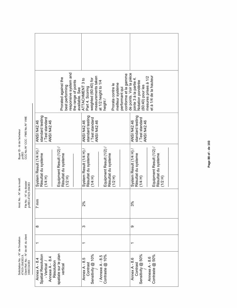
Sol
icita
tion
No.
-N
° de
l'in
vita
tion
Am
d. N
o. -
N°
de la
mod
if.B
uyer
ID -
Id d
e l'a
chet
eur
4741
9-18
4383
/Apv
883
Clie
nt R
ef. N
o. -
N°
de ré
f. du
clie
ntFi
le N
o. -
N°
du d
ossi
erC
CC
No.
/N°
CC
C -
FMS
No.
/N°
VM
E10
0033
4383
pv88
3.47
419-
1843
83
Pag
e 88
of
-d
e 10
3
Anne
x A
-8.4
Sp
atia
l Res
olut
ion
-Ver
tical
/
Anne
xe A
-8.
4 R
ésol
utio
n sp
atia
le s
ur le
pla
n ve
rtica
l
18
7 m
mS
yste
m R
esul
t (1/
4 H
) /
Rés
ulta
t du
syst
eme
(1/4
H)
____
____
____
____
__
Equi
pmen
t Res
ult (
1/2)
/ R
ésul
tat d
u sy
stem
e (1
/2 H
) __
____
____
____
__
ANS
I N42
.46
stan
dard
test
ing
/ Tes
t sta
ndar
d AN
SI N
42.4
6
Pror
ated
aga
inst
the
best
per
form
ing
resp
onsi
ve s
yste
m a
nd
the
rang
e of
poi
nts
avai
labl
e. S
ee
ATTA
CH
ME
NT
3 to
Pa
rt 4.
Sco
ring
wei
ghte
d (6
0:40
) for
m
easu
rem
ents
take
n at
1/2
hei
ght t
o 1/
4 he
ight
/
Pror
ata
cont
re le
m
eille
ur s
ystè
me
perfo
rman
t qui
co
nfor
me
et la
gam
me
de p
oint
s. V
oir l
a pi
èce
join
te 3
à la
par
tie 4
. N
otat
ion
pond
érée
(6
0:40
) pou
r les
m
esur
es p
rises
à 1
/2
et à
1/4
de
la h
aute
ur
Anne
x A
-8.5
C
ontra
st
Sens
itivi
ty @
10%
/
/ Ann
exe
A -8
.5
Con
trast
e @
10%
13
2%S
yste
m R
esul
t (1/
4 H
) /
Rés
ulta
t du
syst
eme
(1/4
H)
____
____
____
____
_
Equi
pmen
t Res
ult (
1/2)
/ R
ésul
tat d
u sy
stem
e (1
/2 H
) __
____
____
____
____
ANS
I N42
.46
stan
dard
test
ing
/ Tes
t sta
ndar
d AN
SI N
42.4
6
Anne
x A
-8.6
C
ontra
st
Sens
itivi
ty @
50%
/
Anne
xe A
-8.
6 C
ontra
ste
@ 5
0%
19
3%S
yste
m R
esul
t (1/
4 H
) /
Rés
ulta
t du
syst
eme
(1/4
H)
____
____
____
____
___
Equi
pmen
t Res
ult (
1/2)
/ R
ésul
tat d
u sy
stem
e (1
/2 H
) __
____
____
____
____
_
ANS
I N42
.46
stan
dard
test
ing
/ Tes
t sta
ndar
d AN
SI N
42.4
6
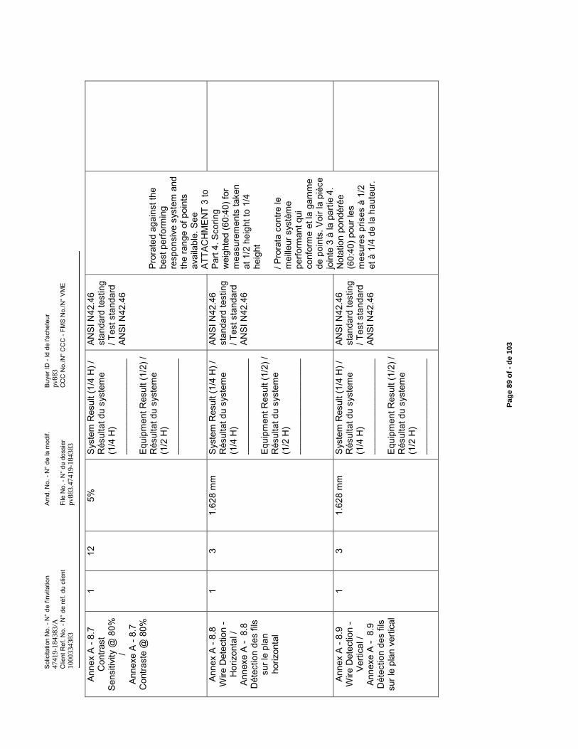
Sol
icita
tion
No.
-N
° de
l'in
vita
tion
Am
d. N
o. -
N°
de la
mod
if.B
uyer
ID -
Id d
e l'a
chet
eur
4741
9-18
4383
/Apv
883
Clie
nt R
ef. N
o. -
N°
de ré
f. du
clie
ntFi
le N
o. -
N°
du d
ossi
erC
CC
No.
/N°
CC
C -
FMS
No.
/N°
VM
E10
0033
4383
pv88
3.47
419-
1843
83
Pag
e 89
of
-d
e 10
3
Anne
x A
-8.7
C
ontra
st
Sens
itivi
ty @
80%
/
Anne
xe A
-8.
7 C
ontra
ste
@ 8
0%
112
5%S
yste
m R
esul
t (1/
4 H
) /
Rés
ulta
t du
syst
eme
(1/4
H)
____
____
____
____
___
Equi
pmen
t Res
ult (
1/2)
/ R
ésul
tat d
u sy
stem
e (1
/2 H
) __
____
____
____
____
_
ANS
I N42
.46
stan
dard
test
ing
/ Tes
t sta
ndar
d AN
SI N
42.4
6
Pror
ated
aga
inst
the
best
per
form
ing
resp
onsi
ve s
yste
m a
nd
the
rang
e of
poi
nts
avai
labl
e. S
ee
ATTA
CH
ME
NT
3 to
Pa
rt 4.
Sco
ring
wei
ghte
d (6
0:40
) for
m
easu
rem
ents
take
n at
1/2
hei
ght t
o 1/
4 he
ight
/ Pro
rata
con
tre le
m
eille
ur s
ystè
me
perfo
rman
t qui
co
nfor
me
et la
gam
me
de p
oint
s. V
oir l
a pi
èce
join
te 3
à la
par
tie 4
. N
otat
ion
pond
érée
(6
0:40
) pou
r les
m
esur
es p
rises
à 1
/2
et à
1/4
de
la h
aute
ur.
Anne
x A
-8.8
W
ire D
etec
tion
-H
oriz
onta
l /
Anne
xe A
-8.
8 D
étec
tion
des
fils
sur l
e pl
an
horiz
onta
l
13
1.62
8m
mS
yste
m R
esul
t (1/
4 H
) /
Rés
ulta
t du
syst
eme
(1/4
H)
____
____
____
____
___
Equi
pmen
t Res
ult (
1/2)
/ R
ésul
tat d
u sy
stem
e (1
/2 H
)__
____
____
____
____
_
ANS
I N42
.46
stan
dard
test
ing
/ Tes
t sta
ndar
d AN
SI N
42.4
6
Anne
x A
-8.9
W
ire D
etec
tion
-Ve
rtica
l /
Anne
xe A
-8.
9 D
étec
tion
des
fils
sur l
e pl
an v
ertic
al
13
1.62
8 m
mS
yste
m R
esul
t (1/
4 H
) /
Rés
ulta
t du
syst
eme
(1/4
H)
____
____
____
____
___
Equi
pmen
t Res
ult (
1/2)
/ R
ésul
tat d
u sy
stem
e (1
/2 H
) __
____
____
____
____
_
ANS
I N42
.46
stan
dard
test
ing
/ Tes
t sta
ndar
d AN
SI N
42.4
6
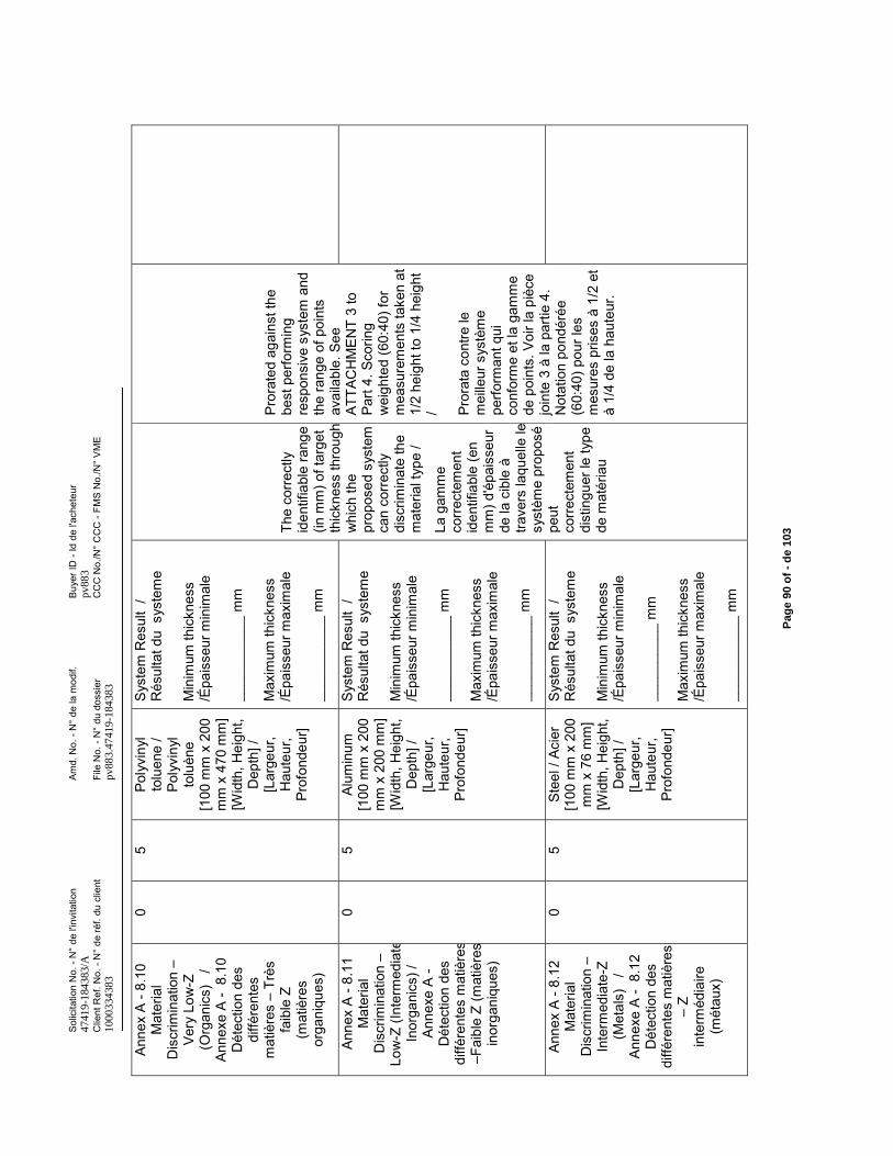
Sol
icita
tion
No.
-N
° de
l'in
vita
tion
Am
d. N
o. -
N°
de la
mod
if.B
uyer
ID -
Id d
e l'a
chet
eur
4741
9-18
4383
/Apv
883
Clie
nt R
ef. N
o. -
N°
de ré
f. du
clie
ntFi
le N
o. -
N°
du d
ossi
erC
CC
No.
/N°
CC
C -
FMS
No.
/N°
VM
E10
0033
4383
pv88
3.47
419-
1843
83
Pag
e 90
of
-d
e 10
3
Anne
x A
-8.1
0 M
ater
ial
Dis
crim
inat
ion
–Ve
ry L
ow-Z
(O
rgan
ics)
/
Anne
xe A
-8.
10
Dét
ectio
n de
s di
ffére
ntes
m
atiè
res
–Tr
ès
faib
le Z
(mat
ière
s or
gani
ques
)
05
Poly
viny
l to
luen
e /
Poly
viny
l to
luèn
e [1
00 m
m x
200
m
m x
470
mm
] [W
idth
, Hei
ght,
Dep
th] /
[L
arge
ur,
Hau
teur
, Pr
ofon
deur
]
Sys
tem
Res
ult
/ R
ésul
tat d
u s
yste
me
Min
imum
thic
knes
s /É
pais
seur
min
imal
e
____
____
___
mm
Max
imum
thic
knes
s /É
pais
seur
max
imal
e
____
____
___
mm
The
corr
ectly
id
entif
iabl
e ra
nge
(in m
m) o
f tar
get
thic
knes
s th
roug
h w
hich
the
prop
osed
sys
tem
ca
n co
rrec
tly
disc
rimin
ate
the
mat
eria
l typ
e /
La g
amm
e co
rrec
tem
ent
iden
tifia
ble
(en
mm
) d'é
pais
seur
de
la c
ible
à
trave
rs la
quel
le le
sy
stèm
e pr
opos
é pe
ut
corr
ecte
men
t di
stin
guer
le ty
pe
de m
atér
iau
Pror
ated
aga
inst
the
best
per
form
ing
resp
onsi
ve s
yste
m a
nd
the
rang
e of
poi
nts
avai
labl
e. S
ee
ATTA
CH
ME
NT
3 to
Pa
rt 4.
Sco
ring
wei
ghte
d (6
0:40
) for
m
easu
rem
ents
take
n at
1/
2 he
ight
to 1
/4 h
eigh
t / Pr
orat
a co
ntre
le
mei
lleur
sys
tèm
e pe
rform
ant q
ui
conf
orm
e et
la g
amm
e de
poi
nts.
Voi
r la
pièc
e jo
inte
3 à
la p
artie
4.
Not
atio
n po
ndér
ée
(60:
40) p
our l
es
mes
ures
pris
es à
1/2
et
à 1/
4 de
la h
aute
ur.
Anne
x A
-8.1
1 M
ater
ial
Dis
crim
inat
ion
–Lo
w-Z
(Int
erm
edia
teIn
orga
nics
) /
Anne
xe A
-D
étec
tion
des
diffé
rent
es m
atiè
res
–Fai
ble
Z (m
atiè
res
inor
gani
ques
)
05
Alum
inum
[1
00 m
m x
200
m
m x
200
mm
] [W
idth
, Hei
ght,
Dep
th] /
[L
arge
ur,
Hau
teur
, Pr
ofon
deur
]
Sys
tem
Res
ult
/ R
ésul
tat d
u s
yste
me
Min
imum
thic
knes
s /É
pais
seur
min
imal
e
____
____
___
mm
Max
imum
thic
knes
s /É
pais
seur
max
imal
e
____
____
___
mm
Anne
x A
-8.1
2 M
ater
ial
Dis
crim
inat
ion
–In
term
edia
te-Z
(M
etal
s)
/ An
nexe
A -
8.12
D
étec
tion
des
diffé
rent
es m
atiè
res
–Z
inte
rméd
iaire
(m
étau
x)
05
Stee
l / A
cier
[1
00 m
m x
200
m
m x
76
mm
] [W
idth
, Hei
ght,
Dep
th] /
[L
arge
ur,
Hau
teur
, Pr
ofon
deur
]
Sys
tem
Res
ult
/ R
ésul
tat d
u s
yste
me
Min
imum
thic
knes
s /É
pais
seur
min
imal
e
____
____
__ m
m
Max
imum
thic
knes
s /É
pais
seur
max
imal
e
____
____
___
mm
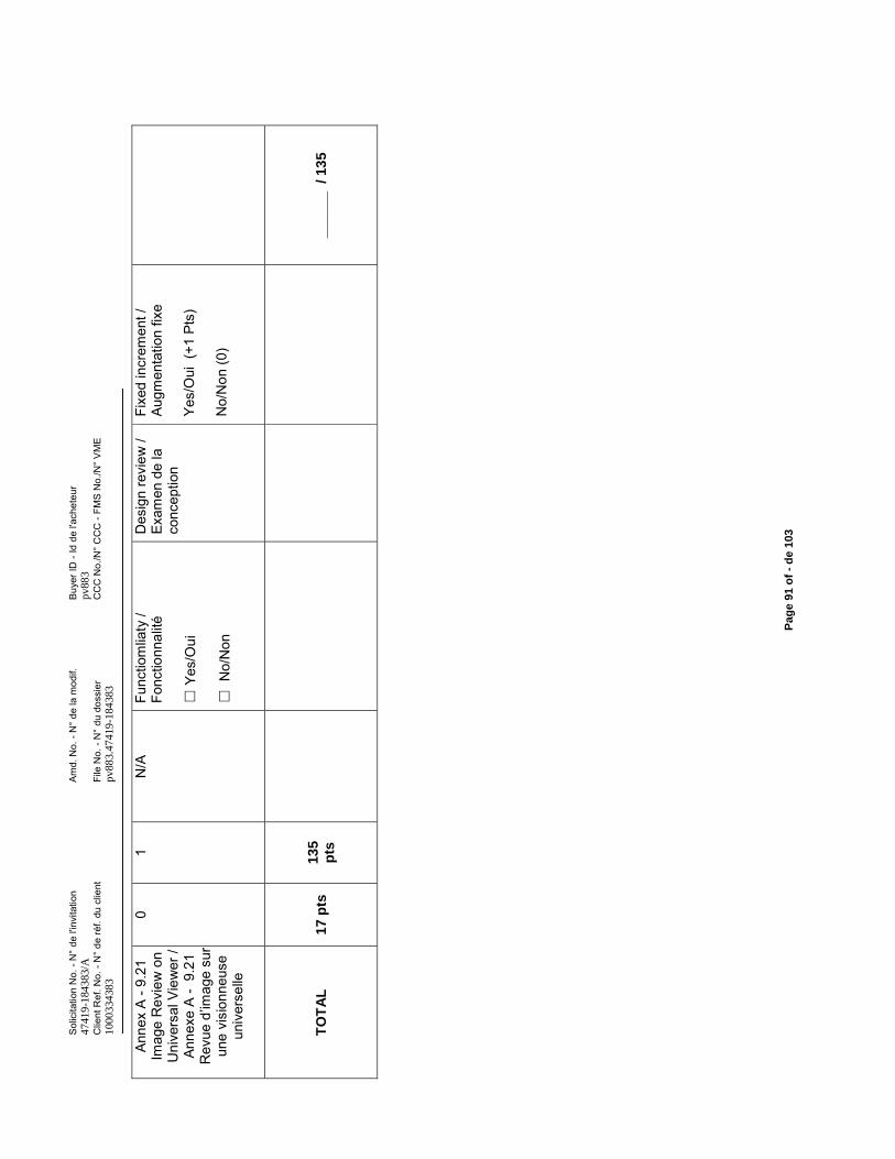
Sol
icita
tion
No.
-N
° de
l'in
vita
tion
Am
d. N
o. -
N°
de la
mod
if.B
uyer
ID -
Id d
e l'a
chet
eur
4741
9-18
4383
/Apv
883
Clie
nt R
ef. N
o. -
N°
de ré
f. du
clie
ntFi
le N
o. -
N°
du d
ossi
erC
CC
No.
/N°
CC
C -
FMS
No.
/N°
VM
E10
0033
4383
pv88
3.47
419-
1843
83
Pag
e 91
of
-d
e 10
3
Anne
x A
-9.2
1
Imag
e R
evie
w o
n U
nive
rsal
Vie
wer
/ An
nexe
A -
9.21
R
evue
d’im
age
sur
une
visi
onne
use
univ
erse
lle
01
N/A
Func
tiom
liaty
/ Fo
nctio
nnal
ité
Yes/
Oui
No/
Non
Des
ign
revi
ew /
Exam
en d
e la
co
ncep
tion
Fixe
d in
crem
ent /
Au
gmen
tatio
nfix
e
Yes/
Oui
(+1
Pts
)
No/
Non
(0)
TO
TA
L17
pts
135
pts
____
__
/ 13
5
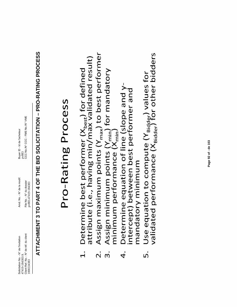
Sol
icita
tion
No.
-N
° de
l'in
vita
tion
Am
d. N
o. -
N°
de la
mod
if.B
uyer
ID -
Id d
e l'a
chet
eur
4741
9-18
4383
/Apv
883
Clie
nt R
ef. N
o. -
N°
de ré
f. du
clie
ntFi
le N
o. -
N°
du d
ossi
erC
CC
No.
/N°
CC
C -
FMS
No.
/N°
VM
E10
0033
4383
pv88
3.47
419-
1843
83
Pag
e 92
of
-d
e 10
3
AT
TA
CH
ME
NT
3 T
O P
AR
T 4
OF
TH
E B
ID S
OL
ICIT
AT
ION
–P
RO
-RA
TIN
G P
RO
CE
SS
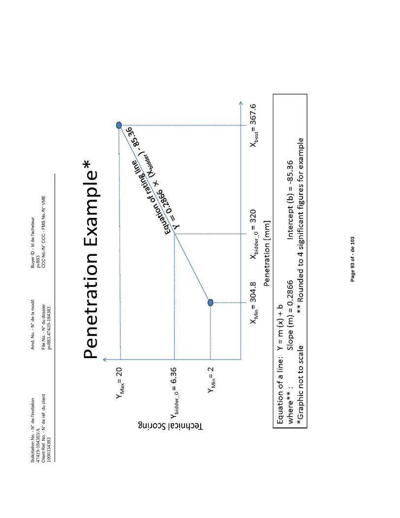
Sol
icita
tion
No.
-N
° de
l'in
vita
tion
Am
d. N
o. -
N°
de la
mod
if.B
uyer
ID -
Id d
e l'a
chet
eur
4741
9-18
4383
/Apv
883
Clie
nt R
ef. N
o. -
N°
de ré
f. du
clie
ntFi
le N
o. -
N°
du d
ossi
erC
CC
No.
/N°
CC
C -
FMS
No.
/N°
VM
E10
0033
4383
pv88
3.47
419-
1843
83
Pag
e 93
of
-d
e 10
3
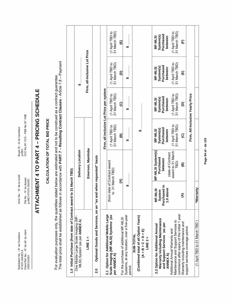
Sol
icita
tion
No.
-N
° de
l'in
vita
tion
Am
d. N
o. -
N°
de la
mod
if.B
uyer
ID -
Id d
e l'a
chet
eur
4741
9-18
4383
/Apv
883
Clie
nt R
ef. N
o. -
N°
de ré
f. du
clie
ntFi
le N
o. -
N°
du d
ossi
erC
CC
No.
/N°
CC
C -
FMS
No.
/N°
VM
E10
0033
4383
pv88
3.47
419-
1843
83
Pag
e 94
of
-d
e 10
3
AT
TA
CH
ME
NT
4T
O P
AR
T 4
–P
RIC
ING
SC
HE
DU
LE
CA
LC
UL
AT
ION
OF
TO
TA
L B
ID P
RIC
E
For e
valu
atio
n pu
rpos
es o
nly,
the
quan
titie
s st
ated
bel
ow a
re e
stim
ated
and
not t
o be
con
stru
ed a
s a
cont
ract
gua
rant
ee.
The
tota
l pric
e sh
all b
e es
tabl
ishe
d as
follo
ws
in a
ccor
danc
e w
ith P
AR
T 7
–R
esu
ltin
g C
on
trac
t C
lau
ses
-Arti
cle
7.8
–P
aym
ent
1.0
Init
ial
Pu
rch
ase
(fro
m d
ate
of
Co
ntr
ac
t aw
ard
to
31
Ma
rch
TB
D)
One
Mob
ile L
arge
Sca
le Im
agin
g (M
F-M
LSI)
Sys
tem
(as
per A
NN
EX
A)
LIN
E 1
=
De
live
ry L
oc
ati
on
$ _
___
__
___
___
__
Fir
m,
all-
incl
usi
ve L
ot
Pri
ceE
me
rso
n, M
an
ito
ba
2.0
Op
tio
na
l G
oo
ds
an
d S
erv
ices
, o
n a
n“a
s a
nd
wh
en
req
ues
ted
” b
as
is
2.1
Op
tio
n f
or
Ad
dit
ion
alM
ob
ile
La
rge
Sc
ale
Ima
gin
g (
MF
-ML
SI)
Sys
tem
s(a
s
pe
r A
NN
EX
A)
Fo
r the
pur
chas
e of
add
ition
al M
F-M
LSI
Sys
tem
s, a
t any
loca
tion,
ove
r a fi
ve-y
ear
perio
d.
Fir
m,
all i
ncl
usi
ve L
ot
Pri
ce p
er s
yste
m(fr
om d
ate
of C
ontra
ct a
war
dto
31 M
arch
TB
D)
(A)
(1 A
pril
TBD
to
31 M
arch
TB
D)
(B)
(1 A
pril
TBD
to
31 M
arch
TB
D)
(C)
(1 A
pril
TBD
to
31 M
arch
TB
D)
(D)
(1 A
pril
TBD
to
31 M
arch
TB
D)
(E)
$ _
___
__
$ _
___
__
$ _
___
__
$ _
___
__
$ _
___
__
SU
B-T
OT
AL
(Co
mb
ine
d t
ota
l of
all
Op
tio
n Y
ea
rs)
(A +
B +
C +
D +
E)
LIN
E 2
=
$ _
___
__
___
___
__
2.2
Op
tio
n f
or
Ad
dit
ion
al
An
nu
al
Wa
rra
nty
in
clu
din
g M
ain
ten
an
ce
a
nd
Su
pp
ort
Se
rvic
es
(a
s p
er
AN
NE
X A
)A
dditi
onal
Ann
ualW
arra
nty
and
Mai
nten
ance
and
Sup
port
Ser
vice
s to
co
mm
ence
afte
r exp
iry o
f the
initi
al 1
year
W
arra
nty
incl
udin
g m
aint
enan
ce a
nd
supp
ort s
ervi
ces
cove
rage
per
iod.
MF
-ML
SI
Sys
tem
P
urc
ha
se
d i
n
1.0
ab
ove
(A)
MF
-ML
SI
Sys
tem
(s)
Pu
rch
as
ed
be
twee
n
(dat
e of
Con
tract
aw
ard
to 3
1 M
arch
TB
D)
(B)
MF
-ML
SI
Sys
tem
(s)
Pu
rch
as
ed
be
twee
n
(1 A
pril
TBD
to
31 M
arch
TB
D)
(C)
MF
-ML
SI
Sys
tem
(s)
Pu
rch
as
ed
be
twee
n
(1 A
pril
TBD
to
31 M
arch
TB
D)
(D)
MF
-ML
SI
Sys
tem
(s)
Pu
rch
as
ed
be
twee
n
(1 A
pril
TBD
to
31 M
arch
TB
D)
(E)
MF
-ML
SI
Sys
tem
(s)
Pu
rch
as
ed
be
twee
n
(1 A
pril
TBD
to
31 M
arch
TB
D)
(F)
Fir
m,
All
-In
clu
sive
Yea
rly
Pri
ce
(1 A
pril
TBD
to 3
1 M
arch
TB
D )
*Wa
rra
nty
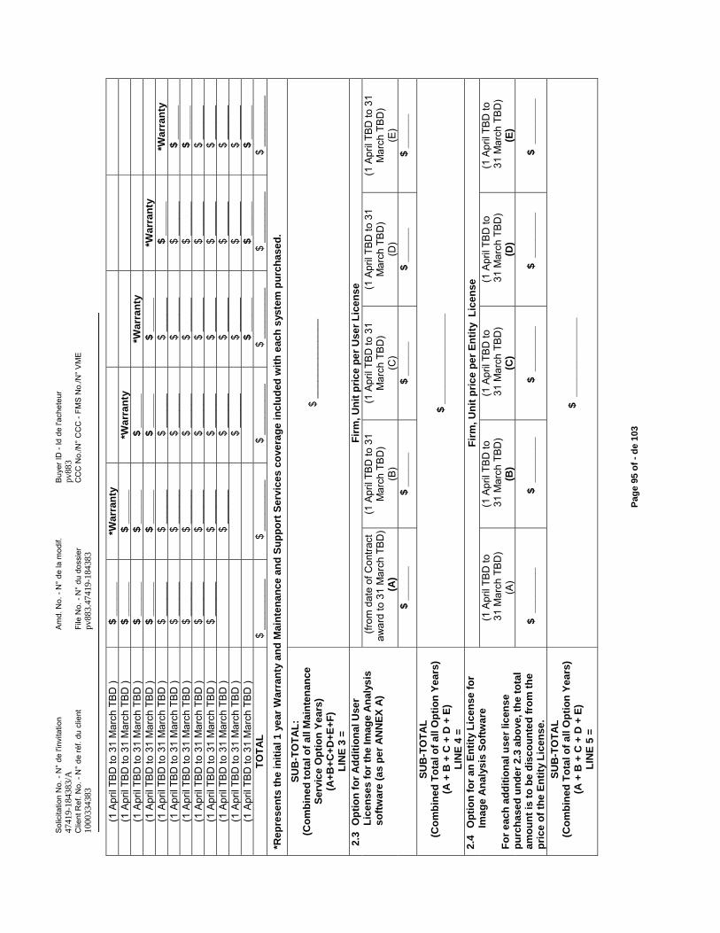
Sol
icita
tion
No.
-N
° de
l'in
vita
tion
Am
d. N
o. -
N°
de la
mod
if.B
uyer
ID -
Id d
e l'a
chet
eur
4741
9-18
4383
/Apv
883
Clie
nt R
ef. N
o. -
N°
de ré
f. du
clie
ntFi
le N
o. -
N°
du d
ossi
erC
CC
No.
/N°
CC
C -
FMS
No.
/N°
VM
E10
0033
4383
pv88
3.47
419-
1843
83
Pag
e 95
of
-d
e 10
3
(1 A
pril
TBD
to 3
1 M
arch
TB
D )
$ _
___
__
*Wa
rra
nty
(1 A
pril
TBD
to 3
1 M
arch
TB
D )
$ _
___
__
$ _
___
__
*Wa
rra
nty
(1 A
pril
TBD
to 3
1 M
arch
TB
D )
$ _
___
__
$ _
___
__
$ _
___
__
*Wa
rra
nty
(1 A
pril
TBD
to 3
1 M
arch
TB
D )
$ _
___
__
$ _
___
__
$ _
___
__
$ _
___
__
*Wa
rra
nty
(1 A
pril
TBD
to 3
1 M
arch
TB
D )
$ __
____
$ __
____
$ __
____
$ __
____
$ _
___
__
*Wa
rra
nty
(1 A
pril
TBD
to 3
1 M
arch
TB
D )
$__
____
$ __
____
$ __
____
$ __
____
$ __
____
$ _
___
__
(1 A
pril
TBD
to 3
1 M
arch
TB
D )
$ __
____
$ __
____
$ __
____
$ __
____
$ __
____
$ _
___
__
(1 A
pril
TBD
to 3
1 M
arch
TB
D )
$ __
____
$ __
____
$ __
____
$ __
____
$ __
____
$ __
____
(1 A
pril
TBD
to 3
1 M
arch
TB
D )
$ __
____
$ __
____
$ __
____
$ __
____
$ __
____
$ __
____
(1 A
pril
TBD
to 3
1 M
arch
TB
D )
$ __
____
$ __
____
$ __
____
$ __
____
$ __
____
(1 A
pril
TBD
to 3
1 M
arch
TB
D )
$ __
____
$ __
____
$ __
____
$ __
____
(1 A
pril
TBD
to 3
1 M
arch
TB
D )
$ _
___
__
$ _
___
__
$_
___
__
TO
TA
L$
____
____
_$
____
____
_$
____
____
_$
____
____
_$
____
____
_$
____
____
_
*Re
pre
se
nts
th
e i
nit
ial 1
yea
r W
arr
an
ty a
nd
Ma
inte
na
nce
an
d S
up
po
rt S
erv
ice
s c
ove
rag
e i
nc
lud
ed w
ith
eac
h s
yste
m p
urc
ha
se
d.
SU
B-T
OT
AL
:(C
om
bin
ed
to
tal o
f a
ll M
ain
ten
an
ce
Se
rvic
e O
pti
on
Ye
ars
)(A
+B
+C
+D
+E
+F
)L
INE
3 =
$ __
____
____
____
2.3
Op
tio
n f
or
Ad
dit
ion
al U
ser
Lic
en
ses
fo
r th
e I
ma
ge
An
aly
sis
so
ftw
are
(as
per
AN
NE
X A
)
Fir
m,
Un
it p
ric
e p
er
Us
er
Lic
en
se
(from
dat
e of
Con
tract
aw
ard
to 3
1 M
arch
TB
D)
(A)
(1 A
pril
TBD
to 3
1 M
arch
TB
D)
(B)
(1 A
pril
TBD
to 3
1 M
arch
TB
D)
(C)
(1 A
pril
TBD
to 3
1 M
arch
TB
D)
(D)
(1 A
pril
TBD
to 3
1 M
arch
TB
D)
(E)
$ _
___
__
$ _
___
__
$ _
___
__
$ _
___
__
$ _
___
__
SU
B-T
OT
AL
(Co
mb
ined
To
tal o
f al
l Op
tio
n Y
ears
)(A
+ B
+ C
+ D
+ E
)L
INE
4 =
$ _
___
__
___
___
___
_
2.4
Op
tio
n f
or
an
En
tity
Lic
en
se
fo
r Im
ag
e A
na
lys
is S
oft
wa
re
Fo
r e
ac
h a
dd
itio
na
l us
er
licen
se
p
urc
ha
sed
un
de
r 2
.3 a
bo
ve, t
he
to
tal
am
ou
nt
is t
o b
e d
isc
ou
nte
d f
rom
th
e
pri
ce
of
the
En
tity
Lic
en
se
.
Fir
m,
Un
it p
rice
pe
rE
nti
ty
Lic
ense
(1A
pril
TBD
to31
Mar
ch T
BD
) (A
)
(1 A
pril
TBD
to31
Mar
ch T
BD
) (B
)
(1 A
pril
TBD
to31
Mar
ch T
BD
) (C
)
(1 A
pril
TBD
to31
Mar
ch T
BD
) (D
)
(1 A
pril
TBD
to31
Mar
ch T
BD
) (E
)
$ _
___
___
_$
__
___
___
$ _
___
___
_$
__
___
___
$ _
___
___
_
SU
B-T
OT
AL
(Co
mb
ined
To
tal o
f al
l Op
tio
n Y
ears
)(A
+ B
+ C
+ D
+ E
)L
INE
5 =
$
__
___
___
___
___
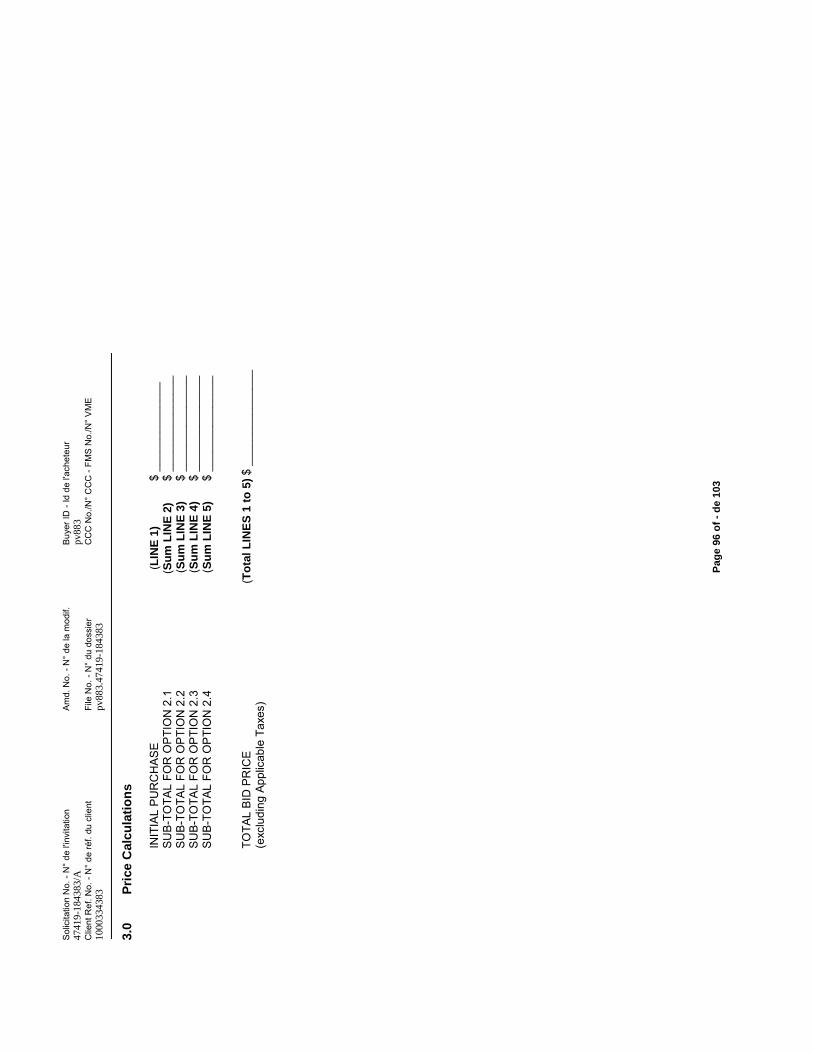
Sol
icita
tion
No.
-N
° de
l'in
vita
tion
Am
d. N
o. -
N°
de la
mod
if.B
uyer
ID -
Id d
e l'a
chet
eur
4741
9-18
4383
/Apv
883
Clie
nt R
ef. N
o. -
N°
de ré
f. du
clie
ntFi
le N
o. -
N°
du d
ossi
erC
CC
No.
/N°
CC
C -
FMS
No.
/N°
VM
E10
0033
4383
pv88
3.47
419-
1843
83
Pag
e 96
of
-d
e 10
3
3.0
Pri
ce C
alcu
lati
on
s
INIT
IAL
PU
RC
HA
SE
(L
INE
1)
$
____
____
____
__S
UB
-TO
TAL
FOR
OP
TIO
N 2
.1
(S
um
LIN
E 2
) $
____
____
____
___
SU
B-T
OTA
L FO
R O
PTI
ON
2.2
(Su
m L
INE
3)
$ __
____
____
____
_S
UB
-TO
TAL
FOR
OP
TIO
N 2
.3(S
um
LIN
E 4
) $
____
____
____
___
SU
B-T
OTA
L FO
R O
PTI
ON
2.4
(Su
m L
INE
5)
$ __
____
____
____
_
TOTA
L B
ID P
RIC
E
(T
ota
l L
INE
S 1
to
5)
$ __
____
____
____
_(e
xclu
ding
App
licab
le T
axes
)
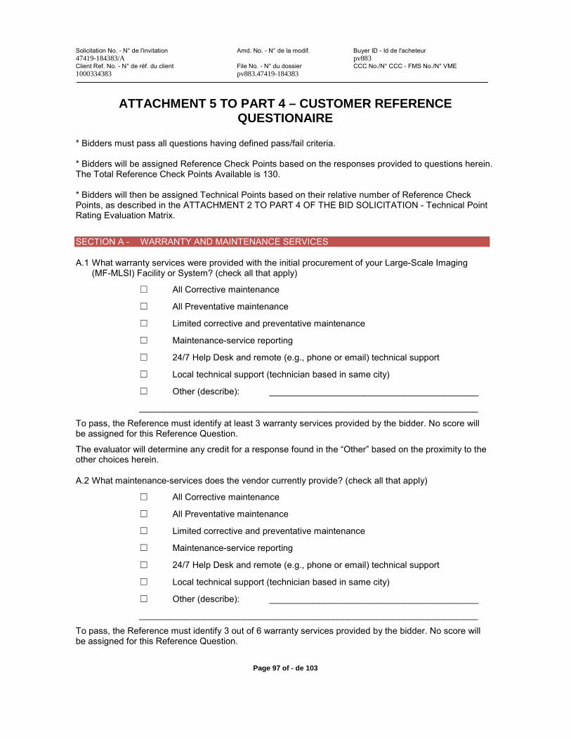
Solicitation No. - N° de l'invitation Amd. No. - N° de la modif. Buyer ID - Id de l'acheteur47419-184383/A pv883Client Ref. No. - N° de réf. du client File No. - N° du dossier CCC No./N° CCC - FMS No./N° VME1000334383 pv883.47419-184383
Page 97 of - de 103
ATTACHMENT 5 TO PART 4 – CUSTOMER REFERENCE QUESTIONAIRE
* Bidders must pass all questions having defined pass/fail criteria.
* Bidders will be assigned Reference Check Points based on the responses provided to questions herein. The Total Reference Check Points Available is 130.
* Bidders will then be assigned Technical Points based on their relative number of Reference Check Points, as described in the ATTACHMENT 2 TO PART 4 OF THE BID SOLICITATION - Technical Point Rating Evaluation Matrix.
SECTION A - WARRANTY AND MAINTENANCE SERVICES
A.1 What warranty services were provided with the initial procurement of your Large-Scale Imaging (MF-MLSI) Facility or System? (check all that apply)
All Corrective maintenance
All Preventative maintenance
Limited corrective and preventative maintenance
Maintenance-service reporting
24/7 Help Desk and remote (e.g., phone or email) technical support
Local technical support (technician based in same city)
Other (describe): __________________________________________
____________________________________________________________________
To pass, the Reference must identify at least 3 warranty services provided by the bidder. No score will be assigned for this Reference Question.
The evaluator will determine any credit for a response found in the “Other” based on the proximity to the other choices herein.
A.2 What maintenance-services does the vendor currently provide? (check all that apply)
All Corrective maintenance
All Preventative maintenance
Limited corrective and preventative maintenance
Maintenance-service reporting
24/7 Help Desk and remote (e.g., phone or email) technical support
Local technical support (technician based in same city)
Other (describe): __________________________________________
____________________________________________________________________
To pass, the Reference must identify 3 out of 6 warranty services provided by the bidder. No score will be assigned for this Reference Question.
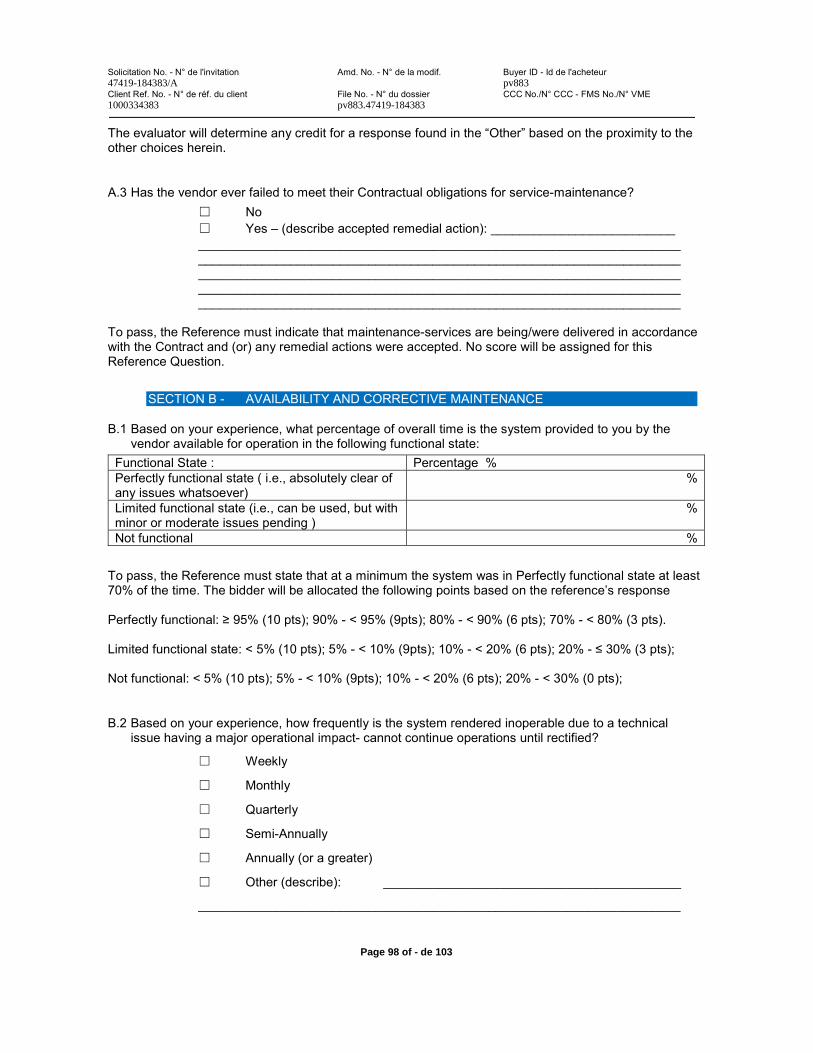
Solicitation No. - N° de l'invitation Amd. No. - N° de la modif. Buyer ID - Id de l'acheteur47419-184383/A pv883Client Ref. No. - N° de réf. du client File No. - N° du dossier CCC No./N° CCC - FMS No./N° VME1000334383 pv883.47419-184383
Page 98 of - de 103
The evaluator will determine any credit for a response found in the “Other” based on the proximity to the other choices herein.
A.3 Has the vendor ever failed to meet their Contractual obligations for service-maintenance? No Yes – (describe accepted remedial action): __________________________
____________________________________________________________________________________________________________________________________________________________________________________________________________________________________________________________________________________________________________________________________________________
To pass, the Reference must indicate that maintenance-services are being/were delivered in accordance with the Contract and (or) any remedial actions were accepted. No score will be assigned for this Reference Question.
SECTION B - AVAILABILITY AND CORRECTIVE MAINTENANCE
B.1 Based on your experience, what percentage of overall time is the system provided to you by the vendor available for operation in the following functional state:
Functional State : Percentage %Perfectly functional state ( i.e., absolutely clear of any issues whatsoever)
%
Limited functional state (i.e., can be used, but with minor or moderate issues pending )
%
Not functional %
To pass, the Reference must state that at a minimum the system was in Perfectly functional state at least 70% of the time. The bidder will be allocated the following points based on the reference’s response
Perfectly functional: 95% (10 pts); 90% - < 95% (9pts); 80% - < 90% (6 pts); 70% - < 80% (3 pts).
Limited functional state: < 5% (10 pts); 5% - < 10% (9pts); 10% - < 20% (6 pts); 20% - % (3 pts);
Not functional: < 5% (10 pts); 5% - < 10% (9pts); 10% - < 20% (6 pts); 20% - < 30% (0 pts);
B.2 Based on your experience, how frequently is the system rendered inoperable due to a technical issue having a major operational impact- cannot continue operations until rectified?
Weekly
Monthly
Quarterly
Semi-Annually
Annually (or a greater)
Other (describe): __________________________________________
____________________________________________________________________
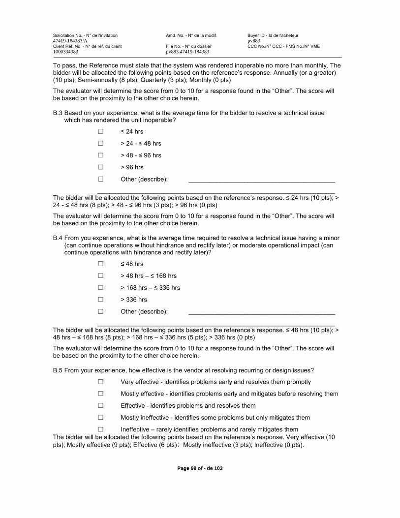
Solicitation No. - N° de l'invitation Amd. No. - N° de la modif. Buyer ID - Id de l'acheteur47419-184383/A pv883Client Ref. No. - N° de réf. du client File No. - N° du dossier CCC No./N° CCC - FMS No./N° VME1000334383 pv883.47419-184383
Page 99 of - de 103
To pass, the Reference must state that the system was rendered inoperable no more than monthly. The bidder will be allocated the following points based on the reference’s response. Annually (or a greater) (10 pts); Semi-annually (8 pts); Quarterly (3 pts); Monthly (0 pts)
The evaluator will determine the score from 0 to 10 for a response found in the “Other”. The score will be based on the proximity to the other choice herein.
B.3 Based on your experience, what is the average time for the bidder to resolve a technical issue which has rendered the unit inoperable?
24 hrs
> 24 - 48 hrs
> 48 - 96 hrs
> 96 hrs
Other (describe): __________________________________________
____________________________________________________________________The bidder will be allocated the following points based on the reference’s response. 24 hrs (10 pts); >24 - (8 pts); > 48 - (3 pts); > 96 hrs (0 pts)
The evaluator will determine the score from 0 to 10 for a response found in the “Other”. The score will be based on the proximity to the other choice herein.
B.4 From you experience, what is the average time required to resolve a technical issue having a minor (can continue operations without hindrance and rectify later) or moderate operational impact (can continue operations with hindrance and rectify later)?
48 hrs
> 48 hrs – 168 hrs
> 168 hrs – 336 hrs
> 336 hrs
Other (describe): __________________________________________
____________________________________________________________________The bidder will be allocated the following points based on the reference’s response. (10 pts); >48 hrs – (8 pts); > 168 hrs – (5 pts); > 336 hrs (0 pts)
The evaluator will determine the score from 0 to 10 for a response found in the “Other”. The score will be based on the proximity to the other choice herein.
B.5 From your experience, how effective is the vendor at resolving recurring or design issues?
Very effective - identifies problems early and resolves them promptly
Mostly effective - identifies problems early and mitigates before resolving them
Effective - identifies problems and resolves them
Mostly ineffective - identifies some problems but only mitigates them
Ineffective – rarely identifies problems and rarely mitigates themThe bidder will be allocated the following points based on the reference’s response. Very effective (10 pts); Mostly effective (9 pts); Effective (6 pts) Mostly ineffective (3 pts); Ineffective (0 pts).
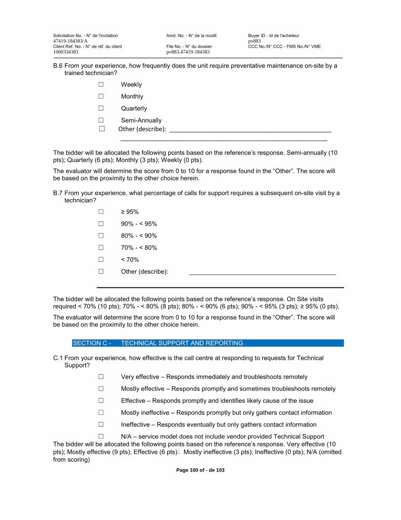
Solicitation No. - N° de l'invitation Amd. No. - N° de la modif. Buyer ID - Id de l'acheteur47419-184383/A pv883Client Ref. No. - N° de réf. du client File No. - N° du dossier CCC No./N° CCC - FMS No./N° VME1000334383 pv883.47419-184383
Page 100 of - de 103
B.6 From your experience, how frequently does the unit require preventative maintenance on-site by a trained technician?
Weekly
Monthly
Quarterly
Semi-Annually Other (describe): _______________________________________________
____________________________________________________________
The bidder will be allocated the following points based on the reference’s response. Semi-annually (10 pts); Quarterly (6 pts); Monthly (3 pts); Weekly (0 pts).
The evaluator will determine the score from 0 to 10 for a response found in the “Other”. The score will be based on the proximity to the other choice herein.
B.7 From your experience, what percentage of calls for support requires a subsequent on-site visit by a technician?
95%
90% - < 95%
80% - < 90%
70% - < 80%
< 70%
Other (describe): __________________________________________
The bidder will be allocated the following points based on the reference’s response. On Site visits required < 70% (10 pts); 70% - < 80% (8 pts); 80% - < 90% (6 pts); 90% - < 95% (3 pts); % (0 pts).
The evaluator will determine the score from 0 to 10 for a response found in the “Other”. The score will be based on the proximity to the other choice herein.
SECTION C - TECHNICAL SUPPORT AND REPORTING
C.1 From your experience, how effective is the call centre at responding to requests for Technical Support?
Very effective – Responds immediately and troubleshoots remotely
Mostly effective – Responds promptly and sometimes troubleshoots remotely
Effective – Responds promptly and identifies likely cause of the issue
Mostly ineffective – Responds promptly but only gathers contact information
Ineffective – Responds eventually but only gathers contact information
N/A – service model does not include vendor provided Technical SupportThe bidder will be allocated the following points based on the reference’s response. Very effective (10 pts); Mostly effective (9 pts); Effective (6 pts) Mostly ineffective (3 pts); Ineffective (0 pts); N/A (omitted from scoring)
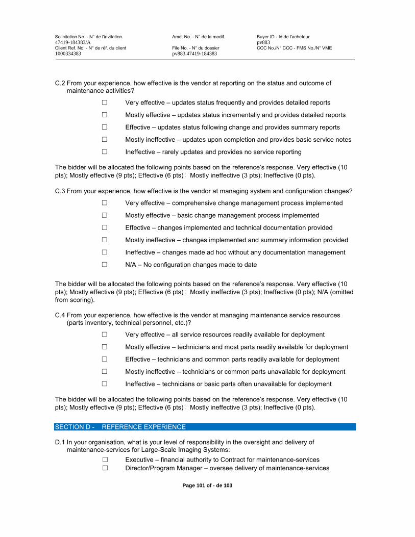
Solicitation No. - N° de l'invitation Amd. No. - N° de la modif. Buyer ID - Id de l'acheteur47419-184383/A pv883Client Ref. No. - N° de réf. du client File No. - N° du dossier CCC No./N° CCC - FMS No./N° VME1000334383 pv883.47419-184383
Page 101 of - de 103
C.2 From your experience, how effective is the vendor at reporting on the status and outcome of maintenance activities?
Very effective – updates status frequently and provides detailed reports
Mostly effective – updates status incrementally and provides detailed reports
Effective – updates status following change and provides summary reports
Mostly ineffective – updates upon completion and provides basic service notes
Ineffective – rarely updates and provides no service reporting
The bidder will be allocated the following points based on the reference’s response. Very effective (10 pts); Mostly effective (9 pts); Effective (6 pts) Mostly ineffective (3 pts); Ineffective (0 pts).
C.3 From your experience, how effective is the vendor at managing system and configuration changes?
Very effective – comprehensive change management process implemented
Mostly effective – basic change management process implemented
Effective – changes implemented and technical documentation provided
Mostly ineffective – changes implemented and summary information provided
Ineffective – changes made ad hoc without any documentation management
N/A – No configuration changes made to date
The bidder will be allocated the following points based on the reference’s response. Very effective (10 pts); Mostly effective (9 pts); Effective (6 pts) Mostly ineffective (3 pts); Ineffective (0 pts); N/A (omitted from scoring).
C.4 From your experience, how effective is the vendor at managing maintenance service resources (parts inventory, technical personnel, etc.)?
Very effective – all service resources readily available for deployment
Mostly effective – technicians and most parts readily available for deployment
Effective – technicians and common parts readily available for deployment
Mostly ineffective – technicians or common parts unavailable for deployment
Ineffective – technicians or basic parts often unavailable for deployment
The bidder will be allocated the following points based on the reference’s response. Very effective (10 pts); Mostly effective (9 pts); Effective (6 pts) Mostly ineffective (3 pts); Ineffective (0 pts).
SECTION D - REFERENCE EXPERIENCE
D.1 In your organisation, what is your level of responsibility in the oversight and delivery of maintenance-services for Large-Scale Imaging Systems:
Executive – financial authority to Contract for maintenance-servicesDirector/Program Manager – oversee delivery of maintenance-services

Solicitation No. - N° de l'invitation Amd. No. - N° de la modif. Buyer ID - Id de l'acheteur47419-184383/A pv883Client Ref. No. - N° de réf. du client File No. - N° du dossier CCC No./N° CCC - FMS No./N° VME1000334383 pv883.47419-184383
Page 102 of - de 103
Manager – supervise maintenance-service technicians and equipmentTechnician – diagnose and resolve maintenance-service issues
Other (Title and description of responsibility): _________________________
____________________________________________________________________
____________________________________________________________________
____________________________________________________________________
____________________________________________________________________
D.2 How long have you held this responsibility
____ years
To pass, the Reference must have held this level of responsibility for least 6 months in the last 3 years and be currently employed by the same organization.
The evaluator will determine the applicability of a response found in the “Other”. The assessment will be based on the title and description to the other choice herein.
No score will be assigned for this Reference Question.
D.3 In your organisation, what is your level of responsibility in the Procurement and Management of Large-Scale Imaging (MF-MLSI) Systems:
Executive – financial authority to Procure assets > $1 M USDDirector/Program Manager – determine organizational requirements Manager – develop statement of requirements and evaluate bidsTechnician – provide input into procurement requirements
Other (describe): __________________________________________
____________________________________________________________________
____________________________________________________________________
____________________________________________________________________
For information only; no score will be assigned for this Reference Question.
D.4 If your organization were to procure additional Large-Scale Imaging Systems, how likely is it that you will procured the same or updated model as previously:
Very Likely – Contracting mechanism is already in place or being preparedLikely – subject to competitive procurement processes Possibly – if new capabilities were demonstratedUnlikely – our organizational needs have changed
Other (describe): __________________________________________
____________________________________________________________________
____________________________________________________________________
____________________________________________________________________
For information only; no score will be assigned for this Reference Question.

Solicitation No. - N° de l'invitation Amd. No. - N° de la modif. Buyer ID - Id de l'acheteur47419-184383/A pv883Client Ref. No. - N° de réf. du client File No. - N° du dossier CCC No./N° CCC - FMS No./N° VME1000334383 pv883.47419-184383
Page 103 of - de 103
NAME ________________________________________________
TITLE ________________________________________________
SIGNATURE ________________________________________________
DATE _______________


