Embed Size (px)
Citation preview
RNI: DELENG/2005/15153 No: DL(E)-01/5079/17-19 Publication: 15th of every month Licensed to post without pre-payment U(E) 28/2017-19Posting: 19th/20th of every month at NDPSO Rs.150
Volume XV, Issue 5, May 2019 THE MONTHLY MAGAZINE ON POSITIONING, NAVIGATION AND BEYOND
ISSN
0973-2
136
Soil moisture retrieval using NavIC-GPS-SBAS receiver
Robotic forest harvesting process using GNSS

Rethinkingasset management.At 172 megapixels per full-spherical image, the UltraCam Panther Reality Capture System lets you capture your production plant in more detail, with superior sharpness and in higher fidelity than ever before.
Discover more on www.vexcel-imaging.com
Indoor and outdoor mapping even without GPS
Multitude of use cases through
modular design
Easy to deploy, operate and
maintain
U LT R A C A M P A N T H E R K E Y F E AT U R E S
Coordinates May 2019 | 3
Rethinkingasset management.At 172 megapixels per full-spherical image, the UltraCam Panther Reality Capture System lets you capture your production plant in more detail, with superior sharpness and in higher fidelity than ever before.
Discover more on www.vexcel-imaging.com
Indoor and outdoor mapping even without GPS
Multitude of use cases through
modular design
Easy to deploy, operate and
maintain
U LT R A C A M P A N T H E R K E Y F E AT U R E S
i50 GNSS RTK Brings speed and accuracy in one easy-to-use GNSS solution
Preset work modesSelect configurations in a few
Full GNSS technologyGPS+Glonass+Beidou+Galileo
Extended connectivity
Rugged and compactIndustrial design to withstand
Internal UHF and 4G modems for robust data quality
seconds for higher productivity
for optimized field operations
harsh environmental conditions
Contact us at [email protected]
WWW.CHCNAV.COM
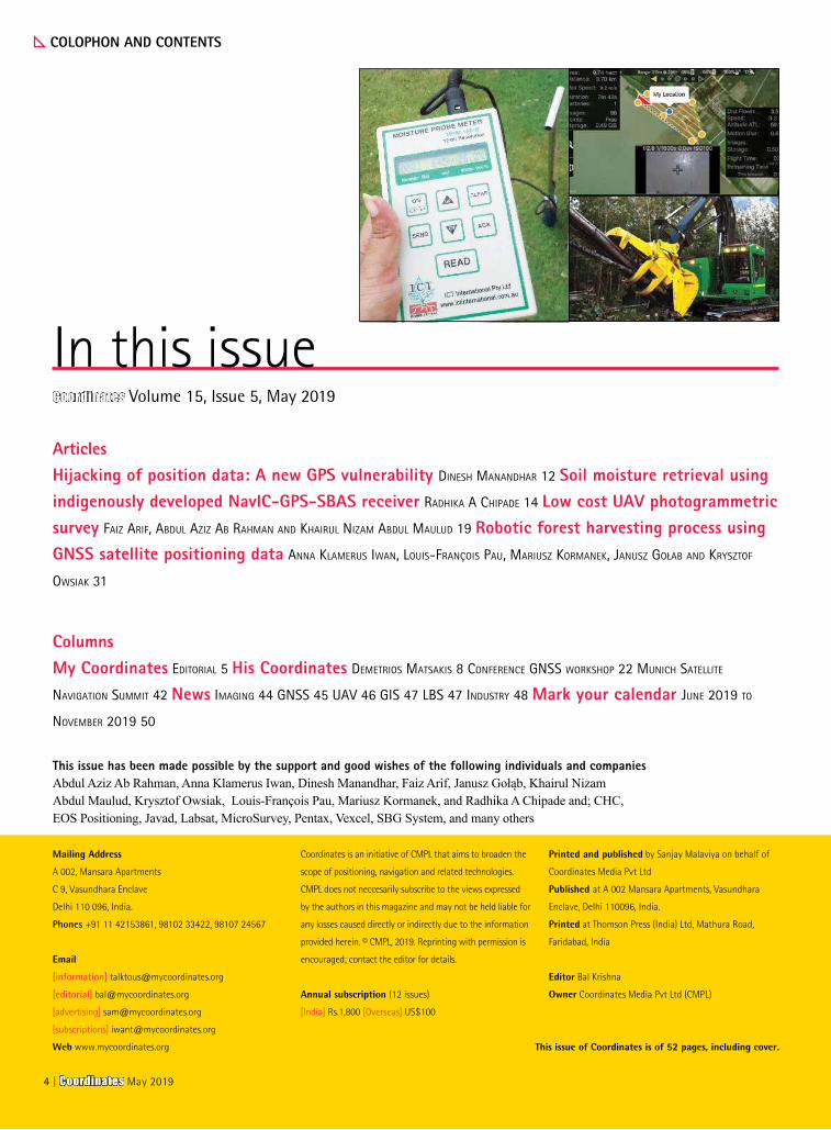
ArticlesHijacking of position data: A new GPS vulnerability Dinesh MananDhar 12 Soil moisture retrieval using indigenously developed NavIC-GPS-SBAS receiver raDhika a ChipaDe 14 Low cost UAV photogrammetric survey Faiz ariF, abDul aziz ab rahMan anD khairul nizaM abDul MauluD 19 Robotic forest harvesting process using GNSS satellite positioning data anna klaMerus iwan, louis-François pau, Mariusz korManek, Janusz Gołab anD krysztoF
owsiak 31
This issue has been made possible by the support and good wishes of the following individuals and companies Abdul Aziz Ab Rahman, Anna Klamerus Iwan, Dinesh Manandhar, Faiz Arif, Janusz Gołąb, Khairul Nizam Abdul Maulud, Krysztof Owsiak, Louis-François Pau, Mariusz Kormanek, and Radhika A Chipade and; CHC, EOS Positioning, Javad, Labsat, MicroSurvey, Pentax, Vexcel, SBG System, and many others
COLOPHON AND CONTENTS
Mailing Address
A 002, Mansara Apartments
C 9, Vasundhara Enclave
Delhi 110 096, India.
Phones +91 11 42153861, 98102 33422, 98107 24567
[information] [email protected]
[editorial] [email protected]
[advertising] [email protected]
[subscriptions] [email protected]
Web www.mycoordinates.org
In this issueCoordinates Volume 15, Issue 5, May 2019
Coordinates is an initiative of CMPL that aims to broaden the
scope of positioning, navigation and related technologies.
CMPL does not neccesarily subscribe to the views expressed
by the authors in this magazine and may not be held liable for
any losses caused directly or indirectly due to the information
provided herein. © CMPL, 2019. Reprinting with permission is
encouraged; contact the editor for details.
Annual subscription (12 issues)
[India] Rs.1,800 [Overseas] US$100
Printed and published by Sanjay Malaviya on behalf of
Coordinates Media Pvt Ltd
Published at A 002 Mansara Apartments, Vasundhara
Enclave, Delhi 110096, India.
Printed at Thomson Press (India) Ltd, Mathura Road,
Faridabad, India
Editor Bal Krishna
Owner Coordinates Media Pvt Ltd (CMPL)
ColumnsMy Coordinates eDitorial 5 His Coordinates DeMetrios Matsakis 8 ConFerenCe Gnss workshop 22 MuniCh satellite
naviGation suMMit 42 News iMaGinG 44 Gnss 45 uav 46 Gis 47 lbs 47 inDustry 48 Mark your calendar June 2019 to
noveMber 2019 50
This issue of Coordinates is of 52 pages, including cover.
4 | Coordinates May 2019


ADVISORS Naser El-Sheimy PEng, CRC Professor, Department of Geomatics Engineering, The University of Calgary Canada, George
Cho Professor in GIS and the Law, University of Canberra, Australia, Professor Abbas Rajabifard Director, Centre for SDI and Land
Administration, University of Melbourne, Australia, Luiz Paulo Souto Fortes PhD Associate Professor, University of State of Rio Janeiro
(UERJ), Brazil, John Hannah Professor, School of Surveying, University of Otago, New Zealand
MYCOORDINATES
As the state of Odisha in India grapples with the aftermath of cyclone Fani,
What deserves to be appreciated
Is the initial response of the Odisha government.
Timely weather alerts, preparedness and public participation
Have played the key roles.
Though Fani has caused massive devastation,
Loss of lives were limited to 41
Given the fact that the millions were affected.
This is in sharp contrast with the loss of 10,000 people
When the ill-fated state was hit by super cyclone 05B in 1999.
Although restoration of infrastructure and rehabilitation of people
Will be a long battle,
The management of Cyclone Fani within the available resources.
Is in a way, a success story.
Bal Krishna, Editor [email protected]
Setting an example
6 | Coordinates May 2019

What is the importance of satellite clock?
Without precise satellite clocks, GNSS systems as they are designed today would not work, because a satellite’s chief utility comes from broadcasting the time of its clock in analog form. A satellite also broadcasts crucial digital information, such as where the satellite is and how far off its clock is – but those could in theory also be provided by other means, including the internet. Since it takes time for the GNSS analog signals to arrive at the receiver, it can use the difference between its internal time and the received time to infer the distance of the satellite. That’s called the pseudorange, and once you have this value for four or more satellites it’s only a matter of math and digital corrections to figure out where the receiver is and the time as referenced to the GNSS constellation. One important correction is the difference between the time of a GNSS clock, which is free-running, and the system time. Since each satellite is only told its time and orbital elements at specific intervals, once a day for GPS but every 100 minutes for Galileo, any wandering its clock might do in time or space leads to an error in the positioning – for most applications that would of course be a small error.
In the distant future however, it is possible that a GNSS system will be designed with cross links between satellites that will allow almost immediate synchronization of their clocks. In that case, good oscillators could
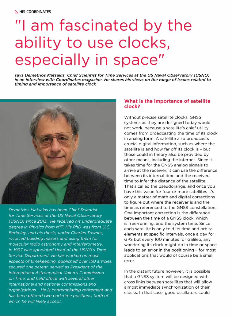
says Demetrios Matsakis, Chief Scientist for Time Services at the US Naval Observatory (USNO) in an interview with Coordinates magazine. He shares his views on the range of issues related to timing and importance of satellite clock
"I am fascinated by the ability to use clocks, especially in space"
Demetrios Matsakis has been Chief Scientist
for Time Services at the US Naval Observatory
(USNO) since 2013. He received his undergraduate
degree in Physics from MIT. His PhD was from U.C.
Berkeley, and his thesis, under Charles Townes,
involved building masers and using them for
molecular radio astronomy and interferometry.
In 1997 was appointed Head of the USNO’s Time
Service Department. He has worked on most
aspects of timekeeping, published over 150 articles,
secured one patent, served as President of the
International Astronomical Union’s Commission
on Time, and held office with several other
international and national commissions and
organizations. He is contemplating retirement and
has been offered two part-time positions, both of
which he will likely accept.
HIS COORDINATES
be substituted for clocks. Positioning just needs all the clocks to be at the same time, and the correction for UTC can be derived using constant uploads from the ground via intermediate satellites. Such a scheme is being proposed by researchers at the DLR.
What are more important GNSS applications and their timing requirements?
Measuring an application’s importance in terms of money, financial systems are being increasingly regulated with tighter and tighter requirements – right now the EU requires 100 microseconds for High Frequency Trading. The application with the greatest number of users would be mobile phones. They get their time from cell phone towers, which usually get their time for GNSS and which usually need it at the microsecond level so the cell towers can communicate with each other. Measuring an application in terms of precision, nanosecond-level requirements come from pure and applied research applications that require synchronizing clocks over a distance. For example, Very Long Baseline Interferometry is based upon synchronizing radio telescopes located around the world so they act like one big one the size of the Earth. This how the Event Horizon Telescope imaged a black hole recently, although in this case they supplemented GNSS with internal adjustments of their data. For many research purposes, such as verifying that neutrinos do not exceed the speed of light, there is no limit to the desired level of accuracy.
Please explain our readers the concept of GNSS time transfer?
Time Transfer is a term for measuring the difference between two clocks. It is never trivial
at the nanosecond level, particularly for clocks too far apart to connect with a simple cable. While specialized means exist that utilize point-to-point connections, such as optical fibers and Two Way Satellite Time and Frequency Transfer, GNSS is often the most practical means available. Here is how it works: Users A and B apply properly calibrated GNSS systems to measure the time difference between their local clocks and the time of a GNSS satellite, system, or systems. If you call these differences A-GNSS and B-GNSS, the difference between the two ground clocks is A-B = (A-GNSS)-(B-GNSS). There are many different ways to do the measurements, but the basic idea is the same.
How time transfer is different from frequency transfer?
Often misunderstood, frequency transfer is just uncalibrated time transfer. This is because you can get the frequency from data that look like time transfer, whether or not your systems are calibrated. You do that by dividing the difference between consecutive time measurements by the interval between them - this taking the derivative if you know calculus. But it doesn’t go the other way. If you have only the frequency differences, you can’t generate the time differences by just adding up the frequency differences times their intervals.
You also need to know the time at the start – in terms of calculus that would be the constant of integration and in terms of engineering that would be the calibration. As a result, if you have data with time transfer units but are not calibrated, it is frequency transfer because you can’t say anything about the time difference between the clocks but you can say everything about the frequency difference between them.
Do different GNSS systems have different time references?
Yes. In order to operate, GNSS systems have to generate their own time references so the equipment can perform. Since a user can get much improved positioning by combining data from multiple GNSS systems, GNSS systems are moving towards broadcasting the difference between their system time and the system time
In the distant future however, it is
possible that a GNSS system will be
designed with cross links between
satellites that will allow almost immediate
synchronization of their clocks
Coordinates May 2019 | 9
of cooperating GNSS systems.The GGTO (Galileo/GPS Time Offset) is an example – USNO has for years been measuring this offset and reporting it to their respective operations centers. Of course, the user’s receiver can also infer the difference as a parameter in its position-and-time solution. That effectively removes one satellite from the solution for each new GNSS system used, but it has the advantage of also correcting for any of the receiver’s GNSS-specific calibration biases. None of this provides an answer for which GNSS time to define as “correct”, and which GNSS time to re-reference – the receiver will have to be told that by the user.
Are the time obtained from GNSS satellite signals are related to the international time scale, UTC?
All GNSS systems seek to provide UTC. Technically speaking, UTC is realized only at a participating laboratory, k, and that realization is termed UTC(k). It is defined by an electronic signal generated at that laboratory. UTC can be derived from after-the fact corrections to the UTC(k), published monthly by the International Bureau of Weights and Measures (BIPM) in the Circular T. Since each GNSS system time is set by some sort of control loops to a national lab, or a group of national labs for Galileo, the time as broadcast by GNSS is only a prediction of the UTC(k), which themselves are imperfect predictions/realizations of what UTC will have been determined to be when the Circular T comes out. But these are very good
predictions. In the end, the difference between GNSS predictions of UTC are at the level of a few nanoseconds. Most users don’t care, especially as their receivers may have biases much larger than that. Those who do care can usually wait until all the information is available so as to correct their data. I can refer users who need traceability to UTC to an article published in the 2018 proceedings of ION-PTTI, a version of this has just appeared in the March/April 2019 GNSS Solutions. In this article Judah Levine and Michael Lombardi from the National Institute of Standards and Technology (NIST), along with me, describe what would be needed to use GNSS data for traceability to UTC.
The details about how GNSS systems provide UTC can differ. For all but GLONASS, the GNSS clock corrections are first given in terms of their system time, which are continuous time scales that do not jump when leap seconds are inserted. Instead, other digital corrections enable the receiver to infer the number of leap seconds as well as how to relate the satellite clocks to the relevant UTC(k)’s. For GLONASS, no continuous system time is broadcast. Rather GLONASS clock corrections give a prediction of UTC(SU), SU being the identifier for their national timing lab VINIFRI. So GLONASS clocks appear to jump with every leap second – let’s just call it a programmer’s nightmare.
Is there any multi-GNSS clock solution?
This can be easily done inside of GNSS receivers, and people are actively working on how to do best do it at the professional level. Although not important for a receiver in an automobile, there are biases between satellites and systems that need to be worked out. In 2004-2007, involving MITRE and USNO, it was found that biases can be a function of receiver type, receiver setting, and which individual satellite is being observed.
With the advent of satellites that broadcast more than two frequencies, such biases result in measurements of the ionosphere, which requires two frequencies, yielding systematically different values depending on which pair of frequencies is used. Pinning these biases down will be an interesting problem for the years to come.
Measuring an application’s importance
in terms of money, financial systems
are being increasingly regulated with
tighter and tighter requirements – right
now the EU requires 100 microseconds
for High Frequency Trading. The
application with the greatest number
of users would be mobile phones
10 | Coordinates May 2019
How to ensure that GNSS receivers are functioning correctly as a reliable source of time?
You are asking a deep question, in many ways equivalent to the question of how do we know any clocks are measuring the right time. Receiver manufacturers should be able to provide an estimate on how well calibrated their products are. Comparing multiple receivers and/or receivers getting time from multiple GNSS constellations will help. Sanity-checks can be made using direct comparisons with time from a national lab, over the Internet using Network Time Protocol (NTP), or as a last resort over the telephone. Depending on where you are, there may be low-frequency transmissions such as WWVB, JYY, or DCF77, or even LORAN.
Would you like to comment on the clock failures that some of the GNSS systems had to go through?
Any piece of equipment is vulnerable to failures of all sorts, and that is why GNSS systems typically have many safeguards. Unless diagnostic information leads to a satellite being proactively marked unhealthy, there will always be a lag between a failure and the satellite being marked. The more redundancy we have in terms of satellites, and even satellite systems, the better job a receiver can do in detecting and eliminating them on its own. Most of the GPS failures have not been due to clocks – as any reader of your magazine can infer. Many of those failures could have been avoided if receiver manufacturers had correctly programmed the
ICD200 – they certainly would have had no problems with the roll-over, leap seconds, or some of the other well-publicized failures.
Any research going on in the domain of clock development? What are the key challenges in clock development?
There is of course a widely publicized rapidly advancing worldwide effort to create fully functional optical clocks, with precisions of 10-18 and better. For many applications it is not just a matter of being more precise. Especially for GNSS it can also involve such things as reductions in weight, size, power consumption, temperature dependence, and sensitivity to shaking. As a scientist, I am fascinated by the ability to use clocks, especially clocks in space, to expand our knowledge of astronomy and for fundamental tests of relativity and quantum mechanics. But equally interesting from an engineering point of view are the benefits of clocks in space being better able to keep time between uploads, and how a better clock inside a receiver might help it find its position faster.
What is your role as Chief Scientist for Time Services at the US Naval Observatory (USN0)?
According to my position description, I have no role in day-to-day operations aside from quality control. This leaves me free to conduct research on various things – in the past few years I have worked on a test of general relativity involving GPS observations word-wide, better ways to steer clocks, the precision of time delivery via the phase of electric power in the USA, how to better predict the rotation of the Earth so GPS can better account for its variations, and as I mentioned how to use GPS to establish traceability to UTC. I also looked into some subnanosecond peculiarities in our GPS receivers, which ultimately resulted in a resolution by the Consultative Committee on Time and Frequency (CCTF) that GNSS manufacturers take steps to minimize the code-phase latching biases. I have held or hold various offices for the IAU, URSI, and ITU, and serve on the technical advisory committee of ION-PTTI. It seems I am frequently asked to referee journal articles, which I like because it helps keep me informed.
Most of the GPS failures have not been due
to clocks. Many of those failures could have
been avoided if receiver manufacturers
had correctly programmed the ICD200 –
they certainly would have had no problems
with the roll-over, leap seconds, or some
of the other well-publicized failures
Coordinates May 2019 | 11
GNSS
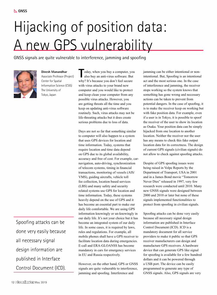
Hijacking of position data: A new GPS vulnerabilityGNSS signals are quite vulnerable to interference, jamming and spoofing
Dinesh ManandharAssociate Professor (Project)Center for Spatial Information Science (CSIS)The University of Tokyo, Japan
Today, when you buy a computer, you also buy an anti-virus software. But
why? It’s because you don’t feel secure with virus attacks to your brand new computer and you would like to protect and keep clean your computer from any possible virus attacks. However, you are getting threats all the time and you keep on updating anti-virus software routinely. Such, virus attacks may not be life-threating attacks but it does create serious problems due to loss of data.
Days are not so far that something similar to computer will also happen to a system that uses GPS devices for location and time information. Today, systems that require location and time data depend on GPS due to its global availability, accuracy and free of cost. For example, car-navigation, auto-driving, synchronization of telecom systems, timing in financial transactions, monitoring of vessels (AIS/VMS), guiding aircrafts, vehicle toll fee collection, location based services (LBS) and many safety and security related systems use GPS for location and time information. Today, these systems heavily depend on the use of GPS and it has become an essential part to make our daily life comfortable. We are using GPS information knowingly or un-knowingly in our daily life. It’s not your choice but it has become an integrated system of our daily life. In some cases, it is required by laws, rules and regulations. For example, all mobile phones shall have a GPS receiver to facilitate location data during emergencies. E-call and ERA-GLOANSS has become mandatory in cars for emergency services in EU and Russia respectively.
However, on the other hand, GPS or GNSS signals are quite vulnerable to interference, jamming and spoofing. Interference and
jamming can be either intentional or non-intentional. But, Spoofing is an intentional act and the most serious one. In the case of interference and jamming, the receiver stops working so the system knows that something has gone wrong and necessary actions can be taken to prevent from potential dangers. In the case of spoofing, it is to make the receiver keep on working but with fake position data. For example, even if a user is in Tokyo, it is possible to spoof the receiver of the user to show its location as Osaka. Your position data can be simply hijacked from one location to another location. Neither the receiver nor the user has any means to check this fake output location data for its correctness. The design of current GPS signals (civilian signals) do not allow to check against spoofing attacks.
Despite of GPS spoofing issues were being raised in Volpe Reports by the Department of Transport, USA in 2001 and in a James Bond movie “Tomorrow Never Dies” released in 1997, very few research were conducted until 2010. Many new GNSS signals were designed between 2000 and 2010 or later but none of these signals implemented functionalities to protect from spoofing in civilian signals.
Spoofing attacks can be done very easily because all necessary signal design information are published in Interface Control Document (ICD). ICD is a mandatory document for all service providers to make it public so that GPS receiver manufacturers can design and manufacture GPS receivers. A hardware device that can generate GPS like signal for spoofing is available for a few hundred dollars and it can be powered through a USB port. The device can be easily programmed to generate any type of GNSS signals. Also, GPS signals are very
Spoofing attacks can be
done very easily because
all necessary signal
design information are
published in Interface
Control Document (ICD).
12 | Coordinates May 2019
weak power signals (-130dBm at receiver antenna which is below the thermal noise of the device) and a spoofer signal at very low power, say -64dBm (EIRP at transmitter antenna) is strong enough to spoof receivers in it’s vicinity of about 5-10 meters radius. -64dBm corresponds to license free signal power at the transmitter antenna (EIRP) at 1-10GHz frequency in Japan. This level of very weak signal is not a problem in terms of interference and jamming because it will not have any significant impact on other signals beyond 1-3m distance. But, if we consider spoofing attacks, this power level is strong enough to attack users in its vicinity within 5-10 meters. The radio regulations in many countries basically focus on interference and jamming vulnerabilities but not spoofing. The radio regulations related with GNSS or RNSS frequencies shall be revised considering spoofing issues as well. For example, the government of the USA does not allow broadcasting any other signal in the RNSS (used for GPS/
GNSS) frequency bandwidths. However, this is just an overall approach to keep the whole RNSS bandwidth clean from any other harmful signals. This may help to protect from interference and jamming but not from spoofing. For example, what will happen if some systems intentionally or un-intentionally transmits a GPS like signal to spoof GPS users from space?
After 2010, we have seen many research, papers and some tentative solutions coming up to solve spoofing issues. However it is not an easy task since these solutions have to be compatible with the signals already in the space and without impact on existing receiver hardware integrated with other systems. We have been working in this field for more than ten years. We have already developed a test-bed system few years ago that is capable to conduct real-time authentication tests by broadcasting test signals from QZSS satellites. Our system is capable to authenticate GPS
(USA), GALILEO (EU) and BEIDOU (China) beside QZSS (Japan) signals. GALILEO has also announced that it’s open signal in E1 band will also provide authentication capabilities.
Thus, we do see bright aspects in protecting the GPS systems from spoofing attacks. This means that in the next few years when you buy a GPS receiver or GPS based system, you will also be buying an “anti-virus package” to protect your GPS from spoofing attacks. We call this “anti-virus package” as “Signal authentication service” that will detect whether the position and time data from your receiver is actually computed from the GPS satellites in the space or not. This type of authentication service will be a must for safe and secure operation of auto-driving and many other safety and security related applications.
Please refer https://home.csis.u-tokyo.ac.jp/~dinesh/index.htm for more information related with GNSS.
GNSS
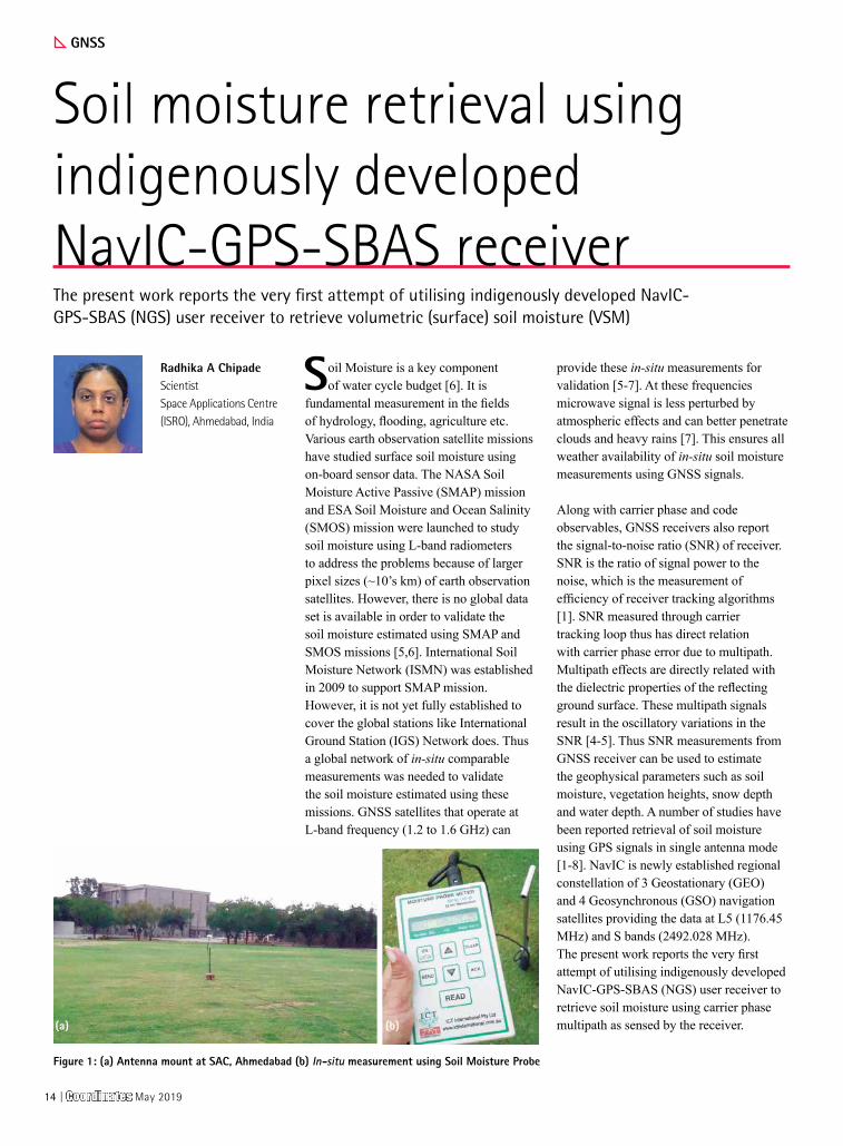
Soil moisture retrieval using indigenously developed NavIC-GPS-SBAS receiverThe present work reports the very first attempt of utilising indigenously developed NavIC-GPS-SBAS (NGS) user receiver to retrieve volumetric (surface) soil moisture (VSM)
Radhika A ChipadeScientistSpace Applications Centre (ISRO), Ahmedabad, India
Soil Moisture is a key component of water cycle budget [6]. It is
fundamental measurement in the fields of hydrology, flooding, agriculture etc. Various earth observation satellite missions have studied surface soil moisture using on-board sensor data. The NASA Soil Moisture Active Passive (SMAP) mission and ESA Soil Moisture and Ocean Salinity (SMOS) mission were launched to study soil moisture using L-band radiometers to address the problems because of larger pixel sizes (~10’s km) of earth observation satellites. However, there is no global data set is available in order to validate the soil moisture estimated using SMAP and SMOS missions [5,6]. International Soil Moisture Network (ISMN) was established in 2009 to support SMAP mission. However, it is not yet fully established to cover the global stations like International Ground Station (IGS) Network does. Thus a global network of in-situ comparable measurements was needed to validate the soil moisture estimated using these missions. GNSS satellites that operate at L-band frequency (1.2 to 1.6 GHz) can
provide these in-situ measurements for validation [5-7]. At these frequencies microwave signal is less perturbed by atmospheric effects and can better penetrate clouds and heavy rains [7]. This ensures all weather availability of in-situ soil moisture measurements using GNSS signals.
Along with carrier phase and code observables, GNSS receivers also report the signal-to-noise ratio (SNR) of receiver. SNR is the ratio of signal power to the noise, which is the measurement of efficiency of receiver tracking algorithms [1]. SNR measured through carrier tracking loop thus has direct relation with carrier phase error due to multipath. Multipath effects are directly related with the dielectric properties of the reflecting ground surface. These multipath signals result in the oscillatory variations in the SNR [4-5]. Thus SNR measurements from GNSS receiver can be used to estimate the geophysical parameters such as soil moisture, vegetation heights, snow depth and water depth. A number of studies have been reported retrieval of soil moisture using GPS signals in single antenna mode [1-8]. NavIC is newly established regional constellation of 3 Geostationary (GEO) and 4 Geosynchronous (GSO) navigation satellites providing the data at L5 (1176.45 MHz) and S bands (2492.028 MHz). The present work reports the very first attempt of utilising indigenously developed NavIC-GPS-SBAS (NGS) user receiver to retrieve soil moisture using carrier phase multipath as sensed by the receiver.
Figure 1: (a) Antenna mount at SAC, Ahmedabad (b) In-situ measurement using Soil Moisture Probe
(a) (b)
14 | Coordinates May 2019
Data used
Indigenously developed NGS receiver by M/s. Accord Ltd. was used to record the NavIC and GPS signal strengths. Data was collected at Space Applications Centre (SAC), Ahmedabad for continuously 4 days to log the SNR measurements. Elevation angle cut-off for the receiver was kept at 5o. SNR data for NavIC L5 (1176.45 MHz) and GPS L1 (1575.42 MHz) were logged using L1-L5-S tri-band antenna. Antenna was mounted at a height of 1.3 m from the ground with soil as the reflecting surface and with no other reflecting surface in 225 m2 area surrounding the antenna (figure 1a).
In-situ measurements of volumetric surface soil moisture (in m3.m-3) were done using a soil moisture probe by M/s. ICT International Ltd. at regular interval of 3 hrs for 4 days for validation of estimated soil moisture values (figure 1b) during day time between 1000 hrs to 1800 hrs.
Methodology
As stated earlier, reflected multipath signals cause temporal variations in the SNR. The changes in the geophysical parameters such as soil moisture affect the amplitude, frequency and phase of the SNR. When there is no multipath, SNR is equivalent to direct amplitude of the received signals. In presence of multipath, SNR is combination of direct amplitude (Ad), multipath amplitude (Am) and multipath relative phase (Ψ) as given by equation (1), derived using the geometry of phase relationship between in-phase (I) and quadrature (Q) channels used in carrier tracking loop [2].
(1)
Multipath relative phase (Ψ) is a function of satellite elevation angle (θ), antenna height above the ground (h) and the wavelength of the signal (λ) as given by equation (2) [2]. Satellite motion substantially affects the phase of multipath reflections as shown by equation (2).
(2)
These multipath reflections are directly
proportional to the dielectric properties of the reflecting surface and thus are directly related to the geophysical parameter such as soil moisture.
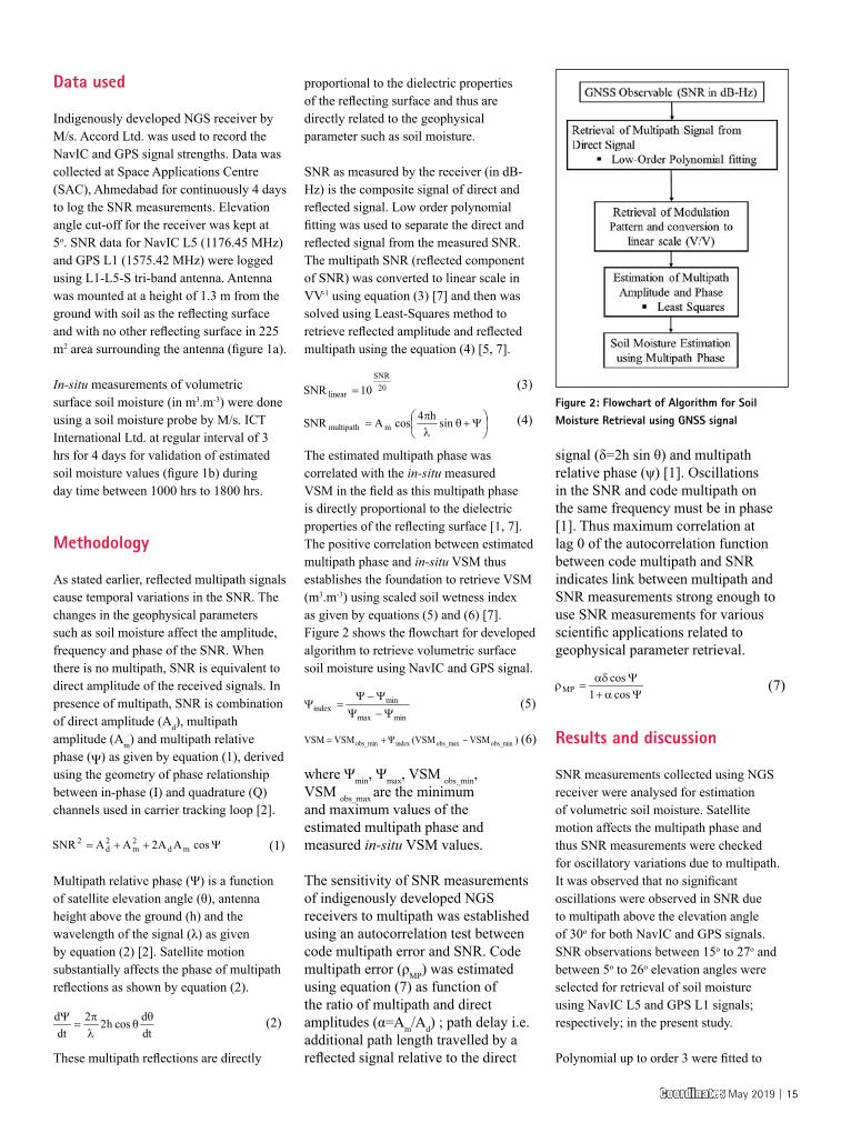
SNR as measured by the receiver (in dB-Hz) is the composite signal of direct and reflected signal. Low order polynomial fitting was used to separate the direct and reflected signal from the measured SNR. The multipath SNR (reflected component of SNR) was converted to linear scale in VV-1 using equation (3) [7] and then was solved using Least-Squares method to retrieve reflected amplitude and reflected multipath using the equation (4) [5, 7].
(3)
(4)
The estimated multipath phase was correlated with the in-situ measured VSM in the field as this multipath phase is directly proportional to the dielectric properties of the reflecting surface [1, 7]. The positive correlation between estimated multipath phase and in-situ VSM thus establishes the foundation to retrieve VSM (m3.m-3) using scaled soil wetness index as given by equations (5) and (6) [7]. Figure 2 shows the flowchart for developed algorithm to retrieve volumetric surface soil moisture using NavIC and GPS signal.
(5)
(6)
where Ψmin, Ψmax, VSM obs_min, VSM obs_max are the minimum and maximum values of the estimated multipath phase and measured in-situ VSM values.
The sensitivity of SNR measurements of indigenously developed NGS receivers to multipath was established using an autocorrelation test between code multipath error and SNR. Code multipath error (ρMP) was estimated using equation (7) as function of the ratio of multipath and direct amplitudes (α=Am/Ad) ; path delay i.e. additional path length travelled by a reflected signal relative to the direct
signal (δ=2h sin θ) and multipath relative phase (ψ) [1]. Oscillations in the SNR and code multipath on the same frequency must be in phase [1]. Thus maximum correlation at lag 0 of the autocorrelation function between code multipath and SNR indicates link between multipath and SNR measurements strong enough to use SNR measurements for various scientific applications related to geophysical parameter retrieval.
(7)
Results and discussion
SNR measurements collected using NGS receiver were analysed for estimation of volumetric soil moisture. Satellite motion affects the multipath phase and thus SNR measurements were checked for oscillatory variations due to multipath. It was observed that no significant oscillations were observed in SNR due to multipath above the elevation angle of 30o for both NavIC and GPS signals. SNR observations between 15o to 27o and between 5o to 26o elevation angles were selected for retrieval of soil moisture using NavIC L5 and GPS L1 signals; respectively; in the present study.
Polynomial up to order 3 were fitted to
Figure 2: Flowchart of Algorithm for Soil Moisture Retrieval using GNSS signal
Coordinates May 2019 | 15
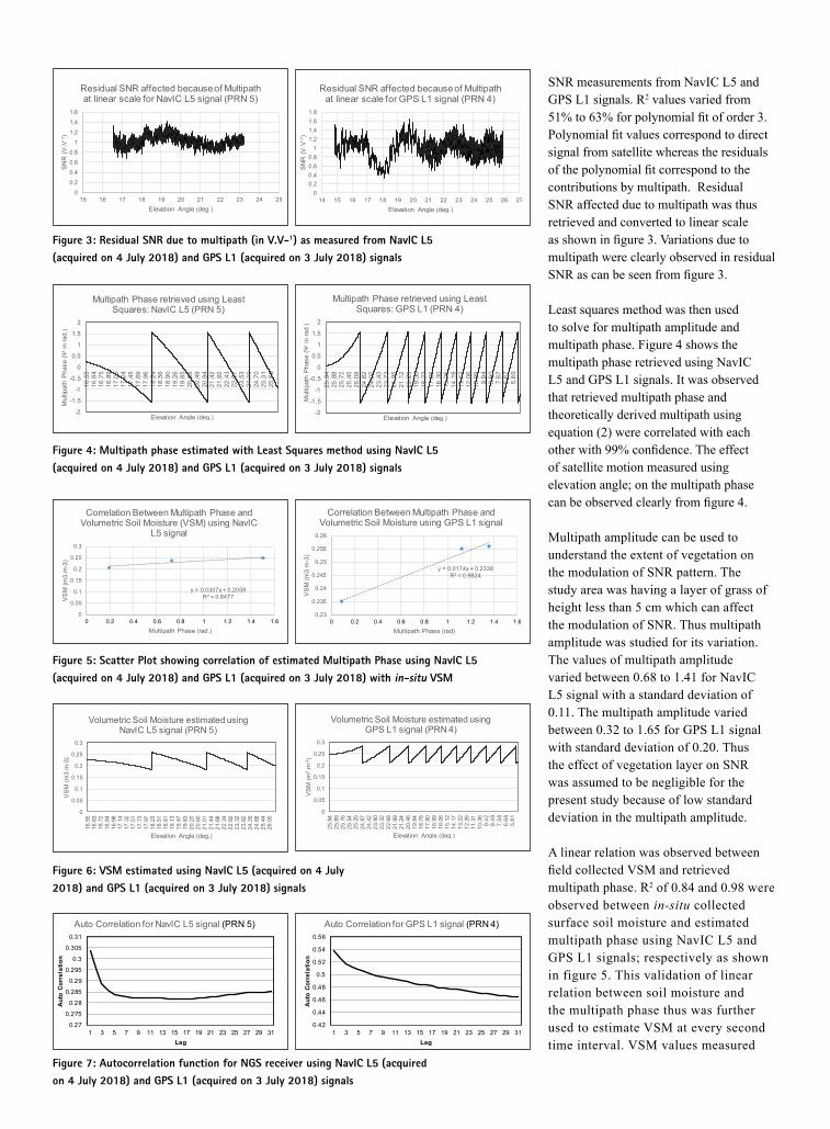
SNR measurements from NavIC L5 and GPS L1 signals. R2 values varied from 51% to 63% for polynomial fit of order 3. Polynomial fit values correspond to direct signal from satellite whereas the residuals of the polynomial fit correspond to the contributions by multipath. Residual SNR affected due to multipath was thus retrieved and converted to linear scale as shown in figure 3. Variations due to multipath were clearly observed in residual SNR as can be seen from figure 3.
Least squares method was then used to solve for multipath amplitude and multipath phase. Figure 4 shows the multipath phase retrieved using NavIC L5 and GPS L1 signals. It was observed that retrieved multipath phase and theoretically derived multipath using equation (2) were correlated with each other with 99% confidence. The effect of satellite motion measured using elevation angle; on the multipath phase can be observed clearly from figure 4.
Multipath amplitude can be used to understand the extent of vegetation on the modulation of SNR pattern. The study area was having a layer of grass of height less than 5 cm which can affect the modulation of SNR. Thus multipath amplitude was studied for its variation. The values of multipath amplitude varied between 0.68 to 1.41 for NavIC L5 signal with a standard deviation of 0.11. The multipath amplitude varied between 0.32 to 1.65 for GPS L1 signal with standard deviation of 0.20. Thus the effect of vegetation layer on SNR was assumed to be negligible for the present study because of low standard deviation in the multipath amplitude.
A linear relation was observed between field collected VSM and retrieved multipath phase. R2 of 0.84 and 0.98 were observed between in-situ collected surface soil moisture and estimated multipath phase using NavIC L5 and GPS L1 signals; respectively as shown in figure 5. This validation of linear relation between soil moisture and the multipath phase thus was further used to estimate VSM at every second time interval. VSM values measured
Figure 3: Residual SNR due to multipath (in V.V-1) as measured from NavIC L5 (acquired on 4 July 2018) and GPS L1 (acquired on 3 July 2018) signals
Figure 4: Multipath phase estimated with Least Squares method using NavIC L5 (acquired on 4 July 2018) and GPS L1 (acquired on 3 July 2018) signals
Figure 5: Scatter Plot showing correlation of estimated Multipath Phase using NavIC L5 (acquired on 4 July 2018) and GPS L1 (acquired on 3 July 2018) with in-situ VSM
Figure 6: VSM estimated using NavIC L5 (acquired on 4 July 2018) and GPS L1 (acquired on 3 July 2018) signals
Figure 7: Autocorrelation function for NGS receiver using NavIC L5 (acquired on 4 July 2018) and GPS L1 (acquired on 3 July 2018) signals
in the field showed variation from 0.18 m3.m-3 to 0.25 m3.m-3 for different days.
VSM was retrieved separately for each day. Figure 6 show the sample of volumetric surface soil moisture estimated using NavIC L5 and GPS L1 signals. The results obtained for VSM using GPS L1 signal were observed to be consistent with those already reported in earlier literature. Comparison between VSM retrieved using GPS L1 and NavIC L5 could not be carried out as observations were done at different time intervals. However, VSM estimated using NavIC signal was validated using in-situ data collected with soil moisture probe in the field; for some of the sample values. R2 values of 0.78 to 0.94 were observed between the VSM retrieved using NavIC L5 and in-situ data. The results obtained for VSM using NavIC L5 signal were thus encouraging to further extend the study for different soil types and at different locations.
Autocorrelation test was also performed to assess the quality of SNR measurements of indigenously developed NGS receiver to be used for soil moisture retrieval. Decreasing autocorrelation functions were observed with maximum correlation at lag 0; using NavIC L5 and GPS L1 signals as shown in figure 7. This established the quality of SNR measurements as link between SNR measurements and multipath was strongly defined. Thus indigenously developed NGS user receiver is suitable to be used for soil moisture retrieval and other scientific applications
Conclusions
SNR measurements of indigenously developed NGS receiver were used to estimate volumetric surface soil moisture using newly established NavIC constellation satellites. Algorithm was developed and equations were solved to retrieve multipath phase causing oscillatory SNR and thus soil moisture. This technique of using multipath signals affecting GNSS signals to retrieve geophysical parameters such as soil moisture is known as GNSS multipath reflectometry. This paper has successfully demonstrated use of GNSS multipath reflectometry to retrieve soil moisture
using NavIC L5 signals. R2 values of 0.78 to 0.94 were observed between estimated soil moisture and in-situ data. This paper has also demonstrated that SNR measurements using indigenously developed NGS receiver are sensitive to multipath and thus can be used for GNSS multipath reflectometry related scientific applications. The study has thus set up the platform to use NavIC L5 signals for GNSS multipath reflectometry to study various geophysical parameters such as soil moisture, snow depth, water depth and vegetation heights. The study thus can be further extended to study estimation of soil moisture under different environmental conditions and temporal variations of the soil moisture. Global Network of geodetic receivers have now included tracking of newly established NavIC signals. Thus encouraging results of the present study show that NavIC signals can now be used along with other GNSS signals to retrieve soil moisture and can be major contributor to development of in-situ database of soil moisture in coming future.
Acknowledgement
The authors are thankful to Shri. D. K. Das, Director, Space Applications Centre (SAC), Ahmedabad, for providing the opportunity to carry out this work. The authors are very grateful to Mr. V. K. Tank, Head/NAD; Mr. A. P. Shukla, GD/NAG and Mr. N. M. Desai, DD/SSAA for their constant support, encouragement and keen interest in this work. Authors also extend their thanks to D r. Nikhil Lele, scientist/EPSA/SAC and Dr. Bimal Bhattacharya Head/AED/EPSA/SAC for providing the instrument for in-situ data collection. This work is carried out under the TDP/R&D program of Space Applications Centre, Ahmedabad, India.
References
[1] A. Bilich, P. Axelrad and K. M. Larson, “Scientific utility of the Signal-to-Noise ratio (SNR) reported by geodetic GPS receivers”, ION GNSS 20th Int. Tech. Meeting of Sat. Div., 25-28, Sept. 2007, Forth Worth, TX, pp. 1999-2010.
[2] A. Bilich and K. M. Larson, “Mapping the GPS multipath environment using the signal-to-noise ratio (SNR)”, Radio Sci., 42, 2007, RS6003, doi:10.1029/2007RS003652.
[3] C. C. Chew, E. E. Small, K. M. Larson and V. U. Zavorotny, “Effects of near-surface soil moisture on GPS SNR data: Development of a retrieval algorithm for soil moisture”, IEEE Trans. Geo. Rem. Sens., 52, 1, 2014, pp. 537-543.
[4] K. M. Larson, E. E. Small, E. Gutmann, A. Bilich, P. Axelrad and J. Braun, “Using GPS multipath to measure soil moisture fluctuations: Initial results”, GPS Solut., 12, 2008, pp. 173-177.
[5] K. M. Larson, E. E. Small, E. Gutmann, A. Bilich, P. Axelrad, J. Braun and V. U. Zavorotny, “Use of GPS receivers as a soil moisture network for water cycle studies”, Geo. Res. Lett., 35, 2008, L24405, doi:10.1029/2008GL036013.
[6] K. M. Larson, J. Braun, E. E. Small, V. U. Zavorotny, E. Gutmann, and A. Bilich, “GPS multipath and its relation to near-surface soil moisture content”, IEEE J. Sel. App. Eart. Obs. Rem. Sens., 2010, doi:10.1109/JSTARS.2009.2033612.
[7] S. Zhang, N. Roussel, K. Boniface, M. C. Ha, F. Frappart, J. Darrozes, F. Baup and J. C. Calvet, “Use of reflected GNSS SNR data to retrieve either soil moisture or vegetation height from a wheat crop,” Hydrol. Earth Syst. Sci., 21, 2017, pp. 4767-4784.
[8] V. U. Zavorotny, K. M. Larson, J. Braun, E. E. Small, E. Gutmann, and A. Bilich, “A Physical Model for GPS Multipath caused by Land Reflections: Toward Bare Soil Moisture Retrievals”, IEEE J. Sel. App. Eart. Obs. Rem. Sens., 3, 1 2010, doi: 10.1109/JSTARS.2009.2033608, pp. 100-110. .
Coordinates May 2019 | 17
UAV
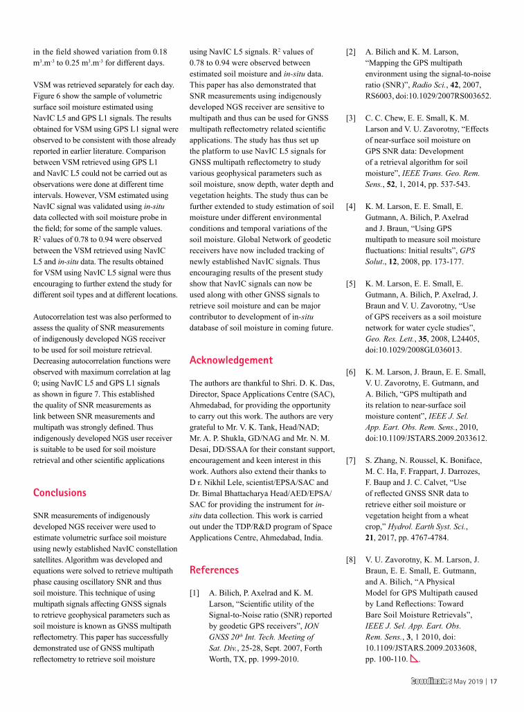
Low cost UAV photogrammetric surveyThe research shows that UAV is applicable in monitoring changes along the coastal region which can be useful to assist the authority in deciding on enforcing nature conservation strategy to the affected site
Faiz ArifMSc candidateEarth Observation Centre,Institute of Climate Change, Universiti Kebangsaan, Malaysiaa
Abdul Aziz Ab RahmanMSc candidateEarth Observation Centre, Institute of Climate Change, Universiti Kebangsaan, Malaysiaa
Khairul Nizam Abdul MauludAssoc. Prof, Sr. Dr Smart and Sustainable Township Research Centre (SUTRA), Faculty of Engineering and Built Environment & Earth Observation Centre, Institute of Climate Change, Universiti Kebangsaan, Malaysia
Unmanned aerial vehicle (UAV) is emerging to become a common tool
in the geoscience field as it is usable across different field to cover a large-scale area with minimal cost. A low-cost UAV with low-altitude platform is advantageous as it is not affected by cloud cover and easily operable which allows the frequent flight of the same area at low-cost. This is applicable in monitoring effects of coastal erosion and shoreline changes. Coastal erosion is recognized as a permanent loss of land and habitat along the shoreline resulting in changes of the coast. The shoreline is highly vulnerable to erosion and flooding that can spawn negative impact on the wellbeing of human, vegetation, environment and ecosystem altogether. Hence, it is important to monitor shoreline changes by identifying the rate of erosion and accretion to quantify the losses of land due to climate change. This research suggests the usage of low-cost UAV namely DJI Phantom 3 Professional (Phantom 3) to monitor shoreline changes physically at Pantai Jeram. Sub nadir aerial images were taken from the UAV and flew alongshore at above ground level (AGL) altitude of 70 m. The study was conducted at three different months (May, September and December) in 2017 to observe the shoreline changes and vegetation changes during different monsoon periods. The result shows apparent changes of the shoreline and vegetation in the west coast of Malaysia produced at high-resolution because of the images taken by the UAV at low-altitude which allows the observation of the shoreline changes and vegetation changes to be intricate. In Pantai Jeram, the result of 3-months observation shows noticeable changes in shoreline and vegetation. The research shows that UAV is applicable
in monitoring changes along the coastal region which can be useful to assist the authority in deciding on enforcing nature conservation strategy to the affected site.
Unmanned aerial vehicle (UAV)
The UAV system is becoming a common tool in the geoscience field nowadays [1]&[2]. The emergence of new survey technique based on UAV system is becoming a common tool in the geoscience field. It is utilizable across the different field because it can cover large-scale area with minimal cost. With improvements in a camera system and an inertial measurement unit (IMU), UAV is advantageous to be used for photogrammetric surveying and mapping. The system can be mounted in high- or low-altitude platforms providing a different advantage for both platforms [3]. Low-altitude system is advantageous in performing survey because it is not affected by cloud cover able to capture full image from above, and it can be used for frequent surveying of the same place at specific time compared to remote-sensing technique, which can be affected by cloud cover and if it has, the time of image acquisition will have to be changed. An example of this situation is shoreline changes at the coast as an effect of global warming and sea-level rise. The shoreline is highly dynamic and highly vulnerable to erosion and flooding that can spawn a negative impact on the wellbeing of human, environment and ecosystem altogether.
Global warming is an observed century-scale increase in the average Earth temperature. As an effect of global
18 | Coordinates May 2019
warming, the world faces a sea-level rise (SLR). Intergovernmental Panel on Climate Change (IPCC) conducted a study which resulted in findings in the 21st century; the sea level is projected to rise from 18 to 66 cm [4]&[5]. This significant increase in sea-level is identified as one of the leading causes to coastal erosion [6]. Coastal erosion contributes to the changes of the shoreline which can reduce the dunes and boundaries of the coastal area and significantly affect the vegetation at near coast area.
A study by National Hydraulic Research Institute of Malaysia (NAHRIM) states that Peninsular Malaysia will face rate of sea-level rise by 2.7 mm to 7.0mm per year; and within the range of 0.253 m to 0.517 m by the year 2100 concerning the year 2010 [7]&[8]. According to the National Coastal Erosion Study (NCES), Selangor is one of the places with potential to the coastal erosion. Hence, it is important to monitor the changes at the coastal area to strategize further action to mitigate the effects of sea-level rise in the area. Previously, the shoreline monitoring is done by using various techniques either direct measurement or indirect measurement.
High accuracy GNSS surveys are the most popular method but it can be costly, timely and requires a lot of manpower towards completion. Hence, in this study we propose the usage of low-cost UAV to monitor changes at the coastal area at high resolution to help enforcers strategize future actions.
Materials and methods
Study area
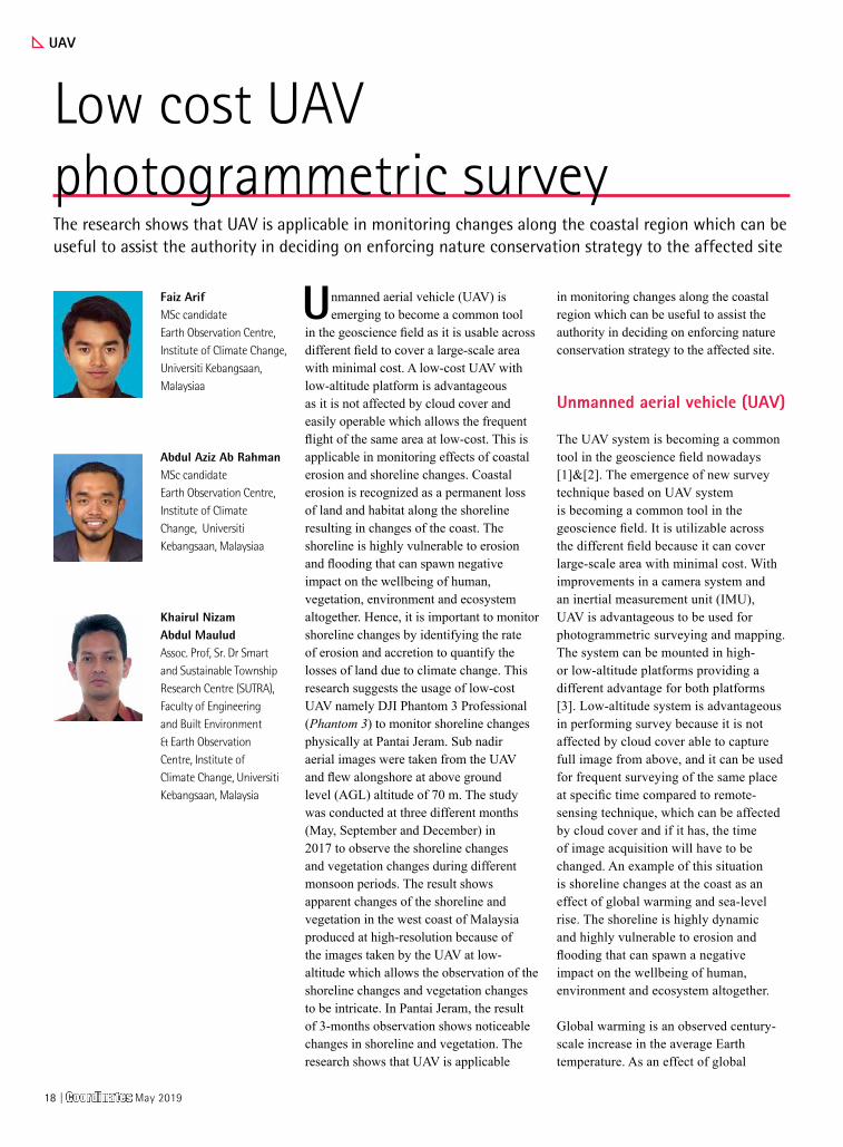
This research is conducted in coastal areas in Selangor along the Pantai Jeram coast, which is located at the west coast of Peninsular Malaysia facing the Straits of Malacca. Pantai Jeram is a low-lying area between the latitude of 3° 13’ 33.762” North and longitude of 101° 18’ 17.761” East. The study area covers a coastal area where sand dunes are the majority material along the coast with vegetations
and several man-made structures. Climate condition is affected by Southwest monsoon from April to September; and Northeast monsoon from October to March. This study will be conducted on June, September and December of 2017 to assess the changes at differing monsoons. Pantai Jeram is located as shown in Figure 1.
Data acquisition
The data used in this study was obtained from Phantom 3 as shown in Figure 2. This UAV costs USD1000 at the time of launch and it has integrated GNSS positioning module, camera stabilization system, IMU, 12-Megapixel camera with f/2.8 lens and 94° field of view. Aerial images perpendicular to the ground were taken from it and flew alongshore at AGL altitude of 70 m to obtain data at the highest resolution possible while avoiding an obstacle on
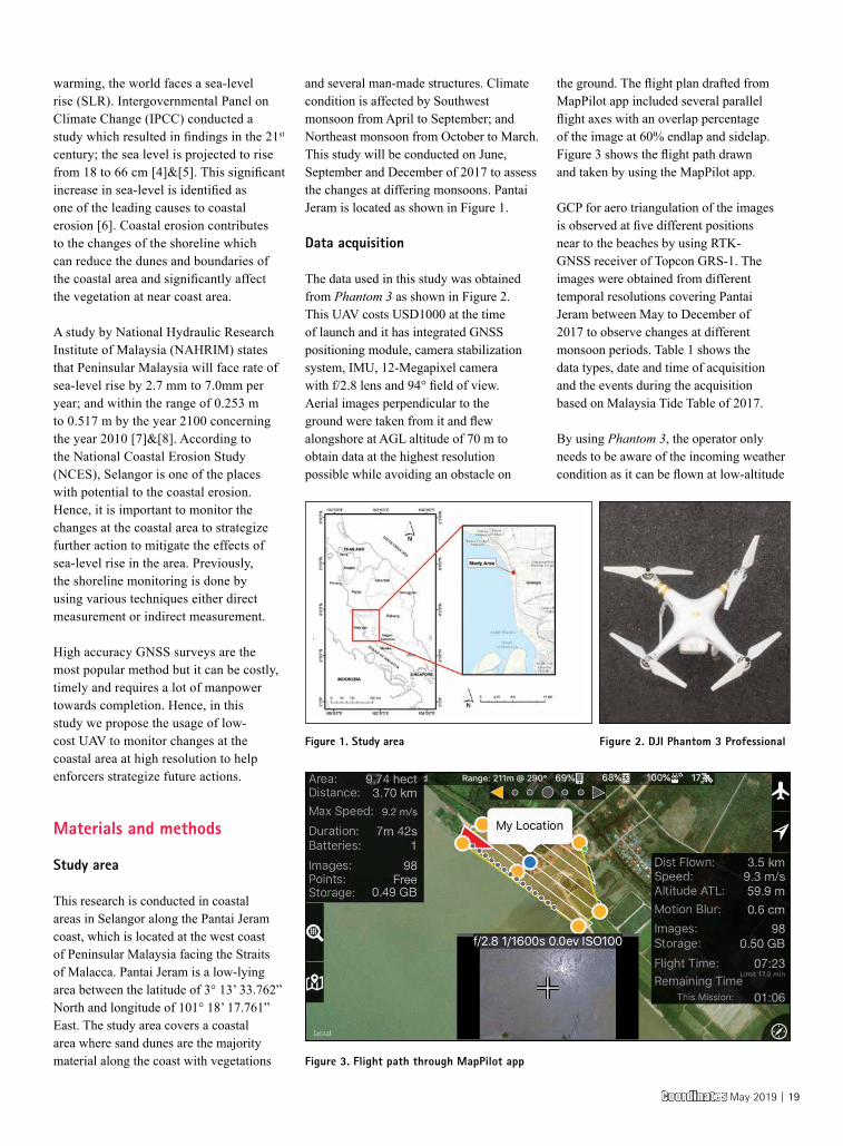
the ground. The flight plan drafted from MapPilot app included several parallel flight axes with an overlap percentage of the image at 60% endlap and sidelap. Figure 3 shows the flight path drawn and taken by using the MapPilot app.
GCP for aero triangulation of the images is observed at five different positions near to the beaches by using RTK-GNSS receiver of Topcon GRS-1. The images were obtained from different temporal resolutions covering Pantai Jeram between May to December of 2017 to observe changes at different monsoon periods. Table 1 shows the data types, date and time of acquisition and the events during the acquisition based on Malaysia Tide Table of 2017.
By using Phantom 3, the operator only needs to be aware of the incoming weather condition as it can be flown at low-altitude
Figure 1. Study area Figure 2. DJI Phantom 3 Professional
Figure 3. Flight path through MapPilot app
Coordinates May 2019 | 19
which minuses the cloud-coverage factor when compared to the usage of remote sensing. UAV can provide estimates of change directly from the site itself and is a
unique tool for coastal monitoring research. During high tides level, we can identify the areas that are changing, either erosion or accretion. According to the NCES 2017,
when the images were captured during the peak level, the shoreline changes can be detected during that time.
By referring Malaysia Tide Tables, the prediction of high tides event can be predicted either time of acquisition or the height of tides level.
Data processing and analysis
Aerial photos of Pantai Jeram obtained from Phantom 3 at different temporal conditions were used for observation of shoreline changes. From the series of aerial photos obtained, it is then imported into Agisoft PhotoScan, an image processing software which stitches images via Multi-View Stereo (MVS) concept. The software uses Structure from Motion (SfM) algorithm [9]&[10] to produce point cloud, dense cloud, mesh and texture. The spatial resolution of these photos will be produced later in the results. The aero triangulation via GCP allows the usage of the orthophoto for quantitative and qualitative analysis. Subsequently, orthophotos of the coastal area of Pantai Jeram is produced.
Results and discussion
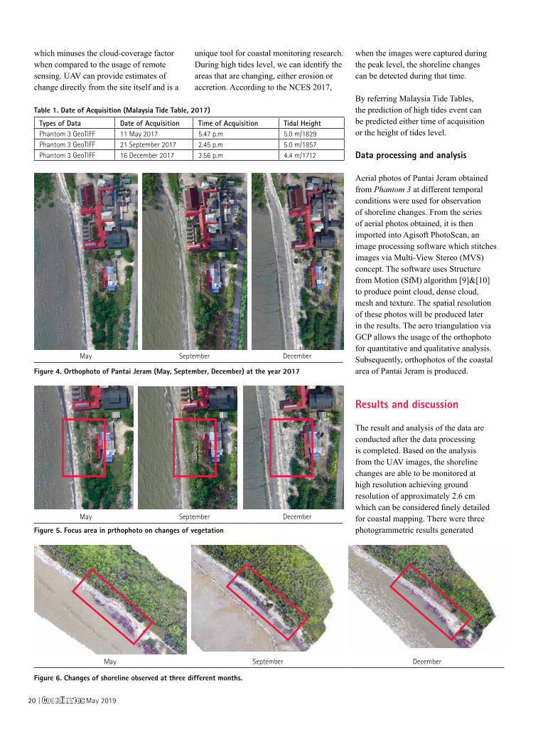
The result and analysis of the data are conducted after the data processing is completed. Based on the analysis from the UAV images, the shoreline changes are able to be monitored at high resolution achieving ground resolution of approximately 2.6 cm which can be considered finely detailed for coastal mapping. There were three photogrammetric results generated
Types of Data Date of Acquisition Time of Acquisition Tidal HeightPhantom 3 GeoTIFF 11 May 2017 5.47 p.m 5.0 m/1829Phantom 3 GeoTIFF 21 September 2017 2.45 p.m 5.0 m/1857Phantom 3 GeoTIFF 16 December 2017 3.56 p.m 4.4 m/1712
Table 1. Date of Acquisition (Malaysia Tide Table, 2017)
Figure 4. Orthophoto of Pantai Jeram (May, September, December) at the year 2017
May September December
May September December
May September December
Figure 5. Focus area in prthophoto on changes of vegetation
Figure 6. Changes of shoreline observed at three different months.
20 | Coordinates May 2019
after performing the aerial triangulation process which is the orthophoto for three different months (May, September and December of 2017) at Pantai Jeram.
The images obtained from Phantom 3 were projected with a coordinate system of the World Geodetic System (WGS84). The most important part of this survey is the ability to analyze the changes in the coastal area. Figure 4 shows the changes of the shoreline of the three different months based on May 2017. Based on the above results, the UAV images show that September experienced the most changes in coastal settlements. The changes in vegetation area are also recorded in the differing months as shown in Figure 5. From the recorded changes in shoreline and vegetation, it is observed that the sea level rise is detrimental not only to the shoreline, but also the near coast as the vegetation area is also affected by it. The study that has been carried out proves that UAV is potential to be used for monitoring shoreline changes. With this finding, it is proven that UAV can be used to help the related departments to monitor changes and consequently, draft an action to be taken to help minimize the changes to coasts. Apart from vegetation changes, The following Figure 6 shows the decrease/increase of the shoreline.
Conclusion
This study has proven that low-cost UAV, specifically DJI Phantom 3 Pro, is utilizable for conducting a photogrammetric survey at the coastal area for shoreline monitoring. UAV is an autonomous vehicle operable via remote which is cost- and time-
practical sufficient for the coastal area. This technology has advantages over land survey technique which can be costly, or remote sensing technique which can have cloud cover. This paper is completed after 6-months of survey works. The shoreline changes were monitored successfully based on the results obtained from survey flights. Hence, it is proven that low-cost UAV can be further used to help mitigate the effects of climate change.
Acknowledgement
This study was supported by the research grants namely the Trans-Disciplinary Research Grant Scheme (TRGS/1/2015/UKM/02/5/1) and Research University Grant (KRA-2018-019). The authors gratefully acknowledge the Earth Observation Centre, Institute of Climate Change, UKM for sharing the satellite data.
Reference
[1] Arif, F., Maulud, K. N., & Rahman, A. A. (2018). Generation of digital elevation model through aerial technique. IOP Conference Series: Earth and Environmental Science, 169, 012093. doi:10.1088/1755-1315/169/1/012093.
[2] Rahman, A. A., Maulud, K. N., Mohd, F. A., Jaafar, O., &Tahar, K. N. (2017). Volumetric calculation using low cost unmanned aerial vehicle (UAV) approach. IOP Conference Series: Materials Science and Engineering, 270, 012032. doi:10.1088/1757-899x/270/1/012032
[3] Darwin, N., Ahmad, A., &Zainon, O. (2014). The Potential of Unmanned Aerial Vehicle for Large Scale Mapping of Coastal Area. IOP Conference Series: Earth and Environmental Science,18, 012031. doi:10.1088/1755-1315/18/1/012031
[4] Warrick, R., and Oerlemans, J. 1990. Climate Change: IPCC Scientific Assessment. Chapter 9. Sea Level Rise.
[5] IPCC. 2012. Managing the Risks of Extreme Events and Disasters to Advance Climate Change Adaptation. A Special Report of Working Groups I and II of the Intergovernmental Panel on Climate Change [Field, C.B., V. Barros, T.F. Stocker, D. Qin, D.J. Dokken, K.L. Ebi, M.D. Mastrandrea, K.J. Mach, G.-K. Plattner, S.K. Allen, M. Tignor, and P.M. Midgley (eds.)] Cambridge University Press, Cambridge, UK, and New York, NY, USA, pp 582.
[6] Brunn, P. 1962. Sea level rise as a cause of shore erosion. ASCE Journal, Waters and Harbours Division, 188, pp 117-130.
[7] National Hydraulic Research Institute of Malaysia. 2010. The study of Impact of Sea Level Rise in Pulau Langkawi. pp 31.
[8] Awang, N.A. and Hamid, M.A., 2013. Sea level rise in Malaysia. Sea level rise adaptation measures. Hydrolink, 2, pp 47-49.
[9] Snavely, N., Seitz, S., and Szeliski, R., 2007. Modeling the world from the internet photo collections. International Journal of Computer Vision, 80 (2), pp 189-210.
[10] Gonçalves, J.A. and Henriques, R., 2015. UAV photogrammetry for topographic monitoring of coastal areas. ISPRS Journal of Photogrammetry and Remote Sensing, 104, pp 101-111.
The paper was published in Proceedings Asian Conference on Remote Sensing 2018.
High accuracy GNSS surveys are the most popular
method but it can be costly, timely and requires a
lot of manpower towards completion. Hence, in this
study we propose the usage of low-cost UAV to
monitor changes at the coastal area at high resolution
to help enforcers strategize future actions.
Coordinates May 2019 | 21
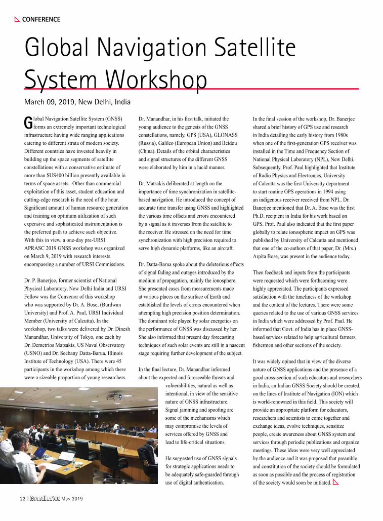
Global Navigation Satellite System (GNSS) forms an extremely important technological
infrastructure having wide ranging applications catering to different strata of modern society. Different countries have invested heavily in building up the space segments of satellite constellations with a conservative estimate of more than $US400 billion presently available in terms of space assets. Other than commercial exploitation of this asset, student education and cutting-edge research is the need of the hour. Significant amount of human resource generation and training on optimum utilization of such expensive and sophisticated instrumentation is the preferred path to achieve such objective. With this in view, a one-day pre-URSI APRASC 2019 GNSS workshop was organized on March 9, 2019 with research interests encompassing a number of URSI Commissions.
Dr. P. Banerjee, former scientist of National Physical Laboratory, New Delhi India and URSI Fellow was the Convenor of this workshop who was supported by Dr. A. Bose, (Burdwan University) and Prof. A. Paul, URSI Individual Member (University of Calcutta). In the workshop, two talks were delivered by Dr. Dinesh Manandhar, University of Tokyo, one each by Dr. Demetrios Matsakis, US Naval Observatory (USNO) and Dr. Seebany Datta-Barua, Illinois Institute of Technology (USA). There were 45 participants in the workshop among which there were a sizeable proportion of young researchers.
Dr. Manandhar, in his first talk, initiated the young audience to the genesis of the GNSS constellations, namely, GPS (USA), GLONASS (Russia), Galileo (European Union) and Beidou (China). Details of the orbital characteristics and signal structures of the different GNSS were elaborated by him in a lucid manner.
Dr. Matsakis deliberated at length on the importance of time synchronization in satellite-based navigation. He introduced the concept of accurate time transfer using GNSS and highlighted the various time offsets and errors encountered by a signal as it traverses from the satellite to the receiver. He stressed on the need for time synchronization with high precision required to serve high dynamic platforms, like an aircraft.
Dr. Datta-Barua spoke about the deleterious effects of signal fading and outages introduced by the medium of propagation, mainly the ionosphere. She presented cases from measurements made at various places on the surface of Earth and established the levels of errors encountered when attempting high precision position determination. The dominant role played by solar energetics on the performance of GNSS was discussed by her. She also informed that present day forecasting techniques of such solar events are still in a nascent stage requiring further development of the subject.
In the final lecture, Dr. Manandhar informed about the expected and foreseeable threats and
vulnerabilities, natural as well as intentional, in view of the sensitive nature of GNSS infrastructure. Signal jamming and spoofing are some of the mechanisms which may compromise the levels of services offered by GNSS and lead to life-critical situations.
He suggested use of GNSS signals for strategic applications needs to be adequately safe-guarded through use of digital authentication.
In the final session of the workshop, Dr. Banerjee shared a brief history of GPS use and research in India detailing the early history from 1980s when one of the first-generation GPS receiver was installed in the Time and Frequency Section of National Physical Laboratory (NPL), New Delhi. Subsequently, Prof. Paul highlighted that Institute of Radio Physics and Electronics, University of Calcutta was the first University department to start routine GPS operations in 1994 using an indigenous receiver received from NPL. Dr. Banerjee mentioned that Dr. A. Bose was the first Ph.D. recipient in India for his work based on GPS. Prof. Paul also indicated that the first paper globally to relate ionospheric impact on GPS was published by University of Calcutta and mentioned that one of the co-authors of that paper, Dr. (Mrs.) Arpita Bose, was present in the audience today.
Then feedback and inputs from the participants were requested which were forthcoming were highly appreciated. The participants expressed satisfaction with the timeliness of the workshop and the content of the lectures. There were some queries related to the use of various GNSS services in India which were addressed by Prof. Paul. He informed that Govt. of India has in place GNSS-based services related to help agricultural farmers, fishermen and other sections of the society.
It was widely opined that in view of the diverse nature of GNSS applications and the presence of a good cross-section of such educators and researchers in India, an Indian GNSS Society should be created, on the lines of Institute of Navigation (ION) which is world-renowned in this field. This society will provide an appropriate platform for educators, researchers and scientists to come together and exchange ideas, evolve techniques, sensitize people, create awareness about GNSS system and services through periodic publications and organize meetings. These ideas were very well appreciated by the audience and it was proposed that preamble and constitution of the society should be formulated as soon as possible and the process of registration of the society would soon be initiated.
Global Navigation Satellite System WorkshopMarch 09, 2019, New Delhi, India
CONFERENCE
22 | Coordinates May 2019


Robotic forest harvesting process using GNSS satellite positioning dataIn this paper we contribute experimental findings to the issue of the accuracy of GNSS location measurements in forest environments, by addressing the effects of harvester trajectory errors due to GNSS measurements
FORESTRY
Louis-Francois PauCorresponding authorProfessor, Copenhagen Business School, Copenhagen, [email protected]
Krzysztof OwsiakDept. of Forest Engineering, Faculty of Forestry, University of Agriculture, Krakow, Poland
Anna Klamerus IwanDept. of Forest Engineering, Faculty of Forestry, University of Agriculture in Krakow, Poland
Mariusz KormanekDepartment of Forest Work Mechanization, Faculty of Forestry, University of Agriculture, Krakow, Poland
Janusz GołabDept. of Forest Engineering, Faculty of Forestry, University of Agriculture, Krakow, Poland
1 Introduction
Navigation often relies on high accuracy and high-update rate global navigation satellite systems (GNSS) such as GPS, Galileo, Glonass, Beidu, Navstar [1], however their deployment in the context of agriculture, vineyards, farming is far more frequent than in forestry. These fields are not behind in the adoption of robots, “precision farming”, and the use of drones [2]. In “precision farming”, mapping information is matched with GNSS measurements and vision/sensor systems to image plants/ crops, and accurately navigates between them to perform specific tasks, thanks to open skies, besides adding to the traceability or quality control of harvested products [3].
In agriculture and forestry though, inaccuracies in position and directional information lead directly to economic, productivity and environmental losses. Crop parcel zones may not be harvested, requiring a “second pass”. Crop collection after a navigation error also requires a “second pass” which costs manpower time, machine time and fuel. Residues may be generated at higher rates lowering yield and eventually leading to environmental problems over some time. Nevertheless, such economic impacts of GNSS kinematic inaccuracies are rarely even considered, even if they should in the overall trade-offs between system performances, manpower costs, equipment usage time, and high investment costs of precision farming equipment [4].
Narrowing down our focus now onto the effects of inaccuracies affecting forestry operations, GNSS accuracy is already considered sufficient in some specific forestry uses such as those for chippers, trucks, guidance to visitors, and location of storage and landings [5].Coupled to wheel rotation sensors, Differential GPS (DGPS) allows to estimate wheel slippage in uneven forest terrains [5]. Areas insufficiently researched though are first the effects of GNSS kinematic errors on harvesting itself, as well as next on log collection and logistics.
Contrary to many other application areas, high accuracy mapping information in forestry is very often lacking, and even more so for individual tree locations. In addition, the harvester navigation using GNSS receivers requires an unobstructed line of sight (or sufficient signal/noise values) from the harvester trajectory points to a minimum of four satellites. This is often difficult to achieve in forest environments, as trunks, foliage can block the GNSS signal; furthermore the propagation is also affected by humidity, snow, and wind. Forest canopy can be characterized by means of parameters such as tree density and biomass volume, but it is important to know which parameters in particular have a bearing on the accuracy of GNSS measurements. Canopy density can be evaluated by LIDAR pulse density [7], imaging spectroscopy, or vertical structure profiles (as Plant Area Volume Density, PAVD), all of these techniques being costly and sometimes
Coordinates May 2019 | 31
In a robotic operational mode, the harvester makes autonomously navigation decisions to maximize productivity and harvesting revenue. The forest product industry is maximizing the combined value and quality of timber logs, and secondary products, while minimizing the volume and handling of residues. As shown in [16] it is possible to gain significant profit margins when having full certainty about the tree attribute and quality information.
2 Research questions
As discussed above, one specific class of restrictions on robotic harvesting comes from how the terrain and canopy combined limit GNSS signal quality and thus location and trajectory accuracy. This is especially true of forestry in rugged terrain, dis-homogeneous tree growth, high canopies and wet/snow covered foliage. This paper is specifically dealing with forestry operations with robotic or assisted harvesters, taking into account the maneuvers, relative positions or directions, and trajectories.
The research questions which were studied experimentally and by modeling are:
Research Question 1: how much are location and directional accuracies of GNSS signals degraded in forests, compared to the operational capabilities and kinematic requirements of future precision forestry harvesting?
Research Question 2: how approximately is the forestry harvesting yield affected by GNSS signal accuracy in forestry environments, so a trade-off can be made between harvesting by manned resources vs. costlier autonomous equipment?
3 Real time estimates of effects of canopy opacity and precipitation
This Section analyzes in more detail some effects linked to Research question A: water retention in foliage (Section 3.1), electromagnetic propagation aspects (Section 3.2), and opacity determination by real-time image processing (Section 3.3).
slow. In view of the complexity of forest environments, propagation effects, and signal outages, some research has dealt with refined algorithmic approaches (eventually coupled to inertial navigation systems) to estimate the accuracy of individual GNSS positions [8-10]. Vertical measurement accuracy by GNSS has also been studied in [11]. These results show that the highest impact on the positional accuracy is from the forest canopy.
GNSS data from the harvester can be combined with a laser-rangefinder (lidar), or laser scanners, serving to determine the tree trunk position and diameter [12]; laser sensors determine distance and angle information to determine the presence, range and diameter of a stem before it is cut. However, they are of no use once the stem has fallen, and this is where the robotic harvester with GNSS investigated in this paper steps in.
In this paper we contribute experimental findings to the issue of the accuracy of GNSS location measurements in forest environments, by addressing the effects of harvester trajectory errors due to GNSS measurements. The deployment context is GNSS assisted [13] or GNSS robotic guided dynamic forest harvesting [14] where a process-linked sequence of relative positions and directions between the harvester and a fallen tree translate into harvesting yield. In future generation harvesters, the harvester will have its own integrated GNSS receiver, coupled to a data acquisition and to a communications module; the harvester will operate either in an assisted mode, or in an autonomous navigation and harvesting mode.
In an assisted mode, the data (operation speed, location, harvested yield, machine settings, knife drum speed, engine and motor alarms) are transferred from the harvester to a remote control system, reducing manned operator workload while exploiting, if available, mapping [15] and other Forest Management centers’ information. The harvested area can be characterized in real time from the field patterns registered by the GNSS system on the harvester, for later use in log recovery and logistics.
3.1. Vegetation based interception
Interception is defined in the present context as the process of retaining rainfall water on the whole surface of a plant. The amount of water retained depends mainly upon the size of the tree’s surface, and upon the potential influence of species [22]. The adhesion and retention of water droplets on leaves and needle surfaces depends also upon the surface state and even upon the temperature of the rain water [23]. The biggest amount of water from rainfalls may accumulate in tree crowns at low rainfall intensities and for smaller raindrops. The maximum water absorption capacity of tree crowns is a not constant value: it changes under influence of rainfall characteristics [22]. As a result, the GNSS electromagnetic propagation in and around canopies depend from botanic properties and these rainfall characteristics.
3.2. Electromagnetic propagation aspects
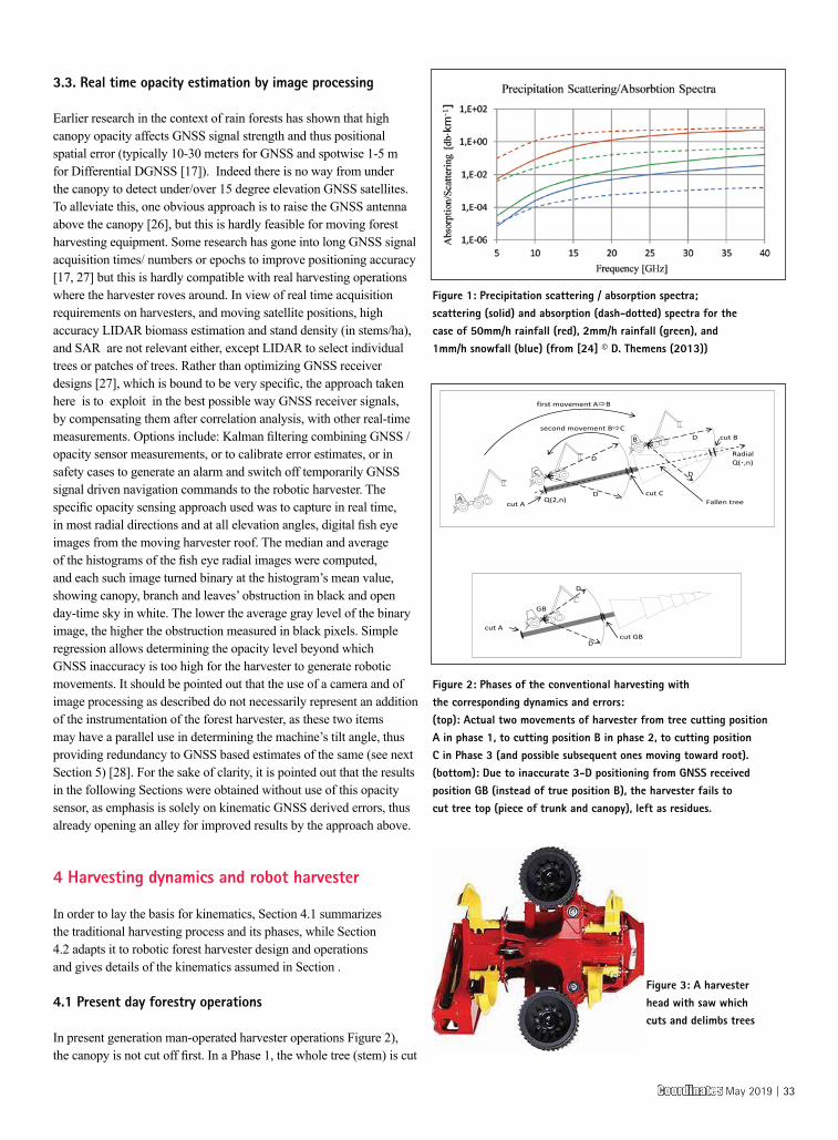
First, forest canopy absorption affects the GNSS signals used to determine the harvester position. This interference is difficult to study by GNSS interference instrumentation [38]. Second, leaves and foliage worsen multipath effects; this in general eliminates Differential GNSS (DGNSS) relevance. A third effect has to do with water retention by the canopy after rain or snow (see Section 3.1.); this is difficult to model by propagation theory as the water content is both on and in the leaves and depends on local hydrological conditions; leaves also release water vapor which can have a far stronger impact on the GNSS signal than the liquid water content. Figure 1 (from [24] using [25]) gives the microwave scattering spectra in snow and rain for GPS broadcasts in two L-band signals at 1575.42 MHz and 1227.6 MHz from an orbit of roughly 20200 km. They show that liquid water doesn’t typically interact strongly with L-band signals or anything below 15 GHz. The fourth effect is linked to the tree species; in some regions for example Pinus Sylvestris L. (pine) needle length approximates one wavelength of GPS L1 signal. As a result of all these four effects, in the remainder of this paper we refer to the combined opacity degradation from multipath, refraction, attenuation and blocking.
32 | Coordinates May 2019
3.3. Real time opacity estimation by image processing
Earlier research in the context of rain forests has shown that high canopy opacity affects GNSS signal strength and thus positional spatial error (typically 10-30 meters for GNSS and spotwise 1-5 m for Differential DGNSS [17]). Indeed there is no way from under the canopy to detect under/over 15 degree elevation GNSS satellites. To alleviate this, one obvious approach is to raise the GNSS antenna above the canopy [26], but this is hardly feasible for moving forest harvesting equipment. Some research has gone into long GNSS signal acquisition times/ numbers or epochs to improve positioning accuracy [17, 27] but this is hardly compatible with real harvesting operations where the harvester roves around. In view of real time acquisition requirements on harvesters, and moving satellite positions, high accuracy LIDAR biomass estimation and stand density (in stems/ha), and SAR are not relevant either, except LIDAR to select individual trees or patches of trees. Rather than optimizing GNSS receiver designs [27], which is bound to be very specific, the approach taken here is to exploit in the best possible way GNSS receiver signals, by compensating them after correlation analysis, with other real-time measurements. Options include: Kalman filtering combining GNSS /opacity sensor measurements, or to calibrate error estimates, or in safety cases to generate an alarm and switch off temporarily GNSS signal driven navigation commands to the robotic harvester. The specific opacity sensing approach used was to capture in real time, in most radial directions and at all elevation angles, digital fish eye images from the moving harvester roof. The median and average of the histograms of the fish eye radial images were computed, and each such image turned binary at the histogram’s mean value, showing canopy, branch and leaves’ obstruction in black and open day-time sky in white. The lower the average gray level of the binary image, the higher the obstruction measured in black pixels. Simple regression allows determining the opacity level beyond which GNSS inaccuracy is too high for the harvester to generate robotic movements. It should be pointed out that the use of a camera and of image processing as described do not necessarily represent an addition of the instrumentation of the forest harvester, as these two items may have a parallel use in determining the machine’s tilt angle, thus providing redundancy to GNSS based estimates of the same (see next Section 5) [28]. For the sake of clarity, it is pointed out that the results in the following Sections were obtained without use of this opacity sensor, as emphasis is solely on kinematic GNSS derived errors, thus already opening an alley for improved results by the approach above.
4 Harvesting dynamics and robot harvester
In order to lay the basis for kinematics, Section 4.1 summarizes the traditional harvesting process and its phases, while Section 4.2 adapts it to robotic forest harvester design and operations and gives details of the kinematics assumed in Section .
4.1 Present day forestry operations
In present generation man-operated harvester operations Figure 2), the canopy is not cut off first. In a Phase 1, the whole tree (stem) is cut
Fallen tree
first movement AB
Q(2,n) cut A cut C
cut B
D
D
D
D
Radial Q(·,n)
A
C
B
second movement BC
cut A cut GB
D
D
GB
Figure 2: Phases of the conventional harvesting with the corresponding dynamics and errors:(top): Actual two movements of harvester from tree cutting position A in phase 1, to cutting position B in phase 2, to cutting position C in Phase 3 (and possible subsequent ones moving toward root).(bottom): Due to inaccurate 3-D positioning from GNSS received position GB (instead of true position B), the harvester fails to cut tree top (piece of trunk and canopy), left as residues.
Figure 1: Precipitation scattering / absorption spectra; scattering (solid) and absorption (dash-dotted) spectra for the case of 50mm/h rainfall (red), 2mm/h rainfall (green), and 1mm/h snowfall (blue) (from [24] © D. Themens (2013))
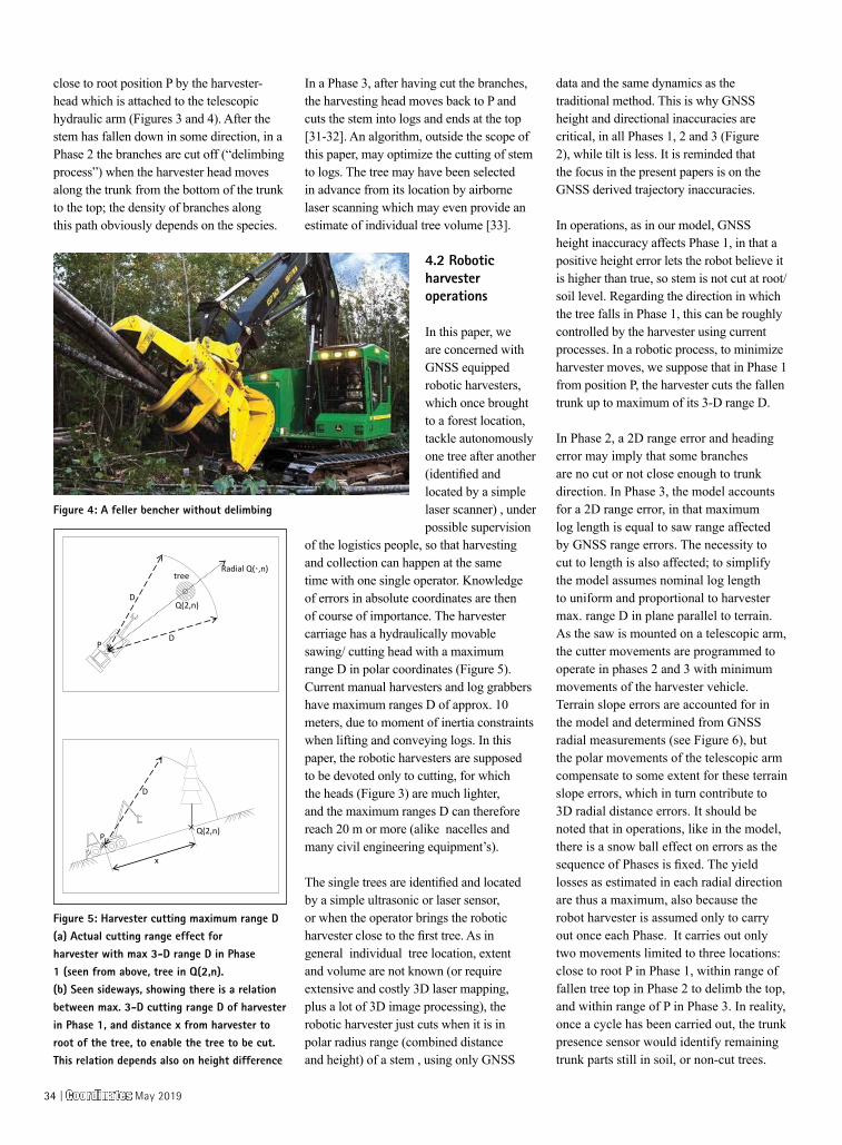
Figure 3: A harvester head with saw which cuts and delimbs trees
Coordinates May 2019 | 33
close to root position P by the harvester-head which is attached to the telescopic hydraulic arm (Figures 3 and 4). After the stem has fallen down in some direction, in a Phase 2 the branches are cut off (“delimbing process”) when the harvester head moves along the trunk from the bottom of the trunk to the top; the density of branches along this path obviously depends on the species.
In a Phase 3, after having cut the branches, the harvesting head moves back to P and cuts the stem into logs and ends at the top [31-32]. An algorithm, outside the scope of this paper, may optimize the cutting of stem to logs. The tree may have been selected in advance from its location by airborne laser scanning which may even provide an estimate of individual tree volume [33].
4.2 Robotic harvester operations
In this paper, we are concerned with GNSS equipped robotic harvesters, which once brought to a forest location, tackle autonomously one tree after another (identified and located by a simple laser scanner) , under possible supervision
of the logistics people, so that harvesting and collection can happen at the same time with one single operator. Knowledge of errors in absolute coordinates are then of course of importance. The harvester carriage has a hydraulically movable sawing/ cutting head with a maximum range D in polar coordinates (Figure 5). Current manual harvesters and log grabbers have maximum ranges D of approx. 10 meters, due to moment of inertia constraints when lifting and conveying logs. In this paper, the robotic harvesters are supposed to be devoted only to cutting, for which the heads (Figure 3) are much lighter, and the maximum ranges D can therefore reach 20 m or more (alike nacelles and many civil engineering equipment’s).
The single trees are identified and located by a simple ultrasonic or laser sensor, or when the operator brings the robotic harvester close to the first tree. As in general individual tree location, extent and volume are not known (or require extensive and costly 3D laser mapping, plus a lot of 3D image processing), the robotic harvester just cuts when it is in polar radius range (combined distance and height) of a stem , using only GNSS
data and the same dynamics as the traditional method. This is why GNSS height and directional inaccuracies are critical, in all Phases 1, 2 and 3 (Figure 2), while tilt is less. It is reminded that the focus in the present papers is on the GNSS derived trajectory inaccuracies.
In operations, as in our model, GNSS height inaccuracy affects Phase 1, in that a positive height error lets the robot believe it is higher than true, so stem is not cut at root/soil level. Regarding the direction in which the tree falls in Phase 1, this can be roughly controlled by the harvester using current processes. In a robotic process, to minimize harvester moves, we suppose that in Phase 1 from position P, the harvester cuts the fallen trunk up to maximum of its 3-D range D.
In Phase 2, a 2D range error and heading error may imply that some branches are no cut or not close enough to trunk direction. In Phase 3, the model accounts for a 2D range error, in that maximum log length is equal to saw range affected by GNSS range errors. The necessity to cut to length is also affected; to simplify the model assumes nominal log length to uniform and proportional to harvester max. range D in plane parallel to terrain. As the saw is mounted on a telescopic arm, the cutter movements are programmed to operate in phases 2 and 3 with minimum movements of the harvester vehicle. Terrain slope errors are accounted for in the model and determined from GNSS radial measurements (see Figure 6), but the polar movements of the telescopic arm compensate to some extent for these terrain slope errors, which in turn contribute to 3D radial distance errors. It should be noted that in operations, like in the model, there is a snow ball effect on errors as the sequence of Phases is fixed. The yield losses as estimated in each radial direction are thus a maximum, also because the robot harvester is assumed only to carry out once each Phase. It carries out only two movements limited to three locations: close to root P in Phase 1, within range of fallen tree top in Phase 2 to delimb the top, and within range of P in Phase 3. In reality, once a cycle has been carried out, the trunk presence sensor would identify remaining trunk parts still in soil, or non-cut trees.
P
x
Q(2,n)
D
P
treen
Q(2,n)
Radial Q(·,n)
D
D
Figure 5: Harvester cutting maximum range D(a) Actual cutting range effect for harvester with max 3-D range D in Phase 1 (seen from above, tree in Q(2,n).(b) Seen sideways, showing there is a relation between max. 3-D cutting range D of harvester in Phase 1, and distance x from harvester to root of the tree, to enable the tree to be cut. This relation depends also on height difference
Figure 4: A feller bencher without delimbing
34 | Coordinates May 2019
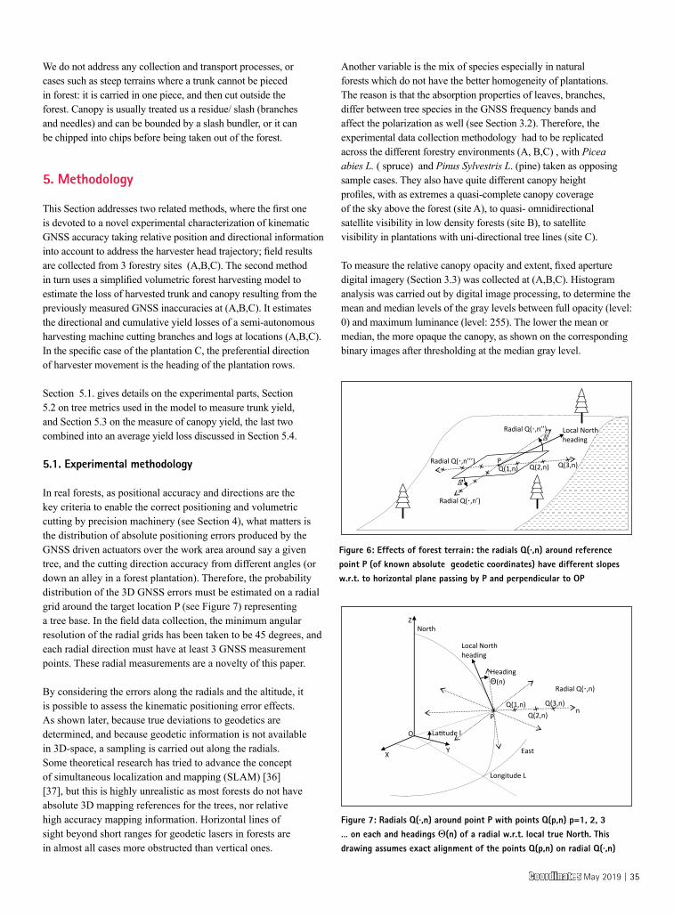
We do not address any collection and transport processes, or cases such as steep terrains where a trunk cannot be pieced in forest: it is carried in one piece, and then cut outside the forest. Canopy is usually treated us a residue/ slash (branches and needles) and can be bounded by a slash bundler, or it can be chipped into chips before being taken out of the forest.
5. Methodology
This Section addresses two related methods, where the first one is devoted to a novel experimental characterization of kinematic GNSS accuracy taking relative position and directional information into account to address the harvester head trajectory; field results are collected from 3 forestry sites (A,B,C). The second method in turn uses a simplified volumetric forest harvesting model to estimate the loss of harvested trunk and canopy resulting from the previously measured GNSS inaccuracies at (A,B,C). It estimates the directional and cumulative yield losses of a semi-autonomous harvesting machine cutting branches and logs at locations (A,B,C). In the specific case of the plantation C, the preferential direction of harvester movement is the heading of the plantation rows.
Section 5.1. gives details on the experimental parts, Section 5.2 on tree metrics used in the model to measure trunk yield, and Section 5.3 on the measure of canopy yield, the last two combined into an average yield loss discussed in Section 5.4.
5.1. Experimental methodology
In real forests, as positional accuracy and directions are the key criteria to enable the correct positioning and volumetric cutting by precision machinery (see Section 4), what matters is the distribution of absolute positioning errors produced by the GNSS driven actuators over the work area around say a given tree, and the cutting direction accuracy from different angles (or down an alley in a forest plantation). Therefore, the probability distribution of the 3D GNSS errors must be estimated on a radial grid around the target location P (see Figure 7) representing a tree base. In the field data collection, the minimum angular resolution of the radial grids has been taken to be 45 degrees, and each radial direction must have at least 3 GNSS measurement points. These radial measurements are a novelty of this paper.
By considering the errors along the radials and the altitude, it is possible to assess the kinematic positioning error effects. As shown later, because true deviations to geodetics are determined, and because geodetic information is not available in 3D-space, a sampling is carried out along the radials. Some theoretical research has tried to advance the concept of simultaneous localization and mapping (SLAM) [36][37], but this is highly unrealistic as most forests do not have absolute 3D mapping references for the trees, nor relative high accuracy mapping information. Horizontal lines of sight beyond short ranges for geodetic lasers in forests are in almost all cases more obstructed than vertical ones.
Another variable is the mix of species especially in natural forests which do not have the better homogeneity of plantations. The reason is that the absorption properties of leaves, branches, differ between tree species in the GNSS frequency bands and affect the polarization as well (see Section 3.2). Therefore, the experimental data collection methodology had to be replicated across the different forestry environments (A, B,C) , with Picea abies L. ( spruce) and Pinus Sylvestris L. (pine) taken as opposing sample cases. They also have quite different canopy height profiles, with as extremes a quasi-complete canopy coverage of the sky above the forest (site A), to quasi- omnidirectional satellite visibility in low density forests (site B), to satellite visibility in plantations with uni-directional tree lines (site C).
To measure the relative canopy opacity and extent, fixed aperture digital imagery (Section 3.3) was collected at (A,B,C). Histogram analysis was carried out by digital image processing, to determine the mean and median levels of the gray levels between full opacity (level: 0) and maximum luminance (level: 255). The lower the mean or median, the more opaque the canopy, as shown on the corresponding binary images after thresholding at the median gray level.
Figure 7: Radials Q(·,n) around point P with points Q(p,n) p=1, 2, 3 … on each and headings Θ(n) of a radial w.r.t. local true North. This drawing assumes exact alignment of the points Q(p,n) on radial Q(·,n)
P
Radial Q(·,n’)
� Radial Q(·,n’’)
Radial Q(·,n’’’)
Local North heading
Q(1,n) Q(2,n) Q(3,n)
�'
Figure 6: Effects of forest terrain: the radials Q(·,n) around reference point P (of known absolute geodetic coordinates) have different slopes w.r.t. to horizontal plane passing by P and perpendicular to OP
P
North
Radial Q(·,n)
Q(1,n)
O
East Y X
Z
La�tude l
Q(2,n) Q(3,n)
Longitude L
n
Local North heading
Heading Θ(n)
Coordinates May 2019 | 35
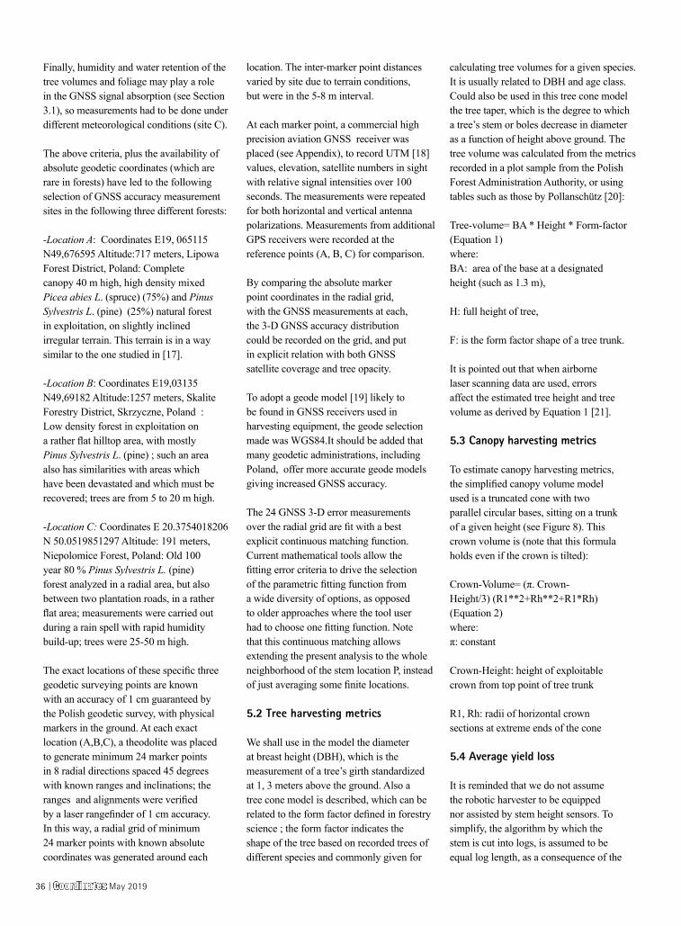
Finally, humidity and water retention of the tree volumes and foliage may play a role in the GNSS signal absorption (see Section 3.1), so measurements had to be done under different meteorological conditions (site C).
The above criteria, plus the availability of absolute geodetic coordinates (which are rare in forests) have led to the following selection of GNSS accuracy measurement sites in the following three different forests:
-Location A: Coordinates E19, 065115 N49,676595 Altitude:717 meters, Lipowa Forest District, Poland: Complete canopy 40 m high, high density mixed Picea abies L. (spruce) (75%) and Pinus Sylvestris L. (pine) (25%) natural forest in exploitation, on slightly inclined irregular terrain. This terrain is in a way similar to the one studied in [17].
-Location B: Coordinates E19,03135 N49,69182 Altitude:1257 meters, Skalite Forestry District, Skrzyczne, Poland : Low density forest in exploitation on a rather flat hilltop area, with mostly Pinus Sylvestris L. (pine) ; such an area also has similarities with areas which have been devastated and which must be recovered; trees are from 5 to 20 m high.
-Location C: Coordinates E 20.3754018206 N 50.0519851297 Altitude: 191 meters, Niepolomice Forest, Poland: Old 100 year 80 % Pinus Sylvestris L. (pine) forest analyzed in a radial area, but also between two plantation roads, in a rather flat area; measurements were carried out during a rain spell with rapid humidity build-up; trees were 25-50 m high.
The exact locations of these specific three geodetic surveying points are known with an accuracy of 1 cm guaranteed by the Polish geodetic survey, with physical markers in the ground. At each exact location (A,B,C), a theodolite was placed to generate minimum 24 marker points in 8 radial directions spaced 45 degrees with known ranges and inclinations; the ranges and alignments were verified by a laser rangefinder of 1 cm accuracy. In this way, a radial grid of minimum 24 marker points with known absolute coordinates was generated around each
location. The inter-marker point distances varied by site due to terrain conditions, but were in the 5-8 m interval.
At each marker point, a commercial high precision aviation GNSS receiver was placed (see Appendix), to record UTM [18] values, elevation, satellite numbers in sight with relative signal intensities over 100 seconds. The measurements were repeated for both horizontal and vertical antenna polarizations. Measurements from additional GPS receivers were recorded at the reference points (A, B, C) for comparison.
By comparing the absolute marker point coordinates in the radial grid, with the GNSS measurements at each, the 3-D GNSS accuracy distribution could be recorded on the grid, and put in explicit relation with both GNSS satellite coverage and tree opacity.
To adopt a geode model [19] likely to be found in GNSS receivers used in harvesting equipment, the geode selection made was WGS84.It should be added that many geodetic administrations, including Poland, offer more accurate geode models giving increased GNSS accuracy.
The 24 GNSS 3-D error measurements over the radial grid are fit with a best explicit continuous matching function. Current mathematical tools allow the fitting error criteria to drive the selection of the parametric fitting function from a wide diversity of options, as opposed to older approaches where the tool user had to choose one fitting function. Note that this continuous matching allows extending the present analysis to the whole neighborhood of the stem location P, instead of just averaging some finite locations.
5.2 Tree harvesting metrics
We shall use in the model the diameter at breast height (DBH), which is the measurement of a tree’s girth standardized at 1, 3 meters above the ground. Also a tree cone model is described, which can be related to the form factor defined in forestry science ; the form factor indicates the shape of the tree based on recorded trees of different species and commonly given for
calculating tree volumes for a given species. It is usually related to DBH and age class. Could also be used in this tree cone model the tree taper, which is the degree to which a tree’s stem or boles decrease in diameter as a function of height above ground. The tree volume was calculated from the metrics recorded in a plot sample from the Polish Forest Administration Authority, or using tables such as those by Pollanschütz [20]:
Tree-volume= BA * Height * Form-factor (Equation 1) where: BA: area of the base at a designated height (such as 1.3 m),
H: full height of tree,
F: is the form factor shape of a tree trunk.
It is pointed out that when airborne laser scanning data are used, errors affect the estimated tree height and tree volume as derived by Equation 1 [21].
5.3 Canopy harvesting metrics
To estimate canopy harvesting metrics, the simplified canopy volume model used is a truncated cone with two parallel circular bases, sitting on a trunk of a given height (see Figure 8). This crown volume is (note that this formula holds even if the crown is tilted):
Crown-Volume= (π. Crown-Height/3) (R1**2+Rh**2+R1*Rh) (Equation 2) where: π: constant
Crown-Height: height of exploitable crown from top point of tree trunk
R1, Rh: radii of horizontal crown sections at extreme ends of the cone
5.4 Average yield loss
It is reminded that we do not assume the robotic harvester to be equipped nor assisted by stem height sensors. To simplify, the algorithm by which the stem is cut into logs, is assumed to be equal log length, as a consequence of the
36 | Coordinates May 2019
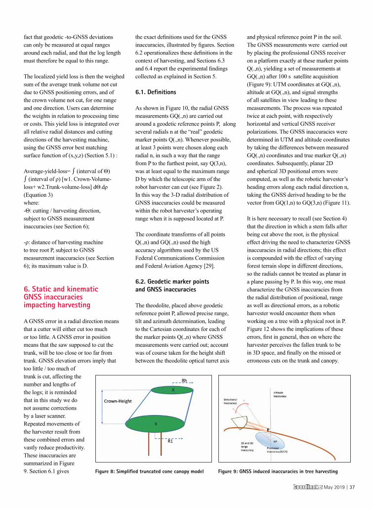
fact that geodetic -to-GNSS deviations can only be measured at equal ranges around each radial, and that the log length must therefore be equal to this range.
The localized yield loss is then the weighed sum of the average trunk volume not cut due to GNSS positioning errors, and of the crown volume not cut, for one range and one direction. Users can determine the weights in relation to processing time or costs. This yield loss is integrated over all relative radial distances and cutting directions of the harvesting machine, using the GNSS error best matching surface function of (x,y,z) (Section 5.1) :
Average-yield-loss= ∫ (interval of Θ) ∫ (interval of ρ) [w1. Crown-Volume-loss+ w2.Trunk-volume-loss] dΘ.dρ (Equation 3) where: -Θ: cutting / harvesting direction, subject to GNSS measurement inaccuracies (see Section 6);
-ρ: distance of harvesting machine to tree root P, subject to GNSS measurement inaccuracies (see Section 6); its maximum value is D.
6. Static and kinematic GNSS inaccuracies impacting harvesting
A GNSS error in a radial direction means that a cutter will either cut too much or too little. A GNSS error in position means that the saw supposed to cut the trunk, will be too close or too far from trunk. GNSS elevation errors imply that too little / too much of trunk is cut, affecting the number and lengths of the logs; it is reminded that in this study we do not assume corrections by a laser scanner. Repeated movements of the harvester result from these combined errors and vastly reduce productivity. These inaccuracies are summarized in Figure 9. Section 6.1 gives
the exact definitions used for the GNSS inaccuracies, illustrated by figures. Section 6.2 operationalizes these definitions in the context of harvesting, and Sections 6.3 and 6.4 report the experimental findings collected as explained in Section 5.
6.1. Definitions
As shown in Figure 10, the radial GNSS measurements GQ(.,n) are carried out around a geodetic reference points P, along several radials n at the “real” geodetic marker points Q(.,n). Whenever possible, at least 3 points were chosen along each radial n, in such a way that the range from P to the furthest point, say Q(3,n), was at least equal to the maximum range D by which the telescopic arm of the robot harvester can cut (see Figure 2). In this way the 3-D radial distribution of GNSS inaccuracies could be measured within the robot harvester’s operating range when it is supposed located at P.
The coordinate transforms of all points Q(.,n) and GQ(.,n) used the high accuracy algorithms used by the US Federal Communications Commission and Federal Aviation Agency [29].
6.2. Geodetic marker points and GNSS inaccuracies
The theodolite, placed above geodetic reference point P, allowed precise range, tilt and azimuth determination, leading to the Cartesian coordinates for each of the marker points Q(.,n) where GNSS measurements were carried out; account was of course taken for the height shift between the theodolite optical turret axis
and physical reference point P in the soil. The GNSS measurements were carried out by placing the professional GNSS receiver on a platform exactly at these marker points Q(.,n), yielding a set of measurements at GQ(.,n) after 100 s satellite acquisition (Figure 9): UTM coordinates at GQ(.,n), altitude at GQ(.,n), and signal strengths of all satellites in view leading to these measurements. The process was repeated twice at each point, with respectively horizontal and vertical GNSS receiver polarizations. The GNSS inaccuracies were determined in UTM and altitude coordinates by taking the differences between measured GQ(.,n) coordinates and true marker Q(.,n) coordinates. Subsequently, planar 2D and spherical 3D positional errors were computed, as well as the robotic harvester’s heading errors along each radial direction n, taking the GNSS derived heading to be the vector from GQ(1,n) to GQ(3,n) (Figure 11).
It is here necessary to recall (see Section 4) that the direction in which a stem falls after being cut above the root, is the physical effect driving the need to characterize GNSS inaccuracies in radial directions; this effect is compounded with the effect of varying forest terrain slope in different directions, so the radials cannot be treated as planar in a plane passing by P. In this way, one must characterize the GNSS inaccuracies from the radial distribution of positional, range as well as directional errors, as a robotic harvester would encounter them when working on a tree with a physical root in P. Figure 12 shows the implications of these errors, first in general, then on where the harvester perceives the fallen trunk to be in 3D space, and finally on the missed or erroneous cuts on the trunk and canopy.
Figure 9: GNSS induced inaccuracies in tree harvestingFigure 8: Simplified truncated cone canopy model
Coordinates May 2019 | 37
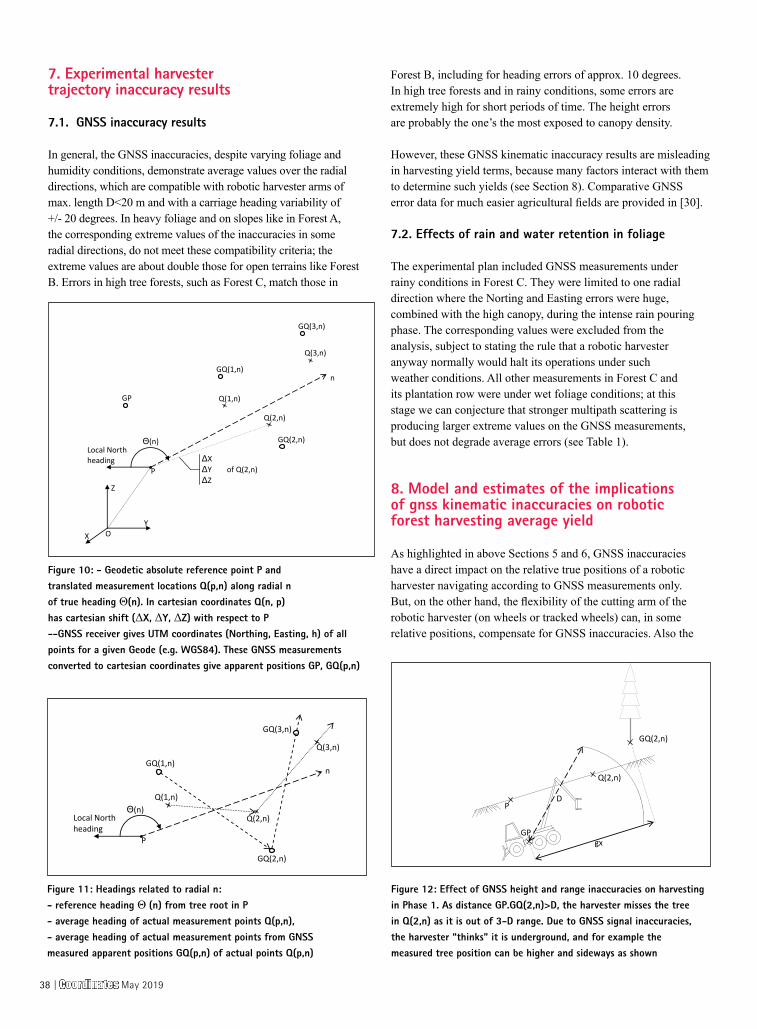
7. Experimental harvester trajectory inaccuracy results
7.1. GNSS inaccuracy results
In general, the GNSS inaccuracies, despite varying foliage and humidity conditions, demonstrate average values over the radial directions, which are compatible with robotic harvester arms of max. length D<20 m and with a carriage heading variability of +/- 20 degrees. In heavy foliage and on slopes like in Forest A, the corresponding extreme values of the inaccuracies in some radial directions, do not meet these compatibility criteria; the extreme values are about double those for open terrains like Forest B. Errors in high tree forests, such as Forest C, match those in
Forest B, including for heading errors of approx. 10 degrees. In high tree forests and in rainy conditions, some errors are extremely high for short periods of time. The height errors are probably the one’s the most exposed to canopy density.
However, these GNSS kinematic inaccuracy results are misleading in harvesting yield terms, because many factors interact with them to determine such yields (see Section 8). Comparative GNSS error data for much easier agricultural fields are provided in [30].
7.2. Effects of rain and water retention in foliage
The experimental plan included GNSS measurements under rainy conditions in Forest C. They were limited to one radial direction where the Norting and Easting errors were huge, combined with the high canopy, during the intense rain pouring phase. The corresponding values were excluded from the analysis, subject to stating the rule that a robotic harvester anyway normally would halt its operations under such weather conditions. All other measurements in Forest C and its plantation row were under wet foliage conditions; at this stage we can conjecture that stronger multipath scattering is producing larger extreme values on the GNSS measurements, but does not degrade average errors (see Table 1).
8. Model and estimates of the implications of gnss kinematic inaccuracies on robotic forest harvesting average yield
As highlighted in above Sections 5 and 6, GNSS inaccuracies have a direct impact on the relative true positions of a robotic harvester navigating according to GNSS measurements only. But, on the other hand, the flexibility of the cutting arm of the robotic harvester (on wheels or tracked wheels) can, in some relative positions, compensate for GNSS inaccuracies. Also the
P
Y X
Z
O
Local North heading
n
GP
GQ(1,n)
GQ(3,n)
GQ(2,n)
Q(2,n)
Q(3,n)
Q(1,n)
Θ(n)
ΔX ΔY of Q(2,n) ΔZ
P
Local North heading
n GQ(1,n)
GQ(3,n)
GQ(2,n)
Q(2,n)
Q(3,n)
Q(1,n) Θ(n)
P
Q(2,n)
GQ(2,n)
GP gx
D
Figure 10: - Geodetic absolute reference point P and translated measurement locations Q(p,n) along radial n of true heading Θ(n). In cartesian coordinates Q(n, p) has cartesian shift (ΔX, ΔY, ΔZ) with respect to P--GNSS receiver gives UTM coordinates (Northing, Easting, h) of all points for a given Geode (e.g. WGS84). These GNSS measurements converted to cartesian coordinates give apparent positions GP, GQ(p,n)
Figure 12: Effect of GNSS height and range inaccuracies on harvesting in Phase 1. As distance GP.GQ(2,n)>D, the harvester misses the tree in Q(2,n) as it is out of 3-D range. Due to GNSS signal inaccuracies, the harvester “thinks” it is underground, and for example the measured tree position can be higher and sideways as shown
Figure 11: Headings related to radial n:- reference heading Θ (n) from tree root in P - average heading of actual measurement points Q(p,n),- average heading of actual measurement points from GNSS measured apparent positions GQ(p,n) of actual points Q(p,n)
38 | Coordinates May 2019
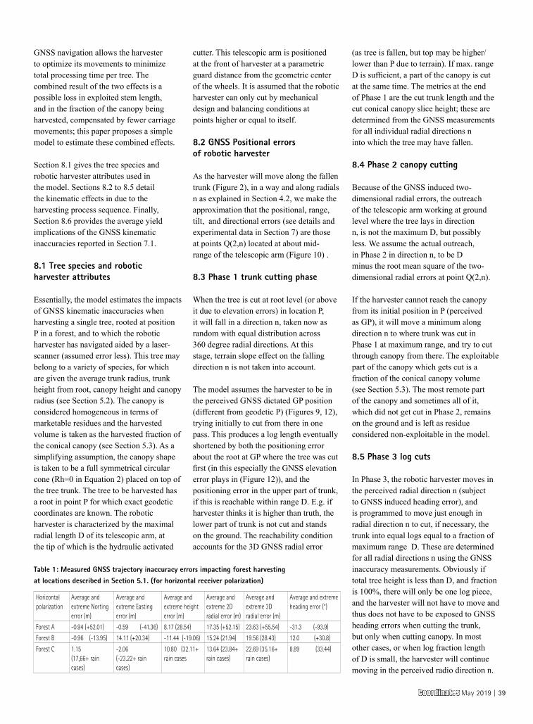
GNSS navigation allows the harvester to optimize its movements to minimize total processing time per tree. The combined result of the two effects is a possible loss in exploited stem length, and in the fraction of the canopy being harvested, compensated by fewer carriage movements; this paper proposes a simple model to estimate these combined effects.
Section 8.1 gives the tree species and robotic harvester attributes used in the model. Sections 8.2 to 8.5 detail the kinematic effects in due to the harvesting process sequence. Finally, Section 8.6 provides the average yield implications of the GNSS kinematic inaccuracies reported in Section 7.1.
8.1 Tree species and robotic harvester attributes
Essentially, the model estimates the impacts of GNSS kinematic inaccuracies when harvesting a single tree, rooted at position P in a forest, and to which the robotic harvester has navigated aided by a laser-scanner (assumed error less). This tree may belong to a variety of species, for which are given the average trunk radius, trunk height from root, canopy height and canopy radius (see Section 5.2). The canopy is considered homogeneous in terms of marketable residues and the harvested volume is taken as the harvested fraction of the conical canopy (see Section 5.3). As a simplifying assumption, the canopy shape is taken to be a full symmetrical circular cone (Rh=0 in Equation 2) placed on top of the tree trunk. The tree to be harvested has a root in point P for which exact geodetic coordinates are known. The robotic harvester is characterized by the maximal radial length D of its telescopic arm, at the tip of which is the hydraulic activated
cutter. This telescopic arm is positioned at the front of harvester at a parametric guard distance from the geometric center of the wheels. It is assumed that the robotic harvester can only cut by mechanical design and balancing conditions at points higher or equal to itself.
8.2 GNSS Positional errors of robotic harvester
As the harvester will move along the fallen trunk (Figure 2), in a way and along radials n as explained in Section 4.2, we make the approximation that the positional, range, tilt, and directional errors (see details and experimental data in Section 7) are those at points Q(2,n) located at about mid-range of the telescopic arm (Figure 10) .
8.3 Phase 1 trunk cutting phase
When the tree is cut at root level (or above it due to elevation errors) in location P, it will fall in a direction n, taken now as random with equal distribution across 360 degree radial directions. At this stage, terrain slope effect on the falling direction n is not taken into account.
The model assumes the harvester to be in the perceived GNSS dictated GP position (different from geodetic P) (Figures 9, 12), trying initially to cut from there in one pass. This produces a log length eventually shortened by both the positioning error about the root at GP where the tree was cut first (in this especially the GNSS elevation error plays in (Figure 12)), and the positioning error in the upper part of trunk, if this is reachable within range D. E.g. if harvester thinks it is higher than truth, the lower part of trunk is not cut and stands on the ground. The reachability condition accounts for the 3D GNSS radial error
(as tree is fallen, but top may be higher/lower than P due to terrain). If max. range D is sufficient, a part of the canopy is cut at the same time. The metrics at the end of Phase 1 are the cut trunk length and the cut conical canopy slice height; these are determined from the GNSS measurements for all individual radial directions n into which the tree may have fallen.
8.4 Phase 2 canopy cutting
Because of the GNSS induced two-dimensional radial errors, the outreach of the telescopic arm working at ground level where the tree lays in direction n, is not the maximum D, but possibly less. We assume the actual outreach, in Phase 2 in direction n, to be D minus the root mean square of the two-dimensional radial errors at point Q(2,n).
If the harvester cannot reach the canopy from its initial position in P (perceived as GP), it will move a minimum along direction n to where trunk was cut in Phase 1 at maximum range, and try to cut through canopy from there. The exploitable part of the canopy which gets cut is a fraction of the conical canopy volume (see Section 5.3). The most remote part of the canopy and sometimes all of it, which did not get cut in Phase 2, remains on the ground and is left as residue considered non-exploitable in the model.
8.5 Phase 3 log cuts
In Phase 3, the robotic harvester moves in the perceived radial direction n (subject to GNSS induced heading error), and is programmed to move just enough in radial direction n to cut, if necessary, the trunk into equal logs equal to a fraction of maximum range D. These are determined for all radial directions n using the GNSS inaccuracy measurements. Obviously if total tree height is less than D, and fraction is 100%, there will only be one log piece, and the harvester will not have to move and thus does not have to be exposed to GNSS heading errors when cutting the trunk, but only when cutting canopy. In most other cases, or when log fraction length of D is small, the harvester will continue moving in the perceived radio direction n.
Horizontal polarization
Average and extreme Norting error (m)
Average and extreme Easting error (m)
Average and extreme height error (m)
Average and extreme 2D radial error (m)
Average and extreme 3D radial error (m)
Average and extreme heading error (°)
Forest A -0.94 (+52.01) -0.59 (-41.36) 8.17 (28.54) 17.35 (+52.15) 23.63 (+55.54) -31.3 (-93.9)
Forest B -0.96 (-13.95) 14.11 (+20.34) -11.44 (-19.06) 15.24 (21.94) 19.56 (28.43) 12.0 (+30.8)
Forest C 1.15 (17,66+ rain cases)
-2.06(-23.22+ rain cases)
10.80 (32.11+ rain cases
13.64 (23.84+ rain cases)
22.69 (35.16+ rain cases)
8.89 (33.44)
Table 1: Measured GNSS trajectory inaccuracy errors impacting forest harvesting at locations described in Section 5.1. (for horizontal receiver polarization)
Coordinates May 2019 | 39
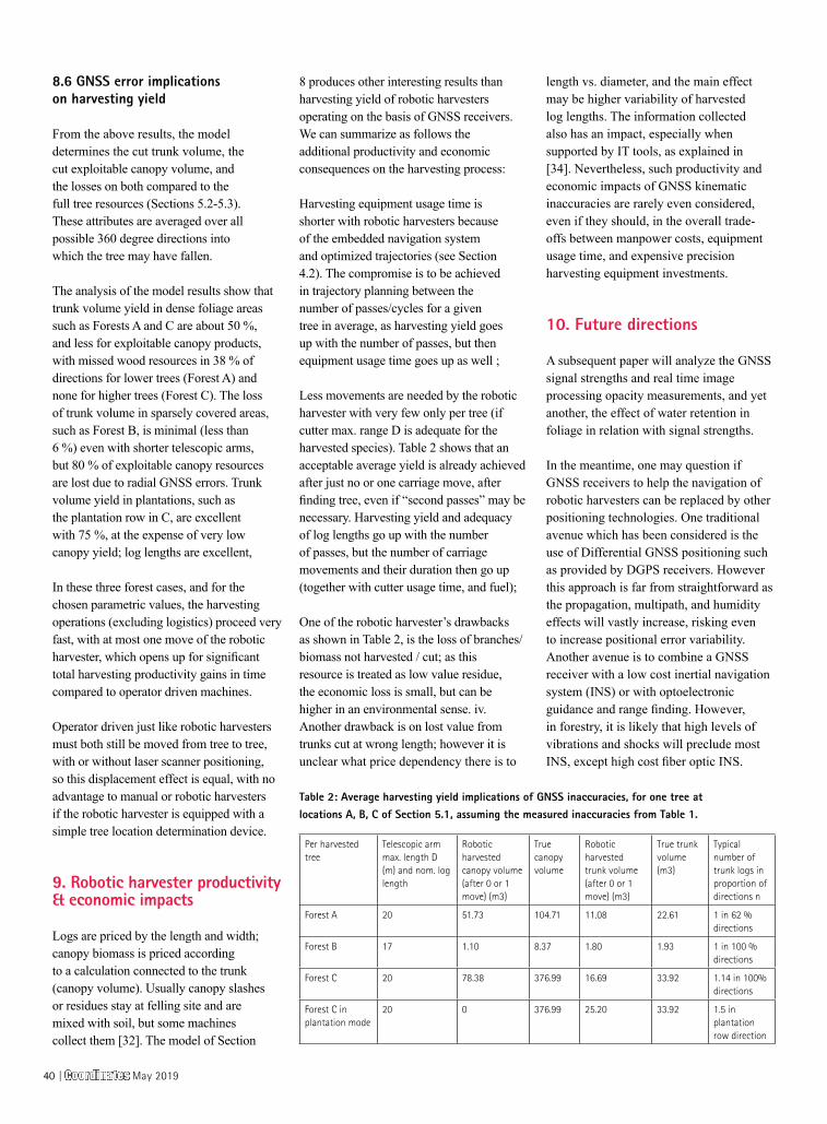
8.6 GNSS error implications on harvesting yield
From the above results, the model determines the cut trunk volume, the cut exploitable canopy volume, and the losses on both compared to the full tree resources (Sections 5.2-5.3). These attributes are averaged over all possible 360 degree directions into which the tree may have fallen.
The analysis of the model results show that trunk volume yield in dense foliage areas such as Forests A and C are about 50 %, and less for exploitable canopy products, with missed wood resources in 38 % of directions for lower trees (Forest A) and none for higher trees (Forest C). The loss of trunk volume in sparsely covered areas, such as Forest B, is minimal (less than 6 %) even with shorter telescopic arms, but 80 % of exploitable canopy resources are lost due to radial GNSS errors. Trunk volume yield in plantations, such as the plantation row in C, are excellent with 75 %, at the expense of very low canopy yield; log lengths are excellent,
In these three forest cases, and for the chosen parametric values, the harvesting operations (excluding logistics) proceed very fast, with at most one move of the robotic harvester, which opens up for significant total harvesting productivity gains in time compared to operator driven machines.
Operator driven just like robotic harvesters must both still be moved from tree to tree, with or without laser scanner positioning, so this displacement effect is equal, with no advantage to manual or robotic harvesters if the robotic harvester is equipped with a simple tree location determination device.
9. Robotic harvester productivity & economic impacts
Logs are priced by the length and width; canopy biomass is priced according to a calculation connected to the trunk (canopy volume). Usually canopy slashes or residues stay at felling site and are mixed with soil, but some machines collect them [32]. The model of Section
8 produces other interesting results than harvesting yield of robotic harvesters operating on the basis of GNSS receivers. We can summarize as follows the additional productivity and economic consequences on the harvesting process:
Harvesting equipment usage time is shorter with robotic harvesters because of the embedded navigation system and optimized trajectories (see Section 4.2). The compromise is to be achieved in trajectory planning between the number of passes/cycles for a given tree in average, as harvesting yield goes up with the number of passes, but then equipment usage time goes up as well ;
Less movements are needed by the robotic harvester with very few only per tree (if cutter max. range D is adequate for the harvested species). Table 2 shows that an acceptable average yield is already achieved after just no or one carriage move, after finding tree, even if “second passes” may be necessary. Harvesting yield and adequacy of log lengths go up with the number of passes, but the number of carriage movements and their duration then go up (together with cutter usage time, and fuel);
One of the robotic harvester’s drawbacks as shown in Table 2, is the loss of branches/biomass not harvested / cut; as this resource is treated as low value residue, the economic loss is small, but can be higher in an environmental sense. iv. Another drawback is on lost value from trunks cut at wrong length; however it is unclear what price dependency there is to
length vs. diameter, and the main effect may be higher variability of harvested log lengths. The information collected also has an impact, especially when supported by IT tools, as explained in [34]. Nevertheless, such productivity and economic impacts of GNSS kinematic inaccuracies are rarely even considered, even if they should, in the overall trade-offs between manpower costs, equipment usage time, and expensive precision harvesting equipment investments.
10. Future directions
A subsequent paper will analyze the GNSS signal strengths and real time image processing opacity measurements, and yet another, the effect of water retention in foliage in relation with signal strengths.
In the meantime, one may question if GNSS receivers to help the navigation of robotic harvesters can be replaced by other positioning technologies. One traditional avenue which has been considered is the use of Differential GNSS positioning such as provided by DGPS receivers. However this approach is far from straightforward as the propagation, multipath, and humidity effects will vastly increase, risking even to increase positional error variability. Another avenue is to combine a GNSS receiver with a low cost inertial navigation system (INS) or with optoelectronic guidance and range finding. However, in forestry, it is likely that high levels of vibrations and shocks will preclude most INS, except high cost fiber optic INS.
Per harvested tree
Telescopic arm max. length D (m) and nom. log length
Robotic harvested canopy volume (after 0 or 1 move) (m3)
True canopy volume
Robotic harvested trunk volume (after 0 or 1 move) (m3)
True trunk volume (m3)
Typical number of trunk logs in proportion of directions n
Forest A 20 51.73 104.71 11.08 22.61 1 in 62 % directions
Forest B 17 1.10 8.37 1.80 1.93 1 in 100 % directions
Forest C 20 78.38 376.99 16.69 33.92 1.14 in 100% directions
Forest C in plantation mode
20 0 376.99 25.20 33.92 1.5 in plantation row direction
Table 2: Average harvesting yield implications of GNSS inaccuracies, for one tree at locations A, B, C of Section 5.1, assuming the measured inaccuracies from Table 1.
40 | Coordinates May 2019
In the future should be envisaged how unmanned flying vehicles (UAV) equipped with higher precision GNSS receivers (including DGPS and equivalent) could work in formation with forest harvesting equipment to increase their accuracy during lapses of insufficient accuracy of on-board harvester GNSS receivers. UAV already helps provide tree height information [35].
11 Conclusions
•Research question 1: Location, range and directional GNSS derived information are degraded in forests; GNSS positioning in some categories of forests as identified in this paper may be sufficiently accurate for automatic forest harvesting, except under rain conditions.
•Research question 2: Even assuming a very simple stem-to-log cutting algorithm, and no stem height sensor, recovered trunk volume is good enough, contrary to recovered canopy volume, to justify robotic harvesting, especially in view of increased time based productivity. Issues remain around the exploitation and pricing from logs with higher variability.
The addition of different robotic harvester-born sensors, on purpose not taken into account in this study (e.g. lidars, real time imaging opacity measures), will strengthen these conclusions. It is also to be noted that if GNSS is the fall-back navigation system in case of the likely frequent failures of optoelectronic sensors on high vibration harvesters, the above conclusions stand.
References
[1] Krüger G., Springer R., Lechner W. 1994. Global navigation satellite systems. Computers and electronics in agriculture 11(1): 3-21
[2] Unknown .2014. La ferme des robots. Valeurs actuelles 20 March 2014 : 52-55
[3] Falkenstein P. 2012. Multispectral imaging plants roots in quality control. Vision systems design Dec. 2012: 23-25
[4] US Congress. 2015. Major uses of GPS and economic benefits. Washington D.C.: US National executive committee for space-based positioning, navigation and timing (PNT)
[5] Sikanen L., Asikainen A., Lehikoinen M. 2005. Transport control of forest fuels by fleet manager, mobile terminals and GPS. Biomass and Bioenergy 28( 2): 183-191. ISSN 0961-9534, http://dx.doi.org/10.1016/j.biombioe.2004.08.011
[6] Ringdahl O., Hellström T., Wästerlund I., Lindroos O. 2012 .Estimating wheel slip for a forest machine using RTK-DGPS. Journal of Terramechanics 49(5): 271-279. ISSN 0022-4898, http://dx.doi.org/10.1016/j.jterra.2012.08.003
[7] Jakubowski M.K., Guo Q., Kelly M. 2013. Tradeoffs between LIDAR pulse density and forest measurement accuracy. Remote Sensing of Environment 130: 245-253. ISSN 0034-4257, http://dx.doi.org/10.1016/j.rse.2012.11.024
[8] Ordóñez Galán C., Rodríguez-Pérez J.R. , Martínez Torres J., García Nieto P.J. 2011. Analysis of the influence of forest environments on the accuracy of GPS measurements by using genetic algorithms. Mathematical and Computer Modeling 54(7–8): 1829-1834. ISSN 0895-7177, http://dx.doi.org/10.1016/j.mcm.2010.11.077.
[9] Adusumilli S., Bhatt D., Wang H., Devabhaktuni V., Bhattacharya P. 2015. A novel hybrid approach utilizing principal component regression and random forest regression to bridge the period of GPS outages. Neurocomputing 166: 185-192. ISSN 0925-2312, http://dx.doi.org/10.1016/j.neucom.2015.03.080.
[10] Wezyk S.M. P. 2013. Pomiary GNNS w przestrzeni lesnej przy wykorzystaniu roznej klasy odbiorkikow oraz wybranych trybow pomiaru (in Polish) (GNSS Measurements in forest environments using various receivers and measurement modes. Archiwum Fotogrametrii, Kartografii i Teledetekcji 25: 217-231
[11] M.G. Wing, J. Frank (2011), Vertical measurement accuracy and reliability of mapping-grade GPS receivers, Computers and Electronics in Agriculture, Vol. 78, no 2, September 2011, p. 188-
194, ISSN 0168-1699, http://dx.doi.org/10.1016/j.compag.2011.07.006.
[12] J. Kalliovirta, J. Laasasenaho, A. Kangas (2005), Evaluation of the Laser-relascope, Forest Ecology and Management, Vol 204, no 2–3, 17 January 2005, p. 181-194, ISSN 0378-1127, http://dx.doi.org/10.1016/j.foreco.2004.09.020
[13] C. Amiama, J. Bueno, C.J. Álvarez, J.M. Pereira (2008), Design and field test of an automatic data acquisition system in a self-propelled forage harvester, Computers and Electronics in Agriculture, Vol 61, no 2, May 2008, p. 192-200, ISSN 0168-1699, http://dx.doi.org/10.1016/j.compag.2007.11.006.
[14] K. M. Bayne, R.J. Parker (2012), The introduction of robotics for New Zealand forestry operations: Forest sector employee perceptions and implications, Technology in Society, Vol 34, no 2, May 2012, p. 138-148, ISSN 0160-791X, http://dx.doi.org/10.1016/j.techsoc.2012.02.004.
[15] L.F. Pau (1990), Mapping and spatial data structures for navigation, ASI Series, Springer Verlag, Heidelberg ISBN: 3642842178
[16] M. Bedarul Alam, C. Shahi, R. Pulkki (2014), Economic impact of enhanced forest inventory information and merchandising yards in the forest product industry supply chain, Socio-Economic Planning Sciences, Vol. 48, no 3, September 2014, p. 189-197, ISSN 0038-0121, http://dx.doi.org/10.1016/j.seps.2014.06.002.
[17] R. Valbuena, F. Mauro, R. Rodriguez-Solano, J.A. Manzanera (2010), Accuracy and precision of GPS receivers under forest canopies in a mountainous environment, Spanish Journal of Agricultural Research, Vol 8, no 4, p. 1047-1057, ISSN: 1695-971-X
[18] UTM, Universal transverse Mercator coordinate system, https://en.wikipedia.org/wiki/Universal_Transverse_Mercator_coordinate_system
[19] D.G. Milbert, D. A. Smith (1998), Converting GPS Height into NAVD88 Elevation with the GEOID96 Geoid Height Model, National Geodetic Survey, NOAA, Washington D.C.
Coordinates May 2019 | 41
[20] J. Pollanschütz (1976), http://www.fs.fed.us/pnw/pubs/pnw_rp345.pdf
[21] P. Tompalski, N.C. Coops, J.C. White, M.A. Wulder (2014), Simulating the impacts of error in species and height upon tree volume derived from airborne laser scanning data, , Forest ecology and management, Vol 327, p. 167-177, DOI: http://dx.doi.org/10.1016/j.foreco.2014.05.011
[22] A. Klamerus-Iwan (2014), Different views on tree interception process and its determinants, Forest Research Papers, Vol 75, no 3, p. 291-300. DOI: 10.2478/frp-2014-0028
[23] K. Owsiak, A. Klamerus-Iwan, J. Gołąb (2013), Effect of current state of the sprinkled surface on rain water coherence: laboratory research on interception by trees,. Sylwan, Vol 157, no 12, p. 922-928
[24] D.R. Themens (2013), The quest for accurate 3D water vapor and temperature fields: a theoretical examination of the capabilities of a mesoscale microwave radiometer, MSc. Thesis Earth Sciences, Mc Gill University, Montréal, http://digitool.library.mcgill.ca/R/?func=dbin-jump-full&object_id=119505&local_base=GEN01-MCG02
[25] F. Fabry, W. Szyrmer (1999), Modeling of the melting layer. Part II: Electromagnetics, J. Atmos. Sci., Vol 56, no 20, p. 3593 – 3600 http://dx.doi.org/10.1175/1520-0469
[26] N.J. Dominy, B. Duncan (2001), GPS and GIS methods in an African rain forest: applications to tropical ecology and conservation, J. Ecology and society, Vol 5, no 2, Art. 6, http://www.consecol.org/vol5/iss2/art6/
[27] J.R. Rodríguez-Pérez, M. Flor Álvarez, E. Sanz, A. Gavela (2006), Comparison of GPS receiver accuracy and precision in forest environments. Practical recommendations regarding methods and receiver selection, Shaping the Change, Proc. XXIII FIG Congress, Munich, Germany, October 8-13, 2006
[28] J. Matej (2014), Determination of forestry machines tilt angle using camera and image processing, Computers and electronics in agriculture, Vol. 109, p. 134-140 doi:10.1016/j.compag.2014.09.011
[29] Geotools and references www.apsalin.com
[30] F. Rovira, I. Chatterjee, V.S. Rubio (2015), The role of GNSS in the navigation strategies of cost effective agricultural robots, Computers and electronics in agriculture, Vol 112, p. 172-183 doi:10.1016/j.compag.2014.12.017
[31] Rottne Extreme Test - Harvester Extreme S2E5, https://www.youtube.com/watch?v=_vZyfa3D1QY
[32] Ponsse Ergo 8w Harvester in hard wood, https://www.youtube.com/watch?v=soLjGPknv2o
[33] P. Tompalski, N.C. Coops, J.C. White, M.A. Wulder (2015), Enriching ALS-Derived Area-Based Estimates of Volume through Tree-Level Downscaling, Forests, Vol 6, no 8, p. 2608-2630, DOI:10.3390/f6082608
[34] M. Carrascal, L-F Pau, L. Reiner (1995), Knowledge and information transfer in agriculture using hypermedia ; a system review; Computers and electronics in agriculture, Vol 12, p 83-119 ISSN:0168-1699
[35] P.J. Zarco-Tejada, R. Diaz-Varela, V. Angileri, P. Loudjani (2014), Tree height quantification using very high resolution imagery acquired from an unmanned aerial vehicle (UAV) and automatic 3D photo-reconstruction methods, European Journal of Agronomy, Vol. 55, April 2014, p. 89-99, ISSN 1161-0301, http://dx.doi.org/10.1016/j.eja.2014.01.004.
[36] M. Miettinen, J. Kulosevi, J. Kalmari, A. Visala (2010) , New measurement concept for forest harvester head, in: A. Howard et al (Eds) , Proc. Intl. Conference “Field and service robotics 7”, Vol 62, Springer Tracts in advanced robotics, 35-44 DOI: 10.1007/978-3-642-13408-1_4
[37] O. Lindroos, O. Ringdahl, P. La Hera, P. Hohnloser, T. Hellström (2015), Estimating the position of the harvester head: a key step towards precision forestry of the future?, Croatian Journal of forest engineering, 36(2), 147-164 ISSN: 1845-5719
[38] Z. Zhu, S. Gunawardena, M. Uut de Haag, F. van Graas, M. Braasch, GNSS Watchdog: a GPS anomalous event monitor,
InsideGNSS, Fall 2008, Vol 3, no 7, 18-27 http://www.insidegnss.com/magazine
[39] M. Petovello, How do you use GNSS to compute the attitude of an object? , Inside GNSS , Sept/Oct 2017, 36-39
Appendix: instrumentation used
-Zeiss Theodolite THEO 010-B ; -Leica Geosystems BSTO2L rangefinder ; -Laser technology TRUPULSE 360° B rangefinder ; Aviation GARMIN GPS receiver with WGS84 geode, two different antenna polarizations, signal strength measurements and some programmability features via FPGA ; Samsung Galaxy S2 Compass level from embedded magnetic MEMS sensors; -MAPPY E418 GPS receiver for planar coordinates
Acknowledgments
We greatly thank Mr. Marian Knapek and Wojciech Motyka from Lasy Panstwowe (Polish Forest Administration) from the Wegierska Gorka forest district for providing access to their forests, and geodetic information, and performing transportation of a team of six. Likewise, is greatly thanked the Krakow Forestry University for making available a team of post-doctoral field assistants (Mariusz Kormanek, Janusz Gołąb, Krzysztof Owsiak), lending extensive equipment and covering the local transportation costs to the remote forest districts (Department of Forest Engineering, Jarosław Kucza). The measurements were carried out as part of a Short term scientific mission under COST Action SaPPART by Prof L-F Pau, to the Krakow Forestry University, covering also the transportation cost for all the equipment brought from Denmark to Poland.
Permissions:Sole Copyright 2017-2019 (C) to all authors , reproduced by permission of the authors to Coordinates, from (researchgate URL ) and EJPAU Electronic Journal of Polish Agricultural Universities, 2018 no 4, Vol 21(4), DOI:10.30825/5.ejpau.163.2018.21.4, EJPAU 21(4), http://www.ejpau.media.pl/volume21/issue4/art-04.html
42 | Coordinates May 2019
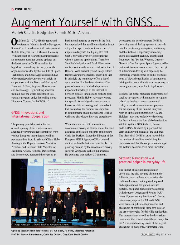
On March 25 – 27, 2019 the renowned conference “Munich Satellite Navigation
Summit” welcomed about 450 participants at the Old Congress Hall in Munich, Germany. Within the last 16 years the Summit became an important event for getting updates on the latest news in GNSS as well as for high-level networking. As every year, the organization was led by the Institute of Space Technology and Space Applications (ISTA) of the Bundeswehr University Munich, in cooperation with the Bavarian Ministry of Economic Affairs, Regional Development and Technology. High-ranking speakers from all over the world contributed to a versatile program under the leading motto “Augment Yourself with GNSS…”.
GNSS Innovations and International Cooperation
The plenary panel discussion for the official opening of the conference was attended by prominent representatives from various European institutions as well as representatives from Russia and China. Hubert Aiwanger, the Deputy Bavarian Minister-President and Bavarian State Minister for Economic Affairs, Regional Development and Technology, honoured the event as an
institutional meeting of experts in the field, but emphasized that satellite navigation is not a topic for experts only as it has a concrete impact on daily life. He highlighted that GNSS provides a variety of possibilities when it comes to applications. Therefore, Satellite Navigation and Earth Observation are key topics in the research infrastructure of Bavaria. With his background in agriculture, Hubert Aiwanger especially underlined that in this field the technology offers a lot of opportunities like the determination of the grow of crops on a field which provides important knowledge on the interaction between climate, land use and soil and plant processes. Finally Hubert Aiwanger valued the specific knowledge that every country has on satellite technology and pointed out that events like the Summit are important to communicate on an international level as well as to share know-how and experiences.
When it comes to GNSS innovations, autonomous driving is clearly one of the most discussed application concepts of the future. Carlo des Dorides, Executive Director of the European GNSS Agency (GSA), pointed out that within the last year there has been a growing demand by the autonomous driving sector in GNSS and Galileo in particular. He explained that besides 3D cameras,
gyroscopes and accelerometers GNSS is becoming one of the key systems to provide data for positioning, navigation, and timing and that Galileo is especially interesting due to its excellent accuracy and the dual frequency. Prof Dr. Jan Woerner, Director-General of the European Space Agency, added that apart from autonomous cars, the concept of autonomous driving will especially be interesting when it comes to trains. From his point of view, the realisation of autonomous driving with cars within cities is not as easy as one might expect, also due to legal aspects.
To show the global relevance and presence of satellite navigation within another navigation related technology, namely augmented reality, a live demonstration was prepared for the opening of the Summit this year: With an application (running on iOS and Hololens) that was exclusively developed for the conference the four global navigation satellite systems GPS, Galileo, Beidou and GLONASS where flying around the earth and above the heads of the audience. The view of all GNSS at once showed that the number of satellites in orbit is quite impressive and that the cooperation amongst the systems becomes even more important.
Satellite Navigation – A practical helper in everyday life
The impact of satellite navigation on day to day life also became visible in the following two conference days. After the traditional session on the global, regional and augmentation navigation satellite systems, one panel discussion was dealing with the topic “Augmented Reality (AR) meets High-Accuracy Positioning”. During this session, experts for AR and GNSS were discussing different approaches and challenges of combining these two state-of-the-art technologies for daily life applications. The presentations as well as the discussions made clear that it is all about the accuracy. For the AR experts tracking is one of the largest challenges to overcome. Fiammetta Diani,
Opening speakers from left to right: Dr. Jun Shen, Jia Peng, Matthias Petschke, Prof. Dr. Pascale Ehrenfreund, Carlo des Dorides, Oleg Kem, David Comby
Augment Yourself with GNSS…Munich Satellite Navigation Summit 2019 - A report
Image copyright “Munich Satellite Navigation Summit”
CONFERENCE
Coordinates May 2019 | 43

NEWS - IMAGING
Satellite remote sensing used in water protection in Myanmar
Satellite remote sensing has transformed environmental law enforcers into clairvoyants with the help of an app on drinking water sources developed by the Ministry of Ecology and Environment.
The drinking water source enforcement app integrates satellite remote sensing images, water environment problems spotted by satellite, water protection zone boundary’s spatial data, water environment problems found by provinces and cities themselves and law enforcement data at the scene, and sends environmental problem lists to law enforcers at the scene to guide their work.
The app was used during the nationwide inspection on water sources in 2018 and the law enforcement during water sources inspection at county level this year.
The remote sensing can also be used in making electric and visual files for water source protection zones after matching the satellite remote sensing images and the ground situation. Such work has been trialed in four cities. In the future, satellite remote sensing will become a normal method in everyday law enforcement of water sources and long-term supervise. https://elevenmyanmar.com
Indian Railways to adopt modern technology that detects track faults
The Central Railway may soon adopt light detection and ranging (LIDAR) technology in order to detect track fractures and faults at the click of a button.
The LIDAR technology will capture fractures as well as missing keys of the section.
Indian Railways to take step to detect track faults in minutes! The Central Railway zone of Indian Railways may soon adopt LIDAR technology soon. At present, gangmen and keymen carry out this maintenance work.
Last year in December, it was reported that a state-of-the-art technology, Automated
Train Examination System (ATES) has been introduced by the Mechanical Branch of Central Railways’ Nagpur Division. The system was introduced in order to eliminate the need for manual monitoring. It was for the first time that such a system, developed by the Konkan Railway Corporation Limited, has been used in the Central Railway zone. The system, which has been manufactured under Modi government’s ‘Make in India’ initiative, checks every passing train through the track on which it is installed. The system warns the railway officials immediately about cases of hot axle as well as brake binding. www.financialexpress.com
SSTL announces new Earth Observation data contract with Airbus
Surrey Satellite Technology Ltd (SSTL) has signed a contract with Airbus to provide high resolution optical data from the SSTL S1-4, an Earth observation satellite which was launched in September 2018.
SSTL will retain ownership and in orbit satellite operation, and will lease imaging payload capacity to Airbus for the lifetime of the satellite, designed to be in excess of 7 years. The new contract will contribute high-resolution panchromatic and multispectral optical data into the Airbus portfolio, which already includes image data from seven satellites manufactured by SSTL, the DMC Constellation and the TripleSat Constellation.
Terra Drone and KDDI launch drone infrastructure inspection services
Terra Drone Corporation and KDDI Corporation has launchd safe, fast, and cost-effective infrastructure inspection services using drones. The solution uses drones with high-resolution cameras to monitor the structural health of industrial systems, such as, wind turbines, telecom and transmission steel towers, smokestacks, and bridges.
The data management and report generation is further automated via Terra Inspection software, an online platform based on Terra UTM autonomous flight system and Terra Mapper 3D modeling system (SfM).
Head of the Market Development Department at GSA, explained that GNSS is already able to react to these demands by providing a meter level accuracy outdoors, even in difficult environments like urban areas, and corrections for Precise Point Positioning (PNT) are already on their way. Therefore, AR may count on a very accurate and reliable GNSS in the coming two or three years, provided that further improvements in the smartphone GNSS-antenna will take place. Miguel Manteiga Bautista from ESA made a point by recognizing that within a few decades the major part of the humanity will live in smart mega cities, but that the current PNT concept relying on GNSS is not really optimized for this area.
Beyond today’s GNSS, Revolution or Evolution?
Under the guidance of this year’s Kepler Award winner, Dr. Oliver Montenbruck, three concepts for the navigation satellites systems for the years >2040 have been discussed. Dominic Hayes from the European Commission outlined requirements. Dr. Todd Walter from the Stanford University showed a concept utilizing a LEO constellation to achieve a higher geometric variability in the orbit and Dr. Christoph Günther from DLR presented the Kepler concept making use of optical technology and to virtually eliminate the need for a ground segment.
As every year, the participants had also the opportunity to visit an international exhibition on site of the conference to get in touch with different companies and institutions working in the field of satellite navigation. Amongst 17 exhibitors, Airbus Defence and Space, spaceopal, the European Commission and the European GNSS Agency (GSA), GMV, and NavCert presented their current activities.
Munich Satellite Navigation Summit 2020
The Munich Satellite Navigation Summit 2019 will take place on March 16 - 18, 2020. Up-to-date information on the conference can be found at www.munich-satellite-navigation-summit.org.
- Thomas Pany and Kristina Kudlich.
44 | Coordinates May 2019
SD65_CMPL_Pentax Half-Page_April17_Ad.indd 1 11/04/17 3:35 pm

NEWS - GNSS
Another Beidou navigation satellite successfully launched
Another satellite to join the China’s independent global navigation network successfully launched from the mountainous Xichang spaceport in the southwest of the country. With this, China has launched 44 Beidou satellites since 2000, including test models no longer in operation, and previous-generation spacecraft that provided regional navigation coverage over Chinese territory and neighboring regions. According to the state-run Xinhua news agency, China plans to launch between eight and 10 Beidou satellites this year. https://spaceflightnow.com
ESCAPE project launches positioning module for autonomous driving
A European Union project has designed and prototyped the ESCAPE GNSS Engine (EGE), a positioning module intended to enable autonomous or semi-autonomous driving functions. Automated vehicles are on the way, and the European GNSS
Agency (GSA) sees satellite navigation as a core technology that will help to ensure their safe operation. Recently, the GSA shared its space with the ESCAPE project, a EU-funded initiative that has developed a unique positioning module for autonomous or semi-autonomous driving.
Autonomous vehicles will feature both sensor-based and connection-based solutions for a variety of vehicle services. Ultimately, the GSA sees a “converged solution” as the best alternative, combining the strengths of both approaches. By integrating sensor data and connectivity-based information, operators can reduce the need for the most expensive sensors and at the same time save money on infrastructure.
The Fundamental Elements-funded ESCAPE project has designed and prototyped the ESCAPE GNSS Engine. It is a unique positioning module that combines precision GNSS and 4G connectivity, for the highly accurate and reliable positioning capabilities required to make automated driving a reality.
The ESCAPE unit also provides for the integration of other data from the vehicle.
Hexagon AB acquires Thermopylae Sciences and Technology
Hexagon AB has announced the completion of the previously announced acquisition of Thermopylae Sciences and Technology. It is a Virginia, USA-based software provider serving both the U.S. government and private sector markets with geospatial applications, mobile frameworks and cloud computing for enhanced location intelligence.
New generation satellites to join GLONASS system early 2020
New generation satellites will join the navigation system GLONASS at the end of 2019 or the beginning of 2020, the deputy CEO, deputy general designer for development and innovations of the JSC M.F. Reshetnev Information Satellite Systems Yuri Vilkov has recently said. http://tass.com
SD65_CMPL_Pentax Half-Page_April17_Ad.indd 1 11/04/17 3:35 pm
NEWS - UAV
SBG Systems introduces Quanta UAV, a New Line of INS/GNSS Systems
SBG Systems has introduced its newest line of INS/GNSS systems for drone-based surveying integrators. Quanta UAV and Quanta UAV Extra are small, lightweight, low-power inertial navigation systems that offer two different levels of accuracy. They’re developed for compact LiDAR to high-end beyond visual line of sight (BVLOS) mapping solutions. Both offer precise orientation and centimeter level position data that’s available in real time and for post-processing.
Because they’re direct geo-referencing solutions, there’s no need for ground control points or overlapping. They also can be used as high-end navigation solutions to feed the UAV autopilot. Tight integration with in-house IMUs, advanced calibration techniques and algorithms help ensure consistent behavior in all weather conditions, as well as a robust position even if the drone gets too close to buildings, electrical lnes, or trees.
The Quanta UAV line comes with Qinertia, SBG’s post-processing software. The software gives users access to offline RTK corrections from more than 7,000 base stations located in 164 countries. Trajectory and orientation are improved by processing inertial data and raw GNSS observables in forward and backward directions. www.sbg-systems.com
Solar 360 thermal drone solution by senseFly
senseFly has introduced its new senseFly Solar 360. Created in collaboration with software company Raptor Maps, this new offering is a uniquely efficient thermal drone solution that enables the automatic assessment of solar plant performance at a sub-module level. Created by combining eBee X fixed-wing drone technology, senseFly’s Duet T thermal mapping camera, and Raptor Maps’ ground-breaking software, it is a fast and fully-automated solution. It is easily integrated into solar management workflows without requiring either drone piloting skills or the manual analysis of aerial solar farm data. www.sensefly.com
Fortem Technologies and Unifly collaborate to keep airspace safe
Fortem Technologies, Inc. and Unifly will collaborate to develop a joint airspace safety and security solution for a drone-enabled society. This new end-to-end solution will allow UTM and U-space architectures to be used by public safety officers, military groups and other government agencies to secure airspace around critical infrastructure, airports, stadiums, public venues and more.
Drone Workforce Solutions (DWS) launches oGlobal Drone Pilot Portal
Drone Workforce Solutions, LLC (DWS) has announced the launch of a one-of-a-kind digital database that connects certified drone pilots with corporate business and government partners around the world. The Drone Workforce Solutions Pilot Portal will offer potential clients access to the most experienced and talented pool of drone operators the industry has to offer. Under Drone Workforce Solutions’ comprehensive vetting system, all American pilots will have passed the Federal Aviation Administration’s Part 107 exam.This vetting system offers corporate and government partners the comfort of knowing they are hiring highly-qualified pilots who can supply a diverse range of drone services. The Portal is now available.
Europe’s first hydrogen drone doubles flight time
Europe’s first hydrogen-powered drone has successfully doubled its maximum flight time thanks to a cylinder from UK-based AMS Composite Cylinders. The e-Drone Zero, launched by Estonia-based Skycorp back in January, is a long endurance quadcopter designed for the commercial market. It features a compact, custom military grade frame, and is powered by a unique, air cooled hydrogen fuel cell module developed by Intelligent Energy. The system is managed by one of the most advanced artificial intelligence (AI) operating systems around. AMS said this is one of the lightest cylinders of its kind in the world today – providing double the gas capacity of the previous
e-Drone Zero cylinder, whilst increasing the system weight by just 600g.
UAVOS launched advanced data link for unmanned systems
UAVOS Inc. has released the pMDDLRadio Data Link, an advanced UAV communication system aimed at the unmanned systems market. It is an easy plug & play device, which gives a solution that packages all drone communication into a single RF channel, except using separate solutions for control, telemetry and payload, thereby reducing the cost and weight. The system uses open architecture and enables full duplex wideband digital link, error correction techniques and high-rate communication in the Uplink (UPL) and Downlink (DNL) channels. Having a weight of 50g, dimensions 90x65x20mm (23g & 40x50x12mm, without enclosure), and power transmission of up to 1 Watts, the pMDDLRadio is ideal for UAV, UGVs (unmanned ground vehicles), and other robotic applications. www.uavos.com
NextCore release new RN Series UAV LiDAR scanner
Airsight has announced it’s first NextCore LiDAR Unit, built specifically for the DJI M600. The RN50 comes as a payload only option and allows operators who already have access to suitable GNSS data to use their existing base station equipment or RINEX subscriptions to process accurate LiDAR datasets. Through improved production methods, increased demand and a move away from a propriety GNSS base the RN series effectively halves the price of the previous version. www.nextcore.com
Centre for drone development soon at IIT Hyderabad
Japan-based Terra Drone Corporation, Terra Drone India and the Indian Institute of Technology, Hyderabad, have signed a pact to establish a first-of-its-kind Centre of Excellence for Unmanned Aerial Vehicles (UAVs) in India and will be set up at IIT Hyderabad.www.business-standard.com
46 | Coordinates May 2019
NEWS - GIS
China Railway Engineering Consulting Group sets benchmark
The Beijing to Zhangjiakou High-speed Rail Project will become the world’s first high-speed railway with a design speed of 350 kilometers per hour. China Railway Engineering Consulting Group Co., Ltd. (CRECG) is responsible for design and construction consulting of the 171-kilometer project. Using Bentley’s comprehensive modeling environment, CRECG’s design team significantly improved efficiency, saving around three months of design time and CNY 3 million in labor costs.
The line, which forms part of China’s preparations for the 2022 Olympic Winter Games in Beijing, is highly complex and includes many firsts. With 71 subsurface sections, 64 bridges, 10 tunnels, and 10 stations, the new high-speed line will be the first in China to adopt a full-lifecycle BIM approach. www.epcworld.in
Capgemini and Autodesk partnership agreement
Capgemini will enter into a new partnership agreement with Autodesk to deploy ReflectIoD, a new cloud-enabled and secure digital twin platform. The new Building Information Modelling (BIM) platform for building and infrastructure operators integrates natively 1D to 3D, point cloud, geographical information, and Internet of Things (IOT) data while offering value added services to improve operations and maintenance. www.autodesk.com
Esri acquires controlling stake from NIIT Technologies Limited in Esri India
NIIT Technologies Limited has signed a definitive agreement for the sale of its entire 88.99% stake in ESRI India Technologies Ltd (Formerly NIIT GIS Ltd.) for consideration of Rs. 89.7 crores. ESRI India Technologies Ltd has been an exclusive distributor of ESRI Inc. cutting edge GIS products in India and has been supporting customers since 1996. The distribution agreement was expiring on 31st March 2019 and Esri Inc expressed its desire to directly manage the distribution of its products in India.
Netherlands forms task force to assess 5G security risks
The Dutch government has said it had established a special task force to weigh potential security risks as it prepares to build a 5G telecommunications network.
The announcement came after Dutch Prime Minister Mark Rutte said his government was still exploring options for 5G and had not yet formed an opinion on the possible role of Chinese companies. The United States has lobbied Europe to shut out China’s Huawei from such projects, saying its equipment could be used by the Chinese government for espionage. That view was supported by the Dutch security service as well. www.tribuneindia.com
South Korea will be first to roll out 5G services
South Korea will become the first country to commercially launch fifth-generation (5G) services as it rolls out the latest wireless technology with Samsung Electronics’ new 5G-enabled smartphone Galaxy S10.
With one of the world’s top smartphone penetration rates, South Korea is in a race with China, the United States and Japan to market 5G, hoping the technology will spur breakthrough in fields such as smart cities and autonomous cars, and drive up its economic growth that slowed to a six-year low in 2018. www.ndtv.com
UAE clears 10-year artificial intelligence strategy
The UAE has launched a national strategy for artificial intelligence (AI) to improve customer services, assess government performance and increase living standards as well as to harness AI technology in the transport, tourism, health and education sectors.
The National Artificial Intelligence Strategy 2031 aims at positioning the UAE as a global leader in artificial intelligence by 2031, and aims to develop an integrated system that employs artificial intelligence in vital areas in the UAE. It includes eight objectives, along with a
number of initiatives aimed at employing artificial intelligence in vital areas such as education, government services and the community well-being. The strategy implementation is overseen by the Emirates Council for Artificial Intelligence and Digital Transactions, in coordination with a number of local and federal entities.
The eight objectives include reaffirming the UAE’s position as a global hub for artificial intelligence, increasing the competitive edge of the AI sector in the UAE, establishing an incubator for AI innovations, employing AI in the field of customer services to improve the quality of life, attracting and training talents for jobs of the future, attracting leading research capabilities, providing a data-driven infrastructure to support AI experiments and optimising AI governance and regulations. https://gulfnews.com
Slovenia to set up Europe’s first AI research centre
Slovenia has announced plans to set up Europe’s first international artificial intelligence (AI) research centre, by converting the department of intelligent systems at the Jožef Stefan Institute in Ljubljana into a centre focusing on the governance and policies which surround AI.
“All of this Slovenian know-how which has been applied for all these years, and all the knowledge that we possessed in the past and that we still possess today is undoubtedly a reason for us, or should I say you, to be proud,” said the country’s prime minister Marjan Šarec at an event celebrating the 70th anniversary of the institute. https://emerging-europe.com
Honeywell integrates Intel to add AI capabilities
Honeywell has announced a first-of-its-kind technology integration with Intel that will enable new artificial intelligence (AI) capabilities in its MAXPRO® connected security platform. The new security platform, which will support MAXPRO Network Video Recorders (NVR) and Video Management Systems (VMS), will incorporate Intel® Vision products that enable advanced analytics, deep learning
NEWS - LBS & AI
Coordinates May 2019 | 47
NEWS - INDUSTRY
and facial recognition capabilities. These greatly enhanced security solutions will drive cost and time savings by significantly reducing false alarms and will meet compliance requirements such as General Data Protection Regulation (GDPR) through identity anonymization. www.honeywell.com
Airbus and ZF to develop end-to-end autonomous driving solution
Airbus Defence and Space and ZF Friedrichshafen AG, a system provider for mobility, are collaborating to enrich and complement ZF on-board system to enhance autonomous driving by using Airbus satellite derived information.WUnder this collaboration, Airbus and ZF are combining their capabilities and expertise to offer a reliable end-to-end solution for self-driving and self-positioning vehicles. www.airbus.com
EU unveils ethics guidelines for artificial intelligence
The European Union presented ethics guidelines as it seeks to promote its own artificial intelligence sector, which has fallen behind developments in China and the United States. The European Commission, the bloc’s executive arm, unveiled a framework aimed at boosting trust in AI by ensuring, for example, data about EU citizens are not used to harm them.
“Ethical AI is a win-win proposition that can become a competitive advantage for Europe: being a leader of human-centric AI that people can trust,” Commission Vice President Andrus Ansip said. The guidelines list seven key requirements for “trustworthy AI” established by independent experts consulted by the Commission.
Among them is one ensuring that data about citizens will not be used to harm them or to discriminate against them. The measures also call for mechanisms to ensure accountability for AI systems and for AI algorithms to be secure and reliable enough to deal with errors or inconsistencies. The Commission now aims to launch a pilot phase in which industry, research and public authorities test the list of key requirements. https://phys.org
SF-5050 INTEGRATED STARFIRE™/RTK GNSS RECEIVER by NavCom
NavCom’s SF-5050 integrated StarFire™/RTK Extend™ Receivers provide 5cm-level position accuracy, anywhere in the world, anytime. Powered by the new Onyx GNSS Engine, it provides 255 channel tracking, including multi-constellation support for GPS and GLONASS. It also provides patented interference rejection and anti-jamming capabilities. Offering the “freedom to choose,” the SF-5050 is fully upgradeable allowing users to upgrade from an autonomous receiver to a variety of augmentation capabilities with just a software bundle upload. This flexible framework makes the SF-5050 ideal for any application.
Sonardyne technology chosen for new Canadian seabed observatory
A major new seabed observatory that will provide critical information about earthquake and tsunami hazards is to be deployed offshore Vancouver, Canada, using long endurance acoustic sensing technology supplied by Sonardyne International Ltd. The new Northern Cascadia Subduction Zone Observatory (NCSZO) will use a “seafloor GPS” network to monitor long-term movements of the subducting Juan de Fuca plate and overriding North American tectonic plate.
The NCSZO is led by Ocean Networks Canada (ONC)—an initiative of the University of Victoria—and is made possible through cooperation of international partners that include Natural Resources Canada (NRCan) scientists at the Pacific Geoscience Centre and David Chadwell from the Scripps Institution of Oceanography. More than 20 Sonardyne Fetch subsea sensor logging nodes, which will be deployed in depths ranging from 400 to 2,500 metres of water depth for seven years or longer at a time, will comprise the backbone of the NCSZO.
Data will be acquired up to two times a year using a technique called GPS-Acoustic method (GPS-A), which uses acoustic positioning techniques, inertial navigation, and GPS data to periodically position
the Fetch instruments to centimetre-level accuracy, using a Sonardyne transceiver mounted on an unmanned surface vessel. These measurements will enable the Fetch positions to be related to a corresponding onshore network of geodetic stations operated by NRCan, allowing the subsea plate motion and onshore plate motion to be correlated, which has only recently been made possible. www.sonardyne.com
3D laser scanning mobile-device app wins IF DESIGN Award
Leica Geosystems announced the Leica Cyclone FIELD 360 laser scanning mobile-device app won an iF DESIGN AWARD 2019. Along with user-experience (UX) company Ergosign, Leica Geosystems submitted the app under the category of communication. For 66 years, the iF DESIGN AWARD has been recognised as an arbiter of quality for exceptional design. The Cyclone FIELD 360 app was selected by a 67-member jury, made up of independent experts from all over the world, from among 6,375 entries from 52 countries.
The Cyclone FIELD 360 mobile-device app is a fundamental element of the Leica RTC360 3D reality capture solution. https://leica-geosystems.com
Trimble TDC150 handheld maximizes productivity for mobile workers
Trimble has announced a new high-performance field computer for its Mapping and GIS portfolio—the Trimble® TDC150 handheld. Designed for GIS data collection, inspection and management activities, the TDC150 provides users a rugged solution that has the flexibility of a handheld, a modern interface with open Android™ operating system, and scalable high-accuracy positioning for professional field workflows.
The TDC150 provides advanced GNSS capabilities in a durable, ergonomic and lightweight form factor. With a built-in GNSS antenna, it is a scalable solution that allows customers to choose their desired accuracy. Easy-to-use and carry in the field, it features a bright 5.3-inch
48 | Coordinates May 2019
sunlight-readable touch screen and an all-day battery for continuous work on the jobsite. www.geospatial.trimble.com
CHC Navigation launches P3 GNSS sensor series
CHC Navigation has announced the release of P2 GNSS sensor series, which the company says provides high-accuracy positioning and heading in a compact, rugged enclosure. It is suitable for a wide variety of applications such as reference station, marine systems, unmanned navigation, industrial automation, robotics and machine control. The P2 GNSS series is designed to significantly reduce system integration efforts by combining numerous connectivity interfaces including RS232, low-latency PPS output, Ethernet, CAN bus protocol and a comprehensive web interface for configuration set-up. www.chcnav.com
Emlid Releases Multi-Band RTK GNSS receiver with centimeter precision
Designed for surveying, mapping and navigation, the new REACH RS2 RTK GNSS receiver from Emlid comes with a mobile app. Reach RS2 gets a fixed solution in just seconds and maintains robust performance even in challenging conditions, according to the manufacturer. Centimeter accuracy can be achieved on distances over 60 kilometers in RTK, and 100 kilometers in PPK mode. The multi-band receiver features GPS, GLONASS, BeiDou, Galileo, and QZSS capability, with L1OF, L2OF, L1C/A, L2C, E1B/C, E5b, B1I and B2I signals.
Septentrio GPS/GNSS helps cars avoid collisions on a smart highway
Septentrio’s high-precision GPS/GNSS technology will be one of the key components in a Smart Highway system, which launched April 8 with a live demonstration in Antwerp, Belgium. A section of a highway will be dedicated as a test environment for technology which prepares Belgium for automated driving and truck platooning. Roadside units along the highway will feature GNSS receivers acting as reference stations,
sending out continuous positioning corrections. Onboard GNSS units will use these corrections together with built-in quality indicators to calculate trustworthy, sub-decimeter positioning. They will also provide precise timing for syncing the multitude of sensors onboard these “smart vehicles.”
Smart Highway is a project of the Flemish government coordinated by imec, a world-renowned research and innovation hub of nano-electronics and digital technology.
Russian company plans to create a federal Internet of things network
A company called GLONASS-TM that is controlled jointly by Igor Rotenberg, Rostekh, and GLONASS has announced plans to create a federal network using Internet of things (IoT) technology. IoT technology establishes remote connections among objects that would typically lack Internet access, enabling them to exchange data and be controlled remotely.
Its construction is scheduled to begin in 2020. By 2024, the network is set to include more than 34,000 base stations that would enable the system’s users to model energy usage and individual behavior in public spaces. https://meduza.io
Singapore Police uses drone-equipped surveillance vehicles
Singapore Police have gone high-tech with the launch of drone-equipped surveillance vehicles, smart glasses, miniature humanoid robots and enhanced live firing system. The drones will be deployed for use in pre-planned security events, search missions and situations requiring aerial surveillance.
It has been christened as Sky Aerial Response Command (Sky ARC) and can carry up to three drones. The drones, which can fly to an altitude of a few hundred metres, will feed information and transmit images back to an integrated command and control system. It can also be used in tracking suspects across a large area, such as a forest, as it is equipped with thermal imaging and can detect human presence.
Singapore Police are also going to equip its front-line police officers with the use of wearable technology such as smart glasses armed with video feeds for information gathering. The glasses will be able to perform real-time video analytics such as facial recognition.
To enhance its outreach to pre-schoolers and students, Singapore Police will use a miniature humanoid robot named Mini Autonomous School Talk Robot Officer (Mi-ASTRO). This robot is interestingly programmed with customised messages on police information and safety tips for children and is a useful icebreaker between officers and kids. www.msn.com
Hemisphere GNSS announces Multi-GNSS Vector™ V200 GNSS Compass
Hemisphere GNSS, Inc. (Hemisphere) has announced the all-new single-frequency, multi-GNSS Vector V200 smart antenna with integrated Atlas L-band designed for general marine applications and markets.
Powered by Hemisphere’s Crescent® Vector technology, the V200 is a multi-GNSS compass system that utilizes GPS, GLONASS, BeiDou, Galileo, and QZSS (with future firmware upgrade and activation) for simultaneous satellite tracking to offer heading, position, heave, pitch, and roll output.
With support for NMEA 0183 and NMEA 2000, integrating Atlas L-band corrections, and continuing to offer ease of installation, the V200 packages and offers exceptional value and performance. It excels in providing accurate position and heading information to autopilots, chart plotters, and other general marine navigation applications. www.hgnss.com
CHC Navigation Opens U.S. Office
Shanghai Huace Navigation Technology Ltd. (CHC Navigation) announced the establishment of its new North American subsidiary, CHC Navigation USA Corporation (CHC USA) and the opening of the headquarters of its North American operations in Scottsdale, Arizona.
Coordinates May 2019 | 49

MARK YOUR CALENDAR
Intergeo 201917 - 19 SeptemberStuttgart, Germanywww.intergeo.de
ION GNSS+201916 - 20 September Miami, Florida, USAwww.ion.org
MRSS19 - Munich Remote Sensing Symposium 2019
18 - 20 September Munich, Germanywww.mrss.tum.de
PIA19 - Photogrammetric Image Analysis 2019 September 18 - 20 Munich, Germanywww.pia.tum.de
ISDE 1124 - 27 September Florence, Italydigitalearth2019.eu
Interdrone3 - 6 SeptemberLas Vegas, USAwww.interdrone.com
October 2019The 8th FIG Land Administration Domain Model Workshop (LADM 2019)
4th International Conferenceon Smart Data and Smart Cities (SDSC2019)
Geomatics Geospatial Technology (GGT2019)1 - 3 OctoberKuala Lumpur, Malaysia, http://isoladm.orgwww.geoinfo.utm
40th Asian Conference on Remote Sensing (ACRS)
13 - 18 October Deajuong City, Korea www.acrs2019.org
Commercial UAV Expo Americas28 - 30 OctoberLas Vegas, USAwww.expouav.com
ISGNSS 201929 October - 1 November Jeju Island, South Koreawww.ipnt.or.kr/isgnss2019
November 2019GEO Week 2019 and the GEO Ministerial Summit
4-9 NovemberCanberra, Australiawww.earthobservations.org
June 2019International Conference on Localization and GNSS
4 - 6 June Nuremberg, Germanywww.icl-gnss.org/2019/index.html
Geospatial Week 201910 - 14 June Enschede, The Netherlandswww.gsw2019.org
HxGN LIVE 201911 - 14 JuneLas Vegas, USAhttps://hxgnlive.com/2019
TransNav 201912 - 14 JuneGdynia, Poland http://transnav.am.gdynia.pl
United Nations/Fiji Workshop on the applications of GNSS
24 - 28 June 2019 Suva, Fijiwww.unoosa.org
July 2019Esri User Conference
8 - 12 July San Diego, Californiawww.esri.com
August 2019Nine-month post graduate courses on Global Navigation Satellite Systems (GNSS) and Satellite Communications (SATCOM)
1 August 2019- 30 April 2020 Space Applications Centre (SAC), Ahmedabad, India www.cssteap.org, www.sac.gov.in.
Smart Geospatial Expo 7 - 9 August Seoul, Republic of Koreawww.smartgeoexpo.kr
The South-East Asia Survey Congress (SEASC) 2019
15 - 19 AugustDarwin, Australiahttps://sssi.org.au
Hidden Geographies: Slovenia 201928-31 Augusthttp://hiddengeographies.geografija.si
September 2019GI4DM
3 - 6 SeptemberPrague, Czech Republicwww.gi4dm2019.org
First name .........................................................................
Last name ..........................................................................
Designation .......................................................................
Organization .....................................................................
Address ...............................................................................
...............................................................................................
City ................................... Pincode .................................
State ................................ Country .................................
Phone .................................................................................
Fax .......................................................................................
Email ...................................................................................
I enclose cheque no. ......................................................
drawn on ...........................................................................
date .................................. towards subscription
charges for Coordinates magazine
in favour of ‘Coordinates Media Pvt. Ltd.’
Sign .................................. Date .......................................
Mail this form with payment to:
CoordinatesA 002, Mansara Apartments
C 9, Vasundhara Enclave
Delhi 110 096, India.
If you’d like an invoice before sending your
payment, you may either send us this completed
subscription form or send us a request for
an invoice at [email protected]
YES! I want my
I would like to subscribe for (tick one)
Rs.1800/US$100 Rs.3000/US$170 Rs.4300/US$240
50 | Coordinates May 2019

Focusing on true performance!
www.pentaxsurveying.com/en/
TI Asahi Co., Ltd.International Sales Department 4-3-4 Ueno Iwatsuki-Ku, Saitama-ShiSaitama, 339-0073 Japan
Tel.: +81-48-793-0118Fax: +81-48-793-0128E-mail: [email protected]
www.lawrenceandmayo.co.in
Authorized Distributor in IndiaLawrence & Mayo Pvt. Ltd.274, Dr. Dadabhai Naoroji Rd.Mumbai 400 001 India
Tel.: +91 22 22 07 7440 Fax: +91 22 22 07 0048 E-mail: [email protected]
R-1500N & R-2800N
Reflectorless Total StationsTotal surveying solutions
W-1500N & W-2800
Windows CE Total StationsTruly integrated systems
S-3180V
Scanning System3D laser measurement system
GNSS ReceiversPrecision Satellite Surveying with wireless communications
G6 Ti |Ni
D-600
Precise Aerial Imaging System6 Rotor Multicopter with Autopilot
SatGen signal simulation
We are proud to announce that SatGen signal simulation software can now be used with LabSat Wideband to simulate all major constellations and signals.
If you need to record, replay or simulate multi-frequency, multi-constellation signals, then we have an easy to use, and cost-effective solution.
For more details, please visit labsat.co.uk/simulate
SatGen Signal Simulation Software


