Embed Size (px)
Citation preview
Peter Gruntfest is Chief Engineer,Mechanical Equipment and MachineryControls, for The BOC Group (ProcessPlants Division) in Murray Hill, NewJersey. He currently provides technicalsupport for rotating machinery, machinerycontrols including antisurge controlsystems, commissioning, failure analysis,field troubleshooting, field-testing, andmachinery performance analysis. Sincejoining BOC in 1979, Mr. Gruntfest has had
extensive worldwide experience with all types of compressors (upto 34,000 hp), cryogenic turboexpanders, cryogenic pumps,refrigeration systems, cooling towers, heat exchangers, andsilencers. He has been responsible for innovative designs forimproving machine/plant efficiency and machinery protectionsystems.
Mr. Gruntfest received a B.S. degree (Mechanical Engineering,1977) from the New Jersey Institute of Technology, and is aregistered Professional Engineer in the State of New Jersey. Healso holds a B.A. degree (Music, 1971) from Rutgers University.
Leo Andronis is a Project Engineer atMechanical Solutions, Inc., in Parsippany,New Jersey. He conducts field-testing andanalysis of rotating equipment, includingcompressors, pumps, and steam and gasturbines. His job responsibilities includerotordynamic design audits, FEA, and fieldtroubleshooting. Prior to his time atMechanical Solutions, he worked as aMachinery Engineer at Exxon Researchand Engineering.
Mr. Andronis received a B.S. degree (Mechanical Engineering,1998) from Virginia Tech.
William Marscher is President andTechnical Director of the rotating machineryanalysis, test, and troubleshooting company,Mechanical Solutions, Inc., of Parsippany,New Jersey. In his 30-year career, he hasheld senior positions with GE/Bendix, Pratt& Whitney, Worthington/Dresser, and CETI.His background and interests include turbo-machinery stress, vibration, rotordynamics,tribology, and mechanical componentdevelopment. Mr. Marscher was 1998/99
President of the Society of Tribologists and Lubrication Engineers(STLE), and is currently Chair of the STLE Seals Technical Com-mittee and the ASME Predictive Maintenance Committee. He haswritten chapters for seven handbooks, including the CRC TribologyHandbook, Sawyer’s Gas Turbine Handbook, and the ModernMarine Engineer’s Handbook. He was the recipient of the 1986Dresser Creativity Gold Medal and the 1983 ASLE Hodson Award.
ABSTRACT
The appearance of a strong subsynchronous instability in anoverhung compressor highlights the fact that rotordynamicinstabilities are not restricted to high-pressure multistage between-bearing compressors but can also occur in lower pressurecompressors with overhung rotors. Another important point is thatmany users mistakenly believe that tilting pad bearings eliminateall cross-coupling forces that cause subsynchronous instability.While this is true of the cross-coupling coefficients of the bearingsthemselves, a substantial cross-coupling force from labyrinth sealscan overcome the beneficial characteristics of tilting pad bearings.
This paper describes the installation of an integrally gearedcompressor that initially had problems with high bearing padtemperatures. The manufacturer attempted to modify the bearingsto reduce the pad temperatures but this was unsuccessful due tounacceptably high vibration amplitudes caused by rotordynamicinstability. The rotordynamic instability was caused by a strong
39
ROTOR INSTABILITY PROBLEMS IN AN INTEGRALLYGEARED COMPRESSOR SUPPORTED BY TILTING PAD BEARINGS
byPeter M. Gruntfest
Chief Engineer
BOC Process Plants
Murray Hill, New Jersey
Leo AndronisProject Engineer
andWilliam D. Marscher
President and Technical Director
Mechanical Solutions, Inc.
Parsippany, New Jersey
subsynchronous excitation of a cantilevered rotor natural frequencylocated at 47 percent of running speed. The subsynchronousexcitation was due to labyrinth seal cross coupling effects. Based onthe recommendation of the authors, the manufacturer installed swirlbrakes to decrease the subsynchronous vibration excitation, whicheliminated the rotordynamic instability and allowed the bearings tobe modified in order to reduce bearing pad temperatures.
INTRODUCTION
A combined service six-stage (three plus three) integrally gearedcompressor was installed in an industrial gas facility. Thecompressor is electric motor driven with three stages for high-pressure nitrogen compression and three stages for high-pressuredry air compression. The compressor was commissioned withbearing pad temperatures that were operating continuously over200°F. Subsequent bearing inspections showed excessive oilcoking and wear. Attempts to modify the bearings wereunsuccessful due to rotor instability causing high vibration trips.Approximately six months after startup, the compressor had aseries of sudden high vibration trips on the first stage of the dry airservice. After each trip, the compressor was successfully restartedand would operate under normal conditions until the nextunexpected vibration trip event.
The authors visited the site to secure more detailed data in orderto analyze the problem and determine a solution with themanufacturer. The data collection involved a series of process andbearing oil tests to recreate the trip phenomena. Subsequentrotordynamic analysis further supported the conclusions reached inthe field from testing.
In the course of the investigation, the manufacturer attemptedseveral bearing modifications to reduce bearing pad temperatures.These were all unsuccessful as each modification reduced the rotorstability further, resulting in unacceptably high vibration amplitudes.
While the manufacturer’s initial design calculations indicatedacceptable rotor stability, it became clear from the field data andanalytical analysis that the rotor was in fact less stable thanpredicted. Redesigning the bearings could increase the stabilitysomewhat but would not eliminate the excitation source. Themanufacturer ultimately agreed to install swirl brakes to reduce theexcitation force and modify the bearings to reduce padtemperatures. This paper describes the reasoning behind the fix,and the results of its implementation.
MACHINE DESCRIPTION
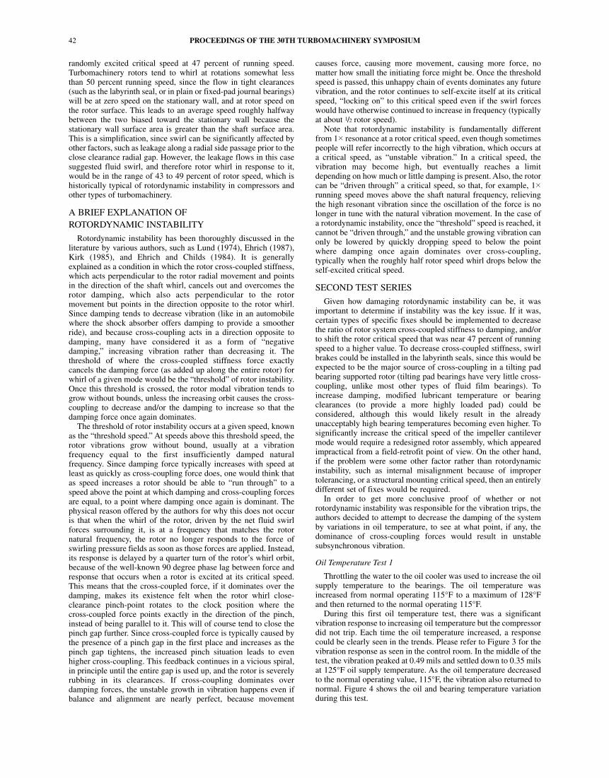
The train consists of an induction motor coupled to a six-stageintegrally geared, multiservice compressor. A central bull geardrives three high-speed pinions with a total of six impellers. Eachservice uses three impellers, i.e., three stages. The 6800 kWinduction motor is coupled to the bull gear via a dry flexible disccoupling. The services include nitrogen compression, designatedas CP53, and dry air compression, designated as CP14. There is anintercooler between each stage. Tables 1 and 2 summarize thecompressor/rotor information and Figure 1 illustrates theconfiguration. When viewed from the motor, rotor one is at thenine o’clock position (upward driven), rotor two is at the threeo’clock position (downward driven), and rotor three is at the 12o’clock position (horizontally driven). The bull gear rotatesclockwise and all pinions rotate counterclockwise.
Continuously adjustable inlet guide vanes (IGVs) are providedat the CP53 first and third stages (positions A and C) and CP14 firststage (position D). The CP53 IGVs are mechanically linked tomodulate flow simultaneously.
Each pinion journal location is equipped with X-Y proximityprobes. There is one keyphasor probe on each rotor. The probetransmitters provide a 4 to 20 mA input to the plant programmablelogic controller (PLC) system so overall vibration levels can bemonitored and trended. Tripping, due to high vibration, is via theplant PLC.
Table 1. General Compressor Information.
Table 2. Rotor 2 Operating Conditions.
Figure 1. Compressor Layout.
Closed impellers, with labyrinth eye seals, are used at positionsC, D, E, and F. The CP53 position’s A, first stage, and B, secondstage, are semi-open impellers (no impeller eye seal). The shaftseals located at the back of the impellers for positions A, B, C, andD are labyrinth type seals, typical for this type of compressor. Dryface mechanical seals are used for the shaft seals of CP14 stagestwo and three, positions E and F, in order to minimize leakagelosses.
The original pinion bearings (unmodified) are a radial typeutilizing five tilting pads (Table 3). The pad material is copper-chrome to provide increased heat dissipation. Bearing load isbetween pads at full gear load. The pads use a center-supportedspherical seat (0.50 offset) with pad arc lengths of 58 degrees. TheC, D, E, and F bearings are identical in design and size. The finalmodified bearing utilized on the C, D, E, and F positions arechamfered on the trailing edge in order to help reduce bearingtemperatures. This chamfer effectively reduces the pad arc lengthto 53 degrees, creating a 0.547 offset.
Oil supply to the bearings is from a shaft-driven main oil pumpwith an oil pressure regulator maintaining 30 psi. Oil temperature
PROCEEDINGS OF THE 30TH TURBOMACHINERY SYMPOSIUM40
Mechanical Linkage
ROTOR INSTABILITY PROBLEMS IN AN INTEGRALLYGEARED COMPRESSOR SUPPORTED BY TILTING PAD BEARINGS
41
Table 3. Bearing Data.
is controlled via a three-way oil temperature control valve.Depending upon the ambient and cooling water temperature, theoil supply temperature ranges from 110°F to 115°F.
OPERATIONAL HISTORY
The compressor is part of an industrial gases plant providingboth high-pressure nitrogen and oxygen to a chemical plantcomplex. The plant was originally commissioned in August-September 1999 but was then taken offline until the customer wasprepared for production. The plant and compressor were restartedin April 2000.
During the shop test, the compressor manufacturer wasconcerned with higher than expected bearing pad temperatures.Bearing temperatures were running well above 200°F. In order todecrease the bearing pad temperatures, the manufacturer provideda specially designed bearing to provide more direct injection ofcold oil into the pad. These bearings were field-installed during theoriginal commissioning in 1999. The compressor could not operatewith these bearings due to high vibration. The bearings wereremoved and the original bearings were reinstalled, and thecommissioning process was completed with higher than desired oiltemperatures.
After the plant was put into full operation in April 2000, thecompressor continued to run for approximately three months untilthere was a series of sudden unexplained trips due to highvibration. The trips occurred on each of four successive days. Alltrips were caused by high vibration on the CP14 first stage(position D). It was noted that the trips occurred during the hottestweather days since the compressor had been started.
Typical trip scenarios involved the plant personnel operating theplant in steady-state conditions and, without warning, thecompressor tripping on high vibration. One of the trips is shown inFigure 2 and is indicative of what the plant personnel would see inthe control room. The compressor would be running steady-statewith all parameters “flatlining”; the process flows/pressures/temperatures, oil supply pressure/temperature, and vibrationswould be unchanging. The CP14 first stage vibration would start toincrease until a sharp spike initiated a shutdown. From the time ofthe first increase in vibration till shutdown was two and halfminutes. The sudden increase in vibration amplitude occurred in amatter of seconds.
Figure 2. Sudden Vibration Trip as Seen in Plant Control Room.
After the fourth trip, the authors traveled to site to investigate thecause of the trips. It was the intent of the authors to try to reproducethe operating conditions that would cause the trip and to observeand record the trip with a spectrum analyzer. Up to now, the maininformation available included overall compressor operation(pressures, temperatures, IGV positions, overall vibration levels,oil pressure/temperature, etc.). No vibration data in the form of fastFourier transforms (FFTs) were available.
INITIAL FIELD TESTING
Upon arrival on site, the available field data were analyzed todetermine if there were any discernable trends prior to the highvibration trips. This review showed the plant and compressorrunning steady-state with most trends “flatlining,” including oiltemperature and pressure. This analysis was inconclusive, althoughsmall changes in IGV position and compressor load were observedjust prior to the trips.
The authors initiated a variety of tests in order to isolate thecause of the high vibration trips. The testing was intended tosimulate the operating conditions immediately before a trip andwas ultimately successful in causing a trip during oil temperaturevariation tests.
Instrumentation
The main measurement techniques involved using real-time highfrequency FFT spectra plotted as a function of time (with a highdegree of sample-to-sample overlap) to examine various transduceroutputs:
• Accelerometers—Such phenomena as vane pass, IGV, anddiffuser vane frequency could be examined based on the casingaxial sidewall and bearing housing radial accelerometermeasurements.
• Pressure transducers—Pressure transducers were used toexamine the dynamic nature of the pressure at both the inlet anddischarge of the first stage of CP14. Pressure measurements werealso examined on the labyrinth rotor seal discharge location to lookfor evidence of aerodynamically induced cross-coupled forces.
• Proximity probes—Proximity probes already mounted on themachine were used to obtain direct measurements of the rotorvibration relative to the bearing housing.
Process Variation Tests
A number of process variable tests were conducted to investigatewhether process conditions were contributing to the suddenvibration trips. These tests included variations of the IGV angles atvarious flow rates, depressurization of the nitrogen stages of thecompressor, and unloading of the air stages of the compressor. Nosudden changes in vibration levels were observed through thistesting, although the subsynchronous component later found to becausing the vibration trips was seen to lessen in magnitude as theair compressor stage was unloaded.
Observing the spectrum on a real-time basis, a subsynchronous(i.e., below running speed) component could be observed“bobbing” up and down while the rest of the spectra including onetimes running speed and multiples thereof were of constantmagnitude. The overall magnitude of this subsynchronousfrequency and of the overall vibration was quite low however, andcould not be conclusively pinpointed as causing the problem. Theauthors began to suspect the possibility of an aerodynamicallyinduced whirl phenomena in the seals, and therefore attempted toobserve the pressure at the problem seal location in hopes of seeingsome confirmation of subsynchronous whirl in the spectrum of thepressure probe. However, investigation of the CP14 first stagelabyrinth shaft seal pressure failed to detect any unusualsubsynchronous pressure phenomena.
Even though the seal gas tests were inconclusive, the authors stillsuspected rotordynamic instability based on the unsteadiness of the
randomly excited critical speed at 47 percent of running speed.Turbomachinery rotors tend to whirl at rotations somewhat lessthan 50 percent running speed, since the flow in tight clearances(such as the labyrinth seal, or in plain or fixed-pad journal bearings)will be at zero speed on the stationary wall, and at rotor speed onthe rotor surface. This leads to an average speed roughly halfwaybetween the two biased toward the stationary wall because thestationary wall surface area is greater than the shaft surface area.This is a simplification, since swirl can be significantly affected byother factors, such as leakage along a radial side passage prior to theclose clearance radial gap. However, the leakage flows in this casesuggested fluid swirl, and therefore rotor whirl in response to it,would be in the range of 43 to 49 percent of rotor speed, which ishistorically typical of rotordynamic instability in compressors andother types of turbomachinery.
A BRIEF EXPLANATION OFROTORDYNAMIC INSTABILITY
Rotordynamic instability has been thoroughly discussed in theliterature by various authors, such as Lund (1974), Ehrich (1987),Kirk (1985), and Ehrich and Childs (1984). It is generallyexplained as a condition in which the rotor cross-coupled stiffness,which acts perpendicular to the rotor radial movement and pointsin the direction of the shaft whirl, cancels out and overcomes therotor damping, which also acts perpendicular to the rotormovement but points in the direction opposite to the rotor whirl.Since damping tends to decrease vibration (like in an automobilewhere the shock absorber offers damping to provide a smootherride), and because cross-coupling acts in a direction opposite todamping, many have considered it as a form of “negativedamping,” increasing vibration rather than decreasing it. Thethreshold of where the cross-coupled stiffness force exactlycancels the damping force (as added up along the entire rotor) forwhirl of a given mode would be the “threshold” of rotor instability.Once this threshold is crossed, the rotor modal vibration tends togrow without bounds, unless the increasing orbit causes the cross-coupling to decrease and/or the damping to increase so that thedamping force once again dominates.
The threshold of rotor instability occurs at a given speed, knownas the “threshold speed.” At speeds above this threshold speed, therotor vibrations grow without bound, usually at a vibrationfrequency equal to the first insufficiently damped naturalfrequency. Since damping force typically increases with speed atleast as quickly as cross-coupling force does, one would think thatas speed increases a rotor should be able to “run through” to aspeed above the point at which damping and cross-coupling forcesare equal, to a point where damping once again is dominant. Thephysical reason offered by the authors for why this does not occuris that when the whirl of the rotor, driven by the net fluid swirlforces surrounding it, is at a frequency that matches the rotornatural frequency, the rotor no longer responds to the force ofswirling pressure fields as soon as those forces are applied. Instead,its response is delayed by a quarter turn of the rotor’s whirl orbit,because of the well-known 90 degree phase lag between force andresponse that occurs when a rotor is excited at its critical speed.This means that the cross-coupled force, if it dominates over thedamping, makes its existence felt when the rotor whirl close-clearance pinch-point rotates to the clock position where thecross-coupled force points exactly in the direction of the pinch,instead of being parallel to it. This will of course tend to close thepinch gap further. Since cross-coupled force is typically caused bythe presence of a pinch gap in the first place and increases as thepinch gap tightens, the increased pinch situation leads to evenhigher cross-coupling. This feedback continues in a vicious spiral,in principle until the entire gap is used up, and the rotor is severelyrubbing in its clearances. If cross-coupling dominates overdamping forces, the unstable growth in vibration happens even ifbalance and alignment are nearly perfect, because movement
causes force, causing more movement, causing more force, nomatter how small the initiating force might be. Once the thresholdspeed is passed, this unhappy chain of events dominates any futurevibration, and the rotor continues to self-excite itself at its criticalspeed, “locking on” to this critical speed even if the swirl forceswould have otherwise continued to increase in frequency (typicallyat about 1/2 rotor speed).
Note that rotordynamic instability is fundamentally differentfrom 1� resonance at a rotor critical speed, even though sometimespeople will refer incorrectly to the high vibration, which occurs ata critical speed, as “unstable vibration.” In a critical speed, thevibration may become high, but eventually reaches a limitdepending on how much or little damping is present. Also, the rotorcan be “driven through” a critical speed, so that, for example, 1�
running speed moves above the shaft natural frequency, relievingthe high resonant vibration since the oscillation of the force is nolonger in tune with the natural vibration movement. In the case ofa rotordynamic instability, once the “threshold” speed is reached, itcannot be “driven through,” and the unstable growing vibration canonly be lowered by quickly dropping speed to below the pointwhere damping once again dominates over cross-coupling,typically when the roughly half rotor speed whirl drops below theself-excited critical speed.
SECOND TEST SERIES
Given how damaging rotordynamic instability can be, it wasimportant to determine if instability was the key issue. If it was,certain types of specific fixes should be implemented to decreasethe ratio of rotor system cross-coupled stiffness to damping, and/orto shift the rotor critical speed that was near 47 percent of runningspeed to a higher value. To decrease cross-coupled stiffness, swirlbrakes could be installed in the labyrinth seals, since this would beexpected to be the major source of cross-coupling in a tilting padbearing supported rotor (tilting pad bearings have very little cross-coupling, unlike most other types of fluid film bearings). Toincrease damping, modified lubricant temperature or bearingclearances (to provide a more highly loaded pad) could beconsidered, although this would likely result in the alreadyunacceptably high bearing temperatures becoming even higher. Tosignificantly increase the critical speed of the impeller cantilevermode would require a redesigned rotor assembly, which appearedimpractical from a field-retrofit point of view. On the other hand,if the problem were some other factor rather than rotordynamicinstability, such as internal misalignment because of impropertolerancing, or a structural mounting critical speed, then an entirelydifferent set of fixes would be required.
In order to get more conclusive proof of whether or notrotordynamic instability was responsible for the vibration trips, theauthors decided to attempt to decrease the damping of the systemby variations in oil temperature, to see at what point, if any, thedominance of cross-coupling forces would result in unstablesubsynchronous vibration.
Oil Temperature Test 1
Throttling the water to the oil cooler was used to increase the oilsupply temperature to the bearings. The oil temperature wasincreased from normal operating 115°F to a maximum of 128°Fand then returned to the normal operating 115°F.
During this first oil temperature test, there was a significantvibration response to increasing oil temperature but the compressordid not trip. Each time the oil temperature increased, a responsecould be clearly seen in the trends. Please refer to Figure 3 for thevibration response as seen in the control room. In the middle of thetest, the vibration peaked at 0.49 mils and settled down to 0.35 milsat 125°F oil supply temperature. As the oil temperature decreasedto the normal operating value, 115°F, the vibration also returned tonormal. Figure 4 shows the oil and bearing temperature variationduring this test.
PROCEEDINGS OF THE 30TH TURBOMACHINERY SYMPOSIUM42
ROTOR INSTABILITY PROBLEMS IN AN INTEGRALLYGEARED COMPRESSOR SUPPORTED BY TILTING PAD BEARINGS
43
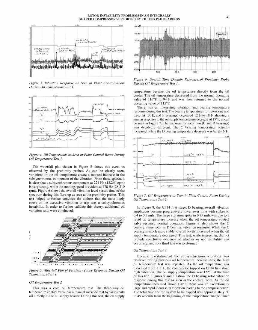
Figure 3. Vibration Response as Seen in Plant Control RoomDuring Oil Temperature Test 1.
Figure 4. Oil Temperature as Seen in Plant Control Room DuringOil Temperature Test 1.
The waterfall plot shown in Figure 5 shows this event asobserved by the proximity probes. As can be clearly seen,variations in the oil temperature create a marked increase in thesubsynchronous component of the vibration. From these spectra itis clear that a subsynchronous component at 221 Hz (13,260 cpm)is very strong, while the running speed is evident at 470 Hz (28,210rpm). Figure 6 shows the overall vibration level versus time of thespectrum during this flare-up as seen at the proximity probes. Thistest helped to further convince the authors that the most likelycause of the excessive vibration at trip was a subsynchronousinstability. In order to further validate this theory, additional oilvariation tests were conducted.
Figure 5. Waterfall Plot of Proximity Probe Response During OilTemperature Test 1.
Oil Temperature Test 2
This was a cold oil temperature test. The three-way oiltemperature control valve has a manual override that bypasses coldoil directly to the oil supply header. During this test, the oil supply
Figure 6. Overall Time Domain Response of Proximity ProbeDuring Oil Temperature Test 1.
temperature became the oil temperature directly from the oilcooler. The oil temperature decreased from the normal operatingvalue of 115°F to 94°F and was then returned to the normaloperating value of 115°F.
There was an interesting vibration and bearing temperatureresponse during this test. The bearing temperatures for rotors one andthree (A, B, E, and F bearings) decreased 12°F to 18°F, showing asimilar response to the oil supply temperature decrease of 19°F, as canbe seen in Figure 7. The response for rotor two (C and D bearings)was decidedly different. The C bearing temperature actuallyincreased, while the D bearing temperature decrease was barely 6°F.
Figure 7. Oil Temperature as Seen in Plant Control Room DuringOil Temperature Test 2.
In Figure 8, the CP14 first stage, D bearing, overall vibrationamplitudes became progressively lower over time with spikes to0.4 to 0.5 mils. The large vibration spike to 0.75 mils was due to arapid oil temperature increase when the oil temperature controlvalve resumed normal operation. Figure 8 also shows the Cbearing, same rotor as D bearing, vibration response. While the Cbearing is much more stable, overall levels increased when the oilsupply temperature decreased. This test, while interesting, did notprovide conclusive evidence of whether or not instability wasoccurring, and so a third test was performed.
Oil Temperature Test 3
Because excitation of the subsynchronous vibration wasobserved during previous oil temperature increase tests, the highoil temperature test was repeated. As the oil temperature wasincreased from 111°F, the compressor tripped on CP14 first stagehigh vibration. The oil supply temperature was 122°F at the timeof this trip. Figures 9 and 10 show the D bearing rotor vibrationresponse during this test as seen in the control room. As the oiltemperature increased above 120°F, there was an exceptionallylarge and rapid increase in vibration leading to the compressor trip.The total time for the system to be tripped was approximately 30to 45 seconds from the beginning of the temperature change. Once
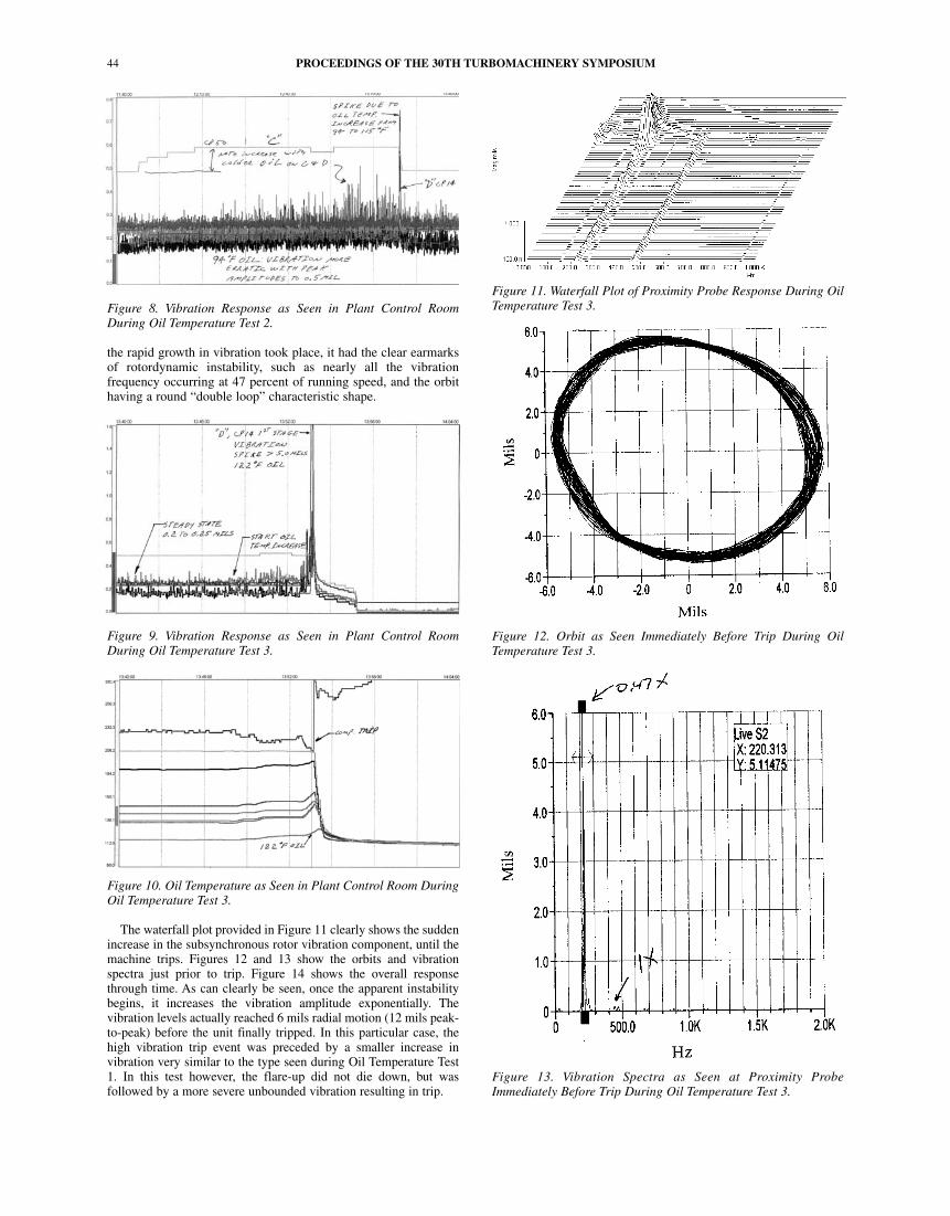
Figure 8. Vibration Response as Seen in Plant Control RoomDuring Oil Temperature Test 2.
the rapid growth in vibration took place, it had the clear earmarksof rotordynamic instability, such as nearly all the vibrationfrequency occurring at 47 percent of running speed, and the orbithaving a round “double loop” characteristic shape.
Figure 9. Vibration Response as Seen in Plant Control RoomDuring Oil Temperature Test 3.
Figure 10. Oil Temperature as Seen in Plant Control Room DuringOil Temperature Test 3.
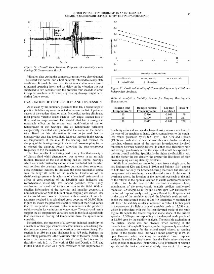
The waterfall plot provided in Figure 11 clearly shows the suddenincrease in the subsynchronous rotor vibration component, until themachine trips. Figures 12 and 13 show the orbits and vibrationspectra just prior to trip. Figure 14 shows the overall responsethrough time. As can clearly be seen, once the apparent instabilitybegins, it increases the vibration amplitude exponentially. Thevibration levels actually reached 6 mils radial motion (12 mils peak-to-peak) before the unit finally tripped. In this particular case, thehigh vibration trip event was preceded by a smaller increase invibration very similar to the type seen during Oil Temperature Test1. In this test however, the flare-up did not die down, but wasfollowed by a more severe unbounded vibration resulting in trip.
Figure 11. Waterfall Plot of Proximity Probe Response During OilTemperature Test 3.
Figure 12. Orbit as Seen Immediately Before Trip During OilTemperature Test 3.
Figure 13. Vibration Spectra as Seen at Proximity ProbeImmediately Before Trip During Oil Temperature Test 3.
PROCEEDINGS OF THE 30TH TURBOMACHINERY SYMPOSIUM44
ROTOR INSTABILITY PROBLEMS IN AN INTEGRALLYGEARED COMPRESSOR SUPPORTED BY TILTING PAD BEARINGS
45
Figure 14. Overall Time Domain Response of Proximity ProbeDuring Oil Temperature Test 3.
Vibration data during the compressor restart were also obtained.The restart was normal and vibration levels returned to steady-stateconditions. It should be noted that the oil temperature was returnedto normal operating levels and the delay on the vibration trip wasshortened to two seconds from the previous four seconds in orderto trip the machine well before any bearing damage might occurduring future events.
EVALUATION OF TEST RESULTS AND DISCUSSION
As is clear by the summary presented thus far, a broad range ofpractical field testing was conducted to narrow the list of potentialcauses of the sudden vibration trips. Methodical testing eliminatedmost process variable issues such as IGV angle, sudden loss offlow, and antisurge control. The variable that had a strong andrepeatable effect on the system was modification of the oiltemperature of the bearings. The oil temperature variationscategorically recreated and pinpointed the cause of the suddentrips. Based on this information, it was conjectured that theunusually hot days had most likely led to an increase in the bearingoil temperatures at the inlet to the bearing, and reduced thedamping of the bearing enough to cause seal cross-coupling forcesto exceed the damping forces, allowing the subsynchronousfrequency to trip the machine out.
Therefore, results of the testing made it very clear that some typeof classic fluid whirl phenomenon was at work in an unstablefashion. Because of the use of tilting pad oil journal bearings,which are whirl-resistant by nature, it was concluded that the whirlwas not from the bearings themselves but rather from some otherclose clearance location. In this case the most reasonable sourcewas the labyrinth seals of the machine. Evaluation of theshaft/bearing system with inclusion of a “nominal” estimate of theeffect of cross-coupling of the labyrinth seals indicated thatrotordynamic instability was indeed possible, even likely,confirming the results of testing as seen in the field. Withoutdetailed information of the labyrinth and impeller geometry, anominal amount of 20,000 lb/in of cross coupling was chosen. Useof the well-known Wachel equation with estimates of impellergeometry resulted in a calculated cross coupling of 20,700 lb/in.Figure 15 shows the predicted stability results of the OEM versusthat of independent analysis. Table 4 summarizes the predictedstability results for variations in temperature. The analytical resultssupport the oil temperature variations seen in the field. Specificallythat increases in bearing oil temperature drive the system moreunstable.
Nevertheless, the presence of a labyrinth-induced instability ona machine of this type seemed somewhat unusual considering thatthe pressure across the stage in question is not extraordinary. Thesuction is at 280 psig and discharge is at 453 psig. Perhaps themore telling parameter is the flexibility ratio of the rotor (flexibilityratio = max operating speed/1st critical speed). In this case theflexibility ratio is 2.14. The work of Kirk and Donald (1983) andFulton (1984) is cited as a good overview of the importance of
Figure 15. Predicted Stability of Unmodified System by OEM andIndependent Analysis.
Table 4. Analytical Stability Results for Varying Bearing OilTemperatures.
flexibility ratio and average discharge density across a machine. Inthe case of the machine at hand, direct comparisons to the empir-ical results presented by Fulton (1984), and Kirk and Donald(1983) are qualitative at best because this is a double overhungmachine, whereas most of the previous investigations involvedmultistage between-bearing designs. In either case, flexibility ratioand average gas density across the stage still would be expected toindicate overall stability. Specifically the higher the flexibility ratioand the higher the gas density, the greater the likelihood of highcross-coupling causing stability problems.
While firm conclusions cannot be drawn from a single case, thekey findings of Kirk and Donald (1983) and Fulton (1984) appearto hold true not only for between-bearing machines but also for acompressor with overhung or cantilevered rotors. In the case ofoverhung rotors, the location of the labyrinth eye seals at the endof the rotor is at the optimal location to excite cantilevered modesof the rotor. In the case of the machine investigated here,examination of the rotordynamic analysis predicts cantileveredmodes at 12,500 cpm (208 Hz) and 13,500 cpm (225 Hz) (refer tothe forced response analysis of Figures 16 and 17). It appears thatin the case of the machine at hand, the labyrinth seals served toexcite the cantilevered mode at 221 Hz (analytically predicted at208 Hz). The stability results summarized in Table 4 further pointto the presence of a lightly damped unstable mode at 12,599 cpm,which is coincident with the first cantilevered mode of the rotor.Figure 18 depicts the forced response mode shape of the criticalspeed at 12,500 rpm corresponding to the damped mode predictedat 12,599 cpm by the stability analysis. The possible excitation ofthe critical speed was not obvious when looking at themanufacturer’s Campbell Diagram, as the diagram only consideredthe separation margin for the critical speed closest to runningspeed. In the present case, this was a mode occurring at 19,000cpm. However, when examining the analytical forced responseanalysis, it could be clearly seen that the likely subsynchronouswhirl excitation frequency (historically 43 to 49 percent of runningspeed) and the first critical were nearly coincident. This brings
forth an important evaluation criterion when examiningcantilevered machine configurations. Specifically, the location ofthe cantilevered modes, in relation to possible 43 to 49 percentexcitation frequencies must be closely examined. Simply meetingAPI separation margins for synchronous excitation and integermultiples of running speed is not adequate.
Figure 16. Analytical Forced Response of Unstable Rotor (A).
Figure 17. Analytical Forced Response of Unstable Rotor (B).
Figure 18. Analytical Forced Response Mode Shape.
DESIGN CHANGES
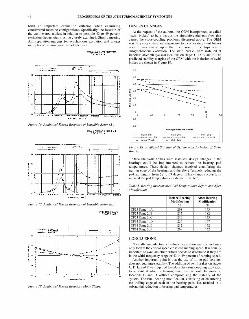
At the request of the authors, the OEM incorporated so-called“swirl brakes” to help disrupt the circumferential gas flow thatcauses the cross-coupling problems discussed above. The OEMwas very cooperative and responsive to incorporating swirl brakesonce it was agreed upon that the cause of the trips was asubsynchronous excitation. The swirl breaks were installed atimpeller labyrinth eye seal locations on stages C, D, E, and F. Thepredicted stability margins of the OEM with the inclusion of swirlbrakes are shown in Figure 19.
Figure 19. Predicted Stability of System with Inclusion of SwirlBreaks.
Once the swirl brakes were installed, design changes to thebearings could be implemented to reduce the bearing padtemperatures. These design changes involved chamfering thetrailing edge of the bearings and thereby effectively reducing thepad arc lengths from 58 to 53 degrees. This change successfullyreduced the pad temperatures as shown in Table 5.
Table 5. Bearing Instrumented Pad Temperatures Before and AfterModification.
CONCLUSIONS
Normally manufacturers evaluate separation margin and mayonly look at the critical speed closest to running speed. It is equallyimportant to evaluate other critical speeds to determine if they arein the whirl frequency range of 43 to 49 percent of running speed.
Another important point is that the use of tilting pad bearingsdoes not guarantee stability. The addition of swirl brakes on stagesC, D, E, and F was required to reduce the cross-coupling excitationto a point at which a bearing modification could be made tolocations C and D without compromising the stability of thesystem. The final bearing modification, consisting of chamferingthe trailing edge of each of the bearing pads, has resulted in asubstantial reduction in bearing pad temperatures.
PROCEEDINGS OF THE 30TH TURBOMACHINERY SYMPOSIUM46
ROTOR INSTABILITY PROBLEMS IN AN INTEGRALLYGEARED COMPRESSOR SUPPORTED BY TILTING PAD BEARINGS
47
Most users are well aware of the potential for oil whirlinstabilities present in nontilting journal bearings, and the fact thattilting pad style bearings tend to virtually eliminate the cross-coupling forces that cause this subsynchronous instability. Thisbeneficial attribute of tilting pad bearings has been misinterpretedby many users to mean that the use of tilting pad bearings willguarantee stability. However the presence of substantial cross-coupling forces from labyrinth seals can still overcome thedamping of tilting pad bearings and, therefore, this possibilityneeds to be closely examined. In the case of the machineinvestigated here, variations in oil temperature were enough toreduce the damping in the bearings to the point that the labyrinthcross-coupling forces could cause the system to run in unstableoperation.
Perhaps the most important thing to note is that stabilityproblems are not just limited to high-pressure machines as typicalin petroleum reinjection service for example, but can also occur inflexible rotor systems with lower pressure stages. The combinationof increasing flexibility ratios, increased speeds, and increasedpressure rises has made the threat of instabilities in cantileveredmachines a very real possibility. It is particularly important toclosely examine the location of the first two cantilevered modes incomparison to the running speed range. As running speeds haveincreased and rotors have become more flexible, the moderatelydamped cantilevered modes of the high-speed pinions of integrallygeared compressors can tend to drop into the range of 43 to 49percent of the running speed of the machine, at which point thesemodes become prone to rotordynamic instability. The cantileveredimpellers are the optimum location for cross-coupling forces fromlabyrinth swirl to reexcite the natural frequency and cause asubstantial instability problem.
REFERENCES
Ehrich, F. F., 1987, “Self-Excited Vibration,” Section 5, Shock andVibration Handbook, New York, New York: McGraw-Hill.
Ehrich, F. F. and Childs, D. W., 1984, “Identification andAvoidance of Instabilities in High Performance Turboma-chinery,” Mechanical Engineering, pp. 66-79.
Fulton, J. W., 1984, “The Decision to Full Load Test a HighPressure Centrifugal Compressor in its Module Prior to Tow-Out,” IMechE, Second European Congress on Fluid Machineryfor the Oil, Petrochemical, and Related Industries, The Hague,The Netherlands, pp. 133-138.
Kirk, R. G., 1985, “Evaluation of Aerodynamic InstabilityMechanisms for Centrifugal Compressors,” ASME TenthBiennial Conference on Mechanical Vibration and Noise,ASME Paper No. 85-DET-147.
Kirk, R. G. and Donald, G. H., 1983, “Design Criteria forImproved Stability of Centrifugal Compressors,” RotorDynamic Instability, AMD, 55, pp. 59-72.
Lund, J. W., May 1974, “Stability and Damped Critical Speeds ofa Flexible Rotor in Fluid-Film Bearings,” Journal ofEngineering for Industry, Trans. ASME, pp. 509-517.
ACKNOWLEDGEMENT
The authors would like to thank The BOC Group for permissionto publish this paper. The authors also express their sincereappreciation to Dr. John C. Nicholas of RMT for his analyticalbearing evaluation and supporting rotordynamic analysis.

PROCEEDINGS OF THE 30TH TURBOMACHINERY SYMPOSIUM48


