Embed Size (px)
Citation preview

CUSTOMERSUPPORT
INFORMATION
SEPTEMBER 1998CL050A
CL050A-R2CL050C
CL050AERM005
RS-232 ↔ Current Loop
Interface Converter (232/CL-E)
232/CL-E
RX TX
Order toll-free in the U.S. 24 hours, 7 A.M. Monday to midnight Friday: 877-877-BBOXFREE technical support, 24 hours a day, 7 days a week: Call 724-746-5500 or fax 724-746-0746Mail order: Black Box Corporation, 1000 Park Drive, Lawrence, PA 15055-1018Web site: www.blackbox.com • E-mail: [email protected]

3
FCC STATEMENT
FEDERAL COMMUNICATIONS COMMISSIONAND
CANADIAN DEPARTMENT OF COMMUNICATIONSRADIO FREQUENCY INTERFERENCE STATEMENTS
This equipment generates, uses, and can radiate radio frequency energy and if notinstalled and used properly, that is, in strict accordance with the manufacturer’sinstructions, may cause interference to radio communication. It has been testedand found to comply with the limits for a Class A computing device in accordancewith the specifications in Subpart J of Part 15 of FCC rules, which are designed toprovide reasonable protection against such interference when the equipment isoperated in a commercial environment. Operation of this equipment in aresidential area is likely to cause interference, in which case the user at his ownexpense will be required to take whatever measures may be necessary to correct theinterference.
Changes or modifications not expressly approved by the party responsible forcompliance could void the user’s authority to operate the equipment.
This digital apparatus does not exceed the Class A limits for radio noise emission from digitalapparatus set out in the Radio Interference Regulation of the Canadian Department ofCommunications.
Le présent appareil numérique n’émet pas de bruits radioélectriques dépassant les limitesapplicables aux appareils numériques de classe A prescrites dans le Règlement sur lebrouillage radioélectrique publié par le ministère des Communications du Canada.
4
INSTRUCCIONES DE SEGURIDAD
NORMAS OFICIALES MEXICANAS (NOM)ELECTRICAL SAFETY STATEMENT
INSTRUCCIONES DE SEGURIDAD
1. Todas las instrucciones de seguridad y operación deberán ser leídas antes deque el aparato eléctrico sea operado.
2. Las instrucciones de seguridad y operación deberán ser guardadas parareferencia futura.
3. Todas las advertencias en el aparato eléctrico y en sus instrucciones deoperación deben ser respetadas.
4. Todas las instrucciones de operación y uso deben ser seguidas.
5. El aparato eléctrico no deberá ser usado cerca del agua—por ejemplo, cercade la tina de baño, lavabo, sótano mojado o cerca de una alberca, etc..
6. El aparato eléctrico debe ser usado únicamente con carritos o pedestales quesean recomendados por el fabricante.
7. El aparato eléctrico debe ser montado a la pared o al techo sólo como searecomendado por el fabricante.
8. Servicio—El usuario no debe intentar dar servicio al equipo eléctrico más alláa lo descrito en las instrucciones de operación. Todo otro servicio deberá serreferido a personal de servicio calificado.
9. El aparato eléctrico debe ser situado de tal manera que su posición nointerfiera su uso. La colocación del aparato eléctrico sobre una cama, sofá,alfombra o superficie similar puede bloquea la ventilación, no se debe colocaren libreros o gabinetes que impidan el flujo de aire por los orificios deventilación.
10. El equipo eléctrico deber ser situado fuera del alcance de fuentes de calorcomo radiadores, registros de calor, estufas u otros aparatos (incluyendoamplificadores) que producen calor.

5
INSTRUCCIONES DE SEGURIDAD
11. El aparato eléctrico deberá ser connectado a una fuente de poder sólo deltipo descrito en el instructivo de operación, o como se indique en el aparato.
12. Precaución debe ser tomada de tal manera que la tierra fisica y la polarizacióndel equipo no sea eliminada.
13. Los cables de la fuente de poder deben ser guiados de tal manera que no seanpisados ni pellizcados por objetos colocados sobre o contra ellos, poniendoparticular atención a los contactos y receptáculos donde salen del aparato.
14. El equipo eléctrico debe ser limpiado únicamente de acuerdo a lasrecomendaciones del fabricante.
15. En caso de existir, una antena externa deberá ser localizada lejos de las lineasde energia.
16. El cable de corriente deberá ser desconectado del cuando el equipo no seausado por un largo periodo de tiempo.
17. Cuidado debe ser tomado de tal manera que objectos liquidos no seanderramados sobre la cubierta u orificios de ventilación.
18. Servicio por personal calificado deberá ser provisto cuando:
A: El cable de poder o el contacto ha sido dañado; u
B: Objectos han caído o líquido ha sido derramado dentro del aparato; o
C: El aparato ha sido expuesto a la lluvia; o
D: El aparato parece no operar normalmente o muestra un cambio en sudesempeño; o
E: El aparato ha sido tirado o su cubierta ha sido dañada.

6
RS-232 ↔ CURRENT LOOP INTERFACE CONVERTER
TRADEMARKS
All applied-for and registered trademarks are the property of their respectiveowners.

7
RS-232 ↔ CURRENT LOOP INTERFACE CONVERTER
CONTENTS
1. Specifications . . . . . . . . . . . . . . . . . . . . . . . . . . . . . . . . . . . . . . . . . . . . .8
2. Introduction . . . . . . . . . . . . . . . . . . . . . . . . . . . . . . . . . . . . . . . . . . . . . .9
3. Installation . . . . . . . . . . . . . . . . . . . . . . . . . . . . . . . . . . . . . . . . . . . . . . .10
4. The Current-Loop Interface . . . . . . . . . . . . . . . . . . . . . . . . . . . . . . . . .114.1 Testing for Other Active Devices on the Current Loop . . . . . . .11
4.1.1 LED Test . . . . . . . . . . . . . . . . . . . . . . . . . . . . . . . . . . . . . . .114.1.2 Voltmeter Test . . . . . . . . . . . . . . . . . . . . . . . . . . . . . . . . . . .12
4.2 Connecting the Current Loop Wires to the CL050A . . . . . . . . .124.2.1 4-Wire Current Loop . . . . . . . . . . . . . . . . . . . . . . . . . . . . .124.2.2 2-Wire Current Loop . . . . . . . . . . . . . . . . . . . . . . . . . . . . .13
4.3 Switch SWA . . . . . . . . . . . . . . . . . . . . . . . . . . . . . . . . . . . . . . . . . .174.4 Switch SWB . . . . . . . . . . . . . . . . . . . . . . . . . . . . . . . . . . . . . . . . . . .17
5. The RS-232C Interface . . . . . . . . . . . . . . . . . . . . . . . . . . . . . . . . . . . . .185.1 The RS-232C Interface Pinout . . . . . . . . . . . . . . . . . . . . . . . . . . .185.2 Switch SWC . . . . . . . . . . . . . . . . . . . . . . . . . . . . . . . . . . . . . . . . . .19
5.2.1 DCE . . . . . . . . . . . . . . . . . . . . . . . . . . . . . . . . . . . . . . . . . . .195.2.2 DTE . . . . . . . . . . . . . . . . . . . . . . . . . . . . . . . . . . . . . . . . . . .19
6. Operations and Troubleshooting . . . . . . . . . . . . . . . . . . . . . . . . . . . . .206.1 Indicators . . . . . . . . . . . . . . . . . . . . . . . . . . . . . . . . . . . . . . . . . . . .206.2 Self Test . . . . . . . . . . . . . . . . . . . . . . . . . . . . . . . . . . . . . . . . . . . . .21
7. Current Loop Rack and Cards . . . . . . . . . . . . . . . . . . . . . . . . . . . . . . .227.1 Description . . . . . . . . . . . . . . . . . . . . . . . . . . . . . . . . . . . . . . . . . . .227.2 Specifications for RM005 . . . . . . . . . . . . . . . . . . . . . . . . . . . . . . .23

8
RS-232 ↔ CURRENT LOOP INTERFACE CONVERTER
Connectors — RS-232/CCITT V.24: DB25 (female)Current Loop: 4 screw terminals
Indicators — (2) LEDs indicating RS-232 port activity:RX for Receive Data from an RS-232 external deviceTX for Transmit Data to an RS-232 external device
Switches — 10-position DIP switch for current-loop transmission mode10-position DIP switch for RS-232 DTE or DCE configuration4-position DIP switch for electrical current in the current loop
Maximum TransmissionDistance — (based on using 24-AWG solid copper wire):
at 9600 bps: 300 to 400 meters (984 to 1,312 feet)
at 300 bps: 1000 to 3000 meters(3,281 to 9,843 feet)
Power — Input — 115/220 VAC, 50 to 60 Hz, 12WOutput — 18 VAC, center tapped, 8VA
Size — 1.75"H x 5.5"W x 8.5"D (4.4 x 14 x 21.6 cm)
Weight — 1.5 lb. (0.7 kg)
CAUTIONMake sure you have the right power supply for your local power. If not,call Technical Support to get a replacement power supply.
1. Specifications

9
RS-232 ↔ CURRENT LOOP INTERFACE CONVERTER
The RS-232 ↔ Current Loop InterfaceConverter (CL050) is a bidirectionalself-contained unit that enables theinterconnection of a digital20/30/60mA unipolar current-loopinterface with an RS-232 interface. TheCL050 cannot be used with an analogcurrent loop (4 to 20 mA) or bipolarcurrent loop.
Current loop was designed to transferdata in a noisy environ-ment with asmuch integrity as possible. Themaximum distance that the CL050 canbe placed from other devices on thecurrent loop (see Chapter 1) is basedon using 24 AWG under idealconditions, with the CL050 designatedas the active device in a point-to-pointconfiguration.
The CL050 can act as either an activeor passive device on the current loop.As an active device, the CL050 supplies20, 30, or 60 ma loop current at 18VDC for operation. As a passive device,
the CL050 will not supply loop current,but it will operate with 20, 30, or 60 maunipolar current at up to 30 VDC.
WARNING!Only one device on the currentloop may be active. If more thanone device is active, each of thedevices will be permanentlydamaged.
Refer to Sections 4.1 and 4.2 forinstructions on testing the current loopand connecting it to the CL050.
Switch selections allow for half-duplexor full-duplex operation; 20, 30, or 60mA loop current; and configuring theCL050 as either DTE or DCE.
Two LEDs monitor data flow.
If you ordered the CL050A-R2, youshould have received cables with it.
A 220-volt power supply (CL050E) isalso available.
2. Introduction
Figure 2-1. With the CL050, you can interconnect acurrent loop interface and an RS-232 interface.
CurrentLoop
Device
CL050
Device using RS-232 Interface

10
RS-232 ↔ CURRENT LOOP INTERFACE CONVERTER
1. Remove the screw located at thecenter of the bottom cover.
2. Remove the top cover.
3. Lift the back panel from its guide.
4. Insert the power supply receptacleinto the 4-prong plug (See Figure7-1 on page 16. The 4-prong plugis near W1). The receptacleshould be aligned so that the lip ison the upward side. DO NOTPLUG THE POWER SUPPLYINTO AN AC OUTLET!
5. Test your current loop for activedevices. See Section 4.1 on page11.
6. Connect your current loop to theCL050. See Section 4.2 on page12.
7. Insert the back panel into itsguide, making sure the power-supply cable and current-loopcable exit through the holesprovided for them.
8. Set switches SWA, SWB and SWCto the desired positions. TheCL050 is shipped with SWA set toFull-Duplex, Passive; SWB set to20mA receive; 20mA transmit; andSWC set to DTE. See Sections 4.3,4.4, and 5.2, respectively, on pages11 and 13 for more informationon these switches.
9. Replace the top cover.
10. Replace the screw.
11. Attach your RS-232C cable.
12. Plug the power supply into an ACoutlet. The CL050 is now readyfor operation.
3. Installation

11
RS-232 ↔ CURRENT LOOP INTERFACE CONVERTER
4.1 Testing for Other Active Deviceson the Current LoopYou must test for an active device onthe current loop if you plan to have theCL050 supply loop current.
WARNING!Only one device on thecurrent loop may be active.If more than one device isactive at the same time,each device will bepermanently damaged.
There are two tests that you can run.Either is sufficient.
4.1.1 LED TEST
(1) Unplug the CL050 from the ACoutlet.
(2) Set the SWA switch to full duplex,passive.
(3) Attach the T- of the 4-wire currentloop device (or “-” in a 2-wire currentloop) to R- of the CL050A.
(4) Attach the T+ of the 4-wire currentloop device (or “+” in a 2-wire currentloop) to R+ of the CL050A. See Figure4-1 (4-wire current loop) or Figure 4-2(2-wire current loop).
(5) Plug the CL050 into the AC outlet.
4. The Current-Loop Interface
Figure 4-1. Wiring configuration for a 4-wire current loop LED test.
Figure 4-2. Wiring configuration for a 2-wire current loop LED test.
T+
T-
R+
R-
T+
T-
R+
R-
T+
+
-
R-
T+
T-
R+
R-
CL050A
CL050A
R+R-T+T-

12
RS-232 ↔ CURRENT LOOP INTERFACE CONVERTER
(6) Test results:
(a) If the TX LED on the CL050 isoff, the other device is active.
(b) If the TX LED on the CL050lights continuously, there is no currentin the loop. Therefore, the othercurrent-loop device is passive.
(c) If the TX LED flashes, thecurrent loop is sending data. Thisindicates that the other device is active.
(7) Unplug the CL050 from the ACoutlet and remove the R- to R- and R+to R+ wires.
4.1.2 VOLTMETER TEST
Attach the voltmeter to the two Transmit lines (T+ and T-) of a currentloop device (not the CL050). If thevoltmeter reads voltage, the device isactive. If no voltage registers, thedevice is passive.
4.2 Connecting the Current LoopWires to the CL050AWhen you attach current loop wires tothe CL050, the unit should not beconnected to an AC outlet. Unless veryfine stranded-wire cable is used, wiretinning is not required. Just insert thewire into the receptacle and tightenthe screw. The wire will be firmlygripped by the terminal. Table 1details how the current loop should beconnected to the CL050. Refer also toFigures 4-3 through 4-7 on pages 8, 9,and 10.
4.2.1 4-WIRE CURRENT LOOP
Regardless of whether the CL050 isactive or passive, attach the currentloop wires as indicated in Table 1 andas shown in Figures 4-3 or 4-4.
Terminals
1 (T+) 2 (T-) 3 (R+) 4 (R-)
4-Wire Full-Duplex + Receive - Receive + Transmit - Transmit
2-Wire Half-Duplex + Loop Jumper to Jumper to - LoopPassive 3 (R+) 2 (T-)
2-Wire Half-Duplex No + Loop - Loop NoActive Connection Connection
Table 1. Current Loop Cable Connections.

13
RS-232 ↔ CURRENT LOOP INTERFACE CONVERTER
4.2.2 2-WIRE CURRENT LOOP
Connections to a 2-wire half-duplexmultipoint current loop depend onwhether the CL050 is used as an activeor passive unit. Note the connectionsin Table 1. The connections are alsoshown in Figures 4-5, 4-6, and 4-7.Note: Not all 2-wire current loops arebidirectional half-duplex. Somecurrent loops are simplex.

14
RS-232 ↔ CURRENT LOOP INTERFACE CONVERTER
T+
T-
R+
R-
T+
T-
R+
R-
T+
T-
R+
R-
T+
T-
R+
R-
Figure 4-4. 4-Wire Multipoint.
T+
T-
R+
R-
R+
R-
T+
T-
Figure 4-3. 4-Wire Point-to-Point.
Passive
Passive
Passive
Active

15
RS-232 ↔ CURRENT LOOP INTERFACE CONVERTER
T+
T-
R+
R-
+
-
+
-
+
-
Figure 4-6. 2-Wire Half-Duplex Multipoint(CL050 passive).
+
-
T+
T-
R+
R-
Figure 4-5. 2-Wire Point-to-Point (half-duplex).
CL050(set to
half-duplexactive)
CL050(Passive)
Jumper
Passive
Passive
Active
Passive

16
RS-232 ↔ CURRENT LOOP INTERFACE CONVERTER
Figure 4-7. 2-Wire Half-Duplex Multipoint(CL050 active).
T+
T-
R+
R-
+
-
+
-
+
-
CL050(active)
Passive
Passive
Passive

17
RS-232 ↔ CURRENT LOOP INTERFACE CONVERTER
4.3 Switch SWASwitch SWA controls the Current Loop Configuration. The CL050 is shipped withthe SWA in a “Full-Duplex, Passive” configuration.
Note: 0 indicates “OPEN” and 1 indicates “CLOSED.”
SW1 SW2 SW3 SW4 SW5 SW6 SW7 SW8 SW9 SW10 Loop Configuration
0 1 0 1 0 0 1 0 1 0 Full-Duplex, Passive
1 0 1 0 1 1 0 1 0 1 Full-Duplex, Active
0 1 0 1 0 1 0 1 0 1 Full-Duplex, PassiveReceive/Active Transmit
1 0 1 0 1 0 1 0 1 0 Full-Duplex, ActiveReceive/Passive Transmit
0 1 0 1 0 0 1 0 1 0 Half-Duplex, Passive(2-wire operation)
0 1 0 0 1 1 1 0 1 0 Half-Duplex, Active(2-wire operation)
4.4 Switch SWBSwitch SWB controls loop current (20/30/60 mA). The CL050 is shipped with theSWB in a “20mA receive; 20mA transmit” configuration.
Note: 0 indicates “OPEN” and 1 indicates “CLOSED.”
SW1 SW2 SW3 SW4 Loop Current
0 0 0 0 20mA receive; 20mA transmit loops
1 1 1 1 60mA receive; 60mA transmit loops
1 1 0 0 60mA receive; 20mA transmit loops
0 0 1 1 20mA receive; 60mA transmit loops
1 0 1 0 30mA receive; 30mA transmit loops

18
RS-232 ↔ CURRENT LOOP INTERFACE CONVERTER
5.1 The RS-232C Interface PinoutPin Circuit Description Direction
1 AA Protective Ground ---
2 BA Transmit Data To DCE
3 BB Receive Data From DCE
4 CA Request to Send To DCE
5 CB Clear to Send From DCE
6 CC Data Set Ready From DCE
7 AB Signal Ground ---
20 CD Data Terminal Ready To DCE
5. The RS-232C Interface
123456789
10111213
141516171819202122232425
SECONDARY TRANSMITTED DATADCE TRANSMITTER SIGNAL ELEMENT TIMINGSECONDARY RECEIVED DATARECEIVER SIGNAL ELEMENT TIMING
SECONDARY REQUEST TO SENDDATA TERMINAL READYSIGNAL QUALITY DETECTORRING INDICATORDATA SIGNAL RATE SELECTORDTE TRANSMITTER SIGNAL ELEMENT TIMING
PROTECTIVE GROUNDTRANSMITTED DATA
RECEIVED DATAREQUEST TO SEND
CLEAR TO SENDDATA SET READY
SIGNAL GROUND / COMMON RETURNRECEIVED LINE SIGNAL DETECTOR
+ VOLTAGE- VOLTAGE
SECONDARY RECEIVED LINE SIGNAL INDICATORSECONDARY CLEAR TO SEND
SIGNALDESTINATION
PINNUMBER
PINNUMBER
SIGNALDESTINATION
RS-232 Interface (Female)
Figure 5-1. The RS-232C Interface.

19
RS-232 ↔ CURRENT LOOP INTERFACE CONVERTER
5.2 Switch SWCSwitch SWC controls the RS-232 Connector Configuration (DCE/DTE).
Note: “OPEN” indicates Off and “CLOSED” indicates On.
5.2.1 DCEThe CL050 default configuration is DCE. The 10-position DIP switch is set asfollows:
SW1 Not UsedSW2 OPEN = SW2 and SW3 are ALWAYS in opposite
positionsSW3 CLOSED = With SW2 OPEN, Data Out is on Pin 3SW4 OPEN = SW4 and SW5 are ALWAYS in opposite
positionsSW5 CLOSED = With SW4 OPEN, Data In is on Pin 2SW6 OPEN = Pin 4 (RTS) not connectedSW7 CLOSED = Ties Pin 5 (CTS) to Pin 20 (DTR)SW8 OPEN = Removes High on Pin 20 (DTR). If
system does not use DTR, raise CTS by CLOSING both SW7 and SW8
SW9 CLOSED = Place High on Pin 6 (DSR)SW10 Not Used
5.2.2 DTEWhen configuring the CL050 as a DTE, the 10-position DIP switch is set as follows:
SW1 Not UsedSW2 CLOSED = With SW3 OPEN, Data Out is on Pin 2SW3 OPEN = SW2 and SW3 are ALWAYS in opposite
positionsSW4 CLOSED = With SW5 OPEN, Data In is on Pin 3SW5 OPEN = SW4 and SW5 are ALWAYS in opposite
positionsSW6 CLOSED = Place High on Pin 4 (RTS)SW7 OPEN = Pin 5 (CTS) not connectedSW8 CLOSED = Place High on Pin 20 (DTR)SW9 OPEN = Pin 6 (DSR) not connectedSW10 Not Used

20
RS-232 ↔ CURRENT LOOP INTERFACE CONVERTER
6.1 IndicatorsTX LED
On Continuously: Indicates (1) receive current loop notattached; (2) no current flowing;or (3) you have an open loop.Check the polarity of the receiveloop and/or the active/passiveoptions.
Off: The CL050 is not connected toan AC outlet or loop current isflowing continuously (which isnormal in an idle state).
Flashing: Data is being transmittedfrom the RS-232 port to the RS-232C interface.
RX LED
On Continuously: Error. CallTechnical Support.
Off: No data being received by the RS-232 port.
Flashing: Data is being received by theRS-232 port from the RS-232Cinterface.
6. Operations and Troubleshooting

21
RS-232 ↔ CURRENT LOOP INTERFACE CONVERTER
(6) On the CL050, connect a wire fromT+ to R+.
(7) Plug the CL050 into an AC outlet.
(8) Set the DTE device to full-duplex.
(9) Enter data.
(10) The TX and RX LEDs shouldflash and the data should display onthe DTE’s monitor. If this occurs, allinternal circuitry is operational.
6.2 Self Test
Follow these instructions to test theinternal circuitry of the CL050:
(1) Unplug the CL050 from AC outlet.
(2) Set switch SWA to full-duplex,transmit active, receive passive.
(3) Set switch SWC to DCEconfiguration.
(4) Attach a DTE device using astraight-pinned cable from the DTE tothe CL050.
(5) On the CL050, connect a wire fromT- to R-.
+
-
+
-
T
R
DTEDCE
Configuration
CL050RS-232C Cable
Figure 6-1. Wiring for the Internal Circuitry Test.

22
RS-232 ↔ CURRENT LOOP INTERFACE CONVERTER
Figure 7-1. Component Layout.
WI
DTE/DCE
SW C
SWITCH C(DTE/DCE)
SWITCH A(Current Loop Configuration)
U1
U2
U3
U4
C5 C4
U6 U5
SW B
SW A
TD
RDC6 C7
Q2
Q3
Q1
LEDs
CURRENT LOOPINTERFACE CONNECTOR
POWERCONNECTOR
RS-232INTERFACE
CONNECTOR
SWITCH B(20/30/60 mA)
T+T-R+R-
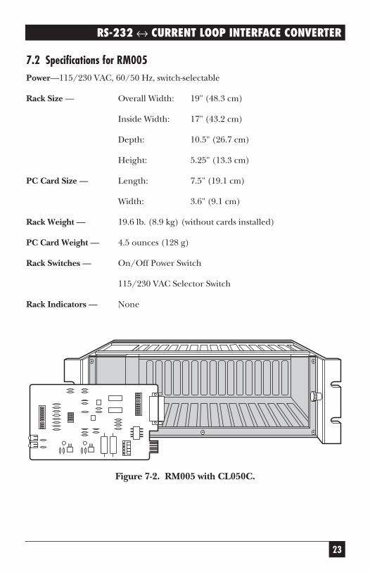
7.1 DescriptionThe RM005 Rack can hold up to 16 CL050C printed circuit cards andfits in a standard 19-inch equipmentrack. The RM005 comes complete withits own built-in AC power supply. Theoperation of the CL050C is the same asthe CL050.
WARNING!Do not apply primary poweruntil after you have properlyconfigured the RM005 powersupply.
• For 115 VAC ±15%primary power: Set 115/230
7. Current Loop Rack and Cardsvoltage selector switch to115 and make sure the inputfuse is rated at 1 A.
• For 230 VAC ±15%primary power: The voltageselector switch must be setto 230 and the fuse must berated 0.5 A.
Inside the fuseholder aretwo fuses. Open thefuseholder by pressingdown on the cover, thenrelease. The fuse closest tothe cover is a spare. Selectthe correct fuses and placethem in the Fuse RetainingCover. Discard the incorrectfuses.
23
RS-232 ↔ CURRENT LOOP INTERFACE CONVERTER
7.2 Specifications for RM005Power—115/230 VAC, 60/50 Hz, switch-selectable
Rack Size — Overall Width: 19" (48.3 cm)
Inside Width: 17" (43.2 cm)
Depth: 10.5" (26.7 cm)
Height: 5.25" (13.3 cm)
PC Card Size — Length: 7.5" (19.1 cm)
Width: 3.6" (9.1 cm)
Rack Weight — 19.6 lb. (8.9 kg) (without cards installed)
PC Card Weight — 4.5 ounces (128 g)
Rack Switches — On/Off Power Switch
115/230 VAC Selector Switch
Rack Indicators — None
Figure 7-2. RM005 with CL050C.

1000 Park Drive • Lawrence, PA 15055-1018 • 724-746-5500 • Fax 724-746-0746
© Copyright 1998. Black Box Corporation. All rights reserved.


