Embed Size (px)
Citation preview

Safety Warning
This Workshop Manuan will alert you to certain procedures thatmust be done very carefully, if you ignore this information,you couid.o.
® injure yourself or peopte around you® injure the boat operator, boat passengers, or
people around the boat® Damage the Volvo Penta product or its systems
Understand the following symbols before proceeding:
Anerts you to the possibinity of danger andSafety Warning identifies information that wile help pre-
vent injuries.
identifies information that vviln help pre-vent damage to machinery.
Appears next to information that controlscorrect assembly and operation of theproduct.
This Workshop Manual is written for qualified, factory trainedservice technicians familiar ,with the use of Volvo Penta specialtools.
This Workshop Manual teRIs you hovv to correctly maintain andservice Volvo Penta products and systems. When correctlyserviced, the Volvo Penta product will be reliable and safe tooperate.
When Volvo Penta specia~ tools are called for, use them.Where mentioned, the tools are required to perform the serviceprocedure.
if you use service procedures or service tools that are notrecommended in this manual, YOU ALONE must decided ifyour actions might injure people or damage the Volvo Pentaproduct.
Contents
General Information ...................................
ECM and Sensors ......................................
Fuel System ..........................................
Spark Management ....................................
Symptoms .............................................
Diagnoses .............................................
On-Board Service .......................................
Glossary ................................................
Diagrams ...............................................
Safety ..................................................
GMEFID{/eng i

This wor’~hop manual is one of a set of nine that covers Volvo Penta stemddve models. All nine books can be ordered as a set from Volvo Penta Parts.Order P/N 7788850-1.Individual workshop manuals covering these models are also available. 0icierthe following part numbers from Volvo Penta Parts.
¯ P/N 7788851-9 SX Drive Unit and Transom ShieldIncludes information on Transom Shield, Upper Gear Unit and Lower Gear Unitservice; Drive Unit removal and installation; Propellers; and Trim/Tilt hydraulic op-eration.
¯ P/N 77888568 Engine ComponentsIncludes information on Engine service and troubleshooting; Engine removal andinstallation; Steering systems; Throttle and Shift Control systems; and Coolingsystems.
, PIN 7788857=6 Electrical & Ign~on SystemIncludes service and troubleshooting information on Cranking systems; Chargingsystems; Trirnmlt electrical systems; Ignition systems; and Engine and Instrumentwiring diagrams.
. P/N 7788858-4 Fuel SystemIncludes service and troubleshooting information on all carburetor, MFI and TBIfuel systems and related components.
¯ P/N 7788852=7 MFi Diagnostic Manual (5.0 Fi, 5.8 R/FSi) - FordIncludes step by step troubleshooting procedures for all MFI Ford related compo-nents and wiring.
¯ P/N 7788853=5 TB! Diagnostic Manual (4.3 Gi, 5. 7" Gi) - Contains troubleshooting procedures for all TESl GM models and related compo-Rents.
¯ P/N 7788855-0 SP and DP Workshop ManualIncludes Upper Gear Unit and Lower Gear Unit overhaul procedures, installationand removal.
¯ P/N 7788854~3 MR Diagnostic Manual (7.4 Gi, 7.4 GSi) - Includes step by step troubleshooting procedures for all MFI GM related componentsand wiring.
¯ P/N 7788859-0 DPX- Lower Unit Workshop Manualincludes specific information for repair and overhaul of the DPX Lower unit andXactTM steering systems not covered in the SP and DP Workshop manual.
ii GMMFIDVeng
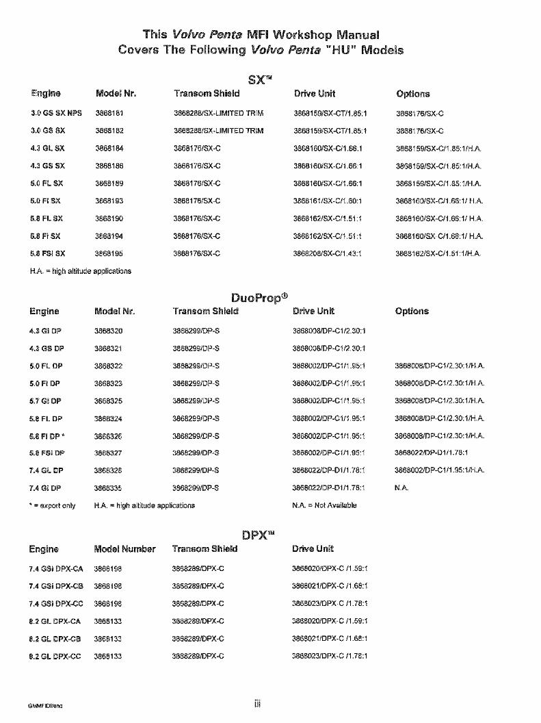
This Volvo Penta NIFI Workshop ManualCovers The Following Volvo Penta "HU" Models
Engine Model Nr.
3o~I GS $X NPS 386818’1
3.~ G$ SX 3868182
4.3 GL SX 3868184
4.3 GS SX 3868186
5.0 FL SX 386818(,)
5.0 Fi SX 3868193
5.8 FL SX 3868190
5.8 Fi SX 3868194
5.8 FSi $X 3886195
H.A. = high altitude applications
Engine Model Nr.
4.3 Gi DP 3868320
4.3 GS DP 3868321
5.0 FL DP 3688322
5.G Fl DP 3888323
5.7 Gi DP 3886325
5,8 FL DP 3868324.
6.8 Fi DP * 3868326
5.8 FSI DP 3868327
7.4 GL DP 3886328
7.4 Gi DP 3886335
¯ = export only
SXTM
Transom Shield
3868286/SX-LIMITED TRIM
3868288/SX-LIMITED TRIM
3868176/SX-C
3868176/SX-C
3868176/SX-C
3868176/SX-C
3868176/SX-C
3868176/SX-C
3868176/SX-C
DuoProp®Transom Shield
3886299/DP-S
3868299/DP-S
3868299/DP-S
3868299/DP-S
3868299/DP-S
3868299/DP-S
3868299fDP-S
3868299/DP-$
3868299/DP-S
3868299/DP-S
H.A. = high altitude applications
Drive Unit
3868159/SX-CT/1.85:1
3868159/SX-CT/1.85:1
3868160/SX-C/1.66:1
3868160tSX-C/1.66:1
3868160/SX-C/1.66:1
386816~/SX-C/1.60:1
3868162/SX-C/1.51:1
3868162/SX-C/1.51 :’~
3868208/SX-C/1.43:1
Drive Unit
3868008/DP-C1/2.30:1
3868008/D P-C 1/2.30:1
3886002/DP-Cl/1.95:1
3886002/D P-C 1 / 1.95:1
3886002/DP-C1/1.95:1
3868002/D P-C 1/1.95:1
38680021DP-Clll .95:1
38680021DP-Clll .95:1
3868022JDP-D1/1.78:1
3868022/DP=D1/1.78:1
N.A. = Net Available
Engine Model Number
7.4 GSi DPX=CA3868198
7.4 GSi DPX=CB3886198
7.4 GSi DPX-CC 3868198
8.2 GL DPX=CA 3868133
8.2 GL DPX-CB 3868133
8.2 GL DPX-CC 3868133
Transom Shield
3886289/DPX-C
386828g/DPX-C
3868289/DPX=C
3868289/DPX=C
38682891DPX-C
38682891DPX-C
DPXTM
Drive Unit
3868020/DPX-C/1.59:1
386802 I/DPX-C/1.68:1
3868023/DPX-C/1.78:1
3868020/DPX-C/1.59:1
3868021/DPX-C/1.68:1
3868023/DPX-C/1.78:1
Options
3868t76/$X-C
3868176/$X-C
3868159/SX-C/1.85: I/H.A.
3868159/SX-C/1.85:1/H.A.
3868159/SX-C/1.85:1/H.A.
386816O/SX-C/1.66:1/H.A.
3868160/SX-C/1.68:1/ H.A.
3868160/SX-C/1.66:1/ H.A.
3868162/SX-C/I.51:llH.A.
Options
3868008/DP-C1/2.30:1/H.A.
3868008/DP-C1/2.30: l/H.A.
3868008/DP-C1/2.30: I/H.A.
3868008/DP-C1/2.30:1/H.A.
3868008/DP-Cl/2.30:1/H.A.
3868022/DP=D1/1.78:1
3868002/DP-C111.95:1/H.A.
N.A.
GMMFIDI/en~ iii
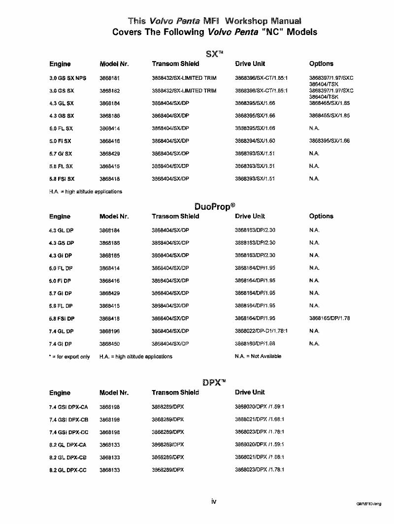
This Volvo Penta MFI Workshop ManualCovers The Fo|iowing Volvo Penta "NC" Models
Engine
3.0 GS SX NPS
3.0 GS SX
4,3 GL SX
4=3 GS SX
5.0 FL SX
5=0 Fi SX
5,7 Gi SX
5,8 FL $X
5.8 FSI SX
SX~,Model Nr. Transom Shield Drive Unit
3868181 3868432JS×-LIMITED TRIM 3868396/SX-CT/1.85:1
3868182 3868432/SX-LIMITED TRIM 3868396/SX-CT/1.65:1
3868184 3868404/SX/DP 3868395/SX/1.66
3868186 3868404/SX/DP 3868395/SX/1.66
3868414 3868404/SX/DP 3868395/SX/1.66
3868416 3868404/SX/DP 3868394tSX/1.60
3868429 3868404/SX/DP 3868393/SX/1.51
3868415 3868404/SX/DP 3868393/SX/1.51
3868418 3868404/SX/DP 3868393/SX/1.51
H.A. = high altitude applications
Engine Model Nr.
4.3 GL DP 3868184
4.3 GS DP 3868186
4.3 Gi DP 3868165
5,0 FL DP 3868414
5.0 Fi DP 3868416
5.7 Gi DP 3868429
5.8 FL DP 3868415
5.8 FSi DP 3868418
7.4 GL DP 3868196
7.4 Gi DP 3868450
* = for export only
Transom Shield
3868404/SX/DP
3868404/SY-JDP
3868404/SX/DP
3868404/SX/DP
3868404/SX/DP
3868404/SX/DP
3868404/SX/DP
3868404/SX/DP
3868404/SX/DP
3868404/SX/DP
H.A. = high altitude applications
DuoProp®Drive Unit
3868163/DP/2.30
3868163/DP/2.30
3868163/DP/2.30
3868164/DP/1.95
3868"164/DP/1.95
3868164/DP/1.95
3868164/DP/1.95
3866164/DP/1.95
3868022/DP-DI/1.78:1
3868166/DP/1.68
N.A. = Not Available
Options
3868397/1.97/SXC386404/TSK3868397/1.97/SXC386404/TSK3868465/SX/1.85
3868465/SX/1.85
N.A.
3868395/SX/1.68
N.A.
N.A.
N.A.
Options
N.A.
N.A.
N.A.
N.A.
N.A.
N.A.
N.A.
3868165/DP/1.78
N.A.
N.A.
DPX=Engine Model Nr.
7,4 GSI DPX-CA 3868198
7.4 GSi DPX-CB 3868198
7.4 GSi DPX-CC 3868198
8.2 GL DPX-CA 3868133
8.2 GL DPX-CB 3868133
8.2 GL DPX-CC 3868133
Transom Shield
3868289/DPX
3866289/DPX
3888289/DPX
3868289/DPX
3868289/DPX
3868289/DPX
Drive Unit
3868020/DPX/1,59:1
3868021/DPX/1.68:1
3868023/DPX/1.78:1
3868020/DPX/1.59:1
3868021/DPX/1.68:1
3868023/DP×/1.78:1
iv GMMFIDI/eng
Section 1
General Information
Table of Contents
Basic Knowledge and Tools Required .................. 1-2Code / Scan Tools ................................. 1-3Diagnosis of Driveability Concerns (With No DTC’s Set) ... 1-6Diagnostic Information ............................. 1-2Diagnostic Trouble Codes (DTC’s) ..................... 1-2
ECM Clearing ................................... 1-5How They Are Set ............................... 1-3Manua|ly Clearing ............................... 1-5Reading ....................................... 1-4
DLC Connector ................................... 1-3ECM Self-Diagnostics .............................. 1-3Electrostatic Discharge Damage ...................... 1=2Metri-Pack Series 150 Terminals ...................... 1-7On-Board Diagnostic (OBD) ......................... 1-3Service Mode .................................... 1-4Service Tools Needed .............................. 1-9Visual / Physical Inspection ......................... 1-3Weather-Pack Terminals ............................ 1-7Wiring Connector Service ........................... 1-6Wiring Harness Service ............................ 1-8
A_ Safety Warning
To reduce the chance of personal injury and / orproperty damage, the following cautions mustbe carefully observed.
Proper service and repair are important to thesafety of the service technician and safe, reliableoperation of all Electronic Fuel injection (EF|)equipped engines, if part replacement is neces=satry, the part must be replaced with one of thesame part number or with an equivalent part. Donot use a replacement part of lesser quality.
The service procedures recommended and de-scribed in this service manual are effectivemethods of performing service and repair. Someof these procedures require the use of toolsspecially designed for the purpose.
Accordingly, anyone who intends to use a re-placement part, service procedure or tool, whichis not recommended by the manufacturer, mustfirst determine that neither his safety nor thesafe operation of the engine will be jeopardizedby the replacement part, service procedure ortool selected.
It’s important to note that this manual containsvarious "Safety Warnings" and "Notes" thatmust be carefu|iy observed in order to reducethe risk of personal injury during service orrepair, or the possibility that improper service orrepair may damage the engine or render it un-safe. It’s also important to understand that these"Safety Warnings" and "Notes" are not exhaus-tive, because it’s impossible to warn of all thepossible hazardous consequences that mightresult from failure to follow these instructions.
Basic Knowledge / Tools Required __ Diagnostic information
To use this manual most effectively, a generalunderstanding of basic electrical circuits andcircuit testing tools is required. You should un-derstand the meaning of voltage, ohms, andamps; the basic theories of electricity; whathappens to an open, shorted or grounded wire;and be able to follow wiring diagrams.
To perform system diagnostics, several specialtools and equipment are required. Become ac-quainted with the tools and their use beforeattempting to diagnose the system. Special toolswhich are required for system service are illus-trated at the end of this section.
Electrostatic Discharge Damage __
Electronic components used in controJ systemsare often designed to carry very low voUtages,and are very susceptible to damage caused byelectrostatic discharge, it’s possible for Uess than100 volts of static electricity to cause damage tosome electronic components. By comparison, ittakes as much as 4,000 volts for a person to feelthe zap of a static discharge.
There are several ways for a person to becomestatically charged. The most common methodsof charging are by friction and induction. Anexample of charging by friction is a person slid-ing across a seat, in which a charge of as much as25,000 vents can build up.
Charging by induction occurs when a personwith well-insutated shoes stands near a highlycharged object and momentarily touchesground. Charges of the same polarity are drainedoff, leaving the person highly charged with theopposite polarity. Static charges of either typecan cause damage; therefore, it’s important touse care when handling and testing electroniccomponents.
The diagnostic charts and function checks in thismanual are designed to locate a faulty circuit orcomponent through logic based on the processof elimination. The charts are prepared with theassumption that the system functioned correctlyat the time of assembly and that there are nomultiple failures.
Engine control circuits contain many special de-sign features not found in standard marine wir-ing. Electrical contacts are protected against en-vironmental effects and proper splicing methodsmust be used when necessary. The proper oper-ation of low amperage input / output circuitsdepends upon good continuity between circuitconnectors.
It’s important before component replacementand / or during normal troubleshooting proce-dures that a visual inspection of any question-able mating connector be performed. Matingsurfaces should be properly formed, dean, andmake good contact. Some typical causes of con-nector problems are listed below.
¯ Improperly formed contacts and / or connec-tor housing
¯ Damaged contacts or housing due to im-proper engagement
¯ Corrosion, sealer or other contaminants onthe contact mating surfaces
¯Incompiete mating of the connector halvesduring initial assembly or during subsequenttroubleshooting procedures
¯ Tendency for connectors to come apart dueto vibration and / or temperature cycling
® Terminals not fully seated in the connectorbodies
¯ Inadequate terminal crimps to the wire
1-2 GMEFIDIteng
DLC Connector
The ECM can communicate a variety of informationthrough the Data Link Connector (DLC) at the front the engine. Stored information can be acquired usinga scan tool or a Marine Diagnostic Trouble Code(MDTC) tool. Step charts in the Diagnoses sectionincorporate procedures using the MDTC toot.
~The marine DLC is a 10-pin connector;an automotive DLC is a 12-pin connector. Makesure the scan or code tool is an appropnate one formarine use.
Code / Scan Tools
A variety of devices attach to the DLC to aid techni-cian diagnostics. They range from inexpensive blink-ing lights (code tools) to sophisticated LCD / LED read-outs (scan tools). Choose one that has been designedfor madne applications, and best suits your needsand budget. The text in this manual has been writtenin terms of using a Marine Dignostic trouble Code(MDTC) tool. if using a scan tool, follow themanufacturer’s instructions.
ECM Self-Diagnosis
If a sensor is within its working or acceptable parameters,the ECM will not detect a problem. When a sensor volt-age signal falls out of this "windo~’, or an open or shortoccurs in the wiring to the sensor, the ECM would notreceive the "window" voltage for that sensor.
When the ECM does not receive the "window" voltage fora programmed length of time, a DTC will be stored. TheCheck Engine light (if so equipped) will be illuminated anda known default value witl replace the sensed value torestore engine performance.
Visual / Physical Inspection
A careful visual and physical inspection must beperformed as part of any diagnostic procedure.This can often lead to fixing a problem withoutfurther steps, inspect all vacuum hoses for correctrouting, pinches, cuts, or disconnects. Be sure to in-spect hoses that are difficult to see. Inspect all thewires in the engine compartment for proper connec-tions, burned or chafed spots, pinched wires, or con-tact with sharp edges or hot manifolds. This visual /physical inspection is very important. It must be donecarefully and thoroughly.
On-Board Diagnostic (OBD) SystemCheck
The ECM performs a continual self-diagnosis on cer-tain control functions. This diagnostic capability iscomplemented by the diagnostic procedures con-tained in this manual. The ECM’s language for com-municating the source of a malfunction is a system ofdiagnostic codes. The codes are two digit numbersthat can range from "12 to 51. When a malfunction isdetected by the ECM, a code is set.
How Diagnostic Trouble Codes(DTC’s) Are Set
The ECM is programmed to receive calibrated volt-age signals from the sensors. The voltage signal froma sensor may range from as low as 0.1 volt to as highas 4.9 volts. The sensor voltage signal is calibratedfor engine application. This would be the sensor’sworking parameter or ’k, Jindow=" The ECM and sen-sots will be discussed further in the ECM and Sen=sot section.
After the visual / physical inspection, the OBD sys-tem check is the starting point for all diagnostic pro-cedures. Refer to the Diagnoses section.
The correct procedure to diagnose a problem is tofollow two basic steps:
1. Are the on-board diaanostic worki ? This isdetermined by performing the OBD system check.Since this is the starting point for the diagnostic pro-cedures, always begin here. If the on-board diagnos-tics aren’t working, the OBD system check will leadto a diagnostic chart in the Diagnoses section to cor-rect the problem. If the on-board diagnostics are work-ing correctly, the next step is:
2. i~ there a DTC stored? If a DTC is stored, go di-rectly to the numbered DTC chart in the Diagnosessection. This will determine if the fault is still present.
Service Mode.
When the MDTC tool is connected to the DLC, andthe MDTC tool switch is in the "ON" position, the sys-tem will enter what is called Service Mode. in thismode the ECM will:
1. Display a DTC 12 by flashing the MDTC tool light(indicating the system is operating correctly).
2. Display any stored DTC’s by flashing the MDTCtool light. Each DTC will be flashed three times, thenDTC 12 will be flashed again.
3. Hold ignition timing at a fixed timing degree pro-grammed into the ECM. This will allow base timing tobe adjusted on distributor ignition engines.
4. Move the IAC valve to its fully extended position,blocking the idle air passage. This is important to re-member, as an attempt to run the boat while in Ser-vice Mode will most likely result in an abnormally lowidle speed.
Reading Diagnostic Trouble Codes(DTC)
The provision for communicating with the ECM is theData Unk Connector (DLC). It’s part of the MFI en-gine widng harness, and is a 10-pin connector. It’sused in the assembly plant to check engine opera-tion before it leaves the plant. The DTC’s stored inthe ECM’s memory can be read either through a scantool (a hand-held diagnostic scanner plugged into theDLC), or by counting the number of flashes of theMDTC tool when in Service Mode.
The ignition and MDTC tool switches must be in the"OFF" position when connecting the MDTC tool tothe DLC. Then turn the ignition switch to the "ON"position with the engine not running. At this point, theMDTC tool light should be on. Push the MDTC toolswitch to the "ON" position and the Jight should flashDTC 12 three times consecutively (i.e. flash pause fflash-flash - pause, then it would repeat two moretimes). DTC 12 indicates that the ECM’s diagnosticsystem is operating, if DTC 12 is not indicated, a prob-lem is present within the diagnostic system itself, andshould be addressed by consuRting the appropriatediagnostics chart in the Diagnoses section.
Following the output of DTC 12, the MDTC tooE lightwill indicate a DTC three times if a DTC is present, orit will simply continue to output DTC 12o ff more thanone DTC has been stored in the ECM’s memory, theDTC’s will be displayed from the numerically lowestto the highest, with each DTC being displayed threetimes.
Malfunction Indicator Lamp (MIL)
This might is part of the Madne Dignostic Trouble Code(MDTC) tool 3851088-9 and has the following func-tions:
. It informs the operator that a problem has occurred and that the boat should be taken in forservice as soon as reasonably possible.
. It displays DTC’s stored by the ECM which helpthe technician diagnose system problems.
1 =4 GMMFIDIleng
When the MDTC tool is attached to the DLC withits switch in the "OFF:" position, and the key in the"ON" position and the engine not running, the MDTCtool light will come "ON". When the engine is started,the light will turn "OFF". If the light remains "ON",the self-diagnostic system has detected a problem.If the problem goes away, the light will go out inmost cases after 10 seconds, but a code will re-main stored in the ECM.
When the light remains "ON" while the engine isrunning, or when a malfunction is suspected dueto a ddveability problem, an MFI Diagnostic CircuitCheck must be performed. These checks will ex-pose malfunctions which may not be detected ifother diagnostics are performed prematurely.
To retrieve a DTC, turn the key to the "ON" posi-tion with the engine not running. Push the MDTCtool switch to the "ON" position and the light shouldflash a Code 12 three times, and then any otherCode(s) that are stored in the ECM memory.
Intermittent Light
In the case of an "intermittent" problem, the MDTCtool bulb will light for 10 seconds and then go out.However, the corresponding code will be stored inthe memory of the ECM. When unexpected codesappear during the code reading process, one canassume that these codes were set by an intermit-tent malfunction and could be helpful in diagnos-in(,;] the system.
An intermittent DTC, if cleared, may or may notreset, if it’s an intermittent failure, consult the Di-agnostic Aids on the page facing the diagnosticcode chart corresponding to the intermittent DTC.Symptoms also covers the topic of "intermittents".A physical inspection of the applicable sub-systemmost often will resolve the problem.
Manually Clearing DTC’s
I. Turn ignition switch to the "OFF" position.
2. Install Marine Diagmostic Trouble Code (MDTC)tool with push switch in the "OFF" position.
3. Turn ignition "ON", engine not running.
4. Push MDTC tool switch to "ON" position.
5. To clear DTC’s, disengage the remote control’sshift function, then SLOWLY move the throttle from0% (idle) to 100% (WOT) then back to
6. Push MDTC tool switch to "OFF" position.
7. Turn ignition "OFF" for 20 seconds.
8. Start engine and let it run for 20 seconds.
9. Turn ignition "OFF" for 20 seconds.
Turn ignition "ON", engine not running. Push MDTCtool switch to "ON" position and verify DTC 12 only.Remove MDTC tool.
When clearingDTC’s, the batten] must befully charged and cranking speed must be at least200 RPM. The ability to clear DTC’s is directly de-pendent on the battery being fully charged and ableto crank engine with adequate cranking RPM.
ECM Clearing of DTC’s
The ECM will automatically clear DTC’s if they havenot re-occurred within 25 "power-ups". One "power-up" is defined as any time the engine, either crank-ing or running, enters Run Mode by exceeding 300RPM for 16 seconds or more.
1-5GMMFIDIleng
Diagnosis of Driveability Concerns(With No DTC’s Set)
ff a driveability concern still exists after following thediagnostic circuit check and reviewing the Symptomssection, an out-of-range sensor may be suspected.Because of the unique design of the MH system,failsafes have been incorporated into the ECM. Asensed value is replaced with a default value in thecase of a sensor malfunction or sensor wiring prob-lem. With this feature, limited engine performance isrestored until the engine is repaired. A basic under-standing of sensor operation is necessary to be ableto diagnose an out-of-range sensor.
If a sensor is out of range, but still within the operat-ing ’~,vindow" of the ECM, the problem will go unde-tected by the ECM and may result in a ddveabilityconcern.
Example: coolant temperature is 150°, but the cool-ant sensor incorrectly reads 50°. This would causethe ECM to deliver more fuel than was actually neededand result in an ovedy rich, rough running condition.This condition would not have caused a DTC to setas the ECM interprets this as within it’s "range".
To identify a sensor which is out of range, unplug itwhile running the engine. After approximately 2 min-utes, the diagnostic DTC for that sensor will set, illu-minate the Check Engine or Marine DiagnosticTrouble Code tool light, and replace the sensed valuewith a default value. If at that point a noticeable per-formance improvement is observed, the DTC chartfor that particular sensor should be followed to cor-rect the problem.
Be sure to clear each DTC after disconnecting andreconnecting each sensor. Failure to do so may re-sult in a mis-diagnosis of the ddveability concern.
Wiring Connector Service
Most connectors in the engine compartment are pro-tected against moisture and dirt which could createoxidation and deposits on the terminals. This protec-tion is important because of the very low voltage andcurrent levels found in the electronics system. Theconnectors have a lock which secures the male andfemale terminals together. A secondary lock holdsthe seal and terminal into the connector.
When diagnosing, open circuits are often difficult tolocate by sight because oxidation or terminal misalign-ment are hidden by the connectors. Merely wigglinga connector on a sensor or in the wiring harness maylocate the open circuit condition. This should alwaysbe considered when an open circuit or failed sensoris indicated. Intermittent problems may also be causedby oxidized or toose connections.
Before making a connector repair, be certain of thetype of connector. Some connectors look simitar butare serviced differently. Replacement connectors andterminals are listed in the Parts Catalog.
DRC5463 DR54~ DR5465
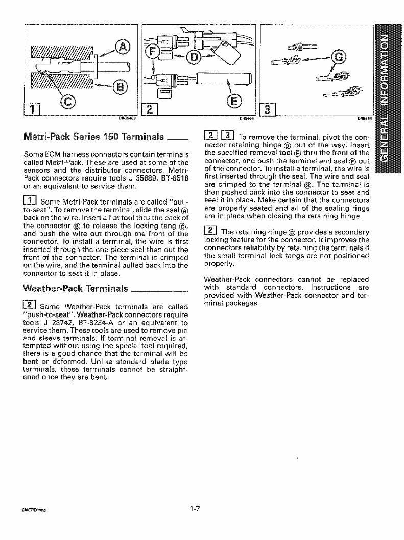
Metri-Pack Series 150 Terminals __
Some ECM harness connectors contain terminalscalled Metri-Pack. These are used at some of thesensors and the distributor connectors. Metri-Pack connectors require tools J 35689, BT-8518or an equivalent to service them.
D~ Some Metri-Pack terminals are called "pull-to-seat". To remove the terminal, slide the sealback on the wire. mnsert a flat tool thru the back ofthe connector ® to release the locking tang @,and push the wire out through the front of theconnector. To install a terminal, the wire is firstinserted through the one piece seal then out thefront of the connector. The terminal is crimpedon the wire, and the terminal punled back into theconnector to seat it in place.
Weather-Pack Terminals
Some Weather-Pack terminals are called"push-to-seat". Weather-Pack connectors requiretools J 28742, BT-8234-A or an equivalent toservice them. These tools are used to remove pinand sieeve terminals. If terminal removam is at-tempted without using the special tool required,there is a good chance that the terminal will bebent or deformed. Unlike standard blade typeterminals, these terminals cannot be straight-ened once they are bent.
[~] To remove the terminal, pivot the con-nector retaining hinge @ out of the way. Insertthe specified removal tool ~ thru the front of theconnector, and push the terminal and seal ® outof the connector. To install a terminal, the wire isfirst inserted through the seal The wire and sealare crimped to the terminal @. The terminal isthen pushed back into the connector to seat andseal it in place. Make certain that the connectorsare properly seated and all of the sealing ringsare in place when closing the retaining hinge.
E~] The retaining hinge@ provides a secondarylocking feature for the connector. It improves theconnectors reliability by retaining the terminals ifthe small terminal lock tangs are not positionedproperly.
Weather-Pack connectors cannot be replacedwith standard connectors. Instructions areprovided with VVeather-Pack connector and ter-minal packages.
G,4E:.~,’.U 1-7
DR5575
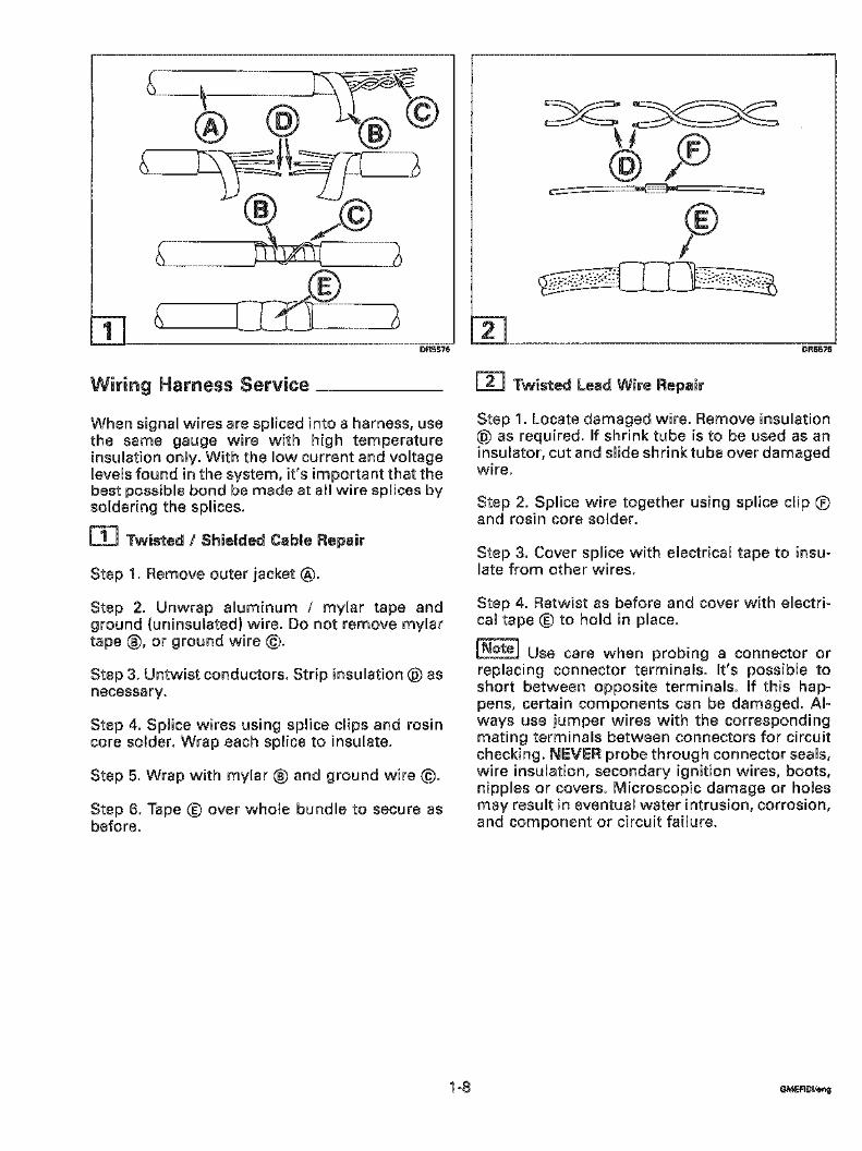
Wiring Harness Service
When signal wires are spliced into a harness, usethe same gauge wire with high temperatureinsulation only. With the low current and voltagelevels found in the system, it’s important that thebest possible bond be made at aH wire splices bysoldering the splices.
[~ Twisted / Shielded Cable Repair
Step 1. Remove outer jacket (~.
Step 2. Unwrap aluminum / mylar tape andground (uninsulated) wire. Do not remove mylartape ®, or ground wire ©.
Step 3. Untwist conductors. Strip insulation @ asnecessary.
Step 4. Spnice wires using splice clips and rosincore solder. Wrap each splice to insulate.
Step 5. Wrap with mylar ® and ground wire ©.
Step 6. Tape ~) over whole bundle to secure asbefore.
DR5575
[~ Twisted Lead Wire Repair
Step 1. Locate damaged wire. Remove insulation@ as required. If shrink tube is to be used as aninsulator, cut and slide shrink tube over damagedwire.
Step 2. Splice wire together using splice clip ®and rosin core solder.
Step 3. Cover splice with electrical tape to insu-late from other wires.
Step 4. Retwist as before and cover with electri-cal tape (~ to hold in place.
Use care when probing a connector orreplacing connector terminals. It’s possible toshort between opposite terminals, if this hap-pens, certain components can be damaged. An-ways use jumper wires with the correspondingmating terminals between connectors for circuitchecking. NEVER probe through connector seans,wire insulation, secondary ignition wires, boots,nipples or covers. Microscopic damage or holesmay result in eventual water intrusion, corrosion,and component or circuit failure.
1-8 GMEROdI~
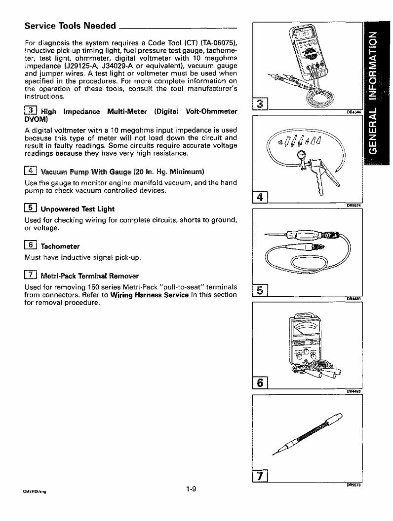
Service Tools NeededFor diagnosis the system requires a Code Tool (CT) (TA-06075),inductive pick-up timing light, fuel pressure test gauge, tachome-ter, test light, ohmmeter, digital voltmeter with 10 megohmsimpedance (J29125-A, J34029-A or equivalent), vacuum gaugeand jumper wires. A test light or voltmeter must be used whenspecified in the procedures. For more complete information onthe operation of these tools, consult the tool manufacturer’sinstructions.
[~] High impedance Multi-Meter (Digital Volt-OhmmeterDVOM)A digital voltmeter with a 10 megohms input impedance is usedbecause this type of meter will not toad down the circuit andresult in faulty readings. Some circuits require accurate voltagereadings because they have very high resistance.
[-~ Vacuum Pump With Gauge (20 in. Hg. Minimum)Use the gauge to monitor engine manifold vacuum, and the handpump to check vacuum controlled devices.
L-~ Unpowered Test LightUsed for checking wiring for complete circuits, shorts to ground,or voltage.
~’~ TachometerMust have inductive signal pick-up.
~-~ Metri-Pack Terminal RemoverUsed for removing 150 series Metri-Pack "pull-to-seat" terminalsfrom connectors. Refer to Wiring Harness Service in this sectionfor removal procedure.
DR4544
DR5574
DR4489
DR4483
DR5573
DR5572
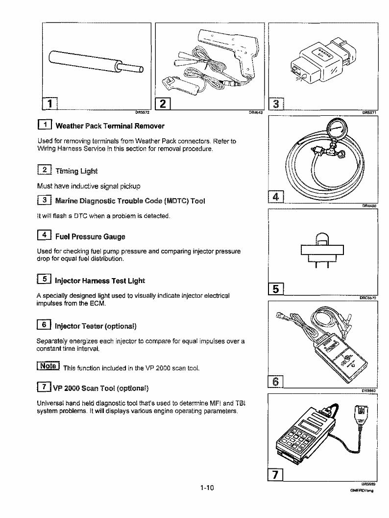
[~ Weather Pack Terminal Remover
Used for removing terminals from Weather Pack connectors. Refer toW~dng Harness Service in this section for removal procedure.
Timing Light
have inductive signal pickup
Marine Diagnostic Trouble Cede (MDTC) Tool
It will flash a DTC when a problem is detected.
Must
Fuel Pressure Gauge
Used for checking fuel pump pressure and comparing injector pressuredrop for equal fuel distribution.
[~ injector Harness Test Light
A specially designed light used to visually indicate injector electricalimpulses from the ECM.
injector Tester (optional)
Separately energizes each injector to compare for equal impulses over aconstant time interval.
This function included in the VP 2000 scan tool.
[~ VP 2000 Scan Tool (optional)
Universa~ hand held diagnostic tool that’s used to determine MFt and TBIsystem problems. It will displays various engine operating parameters.
DR4~3
1-10
DR5571
DR4488
AL 1
DRC5570
DR5560
DR5559GMERDI/eng
Section 2
Engine Control Module(ECM} and Sensors
Table of Contents
Analog Signals ................................... 2-2Three Wire Sensors .............................. 2-2Two Wire Sensors ............................... 2-2
Check Engine Light ................................ 2-9Computers and Voltage Signals ...................... 2-2Digital Signals ................................... 2-3
Pulse Counters ................................. 2-3Switch Types ................................... 2-3
ECM Inputs and Sensor Description ................... 2-5Discrete Switch Inputs ........................... 2-9Engine Coolant Temperature Sensor (ECT) ............ 2-6ignition Control Reference (IC) ..................... 2-9Intake Air Temperature Sensor (IAT) ................. 2-8Knock Sensor (KS) ............................... 2-7Knock Sensor (KS) Module ........................ 2-7Manifold Absolute Pressure (MAP) Sensor ............ 2-6Throttle Position Sensor (TP) ...................... 2-8
Engine Control Module (ECM) ....................... 2-4ECM Function .................................. 24Memory ....................................... 24
EEPROM ..................................... 2-4RAM ........................................ 2-4ROM ........................................ 2-4
General Description ............................... 2-2RPM Limiter ..................................... 2-9S,LO.W. TM . ...................................... 2-9Speed Density System ............................. 2-5
/~ Safety Warning
Before working on any part of the electrical system, read thesection called Safety at the end of this manual.
GMER~/eng 2-1
TYPICALSENSOR
I I
ECM
VOLTAGE OUT
~GNALINPUT
General Description
TYPICALSENSOR
ECM
SENSORSIGNAL
SENSORGROUND
DRC56 ~ 1 DRC5612
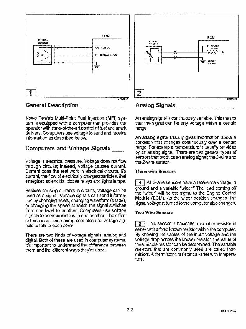
Volvo Penta’s Multi-Point Fuel injection (MFI) sys-tem is equipped with a computer that provides theoperator with state-of-the-art control of fuel and sparkdelivery. Computers use voltage to send and receiveinformation as described below.
Computers and Voltage Signals
Voltage is electrical pressure. Voltage does not flowthrough circuits; instead, voltage causes current.Current does the real work in electrical circuits. It’scurrent, the flow of electrically charged particles, thatenergizes solenoids, closes relays and lights lamps.
Besides causing currents in circuits, voltage can beused as a signal. Voltage signals can send informa-tion by changing levels, changing waveform (shape),or changing the speed at which the signal switchesfrom one level to another. Computers use voltagesignals to communicate with one another. The differ-ent sections inside computers also use voltage sig-nals to talk to each other.
There are two kinds of voltage signals, analog anddigital. Both of these are used in computer systems.It’s important to understand the difference betweenthem and the different ways they’re used.
An ananog signal is continuously variable. This meansthat the signaE can be any voltage within a certainrange.
An analog signal usually gives information about acondition that changes continuously over a certainrange. For example, temperature is usuatly providedby an analog signal. There are two general types ofsensors that produce an analog signal; the 3-wire andthe 2-wire sensor.
Three wire Sensors
[~ All 3-wire sensors have a reference voltage, aground and a variable "wiper." The Jead coming offthe "wiper" will be the signal to the Engine ControlModule (ECM). As the wiper position changes, thesignal voltage returned to the computer also changes.
Two Wire Sensors
E~ This sensor is basically a variable resistor inseries with a fixed known resistor within the computer.By knowing the values of the input voltage and thevoltage drop across the known resistor, the value ofthe variable resistor can be determined. The variableresistors that are commonly used are called ther-mistors. A thermistor’s resistance varies with tempera-ture.
2-2 GMEFIDt/eng
vGLTAGE
DIGITAL BINARY SIGNAL
TmME
DRC5615
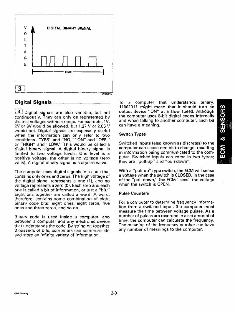
Digital Signals~3~ Digital signals are also variable, but notcontinuously. They can only be represented bydistinct voltages within a range. For example, 1V,2V or 3V would be allowed, but 1.27 V or 2.65 Vwould not. Digital signals are especially usefulwhen the information can only refer to twoconditions- "YES" and "NO," "ON" and "OFF,"or "HIGH" and "LOW." This would be called adigital binary signal. A digital binary signal islimited to two voltage levels. One level is apositive voltage, the other is no voltage (zerovolts). A digital binary signal is a square wave.
The computer uses digital signals in a code thatcontains only ones and zeros. The high voltage ofthe digital signal represents a one (1), and voltage represents a zero (0). Each zero and eachone is called a bit of information, or just a "bit."Eight bits together are called a word. A word,therefore, contains some combination of eightbinary code bits: eight ones, eight zeros, fiveones and three zeros, and so on.
Binary code is used inside a computer, andbetween a computer and any electronic devicethat understands the code. By stringing togetherthousands of bits, computers can communicateand store an infinite variety of information.
To a computer that understands binary,11001011 might mean that it should turn anoutput device "ON" at a slow speed. Althoughthe computer uses 8-bit digital codes internallyand when talking to another computer, each bitcan have a meaning.
Switch Types
Switched inputs (also known as discretes) to thecomputer can cause one bit to change, resultingin information being communicated to the com-puter. Switched inputs can come in two types;they are "pull-up" and "pull-down".
With a "pull-up" type switch, the ECM will sensea voltage when the switch is CLOSED. In the caseof the "pull-down," the ECM "sees" the voltagewhen the switch is OPEN.
Pulse Counters
For a computer to determine frequency informa-tion from a switched input, the computer mustmeasure the time between voltage pulses. As anumber of pulses are recorded in a set amount oftime, the computer can calculate the frequency.The meaning of the frequency number can haveany number of meanings to the computer.
DR5458
An example of a pulse counter type of input is thedistributor reference pulse input. The computercan count a train of pulses, a given number ofpulses per engine revolution. In this way, thecomputer can determine the RPM of the engine.
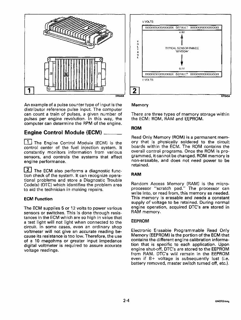
Engine Control Module (ECM)[~] The Engine Control Module (ECM} is thecontrol center of the fuel injection system. Itconstantly monitors information from varioussensors, and controls the systems that affectengine performance.
[~ The ECM also performs a diagnostic func-tion check of the system. It can recognize opera-tional problems and store a Diagnostic TroubleCode(s) (DTC) which identifies the problem to aid the technician in making repairs.
ECM Function
The ECM supplies 5 or 12 volts to power varioussensors or switches. This is done through resis-tances in the ECM which are so high in value thata test light will not light when connected to thecircuit. In some cases, even an ordinary shopvoltmeter will not give an accurate reading be-cause its resistance is too low. Therefore, the useof a 10 megohms or greater input impedancedigital voltmeter is required to assure accuratevoltage readings.
VOLTS
XXXXXXXXXXXXXXXX DEFAULT XXXXXX×XXXXXXXXX49V
TYPLCAL SENSOR RANGE"WINDOW"
0.1V
XXXXXXXXXXXXXXXX DEFAULT XXXXXXXXXXXXXXXX
VOLTS
DR54,54
Memory
There are three types of memory storage withinthe ECM: ROM, RAM and EEPROM.
Read Only Memory (ROM) is a permanent mem-ory that is physicaaly soldered to the circuitboards within the ECM. The ROM contains theoverall control programs. Once the ROM is pro-grammed, it cannot be changed. ROM memory isnon-erasable, and does not need power to beretained.
RAM
Random Access Memory (RAM) is the micro-processor "scratch pad." The processor canwrite into, or read from, this memory as needed.This memory is erasable and needs a constantsupply of vomtage to be retained. During normalengine operation, acquired DTC’s are stored inRAM memory.
Electronic Erasable Programmable Read OnlyMemory (EEPROM) is the portion of the ECM thatcontains the different engine calibration informa-tion that is specific to each application. Uponengine shut-off, DTC’s are stored to the EEPROMfrom RAM. DTC’s will remain in the EEPROMeven if B+ voltage is subsequently lost (i.e.battery removed, master switch turned off, etc.).


