Embed Size (px)
Citation preview

Procedia Engineering 62 ( 2013 ) 954 – 962
Available online at www.sciencedirect.com
1877-7058 © 2013 International Association for Fire Safety Science. Published by Elsevier Inc. All Rights ReservedSelection and peer-review under responsibility of the Asian-Oceania Association of Fire Science and Technologydoi: 10.1016/j.proeng.2013.08.148
ScienceDirect
The 9th Asia-Oceania Symposium on Fire Science and Technology
Fire behavior and mist suppression of a room lined with glass reinforced polymer (GRP) panels
G. J. Griffina,*, Q. Xub, C. M. L. Prestonc, A. D. Bicknellc, G. P. Bradburyc, N. Whitec
aSchool of Civil, Environmental and Chemical Engineering, RMIT University, GPO Box 2476, Melbourne 3001, Australia bSchool of Mechanical Engineering, Nanjing University of Science and Technology, Nanjing 210014, China
cCSIRO Materials Science and Engineering, PO Box 56, Highett 3190, Australia
Abstract
Six water mist suppression experiments were conducted in an ISO 9705 size room lined with GRP panels with a small wooden crib as a fire initiation source. A four-nozzle water mist suppression system was used to extinguish the fires. Heat release rate (HRR) from the fires was measured, as well as: room temperature; wall surface temperature of GRP panels, and; heat flux to the wall at specific locations within the room. The concentration of oxygen, carbon monoxide and carbon dioxide was also measured in one corner of the room. It was found that the mist suppression method used was an effective system for extinguishing fires from 500 kW – 1.5 MW in magnitude. However, in one experiment in which only a single, centrally located nozzle was used the fire could not be completely extinguished. The GRP material was characterised using thermal gravimetric analysis (TGA), differential scanning calorimetry (DSC) and cone calorimetry. The TGA results showed that the resin component of the GRP underwent pyrolysis over a temperature range of 225 C to 450 C when most of the resin mass was gasified leaving a solid char. The char material was completely consumed over a temperature range of 375 C to 430 C when heated in air. The DSC showed that, when heated in air, these two degradation steps released large amounts of energy. Cone calorimetry tests were conducted to measure the combustion behavior of the panel material (e.g. heat release rate (HRR) and time to ignition) when subjected to a constant incident radiant heat flux. The results showed that the panel material was flammable with a peak HRR of between 350 – 400 kW/m2 and the minimum heat flux for ignition was determined to be 16.5 kW/m2. © 2013 Published by Elsevier Ltd. Selection and/or peer-review under responsibility of the Asia-Oceania Association for Fire Science and Technology.
Keywords: GRP; Fire behaviour; Mist suppresion; Room fire
1. Introduction
Lightweight, glass-reinforced polymer (GRP) panels are used extensively for structural and interior applications in aircraft, marine craft and train passenger compartments. GRP panels exhibit favorable properties in terms of strength–to-weight ratio; durability; ease of maintenance and repair; toughness, and low thermal conductivity – especially when compared to traditional metal materials [1]. However, GRP panels are known to be vulnerable to structural failure when subjected to flames or high temperatures due to the low temperatures at which the polymer resin softens [2]. Furthermore, the flammability of the polymer resin can present a significant risk of contributing to fire spread, even with the application of fire resistant coatings. In passenger train carriages it has been found that an ignition source of between 150 kW to 300 kW in the corner of a train carriage is sufficient to cause involvement of unprotected linings with consequent flame spread and flashover [3].
* Corresponding author. Tel.: +61 3 9925 2200; fax: +61 3 9925 2268. E-mail address: [email protected].
© 2013 International Association for Fire Safety Science. Published by Elsevier Inc. All Rights ReservedSelection and peer-review under responsibility of the Asian-Oceania Association of Fire Science and Technology

955 G. J. Griffi n et al. / Procedia Engineering 62 ( 2013 ) 954 – 962
Water mist has been shown to be an effective extinguishing system in maritime applications [4] and has been used in the protection of engine rooms in some Australian trains. The use of water mist suppression has the potential to provide major benefits. Water mist has the advantage over gaseous suppressants in that it is: (a) non-asphyxiating; (b) does not produce harmful breakdown products; (c) is non-toxic, and; (d) does not have negative environmental affects that other, halogen-based suppressant (e.g. Halon 1301) have.
Water mist technology refers to fine water sprays in which 99% of the volume of the spray is in drops of diameters less than 1000 micron [5]. Although the efficacy of water mist in suppressing a class A (wood, paper, plastic) and Class B (flammable and combustible liquids) fires has been reported since the 1950’s [6], the use of halon suppressants has been considered more effective. Water mist systems are now being widely investigated as a halon replacement because of the requirement to replace halon with more environmentally friendly (non-ozone-depleting) substances [7].
This paper describes a series of fire tests conducted on GRP panels in which fire extinguishment was conducted using water mist. The primary purposes of the tests were (i) to measure fundamental fire and thermal properties of the GRP panels; (ii) to measure the rate of flame spread and heat release of the GRP when subjected to a reproducible ignition source; and (iii) to measure the efficacy of mist suppression applied to fires involving GRP.
2. Experimental methods - GRP characterization
2.1. GRP panel description
GRP panels of nominal dimension of 1.2 m 1.0 m were manufactured for use in the experimental program with sufficient panels produced to line an ISO 9705 [8] room and to replace each panel if damaged by fire. The constituent materials and the lay-up structure of the panels are given in Table 1. The panels were hand laid up resulting in panel thickness varying between 6.2 mm and 8.6 mm.
The percentage of resin in the GRP panel was estimated by ashing (ashing of the sample involved heating a weighed sample to 1000 C, in an air environment, for an hour to determine weight loss) and gave a combustible mass fraction of 52%. The density of the panels was measured as 1560 kg/m3. The panels were a translucent, greenish color with one side of the panel smooth and the other slightly rougher, a function of the lay-up process.
Table 1. Constituent components of GRP panels
Temperature (C)
0 100 200 300 400 500 600 700 800 900 1000
Res
idua
l deg
rada
ble
mas
s fra
ctio
n
0.0
0.2
0.4
0.6
0.8
1.0
Hea
t flo
w (m
W)
0
10
20
30
40
Air environemntN2 environment
Fig. 1. Mass loss and heat flow curves from TGA/DSC.
1 layer of tissue TA300
1 layer of chopped strand mat (300 g/m2)
5 layers of woven roving (600 g/m2)
1 layer of chopped strand mat (300 g/m2)
1 layer of tissue layer TA300
Resin: Nuplex Structural Resin Synolite 0593-N-2
2.2. Thermal gravimetric analysis / differential scanning calorimetry (TGA/DSC)
GRP samples of about 10 mg were tested in a TA Instruments SDT Q600 thermal gravimetric analyser. The samples were heated at a rate of 10 C/min from room temperature to 900 C in an environment of air or high purity nitrogen. After the nitrogen test, the sample was heated in air to 900 C to determine the residual amount of combustible material remaining. Fig. 1 shows the changes in degradable mass (essentially the mass excluding the glass components) of the samples and the relative heat flows to/from the samples as they were heated. The plot shows the GRP resin underwent a 3-stage mass loss process when heated in air; the first mass-loss stage occurred at temperatures between 60 C and 150 C and is indicative of the resin softening and releasing highly volatile components from the matrix with approximately a 4% loss in degradable material. The second stage loss occurred between 225 C and 375 C resulting in a mass loss of about 75%; this is typical for the combustion of volatile components leaving a carbonaceous char residue. The final mass-loss stage occurred between 375 C and 530 C with the consumption of the char material. The DSC results showed considerable exothermic peaks for the second and third stage mass loss processes indicative of combustion.

956 G. J. Griffi n et al. / Procedia Engineering 62 ( 2013 ) 954 – 962
When heated under nitrogen, a two-stage mass loss process was observed. The first stage was identical to that shown under air. The DSC showed no measurable heat flow indicating that this process may be purely physical, i.e. mass loss due to release of trapped volatile components as the resin melted. The second stage was endothermic and occurred over the temperature range of 250 C to 450 C and was indicative of pyrolysis of the resin from the release of volatile gases. About 5% of the resin remained as char which could not be further degraded under nitrogen.
2.3. Cone calorimetry
Samples of GRP were tested in the cone calorimeter according to ISO 5660 [9]. The tests were conducted at incident heat fluxes of 25, 35 and 50 kW/m2. Tests on either side (rough or smooth) of the GRP panels were conducted. The time to ignition was not affected when tests were repeated or by which face (smooth or rough) was exposed to the radiant heat. The incident heat flux was plotted against the reciprocal ignition time and showed that the minimum heat flux required for ignition of the GRP was 16.2 kW/m2. Peak rate of heat release measured between 348.5 and 404.7 kW/m2. Greater detail of the measured data may be found in [10].
The thermal resistance of the GRP panel was estimated using a methodology provided in [11]. The thermal resistance varied between 10 K/W and 20 K/W, with no obvious trend as the material degrades. These values equate to an ‘effective’ thermal conductivity of between 0.035 – 0.07 W/m K.
3. Experimental methods - tests conducted in GRP lined room
3.1. Room layout
The experiments were conducted in an enclosure complying with the standard ISO 9705 room burn [8]. The ISO room burn consists of four walls at right angles, a floor and a ceiling and has the approximate internal dimensions of 3.60 (L) 2.40 (W) 2.40 (H) metres. It has a door in the centre of one of the (2.40 2.40 metre) walls, 0.8 metres wide and 2.00 metres high. The room is constructed in accordance with Section 5 of ISO 9705 [8], the walls, ceiling and floor of the room are made from a layer of 15 mm plywood (outside surface) faced with one layer (on the inside walls) or two layers (on the ceiling) of 16 mm, glass reinforced, paper-faced, gypsum plasterboard. These are supported on an external steel frame.
The GRP panels lined three walls and the ceiling of the room (refer Fig. 2). The panels were held in place by steel screws drilled through the panels/plasterboard and into the underlying plywood. Nine screws were used in each of the major panel sections. Steel washers of 20 mm and 50 mm outside diameter were used to support the wall and ceiling panels respectively. Fig. 3 shows the layout and dimensions of the individual panels used in the room. Note that the area 20 cm from the front of the room was left bare.
The GRP panels are denoted W1-6 (panels on west wall), B1-4 (panels on back, or rear, of room), E1-6 (panels on east wall) and C1-6 (panels placed on the ceiling).
Fig. 2. Rear of room lined with GRP panels. Note wooden crib in corner.
The mist nozzles were Type AM4 supplied by TYCO Pty Ltd. Fig. 4 shows the ceiling position of the five mist nozzles used in the test. The nozzles were used as either a system comprising the four outer nozzles or the centre nozzle only. The nozzles were attached to hangers so that the nozzle diffuser was located 20 cm below the ceiling – in accordance with the manufacturer’s instructions. The details of the nozzle technical specifications, layout and the water droplet size distribution

957 G. J. Griffi n et al. / Procedia Engineering 62 ( 2013 ) 954 – 962
are given in [12]. The nozzles are designed to operate at inlet water pressures of between 12 and 17 bar, with mist flow rate of between 0.22 and 0.25 l/s.
Fig. 3. Layout of GRP panels used to line an ISO 9705 room. Fig. 4. Plan schematic diagram showing layout of mist nozzles in ceiling. Note that the mist heads are located 20 cm below the level of the ceiling.
3.2. Instrumentation used during room experiments
The room doorway opens under a smoke collection hood and exhaust duct system which meets the requirements of ISO 9705. The exhaust duct contains instrumentation for measuring the flow rate and temperature of the exhaust gases, an optical smoke measurement system to determine optical density of the combustion gases and a gas-sampling probe. Sampled gases are continuously analysed for concentrations of O2, CO and CO2 allows the calculation of heat release rate (HRR) using oxygen calorimetry.
Thermocouples (1.5 mm diameter, Type K MIMS) were placed on the centre front and back sides of each GRP panel (i.e. panels W1-6, E1-6, C1-6, B1-4). Ten Schmidt-Boelter type heat flux sensors were distributed in the walls, ceiling and floor of the room. Fig. 5 shows the position of nine of these sensors (R1-9). The tenth sensor was placed in the doorway of the room, 1m above the floor.
Fig. 5. Position of heat flux sensors. Fig. 6. Position of thermocouple trees and gas sampling probes used in room.
Two thermocouple trees (Tree 1 and Tree 2) were placed in the room and a third tree was placed in the doorway (Tree 3), the position of the trees within the room are shown in Fig. 6. Each tree consisted of ten thermocouples (1.5 mm diameter, type K MIMS), the lowest thermocouple was positioned 32 cm above the floor with the other thermocouples positioned at 20 cm intervals (the uppermost thermocouple was ~24 cm from the ceiling).
Two gas sampling probes were placed towards the rear of the room and drew gas from 0.6 m above the floor (GP 1 in Fig. 6) and 0.35 m below the ceiling (GP 2 in Fig. 6). Gases extracted through these probes were continuously analysed for O2, CO and CO2 (on a dry basis) concentration.

958 G. J. Griffi n et al. / Procedia Engineering 62 ( 2013 ) 954 – 962
3.3. Ignition source used for experiments
All tests were conducted using a wooden crib as the ignition source. The crib was composed of 24 wooden sticks (pinus radiata, the stick dimensions were 35 mm × 35 mm × 500 mm and a density of 500 kg/m3) which had been conditioned at 25.2 C and 50.5% Relative Humidity for at least 7 days. The arrangement of the sticks making up the crib is shown in Fig. 2. The crib was placed in the West, rear corner of the room, two aluminium trays containing 600 ml of methylated spirits were placed underneath the crib and ignited to begin the experiments. Tests conducted in which only cribs were involved [10] showed that the crib HRR climbed to a peak value of 200 ± 10 kW after 200-300 s before declining to less than 50 kW over the following 1200 s.
4. Experimental results
Six experiments were conducted on mist suppression of fires involving GRP panels – refer Table 2. Two variables were tested in these experiments – the time at which suppression was initiated (which equates to the HRR when the mist suppression was initiated) and the line pressure used to supply the mist nozzles (which equates to the flow rate delivered into the room). In all tests the mist suppression was applied for 2 minutes. For 5 of the tests four outer nozzles were used and suppression was achieved. In the other test (Mist experiment 4) only the central nozzle was used and extinguishment was not achieved.
Table 2. Mist suppression parameters for GRP fires
Experiment no. Line pressure
(barg)
Suppression start time (s)
HRR at suppression start (kW)
Peak HRR(kW)
Time for extinguishment
(s)
Mist Experiment 1 17 245 1070 3030 25
Mist Experiment 2 17 246 1430 5410 34
Mist Experiment 3 17 202 520 1130 25.5
Mist Experiment 4 12 205 160 240 -
Mist Experiment 5 12 203 210 465 22
Mist Experiment 6 12 274 1050 3580 28.5
Figure 7 shows the total heat release rate (HRR) measured for the combustion of the GRP and cribs (the figure uses a
time scale based upon the time at which suppression is initiated). Over the first 150 seconds the HRR builds slowly to a value of between 150–200 kW (the HRR of the wood crib) then climbs rapidly as the GRP panels adjacent to the crib ignite and the flames spread across the panels on the ceiling. The timing of this transition in HRR varied between tests, possibly due to the slight differences between the burning behavior of the cribs and panels used in each test. It can be seen that the initiation of the water mist does not immediately reduce the HRR, indeed the HRR increases at a faster rate for a short period before undergoing a rapid decline. The increase in HRR after water mist initiation may be explained by: a) the time delay for water droplets to reach the flame zone in sufficient quantities to perform the necessary zone cooling, surface cooling and oxygen displacement/depletion and; b) pyrolysis gases and gaseous water produced during the extinguishment of the flames artificially increasing the HRR value calculated by oxygen calorimetry.
From Fig. 7, it can be seen that the higher the HRR when mist suppression is initiated, the longer the time taken for the fires to be extinguished (it is assumed that the fire is extinguished when the HRR has fallen below 200 kW). Table 2 shows the extinguishment time for the experiments based on this criterion. The lower line pressures used (lower rate of mist application) also increases the time for extinguishment, although the effect was minor.
Figures 8 and 9 show the oxygen concentrations measured at the gas probes GP 1 and GP 2 respectively for Mist Experiment 1 (note: the following sets of results are for mist experiment 1 – other tests showed similar results). The gas probe closest to the floor (GP 1) measured negligible change in oxygen concentration until the mist suppression was initiated and the oxygen deficient gases from the hot gas layer were mixed through the room. The oxygen concentration measured at GP 1 decreased sharply when the mist suppression was initiated then increased as the fire was extinguished. At the gas probe closest to the ceiling (GP 2) there was a steady decrease in oxygen concentration as the fire progressed, accelerating to a faster rate of decline as the fire proceeded towards flashover. When the mist suppression was initiated, the oxygen concentration climbed rapidly due to disruption of the oxygen rich layer.

959 G. J. Griffi n et al. / Procedia Engineering 62 ( 2013 ) 954 – 962
Fig. 7. Measured HRR for mist suppression of GRP/crib fires with time adjustment.
Fig. 8. Oxygen concentration at probe GP 1 (close to floor).
Fig. 9. Oxygen concentration at probe GP 2 (close to ceiling).
Fig. 10. Temperature profiles measured on west wall (W1-W3).
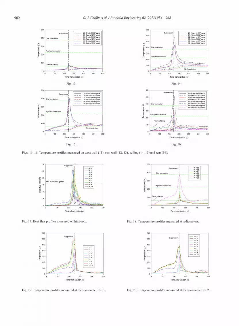
Figures 10–16 show the temperature profiles measured at the GRP wall panels (exposed and back face) during Mist Experiment 1. Each plot shows the temperature at which chemical and physical processes are deemed important (i.e. resin softening, 60 C; pyrolysis of the resin or combustion, 225 C and combustion of the char, 375 C – as determined from tests conducted in the TGA. The time at which the mist suppression was initiated is also shown. Panels C1 (the ceiling panel directly above the crib) and B1 (the ceiling panel above the crib on the back wall) showed the highest surface temperatures (~ 600 C). Panel W1 and panels C2–C6 showed a surface temperatures of ~400 C. These temperatures correlated with the fire damage seen on the room at the conclusion of the experiment. It was found that the most severe fire impingement occurred on panels C1–C4, B1, B3, B4, W1, W4 and W5. The ceiling temperatures on panels C2-C6 were very similar indicating the hot layer of gas trapped below the ceiling was of a reasonably uniform temperature. When the mist suppression was initiated there was an almost immediate, monotonic drop in temperatures until the water mist ceased 120 seconds after initiation.
Fig. 11.
Fig. 12.
960 G. J. Griffi n et al. / Procedia Engineering 62 ( 2013 ) 954 – 962
Fig. 13.
Fig. 14.
Fig. 15.
Fig. 16.
Figs. 11–16. Temperature profiles measured on west wall (11), east wall (12, 13), ceiling (14, 15) and rear (16).
Fig. 17. Heat flux profiles measured within room.
Fig. 18. Temperature profiles measured at radiometers.
Fig. 19. Temperature profiles measured at thermocouple tree 1.
Fig. 20. Temperature profiles measured at thermocouple tree 2.

961 G. J. Griffi n et al. / Procedia Engineering 62 ( 2013 ) 954 – 962
Fig. 21. Temperature profiles measured at thermocouple tree 3.
On the back faces of the panels, the temperatures did not generally exceed temperatures greater than ~100 C. The highest rear temperature measured was in the ceiling panel directly above the crib (C1) which registered a maximum temperature of ~150 C. Thus there was no combustion or pyrolysis at the rear of the panels. The temperature rise on the back face of the material was low due to the low thermal conductivity of the composite material. However, with time, combustion of the GRP material will occur if suppression is not employed.
Figure 17 shows the incident heat flux at the 10 sensors placed around the room. The heat flux mimics the temperature profiles measured, i.e. the heat flux increases slowly over the first 200 s then increases rapidly as the fire approaches flashover. At the time of suppression, the heat flux measured in the panels had climbed beyond the minimum requirement of 16.2 kW/m2 to ignite the GRP panels (with the exception of R5). However, the suppression system reduced the temperatures sufficiently to prevent ignition of the GRP at these regions. Fig. 18 shows the panel temperatures measured adjacent to the heat flux sensors. It can be seen that only one sensor (R6, which was placed in the ceiling) measured temperatures high enough to indicate that the GRP underwent combustion or pyrolysis.
Figures 19–21 show the temperatures measured at the thermocouple trees during the experiment. As the fire within the room approached flashover, the temperature of the upper 4 thermocouples of Trees 1 and 2 (i.e. within 0.8 metres from the ceiling) exceed 400 C and are of similar temperatures, indicating they lie within the hot layer of the ceiling. The lower 4 thermocouples (TC 1–TC4) showed similar temperatures (<100 C) indicative that these are located well away from the hot layer. Thermocouples TC5 and TC6 lay within the area of transition from the upper hot layer to the cooler lower layer. For thermocouple tree 3, which is placed at the doorway of the room, there is a rapid transition in temperature between the upper thermocouples (TC1–TC4) to the lower thermocouples which are maintained near or at ambient temperature as they are exposed to the colder incoming flow of air from outside the room.
When the mist suppression system is initiated there is a rapid decrease in temperature measured at the upper thermocouples as the upper gas layer is cooled and disrupted.
5. Discussion and conclusions
For the fires involving a wood crib and GRP panels, the heat release rate was reduced significantly on activation of the water mist. The oxygen concentration close to the floor was not reduced sufficiently to be the dominant extinguishing mechanism. Fig. 9 shows that for higher heat release rates, the oxygen concentration approaches the point where it could contribute more significantly to extinguishment. The higher heat release rates produce greater water vapor generation and dilution of the oxygen concentration. Mist Experiment 4 did not produce sufficient mist to allow extinguishment of the crib fire although it was sufficient to prevent involvement of the GRP panels in the fire. A lower heat release rate was achieved but oxygen dilution was insufficient to extinguish the fire.
During the extinguishing tests in the ISO room, the spray characteristics controlled the extinguishing behavior. If a sufficient volume of water did not flow through the nozzles then the flame cooling mechanism will not cause extinguishment. Water pressure will also contribute to the extinguishing behavior because sufficient water particle momentum is necessary for the mist to penetrate the hot upper layer to provide flame cooling. The system used in these tests was a low pressure system operating at between 12 and 17 bar which was sufficient to produce extinguishment if enough nozzles were operational.
The combustible GRP boundaries did not pose any special concern for the water mist extinguishing system used in these series of tests. The greater heat release rate of the GRP fires contribute to the extinguishment by oxygen dilution.

962 G. J. Griffi n et al. / Procedia Engineering 62 ( 2013 ) 954 – 962
Ventilation is an important mechanism in extinguishing fires. However in these experiments the dominant mechanism was flame cooling as the ISO room has an open door. If oxygen dilution was the controlling mechanism, inflow of air into the room will disrupt this mechanism.
References
[1] Edwards, K. L., 1998. An Overview of the Technology of Fibre Reinforced Plastics for Design Purposes, Materials & Design, 19, p. 1. [2] Kandare, E., Griffin, G. J., Feih, S., Gibson, A. G., Lattimer, B. Y., Mouritz, A. P., 2012. Fire Structural Modelling of Fibre–polymer Laminates
Protected with an Intumescent Coating, Composites A 43(5), p. 793. [3] White, N., Dowling, V., Barnett, J., 2005. “Full-scale Fire Experiment on a Typical Passenger Train,” Proceedings of the Eighth International
Symposium on Fire Safety Science, Tsinghua University, Beijing, China, pp. 1157 – 1168. [4] Darwin, R. L., Williams, F. W., 2000. The Development of Water Mist Fire Protection Systems for U.S. Navy Ships, Naval Engineers Journal 112(6),
p. 49. [5] Mawhinney, J. R., 1997, Fire Protection Water Mist Suppression Systems, in “Fire Protection Handbook,” 18th ed., National Fire Protection
Association, Quincy, MA. [6] Rasbash, D. J., Rogowski, Z. W., 1957, Extinction of Fires in Liquids by Cooling With Water Sprays, Combustion and Flame 1(4), p. 453. [7] United Nations Environment Program, 1987. The Montreal Protocol on Substances that Deplete the Ozone Layer, United Nations Environment
Program, Nairobi. [8] ISO 9705:1993(E), Fire Tests – Full-scale Room Test for Surface Products, International Organisation for Standardization (1993). [9] ISO 5660-1:2002: Reaction-to-fire tests - Heat Release, Smoke Production and Mass Loss Rate - Part 1: Heat Release Rate (Cone Calorimeter
Method), International Organisation for Standardization (1993). [10] Xu, Q., Griffin, G., 2011. Evaluate Fire Behavior GRP Panel, Journal of Reinforced Plastics and Composites, 30(2), p. 142. [11] Griffin, G. J., Bicknell, A. D., Brown, T. J., 2005. Studies on the Effect of Atmospheric Oxygen Content on the Thermal Resistance of Intumescent,
Fire-retardant Coatings”, Journal of Fire Sciences, 23(4), p. 303. [12] Lefort, G., Marshall, A. W., Pabon, M., 2009. Evaluation of Surfactant Enhanced Water Mist Performance, Fire Technology 45, p. 34.


