Embed Size (px)
Citation preview
INSTRUCTION MANUAL Scotch-Yoke part turn pneumatic
actuator
ACTUATECH S.p.A. Via san Lorenzo, 70 – 25069 VILLA CARCINA (BS) – ITALY Tel. (+39) 0308908142 Fax (+39) 0308908143 - Fax 030/xxxxxxxxxxxxx http://www.actuatech.com
MAN80515
Page 1 of 29
Modification reserved. Rev. date 09/2019. No guarantee for accuracy. Older data sheets are invalid
INSTRUCTION MANUAL
Scotch – Yoke Part turn pneumatic actuator
GD15 - GD1920 GS15 – GS960 INDEX
1) GENERAL FEATURES pag. 2
2) WORKING CONDITIONS pag. 2
3) OPERATION AND ROTATION DIRECTION pag. 6
4) SAFETY INFORMATION pag. 9
5) INSTALLATION INSTRUCTION pag. 9
6) MATERIALS AND THEIR DURABILITY pag. 18
7) MAINTENANCE pag. 20
8) ATEX SPECIFICATION pag. 25
9) SPECIAL VERSIONS pag. 26
10) STORAGE pag. 28
11) TROUBLESHOOTING pag. 28
12) DISPOSAL OF PRODUCTS AT THE END OF THEIR LIFE CYCLE pag. 29
13) DECLARATION OF CONFORMITY pag. 29
INSTRUCTION MANUAL Scotch-Yoke part turn pneumatic
actuator
ACTUATECH S.p.A. Via san Lorenzo, 70 – 25069 VILLA CARCINA (BS) – ITALY Tel. (+39) 0308908142 Fax (+39) 0308908143 - Fax 030/xxxxxxxxxxxxx http://www.actuatech.com
MAN80515
Page 2 of 29
Modification reserved. Rev. date 09/2019. No guarantee for accuracy. Older data sheets are invalid
Actuatech reserves the right to change, at any time, the features and data of its own products, to better improve the quality
and the duration of said products.
FOREWORD
The present User’s Installation and Maintenance Manual has been edited in conformity with:
- 2006/42/EC Directive “Machinery”;
- 2014/34/UE Directive “Equipment and protection systems designated to be used in potentially explosive atmospheres”
(ATEX).
The following standards/technical specifications also apply:
- EN 15714-3:2009 Industrial valves: Actuators – Pneumatic part-turn actuators for industrial valves.
- IEC 61508:2010-1/7 Functional safety of electrical/electronic/programmable electronic safety-related systems. Part 1 :7
- UNI CEN/TS 764-6:2005 Pressure equipment Part 6: Operating instructions structure and contents.
Below you will find the safety instructions, the minimum information for storage / warehousing, the installation, the
commissioning, the maintenance and the instructions for disposal of products at the end of their life cycle for the pneumatic
actuators:
Actuatech disclaims any liability for damage caused by improper use, even if partial, respect to the information contained in
this manual.
1) GENERAL FEATURES •••••••••••••••••••••••••••••••••••••••••••••••••••••••••••••••••••••••••••••••••••••••••••••••••• Actuatech manufacture a wide range of part turn pneumatic actuators for valve remote control. The actuators are available on Double Acting “GD” and Spring Return “GS” versions. - The principle of the actuator application is to open and close the connected valve, without the manual operation with lever or hand wheel, by means of an electric-pneumatic connection on remote control. - Scotch – Yoke is a mechanical system that allows to transform the linear force into a rotary torque. Actuatech applies the scotch - yoke system for its actuator production to transfer the pistons linear force to a driving shaft torque. This system provides a long working life and best performance with the minimum energy consumption. - Actuatech Scotch-Yoke system with its oblique grooves produces a torque curve with the highest torque at the start opening operation in order to overcome the valve breakaway torque. The maintenance should be done by Actuatech trained personnel only. This instruction manual contains important information regarding the Actuatech Scotch-Yoke pneumatic actuator operation, installation, maintenance and storage. Please read carefully before installation and keep it in a safe place for further reference. 2) WORKING CONDITIONS •••••••••••••••••••••••••••••••••••••••••••••••••••••••••••••••••••••••••••••••••••••••••••••••••• a) Construction. Standard Actuatech actuators are suitable for indoor and outdoor installation. The laser marking or a printed label on the actuator body gives the actuator technical characteristics: type, size, operating pressure, output torque, operating temperature, flange connection, product code and production date (see drawing pag.4).
INSTRUCTION MANUAL Scotch-Yoke part turn pneumatic
actuator
ACTUATECH S.p.A. Via san Lorenzo, 70 – 25069 VILLA CARCINA (BS) – ITALY Tel. (+39) 0308908142 Fax (+39) 0308908143 - Fax 030/xxxxxxxxxxxxx http://www.actuatech.com
MAN80515
Page 3 of 29
Modification reserved. Rev. date 09/2019. No guarantee for accuracy. Older data sheets are invalid
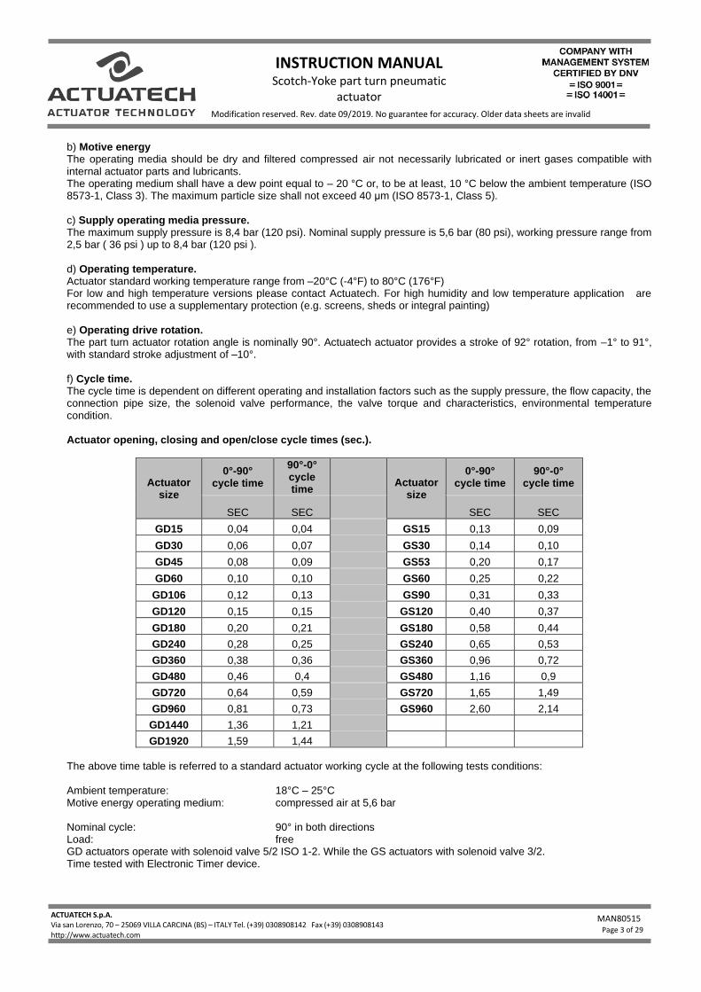
b) Motive energy The operating media should be dry and filtered compressed air not necessarily lubricated or inert gases compatible with internal actuator parts and lubricants. The operating medium shall have a dew point equal to – 20 °C or, to be at least, 10 °C below the ambient temperature (ISO 8573-1, Class 3). The maximum particle size shall not exceed 40 μm (ISO 8573-1, Class 5). c) Supply operating media pressure. The maximum supply pressure is 8,4 bar (120 psi). Nominal supply pressure is 5,6 bar (80 psi), working pressure range from 2,5 bar ( 36 psi ) up to 8,4 bar (120 psi ). d) Operating temperature. Actuator standard working temperature range from –20°C (-4°F) to 80°C (176°F) For low and high temperature versions please contact Actuatech. For high humidity and low temperature application are recommended to use a supplementary protection (e.g. screens, sheds or integral painting) e) Operating drive rotation. The part turn actuator rotation angle is nominally 90°. Actuatech actuator provides a stroke of 92° rotation, from –1° to 91°, with standard stroke adjustment of –10°. f) Cycle time. The cycle time is dependent on different operating and installation factors such as the supply pressure, the flow capacity, the connection pipe size, the solenoid valve performance, the valve torque and characteristics, environmental temperature condition. Actuator opening, closing and open/close cycle times (sec.).
Actuator size
0°-90° cycle time
90°-0° cycle time
Actuator size
0°-90° cycle time
90°-0° cycle time
SEC SEC SEC SEC
GD15 0,04 0,04 GS15 0,13 0,09
GD30 0,06 0,07 GS30 0,14 0,10
GD45 0,08 0,09 GS53 0,20 0,17
GD60 0,10 0,10 GS60 0,25 0,22
GD106 0,12 0,13 GS90 0,31 0,33
GD120 0,15 0,15 GS120 0,40 0,37
GD180 0,20 0,21 GS180 0,58 0,44
GD240 0,28 0,25 GS240 0,65 0,53
GD360 0,38 0,36 GS360 0,96 0,72
GD480 0,46 0,4 GS480 1,16 0,9
GD720 0,64 0,59 GS720 1,65 1,49
GD960 0,81 0,73 GS960 2,60 2,14
GD1440 1,36 1,21
GD1920 1,59 1,44
The above time table is referred to a standard actuator working cycle at the following tests conditions: Ambient temperature: 18°C – 25°C Motive energy operating medium: compressed air at 5,6 bar Nominal cycle: 90° in both directions Load: free GD actuators operate with solenoid valve 5/2 ISO 1-2. While the GS actuators with solenoid valve 3/2. Time tested with Electronic Timer device.
INSTRUCTION MANUAL Scotch-Yoke part turn pneumatic
actuator
ACTUATECH S.p.A. Via san Lorenzo, 70 – 25069 VILLA CARCINA (BS) – ITALY Tel. (+39) 0308908142 Fax (+39) 0308908143 - Fax 030/xxxxxxxxxxxxx http://www.actuatech.com
MAN80515
Page 4 of 29
Modification reserved. Rev. date 09/2019. No guarantee for accuracy. Older data sheets are invalid
NOTE: different working condition such as air pressure, piping connection, filters or solenoid valves, could change the timing of the operations. g) Lubrication. The actuators are factory lubricated for the standard working condition life. During maintenance and reassembling Actuatech recommends using TECNOLUBE SYNTHY POLYMER 402, or equivalents. h) Internal wear protection The cylinder is lapped to obtain a surface with fine roughness and is protected with 20 µm technical oxidation. The pistons slide supports are in P.T.F.E. or polyurethane only, no rubber in contact. The use of steel bearings on the Scotch-Yoke system ensures no play and low friction during operation i) External protection Actuatech standard actuators are suitable for indoor and outdoor installation. The aluminium body is external protected form corrosion and wear with 20 µm technical oxidation. The cast aluminium end caps are polyester painted. Driving shaft and caps screws are in stainless steel. For aggressive atmosphere and severe environmental condition select the required protection from the external finishes showed in our catalogue or contact directly our technical department. j) Functional Safety
The Actuatech S.p.A. pneumatic actuators are also suitable for installations which require high level of functional reliability,
up to SIL3, in compliance with the IEC 61508 standard.
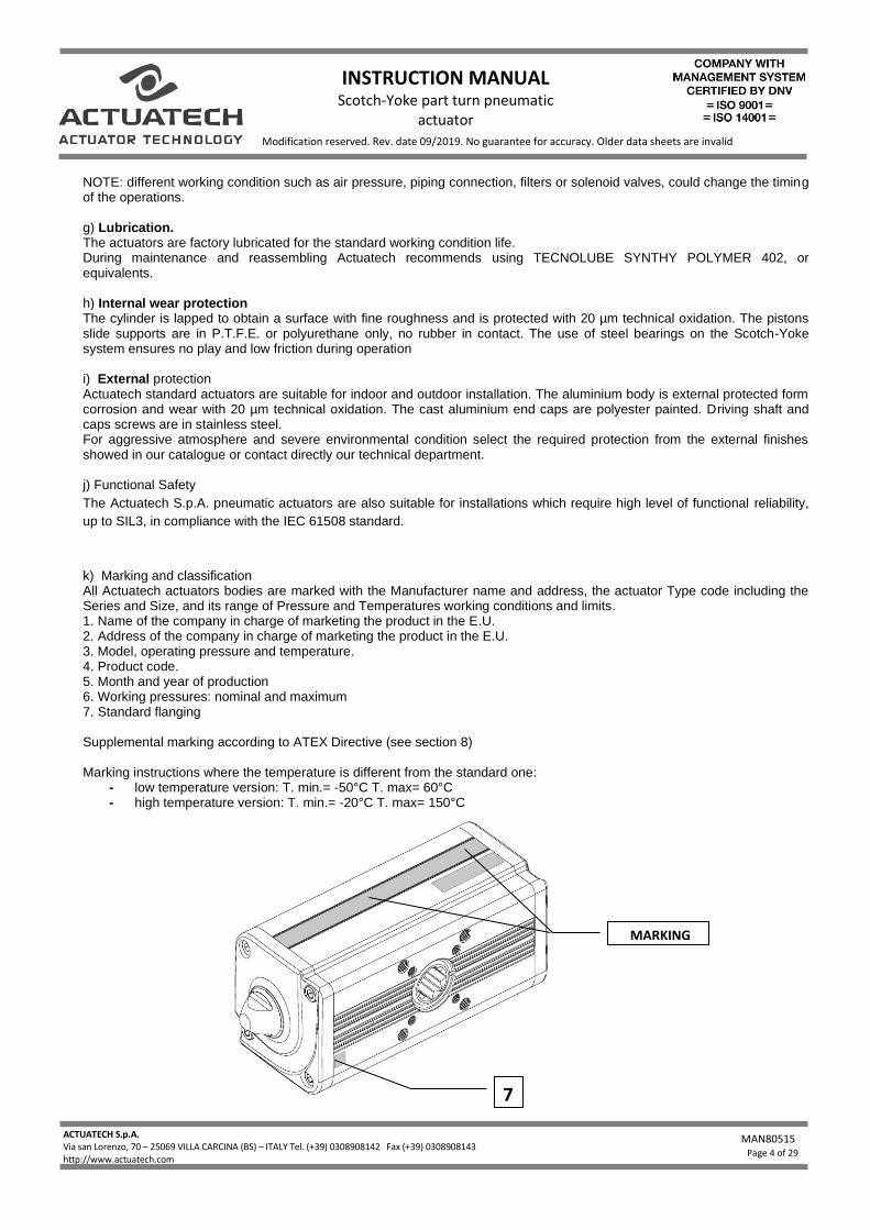
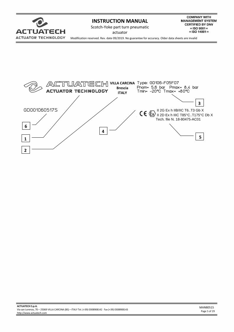
k) Marking and classification All Actuatech actuators bodies are marked with the Manufacturer name and address, the actuator Type code including the Series and Size, and its range of Pressure and Temperatures working conditions and limits. 1. Name of the company in charge of marketing the product in the E.U. 2. Address of the company in charge of marketing the product in the E.U. 3. Model, operating pressure and temperature. 4. Product code. 5. Month and year of production 6. Working pressures: nominal and maximum 7. Standard flanging Supplemental marking according to ATEX Directive (see section 8) Marking instructions where the temperature is different from the standard one:
- low temperature version: T. min.= -50°C T. max= 60°C - high temperature version: T. min.= -20°C T. max= 150°C
MARKING
7
INSTRUCTION MANUAL Scotch-Yoke part turn pneumatic
actuator
ACTUATECH S.p.A. Via san Lorenzo, 70 – 25069 VILLA CARCINA (BS) – ITALY Tel. (+39) 0308908142 Fax (+39) 0308908143 - Fax 030/xxxxxxxxxxxxx http://www.actuatech.com
MAN80515
Page 5 of 29
Modification reserved. Rev. date 09/2019. No guarantee for accuracy. Older data sheets are invalid
6
3
5 1
2
4
II 2G Ex h IIB/IIC T6..T3 Gb X
II 2D Ex h IIIC T85°C..T175°C Db X
Tech. file N. 18-80475-AC01
VILLA CARCINA Brescia ITALY
INSTRUCTION MANUAL Scotch-Yoke part turn pneumatic
actuator
ACTUATECH S.p.A. Via san Lorenzo, 70 – 25069 VILLA CARCINA (BS) – ITALY Tel. (+39) 0308908142 Fax (+39) 0308908143 - Fax 030/xxxxxxxxxxxxx http://www.actuatech.com
MAN80515
Page 6 of 29
Modification reserved. Rev. date 09/2019. No guarantee for accuracy. Older data sheets are invalid
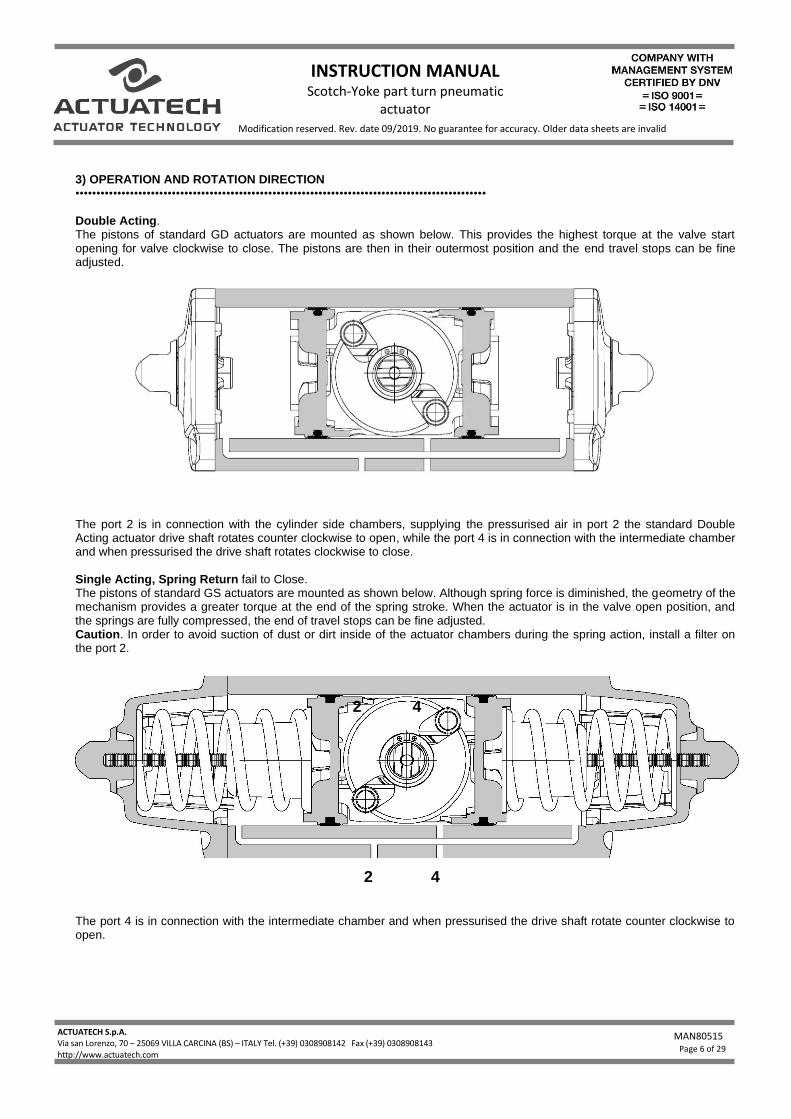
3) OPERATION AND ROTATION DIRECTION •••••••••••••••••••••••••••••••••••••••••••••••••••••••••••••••••••••••••••••••••••••••••••••••••• Double Acting. The pistons of standard GD actuators are mounted as shown below. This provides the highest torque at the valve start opening for valve clockwise to close. The pistons are then in their outermost position and the end travel stops can be fine adjusted.
The port 2 is in connection with the cylinder side chambers, supplying the pressurised air in port 2 the standard Double Acting actuator drive shaft rotates counter clockwise to open, while the port 4 is in connection with the intermediate chamber and when pressurised the drive shaft rotates clockwise to close. Single Acting, Spring Return fail to Close. The pistons of standard GS actuators are mounted as shown below. Although spring force is diminished, the geometry of the mechanism provides a greater torque at the end of the spring stroke. When the actuator is in the valve open position, and the springs are fully compressed, the end of travel stops can be fine adjusted. Caution. In order to avoid suction of dust or dirt inside of the actuator chambers during the spring action, install a filter on the port 2.
The port 4 is in connection with the intermediate chamber and when pressurised the drive shaft rotate counter clockwise to open.
2 4
4 2
INSTRUCTION MANUAL Scotch-Yoke part turn pneumatic
actuator
ACTUATECH S.p.A. Via san Lorenzo, 70 – 25069 VILLA CARCINA (BS) – ITALY Tel. (+39) 0308908142 Fax (+39) 0308908143 - Fax 030/xxxxxxxxxxxxx http://www.actuatech.com
MAN80515
Page 7 of 29
Modification reserved. Rev. date 09/2019. No guarantee for accuracy. Older data sheets are invalid
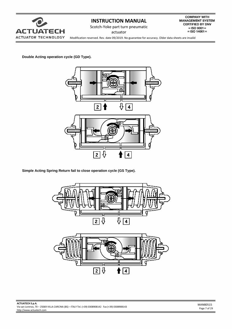
Double Acting operation cycle (GD Type).
Simple Acting Spring Return fail to close operation cycle (GS Type).
INSTRUCTION MANUAL Scotch-Yoke part turn pneumatic
actuator
ACTUATECH S.p.A. Via san Lorenzo, 70 – 25069 VILLA CARCINA (BS) – ITALY Tel. (+39) 0308908142 Fax (+39) 0308908143 - Fax 030/xxxxxxxxxxxxx http://www.actuatech.com
MAN80515
Page 8 of 29
Modification reserved. Rev. date 09/2019. No guarantee for accuracy. Older data sheets are invalid
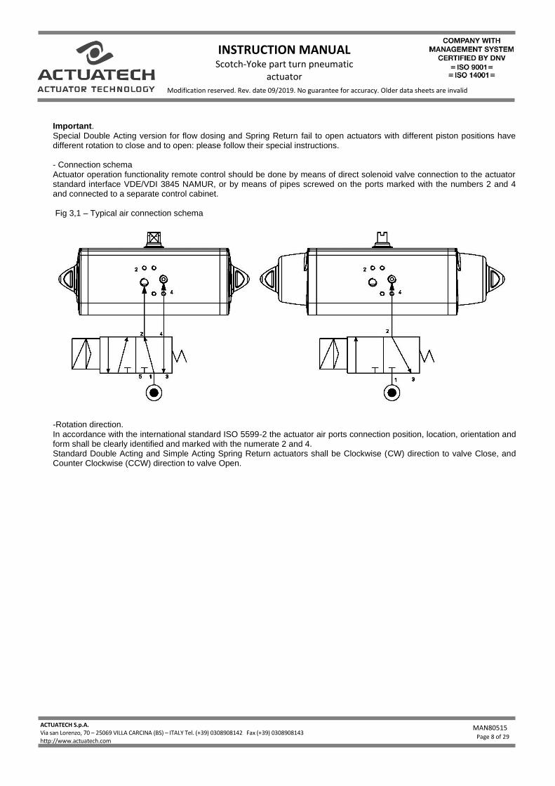
Important. Special Double Acting version for flow dosing and Spring Return fail to open actuators with different piston positions have different rotation to close and to open: please follow their special instructions. - Connection schema Actuator operation functionality remote control should be done by means of direct solenoid valve connection to the actuator standard interface VDE/VDI 3845 NAMUR, or by means of pipes screwed on the ports marked with the numbers 2 and 4 and connected to a separate control cabinet. Fig 3,1 – Typical air connection schema
-Rotation direction. In accordance with the international standard ISO 5599-2 the actuator air ports connection position, location, orientation and form shall be clearly identified and marked with the numerate 2 and 4. Standard Double Acting and Simple Acting Spring Return actuators shall be Clockwise (CW) direction to valve Close, and Counter Clockwise (CCW) direction to valve Open.
INSTRUCTION MANUAL Scotch-Yoke part turn pneumatic
actuator
ACTUATECH S.p.A. Via san Lorenzo, 70 – 25069 VILLA CARCINA (BS) – ITALY Tel. (+39) 0308908142 Fax (+39) 0308908143 - Fax 030/xxxxxxxxxxxxx http://www.actuatech.com
MAN80515
Page 9 of 29
Modification reserved. Rev. date 09/2019. No guarantee for accuracy. Older data sheets are invalid
4) SAFETY NOTICE •••••••••••••••••••••••••••••••••••••••••••••••••••••••••••••••••••••••••••••••••••••••••••••••••• - The actuator should be used within the pressure mentioned limits only, operating the actuator over the pressure limit will
damage the internal actuator parts. - Operating the actuator over or under the temperature limits will damage the internal and external parts. - Operating the actuator in corrosive environments without the required external protection will damage the actuator. - Before installation, service or maintenance verify that the actuator is not pressurised, disconnect the air lines and make
sure that the air ports are vented - Do not remove the end caps while the actuator is installed in the line, or while the actuator is under pressure. - Do not disassemble the caps end spring cartridge, this operation should be done by Actuatech trained personnel only,
this operation could cause personal injury. - Before mounting the actuator onto the valve make sure that the valve rotation is according with the actuator operating
rotation, and the upper shaft slot orientation is also correct. - Before installing the actuated valve do cycling test for a wile to ensure the correct mechanical mounting and
actuator/valve operations. - The actuator installation shall be done according to and in observance with the local and national laws regulation. - Actuatech cannot be responsible for any damage to people, animals or things due to an improper use of the
product. 5) INSTALLATION INSTRUCTION •••••••••••••••••••••••••••••••••••••••••••••••••••••••••••••••••••••••••••••••••••••••••••••••••• The principle of the actuator application is to open and close the connected part turn valve installed in a plant, without the manual operation, by remote control by means of an electric-pneumatic connection. The normal sizing of actuators requires a 20%-30% safety margin over the valve breakaway torque to handle valves. Plant design, chemical and physical flow characteristics and environmental condition could increase the safety factor to apply to actuator sizing. Before performing any installation operation, verify the actuator and valve conditions according to the safety notice above described. Moreover, the utmost clearness is required during valve installation of the air supply connection to the actuator. All the connection parts such as reductions, joints, plates, brackets and equipment must be clean and dirty free. Before assembling the actuator onto the valve make sure that both items are correctly oriented, depending upon which direction of rotation is required. - Before starting the actuator installation, should be done a visual actuator control to verify its physical condition after
transportation and storage. - Control trough the shaft slot or caps the actuator position - Read carefully the Actuatech instruction sheet included in the cardboard box - Read the actuator limits and performances marked on the actuator body to verify its suitability - Remove the protection label stickers from the ports
INSTRUCTION MANUAL Scotch-Yoke part turn pneumatic
actuator
ACTUATECH S.p.A. Via san Lorenzo, 70 – 25069 VILLA CARCINA (BS) – ITALY Tel. (+39) 0308908142 Fax (+39) 0308908143 - Fax 030/xxxxxxxxxxxxx http://www.actuatech.com
MAN80515
Page 10 of 29
Modification reserved. Rev. date 09/2019. No guarantee for accuracy. Older data sheets are invalid
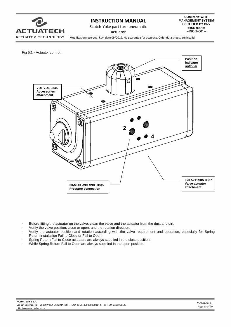
Fig 5,1 - Actuator control.
- Before fitting the actuator on the valve, clean the valve and the actuator from the dust and dirt. - Verify the valve position, close or open, and the rotation direction. - Verify the actuator position and rotation according with the valve requirement and operation, especially for Spring
Return installation Fail to Close or Fail to Open. - Spring Return Fail to Close actuators are always supplied in the close position. - While Spring Return Fail to Open are always supplied in the open position.
NAMUR -VDI /VDE 3845 Pressure connection
VDI /VDE 3845 Accessories attachment
Position indicator optional
ISO 5211/DIN 3337 Valve actuator attachment
2
4
INSTRUCTION MANUAL Scotch-Yoke part turn pneumatic
actuator
ACTUATECH S.p.A. Via san Lorenzo, 70 – 25069 VILLA CARCINA (BS) – ITALY Tel. (+39) 0308908142 Fax (+39) 0308908143 - Fax 030/xxxxxxxxxxxxx http://www.actuatech.com
MAN80515
Page 11 of 29
Modification reserved. Rev. date 09/2019. No guarantee for accuracy. Older data sheets are invalid
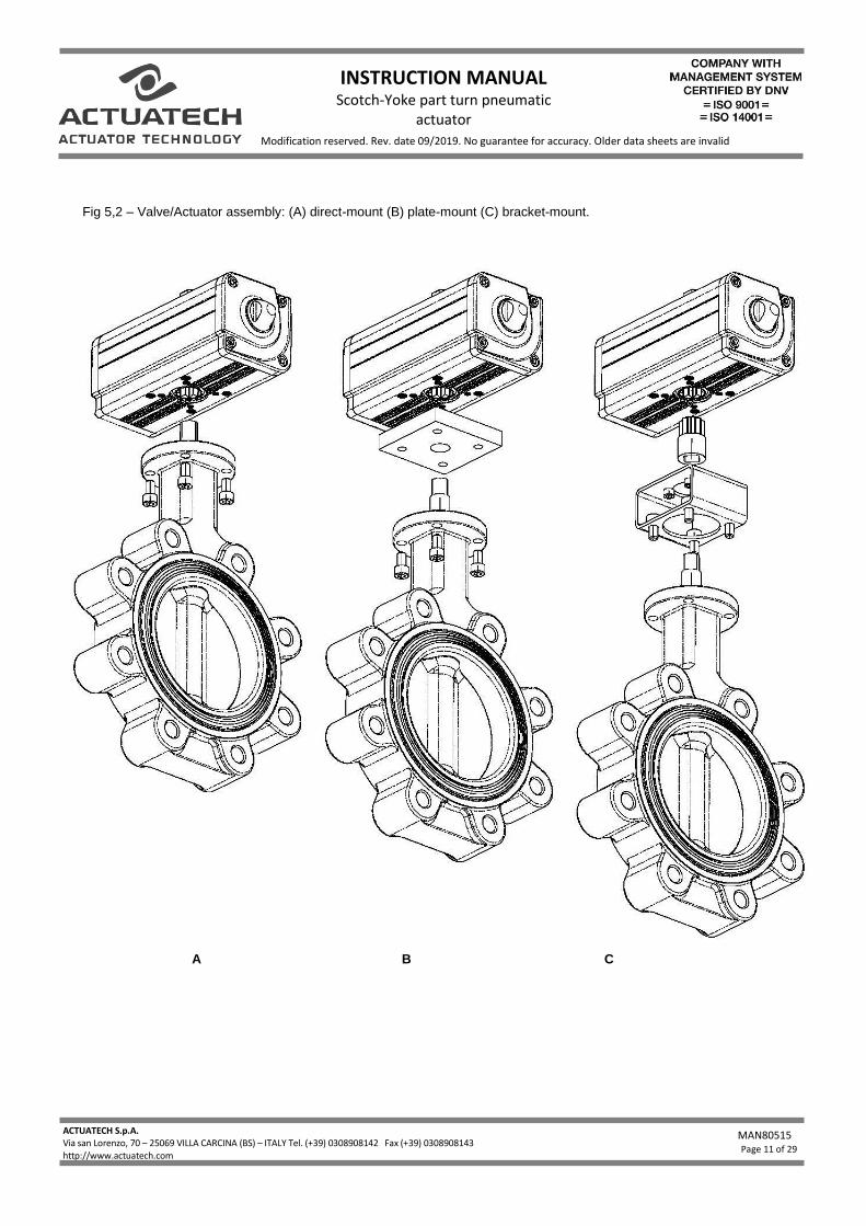
Fig 5,2 – Valve/Actuator assembly: (A) direct-mount (B) plate-mount (C) bracket-mount.
A B C
INSTRUCTION MANUAL Scotch-Yoke part turn pneumatic
actuator
ACTUATECH S.p.A. Via san Lorenzo, 70 – 25069 VILLA CARCINA (BS) – ITALY Tel. (+39) 0308908142 Fax (+39) 0308908143 - Fax 030/xxxxxxxxxxxxx http://www.actuatech.com
MAN80515
Page 12 of 29
Modification reserved. Rev. date 09/2019. No guarantee for accuracy. Older data sheets are invalid
A) Direct mounting. Valve actuator Direct mounting is the best solution to avoid plays between valve stem and actuator drive shaft. For a direct mounting you should have the same standard flange connection on valve and actuator as well as the valve stem dimensions that fit perfectly with the actuator drive. Before installation please verify that the actuator and valve flange ISO connections are the same size; verify that the valve stem size and shape is suitable for direct mounting, if necessary, use a drive reduction. Fit the valve stem into the actuator drive shaft connection, and bolt together the two ISO flanges. B) Mounting plate connection. In case direct mounting is not possible cause of little differences in actuator/valve flanges or drives sizes, mounting plates adapters with suitable flanges dimensions allows an easy connection living a sufficient space for the valve/actuator drive adapter. C) Bracket & Joint connection. Wherever for technical reason the plant installation requires a distance between actuator and valve, or the valve flange and/or stem are not standard, and in any case, where the valve/actuator connection could not be possible, a bracket and joint is the right answer. The Bracket is a steel bridge that allows to connect the valve with is own flange connection in one side and with the suitable actuator connection onto the opposite side, living a space in between for a steel joint connection. The joint allows a drive connection between the actuator and the valve stem indispensable in case of stem key drive and flat head. Chose the suitable flange bracket and the required joint connections to fix the actuator onto the valve very tight without any plays. Actuatech actuator with its draining channels system on the flange connection pattern is especially designed for valve direct mounting. This system allows to drop away any possible flow coming from the valve stem that with valve/actuator direct mounting could damage the actuator. Screw torque wrench setting
SIZE TORQUE Nm
M5 5-6
M6 10-11
M8 20-23
M10 45-50
M12 80-85
M14 125-135
M16 190-200
M20 370-390
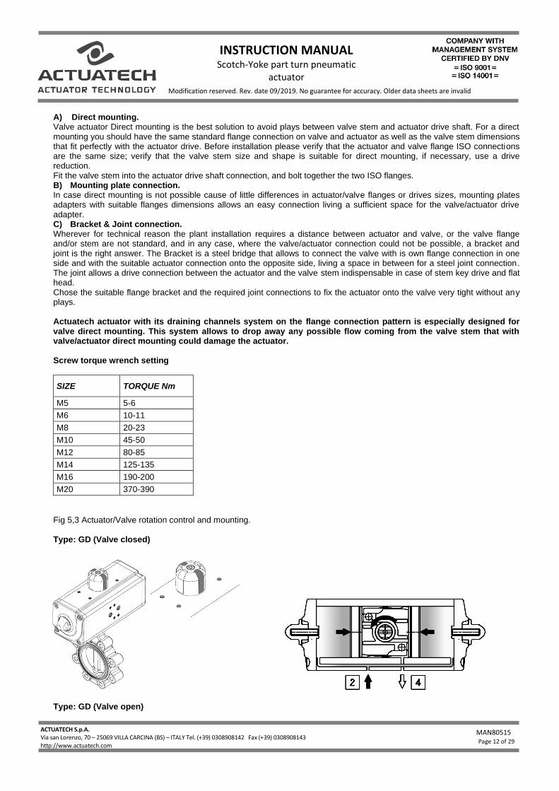
Fig 5,3 Actuator/Valve rotation control and mounting. Type: GD (Valve closed)
Type: GD (Valve open)
INSTRUCTION MANUAL Scotch-Yoke part turn pneumatic
actuator
ACTUATECH S.p.A. Via san Lorenzo, 70 – 25069 VILLA CARCINA (BS) – ITALY Tel. (+39) 0308908142 Fax (+39) 0308908143 - Fax 030/xxxxxxxxxxxxx http://www.actuatech.com
MAN80515
Page 13 of 29
Modification reserved. Rev. date 09/2019. No guarantee for accuracy. Older data sheets are invalid
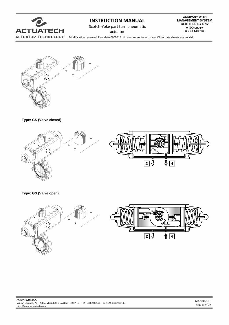
Type: GS (Valve closed)
Type: GS (Valve open)
INSTRUCTION MANUAL Scotch-Yoke part turn pneumatic
actuator
ACTUATECH S.p.A. Via san Lorenzo, 70 – 25069 VILLA CARCINA (BS) – ITALY Tel. (+39) 0308908142 Fax (+39) 0308908143 - Fax 030/xxxxxxxxxxxxx http://www.actuatech.com
MAN80515
Page 14 of 29
Modification reserved. Rev. date 09/2019. No guarantee for accuracy. Older data sheets are invalid
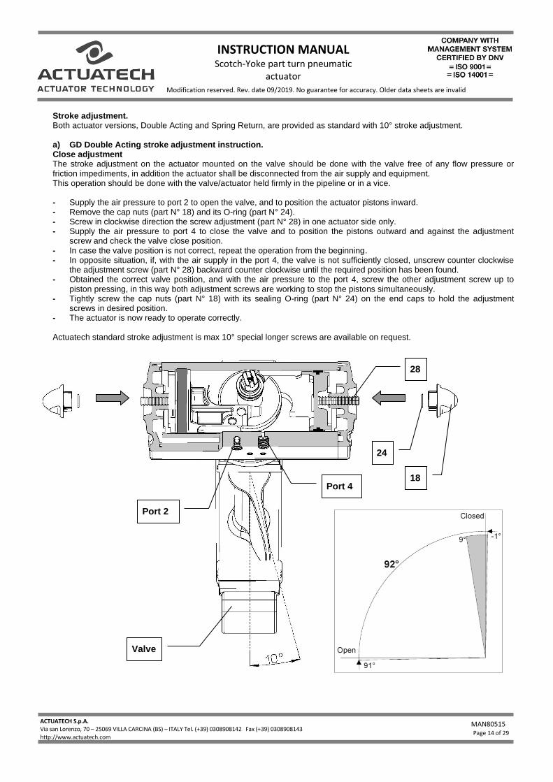
Stroke adjustment. Both actuator versions, Double Acting and Spring Return, are provided as standard with 10° stroke adjustment. a) GD Double Acting stroke adjustment instruction. Close adjustment The stroke adjustment on the actuator mounted on the valve should be done with the valve free of any flow pressure or friction impediments, in addition the actuator shall be disconnected from the air supply and equipment. This operation should be done with the valve/actuator held firmly in the pipeline or in a vice. - Supply the air pressure to port 2 to open the valve, and to position the actuator pistons inward. - Remove the cap nuts (part N° 18) and its O-ring (part N° 24). - Screw in clockwise direction the screw adjustment (part N° 28) in one actuator side only. - Supply the air pressure to port 4 to close the valve and to position the pistons outward and against the adjustment
screw and check the valve close position. - In case the valve position is not correct, repeat the operation from the beginning. - In opposite situation, if, with the air supply in the port 4, the valve is not sufficiently closed, unscrew counter clockwise
the adjustment screw (part N° 28) backward counter clockwise until the required position has been found. - Obtained the correct valve position, and with the air pressure to the port 4, screw the other adjustment screw up to
piston pressing, in this way both adjustment screws are working to stop the pistons simultaneously. - Tightly screw the cap nuts (part N° 18) with its sealing O-ring (part N° 24) on the end caps to hold the adjustment
screws in desired position. - The actuator is now ready to operate correctly. Actuatech standard stroke adjustment is max 10° special longer screws are available on request.
24
Valve
28
Port 2
Port 4 18
INSTRUCTION MANUAL Scotch-Yoke part turn pneumatic
actuator
ACTUATECH S.p.A. Via san Lorenzo, 70 – 25069 VILLA CARCINA (BS) – ITALY Tel. (+39) 0308908142 Fax (+39) 0308908143 - Fax 030/xxxxxxxxxxxxx http://www.actuatech.com
MAN80515
Page 15 of 29
Modification reserved. Rev. date 09/2019. No guarantee for accuracy. Older data sheets are invalid
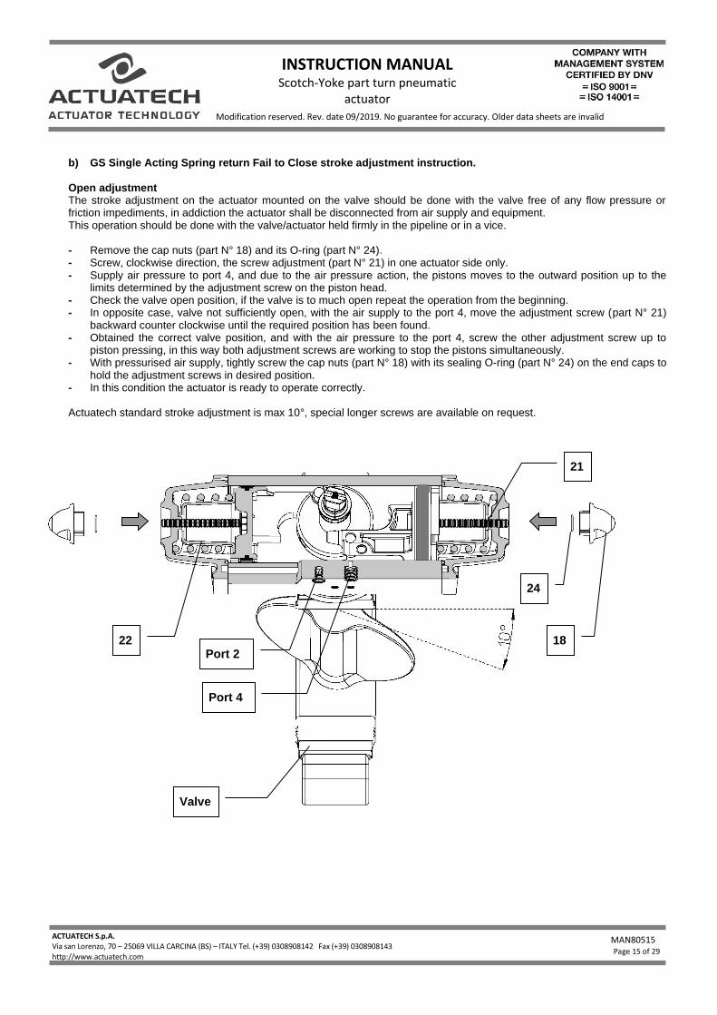
b) GS Single Acting Spring return Fail to Close stroke adjustment instruction. Open adjustment The stroke adjustment on the actuator mounted on the valve should be done with the valve free of any flow pressure or friction impediments, in addiction the actuator shall be disconnected from air supply and equipment. This operation should be done with the valve/actuator held firmly in the pipeline or in a vice. - Remove the cap nuts (part N° 18) and its O-ring (part N° 24). - Screw, clockwise direction, the screw adjustment (part N° 21) in one actuator side only. - Supply air pressure to port 4, and due to the air pressure action, the pistons moves to the outward position up to the
limits determined by the adjustment screw on the piston head. - Check the valve open position, if the valve is to much open repeat the operation from the beginning. - In opposite case, valve not sufficiently open, with the air supply to the port 4, move the adjustment screw (part N° 21)
backward counter clockwise until the required position has been found. - Obtained the correct valve position, and with the air pressure to the port 4, screw the other adjustment screw up to
piston pressing, in this way both adjustment screws are working to stop the pistons simultaneously. - With pressurised air supply, tightly screw the cap nuts (part N° 18) with its sealing O-ring (part N° 24) on the end caps to
hold the adjustment screws in desired position. - In this condition the actuator is ready to operate correctly. Actuatech standard stroke adjustment is max 10°, special longer screws are available on request.
18
24
Valve
21
Port 2
Port 4
22
INSTRUCTION MANUAL Scotch-Yoke part turn pneumatic
actuator
ACTUATECH S.p.A. Via san Lorenzo, 70 – 25069 VILLA CARCINA (BS) – ITALY Tel. (+39) 0308908142 Fax (+39) 0308908143 - Fax 030/xxxxxxxxxxxxx http://www.actuatech.com
MAN80515
Page 16 of 29
Modification reserved. Rev. date 09/2019. No guarantee for accuracy. Older data sheets are invalid
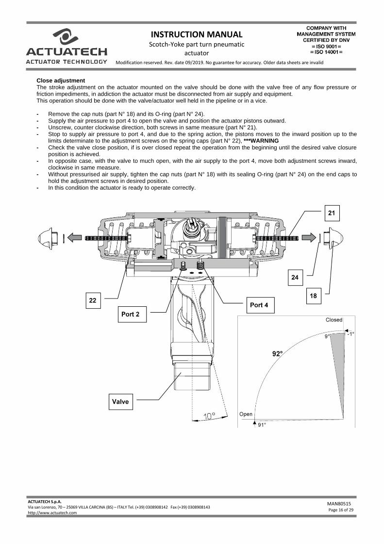
Close adjustment The stroke adjustment on the actuator mounted on the valve should be done with the valve free of any flow pressure or friction impediments, in addiction the actuator must be disconnected from air supply and equipment. This operation should be done with the valve/actuator well held in the pipeline or in a vice. - Remove the cap nuts (part N° 18) and its O-ring (part N° 24). - Supply the air pressure to port 4 to open the valve and position the actuator pistons outward. - Unscrew, counter clockwise direction, both screws in same measure (part N° 21). - Stop to supply air pressure to port 4, and due to the spring action, the pistons moves to the inward position up to the
limits determinate to the adjustment screws on the spring caps (part N° 22), ***WARNING - Check the valve close position, if is over closed repeat the operation from the beginning until the desired valve closure
position is achieved. - In opposite case, with the valve to much open, with the air supply to the port 4, move both adjustment screws inward,
clockwise in same measure. - Without pressurised air supply, tighten the cap nuts (part N° 18) with its sealing O-ring (part N° 24) on the end caps to
hold the adjustment screws in desired position. - In this condition the actuator is ready to operate correctly.
INSTRUCTION MANUAL Scotch-Yoke part turn pneumatic
actuator
ACTUATECH S.p.A. Via san Lorenzo, 70 – 25069 VILLA CARCINA (BS) – ITALY Tel. (+39) 0308908142 Fax (+39) 0308908143 - Fax 030/xxxxxxxxxxxxx http://www.actuatech.com
MAN80515
Page 17 of 29
Modification reserved. Rev. date 09/2019. No guarantee for accuracy. Older data sheets are invalid
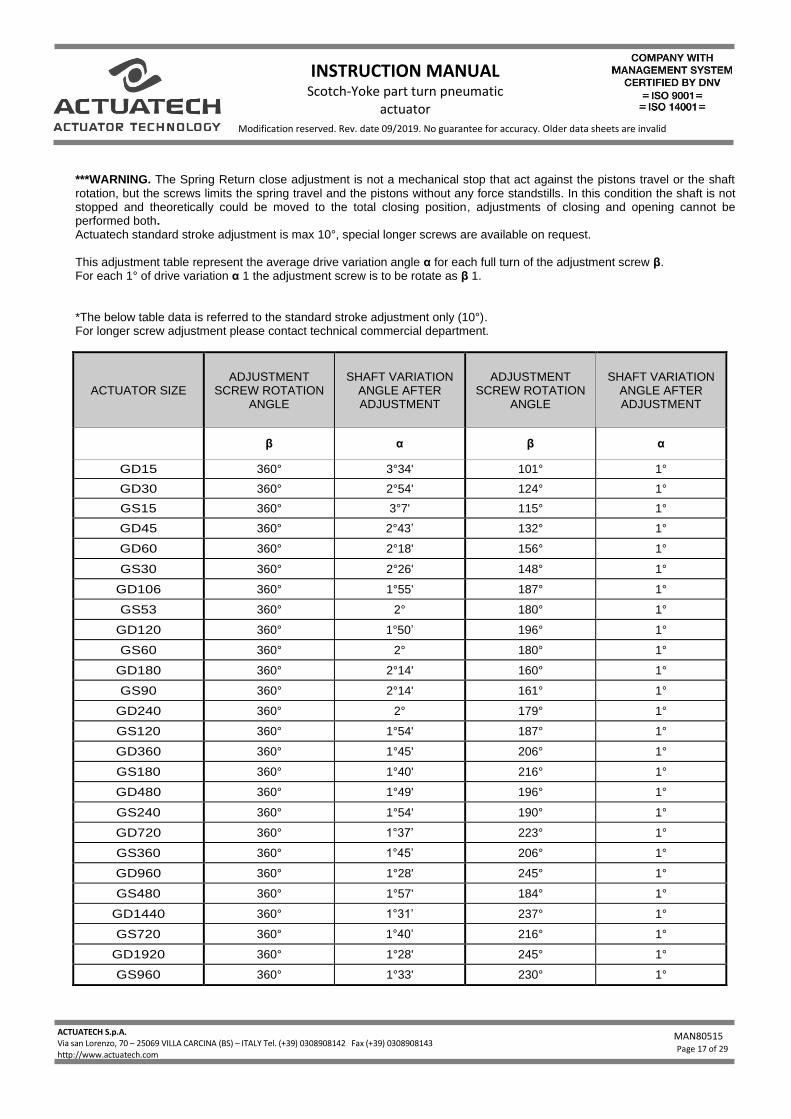
***WARNING. The Spring Return close adjustment is not a mechanical stop that act against the pistons travel or the shaft rotation, but the screws limits the spring travel and the pistons without any force standstills. In this condition the shaft is not stopped and theoretically could be moved to the total closing position, adjustments of closing and opening cannot be performed both. Actuatech standard stroke adjustment is max 10°, special longer screws are available on request. This adjustment table represent the average drive variation angle α for each full turn of the adjustment screw β. For each 1° of drive variation α 1 the adjustment screw is to be rotate as β 1. *The below table data is referred to the standard stroke adjustment only (10°). For longer screw adjustment please contact technical commercial department.
ACTUATOR SIZE ADJUSTMENT
SCREW ROTATION ANGLE
SHAFT VARIATION ANGLE AFTER ADJUSTMENT
ADJUSTMENT SCREW ROTATION
ANGLE
SHAFT VARIATION ANGLE AFTER ADJUSTMENT
β α β α
GD15 360° 3°34' 101° 1°
GD30 360° 2°54' 124° 1°
GS15 360° 3°7' 115° 1°
GD45 360° 2°43’ 132° 1°
GD60 360° 2°18' 156° 1°
GS30 360° 2°26' 148° 1°
GD106 360° 1°55' 187° 1°
GS53 360° 2° 180° 1°
GD120 360° 1°50’ 196° 1°
GS60 360° 2° 180° 1°
GD180 360° 2°14' 160° 1°
GS90 360° 2°14' 161° 1°
GD240 360° 2° 179° 1°
GS120 360° 1°54' 187° 1°
GD360 360° 1°45' 206° 1°
GS180 360° 1°40' 216° 1°
GD480 360° 1°49' 196° 1°
GS240 360° 1°54' 190° 1°
GD720 360° 1°37’ 223° 1°
GS360 360° 1°45’ 206° 1°
GD960 360° 1°28' 245° 1°
GS480 360° 1°57' 184° 1°
GD1440 360° 1°31’ 237° 1°
GS720 360° 1°40’ 216° 1°
GD1920 360° 1°28' 245° 1°
GS960 360° 1°33' 230° 1°
INSTRUCTION MANUAL Scotch-Yoke part turn pneumatic
actuator
ACTUATECH S.p.A. Via san Lorenzo, 70 – 25069 VILLA CARCINA (BS) – ITALY Tel. (+39) 0308908142 Fax (+39) 0308908143 - Fax 030/xxxxxxxxxxxxx http://www.actuatech.com
MAN80515
Page 18 of 29
Modification reserved. Rev. date 09/2019. No guarantee for accuracy. Older data sheets are invalid
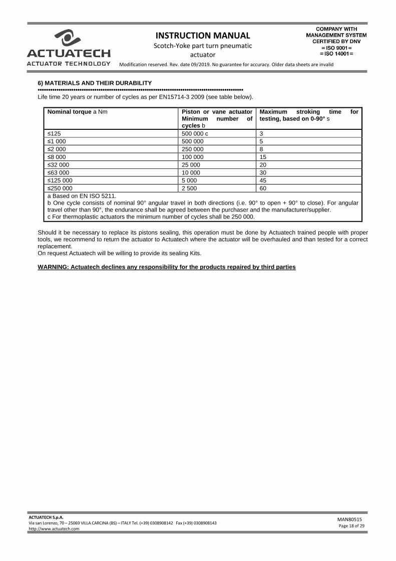
6) MATERIALS AND THEIR DURABILITY •••••••••••••••••••••••••••••••••••••••••••••••••••••••••••••••••••••••••••••••••••••••••••••••••• Life time 20 years or number of cycles as per EN15714-3 2009 (see table below).
Nominal torque a Nm Piston or vane actuator Minimum number of cycles b
Maximum stroking time for testing, based on 0-90° s
≤125 500 000 c 3
≤1 000 500 000 5
≤2 000 250 000 8
≤8 000 100 000 15
≤32 000 25 000 20
≤63 000 10 000 30
≤125 000 5 000 45
≤250 000 2 500 60
a Based on EN ISO 5211. b One cycle consists of nominal 90° angular travel in both directions (i.e. 90° to open + 90° to close). For angular travel other than 90°, the endurance shall be agreed between the purchaser and the manufacturer/supplier. c For thermoplastic actuators the minimum number of cycles shall be 250 000.
Should it be necessary to replace its pistons sealing, this operation must be done by Actuatech trained people with proper tools, we recommend to return the actuator to Actuatech where the actuator will be overhauled and than tested for a correct replacement. On request Actuatech will be willing to provide its sealing Kits. WARNING: Actuatech declines any responsibility for the products repaired by third parties
INSTRUCTION MANUAL Scotch-Yoke part turn pneumatic
actuator
ACTUATECH S.p.A. Via san Lorenzo, 70 – 25069 VILLA CARCINA (BS) – ITALY Tel. (+39) 0308908142 Fax (+39) 0308908143 - Fax 030/xxxxxxxxxxxxx http://www.actuatech.com
MAN80515
Page 19 of 29
Modification reserved. Rev. date 09/2019. No guarantee for accuracy. Older data sheets are invalid
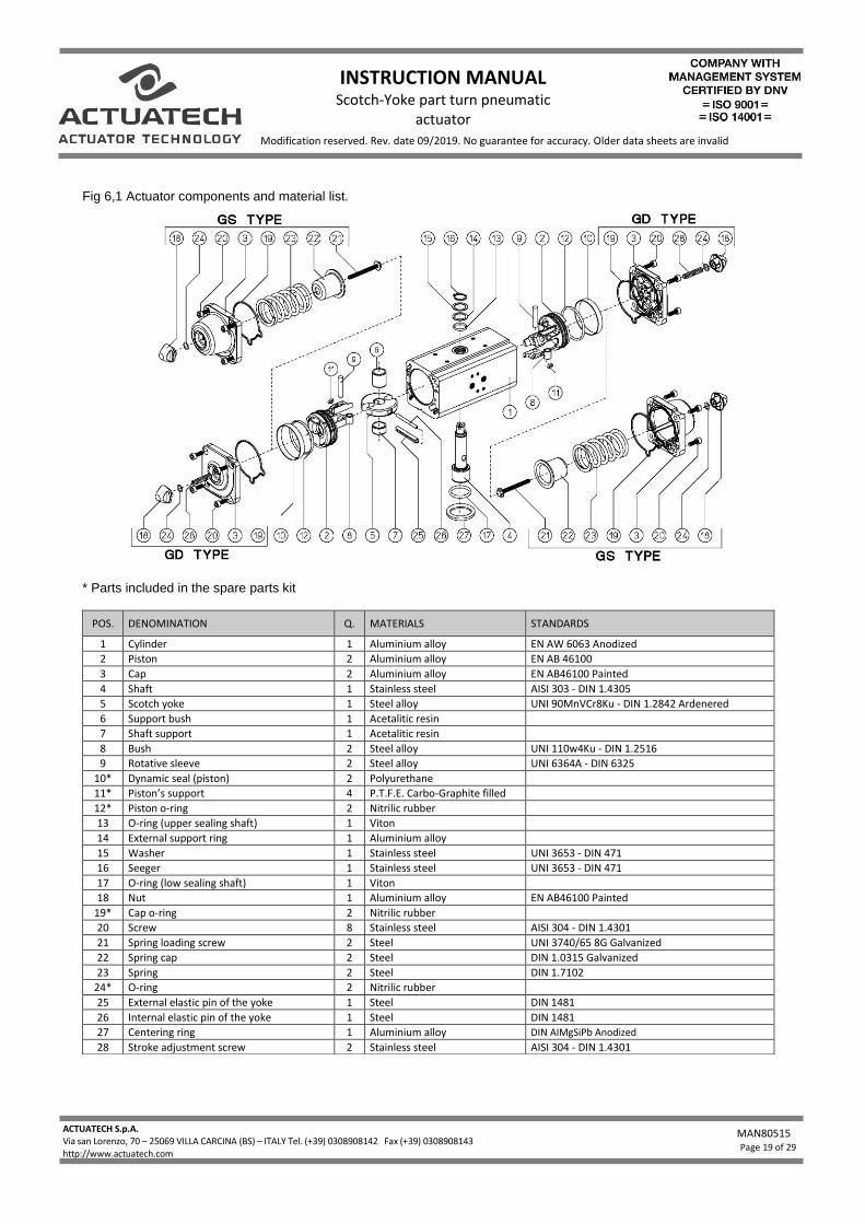
Fig 6,1 Actuator components and material list.
* Parts included in the spare parts kit
POS. DENOMINATION Q. MATERIALS STANDARDS
1 Cylinder 1 Aluminium alloy EN AW 6063 Anodized
2 Piston 2 Aluminium alloy EN AB 46100
3 Cap 2 Aluminium alloy EN AB46100 Painted
4 Shaft 1 Stainless steel AISI 303 - DIN 1.4305
5 Scotch yoke 1 Steel alloy UNI 90MnVCr8Ku - DIN 1.2842 Ardenered
6 Support bush 1 Acetalitic resin
7 Shaft support 1 Acetalitic resin
8 Bush 2 Steel alloy UNI 110w4Ku - DIN 1.2516
9 Rotative sleeve 2 Steel alloy UNI 6364A - DIN 6325
10* Dynamic seal (piston) 2 Polyurethane
11* Piston’s support 4 P.T.F.E. Carbo-Graphite filled
12* Piston o-ring 2 Nitrilic rubber
13 O-ring (upper sealing shaft) 1 Viton
14 External support ring 1 Aluminium alloy
15 Washer 1 Stainless steel UNI 3653 - DIN 471
16 Seeger 1 Stainless steel UNI 3653 - DIN 471
17 O-ring (low sealing shaft) 1 Viton
18 Nut 1 Aluminium alloy EN AB46100 Painted
19* Cap o-ring 2 Nitrilic rubber
20 Screw 8 Stainless steel AISI 304 - DIN 1.4301
21 Spring loading screw 2 Steel UNI 3740/65 8G Galvanized
22 Spring cap 2 Steel DIN 1.0315 Galvanized
23 Spring 2 Steel DIN 1.7102
24* O-ring 2 Nitrilic rubber
25 External elastic pin of the yoke 1 Steel DIN 1481
26 Internal elastic pin of the yoke 1 Steel DIN 1481
27 Centering ring 1 Aluminium alloy DIN AIMgSiPb Anodized
28 Stroke adjustment screw 2 Stainless steel AISI 304 - DIN 1.4301
INSTRUCTION MANUAL Scotch-Yoke part turn pneumatic
actuator
ACTUATECH S.p.A. Via san Lorenzo, 70 – 25069 VILLA CARCINA (BS) – ITALY Tel. (+39) 0308908142 Fax (+39) 0308908143 - Fax 030/xxxxxxxxxxxxx http://www.actuatech.com
MAN80515
Page 20 of 29
Modification reserved. Rev. date 09/2019. No guarantee for accuracy. Older data sheets are invalid
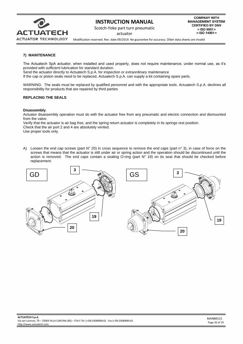
7) MAINTENANCE The Actuatech SpA actuator, when installed and used properly, does not require maintenance, under normal use, as it’s provided with sufficient lubrication for standard duration. Send the actuator directly to Actuatech S.p.A. for inspection or extraordinary maintenance If the cap or piston seals need to be replaced, Actuatech S.p.A. can supply a kit containing spare parts. WARNING: The seals must be replaced by qualified personnel and with the appropriate tools. Actuatech S.p.A. declines all responsibility for products that are repaired by third parties REPLACING THE SEALS Disassembly. Actuator disassembly operation must do with the actuator free from any pneumatic and electric connection and dismounted from the valve. Verify that the actuator is air bag free, and the spring return actuator is completely in its springs rest position. Check that the air port 2 and 4 are absolutely vented. Use proper tools only. A) Loosen the end cap screws (part N° 20) in cross sequence to remove the end caps (part n° 3), in case of force on the
screws that means that the actuator is still under air or spring action and the operation should be discontinued until the action is removed. The end caps contain a sealing O-ring (part N° 19) on its seat that should be checked before replacement.
GS GD
20
3
19
20
3
19
INSTRUCTION MANUAL Scotch-Yoke part turn pneumatic
actuator
ACTUATECH S.p.A. Via san Lorenzo, 70 – 25069 VILLA CARCINA (BS) – ITALY Tel. (+39) 0308908142 Fax (+39) 0308908143 - Fax 030/xxxxxxxxxxxxx http://www.actuatech.com
MAN80515
Page 21 of 29
Modification reserved. Rev. date 09/2019. No guarantee for accuracy. Older data sheets are invalid
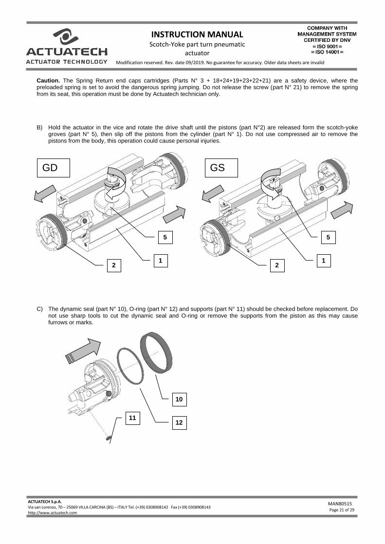
Caution. The Spring Return end caps cartridges (Parts N° 3 + 18+24+19+23+22+21) are a safety device, where the preloaded spring is set to avoid the dangerous spring jumping. Do not release the screw (part N° 21) to remove the spring from its seat, this operation must be done by Actuatech technician only. B) Hold the actuator in the vice and rotate the drive shaft until the pistons (part N°2) are released form the scotch-yoke
groves (part N° 5), then slip off the pistons from the cylinder (part N° 1). Do not use compressed air to remove the pistons from the body, this operation could cause personal injuries.
C) The dynamic seal (part N° 10), O-ring (part N° 12) and supports (part N° 11) should be checked before replacement. Do
not use sharp tools to cut the dynamic seal and O-ring or remove the supports from the piston as this may cause furrows or marks.
2
GD GS
2
5 5
1 1
10
12 11
INSTRUCTION MANUAL Scotch-Yoke part turn pneumatic
actuator
ACTUATECH S.p.A. Via san Lorenzo, 70 – 25069 VILLA CARCINA (BS) – ITALY Tel. (+39) 0308908142 Fax (+39) 0308908143 - Fax 030/xxxxxxxxxxxxx http://www.actuatech.com
MAN80515
Page 22 of 29
Modification reserved. Rev. date 09/2019. No guarantee for accuracy. Older data sheets are invalid
D) When the components are disassembled, they should be properly cleaned, and wear checked prior to being greased
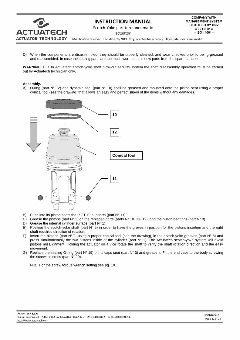
and reassembled. In case the sealing parts are too much worn out use new parts from the spare parts kit. WARNING. Due to Actuatech scotch-yoke shaft blow-out security system the shaft disassembly operation must be carried out by Actuatech technician only. Assembly. A) O-ring (part N° 12) and dynamic seal (part N° 10) shall be greased and mounted onto the piston seat using a proper
conical tool (see the drawing) that allows an easy and perfect slip-in of the items without any damages.
B) Push into its piston seats the P.T.F.E. supports (part N° 11). C) Grease the pistons (part N° 2) on the replaced parts (parts N° 10+11+12), and the piston bearings (part N° 8). D) Grease the internal cylinder surface (part N° 1). E) Position the scotch-yoke shaft (part N° 5) in order to have the groves in position for the pistons insertion and the right
shaft required direction of rotation. F) Insert the pistons (part N°2), using a proper conical tool (see the drawing), in the scotch-yoke grooves (part N° 5) and
press simultaneously the two pistons inside of the cylinder (part N° 1). The Actuatech scotch-yoke system will avoid pistons misalignment. Holding the actuator on a vice rotate the shaft to verify the shaft rotation direction and the easy movement.
G) Replace the sealing O-ring (part N° 19) on its caps seat (part N° 3) and grease it. Fit the end caps to the body screwing the screws in cross (part N° 20). N.B. For the screw torque wrench setting see pg. 10.
10
12
11
Conical tool
INSTRUCTION MANUAL Scotch-Yoke part turn pneumatic
actuator
ACTUATECH S.p.A. Via san Lorenzo, 70 – 25069 VILLA CARCINA (BS) – ITALY Tel. (+39) 0308908142 Fax (+39) 0308908143 - Fax 030/xxxxxxxxxxxxx http://www.actuatech.com
MAN80515
Page 23 of 29
Modification reserved. Rev. date 09/2019. No guarantee for accuracy. Older data sheets are invalid
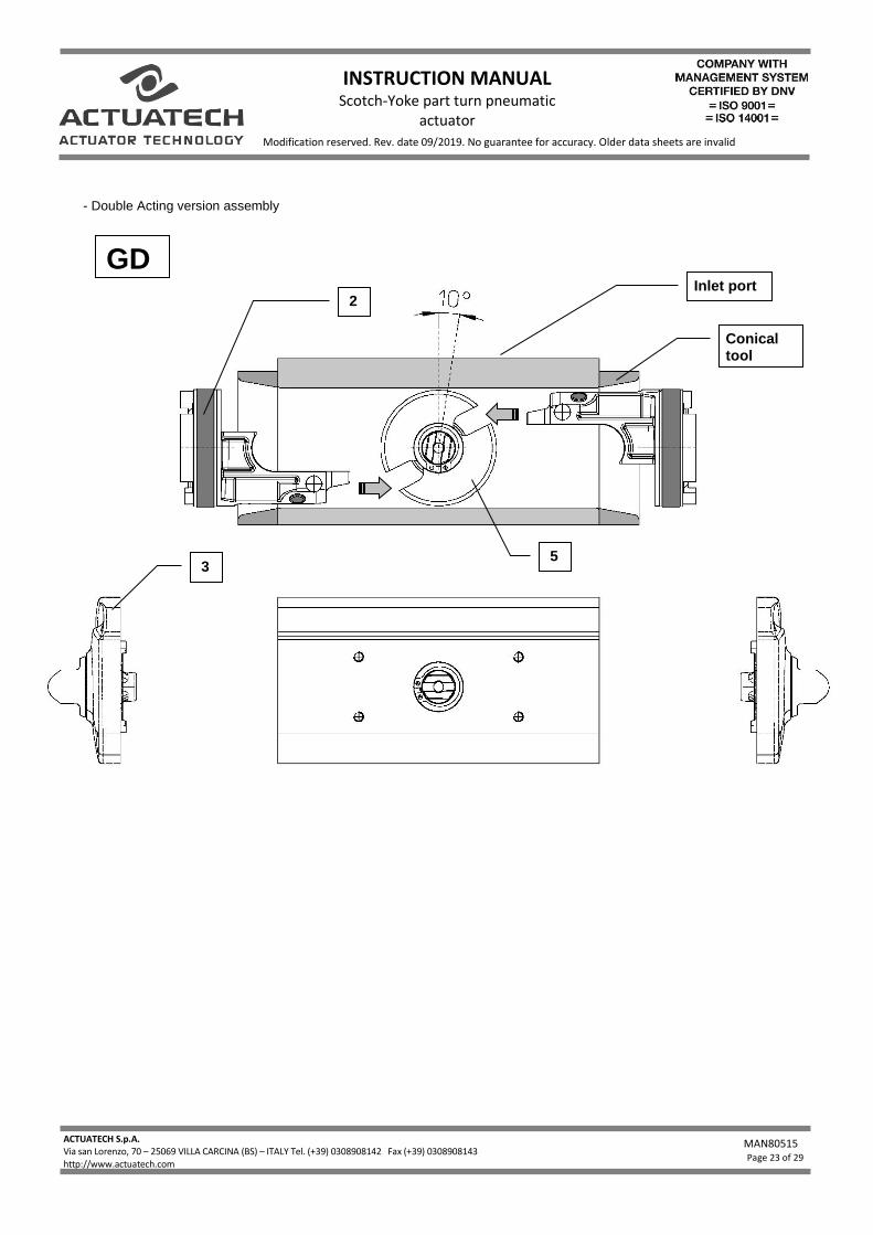
- Double Acting version assembly
GD Inlet port
2
5
Conical tool tool
3
INSTRUCTION MANUAL Scotch-Yoke part turn pneumatic
actuator
ACTUATECH S.p.A. Via san Lorenzo, 70 – 25069 VILLA CARCINA (BS) – ITALY Tel. (+39) 0308908142 Fax (+39) 0308908143 - Fax 030/xxxxxxxxxxxxx http://www.actuatech.com
MAN80515
Page 24 of 29
Modification reserved. Rev. date 09/2019. No guarantee for accuracy. Older data sheets are invalid
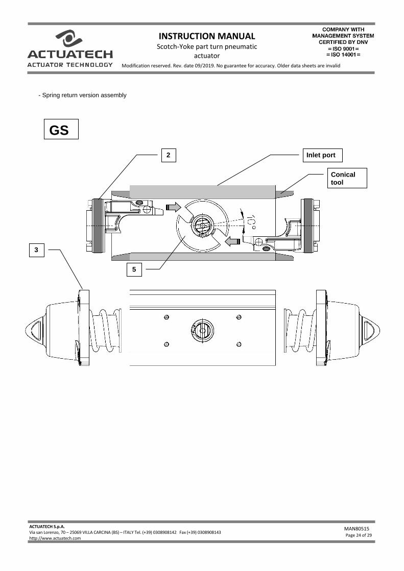
- Spring return version assembly
GS
Inlet port 2
5
3
Conical tool tool
INSTRUCTION MANUAL Scotch-Yoke part turn pneumatic
actuator
ACTUATECH S.p.A. Via san Lorenzo, 70 – 25069 VILLA CARCINA (BS) – ITALY Tel. (+39) 0308908142 Fax (+39) 0308908143 - Fax 030/xxxxxxxxxxxxx http://www.actuatech.com
MAN80515
Page 25 of 29
Modification reserved. Rev. date 09/2019. No guarantee for accuracy. Older data sheets are invalid
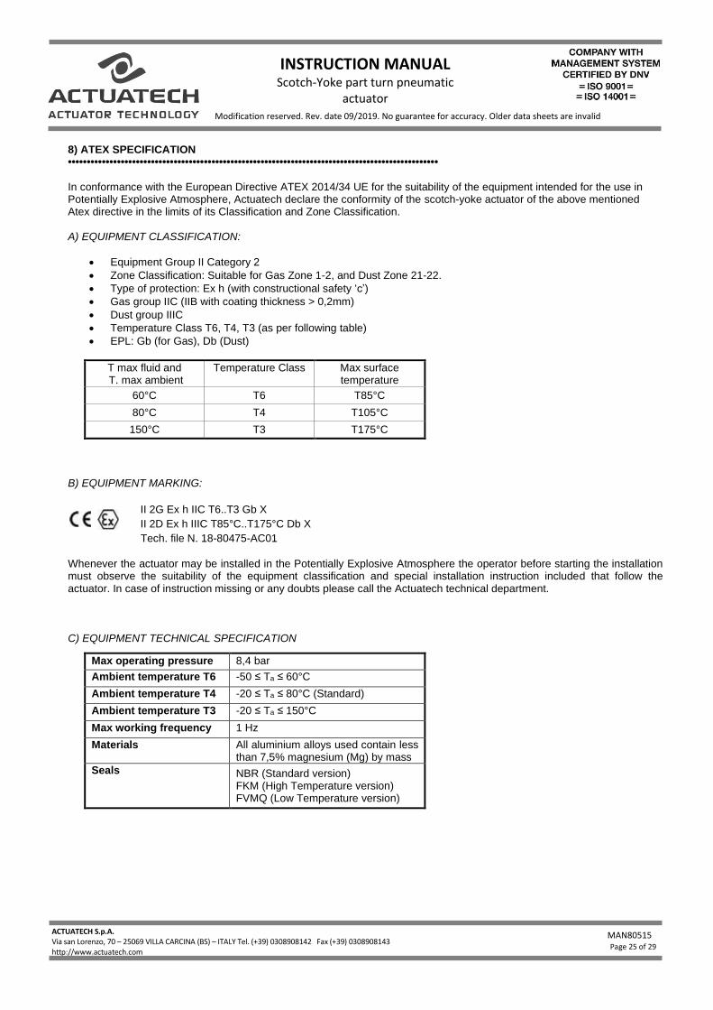
8) ATEX SPECIFICATION •••••••••••••••••••••••••••••••••••••••••••••••••••••••••••••••••••••••••••••••••••••••••••••••••• In conformance with the European Directive ATEX 2014/34 UE for the suitability of the equipment intended for the use in Potentially Explosive Atmosphere, Actuatech declare the conformity of the scotch-yoke actuator of the above mentioned Atex directive in the limits of its Classification and Zone Classification. A) EQUIPMENT CLASSIFICATION:
• Equipment Group II Category 2
• Zone Classification: Suitable for Gas Zone 1-2, and Dust Zone 21-22.
• Type of protection: Ex h (with constructional safety ‘c’)
• Gas group IIC (IIB with coating thickness > 0,2mm)
• Dust group IIIC
• Temperature Class T6, T4, T3 (as per following table)
• EPL: Gb (for Gas), Db (Dust)
T max fluid and T. max ambient
Temperature Class Max surface temperature
60°C T6 T85°C
80°C T4 T105°C
150°C T3 T175°C
B) EQUIPMENT MARKING:
II 2G Ex h IIC T6..T3 Gb X
II 2D Ex h IIIC T85°C..T175°C Db X
Tech. file N. 18-80475-AC01
Whenever the actuator may be installed in the Potentially Explosive Atmosphere the operator before starting the installation must observe the suitability of the equipment classification and special installation instruction included that follow the actuator. In case of instruction missing or any doubts please call the Actuatech technical department. C) EQUIPMENT TECHNICAL SPECIFICATION
Max operating pressure 8,4 bar
Ambient temperature T6 -50 ≤ Ta ≤ 60°C
Ambient temperature T4 -20 ≤ Ta ≤ 80°C (Standard)
Ambient temperature T3 -20 ≤ Ta ≤ 150°C
Max working frequency 1 Hz
Materials All aluminium alloys used contain less than 7,5% magnesium (Mg) by mass
Seals NBR (Standard version) FKM (High Temperature version) FVMQ (Low Temperature version)
INSTRUCTION MANUAL Scotch-Yoke part turn pneumatic
actuator
ACTUATECH S.p.A. Via san Lorenzo, 70 – 25069 VILLA CARCINA (BS) – ITALY Tel. (+39) 0308908142 Fax (+39) 0308908143 - Fax 030/xxxxxxxxxxxxx http://www.actuatech.com
MAN80515
Page 26 of 29
Modification reserved. Rev. date 09/2019. No guarantee for accuracy. Older data sheets are invalid
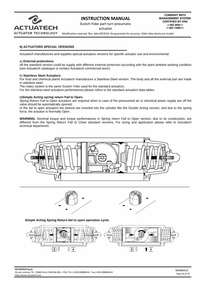
9) ACTUATORS SPECIAL VERSIONS •••••••••••••••••••••••••••••••••••••••••••••••••••••••••••••••••••••••••••••••••••••••••••••••••• Actuatech manufactures and supplies special actuators versions for specific actuator use and environmental. a) External protections. All the standard version could be supply with different external protection according with the plant ambient working condition (see Actuatech catalogue or contact Actuatech commercial team). b) Stainless Steel Actuators For food and chemical plants Actuatech manufacture a Stainless-Steel version. The body and all the external part are made in stainless steel. The rotary system is the same Scotch-Yoke used for the standard actuators. For the stainless-steel actuators performances please refers to the standard actuators data tables. c)Simple Acting spring return Fail to Open. Spring Return Fail to Open actuators are required when in case of the pressurised air or electrical power supply are off the valve should be automatically opened. In the fail to open actuators the pistons are inserted into the cylinder like the Double Acting version, and due to the spring force, the actuator is Normally Open. WARNING. Nominal torque and torque performances in Spring return Fail to Open version, due to its construction, are different from the Spring Return Fail to Close standard versions. For sizing and application please refer to Actuatech technical department.
Simple Acting Spring Return fail to open operation cycle.
INSTRUCTION MANUAL Scotch-Yoke part turn pneumatic
actuator
ACTUATECH S.p.A. Via san Lorenzo, 70 – 25069 VILLA CARCINA (BS) – ITALY Tel. (+39) 0308908142 Fax (+39) 0308908143 - Fax 030/xxxxxxxxxxxxx http://www.actuatech.com
MAN80515
Page 27 of 29
Modification reserved. Rev. date 09/2019. No guarantee for accuracy. Older data sheets are invalid
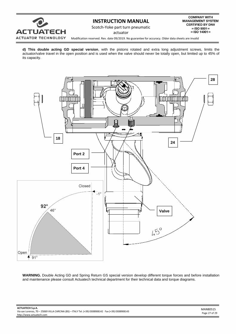
d) This double acting GD special version, with the pistons rotated and extra long adjustment screws, limits the actuator/valve travel in the open position and is used when the valve should never be totally open, but limited up to 45% of its capacity.
WARNING. Double Acting GD and Spring Return GS special version develop different torque forces and before installation and maintenance please consult Actuatech technical department for their technical data and torque diagrams.
Valve
28
Port 2
Port 4
24 18
INSTRUCTION MANUAL Scotch-Yoke part turn pneumatic
actuator
ACTUATECH S.p.A. Via san Lorenzo, 70 – 25069 VILLA CARCINA (BS) – ITALY Tel. (+39) 0308908142 Fax (+39) 0308908143 - Fax 030/xxxxxxxxxxxxx http://www.actuatech.com
MAN80515
Page 28 of 29
Modification reserved. Rev. date 09/2019. No guarantee for accuracy. Older data sheets are invalid
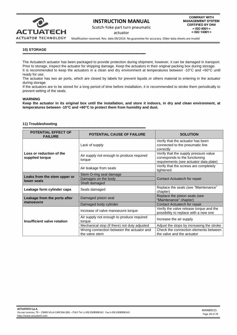
10) STORAGE •••••••••••••••••••••••••••••••••••••••••••••••••••••••••••••••••••••••••••••••••••••••••••••••••• The Actuatech actuator has been packaged to provide protection during shipment, however, it can be damaged in transport. Prior to storage, inspect the actuator for shipping damage. Keep the actuators in their original packing box during storage. It is recommended to keep the actuators in a clean and dry environment at temperatures between -10°C and +60°C until ready for use. The actuator has two air ports, which are closed by labels for prevent liquids or others material to entering in the actuator during storage. If the actuators are to be stored for a long period of time before installation, it is recommended to stroke them periodically to prevent setting of the seals. WARNING Keep the actuator in its original box until the installation, and store it indoors, in dry and clean environment, at temperatures between -10°C and +60°C to protect them from humidity and dust. 11) Troubleshooting ••••••••••••••••••••••••••••••••••••••••••••••••••••••••••••••••••••••••••••••••••••••••••••••••••
POTENTIAL EFFECT OF FAILURE
POTENTIAL CAUSE OF FAILURE SOLUTION
Loss or reduction of the supplied torque
Lack of supply Verify that the actuator has been connected to the pneumatic line correctly
Air supply not enough to produce required torque
Verify that the supply pressure value corresponds to the functioning requirements (see actuator data plate)
Air leakage from seals Verify that the screws are completely tightened
Leaks from the stem upper or lower seals
Stem O-ring seal damage
Contact Actuatech for repair Damages on the body
Shaft damaged
Leakage form cylinder caps Seals damaged Replace the seals (see “Maintenance” chapter)
Leakage from the ports after manoeuvre
Damaged piston seal Replace the piston seals (see “Maintenance” chapter)
Damaged body cylinder Contact Actuatech for repair
Insufficient valve rotation
Increase of valve manoeuvre torque Verify the valve release torque and the possibility to replace with a new one
Air supply not enough to produce required torque
Increase the air supply
Mechanical stop (if there) not duty adjusted Adjust the stops by increasing the stroke
Wrong connection between the actuator and the valve stem
Check the connection elements between the valve and the actuator
INSTRUCTION MANUAL Scotch-Yoke part turn pneumatic
actuator
ACTUATECH S.p.A. Via san Lorenzo, 70 – 25069 VILLA CARCINA (BS) – ITALY Tel. (+39) 0308908142 Fax (+39) 0308908143 - Fax 030/xxxxxxxxxxxxx http://www.actuatech.com
MAN80515
Page 29 of 29
Modification reserved. Rev. date 09/2019. No guarantee for accuracy. Older data sheets are invalid
12) DISPOSAL OF PRODUCTS AT THE END OF THEIR LIFE CYCLE
•••••••••••••••••••••••••••••••••••••••••••••••••••••••••••••••••••••••••••••••••••••••••••••••••• The Actuatech products are designed so that when they are at the end of their life cycle they can be completely
disassembled, separating the different materials for the proper disposal and/or recovery. All materials have been selected in
order to ensure minimal environmental impact, health and safety of personnel during their installation and maintenance,
provided that, during use, they are not contaminated by hazardous substances.
The personnel in charge of the product disposal/recovery, must be qualified and equipped with appropriate personal
protective equipment (PPE), according to the product size and the type of service for which the device was intended. The
management of waste generated during the installation, maintenance or due to the product disposal, is governed by the
rules in force in the country where the product is installed, in any case, the following are general guidelines:
- The metal components (aluminium/steel) can be restored as raw material;
- Seals/sealing elements (NBR, FPM, FVMQ...), as contaminated by fluids from other materials and lubrication, must be
disposed of.
- The packaging materials that come with the product, should be transferred to the differentiated collection system available
in the country.
13) DECLARATION OF CONFORMITY
••••••••••••••••••••••••••••••••••••••••••••••••••••••••••••••••••••••••••••••••••••••••••••••••••
The Actuatech S.p.A. actuators have been designed, manufactured and tested to meet the requirements of the following
European standards and are marked, where provided, with the relative CE conformity marking:
- 2006/42/EC Directive “Machinery”;
- 2014/34/EU Directive “Equipment and protective systems intended for use in potentially explosive atmospheres” (ATEX).
- Regulation (EC) No 1907/2006 and successive concerning the Registration, Evaluation, Authorization and Restriction
of Chemicals (REACH).


