Embed Size (px)
Citation preview
PSoC® Creator™ Component Datasheet
Cypress Semiconductor Corporation • 198 Champion Court • San Jose, CA 95134-1709 • 408-943-2600Document Number: 001-68645 Rev. *A Revised November 1, 2011
Features 2 to 768 pixels or symbols
1/3, 1/4 and 1/5 bias supported
10- to 150-Hz refresh rate
Integrated bias generation between 2.0 V and 5.2 V with up to 128 digitally controlled biaslevels for dynamic contrast control
Supports both type A (standard) and type B (low power) waveforms
Pixel state of the display may be inverted for negative image
256 bytes of display memory (frame buffer)
User-defined pixel or symbol map with optional 7-, 14-, or 16-segment character; 5x7 or 5x8dot matrix; and bar graph calculation routines.
Supports PSoC 3 ES3 silicon revisions and above
General DescriptionThe Segment LCD (LCD_Seg) component can directly drive a variety of LCD glass at differentvoltage levels with multiplex ratios up to 16x. This component provides an easy method ofconfiguring the PSoC device to drive your custom or standard glass.Internal bias generation eliminates the need for any external hardware and allows for software-based contrast adjustment. Using the Boost Converter, the glass bias may be at a higher voltagethan the PSoC supply voltage. This allows increased display flexibility in portable applications.Each LCD pixel/symbol may be either on or off. The Segment LCD component also providesadvanced support to simplify the following types of display structures within the glass:
7-segment numerals
14-segment alphanumeric
16-segment alphanumeric
Segment LCD (LCD_Seg)3.0
Segment LCD (LCD_Seg) PSoC® Creator™ Component Datasheet
Page 2 of 34 Document Number: 001-68645 Rev. *A
5x7 and 5x8 dot matrix alphanumeric (Use the same look-up table on the 5x7 and 5x8. Allsymbols in the look-up table are the size of 5x7 pixels.)
1- to 255-element bar graphsFor more information about using the Segment LCD component, refer to the application noteAN52927: PSoC® 3: Segment LCD Direct Drive Basics.
When to Use a Segment LCDUse the Direct Segment Drive LCD component when you need to directly drive a variety of LCDglass at different voltage levels with multiplex ratios up to 16x. The Direct Segment Drive LCDcomponent requires that the target PSoC device support LCD direct drive.
Input/Output ConnectionsThere are no visible connections for the component on the schematic canvas; however, thevarious signals can be connected to pins using the Design-Wide Resources Pin Editor.
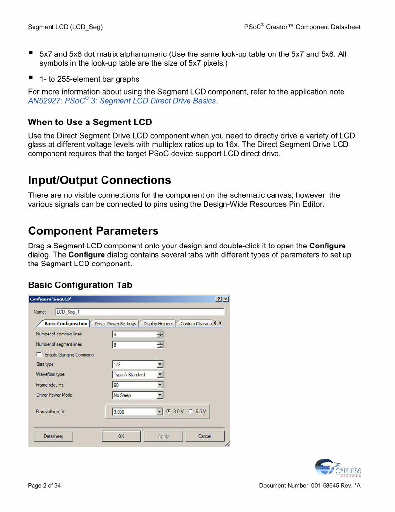
Component ParametersDrag a Segment LCD component onto your design and double-click it to open the Configuredialog. The Configure dialog contains several tabs with different types of parameters to set upthe Segment LCD component.
Basic Configuration Tab
PSoC® Creator™ Component Datasheet Segment LCD (LCD_Seg)
Document Number: 001-68645 Rev. *A Page 3 of 34
Number of common linesDefines the number of common signals required by the display (default is 4).
Number of segment linesDefines the number of segment signals required by the display. The range of possible values isfrom 2 to 62. The default is 8.
Enable Ganging CommonsSelect this check box to gang PSoC pins to drive common signals. Two PSoC pins are allocatedfor each common signal. This is used to drive larger displays.
Bias typeThis value determines the proper bias mode for the set of common and segment lines.
Waveform typeThis determines the waveform type: Type A - 0 VDC average over a single frame (default) orType B - 0 VDC average over two frames.
Frame rate, HzThis determines the refresh rate of the display. In No Sleep mode, the range of possible valuesis selectable from 10 Hz to 150 Hz, in increments of 10. The default is 60 Hz.In low-power modes, the frame rate selection is limited and is unique for every configuration. Fora detailed description, refer to Driver Power Modes in the Functional Description section later inthis datasheet.
Driver Power ModeThe Driver Power Mode parameter defines the power mode of the component. The followingpower mode settings are available:
No Sleep: LCD DAC is always turned on and the chip will not enter a sleep mode
Low Power using ILO: LCD DAC is turned on but the chip will enter sleep between voltagetransactions. As a wakeup source, the component will use 1-kHz internal ILO.
Low Power using Ext 32kHz crystal: LCD DAC is turned on but the chip will enter sleepbetween voltage transactions. As a wakeup source the component will use 8-K tap fromOPPS timer.
Note Depending on the low-power mode you are using, use either an ILO set to 1 kHz or anexternal 32-kHz crystal connected and enabled. You can enable the 32-kHz crystal or set thefrequency of the ILO in the Design-Wide Resources Clock Editor.
Segment LCD (LCD_Seg) PSoC® Creator™ Component Datasheet
Page 4 of 34 Document Number: 001-68645 Rev. *A
Refer also to Driver Power Modes in the Functional Description section later in this datasheet.
Bias voltage, VThis determines the bias voltage level for the LCD DAC. The range of possible values is from2.35 V to 5.5 V or from 2.017 V to 3 V, depending on the supply source.
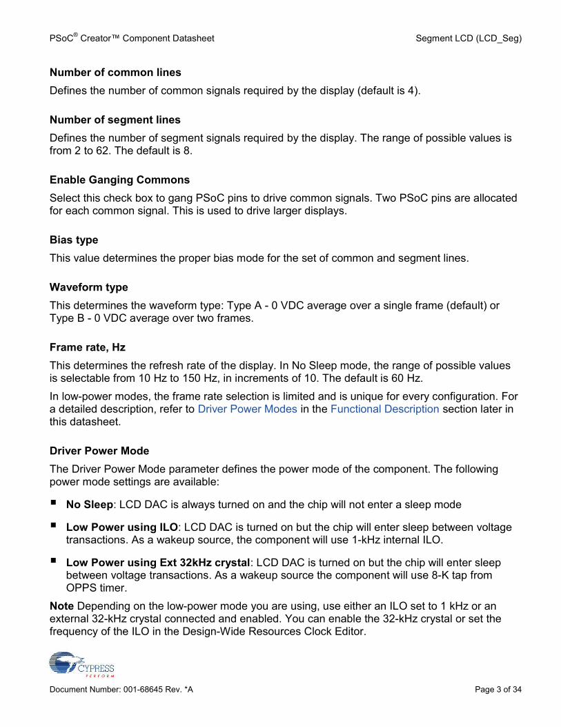
Driver Power Settings Tab
Glass Size, sq cmUse this field to enter the approximate size of the active area of the glass in square centimeters.This value will be used in conjunction with the Number of common lines parameter to calculatethe approximate capacitive load.
AdvancedIf this check box is selected, you are allowed to manually change the Driver Power Settings ofthe LCD. If it is unchecked, the driver power settings will be set automatically based on theselection from the Basic Configuration tab and the Glass Size parameter.
High Drive Time, µsThis parameter defines the time during which High Drive mode will be active within one voltagetransaction.
PSoC® Creator™ Component Datasheet Segment LCD (LCD_Seg)
Document Number: 001-68645 Rev. *A Page 5 of 34
Default StepDefines the automatically calculated High Drive step for the selected configuration. If it isselected, this is the step with which the High Drive time value will be incremented/decremented.Default High Drive step is the only possible selection for No Sleep mode.
Custom StepAvailable only in low-power modes. Defines the user-selectable High Drive step. The minimumpossible value of the custom High Drive step depends on the frequency of the master clock. Themaximum possible value is limited by the value of Default Step.Note If you change the Frame rate, Number of common lines, or Waveform type parameters,the High Drive Time parameter will be set automatically to half of the frame as that is its defaultvalue (only if the Advanced check box is selected):
HighDriveTimeValdef= 1.075/DefaultStep × 128 (Type A)
HighDriveTimeValdef= 1.075/DefaultStep × 128 (Type B)
The calculation of High Drive Time minimum value is defined later in this datasheet. Themaximum value of High Drive Time in the current configuration is:
HighDriveTimeValmax= 1.075/DefaultStep × 253 (Type A)
HighDriveTimeValmax= 1.075/DefaultStep × 253 (Type B)
The above equations are also applied to High Drive Time value with a Custom Step.If you have selected one of the low-power modes, it is not recommended to set the High DriveTime to its maximum values if you are using the default High Drive step. The use of low-powermodes will be ineffective because the device will enter sleep mode for only a short time, and inthe worst case it may not enter sleep at all. With a Custom Step it is possible to adjust the High Drive Time value more accurately, which is a requirement of many low-power applications.
High Drive StrengthThis parameter selects the drive strength for High Drive.
Low Drive Time, µsThe Low Drive Time parameter defines the time during which Low Drive Mode will be activewithin the voltage transaction.
Low Drive StrengthThis parameter selects the drive strength for Low Drive. Low Drive Strength is relative to HighDrive Strength and it sets automatically depending on the High Drive.
Segment LCD (LCD_Seg) PSoC® Creator™ Component Datasheet
Page 6 of 34 Document Number: 001-68645 Rev. *A
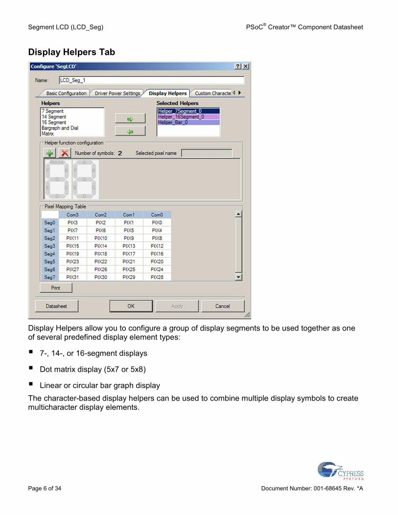
Display Helpers Tab
Display Helpers allow you to configure a group of display segments to be used together as oneof several predefined display element types:
7-, 14-, or 16-segment displays
Dot matrix display (5x7 or 5x8)
Linear or circular bar graph displayThe character-based display helpers can be used to combine multiple display symbols to createmulticharacter display elements.
PSoC® Creator™ Component Datasheet Segment LCD (LCD_Seg)
Document Number: 001-68645 Rev. *A Page 7 of 34
Helpers/Selected HelpersYou may add one or more helpers to the Selected Helpers list by selecting the desired helpertype in the Helpers list and clicking the right-arrow button. If there are not enough pins to supportthe new helper, it will not be added. To delete a helper, select it in the Selected Helpers list andclick the left-arrow button.Note: It is important to set the number of common and segment lines for the component beforedefining any display helpers. Any defined display helpers must be removed before you changethe number of common or segment lines, because you can lose helper configuration information.If you attempt to change the number of common or segment lines, a warning will displayindicating that helper pixel mapping configuration can be lost.The order in which the Selected Helpers appear in the list is significant. By default, the firsthelper of a given type added to the Selected Helper list is named with a 0 suffix, the next one ofthe same type will have a suffix of 1, and so on. If a Selected Helper is removed from the list,the remaining helpers will not be renamed. When a helper is added, the name will use the lowestavailable suffix.APIs are provided for each helper. Refer to the Application Programming Interface section formore information.
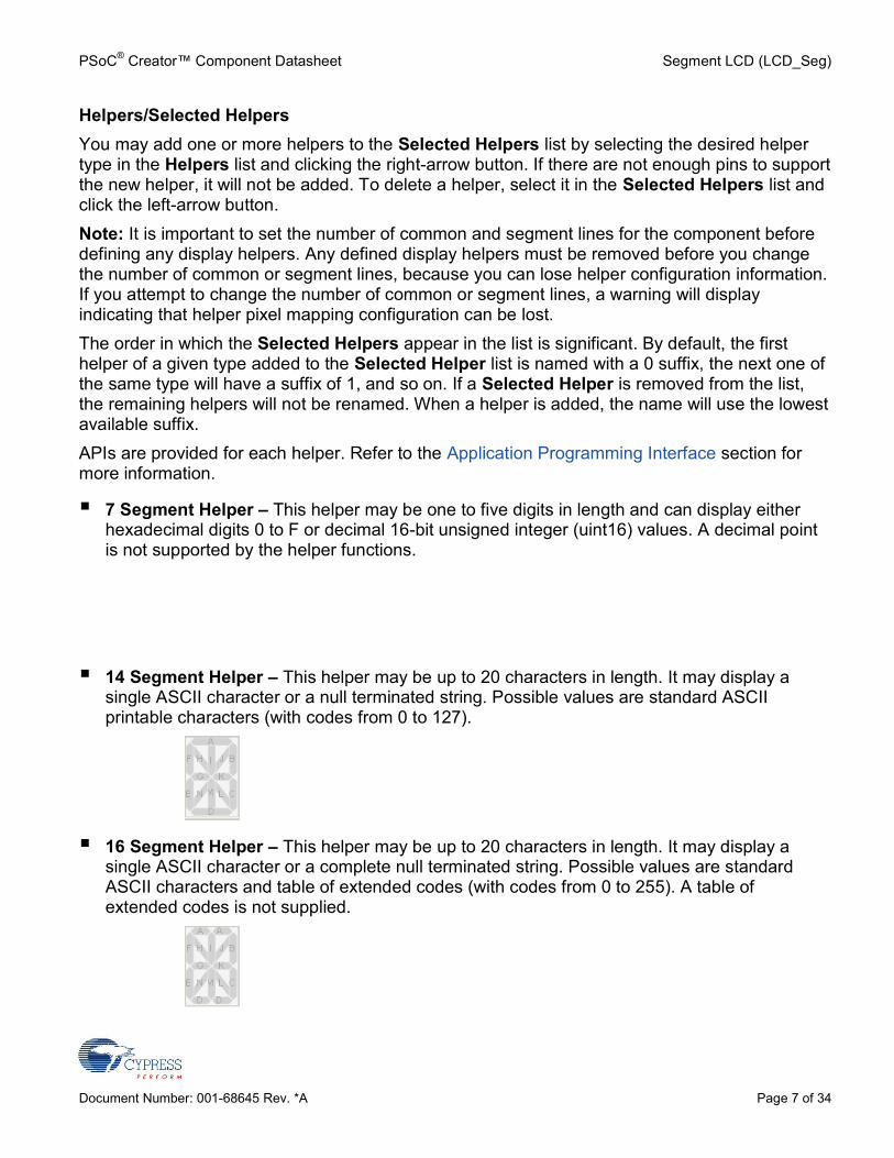
7 Segment Helper – This helper may be one to five digits in length and can display eitherhexadecimal digits 0 to F or decimal 16-bit unsigned integer (uint16) values. A decimal pointis not supported by the helper functions.
14 Segment Helper – This helper may be up to 20 characters in length. It may display asingle ASCII character or a null terminated string. Possible values are standard ASCIIprintable characters (with codes from 0 to 127).
16 Segment Helper – This helper may be up to 20 characters in length. It may display asingle ASCII character or a complete null terminated string. Possible values are standardASCII characters and table of extended codes (with codes from 0 to 255). A table ofextended codes is not supplied.
Segment LCD (LCD_Seg) PSoC® Creator™ Component Datasheet
Page 8 of 34 Document Number: 001-68645 Rev. *A
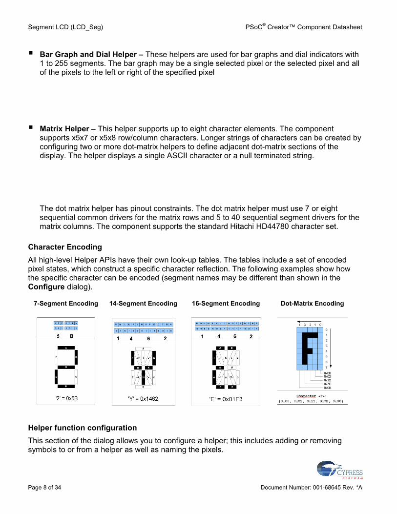
Bar Graph and Dial Helper – These helpers are used for bar graphs and dial indicators with1 to 255 segments. The bar graph may be a single selected pixel or the selected pixel and allof the pixels to the left or right of the specified pixel
Matrix Helper – This helper supports up to eight character elements. The componentsupports x5x7 or x5x8 row/column characters. Longer strings of characters can be created byconfiguring two or more dot-matrix helpers to define adjacent dot-matrix sections of thedisplay. The helper displays a single ASCII character or a null terminated string.
The dot matrix helper has pinout constraints. The dot matrix helper must use 7 or eightsequential common drivers for the matrix rows and 5 to 40 sequential segment drivers for thematrix columns. The component supports the standard Hitachi HD44780 character set.
Character EncodingAll high-level Helper APIs have their own look-up tables. The tables include a set of encodedpixel states, which construct a specific character reflection. The following examples show howthe specific character can be encoded (segment names may be different than shown in theConfigure dialog).
7-Segment Encoding 14-Segment Encoding 16-Segment Encoding Dot-Matrix Encoding
Helper function configurationThis section of the dialog allows you to configure a helper; this includes adding or removingsymbols to or from a helper as well as naming the pixels.
PSoC® Creator™ Component Datasheet Segment LCD (LCD_Seg)
Document Number: 001-68645 Rev. *A Page 9 of 34
1. Select a helper from the Selected Helpers list.2. Click the [+] or [x] button to add or remove a symbol for the selected helper.
The maximum number of symbols you may add depends on the helper type and the totalnumber of pixels supported by the component. If the number of available pins is not sufficientto support a new symbol, it will not be added.
3. To rename a pixel which is a part of a helper function, select the pixel on the symbol image inthe Helper function configuration display. The current name will display in the selectedpixel name field and can be modified as desired.
Pixel NamingThe default pixel names have the form “PIX#,” where “#” is the number of the pixel in incrementalorder starting from right upper corner of the Pixel Mapping Table.The default naming for pixels associated with a helper symbol has a different format. The defaultname consists of a prefix portion, common to all of the pixels in a symbol, and a unique segmentidentifier. The default prefix indicates the helper type and the symbol instance. For example, thedefault name of a pixel in one of the symbols in a 7-segment display helper might be“H7SEG4_A” where:
H7 indicates the pixel is part of a 7-segment helperSEG4 indicates the pixel is part of the symbol designated as the fourth 7-segment
symbol in the projectA identifies the unique segment within the 7 segment symbol
For default pixel names, only the unique portion of the pixel name is shown on the symbolimage. If you modify a pixel name, then the entire name will be shown on the symbol image evenif they have a common prefix.Note All pixel names must be unique.When a helper function symbol element is assigned to a pixel in the Pixel Mapping Table(described below), the pixel assumes the name of the helper symbol element. The helper symbolelement name supersedes the default pixel name, but does not replace it. You cannot reuse thedefault pixel name of pixels that are associated with a helper function.
Pixel Mapping TableThe Pixel Mapping Table is a representation of the frame buffer. For the API functions to workproperly, each pixel from the Helper function configuration must be assigned to a pixellocation in the Pixel Mapping Table. Refer to the datasheet for your LCD glass for theinformation you will need to make the correct assignments.To assign pixels, select the desired pixel in the Helper function configuration panel and drag itto the correct location in the Pixel Mapping Table.
Segment LCD (LCD_Seg) PSoC® Creator™ Component Datasheet
Page 10 of 34 Document Number: 001-68645 Rev. *A
You can rename a pixel in the Pixel Mapping Table by double-clicking on the pixel in the tabledisplay and entering the desired name. This method can be used to name a pixel that is notassociated with one of the available helper types.The Print button prints the Pixel Mapping Table.
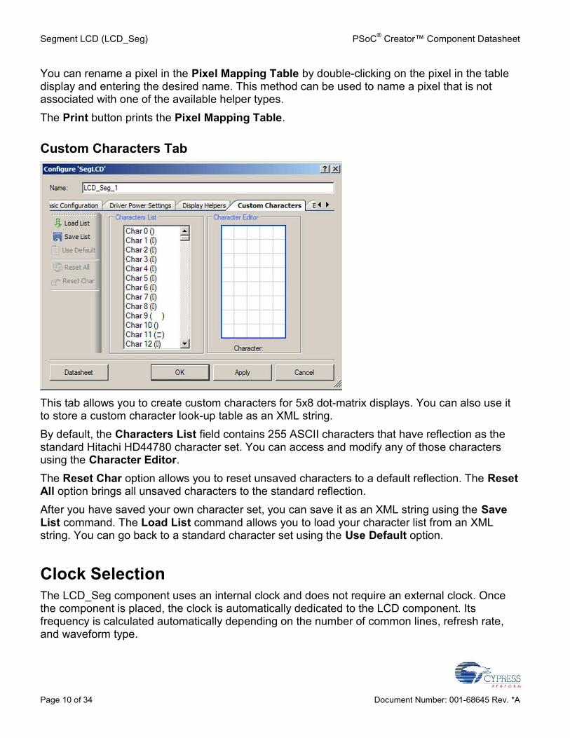
Custom Characters Tab
This tab allows you to create custom characters for 5x8 dot-matrix displays. You can also use itto store a custom character look-up table as an XML string.By default, the Characters List field contains 255 ASCII characters that have reflection as thestandard Hitachi HD44780 character set. You can access and modify any of those charactersusing the Character Editor.The Reset Char option allows you to reset unsaved characters to a default reflection. The ResetAll option brings all unsaved characters to the standard reflection.After you have saved your own character set, you can save it as an XML string using the SaveList command. The Load List command allows you to load your character list from an XMLstring. You can go back to a standard character set using the Use Default option.
Clock SelectionThe LCD_Seg component uses an internal clock and does not require an external clock. Oncethe component is placed, the clock is automatically dedicated to the LCD component. Itsfrequency is calculated automatically depending on the number of common lines, refresh rate,and waveform type.
PSoC® Creator™ Component Datasheet Segment LCD (LCD_Seg)
Document Number: 001-68645 Rev. *A Page 11 of 34
PlacementThe LCD_Seg component implementation consists of two parts. The LCDDAC is a fixed-functionhardware block in the PSoC that is used by this component. Additional timing logic for the drivesignals is implemented in UDBs. UDB resources are automatically placed in the UDB arrayduring the project-generation process.Note: Only one instance of the component can be used in a project. If you try to use more thanone, a placement error will be generated during the build.Default pin assignments are made during the build process and can be modified using the PinEditor in the PSoC Creator Design-Wide Resources tool.
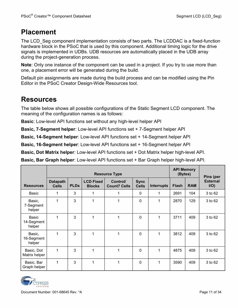
ResourcesThe table below shows all possible configurations of the Static Segment LCD component. Themeaning of the configuration names is as follows:Basic: Low-level API functions set without any high-level helper APIBasic, 7-Segment helper: Low-level API functions set + 7-Segment helper APIBasic, 14-Segment helper: Low-level API functions set + 14-Segment helper APIBasic, 16-Segment helper: Low-level API functions set + 16-Segment helper APIBasic, Dot Matrix helper: Low-level API functions set + Dot Matrix helper high-level API.Basic, Bar Graph helper: Low-level API functions set + Bar Graph helper high-level API.
Resources
Resource TypeAPI Memory
(Bytes)Pins (perExternal
I/O)Datapath
Cells PLDsLCD Fixed
BlocksControl/
Count7 CellsSyncCells Interrupts Flash RAM
Basic 1 3 1 1 0 1 2691 104 3 to 62
Basic,7-Segment
helper
1 3 1 1 0 1 2870 129 3 to 62
Basic14-Segment
helper
1 3 1 1 0 1 3711 409 3 to 62
Basic,16-Segment
helper
1 3 1 1 0 1 3812 409 3 to 62
Basic, DotMatrix helper
1 3 1 1 0 1 4875 409 3 to 62
Basic, BarGraph helper
1 3 1 1 0 1 3590 409 3 to 62
Segment LCD (LCD_Seg) PSoC® Creator™ Component Datasheet
Page 12 of 34 Document Number: 001-68645 Rev. *A
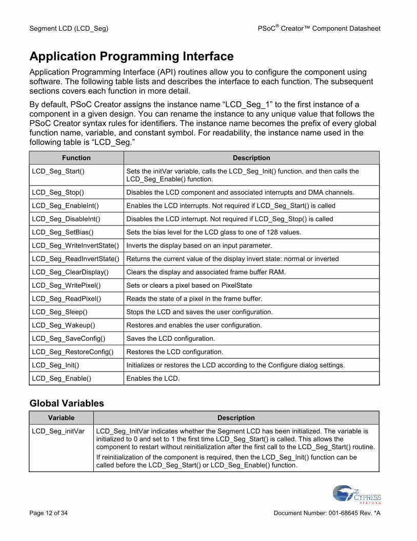
Application Programming InterfaceApplication Programming Interface (API) routines allow you to configure the component usingsoftware. The following table lists and describes the interface to each function. The subsequentsections covers each function in more detail.By default, PSoC Creator assigns the instance name “LCD_Seg_1” to the first instance of acomponent in a given design. You can rename the instance to any unique value that follows thePSoC Creator syntax rules for identifiers. The instance name becomes the prefix of every globalfunction name, variable, and constant symbol. For readability, the instance name used in thefollowing table is “LCD_Seg.”
Function Description
LCD_Seg_Start() Sets the initVar variable, calls the LCD_Seg_Init() function, and then calls theLCD_Seg_Enable() function.
LCD_Seg_Stop() Disables the LCD component and associated interrupts and DMA channels.
LCD_Seg_EnableInt() Enables the LCD interrupts. Not required if LCD_Seg_Start() is called
LCD_Seg_DisableInt() Disables the LCD interrupt. Not required if LCD_Seg_Stop() is called
LCD_Seg_SetBias() Sets the bias level for the LCD glass to one of 128 values.
LCD_Seg_WriteInvertState() Inverts the display based on an input parameter.
LCD_Seg_ReadInvertState() Returns the current value of the display invert state: normal or inverted
LCD_Seg_ClearDisplay() Clears the display and associated frame buffer RAM.
LCD_Seg_WritePixel() Sets or clears a pixel based on PixelState
LCD_Seg_ReadPixel() Reads the state of a pixel in the frame buffer.
LCD_Seg_Sleep() Stops the LCD and saves the user configuration.
LCD_Seg_Wakeup() Restores and enables the user configuration.
LCD_Seg_SaveConfig() Saves the LCD configuration.
LCD_Seg_RestoreConfig() Restores the LCD configuration.
LCD_Seg_Init() Initializes or restores the LCD according to the Configure dialog settings.
LCD_Seg_Enable() Enables the LCD.
Global VariablesVariable Description
LCD_Seg_initVar LCD_Seg_InitVar indicates whether the Segment LCD has been initialized. The variable isinitialized to 0 and set to 1 the first time LCD_Seg_Start() is called. This allows thecomponent to restart without reinitialization after the first call to the LCD_Seg_Start() routine.If reinitialization of the component is required, then the LCD_Seg_Init() function can becalled before the LCD_Seg_Start() or LCD_Seg_Enable() function.
PSoC® Creator™ Component Datasheet Segment LCD (LCD_Seg)
Document Number: 001-68645 Rev. *A Page 13 of 34
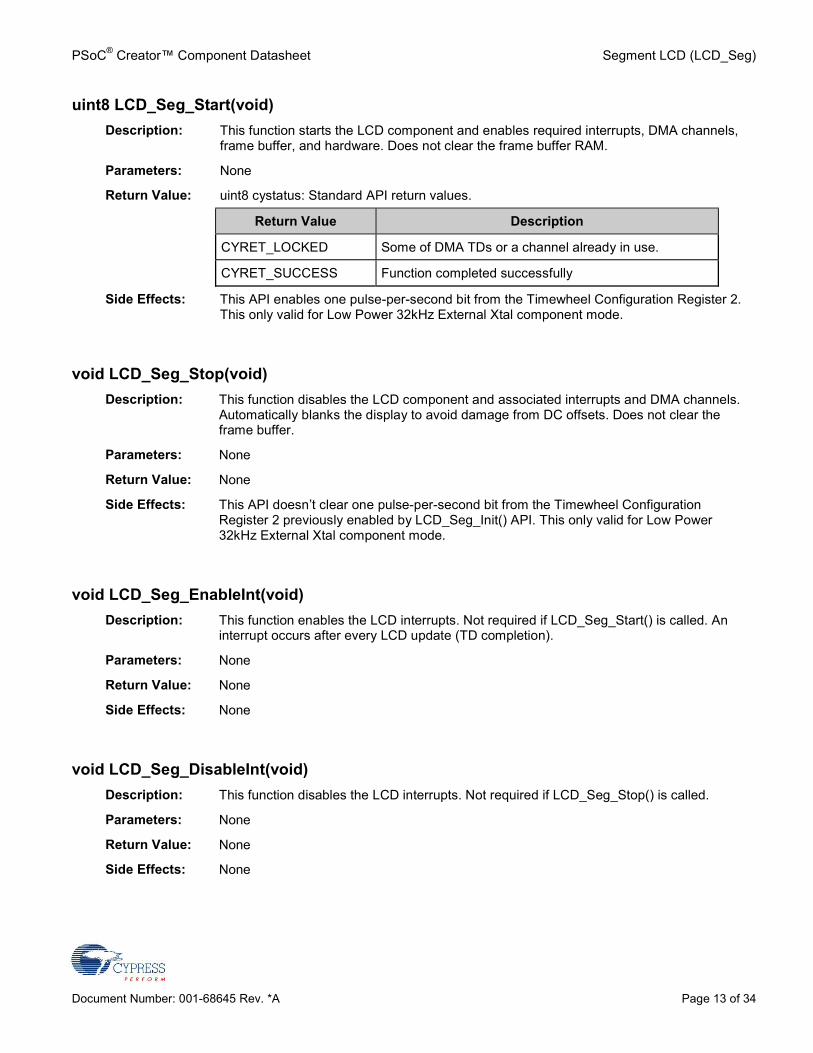
uint8 LCD_Seg_Start(void)Description: This function starts the LCD component and enables required interrupts, DMA channels,
frame buffer, and hardware. Does not clear the frame buffer RAM.
Parameters: None
Return Value: uint8 cystatus: Standard API return values.
Return Value Description
CYRET_LOCKED Some of DMA TDs or a channel already in use.
CYRET_SUCCESS Function completed successfully
Side Effects: This API enables one pulse-per-second bit from the Timewheel Configuration Register 2.This only valid for Low Power 32kHz External Xtal component mode.
void LCD_Seg_Stop(void)Description: This function disables the LCD component and associated interrupts and DMA channels.
Automatically blanks the display to avoid damage from DC offsets. Does not clear theframe buffer.
Parameters: None
Return Value: None
Side Effects: This API doesn’t clear one pulse-per-second bit from the Timewheel ConfigurationRegister 2 previously enabled by LCD_Seg_Init() API. This only valid for Low Power32kHz External Xtal component mode.
void LCD_Seg_EnableInt(void)Description: This function enables the LCD interrupts. Not required if LCD_Seg_Start() is called. An
interrupt occurs after every LCD update (TD completion).
Parameters: None
Return Value: None
Side Effects: None
void LCD_Seg_DisableInt(void)Description: This function disables the LCD interrupts. Not required if LCD_Seg_Stop() is called.
Parameters: None
Return Value: None
Side Effects: None
Segment LCD (LCD_Seg) PSoC® Creator™ Component Datasheet
Page 14 of 34 Document Number: 001-68645 Rev. *A
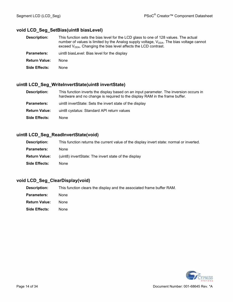
void LCD_Seg_SetBias(uint8 biasLevel)Description: This function sets the bias level for the LCD glass to one of 128 values. The actual
number of values is limited by the Analog supply voltage, VDDA. The bias voltage cannotexceed VDDA. Changing the bias level affects the LCD contrast.
Parameters: uint8 biasLevel: Bias level for the display
Return Value: None
Side Effects: None
uint8 LCD_Seg_WriteInvertState(uint8 invertState)Description: This function inverts the display based on an input parameter. The inversion occurs in
hardware and no change is required to the display RAM in the frame buffer.
Parameters: uint8 invertState: Sets the invert state of the display
Return Value: uint8 cystatus: Standard API return values
Side Effects: None
uint8 LCD_Seg_ReadInvertState(void)Description: This function returns the current value of the display invert state: normal or inverted.
Parameters: None
Return Value: (uint8) invertState: The invert state of the display
Side Effects: None
void LCD_Seg_ClearDisplay(void)Description: This function clears the display and the associated frame buffer RAM.
Parameters: None
Return Value: None
Side Effects: None
PSoC® Creator™ Component Datasheet Segment LCD (LCD_Seg)
Document Number: 001-68645 Rev. *A Page 15 of 34
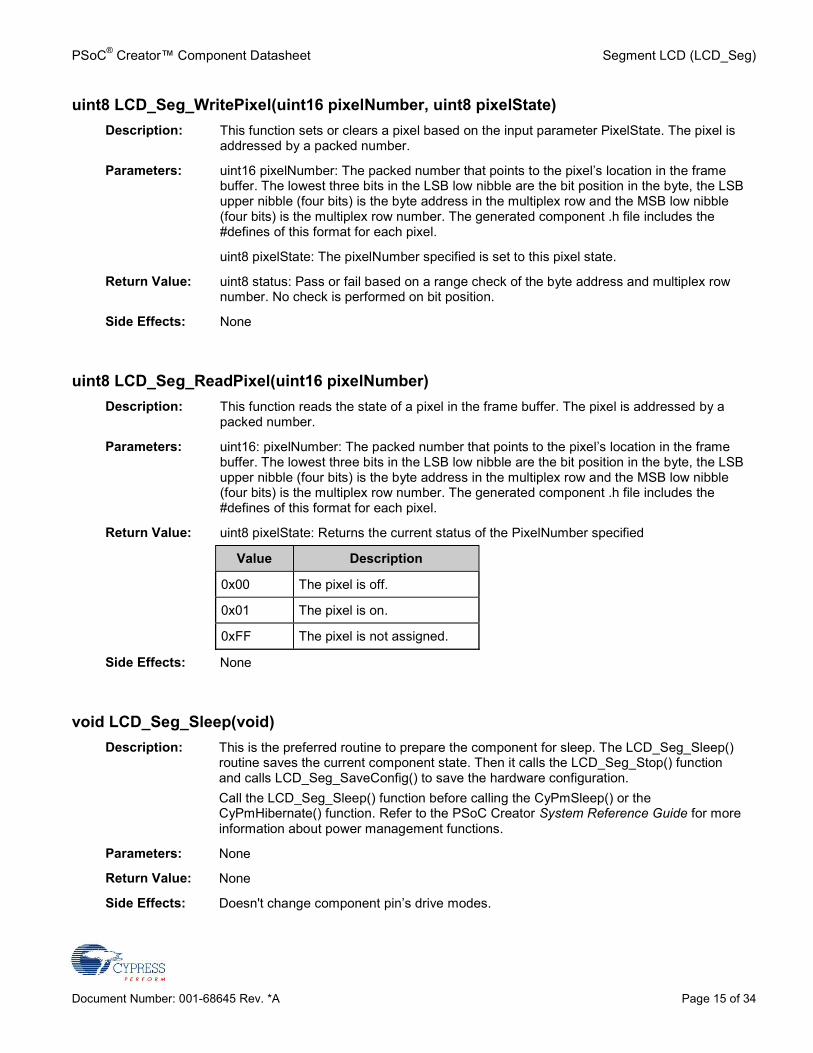
uint8 LCD_Seg_WritePixel(uint16 pixelNumber, uint8 pixelState)Description: This function sets or clears a pixel based on the input parameter PixelState. The pixel is
addressed by a packed number.
Parameters: uint16 pixelNumber: The packed number that points to the pixel’s location in the framebuffer. The lowest three bits in the LSB low nibble are the bit position in the byte, the LSBupper nibble (four bits) is the byte address in the multiplex row and the MSB low nibble(four bits) is the multiplex row number. The generated component .h file includes the#defines of this format for each pixel.
uint8 pixelState: The pixelNumber specified is set to this pixel state.
Return Value: uint8 status: Pass or fail based on a range check of the byte address and multiplex rownumber. No check is performed on bit position.
Side Effects: None
uint8 LCD_Seg_ReadPixel(uint16 pixelNumber)Description: This function reads the state of a pixel in the frame buffer. The pixel is addressed by a
packed number.
Parameters: uint16: pixelNumber: The packed number that points to the pixel’s location in the framebuffer. The lowest three bits in the LSB low nibble are the bit position in the byte, the LSBupper nibble (four bits) is the byte address in the multiplex row and the MSB low nibble(four bits) is the multiplex row number. The generated component .h file includes the#defines of this format for each pixel.
Return Value: uint8 pixelState: Returns the current status of the PixelNumber specified
Value Description
0x00 The pixel is off.
0x01 The pixel is on.
0xFF The pixel is not assigned.
Side Effects: None
void LCD_Seg_Sleep(void)Description: This is the preferred routine to prepare the component for sleep. The LCD_Seg_Sleep()
routine saves the current component state. Then it calls the LCD_Seg_Stop() functionand calls LCD_Seg_SaveConfig() to save the hardware configuration.Call the LCD_Seg_Sleep() function before calling the CyPmSleep() or theCyPmHibernate() function. Refer to the PSoC Creator System Reference Guide for moreinformation about power management functions.
Parameters: None
Return Value: None
Side Effects: Doesn't change component pin’s drive modes.
Segment LCD (LCD_Seg) PSoC® Creator™ Component Datasheet
Page 16 of 34 Document Number: 001-68645 Rev. *A
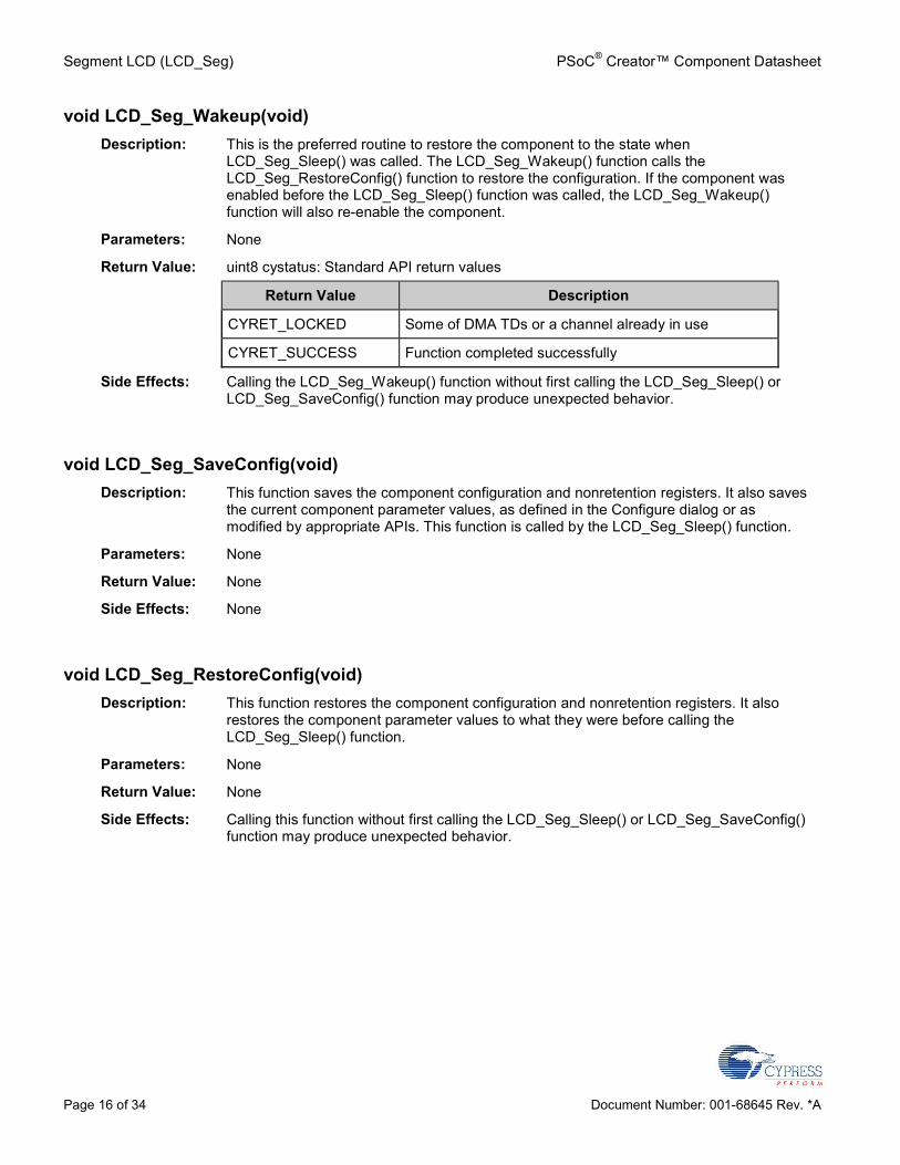
void LCD_Seg_Wakeup(void)Description: This is the preferred routine to restore the component to the state when
LCD_Seg_Sleep() was called. The LCD_Seg_Wakeup() function calls theLCD_Seg_RestoreConfig() function to restore the configuration. If the component wasenabled before the LCD_Seg_Sleep() function was called, the LCD_Seg_Wakeup()function will also re-enable the component.
Parameters: None
Return Value: uint8 cystatus: Standard API return values
Return Value Description
CYRET_LOCKED Some of DMA TDs or a channel already in use
CYRET_SUCCESS Function completed successfully
Side Effects: Calling the LCD_Seg_Wakeup() function without first calling the LCD_Seg_Sleep() orLCD_Seg_SaveConfig() function may produce unexpected behavior.
void LCD_Seg_SaveConfig(void)Description: This function saves the component configuration and nonretention registers. It also saves
the current component parameter values, as defined in the Configure dialog or asmodified by appropriate APIs. This function is called by the LCD_Seg_Sleep() function.
Parameters: None
Return Value: None
Side Effects: None
void LCD_Seg_RestoreConfig(void)Description: This function restores the component configuration and nonretention registers. It also
restores the component parameter values to what they were before calling theLCD_Seg_Sleep() function.
Parameters: None
Return Value: None
Side Effects: Calling this function without first calling the LCD_Seg_Sleep() or LCD_Seg_SaveConfig()function may produce unexpected behavior.
PSoC® Creator™ Component Datasheet Segment LCD (LCD_Seg)
Document Number: 001-68645 Rev. *A Page 17 of 34
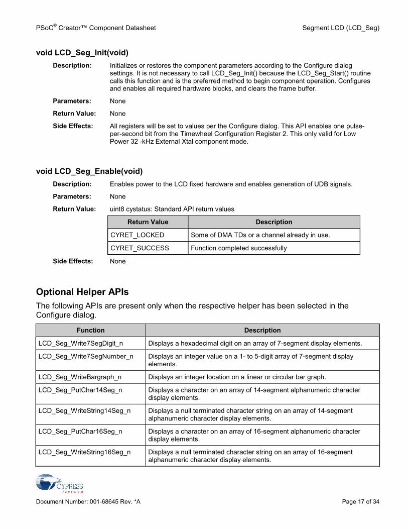
void LCD_Seg_Init(void)Description: Initializes or restores the component parameters according to the Configure dialog
settings. It is not necessary to call LCD_Seg_Init() because the LCD_Seg_Start() routinecalls this function and is the preferred method to begin component operation. Configuresand enables all required hardware blocks, and clears the frame buffer.
Parameters: None
Return Value: None
Side Effects: All registers will be set to values per the Configure dialog. This API enables one pulse-per-second bit from the Timewheel Configuration Register 2. This only valid for LowPower 32 -kHz External Xtal component mode.
void LCD_Seg_Enable(void)Description: Enables power to the LCD fixed hardware and enables generation of UDB signals.
Parameters: None
Return Value: uint8 cystatus: Standard API return values
Return Value Description
CYRET_LOCKED Some of DMA TDs or a channel already in use.
CYRET_SUCCESS Function completed successfully
Side Effects: None
Optional Helper APIsThe following APIs are present only when the respective helper has been selected in theConfigure dialog.
Function Description
LCD_Seg_Write7SegDigit_n Displays a hexadecimal digit on an array of 7-segment display elements.
LCD_Seg_Write7SegNumber_n Displays an integer value on a 1- to 5-digit array of 7-segment displayelements.
LCD_Seg_WriteBargraph_n Displays an integer location on a linear or circular bar graph.
LCD_Seg_PutChar14Seg_n Displays a character on an array of 14-segment alphanumeric characterdisplay elements.
LCD_Seg_WriteString14Seg_n Displays a null terminated character string on an array of 14-segmentalphanumeric character display elements.
LCD_Seg_PutChar16Seg_n Displays a character on an array of 16-segment alphanumeric characterdisplay elements.
LCD_Seg_WriteString16Seg_n Displays a null terminated character string on an array of 16-segmentalphanumeric character display elements.
Segment LCD (LCD_Seg) PSoC® Creator™ Component Datasheet
Page 18 of 34 Document Number: 001-68645 Rev. *A
Function Description
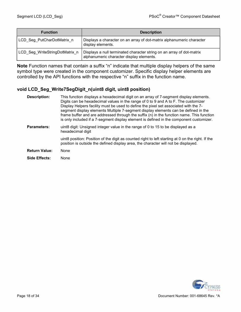
LCD_Seg_PutCharDotMatrix_n Displays a character on an array of dot-matrix alphanumeric characterdisplay elements.
LCD_Seg_WriteStringDotMatrix_n Displays a null terminated character string on an array of dot-matrixalphanumeric character display elements.
Note Function names that contain a suffix “n” indicate that multiple display helpers of the samesymbol type were created in the component customizer. Specific display helper elements arecontrolled by the API functions with the respective “n” suffix in the function name.
void LCD_Seg_Write7SegDigit_n(uint8 digit, uint8 position)Description: This function displays a hexadecimal digit on an array of 7-segment display elements.
Digits can be hexadecimal values in the range of 0 to 9 and A to F. The customizerDisplay Helpers facility must be used to define the pixel set associated with the 7-segment display elements Multiple 7-segment display elements can be defined in theframe buffer and are addressed through the suffix (n) in the function name. This functionis only included if a 7-segment display element is defined in the component customizer.
Parameters: uint8 digit: Unsigned integer value in the range of 0 to 15 to be displayed as ahexadecimal digit
uint8 position: Position of the digit as counted right to left starting at 0 on the right. If theposition is outside the defined display area, the character will not be displayed.
Return Value: None
Side Effects: None
PSoC® Creator™ Component Datasheet Segment LCD (LCD_Seg)
Document Number: 001-68645 Rev. *A Page 19 of 34
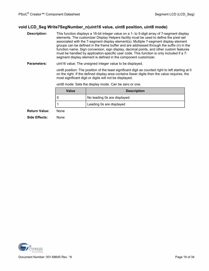
void LCD_Seg Write7SegNumber_n(uint16 value, uint8 position, uint8 mode)Description: This function displays a 16-bit integer value on a 1- to 5-digit array of 7-segment display
elements. The customizer Display Helpers facility must be used to define the pixel setassociated with the 7-segment display element(s). Multiple 7-segment display elementgroups can be defined in the frame buffer and are addressed through the suffix (n) in thefunction name. Sign conversion, sign display, decimal points, and other custom featuresmust be handled by application-specific user code. This function is only included if a 7-segment display element is defined in the component customizer.
Parameters: uint16 value: The unsigned integer value to be displayed.
uint8 position: The position of the least significant digit as counted right to left starting at 0on the right. If the defined display area contains fewer digits then the value requires, themost significant digit or digits will not be displayed.
uint8 mode: Sets the display mode. Can be zero or one.
Value Description
0 No leading 0s are displayed.
1 Leading 0s are displayed
Return Value: None
Side Effects: None
Segment LCD (LCD_Seg) PSoC® Creator™ Component Datasheet
Page 20 of 34 Document Number: 001-68645 Rev. *A
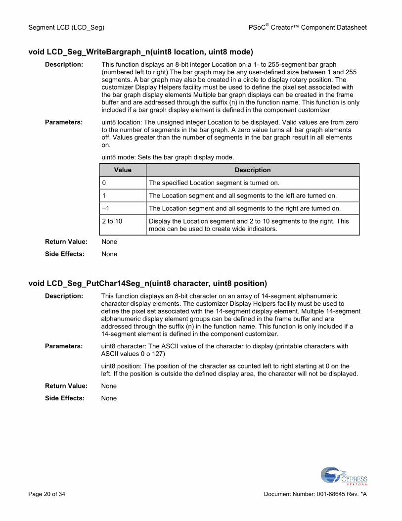
void LCD_Seg_WriteBargraph_n(uint8 location, uint8 mode)Description: This function displays an 8-bit integer Location on a 1- to 255-segment bar graph
(numbered left to right).The bar graph may be any user-defined size between 1 and 255segments. A bar graph may also be created in a circle to display rotary position. Thecustomizer Display Helpers facility must be used to define the pixel set associated withthe bar graph display elements Multiple bar graph displays can be created in the framebuffer and are addressed through the suffix (n) in the function name. This function is onlyincluded if a bar graph display element is defined in the component customizer
Parameters: uint8 location: The unsigned integer Location to be displayed. Valid values are from zeroto the number of segments in the bar graph. A zero value turns all bar graph elementsoff. Values greater than the number of segments in the bar graph result in all elementson.
uint8 mode: Sets the bar graph display mode.
Value Description
0 The specified Location segment is turned on.
1 The Location segment and all segments to the left are turned on.
–1 The Location segment and all segments to the right are turned on.
2 to 10 Display the Location segment and 2 to 10 segments to the right. Thismode can be used to create wide indicators.
Return Value: None
Side Effects: None
void LCD_Seg_PutChar14Seg_n(uint8 character, uint8 position)Description: This function displays an 8-bit character on an array of 14-segment alphanumeric
character display elements. The customizer Display Helpers facility must be used todefine the pixel set associated with the 14-segment display element. Multiple 14-segmentalphanumeric display element groups can be defined in the frame buffer and areaddressed through the suffix (n) in the function name. This function is only included if a14-segment element is defined in the component customizer.
Parameters: uint8 character: The ASCII value of the character to display (printable characters withASCII values 0 o 127)
uint8 position: The position of the character as counted left to right starting at 0 on theleft. If the position is outside the defined display area, the character will not be displayed.
Return Value: None
Side Effects: None
PSoC® Creator™ Component Datasheet Segment LCD (LCD_Seg)
Document Number: 001-68645 Rev. *A Page 21 of 34
void LCD_Seg_WriteString14Seg_n(*uint8 character, uint8 position)Description: This function displays a null terminated character string on an array of 14-segment
alphanumeric character display elements. The customizer Display Helpers facility mustbe used to define the pixel set associated with the 14-segment display elements. Multiple14-segment alphanumeric display element groups can be defined in the frame buffer andare addressed through the suffix (n) in the function name. This function is only included ifa 14-segment display element is defined in the component customizer
Parameters: *uint8 character: The pointer to the null terminated character string.
uint8 position: The position of the first character as counted left to right starting at 0 on theleft. If the length of the string exceeds the size of the defined display area, the extracharacters will not be displayed.
Return Value: None
Side Effects: None
void LCD_Seg_PutChar16Seg_n(uint8 character, uint8 position)Description: This function displays an 8-bit character on an array of 16-segment alphanumeric
character display elements. The customizer Display Helpers facility must be used todefine the pixel set associated with the 16-segment display element(s). Multiple 16-segment alphanumeric display element groups can be defined in the frame buffer and areaddressed through the suffix (n) in the function name. This function is only included if a16-segment display element is defined in the component customizer
Parameters: uint8 character: The ASCII value of the character to display (printable ASCII and tableextended characters with values 0 to 255).
uint8 position: The position of the character as counted left to right starting at 0 on theleft. If the position is outside the defined display area, the character will not be displayed.
Return Value: None
Side Effects: None
Segment LCD (LCD_Seg) PSoC® Creator™ Component Datasheet
Page 22 of 34 Document Number: 001-68645 Rev. *A
(void) LCD_Seg_WriteString16Seg_n(*uint8 character, uint8 position)Description: This function displays a null terminated character string on an array of 16-segment
alphanumeric character display elements. The customizer Display Helpers facility mustbe used to define the pixel set associated with the 16 segment display elements. Multiple16-segment alphanumeric display element groups can be defined in the frame buffer andare addressed through the suffix (n) in the function name. This function is only included ifa 16-segment display element is defined in the component customizer.
Parameters: *uint8 character: The pointer to the null terminated character string.
uint8 position: The position of the first character as counted left to right starting at 0 on theleft. If the length of the string exceeds the size of the defined display area, the extracharacters will not be displayed.
Return Value: None
Side Effects: None
void LCD_Seg_PutCharDotMatrix_n(uint8 character, uint8 position)Description: This function displays an 8-bit character on an array of dot-matrix alphanumeric character
display elements. The customizer Display Helpers facility must be used to define the pixelset associated with the dot matrix display elements. Multiple dot-matrix alphanumericdisplay element groups can be defined in the frame buffer and are addressed through thesuffix (n) in the function name. This function is only included if a dot-matrix displayelement is defined in the component customizer
Parameters: uint8 character: The ASCII value of the character to display.
uint8 position: The position of the character as counted left to right starting at 0 on theleft. If the position is outside the defined display area, the character will not be displayed.
Return Value: None
Side Effects: None
PSoC® Creator™ Component Datasheet Segment LCD (LCD_Seg)
Document Number: 001-68645 Rev. *A Page 23 of 34
void LCD_Seg_WriteStringDotMatrix_n(*uint8 character, uint8 position)Description: This function displays a null terminated character string on an array of dot-matrix
alphanumeric character display elements. The customizer Display Helpers facility mustbe used to define the pixel set associated with the dot-matrix display elements. Multipledot-matrix alphanumeric display element groups can be defined in the frame buffer andare addressed through the suffix (n) in the function name. This function is only included ifa dot- matrix display element is defined in the component customizer
Parameters: *uint8 character: The pointer to the null terminated character string.
uint8 position: The position of the first character as counted left to right starting at 0 on theleft. If the length of the string exceeds the size of the defined display area, the extracharacters will not be displayed.
Return Value: None
Side Effects: None
Pins APIsThese API functions are used to change drive mode of pins used by Segment LCD component.
Function Description
LCD_Seg_ComPort_SetDriveMode Sets the drive mode for all pins used by common lines of the SegmentLCD component
LCD_Seg_SegPort_SetDriveMode Sets the drive mode for all pins used by segment lines of the SegmentLCD component.
void LCD_Seg_ComPort_SetDriveMode(uint8 mode)Description: Sets the drive mode for all pins used by common lines of the Segment LCD component.
Parameters: uint8 mode: The desired drive mode. See the Pins component datasheet for informationon drive modes.
Return Value: None
Side Effects: None
LCD_Seg_SegPort_SetDriveMode(uint8 mode)Description: Sets the drive mode for all pins used by segment lines of the Segment LCD component.
Parameters: uint8 mode: The desired drive mode. See the Pins component datasheet for informationon drive modes.
Return Value: None
Side Effects: None
Segment LCD (LCD_Seg) PSoC® Creator™ Component Datasheet
Page 24 of 34 Document Number: 001-68645 Rev. *A
Macros LCD_Seg_COMM_NUM – Defines the number of common lines in the user-defined display
for the current configuration of the component.
LCD_Seg_SEG_NUM – Defines the number of segment lines for the user-defined display forthe current configuration of the component.
LCD_Seg_BIAS_TYPE – Defines the bias type for the user-defined display current for theconfiguration of the component.
LCD_Seg_BIAS_VOLTAGE – Defines default bias voltage level for the user-defined display.This value will be set in the LCDDAC control register during the initialization process.
LCD_Seg_FRAME_RATE – Defines the refresh rate for the user-defined display for thecurrent configuration of the component.
LCD_Seg_EXTRACT_ROW – Calculates the row of the specific pixel in the frame buffer.
LCD_Seg_EXTRACT_PORT – Calculates the byte offset of the specific pixel in the framebuffer.
LCD_Seg_EXTRACT_PIN – Calculates the bit position of the specific pixel in the framebuffer.
LCD_Seg_WRITE_PIXEL – This is a macro define of the LCD_Seg_WritePixel() function withvoid type.
LCD_Seg_READ_PIXEL – This is a macro define of the LCD_Seg_ReadPixel() function.
LCD_Seg_FIND_PIXEL – This macro calculates pixel location in the frame buffer. It usesinformation from the customizer pixel table and information about the physical pins that willbe dedicated for the LCD. This macro is the base of the pixel mapping mechanism. Everypixel name from the pixel table is defined with a calculated pixel location in the frame buffer.APIs use pixel names to access the respective pixel.
Sample Firmware Source CodePSoC Creator provides numerous example projects that include schematics and example codein the Find Example Project dialog. For component-specific examples, open the dialog from theComponent Catalog or an instance of the component in a schematic. For general examples,open the dialog from the Start Page or File menu. As needed, use the Filter Options in thedialog to narrow the list of projects available to select.Refer to the “Find Example Project” topic in the PSoC Creator Help for more information.
PSoC® Creator™ Component Datasheet Segment LCD (LCD_Seg)
Document Number: 001-68645 Rev. *A Page 25 of 34
Note Because of specific component implementation, you cannot use the component with theCyPmSaveClocks() and CyPmRestoreClocks() APIs when it is in low-power mode. In othercases, you can use the CyPmSaveClocks() and CyPmRestoreClocks() APIs.
Functional DescriptionThe Segment LCD component provides a powerful and flexible mechanism for driving differenttypes of LCD glass. The configuration dialog provides access to the parameters that can be usedto customize the component functionality. A standard set of API routines provides control of thedisplay and of specific pixels. Additional display APIs are generated based on the type andnumber of Display Helpers defined.
Default ConfigurationThe default configuration of the LCD_Seg component provides a generic LCD Direct Segmentdrive controller. The default LCD_Seg configuration is:
Four common lines
Eight segment lines
1/3 bias type
60-Hz refresh rate
No Sleep power mode
3-V bias voltage
Glass Size: 10 sq cm
968.99-µs High Drive time
seg - 1x, com - 2x High Drive strength
7.57-µs Low Drive time
seg – 0.06x, com 0.12x Low Drive strength
No display helpers are defined. Default API generation does not include functions for any ofthe supported display elements.
Custom ConfigurationA key feature of the Segment LCD component is flexible support for LCDs with differentcharacteristics and layouts.
Segment LCD (LCD_Seg) PSoC® Creator™ Component Datasheet
Page 26 of 34 Document Number: 001-68645 Rev. *A
Driver Power ModesSegment LCD can operate in two power modes: No Sleep and Low Power. No Sleep is thedefault operation mode.
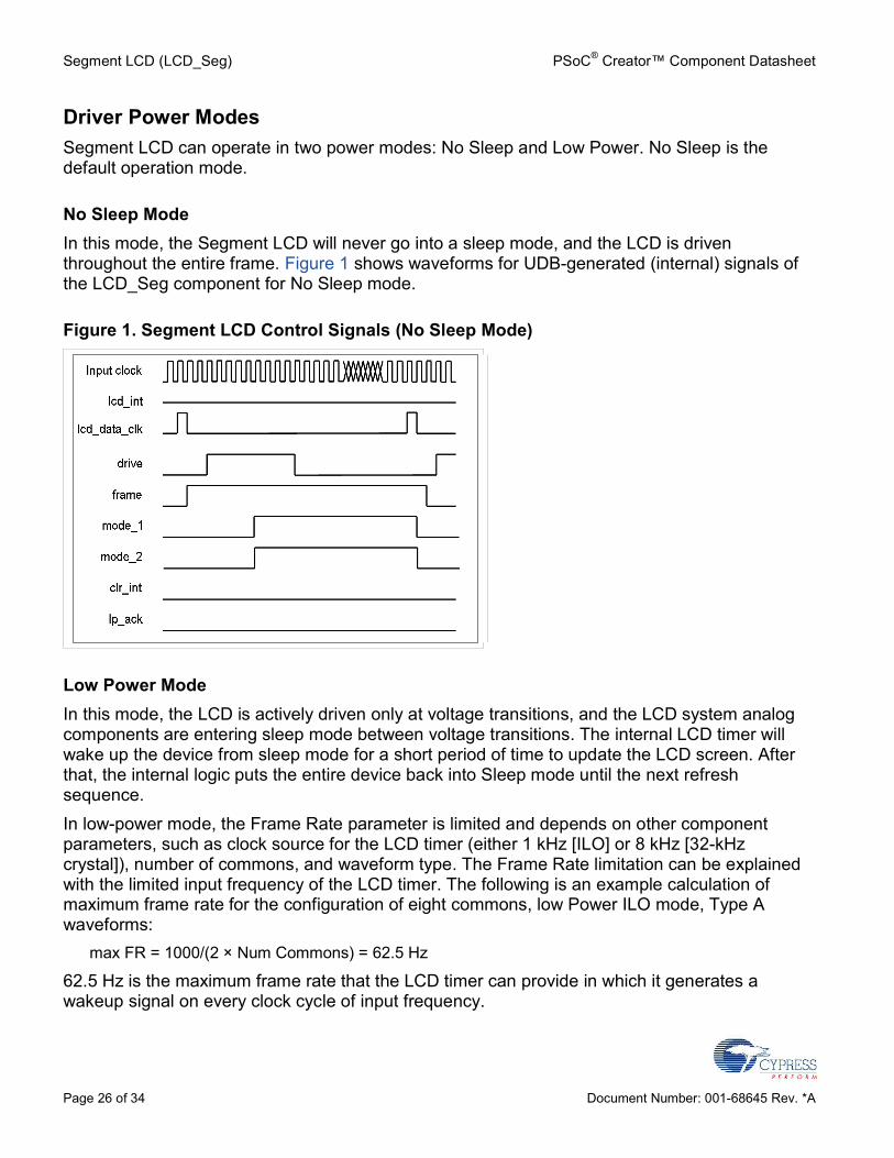
No Sleep ModeIn this mode, the Segment LCD will never go into a sleep mode, and the LCD is driventhroughout the entire frame. Figure 1 shows waveforms for UDB-generated (internal) signals ofthe LCD_Seg component for No Sleep mode.
Figure 1. Segment LCD Control Signals (No Sleep Mode)
Low Power ModeIn this mode, the LCD is actively driven only at voltage transitions, and the LCD system analogcomponents are entering sleep mode between voltage transitions. The internal LCD timer willwake up the device from sleep mode for a short period of time to update the LCD screen. Afterthat, the internal logic puts the entire device back into Sleep mode until the next refreshsequence.In low-power mode, the Frame Rate parameter is limited and depends on other componentparameters, such as clock source for the LCD timer (either 1 kHz [ILO] or 8 kHz [32-kHzcrystal]), number of commons, and waveform type. The Frame Rate limitation can be explainedwith the limited input frequency of the LCD timer. The following is an example calculation ofmaximum frame rate for the configuration of eight commons, low Power ILO mode, Type Awaveforms:
max FR = 1000/(2 × Num Commons) = 62.5 Hz
62.5 Hz is the maximum frame rate that the LCD timer can provide in which it generates awakeup signal on every clock cycle of input frequency.
PSoC® Creator™ Component Datasheet Segment LCD (LCD_Seg)
Document Number: 001-68645 Rev. *A Page 27 of 34
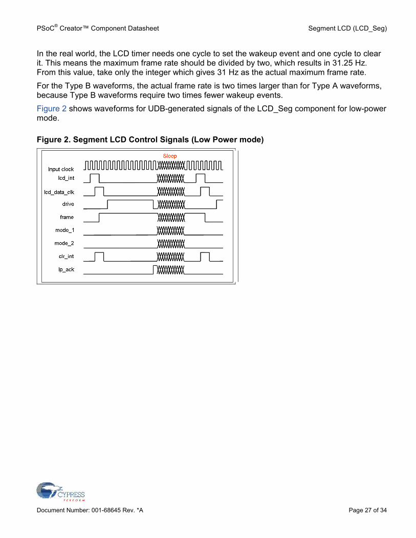
In the real world, the LCD timer needs one cycle to set the wakeup event and one cycle to clearit. This means the maximum frame rate should be divided by two, which results in 31.25 Hz.From this value, take only the integer which gives 31 Hz as the actual maximum frame rate.For the Type B waveforms, the actual frame rate is two times larger than for Type A waveforms,because Type B waveforms require two times fewer wakeup events.Figure 2 shows waveforms for UDB-generated signals of the LCD_Seg component for low-powermode.
Figure 2. Segment LCD Control Signals (Low Power mode)
Segment LCD (LCD_Seg) PSoC® Creator™ Component Datasheet
Page 28 of 34 Document Number: 001-68645 Rev. *A
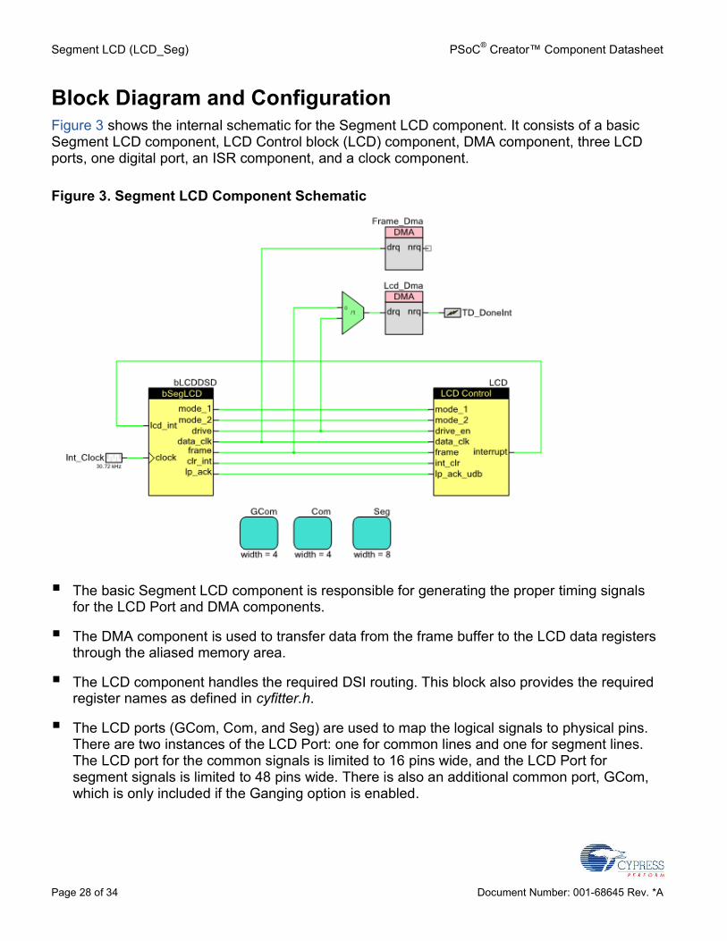
Block Diagram and ConfigurationFigure 3 shows the internal schematic for the Segment LCD component. It consists of a basicSegment LCD component, LCD Control block (LCD) component, DMA component, three LCDports, one digital port, an ISR component, and a clock component.
Figure 3. Segment LCD Component Schematic
The basic Segment LCD component is responsible for generating the proper timing signalsfor the LCD Port and DMA components.
The DMA component is used to transfer data from the frame buffer to the LCD data registersthrough the aliased memory area.
The LCD component handles the required DSI routing. This block also provides the requiredregister names as defined in cyfitter.h.
The LCD ports (GCom, Com, and Seg) are used to map the logical signals to physical pins.There are two instances of the LCD Port: one for common lines and one for segment lines.The LCD port for the common signals is limited to 16 pins wide, and the LCD Port forsegment signals is limited to 48 pins wide. There is also an additional common port, GCom,which is only included if the Ganging option is enabled.
PSoC® Creator™ Component Datasheet Segment LCD (LCD_Seg)
Document Number: 001-68645 Rev. *A Page 29 of 34
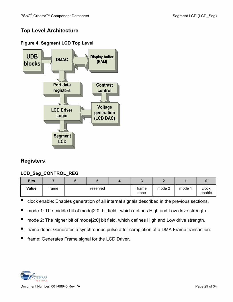
Top Level Architecture
Figure 4. Segment LCD Top Level
Registers
LCD_Seg_CONTROL_REGBits 7 6 5 4 3 2 1 0
Value frame reserved framedone
mode 2 mode 1 clockenable
clock enable: Enables generation of all internal signals described in the previous sections.
mode 1: The middle bit of mode[2:0] bit field, which defines High and Low drive strength.
mode 2: The higher bit of mode[2:0] bit field, which defines High and Low drive strength.
frame done: Generates a synchronous pulse after completion of a DMA Frame transaction.
frame: Generates Frame signal for the LCD Driver.
Segment LCD (LCD_Seg) PSoC® Creator™ Component Datasheet
Page 30 of 34 Document Number: 001-68645 Rev. *A
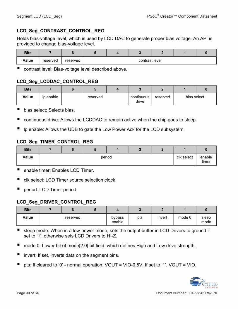
LCD_Seg_CONTRAST_CONTROL_REGHolds bias-voltage level, which is used by LCD DAC to generate proper bias voltage. An API isprovided to change bias-voltage level.
Bits 7 6 5 4 3 2 1 0
Value reserved reserved contrast level
contrast level: Bias-voltage level described above.
LCD_Seg_LCDDAC_CONTROL_REGBits 7 6 5 4 3 2 1 0
Value lp enable reserved continuousdrive
reserved bias select
bias select: Selects bias.
continuous drive: Allows the LCDDAC to remain active when the chip goes to sleep.
lp enable: Allows the UDB to gate the Low Power Ack for the LCD subsystem.
LCD_Seg_TIMER_CONTROL_REGBits 7 6 5 4 3 2 1 0
Value period clk select enabletimer
enable timer: Enables LCD Timer.
clk select: LCD Timer source selection clock.
period: LCD Timer period.
LCD_Seg_DRIVER_CONTROL_REGBits 7 6 5 4 3 2 1 0
Value reserved bypassenable
pts invert mode 0 sleepmode
sleep mode: When in a low-power mode, sets the output buffer in LCD Drivers to ground ifset to ‘1’, otherwise sets LCD Drivers to HI-Z.
mode 0: Lower bit of mode[2:0] bit field, which defines High and Low drive strength.
invert: If set, inverts data on the segment pins.
pts: If cleared to ‘0’ - normal operation, VOUT = VIO-0.5V. If set to ‘1’, VOUT = VIO.
PSoC® Creator™ Component Datasheet Segment LCD (LCD_Seg)
Document Number: 001-68645 Rev. *A Page 31 of 34
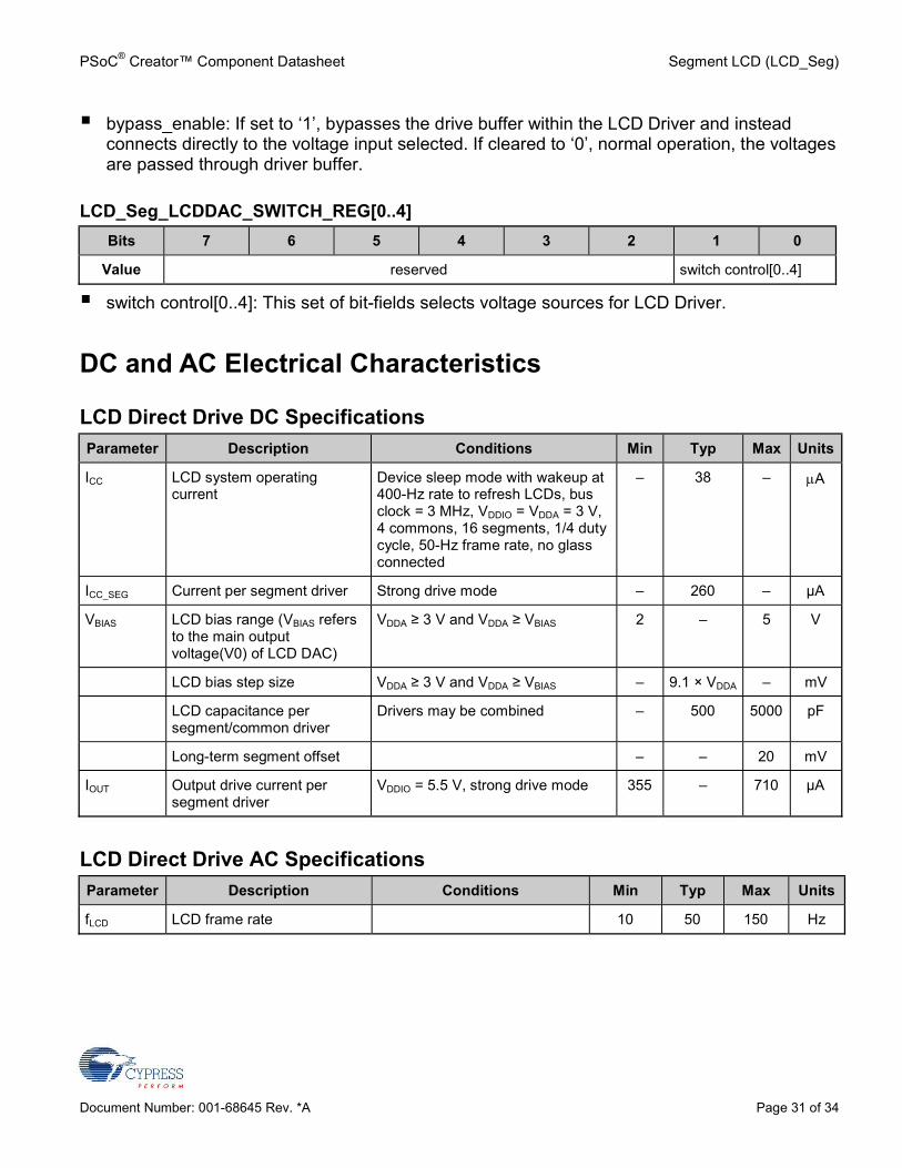
bypass_enable: If set to ‘1’, bypasses the drive buffer within the LCD Driver and insteadconnects directly to the voltage input selected. If cleared to ‘0’, normal operation, the voltagesare passed through driver buffer.
LCD_Seg_LCDDAC_SWITCH_REG[0..4]Bits 7 6 5 4 3 2 1 0
Value reserved switch control[0..4]
switch control[0..4]: This set of bit-fields selects voltage sources for LCD Driver.
DC and AC Electrical Characteristics
LCD Direct Drive DC SpecificationsParameter Description Conditions Min Typ Max Units
ICC LCD system operatingcurrent
Device sleep mode with wakeup at400-Hz rate to refresh LCDs, busclock = 3 MHz, VDDIO = VDDA = 3 V,4 commons, 16 segments, 1/4 dutycycle, 50-Hz frame rate, no glassconnected
– 38 – A
ICC_SEG Current per segment driver Strong drive mode – 260 – µA
VBIAS LCD bias range (VBIAS refersto the main outputvoltage(V0) of LCD DAC)
VDDA ≥ 3 V and VDDA ≥ VBIAS 2 – 5 V
LCD bias step size VDDA ≥ 3 V and VDDA ≥ VBIAS – 9.1 × VDDA – mV
LCD capacitance persegment/common driver
Drivers may be combined – 500 5000 pF
Long-term segment offset – – 20 mV
IOUT Output drive current persegment driver
VDDIO = 5.5 V, strong drive mode 355 – 710 µA
LCD Direct Drive AC SpecificationsParameter Description Conditions Min Typ Max Units
fLCD LCD frame rate 10 50 150 Hz
Segment LCD (LCD_Seg) PSoC® Creator™ Component Datasheet
Page 32 of 34 Document Number: 001-68645 Rev. *A
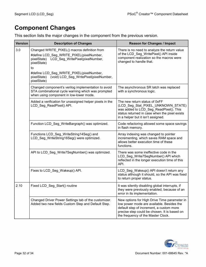
Component ChangesThis section lists the major changes in the component from the previous version.
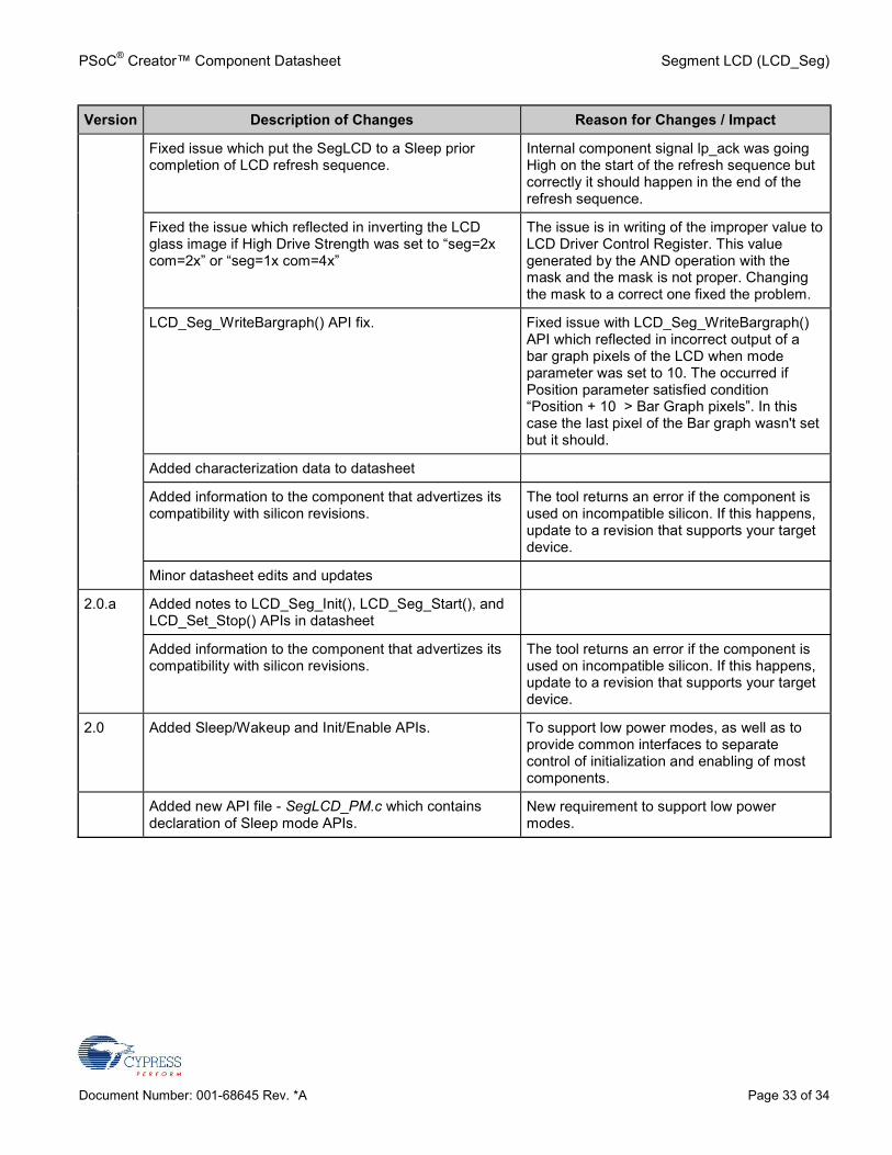
Version Description of Changes Reason for Changes / Impact
3.0 Changed WRITE_PIXEL() macros definition from#define LCD_Seg_WRITE_PIXEL(pixelNumber,pixelState) LCD_Seg_WritePixel(pixelNumber,pixelState)to#define LCD_Seg_WRITE_PIXEL(pixelNumber,pixelState) (void) LCD_Seg_WritePixel(pixelNumber,pixelState)
There is no need to analyze the return valueof the LCD_Seg_WritePixel() API insidecomponent realization so the macros werechanged to handle that.
Changed component’s verilog implementation to avoidSTA combinational cycle warning which was promptedwhen using component in low-lower mode.
The asynchronous SR latch was replacedwith a synchronous logic.
Added a verification for unassigned helper pixels in theLCD_Seg_ReadPixel() API.
The new return status of 0xFF(LCD_Seg_Stat_PIXEL_UNKNOWN_STATE)was added to LCD_Seg_ReadPixel(). Thisstatus returned in case when the pixel existsin a helper but it isn’t assigned.
Function LCD_Seg_WriteBargraph() was optimized. Code refactoring allowed some space savingsin flash memory.
Functions LCD_Seg_WriteString14Seg() andLCD_Seg_WriteString16Seg() were optimized.
Array indexing was changed to pointerincrementing, which saves RAM space andallows better execution time of thesefunctions.
API to LCD_Seg_Write7SegNumber() was optimized. There was some ineffective code in theLCD_Seg_Write7SegNumber() API whichreflected in the longer execution time of thisAPI.
Fixes to LCD_Seg_Wakeup() API. LCD_Seg_Wakeup() API doesn’t return anystatus although it should, so the API was fixedto return proper status.
2.10 Fixed LCD_Seg_Start() routine It was silently disabling global interrupts, ifthey were previously enabled, because of anerror in its implementation.
Changed Driver Power Settings tab of the customizer.Added two new fields Custom Step and Default Step.
New options for High Drive Time parameter inlow power mode are available. Besides thedefault step of increment, a custom moreprecise step could be chosen. It is based onthe frequency of the Master Clock.
PSoC® Creator™ Component Datasheet Segment LCD (LCD_Seg)
Document Number: 001-68645 Rev. *A Page 33 of 34
Version Description of Changes Reason for Changes / Impact
Fixed issue which put the SegLCD to a Sleep priorcompletion of LCD refresh sequence.
Internal component signal lp_ack was goingHigh on the start of the refresh sequence butcorrectly it should happen in the end of therefresh sequence.
Fixed the issue which reflected in inverting the LCDglass image if High Drive Strength was set to “seg=2xcom=2x” or “seg=1x com=4x”
The issue is in writing of the improper value toLCD Driver Control Register. This valuegenerated by the AND operation with themask and the mask is not proper. Changingthe mask to a correct one fixed the problem.
LCD_Seg_WriteBargraph() API fix. Fixed issue with LCD_Seg_WriteBargraph()API which reflected in incorrect output of abar graph pixels of the LCD when modeparameter was set to 10. The occurred ifPosition parameter satisfied condition“Position + 10 > Bar Graph pixels”. In thiscase the last pixel of the Bar graph wasn't setbut it should.
Added characterization data to datasheet
Added information to the component that advertizes itscompatibility with silicon revisions.
The tool returns an error if the component isused on incompatible silicon. If this happens,update to a revision that supports your targetdevice.
Minor datasheet edits and updates
2.0.a Added notes to LCD_Seg_Init(), LCD_Seg_Start(), andLCD_Set_Stop() APIs in datasheet
Added information to the component that advertizes itscompatibility with silicon revisions.
The tool returns an error if the component isused on incompatible silicon. If this happens,update to a revision that supports your targetdevice.
2.0 Added Sleep/Wakeup and Init/Enable APIs. To support low power modes, as well as toprovide common interfaces to separatecontrol of initialization and enabling of mostcomponents.
Added new API file - SegLCD_PM.c which containsdeclaration of Sleep mode APIs.
New requirement to support low powermodes.
Segment LCD (LCD_Seg) PSoC® Creator™ Component Datasheet
Page 34 of 34 Document Number: 001-68645 Rev. *A
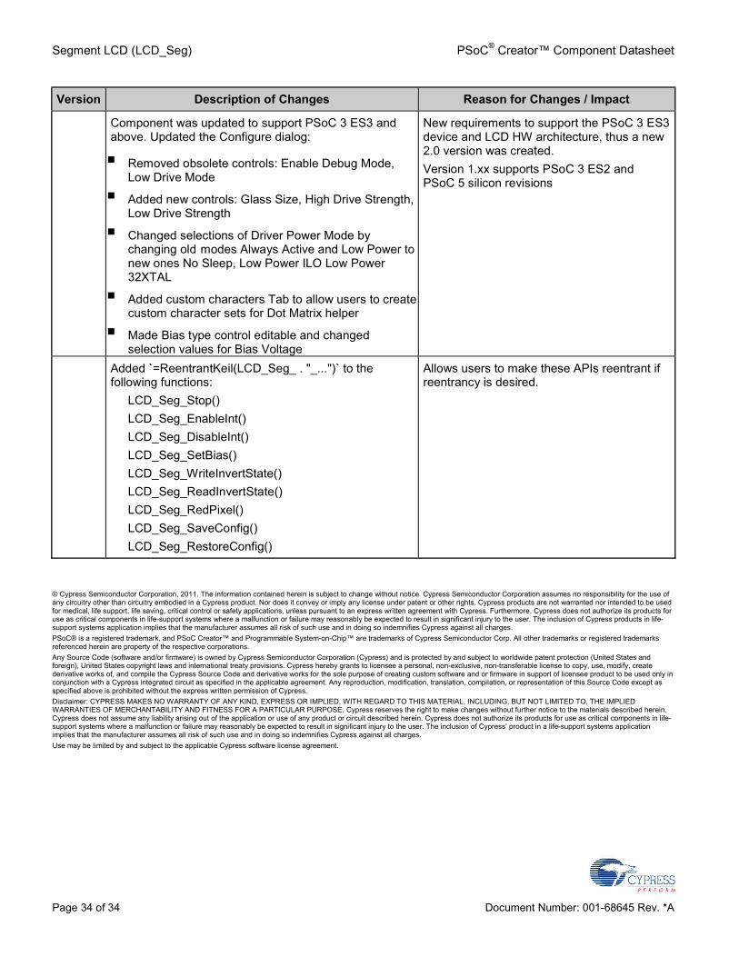
Version Description of Changes Reason for Changes / Impact
Component was updated to support PSoC 3 ES3 andabove. Updated the Configure dialog:
Removed obsolete controls: Enable Debug Mode,Low Drive Mode
Added new controls: Glass Size, High Drive Strength,Low Drive Strength
Changed selections of Driver Power Mode bychanging old modes Always Active and Low Power tonew ones No Sleep, Low Power ILO Low Power32XTAL
Added custom characters Tab to allow users to createcustom character sets for Dot Matrix helper
Made Bias type control editable and changedselection values for Bias Voltage
New requirements to support the PSoC 3 ES3device and LCD HW architecture, thus a new2.0 version was created.Version 1.xx supports PSoC 3 ES2 andPSoC 5 silicon revisions
Added `=ReentrantKeil(LCD_Seg_ . "_...")` to thefollowing functions:
LCD_Seg_Stop()LCD_Seg_EnableInt()LCD_Seg_DisableInt()LCD_Seg_SetBias()LCD_Seg_WriteInvertState()LCD_Seg_ReadInvertState()LCD_Seg_RedPixel()LCD_Seg_SaveConfig()LCD_Seg_RestoreConfig()
Allows users to make these APIs reentrant ifreentrancy is desired.
© Cypress Semiconductor Corporation, 2011. The information contained herein is subject to change without notice. Cypress Semiconductor Corporation assumes no responsibility for the use ofany circuitry other than circuitry embodied in a Cypress product. Nor does it convey or imply any license under patent or other rights. Cypress products are not warranted nor intended to be usedfor medical, life support, life saving, critical control or safety applications, unless pursuant to an express written agreement with Cypress. Furthermore, Cypress does not authorize its products foruse as critical components in life-support systems where a malfunction or failure may reasonably be expected to result in significant injury to the user. The inclusion of Cypress products in life-support systems application implies that the manufacturer assumes all risk of such use and in doing so indemnifies Cypress against all charges.PSoC® is a registered trademark, and PSoC Creator™ and Programmable System-on-Chip™ are trademarks of Cypress Semiconductor Corp. All other trademarks or registered trademarksreferenced herein are property of the respective corporations.Any Source Code (software and/or firmware) is owned by Cypress Semiconductor Corporation (Cypress) and is protected by and subject to worldwide patent protection (United States andforeign), United States copyright laws and international treaty provisions. Cypress hereby grants to licensee a personal, non-exclusive, non-transferable license to copy, use, modify, createderivative works of, and compile the Cypress Source Code and derivative works for the sole purpose of creating custom software and or firmware in support of licensee product to be used only inconjunction with a Cypress integrated circuit as specified in the applicable agreement. Any reproduction, modification, translation, compilation, or representation of this Source Code except asspecified above is prohibited without the express written permission of Cypress.Disclaimer: CYPRESS MAKES NO WARRANTY OF ANY KIND, EXPRESS OR IMPLIED, WITH REGARD TO THIS MATERIAL, INCLUDING, BUT NOT LIMITED TO, THE IMPLIEDWARRANTIES OF MERCHANTABILITY AND FITNESS FOR A PARTICULAR PURPOSE. Cypress reserves the right to make changes without further notice to the materials described herein.Cypress does not assume any liability arising out of the application or use of any product or circuit described herein. Cypress does not authorize its products for use as critical components in life-support systems where a malfunction or failure may reasonably be expected to result in significant injury to the user. The inclusion of Cypress’ product in a life-support systems applicationimplies that the manufacturer assumes all risk of such use and in doing so indemnifies Cypress against all charges.Use may be limited by and subject to the applicable Cypress software license agreement.


