Embed Size (px)
Citation preview

20070802
SEL-351RRecloser Control
Quick-Start Installationand User’s Guide
*PM351RQS-01*

SEL-351R Recloser Control Quick-Start Installation and User’s Guide Date Code 20070802
© 1998–2007 by Schweitzer Engineering Laboratories, Inc. All rights reserved.
All brand or product names appearing in this document are the trademark or registered trademark of their respective holders. No SEL trademarks may be used without written permission. SEL products appearing in this document may be covered by US and Foreign patents.
Schweitzer Engineering Laboratories, Inc. reserves all rights and benefits afforded under federal and international copyright and patent laws in its products, including without limitation software, firmware, and documentation.
The information in this manual is provided for informational use only and is subject to change without notice. Schweitzer Engineering Laboratories, Inc. has approved only the English language manual.
This product is covered by the standard SEL 10-year warranty. For warranty details, visit www.selinc.com or contact your customer service representative. Note: The 24 Vdc battery inside the SEL-351R Recloser Control enclosure is excluded from the product warranty.

Table of ContentsList of Tables ........................................................................................................................................................ v
List of Figures .................................................................................................................................................... vii
Preface .................................................................................................................................................................. ixAbout This Quick-Start Installation and User’s Guide...................................................................................... ix
Page Numbering ......................................................................................................................................... ixConventions ........................................................................................................................................................ x
Typographic Conventions............................................................................................................................ xSafety Information....................................................................................................................................... x
Section 1: InstallationOverview ......................................................................................................................................................... 1.1
Compatibility............................................................................................................................................ 1.1Hardware Overview......................................................................................................................................... 1.1
Reclosers With Internal Battery Charging Transformers ......................................................................... 1.2Terminal Block ......................................................................................................................................... 1.2Accessories............................................................................................................................................... 1.2Control Cable ........................................................................................................................................... 1.2Knockout Details and Uses ...................................................................................................................... 1.2
Installation Step 1: Mount the Enclosure ........................................................................................................ 1.3Important Notes for Installation Step 1 .................................................................................................... 1.3
Installation Step 2: Ground the Enclosure....................................................................................................... 1.4Important Notes for Installation Step 2 .................................................................................................... 1.4
Installation Step 3: Connect the Battery.......................................................................................................... 1.5Installation Step 4: Wake Up the Control ........................................................................................................ 1.6Installation Step 5: Connecting Three-Phase Voltage? ................................................................................... 1.6Installation Step 6: Connect the 120 Vac Power.............................................................................................. 1.7
Important Notes for Installation Step 6 .................................................................................................... 1.7Installation Step 7: Verify Settings and Set Date and Time ............................................................................ 1.8Installation Step 8: Disable Ground ................................................................................................................ 1.8Installation Step 9: Connect the Control Cable ............................................................................................... 1.8Installation Step 10: Metering Check (if Recloser Is Closed) ......................................................................... 1.9Installation Step 11: Enable Ground................................................................................................................ 1.9Option 1: Connect Three-Phase and Synchronism Check Voltage ............................................................... 1.10
Important Notes for Option 1 ................................................................................................................. 1.11Option 2: Monitor Ext. Contacts With 24 Vdc; Power Radio With 12 Vdc ................................................. 1.12
Important Notes for Option 2 ................................................................................................................. 1.12Option 3: Mount Accessories Inside Enclosure ............................................................................................ 1.13
Important Notes for Option 3 ................................................................................................................. 1.13Detail 1: Factory-Installed Terminal Block Voltage Jumpers........................................................................ 1.14
Important Notes for Detail 1 .................................................................................................................. 1.14Detail 2: Side Panel (Figure 1.12) ................................................................................................................. 1.15
Important Notes for Detail 2 .................................................................................................................. 1.15Detail 3: Wiring Diagram (Figure 1.13) ........................................................................................................ 1.15
Important Notes for Detail 3 .................................................................................................................. 1.15Detail 4: Current Polarity/Recloser Primary Connections ............................................................................ 1.18Detail 5: Control Cable Receptacle and Replacement Fuses ........................................................................ 1.21Detail 6: Trip and Close Circuits ................................................................................................................... 1.23
Important Notes for Detail 6 .................................................................................................................. 1.24
Section 2: CommunicationsOverview ......................................................................................................................................................... 2.1Getting Started With Communications............................................................................................................ 2.1Communications Connections Example.......................................................................................................... 2.2Serial Ports....................................................................................................................................................... 2.3Serial Port Default Settings ............................................................................................................................. 2.3
Date Code 20070802 Quick-Start Installation and User’s Guide SEL-351R Recloser Control

ii
SEL-351R R
Table of Contents
EIA-232 Pinout Functions for Ports 2, 3, and F ..............................................................................................2.3EIA-485 Pinout Functions for Port 1 ...............................................................................................................2.4Communications Cables ..................................................................................................................................2.5Cable Diagrams................................................................................................................................................2.5Commands .......................................................................................................................................................2.6Event Reports...................................................................................................................................................2.9Access Levels and Password Protection ........................................................................................................2.10Change Passwords .........................................................................................................................................2.11Disable Passwords .........................................................................................................................................2.12Password Jumper ...........................................................................................................................................2.12
Section 3: Front-Panel InterfaceStatus and Trip Target LEDs............................................................................................................................3.3Pushbuttons ......................................................................................................................................................3.3Pushbutton Primary Functions .........................................................................................................................3.5Operator Controls ............................................................................................................................................3.8
Section 4: SettingsOverview..........................................................................................................................................................4.1Curve Information............................................................................................................................................4.1Factory EZ Settings..........................................................................................................................................4.3Settings Descriptions .......................................................................................................................................4.6
Settings Groups 1 (Main) and 2 (Alternate) EZ Settings .........................................................................4.6Global EZ Settings..................................................................................................................................4.22
EZ Settings Sheets for the SEL-351R Recloser Control ............................................................................ SET.1Recloser Curve Designations...................................................................................................................... SET.8
Section 5: TestingOverview..........................................................................................................................................................5.1AC AMMETER on the Type MET Control Tester ..........................................................................................5.2Testing In-Service Control ...............................................................................................................................5.2
Removing the SEL-351R Recloser Control From Service.......................................................................5.2Placing the SEL-351R Recloser Control Back in Service........................................................................5.3
Initial Conditions for Control Tests .................................................................................................................5.3SEL-351R Recloser Control .....................................................................................................................5.3Type MET Control Tester .........................................................................................................................5.4
Control Operation Tests ...................................................................................................................................5.5Phase Trip .................................................................................................................................................5.5Ground Trip ..............................................................................................................................................5.6
Minimum-Trip Tests ........................................................................................................................................5.7Phase .........................................................................................................................................................5.7Ground ......................................................................................................................................................5.8
Fast and Delay Curve Checks ..........................................................................................................................5.9Phase Fast Curve.......................................................................................................................................5.9Phase Delay Curve..................................................................................................................................5.10Ground Fast Curve..................................................................................................................................5.11Ground Delay Curve...............................................................................................................................5.12
Reclosing Tests ..............................................................................................................................................5.14Reclose Interval Times ...........................................................................................................................5.14Reset Times.............................................................................................................................................5.15
Section 6: BatteryOverview..........................................................................................................................................................6.1Battery-Related Settings ..................................................................................................................................6.1Battery Status ...................................................................................................................................................6.2
Battery Status via Front Panel ..................................................................................................................6.2Battery Status via Serial Port....................................................................................................................6.3
Automatic Battery Load Test ...........................................................................................................................6.3Battery Load Test via Front Panel ...................................................................................................................6.3Battery Load Test via Serial Port .....................................................................................................................6.4
ecloser Control Quick-Start Installation and User’s Guide Date Code 20070802

iiiTable of Contents
Battery Replacement ....................................................................................................................................... 6.5
Section 7: Convenience OutletTesting the 120 Vac (GFCI) Convenience Outlet ............................................................................................ 7.1Factory Assistance........................................................................................................................................... 7.1
Section 8: SpecificationsSpecifications .................................................................................................................................................. 8.2
Appendix A: Quick-Start Guide Change Information
Appendix B: ReferenceReplaced Figures .............................................................................................................................................B.1
Date Code 20070802 Quick-Start Installation and User’s Guide SEL-351R Recloser Control

List of TablesTable 1.1 Ratings for User-Available Voltage Sources (see Figure 1.9) .............................................. 1.13Table 1.2 Control Cable Receptacle Pin Descriptions ......................................................................... 1.21Table 1.3 Replacement Fuses for the SEL-351R Recloser Control (see Figure 1.13)......................... 1.22Table 2.1 EIA-232 Pinout Functions...................................................................................................... 2.3Table 2.2 EIA-485 Pinout Functions...................................................................................................... 2.4Table 2.3 Serial Communications Port Pin Function Definitions .......................................................... 2.4Table 2.4 SEL EIA-232 Serial Communications Cable Guide .............................................................. 2.5Table 2.5 SEL-351R Recloser Control Command Summary ................................................................ 2.7Table 2.6 Event Report Parameters ...................................................................................................... 2.10Table 2.7 Access Level, Summary Information ................................................................................... 2.11Table 2.8 Valid Password Characters ................................................................................................... 2.11Table 3.1 Front-Panel Pushbutton Secondary Functions ....................................................................... 3.4Table 4.1 Recloser Curve Designations ................................................................................................. 4.2Table 4.2 US, IEC, and User-Programmable Curve Designations......................................................... 4.2Table 4.3 EZ Settings Quick Reference ................................................................................................. 4.3Table 4.4 Seconds-to-Cycles Conversion (60 Hz) ............................................................................... 4.11Table 4.5 Recloser Interrupt Data ........................................................................................................ 4.23Table 6.1 Battery Status Information Accessed From the Front Panel .................................................. 6.2Table A.1 Quick-Start Guide Change Information ................................................................................ A.1
Date Code 20070802 Quick-Start Installation and User’s Guide SEL-351R Recloser Control

List of FiguresFigure 1.1 SEL-351R Recloser Control Enclosure With Swing Panel Closed........................................ 1.1Figure 1.2 SEL 351R Recloser Control Enclosure With Swing Panel Open (wiring not shown)........... 1.2Figure 1.3 SEL-351R Recloser Control Dimensions and Mounting Drill Plan ...................................... 1.3Figure 1.4 SEL-351R Customer Ground Connection to Required System Grounding........................... 1.4Figure 1.5 SEL-351R Recloser Control Grounding
Lug Location and Other Dimensional Information (bottom view) .................................... 1.5Figure 1.6 Battery Wiring Harness Connections ..................................................................................... 1.5Figure 1.7 Connections to 120 Vac Power Bus ....................................................................................... 1.7Figure 1.8 Three-Phase and Synchronism Check Voltage Connections................................................ 1.10Figure 1.9 Monitor External Contacts Using 24 Vdc
From the SEL 351R Recloser Control; 12 Vdc Connection ............................................ 1.12Figure 1.10 Recommended Dimensions and Drill Plan for User-Supplied Accessory Panel ................. 1.13Figure 1.11 Factory-Installed Jumpers From 120 Vac Power Bus to Voltage Input V1.......................... 1.14Figure 1.12 SEL-351R Recloser Control Side Panel............................................................................... 1.16Figure 1.13 SEL-351R Recloser Control Factory-Installed Wiring Inside the Enclosure ...................... 1.17Figure 1.14 Current Polarity From Recloser Primary to SEL-351R Recloser Control Current Inputs... 1.19Figure 1.15 User Terminal Block Wiring or Setting Changes Accommodate
All Possible Primary Connections to the Recloser (to keep consistent with SEL-351R Recloser Control current channel designations)...... 1.20
Figure 1.16 Control Cable Receptacle (viewed from inside SEL-351R enclosure) ................................ 1.21Figure 1.17 Trip and Close Circuit Connections ..................................................................................... 1.23Figure 2.1 SEL-351R Recloser Control Communications Connections Example .................................. 2.2Figure 2.2 DB-9 Connector Pinout (Female) for EIA-232 Serial Ports .................................................. 2.3Figure 2.3 EIA-485 Pinout for Port 1 ...................................................................................................... 2.4Figure 2.4 SEL-351R to Computer.......................................................................................................... 2.5Figure 2.5 SEL-351R to SEL-2032/SEL-2030/SEL-2020 Communications Processor ......................... 2.6Figure 2.6 SEL-351R to Modem ............................................................................................................. 2.6Figure 2.7 Jumper, Connector, and Major Component Locations on the SEL-351R Main Board........ 2.15Figure 3.1 SEL-351R Front-Panel Interface............................................................................................ 3.1Figure 3.2 SEL-351R Front-Panel Interface Configurable Labels .......................................................... 3.2Figure 3.3 Status and Trip Target LEDs .................................................................................................. 3.3Figure 3.4 Primary and Secondary Functions of Front-Panel Pushbuttons ............................................. 3.3Figure B.1 SEL-351R Factory-Installed Wiring Inside the Enclosure
(for units built before June 2001) .......................................................................................B.1Figure B.2 SEL-351R Recloser Control Side Panel Prior to October 2004.............................................B.2
Date Code 20070802 Quick-Start Installation and User’s Guide SEL-351R Recloser Control

Preface
About ThisQuick-Start Installation and User’s Guide
This SEL-351R Recloser Control Quick-Start Installation and User's Guide helps you install, communicate with, set, and test the SEL-351R in its EZ (“easy”) mode of operation. The EZ mode performs traditional recloser control functions and operations.
SEL designed the SEL-351R based on the SEL-351 Distribution Relay. The SEL-351R has full SEL-351 Relay functionality together with a modified user interface designed for recloser control. When using the SEL-351R as a traditional line recloser control, it is only necessary to access the EZ Level (Access Level E) Settings. See the SEL-351R Recloser Control Instruction Manual for complete information regarding the full functionality of the SEL-351R.
This Quick-Start Installation and User’s Guide includes the following:
➤ Preface
➤ Section 1: Installation
➤ Section 2: Communications
➤ Section 3: Front-Panel Interface
➤ Section 4: Settings
➤ Section 5: Testing
➤ Section 6: Battery
➤ Section 7: Convenience Outlet
➤ Section 8: Specifications
➤ Appendix A: Quick-Start Guide Change Information
➤ Appendix B: Reference
Page Numbering This guide shows page identifiers at the top of each page; see the figure below.
Page Number Format
Installation
Title Block Page Number
Installation Step 11: Enable Ground2.13
Date Code 20070802 Quick-Start Installation and User’s Guide SEL-351R Recloser Control
x
SEL-351R Rec
Preface
The page number appears at the outside edge of each page; a vertical bar separates the page number from the page title block. The page numbers of the SEL-351R Quick-Start Installation and User’s Guide are represented by the following building blocks:
➤ Section number
➤ Actual page number in the particular section
The section title is at the top of the page title block, with the main subsection reference in bold type underneath the section title.
Conventions
TypographicConventions
There are three ways to communicate with the SEL-351R:
➤ Using a command line interface on a PC terminal emulation window, such as Microsoft® HyperTerminal.
➤ Using the front-panel menus and pushbuttons.
➤ Using ACSELERATOR® SEL-5030 Software.
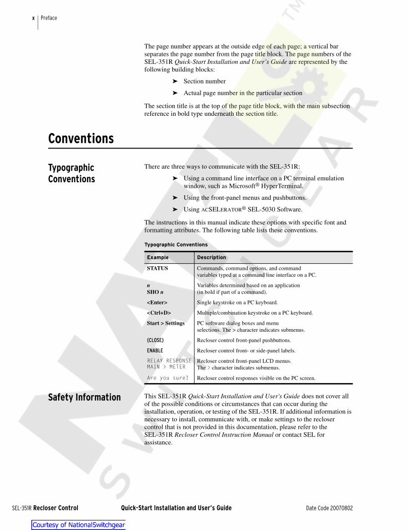
The instructions in this manual indicate these options with specific font and formatting attributes. The following table lists these conventions.
Safety Information This SEL-351R Quick-Start Installation and User's Guide does not cover all of the possible conditions or circumstances that can occur during the installation, operation, or testing of the SEL-351R. If additional information is necessary to install, communicate with, or make settings to the recloser control that is not provided in this documentation, please refer to the SEL-351R Recloser Control Instruction Manual or contact SEL for assistance.
Typographic Conventions
Example Description
STATUS Commands, command options, and commandvariables typed at a command line interface on a PC.
nSHO n
Variables determined based on an application(in bold if part of a command).
<Enter> Single keystroke on a PC keyboard.
<Ctrl+D> Multiple/combination keystroke on a PC keyboard.
Start > Settings PC software dialog boxes and menuselections. The > character indicates submenus.
{CLOSE} Recloser control front-panel pushbuttons.
ENABLE Recloser control front- or side-panel labels.
RELAY RESPONSEMAIN > METER
Recloser control front-panel LCD menus.The > character indicates submenus.
Are you sure? Recloser control responses visible on the PC screen.
loser Control Quick-Start Installation and User’s Guide Date Code 20070802

xiPreface
This guide uses three kinds of hazard statements, formatted as follows:
Indicates a potentially hazardous situation that, if not avoided, may result in minor or moderate injury or equipment damage.
! CAUTION
Indicates a potentially hazardous situation that, if not avoided, could result in death or serious injury.
! WARNING
Indicates an imminently hazardous situation that, if not avoided, will result in death or serious injury.
! DANGER
Keep the following safety concerns in mind when working with your SEL-351R.
The SEL-351R contains devices sensitive to Electrostatic Discharge (ESD). When working on the relay module with cover removed, work surfaces and personnel must be properly grounded or equipment damage may result.
! CAUTIONDo not connect this control to an energized recloser until all control settings have been properly programmed and verified. Refer to the Settings section of this guide for programming procedures. Failure to comply can result in control and recloser misoperation, equipment damage, and personal injury.
! CAUTION
Before installing, operating, maintaining, or testing this equipment, carefully read and understand the contents of this guide. Improper installation, handling, or maintenance can result in death, severe personal injury, and/or equipment damage.
! WARNINGThis equipment is not intended to protect human life. Follow all locally approved procedures and safety practices when installing or operating this equipment. Failure to comply may result in death, severe personal injury, and/or equipment damage.
! WARNING
Contact with instrument terminals may cause electric shock that can result in injury or death.
! DANGER
Date Code 20070802 Quick-Start Installation and User’s Guide SEL-351R Recloser Control

Section 1Installation
Overview
This section provides:
➤ Hardware Overview
➤ Numbered Step-by-Step Installation Instructions
➤ Installation Instructions for Optional Connections
➤ Extra Detail
Compatibility Install the SEL-351R Recloser Control in new or retrofit recloser installations in place of Kyle® Form 3, 3A, 4, 4A, 4C, and Type FXA and FXB controls. The SEL-351R is compatible with Cooper three-phase reclosers (with 24 Vdc trip/close circuits) that are compatible with the previously mentioned Kyle controls.
Hardware Overview
Figure 1.1 SEL-351R Recloser Control Enclosure With Swing Panel Closed
MOTOR-OPERATED RECLOSERSRefer to SEL Application Guide AG99-10, Change Logic in SEL-351R Recloser Control for Motor-Operated Reclosers to modify a few settings for motor-operated reclosers (e.g., MVE, CVE, CXE, CZE, VSA).
Document Holder
Front Panel
120 Vac (GFCI) Convenience Outlet
Control Cable Receptacle
Fuse Holder
Shipping ScrewsREMOVESHIPPING SCREWSThe SEL-351R ships from the factory with three shipping screws. In order to open the swing panel, these screws (#10-32) must be removed. Refer to Figure 1.1.
GFCI = GROUND-FAULT CIRCUIT INTERRUPTERThe panel-mounted fuse holder in Figure 1.1 provides additional protection for the 120 Vac (GFCI) convenience outlet. Maximum loading is 10 A (see Table 1.3 and Section 7: Convenience Outlet).
Date Code 20070802 Quick-Start Installation and User’s Guide SEL-351R Recloser Control

1.2
SEL-351R Rec
InstallationHardware Overview
Reclosers With Internal Battery Charging Transformers
Some Cooper reclosers have an internal battery charging transformer (current transformer). This charging transformer is not used by the SEL-351R. Its 24 Vdc battery is charged from a user-supplied 120 Vac power source. If one of these reclosers is connected to the SEL-351R, this charging transformer is electrically shorted at the control cable receptacle (see Figure 1.13; pins K and L are shorted together and grounded).
Terminal Block ➤ Rail: DIN 3
➤ Screws: #6-32
➤ Lug width: 0.334" max. (8.5 mm)
Accessories Accessories can be mounted on the back panel, above the terminal block. See Figure 1.10 for more details.
Control Cable The SEL-351R uses the same control cable that connects a Kyle Form 3, 3A, 4, 4A, 4C, or Type FXA or FXB control to a Cooper three-phase recloser.
KnockoutDetails and Uses
➤ 7/8" for 1/2" conduit fittings
➤ 1-3/8" for 1" conduit fittings
See Figure 1.5 for more knockout details.
Bring 120 Vac power, close power, three-phase voltage, external control, etc., in and out of the SEL-351R enclosure via the knockout holes.
Figure 1.2 SEL 351R Recloser ControlEnclosure With Swing Panel Open (wiring not shown)
Control Cable
Receptacle 7/8" and 1-3/8"
Knockouts
Terminal
Block
Battery Fence
Batteries
NEMA Type 3R
(IP32) Enclosure
Relay Module
120 Vac (GFCI)
Convenience Outlet
Side
Panel
loser Control Quick-Start Installation and User’s Guide Date Code 20070802
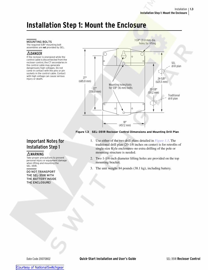
1.3InstallationInstallation Step 1: Mount the Enclosure
Installation Step 1: Mount the Enclosure
Figure 1.3 SEL-351R Recloser Control Dimensions and Mounting Drill Plan
Important Notes for Installation Step 1
1. Use either of the two drill plans detailed in Figure 1.3. The traditional drill plan (20-1/8 inches on center) is for retrofits of single-size Kyle enclosures–no extra drilling of the pole or mounting structure is needed.
2. Two 1-1/4-inch diameter lifting holes are provided on the top mounting bracket.
3. The unit weighs 84 pounds (38.1 kg), including battery.
20-1/8"(511.2 mm)
24-5/8"(625.5 mm)
18"(457.2 mm)
Mounting holes/slotsfor 5/8" (16 mm) bolts
1-1/4" (31.8 mm) dia.holes for lifting
SELdrill plan
Traditionaldrill plan
27" (685.8 mm)
22"(558.8 mm)
MOUNTING BOLTSThe required 5/8" mounting bolt assemblies are not provided by SEL.
! DANGERIf the recloser is energized while the control cable is disconnected from the recloser control, the CT secondaries in the control cable may generate dangerously high voltages. Do not come in contact with the pins or pin sockets in the control cable. Contact with high voltage can cause serious injury or death.
! WARNINGTake proper precautions to prevent personal injury or equipment damage when lifting and mounting the SEL-351R.
DO NOT TRANSPORTTHE SEL-351R WITHTHE BATTERY INSIDETHE ENCLOSURE!
Date Code 20070802 Quick-Start Installation and User’s Guide SEL-351R Recloser Control
1.4
SEL-351R Rec
InstallationInstallation Step 2: Ground the Enclosure
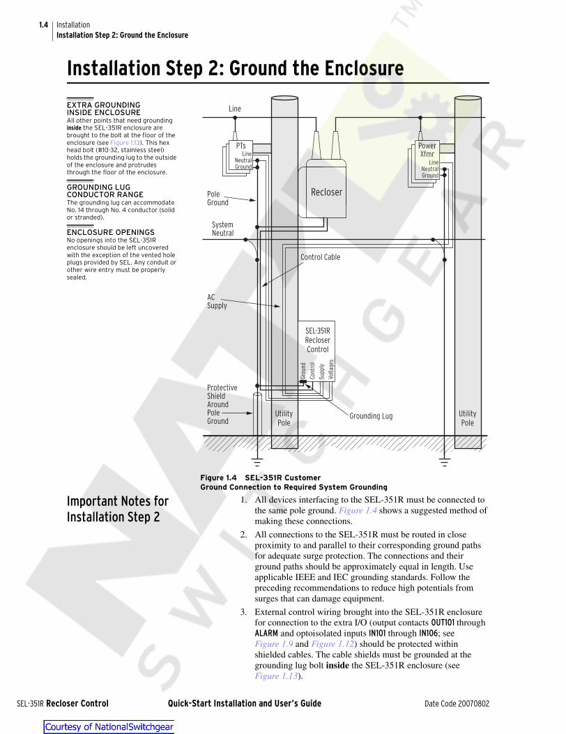
Installation Step 2: Ground the Enclosure
Figure 1.4 SEL-351R CustomerGround Connection to Required System Grounding
Important Notes for Installation Step 2
1. All devices interfacing to the SEL-351R must be connected to the same pole ground. Figure 1.4 shows a suggested method of making these connections.
2. All connections to the SEL-351R must be routed in close proximity to and parallel to their corresponding ground paths for adequate surge protection. The connections and their ground paths should be approximately equal in length. Use applicable IEEE and IEC grounding standards. Follow the preceding recommendations to reduce high potentials from surges that can damage equipment.
3. External control wiring brought into the SEL-351R enclosure for connection to the extra I/O (output contacts OUT101 through ALARM and optoisolated inputs IN101 through IN106; see Figure 1.9 and Figure 1.12) should be protected within shielded cables. The cable shields must be grounded at the grounding lug bolt inside the SEL-351R enclosure (see Figure 1.13).
Recloser
SEL-351RRecloserControl
Gro
und
Cont
rol
Supp
ly
Volt
ages
LineNeutralGround
PTs
LineNeutralGround
PowerXfmr
UtilityPole
Grounding Lug UtilityPole
Control Cable
Line
SystemNeutral
AC Supply
ProtectiveShieldAroundPoleGround
PoleGround
EXTRA GROUNDINGINSIDE ENCLOSUREAll other points that need grounding inside the SEL-351R enclosure are brought to the bolt at the floor of the enclosure (see Figure 1.13). This hex head bolt (#10-32, stainless steel) holds the grounding lug to the outside of the enclosure and protrudes through the floor of the enclosure.
GROUNDING LUG CONDUCTOR RANGEThe grounding lug can accommodate No. 14 through No. 4 conductor (solid or stranded).
ENCLOSURE OPENINGSNo openings into the SEL-351R enclosure should be left uncovered with the exception of the vented hole plugs provided by SEL. Any conduit or other wire entry must be properly sealed.
loser Control Quick-Start Installation and User’s Guide Date Code 20070802

1.5InstallationInstallation Step 3: Connect the Battery
Figure 1.5 SEL-351R Recloser Control Grounding Lug Location and Other Dimensional Information (bottom view)
Installation Step 3: Connect the Battery
q See Table 1.3.
Figure 1.6 Battery Wiring Harness Connections
Grounding Lug
Control Cable
Receptacle
1/4" (6.4 mm) dia. holes (6 hole plugs installed)
3/8" (9.5 mm) hole for customer lock
11-1/4" (285.8 mm)
14-1/4" (362.0mm)
3"76. 2 m m)
1-3/8"(34.9 mm)
1-3/8"(34.9 mm)
2"(50.8 mm)
1-3/8" (34.9 mm) dia. holes
1/8" (3.2 mm) holes (4 screws installed
for battery tray)
1-1/4" (31.8 mm)
1/8" (3.2 mm) holes for #4-40 screws
7/8" (22.2 mm) dia. holes (1 vent plug installed) 1-2/10"
(30.5 mm)
12 Vdc
Battery
12 Vdc
Battery
Front of Enclosure
red
black
_
+
_
+
to POWER
connector J6
Battery
Fence
2 x 3 E-Cells,
shrink-wrapped
2 x 3 E-Cells,
shrink-wrapped
separable
connector
J12
black
Positive terminals (+)
are set back farther
from battery edge
than negative
terminals (-)
21
Battery Fuse–
See q
FRONT PANEL STILL DARK! The front panel is still dark after connecting the battery. Installation Step 4 turns on the SEL-351R.
REPLACING A BATTERY? Refer to Battery Replacement on page 6.5.
DO NOT TRANSPORTTHE SEL-351R WITHTHE BATTERY INSIDETHE ENCLOSURE!
COMPLETE WIRING DIAGRAM See Figure 1.13.
TEST THE BATTERY? To test the battery after it has been connected and the SEL-351R is turned on, refer to Section 6: Battery.
! CAUTIONSeparable connector J12 should be the first disconnected when removing batteries and the last connected when installing batteries. Do not leave J12 connected without the batteries also connected. The tab disconnects on the battery wiring harness are energized and can short-circuit if they come in contact with the enclosure floor or each other, consequently damaging the internal power supply.
Date Code 20070802 Quick-Start Installation and User’s Guide SEL-351R Recloser Control

1.6
SEL-351R Rec
InstallationInstallation Step 4: Wake Up the Control
Set the batteries inside the battery fence as shown in Figure 1.2. Fasten and secure the hook and loop strap over the battery top. Connect the battery wiring harness as shown in Figure 1.6, following the instructions given in the accompanying CAUTION. Note that the small jumper wire in the harness connects the (–) terminal of one 12 Vdc battery to the (+) terminal of the other 12 Vdc battery to make an effective 24 Vdc battery.
Installation Step 4: Wake Up the Control
Press the front-panel {WAKE UP} operator control, and the SEL-351R turns on. The following should be observed:
➤ CONTROL ENABLED LED illuminates
➤ BATTERY PROBLEM LED remains extinguished
If the unit does not turn on, check the following items:
➤ Battery is low-charged or dead
➤ Battery fuse is blown–see Figure 1.6 and Table 1.3.
Installation Step 5: Connecting Three-Phase Voltage?
WAKE UPWITHOUT {WAKE UP}: If Installation Step 4 is skipped, the SEL-351R will turn on automatically when Installation Step 6 is executed. Application of 120 Vac power always turns on the SEL-351R.
NO If not connecting three-phase voltage, go directly to Installation Step 6: Connect the 120 Vac Power on page 1.7.
YES If connecting three-phase voltage, read and understand the following subsections and then answer the following question:
Option 1: Connect Three-Phase and Synchronism Check Voltage on page 1.10 (see Figure 1.8)Detail 1: Factory-Installed Terminal Block Voltage Jumpers on page 1.14 (see Figure 1.11)Will the SEL-351R also be powered from the three-phase voltage (must be 120 Vac power)?
NO Go to Installation Step 6: Connect the 120 Vac Power, but first remove the factory-installed jumpers to voltage input V1 (refer to the subsections listed above). After completing Installation Step 6: Connect the 120 Vac Power (and removing the factory-installed jumpers to voltage input V1), connect three-phase voltage before proceeding to Installation Step 7: Verify Settings and Set Date and Time on page 1.8.
YES Skip Installation Step 6: Connect the 120 Vac Power and connect the three-phase voltage to the unit (refer to the subsections listed above).
ENABLE FAULTLOCATION IF THREE-PHASE VOLTAGE IS CONNECTED Use SET n command [n = 1 (main settings), n = 2 (alternate settings)]
Make line parameter settings:Z1MAG, Z1ANG, Z0MAG, Z0ANG, LL
Enable fault locating:EFLOC = Y
loser Control Quick-Start Installation and User’s Guide Date Code 20070802

1.7InstallationInstallation Step 6: Connect the 120 Vac Power
Installation Step 6: Connect the 120 Vac Power
q See Table 1.3.
Figure 1.7 Connections to 120 Vac Power Bus
Important Notes for Installation Step 6
1. The power brought into the enclosure is shown wired to terminal block positions 18 and 21. Because terminal block positions 17, 18, and 19 are bused together as the 120 Vac bus and terminal block positions 20, 21, and 22 are bused together as the Neutral bus, the Power In can be connected to any of these terminals for respective 120 Vac and neutral connections. The same is true for the Close Power going out of the unit.
2. For reclosers equipped to be closed from 120 Vac power, Close Power can be brought out from the 120 Vac and Neutral buses as shown. Close operations are started with the 24 Vdc close circuit (detailed in Figure 1.17), but the power required to close the main contacts and compress the tripping springs in the recloser is usually either 120 Vac, as discussed here, or primary voltage. This depends on recloser construction.
222120191817
USER
Terminal Block
SEL
To POWER connector J6
Factory-installed jumpers to voltage
input V1
120 Vac
To connector J11 on120 Vac (GFCI)
convenience outlet
Neutral
120 Vac
Neutral
Power In
Close Power (if recloser is equipped)
120 VacBus
NeutralBus
120 Vac
120
Vac
Neu
tral
120 Vac
Neutral
PossibleUserConnection
UserConnection
28
120 Vac (fuse protected)
Fuse–see q
Neu
tral
FRONT-PANEL INDICATIONWhen 120 Vac is connected to the SEL-351R, the front-panel AC SUPPLY LED illuminates.
If still extinguished, check fuse in terminal block position 28. The AC SUPPLY LED illuminates if the relay module is powered-up/functional and the battery is not discharging. The AC SUPPLY LED may flicker at times when tripping or closing, due to the battery momentarily discharging a bit.
120 VAC POWERALSO ENERGIZESVOLTAGE INPUT V1See Figure 1.11 for more information.
Date Code 20070802 Quick-Start Installation and User’s Guide SEL-351R Recloser Control

1.8
SEL-351R Rec
InstallationInstallation Step 7: Verify Settings and Set Date and Time
Installation Step 7: Verify Settings and Set Date and Time
If the alternate settings are not going to be used, copy the main settings (Settings Group 1) to the alternate settings (Settings Group 2) with the COPY command (i.e., COP 1 2). The settings in both settings groups will then be the same. If the {ALTERNATE SETTINGS} operator control pushbutton is accidentally pressed (switching the active settings group), the SEL-351R still operates on the same settings. Refer to the Factory EZ Settings on page 4.3 for more information on main and alternate settings.
Set the date and time with the DATE and TIME commands (DAT and TIM, respectively; see Table 2.5).
Installation Step 8: Disable Ground
Disable ground overcurrent tripping with the {GROUND ENABLED} operator control on the SEL-351R (corresponding LED extinguishes). Set other operator controls as desired for normal operation.
Installation Step 9: Connect the Control Cable
Connect the control cable to the control cable receptacle at the bottom of the SEL-351R enclosure (see Figure 1.5). The SEL-351R uses the same control cable that connects a Kyle Form 3, 3A, 4, 4A, 4C, or Type FXA or FXB control to a Cooper three-phase recloser.
! CAUTIONDo not connect the SEL-351R to an energized recloser until all control settings have been properly programmed and verified. Refer to Section 4: Settings for programming procedures. Failure to comply can result in control and recloser misoperation, equipment damage, and personal injury.
! DANGERIf the recloser is energized while the control cable is disconnected from the recloser control, the CT secondaries in the control cable may generate dangerously high voltages. Do not come in contact with the pins or pin sockets in the control cable. Contact with high voltage can cause serious injury or death.
DO RECLOSERPRIMARY CONNECTIONS MATCH SEL-351R FACTORY CONNECTIONS?See Figure 1.14 and Figure 1.15.
loser Control Quick-Start Installation and User’s Guide Date Code 20070802

1.9InstallationInstallation Step 10: Metering Check (if Recloser Is Closed)
Installation Step 10:Metering Check (if Recloser Is Closed)
Press the front-panel {METER} pushbutton and select the INST (instantaneous metering) option. Scroll through the instantaneous metering values (primary), checking current IA, IB, and IC magnitude and angle for expected phase rotation. The residual ground (IG) and neutral ground (IN) current displays should show relatively low current magnitudes, when compared to IA, IB, and IC, if system loading is well-balanced. The negative-sequence (3I2) current display should show relatively low current magnitude, when compared to IA, IB, and IC, if system loading is well-balanced and phase rotation is correct.
If system loading is well-balanced, but current display IG , IN, or 3I2 shows an abnormally high current level, suspect a wiring or setting problem. Solve this problem before enabling ground overcurrent tripping (you may need to take the SEL-351R out of service). See Figure 1.14 and Figure 1.15.
In installations where single-phase 120 Vac power is the only voltage brought to the SEL-351R, the instantaneous metering values will display the expected primary value for VA, VB, and VC for assigned voltage input V1, V2, and V3; and VS will be equal to zero (0) or negligible. (See Figure 1.11 for voltage input V1 information.)
Installation Step 11: Enable Ground
If desired for normal operation, enable ground overcurrent tripping with the {GROUND ENABLED} operator control on the SEL-351R (corresponding LED illuminates).
LAST REQUIRED STEP!
ENERGIZE VOLTAGE INPUT V1 FOR AUTO-RECLOSINGFactory-default settings require that voltage input V1 be energized (indicating presence of close power) in order for auto-reclosing to proceed after a reclose interval times out.
See Figure 1.11 and Initial Conditions for Control Tests on page 5.3 for more information.
Date Code 20070802 Quick-Start Installation and User’s Guide SEL-351R Recloser Control

1.10
SEL-351R Rec
InstallationOption 1: Connect Three-Phase and Synchronism Check Voltage
Option 1: Connect Three-Phaseand Synchronism Check Voltage
The SEL-351R has three analog voltage input terminal connections labeled V1, V2, and V3. Wiring to the power system (potential transformer connections and recloser primary bushing connections) can be random, but correct power system “A-B-C” designation is still needed within the SEL-351R algorithms. EZ Settings and Global EZ settings (True three-phase voltage connected, Phantom voltages, V123 Terminal Conn., I123 Terminal Conn., CT Polarity) define how the transition occurs between the power system wiring and the SEL-351R relay algorithms.
The factory default settings connect power system VA to relay voltage V1 (e.g., EZ Setting #42 True three-phase voltage connected = N, EZ Setting #43 Phantom voltages = OFF, and EZ Setting #44 V123 Terminal Conn.= A [see Table 4.3]). While the SEL-351R is using EZ Settings, power system potential transformer connections “A-B-C” can be designated to V1, V2, and V3 terminal connections by setting EZ Setting #42 True three-phase voltage connected = Y, and EZ Setting #44 V123 Terminal Conn. = ABC (see Figure 1.8). See Current and Voltage Connection Settings in Section 9: Setting the SEL-351R Recloser Control in the SEL-351R Recloser Control Instruction Manual for more details.
Figure 1.8 Three-Phase and Synchronism Check Voltage Connections
161514131211109
USER
Terminal Block
SEL
To VOLTAGES connector J3
V1
52
V2 V3 VS
B
C
A
Power System
CONNECT 67 OR 120 VACConnect 67 Vac line-to-neutral or 120 Vac line-to-neutral to voltage inputs V1, V2, V3, or VS.
SYNCHRONISMCHECK WITH ANY PHASEVoltage input VS can be connected to any phase. Besides synchronism check, VS can provide dead or hot line checks (see SEL-351R Instruction Manual).
ORDERING OPTIONSVoltages VB, VC, and VS are an ordering option (see Figure 1.12).
loser Control Quick-Start Installation and User’s Guide Date Code 20070802

1.11InstallationOption 1: Connect Three-Phase and Synchronism Check Voltage
ImportantNotes for Option 1
1. Factory-installed jumpers connect terminal block positions 10, 12, and 14. These jumpers make up the neutral point for three-phase voltage connections. These factory-installed neutral-point jumpers can be kept in place, even if three-phase voltage is not brought to the SEL-351R.
2. Exception to the accompanying DANGER statement: If three-phase voltage (rated 120 Vac line-to-neutral) is brought separately to the SEL-351R and is also required to provide 120 Vac to power the unit, then the factory-installed jumpers that provide 120 Vac to voltage input V1 (see Figure 1.11) do not have to be removed. Do not make the Power In connections to terminal block positions 18 and 21 (detailed in Figure 1.7).
! DANGERIf three-phase voltage is brought separately to the SEL-351R, the factory-installed jumpers (bringing 120 Vac to voltage input V1) must be removed. (There is an exception to removing the factory-installed jumpers, see the Exception to the accompanying DANGER statement.) No parallel connection can exist between the 120 Vac power and the separate three-phase voltage brought into the SEL-351R enclosure.
Date Code 20070802 Quick-Start Installation and User’s Guide SEL-351R Recloser Control
1.12
SEL-351R Rec
InstallationOption 2: Monitor Ext. Contacts With 24 Vdc; Power Radio With 12 Vdc
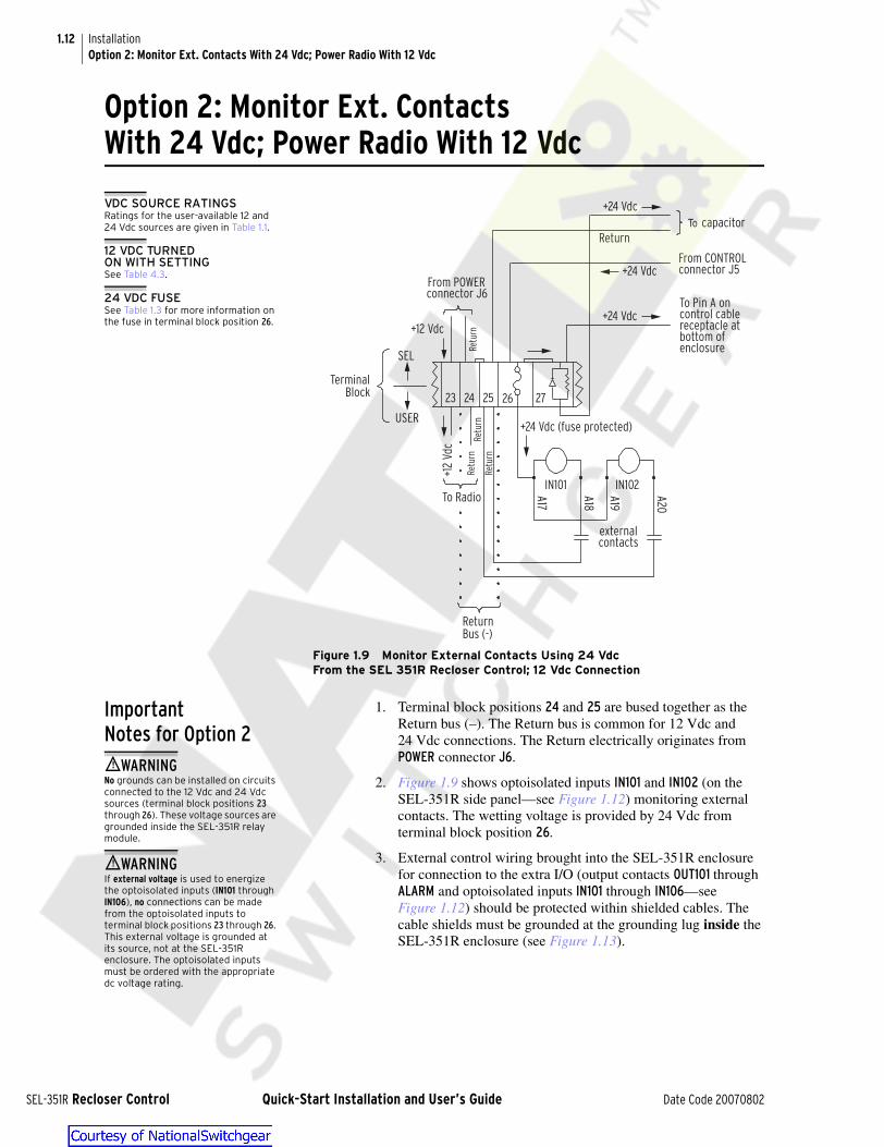
Option 2: Monitor Ext. ContactsWith 24 Vdc; Power Radio With 12 Vdc
Figure 1.9 Monitor External Contacts Using 24 VdcFrom the SEL 351R Recloser Control; 12 Vdc Connection
ImportantNotes for Option 2
1. Terminal block positions 24 and 25 are bused together as the Return bus (–). The Return bus is common for 12 Vdc and 24 Vdc connections. The Return electrically originates from POWER connector J6.
2. Figure 1.9 shows optoisolated inputs IN101 and IN102 (on the SEL-351R side panel—see Figure 1.12) monitoring external contacts. The wetting voltage is provided by 24 Vdc from terminal block position 26.
3. External control wiring brought into the SEL-351R enclosure for connection to the extra I/O (output contacts OUT101 through ALARM and optoisolated inputs IN101 through IN106—see Figure 1.12) should be protected within shielded cables. The cable shields must be grounded at the grounding lug inside the SEL-351R enclosure (see Figure 1.13).
26252423
USER
TerminalBlock
SEL
From POWERconnector J6
+12
Vdc
To Pin A oncontrol cablereceptacle atbottom ofenclosure
ReturnBus (-)
From CONTROLconnector J5
Ret
urn
Ret
urn
To Radio A17
A18
A19
A20
externalcontacts
IN101 IN102
+24 Vdc
+24 Vdc (fuse protected)
Ret
urn
+12 Vdc
Ret
urn
To capacitor
+24 Vdc
Return
27
+24 Vdc
VDC SOURCE RATINGSRatings for the user-available 12 and 24 Vdc sources are given in Table 1.1.
12 VDC TURNEDON WITH SETTINGSee Table 4.3.
24 VDC FUSESee Table 1.3 for more information on the fuse in terminal block position 26.
! WARNINGNo grounds can be installed on circuits connected to the 12 Vdc and 24 Vdc sources (terminal block positions 23 through 26). These voltage sources are grounded inside the SEL-351R relay module.
! WARNINGIf external voltage is used to energize the optoisolated inputs (IN101 through IN106), no connections can be made from the optoisolated inputs to terminal block positions 23 through 26. This external voltage is grounded at its source, not at the SEL-351R enclosure. The optoisolated inputs must be ordered with the appropriate dc voltage rating.
loser Control Quick-Start Installation and User’s Guide Date Code 20070802

1.13InstallationOption 3: Mount Accessories Inside Enclosure
Option 3: Mount Accessories Inside Enclosure
Figure 1.10 Recommended Dimensionsand Drill Plan for User-Supplied Accessory Panel
ImportantNotes for Option 3
1. Accessory mounting is facilitated by four mounting studs protruding from the back panel of the SEL-351R enclosure. The location of these mounting studs relative to one another is shown with the locations of the 1/4-inch diameter holes in the recommended accessory panel in Figure 1.10.
2. Mounting stud details: #10-32; 5/8-inch (15.9 mm) length.
3. Refer to Figure 1.1 and Figure 1.2. When the swing panel is closed, the distance between the back panel of the SEL-351R relay module and the back panel of the SEL-351R enclosure (above the terminal block) is 4 inches (101.6 mm). This does not include space taken up by mounting an accessory panel onto the mounting studs–this would subtract from the 4-inch dimension.
Table 1.1 Ratings for User-Available Voltage Sources (see Figure 1.9)
VoltageTerminal
Block PositionsVoltage Range Maximum Capability
12 Vdc 23 (+), 24/25 (–; return) 11–14 Vdc 6 W continuous,13 W for 1 second
24 Vdc 26 (+), 24/25 (–; return) 20–42a Vdc
a If 24 Vdc-rated optoisolated inputs (e.g., IN101 and IN102 in the example in Figure 1.9) are wetted with the 24 Vdc from terminal block position 26, the inputs can handle the possible upper voltage output (42 Vdc) from this 24 Vdc source. The inputs will be “on” at this upper limit.
0.1 A
12"(304.8 mm)
1/4" (6.4 mm)dia. (4 holes)
14"(355.6 mm)
max.
16"(406.4 mm) max.
15"(381 mm)
ACCESSORY PANELYou can mount an accessory panel on the back panel studs of the SEL-351R enclosure, above the terminal block (see Figure 1.2). The accessory panel is not provided by SEL.
Date Code 20070802 Quick-Start Installation and User’s Guide SEL-351R Recloser Control

1.14
SEL-351R Rec
InstallationDetail 1: Factory-Installed Terminal Block Voltage Jumpers
Detail 1: Factory-InstalledTerminal Block Voltage Jumpers
Figure 1.11 Factory-Installed JumpersFrom 120 Vac Power Bus to Voltage Input V1
Important Notesfor Detail 1
1. Factory-installed jumpers bring 120 Vac to voltage input V1 for installations where three-phase voltage is not brought separately to the SEL-351R unit. The 120 Vac power does not have to come from power system Phase A. Voltage input V1 should be energized, either with the factory-installed jumpers or with three-phase voltage (see Figure 1.8).
Voltage input V1 provides frequency monitoring and close power indication. Factory-default settings require that voltage input V1 be energized (indication of present close power) in order for auto-reclosing to proceed after a reclose interval times out. See Initial Conditions for Control Tests on page 5.3 for additional details on voltage input V1 detecting close power and other possible variations.
2. Factory-installed jumpers connect terminal block positions 10, 12, and 14. These jumpers make up the neutral point for optional three-phase voltage connections (detailed in Figure 1.8). These factory-installed neutral-point jumpers can be kept in place, even if three-phase voltage is not brought to the SEL-351R.
3. Exception to the accompanying DANGER statement: If three-phase voltage (rated 120 Vac line-to-neutral) is brought separately to the SEL-351R (see Figure 1.8) and is also required to provide 120 Vac to power the unit, then the factory-installed jumpers that provide 120 Vac to voltage input V1 do not have to be removed. Do not make the Power In connections to terminal block positions 18 and 21 (detailed in Figure 1.7).
222120191817161514131211109
USER
Terminal Block
SEL
To POWER connector J6
To VOLTAGES connector J3
V1
120 Vac
Neutral
Factory-installed jumpers to voltage
input V1
120 Vac Bus
Neutral Bus
To connector J11 on 120 Vac (GFCI) convenience outlet
! DANGERIf three-phase voltage is brought separately to the SEL-351R, the factory-installed jumpers (bringing 120 Vac to voltage input V1) must be removed. (There is an exception to removing the factory-installed jumpers, see Exception to the accompanying DANGER statement.) No parallel connection can exist between the 120 Vac power and the separate three-phase voltage brought into the SEL-351R enclosure.
loser Control Quick-Start Installation and User’s Guide Date Code 20070802

1.15InstallationDetail 2: Side Panel (Figure 1.12)
Detail 2: Side Panel (Figure 1.12)
Important Notesfor Detail 2
1. A number of the connector terminals are not connected (N/C). The N/C option shown in the VOLTAGES connector J3 legend (e.g., • VS, VS, or N/C) refers to an ordering option. Voltage channels VB, VC, and VS are an ordering option. Regardless of the voltage channels ordered, the wiring is in place between the terminal block and the VOLTAGES connector J3 for all voltage channel positions (see Figure 1.13).
2. The extra I/O (output contacts OUT101 through ALARM and optoisolated inputs IN101 through IN106) is not needed for the basic recloser control functions. The extra I/O is available for SCADA connection or other control (see Figure 1.9) and is not polarity sensitive.
The optoisolated inputs must be ordered with the appropriate dc voltage rating. Refer to the serial number sticker on the side panel for the optoisolated input voltage rating (listed under label: EXT. CONTACT SENSING INPUTS).
The connectors for the extra I/O accept wire size AWG 24 to 12. Strip the wires to 0.31 inch (8 mm) and install with a small slotted-tip screwdriver.
3. Optoisolated inputs IN101 through IN106 can be configured via settings to operate on ac voltage. See Optoisolated Inputs on page 8.2 for more information on ac operation.
Detail 3: Wiring Diagram (Figure 1.13)
Important Notesfor Detail 3
1. See Table 1.3 for more information on the fuses in terminal block positions 26 and 28, the fuse on the 120 Vac (GFCI) convenience outlet, and the battery fuse.
2. The wiring between the terminal block (positions 1–8) and the control cable receptacle accommodates the current polarity of Cooper reclosers, as further detailed in Figure 1.14. If the SEL-351R is used with a circuit breaker, positions 1–8 would probably need to be rewired on the user side. Figure 1.12 and Figure 1.14 show the polarity/non-polarity terminals for the CURRENTS connector J10.
3. In June 2001, the SEL-351R wiring was changed to accommodate two additional fuses (terminal block position 28 and battery wiring harness). Older units have the previous wiring found in Figure B.1.
4. In October 2004, the SEL-351R was updated to provide assignable power system VA, VB, VC, IA, IB, and IC to terminal inputs V1, V2, V3, I1, I2, and I3 with EZ or Global Settings. Figure B.2 shows the previous side panel terminal designations.
Date Code 20070802 Quick-Start Installation and User’s Guide SEL-351R Recloser Control

1.16
SEL-351R Rec
InstallationDetail 3: Wiring Diagram (Figure 1.13)
Figure 1.12 SEL-351R Recloser Control Side Panel
loser Control Quick-Start Installation and User’s Guide Date Code 20070802

1.17InstallationDetail 3: Wiring Diagram (Figure 1.13)
q See Figure 1.15.
Figure 1.13 SEL-351R Recloser ControlFactory-Installed Wiring Inside the Enclosure
2625
2423
2221
2019
1817
1615
1413
1211
109
87
65
43
21
98
76
54
32
1J1
06
27
38
49
510
J32
63
71
54
8J6
11
23
45
6J5
123J11
CON
TRO
LPO
WER
VO
LTA
GES
CUR
REN
TS12
0 V
ac (
GFC
I)Co
nven
ienc
e O
utle
t
J HD
M
N
PKA
G
B
C
EF
GR
OU
ND
SEL
USE
R
Term
inal
Blo
ck
Gro
und
conn
ecti
ons
insi
de t
he e
nclo
sure
(#10
-32,
sta
inle
ssst
eel b
olt)
Conn
ecti
ons
toco
ntro
l cab
lere
cept
acle
insi
de t
heen
clos
ure
L
Swin
g Pa
nel
Gro
und
Conn
ecti
on
Conn
ecti
ons
on s
ide
pane
lof
SEL
-351
R
Use
thi
s bo
lt f
orco
nnec
ting
oth
er p
oint
sin
side
the
enc
losu
re t
hat
requ
ire
grou
ndin
g .
+ 220
00
F
27
I1I2
I3IN
Cur
rent
con
nect
ions
to
the
term
inal
blo
ck c
an b
ech
ange
d by
the
use
r to
acco
mod
ate
all p
ossi
ble
prim
ary
conn
ecti
ons
to t
here
clos
er –
see
q.
28
24 V
dc L
ead-
Aci
d B
atte
ry21J12
Date Code 20070802 Quick-Start Installation and User’s Guide SEL-351R Recloser Control

1.18
SEL-351R Rec
InstallationDetail 4: Current Polarity/ Recloser Primary Connections
Detail 4: Current Polarity/Recloser Primary Connections
The SEL-351R has three current inputs I1, I2, and I3 for terminal connections. Wiring to the power system current transformer connections can be random, but correct power system “A-B-C” designation is still needed within the SEL-351R algorithms. EZ or equivalent Global settings define how the transition occurs between the power system wiring and the SEL-351R Recloser Control algorithms. The SEL-351R can accommodate different power system relay phase assignments by rewiring or settings.
The factory default settings connect power system currents IA, IB, and IC to relay terminals I1, I2, and I3, respectively as shown in Figure 1.14.
Use EZ Setting #45 (see Table 4.3) as noted in Figure 1.15 to accommodate other power system connections (or change settings IPCONN and CTPOL to transition the power system “A-B-C” designation to the SEL-351R Recloser Control algorithm). See Section 9: Current and Voltage Connection Settings in the SEL-351R Recloser Control Instruction Manual for more details.
loser Control Quick-Start Installation and User’s Guide Date Code 20070802

1.19InstallationDetail 4: Current Polarity/ Recloser Primary Connections
Figure 1.14 Current Polarity From RecloserPrimary to SEL-351R Recloser Control Current Inputs
SEL
U
SER
Control CableReceptacle
LL
KK
JJ
HH
MM
GG
Cab
le
Con
trol
Rec
lose
rSE
L-35
1R
13
5
100
Ω
100
Ω
100
Ω
I ABI
CI
8 7 6 5 4 3 2 112349 678
AIBICI
NI
IN I3 I2 I1
J10
Term
.B
lock
Rec
lose
r C
ontr
ol
46
2
SEL-351RFACTORY CONNECTIONSAll the connections shown inside the SEL-351R in Figure 1.14 are factory made. Only the current connections from the control cable receptacle to the user-side of the terminal block can be changed–see Figure 1.15.
RECLOSER PRIMARY CONNECTIONSTraditional connections are assumed for primary currents IA-IB-IC into recloser source-side bushing 1-3-5, respectively, in Figure 1.14. Figure 1.15 describes all other possible connections.
PHASE ROTATIONIS A SEPARATE ISSUEFigure 1.14 and Figure 1.15 address current polarity and recloser primary connections, not phase rotation.
Phase rotation is handled with the Phase Rotation setting in Table 4.3 and in Settings Descriptions on page 4.6.
Date Code 20070802 Quick-Start Installation and User’s Guide SEL-351R Recloser Control

1.20
SEL-351R Rec
InstallationDetail 4: Current Polarity/ Recloser Primary Connections
Figure 1.15 User Terminal Block Wiring or Setting Changes Accommodate All Possible Primary Connectionsto the Recloser (to keep consistent with SEL-351R Recloser Control current channel designations)
q See Figure 1.14. or leave wiring as in Figure 1.14 and set EZ Setting #45 to CBA (see Table 4.3).
or leave wiring as in Figure 1.14 and set EZ Setting #45 to CAB (see Table 4.3).
or leave wiring as in Figure 1.14 and set EZ Setting #45 to BAC (see Table 4.3).
or leave wiring as in Figure 1.14 and set EZ Setting #45 to ACB (see Table 4.3).
or leave wiring as in Figure 1.14 and set EZ Setting #45 to BCA (see Table 4.3).
K K
J J
H H
G G
RecloserSEL-351R
1 3 5
8
7
6
5
4
3
2
1
4 62
Cable
Control
SEL USER
factory connections
(see q)
Term.Block
CI
NI
BI
AI
A B C
a.
K K
J J
H H
G G
RecloserSEL-351R
1 3 5
8
7
6
5
4
3
2
1
4 62
Cable
Control
Term.Block
AI
NI
BI
CI
C B A
b.
SEL USER
K K
J J
H H
G G
RecloserSEL-351R
1 3 5
8
7
6
5
4
3
2
1
4 62
Cable
Control
Term.Block
BI
NI
AI
CI
C A B
c.
SEL USER
K K
J J
H H
G G
RecloserSEL-351R
1 3 5
8
7
6
5
4
3
2
1
4 62
CableControl
Term.Block
CI
NI
AI
BI
B A C
d.
SEL USER
K K
J J
H H
G G
RecloserSEL-351R
1 3 5
8
7
6
5
4
3
2
1
4 62
CableControl
Term.Block
BI
NI
CI
AI
A C B
e.
SEL USER
K K
J J
H H
G G
RecloserSEL-351R
1 3 5
8
7
6
5
4
3
2
1
4 62
CableControl
Term.Block
AI
NI
CI
BI
B C A
f.
SEL USER
loser Control Quick-Start Installation and User’s Guide Date Code 20070802

1.21InstallationDetail 5: Control Cable Receptacle and Replacement Fuses
Detail 5: Control CableReceptacle and Replacement Fuses
For additional information on wiring connections, refer to Figure 1.13.
Figure 1.16 Control Cable Receptacle(viewed from inside SEL-351R enclosure)
Table 1.2 Control Cable Receptacle Pin Descriptions
A 24 Vdc H Terminal I2 Current
B Monitored Trip Circuit Point J Terminal I3 Current
C Trip K Residual Current Return
D Monitored Trip Circuit Point L (not used in control)
E Close M Recloser Ground
F Monitored Close Circuit Point N (not connected)
G Terminal I1 Current P (not connected)
Date Code 20070802 Quick-Start Installation and User’s Guide SEL-351R Recloser Control

1.22
SEL-351R Rec
InstallationDetail 5: Control Cable Receptacle and Replacement Fuses
Table 1.3 Replacement Fuses for the SEL-351R Recloser Control (see Figure 1.13)
Fuse Location Ampere Rating Dimensions ManufacturerCatalog Numbers
Purpose
Terminal block position 26 (see Figure 1.9)a
a Spare fuse included in respective terminal block.
0.125 A 0.197 x 0.787"(5 x 20 mm)
Bussman GMD-0.125 Protectaccessible 24 Vdc(0.1 Amp load limit).
Swing panel-mounted fuse holder (in series with terminal 3 of connector J11)
15 A 0.25 x 1.25"(6.4 x 31.8 mm)
Littelfuse 314015 Protect 120 Vac(GFCI) convenience outlet for overload or line-to-line short circuits (10 Amp load limit).
Terminal block position 28 (see Figure 1.7a,b
b The last two fuse entries in Table 1.3 are not found in earlier SEL-351R units. See explanation in Important Notes for Detail 3.
1 A 0.197 x 0.787"(5 x 20 mm)
LittelfuseSlo-Blo Type
218001 Protect SEL-351R relay module from overvoltageor internal short.
Battery wiring harness (seeFigure 1.6)b
3 A 0.25 x 1.25" (6.4 x 31.8 mm)
Bussman
Littelfuse 3AG Fast-Acting Type
AGC-3
312003
Protect battery and charger circuitryfrom inadvertent short.
loser Control Quick-Start Installation and User’s Guide Date Code 20070802

1.23InstallationDetail 6: Trip and Close Circuits
Detail 6: Trip and Close Circuits
Figure 1.17 Trip and Close Circuit Connections
TC
CC
1 A A
BB
CC
EE
FF
2
3
5
6
4
SW1
(52a)
SW2
(69)
SW3
(52b)
Trip
Coil
Close
Coil
monitored closecircuit point
HV FET
trip
monitored trip
circuit point
monitored tripcircuit point
monitored closecircuit point
SEL-351R
Recloser
Control
Recloser with internal
trip and close circuits
Control cable with
pin designations
CON
TRO
Lco
nnec
tor
J5
+24 Vdc
DD
HV FET
close
Cont
rol c
able
rece
ptac
le
CONTROL CABLE RECEPTACLEFigure 1.17 shows only part of the control cable receptacle connections (pins A through F). Figure 1.13 and Figure 1.16 detail the rest of the control cable receptacle connections.
TRIP CIRCUIT DIFFERS FOR MOTOR-OPERATED RECLOSERS (e.g., MVE, CVE, CXE, CZE, VSAThe differing trip circuit for Cooper three-phase motor-operated reclosers (as compared to Figure 1.17) requires a few settings to be modified. Refer to SEL Application Guide AG99-10, Change Logic in SEL-351R Recloser Control for Motor-Operated Reclosers.
Date Code 20070802 Quick-Start Installation and User’s Guide SEL-351R Recloser Control

1.24
SEL-351R Rec
InstallationDetail 6: Trip and Close Circuits
ImportantNotes for Detail 6
1. Separate high-voltage FETs (Field-Effect Transistors) trip and close the recloser. When an FET is “off,” it is an open circuit. When an FET is “on,” it is a short circuit, making up the trip or close circuit and energizing the corresponding trip or close coil. Normally, contacts SW1 (52a) and SW3 (52b) break the trip and close circuit currents, respectively. However, if required, the high-voltage FETs can break these currents.
2. Close operations are started with the 24 Vdc close circuit detailed above, but the power to close the main contacts and compress the tripping springs in the recloser is usually 120 Vac or primary voltage (see Figure 1.7, Important Notes for Installation Step 6 on page 1.7).
3. Contact SW2 (69) opens and stays open when the external manual operating lever on the recloser is pulled to the lock-open position. With contact SW2 open, there is no way to close the recloser until the manual operating lever is reset again–contact SW2 is then closed.
loser Control Quick-Start Installation and User’s Guide Date Code 20070802
Section 2Communications
Overview
Topics covered in this section:
➤ Serial Port Connectors
➤ Communications Cables
➤ Commands
➤ Access Levels
➤ Password Protection
You can view and change control settings, and obtain event and status information either from the front-panel interface or via one of the serial ports.
You can access many of the features of the SEL-351R from the front panel; however, some features can only be accessed from one of the serial ports. Table 2.5 provides the serial port commands (with descriptions) as well as the corresponding front-panel pushbutton, if applicable.
Getting Started With Communications
Before you attempt communications with the SEL-351R, via either the serial ports or the front-panel interface, the following precautions must be taken:
➤ Verify that the SEL-351R has been properly installed and that the settings have been programmed by qualified personnel.
➤ Become familiar with and understand the information presented in this section, Section 3: Front-Panel Interface, and Section 4: Settings.
For serial port communications, the previous two precautions apply. You must also carry out the following:
Step 1. Select the appropriate communications cable (usually SEL Cable C234A–see Table 2.4).
Step 2. Choose a terminal emulation program on your personal computer (PC) to communicate with the SEL-351R.
Step 3. Set the communications parameters for the connected PC communications port to the default settings.
Step 4. Press the <Enter> key, and the SEL-351R will respond with a = prompt, which indicates Level 0 access is established–see Table 2.7.)
HINTFor the best display, use VT-100 terminal emulation or the closest variation.
TERMINALEMULATION PROGRAMSExamples of PC-based terminal emulation programs include: Procomm® Plus, Relay/Gold, Microsoft® Windows® Terminal and HyperTerminal, SmartCOM, and CROSSTALK®.
DEFAULT SETTINGSFOR SERIAL PORTSBaud Rate = 2400 Data Bits = 8Parity = N Stop Bits = 1
Date Code 20070802 Quick-Start Installation and User’s Guide SEL-351R Recloser Control

2.2
SEL-351R R
CommunicationsCommunications Connections Example
Communications Connections Example
You can connect the serial port to a computer serial port for local communications or to a modem for remote communications. Other devices useful for automated communications include the SEL-2032, SEL-2030, and SEL-2020 Communications Processors.
You can use a variety of terminal emulation programs on your personal computer to communicate with the SEL-351R. Figure 2.1 presents some example SEL-351R communications connections (see Table 2.4 and contact SEL for more information).
Protection, Integration, Automation, and Control by SEL
Figure 2.1 SEL-351R Recloser ControlCommunications Connections Example
Front PanelSEL-2032
SEL-351R (#2)SEL-351R (#1)
SEL-351R (#1)
Computer
PORT 2
(METALLIC)Cable #C273A
SEL-351R
SEL-351RSEL-351R
SELCommunications
Processor
SEL-351R (#2) SEL-351R (#32)
DATA AND TIME-SYNCHRONIZATION* CONNECTIONS
SELCommunications
Processor
PORT 2
Fiber-Optic Cable#C273AFZ
or #C273AF0 SEL-2810
Optical Cable ConnectionMetallic Cable Connection
EIA-485 CONNECTIONS (if ordered with EIA-485 port)
PORT 1 PORT 1 PORT 1
LOCAL CONNECTIONS
PORT 2
PORT F Front Panel
* Demodulated IRIG-B time code can be input into the connector for either serial port 1 orserial port 2, but not both at the same time.
PORT 2
PORT F Front
Panel
Cable#C234A
Side
Panel
Connect to the SEL Communications Processor once and communicate with any connected SEL Relay or Recloser Control
or... Connect to the SEL-351R Recloser Control individually via the Front-Panel Serial Port
Side Panel
ecloser Control Quick-Start Installation and User’s Guide Date Code 20070802

2.3CommunicationsSerial Ports
Serial Ports
Three EIA 232 serial communications ports are available:
➤ Serial Port 2 (side panel)
➤ Serial Port 3 (side panel)
➤ Serial Port F (front panel)
An EIA-485 serial communications port is available as an ordering option:
➤ Serial Port 1 (side panel)
Serial Port Default Settings
The default settings for all serial ports are:
➤ Baud Rate = 2400
➤ Data Bits = 8
➤ Parity = N
➤ Stop Bits = 1
The serial port default settings can be changed from the front-panel interface or from the serial communications port itself. After connecting the appropriate communications cable and setting the terminal emulator, press the <Enter> key, and the control will respond with a = prompt, which indicates Level 0 access is established–see Table 2.7.
EIA-232 Pinout Functions for Ports 2, 3, and F
Figure 2.2 DB-9 Connector Pinout (Female) for EIA-232 Serial Ports
WAKE-UP PORTFigure 1.12 shows a Wake-Up Port.Its pin functions are defined inEIA-232 Pinout Functions for Ports 2, 3, and F and EIA-485 Pinout Functions for Port 1. See the front of Section 10 in the SEL-351R Recloser Control Instruction Manual for more information on the Wake-Up Port.
Table 2.1 EIA-232 Pinout Functions
Pin Port 2 Port 3 Port F
1 N/Ca or +5 Vdc
a Pin 1 not connected for Ports 2 and 3 when shipped from the factory.
N/Ca or +5 Vdc N/C
2 RXD RXD RXD
3 TXD TXD TXD
4 +IRIG-B N/C N/C
5, 9 GND GND GND
6 -IRIG-B N/C N/C
7 RTS RTS RTS
8 CTS CTS CTS
5 4 3 2 1
9 8 7 6
MAKE ONLY ONEIRIG-B CONNECTIONIf making an IRIG-B connection, connect demodulated IRIG-B time code to either the serial Port 2 or serial Port 1 connector (see EIA-485 Pinout Functions for Port 1), but not both.
Date Code 20070802 Quick-Start Installation and User’s Guide SEL-351R Recloser Control

2.4
SEL-351R R
CommunicationsEIA-485 Pinout Functions for Port 1
EIA-485 Pinout Functions for Port 1
Figure 2.3 EIA-485 Pinout for Port 1
Table 2.2 EIA-485 Pinout Functions
Pin Function Pin Function
1 +TX 5 SHIELD
2 –TX 6 N/C
3 +RX 7 +IRIG-B
4 –RX 8 –IRIG-B
Table 2.3 Serial Communications Port Pin Function Definitions
Pin Function Definition
N/C No Connection
+5 Vdc (0.5 Amp limit) 5 Vdc Power Connection
RXD, RX Receive Data
TXD, TX Transmit Data
IRIG-B IRIG-B Time-Code Input
GND Ground
SHIELD Shielded Ground
RTS Request To Send
CTS Clear To Send
DCD Data Carrier Detect
DTR Data Terminal Ready
DSR Data Set Ready
CONVENIENTIRIG-B CONNECTIONSerial Port 2 provides the most convenient connection for demodulated IRIG-B time code. See the top of Figure 2.1 and SEL Cable C273A in Table 2.4, and the corresponding cable diagram.
ecloser Control Quick-Start Installation and User’s Guide Date Code 20070802

2.5CommunicationsCommunications Cables
Communications Cables
Cable Diagrams
The following cable diagrams correspond to the cables listed in Table 2.4 (most commonly used cables). The male/female references in the cable diagrams refer to the cable connectors, not the device they are connecting to (which would be the opposite gender). Contact SEL for information on other available cables.
Figure 2.4 SEL-351R to Computer
Table 2.4 SEL EIA-232 Serial Communications Cable Guide
ConnectFrom
Connect ToSELCable
SEL-351R Computer (9-pin) C234A
SEL-351R Computer (25-pin) C227A
SEL-351R SEL-2032, SEL-2030, or SEL-2020 Communications Processor C273A
SEL-351R Modem C222
OTHER CABLES AVAILABLETable 2.4 lists the most commonly used cables (see corresponding cable diagrams on the following page). Contact SEL for information on other available cables.
9-Pin DTE* DeviceSEL-351R
9-Pin MaleD–Subconnector D–Subconnector
9-Pin Female
2 3
3
5
8
2
5
8
7
RXD TXD
TXD RXD
GND GND
CTS CTS
RTS
DCD
DTR
DSR
1
4
6
PinFunc.
PinFunc.
Pin#
Pin#
Cable C234A
25-Pin DTE* DeviceSEL-351R
9-Pin MaleD–Subconnector D–Subconnector
25-Pin Female
5 7
3
2
8
3
2
4
5
GND GND
TXD RXD
RXD TXD
CTS RTS
CTS
DSR
DCD
DTR
6
8
20
9 1GND GND
PinFunc.
PinFunc.
Pin#
Pin#
Cable C227A
*DTE = Data Terminal Equipment (Computer, Terminal, Printer, etc.)
Date Code 20070802 Quick-Start Installation and User’s Guide SEL-351R Recloser Control

2.6
SEL-351R R
CommunicationsCommands
Figure 2.5 SEL-351R to SEL-2032/SEL-2030/SEL-2020 Communications Processor
Figure 2.6 SEL-351R to Modem
Commands
The following serial port commands are available for use with the SEL-351R. Much of the information available from the serial port commands is also available via the front-panel pushbuttons (see Pushbutton Primary Functions on page 3.5).
The commands are shown in uppercase letters, but they can also be entered using lowercase letters.
SEL-2032/SEL-2030/SEL-2020SEL-351R
9-Pin MaleD–Subconnector D–Subconnector
9-Pin Male
3 2
2
4
5
6
8
7
3
4
5
6
TXD RXD
RXD TXD
IRIG+ IRIG+
GND
IRIG–
CTS
RTS
GND
IRIG–
RTS
CTS
7
8
PinFunc.
PinFunc.
Pin#
Pin#
Cable C73A
SEL-351R
9-Pin MaleD–Subconnector D–Subconnector
25-Pin Male
5 7
3
7
2
8
9
2
20
3
8
GND GND
TXD TXD (IN)
RTS DTR (IN)
RXD
CTS
GND
RXD (OUT)
CD (OUT)
GND1
PinFunc.
PinFunc.
Pin#
Pin#
*DCE Device
Cable C222
*DCE = Data Communications Equipment (Modem, etc.)
Commands, passwords, or settings you type appear in bold/uppercase: DAKOTA. Computer keys you press appear in bold/brackets: <Enter>.
ecloser Control Quick-Start Installation and User’s Guide Date Code 20070802
2.7CommunicationsCommands
Table 2.5 SEL-351R Recloser Control Command Summary (Sheet 1 of 3)
Access Leveland Available Commands
DescriptionCorrespondingFront-PanelPushbutton
Access Level 0 The only operation that can be performed at Access Level 0is to go to Access Levels 1 or E. The screen prompt is: = (see Table 2.7).
ACC Enter Access Level 1.
EZA Enter Access Level E.
Access Level 1 The Access Level 1 commands primarilyallow the user to look at information (e.g., settings,metering), not change it. The screen prompt is: => (see Table 2.7).
2AC Enter Access Level 2.
BAC Enter Breaker Access Level (Access Level B).
BRE Display breaker/recloser contact wear report. {OTHER}
BRE A Display breaker/recloser contact wear and trip operation report. {OTHER}
COM MIRRORED BITS® communications statistics.
COU Display SELOGIC® counter values (SEL-351R-2 only).
DAT Show date. {OTHER}
DAT m/d/y Enter date in this manner if Date Format setting DATE_F = MDY. {OTHER}
DAT y/m/d Enter date in this manner if Date Format setting DATE_F = YMD. {OTHER}
EVE n Show event report number n with 1/4 cycle resolution.
EVE L n Show event report number n with 1/16 cycle resolution.
EVE R n Show raw event report number n with 1/16 cycle resolution.
EVE C n Show compressed event report number nfor use with SEL-5601 Analytic Assistant.
EZA Enter EZ Access Level (Access Level E).
GRO Display active group number. {GROUP}
HIS n Show brief summary of the n latest event reports. {EVENTS}
HIS C Clear the brief summary and corresponding event reports.
IRI Force synchronization attempt ofinternal relay clock to IRIG-B time-code input.
MET k Display instantaneous metering data. Enter k for repeat count. {METER}
MET D Display demand and peak demand data. {METER}
MET E Display energy metering data. {METER}
MET M Display maximum/minimum metering data. {METER}
MET RD Reset demand metering data. {METER}
MET RE Reset energy metering data. {METER}
MET RM Reset maximum/minimum metering data. {METER}
MET RP Reset peak demand metering data. {METER}
QUI Quit. Returns to Access Level 0.Terminates SEL Distributed Port Switch Protocol (LMD) connection.
SER n Show the latest n rows in the Sequential Events Recorder (SER) event report.
SER m n Show rows m through n in the Sequential Events Recorder (SER) event report.
SER d1 Show rows in the Sequential Events Recorder (SER) event report from date d1.
Date Code 20070802 Quick-Start Installation and User’s Guide SEL-351R Recloser Control
2.8
SEL-351R R
CommunicationsCommands
SER d1 d2 Show rows in the Sequential Events Recorder (SER)event report from date d1 to d2. Entry of dates is dependenton the Date Format setting DATE_F (= MDY or YMD).
SER C Clear SER records from nonvolatile memory.
SER D List active chattering elements from the SER records and present auto-removal settings.
SHO n Show relay settings (overcurrent, reclosing, timers, etc.) for Group n. {SET}
SHO L n Show SELOGIC control equation settings for Group n.
SHO EZ n Show EZ settings for Group n. {SET}
SHO FZ Show FZ settings (global EZ settings). {SET}
SHO G Show global settings. {SET}
SHO P n Show Port n settings. {SET}
SHO R Show Sequential Events Recorder (SER) settings.
SHO T Show text label settings.
STA Show relay self-test status. STA C resets self-test warnings/failures. {STATUS}
TAR R Reset the front-panel tripping targets. {TARGET RESET}
TAR n k Display Relay Word row. If n = 0 through 59,display row n. If n is an element name (e.g., 50A1),display the row containing element n. Enter k for repeat count.
{OTHER}
TIM Show or set time (24-hour time). Show timepresently in the relay by entering just TIM(e.g., time 22:47:36 is entered with the following command: TIM 22:47:36).
{OTHER}
TRI Trigger an event report.
Access Level E The Access Level E commands allow the userto access and change the EZ settings as well asLevel 1 commands. The screen prompt is: =+> (see Table 2.7).
BTT Display status of latest battery discharge testand the time remaining until next battery discharge test.
BTT NOW Force new battery discharge test immediately. {OTHER}
SET EZ Change recloser control EZ settings. {SET}
SET FZ Change recloser control global EZ settings. {SET}
Access Level B The Access Level B commands primarily allow the user to operate relayparameters and output contacts. All Access Level 1 and E commands can also be executed from Access Level B. The screen prompt is: ==> (see Table 2.7).
BRE W Preload breaker/recloser contact wear. {OTHER}
BRE W A Preload breaker/recloser contact wear and trip operation counters. {OTHER}
BRE R Reset breaker/recloser contact wear and trip operation counters. {OTHER}
CLO Close the circuit breaker.
GRO n Change active group to Group n. {GROUP}
OPE Open the circuit breaker.
PUL n k Pulse output contact n (OUT101 through OUT107, ALARM) fork (1–30) seconds. Parameter n must be specified; k defaults to 1 if not specified.
{CNTRL}
Table 2.5 SEL-351R Recloser Control Command Summary (Sheet 2 of 3)
Access Leveland Available Commands
DescriptionCorrespondingFront-PanelPushbutton
ecloser Control Quick-Start Installation and User’s Guide Date Code 20070802

2.9CommunicationsEvent Reports
Event Reports
Event reports are automatically triggered at the beginning of a fault and when the SEL-351R issues a trip. Event report length is 15 cycles (factory default). The latest twenty-eight 15-cycle event reports are stored in nonvolatile memory.
To obtain event report information, use the EVE command. There are numerous options that allow you to customize event information. For descriptions and examples of all options, refer to the SEL-351R Recloser Control Instruction Manual. The general command format is:
EVE [ n A D ]
The parameters in brackets [ ] are optional. Table 2.6 defines the parameters [ n A D ] that can be issued with the EVE command to customize the report format.
Access Level 2 The Access Level 2 commands allow unlimited access to relay settings,parameters, and output contacts. All Access Level 1, E, and B commands are available from Access Level 2. The screen prompt is: =>> (see Table 2.7).
CON n Control Relay Word bit RBn, Remote Bit nwhere n = 1 through 8 (1 through 16 on the SEL-351R-2). Execute CON n,and the relay responds: CONTROL RBn. Then reply with one of the following:
SRB n set Remote Bit n (assert RBn).
CRB n clear Remote Bit n (deassert RBn).
PRB n pulse Remote Bit n (assert RBn for 1/4 cycle).
COP m n Copy relay and logic settings from Group m to Group n.
PAS 1 Change Access Level 1 password. {SET}
PAS E Change Access Level E password. {SET}
PAS B Change Access Level B password. {SET}
PAS 2 Change Access Level 2 password. {SET}
SET n Change relay settings (overcurrent, reclosing, timers, etc.) for Group n. {SET}
SET L n Change SELOGIC control equation settings for Group n.
SET EZ n Change EZ settings for Group n. {SET}
SET FZ Change FZ settings (global EZ settings). {SET}
SET G Change global settings. {SET}
SET P n Change Port n settings. {SET}
SET R Change Sequential Events Recorder (SER) settings.
SET T Change text label settings.
VER Show version information.
Table 2.5 SEL-351R Recloser Control Command Summary (Sheet 3 of 3)
Access Leveland Available Commands
DescriptionCorrespondingFront-PanelPushbutton
NOTE: The event report length is selectable: 15 or 30 cycles. More options are available to customize event reports.
Refer to the SEL-351R Recloser Control Instruction Manual for more event information.
Date Code 20070802 Quick-Start Installation and User’s Guide SEL-351R Recloser Control

2.10
SEL-351R R
CommunicationsAccess Levels and Password Protection
Summary event information can be viewed at the control front-panel LCD using the front-panel pushbuttons. Press the {EVENTS} pushbutton (primary function) and the appropriate left/right and up/down pushbuttons (secondary function) to view event information.
If no parameters are issued with the EVE command, then you will automatically receive both the analog (A) and digital (D) sections of the event report.
Access Levels and Password Protection
Issue serial port commands to the SEL-351R to view metering values, change recloser control settings, obtain event information, etc. The available serial port commands are listed in Table 2.5. The commands can be accessed only from the corresponding access level as shown in the table, but a higher access level can access the serial port commands in a lower access level.
Access Level 0 (the lowest access level)
Access Level 1
Access Level E (EZ access level)Access Level B Access Level 2 (the highest access level)
As a security measure, entry to a particular access level (except Access Level 0) requires a unique password. This allows the user to set up a password system to deny unqualified or unauthorized personnel access to higher levels.
The SEL-351R ships from the factory with default passwords (see Table 2.7). If restrictions are to be placed on personnel using the SEL-351R, the factory default passwords must be changed. Make sure that password information is stored for future reference in the event that it is lost or forgotten.
Table 2.6 Event Report Parameters
Parameter Description
n Choose event number (1–28). Defaults to 1 if not specified.
A Specifies that the analog section of the event is to be displayed(current, voltage, frequency, contact outputs, and optoisolated inputs).
D Specifies that the digital section(Protection and Control Elements) of the event is to be displayed.
PASSWORDSREQUIRED WITH FRONT-PANEL PUSHBUTTONS?See Pushbutton Primary Functions on page 3.5.
This device is shipped with default passwords. Default passwords should be changed to private passwords at installation. Failure to change each default password to a private password may allow unauthorized access. SEL shall not be responsible for any damage resulting from unauthorized access.
! WARNING
ecloser Control Quick-Start Installation and User’s Guide Date Code 20070802

2.11CommunicationsChange Passwords
Change Passwords
The PAS command allows you to change existing passwords at Access Level 2. To change passwords, enter PAS x, where x is the access level password being changed. The relay will prompt for the old password, new password, and a confirmation of the new password as follows:
=>>PAS 1 <Enter>
Old Password: *****
New Password: ************Confirm New Password: ************
Password Changed=>>
Passwords may include as many as 12 characters. Valid characters are listed in Table 2.8.
Record the new password in a safe place for future reference. Passwords cannot be viewed from the recloser control.
Upper- and lowercase letters are treated as different characters. Strong passwords consist of the maximum allowable characters, with at least one special character, number, lowercase letter, and uppercase letter. Strong passwords do not include a name, date, acronym, or word. The recloser control may issue a weak password warning if the new password can be strengthened.
Examples of valid, distinct passwords include:
Table 2.7 Access Level, Summary Information
AccessLevel
AccessCommand
PromptFactoryDefaultPassword
Description of Access Level Command Privileges
0 = Signifies serial communications are established. The only operation available here is go to Access Level 1 or Access Level E.
1 ACC => OTTER Primarily allows you to only look atinformation (i.e., metering, settings), not change it.
E EZA =+> DAKOTA Primarily allows the user to changethe EZ group settings and global EZ settings.
B BAC ==> EDITH Primarily allows the user to operateoutput contacts or change the active setting group.
2 2AC =>> TAIL Unlimited access to relay settings, parameters, and output contacts.
Table 2.8 Valid Password Characters
Alpha A BC D E F G H I J K L M N O P Q R S T U V W X Y Za b c d e f g h i j k l m n o p q r s t u v w x y z
Numeric 0 1 2 3 4 5 6 7 8 9
Special ! " # $ % & ' ( ) * + , - . / : ; < = > ? @ [ \ ] ^ _ ` { | } ~
SDFdfa098&^# &*LKJoi09873 m,nYIO689&(*
LOST OR FORGOTTEN PASSWORD?When passwords are lost or forgotten, you can set new passwords by putting the main board password jumper in place. See Password Jumper.
WANT TO OPERATE WITHOUT PASSWORDS?See Disable Passwords.
Date Code 20070802 Quick-Start Installation and User’s Guide SEL-351R Recloser Control
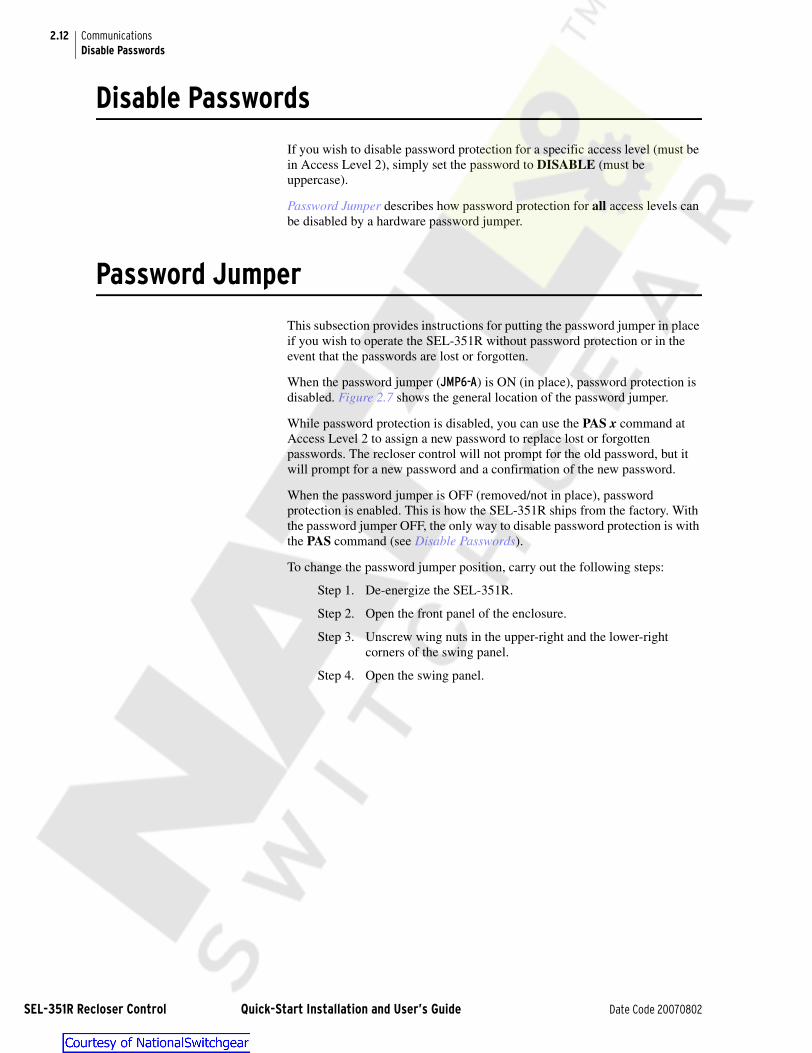
2.12
SEL-351R R
CommunicationsDisable Passwords
Disable Passwords
If you wish to disable password protection for a specific access level (must be in Access Level 2), simply set the password to DISABLE (must be uppercase).
Password Jumper describes how password protection for all access levels can be disabled by a hardware password jumper.
Password Jumper
This subsection provides instructions for putting the password jumper in place if you wish to operate the SEL-351R without password protection or in the event that the passwords are lost or forgotten.
When the password jumper (JMP6-A) is ON (in place), password protection is disabled. Figure 2.7 shows the general location of the password jumper.
While password protection is disabled, you can use the PAS x command at Access Level 2 to assign a new password to replace lost or forgotten passwords. The recloser control will not prompt for the old password, but it will prompt for a new password and a confirmation of the new password.
When the password jumper is OFF (removed/not in place), password protection is enabled. This is how the SEL-351R ships from the factory. With the password jumper OFF, the only way to disable password protection is with the PAS command (see Disable Passwords).
To change the password jumper position, carry out the following steps:
Step 1. De-energize the SEL-351R.
Step 2. Open the front panel of the enclosure.
Step 3. Unscrew wing nuts in the upper-right and the lower-right corners of the swing panel.
Step 4. Open the swing panel.
ecloser Control Quick-Start Installation and User’s Guide Date Code 20070802

2.13CommunicationsPassword Jumper
Step 5. Disconnect all connections from the side panel of the SEL-351R relay module and remove the wire clamps. See above figure.
Step 6. Remove swing panel by lifting up.
Step 7. Take swing panel with the SEL-351R relay module to an ESD (Electrostatic Discharge) protected work area.
Step 8. Remove six hex nuts and shoulder washers on right and left sides of the SEL-351R relay module.
Step 9. Remove the SEL-351R relay module from the swing panel.
Step 10. Remove eight Phillips-head screws from the front and left side panel of the SEL-351R relay module.
Step 11. Disconnect the ribbon cables from the front panel.
Step 12. Remove the front panel of the SEL-351R relay module.
Step 13. Locate the jumper(s) to be changed (refer to Figure 2.7).
a. Change the jumper position.
Step 14. Reconnect ribbon cables to the front panel.
Step 15. Replace eight Phillips-head screws in the front and left side panel of SEL-351R relay module.
Step 16. Place the SEL-351R relay module in the swing panel.
Step 17. Replace six shoulder washers and hex nuts to the right and left sides of the SEL-351R relay module.
Step 18. Replace the swing panel to the hinges.
Step 19. Reconnect all connections on the right-side panel of the SEL-351R relay module and attach the wire clamps.
Step 20. Close the swing panel.
Connections on
side panel
Wire
clamps
Relay module
The relay contains devices sensitive to Electrostatic Discharge (ESD). When working on the relay with the front panel removed, work surfaces and personnel must be properly grounded or equipment damage may result.
! CAUTION
NOTE FOR Step 6: Hinges fit tightly—it may take some shimmying to lift the swing panel from the hinges.
Date Code 20070802 Quick-Start Installation and User’s Guide SEL-351R Recloser Control

2.14
SEL-351R R
CommunicationsPassword Jumper
Step 21. Reinstall wing nuts in the upper-right and lower-right corners of the swing panel.
Step 22. Reenergize the SEL-351R.
ecloser Control Quick-Start Installation and User’s Guide Date Code 20070802

2.15CommunicationsPassword Jumper
.
Figure 2.7 Jumper, Connector, and Major Component Locations on the SEL-351R Main Board
LOC
ATI
ON
JUM
PER
PASS
WO
RD
JMP2
OUT102
OUT103
OUT104
OUT105
OUT106
OUT107
ALARM
OUT101
JMP6
(EIA
-485
)PO
RT
1SE
RIA
L
OU
TPU
T C
ON
TAC
TS
A
BJMP2
9
A
BJMP2
8
A
BJMP2
7
A
BJMP2
6
A
BJMP2
5
A
BJMP2
4
A
BJMP2
2
A
JMP2
1
B
JMP23
JMP1
DC
B
POW
ER-I
/OC
ON
NEC
TOR
J10
J8/J
9
B1 BA
TTER
YC
LOC
K
AN
ALO
GC
ON
NEC
TOR
R13
1
J7
POR
T F
(EIA
-232
)
SER
IAL
U46
A
J1
POR
T 2
(EIA
-232
)
SER
IAL
(EIA
-232
)PO
RT
3SE
RIA
L
OPT
OIS
OLA
TED
INPU
TS
μC
3 V
Lit
hium
Coi
n C
ell
Ray
-O-V
ac®
No.
BR
2335
o
r eq
uiva
lent
("+
" si
de u
p)
SID
E PA
NEL
Date Code 20070802 Quick-Start Installation and User’s Guide SEL-351R Recloser Control

Section 3Front-Panel Interface
Topics covered in this section:
➤ Status and Trip Target LEDs
➤ Pushbuttons
➤ Operator Controls
Figure 3.1 SEL-351R Front-Panel Interface
PULLMAN WASHINGTON USA
U.S. Patents 5,041,737 5,208,545 5,317,472 5,349,490 5,365,396, 5,479,315 5,515,227 5,602,707 5,694,281
Foreign Patents issued and other U.S. and Foreign Patents Pending
Status and TripTarget LEDs
Pushbuttons
Operator Controls
Display (defaultdisplay shows IA,
IB, IC, and INprimary currents)
Date Code 20070802 Quick-Start Installation and User’s Guide SEL-351R Recloser Control

3.2
SEL-351R R
Front-Panel Interface
Figure 3.2 SEL-351R Front-Panel Interface Configurable Labels
Opening
PULLMAN WASHINGTON USA
U.S. Patents 5,041,737 5,208,545 5,317,472 5,349,490 5,365,396, 5,479,315 5,515,227 5,602,707 5,694,281Foreign Patents issued and other U.S. and Foreign Patents Pending
Status and TripTarget LEDs
Pushbuttons
Operator Controls
Display (defaultdisplay shows IA,
IB, IC, and INprimary currents)
Operator Control Label
Opening
Target LED Label
USER-CONFIGURABLE LABELSThe SEL-351R is available with user-configurable labels. Figure 3.2 shows the SEL-351R with default labels. The dashed lines in Figure 3.2 indicate the areas for user-configurable labels.
ecloser Control Quick-Start Installation and User’s Guide Date Code 20070802

3.3Front-Panel InterfaceStatus and Trip Target LEDs
Status and Trip Target LEDs
Most of the Status and Trip Target LEDs and Operator Controls can change function (if desired by the user) by programming at a higher logic level (see the SEL-351R Recloser Control Instruction Manual). This subsection discusses each function as shipped from the factory and inscribed on the front panel.
Figure 3.3 Status and Trip Target LEDs
Pushbuttons
The front-panel pushbuttons shown in Figure 3.4 allow access to settings, metering values, event information, and other functions and information.
Figure 3.4 Primary and Secondary Functions of Front-Panel Pushbuttons
The front-panel pushbuttons (except {TARGET RESET/LAMP TEST}) have dual functions (primary and secondary functions). The primary function is the text printed on the pushbutton. After a primary function is selected (e.g., the {STATUS} pushbutton is pressed), the secondary function pushbuttons (e.g., {CANCEL}, {SELECT}, left/right arrows, up/down arrows, {EXIT}) are then enabled.
SEL-351R is enabled
120 Vac poweris present
Underfrequencytrip
Indicates that a trip occurred (overcurrent or otherwise)
Control in reset state
and ready for reclose cycle
Ground involved
in fault
Sensitive earth fault overcurrent
element trip
Indicates any of thefollowing battery problems:- discharge test failure- disconnected- cannot be charged- monitor/charger failure- battery fuse blown
No closing or auto reclosing can take place via the control
Fast curve overcurrent element trip
High-set overcurrent element trip
Phase A, B, or C involved
in fault
Control actively in trip/reclose
cycle mode
All reclose attempts unsuccessful, control
in lockout state
TARGETRESET METER EVENTS STATUS OTHER SET CNTRL GROUP
LAMPTEST CANCEL SELECT EXIT
Primary Functions
Secondary Functions
Date Code 20070802 Quick-Start Installation and User’s Guide SEL-351R Recloser Control
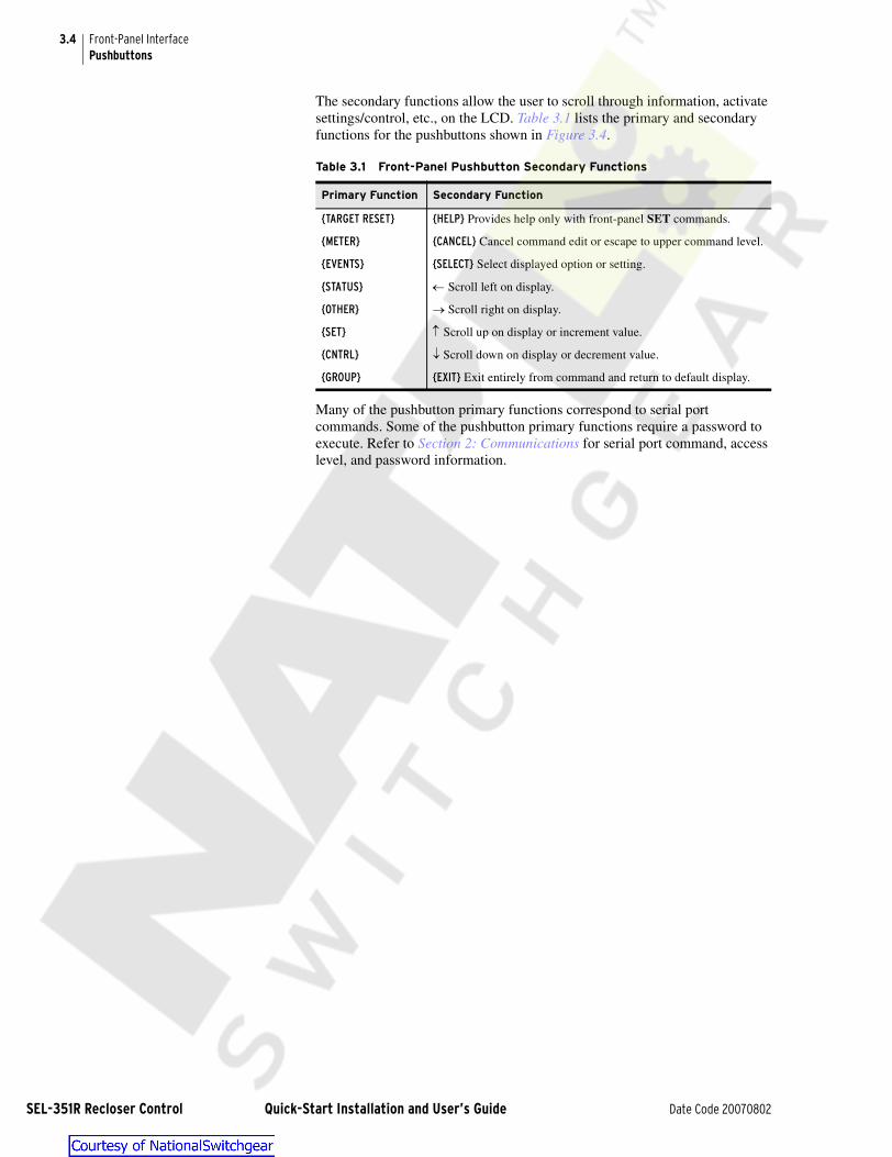
3.4
SEL-351R R
Front-Panel InterfacePushbuttons
The secondary functions allow the user to scroll through information, activate settings/control, etc., on the LCD. Table 3.1 lists the primary and secondary functions for the pushbuttons shown in Figure 3.4.
Many of the pushbutton primary functions correspond to serial port commands. Some of the pushbutton primary functions require a password to execute. Refer to Section 2: Communications for serial port command, access level, and password information.
Table 3.1 Front-Panel Pushbutton Secondary Functions
Primary Function Secondary Function
{TARGET RESET} {HELP} Provides help only with front-panel SET commands.
{METER} {CANCEL} Cancel command edit or escape to upper command level.
{EVENTS} {SELECT} Select displayed option or setting.
{STATUS} ← Scroll left on display.
{OTHER} → Scroll right on display.
{SET} ↑ Scroll up on display or increment value.
{CNTRL} ↓ Scroll down on display or decrement value.
{GROUP} {EXIT} Exit entirely from command and return to default display.
ecloser Control Quick-Start Installation and User’s Guide Date Code 20070802

3.5Front-Panel InterfacePushbutton Primary Functions
Pushbutton Primary Functions
Primary Function
CorrespondingSerial PortCommand
AccessLevel
Password forFront-Panel
AccessDescription
LAMPTEST
TAR R 1 None Illuminate all front-panel LEDs for1 second and clear trip-latched targets TRIP, FAST CURVE, HIGH CURRENT, 81, A, B, C, G, and SEF.
Primary Function
CorrespondingSerial PortCommand
AccessLevel
Password forFront-Panel
AccessDescription
INST MET 1 None Display instantaneous magnitudes(and angles if applicable) of meter values.
ENERGYDISPLAY
RESET
MET EMET RE
1
1
None
None
Display energy meter values.
Reset energy meter values.
MAX/MINDISPLAY
RESET
MET MMET RM
1
1
None
None
Display maximum/minimum metering values.
Reset maximum/minimum metering values.
DEMANDDISPLAY
RESET
MET DMET RDMET RP
1
1
1
None
None
None
Display demand and peak demand meter values.
Reset demand meter values.
Reset peak meter values.
Primary Function
CorrespondingSerial PortCommand
AccessLevel
Password forFront-Panel
AccessDescription
HIS 1 None Show SEL-351R event data.
Primary Function
Corresponding Serial Port Command
Access Level
Password for Front-Panel
AccessDescription
STA 1 None Show SEL-351R diagnostic and battery information.
Date Code 20070802 Quick-Start Installation and User’s Guide SEL-351R Recloser Control
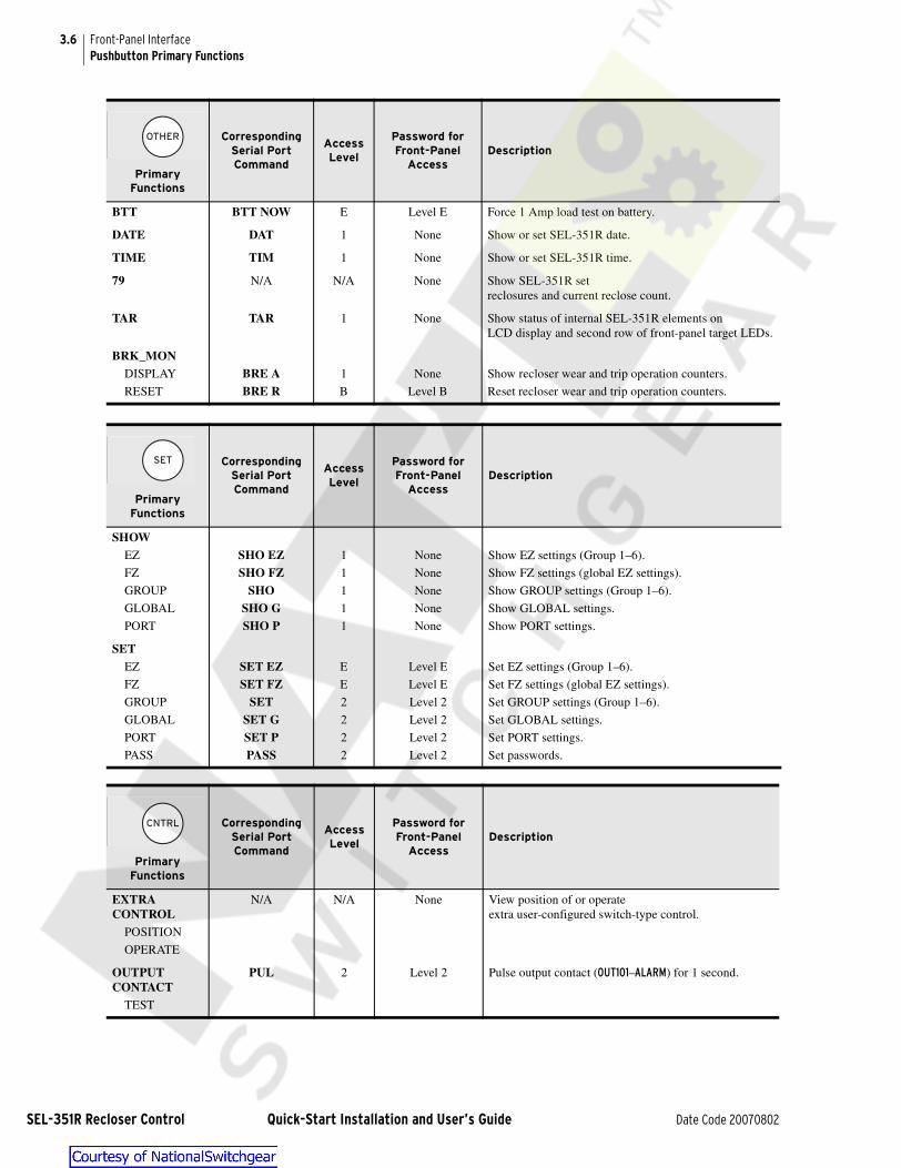
3.6
SEL-351R R
Front-Panel InterfacePushbutton Primary Functions
Primary Functions
Corresponding Serial Port Command
Access Level
Password for Front-Panel
AccessDescription
BTT BTT NOW E Level E Force 1 Amp load test on battery.
DATE DAT 1 None Show or set SEL-351R date.
TIME TIM 1 None Show or set SEL-351R time.
79 N/A N/A None Show SEL-351R setreclosures and current reclose count.
TAR TAR 1 None Show status of internal SEL-351R elements onLCD display and second row of front-panel target LEDs.
BRK_MONDISPLAY
RESET
BRE ABRE R
1
B
None
Level B
Show recloser wear and trip operation counters.
Reset recloser wear and trip operation counters.
Primary Functions
Corresponding Serial Port Command
Access Level
Password for Front-Panel
AccessDescription
SHOWEZ
FZ
GROUP
GLOBAL
PORT
SHO EZSHO FZ
SHOSHO GSHO P
1
1
1
1
1
None
None
None
None
None
Show EZ settings (Group 1–6).
Show FZ settings (global EZ settings).
Show GROUP settings (Group 1–6).
Show GLOBAL settings.
Show PORT settings.
SETEZ
FZ
GROUP
GLOBAL
PORT
PASS
SET EZSET FZ
SETSET GSET PPASS
E
E
2
2
2
2
Level E
Level E
Level 2
Level 2
Level 2
Level 2
Set EZ settings (Group 1–6).
Set FZ settings (global EZ settings).
Set GROUP settings (Group 1–6).
Set GLOBAL settings.
Set PORT settings.
Set passwords.
Primary Functions
Corresponding Serial Port Command
Access Level
Password for Front-Panel
AccessDescription
EXTRACONTROL
POSITION
OPERATE
N/A N/A None View position of or operateextra user-configured switch-type control.
OUTPUTCONTACT
TEST
PUL 2 Level 2 Pulse output contact (OUT101–ALARM) for 1 second.
ecloser Control Quick-Start Installation and User’s Guide Date Code 20070802

3.7Front-Panel InterfacePushbutton Primary Functions
Primary Functions
Corresponding Serial Port Command
Access Level
Password for Front-Panel
AccessDescription
ACTIVEGROUP
DISPLAY
CHANGE
GROGRO n
1
B
None
Level B
Show active setting group.
Change active setting group to setting group n.
Date Code 20070802 Quick-Start Installation and User’s Guide SEL-351R Recloser Control

3.8
SEL-351R R
Front-Panel InterfaceOperator Controls
Operator Controls
Except for the {LOCK} operator control pushbutton, all the following operator control pushbuttons should be pressed momentarily to execute their function.
Press the {GROUND ENABLED} operator control pushbutton to enable/disable ground overcurrent and sensitive earth fault (SEF) element tripping.Corresponding LED illuminates to indicate the enabled state.
Press the {RECLOSE ENABLED} operator control pushbutton to enable/disable auto reclosing. Corresponding LED illuminates to indicate the enabled state.
Press the {REMOTE ENABLED} operator control pushbutton to enable/disable remote control. Corresponding LED illuminates to indicate the enabled state.
NOTE: The {REMOTE ENABLED} operator control is not operable with thefactory settings. See the SEL-351R Recloser Control Instruction Manual for information and ideas on how to program this control.
Press the {ALTERNATE SETTINGS} operator control pushbutton to switch the active setting group between the main setting group (Setting Group 1) and the alternate setting group (Setting Group 2). Corresponding LED illuminates to indicate that the alternate setting group is active.
Continually press the {LOCK} operator control pushbutton for three (3) seconds to engage/disengage the lock function. While this pushbutton is pressed, the corresponding LED flashes on and off, indicating a pending engagement ordisengagement of the lock function. The LED illuminates constantly to indicate the engaged state. While the lock function is engaged, the following operator controls are “locked in position”:
While “locked in position,” these operator controls cannot change state if pressed–their corresponding LEDs remain in the same state. When the lock function is engaged, the {CLOSE} operator control cannot close the recloser, but the {TRIP} operator control can still trip the recloser.
See the Global EZ Settings on page 4.22 (setting “Reset trip-latched LEDs on close”) for options to defeat the 3-second delay on the {LOCK} operator control.
Press the {AUX 1} operator control pushbutton to enable/disable user-programmed auxiliary control. Corresponding LED illuminates to indicate the enabled state.
NOTE: The {AUX 1} operator control is not operable with the factory settings. See the SEL-351R Recloser Control Instruction Manual for information and ideas on how to program this control.
Press the {AUX 2} operator control pushbutton to enable/disable user-pro-grammed auxiliary control. Corresponding LED illuminates to indicate the enabled state.
NOTE: The {AUX 2} operator control is not operable with the factory settings. See the SEL-351R Recloser Control Instruction Manual for information and ideas on how to program this control.
LED
Operator Control Pushbutton
{GROUND ENABLED} {ALTERNATE SETTINGS}{RECLOSE ENABLED} {AUX 1}{REMOTE ENABLED} {AUX 2)
ecloser Control Quick-Start Installation and User’s Guide Date Code 20070802

3.9Front-Panel InterfaceOperator Controls
Press the {WAKE UP} operator control pushbutton to wake up the if the front panel is dark (the unit put itself to sleep after an extended outage). After the unit wakes up, the front panel illuminates, and the unit can then be interrogated via the front panel or serial port.
The {WAKE UP} operator control is also used to turn on the SEL-351R after the battery has been installed (see the installation steps in the Section 1: Installation).
The SEL-351R wakes up automatically from an extended outage when 120 Vac power returns to the unit.
Press the {CLOSE} operator control pushbutton to close the recloser.Corresponding RECLOSER CLOSED LED illuminates to indicate the recloser is closed.
The {CLOSE} operator control pushbutton does not have to be continually pressed to allow for cold load pickup (i.e., disable fast curves, and desensitize delay curves and SEF element). There is automatic allowance for cold load pickup. See the Cold Load Pickup Scheme (No. 33) settings in Section 4: Settings.
Option: Set a delay, so the operator can press the {CLOSE} operator controlpushbutton and then move a safe distance away from the recloser before the SEL-351R issues a close (the {CLOSE} operator control comes with no set delay in the factory settings). With a set delay, press the {CLOSE} operator control push-button momentarily, and notice that the corresponding RECLOSER CLOSED LED flashes on and off during the delay time, indicating a pending close. Abort the pending close by pressing the {CLOSE} operator control pushbutton again or by pressing the {TRIP} operator control pushbutton. This delay setting for the {CLOSE} operator control is PB8D (range: 0 to 3600 cycles; factory set at 0 cycles–no delay). The delay is set via the SET G command (PB8D is not an EZ setting). See Section 1: Factory-Set Logic in the SEL-351R Recloser Control Instruction Manual for more information.
NOTE: The time-delay setting for the PB8 operator control (global setting PB8D) should be left set to the factory default of PB8D = 0 cycles (no time delay) if the control is programmed to operate independently of the close logic. If PB8D > 0 cycles, the operation of corresponding Relay Word bit PB8 will be supervised by SELOGIC setting ULCL. If ULCL is asserted (logical 1), this operator will be effectively disabled.
Press the {TRIP} operator control pushbutton to trip the recloser (and take the control to the lockout state). Corresponding RECLOSER OPEN LED illuminates to indicate the recloser is open.
Option: Set a delay, so the operator can press the {TRIP} operator control pushbutton and then move a safe distance away from the recloser before the SEL-351R issues a trip (the {TRIP} operator control comes with no set delayin the factory settings). With a set delay, press the {TRIP} operator controlpushbutton momentarily and notice the corresponding RECLOSER OPEN LED flashes on and off during the delay time, indicating a pending trip. Abort the pending trip by pressing the {TRIP} operator control pushbutton again or by pressing the {CLOSE} operator control pushbutton. This delay setting for the {TRIP} operator control is PB9D (range: 0 to 3600 cycles; factory set at 0 cycles–no delay). The delay is set via the SET G command (PB9D is not an EZ Setting). See Section 1: Factory-Set Logic in the SEL-351R Recloser Con-trol Instruction Manual for more information.
NOTE: The time-delay setting for the PB9 operator control (global setting PB9D) should be left set to the factory default of PB9D = 0 cycles (no time delay) if the control is programmed to operate independently of the trip logic.
CLOSE
(Model 0351RXXXXXXXXXX)
(Model 0351RXXXXXXX5XX)
TRIP
(Model 0351RXXXXXXXXXX)
(Model 0351RXXXXXXX5XX)
Date Code 20070802 Quick-Start Installation and User’s Guide SEL-351R Recloser Control

Section 4Settings
Overview
This section details the EZ (“easy”) settings–the settings used to perform traditional recloser control operations.
Topics covered in this section:
➤ Curve Designations
➤ EZ (“Easy”) Settings
➤ Global EZ Settings
➤ EZ Settings Sheets (end of this section)
Curve Information
Fast and delay curves are available for phase and ground overcurrent protection. These curves can be set with any of the numerous resident curve choices:
➤ Recloser Curves (see Table 4.1)
➤ US Curves (see Table 4.2)
➤ IEC Curves (see Table 4.2)
➤ User-Programmable Curves (see Table 4.2)
The recloser curves in Table 4.1 show both the older electronic control designation and the newer microprocessor-based control designation. The recloser curves can be specified in a curve setting using either designation. For example, a given traditional recloser curve has the following two designations:
Older electronic control designation: A
Newer microprocessor-based control designation: 101
Traditional recloser curve A and curve 101 are the same curve–use either designation in making curve settings in the SEL-351R.
IMPORTANT: This Quick-Start Installation and User's Guide provides only information applicable to the EZ settings–settings associated with traditional recloser control operations.
MOTOR-OPERATED RECLOSERSRefer to SEL Application Guide AG99-10, Change Logic in SEL-351R Recloser Control for Motor-Operated Reclosers to modify a few settings for motor-operated reclosers (e.g., MVE, CVE, CXE, CZE, VSA).
CURVE MODIFIERS AVAILABLE FORANY CURVE TYPEConstant Time Adder; Vert. Multiplier/Time Dial; Min. Response Time
HIGH CURRENTOPTIONS AVAILABLEFOR PHASE AND GROUNDHigh Current Trip; High Current Lockout
Date Code 20070802 Quick-Start Installation and User’s Guide SEL-351R Recloser Control

4.2
SEL-351R R
SettingsCurve Information
The four (4) user-programmable curves are factory set as shown in Table 4.2, with definite-time characteristics. User-designed curves (created with the SEL-5804 TOC [Time-Overcurrent] Recloser Curve Designer software package) can be downloaded instead to any of the four user-programmable curves in the SEL-351R.
Table 4.1 Recloser Curve Designations
Recloser Curve Cross Reference–Old to New
Old New Old New Old New
A 101 P 115 7 152
B 117 R 105 8 113
C 133 T 161 8PLUS 111
D 116 V 137 9 131
E 132 W 138 KG 165
F 163 Y 120 11 141
G 121 Z 134 13 142
H 122 1 102 14 119
J 164 2 135 15 112
KP 162 3 140 16 139
L 107 4 106 17 103
M 118 5 114 18 151
N 104 6 136
Table 4.2 US, IEC, and User-Programmable Curve Designations
US Curve Description
U1 moderately inverse
U2 inverse
U3 very inverse
U4 extremely inverse
U5 short-time inverse
IEC Curve Description
C1 class A (standard inverse)
C2 class B (very inverse)
C3 class C (extremely inverse)
C4 long-time inverse
C5 short-time inverse
User-ProgrammableCurves (factory set)
Description
DEF_01 definite-time curve (0.1 seconds)
DEF_05 definite-time curve (0.5 seconds)
DEF_1 definite-time curve (1.0 seconds)
DEF_5 definite-time curve (5.0 seconds)
NOTE: All 38 traditional recloser curves are available!
CURVES CONFORMTO STANDARDThe US and IEC curves conform to IEEE C37.112-1996 IEEE Standard Inverse-Time Characteristic Equations for Overcurrent Relays.
COOPER CURVESCooper 200 = IEC Inverse Cooper 201 = IEC Very Inverse Cooper 202 = IEC Extremely Inverse
USER DESIGNED CURVESCreated with SEL-5804 software. 3.5" high-density disk; requires Windows 3.1 or later.
ecloser Control Quick-Start Installation and User’s Guide Date Code 20070802

4.3SettingsFactory EZ Settings
Factory EZ Settings
The SEL-351R ships with the factory EZ settings shown in Table 4.3. The corresponding number references provide a quick way to find the settings (or subsettings) in the Settings Descriptions on page 4.6.
The reference to Settings Groups 1 and 2 at the top of Table 4.3 refers to the two choices for the active setting group:
➤ Settings Group 1 = main settings
➤ Settings Group 2 = alternate settings
Refer to Operator Controls on page 3.8 ({ALTERNATE SETTINGS} operator control pushbutton) for more information on how to switch between these two setting groups. In the factory EZ settings, these two setting groups are set the same.
The Global EZ settings at the end of Table 4.3 apply to both settings Groups 1 and 2.
Those factory settings indicated with an a in Table 4.3 are hidden with these particular factory settings. As a general rule, if a main setting is set to N, then the subsettings that follow are hidden. Setting “Phantom voltages from (VA,VB,VC,VAB,VBC,VCA,OFF)” is only available on SEL-351R-2 relays. Settings Descriptions explains the details behind hiding the settings. Complete setting ranges are also given in Settings Descriptions.
Table 4.3 EZ Settings Quick Reference (Sheet 1 of 3)
No.Settings Groups 1 (Main)and 2 (Alternate) EZ Settings
FactorySettings:
1 Control Identifier RECLOSER R1
2 Circuit Identifier FEEDER 2101
3 CT Ratio 1000.0
4 PT Ratio 100.0
5 Min. trip–phase (A pri.) 400.00
6 Min. trip–ground (A pri.) 100.00
7 Min. trip–SEF (A pri.) OFF
8 Fast curve–phase A
Time dial–phase fast curve 1.00a
EM reset–phase fast curve Na
9 Fast curve–ground 1
Time dial–ground fast curve 1.00a
EM reset–ground fast curve Na
10 Delay curve–phase C
Time dial–phase delay curve 1.00a
EM reset–phase delay curve Na
11 Delay curve–ground 13
Time dial–ground delay curve 1.00a
EM reset–ground delay curve Na
12 Time delay–SEF (cycles) 0.00a
VIEW EZ SETTINGSWITH COMMANDSSHO EZ 1 (Group 1);SHO EZ 2 (Group 2); SHO FZ (Global). See Table 2.5.
SET EZ SETTINGSWITH COMMANDSSET EZ 1 (Group 1);SET EZ 2 (Group 2); SET FZ (Global). See Table 2.5.
! WARNINGAnytime an EZ setting is changed, review all the EZ settings before enabling the new settings. Pay close attention in circumstances where a setting was once set to OFF or N and then later turned on (enabled)–other related settings may need to be turned on, though may still be set to OFF or N.
Date Code 20070802 Quick-Start Installation and User’s Guide SEL-351R Recloser Control
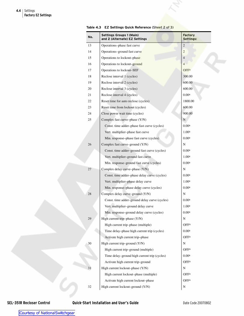
4.4
SEL-351R R
SettingsFactory EZ Settings
13 Operations–phase fast curve 2
14 Operations–ground fast curve 2
15 Operations to lockout–phase 4
16 Operations to lockout–ground 4
17 Operations to lockout–SEF OFFa
18 Reclose interval 1 (cycles) 300.00
19 Reclose interval 2 (cycles) 600.00
20 Reclose interval 3 (cycles) 600.00
21 Reclose interval 4 (cycles) 0.00a
22 Reset time for auto reclose (cycles) 1800.00
23 Reset time from lockout (cycles) 600.00
24 Close power wait time (cycles) 900.00
25 Complex fast curve–phase (Y/N) N
Const. time adder–phase fast curve (cycles) 0.00a
Vert. multiplier–phase fast curve 1.00a
Min. response–phase fast curve (cycles) 0.00a
26 Complex fast curve–ground (Y/N) N
Const. time adder–ground fast curve (cycles) 0.00a
Vert. multiplier–ground fast curve 1.00a
Min. response–ground fast curve (cycles) 0.00a
27 Complex delay curve–phase (Y/N) N
Const. time adder–phase delay curve (cycles) 0.00a
Vert. multiplier–phase delay curve 1.00a
Min. response–phase delay curve (cycles) 0.00a
28 Complex delay curve–ground (Y/N) N
Const. time adder–ground delay curve (cycles) 0.00a
Vert. multiplier–ground delay curve 1.00a
Min. response–ground delay curve (cycles) 0.00a
29 High current trip–phase (Y/N) N
High current trip–phase (multiple) OFFa
Time delay–phase high current trip (cycles) 0.00a
Activate high current trip–phase OFFa
30 High current trip–ground (Y/N) N
High current trip–ground (multiple) OFFa
Time delay–ground high current trip (cycles) 0.00a
Activate high current trip–ground OFFa
31 High current lockout–phase (Y/N) N
High current lockout–phase (multiple) OFFa
Activate high current lockout–phase OFFa
32 High current lockout–ground (Y/N) N
Table 4.3 EZ Settings Quick Reference (Sheet 2 of 3)
No.Settings Groups 1 (Main)and 2 (Alternate) EZ Settings
FactorySettings:
ecloser Control Quick-Start Installation and User’s Guide Date Code 20070802

4.5SettingsFactory EZ Settings
High current lockout–ground (multiple) OFFa
Activate high current lockout–ground OFFa
33 Cold load pickup scheme (Y/N) N
Cold load pickup–phase (multiple) OFFa
Cold load pickup–ground (multiple) OFFa
Loss of load diversity time (cycles) 0.00a
Restore min. trips–time limit (cycles) OFFa
Restore min. trip–phase (Y/N) Na
Restore min. trip–ground (Y/N) Na
Restore min. trip–SEF (Y/N) Na
34 Sequence coordination (Y/N) N
35 Ground trip precedence (Y/N) Na
36 Underfrequency loadshedding (Y/N) N
Underfrequency pickup (Hz) OFFa
Underfrequency time delay (cycles) 6.00a
37 Demand meter time constant (min.) 5
Global EZ Settings:
38 System Frequency (Hz) 60
39 Phase Rotation ABC
40 Recloser Wear Monitor (AUTO,Y,N) AUTO
Recloser type OIL
Interrupt rating (A pri.) 6000
41 Reset trip-latched LEDs on close (Y,Y1,N,N1) Y
42 True three-phase voltage connected (Y,N) N
43 Phantom voltages from (VA,VB,VC,VAB,VBC,VCA,OFF)
OFF
44 V123 Terminal Conn. (A,B,C,AB,BC,CA,OFF) A
45 I123 Terminal Conn. (ABC,ACB,BAC,BCA,CAB,CBA) ABC
46 CT Polarity (POS,NEG) POS
47 Battery Amp-hours 8.0
48 % Battery capacity for sleep 20
49 Turn on the 12 V power (Y,N) N
Keep the 12 V power on while asleep (Y,N) Na
a Factory defaults cause these settings to be hidden. As a general rule, if a main setting is set to N, the subsettings that follow are hidden.
Table 4.3 EZ Settings Quick Reference (Sheet 3 of 3)
No.Settings Groups 1 (Main)and 2 (Alternate) EZ Settings
FactorySettings:
Date Code 20070802 Quick-Start Installation and User’s Guide SEL-351R Recloser Control

4.6
SEL-351R R
SettingsSettings Descriptions
Settings Descriptions
! WARNINGAnytime an EZ setting is changed, review all the EZ settings before enabling the new settings. Pay close attention in circumstances where a setting was once set to Off or N and then later turned on (enabled)–other related settings may need to be turned on, though may still be set to Off or N.
Settings Groups 1 (Main) and 2 (Alternate) EZ SettingsNo. Setting Default Range Incr.
1 Control Identifier RECLOSER R1 0–9, A–Z, - , / , . , space
The Control Identifier setting contains the control installation designation (e.g., RECLOSER R1). This identifier is listed at the top of event, history, meter, and status reports (see Table 2.5).
➤ This setting may be up to 30 characters long.
➤ This setting cannot be made via the front-panel interface.
No. Setting Default Range Incr.
2 Circuit Identifier FEEDER 2101 0–9, A–Z, - , / , . , space
The Circuit Identifier setting contains the greater circuit or substation designation (e.g., FEEDER 2101). This identifier is listed at the top of event, history, meter, and status reports (see Table 2.5).
➤ This setting may be up to 30 characters long.
➤ This setting cannot be made via the front-panel interface.
No. Setting Default Range Incr.
3 CT Ratio 1000.0 1.0–6000.0 0.1
The CT Ratio (current transformer [CT] ratio) setting programs the SEL-351R to operate with a recloser CT ratio (e.g., for thecommon recloser CT ratio 1000:1, the setting CT Ratio = 1000.0 is made).
➤ IMPORTANT: The following settings change in accordance to the CT Ratio setting:
Min. trip–phase (No. 5)
Min. trip–ground (No. 6)
Min. trip–SEF (No. 7)
No. Setting Default Range Incr.
4 PT Ratio 100.0 1.0–10000.0 0.1
The PT Ratio setting is the potential transformer (PT) ratio.
➤ For applications where single-phase 120 Vac power is the only voltage brought to the SEL-351R, the PT ratio should still be entered, otherwise the SEL-351R voltage metering information will not be accurate. Enter the effective power transformer ratio, relative to the 120 Vac secondary winding.
➤ When calculating the PTR, verify that the unit for the power transformer primary voltage is Vac not kVac.
ecloser Control Quick-Start Installation and User’s Guide Date Code 20070802

4.7SettingsSettings Descriptions
No. Setting Default Range Incr.
5 Min. trip–phase 400.00 OFF, 100.00–3199.99 Amps primary 0.01
The Min. trip–phase setting determines the minimum phase current threshold for overcurrent detection in primary amps.
The displayed Amps primary setting range for Min. trip–phase is calculated by multiplying the effective Amps secondary range [0.10 to 3.20] by the CT Ratio (No. 3) [1000]:
(0.10 to 3.20) • 1000 = 100.00 to 3200.00 range (Amps primary)
If the CT Ratio setting changes, the displayed Amps primary setting range for Min. trip–phase changes accordingly. Due toprocessor calculations and rounding techniques, displayed range numbers may appear slightly different than expected (e.g., 3199.99 instead of 3200.00).
➤ IMPORTANT: If Min. trip–phase (No. 5), Min. trip–ground (No. 6), and Min. trip–SEF (No. 7) are all set to OFF, then overcur-rent protection and reclosing are disabled.
➤ IMPORTANT: If Min. trip–phase is set to OFF, then the following settings are all hidden and set to OFF or N:
Fast curve–phase (No. 8) Complex fast curve–phase (No. 25)Delay curve–phase (No. 10) Complex delay curve–phase (No. 27)Operations–phase fast curve (No. 13) High current trip–phase (No. 29)Operations to lockout–phase (No. 15) High current lockout–phase (No. 31)
No. Setting Default Range Incr.
6 Min. trip–ground 100.00 OFF, 5.00–3199.99 Amps primary 0.01
The Min. trip–ground setting determines the minimum ground current threshold for overcurrent detection in primary amps.
The displayed Amps primary setting range for Min. trip–ground is calculatedby multiplying the effective Amps secondary range [0.005 to 3.20] by the CT Ratio (No. 3) [1000]:
(0.005 to 3.20) • 1000 = 5.00 to 3200.00 range (Amps primary)
If the CT Ratio setting changes, the displayed Amps primary setting range for Min. trip–ground changes accordingly. Due to processor calculations and rounding techniques, displayed range numbers may appear slightly different than expected (e.g., 3199.99 instead of 3200.00).
If Min. trip–ground is effectively set <0.1 Amp secondary (e.g., for CT ratio [No. 3] = 1000, Min. trip–ground <100.00 Amps primary), then the corresponding curves flatten out above 1.5 Amps secondary (e.g., for CT ratio [No. 3] = 1000, Fast curve–ground [No. 9] and Delay curve–ground [No. 11] flatten out above 1500 Amps primary).
➤ IMPORTANT: If Min. trip–phase (No. 5), Min. trip–ground (No. 6), and Min. trip–SEF (No. 7) are all set to OFF, then overcurrent protection and reclosing are disabled.
➤ IMPORTANT: If Min. trip–ground is set to OFF, then the following settings are all hidden and set to OFF or N:
Fast curve–ground (No. 9) Complex fast curve–ground (No. 26)Delay curve–ground (No. 11) Complex delay curve–ground (No. 28)Operations–ground fast curve (No. 14) High current trip–ground (No. 30)Operations to lockout–ground (No. 16) High current lockout–ground (No. 32)
No. Setting Default Range Incr.
7 Min. trip–SEF OFF OFF, 5.00–1499.99 Amps primary 0.01
The Min. trip–SEF setting determines the minimum sensitive earth fault threshold for overcurrent detection set in primary Amps.
The displayed Amps primary setting range for Min. trip–SEF is calculated by multiplying the effective Amps secondary range [0.005 to 1.500] by the CT Ratio (No. 3) [1000]:
(0.005 to 1.500) • 1000 = 5.00 to 1500.00 range (Amps primary)
If the CT Ratio setting changes, the displayed Amps primary setting range for Min. trip–ground changes accordingly. Due to processor calculations and rounding techniques, displayed range numbers may appear slightly different than expected (e.g., 1499.99 instead of 1500.00).
➤ IMPORTANT: If Min. trip–phase (No. 5), Min. trip–ground (No. 6),and Min. trip–SEF (No. 7) are all set to OFF, then overcurrent protection and reclosing are disabled.
➤ IMPORTANT: If Min. trip–SEF is set to OFF, then thefollowing settings are all hidden and set to zero (0) and OFF, respectively:
Time delay–SEF (No. 12) Operations to lockout–SEF (No. 17)
Date Code 20070802 Quick-Start Installation and User’s Guide SEL-351R Recloser Control

4.8
SEL-351R R
SettingsSettings Descriptions
No. Setting Default Range Incr.
8 Fast curve–phase A OFF, U1–U5, C1–C5, recloser or user curve
The Fast curve–phase setting selects the time-overcurrent curve for phase fast curve tripping. Curve designations are provided in Table 4.1 and Table 4.2.
➤ This setting is hidden and set to OFF if Min. trip–phase (No. 5) is set to OFF.
➤ If Fast curve–phase is programmed with a US (U1–U5) or IEC (C1–C5) curve, enter the following two settings:
Setting Default Range Incr.
Time-dial–phasefast curve
1.00 0.50–15.00 for US curves U1–U5
0.05–1.00 for IEC curves C1–C5
0.01
0.01
The Time-dial–phase fast curve setting shifts the US or IEC curve in time by the entered multiplier.
➤ This setting is hidden and nonoperative if Fast curve–phase is programmed with a recloser or user curve.
Setting Default Range Incr.
EM reset–phase fast curve N Y/N
The EM reset–phase fast curve setting enables the electromechanical reset emulation for the US or IEC curve, if set to Y.
➤ This setting is usually set to N, except for special applications.
➤ This setting is hidden and set to N if Fast curve–phase is programmed with a recloser or user curve.
No. Setting Default Range Incr.
9 Fast curve–ground 1 OFF, U1–U5, C1–C5, recloser or user curve
The Fast curve–ground setting selects the time-overcurrent curve for ground fast curve tripping. Curve designations are provided in Table 4.1 and Table 4.2.
If Min. trip–ground (No. 6) is effectively set <0.1 Amp secondary (e.g., for CT ratio [No. 3] = 1000, Min. trip–ground (No. 6) <100.00 Amps primary), then Fast curve–ground flattens out above 1.5 Amps secondary (e.g., for CT ratio [No. 3] = 1000, Fast curve–ground flattens out above 1500 Amps primary).
➤ This setting is hidden and set to OFF if Min. trip–ground (No. 6) is set to OFF.
➤ If Fast curve–ground is programmed with a US (U1–U5) or IEC (C1–C5) curve, enter the following two settings:
Setting Default Range Incr.
Time-dial–ground fast curve
1.00 0.50–15.00 for US curves U1–U5
0.05–1.00 for IEC curves C1–C5
0.01
0.01
The Time-dial–ground fast curve setting shifts the US or IEC curve in time by the entered multiplier.
➤ This setting is hidden and nonoperative if Fast curve–ground is programmed with a recloser or user curve.
Setting Default Range Incr.
EM reset–groundfast curve
N Y/N
The EM reset–ground fast curve settingenables the electromechanical reset emulation for the US or IEC curve, if set to Y.
➤ This setting is usually set to N, except for special applications.
➤ This setting is hidden and set to N if Fast curve–ground is programmed with a recloser or user curve.
ecloser Control Quick-Start Installation and User’s Guide Date Code 20070802

4.9SettingsSettings Descriptions
No. Setting Default Range Incr.
10 Delay curve–phase C OFF, U1–U5, C1–C5, recloser or user curve
The Delay curve–phase setting selects the time-overcurrent curve for phase delay curve tripping. Curve designations are provided in Table 4.1 and Table 4.2.
➤ This setting is hidden and set to OFF if Min. trip–phase (No. 5) is set to OFF.
➤ If Delay curve–phase is programmed with a US (U1–U5) or IEC (C1–C5) curve, enter the following two settings:
Setting Default Range Incr.
Time-dial–phase delay curve
1.00 0.50–15.00 for US curves U1–U5
0.05–1.00 for IEC curves C1–C5
0.010.01
The Time-dial–phase delay curve setting shifts the US or IEC curve in time by the entered multiplier.
➤ This setting is hidden and nonoperative if Delay curve–phase is programmed with a recloser or user curve.
Setting Default Range Incr.
EM reset–phase delay curve
N Y/N
The EM reset–phase delay curve setting enables the electromechanical reset emulation for the US or IEC curve, if set to Y.
➤ This setting is usually set to N, except for special applications.
➤ This setting is hidden and set to N if Delay curve–phase is programmed with a recloser or user curve.
No. Setting Default Range Incr.
11 Delay curve–ground 13 OFF, U1–U5, C1–C5, recloser or user curve
The Delay curve–ground setting selects the time-overcurrent curve for ground fast curve tripping. Curve designations are provided in Table 4.1 and Table 4.2.
If Min. trip–ground (No. 6) is effectively set <0.1 Amp secondary (e.g., for CT ratio [No. 3] = 1000, Min. trip–ground [No. 6] <100.00 Amps primary), then Delay curve–ground flattens out above 1.5 Amps secondary (e.g., for CT ratio [No. 3] = 1000, Delay curve–ground flattens out above 1500 Amps primary).
➤ This setting is hidden and set to OFF if Min. trip–ground (No. 6) is set to OFF.
➤ If Delay curve–ground is programmed with a US (U1–U5) or IEC (C1–C5) curve, enter the following two settings:
Setting Default Range Incr.
Time-dial–ground delay curve
1.00 0.50–15.00 for US curves U1–U5
0.05–1.00 for IEC curves C1–C5
0.01
0.01
The Time-dial–ground delay curve setting shifts the US or IEC curve in time by the entered multiplier.
➤ This setting is hidden and nonoperative if Delay curve–ground is programmed with a recloser or user curve.
Setting Default Range Incr.
EM reset–ground delay curve
N Y/N
The EM reset–ground delay curve setting enables theelectromechanical reset emulation for the US or IEC curve, if set to Y.
➤ This setting is usually set to N, except for special applications.
➤ This setting is hidden and set to N if Delay curve–ground is programmed with a recloser or user curve.
No. Setting Default Range Incr.
12 Time delay–SEF 0.00 0–16000.00 cycles 0.25 cyc.
The Time delay–SEF setting programs an intentional time delay for the definite-time SEF (sensitive earth fault) overcurrent element. This is in addition to the built-in 2-cycle time delay.
➤ This setting is hidden and set to zero (0) if Min. trip–SEF (No. 7) is set to OFF.
Date Code 20070802 Quick-Start Installation and User’s Guide SEL-351R Recloser Control

4.10
SEL-351R R
SettingsSettings Descriptions
No. Setting Default Range Incr.
13 Operations–phase fast curve
2 OFF, 1–5 1
The Operations–phase fast curve setting determines the number of phase fast curve trip operations (e.g., if Operations–phase fast curve = 2, then the phase fast curve is enabled for the first two [2] trip operations).
➤ This setting is hidden and set to OFF if Fast curve–phase (No. 8) is set to OFF.
➤ This setting only enables the phase fast curve operations; it does not disable the phase delay curve (the phase delay curve is always active). Traditional protection schemes use fast curves followed by delay curves so the delay curves do not have to be defeated. If a slower first operation than second operation is desired, higher logic level settings changes are required.
No. Setting Default Range Incr.
14 Operations–ground fast curve
2 OFF, 1–5 1
The Operations–ground fast curve setting determines the number of ground fast curve trip operations (e.g., if Opera-tions–ground fast curve = 2, then the ground fast curve is enabled for the first two [2] trip operations).
➤ This setting is hidden and set to OFF if Fast curve–ground (No. 9) is set to OFF.
➤ This setting only enables the ground fast curve operations; it does not disable the ground delay curve (the ground delay curve is always active, provided that the {GROUND ENABLED} operator control is on). Traditional protection schemes use fast curves followed by delay curves so the delay curves do not have to be defeated. If a slower first operation than second operation is desired, higher logic level settings changes are required.
No. Setting Default Range Incr.
15 Operationsto lockout–phase
4 OFF, 1–5 1
The Operations to lockout–phase setting determines the total number of phase curve tripoperations. The difference between setting Operations to lockout–phase and setting Operations–phase fast curve (No. 13) is the number of remaining phase delay curve operations (e.g., 4 – 2 = 2).
The setting range for Operations to lockout–phase adjusts according to Operations–phasefast curve (e.g., if Operations–phase fast curve = 2, then the range for Operations to lockout–phase is from 2 to 5).
➤ If Delay curve–phase (No. 10) = OFF, then Operations to lockout–phaseis set automatically equal to Operations–phase fast curve, and there are no phase delay curve operations (e.g., 2 – 2 = 0).
➤ This setting is hidden and set to OFF if Min. trip–phase (No. 5) is set to OFF.
➤ IMPORTANT: If Operations to lockout–phase (No. 15), Operations to lockout–ground (No. 16), and Operations to lockout–SEF (No. 17) are all set to OFF, then overcurrent protection and reclosing are disabled.
However, if both Min. trip–phase (No. 5) and Delay curve–phase (No. 10) are set tovalues other than OFF, the phase delay curve element is still active. If absolutely no phase protectionis desired (e.g., “switch” mode), Min. trip–phase (No. 5) or Delay curve–phase (No. 10) must also be set to OFF.
No. Setting Default Range Incr.
16 Operationsto lockout–ground
4 OFF, 1–5 1
The Operations to lockout–ground setting determines the total number of ground curve trip operations. The difference between set-ting Operations to lockout–ground and setting Operations–ground fast curve (No. 14) is the number of remaining ground delay curve operations (e.g., 4 – 2 = 2).
The setting range for Operations to lockout–ground adjusts according to Operations–ground fast curve (e.g., if Operations–ground fast curve = 2, then the range for Operations to lockout–ground is from 2 to 5).
➤ If Delay curve–ground (No. 11) = OFF, then Operations to lockout–ground is set automatically equal to Operations–ground fast curve, and there are no ground delay curve operations (e.g., 2 – 2 = 0).
➤ This setting is hidden and set to OFF if Min. trip–ground (No. 6) is set to OFF.
➤ IMPORTANT: If Operations to lockout–phase (No. 15), Operations to lockout–ground (No. 16), and Operations to lockout–SEF (No. 17) are all set to OFF, then overcurrent protection and reclosing are disabled.
However, if both Min. trip–ground (No. 6) and Delay curve–ground (No. 11) are set to values other than OFF, the ground delay curve element is still active (provided the {GROUND ENABLED} operator control is on). If absolutely no ground protection is desired (e.g., “switch” mode), Min. trip–ground (No. 6) or Delay curve–ground (No. 11) must also be set to OFF.
ecloser Control Quick-Start Installation and User’s Guide Date Code 20070802

4.11SettingsSettings Descriptions
for 50 Hz systems: _____ seconds x 50 cycles/second = _____ cycles_____ minutes x 3000 cycles/minute = _____ cycles
for 60 Hz systems: _____ seconds x 60 cycles/second = _____ cycles_____ minutes x 3600 cycles/minute = _____ cycles
No. Setting Default Range Incr.
17 Operationsto lockout–SEF
OFF OFF, 1–5 1
The Operations to lockout–SEF setting determines the number of SEF (sensitive earth fault) element trip operations.
➤ This setting is hidden and set to OFF if Min. trip–SEF (No. 7) is set to OFF.
➤ IMPORTANT: If Operations to lockout–phase (No. 15), Operations to lockout–ground (No. 16), and Operations to lockout–SEF (No. 17) are all set to OFF, then overcurrent protection and reclosing are disabled. See similar warnings for preceding set-ting number 15 and setting number 16.
Table 4.4 Seconds-to-Cycles Conversion (60 Hz)
Seconds Cycles Seconds Cycles
(50 Hz) (60 Hz) (50 Hz) (60 Hz)
0.3 15 18 15 750 900
0.5 25 30 20 1000 1200
1 50 60 30 1500 1800
2 100 120 45 2250 2700
3 150 180 60 3000 3600
5 250 300 90 4500 5400
7 350 420 120 6000 7200
10 500 600 180 9000 10800
No. Setting Default Range Incr.
18 Reclose interval 1 300.00 0–999999.00 cycles 0.25 cyc.
19 Reclose interval 2 600.00 0–999999.00 cycles 0.25 cyc.
20 Reclose interval 3 600.00 0–999999.00 cycles 0.25 cyc.
21 Reclose interval 4 0.00 0–999999.00 cycles 0.25 cyc.
The Reclose interval settings (1 through 4) are each successively and individually timed. Reclose interval timing cannot proceed until the following two conditions are met:
➤ The trip condition has gone away (minimum trip time is factory–set at 12 cycles).
➤ The recloser has opened.
At the end of a reclose interval, an auto reclose attempt is made.
The number of available Reclose interval settings corresponds to the highest set Operations to lockout (No. 15, 16, or 17) setting.
For example, if the highest set Operations to lockout setting is Operations to lockout–phase (No. 15) = 4, then settings Reclose interval 1, Reclose interval 2, and Reclose interval 3 are available (three reclose attempts). Because it is not available, Recloseinterval 4 is hidden and set to zero (0).
The number of reclosing attempts (i.e., available Reclose interval settings) is always one less than the number of trip operations (e.g., 4 “trips” – 1 = 3 “reclosures”).
➤ All the Reclose interval settings are hidden and set to zero (0) if none of the Operations to lockout (No. 15, 16, or 17) settings are set greater than 1 (reclosing is disabled; 1 “trip” – 1 = 0 “reclosures”).
➤ If a Reclose interval setting is set to zero (0), the corresponding auto reclose attempt and any following auto reclose attempts are aborted.
Date Code 20070802 Quick-Start Installation and User’s Guide SEL-351R Recloser Control

4.12
SEL-351R R
SettingsSettings Descriptions
No. Setting Default Range Incr.
22 Reset timefor auto reclose
1800.00 0–999999.00 cycles 0.25 cyc.
23 Reset time from lockout 600.00 0–999999.00 cycles 0.25 cyc.
The Reset time for auto reclose setting qualifies an auto reclose of the recloser. The Reset time from lockout setting qualifies a manual/remote close of the recloser from the lockout state. Traditionally, the Reset time from lockout setting is set shorter than the Reset time for auto reclose setting.
Reset timing is blocked (and the reset timer is reloaded) if any overcurrent elements are picked up. Reset timing can only proceed if all the overcurrent elements are continually dropped out.
➤ Both the Reset time for auto reclose and Reset time from lockout settings are hidden and set to zero (0) if none of the Operations to lockout (No. 15, 16, or 17) settings are set greater than 1 (reclosing is disabled; 1 “trip” – 1 = 0 “reclosures”).
No. Setting Default Range Incr.
24 Close power wait time 900.00 OFF, 0–999999.00 cycles 0.25 cyc.
The Close power wait time setting is a time window that starts timing after a reclose interval times out. During this time window, the SEL-351R checks the 120 Vac connected to it:
➤ If the 120 Vac is present, this indicates that the close power to the recloser (120 Vac or primary voltage) is also present, and reclosing proceeds.
➤ If the 120 Vac is not present, this indicates that the close power to the recloser (120 Vac or primary voltage) is also not present and reclosing is stalled. If the 120 Vac is not present throughout the time window, reclosing is aborted at the end of the timewindow, and the SEL-351R goes to the lockout state.
The presence of 120 Vac is detected with voltage input VA. See subsection Initial Conditions for Control Tests on page 5.3 for additional details on voltage input VA detecting 120 Vac.
➤ IMPORTANT: If Close power wait time is set to OFF, then the SEL-351R waits indefinitely for 120 Vac to appear, in order for reclosing to proceed–there is no restrictive time window.
➤ This setting is hidden and set to 0 cycles if none of the Operations to lockout (No. 15, 16, or 17) settings are set greater than 1 (reclosing is disabled; 1 “trip” – 1 = 0 “reclosures”). Previous firmware versions set it to OFF (instead of 0 cycles) for this condition.
No. Setting Default Range Incr.
25 Complex fast curve–phase
N Y/N
The Complex fast curve–phase setting enables the following three settings for the phase fast curve, if set to Y.
➤ This setting is hidden and set to N if Fast curve–phase (No. 8) is set to OFF.
Setting Default Range Incr.
Const. time adder–phase fast curve
0.00 0–60.00 cycles 0.25 cyc.
The Const. time adder–phase fast curve setting adds a constant time to the phase fast curve, if set to other than 0 cycles.
➤ This setting is hidden and set to zero (0) if Complex fast curve–phase is set to N.
Setting Default Range Incr.
Vert. multiplier–phase fast curve
1.00 0.10–2.00 0.01
The Vert. multiplier–phase fast curve setting shifts the phase fast curve in time, by the entered multiplier, if Fast curve–phase (No. 8) is programmed with a recloser or user curve. If no particular multiplier is desired, set Vert. mul-tiplier–phase fast curve equal to 1.00.
➤ If Fast curve–phase (No. 8) is programmed with a US (U1–U5) or IEC (C1–C5) curve, Vert. multiplier–phase fast curve is hidden and nonoperative. The preceding Time–dial–phase fast curve (No. 8) subsetting provides the US and IEC curves with an effective vertical multiplier, instead.
➤ This setting has no multiplying effect on the Constant time adder–phase fast curve and Min. response time–phase fast curve settings. They all operate independently.
➤ This setting is hidden and set to 1.00 if Complex fast curve–phase is set to N and Fast curve–phase (No. 8) is pro-grammed with a recloser or user curve.
ecloser Control Quick-Start Installation and User’s Guide Date Code 20070802

4.13SettingsSettings Descriptions
Setting Default Range Incr.
Min. response–phase fast curve
0.00 0–60.00 cycles 0.25 cyc.
The phase fast curve can trip no faster than the Min. response time–phase fast curve setting.
If the Min. response time–phase fast curve setting is set equal to zero (0), it has no effect on the phase fast curve. If the Min. response time–phase fast curve setting is set equal to 15 cycles, for example, the phase fast curve cannot trip on the portion of the curve that is faster than 15 cycles–the phase fast curve effectively flattens out at 15 cycles.
➤ This setting is hidden and set to zero (0) if Complex fast curve–phase is set to N.
No. Setting Default Range Incr.
26 Complex fastcurve–ground
N Y/N
The Complex fast curve–ground setting enables the following three settings for the ground fast curve, if set to Y.
➤ This setting is hidden and set to N if Fast curve–ground (No. 9) is set to OFF.
Setting Default Range Incr.
Const. time adder–ground fast curve
0.00 0–60.00 cycles 0.25 cyc.
The Const. time adder–ground fast curve setting adds a constant time to the ground fast curve, if set to other than 0 cycles.
➤ This setting is hidden and set to zero (0) if Complex fast curve–ground is set to N.
Setting Default Range Incr.
Vert. multiplier–ground fast curve
1.00 0.10–2.00 0.01
The Vert. multiplier–ground fast curve setting shifts the ground fast curve in time, by the entered multiplier, if Fast curve–ground (No. 9) is programmed with a recloser or user curve. If no particular multiplier is desired, set Vert. multiplier–ground fast curve equal to 1.00.
➤ If Fast curve–ground (No. 9) is programmed with a US (U1–U5) or IEC (C1–C5) curve, Vert. multiplier–ground fast curve is hidden and nonoperative. The preceding Time–dial–ground fast curve (No. 9) subsetting provides the US and IEC curves with an effective vertical multiplier, instead.
➤ This setting has no multiplying effect on the Constant time adder–ground fast curve and Min. response time–ground fast curve settings. They all operate independently.
➤ This setting is hidden and set to 1.00 if Complex fast curve–ground is set to N and Fast curve–ground (No. 9) is programmed with a recloser or user curve.
Setting Default Range Incr.
Min. response–ground fast curve
0.00 0–60.00 cycles 0.25 cyc.
The phase fast curve can trip no faster than the Min. response time–ground fast curve setting.
If the Min. response time–ground fast curve setting is set equal to zero (0), it has no effect on the ground fast curve. If the Min. response time–ground fast curve setting is set equal to 15 cycles, for example, the ground fast curve can-not trip on the portion of the curve that is faster than 15 cycles–the ground fast curve effectively flattens out at 15 cycles.
➤ This setting is hidden and set to zero (0) if Complex fast curve–ground is set to N.
No. Setting Default Range Incr.
Date Code 20070802 Quick-Start Installation and User’s Guide SEL-351R Recloser Control

4.14
SEL-351R R
SettingsSettings Descriptions
No. Setting Default Range Incr.
27 Complex delaycurve–phase
N Y/N
The Complex delay curve–phase setting enables the following three settings for the phase delay curve, if set to Y.
➤ This setting is hidden and set to N if Delay curve–phase (No. 10) is set to OFF.
Setting Default Range Incr.
Const. time adder–phase delay curve
0.00 0–60.00 cycles 0.25 cyc.
The Const. time adder–phase delay curve setting adds a constant time to the phase delay curve, if set other than 0 cycles.
➤ This setting is hidden and set to zero (0) if Complex delay curve–phase is set to N.
Setting Default Range Incr.
Vert. multiplier–phase delay curve
1.00 0.10–2.00 0.01
The Vert. multiplier–phase delay curve setting shifts the phase delay curve in time, by the entered multiplier, if Delay curve–phase (No. 10) is programmed with a recloser or user curve. If no particular multiplier is desired, set Vert. multiplier–phase delay curve equal to 1.00.
➤ If Delay curve–phase (No. 10) is programmed with a US (U1–U5) or IEC (C1–C5) curve, Vert. multiplier–phase delay curve is hidden and nonoperative. The preceding Time-dial–phase delay curve (No. 10) subsetting provides the US and IEC curves with an effective vertical multiplier, instead.
➤ This setting has no multiplying effect on the Constant time adder–phase delay curve and Min. response time–phase delay curve settings. They all operate independently.
➤ This setting is hidden and set to 1.00 if Complex delay curve–phase is set to N and Delay curve–phase (No. 10) is programmed with a recloser or user curve.
Setting Default Range Incr.
Min. response–phase delay curve
0.00 0–60.00 cycles 0.25 cyc.
The phase delay curve can trip no faster than the Min. response time–phase delay curve setting.
If the Min. response time–phase delay curve setting is set equal to zero (0), it has no effect on the phase delay curve. If the Min. response time–phase delay curve setting is set equal to 15 cycles, for example, the phase delay curve can-not trip on the portion of the curve that is faster than 15 cycles–the phase delay curve effectively flattens out at 15 cycles.
➤ This setting is hidden and set to zero (0) if Complex delay curve–phase is set to N.
No. Setting Default Range Incr.
28 Complex delaycurve–ground
N Y/N
The Complex delay curve–ground setting enables the following three settings for the ground delay curve, if set to Y.
➤ This setting is hidden and set to N if Delay curve–ground (No. 11) is set to OFF.
Setting Default Range Incr.
Const. time adder–ground delay curve
0.00 0–60.00 cycles 0.25 cyc.
The Const. time adder–ground delay curve setting adds a constant time to the ground delay curve, if set other than 0 cycles.
➤ This setting is hidden and set to zero (0) if Complex delay curve–ground is set to N.
ecloser Control Quick-Start Installation and User’s Guide Date Code 20070802

4.15SettingsSettings Descriptions
Setting Default Range Incr.
Vert. multiplier–ground delay curve
1.00 0.10–2.00 0.01
The Vert. multiplier–ground delay curve setting shifts the phase delay curve in time, by the entered multiplier, if Delay curve–ground (No. 11) is programmed with a recloser or user curve. If no particular multiplier is desired, set Vert. multiplier–ground delay curve equal to 1.00.
➤ If Delay curve–ground (No. 11) is programmed with a US (U1–U5) or IEC (C1–C5) curve, Vert. multiplier–ground delay curve is hidden and nonoperative. The preceding Time-dial–ground delay curve (No. 11)–setting provides the US and IEC curves with an effective vertical multiplier, instead.
➤ This setting has no multiplying effect on the Constant time adder–ground delay curve and Min. response time–ground delay curve settings. They all operate independently.
➤ This setting is hidden and set to 1.00 if Complex delay curve–ground is set to N and Delay curve–ground (No. 11) is programmed with a recloser or user curve.
Setting Default Range Incr.
Min. response–ground delay curve
0.00 0–60.00 cycles 0.25 cyc.
The ground delay curve can trip no faster than the Min. response time–ground delay curve setting.
If the Min. response time–ground delay curve setting is set equal to zero (0), it has no effect on the ground delay curve. If the Min. response time–ground delay curve setting is set equal to 15 cycles, for example, the ground delay curve cannot trip on the portion of the curve that is faster than 15 cycles the ground delay curve effectively flattens out at 15 cycles.
➤ This setting is hidden and set to zero (0) if Complex delay curve–ground is set to N.
No. Setting Default Range Incr.
No. Setting Default Range Incr.
29 High current trip–phase N Y/N
The High current trip–phase setting enables the following three settings for phase high current tripping, if set to Y. Phase high cur-rent tripping is not affected by the cold load pickup scheme.
➤ This setting is hidden and set to N if Fast curve–phase (No. 8) and Delay curve–phase (No. 10) are both set to OFF.
Setting Default Range Incr.
High current trip–phase OFF OFF, 1.00–49.99 multiples of Min. trip–phase 0.01
The High current trip–phase (multiples of Min. trip–phase) setting determines the phase current threshold for phase high current tripping.
Example: If High current trip–phase = 12.00 (multiples of Min. trip–phase) and Min. trip–phase (No. 5) = 400 Amps primary, then the phase current threshold for phase high current tripping operates at a value equal to:
12.00 • 400 Amps primary = 4800 Amps primary
The upper limit of this setting (50.00 multiples) is calculated from the Amps secondary range upper limit [20] and settings CT Ratio (No. 3) [1000] and Min. trip–phase (No. 5) [400]:
(20 • 1000)/400 = 50 multiples (upper limit)
Due to processor calculations and rounding techniques, displayed range numbers may appear slightly different than expected (e.g., 49.99 instead of 50.00).
➤ This setting is hidden and set to OFF if High current trip–phase is set to N.
Setting Default Range Incr.
Time delay–phasehigh current trip
0.00 0–16000.00 cycles 0.25 cyc.
The Time delay–phase high current trip setting programs an intentional time delay for the phase high currenttripping. If set to zero (0), phase high current tripping operates instantaneously.
➤ This setting is hidden and set to zero (0) if High current trip–phase is set to N.
Date Code 20070802 Quick-Start Installation and User’s Guide SEL-351R Recloser Control
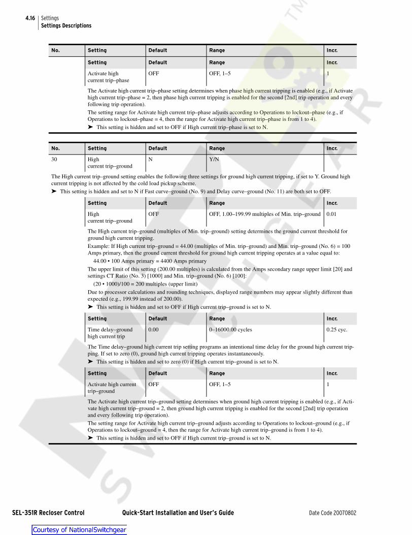
4.16
SEL-351R R
SettingsSettings Descriptions
Setting Default Range Incr.
Activate highcurrent trip–phase
OFF OFF, 1–5 1
The Activate high current trip–phase setting determines when phase high current tripping is enabled (e.g., if Activate high current trip–phase = 2, then phase high current tripping is enabled for the second [2nd] trip operation and every following trip operation).
The setting range for Activate high current trip–phase adjusts according to Operations to lockout–phase (e.g., if Operations to lockout–phase = 4, then the range for Activate high current trip–phase is from 1 to 4).
➤ This setting is hidden and set to OFF if High current trip–phase is set to N.
No. Setting Default Range Incr.
30 High current trip–ground
N Y/N
The High current trip–ground setting enables the following three settings for ground high current tripping, if set to Y. Ground high current tripping is not affected by the cold load pickup scheme.
➤ This setting is hidden and set to N if Fast curve–ground (No. 9) and Delay curve–ground (No. 11) are both set to OFF.
Setting Default Range Incr.
High current trip–ground
OFF OFF, 1.00–199.99 multiples of Min. trip–ground 0.01
The High current trip–ground (multiples of Min. trip–ground) setting determines the ground current threshold for ground high current tripping.
Example: If High current trip–ground = 44.00 (multiples of Min. trip–ground) and Min. trip–ground (No. 6) = 100 Amps primary, then the ground current threshold for ground high current tripping operates at a value equal to:
44.00 • 100 Amps primary = 4400 Amps primary
The upper limit of this setting (200.00 multiples) is calculated from the Amps secondary range upper limit [20] and settings CT Ratio (No. 3) [1000] and Min. trip–ground (No. 6) [100]:
(20 • 1000)/100 = 200 multiples (upper limit)
Due to processor calculations and rounding techniques, displayed range numbers may appear slightly different than expected (e.g., 199.99 instead of 200.00).
➤ This setting is hidden and set to OFF if High current trip–ground is set to N.
Setting Default Range Incr.
Time delay–ground high current trip
0.00 0–16000.00 cycles 0.25 cyc.
The Time delay–ground high current trip setting programs an intentional time delay for the ground high current trip-ping. If set to zero (0), ground high current tripping operates instantaneously.
➤ This setting is hidden and set to zero (0) if High current trip–ground is set to N.
Setting Default Range Incr.
Activate high current trip–ground
OFF OFF, 1–5 1
The Activate high current trip–ground setting determines when ground high current tripping is enabled (e.g., if Acti-vate high current trip–ground = 2, then ground high current tripping is enabled for the second [2nd] trip operation and every following trip operation).
The setting range for Activate high current trip–ground adjusts according to Operations to lockout–ground (e.g., if Operations to lockout–ground = 4, then the range for Activate high current trip–ground is from 1 to 4).
➤ This setting is hidden and set to OFF if High current trip–ground is set to N.
No. Setting Default Range Incr.
ecloser Control Quick-Start Installation and User’s Guide Date Code 20070802
4.17SettingsSettings Descriptions
No. Setting Default Range Incr.
31 High currentlockout–phase
N Y/N
The High current lockout–phase setting enables the following two settings for phase high current lockout, if set to Y. Phase high cur-rent lockout is not affected by the cold load pickup scheme.
➤ This setting is hidden and set to N if Fast curve–phase (No. 8) and Delay curve–phase (No. 10) are both set to OFF.
Setting Default Range Incr.
High currentlockout–phase
OFF OFF, 1.00–49.99 multiples of Min. trip–phase 0.01
The High current lockout–phase (multiples of Min. trip–phase) setting determines the exceeded phase current thresh-old at which the SEL-351R goes to the lockout state immediately when tripping.
Example: If High current lockout–phase = 13.00 (multiples of Min. trip–phase) and Min. trip–phase (No. 5) = 400 Amps primary, then the phase current threshold for phase high current lockout operates at a value equal to:
13.00 • 400 Amps primary = 5200 Amps primary
The upper limit of this setting (50.00 multiples) is calculated from the Amps secondary range upper limit [20] and settings CT Ratio (No. 3) [1000] and Min. trip–phase (No. 5) [400]:
(20 • 1000)/400 = 50 multiples (upper limit)
Due to processor calculations and rounding techniques, displayed range numbers may appear slightly different than expected (e.g., 49.99 instead of 50.00).
➤ This setting is hidden and set to OFF if High current lockout–phase is set to N.
Setting Default Range Incr.
Activate high current lockout–phase
OFF OFF, 1–5 1
The Activate high current lockout–phase setting determines when phase high current lockout is enabled (e.g., if Acti-vate high current lockout–phase = 3, then phase high current tripping is enabled for the third [3rd] trip operation and every following trip operation).
The setting range for Activate high current lockout–phase adjusts according to Operations to lockout–phase (e.g., if Operations to lockout–phase = 4, then the range for Activate high current lockout–phase is from 1 to 4).
➤ This setting is hidden and set to OFF if High current lockout–phase is set to N.
No. Setting Default Range Incr.
32 High current lockout–ground
N Y/N
The High current lockout–ground setting enables the following two settings for ground high current lockout, if set to Y. High current lockout–ground is not affected by the cold load pickup scheme.
➤ This setting is hidden and set to N if Fast curve–ground (No. 9) and Delay curve–ground (No. 11) are both set to OFF.
Setting Default Range Incr.
High current lockout–ground
OFF OFF, 1.00–199.99 multiples of Min. trip–ground 0.01
The High current lockout–ground (multiples of Min. trip–ground) setting determines the exceeded ground current threshold at which the SEL-351R goes to the lockout state immediately when tripping.
Example: If High current lockout–ground = 45.00 (multiples of Min. trip–ground) and Min. trip–ground (No. 6) = 100 Amps primary, then the ground current threshold for ground high current lockout operates at a value equal to:
45.00 • 100 Amps primary = 4500 Amps primary
The upper limit of this setting (200.00 multiples) is calculated from the Amps secondary range upper limit [20] and settings CT Ratio (No. 3) [1000] and Min. trip–ground (No. 6) [100]:
(20 • 1000)/100 = 200 multiples (upper limit)
Due to processor calculations and rounding techniques, displayed range numbers may appear slightly different than expected (e.g., 199.99 instead of 200.00).
➤ This setting is hidden and set to OFF if High current lockout–ground is set to N.
Date Code 20070802 Quick-Start Installation and User’s Guide SEL-351R Recloser Control

4.18
SEL-351R R
SettingsSettings Descriptions
Setting Default Range Incr.
Activate high current lockout–ground
OFF OFF, 1–5 1
The Activate high current lockout–ground setting determines when ground high current lockout is enabled (e.g., if Activate high current lockout–ground = 3, then ground high current tripping is enabled for the third [3rd] trip oper-ation and every following trip operation).
The setting range for Activate high current lockout–ground adjusts according to Operations to lockout–ground (e.g., if Operations to lockout–ground = 4, then the range for Activate high current lockout–ground is from 1 to 4).
➤ This setting is hidden and set to OFF if High current lockout–ground is set to N.
No. Setting Default Range Incr.
33 Cold load pickup scheme
N Y/N
The Cold load pickup scheme setting enables the cold load pickup scheme when set to Y.
➤ This setting is hidden and set to N if Delay curve–phase (No. 10) is set to OFF and Delay curve–ground (No. 11) is set to OFF.
➤ If Cold load pickup scheme is set to Y, then you are prompted to program the following settings:
Setting Default Range Incr.
Cold load pickup–phase OFF OFF, 1.00–49.99 multiples of Min. trip–phase 0.01
The Cold load pickup–phase setting determines the phase current threshold for overcurrent detection when the Cold load pickup scheme is active.
Example: If Cold load pickup–phase = 1.70 (multiples of Min. trip–phase), Min. trip–phase (No. 5) = 400 Amps pri-mary, and the cold load pickup scheme is active, then the phase current threshold for overcurrent detection operates at a value equal to:
1.70 • 400 Amps primary = 680 Amps primary
The upper limit of this setting (50.00 multiples) is calculated from the Amps secondary range upper limit [20] and settings CT Ratio (No. 3) [1000] and Min. trip–phase (No. 5) [400]:
(20 • 1000)/400 = 50 multiples (upper limit)
Due to processor calculations and rounding techniques, displayed range numbers may appear slightly different than expected (e.g., 49.99 instead of 50.00).
➤ If Cold load pickup–phase is set to OFF, then the phase current threshold for overcurrent detection remains unchanged (threshold remains equal to Min. trip–phase [No. 5]).
➤ This setting is hidden and set to OFF if Cold load pickup scheme is set to N or Delay curve–phase (No. 10) is set to OFF.
No. Setting Default Range Incr.
ecloser Control Quick-Start Installation and User’s Guide Date Code 20070802

4.19SettingsSettings Descriptions
Setting Default Range Incr.
Cold loadpickup–ground
OFF OFF, 1.00–199.99 multiples of Min. trip–ground 0.01
The Cold load pickup–ground setting determines the ground current threshold for overcurrent detection when the Cold load pickup scheme is active (also applied to SEF element as the SEF current threshold for overcurrent detection).
Example: If Cold load pickup–ground = 1.50 (multiples of Min. trip–ground), Min. trip–ground (No. 6) = 100 Amps primary, and the cold load pickup scheme is active, then the ground current threshold for overcurrent detection operates at a value equal to:
1.50 • 100 Amps primary = 150 Amps primary
The SEF current threshold for overcurrent detection also operates at a value equal to 150 Amps primary when the cold load pickup scheme is active.
The upper limit of this setting (200.00 multiples) is calculated from the Amps secondary range upper limit [20] and settings CT Ratio (No. 3) [1000] and Min. trip–ground (No. 6) [100]:
(20 • 1000)/100 = 200 multiples (upper limit)
Due to processor calculations and rounding techniques, displayed range numbers may appear slightly different than expected (e.g., 199.99 instead of 200.00).
➤ If Cold load pickup–ground is set to OFF, then the ground current threshold for overcurrent detection remains unchanged (threshold remains equal to setting Min. trip–ground [No. 6]) and the SEF current threshold for overcurrent detection remains unchanged (threshold remains equal to setting Min. trip–SEF [No. 7]).
➤ This setting is hidden and set to OFF if Cold load pickup scheme is set to N or Delay curve–ground (No. 11) is set to OFF.
Setting Default Range Incr.
Loss of loaddiversity time
0.00 0–999999.00 cycles 0.25 cyc.
The Loss of load diversity timer starts to time if both the following are true:
➤ The recloser is open.
➤ The control is in the lockout state or reclosing is defeated.
When the Loss of load diversity timer times out, the cold load pickup scheme is activated, causing the following to occur:
➤ Fast curves are disabled.
➤ Delay curves and SEF element are desensitized per preceding cold load pickup settings (the curves are not shifted–coordination is maintained).
When the recloser is closed, the cold load pickup scheme remains active. If the recloser remains closed, the current thresholds for overcurrent detection return naturally to their regular Min. trip (No. 5, 6, or 7) levels when the inrush current goes below these respective regular levels for at least 15 seconds. The respective fast curves are enabled again. This return to normal conditions is separate for phase, ground, and SEF elements (e.g., ground could return to normal before phase or SEF, depending on the subsidence rates of inrush currents).
➤ This setting is hidden and set to zero (0) if Cold load pickup scheme is set to N.
No. Setting Default Range Incr.
Date Code 20070802 Quick-Start Installation and User’s Guide SEL-351R Recloser Control

4.20
SEL-351R R
SettingsSettings Descriptions
Setting Default Range Incr.
Restore min.trips–time limit
OFF OFF, 0–999999.00 cycles 0.25 cyc.
The Restore min. trips–time limit is an option to force current thresholds for overcurrent detection from temporary cold load pickup values back to regular Min. trip (No. 5, 6, or 7) levels. This time limit is set if the user is concerned about an overcurrent element being desensitized too long in the cold load inrush scheme (force the threshold back, do not let it return naturally as described with the preceding Loss of load diversity timer setting).
Restore min. trips–time limit ≠ OFF:
The Restore min. trips–time limit starts to time if the recloser is closed and both of the following are true:
➤ The cold load pickup scheme is active for at least one element (see preceding Cold load pickup and Loss of load diversity settings).
➤ At least one of the following three Restore min. trip settings is set to Y.
If the recloser remains closed, the Restore min. trips–time limit times out and selected current thresholds for over-current detection (see following three Restore min. trip settings) are forced back to their respective regular Min. trip (No. 4, 5, and 6) levels. The respective fast curves are also enabled again. The natural return to the regular Min. trip levels (described with the preceding Loss of load diversity timer setting) can also occur if the inrush current goes below the Min. trip level for at least 15 seconds before Restore min. trips–time limit times out.
Restore min. trips–time limit = OFF:
If the cold load pickup scheme is active, then the current thresholds for overcurrent detection can only return back to their regular Min. trip levels naturally as described with the preceding Loss of load diversity timer setting.
➤ This setting is hidden and set to OFF if Cold load pickup scheme is set to N.
Setting Default Range Incr.
Restore min. trip–phase N Y/N
Restore min. trip–phase = Y:
If the cold load pickup scheme is active, the phase current threshold for overcurrent detection is forced back to the regular Min. trip–phase (No. 5) level when the preceding Restore min. trips–time limit times out.
Restore min. trip–phase = N:
If the cold load pickup scheme is active, the phase current threshold for overcurrent detection can only return back to its regular Min. trip–phase level naturally as described with the preceding Loss of load diversity timer setting.
➤ This setting is hidden and set to N if Restore min. trips–time limit is set to OFF or Delay curve–phase (No. 10) is set to OFF.
Setting Default Range Incr.
Restore min.trip–ground
N Y/N
Restore min. trip–ground = Y:
If the cold load pickup scheme is active, the ground current threshold for overcurrent detection is forced back to the regular Min. trip–ground (No. 6) level when the preceding Restore min. trips–time limit times out.
Restore min. trip–ground = N:
If the cold load pickup scheme is active, the ground current threshold for overcurrent detection can only return back to its regular Min. trip–ground level naturally as described with the preceding Loss of load diversity timer setting.
➤ This setting is hidden and set to N if Restore min. trips–time limit is set to OFF or Delay curve–ground (No. 11) is set to OFF.
No. Setting Default Range Incr.
ecloser Control Quick-Start Installation and User’s Guide Date Code 20070802
4.21SettingsSettings Descriptions
Setting Default Range Incr.
Restore min. trip–SEF N Y/N
Restore min. trip–SEF = Y:
If the cold load pickup scheme is active, the SEF current threshold for overcurrent detection is forced back to the regular Min. trip–SEF (No. 7) level when the preceding Restore min. trips–time limit times out. The ground cur-rent threshold for overcurrent detection derived from setting Cold load pickup–ground is also applied to the SEF element (as the SEF current threshold for overcurrent detection).
Restore min. trip–SEF = N:
If the cold load pickup scheme is active, the SEF current threshold for overcurrent detection can only return back to its regular Min. trip–SEF level naturally as described with the preceding Loss of load diversity timer setting.
➤ This setting is hidden and set to N if Restore min. trips–time limit is set to OFF, Delay curve–ground (No. 11) is set to OFF, or Min. trip–SEF (No. 7) is set to OFF.
No. Setting Default Range Incr.
34 Sequence coordination N Y/N
The Sequence coordination setting keeps the SEL-351R in step with a downstream recloser control, preventing the overreaching SEL-351R Fast curve elements from tripping for faults beyond the downstream recloser.
Sequence coordination advances the operations counter each time the following sequence occurs:
➤ The SEL-351R is in the reset state.
➤ Fast curve–phase (No. 8) or Fast curve–ground (No. 9) element picks up and starts timing for a fault.
➤ Fast curve–phase (No. 8) or Fast curve–ground (No. 9) element remains picked up for at least 1.25 cycles, but then drops out before tripping (fault was interrupted by downstream device closer to the fault).
When the operations counter is advanced beyond the corresponding Operations–phase fast curve (No. 13) or Operations–ground fast curve (No. 14), no more advancing of the operations counter occurs (the Fast curve elements are disabled). The Fast curve elements are enabled again (the operations counter is reset) after a time period equal to Reset time for auto reclose (No. 22).
➤ This setting is hidden and set to N if the Fast curve–phase and the Fast curve–ground settings are both set to OFF.
No. Setting Default Range Incr.
35 Ground trip precedence N Y/N
Ground trip precedence = Y:
➤ If the ground fault current is above the Min. trip–ground (No. 6) level at the time of trip, the operations to lockout follows Oper-ations to lockout–ground (No. 16).
➤ If ground fault current is below the Min. trip–ground (No. 6) level and phase fault current is above the Min. trip–phase (No. 5) level at the time of trip, the determination to go to lockout is controlled by Operations to lockout–phase (No. 15).
Ground trip precedence = N:
➤ If ground fault current is above the Min. trip–ground (No. 6) level and phase fault current is below the Min. trip–phase (No. 5) level at the time of trip, the determination to go to lockout is controlled by Operations to lockout–ground (No. 16).
➤ If phase fault current is above the Min. trip–phase (No. 5) at the time of trip, the determination to go to lockout is controlled by Operations to lockout–phase (No. 15).
➤ NOTE: The Operations to lockout–SEF (No. 17) is independent of Ground trip precedence.
➤ This setting is hidden and set to N if Operations to lockout–phase (No. 15) = OFF, Operations to lockout–ground (No. 16) = OFF, or the Operations to lockout–phase setting equals (=) the Operations to lockout–ground setting.
No. Setting Default Range Incr.
Date Code 20070802 Quick-Start Installation and User’s Guide SEL-351R Recloser Control

4.22
SEL-351R R
SettingsSettings Descriptions
Global EZ Settings
No. Setting Default Range Incr.
36 Underfrequencyloadshedding
N Y/N
The Underfrequency loadshedding setting enables the underfrequency loadshedding scheme, if set to Y.
➤ If Underfrequency loadshedding is set to Y, enter the following two settings:
Setting Default Range Incr.
Underfrequency pickup OFF OFF, 40.10–65.00 Hz 0.01 Hz
The Underfrequency pickup setting determines the frequency threshold for underfrequency loadshedding.
Setting Default Range Incr.
Underfrequencytime delay
6.00 2.00–16000.00 cycles 0.25 cyc.
The Underfrequency time delay setting determines the time delay for underfrequency loadshedding.
No. Setting Default Range Incr.
37 Demand meter time constant
5 5, 10, 15, 30, 60 minutes
The Demand meter time constant setting determines the thermal demand meter response time.
No. Setting Default Range Incr.
38 System Frequency 60 50, 60 Hz
Enter nominal System frequency.
No. Setting Default Range Incr.
39 Phase Rotation ABC ABC, ACB
Enter system Phase rotation.
No. Setting Default Range Incr.
40 Recloser Wear Monitor AUTO AUTO, Y, N
Recloser Wear Monitor = Y:
The recloser wear monitor must be set at a higher level, with the SET G command (see the SEL-351R Recloser Control Instruc-tion Manual). This setting is usually selected if a circuit breaker is connected to the SEL-351R instead of a recloser.
Recloser Wear Monitor = N:
The recloser wear monitor is turned off.
Recloser Wear Monitor = AUTO:
This setting is usually selected if a recloser is connected to the SEL-351R. Enter the following two settings:
Setting Default Range Incr.
Recloser type OIL OIL, VAC1, VAC2
Interrupt rating 6000 500–20000 Amps primary 1
These settings are derived from ANSI C37.61-1973/IEEE Standard 321–1973, IEEE Standard Guide for the Appli-cation, Operation, and Maintenance of Automatic Circuit Reclosers. Make these settings by finding your recloser model in Table 4.5 and then entering the corresponding settings.
➤ These settings are hidden and nonoperative if Recloser Wear Monitor ≠ AUTO.
·
ecloser Control Quick-Start Installation and User’s Guide Date Code 20070802

4.23SettingsSettings Descriptions
Table 4.5 Recloser Interrupt Data
Recloser Model Recloser TypeInterrupt Rating(Amps primary)
Recloser Model Recloser TypeInterrupt Rating(Amps primary)
RXE OIL 6000 WVE38X OIL 8000
RVE OIL 6000 VSA12 VAC2 12000
WE OIL 12000 (@ 4.8 kV) VSA16 VAC2 16000
WE OIL 10000 (@ 14.4 kV) VSA20 VAC2 20000
VWE VAC2 12000 VSA20A VAC2 20000
VWVE27 VAC2 12000 VSA20B VAC2 20000
VWVE38X VAC2 12000 VSO12 VAC2 12000
WVE27 OIL 8000 VSO16 VAC2 16000
No. Setting Default Range Incr.
41 Reset trip–latched LEDs on close
Y Y,Y1,N,N1
Figure 3.3 shows the front-panel trip–latched LEDs. They are: TRIP, FAST CURVE, HIGH CURRENT, 81, and all FAULT TYPE LEDs.
These LEDs latch in at the rising edge of trip and remain illuminated–even after power is turned off and then on again.
Reset trip–latched LEDs on close = Y or Y1:
The trip–latched LEDs extinguish automatically when the recloser closes.
Reset trip–latched LEDs on close = N or N1:
The trip–latched LEDs extinguish automatically (or are newly latched in) when the SEL-351R trips again.
Settings options Y1 and N1 disable the embedded 3–second qualifying time delay on the {LOCK} operator control (see Operator Con-trols on page 3.8). In this mode, the {LOCK} operator control effectively operates as the other operator controls, with no time delay.
No. Setting Default Range Incr.
42 True three–phasevoltage connected
N Y/N
If True three–phase voltage is connected to the SEL-351R, the indication provided by A, B, and C FAULT TYPE LEDs is made more secure (see Figure 3.3).
No. Setting Default Range Incr.
43 Phantom voltages from OFF VA,VB,VC,VAB,VBC,VCA,OFF
If True three–phase voltage is set to N on an SEL-351R–2, the phantom voltage setting is available. In this mode the relay generates three balanced voltages, for metering only, from a single phase–to–ground or phase–to–phase connected voltage. Regardless of the phase selected, the voltage must be physically connected to phase V1 on the SEL-351R–2.
No. Setting Default Range Incr.
44 V123 Terminal Conn.orV123 Terminal Conn.
A A,B,C,AB,BC,CA,OFF
ABC,ACB,BAC,BCA,CAB,CBA
The voltage terminal connection setting allows the transition from the power system A-B-C wiring to the SEL-351R recloser control terminals V1-V2-V3.
If True three-phase voltage (#42) is set to N and Phantom voltages (#43) is set to OFF, voltage terminal connections A, B, C, AB, BC, CA, and OFF are available. When settings are saved, if V123 Terminal Connection setting is out of range, the setting defaults to A.
If True three-phase voltage is set to Y then voltage terminal connections ABC, ACB, BAC, BCA, CAB, and CBA are available. When settings are saved, if V123 Terminal Connection setting is out of range, the setting defaults to ABC.
Date Code 20070802 Quick-Start Installation and User’s Guide SEL-351R Recloser Control

4.24
SEL-351R R
SettingsSettings Descriptions
No. Setting Default Range Incr.
45 I123 Terminal Conn. ABC ABC,ACB,BAC,BCA,CAB,CBA
The current terminal connection setting allows the transition from the power system A-B-C wiring to the SEL-351R recloser control terminals I1-I2-I3. The default current setting wiring is shown in Figure 1.14.
No. Setting Default Range Incr.
46 CT polarity POS POS, NEG
The CT Polarity setting provides an easy way to change the polarity of the measured current signals, thus the resulting power direc-tion and impedances.
No. Setting Default Range Incr.
47 Battery Amp–hours 8.0 6.5–20.0 Amp–hours 0.1
The SEL-351R ships with two 2 x 3 cell assemblies each consisting of six 2 V, 8 Ah sealed lead–acid E-cells (Hawker Energy Cyclon 0850-004). The six E-cells are shrink–wrapped to make up a 12 V battery by Rose Electronics, part number EPG–0497. These two batteries are connected in series to make an effective 24 Vdc battery (see Figure 1.6). The Amp–hours rating remains the same for this 24 Vdc battery (8.0 Ah).
➤ If a different replacement battery is used, the Battery Amp–hours setting may have to be changed (set no greater than the battery rating; see Battery Replacement on page 6.5.
No. Setting Default Range Incr.
48 % Battery capacity for sleep
20 0–100% 1
The % Battery capacity for sleep setting is typically set at 20% capacity, so that the battery is not totally depleted during an extended outage.
➤ If the % Battery capacity for sleep setting (e.g., 20% capacity) is reached or the battery voltage measurement falls below 21.6 V during an extended outage, the SEL-351R goes to sleep, unless communications are actively ongoing with the SEL-351R.
➤ If the % Battery capacity for sleep is set at 0% capacity and the SEL-351R is operating on the battery during an extended outage, the SEL-351R goes to sleep when the battery voltage measurement falls below 21.6 V, unless communications are actively ongo-ing with the SEL-351R.
➤ If the battery voltage measurement falls below 20.4 V during an extended outage, the SEL-351R goes to sleep, regardless of any other conditions.
No. Setting Default Range Incr.
49 Turn on the 12 V power N Y/N
The Turn on the 12 V power setting turns the 12 V power on when set to Y.
➤ See Figure 1.9 and Table 1.1 for information on how to access the 12 Vdc power and its capability rating.
➤ If the Turn on the 12 V power setting is set to Y, then you are prompted to enter the following setting:
Setting Default Range Incr.
Keep the 12 V power on while asleep
N Y/N
Refer to the preceding % Battery capacity for sleep setting (No. 48).
Keep the 12 V power on while asleep = Y:
➤ If the SEL-351R goes to sleep, but the battery voltage measurement is above 21.0 V, the 12 Vdc power is kept on.
➤ If the battery voltage measurement falls below 21.0 V during an extended outage, the 12 Vdc power is turned off.
➤ The application for this feature involves keeping a radio or some device powered to receive a signal to transmit to the Wake–Up port to wake up the SEL-351R remotely (see the front of Section 10 in the SEL-351R Recloser Control Instruction Manual for more information on the Wake–Up port).
Keep the 12 V power on while asleep = N:
➤ If the SEL-351R goes to sleep, the 12 Vdc power is turned off.
➤ This setting is hidden and set to N if Turn on the 12 V power is set to N.
ecloser Control Quick-Start Installation and User’s Guide Date Code 20070802

Date _______________ SET.1of 10
EZ Settings Sheets for the SEL-351R Recloser ControlSettings Groups 1 (Main) and 2 (Alternate) EZ Settings (SET EZ n com-
EZ Settings Sheets for theSEL-351R Recloser Control
SET
! WARNINGAnytime an EZ setting is changed, review all the EZ settings before enabling the new settings. Pay close attention in circumstances where a setting was once set to OFF or N and then later turned on (enabled)–other related settings may need to be turned on, though may still be set to OFF or N.
Settings Groups 1 (Main) and 2 (Alternate) EZ Settings (SET EZ n command; n = 1, 2)
Control Identifier (30 characters)Range: 0–9, A–Z, -, /, ., spaceIncr.: --
Control Identifier (30 characters)Range: 0–9, A–Z, -, /, ., spaceIncr.: --
CT RatioRange: 1.0–6000.0Incr.: 1
PT RatioRange: 1.0–10000.0Incr.: 1
Min. trip–phase Ranges given for CT Ratio = 1000.0Range: OFF, 100.00–3199.99 A primaryIncr.: 0.01
Min. trip–ground Ranges given for CT Ratio = 1000.0Range: OFF, 5.00–3199.99 A primaryIncr.: 0.01
Min. trip–SEF Ranges given for CT Ratio = 1000.0Range: OFF, 5.00–1499.99 A primaryIncr.: 0.01
Fast Curve–phase (see Recloser Curve Designations on page SET.9)Range: OFF, U1–U5 (US), C1–C5 (IEC)Incr.: --
Time dial–phase fast curveRange: 0.50–15.00 (U1–U5), 0.05–1.00 (C1–C5)Incr.: 0.01
EM reset–phase fast curveRange: Y/NIncr.: --
Date Code 20070802 Quick-Start Installation and User’s Guide SEL-351R Recloser Control

SET.2of 10
EZ Settings Sheets for the SEL-351R Recloser ControlSettings Groups 1 (Main) and 2 (Alternate) EZ Settings (SET EZ n com-
SEL-351R R
Date________________
Fast Curve–ground (see Recloser Curve Designations)Range: OFF, U1–U5 (US), C1–C5 (IEC)Incr.: --
Time dial–ground fast curveRange: 0.50–15.00 (U1–U5), 0.05–1.00 (C1–C5)Incr.: 0.01
EM reset–ground fast curveRange: Y/NIncr.: --
Delay Curve–phase (see Recloser Curve Designations)Range: OFF, U1–U5 (US), C1–C5 (IEC)Incr.: --
Time dial–phase delay curveRange: 0.50–15.00 (U1–U5), 0.05–1.00 (C1–C5)Incr.: 0.01
EM reset–phase delay curveRange: Y/NIncr.: --
Delay Curve–ground (see Recloser Curve Designations)Range: OFF, U1–U5 (US), C1–C5 (IEC)Incr.: --
Time dial–ground delay curveRange: 0.50–15.00 (U1–U5), 0.05–1.00 (C1–C5)Incr.: 0.01
EM reset–ground delay curveRange: Y/NIncr.: --
Time delay–SEFRange: 0–16000.00 cyclesIncr.: 0.25
Operations–phase fast curveRange: OFF, 1–5Incr.: 1
Operations–ground fast curveRange: OFF, 1–5Incr.: 1
Operations to lockout–phaseRange: OFF, 1–5Incr.: 1
Operations to lockout–groundRange: OFF, 1–5Incr.: 1
Operations to lockout–SEFRange: OFF, 1–5Incr.: 1
ecloser Control Quick-Start Installation and User’s Guide Date Code 20070802

Date _______________ SET .3of 10
EZ Settings Sheets for the SEL-351R Recloser ControlSettings Groups 1 (Main) and 2 (Alternate) EZ Settings (SET EZ n com-
Reclose interval 1Range: 0–999999.00 cyclesIncr.: 0.25
Reclose interval 2Range: 0–999999.00 cyclesIncr.: 0.25
Reclose interval 3Range: 0–999999.00 cyclesIncr.: 0.25
Reclose interval 4Range: 0–999999.00 cyclesIncr.: 0.25
Reset time from auto recloseRange: 0–999999.00 cyclesIncr.: 0.25
Reset time from lockoutRange: 0–999999.00 cyclesIncr.: 0.25
Close power wait timeRange: OFF, 0–999999.00 cyclesIncr.: 0.25
Complex fast curve–phaseRange: Y/NIncr.:--
Const. time adder–phase fast curveRange: 0–60.00 cyclesIncr.: 0.25
Vert. multiplier–phase fast curveRange: 0.10–2.00 cyclesIncr.: 0.01
Min. response–phase fast curveRange: 0–60.00 cyclesIncr.: 0.25
Complex fast curve–groundRange: Y/NIncr.:--
Const. time adder–ground fast curveRange: 0–60.00 cyclesIncr.: 0.25
Vert. multiplier–ground fast curveRange: 0.10–2.00 cyclesIncr.: 0.01
Min. response–ground fast curveRange: 0–60.00 cyclesIncr.: 0.25
Complex delay curve–phaseRange: Y/NIncr.:--
Date Code 20070802 Quick-Start Installation and User’s Guide SEL-351R Recloser Control

SET.4of 10
EZ Settings Sheets for the SEL-351R Recloser ControlSettings Groups 1 (Main) and 2 (Alternate) EZ Settings (SET EZ n com-
SEL-351R R
Date________________
Const. time adder–phase delay curveRange: 0–60.00 cyclesIncr.: 0.25
Vert. multiplier–phase delay curveRange: 0.10–2.00 cyclesIncr.: 0.01
Min. response–phase delay curveRange: 0–60.00 cyclesIncr.: 0.25
Complex delay curve–groundRange: Y/NIncr.:--
Const. time adder–ground delay curveRange: 0–60.00 cyclesIncr.: 0.25
Vert. multiplier–ground delay curveRange: 0.10–2.00 cyclesIncr.: 0.01
Min. response–ground delay curveRange: 0–60.00 cyclesIncr.: 0.25
High current trip–phaseRange: Y/NIncr.: --
High current trip–phase (range given for CT Ratio = 1000.0)Range: 1.00–(20000/Min. trip–phase)multiples of Min. trip–phaseIncr.: 0.01
Time delay–phase high current tripRange: 0–16000.00 cyclesIncr.: 0.25
Activate high current trip–phaseRange: OFF, 1–5Incr.: 1
High current trip–groundRange: Y/NIncr.: --
High current trip–ground (range given for CT Ratio = 1000.0)Range: 1.00–(20000/Min. trip–ground)multiples of Min. trip–groundIncr.: 0.01
Time delay–ground high current tripRange: 0–16000.00 cyclesIncr.: 0.25
Activate high current trip–groundRange: OFF, 1–5Incr.: 1
ecloser Control Quick-Start Installation and User’s Guide Date Code 20070802

Date _______________ SET .5of 10
EZ Settings Sheets for the SEL-351R Recloser ControlSettings Groups 1 (Main) and 2 (Alternate) EZ Settings (SET EZ n com-
High current lockout–phaseRange: Y/NIncr.: --
High current lockout–phase (range given for CT Ratio = 1000.0)Range: 1.00–(20000/Min. trip–phase)multiples of Min. trip–phaseIncr.: 0.01
Activate high current lockout–phaseRange: OFF, 1–5Incr.: 1
High current lockout–groundRange: Y/NIncr.: --
High current lockout–ground(range given for CT Ratio = 1000.0)Range: 1.00–(20000/Min. trip–ground)multiples of Min. trip–groundIncr.: 0.01
Activate high current lockout–groundRange: OFF, 1–5Incr.: 1
Cold load pickup schemeRange: Y/NIncr.: --
Cold load pickup–phase (range given for CT Ratio = 1000.0)Range: 1.00–(20000/Min. trip–phase)multiples of Min. trip–phaseIncr.: 0.01
Cold load pickup–ground (range given for CT Ratio = 1000.0)Range: 1.00–(20000/Min. trip–ground)multiples of Min. trip–groundIncr.: 0.01
Loss of load diversity timeRange: 0–999999.00 cyclesIncr.: 0.25
Restore min. trips–time limitRange: OFF, 0–999999.00 cyclesIncr.: 0.25
Restore min. trip–phaseRange: Y/NIncr.: --
Restore min. trip–groundRange: Y/NIncr.: --
Restore min. trip–SEFRange: Y/NIncr.: --
Date Code 20070802 Quick-Start Installation and User’s Guide SEL-351R Recloser Control

SET.6of 10
EZ Settings Sheets for the SEL-351R Recloser ControlSettings Groups 1 (Main) and 2 (Alternate) EZ Settings (SET EZ n com-
SEL-351R R
Date________________
Sequence coordinationRange: Y/NIncr.: --
Ground trip precedenceRange: Y/NIncr.: --
Underfrequency loadsheddingRange: Y/NIncr.: --
Underfrequency pickupRange: OFF, 40.10–65.00 HzIncr.: 0.01
Underfrequency time delayRange: 2–16000.00 cyclesIncr.: 0.25
Demand meter time constantRange: 5, 10, 15, 30, 60 minutesIncr.: --
ecloser Control Quick-Start Installation and User’s Guide Date Code 20070802

Date _______________ SET .7of 10
EZ Settings Sheets for the SEL-351R Recloser ControlGlobal EZ Settings (SET FZ command)
Global EZ Settings (SET FZ command)System Frequency
Range: 50, 60 HzIncr.: --
Phase RotationRange: ABC, ACBIncr.: --
Recloser Wear MonitorRange: AUTO, Y, NIncr.: --
Recloser typeRange: OIL, VAC1, VAC2Incr.: --
Interrupt ratingRange: 500–20000 A pri.Incr.: 1
Reset trip-latched LEDs on closeRange: Y, Y1, N, N1Incr.: --
True three-phase voltage connectedRange: Y/NIncr.: --
Phantom voltages fromRange: VA, VB, VC, VAB, VBC, VCA, OFFIncr.: --
Voltage terminal connections (V1, V2, V3)
V123 terminal connectionsIf True three-phase voltage connected = N andPhantom voltages = OFFRange: A, B, C, AB, BC, CA, OFFIncr.: --OrIf True three-phase voltage connected = Y, thenRange: ABC, ACB, BAC, BCA, CAB,CBAIncr.: --
Current terminal connections (I1, I2, I3)
I123 terminal connectionsRange: ABC, ACB, BAC, BCA, CAB, CBAIncr.: --
CT polarity
Range: POS, NEGIncr.: --
Battery Amp-hours
Range: 6.5–20.0 Amp-hoursIncr.: 0.1
Date Code 20070802 Quick-Start Installation and User’s Guide SEL-351R Recloser Control

SET.8of 10
EZ Settings Sheets for the SEL-351R Recloser ControlGlobal EZ Settings (SET FZ command)
SEL-351R R
Date________________
% Battery capacity for sleepRange: 0–100%Incr.: 1
Turn on the 12 V powerRange: Y/NIncr.: --
Keep the 12 V power on while asleepRange: Y/NIncr.: --
ecloser Control Quick-Start Installation and User’s Guide Date Code 20070802

Date _______________ SET .9of 10
EZ Settings Sheets for the SEL-351R Recloser ControlGlobal EZ Settings (SET FZ command)
Recloser Curve Designations
Recloser Curve Cross Reference-Old to New
Old New Old New Old New
A 101 P 115 7 152
B 117 R 105 8 113
C 133 T 161 8PLUS 111
D 116 V 137 9 131
E 132 W 138 KG 165
F 163 Y 120 11 141
G 121 Z 134 13 142
H 122 1 102 14 119
J 164 2 135 15 112
KP 162 3 140 16 139
L 107 4 106 17 103
M 118 5 114 18 151
N 104 6 136
US Curve Description
U1 moderately inverse
U2 inverse
U3 very inverse
U4 extremely inverse
U5 short-time inverse
IEC Curve Description
C1 class A (standard inverse)
C2 class B (very inverse)
C3 class C (extremely inverse)
C4 long-time inverse
C5 short-time inverse
User-Programmable Curves (factory-set)
Description
DEF_01 definite-time curve (0.1 seconds)
DEF_05 definite-time curve (0.5 seconds)
DEF_1 definite-time curve (1.0 seconds)
DEF_5 definite-time curve (5.0 seconds)
Quick Reference for Curve Settings:
Fast Curve–phaseFast curve–groundDelay curve–phaseDelay curve–groundUse any mix of old and new recloser curve designations when making curve settings.
Date Code 20070802 Quick-Start Installation and User’s Guide SEL-351R Recloser Control

Section 5Testing
Overview
Basic recloser control functions in the SEL-351R Recloser Control can be tested with the Type MET Electronic Recloser Control Tester (Type MET Control Tester). The tests covered in this section are:
➤ Control operation–sequencing through a reclose cycle with fast and delay curve operations
➤ Minimum-trip tests–for phase and ground
➤ Fast and delay curve checks–for phase and ground
➤ Reclosing tests–for reclose interval and reset times
Preceding sections in this guide explain how to set, operate, and communicate with the SEL-351R.
TEST BATTERY WITH TYPE MET CONTROL TESTER?The battery testing capability of the Type MET Control Tester is not used with the SEL-351R Recloser Control. See Section 6: Battery for battery test procedures used with the SEL-351R.
! CAUTIONRead the operating instructions accompanying the Type MET Electronic Recloser Control Tester for an understanding of the safety and operating issues related to the Type MET Control Tester. Pay special attention to all CAUTION, WARNING, and DANGER messages in the operating instructions accompanying the Type MET Electronic Recloser Control Tester.
Date Code 20070802 Quick-Start Installation and User’s Guide SEL-351R Recloser Control

5.2
SEL-351R R
TestingAC AMMETER on the Type MET Control Tester
AC AMMETER on the Type MET Control Tester
The AC AMMETER has two scales:
➤ top scale: range 0 through 10
➤ bottom scale: range 0 through 3
Switch S-4 (AMMETER RANGE) on the Type MET Control Tester has the following five range selections:
30 mA 100 mA 300 mA 1 A 3 A
Use the top scale of the AC AMMETER (0 through 10) when switch S-4 (AMMETER RANGE) is set on the 100 mA or 1 A range selections. Use the bottom scale of the AC AMMETER (0 through 3) when switch S-4 (AMMETER RANGE) is set on the 30 mA, 300 mA, or 3 A range selections.
To convert the displayed current value on the AC AMMETER (in mA secondary or Amp secondary) to primary current values, multiply the displayed current value by the current transformer ratio (typically 1000:1 in reclosers). For example, if switch S-4 (AMMETER RANGE) is set on the 300 mA range selection (use bottom scale: range 0 through 3) and the AC AMMETER displays 2.6 (260 mA secondary) then:
0.26 Amp secondary • 1000 (Amps primary/Amps secondary)= 260 Amp primary.
Testing In-Service Control
The SEL-351R can be removed from service for testing and placed back into service without opening the recloser and interrupting service. However, during the time the SEL-351R is out of service, overcurrent protection provided by this recloser installation is lost. Backup overcurrent protection from other locations needs to be checked for adequacy.
Removing the SEL-351R Recloser Control From Service
Step 1. Record settings and status of the front-panel operator controls so you can return to these settings and operator control status when testing is finished and the SEL-351R is placed back in service.
Step 2. Disable ground overcurrent tripping with the {GROUND ENABLED} operator control on the SEL-351R (corresponding LED extinguishes).
Step 3. Disconnect the control cable from the control cable receptacle at the bottom of the SEL-351R enclosure.
! CAUTIONTo prevent unintentional tripping of the recloser, the SEL-351R must be removed from service prior to any testing.
! DANGERIf the recloser is energized while the control cable is disconnected from the recloser control, the CT secondaries in the control cable may generate dangerously high voltages. Do not come in contact with the pins or pin sockets in the control cable. Contact with high voltage can cause serious injury or death.
ecloser Control Quick-Start Installation and User’s Guide Date Code 20070802

5.3TestingInitial Conditions for Control Tests
Placing the SEL-351RRecloser Control Back in Service
Step 1. Check that the battery is connected and all settings and operator control status are as desired for normal operation.
Step 2. Disable ground overcurrent tripping with the {GROUND ENABLED} operator control on the SEL-351R (corresponding LED extinguishes).
Step 3. Reconnect the control cable from the control cable receptacle at the bottom of the SEL-351R enclosure.
Step 4. If desired for normal operation, enable ground overcurrent tripping with the {GROUND ENABLED} operator control on the SEL-351R (corresponding LED illuminates).
Initial Conditions for Control TestsSEL-351RRecloser Control
Step 1. De-energize the SEL-351R.
Step 2. Ground the enclosure of the SEL-351R (see Figure 1.4).
Step 3. Connect the battery inside the SEL-351R enclosure–be sure of polarity (see Figure 1.6).
Step 4. Power the SEL-351R with 120 Vac (see Figure 1.7). The CONTROL ENABLED and AC SUPPLY LEDs illuminate.
Step 5. If reclosing tests are going to be performed, voltage input V1 must be energized with nominal 120 Vac.
Energized voltage input V1 is an indication that close power is present for reclosing the main contacts and compressing the tripping springs in the recloser. Close power is usually either 120 Vac or primary voltage, depending on recloser construction.
For installations without three-phase voltage, the factory-installed jumper to voltage input V1 provides the required 120 Vac indication (see Figure 1.7 and Figure 1.11).
For installations with three-phase voltage, the factory-installed jumper to voltage input V1 is removed (see Figure 1.8 and Figure 1.11).
But if three-phase voltage is not brought to the unit during testing, the factory-installed jumper to voltage input V1 can be left in place to provide the required 120 Vac indication. Make sure to remove the factory-installed jumper to voltage input V1 after testing, before three-phase voltage is brought to the unit for the actual installation.
Other variations are possible for close power indication. See Reclose Supervision Logic in Section 1: Factory-Set Logic in the SEL-351R Recloser Control Instruction Manual.
The battery must also be healthy (i.e., battery charges/discharges OK, passes load test) for reclosing to proceed. A trip may follow any reclose and thus full trip circuit integrity (which includes a healthy battery) is required.
OBSERVE RECLOSERCOUNT SEQUENCINGDURING TESTINGSee Pushbutton Primary Functions on page 3.5 ({OTHER} pushbutton–select 79).
REMEMBER, {LOCK} CONTROLS OTHER OPERATOR CONTROLSSee Operator Controls on page 3.8.
Date Code 20070802 Quick-Start Installation and User’s Guide SEL-351R Recloser Control

5.4
SEL-351R R
TestingInitial Conditions for Control Tests
Step 6. Disable all the functions controlled by the SEL-351R operator controls: {GROUND ENABLED}, {RECLOSE ENABLED}, {REMOTE ENABLED}, {ALTERNATE SETTINGS}, {LOCK}, {AUX 1}, and {AUX 2}. The corresponding LEDs for all these functions should then be extinguished, indicating that the features are disabled.
Step 7. Make appropriate settings for the SEL-351R, if needed.
Type METControl Tester
Step 1. De-energize Type MET Control Tester (not plugged in and switch S-1 [POWER 115 Vac] is in the OFF position).
Step 2. Set knob switch S-6 (TEST SELECTOR) to BATT. VOLTS 40 V.
Step 3. Set all other rotary switches (S-3, S-4, S-5, and TR-1) in the most counter-clockwise position.
Step 4. Set switch S-9 (GROUND TRIP) to NORMAL. If setting Min. Trip–Ground < 10 Amp primary (1000:1 CT ratio), then set switch S-9 (GROUND TRIP) to LOW.
Step 5. Set switch S-2 (FAULT CURRENT) to OFF.
Step 6. For newer Type MET Control Testers with switches S-11 (DISPLAY MODE) and S-12 (AUTO RESET), set these to UPDATE and ON, respectively.
Step 7. Plug the power cord into a 115 Vac grounded outlet.
Step 8. Energize the tester by moving switch S-1 (POWER 115 Vac) to ON.
Step 9. Connect the Type MET Control Tester to the SEL-351R with an appropriate test cable supplied with the tester.
a. Make the connection from the CONTROL receptacle on the Type MET Control Tester (using the elbow-plug end of the test cable) to the control cable receptacle at the bottom of the SEL-351R enclosure (using the straight-plug end of the test cable).
Step 10. Check the RECLOSER SIMULATOR lights (OPEN–Green; CLOSED–Red).
a. If the OPEN light is not illuminated, open the RECLOSER SIMULATOR by pressing the {TRIP} operator control pushbutton on the SEL-351R.
The OPEN light on the Type MET Control Tester and the corresponding RECLOSER OPEN LED on the SEL-351R both illuminate.
Step 11. Press pushbutton S-10 (RESET TIMER) to reset the timer to zero.
! CAUTIONRead the operating instructions accompanying the Type MET Electronic Recloser Control Tester for an understanding of the safety and operating issues related to the Type MET Control Tester. Pay special attention to all CAUTION, WARNING, and DANGER messages in the operating instructions accompanying the Type MET Control Tester.
ecloser Control Quick-Start Installation and User’s Guide Date Code 20070802

5.5TestingControl Operation Tests
Control Operation TestsPhase Trip Step 1. Check that the SEL-351R and Type MET Control Tester
settings are as specified in Initial Conditions for Control Tests on page 5.3 (including RECLOSER SIMULATOR OPEN and rotary switch TR-1 [FAULT CURRENT ADJUST] in most counter-clockwise position).
Step 2. Disable ground overcurrent tripping with the {GROUND ENABLED} operator control on the SEL-351R (corresponding LED extinguishes).
Step 3. Enable reclosing with the {RECLOSE ENABLED} operator control on the SEL-351R (corresponding LED illuminates).
Step 4. Set switch S-4 (AMMETER RANGE) to the appropriate range.
a. Refer to preceding AC AMMETER on the Type MET Control Tester on page 5.2 for more information on selecting this range. Most often, the 1 Amp range will suffice.
Step 5. While holding switch S-2 (FAULT CURRENT) in the CALIBRATE position, adjust switch TR-1 (FAULT CURRENT ADJUST) clockwise until the AC AMMETER displays a current level corresponding to approximately 125–150% of the Min. trip–phase setting.
a. Release switch S-2 (FAULT CURRENT), and it returns to the OFF position.
Step 6. Set switch S-3 (TIME SELECTOR) to CONTROL RESPONSE.
a. For newer Type MET Control Testers with switches S-11 (DISPLAY MODE) and S-12 (AUTO RESET), set these to UPDATE and ON, respectively.
b. Press pushbutton S-10 (TIMER RESET) to reset the timer to zero if needed.
Step 7. Close the RECLOSER SIMULATOR by pressing the {CLOSE} operator control pushbutton on the SEL-351R.
The CLOSED light on the Type MET Control Tester and the RECLOSER CLOSED LED on the SEL-351R both illuminate.
a. Wait a time period equal to the Reset time from lockout setting for the CONTROL STATE RESET LED on the SEL-351R to illuminate.
Step 8. Apply a fault to the SEL-351R by setting switch S-2 (FAULT CURRENT) to the TEST position.
Observe a number of things going on with the SEL-351R target LEDs: the CONTROL STATE RESET LED extinguishes and the CYCLE LED illuminates; TRIP and FAULT TYPE LEDs illuminate with each trip.
At the end of the reclose cycle, the CONTROL STATE CYCLE LED extinguishes, and the LOCKOUT LED illuminates.
Step 9. Set switch S-2 (FAULT CURRENT) back to the OFF position.
Step 10. Compare the number of phase fast and delay curve operations with the actual settings of the SEL-351R.
Step 11. Repeat steps 7 through 10 with switch S-5 (PHASE SELECTOR) set at B (Phase B) and then at C (Phase C).
Date Code 20070802 Quick-Start Installation and User’s Guide SEL-351R Recloser Control

5.6
SEL-351R R
TestingControl Operation Tests
Step 12. Return the SEL-351R and Type MET Control Tester settings to those specified in Initial Conditions for Control Tests on page 5.3 before proceeding to the next test.
Ground Trip Step 1. Check that the SEL-351R and Type MET Control Tester settings are as specified in Initial Conditions for Control Tests (including RECLOSER SIMULATOR OPEN and rotary switch TR-1 [FAULT CURRENT ADJUST] in most counter-clockwise position).
Step 2. Effectively disable phase overcurrent tripping by doubling (2 x) or tripling (3 x) setting value Min. trip–phase and making setting Operations–phase fast curve = OFF.
Step 3. Enable ground overcurrent tripping with the {GROUND ENABLED} operator control on the SEL-351R (corresponding LED illuminates).
Step 4. Enable reclosing with the {RECLOSE ENABLED} operator control on the SEL-351R (corresponding LED illuminates).
Step 5. Set switch S-4 (AMMETER RANGE) to the appropriate range.
a. Refer to AC AMMETER on the Type MET Control Tester on page 5.2 for more information on selecting this range.
Most often, the 300 mA range will suffice for ground overcurrent elements (usually set more sensitively than phase overcurrent elements).
Step 6. While holding switch S-2 (FAULT CURRENT) in the CALIBRATE position, adjust switch TR-1 (FAULT CURRENT ADJUST) clockwise until the AC AMMETER displays a current level corresponding to approximately 125–150% of the Min. trip–ground setting (make sure to look at the correct scale on the AC AMMETER).
a. Release switch S-2 (FAULT CURRENT), and it returns to the OFF position.
Step 7. Set switch S-3 (TIME SELECTOR) to CONTROL RESPONSE.
a. For newer Type MET Control Testers with switches S-11 (DISPLAY MODE) and S-12 (AUTO RESET), set these to UPDATE and ON, respectively.
b. Press pushbutton S-10 (TIMER RESET) to reset the timer to zero if needed.
Step 8. Close the RECLOSER SIMULATOR by pressing the {CLOSE} operator control pushbutton on the SEL-351R.
The CLOSED light on the Type MET Control Tester and the RECLOSER CLOSED LED on the SEL-351R both illuminate.
a. Wait a time period equal to the Reset time from lockout setting for the CONTROL STATE RESET LED on the SEL-351R to illuminate.
ecloser Control Quick-Start Installation and User’s Guide Date Code 20070802

5.7TestingMinimum-Trip Tests
Step 9. Apply a fault to the SEL-351R by setting switch S-2 (FAULT CURRENT) to the TEST position.
Observe a number of things going on with the SEL-351R target LEDs: the CONTROL STATE RESET LED extinguishes and the CYCLE LED illuminates; TRIP and FAULT TYPE LEDs illuminate with each trip.
At the end of the reclose cycle, the CONTROL STATE CYCLE LED extinguishes, and the LOCKOUT LED illuminates.
Step 10. Set switch S-2 (FAULT CURRENT) back to the OFF position.
Step 11. Compare the number of ground fast and delay curve operations with the actual settings of the SEL-351R.
Step 12. Enable phase overcurrent tripping by returning settings Min. trip–phase and Operations–phase fast curve to their normal setting values.
Step 13. Return the SEL-351R and Type MET Control Tester settings to those specified in Initial Conditions for Control Tests on page 5.3 before proceeding to the next test.
Minimum-Trip TestsPhase Step 1. Check that the SEL-351R and Type MET Control Tester
settings are as specified in Initial Conditions for Control Tests (including RECLOSER SIMULATOR OPEN and rotary switch TR-1 [FAULT CURRENT ADJUST] in most counter-clockwise position).
Step 2. Check to make sure that the SEL-351R is programmed for at least one phase fast curve trip operation (setting Operations–phase fast curve ≥ 1).
Step 3. Disable ground overcurrent tripping with the {GROUND ENABLED} operator control on the SEL-351R (corresponding LED extinguishes).
Step 4. Disable reclosing with the {RECLOSE ENABLED} operator control on the SEL-351R (corresponding LED extinguishes).
Step 5. Set switch S-4 (AMMETER RANGE) to the appropriate range.
a. Refer to AC AMMETER on the Type MET Control Tester on page 5.2 for more information on selecting this range. Most often, the 1 Amp range will suffice.
Step 6. Close the RECLOSER SIMULATOR by pressing the {CLOSE} operator control pushbutton on the SEL-351R.
The CLOSED light on the Type MET Control Tester and the RECLOSER CLOSED LED on the SEL-351R both illuminate.
a. Wait a time period equal to the Reset time from lockout setting for the CONTROL STATE RESET LED on the SEL-351R to illuminate.
Step 7. Set switch S-2 (FAULT CURRENT) to the TEST position.
a. Slowly adjust switch TR-1 (FAULT CURRENT ADJUST) clockwise until the SEL-351R trips.
b. Set switch S-2 (FAULT CURRENT) back to the OFF position.
Date Code 20070802 Quick-Start Installation and User’s Guide SEL-351R Recloser Control

5.8
SEL-351R R
TestingMinimum-Trip Tests
c. To again read the current level that the phase fast curve tripped at (equal to setting Min. trip–phase), hold switch S-2 (FAULT CURRENT) in the CALIBRATE position and again read the AC AMMETER.
d. Release switch S-2 (FAULT CURRENT), and it returns to the OFF position.
Step 8. Repeat steps 6 and 7 with switch S-5 (PHASE SELECTOR) set at B (Phase B) and then at C (Phase C).
Step 9. Return the SEL-351R and Type MET Control Tester settings to those specified in Initial Conditions for Control Tests on page 5.3 before proceeding to the next test.
Ground Step 1. Check that the SEL-351R and Type MET Control Tester settings are as specified in Initial Conditions for Control Tests (including RECLOSER SIMULATOR OPEN and rotary switch TR-1 [FAULT CURRENT ADJUST] in most counter-clockwise position).
Step 2. Effectively disable phase overcurrent tripping by doubling (2 x) or tripling (3 x) setting value Min. trip–phase and making setting Operations–phase fast curve = OFF.
Step 3. Check to make sure that the SEL-351R is programmed for at least one ground fast curve trip operation (setting Operations–ground fast curve ≥ 1).
Step 4. Enable ground overcurrent tripping with the {GROUND ENABLED} operator control on the SEL-351R (corresponding LED illuminates).
Step 5. Disable reclosing with the {RECLOSE ENABLED} operator control on the SEL-351R (corresponding LED extinguishes).
Step 6. Set switch S-4 (AMMETER RANGE) to the appropriate range.
a. Refer to AC AMMETER on the Type MET Control Tester on page 5.2 for more information on selecting this range.
Most often, the 300 mA range will suffice for ground overcurrent elements (usually set more sensitively than phase overcurrent elements).
Step 7. Close the RECLOSER SIMULATOR by pressing the {CLOSE} operator control pushbutton on the SEL-351R.
The CLOSED light on the Type MET Control Tester and the RECLOSER CLOSED LED on the SEL-351R both illuminate.
a. Wait a time period equal to the Reset time from lockout setting for the CONTROL STATE RESET LED on the SEL-351R to illuminate.
Step 8. Set switch S-2 (FAULT CURRENT) to the TEST position.
a. Slowly adjust switch TR-1 (FAULT CURRENT ADJUST) clockwise until the SEL-351R trips.
b. Set switch S-2 (FAULT CURRENT) back to the OFF position.
c. To again read the current level at which the ground fast curve tripped (equal to setting Min. trip–ground), hold switch S-2 (FAULT CURRENT) in the CALIBRATE position and again read the AC AMMETER (make sure to look at the correct scale on the AC AMMETER).
ecloser Control Quick-Start Installation and User’s Guide Date Code 20070802

5.9TestingFast and Delay Curve Checks
d. Release switch S-2 (FAULT CURRENT), and it returns to the OFF position.
Step 9. Enable phase overcurrent tripping by returning settings Min. trip–phase and Operations–phase fast curve to their normal setting values.
Step 10. Return the SEL-351R and Type MET Control Tester settings to those specified in Initial Conditions for Control Tests on page 5.3 before proceeding to the next test.
Fast and Delay Curve ChecksPhase Fast Curve Step 1. Check that the SEL-351R and Type MET Control Tester
settings are as specified in Initial Conditions for Control Tests (including RECLOSER SIMULATOR OPEN and rotary switch TR-1 [FAULT CURRENT ADJUST] in most counter-clockwise position).
Step 2. Check to make sure that the SEL-351R is programmed for at least one phase fast curve trip operation (setting Operations–phase fast curve ≥ 1).
Step 3. Disable ground overcurrent tripping with the {GROUND ENABLED} operator control on the SEL-351R (corresponding LED extinguishes).
Step 4. Disable reclosing with the {RECLOSE ENABLED} operator control on the SEL-351R (corresponding LED extinguishes).
Step 5. Set switch S-4 (AMMETER RANGE) to the appropriate range.
a. Refer to AC AMMETER on the Type MET Control Tester on page 5.2 for more information on selecting this range.
Most often, the 1 Amp range will suffice.
Step 6. While holding switch S-2 (FAULT CURRENT) in the CALIBRATE position, adjust switch TR-1 (FAULT CURRENT ADJUST) clockwise until the AC AMMETER displays a current level corresponding to the desired multiple of Min. trip–phase setting.
a. Release switch S-2 (FAULT CURRENT), and it returns to the OFF position.
Step 7. Set switch S-3 (TIME SELECTOR) to CONTROL RESPONSE.
a. Press pushbutton S-10 (TIMER RESET) to reset the timer to zero if needed.
Step 8. Close the RECLOSER SIMULATOR by pressing the {CLOSE} operator control pushbutton on the SEL-351R.
The CLOSED light on the Type MET Control Tester and the RECLOSER CLOSED LED on the SEL-351R both illuminate.
a. Wait a time period equal to the Reset time from lockout setting for the CONTROL STATE RESET LED on the SEL-351R to illuminate.
Step 9. Apply a fault to the SEL-351R by setting switch S-2 (FAULT CURRENT) to the TEST position.
a. After the SEL-351R trips, set switch S-2 (FAULT CURRENT) back to the OFF position.
Date Code 20070802 Quick-Start Installation and User’s Guide SEL-351R Recloser Control

5.10
SEL-351R R
TestingFast and Delay Curve Checks
Step 10. Record the control response time on the timer, and then press pushbutton S-10 (RESET TIMER) to reset the timer.
Step 11. Repeat steps 8 through 10 as many times as desired to gather data for the particular test point.
Step 12. Repeat steps 8 through 11 with switch S-5 (PHASE SELECTOR) set at B (Phase B) and then at C (Phase C).
Step 13. To test the phase fast curve at another multiple of Min. trip–phase setting, repeat steps 5 through 12.
Step 14. Compare recorded control response times to the appropriate curve control response times.
Step 15. Return the SEL-351R and Type MET Control Tester settings to those specified in Initial Conditions for Control Tests on page 5.3 before proceeding to the next test.
Phase Delay Curve Step 1. Check that the SEL-351R and Type MET Control Tester settings are as specified in Initial Conditions for Control Tests (including RECLOSER SIMULATOR OPEN and rotary switch TR-1 [FAULT CURRENT ADJUST] in most counter-clockwise position).
Step 2. Set the SEL-351R for no phase fast curve trip operations (setting Operations–phase fast curve = OFF).
Step 3. Disable ground overcurrent tripping with the {GROUND ENABLED} operator control on the SEL-351R (corresponding LED extinguishes).
Step 4. Disable reclosing with the {RECLOSE ENABLED} operator control on the SEL-351R (corresponding LED extinguishes).
Step 5. Set switch S-4 (AMMETER RANGE) to the appropriate range.
a. Refer to AC AMMETER on the Type MET Control Tester on page 5.2 for more information on selecting this range.
Most often, the 1 Amp range will suffice.
Step 6. While holding switch S-2 (FAULT CURRENT) in the CALIBRATE position, adjust switch TR-1 (FAULT CURRENT ADJUST) clockwise until the AC AMMETER displays a current level corresponding to the desired multiple of Min. trip–phase setting.
a. Release switch S-2 (FAULT CURRENT), and it returns to the OFF position.
Step 7. Set switch S-3 (TIME SELECTOR) to CONTROL RESPONSE.
a. Press pushbutton S-10 (TIMER RESET) to reset the timer to zero if needed.
Step 8. Close the RECLOSER SIMULATOR by pressing the {CLOSE} operator control pushbutton on the SEL-351R.
The CLOSED light on the Type MET Control Tester and the RECLOSER CLOSED LED on the SEL-351R both illuminate.
Step 9. Apply a fault to the SEL-351R by setting switch S-2 (FAULT CURRENT) to the TEST position.
a. After the SEL-351R trips, set switch S-2 (FAULT CURRENT) back to the OFF position.
ecloser Control Quick-Start Installation and User’s Guide Date Code 20070802

5.11TestingFast and Delay Curve Checks
Step 10. Record the control response time on the timer, and then press pushbutton S-10 (TIMER RESET) to reset the timer.
Step 11. Repeat steps 8 through 10 for as many times as desired to gather data for the particular test point.
Step 12. Repeat steps 8 through 11 with switch S-5 (PHASE SELECTOR) set at B (Phase B) and then at C (Phase C).
Step 13. To test the phase delay curve at another multiple of Min. trip–phase setting, repeat steps 5 through 12.
Step 14. Enable the phase fast curve again by returning setting Operations–phase fast curve to its normal setting.
Step 15. Compare recorded control response times to the appropriate curve control response times.
Step 16. Return the SEL-351R and Type MET Control Tester settings to those specified in Initial Conditions for Control Tests on page 5.3 before proceeding to the next test.
Ground Fast Curve Step 1. Check that the SEL-351R and Type MET Control Tester settings are as specified in Initial Conditions for Control Tests (including RECLOSER SIMULATOR OPEN and rotary switch TR-1 [FAULT CURRENT ADJUST] in most counter-clockwise position).
Step 2. Effectively disable phase overcurrent tripping by doubling (2 x) or tripling (3 x) setting value Min. trip–phase and making setting Operations–phase fast curve = OFF.
Step 3. Check to make sure that the SEL-351R is programmed for at least one ground fast curve trip operation (setting Operations–ground fast curve = 1).
Step 4. Enable ground overcurrent tripping with the {GROUND ENABLED} operator control on the SEL-351R (corresponding LED illuminates).
Step 5. Disable reclosing with the {RECLOSE ENABLED} operator control on the SEL-351R (corresponding LED extinguishes).
Step 6. Set switch S-4 (AMMETER RANGE) to the appropriate range.
a. Refer to preceding AC AMMETER on the Type MET Control Tester on page 5.2 for more information on selecting this range.
Most often, the 300 mA range will suffice for ground overcurrent elements (usually set more sensitively than phase overcurrent elements).
Step 7. While holding switch S-2 (FAULT CURRENT) in the CALIBRATE position, adjust switch TR-1 (FAULT CURRENT ADJUST) clockwise until the AC AMMETER displays a current level corresponding to the desired multiple of Min. trip–ground setting (make sure to look at the correct scale on the AC AMMETER).
a. Release switch S-2 (FAULT CURRENT), and it returns to the OFF position.
Step 8. Set switch S-3 (TIME SELECTOR) to CONTROL RESPONSE.
a. Press pushbutton S-10 (TIMER RESET) to reset the timer to zero if needed.
Date Code 20070802 Quick-Start Installation and User’s Guide SEL-351R Recloser Control

5.12
SEL-351R R
TestingFast and Delay Curve Checks
Step 9. Close the RECLOSER SIMULATOR by pressing the {CLOSE} operator control pushbutton on the SEL-351R.
The CLOSED light on the Type MET Control Tester and the RECLOSER CLOSED LED on the SEL-351R both illuminate.
a. Wait a time period equal to the Reset time from lockout setting for the CONTROL STATE RESET LED on the SEL-351R to illuminate.
Step 10. Apply a fault to the SEL-351R by setting switch S-2 (FAULT CURRENT) to the TEST position.
a. After the SEL-351R trips, set switch S-2 (FAULT CURRENT) back to the OFF position.
Step 11. Record the control response time on the timer, and then press pushbutton S-10 (TIMER RESET) to reset the timer.
Step 12. Repeat steps 9 through 11 as many times as desired to gather data for the particular test point.
Step 13. To test the ground fast curve at another multiple of Min. trip–ground setting, repeat steps 6 through 12.
Step 14. Compare recorded control response times to the appropriate curve control response times.
Step 15. If not continuing on to the following Ground Delay Curve test, then enable phase overcurrent tripping by returning settings Min. trip–phase and Operations–phase fast curve to their normal setting values.
Step 16. Return the SEL-351R and Type MET Control Tester settings to those specified in Initial Conditions for Control Tests on page 5.3 before proceeding to the next test.
Ground Delay Curve Step 1. Check that the SEL-351R and Type MET Control Tester settings are as specified in Initial Conditions for Control Tests (including RECLOSER SIMULATOR OPEN and rotary switch TR-1 [FAULT CURRENT ADJUST] in most counter-clockwise position).
Step 2. Effectively disable phase overcurrent tripping by doubling (2 x) or tripling (3 x) setting value Min. trip–phase and making setting Operations–phase fast curve = OFF.
Step 3. Set the SEL-351R for no ground fast curve trip operations (setting Operations–ground fast curve = OFF).
Step 4. Enable ground overcurrent tripping with the {GROUND ENABLED} operator control on the SEL-351R (corresponding LED illuminates).
Step 5. Disable reclosing with the {RECLOSE ENABLED} operator control on the SEL-351R (corresponding LED extinguishes).
Step 6. Set switch S-4 (AMMETER RANGE) to the appropriate range.
a. Refer to AC AMMETER on the Type MET Control Tester on page 5.2 for more information on selecting this range.
Most often, the 300 mA range will suffice for ground overcurrent elements (usually set more sensitively than phase overcurrent elements).
ecloser Control Quick-Start Installation and User’s Guide Date Code 20070802

5.13TestingFast and Delay Curve Checks
Step 7. While holding switch S-2 (FAULT CURRENT) in the CALIBRATE position, adjust switch TR-1 (FAULT CURRENT ADJUST) clockwise until the AC AMMETER displays a current level corresponding to the desired multiple of Min. trip–ground setting (make sure to look at the correct scale on the AC AMMETER).
a. Release switch S-2 (FAULT CURRENT), and it returns to the OFF position.
Step 8. Set switch S-3 (TIME SELECTOR) to CONTROL RESPONSE. Press pushbutton S-10 (TIMER RESET) to reset the timer to zero if needed.
Step 9. Close the RECLOSER SIMULATOR by pressing the {CLOSE} operator control pushbutton on the SEL-351R.
The CLOSED light on the Type MET Control Tester and the RECLOSER CLOSED LED on the SEL-351R both illuminate.
Step 10. Apply a fault to the SEL-351R by setting switch S-2 (FAULT CURRENT) to the TEST position.
a. After the SEL-351R trips, set switch S-2 (FAULT CURRENT) back to the OFF position.
Step 11. Record the control response time shown on the timer and then press pushbutton S-10 (TIMER RESET) to reset the timer.
Step 12. Repeat steps 9 through 11 for as many times as desired to gather data for the particular test point.
Step 13. To test the phase delay curve at another multiple of Min. trip–phase setting, repeat steps 6 through 12.
Step 14. Enable the ground fast curve again by returning setting Operations–ground fast curve to its normal setting.
Step 15. Compare recorded control response times to the appropriate curve control response times.
Step 16. Enable phase overcurrent tripping by returning settings Min. trip–phase and Operations–phase fast curve to their normal setting values.
Step 17. Return the SEL-351R and Type MET Control Tester settings to those specified in Initial Conditions for Control Tests on page 5.3 before proceeding to the next test.
Date Code 20070802 Quick-Start Installation and User’s Guide SEL-351R Recloser Control

5.14
SEL-351R R
TestingReclosing Tests
Reclosing Tests
Voltage input VA must be energized with nominal 120 Vac for reclosing tests. See Initial Conditions for Control Tests on page 5.3 for additional details.
Reclose Interval Times
Step 1. Check that the SEL-351R and Type MET Control Tester settings are as specified in Initial Conditions for Control Tests (including RECLOSER SIMULATOR OPEN and rotary switch TR-1 (FAULT CURRENT ADJUST) in most counter-clockwise position).
Step 2. Disable ground overcurrent tripping with the {GROUND ENABLED} operator control on the SEL-351R (corresponding LED extinguishes).
Step 3. Enable reclosing with the {RECLOSE ENABLED} operator control on the SEL-351R (corresponding LED illuminates).
Step 4. If the SEL-351R is programmed for more than one phase fast curve trip operation (setting Operations–phase fast curve > 1), the reclose interval time preceding the second (or later) phase fast curve trip operation may be difficult to read on the MET Control Tester timer.
After the first reclose interval times out, the timer stalls, the recloser closes, the fault is applied again, and the SEL-351R trips again on the phase fast curve (if so programmed). The timer is not stalled long enough to be read–the SEL-351R trips right away on the phase fast curve, and the timer then begins timing again for the new reclose interval.
To solve this problem, set setting Operations–phase fast curve = OFF. Then all operations will be on the phase delay curve–providing more time to read the timer at the end of a reclose interval.
Step 5. Set switch S-4 (AMMETER RANGE) to the appropriate range.
a. Refer to AC AMMETER on the Type MET Control Tester on page 5.2 for more information on selecting this range.
Most often, the 1 Amp range will suffice.
Step 6. While holding switch S-2 (FAULT CURRENT) in the CALIBRATE position, adjust switch TR-1 (FAULT CURRENT ADJUST) clockwise until the AC AMMETER displays a current level corresponding to approximately 125–150% of the Min. trip–phase setting.
a. Release switch S-2 (FAULT CURRENT), and it returns to the OFF position.
Step 7. Set switch S-3 (TIME SELECTOR) to CONTROL RECLOSE/RESET.
a. Press pushbutton S-10 (TIMER RESET) to reset the timer to zero if needed.
ecloser Control Quick-Start Installation and User’s Guide Date Code 20070802

5.15TestingReclosing Tests
Step 8. Close the RECLOSER SIMULATOR by pressing the {CLOSE} operator control pushbutton on the SEL-351R.
The CLOSED light on the Type MET Control Tester and the RECLOSER CLOSED LED on the SEL-351R both illuminate.
a. Wait a time period equal to the Reset time from lockout setting for the CONTROL STATE RESET LED on the SEL-351R to illuminate.
Step 9. Apply a fault to the SEL-351R by setting switch S-2 (FAULT CURRENT) to the TEST position.
Step 10. Record the reclose interval times as they appear on the timer after each reclose.
Step 11. For older MET Control Testers without switches S-11 (DISPLAY MODE) and S-12 (AUTO RESET), the timer stalls after each reclose–the time accumulates for each following reclose interval time.
a. Record the number displayed each time the timer stalls–the differences between adjacent noted times are the consecutive reclose interval times.
Step 12. For newer MET Control Testers with switches S-11 (DISPLAY MODE) and S-12 (AUTO RESET) set per Initial Conditions for Control Tests on page 5.3, the timer resets for each new reclose interval time.
a. Record the number displayed each time the timer stalls–these noted times are the consecutive reclose interval times.
Step 13. Set switch S-2 (FAULT CURRENT) back to the OFF position.
Step 14. Compare recorded reclose interval times to the set reclose interval times.
Note: Each recorded reclose interval time is extended by the Minimum trip duration time (factory set at TDURD = 12 cycles [= 0.2 seconds]). Setting TDURD is not accessible with the EZ settings (see the SEL-351R Recloser Control Instruction Manual).
Step 15. If setting Operations–phase fast curve was set OFF at the beginning of this test (for ease of reading the timer), enable the phase fast curve again by returning setting Operations–phase fast curve to its normal setting.
Step 16. Return the SEL-351R and Type MET Control Tester settings to those specified in Initial Conditions for Control Tests on page 5.3 before proceeding to the next test.
Reset Times Step 1. Check that the SEL-351R and Type MET Control Tester settings are as specified in Initial Conditions for Control Tests (including RECLOSER SIMULATOR OPEN and rotary switch TR-1 [FAULT CURRENT ADJUST] in most counter-clockwise position).
Step 2. Disable ground overcurrent tripping with the {GROUND ENABLED} operator control on the SEL-351R (corresponding LED extinguishes).
Step 3. Enable reclosing with the {RECLOSE ENABLED} operator control on the SEL-351R (corresponding LED illuminates).
Date Code 20070802 Quick-Start Installation and User’s Guide SEL-351R Recloser Control

5.16
SEL-351R R
TestingReclosing Tests
Step 4. Set switch S-4 (AMMETER RANGE) to the appropriate range.
a. Refer to AC AMMETER on the Type MET Control Tester on page 5.2 for more information on selecting this range.
Most often, the 1 Amp range will suffice.
Step 5. Set switch S-3 (TIME SELECTOR) to CONTROL RESPONSE.
Step 6. Set switch S-2 (FAULT CURRENT) to the TEST position.
Step 7. Press pushbutton S-10 (TIMER RESET) to reset the timer to zero.
Step 8. The CONTROL STATE LOCK LED should be illuminated.
Step 9. While monitoring the CONTROL STATE RESET and LOCK LEDs, close the RECLOSER SIMULATOR by pressing the {CLOSE} operator control pushbutton on the SEL-351R.
a. At the instant the CONTROL STATE LOCK LED extinguishes and the RESET LED illuminates, move switch S-2 (FAULT CURRENT) quickly to the OFF position.
The timer then stops.
Step 10. The displayed time corresponds to the Reset time from lockout setting, with a margin of error for how fast switch S-2 (FAULT CURRENT) can be moved to the OFF position after the RESET LED is observed to illuminate.
a. Record this time.
Step 11. Set switch S-2 (FAULT CURRENT) to the TEST position again.
Step 12. Press pushbutton S-10 (TIMER RESET) to reset the timer to zero.
Step 13. Slowly adjust switch TR-1 (FAULT CURRENT ADJUST) clockwise until the SEL-351R trips.
a. Quickly move switch TR-1 (FAULT CURRENT ADJUST) back to zero (full counter-clockwise position).
Step 14. Monitor the CONTROL STATE RESET and CYCLE LEDs.
a. At the instant the CONTROL STATE CYCLE LED extinguishes and the RESET LED illuminates, move switch S-2 (FAULT CURRENT) quickly to the OFF position.
The timer stops.
Step 15. The displayed time corresponds to the Reset time from the auto reclose setting, with a margin of error for how fast switch S-2 (FAULT CURRENT) can be moved to the OFF position after the RESET LED is observed to illuminate.
a. Record this time.
Step 16. Return the SEL-351R and Type MET Control Tester settings to those specified in Initial Conditions for Control Tests on page 5.3 before proceeding to the next test.
ecloser Control Quick-Start Installation and User’s Guide Date Code 20070802
Section 6Battery
Overview
When 120 Vac power is interrupted to the SEL-351R, a 24 Volt, 8.0 Amp-hour sealed lead-acid battery supplies power to the SEL-351R. The temperature-compensated battery monitor/charger monitors battery capacity, measures power supply load current, and calculates expected battery run time. A fully charged 8.0 Amp-hour battery supplies the trip and control power for 10 to 24 hours depending on ambient temperature and load. It takes approximately 55 hours to fully charge the battery from a complete discharge state.
After battery capacity discharges to a user-set threshold, the SEL-351R puts itself to sleep.
The SEL-351R wakes up if any of the following occur:
➤ 120 Vac power is restored
➤ A specific message is received by the EIA 232 Wake-Up port (see the front of Section 10 in the SEL-351R Recloser Control Instruction Manual)
➤ The {WAKE UP} operator control is pressed
Battery-Related Settings
The following four battery-related settings are made with the SET FZ (global EZ settings) command:
➤ Setting battery Amp-hours (6.5–20.0)
➤ Percent battery capacity for sleep (0–100)
➤ Turn on the 12 V power (Y, N)
➤ Keep the 12 V power on while asleep (Y, N)
See Section 4: Settings for explanations and default settings.
BATTERY LISTSee Battery Replacement on page 6.5.
DO NOT TRANSPORTTHE SEL-351R WITHTHE BATTERY INSIDETHE ENCLOSURE!
Date Code 20070802 Quick-Start Installation and User’s Guide SEL-351R Recloser Control

6.2
SEL-351R R
BatteryBattery Status
Battery Status
The status of the battery can be checked via the front panel or serial port.
Battery Statusvia Front Panel
The BATTERY PROBLEM LED illuminates for any of the following battery problems:
➤ Load test failure
➤ Damaged or disconnected (battery cannot charge or discharge)
➤ Battery monitor/charger failure
➤ Battery fuse blown
Press the {STATUS} pushbutton on the front panel of the SEL-351R to access more battery status information. With the secondary function up/down arrow pushbuttons, move to different status screens. Those of interest for the battery are listed in Table 6.1:
REVIEW MAY BE NECESSARYThis battery test section makes use of front-panel pushbuttons and serial port commands. Review Section 2: Communications and Section 3: Front-Panel Interface if needed.
Table 6.1 Battery Status Information Accessed From the Front Panel
Display Description
MODE = CHARGE battery is charged ≥ 90% (trickle charging)
MODE = HICHRG battery is charged < 90% (high charging)
MODE = DISCHRG battery is discharging
MODE = DISTST battery load test in progress
MODE = NOBATT battery is damaged, disconnected, or fuse is open (it cannot charge or discharge)
MODE = FAIL battery monitor/charger failed or communicationswith the battery monitor/charger are permanently interrupted
MODE = NOMSG Communications with the batterymonitor/charger are temporarily suspended afterpower up, settings change, or active settings group change
%CAP = 0–100 Battery charge level (independent of temperature)
HRS_LFT = hh:mm–hours and minutes left to runon battery in discharge mode before the SEL-351R puts itself to sleep (dependent on setting “% Battery capacity for sleep [0 100]”). Shows XX:XX if battery is charging.
5V_PSBC = internal 5 V power supply level for battery monitor/charger
12V_AUX = 12 V power output level–available viaterminal block positions 23 and 24–controlled by two 12 V settings in Battery-Related Settings on page 6.1
VBAT = voltage level of 24 V battery
IBAT = current level (in mA) at which the 24 V battery ischarging or discharging (preceded by a minus sign for discharging)
Approximately 8 mA (trickle charging)
Approximately 150 mA (high charging)
WAS IT A LOADTEST FAILURE?If the BATTERY PROBLEM LED is illuminated and MODE displays neither NOBATT, nor FAIL, then the battery failed the latest load test. See Battery Load Test via Front Panel on page 6.3 and Battery Load Test via Serial Port on page 6.4.
ecloser Control Quick-Start Installation and User’s Guide Date Code 20070802

6.3BatteryAutomatic Battery Load Test
Battery Statusvia Serial Port
Execute the STATUS command, and have the same information available via the preceding front-panel {STATUS} pushbutton.
Automatic Battery Load Test
The SEL-351R automatically load tests the 24 V battery about every 24 hours.
An internal 24-hour timer cumulatively times whenever the SEL-351R is in the charge mode (120 Vac is powering the SEL-351R and charging the battery). Even if the battery is fully charged, it is still trickle charged and thus, the SEL-351R is still in the charge mode.
After the 24-hour timer times out (and the SEL-351R is still in the charge mode), a 1 Amp load is automatically paralleled with the battery for 5 seconds. If battery voltage drops below 22.0 V during this load test, the BATTERY PROBLEM LED illuminates and stays illuminated until the next battery test is successful. This load test failure condition can be routed to an output contact if desired (see the SEL-351R Recloser Control Instruction Manual).
Battery Load Test via Front Panel
Step 1. Press the {OTHER} pushbutton on the front panel of the SEL-351R.
A new screen appears, with BTT (battery test) as one of the choices.
Step 2. With the secondary function arrow pushbuttons, move the underscore to BTT.
Step 3. To test the battery, press the secondary function {SELECT} pushbutton. The following are possible results:
a. If the battery monitor/charger has a problem, the following message is displayed:Battery ChargerBoard FAILED
The BATTERY PROBLEM LED would already be illuminated for this condition. The battery load test is not performed.
b. If the battery is damaged or disconnected (it cannot charge or discharge), the following message is displayed:Battery failed or not present
The BATTERY PROBLEM LED would already be illuminated for this condition. The battery load test is not performed.
Date Code 20070802 Quick-Start Installation and User’s Guide SEL-351R Recloser Control

6.4
SEL-351R R
BatteryBattery Load Test via Serial Port
c. If the battery is okay (it is charging or discharging), the battery load test proceeds, and the following message is displayed:Testing Battery. . . . . OK/FAIL
The periods on the second line appear consecutively as each second of the five-second load test times by. At the end of the test, OK or FAIL is displayed. If the battery fails the 1 Amp load test (same criteria as described in Automatic Battery Load Test on page 6.3), the BATTERY PROBLEM LED illuminates and stays illuminated until the next battery load test is successful. This load test failure condition can be routed to an output contact if desired (see the SEL-351R Recloser Control Instruction Manual).
Battery Load Test via Serial Port
Step 1. Execute the BTT NOW command, and the following are possible results:
a. If the battery monitor/charger has a problem, the following message is displayed:Battery Charger Board FAILED
The BATTERY PROBLEM LED would already be illuminated for this condition. The battery load test is not performed for the execution of the BTT NOW command.
b. If the battery is damaged or disconnected (it cannot charge or discharge), the following message is displayed:Battery failed or not present
The BATTERY PROBLEM LED would already be illuminated for this condition. The battery load test is not performed for the execution of the BTT NOW command.
c. If the battery is okay (it is charging or discharging), the following message is displayed:Battery test initiated. Duration 5 seconds.....Battery test state is: OK/FAILED
The periods appear on each consecutive line as each second of the five-second battery load test times. At the end of the test, OK or FAILED is displayed. If the battery fails the 1 Amp load test (same criteria as described in Automatic Battery Load Test on page 6.3), the BATTERY PROBLEM LED illuminates and stays illuminated until the next battery load test is successful. This load test failure condition can be routed to an output contact if desired (see the SEL-351R Recloser Control Instruction Manual).
ecloser Control Quick-Start Installation and User’s Guide Date Code 20070802

6.5BatteryBattery Replacement
Step 2. Execute the BTT command to see how much time remains until the next automatic battery discharge test. If the battery is okay (it is charging or discharging), the following message is displayed:
Battery test state is: OK/FAILEDTime until next battery test: XX (hours)
The “next battery test” is the automatic load test described in Automatic Battery Load Test.
Battery Replacement
The battery shipped with the SEL-351R consists of:
➤ Two 2 x 3 cell assemblies each consisting of six 2 V, 8 Ah sealed lead-acid E-cells (Hawker Energy Cyclon 0850-004). The six E-cells are shrink-wrapped to make up a 12 V battery by Rose Electronics, part number EPG-0497.
Two 12 V batteries are connected in series to make an effective 24 Vdc battery (see Figure 1.6). Only same model batteries can be connected together.
The tab sizes of the battery terminals are:
➤ Hawker Energy Cyclon 0850 004: 0.25 inch x 0.025 inch
If other batteries are substituted for the original batteries, both 12 V batteries must be changed and the new batteries must be the same model and rating as each other. The new amp hour rating can be entered too (set no greater than the battery rating; see Section 4: Settings, setting No. 47–Battery Amp-hours).
The red wire from the harness must be connected to the positive battery terminal (24 V), and the black wire must be connected to the negative terminal (see Figure 1.6).
Check the battery status, via the front panel or serial port (see Battery Status via Front Panel on page 6.2 and Battery Status via Serial Port on page 6.3.
NEED TO CHANGE BATTERY AMP-HOURS SETTING?If the replacement battery has a different Amp-hours rating than the previous battery, the battery Amp-hours setting can be changed (set no greater than the battery rating; see Section 4: Settings).
DO NOT TRANSPORTTHE SEL-351R WITHTHE BATTERY INSIDETHE ENCLOSURE!
! CAUTIONRefer to Figure 1.6. Separable connector J12 should be the first disconnected when removing batteries and the last connected when installing batteries. Do not leave J12 connected without the batteries also connected. The tab disconnects on the battery wiring harness are energized and can short-circuit if they come in contact with the enclosure floor or each other, consequently damaging the internal power supply.
Date Code 20070802 Quick-Start Installation and User’s Guide SEL-351R Recloser Control

Section 7Convenience Outlet
Testing the 120 Vac (GFCI) Convenience Outlet
The GFCI (Ground-Fault Circuit-Interrupter) protection in the 120 Vac (GFCI) convenience outlet should be checked every month to make sure it is operating correctly, per the outlet manufacturer. Enter the test date in a conspicuous log. Refer to Figure 1.1 and Table 1.3 for more details.
Step 1. Push black {TEST} button.
Red {RESET} button should pop out from inner surface. This should result in 120 Vac power being OFF.
Step 2. Verify by plugging test lamp into the outlet or check with voltmeter. See accompanying CAUTION.
Step 3. If the GFCI tests okay, restore power by pushing the {RESET} button back in. THE {RESET} BUTTON MUST BE PUSHED FIRMLY AND FULLY INTO PLACE UNTIL IT LOCKS AND REMAINS DEPRESSED. After pressure has been removed, if the GFCI fails to reset properly, DO NOT USE OUTLET. Test lamp should again illuminate (or voltmeter indicates return of 120 Vac power).
Step 4. IF GFCI TRIPS BY ITSELF at any time, reset and perform test Step 1, Step 2, and Step 3 above. If {RESET} button does not pop out when {TEST} button is depressed, DO NOT USE OUTLET.
Factory Assistance
We appreciate your interest in SEL products and services. If you have questions or comments, please contact us at:
Schweitzer Engineering Laboratories, Inc.2350 NE Hopkins CourtPullman, WA USA 99163-5603Telephone: (509) 332-1890Fax: (509) 332-7990Internet: www.selinc.com
! CAUTIONIf {RESET} button does not pop out or if test lamp remains illuminated (or voltmeter indicates 120 Vac power when {RESET} pushbutton does not pop out), DO NOT USE OUTLET.
NOTE: Applying greater than 120 Vac (e.g., 208 V) to recloser control may damage or destroy the GFCI outlet. Replace the GFCI outlet if this occurs.
Date Code 20070802 Quick-Start Installation and User’s Guide SEL-351R Recloser Control

Date Code 20070802 Quick-Start Installation and User’s Guide SEL-351R Recloser Control
Section 8Specifications
This section includes the specifications for the SEL-351R Recloser Control.

8.2
SEL-351R R
SpecificationsSpecifications
SpecificationsSection 8 Specifications ``
General Specifications
AC Current Inputs
1 A nominal: 3 A continuous, linear to20 A symmetrical; 100 Afor 1 s; 250 A for 1 cycle
Burden: 0.13 VA @ 1 A, 1.31 VA @ 3 A
Sensitive Earth Fault (SEF) Channel IN Current Input
0.05 A nominal: 1.5 A continuous,linear to 1.5 A symmetrical;20 A for 1 s; 100 A for 1 cycle
Burden: 0.0004 VA @ 0.05 A, 0.36 VA @ 1.5 A
AC Voltage Inputs
300 VL-N continuous (connect any voltage up to 300 Vac).600 Vac for 10 seconds.
Burden: 0.03 VA @ 67 V 0.06 VA @ 120 V0.80 VA @ 300 V
Power Supply
106–140 Vac, 120 Vac nominal
12 V Radio Supply
11–14 Vdc, 6 W continuous, 13 W for 1 s
Output Contacts (Except Trip and Close)
Make: 30 A per IEEE C37.90-1989
Carry: 6 A continuous at 70°C4 A continuous at 85°C
1 s Rating: 100 A
MOV Protection: 270 Vac, 360 Vdc, 40 J
Pickup Time: < 5 ms
Breaking Capacity (10,000 operations, L/R = 40 ms):
24 V 0.75 A48 V 0.50 A125 V 0.30 A250 V 0.20 A
Cyclic Capacity (2.5 cycles/second, L/R = 40 ms):
24 V 0.75 A48 V 0.50 A125 V 0.30 A250 V 0.20 A
Note: Per IEC 60255-0-20:1974, using the simplified method of assessment.
Trip and Close Outputs
3 A continuous @ –40° to 40°C, 1 minute @ 85°C
Make and Carry: 5 A for 0.2 s at 1 s intervals
Optoisolated Inputs
DC Range
250 Vdc: Pickup 200–300 Vdc;Dropout 150 Vdc
125 Vdc: Pickup 105–150 Vdc;Dropout 75 Vdc
48 Vdc: Pickup 38.4–60 Vdc;Dropout 28.8 Vdc
24 Vdc: Pickup 15.0–30 Vdc
AC Range
250 Vdc: Pickup 170.6–300 Vac;Dropout 106 Vac
125 Vdc: Pickup 89.6–150 Vac;Dropout 53 Vac
48 Vdc: Pickup 32.8–60 Vac; Dropout 20.3 Vac
24 Vdc: Pickup 12.8–30 Vac
Note: Optoisolated inputs draw approximately 4 mA of current. All current ratings are at nominal input voltages.
Frequency and Rotation
System Frequency: 60 or 50 Hz
Phase Rotation: ABC or ACB
FrequencyTracking Range: 40.1–65 Hz
Note: VA required for frequency tracking.
Communications Ports
EIA-232: 1 Front; 2 Side
EIA-485 (optional): 1 Side; 2100 Vdc of isolation
Baud Rate: 300–38400
Time-Code Input
Recloser control accepts demodulated IRIG-B time-code input at Port 1 (optional) and Port 2. Do not connect the time-code input into both Port 1 and Port 2 at the same time. Recloser control time is synchronized to within ±5 ms of time-source input.
Operating Temperature
Relay Module: –40° to +85°C (–40° to +185°F)
Batteries: –40° to +60°C (–40° to +140°F)
Entire SEL-351R unit: –40° to +50°C (–40° to +122°F)
Note: LCD contrast impaired for temperatures below – 20°C(–4°F). The entire SEL-351R unit was operation tested up to +70°C (+158°F). The 20°C (36°F) difference between the +50°C rating and +70°C allows for temperature rise due to sunlight.
Weight
38.1 kg (84 lbs), including batteries
Battery Specifications
Normal Capacity: 8.0 amp-hours at +25°C (+77°F)
Run Time: 20 hours at +25°C (+77°F),8 hours at –40°C (–40°F)
Estimated Life: 4 years at +25°C (+77°F),8 months at +60°C (+140°F)
Recharge Time: 55 hours at +25°C (+77°F)
Note: The above run times presume the following global EZ settings are made:
% Battery sleep capacity: 0% (no battery capacity retained)Turn on the 12 V power: N (12 Vdc power off)
Type Tests
Damp Heat, Cyclic: IEC 60068-2-30:1980, Test Ca; 55°C,12 + 12-hour cycles, 95% humidity
Dielectric Strength: IEC 60255-5:1977,IEEE C37.90-1989, 2500 Vac on analogs, inputs, and output contacts except Trip and Close; 3100 Vdc on power supply for 10 s; 2200 Vdc on EIA-485 communications port
ecloser Control Quick-Start Installation and User’s Guide Date Code 20070802

8.3SpecificationsSpecifications
Impulse: IEC 60255-5:1977, 0.5 J, 5000 V
Vibration: IEC 60255-21-1:1988, Class 1
Shock and Bump: IEC 60255-21-2:1988, Class 1
Seismic: IEC 60255-21-3:1993, Class 2
1 MHz Burst Disturbance:
IEC 60255-22-1:1988, Severity Level 3 (2500 V common, 1000 V differential)
Electrostatic Discharge: IEC 60255-22-2:1996, Severity Level 4 (8 kV contact discharge allpoints except serial ports, 15 kVair discharge to all other points.)
Radiated Radio Frequency:
IEC 60255-22-3:1989, Severity Level 3 (10 V/m)IEEE C37.90.2-1987, (35 V/m)
Exceptions:5.5.2(2): Performed with 200 frequency steps per octave.5.5.3: Digital Equipment Modulation Test not performed.5.5.4: Test signal off between frequency steps to simulate
keying.
Fast Transient Disturbance:
IEC 60255-22-4:1992IEC 60801-4:1988, Severity Level 4 (4000 V optional, 2000 V inputs)
Surge Withstand: IEEE C37.90.1-1989, 3000 V oscillatory, 5000 V transient
Enclosure Protection: IEC 60529:1989, IP32/NEMA 3R
Recloser Type Tests
ANSI/IEEE C37.60-1981, performed with the following reclosers:
McGraw Edison VWVE
27 kV, 12 kA interrupting,560 A continuous
Cooper NOVA 15 kV, 12.5 kA interrupting, 630 A continuous
G&W VIPER SF6 15, 27, 38 kV, 12.5 kA interrupting,630 A continuous
G&W VIPERSolid Dielectric
27 kV, 12.5 kA interrupting,630 A continuous
Section 6.12Cable Charging Current Interrupting test for automatic circuit reclosers and fault interrupters for AC systems, 5 A rms charging current interrupted, 20 close-open operations, randomly timed.
Section 6.13Transformer Magnetizing Current Interruption test for automatic circuit reclosers and fault interrupters for AC systems, magnetizing current interrupted equal to 3.5% of the continuous current rating of the recloser, 20 close-open operations, randomly timed.
Section 6.14.1Control Elements, SWC tests for automatic circuit reclosers and fault interrupters for AC systems, 1.0–1.5 MHz oscillatory test wave of crest voltage of 2.5–3.0 kV occurring in the first half-cycle, decaying to 50% in not less than 6 μs.
Section 6.2Insulation (Dielectric) tests for automatic circuit reclosers and fault interrupters for AC systems, 1.2 • 50 μs voltage impulse (positive and negative) of crest voltage of 125 kV, applied to recloser with control connected.
ANSI/IEEE C37.60-2003, performed with the following recloser:
Cooper Power Systems
Type: VWVE
Voltage Rating: 27 kV
CurrentBreak Rating: 12 kA
ContinuousCurrent Rating: 800 A
Section 6.13.1Control Elements, SWC tests for automatic circuit reclosers and fault interrupters for AC systems, oscillatory and fast transient surge tests, 1.0–1.5 MHz oscillatory test wave of crest voltage of 2.5–3.0 kV occurring in the first half-cycle, decaying to 50% in not less than 6 μs.
Section 6.13.2Control Elements, SWC tests for automatic circuit reclosers and fault interrupters for AC systems, simulated surge arrester operation test, 7000 A surge test wave of crest voltage of 80% rated impulse withstand voltage.
Certifications
ISO: recloser control is designed and manufactured using ISO 9001 certified quality program.
CE Mark.
Processing Specifications
AC Voltage and Current Inputs
16 samples per power system cycle, 3 dB low-pass filter cut-off frequency of 560 Hz.
Digital Filtering
One cycle cosine after low-pass analog filtering.Net filtering (analog plus digital) rejects dc and all harmonics
greater than the fundamental.
Protection and Control Processing
Four times per power system cycle.
Relay Element Setting Ranges and Accuracies
Instantaneous/Definite-TimeOvercurrent Elements (50)
Current Pickup Range (A secondary)
1 A Model: 0.05–20.00 A, 0.01 A steps0.20–34.00 A, 0.01 A steps for phase-to-phase elements
SEF (0.05 A IN)Model: 0.005–1.500 A, 0.001 A steps
Steady-State Pickup Accuracy
1 A Model: ±0.01 A, ±3%
SEF (0.05 A IN)Model: ±0.001 A, ±5%
Transient Overreach: ±5% of pickup
Time Delay: 0.00–16,000.00 cycles, 0.25–cycle steps
Timer Accuracy: ±0.25 cycle, ±0.1%
Time-Overcurrent Elements (51)
Current Pickup Range (A secondary)
1 A Model: 0.1–3.2 A, 0.01 A steps
SEF (0.05 A IN)Model: 0.005–0.160 A, 0.001 A steps
Steady-State Pickup Accuracy
1 A Model: ±0.01 A, ±3%
SEF (0.05 A IN)Model: ±0.001 A, ±5%
Time Dials
US: 0.5–15.0, 0.01 steps
IEC: 0.05–1.00, 0.01 steps
Recloser Curves: 0.10–2.00, 0.01 steps
Date Code 20070802 Quick-Start Installation and User’s Guide SEL-351R Recloser Control

8.4
SEL-351R R
SpecificationsSpecifications
Curve Timing Accuracy
1 A Model: ±1.50 cycles, ±4% between2 and 30 multiples of pickup
SEF (0.05 A IN)Model:
±3.50 cycles, ±4% between2 and 30 multiples of pickup
Under- (27)/Overvoltage (59) Elements
Pickup Ranges (V secondary)
Various Elements: 0.00–300.00 V, 0.01 V steps
Phase-to-Phase Elements: 0.00–520.00 V, 0.01 V steps
Steady-State Pickup Accuracy: ±2 V, ±5%
Transient Overreach: ±5%
Synchronism-Check Elements (25)
Slip FrequencyPickup Range: 0.005–0.500 Hz, 0.001 Hz steps
Slip FrequencyPickup Accuracy: ±0.003 Hz
Phase Angle Range: 0–80°, 1° steps
Phase Angle Accuracy: ±4°
Under-/Overfrequency Elements (81)
Frequency: 40.1–65.00 Hz, 0.01 Hz steps
Time Delays: 2.00–16,000.00 cycles, 0.25-cycle steps
Timer Accuracy: ±0.25 cycle, ±0.1%
Steady-State plusTransient Overshoot: ±0.01 Hz
Undervoltage Frequency Element Block Range: 25.00–300.00 V
SELOGIC Control Equation Variable Timers
Pickup Ranges
0.00–999,999.00 cycles:
0.25-cycle steps (reclosing relayand some programmable timers)
0.00–16,000.00 cycles:
0.25-cycle steps (someprogrammable and other timers)
Pickup/Dropout Accuracy: ±0.25 cycle, ±0.1%
Metering Accuracy
Accuracies are specified at 20°C and at nominal system frequency unless noted otherwise.
Voltages VA, VB, VC, VS, 3V0, V1, V2:
±0.2%, (67–300.0 V; wye connected)
Currents IA, IB, IC: 1 A nominal ±3 mA, ±0.1% (0.1–20 A)
Temperature Coefficient:
[(0.0002%)/(°C)2] • (__°C–20°C)2
(see example below)
Phase Angle Accuracy: ±1.0°
Currents IN, I1, 3I0, 3I2: 1 A nominal ±0.01 A, ±3% (0.1–20.0 A)
IN (SEF): 0.05 A IN nominal ±1 mA, ±5 % (0.01–1.5 A)
Example metering accuracy calculation for currents IA, IB, and IC due to preceding stated temperature coefficient:
For temperature of 40°C, the additional error for currents IA, IB, and IC is: [(0.0002%)/(°C)2] • (40°C–20°C)2 = 0.08%
ecloser Control Quick-Start Installation and User’s Guide Date Code 20070802

Appendix AQuick-Start Guide Change Information
Changes in this guide to date are summarized below (most recent revisions listed at top).
Table A.1 Quick-Start Guide Change Information
Revision Date
Summary of Revisions
The Quick-Start Guide Change Information section has been created to begin a record of revisions to this manual. All changes will be recorded in this Summary of Revisions table.
20070802 This revision includes the following changes:
➤ Updated for firmware version R305.
20061016 This revision includes the following changes:
Section 1➤ Modified Table 1.3.
20050627 This revision includes the following changes:
Section 1➤ Added note to properly seal enclosure openings.
20041130 This revision includes the following changes:
Section 1➤ Changed voltage inputs VA, VB, and VC to V1, V2, and V3.
➤ Changed current inputs IA, IB, and IC to I1, I2, and I3.
➤ Modified Figure 1.15.
➤ Changed description of control cable receptacle pins in Table 1.2 from Phase A, Phase B, and Phase C to Termi-nal I1, Terminal I2, and Terminal I3.
Section 2➤ Modified Table 2.5.
➤ Removed reference to viewing passwords.
Section 3➤ Removed PASS as a secondary function from under the SHOW function in the pushbutton primary functions
table.
Section 4➤ Added V123 Terminal Connections, I123 Terminal Connections, and CT Polarity to Table 4.3.
➤ Changed VA to V1.
➤ Modified description in Table 4.5 of % Battery capacity and the setting to keep 12 V power on while asleep.
Settings Sheets➤ Added V123 Terminal Connections, I123 Terminal Connections, and CT Polarity.
Section 5➤ Changed VA to V1.
Section 6➤ Modified description of Automatic Battery Load Test.
Appendix B➤ Added Figure B.2.
Date Code 20070802 Quick-Start Installation and User’s Guide SEL-351R Recloser Control

A.2
SEL-351R R
Quick-Start Guide Change Information
20040820 This revision includes the following changes:
Converted the guide from Microsoft® Word to Adobe® FrameMaker®.
Moved Quick-Start Guide Change Information page to Reference section.
Applied formats consistent with Typographic Conventions throughout the Guide.
Preface➤ Added Typographic Conventions used in this Guide.
Section 1: Installation➤ Updated Figure 1.4 and Figure 1.5.
➤ Updated text in Installation Step 2: Ground the Enclosure on page 1.4.
Section 2: Communication➤ Updated information in the section.
➤ Updated information in Change Passwords on page 2.11 to advise the customer to use strong passwords.
Section 4: Settings➤ In Table 4.3 corrected Battery amp-hours factory setting from 6.5 to 8.
➤ In Global EZ Settings, No. 43, changed the Default from NO to OFF.
Section 8: Specifications➤ Updated Specifications.
20021119 This revision includes the following changes:
Front-Panel Interface➤ Added figure describing configurable labels ordering option (see Figure 3.2).
➤ Added notes to {TRIP} and {CLOSE} operator controls suggesting time-delay settings for configurable labels order-ing option.
Settings➤ Edited Close power wait time setting notes.
Battery➤ Changed Status item IBAT trickle charging current to 8 mA from 15 mA.
20020215 This revision includes the following changes:
➤ Added COU and COM command to Table 2.5 and edited the CON command.
Settings➤ Added setting “Phantom voltages from (VA,VB,VC,VAB,VBC,VCA,OFF)” (SEL-351R-2 only) to provide more
metering capability when three-phase voltages are not available.
20010518 This revision includes the following changes:
Replaced Standard Product Warranty section with warranty statement on cover page.
Installation➤ Added two fuses (see Table 1.3 and Figure 1.13 for overall wiring view):
- Terminal block position 28 (see Figure 1.6).
- Battery wiring harness (see Figure 1.7).
➤ Settings enhancement allows optoisolated inputs IN101 through IN106 to operate on ac voltage (see Detail 2: Side Panel (Figure 1.12) on page 1.15).
Settings➤ Settings enhancement allows 3-second delay on the {LOCK} operator control to be defeated (see setting “Reset
trip-latched LEDs on close” in Global EZ Settings (SET FZ command) on page SET.7).
Reference➤ Added new Reference section in back, for previous figures, etc.
Table A.1 Quick-Start Guide Change Information
Revision Date
Summary of Revisions
ecloser Control Quick-Start Installation and User’s Guide Date Code 20070802

B.1ReferenceReplaced Figures
Appendix BReference
Replaced Figures
This figure has been replaced by Figure 1.13. See the explanation in the notes accompanying Figure 1.13.
Figure B.1 SEL-351R Factory-Installed Wiring Inside the Enclosure (for units built before June 2001)
2625
2423
2221
2019
1817
1615
1413
1211
109
87
65
43
21
98
76
54
32
1J1
06
27
38
49
510
J32
63
71
54
8J6
11
23
45
6J5
123J11
CON
TRO
LPO
WER
VO
LTA
GES
CU
RR
ENTS
120
Vac
(G
FCI)
Conv
enie
nce
Out
let
J HD
M
N
PKA
G
B
C
EF
GR
OU
ND
SEL
USE
R
Term
inal
Blo
ck
Gro
und
conn
ecti
ons
insi
de t
he e
nclo
sure
(#10
-32,
sta
inle
ssst
eel b
olt)
Conn
ecti
ons
toco
ntro
l cab
lere
cept
acle
insi
de t
heen
clos
ure
L
Swin
g Pa
nel
Gro
und
Conn
ecti
on
Conn
ecti
ons
on s
ide
pane
lof
SEL
-351
R
Use
thi
s bo
lt f
orco
nnec
ting
oth
er p
oint
sin
side
the
enc
losu
re t
hat
requ
ire
grou
ndin
g.
+ 220
00
F
27
IAIB
ICIN
Curr
ent
conn
ecti
ons
to t
hete
rmin
al b
lock
can
be
chan
ged
by t
he u
ser
toac
com
odat
e al
l pos
sibl
epr
imar
y co
nnec
tion
s to
the
recl
oser
– s
ee q
.
24 V
dc L
ead-
Aci
d B
atte
ry21J12
Date Code 20070802 Quick-Start Installation and User’s Guide SEL-351R Recloser Control

B.2
SEL-351R R
ReferenceReplaced Figures
Figure B.2 SEL-351R Recloser Control Side Panel Prior to October 2004
ecloser Control Quick-Start Installation and User’s Guide Date Code 20070802


