Embed Size (px)
Citation preview
MADE IN ITALY
SELF CLEANING SUCTION FILTER
2 DATASHEET
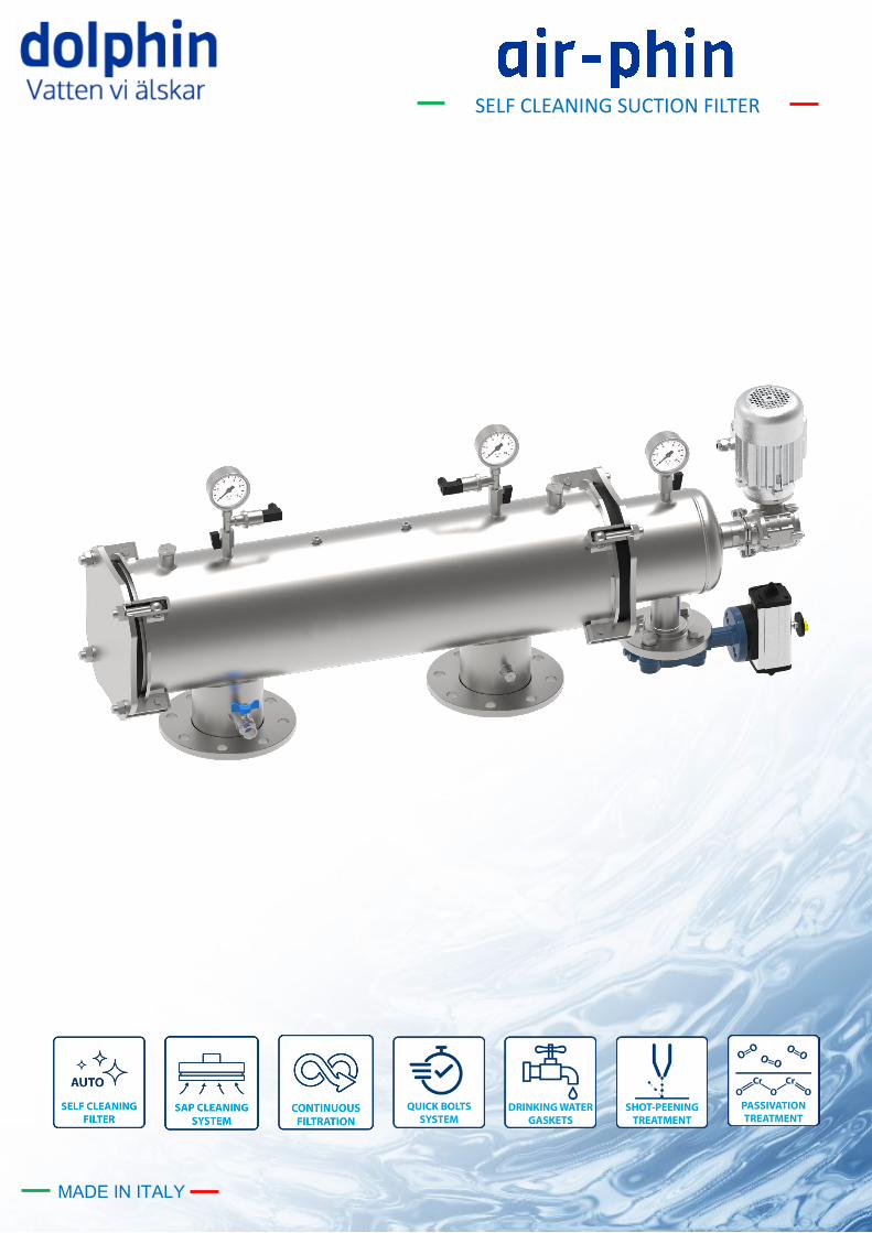
air-phin is a self-cleaning suction mesh filter equipped with a motorized adaptive suction pad cleaning system which easily regenerates the filte-ring element within a few seconds, without interrupting the flow. It is ideal to treat water loaded with suspended solids and can be imple-mented in various industrial applications: process water treatment, HVAC closed circuit systems, fire prevention systems and many more. It is available in 3 different constructive shapes,Y- L and O in order to adapt to different installation layouts. The vessel and cleaning system are completely made of stainless steel supplemented with adaptive and resistant suction pads which make the filter very robust and low- maintenance The wide array of filter screens, supplied with a PES or Stainless Steel AISI 316 filtering mesh, allows the user to choose between various filtration degrees, ranging from 3000µm to 25µm.
FILTRATION PROCESS
To-be-treated raw liquid enters the filter through the inlet connection (IN), suspen-ded solids are retained inside the filtering element and purified liquid flow out of the outlet connection (OUT).
CLEANING The continuous build-up of solids, trapped inside the filter mesh, creates a diffe-rential pressure between inlet and outlet that can be read on the filter’s manometers The cleaning cycle is activated at regular time intervals or when the progressive build-up of suspended solids, trapped inside the filtering mesh, causes an excessive differential pressure between inlet and outlet (0,8 bar).Both parameters can be set by the controller. During the cleaning cycle the drain valve is opened while the adaptive suction pads start rotating and removing the dirt accumulated on the filtering element, thanks to the suction force created by the pressure differential between the filter and the drain chamber. Captured dirt particles are discharged through the drain valve (DRAIN). Filtration is not interrupted if the inlet pressure is above 3 bars
3 DATASHEET
TECHNICAL SPECIFICATION
MATERIAL
Filter housing Stainless steel AISI 304 - AISI 316L
Gasket EPDM*
Drain/Vent valve Cast Iron Body with AISI 316L lens
Pressure Gauges Stainless steel AISI 304 - AISI 316L
Surface finish Microshot Peening and Passivation
DESIGNDATA
Flow rate Up to 400 m3/h
Design pressure [bar] PN 10
Max Temperature [°C] 80
Salinity [TDS] <10.000 ppm
pH range 3-9
Design Code PED 68/2014/EU * Certified for the following European Drinking Water regulations: UBA,
DVGW-standard W-270, WRAS och ACS.
POWER SUPPLY
Electric Voltage 230Vac 50/60 Hz single phase
Compressed air 6 bar
ACTUATION
Electric motor 230Vac 0,11 kW
Solenoid Vale Electropneumatic 24 Vdc
CONTROLLER
POWER SUPPLY PROTECTION CLASS MATERIAL INPUT OUTPUT CLEANING CUCPLE MANAGEMENT
230Vac 50/60 Hz
single phase IP65
2 digital (Pause, DP)
4 SPDT 16A 250Vac
Differential Pressure (0,6-0,8bar)
ABS 3 analogic (Pressure)
4 SPST 1A 24Vdc Pre-set time intervals
1 SPST (alarm) Manual
Filter’s actuation is powered by the controller
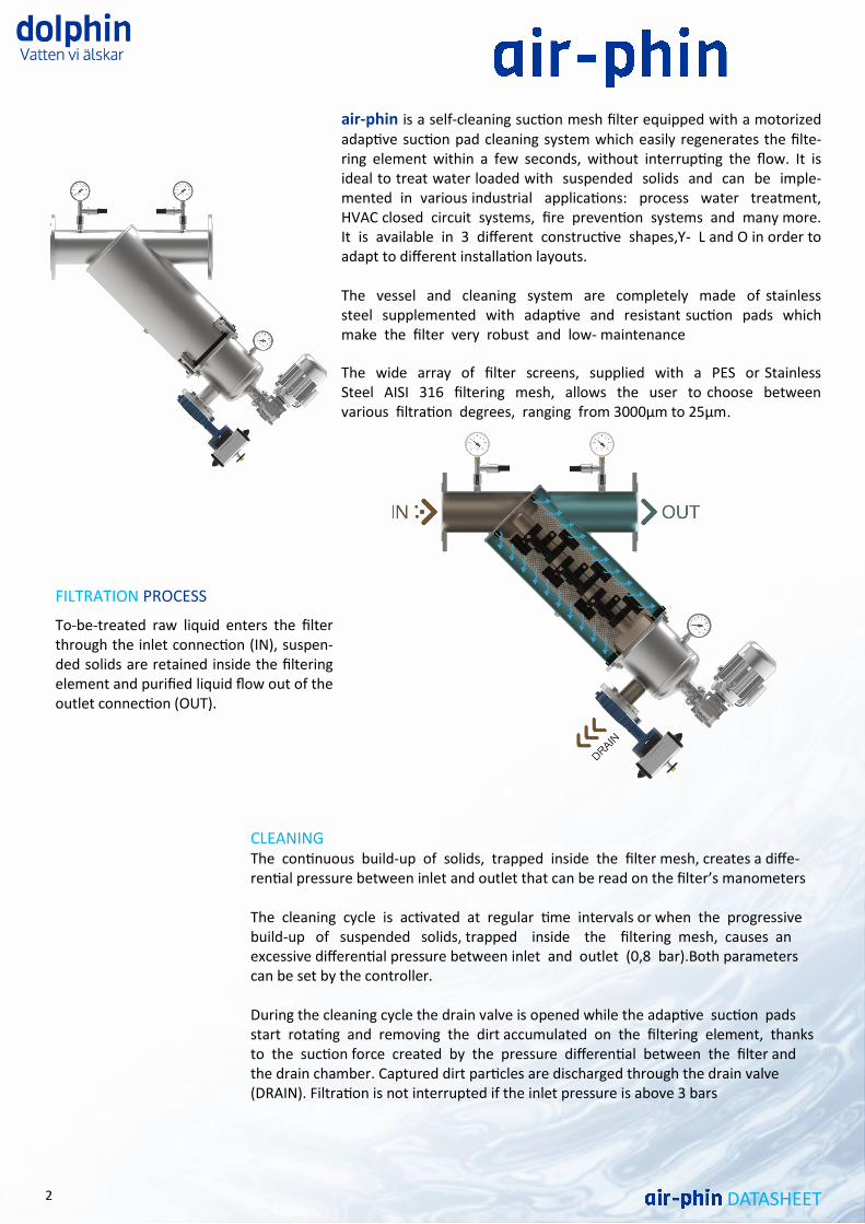
SAP (SUCTION ADAPTIVE PADS) SELF-CLEANING SYSTEM
air-phin's self-cleaning system is composed of suction
adaptive pads installed on a stainless steel shaft which rotates during the cleaning cycle,started by the electronic controller, and remove suspended particles from the filte-ring screen. The system does not require external inter-vention but is activated at regular time intervals or when the progressive build-up of suspended solids, trapped insi-de the filtering mesh, causes an excessive differential pres-sure between inlet and outlet (0,8 bar).
4 DATASHEET
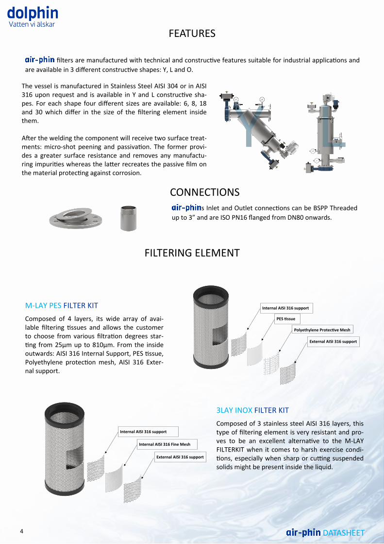
FEATURES
filters are manufactured with technical and constructive features suitable for industrial applications and
are available in 3 different constructive shapes: Y, L and O.
CONNECTIONS s Inlet and Outlet connections can be BSPP Threaded
up to 3” and are ISO PN16 flanged from DN80 onwards.
FILTERING ELEMENT
M-LAY PES FILTER KIT
Composed of 4 layers, its wide array of avai-lable filtering tissues and allows the customer to choose from various filtration degrees star-ting from 25μm up to 810μm. From the inside outwards: AISI 316 Internal Support, PES tissue, Polyethylene protection mesh, AISI 316 Exter-nal support.
3LAY INOX FILTER KIT
Composed of 3 stainless steel AISI 316 layers, this type of filtering element is very resistant and pro-ves to be an excellent alternative to the M-LAY FILTERKIT when it comes to harsh exercise condi-tions, especially when sharp or cutting suspended solids might be present inside the liquid.
The vessel is manufactured in Stainless Steel AISI 304 or in AISI 316 upon request and is available in Y and L constructive sha-pes. For each shape four different sizes are available: 6, 8, 18 and 30 which differ in the size of the filtering element inside them. After the welding the component will receive two surface treat-ments: micro-shot peening and passivation. The former provi-des a greater surface resistance and removes any manufactu-ring impurities whereas the latter recreates the passive film on the material protecting against corrosion.
Polyethylene Protective Mesh
External AISI 316 support
Internal AISI 316 support
PES tissue
Internal AISI 316 Fine Mesh
External AISI 316 support
Internal AISI 316 support
5 DATASHEET
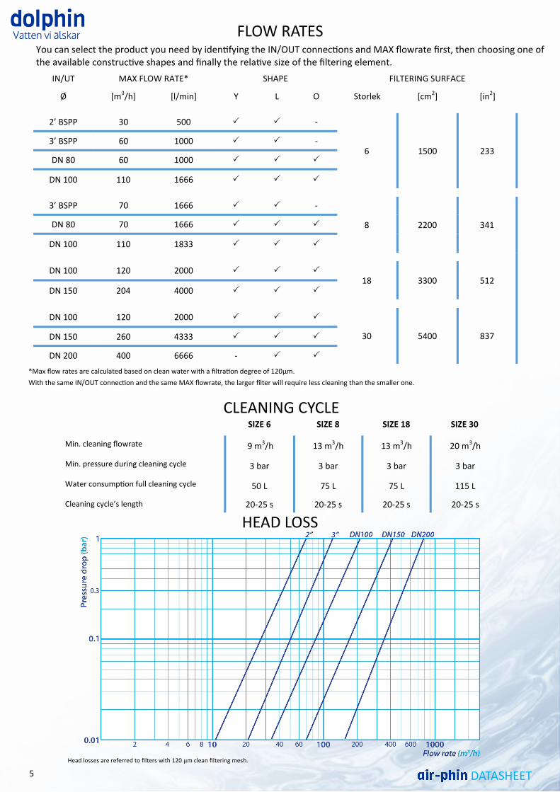
FLOW RATES
*Max flow rates are calculated based on clean water with a filtration degree of 120μm.
With the same IN/OUT connection and the same MAX flowrate, the larger filter will require less cleaning than the smaller one.
You can select the product you need by identifying the IN/OUT connections and MAX flowrate first, then choosing one of the available constructive shapes and finally the relative size of the filtering element.
HEAD LOSS
SIZE 6 SIZE 8 SIZE 18 SIZE 30
Min. cleaning flowrate 9 m3/h 13 m3/h 13 m3/h 20 m3/h
Min. pressure during cleaning cycle 3 bar 3 bar 3 bar 3 bar
Water consumption full cleaning cycle 50 L 75 L 75 L 115 L
Cleaning cycle’s length 20-25 s 20-25 s 20-25 s 20-25 s
CLEANING CYCLE
Head losses are referred to filters with 120 μm clean filtering mesh.
IN/UT MAX FLOW RATE* SHAPE FILTERING SURFACE
Ø [m3/h] [l/min] Y L O Storlek [cm2] [in2]
2’ BSPP 30 500 -
6 1500 233 3’ BSPP 60 1000 -
DN 80 60 1000
DN 100 110 1666
3’ BSPP 70 1666 -
8 2200 341 DN 80 70 1666
DN 100 110 1833
DN 100 120 2000
18 3300 512 DN 150 204 4000
DN 100 120 2000
30 5400 837 DN 150 260 4333
DN 200 400 6666 -
6 DATASHEET
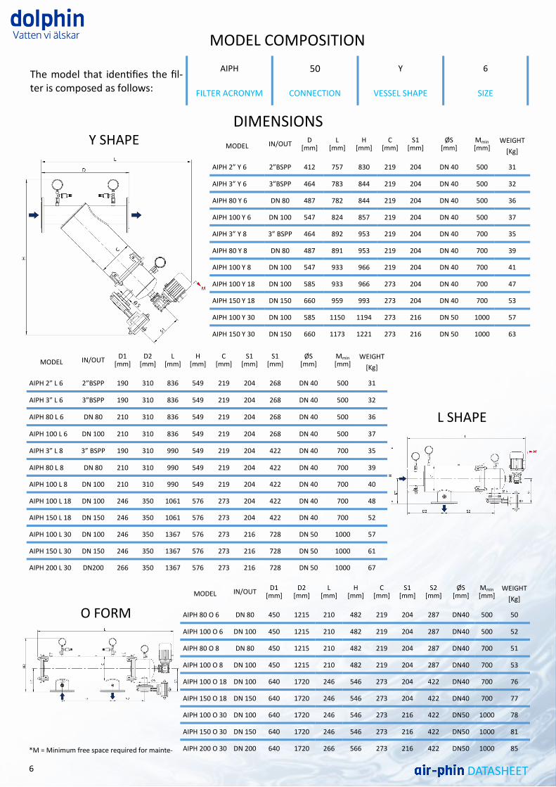
DIMENSIONS
*M = Minimum free space required for mainte-
AIPH 50 Y 6 The model that identifies the fil-ter is composed as follows: FILTER ACRONYM CONNECTION VESSEL SHAPE SIZE
MODEL COMPOSITION
MODEL D
[mm] L
[mm] H
[mm] C
[mm] S1
[mm] ØS
[mm] Mmin [mm]
WEIGHT
[Kg] IN/OUT
AIPH 2” Y 6 412 757 830 219 204 DN 40 500 31 2”BSPP
AIPH 3” Y 6 464 783 844 219 204 DN 40 500 32 3”BSPP
AIPH 80 Y 6 487 782 844 219 204 DN 40 500 36 DN 80
AIPH 100 Y 6 547 824 857 219 204 DN 40 500 37 DN 100
AIPH 3” Y 8 464 892 953 219 204 DN 40 700 35 3” BSPP
AIPH 80 Y 8 487 891 953 219 204 DN 40 700 39 DN 80
AIPH 100 Y 8 547 933 966 219 204 DN 40 700 41 DN 100
AIPH 100 Y 18 585 933 966 273 204 DN 40 700 47 DN 100
AIPH 150 Y 18 660 959 993 273 204 DN 40 700 53 DN 150
AIPH 100 Y 30 585 1150 1194 273 216 DN 50 1000 57 DN 100
AIPH 150 Y 30 660 1173 1221 273 216 DN 50 1000 63 DN 150
Y SHAPE
MODEL D1
[mm] D2
[mm] L
[mm] H
[mm] C
[mm] S1
[mm] S1
[mm] ØS
[mm] Mmin [mm]
WEIGHT
[Kg] IN/OUT
AIPH 2” L 6 190 310 836 549 219 204 268 DN 40 500 31 2”BSPP
AIPH 3” L 6 190 310 836 549 219 204 268 DN 40 500 32 3”BSPP
AIPH 80 L 6 210 310 836 549 219 204 268 DN 40 500 36 DN 80
AIPH 100 L 6 210 310 836 549 219 204 268 DN 40 500 37 DN 100
AIPH 3” L 8 190 310 990 549 219 204 422 DN 40 700 35 3” BSPP
AIPH 80 L 8 210 310 990 549 219 204 422 DN 40 700 39 DN 80
AIPH 100 L 8 210 310 990 549 219 204 422 DN 40 700 40 DN 100
AIPH 100 L 18 246 350 1061 576 273 204 422 DN 40 700 48 DN 100
AIPH 150 L 18 246 350 1061 576 273 204 422 DN 40 700 52 DN 150
AIPH 100 L 30 246 350 1367 576 273 216 728 DN 50 1000 57 DN 100
AIPH 150 L 30 246 350 1367 576 273 216 728 DN 50 1000 61 DN 150
AIPH 200 L 30 266 350 1367 576 273 216 728 DN 50 1000 67 DN200
L SHAPE
MODEL D1
[mm] L
[mm] H
[mm] C
[mm] S1
[mm] ØS
[mm] Mmin [mm]
WEIGHT
[Kg]
D2 [mm]
S2 [mm]
IN/OUT
AIPH 80 O 6 450 210 482 219 204 DN40 500 50 1215 287 DN 80
AIPH 100 O 6 450 210 482 219 204 DN40 500 52 1215 287 DN 100
AIPH 80 O 8 450 210 482 219 204 DN40 700 51 1215 287 DN 80
AIPH 100 O 8 450 210 482 219 204 DN40 700 53 1215 287 DN 100
AIPH 100 O 18 640 246 546 273 204 DN40 700 76 1720 422 DN 100
AIPH 150 O 18 640 246 546 273 204 DN40 700 77 1720 422 DN 150
AIPH 100 O 30 640 246 546 273 216 DN50 1000 78 1720 422 DN 100
AIPH 150 O 30 640 246 546 273 216 DN50 1000 81 1720 422 DN 150
AIPH 200 O 30 640 266 566 273 216 DN50 1000 85 1720 422 DN 200
O FORM
Heation AB
Laxholmstorget 3
602 21 NORRKÖPING SWEDEN
E-mail: [email protected]
Phone number: +46(0)763102470
www.heationab.com/dolphin
Company number: 559193-4640