Embed Size (px)
Citation preview

SEMESTER V
APPLIED ELECTRONICS & INSTRUMENTATION
AET301 CONTROL SYSTEMS CATEGORY L T P CREDITS
PCC 3 1 0 4
Preamble: This course aims to analyze and design control systems.
Prerequisite: ECT205: NETWORK THEORY
Course Outcomes: After the completion of the course the student will be able to
CO 1 Analyze the control systems by transfer function approach.
CO 2 Get an adequate knowledge in the time response of systems & steady state error analysis
CO 3 Learn the concept of stability of control systems and methods of stability analysis.
CO 4 Analyze the control systems using frequency domain method.
CO 5 Apply the State Space Techniques to Control Systems.
Mapping of course outcomes with program outcomes
PO 1
PO 2
PO 3 PO 4 PO 5 PO 6 PO 7 PO 8 PO 9 PO 10
PO 11
PO 12
CO 1 3 2 CO 2 3 2 CO 3 2 3 CO 4 2 3 2 CO 5 3 2
Assessment Pattern
Bloom’s Category Continuous Assessment Tests
End Semester Examination
1 2
Remember K1 10 10 20 Understand K2 10 10 20 Apply K3 30 30 60 Analyze K4 Evaluate K5 Create
Mark distribution
Total Marks CIE ESE ESE Duration
150 50 100 3 hours
APPLIED ELECTRONICS & INSTRUMENTATION
Continuous Internal Evaluation Pattern:
Attendance : 10 marks
Continuous Assessment Test (2 numbers) : 25 marks
Assignment/Quiz/Course project : 15 marks
End Semester Examination Pattern: There will be two parts; Part A and Part B. Part A contains 10 questions with 2 questions from each module, having 3 marks for each question. Students should answer all questions. Part B contains 2 questions from each module of which student should answer any one. Each question can have maximum 2 sub-divisions and carry 14 marks.
Course Level Assessment Questions
Course Outcome 1 (CO1): Analyze the control systems by transfer function approach
1. Define close loop transfer function and obtain the general equation for the characteristic equation of a system.
2. Explain the terms transmittance and non touching loops with respect to signal flow graphs.
(ii) Obtain the transfer function 𝒀𝒀(𝒔𝒔)𝑭𝑭(𝒔𝒔)
𝑓𝑓𝑓𝑓𝑓𝑓 𝑓𝑓(𝑡𝑡) = 1, for the 𝑌𝑌(𝑠𝑠) given in the
above question. If the obtained transfer function represents the transfer function of a mass-spring-damper system as shown in Figure, find the values of M, B and K and also draw its equivalent force - voltage analogous circuit clearly writing the numerical values of R, L and C.
3. (i) Find y(t), for the given, 𝑌𝑌(𝑠𝑠) = 9𝑠𝑠(𝑠𝑠+0.2)(𝑠𝑠+3)
APPLIED ELECTRONICS & INSTRUMENTATION
Course Outcome 2 (CO2): Get an adequate knowledge in the time response of systems and steady state error analysis
1. Obtain the ramp response of a general first order system with unity system gain and time constant of 2 seconds. Also draw the time response.
2. Derive the expression for the step response of a second order underdamped system as given below:
−+−= − ttetc dd
tn ωζ
ζωζω sincos)(21
1
−+−= − ttetc dd
tn ωζ
ζωζω sincos)(21
1
3. Find the numerical value of steady state error associated with the system shown below for a unit step input.
4. Derive the expression for the maximum percentage overshoot of the second order
underdamped system as given below.
100
21 ×= −−
ζ
πζ
eM p 10021 ×= −
−ζ
πζ
eM p Course Outcome 3 (CO3): Learn the concept of stability of control systems and methods of
stability analysis.
1. Explain briefly the conditions that is to be satisfied for a system to be
(a) Absolutely stable
(b) Marginally stable
2. For the transfer function given below, determine how many poles are in the right half s-plane, left half s-plane and on the jω axis.
3. For a unity feedback system, the open loop transfer function is given by
𝐺𝐺(𝑠𝑠)𝐻𝐻(𝑠𝑠) =𝐾𝐾
𝑠𝑠(𝑠𝑠 + 2)(𝑠𝑠2 + 6𝑠𝑠 + 25)
APPLIED ELECTRONICS & INSTRUMENTATION

(a) Sketch the root locus
(b) At what value of K, the system becomes unstable?
(c) At this point of instability, determine the frequency of oscillation of the system.
Course Outcome 4 (CO4): Analyze the control systems using frequency domain method.
1. Define the frequency domain specifications
(a) Resonant peak
(b) Resonant frequency
(c) Bandwidth
Also obtain the expressions for the above for a second order underdamped
system with transfer function
2. Draw the Bode plot of the system given below. Also find the Gain margin
and Phase margin.
3. State and explain Nyquist Stability criteria.
4. The open loop transfer function for an unmanned under water vehicle is given by
(a) At a frequency of 3 rad/sec, it is known that the gain of the system is 5, hencecalculate the value of “a”.
(b) Estimate the phase margin for the above value of “a” without drawing Nyquist Plot.
Course Outcome 5 (CO5): Apply the State Space Techniques to Control Systems.
1. Define the following:
(a) State of a system
)02.01)(1(20G(s)
sass ++=
APPLIED ELECTRONICS & INSTRUMENTATION

(b) State variables
(c) State vector
2. Obtain the state space model of the armature controlled DC motor shown below:
3. Determine the transfer function of the system represented by the state space model given below, for if K=3, B=1 and M=10;
)(tfMv
x
MB
MK
vx
+
−−=
1010
)(tf
Mvx
MB
MK
vx
+
−−=
1010
[ ]
=
vx
ty 10)( [ ]
=
vx
ty 10)(
4. A dynamic system is given below. Check whether the system is completely controllable.
APPLIED ELECTRONICS & INSTRUMENTATION
SYLLABUS
Module 1: System modeling - Transfer function approach: Introduction to control systems – Classification of control systems. Principles of automatic control. Feedback control systems – Practical examples – Transfer function – Transfer function of electrical, mechanical and electromechanical system – Block diagram – Signal flow graph – Mason’s gain formula.
Module 2: Time domain analysis: Standard test signals - Response of systems to standard test signals – Step response of second order systems in detail – Time domain specifications – delay time, rise time, peak time, maximum percentage overshoot and settling time. Steady state response – Steady state error- Static & Dynamic error coefficients.
Module 3: Stability of linear systems in time domain: Asymptotic and BIBO stability, Routh-Hurwitz criterion of stability. Root locus - Construction of root locus – Effect of addition of poles and zeros on root locus.
Module 4: Frequency domain analysis: Frequency response – Frequency domain specifications – Stability in the frequency domain- Nyquist stability criterion – Stability from polar and Bode plots - Relative stability – Gain margin and phase margin – M & N circles – Nichol’s chart.
Module 5: State variable analysis: State space representation of Continuous Time systems. Transfer function from State Variable Representation, Solution of state equations, state transition matrix, Concepts of Controllability and Observability, Kalman’s Test.
Text Books 1. S. Hassan Saeed, Automatic Control Systems (with MATLAB programs), KATSON
Books.2. Norman S Nise, Control System Engineering, Sixth Edition.
Reference Books1. Katsuhiko Ogata, Modern Control Engineering, Pearson Education.2. M. Gopal, Control Systems, McGraw Hill Education India Education, 2012.3. B.C. Kuo, PHI, Automatic Control Systems.4. Richard C Dorf and Robert H. Bishop, Modern Control Systems, Pearson Education, 2001.
APPLIED ELECTRONICS & INSTRUMENTATION
Course Contents and Lecture Schedule
No Topic No. of Lectures
1 System modeling - Transfer function approach: 1.1 Introduction to control system – Classification of control systems. 1 1.2 Principles of automatic control. 1 1.3 Feedback control systems – Practical examples 1 1.4 Transfer function – Transfer function of electrical and mechanical
systems 2
1.5 Transfer function of electromechanical systems 1 1.6 Block diagram reduction Techniques 1
1.7 Signal flow graph – Mason’s gain formula. 2
2 Time domain analysis: 2.1 Standard test signals - Response of systems to standard test signals 1
2.2 Step response of second order systems in detail 2 2.3 Time domain specifications – delay time, rise time, peak time,
maximum percentage overshoot and settling time. Example problems. 4
2.4 Steady state response – Steady state error 1 2.5 Static & Dynamic error coefficients. 2
3 Stability of linear systems in time domain:
3.1 Asymptotic and BIBO stability 1 3.2 Routh-Hurwitz criterion of stability 1 3.3 Root locus - Construction of root locus 3
3.4 Root locus- Examples 2 3.5 Effect of addition of poles and zeros on the root locus 1 4 Frequency domain analysis:
4.1 Frequency response – Frequency domain specifications 1 4.2 Stability in the frequency domain - Nyquist stability criterion.
Examples. 3
4.3 Relative stability – Gain margin and phase margin. Examples. 2
4.4 M & N circles – Nichol’s chart. 2 5 State variable analysis: 5.1 State space representation of Continuous Time systems. Standard
canonical forms. 3
5.2 Transfer function from State Variable Representation 2 5.3 Solution of state equations, state transition matrix. Examples 3 5.4 Concepts of Controllability and Observability, Kalman’s Test. 2
APPLIED ELECTRONICS & INSTRUMENTATION
Model Question paper
APJ ABDUL KALAM TECHNOLOGICAL UNIVERSITY
FIFTH SEMESTER B.TECH DEGREE EXAMINATION
Course Code: AET301
Program: Applied Electronics and Instrumentation Engineering
Course Name: Control Systems
Max. Marks: 100 Duration: 3 Hours
PART A
Answer ALL Questions. Each Carries 3 mark.
1. Write the Force – Current analogies for Mass, Spring constant and Damping coefficient of a mechanical system.
K1
2 Derive the expression for closed loop transfer function. K2
3 Impulse response of a 1st order system is given below:
tetc 503 .)( −= tetc 503 .)( −=
Find out
(a) Time constant T (b) D.C Gain K (c) Transfer Function
K3
4 Write the expressions for Kp, Kv and Ka, for a given system with open loop transfer function G(s)
K1
5 What is the inference of having all the elements of a row as zeroes in the Routh Table?
K2
6 Write the angle and magnitude conditions for constructing the
root locus of a system. K1
7 Briefly explain the steps for drawing a polar plot. K2
8 Define (i) Gain cross over frequency (ii) Phase cross over frequency and (iii) Phase Margin
K1
9 Derive the expression for the state transition matrix from the unforced state equation.
K2
APPLIED ELECTRONICS & INSTRUMENTATION
10 What is duality property between controllable and observable canonical form. Write the 4 equations relating the matrices A, B, C, D in observable and controllable forms.
K2
PART – B Answer one question from each module; each question carries 14 marks.
Module – I
11.a) Write any 2 advantages and disadvantages of closed loop control systems 4 CO1 K1
11.b) Using block diagram reduction technique, find the overall transfer function of the system shown below:
10 CO1 K3
OR
12.a) Draw the free-body diagrams of masses M1 and M2, for the system shown below
4 CO1 K1
12.b) For the mechanical system shown, draw the Force - Current analogous system, after clearly writing the equations of motion for each mass.
10 CO2 K3
APPLIED ELECTRONICS & INSTRUMENTATION
Module – II
13 a) For the system represented by the block diagram given below, determine the values of ‘𝑎𝑎’ and ‘𝑏𝑏’ to yield a unit step response, with maximum percentage overshoot of 5 and undamped natural frequency (𝜔𝜔𝑛𝑛 ) as 2 rad/sec.
10 CO2 K3
13 b) For the obtained values of ‘𝑎𝑎’ and ‘𝑏𝑏’, in the above question, find the risetime and settling time for a 2% criterion.
4 CO2 K1
OR
14 a) What are the 4 standard test signals used in control systems. Write the Laplace Transform of the above test signals.
4 CO2 K1
14 b) For the system shown in figure below, evaluate the static error constants and find the expected steady state errors for the standard step, ramp and parabolic inputs.
10 CO2 K3
C(S) S) ))(())((
12852100
2 ++
++
sssss
APPLIED ELECTRONICS & INSTRUMENTATION
Module – III 15 a) State and explain the Routh Hurwitz criteria for stability analysis 5 CO3 K2
15 b) Sketch the complete root locus of the system shown below:
9 CO3 K3
OR
16 a) Write the 9 rules for construction of root locus. 5 CO3 K2
16 b) Sketch the root locus for the transfer function given below in a graphsheet Add a zero at s = -2, to the above transfer function and draw the root locus. Also clearly specify the effect of adding the zero to the transfer function.
9 CO3 K3
Module – IV 17 Sketch the asymptotic bode plot of the open loop system for a system
represented by block diagram shown in Figure. Estimate the gain and phase margin of the system and calculate the phase crossover frequency and gain crossover frequency.
14 CO4 K3
OR
18 The open loop transfer function of a control system is given by
Determine the value of K so that the system will be stable with
(a) Gain Margin = 6 dB (b) Phase Margin = 450
14 CO4 K3
APPLIED ELECTRONICS & INSTRUMENTATION
Module – V
19 a) Draw the block diagram representing the state space model given by
)()()( tButAxtx += )()()( tButAxtx +=
)()()( tDutCxty += )()()( tDutCxty +=
4 CO5 K3
19 b) Obtain the state space model of the electrical network shown below: Clearly write the state equation and output equation.
10 CO5 K3
OR
20 a) Obtain the observable canonical form of the given transfer function:
8 CO5 K3
20 b) Determine the controllability and observability of the system shown below:
6 CO5 K3
𝑌𝑌(𝑠𝑠)𝑈𝑈(𝑠𝑠) =
𝑠𝑠 + 3𝑠𝑠2 + 5𝑠𝑠 + 2
APPLIED ELECTRONICS & INSTRUMENTATION

AET303 INDUSTRIAL INSTRUMENTATION
CATEGORY L T P CREDITS PCC 3 1 0 4
Preamble: This course aims to develop a strong understanding of the principle of operation of various temperature, pressure, flow and level measuring devices.
Prerequisite: Nil
Course Outcomes: After the completion of the course the student will be able to
CO 1 Understand the working of different types of temperature sensors
CO 2 Familiarize with the various types of pressure measurement techniques
CO 3 Study the working of various flow measurement devices
CO4 Familiarize with the working of anemometers and viscometers
CO5 Understand the various level measurement techniques
Mapping of course outcomes with program outcomes
PO 1
PO 2
PO 3 PO 4 PO 5 PO 6 PO 7 PO 8 PO 9 PO 10
PO 11
PO 12
CO 1 3 3 2 CO 2 3 3 2 CO 3 3 3 2 CO 4 3 3 2 CO5 3 3 2
Assessment Pattern
Bloom’s Category Continuous Assessment Tests
End Semester Examination
1 2
Remember K1 10 10 20 Understand K2 30 30 70 Apply K3 10 10 10 Analyse K4 Evaluate Create
Mark distribution
Total Marks
CIE ESE ESE Duration
150 50 100 3 hours
APPLIED ELECTRONICS & INSTRUMENTATION

Continuous Internal Evaluation Pattern:
Attendance : 10 marks
Continuous Assessment Test (2 numbers) : 25 marks
Assignment/Quiz/Course project : 15 marks
End Semester Examination Pattern: There will be two parts; Part A and Part B. Part A contain 10 questions with 2 questions from each module, having 3 marks for each question. Students should answer all questions. Part B contains 2 questions from each module of which student should answer any one. Each question can have maximum 2 sub-divisions and carry 14 marks.
Course Level Assessment Questions
Course Outcome 1 (CO1): Understand the working of different types of temperature sensors
1. Explain the working principle of Resistance Temperature detectors.
2. Explain the theory of operation of thermocouples.
Course Outcome 2 (CO2): Familiarize with the various types of pressure measurement techniques
1. Explain the construction and principle of operation of Bourdon tubes.
2. Compare the performance of various types of electronic pressure sensors.
Course Outcome 3 (CO3): Study the working of various flow measurement devices 1. Explain how venturi tubes are used in Flow Measurement?
2. Explain the working of Angular-momentum type flow meter.
Course Outcome 4 (CO4): Familiarize with the working of anemometers and viscometers
1. What are anemometers used for? Explain the different categories of anemometers.
2. Explain the working of differential pressure type capillary viscometers
Course Outcome 5 (CO5): Understand the various level measurement techniques
1. What are the different types of float type designs for level measurement and control?
2. Compare the performance of various types of electrical level gauging methods
APPLIED ELECTRONICS & INSTRUMENTATION
SYLLABUS
Module 1: Temperature Measurement: Resistance Temperature Detectors – Applications, Industrial RTD construction requirement, RTD Transmitters. Thermistors – Principle of Operation, Sensor types, Temperature measurement using Thermistors. Thermocouples – Theory of Operation, Thermocouple types. Diode – Type Temperature Sensors, Fluidic Sensors, Johnson noise thermometer, Electronic Temperature Switches. Module 2: Pressure Measurement: Manometers, Bourdon Tubes, Diaphragm Elements. Electronic Pressure Sensors – Strain Gauge Transducers, Capacitance Transducer, Potentiometric Transducer, Resonant Wire Transducer, Piezoelectric Pressure Sensors, Linear Variable Differential Transformer, Optical Transducers. Differential Pressure Transmitters – Pneumatic transmitter. Module 3: Flow Measurement: Introduction, Orifice Plates, Venturi Tubes and Nozzles, Pitot Tubes. Positive Displacement Flowmeters - Nutating disc flowmeter, Sliding vane flowmeter, Lobed impeller flowmeter, Reciprocating piston flowmeter Mass Flowmeters – Radiation type, Angular – Momentum type, Impeller-Turbine Flowmeter, Constant torque - Hysteresis Clutch, Twin-Turbine. Module 4: Anemometers – Mechanical Anemometer, Hot-wire anemometer, Laser Doppler anemometer. Cross-Correlation flow meter, Ultrasonic flow meter – Transit-time flow meter, Doppler flow meter Measurement of Viscosity – Introduction, Viscometer selection and application. Capillary Viscometers – Differential Pressure type. Module 5 : Level Measurement – Float Type level indicator, Displacer Type – Torque tube assembly. Electrical Methods – Resistance, Conductance, Inductive and Capacitive level gauging. Ultrasonic Method, Microwave Level Switches, Noncontacting optical level sensor, Rotating Paddle Switches.
Text Books
1. Patranabis D, “Principles of Industrial Instrumentation”, 3rd Edition, Tata McGraw Hill,
New Delhi, 2010. 2. Liptak B.G, “Process Measurement and Analysis”, 4th Edition, Chilton Book Company,
Radnor, Pennsylvania, 2003. 3. Doebelin E.O, “Measurement Systems: Application and Design”, 4th Edition, McGraw Hill,
New York, 2003.
APPLIED ELECTRONICS & INSTRUMENTATION
Reference Books 1. Andrew W.G, “Applied Instrumentation in Process Industries – A survey”, Vol I & Vol II,
Gulf Publishing Company, Houston, 2001. 2. Douglas M. Considine, “Process / Industrial Instruments & Controls Handbook”, 5th
Edition, McGraw Hill, Singapore, 1999. 3. Spitzer D. W., Flow measurement, ISA press, New York, 1998 4. Noltingk B.E.,
“Instrumentation Reference Book”, 2nd Edition, Butterworth Heinemann, 1995. 4. Noltingk B.E., “Instrumentation Reference Book”, 2nd Edition, Butterworth Heinemann, 1995.
Course Contents and Lecture Schedule No
Topic
No. of
Lectures 1 Temperature Measurement
1.1 Resistance Temperature Detectors – Applications, Industrial RTD construction requirement, RTD Transmitters 2
1.2 Thermistors – Principle of Operation, Sensor types, Temperature measurement using Thermistors 2
1.3 Thermocouples – Theory of Operation, Thermocouple types. 1 1.4 Diode – Type Temperature Sensors, Fluidic Sensors 2 1.5 Johnson noise thermometer, Electronic Temperature Switches 2
2 Pressure Measurement
2.1 Manometers, Bourdon Tubes, Diaphragm Elements. 2
2.2 Electronic Pressure Sensors – Strain Gauge Transducers, Capacitance Transducer, Potentiometric Transducer 3
2.3 Resonant Wire Transducer, Piezoelectric Pressure Sensors, 1 2.4 Linear Variable Differential Transformer, Optical Transducers. 2 2.5 Differential Pressure Transmitters – Pneumatic Transmitter 1
3 Flow Measurement
3.1 Introduction, Orifice Plates, Venturi Tubes and Nozzles, Pitot Tubes. 2
3.2 Positive Displacement Flowmeters - Nutating disc flowmeter, Sliding vane flowmeter, Lobed impeller flowmeter, Reciprocating piston flowmeter
3
3.3 Mass Flowmeters – Radiation type, Angular – Momentum type, Impeller-Turbine Flowmeter
2
3.4 Constant torque-Hysterisis Clutch, Twin-Turbine 2 4 Anemometers
4.1 Mechanical Anemometer, Hot-wire anemometer, Laser Doppler anemometer. 3
APPLIED ELECTRONICS & INSTRUMENTATION
4.2 Cross-Correlation flow meter, Ultrasonic flow meter – Transit-time flow meter, Doppler flow meter
3
4.3 Measurement of Viscosity – Introduction, Viscometer selection and application. 2
4.4 Capillary Viscometers – Differential Pressure type. 1 5 Level Measurement
5.1 Float Type level indicator, Displacer Type – Torque tube assembly. 2
5.2 Electrical Methods – Resistance, Conductance, Inductive and Capacitive level gauging. 3
5.3 Ultrasonic Method, Microwave Level Switches, 2 5.4 Noncontacting optical level sensor, Rotating Paddle Switches. 2
APPLIED ELECTRONICS & INSTRUMENTATION
Model Question paper APJ ABDUL KALAM TECHNOLOGICAL UNIVERSITY
FIFTH SEMESTER B.TECH DEGREE EXAMINATION
Course Code: AET303
Program: Applied Electronics and Instrumentation Engineering/ Electronics and Instrumentation Engineering
Course Name: Industrial Instrumentation
Max. Marks : 100 Duration: 3 Hours
PART A
Answer ALL Questions. Each Carries 3 mark.
1. Explain the theory of operation of thermocouples. K2 CO1
2 List two advantages and limitation of RTD’s. K2 CO1
3 Explain the working of a diaphragm pressure gauge. K2 CO2
4 Explain the construction of a potentiometric pressure transducer. K2 CO2
5 Illustrate the different types of orifice plates. K2 CO3
6 Draw the schematic of a lobed impeller flow meter and explain. K2 CO3
7 Explain the working of any one type of mechanical Anemometer. K2 CO4
8 Explain any two applications of viscometers. K2 CO4
9 Explain the working of a typical float type level indicator. K2 CO5
10 Illustrate the working principle of a noncontacting optical level sensor.
K2 CO5
PART – B
Answer one question from each module each question carries 14 marks.
Module – I
11. a)
What are the considerations that need to be followed in the construction of industrial RTD’s ?
8 CO1 K1
11. b)
Explain how temperature measurement is done using thermistors?
6 CO1 K2
OR
12.a) With the help of neat diagrams explain the working of diode type temperature sensor.
7 CO1 K2
12.b) Explain the working of fluidic sensor with the help of a neat block diagram.
7 CO1 K1
APPLIED ELECTRONICS & INSTRUMENTATION
Module – II
Module III
Module IV
Module – V
13. a)
With the help of neat schematics explain the working of Bourdon pressure gauge.
8 CO2 K2
13. b)
Explain how pressure transducer can be constructed using unbounded strange gauge wires.
6 CO2 K3
OR
14.a) Explain the construction and working of a Resonant wire type differential pressure sensor.
7 CO2 K2
14.b) Illustrate the working principle of Linear Variable Differential Transformer.
7 CO2 K2
15. a)
Explain the working principle of pitot tube. 4 CO3 K1
15. b)
With the help of neat schematics explain the working of nutating disc flowmeter and sliding vane flowmeter.
10 CO3 K2
OR
16.a) Draw a neat diagram of a radiation-type mass flowmeter and explain
7 CO3 K2
16.b) With the help of neat sketches explain the working of Twin-Turbine flowmeter.
7 CO3 K2
17. a)
With the help of neat sketches explain the working of Laser Doppler Anemometer.
8 CO4 K2
17. b)
Illustrate the principle of cross-correlation flow monitoring. 6 CO4 K2
OR
18.a) Explain the principle of operation of Doppler flowmeter with the help of neat diagrams
7 CO4 K1
18.b) With the help of neat schematics explain the working of Differential-pressure-type capillary viscometer
7 CO4 K2
19. a)
With neat schematics explain the working of torque tube assembly displacer type level indicator.
6 CO5 K2
19. b)
Draw and explain any two electrical methods for level gauging. 8 CO5 K2
APPLIED ELECTRONICS & INSTRUMENTATION

OR
20.a) With the help of a neat block diagram explain about ultrasonic level gauging.
7 CO5 K2
20.b) Explain how microwave switches are used in level measurement. 7 CO5 K2
APPLIED ELECTRONICS & INSTRUMENTATION

AET305 COMPUTER ARCHITECTURE AND EMBEDDED SYSTEMS
CATEGORY L T P CREDITS PCC 3 1 0 4
Preamble: This course aims to impart knowledge of basic computer architecture, microcontroller and embedded programming
Prerequisite: ECT203 Logic Circuit Design & EST102 Programming in C
Course Outcomes: After the completion of the course the student will be able to
CO 1 Explain the processor architecture and operation. K2
CO 2 Explain the architecture of 8051 microcontroller. K2
CO 3 Develop programs using assembly language 8051. K3
CO4 Develop Programming concepts of Embedded programming in C.
K3
CO5 Explain the concepts of RTOS based embedded system. K2
Mapping of course outcomes with program outcomes
PO 1 PO 2
PO 3 PO 4 PO 5 PO 6 PO 7 PO 8 PO 9 PO 10
PO 11
PO 12
CO 1 3 3 3 CO 2 3 3 3 CO 3 3 3 3 3 3 3 CO 4 3 3 3 3 3 3 CO5 3 3 3
Assessment Pattern
Bloom’s Category Continuous Assessment Tests
End Semester Examination
1 2
Remember K1 10 10 10 Understand K2 30 30 60 Apply K3 10 10 30 Analyse K4 Evaluate Create
Mark distribution
Total Marks
CIE ESE ESE Duration
150 50 100 3 hours
APPLIED ELECTRONICS & INSTRUMENTATION
Continuous Internal Evaluation Pattern:
Attendance : 10 marks
Continuous Assessment Test (2 numbers) : 25 marks
Assignment/Quiz/Course project : 15 marks
End Semester Examination Pattern: There will be two parts; Part A and Part B. Part A contain 10 questions with 2 questions from each module, having 3 marks for each question. Students should answer all questions. Part B contains 2 questions from each module of which student should answer any one. Each question can have maximum 2 sub-divisions and carry 14 marks.
Course Level Assessment Questions
Course Outcome 1 (CO1): Explain the processor architecture and operation.
1. Write the sequence of elementary operations required to execute an instruction a. Sub (R4), R3 b. Add (R4), R1
Course Outcome 2 (CO2): Explain the architecture of 8051 microcontroller.
2. Draw the memory map and briefly explain the memory organization for 128 byte internal RAM of 8051 microcontroller.
Course Outcome 3 (CO3): Develop programs using assembly language 8051. 3. Develop following programs for 8051
a. Program to convert the ASCII number into unpacked BCD.
b. Program to swap a number 0 x ab to 0 x ba, where a and b are hex digits.
c. Program to find the number of 1’s in an 8-bit data item.
d. Program to display ‘M’ and ‘E’ on the LCD connected to 8051 using the BUSY
FLAG.
e. Program to rotate a stepper motor 500 in the clockwise direction.
f. Program to toggle pin P1.4 every second using interrupts for a frequency of 22
MHz. Use timer 1 in mode 1.
g. Program to generate a square wave of 1 kHz with duty cycle 33%. Use timer 1 in
interrupt mode with a crystal frequency of 11.0592 MHz.
APPLIED ELECTRONICS & INSTRUMENTATION
Course Outcome 4 (CO4): Develop Programming concepts of Embedded programming in C. 4. The following examples may be solved in C program
a. Program to convert the ASCII number into unpacked BCD.
b. Program to swap a number 0 x ab to 0 x ba, where a and b are hex digits.
c. Program to find the number of 1’s in an 8-bit data item.
Course Outcome 4 (CO5): Explain the concepts of RTOS based embedded system. 5. What are the functional and non functional requirements that needs to be analysed whilechoosing an RTOS.
SYLLABUS
Module 1: Computer Arithmetic and Processor Basics
Functional units of a computer, Von Neumann and Harvard computer
architectures,. Processing unit- Fundamental concepts, Execution of a complete Instruction, Hardwired Control, Multiple Bus organization, other enhancements Microprogrammed control. Number representations - Fixed and floating point-number representation, Arithmetic operations on floating point numbers
Module 2: 8051 Architecture
Microcontrollers and Embedded Processors. Architecture – Block diagram of 8051, Pin
configuration, Registers, Internal Memory, Timers, Port Structures, Interrupts. Assembly
Language Programming - Addressing Modes, Instruction set of 8051, Simple programming examples in assembly language.
Module 3: Programming and Interfacing of 8051
Interfacing with 8051 using Assembly language programming: LED, Seven segment LED display.. Interfacing of Keyboard, Stepper Motor and DAC -- with 8051 and its programming.
8051 Timers/Counters - Modes and Applications
Module 4: Embedded programming
Introduction to Embedded Systems: Definition of Embedded System, Embedded Systems Vs General Computing Systems. Programming concepts of Embedded programming in C Program Elements, Macros and functions - Use of Pointers - NULL Pointers - Use of Function Calls – Multiple function calls in a Cyclic Order in the Main Function Pointers – Function Queues and Interrupt Service Routines Queues Pointers
Module 5: RTOS Based Embedded System
RTOS Based Embedded System Design: Operating System Basics, Types of Operating Systems, Tasks, Process and Threads, Multiprocessing and Multitasking, Task Scheduling. How to Choose an RTOS
APPLIED ELECTRONICS & INSTRUMENTATION
Text Books 1. V. Carl Hamacher, Zvono G. Vranesic, Safwat G. Zaky Computer Organization.
McGraw-Hill International Editions 2. Muhammed Ali Mazidi & Janice Gilli Mazidi, R.D. Kinley, The 8051
microcontroller and Embedded System, Pearson Education, 2nd edition.Robert 3. Shibu K.V, Introduction to Embedded Systems, Mc Graw Hill
Reference Books 1. Computer organization and design: The Hardware/Software interface/David A.Patterson,
John L. Hennessy. — 5th ed. 2. Mano M M, Computer System Architecture, 3rd Ed, Prentice Hall of India. 3. Wayne Wolf, Computers as Components: Principles of Embedded Computing System
Design – Harcourt India, Morgan Kaufman Publishers, First Indian Reprint 2001 4. Lyla B Das, Embedded Systems An Integrated Approach, Pearson, 2013 5. Rajkamal, Embedded Systems Architecture, Programming and Design, TATA McGraw-
Hill, First reprint Oct. 2003
Course Contents and Lecture Schedule
No
Topic
No. of
Lectures 1 Computer Arithmetic and Processor Basics
1.1 Functional units of a computer, Von Neumann and Harvard computer architectures
1
1.2 Processing unit- Fundamental concepts 1 1.3 Execution of a complete Instruction 2 1.4 Hardwired Control 1
1.5 Multiple Bus organization, Other enhancements 1 1.6 Microprogrammed control 1
1.7 Number representations 1
1.8 Fixed and floating point-number representation 1
1.9 Arithmetic operations on floating point numbers 2
2 8051 Architecture
2.1 Microcontrollers and Embedded Processors, Block diagram of 8051 1
2.2 Pin configuration, Registers 1
2.3 Internal Memory, Port Structures, Interrupts 3
2.4 Addressing Modes 1
2.5 Instruction set of 8051 1
2.6 Programming examples in assembly language 2
3 Programming and Interfacing of 8051
APPLIED ELECTRONICS & INSTRUMENTATION
3.1 Programming examples Interfacing with 8051 using Seven segment LED display
2
3.2 Interfacing of Keyboard and Stepper Motor 3
3.3 Interfacing of DAC -- with 8051 and its programming. 2
3.4 8051 Timers/Counters - Modes and Applications 3
4 Embedded programming 4.1 Definition of Embedded System, Embedded Systems Vs General
Computing Systems. 1
4.2 Programming concepts of Embedded programming in C Program Elements
2
4.3 Macros and functions 1
4.4 Use of Pointers - NULL Pointers 1
4.5 Function Calls – Multiple function calls in a Cyclic Order in the Main Function Pointers
2
4.6 Function Queues and Interrupt Service Routines Queues Pointers 2
5 RTOS Based Embedded System
5.1 Operating System Basics, Types of Operating Systems, 1
5.2 Tasks, Process and Threads 2
5.3 Multiprocessing and Multitasking 1
5.4 Task Scheduling. 1
5.5 How to Choose an RTOS 1
Assignment:
At least one assignment should be simulation of 8051 using KEIL
APPLIED ELECTRONICS & INSTRUMENTATION
Model Question paper
APJ ABDUL KALAM TECHNOLOGICAL UNIVERSITY
FIFTH SEMESTER B.TECH DEGREE EXAMINATION
Course Code: AET305
Program: Applied Electronics and Instrumentation Engineering/ Electronics and Instrumentation Engineering
Course Name: Computer Architecture and Embedded Systems
Max. Marks: 100 Duration: 3 Hours
PART A
Answer ALL Questions. Each Carries 3 mark.
1. Draw IEEE standard floating point number format with single precision K1
2. What are the sequence of operations and control signals generated, for fetching a word from memory K3
3. Draw the bit pattern for 8051 flag register (PSW) K1
4. Explain the following instructions K2 MOVX A, @DPTR DJNZ R0, BACK DAA
5. Explain TMOD SFR ( Special Function Register) K2
6. How will you generate a 1 ms delay using 8051? K3
7. Compare Embedded System with General Computing System K2
8. How is a pointer different from a NULL pointer? (Any 2 differences) K2
9. Define a thread. What are the advantages of using a multithreaded program K1
10. What are the types of Operating systems K1
PART – B
Answer one question from each module; each question carries 14 marks.
Module – I
APPLIED ELECTRONICS & INSTRUMENTATION
11. a)
Rules of Arithmetic operations on floating point numbers 6 CO1 K2
11. b)
With diagrams explain the operation of hardwired control
8 CO1 K3
OR
12.a) Explain with a diagram, how a 3 operand instruction is executed in a 3 bus CPU structure
8 CO1 K2
12.b) With a diagram explain the basic organization of a microprogrammed control unit
6 CO1 K1
Module – II
13 a) Draw the memory map and briefly explain the memory organization for 128 byte internal RAM of 8051 microcontroller.
8 CO2 K1
13 b) Write an 8051 assembly language program to add two 64 bit numbers
6 CO3 K3
OR
14 a) Write a program to find the sum of the values at RAM locations 50 – 54H (5 values) . At the end of the program, register A should contain the low byte of the sum and R7 the high byte of the sum.
8 CO3 K3
14 b) List the addressing modes of 8051 with proper examples
6 CO2 K2
Module – III
15 a) Draw a block diagram to interface stepper motor with 8051 with a step angle of 2 degree. Also write an assembly language program to rotate a motor 64 degree in clock wise direction. Use 4 step sequence
14 CO3 K3
OR
16 a) Explain TCON SFR ( Special Function Register)
5 CO2 K1
16 b)
How a triangular waveform can be generated using 8051? 9 CO3 K3
Module – IV
17 a)
Explain in detail various data structures used in embedded C programming.
10 CO4 K1
17 b)
Write 4 differences between macros and functions.
4 CO4 K2
APPLIED ELECTRONICS & INSTRUMENTATION

OR
18 a)
Explain a function pointer with syntax, example and uses. 9 CO4 K2
18 b)
Compare pass by value and pass by reference 5 CO4 K2
Module – V
19 a) What are the Functional and Non functional requirements that
needs to be analysed while choosing an RTOS. 10 CO4 K1
19 b) What is the use of a watch dog timer. 4 CO4 K2
OR
20 a) What is meant by task synchronization? Discuss on various task synchronization issues and solutions in real time systems.
10 CO4 K2
20 b) What is a semaphore? How they are classified? 4 CO4 K1
APPLIED ELECTRONICS & INSTRUMENTATION
AET307 ANALOG INTEGRATED CIRCUITS
CATEGORY L T P CREDITS PCC 3 1 0 4
Preamble: This course aims to develop the skill to design circuits using operational amplifiers and other linear ICs for various applications.
Prerequisite: ECT202 Analog Circuits
Course Outcomes: After the completion of the course the student will be able to
CO 1 Outline Op Amp fundamentals and differential amplifier configurations
CO 2 Design operational amplifier circuits for various applications
CO 3 Design Oscillators and active filters using opamps
CO4 Explain the working and applications of timer, VCO and PLL ICs
CO5 Outline the working of Voltage regulator IC’s and Data converters
Mapping of course outcomes with program outcomes
PO 1
PO 2
PO 3 PO 4 PO 5 PO 6 PO 7 PO 8 PO 9 PO 10
PO 11
PO 12
CO 1 3 3 1 2 1 CO 2 3 3 2 2 2 1 CO 3 3 3 2 2 2 1 CO 4 3 3 1 2 2 1 CO 5 3 3 2 2 2 1
Assessment Pattern
Bloom’s Category Continuous Assessment Tests
End Semester Examination
1 2
Remember K1 10 10 10 Understand K2 20 20 50 Apply K3 20 20 40 Analyse K4 Evaluate Create
Mark distribution
Total Marks
CIE ESE ESE Duration
150 50 100 3 hours
APPLIED ELECTRONICS & INSTRUMENTATION
Continuous Internal Evaluation Pattern:
Attendance : 10 marks
Continuous Assessment Test (2 numbers) : 25 marks
Assignment/Quiz/Course project : 15 marks
End Semester Examination Pattern: There will be two parts; Part A and Part B. Part A contain 10 questions with 2 questions from each module, having 3 marks for each question. Students should answer all questions. Part B contains 2 questions from each module of which student should answer any one. Each question can have maximum 2 sub-divisions and carry 14 marks.
Course Level Assessment Questions
Course Outcome 1 (CO1): Understand Op Amp fundamentals and differential amplifier configurations.
1. Explain the working of BJT differential amplifiers. 2. Calculate the input resistance, output resistance, voltage gain and
CMRR of differential amplifiers. 3. Explain the non-ideal parameters of differential amplifiers. 4. Derive CMRR, input resistance and output resistance of a dual input
balanced output differential amplifier configuration.
Course Outcome 2 (CO2): Design operational amplifier circuits for various applications.
1. Design an opamp circuit to obtain an output voltage V0=-(2V1+4V2 + 3V3)
2. A 741C op-amp is used as an inverting amplifier with a gain of 50. The voltage gain vs frequency curve of 741C is flat upto 20kHz.What maximum peak to peak input signal can be applied without distorting the output?
3. With the help of a neat circuit diagram, derive the equation for the output voltage of an Instrumentation amplifier.
4. With the help of circuit diagrams and graphs, explain the working of a Full wave Precision rectifier.
Course Outcome 3 (CO3): Design Oscillators and active filters using opamps.
1. Derive the design equations for a second order Butterworth active low pass filter.
2. Design a Notch filter to eliminate power supply hum (50 Hz).
3. Design a first order low pass filter at a cut-off frequency of 2kHz with a pass band gain of 3
APPLIED ELECTRONICS & INSTRUMENTATION
Course Outcome 4 (CO4): Explain the working and applications of timer, VCO and PLL ICs .
1. With the help of internal diagram explain the monostable operation of timer IC
555. Draw the input and different output waveforms. Derive the equation for pulse width.
2. Explain the operation of Phase Locked Loop. What is lock range and capture range? Realize a summing amplifier to obtain a given output voltage.
3. Design a circuit to multiply the incoming frequency by a factor of 5 using 565 PLL.
Course Outcome 5 (CO5): Outline the working of Voltage regulator IC’s and Data converters
1. What is the principle of operation of Dual slope ADC. Deduce the relationship
between analogue input and digital output of the ADC.
2. Explain how current boosting is achieved using I.C 723
3. Explain the working of successive approximation ADC
APPLIED ELECTRONICS & INSTRUMENTATION
SYLLABUS
Module 1: Operational amplifiers (Op Amps): The 741 Op Amp, Block diagram, Ideal op-amp parameters, typical parameter values for 741, Equivalent circuit, Open loop configurations, Voltage transfer curve, Frequency response curve.
Differential Amplifiers: Differential amplifier configurations-Dual input Balanced Output, Dual input Unbalanced Output, Single input Balanced Output, Single input Unbalanced Output- using BJT, Basic Differential pair using BJT- DC Analysis- transfer characteristics; AC analysis- differential and common mode gains, CMRR, input and output resistance, Voltage gain. Virtual ground. Concept of current mirror-the two transistor current mirror, Wilson and Widlar current mirrors.
Module 2: Op-amp with negative feedback: General concept of Voltage Series, Voltage Shunt, current series and current shunt negative feedback, Op Amp circuits with voltage series and voltage shunt feedback, Virtual ground Concept; analysis of practical inverting and non-inverting amplifiers for closed loop gain, Input Resistance and Output Resistance. Op-amp applications: Summer, Voltage Follower-loading effects, Differential and Instrumentation Amplifiers, Voltage to current and Current to voltage converters, Integrator, Differentiator, Precision rectifiers, Comparators, Schmitt Triggers, Log and antilog amplifiers.
Module 3: Op-amp Oscillators and Multivibrators: Phase Shift and Wien-bridge Oscillators, Triangular and Sawtooth waveform generators, Astable and monostable multivibrators.
Active filters: Comparison with passive filters, First and second order low pass, High pass, Band pass and band reject active filters, state variable filters.
Module 4: Timer and VCO: Timer IC 555- Functional diagram, Astable and monostable operations;. Basic concepts of Voltage Controlled Oscillator and application of VCO IC LM566,
Phase Locked Loop – Operation, Closed loop analysis, Lock and capture range, Basic building blocks, PLL IC 565, Applications of PLL.
Module 5: Voltage Regulators: Fixed and Adjustable voltage regulators, IC 723 – Low voltage and high voltage configurations, Current boosting, Current limiting, Short circuit and Fold-back protection.
Data Converters: Digital to Analog converters, Specifications, Weighted resistor type and R-2R Ladder type.
Analog to Digital Converters: Specifications, Flash type and Successive approximation type.
APPLIED ELECTRONICS & INSTRUMENTATION

Text Books 1. Roy D. C. and S. B. Jain, Linear Integrated Circuits, New Age International, 3/e, 2010
Reference Books 1. DFranco S., Design with Operational Amplifiers and Analog Integrated Circuits, 3/e,
Tata McGraw Hill, 20082. Gayakwad R. A., Op-Amps and Linear Integrated Circuits, Prentice Hall, 4/e, 20103. Salivahanan S. and V. S. K. Bhaaskaran, Linear Integrated Circuits, Tata McGraw Hill,
2008.4. Botkar K. R., Integrated Circuits, 10/e, Khanna Publishers, 20105. C.G. Clayton, Operational Amplifiers, Butterworth & Company Publ. Ltd. Elsevier, 19716. David A. Bell, Operational Amplifiers & Linear ICs, Oxford University Press, 2nd
edition,20107. R.F. Coughlin & Fredrick Driscoll, Operational Amplifiers & Linear Integrated
Circuits,6th Edition, PHI,20018. . Sedra A. S. and K. C. Smith, Microelectronic Circuits, 6/e, Oxford University Press,
2013.
Course Contents and Lecture Schedule
No Topic No. of Lectures
1 Operational amplifiers (9) 1.1 The 741 Op Amp, Block diagram, Ideal op-amp parameters, typical
parameter values for 741 1
1.2 Equivalent circuit, Open loop configurations, Voltage transfer curve, Frequency response curve.
1
1.3 Differential amplifier configurations using BJT, DC Analysis- transfer characteristics
2
1.4 AC analysis- differential and common mode gains, CMRR, input and output resistance, Voltage gain
2
1.5 Constant current bias and constant current source 1
1.6 Concept of current mirror, the two transistor current mirror Wilson and Widlar current mirrors.
2
2 Op-amp with negative feedback and Op-amp applications 10
2.1 General concept of Voltage Series, Voltage Shunt, current series and current shunt negative feedback,
1
2.2 Op Amp circuits with voltage series and voltage shunt feedback, Virtual ground Concept
1
2.3 analysis of practical inverting and non-inverting amplifier 1
2.4 Summer, Voltage Follower-loading effect 1 2.5 Differential and Instrumentation Amplifiers 1
APPLIED ELECTRONICS & INSTRUMENTATION
2.6 Voltage to current and Current to voltage converters 1
2.7 Integrator, Differentiator 1 2.8 Precision rectifiers-half wave and full wave 1 2.9 Comparators, Schmitt Triggers 1 2.10 Log and antilog amplifier 1 3 Op-amp Oscillators and Multivibrators 9
3.1 Phase Shift and Wien-bridge Oscillators, 2
3.2 Triangular and Sawtooth waveform generators, Astable and monostable multivibrators
2
3.3 Comparison, design of First and second order low pass and High pass active filters
2
3.4 Design of Second Order Band pass and band reject filters 2 3.5 State variable filters 1
4 Timer, VCO and PLL 8
4.1 Timer IC 555- Functional diagram, Astable and monostable operations. 2
4.2 Basic concepts of Voltage Controlled Oscillator 1 4.3 application of VCO IC LM566, 2
4.4 PLL Operation, Closed loop analysis Lock and capture range. 1
4.5 Basic building blocks, PLL IC 565, Applications of PLL 2 5 Voltage regulators and Data converters 9 5.1 Fixed and Adjustable voltage regulators 1
5.2 IC 723 – Low voltage and high voltage configurations, 2
5.3 Current boosting, Current limiting, Short circuit and Fold-back protection.
2
5.4 Digital to Analog converters, Specifications, Weighted resistor type and R-2R Ladder type.
2
5.5 Analog to Digital Converters: Specifications, Flash type and Successive approximation type.
2
Total 45
APPLIED ELECTRONICS & INSTRUMENTATION
Assignment:
Assignment may be given on related innovative topics on linear IC, like Analog multiplier- Gilbert multiplier cell, variable trans-conductance technique, application of analog multiplier IC AD633., sigma delta or other types of ADC etc
At least one assignment should be simulation of opamp circuits on any circuit simulation software
Model Question paper
APJ ABDUL KALAM TECHNOLOGICAL UNIVERSITY
FIFTH SEMESTER B.TECH DEGREE EXAMINATION
Course Code: AET307
Program: Applied Electronics and Instrumentation Engineering / Electronics and Instrumentation Engineering
Course Name: Analog Integrated Circuits
Max. Marks: 100 Duration: 3 Hours
PART A
Answer ALL Questions. Each Carries 3 mark.
1. Draw and list the functions of 741 IC pins K1 2. Define slew rate with its unit. What is its effect at the output signal? K2 3. How the virtual ground is different from actual ground? K2 4. A differential amplifier has a common mode gain of 0.05 and difference mode
gain of 1000.Calculate the output voltage for two signals V1 = 1mV and V2 = 0.9Mv K3
5. Design a second order Butterworth Low Pass Filter with fH= 2KHz K3 6. Draw the circuit of monostable multivibrator using opamp. K1 7. What is the principle of VCO? K1 8. Design a non inverting amplifier for a gain of 11. K3 9. Define the following terms with respect to DAC (i) Resolution (ii) Linearity (iii) Full scale output voltage K2 10. Differentiate between line and load regulations. K3 PART – B Answer one question from each module; each question carries 14 marks.
Module – I 11. a)
Derive CMRR, input resistance and output resistance of a dual input balanced output differential amplifier configuration.
7 CO1 K3
11. b)
What is the principle of operation of Wilson current mirror and its advantages? Deduce the expression for its current gain.
7 CO1 K2
APPLIED ELECTRONICS & INSTRUMENTATION
OR
12.a) Draw the equivalent circuit of an operational amplifier. Explain voltage transfer characteristics of an operational amplifier.
7 CO1 K3
12.b) Explain the following properties of a practical opamp (i) Bandwidth (ii) Slew rate (iii) Input offset voltage (iv) Input offset current
7 CO1 K2
Module – II 13. a)
Design a fullwave rectifier to rectify an ac signal of 0.2V peak-to-peak. Explain its principle of operation.
7 CO2 K3
13. b)
Draw the circuit diagram of a differential instrumentation amplifier with a transducer bridge and show that the output voltage is proportional to the change in resistance.
7 CO2 K2
OR
14.a) Derive the following characteristics of voltage shunt amplifier:
i) Closed loop voltage gain ii)Input resistance
iii) Output resistance iv)Bandwidth
7 CO2 K3
14.b) Explain the working of an inverting Schmitt trigger and draw its transfer characteristics.
7 CO2 K2
Module-III
Module-IV 17 a) Design a circuit to multiply the incoming frequency by a factor of 5
using 565 PLL. 8 CO4 K3
17 b)
With the help of internal diagram explain the monostable operation of timer IC 555. Draw the input and output waveforms. Derive the equation for pulse width.
6 CO4 K2
15 a) Derive the equation for frequency of oscillation (f0) of a Wein Bridge oscillator. Design a Wein Bridge oscillator for f0 = 1KHz.
7 CO3 K3
15 b)
Derive the equation for the transfer function of a first order wide Band Pass filter.
7 CO3 K3
OR
16a Derive the design equations for a second order Butterworth active low pass filter.
7 CO3 K3
16b Design a circuit to generate 1KHz triangular wave with 5V peak. 7 CO3 K3
APPLIED ELECTRONICS & INSTRUMENTATION
OR
18 a) Design a monostable multi-vibrator for a pulse duration of 1ms using IC555.
8 CO4 K3
18 b)
Explain the operation of Phase Locked Loop. What is lock range and capture range?
6 CO4 K2
Module-V
Simulation Assignments (AET307)
The following simulations can be done in QUCS, KiCad or PSPICE. (The course tutor is free to add or modify the list)
1. Design and simulate a BJT differential amplifier. Observe the input and output signals. Plot the AC frequency response.
2. Design and simulate Wien bridge oscillator for a frequency of 10 kHz. Run a transient simulation and observe the output waveform.
3. Design and implement differential amplifier and measure its CMRR. Plot its transfer characteristics.
4. Design and simulate non-inverting amplifier for gain 5. Observe the input and output signals. Run the ac simulation and observe the frequency response and 3− db bandwidth.
5. Design and simulate a 3 bit flash type ADC. Observe the output bit patterns and transfer characteristics
6. Design and simulate R − 2R DAC circuit. 7. Design and implement Schmitt trigger circuit for upper triggering point of +8 V and a lower
triggering point of −4 V using op-amps. 8. Design a function generator using Op Amp and observe output waveforms.
19 a) Explain the working of R-2R ladder type DAC. In a 10 bit DAC, reference voltage is given as 15V. Find analog output for digital input of 1011011001.
7 CO5 K2
19 b)
Explain how short circuit, fold back protection and current boosting are done using IC723 voltage regulator.
7 CO5 K2
OR
20 a) With a functional diagram, explain the principle of operation of Successive approximation type ADC.
7 CO5 K2
20 b)
With a neat circuit diagram, explain the operation of a 3-bit flash converter.
7 CO5 K2
APPLIED ELECTRONICS & INSTRUMENTATION
AEL331 ANALOG INTEGRATED CIRCUITS AND INSTRUMENTATION LAB
CATEGORY L T P CREDIT PCC 0 0 3 2
Preamble: This course aims to
i) Develop skills in designing and testing analog integrated circuits ii) Expose the students to a variety of practical circuits using various analog ICs iii) Understand the working principle of various transducers and their application in engineering
Prerequisite: Nil
Course Outcomes: After the completion of the course the student will be able to
CO 1 Design the linear and non-linear applications of an opamp and special application ICs.
CO 2 Explain and compare the working of multivibrators using special application IC 555
CO 3 Illustrate the function of application specific ICs such as Voltage regulators, Data converters and PLL.
CO4 Explain the working of various transducers and their applications
Mapping of course outcomes with program outcomes PO
1 PO 2 PO
3 PO 4 PO
5 PO 6
PO 7 PO 8
PO 9 PO 10
PO 11
PO 12
CO 1 3 2 2 3 3 3 3 2 1
CO 2 3 2 2 3 3 3 3 2 2
CO 3 3 2 2 3 3 3 3 2 2 3
CO4 3 2 2 3 3 3 2 3
Assessment
Mark distribution
Total Marks
CIE ESE ESE Duration
150 75 75 2.5 hours
APPLIED ELECTRONICS & INSTRUMENTATION
Continuous Internal Evaluation Pattern:
Attendance : 15 marks Continuous Assessment : 30 marks Internal Test (Immediately before the second series test) : 30marks
End Semester Examination Pattern: The following guidelines should be followed regarding award of marks
(a) Preliminary work : 15 Marks (b) Implementing the work/Conducting the experiment : 10 Marks (c) Performance, result and inference (usage of equipments and trouble shooting) : 25 Marks (d) Viva voce : 20 marks (e) Record : 5 Marks
General instructions: End-semester practical examination is to be conducted immediately after the second series test covering entire syllabus given below. Evaluation is to be conducted under the equal responsibility of both the internal and external examiners. The number of candidates evaluated per day should not exceed 20. Students shall be allowed for the examination only on submitting the duly certified record. The external examiner shall endorse the record.
Part A Analog Integrated Circuits Lab (At least 8 experiments are mandatory)
1. Design and plot the frequency response of i) Inverting and Non inverting amplifiers ii) Differentiator and Integrator.
2. Design of Adder circuits. 3. Measurement of Opamp parameters. 4. Difference Amplifier and Instrumentation amplifier 5. Schmitt trigger circuit using Op –Amps. 6. Astable and Monostable multivibrator using Op -Amps. 7. Triangular and square wave generators using Op- Amps. 8. RC Phase shift Oscillator using Op-Amps 9. Wien bridge oscillator using Op-Amp - without & with amplitude stabilization. 10. Active second order filters using Op-Amp (LPF, HPF, BPF and BSF). 11. Notch filters to eliminate the 50Hz power line frequency. 12. Astable and Monostable multivibrator using Timer IC NE555. 13. IC voltage regulators. 14. A/D converters - Flash type. 15. D/A Converters-R-2R ladder circuit. 16. Study of PLL IC: free running frequency lock range capture range
APPLIED ELECTRONICS & INSTRUMENTATION

Part B Instrumentation lab (At least 4 experiments are mandatory)
1. Determination of the characteristics of LVDT
2. Determination of characteristics of temperature sensor (AD590).
3. Determination of the characteristics of thermocouple.
4. Determination of the characteristics of RTD
5. Determination of the characteristics of optical transducers using LDR.
6. Measurement of pressure using piezoelectric pick up.
7. Measurement of strain and load using strain gauges.
8. Level measurement using capacitive transducer
APPLIED ELECTRONICS & INSTRUMENTATION
AEL333 EMBEDDED SYSTEMS LAB CATEGORY L T P CREDIT
PCC 0 0 3 2
Preamble: This course aims to
(i) Familiarize the students with Assembly LanguageProgramming of modern microcontrollers.
(ii) Impart the skills for interfacing the microcontroller with thehelp of Embedded C/Assembly Language Programming.
Prerequisite: Nil
Course Outcomes: After the completion of the course the student will be able to
CO 1 Write an Assembly language program/Embedded C program for performing data manipulation.
CO 2 Develop ALP/Embedded C Programs to interface microcontroller with peripherals CO 3 Perform programming/interfacing experiments with IDE for modern
microcontrollers.
Mapping of course outcomes with program outcomes
PO 1 PO 2 PO 3 PO 4 PO 5 PO 6 PO 7 PO 8 PO 9 PO 10 PO 11 PO 12
CO 1 3 3 3 3 3 CO 2 3 3 2 3 3 3 CO 3 3 3 3 3 3 3 3 3
Assessment
Mark distribution
Total Marks CIE ESE ESE Duration
150 75 75 2.5 hours
Continuous Internal Evaluation Pattern:
Attendance : 15 marks Continuous Assessment : 30 marks Internal Test (Immediately before the second series test) : 30 marks
End Semester Examination Pattern: The following guidelines should be followed regarding award of marks
(a) Preliminary work : 15 Marks (b) Implementing the work/Conducting the experiment : 10 Marks
APPLIED ELECTRONICS & INSTRUMENTATION

(c) Performance, result and inference (usage of equipments and trouble shooting) : 25 Marks
(d) Viva voce : 20 marks (e) Record : 5 Marks
General instructions: End-semester practical examination is to be conducted immediately after the second series test covering entire syllabus given below. Evaluation is to be conducted under the equal responsibility of both the internal and external examiners. The number of candidates evaluated per day should not exceed 20. Students shall be allowed for the examination only on submitting the duly certified record. The external examiner shall endorse the record.
PART – A (At least 6 experiments are mandatory)
These experiments shall be performed using 8051 trainer kit. The programs shall be written either in embedded C or in assembly language.
1. Data transfer/exchange between specified memory locations.
2. Largest/smallest from a series.
3. Sorting (Ascending/Descending) of data.
4. Addition / subtraction / multiplication / division of 8/16 bit data.
5. Sum of a series of 8 bit data.
6. Multiplication by shift and add method.
7. Square / cube / square root of 8 bit data.
8. Matrix addition.
9. LCM and HCF of two 8 bit numbers.
10. Code conversion – Hex to Decimal/ASCII to Decimal and vice versa.
APPLIED ELECTRONICS & INSTRUMENTATION

PART – B (At least 4 experiments are mandatory.)
Interfacing experiments shall be done using modern microcontrollers such as 8051 or ARM. The interfacing modules may be developed using Embedded C.
1. Time delay generation and relay interface.
2. Display (LED/Seven segments/LCD) and keyboard interface.
3. ADC interface.
4. DAC interface with wave form generation.
5. Stepper motor and DC motor interface.
6. Realization of Boolean expression through port.
APPLIED ELECTRONICS & INSTRUMENTATION

SEMESTER V MINOR
APPLIED ELECTRONICS & INSTRUMENTATION
AET381 DIGITAL IMAGE PROCESSING CATEGORY L T P CREDITS
VAC 3 1 0 4
Preamble: This course aims to develop a strong understanding of the basic image processing operations.
Prerequisite: AET281Introduction to Signals and Systems
Course Outcomes: After the completion of the course, the student will be able to
CO 1 Explain the fundamental concepts related to digital image processing and generation of digital images.
CO 2 Apply the principles of various 2D transforms in digital image processing.
CO 3 Implement spatial and frequency domain image enhancement techniques using mathematical principles.
CO4 Interpret the techniques involved in image segmentation and image restoration algorithms.
CO5 Compare different techniques involved in image compression and implement the fundamental image processing algorithms on computers.
Mapping of course outcomes with program outcomes
PO 1
PO 2
PO 3 PO 4 PO 5 PO 6 PO 7 PO 8 PO 9 PO10 PO 11 PO 12
CO 1 3 3 3 3 CO 2 3 3 3 3 3 CO 3 3 3 3 3 3 CO 4 3 3 3 3 3 CO5 3 3 3 3 3 3 3
Assessment Pattern
Bloom’s Category Continuous Assessment Tests
End Semester Examination
1 2 Remember K1 10 10 20 Understand K2 30 30 60 Apply K3 10 10 20 Analyse K4 Evaluate Create
Mark distribution
Total Marks
CIE ESE ESE Duration
150 50 100 3 hours
APPLIED ELECTRONICS & INSTRUMENTATION
Continuous Internal Evaluation Pattern:
Attendance : 10 marks Continuous Assessment Test (2 numbers) : 25 marks Assignment/Quiz/Course project : 15 marks
End Semester Examination Pattern: There will be two parts; Part A and Part B. Part A contain 10 questions with 2 questions from each module, having 3 marks for each question. Students should answer all questions. Part B contains 2 questions from each module of which student should answer any one. Each question can have maximum 2 sub-divisions and carry 14 marks.
Course Level Assessment Questions
Course Outcome 1 (CO1): Explain the fundamental concepts related to digital image processing and generation of digital images.
1. Explain the fundamental steps in image processing. 2. Explain image digitization.
Course Outcome 2 (CO2): Apply the principles of various 2D transforms in digital image processing.
1. Explain the properties of 2D DFT. 2. Find the KL transform for the given image patch.
Course Outcome 3 (CO3): Implement spatial and frequency domain image enhancement techniques using mathematical principles.
1. Explain the various spatial domain image enhancement techniques. 2. Compare smoothening and sharpening filters.
Course Outcome 4 (CO4): Interpret the techniques involved in image segmentation and image restoration algorithms.
1. Explain region based segmentation. 2. What is image restoration? Give the model of image degradation/restoration process.
Course Outcome 5 (CO5): Compare different techniques involved in image compression and implement the fundamental image processing algorithms on computers.
1. Explain an image compression model. 2. Obtain the Huffman code for the word ‘SEGMENTATION’
APPLIED ELECTRONICS & INSTRUMENTATION
SYLLABUS
Module 1:
Image fundamentals: Fundamental Steps in Image Processing, Elements of a Digital Image
Processing System, Elements of Visual Perception, A Simple Image Model. Digital Image
representation- 2D Sampling and Quantization. Two dimensional systems - 2D convolution, 2D
correlation. Colour image fundamentals-RGB, CMY, HIS models
Module 2:
Image transforms: Introduction to Fourier Transform, 2D Discrete Fourier Transform and
Properties. Haar Transform, Hadamard Transform, Walsh transform, Discrete Cosine Transform
(DCT), Discrete Wavelet Transform (DWT) , KL transform and Singular Value Decomposition.
Module 3:
Image Enhancement in spatial domain: Point operations and Neighbourhood Operations , Gray-
Level Transformation, Bit plane slicing , Histogram Processing. Spatial filtering- smoothing filters,
sharpening filters. Image Enhancement in frequency domain: Low pass and high pass filters,
homomorphic filtering.
Module 4:
Image Restoration: Image Degradation model, Types of Image blur, Classification of image
restoration Techniques, Estimation of degradation function. Inverse filtering, Weiner filtering.
Image segmentation: Classification of Image segmentation techniques, Type of edges, Edge
detection, Segmentation based on thresholding, Region based segmentation, Hough Transform.
Module 5:
Image Compression: Types of redundancy, Image Compression Model, Lossless Compression
methods: Arithmetic Coding, Huffman Coding, Vector quantization - Types.
Image compression standards – JPEG &MPEG, Wavelet based image compression, Introduction to
fractal image compression.
Text Books 1. Gonzalez Rafel C, Digital Image Processing, Pearson Education, 2009 2. S Jayaraman, S Esakkirajan, T Veerakumar, Digital image processing , Tata Mc Graw Hill,
2015.
APPLIED ELECTRONICS & INSTRUMENTATION

Reference Books 1. Anil K Jain , Fundamentals of digital image processing: , PHI,19882. Kenneth R Castleman , Digital image processing:, Pearson Education,2/e,20033. Pratt William K, Digital Image Processing: , John Wiley,4/e,2007.4. Milan Sonka et. Al., ‘Image Processing, Analysis and Machine Vision’, Brookes/Cole, Vikas
Publishing House, 2nd edition, 1999.
Course Contents and Lecture Schedule
No Topic No. of Lectures
1 Image Fundamentals
1.1 Fundamental Steps in Image Processing, Elements of a Digital Image Processing System 1
1.2 Elements of Visual Perception, A Simple Image Model. 1 1.3 Digital Image representation- 2D Sampling and Quantization 2 1.4 Two dimensional systems – 2D convolution 2 1.5 2D Correlation 1 1.6 Colour image fundamentals-RGB, CMY, HIS models 2
2 Image transforms
2.1 Introduction to Fourier Transform, 2D Discrete Fourier Transform and Properties. 2
2.2 Hadamard Transform, Walsh transform, Discrete Cosine Transform (DCT), Haar Transform 4
2.3 Discrete Wavelet Transform (DWT) 1
2.4 KL transform and Singular Value Decomposition.
2
3 Image Enhancement
3.1 Point operations and Neighbourhood Operations , Gray-Level Transformation, Bit plane slicing 2
3.2 Histogram Processing 2 3.3 Spatial filtering- smoothing filters, sharpening filters 1
3.4
Image Enhancement in frequency domain: Low pass and high pass
filters, homomorphic filtering. 2
4 Image Restoration
4.1 Estimation of degradation function, Image Degradation model 2 4.2 Types of Image blur, Classification of image restoration Techniques. 2 4.2 Inverse filtering, Weiner filtering 1
4.3 Image segmentation: Classification of Image segmentation techniques, Type of edges 2
4.4 Edge detection 1 4.5 Segmentation based on thresholding, Region based segmentation. 2
APPLIED ELECTRONICS & INSTRUMENTATION
4.6 Hough Transform 1
5 Image Compression
5.1 Types of redundancy, Image Compression Model 2 5.2 Lossless Compression methods : Arithmetic Coding, Huffman Coding 2
5.3 Vector quantization - Types 1
5.5 Image compression standards -JPEG &MPEG 2
5.4 Wavelet based image compression. 1
5.5 Introduction to fractal image compression. 1
Model Question paper
APJ ABDUL KALAM TECHNOLOGICAL UNIVERSITY
FIFTH SEMESTER B.TECH DEGREE EXAMINATION
Course Code: AET381
Program: Applied Electronics and Instrumentation Engineering
Course Name: Digital Image Processing
Max. Marks : 100 Duration: 3 Hours
PART A
Answer ALL Questions. Each Carries 3 mark.
1. Explain the fundamental steps in image processing. CO1
2 What is image digitization? CO1
3 For the image segment I =2 21 3, compute the transform
coefficients using DFT.
CO2
4 What are orthogonal transforms? CO2
5 Distinguish between unsharp masking and high boost filtering. CO3
6 What is histogram equalization? CO3
7 Give the model of image degradation/restoration process and explain.
CO4
8 Mention the different types of edges in an image. CO4
9 State and explain the state of redundancies in images. CO5
10 Draw the block diagram of an image compression model. CO5
APPLIED ELECTRONICS & INSTRUMENTATION
PART – B
Answer one question from each module each question carries 14 marks.
Module – I
11. a) State and explain 2D sampling theorem for band limited images. 8 CO1 K2 11. b) Explain how colour images are represented using HSI colour space
model. 6 CO1 K2
OR 12.a) An image f(x, y) = 2 cos 2π (3x + 4y) is sampled with sampling
intervals Δx = 0.2 and Δy = 0.2 in x and y direction respectively.
Determine the
i) Sampled image spectrum
ii) Fourier transform of image after it has been low
pass filtered
iii) Reconstructed image.
Will the system produce aliasing error?
7 CO1 K2
12.b) Explain the basic elements in a digital image processing system. 7 CO1 K2
Module – II
Module-III
13. a) State and prove any two properties of 2D DFT. 4 CO2 K1 13. b) Find the DCT of the sequence x(n) = 11,22,33,44 10 CO2 K2
OR 14.a)
Perform KL transform of the following matrix X = 4 −1
−2 3
10 CO2 K2
14.b) Define the energy compaction property of a unitary transform. 4 CO2 K1
15. a) Given an image in which the stars are barely visible, owing to superimposed illumination resulting from atmospheric dispersion. Give an enhancement procedure based on homomorphic filtering to bring out the image components due to the stars themselves.
10 CO3 K3
15. b) Briefly explain the various image enhancement operations in spatial domain.
4 CO3 K2
OR 16.a)
What are the advantages of filtering in frequency domain?
4 CO3 K2
APPLIED ELECTRONICS & INSTRUMENTATION

MODULE IV
MODULE – V
16.b) A 4 x 4 image patch (4 bits/pixel) is given by
I=12 912 14
12 108 10
9 1312 14
12 1012 10
Apply histogram equalization to the image by rounding the resulting image pixels to integers. Sketch the histograms of original image and histogram equalised image.
10 CO3 K3
17. a) Explain the Wiener filter for image restoration. State the advantages and disadvantages of wiener filter.
8 CO4 K2
17. b) Explain split and merge procedure in image segmentation. 6 CO4 K2 OR 18.a) Explain how a degraded image can be restored using an inverse
filter. Explain its limitations.
7 CO4 K2
18.b) How edge detection is performed in images? 7 CO4 K2
19. a) With the help of a block diagram, explain DCT based JPEG compression standard.
6 CO5 K2
19. b) Explain the analytics of Arithmetic Coding based Compression.
8 CO5 K3 OR 20.a) Obtain the Huffman code for the word ‘SEGMENTATION’ 8 CO5 K3 20.b) Discuss Vector quantization. 6 CO5 K2
APPLIED ELECTRONICS & INSTRUMENTATION
Module IV
Module – V
19. a)
With the help of a block diagram, explain DCT based JPEG compression standard.
6 CO5 K2
19. b)
With a suitable example, discuss Vector quantization 8 CO5 K3
OR
20.a) Obtain the Huffman code for the word ‘SEGMENTATION’ 8 CO5 K3
20.b) Explain the analytics of Arithmetic Coding based Compression. 6 CO5 K2
OR
16.a)
Explain the advantages of filtering in frequency domain?
4 CO3 K2
16.b) A 4 x 4 image patch (4 bits/pixel) is given by I=
12 912 14
12 108 10
9 1312 14
12 1012 10
Apply histogram equalization to the image by rounding the resulting image pixels to integers. Sketch the histograms of original image and histogram equalised image.
10 CO3 K3
17. a)
Explain the Wiener filter for image restoration. State the advantages and disadvantages of wiener filter.
8 CO4 K2
17. b)
Explain split and merge procedure in image segmentation. 6 CO4 K2
OR
18.a)
Explain how a degraded image can be restored using an inverse filter. Explain its limitations.
7 CO4 K2
18.b) How edge detection is performed in images? 7 CO4 K2
APPLIED ELECTRONICS & INSTRUMENTATION
AET383 POWER ELECTRONICS CATEGORY L T P CREDITS
VAC 3 1 0 4
Preamble: This course aims to develop the skill of the design of various power electronic circuits.
Prerequisite: AET284- INTRODUCTION TO ANALOG CIRCUITS
Course Outcomes: After the completion of the course the student will be able to
CO 1 Explain the characteristics of important power semiconductor switches K2
CO 2 Explain the principle of drive circuits and snubber circuits for power semiconductor switches K2
CO 3 Build diode bridge rectifiers and Controlled rectifiers K3
CO4 Explain the principle of DC – DC Switch-Mode Converter. K2
CO 5 Illustrate the principle of DC – AC Switch-Mode Inverter K2
CO 6 Apply the principle of power electronics for various applications. K3
Mapping of course outcomes with program outcomes
PO 1 PO 2
PO 3 PO 4 PO 5 PO 6 PO 7 PO 8 PO 9 PO 10
PO 11
PO 12
CO 1 3 3 2 2 CO 2 3 3 2 2 CO 3 3 3 2 2 CO 4 3 3 2 2 CO 5 3 3 2 2 CO 6 3 3 2 2
Assessment Pattern
Bloom’s Category Continuous Assessment Tests
End Semester Examination
1 2
Remember K1 10 10 10 Understand K2 30 30 60 Apply K3 10 10 30 Analyse K4 Evaluate Create
APPLIED ELECTRONICS & INSTRUMENTATION

Mark distribution
Total Marks CIE ESE ESE Duration 150 50 100 3 hours
Continuous Internal Evaluation Pattern:
Attendance : 10marks
Continuous Assessment Test(2numbers) : 25 marks
Assignment/Quiz/Courseproject : 15marks
End Semester Examination Pattern: There will be two parts; Part A and Part B. Part A contain 10 questions with 2 questions from each module, having 3 marks for each question. Students should answer all questions. Part B contains 2 questions from each module of which student should answer any one. Each question can have maximum 2 sub-divisions and carry 14 marks.
Course Level Assessment Questions
Course Outcome 1 (CO1): Explain the characteristics of important power semiconductor switches.
1. Illustrate the static and dynamic characteristics, Power BJT, Power MOSFET and IGBT.
2. Evaluate the switching losses of the Power diode, Power BJT, Power MOSFET. 3. Model and simulate power semiconductor switches.
Course Outcome 2 (CO2) : Explain the principle of drive circuits and snubber circuits for power semiconductor switches.
1. Explain the base drive circuits for Power BJT. 2. Explain the gate drive circuits forPower MOSFET. 3. Outline the principle of snubber circuits for power switches. 4. Model and simulate above circuits.
Course Outcome 3 (CO3): Build diode bridge rectifiers and Controlled rectifiers.
1. Explain the operation of diode rectifiers and the effect of various loads on the rectifier function.
2. Explain the operation of controlled rectifiers and the effect of various loads on the rectifier function.
3. Model and simulatediode rectifiers and controlled rectifiers for various loads
APPLIED ELECTRONICS & INSTRUMENTATION
Course Outcome 4 (CO4): Explain the principle of DC – DC Switch-Mode Converter
1. Illustrate the principle of DC-DC converters under steady state conditions. 2. Model and simulate non-isolated and isolated DC-DC Switch-Modeconverters
Course Outcome 5 (CO5): Illustrate the principle of DC – AC Switch-Mode Inverter.
1. Explain the different types of inverters
2. Construct Driven Inverters for given specifications.
3. Model and simulateDriven Inverters
Course Outcome 6 (CO6) : Apply the principle of power electronics for various applications.
1. Illustrate the principle of Adjustable-speed DC drive.
2. Explain the principle of Variable frequency PWM-VSI Induction Motor drives
3. Give applications of power electronic circuits for residential applications.
4. Explain applications of power electronic circuits for industrial applications
SYLLABUS
Module 1: Power Semiconductor Switches: Overview of Power electronics application, Power diodes and Bipolar power transistors, Power MOSFET and IGBT,SCR and GTO Module 2: Protection circuits and Rectifiers: BJT and MOSFET driver circuits, Semiconductor device temperature control, Single phase and three phase diode bridge rectifiers, Single phase and three phase Controlled rectifiers. Module 3: DC – DC Switch-Mode Converter: Buck, Boost and Buck-Boost converters underContinuous conduction mode, Isolated Converters: Forward, Push-Pull, Half bridge and Full bridge configurations, Selection of power switches, Switched Mode Power Supply. Module 4: DC – AC Switch-Mode Inverter: Inverter topologies, Driven Inverters: Push-Pull, Half bridge and Full bridge configurations, Three phase Inverter, Pulse width modulation. Module 5: Applications: DC Motor Drives, Induction Motor Drives, Residential and Industrial applications, Electric utility applications.
APPLIED ELECTRONICS & INSTRUMENTATION
Text Books 1. Mohan N. and T. M. Undeland, Power Electronics: Converters, Applications and Design,
John Wiley, 2015 2. Umanand L., Power Electronics Essentials and Applications, Wiley India, 2015.
Reference Books
1. Rashid M. H., "Power Electronics Circuits, Devices and Applications”, Prentice Hall India, Third Edition, New Delhi.
2. Daniel W. Hart, Power Electronics, McGraw Hill, 2011.
Course Contents and Lecture Schedule
No
Topic
No. of Lectures
1 Power Semiconductor Switches 1.1 Power electronics versus Linear Electronics, Overview of Power
electronics application 1
1.2 Power diodes and Bipolar power transistors, structure 3 1.3 Power MOSFET and IGBT - structure 3 1.4 SCR and GTO – construction and characteristics 2 2 Protection circuits and Rectifiers 2.1 BJT and MOSFET driver circuits (one circuits each) 2
2.2 Semiconductor device temperature control 2 2.3 Single phase and three phase diode bridge rectifiers – basic principles
only 2
2.4 Single phase and three phase Controlled rectifiers (with R, RL & RLE loads) – basic principles only
3
3 DC – DC Switch-Mode Converter 3.1 Buck, Boost and Buck-Boost DC-DCconverters 2 3.2 Waveforms and expression of DC-DC converters for output voltage,
voltage and current ripple under continuous conduction mode. (Derivation not required)
2
3.3 Isolated Converters : Forward, Push-Pull, Half bridge, and Full bridge configurations, waveforms and design equations. (Derivation not required)
3
3.4 Selection of power switches 1
3.5 Switched Mode Power Supply, Principles of PWM switching schemes 1
4 DC – AC Switch-Mode Inverter 4.1 Inverter topologies 2 4.2 Driven Inverters : Push-Pull, Half bridge and Full bridge configurations 2 4.3 Three phase Inverter 2 4.4 Sinusoidal PWM in three phase inverters 3 5 Applications
APPLIED ELECTRONICS & INSTRUMENTATION
5.1 DC Motor Drives – Adjustable-speed DC drive 2 5.2 Induction Motor Drives – Variable frequency PWM-VSI drives 3 5.3 Residential and Industrial applications 2 5.4 Electric utility applications 2
Assignment:
Atleast one assignment should be simulation of power electronic circuits using any circuit simulation software
Model Question paper
APJ ABDUL KALAM TECHNOLOGICAL UNIVERSITY
FIFTH SEMESTER B.TECH. DEGREE EXAMINATION
Course Code: AET 383
Program: Minor in Applied Electronics and Instrumentation Engineering/ Electronics & Instrumentation Engineering
Course Name: Power Electronics
Max. Marks: 100 Duration: 3 Hours
PART A
Answer ALL Questions. Each Carries 3 mark.
1. What is the switching losses in a power diode ? K3 CO1
2 What is the tail current in IGBT ? K2 CO1
3 What is the purpose of snubbercircuits ? K2 CO2
4 Obtain the expression for average load voltage in three phase full wave bridge rectifier
K3 CO3
5 What is volt-second balancing? K2 CO4
6 What is the flux walking problem in push-pull converter ? K2 CO4
7 What is the distinction between chopper, oscillators and inverters ? K3 CO5
8 Distinguish between driven and self-driven inverters. K2 CO5
9 How converters are used in induction heating ? K2 CO6
10 What is the principle of harmonic filters ? K2 CO6
APPLIED ELECTRONICS & INSTRUMENTATION
PART – B Answer one question from each module; each question carries 14 marks.
Module – I
11. a) Compare and contrast power BJT, MOSFET and IGBT for switching applications
7 CO1 K2
11. b) A diode and a 10 Ω resistor are connected in series to a square wave voltage source of 50V peak. The reverse recovery time for the diode is 200nsec. Find the switching loss of the diode when the input frequency is 100 KHz.
7 CO1 K3
OR
12.a) With the two transistor model of SCR, explain the working principle of SCR
7 CO1 K2
12.b) Illustrate the dynamic characteristics of GTO 7 CO1 K2
Module – II
13.a) Illustrate the base current requirement of power BJT 7 CO2 K2
b) Explain the operation of any one of the power BJT base drive circuit 7 CO2 K2
OR
14.a) Illustrate the principle of operation of a single-phase, 2 pulse, fully controlled rectifier for RL load with circuit diagram and waveforms.
10 CO3 K2
b) Deduce the expression for average load voltage in the circuit. 4 CO3 K2
Module – III
15 a) Explain the operation of Buck-Boost converter and illustrate the operation with the inductor current and switching waveforms.
8 CO4 K2
b)
A Buck-Boost converter that switching at 50 KHz is supplied with an input voltage that varies between 5V to 10V. The output is required to be regulated at 15V. A load resistor of 15Ω is connected across the output. If the maximum allowable inductor current ripple is 10% of the average inductor current, estimate the value of the inductance to be used in the Buck-Boost converter.
6 CO4 K3
OR
16 a) Describe the principle of operation of the full-bridge converter with circuit diagram and waveforms.
8 CO4 K2
b) How is the flux walking problem solved in full-bridge converter ? 6 CO4 K2
Module – IV
17 a) Explain the operation of push-pull inverter 8 CO5 K2
APPLIED ELECTRONICS & INSTRUMENTATION
b) Illustrate the PWM switching scheme for sine wave output of the inverter 6 CO5 K2
OR
18 a) Enumerate the principle of operation ofthree phase inverters 8 CO5 K2
b) Explain sinusoidal pulse width modulation in three phase inverters 6 CO5 K2
Module – V
19 a) Explain the principle of adjustable speed DC drive using switched mode DC-DC converter.
8 CO6 K2
b) Compare adjustable speed DC drives using switched mode DC-DC converter and line frequency controlled converter.
6 CO6 K2
OR
20 a) Illustrate the principle of operation of Variable frequency PWM-VSI Induction Motor drive.
9 CO6 K2
b) Explain regenerative braking scheme in Induction Motor drive. 5 CO6 K2
APPLIED ELECTRONICS & INSTRUMENTATION
AET385 CONTROL SYSTEMS CATEGORY L T P CREDITS
VAC 3 1 0 4
Preamble: This course aims to analyze and design control systems.
Prerequisite: ECT205: NETWORK THEORY
Course Outcomes: After the completion of the course the student will be able to
CO 1 Analyze the control systems by transfer function approach.
CO 2 Get an adequate knowledge in the time response of systems & steady state error analysis
CO 3 Learn the concept of stability of control systems and methods of stability analysis.
CO 4 Analyze the control systems using frequency domain method.
CO 5 Design of basic control actions and controller characteristics.
Mapping of course outcomes with program outcomes
PO 1
PO 2
PO 3 PO 4 PO 5 PO 6 PO 7 PO 8 PO 9 PO 10
PO 11
PO 12
CO 1 3 2 CO 2 3 2 CO 3 2 3 CO 4 2 3 2 CO 5 3 2
Assessment Pattern
Bloom’s Category Continuous Assessment Tests
End Semester Examination
1 2
Remember K1 10 10 20 Understand K2 10 10 20 Apply K3 30 30 60 Analyze K4 Evaluate K5 Create
Mark distribution
Total Marks CIE ESE ESE Duration
150 50 100 3 hours
APPLIED ELECTRONICS & INSTRUMENTATION
Continuous Internal Evaluation Pattern:
Attendance : 10 marks
Continuous Assessment Test (2 numbers) : 25 marks
Assignment/Quiz/Course project : 15 marks
End Semester Examination Pattern: There will be two parts; Part A and Part B. Part A contains 10 questions with 2 questions from each module, having 3 marks for each question. Students should answer all questions in Part A. Part B contains 2 questions from each module of which student should answer any one. Each question can have maximum 2 sub-divisions and carry 14 marks.
Course Level Assessment Questions
Course Outcome 1 (CO1): Analyze the control systems by transfer function approach
1. Define closed loop transfer function and obtain the general equation for the characteristic equation of a system.
2. Explain the terms transmittance and non touching loops with respect to signal flow graphs.
(ii) Obtain the transfer function 𝒀𝒀(𝒀𝒀)𝒀𝒀(𝒀𝒀)
𝒀𝒀𝒀𝒀𝒀𝒀 𝒀𝒀(𝒀𝒀) = 1, for the 𝒀𝒀(𝒀𝒀) given in the
above question. If the obtained transfer function represents the transfer function of a mass-spring-damper system as shown in Figure, find the values of M, B and K and also draw its equivalent force - voltage analogous circuit clearly writing the numerical values of R, L and C.
Course Outcome 2 (CO2): Get an adequate knowledge in the time response of systems and steady state error analysis
1. Obtain the ramp response of a general first order system with unity system gain and time constant of 2 seconds. Also draw first order system time response.
2. Derive the expression for the step response of a second order underdamped system as given below:
3. (i) Find y(t), for the given, 𝒀𝒀(𝒀𝒀) = 9𝒀𝒀(𝒀𝒀+0.2)(𝒀𝒀+3)
APPLIED ELECTRONICS & INSTRUMENTATION
−+−= − ttetc dd
tn ωζ
ζωζω sincos)(21
1
−+−= − ttetc dd
tn ωζ
ζωζω sincos)(21
1
3. Find the numerical value of steady state error associated with the system shown below for a unit step input.
4. Derive the expression for the maximum percentage overshoot of the second order
underdamped system as given below.
𝒀𝒀𝒀𝒀 = 𝒀𝒀− 𝒀𝒀𝒀𝒀1−𝒀𝒀2 × 100
Course Outcome 3 (CO3): Learn the concept of stability of control systems and methods of stability analysis.
1. Explain briefly the conditions that is to be satisfied for a system to be
(c) Absolutely stable
(d) Marginally stable
2. For the transfer function given below, determine how many poles are in the right half s-plane, left half s-plane and on the jω axis.
3. For a unity feedback system, the open loop transfer function is given by
(d) Sketch the root locus
(e) At what value of K, the system becomes unstable?
(f) At this point of instability, determine the frequency of oscillation of the system.
Course Outcome 4 (CO4): Analyze the control systems using frequency domain method.
1. Define the frequency domain specifications
(d) Resonant peak
(e) Resonant frequency
𝐺𝐺(𝑠𝑠)𝐻𝐻(𝑠𝑠) =𝐾𝐾
𝑠𝑠(𝑠𝑠 + 2)(𝑠𝑠2 + 6𝑠𝑠 + 25)
APPLIED ELECTRONICS & INSTRUMENTATION
(f) Bandwidth
Also obtain the expressions for the above for a second order underdamped system
with transfer function
2. Draw the Bode plot of the system given below. Also find the Gain margin and
Phase margin.
3. State and explain Nyquist Stability criteria.
4. The open loop transfer function for an unmanned under water vehicle is given by
(c) At a frequency of 3 rad/sec, it is known that the gain of the system is 5, hence calculate the value of “a”.
(d) Estimate the phase margin for the above value of “a” without drawing Nyquist Plot.
Course Outcome 5 (CO5): Design of basic control actions and controller characteristics.
1. Obtain the transfer function of a PD controller. Draw its controller characteristics. How the system performance is improved by including the derivative controller?
2. A closed loop control system with unity feedback is shown in Figure. By using the derivative control, the damping ratio is to be made 0.7. Determine the derivative rate feedback 𝒀𝒀𝒀𝒀 and the derivative time 𝒀𝒀𝒀𝒀.
3. Draw the circuit diagram of the PID controller using a single opamp, resistors and capacitors. Obtain the values of 𝒀𝒀𝒀𝒀, 𝒀𝒀𝒀𝒀 𝒀𝒀𝒀𝒀𝒀𝒀 𝒀𝒀𝒀𝒀 in terms of 𝒀𝒀 and 𝒀𝒀.
4. Briefly explain the principle of Proportional plus Integral controller and obtain its transfer function. Also draw the PI controller characteristics.
)02.01)(1(20G(s)
sass ++=
APPLIED ELECTRONICS & INSTRUMENTATION
SYLLABUS
Module 1: System modelling - Transfer function approach:
Introduction to control systems – Classification of control systems. Principles of automatic control. Feedback control systems – Practical examples – Transfer function – Transfer function of electrical, mechanical and electromechanical systems – Block diagram – Signal flow graph – Mason’s gain formula.
Module 2: Time domain analysis: Standard test signals - Response of systems to standard test signals – Step response of second order systems in detail – Time domain specifications – delay time, rise time, peak time, maximum percentage overshoot and settling time. Steady state response – Steady state error- Static & Dynamic error coefficients. Module 3: Stability of linear systems in time domain: Asymptotic and BIBO stability, Routh-Hurwitz criterion of stability. Root locus - Construction of root locus – Effect of addition of poles and zeros on root locus. Module 4: Frequency domain analysis: Frequency response – Frequency domain specifications – Stability in the frequency domain- Nyquist stability criterion – Stability from polar and Bode plots - Relative stability – Gain margin and phase margin – M & N circles – Nichol’s chart. Module 5: Controller Design: Basic Control actions and Controller characteristics: Classification of Controllers, Two position control, proportional, integral and derivative controllers. Integral control action and derivative control action. Electronic Controllers- Design of PI, PD and PID controllers using opamp.
Text Books 1. S. Hassan Saeed, Automatic Control Systems (with MATLAB programs), KATSON
Books. 2. Norman S Nise, Control System Engineering, Sixth Edition.
Reference Books 1. Katsuhiko Ogata, Modern Control Engineering, Pearson Education. 2. M. Gopal, Control Systems, McGraw Hill Education India Education, 2012. 3. B.C. Kuo, PHI, Automatic Control Systems. 4. Richard C Dorf and Robert H. Bishop, Modern Control Systems, Pearson Education, 2001.
APPLIED ELECTRONICS & INSTRUMENTATION
Course Contents and Lecture Schedule
No Topic
No. of Lectures
1 System modelling - Transfer function approach: 1.1 Introduction to control system – Classification of control systems. 1 1.2 Principles of automatic control. 1 1.3 Feedback control systems – Practical examples 1 1.4 Transfer function – Transfer function of electrical and mechanical
systems 2
1.5 Transfer function of electromechanical systems 1 1.6 Block diagram reduction Techniques 1
1.7 Signal flow graph – Mason’s gain formula. 2 2 Time domain analysis: 2.1 Standard test signals - Response of systems to standard test signals 1
2.2 Step response of second order systems in detail 2 2.3 Time domain specifications – delay time, rise time, peak time,
maximum percentage overshoot and settling time. Example problems. 4
2.4 Steady state response – Steady state error 1 2.5 Static & Dynamic error coefficients. 2
3 Stability of linear systems in time domain:
3.1 Asymptotic and BIBO stability 1 3.2 Routh-Hurwitz criterion of stability 1 3.3 Root locus - Construction of root locus 3
3.4 Root locus- Examples 2 3.5 Effect of addition of poles and zeros on the root locus 1 4 Frequency domain analysis:
4.1 Frequency response – Frequency domain specifications 1 4.2 Stability in the frequency domain - Nyquist stability criterion.
Examples. 3
4.3 Relative stability – Gain margin and phase margin. Examples. 2
4.4 M & N circles – Nichol’s chart. 2 5 Basic Control actions and Controller characteristics: 5.1 Classification of Controllers, Two position control, proportional,
integral and derivative controllers. 3
5.2 Controller characteristics: Proportional, Integral and Derivative Controllers
2
5.3 Design of PI, PD and PID controllers using opamp 3 5.4 Integral Control Action and Derivative Control Action 2
APPLIED ELECTRONICS & INSTRUMENTATION
Model Question paper
APJ ABDUL KALAM TECHNOLOGICAL UNIVERSITY
FIFTH SEMESTER B.TECH DEGREE EXAMINATION
Course Code: AET385
Program: Minor in Applied Electronics & Instrumentation Engineering/ Electronics & Instrumentation Engineering
Course Name: Control Systems
Max. Marks: 100 Duration: 3 Hours
PART A
Answer ALL Questions. Each Carries 3 mark.
1. Write the Force – Current analogies for Mass, Spring constant and Damping coefficient of a mechanical system.
K1
2 Derive the expression for closed loop transfer function. K2
3 Impulse response of a 1st order system is given below:
tetc 503 .)( −= tetc 503 .)( −=
Find out (a) Time constant T
(d) D.C Gain K (e) Transfer Function
K3
4 Write the expressions for 𝒀𝒀𝒀𝒀, 𝒀𝒀𝒀𝒀 𝒀𝒀𝒀𝒀𝒀𝒀 𝒀𝒀𝒀𝒀, for a given system with open loop transfer function G(s)
K1
5 What is the inference of having all the elements of a row as zeroes in the Routh Table?
K2
6 Write the angle and magnitude conditions for constructing the root locus of a system.
K1
7 Briefly explain the steps for drawing a polar plot. K2 8 Define (i) Gain cross over frequency (ii) Phase cross over frequency
and (iii) Phase Margin K1
9 Briefly describe the derivative control action. What is the disadvantage of using the derivative controller alone?
K2
10 Draw the circuit diagram of the PID controller using a single opamp, resistors and capacitors. Obtain the values of 𝒀𝒀𝒀𝒀, 𝒀𝒀𝒀𝒀 𝒀𝒀𝒀𝒀𝒀𝒀 𝒀𝒀𝒀𝒀 in terms of 𝒀𝒀 and 𝒀𝒀.
K2
APPLIED ELECTRONICS & INSTRUMENTATION
PART – B
Answer one question from each module; each question carries 14 marks.
Module – I
11.a) Write any 2 advantages and disadvantages of closed loop control systems 4 CO1 K1
11.b) Using block diagram reduction technique, find the overall transfer function of the system shown below:
10 CO1 K3
OR
12.a) Draw the free-body diagrams of masses M1 and M2, for the system shown below
4 CO1 K1
12.b) For the mechanical system shown, draw the Force - Current analogous system, after clearly writing the equations of motion for each mass.
10 CO2 K3
Module – II
13 a)
For the system represented by the block diagram given below, determine the values of ‘𝒀𝒀’ and ‘𝒀𝒀’ to yield a unit step response, with maximum percentage overshoot of 5 and undamped natural frequency (𝒀𝒀𝒀𝒀) as 2 rad/sec.
10 CO2 K3
APPLIED ELECTRONICS & INSTRUMENTATION

13 b)
For the obtained values of ‘𝒀𝒀’ and ‘𝒀𝒀’, in the above question, find the risetime and settling time for a 2% criterion.
4 CO2 K1
OR
14 a)
What are the 4 standard test signals used in control systems. Write the Laplace Transform of the above test signals.
4 CO2 K1
14 b)
For the system shown in figure below, evaluate the static error constants and find the expected steady state errors for the standard step, ramp and parabolic inputs.
10 CO2 K3
Module – III
15 a) State and explain the Routh Hurwitz criteria for stability analysis 5 CO3 K2
15 b) Sketch the complete root locus of the system shown below:
9 CO3 K3
OR
16 a) Write the 9 rules for construction of root locus. 5 CO3 K2
C(S)R(S)R(
-- ))(())((
12852100
2 ++
++
sssss
APPLIED ELECTRONICS & INSTRUMENTATION
16 b) Sketch the root locus for the transfer function given below in a graph sheet Add a zero at s = -2, to the above transfer function and draw the root locus. Also clearly specify the effect of adding the zero to the transfer function.
9 CO3 K3
Module – IV
17 Sketch the asymptotic bode plot of the open loop system for a system represented by block diagram shown in Figure. Estimate the gain and phase margin of the system and calculate the phase crossover frequency and gain crossover frequency.
14 CO4 K3
OR
18 The open loop transfer function of a control system is given by
Determine the value of K so that the system will be stable with
(c) Gain Margin = 6 dB (d) Phase Margin = 450
14 CO4 K3
Module – V
19 Consider a second order process with the transfer function 𝒀𝒀(𝒀𝒀) = 𝒀𝒀
𝒀𝒀2+𝒀𝒀1𝒀𝒀+𝒀𝒀2
The closed loop system with a PI controller is a third order system. Show that it is possible to position the closed loop poles as long as the sum of the poles is −𝒀𝒀1. Give equations for the parameters that give the closed loop characteristic polynomial (𝒀𝒀 + 𝒀𝒀0)(𝒀𝒀2 + 2𝒀𝒀0𝒀𝒀0𝒀𝒀 + 𝒀𝒀0
2) Express 𝒀𝒀𝒀𝒀 𝒀𝒀𝒀𝒀𝒀𝒀 𝒀𝒀𝒀𝒀 in terms of 𝒀𝒀0 , 𝒀𝒀0 𝒀𝒀𝒀𝒀𝒀𝒀 𝒀𝒀0
14 CO5 K3
OR
20 Consider a system with the transfer function:
14 CO5 K3 𝑃𝑃(𝑠𝑠) = (𝑠𝑠 + 1)−2
APPLIED ELECTRONICS & INSTRUMENTATION

Find an integral controller that gives a closed loop pole at 𝒀𝒀 = −𝒀𝒀 and determine the value of 𝒀𝒀 that maximizes the integral gain. Assume that the integral gain is given by 𝒀𝒀𝒀𝒀(𝒀𝒀) = 𝒀𝒀
𝒀𝒀(−𝒀𝒀)
Determine also the other poles of the system.
APPLIED ELECTRONICS & INSTRUMENTATION

SEMESTER V HONOURS
APPLIED ELECTRONICS & INSTRUMENTATION
AET393 OPTIMIZATION TECHNIQUES CATEGORY L T P CREDIT
VAC 3 1 0 4 Preamble: This course aims to provide abroad picture of various applications of optimization methods used in engineering. Prerequisite: NIL
Course Outcomes: After the completion of the course the student will be able to
CO 1 K4
Formulate and classify different optimisation problems.
CO 2 K3
Apply classical and numerical methods solving linear and non-linear optimisation problems.
CO 3 K3
Apply modern methods of optimisation for solving optimisation problems.
Mapping of course outcomes with program outcomes
PO 1
PO 2
PO 3
PO 4
PO 5
PO 6
PO 7
PO 8
PO 9
PO 10
PO 11
PO 12
CO 1
3 3 2
CO 2
3 3 2
CO 3
3 3 2
Assessment Pattern
Bloom’s Category Continuous Assessment Tests
End Semester Examination
1 2 Remember K1 10 10 10 Understand K2 20 20 20 Apply K3 20 20 70 Analyse Evaluate Create
Mark distribution
Total Marks
CIE ESE ESE Duration
150 50 100 3 hours
APPLIED ELECTRONICS & INSTRUMENTATION
Continuous Internal Evaluation Pattern:
Attendance : 10 marks Continuous Assessment Test (2 numbers) : 25 marks Assignment/Quiz/Course project : 15 marks End Semester Examination Pattern: There will be two parts; Part A and Part B. Part A contain 10 questions with 2 questions from each module, having 3 marks for each question. Students should answer all questions. Part B contains 2 questions from each module of which student should answer any one. Each question can have maximum 2 sub-divisions and carry 14 marks.
Course Level Assessment Questions
Course Outcome 1 (CO1): Formulate optimisation problems. (K3)
1. Understand the different classification of optimization problems 2. Apply basic concepts of mathematics to formulate an optimization problem. 3. Formulation of real world problems as linear programming problems. Course Outcome 2 (CO2) : Obtain optimised solution using classical methods for constrained and unconstrained problems. (K3)
1. Identify extreme points of a given function and classify as minimum, maximum or saddle point. 2. Formulate Lagragian equation for constrained problems and solution using KKT conditions. 3. Find optimum solution using Simplex method for the given problem. Course Outcome 2 (CO2): Obtain optimised solution using numerical methods for non-linear problems. (K3) 1. Apply elimination search and direct root methods for finding the optimal solution 2. Find optimal point of a given function using gradient methods. Course Outcome 3 (CO3): Apply modern methods of optimisation for solving optimisation problems. (K3)
1. Explain different steps in the genetic algorithm. 2. Evaluate the strategies to be adopted for players using game theory. 3. Using algorithms find minimum spanning tree and shortest distance for given network path. 3. Two identical sections of the given networks are connected in parallel. Obtain the two port network parameters of the combination.
APPLIED ELECTRONICS & INSTRUMENTATION
SYLLABUS
Module 1 : Introduction to classical method Engineering applications of optimization, Formulation of design problems as mathematical programming problems. Classification of optimization problems/techniques. Classical optimization: unconstrained single and multivariable optimisation, Constrained optimization. Module 2 : Linear programming problems Mathematical formulation of LP Problems, Solving using Simplex method and Graphical method Module 3 : Game Theory, Network path models Game Theory: Introduction, 2- person zero – sum game -Saddle point; Mini-Max and Maxi-Min Theorems (statement only)- Graphical solution (2x n, m x 2 game), dominance property. Introduction to network tree - Minimal Spanning Tree - Prim’s Algorithm. Shortest path problems- solution methods – Dijkstra’s Method. Module 4 : Nonlinear unconstrained optimization Single variable optimization methods- Fibonacci search method, Newton Raphson method Multi-variable methods- Hook-Jeeves pattern search method, Cauchy’s (steepest descent) method Module 5 : Modern methods of optimization Introduction to Genetic algorithm, Basic GA framework GA operators: Encoding, Crossover, Selection, Mutation Introduction to Fuzzy logic. Fuzzy sets and membership functions. Operations on Fuzzy sets. Optimization of Fuzzy Systems. Text Books
1. S.S.Rao, Engineering Optimization.; Theory and Practice; Revised 3rd Edition, New Age International Publishers, New Delhi 2. H.A. Taha, “ Operations Research”, 5/e, Macmillan Publishing Company, 1992. Kanti Swarup, P.K.Gupta and Man Mohan, Operations Research, Sultan Chand and Sons Reference Books
1. Kalynamoy Deb. “Optimization for Engineering Design‐ Algorithms and Examples”, Prentice‐Hall of India Pvt. Ltd., New Delhi. 2. A. Ravindran, D. T. Phillips, J. J. Solberg, Operations Research – Principles and Practice, John Wiley and Sons. 3.. Ashok D Belegundu, Tirupathi R Chandrupatla, “Optimization concepts and Application in Engineering”, Pearson Education. 4. Hadley, G. “Linear programming”, Narosa Publishing House, New Delhi 5. J. S. Arora, Introduction to Optimum Design, McGraw-Hill Book Company.
APPLIED ELECTRONICS & INSTRUMENTATION
Course Contents and Lecture Schedule
No Topic No. of Lectures
1 Introduction to classical method 1.1 Engineering applications of optimization, Formulation of design problems
as mathematical programming problems, objective function, constraints 1
1.2 Classification of optimization problems/techniques. 1 1.3 Classical optimization: unconstrained single and multivariable
minimization necessary and sufficient conditions for optimality, 3
1.4 Constrained optimization: Lagrangian method - Sufficiency conditions - Kuhn-Tucker optimality conditions.
3
8 2 Linear programming problems 2.1 Mathematical formulation of LP Problems 1 2.2 Slack, surplus and artificial variables, Reduction of a LPP to the standard
form, feasible solutions. 1
2.3 Graphical solution method 2 2.4 simplex algorithm and solution using tabular method, 2 2.5 optimality conditions and degeneracy 1 2.6 Duality in linear programming 2 9 3 Game Theory, Network path models 3.1 Game Theory: Introduction, 2- person zero – sum game 1 3.2 Saddle point; Mini-Max and Maxi-Min Theorems (statement only) 2 3.3 Graphical solution (2x n, m x 2 game), dominance property. 2 3.4 Introduction to network tree 1 3.5 Minimal Spanning Tree - Prim’s Algorithm. 1 3.6 Shortest path problems- solution methods – Dijkstra’s Method 1 8 4 Nonlinear unconstrained optimization 4.1 Single variable optimization methods- Fibonacci search method, 3 4.2 Newton Raphson method 3 4.3 Multi-variable methods- Hook-Jeeves pattern search method, 3 4.4 Cauchy’s (steepest descent) method 2 11 5 Modern methods of optimization 5.1 Introduction to Genetic algorithm, Basic GA framework 1 5.2 GA operators: Encoding, Crossover, Selection, Mutation 2
5.3 Introduction to Fuzzy logic. 1 5.4 Fuzzy sets and membership functions. 1 5.5 Operations on Fuzzy sets. 2 5.6 Optimization of Fuzzy Systems 2 9
APPLIED ELECTRONICS & INSTRUMENTATION

Simulation Assignments:
Atleast one assignment should be simulation of optimization Problems using MATLAB/Scilab/Python. The following simulations .
1. Find the solution of the linear programming problem using simplex method.
Refer MATLAB Solution of LP Problems SS Rao.
2.
Ashok D. Belegundu, Tirupathi R. Chandrupatla
3.
Ashok D. Belegundu, Tirupathi R. Chandrupatla
APPLIED ELECTRONICS & INSTRUMENTATION
Model Question paper
APJ ABDUL KALAM TECHNOLOGICAL UNIVERSITY
FIFTH SEMESTER B.TECH DEGREE EXAMINATION
Course Code: AET393
Course Name: OPTIMIZATION TECHNIQUES
Max. Marks: 100 Duration: 3 Hours
PART A
Answer ALL Questions. Each Carries 3 mark.
1 are the necessary and sufficient conditions for the relative minimum of a function of a single variable?
K2
2 Find the extreme points of the function
K3
3 Give five typical applications of optimization techniques in engineering discipline. K1
4 What is the significance of gradient function in minimization problem? K2
5 State the duality principle and write the dual of the following LPP.
K3
6 Write a short note on Dijkstra’s shortest path algorithm K1
7 Explain the transformations needed to represent an LPP in standard form K1
8 State dominance property in game theory K1
9 Discuss membership function in fuzzy logic K2
10 Name and describe the main five features of Genetic Algorithm K2
PART – B
Answer one question from each module; each question carries 14 marks.
Module - I
11 a.
7
K3
b.
7
K3
OR
APPLIED ELECTRONICS & INSTRUMENTATION

12 a.
7 K3
b.
7
K3
Module - II
13 a.
14
K3
OR
14
14
K3
Module - III
15 a.
7
K3
b.
7
K3
OR
APPLIED ELECTRONICS & INSTRUMENTATION
16 a.
b.
7
K3
7
K3
Module - IV
17
14
CO3 K3
OR
18 Using Fibonacci method, minimise in the interval (0,5) in six steps. 14 K3
Module - V
19 .
14
K3
OR
20
Explain the working principles of Genetic Algorithms.
7
K3
7
K2
APPLIED ELECTRONICS & INSTRUMENTATION
AET395 ARM ARCHITECTURE DESIGN CATEGORY L T P CREDITS
VAC 3 1 0 4
Preamble: This course aims to develop a basic knowledge of both Hardware and software of ARM processors.
Prerequisite: Basic knowledge of Digital Electronics and Microprocessors
Course Outcomes: After the completion of the course the student will be able to
CO 1 Summarize the basic architecture of ARM processors K2
CO 2 Explain the ARM instruction set K2
CO 3 Compare the features of Thumb mode and ARM mode K2
CO4 Summarize architectural support and memory K2
CO5 Explain the architectural features of ARM Cortex K2
Mapping of course outcomes with program outcomes
PO 1
PO 2
PO 3 PO 4 PO 5 PO 6 PO 7 PO 8 PO 9 PO 10
PO 11
PO 12
CO 1 3 2 2 CO 2 3 2 2 CO 3 3 2 2 CO 4 3 2 2 CO 5 3 2 2
Assessment Pattern
Bloom’s Category Continuous Assessment Tests
End Semester Examination
1 2
Remember K1 10 10 20
Understand K2 40 40 80 Apply Analyse Evaluate Create
APPLIED ELECTRONICS & INSTRUMENTATION
Mark distribution
Total Marks
CIE ESE ESE Duration
150 50 100 3 hours
Continuous Internal Evaluation Pattern:
Attendance : 10 marks
Continuous Assessment Test (2 numbers) : 25 marks
Assignment/Quiz/Course project : 15 marks
End Semester Examination Pattern: There will be two parts; Part A and Part B. Part A contain 10 questions with 2 questions from each module, having 3 marks for each question. Students should answer all questions. Part B contains 2 questions from each module of which student should answer any one. Each question can have maximum 2 sub-divisions and carry 14 marks.
Course Level Assessment Questions
Course Outcome 1 (CO1): Summarize the basic architecture of ARM processors
1. Draw a neat diagram of ARM architecture and explain its features. 2. Draw and explain the programmer’s model of ARM. 3. Explain about ARM organizations and its implementations. 4. Explain the three stages pipelining in ARM processor. 5. Differentiate between three stages and five stages pipelining in
ARM organization. Course Outcome 2 (CO2): Explain the ARM instruction set
1. Explain the different types of ARM instruction sets and give examples for each.
2. What are the different data types? Explain.
3. Explain coprocessor instructions.
4. Differentiate between Status register to general register transfer instructions and General register to status register transfer instructions.
Course Outcome 3 (CO3): Compare the features of Thumb mode and ARM mode
1. Explain Thumb programmer’s model using a neat diagram.
2. What are the different types of thumb instruction sets?
3. Difference between Thumb single and multiple data transfer instructions.
4. Explain about Thumb data processing instructions with an example.
APPLIED ELECTRONICS & INSTRUMENTATION
Course Outcome 4 (CO4): Summarize architectural support and memory
1. Explain about ARM memory interfaces.
2. What is ARM debug architecture?
3. Explain the memory management in ARM processor.
4. Describe about the different H/w system prototyping tools.
Course Outcome 5 (CO5): Explain the architectural features of ARM Cortex
1. Explain about memory units and need for the memories. Also briefly describe about the memory declarations in FPGA design tools.
2. What are the Memory handling in ASIC designs?
3. Differentiate between TCM integration and Cache integration.
4. Explain about power management features.
SYLLABUS
MODULE 1(9 Hrs )
ARM Introduction:. Overview of ARM architecture – Architecture inheritance, Programmer`s model, ARM organization and implementation: 3-stage pipeline ARM organization, 5-stage pipeline ARM organization, ARM instruction execution, ARM implementation.
MODULE 2: (9 Hrs)
ARM Instruction set -. ARM instruction set (exceptions, conditional execution, branching instructions, multiply instructions, coprocessor instructions). Data types, Floating point datatypes, Conditional statements, Loops. Multiply instructions, Single word and unsigned byte data transfer instructions, Half-word and signed byte data transfer instructions,
Multiple register transfer instructions, Swap memory and register instructions,
Status register to general register transfer instructions, General register to status register transfer instructions, Coprocessor instructions.
MODULE 3: (9Hrs)
Thumb instruction set-Thumb bit, Thumb programmer`s model, Thumb Branch instructions, Thumb data processing instructions, Thumb single and multiple data transfer instructions, Thumb break point instruction, Thumb implementation, Thumb software interrupt instructions, Thumb application
MODULE 4: (9Hrs)
ARM memory interface, AMBA, ARM reference peripheral specifications, H/w system prototyping tools, ARMulator, JTAG, ARM debug architecture, Embedded trace, signal processing support, ARM processor cores.
APPLIED ELECTRONICS & INSTRUMENTATION
Memory size and speed, On-chip memory, Caches, Memory management.
MODULE 5 (9Hrs)
Introduction to system design with Cortex-M processors, Overview of Cortex-M Processors. Need for the memories, Overview of memories -Memory declarations in FPGA design tools, Memory handling in ASIC designs, Memory endianness, Defining the peripherals, Memory map definition, Bus and memory system design, TCM integration, Cache integration, Defining the processor’s configuration options, Interrupt signals and related areas. Event interface Clock generation Reset generation SysTick Debug integration Power management features, Major Applications .
Text book
1. ARM System-on-chip architecture, Steve Furber, Pearson Education
2. System-on-Chip Design with Arm® Cortex®-M Processors JOSEPH YIU Arm Education Media is an imprint of Arm Limited, 110 Fulbourn Road, Cambridge, CBI 9NJ, UK
Reference:
1. Valvano, Jonathan W - Embedded systems_ introduction to ARM® Cortex(TM)-M microcontrollers. 1-CreateSpace Independent Publishing Platform (2014)
Course Contents and Lecture Schedule
No
Topic
No. of Lectures
1 ARM Introduction 9 1.1
ARM Introduction: Overview of ARM architecture – Architecture inheritance, Programmer`s model
3
1.2 ARM organization and implementation: 3-stage pipeline ARM organization, 5-stage pipeline ARM organization
3
1.3 ARM instruction execution, ARM implementation.
3
2 ARM instruction set 9
2.1 ARM Instruction set and programming -. ARM instruction set (exceptions, conditional execution, branching instructions, multiply instructions, coprocessor instructions
2
2.2 Data types, Floating point datatypes, Conditional statements, Loops. 2 2.3
Multiply instructions, Single word and unsigned byte data transfer instructions, Half-word and signed byte data transfer instructions,
2
APPLIED ELECTRONICS & INSTRUMENTATION
Multiple register transfer instructions
2.4 Swap memory and register instructions, Status register to general register transfer instructions, General register to status register transfer instructions, Coprocessor instructions.
3
3 Thumb mode and its instruction set 9
3.1 Thumb instruction set-Thumb bit, Thumb programmer`s model
2
3.2 Thumb Branch instructions, Thumb data processing instructions 2 3.3 Thumb single and multiple data transfer instructions 2
3.4 Thumb break point instruction, Thumb implementation, Thumb software interrupt instructions, Thumb application
3
4 Architectural support and memory 9
4.1 ARM memory interface, AMBA, ARM reference peripheral specifications
2
4.2 H/w system prototyping tools, ARMulator, JTAG, ARM debug architecture
3
4.3
Embedded trace, signal processing support, ARM processor cores. 2
4.4 Memory size and speed, On-chip memory, Caches, Memory management.
2
5 Architectural features of ARM Cortex
9
5.1 Introduction to system design with Cortex-M processors, Overview of Cortex-M Processors.
1
5.2 Need for the memories, Overview of memories -Memory declarations in FPGA design tools, Memory handling in ASIC designs, Memory endianness.
2
5.3 Defining the peripherals, Memory map definition, Bus and memory system design
2
5.4 TCM integration, Cache integration, Defining the processor’s configuration options
2
5.5 Interrupt signals and related areas. Event interface Clock generation Reset generation SysTick Debug integration Power management features, Major Applications.
2
APPLIED ELECTRONICS & INSTRUMENTATION
Total 45
Model Question paper
APJ ABDUL KALAM TECHNOLOGICAL UNIVERSITY
FIFTH SEMESTER B.TECH DEGREE EXAMINATION
Course Code: AET395
Program: Honours in Applied Electronics and Instrumentation Engineering/ Electronics and Instrumentation Engineering
Course Name: ARM Architecture Design
Max. Marks: 100 Duration: 3 Hours
PART A
Answer ALL Questions. Each Carries 3 mark.
1. Draw a neat diagram of ARM architecture. K1
2. Explain coprocessor instructions. K2
3. What are the different types of thumb instruction sets? K2
4. Summarize ARM debug architecture? K2
5. Explain TCM integration. K2
6. What are ARM memory interfaces. K2
7. Explain ARMulator . K2
8. What is On-chip memory? K1
9. What are the 3-stage pipeline ARM organization K2
10. What are Cortex-M Processors. K1
PART – B
Answer one question from each module; each question carries 14 marks. Module – I 11. a) Draw a neat diagram of ARM architecture and explain its features. 7 CO1 K2
11. b) Explain about ARM organizations and its implementations. 7 CO1 K2
OR
12.a) Differentiate between three stages and five stages pipelining in ARM organization.
6 CO1 K2
12.b) Draw and explain the programmer’s model of ARM. 8 CO1 K2 Module – II
APPLIED ELECTRONICS & INSTRUMENTATION
13. a) Explain the different types of ARM instruction sets and give examples for each.
7 CO2 K2
13. b) What are the different data types? Explain 7 CO2 K2
OR
14.a) List the various coprocessor instructions. 7 CO2 K1
14.b) Differentiate between Status register to general register transfer instructions and General register to status register transfer instructions
7 CO2 K2
Module – III
Module – IV 17 a) Explain about ARM memory interfaces. 8 CO4 K2
17b) Discuss ARM debug architecture? 6 CO4 K2
OR
18 a) Explain the memory management in ARM processor. 7 CO4 K2
18b) Describe about the different H/w system prototyping tools. 7 CO4 K2
Module – V
15 a) Explain Thumb programmer’s model using a net diagram. 7 CO3 K2
15b) What are the different types of thumb instruction sets? 7 CO3 K2
OR
16a) Difference between Thumb single and multiple data transfer instructions.
7 CO3 K2
16b) Explain about Thumb data processing instructions with an example. 7 CO3 K2
19 a) Explain about memory units and need for the memories. Also briefly describe about the memory declarations in FPGA design tools.
7 CO5 K2
19b) Explain memory handling in ASIC designs? 7 CO5 K2
OR
20 a) Differentiate between TCM integration and Cache integration. 7 CO5 K2
20b) Write short notes on power management features. 7 CO5 K1
APPLIED ELECTRONICS & INSTRUMENTATION
AET397 WAVELETS CATEGORY L T P CREDITS
VAC 3 1 0 4 Preamble: This course aims to familiarize with wavelet transform of signals, construction of wavelets, filter implementation and practical applications
Prerequisite: ECT204 Signals and Systems
Course Outcomes: After the completion of the course the student will be able to
CO 1 Outline the different frequency transform methods and design multirate systems for applications like sub-band coding. (K2)
CO 2 Relate the principles of Short Time Fourier Transform and Wavelet Transform, taking into consideration time frequency analysis. (K2)
CO 3 Build discrete wavelet transforms with multirate digital filters for signal analysis and understand multi resolution analysis (K3)
CO 4 Develop and implement wavelet based systems using different algorithms. (K3)
CO 5 Apply wavelet transforms for image and audio processing. (K3)
Mapping of course outcomes with program outcomes
PO 1 PO 2 PO 3
PO 4 PO 5 PO 6 PO 7 PO 8 PO 9 PO 10
PO 11
PO 12
CO 1 3 3 3 2 CO 2 3 3 3 2 CO 3 3 3 3 2 CO 4 3 3 3 2 CO 5 3 3 3 2
Assessment Pattern
Bloom’s Category Continuous Assessment Tests
End Semester Examination
1 2
Remember K1 10 10 10 Understand K2 20 20 50 Apply K3 20 20 40 Analyse K4 Evaluate K5 Create
APPLIED ELECTRONICS & INSTRUMENTATION
Mark distribution
Total Marks CIE ESE ESE Duration 150 50 100 3 hours
Continuous Internal Evaluation Pattern:
Attendance : 10marks
Continuous Assessment Test (2numbers) : 25 marks
Assignment/Quiz/Course project : 15marks
End Semester Examination Pattern: There will be two parts; Part A and Part B. Part A contain 10 questions with 2 questions from each module, having 3 marks for each question. Students should answer all questions. Part B contains 2 questions from each module of which student should answer any one. Each question can have maximum 2 sub-divisions and carry 14 marks.
Course Level Assessment Questions
Course Outcome 1 (CO1): Outline the different frequency transform methods and design multirate systems for applications like sub-band coding.
1. Explain the relation of DFT to DTFT and z-transforms.
2. Find the output of given cascaded multirate blocks.
3. Derive the frequency domain representation of an M-fold down/up sampler.
4. Find the output spectrum of system involving upsampler/downsampler.
5. Explain the applications of multirate systems.
Course Outcome 2 (CO2): Relate the principles of Short Time Fourier Transform and Wavelet Transform, taking into consideration time frequency analysis.
1. Explain time-frequency resolution issues in analysis of signals using Fourier transform
2. State and Prove Heisenburg’s Uncertainty Principle
3. Compare STFT and CWT
4. Interpret the filter bank implementation of STFT
5. Find STFT of given signal.
6. Prove any given property of CWT
7. Find CWT of given signal.
APPLIED ELECTRONICS & INSTRUMENTATION
8. Explain admissibility condition of wavelets. Check whether the given function is an admissible wavelet.
Course Outcome 3 (CO3): Build discrete wavelet transforms with multirate digital filters for signal analysis and understand multi resolution analysis
1. Draw the time frequency tiling of Short Time Fourier Transform (STFT) and Discrete Wavelet Transform (DWT). Compare the merits and demerits of these transforms.
2. Show the m-level Haar Wavelet decomposition of the given discrete sequence.
3. Prove that the space spanned by scaling function bases is nested and the space spanned by wavelet function bases is orthogonal among themselves.
4. Explain Haar scaling and refinement relations.
5. Derive the filter bank implementation for signal analysis using DWT. Show the filter bank structure and the spectrum involved.
6. Explain the axioms of MRA.
Course Outcome 4 (CO4): Develop and implement wavelet based systems using different algorithms.
1. State and prove the conditions to be satisfied by filter coefficients to satisfy requirements to develop orthogonal wavelet system. (like orthonormality of translates of scaling function)
2. For 8-tap Daubechies wavelet system, derive the equations that must be satisfied by scaling function coefficients.
3. Derive Daubechies wavelet system with three vanishing moment (a 6-tap wavelet - system).
4. Derive the Mallat Filterbank structure (Analysis & Synthesis) for a Orthogonal Wavelet System.
5. Explain Wavelet Transform using Lifting scheme. 6. What are the advantages of Wavelet Packet Transform over Wavelet
Transform? 7. Obtain the best wavelet packet basis and then draw the best wavelet packet
tree structure for the given data given below using normalized Haar wavelet filter given.
Course Outcome 5 (CO5): Apply wavelet transforms for image and audio processing.
1. Explain how wavelet transform can be used for image compression.
2. lllustrate the filter bank implementation of wavelet transform of images
3. Find the EZW coding of given wavelet decomposed image
4. Explain the application of wavelet transform in image denoising/edge
detection/object detection
5. Explain how wavelet transform can be used for audio compression/coding.
APPLIED ELECTRONICS & INSTRUMENTATION
6. Explain application of Wavelet packet analysis.
SYLLABUS
Module 1: Introduction to signals - Stationary and non-stationary signals, Signal representation using basis functions and orthonormal bases. Signal transforms-Brief introduction to signal transforms from time to frequency domain-CTFT, DTFT, DFT and z-transform, Frequency Response analysis (Detailed analysis not required) Multirate signal processing-Fundamentals of Multirate systems, Basic Upsampling and downsampling in time domain and frequency domain representation, Noble Identities, Multirate Filter Banks and sub band coding of signals.
Module 2: Time - frequency analysis of signals - Spectral analysis of signals, Spectral leakage by windowing effect. Time and frequency localization of signals, the uncertainty principle and its implications Short Time Fourier transform – Continuous time and discrete time STFT, Filterbank implementation of STFT Continuous Wavelet Transform (CWT) – Concept of wavelets, CWT for signal analysis, Condition of admissibility and its implications, Inverse Continuous Wavelet Transform, Properties of CWT. Module 3: Discrete Wavelet Transform – Concept of DWT, Time frequency tiling of DWT and comparison to STFT. Haar Scaling and Wavelet functions, Function Spaces, Refinement relation, Wavelet decomposition of signals. Daubechies wavelets. Designing orthogonal wavelet systems- Relation of DWT to filter banks for signal decomposition and reconstruction Multi resolution Analysis (MRA) - Concept of MRA and Relating it to filter banks, Axioms of MRA Module 4 : Construction of wavelets: Design of wavelet filter coefficients using time domain and frequency domain approaches, Computation of discrete wavelet transform using Mallat Algorithm and Lifting Scheme Wavelet Packet Transform – Signal representation using wavelet packet analysis – selection of best basis. Module 5: Wavelet Transform Applications in image processing – Wavelet Transform of images, Applications of Wavelets in Image compression, EZW Coding - Applications of Wavelets in Image Denoising, Edge detection and Object detection. Wavelet Transform Applications in audio processing - Application of wavelets in audio compression, wavelet based audio coding. Applications of wavelet packet analysis.
Text Books 1. K. P. Soman, K. I. Ramachandran, N. G. Resmi, PHI, Insight into wavelets : From theory
to practice
APPLIED ELECTRONICS & INSTRUMENTATION
2. Reghuveer M. Rao, Ajit S. Bopardikar, Wavelet Transforms – Introduction to Theory andApplications, Pearson Education
Reference Books 1. Proakis J. G. and Manolakis D. G., Digital Signal Processing, 4/e, Pearson Education2. P. P. Vaidyanathan, Multirate Systems & Filter banks , Prentice Hall3. G. Strang& T. Nguyen , Wavelets and Filter bank, Wellesly-Cambridge4. M. Vetterli & J. Kovacevic, Wavelets and sub band coding, Prentice Hall
Course Contents and Lecture Schedule
No Topic No. of
Lectures 1 Introduction to signals
1.1 Stationary and non-stationary signals, Signal representation using basis functions and orthonormal bases.
2
Signal transforms in Fourier domain 1.2 Introduction to CTFT, DTFT, DFT and z-transform , Frequency
Response Analysis 2
Multirate signal processing 1.3 Fundamentals of Multirate systems, Basic Upsampling and
downsampling in time domain 2
1.4 Frequency domain representation of upsampler and downsampler. Noble Identities
2
1.5 Multirate Filter Banks and sub band coding of signals. 1
2 Time - frequency analysis of signals 2.1 Frequency Analysis of Signals using the DFT, Spectral leakage by
windowing effect ,Time and frequency localization of signals 2
2.2 Uncertainty principle and its implications 1 Short Time Fourier transform
2.3 Continuous time and discrete time STFT 1
2.4 Filterbank implementation of STFT 1 Continuous Wavelet Transform
2.5 CWT for signal analysis, Condition of admissibility and its implications, Inverse Continuous Wavelet Transform.
2
2.6 Properties of CWT. 1 3 Discrete Wavelet Transform
3.1 Concept of DWT, Time frequency tiling of DWT and comparison to STFT.
2
3.2 Haar Scaling and Wavelet functions, Function Spaces, Refinement relation, Wavelet decomposition of signals.
3
3.3 Daubechies wavelets. 1 Designing orthogonal wavelet systems
3.4 Relation of DWT to filter banks for signal decomposition and 3
APPLIED ELECTRONICS & INSTRUMENTATION
reconstruction
Multi resolution Analysis (MRA) 3.5 Concept of MRA and Relating it to filter banks, Axioms of MRA 2
4 Construction of wavelets
4.1 Design of wavelet filter coefficients using time domain and frequency domain approaches
3
4.2 Computation of DWT using Mallat Algorithm 2
4.3 Computation of DWT using Lifting Scheme
2
Wavelet Packet Transform 4.4 Signal representation using wavelet packet analysis – selection of best
basis. 2
5 Wavelet Transform Applications in image processing 5.1 Wavelet Transform of images, Applications of Wavelets in Image
compression, EZW Coding 3
5.2 Applications of Wavelets in Image Denoising, Edge detection and Object detection.
2
Wavelet Transform Applications in audio processing 5.3 Application of wavelets in audio compression, wavelet based audio
coding. 2
5.4 Applications of wavelet packet analysis 1
Assignment:
Assignments can be given from textual exercise problems. Atleast two assignments can be given on spectral analysis and wavelet applications using Matlab or any other software.
APPLIED ELECTRONICS & INSTRUMENTATION
Model Question paper
APJ ABDUL KALAM TECHNOLOGICAL UNIVERSITY
FIFTH SEMESTER B.TECH HONOURS EXAMINATION
Course Code: AET397
Program: Honours in Applied Electronics and Instrumentation Engineering/ Electronics and Instrumentation Engineering
Course Name: Wavelets
Max. Marks: 100 Duration: 3Hours
PART A
Answer ALL Questions. Each question carries 3 marks.
1. How can you deduce that a downsampling system is not a time invariant system?
K3 CO1
2 Simplify the multirate systems shown below and develop an expression for y(n) in terms of x(n).
K3 CO1
3 Give the advantage of using STFT over Fourier analysis for signal analysis.
K1 CO2
4 Illustrate and interpret the filter bank implementation of STFT K2 CO2
5 What is the need for Multi Resolution Analysis in images? K1 CO3
6 Illustrate the time frequency tiling of Short Time Fourier Transform (STFT) and Discrete Wavelet Transform (DWT).
K2 CO3
7 Explain the steps for finding wavelet transform through lifting scheme
K2 CO4
8 What are the advantages of Wavelet Packet Transform over Wavelet Transform?
K1 CO4
9 Bring out a comparison between Wavelet based and DCT based image compression.
K3 CO5
10 Explain the application of Wavelet packet analysis. K2 CO5
↑3 ↓2 ↓3 x(n) ↑2 y(n)
APPLIED ELECTRONICS & INSTRUMENTATION
PART – B
Answer one question from each module; each question carries 14 marks.
Module I
11. a) How is DFT related to DTFT ? 6 K2 CO1
11. b)
Prove the orthogonality of basis signals used in Fourier series representation of signals
8 K2 CO1
OR
12.a) Sketch 𝒀𝒀(𝒀𝒀𝒀𝒀𝒀𝒀) for M=3 and M=4.
Given 𝒀𝒀(𝒀𝒀𝒀𝒀𝒀𝒀)
Also suggest a system to recover x(n) from y(n) if M=3.
8 K2 CO1
12.b) Simplify the multirate system shown below and develop an expression for y(n) in terms of x(n)
6 K2 CO1
Module II
13.a) State and Prove Heisenburg’s Uncertainty Principle
7 K2 CO2
13.b) iGiven two signals x1(n) = cos ( 𝒀𝒀
𝒀𝒀𝒀𝒀 ) + 0.5 cos ( 𝒀𝒀
𝒀𝒀 n )
cos ( 𝒀𝒀𝒀𝒀
𝒀𝒀 ), 0 ≤ n ≤ 35
x2(n) = 0.5 cos ( 𝒀𝒀𝒀𝒀
n ) , 36≤n≤71
0 , otherwise
If X(r, k) denotes the STFT of signal, compute the STFT of two signals when both the DFT length N and sampling interval R equals 36. The window
7 K3 CO2
APPLIED ELECTRONICS & INSTRUMENTATION
w(n) is a rectangular window of length L=36. ( r is the time parameter, -∞<r<∞ and k is the frequency parameter ,0≤k≤N-1)
OR
14.a) Check whether the Haar wavelet satisfies admissibility condition. Justify
your answer.
7 K2 CO2
14.b) For the signal f(t) given by
f(t) = 1 0 ≤ t < 1 ,
0 otherwise.
evaluate Continuous Wavelet Transform using Haar wavelet.
7 K3 CO2
Module III
15.a) Prove that the space spanned by scaling function bases is nested and the space spanned by wavelet function bases is orthogonal among themselves.
6 K2 CO3
15.b) Decompose the signal x(n)= [4, 8, 2 ,-6 ,2, 14, 12, 6, 2,6,8,12] in V3 space to its components in V2,V1 ,V0 and W0 space using Haar Wavelet function.
8 K3 CO3
OR
16.a) Explain the axioms of MRA. 6 K2 CO3
16.b) From the dilation and wavelet equation derive the filter bank implementation for signal analysis using DWT.
8 K3 CO3
Module IV
17.a) State the conditions to be satisfied by filter coefficients to satisfy the requirements to develop orthogonal wavelet system.
6 K2 CO4
17.b) For an 8-tap Daubechies wavelet system, derive the equations that must be satisfied by scaling function coefficients.
8 K3 CO4
OR
18.a) Derive the Mallat Filterbank structure (Analysis & Synthesis) for a Orthogonal Wavelet System.
8 K3 CO4
18.b) Explain wavelet packet best basis algorithm. 6 K2 CO4
Module V
19.a) How can you use wavelet filter bank for perceptual audio coding? 8 K3 CO5
APPLIED ELECTRONICS & INSTRUMENTATION
19.b) Explain the application of wavelet transform in image denoising 6 K2 CO5
OR
20. a) Given a DWT coefficient array for 3 levels on an image. Implement EZW algorithm for coding the image ( do atleast 2 dominant passes).
8 K3 CO5
20.b) lllustrate the filter bank implementation of wavelet transform of images 6 K2 CO5
Simulation Assignments in MATLAB
1) Spectral analysis of audio or image signals 2) Wavelet applications for image or audio processing
APPLIED ELECTRONICS & INSTRUMENTATION

SEMESTER VI
APPLIED ELECTRONICS & INSTRUMENTATION
AET302 DIGITAL SIGNAL PROCESSING CATEGORY L T P CREDITS PCC 3 1 0 4
Preamble: This course aims to develop skills to realize and implement systems that process discrete time signals.
Prerequisite: ECT204 Signals and Systems
Course Outcomes: After the completion of the course the student will be able to
CO 1 Outline the fundamental properties relevant to DFT and explain the use of computationally efficient algorithms for finding DFT and IDFT
CO 2 Develop filter response for linear phase FIR digital filters for given specifications
CO 3 Develop filter transfer function for IIR digital filters for given specifications using design concepts of analog filter and analog-to-digital transformations.
CO 4 Implement FIR and IIR filter structures for a given system function.
CO 5 Explain architectural features of general purpose DSP processors and finite word length effects in DSP systems and filters
Mapping of course outcomes with program outcomes
PO 1 PO 2 PO 3 PO 4 PO 5 PO 6 PO 7 PO 8 PO 9 PO 10
PO 11
PO 12
CO 1 3 3 3 CO 2 3 3 3 3 3 CO 3 3 3 3 3 3 CO 4 3 3 3 3 3 CO 5 3 3
Assessment Pattern
Bloom’s Category Continuous Assessment Tests
End Semester Examination
1 2
Remember K1 10 10 10 Understand K2 30 30 60 Apply K3 10 10 30 Analyse Evaluate Create
Mark distribution
Total Marks CIE ESE ESE Duration
150 50 100 3 hours
APPLIED ELECTRONICS & INSTRUMENTATION
Continuous Internal Evaluation Pattern:
Attendance : 10 marks
Continuous Assessment Test (2 numbers) : 25 marks
Assignment/Quiz/Course project : 15 marks
End Semester Examination Pattern: There will be two parts; Part A and Part B. Part A contain 10 questions with 2 questions from each module, having 3 marks for each question. Students should answer all questions. Part B contains 2 questions from each module of which student should answer any one. Each question can have maximum 2 sub-divisions and carry 14 marks.
Course Level Assessment Questions
Course Outcome 1 (CO1): Outline the fundamental properties relevant to DFT and explain the use of computationally efficient algorithms for finding DFT and IDFT.
1. Find the DFT of the given sequence using direct equation. 2. Show that the given property is satisfied by DFT 3. Calculate linear / circular convolutions of given sequence. 4. Explain the relation of DFT to DTFT and z-transforms. 5. Explain the spectrum analysis of discrete signals
6. Draw the butterfly diagram to compute the DFT/ IDFT using DIT/DIF FFT algorithm and find the computational advantage of using FFT algorithm.
Course Outcome 2 (CO2): Develop filter response for linear phase FIR digital filters for given specifications.
1. Prove the linear phase response of type 1 linear FIR filter
2. Find the filter coefficients for a linear phase FIR filter for given order/specifications using given/appropriate window.
3. Find the filter coefficients for a linear phase FIR filter for specifications using frequency sampling method.
Course Outcome 3 (CO3): Develop filter transfer function for IIR digital filters for given specifications using design concepts of analog filter and analog-to-digital transformations.
1. Find the H(z) of the given analog transfer function H(s) using Impulse Invariant/Bilinear Transformation method.
2. Design a Butterworth filter to implement an IIR filter H(z) for given specifications using Impulse Invariant/Bilinear Transformation method .
APPLIED ELECTRONICS & INSTRUMENTATION

3. Find the filter transfer functions for high pass, band pass and band reject filters from the given low pass filter transfer function H(s) or H(z).
Course Outcome 4 (CO4): Implement FIR and IIR filter structures for a given system function.
1. Draw the direct form realization of given FIR filter. 2. Develop the direct form realization of given symmetric FIR filter using
minimum multipliers. 3. Develop the realization of given IIR filter transfer function H(z) in
Direct Form I, Direct Form II, Transposed form, Cascade form, Parallel form.
Course Outcome 5 (CO5): Explain architectural features of general purpose DSP processors and finite word length effects in DSP systems and filters.
1. Explain the representation of numbers in digital systems/digital processors in fixed point and floating point representations.
2. Explain the input/coefficient/product quantization effects in digital filters. 3. Explain the input/coefficient/product quantization effects FFT algorithms . 4. Compare the different architectures used in digital signal processors 5. Explain the architecture of TMS320C67xx digital signal processor.
SYLLABUS
Module 1:
Discrete Fourier Transform: DFT of signals, Relationship of the DFT to other transforms, IDFT, Properties of DFT and examples, Circular convolution, linear convolution using circular convolution. Spectral Analysis of signals: Frequency Analysis of Signals using the DFT, Spectrum leakage and frequency resolution. Fast Fourier Transform: Algorithmic development and computational advantages of Radix-2 Decimation in Time and Decimation in Frequency FFT Algorithms for DFT and IDFT computation. Module 2:
Linear phase FIR filters: Frequency response characteristics of ideal filter and physically realizable filters, Symmetric and Antisymmetric FIR Filters. Design of FIR Filters: Design of linear phase FIR Filters using Window method and Frequency Sampling method, Introduction to Optimal FIR Filters. Module 3:
Design of analog prototype filters: Design of IIR Digital Filters from Analog Filters, Butterworth filter design to meet required filter specifications, Overview and comparison of other analog filters. Design of IIR Filter from Analog filters: IIR Filter Design by Impulse Invariance and Bilinear Transformation methods. Comparison with FIR filter. Frequency Transformations: Frequency Transformations in the Analog and Digital Domain
APPLIED ELECTRONICS & INSTRUMENTATION
Module 4 :
Digital Filter structures: Block diagram and signal flow graph representations of filters FIR Filter Structures: Direct Form, Cascade Form, Lattice Structures IIR Filter Structures: Direct Form I, Direct Form II, Transposed Form, Cascade Form and Parallel Form structures
Module 5:
Finite word length effects in DSP systems: Fixed point and floating-point representation of numbers, Errors resulting from rounding and truncating, Quantization effects of digital filters and FFT algorithms (analysis not required). Computer architecture for digital signal processing: Concepts of Von Neumann and Harvard architectures, Pipelining. Introduction to TMS320C67xx digital signal processor.
Text Books 1. Proakis J. G. and Manolakis D. G., Digital Signal Processing, 4/e, Pearson Education,
2007.2. Oppenheim A. V., Schafer R. W. and Buck J. R., Discrete Time Signal Processing,
3/e, Prentice Hall, 2007.
Reference Books 1. Ifeachor, E.C., & Jervis, B.W., “Digital Signal Processing: A Practical
Approach”, 2/e, Pearson Education Asia, 2002.2. Chassaing, Rulph., DSP applications using C and the TMS320C6x DSK. Vol. 13.
John Wiley & Sons, 2003.3. Mitra, S.K., “Digital Signal Processing: A Computer-Based Approach”, McGraw
Hill, NY, 19984. Salivahanan, Digital Signal Processing,3e, Mc Graw –Hill Education New Delhi,
20145. Chassaing, Rulph., DSP applications using C and the TMS320C6x DSK. Vol. 13.
John Wiley & Sons, 2003.
Course Contents and Lecture Schedule
No Topic No. of Lectures
1 Discrete Fourier Transform 1.1 DFT of signals, Relationship of the DFT to other transforms, IDFT. 2 1.2 Circular convolution, linear convolution using circular convolution. 1
1.3 Properties of DFT and examples. 2 Spectral Analysis of signals
1.4 Frequency Analysis of Signals using the DFT, Spectrum leakage and frequency resolution.
1
Fast Fourier Transform 1.5 Algorithmic development and computational advantages of Radix-2
Decimation in Time and Decimation in Frequency FFT Algorithms. 2
1.6 DFT and IDFT computation using FFT. 2 2 Linear phase FIR filters
2.1 Frequency response characteristics of ideal filter and physically realizable filters –low pass, high pass, band pass and band reject
2
APPLIED ELECTRONICS & INSTRUMENTATION
2.2 Symmetric and Antisymmetric FIR Filters, Frequency response of symmetric and antisymmetric filters
1
Design of FIR Filters 2.3 Design of linear phase FIR Filters using Window method 2 2.4 Comparison of filter response using different windows 1 2.5 Design of linear phase FIR Filters using frequency sampling Method 2 2.6 Introduction to Optimal FIR Filters 1 3 Design of analog prototype filters
3.1 Design of IIR Digital Filters from Analog Filters 1
3.2 Butterworth filter design to meet required filter specifications 2 3.3 Overview and comparison of other analog filters. 1
Design of IIR Filter from Analog filters 3.4 IIR Filter Design by Impulse Invariance method. 2 3.5 IIR Filter Design by Bilinear Transformation method. 2 3.6 Comparison with FIR filter 1
Frequency Transformations 3.7 Frequency Transformations in the Analog and Digital Domain 1
4 Digital Filter structures 4.1 Block diagram and signal flow graph representations of filters 1
FIR Filter Structures 4.2 Direct Form structure, Direct form of linear phase filter with minimum
multipliers, Cascade Form Structures, Lattice structure. 3
IIR Filter Structures 4.3 Direct Form I, Direct Form II, Transposed Form 1 4.4 Cascade Form and Parallel Form structures 3 5 Finite word length effects in DSP systems (analysis not required)
5.1 Fixed point and floating-point representation of numbers, Errors resulting from rounding and truncating
3
5.2 Quantization effects of digital filters and FFT algorithms. 2 Computer architectures for digital signal processing
5.3 Concepts of Von Neumann and Harvard architectures, Pipelining 1 5.4 Introduction to TMS320C67xx digital signal processor. 2
Assignment:
Assignments can be given from textual exercise problems. Atleast one assignments can be given on spectral analysis or filter design using Matlab or any other software.
APPLIED ELECTRONICS & INSTRUMENTATION
Model Question paper
APJ ABDUL KALAM TECHNOLOGICAL UNIVERSITY
SIXTH SEMESTER B.TECH DEGREE EXAMINATION
Course Code: AET302
Program: Applied Electronics and Instrumentation Engineering/ Electronics & Instrumentation Engineering
Course Name: Digital Signal Processing
Max. Marks: 100 Duration: 3 Hours
PART A
Answer ALL Questions. Each Carries 3 mark.
1. How is DFT related to DTFT? K1 CO1
2 Show the butterfly diagram to find 4 point DFT K2 CO1
3 Derive the frequency response of linear phase ideal low pass filter K2 CO2
4 Show the condition for obtaining linear phase characteristics in FIR filters.
K1 CO2
5 What are the advantages of FIR filter over IIR filter? K1 CO3
6 Explain the need of frequency warping in Bilinear transformation? K2 CO3
7 Illustrate the implementation of a linear phase FIR filter of length 9 using minimum number of multipliers
K2 CO4
8 Illustrate the direct form II implementation of a system given by the transfer function
K2 CO4
9 Compare Von Neumann and Harvard architectures K2 CO5
10
What is round off error in digital computer? K1 CO5
APPLIED ELECTRONICS & INSTRUMENTATION
PART – B
Answer one question from each module; each question carries 14 marks.
Module I
11. a) If the first 3 points of a 6 point DFT of x(n)=10,3+2j,-4-2j,0. Find other points without doing calculations.
5 K2 CO1
11. b) Find DFT of the sequence x(n)=1,2,1,2,1,1,1,1 using DITFFT algorithm.
9 K2 CO1
OR
12.a) Verify convolution property of DFT for the sequences x1(n)=1,2,1,2 and x2(n)=1,2,-1,1
7 K2 CO1
12.b) What is the computational advantage of finding 512 point DFT using FFT over direct calculation ?
7 K1 CO1
Module II 13.a) Develop a linear phase FIR filter with the following specifications
using window method. 𝐻𝐻𝑑𝑑𝑒𝑒𝑗𝑗𝑗𝑗 = 𝑒𝑒−𝑗𝑗𝑗𝑗𝑗𝑗 ; 0.2𝜋𝜋 ≤ |𝑗𝑗| ≤ 0.4𝜋𝜋
= 0 𝑜𝑜𝑜𝑜ℎ𝑒𝑒𝑒𝑒𝑒𝑒𝑒𝑒𝑒𝑒𝑒𝑒
Choose N=7 and Hanning window for the design.
Find the filter coefficients and draw the structure of filter.
9 K3 CO2
13.b) Explain the design of linear phase FIR filter using frequency
sampling technique?
5 K2 CO2
OR 14.a) Apply frequency sampling technique to design a low pass linear
phase FIR filter of length N=7 with cut off frequency π/2 rad/s using type-1 method.
9 K3 CO2
14.b) Explain the method of designing optimal FIR filters using Minimax method
5 K2 CO2
Module III 15. Design a Butterworth low pass digital IIR filter with a pass band
edge frequency of 0.25π with a ripple not exceeding 0.5 dB and a minimum stop band attenuation 15dB with a stop band edge frequency of 0.55π. Use bilinear transformation.
14 K3 CO3
OR
APPLIED ELECTRONICS & INSTRUMENTATION
16.a) Determine the digital transfer function obtained by transforming the following causal analog transfer functions using the impulse invariance method. Assume T=0.25 sec
𝐻𝐻(𝑒𝑒) =2(𝑒𝑒 + 2)
(𝑒𝑒 + 3)(𝑒𝑒2 + 4𝑒𝑒 + 5)
7 K2 CO3
16.b) Give the relevant equations to convert a low pass digital filter transfer function to high pass and band pass filters of similar specifications
4 CO3
16.c) Compare Butterworth and Chebyshev filter responses 3 K2 CO3 Module IV 17.a) Show the cascade and parallel realizations (direct form II) of an IIR
filter with the given transfer function
𝐻𝐻(𝑧𝑧) =(1+1
2𝑧𝑧−1)
1−𝑧𝑧−1+14𝑧𝑧
−21−𝑧𝑧−1+12𝑧𝑧
−2
7 K3 CO4
17.b) Given a three stage lattice filter with coefficients K1 = 0.25, K2 = 0.5 and K3 = 1/3, determine the FIR filter coefficients for the direct-form structure.
7 K3 CO4
OR
18.a) Obtain the direct form II, cascade and transposed direct form II structures for the system.
10 K3 CO4
18.b) Determine a direct form realization of the FIR filter with the following filter function h(n)=1,2,3,4,
4 K2 CO4
Module V 19.a) Explain the effect of coefficient quantization in IIR filter structures? 7 K2 CO5 19.b) With an example illustrate the error introduced by truncation and
rounding in fixed point representation of numbers. 7 K2 CO5
OR 20 Explain the architecture of TMS320C67xx DSP with block diagram. 14 K2 CO5
Simulation Assignments
1) Implementation of FFT algorithms 2) Spectral analysis of audio or image signals 3) Filtering of noise from audio signals or images 4) Study of finite word length effect in digital systems 5) Implementing simple DSP projects in DSP processor
APPLIED ELECTRONICS & INSTRUMENTATION
AET304 PROCESS DYNAMICS AND CONTROL
CATEGORY L T P CREDITSPCC 3 1 0 4
Preamble: This course aims to understand the principles of process dynamics and to analyze the various types of process control systems.
Prerequisite: Fundamentals of differential equations and Laplace transform
Course Outcomes: After the completion of the course the student will be able to
CO 1 Explain the characteristics and elements of process dynamics
CO 2 Analyze a process control loop
CO 3 Model and tune a feedback controller
CO4 Analyze multi-loop and multi variable controllers
Mapping of course outcomes with program outcomes
PO 1
PO 2
PO 3 PO 4 PO 5 PO 6 PO 7 PO 8 PO 9 PO 10
PO 11
PO 12
CO 1 3 3 2 CO 2 3 3 2 2 CO 3 3 3 2 2 CO 4 3 3 2 2
Assessment Pattern
Bloom’s Category Continuous Assessment Tests
End Semester Examination
1 2
Remember K1 10 10 10 Understand K2 30 30 60 Apply K3 10 10 30 Analyze K4 Evaluate Create
Mark distribution
Total Marks
CIE ESE ESE Duration
150 50 100 3 hours
APPLIED ELECTRONICS & INSTRUMENTATION
Continuous Internal Evaluation Pattern:
Attendance : 10 marks Continuous Assessment Test (2 numbers) : 25 marks Assignment/Quiz/Course project : 15 marks
End Semester Examination Pattern: There will be two parts; Part A and Part B. Part A contain 10 questions with 2 questions from each module, having 3 marks for each question. Students should answer all questions. Part B contains 2 questions from each module of which student should answer any one. Each question can have maximum 2 sub-divisions and carry 14 marks.
Course Level Assessment Questions
Course Outcome 1 (CO1): Explain the characteristic principles and different elements involved in process dynamics
1. For a given physical system with resistive or capacitive characteristics, find the period of oscillation and damping.
2. Distinguish between the following processes - (i) Regulating and non-regulating,
(ii) Interacting and non-interacting and (iii) Linear and non linear
3. What are the criteria used for selecting the process variables?
Course Outcome 2 (CO2): Analyze control loops.
1. For a given control loop, derive the expression for steady state gain and process gain.
2. Find the expression for the transfer function of a temperature control system. 3. Compare SLPC and MLPC.
Course Outcome 3 (CO3): Model and tune various control systems such as feedback control systems, multi loop as well as nonlinear systems
1. Design aspects for a feedback -feedforward control system?
2. How can we model a liquid level control system?
3. What can you infer from dead band velocity limiting?
Course Outcome 4 (CO4): Analyze multi variable control systems and model-based controllers
1. Derive the transfer function of a multi variable control system.
2. What is the importance of relative Gain Array?
APPLIED ELECTRONICS & INSTRUMENTATION
SYLLABUS
Module 1:
Process characteristics: Incentives for process control, Process Variables types and selection
criteria, Process degree of freedom, The period of Oscillation and Damping, Characteristics of
physical System: Resistance, Capacitive and Combination of both. Elements of Process
Dynamics,
Types of processes- Dead time, Single /multi capacity, self-Regulating /non self-regulating,
Interacting /non interacting, Linear/non-linear, and Selection of control action for them. Study of
Liquid Processes, Gas Processes, Flow Processes, Thermal Processes in respect to above
concepts.
Module 2:
Elements of Process Control Loop: Pneumatic and electric actuators, control valves -
characteristics of control valves, valve positioner - I/P and P/I converters- Electronic Controllers.
Analysis of Control Loop: Steady state gain, Process gain, Valve gain, Process time constant,
Variable time Constant, Transmitter gain, linearizing an equal percentage valve, Variable
pressure drop. Analysis of Liquid level Control, Temperature control. SLPC and MLPC features,
faceplate, functions, SLPC and MLPC comparison. Scaling: types of scaling, examples of
scaling.
Module 3:
Feedback Control: Basic principles, Elements of the feedback Loop, Block Diagram, Control
Performance Measures for Common Input Changes, Selection of Variables for Control
Approach to Process Control. Controller modes (P, PI, PD and PID) and tuning parameters.
Tuning of feedback controllers: Process step testing, tuning for - Quarter Decay ratio response,
minimal error integral criteria, sampled data controllers. Controller tuning for integrating
processes – model of liquid level control system.
Module 4:
Multi Loop & Nonlinear Systems: Cascade control, Feed forward control, feedback-feed
forward control, Ratio control, Selective Control, Split range control- Basic principles, Design
Criteria, Performance, Implementation issues, Examples and any special features of the
individual loop and industrial applications. Nonlinear Elements in Loop: Limiters, Dead Zones,
Backlash, Dead Band Velocity Limiting, Negative Resistance.
APPLIED ELECTRONICS & INSTRUMENTATION
Module 5:
Multivariable Control: Concept of Multivariable Control: Interactions and its effects, Modelling
and transfer functions, Influence of Interaction on the possibility of feedback control, important
effects on Multivariable system behaviour Relative Gain Array, effect of Interaction on stability
and tuning of Multi Loop Control system. Model Based controllers: Internal Model control,
Model Predictive controller, Dynamic matrix controller (DMC), Self-Tuning Controller.
Text Books
1. B.Wayne Bequette, Process Control: Modeling, Design and Simulation, PHI.2. Donald Eckman – Automatic Process Control, Wiley Eastern Limited.3. F.G.Shinskey, Process control Systems ,TMH.4. Carlos A. Smith, Armando B. Corripio - Principles and practice of Automatic
Process Control, John Wiley & Sons, 2nd edition.5. Curtis D Johnson, Process Control Instrumentation Technology, Eighth Edition.
Reference Books
1. B.G.Liptak, Handbook of Instrumentation -Process control , Chilton.
2. Considine, Process Instrumentation and control Handbook, 5th Ed., McGraw Hill.
3. Krishna Kant, Computer Based Industrial Control, PHI.
4. Murrill, Applications concepts of Process control, ISA.
5. Murrill, Fundamentals of Process Control, ISA.
6. Stephanopoulos George, Chemical Process Control, PHI.
7. T.J.Ross Fuzzy Logic with Engineering Applications, John Wiley & Sons, 2004.
8. Thomas E Marlin - Process Control- Designing processes and Control Systems for
Dynamic performance, McGraw-Hill International Editions.
Course Contents and Lecture Schedule
No Topic No. of Lectures
1 Process characteristics:
1.1 Incentives for process control, Process Variables types and selection
criteria.
1
1.2 Process degree of freedom, The period of Oscillation and Damping. 1
1.3 Characteristics of physical System: Resistance, Capacitive and 1
APPLIED ELECTRONICS & INSTRUMENTATION
Combination of both.
1.4 Elements of Process Dynamics, Types of processes- Dead time, Single
/multi capacity, self-Regulating /non self-regulating, Interacting /non
interacting, Linear/non-linear, and Selection of control action for them.
3
1.5 Study of Liquid Processes, Gas Processes, Flow Processes, Thermal
Processes in respect to above concepts.
3
2 Elements of Process Control Loop:
2.1 Pneumatic and electric actuators 1
2.2 Control valves - characteristics of control valves, Valve Positioner 2
2.3 I/P and P/I converters, Electronic Controllers 1
Analysis of Control Loop
2.4 Steady state gain, Process gain, Valve gain, Process time constant,
Variable time Constant, Transmitter gain.
2
2.5 Linearizing an equal percentage valve, Variable pressure drop. 2
2.6 Analysis of Liquid level Control, Temperature control. 2
2.7 SLPC and MLPC features, faceplate, functions, SLPC and MLPC
comparison.
1
2.8 Scaling: types of scaling, examples of scaling. 1 3 Feedback Control:
3.1 Basic principles, Elements of the feedback Loop, Block Diagram, 1
3.2 Control Performance Measures for Common Input Changes, Selection
of Variables for Control Approach to Process Control.
1
3.3 Controller modes and tuning parameters. 2
Tuning of feedback controllers: 3.4 Process step testing, tuning for - Quarter Decay ratio response,
minimal error integral criteria, sampled data controllers.
2
3.5 Controller tuning for integrating processes – model of liquid level
control system.
1
4 Multi Loop & Nonlinear Systems: Basic principles, Design Criteria and Implementation issues of:
APPLIED ELECTRONICS & INSTRUMENTATION

4.1 Cascade control 1
4.2 Feed forward control 1
4.3 Feedback-feed forward control 1
4.4 Ratio control 1
4.5 Selective Control 1
4.6 Split range control 1
4.7 Examples and any special features of the individual loop and industrial
applications
1
4.8 Nonlinear Elements in Loop: Limiters, Dead Zones, Backlash, Dead
Band Velocity Limiting, Negative Resistance.
2
5 Multivariable Control:
5.1 Concept of Multivariable Control: Interactions and its effects, Modelling
and transfer functions, Influence of Interaction on the possibility of
feedback control
2
5.2 Important effects on Multivariable system behaviour Relative Gain Array, effect of Interaction on stability and tuning of Multi Loop Control system.
2
5.3 Model Based controllers: Internal Model control 1 5.4 Model Predictive controller 1
5.5 Dynamic matrix controller (DMC) 1
5.6 Self-Tuning Controller. 1
Assignment:
Atleast one assignment should be simulation of any one type of controller using MATLAB or SIMULINK.
APPLIED ELECTRONICS & INSTRUMENTATION

Model Question paper
APJ ABDUL KALAM TECHNOLOGICAL UNIVERSITY
SIXTH SEMESTER B. TECH DEGREE EXAMINATION
Course Code: AET304
Program: Applied Electronics and Instrumentation Engineering / Electronics & Instrumentation Engineering
Course Name: Process Dynamics and Control
Max. Marks: 100 Duration: 3 Hours
PART A
Answer ALL Questions. Each Carries 3 mark.
1. Mention the various criteria that is taken into account while selecting variables to control a given process.
K2
2 Define degrees of freedom of a process. K2 3 Draw the block diagram of a liquid level control loop. K2 4 What is scaling? What are the different types of scaling? K2 5 How will you select the best tuning constants for a feedback
controller? K3
6 What do you mean by minimal error integral criteria? K2 7 Define dead band velocity limiting in non linear systems. K2 8 Mention few characteristics of cascade control. K2 9 What is Relative Gain Array? How is it useful in predicting the
intertaction on stability in a multivariable control system. K2
10 List a few features of Internal model control. K2
PART – B Answer one question from each module; each question carries 14 marks.
Module – I
11. a)
Draw the block diagram of a general process control system and explain its elements.
6 CO1 K2
11. b)
Derive the period of oscillation and damping for a second order resistive-capacitive system
8 CO1 K3
OR
12.a) Compare the following systems with suitable examples (a) self-regulating and non self-regulating systems (b) Interacting and non-interacting systems
14 CO1 K3
APPLIED ELECTRONICS & INSTRUMENTATION

Module – II
13 a) Derive the expression for process gain, valve gain and steady state
gain for a flow control system. 8 CO2 K3
13 b) Compare SLPC and MLPC features. 6 CO2 K2 OR 14 a) Explain linearization of an equal percentage valve into a linear
valve. 8 CO2 K2
14 b) With a neat sketch, explain a temperature control system. Also derive the expression for process time constant.
6 CO2 K3
Module – III
15 a) Derive the tuning parameters for a PID controller for a second order
process. 5 CO3 K4
15 b) Explain a technique for fine tuning of controller with suitable example.
5 CO3 K3
15 c) What are the various control performance measures for common input changes for a feedback system?
4 CO3 K2
OR 16 a) Explain the steps involved in tuning a process with feedback
controller using step testing procedure. 8 CO3 K2
16 b) How will you tune a process using feedback controller with Quarter Decay ratio response?
6 CO3 K3
Module – IV
Module – V
19 Write notes on:
(a) Dynamic matrix controllers (b) Model predictive controller
14 CO4 K3
OR
17 a) Explain the multi loop control performance through decoupling 9 CO4 K2 17 b) Explain in detail about the various tuning techniques used in multi
loop control system. 5 CO4 K3
OR
18 Write neat sketches explain the following control loops: (a) Ratio control (b) Split range control
14 CO4 K2
APPLIED ELECTRONICS & INSTRUMENTATION
20 a) Explain the influence on interaction on the possibility of feedback control using a 2x2 system.
8 CO4 K3
20 b)
A multivariable system has the following state-space model dx/dt = [-3 2; 1 -4]x +[2 0;0 1]u and y=Ix Obtain the transfer function model matrix for this system.
6 CO4 K3
APPLIED ELECTRONICS & INSTRUMENTATION
AET306 POWER ELECTRONICS CATEGORY L T P CREDITS PCC 3 1 0 4
Preamble: This course aims to develop the skill of the design of various power electronic circuits.
Prerequisite: ECT201 SOLID STATE DEVICES & ECT202 ANALOG CIRCUITS
Course Outcomes: After the completion of the course the student will be able to
CO 1 Explain the characteristics of important power semiconductor switches K2
CO 2 Apply the principle of drive circuits and snubber circuits for power semiconductor switches K3
CO 3 Build diode bridge rectifiers and Controlled rectifiers K3
CO4 Develop the principle of DC – DC Switch-Mode Converter. K3
CO 5 Illustrate the principle of DC – AC Switch-Mode Inverter K2
CO 6 Apply the principle of power electronics for various applications. K3
Mapping of course outcomes with program outcomes
PO 1 PO 2
PO 3 PO 4 PO 5 PO 6 PO 7 PO 8 PO 9 PO 10
PO 11
PO 12
CO 1 3 3 2 2 CO 2 3 3 2 2 CO 3 3 3 2 2 CO 4 3 3 2 2 CO 5 3 3 2 2 CO 6 3 3 2 2
Assessment Pattern
Bloom’s Category Continuous Assessment Tests
End Semester Examination
1 2
Remember K1 10 10 10 Understand K2 30 30 60 Apply K3 10 10 30 Analyse K4 Evaluate Create
APPLIED ELECTRONICS & INSTRUMENTATION
Mark distribution
Total Marks
CIE ESE ESE Duration
150 50 100 3 hours
Continuous Internal Evaluation Pattern:
Attendance : 10 marks
Continuous Assessment Test(2numbers) : 25 marks
Assignment/Quiz/Course project : 15 marks
End Semester Examination Pattern: There will be two parts; Part A and Part B. Part A contain 10 questions with 2 questions from each module, having 3 marks for each question. Students should answer all questions. Part B contains 2 questions from each module of which student should answer any one. Each question can have maximum 2 sub-divisions and carry 14 marks.
Course Level Assessment Questions Course Outcome 1 (CO1): Explain the characteristics of important power
semiconductor switches.
1. Illustrate the static and dynamic characteristics, Power BJT, Power MOSFET and IGBT.
2. Evaluate the switching losses of the Power diode, Power BJT, Power MOSFET. 3. Model and simulate power semiconductor switches.
Course Outcome 2 (CO2) : Apply the principle of drive circuits and snubber circuits for power semiconductor switches.
1. Design the base drive circuits for Power BJT. 2. Design the gate drive circuits forPower MOSFET. 3. Outline the principle of snubber circuits for power switches. 4. Model and simulate above circuits.
Course Outcome 3 (CO3): Build diode bridge rectifiers and Controlled rectifiers.
1. Explain the operation of diode rectifiers and the effect of various loads on the rectifier function.
2. Explain the operation of controlled rectifiers and the effect of various loads on the rectifier function.
3. Model and simulatediode rectifiers and controlled rectifiers for various loads
APPLIED ELECTRONICS & INSTRUMENTATION
Course Outcome 4 (CO4): Develop the principle of DC – DC Switch-Mode Converter
1. Illustrate the principle of DC-DC converters under steady state conditions.
2. Design non-isolated and isolated DC-DC converters for given specifications.
3. Model and simulatenon-isolated and isolated DC-DC Switch-Modeconverters
Course Outcome 5 (CO5): Illustrate the principle of DC – AC Switch-Mode Inverter.
1. Understand the different types of inverters
2. Construct Driven Inverters for given specifications.
3. Model and simulateDriven Inverters
Course Outcome 6 (CO6) :Apply the principle of power electronics for various applications.
1. Illustrate the principle of Adjustable-speed DC drive.
2. Explain the principle of Variable frequency PWM-VSI Induction Motor drives
3. Give atleast two applications of power electronic circuits for residentialapplications.
4. Explain atleast two applications of power electronic circuits for industrialapplications.
SYLLABUS
Module 1:
Power Semiconductor Switches: Overview of Power electronics application, Power diodes and
Bipolar power transistors, static and dynamic characteristics, Power MOSFET and IGBT, SCR
and GTO
Module 2:
Protection circuits and Rectifiers: BJT and MOSFET driver circuits, Snubber circuits,
Semiconductor device temperature control, Single phase and three phase diode bridge rectifiers,
Single phase and three phase Controlled rectifiers.
Module 3:
DC – DC Switch-Mode Converter: Buck, Boost and Buck-Boost converters underContinuous
conduction mode, Isolated Converters: Forward, Push-Pull, Half bridge, Full bridge and Flyback
configurations, Selection of power switches, Switched Mode Power Supply.
APPLIED ELECTRONICS & INSTRUMENTATION
Module 4:
DC – AC Switch-Mode Inverter: Inverter topologies, Driven Inverters: Push-Pull, Half bridge
and Full bridge configurations, Three phase Inverter, Pulse width modulation.
Module 5:
Applications: DC Motor Drives, Induction Motor Drives, Residential and Industrial
applications, Electric utility applications.
Text Books 1. Mohan N. and T. M. Undeland, Power Electronics: Converters, Applications and
Design, John Wiley, 20152. Umanand L., Power Electronics Essentials and Applications, Wiley India, 2015.
Reference Books
1. Rashid M. H., "Power Electronics Circuits, Devices and Applications”, Prentice HallIndia, Third Edition, New Delhi.
2. Daniel W. Hart, Power Electronics, McGraw Hill, 2011.
Course Contents and Lecture Schedule
No Topic No. of Lectures
1 Power Semiconductor Switches 1.1 Power electronics versus Linear Electronics, Overview of Power
electronics application 1
1.2 Power diodes and Bipolar power transistors, structure, static and dynamic characteristics, ratings
3
1.3 Power MOSFET and IGBT - structure, static and dynamic characteristics,
3
1.4 SCR and GTO – construction and characteristics 2 2 Protection circuits and Rectifiers 2.1 BJT and MOSFET driver circuits (Atleast two circuits each) 2 2.2 Snubber circuits– On and Off snubbers 1
2.3 Semiconductor device temperature control 1 2.4 Single phase and three phase diode bridge rectifiers – basic principles
only 2
2.5 Single phase and three phase Controlled rectifiers (with R, RL & RLE loads) – basic principles only
3
3 DC – DC Switch-Mode Converter 3.1 Buck, Boost and Buck-Boost DC-DCconverters 2 3.2 Waveforms and expression of DC-DC converters for output voltage,
voltage and current ripple under continuous conduction mode. (Derivation not required)
2
3.3 Isolated Converters : Forward, Push-Pull, Half bridge, Full bridge and Flyback configurations, waveforms and design equations. (Derivation
3
APPLIED ELECTRONICS & INSTRUMENTATION
not required) 3.4 Selection of power switches 1
3.5 Switched Mode Power Supply, Principles of PWM switching schemes 1
4 DC – AC Switch-Mode Inverter 4.1 Inverter topologies 2 4.2 Driven Inverters : Push-Pull, Half bridge and Full bridge configurations 2 4.3 Three phase Inverter 2 4.4 Sinusoidal and Space vector modulation PWM in three phase inverters 3 5 Applications 5.1 DC Motor Drives – Adjustable-speed DC drive 2 5.2 Induction Motor Drives – Variable frequency PWM-VSI drives 3 5.3 Residential and Industrial applications 2 5.4 Electric utility applications 2
Assignment:
Atleast one assignment should be simulation of power electronic circuits using any circuit simulation software.
Model Question paper
APJ ABDUL KALAM TECHNOLOGICAL UNIVERSITY
SIXTH SEMESTER B.TECH. DEGREE EXAMINATION
Course Code: AET 306
Program: Applied Electronics and Instrumentation Engineering/ Electronics and Instrumentation Engineering
Course Name: Power Electronics
Max. Marks: 100 Duration: 3Hours
PART A
Answer ALL Questions. Each Carries 3 mark.
1. What is the switching losses in a power diode ? K3 CO1
2 What is the tail current in IGBT ? K2 CO1
3 What is the purpose of snubbercircuits ? K2 CO2
4 Obtain the expression for average load voltage in three phase full wave bridge rectifier
K3 CO3
5 What is volt-second balancing? K2 CO4
APPLIED ELECTRONICS & INSTRUMENTATION
6 What is the flux walking problem in push-pull converter ? K2 CO4
7 What is the distinction between chopper, oscillators and inverters ? K3 CO5
8 Distinguish between driven and self-driven inverters. K2 CO5
9 How converters are used in induction heating ? K2 CO6
10 What is the principle of harmonic filters ? K2 CO6
PART – B Answer one question from each module; each question carries 14 marks.
Module – I 11. a) Compare and contrast power BJT, MOSFET and IGBT for switching
applications 7 CO1 K2
11. b) A diode and a 10 Ω resistor are connected in series to a square wave voltage source of 50V peak. The reverse recovery time for the diode is 200nsec. Find the switching loss of the diode when the input frequency is 100 KHz.
7 CO1 K3
OR 12.a) With the two transistor model of SCR, explain the working principle of
SCR 7 CO1 K2
12.b) Illustrate the dynamic characteristics of GTO 7 CO1 K2
Module – II 13.a) Illustrate the base current requirement of power BJT 7 CO2 K2
b) Explain the operation of any one of the power BJT base drive circuit 7 CO2 K2
OR 14.a) Illustrate the principle of operation of a single-phase, 2 pulse, fully
controlled rectifier for RL load with circuit diagram and waveforms. 10 CO3 K2
b) Deduce the expression for average load voltage in the circuit. 4 CO3 K2
Module – III 15 a) Explain the operation of Buck-Boost converter and illustrate the operation with
the inductor current and switching waveforms. 8 CO4 K2
b) A Buck-Boost converter that switching at 50 KHz is supplied with an input voltage that varies between 5V to 10V. The output is required to be regulated at 15V. A load resistor of 15Ω is connected across the output. If the maximum allowable inductor current ripple is 10% of the average inductor current, estimate the value of the inductance to be used in the Buck-Boost converter.
6 CO4 K3
OR
APPLIED ELECTRONICS & INSTRUMENTATION
16 a)
Describe the principle of operation of the full-bridge converter with circuit diagram and waveforms.
8 CO4 K2
b)
How is the flux walking problem solved in full-bridge converter ? 6 CO4 K2
Module – IV 17 a)
Explain the operation of push-pull inverter 8 CO5 K2
b)
Illustrate the PWM switching scheme for sine wave output of the inverter 6 CO5 K2
OR 18 a)
Enumerate the principle of operation ofthree phase inverters 8 CO5 K2
b)
What is Space vector modulation in three phase inverters 6 CO5 K2
Module – V 19 a)
Explain the principle of adjustable speed DC drive using switched mode DC-DC converter.
8 CO6 K2
b)
Compare adjustable speed DC drives using switched mode DC-DC converter and line frequency controlled converter.
6 CO6 K2
OR 20 a)
Illustrate the principle of operation of Variable frequency PWM-VSI Induction Motor drive.
9 CO6 K2
b)
Explain regenerative braking scheme in Induction Motor drive. 5 CO6 K2
Simulation Assignments (AET306) The following simulations can be done in LTPICE or any other circuit simulation software.
1. Model and simulate BJT test circuit Fig. 1.50 of Umanand L., Power Electronics Essentials
and Applications, Wiley India, 2015, page no.48.
2. Model and simulate MOSFET test circuit Fig. 1.51 of Umanand L., Power Electronics Essentials
and Applications, Wiley India, 2015, page no.49.
3. Model and simulate IGBT test circuit Fig. 1.52 of Umanand L., Power Electronics Essentials
and Applications, Wiley India, 2015, page no.50.
4. Model and simulate BJT drive test circuit Fig. 2.33 of Umanand L., Power Electronics
Essentials and Applications, Wiley India, 2015, page no.86.
5. Model and simulate MOSFET drive test circuit Fig. 2.36 of Umanand L., Power Electronics
Essentials and Applications, Wiley India, 2015, page no.88.
APPLIED ELECTRONICS & INSTRUMENTATION
6. Model and simulate MOSFET shunt snubber test circuit Fig. 2.37of Umanand L., Power
Electronics Essentials and Applications, Wiley India, 2015, page no.89.
7. Model and simulate MOSFET seriessnubber test circuit Fig. 2.39of Umanand L., Power
Electronics Essentials and Applications, Wiley India, 2015, page no.90.
8. Model and simulate diode rectifiers and controlled rectifiers for various loads.
9. Model and simulate Buck converter circuit Fig. 5.68of Umanand L., Power Electronics
Essentials and Applications, Wiley India, 2015, page no.277.
10. Model and simulate Boost converter circuit Fig. 5.70of Umanand L., Power Electronics
Essentials and Applications, Wiley India, 2015, page no.278.
11. Model and simulate Buck-boost converter circuit Fig. 5.71of Umanand L., Power
Electronics Essentials and Applications, Wiley India, 2015, page no.279.
12. Model and simulate Forward converter circuit Fig. 5.72of Umanand L., Power
Electronics Essentials and Applications, Wiley India, 2015, page no.280.
13. Model and simulate Flyback converter circuit Fig. 5.73of Umanand L., Power
Electronics Essentials and Applications, Wiley India, 2015, page no.281.
14. Model and simulate Driven Inverters
15. Model and simulate Pulse Width Modulator
APPLIED ELECTRONICS & INSTRUMENTATION
CODE COURSE NAME CATEGORY L T P CREDIT
AET308 COMPREHENSIVE COURSE WORK PCC 1 0 0 1
Preamble: The objective of this Course work is to ensure the comprehensive knowledge of
each student in the most fundamental Program core courses in the curriculum. Five core
courses credited from Semesters 3, 4 and 5 are chosen for the detailed study in this course
work. This course has an End Semester Objective Test conducted by the University for 50
marks. One hour is assigned per week for this course for conducting mock tests of objective
nature in all the listed five courses.
Prerequisite: 1. ECT203 Logic Circuit Design
2. ECT205 Network Theory
3. ECT204 Signals & Systems
4. AET206 Measurements & Instrumentation
5. AET 301 Control Systems.
Course Outcomes: After the completion of the course the student will be able to
CO 1 Design and analyze combinational and sequential logic circuits.
CO 2 Apply the knowledge of fundamental network theory in analyzing any given
network.
CO 3 Analyze continuous and discrete time systems in time and frequency domain using
various transforms.
CO 4 Illustrate the basic principles involved in measurements and Instrumentation
CO 5 Describe fundamental concepts of control systems and mathematical modelling of
the system.
Mapping of course outcomes with program outcomes
PO 1 PO 2 PO 3 PO 4 PO 5 PO 6 PO 7 PO 8 PO 9 P
O 10
PO 11
PO 12
CO 1 3 3 2 3 CO 2 3 3 2 3 CO 3 3 3 2 3 CO 4 3 3 CO 5 3 3 2 3
APPLIED ELECTRONICS & INSTRUMENTATION
Assessment Pattern
Bloom’s Category End Semester Examination
Remember 10 Understand 20 Apply 20 Analyse Evaluate Create
Mark distribution
Total Marks
CIE ESE ESE Duration
50 0 50 1 hour
End Semester Examination Pattern: Objective Questions with multiple choice (Four). Question paper includes fifty questions of one mark each covering the five identified courses.
Syllabus
Full Syllabus of all Five selected Courses.
Course Contents and Lecture Schedule
No Topic No. of Lectures 1 Logic Circuit Design 1.1 Mock Test on Module 1 and Module 2 1 1.2 Mock Test on Module 3, Module 4 and Module 5 1 1.3 Feedback and Remedial 1 2 Network Theory 2.1 Mock Test on Module 1, Module 2 and Module 3 1 2.2 Mock Test on Module 4 and Module 5 1 2.3 Feedback and Remedial 1 3 Signals & Systems 3.1 Mock Test on Module 1 and Module 2 1 3.2 Mock Test on Module 3, Module 4 and Module 5 1 3.3 Feedback and Remedial 1 4 Measurements & Instrumentation 4.1 Mock Test on Module 1, Module 2 and Module 3 1 4.2 Mock Test on Module 4 and Module 5 1 4.3 Mock Test on Module 1, Module 2 and Module 3 1
APPLIED ELECTRONICS & INSTRUMENTATION

5 Control Systems 5.1 Mock Test on Module 1, Module 2 and Module 3 1 5.2 Mock Test on Module 4 and Module 5 1 5.3 Feedback and Remedial 1
APPLIED ELECTRONICS & INSTRUMENTATION

AEL332 POWER ELECTRONICS LAB
CATEGORY L T P CREDIT PCC 0 0 3 2
Preamble: This course aims to
i. Familiarize the students with different types of power electronics circuits and application
ii. Familiarize students with simulation of basic power electronics circuits
Prerequisite: ECL202 - ANALOG CIRCUITS AND SIMULATION LAB
Course Outcomes: After the completion of the course the student will be able to
CO 1 Design and demonstrate the functioning of basic power electronics circuits.
CO 2 Design and simulate the functioning of basic power electronics circuits using simulation tools.
CO 3 Function effectively as an individual and in a team to accomplish the given task.
Mapping of course outcomes with program outcomes
PO 1
PO 2 PO 3 PO 4 PO 5 PO 6 PO 7
PO 8 PO 9
PO 10
PO 11
PO 12
CO 1 3 3 3 3 3 CO 2 3 3 3 3 3 2 CO 3 3 3 3 3 3 3 3
Assessment
Mark distribution
Total Marks
CIE ESE ESE Duration
150 75 75 2.5 hours
Continuous Internal Evaluation Pattern:
Attendance : 15marks ContinuousAssessment : 30 marks Internal Test (Immediately before the second series test : 30marks
End Semester Examination Pattern: The following guidelines should be followed regarding award of marks
(a) Preliminary work : 15 Marks
APPLIED ELECTRONICS & INSTRUMENTATION
(b) Implementing the work/Conducting the experiment : 10 Marks (c) Performance, result and inference (usage of equipments and troubleshooting) : 25 Marks (d) Vivavoce : 20 Marks (e) Record : 5 Marks
General instructions: End-semester practical examination is to be conducted immediately after the second series test covering entire syllabus given below. Evaluation is to be conducted under the equal responsibility of both the internal and external examiners. The number of candidates evaluated per day should not exceed 20. Students shall be allowed for the examination only on submitting the duly certified record. The external examiner shall endorse the record.
Part A (At least 8 experiments are mandatory)
1 Power BJT drive circuits
2. Power MOSFET drive circuits
3 Snubber circuits
4. Three phase diode bridge rectifier
5 Single phase Controlled rectifiers with R, RL loads
6 Realization of basic Buck, Boost and Buck-Boost converters
7 Realization of half bridge converter
8. Application of PWM IC TL 494
9. DC to AC inverter using MOSFET & IC
10. Realization of simple SMPS
Part B (At least 8 experiments are mandatory)
Experiments shall be done using SPICE/ MATLAB
1 Drive circuitsfor Power BJT
2. Drive circuits for Power MOSFET
3 Snubber circuits – shunt and series
4. Three phase diode bridge rectifier
5 Single phase Controlled rectifiers with R, RL loads
APPLIED ELECTRONICS & INSTRUMENTATION
6 Realization of Buck, Boost and Buck-Boost converters. Study its Continuous and discontinuous conduction mode
7 Realization of Isolated Converters : Push-Pull, Half bridgeand Full bridge configurations
8. DC to AC inverter using MOSFET
9. Realization of simple SMPS
10. DC motor speed control
* Manual has to be prepared by the college
APPLIED ELECTRONICS & INSTRUMENTATION
CODE COURSE NAME CATEGORY L T P CREDIT
AED 334 MINIPROJECT PWS 0 0 3 2
Objectives • For enabling the students to apply the knowledge to address the real-world
situations/problems and find solutions. • To estimate the ability of the students in transforming the theoretical knowledge
studied in to a working model of an electronic system. • Design and development of Small electronic project based on hardware or a
combination of hardware and software for electronics systems.
Course Plan In this course, each group consisting of three/four members is expected to design and develop a moderately complex electronic system with practical applications, this should be a working model. The basic concept of product design may be taken into consideration
Students should identify a topic of interest in consultation with Faculty/Advisor. Review the literature and gather information pertaining to the chosen topic. State the objectives and develop a methodology to achieve the objectives. Carryout the design/fabrication or develop codes/programs to achieve the objectives. Demonstrate the novelty of the project through the results and outputs. The progress of the mini project is evaluated based on a minimum of two reviews.
The review committee may be constituted by the Head of the Department. A project report is required at the end of the semester. The product has to be demonstrated for its full design specifications. Innovative design concepts, reliability considerations, aesthetics/ergonomic aspects taken care of in the project shall be given due weight.
Expected outcome 1. Students will be able to practice acquired knowledge within the selected area of
technology for project development. 2. Identify, discuss and justify the technical aspects and design aspects of the project
with a systematic approach. 3. Reproduce, improve and refine technical aspects for engineering projects. 4. Work as a team in development of technical projects. 5. Communicate and report effectively project related activities and findings.
APPLIED ELECTRONICS & INSTRUMENTATION

Evaluation The internal evaluation will be made based on the product, the report and a viva- voce examination, conducted by a 3-member committee appointed by Head of the Department comprising HoD or a senior faculty member, Academic coordinator for that program, project guide/coordinator.
The Committee will be evaluating the level of completion and demonstration of functionality/specifications, presentation, oral examination, work knowledge and involvement.
Total Marks 150 CIE 75 ESE 75
Split up for CIE Attendance 10 Marks awarded by Guide 15 Project Report 10 Evaluation by the Committee 40
Split up for ESE Demonstration 50 Project Report 10 Viva-Voce 15
APPLIED ELECTRONICS & INSTRUMENTATION

SEMESTER VI PROGRAM ELECTIVE I
APPLIED ELECTRONICS & INSTRUMENTATION
ECT312
DIGITAL SYSTEM DESIGN
CATEGORY L T P CREDIT
PEC 2 1 0 3
Preamble: This course aims to design hazard free synchronous and asynchronous sequential circuits and implement the same in the appropriate hardware device
Prerequisite: ECT203 Logic Circuit Design
Course Outcomes: After the completion of the course the student will be able to
CO 1 K4
Analyze clocked synchronous sequential circuits
CO 2 K4
Analyze asynchronous sequential circuits
CO 3 K3
Design hazard free circuits
CO 4 K3
Diagnose faults in digital circuits
CO 5 K2
Summarize the architecture of FPGA and CPLDs
Mapping of course outcomes with program outcomes
PO 1 PO 2 PO 3 PO 4 PO 5 PO 6 PO 7 PO 8 PO 9 PO 10
PO 11
PO 12
CO1 3 3 3
2
2 2
3
CO2 3 3
2
2 2
3
CO3 3 3 3 3
2 2
3
CO4 3 2
1
2 2
3
CO5 2
2 2
3
Assessment Pattern Bloom’s Category Continuous Assessment
Tests End Semester Examination
1 2 Remember K1 10 10 15 Understand K2 10 20 30 Apply K3 20 20 35 Analyse K4 10 20 Evaluate Create
APPLIED ELECTRONICS & INSTRUMENTATION
Mark distribution Total
Marks CIE ESE ESE
Duration
150 50 100 3 hours
Continuous Internal Evaluation Pattern: Attendance : 10 marks
Continuous Assessment Test (2 numbers) : 25 marks Assignment/Quiz/Course project : 15 marks
End Semester Examination Pattern: There will be two parts; Part A and Part B. Part A contain 10 questions with 2 questions from each module, having 3 marks for each question. Students should answer all questions. Part B contains 2 questions from each module of which student should answer any one. Each question can have maximum 2 sub-divisions and carry 14 marks. Course Level Assessment Questions
Course Outcome 1 (CO1): Analyze clocked synchronous sequential circuits (K4) 1. Construct an ASM chart for a sequence recognizer to recognize the input sequence of pairs
x1x2= 01, 01, 11, 00. The output variable, ‘z’ is asserted when x1x2= 00 if and only if the three preceding pairs of inputs are x1x2= 01, 01 and 11, in that order.
2. Obtain a minimal state table for a clocked synchronous sequential network having a single input line ‘x’ in which the symbols 0 and 1 are applied and a single output line ‘z’. An outputof 1 is to be produced if and only if the 3 input symbols following two consecutive input 0’s consist of at least one 1. An example of input/output sequences that satisfy the conditions of the network specifications is:
x=0100010010010010000000011 z=0000001000000100000000001
3. Analyse the following clocked synchronous sequential network. Derive the next state and output equations. Obtain the excitation table, transition table, state table and state diagram.
APPLIED ELECTRONICS & INSTRUMENTATION
Course Outcome 2 (CO2): Analyze asynchronous sequential circuits (K4) 1. A reduced flow table for a fundamental-mode asynchronous sequential network is given
below. Using the universal multiple-row state assignment, construct the correspondingexpanded flow table and transition table. Assign outputs where necessary such that there is at
most a single output change during the time the network is unstable. Assume that the inputs x1and x2 never change simultaneously.
2. Analyze the asynchronous sequential network by forming the excitation/transition table, statetable, flow table and flow diagram. The network operates in the fundamental mode with therestriction that only one input variable can change at a time.
3. Describe races in ASN with example.
Course Outcome 3 (CO3): Design hazard free circuits (K3)
1. Differentiate between static and dynamic hazard.
2. Examine the possibility of hazards in the (i) OR-AND logic circuit whose Booleanfunction is given by (ii) AND-OR logic circuit whose Boolean function is
given by . Show how the hazard can be detected and eliminated in each circuit.
Present state
Next state Output (z)
Input state (x1x2) Input state (x1x2)
00 01 10 11 00 01 10 11
A A B A D 1 - 0 -
B D B B C - 0 1 -
C A C C C - 1 1 0
D D C A D 0 - - 1
APPLIED ELECTRONICS & INSTRUMENTATION
3. Investigate the problem of clock skew in practical sequential circuits and suggest solutions with justification to minimize or eliminate it.
Course Outcome 4 (CO4): Diagnose faults in digital circuits (K3) 1. Illustrate the fault table method used for effective test set generation for the circuit whose
Boolean function is
2. Find the test vectors of all SA0 and SA1 faults of the circuit whose Boolean function is by the Kohavi algorithm.
3. Write a note on BIST techniques.
Course Outcome 5 (CO5): Summarize the architecture of FPGA and CPLDs (K2) 1. Draw and explain the architecture of Xilinx XC4000 configurable logic block.
2. Draw and explain the architecture of Xilinx 9500 CPLD family.
3. Explain the internal structure of XC4000 input/output block.
SYLLABUS
Module 1: Clocked Synchronous Networks
Analysis of clocked Synchronous Sequential Networks (CSSN), Modelling of CSSN – State assignment and reduction, Design of CSSN, ASM Chart and its realization
Module 2: Asynchronous Sequential Circuits
Analysis of Asynchronous Sequential Circuits (ASC), Flow table reduction- Races in ASC, State assignment problem and the transition table- Design of AS, Design of ALU
Module 3: Hazards
Hazards – static and dynamic hazards – essential, Design of Hazard free circuits – Data synchronizers, Mixed operating mode asynchronous circuits, Practical issues- clock skew and jitter, Synchronous and asynchronous inputs – switch bouncing
Module 4: Faults
Fault table method – path sensitization method – Boolean difference method, Kohavi algorithm, Automatic test pattern generation – Built in Self Test (BIST)
Module 5: CPLDs and FPGA
CPLDs and FPGAs - Xilinx XC 9500 CPLD family, functional block diagram– input output block architecture - switch matrix, FPGAs – Xilinx XC 4000 FPGA family – configurable logic block - input output block, Programmable interconnect
APPLIED ELECTRONICS & INSTRUMENTATION
Text Books 1. Donald G Givone, Digital Principles & Design, Tata McGraw Hill, 2003 2. John F Wakerly, Digital Design, Pearson Education, Delhi 2002 3. John M Yarbrough, Digital Logic Applications and Design, Thomson Learning
Reference Books 1. Miron Abramovici, Melvin A. Breuer and Arthur D. Friedman, Digital Systems Testing
and Testable Design, John Wiley & Sons Inc. 2. Morris Mano, M.D.Ciletti, Digital Design, 5th Edition, PHI. 3. N. N. Biswas, Logic Design Theory, PHI 4. Richard E. Haskell, Darrin M. Hanna , Introduction to Digital Design Using Digilent
FPGA Boards, LBE Books- LLC 5. Samuel C. Lee, Digital Circuits and Logic Design, PHI 6. Z. Kohavi, Switching and Finite Automata Theory, 2nd ed., 2001, TMH
Course Contents and Lecture Schedule
No Topic No. of
Lectures
1 Clocked Synchronous Networks 1.1 Analysis of clocked Synchronous Sequential Networks(CSSN) 2
1.2 Modelling of CSSN – State assignment and reduction 2
1.3 Design of CSSN 2
1.4 ASM Chart and its realization 1
2 Asynchronous Sequential Circuits 2.1 Analysis of Asynchronous Sequential Circuits (ASC) 2
2.2 Flow table reduction- Races in ASC 2
2.3 State assignment problem and the transition table- Design of AS 2
2.4 Design of ALU 2
3 Hazards 3.1 Hazards – static and dynamic hazards – essential 1
3.2 Design of Hazard free circuits – Data synchronizers 1
3.3 Mixed operating mode asynchronous circuits 1
3.4 Practical issues- clock skew and jitter 1
3.5 Synchronous and asynchronous inputs – switch bouncing 2
4 Faults
4.1 Fault table method – path sensitization method – Boolean difference method
2
4.2 Kohavi algorithm 2
4.3 Automatic test pattern generation – Built in Self Test(BIST) 3
5 CPLDs and FPGA 5.1 CPLDs and FPGAs - Xilinx XC 9500 CPLD family, functional
block diagram– input output block architecture - switch matrix 3
5.2 FPGAs – Xilinx XC 4000 FPGA family – configurable logic block - input output block, Programmable interconnect
3
APPLIED ELECTRONICS & INSTRUMENTATION

Simulation Assignments: At least one assignment should be design of digital circuits that can be used in day today life. This has to be done in a phased manner. The first phase involves the design in HDL (VHDL/ Verilog) and the second phase implementing the same in a hardware device. Some of the assignments are as listed below:
1. Design of vending machine
2. Design of ALU
3. Architecture of different FPGAs
4. Architecture of different CPLDs
5. Fault detection methods other than those mentioned in the syllabus
6. Metastability condition and methods to avoid it
APPLIED ELECTRONICS & INSTRUMENTATION
Model Question paper
APJ ABDUL KALAM TECHNOLOGICAL UNIVERSITY
SIXTH SEMESTER B.TECH DEGREE EXAMINATION, (Model Question Paper)
Course Code: ECT312
Course Name: DIGITAL SYSTEM DESIGN
Max. Marks: 100 Duration: 3 Hours
PART A
Answer ALL Questions. Each carries 3 marks.
1 Differentiate Mealy and Moore models. K1
2 What are the elements in an ASM chart? K1
3 Describe one-hot assignment technique. K2
4 Define critical and non-critical races. K1
5 What is jitter? List the sources of clock jitter. K2
6 Differentiate positive skew and negative skew. K2
7 List the different types of faults in digital circuits. K1
8 Differentiate between fault and defect. K2
9 What are FPGA? What are the advantages of FPGA? K1
10 Differentiate between FPGA and CPLD K2
PART – B
Answer one question from each module; each question carries 14 marks.
Module - I
11 a Analyze the following sequential network. Derive the next state and output equations. Obtain its transition table and state table.
8
CO1 K4
APPLIED ELECTRONICS & INSTRUMENTATION
b. Construct an ASM chart for the following state diagram shown. Determine the
model of CSSN that this system conforms to with proper justification. 6
CO1 K3
OR
12 For the clocked synchronous sequential network, construct the excitation table, transition table, state table and state diagram.
8
CO1 K4
b. Obtain a minimal state table for a clocked synchronous sequential network having a single input line ‘x’ in which the symbols 0 and 1 are applied and a single output line ‘z’. An output of 1 is to be produced if and only if the 3 input symbols following two consecutive input 0’s consist of at least one 1. An example of input/output sequences that satisfy the conditions of the network specifications is:
x= 0100010010010010000000011
z= 0000001000000100000000001
6
CO1 K3
APPLIED ELECTRONICS & INSTRUMENTATION
Module - II
13a Analyze the asynchronous sequential network by forming the excitation/transition table, state table, flow table and flow diagram. The network operates in the fundamental mode with the restriction that only one input variable can change at a time.
OR
14a A reduced flow table for a fundamental-mode asynchronous sequential network is given below. Using the universal multiple-row state assignment, construct the corre- sponding expanded flow table and transition table. Assign outputs where necessary such that there is at most a single output change during the time the network is un-stable. Assume that the inputs and never change simultaneously.
14
CO2 K4
14
CO2 K4
Present state
Next state Output (z)
Input state ( Input state (
00 01 10 11 00 01 10 11
A A B A D 1 - 0 -
B D B B C - 0 1 -
C A C C C - 1 1 0
D D C A D 0 - - 1
APPLIED ELECTRONICS & INSTRUMENTATION
Module - III
15a. Examine the possibility of hazard in the OR-AND logic circuit whose Boolean function is given by . Show how the hazard can be detected and eliminated.
b. Explain essential hazards in asynchronous sequential networks. What are theconstraints to be satisfied to avoid essential hazards?
OR
8
CO3 K3
6
CO3 K3
16a Draw the logic diagram of the POS expression Y= (x1+x2’) (x2+x3). Show that there is a static-0 hazard when x1 and x3 are equal to 0 and x2 goes from 0 to 1. Find a way to remove the hazard by adding one or more gates.
9
CO3 K3
5
b Discuss the concept of switch bouncing and suggest a suitable solution. K3
Module - IV
17a Illustrate the fault table method used for effective test set generation for the circuit 8
whose Boolean function is CO 4
K3
b How can the timing problems in asynchronous sequential circuits be solved using 6
mixed operating mode circuits?
OR
18 Find the test vectors of all SA0 and SA1 faults of the circuit whose Boolean a.
function is by the Kohavi algorithm.
K3
8
CO4 K3
b. Identify different test pattern generation for BIST 6
CO4 K3
Module - V 19 Explain the architecture of XC 4000 FPGA family. 14
CO5 K2
OR
20 Draw and explain the architecture of Xilinx 9500 CPLD family. Also explain the function block architecture.
14 CO5 K2
APPLIED ELECTRONICS & INSTRUMENTATION
Preamble: This course aims to develop a strong understanding of the basic image processing operations.
Prerequisite: ECT204 Signals and Systems
Course Outcomes: After the completion of the course, the student will be able to
CO 1 Explain the fundamental concepts related to digital image processing and generation of digital images.
CO 2 Apply the principles of various 2D transforms in digital image processing.
CO 3 Implement spatial and frequency domain image enhancement techniques using mathematical principles.
CO4 Interpret the techniques involved in image segmentation and image restoration algorithms.
CO5 Compare different techniques involved in image compression and implement the fundamental image processing algorithms on computers.
Mapping of course outcomes with program outcomes
PO 1
PO 2
PO 3 PO 4 PO 5 PO 6 PO 7 PO 8 PO 9 PO10 PO 11 PO 12
CO 1 3 3 3 3 CO 2 3 3 3 3 3 CO 3 3 3 3 3 3 CO 4 3 3 3 3 3 CO5 3 3 3 3 3 3 3
Assessment Pattern
Bloom’s Category Continuous Assessment Tests
End Semester Examination
1 2
Remember K1 10 10 20 Understand K2 30 30 60 Apply K3 10 10 20 Analyse K4 Evaluate Create
Mark distribution
Total Marks
CIE ESE ESE Duration
150 50 100 3 hours
AET322 DIGITAL IMAGE PROCESSING CATEGORY L T P CREDITSPEC 2 1 0 3APPLIED ELECTRONICS & INSTRUMENTATION
Continuous Internal Evaluation Pattern:
Attendance : 10 marks
Continuous Assessment Test (2 numbers) : 25 marks
Assignment/Quiz/Course project : 15 marks
End Semester Examination Pattern: There will be two parts; Part A and Part B. Part A contain 10 questions with 2 questions from each module, having 3 marks for each question. Students should answer all questions. Part B contains 2 questions from each module of which student should answer any one. Each question can have maximum 2 sub-divisions and carry 14 marks.
Course Level Assessment Questions
Course Outcome 1 (CO1): Explain the fundamental concepts related to digital image processing and generation of digital images.
1. Explain the fundamental steps in image processing.
2. Explain image digitization.
Course Outcome 2 (CO2): Apply the principles of various 2D transforms in digital image processing.
1. Explain the properties of 2D DFT.
2. Find the KL transform for the given image patch.
Course Outcome 3 (CO3): Implement spatial and frequency domain image enhancement techniques using mathematical principles.
1. Explain the various spatial domain image enhancement techniques.
2. Compare smoothening and sharpening filters.
Course Outcome 4 (CO4): Interpret the techniques involved in image segmentation and image restoration algorithms.
1. Explain region based segmentation.
2. What is image restoration? Give the model of image degradation/restoration process.
Course Outcome 5 (CO5): Compare different techniques involved in image compression and implement the fundamental image processing algorithms on computers.
1. Explain an image compression model.
2. Obtain the Huffman code for the word ‘SEGMENTATION’
APPLIED ELECTRONICS & INSTRUMENTATION
SYLLABUS
Module 1:
Image fundamentals: Fundamental Steps in Image Processing, Elements of a Digital Image
Processing System, Elements of Visual Perception, A Simple Image Model. Digital Image
representation- 2D Sampling and Quantization. Two dimensional systems - 2D convolution.
Colour image fundamentals-RGB, CMY, HIS models
Module 2:
Image transforms: Introduction to Fourier Transform, 2D Discrete Fourier Transform and
Properties. Hadamard Transform, Walsh transform, Discrete Cosine Transform (DCT), Discrete
Wavelet Transform (DWT) , KL transform and Singular Value Decomposition.
Module 3:
Image Enhancement in spatial domain: Point operations and Neighbourhood Operations, Gray-
Level Transformation, Bit plane slicing , Histogram Processing. Spatial filtering- smoothing
filters, sharpening filters. Image Enhancement in frequency domain: Low pass and high pass
filters, homomorphic filtering.
Module 4:
Image Restoration: Image Degradation model, Classification of image restoration Techniques,
Estimation of degradation function. Inverse filtering, Weiner filtering.
Image segmentation: Classification of Image segmentation techniques, Type of edges, Edge
detection, Segmentation based on thresholding, Region based segmentation.
Module 5:
Image Compression: Types of redundancy, Image Compression Model, Lossless Compression
methods: Arithmetic Coding, Huffman Coding, Vector quantization.
Image compression standards - JPEG &MPEG, Wavelet based image compression.
Text Books 1. Gonzalez Rafel C, Digital Image Processing, Pearson Education, 2009 2. S Jayaraman, S Esakkirajan, T Veerakumar, Digital image processing , Tata Mc Graw Hill,
2015. Reference Books 1. Anil K Jain , Fundamentals of digital image processing: , PHI,1988 2. Kenneth R Castleman , Digital image processing:, Pearson Education,2/e,2003 3. Pratt William K, Digital Image Processing: , John Wiley,4/e,2007. 4. Milan Sonka et. al., 'Image Processing, Analysis and Machine Vision', Brookes/Cole, Vikas
Publishing House, 2nd edition, 1999.
APPLIED ELECTRONICS & INSTRUMENTATION
Course Contents and Lecture Schedule
No
Topic
No. of Lectures
1 Image Fundamentals
1.1 Fundamental Steps in Image Processing, Elements of a Digital Image Processing System 1
1.2 Elements of Visual Perception, A Simple Image Model. 1 1.3 Digital Image representation- 2D Sampling and Quantization 2 1.4 Two dimensional systems - 2D convolution 1
1.5 Colour image fundamentals-RGB, CMY, HIS models 2
2 Image transforms
2.1 Introduction to Fourier Transform, 2D Discrete Fourier Transform and Properties. 2
2.2 Hadamard Transform, Walsh transform, Discrete Cosine Transform (DCT), 2
2.3 Discrete Wavelet Transform (DWT) 1 2.4 KL transform and Singular Value Decomposition. 2
3 Image Enhancement
3.1 Point operations and Neighbourhood Operations , Gray-Level Transformation, Bit plane slicing 2
3.2 Histogram Processing 2 3.3 Spatial filtering- smoothing filters, sharpening filters 1
3.4 Image Enhancement in frequency domain: Low pass and high pass
filters, homomorphic filtering. 2
4 Image Restoration
4.1 Estimation of degradation function, Image Degradation model, Classification of image restoration Techniques. 2
4.2 Inverse filtering, Weiner filtering 1
4.3 Image segmentation: Classification of Image segmentation techniques, Type of edges, Edge detection 2
4.4 Segmentation based on thresholding, Region based segmentation. 2
5 Image Compression
5.1 Types of redundancy, Image Compression Model 2 5.2 Lossless Compression methods : Arithmetic Coding, Huffman Coding 2
5.3 Vector quantization. Image compression standards -JPEG &MPEG 2
5.4 Wavelet based image compression. 1
APPLIED ELECTRONICS & INSTRUMENTATION

Model Question paper
APJ ABDUL KALAM TECHNOLOGICAL UNIVERSITY
SIXTH SEMESTER B.TECH DEGREE EXAMINATION
Course Code: AE322
Program: Applied Electronics and Instrumentation Engineering / Electronics and Instrumentation Engineering
Course Name: Digital Image Processing
Max. Marks : 100 Duration: 3 Hours
PART A
Answer ALL Questions. Each Carries 3 mark.
1. Explain the fundamental steps in image processing. CO1
2 What is image digitization? CO1
3 For the image segment I =2 21 3, compute the transform
coefficients using DFT.
CO2
4 What are orthogonal transforms? CO2
5 Distinguish between unsharp masking and high boost filtering. CO3
6 What is histogram equalization? CO3
7 Give the model of image degradation/restoration process and
explain.
CO4
8 Mention the different types of edges in an image. CO4
9 State and explain the state of redundancies in images. CO5
10 Draw the block diagram of an image compression model. CO5
PART – B
Answer one question from each module each question carries 14 marks.
Module – I
11. a)
State and explain 2D sampling theorem for band limited images. 8 CO1 K1
APPLIED ELECTRONICS & INSTRUMENTATION

11. b)
Explain how colour images are represented using HSI colour space model.
6 CO1 K2
OR 12.a) An image f(x, y) = 2 cos 2π (3x + 4y) is sampled with sampling
intervals Δx = 0.2 and Δy = 0.2 in x and y direction respectively.
Determine the
i) Sampled image spectrum
ii) Fourier transform of image after it has been low
pass filtered
iii) Reconstructed image.
Will the system produce aliasing error?
7 CO1 K3
12.b) Explain the basic elements in a digital image processing system. 7 CO1 K2
Module – II
MODULE III
13. a)
State and prove any two properties of 2D DFT. 8 CO2 K2
13. b)
Find the DCT of the sequence x(n) = 11,22,33,44 6 CO2 K2
OR 14.a)
Perform KL transform of the following matrix
X = 4 −1−2 3
10 CO2 K2
14.b) Define the energy compaction property of a unitary transform. 4 CO2 K1
15. a)
Given an image in which the stars are barely visible, owing to superimposed illumination resulting from atmospheric dispersion. Give an enhancement procedure based on homomorphic filtering to bring out the image components due to the stars themselves.
6 CO3 K3
15. b)
Briefly explain the various image enhancement operations in spatial domain.
8 CO3 K2
OR
APPLIED ELECTRONICS & INSTRUMENTATION
MODULE IV
Module – V
16.a) What are the advantages of filtering in frequency domain?
4 CO3 K1
16.b) A 4 x 4 image patch (4 bits/pixel) is given by I=
12 912 14
12 108 10
9 1312 14
12 1012 10
Apply histogram equalization to the image by rounding the resulting image pixels to integers. Sketch the histograms of original image and histogram equalised image.
10 CO3 K3
17. a)
Explain the Wiener filter for image restoration. State the advantages and disadvantages of wiener filter.
8 CO4 K2
17. b)
Explain split and merge procedure in image segmentation. 6 CO4 K2
OR 18.a) Explain how a degraded image can be restored using an inverse
filter. Explain its limitations.
7 CO4 K2
18.b) How edge detection is performed in images? 7 CO4 K2
19.a) With the help of a block diagram, explain DCT based JPEG compression standard.
8 CO5 K2
19.b) Explain the analytics of Arithmetic Coding based Compression.
6 CO5 K2
OR 20.a) Obtain the Huffman code for the word ‘SEGMENTATION’ 7 CO5 K3 20.b) Discuss Vector quantization. 7 CO5 K2
APPLIED ELECTRONICS & INSTRUMENTATION
AET332 COMPUTER NETWORKS CATEGORY L T P CREDITS
PEC 2 1 0 3
Preamble: This course aims to impart the basics of computer networking, various functional layers and their functions and the associated protocols.
Prerequisite: Nil.
Course Outcomes: After the completion of the course the student will be able to
CO1 Summarize the functions of each layer in the reference models.
CO2 Explain the addressing at the data link layer, and various media access control methods
CO3 Explain various services and addressing schemes at the network layer
CO4 Review the transport layer services, TCP and UDP
CO5 Summarize the application layer protocols and the concept of flow control for improving QOS.
Mapping of course outcomes with program outcomes
PO 1
PO 2
PO 3 PO 4 PO 5 PO 6 PO 7 PO 8 PO 9 PO 10
PO 11
PO 12
CO 1 3 2 CO 2 3 2 CO 3 3 3 2 CO 4 3 2 CO 5 3 3 2
Assessment Pattern
Bloom’s Category Continuous Assessment
Tests End Semester Examination
1 2 Remember K1 30 30 60 Understand K2 20 20 40 Apply K3 Analyse K4 Evaluate Create
Mark distribution
Total Marks
CIE ESE ESE Duration
150 50 100 3 hours
APPLIED ELECTRONICS & INSTRUMENTATION

Continuous Internal Evaluation Pattern:
Attendance : 10marks Continuous Assessment Test (2numbers) : 25 marks Assignment/Quiz/Courseproject : 15marks
End Semester Examination Pattern: There will be two parts; Part A and Part B. Part A contain 10 questions with 2 questions from each module, having 3 marks for each question. Students should answer all questions. Part B contains 2 questions from each module of which student should answer any one. Each question can have maximum 2 sub-divisions and carry 14 marks.
Course Level Assessment Questions
Course Outcome 1 (CO1): Summarize the functions of each layer in thereference models.
1. Explain the function of data link layer.
2. Compare the characteristics of guided and unguided transmission media.
3. Compare circuit switching with packet switching.
4. Explain TCP/IP protocol suite.
Course Outcome 2 (CO2): Explain the addressing at the data link layer, and various media access control methods.
1. Explain transparent routing of bridges.
2. Compare various multiple access protocols.
3. Explain Selective Repeat ARQ protocol.
4. Compare Standard Ethernet, Fast Ethernet and Gigabit Ethernet.
Course Outcome 3 (CO3): Explain the addressing schemes at the network layer, and various routing algorithms.
1. Explain classless interdomain routing.
2. What is the use of extension header in IPv6?
3. Explain IPv6 header format.
4. Explain ARP with the format of a packet.
Course Outcome 4 (CO4): Describe the transport layer services, and TCP and UDP. 1. Compare connection oriented and connectionless protocols.
2. Compare TCP and UDP services.
3. Explain implicit and explicit signaling for congestion control.
4. TCP is a reliable data protocol. Justify the statement.
APPLIED ELECTRONICS & INSTRUMENTATION
Course Outcome 5 (CO5): Summarize the application layer protocols and the concept of flow control for improving QOS.
1. Explain the flow control mechanism in TCP.
2. Explain WWW and HTTP.
3. Write notes on SNMP.
4. Explain how an email is sent using SMTP.
SYLLABUS
MODULE I
Networks: Network types, Topology, Protocol layering, TCP/ IP protocol suite, The OSI model.
Physical layer: Guided and unguided transmission media, Circuit switched networks, Packet
switched networks
MODULE II
Data-Link Layer: Link-Layer addressing, Peer-to-peer protocols, Stop-and-wait ARQ protocol,
Go-back-N ARQ protocol, Selective-repeat ARQ protocol.
Media Access Control (MAC): Random access: ALOHA, CSMA, Controlled access,
Channelization.
Wired LAN (Ethernet): Ethernet protocol, Standard Ethernet, Fast Ethernet (100 Mbps), Gigabit
Ethernet, LAN bridges and Ethernet switches,
MODULE III
Network layer: Network layer services, Packet switching, IPv4 header, IPv4 addressing, subnet
addressing, IP routing, Classless Interdomain Routing, Address resolution, fragmentation and
reassembly, IPv6 header format, IPv6 addressing, extension headers.
MODULE IV
Transport layer: Transport layer services, Connectionless and connection-oriented protocols.
User Datagram Protocol (UDP): User datagram, UDP services, UDP applications.
Transmission Control Protocol (TCP): TCP Services, TCP features, Segment, TCP connection
establishment and connection termination, Congestion Control.
MODULE V
Application Layer: HTTP, World Wide Web, FTP, Domain Name System, Electronic Mail,
SNMP.
Quality of Service: Data-flow characteristics, Flow control to improve QOS.
APPLIED ELECTRONICS & INSTRUMENTATION

Text Books 1. Forouzan, Data Communications and Networking, 5/e, Mc Graw Hill, 2013. 2. Leon Garcia and Indra Widjaja, Communication Networks, 2/e, Mc Graw Hill, 2013.
Reference Books
1. Larry L. Peterson & Bruce S. Dave, Computer Networks-A Systems Approach, 5/e, Morgan Kaufmann, 2011.
2. William Stallings, Data and Computer Communications, 9/e, Pearson, 2014. 3. Dimitri Bertsekas and Robert Gallager, 2/e, Pearson, 2015. 4. Andrew S Tanenbaum, Computer Networks, 4/e, Pearson, 2003.
Course Contents and Lecture Schedule No. Topic No. of lecture
hours 1 Networks
1.1 Network types, Topology 1
1.2 Protocol layering 1
1.3 TCP/ IP protocol suite 1
1.4 The OSI model 1
Physical layer
1.5 Guided and unguided transmission media 1
1.6 Circuit switched networks 1
1.7 Packet switched networks 1
2 Data-Link Layer
2.1 Link-Layer addressing 1
2.2 Peer-to-peer protocols 1
2.3 Stop-and-wait ARQ protocol, Go-back-N ARQ protocol, Selective-
repeat ARQ protocol
1
Media Access Control (MAC)
2.4 Random access: ALOHA, CSMA 1
2.5 Controlled access, Channelization 1
Wired LAN (Ethernet)
2.6 Ethernet protocol, Standard Ethernet, Fast Ethernet (100 Mbps),
Gigabit Ethernet,
1
2.7 LAN bridges and Ethernet switches 1
3 Network layer
3.1 Network layer services, Packet switching 1
3.2 IPv4 header, IPv4 addressing, subnet addressing 1
APPLIED ELECTRONICS & INSTRUMENTATION
3.3 IP routing, 1
3.4 Classless Interdomain Routing 1
3.5 Address resolution 1
3.6 fragmentation and reassembly 1
3.7 IPv6 header format, IPv6 addressing, extension headers 1
4 Transport layer
4.1 Transport layer services, Connectionless and connection-oriented
protocols
1
User Datagram Protocol (UDP)
4.2 User datagram 1
4.3 UDP services, UDP applications 1
Transmission Control Protocol (TCP)
4.4 TCP Services, TCP features 1
4.5 Segment 1
4.6 TCP connection establishment and connection termination, 1
4.7 Congestion Control 1
5 Application Layer
5.1 World Wide Web, FTP 1
5.2 Domain Name System 1
5.3 Electronic Mail 1
5.4 SNMP 1
Quality of Service
5.5 Data-flow characteristics 1
5.6 Flow control to improve QOS 2
APPLIED ELECTRONICS & INSTRUMENTATION
Model Question paper
APJ ABDUL KALAM TECHNOLOGICAL UNIVERSITY
SIXTH SEMESTER B.TECH DEGREE EXAMINATION
Course Code: AET 332
Program: Applied Electronics and Instrumentation Engineering/Electronics and Instrumentation Engineering
Course Name: Computer Networks
Max. Marks: 100 Duration: 3 Hours
PART A
Answer ALL Questions. Each Carries 3 marks.
1. Mention different types of computer networks. CO1 K1
2. Compare guided and unguided transmission media. CO1 K2
3. What are the functions of a LAN bridge? CO2 K1
4. Name and discuss about the switching devices at different functional layers. CO2 K2
5. What is meant by fragmentation and reassembly? CO3 K1
6. Explain the concept of subnet addressing. CO3 K1
7. Compare congestion control and flow control. CO4 K2
8. Discuss about UDP services. CO4 K1
9. Which are the messages sent between the client and server during the mail
transfer phases?
CO5 K2
10. Explain one of the scheduling techniques used to improve QOS. CO5 K1
PART – B
Answer one question from each module; each question carries 14 marks.
Module – I
11. Explain OSI reference model. 14 CO1 K1
OR
12 a). Compare circuit-switched and packet-switched networks. 5 CO1 K2
12 b). Explain different phases involved in circuit switching. 9 CO1 K1
Module – II
13. Explain various ARQ protocols and compare them. 14 CO2 K2
OR
14. Explain the characteristics, frame format and addressing of standard 14 CO2 K1
APPLIED ELECTRONICS & INSTRUMENTATION
Ethernet.
Module – III
15 a). Draw IPV4 header format and explain various fields. 9 CO3 K1
15 b). Explain the major changes in IPv6 compared to IPv4. 5 CO3 K2
OR
16 a). Draw IPV6 header format and explain various fields. 9 CO3 K1
16 b). Compare classful and classless addressing in IPv4. 5 CO3 K2
Module – IV
17 a). Draw TCP header format and explain various fields. 9 CO4 K1
17 b). Explain send window and receive window in TCP 5 CO4 K2
OR
18 a). Explain the slow start algorithm for congestion control. 9 CO4 K1
18 b). Explain congestion avoidance with a suitable algorithm. 5 CO4 K2
Module – V
19 a). Explain FTP with some examples of FTP commands. 9 CO5 K1
19 b). List the identifiers used to define a web page. Give examples for
URL.
5 CO5 K2
OR
20 a). Explain traffic shaping or policing to improve QOS. 9 CO5 K1
20 b). Compare persistent and nonpersistent connections in HTTP. 5 CO5 K2
APPLIED ELECTRONICS & INSTRUMENTATION
AET342 BIOMEDICAL INSTRUMENTATION
CATEGORY L T P CREDITS PEC 2 1 0 3
Preamble: This course aims to familiarize principles of various biomedical instrumentation systems.
Prerequisite: AET206 Measurements & Instrumentation
Course Outcomes: After the completion of the course the student will be able to
CO 1 Describe the basic principles of physiological systems of human body.
CO 2 Illustrate the design principles and development of various biomedical instruments.
CO 3 Explain the principle of patient monitoring systems and identify safety issues related to biomedical instrumentation.
CO4 Describe the applications of medical imaging techniques in biomedical instrumentation.
Mapping of course outcomes with program outcomes PO1 PO2 PO 3 PO 4 PO 5 PO 6 PO 7 PO 8 PO 9 PO10 PO 11 PO 12
CO 1 3 3 3 3 CO 2 3 3 3 3 CO 3 3 3 3 3 CO 4 3 3 3 3
Assessment Pattern
Bloom’s Category Continuous Assessment Tests
End Semester Examination
1 2 Remember K1 10 10 20 Understand K2 40 40 80 Apply K3 Analyse K4 Evaluate Create
Mark distribution Total Marks
CIE ESE ESE Duration
150 50 100 3 hours
APPLIED ELECTRONICS & INSTRUMENTATION
Continuous Internal Evaluation Pattern: Attendance : 10 marks Continuous Assessment Test (2 numbers) : 25 marks Assignment/Quiz/Course project : 15 marks
End Semester Examination Pattern: There will be two parts; Part A and Part B. Part A contain 10 questions with 2 questions from each module, having 3 marks for each question. Students should answer all questions. Part B contains 2 questions from each module of which student should answer any one. Each question can have maximum 2 sub-divisions and carry 14 marks.
Course Level Assessment Questions
Course Outcome 1 (CO1): Describe the basic principles of physiological systems of human body.
1. What is resting potential and action potential? Explain the propagation of action potential in a nerve fibre.
2. Explain psychological transducers with necessary diagrams.
3. Explain cardiovascular dynamics.
Course Outcome 2 (CO2): Illustrate the design and development of various biomedical instruments.
1. Describe the working of ultrasonic diathermy unit.
2. What are hearing aids? Explain the principle operation of hearing aids.
3. Explain the working of synchronous and asynchronous pace maker with block diagram.
Course Outcome 3 (CO3): Explain the principle of patient monitoring systems and identify safety issues related to biomedical instrumentation.
1. What is biotelemetry? How patient monitoring can be realized using bio telemetry?
2. Explain the causes of electric shock hazards in hospitals. What are the precautions to minimize electric shock hazards?
3. Explain the elements of intensive cardiac unit.
Course Outcome 4 (CO4): Describe the applications of medical imaging techniques in biomedical instrumentation.
1. Describe Holter monitoring technique.
2. Explain with neat diagram the working of X-ray machine. Describe the
application of X-rays in medical field.
3. Explain computer tomography with a necessary diagrams.
APPLIED ELECTRONICS & INSTRUMENTATION
SYLLABUS
Module 1: Development of biomedical instrumentation, man instrument system components- block diagram, problems encountered in biomedical measurements. Physiological systems of the body (brief discussion on Heart and cardio vascular system, Anatomy of nervous system, Physiology of respiratory systems). Sources of bioelectric potentials- resting potential, action potential, bioelectric potentials, electrode theory, bipolar and unipolar electrodes, surface electrodes, physiological transducers. Bio electric potentials example (ECG, EEG, EMG, ERG etc.) Module 2: Electro-conduction system of the heart. Electro cardiography – electrodes and leads – Einthoven triangle, ECG machine– block diagram. Measurement of blood pressure – direct and indirect measurement–oscillometric measurement–ultrasonic method, blood flow cardiac output, plethysmography, cardiac arrhythmia, pace makers, defibrillators. Module 3: Electroencephalogram–neuronal communication– EEG measurement. Muscle response– Electromyogram (EMG)– Nerve Conduction velocity measurements- Electromyogram Measurements. Respiratory parameters – Spiro meter, pneumograph. Artificial respirator, nerve stimulator, artificial kidney machine, hearing aids, diathermy. Module 4: Patient monitoring systems: Intensive cardiac care, bedside and central monitoring systems, patient monitoring through bio-telemetry, implanted transmitters, telemetering multiple information. Sources of electrical hazards and safety techniques Module 5: Recent trends: Medical imaging, X-rays, laser applications. Basic principle of computed tomography, magnetic resonance imaging system and nuclear medicine system – radiation therapy. Ultrasonic imaging system - introduction and basic principle, colour doppler systems. Holter monitoring, endoscopy.
Text Books
John. G. Webster, “Medical Instrumentation, Application and Design” John Wiley, New York, 1998
Cromwell, F. J. Weibell and L. A. Pfeiffer, Biomedical Instrumentation Measurements, Pearson education, Delhi, 1990.
Reference Books
Arumugam M. “Biomedical Instrumentation", Anuradha Agencies Publishers, Kumbakonam, 2006.
R. S. Khandpur, Handbook of Biomedical Instrumentation, Tata Mc Graw Hill ”,
J. Carr and J. M. Brown, Introduction to Biomedical Equipment Technology, Pearson Education
APPLIED ELECTRONICS & INSTRUMENTATION

R Geddes L. A. and Baker L. E., “Principles of Applied Biomedical Instrumentation”, 3rd Edition, John Wiley, New York, 1989
Richard Aston, “Principles of Bio-medical Instrumentation and Measurement”, Merril Publishing Company, New York, 1990.
Course Contents and Lecture Schedule
No Topic No. of Lectures
1 1.1 Development of biomedical instrumentation- need and significance
Man instrumentation system-Block diagram. Problems encountered in biomedical measurements.
1
1.2 Brief introduction on physiological systems of the body-Nervous, cardio-vascular and respiratory systems.
2
1.3 Sources of bioelectric potentials- resting potential, action potential 1 1.4 Electrode theory, Nernst equation and various types of electrodes. 1
Bio electric potentials example (ECG, EEG, EMG, ERG, etc.) 1
2 2.1 Electro-conduction system of the heart. Electrocardiography, electrodes
and leads – Einthoven triangle, ECG machine– block diagram. 3
2.2 Measurement of blood pressure– direct and indirect measurement–oscillometric measurement–ultrasonic method 2
2.2 Blood flow cardiac output, plethysmography, cardiac arrhythmia. 2
2.3 Pace makers, defibrillators. 1 3 3.1 Electro encephalogram–– EEG instrumentation, electrode placement,
EEG patterns. 2
3.2 Muscle response– Electromyogram (EMG)– Nerve Conduction velocity measurements
1
3.3 Respiratory parameters – Spiro meter, pneumograph. 2 3.3 Artificial respirators, artificial kidney machine, hearing aids. 2
3.4 Diathermy-Types 1 4 4.1 Patient monitoring systems: Intensive cardiac care, bedside and central
monitoring systems. 2
4.2 Patient monitoring through bio-telemetry, implanted transmitters, telemetering multiple information.
2
4.3 Sources of electrical hazards and safety techniques 1
APPLIED ELECTRONICS & INSTRUMENTATION

5 5.1 X-rays, laser applications 1 5.2 Basic principle of computed tomography.
1
5.3 Magnetic resonance imaging system and nuclear medicine system 2 5.4 Ultrasonic imaging system - introduction and basic principle 2 5.5 Colour doppler systems, Holter monitoring, Endoscopy. 2
Model Question paper
APJ ABDUL KALAM TECHNOLOGICAL UNIVERSITY
SIXTH SEMESTER B.TECH DEGREE EXAMINATION, (Model Question Paper)
Course Code: AET342
Program: Applied Electronics and Instrumentation Engineering
Course Name: Biomedical Instrumentation
Max. Marks: 100 Duration: 3 Hours
PART A
Answer ALL Questions. Each Carries 3 mark.
1 Draw the block diagram of man instrument system and explain various components present in it.
CO2 K1
2 What are the major problems encountered while measuring a biological variable from an instrument.
CO1 K2
3 Explain the electrical conduction system of the heart. CO1 K2 4 Write notes on plethysmography. CO2 K1 5 Discuss on various EEG patterns. CO2 K2 6 Explain the working principle of spirometer. CO2 K2 7 Explain different methods of electric accident prevention. CO3 K2 8 Identify the situation to use diathermy? Mention its applications? CO3 K2 9 With the help of a block diagram explain the basic principle of Computer
tomography. CO4 K2
10 Explain the biomedical applications of X-Ray CO4 K2
APPLIED ELECTRONICS & INSTRUMENTATION

PART – B Answer one question from each module; each question carries 14 marks.
Module – I 11. a)
Write a short note on Resting potential, Action potential and Propagation of Action potential with Action potential waveform..
9 CO1 K2
11. b)
Enumerate various skin surface electrodes. Write principle of operation of any THREE electrodes
5 CO1 K2
OR
12.a) Explain equivalent circuit of bio-potential electrode interface. 7 CO1 K2
12.b) Identify the various types of transducers used in Biomedical engineering? Write principle of operation of any 5 transducers.
7 CO1 K2
Module – II 13 a) What is cardiac vector? Explain ECG leads with necessary figures. 9 CO2 K2
13 b)
What is plethysmography? Explain impedance plethysmograph with necessary diagram
5 CO2 K1
OR
14 a) With help of neat diagram write how the oscillometric method helps to measure Blood Pressure.
9 CO2 K2
14 b)
Describe the working of electronic pacemaker with necessary diagram.
5 CO2 K1
Module – III 15 a) With neat diagram write how we can measure velocity of
conduction in nerve. 5 CO2 K2
15 b)
What are hearing aids? Differentiate between conventional and digital type of hearing aids with suitable sketches?:-
9 CO2 K2
OR
16 a) Write a short note on tidal volume and vital capacity in breathing mechanism with neat diagram.
7 CO2 K2
16 b)
What is an artificial kidney machine? Explain any one method of dialysis with suitable sketches
7 CO2 K2
APPLIED ELECTRONICS & INSTRUMENTATION
Module – IV 17 a) Describe the bedside monitoring system with a suitable block
diagram. 9 CO3 K2
17 b)
What is diathermy? Explain any one type of diathermy unit. 5 CO3 K2
OR
18 a) Discuss on single channel telemetry system with a suitable block diagram.
9 CO3 K2
18 b)
Explain the physiological effects of electric current, specifying important susceptibility parameters with necessary figures..
5 CO3 K2
Module – V 19 a) With neat diagram explain the working of X-ray machine.
Enumerate the uses of X-rays in medicine? 10 CO4 K2
19 b)
Explain the principle of operation of endoscopy 4 CO4 K2
OR
20 a) Explain the principle of operation of Holter monitoring. 7 CO4 K2
20 b)
With a block diagram, explain the components of an NMR system 7 CO4 K2
APPLIED ELECTRONICS & INSTRUMENTATION
AET352 REAL TIME OPERATING
SYSTEMS CATEGORY L T P CREDITS
PEC 2 1 0 3
Preamble: This course aims to impart the basics of operating systems tasks and basic OS architectures and develop these to RTOS.
Prerequisite: AET305 Computer Architecture and Embedded Systems
Course Outcomes: After the completion of the course the student will be able to
CO1 Summarize the basics of operating systems tasks and basic OS architectures.
CO2 Explain the concepts of different task scheduling schemes.
CO3 Identify the problems and issues related with multitasking.
CO4 Interpret the strategies in interfacing the memory.
CO5 Illustrate various I/O Management and Disk Scheduling algorithms.
CO6 Apply software development to embedded computer systems using RTOS.
Mapping of course outcomes with program outcomes PO
1 PO 2
PO 3 PO 4 PO 5 PO 6 PO 7 PO 8 PO 9 PO 10
PO 11
PO 12
CO 1 3 3 CO 2 3 2 3 CO 3 3 2 2 2 3 CO 4 3 3 CO 5 3 2 2 3 CO 6 3 2 2 2 2 2 3 3
Assessment Pattern
Bloom’s Category Continuous Assessment Tests
End Semester Examination
1 2 Remember K1 15 15 30 Understand K2 25 25 50 Apply K3 10 10 20 Analyse K4 Evaluate Create
APPLIED ELECTRONICS & INSTRUMENTATION
Mark distribution Total Marks
CIE ESE ESE Duration
150 50 100 3 hours
Continuous Internal Evaluation Pattern:
Attendance : 10marks Continuous Assessment Test (2numbers) : 25 marks Assignment/Quiz/Course project : 15marks
End Semester Examination Pattern: There will be two parts; Part A and Part B. Part A contain 10 questions with 2 questions from each module, having 3 marks for each question. Students should answer all questions. Part B contains 2 questions from each module of which student should answer any one. Each question can have maximum 2 sub-divisions and carry 14 marks.
Course Level Assessment Questions
Course Outcome 1 (CO1): Summarize the basics of operating systems and basic OS architectures.
1. What are the two main functions of operating systems? Briefly explain each function.
2. What are the differences between monolithic and microkernel architectures of OS?
3. What is the advantage of Microkernel OS? 4. Explain different types of OS architectures.
Course Outcome 2 (CO2): Explain the concepts of different task scheduling schemes. 1. Discuss the problems associated with multiprocessor scheduling. How they
can be solved? 2. Compare FCFS and Round Robin Scheduling algorithms.. 3. Explain Priority Scheduling algorithm. 4. Explain Scheduling algorithms.
Course Outcome 3 (CO3): Summarize the problems and issues related with multitasking.
1. Describe the principles of Deadlock. 2. With proper code write in detail about producer-consumer problem and suggest a
suitable solution. 3. State and explain the dining philosopher problem. 4. What conditions are generally associated with the reader/writers problem?.
Course Outcome 4 (CO4): Describe the strategies to interface memory. 1. Using a suitable example, illustrate dynamic partitioning. 2. What are the design issues in OS? 3. Explain the I/O management. 4. Discuss the fixed and dynamic memory partitioning techniques.
APPLIED ELECTRONICS & INSTRUMENTATION
Course Outcome 5 (CO5): Explain to develop software for embedded computer systems using a real-time operating systems.
1. Compare Vxworks and μCOS2. Explain the interprocess communication techniques supported vy VxWorks.3. Describe the architecture of µCOS.4. Design a RTOS control system for an avionics system.
SYLLABUS
MODULE I
Introduction to RTOS: Concept-Operating system objectives and functions-Comparison of RTOS and General Purpose Operating Systems. RTOS Architectures: (Monolithic, Microkernel, Layered, Exo-kernel and Hybrid kernel structures) Task- Defining a Task, Task States and Scheduling
MODULE II
Uniprocessor Scheduling: Types of scheduling algorithms: FCFS, SJF, Priority, Round Robin Multi-level feedback queue scheduling, Multiprocessor Scheduling concept
MODULE III
Concurrency: Principles of Concurrency, Mutual Exclusion H/W Support, software approaches, Semaphores and Mutex, Message Passing techniques. Classical Problems of Synchronization: Readers-Writers Problem, Dining Philosopher problem. Deadlock.
MODULE IV
Memory Management requirements, Memory partitioning: Fixed, dynamic, partitioning Memory allocation Strategies (First Fit, Best Fit, Worst Fit, Next Fit), Paging, Demand paging Page Replacement Policies, I/O Management and Disk Scheduling, Operating System Design issues, I/O Buffering.
MODULE V
Comparison and study of RTOS: Vxworks and µCOS, Case studies: RTOS for embedded Systems.
Text Books 1. C.M. Krishna and G.Shin, Real Time Systems, McGraw-Hill International
Edition, 1997.2. Jean J Labrosse, Embedded Systems Building Blocks Complete and Ready-to-
use Modules in C, CMP books, 2/e, 1999
Reference Books 1. Philip A Laplante, “Real-Time Systems Design and Analysis: An Engineer's
Handbook”, 4 th Edition, Wiley
APPLIED ELECTRONICS & INSTRUMENTATION
2. BorkoFurht, Dan Grostick, David Gluch, Guy Rabbat, John Parker, Meg McRoberts, “Real-Time UNIX® Systems: Design and Application Guide” Springer, 2012
3. Jean J Labrosse , Micro C/OS-II, The Real Time Kernel, CMP Books, 2011 4. Sam Siewert, V, Real-Time Embedded Components and Systems: With Linux
and RTOS (Engineering), 2015 Course Contents and Lecture Schedule No. Topic No. of
lecture hours
1 Introduction to RTOS
1.1 Concept-Operating system objectives and functions 1
1.2 Comparison of RTOS and General Purpose Operating Systems 1
1.3 RTOS Architectures: (Monolithic, Microkernel, Layered, Exo-kernel and Hybrid kernel structures)
2
1.4 Task-Defining a Task, Task States and Scheduling. 2
2 Scheduling
2.1 Uniprocessor Scheduling: Types of scheduling 2
2.2 Scheduling algorithms: FCFS, SJF, Priority, Round Robin 2
2.2 Multi-level feedback queue scheduling, Multiprocessor Scheduling concept
3
3 Multitasking
3.1 Concurrency: Principles of Concurrency, software approaches, Semaphores and Mutex, Message Passing techniques.
4
3.2 Classical Problems of Synchronization: Readers-Writers Problem, Dining Philosopher problem. Deadlock
3
4 Memory Management
4.1 Memory Management requirements, Memory partitioning: Fixed, dynamic, partitioning
2
4.2 Memory allocation Strategies (First Fit, Best Fit, Worst Fit,Next Fit), Paging, Demand paging, Page Replacement Policies
3
4.3 I/O Management and Disk Scheduling, Operating System Design issues, I/O Buffering.
3
5 Case studies
5.1 Comparison and study of RTOS: Vxworks and µCOS 3
5.2 Case studies: RTOS for embedded Systems 4
APPLIED ELECTRONICS & INSTRUMENTATION
Model Question paper
APJ ABDUL KALAM TECHNOLOGICAL UNIVERSITY
SIXTH SEMESTER B.TECH DEGREE EXAMINATION, (Model Question Paper)
Course Code: AET 352
Program: Applied Electronics and Instrumentation Engineering
Course Name: Real Time Operating Systems
Max. Marks: 100 Duration: 3 Hours
PART A
Answer ALL Questions. Each carries 3 marks.
1. Differentiate Pre-emptive and Non Pre-emptive Scheduling schemes. Give
examples. CO1 K2
2. Explain the monolithic and layered architecture of operating systems. CO1 K2 3. Explain the concept of multi-level feedback queue scheduling. CO2 K2 4. Discuss the problems associated with multiprocessor scheduling. How they
can be solved? CO2 K3
5. Describe the principles of Deadlock. CO3 K1 6. State and explain the dining philosopher problem. CO3 K2 7. Explain disk management in OS CO4 K2 8. Using a suitable example, illustrate dynamic partitioning. CO4 K2 9. Compare Vxworks and μCOS CO5 K2 10. Explain the interprocess communication techniques CO5 K2
PART – B Answer one question from each module; each question carries 14 marks.
Module – I
11. Explain the operating system functions and services in detail. 14 CO1 K2 OR
12 Explain different types of OS architectures and Mention the advantage of Microkernel OS?
14 CO1 K2
Module – II
13. Describe the virtual machine structure of operating system design. 14 CO2 K2
OR 14. Explain and Compare FCFS and Round Robin Scheduling
algorithms. 14 CO2 K2
APPLIED ELECTRONICS & INSTRUMENTATION
Module – III 15 a) Discuss the different methods of preventing deadlock. 10 CO3 K1 15 b) What conditions are generally associated with the
reader/writers problem? 4 CO3 K2
OR 16 a) State and explain the Dining Philosopher problem. Give a suitable
solution (with code) to the problem using semaphore. 14 CO3 K3
Module – IV
17 a) Explain the basic concepts of demand paging. 6 CO4 K2 17 b) Give a detailed description about the different I/O buffering schemes. 8 CO4 K1
OR 18 Write in detail about any three disk scheduling algorithms. 14 CO4 K2
Module – V 19 Explain the various inter-process communication techniques
supported by VxWorks and MicroC/OS. 14 CO5 K2
OR 20 Using a block diagram explain how a real time system is
implemented. Describe a real life example of an RTOS control system
14 CO5 K3
APPLIED ELECTRONICS & INSTRUMENTATION
AET362 OPTOELECTRONIC DEVICES CATEGORY L T P CREDITS PEC 2 1 0 3
Preamble: This course aims to understand various photonic materials and devices.
Prerequisite: ECT201 Solid State devices
Course Outcomes: After the completion of the course the student will be able to
CO 1 Explain the physics of absorption, recombination and photoemission from semiconductors.
K2
CO 2 Discuss different LED structures with material properties. K2
CO 3 Explain different types of lasers with distinct properties. K2
CO4 Analyze different types of photo detectors based on their performance parameters
K3
CO5 Explain optical modulators and optical components. K2
Mapping of course outcomes with program outcomes
PO 1
PO 2
PO 3 PO 4 PO 5 PO 6 PO 7 PO 8 PO 9 PO 10
PO 11
PO 12
CO 1 3 3 2 CO 2 3 3 2 2 CO 3 3 3 2 2 CO 4 3 3 2 2 CO 5 3 3 2
Assessment Pattern
Bloom’s Category Continuous Assessment Tests
End Semester Examination
1 2
Remember K1 10 10 10 Understand K2 30 30 60 Apply K3 10 10 30 Analyse K4 Evaluate K5 Create K6
Mark distribution
Total Marks
CIE ESE ESE Duration
150 50 100 3 hours
APPLIED ELECTRONICS & INSTRUMENTATION
Continuous Internal Evaluation Pattern:
Attendance : 10 marks
Continuous Assessment Test (2 numbers) : 25 marks
Assignment/Quiz/Course project : 15 marks
End Semester Examination Pattern: There will be two parts; Part A and Part B. Part A contain 10 questions with 2 questions from each module, having 3 marks for each question. Students should answer all questions. Part B contains 2 questions from each module of which student should answer any one. Each question can have maximum 2 sub-divisions and carry 14 marks.
Course Level Assessment Questions
Course Outcome 1 (CO1): Explain the physics of absorption, recombination and photoemission from semiconductors.
1. Briefly explain radiative and non radiative recombination in semiconductors.
2. Describe the absorption in Quantum wells and the Quantum Confined Stark effect.
3. What is Auger Recombination? Derive the equation for absorption coefficient of a semiconductor
Course Outcome 2 (CO2): Discuss different LED structures with material properties.
1. What is quantum efficiency and reponsivity of LED?
2. Explain the construction, principle of operation, of a hetero junction LED.
3. What is meant by Lambartian source?
Course Outcome 3 (CO3): Explain different types of lasers with distinct properties.
1. Explain the principle of operation of FP laser.
2. Explain the characteristics of a semiconductor laser.
3. Explain the construction of VCSEL laser.
Course Outcome 4 (CO4): Analyze different types of photo detectors based on their performance parameters.
1. Explain the construction and operation of PIN diode and APD.
2. Discuss the term responsivity with respect to a photo detector.
Course Outcome 5 (CO5): Explain optical modulators and optical components
APPLIED ELECTRONICS & INSTRUMENTATION
1. Discuss the principle of operation of different electro-optic modulators
2. With suitable diagrams discuss an AWG, FBG and other optical components
SYLLABUS
Module 1:
Optical processes in semiconductors – electron hole recombination, absorption, Franz-Keldysh effect, Stark effect, quantum confined Stark effect, deep level transitions, Auger recombination.
Module 2:
Light-Emitting Diodes: Surface-emitting and edge-emitting LEDs, heterostructure, Lambertian
source InGaN/GaN LED, structure and working, performance parameters, White-light LEDs, generation of white light with LEDs, generation of white light by dichromatic sources, and trichromatic sources, white-light sources based on wavelength converters.
Module 3:
Lasers – threshold condition for lasing, line broadening mechanisms, axial and transverse laser modes, heterojunction lasers, distributed feedback lasers, quantum well lasers, Vertical-Cavity Surface-Emitting Lasers, Tuneable Semiconductor Lasers, modulation of lasers, nitride light emitters. Module 4 :
Optical detection – PIN, APD, modulated barrier photodiode, Schottky barrier photodiode, wavelength selective detection, micro cavity photodiodes. Optical modulators using pn junction, electro-optical modulators, acousto-optical modulators, Raman-Nath modulators.
Module 5:
OIC and Optical Components: Optoelectronic ICs, advantages, integrated transmitters and receivers, guided wave devices. Introduction to optical components, directional couplers, multiplexers, AWG, attenuators, isolators, circulators, tunable filters, fixed filters, add drop multiplexers, optical cross connects, wavelength convertors,
Text Books 1. Pallab Bhattacharya: Semiconductor Optoelectronic Devices, 2/e; Pearson Education,
2002.
2. Yariv, Photonics Optical Electronics in Modern Communication, 6/e, Oxford Univ Press, 2006.
Reference Books
1. S.C Gupta: Optoelectronic Devices and Systems, PHI,2008
2. Khare, Fiber optics and Optoelectronics, Oxford University press, 2006
APPLIED ELECTRONICS & INSTRUMENTATION
3. Saleh and Teich, Fundamentals Of Photonics, Wiley interscience, 2007
4. Simmon and Potter, Optical materials, Elsevier, 2006 Course Contents and Lecture Schedule
No Topic No. of Lectures
1 Optical processes in semiconductors 1.1 Electron hole recombination. 1 1.2 Direct and Indirect band gap semiconductors 1 1.3 Absorption, 1 1.4 Franz-Keldysh effect 1 1.5 Stark effect, quantum confined Stark effect 2 1.6 Deep level transitions, Auger recombination 1 2 Light-Emitting Diodes 2.1 Surface-emitting and edge-emitting LEDs, Lambertian source 2
2.2 Heterostructure, InGaN/GaN LED, structure and working, performance parameters
2
2.3 White-light LEDs, generation of white light with LEDs, 1
2.4 Generation of white light by dichromatic sources, and trichromatic sources,
1
2.5 White-light sources based on wavelength converters. 1
3 Lasers 3.1 Threshold condition for lasing, line broadening mechanisms 1 3.2 Axial and transverse laser modes 1 3.3 Heterojunction lasers, distributed feedback lasers, 1 3.4 Quantum well lasers, Vertical-Cavity Surface-Emitting Lasers, 2 3.5 Tuneable Semiconductor Lasers 1 3.6 Modulation of lasers 1 3.7 Nitride light emitters 1 4 Optical detection 4.1 PIN, APD, modulated barrier photodiode, Schottky barrier photodiode 2 4.2 Wavelength selective detection, micro cavity photodiodes. 2
4.3 Optical modulators using pn junction, electro-optical modulators 1
4.4 Acousto-optical modulators, Raman-Nath modulators 2 5 Optoelectronic ICs and optical components 5.1 Optoelectronic ICs ,integrated transmitters and receivers Advantages 2 5.2 Guided wave devices, directional couplers 1 5.3 Multiplexers, AWG, attenuators, isolators, circulators, add drop
multiplexers 2
5.4 Tunable filters, fixed filters, optical cross connects, wavelength convertors
2
APPLIED ELECTRONICS & INSTRUMENTATION
Assignment:
At least one assignment should be simulation of optical components or devices on Matlab or any optical simulation software.
Model Question paper
APJ ABDUL KALAM TECHNOLOGICAL UNIVERSITY
SIXTH SEMESTER B.TECH DEGREE EXAMINATION
Course Code: AET362
Program: Applied Electronics and Instrumentation Engineering/ Electronics & Instrumentation Engineering
Course Name: Optoelectronic Devices
Max. Marks: 100 Duration: 3 Hours
PART A
Answer ALL Questions. Each Carries 3 mark.
1. Differentiate between photons and phonons. K3
2 What is a lambartian source? K2
3 Calculate momentum change due to phonon absorption in InP having band gap energy of 1.35eV.
K2
4 Explain the working of White LED. K2 5 What is meant by characteristic temperature of LASER? K3 6 Explain Quantum wells in semiconductor energy bands. How
they are formed? K2
7 Explain the term responsivity of a photo detector. K3 8 Explain the working principle of electro absorption modulator. K3 9 What are the features of Optical ICs? K2 10 Explain the construction of Tunable optical filters. K2
PART – B
Answer one question from each module; each question carries 14 marks. Module – I
11. a) With the help of energy band diagrams explain direct and indirect
band gap semiconductors and also describe the process of
10 CO1 K3
APPLIED ELECTRONICS & INSTRUMENTATION
radiative recombination.
11. b) The band gap energy GaAs is 1.43eV. Find the peak emission wave length
4 CO1 K3
OR 12.a) Describe the Absorption in Quantum wells and the Quantum
Confined Stark effect. 5 CO1 K3
12.b) Consider a PN junction Semiconductor sample. At equilibrium the acceptor concentration at P type region is NA=1016cm-3 and that of in N region the donor concentration ND=5x1015cm-3. At a particular temperature the hole concentration in P region is determined to be 1.1x1016cm-3. Find the intrinsic concentration ni for the semi conductor at this temperature. Find the equilibrium electron concentration n in the N region at this temperature.
9 CO2 K3
Module – II 13.a) With necessary diagrams explain the construction and operation of
an edge emitting LED. 7 CO2 K2
13.b) A hetrojunction LED emitting at peak wavelength of 850 nm has radiative and non radiative recombination times of 25ns and 90ns respectively. If the drive current is 35mA find the internal quantum efficiency and internal power level.
7 CO2 K3
OR
14.a) Explain the design features of white-light LED. Describe how white light is obtained from trichromatic sources.
10 CO2 K2
b) Explain the application of wave length converters in white light generation.
4 CO2 K2
Module – III 15.a) Explain the lasing action in semiconductor lasers. Discuss the
light output against current characteristics. 7 CO3 K2
15.b) Calculate the mirror reflectiveness needed in GaAs-AlGaAs double hetro structure laser in which the FP cavity length is 20mico meter and the cavity loss is 10 cm-1. The optical confinement factor is unity and the threshold gain in the medium is 103 cm.-1
7 CO3 K3
OR 16.a) With the aid of suitable diagrams, discuss the principles of
operation of VCSEL laser. 9 CO3 K2
16.b) Briefly explain about nitride light emitters. 5 CO3 K2 Module – IV
APPLIED ELECTRONICS & INSTRUMENTATION
17.a) Draw the layer diagram and explain the operation of a p-i-n diode. 8 CO4 K2
b) An APD has a quantum efficiency of 40% at 1300nm. When illuminated with optical power of 0.3W, it produces an output current of 6µA, after avalanche gain. Calculate the multiplication factor of the diode.
6 CO4 K3
OR 18.a) With suitable diagrams explain the structure of a Mach-Zhender
modulator. Also describe how an applied electric field affects the optical signal.
9 CO5 K2
b) Explain the operation of Raman-Nath modulators 5 CO5 K2 Module – V 19.a) With a schematic explain the working of Array waveguide
grating (AWG) 7 CO5 K3
Design an add drop multiplexer using circulator and FBG. 7 CO5 K3 OR 20.a) With necessary figures explain integrated optical transmitter and
receiver. 8 CO5 K2
20.b) Write short notes on (i) Optical Cross Connects (ii) wavelength Converters.
6 CO5 K2
APPLIED ELECTRONICS & INSTRUMENTATION
AET372 INTERNET OF THINGS CATEGORY L T P CREDITS PEC 2 1 0 3
Preamble: This course aims to develop an understanding on IOT
Prerequisite: NIL
Course Outcomes: After the completion of the course the student will be able to
CO 1 Explain in a concise manner the architecture of IOT K2
CO 2 Identify various hardware components used in IOT K3
CO 3 Discuss the various connectivity technologies and interfaces in IOT K2
CO4 Compare and appreciate the usage of modern technologies like cloud computing for data management in IOT
K2
CO5 Illustrate application of IOT with typical case studies in various fields and protocols
K3
Mapping of course outcomes with program outcomes
PO 1
PO 2
PO 3 PO 4 PO 5 PO 6 PO 7 PO 8 PO 9 PO 10
PO 11
PO 12
CO 1 2 CO 2 3 2 2 CO 3 2 CO 4 2 2 CO 5 3 2 2
Assessment Pattern
Bloom’s Category Continuous Assessment Tests
End Semester Examination
1 2
Remember K1 10 10 20 Understand K2 30 30 60 Apply K3 10 10 20 Analyse K4 Evaluate Create
Mark distribution
Total Marks
CIE ESE ESE Duration
150 50 100 3 hours
APPLIED ELECTRONICS & INSTRUMENTATION
Continuous Internal Evaluation Pattern:
Attendance : 10 marks
Continuous Assessment Test (2 numbers) : 25 marks
Assignment/Quiz/Course project : 15 marks
End Semester Examination Pattern: There will be two parts; Part A and Part B. Part A contain 10 questions with 2 questions from each module, having 3 marks for each question. Students should answer all questions. Part B contains 2 questions from each module of which student should answer any one. Each question can have maximum 2 sub-divisions and carry 14 marks.
COURSE LEVEL ASSESSMENT QUESTIONS
COURSE OUTCOME 1 (CO1): Explain in a concise manner the architecture of IOT
1. With a diagram, explain the function overview of IOT2. Explain how embedded systems are a part of IOT3. Illustrate with a neat block diagram, middle ware based architecture4. List the 7 design principles of IOT
COURSE OUTCOME 2 (CO2): Identify various hardware components used in IOT
1. List few prototyping boards used for IOT design2. A network connected mobile robot is to be designed as a part of home automation
system. Choose any one sensor and its working principle, that will prevent the robotfrom colliding with other objects at home.
3. Illustrate with neat sketches, the working of stepper motor to get accuratepositioning
4. With the help of conceptual diagrams, explain any 3 wireless sensor networktopologies
COURSE OUTCOME 3 (CO3): Discuss the various connectivity technologies and interfaces in IOT
1. How does RFID help in connecting various devices in IOT.2. Explain in detail about CAN.3. Compare and contrast Bluetooth and Zigbee.4. How are various IOT devices uniquely identified in a network? Explain in detail.
COURSE OUTCOME 4 (CO4) : Compare and appreciate the usage of modern technologies like cloud computing for data management in IOT
APPLIED ELECTRONICS & INSTRUMENTATION

1. Elaborate on the flash memory 2. List the advantages of cloud computing 3. Explain any one method used to analyse the data acquired by IOT 4. How is data management made possible in IOT
COURSE OUTCOME 5 (CO5) : Illustrate application of IOT with typical case studies in various fields and protocols
1. Explain your idea on how IOT can help in water management/ supply systems in smart cities
2. What technological method could you suggest to a farmer so that he can monitor his live stock round the clock, where ever he is in his farm?
3. With a neat block diagram, explain fog computing enabled IOT system 4. Give a detailed overview on MQTT and CoAP
APPLIED ELECTRONICS & INSTRUMENTATION
SYLLABUS
Module 1:
Introduction: Definition, basic IOT block diagram, Characteristics of IoT devices – power,
computational constraints, IoT Architectural view – Middle ware based architecture, Service
oriented architecture, M2M Communication and IOT, Typical application areas of IoT,
Functional overview, Design principles of IOT
Module 2:
IOT hardware: Embedded hardware: Embedded platforms for prototyping- Arduino, ESP32,
RaspberryPi (only overview), typical CPU’s and GPU’s used in IoT boards
Sensor technologies (only operating principles required of each) - humidity sensor (DHT11/22),
Gas Sensor (MQ series), Ultrasonic distance sensor (HC-SR04), temperature sensors
Sensor data communication, Wireless Sensor network Topologies
Actuators – ( working principles only) Relays, DC motors, stepper motor, Solenoids.
Module 3:
IOT Communication and Connectivity: IOT device gateways, IP addressing in the IoT,
Electronic Product Codes, RFID, ubiquitous code
Communication Technologies for IoT – Zigbee, Bluetooth, BLE, Wifi, LTE, LoRa, 6LoWPAN
(detailed protocol stack not required)
Overview of I/O interfaces - UART, SPI, I2C, CAN
Module 4 :
IOT Data Management: Organization of Data, Big data, Acquiring methods, management
techniques, Analytics, Storage technologies – Volatile. Non-volatile, Embedded (MTP/OTP),
external flash (NAND/NOR), DRAM, eflash, UFS, eMMC.
Cloud computing and IOT– architecture, advantages of cloud computing, Software as a
Service (SaaS), Platform as a Service (PaaS), Infrastructure as a Service (IaaS).
Module 5:
Internet of Things SMART Applications and protocols:
Applications :- Energy management and Smart grid, IoT for Home (home automation), Cities
(lighting, water supply, parking) , Environment monitoring( pollution control) , Agriculture (live
APPLIED ELECTRONICS & INSTRUMENTATION

stock monitoring, precision farming for irrigation, pesticide spraying), Supply chain and
customer monitoring, Industrial IoT and Automotive IoT, Fog Computing
Protocols:- (fundamental concepts only) - Message Queue Telemetry Transport (MQTT),
Constrained Application Protocol (CoAP), Extensible Messaging and Presence Protocol
(XMPP)
Text Books 1. Rajkamal, “Internet of Things : Architecture and Design Principles”, McGraw Hill
(India) Private Limited.
2. Vijay Madisetti and Arshdeep Bahga, “Internet of Things (A Hands-on- Approach)”,
1st Edition, VPT, 2014
Reference Books 1. The Internet of Things (The MIT Press Essential Knowledge series) Paperback –
March 20, 2015 by Samuel Greengard
2. The Internet of Things: Converging Technologies for Smart Environments and
Integrated Ecosystems, Ovidu Vermesan and Peter Friess, River Publishers.
3. Internet of Things - From Research and Innovation to Market Deployment -RIVER
PUBLISHERS, PETER FRIESS, OVIDIU VERMESAN (Editors)
4. Al-Fuqaha et al. Internet of things: A survey on enabling technologies, protocols, and
applications. IEEE Communications Surveys & Tutorials (2015), pp. 2347- 2376.
APPLIED ELECTRONICS & INSTRUMENTATION
Course Contents and Lecture Schedule
No Topic No. of Lectures
1 Introduction to IOT 7 1.1 Definition, basic IOT block diagram, Characteristics of IoT devices –
power, computational constraints 1
1.2 IoT Architectural view – Middle ware based architecture, Service oriented architecture,
2
1.3 IoT Technology, M2M Communication and IOT, Typical application areas of IoT
3
1.4 Functional overview, design principles of IOT 1 2 IOT hardware: 7
2.1 Embedded platforms for prototyping- Arduino, ESP32, RaspberryPi
(only overview), typical CPU’s and GPU’s used in IoT boards
2
2.2 Sensor technologies (only operating principles required of each) -
humidity sensor (DHT11/22), Gas Sensor (MQ series), Ultrasonic
distance sensor (HC-SR04), temperature sensors, Sensor data is
communication, Wireless Sensor network Topologies
3
2.3 Actuators –( working principles only) Relays, DC motors, stepper
motor, Solenoids
2
3 IOT Communication and Connectivity: 7 3.1 IOT device gateways, IP addressing in the IoT, Electronic Product
Codes, RFID, ubiquitous code
2
3.2 Communication Technologies for IoT – Zigbee, Bluetooth, BLE,
Wifi, LTE, LoRa, 6LoWPAN(detailed protocol stack not required)
3
3.3 Overview of I/O interfaces - UART, SPI, I2C, CAN 2
4 IOT Data Management: 7 4.1 Organization of Data, Big data, Acquiring methods, management
techniques, Analytics 2
4.2 Storage technologies – Volatile. Non-volatile, Embedded (MTP/OTP), external flash (NAND/NOR), DRAM, eflash, UFS, eMMC.
2
4.3 Cloud computing and IOT– architecture, advantages of cloud
computing
2
4.4 Software as a Service (SaaS), Platform as a Service (PaaS), Infrastructure as a Service (IaaS).
1
5 Internet of Things SMART Applications and protocols: 7
5.1 Energy management and Smart grid 1
5.2 IoT for Home (home automation), Cities (lighting, water supply, 3
APPLIED ELECTRONICS & INSTRUMENTATION
parking), Environment monitoring, pollution control) , Agriculture
(live stock monitoring, precision farming for irrigation, pesticide
spraying), Supply chain and customer monitoring
5.3 Industrial IoT and Automotive IoT, Fog Computing 1
5.4 Protocols:- (fundamental concepts only) - Message Queue
Telemetry Transport (MQTT), Constrained Application Protocol
(CoAP), Extensible Messaging and Presence Protocol (XMPP)
2
Model Question paper
APJ ABDUL KALAM TECHNOLOGICAL UNIVERSITY
SIXTH SEMESTER B.TECH DEGREE EXAMINATION
Course Code: AET372
Program: Applied Electronics and Instrumentation Engineering/ Electronics & Instrumentation Engineering
Course Name: Internet of Things
Max. Marks: 100 Duration: 3 Hours
PART A
Answer ALL Questions. Each Carries 3 mark.
Q. No
Question K level
CO
1 Cite few application areas of IOT 2 CO1 2 What is M2M communication 1 CO1 3 Define the term actuator? Give an example. 1 CO2 4 Briefly explain any one sensor for measuring temperature 2 CO2 5 Write short note on Bluetooth technology 1 CO3 6 Define Gateway 1 CO3 7 Elaborate on the term big data? 2 CO4 8 Differentiate Saas, PaaS and IaaS 2 CO4 9 Mention various IOT enabled services in smart cities 2 CO5
10 Describe how customers who carry internet connected devices can be tracked 2 CO5
APPLIED ELECTRONICS & INSTRUMENTATION
PART – B Answer one question from each module; each question carries 14 marks.
MODULE - 1 11 (a) Describe the typical characteristics of IOT devices 8 CO1 K2 11(b) In detail, describe the constraints while designing an IOT
system 6 CO1 K2
OR 12 (a) With necessary diagrams, describe in detail any 2
architectures of IOT 14 CO1 K2
MODULE - 2 13(a) An IOT based home is to be designed with gas leak detection
system. Choose a suitable sensor for the same and explain about its working principle
8 CO2 K3
13(b) Name any GPU. Explain its typical features 6 CO2 K1 OR
14 (a) Choose a sensor that would help in detecting moisture content in a go down storage facility for vegetables. Explain its working principle.
8 CO2 K3
14 (b) List few features of Arduino boards used for prototyping 6 CO2 K1
MODULE - 3 15(a) Write short notes on (i) RFID (ii) ubiquitous code 8 CO3 K2 15(b) Compare and contrast LoRa and 6LoWPAN 6 CO3 K2
OR 16 (a) Give a detailed explanation of I2C. Use necessary diagrams 8 CO3 K2 16 (b) Differentiate IPv4 from IPv6 6 CO3 K2
MODULE - 4 17(a) How can we manage large data from various sensors 8 CO4 K2 17(b) How does cloud computing help in data storage 6 CO4 K2
OR 18 (a) Explain about the tools that can be used for data analysis 8 CO4 K2 18 (b) Write short note on UFS 6 CO4 K2
MODULE - 5 19 (a) A smart city is to be designed with smart parking facility.
Describe the features necessary for the same. 8 CO5 K3
19 (b) How pollution monitoring can be done with IOT in the 6 CO5 K3
APPLIED ELECTRONICS & INSTRUMENTATION
premises of industries OR
20 (a) List few facilities that can be incorporated into a smart home with IOT
6 CO5 K3
20 (b) Describe how an ordinary irrigation system for agricultural purposes can be made efficient with the help of IOT
8 CO5 K3
APPLIED ELECTRONICS & INSTRUMENTATION

SEMESTER VI MINOR
APPLIED ELECTRONICS & INSTRUMENTATION
AET382 SOFT COMPUTING CATEGORY L T P CREDITSVAC 3 1 0 4
Preamble: This course aims to introduce the concepts of Soft Computing that include Statistical learning models, Artificial Neural Networks, Support Vector Machines, Fuzzy logic based systems, Genetic Algorithm-based systems and their hybrids.
Prerequisite: Nil
Course Outcomes: After the completion of the course the student will be able to
CO 1 Define and explain soft computing techniques and their applications.
CO 2 Analyze various neural network architectures and Support Vector Machine.
CO 3 Define the fuzzy systems and explain the concepts of genetic algorithm.
CO4 Identify and select a suitable Soft Computing technique to solve the real world problems.
Mapping of course outcomes with program outcomes
PO 1
PO 2
PO 3 PO 4 PO 5 PO 6 PO 7 PO 8 PO 9 PO 10
PO 11
PO 12
CO 1 3 3 2 2 CO 2 3 3 2 2 CO 3 2 2 2 3 3 2 CO 4 2 3 3 2
Assessment Pattern
Bloom’s Category Continuous Assessment /Tests
End Semester Examination
1 2
Remember K1 10 10 20 Understand K2 25 25 50 Apply K3 15 15 30 Analyze K4 Evaluate Create
Mark distribution
Total Marks
CIE ESE ESE Duration
150 50 100 3 hours
APPLIED ELECTRONICS & INSTRUMENTATION
Continuous Internal Evaluation Pattern:
Attendance : 10 marks Continuous Assessment Test (2 numbers) : 25 marks Assignment/Quiz/Course project : 15 marks
End Semester Examination Pattern: There will be two parts; Part A and Part B. Part A contain 10 questions with 2 questions from each module, having 3 marks for each question. Students should answer all questions. Part B contains 2 questions from each module of which student should answer any one. Each question can have maximum 2 sub-divisions and carry 14 marks.
Course Level Assessment Questions
Course Outcome 1 (CO1): Define and explain soft computing techniques and their applications.
1. Explain the basic terminologies in soft computing and categorize different learning approaches.
2. Compare and contrast between human learning and machine learning. 3. Explain the principles of statistical learning methods
Course Outcome 2 (CO2): Analyze various neural network architectures and Support Vector Machine.
1. Explain the basic principles and terminologies in Artificial Neural Networks.
2. Explain the working principles of perceptron- understand the perceptron learning algorithm.
3. Explain the theory behind maximum margin based classifiers. 4. Explain the use of SVM based classifiers for multi-class classifications
Course Outcome 3 (CO3): Define the fuzzy systems and explain concepts of the Genetic Algorithm.
1. Explain the basic principles and properties of Fuzzy logic and fuzzy sets. 2. Outline the operations on fuzzy relations, Fuzzy membership functions and
fuzzification. 3. Explain the concepts of defuzzification methods.
Course Outcome 4 (CO4): Identify and select a suitable Soft Computing technique to solve the real world problems.
1. Generate synthetic and toy datasets such as linearly separable, non linearly separable and overlapping datasets.
2. Design and implement Bayesian classifiers for different cases of covariance matrices
3. Implement ANNs and SVMs using suitable software tools.
APPLIED ELECTRONICS & INSTRUMENTATION
SYLLABUS
Module 1:
Introduction to Soft Computing: Artificial neural networks - biological neurons, Basic models
of artificial neural networks – McCulloch and Pitts Neuron, Perceptron networks Learning rule –
Training and testing algorithm, Activation Functions – Multi-layer perceptrons, Back
propagation Network – Architecture, Learning algorithm
Module 2:
Statistical Learning Models: Bayesian decision theory- Bayes classifier, Decision regions,
significance of covariance matrix. Introduction to GMM. Support vector machines- introduction-
concept of maximum margin- Multi-class classifiers using SVM
Module 3:
Fuzzy Systems: Fuzzy logic - fuzzy sets - properties - operations on fuzzy sets, fuzzy relations -
operations on fuzzy relations, Fuzzy membership functions, fuzzification, Methods of
membership value assignments – intuition – inference – rank ordering, Lambda –cuts for fuzzy
sets, Defuzzification methods- Truth values and Tables in Fuzzy Logic, Fuzzy propositions,
Formation of fuzzy rules - Decomposition of rules –Aggregation of rules, Fuzzy Inference
Systems – Mamdani and Sugeno types, Neuro-fuzzy hybrid systems –characteristics –
classification
Module 4 :
Genetic Algorithm: Introduction to genetic algorithm, operators in genetic algorithm - coding -
selection - cross over – mutation,Stopping condition for genetic algorithm flow, Genetic neuro
hybrid systems, Genetic-Fuzzy rule based system
Module 5:
Design and Implementation of Simple Soft Computing Systems: Study of synthetic datasets-
linearly separable- non linearly separable -overlapping types. Implementation of perceptrons-
Bayes classifiers- ANNs and SVMs using software tools.
Text Books 1. S. N. Sivanandam and S. N.Deepa, Principles of soft computing – John Wiley & Sons, 2007.
2. Timothy J. Ross, Fuzzy Logic with engineering applications , John Wiley & Sons, 2016.
APPLIED ELECTRONICS & INSTRUMENTATION

Reference Books
1. N. K. Sinha and M. M. Gupta, Soft Computing & Intelligent Systems: Theory &
Applications-Academic Press /Elsevier. 2009.
2. Simon Haykin, Neural Network- A Comprehensive Foundation- Prentice Hall International, Inc.
3. R. Eberhart and Y. Shi, Computational Intelligence: Concepts to Implementation, Morgan Kaufman/Elsevier, 2007.
4. Ross T.J. , Fuzzy Logic with Engineering Applications- McGraw Hill.
5. Driankov D., Hellendoorn H. and Reinfrank M., An Introduction to Fuzzy Control-Narosa Pub.
6. Bart Kosko, Neural Network and Fuzzy Systems- Prentice Hall, Inc., Englewood Cliffs
7. Goldberg D.E., Genetic Algorithms in Search, Optimization, and Machine Learning-Addison Wesley.
8. B. Yegnanarayana, Artificial Neural Networks, Prentice Hall, Inc., 2004.
Course Contents and Lecture Schedule
No
Topic
No. of
Lectures 1 Introduction to Soft Computing
1.1 Introduction to soft computing techniques 2 1.2 Artificial neural networks - biological neurons, Basic models of
artificial neural networks – McCulloch and Pitts Neuron 3
1.3 Perceptron networks Learning rule – Training and testing algorithm, Activation Functions
3
Multi-Layer Perceptrons 1.4 Multi-layer perceptrons, Back propagation Network – Architecture,
Learning algorithm 3
2 Statistical Learning Models:
2.1 Bayesian decision theory- Bayes classifier, Decision regions,
significance of covariance matrix.
3
GMMs and Support vector machines
2.2 Introduction to GMM. Support vector machines- introduction-concept
of maximum margin- Multi-class classifiers using SVM
3
2.3 introduction-concept of maximum margin- Multi-class classifiers using
SVM
3
APPLIED ELECTRONICS & INSTRUMENTATION
3 Fuzzy Systems
3.1 Fuzzy logic - fuzzy sets - properties - operations on fuzzy sets, fuzzy
relations -
2
3.2 operations on fuzzy relations, Fuzzy membership functions,
fuzzification, Methods of membership value assignments – intuition –
inference – rank ordering, Lambda –cuts for fuzzy sets
2
Defuzzification methods
3.3 Defuzzification methods- Truth values and Tables in Fuzzy Logic,
Fuzzy propositions, Formation of fuzzy rules -
2
3.4 Decomposition of rules –Aggregation of rules, Fuzzy Inference Systems
– Mamdani and Sugeno types,
2
3.5 Neuro-fuzzy hybrid systems –characteristics - classification 1
4 Genetic Algorithm
4.1 Introduction to genetic algorithm, operators in genetic algorithm -
coding - selection - cross over – mutation.
2
4.2 Stopping condition for genetic algorithm flow, Genetic neuro hybrid
systems,
2
4.3 Genetic-Fuzzy rule based system 1
5 Design and Implementation of Simple Soft Computing Systems:
5.1 Study of synthetic datasets- linearly separable- non linearly separable -
overlapping types.
2
5.2 Implementation of perceptrons- Bayes classifiers- 3
5.3 Implementation of ANNs using software tools. 3
5.4 Implementation of SVMss using software tools. 3
Assignment:
Assignment1: Implementation of Bayesian classifiers- Perceptrons.
Assignment2: Implementation of ANNs and SVMs
APPLIED ELECTRONICS & INSTRUMENTATION

Model Question paper
APJ ABDUL KALAM TECHNOLOGICAL UNIVERSITY
SIXTH SEMESTER B.TECH DEGREE EXAMINATION
Course Code: AET382
Program: Minor in Applied Electronics and Instrumentation Engineering
Course Name: Soft Computing
Max. Marks: 100 Duration: 3 Hours
PART A
Answer ALL Questions. Each carries 3 marks.
1 With the help of a neat schematic, explain the operation of a perceptron. Also explain the significance of bias and activation function.
CO1 K2
2 Explain the significance of learning rate parameter associated with the perceptron learning.
CO1 K2
3 Explain Bayes decision theory. Discuss how a two class classification problem can be solved using Bayes classifier.
CO2 K2
4 What do you mean be maximum margin? Derive an expression for the margin of SVM.
CO2 K2
5 Give a list of properties and operations on a fuzzy set. CO3 K3
6 Briefly explain the characteristics of fuzzy inference systems. CO3 K2 7 Discuss the importance of Genetic Algorithm in soft computing. CO4 K2
8 Explain various operators used in Genetic Algorithm CO4 K2
9 Discuss how do you generate synthetic datasets for different experiments associated with building classifiers.
CO5 K2
10 Briefly explain the procedure for generating training, testing and validation datasets for experiments.
CO5 K2
PART – B Answer one question from each module; each question carries 14 marks.
Module – I
11. a)
Explain the learning rule for perceptron. Also explain how weights are updated in the perceptron learning process.
5 CO1 K2
11. b)
With neat waveforms and expressions explain the hard threshold logic and sigmoid activation functions. Discuss the significance of spread parameter associated with the sigmoid activation function.
9 CO2 K2
APPLIED ELECTRONICS & INSTRUMENTATION

OR 12.a) With the help of a neat diagram explain the architecture of a single
hidden layer artificial Neural Network. Also discuss how different parameters such as number of neurons in different layers, initial weights, activation functions etc., are selected.
5 CO1 K2
12.b) Explain the back propagation algorithm associated with the ANN learning. Also explain hoe weights are updated and conditions for convergence.
5 CO2 K2
12.c) Discuss the significance of momentum constant associated with the ANN.
4 CO1 K2
Module – II
13 a) Give the expression for multivariate Gaussian distribution and explain
each term. Explain the significance of covariance matrix. 9 CO2 K2
13 b) Design Bayes classifier for a two class classification problem. Assume that the data is distributed as per multivariate Gaussian. Explain the decision logic.
5 CO2 K2
OR 14 a) With the help of a neat schematic explain the basic principle of GMM. 9 CO2 K2 14 b) With the help of a neat schematic explain the functionality of SVM.
Also explain how do you determine the optimum decision surface if the underlying data is linearly separable ?
5 CO2 K2
Module – III
15 a) Explain the concept of fuzzy membership functions. Also explain basic
features of membership functions. 5 CO3 K2
15 b) Discuss different methods for assigning membership values. Illustrate intuition and inference with relevant examples.
9 CO3 K3
OR 16 a) Briefly explain the basic principles of defuzzification. Explain any two
defuzzification methods. 7 CO3 K2
16 b) Compare and contrast between conventional control and fuzzy control systems.
4 CO3 K2
16 c) Explain the characteristics of a fuzzy inference system. Also with the help of sketches, explain Mamdani inference system
3 CO3 K3
APPLIED ELECTRONICS & INSTRUMENTATION
Module – IV
17 a) Briefly explain the concept of selection associated with the genetic algorithm. Distinguish between random selection and rank selection strategies.
9 CO3 K2
17 b) What do you mean by cross over ? Explain single point and two point cross over with necessary illustrations. Also explain cross over probability.
5 CO4 K2
OR 18 a) Explain various stopping conditions for genetic algorithm flow.
Compare and contrast between best individual and worst individual conditions for stopping.
9 CO3 K2
18 b) With the help of a neat schematic explain genetic neuro hybrid systems 5 CO3 K2
Module – V
19 a) With neat illustrations, explain the characteristics of linearly, nonlinearly separable and overlapping type datasets.
6 CO4 K3
19 b) Explain the experimental set up and procedures for conducting pattern analysis experiments using SVM
8 CO4 K2
OR 20 a) Briefly comment on available software tools for implementing ANNs
and SVMs. 4 CO4 K2
20 b) Explain the experimental set up and procedures for conducting pattern analysis experiments using ANN using a suitable software tool
5 CO4 K3
20 c) Explain how do you perform multi-class classification using SVM. What are the different approaches for multi-class classification using SVM ?
5 CO2 K2
APPLIED ELECTRONICS & INSTRUMENTATION
AET384 MEMS CATEGORY L T P CREDITS VAC 3 1 0 4
Preamble: This course aims to impart knowledge in design and fabrication of microsystems
Prerequisite: Nil
Course Outcomes: After the completion of the course the student will be able to
CO 1 Explain the Laws of scaling, multidisciplinary nature of MEMS and various Engineering disciplines in MEMS.
CO 2 Describe the various actuation mechanisms employed in MEMS devices and the geometry of typical sensors and actuators
CO 3 Discuss the various process steps in microfabrication
CO4 Explain the various micromachining techniques and packaging techniques employed in MEMS
CO5 List and explain the multi-disciplinary applications of MEMS
Mapping of course outcomes with program outcomes
PO 1
PO 2
PO 3 PO 4 PO 5 PO 6 PO 7 PO 8 PO 9 PO 10
PO 11
PO 12
CO 1 3 3 3 3 2 2 CO 2 3 3 3 3 2 2 CO 3 3 3 3 3 2 2 CO 4 3 3 3 3 2 2 CO5 3 3 3 3 3
Assessment Pattern
Bloom’s Category Continuous Assessment Tests
End Semester Examination
1 2
Remember K1 10 10 10 Understand K2 30 30 60 Apply K3 10 10 30 Analyse K4 Evaluate Create
Mark distribution
Total Marks
CIE ESE ESE Duration
150 50 100 3 hours
APPLIED ELECTRONICS & INSTRUMENTATION
Continuous Internal Evaluation Pattern:
Attendance : 10 marks Continuous Assessment Test (2 numbers) : 25 marks Assignment/Quiz/Course project : 15 marks End Semester Examination Pattern: There will be two parts; Part A and Part B. Part A contain 10 questions with 2 questions from each module, having 3 marks for each question. Students should answer all questions. Part B contains 2 questions from each module of which student should answer any one. Each question can have maximum 2 sub-divisions and carry 14 marks.
Course Level Assessment Questions
Course Outcome 1 (CO1): Explain the Laws of scaling, multidisciplinary nature of MEMS and various Engineering disciplines in MEMS.
1. Explain the scaling laws that applies to MEMS
2. Discuss the multidisciplinary nature of MEMS
3. Discuss Microfluidics, MOEMS, Bio-MEMS and RF MEMS Course Outcome 2 (CO2): Describe the various actuation mechanisms employed in MEMS devices and the geometry of typical sensors and actuators.
1. Explain the various actuation mechanisms employed MEMS sensors and actuators
2. Discuss parallel plate sensing employed in MEMS.
3. Describe the principle of micromotors, microvalves and microgrippers
Course Outcome 3 (CO3): Discuss the various process steps in microfabrication.
1. Explain Czochralski crystal growth process of single crystal silicon
2. Compare low pressure CVD (LPCVD) and Plasma Enhanced CVD (PECVD)
3. Describe the various steps of photolithography
Course Outcome 4 (CO4): Explain the various micromachining techniques and packaging techniques employed in MEMS.
1. Compare bulk and surface micromachining technique.
2. Discuss the microfabrication steps of making a MEMS cantilever
3. Explain LIGA process with an example
APPLIED ELECTRONICS & INSTRUMENTATION
Course Outcome 5 (CO5): List and explain the multi-disciplinary applications of MEMS.
1. Describe MEMS medical pressure sensors.
2. Discuss the geometry and operation Digital Mirror Devices
3. Explain MEMS microphone
SYLLABUS
Module 1:
Introduction: Overview of microelectronics manufacture and Microsystem technology.
Definition – MEMS materials. Laws of scaling. The multi-disciplinary nature of MEMS.
Survey of materials central to micro engineering. Application of MEMS in various industries.
Module 2:
Microsensors and Actuators: Working Principle of Microsystems – various micro sensing
and actuation techniques – parallel plate electrostatic sensing - micro sensors – various types
– interdigitated finger capacitors or comb drive sensors - micro accelerometers.
Microactuators – various types - micropump – micromotors – microvalves – microgrippers
Module 3:
Micro Fabrication : Substrates – Single crystal silicon wafer formation – Czochralski crystal
growth process – Photolithography - Ion Implantation – Diffusion – Oxidation – Chemical
Vapour Deposition – LPCVD – PECVD – Physical Vapour Deposition – Deposition Epitaxy
– Etching process – various types – Photo resists
Module 4:
Microsystem Manufacturing: MEMS Process – Bulk Micromachining – Surface
Micromachining -Sacrificial etching process – Micromachined cantilevers – LIGA Process –
SLIGA – Microsystem packaging materials – die level – device level – System level –
packaging techniques – die preparation - surface bonding – wire bonding – sealing
Module 5:
MEMS Applications: Bio-MEMS - Medical pressure sensors, Optical MEMS - Digital
Mirror Devices (DMDs), Microfluidics – InkJet Print head technology, MEMS inertial
sensors – Gyroscopes, RF MEMS – Switches, MEMS Microphones.
APPLIED ELECTRONICS & INSTRUMENTATION

Text Books 1. Tai-Ran- Hsu, MEMS and Microsystems – Design and Manufacture, Tata
McGraw-Hill Publishing Company Limited, 20102. Chang Liu, Foundation of MEMS, Pearson Education, 2012
Reference Books
1. Mohamed Gad – el - Hak, “MEMS Handbook”, CRC Press, 2002
2. Rai - Choudhury P, “MEMS and MOEMS – Technology and Applications”, PHILearning Private Limited, 2009
3. M. H. Bao, “Micromechanical Transducers: Pressure sensors, accelerometers andgyroscopes”, Elsevier Pvt. Ltd., NewYork, 1st Edition, 2000
4. Marc Madou, “Fundamentals of Microfabrication”, CRC Press, 1st Ed., 1997
5. Edited by D.Uttamchandani, “Handbook of MEMS for wireless and mobileapplications”, Woodhead Publishing Limited, 2013
6. Stephen D. Senturia, “Microsystem Design”, Kluwer Academic Publishers, 1st Ed.2001
Course Contents and Lecture Schedule
No Topic No. of Lectures
1 MEMS –Introduction 1.1 Overview of microelectronics manufacture and Microsystem
technology 1
1.2 Quasi-fundamental scaling laws applicable to MEMS 2 1.3 Multi-disciplinary nature of MEMS and Microsystem 1 1.4 Survey of materials central to micro engineering 1 1.5 Application of MEMS in various industries 1
2 Microsensors and Actuators 2.1 Overview of various micro sensing and actuation techniques 1
2.2 Parallel plate electrostatic sensing - analysis 2 2.3 Interdigitated finger capacitors or comb drive sensors and micro
accelerometers 2
2.4 Microactuators – various types - micropump – micromotors 2
2.5 Microvalves – microgrippers 1
3 Microfabrication 3.1 Single crystal silicon wafer formation – Czochralski crystal growth
process 1
3.2 Photolithography 1
APPLIED ELECTRONICS & INSTRUMENTATION
3.3 Ion Implantation – Diffusion – Oxidation 1 3.3 Chemical Vapour Deposition – LPCVD – PECVD – Physical Vapour
Deposition – Sputtering process 3
3.4 Deposition Epitaxy – Etching process – various types – Photo resists 3
4 Microsystem Manufacturing 4.1 MEMS Process – Bulk Micromachining – Surface Micromachining 2 4.2 -Sacrificial etching process – Micromachined cantilevers 2
4.3 LIGA Process – process steps , example , SLIGA 2
4.4 Microsystem packaging materials – die level – device level – System level
2
4.5 MEMS packaging techniques – die preparation - surface bonding – wire
bonding - sealing
2
5 MEMS Applications 5.1 Bio-MEMS - Medical pressure sensors 2 5.2 Optical MEMS - Digital Mirror Devices (DMDs), 2 5.3 Microfluidics – InkJet Print head technology, 1 5.4 MEMS inertial sensors – Gyroscopes 2
5.5 MEMS microphones and RF MEMS switches 2
Assignment:
1. List the multidisciplinary applications of MEMS 2. Perform a study of Bio-MEMS, microfluidics, MOEMS, RFMEMS 3. Discuss various MEMS sensors and actuators
APPLIED ELECTRONICS & INSTRUMENTATION

Model Question paper
APJ ABDUL KALAM TECHNOLOGICAL UNIVERSITY
SIXTH SEMESTER B.TECH DEGREE EXAMINATION
Course Code: AET384
Program: Minor in Applied Electronics and Instrumentation Engineering / Electronics and Instrumentation Engineering
Course Name: MEMS
Max. Marks: 100 Duration: 3 Hours
PART A
Answer ALL Questions. Each Carries 3 mark.
1. List the applications of MEMS devices in industry K2
2 Comment on the multi-disciplinary nature of MEMS. K2 3 Discuss the principal components of Microsystem. K2 4 Explain the various actuation mechanisms employed in MEMS
devices K2
5 Write a brief note on positive and negative photoresists K2 6 Compare Low Pressure CVD and Plasma Enhanced CVD K2 7 Discuss the principle of LIGA process of fabricating MEMS
devices K2
8 Explain the MEMS packaging techniques surface bonding and wire bonding.
K2
9 Explain the principle of RF MEMS switches. K2
10 Distinguish between Bio-MEMS and MOEMS. K2
PART – B
Answer one question from each module; each question carries 14 marks. Module – I
11. a)
Describe the quasi-fundamental scaling laws that applies to MEMS 7 CO1 K3
11. b)
Perform a comparative study of microelectronics and microsystem 7 CO1 K2
OR
APPLIED ELECTRONICS & INSTRUMENTATION

12.a) Comment on the material properties central to microengineering 7 CO1 K3 12.b) Explain the features of MEMS and list the critical factors that affect
commercialization of MEMS devices 7 CO1 K3
Module – II
13. a)
Discuss the principle of parallel-plate electrostatic microsensors. Draw a coupled electro – mechanical model and derive an expression for the electrostatic force at equilibrium
8 CO2 K3
13. b)
With sketches, explain the geometry and principle of micro grippers and micro valves
6 CO2 K2
OR 14.a) Explain the sensing principle of longitudinal and transverse comb
drive sensing. Derive an expression for the magnitude of force in transverse comb drive
8 CO2 K3
14.b) With appropriate diagrams, explain the principle of micromotors and micropumps
6 CO2 K2
Module – III
15. a)
Describe the Czochralski growth process of obtaining single crystal silicon
7 CO3 K2
15. b)
Explain the process of wet chemical etching. Draw the etching profiles of isotropic and anisotropic etching
7 CO3 K2
OR 16.a) With appropriate figures, explain the steps of photolithography 8 CO3 K2 16.b) Describe the sputtering process of deposition employed in
microfabrication 6 CO3 K2
Module – IV
17. a)
Compare bulk and surface micromachining process of fabricating MEMS devices
6 CO4 K2
17. b)
With figures, list the various stages of micromachining a MEMS cantilever. Discuss the sacrificial etching process
8 CO4 K3
OR 18.a) With an example, describe the LIGA process of MEMS
manufacturing 8 CO4 K3
18.b) Explain four important functions of microsystem package. 6 CO4 K2
APPLIED ELECTRONICS & INSTRUMENTATION
Module – V
19. a)
Discuss Bio-MEMS. Explain the principle of MEMS medical pressure sensor
8 CO5 K2
19. b)
Describe the geometry and operation of MEMS microphone 6 CO5 K2
OR 20. a)
Comment on Optical MEMS. Explain the principle of Digital Mirror Devices (DMDs)
7 CO1 K2
20. b)
Discuss the geometry and principle of MEMS gyroscopes. 7 CO1 K2
APPLIED ELECTRONICS & INSTRUMENTATION

AET386 PROCESS CONTROL CATEGORY L T P CREDITSVAC 3 1 0 4
Preamble: This course aims to understand the principles of process dynamics and to analyze the various types of process control systems.
Prerequisite: Fundamentals of differential equations and Laplace transform
Course Outcomes: After the completion of the course the student will be able to
CO 1 Explain the characteristics and elements of process dynamics
CO 2 Analyze a process control loop
CO 3 Model and tune a feedback controller
CO4 Analyze multi-loop and multi variable controllers
Mapping of course outcomes with program outcomes
PO 1
PO 2
PO 3 PO 4 PO 5 PO 6 PO 7 PO 8 PO 9 PO 10
PO 11
PO 12
CO 1 3 3 2 CO 2 3 3 2 2 CO 3 3 3 2 2 CO 4 3 3 2 2
Assessment Pattern
Bloom’s Category Continuous Assessment Tests
End Semester Examination
1 2
Remember K1 10 10 10 Understand K2 30 30 60 Apply K3 10 10 30 Analyze K4 Evaluate Create
Mark distribution
Total Marks
CIE ESE ESE Duration
150 50 100 3 hours
APPLIED ELECTRONICS & INSTRUMENTATION
Continuous Internal Evaluation Pattern:
Attendance : 10 marks Continuous Assessment Test (2 numbers) : 25 marks Assignment/Quiz/Course project : 15 marks
End Semester Examination Pattern: There will be two parts; Part A and Part B. Part A contain 10 questions with 2 questions from each module, having 3 marks for each question. Students should answer all questions. Part B contains 2 questions from each module of which student should answer any one. Each question can have maximum 2 sub-divisions and carry 14 marks.
Course Level Assessment Questions
Course Outcome 1 (CO1): Explain the characteristic principles and different elements involved in process dynamics
1. For a given physical system with resistive or capacitive characteristics, find the period of oscillation and damping.
2. Distinguish between the following processes - (i) Regulating and non-regulating, (ii)
Interacting and non-interacting and (iii) Linear and non linear
3. What are the criteria used for selecting the process variables?
Course Outcome 2 (CO2): Analyze a process control loop.
1. For a given control loop, derive the expression for steady state gain and process gain.
2. Find the expression for the transfer function of a temperature control system. 3. Compare SLPC and MLPC.
Course Outcome 3 (CO3): Model and tune various control systems such as feedback control systems, multi loop as well as nonlinear systems
1. Design aspects for a feedback -feedforward control system?
2. How can we model a liquid level control system?
3. What can you infer from dead band velocity limiting?
Course Outcome 4 (CO4): Analyze multi variable control systems and model-based controllers
1. Derive the transfer function of a multi variable control system.
2. What is the importance of relative Gain Array?
APPLIED ELECTRONICS & INSTRUMENTATION
SYLLABUS
Module 1:
Process characteristics: Incentives for process control, Process Variables types and selection
criteria, Process degree of freedom, The period of Oscillation and Damping, Characteristics of
physical System: Resistance, Capacitive and Combination of both. Elements of Process Dynamics,
Types of processes- Dead time, Single /multi capacity, self-Regulating /non self-regulating,
Interacting /non interacting, Linear/non-linear, and Selection of control action for them. Study of
Liquid Processes, Gas Processes, Flow Processes, Thermal Processes in respect to above concepts.
Module 2:
Elements of Process Control Loop: Pneumatic and electric actuators, control valves - characteristics
of control valves, valve positioner - I/P and P/I converters- Electronic Controllers. Analysis of
Control Loop: Steady state gain, Process gain, Valve gain, Process time constant, Variable time
Constant, Transmitter gain, linearizing an equal percentage valve, Variable pressure drop. Analysis
of Liquid level Control, Temperature control. SLPC and MLPC features, faceplate, functions,
SLPC and MLPC comparison. Scaling: types of scaling, examples of scaling.
Module 3:
Feedback Control: Basic principles, Elements of the feedback Loop, Block Diagram, Control
Performance Measures for Common Input Changes, Selection of Variables for Control Approach to
Process Control. Controller modes (P, PI, PD and PID) and tuning parameters. Tuning of feedback
controllers: Process step testing, tuning for - Quarter Decay ratio response, minimal error integral
criteria, sampled data controllers. Controller tuning for integrating processes – model of liquid level
control system.
Module 4:
Multi Loop & Nonlinear Systems: Cascade control, Feed forward control, feedback-feed forward
control, Ratio control, Selective Control, Split range control- Basic principles, Design Criteria,
Performance, Implementation issues, Examples and any special features of the individual loop and
industrial applications. Nonlinear Elements in Loop: Limiters, Dead Zones, Backlash, Dead Band
Velocity Limiting, Negative Resistance.
Module 5:
Multivariable Control: Concept of Multivariable Control: Interactions and its effects, Modelling
and transfer functions, Influence of Interaction on the possibility of feedback control, important
effects on Multivariable system behaviour Relative Gain Array, effect of Interaction on stability
APPLIED ELECTRONICS & INSTRUMENTATION

and tuning of Multi Loop Control system. Model Based controllers: Internal Model control, Model
Predictive controller, Dynamic matrix controller (DMC), Self-Tuning Controller.
Text Books
1. B.Wayne Bequette, Process Control: Modeling, Design and Simulation, PHI.
2. Donald Eckman – Automatic Process Control, Wiley Eastern Limited.
3. F.G.Shinskey, Process control Systems ,TMH.
4. Carlos A. Smith, Armando B. Corripio - Principles and practice of Automatic Process Control, John Wiley & Sons, 2nd edition.
5. Curtis D Johnson, Process Control Instrumentation Technology, Eighth Edition.
Reference Books
1. B.G.Liptak ,Handbook of Instrumentation -Process control , Chilton.
2. Considine, Process Instrumentation and control Handbook, 5th Ed., McGraw Hill.
3. Krishna Kant, Computer Based Industrial Control, PHI.
4. Murrill , Applications concepts of Process control, ISA.
5. Murrill, Fundamentals of Process Control, ISA.
6. Stephanopoulos George, Chemical Process Control, PHI.
7. T.J.Ross Fuzzy Logic with Engineering Applications, John Wiley & Sons, 2004.
8. Thomas E Marlin - Process Control- Designing processes and Control Systems for
Dynamic performance, McGraw-Hill International Editions.
Course Contents and Lecture Schedule
No
Topic
No. of
Lectures 1 Process characteristics:
1.1 Incentives for process control, Process Variables types and selection
criteria.
1
1.2 Process degree of freedom, The period of Oscillation and Damping. 1
1.3 Characteristics of physical System: Resistance, Capacitive and
Combination of both.
1
1.4 Elements of Process Dynamics, Types of processes- Dead time, Single
/multi capacity, self-Regulating /non self-regulating, Interacting /non
interacting, Linear/non-linear, and Selection of control action for them.
3
1.5 Study of Liquid Processes, Gas Processes, Flow Processes, Thermal
Processes in respect to above concepts.
3
APPLIED ELECTRONICS & INSTRUMENTATION
2 Elements of Process Control Loop:
2.1 Pneumatic and electric actuators 1
2.2 Control valves - characteristics of control valves, Valve Positioner 2
2.3 I/P and P/I converters, Electronic Controllers 1
Analysis of Control Loop
2.4 Steady state gain, Process gain, Valve gain, Process time constant,
Variable time Constant, Transmitter gain.
2
2.5 Linearizing an equal percentage valve, Variable pressure drop. 2
2.6 Analysis of Liquid level Control, Temperature control. 2
2.7 SLPC and MLPC features, faceplate, functions, SLPC and MLPC
comparison.
1
2.8 Scaling: types of scaling, examples of scaling. 1 3 Feedback Control:
3.1 Basic principles, Elements of the feedback Loop, Block Diagram, 1
3.2 Control Performance Measures for Common Input Changes, Selection
of Variables for Control Approach to Process Control.
1
3.3 Controller modes and tuning parameters. 2
Tuning of feedback controllers: 3.4 Process step testing, tuning for - Quarter Decay ratio response,
minimal error integral criteria, sampled data controllers.
2
3.5 Controller tuning for integrating processes – model of liquid level
control system.
1
4 Multi Loop & Nonlinear Systems: Basic principles, Design Criteria and Implementation issues of:
4.1 Cascade control 1
4.2 Feed forward control 1
4.3 Feedback-feed forward control 1
4.4 Ratio control 1
4.5 Selective Control 1
4.6 Split range control 1
APPLIED ELECTRONICS & INSTRUMENTATION
4.7 Examples and any special features of the individual loop and industrial
applications
1
4.8 Nonlinear Elements in Loop: Limiters, Dead Zones, Backlash, Dead
Band Velocity Limiting, Negative Resistance.
2
5 Multivariable Control:
5.1 Concept of Multivariable Control: Interactions and its effects, Modelling
and transfer functions, Influence of Interaction on the possibility of
feedback control
2
5.2 Important effects on Multivariable system behaviour Relative Gain Array, effect of Interaction on stability and tuning of Multi Loop Control system.
2
5.3 Model Based controllers: Internal Model control 1 5.4 Model Predictive controller 1
5.5 Dynamic matrix controller (DMC) 1
5.6 Self-Tuning Controller. 1
Assignment:
Atleast one assignment should be simulation of any one type of controller using MATLAB or SIMULINK.
APPLIED ELECTRONICS & INSTRUMENTATION
Model Question paper
APJ ABDUL KALAM TECHNOLOGICAL UNIVERSITY
SIXTH SEMESTER B. TECH DEGREE EXAMINATION
Course Code: AET386
Program: Minor in Applied Electronics and Instrumentation Engineering / Electronics and Instrumentation Engineering
Course Name: Process Control
Max. Marks: 100 Duration: 3 Hours
PART A
Answer ALL Questions. Each Carries 3 mark.
1. Mention the various criteria that is taken into account while selecting variables to control a given process.
K2
2 Define degrees of freedom of a process. K2 3 Draw the block diagram of a liquid level control loop. K2 4 What is scaling? What are the different types of scaling? K2 5 How will you select the best tuning constants for a feedback
controller? K3
6 What do you mean by minimal error integral criteria? K2 7 Define dead band velocity limiting in non linear systems. K2 8 Mention few characteristics of cascade control. K2 9 What is Relative Gain Array? How is it useful in predicting the
intertaction on stability in a multivariable control system. K2
10 List a few features of Internal model control. K2
PART – B
Answer one question from each module; each question carries 14 marks.
Module – I 11. a)
Draw the block diagram of a general process control system and explain its elements.
6 CO1 K2
11. b)
Derive the period of oscillation and damping for a second order resistive-capacitive system
8 CO1 K3
OR 12.a) Compare the following systems with suitable examples
(a) self-regulating and non self-regulating systems (b) Interacting and non-interacting systems
14 CO1 K3
APPLIED ELECTRONICS & INSTRUMENTATION

Module – II
13 a) Derive the expression for process gain, valve gain and steady state gain for a flow control system.
8 CO2 K3
13 b) Compare SLPC and MLPC features. 6 CO2 K2 OR 14 a) Explain linearization of an equal percentage valve into a linear
valve. 8 CO2 K2
14 b) With a neat sketch, explain a temperature control system. Also derive the expression for process time constant.
6 CO2 K3
Module – III
15 a) Derive the tuning parameters for a PID controller for a second order
process. 5 CO3 K4
15 b) Explain a technique for fine tuning of controller with suitable example.
5 CO3 K3
15 c) What are the various control performance measures for common input changes for a feedback system?
4 CO3 K2
OR 16 a) Explain the steps involved in tuning a process with feedback
controller using step testing procedure. 8 CO3 K2
16 b) How will you tune a process using feedback controller with Quarter Decay ratio response?
6 CO3 K3
Module – IV
17 a) Explain the multi loop control performance through decoupling 9 CO4 K2 17 b) Explain in detail about the various tuning techniques used in multi
loop control system. 5 CO4 K3
OR 18 Write neat sketches explain the following control loops:
(a) Ratio control (b) Split range control
14 CO4 K2
Module – V
19 Write notes on:
(a) Dynamic matrix controllers (b) Model predictive controller
14 CO4 K3
OR
20 a) Explain the influence on interaction on the possibility of feedback control using a 2x2 system.
8 CO4 K3
20 b)
A multivariable system has the following state-space model dx/dt = [-3 2; 1 -4]x +[2 0;0 1]u and y=Ix Obtain the transfer function model matrix for this system.
6 CO4 K3
APPLIED ELECTRONICS & INSTRUMENTATION

SEMESTER VI HONOURS
APPLIED ELECTRONICS & INSTRUMENTATION
AET 394 PWM SCHEME FOR POWER CONVERTERS
CATEGORY L T P CREDIT VAC 3 1 0 4
Preamble: This course aims to develop the skill to design PWM based power converters.
Prerequisite: AET306 Power Electronics Course Outcomes: After the completion of the course the student will be able to
CO 1 K2
Explain the principle of Sinusoidal and space vector pulse width modulation in three phase inverters
CO 2 K3 Apply the principle of sinusoidal and space vector modulation in multilevel inverters
CO 3 K2 Explain the principle of current source inverters
CO 4 K2 Discuss the principle of voltage source inverter fed drives
CO 5 K2 Explain the principle of current source inverter fed drives
Mapping of course outcomes with program outcomes
PO 1
PO 2
PO 3
PO 4
PO 5
PO 6
PO 7
PO 8
PO 9
PO 10 PO 11 PO 12
CO 1 3 2 CO 2 3 2 CO 3 3 2 CO 4 3 2 CO 5 3 2 CO 6 3 2
Assessment Pattern
Bloom’s Category Continuous Assessment Tests
End Semester Examination
1 2 Remember K1 10 10 10 Understand K2 30 30 60 Apply K3 10 10 30 Analyse Evaluate Create
Mark distribution
Total Marks CIE ESE ESE Duration
150 50 100 3 hours
APPLIED ELECTRONICS & INSTRUMENTATION
Continuous Internal Evaluation Pattern:
Attendance : 10 marks Continuous Assessment Test (2 numbers) : 25 marks Assignment/Quiz/Course project : 15 marks End Semester Examination Pattern: There will be two parts; Part A and Part B. Part A contain 10 questions with 2 questions from each module, having 3 marks for each question. Students should answer all questions. Part B contains 2 questions from each module of which student should answer any one. Each question can have maximum 2 sub-divisions and carry 14 marks.
Course Level Assessment Questions
Course Outcome 1 (CO1): Explain the principle of sinusoidal and space vector pulse width modulation in three phase inverters
1. Illustrate the principle of two-level, three phase voltage source inverters
2. Explain the principle of third harmonic injection in sinusoidal PWM
3. Explain the principle of overmodulation in sinusoidal and space vector PWM
4. Model and simulate two-level three phase voltage source inverter using sinusoidal and space vector PWM
Course Outcome 2 (CO2): Explain the principle of sinusoidal and space vector modulation in multilevel inverters
1. Explain three-level inverter topology of Neutral Point Clamped, Cascaded H-bridge
and Flying capacitor inverters
2. Apply the principle of sinusoidal and space vector PWM in Neutral Point Clamped,
Cascaded H-bridge and Flying capacitor inverters
3. Illustrate the adverse effect of common mode voltage in multilevel inverters and its
elimination techniques (any 2 methods)
4. Model and simulate three level inverters.
Course Outcome 3 (CO3): Explain the principle of current source inverters.
1. Explain the principle of trapezoidal, selective harmonic elimination and space vector modulation in current source inverters
2. Explain the topology and space vector modulation technique of parallel current source inverter.
3. Model and simulate a PWM GCT CSI
Course Outcome 4 (CO4): Discuss the principle of voltage source inverter fed drives
1. Illustrate the principle of two-level inverter fed medium voltage drives
2. Illustrate the principle of three-level NPC inverter fed drive
APPLIED ELECTRONICS & INSTRUMENTATION
3. Explain the principle of cascaded H-bridge and NPC-H bridge inverter fed drives
4. Model and simulate IGBT based three-level NPC and cascaded H-bridge inverter fed drives
Course Outcome 5 (CO5): Explain the principle of Current source inverter fed drives
1. Illustrate the principle of single bridge and dual bridge PWM rectifiers
2. Explain the principle of transformerless CSI Drive for Standard AC motors
3. Illustrate the principle of CSI drive with multipulse SCR rectifier
4. Explain the principle of LCI drives for synchronous motors
5. Model and simulate a low-cost CSI drive with 6-pulse SCR rectifier
SYLLABUS
Module 1 : Two-level Voltage Source Inverters (10)
Pulse width modulation – Sinusoidal PWM and Space vector modulation
Module 2 : Multilevel Inverters and Modulation Schemes 10
Neutral Point Clamped, Cascaded H-bridge and Flying capacitor multilevel inverters – Modulation
Schemes – Common mode voltage and elimination schemes
Module 3 : PWM Current Source Inverters 9
Current source inverters – Trapezoidal Modulation-Selective Harmonic Elimination-Parallel
current source inverters
Module 4 : Voltage Source Inverter-Fed Drives 8
Voltage source inverter based medium voltage drives- NPC and CHB inverter fed drives
Module 5 : Current Source Inverter-Fed Drives 8
Current source inverter drives with PWM rectifier-Trasnformerless CSI drive-CSI drive with multipulse SCR rectifier-LCI drives for Synchronous motors
Text Books
1. Bin Wu, “High - Power Converters and AC Drives”, Wiley Interscience
Reference Books
1. G.Holmes & T.A. Lipo, ”Pulse width Modulation for Power Converters, Principle and practice”, IEEE Press, 2003
APPLIED ELECTRONICS & INSTRUMENTATION
2. M.P.Kazmierkowski , ”Control of Power Converters : Selected Problems”, Academic Press, 2003
Course Contents and Lecture Schedule
No Topic No. of Lectures
1 Two-level Voltage Source Inverters 1.1 Two-level three phase voltage source inverters - Sinusoidal PWM-
Modulation Scheme-Harmonic Content-Over modulation 3
1.2 Third Harmonic Injection PWM 1 1.3 Space vector modulation-Switching states-Space vectors-Space vector
diagram 2
1.4 Dwell time calculation, modulation index, switching sequence 2 1.5 Overmodulation 1 1.6 Comparison of Sinusoidal PWM and Space vector modulation 1 2 Multilevel Inverters and Modulation Schemes 2.1 Neutral point clamped three level inverter- converter configuration 1 2.2 Cascaded H-bridge three level Inverter –converter configuration 1 2.3 Flying capacitor three level inverter – converter configuration 1 2.4 Switching States and Space vector diagram of three-level inverter 2 2.5 Modulation Schemes- Sinusoidal PWM and Space vector PWM in
three level inverters (basic principles only) 2
2.6 Optimum switching in Space vector PWM 1 2.7 Common mode voltage and its adverse effects in multilevel inverters–
elimination techniques 2
3 PWM Current Source Inverters 3.1 PWM Current source inverter-Trapezoidal modulation-basic principle
only 2
3.2 Selective Harmonic Elimination – basic principle only 2 3.3 Space vector modulation in current source inverters 2 3.4 Parallel current source inverters – inverter topology 2 3.5 Space vector modulation in parallel current source inverters 1 4 Voltage Source Inverter-Fed Drives 4.1 Two-level VBSI based medium voltage drives-power converter
building block 2
4.2 Two-Level VSI with Passive Front End 1 4.3 GCT-Based NPC Inverter drives 1 4.4 IGBT-Based NPC Inverter drives 1 4.5 Multilevel CHB Inverter fed drives 2 4.6 NPC/H-bridge Inverter fed drives 1 5 Current Source Inverter-Fed Drives 5.1 CSI drives with single-bridge PWM rectifier 1 5.2 CSI drives with Dual bridge PWM rectifier 1 5.3 Transformerless CSI Drive for Standard AC Motors - CSI Drive
Configuration 1
5.4 Integrated dc Choke for Common-Mode Voltage Suppression 1
APPLIED ELECTRONICS & INSTRUMENTATION
5.5 CSI Drive with 18 pulse SCR Rectifier - Low-Cost CSI Drive with 6-Pulse SCR Rectifier
2
5.6 LCI Drives for Synchronous Motors - LCI Drives with 12-Pulse Input and 6-Pulse Output - LCI Drives with 12-Pulse Input and 12-Pulse Output
2
Assignment:
At least one assignment should be simulation of power electronic circuits using any circuit simulation software.
Model Question paper
APJ ABDUL KALAM TECHNOLOGICAL UNIVERSITY
SIXTH SEMESTER B.TECH DEGREE EXAMINATION
Course Code: AET 394
Program: B Tech Honours in Applied Electronics and Instrumentation Engineering/ Electronics and Instrumentation Engineering
Course Name: PWM Scheme for Power Converters
Max. Marks: 100 Duration: 3Hours
PART A
Answer ALL Questions. Each Carries 3 mark.
1 What is the principle of sinusoidal PWM? CO1 K2
2 What is redundant switching state in space vector PWM? CO1 K2 3 Discuss the advantages and drawbacks of cascaded H-bridge inverters CO2 K1 4 Explain the importance of optimum switching in space vector PWM CO2 K2 5 Compare SVM, TPWM and SHE for current source inverters CO3 K1 6 Explain the principle of load commutated inverters CO3 K2
7 Draw the schematic of power converter building block used in medium voltage drives. What is the function of the snubber circuit? CO4 K2
8 What is meant by N+1 redundancy in medium voltage drives? CO4 K2 9 List the features of CSI medium voltage drives CO5 K1
10 Discuss the use of an integrated dc choke for common mode voltage suppression in CSI drives. CO5 K2
PART – B Answer one question from each module; each question carries 14 marks.
Module – I
11(a) Derive expression for dwell times for a 2-level voltage source inverter 8 CO1 K3
APPLIED ELECTRONICS & INSTRUMENTATION

employing space vector modulation
11(b) Illustrate the principle of third harmonic injection PWM 6 CO1 K3
OR
12(a) Explain overmodulation in sinusoidal and space vector modulation 8 CO1 K3
12(b) Compare sinusoidal PWM and space vector PWM 6 CO1 K2
Module – II
13(a) Draw and explain the topology of 3-level neutral point clamped inverter with space vector diagram 8 CO2 K2
13(b) Explain the importance of optimum switching in space vector PWM 6 CO2 K2
OR
14(a) Draw and explain the topology of three-level cascaded H-bridge inverter 6 CO3 K2
14(b) Define common mode voltage in three level inverters. What are its adverse effects? Discuss any one method for eliminating CMV. 8 CO3 K2
Module – III
15(a) With schematic explain PWM GCT current source inverter 8 CO4 K2
15(b) Explain the principle of trapezoidal modulation in current source inverters 6 CO4 K2
OR
16(a) Illustrate the principle of parallel current source inverters for high-power MV drives 8 CO4 K2
16(b) Discuss selective harmonic elimination technique in current source inverters 6 CO4 K2
Module – IV
17(a) With schematic explain a typical two-level VSI drive with a passive front end. 8 CO5 K2
17(b) List the advantages and drawbacks of CHB inverter drives 6 CO5 K2
OR
18(a) With schematic explain GCT based three-level NPC inverter-fed drive 7 CO5 K2
18(b) Draw and explain NPC/H-bridge inverter fed drive 7 CO5 K2
Module – V
19(a) With schematic explain a CSI drive with single bridge PWM rectifier and inverter. 7 CO6 K2
APPLIED ELECTRONICS & INSTRUMENTATION
19(b) With circuit schematic explain the operation of LCI drive system with 12-pulse input and 6-pulse output. 7 CO6 K2
OR
20 (a) Draw and explain the operation of transformerless CSI drive with an integrated dc choke 7 CO6 K2
20(b) With schematic explain a CSI drive with 18 pulse SCR rectifier 7 CO6 K3
Simulation Assignments (AET 394) The following simulations can be done in MATLAB software.
1. Sine triangle PWM generation for three phase, two-level inverter
2. Sine triangle PWM generation for three phase, three-level inverter
3. Space vector PWM for three phase, two-level inverter
4. Space vector PWM for three phase, three-level inverter
5. PWM GCT CSI
APPLIED ELECTRONICS & INSTRUMENTATION
AET396 MIXED CIRCUIT DESIGN CATEGORY L T P CREDITS VAC 3 1 0 4
Preamble: This course aims to develop the skill of the design of various analog and digital circuits.
Prerequisite: Basic understanding of Analog and Digital circuits
Course Outcomes: After the completion of the course the student will be able to
CO 1 Analyze MOS amplifier circuits in CS, CD, CG and cascode configurations
K3
CO 2 Build current mirror and differential amplifier circuits K3
CO 3 Develop operational amplifier circuits using differential amplifier stages. K3
CO4 Explain concepts of PLL and Develop dynamic analog circuits using MOS switches
K2
CO5 Explain the working concepts of data convertors and develop circuits for D/A and A/D conversions.
K3
Mapping of course outcomes with program outcomes
PO 1
PO 2
PO 3 PO 4 PO 5 PO 6 PO 7 PO 8 PO 9 PO 10
PO 11
PO 12
CO 1 3 3 2 CO 2 3 3 2 2 CO 3 3 3 2 2 CO 4 3 3 2 2 CO5 3 3 2 2
Assessment Pattern
Bloom’s Category Continuous Assessment Tests
End Semester Examination
1 2
Remember K1 10 10 10 Understand K2 30 30 60 Apply K3 10 10 30 Analyse K4 Evaluate Create
Mark distribution
Total Marks
CIE ESE ESE Duration
150 50 100 3 hours
APPLIED ELECTRONICS & INSTRUMENTATION
Continuous Internal Evaluation Pattern:
Attendance : 10 marks Continuous Assessment Test (2 numbers) : 25 marks Assignment/Quiz/Course project : 15 marks
End Semester Examination Pattern: There will be two parts; Part A and Part B. Part A contain 10 questions with 2 questions from each module, having 3 marks for each question. Students should answer all questions. Part B contains 2 questions from each module of which student should answer any one. Each question can have maximum 2 sub-divisions and carry 14 marks.
Course Level Assessment Questions
Course Outcome 1 (CO1): Analyze MOS amplifier circuits in CS, CD, CG and cascode configurations.
1. Derive the output impedance and voltage gain of MOS amplifiers. 2. Design single stage MOS amplifiers for a given specification
3. Explain the working of Cascode configuration and the calculation of voltage gain
Course Outcome 2 (CO2): Build current mirror and differential amplifier circuits.
1. For the given power consumption and input CM level design a basic NMOS differential pair .
2. Explain the principle of operation of current mirror 3. Design a current copying circuit
Course Outcome 3 (CO3): Develop operational amplifier circuits using differential amplifier stages.
1. Design a single stage opamp amplifier for a specific gain.
2. Design a 2 stage opamp amplifier for an output swing.
3. Explain frequency compensation in opamp.
Course Outcome 4 (CO4): Explain concepts of PLL and Develop dynamic analog circuits using MOS switches
1. Explain the use of PLL as a frequency multiplier.
2. Design a low pass switched integrated circuit for a given cut off frequency
3. Explain the charge injection effect in series MOS switches.
APPLIED ELECTRONICS & INSTRUMENTATION
Course Outcome 5 (CO5): Explain the working concepts of data convertors develop circuits for D/A and A/D conversions.
1. Design a 3 bit R-2R DAC circuit with R = 1Kohm and Rf = 2Kohm
2. Explain the working concepts of cyclic DAC with an example
3. Design 3 bit Flash ADC and draw the transfer curve for Vin = 0 to 5V.
SYLLABUS
Module 1:
MOS Amplifiers: Common Source with resistive load, diode connected loads and current source
load, CS stage with source degeneration, Source follower and CG stage (Derivation of Voltage
Gain and Output impedance of circuits)
Cascoded stages : Cascoded amplifier, Cascoded amplifier with cascoded loads, Folded cascode
Amplifier. Comparison of Cascode and folded cascode configuration.
Module 2:
MOS Current Mirror: Operation principle of basic current mirror. PMOS and NMOS current
Mirrors, Current mirror copying circuits, MOSFET cascode current mirror circuits
Differential Amplifiers: Need of Differential Amplifier. Basic MOS differential pair, Differential
mode and Common mode gain. Differential Amplifier with diode connected load. Differential
Amplifier with current source Load and current mirror load, MOS telescopic cascode amplifier.
(Only Voltage Gain and Output impedance of circuits)
Module 3:
CMOS OP AMPS: Performance parameters in an opamp, Comparison of ideal and practical
opamp, Single stage Folded cascode opamp. Two Stage Operational Amplifiers -Frequency
compensation of OPAMPS - miller compensation, Design of classical two stage OP AMP
Comparator: Characterization of a comparator-static and dynamic, A two stage open loop
comparator (analysis not required)
Module 4 :
Phase Locked Loop : Voltage controlled oscillators, Simple PLL, Basic PLL Topology, Charge
Pump PLL, Basic Charge Pump PLL, Applications of PLL.
APPLIED ELECTRONICS & INSTRUMENTATION
Switched Capacitor Circuits: Charge injection and clock feed through in MOS switches. Sample
and hold circuits, Switched Capacitor Integrator, Ladder filters
Module 5:
Data Converters: DAC Specifications-DNL, INL, latency, SNR, Dynamic Range ADC
Specifications-Quantization error, Aliasing, SNR, Aperture error
DAC Architecture: Resistor String, Charge Scaling, Cyclic and Pipeline types.
ADC Architecture: Flash, Pipe line and successive approximation ADC
Text Books 1. Razavi B., Design of Analog CMOS Integrated Circuits, Mc Graw Hill, 2001 2. Phillip E. Allen, Douglas R. Holbery, CMOS Analog Circuit Design, Oxford, 2004.
Reference Books 1. Baker, Li, Boyce, CMOS: Circuits Design, Layout and Simulation,
Prentice Hall India, 2000
2. Razavi B., Fundamentals of Microelectronics, Wiley student Edition 2014.
Course Contents and Lecture Schedule
No Topic No. of Lectures
1 MOS Amplifiers 1.1 Common Source with resistive load, diode connected loads and current
source load, CS stage with source degeneration. Calculation of Voltage gain and Output impedance .
3
1.2 Source follower circuit working. Calculation of Voltage gain and Output impedance.
1
1.3 CG stage, Calculation of Voltage Gain and Output impedance of circuits in CG configuration
1
Cascoded stages 1.4 Cascoded amplifier, Cascoded amplifier with cascoded loads.
Calculation of Voltage Gain and Output impedance 2
1.5 Folded cascode Amplifier : Fold up and fold down cascode. Calculation of Voltage Gain and Output impedance. Comparison with Cascode configuration.
2
2 MOS Current Mirror 2.1 Operation principle of basic current mirror. PMOS and NMOS current
Mirrors, Current mirror copying circuits, MOSFET cascode current mirror circuits
2
Differential Amplifiers 2.2 Need of Differential Amplifier. Basic MOS differential pair,
Differential mode and Common mode gain. Differential Amplifier with 4
APPLIED ELECTRONICS & INSTRUMENTATION
diode connected load
2.3 Differential Amplifier with current source Load and current mirror load, MOS telescopic cascode amplifier. (Only Voltage Gain and Output impedance of circuits)
3
3 CMOS OP AMPS
3.1 Performance parameters in an opamp, Comparison of ideal and practical opamp Single stage Folded cascode opamp. 2
3.2 Two Stage Operational Amplifiers -Frequency compensation of OPAMPS - miller compensation, Design of classical two stage OP AMP
4
Comparator
3.3 Characterization of a comparator-static and dynamic, A two stage open loop comparator (analysis not required) 3
4 Phase Locked Loop
4.1 Voltage controlled oscillators, Simple PLL, Basic PLL Topology, Charge Pump PLL, Basic Charge Pump PLL, Applications of PLL 4
4.2 Switched Capacitor Circuits Charge injection and clock feed through in MOS switches. Sample and
hold circuits, Switched Capacitor Integrator, Ladder filters 5
5 Data Converters
5.1 DAC Specifications-DNL, INL, latency, SNR, Dynamic Range
ADC Specifications-Quantization error, Aliasing, SNR, Aperture error 4
5.2 DAC Architecture - Resistor String, Charge Scaling , Cyclic and Pipeline types. 3
5.3 ADC Architecture- Flash, Pipe line and successive approximation ADC 2
Assignment:
Atleast one assignment should be simulation of MOS differential amplifiers and opamps on any circuit simulation software.
APPLIED ELECTRONICS & INSTRUMENTATION

Model Question paper
APJ ABDUL KALAM TECHNOLOGICAL UNIVERSITY
SIXTH SEMESTER B.TECH DEGREE EXAMINATION, (Model Question Paper)
Course Code: AET396
Program: Honours in Applied Electronics and Instrumentation Engineering/ Electronics and Instrumentation Engineering
Course Name: Mixed Circuit Design
Max. Marks: 100 Duration: 3 Hours
PART A Answer ALL Questions. Each Carries 3 mark.
1. Obtain the transfer characteristics of the circuit shown in the
Figure
K3
2 Calculate the small signal voltage gain of the circuit.
K2
3 Explain the need of differential amplifier circuits. K1 4 With relevant circuit diagram explain the working of a MOS
current mirror circuit K2
5 Compare the characteristics of ideal and non ideal operational amplifier
K1
6 Draw the general block diagram of a 2 stage opamp circuit and list the ideal characteristics.
K2
7 Write notes on Charge injection K1 8 Briefly explain the working of PLL K2 9 Describe the working of a 3 bit Flash type A/D Converter, with a
circuit diagram. K2
10 Explain Quantization error in the data convertors. K1
APPLIED ELECTRONICS & INSTRUMENTATION
PART – B
Answer one question from each module; each question carries 14 marks. Module – I
11. a)
Consider the circuit shown in Figure, Calculate the small signal voltage gain Av. (Assume all MOSFETs in sat λ≠0, γ=0)
5 CO1 K2
11. b)
Sketch Vout vs Vin for the circuit shown in Figure
9 CO1 K3
OR 12.a) Compare the features of folded cascode configuration and cascode
configuration 5 CO1 K2
12.b) Calculate the small signal voltage gain of the circuit. (Assume λ= 0)
9 CO1 K3
Module – II
13 a) Prove that in an NMOS differential pair amplifier:- (Vout1- Vout2)/(Vin1 –Vin2) = -gm RD
5 CO2 K2
13 b)
A designed system employs the circuit stages shown in Figure. Design a circuit that produces I1 and I2 from a 0.4-mA reference.
9 CO2 K3
OR
APPLIED ELECTRONICS & INSTRUMENTATION
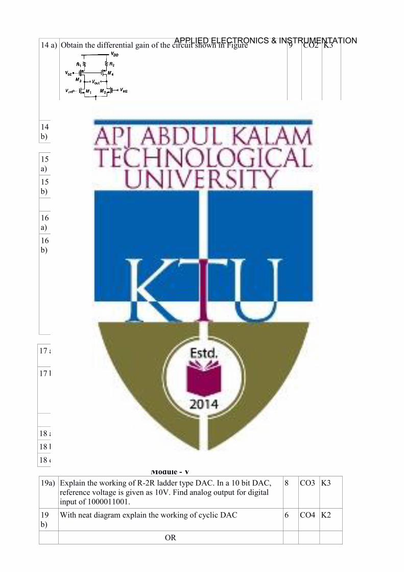
14 a) Obtain the differential gain of the circuit shown in Figure
9 CO2 K3
14 b)
Estimate CMRR due to transistor mismatch in an NMOS differential pair circuit with resistive load
5 CO2 K2
Module - III 15 a)
Draw the circuit of a 2stage comparator circuit and explain the working.
4 CO3 K2
15 b)
Explain any two frequency compensation techniques in the opamp circuits.
10 CO3 K2
OR 16 a)
Explain the need of a 2 stage opamp circuit with appropriate circuit diagram.
4 CO2 K2
16 b)
Design the 2 stage opamp shown in the figure for a power budget = 6mW and maximum differential swing = 4V,Iss = 0.5mA.(Assume typical circuit parameters)
10 CO3 K2
Module – IV 17 a) Discuss the usage of PLL in frequency multiplication and
synthesis
6 CO4 K2
17 b) Design a switched capacitor implementation of a summing
integrator with the relationship )()(
21
fCCj
v
fCCj
vV
B
F
A
Fo
ωω+=
9 CO4 K2
OR 18 a) Explain the non ideal effects in PLL 6 CO4 K2 18 b) Explain the working of sample and hold circuits . 4 CO4 K2 18 c) Write notes on Capacitive feed through in Dynamic circuits 4 CO4 K2
Module - V 19a) Explain the working of R-2R ladder type DAC. In a 10 bit DAC,
reference voltage is given as 10V. Find analog output for digital input of 1000011001.
8 CO3 K3
19 b)
With neat diagram explain the working of cyclic DAC 6 CO4 K2
OR
APPLIED ELECTRONICS & INSTRUMENTATION
20 a)
A 4-bit R-2R ladder type DAC having R= 5 kΩ and VR= 5 V. Find its resolution and output voltage for inputs 1)1101 and 2) 1001
8 CO4 K3
20 b)
With neat diagram explain the working of pipeline ADC 6 CO4 K2
Simulation Assignments
The following simulations can be done in LTSPICE.
1. Design single stage MOS amplifier stages in CS CD and CG configurations . Observe the
input and output signals. Plot the AC frequency response and understand the variation of
gain at high frequencies.
2. Design and simulate current mirror circuit for various reference currents and verify the W/L
requirements of the devices .
3. Design MOS amplifier stages in cascode configurations . Observe the input and output
signals. Plot the AC frequency response and understand the tradeoffs.
4. Design and implement differential amplifier and measure its CMRR. Plot its transfer
characteristics.
5. Design and simulate a 3 bit flash type ADC. Observe the output bit patterns and transfer
characteristics
6. Design and simulate R − 2R DAC circuit.
7. Observe the effect of clock feed through on the voltage across the load capacitors(CL) in
dynamic analog circuits. See the changes with the load capacitor(CL) values
APPLIED ELECTRONICS & INSTRUMENTATION

AET398 COMPUTER VISION CATEGORY L T P CREDITSVAC 4 0 0 4
Preamble: This course aims to develop skills to implement solutions for computer vision challenges.
Prerequisite: AET322 Digital Image Processing.
Course Outcomes: After the completion of the course the student will be able to
CO 1 Explain the fundamentals of imaging systems, camera and derive its parameters.
CO 2 Apply various image processing and feature extraction techniques in computer vision applications.
CO 3 Demonstrate 3D modeling from 2D images.
CO4 Make use of motion analysis and detection methods in computer vision applications.
CO5 Apply deep neural network systems for computer vision challenges.
Mapping of course outcomes with program outcomes
PO 1
PO 2
PO 3 PO 4 PO 5 PO 6 PO 7 PO 8 PO 9 PO 10
PO 11
PO 12
CO 1 3 3 3 2 3 CO 2 3 3 3 2 3 3 CO 3 3 3 3 2 3 3 CO 4 3 3 3 2 3 3 CO 5 3 3 3 2 3 2 3
Assessment Pattern
Bloom’s Category Continuous Assessment Tests
End Semester Examination
1 2
Remember K1 10 10 10 Understand K2 30 30 60 Apply K3 10 10 30 Analyse K4 Evaluate Create
Mark distribution
Total Marks
CIE ESE ESE Duration
150 50 100 3 hours
APPLIED ELECTRONICS & INSTRUMENTATION
Continuous Internal Evaluation Pattern:
Attendance : 10 marks Continuous Assessment Test (2 numbers) : 25 marks Assignment/Quiz/Course project : 15 marks
End Semester Examination Pattern: There will be two parts; Part A and Part B. Part A contain 10 questions with 2 questions from each module, having 3 marks for each question. Students should answer all questions. Part B contains 2 questions from each module of which student should answer any one. Each question can have maximum 2 sub-divisions and carry 14 marks.
Course Level Assessment Questions
Course Outcome 1 (CO1): Explain the fundamentals of imaging systems, camera and derive its parameters.
1. Explain pin hole camera model.
2. Differentiate intrinsic and extrinsic parameters.
3. Explain the concept of disparity and its relationship with depth
Course Outcome 2 (CO2): Apply various image processing and feature extraction techniques in computer vision applications.
1. For a given task, identify a method for feature extraction.
2. Find suitable application of SURF features. 3. Choose suitable technique for medical image segmentation. 4. Explore different applications of dimensionality reduction techniques.
Course Outcome 3 (CO3): Demonstrate 3D modeling from 2D images.
1. Given single image and reflectance map obtain its shape.
2. Derivation of Fundamental matrix.
3. Demonstrate the idea of obtaining structure from motion.
Course Outcome 4 (CO4): Make use of motion analysis and detection methods in computer vision applications.
1. Obtain optical flow for a given video.
2. Face detection using Viola Jones algorithm.
3. Pedestrian detection using HOG.
Course Outcome 5 (CO5): Apply deep neural network systems for computer vision challenges
1. Explain different layers in CNN.
APPLIED ELECTRONICS & INSTRUMENTATION
2. Identify a CNN architecture for specific task.
SYLLABUS
Module 1
Fundamentals of Image Formation: Pinhole camera. Perspective Projection, Homogeneous Coordinates. Camera: Intrinsic and extrinsic parameters. Transformation- Orthogonal, Euclidean and Affine. Orthographic projection; Parallel Projection. Camera Calibration, Stereo vision: introduction, concept of disparity and its relationship with depth.
Module 2
Feature Extraction: Edges - Canny, LOG, DOG. Line detection-Hough Transform. Corners - Harris and Hessian. SIFT, SURF, HOG. Image Segmentation and Pattern Analysis: Image Region Growing, Edge Based approaches to segmentation, Graph-Cut, Mean-Shift, MRFs. Clustering: K-Means, Mixture of Gaussians, Dimensionality Reduction: PCA
Module 3
Depth estimation: Binocular Stereopsis, Reflectance Map, Albedo estimation Photometric Stereo. Shape from shading- Propagation and Optimization Method, Frankot Chellappa Algorithm. Two view geometry- Epipolar geometry, Fundamental matrix, Essential Matrix. Structure from Motion: Triangulation, Two frame structure from motion.
Module 4
Motion Analysis- Regularization theory, Background Subtraction and Modeling, Optical Flow: brightness constancy equation, aperture problem, Horn-Shunck method, Lucas Kanade method, Depth from optical flow.
Object detection: Sliding window method, Detecting deformable objects. Face detection using Viola Jones algorithm. Face recognition using Eigen faces. Pedestrian Detection using HOG.
Module 5
Introduction to Neural Networks: Model of a biological neuron, activation functions, Back propagation, Learning XOR, Gradient-Based Learning. Convolutional Neural Networks, CNN Architectures - AlexNet, VGG 16, GoogLeNet, ResNet.
Text Books 1. Computer Vision: Algorithms and Applications, Richard Szeliski, Springer 2010.2. Computer vision: A modern approach, by Forsyth and Ponce. Prentice Hall, 2002.3. Ian Goodfellow, Yoshua Bengio, Aaron Courville, Deep Learning, MIT Press, 2016.
Reference Books
1. Multiple View Geometry in Computer Vision, Richard Hartley and AndrewZisserman,Second Edition, Cambridge University Press, March 2004.
2. B K P Horn , Robot Vision, McGraw-Hill,1986
APPLIED ELECTRONICS & INSTRUMENTATION
Course Contents and Lecture Schedule
No Topic No. of Lectures
1 Fundamentals of Image Formation 1.1 Pinhole camera. Perspective Projection, Homogeneous Coordinates. 2 1.2 Camera: Intrinsic and extrinsic parameters 2 1.3 Transformation- Orthogonal, Euclidean and Affine. Orthographic
projection; Parallel Projection 2
1.4 Camera Calibration 1 1.5 Stereo vision: introduction; concept of disparity and its relationship with
depth. 2
2 Feature Extraction 2.1 Edges - Canny, LOG, DOG 1
Line detection-Hough Transform 1 2.2 Corners - Harris and Hessian 1
2.3 SIFT, SURF, HOG 2 2.4 Image Region Growing, Edge Based approaches to segmentation,
Graph-Cut, Mean-Shift, MRFs. 2
2.5 Clustering: K-Means, Mixture of Gaussians, 1
2.6 Dimensionality Reduction: PCA 1 3 Depth estimation
3.1 Binocular Stereopsis; Reflectance Map; Albedo estimation Photometric Stereo
2
3.2 Shape from shading- Propagation and Optimization Method, Frankot Chellappa Algorithm
2
Two view geometry 3.3 Epipolar geometry, Fundamental matrix, Essential Matrix 3
3.4 Structure from Motion: Triangulation, Two frame structure from motion.
2
4 Motion Analysis
4.1 Regularization theory, Background Subtraction and Modeling 2 4.2 Optical Flow: brightness constancy equation, aperture problem, Horn-
Shunck method, Lucas Kanade method, Depth from optical flow. 3
Object detection
4.3 Sliding window method, Detecting deformable objects. 1 4.4 Face detection using Viola Jones algorithm. 1 4.5 Face recognition using Eigen faces 1 4.6 Pedestrian Detection using HOG 1 5 Introduction to Neural Networks
5.1 Model of a biological neuron, activation functions 1
APPLIED ELECTRONICS & INSTRUMENTATION
5.2 Back propagation, Learning XOR 1
5.3 Gradient-Based Learning 2
5.4 Convolutional Neural Networks 2
CNN Architectures
5.5 AlexNet, VGG 16, GoogLeNet, ResNet. 3
Model Question paper
APJ ABDUL KALAM TECHNOLOGICAL UNIVERSITY
SIXTH SEMESTER B.TECH DEGREE EXAMINATION, (Model Question Paper)
Course Code: AET398
Program: B Tech. Honours in Applied Electronics and Instrumentation Engineering / Electronics and Instrumentation Engineering
Course Name: Computer Vision
Max. Marks:100 Duration: 3 Hours
PART A
Answer ALL Questions. Each question carries 3 marks.
1 Find linear transformation matrix that represent perspective projection and orthogonal projection?
CO1 K2
2 Explain the concept of disparity and its relationship with depth. CO1 K2 3 Explain K-means clustering algorithm. CO2 K2 4 Explain HOG algorithm. CO2 K2 5 Explain the concept of obtaining shape from shading. CO3 K2 6 Explain triangulation method. CO3 K2 7 Prove that optical flow obtained using Lucas-Kanade algorithm is the
least squared solution of optical flow constraint equation. CO4 K3
8 What is aperture problem in optical flow. CO4 K1 9 What do you mean by a learning algorithm? CO5 K1 10 What are problems with SGD? CO5 K2
PART – B Answer one question from each module; each question carries 14 marks.
Module – I
11. a) Derive the camera calibration matrix. What are cameras intrinsic and extrinsic (calibration) parameters?
9 CO1 K2
11. b) Obtain affine transformation matrix. 5 CO1 K2 OR
APPLIED ELECTRONICS & INSTRUMENTATION
12.a) Discuss on camera calibration. 9 CO1 K1 12.b) Derive the perspective projection equation for a virtual image
located at a distance d in front of the pinhole.
5 CO1 K2
Module – II
13 a) Explain Harris corner detection. 5 CO2 K2 13 b) Briefly explain the principles of PCA. Explain the steps involved in
determining principal components 9 CO2 K2
OR 14 a) Explain how Hough transform can be used to detect lines. 5 CO2 K2 14 b) Explain the steps for constructing SIFT feature. 9 CO2 K2
Module – III
15 a) Let M1 and M2 be two camera matrices. Assume that M1 = [I|0] and M2 = [A|a], where A is a 3x3 matrix. Prove that fundamental matrix corresponding to these camera matrices is of the form F = [a]xA, where [a]x represents linear transformation matrix of cross product.
10 CO3 K4
15 b) Explain photometric stereo for image reconstruction. 4 CO3 K2 OR
16 a) Given reflectance map and a single image, explain how to obtain surface normals corresponding to real 3D scene that is imaged.
9 CO3 K3
16 b) Explain the steps in obtaining structure from motion. 5 CO3 K2
Module – IV
17 a) Explain in detail the computation of optical flow using Horn Schunk algorithm.
9 CO4 K2
17 b) Explain Sliding window method for object detection. 5 CO4 K2 OR
18 a) Explain face detection using Viola Jones algorithm. 9 CO4 K2 18 b) Discuss on background Subtraction methods. 5 CO4 K2
Module – V
19 a) Explain the role of optimization in machine learning algorithms. 4 CO5 K2
b) Compare AlexNet and VGG 16 architectures. 5 CO5 K2
c) Differentiate between RMS prop and ADAM. 5 K3
OR
20 a) Explain the structure of Convolutional Neural Network. 10 CO5 K2 (b) Explain the concept of back propagation. 4 CO5 K2
APPLIED ELECTRONICS & INSTRUMENTATION


![Three Year Diploma in Cement Technology [C01] (V Semester)](https://img.pdfslide.net/doc/110x75/63189796c51d6b41aa041295/three-year-diploma-in-cement-technology-c01-v-semester.jpg)


