Embed Size (px)
Citation preview
Seminar ReportOn
“Magneto Abrasive Flow Machining”
Submitted for the partial fulfillment of requirement for the degree of
BACHELOR OF ENGINEERING(Mechanical Engineering)
Submitted ByMr. Ashish S. Honale
Under the Guidance of
Prof.
Department of Mechanical EngineeringSiddhivinayak Technical Campus, SERT, Khamgaon.
Sant Gadge Baba Amravati University, Amravati2015-2016

CertificateCertificateThis is to certify that the seminar entitled
“Magneto Abrasive Flow Machining”is a bona-fide work and it is submitted to the
Sant Gadge Baba Amravati University, AmravatiBy
Mr. Ashish S. Honalein the partial fulfillment of the degree of Bachelor of Engineering in
Mechanical Engineering during the academic year 2015-2016 under my guidance.
Prof. A. N. RakhondePrincipal
Prof. Guide
Department of Mech Engg
Prof. Pramod S. Wankhade
HOD Department of Mech Engg

Department of Mechanical EngineeringSiddhivinayak Technical Campus, SERT, Khamgaon.
2015-2016
AcknowledgementIt is pleasant endeavor to present seminar report on “Magneto Abrasive Flow
Machining”. I avail this opportunity to express my deep sense of gratitude and whole hearted thanks to my guide Prof. …….. of STC, SERT, Khamgaon for substantial guidance and cooperation in the seminar work. He has provided all the facilities whenever I need and mostly for his gracious encouragement, advice and guidance to make this project a success.
I also express my gratitude to Prof. A. N. Rakhonde Principal, STC SERT, Khamgaon for constant inspiration and valuable advice.
I am equally thankful to Mr. P. S. Wankhade (HOD) Dept of Mech Engg. and All the Faculties of Mechanical engineering Department of STC, SERT, Khamgaon for constant inspiration and valuable suggestions.
Words fall short to express my deep sense of gratitude towards them all, who have directly or indirectly helped in making this project.
Mr. Ashish S. Honale Final year Mech Engg
STC, SERT, KHAMGAON

List of Figure
1. Schematic illustration of the magneto abrasive flow machining process
2. Principle of Material Removal Mechanism
3. Mechanism of Magneto Abrasive Flow Machining
4. Unidirectional MAFM Process
5. Two–way MAFM Process
6. Orbital MAFM Process (a) Before start of finishing (b) While finishing.
7. Surface finish improvement before and after on (a) internal passages within turbine engine
diffuser (b) medical implants (c) complete automotive engine parts.

List of Table

CONTENT
Abstract
Chapter 1
1.1 Introduction …………………………………………………………………
1.2 Aim and specific objectives…………………… ……………………………………
1.3 Method………………………………………………………………………
Chapter 2
2.1 General concept ………………………………………………….…………
Chapter 3
3.1 Experimental set-up …………………………………………………………….
3.2 Types of MAFM machines removal …………………………………………..
3.3 Mechanism of material
Chapter 4
4.1 Advantages ……………………………………………………………………
4.2 Limitations ……………………………………………………………………4.3 Application …………………………………………………………………4.4 Conclusion …………………………..4.5 References …………………………………………………………………………..

1. Abstract
Magneto abrasive flow machining (MAFM) is a new technique in machining. The orbital flow machining process
has been recently claimed to be another improvement over AFM, which performs three-dimensional machining of
complex components. These processes can be classified as hybrid machining processes (HMP)—a recent concept
in the advancement of non-conventional machining. The reasons for developing a hybrid machining process is to
make use of combined or mutually enhanced advantages and to avoid or reduce some of the adverse effects the
constituent processes produce when they are individually applied. In almost all non-conventional machining
processes such as electric discharge machining, electrochemical machining, laser beam machining, etc., low
material removal rate is considered a general problem and attempts are continuing to develop techniques to
overcome it. The present paper reports the preliminary results of an on-going research project being conducted
with the aim of exploring techniques for improving material removal (MR) in AFM. One such technique studied
uses a magnetic field around the work piece. Magnetic fields have been successfully exploited in the past, such as
machining force in magnetic abrasive finishing (MAF), used for micro machining and finishing of components,
particularly circular tubes. The process under investigation is the combination of AFM and MAF, and is given the
name Magneto Abrasive Flow Machining (MAFM).

2. INTRODUCTION
Magneto Abrasive flow machining (MAFM) is one of the latest non-conventional machining processes,
which possesses excellent capabilities for finish-machining of inaccessible regions of a component. It has been
successfully employed for deburring , radiusing and removing recast layers of precision components. High levels
of surface finish and sufficiently close tolerances have been achieved for a wide range of components . In MAFM,
a semi-solid medium consisting of a polymer-based carrier and abrasives in a typical proportion is extruded under
pressure through or across the surfaces to be machined. The medium acts as a deformable grinding tool whenever
it is subjected to any restriction. A special fixture is generally required to create restrictive passage or to direct the
medium to the desired locations in the work piece

3.3. Aim and Specific Objectives
This report discusses the possible improvement in surface roughness and material removal rate by applying a
magnetic field around the work piece in AFM. A set-up has been developed for a composite process termed
magneto abrasive flow machining (MAFM), and the effect of key parameters on the performance of the process
has been studied. Relationships are developed between the material removal rate and the percentage
improvement in surface roughness of brass components when finish-machined by this process.
3.4. Method
In almost all non-conventional machining processes such as electric discharge machining, electrochemical
machining, laser beam machining, etc., low material removal rate is considered a general problem and attempts
are continuing to develop techniques to overcome it. This report presents the preliminary results of an ongoing
research project being conducted with the aim of exploring techniques for improving material removal (MR) in
AFM. One such technique studied uses a magnetic field around the work piece. Magnetic fields have been
successfully exploited in the past, such as machining force in magnetic abrasive finishing (MAF), used for micro
machining and finishing of components, particularly circular tubes. Shinmura and Yamaguchi and more recently
Kim et al., Kremen et al. and Khairy have reported studies on this process. The process under investigation is the
combination of AFM and MAF, and is given the name magneto abrasive flow machining (MAFM).
4. OVERVIEW
AFM was developed in 1960s as a method to deburr, machining. This provides improvement in surface
roughness and material removal rate, polish intricate geometries. The process has found applications in a wide
range of fields such as aerospace, defence, and surgical and tool manufacturing industries. Extrusion pressure,
flow volume, grit size, number of cycles, media, and work piece configuration are the principal machining
parameters that control the surface finish characteristics. Recently there has been a trend to create hybrid
processes by merging the AFF process with other non-conventional processes. This has opened up new vistas for
finishing difficult to machine materials with
complicated shapes which would have been otherwise impossible. These processes are emerging as major
technological infrastructure for precision, meso, micro, and nano scale engineering. This review provides an
insight into the fundamental and applied research in the area and creates a better understanding of this finishing
process, with the objective of helping in the selection of optimum machining parameters for the finishing of
varied work pieces in practice.MAFM is a new non-conventional machining technique .It produces surface
finishes ranging from rough to extremely fine. Here chips are formed by small cutting edges on abrasive
particles.The use of magnetic field around the work piece. It deflects the path of abrasive flow. Here
‘Microchipping’ of the surface is done.
The various limitations of Abrasive Flow Machining are overcome like:
1. Low finishing rate.

2. Low MRR.
3. Bad surface texture.
4. Uneconomical.
6. EXPERIMENTAL SET-UP
6.1 MAFM set - up.
An experimental set-up is designed and fabricated, it is shown in fig:6.1. It consisted of two cylinders (1)
containing the medium along with oval flanges (2). The flanges facilitate clamping of the fixture (3) that contains
the work piece (4) and index the set-up through 180° when required. Two eye bolts (5) also support this purpose.
The setup is integrated to a hydraulic press (6). The flow rate and pressure acting on piston of the press were
made adjustable. The flow rate of the medium was varied by changing the speed of the press drive whereas the
pressure acting on the medium is controlled by an auxiliary hydraulic cylinder (7), which provides additional
resistance to the medium flowing through the work piece. The resistance provided by this cylinder is adjustable
and can be set to any desired value with the help of a modular relief valve (8). The piston (9) of the hydraulic
press then imparts pressure to the medium according to the passage size and resistance provided by opening of
the valve. As the pressure provided by the piston of the press exceeds the resistance offered by the valve, the
medium starts flowing at constant pressure through the passage in the work piece. The upward movement of the
piston (i.e. stroke length) is controlled with the help of a limit switch. At the end of the stroke the lower cylinder
completely transfers the medium through the work piece to the upper cylinder. The position of the two cylinders
is interchanged by giving rotation to the assembly through 180° and the next stroke is started. Two strokes make
up one cycle. A digital counter is used to count the number of cycles. Temperature indicators for medium and
hydraulic oil are also attached.
6.2 The Fixture.
The work fixture was made of nylon, a non-magnetic material. It was specially designed to accommodate
electromagnet poles such that the maximum magnetic pull occurs near the inner surface of the work piece.
6.3 The Electromagnet.
The electromagnet was designed and fabricated for its location around the cylindrical work piece. It consists of
two poles that are surrounded by coils arranged in such a manner as to provide the maximum magnetic field near
the entire internal surface of the work piece.
6.4 The Abrasive Medium.
The medium used for this study consists of a silicon based polymer, hydrocarbon gel and the abrasive grains. The
abrasive required for this experimentation has essentially to be magnetic in nature. In this study, an abrasive
called Brown Super Emery (trade name), supplied by an Indian company, was used. It contains 40%
ferromagnetic constituents, 45% Al2O3 and 15% Si2O3.

Figure 6.1: The Workpiece

Figure 6.2: Schematic illustration of the magneto abrasive flow machining process

(1.Cylinder containing medium, 2. Flange, 3.Nylon fixture, 4.Workpiece, 5.Eye bolt, 6.Hydraulic press, 7.Auxiliary
cylinder, 8.Modular relief valve, 9.Piston of Hydraulic press, 10.Directional control valve, 11.Manifold blocks,
13.Electromagnet).
Figure 6.3: Typical Machining Centre.

8. PRINCIPLE
The volume of abrasive particles is carried by the abrasive fluid through the work piece. Abrasives are impinged
on the work piece with a specified pressure which is provided by the piston and cylinder arrangement or with the
help of an intensifier pump. The pressure energy of the fluid is converted into kinetic energy of the fluid in order
to get high velocity.
When a strong magnetic field is applied around the work piece, the flowing abrasive particles (which must
essentially be magnetic in nature) experience a sideways pull that causes a deflection in their path of movement
to get them to impinge on to the work surface with a small angle, thereby resulting in microchipping of the
surface. The magnetic field is also expected to affect the abrasive distribution pattern at the machining surface of
the work piece. The particles that otherwise would have passed without striking the surface now change their
path and take an active part in the abrasion process, thus causing an enhancement in material removal. It is to be
mentioned here that although the mechanical pull generated by the magnetic field is small, it is sufficient to
deflect the abrasive particles, which are already moving at considerable speed. Therefore it appears that, by
virtue of the application of the magnetic field, more abrasive particles strike the surface. Simultaneously, some of
them impinge on the surface at small angles, resulting in an increased amount of cutting wear and thereby giving
rise to an overall enhancement of material removal rate.
(a) (b)
Figure 8.1: (a) Off-state MR fluid particles (b) Aligning in an applied magnetic field.

Figure 8.2: Principle of Material Removal Mechanism
9. ABRASIVE MEDIUM
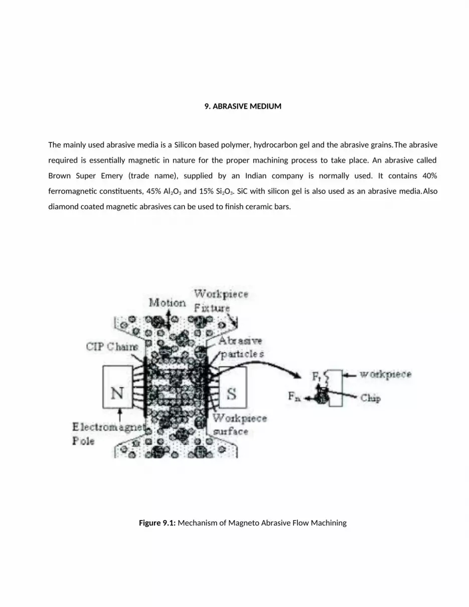
The mainly used abrasive media is a Silicon based polymer, hydrocarbon gel and the abrasive grains.The abrasive
required is essentially magnetic in nature for the proper machining process to take place. An abrasive called
Brown Super Emery (trade name), supplied by an Indian company is normally used. It contains 40%
ferromagnetic constituents, 45% Al2O3 and 15% Si2O3. SiC with silicon gel is also used as an abrasive media.Also
diamond coated magnetic abrasives can be used to finish ceramic bars.
Figure 9.1: Mechanism of Magneto Abrasive Flow Machining

10. MAFM MACHINES
MAFM Machines are classified into 3, namely:-
1. One-Way Machines
2. Two-Way Machines
3. Orbital Machines
10.1 One-way machines.
One way MAFM process apparatus is provided with a hydraulically actuated reciprocating piston and an extrusion
medium chamber adapted to receive and extrude medium unidirectionally across the internal surfaces of a work
piece having internal passages formed therein. Fixture directs the flow of the medium from the extrusion
medium chamber into the internal passages of the work piece, while a medium collector collects the medium as
it extrudes out from the internal passages. The extrusion medium chamber is provided with an access port to
periodically receive medium from the collector into extrusion chamber.
The hydraulically actuated piston intermittently withdraws from its extruding position to open the extrusion
medium chamber access port to collect the medium in the extrusion medium chamber. When the extrusion
medium chamber is charged with the working medium, the operation is resumed.
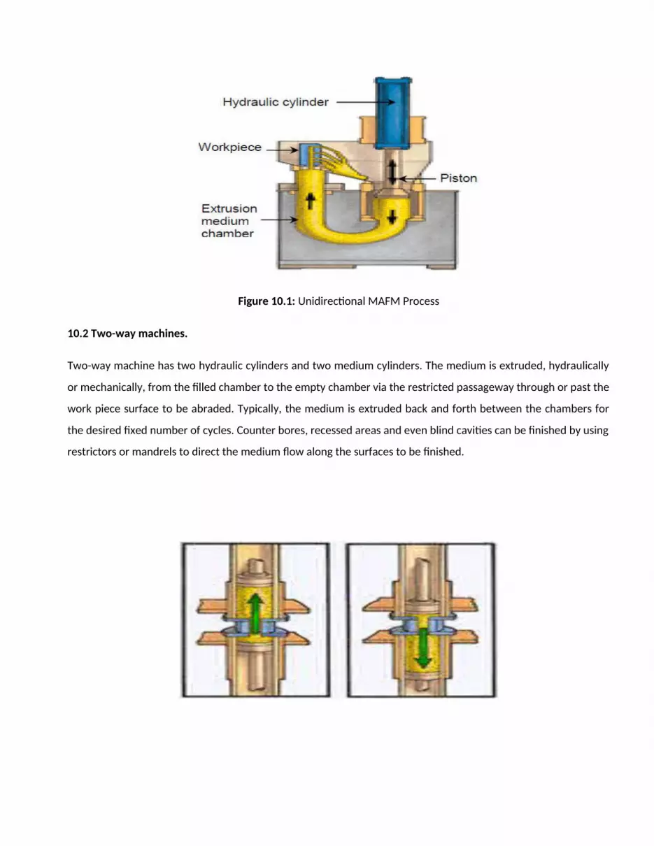
Figure 10.1: Unidirectional MAFM Process
10.2 Two-way machines.
Two-way machine has two hydraulic cylinders and two medium cylinders. The medium is extruded, hydraulically
or mechanically, from the filled chamber to the empty chamber via the restricted passageway through or past the
work piece surface to be abraded. Typically, the medium is extruded back and forth between the chambers for
the desired fixed number of cycles. Counter bores, recessed areas and even blind cavities can be finished by using
restrictors or mandrels to direct the medium flow along the surfaces to be finished.

Figure 10.2: Two–way MAFM Process
10.3 Orbital machines.
In orbital MAFM, the work piece is precisely oscillated in two or three dimensions within a slow flowing ‘pad’ of
compliant elastic/plastic MAFM medium.
In orbital MAFM, surface and edge finishing are achieved by rapid, low-amplitude, oscillations of the work piece
relative to a self-forming elastic plastic abrasive polishing tool. The tool is a pad or layer of abrasive-laden elastic
plastic medium, but typically higher in viscosity and more in elastic.
Orbital MAFM concept is to provide transitional motion to the work piece. When work piece with complex
geometry translates, it compressively displaces and tangentially slides across the compressed elastic plastic self-
formed pad which is positioned on the surface of a displacer which is roughly a mirror image of the work piece,
plus or minus a gap accommodating the layer of medium and a clearance.
A small orbital oscillation (0.5-5 mm) circular eccentric planar oscillation is applied to the work piece so that, at
any point in its oscillation, a portion of its surface bumps into the medium pad, elastically compresses (5 to 20%)
and slides across the medium as the work piece moves along its orbital oscillation path. As the circular eccentric
oscillation continues, different portions of the work piece slide across the medium. Ultimately, the full circular
oscillation engages each portion of the surface.

To assure uniformity, the highly elastic abrasive medium must be somewhat plastic in order to be self-forming
and to be continually presenting fresh medium to the polishing gap.
Figure 10.3: Orbital MAFM Process (a) Before start of finishing (b) While finishing.
12. MECHANISM OF MATERIAL REMOVAL.
Solid particle erosion proposed by Finnie is considered as the basic mechanism of material removal in MAFM
with some modifications. In abrasive jet machining the energy of the striking abrasive particle is imparted by the
high speed of the medium stream, but in MAFM the required energy to the abrasive particles is provided by high
pressure acting on the viscoelastic carrier medium. The medium dilates and the abrasive particles come under a
high level of strain due to the pressure acting in the restriction. The momentum that abrasive particles acquire
due to these conditions can be considered to be responsible for microploughing and microchipping of the surface
in contact with the abrasive. Microploughing causes plastic deformation on the surface of the metal. Initially no
material removal takes place. However, the surface atoms become more vulnerable to removal by subsequent
abrasive grains. More abrasive particles attack the surface repeatedly, which causes the detachment of material
often referred to as ‘cutting wear’. When a strong magnetic field is applied around the work piece, the flowing
abrasive particles (which must essentially be magnetic in nature) experience a sideways pull that causes a
deflection in their path of movement to get them to impinge on to the work surface with a small angle, thereby
resulting in microchipping of the surface. The magnetic field is also expected to affect the abrasive distribution
pattern at the machining surface of the work piece. The particles that otherwise would have passed without
striking the surface now change their path and take an active part in the abrasion process, thus causing an
enhancement in material removal. It is to be mentioned here that although the mechanical pull generated by the
magnetic field is small, it is sufficient to deflect the abrasive particles, which are already moving at considerable
speed. Therefore it appears that, by virtue of the application of the magnetic field, more abrasive particles strike
the surface. Simultaneously, some of them impinge on the surface at small angles, resulting in an increased
amount of cutting wear and thereby giving rise to an overall enhancement of material removal rate.
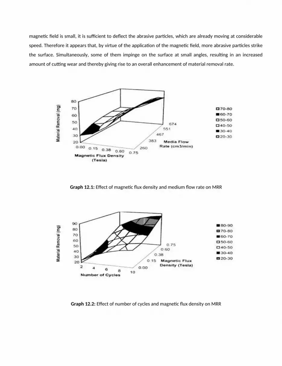
Graph 12.1: Effect of magnetic flux density and medium flow rate on MRR
Graph 12.2: Effect of number of cycles and magnetic flux density on MRR
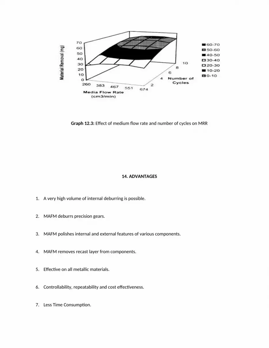
Graph 12.3: Effect of medium flow rate and number of cycles on MRR
14. ADVANTAGES
1. A very high volume of internal deburring is possible.
2. MAFM deburrs precision gears.
3. MAFM polishes internal and external features of various components.
4. MAFM removes recast layer from components.
5. Effective on all metallic materials.
6. Controllability, repeatability and cost effectiveness.
7. Less Time Consumption.
15. LIMITATIONS
1. Abrasive materials tend to get embedded, if the work material is ductile.
2. Require closed environment.
3. Require start up hole.
4. Mostly Magnetic materials.
16. APPLICATIONS
1. Automotives.
The demand for this process is increasing among car and two wheeler manufacturers as it is capable to make the
surfaces smoother for improved air flow and better performance of high-speed automotive engines. MAFM
process is capable to finish automotive and medical parts, and turbine engine components. Internal passages
within a turbine engine diffuser are polished to increase air flow to the combustion chamber of the engine. The
rough, power robbing cast surfaces are improved from 80-90% regardless of surface complexities.
2. Dies and Moulds.
Since in the MAFM process, abrading medium conforms to the passage geometry, complex shapes can be
finished with ease. Dies are ideal workpieces for the MAFM process as they provide the restriction for medium
flow, typically eliminating fixturing requirements. The uniformity of stock removal by MAFM permits accurate
‘sizing’ of undersized precision die passages.
The original 2 micron ∑Rs (EDM Finish) is improved to 0.2 micron with a stock removal of (EDM recast layer)
0.025 mm per surface.
3. Laser Shops with materials as titanium, and steel
(Thicker metal or composites).

4. Prototype, R&D, Maintenance and Repair Shops.
5. Controls Just-in-Time inventory requirements.
6. Metal Fabricators: Offer "clean edge" plate work.
7. Aerospace engine and control system components.
Figure 16.1: Surface finish improvement before and after on (a) internal passages within turbine engine diffuser
(b) medical implants (c) complete automotive engine parts.
Figure 16.2: Photomicrograph showing complete removal of EDM recast layer.

17. CONCLUSION
A magnetic field has been applied around a component being processed by abrasive flow machining and an
enhanced rate of material removal has been achieved. Empirical modelling with the help of response surface has
led to the following conclusions about the variation of response parameters in terms of independent parameters
within the specified range.
1. Magnetic field significantly affects both MRR and surface roughness. The slope of the curve indicates that MRR
increases with magnetic field more than does surface roughness. Therefore, more improvement in MRR is
expected at still higher values of magnetic field.
2. For a given number of cycles, there is a discernible improvement in MRR and surface roughness. Fewer cycles
are required for removing the same amount of material from the component, if processed in the magnetic field.
3. Magnetic field and medium flow rate interact with each other .The combination of low flow rates and high
magnetic flux density yields more MRR and smaller surface roughness.
4. Medium flow rates do not have a significant effect on MRR and surface roughness in the presence of a
magnetic field.
5. MRR and surface roughness both level off after a certain number of cycles.
MAFM is a well-established advanced finishing process capable of meeting the diverse finishing requirements
from various sectors of applications like aerospace, medical and automobile. It is commonly applied to finish
complex shapes for better surface roughness values and tight tolerances. But the major disadvantage of this
process is low finishing rate. The better performance is achieved if the process is monitored online. So, acoustic
emission technique is tried to monitor the surface finish and material removal .Various modelling techniques are
also used to model the process and to correlate with experimental results. But experts believe that there is still
room for a lot of improvements in the present MAFM status.

18. REFERENCES
1. Singh S, Shan H. S, “Development of magneto abrasive flow machining process”, International Journal of
machine tools and manufacture, Issue number 42 (2002), 953-959.
2. L.J Rhoades, Kohut T.A, Nokovich N.P, Unidirectional abrasive flow machining, US patent number 5, 367,
833, Nov 29th,1994.
3. Gorana V.K, Lal G.K, “Forces prediction during material deformation in magneto abrasive flow machining”,
Journal of manufacturing systems, Issue number 260 (2006),128-139.
4. V.K Jain, R.K Jain, “Modeling of material removal and surface roughness in magneto abrasive flow machining
process”, International Journal of Machine tool & manufacture, Issue number 39 (1999), 1903-1923.
5. R.E Williams, “Stochastic modeling and analysis of abrasive flow machining”, Journal of Engineering for
Industry, Issue number 114 (1992), 74-81.
6. Petri K.L, Bidanda B, “A neural network process model for magneto abrasive flow machining operations,
Journal of manufacturing systems, Issue number 17 (1998), 52-64.
7. Jha S, Jain V.K, “Design and development of the magneto rheological abrasive flow finishing process”,
International Journal of machine tool & manufacture, Issue number 44 (2004), 1019-1029.
8. http://www.tnmsc.cn


