Embed Size (px)
Citation preview
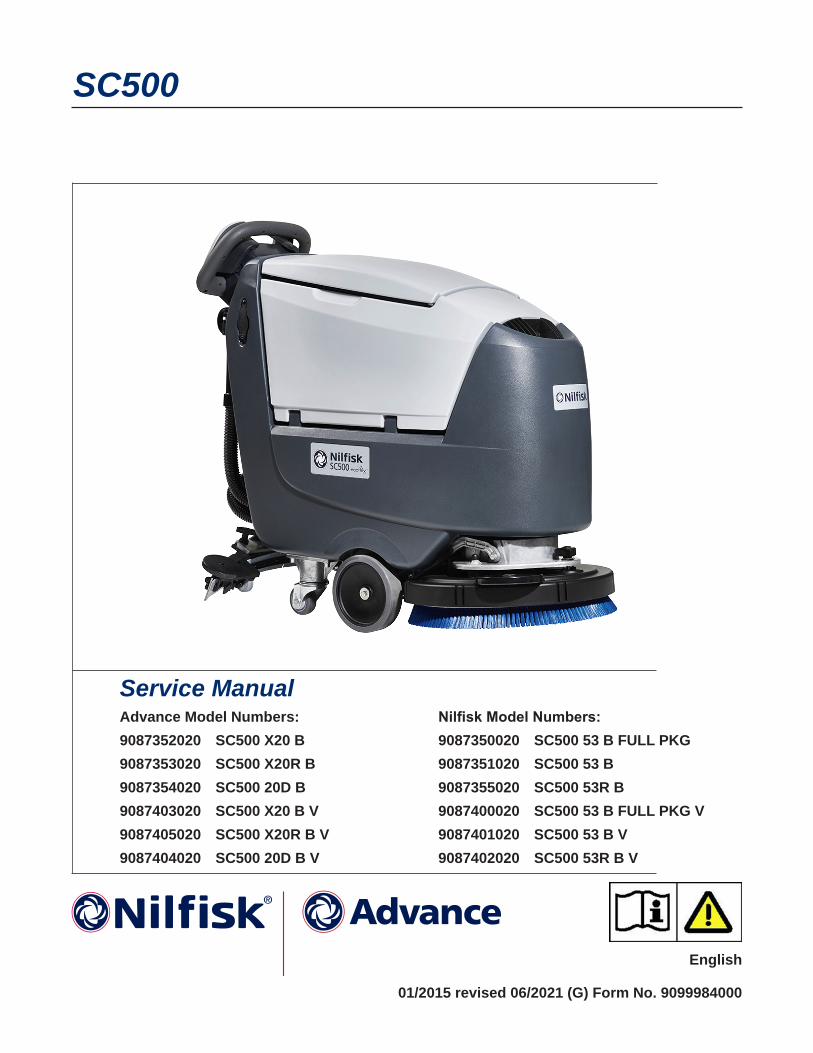
SC500
Service Manual
English
Advance Model Numbers:9087352020 SC500 X20 B9087353020 SC500 X20R B9087354020 SC500 20D B9087403020 SC500 X20 B V9087405020 SC500 X20R B V9087404020 SC500 20D B V
Nilfisk Model Numbers:9087350020 SC500 53 B FULL PKG9087351020 SC500 53 B9087355020 SC500 53R B9087400020 SC500 53 B FULL PKG V9087401020 SC500 53 B V9087402020 SC500 53R B V
01/2015 revised 06/2021 (G) Form No. 9099984000
Contents iiService Manual – SC500
Contents03 - General Information . . . . . . . . . . . . . . . . . . . . . . . . . . . . . . . . . . . 6
Machine General Description 6Service Manual Purpose and Field of Application 6Other Reference Manuals 6Conventions 7Name Plate 7Safety 8
Visible Symbols on the Machine 8Symbols 8General Safety Instructions 9Lithium-Ion Battery Module Safety Instructions 11
Lifting The Machine 13Transporting The Machine 13Technical Specifications 14Maintenance Schedule 16Know Your Machine 17
Control panel Disc deck (Model No : 9087352020, 9087354020, 9087350020, 9087351020) 17
Control panel REV deck (Model No : 9087353020, 9087355020) 17Control panel Disc deck (Model No : 9087403020, 9087404020, 9087400020,9087401020)
18Control panel REV deck (Model No : 9087405020, 9087402020) 18
Service and Diagnostic Equipment 21Dimensions 22
SC500 Disc 22SC500 REV 23
04 - Control System - models with key slot . . . . . . . . . . . . . . . . . . . . . . . 24Model No : 9087352020, 9087354020, 9087350020, 9087351020, 9087353020, 9087355020 24Functional Description 24Wiring Diagram 25Component Locations 26Troubleshooting 27
Main machine controller (EB1) Alarm Codes 27Black-box: Recording of Alarms, Parameters (see pages 34-35), Partial Operating Time
Counter 32Display, Main Screen 32Display, Alarms Log Screen 33Display, Machine Settings Screen 34Display, Operating Time Counter Screen 36System for Flow Rate Regulation as Function of Speed 37
Removal and Installation 38Main machine controller (EB1) 38Display Controller (EB2) and User interface controller (EB3) 40
Specifications 42Main machine controller (EB1) Connectors 42Connectors of the Display Controller (EB2) 48
Shop Measurements 50Shop Measurements - Main machine controller (EB1) 50Shop Measurements - Display Controller (EB2) 57
Contents iiiService Manual – SC500
05 - Control System, Models with magnetic smart key . . . . . . . . . . . . . . . . 61Model No : 9087403020, 9087404020, 9087400020,9087401020, 9087405020, 9087402020 61Functional Description 61Wiring Diagram 62Component Locations 63Troubleshooting 64
Main machine controller (EB1) Alarm Codes 64Drive System Alarm Codes 67On-Board Battery Charger Alarm Codes 68Nilfisk Lithium-ion Battery Alarm Codes 69Black-box: Recording of Alarms, Parameters (see pages 71-72), Partial Operating Time
Counter 71Display, Main Screen 71Display, Alarms Log Screen 73Display, Machine Settings Screen 74Display, Operating Time Counter Screen 76Display, Magnetic Smart Keys Management Screen 77System for Flow Rate Regulation as Function of Speed 78
Removal and Installation 79Main machine controller (EB1) 79Display Controller (EB2), User interface controller (EB3) and Smart Key Reader (IB) 81
Specifications 83Main machine controller (EB1) Connectors 83Connectors of the Display Controller (EB2) 89
Shop Measurements 92Shop Measurements - Main machine controller (EB1) 92Shop Measurements - Display Controller (EB2) 100
10 - Chassis System . . . . . . . . . . . . . . . . . . . . . . . . . . . . . . . . . . . . . 104Chassis (main parts) 104
20 - Wheel System, Traction . . . . . . . . . . . . . . . . . . . . . . . . . . . . . . . . 105Functional Description 105Wiring Diagram 106Component Locations 107Troubleshooting 109
Drive System Gear Motor Current Draw Test 110Removal and Installation 111
Speed Potentiometer 111Specifications 112
24 - Electrical System . . . . . . . . . . . . . . . . . . . . . . . . . . . . . . . . . . . . 113Functional Description 113
With Conventional Lead/Acid Batteries 113With Lithium-Ion Batteries 113Low voltage cut out 115
Wiring Diagram 116Component Locations 118
With Conventional Lead/Acid Batteries 118With Lithium-ion Batteries 119
Maintenance and Adjustments 120Setting the Installed Battery Type 120Disconnect/Connect Lithium-Ion Batteries 121Disconnection 121Connection 121
Contents ivService Manual – SC500
Battery Charging - Conventional Lead/Acid Batteries 121Removal and Installation 123
Conventional Lead/Acid Batteries 123Lithium-ion Batteries 124Installation of a Replacement Lithium-ion Battery Module 126
Troubleshooting 130With Conventional Lead/Acid Batteries 130With Lithium-ion Batteries 130
General Wiring Diagram - With key slot (Model No : 9087352020, 9087354020, 9087350020, 9087351020, 9087353020, 9087355020) 131General Wiring Diagram - with magnetic smart key and conventional batteries 132General Wiring Diagram - with magnetic smart key and Lithium-Ion batteries 133Specifications 134
30 - Solution System . . . . . . . . . . . . . . . . . . . . . . . . . . . . . . . . . . . . 135Functional Description 135
Water Level Sensor Operation 136Wiring Diagram 137Component Locations 138Maintenance and Adjustments 140
Cleaning the Detergent Solution Tank and Filter 140Cleaning the EcoFlex Detergent Tank 141Draining the EcoFlex System 142
Troubleshooting 143Removal and Installation 145
Solenoid Valve 145Detergent Pump (Piston Pump) 146Detergent Pump (Peristaltic Pump) 147Checking the Water Level Sensor Operation 148Water Level Sensor 149
Specifications 150
34 - Scrub System, Disc . . . . . . . . . . . . . . . . . . . . . . . . . . . . . . . . . . . 151Functional Description 151
Brush Release System 151Wiring Diagram 152Brush Deck Actuator System 153Component Locations 154Maintenance and Adjustments 156
Brush Installation/Removal 156Troubleshooting 157
Brush Motor Current Draw Test 158Removal and Installation 159
Brush Deck 159Checking/Replacing Brush Motor Carbon Brushes 161Brush Motor Disassembly/Assembly 162Brush Deck Actuator 163
Specifications 163
34 - Scrub System, REV . . . . . . . . . . . . . . . . . . . . . . . . . . . . . . . . . . 165
Contents vService Manual – SC500
Functional Description 165Wiring Diagram 166Brush Deck Actuator System 167Component Locations 168Maintenance and Adjustments 170
Brush Installation/Removal 170Troubleshooting 171
REV Motor Current Draw Test 172Removal and Installation 173
REV Deck 173Checking/Replacing REV Motor Carbon Brushes 175Brush Deck Actuator 178
Specifications 179
38 - Squeegee System . . . . . . . . . . . . . . . . . . . . . . . . . . . . . . . . . . . . 180Functional Description 180Component Locations 181Maintenance and Adjustments 182
Squeegee cleaning 182Checking/Replacing the Squeegee Blades 183
Troubleshooting 184Removal and Installation 185
Gas Spring on the Squeegee Support 185Spring on the Squeegee Support 186
Specifications 187
40 - Recovery System . . . . . . . . . . . . . . . . . . . . . . . . . . . . . . . . . . . . 188Functional Description 188Wiring Diagram 189Component Locations 190Maintenance and Adjustments 191
Recovery Tank Cleaning 191Troubleshooting 192
Vacuum Motor Current Draw Test 193Removal and Installation 194
Vacuum Motor Unit 194Container and Vacuum Motor Disassembly/Assembly 195
Specifications 198
90 - Options . . . . . . . . . . . . . . . . . . . . . . . . . . . . . . . . . . . . . . . . . 199
6Service Manual – SC500
03 - General Information
Machine General DescriptionThe SC500 is a “walk-behind” industrial machine designed to wash and dry floors in one pass. The machine is powered by on-board batteries, models can be equipped with EcoFlex system The machine features variable floor pressure disc brush or REV system, controlled detergent solution dosing and a rear squeegee with rubber blades that vacuums and dries the floor.
Service Manual Purpose and Field of ApplicationThe Service Manual is a technical resource intended to help service technicians when carrying out maintenance and repairs on the SC500, to guarantee the best cleaning performance and a long working life for the machine
Please read this manual carefully before performing any maintenance and repair procedure on the machine
Other Reference Manuals
Model Form No.Instructions for Use, Advance Brand 9099980000Instructions for Use, Nilfisk Brand 9099974000Parts List, Advance Brand 9099981000Parts List, Nilfisk Brand 9099975000Nilfisk Lithium-Ion Battery Module Service Manual 56043180
Assembly Instructions Instruction Code Machines concernedEcoFlex Kit 9100000923 SC500 NilfiskBattery charger kit 9100000924 SC500 NilfiskVacuum system motor kit 9100000753 All SC500TrackClean 9100000057 All SC500Lithium-Ion Battery Module Kit 9100003105 SC500 with magnetic key
These manuals are available at:
• Local Advance or Nilfisk retailer
• Advance website: www advance-us com
• Nilfisk website: www.nilfisk.com
• EZ-Data application
7Service Manual – SC500 03 - General Information
Conventions Forward, backward, front, rear, left or right are intended with reference to the operator’s position, that is to say in driving position
Name Plate
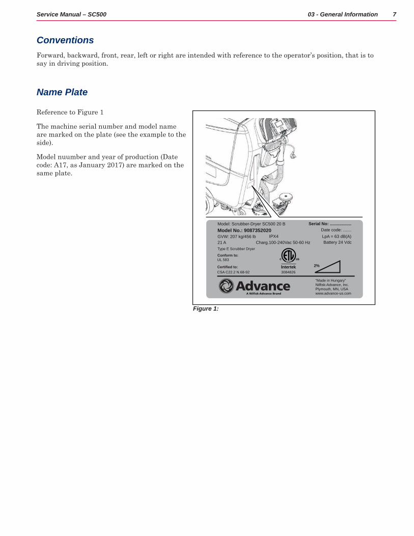
Reference to Figure 1
The machine serial number and model name are marked on the plate (see the example to the side)
Model nuumber and year of production (Date code: A17, as January 2017) are marked on the same plate
Model: Scrubber-Dryer SC500 20 BModel No.: 9087352020GVW: 207 kg/456 lb
Battery 24 Vdc21 A Charg.100-240Vac 50-60 Hz Type E Scrubber Dryer
Serial No: ..................Date code: .......LpA = 63 dB(A)IPX4
2%
“Made in Hungary”Nilfisk-Advance, Inc.Plymouth, MN, USAwww.advance-us.com
UL 583
CSA C22.2 N.68-92
A Nilfisk-Advance Brand
3084826
Figure 1:
8Service Manual – SC500 03 - General Information
SafetyThe following symbols indicate potentially dangerous situations Always read this information carefully and take all necessary precautions to safeguard people and property
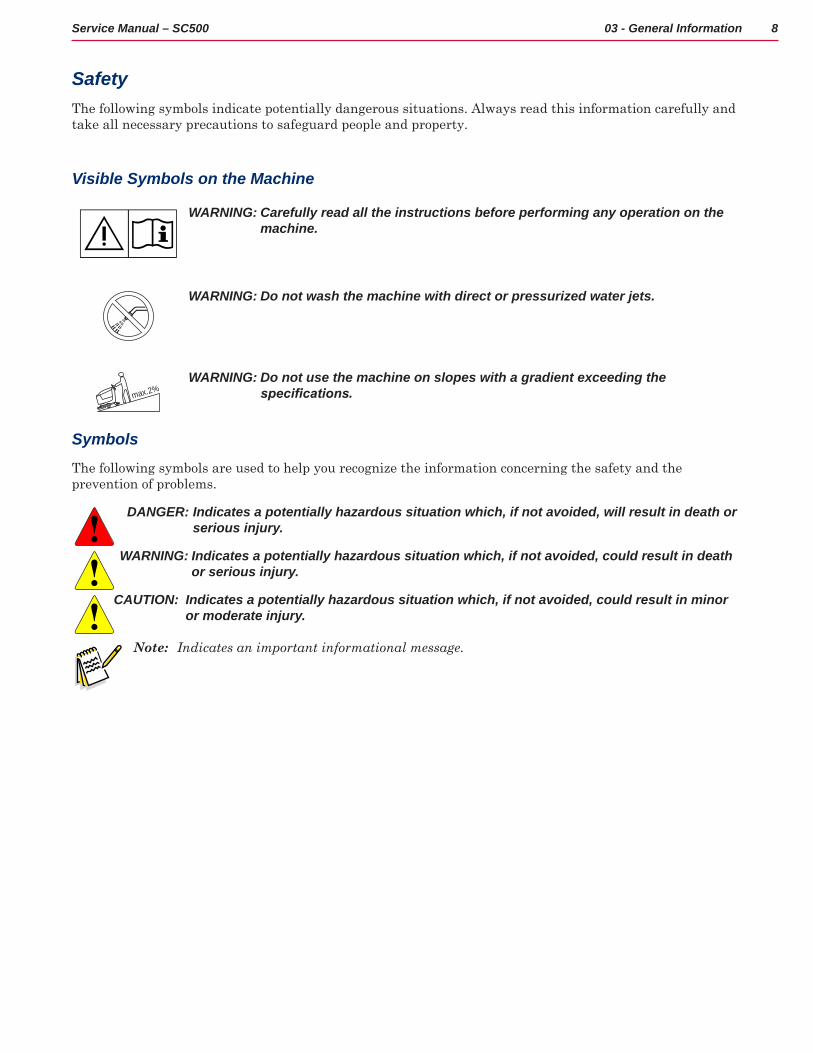
Visible Symbols on the Machine
WARNING: Carefully read all the instructions before performing any operation on the machine.
WARNING: Do not wash the machine with direct or pressurized water jets.
max.2%WARNING: Do not use the machine on slopes with a gradient exceeding the
specifications.
Symbols
The following symbols are used to help you recognize the information concerning the safety and the prevention of problems
DANGER: Indicates a potentially hazardous situation which, if not avoided, will result in death or serious injury.
WARNING: Indicates a potentially hazardous situation which, if not avoided, could result in death or serious injury.
CAUTION: Indicates a potentially hazardous situation which, if not avoided, could result in minor or moderate injury.
Note: Indicates an important informational message.
9Service Manual – SC500 03 - General Information
General Safety Instructions
Specific warnings and cautions to inform about potential damages to people and machine are shown below.
DANGER: Before performing any maintenance, repair, cleaning or replacement procedure, remove the ignition key and disconnect the battery connector).
− This machine must be used by properly trained operators only.
− Do not wear jewels when working near electrical components.
− Do not work under the lifted machine without supporting it with safety stands.
− Do not operate the machine near toxic, dangerous, flammable and/or explosive powders, liquids or vapors: This machine is not suitable for collecting dangerous powders.
− When using lead (WET) batteries, keep sparks, flames and smoking materials away from the batteries. During the normal operation explosive gases are released.
− When using lead (WET) batteries, battery charging produces highly explosive hydrogen gas. During battery charging, lift the recovery tank and perform this procedure in well-ventilated areas and away from naked flames.
CAUTION: Carefully read all the instructions before performing any maintenance/repair procedure.
− The machine ignition key has a built-in magnet. Do not place objects having magnetic bands (such as credit cards, electronic keys, phone cards) near the key. The built-in magnet can damage or erase the data stored on the magnetic bands.
− Before using the battery charger, ensure that frequency and voltage values, indicated on the machine serial number plate, match the electrical mains voltage.
− Do not pull or carry the machine by the battery charger cable and never use the battery charger cable as a handle. Do not close a door on the battery charger cable, or pull the battery charger cable around sharp edges or corners. Do not run the machine on the battery charger cable.
− Keep the battery charger cable away from heated surfaces.
− Do not charge the batteries if the battery charger cable or the plug are damaged.
− To reduce the risk of fire, electric shock, or injury, do not leave the machine unattended when it is plugged in. Before performing any maintenance procedure, disconnect the battery charger cable from the electrical mains.
− Do not smoke while charging the batteries.
− To avoid any unauthorized use of the machine, remove the ignition key.
− Do not leave the machine unattended without being sure that it cannot move independently.
− Always protect the machine against the sun, rain and bad weather, both under operation and inactivity condition. Store the machine indoors, in a dry place: This machine must not be used or stored outdoors in wet conditions.
− Before using the machine, close all doors and/or covers as shown in the User Manual.
10Service Manual – SC500 03 - General Information
− This machine is not intended for use by persons (including children) with reduced physical, sensory or mental capabilities, or lack of experience and knowledge, unless they have been given supervision or instruction concerning use of the machine by a person responsible for they safety.
− Children should be supervised to ensure that they do not play with the machine.
− Close attention is necessary when used near children. Use only as shown in this Manual. Use only Nilfisk or Advance recommended accessories.
− Check the machine carefully before each use, always check that all the components have been properly assembled before use. If the machine is not perfectly assembled it can cause damages to people and properties.
− Take all necessary precautions to prevent hair, jewels and loose clothes from being caught by the machine moving parts.
− Do not use the machine on incline.
− Do not tilt the machine more than the angle indicated on the machine itself, in order to prevent instability.
− Do not use the machine in particularly dusty areas.
− Use the machine only where a proper lighting is provided.
− While using this machine, take care not to cause damage to people or objects.
− Do not bump into shelves or scaffoldings, especially where there is a risk of falling objects.
− Do not lean liquid containers on the machine, use the relevant can holder.
− The machine operating temperature must be between 32°F and 104°F (0°C and +40°C).
− The machine storage temperature must be between 32°F and 104°F (0°C and +40°C).
− The humidity must be between 30% and 95%.
− When using floor cleaning detergents, follow the instructions on the labels of the detergent bottles.
− To handle floor cleaning detergents, wear suitable gloves and protections.
− Do not use the machine as a means of transport.
− Do not allow the brush/pad to operate while the machine is stationary to avoid damaging the floor.
− In case of fire, use a powder fire extinguisher, not a water one.
− Do not tamper with the machine safety guards and follow the ordinary maintenance instructions scrupulously.
− Do not allow any object to enter into the openings. Do not use the machine if the openings are clogged. Always keep the openings free from dust, hairs and any other foreign material which could reduce the air flow.
− Do not remove or modify the plates affixed to the machine.
− When the machine is to be pushed for service reasons (missing or discharged batteries, etc.), the speed must not exceed 2.5 mi/h (4 km/h).
11Service Manual – SC500 03 - General Information
− This machine cannot be used on roads or public streets.
− Pay attention during machine transportation when temperature is below freezing point. The water in the recovery tank or in the hoses could freeze and seriously damage the machine.
− Use brushes and pads supplied with the machine or those specified in the User Manual. Using other brushes or pads could reduce safety.
− In case of machine malfunctions, ensure that these are not due to lack of maintenance. If necessary, request assistance from the authorised personnel or from an authorised Service Center.
− If parts must be replaced, require ORIGINAL spare parts from an Authorised Dealer or Retailer.
− To ensure machine proper and safe operation, the scheduled maintenance shown in the relevant chapter of this Manual, must be performed by the authorised personnel or by an authorised Service Center.
− Do not wash the machine with direct or pressurised water jets, or with corrosive substances.
− The machine must be disposed of properly, because of the presence of toxic-harmful materials (batteries, etc.), which are subject to standards that require disposal in special centres.
Lithium-Ion Battery Module Safety Instructions
Specific warnings and cautions to inform about potential damages to people and machine are shown below.
DANGER: Before performing any maintenance, repair, cleaning or replacement procedure on the cleaning machine turn of the battery pack by taking off the reader key and disconnect the battery pack using the large power connector.
− Do not wear jewelry when working near electrical components.
− Read all safety warnings and all instructions. Failure to follow the warnings and instructions may result in electrical shock, fire and/or serious injury.
CAUTION: Carefully read all the instructions before performing any maintenance/repair procedure.
− Do not use any other type of batteries; only use the one supplied with the machine or its original spare part.
− Before each use, check if it’s damaged.
− Do not soak in liquids.
− Recharge only with the charger specified by the manufacturer. A charger that is suitable for one type of battery pack may create a risk of fire when used with another battery pack.
− Under abusive conditions, liquid may be ejected from the battery; avoid contact. If contact accidentally occurs, flush with water. lf liquid contacts eyes, additionally seek medical help. Liquid ejected from the battery may cause irritation or burns.
− When battery pack is not in use, keep it away from other metal objects, like paper clips, coins, keys, nails, screws or other small metal objects that can make a connection from one terminal to another. Shorting the battery terminals together may cause burns or a fire.
12Service Manual – SC500 03 - General Information
− Do not use a battery pack or appliance that is damaged or modified. Damaged or modified batteries may exhibit unpredictable behavior resulting in fire, explosion or risk of injury. Follow all charging instructions and do not charge the battery pack or appliance outside of the temperature range specified in the instructions. Charging improperly or at temperatures outside of the specified range may damage the battery and increase the risk of fire.
− Do not expose a battery pack or appliance to fire or excessive temperature. Exposure to fire or temperature above 130°C may cause explosion.
− Have servicing performed by a qualified repair person using only identical replacement parts. This will ensure that the safety of the product is maintained.
− Do not modify or attempt to repair the the battery pack.
− Do not store, use or recharge in environments with a temperature higher than 45°C.
− Do not recharge with temperatures lower than 0°C.
− Due to the risk of short-circuit, do not store the battery with metal objects.
− If the battery is damaged, take it to a Nilfisk Service Centre.
− Before decommissioning the machine, remove the battery.
− Store the battery charger in a dry place.
− If the battery charger or the cable are wet, do not use it.
− Do not use the battery charger in environments where there are flammable powders and/or explosive materials.
− Only handle the loose battery charger by its lifting handle.
− Do not cover the battery charger.
− Always use the battery charger supplied with the machine or the original spare part.
− Disconnect the battery pack from the appliance before making any adjustments, changing accessories, or storing appliance. Such preventive safety measures reduce the risk of starting the appliance accidentally.
− Use appliances only with specifically designated battery packs. Use of any other battery packs may create a risk of injury and fire.
− Keep the battery pack, including the ventilation channels and contact areas clean from dirt and moisture. Avoid that dirt and moisture is getting inside the battery pack during cleaning.
13Service Manual – SC500 03 - General Information
Lifting The MachineWARNING: Do not work under the lifted machine without supporting it with safety stands.
Transporting The MachineWARNING: Before transporting the machine, make sure that:
− All covers are closed.
− The recovery tank and the detergent tank are empty.
− The batteries are disconnected.
− The ignition key is removed.
− The machine is securely fastened to the means of transport.
14Service Manual – SC500 03 - General Information
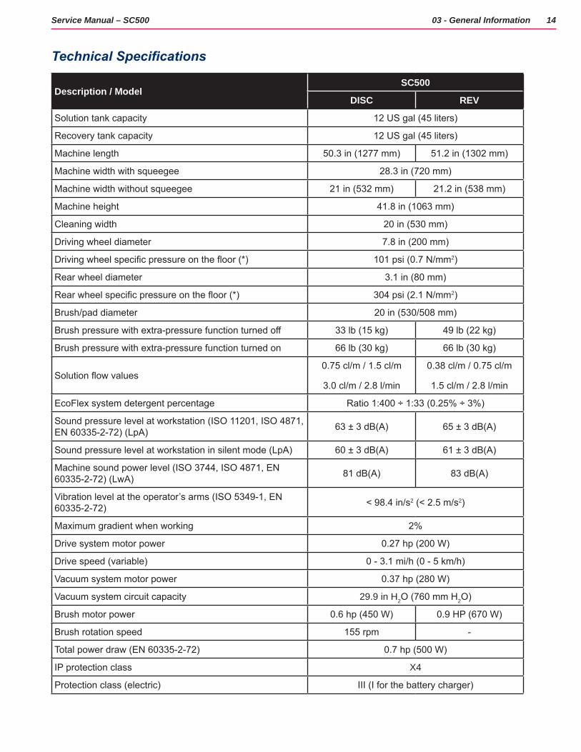
Technical Specifications
Description / ModelSC500
DISC REV
Solution tank capacity 12 US gal (45 liters)
Recovery tank capacity 12 US gal (45 liters)
Machine length 50.3 in (1277 mm) 51.2 in (1302 mm)
Machine width with squeegee 28.3 in (720 mm)
Machine width without squeegee 21 in (532 mm) 21.2 in (538 mm)
Machine height 41.8 in (1063 mm)
Cleaning width 20 in (530 mm)
Driving wheel diameter 7.8 in (200 mm)
Driving wheel specific pressure on the floor (*) 101 psi (0.7 N/mm2)
Rear wheel diameter 3.1 in (80 mm)
Rear wheel specific pressure on the floor (*) 304 psi (2.1 N/mm2)
Brush/pad diameter 20 in (530/508 mm)
Brush pressure with extra-pressure function turned off 33 lb (15 kg) 49 lb (22 kg)
Brush pressure with extra-pressure function turned on 66 lb (30 kg) 66 lb (30 kg)
Solution flow values0.75 cl/m / 1.5 cl/m
3.0 cl/m / 2.8 l/min
0.38 cl/m / 0.75 cl/m
1.5 cl/m / 2.8 l/min
EcoFlex system detergent percentage Ratio 1:400 ÷ 1:33 (0.25% ÷ 3%)
Sound pressure level at workstation (ISO 11201, ISO 4871, EN 60335-2-72) (LpA) 63 ± 3 dB(A) 65 ± 3 dB(A)
Sound pressure level at workstation in silent mode (LpA) 60 ± 3 dB(A) 61 ± 3 dB(A)
Machine sound power level (ISO 3744, ISO 4871, EN 60335-2-72) (LwA) 81 dB(A) 83 dB(A)
Vibration level at the operator’s arms (ISO 5349-1, EN 60335-2-72) < 98.4 in/s2 (< 2.5 m/s2)
Maximum gradient when working 2%
Drive system motor power 0.27 hp (200 W)
Drive speed (variable) 0 - 3.1 mi/h (0 - 5 km/h)
Vacuum system motor power 0.37 hp (280 W)
Vacuum system circuit capacity 29.9 in H2O (760 mm H2O)
Brush motor power 0.6 hp (450 W) 0.9 HP (670 W)
Brush rotation speed 155 rpm -
Total power draw (EN 60335-2-72) 0.7 hp (500 W)
IP protection class X4
Protection class (electric) III (I for the battery charger)
15Service Manual – SC500 03 - General Information
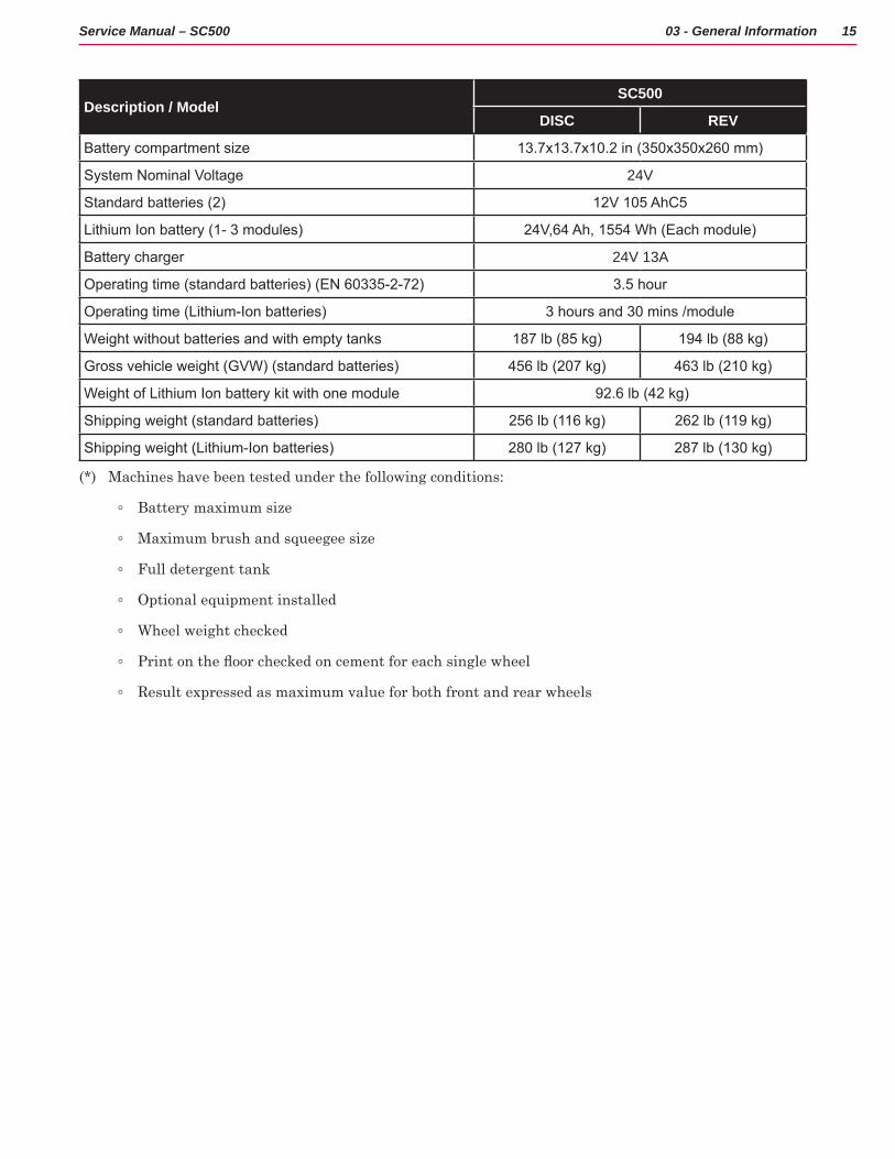
Description / ModelSC500
DISC REV
Battery compartment size 13.7x13.7x10.2 in (350x350x260 mm)
System Nominal Voltage 24V
Standard batteries (2) 12V 105 AhC5
Lithium Ion battery (1- 3 modules) 24V,64 Ah, 1554 Wh (Each module)
Battery charger 24V 13A
Operating time (standard batteries) (EN 60335-2-72) 3.5 hour
Operating time (Lithium-Ion batteries) 3 hours and 30 mins /module
Weight without batteries and with empty tanks 187 lb (85 kg) 194 lb (88 kg)
Gross vehicle weight (GVW) (standard batteries) 456 lb (207 kg) 463 lb (210 kg)
Weight of Lithium Ion battery kit with one module 92.6 lb (42 kg)
Shipping weight (standard batteries) 256 lb (116 kg) 262 lb (119 kg)
Shipping weight (Lithium-Ion batteries) 280 lb (127 kg) 287 lb (130 kg)
(*) Machines have been tested under the following conditions:
◦ Battery maximum size
◦ Maximum brush and squeegee size
◦ Full detergent tank
◦ Optional equipment installed
◦ Wheel weight checked
◦ Print on the floor checked on cement for each single wheel
◦ Result expressed as maximum value for both front and rear wheels
16Service Manual – SC500 03 - General Information
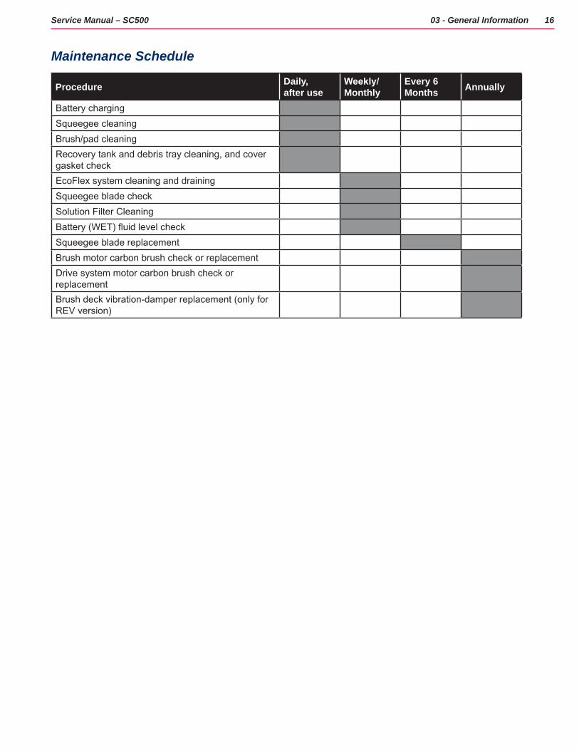
Maintenance Schedule
Procedure Daily, after use
Weekly/Monthly
Every 6 Months Annually
Battery chargingSqueegee cleaningBrush/pad cleaningRecovery tank and debris tray cleaning, and cover gasket checkEcoFlex system cleaning and drainingSqueegee blade checkSolution Filter CleaningBattery (WET) fluid level checkSqueegee blade replacementBrush motor carbon brush check or replacementDrive system motor carbon brush check or replacementBrush deck vibration-damper replacement (only for REV version)
17Service Manual – SC500 03 - General Information
Know Your Machine
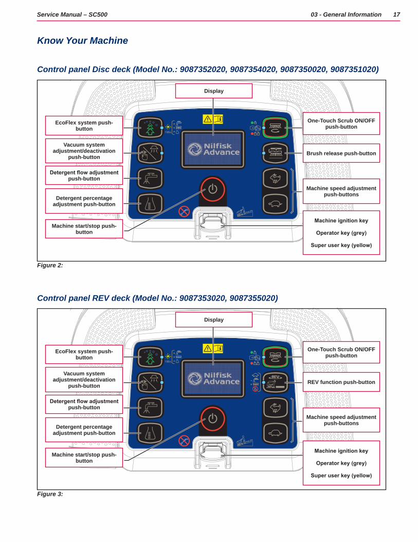
Control panel Disc deck (Model No.: 9087352020, 9087354020, 9087350020, 9087351020)
max.2%
1s
EcoFlex system push-button
Display
Vacuum system adjustment/deactivation
push-button
One-Touch Scrub ON/OFF push-button
Detergent flow adjustment push-button
Brush release push-button
Detergent percentage adjustment push-button
Machine speed adjustment push-buttons
Machine start/stop push-button
Machine ignition key
Operator key (grey)
Super user key (yellow)
Figure 2:
Control panel REV deck (Model No.: 9087353020, 9087355020)
max.2%
1s
EcoFlex system push-button
Display
Vacuum system adjustment/deactivation
push-button
One-Touch Scrub ON/OFF push-button
Detergent flow adjustment push-button
REV function push-button
Detergent percentage adjustment push-button
Machine speed adjustment push-buttons
Machine start/stop push-button
Machine ignition key
Operator key (grey)
Super user key (yellow)
Figure 3:
18Service Manual – SC500 03 - General Information
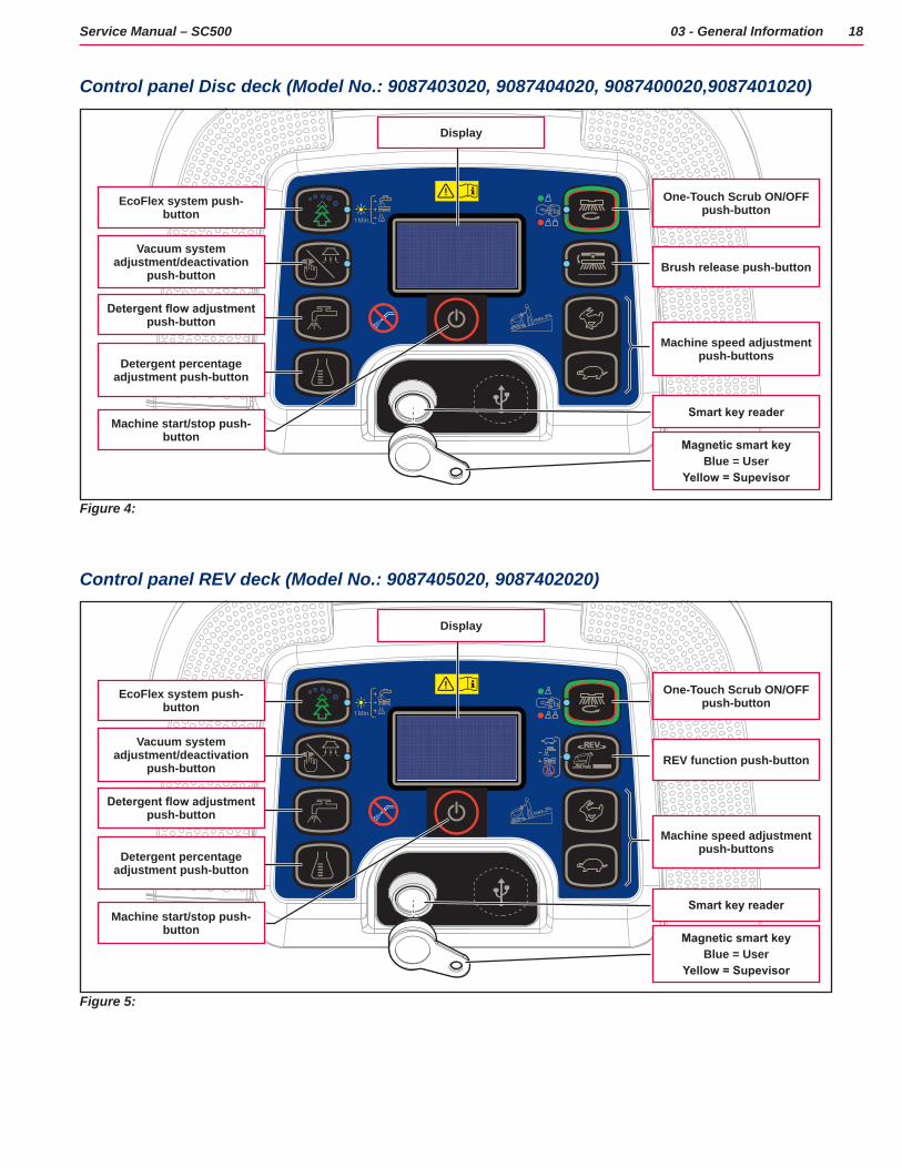
Control panel Disc deck (Model No.: 9087403020, 9087404020, 9087400020,9087401020)
max.2%
1sEcoFlex system push-
button
Display
Vacuum system adjustment/deactivation
push-button
One-Touch Scrub ON/OFF push-button
Detergent flow adjustment push-button
Brush release push-button
Detergent percentage adjustment push-button
Machine speed adjustment push-buttons
Machine start/stop push-button
Smart key reader
Magnetic smart keyBlue = User
Yellow = Supevisor
Figure 4:
Control panel REV deck (Model No.: 9087405020, 9087402020)
max.2%
1sEcoFlex system push-
button
Display
Vacuum system adjustment/deactivation
push-button
One-Touch Scrub ON/OFF push-button
Detergent flow adjustment push-button
REV function push-button
Detergent percentage adjustment push-button
Machine speed adjustment push-buttons
Machine start/stop push-button
Smart key reader
Magnetic smart keyBlue = User
Yellow = Supevisor
Figure 5:
19Service Manual – SC500 03 - General Information
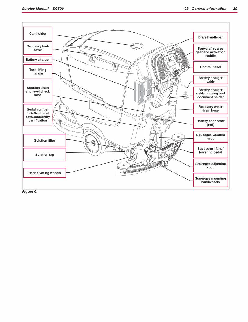
Battery charger
Recovery tank cover
Can holderDrive handlebar
Forward/reverse gear and activation
paddle
Control panel
Battery charger cable
Battery charger cable housing and document holder
Recovery water drain hose
Battery connector (red)
Squeegee vacuum hose
Squeegee lifting/lowering pedal
Squeegee adjusting knob
Squeegee mounting handwheels
Solution drain and level check
hose
Tank lifting handle
Serial number plate/technical data/conformity
certification
Solution filter
Solution tap
Rear pivoting wheels
Figure 6:
20Service Manual – SC500 03 - General Information
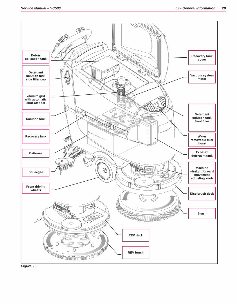
Debris collection tank
Detergent solution tank side filler cap
Recovery tank cover
Vacuum grid with automatic shut-off float
Vacuum system motor
Solution tank
Recovery tank
Detergent solution tank
front filler
Batteries
Water removable filler
hose
Squeegee
EcoFlex detergent tank
Disc brush deck
REV deck
Front driving wheels
Machine straight forward
movement adjusting knob
Brush
REV brush
Figure 7:
21Service Manual – SC500 03 - General Information
Service and Diagnostic EquipmentBesides a complete set of standard meters, the following instruments are necessary to perform fast checks and repairs on Nilfisk machines:
• Laptop computer charged with the current version of EzParts, Adobe Reader and (if possible) Internet connection
• Digital Volt Meter (DVM)
• Amp clamp with possibility of making DC measurements
• Hydrometer
• Battery charge tester to check 12V batteries
• Static control wrist strap
• Dynamometric wrench set
• A copy of the Instructions for Use Manual and Spare Parts List of the machine to be serviced (provided with the machine or available at www.advance-us.com or other Nilfisk websites).
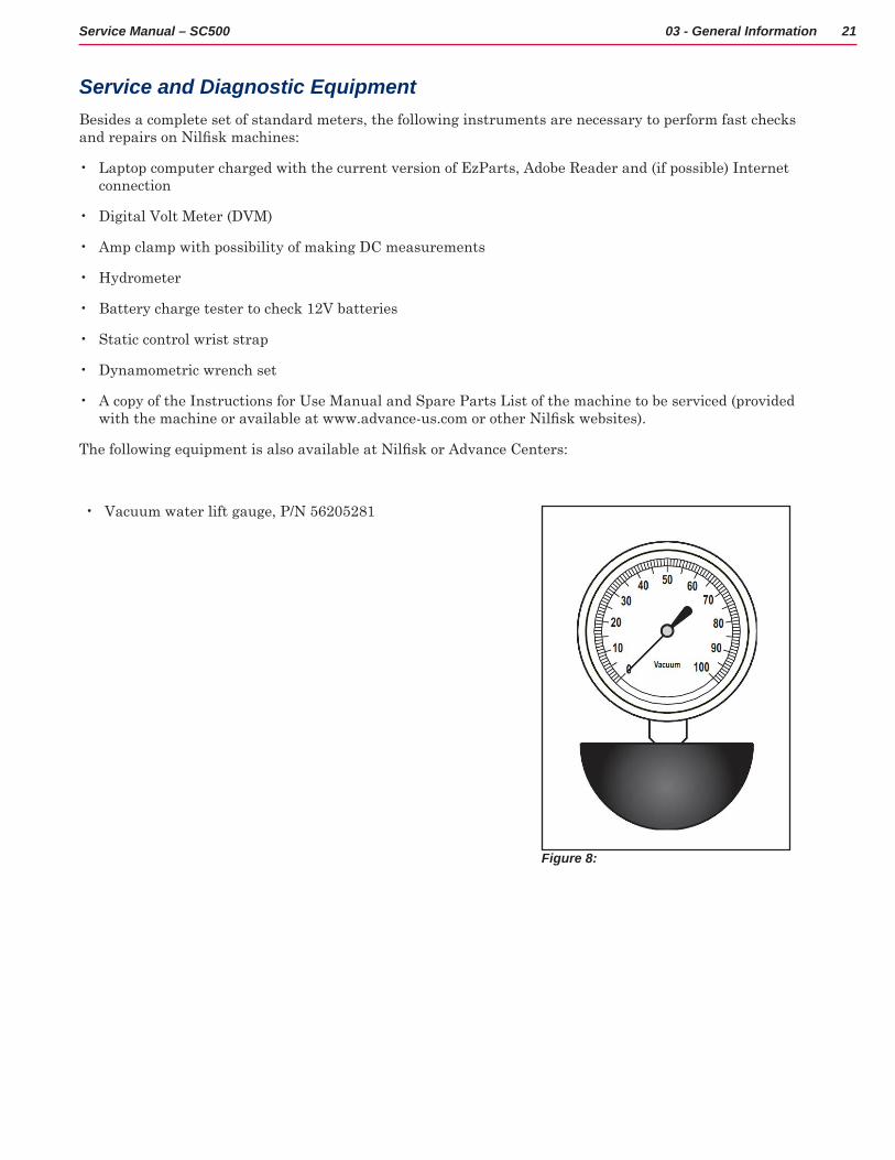
The following equipment is also available at Nilfisk or Advance Centers:
• Vacuum water lift gauge, P/N 56205281
Figure 8:
22Service Manual – SC500 03 - General Information
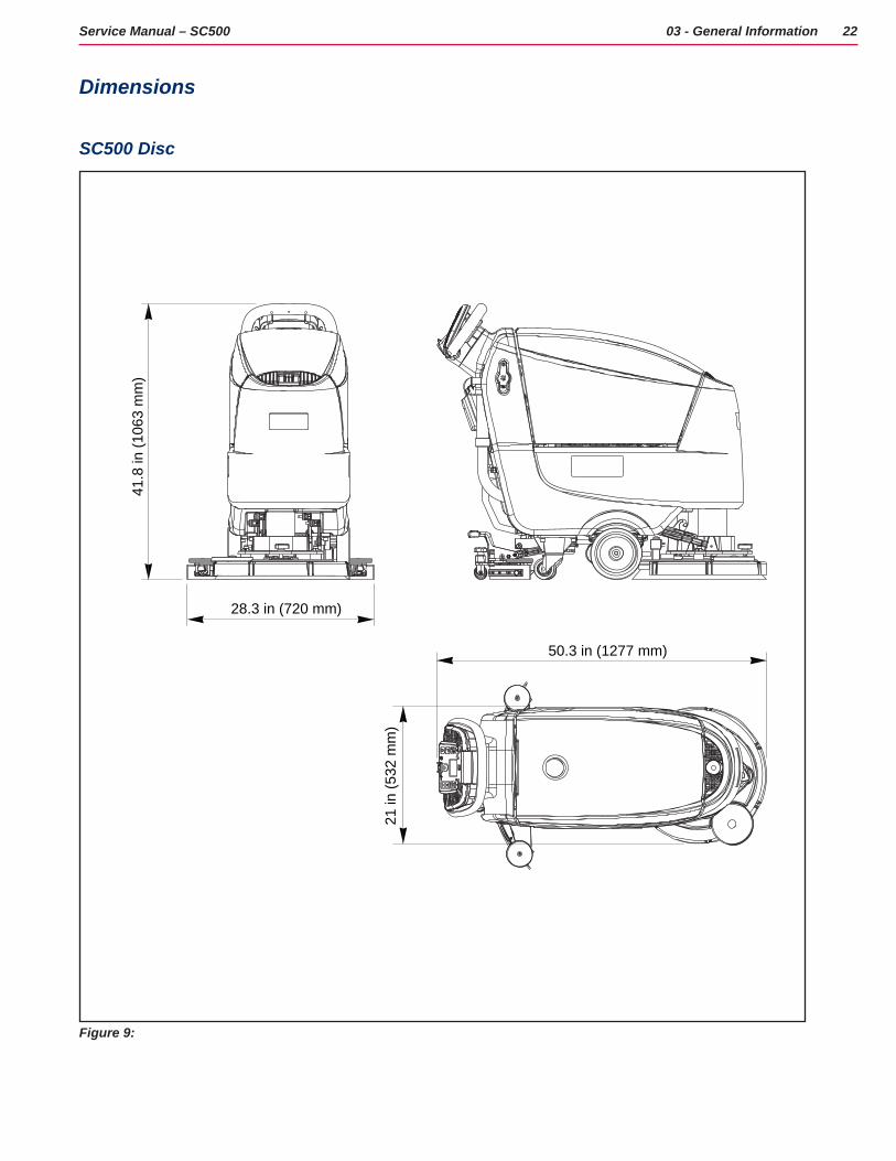
Dimensions
SC500 Disc
50.3 in (1277 mm)
28.3 in (720 mm)
41.8
in (1
063
mm
)
21 in
(532
mm
)
Figure 9:
23Service Manual – SC500 03 - General Information
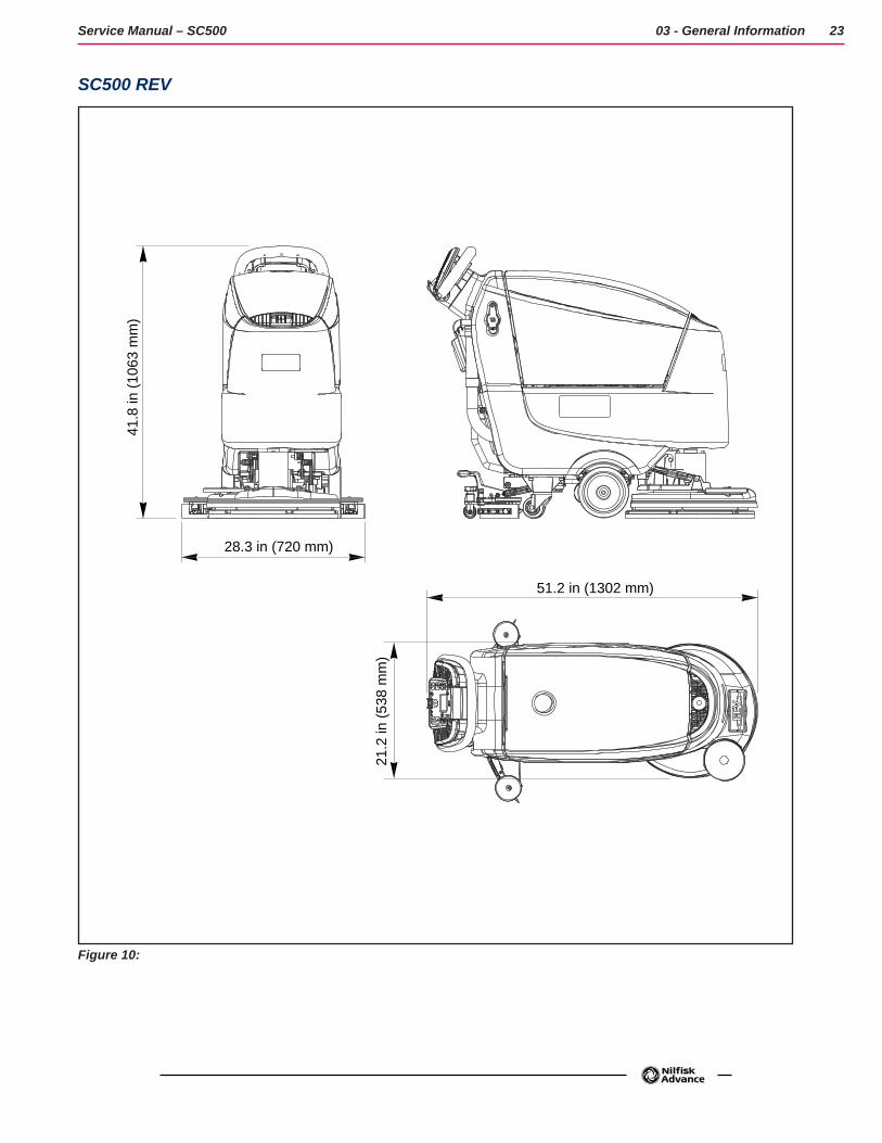
SC500 REV
51.2 in (1302 mm)
28.3 in (720 mm)
41.8
in (1
063
mm
)
21.2
in (5
38 m
m)
Figure 10:
24Service Manual – SC500
04 - Control System - models with key slot
Model No.: 9087352020, 9087354020, 9087350020, 9087351020, 9087353020, 9087355020
Functional Description
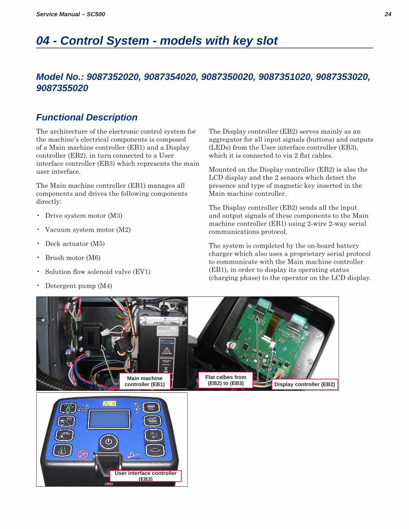
Main machine controller (EB1) Display controller (EB2)
Flat calbes from (EB2) to (EB3)
User interface controller (EB3)
The architecture of the electronic control system for the machine’s electrical components is composed of a Main machine controller (EB1) and a Display controller (EB2), in turn connected to a User interface controller (EB3) which represents the main user interface
The Main machine controller (EB1) manages all components and drives the following components directly:
• Drive system motor (M3)
• Vacuum system motor (M2)
• Deck actuator (M5)
• Brush motor (M6)
• Solution flow solenoid valve (EV1)
• Detergent pump (M4)
The Display controller (EB2) serves mainly as an aggregator for all input signals (buttons) and outputs (LEDs) from the User interface controller (EB3), which it is connected to via 2 flat cables.
Mounted on the Display controller (EB2) is also the LCD display and the 2 sensors which detect the presence and type of magnetic key inserted in the Main machine controller
The Display controller (EB2) sends all the input and output signals of these components to the Main machine controller (EB1) using 2-wire 2-way serial communications protocol
The system is completed by the on-board battery charger which also uses a proprietary serial protocol to communicate with the Main machine controller (EB1), in order to display its operating status (charging phase) to the operator on the LCD display
25Service Manual – SC500 04 - Control System - models with key slot
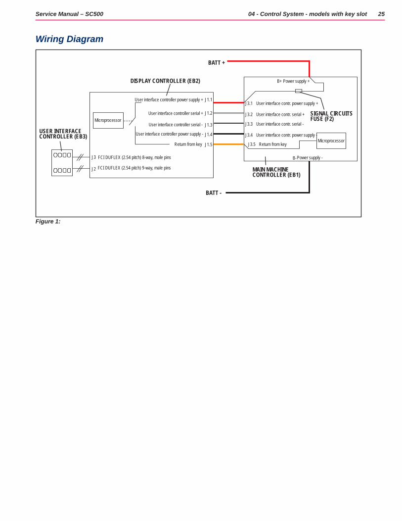
Wiring Diagram
J1.5
J1.4
J1.3
J1.2
J1.1
J3
J2
J3.1
J3.2
J3.3
J3.4
J3.5
User interface contr. power supply +
User interface contr. serial +
User interface contr. serial -
User interface contr. power supply -
Return from key
FCI DUFLEX (2.54 pitch) 8-way, male pins
FCI DUFLEX (2.54 pitch) 9-way, male pins
User interface controller power supply +
User interface controller serial +
User interface controller serial -
User interface controller power supply -
Return from key
B-
B+DISPLAY CONTROLLER (EB2)
BATT +
BATT -
Microprocessor
Microprocessor
SIGNAL CIRCUITSFUSE (F2)
MAIN MACHINECONTROLLER (EB1)
USER INTERFACE CONTROLLER (EB3)
Power supply +
Power supply -
Figure 1:
26Service Manual – SC500 04 - Control System - models with key slot
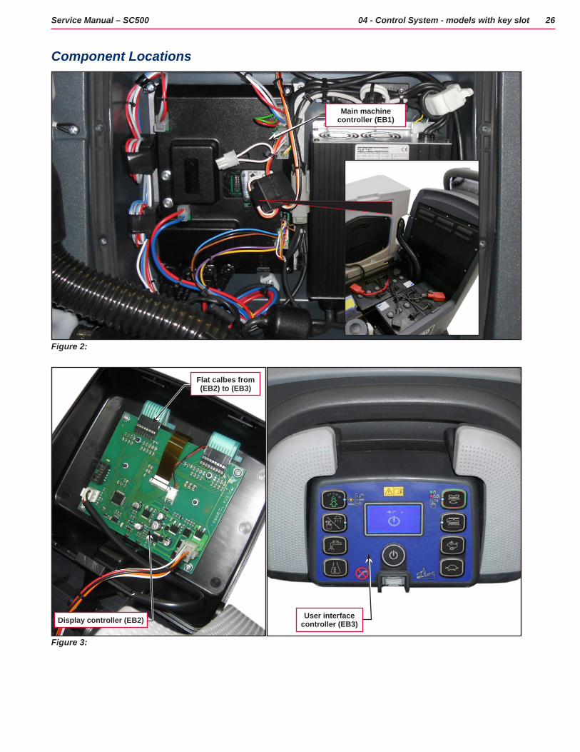
Component Locations
Figure 2:
Main machine controller (EB1)
Figure 3:
Flat calbes from (EB2) to (EB3)
User interface controller (EB3)Display controller (EB2)
27Service Manual – SC500 04 - Control System - models with key slot
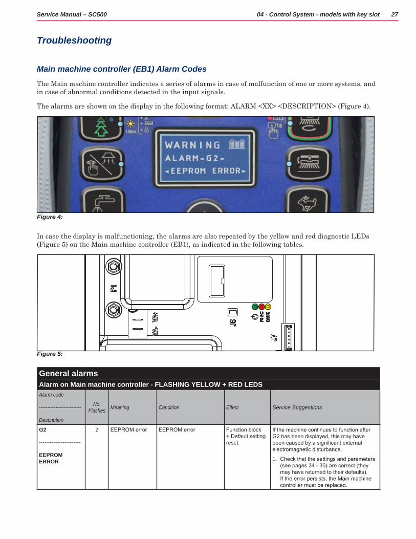
Troubleshooting
Main machine controller (EB1) Alarm Codes
The Main machine controller indicates a series of alarms in case of malfunction of one or more systems, and in case of abnormal conditions detected in the input signals
The alarms are shown on the display in the following format: ALARM <XX> <DESCRIPTION> (Figure 4)
Figure 4:
In case the display is malfunctioning, the alarms are also repeated by the yellow and red diagnostic LEDs (Figure 5) on the Main machine controller (EB1), as indicated in the following tables
Figure 5:
General alarmsAlarm on Main machine controller - FLASHING YELLOW + RED LEDSAlarm code
--------------------------
Description
No. Flashes Meaning Condition Effect Service Suggestions
G2
-----------------------
EEPROM ERROR
2 EEPROM error EEPROM error Function block + Default setting reset
If the machine continues to function after G2 has been displayed, this may have been caused by a significant external electromagnetic disturbance.
1. Check that the settings and parameters (see pages 34 - 35) are correct (they may have returned to their defaults). If the error persists, the Main machine controller must be replaced.
28Service Manual – SC500 04 - Control System - models with key slot
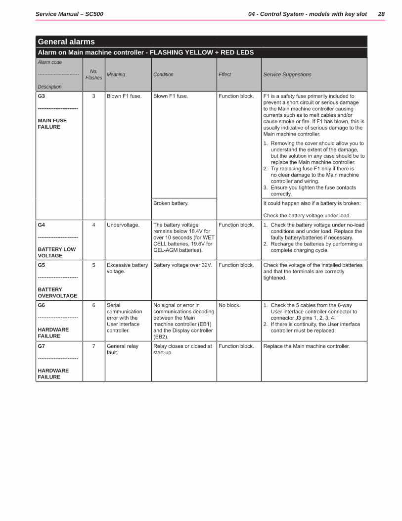
General alarmsAlarm on Main machine controller - FLASHING YELLOW + RED LEDSAlarm code
--------------------------
Description
No. Flashes Meaning Condition Effect Service Suggestions
G3
-----------------------
MAIN FUSE FAILURE
3 Blown F1 fuse. Blown F1 fuse. Function block. F1 is a safety fuse primarily included to prevent a short circuit or serious damage to the Main machine controller causing currents such as to melt cables and/or cause smoke or fire. If F1 has blown, this is usually indicative of serious damage to the Main machine controller.
1. Removing the cover should allow you to understand the extent of the damage, but the solution in any case should be to replace the Main machine controller.
2. Try replacing fuse F1 only if there is no clear damage to the Main machine controller and wiring.
3. Ensure you tighten the fuse contacts correctly.
Broken battery. It could happen also if a battery is broken:
Check the battery voltage under load.
G4
-----------------------
BATTERY LOW VOLTAGE
4 Undervoltage. The battery voltage remains below 18.4V for over 10 seconds (for WET CELL batteries, 19.6V for GEL-AGM batteries).
Function block. 1. Check the battery voltage under no-load conditions and under load. Replace the faulty battery/batteries if necessary.
2. Recharge the batteries by performing a complete charging cycle.
G5
-----------------------
BATTERY OVERVOLTAGE
5 Excessive battery voltage.
Battery voltage over 32V. Function block. Check the voltage of the installed batteries and that the terminals are correctly tightened.
G6
-----------------------
HARDWARE FAILURE
6 Serial communication error with the User interface controller.
No signal or error in communications decoding between the Main machine controller (EB1) and the Display controller (EB2).
No block. 1. Check the 5 cables from the 6-way User interface controller connector to connector J3 pins 1, 2, 3, 4.
2. If there is continuity, the User interface controller must be replaced.
G7
-----------------------
HARDWARE FAILURE
7 General relay fault.
Relay closes or closed at start-up.
Function block. Replace the Main machine controller.
29Service Manual – SC500 04 - Control System - models with key slot
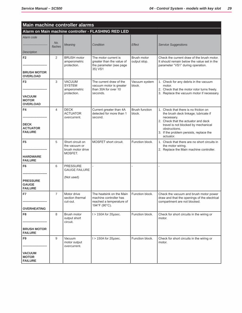
Main machine controller alarmsAlarm on Main machine controller - FLASHING RED LEDAlarm code
--------------------------
Description
No. flashes Meaning Condition Effect Service Suggestions
F2
-----------------------
BRUSH MOTOR OVERLOAD
2 BRUSH motor amperometric protection.
The motor current is greater than the value of the parameter (see page 35) VS1
Brush motor output stop.
Check the current draw of the brush motor. It should remain below the value set in the parameter “VS1” during operation.
F3
-----------------------
VACUUM MOTOR OVERLOAD
3 VACUUM SYSTEM amperometric protection.
The current draw of the vacuum motor is greater than 30A for over 10 seconds.
Vacuum system block.
1. Check for any debris in the vacuum motor.
2. Check that the motor rotor turns freely.3. Replace the vacuum motor if necessary.
F4
-----------------------
DECK ACTUATOR FAILURE
4 DECK ACTUATOR overcurrent.
Current greater than 4A detected for more than 1 second.
Brush function block.
1. Check that there is no friction on the brush deck linkage; lubricate if necessary.
2. Check that the actuator and deck travel is not blocked by mechanical obstructions.
3. If the problem persists, replace the actuator.
F5
-----------------------
HARDWARE FAILURE
5 Short circuit on the vacuum or brush motor drive MOSFET.
MOSFET short circuit. Function block. 1. Check that there are no short circuits in the motor wiring.
2. Replace the Main machine controller.
F6
-----------------------
PRESSURE GAUGE FAILURE
6 PRESSURE GAUGE FAILURE
(Not used)
- - -
F7
-----------------------
OVERHEATING
7 Motor drive section thermal cut-out.
The heatsink on the Main machine controller has reached a temperature of 194°F (90°C).
Function block. Check the vacuum and brush motor power draw and that the openings of the electrical compartment are not blocked.
F8
-----------------------
BRUSH MOTOR FAILURE
8 Brush motor output short circuit.
I > 150A for 20µsec. Function block. Check for short circuits in the wiring or motor.
F9
-----------------------
VACUUM MOTOR FAILURE
9 Vacuum motor output overcurrent.
I > 150A for 20µsec. Function block. Check for short circuits in the wiring or motor.
30Service Manual – SC500 04 - Control System - models with key slot
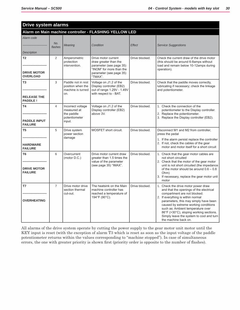
Drive system alarmsAlarm on Main machine controller - FLASHING YELLOW LEDAlarm code
--------------------------
Description
No. flashes Meaning Condition Effect Service Suggestions
T2
-----------------------
DRIVE MOTOR OVERLOAD
2 Amperometric protection intervention.
Drive motor current draw greater than the parameter (see page 35) “INOM” for more than the parameter (see page 35) “TMAX”.
Drive blocked. Check the current draw of the drive motor (this should be around 6-8amps without load and remain below 10-12amps during operation).
T3
-----------------------
RELEASE THE PADDLE !
3 Paddle not in rest position when the machine is turned on.
Voltage on J1.2 of the Display controller (EB2) out of range 1.29V - 1.49V with respect to - BAT.
Drive blocked. Check that the paddle moves correctly, lubricating if necessary; check the linkage and potentiometer.
T4
-----------------------
PADDLE INPUT FAILURE
4 Incorrect voltage measured at the paddle potentiometer input.
Voltage on J1.2 of the Display controller (EB2) above 3V.
Drive blocked. 1. Check the connection of the potentiometer to the Display controller.
2. Replace the potentiometer. 3. Replace the Display controller (EB2).
T5
-----------------------
HARDWARE FAILURE
5 Drive system power section damage
MOSFET short circuit. Drive blocked. Disconnect M1 and M2 from controller, press the pedal
1. If the alarm persist replace the controller2. If not, check the cables of the gear
motor and motor itself for a short circuit
T6
-----------------------
DRIVE MOTOR FAILURE
6 Overcurrent (motor D.C.)
Drive motor current draw greater than 1.5 times the value of the parameter (see page 35) “IMAX”.
Drive blocked. 1. Check that the gear motor cables are not short circuited
2. Check that the motor of the gear motor unit is not short circuited (the impedance of the motor should be around 0.6 – 0.8 Ohm)
3. If necessary, replace the gear motor unit motor
T7
-----------------------
OVERHEATING
7 Drive motor drive section thermal cut-out.
The heatsink on the Main machine controller has reached a temperature of 194°F (90°C).
Drive blocked. 1. Check the drive motor power draw and that the openings of the electrical compartment are not blocked.
2. If everything is within normal parameters, this may simply have been caused by extreme working conditions such as: Ambient temperature over 86°F (>30°C), sloping working sections. Simply leave the system to cool and turn the machine back on.
All alarms of the drive system operate by cutting the power supply to the gear motor unit motor until the KEY input is reset (with the exception of alarm T3 which is reset as soon as the input voltage of the paddle potentiometer returns within the values corresponding to “machine stopped”) In case of simultaneous errors, the one with greater priority is shown first (priority order is opposite to the number of flashes).
31Service Manual – SC500 04 - Control System - models with key slot
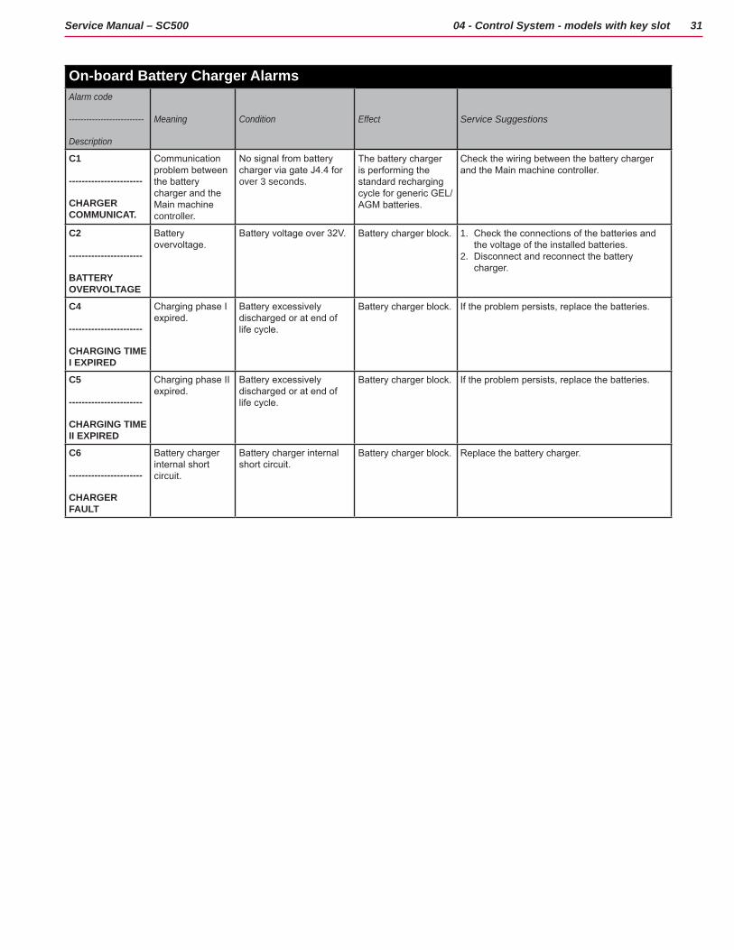
On-board Battery Charger AlarmsAlarm code
--------------------------
Description
Meaning Condition Effect Service Suggestions
C1
-----------------------
CHARGER COMMUNICAT.
Communication problem between the battery charger and the Main machine controller.
No signal from battery charger via gate J4.4 for over 3 seconds.
The battery charger is performing the standard recharging cycle for generic GEL/AGM batteries.
Check the wiring between the battery charger and the Main machine controller.
C2
-----------------------
BATTERY OVERVOLTAGE
Battery overvoltage.
Battery voltage over 32V. Battery charger block. 1. Check the connections of the batteries and the voltage of the installed batteries.
2. Disconnect and reconnect the battery charger.
C4
-----------------------
CHARGING TIME I EXPIRED
Charging phase I expired.
Battery excessively discharged or at end of life cycle.
Battery charger block. If the problem persists, replace the batteries.
C5
-----------------------
CHARGING TIME II EXPIRED
Charging phase II expired.
Battery excessively discharged or at end of life cycle.
Battery charger block. If the problem persists, replace the batteries.
C6
-----------------------
CHARGER FAULT
Battery charger internal short circuit.
Battery charger internal short circuit.
Battery charger block. Replace the battery charger.
32Service Manual – SC500 04 - Control System - models with key slot
Black-box: Recording of Alarms, Parameters (see pages 34-35), Partial Operating Time Counter
The alarms activated during normal machine operation are stored and can be read in the corresponding log (Alarm Log Screen)
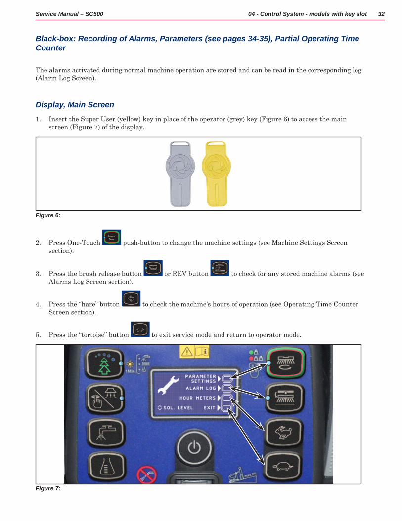
Display, Main Screen
1 Insert the Super User (yellow) key in place of the operator (grey) key (Figure 6) to access the main screen (Figure 7) of the display
Figure 6:
2 Press One-Touch push-button to change the machine settings (see Machine Settings Screen section)
3 Press the brush release button or REV button to check for any stored machine alarms (see Alarms Log Screen section)
4 Press the “hare” button to check the machine’s hours of operation (see Operating Time Counter Screen section)
5 Press the “tortoise” button to exit service mode and return to operator mode
Figure 7:

33Service Manual – SC500 04 - Control System - models with key slot
Display, Alarms Log Screen
The alarms log screen (Figure 8) function allows you to check any alarms stored on the machine
To return to the main screen (Figure 6), press the One-Touch button repeatedly
Figure 8:
Each alarm (See table of alarms in the Main machine controller Alarm Codes section) is stored along with the working hour (machine operating time counter) at which it occurred and all alarms are recorded in the order in which they occurred, from the most recent to the oldest
The memory holds up to 20 alarm records, after which the oldest are overwritten when new alarms occur
Improper uses of the batteries or battery charger are also recorded, as in the following table:
On-board Battery Charger AlarmsAlarm code
--------------------------
Description
Meaning Condition Effect
GB-N
-----------------------
CONTINUOUS LOW BATTERY VOLTAGE
Time of continuous use with discharged batteries
“N” is the number of hours from key on to off when the battery level is below 20.4V for WET CELL (21.6 for AGM) batteries. This event is not recorded if the usage time is below 10 minutes.
Incorrect use by customer. Risk of reduced battery life.
GC
-----------------------
CHARGER DISCONN BEFORE END CYCLE
Charging cycle interrupted before completion
Disconnection of battery charger before stage IV = battery symbol with 3 segments lit steadily.
Incorrect use by customer. Risk of reduced battery life.
GD-N
-----------------------
CHARGING TIME LESS THAN 4 HOURS
Charging phase duration
N = Number of hours from battery charger connection to completion of PHASE II (red LED on) if < 4
Incorrect use by customer. Risk of reduced battery life.
34Service Manual – SC500 04 - Control System - models with key slot
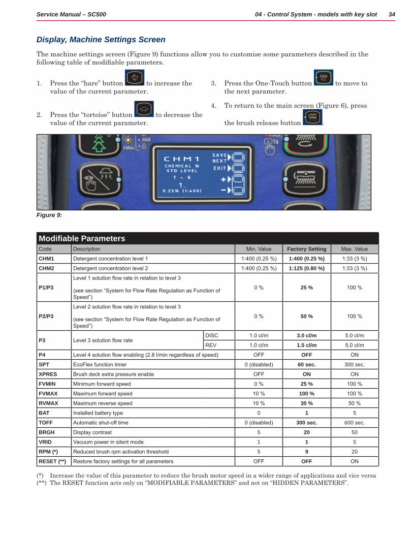
Display, Machine Settings Screen
The machine settings screen (Figure 9) functions allow you to customise some parameters described in the following table of modifiable parameters.
1 Press the “hare” button to increase the value of the current parameter
2 Press the “tortoise” button to decrease the value of the current parameter
3 Press the One-Touch button to move to the next parameter
4 To return to the main screen (Figure 6), press
the brush release button
Figure 9:
Modifiable ParametersCode Description Min. Value Factory Setting Max. Value
CHM1 Detergent concentration level 1 1:400 (0.25 %) 1:400 (0.25 %) 1:33 (3 %)
CHM2 Detergent concentration level 2 1:400 (0.25 %) 1:125 (0.80 %) 1:33 (3 %)
P1/P3Level 1 solution flow rate in relation to level 3
(see section “System for Flow Rate Regulation as Function of Speed”)
0 % 25 % 100 %
P2/P3Level 2 solution flow rate in relation to level 3
(see section “System for Flow Rate Regulation as Function of Speed”)
0 % 50 % 100 %
P3 Level 3 solution flow rateDISC 1.0 cl/m 3.0 cl/m 5.0 cl/m
REV 1.0 cl/m 1.5 cl/m 5.0 cl/m
P4 Level 4 solution flow enabling (2.8 l/min regardless of speed) OFF OFF ON
SPT EcoFlex function timer 0 (disabled) 60 sec. 300 sec.
XPRES Brush deck extra pressure enable OFF ON ON
FVMIN Minimum forward speed 0 % 25 % 100 %
FVMAX Maximum forward speed 10 % 100 % 100 %
RVMAX Maximum reverse speed 10 % 30 % 50 %
BAT Installed battery type 0 1 5
TOFF Automatic shut-off time 0 (disabled) 300 sec. 600 sec.
BRGH Display contrast 5 20 50
VRID Vacuum power in silent mode 1 1 5
RPM (*) Reduced brush rpm activation threshold 5 9 20
RESET (**) Restore factory settings for all parameters OFF OFF ON
(*) Increase the value of this parameter to reduce the brush motor speed in a wider range of applications and vice versa(**) The RESET function acts only on “MODIFIABLE PARAMETERS” and not on “HIDDEN PARAMETERS”
35Service Manual – SC500 04 - Control System - models with key slot
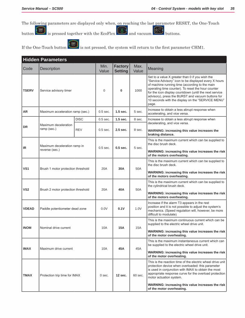
The following parameters are displayed only when, on reaching the last parameter RESET, the One-Touch
button is pressed together with the EcoFlex and vacuum buttons
If the One-Touch button is not pressed, the system will return to the first parameter CHM1.
Hidden Parameters
Code Description Min. Value
Factory Setting
Max. Value Meaning
TSERV Service advisory timer 0 0 1000
Set to a value X greater than 0 if you wish the “Service Advisory” icon to be displayed every X hours of machine running time (according to the main operating time counter). To reset the hour counter for the icon display countdown (until the next service advisory), press the BURST and vacuum buttons for 10 seconds with the display on the “SERVICE MENU” page.
AR Maximum acceleration ramp (sec.) 0.5 sec. 1.5 sec. 5 sec. Increase to obtain a less abrupt response when accelerating, and vice versa.
DR Maximum deceleration ramp (sec.)
DISC 0.5 sec. 1.5 sec. 8 sec. Increase to obtain a less abrupt response when decelerating, and vice versa.
WARNING: increasing this value increases the braking distance.
REV 0.5 sec. 2.5 sec. 8 sec.
IR Maximum deceleration ramp in reverse (sec.) 0.5 sec. 0.5 sec. 5 sec.
This is the maximum current which can be supplied to the disc brush deck.
WARNING: increasing this value increases the risk of the motors overheating.
VS1 Brush 1 motor protection threshold 20A 30A 50A
This is the maximum current which can be supplied to the disc brush deck.
WARNING: increasing this value increases the risk of the motors overheating.
VS2 Brush 2 motor protection threshold 20A 40A 50A
This is the maximum current which can be supplied to the cylindrical brush deck.
WARNING: increasing this value increases the risk of the motors overheating.
VDEAD Paddle potentiometer dead zone 0.0V 0.1V 1.0V
Increase if the alarm T3 appears in the rest position and it is not possible to adjust the system’s mechanics. (Speed regulation will, however, be more difficult to modulate)
INOM Nominal drive current 10A 15A 15A
This is the maximum continuous current which can be supplied to the electric wheel drive unit.
WARNING: increasing this value increases the risk of the motor overheating.
IMAX Maximum drive current 10A 45A 45A
This is the maximum instantaneous current which can be supplied to the electric wheel drive unit.
WARNING: increasing this value increases the risk of the motor overheating.
TMAX Protection trip time for IMAX 0 sec. 12 sec. 60 sec.
This is the reaction time of the electric wheel drive unit protection device when overloaded: this parameter is used in conjunction with IMAX to obtain the most appropriate response curve for the overload protection motor actuation system.
WARNING: increasing this value increases the risk of the motor overheating.

36Service Manual – SC500 04 - Control System - models with key slot
Display, Operating Time Counter Screen
The operating time counter screen (Figure 10) function allows you to check the total accumulated hours of work for each machine subsystem:
• (A) TOTAL counter (machine running time): same counter display on screen after starting machine
• (B) DRIVE counter (drive system usage time)
• (C) BRUSH counter (brush rotation system usage time)
• (D) VACUUM counter (vacuum system usage time)
Figure 10:
A
B
C
D
Time Counter Reset
To reset the time counter see the table below for the procedure:
PUSH-BUTTON (> 10 SEC.) TIME COUNTER RESET(A) TOTAL counter (*)
(B) DRIVE counter
(C) BRUSH counter
(D) VACUUM counter
(*) When the TOTAL counter is reset, it is automatically reset also all partial ones (B, C, D) and deleted all LOG memory
To return to the main screen (Figure 7), press the One-Touch button
37Service Manual – SC500 04 - Control System - models with key slot
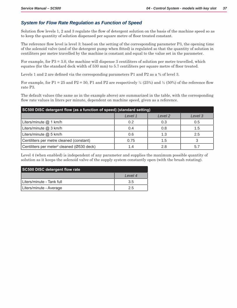
System for Flow Rate Regulation as Function of Speed
Solution flow levels 1, 2 and 3 regulate the flow of detergent solution on the basis of the machine speed so as to keep the quantity of solution dispensed per square metre of floor treated constant.
The reference flow level is level 3: based on the setting of the corresponding parameter P3, the opening time of the solenoid valve (and of the detergent pump when fitted) is regulated so that the quantity of solution in centiliters per metre travelled by the machine is constant and equal to the value set in the parameter
For example, for P3 = 3 0, the machine will dispense 3 centiliters of solution per metre travelled, which equates (for the standard deck width of 530 mm) to 5.7 centiliters per square metre of floor treated.
Levels 1 and 2 are defined via the corresponding parameters P1 and P2 as a % of level 3.
For example, for P1 = 25 and P2 = 50, P1 and P2 are respectively ¼ (25%) and ½ (50%) of the reference flow rate P3
The default values (the same as in the example above) are summarized in the table, with the corresponding flow rate values in liters per minute, dependent on machine speed, given as a reference.
SC500 DISC detergent flow (as a function of speed) (standard setting)Level 1 Level 2 Level 3
Liters/minute @ 1 km/h 0.2 0.3 0.5Liters/minute @ 3 km/h 0.4 0.8 1.5Liters/minute @ 5 km/h 0.6 1.3 2.5Centiliters per metre cleaned (constant) 0.75 1.5 3Centiliters per meter2 cleaned (Ø530 deck) 1.4 2.8 5.7
Level 4 (when enabled) is independent of any parameter and supplies the maximum possible quantity of solution as it keeps the solenoid valve of the supply system constantly open (with the brush rotating)
SC500 DISC detergent flow rateLevel 4
Liters/minute - Tank full 3.5Liters/minute - Average 2.5
38Service Manual – SC500 04 - Control System - models with key slot
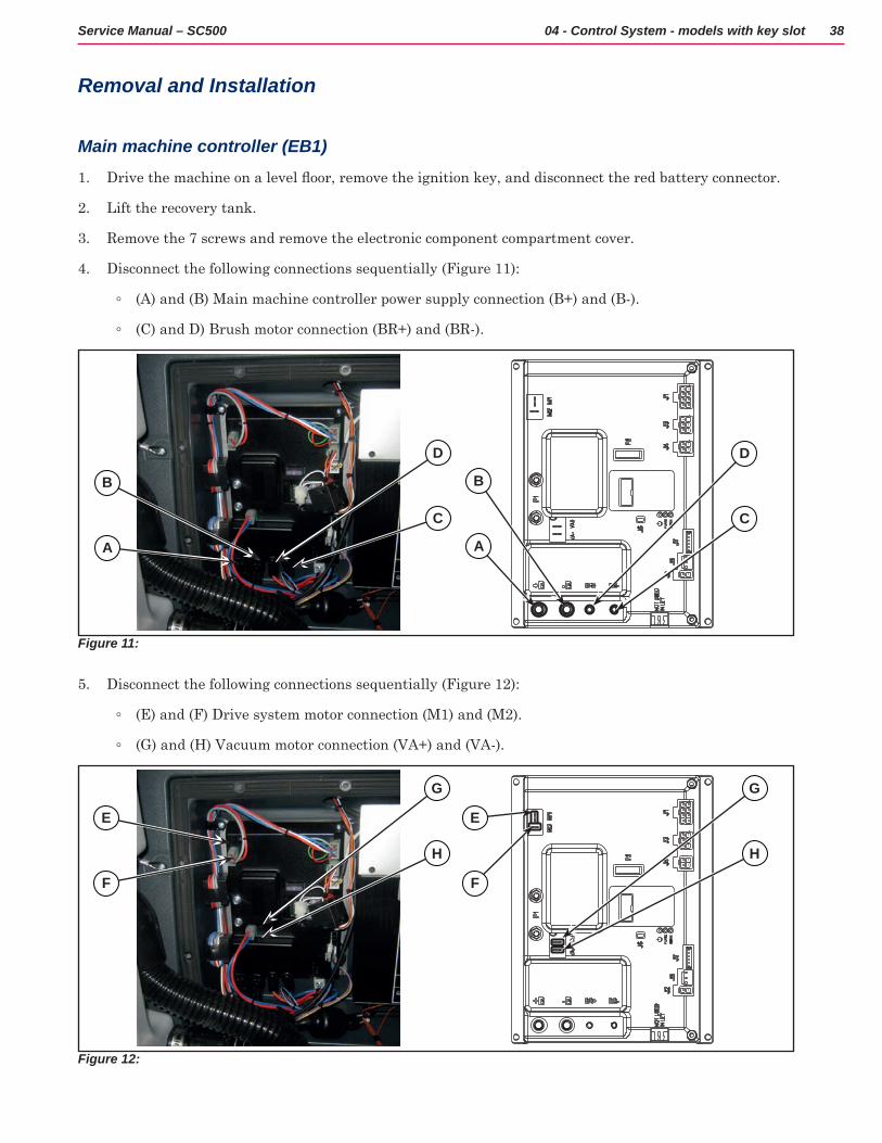
Removal and Installation
Main machine controller (EB1)
1 Drive the machine on a level floor, remove the ignition key, and disconnect the red battery connector.
2 Lift the recovery tank
3 Remove the 7 screws and remove the electronic component compartment cover
4 Disconnect the following connections sequentially (Figure 11):
◦ (A) and (B) Main machine controller power supply connection (B+) and (B-)
◦ (C) and D) Brush motor connection (BR+) and (BR-)
Figure 11:
B
D
B
D
A
C
A
C
5 Disconnect the following connections sequentially (Figure 12):
◦ (E) and (F) Drive system motor connection (M1) and (M2)
◦ (G) and (H) Vacuum motor connection (VA+) and (VA-)
Figure 12:
E E
G G
F F
H H

39Service Manual – SC500 04 - Control System - models with key slot
6 Disconnect the following connections sequentially (Figure 13):
◦ (I) Deck actuator and detergent pump connection (J1)
◦ (J) Solenoid valve connection (J2)
◦ (K) Display controller connection (J3)
◦ (L) Battery charger connection (J4)
◦ (M) Detergent level sensor connection (J5)
◦ (N) Connection (J6)
Figure 13:
I I
K K
L L
N N
M M
J J
7 Unscrew the 4 retaining screws (O) and carefully remove the Main machine controller (Figure 14)
Figure 14:
O
OO
O
8 Assemble the components in the reverse order of disassembly
40Service Manual – SC500 04 - Control System - models with key slot
Display Controller (EB2) and User interface controller (EB3)
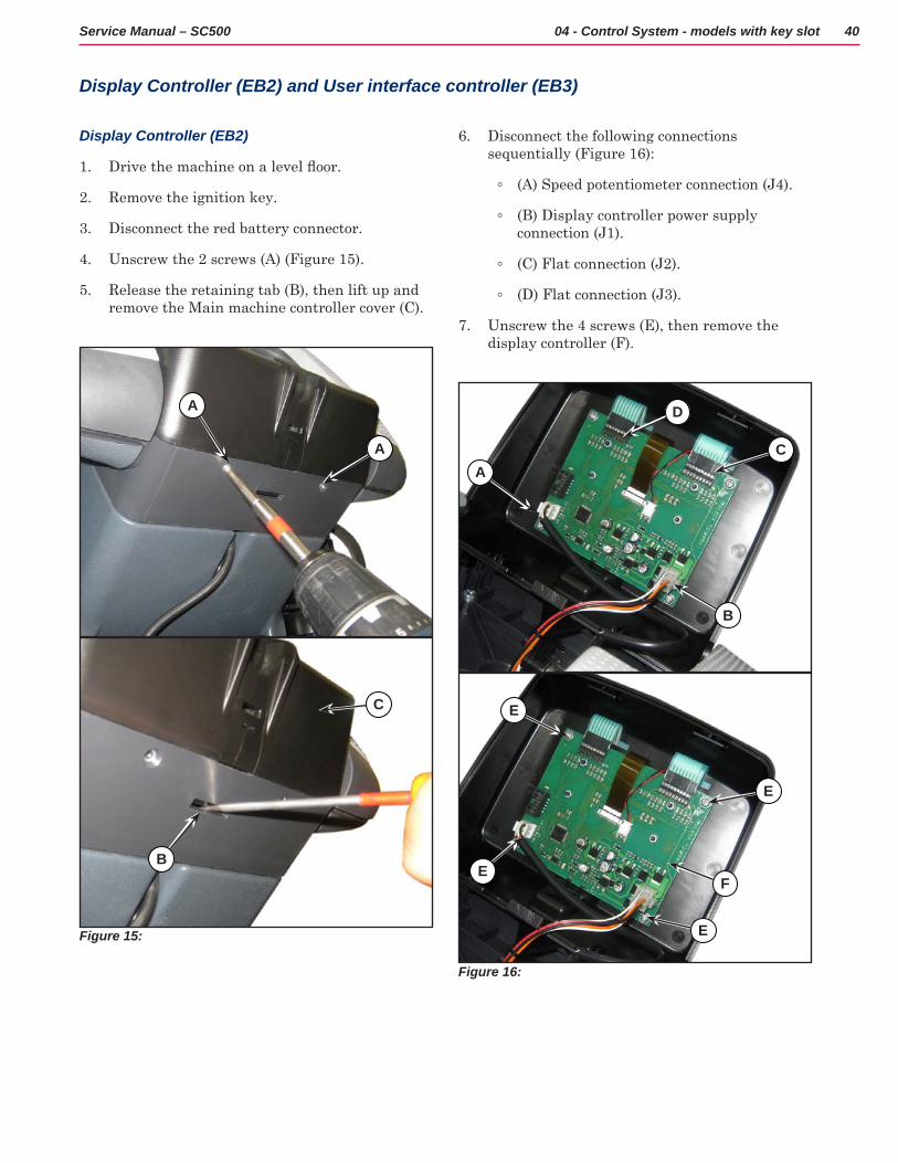
Display Controller (EB2)
1 Drive the machine on a level floor.
2 Remove the ignition key
3 Disconnect the red battery connector
4 Unscrew the 2 screws (A) (Figure 15)
5 Release the retaining tab (B), then lift up and remove the Main machine controller cover (C)
Figure 15:
A
A
C
B
6 Disconnect the following connections sequentially (Figure 16):
◦ (A) Speed potentiometer connection (J4)
◦ (B) Display controller power supply connection (J1)
◦ (C) Flat connection (J2)
◦ (D) Flat connection (J3)
7 Unscrew the 4 screws (E), then remove the display controller (F)
Figure 16:
B
C
D
A
E
F
E
E
E
41Service Manual – SC500 04 - Control System - models with key slot
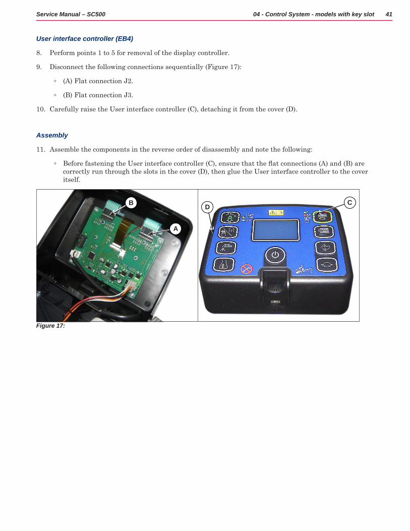
User interface controller (EB4)
8 Perform points 1 to 5 for removal of the display controller
9 Disconnect the following connections sequentially (Figure 17):
◦ (A) Flat connection J2
◦ (B) Flat connection J3
10 Carefully raise the User interface controller (C), detaching it from the cover (D)
Assembly
11 Assemble the components in the reverse order of disassembly and note the following:
◦ Before fastening the User interface controller (C), ensure that the flat connections (A) and (B) are correctly run through the slots in the cover (D), then glue the User interface controller to the cover itself
Figure 17:
B
A
D C
42Service Manual – SC500 04 - Control System - models with key slot
Specifications
Main machine controller (EB1) Connectors
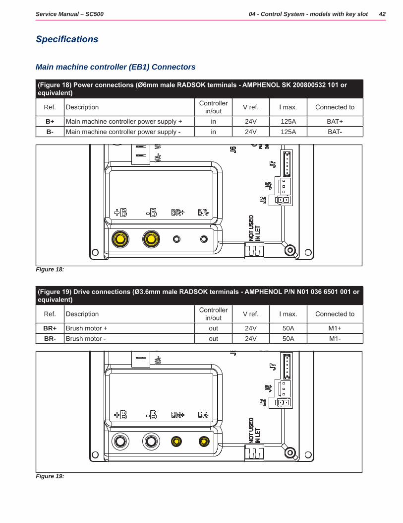
(Figure 18) Power connections (Ø6mm male RADSOK terminals - AMPHENOL SK 200800532 101 or equivalent)
Ref. Description Controller in/out V ref. I max. Connected to
B+ Main machine controller power supply + in 24V 125A BAT+B- Main machine controller power supply - in 24V 125A BAT-
Figure 18:
(Figure 19) Drive connections (Ø3.6mm male RADSOK terminals - AMPHENOL P/N N01 036 6501 001 or equivalent)
Ref. Description Controller in/out V ref. I max. Connected to
BR+ Brush motor + out 24V 50A M1+BR- Brush motor - out 24V 50A M1-
Figure 19:
43Service Manual – SC500 04 - Control System - models with key slot
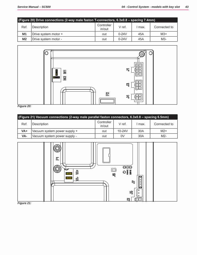
(Figure 20) Drive connections (2-way male faston T-connectors, 6.3x0.8 – spacing 7.4mm)
Ref. Description Controller in/out V ref. I max. Connected to
M1 Drive system motor + out 0-24V 45A M3+M2 Drive system motor - out 0-24V 45A M3-
Figure 20:
(Figure 21) Vacuum connections (2-way male parallel faston connectors, 6.3x0.8 – spacing 6.5mm)
Ref. Description Controller in/out V ref. I max. Connected to
VA+ Vacuum system power supply + out 10-24V 30A M2+VA- Vacuum system power supply - out 0V 30A M2-
Figure 21:
44Service Manual – SC500 04 - Control System - models with key slot
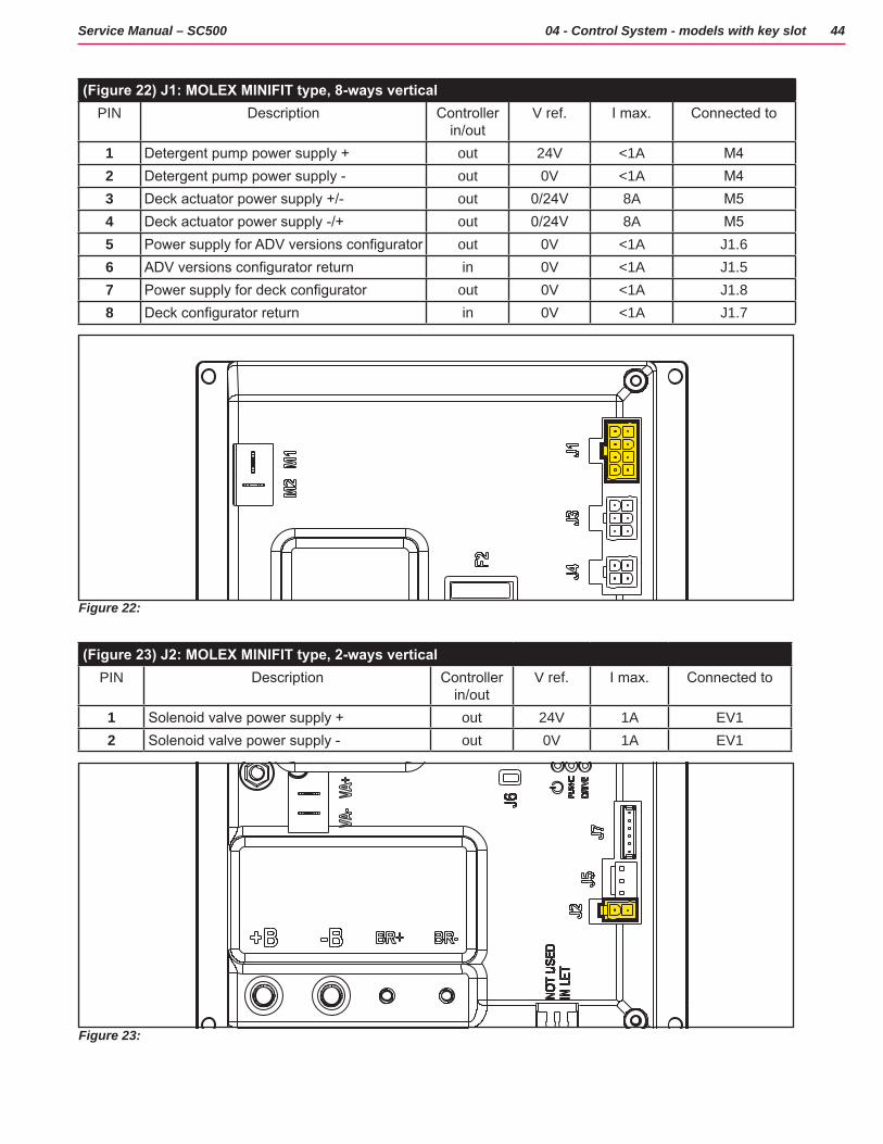
(Figure 22) J1: MOLEX MINIFIT type, 8-ways verticalPIN Description Controller
in/outV ref. I max. Connected to
1 Detergent pump power supply + out 24V <1A M42 Detergent pump power supply - out 0V <1A M43 Deck actuator power supply +/- out 0/24V 8A M54 Deck actuator power supply -/+ out 0/24V 8A M55 Power supply for ADV versions configurator out 0V <1A J1.66 ADV versions configurator return in 0V <1A J1.57 Power supply for deck configurator out 0V <1A J1.88 Deck configurator return in 0V <1A J1.7
Figure 22:
(Figure 23) J2: MOLEX MINIFIT type, 2-ways verticalPIN Description Controller
in/outV ref. I max. Connected to
1 Solenoid valve power supply + out 24V 1A EV12 Solenoid valve power supply - out 0V 1A EV1
Figure 23:
45Service Manual – SC500 04 - Control System - models with key slot
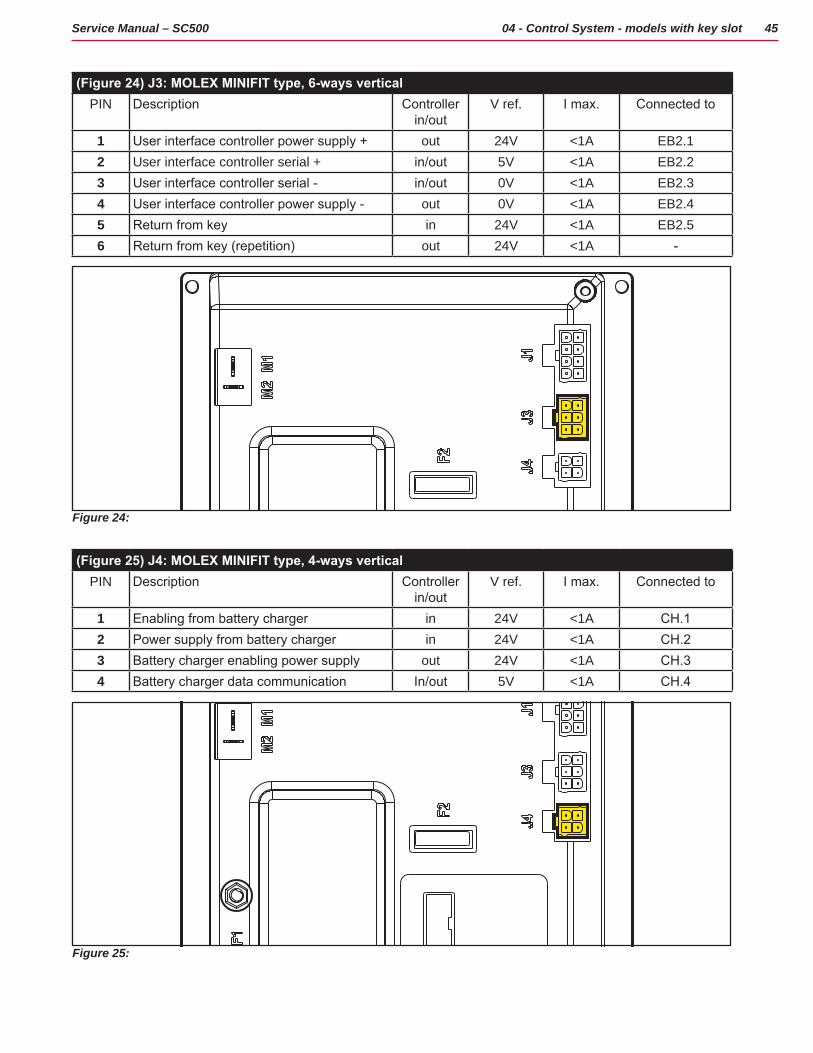
(Figure 24) J3: MOLEX MINIFIT type, 6-ways verticalPIN Description Controller
in/outV ref. I max. Connected to
1 User interface controller power supply + out 24V <1A EB2.12 User interface controller serial + in/out 5V <1A EB2.23 User interface controller serial - in/out 0V <1A EB2.34 User interface controller power supply - out 0V <1A EB2.45 Return from key in 24V <1A EB2.56 Return from key (repetition) out 24V <1A -
Figure 24:
(Figure 25) J4: MOLEX MINIFIT type, 4-ways verticalPIN Description Controller
in/outV ref. I max. Connected to
1 Enabling from battery charger in 24V <1A CH.12 Power supply from battery charger in 24V <1A CH.23 Battery charger enabling power supply out 24V <1A CH.34 Battery charger data communication In/out 5V <1A CH.4
Figure 25:
46Service Manual – SC500 04 - Control System - models with key slot
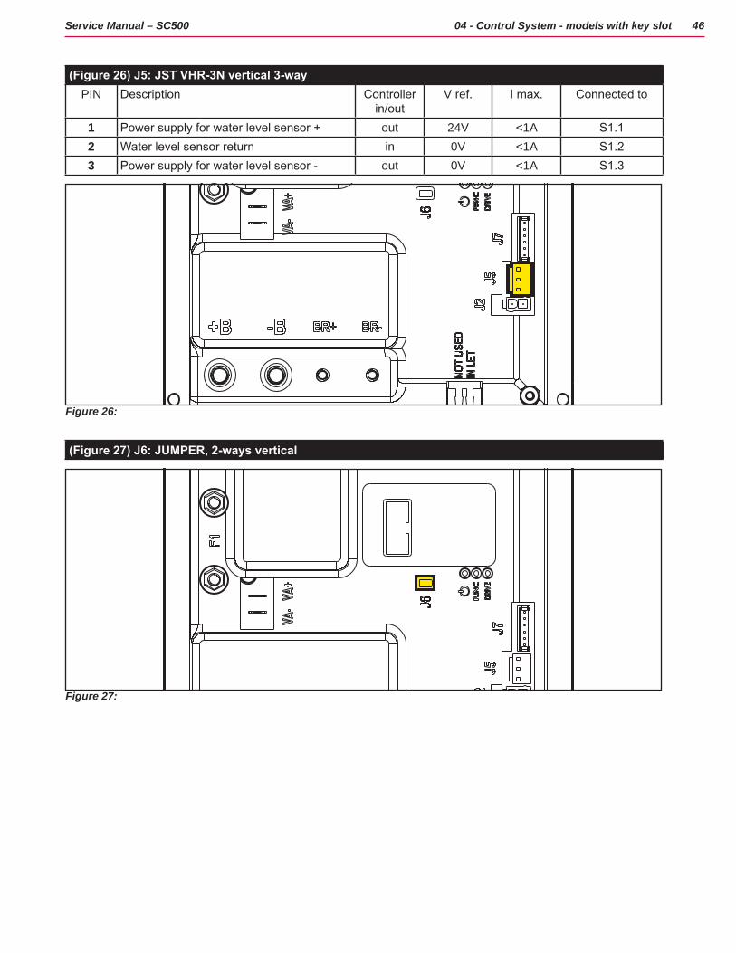
(Figure 26) J5: JST VHR-3N vertical 3-wayPIN Description Controller
in/outV ref. I max. Connected to
1 Power supply for water level sensor + out 24V <1A S1.12 Water level sensor return in 0V <1A S1.23 Power supply for water level sensor - out 0V <1A S1.3
Figure 26:
(Figure 27) J6: JUMPER, 2-ways vertical
Figure 27:
47Service Manual – SC500 04 - Control System - models with key slot
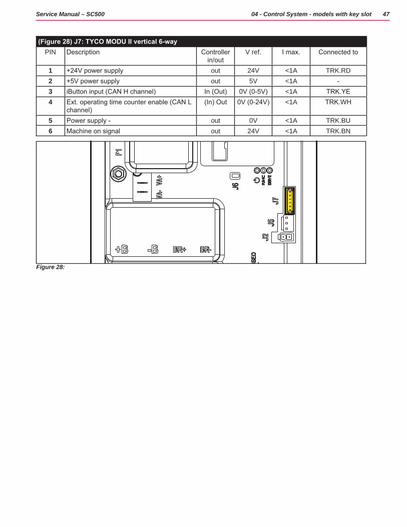
(Figure 28) J7: TYCO MODU II vertical 6-wayPIN Description Controller
in/outV ref. I max. Connected to
1 +24V power supply out 24V <1A TRK.RD2 +5V power supply out 5V <1A -3 iButton input (CAN H channel) In (Out) 0V (0-5V) <1A TRK.YE4 Ext. operating time counter enable (CAN L
channel)(In) Out 0V (0-24V) <1A TRK.WH
5 Power supply - out 0V <1A TRK.BU6 Machine on signal out 24V <1A TRK.BN
Figure 28:

48Service Manual – SC500 04 - Control System - models with key slot
Connectors of the Display Controller (EB2)
(Figure 29) J1: MOLEX MINIFIT type, 6-ways vertical
Ref. Description Controller in/out V ref. I max. Connected to
1 Power supply + in/out 24V <1A CFD12.J3.12 Main machine controller serial + in/out 5V <1A CFD12.J3.23 Main machine controller serial - in 0V <1A CFD12.J3.34 Power supply - out 0V <1A CFD12.J3.45 Key signal return (KEY0) out 24V <1A CFD12.J3.56 Key signal return (KEY0) in 24V <1A -
Figure 29:
(Figure 30) J2: FCI DUFLEX (2.54 pitch) 9-way, male pins
Ref. Description Controller in/out V ref. I max.
1 Power supply - common out 0V <1A2 ON/OFF button (P0) in 0V <1A3 DETERGENT MIX button (P4) in 0V <1A4 EDS button (P3) in 0V <1A5 VACUUM button (P2) in 0V <1A6 VACUUM function LED (LD2) out 5V <1A7 SPOT function LED (LD1) out 5V <1A8 SPOT button (P1) in 0V <1A9 DS versions configurator in 0V <1A
Figure 30:

49Service Manual – SC500 04 - Control System - models with key slot
(Figure 31) J3: FCI DUFLEX (2.54 pitch) 8-way, male pins
Ref. Description Controller in/out V ref. I max.
1 Power supply - common out 0V <1A2 SP / EXTRAPR function LED (red) (LD3R) out 5V <1A3 SP / EXTRAPR function LED (green)
(LD3V)out 5V <1A
4 BRUSH RELEASE function LED (LD4) out 5V <1A5 BRUSH RELEASE switch (P6) in 0V <1A6 INCREASE SPEED button (P7) in 0V <1A7 DECREASE SPEED button (P8) in 0V <1A8 ONETOUCH / EXTRAPR. button (P5) in 0V <1A
Figure 31:
(Figure 32) J4: JST VH vertical, 3-way (B 3P-VH)
PIN Description Controller in/out V ref. I max. Connected to
1 VR1 potentiometer power supply + Out 3V <1A VR1.12 VR1 potentiometer return In 0-3V <1A VR1.23 VR1 potentiometer power supply - out 0V <1A VR1.3
Figure 32:
50Service Manual – SC500 04 - Control System - models with key slot
Shop Measurements
The following tables contain some “real world” shop voltage measurements to help you recognize what “normal” looks like All voltage values were measured with the black (Negative) voltmeter lead connected to the main battery negative unless otherwise specified.
Shop Measurements - Main machine controller (EB1)
Battery volts at battery, key on = 25 03V
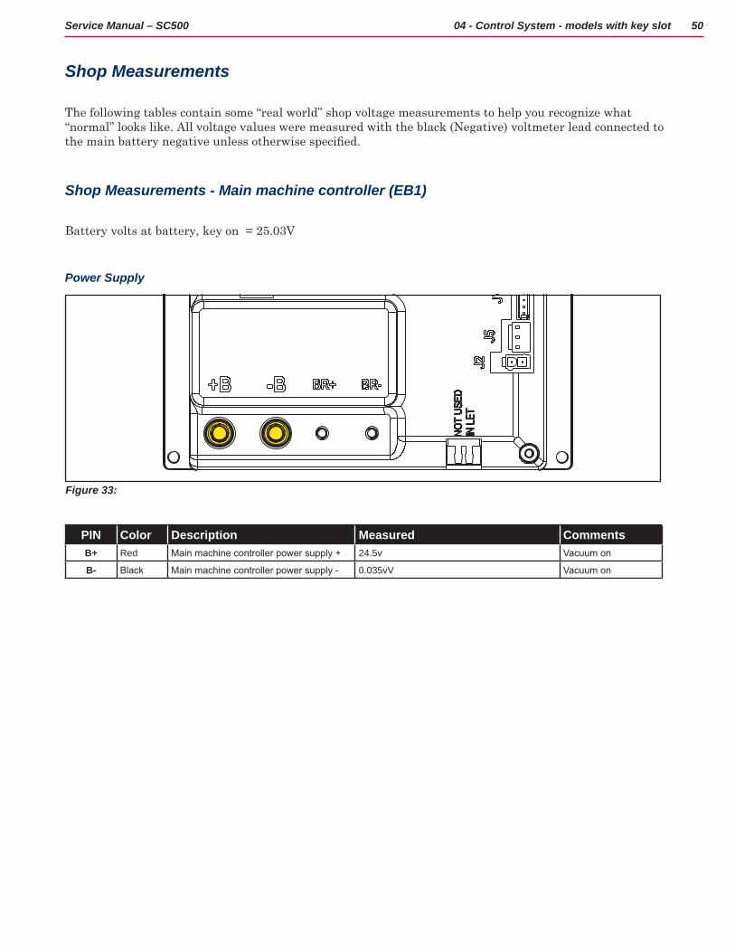
Power Supply
Figure 33:
PIN Color Description Measured CommentsB+ Red Main machine controller power supply + 24.5v Vacuum on
B- Black Main machine controller power supply - 0.035vV Vacuum on
51Service Manual – SC500 04 - Control System - models with key slot
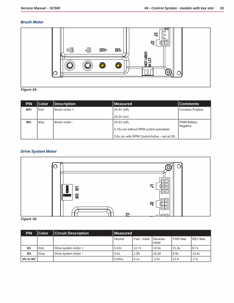
Brush Motor
Figure 34:
PIN Color Description Measured CommentsBR+ Red Brush motor + 24.4V (off),
24.2V (on)
Constant Positive
BR- Blue Brush motor - 24.4V (off),
0.15v (on without RPM control activated)
5.8v (on with RPM Control Active – set at 20)
PWM Battery Negative
Drive System Motor
Figure 35:
PIN Color Circuit Description MeasuredNeutral Fwd - Initial Reverse -
InitialFWD Max REV Max
M1 Red Drive system motor + 5.62v 12.7v 10.9v 21.8v 8.7v
M2 Gray Drive system motor - 5.61 1.95 16.00 8.9v 13.5v
M1 to M2 0.001v 6.1v -2.5v 22.6 -7.4
52Service Manual – SC500 04 - Control System - models with key slot
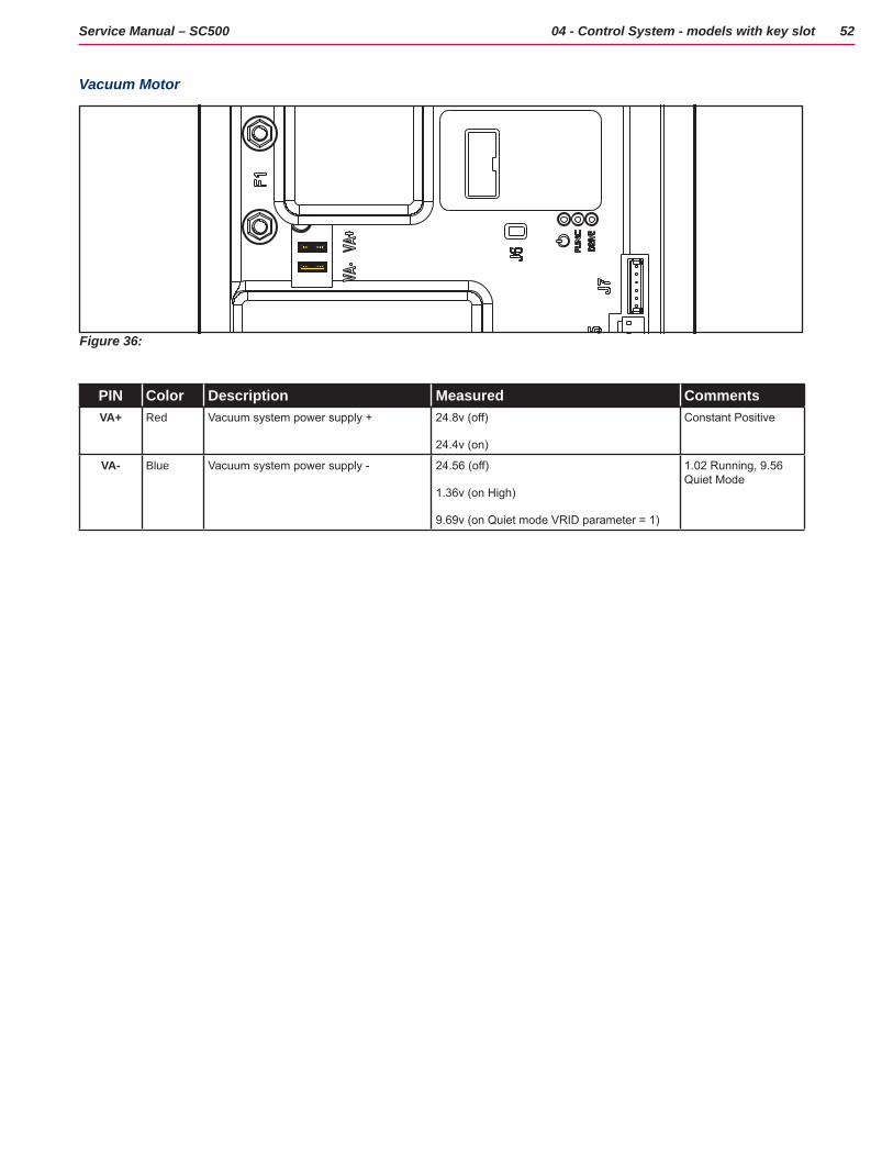
Vacuum Motor
Figure 36:
PIN Color Description Measured CommentsVA+ Red Vacuum system power supply + 24.8v (off)
24.4v (on)
Constant Positive
VA- Blue Vacuum system power supply - 24.56 (off)
1.36v (on High)
9.69v (on Quiet mode VRID parameter = 1)
1.02 Running, 9.56 Quiet Mode
53Service Manual – SC500 04 - Control System - models with key slot
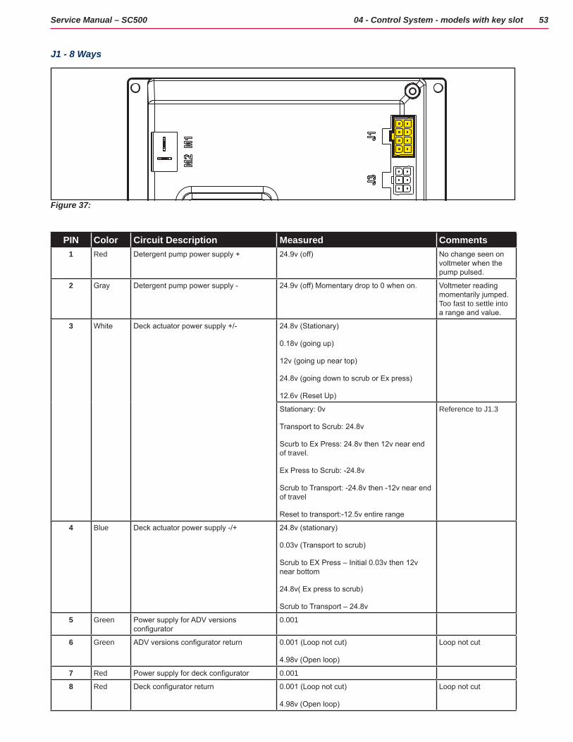
J1 - 8 Ways
Figure 37:
PIN Color Circuit Description Measured Comments1 Red Detergent pump power supply + 24.9v (off) No change seen on
voltmeter when the pump pulsed.
2 Gray Detergent pump power supply - 24.9v (off) Momentary drop to 0 when on. Voltmeter reading momentarily jumped. Too fast to settle into a range and value.
3 White Deck actuator power supply +/- 24.8v (Stationary)
0.18v (going up)
12v (going up near top)
24.8v (going down to scrub or Ex press)
12.6v (Reset Up)
Stationary: 0v
Transport to Scrub: 24.8v
Scurb to Ex Press: 24.8v then 12v near end of travel.
Ex Press to Scrub: -24.8v
Scrub to Transport: -24.8v then -12v near end of travel
Reset to transport:-12.5v entire range
Reference to J1.3
4 Blue Deck actuator power supply -/+ 24.8v (stationary)
0.03v (Transport to scrub)
Scrub to EX Press – Initial 0.03v then 12v near bottom
24.8v( Ex press to scrub)
Scrub to Transport – 24.8v
5 Green Power supply for ADV versions configurator
0.001
6 Green ADV versions configurator return 0.001 (Loop not cut)
4.98v (Open loop)
Loop not cut
7 Red Power supply for deck configurator 0.001
8 Red Deck configurator return 0.001 (Loop not cut)
4.98v (Open loop)
Loop not cut
54Service Manual – SC500 04 - Control System - models with key slot
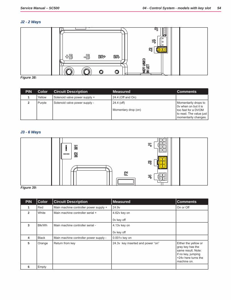
J2 - 2 Ways
Figure 38:
PIN Color Circuit Description Measured Comments1 Yellow Solenoid valve power supply + 24.4 (Off and On)
2 Purple Solenoid valve power supply - 24.4 (off)
Momentary drop (on)
Momentarily drops to 0v when on but it is too fast for a DVOM to read. The value just momentarily changes.
J3 - 6 Ways
Figure 39:
PIN Color Circuit Description Measured Comments1 Red Main machine controller power supply + 24.9v On or Off
2 White Main machine controller serial + 4.62v key on
0v key off
3 Blk/Wh Main machine controller serial - 4.13v key on
0v key off
4 Black Main machine controller power supply - 0.001v key on
5 Orange Return from key 24.3v key inserted and power “on” Either the yellow or gray key has the same result. Note: if no key, jumping +24v here turns the machine on.
6 Empty
55Service Manual – SC500 04 - Control System - models with key slot
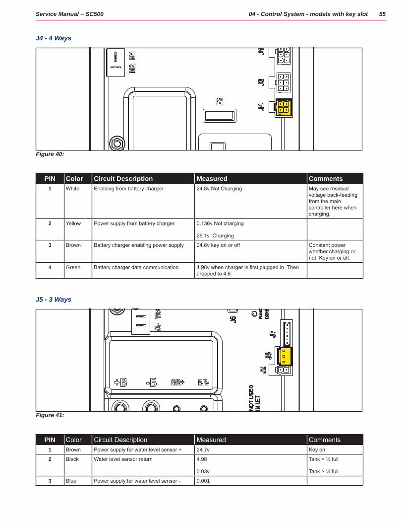
J4 - 4 Ways
Figure 40:
PIN Color Circuit Description Measured Comments1 White Enabling from battery charger 24.8v Not Charging May see residual
voltage back-feeding from the main controller here when charging.
2 Yellow Power supply from battery charger 0.136v Not charging
26.1v Charging
3 Brown Battery charger enabling power supply 24.8v key on or off Constant power whether charging or not. Key on or off.
4 Green Battery charger data communication 4.98v when charger is first plugged in. Then dropped to 4.6
J5 - 3 Ways
Figure 41:
PIN Color Circuit Description Measured Comments1 Brown Power supply for water level sensor + 24.7v Key on
2 Black Water level sensor return 4.98
0.03v
Tank < ½ full
Tank > ½ full
3 Blue Power supply for water level sensor - 0.001
56Service Manual – SC500 04 - Control System - models with key slot
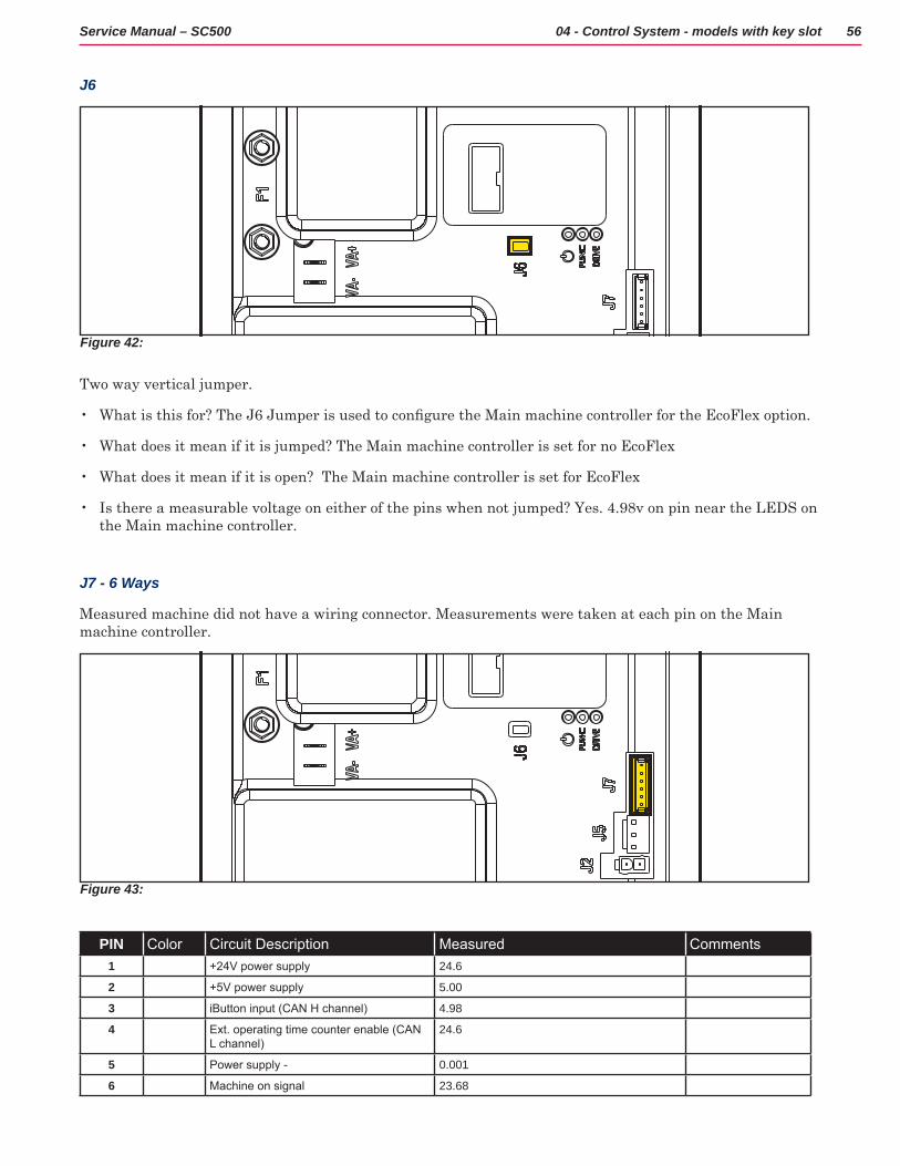
J6
Figure 42:
Two way vertical jumper
• What is this for? The J6 Jumper is used to configure the Main machine controller for the EcoFlex option.
• What does it mean if it is jumped? The Main machine controller is set for no EcoFlex
• What does it mean if it is open? The Main machine controller is set for EcoFlex
• Is there a measurable voltage on either of the pins when not jumped? Yes 4 98v on pin near the LEDS on the Main machine controller
J7 - 6 Ways
Measured machine did not have a wiring connector Measurements were taken at each pin on the Main machine controller
Figure 43:
PIN Color Circuit Description Measured Comments1 +24V power supply 24.6
2 +5V power supply 5.00
3 iButton input (CAN H channel) 4.98
4 Ext. operating time counter enable (CAN L channel)
24.6
5 Power supply - 0.001
6 Machine on signal 23.68
57Service Manual – SC500 04 - Control System - models with key slot
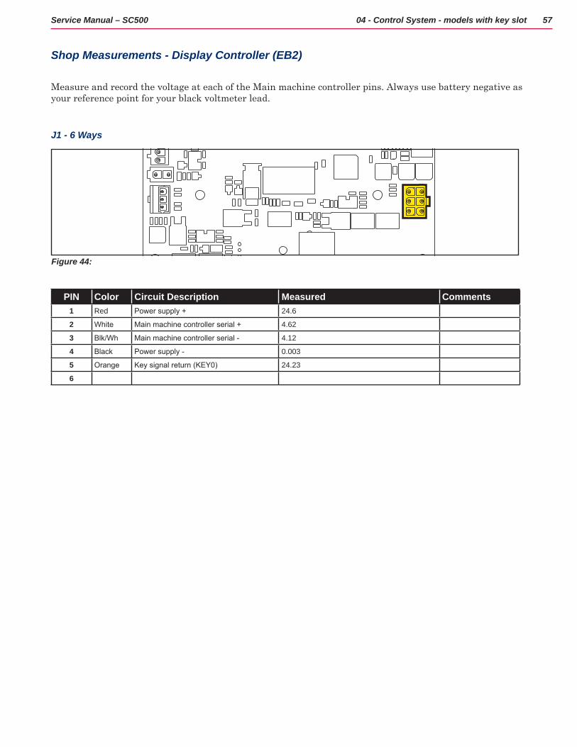
Shop Measurements - Display Controller (EB2)
Measure and record the voltage at each of the Main machine controller pins Always use battery negative as your reference point for your black voltmeter lead
J1 - 6 Ways
Figure 44:
PIN Color Circuit Description Measured Comments1 Red Power supply + 24.6
2 White Main machine controller serial + 4.62
3 Blk/Wh Main machine controller serial - 4.12
4 Black Power supply - 0.003
5 Orange Key signal return (KEY0) 24.23
6
58Service Manual – SC500 04 - Control System - models with key slot
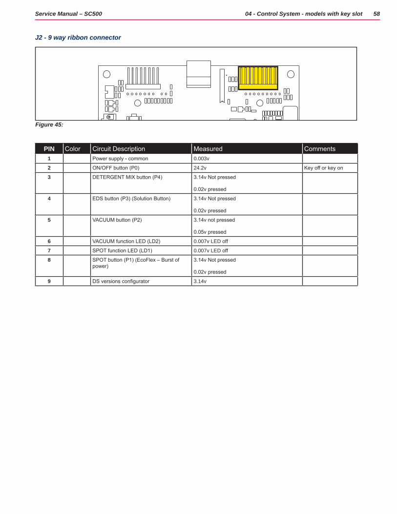
J2 - 9 way ribbon connector
Figure 45:
PIN Color Circuit Description Measured Comments1 Power supply - common 0.003v
2 ON/OFF button (P0) 24.2v Key off or key on
3 DETERGENT MIX button (P4) 3.14v Not pressed
0.02v pressed
4 EDS button (P3) (Solution Button) 3.14v Not pressed
0.02v pressed
5 VACUUM button (P2) 3.14v not pressed
0.05v pressed
6 VACUUM function LED (LD2) 0.007v LED off
7 SPOT function LED (LD1) 0.007v LED off
8 SPOT button (P1) (EcoFlex – Burst of power)
3.14v Not pressed
0.02v pressed
9 DS versions configurator 3.14v
59Service Manual – SC500 04 - Control System - models with key slot
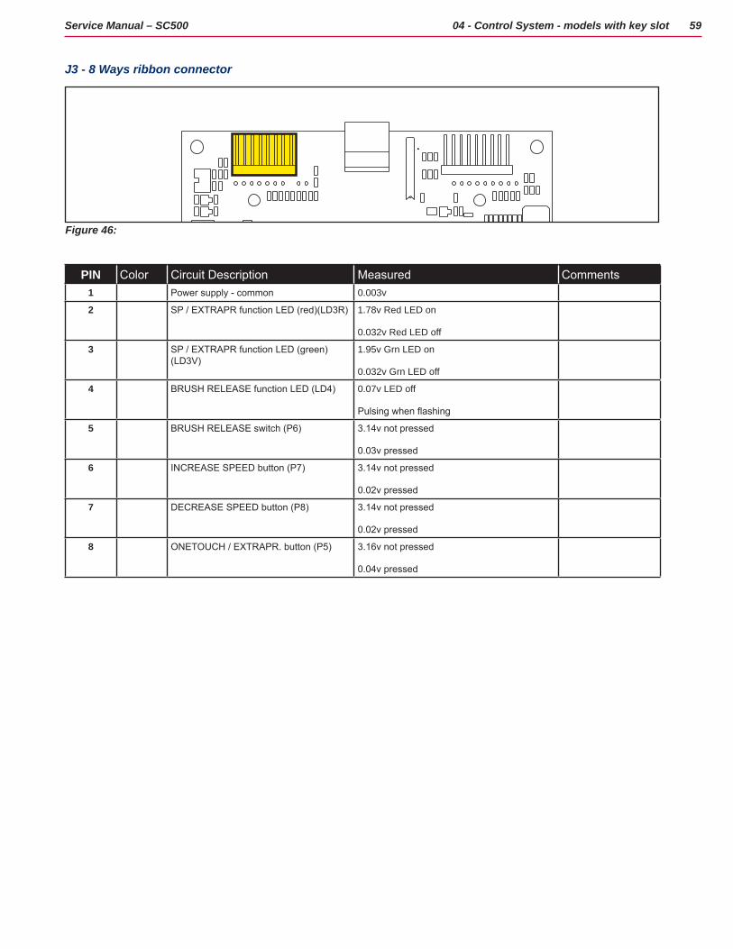
J3 - 8 Ways ribbon connector
Figure 46:
PIN Color Circuit Description Measured Comments1 Power supply - common 0.003v
2 SP / EXTRAPR function LED (red)(LD3R) 1.78v Red LED on
0.032v Red LED off
3 SP / EXTRAPR function LED (green)(LD3V)
1.95v Grn LED on
0.032v Grn LED off
4 BRUSH RELEASE function LED (LD4) 0.07v LED off
Pulsing when flashing
5 BRUSH RELEASE switch (P6) 3.14v not pressed
0.03v pressed
6 INCREASE SPEED button (P7) 3.14v not pressed
0.02v pressed
7 DECREASE SPEED button (P8) 3.14v not pressed
0.02v pressed
8 ONETOUCH / EXTRAPR. button (P5) 3.16v not pressed
0.04v pressed
60Service Manual – SC500 04 - Control System - models with key slot
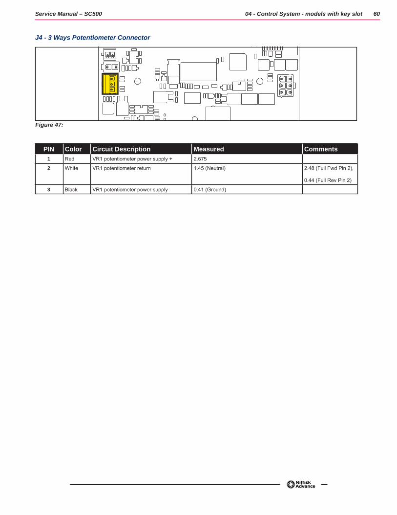
J4 - 3 Ways Potentiometer Connector
Figure 47:
PIN Color Circuit Description Measured Comments1 Red VR1 potentiometer power supply + 2.675
2 White VR1 potentiometer return 1.45 (Neutral) 2.48 (Full Fwd Pin 2),
0.44 (Full Rev Pin 2)
3 Black VR1 potentiometer power supply - 0.41 (Ground)
61Service Manual – SC500
05 - Control System, Models with magnetic smart key
Model No.: 9087403020, 9087404020, 9087400020,9087401020, 9087405020, 9087402020
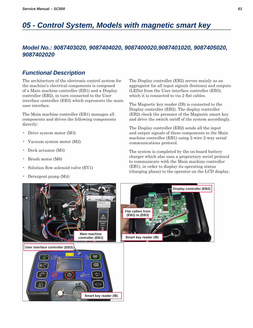
Functional DescriptionThe architecture of the electronic control system for the machine’s electrical components is composed of a Main machine controller (EB1) and a Display controller (EB2), in turn connected to the User interface controller (EB3) which represents the main user interface
The Main machine controller (EB1) manages all components and drives the following components directly:
• Drive system motor (M3)
• Vacuum system motor (M2)
• Deck actuator (M5)
• Brush motor (M6)
• Solution flow solenoid valve (EV1)
• Detergent pump (M4)
The Display controller (EB2) serves mainly as an aggregator for all input signals (buttons) and outputs (LEDs) from the User interface controller (EB3), which it is connected to via 2 flat cables.
The Magnetic key reader (IB) is connected to the Display controller (EB2) The display controller (EB2) check the presence of the Magnetic smart key and drive the switch on/off of the system accordingly
The Display controller (EB2) sends all the input and output signals of these components to the Main machine controller (EB1) using 2-wire 2-way serial communications protocol
The system is completed by the on-board battery charger which also uses a proprietary serial protocol to communicate with the Main machine controller (EB1), in order to display its operating status (charging phase) to the operator on the LCD display
Main machine controller (EB1)
Display controller (EB2)
Flat calbes from (EB2) to (EB3)
Smart key reader (IB)
Smart key reader (IB)
User interface controller (EB3)
62Service Manual – SC500 05 - Control System, Models with magnetic smart key
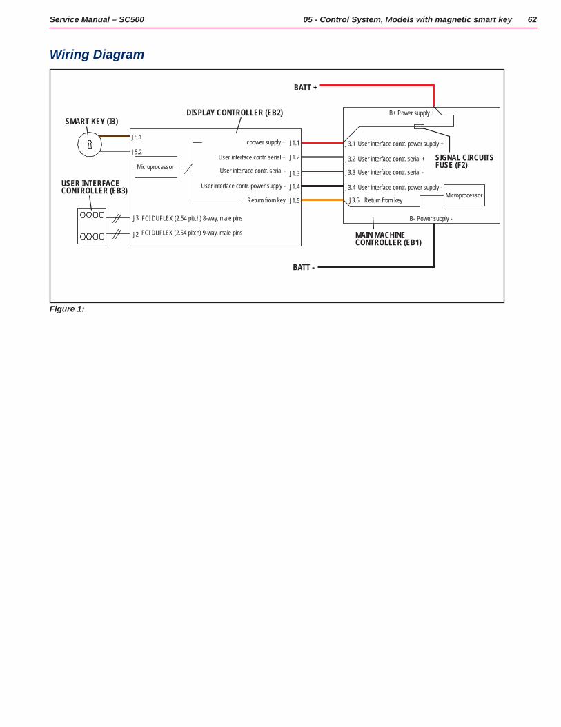
Wiring Diagram
J1.5
J1.4
J1.3
J1.2
J1.1
J3
J2
J3.1
J3.2
J3.3
J3.4
J3.5
User interface contr. power supply +
User interface contr. serial +
User interface contr. serial -
User interface contr. power supply -
Return from key
FCI DUFLEX (2.54 pitch) 8-way, male pins
FCI DUFLEX (2.54 pitch) 9-way, male pins
cpower supply +
User interface contr. serial +
User interface contr. serial -
User interface contr. power supply -
Return from key
B-
B+DISPLAY CONTROLLER (EB2)
BATT +
BATT -
Microprocessor
Microprocessor
SIGNAL CIRCUITSFUSE (F2)
MAIN MACHINECONTROLLER (EB1)
Power supply +
Power supply -
J5.1
J5.2
SMART KEY (IB)
USER INTERFACE CONTROLLER (EB3)
Figure 1:
63Service Manual – SC500 05 - Control System, Models with magnetic smart key
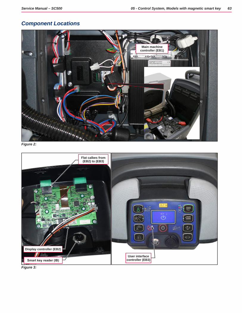
Component Locations
Figure 2:
Main machine controller (EB1)
Figure 3:
Flat calbes from (EB2) to (EB3)
User interface controller (EB3)
Display controller (EB2)
Smart key reader (IB)

64Service Manual – SC500 05 - Control System, Models with magnetic smart key
Troubleshooting
Main machine controller (EB1) Alarm Codes
The Main machine controller (EB1) indicates a series of alarms in case of malfunction of one or more systems, and in case of abnormal conditions detected in the input signals
The alarms are shown on the display in the following format: ALARM <XX> <DESCRIPTION> (Figure 4)
Figure 4:
In case the display is malfunctioning, the alarms are also repeated by the yellow and red diagnostic LEDs (Figure 5) on the Main machine controller (EB1), as indicated in the following tables
Figure 5:
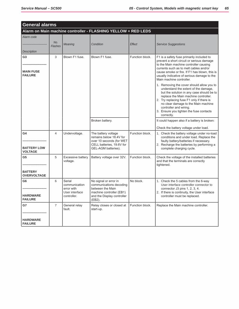
General alarmsAlarm on Main machine controller - FLASHING YELLOW + RED LEDSAlarm code
--------------------------
Description
No. Flashes Meaning Condition Effect Service Suggestions
G2
-----------------------
EEPROM ERROR
2 EEPROM error EEPROM error Function block + Default setting reset
If the machine continues to function after G2 has been displayed, this may have been caused by a significant external electromagnetic disturbance.
1. Check that the settings and parameters (see pages 71 - 72) are correct (they may have returned to their defaults). If the error persists, the Main machine controller must be replaced.
65Service Manual – SC500 05 - Control System, Models with magnetic smart key
General alarmsAlarm on Main machine controller - FLASHING YELLOW + RED LEDSAlarm code
--------------------------
Description
No. Flashes Meaning Condition Effect Service Suggestions
G3
-----------------------
MAIN FUSE FAILURE
3 Blown F1 fuse. Blown F1 fuse. Function block. F1 is a safety fuse primarily included to prevent a short circuit or serious damage to the Main machine controller causing currents such as to melt cables and/or cause smoke or fire. If F1 has blown, this is usually indicative of serious damage to the Main machine controller.
1. Removing the cover should allow you to understand the extent of the damage, but the solution in any case should be to replace the Main machine controller.
2. Try replacing fuse F1 only if there is no clear damage to the Main machine controller and wiring.
3. Ensure you tighten the fuse contacts correctly.
Broken battery. It could happen also if a battery is broken:
Check the battery voltage under load.
G4
-----------------------
BATTERY LOW VOLTAGE
4 Undervoltage. The battery voltage remains below 18.4V for over 10 seconds (for WET CELL batteries, 19.6V for GEL-AGM batteries).
Function block. 1. Check the battery voltage under no-load conditions and under load. Replace the faulty battery/batteries if necessary.
2. Recharge the batteries by performing a complete charging cycle.
G5
-----------------------
BATTERY OVERVOLTAGE
5 Excessive battery voltage.
Battery voltage over 32V. Function block. Check the voltage of the installed batteries and that the terminals are correctly tightened.
G6
-----------------------
HARDWARE FAILURE
6 Serial communication error with User interface controller.
No signal or error in communications decoding between the Main machine controller (EB1) and the Display controller (EB2).
No block. 1. Check the 5 cables from the 6-way User interface controller connector to connector J3 pins 1, 2, 3, 4.
2. If there is continuity, the User interface controller must be replaced.
G7
-----------------------
HARDWARE FAILURE
7 General relay fault.
Relay closes or closed at start-up.
Function block. Replace the Main machine controller.
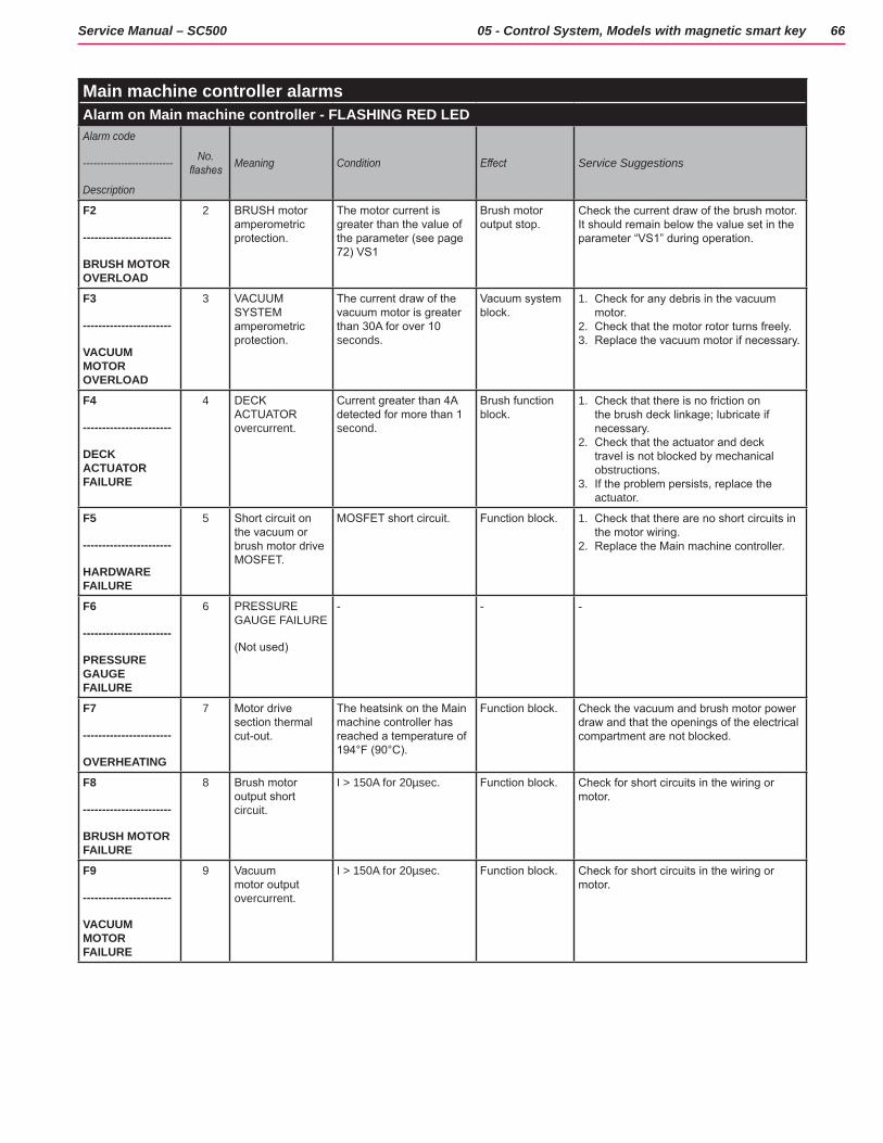
66Service Manual – SC500 05 - Control System, Models with magnetic smart key
Main machine controller alarmsAlarm on Main machine controller - FLASHING RED LEDAlarm code
--------------------------
Description
No. flashes Meaning Condition Effect Service Suggestions
F2
-----------------------
BRUSH MOTOR OVERLOAD
2 BRUSH motor amperometric protection.
The motor current is greater than the value of the parameter (see page 72) VS1
Brush motor output stop.
Check the current draw of the brush motor. It should remain below the value set in the parameter “VS1” during operation.
F3
-----------------------
VACUUM MOTOR OVERLOAD
3 VACUUM SYSTEM amperometric protection.
The current draw of the vacuum motor is greater than 30A for over 10 seconds.
Vacuum system block.
1. Check for any debris in the vacuum motor.
2. Check that the motor rotor turns freely.3. Replace the vacuum motor if necessary.
F4
-----------------------
DECK ACTUATOR FAILURE
4 DECK ACTUATOR overcurrent.
Current greater than 4A detected for more than 1 second.
Brush function block.
1. Check that there is no friction on the brush deck linkage; lubricate if necessary.
2. Check that the actuator and deck travel is not blocked by mechanical obstructions.
3. If the problem persists, replace the actuator.
F5
-----------------------
HARDWARE FAILURE
5 Short circuit on the vacuum or brush motor drive MOSFET.
MOSFET short circuit. Function block. 1. Check that there are no short circuits in the motor wiring.
2. Replace the Main machine controller.
F6
-----------------------
PRESSURE GAUGE FAILURE
6 PRESSURE GAUGE FAILURE
(Not used)
- - -
F7
-----------------------
OVERHEATING
7 Motor drive section thermal cut-out.
The heatsink on the Main machine controller has reached a temperature of 194°F (90°C).
Function block. Check the vacuum and brush motor power draw and that the openings of the electrical compartment are not blocked.
F8
-----------------------
BRUSH MOTOR FAILURE
8 Brush motor output short circuit.
I > 150A for 20µsec. Function block. Check for short circuits in the wiring or motor.
F9
-----------------------
VACUUM MOTOR FAILURE
9 Vacuum motor output overcurrent.
I > 150A for 20µsec. Function block. Check for short circuits in the wiring or motor.
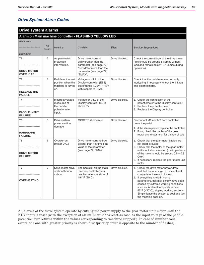
67Service Manual – SC500 05 - Control System, Models with magnetic smart key
Drive System Alarm Codes
Drive system alarmsAlarm on Main machine controller - FLASHING YELLOW LEDAlarm code
--------------------------
Description
No. flashes Meaning Condition Effect Service Suggestions
T2
-----------------------
DRIVE MOTOR OVERLOAD
2 Amperometric protection intervention.
Drive motor current draw greater than the parameter (see page 72) “INOM” for more than the parameter (see page 72) “TMAX”.
Drive blocked. Check the current draw of the drive motor (this should be around 6-8amps without load and remain below 10-12amps during operation).
T3
-----------------------
RELEASE THE PADDLE !
3 Paddle not in rest position when the machine is turned on.
Voltage on J1.2 of the Display controller (EB2) out of range 1.29V - 1.49V with respect to - BAT.
Drive blocked. Check that the paddle moves correctly, lubricating if necessary; check the linkage and potentiometer.
T4
-----------------------
PADDLE INPUT FAILURE
4 Incorrect voltage measured at the paddle potentiometer input.
Voltage on J1.2 of the Display controller (EB2) above 3V.
Drive blocked. 1. Check the connection of the potentiometer to the Display controller.
2. Replace the potentiometer. 3. Replace the Display controller.
T5
-----------------------
HARDWARE FAILURE
5 Drive system power section damage
MOSFET short circuit. Drive blocked. Disconnect M1 and M2 from controller, press the pedal
1. if the alarm persist replace the controller, 2. if not, check the cables of the gear
motor and motor itself for a short circuit
T6
-----------------------
DRIVE MOTOR FAILURE
6 Overcurrent (motor D.C.)
Drive motor current draw greater than 1.5 times the value of the parameter (see page 72) “IMAX”.
Drive blocked. 1. Check that the gear motor cables are not short circuited
2. Check that the motor of the gear motor unit is not short circuited (the impedance of the motor should be around 0.6 – 0.8 Ohm)
3. If necessary, replace the gear motor unit motor
T7
-----------------------
OVERHEATING
7 Drive motor drive section thermal cut-out.
The heatsink on the Main machine controller has reached a temperature of 194°F (90°C).
Drive blocked. 1. Check the drive motor power draw and that the openings of the electrical compartment are not blocked.
2. If everything is within normal parameters, this may simply have been caused by extreme working conditions such as: Ambient temperature over 86°F (>30°C), sloping working sections. Simply leave the system to cool and turn the machine back on.
All alarms of the drive system operate by cutting the power supply to the gear motor unit motor until the KEY input is reset (with the exception of alarm T3 which is reset as soon as the input voltage of the paddle potentiometer returns within the values corresponding to “machine stopped”) In case of simultaneous errors, the one with greater priority is shown first (priority order is opposite to the number of flashes).
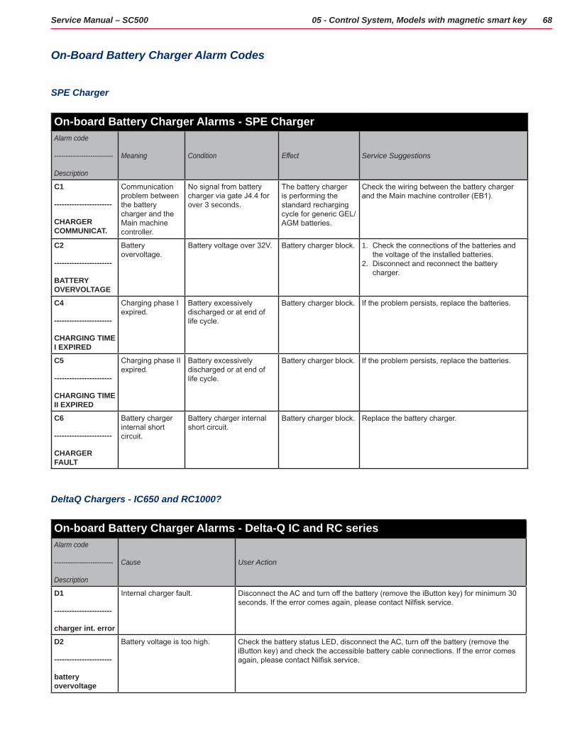
68Service Manual – SC500 05 - Control System, Models with magnetic smart key
On-Board Battery Charger Alarm Codes
SPE Charger
On-board Battery Charger Alarms - SPE ChargerAlarm code
--------------------------
Description
Meaning Condition Effect Service Suggestions
C1
-----------------------
CHARGER COMMUNICAT.
Communication problem between the battery charger and the Main machine controller.
No signal from battery charger via gate J4.4 for over 3 seconds.
The battery charger is performing the standard recharging cycle for generic GEL/AGM batteries.
Check the wiring between the battery charger and the Main machine controller (EB1).
C2
-----------------------
BATTERY OVERVOLTAGE
Battery overvoltage.
Battery voltage over 32V. Battery charger block. 1. Check the connections of the batteries and the voltage of the installed batteries.
2. Disconnect and reconnect the battery charger.
C4
-----------------------
CHARGING TIME I EXPIRED
Charging phase I expired.
Battery excessively discharged or at end of life cycle.
Battery charger block. If the problem persists, replace the batteries.
C5
-----------------------
CHARGING TIME II EXPIRED
Charging phase II expired.
Battery excessively discharged or at end of life cycle.
Battery charger block. If the problem persists, replace the batteries.
C6
-----------------------
CHARGER FAULT
Battery charger internal short circuit.
Battery charger internal short circuit.
Battery charger block. Replace the battery charger.
DeltaQ Chargers - IC650 and RC1000?
On-board Battery Charger Alarms - Delta-Q IC and RC seriesAlarm code
--------------------------
Description
Cause User Action
D1
-----------------------
charger int. error
Internal charger fault. Disconnect the AC and turn off the battery (remove the iButton key) for minimum 30 seconds. If the error comes again, please contact Nilfisk service.
D2
-----------------------
battery overvoltage
Battery voltage is too high. Check the battery status LED, disconnect the AC, turn off the battery (remove the iButton key) and check the accessible battery cable connections. If the error comes again, please contact Nilfisk service.
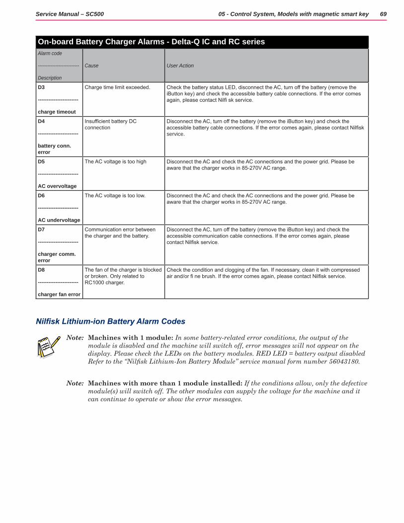
69Service Manual – SC500 05 - Control System, Models with magnetic smart key
On-board Battery Charger Alarms - Delta-Q IC and RC seriesAlarm code
--------------------------
Description
Cause User Action
D3
-----------------------
charge timeout
Charge time limit exceeded. Check the battery status LED, disconnect the AC, turn off the battery (remove the iButton key) and check the accessible battery cable connections. If the error comes again, please contact Nilfi sk service.
D4
-----------------------
battery conn. error
Insufficient battery DC connection
Disconnect the AC, turn off the battery (remove the iButton key) and check the accessible battery cable connections. If the error comes again, please contact Nilfisk service.
D5
-----------------------
AC overvoltage
The AC voltage is too high Disconnect the AC and check the AC connections and the power grid. Please be aware that the charger works in 85-270V AC range.
D6
-----------------------
AC undervoltage
The AC voltage is too low. Disconnect the AC and check the AC connections and the power grid. Please be aware that the charger works in 85-270V AC range.
D7
-----------------------
charger comm. error
Communication error between the charger and the battery.
Disconnect the AC, turn off the battery (remove the iButton key) and check the accessible communication cable connections. If the error comes again, please contact Nilfisk service.
D8
-----------------------
charger fan error
The fan of the charger is blocked or broken. Only related to RC1000 charger.
Check the condition and clogging of the fan. If necessary, clean it with compressed air and/or fi ne brush. If the error comes again, please contact Nilfisk service.
Nilfisk Lithium-ion Battery Alarm Codes
Note: Machines with 1 module: In some battery-related error conditions, the output of the module is disabled and the machine will switch off, error messages will not appear on the display. Please check the LEDs on the battery modules. RED LED = battery output disabled Refer to the “Nilfisk Lithium-Ion Battery Module” service manual form number 56043180.
Note: Machines with more than 1 module installed: If the conditions allow, only the defective module(s) will switch off. The other modules can supply the voltage for the machine and it can continue to operate or show the error messages.
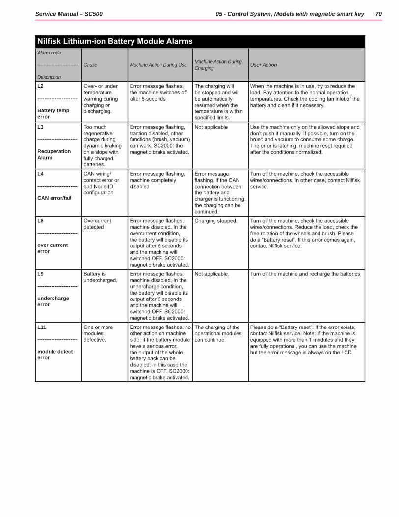
70Service Manual – SC500 05 - Control System, Models with magnetic smart key
Nilfisk Lithium-ion Battery Module AlarmsAlarm code
--------------------------
Description
Cause Machine Action During Use Machine Action During Charging User Action
L2
-----------------------
Battery temp error
Over- or under temperature warning during charging or discharging.
Error message flashes, the machine switches off after 5 seconds
The charging will be stopped and will be automatically resumed when the temperature is within specified limits.
When the machine is in use, try to reduce the load. Pay attention to the normal operation temperatures. Check the cooling fan inlet of the battery and clean if it necessary.
L3
-----------------------
Recuperation Alarm
Too much regenerative charge during dynamic braking on a slope with fully charged batteries.
Error message flashing, traction disabled, other functions (brush, vacuum) can work. SC2000: the magnetic brake activated.
Not applicable Use the machine only on the allowed slope and don’t push it manually. If possible, turn on the brush and vacuum to consume some charge. The error is latching, machine reset required after the conditions normalized.
L4
-----------------------
CAN error/fail
CAN wiring/contact error or bad Node-ID configuration
Error message flashing, machine completely disabled
Error message flashing. If the CAN connection between the battery and charger is functioning, the charging can be continued.
Turn off the machine, check the accessible wires/connections. In other case, contact Nilfisk service.
L8
-----------------------
over current error
Overcurrent detected
Error message flashes, machine disabled. In the overcurrent condition, the battery will disable its output after 5 seconds and the machine will switched OFF. SC2000: magnetic brake activated.
Charging stopped. Turn off the machine, check the accessible wires/connections. Reduce the load, check the free rotation of the wheels and brush. Please do a “Battery reset”. If this error comes again, contact Nilfisk service.
L9
-----------------------
undercharge error
Battery is undercharged.
Error message flashes, machine disabled. In the undercharge condition, the battery will disable its output after 5 seconds and the machine will switched OFF. SC2000: magnetic brake activated.
Not applicable. Turn off the machine and recharge the batteries.
L11
-----------------------
module defect error
One or more modules defective.
Error message flashes, no other action on machine side. If the battery module have a serious error, the output of the whole battery pack can be disabled, in this case the machine is OFF. SC2000: magnetic brake activated.
The charging of the operational modules can continue.
Please do a “Battery reset”. If the error exists, contact Nilfisk service. Note: If the machine is equipped with more than 1 modules and they are fully operational, you can use the machine but the error message is always on the LCD.
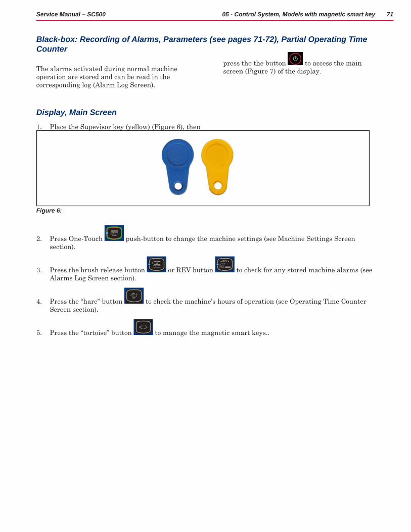
71Service Manual – SC500 05 - Control System, Models with magnetic smart key
Black-box: Recording of Alarms, Parameters (see pages 71-72), Partial Operating Time Counter
The alarms activated during normal machine operation are stored and can be read in the corresponding log (Alarm Log Screen)
Display, Main Screen
1 Place the Supevisor key (yellow) (Figure 6), then
press the the button to access the main screen (Figure 7) of the display
Figure 6:
2 Press One-Touch push-button to change the machine settings (see Machine Settings Screen section)
3 Press the brush release button or REV button to check for any stored machine alarms (see Alarms Log Screen section)
4 Press the “hare” button to check the machine’s hours of operation (see Operating Time Counter Screen section)
5 Press the “tortoise” button to manage the magnetic smart keys
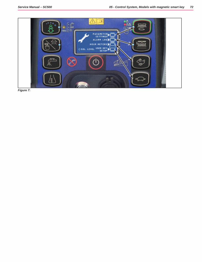
72Service Manual – SC500 05 - Control System, Models with magnetic smart key
Figure 7:
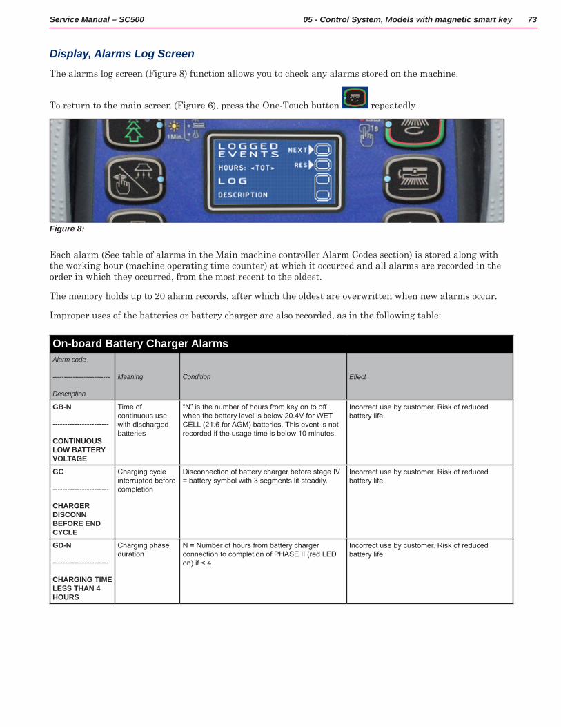
73Service Manual – SC500 05 - Control System, Models with magnetic smart key
Display, Alarms Log Screen
The alarms log screen (Figure 8) function allows you to check any alarms stored on the machine
To return to the main screen (Figure 6), press the One-Touch button repeatedly
Figure 8:
Each alarm (See table of alarms in the Main machine controller Alarm Codes section) is stored along with the working hour (machine operating time counter) at which it occurred and all alarms are recorded in the order in which they occurred, from the most recent to the oldest
The memory holds up to 20 alarm records, after which the oldest are overwritten when new alarms occur
Improper uses of the batteries or battery charger are also recorded, as in the following table:
On-board Battery Charger AlarmsAlarm code
--------------------------
Description
Meaning Condition Effect
GB-N
-----------------------
CONTINUOUS LOW BATTERY VOLTAGE
Time of continuous use with discharged batteries
“N” is the number of hours from key on to off when the battery level is below 20.4V for WET CELL (21.6 for AGM) batteries. This event is not recorded if the usage time is below 10 minutes.
Incorrect use by customer. Risk of reduced battery life.
GC
-----------------------
CHARGER DISCONN BEFORE END CYCLE
Charging cycle interrupted before completion
Disconnection of battery charger before stage IV = battery symbol with 3 segments lit steadily.
Incorrect use by customer. Risk of reduced battery life.
GD-N
-----------------------
CHARGING TIME LESS THAN 4 HOURS
Charging phase duration
N = Number of hours from battery charger connection to completion of PHASE II (red LED on) if < 4
Incorrect use by customer. Risk of reduced battery life.
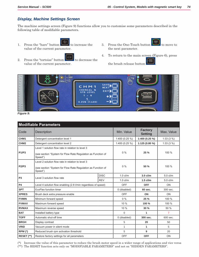
74Service Manual – SC500 05 - Control System, Models with magnetic smart key
Figure 9:
Modifiable Parameters
Code Description Min. Value Factory Setting Max. Value
CHM1 Detergent concentration level 1 1:400 (0.25 %) 1:400 (0.25 %) 1:33 (3 %)
CHM2 Detergent concentration level 2 1:400 (0.25 %) 1:125 (0.80 %) 1:33 (3 %)
P1/P3Level 1 solution flow rate in relation to level 3
(see section “System for Flow Rate Regulation as Function of Speed”)
0 % 25 % 100 %
P2/P3Level 2 solution flow rate in relation to level 3
(see section “System for Flow Rate Regulation as Function of Speed”)
0 % 50 % 100 %
P3 Level 3 solution flow rateDISC 1.0 cl/m 3.0 cl/m 5.0 cl/m
REV 1.0 cl/m 1.5 cl/m 5.0 cl/m
P4 Level 4 solution flow enabling (2.8 l/min regardless of speed) OFF OFF ON
SPT EcoFlex function timer 0 (disabled) 60 sec. 300 sec.
XPRES Brush deck extra pressure enable OFF ON ON
FVMIN Minimum forward speed 0 % 25 % 100 %
FVMAX Maximum forward speed 10 % 100 % 100 %
RVMAX Maximum reverse speed 10 % 30 % 50 %
BAT Installed battery type 0 1 7
TOFF Automatic shut-off time 0 (disabled) 300 sec. 600 sec.
BRGH Display contrast 5 20 50
VRID Vacuum power in silent mode 1 1 5
RPM (*) Reduced brush rpm activation threshold 5 9 20
RESET (**) Restore factory settings for all parameters OFF OFF ON
(*) Increase the value of this parameter to reduce the brush motor speed in a wider range of applications and vice versa(**) The RESET function acts only on “MODIFIABLE PARAMETERS” and not on “HIDDEN PARAMETERS”
Display, Machine Settings Screen
The machine settings screen (Figure 9) functions allow you to customise some parameters described in the following table of modifiable parameters.
1 Press the “hare” button to increase the value of the current parameter
2 Press the “tortoise” button to decrease the value of the current parameter
3 Press the One-Touch button to move to the next parameter
4 To return to the main screen (Figure 6), press
the brush release button
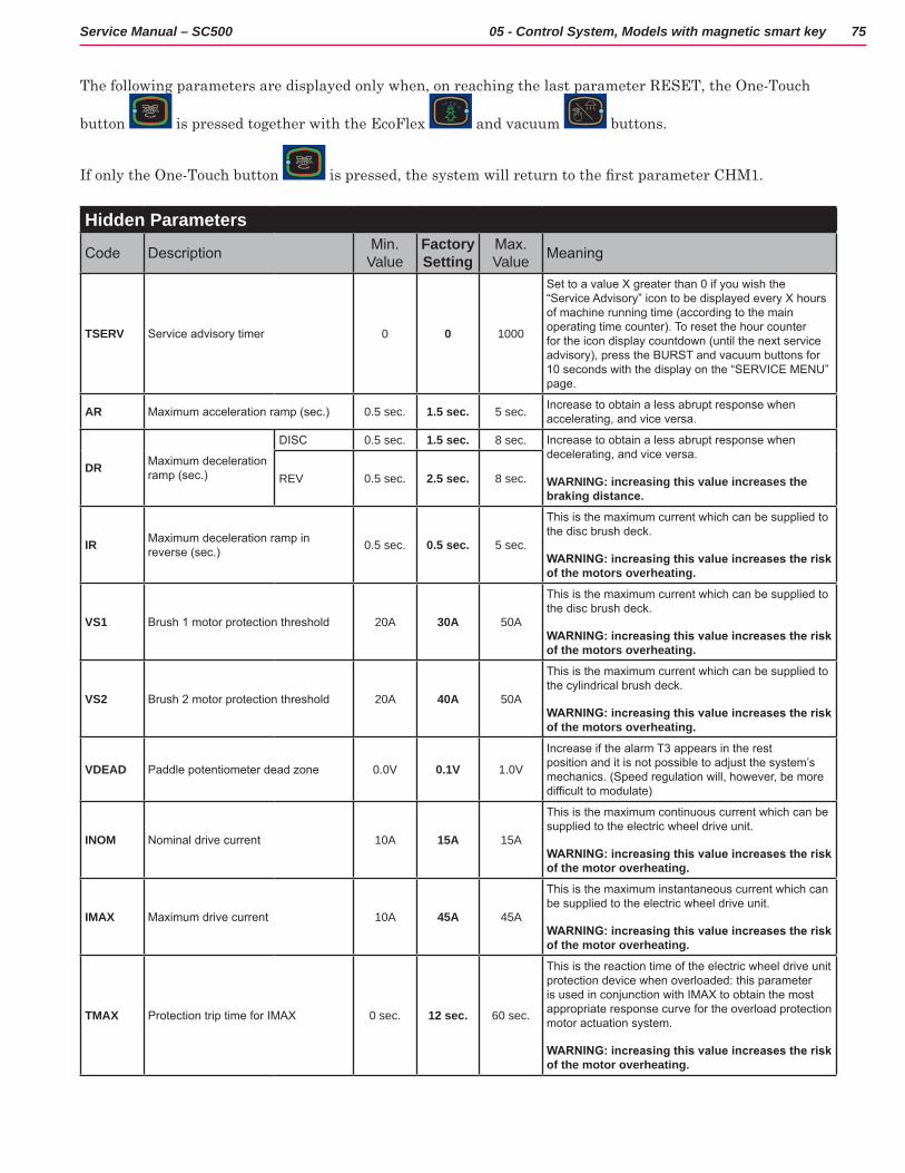
75Service Manual – SC500 05 - Control System, Models with magnetic smart key
The following parameters are displayed only when, on reaching the last parameter RESET, the One-Touch
button is pressed together with the EcoFlex and vacuum buttons
If only the One-Touch button is pressed, the system will return to the first parameter CHM1.
Hidden Parameters
Code Description Min. Value
Factory Setting
Max. Value Meaning
TSERV Service advisory timer 0 0 1000
Set to a value X greater than 0 if you wish the “Service Advisory” icon to be displayed every X hours of machine running time (according to the main operating time counter). To reset the hour counter for the icon display countdown (until the next service advisory), press the BURST and vacuum buttons for 10 seconds with the display on the “SERVICE MENU” page.
AR Maximum acceleration ramp (sec.) 0.5 sec. 1.5 sec. 5 sec. Increase to obtain a less abrupt response when accelerating, and vice versa.
DR Maximum deceleration ramp (sec.)
DISC 0.5 sec. 1.5 sec. 8 sec. Increase to obtain a less abrupt response when decelerating, and vice versa.
WARNING: increasing this value increases the braking distance.
REV 0.5 sec. 2.5 sec. 8 sec.
IR Maximum deceleration ramp in reverse (sec.) 0.5 sec. 0.5 sec. 5 sec.
This is the maximum current which can be supplied to the disc brush deck.
WARNING: increasing this value increases the risk of the motors overheating.
VS1 Brush 1 motor protection threshold 20A 30A 50A
This is the maximum current which can be supplied to the disc brush deck.
WARNING: increasing this value increases the risk of the motors overheating.
VS2 Brush 2 motor protection threshold 20A 40A 50A
This is the maximum current which can be supplied to the cylindrical brush deck.
WARNING: increasing this value increases the risk of the motors overheating.
VDEAD Paddle potentiometer dead zone 0.0V 0.1V 1.0V
Increase if the alarm T3 appears in the rest position and it is not possible to adjust the system’s mechanics. (Speed regulation will, however, be more difficult to modulate)
INOM Nominal drive current 10A 15A 15A
This is the maximum continuous current which can be supplied to the electric wheel drive unit.
WARNING: increasing this value increases the risk of the motor overheating.
IMAX Maximum drive current 10A 45A 45A
This is the maximum instantaneous current which can be supplied to the electric wheel drive unit.
WARNING: increasing this value increases the risk of the motor overheating.
TMAX Protection trip time for IMAX 0 sec. 12 sec. 60 sec.
This is the reaction time of the electric wheel drive unit protection device when overloaded: this parameter is used in conjunction with IMAX to obtain the most appropriate response curve for the overload protection motor actuation system.
WARNING: increasing this value increases the risk of the motor overheating.
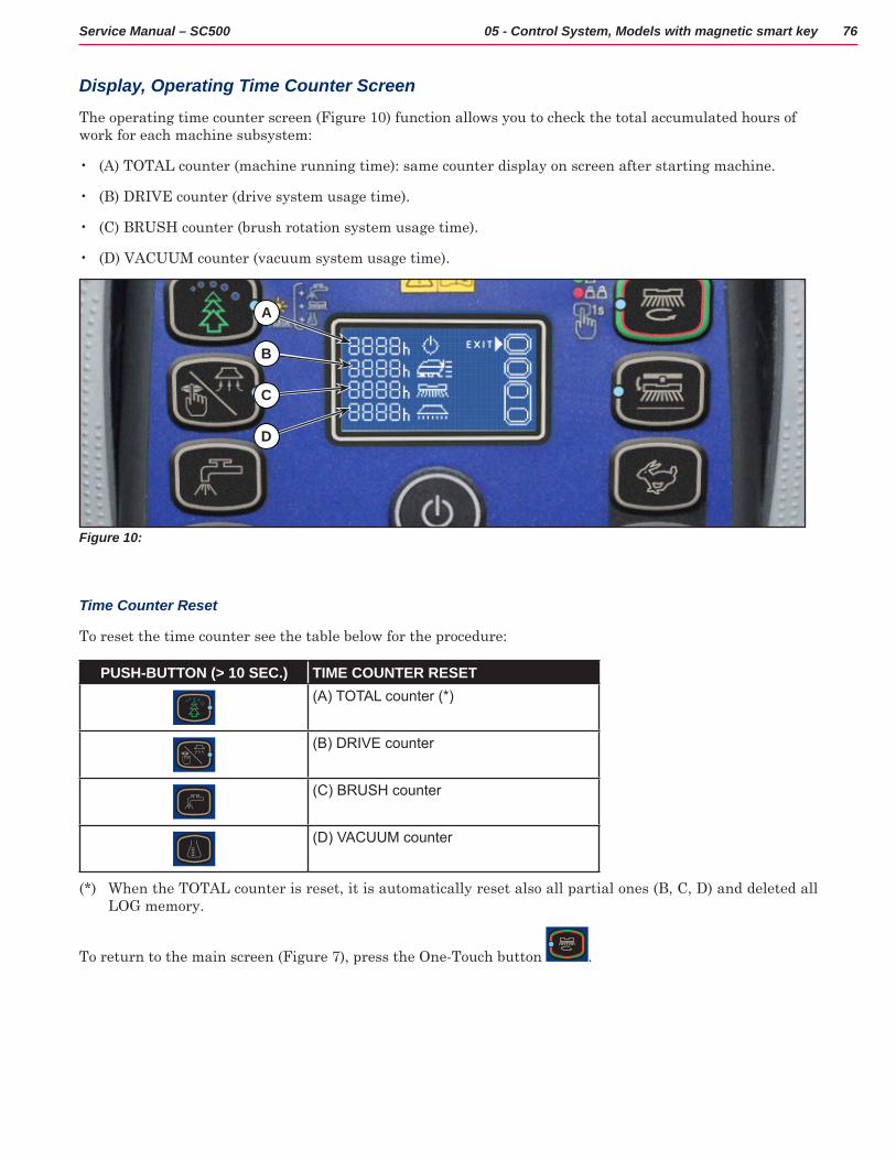
76Service Manual – SC500 05 - Control System, Models with magnetic smart key
Display, Operating Time Counter Screen
The operating time counter screen (Figure 10) function allows you to check the total accumulated hours of work for each machine subsystem:
• (A) TOTAL counter (machine running time): same counter display on screen after starting machine
• (B) DRIVE counter (drive system usage time)
• (C) BRUSH counter (brush rotation system usage time)
• (D) VACUUM counter (vacuum system usage time)
Figure 10:
A
B
C
D
Time Counter Reset
To reset the time counter see the table below for the procedure:
PUSH-BUTTON (> 10 SEC.) TIME COUNTER RESET(A) TOTAL counter (*)
(B) DRIVE counter
(C) BRUSH counter
(D) VACUUM counter
(*) When the TOTAL counter is reset, it is automatically reset also all partial ones (B, C, D) and deleted all LOG memory
To return to the main screen (Figure 7), press the One-Touch button
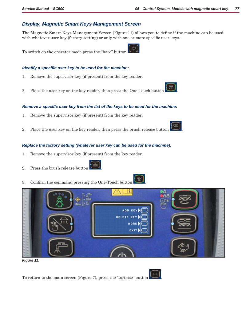
77Service Manual – SC500 05 - Control System, Models with magnetic smart key
Display, Magnetic Smart Keys Management Screen
The Magnetic Smart Keys Management Screen (Figure 11) allows you to define if the machine can be used with whatever user key (factory setting) or only with one or more specific user keys.
To switch on the operator mode press the “hare” button
Identify a specific user key to be used for the machine:
1 Remove the supervisor key (if present) from the key reader
2 Place the user key on the key reader, then press the One-Touch button
Remove a specific user key from the list of the keys to be used for the machine:
1 Remove the supervisor key (if present) from the key reader
2 Place the user key on the key reader, then press the brush release button
Replace the factory setting (whatever user key can be used for the machine):
1 Remove the supervisor key (if present) from the key reader
2 Press the brush release button
3 Confirm the command pressing the One-Touch button
Figure 11:
To return to the main screen (Figure 7), press the “tortoise” button

78Service Manual – SC500 05 - Control System, Models with magnetic smart key
System for Flow Rate Regulation as Function of Speed
Solution flow levels 1, 2 and 3 regulate the flow of detergent solution on the basis of the machine speed so as to keep the quantity of solution dispensed per square metre of floor treated constant.
The reference flow level is level 3: based on the setting of the corresponding parameter P3, the opening time of the solenoid valve (and of the detergent pump when fitted) is regulated so that the quantity of solution in centiliters per metre travelled by the machine is constant and equal to the value set in the parameter
For example, for P3 = 3 0, the machine will dispense 3 centiliters of solution per metre travelled, which equates (for the standard deck width of 530 mm) to 5.7 centiliters per square metre of floor treated.
Levels 1 and 2 are defined via the corresponding parameters P1 and P2 as a % of level 3.
For example, for P1 = 25 and P2 = 50, P1 and P2 are respectively ¼ (25%) and ½ (50%) of the reference flow rate P3
The default values (the same as in the example above) are summarized in the table, with the corresponding flow rate values in liters per minute, dependent on machine speed, given as a reference.
SC500 DISC detergent flow (as a function of speed) (standard setting)Level 1 Level 2 Level 3
Liters/minute @ 1 km/h 0.2 0.3 0.5Liters/minute @ 3 km/h 0.4 0.8 1.5Liters/minute @ 5 km/h 0.6 1.3 2.5Centiliters per metre cleaned (constant) 0.75 1.5 3Centiliters per meter2 cleaned (Ø530 deck) 1.4 2.8 5.7
Level 4 (when enabled) is independent of any parameter and supplies the maximum possible quantity of solution as it keeps the solenoid valve of the supply system constantly open (with the brush rotating)
SC500 DISC detergent flow rateLevel 4
Liters/minute - Tank full 3.5Liters/minute - Average 2.5
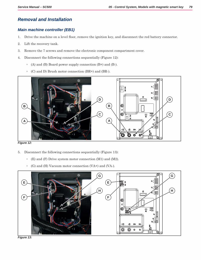
79Service Manual – SC500 05 - Control System, Models with magnetic smart key
Removal and Installation
Main machine controller (EB1)
1 Drive the machine on a level floor, remove the ignition key, and disconnect the red battery connector.
2 Lift the recovery tank
3 Remove the 7 screws and remove the electronic component compartment cover
4 Disconnect the following connections sequentially (Figure 12):
◦ (A) and (B) Board power supply connection (B+) and (B-)
◦ (C) and D) Brush motor connection (BR+) and (BR-)
Figure 12:
B
D
B
D
A
C
A
C
5 Disconnect the following connections sequentially (Figure 13):
◦ (E) and (F) Drive system motor connection (M1) and (M2)
◦ (G) and (H) Vacuum motor connection (VA+) and (VA-)
Figure 13:
E E
G G
F F
H H
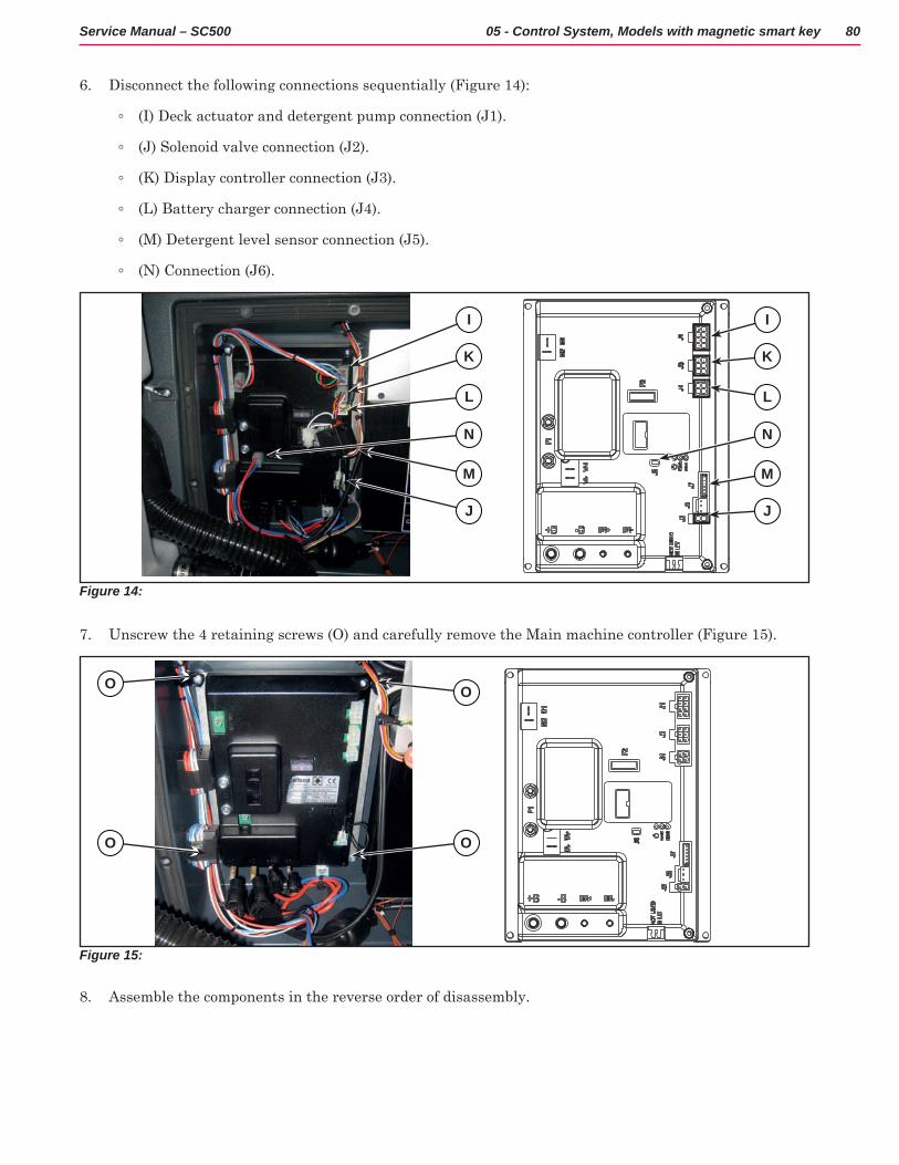
80Service Manual – SC500 05 - Control System, Models with magnetic smart key
6 Disconnect the following connections sequentially (Figure 14):
◦ (I) Deck actuator and detergent pump connection (J1)
◦ (J) Solenoid valve connection (J2)
◦ (K) Display controller connection (J3)
◦ (L) Battery charger connection (J4)
◦ (M) Detergent level sensor connection (J5)
◦ (N) Connection (J6)
Figure 14:
I I
K K
L L
N N
M M
J J
7 Unscrew the 4 retaining screws (O) and carefully remove the Main machine controller (Figure 15)
Figure 15:
O
OO
O
8 Assemble the components in the reverse order of disassembly
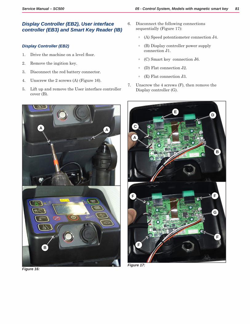
81Service Manual – SC500 05 - Control System, Models with magnetic smart key
Display Controller (EB2), User interface controller (EB3) and Smart Key Reader (IB)
Display Controller (EB2)
1 Drive the machine on a level floor.
2 Remove the ingition key
3 Disconnect the red battery connector
4 Unscrew the 2 screws (A) (Figure 16)
5 Lift up and remove the User interface controller cover (B)
Figure 16:
A A
B
6 Disconnect the following connections sequentially (Figure 17):
◦ (A) Speed potentiometer connection J4
◦ (B) Display controller power supply connection J1
◦ (C) Smart key connection J6
◦ (D) Flat connection J2
◦ (E) Flat connection J3
7 Unscrew the 4 screws (F), then remove the Display controller (G)
Figure 17:
B
DE
C
A
F
F
G
F
F
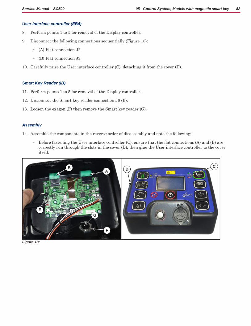
82Service Manual – SC500 05 - Control System, Models with magnetic smart key
User interface controller (EB4)
8 Perform points 1 to 5 for removal of the Display controller
9 Disconnect the following connections sequentially (Figure 18):
◦ (A) Flat connection J2
◦ (B) Flat connection J3
10 Carefully raise the User interface controller (C), detaching it from the cover (D)
Smart Key Reader (IB)
11 Perform points 1 to 5 for removal of the Display controller
12 Disconnect the Smart key reader connection J6 (E)
13 Loosen the exagon (F) then remove the Smart key reader (G)
Assembly
14 Assemble the components in the reverse order of disassembly and note the following:
◦ Before fastening the User interface controller (C), ensure that the flat connections (A) and (B) are correctly run through the slots in the cover (D), then glue the User interface controller to the cover itself
Figure 18:
B
EG
F
A D C
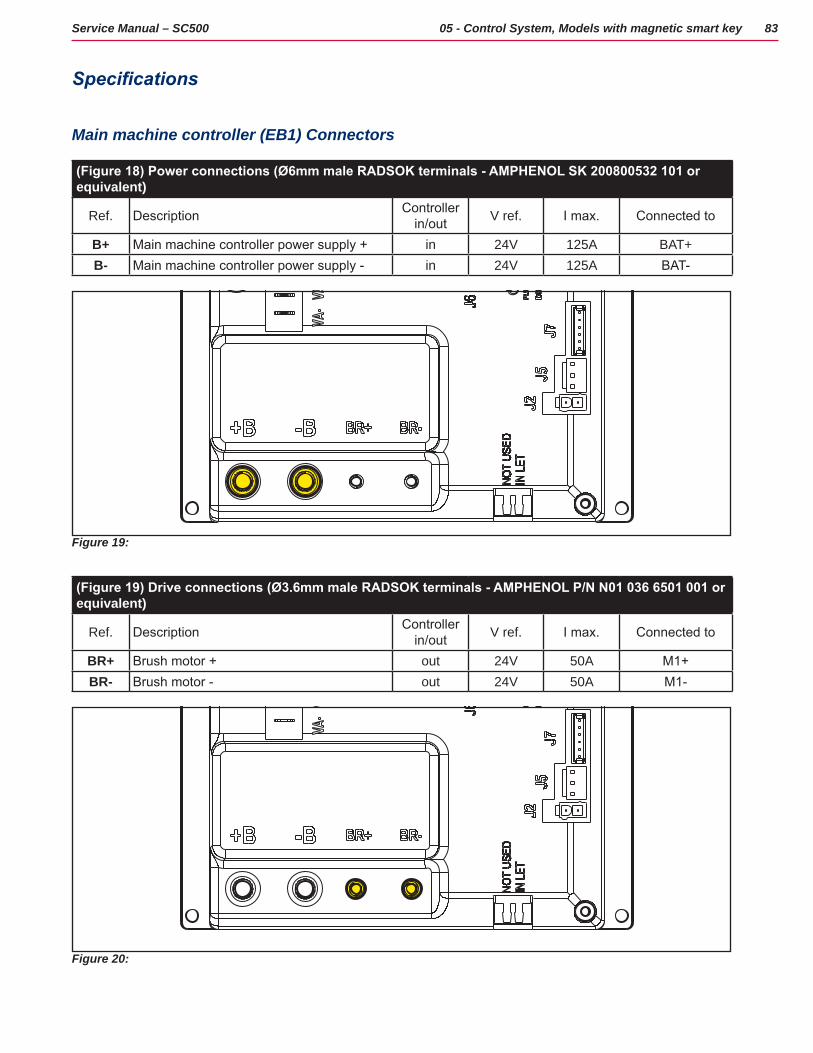
83Service Manual – SC500 05 - Control System, Models with magnetic smart key
Specifications
Main machine controller (EB1) Connectors
(Figure 18) Power connections (Ø6mm male RADSOK terminals - AMPHENOL SK 200800532 101 or equivalent)
Ref. Description Controller in/out V ref. I max. Connected to
B+ Main machine controller power supply + in 24V 125A BAT+B- Main machine controller power supply - in 24V 125A BAT-
Figure 19:
(Figure 19) Drive connections (Ø3.6mm male RADSOK terminals - AMPHENOL P/N N01 036 6501 001 or equivalent)
Ref. Description Controller in/out V ref. I max. Connected to
BR+ Brush motor + out 24V 50A M1+BR- Brush motor - out 24V 50A M1-
Figure 20:
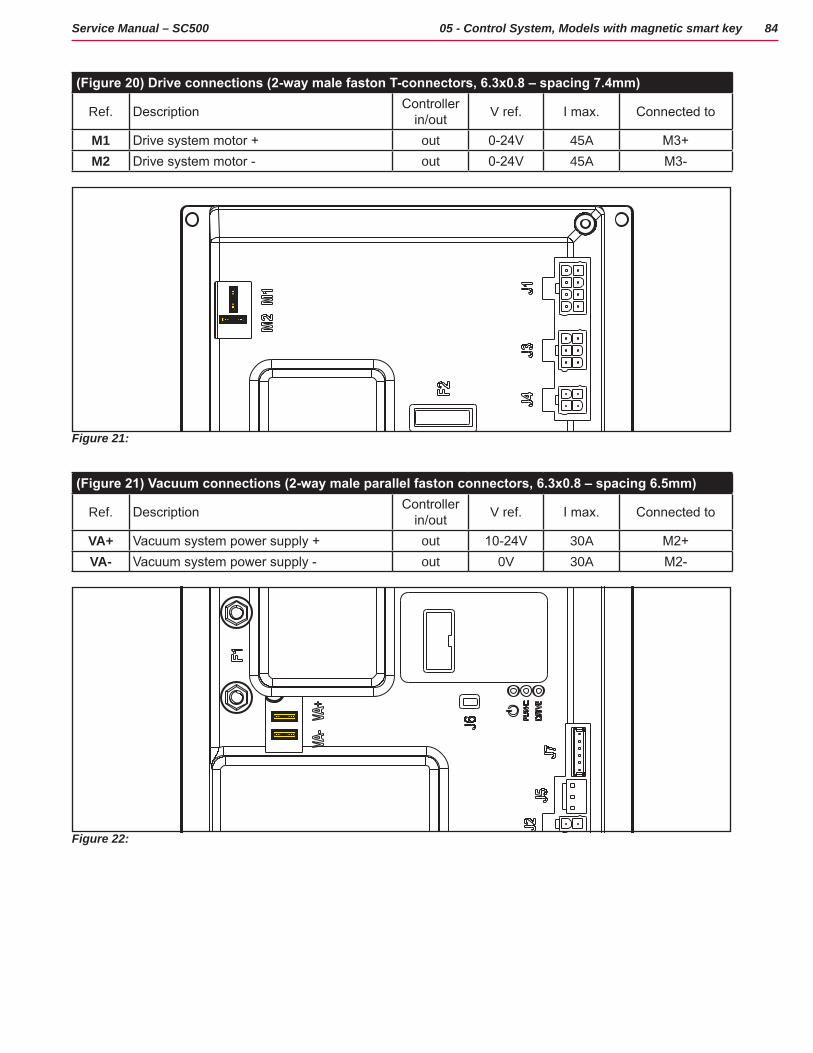
84Service Manual – SC500 05 - Control System, Models with magnetic smart key
(Figure 20) Drive connections (2-way male faston T-connectors, 6.3x0.8 – spacing 7.4mm)
Ref. Description Controller in/out V ref. I max. Connected to
M1 Drive system motor + out 0-24V 45A M3+M2 Drive system motor - out 0-24V 45A M3-
Figure 21:
(Figure 21) Vacuum connections (2-way male parallel faston connectors, 6.3x0.8 – spacing 6.5mm)
Ref. Description Controller in/out V ref. I max. Connected to
VA+ Vacuum system power supply + out 10-24V 30A M2+VA- Vacuum system power supply - out 0V 30A M2-
Figure 22:
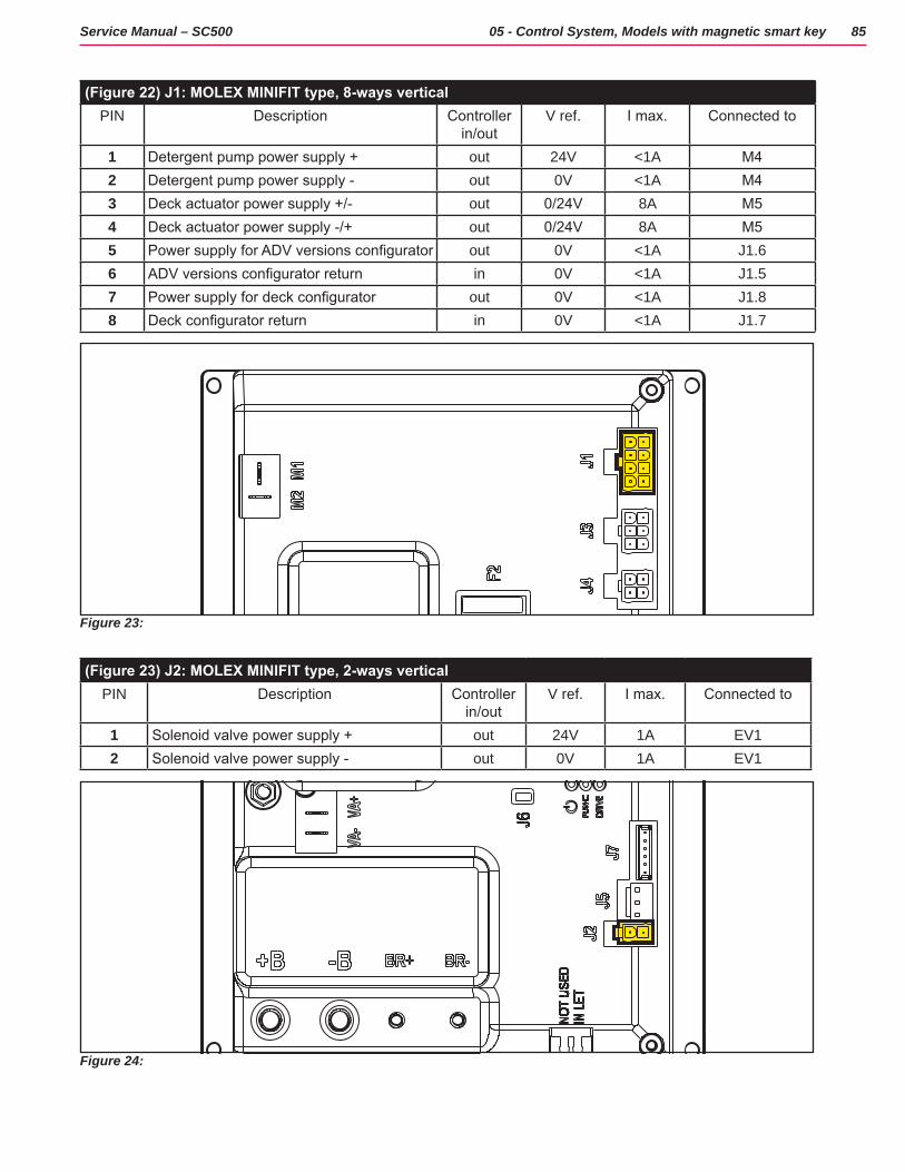
85Service Manual – SC500 05 - Control System, Models with magnetic smart key
(Figure 22) J1: MOLEX MINIFIT type, 8-ways verticalPIN Description Controller
in/outV ref. I max. Connected to
1 Detergent pump power supply + out 24V <1A M42 Detergent pump power supply - out 0V <1A M43 Deck actuator power supply +/- out 0/24V 8A M54 Deck actuator power supply -/+ out 0/24V 8A M55 Power supply for ADV versions configurator out 0V <1A J1.66 ADV versions configurator return in 0V <1A J1.57 Power supply for deck configurator out 0V <1A J1.88 Deck configurator return in 0V <1A J1.7
Figure 23:
(Figure 23) J2: MOLEX MINIFIT type, 2-ways verticalPIN Description Controller
in/outV ref. I max. Connected to
1 Solenoid valve power supply + out 24V 1A EV12 Solenoid valve power supply - out 0V 1A EV1
Figure 24:

86Service Manual – SC500 05 - Control System, Models with magnetic smart key
(Figure 24) J3: MOLEX MINIFIT type, 6-ways verticalPIN Description Controller
in/outV ref. I max. Connected to
1 User interface controller power supply + out 24V <1A EB2.12 User interface controller serial + in/out 5V <1A EB2.23 User interface controller serial - in/out 0V <1A EB2.34 User interface controller power supply - out 0V <1A EB2.45 Return from key in 24V <1A EB2.56 Return from key (repetition) out 24V <1A -
Figure 25:
(Figure 25) J4: MOLEX MINIFIT type, 4-ways verticalPIN Description Controller
in/outV ref. I max. Connected to
1 Enabling from battery charger in 24V <1A CH.12 Power supply from battery charger in 24V <1A CH.23 Battery charger enabling power supply out 24V <1A CH.34 Battery charger data communication In/out 5V <1A CH.4
Figure 26:
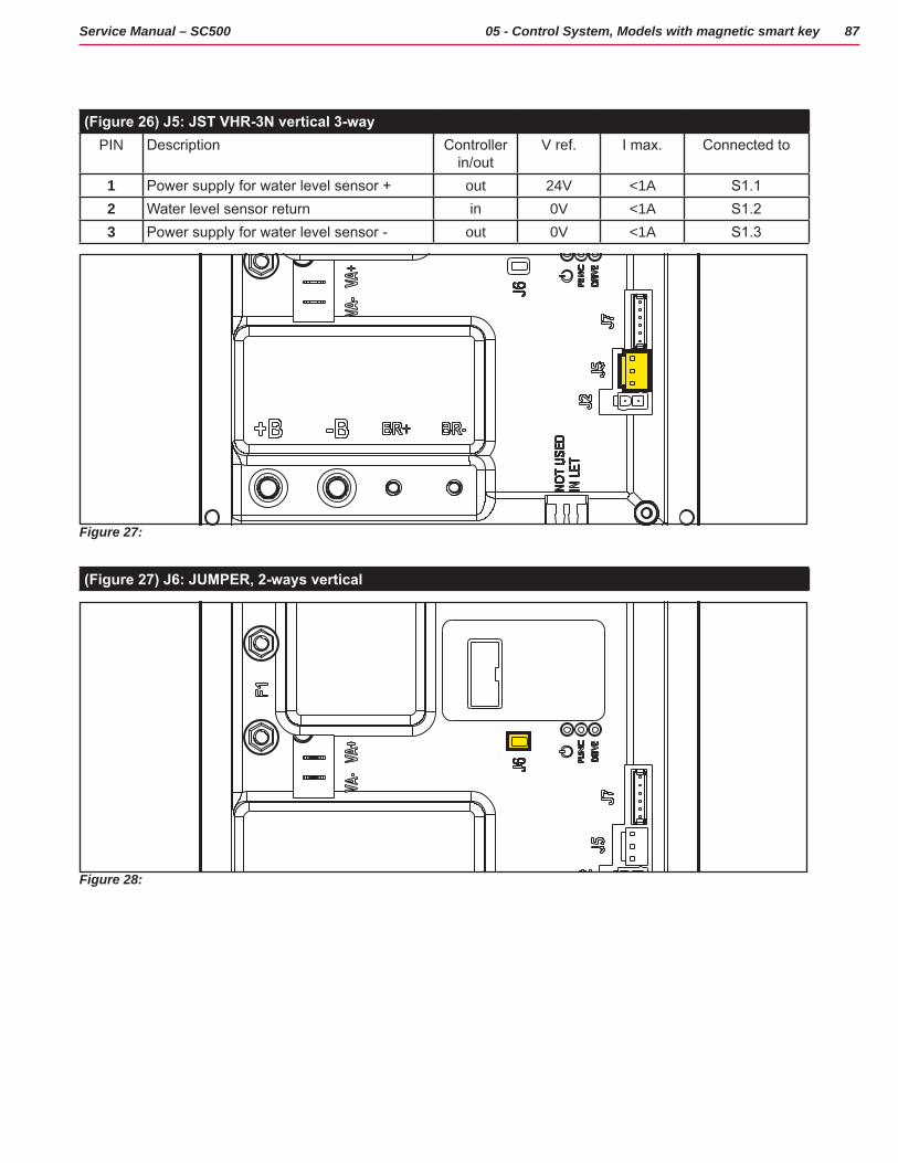
87Service Manual – SC500 05 - Control System, Models with magnetic smart key
(Figure 26) J5: JST VHR-3N vertical 3-wayPIN Description Controller
in/outV ref. I max. Connected to
1 Power supply for water level sensor + out 24V <1A S1.12 Water level sensor return in 0V <1A S1.23 Power supply for water level sensor - out 0V <1A S1.3
Figure 27:
(Figure 27) J6: JUMPER, 2-ways vertical
Figure 28:

88Service Manual – SC500 05 - Control System, Models with magnetic smart key
(Figure 28) J7: TYCO MODU II vertical 6-wayPIN Description Controller
in/outV ref. I max. Connected to
1 +24V power supply out 24V <1A TRK.RD2 +5V power supply out 5V <1A -3 iButton input (CAN H channel) In (Out) 0V (0-5V) <1A TRK.YE4 Ext. operating time counter enable (CAN L
channel)(In) Out 0V (0-24V) <1A TRK.WH
5 Power supply - out 0V <1A TRK.BU6 Machine on signal out 24V <1A TRK.BN
Figure 29:
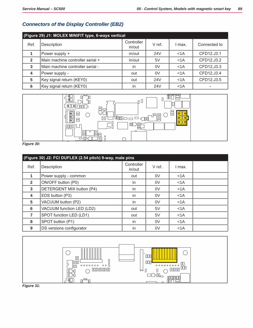
89Service Manual – SC500 05 - Control System, Models with magnetic smart key
Connectors of the Display Controller (EB2)
(Figure 29) J1: MOLEX MINIFIT type, 6-ways vertical
Ref. Description Controller in/out V ref. I max. Connected to
1 Power supply + in/out 24V <1A CFD12.J3.12 Main machine controller serial + in/out 5V <1A CFD12.J3.23 Main machine controller serial - in 0V <1A CFD12.J3.34 Power supply - out 0V <1A CFD12.J3.45 Key signal return (KEY0) out 24V <1A CFD12.J3.56 Key signal return (KEY0) in 24V <1A -
Figure 30:
(Figure 30) J2: FCI DUFLEX (2.54 pitch) 9-way, male pins
Ref. Description Controller in/out V ref. I max.
1 Power supply - common out 0V <1A2 ON/OFF button (P0) in 0V <1A3 DETERGENT MIX button (P4) in 0V <1A4 EDS button (P3) in 0V <1A5 VACUUM button (P2) in 0V <1A6 VACUUM function LED (LD2) out 5V <1A7 SPOT function LED (LD1) out 5V <1A8 SPOT button (P1) in 0V <1A9 DS versions configurator in 0V <1A
Figure 31:
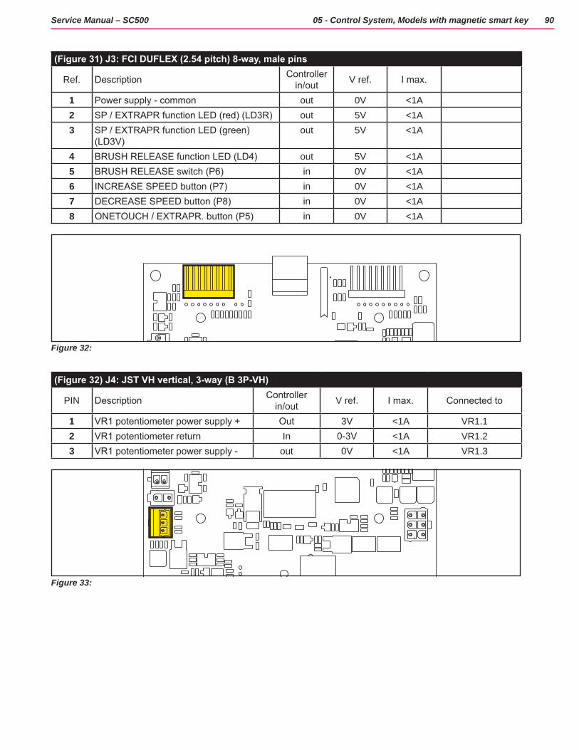
90Service Manual – SC500 05 - Control System, Models with magnetic smart key
(Figure 31) J3: FCI DUFLEX (2.54 pitch) 8-way, male pins
Ref. Description Controller in/out V ref. I max.
1 Power supply - common out 0V <1A2 SP / EXTRAPR function LED (red) (LD3R) out 5V <1A3 SP / EXTRAPR function LED (green)
(LD3V)out 5V <1A
4 BRUSH RELEASE function LED (LD4) out 5V <1A5 BRUSH RELEASE switch (P6) in 0V <1A6 INCREASE SPEED button (P7) in 0V <1A7 DECREASE SPEED button (P8) in 0V <1A8 ONETOUCH / EXTRAPR. button (P5) in 0V <1A
Figure 32:
(Figure 32) J4: JST VH vertical, 3-way (B 3P-VH)
PIN Description Controller in/out V ref. I max. Connected to
1 VR1 potentiometer power supply + Out 3V <1A VR1.12 VR1 potentiometer return In 0-3V <1A VR1.23 VR1 potentiometer power supply - out 0V <1A VR1.3
Figure 33:
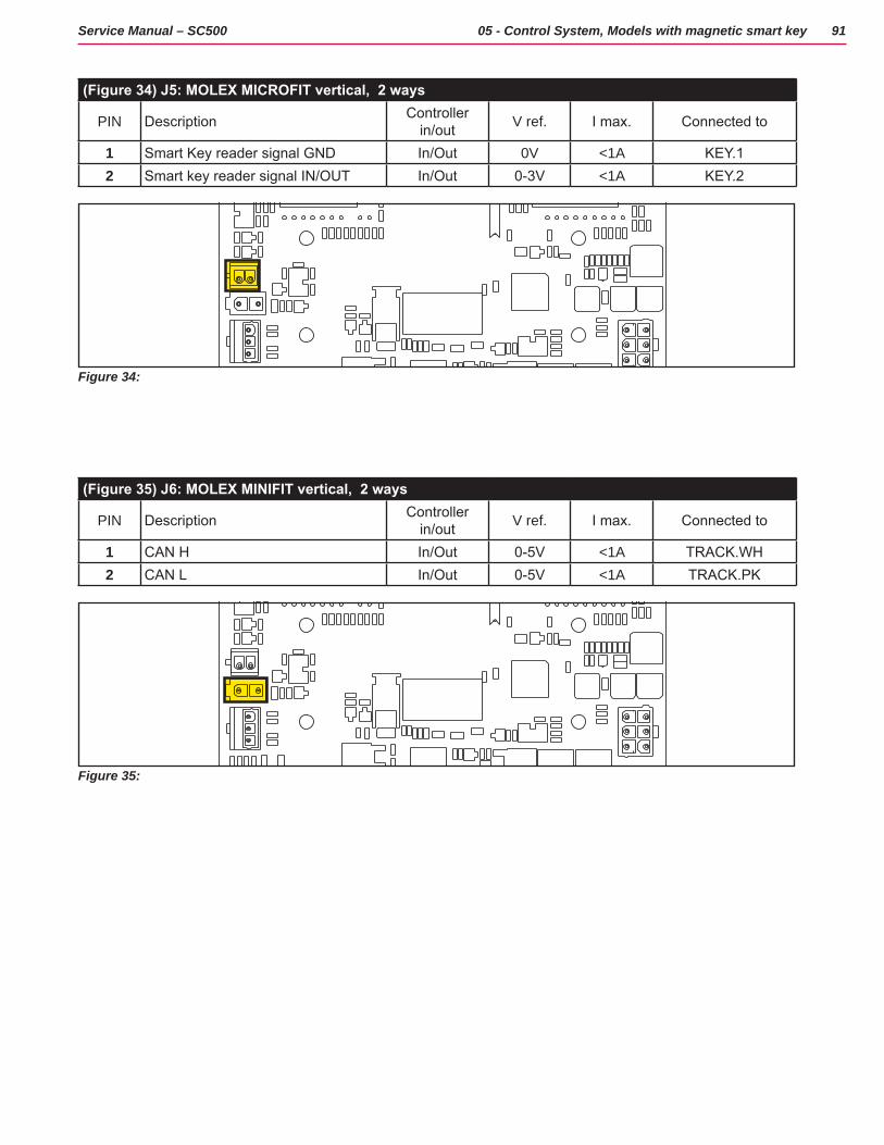
91Service Manual – SC500 05 - Control System, Models with magnetic smart key
(Figure 34) J5: MOLEX MICROFIT vertical, 2 ways
PIN Description Controller in/out V ref. I max. Connected to
1 Smart Key reader signal GND In/Out 0V <1A KEY.12 Smart key reader signal IN/OUT In/Out 0-3V <1A KEY.2
Figure 34:
(Figure 35) J6: MOLEX MINIFIT vertical, 2 ways
PIN Description Controller in/out V ref. I max. Connected to
1 CAN H In/Out 0-5V <1A TRACK.WH2 CAN L In/Out 0-5V <1A TRACK.PK
Figure 35:
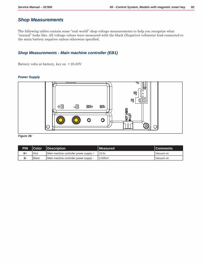
92Service Manual – SC500 05 - Control System, Models with magnetic smart key
Shop Measurements
The following tables contain some “real world” shop voltage measurements to help you recognize what “normal” looks like All voltage values were measured with the black (Negative) voltmeter lead connected to the main battery negative unless otherwise specified.
Shop Measurements - Main machine controller (EB1)
Battery volts at battery, key on = 25 03V
Power Supply
Figure 36:
PIN Color Description Measured CommentsB+ Red Main machine controller power supply + 24.5v Vacuum on
B- Black Main machine controller power supply - 0.035vV Vacuum on
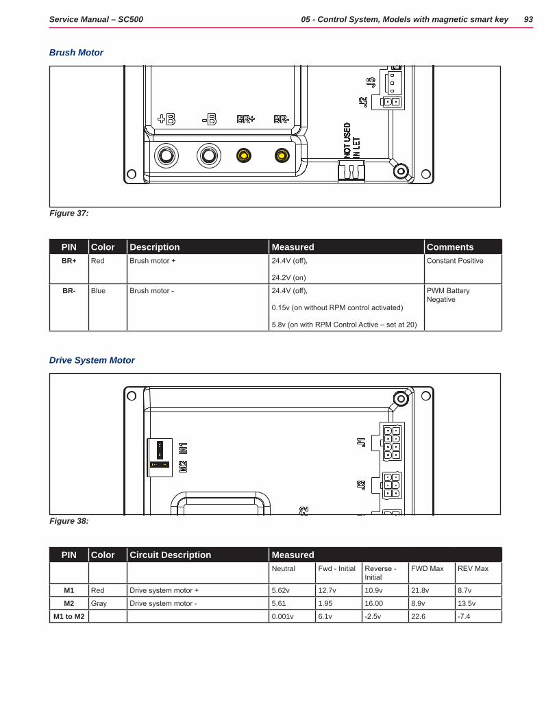
93Service Manual – SC500 05 - Control System, Models with magnetic smart key
Brush Motor
Figure 37:
PIN Color Description Measured CommentsBR+ Red Brush motor + 24.4V (off),
24.2V (on)
Constant Positive
BR- Blue Brush motor - 24.4V (off),
0.15v (on without RPM control activated)
5.8v (on with RPM Control Active – set at 20)
PWM Battery Negative
Drive System Motor
Figure 38:
PIN Color Circuit Description MeasuredNeutral Fwd - Initial Reverse -
InitialFWD Max REV Max
M1 Red Drive system motor + 5.62v 12.7v 10.9v 21.8v 8.7v
M2 Gray Drive system motor - 5.61 1.95 16.00 8.9v 13.5v
M1 to M2 0.001v 6.1v -2.5v 22.6 -7.4
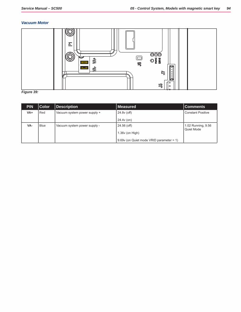
94Service Manual – SC500 05 - Control System, Models with magnetic smart key
Vacuum Motor
Figure 39:
PIN Color Description Measured CommentsVA+ Red Vacuum system power supply + 24.8v (off)
24.4v (on)
Constant Positive
VA- Blue Vacuum system power supply - 24.56 (off)
1.36v (on High)
9.69v (on Quiet mode VRID parameter = 1)
1.02 Running, 9.56 Quiet Mode
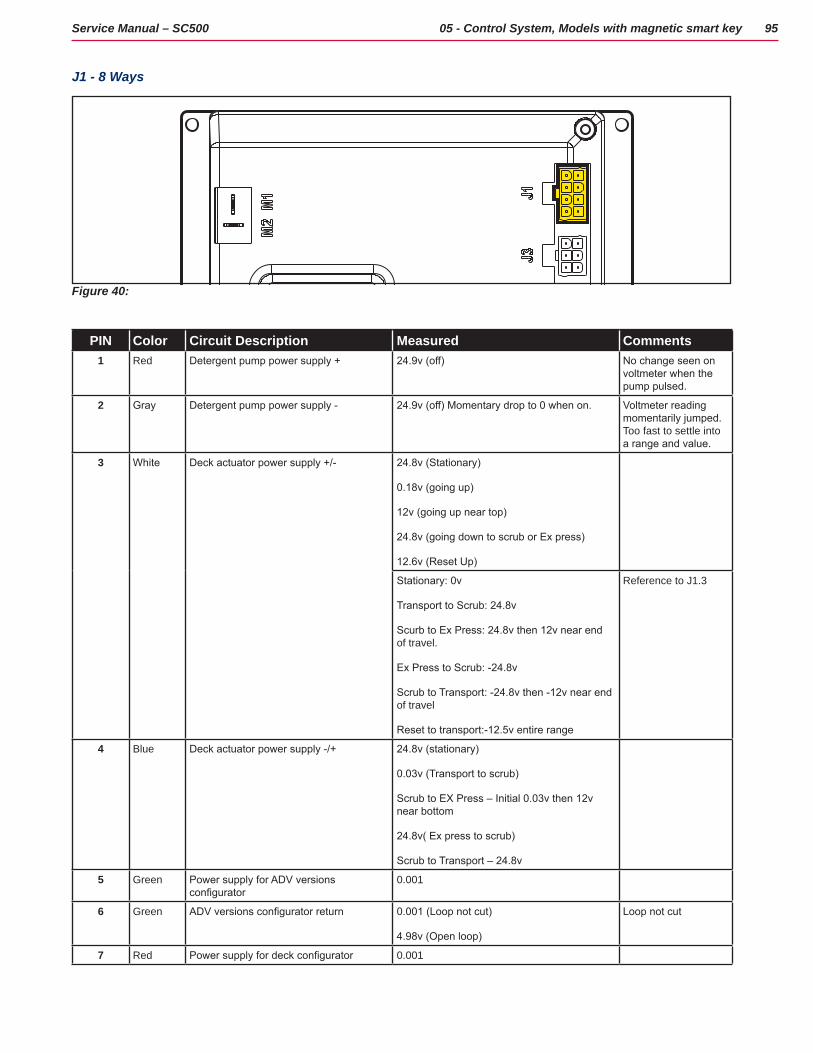
95Service Manual – SC500 05 - Control System, Models with magnetic smart key
J1 - 8 Ways
Figure 40:
PIN Color Circuit Description Measured Comments1 Red Detergent pump power supply + 24.9v (off) No change seen on
voltmeter when the pump pulsed.
2 Gray Detergent pump power supply - 24.9v (off) Momentary drop to 0 when on. Voltmeter reading momentarily jumped. Too fast to settle into a range and value.
3 White Deck actuator power supply +/- 24.8v (Stationary)
0.18v (going up)
12v (going up near top)
24.8v (going down to scrub or Ex press)
12.6v (Reset Up)
Stationary: 0v
Transport to Scrub: 24.8v
Scurb to Ex Press: 24.8v then 12v near end of travel.
Ex Press to Scrub: -24.8v
Scrub to Transport: -24.8v then -12v near end of travel
Reset to transport:-12.5v entire range
Reference to J1.3
4 Blue Deck actuator power supply -/+ 24.8v (stationary)
0.03v (Transport to scrub)
Scrub to EX Press – Initial 0.03v then 12v near bottom
24.8v( Ex press to scrub)
Scrub to Transport – 24.8v
5 Green Power supply for ADV versions configurator
0.001
6 Green ADV versions configurator return 0.001 (Loop not cut)
4.98v (Open loop)
Loop not cut
7 Red Power supply for deck configurator 0.001
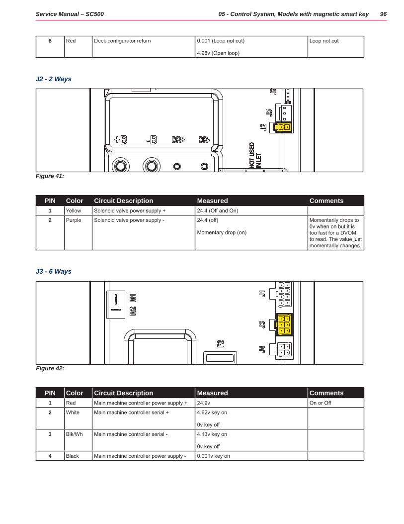
96Service Manual – SC500 05 - Control System, Models with magnetic smart key
8 Red Deck configurator return 0.001 (Loop not cut)
4.98v (Open loop)
Loop not cut
J2 - 2 Ways
Figure 41:
PIN Color Circuit Description Measured Comments1 Yellow Solenoid valve power supply + 24.4 (Off and On)
2 Purple Solenoid valve power supply - 24.4 (off)
Momentary drop (on)
Momentarily drops to 0v when on but it is too fast for a DVOM to read. The value just momentarily changes.
J3 - 6 Ways
Figure 42:
PIN Color Circuit Description Measured Comments1 Red Main machine controller power supply + 24.9v On or Off
2 White Main machine controller serial + 4.62v key on
0v key off
3 Blk/Wh Main machine controller serial - 4.13v key on
0v key off
4 Black Main machine controller power supply - 0.001v key on
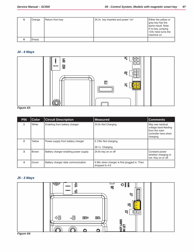
97Service Manual – SC500 05 - Control System, Models with magnetic smart key
5 Orange Return from key 24.3v key inserted and power “on” Either the yellow or gray key has the same result. Note: if no key, jumping +24v here turns the machine on.
6 Empty
J4 - 4 Ways
Figure 43:
PIN Color Circuit Description Measured Comments1 White Enabling from battery charger 24.8v Not Charging May see residual
voltage back-feeding from the main controller here when charging.
2 Yellow Power supply from battery charger 0.136v Not charging
26.1v Charging
3 Brown Battery charger enabling power supply 24.8v key on or off Constant power whether charging or not. Key on or off.
4 Green Battery charger data communication 4.98v when charger is first plugged in. Then dropped to 4.6
J5 - 3 Ways
Figure 44:
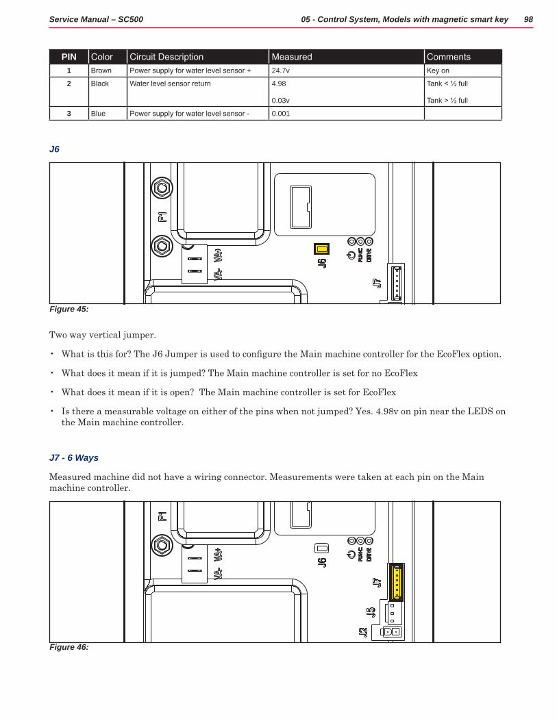
98Service Manual – SC500 05 - Control System, Models with magnetic smart key
PIN Color Circuit Description Measured Comments1 Brown Power supply for water level sensor + 24.7v Key on
2 Black Water level sensor return 4.98
0.03v
Tank < ½ full
Tank > ½ full
3 Blue Power supply for water level sensor - 0.001
J6
Figure 45:
Two way vertical jumper
• What is this for? The J6 Jumper is used to configure the Main machine controller for the EcoFlex option.
• What does it mean if it is jumped? The Main machine controller is set for no EcoFlex
• What does it mean if it is open? The Main machine controller is set for EcoFlex
• Is there a measurable voltage on either of the pins when not jumped? Yes 4 98v on pin near the LEDS on the Main machine controller
J7 - 6 Ways
Measured machine did not have a wiring connector Measurements were taken at each pin on the Main machine controller
Figure 46:

99Service Manual – SC500 05 - Control System, Models with magnetic smart key
PIN Color Circuit Description Measured Comments1 +24V power supply 24.6
2 +5V power supply 5.00
3 iButton input (CAN H channel) 4.98
4 Ext. operating time counter enable (CAN L channel)
24.6
5 Power supply - 0.001
6 Machine on signal 23.68
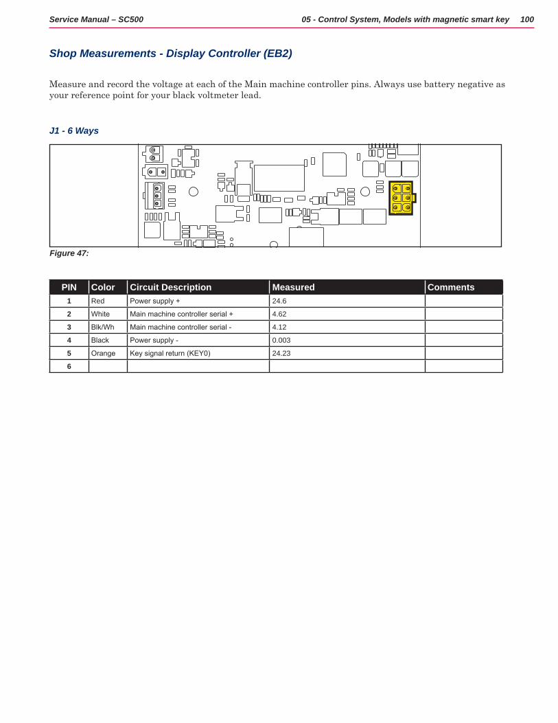
100Service Manual – SC500 05 - Control System, Models with magnetic smart key
Shop Measurements - Display Controller (EB2)
Measure and record the voltage at each of the Main machine controller pins Always use battery negative as your reference point for your black voltmeter lead
J1 - 6 Ways
Figure 47:
PIN Color Circuit Description Measured Comments1 Red Power supply + 24.6
2 White Main machine controller serial + 4.62
3 Blk/Wh Main machine controller serial - 4.12
4 Black Power supply - 0.003
5 Orange Key signal return (KEY0) 24.23
6
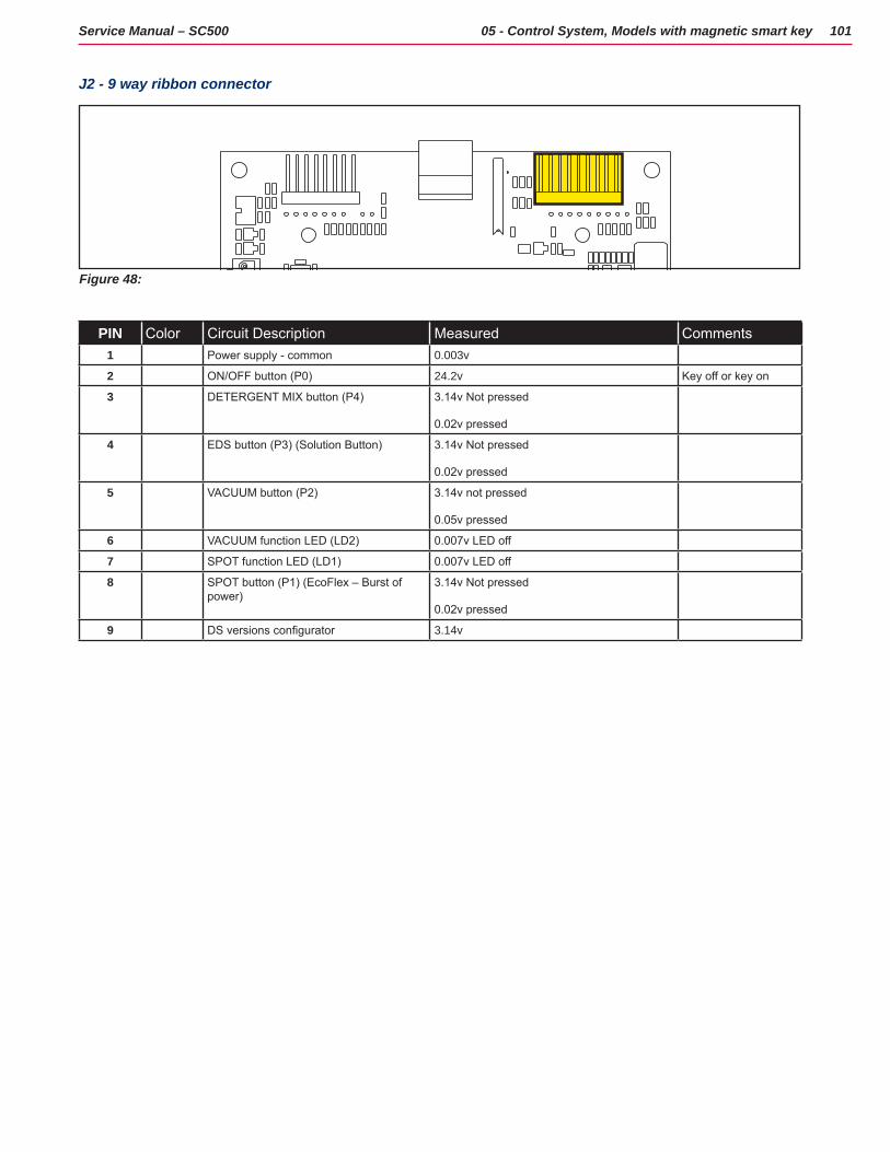
101Service Manual – SC500 05 - Control System, Models with magnetic smart key
J2 - 9 way ribbon connector
Figure 48:
PIN Color Circuit Description Measured Comments1 Power supply - common 0.003v
2 ON/OFF button (P0) 24.2v Key off or key on
3 DETERGENT MIX button (P4) 3.14v Not pressed
0.02v pressed
4 EDS button (P3) (Solution Button) 3.14v Not pressed
0.02v pressed
5 VACUUM button (P2) 3.14v not pressed
0.05v pressed
6 VACUUM function LED (LD2) 0.007v LED off
7 SPOT function LED (LD1) 0.007v LED off
8 SPOT button (P1) (EcoFlex – Burst of power)
3.14v Not pressed
0.02v pressed
9 DS versions configurator 3.14v
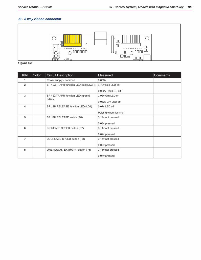
102Service Manual – SC500 05 - Control System, Models with magnetic smart key
J3 - 8 way ribbon connector
Figure 49:
PIN Color Circuit Description Measured Comments1 Power supply - common 0.003v
2 SP / EXTRAPR function LED (red)(LD3R) 1.78v Red LED on
0.032v Red LED off
3 SP / EXTRAPR function LED (green)(LD3V)
1.95v Grn LED on
0.032v Grn LED off
4 BRUSH RELEASE function LED (LD4) 0.07v LED off
Pulsing when flashing
5 BRUSH RELEASE switch (P6) 3.14v not pressed
0.03v pressed
6 INCREASE SPEED button (P7) 3.14v not pressed
0.02v pressed
7 DECREASE SPEED button (P8) 3.14v not pressed
0.02v pressed
8 ONETOUCH / EXTRAPR. button (P5) 3.16v not pressed
0.04v pressed
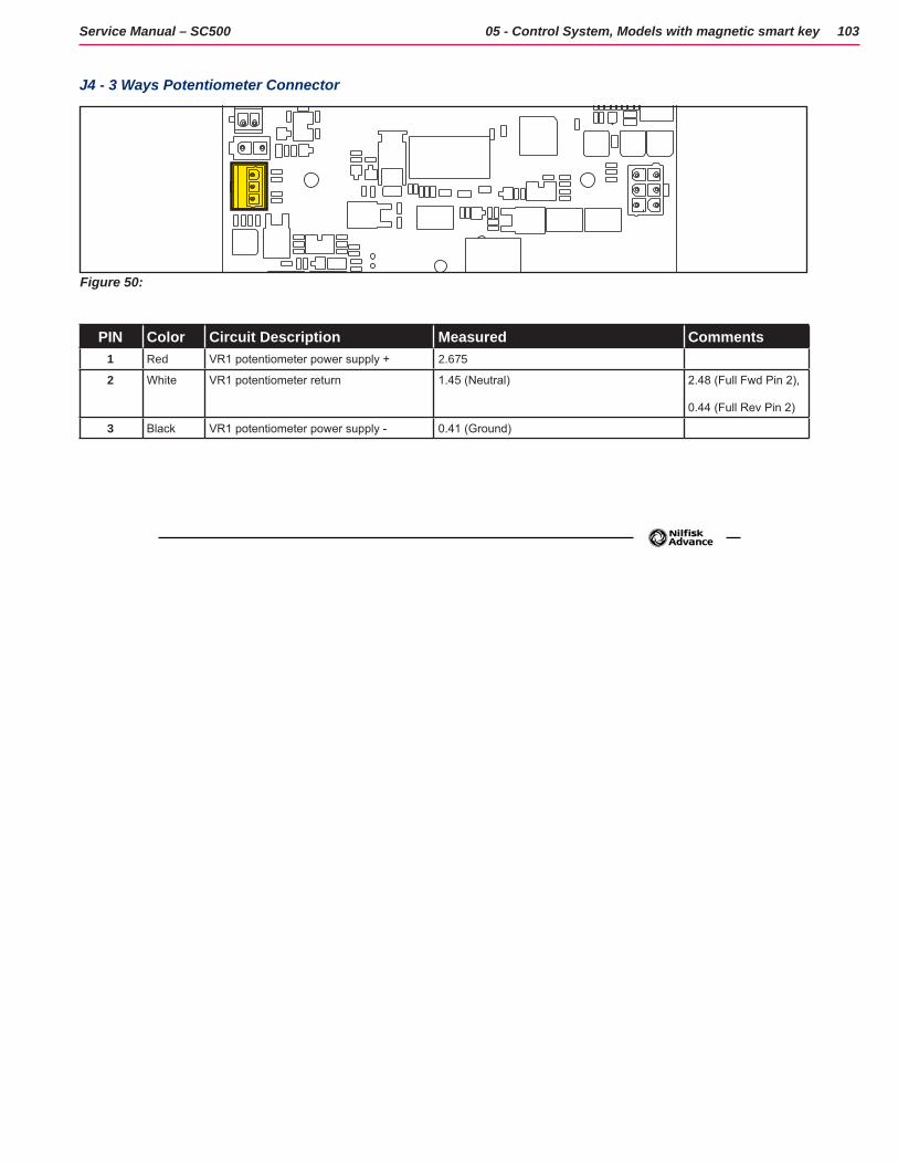
103Service Manual – SC500 05 - Control System, Models with magnetic smart key
J4 - 3 Ways Potentiometer Connector
Figure 50:
PIN Color Circuit Description Measured Comments1 Red VR1 potentiometer power supply + 2.675
2 White VR1 potentiometer return 1.45 (Neutral) 2.48 (Full Fwd Pin 2),
0.44 (Full Rev Pin 2)
3 Black VR1 potentiometer power supply - 0.41 (Ground)
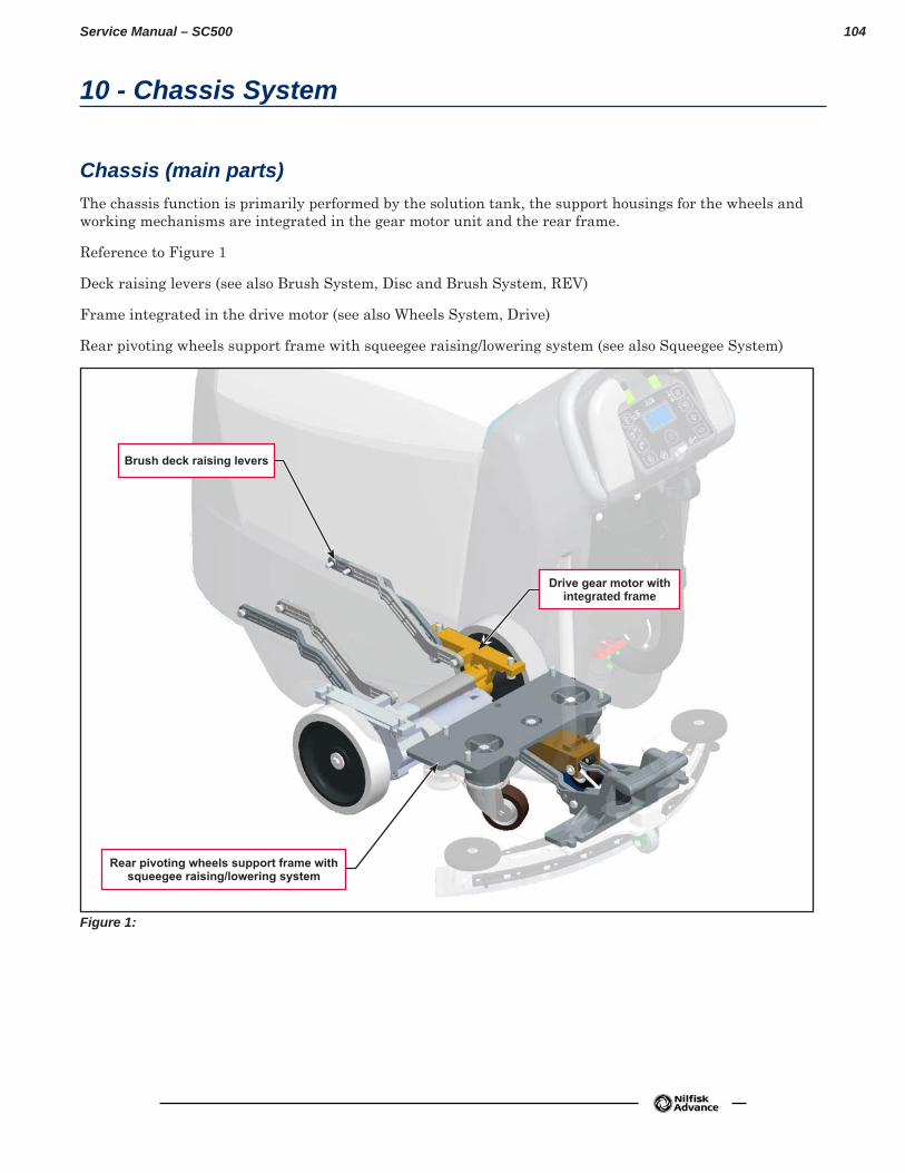
104Service Manual – SC500
10 - Chassis System
Chassis (main parts)The chassis function is primarily performed by the solution tank, the support housings for the wheels and working mechanisms are integrated in the gear motor unit and the rear frame
Reference to Figure 1
Deck raising levers (see also Brush System, Disc and Brush System, REV)
Frame integrated in the drive motor (see also Wheels System, Drive)
Rear pivoting wheels support frame with squeegee raising/lowering system (see also Squeegee System)
Figure 1:
Drive gear motor with integrated frame
Rear pivoting wheels support frame with squeegee raising/lowering system
Brush deck raising levers
105Service Manual – SC500
20 - Wheel System, Traction
Functional DescriptionMachine movement is provided by the gear motor unit (M3)
The gear motor unit (M3) also functions as the main support of the machine, and is composed of an electric motor, the reduction unit with differential and the drive wheels
The operator regulates the transfer speed, the working speed and reverse via the paddles, which are connected directly to the speed potentiometer (RV1) Reversing is performed by pressing the back paddle
The Main machine controller (EB1) checks that the paddles are not pressed when the machine is started; if they are, an alarm is generated (see section “Main machine controller Alarm Codes” in the “Control System” chapter) and the drive system is inhibited
Once the paddles are returned to the rest position, the alarm will stop automatically (without the need to turn the machine on and off)
When the paddles are pressed, the Main machine controller (EB1) supplies a voltage to the motor proportional to the position of the paddles themselves The acceleration ramps and maximum speed can be set via the corresponding parameters (see section “Displaying and Modifying User Modifiable Parameters” in the “Control System” chapter)
Regulation of the maximum speed can be set with the buttons (hare / tortoise) on the User interface controller (EB3)
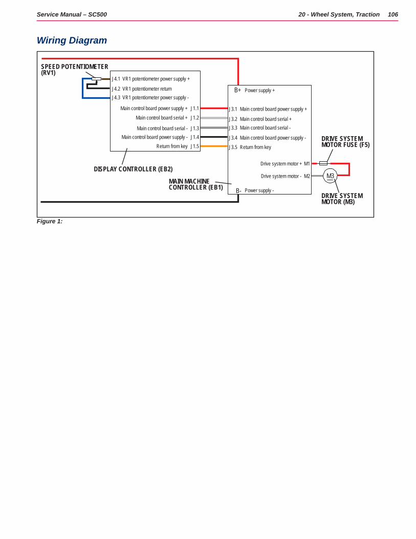
106Service Manual – SC500 20 - Wheel System, Traction
Wiring Diagram
M3
J1.5J1.4J1.3
J1.2
J1.1
J4.1
J4.2J4.3
VR1 potentiometer power supply +
VR1 potentiometer returnVR1 potentiometer power supply -
M2
M1
Drive system motor -
Drive system motor +
J3.1
J3.2J3.3
J3.4
J3.5
B-
B+
DRIVE SYSTEM MOTOR (M3)
Main control board power supply +
Power supply +
Power supply -
Main control board serial +Main control board serial -
Main control board power supply -
Return from key
Main control board power supply +
Main control board serial +
Main control board serial -Main control board power supply -
Return from key
SPEED POTENTIOMETER(RV1)
MAIN MACHINECONTROLLER (EB1)
DISPLAY CONTROLLER (EB2)
DRIVE SYSTEM MOTOR FUSE (F5)
Figure 1:
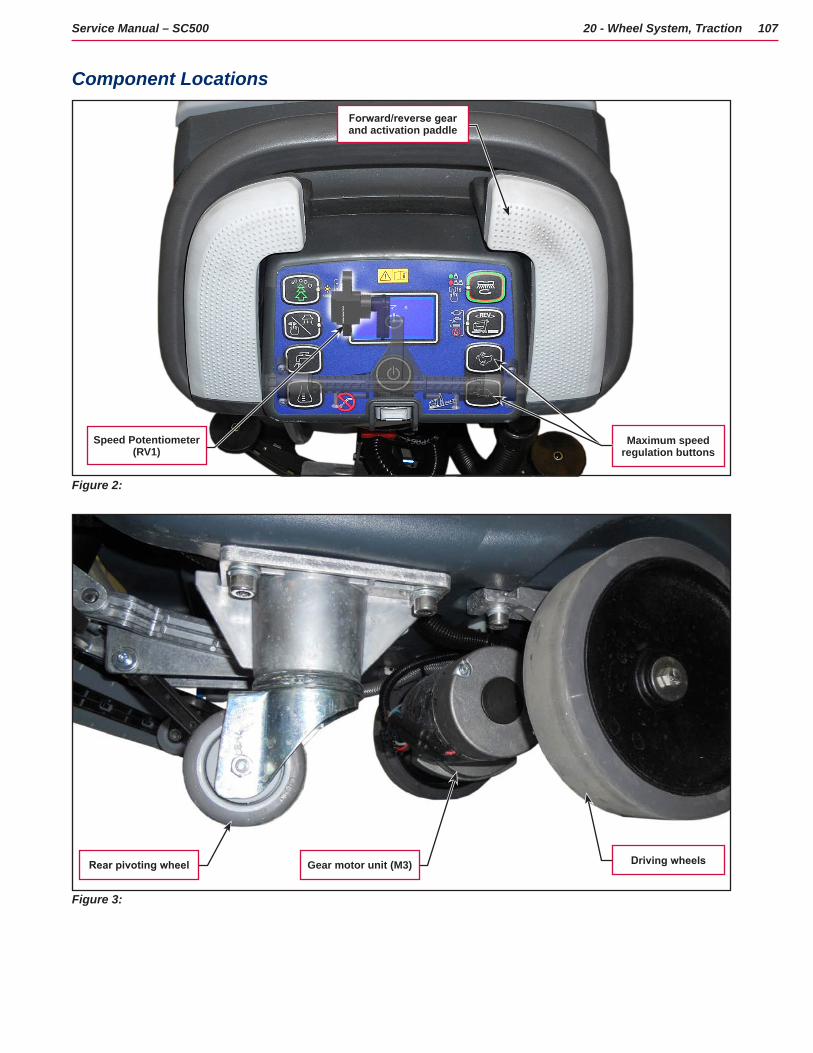
107Service Manual – SC500 20 - Wheel System, Traction
Component Locations
Figure 2:
Maximum speed regulation buttons
Speed Potentiometer (RV1)
Forward/reverse gear and activation paddle
Figure 3:
Driving wheelsRear pivoting wheel Gear motor unit (M3)
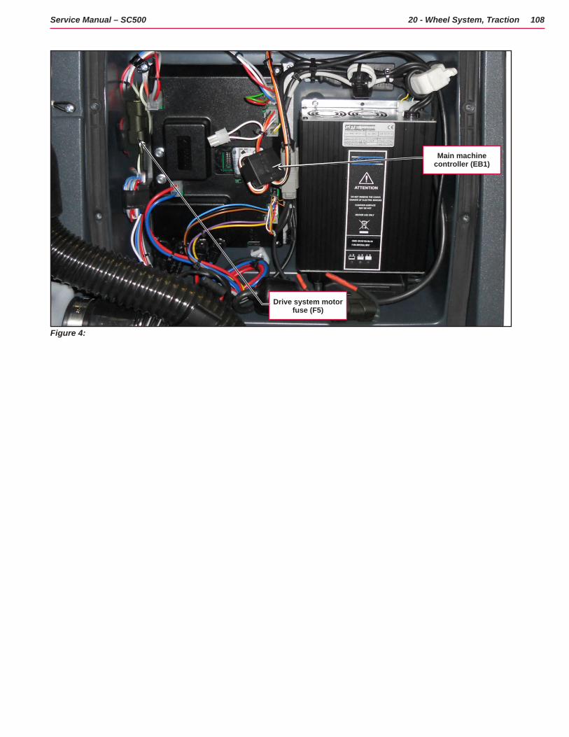
108Service Manual – SC500 20 - Wheel System, Traction
Figure 4:
Drive system motor fuse (F5)
Main machine controller (EB1)
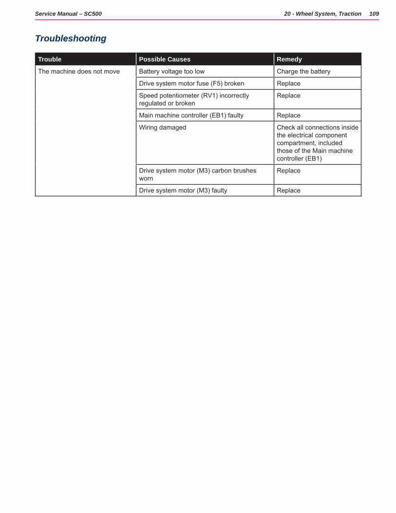
109Service Manual – SC500 20 - Wheel System, Traction
Troubleshooting
Trouble Possible Causes Remedy
The machine does not move Battery voltage too low Charge the battery
Drive system motor fuse (F5) broken Replace
Speed potentiometer (RV1) incorrectly regulated or broken
Replace
Main machine controller (EB1) faulty Replace
Wiring damaged Check all connections inside the electrical component compartment, included those of the Main machine controller (EB1)
Drive system motor (M3) carbon brushes worn
Replace
Drive system motor (M3) faulty Replace
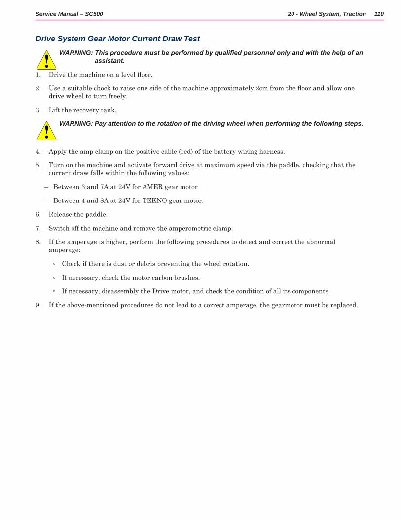
110Service Manual – SC500 20 - Wheel System, Traction
Drive System Gear Motor Current Draw Test
WARNING: This procedure must be performed by qualified personnel only and with the help of an assistant.
1 Drive the machine on a level floor.
2 Use a suitable chock to raise one side of the machine approximately 2cm from the floor and allow one drive wheel to turn freely
3 Lift the recovery tank
WARNING: Pay attention to the rotation of the driving wheel when performing the following steps.
4 Apply the amp clamp on the positive cable (red) of the battery wiring harness
5 Turn on the machine and activate forward drive at maximum speed via the paddle, checking that the current draw falls within the following values:
– Between 3 and 7A at 24V for AMER gear motor
– Between 4 and 8A at 24V for TEKNO gear motor
6 Release the paddle
7 Switch off the machine and remove the amperometric clamp
8 If the amperage is higher, perform the following procedures to detect and correct the abnormal amperage:
◦ Check if there is dust or debris preventing the wheel rotation
◦ If necessary, check the motor carbon brushes
◦ If necessary, disassembly the Drive motor, and check the condition of all its components
9 If the above-mentioned procedures do not lead to a correct amperage, the gearmotor must be replaced
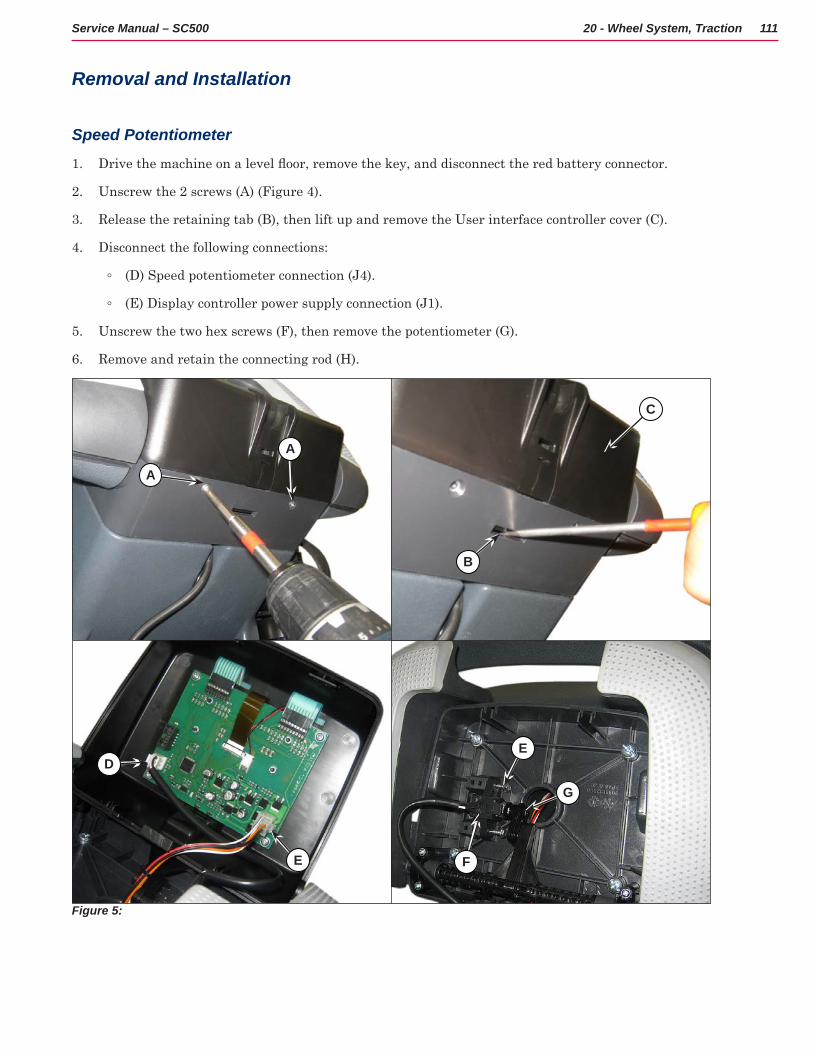
111Service Manual – SC500 20 - Wheel System, Traction
Removal and Installation
Speed Potentiometer
1 Drive the machine on a level floor, remove the key, and disconnect the red battery connector.
2 Unscrew the 2 screws (A) (Figure 4)
3 Release the retaining tab (B), then lift up and remove the User interface controller cover (C)
4 Disconnect the following connections:
◦ (D) Speed potentiometer connection (J4)
◦ (E) Display controller power supply connection (J1)
5 Unscrew the two hex screws (F), then remove the potentiometer (G)
6 Remove and retain the connecting rod (H)
Figure 5:
A
B
A
C
DE
FE
G
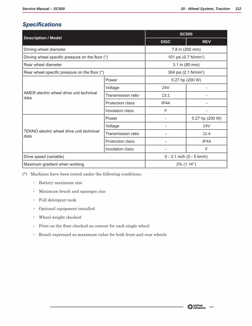
112Service Manual – SC500 20 - Wheel System, Traction
Specifications
Description / ModelSC500
DISC REV
Driving wheel diameter 7.8 in (200 mm)
Driving wheel specific pressure on the floor (*) 101 psi (0.7 N/mm2)
Rear wheel diameter 3.1 in (80 mm)
Rear wheel specific pressure on the floor (*) 304 psi (2.1 N/mm2)
AMER electric wheel drive unit technical data
Power 0.27 hp (200 W)
Voltage 24V -
Transmission ratio 13:1 -
Protection class IP44 -
Insulation class F -
TEKNO electric wheel drive unit technical data
Power - 0.27 hp (200 W)
Voltage - 24V
Transmission ratio - 11:4
Protection class - IP44
Insulation class - F
Drive speed (variable) 0 - 3.1 mi/h (0 - 5 km/h)
Maximum gradient when working 2% (1.14°)
(*) Machines have been tested under the following conditions:
◦ Battery maximum size
◦ Maximum brush and squeegee size
◦ Full detergent tank
◦ Optional equipment installed
◦ Wheel weight checked
◦ Print on the floor checked on cement for each single wheel
◦ Result expressed as maximum value for both front and rear wheels
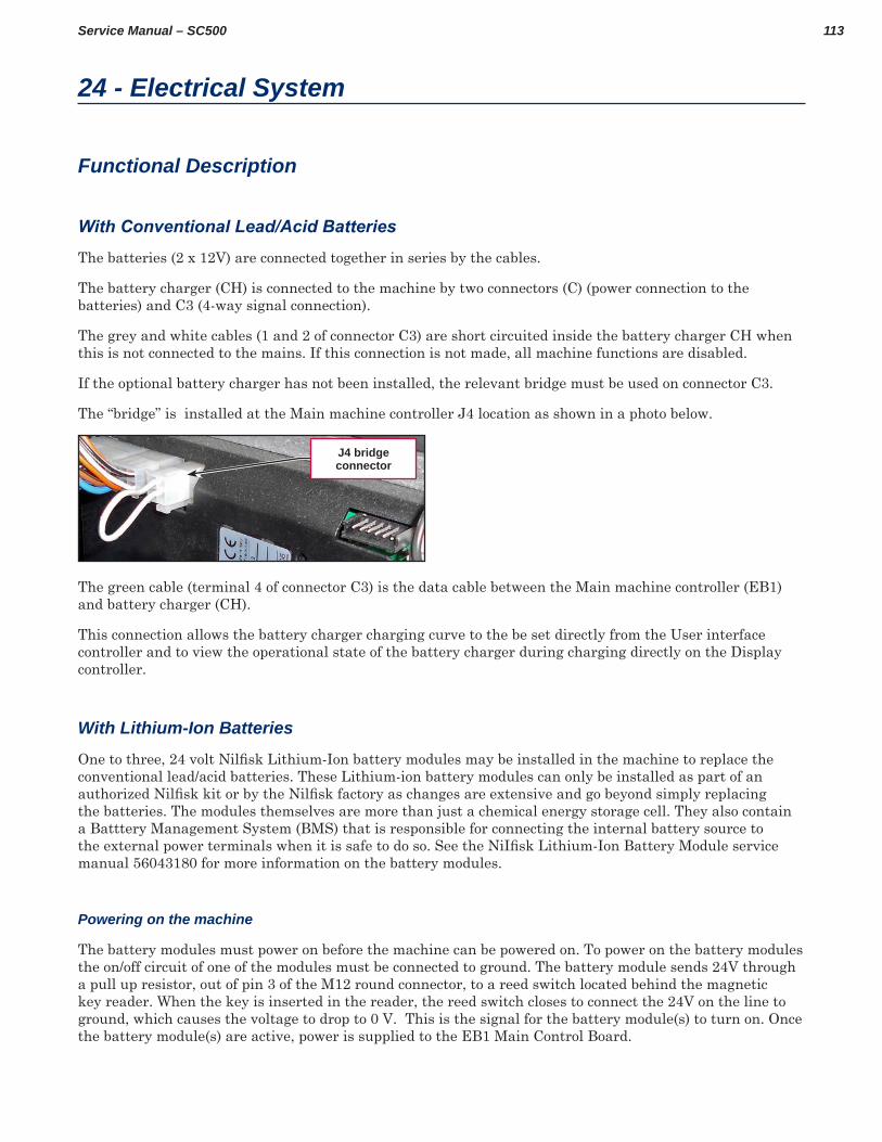
113Service Manual – SC500
24 - Electrical System
Functional Description
With Conventional Lead/Acid Batteries
The batteries (2 x 12V) are connected together in series by the cables
The battery charger (CH) is connected to the machine by two connectors (C) (power connection to the batteries) and C3 (4-way signal connection)
The grey and white cables (1 and 2 of connector C3) are short circuited inside the battery charger CH when this is not connected to the mains If this connection is not made, all machine functions are disabled
If the optional battery charger has not been installed, the relevant bridge must be used on connector C3
The “bridge” is installed at the Main machine controller J4 location as shown in a photo below
J4 bridge connector
The green cable (terminal 4 of connector C3) is the data cable between the Main machine controller (EB1) and battery charger (CH)
This connection allows the battery charger charging curve to the be set directly from the User interface controller and to view the operational state of the battery charger during charging directly on the Display controller
With Lithium-Ion Batteries
One to three, 24 volt Nilfisk Lithium-Ion battery modules may be installed in the machine to replace the conventional lead/acid batteries These Lithium-ion battery modules can only be installed as part of an authorized Nilfisk kit or by the Nilfisk factory as changes are extensive and go beyond simply replacing the batteries The modules themselves are more than just a chemical energy storage cell They also contain a Batttery Management System (BMS) that is responsible for connecting the internal battery source to the external power terminals when it is safe to do so. See the NiIfisk Lithium-Ion Battery Module service manual 56043180 for more information on the battery modules
Powering on the machine
The battery modules must power on before the machine can be powered on To power on the battery modules the on/off circuit of one of the modules must be connected to ground The battery module sends 24V through a pull up resistor, out of pin 3 of the M12 round connector, to a reed switch located behind the magnetic key reader When the key is inserted in the reader, the reed switch closes to connect the 24V on the line to ground, which causes the voltage to drop to 0 V This is the signal for the battery module(s) to turn on Once the battery module(s) are active, power is supplied to the EB1 Main Control Board
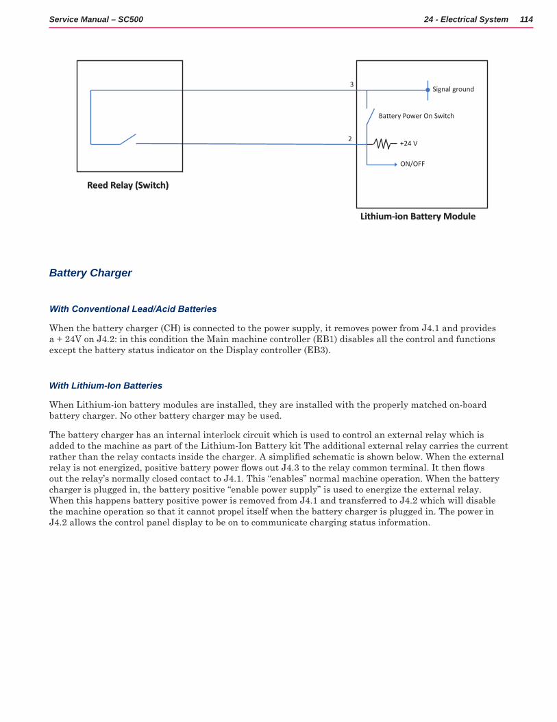
114Service Manual – SC500 24 - Electrical System
Power On Battery Module(s)
ON/OFF
2 +24 V
Lithium-ion Battery Module
Reed Relay (Switch)
Signal ground
Battery Power On Switch
3
Battery Charger
With Conventional Lead/Acid Batteries
When the battery charger (CH) is connected to the power supply, it removes power from J4 1 and provides a + 24V on J4 2: in this condition the Main machine controller (EB1) disables all the control and functions except the battery status indicator on the Display controller (EB3)
With Lithium-Ion Batteries
When Lithium-ion battery modules are installed, they are installed with the properly matched on-board battery charger No other battery charger may be used
The battery charger has an internal interlock circuit which is used to control an external relay which is added to the machine as part of the Lithium-Ion Battery kit The additional external relay carries the current rather than the relay contacts inside the charger. A simplified schematic is shown below. When the external relay is not energized, positive battery power flows out J4.3 to the relay common terminal. It then flows out the relay’s normally closed contact to J4 1 This “enables” normal machine operation When the battery charger is plugged in, the battery positive “enable power supply” is used to energize the external relay When this happens battery positive power is removed from J4 1 and transferred to J4 2 which will disable the machine operation so that it cannot propel itself when the battery charger is plugged in The power in J4 2 allows the control panel display to be on to communicate charging status information
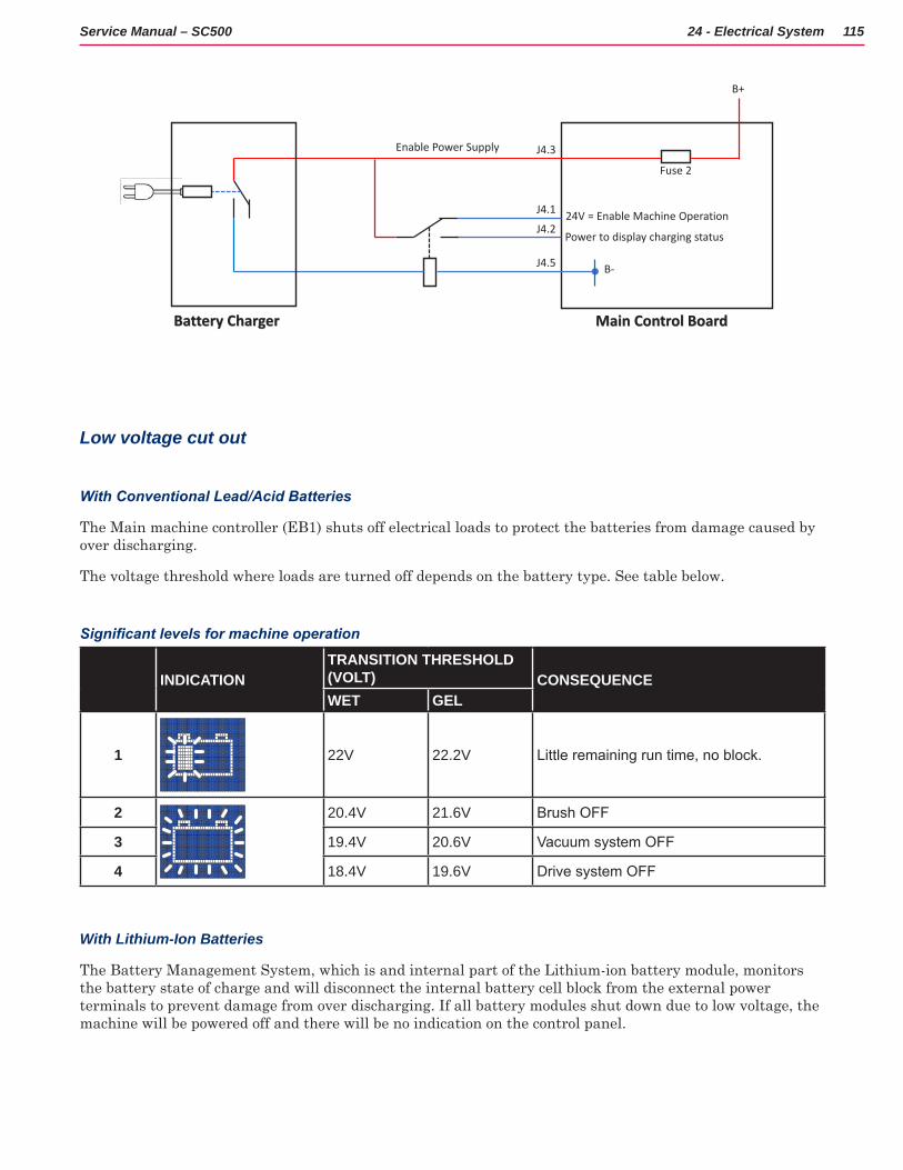
115Service Manual – SC500 24 - Electrical System
Battery Charger Interlock Circuit
Main Control BoardBattery Charger
J4.3
J4.1
J4.2
J4.5 B-
B+
Enable Power Supply
Fuse 2
24V = Enable Machine Operation
Power to display charging status
Low voltage cut out
With Conventional Lead/Acid Batteries
The Main machine controller (EB1) shuts off electrical loads to protect the batteries from damage caused by over discharging
The voltage threshold where loads are turned off depends on the battery type See table below
Significant levels for machine operation
INDICATIONTRANSITION THRESHOLD (VOLT) CONSEQUENCEWET GEL
1 22V 22.2V Little remaining run time, no block.
2 20.4V 21.6V Brush OFF
3 19.4V 20.6V Vacuum system OFF
4 18.4V 19.6V Drive system OFF
With Lithium-Ion Batteries
The Battery Management System, which is and internal part of the Lithium-ion battery module, monitors the battery state of charge and will disconnect the internal battery cell block from the external power terminals to prevent damage from over discharging If all battery modules shut down due to low voltage, the machine will be powered off and there will be no indication on the control panel
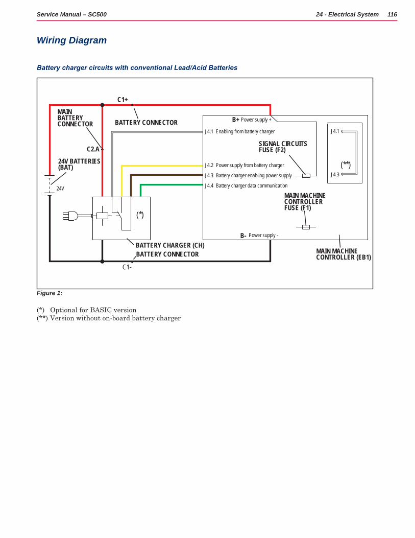
116Service Manual – SC500 24 - Electrical System
Wiring Diagram
Battery charger circuits with conventional Lead/Acid Batteries
24V
J4.1
J4.2
J4.3
J4.1
J4.3
J4.4
Enabling from battery charger
Power supply from battery charger
Battery charger enabling power supply
Battery charger data communication
B-
B+
C1+
C1-
C2.A
24V BATTERIES(BAT)
SIGNAL CIRCUITS FUSE (F2)
BATTERY CONNECTOR
MAINBATTERYCONNECTOR BATTERY CONNECTOR
BATTERY CHARGER (CH)
(**)
(*)
MAIN MACHINECONTROLLER FUSE (F1)
MAIN MACHINECONTROLLER (EB1)
Power supply +
Power supply -
Figure 1:
(*) Optional for BASIC version(**) Version without on-board battery charger
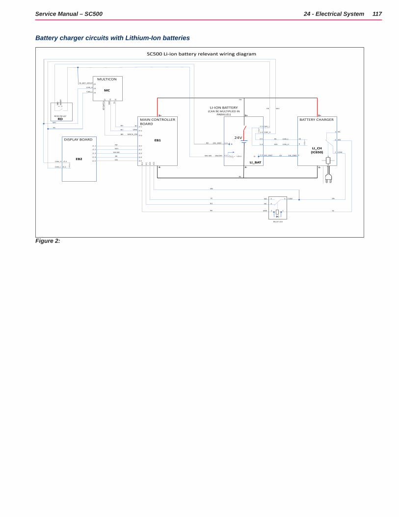
117Service Manual – SC500 24 - Electrical System
Battery charger circuits with Lithium-Ion batteries
CAN_H
CAN_L
SIG_GND
ON/OFF
M_BAT_WKUP
CAN_H
CAN_L
MAIN CONTROLLERBOARD
DISPLAY BOARD
J5.1
J5.2
MULTICON
LI-ION BATTERY(CAN BE MULTIPLIED IN
PARALLEL)
BATTERY CHARGER
CAN_H
CAN_L
B+
24V
B+B+
B- B- B-
EB1
EB2LI_BAT
REED RELAY
LI_CH(IC650)
NC
NO
GND
MACH_ON
MC
RDB+GN
D
ON/O
FFGN
D
COM
J4.1
J4.2
J4.3
J3.1
J3.2
J3.3
J3.4
J3.5
J1.1
J1.2
J1.3
J1.4
J1.5
SC500 Li-ion battery relevant wiring diagram
RD
WH
WH-BK
BK
OG
BK
RD
BN
YE
BU
WHPK
BK
WH-BN
BU
RD
BN
CAN_H
CAN_L
WH
PK
KEY S
WITC
H
B+
1113
23
24
17
22
J7.1
J7.5
J7.6
4
3
2
WH
PK
6
10
1-4
1-5
1-2
1-3
1 2
NC
NO COM
J1.5
BK
RELAY 24V
GND 2 1
3
4
5
YE
BN
+24 V
B-
B- SIG_GND SIG_GND 12-3 GY
2-5
2-4
Figure 2:
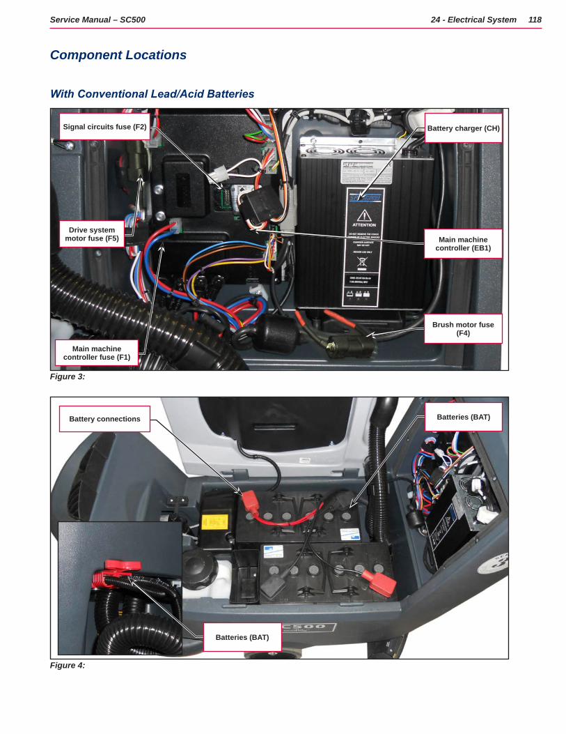
118Service Manual – SC500 24 - Electrical System
Component Locations
With Conventional Lead/Acid Batteries
Figure 3:
Main machine controller (EB1)
Brush motor fuse (F4)
Battery charger (CH)
Main machine controller fuse (F1)
Signal circuits fuse (F2)
Drive system motor fuse (F5)
Figure 4:
Batteries (BAT)
Batteries (BAT)Battery connections
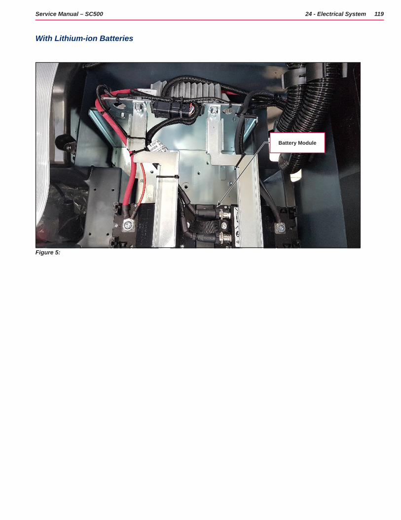
119Service Manual – SC500 24 - Electrical System
With Lithium-ion Batteries
Figure 5:
Battery Module
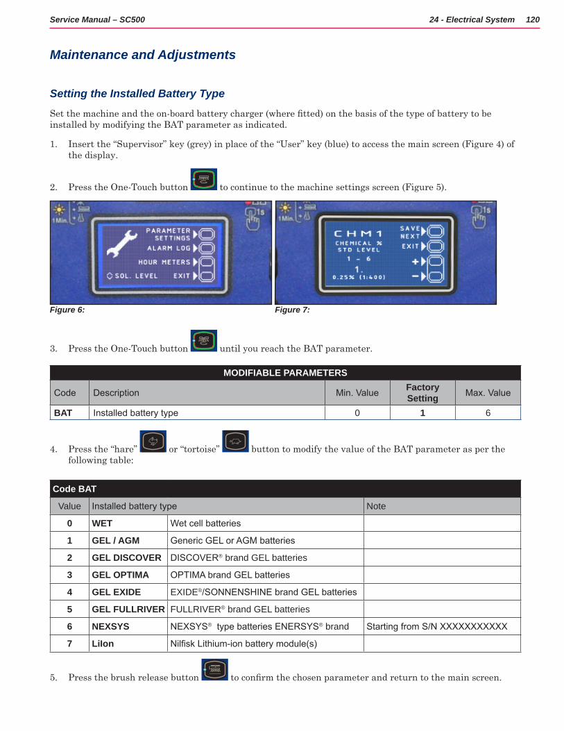
120Service Manual – SC500 24 - Electrical System
Maintenance and Adjustments
Setting the Installed Battery Type
Set the machine and the on-board battery charger (where fitted) on the basis of the type of battery to be installed by modifying the BAT parameter as indicated
1 Insert the “Supervisor” key (grey) in place of the “User” key (blue) to access the main screen (Figure 4) of the display
2 Press the One-Touch button to continue to the machine settings screen (Figure 5)
Figure 6: Figure 7:
3 Press the One-Touch button until you reach the BAT parameter
MODIFIABLE PARAMETERS
Code Description Min. Value Factory Setting Max. Value
BAT Installed battery type 0 1 6
4 Press the “hare” or “tortoise” button to modify the value of the BAT parameter as per the following table:
Code BAT
Value Installed battery type Note
0 WET Wet cell batteries
1 GEL / AGM Generic GEL or AGM batteries
2 GEL DISCOVER DISCOVER® brand GEL batteries
3 GEL OPTIMA OPTIMA brand GEL batteries
4 GEL EXIDE EXIDE®/SONNENSHINE brand GEL batteries
5 GEL FULLRIVER FULLRIVER® brand GEL batteries
6 NEXSYS NEXSYS® type batteries ENERSYS® brand Starting from S/N XXXXXXXXXXX
7 LiIon Nilfisk Lithium-ion battery module(s)
5 Press the brush release button to confirm the chosen parameter and return to the main screen.
121Service Manual – SC500 24 - Electrical System
Disconnect/Connect Lithium-Ion Batteries
CAUTION: Connections to lithium-ion batteries are not the same as a lead-acid batteries partly due to the CAN communication connections. Disconnect and reconnect lithium-ion battery cabling in the order given below to prevent damage to the batteries.
Disconnection
1 Power off the machine
2 Turn off battery modules
3 Separate the machine power connector
4 Disconnect the Battery Positive Cable
5 Disconnect the M12 round communication connection
6 Disconnect the Battery Negative Cable
7 Remove the termination resistor connector if present
Connection
1 Connect the Battery Negative cable
2 Connect the M12 round communication connection
3 Connect the Battery Positive cable
4 Install the termination resistor connector if required
5 Connect the machine power connector
6 Power on the battery modules
7 Power on the machine
Battery Charging - Conventional Lead/Acid Batteries
Note: Charge the batteries when there is only one flashing segment displayed in the battery symbol, or at the end of each shift. Keeping the batteries charged make their life last longer.
CAUTION: When the batteries are discharged, charge them as soon as possible, as that condition makes their life shorter. Check for battery charge at least once a week.
CAUTION: If the machine is not equipped with on-board battery charger, choose an external battery charger suitable for the type of batteries installed.
WARNING: When using lead (WET) batteries, battery charging produces highly explosive hydrogen gas. Charge the batteries in well-ventilated areas and away from naked flames. Do not smoke while charging the batteries. Keep the recovery tank raised until the battery charging cycle is over.
122Service Manual – SC500 24 - Electrical System
WARNING: Pay close attention when charging WET CELL batteries, as there may be battery fluid leakages. The battery fluid is corrosive. If it comes in contact with skin or eyes, rinse thoroughly with water and consult a physician.
1 (For WET CELL batteries only) Check the level of electrolyte inside the batteries If necessary, unscrew the caps and top up
2 When the correct level is restored, close the caps and clean the tops of the batteries
Charging Conventional Lead/Acid Batteries with an External Battery Charger
3 Check that the external battery charger is suitable by referring to the relevant Manual The battery charger voltage rating must be 24V
4 Disconnect the red battery connector with handle and connect it to the external battery charger
5 Connect the battery charger to the electrical mains
6 After charging, disconnect the battery charger from the electrical mains and from the battery red connector
7 Connect the battery connector to the machine
8 Carefully lower the recovery tank
CAUTION: Never connect the battery charger to the opposing part of the red connector fixed to the machine. The electronic system could be irreparably damaged.
Charging Conventional Lead/Acid Batteries with an On-board Battery Charger
9 Plug the battery charger into the mains electricity supply (the mains voltage and frequency must be compatible with the battery charger values shown on the machine serial number plate)
Note: When the battery charger is connected to the electrical mains, all machine functions are automatically cut off.
10 When the first or second segment from the left in the battery symbol is flashing, this means that the battery charger is charging the batteries
11 When the third segment from the left in the battery symbol is flashing, this means that the battery charger is finishing the battery charging cycle.
12 When all segments of the battery symbol are steadily lit, the battery charging cycle is complete
13 Disconnect the battery charger plug from the mains and place it in its holder
14 Carefully lower the recovery tank
Note: For further information about the operation of the battery charger, see the relevant Manual.
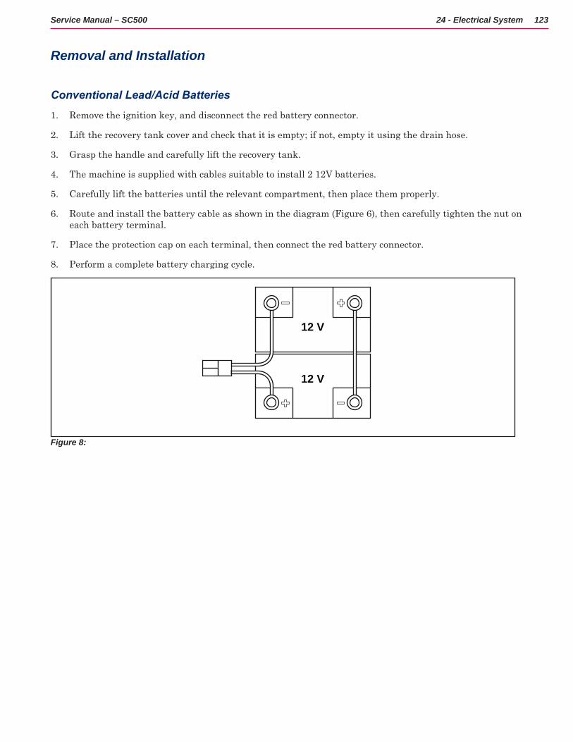
123Service Manual – SC500 24 - Electrical System
Removal and Installation
Conventional Lead/Acid Batteries
1 Remove the ignition key, and disconnect the red battery connector
2 Lift the recovery tank cover and check that it is empty; if not, empty it using the drain hose
3 Grasp the handle and carefully lift the recovery tank
4 The machine is supplied with cables suitable to install 2 12V batteries
5 Carefully lift the batteries until the relevant compartment, then place them properly
6 Route and install the battery cable as shown in the diagram (Figure 6), then carefully tighten the nut on each battery terminal
7 Place the protection cap on each terminal, then connect the red battery connector
8 Perform a complete battery charging cycle
12 V
12 V
Figure 8:
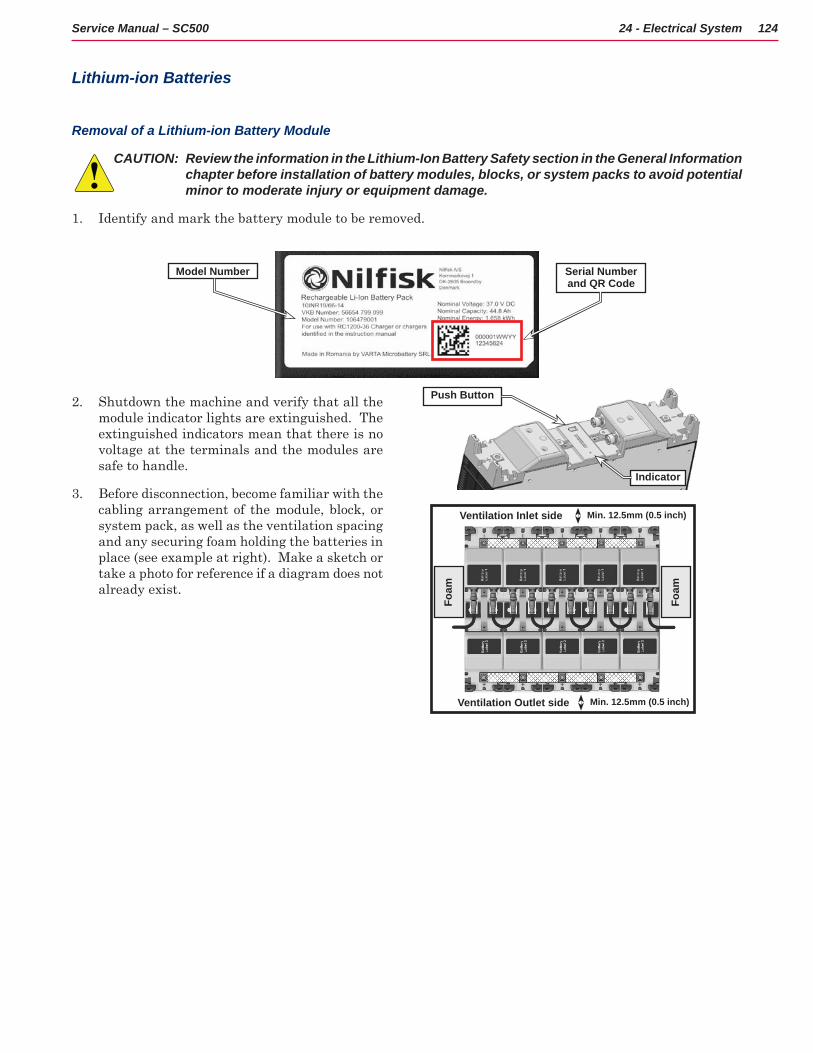
124Service Manual – SC500 24 - Electrical System
Lithium-ion Batteries
Removal of a Lithium-ion Battery Module
CAUTION: Review the information in the Lithium-Ion Battery Safety section in the General Information chapter before installation of battery modules, blocks, or system packs to avoid potential minor to moderate injury or equipment damage.
1 Identify and mark the battery module to be removed
2 Shutdown the machine and verify that all the module indicator lights are extinguished The extinguished indicators mean that there is no voltage at the terminals and the modules are safe to handle
3 Before disconnection, become familiar with the cabling arrangement of the module, block, or system pack, as well as the ventilation spacing and any securing foam holding the batteries in place (see example at right) Make a sketch or take a photo for reference if a diagram does not already exist
Serial Number and QR Code
Model Number
Push Button
Indicator
Ventilation Inlet side
Ventilation Outlet side
Min. 12.5mm (0.5 inch)
Min. 12.5mm (0.5 inch)
Foam
Foam
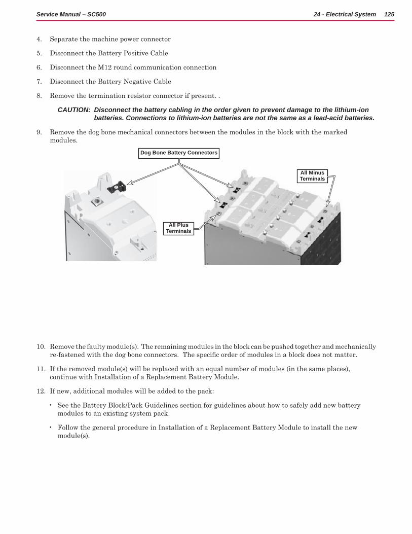
125Service Manual – SC500 24 - Electrical System
4 Separate the machine power connector
5 Disconnect the Battery Positive Cable
6 Disconnect the M12 round communication connection
7 Disconnect the Battery Negative Cable
8 Remove the termination resistor connector if present
CAUTION: Disconnect the battery cabling in the order given to prevent damage to the lithium-ion batteries. Connections to lithium-ion batteries are not the same as a lead-acid batteries.
9 Remove the dog bone mechanical connectors between the modules in the block with the marked modules
10 Remove the faulty module(s) The remaining modules in the block can be pushed together and mechanically re-fastened with the dog bone connectors. The specific order of modules in a block does not matter.
11 If the removed module(s) will be replaced with an equal number of modules (in the same places), continue with Installation of a Replacement Battery Module
12 If new, additional modules will be added to the pack:
• See the Battery Block/Pack Guidelines section for guidelines about how to safely add new battery modules to an existing system pack
• Follow the general procedure in Installation of a Replacement Battery Module to install the new module(s)
Dog Bone Battery Connectors
All Plus Terminals
All Minus Terminals
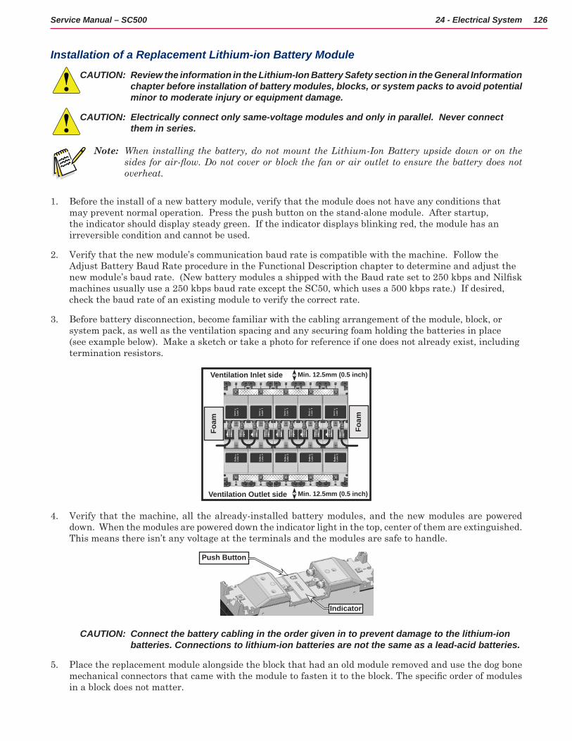
126Service Manual – SC500 24 - Electrical System
Installation of a Replacement Lithium-ion Battery Module
CAUTION: Review the information in the Lithium-Ion Battery Safety section in the General Information chapter before installation of battery modules, blocks, or system packs to avoid potential minor to moderate injury or equipment damage.
CAUTION: Electrically connect only same-voltage modules and only in parallel. Never connect them in series.
Note: When installing the battery, do not mount the Lithium-Ion Battery upside down or on the sides for air-flow. Do not cover or block the fan or air outlet to ensure the battery does not overheat.
1 Before the install of a new battery module, verify that the module does not have any conditions that may prevent normal operation Press the push button on the stand-alone module After startup, the indicator should display steady green If the indicator displays blinking red, the module has an irreversible condition and cannot be used
2 Verify that the new module’s communication baud rate is compatible with the machine Follow the Adjust Battery Baud Rate procedure in the Functional Description chapter to determine and adjust the new module’s baud rate. (New battery modules a shipped with the Baud rate set to 250 kbps and Nilfisk machines usually use a 250 kbps baud rate except the SC50, which uses a 500 kbps rate ) If desired, check the baud rate of an existing module to verify the correct rate
3 Before battery disconnection, become familiar with the cabling arrangement of the module, block, or system pack, as well as the ventilation spacing and any securing foam holding the batteries in place (see example below) Make a sketch or take a photo for reference if one does not already exist, including termination resistors
4 Verify that the machine, all the already-installed battery modules, and the new modules are powered down When the modules are powered down the indicator light in the top, center of them are extinguished This means there isn’t any voltage at the terminals and the modules are safe to handle
CAUTION: Connect the battery cabling in the order given in to prevent damage to the lithium-ion batteries. Connections to lithium-ion batteries are not the same as a lead-acid batteries.
5 Place the replacement module alongside the block that had an old module removed and use the dog bone mechanical connectors that came with the module to fasten it to the block. The specific order of modules in a block does not matter
Ventilation Inlet side
Ventilation Outlet side
Min. 12.5mm (0.5 inch)
Min. 12.5mm (0.5 inch)
Foam
Foam
Push Button
Indicator
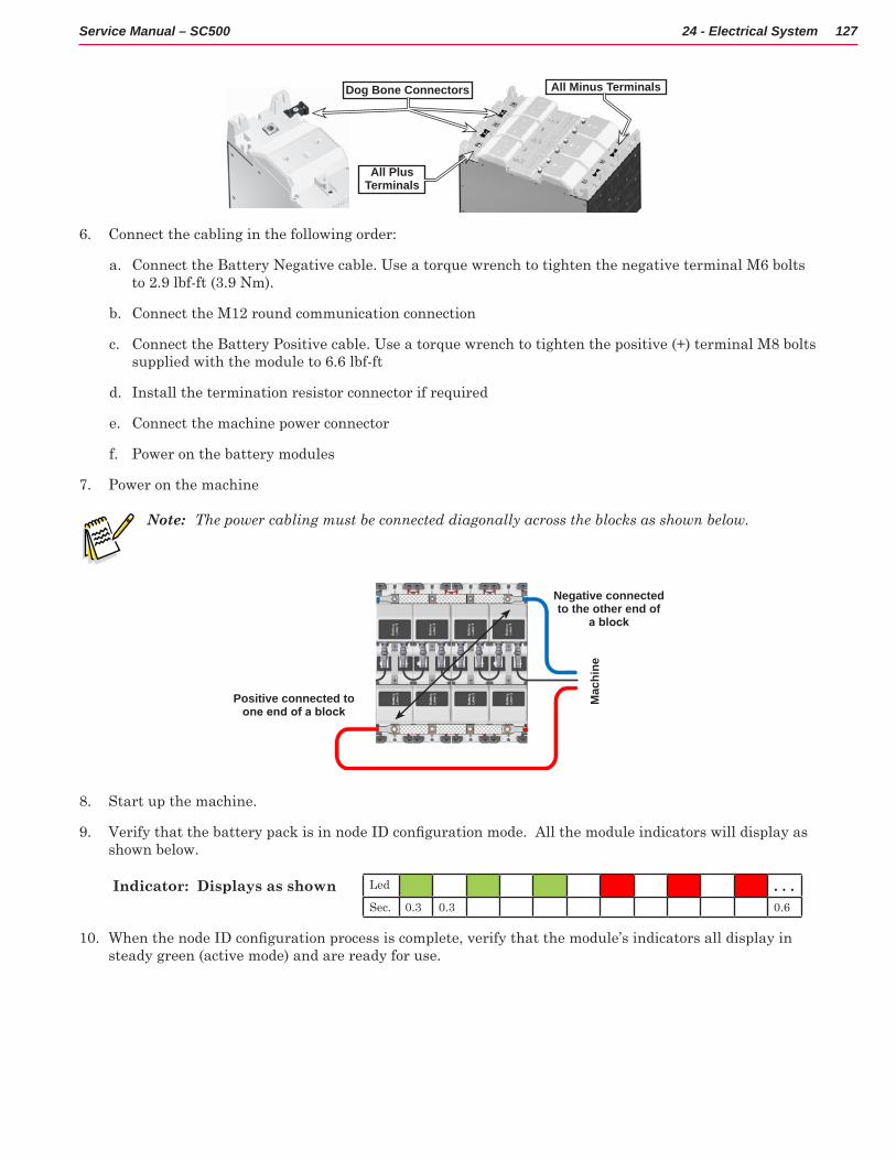
127Service Manual – SC500 24 - Electrical System
6 Connect the cabling in the following order:
a Connect the Battery Negative cable Use a torque wrench to tighten the negative terminal M6 bolts to 2 9 lbf-ft (3 9 Nm)
b Connect the M12 round communication connection
c Connect the Battery Positive cable Use a torque wrench to tighten the positive (+) terminal M8 bolts supplied with the module to 6 6 lbf-ft
d Install the termination resistor connector if required
e Connect the machine power connector
f Power on the battery modules
7 Power on the machine
Note: The power cabling must be connected diagonally across the blocks as shown below.
8 Start up the machine
9 Verify that the battery pack is in node ID configuration mode. All the module indicators will display as shown below
Indicator: Displays as shown Led . . .Sec 0 3 0 3 0 6
10 When the node ID configuration process is complete, verify that the module’s indicators all display in steady green (active mode) and are ready for use
Dog Bone Connectors
All Plus Terminals
All Minus Terminals
Negative connected to the other end of
a block
Positive connected to one end of a block
Mac
hine
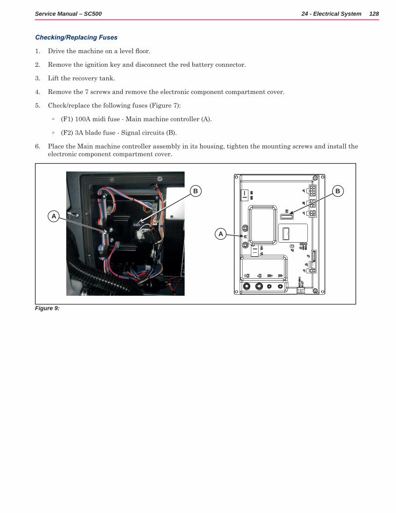
128Service Manual – SC500 24 - Electrical System
Checking/Replacing Fuses
1 Drive the machine on a level floor.
2 Remove the ignition key and disconnect the red battery connector
3 Lift the recovery tank
4 Remove the 7 screws and remove the electronic component compartment cover
5 Check/replace the following fuses (Figure 7):
◦ (F1) 100A midi fuse - Main machine controller (A)
◦ (F2) 3A blade fuse - Signal circuits (B)
6 Place the Main machine controller assembly in its housing, tighten the mounting screws and install the electronic component compartment cover
Figure 9:
A
B
A
B
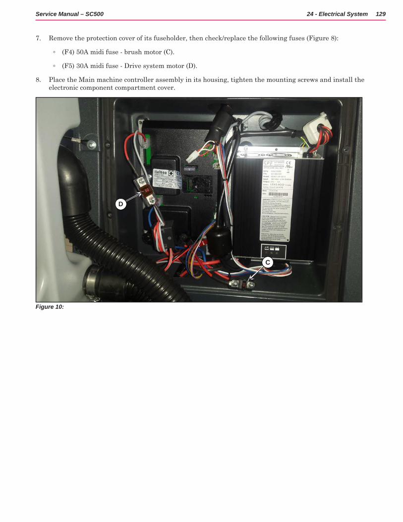
129Service Manual – SC500 24 - Electrical System
7 Remove the protection cover of its fuseholder, then check/replace the following fuses (Figure 8):
◦ (F4) 50A midi fuse - brush motor (C)
◦ (F5) 30A midi fuse - Drive system motor (D)
8 Place the Main machine controller assembly in its housing, tighten the mounting screws and install the electronic component compartment cover
Figure 10:
D
C
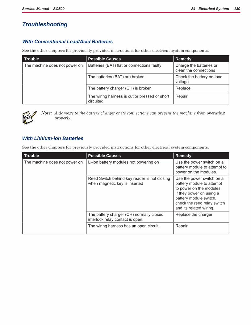
130Service Manual – SC500 24 - Electrical System
Troubleshooting
With Conventional Lead/Acid Batteries
See the other chapters for previously provided instructions for other electrical system components
Trouble Possible Causes RemedyThe machine does not power on Batteries (BAT) flat or connections faulty Charge the batteries or
clean the connectionsThe batteries (BAT) are broken Check the battery no-load
voltageThe battery charger (CH) is broken Replace
The wiring harness is cut or pressed or short circuited
Repair
Note: A damage to the battery charger or its connections can prevent the machine from operating properly.
With Lithium-ion Batteries
See the other chapters for previously provided instructions for other electrical system components
Trouble Possible Causes RemedyThe machine does not power on Li-ion battery modules not powering on Use the power switch on a
battery module to attempt to power on the modules.
Reed Switch behind key reader is not closing when magnetic key is inserted
Use the power switch on a battery module to attempt to power on the modules. If they power on using a battery module switch, check the reed relay switch and its related wiring.
The battery charger (CH) normally closed interlock relay contact is open.
Replace the charger
The wiring harness has an open circuit Repair
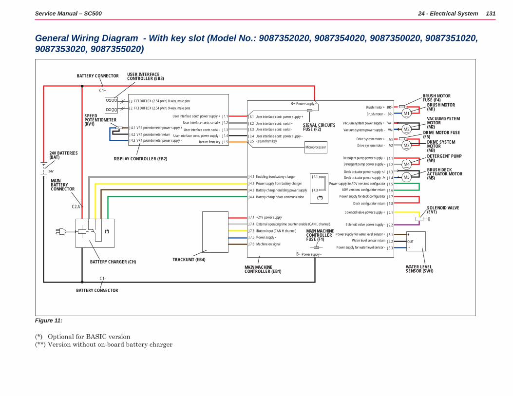
24 - Electrical System 131Service Manual – SC500
General Wiring Diagram - With key slot (Model No.: 9087352020, 9087354020, 9087350020, 9087351020, 9087353020, 9087355020)
SOLENOID VALVE (EV1)
BRUSH DECK ACTUATOR MOTOR (M5)
DETERGENT PUMP(M4)
M5
M4
DRIVE SYSTEM MOTOR (M3)
VACUUM SYSTEM MOTOR(M2)
BRUSH MOTOR(M1)
M3
M2
M1
BRUSH MOTORFUSE (F4)
DRIVE MOTOR FUSE(F5)
+
-OUT
J5.3
J5.2
J5.1
J2.2
J2.1
J1.8
J1.7
J1.6
J1.5J1.4J1.3
J1.2
J1.1
J1.5J1.4J1.3
J1.2
J1.1
J3
J2
24V
J4.1
J4.2J4.3
VR1 potentiometer power supply +
VR1 potentiometer returnVR1 potentiometer power supply -
M2M1
VA-
VA+
BR-
BR+
Brush motor -
Brush motor +
Vacuum system power supply -
Vacuum system power supply +
Drive system motor -
Detergent pump power supply +Detergent pump power supply -
Deck actuator power supply +/-Deck actuator power supply -/+
Power supply for ADV versions configuratorADV versions configurator return
Power supply for deck configurator
Deck configurator return
Solenoid valve power supply +
Solenoid valve power supply -
Power supply for water level sensor +Water level sensor return
Power supply for water level sensor -
Drive system motor +
J3.1
J3.2J3.3
J3.4J3.5
J4.1
J4.2
J4.3
J4.1
J4.3
J4.4
J7.1
J7.4
J7.3
J7.5
J7.6
+24V power supply
External operating time counter enable (CAN L channel)
iButton input (CAN H channel)
Power supply -
Machine on signal
B-
B+
C1+
C1-
C2.A
24V BATTERIES(BAT)
MAIN MACHINECONTROLLER FUSE (F1)
WATER LEVEL SENSOR (SW1)
BATTERY CONNECTOR
MAIN BATTERY CONNECTOR
BATTERY CONNECTOR
TRACKUNIT (EB4)BATTERY CHARGER (CH)
(**)
(*)
User interface contr. power supply +
Power supply +
Power supply -
User interface contr. serial +User interface contr. serial -
User interface contr. power supply -Return from key
FCI DUFLEX (2.54 pitch) 8-way, male pins
FCI DUFLEX (2.54 pitch) 9-way, male pins
User interface contr. power supply +
User interface contr. serial +
User interface contr. serial -User interface contr. power supply -
Return from key
SPEEDPOTENTIOMETER(RV1)
Enabling from battery charger
Power supply from battery charger
Battery charger enabling power supply
Battery charger data communication
MAIN MACHINECONTROLLER (EB1)
DISPLAY CONTROLLER (EB2)
Microprocessor
SIGNAL CIRCUITSFUSE (F2)
USER INTERFACE CONTROLLER (EB3)
Figure 11:
(*) Optional for BASIC version(**) Version without on-board battery charger
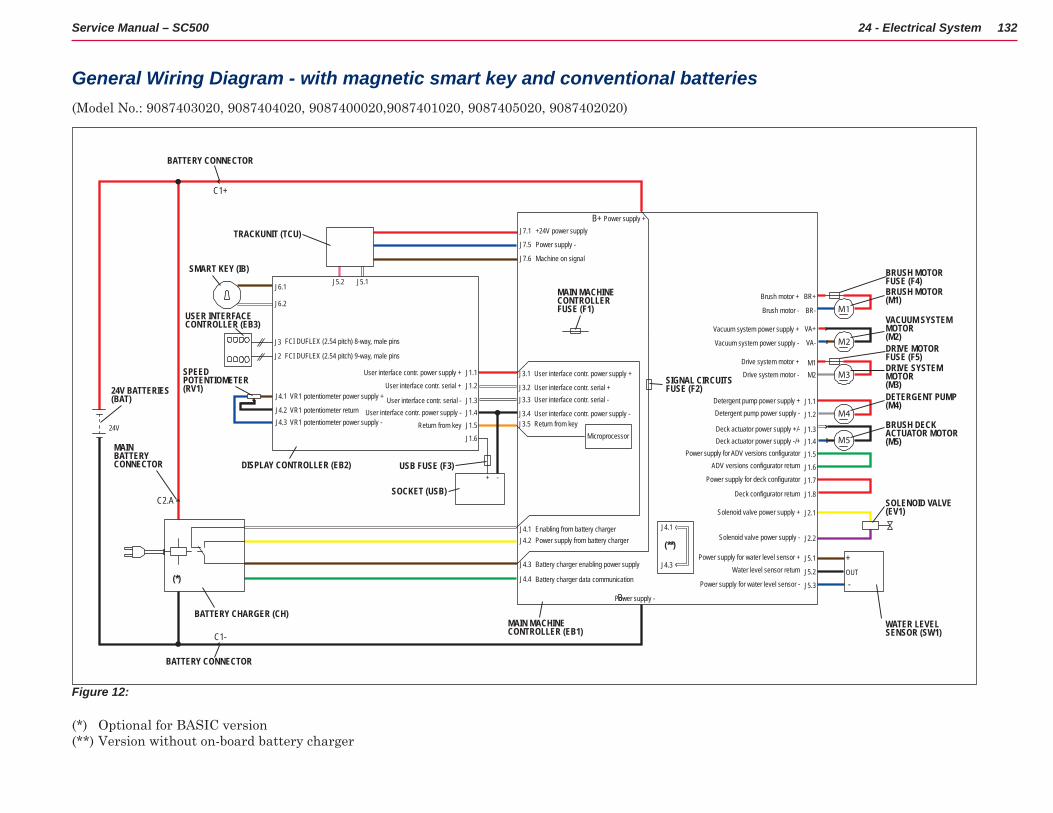
24 - Electrical System 132Service Manual – SC500
General Wiring Diagram - with magnetic smart key and conventional batteries (Model No : 9087403020, 9087404020, 9087400020,9087401020, 9087405020, 9087402020)
SOLENOID VALVE (EV1)
BRUSH DECK ACTUATOR MOTOR (M5)
DETERGENT PUMP(M4)
DRIVE SYSTEM MOTOR (M3)
VACUUM SYSTEM MOTOR(M2)
BRUSH MOTOR(M1)
M5
M4
M3
M2
M1
BRUSH MOTORFUSE (F4)
DRIVE MOTOR FUSE (F5)
+
-OUT
J5.3
J5.2
J5.1
J2.2
J2.1
J1.8
J1.7
J1.6
J1.5J1.4J1.3
J1.2
J1.1
J1.5
J1.6
J1.4J1.3
J1.2
J1.1
J3
J2
J6.1 J5.2 J5.1
J6.2
24V
J4.1
J4.2J4.3
VR1 potentiometer power supply +
VR1 potentiometer returnVR1 potentiometer power supply -
+ -
M2M1
VA-
VA+
BR-
BR+
Brush motor -
Brush motor +
Vacuum system power supply -
Vacuum system power supply +
Drive system motor -
Detergent pump power supply +Detergent pump power supply -
Deck actuator power supply +/-Deck actuator power supply -/+
Power supply for ADV versions configuratorADV versions configurator return
Power supply for deck configurator
Deck configurator return
Solenoid valve power supply +
Solenoid valve power supply -
Power supply for water level sensor +Water level sensor return
Power supply for water level sensor -
Drive system motor +J3.1
J3.2J3.3
J3.4J3.5
J4.1J4.2
J4.3
J4.1
J4.3
J4.4
B-
B+
C1+
C1-
C2.A
24V BATTERIES(BAT)
MAIN MACHINECONTROLLER FUSE (F1)
WATER LEVEL SENSOR (SW1)
BATTERY CONNECTOR
MAIN BATTERY CONNECTOR
BATTERY CONNECTOR
J7.1
J7.5
J7.6
+24V power supply
Power supply -
Machine on signal
TRACKUNIT (TCU)
BATTERY CHARGER (CH)
(**)
(*)
User interface contr. power supply +
Power supply +
Power supply -
User interface contr. serial +User interface contr. serial -
User interface contr. power supply -Return from key
FCI DUFLEX (2.54 pitch) 8-way, male pins
FCI DUFLEX (2.54 pitch) 9-way, male pins
User interface contr. power supply +
User interface contr. serial +
User interface contr. serial -User interface contr. power supply -
Return from key
SPEEDPOTENTIOMETER(RV1)
Enabling from battery chargerPower supply from battery charger
Battery charger enabling power supply
Battery charger data communication
MAIN MACHINECONTROLLER (EB1)
DISPLAY CONTROLLER (EB2)
SOCKET (USB)
USB FUSE (F3)
SMART KEY (IB)
Microprocessor
SIGNAL CIRCUITSFUSE (F2)
USER INTERFACE CONTROLLER (EB3)
Figure 12:
(*) Optional for BASIC version(**) Version without on-board battery charger
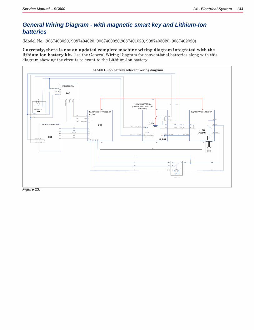
133Service Manual – SC500 24 - Electrical System
General Wiring Diagram - with magnetic smart key and Lithium-Ion batteries (Model No : 9087403020, 9087404020, 9087400020,9087401020, 9087405020, 9087402020)
Currently, there is not an updated complete machine wiring diagram integrated with the lithium ion battery kit . Use the General Wiring Diagram for conventional batteries along with this diagram showing the circuits relevant to the Lithium-Ion battery
CAN_H
CAN_L
SIG_GND
ON/OFF
M_BAT_WKUP
CAN_H
CAN_L
MAIN CONTROLLERBOARD
DISPLAY BOARD
J5.1
J5.2
MULTICON
LI-ION BATTERY(CAN BE MULTIPLIED IN
PARALLEL)
BATTERY CHARGER
CAN_H
CAN_L
B+
24V
B+B+
B- B- B-
EB1
EB2LI_BAT
REED RELAY
LI_CH(IC650)
NC
NO
GND
MACH_ON
MC
RD
B+GND
ON/O
FFGN
D
COM
J4.1
J4.2
J4.3
J3.1
J3.2
J3.3
J3.4
J3.5
J1.1
J1.2
J1.3
J1.4
J1.5
SC500 Li-ion battery relevant wiring diagram
RD
WH
WH-BK
BK
OG
BK
RD
BN
YE
BU
WHPK
BK
WH-BN
BU
RD
BN
CAN_H
CAN_L
WH
PK
KEY S
WITC
H
B+
1113
23
24
17
22
J7.1
J7.5
J7.6
4
3
2
WH
PK
6
10
1-4
1-5
1-2
1-3
1 2
NC
NO COM
J1.5
BK
RELAY 24V
GND 2 1
3
4
5
YE
BN
+24 V
B-
B- SIG_GND SIG_GND 12-3 GY
2-5
2-4
Figure 13:
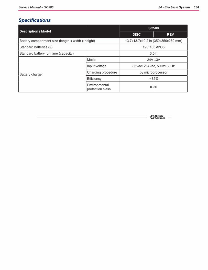
134Service Manual – SC500 24 - Electrical System
Specifications
Description / ModelSC500
DISC REV
Battery compartment size (length x width x height) 13.7x13.7x10.2 in (350x350x260 mm)
Standard batteries (2) 12V 105 AhC5
Standard battery run time (capacity) 3.5 h
Battery charger
Model 24V 13A
Input voltage 85Vac÷264Vac, 50Hz÷60Hz
Charging procedure by microprocessor
Efficiency > 85%
Environmental protection class IP30
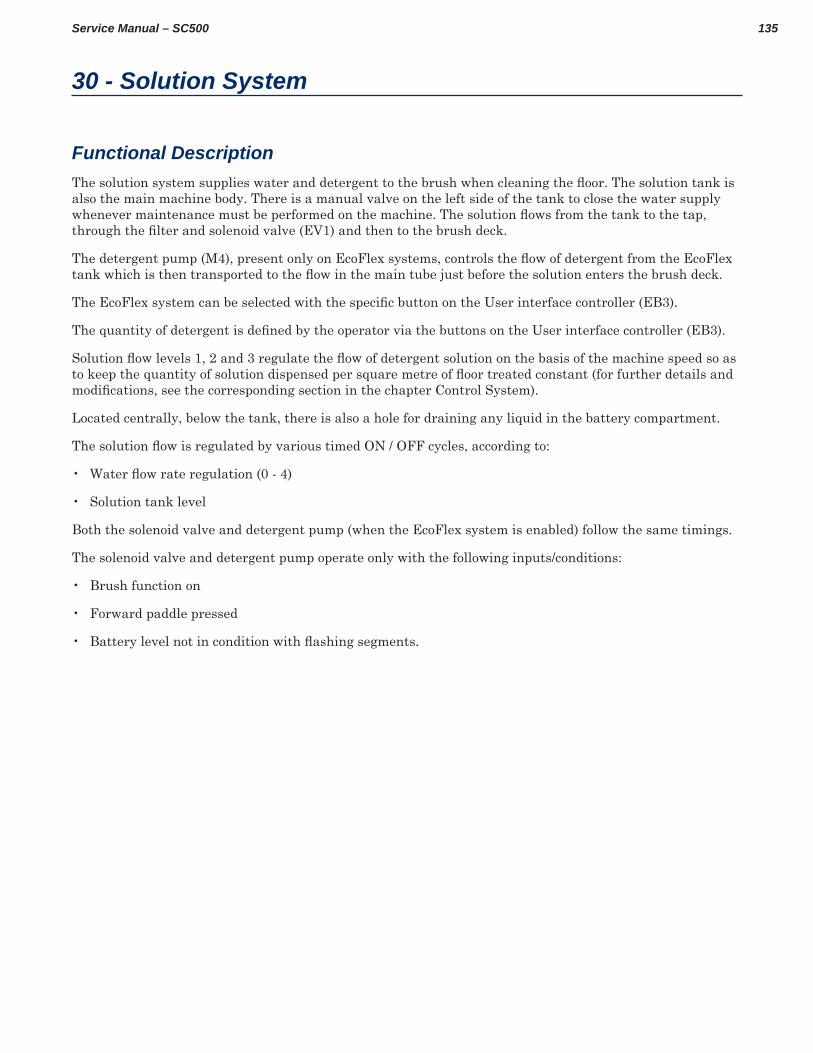
135Service Manual – SC500
30 - Solution System
Functional DescriptionThe solution system supplies water and detergent to the brush when cleaning the floor. The solution tank is also the main machine body There is a manual valve on the left side of the tank to close the water supply whenever maintenance must be performed on the machine. The solution flows from the tank to the tap, through the filter and solenoid valve (EV1) and then to the brush deck.
The detergent pump (M4), present only on EcoFlex systems, controls the flow of detergent from the EcoFlex tank which is then transported to the flow in the main tube just before the solution enters the brush deck.
The EcoFlex system can be selected with the specific button on the User interface controller (EB3).
The quantity of detergent is defined by the operator via the buttons on the User interface controller (EB3).
Solution flow levels 1, 2 and 3 regulate the flow of detergent solution on the basis of the machine speed so as to keep the quantity of solution dispensed per square metre of floor treated constant (for further details and modifications, see the corresponding section in the chapter Control System).
Located centrally, below the tank, there is also a hole for draining any liquid in the battery compartment
The solution flow is regulated by various timed ON / OFF cycles, according to:
• Water flow rate regulation (0 - 4)
• Solution tank level
Both the solenoid valve and detergent pump (when the EcoFlex system is enabled) follow the same timings
The solenoid valve and detergent pump operate only with the following inputs/conditions:
• Brush function on
• Forward paddle pressed
• Battery level not in condition with flashing segments.
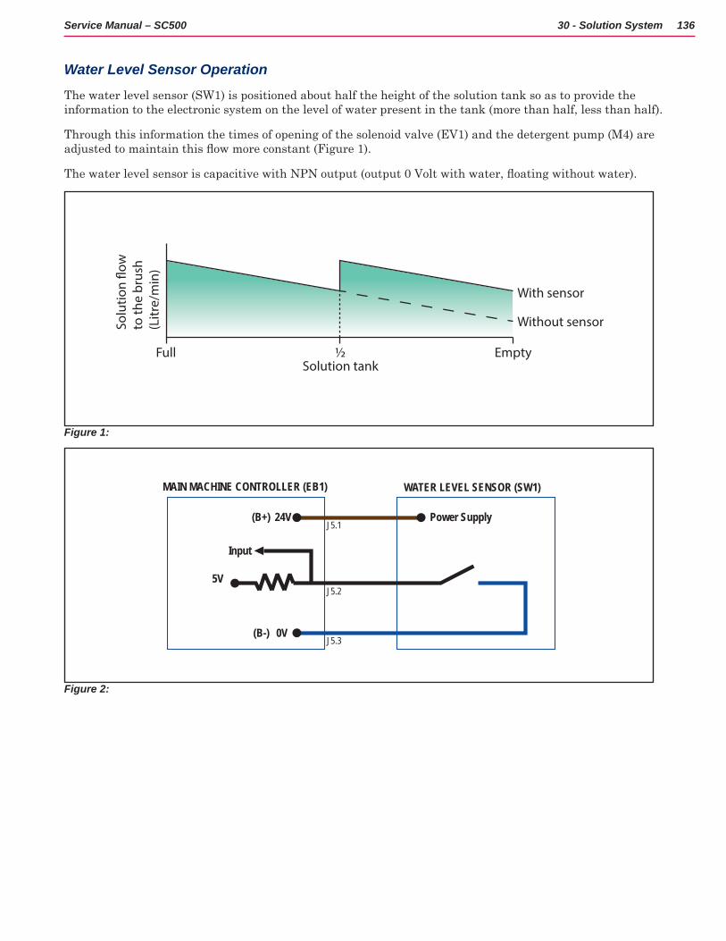
136Service Manual – SC500 30 - Solution System
Water Level Sensor Operation
The water level sensor (SW1) is positioned about half the height of the solution tank so as to provide the information to the electronic system on the level of water present in the tank (more than half, less than half)
Through this information the times of opening of the solenoid valve (EV1) and the detergent pump (M4) are adjusted to maintain this flow more constant (Figure 1)
The water level sensor is capacitive with NPN output (output 0 Volt with water, floating without water).
Full ½ EmptySolution tank
With sensor
Without sensorSolu
tion
�ow
to
the
brus
h(L
itre/
min
)
Figure 1:
J5.1
J5.2
J5.3
MAIN MACHINE CONTROLLER (EB1) WATER LEVEL SENSOR (SW1)
24V(B+)
0V(B-)
Power Supply
Input
5V
Figure 2:
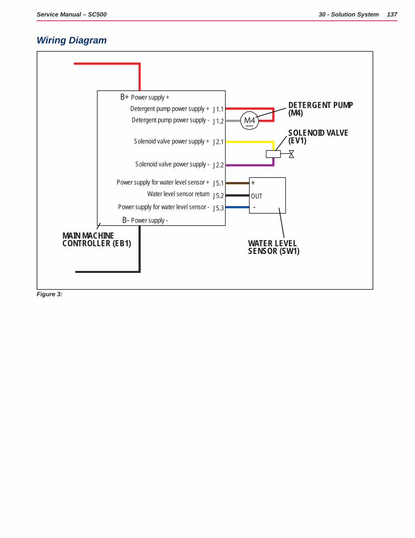
137Service Manual – SC500 30 - Solution System
Wiring Diagram
SOLENOID VALVE(EV1)
DETERGENT PUMP(M4)
M4
+
-OUT
J5.3
J5.2
J5.1
J2.2
J2.1
J1.2
J1.1Detergent pump power supply +Detergent pump power supply -
Solenoid valve power supply +
Solenoid valve power supply -
Power supply for water level sensor +Water level sensor return
Power supply for water level sensor -
B-
B+
WATER LEVEL SENSOR (SW1)
Power supply +
Power supply -
MAIN MACHINECONTROLLER (EB1)
Figure 3:
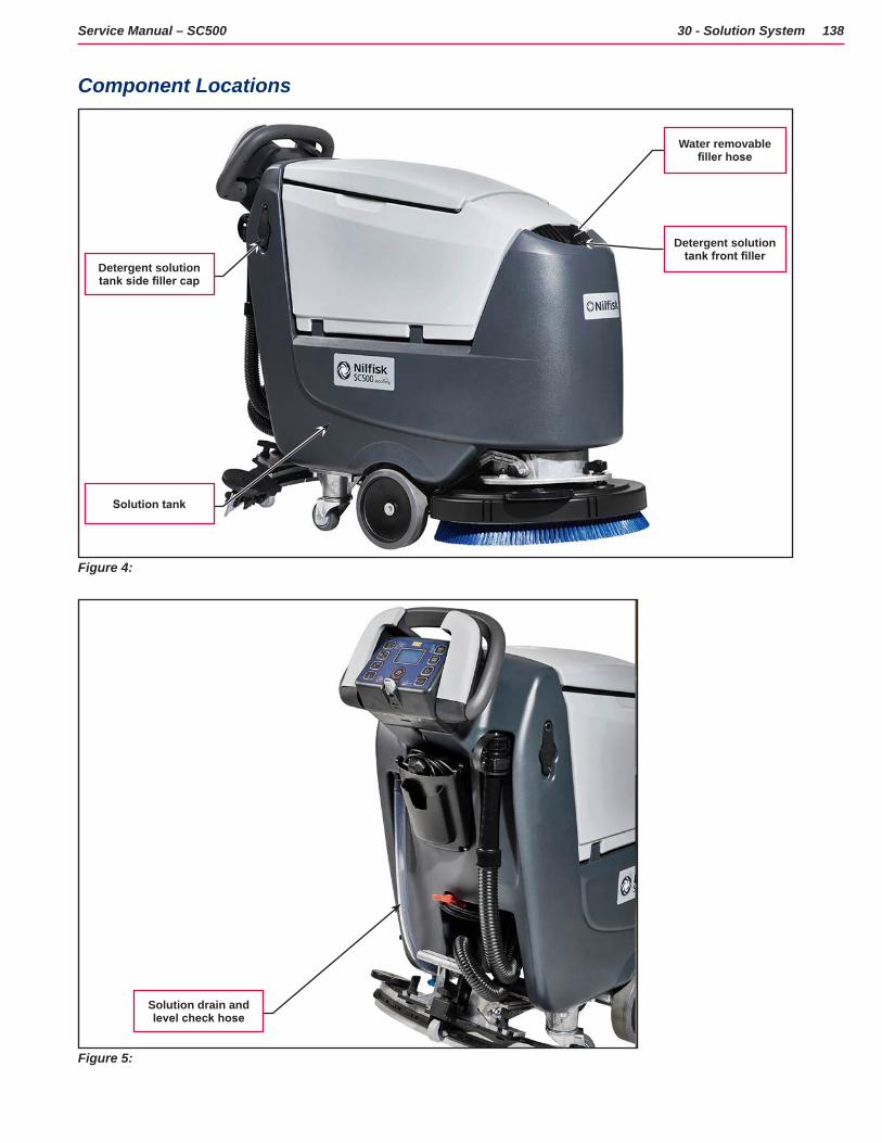
138Service Manual – SC500 30 - Solution System
Component Locations
Figure 4:
Detergent solution tank front filler
Water removable filler hose
Solution tank
Detergent solution tank side filler cap
Figure 5:
Solution drain and level check hose
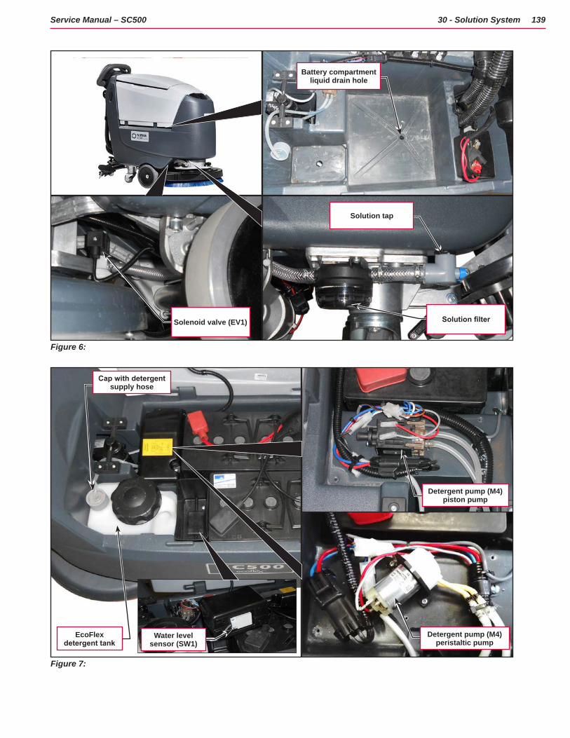
139Service Manual – SC500 30 - Solution System
Figure 6:
Solution filterSolenoid valve (EV1)
Battery compartment liquid drain hole
Solution tap
Figure 7:
Cap with detergent supply hose
Detergent pump (M4) piston pump
Detergent pump (M4) peristaltic pump
EcoFlex detergent tank
Water level sensor (SW1)
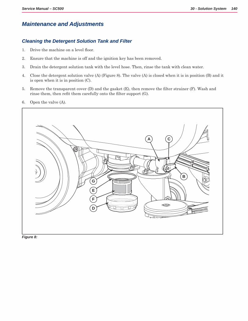
140Service Manual – SC500 30 - Solution System
Maintenance and Adjustments
Cleaning the Detergent Solution Tank and Filter
1 Drive the machine on a level floor.
2 Ensure that the machine is off and the ignition key has been removed
3 Drain the detergent solution tank with the level hose Then, rinse the tank with clean water
4 Close the detergent solution valve (A) (Figure 8) The valve (A) is closed when it is in position (B) and it is open when it is in position (C)
5 Remove the transparent cover (D) and the gasket (E), then remove the filter strainer (F). Wash and rinse them, then refit them carefully onto the filter support (G).
6 Open the valve (A)
D
F
E
G
A C
B
Figure 8:
A C
BG
E
F
D
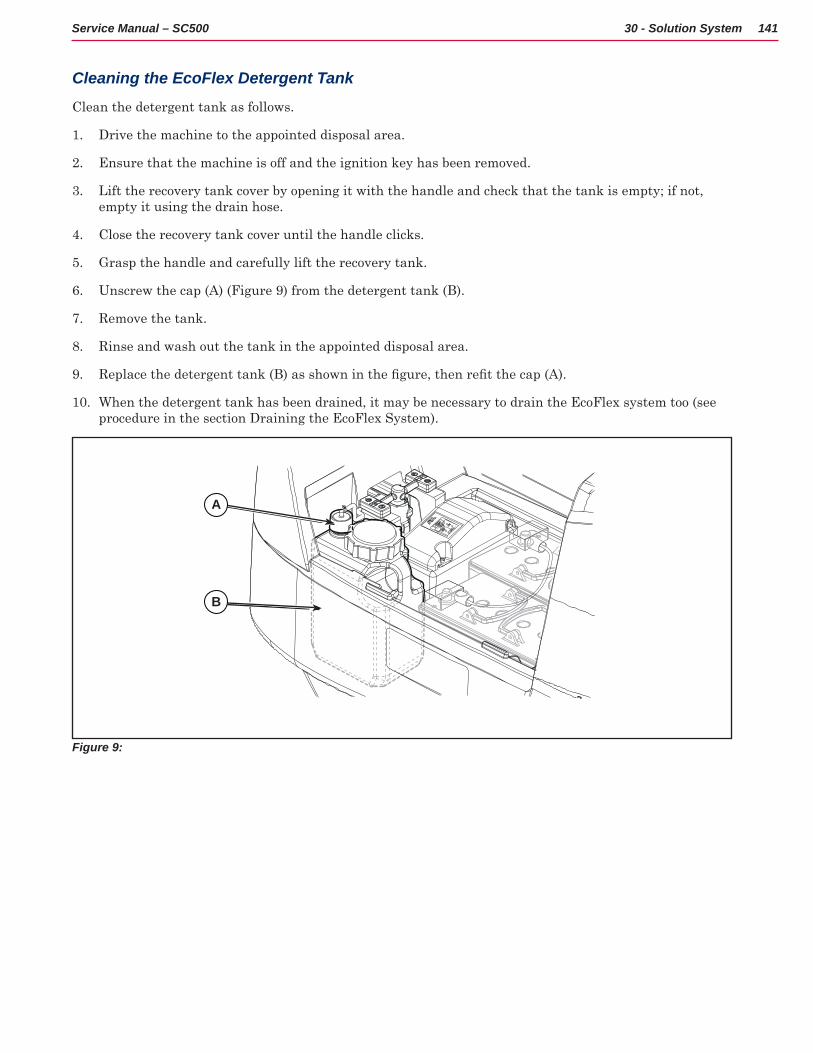
141Service Manual – SC500 30 - Solution System
Cleaning the EcoFlex Detergent Tank
Clean the detergent tank as follows
1 Drive the machine to the appointed disposal area
2 Ensure that the machine is off and the ignition key has been removed
3 Lift the recovery tank cover by opening it with the handle and check that the tank is empty; if not, empty it using the drain hose
4 Close the recovery tank cover until the handle clicks
5 Grasp the handle and carefully lift the recovery tank
6 Unscrew the cap (A) (Figure 9) from the detergent tank (B)
7 Remove the tank
8 Rinse and wash out the tank in the appointed disposal area
9 Replace the detergent tank (B) as shown in the figure, then refit the cap (A).
10 When the detergent tank has been drained, it may be necessary to drain the EcoFlex system too (see procedure in the section Draining the EcoFlex System)
B
A
Figure 9:
A
B
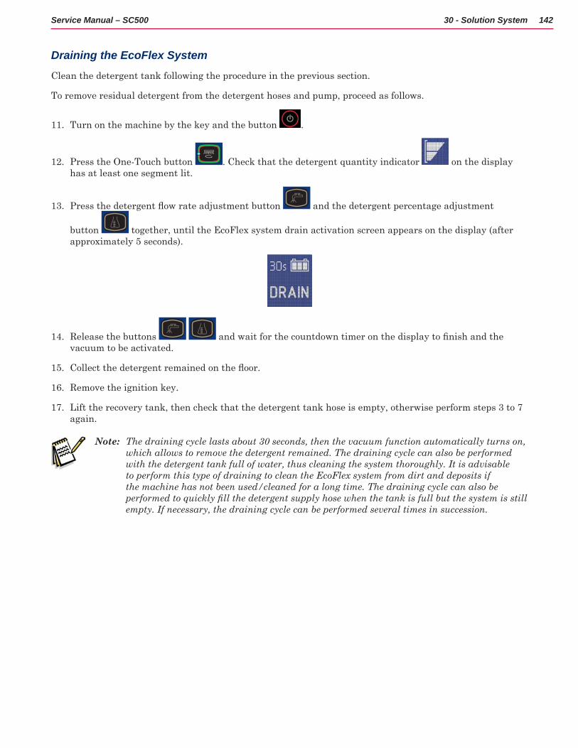
142Service Manual – SC500 30 - Solution System
Draining the EcoFlex System
Clean the detergent tank following the procedure in the previous section
To remove residual detergent from the detergent hoses and pump, proceed as follows
11 Turn on the machine by the key and the button
12 Press the One-Touch button Check that the detergent quantity indicator on the display has at least one segment lit
13 Press the detergent flow rate adjustment button and the detergent percentage adjustment
button together, until the EcoFlex system drain activation screen appears on the display (after approximately 5 seconds)
14 Release the buttons and wait for the countdown timer on the display to finish and the vacuum to be activated
15 Collect the detergent remained on the floor.
16 Remove the ignition key
17 Lift the recovery tank, then check that the detergent tank hose is empty, otherwise perform steps 3 to 7 again
Note: The draining cycle lasts about 30 seconds, then the vacuum function automatically turns on, which allows to remove the detergent remained. The draining cycle can also be performed with the detergent tank full of water, thus cleaning the system thoroughly. It is advisable to perform this type of draining to clean the EcoFlex system from dirt and deposits if the machine has not been used/cleaned for a long time. The draining cycle can also be performed to quickly fill the detergent supply hose when the tank is full but the system is still empty. If necessary, the draining cycle can be performed several times in succession.
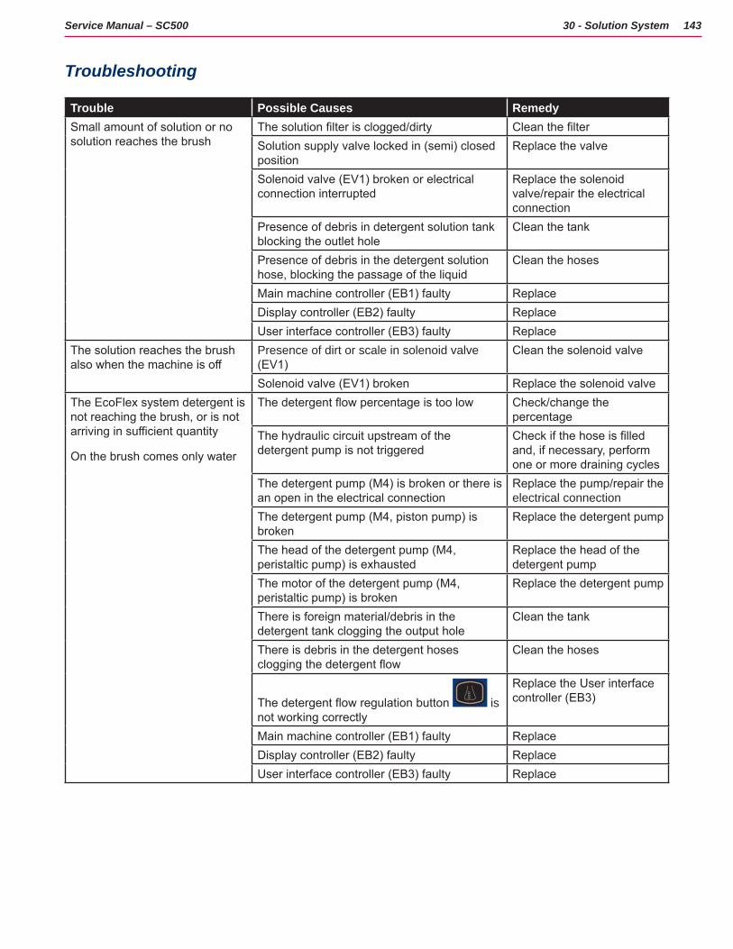
143Service Manual – SC500 30 - Solution System
Troubleshooting
Trouble Possible Causes RemedySmall amount of solution or no solution reaches the brush
The solution filter is clogged/dirty Clean the filterSolution supply valve locked in (semi) closed position
Replace the valve
Solenoid valve (EV1) broken or electrical connection interrupted
Replace the solenoid valve/repair the electrical connection
Presence of debris in detergent solution tank blocking the outlet hole
Clean the tank
Presence of debris in the detergent solution hose, blocking the passage of the liquid
Clean the hoses
Main machine controller (EB1) faulty ReplaceDisplay controller (EB2) faulty ReplaceUser interface controller (EB3) faulty Replace
The solution reaches the brush also when the machine is off
Presence of dirt or scale in solenoid valve (EV1)
Clean the solenoid valve
Solenoid valve (EV1) broken Replace the solenoid valveThe EcoFlex system detergent is not reaching the brush, or is not arriving in sufficient quantity
On the brush comes only water
The detergent flow percentage is too low Check/change the percentage
The hydraulic circuit upstream of the detergent pump is not triggered
Check if the hose is filled and, if necessary, perform one or more draining cycles
The detergent pump (M4) is broken or there is an open in the electrical connection
Replace the pump/repair the electrical connection
The detergent pump (M4, piston pump) is broken
Replace the detergent pump
The head of the detergent pump (M4, peristaltic pump) is exhausted
Replace the head of the detergent pump
The motor of the detergent pump (M4, peristaltic pump) is broken
Replace the detergent pump
There is foreign material/debris in the detergent tank clogging the output hole
Clean the tank
There is debris in the detergent hoses clogging the detergent flow
Clean the hoses
The detergent flow regulation button is not working correctly
Replace the User interface controller (EB3)
Main machine controller (EB1) faulty ReplaceDisplay controller (EB2) faulty ReplaceUser interface controller (EB3) faulty Replace
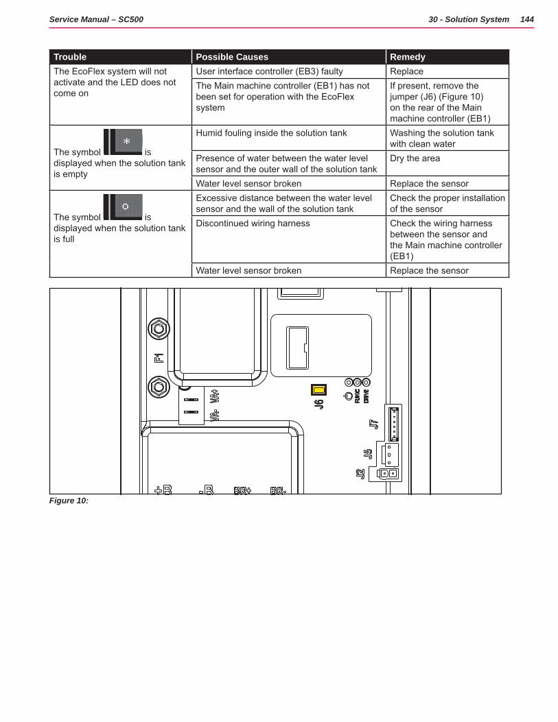
144Service Manual – SC500 30 - Solution System
Trouble Possible Causes RemedyThe EcoFlex system will not activate and the LED does not come on
User interface controller (EB3) faulty ReplaceThe Main machine controller (EB1) has not been set for operation with the EcoFlex system
If present, remove the jumper (J6) (Figure 10) on the rear of the Main machine controller (EB1)
The symbol is displayed when the solution tank is empty
Humid fouling inside the solution tank Washing the solution tank with clean water
Presence of water between the water level sensor and the outer wall of the solution tank
Dry the area
Water level sensor broken Replace the sensor
The symbol is displayed when the solution tank is full
Excessive distance between the water level sensor and the wall of the solution tank
Check the proper installation of the sensor
Discontinued wiring harness Check the wiring harness between the sensor and the Main machine controller (EB1)
Water level sensor broken Replace the sensor
Figure 10:
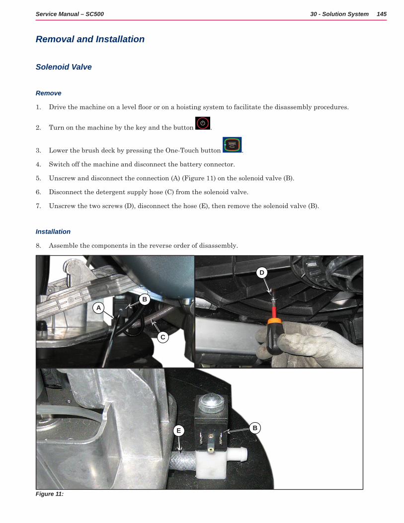
145Service Manual – SC500 30 - Solution System
Removal and Installation
Solenoid Valve
Remove
1 Drive the machine on a level floor or on a hoisting system to facilitate the disassembly procedures.
2 Turn on the machine by the key and the button
3 Lower the brush deck by pressing the One-Touch button
4 Switch off the machine and disconnect the battery connector
5 Unscrew and disconnect the connection (A) (Figure 11) on the solenoid valve (B)
6 Disconnect the detergent supply hose (C) from the solenoid valve
7 Unscrew the two screws (D), disconnect the hose (E), then remove the solenoid valve (B)
Installation
8 Assemble the components in the reverse order of disassembly
Figure 11:
E
AB
C
D
B
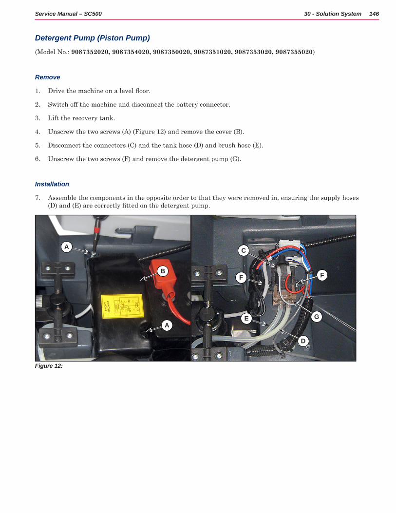
146Service Manual – SC500 30 - Solution System
Detergent Pump (Piston Pump)
(Model No : 9087352020, 9087354020, 9087350020, 9087351020, 9087353020, 9087355020)
Remove
1 Drive the machine on a level floor.
2 Switch off the machine and disconnect the battery connector
3 Lift the recovery tank
4 Unscrew the two screws (A) (Figure 12) and remove the cover (B)
5 Disconnect the connectors (C) and the tank hose (D) and brush hose (E)
6 Unscrew the two screws (F) and remove the detergent pump (G)
Installation
7 Assemble the components in the opposite order to that they were removed in, ensuring the supply hoses (D) and (E) are correctly fitted on the detergent pump.
Figure 12:
A
B
A
C
FF
GE
D
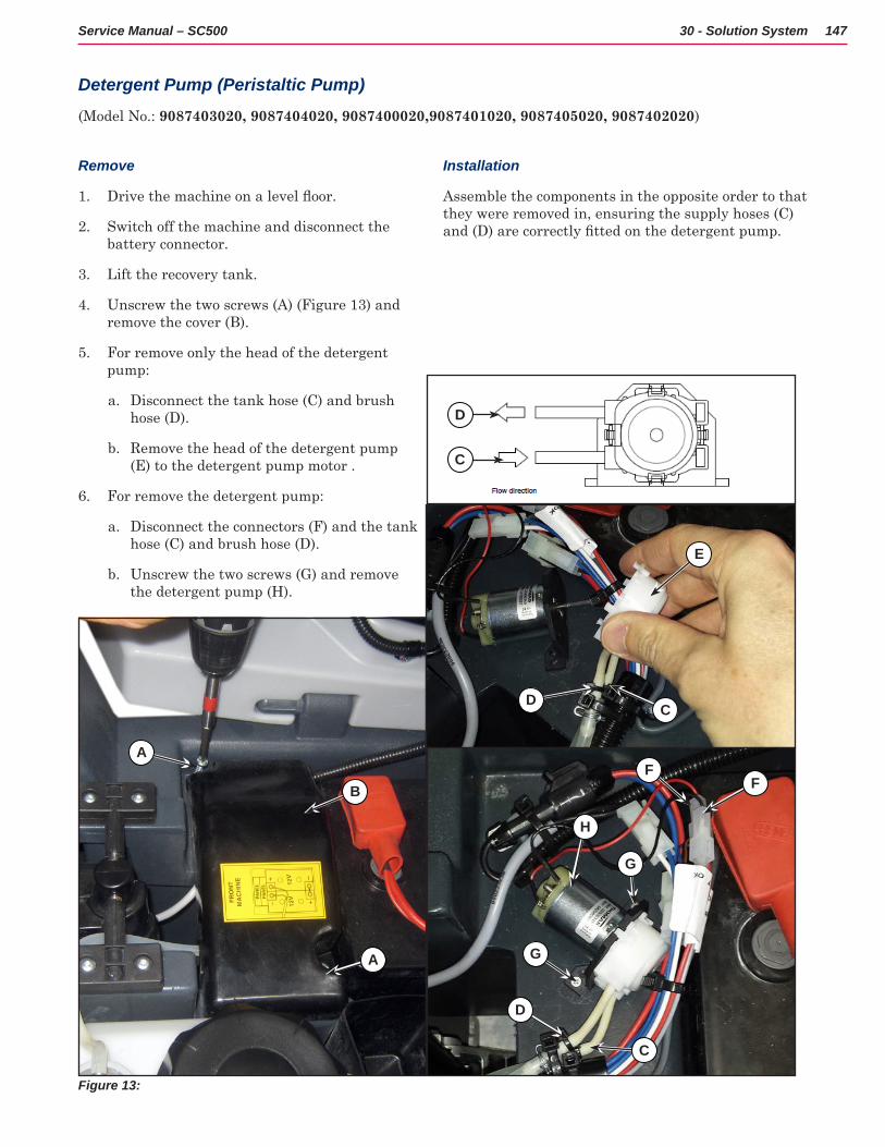
147Service Manual – SC500 30 - Solution System
Detergent Pump (Peristaltic Pump)
(Model No : 9087403020, 9087404020, 9087400020,9087401020, 9087405020, 9087402020)
Remove
1 Drive the machine on a level floor.
2 Switch off the machine and disconnect the battery connector
3 Lift the recovery tank
4 Unscrew the two screws (A) (Figure 13) and remove the cover (B)
5 For remove only the head of the detergent pump:
a Disconnect the tank hose (C) and brush hose (D)
b Remove the head of the detergent pump (E) to the detergent pump motor
6 For remove the detergent pump:
a Disconnect the connectors (F) and the tank hose (C) and brush hose (D)
b Unscrew the two screws (G) and remove the detergent pump (H)
Installation
Assemble the components in the opposite order to that they were removed in, ensuring the supply hoses (C) and (D) are correctly fitted on the detergent pump.
Figure 13:
A
B
A
C
E
D
C
FF
G
D
H
G
C
D
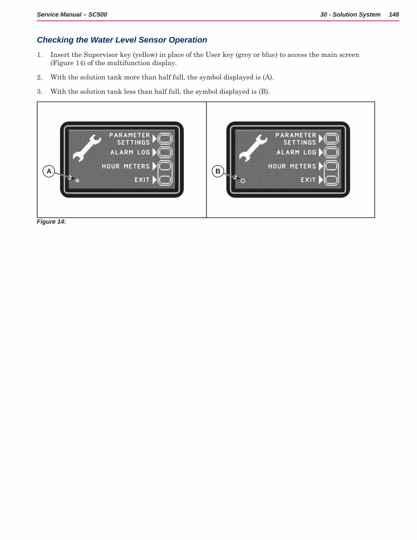
148Service Manual – SC500 30 - Solution System
Checking the Water Level Sensor Operation
1 Insert the Supervisor key (yellow) in place of the User key (grey or blue) to access the main screen (Figure 14) of the multifunction display
2 With the solution tank more than half full, the symbol displayed is (A)
3 With the solution tank less than half full, the symbol displayed is (B)
Figure 14:
A B
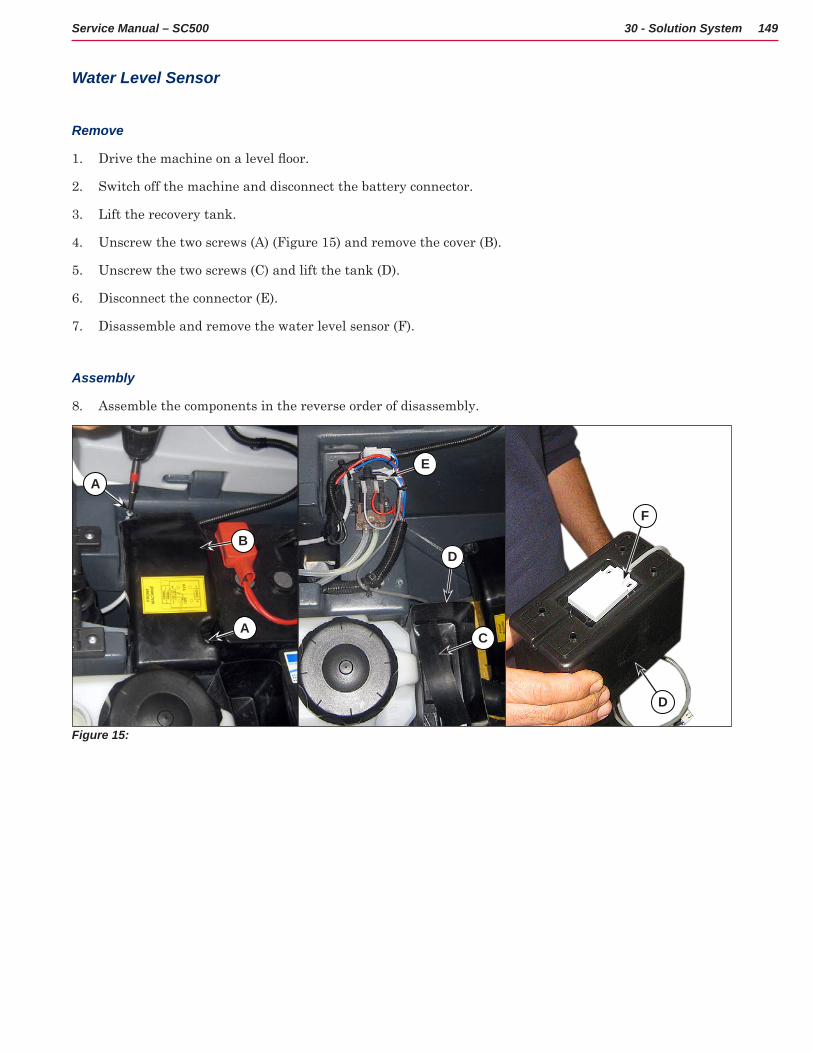
149Service Manual – SC500 30 - Solution System
Water Level Sensor
Remove
1 Drive the machine on a level floor.
2 Switch off the machine and disconnect the battery connector
3 Lift the recovery tank
4 Unscrew the two screws (A) (Figure 15) and remove the cover (B)
5 Unscrew the two screws (C) and lift the tank (D)
6 Disconnect the connector (E)
7 Disassemble and remove the water level sensor (F)
Assembly
8 Assemble the components in the reverse order of disassembly
Figure 15:
A
B
A
E
D
C
F
D
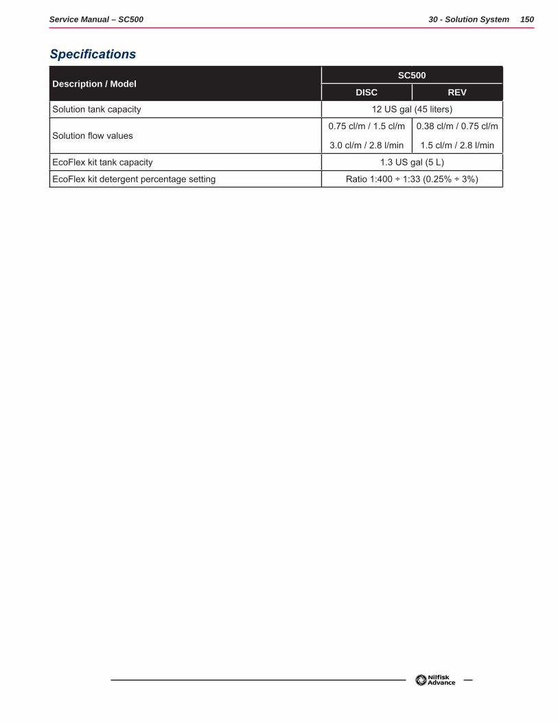
150Service Manual – SC500 30 - Solution System
Specifications
Description / ModelSC500
DISC REV
Solution tank capacity 12 US gal (45 liters)
Solution flow values 0.75 cl/m / 1.5 cl/m
3.0 cl/m / 2.8 l/min
0.38 cl/m / 0.75 cl/m
1.5 cl/m / 2.8 l/min
EcoFlex kit tank capacity 1.3 US gal (5 L)
EcoFlex kit detergent percentage setting Ratio 1:400 ÷ 1:33 (0.25% ÷ 3%)
151Service Manual – SC500
34 - Scrub System, Disc
Functional DescriptionThe disc brush system can be started by the operator
The disc brush turn counter-clockwise
The rotating brush system cleans the surface of the floor. The main component of the brush system is the deck where the brush or the pad holder with pad suitable for the type of surface to be cleaned is installed
The brush deck is installed on a frame to which the electrical actuator and the four levers for connection to the frame integrated with the brush motor is coupled
The electrical actuator (M5) lifts and lowers the deck The operating and washing pressure depends on the weight of the deck The actuator also permits the extra pressure function Extra pressure is selected via the button on the User interface controller
Brush rotation occurs only when the brush motor (M1) is driven by the Main machine controller (EB1) following activation of the paddle
The brush system uses the solution to wash the floor.
In case of brush motor overload, a safety system stops the brush to prevent continuous overload
If the overload takes place when the extra pressure function is on, the system automatically turns the extra pressure function off If the overload persists, the brush stops
The overload is detected by monitoring the current flow on the brush motor. If the motor current reaches the value stored in the parameter “VS1” and the overload persists, the brush motor will stop following a delay which varies on the basis of the extent of the overload
To start scrubbing again after a brush stop due to overload, turn the machine off Then restart the machine
To work properly, the brush motor (M1) needs the following:
• Brush function on
• Forward paddle pressed
• Battery level not in critical condition with flashing segments.
Brush Release System
In order to release the brush from its hub, the brush motor starts up and then stops rapidly The brush’s inertia thus causes it to disengage from the hub
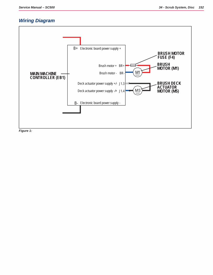
152Service Manual – SC500 34 - Scrub System, Disc
Wiring Diagram
M5J1.4
J1.3Deck actuator power supply +/-
Deck actuator power supply -/+
BRUSH DECK ACTUATOR MOTOR (M5)
M1BR-
BR+
Brush motor -
Brush motor +
B-
B+
BRUSH MOTOR (M1)
Electronic board power supply +
Electronic board power supply -
MAIN MACHINECONTROLLER (EB1)
BRUSH MOTORFUSE (F4)
Figure 1:
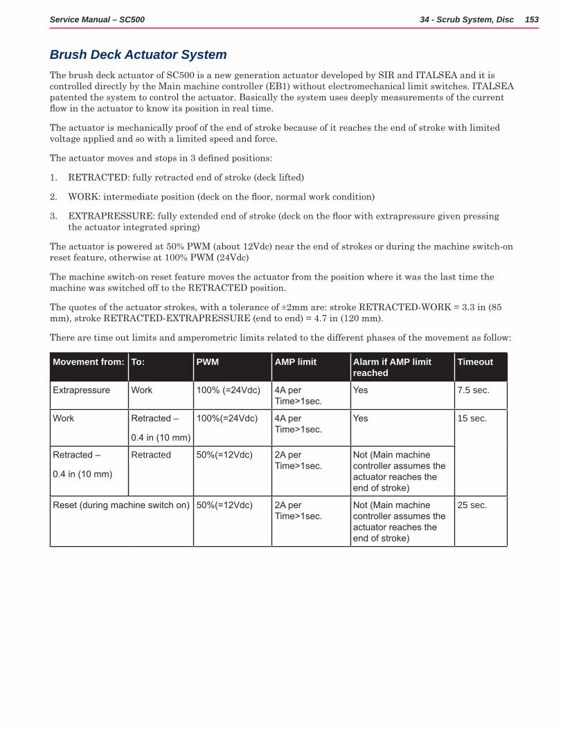
153Service Manual – SC500 34 - Scrub System, Disc
Brush Deck Actuator SystemThe brush deck actuator of SC500 is a new generation actuator developed by SIR and ITALSEA and it is controlled directly by the Main machine controller (EB1) without electromechanical limit switches ITALSEA patented the system to control the actuator Basically the system uses deeply measurements of the current flow in the actuator to know its position in real time.
The actuator is mechanically proof of the end of stroke because of it reaches the end of stroke with limited voltage applied and so with a limited speed and force
The actuator moves and stops in 3 defined positions:
1 RETRACTED: fully retracted end of stroke (deck lifted)
2 WORK: intermediate position (deck on the floor, normal work condition)
3 EXTRAPRESSURE: fully extended end of stroke (deck on the floor with extrapressure given pressing the actuator integrated spring)
The actuator is powered at 50% PWM (about 12Vdc) near the end of strokes or during the machine switch-on reset feature, otherwise at 100% PWM (24Vdc)
The machine switch-on reset feature moves the actuator from the position where it was the last time the machine was switched off to the RETRACTED position
The quotes of the actuator strokes, with a tolerance of ±2mm are: stroke RETRACTED-WORK = 3 3 in (85 mm), stroke RETRACTED-EXTRAPRESSURE (end to end) = 4 7 in (120 mm)
There are time out limits and amperometric limits related to the different phases of the movement as follow:
Movement from: To: PWM AMP limit Alarm if AMP limit reached
Timeout
Extrapressure Work 100% (=24Vdc) 4A per Time>1sec.
Yes 7.5 sec.
Work Retracted –
0.4 in (10 mm)
100%(=24Vdc) 4A per Time>1sec.
Yes 15 sec.
Retracted –
0.4 in (10 mm)
Retracted 50%(=12Vdc) 2A per Time>1sec.
Not (Main machine controller assumes the actuator reaches the end of stroke)
Reset (during machine switch on) 50%(=12Vdc) 2A per Time>1sec.
Not (Main machine controller assumes the actuator reaches the end of stroke)
25 sec.
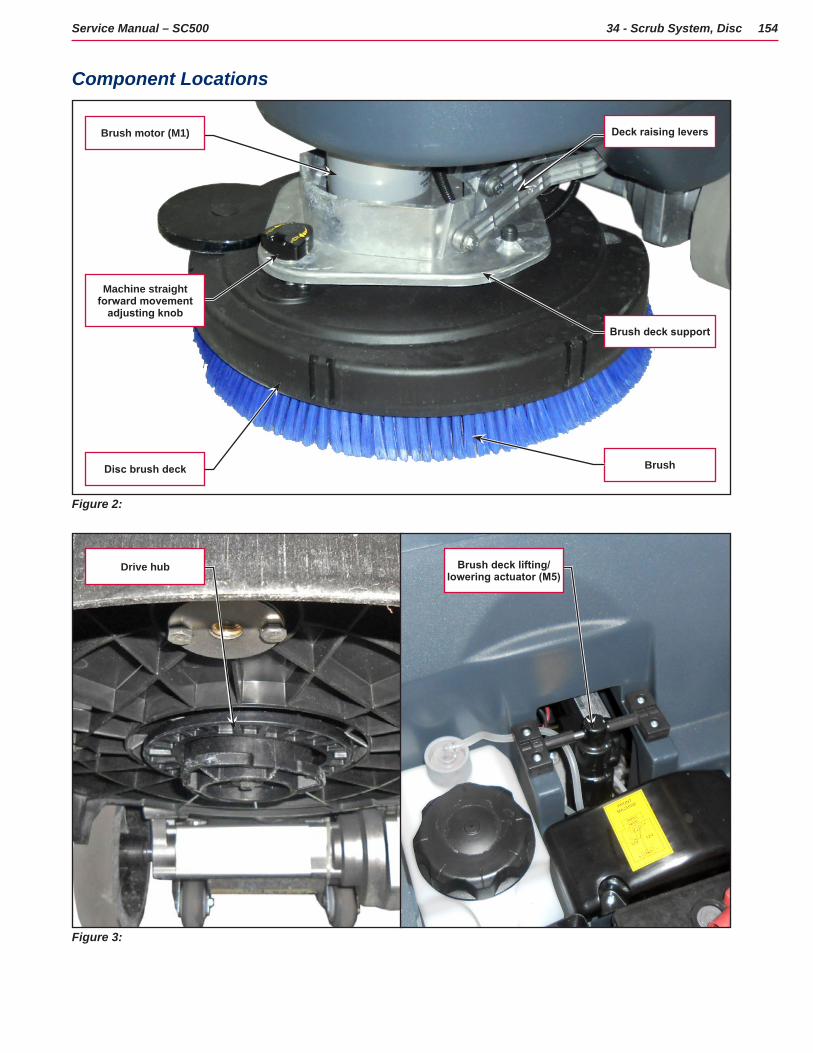
154Service Manual – SC500 34 - Scrub System, Disc
Component Locations
Figure 2:
Brush deck support
Brush
Deck raising levers
Machine straight forward movement
adjusting knob
Disc brush deck
Brush motor (M1)
Figure 3:
Drive hub Brush deck lifting/lowering actuator (M5)
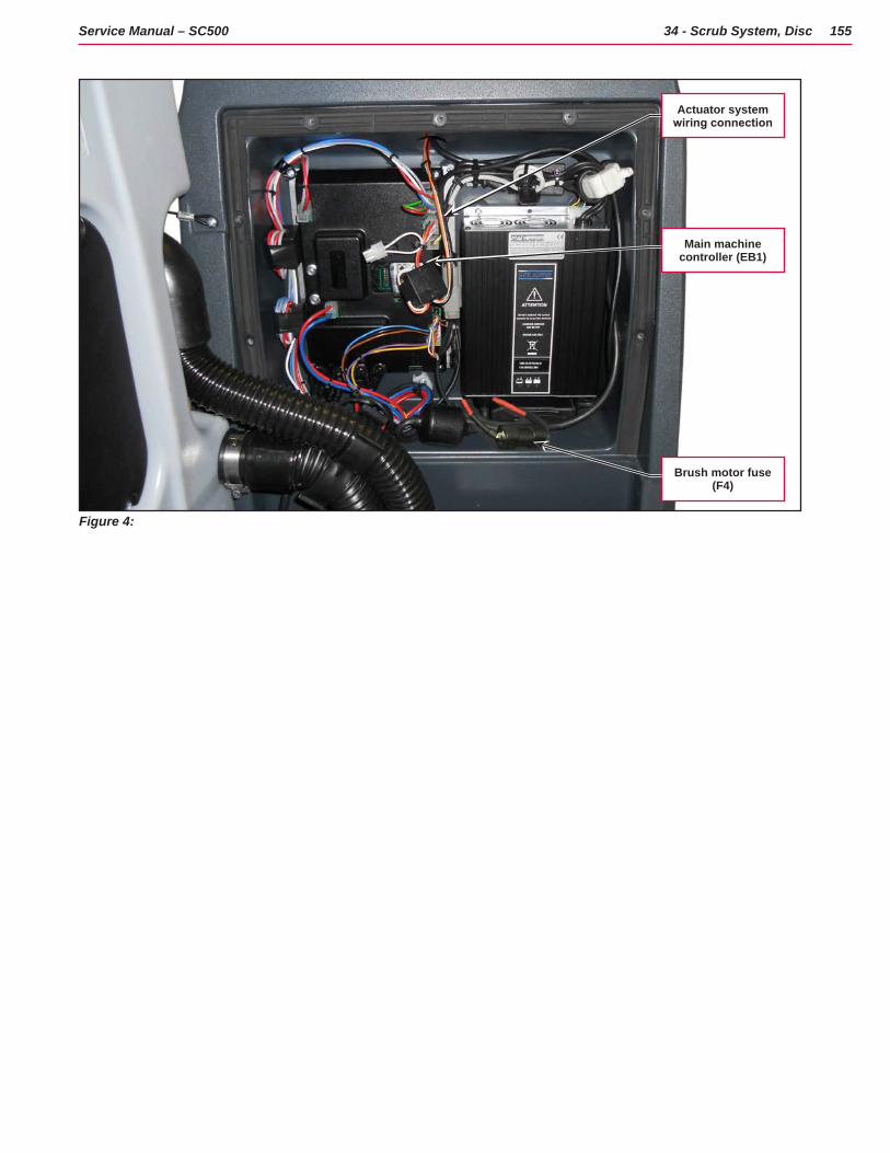
155Service Manual – SC500 34 - Scrub System, Disc
Figure 4:
Brush motor fuse (F4)
Main machine controller (EB1)
Actuator system wiring connection
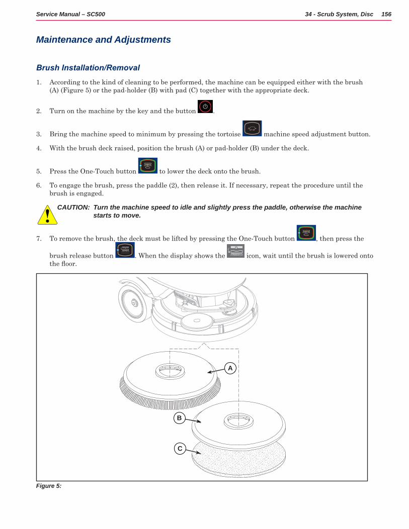
156Service Manual – SC500 34 - Scrub System, Disc
Maintenance and Adjustments
Brush Installation/Removal
1 According to the kind of cleaning to be performed, the machine can be equipped either with the brush (A) (Figure 5) or the pad-holder (B) with pad (C) together with the appropriate deck
2 Turn on the machine by the key and the button
3 Bring the machine speed to minimum by pressing the tortoise machine speed adjustment button
4 With the brush deck raised, position the brush (A) or pad-holder (B) under the deck
5 Press the One-Touch button to lower the deck onto the brush
6 To engage the brush, press the paddle (2), then release it If necessary, repeat the procedure until the brush is engaged
CAUTION: Turn the machine speed to idle and slightly press the paddle, otherwise the machine starts to move.
7 To remove the brush, the deck must be lifted by pressing the One-Touch button , then press the
brush release button When the display shows the icon, wait until the brush is lowered onto the floor.
A
B
C
Figure 5:
C
B
A
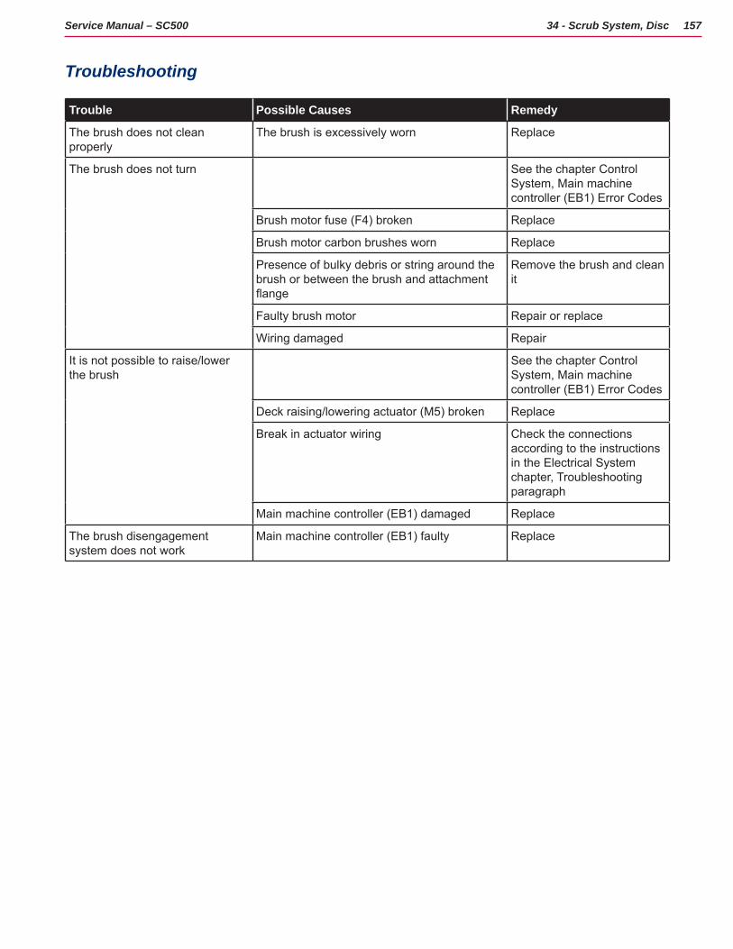
157Service Manual – SC500 34 - Scrub System, Disc
Troubleshooting
Trouble Possible Causes Remedy
The brush does not clean properly
The brush is excessively worn Replace
The brush does not turn See the chapter Control System, Main machine controller (EB1) Error Codes
Brush motor fuse (F4) broken Replace
Brush motor carbon brushes worn Replace
Presence of bulky debris or string around the brush or between the brush and attachment flange
Remove the brush and clean it
Faulty brush motor Repair or replace
Wiring damaged Repair
It is not possible to raise/lower the brush
See the chapter Control System, Main machine controller (EB1) Error Codes
Deck raising/lowering actuator (M5) broken Replace
Break in actuator wiring Check the connections according to the instructions in the Electrical System chapter, Troubleshooting paragraph
Main machine controller (EB1) damaged Replace
The brush disengagement system does not work
Main machine controller (EB1) faulty Replace
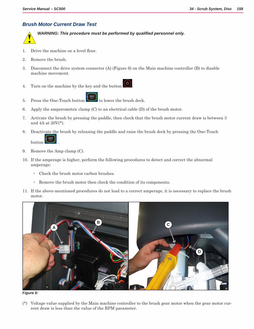
158Service Manual – SC500 34 - Scrub System, Disc
Brush Motor Current Draw Test
WARNING: This procedure must be performed by qualified personnel only.
1 Drive the machine on a level floor.
2 Remove the brush
3 Disconnect the drive system connector (A) (Figure 6) on the Main machine controller (B) to disable machine movement
4 Turn on the machine by the key and the button
5 Press the One-Touch button to lower the brush deck
6 Apply the amperometric clamp (C) to an electrical cable (D) of the brush motor
7 Activate the brush by pressing the paddle, then check that the brush motor current draw is between 3 and 4A at 20V(*)
8 Deactivate the brush by releasing the paddle and raise the brush deck by pressing the One-Touch
button
9 Remove the Amp clamp (C)
10 If the amperage is higher, perform the following procedures to detect and correct the abnormal amperage:
◦ Check the brush motor carbon brushes
◦ Remove the brush motor then check the condition of its components
11 If the above-mentioned procedures do not lead to a correct amperage, it is necessary to replace the brush motor
Figure 6:
AB C
D
(*) Voltage value supplied by the Main machine controller to the brush gear motor when the gear motor cur-rent draw is less than the value of the RPM parameter
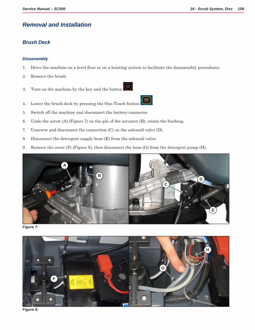
159Service Manual – SC500 34 - Scrub System, Disc
Removal and Installation
Brush Deck
Disassembly
1 Drive the machine on a level floor or on a hoisting system to facilitate the disassembly procedures.
2 Remove the brush
3 Turn on the machine by the key and the button
4 Lower the brush deck by pressing the One-Touch button
5 Switch off the machine and disconnect the battery connector
6 Undo the screw (A) (Figure 7) on the pin of the actuator (B); retain the bushing
7 Unscrew and disconnect the connection (C) on the solenoid valve (D)
8 Disconnect the detergent supply hose (E) from the solenoid valve
9 Remove the cover (F) (Figure 8), then disconnect the hose (G) from the detergent pump (H)
Figure 7:
A
B
CD
E
Figure 8:
F
G
H
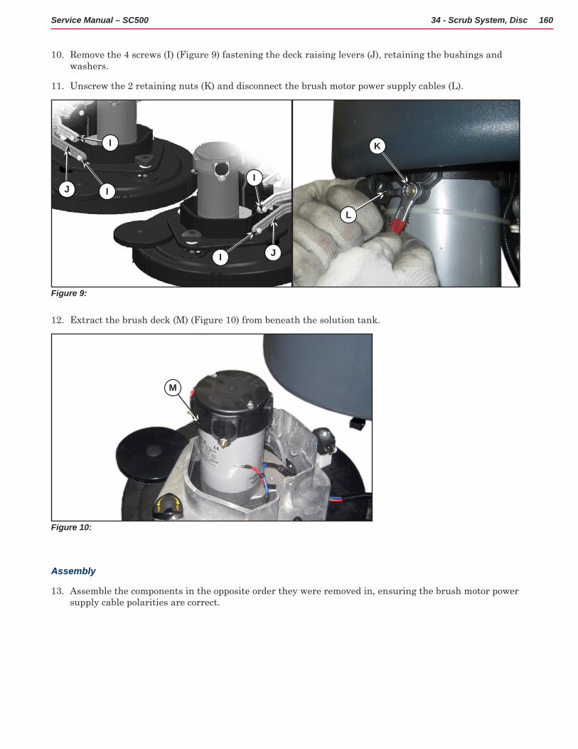
160Service Manual – SC500 34 - Scrub System, Disc
10 Remove the 4 screws (I) (Figure 9) fastening the deck raising levers (J), retaining the bushings and washers
11 Unscrew the 2 retaining nuts (K) and disconnect the brush motor power supply cables (L)
Figure 9:
I
IJ
I
I
J
L
K
12 Extract the brush deck (M) (Figure 10) from beneath the solution tank
Figure 10:
M
Assembly
13 Assemble the components in the opposite order they were removed in, ensuring the brush motor power supply cable polarities are correct
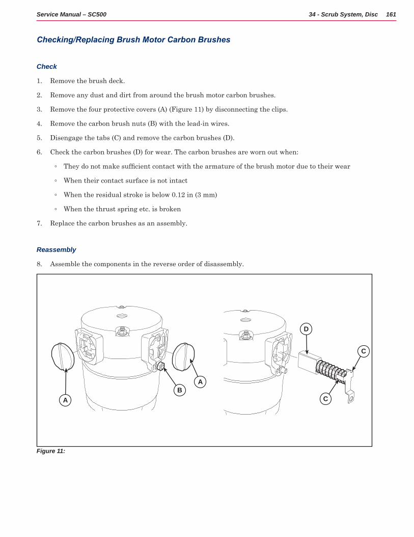
161Service Manual – SC500 34 - Scrub System, Disc
Checking/Replacing Brush Motor Carbon Brushes
Check
1 Remove the brush deck
2 Remove any dust and dirt from around the brush motor carbon brushes
3 Remove the four protective covers (A) (Figure 11) by disconnecting the clips
4 Remove the carbon brush nuts (B) with the lead-in wires
5 Disengage the tabs (C) and remove the carbon brushes (D)
6 Check the carbon brushes (D) for wear The carbon brushes are worn out when:
◦ They do not make sufficient contact with the armature of the brush motor due to their wear
◦ When their contact surface is not intact
◦ When the residual stroke is below 0 12 in (3 mm)
◦ When the thrust spring etc is broken
7 Replace the carbon brushes as an assembly
Reassembly
8 Assemble the components in the reverse order of disassembly
Figure 11:
D
A CB
C
A
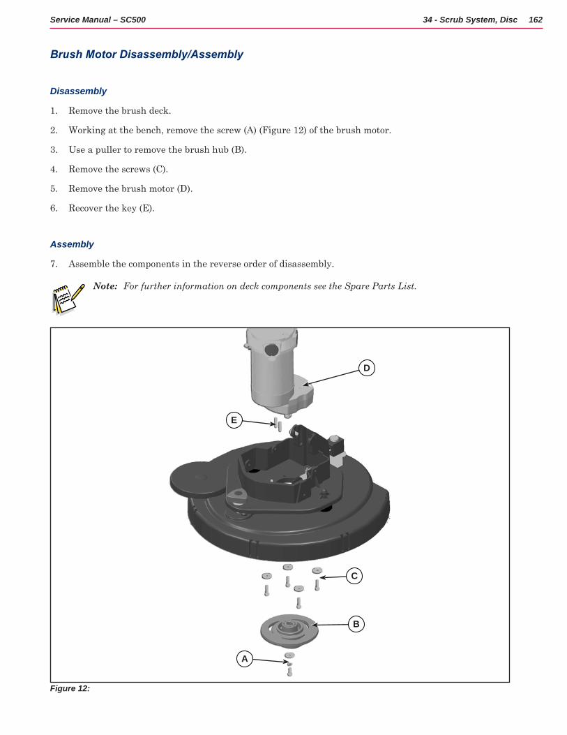
162Service Manual – SC500 34 - Scrub System, Disc
Brush Motor Disassembly/Assembly
Disassembly
1 Remove the brush deck
2 Working at the bench, remove the screw (A) (Figure 12) of the brush motor
3 Use a puller to remove the brush hub (B)
4 Remove the screws (C)
5 Remove the brush motor (D)
6 Recover the key (E)
Assembly
7 Assemble the components in the reverse order of disassembly
Note: For further information on deck components see the Spare Parts List.
Figure 12:
D
A
E
B
C
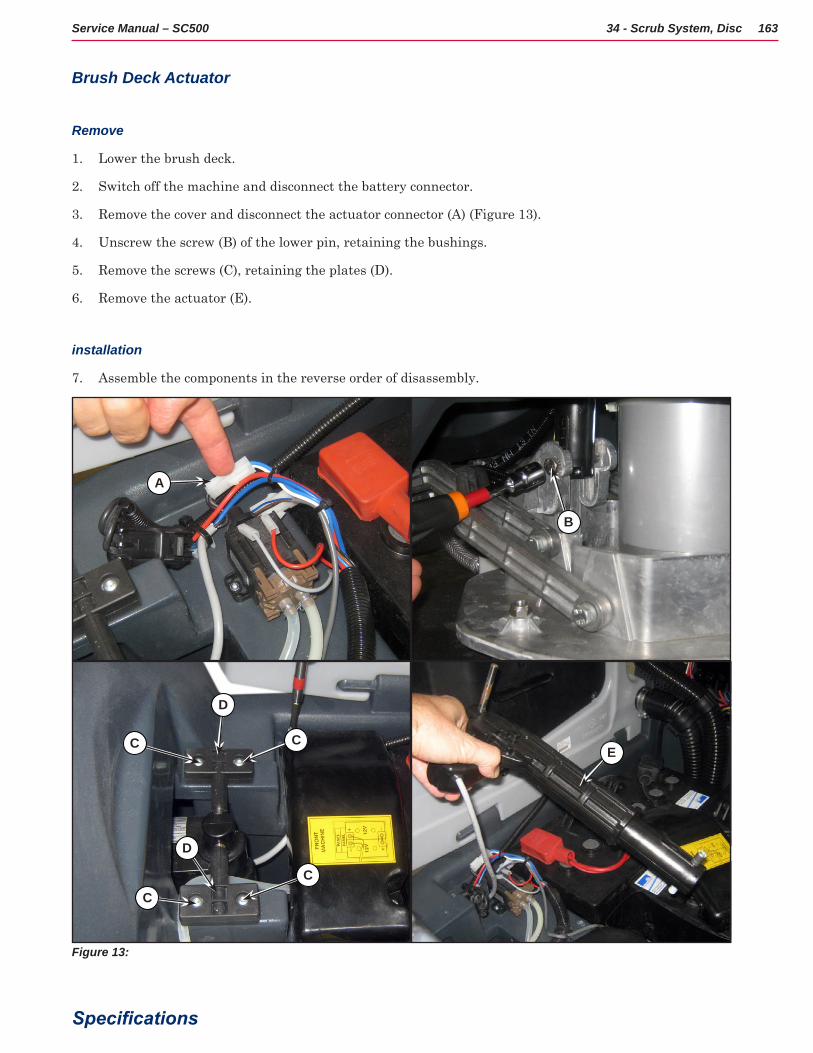
163Service Manual – SC500 34 - Scrub System, Disc
Brush Deck Actuator
Remove
1 Lower the brush deck
2 Switch off the machine and disconnect the battery connector
3 Remove the cover and disconnect the actuator connector (A) (Figure 13)
4 Unscrew the screw (B) of the lower pin, retaining the bushings
5 Remove the screws (C), retaining the plates (D)
6 Remove the actuator (E)
installation
7 Assemble the components in the reverse order of disassembly
Figure 13:
C
D
C
C
D
C
B
E
A
Specifications
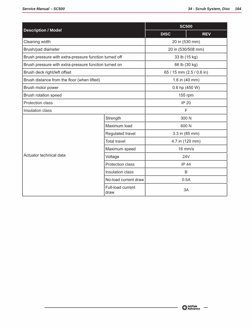
164Service Manual – SC500 34 - Scrub System, Disc
Description / ModelSC500
DISC REV
Cleaning width 20 in (530 mm)
Brush/pad diameter 20 in (530/508 mm)
Brush pressure with extra-pressure function turned off 33 lb (15 kg)
Brush pressure with extra-pressure function turned on 66 lb (30 kg)
Brush deck right/left offset 65 / 15 mm (2.5 / 0.6 in)
Brush distance from the floor (when lifted) 1.6 in (40 mm)
Brush motor power 0.6 hp (450 W)
Brush rotation speed 155 rpm
Protection class IP 20
Insulation class F
Actuator technical data
Strength 300 N
Maximum load 600 N
Regulated travel 3.3 in (85 mm)
Total travel 4.7 in (120 mm)
Maximum speed 16 mm/s
Voltage 24V
Protection class IP 44
Insulation class B
No-load current draw 0.5A
Full-load current draw 3A
165Service Manual – SC401, SCRUBTEC 334
34 - Scrub System, REV
Functional DescriptionThe REV brush system can be operated by the operator
The REV brush has a movement with distinctive orbital movements and anticlockwise rotation
The REV allows the surface concerned to be washed/cleaned by the movement of the brush The main component of the system is the deck where the brush or the pad suitable for the type of surface to be cleaned is installed
The brush deck is fixed to the machine with a support to which the electrical actuator and two anchor levers are applied
The electrical actuator (M5) lifts and lowers the deck The operating and washing pressure depends on the weight of the deck The actuator also permits the extra pressure function Extra pressure is selected via the button on the User interface controller
Brush rotation occurs only when the REV motor (M1) is driven by the Main machine controller (EB1)following activation of the paddle
Transmission of motion from the gear motor to the brush occurs via an eccentric system which provides the orbital movement
The system, once activated, uses the solution coming form the solution system, to wash the floor.
In case of REV motor overload, a safety system stops the brush to prevent continuous overload
If the overload takes place when the extra pressure function is on, the system automatically turns the extra pressure function off If the overload persists, the brush stops
The overload is detected by monitoring the current flow sum on the REV motor. If the motor current reaches the value stored in the parameter “VS1” and if the overload persists, the REV motor will stop following a delay which varies on the basis of the extent of the overload
To start scrubbing again after a brush stop due to overload, turn the machine off Then restart the machine
In summary, operation of the REV motor (M1) requires the following conditions/inputs:
• Brush function on
• Forward paddle pressed
• Battery level not in critical condition with flashing segments.

166Service Manual – SC500 34 - Scrub System, REV
Wiring Diagram
M5J1.4
J1.3Deck actuator power supply +/-
Deck actuator power supply -/+
BRUSH DECK ACTUATOR MOTOR (M5)
M1BR-
BR+
Brush motor -
Brush motor +
B-
B+
BRUSH MOTOR (M1)
Electronic board power supply +
Electronic board power supply -
MAIN MACHINECONTROLLER (EB1)
BRUSH MOTORFUSE (F4)
Figure 1:

167Service Manual – SC500 34 - Scrub System, REV
Brush Deck Actuator SystemThe brush deck actuator of SC500 is a new generation actuator developed by SIR and ITALSEA and it is controlled directly by the Main machine controller (EB1) without electromechanical limit switches ITALSEA patented the system to control the actuator Basically the system uses deeply measurements of the current flow in the actuator to know its position in real time.
The actuator is mechanically proof of the end of stroke because of it reaches the end of stroke with limited voltage applied and so with a limited speed and force
The actuator moves and stops in 3 defined positions:
1 RETRACTED: fully retracted end of stroke (deck lifted)
2 WORK: intermediate position (deck on the floor, normal work condition)
3 EXTRAPRESSURE: fully extended end of stroke (deck on the floor with extrapressure given pressing the actuator integrated spring)
The actuator is powered at 50% PWM (about 12Vdc) near the end of strokes or during the machine switch-on reset feature, otherwise at 100% PWM (24Vdc)
The machine switch-on reset feature moves the actuator from the position where it was the last time the machine was switched off to the RETRACTED position
The quotes of the actuator strokes, with a tolerance of ±2mm are: stroke RETRACTED-WORK = 2 5 in (63 mm), stroke RETRACTED-EXTRAPRESSURE (end to end) = 3 8 in (98 mm)
There are time out limits and amperometric limits related to the different phases of the movement as follow:
Movement from: To: PWM AMP limit Alarm if AMP limit reached
Timeout
Extrapressure Work 100% (=24Vdc) 4A per Time>1sec.
Yes 7.5 sec.
Work Retracted –
0.4 in (10 mm)
100%(=24Vdc) 4A per Time>1sec.
Yes 15 sec.
Retracted –
0.4 in (10 mm)
Retracted 50%(=12Vdc) 2A per Time>1sec.
Not (Main machine controller assumes the actuator reaches the end of stroke)
Reset (during machine switch on) 50%(=12Vdc) 2A per Time>1sec.
Not (Main machine controller assumes the actuator reaches the end of stroke)
25 sec.
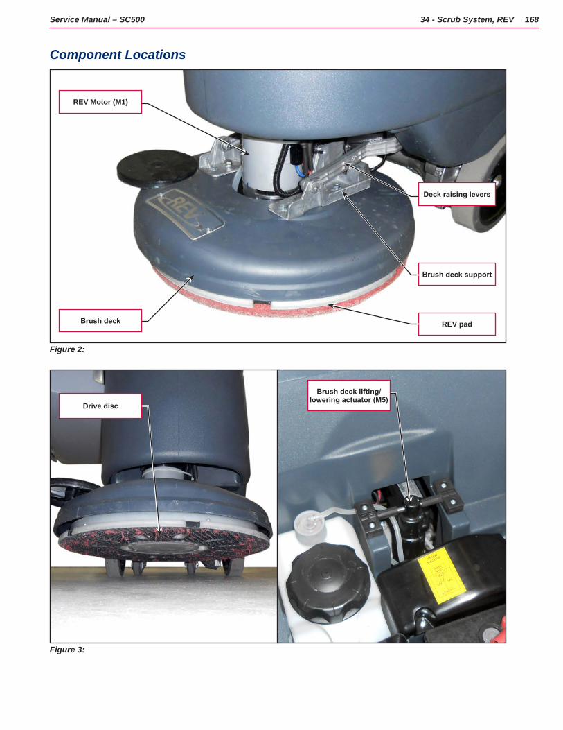
168Service Manual – SC500 34 - Scrub System, REV
Component Locations
Figure 2:
Brush deck support
REV pad
Deck raising levers
Brush deck
REV Motor (M1)
Figure 3:
Drive disc
Brush deck lifting/lowering actuator (M5)

169Service Manual – SC500 34 - Scrub System, REV
Figure 4:
Brush motor fuse (F4)
Main machine controller (EB1)
Actuator system wiring connection
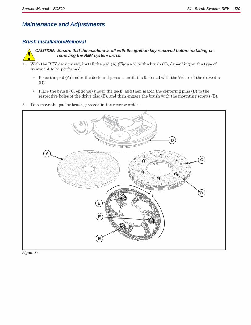
170Service Manual – SC500 34 - Scrub System, REV
Maintenance and Adjustments
Brush Installation/Removal
CAUTION: Ensure that the machine is off with the ignition key removed before installing or removing the REV system brush.
1 With the REV deck raised, install the pad (A) (Figure 5) or the brush (C), depending on the type of treatment to be performed:
◦ Place the pad (A) under the deck and press it until it is fastened with the Velcro of the drive disc (B)
◦ Place the brush (C, optional) under the deck, and then match the centering pins (D) to the respective holes of the drive disc (B), and then engage the brush with the mounting screws (E)
2 To remove the pad or brush, proceed in the reverse order
A
E
C
B
D
E
E
Figure 5:
A
B
C
D
E
E
E
171Service Manual – SC500 34 - Scrub System, REV
Troubleshooting
Trouble Possible Causes Remedy
The brush does not clean properly
The brush is excessively worn Replace
The brush does not turn See the chapter Control System, Main machine controller (EB1) Error Codes
Brush motor fuse (F4) broken Replace
REV motor carbon brushes worn Replace
Faulty REV motor Repair or replace
Wiring damaged Repair
It is not possible to raise/lower the brush
See the chapter Control System, Main machine controller (EB1) Error Codes
Deck raising/lowering actuator (M5) broken Replace
Break in actuator wiring Check the connections according to the instructions in the Electrical System chapter, Troubleshooting paragraph
Main machine controller (EB1) damaged Replace
The deck is transmitting too much vibration to the machine
Deck vibration dampers worn. Replace.
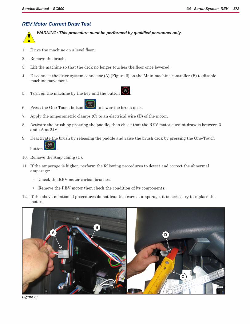
172Service Manual – SC500 34 - Scrub System, REV
REV Motor Current Draw Test
WARNING: This procedure must be performed by qualified personnel only.
1 Drive the machine on a level floor.
2 Remove the brush
3 Lift the machine so that the deck no longer touches the floor once lowered.
4 Disconnect the drive system connector (A) (Figure 6) on the Main machine controller (B) to disable machine movement
5 Turn on the machine by the key and the button
6 Press the One-Touch button to lower the brush deck
7 Apply the amperometric clamps (C) to an electrical wire (D) of the motor
8 Activate the brush by pressing the paddle, then check that the REV motor current draw is between 3 and 4A at 24V
9 Deactivate the brush by releasing the paddle and raise the brush deck by pressing the One-Touch
button
10 Remove the Amp clamp (C)
11 If the amperage is higher, perform the following procedures to detect and correct the abnormal amperage:
◦ Check the REV motor carbon brushes
◦ Remove the REV motor then check the condition of its components
12 If the above-mentioned procedures do not lead to a correct amperage, it is necessary to replace the motor
Figure 6:
AB
D
C
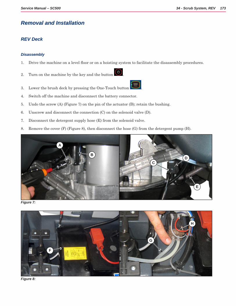
173Service Manual – SC500 34 - Scrub System, REV
Removal and Installation
REV Deck
Disassembly
1 Drive the machine on a level floor or on a hoisting system to facilitate the disassembly procedures.
2 Turn on the machine by the key and the button
3 Lower the brush deck by pressing the One-Touch button
4 Switch off the machine and disconnect the battery connector
5 Undo the screw (A) (Figure 7) on the pin of the actuator (B); retain the bushing
6 Unscrew and disconnect the connection (C) on the solenoid valve (D)
7 Disconnect the detergent supply hose (E) from the solenoid valve
8 Remove the cover (F) (Figure 8), then disconnect the hose (G) from the detergent pump (H)
Figure 7:
A
B
CD
E
Figure 8:
F
G
H
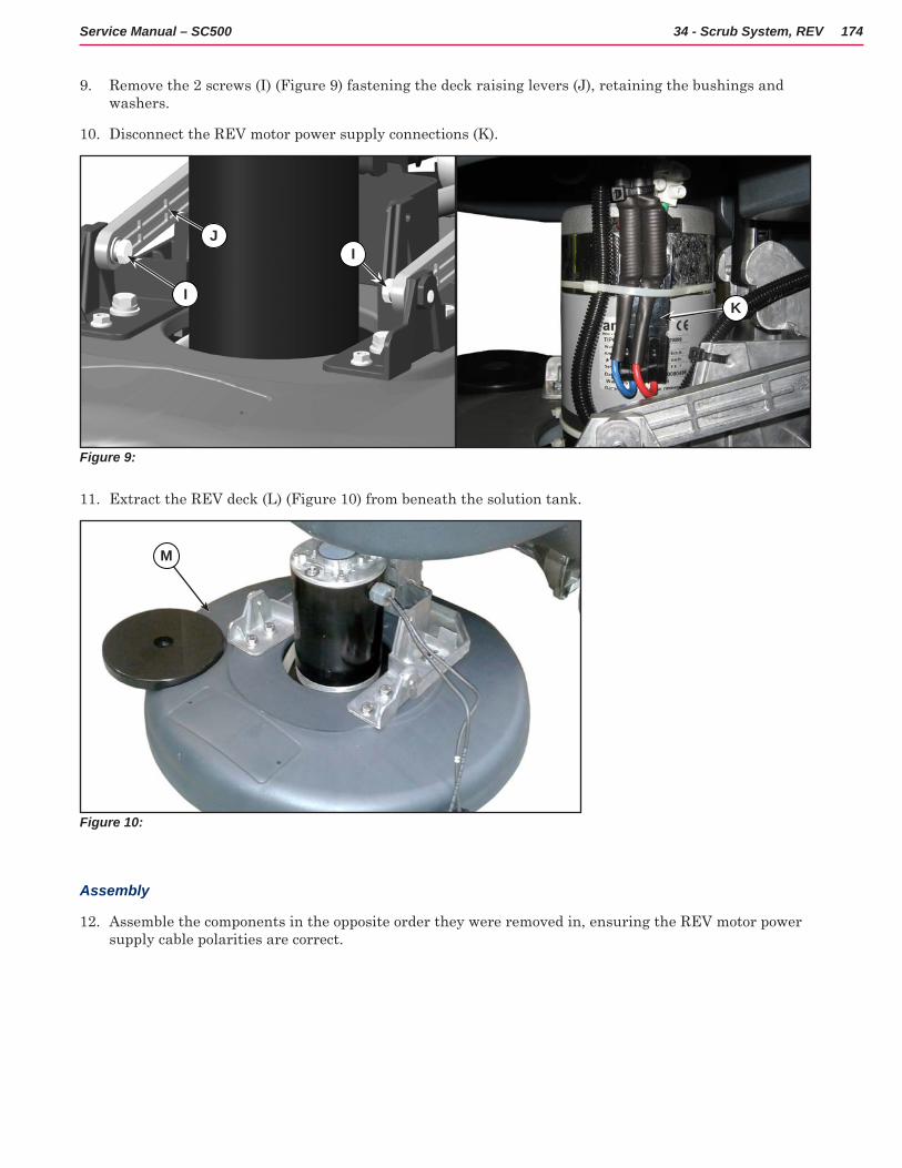
174Service Manual – SC500 34 - Scrub System, REV
9 Remove the 2 screws (I) (Figure 9) fastening the deck raising levers (J), retaining the bushings and washers
10 Disconnect the REV motor power supply connections (K)
Figure 9:
J
I
I
K
11 Extract the REV deck (L) (Figure 10) from beneath the solution tank
Figure 10:
M
Assembly
12 Assemble the components in the opposite order they were removed in, ensuring the REV motor power supply cable polarities are correct
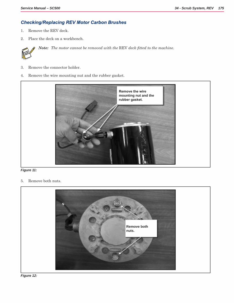
175Service Manual – SC500 34 - Scrub System, REV
Checking/Replacing REV Motor Carbon Brushes
1 Remove the REV deck
2 Place the deck on a workbench
Note: The motor cannot be removed with the REV deck fitted to the machine.
3 Remove the connector holder
4 Remove the wire mounting nut and the rubber gasket
Figure 11:
Remove the wire mounting nut and the rubber gasket.
5 Remove both nuts
Figure 12:
Remove both nuts.
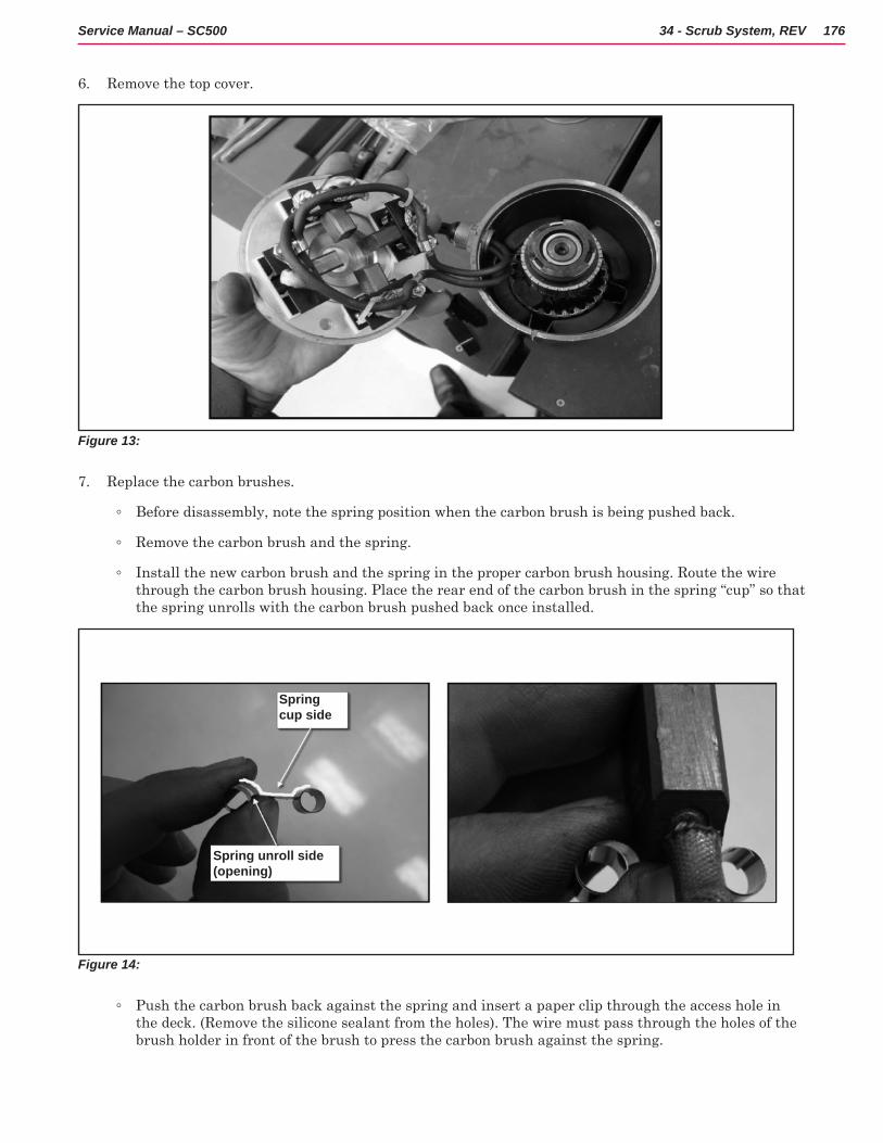
176Service Manual – SC500 34 - Scrub System, REV
6 Remove the top cover
Figure 13:
7 Replace the carbon brushes
◦ Before disassembly, note the spring position when the carbon brush is being pushed back
◦ Remove the carbon brush and the spring
◦ Install the new carbon brush and the spring in the proper carbon brush housing Route the wire through the carbon brush housing Place the rear end of the carbon brush in the spring “cup” so that the spring unrolls with the carbon brush pushed back once installed
Figure 14:
Spring cup side
Spring unroll side (opening)
◦ Push the carbon brush back against the spring and insert a paper clip through the access hole in the deck (Remove the silicone sealant from the holes) The wire must pass through the holes of the brush holder in front of the brush to press the carbon brush against the spring
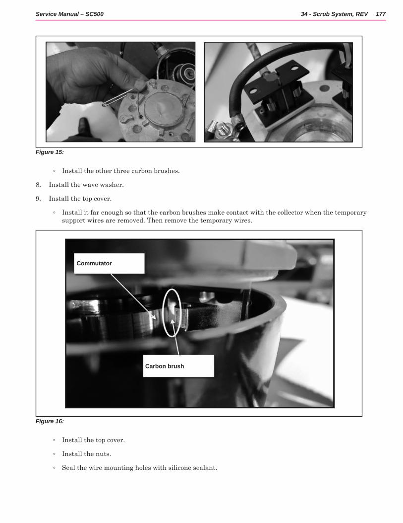
177Service Manual – SC500 34 - Scrub System, REV
Figure 15:
◦ Install the other three carbon brushes
8 Install the wave washer
9 Install the top cover
◦ Install it far enough so that the carbon brushes make contact with the collector when the temporary support wires are removed Then remove the temporary wires
Figure 16:
Commutator
Carbon brush
◦ Install the top cover
◦ Install the nuts
◦ Seal the wire mounting holes with silicone sealant
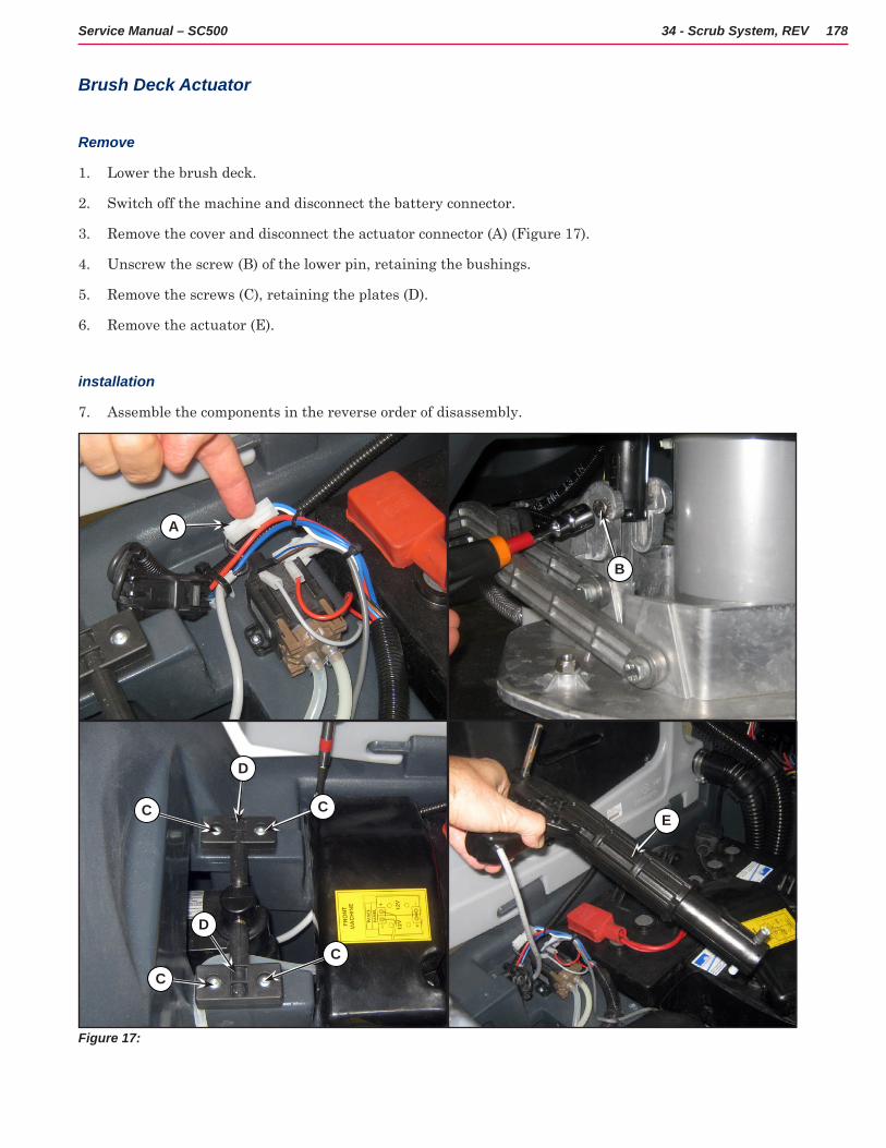
178Service Manual – SC500 34 - Scrub System, REV
Brush Deck Actuator
Remove
1 Lower the brush deck
2 Switch off the machine and disconnect the battery connector
3 Remove the cover and disconnect the actuator connector (A) (Figure 17)
4 Unscrew the screw (B) of the lower pin, retaining the bushings
5 Remove the screws (C), retaining the plates (D)
6 Remove the actuator (E)
installation
7 Assemble the components in the reverse order of disassembly
Figure 17:
C
D
C
C
D
C
B
E
A
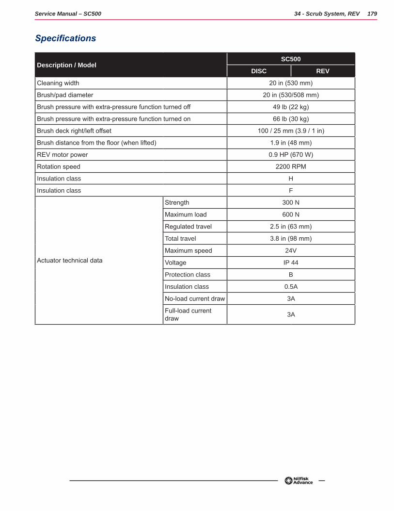
179Service Manual – SC500 34 - Scrub System, REV
Specifications
Description / ModelSC500
DISC REV
Cleaning width 20 in (530 mm)
Brush/pad diameter 20 in (530/508 mm)
Brush pressure with extra-pressure function turned off 49 lb (22 kg)
Brush pressure with extra-pressure function turned on 66 lb (30 kg)
Brush deck right/left offset 100 / 25 mm (3.9 / 1 in)
Brush distance from the floor (when lifted) 1.9 in (48 mm)
REV motor power 0.9 HP (670 W)
Rotation speed 2200 RPM
Insulation class H
Insulation class F
Actuator technical data
Strength 300 N
Maximum load 600 N
Regulated travel 2.5 in (63 mm)
Total travel 3.8 in (98 mm)
Maximum speed 24V
Voltage IP 44
Protection class B
Insulation class 0.5A
No-load current draw 3A
Full-load current draw 3A
180Service Manual – SC500
38 - Squeegee System
Functional DescriptionThe squeegee system cleans the liquid off the floor, which is then collected by the recovery system.
The squeegee is mounted on castors and the weight of the system presses it down on the floor.
The squeegee is attached with two quick-fastening handwheels which fit in the slots of the squeegee support. In case of fixed obstacles, the quick-fit system allows for squeegee immediate removal.
The squeegee can be raised and lowered by the operator using just their foot on the squeegee support footrest thanks to a mechanism consisting of two levers and a gas spring
The angle of the squeegee and the correct adherence of the blades on the floor can be adjusted with a knob.
The front blade has an opening in the bottom edge so the squeegee can collect the water on the floor. The design and the central duct make it easy for the squeegee to clear the water The bottom edge of the blade is smooth
All 4 functional edges of each blade can be used before it needs replacing
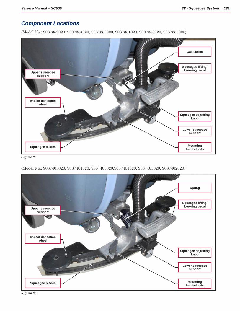
181Service Manual – SC500 38 - Squeegee System
Component Locations(Model No : 9087352020, 9087354020, 9087350020, 9087351020, 9087353020, 9087355020)
Figure 1:
Squeegee adjusting knob
Lower squeegee support
Mounting handwheels
Squeegee lifting/lowering pedal
Gas spring
Squeegee blades
Impact deflection wheel
Upper squeegee support
(Model No : 9087403020, 9087404020, 9087400020,9087401020, 9087405020, 9087402020)
Figure 2:
Squeegee adjusting knob
Lower squeegee support
Mounting handwheels
Squeegee lifting/lowering pedal
Spring
Squeegee blades
Impact deflection wheel
Upper squeegee support
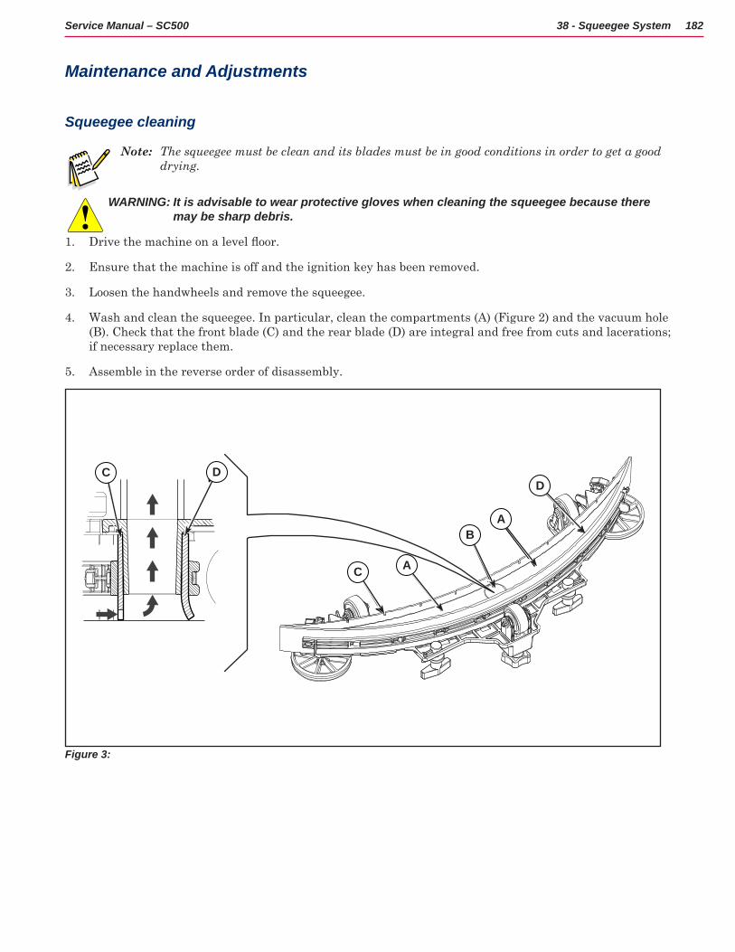
182Service Manual – SC500 38 - Squeegee System
Maintenance and Adjustments
Squeegee cleaning
Note: The squeegee must be clean and its blades must be in good conditions in order to get a good drying.
WARNING: It is advisable to wear protective gloves when cleaning the squeegee because there may be sharp debris.
1 Drive the machine on a level floor.
2 Ensure that the machine is off and the ignition key has been removed
3 Loosen the handwheels and remove the squeegee
4 Wash and clean the squeegee In particular, clean the compartments (A) (Figure 2) and the vacuum hole (B) Check that the front blade (C) and the rear blade (D) are integral and free from cuts and lacerations; if necessary replace them
5 Assemble in the reverse order of disassembly
A
A
B
D
C
DC
Figure 3:
C D
C A
BA
D
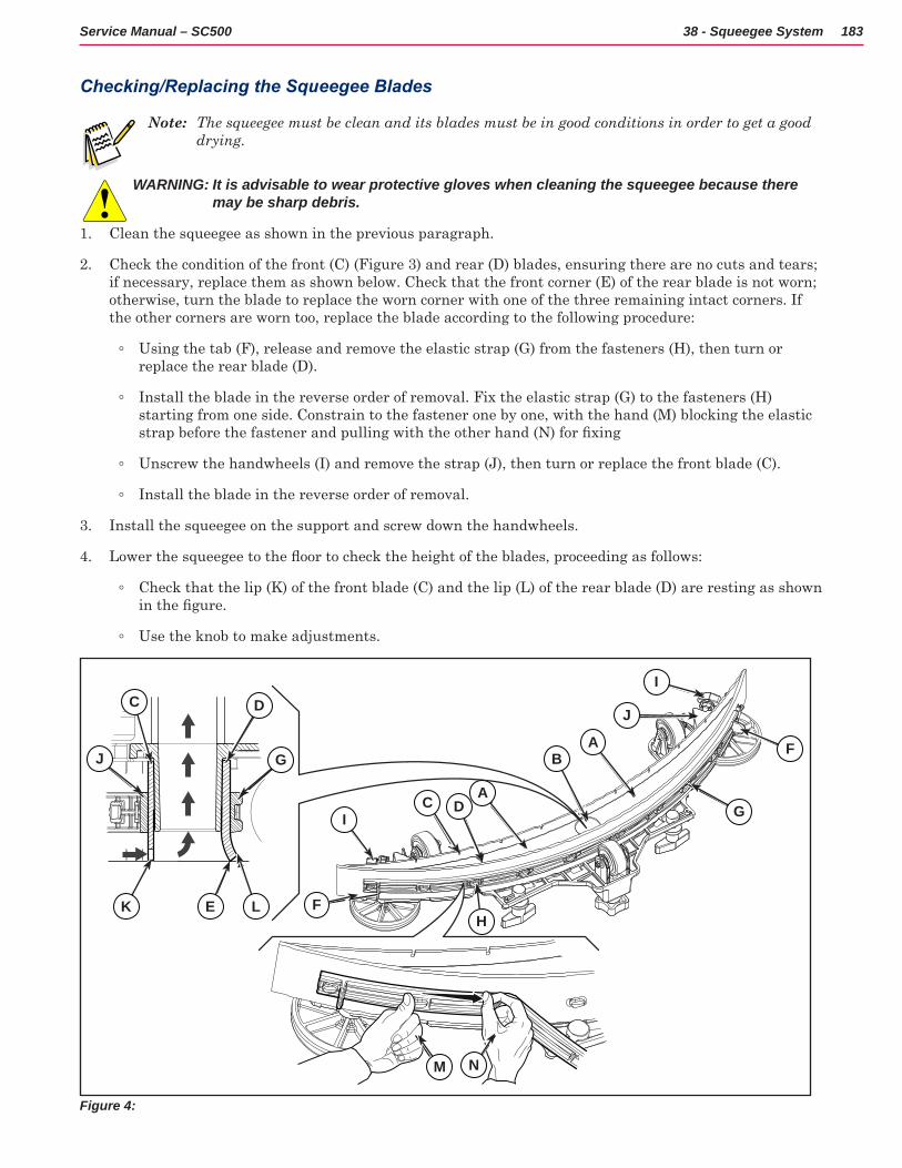
183Service Manual – SC500 38 - Squeegee System
Checking/Replacing the Squeegee Blades
Note: The squeegee must be clean and its blades must be in good conditions in order to get a good drying.
WARNING: It is advisable to wear protective gloves when cleaning the squeegee because there may be sharp debris.
1 Clean the squeegee as shown in the previous paragraph
2 Check the condition of the front (C) (Figure 3) and rear (D) blades, ensuring there are no cuts and tears; if necessary, replace them as shown below Check that the front corner (E) of the rear blade is not worn; otherwise, turn the blade to replace the worn corner with one of the three remaining intact corners If the other corners are worn too, replace the blade according to the following procedure:
◦ Using the tab (F), release and remove the elastic strap (G) from the fasteners (H), then turn or replace the rear blade (D)
◦ Install the blade in the reverse order of removal Fix the elastic strap (G) to the fasteners (H) starting from one side Constrain to the fastener one by one, with the hand (M) blocking the elastic strap before the fastener and pulling with the other hand (N) for fixing
◦ Unscrew the handwheels (I) and remove the strap (J), then turn or replace the front blade (C)
◦ Install the blade in the reverse order of removal
3 Install the squeegee on the support and screw down the handwheels
4 Lower the squeegee to the floor to check the height of the blades, proceeding as follows:
◦ Check that the lip (K) of the front blade (C) and the lip (L) of the rear blade (D) are resting as shown in the figure.
◦ Use the knob to make adjustments
A
I
A
B
DC
G
K E L
DC
J
J
H
F
G
F
M N
I
Figure 4:
C
K E L
J
D
G
C DI
F
A
BA
J
I
F
G
N
H
M
184Service Manual – SC500 38 - Squeegee System
Troubleshooting
Trouble Possible Causes Remedy
Suction of dirty water is insufficient or non-existent
Squeegee or vacuum hose blocked or damaged
Clean or repair/replace
The squeegee leaves lining on the floor or does not collect water
There is debris under the blade Remove
Squeegee blade lips damaged or worn Replace
Squeegee not balanced Adjust with the relevant handwheel
Squeegee will not raise Gas spring worn out. Replace.
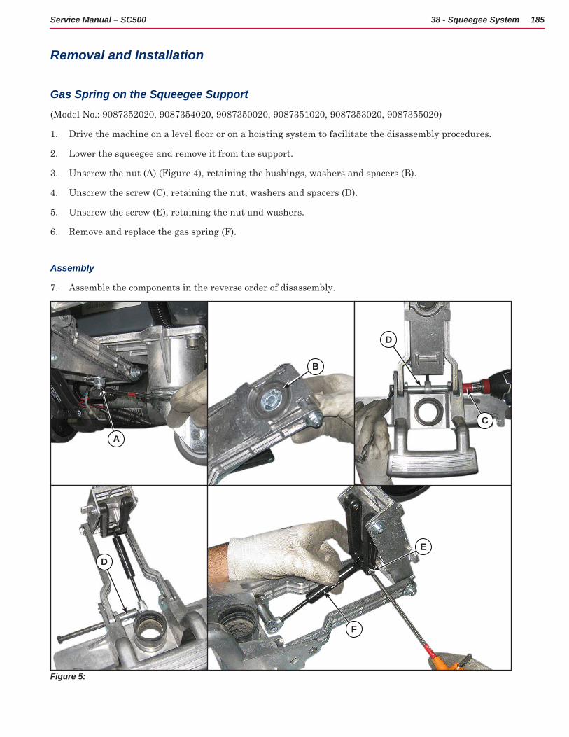
185Service Manual – SC500 38 - Squeegee System
Removal and Installation
Gas Spring on the Squeegee Support
(Model No : 9087352020, 9087354020, 9087350020, 9087351020, 9087353020, 9087355020)
1 Drive the machine on a level floor or on a hoisting system to facilitate the disassembly procedures.
2 Lower the squeegee and remove it from the support
3 Unscrew the nut (A) (Figure 4), retaining the bushings, washers and spacers (B)
4 Unscrew the screw (C), retaining the nut, washers and spacers (D)
5 Unscrew the screw (E), retaining the nut and washers
6 Remove and replace the gas spring (F)
Assembly
7 Assemble the components in the reverse order of disassembly
Figure 5:
A
ED
F
D
C
B
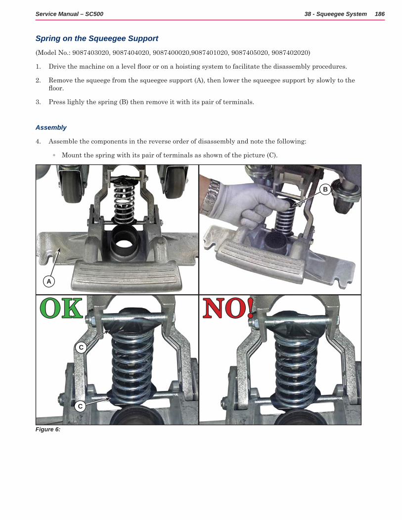
186Service Manual – SC500 38 - Squeegee System
Spring on the Squeegee Support
(Model No : 9087403020, 9087404020, 9087400020,9087401020, 9087405020, 9087402020)
1 Drive the machine on a level floor or on a hoisting system to facilitate the disassembly procedures.
2 Remove the squeege from the squeegee support (A), then lower the squeegee support by slowly to the floor.
3 Press lighly the spring (B) then remove it with its pair of terminals
Assembly
4 Assemble the components in the reverse order of disassembly and note the following:
◦ Mount the spring with its pair of terminals as shown of the picture (C)
Figure 6:
A
C
C
B
OKOK NO!NO!
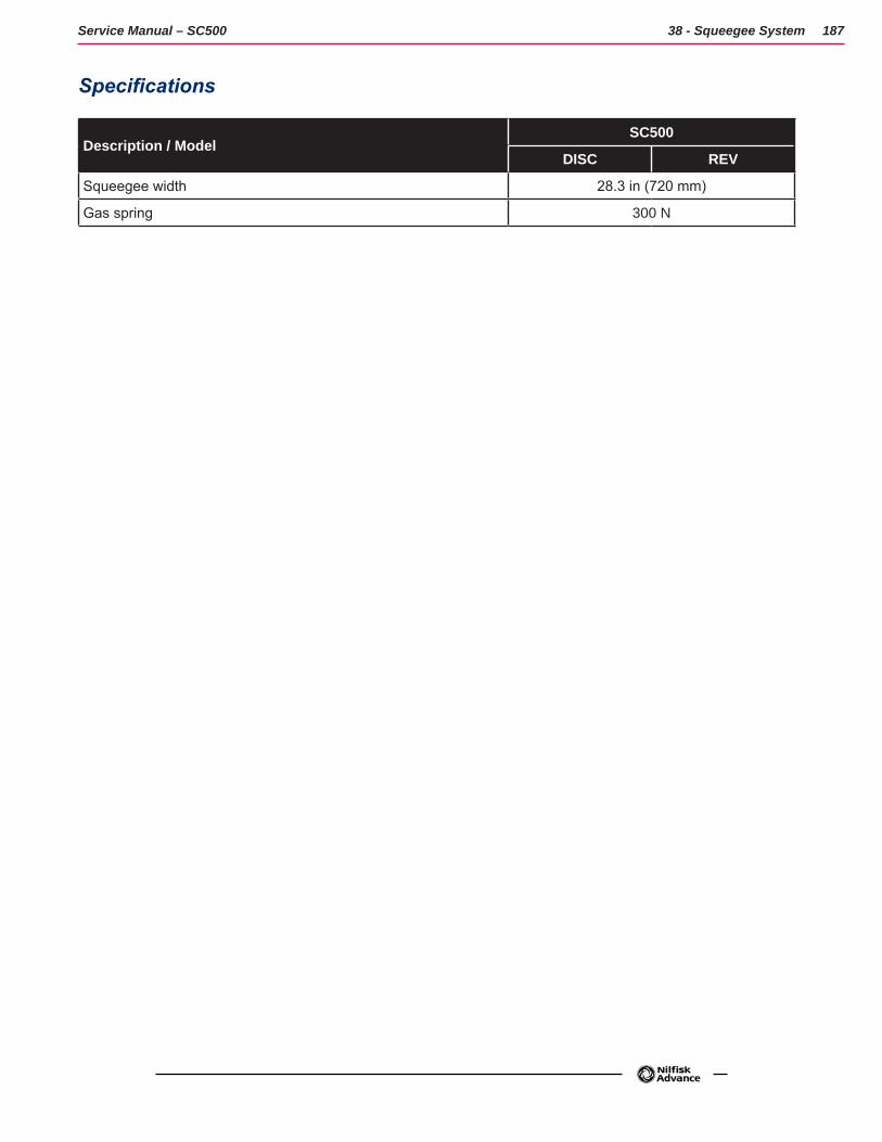
187Service Manual – SC500 38 - Squeegee System
Specifications
Description / ModelSC500
DISC REV
Squeegee width 28.3 in (720 mm)
Gas spring 300 N
188Service Manual – SC500
40 - Recovery System
Functional DescriptionThe recovery system removes the dirty water from the floor and pipes it to a recovery tank. When the machine is running, the dirty water on the floor is collected by the squeegee blades and collected through the slots in the same, piped through the vacuum hose and into the tank by the airflow created by vacuum motor (M2). The dirty water is piped into the recovery tank, while the airflow continues to the vacuum fan.
A tank with a grid collects the largest debris going through the recovery tank hose
The automatic float in the vacuum grid stops vacuum system motor (M2) from collecting any liquids.
When the automatic float closes and shuts down the vacuum system, the vacuum system motor noise will increase and the floor will not be dried.
The vacuum system is activated automatically with the One-Touch button . It can then be managed
independently via the vacuum button . The vacuum system is activated in full power or silent mode depending on the last mode in use before the machine was switched off. This mode can be changed by repeatedly
pressing the vacuum button . The various vacuum modes are also displayed on the multifunction display.
When the recovery tank is full it can be emptied through the drain hose
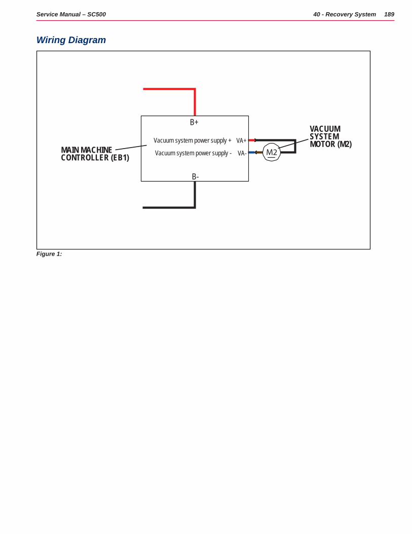
189Service Manual – SC500 40 - Recovery System
Wiring Diagram
M2VA-
VA+
B-
B+VACUUM SYSTEM MOTOR (M2)
Vacuum system power supply -
Vacuum system power supply +MAIN MACHINECONTROLLER (EB1)
Figure 1:
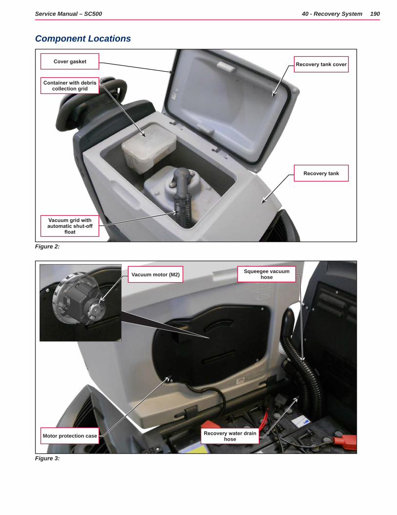
190Service Manual – SC500 40 - Recovery System
Component Locations
Figure 2:
Recovery tank cover
Recovery tank
Vacuum grid with automatic shut-off
float
Container with debris collection grid
Cover gasket
Figure 3:
Motor protection case
Squeegee vacuum hose
Recovery water drain hose
Vacuum motor (M2)
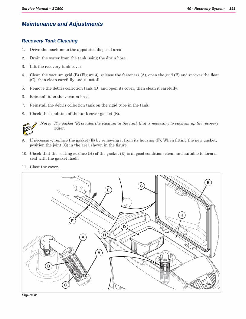
191Service Manual – SC500 40 - Recovery System
Maintenance and Adjustments
Recovery Tank Cleaning
1 Drive the machine to the appointed disposal area
2 Drain the water from the tank using the drain hose
3 Lift the recovery tank cover
4 Clean the vacuum grid (B) (Figure 4), release the fasteners (A), open the grid (B) and recover the float (C), then clean carefully and reinstall
5 Remove the debris collection tank (D) and open its cover, then clean it carefully
6 Reinstall it on the vacuum hose
7 Reinstall the debris collection tank on the rigid tube in the tank
8 Check the condition of the tank cover gasket (E)
Note: The gasket (E) creates the vacuum in the tank that is necessary to vacuum up the recovery water.
9 If necessary, replace the gasket (E) by removing it from its housing (F). When fitting the new gasket, position the joint (G) in the area shown in the figure.
10 Check that the seating surface (H) of the gasket (E) is in good condition, clean and suitable to form a seal with the gasket itself
11 Close the cover
A
C
B
A
F
EE
G
D
H
H
Figure 4:
C
B
A
A
F
E
H
D
G
H
E
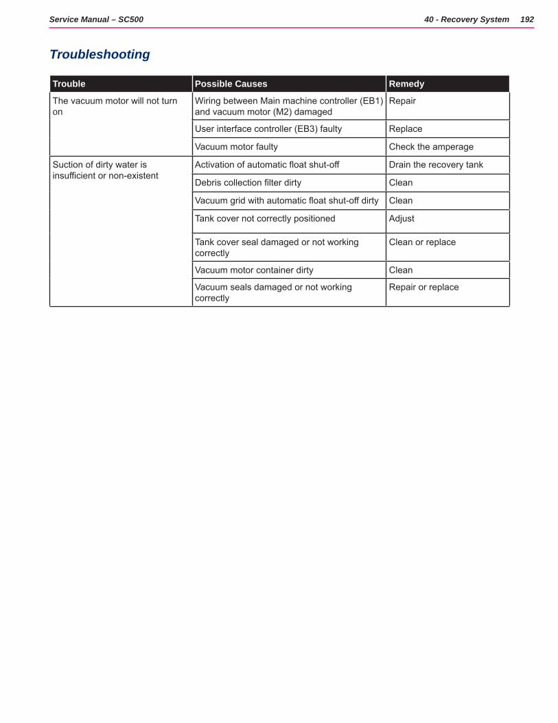
192Service Manual – SC500 40 - Recovery System
Troubleshooting
Trouble Possible Causes Remedy
The vacuum motor will not turn on
Wiring between Main machine controller (EB1) and vacuum motor (M2) damaged
Repair
User interface controller (EB3) faulty Replace
Vacuum motor faulty Check the amperage
Suction of dirty water is insufficient or non-existent
Activation of automatic float shut-off Drain the recovery tank
Debris collection filter dirty Clean
Vacuum grid with automatic float shut-off dirty Clean
Tank cover not correctly positioned Adjust
Tank cover seal damaged or not working correctly
Clean or replace
Vacuum motor container dirty Clean
Vacuum seals damaged or not working correctly
Repair or replace
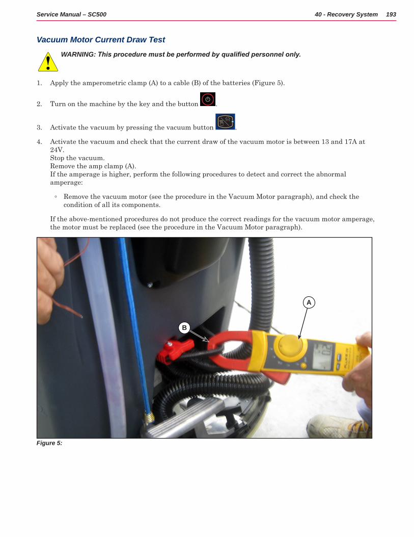
193Service Manual – SC500 40 - Recovery System
Vacuum Motor Current Draw Test
WARNING: This procedure must be performed by qualified personnel only.
1 Apply the amperometric clamp (A) to a cable (B) of the batteries (Figure 5)
2 Turn on the machine by the key and the button
3 Activate the vacuum by pressing the vacuum button
4 Activate the vacuum and check that the current draw of the vacuum motor is between 13 and 17A at 24V Stop the vacuum Remove the amp clamp (A) If the amperage is higher, perform the following procedures to detect and correct the abnormal amperage:
◦ Remove the vacuum motor (see the procedure in the Vacuum Motor paragraph), and check the condition of all its components
If the above-mentioned procedures do not produce the correct readings for the vacuum motor amperage, the motor must be replaced (see the procedure in the Vacuum Motor paragraph)
Figure 5:
B
A
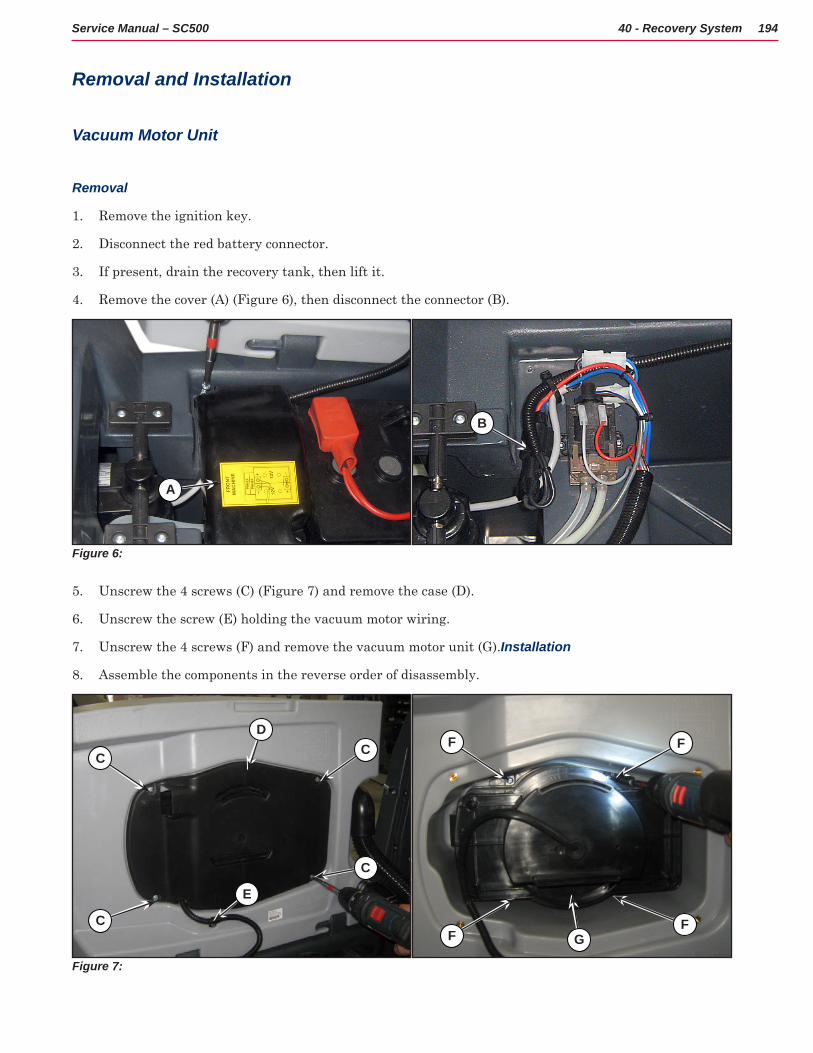
194Service Manual – SC500 40 - Recovery System
Removal and Installation
Vacuum Motor Unit
Removal
1 Remove the ignition key
2 Disconnect the red battery connector
3 If present, drain the recovery tank, then lift it
4 Remove the cover (A) (Figure 6), then disconnect the connector (B)
Figure 6:
A
B
5 Unscrew the 4 screws (C) (Figure 7) and remove the case (D)
6 Unscrew the screw (E) holding the vacuum motor wiring
7 Unscrew the 4 screws (F) and remove the vacuum motor unit (G) Installation
8 Assemble the components in the reverse order of disassembly
Figure 7:
C
DC
C
E
C
F F
F GF
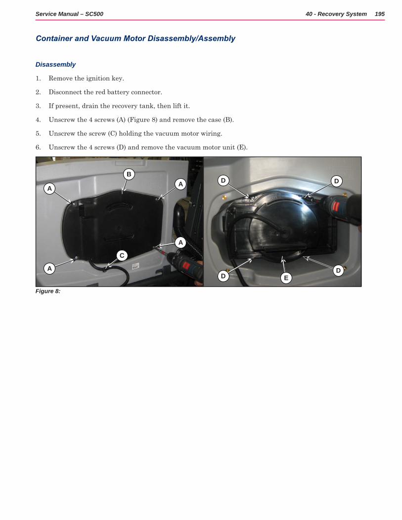
195Service Manual – SC500 40 - Recovery System
Container and Vacuum Motor Disassembly/Assembly
Disassembly
1 Remove the ignition key
2 Disconnect the red battery connector
3 If present, drain the recovery tank, then lift it
4 Unscrew the 4 screws (A) (Figure 8) and remove the case (B)
5 Unscrew the screw (C) holding the vacuum motor wiring
6 Unscrew the 4 screws (D) and remove the vacuum motor unit (E)
Figure 8:
A
BA
A
C
A
D D
D ED
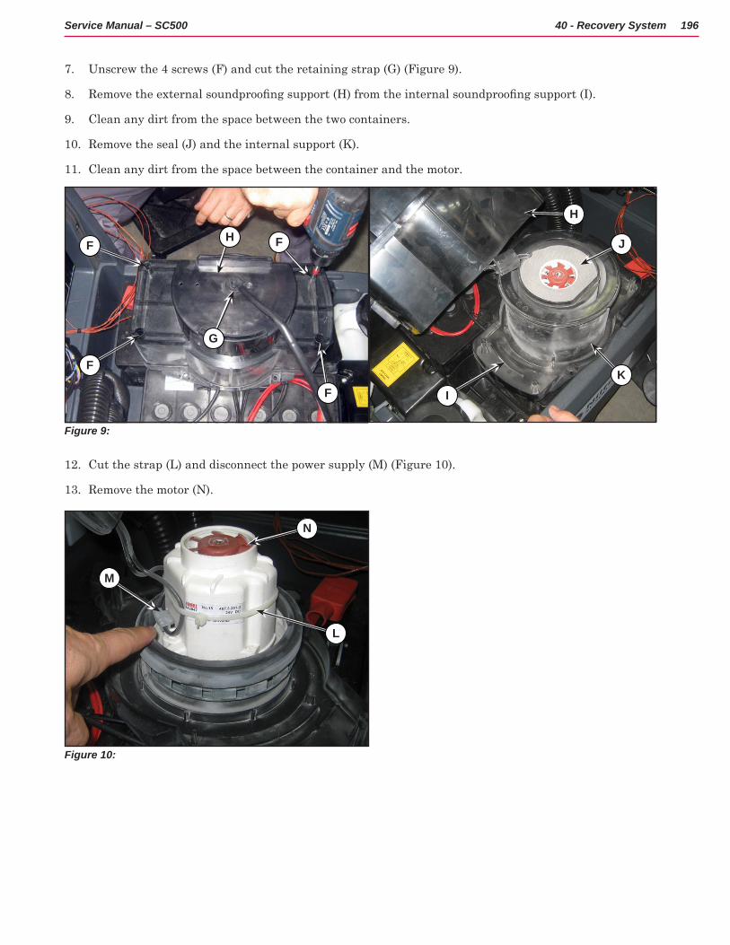
196Service Manual – SC500 40 - Recovery System
7 Unscrew the 4 screws (F) and cut the retaining strap (G) (Figure 9)
8 Remove the external soundproofing support (H) from the internal soundproofing support (I).
9 Clean any dirt from the space between the two containers
10 Remove the seal (J) and the internal support (K)
11 Clean any dirt from the space between the container and the motor
Figure 9:
FH F
F
G
F
H
IK
J
12 Cut the strap (L) and disconnect the power supply (M) (Figure 10)
13 Remove the motor (N)
Figure 10:
N
L
M
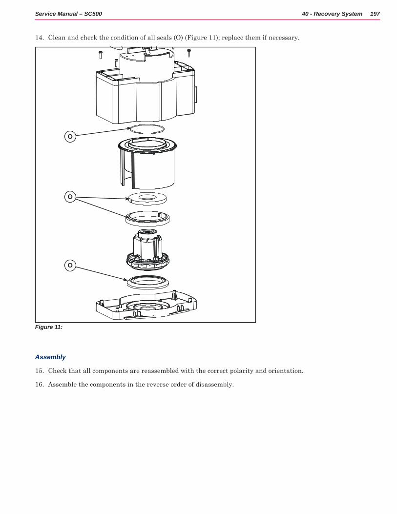
197Service Manual – SC500 40 - Recovery System
14 Clean and check the condition of all seals (O) (Figure 11); replace them if necessary
Figure 11:
O
O
O
Assembly
15 Check that all components are reassembled with the correct polarity and orientation
16 Assemble the components in the reverse order of disassembly
198Service Manual – SC500 40 - Recovery System
Specifications
Description / ModelSC500
DISC REV
Recovery tank capacity 12 US gal (45 L)
Vacuum motor technical data0.37 hp (280 W)
20.8A VDC 24V
Vacuum circuit capacity 29.9 in H2O (760 mm H2O)
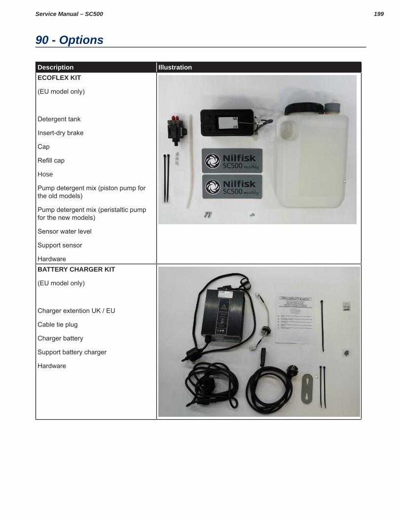
199Service Manual – SC500
90 - Options
Description IllustrationECOFLEX KIT
(EU model only)
Detergent tank
Insert-dry brake
Cap
Refill cap
Hose
Pump detergent mix (piston pump for the old models)
Pump detergent mix (peristaltic pump for the new models)
Sensor water level
Support sensor
HardwareBATTERY CHARGER KIT
(EU model only)
Charger extention UK / EU
Cable tie plug
Charger battery
Support battery charger
Hardware
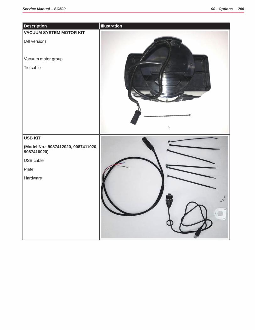
200Service Manual – SC500 90 - Options
Description IllustrationVACUUM SYSTEM MOTOR KIT
(All version)
Vacuum motor group
Tie cable
USB KIT
(Model No.: 9087412020, 9087411020, 9087410020)
USB cable
Plate
Hardware
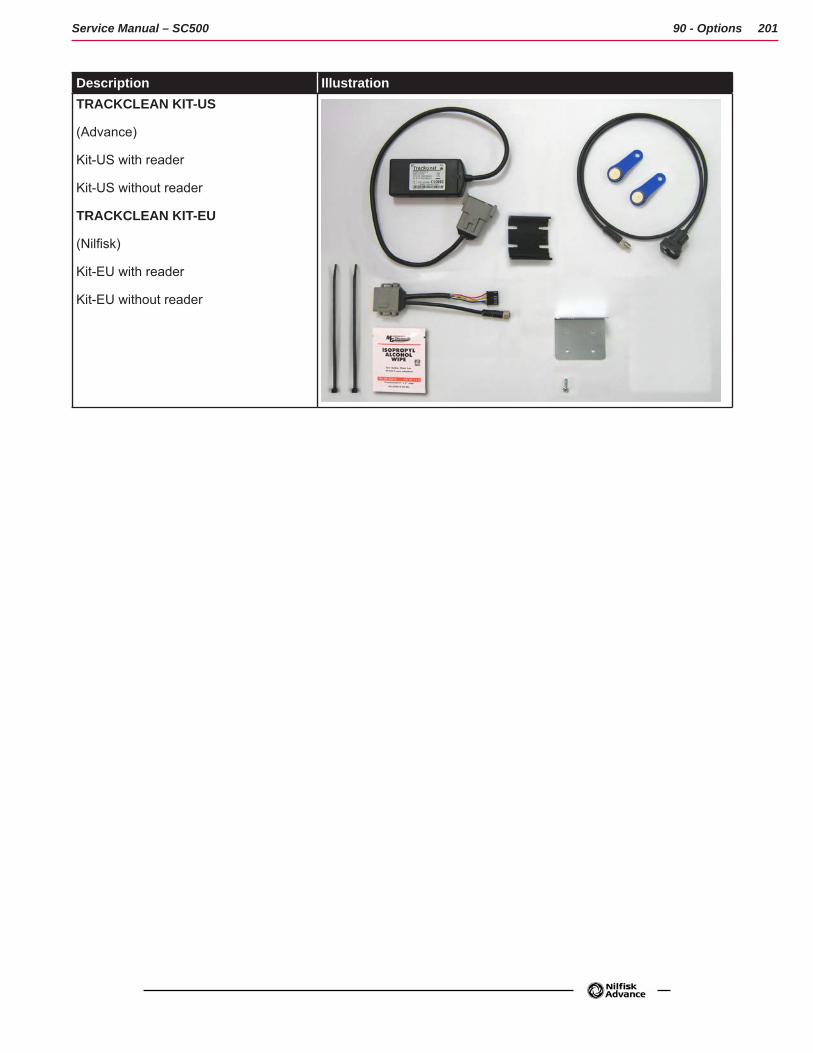
201Service Manual – SC500 90 - Options
Description IllustrationTRACKCLEAN KIT-US
(Advance)
Kit-US with reader
Kit-US without reader
TRACKCLEAN KIT-EU
(Nilfisk)
Kit-EU with reader
Kit-EU without reader


