Embed Size (px)
Citation preview
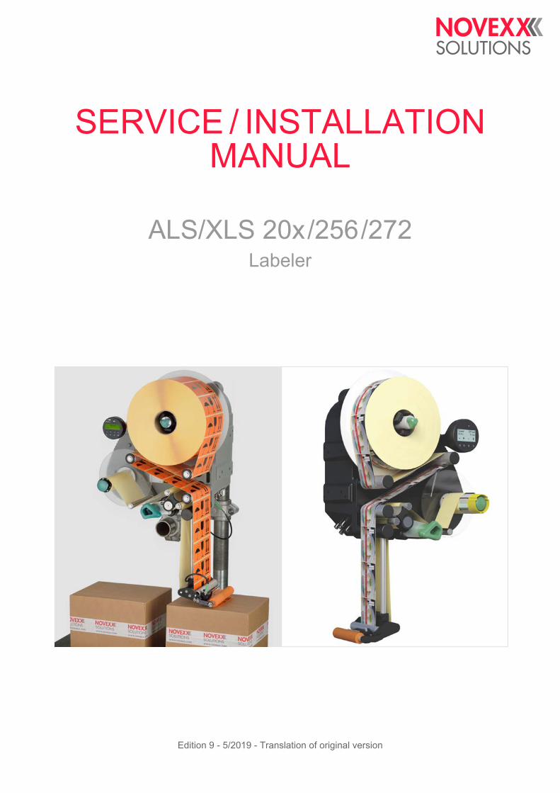
SERVICE / INSTALLATION MANUAL
ALS/XLS 20x/256/272Labeler
Edition 9 - 5/2019 - Translation of original version

Service Manual ALS 20x/256/272
Contents
Please observe the following -9
General information -9Validity and applicability of this manual -9Conventions and information -10
Notes on installation and repair work -11
Safety instructions -15Information and qualifications -15
Machine operating safety -16
Safe operation -17
Technical Data -19
Technical Data -19Characteristics -19
Labels -19
Label sensor -20
Power supply -20
Electronics -21
Interfaces -21
Internal Interfaces -22
Status messages, test functions, product profiles -22
Dimensions -22
Ambient conditions -23
Integration -23
Certificates/Markings -23
Dimension diagrams -24ALS 20x / ALS 256 -24
ALS 272 -26
Performance data -28Label rate -28
Dispensing speed over duration v(t) -30
Dispensing speed over length v(x) -31
Dispensed label length over duration x(t) -33
(ALS/XLS 256) Performance matrix -34
Installation and Deinstallation -36
Unpacking, assembling and connecting the machine -36Transport -36
Unpacking -36
Setting up -37
Attaching the dispensing edge -41
Connecting to the mains power supply -43
Connecting the sensors -46Photoelectric label sensor -46
Alternative label sensor -51
Changing light/dark switching at the product sensor or the alternative label sensor -58
05/2019 3 Contents
Service Manual ALS 20x/256/272
Photoelectric product sensor -59
Photoelectric roll diameter sensor -60
Rotary encoder -64
Installing Options -66Connecting / mounting the external operator panel -66
Mounting a splice table -68
Mounting/connecting the signal beacon -69
Adjustable dispensing edge holder -70
Rotatable dispensing edge holder -71
Narrow label spring kit (ALS/XLS 20x and ALS/XLS 256) -74
Decommissioning, Dismantling, Disposal -76Take the machine out of operation -76
Dismantling the machine -76
Machine disposal -77
Functions -78
Function menu -78Overview -78
Notes on the description of functions -80
LABEL SETUP menu -80
MACHINE SETUP menu -82
INTERFACE PARA menu -90
Submenu >EASYPLUGINTERPR -90
Submenu >COM1 PORT -90
Submenu >NETWORK PARAM. -91
SIGNAL INTERFACE -93
Submenu >PLC SIGNALS -93
Submenu >APPLIC. SIGNALS -94
Submenu >AI BOARD SIGNAL -97
Submenu >AI BOARD SIGNAL -98
Submenu >ACTIVE INPUTS -98
SERVICE/DIAGNOS. menu -99
SERVICE DATA menu -100
Submenu >MODULE FW VERS. -100
Submenu >OPERATION DATA -101
Submenu >POWERSUPPLYDATA -101
Submenu >CPU BOARD DATA -102
Submenu >DISPLAY DATA -102
Submenu > PERIPHERAL DATA -103
Submenu >MEMORY DATA -103
Operation -104
Automatic dispensing speed adjustment -104Principle of operation -104
Mounting the rotary encoder -105
Entering the rotary encoder resolution -106
Entering the diameter of the measuring wheel -106
05/2019 4 Contents
Service Manual ALS 20x/256/272
Entering the rotary encoder type -106
Example: Entering the values for the recommended rotary encoder -107
Calibrating the belt speed -107
Calculation scheme for the automatic dispensing speed adjustment -108
Tandem Operation -111Overview -111
Master operating modes -111
Prerequisites -112
Setting up tandem operation -114
Applicator Operation -121Function -121
System requirements -121
Assembly and operation -121
Enhanced Functions -122
Access via a Web/FTP server -122Web server -122
FTP server -126
Loading Firmware -128Firmware Version -128
Loading from USB stick -129
Download via data interface -130
Loading with the bootloader -132
Saving/loading a configuration -134Applications -134
Saving onto an external memory medium -134
Loading from an external memory medium -136
Automatic loading -137
Loading a configuration via the data interface -137
Interface commands -142Command overview -142
Immediately executable commands -143
Not immediately executable commands -146
Forced bootloader start -150Gen. 1 -150
Gen. 2 -151
Diagnose Dump -152Storing diagnosis data -152
Reading out via serial interface -152
Storing on memory medium -155
Electronics Description -156
Wiring Diagrams -156„Gen. 1“-Electronics -156
„Gen. 2“-Electronics -159
Block diagram -162
05/2019 5 Contents
Service Manual ALS 20x/256/272
Electronics Components -163ALS/XLS 20x -163
ALS/XLS 256 -164
ALS/XLS 272 -165
Circuit boards -166CPU board (Gen. 1) -166
CPU board (Gen. 2) -172
Motor driver board -179
Operator panel board -181
Applicator Interface -184
Power supplies / Transformer -191Power supply ALS/XLS 20x -191
Transformer ALS/XLS 20x -193
Power supply ALS/XLS 256/272 -193
Signal Interface -195General notes -195
Circuit diagrams for signal inputs -196
Circuit diagram for signal outputs -197
Signals for applicator connection -197
Applicator type <--> Signals -199
Signal wave forms of applicator signals -200
Signals for PLC connection -209
Signal response „Dispense End“ -210
Impact of the inhibit signal -211
Data interfaces -214Overview connector positions -214
RS 232 -214
Connection for external operator panel -214
USB (device) -215
USB (host) -215
Ethernet -215
Applicator Interface (option) -218Important notes -218
Circuit diagrams for signal inputs -218
Circuit diagrams for signal outputs -219
Power outputs -220
Pin assignment for applicator connection -221
Pin assignment for machine status connection -224
Pin assignment for product sensor connection -226
Signal-LEDs -227
Signal wave forms -227
Fault description -228
Types of status messages -228Error messages -228
Warnings -228
Setting back a warning -228
05/2019 6 Contents
Service Manual ALS 20x/256/272
General software errors -229
Machine fails to start -229
Reference of status messages -230List of warnings -230
List of error messages -231
Repair -242
Tests -242Sensor test -242
Power Supply ALS/XLS 256/272 -245Initial state -245
Power supply functions -245
Checking output voltages -246
Troubleshooting -249
Checking the power supply -251
Opening the casing -252Removing the dust/splash guard (ALS/XLS 20x) -252
Opening the casing at machines held in place by side plate or base plate -253
Opening the casing at machines held from the rear side -255
Overview: Screws holding the casing rear wall -256
(ALS/XLS 256/272) Exchanging the fan -257
Unwind unit -259Expanding mandrel -259
Brake -261
Dancer arm -263
Feed unit -275Feed roller unit -275
Drive -281
Pressure roller -285
Rewind unit -288Expanding mandrel (ALS 2xx) -288
Expanding Mandrel (XLS 2xx) -291
Dancer arm -294
Drive -300
Appendix -302
Additional helpful information -302Installing a „Generic“ printer on a Windows 7 host PC for the purpose of firmware upload -302
Settings -305Setting the capacitive (Leuze) sensor -305
Calculation sheet for performance diagrams -306Using the calculation sheet -306
Inputs -306
Outputs -307
Diagrams of performance data -307
05/2019 7 Contents

Service Manual ALS 20x/256/272
05/2019 8 Contents
Service Manual ALS/XLS 20x/256/272
05/2019 | 04 9
Please observe the following
GENERAL INFORMATION
Validity and applicability of this manual
Contents
The present service manual refers exclusively to the labelers:
– ALS 204, ALS 206, ALS 209, ALS 256, ALS 272
– XLS 204, XLS 206, XLS 209, XLS 256, XLS 272
The manual is to be referred to for correct installation, set-up, adjustment and repair of the labelers.
The complete operating manual for the respective labeler consists of the following parts:
Technical State
Technical state: 5/2019
Software versions:
– Firmware: 2.76
– Applicator Interface: 1.44
Liability
NOVEXX Solutions assumes no liability for damages resulting from improper adjustments or repairs of the machine. It is assumed that only knowledgeable and appropriately qualified persons are to perform installation, adjustment, or repairs.
Information about the required qualification: see chapter Information and qualifications on page 15.
Copyright notice
All rights to this operating manual are assigned to NOVEXX Solutions. Transmission, reprinting or any other means of reproduction of this manual, whether whole or in part, are not allowed without prior written permission. Third parties, in particular competitors, are not to be allowed access to information derived from this manual.
Printed in Germany
Manual Target group Medium Availability
User manual Operating personnel Printed Comes with machine
Installation manual Service personnel User Docu-CD
Service manual Service Docu-CD NOVEXX Solutions Partner Portal: www.novexx.com
Spare parts catalogue
Service Manual ALS/XLS 20x/256/272
05/2019 | 04 10
Manufacturer
Novexx Solutions GmbH
Ohmstraße 3
D - 85386 Eching
Phone: +49-8165-925-0
FAX: +49-8165-925-231
www.novexx.com
Conventions and information
Explanation of symbols
In order to facilitate legibility and an overview, the various types of information used herein are cat-egorised and identified with certain symbols.
Sentences that are introduced by an arrow contain procedural instructions.
Carry out procedural instructions one after the other in the prescribed order.
The following information is introduced with a dash:
– List items
– Descriptions of conditions
– Description of previous work steps
– Prerequisites for implementing actions described in the following passage
Warnings concerning dangers and risks
Important text passages which must absolutely be followed are particularly marked for special attention:
Illustrations
When required, text passages are accompanied by illustrations. The illustrations normally show an ALS 2xx labeler as RH version. XLS 2xx labellers or LH versions are only displayed if differences need to be highlighted.
The reference to an illustration is indicated by typesetting the [illustration number] in square brack-ets. Capital letters following an illustration number, e.g. [12A], refer to the corresponding position indicated in the illustration.
WARNING!
A warning notice indicates risks which could result in death or serious injury of the personnel! The notice contains safety instructions on how to safeguard possibly affected personnel.
The instructions must be followed.
CAUTION!
A caution notice indicates risks which, if unheeded, could lead to material damage or bodily injury (minor injuries). The notice contains instructions on how to prevent dam-age or injury.
The instructions must be followed.
Service Manual ALS/XLS 20x/256/272
05/2019 | 04 11
Symbols for buttons
– Buttons on the operator panel are represented with symbols, as they can be found on (ALS 2xx) respectively above (XLS 2xx) the buttons. Although the symbols on the control panels of the two machine series differ slightly, for reasons of clarity only the ALS symbols are used in this man-ual:
– Where two or more buttons must be pressed at the same time, a "+" appears between the sym-bols:
+
Functions
Functions are printed in grey text, in the form NAME OF MENU > Name of function .
Supplemental information
The information symbol indicates notices and recommendations as well as additional helpful information.
Auxiliary materials:
– Auxiliary materials, e.g. lubricants, glues or cleaning agents
Tightening torques:
– Tightening torques for the listed screw connections
If special tools or other aids are needed for a task:
Tools:
– List of the tools and aids that are required for the following activities
Notes on installation and repair work
General information
Before performing any maintenance or repair work:
Block access to the working area of the machine to unauthorised persons.
Post a notification sign, which calls attention to the work.
Electro-static discharge:
When the casing is open, protect the electronics from damage due to electro-static discharge, e.g. wear an anti-static arm band.
Tools:
Only use suitable tools.
Ensure all tools are at hand before beginning the work.
Do not attempt to improvise or to use improper tools, e.g. loosening an interior-toothed screw (Torx) with a hexagon socket driver.
Rubber and plastic parts:
Do not allow hoses, seals, and other rubber or plastic parts to come into contact with grease, petrol, benzene, kerosene or mineral oil.
ALS 2xx
XLS 2xx

Service Manual ALS/XLS 20x/256/272
05/2019 | 04 12
Environmental protection
Avoid unnecessary waste, e.g. use cleaning cloths sparingly and reuse packing material.
Only store operating materials, such as fresh or used cleaning agents, in suitable containers. Never allow them to enter the sewerage system or to seep into the ground.
Do not put old batteries, removed parts, and used cleaning agents in household waste. Dispose of them in an eco-friendly manner.
Packaging materials:
– Only recyclable materials are used for packaging the machine.
Dispose of unwanted packaging material in an eco-friendly manner.
Eco-friendly disposal:
Sort the waste as much as possible, e.g. separate metals from plastics.
Avoid contaminating the waste if possible.
Service Manual ALS/XLS 20x/256/272
05/2019 | 04 13
Drop off the waste at the collection points provided for that purposeor
Have the waste collected by suitable recycling agencies.
Use any on-site options.
Observe all relevant rules, ordinances, and laws.
Rules for electromagnetic compatibility
Connect all metallic parts to each other via large surfaces, ensuring electric conductivity:
– Only polished metal surfaces are electrically conductive. Painted or oxidised surfaces are un-suitable. Aluminium which appears to be polished still has an invisible oxidation layer on the sur-face.
– Coated or plated surfaces, though electrically conductive, can reach very high resistance values at high frequencies (skin effect).
Clean contact surfaces, polish the metal, use fan disks (washers) or mounting plates.
Carry out EMC grounding, preferably as a neutral (star) point. A neutral (star) point prevents loops.
When laying the signal lines and power cable, space them apart:
Lay all control and signal lines at least 50 cm distant from power cables (e.g. motor line). Mini-mum distance in the switch cabinet: 20 cm.
Spatially lay out all the lines in the switch cabinet as close as possible to the reference potential.
Lead the signal lines into the unit or switch cabinet from one side only:
– The more lines that are laid in front and in back between the switch cabinet and the machine, the larger the radiation surface of the radiated electromagnetic energy.
Lead the signal lines out of the machine (in one bundle and from one location, if possible) and into the switch cabinet.
Twist together unshielded lines from the same circuit:
– This reduces interference effects of various kinds.
Wire inductive components to suitable interference suppressors:
– Possible inductive components: Relay, solenoid valve
– Possible interference suppressors: Diodes, varistors, RC combinations
House all components suspected of being sources of RF interference fields in a closed metal casing (Faraday screen).
Shield all signal and control lines:
Ground the shielding on both sides at its large surfaces.
For insufficient potential equalisation between the shielding lines: Lay an additional equalisation lead parallel to the shielding with a cross section at least 10 mm2.
Avoid equalisation currents in the shielding of the signal lines:
– Equalisation currents can arise between subassemblies with different grounding conditions.
When the grounding conditions are different, only shield the side with the better grounding con-dition.
Only shield both sides when the grounding conditions are the same (e.g. inside a machine).

Service Manual ALS/XLS 20x/256/272
05/2019 | 04 14
Power filter:
Mount the power filter direct at the power supply.
Connect the filter casing to the EMC grounding via large metal surfaces.
Lay all lines as close as possible to metal parts, even reserve cable:
– Freely hanging lines act as transceiver antennas.
Ground all reserve cables and unused wires in the cables at least at one end.
Keep the cables as short as possible:
– Cable resistance and signal distortion increase with the length of the cable.
Service Manual ALS/XLS 20x/256/272
02/2019 | 01 15 Please observe the following
SAFETY INSTRUCTIONS
Information and qualifications
Ensure necessary qualifications
Only allow appropriately qualified personnel to set up, adjust, and repair the labeler, e.g. me-chanical and electronics specialists.
Only allow work on the electronics system to be done by authorised electronics technicians.
Clearly define the responsibilities for installing, setting up, adjusting, and repairing the labeler. Consistently adhere to the responsibilities.
Qualification for system integrators and service technicians („service personnel“)
Knowledge required to install the print dispenser and perform service work must be demon-strated through appropriate qualification. Only service personnel with technical training are able to assess the tasks to be performed and recognise potential dangers.
– Knowledge acquired through technical training in mechanics and electronics (for example in Germany the training to become a mechatronics engineer).
– Participation in a technical training course for the corresponding labeler offered by the manufac-turer.
– The service personnel must be acquainted with the functionality of the labeler.
– The system integrator must be acquainted with the functionality of the of the system into which the labeler is being integrated.
1) For example faults when detecting labels2) For example incorrect labelling
Tasks System integrator Operator Service technician
Install the machine X
Connect X
Make settings X
Switch on/off X X X
Insert/change material/ribbon X X X
Application-related settings X X X
Rectify minor operating faults 1 X X X
Clean the machine X X
Rectify major operating faults 2 X
Settings to the electronics/ mechanics X
Repairs X
Manual:Service manual Operating Manual
Service manual, spare parts catalogue
[tab. 1]An example of the distribution of tasks among different qualified personnel
Service Manual ALS/XLS 20x/256/272
02/2019 | 01 16 Please observe the following
Pay attention to the information
1) Examples: Work place regulation, Accident prevention regulations, Trade union regulations for occupational safety and health, Equipment safety law, Recycling and waste management law
Information must be made available
This service guide
must be made available to all persons who are entrusted with installing, setting up, adjusting, or repairing the labeler.
must be maintained in legible condition.
must be made available to the new owner if the machine is sold.
Safety and warning notices attached to the labeler must be kept clean and legible. Missing or damaged warning plates are to be replaced.
Machine operating safety
Installation, maintenance
WARNING!
Reliable and efficient operation of the labeler is only guaranteed if all necessary information is observed!
Carry out the installation, connection, programming, setting, and repairing of the machine ex-clusively in accordance with the specifications in this manual.
Observe additional safety and warning notices attached to the labeler.
Observe and adhere to all relevant ordinances and rules in their applicable form1.
WARNING!
Improper usage of the machine can lead to accidents, material damage and loss of production!
When installing the labeler, check for visible shipment damage. Immediately inform Novexx Solutions of any damage.
When installing the machine on a support stand, make sure that it can not tip over.
Only put the labeler into operation if it is in flawless condition.
Only perform alterations or conversions to the labeler with the consent of Novexx Solutions's customer service.
Only use original replacement parts.
Danger of body part trapping and pinching at the dispensing edge due to products moving in the conveyor direction!
Take appropriate measures to prevent personnel from reaching between a product and the dispensing edge; e.g. install a protective guard or shield.
Before starting up the machine:
Carry out test runs using the task-specific settings under near production conditions.
Only put the machine into operation after at least one successful test run has been complet-ed.
Service Manual ALS/XLS 20x/256/272
02/2019 | 01 17 Please observe the following
Protection measures in applicator mode
1) Movable, separating guards according to EN 953
After all servicing or repair work
Safe operation
Protect against injuries that can result from electrical current
WARNING!
Danger of crushing between dispenser edge and applicator pressure plate due to applicator movement!
Prevent personnel from reaching between dispensing edge and applicator by installing high-er-level protective equipment 1.
WARNING!
Risk of an accident due to moving or loose parts!
Re-install all covers and safety equipment.
Check for firm seating of all screw connections that were loosened during the work.
Remove all tools and other aids used during service and repair from the working area of the labeler.
Verify flawless functioning of all safety equipment.
This unit operates at mains voltage! Coming into contact with electrically live components can cause potentially lethal electrical shocks and burns.
After assembling, check the printer according to the regulations relevant in your country.
WARNING!
Contact with energised components can result in life-endangering currents through the body as well as burns. The labeler is connected with the mains supply!
Only allow work on the electronics system to be done by authorised electronics technicians.
Observe the following information unconditionally.
Power connection:
If the power switch is not accessible due to the installation position of the machine, a suitable accessible separator has to be provided by the system integrator.
The device is only completely disconnected from the mains if the power cable is unplugged.
Make sure the power supply socket is accessible.
In case of emergency, switch off the device and disconnect the power cable.
(ALS/XLS 20x with splash guard) The power cable cannot be pulled off from the machine side power connector .
If the machine is connected to a cabinet, a suitable and accessible power separator must be provided by the system integrator.

Service Manual ALS/XLS 20x/256/272
02/2019 | 01 18 Please observe the following
Protection against injuries that can result from mechanical actions
Before any repair work:
Detach the machine from power supply.
Check to ensure it is de-energised.
Secure the power supply against unintentional or unauthorised switch-on.
Casing:
Before opening the casing pull the power plug.
The casing may only be opened by trained personnel and when the machine is de-energised.
Only put the machine into operation when the rear wall of the casing is correctly in place.
If the machine must be switched on while the casing is open for repair or inspection:
Never touch energised components. This also applies to components with low voltages.
Ensure the flawless condition of the electrical system:
Regularly check the electrical equipment.
Only connect the machine to other machines if these meet the requirements for a SELV cir-cuit, in accordance with EN 60950.
Re-tighten loose connections.
Immediately replace damaged lines.
After assembling, check the printer according to the regulations relevant in your country.
WARNING!
Acute risk of injury and long-term bodily injury from working with heavy loads!
Lift or carry the machine with a minimum of 2 persons. If possible, use a crane or other lifting device.
Only use suitable and defect-free restraining devices during transportation and installation.
Never allow the machine to stand with loosened mounting brackets, not even for a short time.
If the machine is fastened to a movable support: Ensure it can not tip over.
Risk of accident due to uncontrolled machine start-up!
Before doing any repair work, switch off the machine and pull the power plug.
Service Manual ALS/XLS 20x/256/272
Technical Data
TECHNICAL DATA
Characteristics
1) The maximum usable dispensing speed depends on the label geometry.2) At a dispensing speed range of 5 m/min to the max. speed in steps of 10 m/min, see also chapter (ALS/XLS 256) Performance matrix on page 34.3) Tested with L-shape dispensing edge on blocks on a conveyor.4) APSF doesn´t work with pneumatic dispensing edge.
Labels
Dispensing speed 1:
ALS/XLS 204
ALS/XLS 206
ALS/XLS 256
ALS/XLS 209
ALS/XLS 272
max. 40 m/min
max. 30 m/min
max. 50 m/min
max. 25 m/min
max. 70 m/min
Labelling halt precision at the peeling edge:
At fixed dispensing speed 2 ±0.5 mm
At variable dispensing speed
ALS/XLS 272
all other machines
±0.5 mm
±1 mm
Labelling halt precision on the product 3:
At fixed dispensing speed 2
ALS/XLS 272 ±1 mm
Speed control: Fixed setting or automatic speed adaption (APSF) via rotary encoder 4
Label material: Converted self-adhesive label material with liner
Internal rewinding yes
Material width (including backing paper)4 :
ALS/XLS 204
ALS/XLS 206
ALS/XLS 256
ALS/XLS 209
ALS/XLS 272
10-110 mm 5
10-160 mm 6
10-160 mm 6
50 -229 mm
10-53 mm 6
Label length: 5 to 1000 mm
Distance between labels on the carrier material: min. 1 mm
05/2019 | 05 19
Service Manual ALS/XLS 20x/256/272
4) Depending on the dispensing edge width.5) Minimum material width for material with PET liner: 30 mm6) Minimum material width for material with PET liner: 50 mm
Label sensor
Power supply
7) For more information on fuses, see section Replacing fuses on page 192.8) Not accessible for user or service technician.
Label roll:
Winding direction
Dispenser (outer) Ø:
Rewinder (outer) Ø:
Core (inner) Ø:
Labels inside or outside
up to 300 mm
up to 200 mm
38.1 / 76.2 / 101.6 mm (1.5 / 3 / 4 ")
Distance to peel edge
L-shape dispensing edge:
V-shape dispensing edge (ALS/XLS 204):
19 mm
77 mm
Sensor type: Transmission sensor; NPN/PNP (switchable)
System voltage:
ALS/XLS 20x
ALS/XLS 256ALS/XLS 272
110 V (AC) at 60 Hz power frequency (permissible tolerance ±10%)
230 V (AC) at 50 Hz power frequency (permissible tolerance ±10%)
100-240 V (AC) at 50-60 Hz power frequency (permissible tolerance ±10%)
Power consumption:
ALS/XLS 20x
ALS/XLS 256ALS/XLS 272
max. 460 VA
max. 560 VA
Fuses:
ALS/XLS 20x
ALS/XLS 256ALS/XLS 272
F1, F2: T5AH 250 V 7
Fuses integrated in the power supply 8
05/2019 | 05 20
Service Manual ALS/XLS 20x/256/272
Electronics
Gen. 1 (ALS 2xx only)
Gen. 2
ALS 2xx: Built-in since 01/2013, starting with serial number 015712.
Interfaces
Processor: MIPS-CPU, 32 Bit, 150 MHz
RAM: 16 MBytes SD
ROM: 4 MBytes
Slot for memory card: 1x CompactFlash
Control panel: Graphical display with 128 x 32 pixels, 2/4 lines, 5 buttons
Processor: ARM926-EJ CPU, 32 Bit, 400 MHz
RAM: 128 MBytes DDR2
ROM: 8 MBytes
Control panel ALS 2xx: Graphical display with 128 x 32 pixels, 2/4 lines, 5 buttons
Control panel XLS 2xx: Graphical display with background illumination, 128 x 64 pixels, 5 buttons
Sensor interfaces for external sensors
Label sensor:
Alternative label sensor:
Product sensor:
APSF-sensor (Rotary encoder):
Stock sensor:
(plug in each case 4-pin M12)
NPN, 24 V
PNP/NPN, 24 V
PNP/NPN, 24 V
single-phase/two-phase, PNP/P-P, 24 V, max. 20 kHz
PNP, 24 V
Internal sensor interfaces:
Material unwider
Pressure roller
Dancer arm
Light barrier
not used
bi-phase light barrier encoder
PLC interface
Outputs:
Inputs:
Sub D15, optically insulated, optionally via two 8-pin M12 (separate inputs/outputs in each case)
4x PNP, 24 V, a maximum of 500 mA/channel, total permissible output current: 1500 mA
3x PNP/NPN, 24 V
05/2019 | 05 21
Service Manual ALS/XLS 20x/256/272
Internal Interfaces
Status messages, test functions, product profiles
Dimensions
10) Measurements without the dispensing edge bracket and dispensing edge
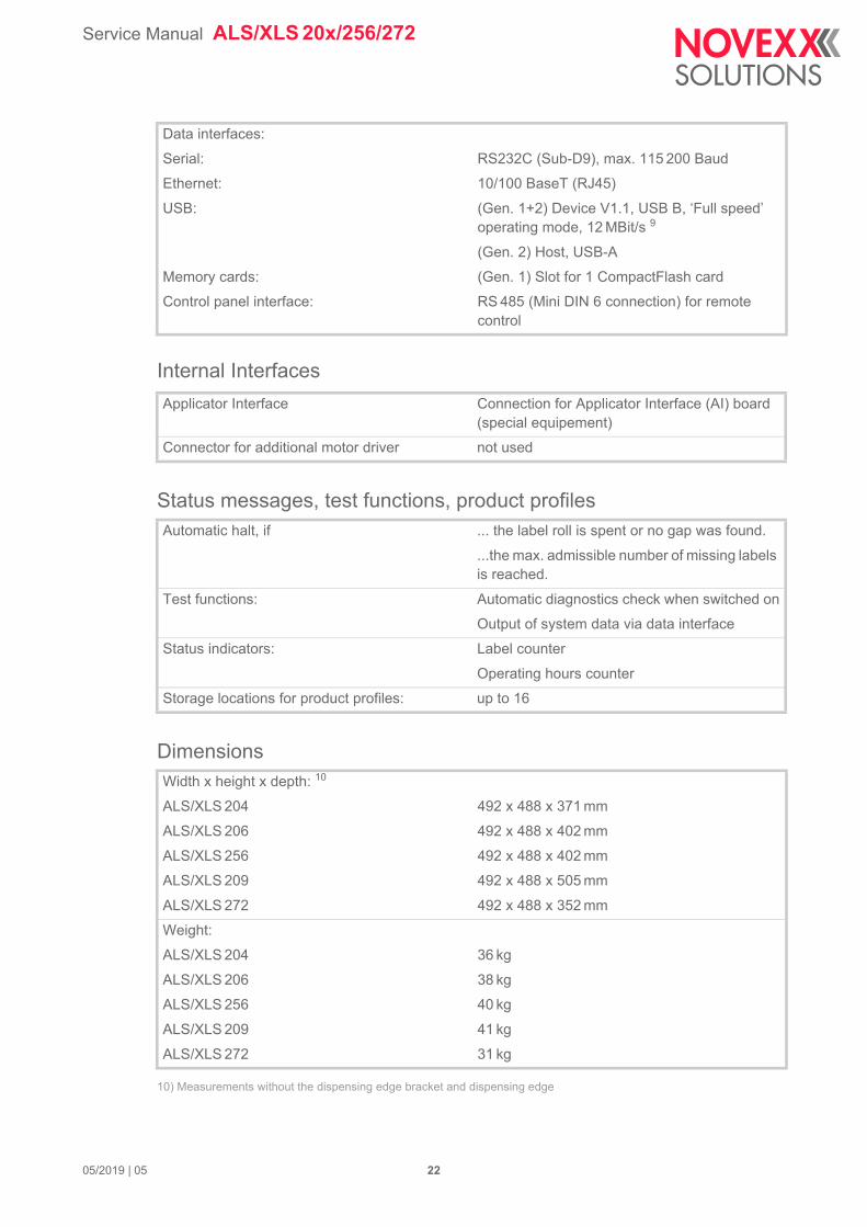
Data interfaces:
Serial:
Ethernet:
USB:
Memory cards:
Control panel interface:
RS232C (Sub-D9), max. 115 200 Baud
10/100 BaseT (RJ45)
(Gen. 1+2) Device V1.1, USB B, ‘Full speed’ operating mode, 12 MBit/s 9
(Gen. 2) Host, USB-A
(Gen. 1) Slot for 1 CompactFlash card
RS 485 (Mini DIN 6 connection) for remote control
Applicator Interface Connection for Applicator Interface (AI) board (special equipement)
Connector for additional motor driver not used
Automatic halt, if ... the label roll is spent or no gap was found.
...the max. admissible number of missing labels is reached.
Test functions: Automatic diagnostics check when switched on
Output of system data via data interface
Status indicators: Label counter
Operating hours counter
Storage locations for product profiles: up to 16
Width x height x depth: 10
ALS/XLS 204
ALS/XLS 206
ALS/XLS 256
ALS/XLS 209
ALS/XLS 272
492 x 488 x 371 mm
492 x 488 x 402 mm
492 x 488 x 402 mm
492 x 488 x 505 mm
492 x 488 x 352 mm
Weight:
ALS/XLS 204
ALS/XLS 206
ALS/XLS 256
ALS/XLS 209
ALS/XLS 272
36 kg
38 kg
40 kg
41 kg
31 kg
05/2019 | 05 22
Service Manual ALS/XLS 20x/256/272
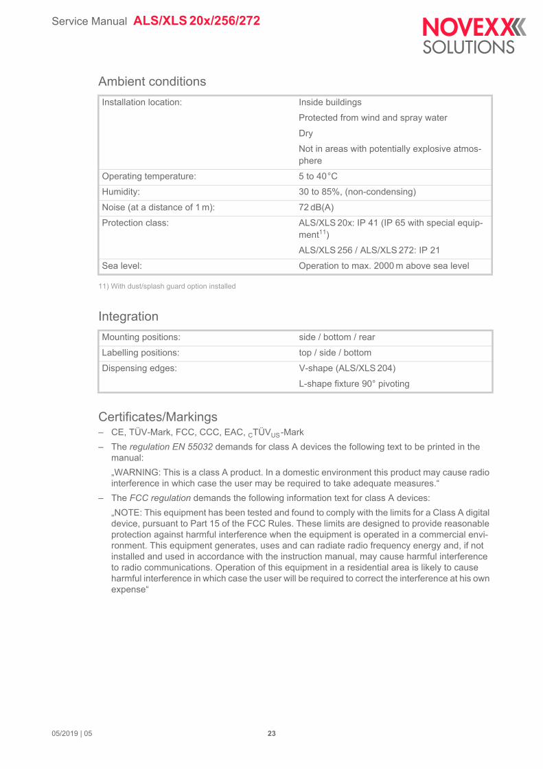
Ambient conditions
11) With dust/splash guard option installed
Integration
Certificates/Markings– CE, TÜV-Mark, FCC, CCC, EAC, CTÜVUS-Mark
– The regulation EN 55032 demands for class A devices the following text to be printed in the manual:
„WARNING: This is a class A product. In a domestic environment this product may cause radio interference in which case the user may be required to take adequate measures.“
– The FCC regulation demands the following information text for class A devices:
„NOTE: This equipment has been tested and found to comply with the limits for a Class A digital device, pursuant to Part 15 of the FCC Rules. These limits are designed to provide reasonable protection against harmful interference when the equipment is operated in a commercial envi-ronment. This equipment generates, uses and can radiate radio frequency energy and, if not installed and used in accordance with the instruction manual, may cause harmful interference to radio communications. Operation of this equipment in a residential area is likely to cause harmful interference in which case the user will be required to correct the interference at his own expense“
Installation location: Inside buildings
Protected from wind and spray water
Dry
Not in areas with potentially explosive atmos-phere
Operating temperature: 5 to 40°C
Humidity: 30 to 85%, (non-condensing)
Noise (at a distance of 1 m): 72 dB(A)
Protection class: ALS/XLS 20x: IP 41 (IP 65 with special equip-ment11)
ALS/XLS 256 / ALS/XLS 272: IP 21
Sea level: Operation to max. 2000 m above sea level
Mounting positions: side / bottom / rear
Labelling positions: top / side / bottom
Dispensing edges: V-shape (ALS/XLS 204)
L-shape fixture 90° pivoting
05/2019 | 05 23
Service Manual ALS/XLS 20x/256/272
02/2019 | 02 24 Technical Data
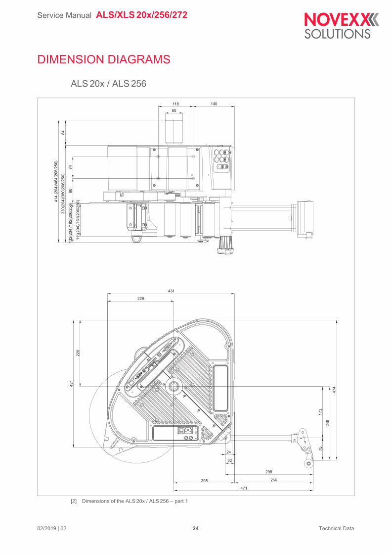
DIMENSION DIAGRAMS
ALS 20x / ALS 256
[2] Dimensions of the ALS 20x / ALS 256 – part 1
74
86
84
33
0(2
04
)/3
80
(20
6/2
56
)
41
4(2
04
)/4
64
(20
6/2
56
)
13
2(2
04
)/1
82
(20
6/2
56
)
111
(20
4)/
16
1(2
06
/25
6)
118
60
140
22
6
43
1
226
431
17
3
24
8
47
4
75
24
32
298
205 266
471
Service Manual ALS/XLS 20x/256/272
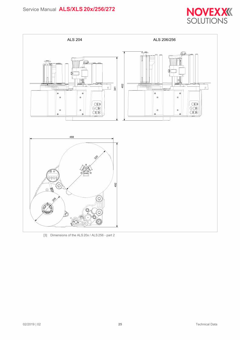
02/2019 | 02 25 Technical Data
[3] Dimensions of the ALS 20x / ALS 256 - part 2
ALS 204 ALS 206/256
341 40
2
492
488
205
320
Service Manual ALS/XLS 20x/256/272
02/2019 | 02 26 Technical Data
ALS 272
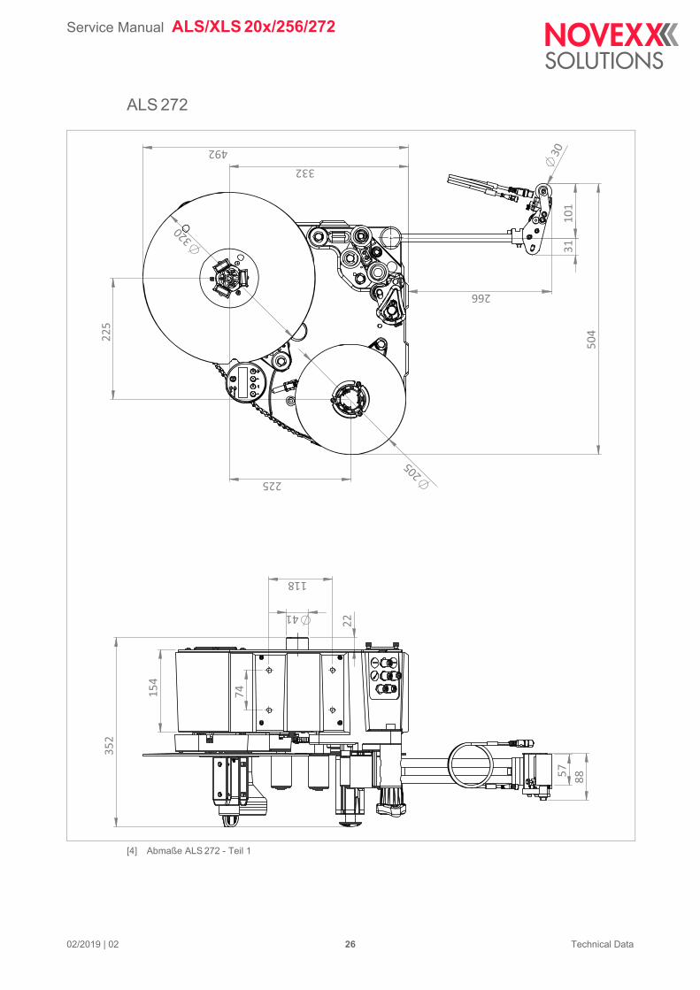
[4] Abmaße ALS 272 - Teil 1
3010
1
332
225
225
320
205
266
492
504
31
57
22
41
352
88
74
118
154
Service Manual ALS/XLS 20x/256/272
02/2019 | 02 27 Technical Data
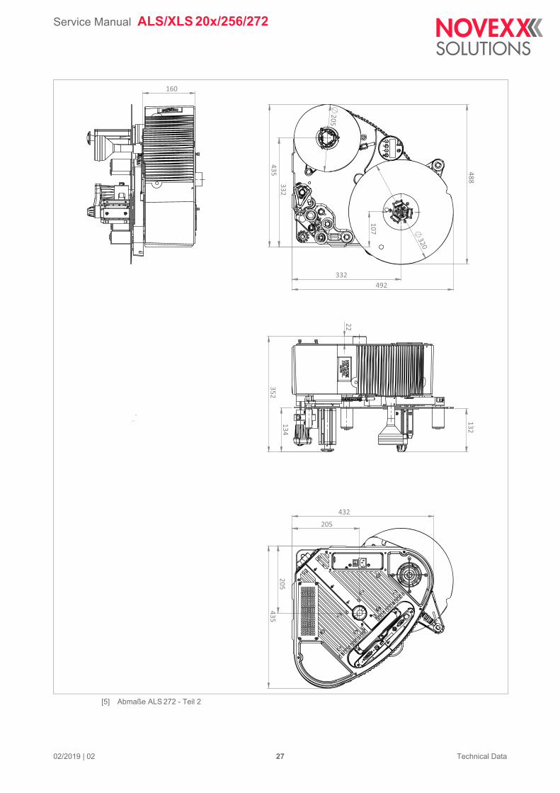
[5] Abmaße ALS 272 - Teil 2
492 332
435 332
205
320
107
488
22
132
134 352
205
205
435
432
160
Service Manual ALS/XLS 20x/256/272
02/2019 | 02 28 Technical Data
PERFORMANCE DATA
Label rate
Prerequisites:
– Direct dispensing (without applicator)
– No printer attached
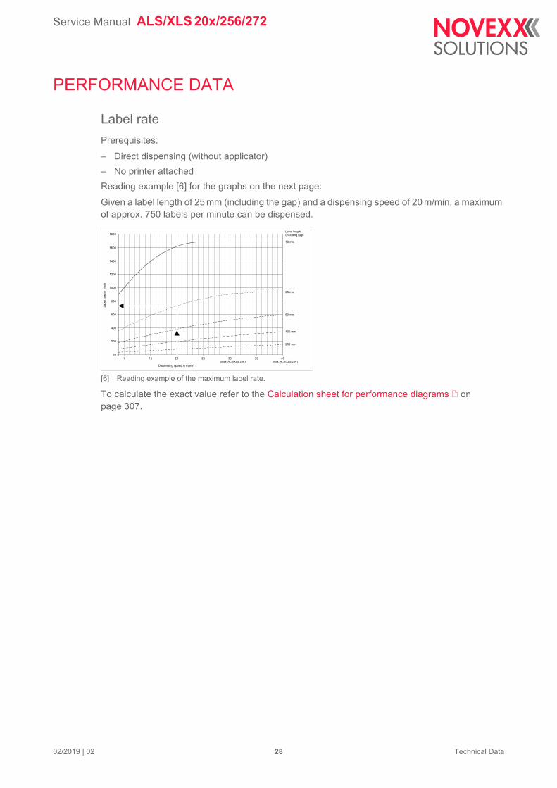
Reading example [6] for the graphs on the next page:
Given a label length of 25 mm (including the gap) and a dispensing speed of 20 m/min, a maximum of approx. 750 labels per minute can be dispensed.
[6] Reading example of the maximum label rate.
To calculate the exact value refer to the Calculation sheet for performance diagrams on page 307.
10 15 20 25 30 35 40
10 mm
25 mm
50 mm
100 mm
250 mm
(max. ALS/XLS 206) (max. ALS/XLS 204)
10
200
400
600
800
1000
1200
1400
1600
1800
Dispensing speed in m/min
Labe
l rat
e in
1/m
in
Label length(including gap)
Service Manual ALS/XLS 20x/256/272
02/2019 | 02 29 Technical Data
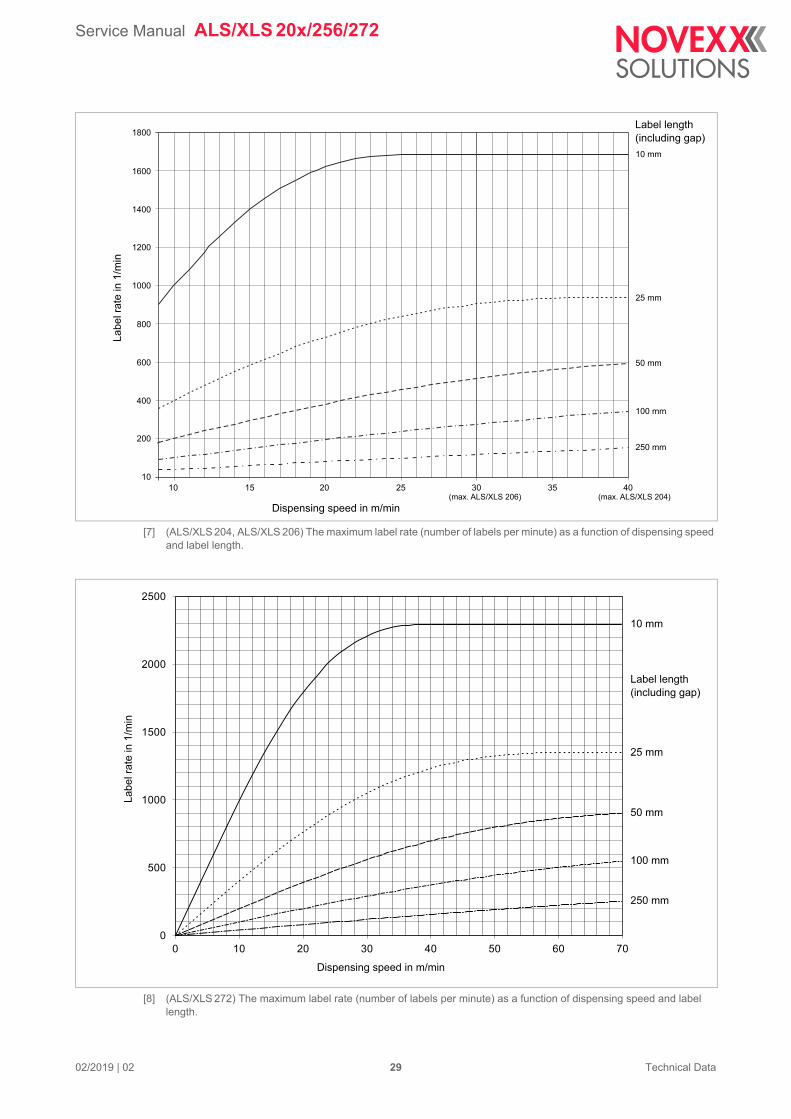
[7] (ALS/XLS 204, ALS/XLS 206) The maximum label rate (number of labels per minute) as a function of dispensing speed and label length.
[8] (ALS/XLS 272) The maximum label rate (number of labels per minute) as a function of dispensing speed and label length.
10 15 20 25 30 35 40
10 mm
25 mm
50 mm
100 mm
250 mm
(max. ALS/XLS 206) (max. ALS/XLS 204)
10
200
400
600
800
1000
1200
1400
1600
1800
Dispensing speed in m/min
Labe
l rat
e in
1/m
inLabel length(including gap)
0
500
1000
1500
2000
2500
0 10 20 30 40 50 60 70
Labe
l rat
e in
1/m
in
Dispensing speed in m/min
Label length(including gap)
10 mm
25 mm
50 mm
100 mm
250 mm
Service Manual ALS/XLS 20x/256/272
02/2019 | 02 30 Technical Data
Dispensing speed over duration v(t)
[9] (ALS/XLS 20x) Diagrams with different settings for dispensing speed over dispensing duration.
A The max. dispensing speed (here 40 m/min) is reached for the duration of 34 ms.
B Because a shorter label is used, the braking begins just in the moment of reaching the max. dis-pensing speed.
C In this case, the label is even shorter, with the consequence that the max. dispensing speed is not reached. The braking already begins at a speed of approx. 36 m/min.
D The same as A), with a lower max. dispensing speed.
By the way: The area below the graph equates to the label length. What means that the areas below the graphs A and D must have the same sizes.
A: v = 40 m/min, l = 50 mm, B: v = 40 m/min,l = 27,5 mm, C: v = 40 m/min,l = 22 mm, D: v = 30 m/min, l = 50 mm
0
5
10
15
20
25
30
m/min
40
45
0 20 40 60 80 100 120 ms
A
BC
Dmax. ALS/XLS 206
max. ALS/XLS 204
Dispensing Speed
Dispensing duration
Service Manual ALS/XLS 20x/256/272
02/2019 | 02 31 Technical Data
[10] (ALS/XLS 272) Diagrams with different settings for dispensing speed over dispensing duration.
Dispensing speed over length v(x)
[11] (ALS/XLS 20x) Diagrams with different settings for dispensing speed over dispensed label length.
0,00
10,00
20,00
30,00
40,00
50,00
70,00
80,00
0 5 10 15 20 25 30 35 ms
m/min
C
max. ALS/XLS 272
A B
A: v = 70 m/min, l = 15 mm, B: v = 70 m/min, l = 19 mm, C: v = 70 m/min, l = 25 mm
Dispensing duration
Dispensingspeed
0
5
10
15
20
25
30
35
40m/min
45
0 10 20 30 40 50mm
max. ALS/XLS 206
max. ALS/XLS 204 A
B
C
D
A: v = 40 m/min, l = 50 mm, B: v = 40 m/min,l = 27.5 mm, C: v = 40 m/min,l = 22 mm, D: v = 30 m/min, l = 50 mm
Dispensed Label Length
Dispense Speed
Service Manual ALS/XLS 20x/256/272
02/2019 | 02 32 Technical Data
For a precise and problem-free application, the label must have the same speed as the product after the first contact.
A The diagram above shows, that already approx. 14 mm are dispensed, until the max. dispensing speed is reached. The distance between dispensing edge and pressure roller measures 15 mm (dotted lines) - thus the label reaches the pressure roller with the max. dispensing or product speed.
B In this case, the max. dispensing speed is reached, though only for a moment.
C In this case, the max. dispensing speed is not reached.
[12] (ALS/XLS 272) Diagrams with different settings for dispensing speed over dispensed label length.
0
10
20
30
40
50
60
70
90
0 5 10 15 20 25 30
m/min
mm
max. ALS/XLS 272
A: v = 70 m/min, l = 15 mm, B: v = 70 m/min, l = 19 mm, C: v = 70 m/min, l = 25 mm
CBA
Dispensed label length
Labe
l sen
sor p
ositi
on
DispensingSpeed
Service Manual ALS/XLS 20x/256/272
02/2019 | 02 33 Technical Data
Dispensed label length over duration x(t)
[13] (ALS/XLS 20x) Diagrams with different settings for dispensed label lengths over dispensing duration.
[14] (ALS/XLS 272) Diagrams with different settings for dispensed label lengths over dispensing duration.
0
5
0 5 10 15 20 25 30 35 40
10
15
20
25
30
mm
ms
A: v = 70 m/min, l = 25 mm, B: v = 70 m/min, l = 19 mm, C: v = 70 m/min, l = 15 mm
A
B
C
Dispense duration
Dispensed label length
Service Manual ALS/XLS 20x/256/272
02/2019 | 02 34 Technical Data
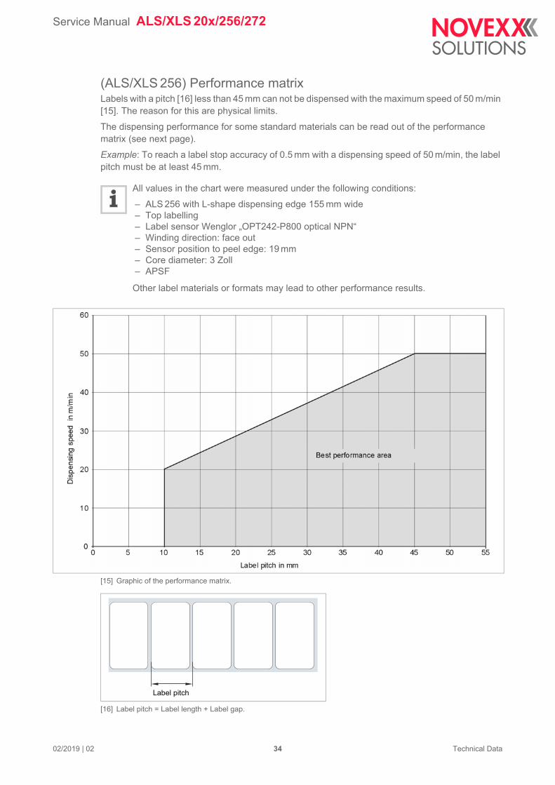
(ALS/XLS 256) Performance matrixLabels with a pitch [16] less than 45 mm can not be dispensed with the maximum speed of 50 m/min [15]. The reason for this are physical limits.
The dispensing performance for some standard materials can be read out of the performance matrix (see next page).
Example: To reach a label stop accuracy of 0.5 mm with a dispensing speed of 50 m/min, the label pitch must be at least 45 mm.
All values in the chart were measured under the following conditions:
– ALS 256 with L-shape dispensing edge 155 mm wide– Top labelling– Label sensor Wenglor „OPT242-P800 optical NPN“– Winding direction: face out– Sensor position to peel edge: 19 mm– Core diameter: 3 Zoll– APSF
Other label materials or formats may lead to other performance results.
[15] Graphic of the performance matrix.
[16] Label pitch = Label length + Label gap.
Label pitch
Service Manual ALS/XLS 20x/256/272
02/2019 | 02 35 Technical Data
1) Width x length2) Narrow label spring kit required (article no. A8612)
Dispensing speed [m/min]
Web
tension
Fixed Variable
5 10 20 30 40 50 5 - 50 (30)
Material type Format [mm] 1) Max. Label stop accuracy[ ± mm]
Fasson5210-100-180AA 1666 MC Primecoat
12x8 0.5 0.5 0.5 n.a. n.a. n.a. 2.4 5 N 2)
20x20 0.5 0.5 0.5 0.5 n.a. n.a. 2.4 5 N 2)
100x32 0.5 0.5 0.5 0.5 0.5 n.a. 1 9 N
45x45 0.5 0.5 0.5 0.5 0.5 0.5 1 9 N
35x65 0.5 0.5 0.5 0.5 0.5 0.5 1.1 9 N
50x125 0.5 0.5 0.5 0.5 0.5 0.5 1 9 N
80x80 0.5 0.5 0.5 0.5 0.5 0.5 1 9 N
100x100 0.5 0.5 0.5 0.5 0.5 0.5 1 9 N
155x200 0.5 0.5 0.5 0.5 0.5 0.5 1 9 N
Fasson5100-150-180AA1658 Vellum Extra
45x45 0.5 0.5 0.5 0.5 0.5 0.5 1 9 N
50x125 0.5 0.5 0.5 0.5 0.5 0.5 1 9 N
100x100 0.5 0.5 0.5 0.5 0.5 0.5 1 9 N
155x200 0.5 0.5 0.5 0.5 0.5 0.5 1 9 N
Fasson5400-110-125PE 85 weiß
45x45 0.5 0.5 0.5 0.5 0.5 0.5 1 9 N
50x125 0.5 0.5 0.5 0.5 0.5 0.5 1 9 N
80x80 0.5 0.5 0.5 0.5 0.5 0.5 1 9 N
100x100 0.5 0.5 0.5 0.5 0.5 0.5 1 9 N
155x200 0.5 0.5 0.5 0.5 0.5 0.5 1 9 N
Fasson9513-100-235MA 0977 Trans-fer Plus
45x45 0.5 0.5 0.5 0.5 0.5 0.5 1 9 N
50x125 0.5 0.5 0.5 0.5 0.5 0.5 1 9 N
80x80 0.5 0.5 0.5 0.5 0.5 0.5 1 9 N
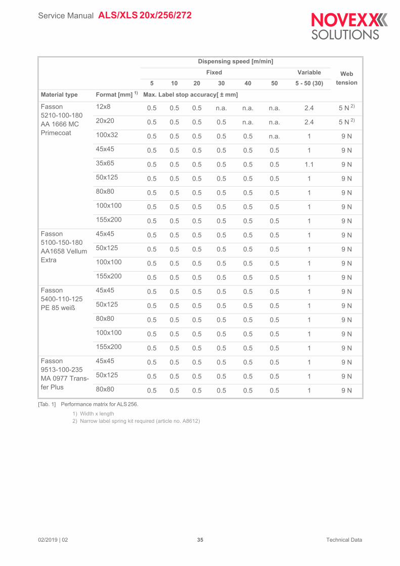
[Tab. 1] Performance matrix for ALS 256.
Service Manual ALS/XLS 20x/256/272
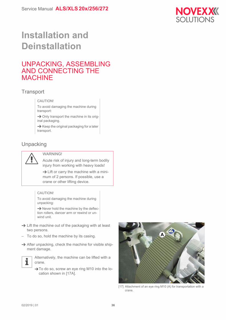
[17] Attachment of an eye ring M10 (A) for transportation with a crane.
A
Installation and Deinstallation
UNPACKING, ASSEMBLING AND CONNECTING THE MACHINE
Transport
Unpacking
Lift the machine out of the packaging with at least two persons.
– To do so, hold the machine by its casing.
After unpacking, check the machine for visible ship-ment damage.
Alternatively, the machine can be lifted with a crane.
To do so, screw an eye ring M10 into the lo-cation shown in [17A].
CAUTION!
To avoid damaging the machine during transport:
Only transport the machine in its orig-inal packaging.
Keep the original packaging for a later transport.
WARNING!
Acute risk of injury and long-term bodily injury from working with heavy loads!
Lift or carry the machine with a mini-mum of 2 persons. If possible, use a crane or other lifting device.
CAUTION!
To avoid damaging the machine during unpacking:
Never hold the machine by the deflec-tion rollers, dancer arm or rewind or un-wind unit.
02/2019 | 01 36
Service Manual ALS/XLS 20x/256/272
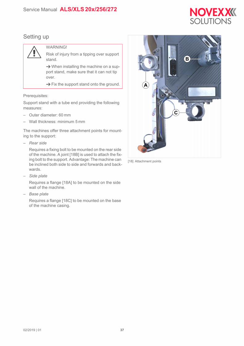
[18] Attachment points
C
B
A
Setting up
Prerequisites:
Support stand with a tube end providing the following measures:
– Outer diameter: 60 mm
– Wall thickness: minimum 5 mm
The machines offer three attachment points for mount-ing to the support:
– Rear side
Requires a fixing bolt to be mounted on the rear side of the machine. A joint [18B] is used to attach the fix-ing bolt to the support. Advantage: The machine can be inclined both side to side and forwards and back-wards.
– Side plate
Requires a flange [18A] to be mounted on the side wall of the machine.
– Base plate
Requires a flange [18C] to be mounted on the base of the machine casing.
WARNING!
Risk of injury from a tipping over support stand.
When installing the machine on a sup-port stand, make sure that it can not tip over.
Fix the support stand onto the ground.
02/2019 | 01 37
Service Manual ALS/XLS 20x/256/272
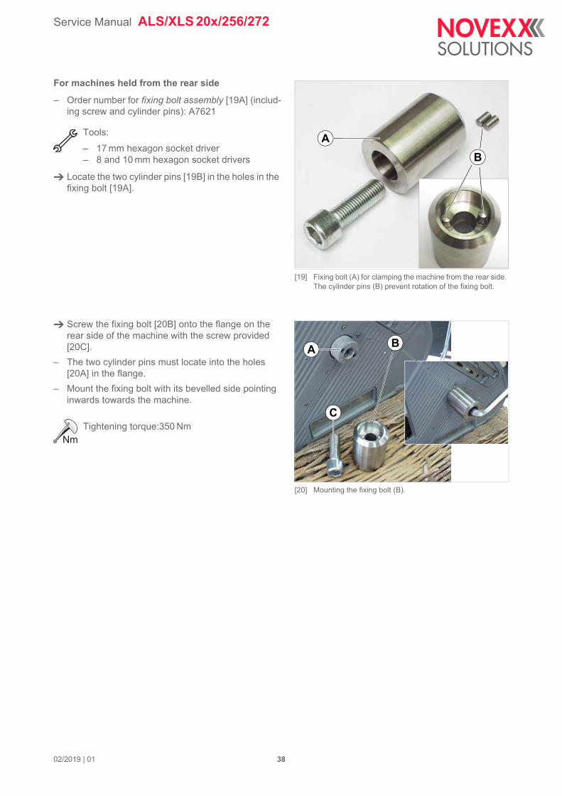
[19] Fixing bolt (A) for clamping the machine from the rear side. The cylinder pins (B) prevent rotation of the fixing bolt.
A
B
[20] Mounting the fixing bolt (B).
BA
C
For machines held from the rear side
– Order number for fixing bolt assembly [19A] (includ-ing screw and cylinder pins): A7621
Tools:
– 17 mm hexagon socket driver– 8 and 10 mm hexagon socket drivers
Locate the two cylinder pins [19B] in the holes in the fixing bolt [19A].
Screw the fixing bolt [20B] onto the flange on the rear side of the machine with the screw provided [20C].
– The two cylinder pins must locate into the holes [20A] in the flange.
– Mount the fixing bolt with its bevelled side pointing inwards towards the machine.
Tightening torque:350 Nm
02/2019 | 01 38
Service Manual ALS/XLS 20x/256/272
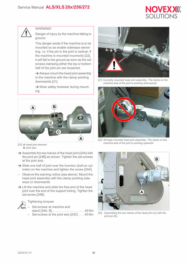
[21] Correctly mounted head joint assembly. The clamp on the machine-side of the joint is pointing downwards!
[22] Wrongly mounted head joint assembly. The clamp on the machine-side of the joint is pointing upwards!
[24] Assembling the two halves of the head joint (A) with the joint pin (B).
B
A
[23] A Head joint elementB Joint axis
Assemble the two halves of the head joint [24A] with the joint pin [24B] as shown. Tighten the set-screws at the joint axis.
Slide one half of joint over the trunnion (bolt-on cyl-inder) on the machine and tighten the screw [24A].
– Observe the warning notice (see above). Mount the head joint assembly with the clamp pointing side-ways or downwards.
Lift the machine and slide the free end of the head joint over the end of the support tubing. Tighten the set-screw [24B].
Tightening torques:
– Set-screws at machine and stand [24A, B] . . . . . . . . . . . . . . . . . . 45 Nm
– Set-screws at the joint axis [23C] . . . 45 Nm
WARNING!
Danger of injury by the machine falling to ground.
This danger exists if the machine is to be mounted so as enable sideways swivel-ling, i.e. if the pin in the joint is vertical. If the machine is mounted incorrectly [22], it will fall to the ground as soon as the set screws clamping either the top or bottom half of the joint pin are loosened.
Always mount the head joint assembly to the machine with the clamp pointing downwards [21].
Wear safety footwear during mount-ing.
A
A
C
B
C
02/2019 | 01 39
Service Manual ALS/XLS 20x/256/272
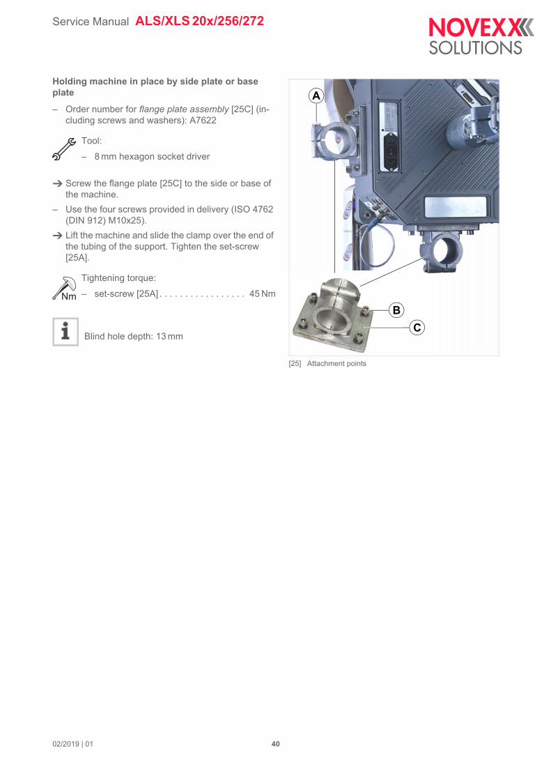
[25] Attachment points
B
C
A
Holding machine in place by side plate or base plate– Order number for flange plate assembly [25C] (in-cluding screws and washers): A7622
Tool:
– 8 mm hexagon socket driver
Screw the flange plate [25C] to the side or base of the machine.
– Use the four screws provided in delivery (ISO 4762 (DIN 912) M10x25).
Lift the machine and slide the clamp over the end of the tubing of the support. Tighten the set-screw [25A].
Tightening torque:
– set-screw [25A] . . . . . . . . . . . . . . . . . 45 Nm
Blind hole depth: 13 mm
02/2019 | 01 40
Service Manual ALS/XLS 20x/256/272
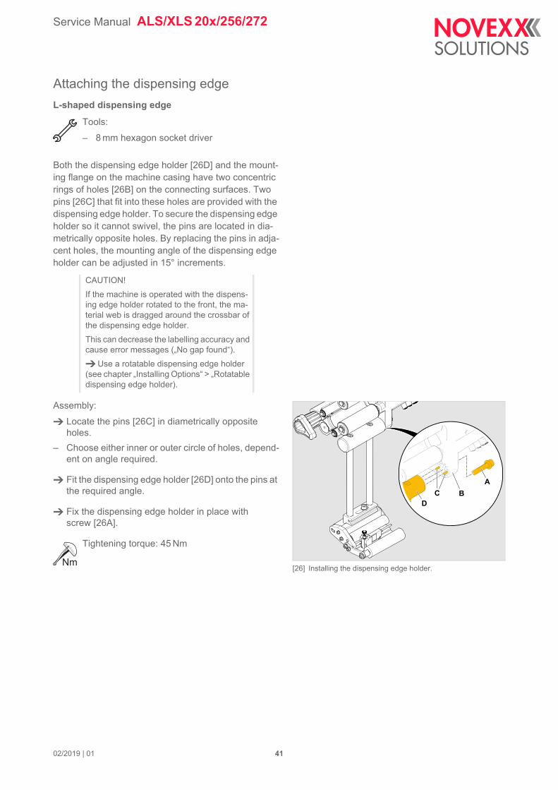
[26] Installing the dispensing edge holder.
ABC
D
Attaching the dispensing edge
L-shaped dispensing edge
Tools:
– 8 mm hexagon socket driver
Both the dispensing edge holder [26D] and the mount-ing flange on the machine casing have two concentric rings of holes [26B] on the connecting surfaces. Two pins [26C] that fit into these holes are provided with the dispensing edge holder. To secure the dispensing edge holder so it cannot swivel, the pins are located in dia-metrically opposite holes. By replacing the pins in adja-cent holes, the mounting angle of the dispensing edge holder can be adjusted in 15° increments.
Assembly:
Locate the pins [26C] in diametrically opposite holes.
– Choose either inner or outer circle of holes, depend-ent on angle required.
Fit the dispensing edge holder [26D] onto the pins at the required angle.
Fix the dispensing edge holder in place with screw [26A].
Tightening torque: 45 Nm
CAUTION!
If the machine is operated with the dispens-ing edge holder rotated to the front, the ma-terial web is dragged around the crossbar of the dispensing edge holder.
This can decrease the labelling accuracy and cause error messages („No gap found“).
Use a rotatable dispensing edge holder (see chapter „Installing Options“ > „Rotatable dispensing edge holder).
02/2019 | 01 41

Service Manual ALS/XLS 20x/256/272
[27] V-shaped dispensing edge in place.
V-shaped dispensing edge
Tool:
– 8 mm hexagon socket driver
Mount V-shaped dispensing edge as shown
– The angle of the V-shaped dispensing edge cannot be changed. It is mounted without fixing pins.
02/2019 | 01 42
Service Manual ALS/XLS 20x/256/272
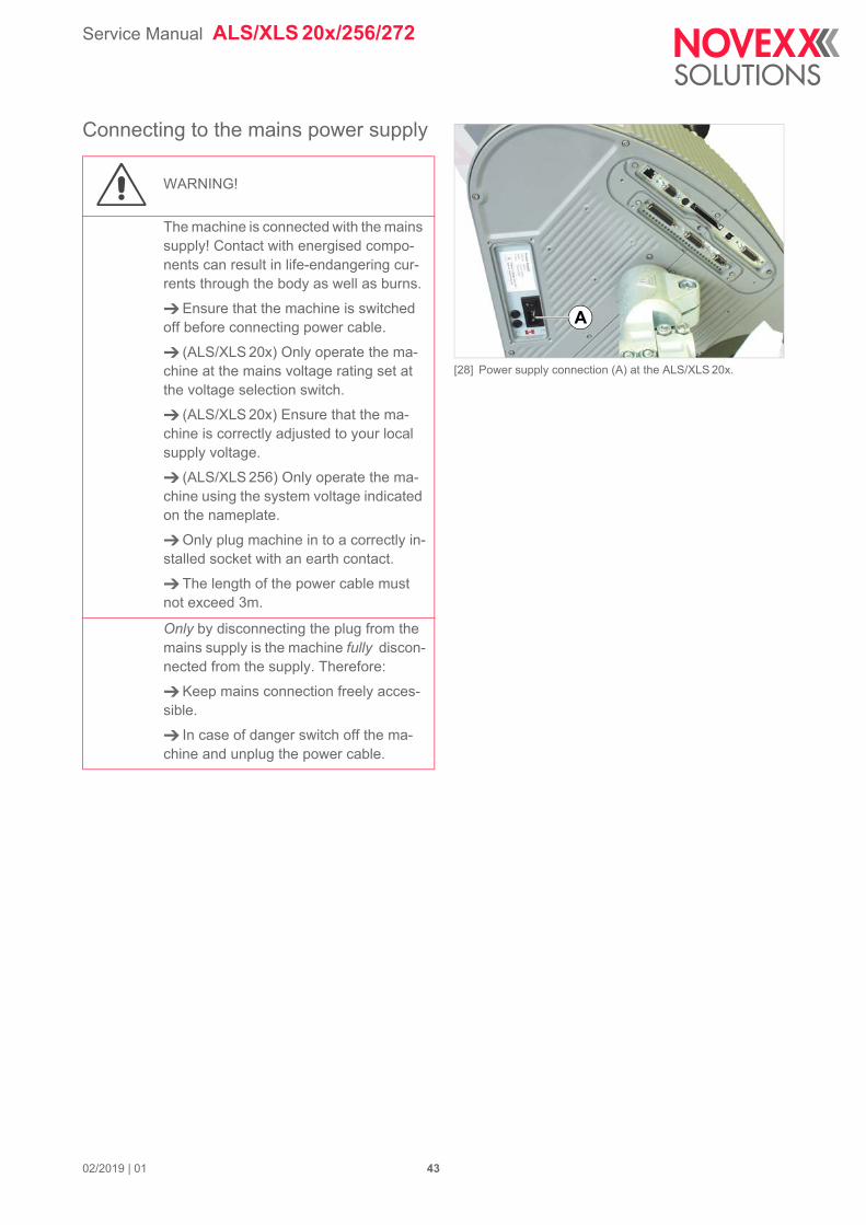
[28] Power supply connection (A) at the ALS/XLS 20x.
A
Connecting to the mains power supply
WARNING!
The machine is connected with the mains supply! Contact with energised compo-nents can result in life-endangering cur-rents through the body as well as burns.
Ensure that the machine is switched off before connecting power cable.
(ALS/XLS 20x) Only operate the ma-chine at the mains voltage rating set at the voltage selection switch.
(ALS/XLS 20x) Ensure that the ma-chine is correctly adjusted to your local supply voltage.
(ALS/XLS 256) Only operate the ma-chine using the system voltage indicated on the nameplate.
Only plug machine in to a correctly in-stalled socket with an earth contact.
The length of the power cable must not exceed 3m.
Only by disconnecting the plug from the mains supply is the machine fully discon-nected from the supply. Therefore:
Keep mains connection freely acces-sible.
In case of danger switch off the ma-chine and unplug the power cable.
02/2019 | 01 43
Service Manual ALS/XLS 20x/256/272
[29] Machine with splash guard (A).
[30] Voltage selection switch at the ALS/XLS 20x (setting shown in picture: 230 V)
A
B
BA
Checking the supply voltage setting
ALS 256: A power supply setting is not required.
ALS 20X: the labellers are designed for use with a supply voltage of 230 V (AC) or 110 V (AC).
Check whether the voltage set matches your local supply voltage.
To change the voltage setting:
Ensure that the mains power supply lead is un-plugged.
Slide the switch [30A] into its other position.
– To do this, insert a small screwdriver into the groove [30B] and push the red insert horizontally until it stops in the opposite position (for case shown in fig. [30], to the left).
Switch position Permitted mains supply voltage
115 100-120 V (AC)
230 200-240 V (AC)
[Tab. 2]Permitted mains supply voltages for the two positions of the voltage selection switch.
02/2019 | 01 44
Service Manual ALS/XLS 20x/256/272
[31] Power lead (B) plugged in (ALS/XLS 20x).
[32] Machine with splash guard.
B
A
A B
Plugging in the power lead
Ensure that the power switch [31A] is set to "O" (off).
Using the power supply cable provided, connect the machine to a mains supply socket.
(ALS/XLS 20x with splash guard) The power supply cable is connected by installing the splash guard.mit Spritzwasserschutz: Das Netzanschlusskabel wird durch aufsetzen der Abdeckhutze angesteckt.
Before installing the splash guard [32A], ensure that…
– the machine side power switch [31A] is switched on (position „I“).
– the power switch at the splash guard [32B] is switched off (switch doesn´t light).
02/2019 | 01 45
Service Manual ALS/XLS 20x/256/272
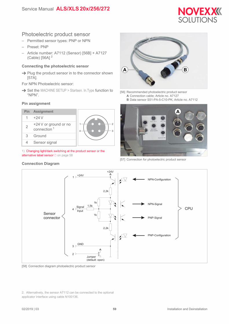
[33] Novexx label sensor (standard since 9/2011)
[34] Wenglor label sensor OPT242-P800(old standard until 9/2011)
[35] Connection for photoelectric label sensor
A
CONNECTING THE SENSORS
Photoelectric label sensor– Permitted sensor type: NPN
– Photoelectric label sensor is included in the dis-pensing edge scope of delivery [33]
Article numbers:
– A101974: Sensor with bracket and cable (1.5 m)
– A101972: Sensor with bracket [33]
– A101971: Connection cable (1.5 m)
Connecting the photoelectric sensor
Plug the photoelectric label sensor in to the connec-tor shown [35A].
Pin assignment
Pin Assignment
1 +24 V
2 LED
3 Ground
4 Sensor signal
[Tab. 3] Pin assignment for photoelectric label sensor connection
1 2
34
02/2019 | 03 46 Installation and Deinstallation
Service Manual ALS/XLS 20x/256/272
+24V
Label gapdetectionsignal
Current feedback signal
LED currentsetting
Connection diagram
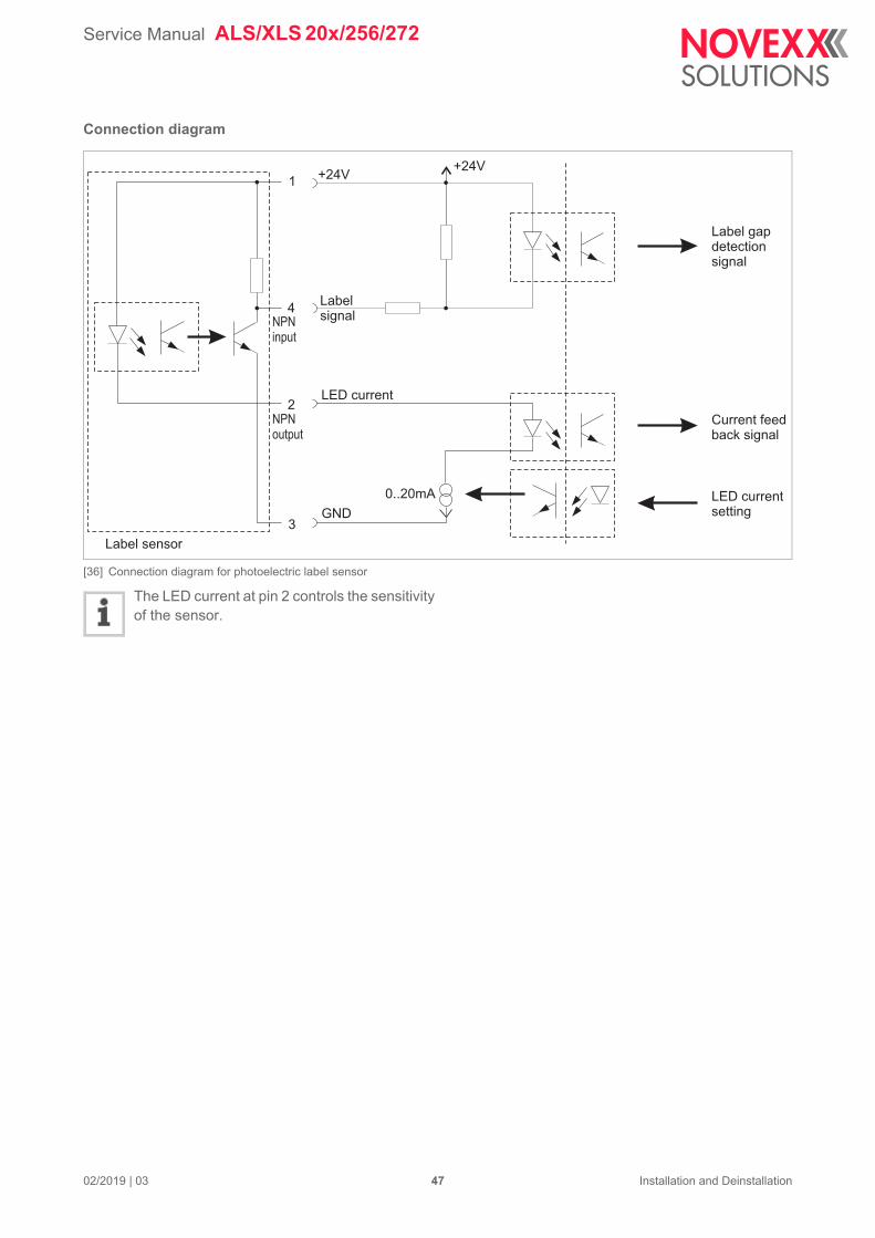
[36] Connection diagram for photoelectric label sensor
The LED current at pin 2 controls the sensitivity of the sensor.
+24V1
2
4
3
0..20mA
NPNinput
NPNoutput
Labelsignal
LED current
GND
Label sensor
02/2019 | 03 47 Installation and Deinstallation
Service Manual ALS/XLS 20x/256/272
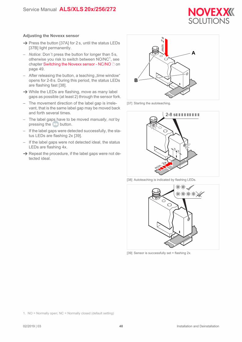
[37] Starting the autoteaching.
[38] Autoteaching is indicated by flashing LEDs.
[39] Sensor is successfully set = flashing 2x.
min
. 2 s
A
B
2-8 s
min. 2x
Adjusting the Novexx sensor
Press the button [37A] for 2 s, until the status LEDs [37B] light permanently.
– Notice: Don´t press the button for longer than 5 s, otherwise you risk to switch between NO/NC1, see chapter Switching the Novexx sensor - NC/NO on page 49.
– After releasing the button, a teaching „time window“ opens for 2-8 s. During this period, the status LEDs are flashing fast [38].
While the LEDs are flashing, move as many label gaps as possible (at least 2) through the sensor fork.
– The movement direction of the label gap is irrele-vant, that is the same label gap may be moved back and forth several times.
– The label gaps have to be moved manually, not by pressing the button.
– If the label gaps were detected successfully, the sta-tus LEDs are flashing 2x [39].
– If the label gaps were not detected ideal, the status LEDs are flashing 4x.
Repeat the procedure, if the label gaps were not de-tected ideal.
1. NO = Normally open; NC = Normally closed (default setting)
02/2019 | 03 48 Installation and Deinstallation
Service Manual ALS/XLS 20x/256/272
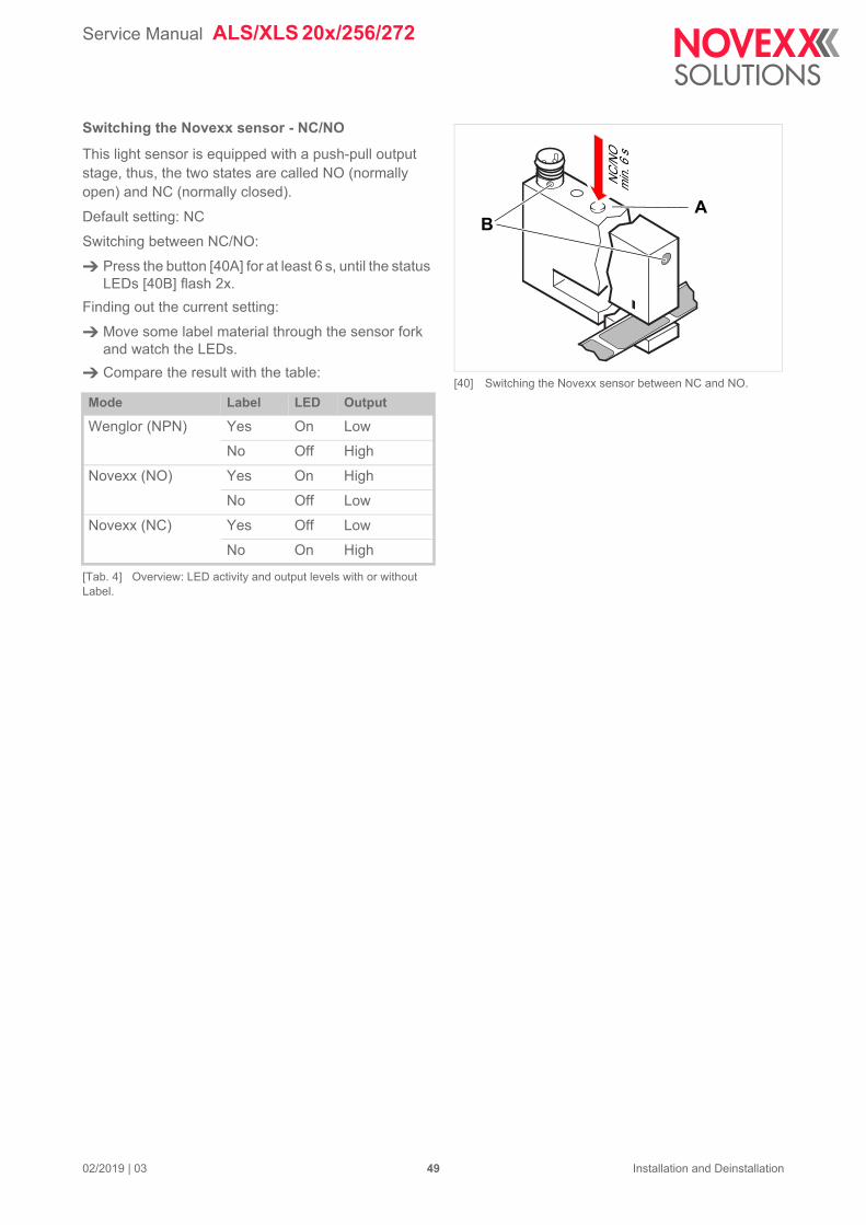
[40] Switching the Novexx sensor between NC and NO.
NC/N
Omi
n. 6 s
AB
Switching the Novexx sensor - NC/NO
This light sensor is equipped with a push-pull output stage, thus, the two states are called NO (normally open) and NC (normally closed).
Default setting: NC
Switching between NC/NO:
Press the button [40A] for at least 6 s, until the status LEDs [40B] flash 2x.
Finding out the current setting:
Move some label material through the sensor fork and watch the LEDs.
Compare the result with the table:
Mode Label LED Output
Wenglor (NPN) Yes On Low
No Off High
Novexx (NO) Yes On High
No Off Low
Novexx (NC) Yes Off Low
No On High
[Tab. 4] Overview: LED activity and output levels with or without Label.
02/2019 | 03 49 Installation and Deinstallation
Service Manual ALS/XLS 20x/256/272
[41] LED (A) at the (Wenglor) photoelectric label sensor
A
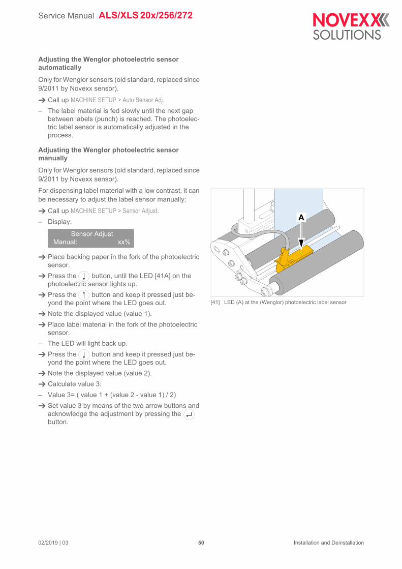
Adjusting the Wenglor photoelectric sensor automatically
Only for Wenglor sensors (old standard, replaced since 9/2011 by Novexx sensor).
Call up MACHINE SETUP > Auto Sensor Adj.
– The label material is fed slowly until the next gap between labels (punch) is reached. The photoelec-tric label sensor is automatically adjusted in the process.
Adjusting the Wenglor photoelectric sensor manually
Only for Wenglor sensors (old standard, replaced since 9/2011 by Novexx sensor).
For dispensing label material with a low contrast, it can be necessary to adjust the label sensor manually:
Call up MACHINE SETUP > Sensor Adjust.
– Display:
Place backing paper in the fork of the photoelectric sensor.
Press the button, until the LED [41A] on the photoelectric sensor lights up.
Press the button and keep it pressed just be-yond the point where the LED goes out.
Note the displayed value (value 1).
Place label material in the fork of the photoelectric sensor.
– The LED will light back up.
Press the button and keep it pressed just be-yond the point where the LED goes out.
Note the displayed value (value 2).
Calculate value 3:
– Value 3= ( value 1 + (value 2 - value 1) / 2)
Set value 3 by means of the two arrow buttons and acknowledge the adjustment by pressing the button.
Sensor AdjustManual: xx%
02/2019 | 03 50 Installation and Deinstallation
Service Manual ALS/XLS 20x/256/272
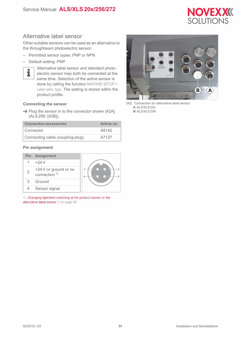
[42] Connection for alternative label sensor:A ALS/XLS 20xB ALS/XLS 256
AB
Alternative label sensorOther suitable sensors can be used as an alternative to the throughbeam photoelectric sensor.
– Permitted sensor types: PNP or NPN
– Default setting: PNP
Alternative label sensor and standard photo-electric sensor may both be connected at the same time. Selection of the active sensor is done by calling the function MACHINE SETUP > Label sens. type. The setting is stored within the product profile.
Connecting the sensor
Plug the sensor in to the connector shown [42A] (ALS 256: [42B]).
Pin assignment
1) Changing light/dark switching at the product sensor or the alternative label sensor on page 58
Connection accessories Article no.
Connector A8142
Connecting cable (coupling-plug) A7127
Pin Assignment
1 +24 V
2+24 V or ground or no connection 1)
3 Ground
4 Sensor signal
1 2
34
02/2019 | 03 51 Installation and Deinstallation
Service Manual ALS/XLS 20x/256/272
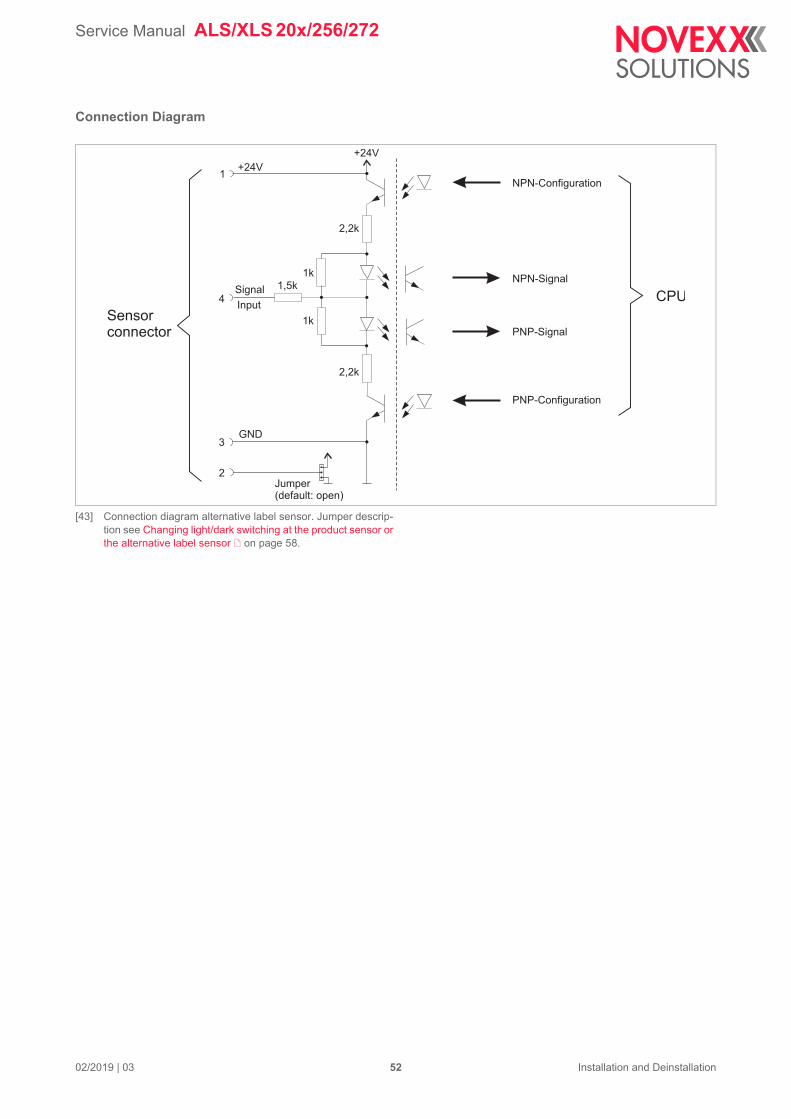
NPN-Configuration
NPN-Signal
PNP-Signal
PNP-Configuration
CPU
Connection Diagram
[43] Connection diagram alternative label sensor. Jumper descrip-tion see Changing light/dark switching at the product sensor or the alternative label sensor on page 58.
+24V
+24V
2,2k
1k
1k
1,5kSignal
Input
GND
Jumper(default: open)
1
4
3
2
2,2k
Sensorconnector
02/2019 | 03 52 Installation and Deinstallation
Service Manual ALS/XLS 20x/256/272
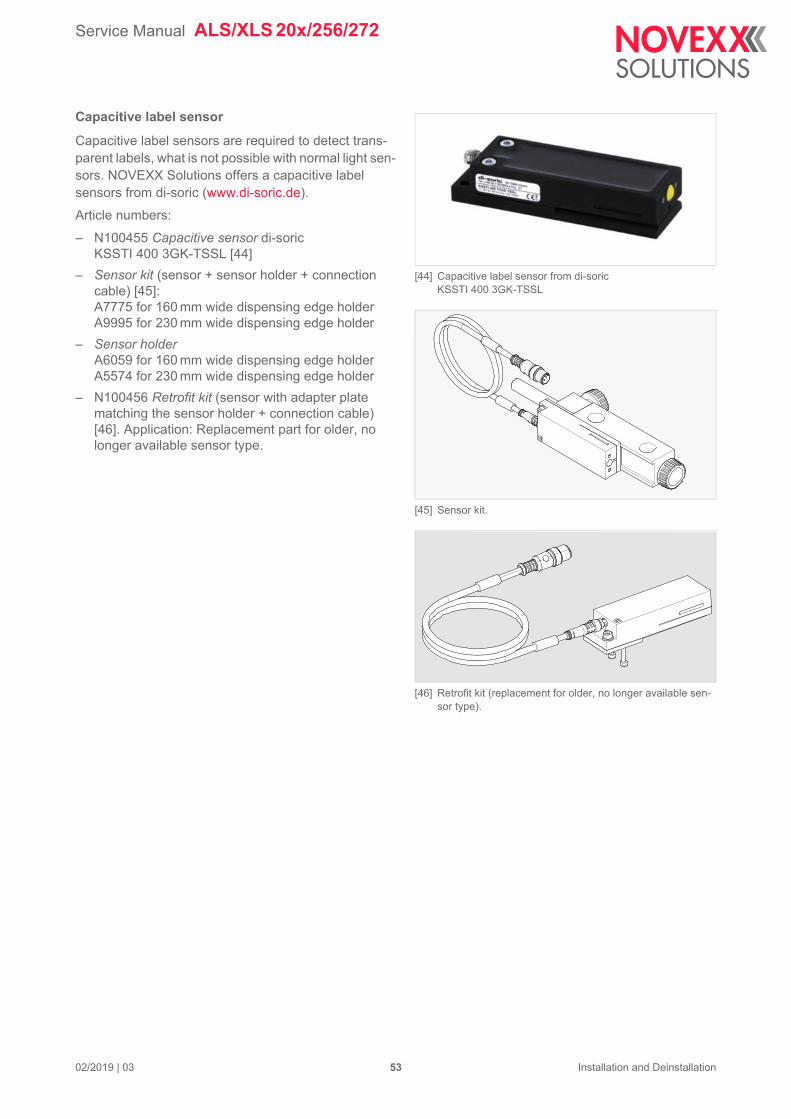
[44] Capacitive label sensor from di-soric KSSTI 400 3GK-TSSL
[45] Sensor kit.
[46] Retrofit kit (replacement for older, no longer available sen-sor type).
Capacitive label sensor
Capacitive label sensors are required to detect trans-parent labels, what is not possible with normal light sen-sors. NOVEXX Solutions offers a capacitive label sensors from di-soric (www.di-soric.de).
Article numbers:
– N100455 Capacitive sensor di-soric KSSTI 400 3GK-TSSL [44]
– Sensor kit (sensor + sensor holder + connection cable) [45]:A7775 for 160 mm wide dispensing edge holderA9995 for 230 mm wide dispensing edge holder
– Sensor holderA6059 for 160 mm wide dispensing edge holderA5574 for 230 mm wide dispensing edge holder
– N100456 Retrofit kit (sensor with adapter plate matching the sensor holder + connection cable) [46]. Application: Replacement part for older, no longer available sensor type.
02/2019 | 03 53 Installation and Deinstallation
Service Manual ALS/XLS 20x/256/272
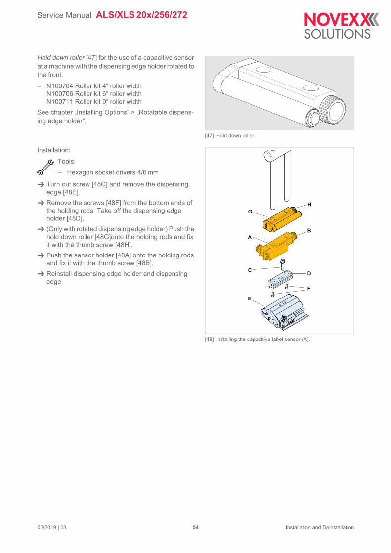
[47] Hold down roller.
[48] Installing the capacitive label sensor (A).
C
E
F
D
HG
AB
Hold down roller [47] for the use of a capacitive sensor at a machine with the dispensing edge holder rotated to the front.
– N100704 Roller kit 4“ roller widthN100706 Roller kit 6“ roller widthN100711 Roller kit 9“ roller width
See chapter „Installing Options“ > „Rotatable dispens-ing edge holder“.
Installation:
Tools:
– Hexagon socket drivers 4/6 mm
Turn out screw [48C] and remove the dispensing edge [48E].
Remove the screws [48F] from the bottom ends of the holding rods. Take off the dispensing edge holder [48D].
(Only with rotated dispensing edge holder) Push the hold down roller [48G]onto the holding rods and fix it with the thumb screw [48H].
Push the sensor holder [48A] onto the holding rods and fix it with the thumb screw [48B].
Reinstall dispensing edge holder and dispensing edge.
02/2019 | 03 54 Installation and Deinstallation

Service Manual ALS/XLS 20x/256/272
[49] Attaching the retrofit kit to the sensor holder.
A
B
C
Installing the retrofit kit:
Screw the sensor to the sensorholder [49].
Connect the cable.
02/2019 | 03 55 Installation and Deinstallation
Service Manual ALS/XLS 20x/256/272
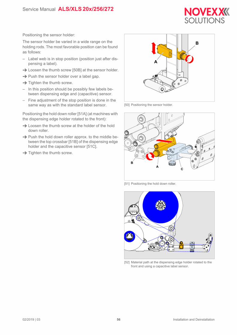
[50] Positioning the sensor holder.
A
B
[51] Positioning the hold down roller.
[52] Material path at the dispensing edge holder rotated to the front and using a capacitive label sensor.
AB
C
Positioning the sensor holder:
The sensor holder be varied in a wide range on the holding rods. The most favorable position can be found as follows:
– Label web is in stop position (position just after dis-pensing a label).
Loosen the thumb screw [50B] at the sensor holder.
Push the sensor holder over a label gap.
Tighten the thumb screw.
– In this position should be possibly few labels be-tween dispensing edge and (capacitive) sensor.
– Fine adjustment of the stop position is done in the same way as with the standard label sensor.
Positioning the hold down roller [51A] (at machines with the dispensing edge holder rotated to the front):
Loosen the thumb screw at the holder of the hold down roller.
Push the hold down roller approx. to the middle be-tween the top crossbar [51B] of the dispensing edge holder and the capacitive sensor [51C].
Tighten the thumb screw.
02/2019 | 03 56 Installation and Deinstallation
Service Manual ALS/XLS 20x/256/272
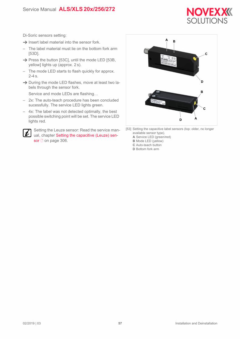
[53] Setting the capacitive label sensors (top: older, no longer available sensor type).A Service LED (green/red)B Mode LED (yellow)C Auto-teach buttonD Bottom fork arm
A B
C
D
A
B
C
D
Di-Soric sensors setting:
Insert label material into the sensor fork.
– The label material must lie on the bottom fork arm [53D].
Press the button [53C], until the mode LED [53B, yellow] lights up (approx. 2 s).
– The mode LED starts to flash quickly for approx. 2-4 s.
During the mode LED flashes, move at least two la-bels through the sensor fork.
Service and mode LEDs are flashing…
– 2x: The auto-teach procedure has been concluded sucessfully. The service LED lights green.
– 4x: The label was not detected optimally, the best possible switching point will be set. The service LED lights red.
Setting the Leuze sensor: Read the service man-ual, chapter Setting the capacitive (Leuze) sen-sor on page 306.
02/2019 | 03 57 Installation and Deinstallation
Service Manual ALS/XLS 20x/256/272
[54] CPU board „Gen. 1“.A Position of the jumper JP901 (A) for the control of pin 2 of
the alternative label sensorB Position of the jumper JP902 (B) for the control of pin 2 of
the product photoelectric sensor
A6379
AA
B
[55] CPU board „Gen. 2“.A Position of the jumper JP2602 for the control of pin 2 of the
alternative label sensorB Position of the jumper JP2601 for the control of pin 2 of the
product photoelectric sensor
R1714
L702
R703
R803
R702
L601
L602
C605
C701
C702
R605
R1116
L1604
L701
C706
C801
R1117
L801
C1220
C802
C804
C1612
R1710
R1115
L1201
R802
C1216
R1712
RP1302
RP1206
RP1303
RP1205
RP1207
RP1304
RP1301
RP1404
L1603
R1146
C602
C1607
C1124
C807
R1111
C1119
R606
C606
C610
C608
R603
C607
R604
C609
C604
C1303
R1203
L802
R1205
C1218
R1201
C1215
R1202
C1217
R1206
R1207
R1301
R1204
R1114
R801
C2624
8
915
1
CN2701
H402
R701
R1401
H401
R1907
R2641
C2721
Z1011
51
96
CN1801
Z1012
C2717
R1406
R1408C1405
U1901
C2418
C2406
RP2405
C2401
C2420
C2001
U2002
C2002
R404
R2630
R1518
C1521
R1506
F2001
C2007
C2006
C2003
L2001
H2601
C2005
C2514
C2502
C2508
C2509
F2501
L2501
T2102
C2516
C2413
C2411
CN2401
R2102
C1515
R1509
R2635R2631
D401
CN2703
C2715
CN2702
C2638
C1406
C1401
C1403
C707
R403
R2707
H2701
C408
F403
C2616
R2601
C2617
D2607
JP2601
D2602
L2602
R2613
R2625C2626
R2624 C2612
C2615
C2630
R2609
R2611
R2623
C2622
D2609 D2605
CN2506
C2619
L2604
C2632
CN2505
C2625
R2610
L2601
R2616
R2628 L2605
C2620
R2621
C2618
C2634
C2629
C2614
L2607
R2622
L2606
R2614
R2612
C2635
R2608
R2607
R2619
C2633
D2608
R2615
C2631
JP2602
R2602
C2611
D2606
C2623
L2603
R2626 R2627
D2601
C2610
C2613
R2647
C2707
R2618
C2621
F402 L402
C403
D403
C2705
D2701
C2720
D2708
D2702
D2710
C2512
R2605 R2604R2606R2603
T2601
R2620
R2636
R2629
C2636
R2617
C2637
R1135
D2610
D2604
C2103
C2213
C410D2705
D2706
D2707
R2701
R2702
R2703
C2716
C2702
C2701
R2704
R2705
R2706
C1710
L1706
C1719
C1711
R1305
L1701
D1401
D1402
RP1402
RP1401
C413
R2648
R1715
C1307
R1707
C1715
C2104
C1706
R1703
RP2703
R1802
R1302
R1007
R1133
R1142
C2410
C603
R2514
R2108
C2004
R1523
C1806
U1801
C1509
R1109R1140
JP1801
R1504
R1522
R1520
C1502
R1503
R2208
C1519
C1510
Q1501
C1512
F1801
L1803
C1511
C1508
R1505
U2708
L1801
C1813
L405
C1520
L1806
R1516
R1501
R1136
R1507
R402
C1513
L1804
U2606
R1508
C1805
L1805
R1709
C1516
C1518
C1507
R1517
C1807
C1810
C1808
C1809
C1814 C1804
C1517
C1505
R2201
R1510
C1802
C1504
C1801
C1503
R1145
C1514
L1802
R2653
R2203
R2001
C1209
C2211
R2104
L2202
R2202
C2009
C2628
R2103
C2627
C2601
C1714C1713
C1717 T1701
C1141
+
C411
R1001
U2703
R2735
R2722R2736
R2737
U2704
R2721
R2728
R2724
U2702
C2709
R1002
R1404
R2738 R2734
R2733
R1713
R1704
C611
H1101
R1609
T1601
U1602
U1603
R1608
R2646
R1607
C1142
C601
F401
U2610U2609
12
CN401
R2632
C1203
R2643
R2210
C2639
CN1401
R1515
R1405
R1407
R1905
C1906
C1404
L1702
+
C1716
C1703
R1701
16
CN1901
L1901
L1905
L1903
L1906
L1904
R1902
R1903
L1902
C1704
C1712
C1720
R406
R405
C1005
R2651
C2412
RP2707
U2705
U2706
C2712
R2723
R2731
R2732
U2709
U2707
RP2701
C2708
C2419
R407
R2212
R2510
R2501
C2408C2405 C2409
C2407
R2107
C2602
L2101
C2102
R2101
C2105
F2102
R2213
RP2406
RP2301C2210
R2205
C2404
RP2401
RP2403
RP2404
C2403
C2402
RP2402
U2401
RP2407
R2504
R2502
R2503
C2522
R2508
C2521
R2507
R2506R2511
R2505
C2520
R2509
C2505
C2501
C2513
C2518
C2519
U2502
C2504
C2506
C2507
C2511
U2501
R2004
C2503
RP2002
RP2506 RP2504
F2101
RP2509
C2205
L2201
C2206
R2211
C2110
U2602
C2112
C2609
R2634
C2722
R2650
R2729
R2730
R2719
R2720
+
C405
R2652
R2649
C2101
U2607
R2642C2608
C2606
R2638C2607
R2644 C2604
U2608
C2640
R2637
C2605 R2645
C2603R2639
R2640
U2605
U2601
R2214
R2633
U2202
C2204
C2202
R2209R2204
L2102
C2109
C409
D402
C2331
C2301
C2324
C2330
U2201
C2303
R2306
C2329
C2305
C401
U2102
U2505
R1606
U2103
R2657
H2201
C2207
C2203
C2201
U2402C2515
16
CN1102
+C402
C803
R1137
C2326
C1135
R1139
R1141
RP2104
C2107C2113
C2111
R1303
T1602
JP1102
U2302
RP1508
JP1101
R1148
R1134
C2318
C2323
R2312
C2327
L2301
R2301
C2314
C2308
U2301
C2325
C2322
C2302
C2315
C2337
C2312
C2334
C2333
C2317
C2311
C2313
C2332C2335
C2310C2316C2306
C2706
JP1301
R1110
H1102
+
C612
C1613
C1614
R1138
C1604
U1201
C1002
RP1403
R1005
C1003
R1004
R1008
C1603
RP1611
C2723
L403
T2701
RP2702
C2710
R2708
C2713
R2709
C2711
H2702
C2714
R2727
C1709
C1702
F1701
F1702
C1707
C1708
R1711
D1704D1701
C1701
C1803
U2504
U2503
RP2507RP2502 RP2508RP2501 RP2505
C2510
RP2503
C2517
C2417 F2201
C2416
R2515
C2414
C2415
T2101
19 2021
CN1103
C2524
C2421
C1522
D1501
C2523
Q1101
U1301
U1601
U1202
C2321
C2336
R2302
C2328
C2307
C2309
R2303
R2307
C2319
C2320
R2311
L1501
R1519
R1524
C1501
R1601
R1603
R2106
C1204
R601
C1304
C2108
C1608
U601
T1603
C902
R902
C901
R903
C904
L901
C903
R901
U1001
Q1102
T1604
C1402
R1306
C1306
U1303
U1302
C1305
U701
C809
RP1610
29302 1
CN1601
R1304
RP1609
C1301
D1801
R1521
R1307
RP1502
RP1507
Z1023
C1134
RP1504
R1403
R1147
R2314
RP1505
R2304
C1004
S1001
D406
C412
R1003
R1009
R1006
C1001
RP1503
R1402
R1128C2338
R1121
JP2201 Q2201
C2212
R602
H601
C1118
C1116
C1219
RP1506
C1506
14
CN1701
+CN1101
U1103C1102 C1101
Z1019
Z1020
RP2001
RP2101
RP2102
RP2103
R2215
+
C1718
C2214
Z1013
R1308
L401
1
CN1704
R1716
C414
D405
L404
R2656
C406
10
12
9
CN403
C407
U2604
12
CN402
D407
U2612
F404
C1302
U1501
U2701
Z1024
Z1026
Z1025
Z1014 Z1017
Z1015
Z1016
Z1021
Z1022
46
28
75
3110
912
11
CN1501
CN1702
T1001
R2207
RP1101
U2611
U1702
U1703
U901
U1401
U2101
U401
U2001
R2654
C2641R2655
R2658
H2301
R2310
RP2409
U2303
U2203
R2216
C2215
C2304
C2339
R2313
C1905
C1904
R1901
F1902
R1904
F1901
U2603
R2206
1
CN1703
R1717
C1721
C1705
L1707
L1703
CN2101
D404 +C404
R2725
RP2302
C1143
U801
R401
R1708
Z1027
CN2201
1
CN2301
CN1902
1
CN2102
Z1030
CN2601 CN2603 CN2602 CN2605CN2604
Z1018
B2
B1
U1101
C2616
C2617
D2607
JP2601
D2602
R2613
C262
R2624
C2615
R2615JP2602
R2602
C2611
D2606
C2623
L2603
R2626 R2627
D2601
C2610
C2613
02
03
D403
R2605R2606R2603
C2628
CN2601CN2604
A B
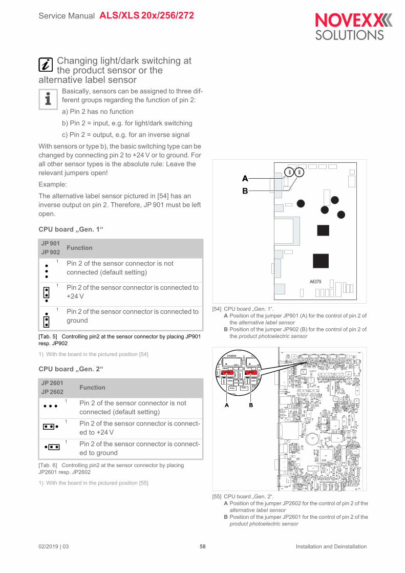
Changing light/dark switching at the product sensor or the
alternative label sensorBasically, sensors can be assigned to three dif-ferent groups regarding the function of pin 2:
a) Pin 2 has no function
b) Pin 2 = input, e.g. for light/dark switching
c) Pin 2 = output, e.g. for an inverse signal
With sensors or type b), the basic switching type can be changed by connecting pin 2 to +24 V or to ground. For all other sensor types is the absolute rule: Leave the relevant jumpers open!
Example:
The alternative label sensor pictured in [54] has an inverse output on pin 2. Therefore, JP 901 must be left open.
CPU board „Gen. 1“
1) With the board in the pictured position [54]
CPU board „Gen. 2“
1) With the board in the pictured position [55]
JP 901
JP 902Function
1 Pin 2 of the sensor connector is not connected (default setting)
1 Pin 2 of the sensor connector is connected to +24 V
1 Pin 2 of the sensor connector is connected to ground
[Tab. 5] Controlling pin2 at the sensor connector by placing JP901 resp. JP902
JP 2601
JP 2602Function
1 Pin 2 of the sensor connector is not connected (default setting)
1 Pin 2 of the sensor connector is connect-ed to +24 V
1 Pin 2 of the sensor connector is connect-ed to ground
[Tab. 6] Controlling pin2 at the sensor connector by placing JP2601 resp. JP2602
02/2019 | 03 58 Installation and Deinstallation
Service Manual ALS/XLS 20x/256/272
[56] Recommended photoelectric product sensorA Connection cable; Article no. A7127B Data sensor S51-PA-5-C10-PK; Article no. A7112
[57] Connection for photoelectric product sensor
BA
A
NPN-Configuration
NPN-Signal
PNP-Signal
PNP-Configuration
CPU
Photoelectric product sensor– Permitted sensor types: PNP or NPN
– Preset: PNP
– Article number: A7112 (Sensor) [56B] + A7127 (Cable) [56A] 2
Connecting the photoelectric sensor
Plug the product sensor in to the connector shown [57A].
For NPN Photoelectric sensor:
Set the MACHINE SETUP > Startsen. In.Type function to “NPN”.
Pin assignment
1) Changing light/dark switching at the product sensor or the alternative label sensor on page 58
Connection Diagram
[58] Connection diagram photoelectric product sensor
2. Alternatively, the sensor A7112 can be connected to the optional applicator interface using cable N100136.
Pin Assignment
1 +24 V
2+24 V or ground or no connection 1
3 Ground
4 Sensor signal
1 2
34
+24V
+24V
2,2k
1k
1k
1,5kSignal
Input
GND
Jumper(default: open)
1
4
3
2
2,2k
Sensorconnector
02/2019 | 03 59 Installation and Deinstallation
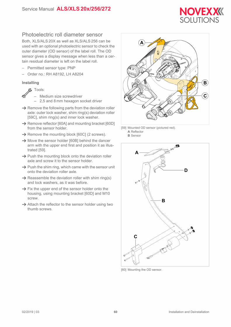
Service Manual ALS/XLS 20x/256/272
[59] Mounted OD sensor (pictured red).A ReflectorB Sensor
[60] Mounting the OD sensor.
A
B
C
A
B
C
D
Photoelectric roll diameter sensorBoth, XLS/ALS 20X as well as XLS/ALS 256 can be used with an optional photoelectric sensor to check the outer diameter (OD sensor) of the label roll. The OD sensor gives a display message when less than a cer-tain residual diameter is left on the label roll.
– Permitted sensor type: PNP
– Order no.: RH A8192, LH A8204
Installing
Tools:
– Medium size screwdriver– 2,5 and 8 mm hexagon socket driver
Remove the following parts from the deviation roller axle: outer lock washer, shim ring(s) deviation roller [59C], shim ring(s) and inner lock washer.
Remove reflector [60A] and mounting bracket [60D] from the sensor holder.
Remove the mounting block [60C] (2 screws).
Move the sensor holder [60B] behind the dancer arm with the upper end first and position it as illus-trated [59].
Push the mounting block onto the deviation roller axle and screw it to the sensor holder.
Push the shim ring, which came with the sensor unit onto the deviation roller axle.
Reassemble the deviation roller with shim ring(s) and lock washers, as it was before.
Fix the upper end of the sensor holder onto the housing, using mounting bracket [60D] and M10 screw.
Attach the reflector to the sensor holder using two thumb screws.
02/2019 | 03 60 Installation and Deinstallation
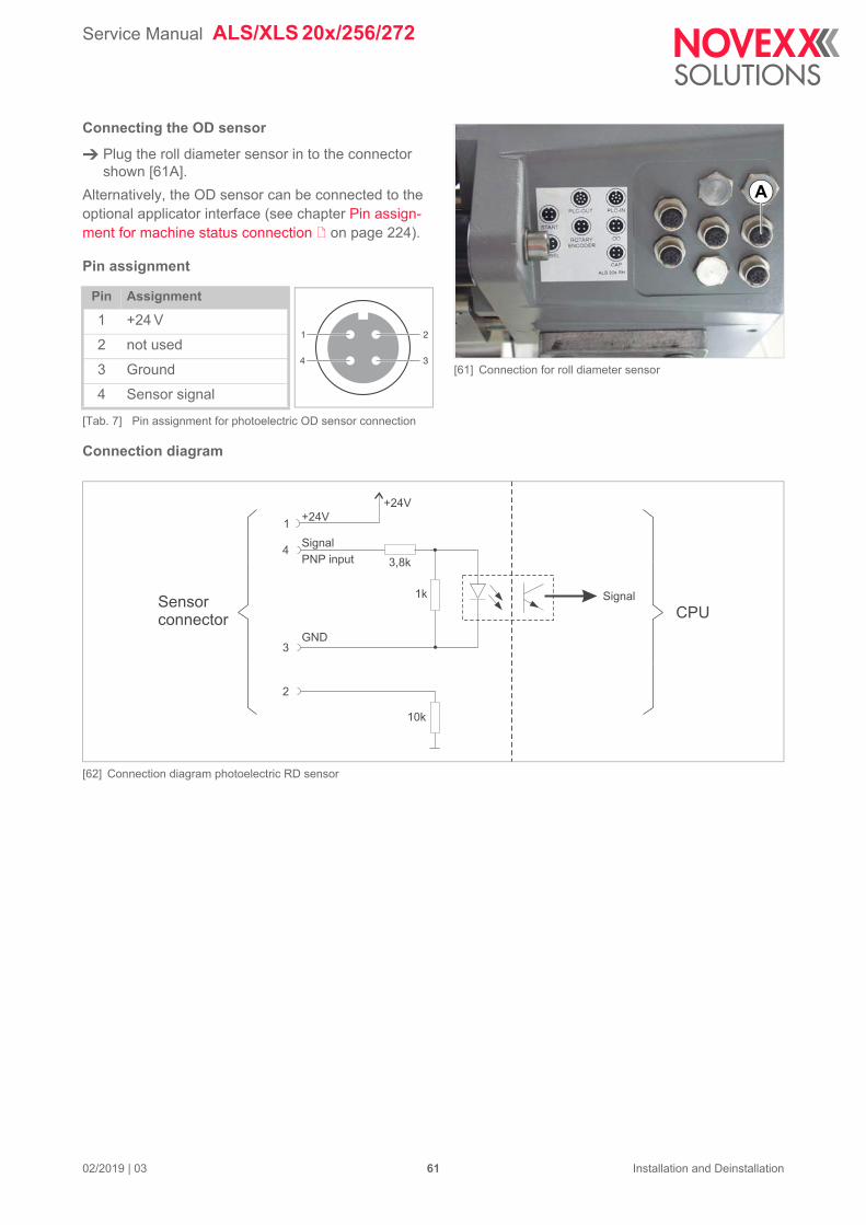
Service Manual ALS/XLS 20x/256/272
[61] Connection for roll diameter sensor
A
Signal
CPU
Connecting the OD sensor
Plug the roll diameter sensor in to the connector shown [61A].
Alternatively, the OD sensor can be connected to the optional applicator interface (see chapter Pin assign-ment for machine status connection on page 224).
Pin assignment
Connection diagram
[62] Connection diagram photoelectric RD sensor
Pin Assignment
1 +24 V
2 not used
3 Ground
4 Sensor signal
[Tab. 7] Pin assignment for photoelectric OD sensor connection
1 2
34
+24V
+24V
PNP input 3,8k
1k
Signal
GND
1
4
3
2
10k
Sensorconnector
02/2019 | 03 61 Installation and Deinstallation
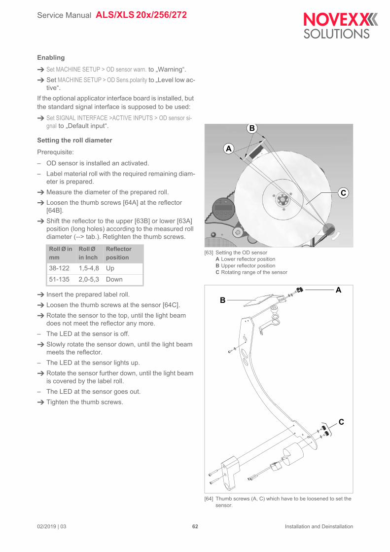
Service Manual ALS/XLS 20x/256/272
[63] Setting the OD sensorA Lower reflector positionB Upper reflector positionC Rotating range of the sensor
[64] Thumb screws (A, C) which have to be loosened to set the sensor.
A
B
C
A
C
B
Enabling
Set MACHINE SETUP > OD sensor warn. to „Warning“.
Set MACHINE SETUP > OD Sens.polarity to „Level low ac-tive“.
If the optional applicator interface board is installed, but the standard signal interface is supposed to be used:
Set SIGNAL INTERFACE >ACTIVE INPUTS > OD sensor si-gnal to „Default input“.
Setting the roll diameter
Prerequisite:
– OD sensor is installed an activated.
– Label material roll with the required remaining diam-eter is prepared.
Measure the diameter of the prepared roll.
Loosen the thumb screws [64A] at the reflector [64B].
Shift the reflector to the upper [63B] or lower [63A] position (long holes) according to the measured roll diameter (--> tab.). Retighten the thumb screws.
Insert the prepared label roll.
Loosen the thumb screws at the sensor [64C].
Rotate the sensor to the top, until the light beam does not meet the reflector any more.
– The LED at the sensor is off.
Slowly rotate the sensor down, until the light beam meets the reflector.
– The LED at the sensor lights up.
Rotate the sensor further down, until the light beam is covered by the label roll.
– The LED at the sensor goes out.
Tighten the thumb screws.
Roll Ø in
mm
Roll Ø
in Inch
Reflector
position
38-122 1,5-4,8 Up
51-135 2,0-5,3 Down
02/2019 | 03 62 Installation and Deinstallation
Service Manual ALS/XLS 20x/256/272
Function test
Prerequisite:
– Machine is in dispensing mode.
– OD sensor is activated (settings according to chap-ter Enabling on page 1).
If the light beam of the sensor [59B] meets the reflector [59A], the following message appears after the next label has been dispensed:
Additionally, the following signals will be activated:
The message disappears immediately, if the light beam stops falling on the reflector.
Note the following, when connecting to the applicator interface:
– No status message will be displayed on the opera-tion panel in case of low material (only the „OD sen-sor“ signal will be activated)
– If no sensor is connected, the output signal „OD sensor“ remains activated
ONLINEOD sensor warn.
Interface Signal name Pin
Standard signal interface Warning 8
Applicator interface (optional)
OD-Sensor16
02/2019 | 03 63 Installation and Deinstallation
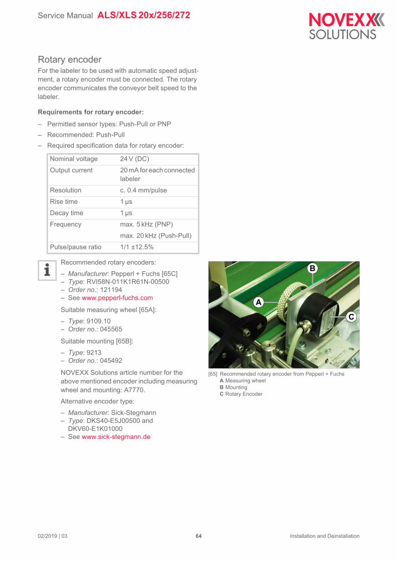
Service Manual ALS/XLS 20x/256/272
[65] Recommended rotary encoder from Pepperl + FuchsA Measuring wheelB MountingC Rotary Encoder
A
C
B
Rotary encoderFor the labeler to be used with automatic speed adjust-ment, a rotary encoder must be connected. The rotary encoder communicates the conveyor belt speed to the labeler.
Requirements for rotary encoder:
– Permitted sensor types: Push-Pull or PNP
– Recommended: Push-Pull
– Required specification data for rotary encoder:
Recommended rotary encoders:
– Manufacturer: Pepperl + Fuchs [65C]– Type: RVI58N-011K1R61N-00500– Order no.: 121194– See www.pepperl-fuchs.com
Suitable measuring wheel [65A]:
– Type: 9109.10– Order no.: 045565
Suitable mounting [65B]:
– Type: 9213– Order no.: 045492
NOVEXX Solutions article number for the above mentioned encoder including measuring wheel and mounting: A7770.
Alternative encoder type:
– Manufacturer: Sick-Stegmann– Type: DKS40-E5J00500 and
DKV60-E1K01000– See www.sick-stegmann.de
Nominal voltage 24 V (DC)
Output current 20 mA for each connected labeler
Resolution c. 0.4 mm/pulse
Rise time 1 µs
Decay time 1 µs
Frequency max. 5 kHz (PNP)
max. 20 kHz (Push-Pull)
Pulse/pause ratio 1/1 ±12.5%
02/2019 | 03 64 Installation and Deinstallation
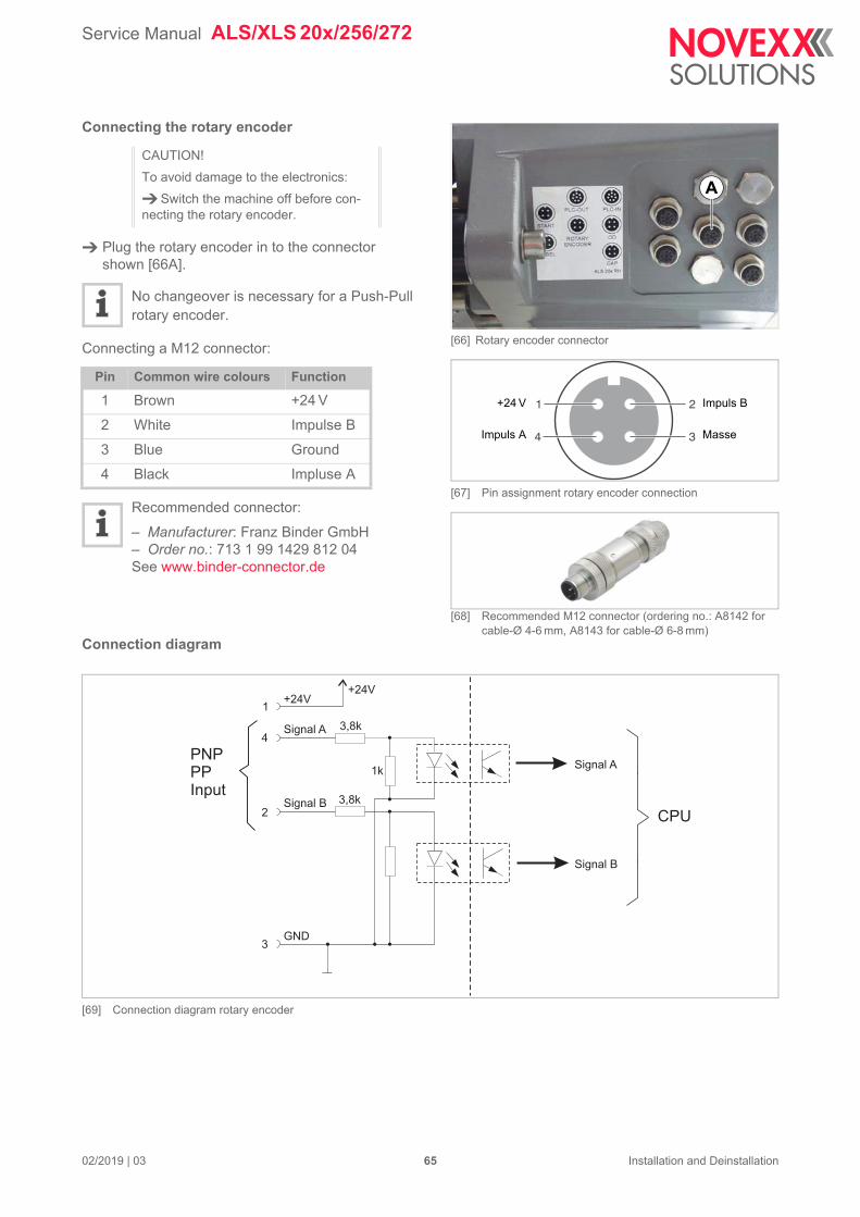
Service Manual ALS/XLS 20x/256/272
[66] Rotary encoder connector
[67] Pin assignment rotary encoder connection
[68] Recommended M12 connector (ordering no.: A8142 for cable-Ø 4-6 mm, A8143 for cable-Ø 6-8 mm)
A
Impuls B
MasseImpuls A
+24 V 1 2
34
Signal A
Signal B
CPU
Connecting the rotary encoder
Plug the rotary encoder in to the connector shown [66A].
No changeover is necessary for a Push-Pull rotary encoder.
Connecting a M12 connector:
Recommended connector:
– Manufacturer: Franz Binder GmbH– Order no.: 713 1 99 1429 812 04See www.binder-connector.de
Connection diagram
[69] Connection diagram rotary encoder
CAUTION!
To avoid damage to the electronics:
Switch the machine off before con-necting the rotary encoder.
Pin Common wire colours Function
1 Brown +24 V
2 White Impulse B
3 Blue Ground
4 Black Impluse A
+24V+24V
3,8k
3,8k
1k
Signal A
Signal B
GND
1
4
2
3
PNPPPInput
02/2019 | 03 65 Installation and Deinstallation
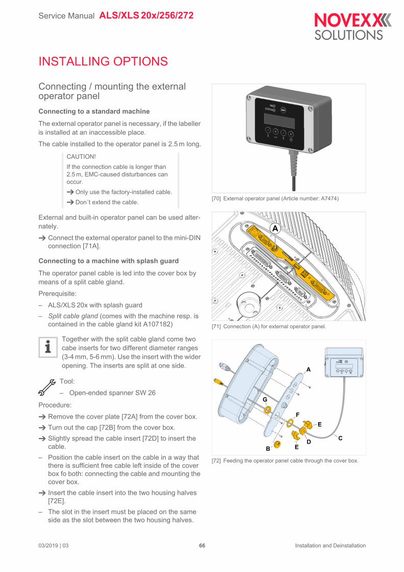
Service Manual ALS/XLS 20x/256/272
03/2019 | 03 66 Installation and Deinstallation
INSTALLING OPTIONS
Connecting / mounting the external operator panel
Connecting to a standard machine
The external operator panel is necessary, if the labeller is installed at an inaccessible place.
The cable installed to the operator panel is 2.5 m long.
External and built-in operator panel can be used alter-nately.
Connect the external operator panel to the mini-DIN connection [71A].
Connecting to a machine with splash guard
The operator panel cable is led into the cover box by means of a split cable gland.
Prerequisite:
– ALS/XLS 20x with splash guard
– Split cable gland (comes with the machine resp. is contained in the cable gland kit A107182)
Together with the split cable gland come two cabe inserts for two different diameter ranges (3-4 mm, 5-6 mm). Use the insert with the wider opening. The inserts are split at one side.
Tool:
– Open-ended spanner SW 26
Procedure:
Remove the cover plate [72A] from the cover box.
Turn out the cap [72B] from the cover box.
Slightly spread the cable insert [72D] to insert the cable.
– Position the cable insert on the cable in a way that there is sufficient free cable left inside of the cover box fo both: connecting the cable and mounting the cover box.
Insert the cable insert into the two housing halves [72E].
– The slot in the insert must be placed on the same side as the slot between the two housing halves.
CAUTION!
If the connection cable is longer than 2.5 m, EMC-caused disturbances can occur.
Only use the factory-installed cable.
Don´t extend the cable.[70] External operator panel (Article number: A7474)
[71] Connection (A) for external operator panel.
[72] Feeding the operator panel cable through the cover box.
A
A
B
CD
E
E
F
G
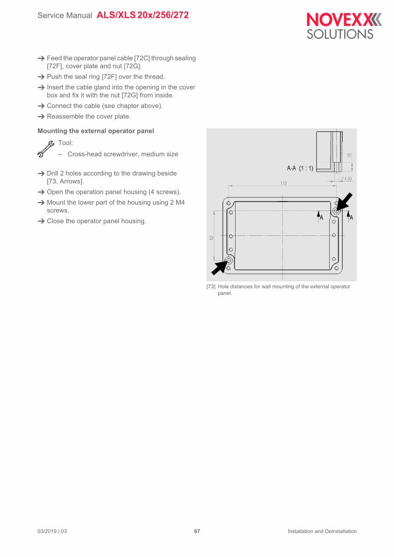
Service Manual ALS/XLS 20x/256/272
03/2019 | 03 67 Installation and Deinstallation
Feed the operator panel cable [72C] through sealing [72F], cover plate and nut [72G].
Push the seal ring [72F] over the thread.
Insert the cable gland into the opening in the cover box and fix it with the nut [72G] from inside.
Connect the cable (see chapter above).
Reassemble the cover plate.
Mounting the external operator panel
Tool:
– Cross-head screwdriver, medium size
Drill 2 holes according to the drawing beside [73, Arrows].
Open the operation panel housing (4 screws).
Mount the lower part of the housing using 2 M4 screws.
Close the operator panel housing.
[73] Hole distances for wall mounting of the external operator panel.
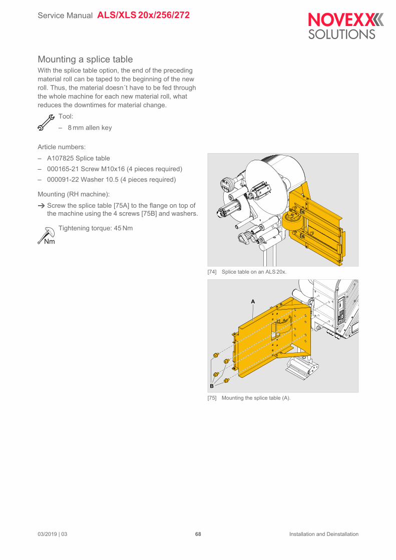
Service Manual ALS/XLS 20x/256/272
03/2019 | 03 68 Installation and Deinstallation
Mounting a splice tableWith the splice table option, the end of the preceding material roll can be taped to the beginning of the new roll. Thus, the material doesn´t have to be fed through the whole machine for each new material roll, what reduces the downtimes for material change.
Tool:
– 8 mm allen key
Article numbers:
– A107825 Splice table
– 000165-21 Screw M10x16 (4 pieces required)
– 000091-22 Washer 10.5 (4 pieces required)
Mounting (RH machine):
Screw the splice table [75A] to the flange on top of the machine using the 4 screws [75B] and washers.
Tightening torque: 45 Nm
[74] Splice table on an ALS 20x.
[75] Mounting the splice table (A).
A
B
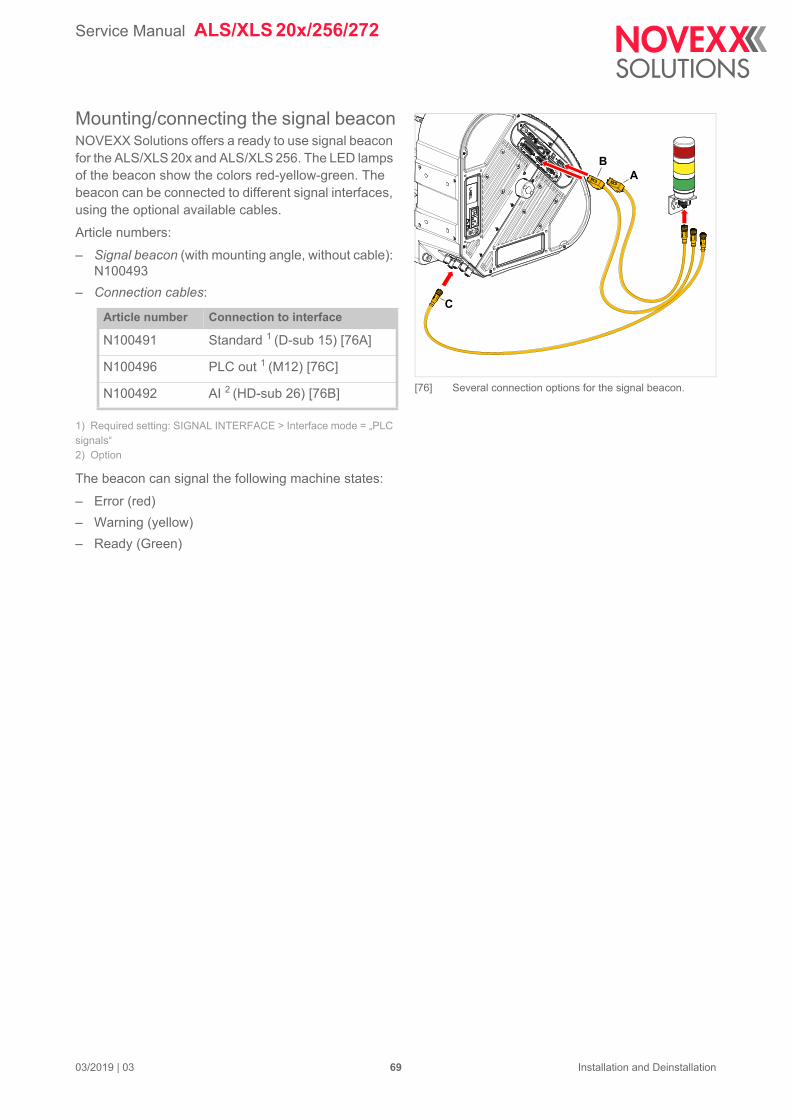
Service Manual ALS/XLS 20x/256/272
03/2019 | 03 69 Installation and Deinstallation
Mounting/connecting the signal beaconNOVEXX Solutions offers a ready to use signal beacon for the ALS/XLS 20x and ALS/XLS 256. The LED lamps of the beacon show the colors red-yellow-green. The beacon can be connected to different signal interfaces, using the optional available cables.
Article numbers:
– Signal beacon (with mounting angle, without cable): N100493
– Connection cables:
1) Required setting: SIGNAL INTERFACE > Interface mode = „PLC signals“2) Option
The beacon can signal the following machine states:
– Error (red)
– Warning (yellow)
– Ready (Green)
Article number Connection to interface
N100491 Standard 1 (D-sub 15) [76A]
N100496 PLC out 1 (M12) [76C]
N100492 AI 2 (HD-sub 26) [76B] [76] Several connection options for the signal beacon.
AB
C
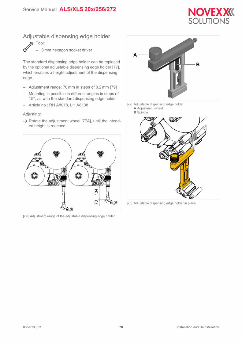
Service Manual ALS/XLS 20x/256/272
03/2019 | 03 70 Installation and Deinstallation
Adjustable dispensing edge holderTool:
– 8 mm hexagon socket driver
The standard dispensing edge holder can be replaced by the optional adjustable dispensing edge holder [77], which enables a height adjustment of the dispensing edge.
– Adjustment range: 70 mm in steps of 0.2 mm [79]
– Mounting is possible in different angles in steps of 15°, as with the standard dispensing edge holder
– Article no.: RH A8018, LH A8138
Adjusting:
Rotate the adjustment wheel [77A], until the intend-ed height is reached.
[79] Adjustment range of the adjustable dispensing edge holder.
[77] Adjustable dispensing edge holder.A Adjustment wheelB Spindle
[78] Adjustable dispensing edge holder in place.
A
B
70
134
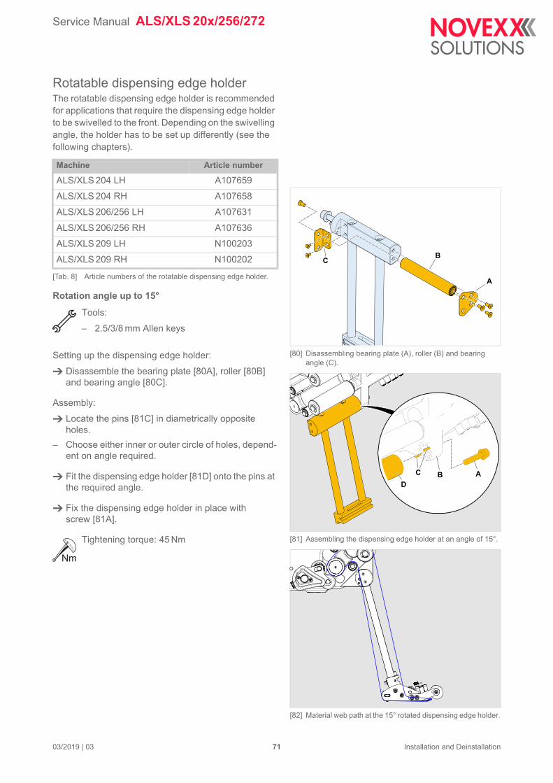
Service Manual ALS/XLS 20x/256/272
03/2019 | 03 71 Installation and Deinstallation
Rotatable dispensing edge holderThe rotatable dispensing edge holder is recommended for applications that require the dispensing edge holder to be swivelled to the front. Depending on the swivelling angle, the holder has to be set up differently (see the following chapters).
Rotation angle up to 15°
Tools:
– 2.5/3/8 mm Allen keys
Setting up the dispensing edge holder:
Disassemble the bearing plate [80A], roller [80B] and bearing angle [80C].
Assembly:
Locate the pins [81C] in diametrically opposite holes.
– Choose either inner or outer circle of holes, depend-ent on angle required.
Fit the dispensing edge holder [81D] onto the pins at the required angle.
Fix the dispensing edge holder in place with screw [81A].
Tightening torque: 45 Nm
Machine Article number
ALS/XLS 204 LH A107659
ALS/XLS 204 RH A107658
ALS/XLS 206/256 LH A107631
ALS/XLS 206/256 RH A107636
ALS/XLS 209 LH N100203
ALS/XLS 209 RH N100202
[Tab. 8] Article numbers of the rotatable dispensing edge holder.
[80] Disassembling bearing plate (A), roller (B) and bearing angle (C).
[81] Assembling the dispensing edge holder at an angle of 15°.
[82] Material web path at the 15° rotated dispensing edge holder.
A
BC
ABCD
Service Manual ALS/XLS 20x/256/272
03/2019 | 03 72 Installation and Deinstallation
Rotation angle from 15° to 30°
Tools:
– 2.5/3/8 mm Allen keys
Setting up the dispensing edge holder:
Install the roller [83A] in the lower position [83B].
Assembly:
Locate the pins [84C] in diametrically opposite holes.
– Choose either inner or outer circle of holes, depend-ent on angle required.
Fit the dispensing edge holder [84D] onto the pins at the required angle.
Fix the dispensing edge holder in place with screw [84A].
Tightening torque: 45 Nm
[83] Install the roller (A) in the lower position (B).
[84] Assembling the dispensing edge holder at an angle of 30°.
[85] Material web path at the 30° rotated dispensing edge holder.
A
B
ABC
D
Service Manual ALS/XLS 20x/256/272
03/2019 | 03 73 Installation and Deinstallation
Rotation angle from 30° to 90°
Tools:
– 2.5/3/8 mm Allen key
Setting up the dispensing edge holder:
Install the roller [86A] in the upper position.
Assembly:
Locate the pins [87C] in diametrically opposite holes.
– Choose either inner or outer circle of holes, depend-ent on angle required.
Fit the dispensing edge holder [87D] onto the pins at the required angle.
Fix the dispensing edge holder in place with screw [87A].
Tightening torque: 45 Nm
[86] Install the roller (A) in the upper position (B).
[87] Assembling the dispensing edge holder at an angle of 90°.
[88] Material web path at the 90° rotated dispensing edge holder.
A B
ABC
D
Service Manual ALS/XLS 20x/256/272
03/2019 | 03 74 Installation and Deinstallation
Narrow label spring kit (ALS/XLS 20x and ALS/XLS 256)Narrow label material may under certain circumstances tear off or expand in a way which results in poor label-ling precision. In those cases, it is adviseable to install weaker dancer arm springs. Those springs are availa-ble as „Narrow label spring kit“ (article number A8612).
If the following creteria apply to the label material, the „Narrow label spring kit“ should be installed:
– Less than 50 mm label width
– Weak or expandable/stretchable backing paper
1) Only available as kit.
[89] Installation positions of the springsA Rewinder pressure springB Unwinder tension springC Unwinder pressure spring
Spring StandardNarrow label
spring kit
Tension spring (unw.) A7889 A7358
Pressure spring (unw.) A8118 1 A8610
Pressure spring (rew.) A7795 1 A107469
Spring kit – A8612
[Tab. 9] Article numbers of dancer arm springs.
A

Service Manual ALS/XLS 20x/256/272
03/2019 | 03 75 Installation and Deinstallation
Exchanging the unwinder springs: See service manual, chapter Replacing dancer arm springs on page 272.
Exchanging the rewinder spring: See service manual, chapter Removing the dancer arm on page 294.
Service Manual ALS/XLS 20x/256/272
02/2019 | 00 76 Installation and Deinstallation
DECOMMISSIONING, DISMANTLING, DISPOSAL
Take the machine out of operationDisconnecting the machine from the compressed air supply (only machines with installed applica-tor):
Switch off the compressed air supply of the applicator.
Disconnect the compressed air hose from the applicator.
– For details read the applicator installation manual.
Disconnect the machine from the power supply:
Switch the machine off at the mains switch (switch position „0“ or „switch illumination off“ for ma-chines with splash guard).
Pull out the mains plug from the mains socket or disconnect the power cord from the electrical cabinet.
Disconnect all cables at the machine.
Dismantling the machineMachine with installed applicator:
Remove the applicator.
– For details read the applicator installation manual.
Let the machine be held by at least 2 persons, while a 3rd person loosens the clamping at the support stand.
– While doing so, hold the machine at its housing.
Strip the machine from the support stand tube and lay it down.
WARNING!
Danger of injury by the machine falling to ground.
Let the machine be hold by at least 2 persons, while a 3rd person loosens the clamping at the support stand.
Wear safety footwear.
Acute risk of injury and long-term bodily injury from working with heavy loads!
Lift or carry the machine with a minimum of 2 persons. If possible, use a crane or other lifting device.
CAUTION!
To avoid damaging the machine during transport:
Never hold the machine by the deflection rollers, dancer arm or rewind or unwind unit.

Service Manual ALS/XLS 20x/256/272
02/2019 | 00 77 Installation and Deinstallation
Machine disposalIt is advisable to remove reusable machine components as long as the machine is firmly mounted.
Remove machine parts which can be reused (e. g. applicator, applicator interface, dispensing edge holder, dispensing edge).
Dispose of the remaining machine parts separated by material groups in an environmentally ac-ceptable manner. Observe the national regulations.
– Dispose of waste properly, i.e. sorted according to the material groups of the parts to be dis-posed of. The aim should always be to achieve a maximum possible reutilisation of the basic materials combined with the minimum possible environmental impact.
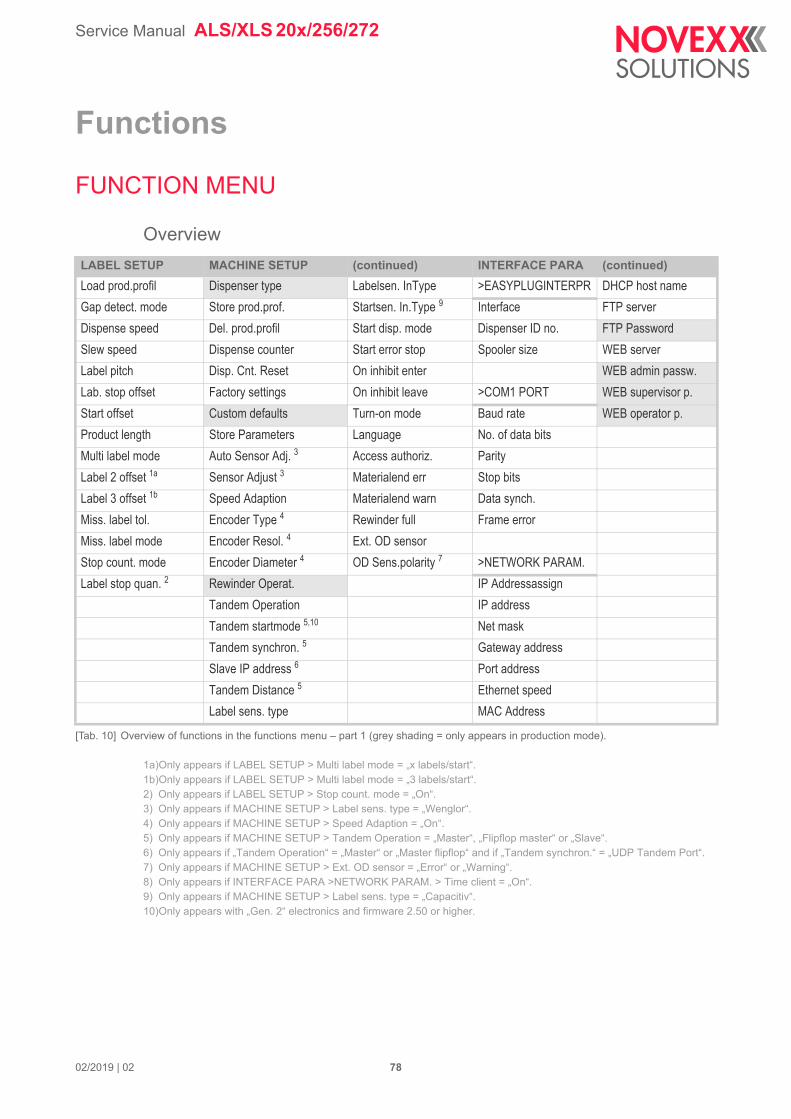
Service Manual ALS/XLS 20x/256/272
Functions
FUNCTION MENU
Overview
1a)Only appears if LABEL SETUP > Multi label mode = „x labels/start“.1b)Only appears if LABEL SETUP > Multi label mode = „3 labels/start“.2) Only appears if LABEL SETUP > Stop count. mode = „On“.3) Only appears if MACHINE SETUP > Label sens. type = „Wenglor“.4) Only appears if MACHINE SETUP > Speed Adaption = „On“.5) Only appears if MACHINE SETUP > Tandem Operation = „Master“, „Flipflop master“ or „Slave“.6) Only appears if „Tandem Operation“ = „Master“ or „Master flipflop“ and if „Tandem synchron.“ = „UDP Tandem Port“.7) Only appears if MACHINE SETUP > Ext. OD sensor = „Error“ or „Warning“.8) Only appears if INTERFACE PARA >NETWORK PARAM. > Time client = „On“.9) Only appears if MACHINE SETUP > Label sens. type = „Capacitiv“.10)Only appears with „Gen. 2“ electronics and firmware 2.50 or higher.
LABEL SETUP MACHINE SETUP (continued) INTERFACE PARA (continued)
Load prod.profil Dispenser type Labelsen. InType >EASYPLUGINTERPR DHCP host name
Gap detect. mode Store prod.prof. Startsen. In.Type 9 Interface FTP server
Dispense speed Del. prod.profil Start disp. mode Dispenser ID no. FTP Password
Slew speed Dispense counter Start error stop Spooler size WEB server
Label pitch Disp. Cnt. Reset On inhibit enter WEB admin passw.
Lab. stop offset Factory settings On inhibit leave >COM1 PORT WEB supervisor p.
Start offset Custom defaults Turn-on mode Baud rate WEB operator p.
Product length Store Parameters Language No. of data bits
Multi label mode Auto Sensor Adj. 3 Access authoriz. Parity
Label 2 offset 1a Sensor Adjust 3 Materialend err Stop bits
Label 3 offset 1b Speed Adaption Materialend warn Data synch.
Miss. label tol. Encoder Type 4 Rewinder full Frame error
Miss. label mode Encoder Resol. 4 Ext. OD sensor
Stop count. mode Encoder Diameter 4 OD Sens.polarity 7 >NETWORK PARAM.
Label stop quan. 2 Rewinder Operat. IP Addressassign
Tandem Operation IP address
Tandem startmode 5,10 Net mask
Tandem synchron. 5 Gateway address
Slave IP address 6 Port address
Tandem Distance 5 Ethernet speed
Label sens. type MAC Address
[Tab. 10] Overview of functions in the functions menu – part 1 (grey shading = only appears in production mode).
02/2019 | 02 78
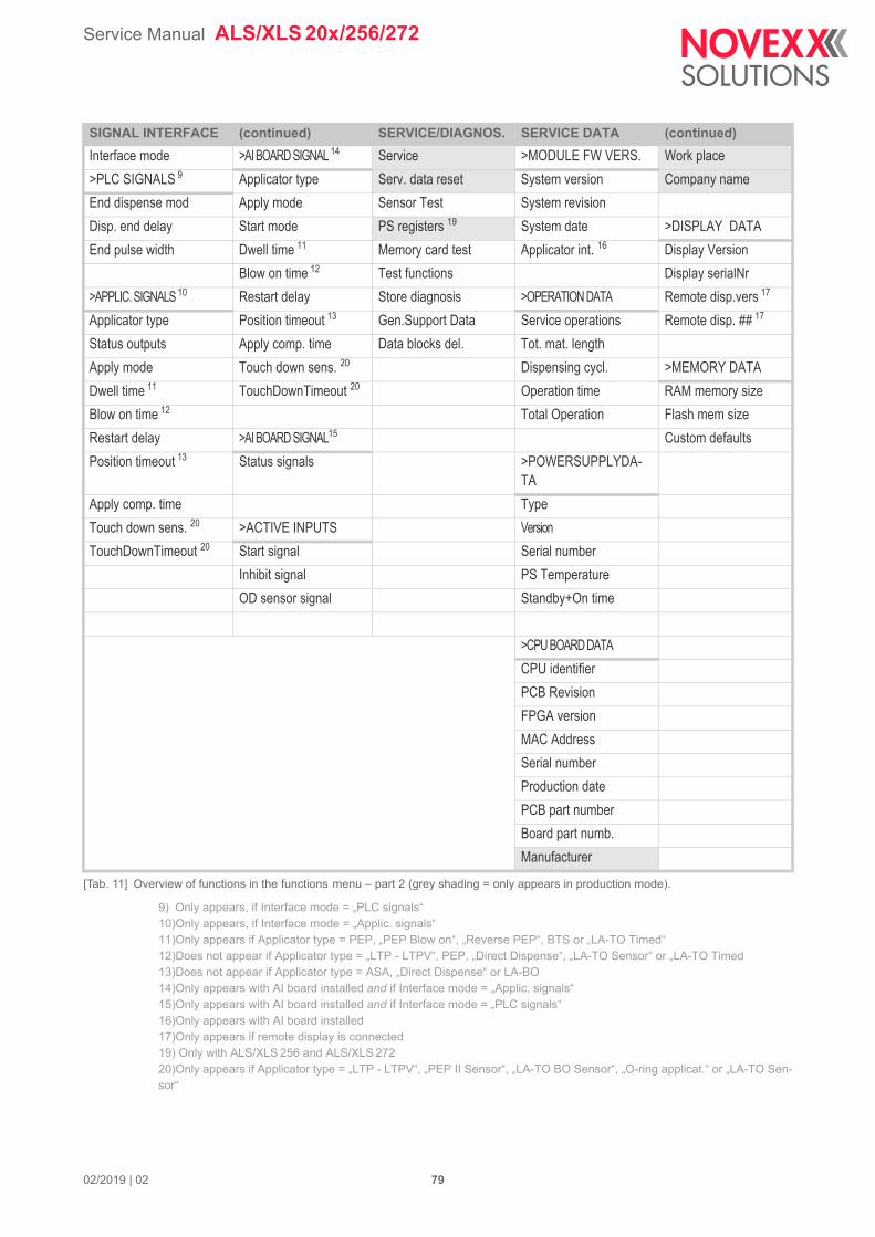
Service Manual ALS/XLS 20x/256/272
9) Only appears, if Interface mode = „PLC signals“10)Only appears, if Interface mode = „Applic. signals“11)Only appears if Applicator type = PEP, „PEP Blow on“, „Reverse PEP“, BTS or „LA-TO Timed“12)Does not appear if Applicator type = „LTP - LTPV“, PEP, „Direct Dispense“, „LA-TO Sensor“ or „LA-TO Timed13)Does not appear if Applicator type = ASA, „Direct Dispense“ or LA-BO14)Only appears with AI board installed and if Interface mode = „Applic. signals“15)Only appears with AI board installed and if Interface mode = „PLC signals“16)Only appears with AI board installed17)Only appears if remote display is connected19) Only with ALS/XLS 256 and ALS/XLS 27220)Only appears if Applicator type = „LTP - LTPV“, „PEP II Sensor“, „LA-TO BO Sensor“, „O-ring applicat.“ or „LA-TO Sen-sor“
SIGNAL INTERFACE (continued) SERVICE/DIAGNOS. SERVICE DATA (continued)
Interface mode >AI BOARD SIGNAL 14 Service >MODULE FW VERS. Work place
>PLC SIGNALS 9 Applicator type Serv. data reset System version Company name
End dispense mod Apply mode Sensor Test System revision
Disp. end delay Start mode PS registers 19 System date >DISPLAY DATA
End pulse width Dwell time 11 Memory card test Applicator int. 16 Display Version
Blow on time 12 Test functions Display serialNr
>APPLIC. SIGNALS 10 Restart delay Store diagnosis >OPERATION DATA Remote disp.vers 17
Applicator type Position timeout 13 Gen.Support Data Service operations Remote disp. ## 17
Status outputs Apply comp. time Data blocks del. Tot. mat. length
Apply mode Touch down sens. 20 Dispensing cycl. >MEMORY DATA
Dwell time 11 TouchDownTimeout 20 Operation time RAM memory size
Blow on time 12 Total Operation Flash mem size
Restart delay >AI BOARD SIGNAL15 Custom defaults
Position timeout 13 Status signals >POWERSUPPLYDA-TA
Apply comp. time Type
Touch down sens. 20 >ACTIVE INPUTS Version
TouchDownTimeout 20 Start signal Serial number
Inhibit signal PS Temperature
OD sensor signal Standby+On time
>CPU BOARD DATA
CPU identifier
PCB Revision
FPGA version
MAC Address
Serial number
Production date
PCB part number
Board part numb.
Manufacturer
[Tab. 11] Overview of functions in the functions menu – part 2 (grey shading = only appears in production mode).
02/2019 | 02 79
Service Manual ALS/XLS 20x/256/272
Notes on the description of functionsThe adjustment range or individual settings available for a function are shown in square brackets.
– For functions with individual values for settings, the default value is printed in italics.
– Quotation marks are set around values for settings that consist of more than one word.
LABEL SETUP menu
Load prod.profil function
– For loading product profiles from the internal database.
– Product profiles contain product-specific settings.
– A maximum of 16 product profiles can be selected.
– The number of a product profile can only be selected when there is already a profile saved under this number.
Gap detect. mode function
– After one of the following events, the printer must always search for the punch, that is initialize the label material: after switching the device on; after changing the label material.
– Settings: [Manual, „Autom. forward“]
Manual: The operator has to initialize the material always manually by pressing the feed button several times.
Autom. forward: The material initialization is always done automatically, if necessary.
Dispense speed function
– Speed at which the label is dispensed
– Adjustment range:
ALS/XLS 204: [1.0…40.0] m/min; default: 10.0
ALS/XLS 206: [1.0…30.0] m/min; default: 10.0
ALS/XLS 209: [1.0…25.0] m/min; default: 10.0
ALS/XLS 256: [1.0…50.0] m/min; default: 10.0
ALS/XLS 272: [1.0…70.0] m/min; default: 10.0
Slew speed function
– Feed speed which is driven over missing-label-gaps and during measuring of the label length.
– Adjustment range:
ALS/XLS 204: [1.0…40.0] m/min; default: 1.0
ALS/XLS 206: [1.0…30.0] m/min; default: 1.0
ALS/XLS 209: [1.0…25.0] m/min; default: 1.0
ALS/XLS 256: [1.0…50.0] m/min; default: 1.0
ALS/XLS 272: [1.0…70.0] m/min; default: 1.0
Label pitch function
– Label pitch = label length + gap
– Adjustment range: [5.0…600.0] mm; default: 100.0 mm
02/2019 | 02 80
Service Manual ALS/XLS 20x/256/272
Lab. stop offset function
– Stopping position of the label at the dispensing plate
– Adjustment range: [0.0…999.9] mm; default: 20.0
Start offset function
The function has a different effect on slave machines in tandem operation.
Standard operation or master machine:
– Distance between photoelectric product sensor and apex of dispensing plate. The setting influ-ences the label position on the product.
– Adjustment range: [15.0…2999.9] mm; default: 15.0
Slave machine:
– Fine adjustment of the label position on the product.
– Adjustment range: [-30.0…+30.0] mm; default: 0.0
Product length function
– Start signals coming in during the set product length are suppressed.
– Adjustment range: [0.0…1999.9] mm; default: 0.0 mm
The Product length function is e. g. helpful for products with uneven surface, which would trigger several start signals.
Multi label mode function
– Settings: [Off, „x labels/start“]
Off: Each start signal causes printing of one label.
„x labels/start“: Each start signal causes printing of x labels; x = [2…20]
x > 3: The distance of all following labels after the 2nd label matches the value set in LABEL SE-TUP > Label 2 offset.
The „Multi label mode“ function works only if a standard signal input (M12 or D-Sub 15) is used - it doesn´t work, if an Applicator Interface is applied as signal input.
Label 2 offset function
– Only appears if LABEL SETUP > Multi label mode = „x labels/start“.
– Defines the distance of the 2nd label and of all following labels, if x > 3 (see LABEL SETUP > Multi label mode function). The distance is measured from the front label edge of the preceding label.
– Setting range: [x…9999.9] mm; Default: x, with x = LABEL SETUP > Label pitch.
Label 3 offset function
– Only appears if LABEL SETUP > Multi label mode = „3 labels/start“.
– Defines the distance of the 3rd label for the LABEL SETUP > Multi label mode function (see above). The distance is measured from the front label edge of the preceding label.
– Setting range: [x…9999.9] mm; Default: x, with x = LABEL SETUP > Label pitch.
Miss. label tol. function
– Tolerance for missing labels
– Maximum permitted number of labels missing consecutively from the label ribbon
– Adjustment range: [0…10]; default: 1
02/2019 | 02 81
Service Manual ALS/XLS 20x/256/272
Miss. label mode function
– Determines the treatment of missing labels
– Settings: [Compensate, Simulate]
Compensate: Quick feeding with slew speed (see LABEL SETUP > Slew speed) until the next label arrives at the label sensor. A missing label will be passed with slew speed and the next label will be applied onto the product with a corresponding offset. The offset depends on the speed set-tings.
Simulate: Feeding in dispensing speed. Missing labels are simulated. A missing label will be simulated by a „virtual label“, there will be no physical label applied onto the product.
Application example: Operation of a printer, which is mounted to the holding rods of the L-schape dispensing edge some label length above the dispensing edge. In „Compensate“ mode, one or more labels would pass the printer unprinted.
With both settings, the machine switches into error state, if the max. admissible number of miss-ing labels (LABEL SETUP > Miss. label tol.) is exceeded (machine stops; error message; error signal active).
Stop count. mode function
– Settings: [On, Off]
On: The dispense counter counts down from the value set in LABEL SETUP > Label stop quan. When the counter reaches 0, no further labels are dispensed.
Off: The labeler counts up, i.e. each label dispensed increases the counter reading.
Label stop quan. function
– After this amount of dispensed labels, the dispenser stops
– Function only appears, if LABEL SETUP > Stop count. mode = „On“
– Setting range: [0…99999]; default: 0
MACHINE SETUP menu
Dispenser type function
– Sets the firmware to fit the machine type. The setting must match the machine type!
– (ALS 2xx, ALS 30x) Settings: [„ALS 204 RH“, „ALS 204 LH“, „ALS 206 RH“, „ALS 206 LH“, „ALS 209 RH“, „ALS 209 LH“, „ALS 272 RH“, „ALS 272 LH“, „ALS 309 RH“, „ALS 309 LH“, „ALS 306 RH“, „ALS 306 LH“, „ALS 256 RH“, „ALS 256 LH“, „ALX 734 RH“, „ALX 734 LH“, „ALX 735 RH“, „ALX 735 LH“, „ALX 736 RH“, „ALX 736 LH“].
– (XLS 2xx) Settings: [„XLS 204 RH“, „XLS 204 LH“, „XLS 206 RH“, „XLS 206 LH“, „XLS 209 RH“, „XLS 209 LH“, „XLS 272 RH“, „XLS 272 LH“, „XLS 256 RH“, „XLS 256 LH“].
Store prod.prof. function
– Saves the current settings as a product profile
The extent of the stored functions is the same as described in MACHINE SETUP > Store Parameters = „Without adj. par“ (file „setup.for“), except for the following functions: MACHINE SETUP > Dispense counter and LABEL SETUP > Label stop quan..
Del. prod.profil function
– Deletes a product profile from the internal database
02/2019 | 02 82
Service Manual ALS/XLS 20x/256/272
Dispense counter function
– Enables dispense counter (displayed during labelling) to be adjusted by pressing the and buttons.
Disp. Cnt. Reset function
– Settings: [No, Yes]
Yes: Dispense counter is set to zero.
No: Dispense counter is not set to zero.
Factory settings function
– All functions are factory set to values depending on the relevant machine type. This factory set-ting can be reinstalled at any time.
– All function settings are overwritten by the factory setting.
– Settings: [No, „Custom defaults“, „Factory defaults“]
No: No factory setting
„Custom defaults“: If customer specific function settings have been stored previously (see func-tion Custom defaults) those are reinstalled. „Custom defaults“ is only visible, if customer settings have already been stored.
„Factory defaults“: The function settings are reset to the factory setting.
Custom defaults function
– Settings: [„Apply current“, „Delete“]
„Apply current“: Stores the current function settings as default values. The stored settings are reinstalled by calling MACHINE SETUP > Factory settings = „Custom defaults“.
„Delete“: Deletes the stored, customer specific settings. „Delete“ is only visible, if settings have already been stored.
Store Parameters function
– Saves the settings of the functions to a file on the CompactFlash card (“FORMATS\” directory)
– Settings: [“With adjust para“, „Without adj. par”]
“With adjust para” Parameters that contain device-specific settings are included in what is saved. The names of the relevant parameters are marked with a * in the text file.
Default file name:
„SETUPALL ALS xxx yy zzzzzzzzzzzzzzzz.FOR“. Application: Service
“Without adj. par”: Parameters that contain device-specific settings are excluded from what is saved.
Default file name:
„SETUP ALS xxx yy zzzzzzzzzzzzzzzz.FOR“. Application: Transferring settings to other devices (when device-specific settings should not be overwritten).
xxx = Machine type, e. g. 306
yy = RH or LH
zzzzzzzzzzzzzzzz = Serial number of the CPU board
02/2019 | 02 83
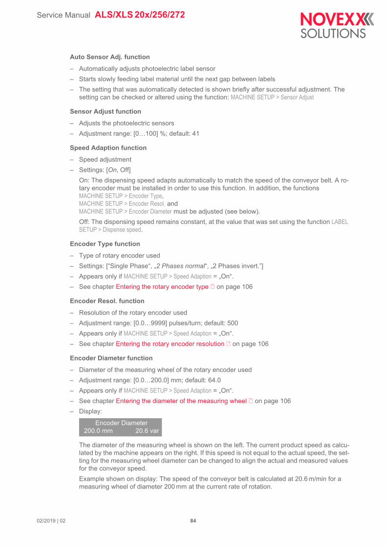
Service Manual ALS/XLS 20x/256/272
Auto Sensor Adj. function
– Automatically adjusts photoelectric label sensor
– Starts slowly feeding label material until the next gap between labels
– The setting that was automatically detected is shown briefly after successful adjustment. The setting can be checked or altered using the function: MACHINE SETUP > Sensor Adjust
Sensor Adjust function
– Adjusts the photoelectric sensors
– Adjustment range: [0…100] %; default: 41
Speed Adaption function
– Speed adjustment
– Settings: [On, Off]
On: The dispensing speed adapts automatically to match the speed of the conveyor belt. A ro-tary encoder must be installed in order to use this function. In addition, the functionsMACHINE SETUP > Encoder Type,MACHINE SETUP > Encoder Resol. andMACHINE SETUP > Encoder Diameter must be adjusted (see below).
Off: The dispensing speed remains constant, at the value that was set using the function LABEL SETUP > Dispense speed.
Encoder Type function
– Type of rotary encoder used
– Settings: [“Single Phase“, „2 Phases normal“, „2 Phases invert.”]
– Appears only if MACHINE SETUP > Speed Adaption = „On“.
– See chapter Entering the rotary encoder type on page 106
Encoder Resol. function
– Resolution of the rotary encoder used
– Adjustment range: [0.0…9999] pulses/turn; default: 500
– Appears only if MACHINE SETUP > Speed Adaption = „On“.
– See chapter Entering the rotary encoder resolution on page 106
Encoder Diameter function
– Diameter of the measuring wheel of the rotary encoder used
– Adjustment range: [0.0…200.0] mm; default: 64.0
– Appears only if MACHINE SETUP > Speed Adaption = „On“.
– See chapter Entering the diameter of the measuring wheel on page 106
– Display:
The diameter of the measuring wheel is shown on the left. The current product speed as calcu-lated by the machine appears on the right. If this speed is not equal to the actual speed, the set-ting for the measuring wheel diameter can be changed to align the actual and measured values for the conveyor speed.
Example shown on display: The speed of the conveyor belt is calculated at 20.6 m/min for a measuring wheel of diameter 200 mm at the current rate of rotation.
Encoder Diameter200.0 mm 20.6 var
02/2019 | 02 84
Service Manual ALS/XLS 20x/256/272
Rewinder Operat. function
– Settings: [On, Off]
On: Normal operation - the internal backing paper rewinder is enabled.
Off: The internal backing paper rewinder is disabled. Application example: Application of an ex-ternal rewinder.
Tandem Operation function
– Settings: [Off, Master, Slave, „FlipFlop master“]
Off: Tandem Operation is disabled.
Master: The first machine products on the conveyor belt reach. In classic master-slave mode, the slave machine replaces the master only for the short time, until an error at the master ma-chine is eliminated.
Slave: The second machine products on the conveyor belt reach
„FlipFlop master“: The first machine products on the conveyor belt reach. In Flipflop mode, the slave machine stays active until it is stopped by an error.
Tandem startmode function
– Application of a separate start sensor for master and slave increases the dispense accuracy.
– Settings: [„1 Start sensor“, „2 Start sensors“]
„1 Start sensor“: One common start sensor is used for master and slave (connected via y-cable).
„2 Start sensors“: Master and slave machine both have a separate start sensor. The start offset has to be set at each machine separately (LABEL SETUP > Start offset).
Tandem synchron. function
– To choose the interface via which tandem operation is synchronised
– Settings: [None, „Serial Com1“, „UDP Tandem Port“]
None, „Serial Com1“, „UDP Tandem Port: No tandem operation (together with Tandem Operation = „Off“).
„Serial Com1“: Tandem synchronisation over Com1 (INTERFACE PARA >EASYPLUGINTERPR > Inter-face function must not be set to „Serial Com1“ or to „Automatic“).
„UDP Tandem Port“: Tandem synchronisation over Ethernet.
Slave IP address function
– Input of the IP address of the slave if tandem synchronisation over Ethernet is selected.
– Appears only if MACHINE SETUP > Tandem Operation = „Master“ or „FlipFlop master“ and if MACHINE SETUP > Tandem synchron. = „UDP Tandem Port“.
Type in the IP address according to the scheme xxx.xxx.xxx.xxx.
– Setting range for each xxx-value: [0…255]; default: 0
Tandem Distance function
– Distance between the dispensing edges of master machine and slave machine
– Adjustment range: [100…1500] mm; default: 500
Label sens. type function
– Type of photoelectric label sensor
– Settings: [Optical, Capacitiv]
Optical: Throughbeam photoelectric sensor for transparent backing material
Capacitiv: Capacitive or other alternative label sensor
02/2019 | 02 85
Service Manual ALS/XLS 20x/256/272
Labelsen. InType function
– Input type of the alternative label sensor (not valid for the standard (Wenglor) photoelectric label sensor)
– Settings: [NPN, PNP]
Startsen. In.Type function
– Product sensor input type
– Settings: [NPN, PNP]
Start disp. mode function
– Defines either the rising or falling side of the start signal peak as the point when dispensing is triggered.
– Settings: [„Pulse falling“, „Level low active“, „Pulse rising“, „Level high activ“, „Pulse fall/ris”]
“Pulse falling”: Dispensing a label is triggered by a change from high to low at the "sensor signal” input.
“Level low active”: Setting is only visible in production mode. Labels are dispensed for as long as the signal at the “sensor signal” input remains at the value low.
“Pulse rising”: Dispensing a label is triggered by a change from low to high at the "sensor signal” input.
“Level high activ”: Setting is only visible in production mode. Labels are dispensed for as long as the signal at the “sensor signal” input remains at the value high.
“Pulse fall/ris”: Dispensing a label is triggered both by a change from low to high and by a change from high to low at the "sensor signal” input.
Start error stop function
– Refers to the standard procuct start input (M12 connector), see chap. Photoelectric product sen-sor on page 59.
– Determines how the machine reacts to a product start error. A product start error occurs when-ever a further start signal is received before the current dispensing process is finished (LABEL SETUP > Product length = 0) respectively before the product with the set length has „passed by“ (LABEL SETUP > Product length > 0).
– Settings: [On, Off, „Off label queued“]
On: A start error is followed by the error message:
The machine stops.
Off: A start error is followed by the warning:
The machine continues labelling. The warning can be set back by Easy-Plug command #!CL-RW.
„Off label queued“: Too early start signals are queued. They are processed, as soon as the ma-chine is idle again.
Status num:5009Start error
ONLINEProductstartwarn
02/2019 | 02 86
Service Manual ALS/XLS 20x/256/272
On inhibit enter function
– „On entering inhibit“ means „after the inhibit signal has been applied“
„Inhibit“ is an input signal, which supresses incoming start signals, what means, that start signals are being ignored as long as „Inhibit“ is active. Nevertheless, incoming start signals are being registered . Registered products are products, which find themselves between start sensor and dispensing edge.
– The function only affects the inhibit input at the standard signal interface in PLC mode. The in-hibit input at the optional applicator interface is not affected.
– The function determines, how products are handled, which already had passed the start sensor, as the inhibit signal applied. The start signals triggered by the products are registered in a queue.
– For details about the effect of the function, read chapter Impact of the inhibit signal on page 211.
– Settings: [„Do regist starts“, „Del regist strts“]
„Do registered starts“: The queue is not touched. Registered products are labelled.
„Delete registered starts“: The queue is deleted. Any started labelling cycle is finished.
On inhibit leave function
– „On leaving inhibit“ means „after the inhibit signal stopped“
– The function only affects the inhibit input at the standard signal interface in PLC mode. The in-hibit input at the optional applicator interface is not affected.
– The function determines, how products are handled, which already had passed the start sensor, as the inhibit signal stopped. The start signals triggered by the products are registered in a queue.
– Settings: [„Do saved starts“, „Del saved starts“]
„Do saved starts“: Registered products are being labelled as soon as the first product reaches the dispensing edge.
„Del saved starts“: The queue is deleted. Incoming start signals are registered.
Turn-on mode function
– Mode the machine is in after being switched on
– Settings: [Online, Offline, Standalone]
Online: Labelling mode
Offline: mode for adjusting settings
Standalone: This mode is used for loading firmware (see chap. Loading Firmware on page 128) or configurations (see chap. Saving/loading a configuration on page 134) from memory card.
Language function
– Language of display text
– Settings: [German, English, French, Spanish, Dutch, Danish, Italian, Polish, Turkish, Russian, Czech, Japanese, Chinese]
– Chinese: Not all display texts are translated into chinese. Not translated texts are displayed in english]
02/2019 | 02 87
Service Manual ALS/XLS 20x/256/272
Access authoriz. function
– Limits access to functions from the menu. Changes only come into force the next time the ma-chine is switched on.
– Settings: [„User auto“, Supervisor, User, „Power-up code“, Off]
„User auto“: Machine starts in user mode.
Supervisor: Activates password check when the machine changes from offline mode to the pa-rameter menu. Valid buttoncodes: Supervisor, Production.
User: Same as the “Supervisor” setting, except for the valid buttoncodes.Valid buttoncodes: All
„Power-up code“: Activates password check as soon as machine is switched on. Once a valid buttoncode has been entered, the machine switches to Offline mode. The machine is then in either User, Supervisor or Production mode, depending on which buttoncode was entered.
Off: Password check deactivated
Materialend err function
– Refers to the internal OD control.
– Settings: [Off, „Mat.diam < x mm“]
– Setting range for x = [40,0…500,0]
– Default setting: x = 60
Deactivating the function:
Set x < 40.
Re-activating the function:
Press the button.
Defines the diameter threshold for the material roll. If the (calculated) material roll diameter is below the threshold value, the following status message appears:
Mode Buttoncode
User - - -
Supervisor - - - - -
Production - - - - - -
[Tab. 12] Valid buttoncodes
Mode Effect
User Access to the LABEL SETUP and SERVICE DATA menus
Supervisor Access to all functions except production functions (indicated in the overview)
Production Access to all functions
[Tab. 13] Effects of the different modes
CAUTION!
Improper use of the special functions only accessible in production mode can damage the labeler or stop it from functioning.
Settings in production mode should only be adjusted by a trained servicing techni-cian.
Status num:5071Material end unw
02/2019 | 02 88
Service Manual ALS/XLS 20x/256/272
An additional material end error is caused, if no unwinder rotation is detected during at least 600 mm of material feeding:
Materialend warn function
– Refers to the internal OD control.
– Settings: [Off, „Mat.diam < x mm“]
– Setting range for x = [40,0…500,0]
– Default setting: x = 80
Deactivating the function:
Set x < 40.
Re-activating the function:
Press the button.
Defines the diameter threshold for the material roll. If the (calculated) material roll diameter is below the threshold value, the following warning appears:
Rewinder full function
Defines the maximum permissible diameter of the wound backing paper on the backing paper rewinder. If the diameter is exceeded, the following status message appears:
– Setting range: [50…500] mm; Default setting: 202 mm
Ext. OD sensor function
– Refers to the external OD light barrier (option).
– Settings: [Off, Warning, Error]
Off: OD sensor is disabled.
Warning: OD sensor is enabled. If the outer roll diameter is less than the critical value, the signal output „Warning“ is activated.
Error: OD sensor is enabled. If the outer roll diameter is less than the critical value, the signal output „Error“ is activated. Additionally, the status message „OD Material end“ appears.
OD Sens.polarity function
– Refers to the external OD light barrier (option).
– Sets the polarity of the OD sensor.
– Appears only if MACHINE SETUP > Ext. OD sensor = „Error“ or „Warning“
– Settings: [„Level low active“, „Level high activ“]
„Level low active“: Warning is displayed, if the sensor signal is low.
„Level high activ“: Warning is displayed, if the sensor signal is high.
Status num:5072Material end unw
ONLINEMaterial low
Status num:5064Rewinder full
02/2019 | 02 89
Service Manual ALS/XLS 20x/256/272
INTERFACE PARA menu
Submenu >EASYPLUGINTERPR
Interface function
– Setting the active data interface
– Settings: [USB, Automatic, „TCP/IP SOCKET“, „Serial Com1“]
USB: USB 1.1 Interface.
USB IDs:
Automatic: All interfaces can receive data, although not simultaneously .
“TCP/IP SOCKET”: Data can be sent via a TCP/IP socket to the Ethernet interface.
“Serial Com1”: Serial interface Com1.
During tandem operation, Com1 is used for communication between master and slave machine. Therefore, the interface function may not be set to „Automatic“ or to „Serial Com 1“.
Dispenser ID no. function
– Labeler identification number
– Adjustment range: [0…31]
– Sets the identification number of the labeler. The labeler can then be called with the interface command: #!An (n=labeler ID). Setting up ID numbers is particularly sensible for data transfer via RS422/485 interface, if more than one labeler is connected via a data link. Each of the labe-lers connected then only processes the data addressed to it using the “#!An” command
Spooler size function
– The size of the data buffer memory can be set to fit customer requirements.
– Adjustment range: [96…256] KBytes; default: 96; increment: 16
Submenu >COM1 PORT
Baud rate function
– Data transfer rate
– Settings: [300, 600, 1200, 2400, 4800, 9600, 19200, 38400, 115200] bit/s
Machine ID
ALS/XLS 204 0x204
ALS/XLS 206 0x206
ALS/XLS 209 0x209
ALS/XLS 256 0x256
ALS/XLS 272 0x202
CAUTION!
To avoid malfunctions:
Do not send data to more than one interface at any one time.
02/2019 | 02 90
Service Manual ALS/XLS 20x/256/272
No. of data bits function
– Settings: [7, 8]
Parity function
– The parity bit is used to check the data transfer. If the check reveals an error, a message is dis-played accordingly. The setting must be the same for both transmitter and receiver. The normal set-up is for transfer without a parity bit.
– Settings: [Odd, Even, None, “Always zero”]
Odd: Odd parity. A parity bit is added in such a way that the total number of 1 bits is odd.
Even: Even parity. A parity bit is added in such a way that the total number of 1 bits is even.
None: No check bit.
“Always zero”: The check bit is always 0 (zero). For transmission and reception without parity checking.
Stop bits function
– Settings: [1, 2]
Data synch. function
– Settings: [RTS/CTS, XON/XOFF, None]
RTS/CTS: Data synchronisation by hardware
XON/XOFF: Data synchronisation by software
None: Handshake lines are not monitored
Frame error function
– Settings: [Display, Ignore]
Display: An error message is shown if frame errors occur during serial transfer.
Ignore: Frame errors are ignored, no error message is displayed.
Submenu >NETWORK PARAM.General rules for entering addresses:
– To change to the next/previous alphanumeric character:Press the or button.– To confirm selection and move to the next position:Press the button.
Alternatively, inputting can be carried out via the WEB Server function.
– See chapter Web server on page 122
IP Addressassign function
– Settings: [“Fixed IP address”, DHCP]
“Fixed IP address”: This setting activates the “Net mask” and “Gateway address” parameters (see below).
DHCP: The IP address is assigned automatically. The IP address assigned is shown briefly in the display while the system starts up.
IP address function
Enter IP Address in the form xxx.xxx.xxx.xxx
– Possible range for each xxx value: [0…255]
02/2019 | 02 91
Service Manual ALS/XLS 20x/256/272
Net mask function
Enter address of the network mask in the form xxx.xxx.xxx.xxx
– Possible range for each xxx value: [0…255]
– default: Depends on the IP address set (it is recommended that you adopt the default value)
Gateway address function
Enter address of the gateway in the form xxx.xxx.xxx.xxx
– Possible range for each xxx value: [0…255]
– 000.000.000.000 = no gateway address used
Port address function
– Adjustment range: [1024…65535]; default: 9100
Ethernet speed function
– Settings: [Automatic, “10M half duplex”, “10M full duplex”, “100M half duplex”, “100M full du-plex”]
Automatic: The transfer rate is set automatically.
“10M Half duplex”: Transfer rate = 10 MBit/s with half duplex operation.
“10M full duplex”: Transfer rate = 10 MBit/s with full duplex operation.
“100M Half duplex”: Transfer rate = 100 MBit/s with half duplex operation.
“100M full duplex”: Transfer rate = 100 MBit/s with full duplex operation.
MAC Address function
– Displays the MAC address of the CPU Board.
– This address cannot be altered via the menu.
DHCP host name function
– Host name of the labeler.
– default: “Device Name” + the last 3 characters of the MAC address
– Permitted characters: A-Z, a-z, 0-9, -
FTP server function
– The file transfer protocol (FTP) server (RFC959) enables access to the labeler's internal RAM disk and to the compact flash card if one is in place. The FTP server is multisession compatible, in that the user name given when logging in is not verified. The password must match the FTP password set (see below).
– Settings [Enabled, Disabled]
Enabled: The FTP server is switched on.
Disabled: The FTP server is switched off.
– See chapter FTP server on page 126
FTP Password function
– To input the password for the FTP server. default: novexx
02/2019 | 02 92
Service Manual ALS/XLS 20x/256/272
WEB server function
– The web server makes it possible
-- to set or read the values of functions from the menu via a web browser
-- to control the operator panel of the labeler via a web browser.
– See chapter Web server on page 121
WEB admin passw. function
– Changes the admin password for the web server
– default: “admin”
– Access rights to functions are equivalent to those in supervisor mode (see MACHINE SETUP > Ac-cess authoriz.)
WEB supervisor p. function
– For changing the supervisor password for the web server
– default: “supervisor”
– Access rights to functions are equivalent to those in production mode (see MACHINE SETUP > Ac-cess authoriz.)
WEB operator p. function
– For changing the operator password for the web server
– default: “operator”
– Access rights to functions are equivalent to those in production mode (see MACHINE SETUP > Ac-cess authoriz.)
SIGNAL INTERFACE
Interface mode function
– Sets the operation mode of the standard signal interface.
– Settings: [„PLC signals“, „Applic. signals“]
„PLC signals“: The signal interface provides PLC signals.
„Applic. signals“: The signal interface provides signals for applicator control.
Submenu >PLC SIGNALSOnly appears, if SIGNAL INTERFACE > Interface mode = „PLC signals“.
End dispense mod function
– Affects the output signal „Dispense End“ at the signal interface. Defines the signal response.
– Settings: [„Mode0 inactive“, „Mode1 low level“, „Mode2 high level“, „Mode3 low pulse“, „Mode4 high pulse“]
„Mode0 inactive“: Signal is disabled
Meaning of the other settings: see chapter Signals for PLC connection on page 209.
Disp.end delay function
– Sets the delay of the „Dispense End“ signal after the feed motor stopped.
– Setting range: [0…10000] ms.
– See chapter Signals for PLC connection on page 209.
02/2019 | 02 93
Service Manual ALS/XLS 20x/256/272
End pulse width function
– Sets the duration of the „Dispense End“ signal.
– Setting range: [0…10000] ms.
Submenu >APPLIC. SIGNALSOnly appears, if SIGNAL INTERFACE > Interface mode = „Applic. signals“.
Applicator type function
– If an applicator is used to attach the labels, the applicator type is set here. Alternatively, “Direct Dispense” should be selected to dispense without an applicator.
– Settings: [„LTP - LTPV“, PEP, „PEP Blow on“, „PEP II Sensor“, ASA, „Reverse PEP“, „Direct Dispense“, „BTS“, „O-ring applicat.“, „LA-BO“, „LA-TO Timed“, „LA-TO Sensor“, „LA-TO BO Ti-med“, „LA-TO BO Sensor“]
“LTP - LTPV”: Sensor controlled tamp-on applicator. The movement of the pneumatic cylinder is limited by (touchdown-)sensors, which react to slight pressure onto the product. The LTPV additionally sucks the labels on with a vacuum nozzle.
PEP: The cylinder movement is limited by a setable length of time. After the run out of this ap-plication time, the applicator moves back into home position
“PEP Blow on”: PEP-type applicator with blow on function: After run out of the application time, the blow on function is activated. After run out of the blow on time, the applicator moves back into home position
“PEP II Sensor”: The cylinder movement is limited by a (touchdown-) sensor, which signals the contact to the product and triggers the backwards-movement.
ASA: Vintage applicator. Same function as LA-BO.
“Reverse PEP”: Combined tamp-on/blow-on applicator. The applicator moves to its end position and “waits“ for the start signal. The start signal triggers the blow on valve which is active for the defined blow on time. After the run out or the blown on time, the applicator moves to home po-sition, gets the next label and moves to the wait position.
“Direct Dispense” Labelling without an applicator
“BTS”: Setting for operation with Bad Tag Separator, an additional unit that removes “bad” RFID labels before they are dispensed.
“O-ring applicat.”: Vintage applicator.
LA-BO: Blow-on applicator. The label is moved by airstream over a short distance onto the prod-uct.
„LA-TO Timed“: Setting for a time-controlled LA-TO. Same function as PEP.
„LA-TO Sensor“: Sensor-controlled tamp-on applicator.
„LA-TO BO Timed“: Setting for time-controlled LA-TO BO.
„LA-TO BO Sensor“: Setting for sensor-controlled LA-TO BO.
For information about the signal wave forms see chapter Signal wave forms of applicator signals on page 200.
For information about the applicator function refer to the relevant applicator service manual.
02/2019 | 02 94
Service Manual ALS/XLS 20x/256/272
Depending on the selected applicator type appear different setting functions for the appli-cator .
Status outputs function
– Determines the output signals at pin 7 and 8 at the signal interface.
– Settings: [Off, On]
Off: Assignment of applicator signals (pin 7 = vacuum, pin 8 = blow on)
On: Assignment of status signals (pin 7 = dispense end, pin 8 = warning)
Apply mode function
– Determines whether the application process begins with application (“after start sig.”) or dis-pensing (“after dispensing”) of a label.
– Settings: [“After dispensing“, „After start sig.”]
“After dispensing”: The start signal triggers both the dispensing and the application of a label.
“After start sig.”: The start signal triggers the application of a label that has already been dis-pensed. The next label is then dispensed immediately after application.
Dwell time function
– Appears only if SIGNAL INTERFACE >APPLIC. SIGNALS > Applicator type = PEP, „PEP Blow on“, „Reverse PEP“; BTS or „LA-TO Timed“
– Determines the length of time for which the applicator is extended
– Is required for applicators that are not limited by a touch-down signal
Functions
Applicators
Dw
ell
tim
e
Blo
w o
n t
ime
Res
tart
del
ay
Po
siti
on
tim
eou
t
LTP - LTPV X X X
PEP X X X
PEP Blow on X X X X
PEP II Sensor X X X
ASA X X
Reverse PEP X X X X
None (Direct Dispense) X
BTS X X X X
O-ring applicat. X X X
LA-BO X X
LA-TO Timed X X X
LA-TO Sensor X X
LA-TO BO Timed X X X X
LA-TO BO Sensor X X X
[Tab. 14] The appearance of those menu functions depends on the selected applicator type (x = function appears).
02/2019 | 02 95
Service Manual ALS/XLS 20x/256/272
– Dedicated signal output: Pin 5 at the signal interface
– Adjustment range: [1…99999] ms; default: 200 ms (LA-TO Timed: 500 ms)
Blow on time function
– Appears only if SIGNAL INTERFACE >APPLIC. SIGNALS > Applicator type = „PEP Blow on“, ASA, „Reverse PEP“, BTS, „O-ring applicat.“ or LA-BO
– Sets the duration for blowing on of each label
– Only appears when an applicator that requires blowing on is used (e.g. “PEP Blow on”)
– Dedicated signal output: Pin 8 at the signal interface
– Adjustment range: [0…99999] ms; default: 50 ms (LA-BO: 60 ms)
Restart delay function
– Determines the length of time after application for which no start signals will be accepted.
– Adjustment range: [0…99999] ms; default: 0 ms
Position timeout function
– Does not appear, if SIGNAL INTERFACE >APPLIC. SIGNALS > Applicator type = ASA, „Direct Dispense“ or LA-BO
– Determines the length of time after which an applicator position error is displayed as an error. A position error is considered to have occurred if the applicator has failed to reach one or both of its end positions within the time set.
– Adjustment range: [500…99999] ms; default: 2000 ms
Apply comp. time function
– Compensation time for the applicator stroke time; required for operation with variable conveyor speed.
– Setting range: [0…99999] ms.
Most applicators have a constant stroke time. If the labeler is driven with variable speed, this leads to different label positions on the product. With a slow conveyor speed, the touch down comes too early, with a high conveyor speed, it is too late. With the stroke time
entered in the function Apply comp. time, the dispenser corrects this effect, and therefore improves the labelling precision.
When the compensation time is added, depends on the setting of the apply mode (see above):
– Apply mode = „After dispensing“: Compensation time is added after the „dispense end“ signal
– Apply mode = „After start sig.“: Compensation time is added after the start signal
Setting instruction:
Setup the dispense-apply-process with a slow conveyor speed.
Turn the conveyor speed high.
Adjust the labelling position by increasing the Apply comp. time step by step, until the labelling po-sition is correct.
Touch down sens. function
– Switching behaviour of the touchdown sensor.
– Settings: [„Pulse falling“, „Pulse rising“]
„Pulse falling“: The falling signal edge at the sensor triggers the touchdown trigger event
„Pulse rising“: The rising signal edge at the sensor triggers the touchdown trigger event
02/2019 | 02 96
Service Manual ALS/XLS 20x/256/272
TouchDownTimeout function
– Timeout at the touchdown sensor. This time specifies the maximal wait time for the touchdown trigger event.
– Settings: [„Off“, (100...99999) ms“]
Off: The function is switched off
xxxx ms: If the specified time xxxx mx is exceeded without the touchdown event, the applicator continues operation in the same manner as the touchdown event would have taken place. No error message will appear in this case.
Submenu >AI BOARD SIGNALThis menu only appears, if an optional applicator interface (AI) is installed and if SIGNAL INTERFACE > Interface mode = „Applic. signals“. The functions in the menu refer to the AI.
Applicator type function
– See description of function SIGNAL INTERFACE >APPLIC. SIGNALS > Applicator type on Seite 94.
Apply mode function
– See description of function SIGNAL INTERFACE >APPLIC. SIGNALS > Apply mode on Seite 95.
Start mode function
– Selects a start mode. Depending on the selected mode, the start signal will be interpreted dif-ferently.
– Settings: [„Pulse falling“, „Level low active“, „Pulse rising“, „Level high activ“, „Pulse fall/ris“]
„Pulse falling“: The dispensing of a label is triggered by a high-low-change of the start signal. The dispensing occurs only after the set delay time.
„Level low active“: Labels are being dispensed as long as the start signal is held low.
„Pulse rising“: The dispensing of a label is triggered by a low-high-change of the start signal. The dispensing occurs only after the set delay time.
„Level high activ“: Labels are being dispensed as long as the start signal is held high.
„Pulse fall/ris“: The dispensing of a label is triggered by a low-high-change as well as by a high-low- change of the start signal. The dispensing occurs only after the set delay time.
Dwell time function
– See description of function SIGNAL INTERFACE >APPLIC. SIGNALS > Dwell time on Seite 95.
Blow on time function
– See description of function SIGNAL INTERFACE >APPLIC. SIGNALS > Blow on time on Seite 96.
Restart delay function
– See description of function SIGNAL INTERFACE >APPLIC. SIGNALS > Restart delay on Seite 96.
Position timeout function
– See description of function SIGNAL INTERFACE >APPLIC. SIGNALS > Position timeout on Seite 96.
Apply comp. time function
– See description of function SIGNAL INTERFACE >APPLIC. SIGNALS > Apply comp. time on Seite 96.
02/2019 | 02 97
Service Manual ALS/XLS 20x/256/272
Touch down sens. function
– See description of function SIGNAL INTERFACE >APPLIC. SIGNALS > Touch down sens. on Seite 96.
TouchDownTimeout function
– See description of function SIGNAL INTERFACE >APPLIC. SIGNALS > TouchDownTimeout on Seite 97.
Submenu >AI BOARD SIGNALThis menu only appears, if an optional applicator interface (AI) is installed and if SIGNAL INTERFACE > Interface mode = „PLC signals“. The functions in the menu refer to the AI.
Status signals function
– Switches the signal outputs at the AI on or off
– Settings: [Off, On]
Off: The AI is completely disabled
On: The applicator control of the AI is disabled. Enabled are the status outputs at the „machine status“ connector and the „Airstream support“ output at the applicator connector.
Submenu >ACTIVE INPUTSIn this menu, the active input signals can be selected, if there are identical input signals at different interfaces. This can e. g. be the case with some signals at standard signal interface and optional applicator interface (AI).
Start signal function
– Settings: [„Default input“, „Opt. appl.interf“].
„Default input“: Activates the standard start signal input (M12 connector).
„Opt. appl.interf“: Activates the start signal input at the optional applicator interface. Setting ap-pears only with the optional AI board built in.
Inhibit signal function
– Settings: [„Default input“, „Opt. appl.interf“].
„Default input“: The Inhibit signal input at the standard signal interface is active.
„Opt. appl.interf“: The Inhibit signal input at the optional applicator interface is active.
OD sensor signal function
– Settings: [„Default input“, „Opt. appl.interf“].
„Default input“: The standard OD sensor signal input (M12 connector) is active.
„Opt. appl.interf“: The OD sensor signal input at the optional applicator interface is active.
Conditions:
a) This setting only appears if an applicator interface is installed.
b) MACHINE SETUP > Ext. OD sensor must be set to„Warning“ or „Error“.
c) MACHINE SETUP > OD Sens.polarity is overridden.
02/2019 | 02 98
Service Manual ALS/XLS 20x/256/272
SERVICE/DIAGNOS. menu
Service function
– Counter for service operations
– Settings: [Yes, No]
Yes: Increments the “Serv. operations” counter by one (see SERVICE DATA >OPERATION DATA > Service operations)
No: Does not increment the counter.
Serv. data reset function
– Settings: [Yes, No]
Yes: Sets all counters in the SERVICE DATA menu to zero.
No: Counts remain unchanged
Sensor Test function
– See chapter Sensor test on page 242
PS registers function
– By means of this parameter, the register contents of the power supply can be changed
– Appears only in production mode
– Parameter only for authorised, trained service personnel
Memory card test function
– Test function for compact flash cards
– Pressing the Online button starts a test routine for the compact flash card memory. After a suc-cessful test, the following is displayed:
If the compact flash card is faulty or not in place, an appropriate error message is displayed.
Test functions function
– Starts motor durability test: Both motors start and stop continually at short intervals
– For use at the factory
Store diagnosis function
– Stores the diagnostic data on memory card.
– The default file name composes as follows:
„Diagnose ALS 306 RH A637804070501067.log“
ALS 306 RH = device type
A637804070501067 = Serial number of the CPU board; equals the value displayed under SER-VICE DATA >CPU BOARD DATA > Serial number
Memory card testCard Test O.K.
02/2019 | 02 99
Service Manual ALS/XLS 20x/256/272
Gen.Support Data function
Generate support data
Generates the folder „SupportData“ on the selected memory medium and stores the following diag-nosis files therein:
– Setup.for (for details see SPECIAL FUNCTION > Store Parameters)
– SetupAll.for (for details see SPECIAL FUNCTION > Store Parameters)
– Diagnose.log (for details see SPECIAL FUNCTION > Store diagnosis)
Each of the file names is completed by the printer type and the serial number of the CPU board. The file content is english, regardless of the language setting at the printer.
Those data are very helpful for the technical support for fault diagnosis purposes.
Data blocks del. function
– Deletes one or all data blocks in the flash memory.
– Appears only, if at least one data block is in the flash memory.
– Settings: [Bxx, All]
Bxx: Deletes block number xx.
After calling the parameter, data block number 01 is displayed:
„B01“: block number 01.
„diagnose inf“: name of the data block; is contained in the data block header.
If the flash memory contains more than one data block:
Press the cut button several times, until the wanted data block appears.
Deleting a data block:
Press the online button.
Press the feed button to change to „yes“.
Press the online button to delete the block.
All: Deletes all blocks
SERVICE DATA menuIf the text shown is longer than the display line length:
Press the button to move the text to the left.
Press the button to move the text to the right.
Submenu >MODULE FW VERS.
System version function
– Shows the firmware version of the labeler
Data blocks del.B01 diagnose inf
Data blocks del.Delete? --> no
02/2019 | 02 100
Service Manual ALS/XLS 20x/256/272
System revision function
– Shows a consecutive revision number.
– Only for factory-internal purpose.
System date function
– Shows the date, at which the firmware was generated.
Bootloader function
– Shows the bootloader version number.
uMon function
– Shows the micromonitor version number.
– Only for factory-internal purpose.
Applicator int. function
– Shows the firmware version of the applicator interface:
V1 – T17 means firmware version 1.17.
Submenu >OPERATION DATA
Service operations function
– Shows the total number of services that have been carried out.
– Increment the counter by using SERVICE/DIAGNOS. > Service
– Maximum value: 4 Bn.
Tot. mat. length function
– Displays the total material length that has been fed, i.e. the "mileage" of the drive roller.
– Maximum value: 4 Bn. metres
Dispensing cycl. function
– Counter for the number of labels dispensed.
Operation time function
– Displays the total running time of the machine since is was last powered up.
Total Operation function
– Displays the total running time of the machine since it was first powered up.
Submenu >POWERSUPPLYDATA
Type function
– Displays the type of power supply.
Version function
– Shows the power supply version.
Applicator int.V 1 – T 17
02/2019 | 02 101
Service Manual ALS/XLS 20x/256/272
Serial number function
– Shows the power supply serial number.
PS Temperature function
– Shows the temperature of the power supply in °C.
Standby+On time function
– Shows the total time, during which the power supply was switched on.
Submenu >CPU BOARD DATA
CPU identifier function
– Displays the identification of the processor used
PCB Revision function
– Displays the layout revision und part number of the CPU board
FPGA version function
– Displays the FPGA version
MAC Address function
– Displays the MAC address, an address for the board which is programmed by the manufacturer and cannot be changed
Serial number function
– Displays the serial number, which is programmed in by the board manufacturer
Production date function
– Displays the date of manufacture of the CPU board
PCB part number function
– Displays the part number of the board without components
Board part numb. function
– Displays the part number of the board complete with components
Manufacturer function
– Displays the manufacturer of the board
Work place function
– Displays the work place of the labeler
Company name function
– Displays the company name
Submenu >DISPLAY DATA
Display Version function
– Displays the version of the operator panel.
02/2019 | 02 102

Service Manual ALS/XLS 20x/256/272
Display serialNr function
– Shows the serial number of the operator panel.
Remote disp.vers function
– Shows the version of the remote operator panel.
Remote disp. ## function
– Shows the serial number of the remote operator panel.
Submenu > PERIPHERAL DATA
Applicator int. function
– Function only appears when there is an applicator interface installed
– Shows the PCI model of the applicator interface
Submenu >MEMORY DATA
RAM memory size function
– Shows the size of the available RAM
Flash mem size function
– Shows the size of the available flash memory
Custom defaults function
– Shows, if custom default settings are stored (displays „Yes“ or „No“, see MACHINE SETUP > Custom defaults)
02/2019 | 02 103
Service Manual ALS/XLS 20x/256/272
02/2019 | 02 104
Operation
AUTOMATIC DISPENSING SPEED ADJUSTMENT
Principle of operationThe automatic dispensing speed adjustment (APSF) doesn´t work, if the labeler is equipped with a pneumatic dispensing edge.
[90] Rotary encoder (A) on the conveyor line (schematic)
The automatic dispensing speed adjustment makes it possible to automatically adapt the dispens-ing speed to the speed of the conveyor belt.
The conveyor belt and the label feed operate in perfect synchronisation thanks to the automatic speed adjustment. If the conveyor belt stops while a label is being dispensed, the label feed will also stop. If the conveyor belt starts up, the label feed will be activated automatically.
The speed of the conveyor belt is picked up by a rotary encoder [90A] and transmitted to the control system of the labeler. The rotary encoder is not included in the scope of delivery of the labeler.
Connecting the rotary encoder: see Rotary encoder on page 64.
A
Service Manual ALS/XLS 20x/256/272
02/2019 | 02 105
Mounting the rotary encoder
Rotary encoder with measuring wheel at the conveyor belt
A measuring wheel translates the conveyor belt movement into rotation of the rotary encoder shaft.
Diameter of the measuring wheel [91D] and resolution (impulses per rotation) of the rotary encoder can be entered directly in the function menu.
[91] Mounting the rotary encoder with measurement wheel at the conveyor belt. D = Diameter of the measurement wheel.
Rotary encoder on the drive axle of the conveyor belt
With this mounting option, the rotary encoder is mounted directly onto the drive axle of the convey-or. In this case, the driving gear of the conveyor belt takes the part of the measuring wheel. Accord-ingly, the diameter of the driving gear [92D] must be entered into function MACHINE SETUP > Encoder Diameter.
[92] Mounting the rotary encoder onto the driving axle of the conveyor belt. D = Diameter of the driving gear.
Rotary encoder at the motor axle
The rotary encoder is mounted onto the motor axle. The rotation speed of the motor is normally transmitted via a reduction gear to the driving axle of the conveyor belt.
The reduction ratio of the gear (motor axle rotates faster than drive axle) must be considered, when entering the rotary encoder data. This can be done on two ways:
Entering a reduced measuring wheel diameter regarding the following:
, with
Reduction gear ration
Entering a increased resolution , regarding the follwing:
IMPORTANT: Mind the setting range of the parameters „Diameter“ and „Resolution“!
D
D
D
D DG----
D Z1Z2
--------------==
GZ2
Z1-----=
I
I I G IZ2
Z1-----= =
Service Manual ALS/XLS 20x/256/272
02/2019 | 02 106
[93] Mounting the rotary encoder on the motor axle.
Entering the rotary encoder resolution Call the function MACHINE SETUP > Encoder Resol.
Enter the resolution of the rotary encoder to be used.
– Adjustment range: [0.0…9999] pulses/revolution
– Take into account the gear ratio, if available (see above).
Entering the diameter of the measuring wheelThe measuring wheel [94A] translates the conveyer belt movement into rotation of the rotary encod-er shaft [94B]. The diameter of the measuring wheel therefore influences the rotational speed of the rotary encoder.
[94] A Measuring wheelB Rotary encoder
Call the function MACHINE SETUP > Encoder Diameter
Enter the diameter of the measuring wheel to be used.
– Adjustment range: [0.0…200.0] mm
Entering the rotary encoder typeDepending on the features of rotary encoder and labeler, there are different ways to count the impulses generated by the rotary encoder:
Call function MACHINE SETUP > Encoder Type.
Enter the type of measuring wheel which is mounted on the rotary encoder shaft (further details see below)
Single-phase operation
Only one phase of the encoder signal (signal A) is utilized.
Advantage:
D
Z2
Z1
A
B
Service Manual ALS/XLS 20x/256/272
02/2019 | 02 107
– less expense (as with double-phase)
Disadvantage:
– Lower resolution (as with double-phase)
– If the conveyor is standing still, vibrations can produce „faulty“ signals, which the labeler cannot distinguish from „real“ signals.
Double-phase normal operation
Many rotary encoder produce a second signal (signal B), which is out of phase by 90°. Using this signal can overcome the restrictions of single-phase operation.
Advantages:
– Detection of the rotational direction, even when standing still
– Double resolution
Disadvantages:
– Higher expenses (the sensor must be able to produce signal B, the labeler must be able to utilize it)
– The rotational direction must be configured
Double-phase inverted operation
If the phase relationship (leading or trailing) between the sensor signals A and B doesn´t match the counting direction of the labeler, the labeler calculates nonsense speed values. The following measures correct this problem:
– Operating the rotary encoder in opposite direction (e. g. by mounting it on the opposite side of the conveyor), or
– Changing the cables, that is exchanging A and B, or
– Connecting the inverse signal /B instead of B, or
– Configuring the inversion of signal B at the labeler:
Set function MACHINE SETUP > Encoder Type to „2 Phases invert.“
Example: Entering the values for the recommended rotary encoderSetting resolution:
Set MACHINE SETUP > Encoder Resol. to “500 Pulses/Turn”.
Setting measuring wheel diameter:
Set MACHINE SETUP > Encoder Diameter to "63.7 mm".
Switching on speed adaption:
Set MACHINE SETUP > Speed Adaption to "On".
Calibrating the belt speedAfter the function MACHINE SETUP > Encoder Diameter has been called the following is displayed:
x.x = diameter of measuring wheel
yy.y = belt speed according to current measurement
var = indicates variable belt speed
If the actual belt speed is known, the measured speed can be synchronised with it as follows:
Encoder Diameterx.x yy.y var
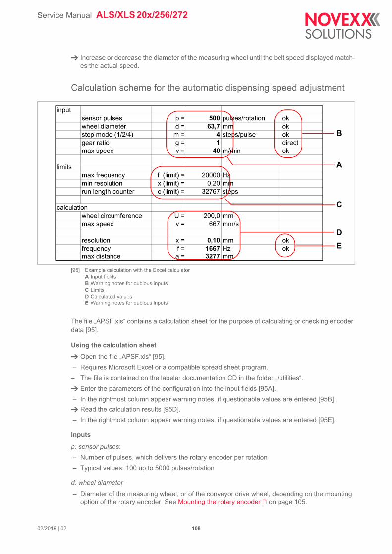
Service Manual ALS/XLS 20x/256/272
02/2019 | 02 108
Increase or decrease the diameter of the measuring wheel until the belt speed displayed match-es the actual speed.
Calculation scheme for the automatic dispensing speed adjustment
[95] Example calculation with the Excel calculatorA Input fieldsB Warning notes for dubious inputsC LimitsD Calculated valuesE Warning notes for dubious inputs
The file „APSF.xls“ contains a calculation sheet for the purpose of calculating or checking encoder data [95].
Using the calculation sheet
Open the file „APSF.xls“ [95].
– Requires Microsoft Excel or a compatible spread sheet program.
– The file is contained on the labeler documentation CD in the folder „/utilities“.
Enter the parameters of the configuration into the input fields [95A].
– In the rightmost column appear warning notes, if questionable values are entered [95B].
Read the calculation results [95D].
– In the rightmost column appear warning notes, if questionable values are entered [95E].
Inputs
p: sensor pulses:
– Number of pulses, which delivers the rotary encoder per rotation
– Typical values: 100 up to 5000 pulses/rotation
d: wheel diameter
– Diameter of the measuring wheel, or of the conveyor drive wheel, depending on the mounting option of the rotary encoder. See Mounting the rotary encoder on page 105.
inputsensor pulses p = 500 pulses/rotation okwheel diameter d = 63,7 mm okstep mode (1/2/4) m = 4 steps/pulse okgear ratio g = 1 directmax speed v = 40 m/min ok
limitsmax frequency f (limit) = 20000 Hzmin resolution x (limit) = 0,20 mmrun length counter c (limit) = 32767 steps
calculationwheel circumference U = 200,0 mmmax speed v = 667 mm/s
resolution x = 0,10 mm okfrequency f = 1667 Hz okmax distance a = 3277 mm
A
C
D
B
E
Service Manual ALS/XLS 20x/256/272
02/2019 | 02 109
– Typical values: up to 200 mm
m: step mode
Depending on the sensor features and the labeler features and the choosen configuration, there are three ways of counting the pulses of the rotary encoder:
– m=1: each pulse is counted as one step (setting required with ALS 104)
– m=2: each pulse is counted twice (rising and falling edge) (Application: labeler in single-phase mode, setting required with ALS/XLS 2xx, ALS 30x, ALX 73x)
– m=4: double-phase operation; rising and falling edge of each pulse is counted. Thus, a sensor pulse can be decoded into four counting steps (Application: Labeler in double-phase mode, set-ting required with ALS/XLS 2xx, ALS 30x, ALX 73x)
g: gear ratio
– Is required, if the rotary encoder is flanged directly to the motor axle, and if a reduction gear is switched between motor and drive axle of the conveyor. In this case rules: g>1.
– See Rotary encoder at the motor axle on page 105.
v: max. speed
Maximum dispensing speed, which should be reached by the labeler.
Limits
flimit : max. frequency
The maximum admissible signal-input-frequency is 20 kHz. This is dependent on the galvanic separation and a digital filter for noise suppression. If the specific output frequency of the rotary encoder is lower, than this value must be entered here.
xlimit : min. resolution
– Minimum admissible resolution, referred to the conveyor belt distance which must be measura-ble.
– The resolution should be at least 0.2 mm, to avoid significant deterioration of the dispensing ac-curacy on the product.
climit : run length counter
The labeler counts the steps between product photoelectric sensor and dispensing edge. Be-cause of the counter register being 16 bit wide (including polarity sign) and no overflow being allowed, the max. counter value is 215-1 = 32767.
Calculations
Size Symbol Calculation Note
Wheel circumference
Max. speed 1000 mm = 1 m; 60 s = 1 min
Resolution ok, if
Frequency ok, if
Max. distance product sensor to dispensing edge
U U d= 3 1415926=
v vmm
s--------- v
mmin--------- 1000
60------------=
x x Up m g -------------------=
x xlimit
f f v p g U
-----------------=f flimit
a a x climit=

Service Manual ALS/XLS 20x/256/272
02/2019 | 02 110
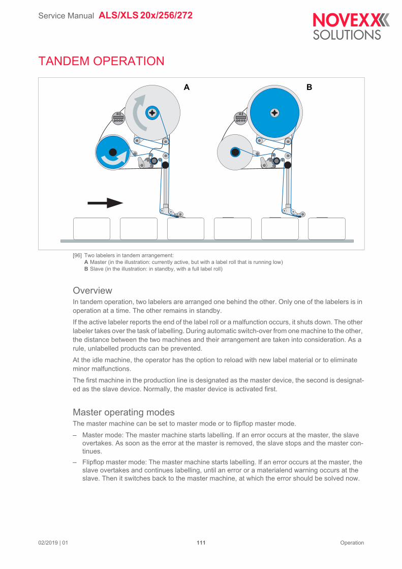
Service Manual ALS/XLS 20x/256/272
02/2019 | 01 111 Operation
TANDEM OPERATION
[96] Two labelers in tandem arrangement:A Master (in the illustration: currently active, but with a label roll that is running low)B Slave (in the illustration: in standby, with a full label roll)
OverviewIn tandem operation, two labelers are arranged one behind the other. Only one of the labelers is in operation at a time. The other remains in standby.
If the active labeler reports the end of the label roll or a malfunction occurs, it shuts down. The other labeler takes over the task of labelling. During automatic switch-over from one machine to the other, the distance between the two machines and their arrangement are taken into consideration. As a rule, unlabelled products can be prevented.
At the idle machine, the operator has the option to reload with new label material or to eliminate minor malfunctions.
The first machine in the production line is designated as the master device, the second is designat-ed as the slave device. Normally, the master device is activated first.
Master operating modesThe master machine can be set to master mode or to flipflop master mode.
– Master mode: The master machine starts labelling. If an error occurs at the master, the slave overtakes. As soon as the error at the master is removed, the slave stops and the master con-tinues.
– Flipflop master mode: The master machine starts labelling. If an error occurs at the master, the slave overtakes and continues labelling, until an error or a materialend warning occurs at the slave. Then it switches back to the master machine, at which the error should be solved now.
A B

Service Manual ALS/XLS 20x/256/272
02/2019 | 01 112 Operation
Prerequisites– Hardware: Two labelers, both RH or both LH, one mounted directly behind the other on the con-
veyor line.
Both machines must be equipped with the same electronics generation (both „Gen. 1“ or both „Gen. 2“, recognizable by the article number of the CPU board; check: SERVICE DATA >CPU BOARD DATA > PCB part number).
– Firmware: From version 2.52 on, both machines must have the same version installed.
– There is potential equalisation between the two machines.
– In case of operation with automatic speed adjustment: The rotary encoder must be connected to both machines using the Y-cable [97]. Both machines must be set for the use of the rotary encoder.
– The product sensor is connected to both machines using the Y-cable [97].
Alternatively can a separate product sensor be connected to each, master and slave, to increse dispense accuracy. Prerequisites for both machines are:
-- Electronics: „Gen. 2“
-- Firmware: Version 2.50 or higher
– Tandem interface cable for synchronisation over Com1 (Article number A7978) or standard net-work cable for synchronisation over Ethernet interface.
CAUTION!
Malfunction caused by a firmware limitation
Don´t operate the machines with the following settings at the same time:
Tandem mode „FlipFlop master“ (MACHINE SETUP > Tandem Operation = „FlipFlop master“)
Applicator operation
Setting SIGNAL INTERFACE >APPLIC. SIGNALS > Apply mode = „After start sig.“ or SIGNAL INTERFACE >AI BOARD SIGNAL > Apply mode = „After start sig.“
Service Manual ALS/XLS 20x/256/272
02/2019 | 01 113 Operation
[97] Y cable for start sensor connection (A7979).
99-1429-812-04
0.7
5m
0.7
5m
Coupling
Plug
Plug
brown 1white 2blue 3
black 4
1 brown2 white3 blue4 black
1 brown2 white3 blue4 black
24VSignal B
GNDSignal A
Plug to machine
(male)
Plug to machine
(male)
Coupling to sensor
(female)
Binder Series 713
Service Manual ALS/XLS 20x/256/272
02/2019 | 01 114 Operation
Setting up tandem operation
Connecting the machines
[98] Cable layout for tandem interface cable (A7978)
Synchronisation over Com1:
Connect the D-sub connector at either end of the tandem interface cable to the serial interface of each machine [?A].
(Gen. 1 only) Connect the mini DIN 6 connector of the tandem interface cable to one of the two machines, at the connection shown [?B].
Machines with Gen. 2 electronics don´t require the mini DIN connector to be connected. Alternatively to the tandem interface cable, a standard null modem cable can be used.
Synchronisation over Ethernet interface (peer-to-peer, that is direct connection without network):
Connect the (crossover) network cabel to the ethernet interface [?C] on both machines.
[99] Connections for the tandem interface cable (A; B).
If both machines are connected to a network, standard (1:1) network cables are required for connection.
brown
yellow
metal coverormetallizedplasticcover
metal coverormetallizedplasticcover
shieldedcableUL style
white
brown
green
yellowbrowngreenwhite
yellow
blue blue
SteckseiteLötseite
CN1A
SUB-D9 connector male
1
2
3
4
5
6
7
8
9
Steckseite Lötseite
CN2A
SUB-D9 connector male
1
2
3
4
5
6
7
8
9
R1
2k2
CN3
use half of AK3233 (Reichelt Elektronik)
6421
35
R2
2k2
AB
C
Service Manual ALS/XLS 20x/256/272
02/2019 | 01 115 Operation
Settings in the functions menu - syncronisation via Com1
From firmware version 2.52 on, the appropriate settings for both COM1 ports are done automati-cally, if COM1 is selected as communication port (MACHINE SETUP > Tandem synchron.. = „Serial Com1“). Additionally, the submenu for COM1 settings (INTERFACE PARA >COM1 PORT) is no longer visible.
[100] Distance (A) between the dispensing edges of the two labelers
Settings on: Menu >Submenu Function Setting
Master and Slave INTERFACE PARA >EA-SYPLUGINTERPR >
Interface not “Serial Com1” and not „Auto negotiation“
During tandem operation, Com1 is used for communication between master and slave machine. Therefore, the interface function may not be set to „Auto negotia-tion“ or to „Serial Com1“.
INTERFACE PARA >COM1 PORT >
Baud rate 115 200
No. of data bits the same setting on both machines
Parity
Stop bits
Data synch. “None”
MACHINE SETUP > Tandem synchron. “Serial Com1”
Master MACHINE SETUP > Tandem Operation “Master” or „FlipFlop master“
Tandem Distance Set the distance [100A] between the dispensing edges of the master and slave.
Slave MACHINE SETUP > Tandem Operation “Slave”
[Tab. 15] Required settings for master and slave for tandem synchronisation via Com1.
A
Service Manual ALS/XLS 20x/256/272
02/2019 | 01 116 Operation
Settings in the functions menu - syncronisation via Ethernet interface
Table 16 contains example addresses for a direct connection (peer-to-peer) of the machines. For connection to a network, the addresses have to be provided by the network administrator. It is recommended to connect both machines to the same subnet which
should have low network traffic.
a) Example address. Regarding the IP addresses it is recommended to avoid using „000“ or „555“. For older machines with a CPU board „Gen. 2“, the addresses 127.xxx.xxx.xxx must not be used.
[101] Distance (A) between the dispensing edges of the two labelers
Settings on: Menu >Submenu Function Setting
Master and Slave INTERFACE PARA >EASY-PLUGINTERPR >
Interface „TCP/IP SOCKET“
MACHINE SETUP > Tandem synchron. „UDP Tandem Port“
Master MACHINE SETUP > Tandem Operation „Master“ or „FlipFlop master“
Tandem Distance Set the distance [101A] between the dis-pensing edges of the master and slave.
Slave IP address 192.168.001.201 a
INTERFACE PARA >NET-WORK PARAM. >
IP Addressassign „Fixed IP address“
IP address 192.168.001.200 a
Slave MACHINE SETUP > Tandem Operation „Slave“
INTERFACE PARA >NET-WORK PARAM. >
IP address 192.168.001.201 a
[Tab. 16] Required settings for master and slave for tandem synchronisation via Ethernet interface.
A
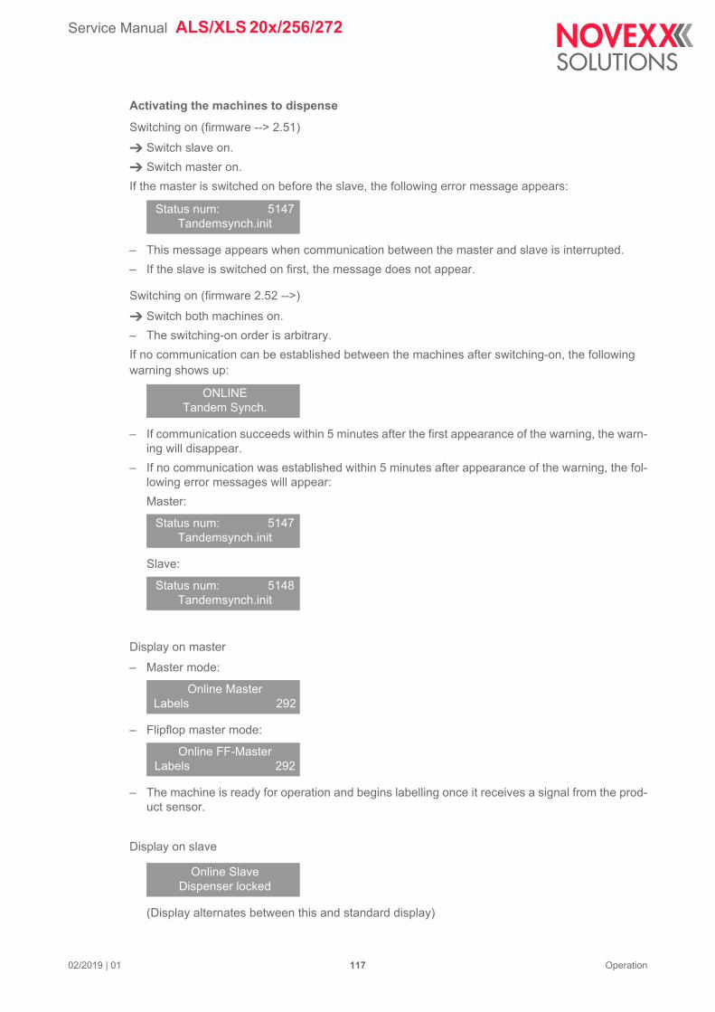
Service Manual ALS/XLS 20x/256/272
02/2019 | 01 117 Operation
Activating the machines to dispense
Switching on (firmware --> 2.51)
Switch slave on.
Switch master on.
If the master is switched on before the slave, the following error message appears:
– This message appears when communication between the master and slave is interrupted.
– If the slave is switched on first, the message does not appear.
Switching on (firmware 2.52 -->)
Switch both machines on.
– The switching-on order is arbitrary.
If no communication can be established between the machines after switching-on, the following warning shows up:
– If communication succeeds within 5 minutes after the first appearance of the warning, the warn-ing will disappear.
– If no communication was established within 5 minutes after appearance of the warning, the fol-lowing error messages will appear:
Master:
Slave:
Display on master
– Master mode:
– Flipflop master mode:
– The machine is ready for operation and begins labelling once it receives a signal from the prod-uct sensor.
Display on slave
(Display alternates between this and standard display)
Status num: 5147Tandemsynch.init
ONLINETandem Synch.
Status num: 5147Tandemsynch.init
Status num: 5148Tandemsynch.init
Online MasterLabels 292
Online FF-MasterLabels 292
Online SlaveDispenser locked
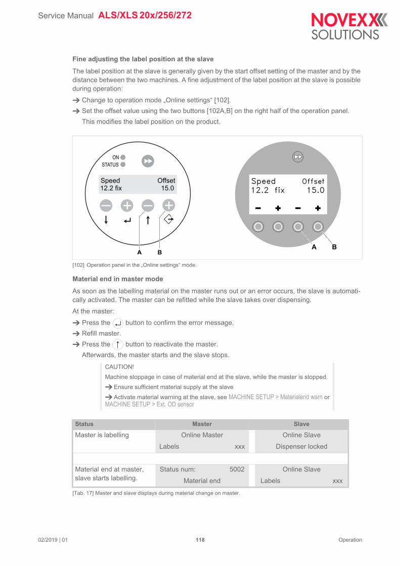
Service Manual ALS/XLS 20x/256/272
02/2019 | 01 118 Operation
Fine adjusting the label position at the slave
The label position at the slave is generally given by the start offset setting of the master and by the distance between the two machines. A fine adjustment of the label position at the slave is possible during operation:
Change to operation mode „Online settings“ [102].
Set the offset value using the two buttons [102A,B] on the right half of the operation panel.
This modifies the label position on the product.
[102] Operation panel in the „Online settings“ mode.
Material end in master mode
As soon as the labelling material on the master runs out or an error occurs, the slave is automati-cally activated. The master can be refitted while the slave takes over dispensing.
At the master:
Press the button to confirm the error message.
Refill master.
Press the button to reactivate the master.
Afterwards, the master starts and the slave stops.
CAUTION!
Machine stoppage in case of material end at the slave, while the master is stopped.
Ensure sufficient material supply at the slave
Activate material warning at the slave, see MACHINE SETUP > Materialend warn or MACHINE SETUP > Ext. OD sensor
Status Master Slave
Master is labelling Online Master
Labels xxx
Online Slave
Dispenser locked
Material end at master, slave starts labelling.
Status num: 5002
Material end
Online Slave
Labels xxx
[Tab. 17] Master and slave displays during material change on master.
+ +––12.2 fix 15.0
ONSTATUS
Speed Offset
A B
12.2 fix 15.0
A B
Speed Offset
Service Manual ALS/XLS 20x/256/272
02/2019 | 01 119 Operation
Material end in flipflop master mode
As soon as the labelling material on the master or on the slave runs out or an error occurs, the other machine is automatically activated. The stopped machine can be refitted while the slave takes over dispensing.
Material roll nenewal in flipflop master mode:
Press the button to confirm the error message.
Replenish material roll.
Press the button to reactivate the stopped machine.
The other machine labels further until it experiences an error itself.
Acknowledge error: Press the button
Replenish material
Slave is labelling Online Master
Stopped : xxx
Online Slave
Labels xxx
Activate master: Press the button
Master is labelling Online Master
Labels xxx
Online Slave
Dispenser locked
Status Master Slave
Master is labelling Online FF-Master
Labels xxx
Online Slave
Dispenser locked
Material end at master, slave starts labelling.
Status num: 5002
Material end
Online Slave
Labels xxx
Acknowledge error: Press the button
Replenish material
Slave is labelling Online FF-Master
Stopped : xxx
Online Slave
Labels xxx
Material end at slave, master starts labelling.
Online FF-Master
Labels xxx
Status num: 5002
Material end
Acknowledge error: Press the button
Replenish material
Master is labelling Online FF-Master
Labels xxx
Online Slave
Dispenser locked
[Tab. 18] Master and slave displays during material change.
Status Master Slave
[Tab. 17] Master and slave displays during material change on master.
Service Manual ALS/XLS 20x/256/272
02/2019 | 01 120 Operation
Toggling to master already after material warning:
If the function „material warning“ is activated at the slave, it toggles back to the master as soon as a material warning occurs, what means that a preset roll diameter is reached (see MACHINE SETUP > Materialend warn resp. MACHINE SETUP > Ext. OD sensor)
Stopping / continuing labelling
To stop labelling:
Press the button.
– Display:
2) Or „Online FF-Master“ or „Online Slave“.
– This has no effect on the second machine
To continue labelling:
Press the button.
Online Master 2
Stopped: xxx
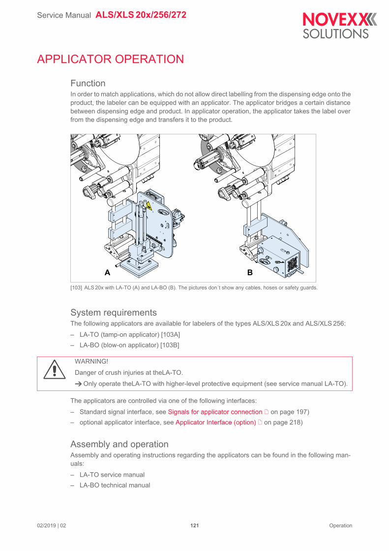
Service Manual ALS/XLS 20x/256/272
02/2019 | 02 121 Operation
APPLICATOR OPERATION
FunctionIn order to match applications, which do not allow direct labelling from the dispensing edge onto the product, the labeler can be equipped with an applicator. The applicator bridges a certain distance between dispensing edge and product. In applicator operation, the applicator takes the label over from the dispensing edge and transfers it to the product.
[103] ALS 20x with LA-TO (A) and LA-BO (B). The pictures don´t show any cables, hoses or safety guards.
System requirementsThe following applicators are available for labelers of the types ALS/XLS 20x and ALS/XLS 256:
– LA-TO (tamp-on applicator) [103A]
– LA-BO (blow-on applicator) [103B]
The applicators are controlled via one of the following interfaces:
– Standard signal interface, see Signals for applicator connection on page 197)
– optional applicator interface, see Applicator Interface (option) on page 218)
Assembly and operationAssembly and operating instructions regarding the applicators can be found in the following man-uals:
– LA-TO service manual
– LA-BO technical manual
A B
WARNING!
Danger of crush injuries at theLA-TO.
Only operate theLA-TO with higher-level protective equipment (see service manual LA-TO).
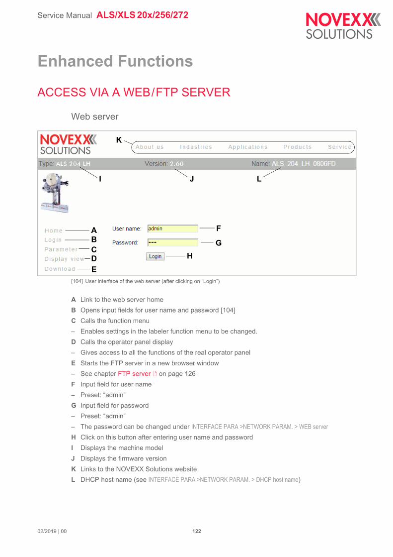
Service Manual ALS/XLS 20x/256/272
02/2019 | 00 122
Enhanced Functions
ACCESS VIA A WEB/FTP SERVER
Web server
[104] User interface of the web server (after clicking on “Login”)
A Link to the web server home
B Opens input fields for user name and password [104]
C Calls the function menu
– Enables settings in the labeler function menu to be changed.
D Calls the operator panel display
– Gives access to all the functions of the real operator panel
E Starts the FTP server in a new browser window
– See chapter FTP server on page 126
F Input field for user name
– Preset: “admin”
G Input field for password
– Preset: “admin”
– The password can be changed under INTERFACE PARA >NETWORK PARAM. > WEB server
H Click on this button after entering user name and password
I Displays the machine model
J Displays the firmware version
K Links to the NOVEXX Solutions website
L DHCP host name (see INTERFACE PARA >NETWORK PARAM. > DHCP host name)
ABCDE
F
G
H
K
I J L
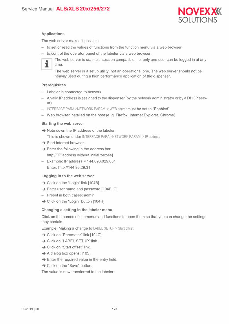
Service Manual ALS/XLS 20x/256/272
02/2019 | 00 123
Applications
The web server makes it possible
– to set or read the values of functions from the function menu via a web browser
– to control the operator panel of the labeler via a web browser.
The web server is not multi-session compatible, i.e. only one user can be logged in at any time.
The web server is a setup utility, not an operational one. The web server should not be heavily used during a high performance application of the dispenser.
Prerequisites
– Labeler is connected to network
– A valid IP address is assigned to the dispenser (by the network administrator or by a DHCP serv-er)
– INTERFACE PARA >NETWORK PARAM. > WEB server must be set to “Enabled”.
– Web browser installed on the host (e. g. Firefox, Internet Explorer, Chrome)
Starting the web server
Note down the IP address of the labeler
– This is shown under INTERFACE PARA >NETWORK PARAM. > IP address
Start internet browser.
Enter the following in the address bar:
http://[IP address without initial zeroes]
– Example: IP address = 144.093.029.031
Enter: http://144.93.29.31
Logging in to the web server
Click on the “Login” link [104B]
Enter user name and password [104F, G]
– Preset in both cases: admin
Click on the “Login” button [104H]
Changing a setting in the labeler menu
Click on the names of submenus and functions to open them so that you can change the settings they contain.
Example: Making a change to LABEL SETUP > Start offset:
Click on “Parameter” link [104C].
Click on “LABEL SETUP” link.
Click on “Start offset” link.
A dialog box opens: [105].
Enter the required value in the entry field.
Click on the “Save” button.
The value is now transferred to the labeler.
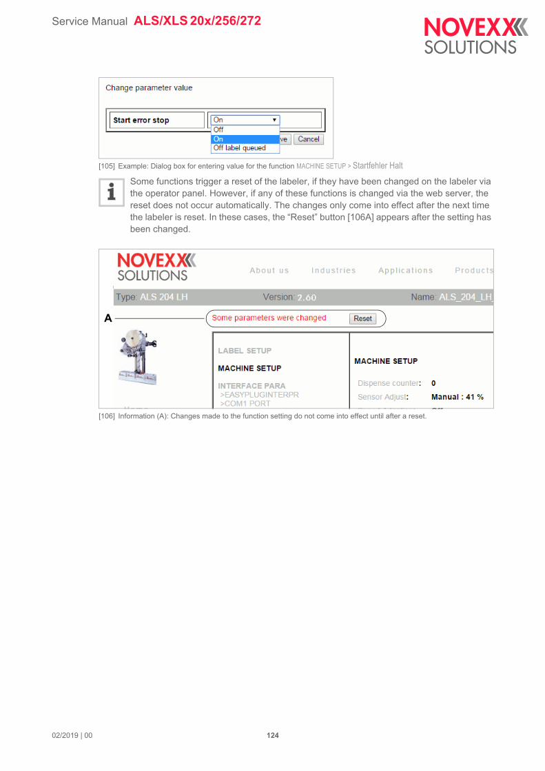
Service Manual ALS/XLS 20x/256/272
02/2019 | 00 124
[105] Example: Dialog box for entering value for the function MACHINE SETUP > Startfehler Halt
Some functions trigger a reset of the labeler, if they have been changed on the labeler via the operator panel. However, if any of these functions is changed via the web server, the reset does not occur automatically. The changes only come into effect after the next time the labeler is reset. In these cases, the “Reset” button [106A] appears after the setting has been changed.
[106] Information (A): Changes made to the function setting do not come into effect until after a reset.
A
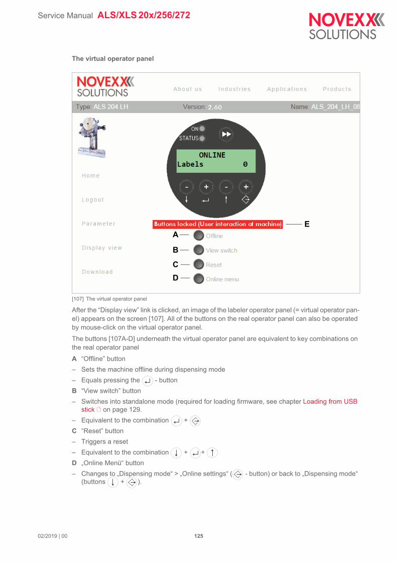
Service Manual ALS/XLS 20x/256/272
02/2019 | 00 125
The virtual operator panel
[107] The virtual operator panel
After the “Display view” link is clicked, an image of the labeler operator panel (= virtual operator pan-el) appears on the screen [107]. All of the buttons on the real operator panel can also be operated by mouse-click on the virtual operator panel.
The buttons [107A-D] underneath the virtual operator panel are equivalent to key combinations on the real operator panel
A “Offline” button
– Sets the machine offline during dispensing mode
– Equals pressing the - button
B “View switch” button
– Switches into standalone mode (required for loading firmware, see chapter Loading from USB stick on page 129.
– Equivalent to the combination +
C “Reset” button
– Triggers a reset
– Equivalent to the combination + +
D „Online Menü“ button
– Changes to „Dispensing mode“ > „Online settings“ ( - button) or back to „Dispensing mode“ (buttons + ).
EA
B
C
D
Service Manual ALS/XLS 20x/256/272
02/2019 | 00 126
FTP server
Applications
The file transfer protocol (FTP) server (RFC959) enables access to the labeler's internal RAM disk and to the compact flash card in the card slot of the labeler (as long as there is a compact flash card in the slot).
In this way, files (configuration or firmware files) can be saved to the CF card or the internal RAM disk, or existing files renamed or deleted.
The FTP server is multi-session compatible.
The FTP server should not be heavily used during a high performance application of the labeler.
Prerequisites
– Labeler is connected to network
– A valid IP address is assigned to the dispenser (by the network administrator or by a DHCP serv-er)
– INTERFACE PARA >NETWORK PARAM. > FTP server must be set to “On”.
– FTP client is installed on the host computer (e. g. WS-FTP, Windows Explorer, Internet Explorer, Midnight Commander).
– The FTP connection is not blocked by a firewall
Establishing a FTP connection
Note down the IP address of the labeler
– This is shown under INTERFACE PARA >NETWORK PARAM. > IP address
Start the FTP client.
Enter the following in the address bar:
ftp://[IP address without initial zeroes]
– Example: IP address = 144.093.029.047
Enter: ftp://144.93.29.47
An input field for the user name and password appears.
Enter user name and password.
– A user name can be chosen at will; preset password = “novexx”
– Change the password under INTERFACE PARA >NETWORK PARAM. > FTP Password
[108] User interface of the FTP server in the Windows Explorer. RAM = internal machine memory; usb = connected USB stick.
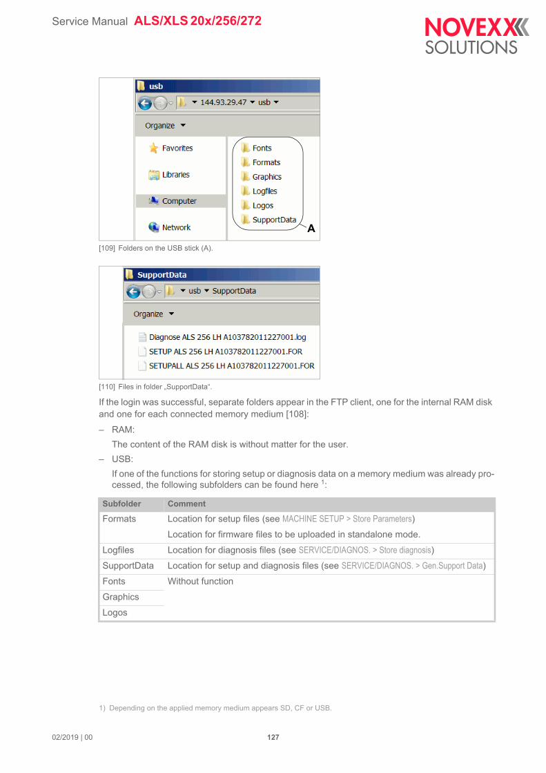
Service Manual ALS/XLS 20x/256/272
02/2019 | 00 127
[109] Folders on the USB stick (A).
[110] Files in folder „SupportData“.
If the login was successful, separate folders appear in the FTP client, one for the internal RAM disk and one for each connected memory medium [108]:
– RAM:
The content of the RAM disk is without matter for the user.
– USB:
If one of the functions for storing setup or diagnosis data on a memory medium was already pro-cessed, the following subfolders can be found here 1:
1) Depending on the applied memory medium appears SD, CF or USB.
Subfolder Comment
Formats Location for setup files (see MACHINE SETUP > Store Parameters)
Location for firmware files to be uploaded in standalone mode.
Logfiles Location for diagnosis files (see SERVICE/DIAGNOS. > Store diagnosis)
SupportData Location for setup and diagnosis files (see SERVICE/DIAGNOS. > Gen.Support Data)
Fonts Without function
Graphics
Logos
A
Service Manual ALS/XLS 20x/256/272
LOADING FIRMWARE
Firmware Version
Valid Firmware Versions
Firmware version 2.75 must be mandatory used with CPU boards A103782 with index -004 or higher, but it may be used with CPU boards with a lower index.
For XLS 2xx, firmware version 2.75 or higher is mandatory.
Find Required Information in the Parameter Menu
Show the installed firmware version:
Call SERVICE DATA > >MODULE FW VERS. > System version.
Show article number and index of the CPU board:
Call SERVICE DATA > >CPU BOARD DATA > Board part numb..
Get Firmware
The current firmware can be downloaded from our web page (SERVICE & SUPPORT > FIRM-WARE): www.novexx.com
CAUTION!
Executing or applying the update procedure incorrectly can set the machine into a crit-ical condition, which can only be rectified by trained technicians.
Firmware should therefore only be updated by experienced operators or service technicians.
Update firmware only, if a) a newly provided function is badly needed, or b) the ma-chine doesn´t work properly.
Never switch off the machine during a firmware update.
Hardware Properties Oldest Firmware Current Firmware
Compatible with „Gen. 1“ electronics
CPU board A6379
Applied up to approx. 02/2014
Up to serial number 021831
1.36 1.60
Compatible with „Gen. 2“ electronics
CPU board A103782 up to index -003
Applied up to approx. 02/2019
Starting with serial number 021832
2.51 2.75
Compatible with „Gen. 2“ electronics
CPU board A103782 up to index -004
Applied since approx. 02/2019
2.75 2.76
[Tab. 19] Overview firmware versions.
02/2019 | 02 128 Enhanced Functions
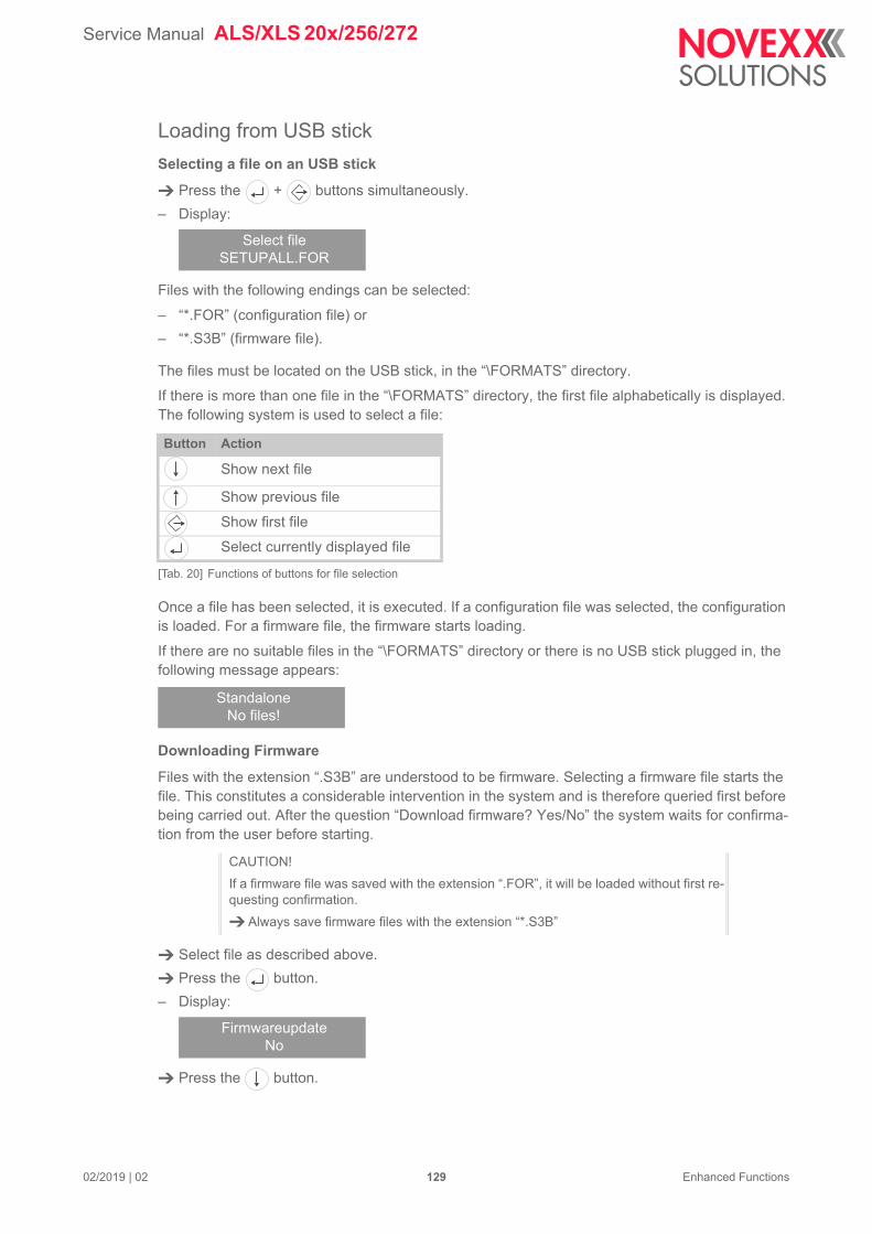
Service Manual ALS/XLS 20x/256/272
Loading from USB stick
Selecting a file on an USB stick
Press the + buttons simultaneously.
– Display:
Files with the following endings can be selected:
– “*.FOR” (configuration file) or
– “*.S3B” (firmware file).
The files must be located on the USB stick, in the “\FORMATS” directory.
If there is more than one file in the “\FORMATS” directory, the first file alphabetically is displayed. The following system is used to select a file:
Once a file has been selected, it is executed. If a configuration file was selected, the configuration is loaded. For a firmware file, the firmware starts loading.
If there are no suitable files in the “\FORMATS” directory or there is no USB stick plugged in, the following message appears:
Downloading Firmware
Files with the extension “.S3B” are understood to be firmware. Selecting a firmware file starts the file. This constitutes a considerable intervention in the system and is therefore queried first before being carried out. After the question “Download firmware? Yes/No” the system waits for confirma-tion from the user before starting.
Select file as described above.
Press the button.
– Display:
Press the button.
Select fileSETUPALL.FOR
Button Action
Show next file
Show previous file
Show first file
Select currently displayed file
[Tab. 20] Functions of buttons for file selection
StandaloneNo files!
CAUTION!
If a firmware file was saved with the extension “.FOR”, it will be loaded without first re-questing confirmation.
Always save firmware files with the extension “*.S3B”
FirmwareupdateNo
02/2019 | 02 129 Enhanced Functions
Service Manual ALS/XLS 20x/256/272
– Display:
Press the button.
The firmware download starts without any further assistance, accompanied by the display:
(V. 2.51: Firmware version; xxx: KBytes loaded)
Afterwards the Flash is programmed. Display:
(V. 2.51: Firmware version; xxx: KBytes loaded)
Once the firmware has been successfully loaded, the machine is restarted.
Download via data interfacePrerequisites:
– The host computer and labeler are connected via the interface which has been activated through the menu: INTERFACE PARA >EASYPLUGINTERPR > Interface (Com1, USB or Ethernet)
– Host computer operating system: Windows XP
– Firmware file is saved on the host computer.
Current firmware can be downloaded from the following website:
www.novexx.com
(Service > Firmware)
Serial interface
On the host computer:
Open a command prompt window.
Enter:
– Replace “ALS.BF2_V2.51.s3b” with the name of the current firmware file.
Press the Enter button.
[111] Command prompt window showing the command to transfer the file “ALS.BF_V1.33.s3b” to the interface Com1.
FirmwareupdateYes
Recv. V. 2.51KBytes: xxx
Prog... V. 2.51KBytes: xxx
copy ALS.BF2_V2.51.s3b com1 /b
02/2019 | 02 130 Enhanced Functions
Service Manual ALS/XLS 20x/256/272
USB/Ethernet interfaces
On the host computer:
Open a command prompt window.
Enter:
– Replace “ALS.BF2_V2.51.s3b” with the name of the current firmware file.
Please note:
– ComputerName = Name of the computer. Find this name here:
Windows XP: START > SETTINGS > CONTROL PANEL > SYSTEM > COMPUTERNAME (e.g. “DM-ECH-0990”).
Windows 7: Click START, then right click COMPUTER, then click PROPERTIES. The computer name can be found under „Computer name, domain, and workgroup settings“.
– Share name = The share name stands for a printer that is connected to a certain port – a USB port for transfer via USB or the TCP/IP port for Ethernet transfer. The share name can be found as follows:
Windows XP: START > SETTINGS > PRINTERS AND FAXES, by right-clicking on the device icon then clicking PROPERTIES > SHARING.
Windows 7: START > DEVICES AND PRINTERS. Right click on the relevant printer, then on PRINTER PROPERTIES, then on the SHARING tab.
The printer must be setup especially for this purpose. Find an how-to instruction in chap-ter Installing a „Generic“ printer on a Windows 7 host PC for the purpose of firmware upload on page 302.
Some tips about transfer via a USB or Ethernet interface:
– The procedure described does not work with Windows 98, Windows ME or Windows NT 4.0.
– The Share name must satisfy MS-DOS conventions (max. 8 characters length, no spe-cial characters or spaces)
The download process
The firmware download starts without any further assistance, accompanied by the display:
(V. 2.51: Firmware version; xxx: KBytes loaded)
Afterwards the Flash is programmed. Display:
(V. 2.51: Firmware version; xxx: KBytes loaded)
Once the firmware has been successfully loaded, the machine is restarted.
copy ALS.BF2_V2.51.s3b \\Computername\ Sharename
Recv. V. 2.51KBytes: xxx
Prog... V. 2.51KBytes: xxx
02/2019 | 02 131 Enhanced Functions
Service Manual ALS/XLS 20x/256/272
Loading with the bootloader(Earliest with firmware version 2.51)
If no or no valid firmware is installed, startup ends with the following bootloader message::
Alternatively, this state can be forced by pressing the buttons + during power-on. In that case, the following message appears:
The message is a simple menu, which offers the 4 (or 2) actions described in the following. The actions are started by pressing the button beneath the relevant text.
Download
Pressing the button starts data receiving via the serial interface. Data must match the following requirements:
– Transmission parameters 115200, n, 8, 1, xon/xoff
– Firmware file in format *.s3b (e. g. ALS.BF2_V2.51.s3b)
Display texts appearing during the transmission:
USB load
Pressing the button starts loading firmware from USB stick. Data must match the following requirements:
– Firmware file must be named ALS.BF2.uimg (original e. g. ALS.BF2_V2.51.uimg)
– Firmware file must be copied to the root folder („\“) on the USB stick.
Display texts appearing during the transmission:
Clr Para
Pressing the button deletes machine specific parameter settings in the memory. Thus, the firm-ware starts with the default factory settngs.
02/2019 | 02 132 Enhanced Functions

Service Manual ALS/XLS 20x/256/272
Version
Pressing the button displays the bootloader version (revision and build no).
02/2019 | 02 133 Enhanced Functions
Service Manual ALS/XLS 20x/256/272
02/2019 | 01 134 Enhanced Functions
SAVING/LOADING A CONFIGURATION
ApplicationsIt sometimes happens that all of the parameter settings for a labeler must be restored or transferred to another labeler. In such cases, the user can import all of the function settings together as a set, saving time, money and stress. The following applications come to mind:
– After a service action, when the same settings as before the service are to be reinstalled on a labeler.
– When the settings in the functions menu of one labeler are to be transferred onto another ma-chine of the same model.
– When several labelers of the same model are to be set up with exactly the same settings.
In these cases, it is convenient to first export and save the settings so that they can later be import-ed. There are two ways of doing this:
– Data interface: Readout via the data interface with the help of appropriate interface commands. This method requires a sound knowledge of the Easy Plug command language and will not be described here (for detailed information see the Easy Plug manual).
– External memory medium: Saving the settings onto a memory medium as a text file (“setup file”) (see description that follows).
For details about applying external memory media refer to the „External memory media manual“.
Saving onto an external memory medium Switch the labeler off.
Connect a memory medium to the USB connector.
Switch the labeler on.
Call MACHINE SETUP > Store Parameters
– This function only appears in the menu if there is a memory card in the labeler’s card slot.
Choose an option for saving: “With adjust para” or “Without adj. par”
– “With adjust para”: (Preset): device-specific settings are included in what is saved. These in-clude sensor settings, for example.
The names of the relevant functions are marked with a “*” in the text file.
This setting is recommended when the intention is to transfer the settings back onto the same machine.
– “Without adj. par”: parameters that contain device-specific settings are excluded from what is saved.
This is recommended when settings from one machine are to be transferred to another machine of the same model.
Press the button.
– The preset file name is now shown (saved in \FORMATS directory on the memory medium):
“SETUPALL ALS xxx yy zzzzzzzzzzzzzzzz.FOR” for MACHINE SETUP > Store Parameters = “With adjust para”
“SETUP ALS xxx yy zzzzzzzzzzzzzzzz.FOR” for MACHINE SETUP > Store Parameters = “Without adj. par”
(with xxx = machine type, e. g. 306; yy = RH or LH; zzzzzzzzzzzzzzzz = CPU board serial num-ber)

Service Manual ALS/XLS 20x/256/272
02/2019 | 01 135 Enhanced Functions
File name and directory can be changed using buttons on labeler operator panel. If a file with the name entered already exists, this will be overwritten without asking for confirma-tion.
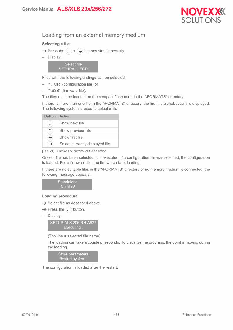
Service Manual ALS/XLS 20x/256/272
02/2019 | 01 136 Enhanced Functions
Loading from an external memory medium
Selecting a file
Press the + buttons simultaneously.
– Display:
Files with the following endings can be selected:
– “*.FOR” (configuration file) or
– “*.S3B” (firmware file).
The files must be located on the compact flash card, in the “\FORMATS” directory.
If there is more than one file in the “\FORMATS” directory, the first file alphabetically is displayed. The following system is used to select a file:
Once a file has been selected, it is executed. If a configuration file was selected, the configuration is loaded. For a firmware file, the firmware starts loading.
If there are no suitable files in the “\FORMATS” directory or no memory medium is connected, the following message appears:
Loading procedure
Select file as described above.
Press the button.
– Display:
(Top line = selected file name)
The loading can take a couple of seconds. To visualize the progress, the point is moving during the loading.
The configuration is loaded after the restart.
Select fileSETUPALL.FOR
Button Action
Show next file
Show previous file
Show first file
Select currently displayed file
[Tab. 21] Functions of buttons for file selection
StandaloneNo files!
SETUP ALS 206 RH A637Executing .
Store parametersRestart system..
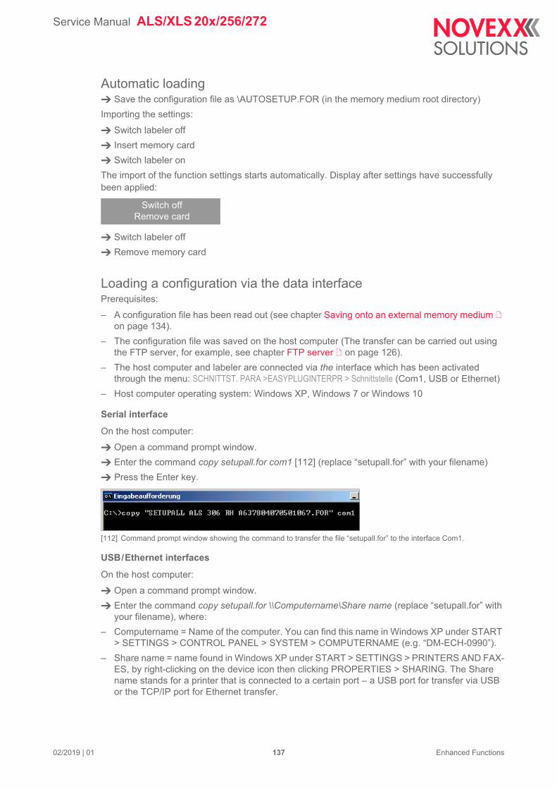
Service Manual ALS/XLS 20x/256/272
02/2019 | 01 137 Enhanced Functions
Automatic loading Save the configuration file as \AUTOSETUP.FOR (in the memory medium root directory)
Importing the settings:
Switch labeler off
Insert memory card
Switch labeler on
The import of the function settings starts automatically. Display after settings have successfully been applied:
Switch labeler off
Remove memory card
Loading a configuration via the data interfacePrerequisites:
– A configuration file has been read out (see chapter Saving onto an external memory medium on page 134).
– The configuration file was saved on the host computer (The transfer can be carried out using the FTP server, for example, see chapter FTP server on page 126).
– The host computer and labeler are connected via the interface which has been activated through the menu: SCHNITTST. PARA >EASYPLUGINTERPR > Schnittstelle (Com1, USB or Ethernet)
– Host computer operating system: Windows XP, Windows 7 or Windows 10
Serial interface
On the host computer:
Open a command prompt window.
Enter the command copy setupall.for com1 [112] (replace “setupall.for” with your filename)
Press the Enter key.
[112] Command prompt window showing the command to transfer the file “setupall.for” to the interface Com1.
USB/Ethernet interfaces
On the host computer:
Open a command prompt window.
Enter the command copy setupall.for \\Computername\Share name (replace “setupall.for” with your filename), where:
– Computername = Name of the computer. You can find this name in Windows XP under START > SETTINGS > CONTROL PANEL > SYSTEM > COMPUTERNAME (e.g. “DM-ECH-0990”).
– Share name = name found in Windows XP under START > SETTINGS > PRINTERS AND FAX-ES, by right-clicking on the device icon then clicking PROPERTIES > SHARING. The Share name stands for a printer that is connected to a certain port – a USB port for transfer via USB or the TCP/IP port for Ethernet transfer.
Switch offRemove card
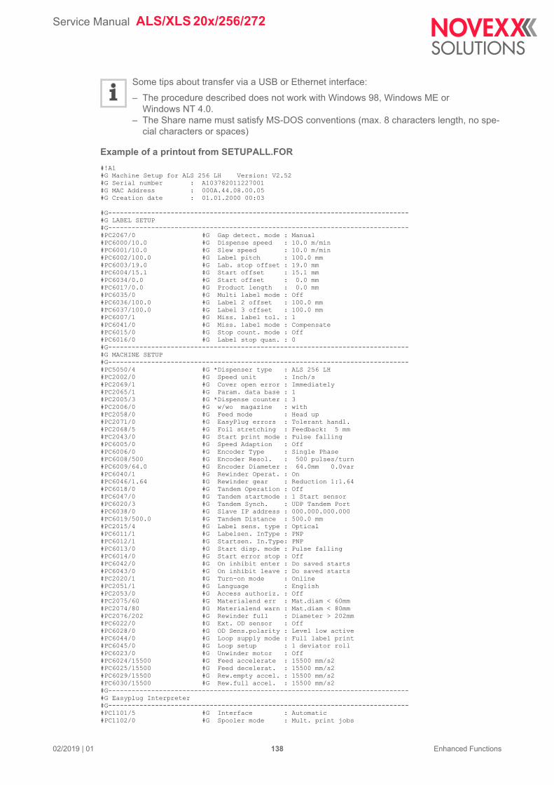
Service Manual ALS/XLS 20x/256/272
02/2019 | 01 138 Enhanced Functions
Some tips about transfer via a USB or Ethernet interface:
– The procedure described does not work with Windows 98, Windows ME or Windows NT 4.0.
– The Share name must satisfy MS-DOS conventions (max. 8 characters length, no spe-cial characters or spaces)
Example of a printout from SETUPALL.FOR
#!A1#G Machine Setup for ALS 256 LH Version: V2.52#G Serial number : A103782011227001#G MAC Address : 000A.44.08.00.05#G Creation date : 01.01.2000 00:03
#G-----------------------------------------------------------------------------#G LABEL SETUP#G-----------------------------------------------------------------------------#PC2067/0 #G Gap detect. mode : Manual#PC6000/10.0 #G Dispense speed : 10.0 m/min#PC6001/10.0 #G Slew speed : 10.0 m/min#PC6002/100.0 #G Label pitch : 100.0 mm#PC6003/19.0 #G Lab. stop offset : 19.0 mm#PC6004/15.1 #G Start offset : 15.1 mm#PC6034/0.0 #G Start offset : 0.0 mm#PC6017/0.0 #G Product length : 0.0 mm#PC6035/0 #G Multi label mode : Off#PC6036/100.0 #G Label 2 offset : 100.0 mm#PC6037/100.0 #G Label 3 offset : 100.0 mm#PC6007/1 #G Miss. label tol. : 1#PC6041/0 #G Miss. label mode : Compensate#PC6015/0 #G Stop count. mode : Off#PC6016/0 #G Label stop quan. : 0#G-----------------------------------------------------------------------------#G MACHINE SETUP#G-----------------------------------------------------------------------------#PC5050/4 #G *Dispenser type : ALS 256 LH#PC2002/0 #G Speed unit : Inch/s#PC2069/1 #G Cover open error : Immediately#PC2065/1 #G Param. data base : 1#PC2005/3 #G *Dispense counter : 3#PC2006/0 #G w/wo magazine : with#PC2058/0 #G Feed mode : Head up#PC2071/0 #G EasyPlug errors : Tolerant handl.#PC2068/5 #G Foil stretching : Feedback: 5 mm#PC2043/0 #G Start print mode : Pulse falling#PC6005/0 #G Speed Adaption : Off#PC6006/0 #G Encoder Type : Single Phase#PC6008/500 #G Encoder Resol. : 500 pulses/turn#PC6009/64.0 #G Encoder Diameter : 64.0mm 0.0var#PC6040/1 #G Rewinder Operat. : On#PC6046/1.64 #G Rewinder gear : Reduction 1:1.64#PC6018/0 #G Tandem Operation : Off#PC6047/0 #G Tandem startmode : 1 Start sensor#PC6020/3 #G Tandem Synch. : UDP Tandem Port#PC6038/0 #G Slave IP address : 000.000.000.000#PC6019/500.0 #G Tandem Distance : 500.0 mm#PC2015/4 #G Label sens. type : Optical#PC6011/1 #G Labelsen. InType : PNP#PC6012/1 #G Startsen. In.Type: PNP#PC6013/0 #G Start disp. mode : Pulse falling#PC6014/0 #G Start error stop : Off#PC6042/0 #G On inhibit enter : Do saved starts#PC6043/0 #G On inhibit leave : Do saved starts#PC2020/1 #G Turn-on mode : Online#PC2051/1 #G Language : English#PC2053/0 #G Access authoriz. : Off#PC2075/60 #G Materialend err : Mat.diam < 60mm#PC2074/80 #G Materialend warn : Mat.diam < 80mm#PC2076/202 #G Rewinder full : Diameter > 202mm#PC6022/0 #G Ext. OD sensor : Off#PC6028/0 #G OD Sens.polarity : Level low active#PC6044/0 #G Loop supply mode : Full label print#PC6045/0 #G Loop setup : 1 deviator roll#PC6023/0 #G Unwinder motor : Off#PC6024/15500 #G Feed accelerate : 15500 mm/s2#PC6025/15500 #G Feed decelerat. : 15500 mm/s2#PC6029/15500 #G Rew.empty accel. : 15500 mm/s2#PC6030/15500 #G Rew.full accel. : 15500 mm/s2#G-----------------------------------------------------------------------------#G Easyplug Interpreter#G-----------------------------------------------------------------------------#PC1101/5 #G Interface : Automatic#PC1102/0 #G Spooler mode : Mult. print jobs
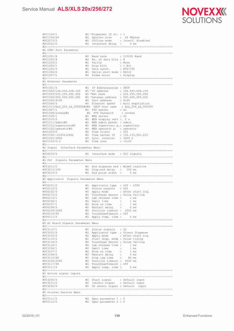
Service Manual ALS/XLS 20x/256/272
02/2019 | 01 139 Enhanced Functions
#PC1103/1 #G *Dispenser ID no. : 1#PC1104/64 #G Spooler size : 64 KBytes#PC2072/0 #G Offline mode : Interf. disabled#PC2021/0 #G Interface delay : 0 ms#G-----------------------------------------------------------------------------#G COM1 Port Parameter#G-----------------------------------------------------------------------------#PC1201/8 #G Baud rate : 115200 Baud#PC1202/8 #G No. of data bits : 8#PC1203/2 #G Parity : None#PC1204/1 #G Stop bits : 1 Bit#PC1205/0 #G Data synch. : RTS/CTS#PC1206/0 #G Serial port mode : RS232#PC1207/1 #G Frame error : Display#G-----------------------------------------------------------------------------#G Ethernet Parameter#G-----------------------------------------------------------------------------#PC1501/0 #G IP Addressassign : DHCP#PC1502/144.093.028.109 #G *IP address : 144.093.028.109#PC1503/255.255.000.000 #G *Net mask : 255.255.000.000#PC1504/000.000.000.000 #G *Gateway address : 000.000.000.000#PC1505/9100 #G Port address : 9100#PC1506/0 #G Ethernet speed : Auto negotiation#PC1513/ALS_204_LH_000000#G#G DHCP host name : ALS_204_LH_000000#PC1507/1 #G FTP server : On#PC1508/novexx#G #G FTP Password : novexx#PC1509/1 #G WEB server : On#PC1510/5 #G WEB display refr : 5 s#PC1511/admin#G #G WEB admin passw. : admin#PC1512/supervisor#G #G WEB supervisor p.: supervisor#PC1532/operator#G #G WEB operator p. : operator#PC1529/0 #G Time client : Off#PC1530/-2105212662 #G Time server IP : 130.133.001.010#PC1531/3600 #G Sync. interval : 3600 s#PC1533/0.0 #G Time zone : +0:00#G-----------------------------------------------------------------------------#G Signal Interface Parameter Menu#G-----------------------------------------------------------------------------#PC6033/0 #G Interface mode : PLC signals#G-----------------------------------------------------------------------------#G PLC Signals Parameter Menu#G-----------------------------------------------------------------------------#PC3211/0 #G End dispense mod : Mode0 inactive#PC3213/100 #G Disp.end delay : 100 ms#PC3214/0 #G End pulse width : 0 ms#G-----------------------------------------------------------------------------#G Applicator Signals Parameter Menu#G-----------------------------------------------------------------------------#PC6101/0 #G Applicator type : LTP - LTPV#PC6112/0 #G Status outputs : Off#PC6102/0 #G Apply mode : After start sig.#PC6115/0 #G TouchDown Sensor : Pulse falling#PC6113/1 #G Lab release time : 1 ms#PC6106/1 #G Dwell time : 1 ms#PC6107/1 #G Blow on time : 1 ms#PC6108/0 #G Restart delay : 0 ms#PC6109/2000 #G Position timeout : 2000 ms#PC6114/99 #G TouchDownTimeout : Off#PC6111/0 #G Apply comp. time : 0 ms#G-----------------------------------------------------------------------------#G AI Board Signals Parameter Menu#G-----------------------------------------------------------------------------#PC3112/1 #G Status signals : On#PC3101/6 #G Applicator type : Direct Dispense#PC3102/0 #G Apply mode : After start sig.#PC3110/2 #G Start disp. mode : Pulse rising#PC3118/0 #G TouchDown Sensor : Pulse falling#PC3116/1 #G Lab release time : 1 ms#PC3106/1 #G Dwell time : 1 ms#PC3107/1 #G Blow on time : 1 ms#PC3108/0 #G Restart delay : 0 ms#PC3115/80 #G Stop lag time : 80 ms#PC3109/2000 #G Position timeout : 2000 ms#PC3117/99 #G TouchDownTimeout : Off#PC3111/0 #G Apply comp. time : 0 ms#G-----------------------------------------------------------------------------#G Active signal inputs#G-----------------------------------------------------------------------------#PC3230/0 #G Start signal : Default input#PC3231/0 #G Inhibit signal : Default input#PC3232/0 #G OD sensor signal : Default input#G-----------------------------------------------------------------------------#G Printer Service Menu#G-----------------------------------------------------------------------------#PC5111/0 #G Spec parameter 1 : 0#PC5112/0 #G Spec parameter 2 : 0
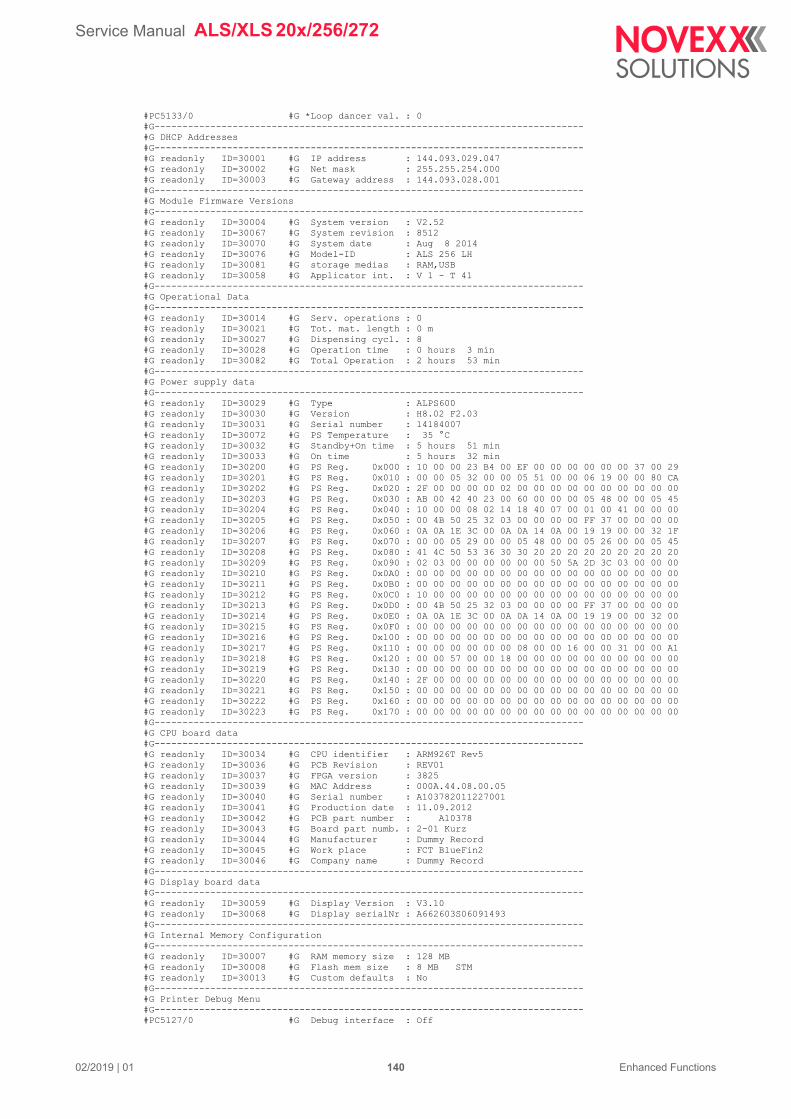
Service Manual ALS/XLS 20x/256/272
02/2019 | 01 140 Enhanced Functions
#PC5133/0 #G *Loop dancer val. : 0#G-----------------------------------------------------------------------------#G DHCP Addresses#G-----------------------------------------------------------------------------#G readonly ID=30001 #G IP address : 144.093.029.047#G readonly ID=30002 #G Net mask : 255.255.254.000#G readonly ID=30003 #G Gateway address : 144.093.028.001#G-----------------------------------------------------------------------------#G Module Firmware Versions#G-----------------------------------------------------------------------------#G readonly ID=30004 #G System version : V2.52#G readonly ID=30067 #G System revision : 8512#G readonly ID=30070 #G System date : Aug 8 2014#G readonly ID=30076 #G Model-ID : ALS 256 LH#G readonly ID=30081 #G storage medias : RAM,USB#G readonly ID=30058 #G Applicator int. : V 1 - T 41#G-----------------------------------------------------------------------------#G Operational Data#G-----------------------------------------------------------------------------#G readonly ID=30014 #G Serv. operations : 0#G readonly ID=30021 #G Tot. mat. length : 0 m#G readonly ID=30027 #G Dispensing cycl. : 8#G readonly ID=30028 #G Operation time : 0 hours 3 min#G readonly ID=30082 #G Total Operation : 2 hours 53 min#G-----------------------------------------------------------------------------#G Power supply data#G-----------------------------------------------------------------------------#G readonly ID=30029 #G Type : ALPS600#G readonly ID=30030 #G Version : H8.02 F2.03 #G readonly ID=30031 #G Serial number : 14184007 #G readonly ID=30072 #G PS Temperature : 35 °C#G readonly ID=30032 #G Standby+On time : 5 hours 51 min#G readonly ID=30033 #G On time : 5 hours 32 min#G readonly ID=30200 #G PS Reg. 0x000 : 10 00 00 23 B4 00 EF 00 00 00 00 00 00 37 00 29 #G readonly ID=30201 #G PS Reg. 0x010 : 00 00 05 32 00 00 05 51 00 00 06 19 00 00 80 CA #G readonly ID=30202 #G PS Reg. 0x020 : 2F 00 00 00 00 02 00 00 00 00 00 00 00 00 00 00 #G readonly ID=30203 #G PS Reg. 0x030 : AB 00 42 40 23 00 60 00 00 00 05 48 00 00 05 45 #G readonly ID=30204 #G PS Reg. 0x040 : 10 00 00 08 02 14 18 40 07 00 01 00 41 00 00 00 #G readonly ID=30205 #G PS Reg. 0x050 : 00 4B 50 25 32 03 00 00 00 00 FF 37 00 00 00 00 #G readonly ID=30206 #G PS Reg. 0x060 : 0A 0A 1E 3C 00 0A 0A 14 0A 00 19 19 00 00 32 1F #G readonly ID=30207 #G PS Reg. 0x070 : 00 00 05 29 00 00 05 48 00 00 05 26 00 00 05 45 #G readonly ID=30208 #G PS Reg. 0x080 : 41 4C 50 53 36 30 30 20 20 20 20 20 20 20 20 20 #G readonly ID=30209 #G PS Reg. 0x090 : 02 03 00 00 00 00 00 00 50 5A 2D 3C 03 00 00 00 #G readonly ID=30210 #G PS Reg. 0x0A0 : 00 00 00 00 00 00 00 00 00 00 00 00 00 00 00 00 #G readonly ID=30211 #G PS Reg. 0x0B0 : 00 00 00 00 00 00 00 00 00 00 00 00 00 00 00 00 #G readonly ID=30212 #G PS Reg. 0x0C0 : 10 00 00 00 00 00 00 00 00 00 00 00 00 00 00 00 #G readonly ID=30213 #G PS Reg. 0x0D0 : 00 4B 50 25 32 03 00 00 00 00 FF 37 00 00 00 00 #G readonly ID=30214 #G PS Reg. 0x0E0 : 0A 0A 1E 3C 00 0A 0A 14 0A 00 19 19 00 00 32 00 #G readonly ID=30215 #G PS Reg. 0x0F0 : 00 00 00 00 00 00 00 00 00 00 00 00 00 00 00 00 #G readonly ID=30216 #G PS Reg. 0x100 : 00 00 00 00 00 00 00 00 00 00 00 00 00 00 00 00 #G readonly ID=30217 #G PS Reg. 0x110 : 00 00 00 00 00 00 08 00 00 16 00 00 31 00 00 A1 #G readonly ID=30218 #G PS Reg. 0x120 : 00 00 57 00 00 18 00 00 00 00 00 00 00 00 00 00 #G readonly ID=30219 #G PS Reg. 0x130 : 00 00 00 00 00 00 00 00 00 00 00 00 00 00 00 00 #G readonly ID=30220 #G PS Reg. 0x140 : 2F 00 00 00 00 00 00 00 00 00 00 00 00 00 00 00 #G readonly ID=30221 #G PS Reg. 0x150 : 00 00 00 00 00 00 00 00 00 00 00 00 00 00 00 00 #G readonly ID=30222 #G PS Reg. 0x160 : 00 00 00 00 00 00 00 00 00 00 00 00 00 00 00 00 #G readonly ID=30223 #G PS Reg. 0x170 : 00 00 00 00 00 00 00 00 00 00 00 00 00 00 00 00 #G-----------------------------------------------------------------------------#G CPU board data#G-----------------------------------------------------------------------------#G readonly ID=30034 #G CPU identifier : ARM926T Rev5#G readonly ID=30036 #G PCB Revision : REV01#G readonly ID=30037 #G FPGA version : 3825#G readonly ID=30039 #G MAC Address : 000A.44.08.00.05#G readonly ID=30040 #G Serial number : A103782011227001#G readonly ID=30041 #G Production date : 11.09.2012#G readonly ID=30042 #G PCB part number : A10378#G readonly ID=30043 #G Board part numb. : 2-01 Kurz #G readonly ID=30044 #G Manufacturer : Dummy Record #G readonly ID=30045 #G Work place : FCT BlueFin2 #G readonly ID=30046 #G Company name : Dummy Record #G-----------------------------------------------------------------------------#G Display board data#G-----------------------------------------------------------------------------#G readonly ID=30059 #G Display Version : V3.10#G readonly ID=30068 #G Display serialNr : A662603S06091493#G-----------------------------------------------------------------------------#G Internal Memory Configuration#G-----------------------------------------------------------------------------#G readonly ID=30007 #G RAM memory size : 128 MB#G readonly ID=30008 #G Flash mem size : 8 MB STM#G readonly ID=30013 #G Custom defaults : No#G-----------------------------------------------------------------------------#G Printer Debug Menu#G-----------------------------------------------------------------------------#PC5127/0 #G Debug interface : Off
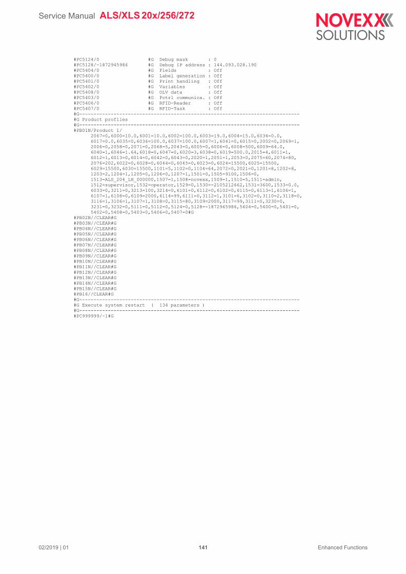
Service Manual ALS/XLS 20x/256/272
02/2019 | 01 141 Enhanced Functions
#PC5124/0 #G Debug mask : 0#PC5128/-1872945986 #G Debug IP address : 144.093.028.190#PC5404/0 #G Fields : Off#PC5400/0 #G Label generation : Off#PC5401/0 #G Print handling : Off#PC5402/0 #G Variables : Off#PC5408/0 #G OLV data : Off#PC5403/0 #G Pctrl communica. : Off#PC5406/0 #G RFID-Reader : Off#PC5407/0 #G RFID-Task : Off#G-----------------------------------------------------------------------------#G Product profiles#G-----------------------------------------------------------------------------#PB01N/Product 1/ 2067=0,6000=10.0,6001=10.0,6002=100.0,6003=19.0,6004=15.0,6034=0.0, 6017=0.0,6035=0,6036=100.0,6037=100.0,6007=1,6041=0,6015=0,2002=0,2069=1, 2006=0,2058=0,2071=0,2068=5,2043=0,6005=0,6006=0,6008=500,6009=64.0, 6040=1,6046=1.64,6018=0,6047=0,6020=3,6038=0,6019=500.0,2015=4,6011=1, 6012=1,6013=0,6014=0,6042=0,6043=0,2020=1,2051=1,2053=0,2075=60,2074=80, 2076=202,6022=0,6028=0,6044=0,6045=0,6023=0,6024=15500,6025=15500, 6029=15500,6030=15500,1101=5,1102=0,1104=64,2072=0,2021=0,1201=8,1202=8, 1203=2,1204=1,1205=0,1206=0,1207=1,1501=0,1505=9100,1506=0, 1513=ALS_204_LH_000000,1507=1,1508=novexx,1509=1,1510=5,1511=admin, 1512=supervisor,1532=operator,1529=0,1530=-2105212662,1531=3600,1533=0.0, 6033=0,3211=0,3213=100,3214=0,6101=0,6112=0,6102=0,6115=0,6113=1,6106=1, 6107=1,6108=0,6109=2000,6114=99,6111=0,3112=1,3101=6,3102=0,3110=2,3118=0, 3116=1,3106=1,3107=1,3108=0,3115=80,3109=2000,3117=99,3111=0,3230=0, 3231=0,3232=0,5111=0,5112=0,5124=0,5128=-1872945986,5404=0,5400=0,5401=0, 5402=0,5408=0,5403=0,5406=0,5407=0#G#PB02N//CLEAR#G#PB03N//CLEAR#G#PB04N//CLEAR#G#PB05N//CLEAR#G#PB06N//CLEAR#G#PB07N//CLEAR#G#PB08N//CLEAR#G#PB09N//CLEAR#G#PB10N//CLEAR#G#PB11N//CLEAR#G#PB12N//CLEAR#G#PB13N//CLEAR#G#PB14N//CLEAR#G#PB15N//CLEAR#G#PB16//CLEAR#G#G-----------------------------------------------------------------------------#G Execute system restart ( 134 parameters )#G-----------------------------------------------------------------------------#PC999999/-1#G
Service Manual ALS/XLS 20x/256/272
02/2019 | 02 142 Enhanced Functions
INTERFACE COMMANDS
Command overview
Command Function Can take values
#!An – Activate interface [4A]
– Once the command #!A1 has been given, all commands re-ceived are interpreted as inter-face commands.
n = Machine ID (is set using INTER-FACE PARA >EASYPLUGINTERPR > Dis-penser ID no.
#!CLRE Acknowledge status message (only possible, if the quit method is not „N“)
#!CLRW Reset warning status.
#!D Same effect as external start signal.
#!ERRF Get status message
#!Pn – Deactivate interface
– Once the command #!P1 has been given, the commands re-ceived are no longer interpreted as interface commands.
n = Machine ID (is set using INTER-FACE PARA >EASYPLUGINTERPR > Dis-penser ID no.
#!PG<Function ID>#G
#!PGn
Gives readout of menu function set-tings via the interface that is set up for use [4].
<Function ID> = identification num-ber of menu function
n = [-1 , -2, -4, -8, -16, -32, -xx]
#PB s/n/<Function ID>=<Value>[, <Function ID>=<Value>]#G
Value assignment to one ore more functions in a product profile.
s = number of the product profile
n = name of the product profile
<Function ID> = identification num-ber of menu function
#PC<Function ID>/ <Value>#G Adjusting a parameter in the param-eter menu. Effective only after reset.
<Function ID> = identification num-ber of menu function
<Value> = Setting value of the func-tion
#!PC<Function ID>/ <Value> Immediate adjustment of a parame-ter in the parameter menu during op-eration. Immediate effect.
<Function ID> = identification num-ber of menu function
<Value> = Setting value of the func-tion
#!SP Stop dispenser
#!SR Restart dispenser
#!WARF Get warning status
#!XMn#G Save diagnose dump in Flash and/or send it to interface
n = [-99, -100]
[Tab. 22] Overview of interface commands
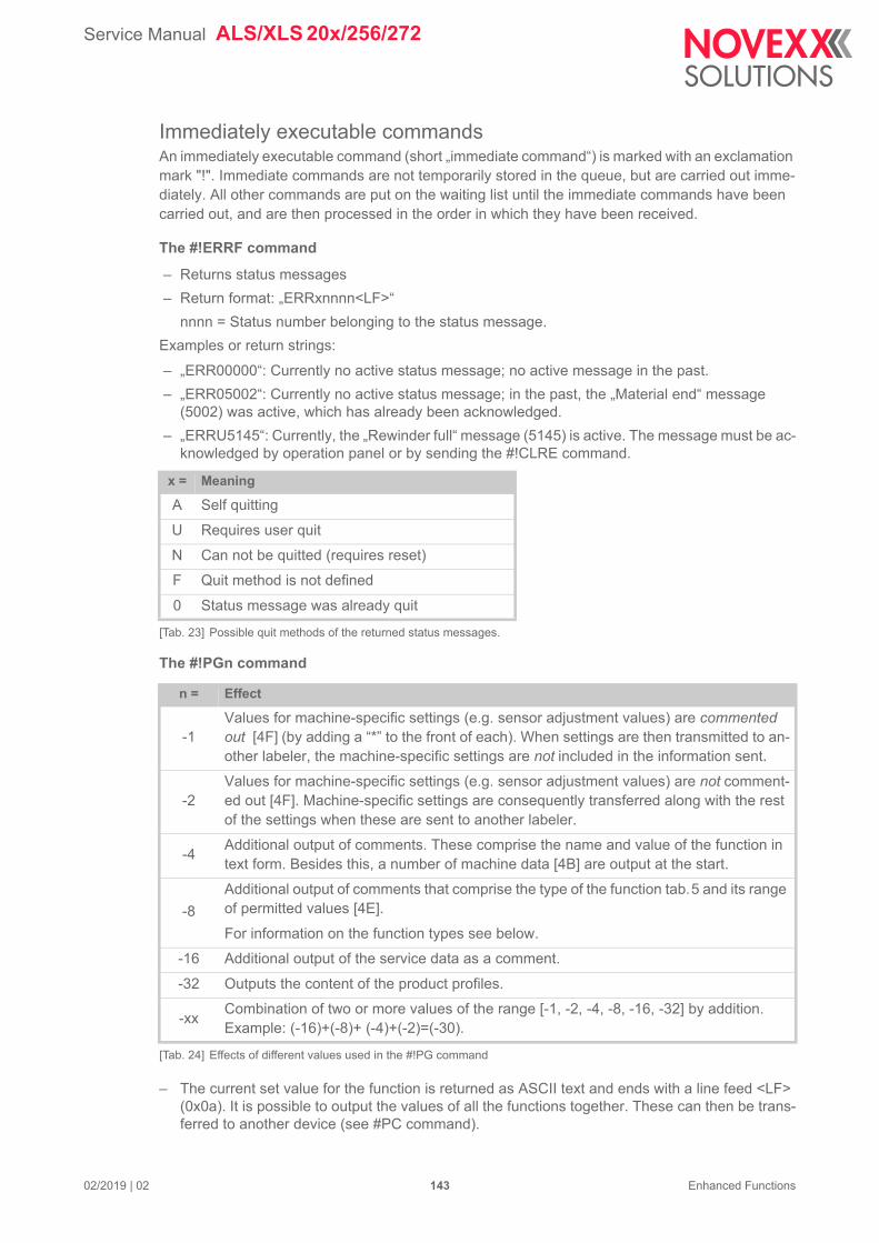
Service Manual ALS/XLS 20x/256/272
02/2019 | 02 143 Enhanced Functions
Immediately executable commandsAn immediately executable command (short „immediate command“) is marked with an exclamation mark "!". Immediate commands are not temporarily stored in the queue, but are carried out imme-diately. All other commands are put on the waiting list until the immediate commands have been carried out, and are then processed in the order in which they have been received.
The #!ERRF command
– Returns status messages
– Return format: „ERRxnnnn<LF>“
nnnn = Status number belonging to the status message.
Examples or return strings:
– „ERR00000“: Currently no active status message; no active message in the past.
– „ERR05002“: Currently no active status message; in the past, the „Material end“ message (5002) was active, which has already been acknowledged.
– „ERRU5145“: Currently, the „Rewinder full“ message (5145) is active. The message must be ac-knowledged by operation panel or by sending the #!CLRE command.
The #!PGn command
– The current set value for the function is returned as ASCII text and ends with a line feed <LF> (0x0a). It is possible to output the values of all the functions together. These can then be trans-ferred to another device (see #PC command).
x = Meaning
A Self quitting
U Requires user quit
N Can not be quitted (requires reset)
F Quit method is not defined
0 Status message was already quit
[Tab. 23] Possible quit methods of the returned status messages.
n = Effect
-1Values for machine-specific settings (e.g. sensor adjustment values) are commented out [4F] (by adding a “*” to the front of each). When settings are then transmitted to an-other labeler, the machine-specific settings are not included in the information sent.
-2Values for machine-specific settings (e.g. sensor adjustment values) are not comment-ed out [4F]. Machine-specific settings are consequently transferred along with the rest of the settings when these are sent to another labeler.
-4Additional output of comments. These comprise the name and value of the function in text form. Besides this, a number of machine data [4B] are output at the start.
-8
Additional output of comments that comprise the type of the function tab.5 and its range of permitted values [4E].
For information on the function types see below.
-16 Additional output of the service data as a comment.
-32 Outputs the content of the product profiles.
-xxCombination of two or more values of the range [-1, -2, -4, -8, -16, -32] by addition. Example: (-16)+(-8)+ (-4)+(-2)=(-30).
[Tab. 24] Effects of different values used in the #!PG command
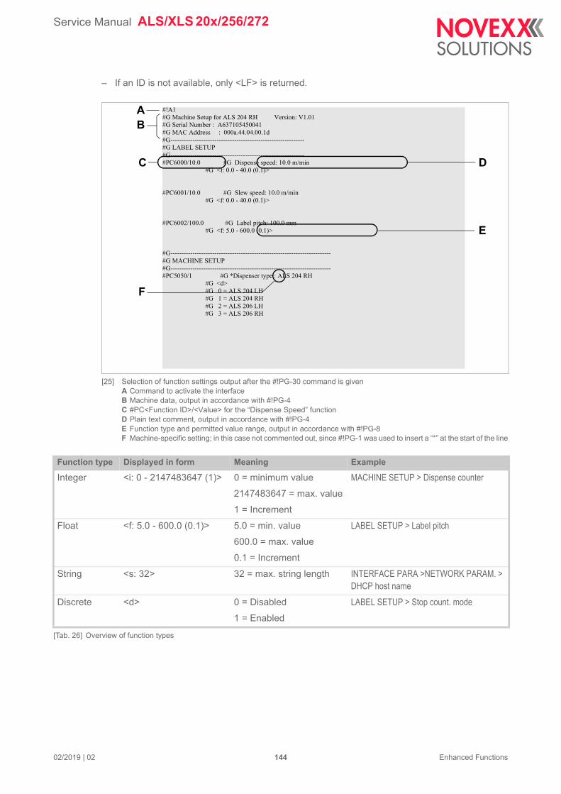
Service Manual ALS/XLS 20x/256/272
02/2019 | 02 144 Enhanced Functions
– If an ID is not available, only <LF> is returned.
[25] Selection of function settings output after the #!PG-30 command is givenA Command to activate the interfaceB Machine data, output in accordance with #!PG-4C #PC<Function ID>/<Value> for the “Dispense Speed” functionD Plain text comment, output in accordance with #!PG-4E Function type and permitted value range, output in accordance with #!PG-8F Machine-specific setting; in this case not commented out, since #!PG-1 was used to insert a “*” at the start of the line
#!A1#G Machine Setup for ALS 204 RH Version: V1.01#G Serial Number : A637105450041#G MAC Address : 000a.44.04.00.1d#G-------------------------------------------------------------#G LABEL SETUP#G-------------------------------------------------------------#PC6000/10.0 #G Dispense speed: 10.0 m/min #G <f: 0.0 - 40.0 (0.1)>
#PC6001/10.0 #G Slew speed: 10.0 m/min #G <f: 0.0 - 40.0 (0.1)>
#PC6002/100.0 #G Label pitch: 100.0 mm #G <f: 5.0 - 600.0 (0.1)>
#G-------------------------------------------------------------------------#G MACHINE SETUP#G-------------------------------------------------------------------------#PC5050/1 #G *Dispenser type : ALS 204 RH #G <d> #G 0 = ALS 204 LH #G 1 = ALS 204 RH #G 2 = ALS 206 LH #G 3 = ALS 206 RH
AB
C D
E
F
Function type Displayed in form Meaning Example
Integer <i: 0 - 2147483647 (1)> 0 = minimum value
2147483647 = max. value
1 = Increment
MACHINE SETUP > Dispense counter
Float <f: 5.0 - 600.0 (0.1)> 5.0 = min. value
600.0 = max. value
0.1 = Increment
LABEL SETUP > Label pitch
String <s: 32> 32 = max. string length INTERFACE PARA >NETWORK PARAM. > DHCP host name
Discrete <d> 0 = Disabled
1 = Enabled
LABEL SETUP > Stop count. mode
[Tab. 26] Overview of function types
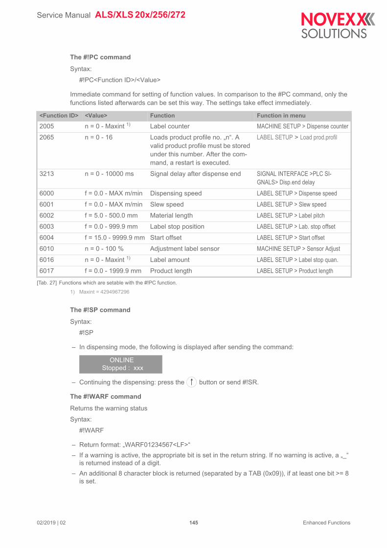
Service Manual ALS/XLS 20x/256/272
02/2019 | 02 145 Enhanced Functions
The #!PC command
Syntax:
#!PC<Function ID>/<Value>
Immediate command for setting of function values. In comparison to the #PC command, only the functions listed afterwards can be set this way. The settings take effect immediately.
1) Maxint = 4294967296
The #!SP command
Syntax:
#!SP
– In dispensing mode, the following is displayed after sending the command:
– Continuing the dispensing: press the button or send #!SR.
The #!WARF command
Returns the warning status
Syntax:
#!WARF
– Return format: „WARF01234567<LF>“
– If a warning is active, the appropriate bit is set in the return string. If no warning is active, a „_“ is returned instead of a digit.
– An additional 8 character block is returned (separated by a TAB (0x09)), if at least one bit >= 8 is set.
<Function ID> <Value> Function Function in menu
2005 n = 0 - Maxint 1) Label counter MACHINE SETUP > Dispense counter
2065 n = 0 - 16 Loads product profile no. „n“. A valid product profile must be stored under this number. After the com-mand, a restart is executed.
LABEL SETUP > Load prod.profil
3213 n = 0 - 10000 ms Signal delay after dispense end SIGNAL INTERFACE >PLC SI-GNALS> Disp.end delay
6000 f = 0.0 - MAX m/min Dispensing speed LABEL SETUP > Dispense speed
6001 f = 0.0 - MAX m/min Slew speed LABEL SETUP > Slew speed
6002 f = 5.0 - 500.0 mm Material length LABEL SETUP > Label pitch
6003 f = 0.0 - 999.9 mm Label stop position LABEL SETUP > Lab. stop offset
6004 f = 15.0 - 9999.9 mm Start offset LABEL SETUP > Start offset
6010 n = 0 - 100 % Adjustment label sensor MACHINE SETUP > Sensor Adjust
6016 n = 0 - Maxint 1) Label amount LABEL SETUP > Label stop quan.
6017 f = 0.0 - 1999.9 mm Product length LABEL SETUP > Product length
[Tab. 27] Functions which are setable with the #!PC function.
ONLINEStopped : xxx
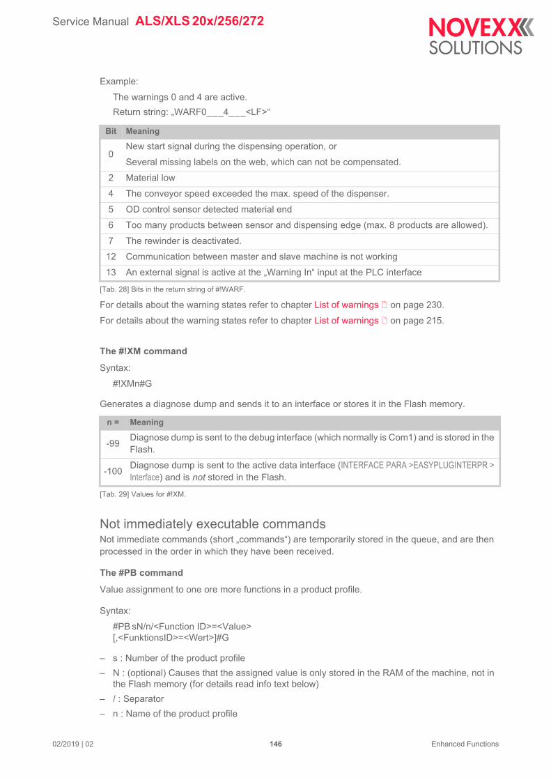
Service Manual ALS/XLS 20x/256/272
02/2019 | 02 146 Enhanced Functions
Example:
The warnings 0 and 4 are active.
Return string: „WARF0___4___<LF>“
For details about the warning states refer to chapter List of warnings on page 230.
For details about the warning states refer to chapter List of warnings on page 215.
The #!XM command
Syntax:
#!XMn#G
Generates a diagnose dump and sends it to an interface or stores it in the Flash memory.
Not immediately executable commandsNot immediate commands (short „commands“) are temporarily stored in the queue, and are then processed in the order in which they have been received.
The #PB command
Value assignment to one ore more functions in a product profile.
Syntax:
#PB sN/n/<Function ID>=<Value>[,<FunktionsID>=<Wert>]#G
– s : Number of the product profile
– N : (optional) Causes that the assigned value is only stored in the RAM of the machine, not in the Flash memory (for details read info text below)
– / : Separator
– n : Name of the product profile
Bit Meaning
0New start signal during the dispensing operation, or
Several missing labels on the web, which can not be compensated.
2 Material low
4 The conveyor speed exceeded the max. speed of the dispenser.
5 OD control sensor detected material end
6 Too many products between sensor and dispensing edge (max. 8 products are allowed).
7 The rewinder is deactivated.
12 Communication between master and slave machine is not working
13 An external signal is active at the „Warning In“ input at the PLC interface
[Tab. 28] Bits in the return string of #!WARF.
n = Meaning
-99Diagnose dump is sent to the debug interface (which normally is Com1) and is stored in the Flash.
-100Diagnose dump is sent to the active data interface (INTERFACE PARA >EASYPLUGINTERPR > Interface) and is not stored in the Flash.
[Tab. 29] Values for #!XM.
Service Manual ALS/XLS 20x/256/272
02/2019 | 02 147 Enhanced Functions
– <Function ID>: Identification number of the function
– <Value>: Value of the function (permitted values depend on function type)
– #G declares end of command
Example:
Creating a product profile with the name „Product 2“ on memory slot 2:
#!A1
– #PB2/Product 2/2067=0,6000=10.0,6001=10.0,6002=35.4,6003=19.0,6004=15.0,6034=0.0,6017=0.0,6035=0,6036=100.0,6037=100.0,6007=1,6041=0,6015=0,2002=0,2069=1,2006=0,2058=0,2071=0,2068=5,2043=0,6005=0,6006=0,6008=500,6009=64.0,6040=1,6046=1.80,6018=0,6047=0,6020=3,6038=0,6019=500.0,2015=4,6011=1,6012=1,6013=0,6014=0,6042=0,6043=0,2020=1,2051=1,2053=0,2075=60,2074=80,2076=270,6022=0,6028=0,6044=0,6045=0,6023=0,6024=50000,6025=50000,6029=15000,6030=2000,1101=0,1102=0,1104=64,2072=0,2021=0,1201=8,1202=8,1203=2,1204=1,1205=0,1206=0,1207=1,1501=1,1505=9100,1506=0,1513=ALS_204_LH_080100,1507=0,1508=novexx,1509=0,1510=5,1511=admin,1512=su-pervisor,1532=operator,1529=0,1530=-2105212662,1531=3600,1533=0.0,6033=0,3211=0,3213=0,3214=0,6101=0,6112=0,6102=0,6113=1,6106=1,6107=0,6108=0,6109=2000,6111=0,3112=1,3101=6,3102=0,3110=2,3116=1,3106=1,3107=1,3108=0,3115=80,3109=2000,3111=0,3230=0,3231=0,3232=0,5111=0,5112=0,5127=1,5124=0,5128=-1872945986,5404=0,5400=0,5401=0,5402=0,5408=0,5403=0,5406=0,5407=0#G
Use of „N“:
Stating „N“ provokes that the parameter value(s) of a product profile are not immediately written into the Flash memory of the machine. This is appropriate, if several #PB commands are transmitted in series, because writing into the Flash memory is a rather time consuming process. In this case, time can be saved if all #PB commands except for the last are trans-mitted with „N“ set, but the last #PB command is transmitted without „N“ (important!). Final-ly, the very last #PB command provokes the writing of all values into the Flash memory.
Example:
Creating several product profiles using „N“:
#!A1
#PB01N/CAN250g/ 2067=0,6000=19.5,6001=10.0,6002=209.6,6003=100.0,6004=48.5,6034=0.0, 6017=65.0,6035=0,6036=255.3,6037=255.3,6007=1,6041=0,6015=0,2002=0,2069=1,(...)#G
#PB02N/CAN500g/ 2067=0,6000=19.5,6001=10.0,6002=209.6,6003=280.0,6004=32.2,6034=0.0, 6017=65.0,6035=0,6036=255.3,6037=255.3,6007=1,6041=0,6015=0,2002=0,2069=1, (...)#G
#G ------------------------------------
#G -- Last PB command of the series
#G -- (without „N“):
#G ------------------------------------
Service Manual ALS/XLS 20x/256/272
02/2019 | 02 148 Enhanced Functions
#PB03/500GM/ 2067=0,6000=19.5,6001=10.0,6002=268.0,6003=100.0,6004=206.3,6034=0.0, 6017=260.0,6035=0,6036=268.0,6037=268.0,6007=1,6041=0,6015=0,2002=0, 2069=1,2006=0,2058=0,2071=0,2068=5,2043=0,6005=0,6006=0,6008=500, (...)#G
The #PC command
Syntax:
#PC<Function ID>/<Value>#G
– <Function ID>: Identification number of the function
– / : Separator
– <Value>: Value of the function (permitted values depend on function type)
– #G declares end of command
Adjusts a parameter in the parameter menu. This parameter is especially suitable for saving and transferring complete machine setups. It can for example be used in the following cases:
– if settings must be transferred from one machine to another.
– if several machines are supposed to have the same settings.
– if the settings of a machine are supposed to be recovered, e.g. after the CPU board was re-placed.
It is adviseable to read out the parameter settings of the concerned machine at first. It thus emerges which parameters are relevant for the respective machine. The reading out can be done one of the following ways:
– Via the immediate command #!PGn, see chapter The #!PGn command on page 1
– Saving a setup file on a memory card, see chapter Saving/loading a configuration on page 132
To activate the setting, the machine must be reset after sending the #PC command. The reset can be triggered at the operation panel of the device or by an Easy-Plug command (#PC999999/-1#G). This is also the last command in a setup file.
Example:
#!A
#PC6000/10.0#G
#PC999999/-1#G
Sets the dispensing speed to 10.0 m/min and restarts the machine:
– #!A sets interface to be ready to receive interface commands
– 6000 = Function ID of the function LABEL SETUP > Dispense speed
– 10.0 = Speed in m/min
– 999999/-1 resets the machine see tab.9
Value Function
-1 Reset the machine
1Store the current parameter settings as customer default (equates to MACHINE SETUP > Cu-stom defaults = „Apply current“)
2Delete the stored customer default values (equates to MACHINE SETUP > Custom defaults = „Delete“)
[Tab. 30] Handover values for the command #PC999999 for special purposes.

Service Manual ALS/XLS 20x/256/272
02/2019 | 02 149 Enhanced Functions
3Restore factory settings with „custom defaults“ if available (equates to MACHINE SETUP > Factory settings = „Custom defaults“), if not use „factory defaults“ (equates to MACHINE SE-TUP > Factory settings = „Factory defaults“)
Value Function
[Tab. 30] Handover values for the command #PC999999 for special purposes.
Service Manual ALS/XLS 20x/256/272
02/2019 | 00 150 Enhanced Functions
FORCED BOOTLOADER STARTA forced bootloader start is required, if the dispenser firmware hung up and the machine will not get ready for operation even after a restart.
Gen. 1Instruction for machines that are equipped with a Gen. 1 CPU board (firmware up to version 1.51).
Switch the machine off.
Keep the buttons + pressed and sumultaneously switch on the machine.
The bootloader appears:
x.x = Bootloader version
Press the button.
The menu LOADER FUNCTIONS with the single function „Clear Params“ shows up:
Press the button.
Press the button to change to „yes“.
Press the button.
All settings in the functions menu are deleted, including the setting which caused the firmware to crash.
Switch the machine off.
Switch the machine on while keeping the buttons + pressed, until the machine type is displayed.
After this display:
press the following buttons in succession:, , , , 3x .
Set the machine type under MACHINE SETUP > Dispenser type.
Switch the machine off and on again after waiting at least 10 s in between.
Boot Loader V x.x115KB, 8N1
NOVEXX SolutionsDispenser-CPU32
LOADER FUNCTIONSClear params
NOVEXX SolutionsDispenser-CPU32
Clear paramsno
NOVEXX SolutionsDispenser-CPU32
Code:
Service Manual ALS/XLS 20x/256/272
02/2019 | 00 151 Enhanced Functions
Gen. 2Instruction for:
– Machines that are equipped with a Gen. 2 CPU board (firmware version 2.51 or higher)
– All XLS 2xx machines
Switch the machine off.
Keep the buttons + pressed and sumultaneously switch on the machine.
The bootloader appears with a simple menu:
Press the button (clr par).
All settings in the functions menu are deleted, including the setting which caused the firmware to crash.
Switch the machine off.
Switch the machine on while keeping the buttons + pressed, until the machine type is displayed.
After this display:
press the following buttons in succession:, , , , 3x .
Set the machine type under MACHINE SETUP > Dispenser type.
Switch the machine off and on again after waiting at least 10 s in between.
For information about the other functions in the bootloader menu, refer to chapter „Loading Firm-ware“ > „Loading with the bootloader“.
Code:
Service Manual ALS/XLS 20x/256/272
02/2019 | 01 152 Enhanced Functions
DIAGNOSE DUMP
Storing diagnosis dataDuring normal operation, machine internal communication is permanently logged and deleted after a certain time. Those log data can be accessed for diagnostic purpose in error case (comparable to the black box in an airplane).
To do so, a „snapshot“ of the diagnostic data is stored in Flash memory, the so-called diagnose dump. Simultaneously, the diagnose dump is sent to the debug interface (normally com1).
Storing a diagnose dump is done either automatically, if the machine got in an undefined state, or manually by pressing all four operation panel buttons simultaneously:
+ + +
Events, which trigger an automatic storing of the diagnose dump:
– Dispensing suddenly stops.
– Status message „unmanaged interrupt“ appears on the display.
– The device suddenly doesn´t react on keystrokes any more.
A diagnose dump can be accessed on the following ways:
– Reading out via serial interface.
– Storing on an external memory medium as logfile.
In the Flash memory, a certain area is reserved for diagnose dumps, which provides enough space for 3-4 dumps. If this area is already filled, the oldest stored dump is over-written by a new one.
Reading out via serial interfacePrerequisites
– Firmware (at least): 1.11Pre6
– Terminal program (e. g. „Hyperterminal“ which was delivered with Windows operating systems up to Windows XP; for newer Windows versions the program is available on the website of the company Hilgraeve: https://www.hilgraeve.com/hyperterminal-trial/)
Carrying out
Connect the printing device to a PC, using the serial interface. Set the transfer parameters to 115 kB, n, 8, 1 (default setting).
Start Hyperterminal.
– The window „Connection Description“ [113] opens.
Service Manual ALS/XLS 20x/256/272
02/2019 | 01 153 Enhanced Functions
[113] Enter a name (A) for the new connection.
Name the new connection [113A]. Click OK.
– The window „Connect“ opens.
[114] Set the transfer parameters.
Select the serial port of the PC and click OK.
– The window „COM1 Properties“ [114] opens (if COM1 was selected).
Set the transfer parameters to 115 kB, n, 8, 1 and click OK.
– The Hyperterminal main window opens.
[115] Hyperterminal main window.
A
Service Manual ALS/XLS 20x/256/272
02/2019 | 01 154 Enhanced Functions
Open the menu „Transfer“ and click „Record Text“ [115].
– An input window opens.
Enter the file name for the record file and click „Start“.
At the printer operation panel press all four buttons simultaneously.
– This starts data being read out of the printing device and being displayed in the Hyperterminal main window [116]. At the same time, the data are saved in the record file.
To stop the transmission, click „Cancel“ in the menu „Transfer > Record text...“.
Generating further record files:
Close Hyperterminal and start new.
[116] Read out data.
Send the generated files with a description of the circumstances in which the error occured per email to the technical support at Novexx Solutions.
Service Manual ALS/XLS 20x/256/272
02/2019 | 01 155 Enhanced Functions
Storing on memory medium Call SERVICE/DIAGNOS. > Store diagnosis.
The second line shows the initial 16 characters of the default file name. The complete file name is::
„Diagnose ALS 206 RH A637804070501067.log“
– ALS 206 RH: Machine type
– A637804070501067: Serial number of the CPU board; equals the string in SERVICE DATA >CPU BOARD DATA > Serial number
Press the button twice to acknowledge and to store the file name.
Typing in a new file name:
Press the button to dismiss the default file name.
Select each character of the new file name by pressing the or buttons and acknowledge it by pressing .
Finally press the button twice to acknowledge and store the file.
Alternatively, type in the file name on an optional keyboard connected to the machine and acknowl-edge by pressing .
The log file will be stored in the \LOGFILES directory on the external memory medium.
Store diagnosisDiagnose ALS 206 RH A
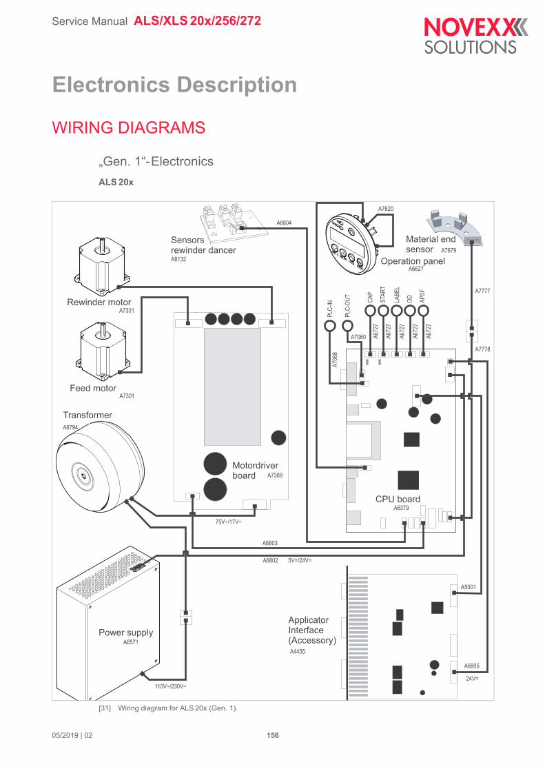
Service Manual ALS/XLS 20x/256/272
05/2019 | 02 156
Electronics Description
WIRING DIAGRAMS
„Gen. 1“-Electronics
ALS 20x
[31] Wiring diagram for ALS 20x (Gen. 1).
CAP
PLC-
OUT
PLC-
IN STAR
T
LABE
L
OD APSF
A7301
A7301
A6794
A8132A6627
A7679
A7777
A7778
A6803
A6379
A7389
A7060A7
068
A672
7
A672
7
A672
7
A672
7
A672
7
A5001
A6805
A4455A6571
A7620
A6804
A6802
110V~/230V~
75V~/17V~
5V=/24V=
24V=
Motordriverboard
CPU board
ApplicatorInterface(Accessory)
Material endsensor
Operation panel
Sensorsrewinder dancer
Feed motor
Rewinder motor
Transformer
Power supply
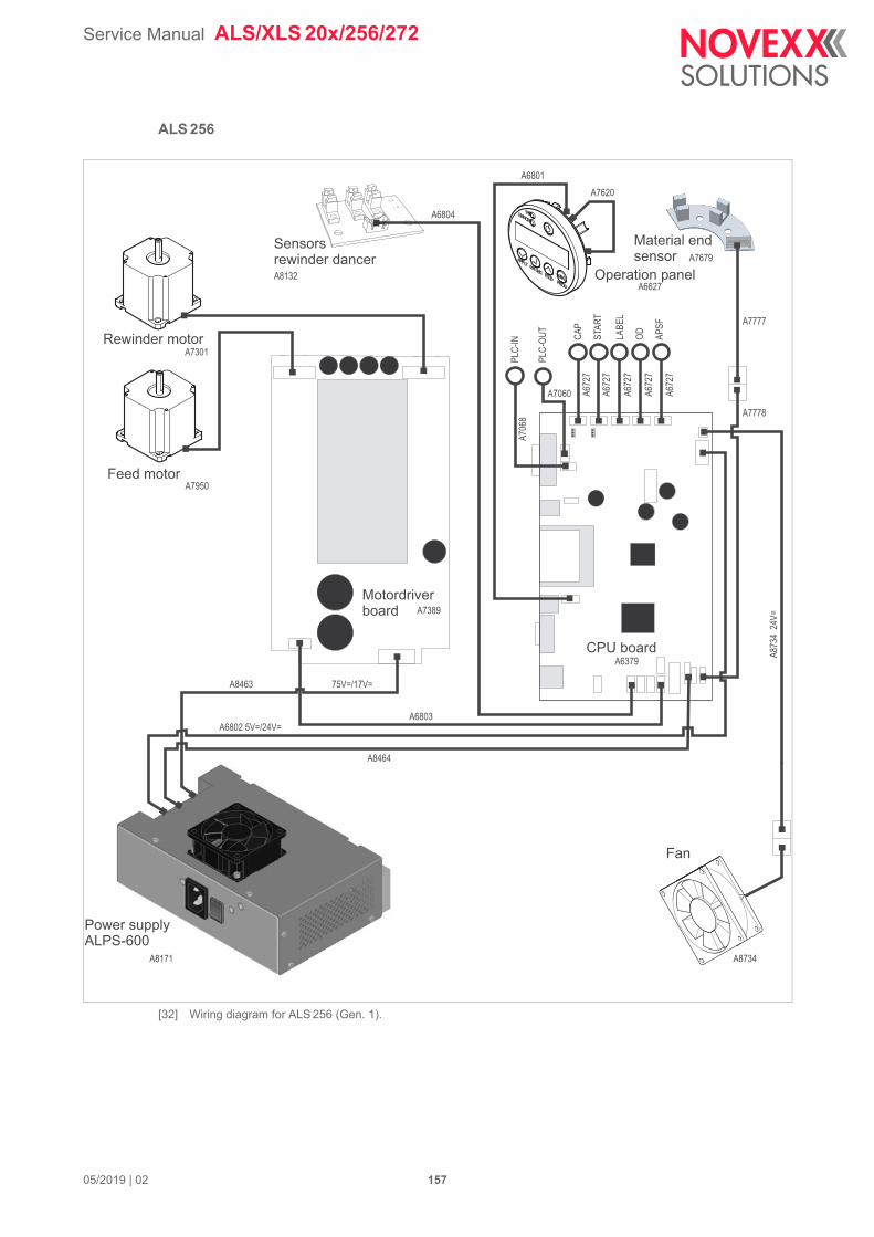
Service Manual ALS/XLS 20x/256/272
05/2019 | 02 157
ALS 256
[32] Wiring diagram for ALS 256 (Gen. 1).
CAP
PLC-
OUT
PLC-
IN STAR
T
LABE
L
OD APSF
A7301
A7950
A8132A6627
A7679
A7777
A7778
A6803
A6379
A7389
A7060
A706
8
A672
7
A672
7
A672
7
A672
7
A672
7
A8734A8171
A7620A6801
A6804
A6802 5V=/24V=
A8463
A8464A8
734
24V=
75V=/17V=
Motordriverboard
CPU board
Material endsensor
Operation panel
Sensorsrewinder dancer
Feed motor
Rewinder motor
Power supplyALPS-600
Fan
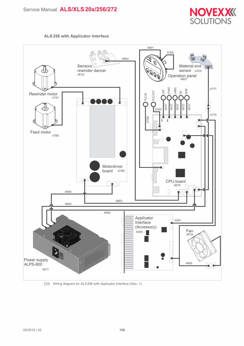
Service Manual ALS/XLS 20x/256/272
05/2019 | 02 158
ALS 256 with Applicator Interface
[33] Wiring diagram for ALS 256 with Applicator Interface (Gen. 1).
CAP
PLC-
OUT
PLC-
IN STAR
T
LABE
L
OD APSF
A7301
A7950
A8132A6627
A7679
A7777
A7778
A6803
A6379
A7389
A7060
A706
8
A672
7
A672
7
A672
7
A672
7
A672
7
A5001
A6805
A8734A4455
A8171
A7620A6801
A6804
A6802
A8463
A8464
Motordriverboard
CPU board
ApplicatorInterface(Accessory)
Material endsensor
Operation panel
Sensorsrewinder dancer
Feed motor
Rewinder motor
Power supplyALPS-600
Fan
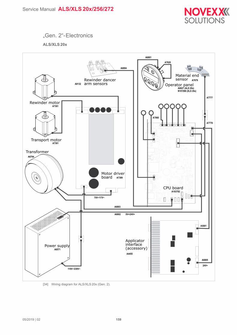
Service Manual ALS/XLS 20x/256/272
05/2019 | 02 159
„Gen. 2“-Electronics
ALS/XLS 20x
[34] Wiring diagram for ALS/XLS 20x (Gen. 2).
L1201
C2640
C1135
R2301
D1501
C2523
Rewinder dancerarm sensors
Material endsensor
Operator panel
Rewinder motor
Transport motor
Transformer
Motor driverboard
CPU board
Applicatorinterface(accessory)Power supply
A8132
A7301
A7301
A6794
A7060
A7679
A7777
A7778
A6627 (ALS 20x)N101590 (XLS 20x)
A6801
A7620
A6804
A103782
A7389
A6803
A6802
A6571A4455
A5001
A6805
75V~/17V~
5V=/24V=
24V=110V~/230V~
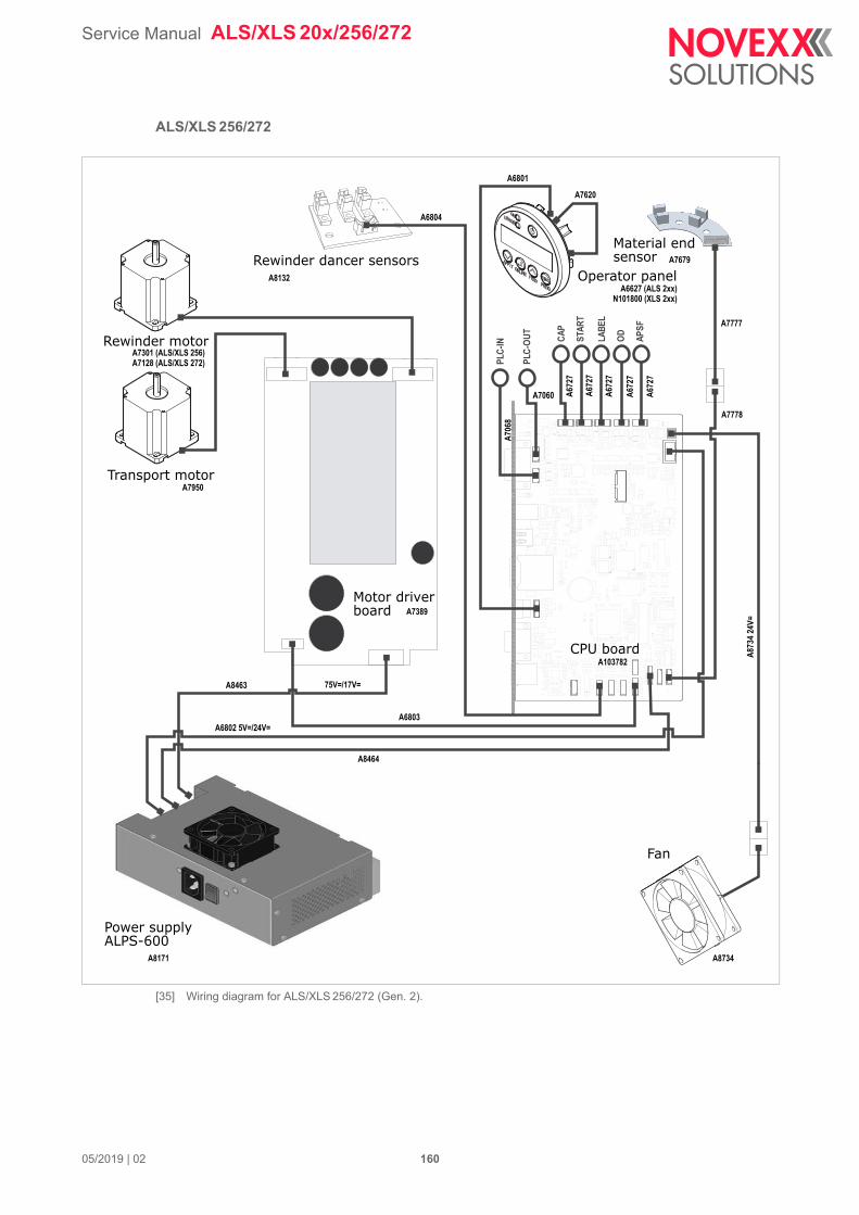
Service Manual ALS/XLS 20x/256/272
05/2019 | 02 160
ALS/XLS 256/272
[35] Wiring diagram for ALS/XLS 256/272 (Gen. 2).
L1201
C2640
C1135
R2301
D1501
C2523
Material endsensor
Operator panelRewinder dancer sensors
Rewinder motor
Transport motor
Motor driverboard
CPU board
Fan
Power supplyALPS-600
CAP
PLC-
OUT
PLC-
IN STAR
T
LABE
L
OD APSF
A8132
A6804
A7950
A6801
A7620
A6627 (ALS 2xx)
A7679
A7777
A7778
A7060
A7301 (ALS/XLS 256)A7128 (ALS/XLS 272)
A8463
A6803
A8464
A6802 5V=/24V=
A7389
A103782
A873
4 24
V=
A8171 A8734
75V=/17V=
A706
8
A672
7
A672
7
A672
7
A672
7
A672
7
N101800 (XLS 2xx)
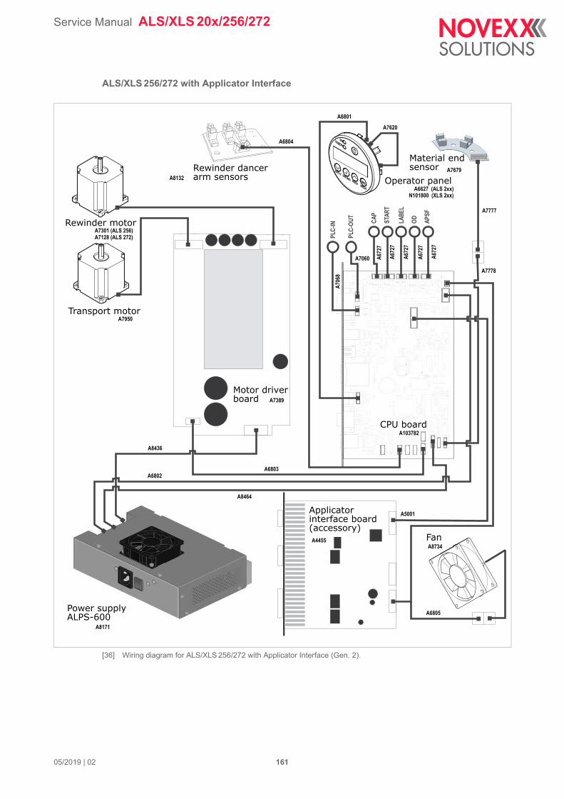
Service Manual ALS/XLS 20x/256/272
05/2019 | 02 161
ALS/XLS 256/272 with Applicator Interface
[36] Wiring diagram for ALS/XLS 256/272 with Applicator Interface (Gen. 2).
L1201
C2640
C1135
R2301
D1501
C2523
A7301 (ALS 256)A7128 (ALS 272)
A8132
A7950
A6804
A6801
A7620
A7777
A7778
A7679
A6627 (ALS 2xx)
A672
7
A672
7
A672
7
A672
7
A672
7
A706
8
A7060
A8436
A6802
A8464
A6803
A8171
A6805
A8734
A5001
A4455
A103782
A7389
N101800 (XLS 2xx)
Rewinder dancerarm sensors
Transport motor
Rewinder motor
Material endsensor
Operator panel
CPU board
Motor driverboard
Fan
Applicatorinterface board(accessory)
Power supplyALPS-600
CAP
PLC-
OUT
PLC-
IN STAR
T
LABE
L
OD APSF
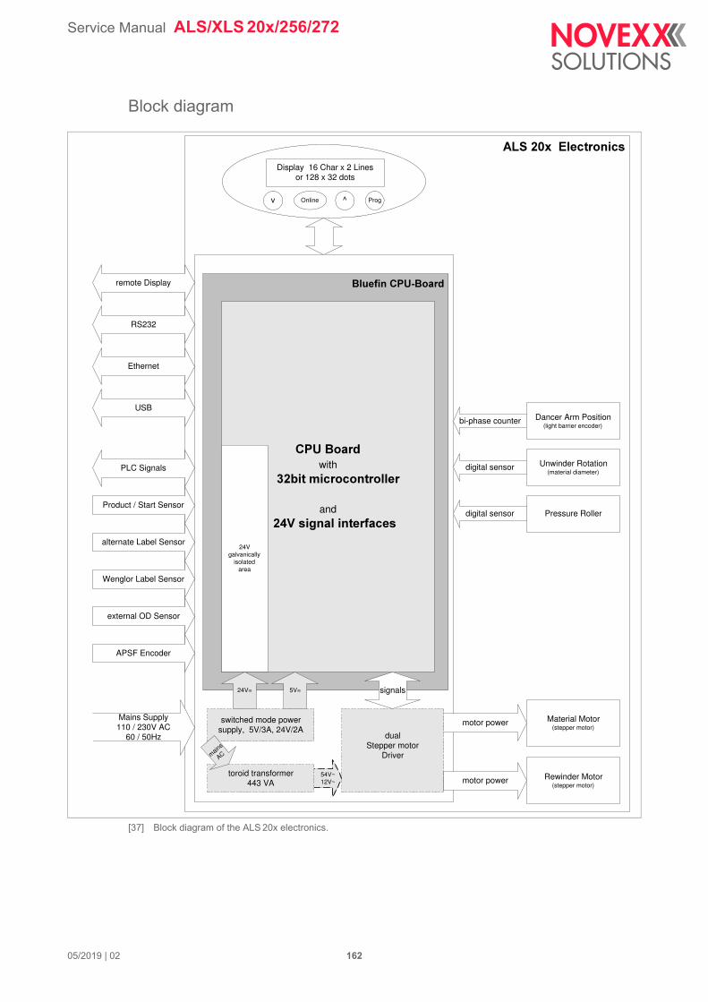
Service Manual ALS/XLS 20x/256/272
05/2019 | 02 162
Block diagram
[37] Block diagram of the ALS 20x electronics.
����������� ������
display unit
Display 16 Char x 2 Linesor 128 x 32 dots
v ^ ProgOnline
Mains Supply110 / 230V AC
60 / 50Hz
RS232
Ethernet
PLC Signals
alternate Label Sensor
Wenglor Label Sensor
Dancer Arm Position(light barrier encoder)
Unwinder Rotation(material diameter)
Pressure Roller
Material Motor(stepper motor)
motor power
digital sensor
digital sensor
bi-phase counter
����������������
switched mode powersupply, 5V/3A, 24V/2A
dualStepper motor
Driver
54V~12V~
24V=
���������with
���������� ��������� ����
and
������ ���!����� �������
signals
USB
remote Display
toroid transformer443 VA
mains
AC
5V=
24Vgalvanically
isolatedarea
Rewinder Motor(stepper motor)
motor power
external OD Sensor
Product / Start Sensor
APSF Encoder
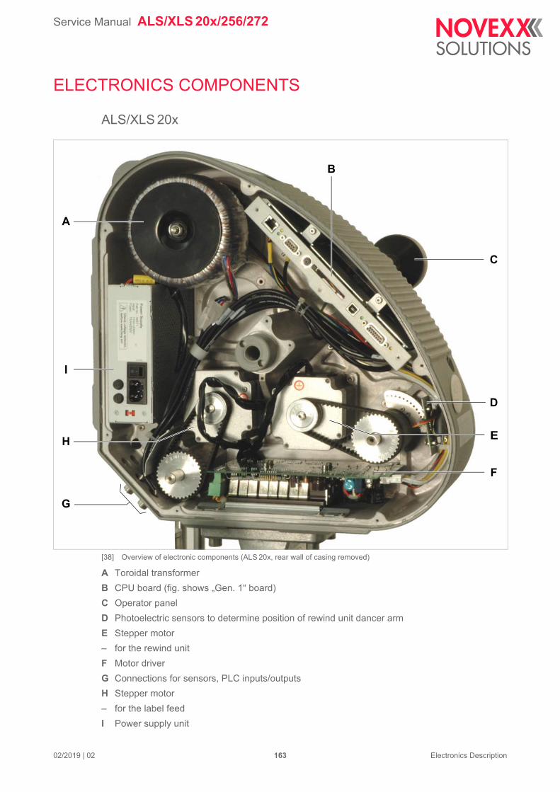
Service Manual ALS/XLS 20x/256/272
02/2019 | 02 163 Electronics Description
ELECTRONICS COMPONENTS
ALS/XLS 20x
[38] Overview of electronic components (ALS 20x, rear wall of casing removed)
A Toroidal transformer
B CPU board (fig. shows „Gen. 1“ board)
C Operator panel
D Photoelectric sensors to determine position of rewind unit dancer arm
E Stepper motor
– for the rewind unit
F Motor driver
G Connections for sensors, PLC inputs/outputs
H Stepper motor
– for the label feed
I Power supply unit
A
B
C
D
F
E
G
H
I
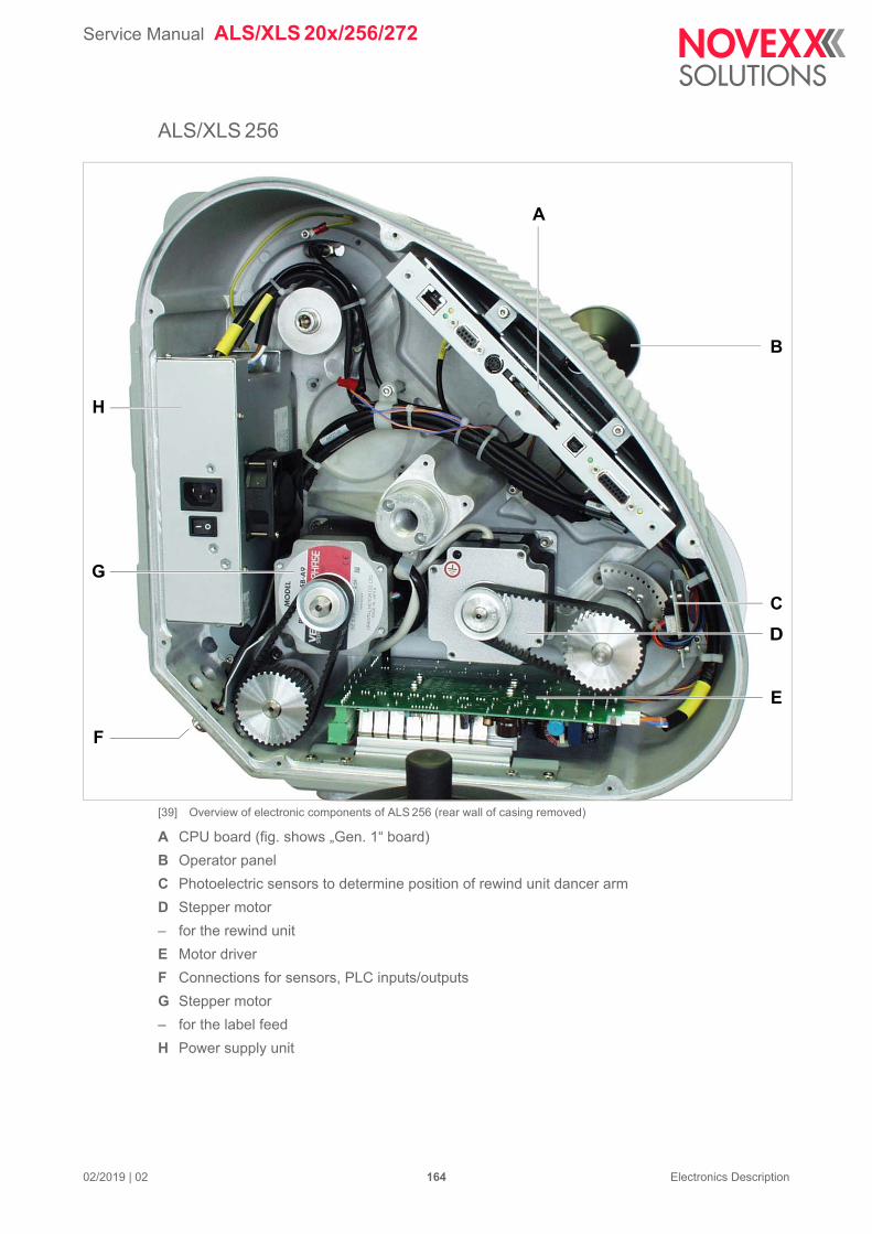
Service Manual ALS/XLS 20x/256/272
02/2019 | 02 164 Electronics Description
ALS/XLS 256
[39] Overview of electronic components of ALS 256 (rear wall of casing removed)
A CPU board (fig. shows „Gen. 1“ board)
B Operator panel
C Photoelectric sensors to determine position of rewind unit dancer arm
D Stepper motor
– for the rewind unit
E Motor driver
F Connections for sensors, PLC inputs/outputs
G Stepper motor
– for the label feed
H Power supply unit
A
C
E
D
H
G
F
B
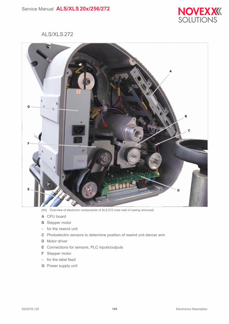
Service Manual ALS/XLS 20x/256/272
02/2019 | 02 165 Electronics Description
ALS/XLS 272
[40] Overview of electronic components of ALS 272 (rear wall of casing removed)
A CPU board
B Stepper motor
– for the rewind unit
C Photoelectric sensors to determine position of rewind unit dancer arm
D Motor driver
E Connections for sensors, PLC inputs/outputs
F Stepper motor
– for the label feed
G Power supply unit
A
B
C
DE
F
G

Service Manual ALS/XLS 20x/256/272
02/2019 | 03 166 Electronics Description
CIRCUIT BOARDS
CPU board (Gen. 1)
Connections and configuration
[117] Connections on the CPU board „Gen. 1“ (A6379)
A B C D E F G
H
I
J
K
L
M
N
OP
QRSTUV
W
Y
Z
AA
AB
AC
ADAE
AF
AG
X
AI
AH
Service Manual ALS/XLS 20x/256/272
02/2019 | 03 167 Electronics Description
A JP 901: Jumper controls pin 2 of the alternative label sensor
– Preset: Jumper open
– See chapter Changing light/dark switching at the product sensor or the alternative label sensor on page 58.
B CN 906: Connection for alternative label sensor
C JP 902: Jumper controls pin 2 of the product/start sensor
– Preset: Jumper open
– See chapter Changing light/dark switching at the product sensor or the alternative label sensor on page 58.
D CN 905: Connection for product/start sensor
E CN 904: Connection for (Wenglor) photoelectric label sensor
F CN 903: Sensor connection for external roll diameter control
G CN 902: Connection for rotary encoder, for automatic speed adjustment
H CN 502: Supply voltage connection for applicator interface (+24 V)
I CN 501: Power supply unit connection
– Power supply for the board with 5 V and 24 V
J CN 702: Connection to applicator interface
K JP 601: Jumper micromonitor (Diagnostic software for factory-internal use)
– Preset: open
L JP 602: Jumper with no function
M CN 802: Connection for additional motor driver (optional)
N CN 808: Sensor connection for internal roll diameter control
O CN 809: Connection for pressure roller switch (optional)
P CN 703: Connection for power supply (I2C bus)
Q CN 801: Motor driver connection
R CN 807: Connection for dancer arm sensor 1 (optional)
S CN 806: Connection for dancer arm sensor 2 (optional)
T CN 805: Connection for dancer arm sensor 3 (rewind unit)
U CN 704: Connection for RFID read-write control (optional)
V CN 101: Debug interface
W CN 401: Ethernet connection 10/100 Base T
X D 401: Operation display for the Ethernet connection:
LED Meaning
Green Continuously lit: High transfer rate (100 Mbit/s)
Service Manual ALS/XLS 20x/256/272
02/2019 | 03 168 Electronics Description
Y CN 701: RS 232 connection
Z CN 601: RS 485 operator panel connection
AA CN 701: External operator panel connection
AB CN 601: Slot for compact flash card
AC CN 102: USB interface (device)
AD CN 103: USB interface for optional internal use
AE D 506: Green display to indicate 5 V supply
AF CN 901: PLC signal interface– For activating simple applicators
AG D 507: Yellow display to indicate 24 V supply
AH CN 907: Connection for the M12 socket for signal inputs
AI CN 908: Connection for the M12 socket for signal outputs
Yellow Continuously lit: Labeler is connected with the network
Flashing: Communicating with network
LED Meaning

Service Manual ALS/XLS 20x/256/272
02/2019 | 03 169 Electronics Description
Preset jumper positions
If a defective CPU board has to be replaced:
Set or remove the jumpers on the new board as shown [?].
[118] CPU board „Gen. 1“: These jumpers on the board must be connected (= ) or removed (= ).
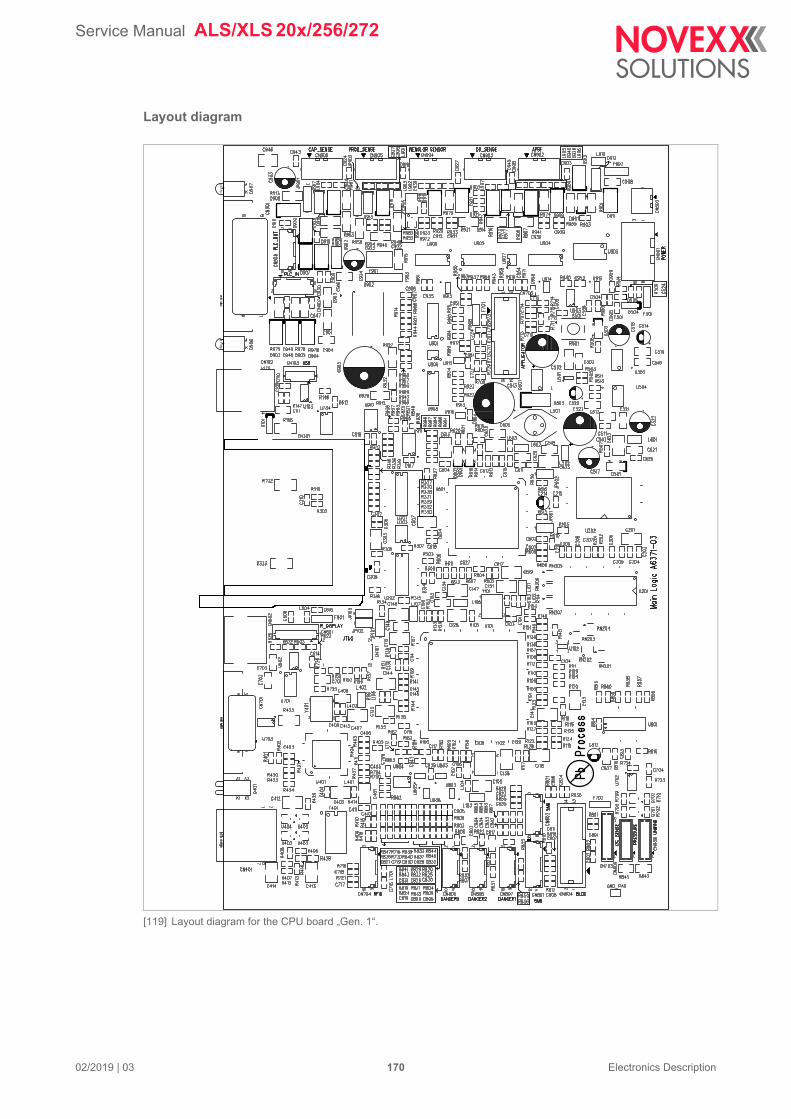
Service Manual ALS/XLS 20x/256/272
02/2019 | 03 170 Electronics Description
Layout diagram
[119] Layout diagram for the CPU board „Gen. 1“.
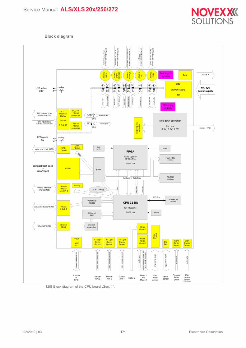
Service Manual ALS/XLS 20x/256/272
02/2019 | 03 171 Electronics Description
Block diagram
[120] Block diagram of the CPU board „Gen. 1“.
text
serial + IRQ
USB
EthernetRJ45
RS232D-Sub 9
CF-slot
USBType B
Applicator
Interface Link
serial bus 12Mb (USB)
serial interface (RS232)
Ethernet 10/100
5V supplysystem
24V supplysystem
Start
Sensor
24V industrial sensor
NP
N or P
NP
selectable
NP
N/P
NP
config
start signa
l
AP
SF
Sensor
24V industrial sensor
2 phase push-pull sign
als
signal phase A
signal phase B
Wenglor
Sensor
24V industrial sensor
LED
current control, NP
N outpu
t
LED
current
current feedback
gap signa
l
alternateLabel
Sensor
24V industrial sensor
NP
N or P
NP
selectable
NP
N/P
NP
config
gap signa
l
OD
Sensor
24V industrial sensor
PN
P sign
al
outer diameter
PLC /MachineStatus
in / out
D-Sub 15
24V inputs (3 x)each LED has its own pins
24V outputs (4 x)High Side Switch, PNP
��
power supply
)
step down converter
5V -->3.3V, 2.5V, 1.5V
24V
remotedisplay
mini DIN 6
display
JTAG Debug JTA
G
I2C-Bus
Buffer
V24 DriverRS232
EthernetPHY
���������
IDT RC32355
PQFP 208 Reset
Flash ROM4 MBytes
SDRAM16 MBytes
Con
figur
atio
n
Inte
rrup
ts
EEPROM256Bytes
*�&�
Altera Cyclone EP 1C3 T144
TQFP 144
PCBversion
Jumper
Address / Data Bus
Ethernetmagnetics
display interface(RS422/485)
3 x LightBarrierSensor
3 x LightBarrierSensor
quadrature & hom
e signal
DancerArm 1
DancerArm 2
3 x LightBarrierSensor
DancerArm 3
MotorControl
FPGA
UART(TTL)
serial interface (UA
RT
)
Scanneror
RFID
doubleMotor
Control
ready signa
l
Motor 1and
Motor 2
control outputs (8 x)clock, direction, acceleration, enable
Motor 3
Mot
orC
ontr
ol
serial bus (I2C)
smallmotordrivers
quadrature & hom
e signal
quadrature & hom
e signal
) �+��� ,�-�����,,#
24V to AI
LightBarrierSensor
digital sign
al
Mat.UnwindDiameter
Calculation
PressureRollerSwitch
digital sign
al
LightBarrierSensor
I2C-Bus
serial bus (I2C)
temp.sensor
compact flash cardor
WLAN card
LED yellow24V
LED green5V
USBinternal
(4 x)
output signals
(3 x)
input signals
PLC outinternal
connector
PLC ininternal
connector
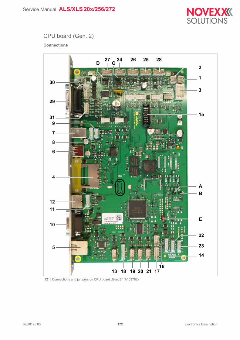
Service Manual ALS/XLS 20x/256/272
02/2019 | 03 172 Electronics Description
CPU board (Gen. 2)
Connections
[121] Connections and jumpers on CPU board „Gen. 2“ (A103782)
2624 25
2
16
3
14
9
8
7
6
4
12
11
10
5
13 18
27
19 17
28
20
1
21
15
23
22
30
31
29
CD
E
A
B
Service Manual ALS/XLS 20x/256/272
02/2019 | 03 173 Electronics Description
Pos. Designation Connect to
1 CN401 FAN_PWR Fan (+24 V)
2 CN402 AI_PWR Applicator interface (+24 V)
3 CN403 POWER Power supply; Voltage supply for the board with 5 V and 24 V
4 CN1401 SD_CARD SD card slot (is not supported by the firmware - slot is masked)
5 CN1501 10/100_ETH Network (Ethernet 10/100 Base T)
6 CN1701 USB_A1 USB thumb drive (USB host interface)
7 CN1702 Data host (USB device interface, is not supported by the firm-ware)
8 CN1703 USB_A2 Additional USB host interface (optional)
9 CN1704 USB_B Additional USB device interface (optional)
10 CN1801 RS232 Data host (RS 232 interface)
11 CN1901 INT_DISPLAY Operator panel (RS 485 interface)
12 CN1902 REM_DISPLAY External operator panel (optional)
13 CN2001 RFID RFID read/write control unit (optional)
14 CN2101 I2C_SENSE (ALS 256) ALPS-600 power supply (I2C bus)
15 CN2102 APPLICATOR Applicator interface
16 CN2401 SMB2 Additional motor driver board (optional)
17 CN2402 SMB1 Motor driver board
18 CN2501 DANCER4 Dancer arm sensor 4 (optional)
19 CN2502 DANCER3 Dancer arm sensor 3 (rewinder)
20 CN2503 DANCER2 Dancer arm sensor 2(optional)
21 CN2504 DANCER1 Dancer arm sensor 1 (optional)
22 CN2505 PRESSURE Switch for contact pressure rollers (optional)
23 CN2506 UNWIND Material end sensor
24 CN2601 PROD_SENSE Product/start sensor
25 CN2602 OD_SENSE External OD control sensor
26 CN2603 LABEL_SENSE Label sensor
27 CN2604 CAP_SENSE Alternativ (e. g. capacitive) label sensor
28 CN2605 APSF Rotary encoder for automatic speed adaption
29 CN2701 Simple applicators (PLC interface)
30 CN2702 PLC_OUT M12 jack for signal outputs
31 CN2703 PLC_IN M12 jack for signal inputs
[Tab. 41] Connectors on the CPU board „Gen. 2“.
Service Manual ALS/XLS 20x/256/272
02/2019 | 03 174 Electronics Description
Pos. Designation Function
A JP1101 Only for factory-internal use
B JP1102
C
JP2601 If the jumper is set, it connects pin 2 of the product/start sensor either to +24 V or to ground.
See chapter Changing light/dark switching at the product sensor or the alternative label sensor on page 58
D
JP2602 If the jumper is set, it connects pin 2 of the alternative label sensor either to +24 V or to ground.
See chapter Changing light/dark switching at the product sensor or the alternative label sensor on page 58
E none Must always be set.
[Tab. 42] Jumpers on the CPU board „Gen. 2“.

Service Manual ALS/XLS 20x/256/272
02/2019 | 03 175 Electronics Description
Preset jumper positions
If a defective CPU board has to be replaced:
Set or remove the jumpers on the new board as shown [?].
[122] CPU board „Gen. 2“: These jumpers on the board must be connected (= ) or removed (= ).
Service Manual ALS/XLS 20x/256/272
02/2019 | 03 176 Electronics Description
Layout diagram / LEDs
[123] LEDs on CPU board „Gen. 2“.
R1714
L702
R703
R803
R702
L601
L602
C605
C701
C702
R605
R1116
L1604
L701
C706
C801
R1117
L801
C1220
C802
C804
C1612
R1710
R1115
L1201
R802
C1216
R1712
RP1302
RP1206
RP1303
RP1205
RP1207
RP1304
RP1301
RP1404
L1603
R1146
C602
C1607
C1124C807
R1111
C1119
R606
C606
C610
C608
R603
C607
R604
C609
C604
C1303
R1203
L802
R1205
C1218
R1201
C1215
R1202
C1217
R1206
R1207
R1301
R1204
R1114
R801
C2624
8
915
1
CN2701
H402
R701
R1401
H401
R1907
R2641
C2721
Z1011
51
96
CN1801
Z1012
C2717
R1406
R1408C1405
U1901
C2418
C2406
RP2405
C2401
C2420
C2001
U2002
C2002
R404
R2630
R1518
C1521
R1506
F2001
C2007
C2006
C2003
CN2001
L2001
H2601
C2005
C2514
C2502
C2508
C2509
F2501
L2501
T2102
C2516
C2413
C2411
CN2401
R2102
C1515
R1509
R2635R2631
D401
CN2703
C2715
CN2702
C2638
C1406
C1401
C1403
C707
R403
R2707
H2701
C408
F403
C2616
R2601
C2617
D2607
JP2601
D2602
L2602
R2613
R2625C2626
R2624 C2612
C2615
C2630
R2609
R2611
R2623
C2622
D2609 D2605
CN2506
C2619
L2604
C2632
CN2505
C2625
R2610
L2601
R2616
R2628 L2605
C2620
R2621
C2618
C2634
C2629
C2614
L2607
R2622
L2606
R2614
R2612
C2635
R2608
R2607
R2619
C2633
D2608
R2615
C2631
JP2602
R2602
C2611
D2606
C2623
L2603
R2626 R2627
D2601
C2610
C2613
R2647
C2707
R2618
C2621
F402 L402
C403
D403
C2705
D2701
C2720
D2708
D2702
D2710
C2512
R2605 R2604R2606R2603
T2601
R2620
R2636
R2629
C2636
R2617
C2637
R1135
D2610
D2604
C2103
C2213
C410D2705
D2706
D2707
R2701
R2702
R2703
C2716
C2702
C2701
R2704
R2705
R2706
C1710
L1706
C1719
C1711
R1305
L1701
D1401
D1402
RP1402
RP1401
C413
R2648
R1715
C1307
R1707
C1715
C2104
C1706
R1703
RP2703
R1802
R1302
R1007
R1133
R1142
C2410
C603
R2514
R2108
C2004
R1523
C1806
U1801
C1509
R1109R1140
JP1801
R1504
R1522
R1520
R1512
C1502
R1503
R2208
C1519
C1510
Q1501
C1512
F1801
L1803
C1511
C1508
R1505
U2708
L1801
C1813
L405
C1520
L1806
R1516
R1501
R1136
R1507
R402
C1513
L1804
U2606
R1508
C1805
L1805
R1709
C1516
C1518
C1507
R1517
C1807
C1810
R1511
C1808
C1809
C1814 C1804
C1517
C1505
R2201
R1514
R1510
C1802
C1504
R1513
C1801
C1503
R1145
C1514
L1802
R2653
R2203
R2001
C1209
C2211
R2104
L2202
R2202
C2009
C2628
R2103
C2627
C2601
C1714C1713
C1717 T1701
C1141
+
C411
R1001
U2703
R2735
R2722R2736
R2737
U2704
R2721
R2728
R2724
U2702
C2709
R1002
R1404
R2738 R2734
R2733
R1713
R1704
C611
H1101
R1609
T1601
U1602
U1603
R1608
R2646
R1607
C1142
C601
F401
U2610U2609
12
CN401
R2632
C1203
R2643
R2210
C2639
CN1401
R1515
R1405
R1407
R1905
C1906
C1404
L1702
+
C1716
C1703
R1701
16
CN1901
L1901
L1905
L1903
L1906
L1904
R1902
R1903
L1902
C1704
C1712
C1720
R406
R405
C1005
R2651
C2412
RP2707
U2705
U2706
C2712
R2723
R2731
R2732
U2709
U2707
RP2701C2708
C2419
CN2402
R407
R2212
R2510
R2501
C2408C2405 C2409
C2407
R2107
C2602
L2101
C2102
R2101
C2105
F2102
R2213
RP2406
RP2301C2210
R2205
C2404
RP2401
RP2403
RP2404
C2403
C2402
RP2402
U2401
RP2407
R2504
R2502
R2503
C2522
CN2502 CN2504
R2508
C2521
R2507
R2506R2511
CN2503
R2505
C2520
R2509
C2505
C2501
C2513
C2518
C2519
U2502
C2504
C2506
C2507
C2511
U2501
R2004
C2503
RP2002
RP2506 RP2504
F2101
RP2509
C2205
L2201
C2206
R2211
C2110
U2602
C2112
C2609
R2634
C2722
R2650
R2729
R2730
R2719
R2720
+
C405
R2652
R2649
C2101
U2607
R2642C2608
C2606
R2638C2607
R2644 C2604
U2608
C2640
R2637
C2605 R2645
C2603R2639
R2640
U2605
U2601
R2214
R2633
U2202
C2204
C2202
R2209R2204
L2102
C2109
C409
D402
C2331
C2301
C2324
C2330
U2201
C2303
R2306
C2329
C2305
C401
U2102
U2505
R1606
U2103
R2657
H2201
C2207
C2203
C2201
U2402C2515
16
CN1102
+C402
C803
R1137
C2326
C1135
R1139
R1141
RP2104
C2107C2113
C2111
R1303
T1602
JP1102
U2302
RP1508
JP1101
R1148
R1134
C2318
C2323
R2312
C2327
L2301
R2301
C2314
C2308
U2301
C2325
C2322
C2302
C2315
C2337
C2312
C2334
C2333
C2317
C2311
C2313
C2332C2335
C2310C2316C2306
C2706
JP1301
R1110
H1102
+
C612
C1613
C1614
R1138
C1604
U1201
C1002
RP1403
R1005
C1003
R1004
R1008
C1603
RP1611
C2723
L403
T2701
RP2702C2710
R2708
C2713
R2709
C2711
H2702
C2714
R2727
C1709
C1702
F1701
F1702
C1707
C1708
R1711
D1704D1701
C1701
C1803
U2504
U2503
RP2507RP2502 RP2508RP2501 RP2505
C2510
RP2503
C2517
C2417 F2201
C2416
R2515
C2414
C2415
T2101
19 2021
CN1103
C2524
C2421
C1522
D1501
C2523
Q1101
U1301
U1601
U1202
C2321
C2336
R2302
C2328
C2307
C2309
R2303
R2307
C2319
C2320
R2311
L1501
R1519
R1524
C1501
R1601
R1603
R2106
C1204
R601
C1304
C2108
C1608
U601
T1603
C902
R902
C901
R903
C904
L901
C903
R901
U1001
Q1102
T1604
C1402
R1306
C1306
U1303
U1302
C1305
U701
C809
RP1610
29302 1
CN1601
R1304
RP1609
C1301
D1801
R1521
R1307
RP1502
RP1507
Z1023
C1134
RP1504
R1403
R1147
R2314
RP1505
R2304
C1004
S1001
D406
C412
R1003
R1009
R1006
C1001
RP1503
R1402
R1128C2338
R1121
JP2201 Q2201
C2212
R602
H601
C1118
C1116
C1219
RP1506
C1506
14
CN1701
+CN1101
U1103C1102 C1101
Z1019
Z1020
RP2001
RP2101
RP2102
RP2103
R2215
+
C1718
C2214
Z1013
R1308
L401
1
CN1704
R1716
C414
D405
L404
R2656
C406
10
12
9
CN403
C407
U2604
12
CN402
D407
U2612
F404
C1302
U1501
U2701
Z1024
Z1026
Z1025
Z1014 Z1017
Z1015
Z1016
Z1021
Z1022
46
28
75
3110
912
11
CN1501
CN1702
T1001
R2207
RP1101
U2611
U1702
U1703
U901
U1401
U2101
U401
U2001
R2654
C2641R2655
R2658
H2301
R2310
RP2409
U2303
U2203
R2216
C2215
C2304
C2339
R2313
C1905
C1904
R1901
F1902
R1904
F1901
U2603
R2206
1
CN1703
R1717
C1721
C1705
L1707
L1703
CN2101
D404 +C404
R2725
RP2302
C1143
U801
R401
R1708
CN2501
Z1027
CN2201
1
CN2301
CN1902
1
CN2102
Z1030
CN2601 CN2603 CN2602 CN2605CN2604
Z1018
B2
B1
U1101
Service Manual ALS/XLS 20x/256/272
02/2019 | 03 177 Electronics Description
Pos. Designation Function
AYellow LED Ethernet operation indicator; Continuously lit: Labeler is connected with the network;
Flashing: Communicating with network
B Green LED Ethernet operation indicator; Continuously lit: High transfer rate (100Mbit/s)
C H401 Yellow indicator for 24 V supply voltage
D H402 Green indicator for 5 V supply voltage
E H601 Indicator for 3,3 V supply voltage
F H2301 Operation indicator for CPLD U2301
G H2401 Indicator for 24 V supply voltage at sensor connectors
HH2701 Indicates that the output driver U2701 switched to overcurrent and/or overheat
protection.
I H2702 Indicator for 24 V supply voltage at the PLC interface CN2701
[124]LEDs on CPU board „Gen. 2“.
Service Manual ALS/XLS 20x/256/272
02/2019 | 03 178 Electronics Description
Block diagramm
[125] Block diagramm of the CPU board „Gen. 2“.
MII
serial + IRQ
EthernetRJ45
Applicator Interface Link
IEEE1588Ethernet 10/100
5V supply system
24V supply system
PLC /MachineStatus
in / out
D-Sub 15
24V inputs (3 x)each LED has its own pins
24V outputs (4 x)High Side Switch, PNP
24V
power supply
5V
step down converter
5V --> 3.3V + core voltages
24V
JTA
G
I2C-Bus
EthernetPHY
Reset
optionalNAND
Flash ROM4 MBytes
DDR2 RAM128 MBytes
Con
figur
atio
nS
PI-B
us
Inte
rrup
ts
EEPROM2 kBytes
CPLD
Lattice MachXO2-2000
PCBversion
Jumper
memory-Bus
Ethernetmagnetics
5V / 24V power supply
24V to AI
LightBarrierSensor
digitalsignal
Mat. UnwindDiameter
Calculation
PressureRollerSwitch
digitalsignal
LightBarrierSensor
I2C-Bus
serial bus (I2C)
temp. sensor
LED yellow24V
LED green5V
output signals (4x)
input signals (3x)
PLC outinternal
connector
PLC ininternal
connector
StartS
ensor24V industrial sensor
NP
NorP
NP
selectable
NP
N/P
NP
config
startsignal
CapacitiveLabel
Sensor
24V industrial sensor
NP
NorP
NP
selectable
NP
N/P
NP
config
gapsignal
Optical
LabelS
ensor24V
industrial sensorLED
currentcontrol,NP
Noutput
LED
current
currentfeedback
gapsignal
OD
Sensor
24V industrial sensor
PNP
signalouterdiam
eter
AP
SF
Sensor
24V industrial sensor
2phase
push-pullsignals
signalphaseA
signalphaseB
intelligentBLDC
motor driverCAN bus
3 x LightBarrierSensor
Dancer Arm 3
quadrature&
home
signal
Dancer Arm 2
3 x LightBarrierSensor
quadrature&
home
signal
3 x LightBarrierSensor
quadrature&
home
signal
Dancer Arm 1
UART(TTL)
serialinterface(U
ART)
Scanneror
RFID
RS232D-Sub 9serial interface (RS232) V24 Driver
RS232 UART
remote display
mini DIN 6
internal display
display interface (RS422/485)
SD-Card slotSD flash
card
RS422 busSDIO bus
USB-bus FS/HS USBType A
USBType B
(optional)
USB-Binternal
USB Host busUSB Device/OTG bus
Address / Data Bus
MotorControl
double Motor
Control
readysignal
Motor 1and
Motor 2
control outputs (8 x)clock,direction,acceleration,enable
Motor 3
(optional)LCD
Touch Interface
LCD Touch Display
LCD / Touch signals
24V 24V to fan
SPI-Bus SERIAL NORFLASH8 MBytes
JTAG Debug
JTAG Debug
JTA
G
CPU 32 BitAT91SAM9G45
ARM 926EJ-S
BGA
(optional)CAN-Bus
4 x PWMSensor
Dancer Arms
Pulse
width
modulation
SPI bus
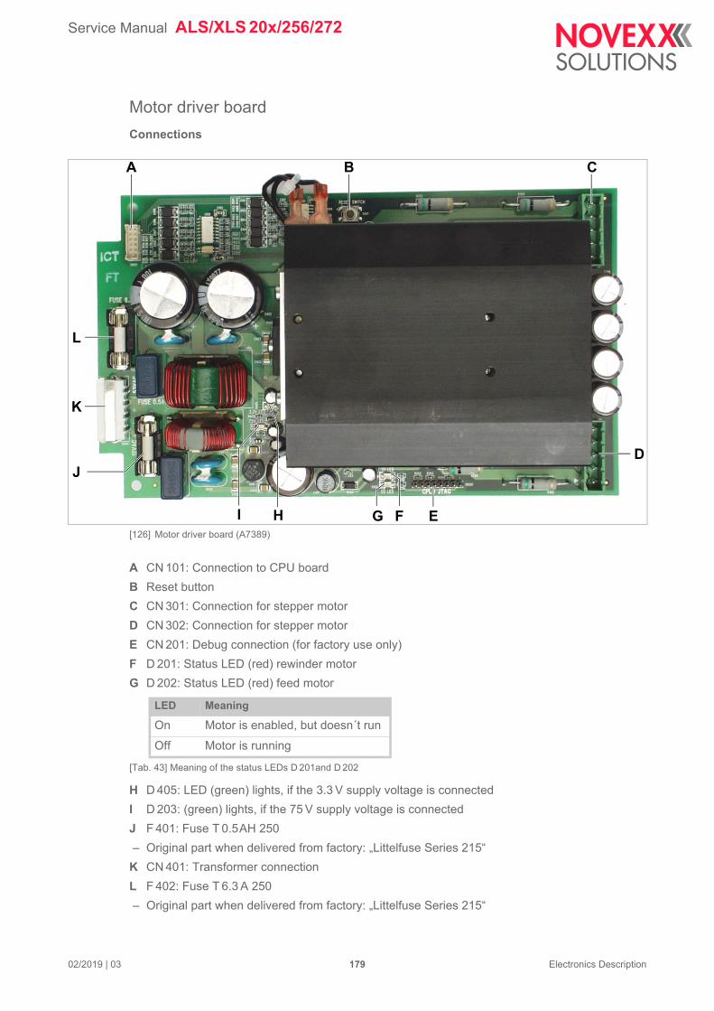
Service Manual ALS/XLS 20x/256/272
02/2019 | 03 179 Electronics Description
Motor driver board
Connections
[126] Motor driver board (A7389)
A CN 101: Connection to CPU board
B Reset button
C CN 301: Connection for stepper motor
D CN 302: Connection for stepper motor
E CN 201: Debug connection (for factory use only)
F D 201: Status LED (red) rewinder motor
G D 202: Status LED (red) feed motor
H D 405: LED (green) lights, if the 3.3 V supply voltage is connected
I D 203: (green) lights, if the 75 V supply voltage is connected
J F 401: Fuse T 0.5AH 250
– Original part when delivered from factory: „Littelfuse Series 215“
K CN 401: Transformer connection
L F 402: Fuse T 6.3 A 250
– Original part when delivered from factory: „Littelfuse Series 215“
BA C
D
EFG
J
K
L
HI
LED Meaning
On Motor is enabled, but doesn´t run
Off Motor is running
[Tab. 43] Meaning of the status LEDs D 201and D 202
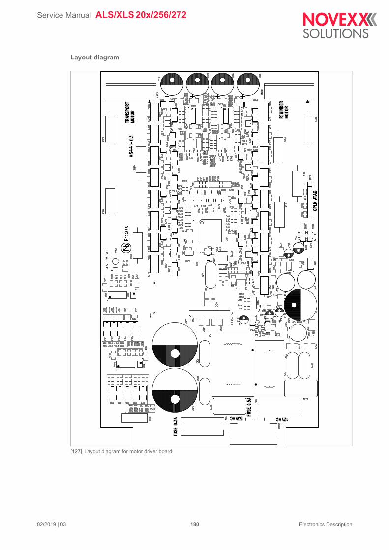
Service Manual ALS/XLS 20x/256/272
02/2019 | 03 180 Electronics Description
Layout diagram
[127] Layout diagram for motor driver board
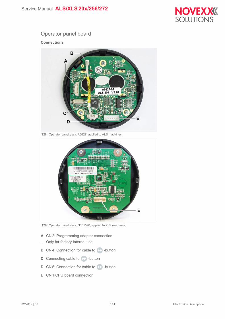
Service Manual ALS/XLS 20x/256/272
02/2019 | 03 181 Electronics Description
Operator panel board
Connections
[128] Operator panel assy. A6627, applied to ALS machines.
[129] Operator panel assy. N101590, applied to XLS machines.
A CN 2: Programming adapter connection
– Only for factory-internal use
B CN 4: Connection for cable to -button
C Connecting cable to -button
D CN 5: Connection for cable to -button
E CN 1:CPU board connection
B
DE
A
C
E
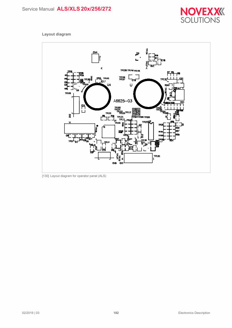
Service Manual ALS/XLS 20x/256/272
02/2019 | 03 182 Electronics Description
Layout diagram
[130] Layout diagram for operator panel (ALS)
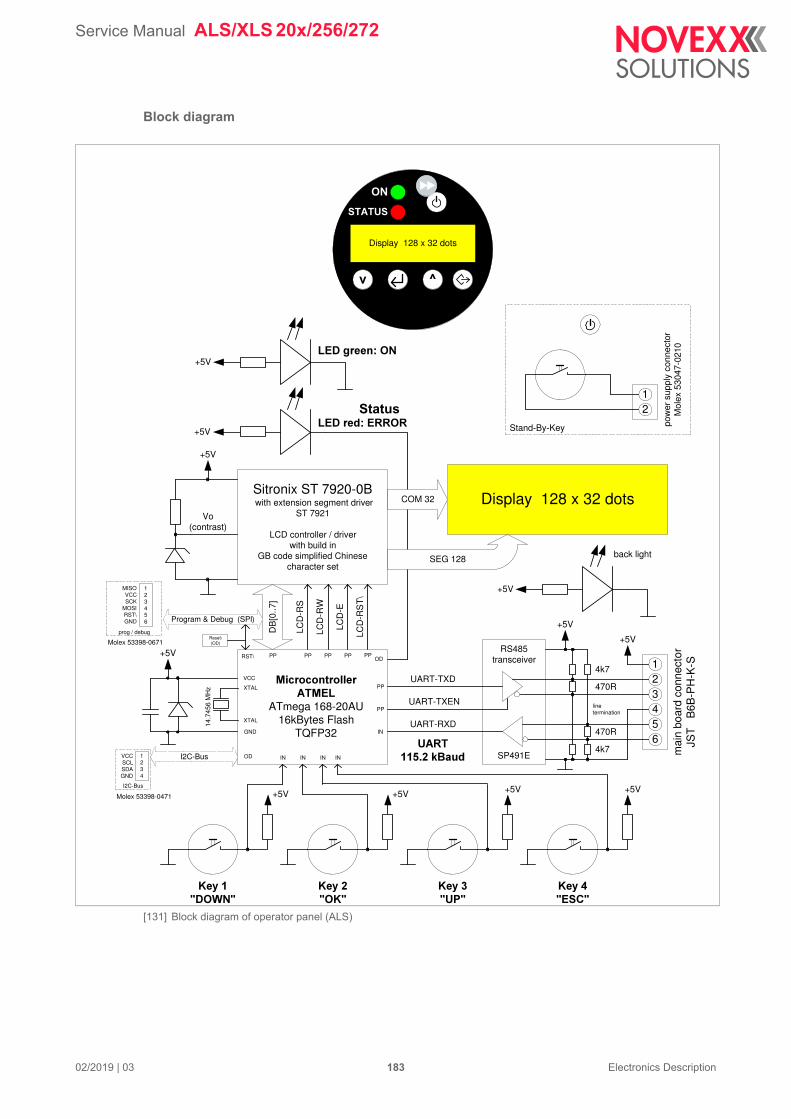
Service Manual ALS/XLS 20x/256/272
02/2019 | 03 183 Electronics Description
Block diagram
[131] Block diagram of operator panel (ALS)
Stand-By-Key
+5V+5V
Display 128 x 32 dotsSitronix ST 7920-0B with extension segment driver
ST 7921
LCD controller / driverwith build in
GB code simplified Chinesecharacter set
COM 32
SEG 128
Vo(contrast)
+5V
+5V
back light
+5V�����������
+5V������ ������
�������������������
ATmega 168-20AU16kBytes Flash
TQFP32
DB
[0..7
]
LCD
-RS
LCD
-RW
LCD
-E
+5V
+5V
1
65432
RS485transceiver
SP491E
UART-RXD
UART-TXD
+5V +5V
12
����������
mai
n bo
ard
conn
ecto
rJS
T
B6B
-PH
-K-S
+5V
UART-TXEN
4k7
4k7
470R
470R
linetermination
������� !�"#$%
pow
er s
uppl
y co
nnec
tor
Mol
ex 5
3047
-021
0
Display 128 x 32 dots
0 1
��
������
ODPP
IN
PP PP PP
INININ
PP
PP
IN
VCC
GND
RST\
Program & Debug (SPI)
����,��2�
����!����
��������3��
LCD
-RS
T\
PP
prog / debug
123456
MISOVCCSCK
MOSIRST\GND
Reset\(OD)
14.7
456
MH
z
XTAL
XTAL
I2C-Bus
I2C-Bus
1234
VCCSCLSDAGND
Molex 53398-0471
Molex 53398-0671
OD
Status
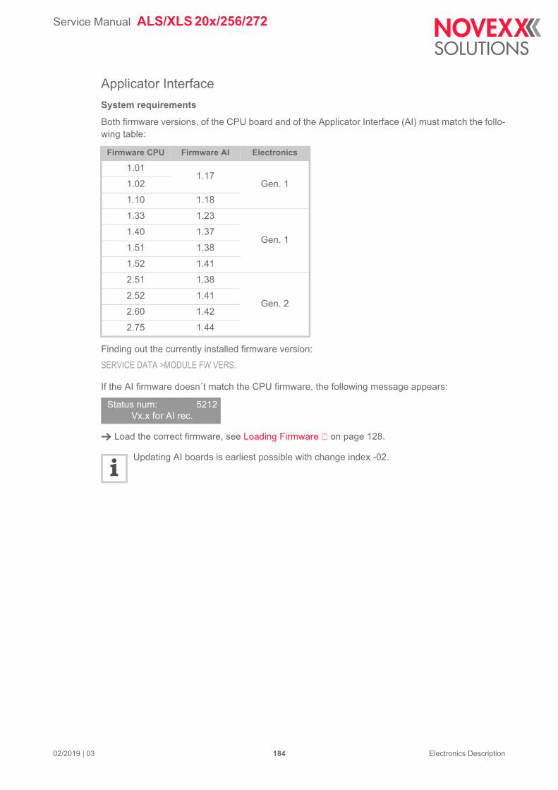
Service Manual ALS/XLS 20x/256/272
02/2019 | 03 184 Electronics Description
Applicator Interface
System requirements
Both firmware versions, of the CPU board and of the Applicator Interface (AI) must match the follo-wing table:
Finding out the currently installed firmware version:
SERVICE DATA >MODULE FW VERS.
If the AI firmware doesn´t match the CPU firmware, the following message appears:
Load the correct firmware, see Loading Firmware on page 128.
Updating AI boards is earliest possible with change index -02.
Firmware CPU Firmware AI Electronics
1.011.17
Gen. 11.02
1.10 1.18
1.33 1.23
Gen. 11.40 1.37
1.51 1.38
1.52 1.41
2.51 1.38
Gen. 22.52 1.41
2.60 1.42
2.75 1.44
Status num: 5212Vx.x for AI rec.
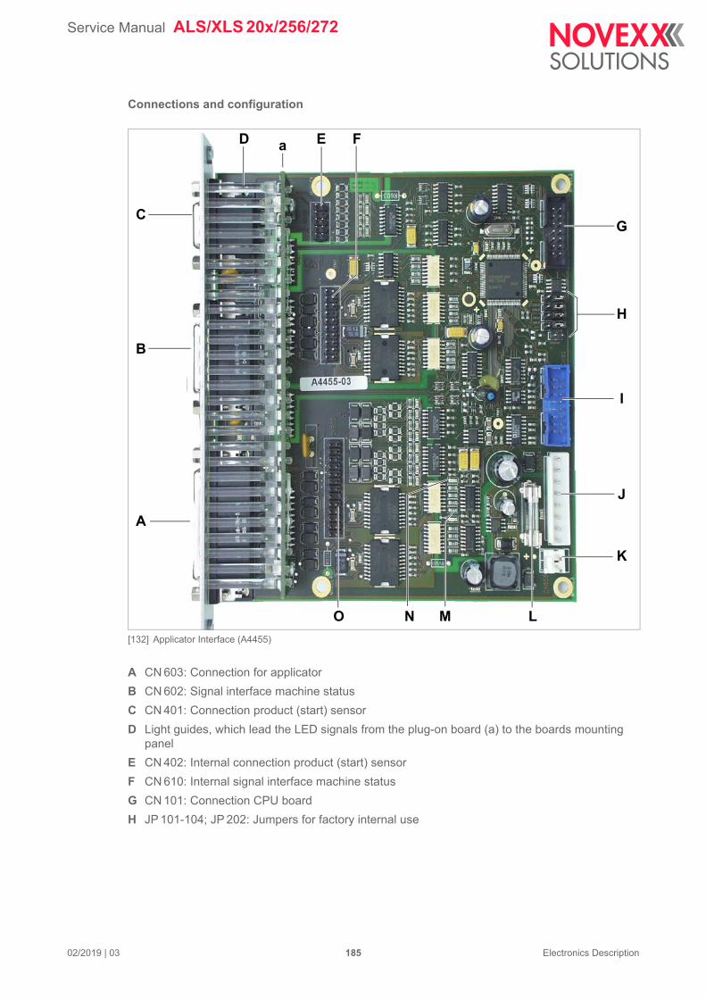
Service Manual ALS/XLS 20x/256/272
02/2019 | 03 185 Electronics Description
Connections and configuration
[132] Applicator Interface (A4455)
A CN 603: Connection for applicator
B CN 602: Signal interface machine status
C CN 401: Connection product (start) sensor
D Light guides, which lead the LED signals from the plug-on board (a) to the boards mounting panel
E CN 402: Internal connection product (start) sensor
F CN 610: Internal signal interface machine status
G CN 101: Connection CPU board
H JP 101-104; JP 202: Jumpers for factory internal use
A
B
C
H
I
J
D
K
O L
a
G
E F
MN
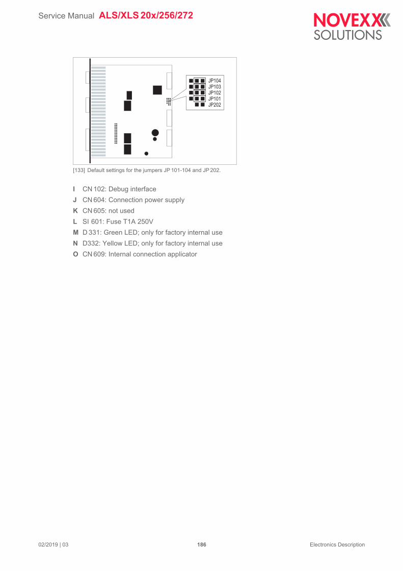
Service Manual ALS/XLS 20x/256/272
02/2019 | 03 186 Electronics Description
[133] Default settings for the jumpers JP 101-104 and JP 202.
I CN 102: Debug interface
J CN 604: Connection power supply
K CN 605: not used
L SI 601: Fuse T1A 250V
M D 331: Green LED; only for factory internal use
N D332: Yellow LED; only for factory internal use
O CN 609: Internal connection applicator
JP104JP103JP102JP101JP202
Service Manual ALS/XLS 20x/256/272
02/2019 | 03 187 Electronics Description
Layout diagram
[134] Layout diagram for Applicator Interface (PCB = A3417-03)
Service Manual ALS/XLS 20x/256/272
02/2019 | 03 188 Electronics Description
Block diagram
[135] Block diagram Applicator Interface.
COM_0
COM_1
ResetControl
RESET
External reset
TxD_0
RxD_0
APSF
AI_IRQ
H8_IRQ
TxD_1
RxD_1
Programming anddebug port
to CPU board
(USI Port)
uC
Exte
rnal
pro
ductlig
htbarr
ier
Isolation barrier
Status
Outputs
M_O
UT
[1..7]
A_O
UT
[1..8]
Sensor inputs
P_IN
[1..3]
D-SUB 15hd
M_IN
[1..3]
D-SUB 26hd
A_IN
[1..6]
D-SUB 44hd
Internalapplicator
A_OUT[1..8]
A_IN[1..6]
P_IN[1..3]
M_IN[1..2]
M_OUT[1..7]
Internalproduct light barrier
Internalmaschine status
Exte
rnal
maschin
esta
tus
Exte
rnal
applic
ato
r
Reset-Steuerung
RESET
Externer Reset
TxD_0
RxD_0
APSF
AI_IRQ
H8_IRQ
TxD_1
RxD_1
Programmier-/Debug-Schnittstelle
zur CPU-Platine
(USI-Port)
uC
Exte
rnP
roduktlic
hts
chra
nke
Isolationsbarriere
Status
Ausgänge
M_O
UT
[1..7]
A_O
UT
[1..8]
Sensor-Eingänge
P_IN
[1..3]
SUB-D15hd
M_IN
[1..3]
SUB-D26hd
A_IN
[1..6]
SUB-D44hd
InternApplikator
A_OUT[1..8]
A_IN[1..6]
P_IN[1..3]
M_IN[1..2]
M_OUT[1..7]
InternProduktlichtschranke
InternMaschinenstatus
Exte
rnM
aschin
ensta
tus
Exte
rnA
pplik
ato
r
Service Manual ALS/XLS 20x/256/272
02/2019 | 03 189 Electronics Description
Installing the Applicator Interface
Requirements for the subsequent installation:
– ALS/XLS 2xx
– Applicator Interface (Article no. A4455)
– Data cabel AI - CPU (Article no. A5001)
– Y supply cabel AI - CPU - Fan (Article no. A6805)
Tool:
– Hexagon socket driver 2,5 mm
Open the casing, see Ch. Opening the casing (page 252).
Remove two screws [?B] at the slot cover. Remove slot cover.
[136] Slot cover (A) with mounting screws (B).
Remove two screws [?A] at the board rack. Carefully pull out the board rack, until the connec-tions at the rear end of the CPU board are accessible.
[137] Board rack with mounting screws (A) (LH version pictured).
Connect both cables to the CPU board and to the Applicator Interface, see chapter Wiring Dia-grams on page 156.
A
B
B
AA
Service Manual ALS/XLS 20x/256/272
02/2019 | 03 190 Electronics Description
Plug the Applicator Interface board onto the spread sockets [?A]at the board rack.
[138] Plug the Applicator Interface onto the spread sockets (A) on the board rack.
Reinstall the board rack. While doing so, pay attention,
– that the noses at the rear end of the board rack fit into the holes at the housing rear wall.
– not to wedge any cable between board rack and housing.
Close the casing.
A
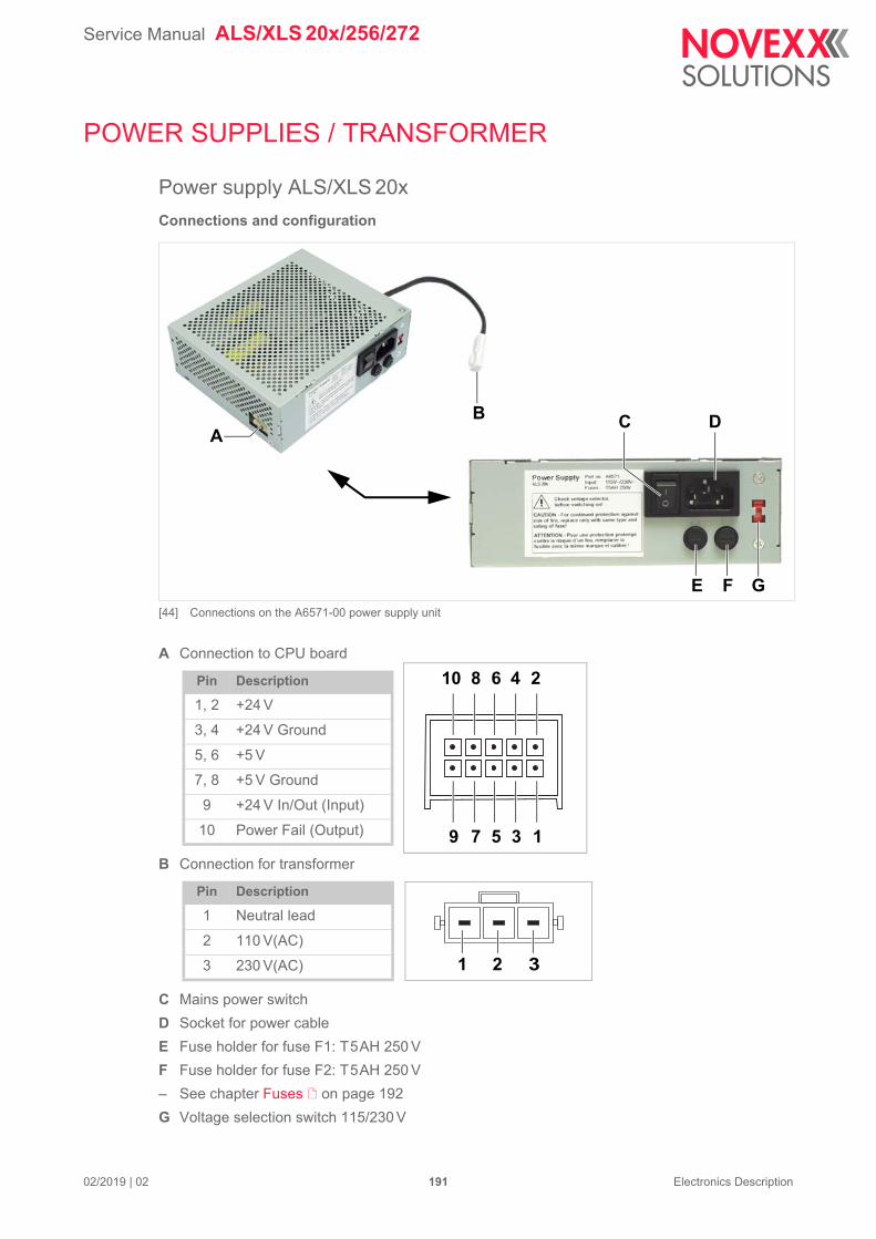
Service Manual ALS/XLS 20x/256/272
02/2019 | 02 191 Electronics Description
POWER SUPPLIES / TRANSFORMER
Power supply ALS/XLS 20x
Connections and configuration
[44] Connections on the A6571-00 power supply unit
A Connection to CPU board
B Connection for transformer
C Mains power switch
D Socket for power cable
E Fuse holder for fuse F1: T5AH 250 V
F Fuse holder for fuse F2: T5AH 250 V
– See chapter Fuses on page 192
G Voltage selection switch 115/230 V
Pin Description
1, 2 +24 V
3, 4 +24 V Ground
5, 6 +5 V
7, 8 +5 V Ground
9 +24 V In/Out (Input)
10 Power Fail (Output)
Pin Description
1 Neutral lead
2 110 V(AC)
3 230 V(AC)
AC D
E F G
B
13579
10 8 6 4 2
1 2 3
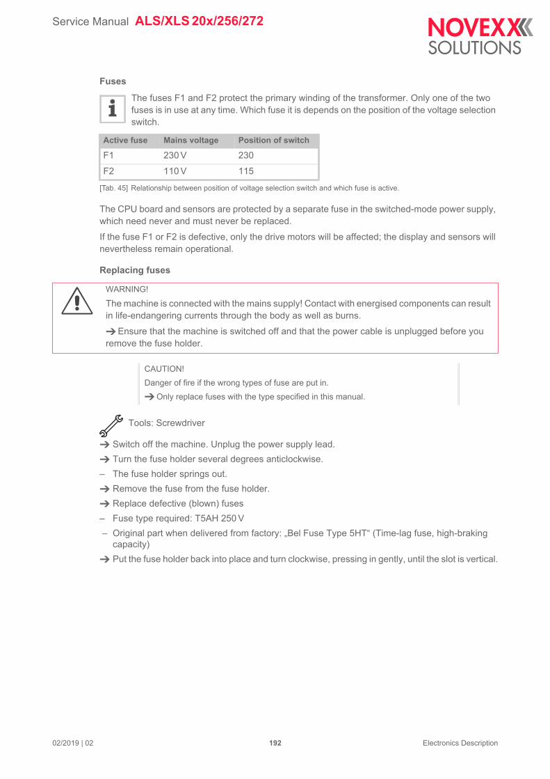
Service Manual ALS/XLS 20x/256/272
02/2019 | 02 192 Electronics Description
Fuses
The fuses F1 and F2 protect the primary winding of the transformer. Only one of the two fuses is in use at any time. Which fuse it is depends on the position of the voltage selection switch.
The CPU board and sensors are protected by a separate fuse in the switched-mode power supply, which need never and must never be replaced.
If the fuse F1 or F2 is defective, only the drive motors will be affected; the display and sensors will nevertheless remain operational.
Replacing fuses
Tools: Screwdriver
Switch off the machine. Unplug the power supply lead.
Turn the fuse holder several degrees anticlockwise.
– The fuse holder springs out.
Remove the fuse from the fuse holder.
Replace defective (blown) fuses
– Fuse type required: T5AH 250 V
– Original part when delivered from factory: „Bel Fuse Type 5HT“ (Time-lag fuse, high-braking capacity)
Put the fuse holder back into place and turn clockwise, pressing in gently, until the slot is vertical.
Active fuse Mains voltage Position of switch
F1 230 V 230
F2 110 V 115
[Tab. 45] Relationship between position of voltage selection switch and which fuse is active.
WARNING!
The machine is connected with the mains supply! Contact with energised components can result in life-endangering currents through the body as well as burns.
Ensure that the machine is switched off and that the power cable is unplugged before you remove the fuse holder.
CAUTION!
Danger of fire if the wrong types of fuse are put in.
Only replace fuses with the type specified in this manual.
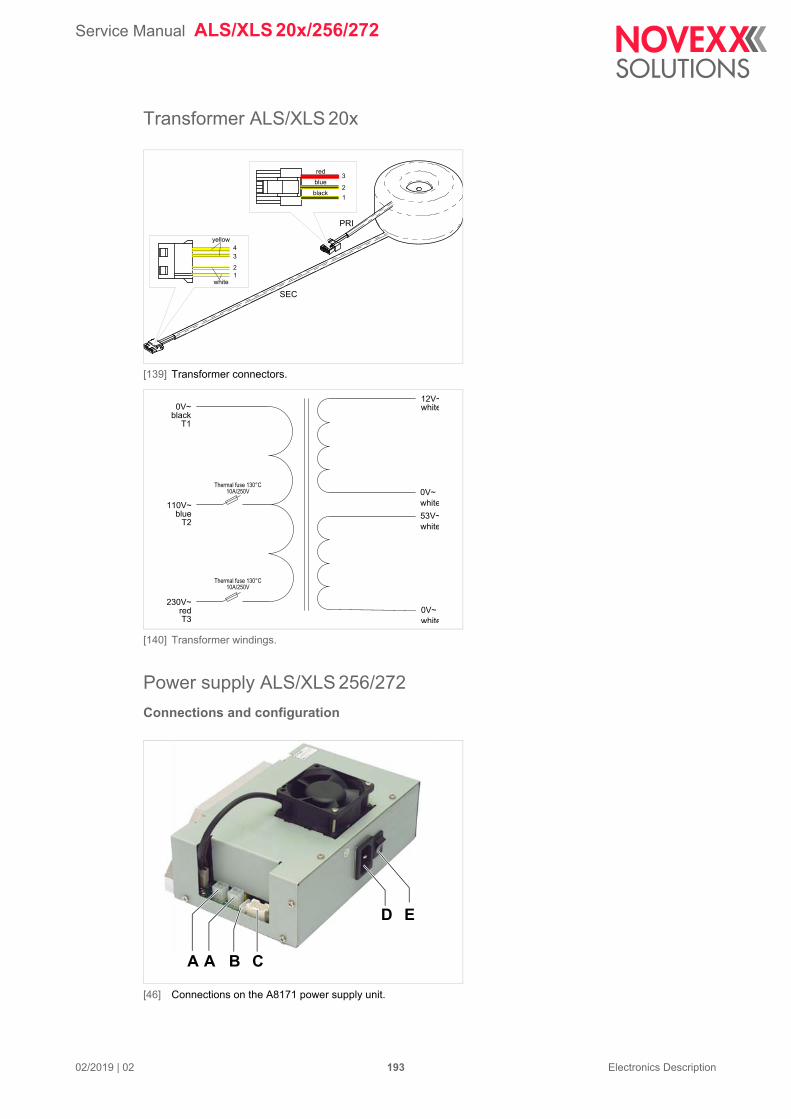
Service Manual ALS/XLS 20x/256/272
02/2019 | 02 193 Electronics Description
Transformer ALS/XLS 20x
[139] Transformer connectors.
[140] Transformer windings.
Power supply ALS/XLS 256/272
Connections and configuration
[46] Connections on the A8171 power supply unit.
12
3
SEC
PRI
12
34
white
yellow
red
blue
black
12V~white
0V~white53V~white
0V~white
0V~blackT1
110V~blueT2
230V~redT3
Thermal fuse 130°C10A/250V
Thermal fuse 130°C10A/250V
A A C
D E
B
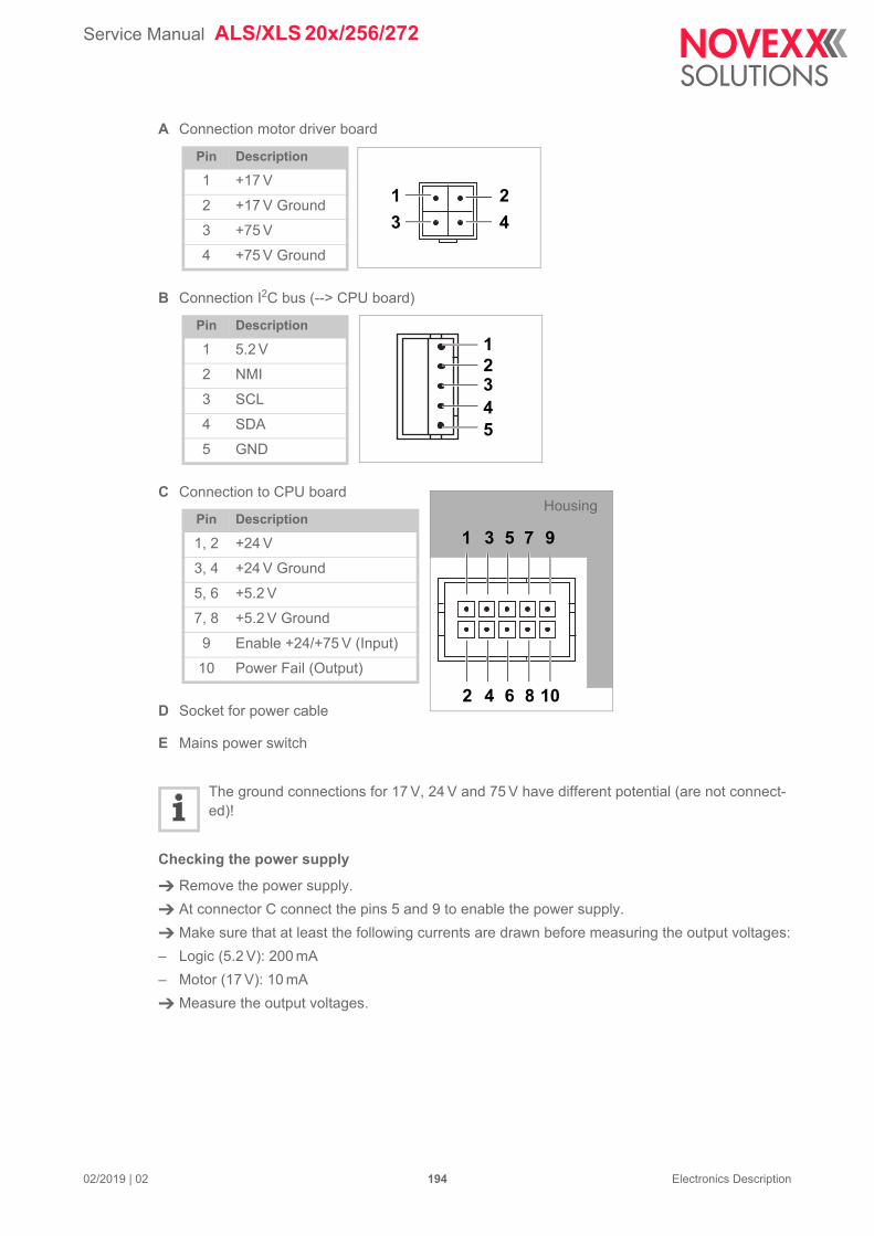
Service Manual ALS/XLS 20x/256/272
02/2019 | 02 194 Electronics Description
A Connection motor driver board
B Connection I2C bus (--> CPU board)
C Connection to CPU board
D Socket for power cable
E Mains power switch
The ground connections for 17 V, 24 V and 75 V have different potential (are not connect-ed)!
Checking the power supply
Remove the power supply.
At connector C connect the pins 5 and 9 to enable the power supply.
Make sure that at least the following currents are drawn before measuring the output voltages:
– Logic (5.2 V): 200 mA
– Motor (17 V): 10 mA
Measure the output voltages.
Pin Description
1 +17 V
2 +17 V Ground
3 +75 V
4 +75 V Ground
Pin Description
1 5.2 V
2 NMI
3 SCL
4 SDA
5 GND
Pin Description
1, 2 +24 V
3, 4 +24 V Ground
5, 6 +5.2 V
7, 8 +5.2 V Ground
9 Enable +24/+75 V (Input)
10 Power Fail (Output)
1 2
3 4
12345
108642
1 3 5 7 9
Housing
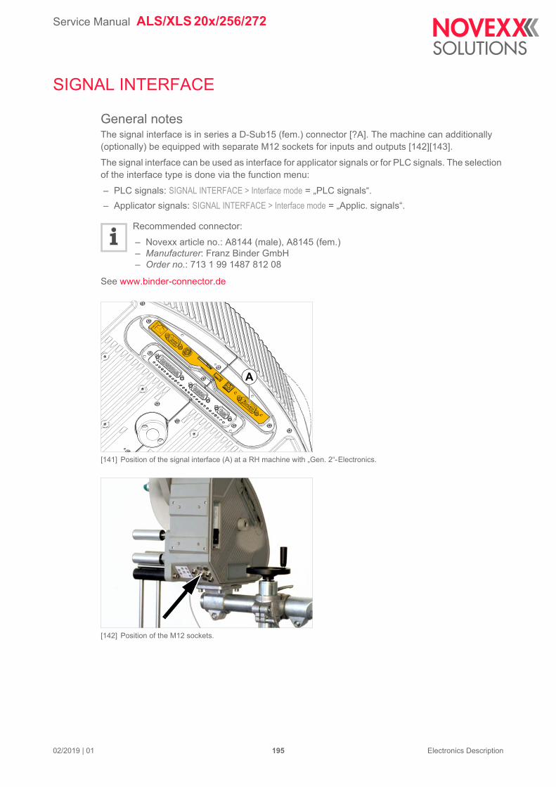
Service Manual ALS/XLS 20x/256/272
02/2019 | 01 195 Electronics Description
SIGNAL INTERFACE
General notesThe signal interface is in series a D-Sub15 (fem.) connector [?A]. The machine can additionally (optionally) be equipped with separate M12 sockets for inputs and outputs [142][143].
The signal interface can be used as interface for applicator signals or for PLC signals. The selection of the interface type is done via the function menu:
– PLC signals: SIGNAL INTERFACE > Interface mode = „PLC signals“.
– Applicator signals: SIGNAL INTERFACE > Interface mode = „Applic. signals“.
Recommended connector:
– Novexx article no.: A8144 (male), A8145 (fem.)– Manufacturer: Franz Binder GmbH– Order no.: 713 1 99 1487 812 08
See www.binder-connector.de
[141] Position of the signal interface (A) at a RH machine with „Gen. 2“-Electronics.
[142] Position of the M12 sockets.
A
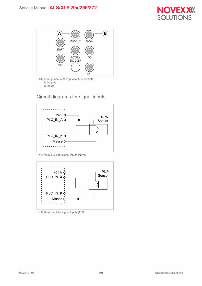
Service Manual ALS/XLS 20x/256/272
02/2019 | 01 196 Electronics Description
[143] Arrangement of the optional M12 sockets:A OutputsB Inputs
Circuit diagrams for signal inputs
[144] Main circuit for signal inputs (NPN)
[145] Main circuit for signal inputs (PNP)
START
PLC-OUT PLC-IN
LABEL
ROTARYENCODER
OD
CAP
A B
+24VPLC_IN_A
PLC_IN_KMasse
NPNSensor
+24VPLC_IN_A
PLC_IN_KMasse
PNPSensor
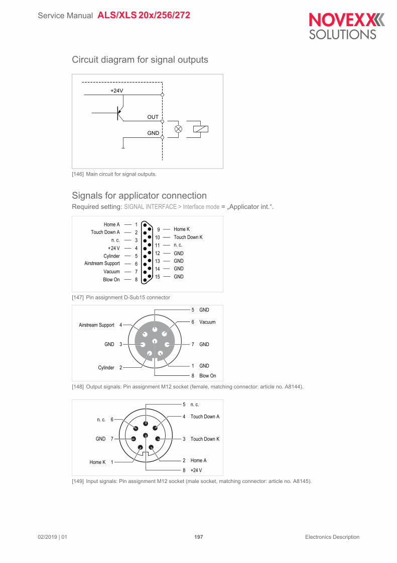
Service Manual ALS/XLS 20x/256/272
02/2019 | 01 197 Electronics Description
Circuit diagram for signal outputs
[146] Main circuit for signal outputs.
Signals for applicator connectionRequired setting: SIGNAL INTERFACE > Interface mode = „Applicator int.“.
[147] Pin assignment D-Sub15 connector
[148] Output signals: Pin assignment M12 socket (female, matching connector: article no. A8144).
[149] Input signals: Pin assignment M12 socket (male socket, matching connector: article no. A8145).
GND
+24V
OUT
1
2
3
4
5
6
7
8
9
10
11
12
13
14
15
CylinderAirstream Support
Vacuum
Blow On GND
GNDGND
GND
+24 V
n. c.
Touch Down A
Home A
n. c.Touch Down K
Home K
Airstream Support 4
GND 3
Cylinder 2
8 Blow On
5 GND
6 Vacuum
1 GND
7 GND
n. c. 6
GND 7
Home K 1
8 +24 V
5 n. c.
4 Touch Down A
2 Home A
3 Touch Down K
Service Manual ALS/XLS 20x/256/272
02/2019 | 01 198 Electronics Description
Not every applicator uses the same signals: See chapter Applicator type <--> Signals on page 199
Signal name Function
Home Input
Active, if the applicator has reached the home position (application is finished)
Touch Down Input
Use with sensor-controlled applicators (e. g. LTP)
Active, if the applicator touches the product
Cylinder Output
Controls the pneumatic cylinder of the applicator
Active during the dwell time or until touch down
Duration setable with: SIGNAL INTERFACE >APPLIC. SIGNALS > Dwell time
Airstream Support
Output
Controls the airstream, which presses the label against the applicator plate.
Active after the start signal until start of application (cylinder)
Vacuum Output
Controls the vacuum at the applicator plate
Active after the start signal until end of application (cylinder)
Blow On Output
Controls the blow-on valve of the applicator
Active after end of application (cylinder)
Duration setable with: SIGNAL INTERFACE >APPLIC. SIGNALS > Blow on time
Service Manual ALS/XLS 20x/256/272
02/2019 | 01 199 Electronics Description
Applicator type <--> SignalsThe table below lists all the signals that are required by the relevant applicator type to be able to work. With some applicator type settings, the interface provides additional signals, which are not mandatory for the applicator to work, e. g. the blow on signal with the setting Applicator type = „LTP - LTPV“
1) Only used with LTPV2) Only used with pneumatic dispensing edge3) Signal only at optional Applicator Interface
For details about applicator types read the description of function SIGNAL INTERFACE >APPLIC. SIGNALS > Applicator type on page 79.
Signal Applicator
LT
P(V
)
PE
P IV
PE
P B
low
on
PE
P II
Sen
s.
AS
A
Rev
. PE
P
Dir
ect
Dis
pe
ns
e
BT
S
O-R
ing
ap
pl.
LA
-BO
LA
-TO
tim
ed.
LA
-TO
se
nso
r
Inputs: Home Position X X X X X X X X X
Touch Down X X X X
Out-puts:
Airstream Support X X X X X X X 2 X X X X
Vacuum X 1 X X X X X X X
Cylinder X X X X X X X X X
Blow On X X X X X X
+24V X X X X X X X X X
BTS 3 X
[Tab. 47] Signals which are used by the different applicator types (X = signal applied)
Service Manual ALS/XLS 20x/256/272
02/2019 | 01 200 Electronics Description
Signal wave forms of applicator signalsFor details about applicator types read the description of function SIGNAL INTERFACE >APPLIC. SIGNALS > Applicator type on page 79.
PEP
[150] Pattern of control signals over time for the setting Applicator type = „PEP“.A Duration is determined by label length and dispensing speed. „Airstream Support“ switching to low means the label
is dispensed.B Can be adjusted via “Dwell time”. Duration t is determined by the backwards movement of the applicator. The ap-
plication cycle ends when the home position signal is high again.C The output signal „Offline“ follows the input signal „Inhibit“.D The start signal is ignored because of the active „Inhibit“.
t
Start signal
Home position
Airstream support
Cylinder(setable)
Additional signals available with optional Applicator Interface:
Offline
Cycle
Inhibit
A
B
C
D
Service Manual ALS/XLS 20x/256/272
02/2019 | 01 201 Electronics Description
PEP Blow On, LA-TO BO timed
[151] Pattern of control signals over time for the settings Applicator type = „PEP Blow on“ or „LA-TO BO zeitge.“.A Duration is determined by label length and dispensing speed. „Airstream Support“ switching to low means the label
is dispensed.B The total duration of Cylinder is the sum of both durations t1 and t2. The duration t1 is setable by “Dwell time”; t2 is
setable by “Blow on time” (see note C).C Can be adjusted with “Blow on time”.D Duration t3 is determined by the backwards movement of the applicator. The application cycle ends when the home
position signal is high again.E The output signal „Offline“ follows the input signal „Inhibit“.F The start signal is ignored because of the active „Inhibit“.
t3
t1 t2
Start signal
Airstreamsupport
Home position
Cylinder(setable)
Vacuum
Blow on(setable)
Additional signals available with optional Applicator Interface:
Cycle
Inhibit
Offline
A
B
C
E
D
F
Service Manual ALS/XLS 20x/256/272
02/2019 | 01 202 Electronics Description
Reverse PEP
[152] Pattern of control signals over time for the setting Applicator type = „Reverse PEP“.A Duration is determined by label length and dispensing speed. „Airstream Support“ switching to low means the label
is dispensed.B Adjustable with “Blow on time”.C Duration t is determined by the backwards movement of the. applicator. The application cycle ends when the home
position signal is high againD The output signal „Offline“ follows the input signal „Inhibit“.E The start signal is ignored because of the active „Inhibit“.F The end of „Cycle“ can be adjusted with “Dwell time” (usually, this function sets the end of the „Cylinder“ signal, in
case of the Reverse PEP, „Cylinder“ stays active up to the next start signal, what means that the dwell time is ig-nored).
t
Start signal
Airstreamsupport
Home position
Cylinder(setable)
Vacuum
Blow on(setable)
Offline
Additional signals available with optional Applicator Interface:
Cycle
Inhibit
A
B
D
C
E
F
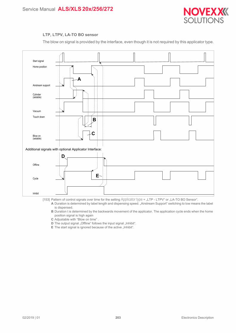
Service Manual ALS/XLS 20x/256/272
02/2019 | 01 203 Electronics Description
LTP, LTPV, LA-TO BO sensor
The blow on signal is provided by the interface, even though it is not required by this applicator type.
[153] Pattern of control signals over time for the setting Applicator type = „LTP - LTPV“ or „LA-TO BO Sensor“.A Duration is determined by label length and dispensing speed. „Airstream Support“ switching to low means the label
is dispensed.B Duration t is determined by the backwards movement of the applicator. The application cycle ends when the home
position signal is high againC Adjustable with “Blow on time” .D The output signal „Offline“ follows the input signal „Inhibit“.E The start signal is ignored because of the active „Inhibit“.
t
Start signal
Home position
Airstream support
Cylinder(setable)
Vacuum
Blow on(setable)
Offline
Cycle
Inhibit
Touch down
Additional signals with optional Applicator Interface:
B
D
A
C
E
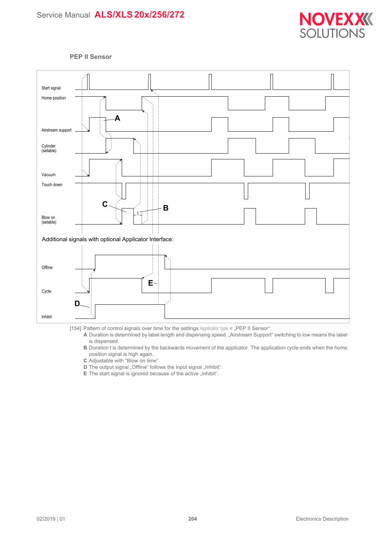
Service Manual ALS/XLS 20x/256/272
02/2019 | 01 204 Electronics Description
PEP II Sensor
[154] Pattern of control signals over time for the settings Applicator type = „PEP II Sensor“.A Duration is determined by label length and dispensing speed. „Airstream Support“ switching to low means the label
is dispensed.B Duration t is determined by the backwards movement of the applicator. The application cycle ends when the home
position signal is high again.C Adjustable with “Blow on time”.D The output signal „Offline“ follows the input signal „Inhibit“.E The start signal is ignored because of the active „Inhibit“.
t
Start signal
Home position
Airstream support
Cylinder(setable)
Vacuum
Blow on(setable)
Offline
Cycle
Inhibit
Touch down
Additional signals with optional Applicator Interface:
B
D
A
C
E
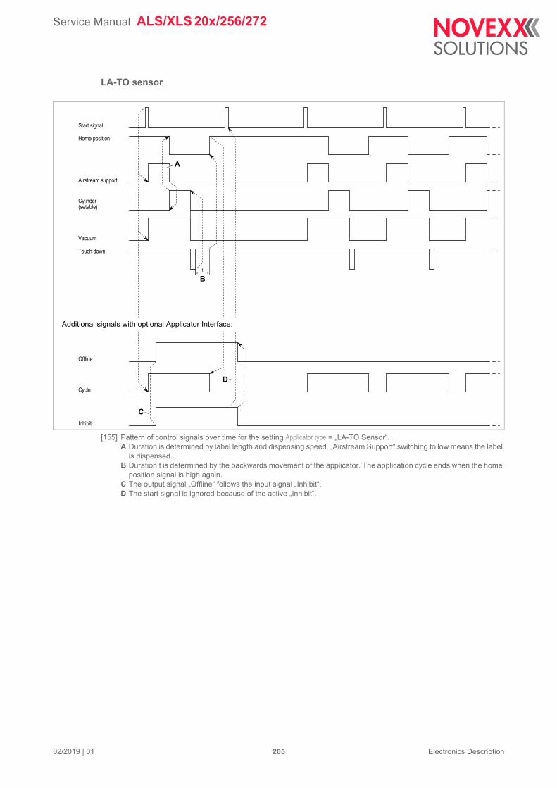
Service Manual ALS/XLS 20x/256/272
02/2019 | 01 205 Electronics Description
LA-TO sensor
[155] Pattern of control signals over time for the setting Applicator type = „LA-TO Sensor“.A Duration is determined by label length and dispensing speed. „Airstream Support“ switching to low means the label
is dispensed.B Duration t is determined by the backwards movement of the applicator. The application cycle ends when the home
position signal is high again.C The output signal „Offline“ follows the input signal „Inhibit“.D The start signal is ignored because of the active „Inhibit“.
t
Start signal
Home position
Airstream support
Cylinder(setable)
Vacuum
Offline
Cycle
Inhibit
Touch down
Additional signals with optional Applicator Interface:
A
B
C
D
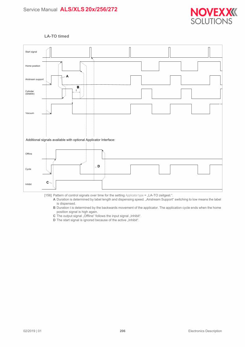
Service Manual ALS/XLS 20x/256/272
02/2019 | 01 206 Electronics Description
LA-TO timed
[156] Pattern of control signals over time for the setting Applicator type = „LA-TO zeitgest.“.A Duration is determined by label length and dispensing speed. „Airstream Support“ switching to low means the label
is dispensed.B Duration t is determined by the backwards movement of the applicator. The application cycle ends when the home
position signal is high again.C The output signal „Offline“ follows the input signal „Inhibit“.D The start signal is ignored because of the active „Inhibit“.
t
Start signal
Home position
Airstream support
Cylinder(setable)
Additional signals available with optional Applicator Interface:
Offline
Cycle
Inhibit
Vacuum
A
BB
C
D
Service Manual ALS/XLS 20x/256/272
02/2019 | 01 207 Electronics Description
ASA
The ASA is a special case, which does not have any moving parts. The label is applied only by com-pressed air. Therefore, signals controlling the movement of the applicator (Home position, Cylinder) are not required.
[157] Pattern of control signals over time for the setting Applicator type = „ASA“.A Duration is determined by the label length and dispensing speed. „Airstream Support“ switching to low means the
label is dispensed.B Can be adjusted via “Blow on time”.C The output signal „Offline“ follows the input signal „Inhibit“.D The start signal is ignored because of the active „Inhibit“.
Start signal
Airstreamsupport
Vacuum
Blow on(setable)
Additional signals available with optional Applicator Interface:
Cycle
Inhibit
Offline
A
B
C
D
Service Manual ALS/XLS 20x/256/272
02/2019 | 01 208 Electronics Description
LA-BO
[158] Pattern of control signals over time for the setting Applicator type = „LA-BO“.A Duration is determined by the label length and dispensing speed. „Airstream Support“ switching to low means the
label is dispensed.B Can be adjusted via “Blow on time”.C The output signal „Offline“ follows the input signal „Inhibit“.D The start signal is ignored because of the active „Inhibit“.
Additional signals available with optional Applicator Interface:
Start signal
Airstreamsupport
Blow on(setable)
Cycle
Inhibit
Offline
A
C
D
B
Service Manual ALS/XLS 20x/256/272
02/2019 | 01 209 Electronics Description
Signals for PLC connectionRequired setting: SIGNAL INTERFACE > Interface mode = „PLC signals“.
[159] Pin assignment D-Sub15 connector
[160] Pin assignment M12 socket (fem. connector; output signals). Matching connector: article no. A8144.
[161] Pin assignment M12 socket (male connector; input signals). Matching connector: article no. A8145.
Signal name Function
Inhibit Input
If the signal is active, start signals at both signal interfaces (standard and AI) are ignored. Triggering via -button is possible.
AI installed: alternatively, the Inhibit input at the AI can be activated (SIGNAL IN-TERFACE >ACTIVE INPUTS > Inhibit signal = „Opt. appl.interf“)
Warning In Input
An external warning status can be signaled by OR-link at the warning output
Error In Input
An external error status can be signaled by OR-link at the error output
Ready Output
Active in dispensing mode (online or online settings)
Not active in configuration mode (offline inclusive error status) and in tandem mode at the deactivated machine
Iout < 500 mA 1)
1
2
3
4
5
6
7
8
9
10
11
12
13
14
15
ErrorReady
Dispense End
Warning GND
GNDGND
GND
+24 V
Error In A
Warning In AInhibit A
Error In K
Warning In K
Inhibit K
Ready 4
GND 3
Error 2
8 Warning
5 GND
6 Dispense End
1 GND
7 GND
Error In A 6
GND 7
Inhibit K 1
8 +24 V
5 Error In K
4 Warning In A
2 Inhibit A
3 Warning In K
Service Manual ALS/XLS 20x/256/272
02/2019 | 01 210 Electronics Description
1) Imax over all outputs < 1500 mA
Signal response „Dispense End“
[162] Signal response of „Dispense End“.
The signal „Dispense End“ can be controlled by the functions in the SIGNAL INTERFACE >PLC SIGNALS submenu.
A Duration of the dispensing operation [162A]
B Period setable via SIGNAL INTERFACE >PLC SIGNALS > Disp.end delay [162B]
C Period setable via SIGNAL INTERFACE >PLC SIGNALS > End pulse width [162C]
D Signal modes; setable via SIGNAL INTERFACE >PLC SIGNALS > End dispense mod [162D]
– Modes high/low active: The signal is activated with the start of dispensing. The duration is the sum of the three periods A+B+C.
– Modes high/low pulse: The signal is activated after dispensing ended and after period B and it lasts period C [162C].
Error Output
Signal active when an error message appears on the operator panel display
Iout < 500 mA 1)
Dispense End Output
Signal that can be used to activate a secondary unit (e.g. a printing unit). Signal length and delay can be set via the function menu
Iout < 500 mA 1)
Warning Output
Active, if a warning status occurs (e. g. label roll diameter below desired nominal value)
Iout < 500 mA 1)
Signal name Function
dispense
high active
low active
high pulse
low pulse
D
B CA
Service Manual ALS/XLS 20x/256/272
02/2019 | 01 211 Electronics Description
Impact of the inhibit signalThe description in this chapter only affects the inhibit input at the standard signal interface (in PLC mode), not the inhibit input at the optional applicator interface.
The impact of the inhibit signal on the start signal is influenced by MACHINE SETUP > On inhibit enter and MACHINE SETUP > On inhibit leave. Combining the settings of the two functions has different effects.
To simplify the description in the following, abbreviations are used for the settings (see table). „A“ refers to the rising slope, „B“ refers to the dropping slope of the inhibit signal.
[163] Example for setting combination A1B1 and A1B2.
– A = relative position of the product sensor at the time of rising signal slope
– A´ = relative position of the dispensing edge at the time of rising signal slope
– B = relative position of the product sensor at the time of dropping signal slope
– B´ = relative position of the dispensing edge at the time of dropping signal slope
Function Setting Abbrev. Signal slope Effect
MACHINE SETUP >On inhibit enter
„Do saved starts“ A1 Low-high Queue is processed
„Del saved starts“ A2 Queue is deleted
MACHINE SETUP > On inhibit leave
„Do saved starts“ B1 High-Low Queue is processed
„Del saved starts“ B2 Queue is deleted
AB A'B'
Start signal
Inhibit signal
Product sensorDispensing edge
= Product will be labelled= Product will not be labelled
Service Manual ALS/XLS 20x/256/272
02/2019 | 01 212 Electronics Description
[164] Example of setting combination A1B2. Green arrow: the rising slope causes products registered in the queue to be labelled. Red arrow: the dropping slope causes the queue to be deleted. Two of the products are matching both con-ditions, in this case, the impact of the dropping slope counts.
[165] Example of setting combination A2B1.
AB A'B'
Start signal
Inhibit signal
Product sensorDispensing edge
= Product will be labelled= Product will not be labelled
AB A'B'
Start signal
Inhibit signal
Product sensorDispensing edge
= Product will be labelled= Product will not be labelled

Service Manual ALS/XLS 20x/256/272
02/2019 | 01 213 Electronics Description
[166] Example of setting combination A2B2.
AB A'B'
Start signal
Inhibit signal
Product sensorDispensing edge
= Product will be labelled= Product will not be labelled
Service Manual ALS/XLS 20x/256/272
02/2019 | 01 214 Electronics Description
DATA INTERFACES
Overview connector positions
[48] A RS 232 interface (D-Sub9)B Connection for external operator panel (Mini DIN 6)C USB interface (device, not supported with „Gen. 2“)D USB interface (host, only at „Gen. 2“ board)
RS 232
Suitable connection cable to a PC:
– D-Sub9, 1:1, connector-socket (extension cable)– Article number: A1207
Connection for external operator panelThe connector [48B] allows for the connection of an external operator panel.
See chapter Connecting / mounting the external operator panel on page 66.
Pin Signal
1, 4, 6 connected
2 RxD
3 TxD
5 Ground
7 RTS
8 CTS
9 not used
[Tab. 49] Pin assignment for RS 232 interface (looked at from „PC point of view“; Dispenser = DCE)
A
B
C
D
59
8
7
6
4
3
2
1
Service Manual ALS/XLS 20x/256/272
02/2019 | 01 215 Electronics Description
USB (device)Not yet supported with „Gen. 2“ CPU board.
Suitable connection cable to a PC:
– USB cable A/B– Article number: 126738
USB (host)Only at „Gen. 2“ CPU board.
Ethernet
[52] Ethernet interface (A)
Pin Signal
1 Vcc from the host (detection, if a connection is existing
2 Data -
3 Data +
4 Ground
[Tab. 50] Pin assignment for USB interface
Pin Signal
1 VCC
2 Data-
3 Data+
4 GND
[Tab. 51] Pinout USB interface
1234
A
Service Manual ALS/XLS 20x/256/272
02/2019 | 01 216 Electronics Description
A Connection at standard device (RJ 45)
B Connection at device with splash/dust guard (M12 D-coded)
Integration of the Ethernet interface
– 10/100 Base T
– The transfer rate is set by auto-negotiation
– LED display on the interface:
MAC address: Every device that is to be used in an Ethernet needs a unique MAC (Media Access Control) address. This consists of 6 Bytes and that are generally separated by colons or hyphens when the address is written out (hexadecimal, e.g. 00:0a:44:02:00:49 or
00-0a-44-02-00-49). The first three bytes are always 00:0A:44 (Novexx identifier); the last 3 bytes vary from device to device. Manufacturers are responsible for assigning MAC addresses to the devices they make.
IP address: The labeller firmware implements a TCP/IP protocol stack, which means that the label-ler needs an IP address for the network in addition to its MAC address. IP addresses are always written in decimal format as 4 bytes separated by points (e.g. 192.168.1.99). IP addresses are assigned by whoever runs the network, generally a network administrator.
MAC and IP addresses originate from different protocol layers and are fundamentally independent from each other.
Setting IP parameters
The following alternatives are available for setting the IP parameters:
Fixed setting
The preset values are as follows:
– IP address: 192.168.1.99
– Net mask: 255.255.255.0
– Default Gateway: 0.0.0.0
Pin Signal
A B
1 1 TD +
2 3 TD –
3 2 RD +
4 Termination
5 Termination
6 4 RD -
7 Termination
8 Termination
[Tab. 53] Pin assignment for Ethernet interface
LED Meaning
Green Continuously lit: High transfer rate (100 Mbit/s)
Yellow Continuously lit: Labeller is connected with the network
Flashing: Communicating with network
A
B1 2
34
12345678
Service Manual ALS/XLS 20x/256/272
02/2019 | 01 217 Electronics Description
Assigned by DHCP server
The following are requested from the DHCP server: Address, net mask, default gateway. During the request process, a device name is communicated to the DHCP server, to assist the system administrator. This name is made up of the model of labeller + 3 characters from the MAC address.
– Example: ALS_204___020049
– It is not necessary to connect to a name server
This is where to set the IP parameters in the labeller function menu:
IMPORTANT: These addresses must be assigned with care, ensuring they are unique on each machine. Call in your network administrator.
Menu Function Description
INTEFACE PARA >NETWORK PARAM.
IP Addressassign Set to “Fixed IP address” or “DHCP”
IP addressNet mask
Gateway address
Input fields for the IP parameters, if the method of assign-ing addresses was set to Fixed IP address”.
Service Manual ALS/XLS 20x/256/272
02/2019 | 00 218 Electronics Description
APPLICATOR INTERFACE (OPTION)
[167] Connections of the Applicator Interface:A Applicator connection (D-Sub 44 hd)B Machine status connection (D-Sub 26 hd)C Product (Start) sensor connection (D-Sub 15 hd)D Monitor-LEDs
Important notesThe Applicator Interface (AI) is an option board for the here described labeler types.
The AI works as a mini-PLC, which can control almost any applicator type.
If an AI is installed, the Menu SIGNAL INTERFACE >AI BOARD SIGNAL appears in the function menu.
Retrofitting kit AI: Article no. A9516.
Required connectors:
„AI connector kit“, Article no. A5069, contains (connector and connector housing for each):
– 1x D-Sub 15 high density– 1x D-Sub 26 high density– 1x D-Sub 44 high density
Circuit diagrams for signal inputsFor each signal input are +24 V and GND 24 V separately available.
[168] Main circuit for signal inputs (NPN).
A
B
C
D
1k6
24 V
GND
470R
1k6
Applicator Interface
NPNSensor
Service Manual ALS/XLS 20x/256/272
02/2019 | 00 219 Electronics Description
[169] Main circuit for signal inputs (PNP).
1) With 3.8 mA input current2) With 5.7 mA input current3) 24 V input 5 V microcontroller input
Circuit diagrams for signal outputsAll signal outputs are designed as PNP and are galvanically separated from the 5 V control system (optocoupler).
The maximum output power drawable from the 24 V supply is 24 W (1 A). This is the sum of all sen-sor supplies and of all switch outputs which are active at the same time.
[170] Main circuit for outputs (PNP).
Quantity Value Note
Supply voltage 24 V ±10%
VIL (state „0“) 5 V
VIH (state „1“) 18,0 V @ 3,8 mA
26,4 V @ 5,7 mA
1
2
tdelay (propagation delay) 60 µs 3
tdebounce (software debouncing) 10 ms
[Tab. 54] Switching level definitions for signal inputs.
Connection Maximalstrom
Applicator 0.5 A each power output
Maschine status 0.5 A each power output
[Tab. 55] Maximum ouput current.
1k6
24 V
GND
470R
1k6
Applicator Interface
PNPSensor
24 V
Load
GNDGND
Applicator Interface
5 V
Service Manual ALS/XLS 20x/256/272
02/2019 | 00 220 Electronics Description
The outputs are equipped with quad channel power switches, which are protected against overcurrent and overtemperature as follows:
–Overtemperature of a power switch: all outputs of the power switch are turned off, until the temperature reaches the admissible range.
–Overcurrent of one or several outputs: the respective outputs are pulsed until the overcur-rent condition is removed. During this, the output current is limited to 400mA
During an error case, each quad channel power switch sets a diagnosis signal, which is detected and sent to the CPU by the microcontroller.
Power outputsPower outputs can directly drive loads.
Maximum admissible output current for each power output: 0.5 A (Imax over all outputs < 1 A).
1) Rise time „0“ „1“ at 48 Ohm2) Fall time „1“ „0“ at 48 Ohm3) 5 V microcontroller output 24 V
Load Max. value
Resistive load 48 Ohm @ 24 VDC
Inductive load 200 mJ
Lamp 10 W
[Tab. 56] Admissible loads at power outputs.
Quantity Value Note
Supply voltage 24 V ±10%
Voltage drop at VOH 0,5 V @ 0,5 A
tpLH 5 µs 1)
tpHL 5 µs 2)
tdelay 60 µs 3)
[Tab. 57] Switching levels of power outputs.
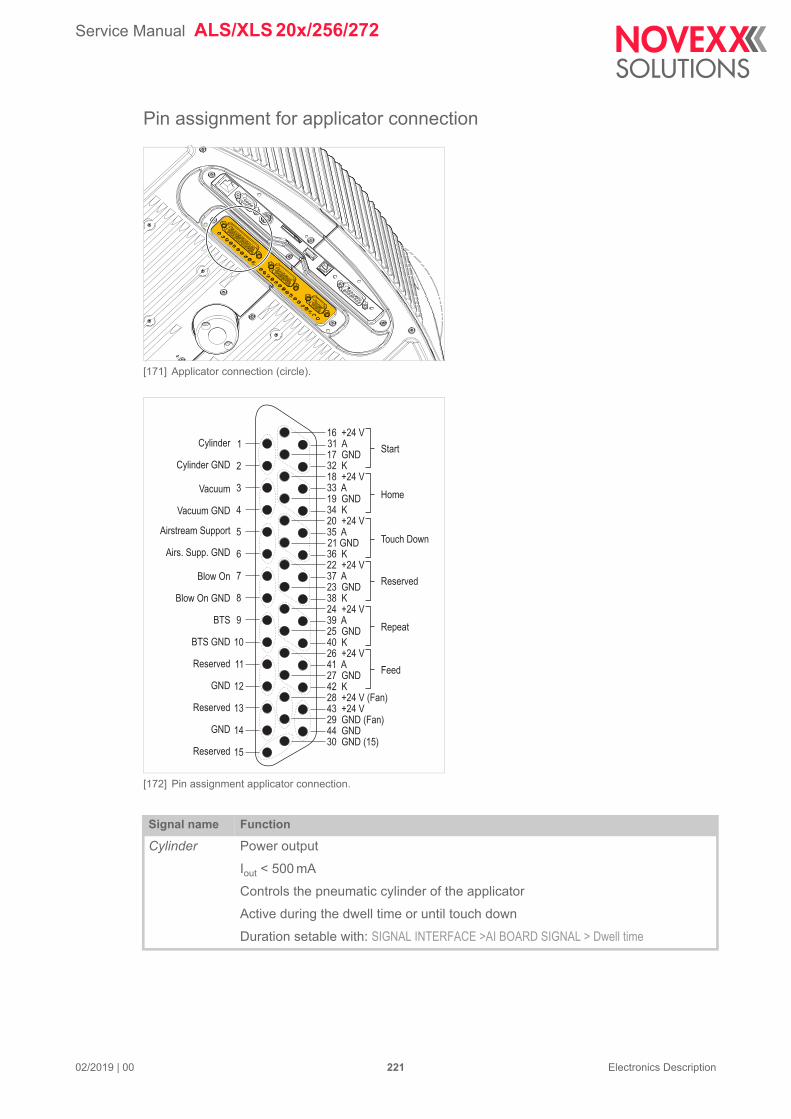
Service Manual ALS/XLS 20x/256/272
02/2019 | 00 221 Electronics Description
Pin assignment for applicator connection
[171] Applicator connection (circle).
[172] Pin assignment applicator connection.
Signal name Function
Cylinder Power output
Iout < 500 mA
Controls the pneumatic cylinder of the applicator
Active during the dwell time or until touch down
Duration setable with: SIGNAL INTERFACE >AI BOARD SIGNAL > Dwell time
Cylinder
Cylinder GND
Vacuum
Vacuum GND
Airstream Support
Airs. Supp. GND
Blow On
Blow On GND
BTS
BTS GND
Reserved
GND
Reserved
GND
Reserved
Home
Touch Down
Repeat
Feed
Reserved
Start1
2
3
4
5
6
7
8
9
10
11
12
13
14
15
31 A
32 K
33 A
34 K
35 A
36 K22 +24 V37 A23 GND38 K24 +24 V39 A25 GND40 K26 +24 V41 A27 GND42 K28 +24 V (Fan)43 +24 V29 GND (Fan)44 GND30 GND (15)
16 +24 V
17 GND
18 +24 V
19 GND
20 +24 V
21 GND
Service Manual ALS/XLS 20x/256/272
02/2019 | 00 222 Electronics Description
Vacuum Power output
Iout < 500 mA
Controls the vacuum at the applicator plate
Active after the start signal until end of application (cylinder)
Airstream Support
Power output
Iout < 500 mA
Controls the airstream, which presses the label against the applicator plate.
Active after the start signal until start of application (cylinder)
Blow On Power output
Iout < 500 mA
Controls the blow-on valve of the applicator
Active after end of application (cylinder)
Duration setable with: SIGNAL INTERFACE >AI BOARD SIGNAL > Blow on time
BTS Power output
Iout < 500 mA
Controls the Bad Tag Separator (BTS)
Active, if a bad RFID tag is detected
Is set back by the following action (e. g. devaluating the bad tag)
Start Input
Iin < 6 mA
Signal is generated by the product sensor
Starts the dispensing/application cycle
Dispenser reaction time is higher than after a start signal at the M12 start input (application for direct dispensing is not advisable)
CAUTION! - Initially, this signal input is deactivated. The standard Start signal in-put (M12 connector) is activated. This setting can be changed with SIGNAL INTER-FACE >ACTIVE INPUTS > Start signal
Home Input
Iin < 6 mA
Active, if the applicator has reached the home position (application is finished)
Touch Down Input
Iin < 6 mA
Use with sensor-controlled applicators (e. g. LTP)
Active, if the applicator touches the product
Repeat Input
Iin < 6 mA
Starts the dispensing/application cycle (1x)
Signal name Function
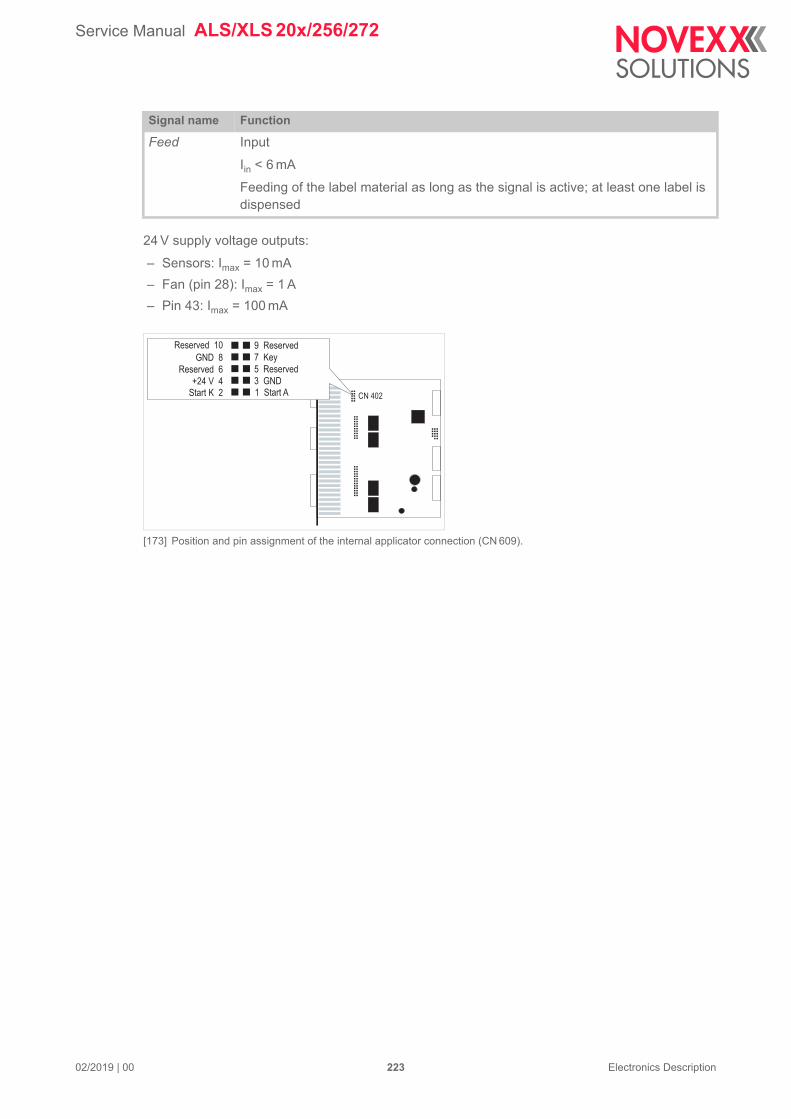
Service Manual ALS/XLS 20x/256/272
02/2019 | 00 223 Electronics Description
24 V supply voltage outputs:
– Sensors: Imax = 10 mA
– Fan (pin 28): Imax = 1 A
– Pin 43: Imax = 100 mA
[173] Position and pin assignment of the internal applicator connection (CN 609).
Feed Input
Iin < 6 mA
Feeding of the label material as long as the signal is active; at least one label is dispensed
Signal name Function
Start K 2+24 V 4
Reserved 6
GND 8
Reserved 10
1 Start A3 GND
5 Reserved
7 Key
9 Reserved
CN 402
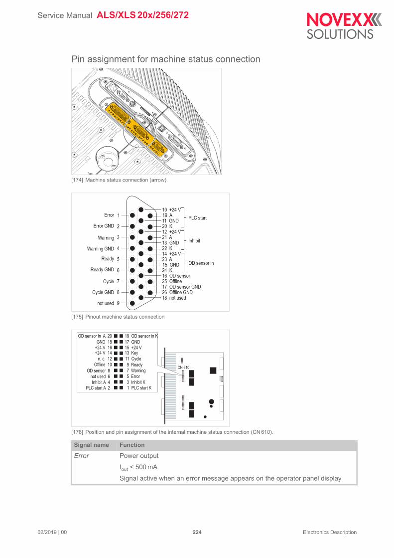
Service Manual ALS/XLS 20x/256/272
02/2019 | 00 224 Electronics Description
Pin assignment for machine status connection
[174] Machine status connection (arrow).
[175] Pinout machine status connection
[176] Position and pin assignment of the internal machine status connection (CN 610).
Signal name Function
Error Power output
Iout < 500 mA
Signal active when an error message appears on the operator panel display
Error
Error GND
Warning
Warning GND
Ready
Ready GND
Cycle
Cycle GND
not used
PLC start
Inhibit
OD sensor in
1
2
3
4
5
6
7
8
9
19 A
20 K
21 A
22 K
23 A
24 K16 OD sensor25 Offline17 OD sensor GND26 Offline GND18 not used
10 +24 V
11 GND
12 +24 V
13 GND
14 +24 V
15 GND
PLC start A 2Inhibit A 4
not used 6
OD sensor 8
+24 V 16GND 18
OD sensor in A 20
Offline 10
n. c. 12
+24 V 14
1 PLC start K3 Inhibit K
5 Error
7 Warning
15 +24 V17 GND
19 OD sensor in K
9 Ready
11 Cycle
13 Key
CN 610

Service Manual ALS/XLS 20x/256/272
02/2019 | 00 225 Electronics Description
24 V supply voltage outputs: Imax =10 mA
Warning Power output
Iout < 500 mA
Active, if a warning status occurs (e. g. label roll diameter below desired nominal value)
Ready Power output
Iout < 500 mA
Active in dispensing mode
Not active in configuration mode
Inverted Offline signal
Cycle Power output
Iout < 500 mA
Active during application cycle
PLC start Input
Iin < 6 mA
Same function as start signal, see section “Pin assignment for applicator connec-tion” on page 221
Inhibit Input
Iin < 6 mA
Start signals are ignored, while signal is active
CAUTION! - Initially, this signal input is deactivated. The Inhibit signal input at the standard signal interface (PLC mode) is activated. This setting can be changed with SIGNAL INTERFACE >ACTIVE INPUTS > Inhibit signal
OD sensor in Input
Iin < 6 mA
Connection for optional roll outer diameter (OD) sensor
CAUTION! - Initially, this signal input is deactivated. The „OD sensor in“ standard signal input (M12 connector) is activated. This setting can be changed with SI-GNAL INTERFACE >ACTIVE INPUTS > OD sensor signal
OD sensor Power output
Iout < 500 mA
Active, if the input „OD sensor“ is set high
Offline Power output
Iout < 500 mA
Active in configuration mode
Not active in dispensing mode
Inverted Ready signal
Signal name Function
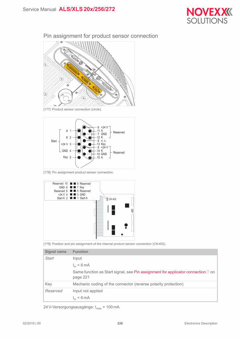
Service Manual ALS/XLS 20x/256/272
02/2019 | 00 226 Electronics Description
Pin assignment for product sensor connection
[177] Product sensor connection (circle).
[178] Pin assignment product sensor connection.
[179] Position and pin assignment of the internal product sensor connection (CN 402).
24 V-Versorgungsausgänge: Imax = 100 mA
Signal name Function
Start Input
Iin < 6 mA
Same function as Start signal, see Pin assignment for applicator connection on page 221
Key Mechanic coding of the connector (reverse polarity protection)
Reserved Input not applied
Iin < 6 mA
A
StartK
+24 V
GND
Key
Reserved
Reserved
A
K
Key
K
A
+24 V
GND
n. c.
+24 V
GND
1
2
3
4
5
11
12
13
14
15
6
7
8
9
10
Start K 2+24 V 4
Reserved 6
GND 8
Reserved 10
1 Start A3 GND
5 Reserved
7 Key
9 Reserved
CN 402
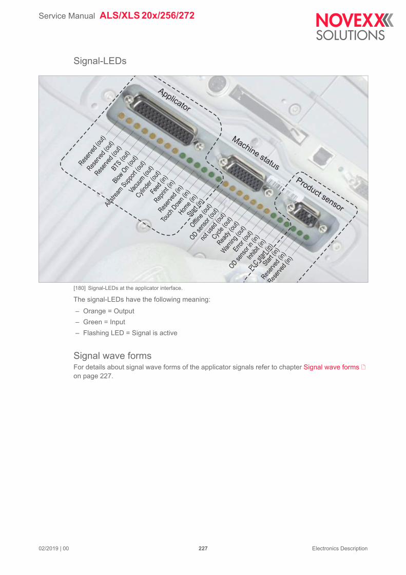
Service Manual ALS/XLS 20x/256/272
02/2019 | 00 227 Electronics Description
Signal-LEDs
[180] Signal-LEDs at the applicator interface.
The signal-LEDs have the following meaning:
– Orange = Output
– Green = Input
– Flashing LED = Signal is active
Signal wave formsFor details about signal wave forms of the applicator signals refer to chapter Signal wave forms on page 227.
Reser
ved
(out
)Res
erve
d(o
ut)
Blow
On
(out
)
BTS(o
ut)
Airstre
amSup
port
(out
)
Vacu
um(o
ut)
Cylind
er(o
ut)
Feed
(in)
Reprin
t (in
)
Reser
ved
(in)
Touc
hDow
n(in
)Hom
e(in
)Sta
rt(in
)
Offl
ine
(out
)
OD
sens
or(o
ut)
not u
sed
(out
)
Cycle
(out
)
Ready
(out
)
War
ning
(out
)
Error (
out)
OD
sens
orin
(in)
Inhi
bit (
in)
PLCst
art (
in)
Start
(in)
Reser
ved
(in)
Reser
ved
(in)
Reser
ved
(out
)
Applicator
Machine status
Product sensor
Service Manual ALS/XLS 20x/256/272
02/2019 | 00 228
Fault description
TYPES OF STATUS MESSAGES
Error messagesIf an error occurs, the machine stops immediately and displays an error message on the operator panel.
The format for error messages is as follows:
[181] Example of an error message:5144 = status number; the message can identified more easily with this number.“Rewinder init” = status text; a short description of the error.
If an error occurs that is not described here:
Press the button to delete the message.
Switch the machine off, wait 30 seconds and switch it back on.
WarningsWarnings indicate less severe status than error messages. The labelling is not interrupted by a warning.
Warning can occur both in dispensing mode and in online setting mode.
Warning format:
[182] Example of a warning in dispensing mode:„Material low“ = Warning text; a short description of what has caused the warning.
Setting back a warningIn dispensing mode:
Press the button (works earliest with firmware versions > 1.10).
In online setting mode:
Switch to dispensing mode. To do so, press the buttons + .
Press the button (works earliest with firmware versions > 1.10).
In both modes:
Send the Easy-Plug command #!CLRW to the machine.
If more than one warning is active at a time, the highest prioritised warning appears at first; if thit one is set back the next one appears, and so on.
Status num: 5144Rewinder init
ONLINEMaterial low
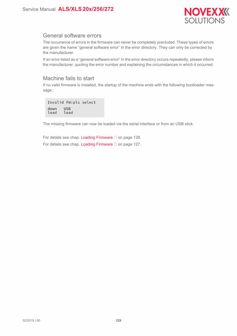
Service Manual ALS/XLS 20x/256/272
02/2019 | 00 229
General software errorsThe occurrence of errors in the firmware can never be completely precluded. These types of errors are given the name “general software error” in the error directory. They can only be corrected by the manufacturer.
If an error listed as a “general software error” in the error directory occurs repeatedly, please inform the manufacturer, quoting the error number and explaining the circumstances in which it occurred.
Machine fails to startIf no valid firmware is installed, the startup of the machine ends with the following bootloader mes-sage::
The missing firmware can now be loaded via the serial interface or from an USB stick.
For details see chap. Loading Firmware on page 128.
For details see chap. Loading Firmware on page 127.
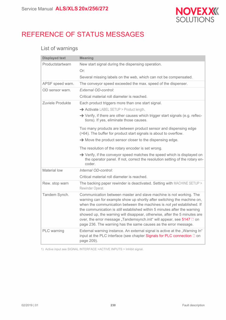
Service Manual ALS/XLS 20x/256/272
REFERENCE OF STATUS MESSAGES
List of warnings
1) Active input see SIGNAL INTERFACE >ACTIVE INPUTS > Inhibit signal.
Displayed text Meaning
Productstartwarn New start signal during the dispensing operation.
Or:
Several missing labels on the web, which can not be compensated.
APSF speed warn. The conveyor speed exceeded the max. speed of the dispenser.
OD sensor warn. External OD-control:
Critical material roll diameter is reached.
Zuviele Produkte Each product triggers more than one start signal.
Activate LABEL SETUP > Product length.
Verify, if there are other causes which trigger start signals (e.g. reflec-tions). If yes, eliminate those causes.
Too many products are between product sensor and dispensing edge (>64). The buffer for product start signals is about to overflow.
Move the product sensor closer to the dispensing edge.
The resolution of the rotary encoder is set wrong.
Verify, if the conveyor speed matches the speed which is displayed on the operator panel. If not, correct the resolution setting of the rotary en-coder.
Material low Internal OD-control:
Critical material roll diameter is reached.
Rew. stop warn The backing paper rewinder is deactivated. Setting with MACHINE SETUP > Rewinder Operat.
Tandem Synch. Communication between master and slave machine is not working. The warning can for example show up shortly after switching the machine on, when the communication between the machines is not yet established. If the communication is still established within 5 minutes after the warning showed up, the warning will disappear, otherwise, after the 5 minutes are over, the error message „Tandemsynch.init“ will appear, see 5147 on page 236. The warning has the same causes as the error message.
PLC warning External warning instance. An external signal is active at the „Warning In“ input at the PLC interface (see chapter Signals for PLC connection on page 209).
02/2019 | 01 230 Fault description
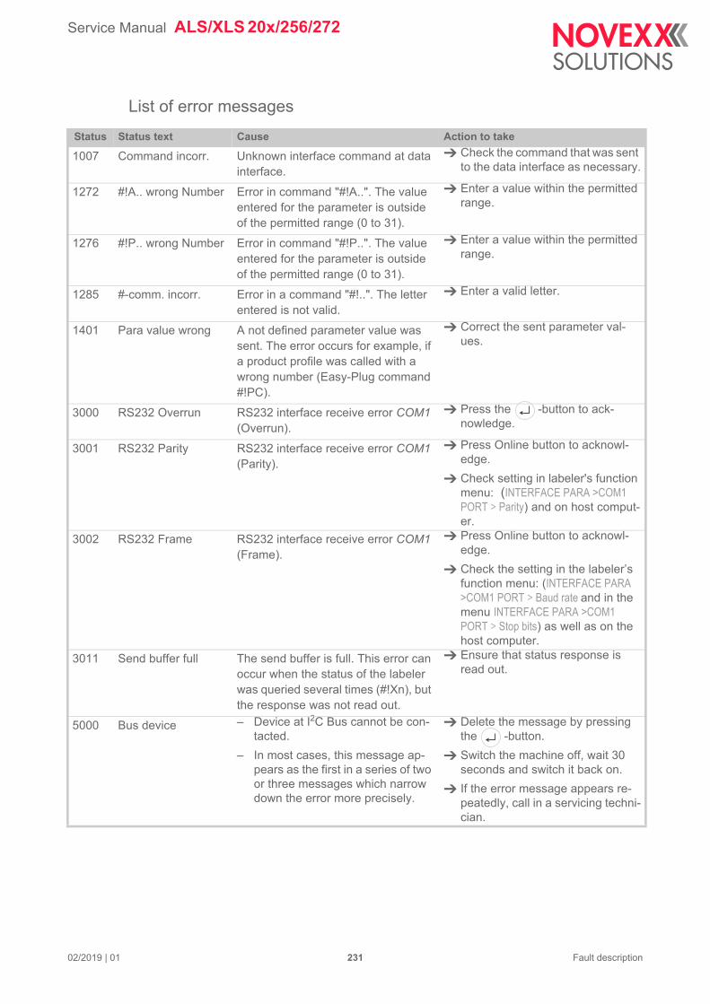
Service Manual ALS/XLS 20x/256/272
List of error messages
Status Status text Cause Action to take
1007 Command incorr. Unknown interface command at data interface.
Check the command that was sent to the data interface as necessary.
1272 #!A.. wrong Number Error in command "#!A..". The value entered for the parameter is outside of the permitted range (0 to 31).
Enter a value within the permitted range.
1276 #!P.. wrong Number Error in command "#!P..". The value entered for the parameter is outside of the permitted range (0 to 31).
Enter a value within the permitted range.
1285 #-comm. incorr. Error in a command "#!..". The letter entered is not valid.
Enter a valid letter.
1401 Para value wrong A not defined parameter value was sent. The error occurs for example, if a product profile was called with a wrong number (Easy-Plug command #!PC).
Correct the sent parameter val-ues.
3000 RS232 Overrun RS232 interface receive error COM1 (Overrun).
Press the -button to ack-nowledge.
3001 RS232 Parity RS232 interface receive error COM1 (Parity).
Press Online button to acknowl-edge.
Check setting in labeler's function menu: (INTERFACE PARA >COM1 PORT > Parity) and on host comput-er.
3002 RS232 Frame RS232 interface receive error COM1 (Frame).
Press Online button to acknowl-edge.
Check the setting in the labeler’s function menu: (INTERFACE PARA >COM1 PORT > Baud rate and in the menu INTERFACE PARA >COM1 PORT > Stop bits) as well as on the host computer.
3011 Send buffer full The send buffer is full. This error can occur when the status of the labeler was queried several times (#!Xn), but the response was not read out.
Ensure that status response is read out.
5000 Bus device – Device at I2C Bus cannot be con-tacted.
– In most cases, this message ap-pears as the first in a series of two or three messages which narrow down the error more precisely.
Delete the message by pressing the -button.
Switch the machine off, wait 30 seconds and switch it back on.
If the error message appears re-peatedly, call in a servicing techni-cian.
02/2019 | 01 231 Fault description
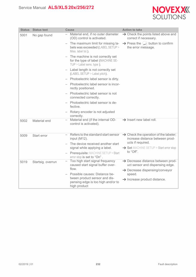
Service Manual ALS/XLS 20x/256/272
5001 No gap found – Material end, if no outer diameter (OD) control is activated.
– The maximum limit for missing la-bels was exceeded (LABEL SETUP > Miss. label tol.).
– The machine is not correctly set for the type of label (MACHINE SE-TUP > Label sens. type ).
– Label length is not correctly set (LABEL SETUP > Label pitch).
– Photoelectric label sensor is dirty.
– Photoelectric label sensor is incor-rectly positioned.
– Photoelectric label sensor is not connected correctly.
– Photoelectric label sensor is de-fective.
– Rotary encoder is not adjusted correctly.
Check the points listed above and correct if necessary.
Press the button to confirm the error message.
5002 Material end – Material end (if the internal OD-control is activated).
Insert new label roll.
5009 Start error – Refers to the standard start sensor input (M12).
– The device received another start signal while applying a label.
– Prerequisite: MACHINE SETUP > Start error stop is set to “On” .
Check the operation of the labeler; increase distance between prod-ucts if required.
Set MACHINE SETUP > Start error stop to “Off”.
5019 Startsig. overrun – Too high start signal frequency caused start signal buffer over-flow.
– Possible causes: Distance be-tween product sensor and dis-pensing edge is too high and/or to high product
Decrease distance between prod-uct sensor and dispensing edge.
Decrease dispensing/conveyor speed.
Increase product distance.
Status Status text Cause Action to take
02/2019 | 01 232 Fault description
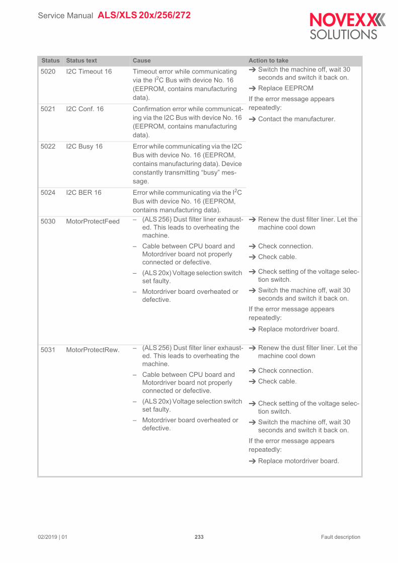
Service Manual ALS/XLS 20x/256/272
5020 I2C Timeout 16 Timeout error while communicating via the I2C Bus with device No. 16 (EEPROM, contains manufacturing data).
Switch the machine off, wait 30 seconds and switch it back on.
Replace EEPROM
If the error message appears repeatedly:
Contact the manufacturer.
5021 I2C Conf. 16 Confirmation error while communicat-ing via the I2C Bus with device No. 16 (EEPROM, contains manufacturing data).
5022 I2C Busy 16 Error while communicating via the I2C Bus with device No. 16 (EEPROM, contains manufacturing data). Device constantly transmitting “busy” mes-sage.
5024 I2C BER 16 Error while communicating via the I2C Bus with device No. 16 (EEPROM, contains manufacturing data).
5030 MotorProtectFeed – (ALS 256) Dust filter liner exhaust-ed. This leads to overheating the machine.
– Cable between CPU board and Motordriver board not properly connected or defective.
– (ALS 20x) Voltage selection switch set faulty.
– Motordriver board overheated or defective.
Renew the dust filter liner. Let the machine cool down
Check connection.
Check cable.
Check setting of the voltage selec-tion switch.
Switch the machine off, wait 30 seconds and switch it back on.
If the error message appears repeatedly:
Replace motordriver board.
5031 MotorProtectRew. – (ALS 256) Dust filter liner exhaust-ed. This leads to overheating the machine.
– Cable between CPU board and Motordriver board not properly connected or defective.
– (ALS 20x) Voltage selection switch set faulty.
– Motordriver board overheated or defective.
Renew the dust filter liner. Let the machine cool down
Check connection.
Check cable.
Check setting of the voltage selec-tion switch.
Switch the machine off, wait 30 seconds and switch it back on.
If the error message appears repeatedly:
Replace motordriver board.
Status Status text Cause Action to take
02/2019 | 01 233 Fault description
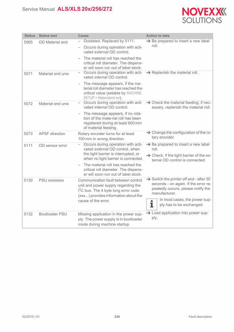
Service Manual ALS/XLS 20x/256/272
5065 OD Material end – Outdated. Replaced by 5111.
– Occurs during operation with acti-vated external OD control.
– The material roll has reached the critical roll diameter. The dispens-er will soon run out of label stock.
Be prepared to insert a new label roll.
5071 Material end unw – Occurs during operation with acti-vated internal OD control.
– The message appears, if the ma-terial roll diameter has reached the critical value (setable by MACHINE SETUP > Materialend err).
Replenish the material roll .
5072 Material end unw – Occurs during operation with acti-vated internal OD control.
– The message appears, if no rota-tion of the mate-rial roll has been registered during at least 600 mm of material feeding.
Check the material feeding; if nec-essary, replenish the material roll.
5073 APSF direction Rotary encoder turns for at least 100 mm in wrong direction.
Change the configuration of the ro-tary encoder.
5111 OD sensor error – Occurs during operation with acti-vated external OD control, when the light barrier is interrupted, or when no light barrier is connected.
– The material roll has reached the critical roll diameter. The dispens-er will soon run out of label stock.
Be prepared to insert a new label roll.
Check, if the light barrier of the ex-ternal OD control is connected.
5130 PSU xxxxxxxx Communication fault between control unit and power supply regarding the I2C bus. The 4 byte long error code (xxx...) provides information about the cause of the error.
Switch the printer off and - after 30 seconds - on again. If the error re-peatedly occurs, please notify the manufacturer.
In most cases, the power sup-ply has to be exchanged.
5132 Bootloader PSU Missing application in the power sup-ply. The power supply is in bootloader mode during machine startup.
Load application into power sup-ply.
Status Status text Cause Action to take
02/2019 | 01 234 Fault description
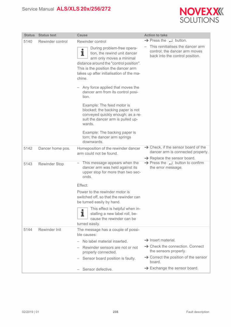
Service Manual ALS/XLS 20x/256/272
5140 Rewinder control Rewinder control
During problem-free opera-tion, the rewind unit dancer arm only moves a minimal
distance around the "control position". This is the position the dancer arm takes up after initialisation of the ma-chine.
– Any force applied that moves the dancer arm from its control posi-tion.
Example: The feed motor is blocked; the backing paper is not conveyed quickly enough; as a re-sult the dancer arm is pulled up-wards.
Example: The backing paper is torn; the dancer arm springs downwards.
Press the button.
– This reinitialises the dancer arm control; the dancer arm moves back into the control position.
5142 Dancer home pos. Homeposition of the rewinder dancer arm could not be found.
Check, if the sensor board of the dancer arm is connected properly.
Replace the sensor board.
5143 Rewinder Stop – This message appears when the dancer arm was held against its upper stop for more than two sec-onds.
Effect:
Power to the rewinder motor is switched off, so that the rewinder can be turned easily by hand.
This effect is helpful when in-stalling a new label roll, be-cause the rewinder can be
turned easily.
Press the button to confirm the error message.
5144 Rewinder Init The message has a couple of possi-ble causes:
– No label material inserted.
– Rewinder sensors are not or not properly connected.
– Sensor board position is faulty.
– Sensor defective.
Insert material.
Check the connection. Connect the sensors properly.
Correct the position of the sensor board.
Exchange the sensor board.
Status Status text Cause Action to take
02/2019 | 01 235 Fault description
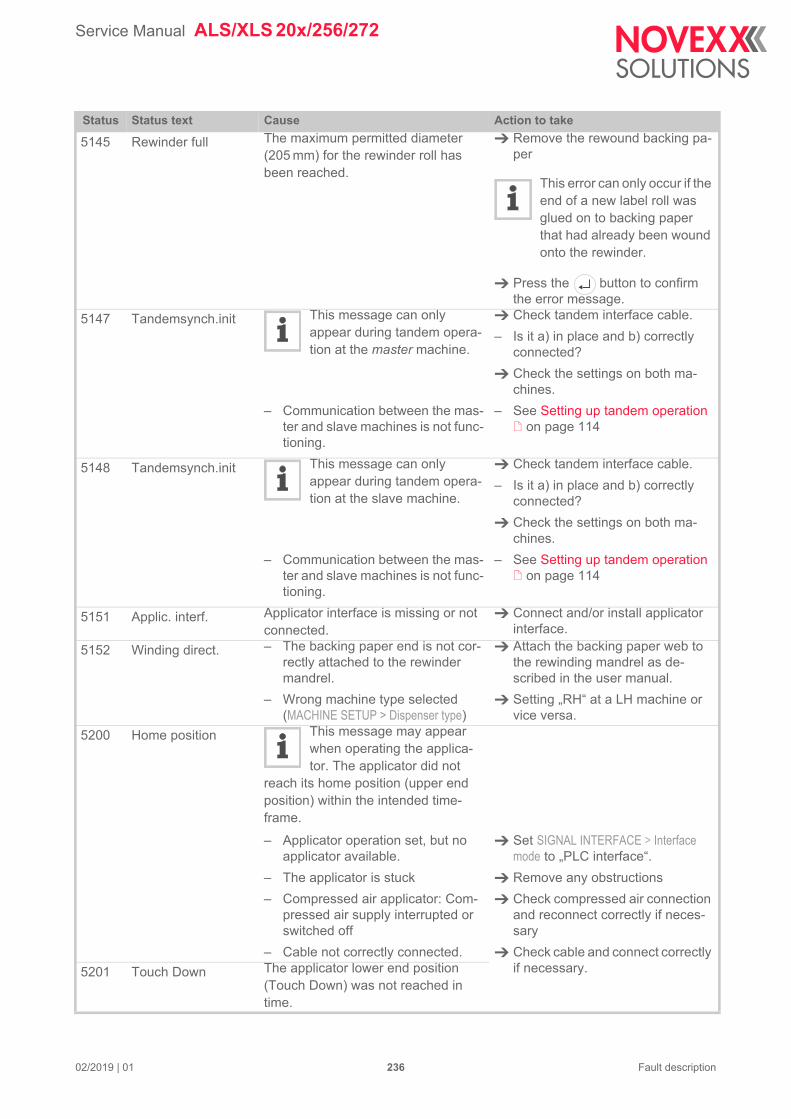
Service Manual ALS/XLS 20x/256/272
5145 Rewinder full The maximum permitted diameter (205 mm) for the rewinder roll has been reached.
Remove the rewound backing pa-per
This error can only occur if the end of a new label roll was glued on to backing paper that had already been wound onto the rewinder.
Press the button to confirm the error message.
5147 Tandemsynch.init This message can only appear during tandem opera-tion at the master machine.
– Communication between the mas-ter and slave machines is not func-tioning.
Check tandem interface cable.
– Is it a) in place and b) correctly connected?
Check the settings on both ma-chines.
– See Setting up tandem operation on page 114
5148 Tandemsynch.init This message can only appear during tandem opera-tion at the slave machine.
– Communication between the mas-ter and slave machines is not func-tioning.
Check tandem interface cable.
– Is it a) in place and b) correctly connected?
Check the settings on both ma-chines.
– See Setting up tandem operation on page 114
5151 Applic. interf. Applicator interface is missing or not connected.
Connect and/or install applicator interface.
5152 Winding direct. – The backing paper end is not cor-rectly attached to the rewinder mandrel.
– Wrong machine type selected (MACHINE SETUP > Dispenser type)
Attach the backing paper web to the rewinding mandrel as de-scribed in the user manual.
Setting „RH“ at a LH machine or vice versa.
5200 Home position This message may appear when operating the applica-tor. The applicator did not
reach its home position (upper end position) within the intended time-frame.
– Applicator operation set, but no applicator available.
– The applicator is stuck
– Compressed air applicator: Com-pressed air supply interrupted or switched off
– Cable not correctly connected.
Set SIGNAL INTERFACE > Interface mode to „PLC interface“.
Remove any obstructions
Check compressed air connection and reconnect correctly if neces-sary
Check cable and connect correctly if necessary.5201 Touch Down The applicator lower end position
(Touch Down) was not reached in time.
Status Status text Cause Action to take
02/2019 | 01 236 Fault description
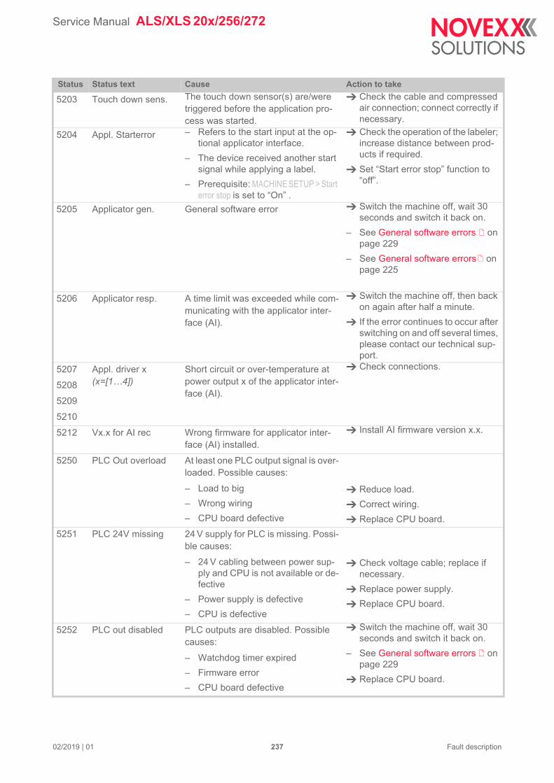
Service Manual ALS/XLS 20x/256/272
5203 Touch down sens. The touch down sensor(s) are/were triggered before the application pro-cess was started.
Check the cable and compressed air connection; connect correctly if necessary.
5204 Appl. Starterror – Refers to the start input at the op-tional applicator interface.
– The device received another start signal while applying a label.
– Prerequisite: MACHINE SETUP > Start error stop is set to “On” .
Check the operation of the labeler; increase distance between prod-ucts if required.
Set “Start error stop” function to “off”.
5205 Applicator gen. General software error Switch the machine off, wait 30 seconds and switch it back on.
– See General software errors on page 229
– See General software errors on page 225
5206 Applicator resp. A time limit was exceeded while com-municating with the applicator inter-face (AI).
Switch the machine off, then back on again after half a minute.
If the error continues to occur after switching on and off several times, please contact our technical sup-port.
5207
5208
5209
5210
Appl. driver x (x=[1…4])
Short circuit or over-temperature at power output x of the applicator inter-face (AI).
Check connections.
5212 Vx.x for AI rec Wrong firmware for applicator inter-face (AI) installed.
Install AI firmware version x.x.
5250 PLC Out overload At least one PLC output signal is over-loaded. Possible causes:
– Load to big
– Wrong wiring
– CPU board defective
Reduce load.
Correct wiring.
Replace CPU board.
5251 PLC 24V missing 24 V supply for PLC is missing. Possi-ble causes:
– 24 V cabling between power sup-ply and CPU is not available or de-fective
– Power supply is defective
– CPU is defective
Check voltage cable; replace if necessary.
Replace power supply.
Replace CPU board.
5252 PLC out disabled PLC outputs are disabled. Possible causes:
– Watchdog timer expired
– Firmware error
– CPU board defective
Switch the machine off, wait 30 seconds and switch it back on.
– See General software errors on page 229
Replace CPU board.
Status Status text Cause Action to take
02/2019 | 01 237 Fault description
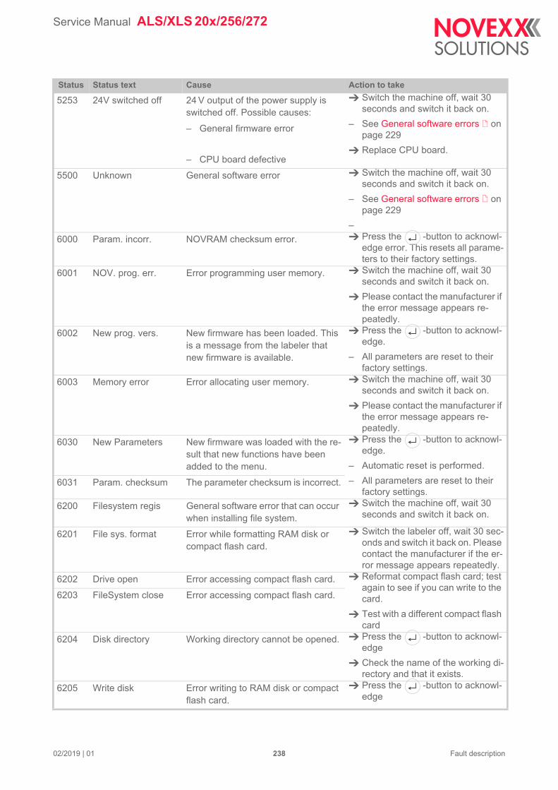
Service Manual ALS/XLS 20x/256/272
5253 24V switched off 24 V output of the power supply is switched off. Possible causes:
– General firmware error
– CPU board defective
Switch the machine off, wait 30 seconds and switch it back on.
– See General software errors on page 229
Replace CPU board.
5500 Unknown General software error Switch the machine off, wait 30 seconds and switch it back on.
– See General software errors on page 229
–
6000 Param. incorr. NOVRAM checksum error. Press the -button to acknowl-edge error. This resets all parame-ters to their factory settings.
6001 NOV. prog. err. Error programming user memory. Switch the machine off, wait 30 seconds and switch it back on.
Please contact the manufacturer if the error message appears re-peatedly.
6002 New prog. vers. New firmware has been loaded. This is a message from the labeler that new firmware is available.
Press the -button to acknowl-edge.
– All parameters are reset to their factory settings.
6003 Memory error Error allocating user memory. Switch the machine off, wait 30 seconds and switch it back on.
Please contact the manufacturer if the error message appears re-peatedly.
6030 New Parameters New firmware was loaded with the re-sult that new functions have been added to the menu.
Press the -button to acknowl-edge.
– Automatic reset is performed.
– All parameters are reset to their factory settings.
6031 Param. checksum The parameter checksum is incorrect.
6200 Filesystem regis General software error that can occur when installing file system.
Switch the machine off, wait 30 seconds and switch it back on.
6201 File sys. format Error while formatting RAM disk or compact flash card.
Switch the labeler off, wait 30 sec-onds and switch it back on. Please contact the manufacturer if the er-ror message appears repeatedly.
6202 Drive open Error accessing compact flash card. Reformat compact flash card; test again to see if you can write to the card.
Test with a different compact flash card
6203 FileSystem close Error accessing compact flash card.
6204 Disk directory Working directory cannot be opened. Press the -button to acknowl-edge
Check the name of the working di-rectory and that it exists.
6205 Write disk Error writing to RAM disk or compact flash card.
Press the -button to acknowl-edge
Status Status text Cause Action to take
02/2019 | 01 238 Fault description
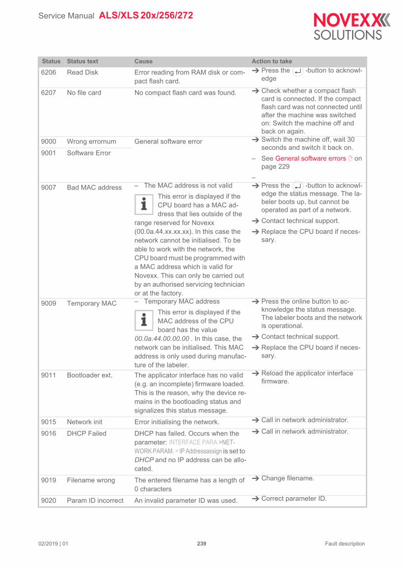
Service Manual ALS/XLS 20x/256/272
6206 Read Disk Error reading from RAM disk or com-pact flash card.
Press the -button to acknowl-edge
6207 No file card No compact flash card was found. Check whether a compact flash card is connected. If the compact flash card was not connected until after the machine was switched on: Switch the machine off and back on again.
9000 Wrong errornum General software error Switch the machine off, wait 30 seconds and switch it back on.
– See General software errors on page 229
–
9001 Software Error
9007 Bad MAC address – The MAC address is not valid
This error is displayed if the CPU board has a MAC ad-dress that lies outside of the
range reserved for Novexx (00.0a.44.xx.xx.xx). In this case the network cannot be initialised. To be able to work with the network, the CPU board must be programmed with a MAC address which is valid for Novexx. This can only be carried out by an authorised servicing technician or at the factory.
Press the -button to acknowl-edge the status message. The la-beler boots up, but cannot be operated as part of a network.
Contact technical support.
Replace the CPU board if neces-sary.
9009 Temporary MAC – Temporary MAC address
This error is displayed if the MAC address of the CPU board has the value
00.0a.44.00.00.00 . In this case, the network can be initialised. This MAC address is only used during manufac-ture of the labeler.
Press the online button to ac-knowledge the status message. The labeler boots and the network is operational.
Contact technical support.
Replace the CPU board if neces-sary.
9011 Bootloader ext. The applicator interface has no valid (e.g. an incomplete) firmware loaded. This is the reason, why the device re-mains in the bootloading status and signalizes this status message.
Reload the applicator interface firmware.
9015 Network init Error initialising the network. Call in network administrator.
9016 DHCP Failed DHCP has failed. Occurs when the parameter: INTERFACE PARA >NET-WORK PARAM. > IP Addressassign is set to DHCP and no IP address can be allo-cated.
Call in network administrator.
9019 Filename wrong The entered filename has a length of 0 characters
Change filename.
9020 Param ID incorrect An invalid parameter ID was used. Correct parameter ID.
Status Status text Cause Action to take
02/2019 | 01 239 Fault description
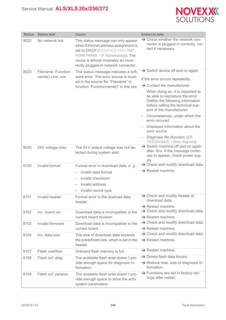
Service Manual ALS/XLS 20x/256/272
9022 No network link This status message can only appear when Ethernet address assignment is set to DHCP (INTERFACE PARA >NET-WORK PARAM. > IP Addressassign). The cause is almost invariably an incor-rectly plugged-in network connector.
Check whether the network con-nector is plugged in correctly, cor-rect if necessary.
9023 Filename: Function-name() Line: xxx
This status message indicates a soft-ware error. The error source is locat-ed in the source file “Filename” in function “Functionname()” in line xxx.
Switch device off and on again.
If the error occurs repeatedly:
Contact the manufacturer.
When doing so, it is important to be able to reproduce the error. Gather the following information before calling the technical sup-port of the manufacturer:
– Circumstances, under which the error occured
– Displayed information about the error source
– Diagnosis file (function SER-VICE/DIAGNOS. > Store diagnosis)
9025 24V voltage miss The 24 V output voltage was not de-tected during system start.
Switch machine off and on again after 30 s. If the message contin-ues to appear, check power sup-ply.
9100 Invalid format Format error in download data, e. g.:
– invalid data format
– invalid checksum
– invalid address
– invalid record type
Check and modify download data.
Restart machine.
9101 Invalid header Format error in the dowload data header.
Check and modify header of download data.
Restart machine.
9102 Inv. board rev. Download data is incompatible to the current board revision.
Check and modify download data.
Restart machine.
9103 Invalid firmware Download data is incompatible to the current board.
Check and modify download data.
Restart machine.
9104 Inv. data size The size of download data exceeds the predefined size, which is set in the header.
Check and modify download data.
Restart machine.
9107 Flash overflow Onboard flash memory is full. Restart machine.
9108 Flash ovf. diag. The available flash area doesn´t pro-vide enough space for diagnosis in-formation.
Delete flash data blocks.
Reduce max. size of diagnosis in-formation.
9109 Flash ovf. params The available flash area doesn´t pro-vide enough space to store the activ system parameters.
Functions are set to factory set-tings after restart.
Status Status text Cause Action to take
02/2019 | 01 240 Fault description
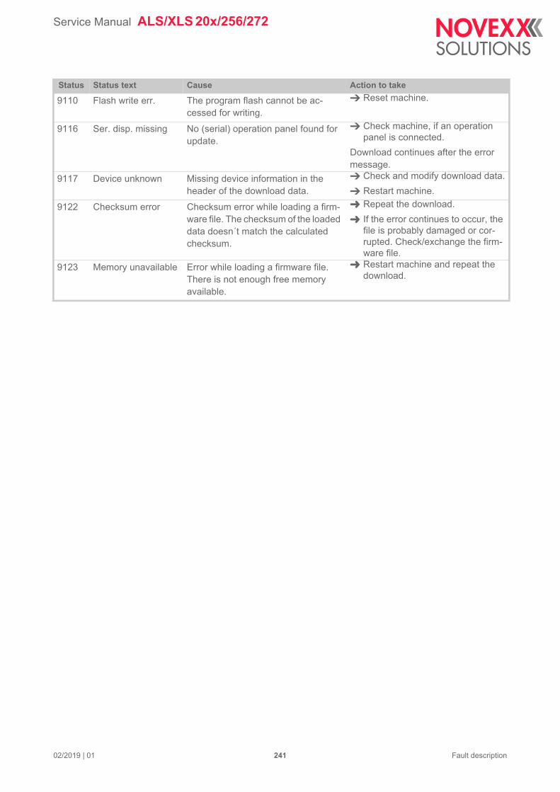
Service Manual ALS/XLS 20x/256/272
9110 Flash write err. The program flash cannot be ac-cessed for writing.
Reset machine.
9116 Ser. disp. missing No (serial) operation panel found for update.
Check machine, if an operation panel is connected.
Download continues after the error message.
9117 Device unknown Missing device information in the header of the download data.
Check and modify download data.
Restart machine.
9122 Checksum error Checksum error while loading a firm-ware file. The checksum of the loaded data doesn´t match the calculated checksum.
Repeat the download.
If the error continues to occur, the file is probably damaged or cor-rupted. Check/exchange the firm-ware file.
9123 Memory unavailable Error while loading a firmware file. There is not enough free memory available.
Restart machine and repeat the download.
Status Status text Cause Action to take
02/2019 | 01 241 Fault description

Service Manual ALS/XLS 20x/256/272
02/2019 | 04 242
Repair
TESTS
Sensor test Call the SERVICE/DIAGNOS. > Sensor Test function.
– Display:
alternating with:
– 00.01 = Identification number of the sensor
– 1 = value currently being transmitted by the sensor “Labels”
Press the button to change to the next sensor in the list
Press the button to change to the preceding sensor in the list
Sensor Test00.01 1
Sensor TestLabels. 1
Sensor ID Name Value Test
00.01 Labels.
(Label sensor)
1 or 0 Move label material through the sensor; a gap between labels (punch) must cause a change between 1 and 0. If no change takes place:
Adjust the sensor (MACHINE SETUP > Sensor Adjust)
00.02 Starts.
(Photoelectric product sen-sor)
1 or 0 Breaking the light beam must cause a change between 1 and 0.
00.03 Capaci.
(capacitive label sensor)
1 or 0 Move label material through the sensor; a gap between labels (punch) must cause a change between 1 and 0.
00.04 Diamet.
(external photoelectric RD sensor)
1 or 0 Breaking the light beam must cause a change between 1 and 0.
00.05 APSF f.
(rotary encoder frequency)
xxx Hz Shows current rotary encoder frequency when labeller operating with automatic speed adjust-ment.
Increase/decrease belt speed
– Displayed frequency must increase/de-crease accordingly
[Tab. 58] Overview for the “MACHINE SETUP > Sensor Test“
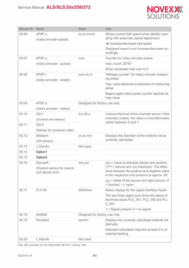
Service Manual ALS/XLS 20x/256/272
02/2019 | 04 243
00.06 APSF s.
(rotary encoder speed)
xx.xx m/min Shows current belt speed when labeller oper-ating with automatic speed adjustment.
Increase/decrease belt speed
Displayed speed must increase/decrease ac-cordingly
00.07 APSF p.
(rotary encoder - pulses)
xxxx Counter for rotary encoder pulses
max. count: 32767
When exceeded rolls over to 0
00.08 APSF l.
(rotary encoder - length)
xxxx.xx m “Mileage counter” for rotary encoder measur-ing wheel
max. value depends on diameter of measuring wheel
Begins again when pulse counter reaches its max value
00.09 APSF s.
(rotary encoder - status)
Designed for factory use only
00.10 OD-1
(Unwind unit sensor)
A=x B=y A shows the level of the unwinder sensor. If the unwinder rotates, the value x must alternately switch between 0 and 1.
00.11 OD-2
(Sensor for pressure roller)
00.12 Matdiam
(OD sensor)
xx.xx mm Displays the diameter of the material roll as currently calculated
00.13 L.DancAr Not used
00.14 Option1
00.15 Option2
00.16 DancerR
(Position sensor for rewind unit dancer arm)
xxx yyy xxx = Value of absolute dancer arm position (??? = dancer arm not initialized). The differ-ence between the positive and negative value in the respective end positions is approx. 40.
yyy = State of the dancer arm light barriers: 0 = blocked; 1 = open
00.17 PLC-IN 00000xxx Status display for the signal interface inputs
The last three digits (xxx) show the status of the three inputs PLC_IN1, PLC_IN2 and PL-C_IN3
1 = Signal present; 0 = no signal
00.18 MotStat Designed for factory use only
00.19 Rewdiam xxxmm Displays the currently calculated material roll diameter.
Diameter calculation requires at least 2 m of material feeding.
00.20 L.DancAr Not used
Sensor ID Name Value Test
[Tab. 58] Overview for the “MACHINE SETUP > Sensor Test“

Service Manual ALS/XLS 20x/256/272
02/2019 | 04 244
00.21 RewDanc xx% Shifting of the two dancer arm encoder signals in %, related to period time.
Can be used for encoder adjustment during machine production.
Rated value: > 50%
Sensor ID Name Value Test
[Tab. 58] Overview for the “MACHINE SETUP > Sensor Test“

Service Manual ALS/XLS 20x/256/272
02/2019 | 02 245 Repair
POWER SUPPLY ALS/XLS 256/272
Initial state
[183] Position of the 10pin connector.
After switching on the power switch, the power supply is in the initial state.:
– 5.2 V: The logic voltage is switched on and applies to the 10pin connector [183A].
– 4 V, 17 V, 75 V: Those voltages are switched off. They are controlled by a signal coming from the machine CPU.
The 24 V, 17 V and 75 V voltages can not be switched on/off separately. They are switched all together by a signal coming from the machine CPU.
Power supply functionsPower fail output:
This hardware signal is activated during switching off the mains supply. It tells the machine CPU to store important parameter settings. For this purpose, a sufficient voltage supply is available. If this output doesn´t work properly, the settings in the function menu are not stored.
Power supply fan:
The speed controlled fan provides active cooling of the power supply. If the fan is defective, the 24 V, 17 V and 75 V voltage outputs are switched off.
Temperature sensor:
The power supply is equipped with a temperature sensor, which controlles the power supply temperature. If the sensor is defective or if a critical temperature is exceeded, the 24 V, 17 V and 75 V voltage outputs are switched off.
Output voltage control:
The power supply separately monitors the output voltages. In case of a failure, the relevant out-put is switched off and a message is displayed.
A
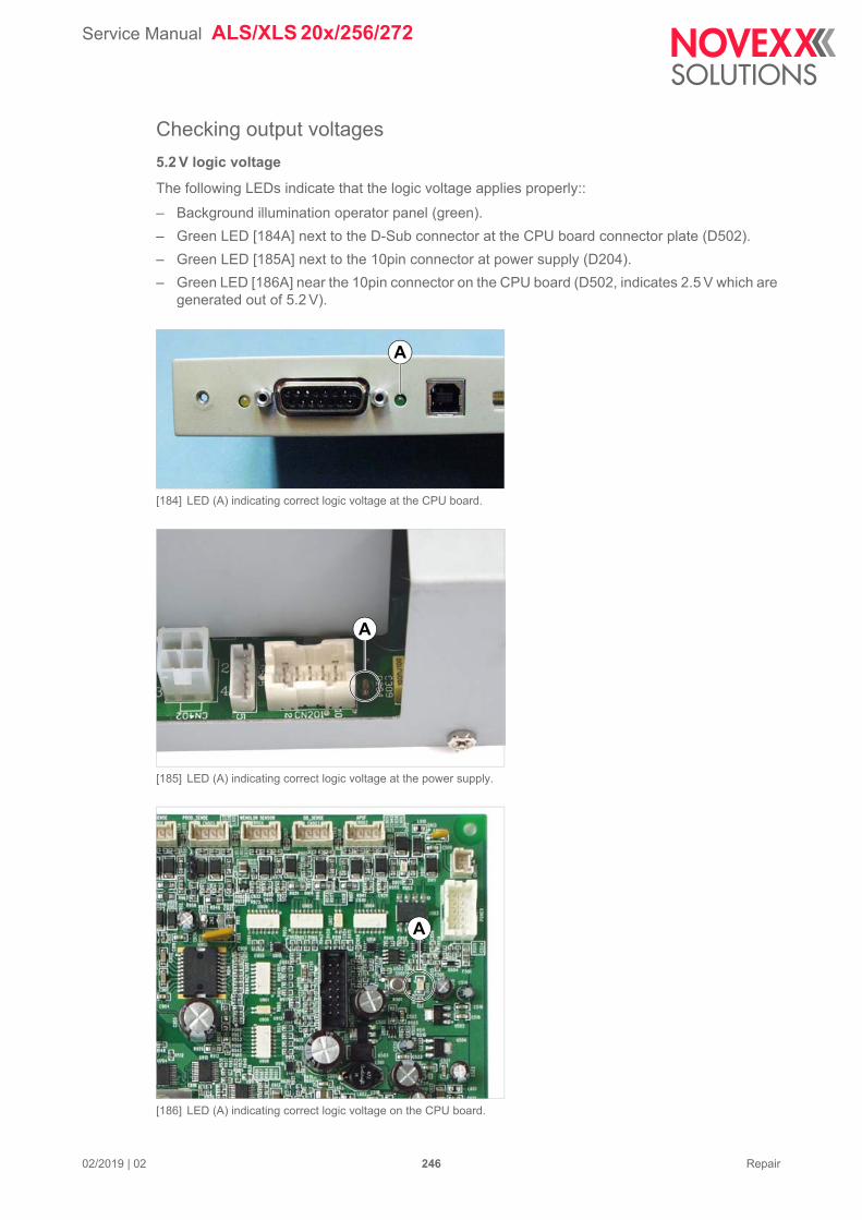
Service Manual ALS/XLS 20x/256/272
02/2019 | 02 246 Repair
Checking output voltages
5.2 V logic voltage
The following LEDs indicate that the logic voltage applies properly::
– Background illumination operator panel (green).
– Green LED [184A] next to the D-Sub connector at the CPU board connector plate (D502).
– Green LED [185A] next to the 10pin connector at power supply (D204).
– Green LED [186A] near the 10pin connector on the CPU board (D502, indicates 2.5 V which are generated out of 5.2 V).
[184] LED (A) indicating correct logic voltage at the CPU board.
[185] LED (A) indicating correct logic voltage at the power supply.
[186] LED (A) indicating correct logic voltage on the CPU board.
A
A
A
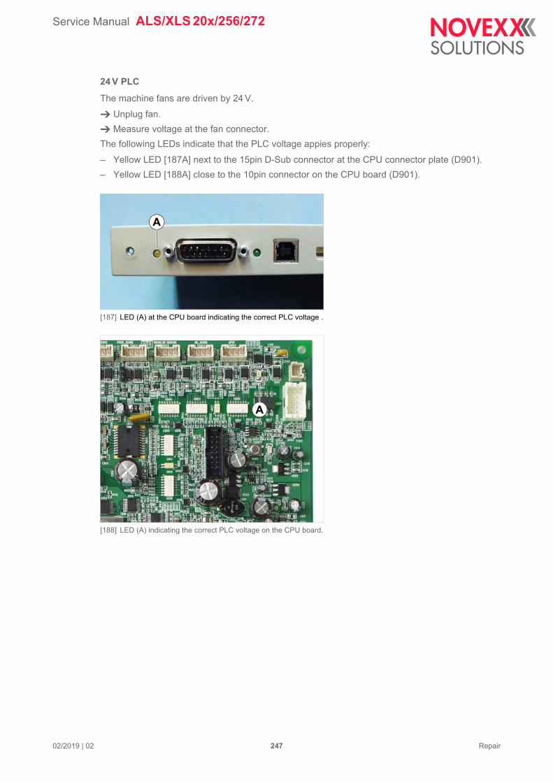
Service Manual ALS/XLS 20x/256/272
02/2019 | 02 247 Repair
24 V PLC
The machine fans are driven by 24 V.
Unplug fan.
Measure voltage at the fan connector.
The following LEDs indicate that the PLC voltage appies properly:
– Yellow LED [187A] next to the 15pin D-Sub connector at the CPU connector plate (D901).
– Yellow LED [188A] close to the 10pin connector on the CPU board (D901).
[187] LED (A) at the CPU board indicating the correct PLC voltage .
[188] LED (A) indicating the correct PLC voltage on the CPU board.
A
A

Service Manual ALS/XLS 20x/256/272
02/2019 | 02 248 Repair
17/75 V motor voltage
A running power supply fan indicates, that 17/75 V are available.
The following LEDs indicate, that the motor voltage applies properly:
– 75 V: Green LED [189B] next to the small inductor on the motordriver board (D203).
– 17 V: Green LED [189A] next to the big inductor on the motordriver board (D405, indicates 3.3 V which are generated out of 17 V).
[189] LED (A) indicating the correct motor voltages.
A
B
Service Manual ALS/XLS 20x/256/272
02/2019 | 02 249 Repair
Troubleshooting
Symptom Diagnosis / possible cause
No machine reaction after switching on; no voltage available.
(no fans are running, display and LEDs are dark)
After switching the power supply on, only the 5.2 V logic voltage is switched on.
Check if cable A6802 is plugged completely to the 10pin con-nectors at the power supply and on the CPU board. The cable plug engages clearly audible to the connector.
Check the logic supply voltage (LED next to the 10pin connec-tor at the power supply).
– LED off: The power supply output is overloaded (shorted) or the power supply is defective.
Disconnect cable A6802 from the 10pin connector and switch the power supply on again.
– LED on: logic voltage (5.2 V) available and stable.
Settings in the function menu are not stored after switching off.
The power fail signal doesn´t arrive at the CPU; when switching the machine off, „Power fail - saving done“ is not displayed.
Check cable A6802 and replace, if damaged.
Power fail output doesn´t work correctly.
Replace power supply.
Power fail input at the CPU board doesn´t work correctly.
Replace CPU board.
24 V and 17/75 V output voltages are switched off approx. 10 s after switching on.
Rotation speed of the power supply fan is being controlled.
If the power supply fan is defective or if the speed control doesn´t work correctly, the outputs 24 V and 17/75 V are switched off ap-prox. 10 s after switching the power supply on (overheat protec-tion). The logic voltage for the CPU board is kept upright.
17/75 V output voltages are missing; 24 V apply over a short term, but are switched off approx. 10 s after switching the power supply on.
Overload on 17/75 V, e. g. by short circuit:
Because of the missing supply voltage for the power supply fan, 24 V voltage is also switched off (for safety reasons).
24 V not available(machine can not initialize correctly, be-cause the external sensors need 24 V).
The power supply switches off single outputs, if overload and/or undervoltage occur.
Check if cable A6802 is plugged completely to the 10pin con-nectors at the power supply and on the CPU board. The cable plug engages clearly audible to the connector.
Check connected loads for short circuit and/or overload.
Service Manual ALS/XLS 20x/256/272
02/2019 | 02 250 Repair
24 V and 17/75 V output voltages not available.
The outputs 24 V and 17/75 V are switched on/off by a hardware signal coming from the CPU board.
Check cable A6802 and replace if damaged.
The power supply signal input doesn´t work properly.
Replace power supply.
CPU hardware signal output doesn´t work properly.
Replace CPU board.
The power supply contains a temperature sensor.
If a sensor fault is detected during operation, the outputs 24V and 17/75 V are switched off for safety reasons. The logic voltage for the CPU is kept upright. An error message is displayed on the operation panel. The machine stops (earliest with firmware > V 1.33).
If the sensor detects overtemperature during operation, a warning is displayed on the operation panel. Furthermore, the „Warning“ output is activated (both earliest with firm-ware > 1.33). The machne does not stop. If the warnng is ignored and no steps are taken to decrease the tempera-ture, the outputs 24 V and 17/75 V are switched off as soon as a critical overtemperature is reached. The logic voltage for the CPU is kept upright. An error message appears on the display. The machine stops (earlilest with firmware > 1.33).
Causes / countermeasures:
Surrounding temperature of the machine is too high.
Let the machine cool down.
Dust filter exhausted.
Clean or replace filter liner.
Machine fan defective?
Check function and replace fan if necessary.
17/75 V not available The power supply switches off single outputs, if overload and/or undervoltage occur.
Check if connected motordriver bear a short circuit or overload. To do so, disconnect motordrivers separately from the power supply and switch on the power supply again.
Check fuses on the motordriver boards and replace if neces-sary.
Symptom Diagnosis / possible cause
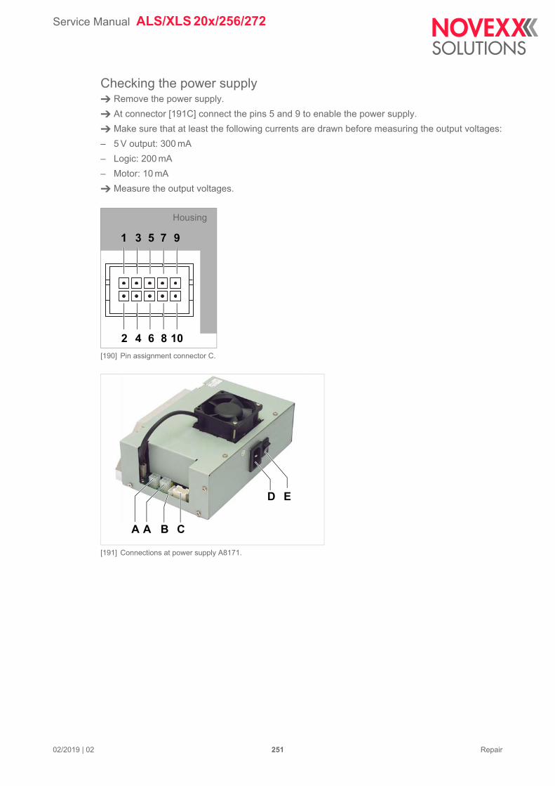
Service Manual ALS/XLS 20x/256/272
02/2019 | 02 251 Repair
Checking the power supply Remove the power supply.
At connector [191C] connect the pins 5 and 9 to enable the power supply.
Make sure that at least the following currents are drawn before measuring the output voltages:
– 5 V output: 300 mA
– Logic: 200 mA
– Motor: 10 mA
Measure the output voltages.
[190] Pin assignment connector C.
[191] Connections at power supply A8171.
108642
1 3 5 7 9
Housing
A A C
D E
B
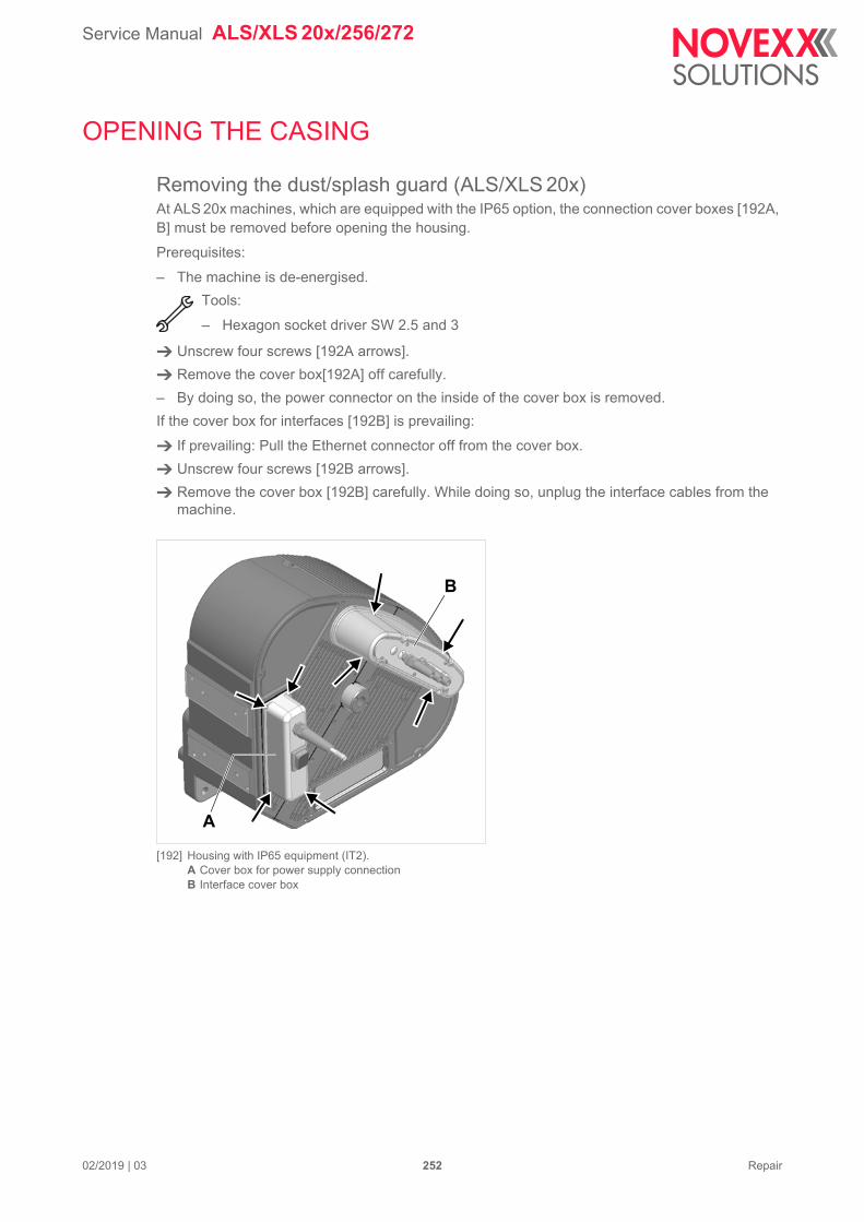
Service Manual ALS/XLS 20x/256/272
02/2019 | 03 252 Repair
OPENING THE CASING
Removing the dust/splash guard (ALS/XLS 20x)At ALS 20x machines, which are equipped with the IP65 option, the connection cover boxes [192A, B] must be removed before opening the housing.
Prerequisites:
– The machine is de-energised.
Tools:
– Hexagon socket driver SW 2.5 and 3
Unscrew four screws [192A arrows].
Remove the cover box[192A] off carefully.
– By doing so, the power connector on the inside of the cover box is removed.
If the cover box for interfaces [192B] is prevailing:
If prevailing: Pull the Ethernet connector off from the cover box.
Unscrew four screws [192B arrows].
Remove the cover box [192B] carefully. While doing so, unplug the interface cables from the machine.
[192] Housing with IP65 equipment (IT2).A Cover box for power supply connectionB Interface cover box
B
A
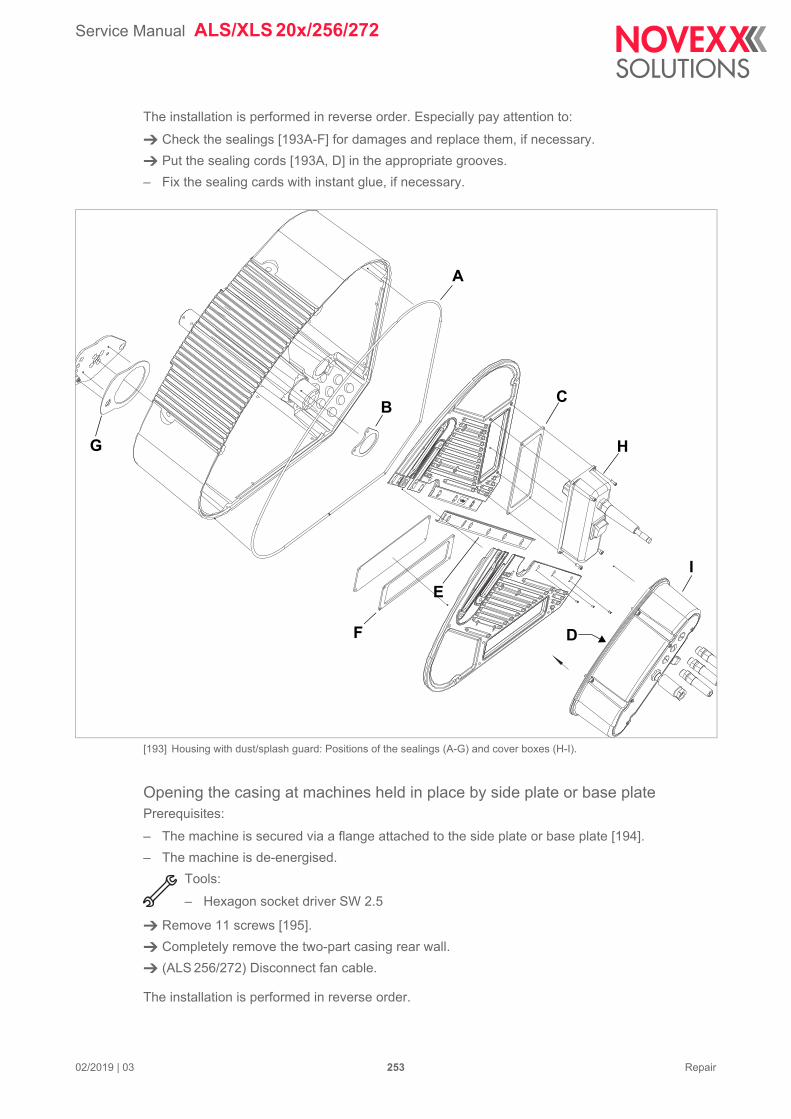
Service Manual ALS/XLS 20x/256/272
02/2019 | 03 253 Repair
The installation is performed in reverse order. Especially pay attention to:
Check the sealings [193A-F] for damages and replace them, if necessary.
Put the sealing cords [193A, D] in the appropriate grooves.
– Fix the sealing cards with instant glue, if necessary.
[193] Housing with dust/splash guard: Positions of the sealings (A-G) and cover boxes (H-I).
Opening the casing at machines held in place by side plate or base platePrerequisites:
– The machine is secured via a flange attached to the side plate or base plate [194].
– The machine is de-energised.
Tools:
– Hexagon socket driver SW 2.5
Remove 11 screws [195].
Completely remove the two-part casing rear wall.
(ALS 256/272) Disconnect fan cable.
The installation is performed in reverse order.
A
E
H
CB
F
G
I
D
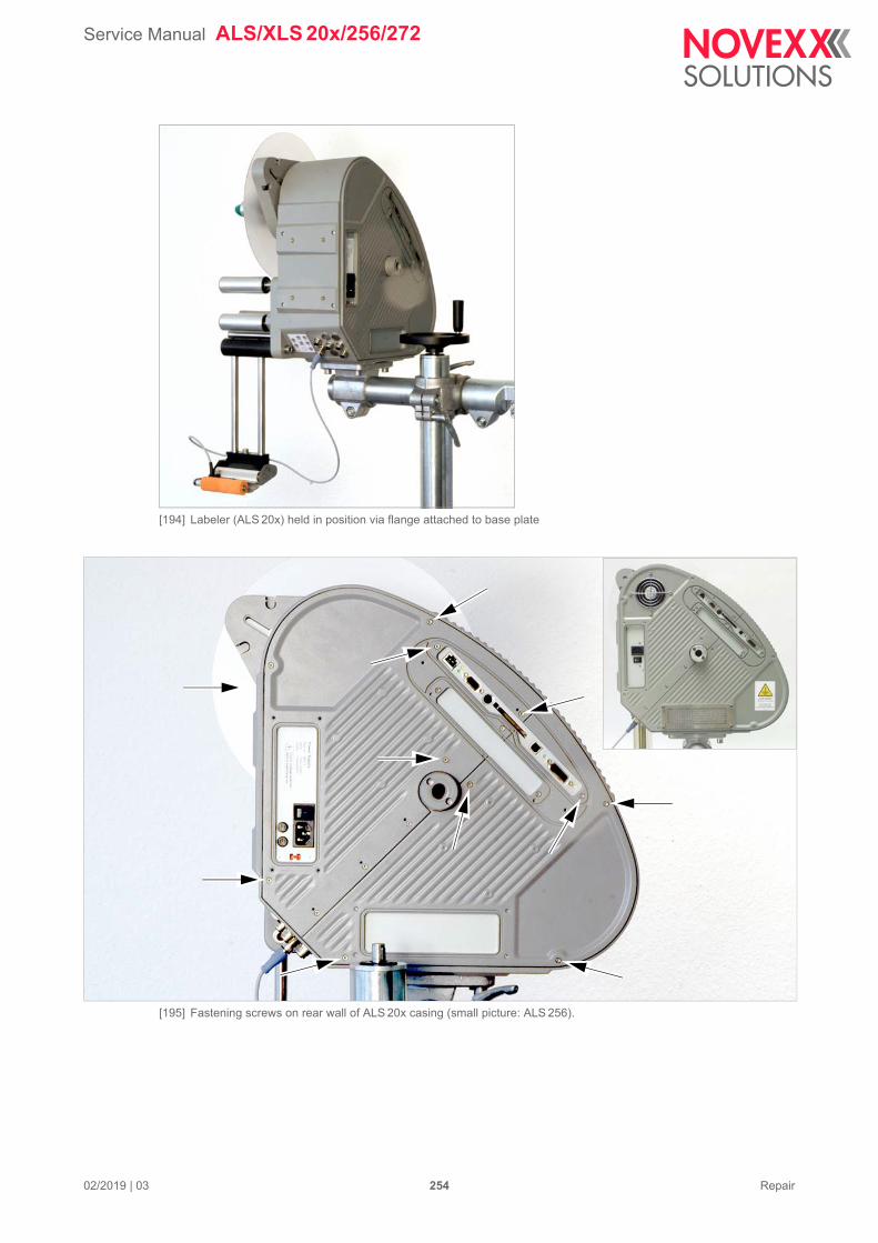
Service Manual ALS/XLS 20x/256/272
02/2019 | 03 254 Repair
[194] Labeler (ALS 20x) held in position via flange attached to base plate
[195] Fastening screws on rear wall of ALS 20x casing (small picture: ALS 256).
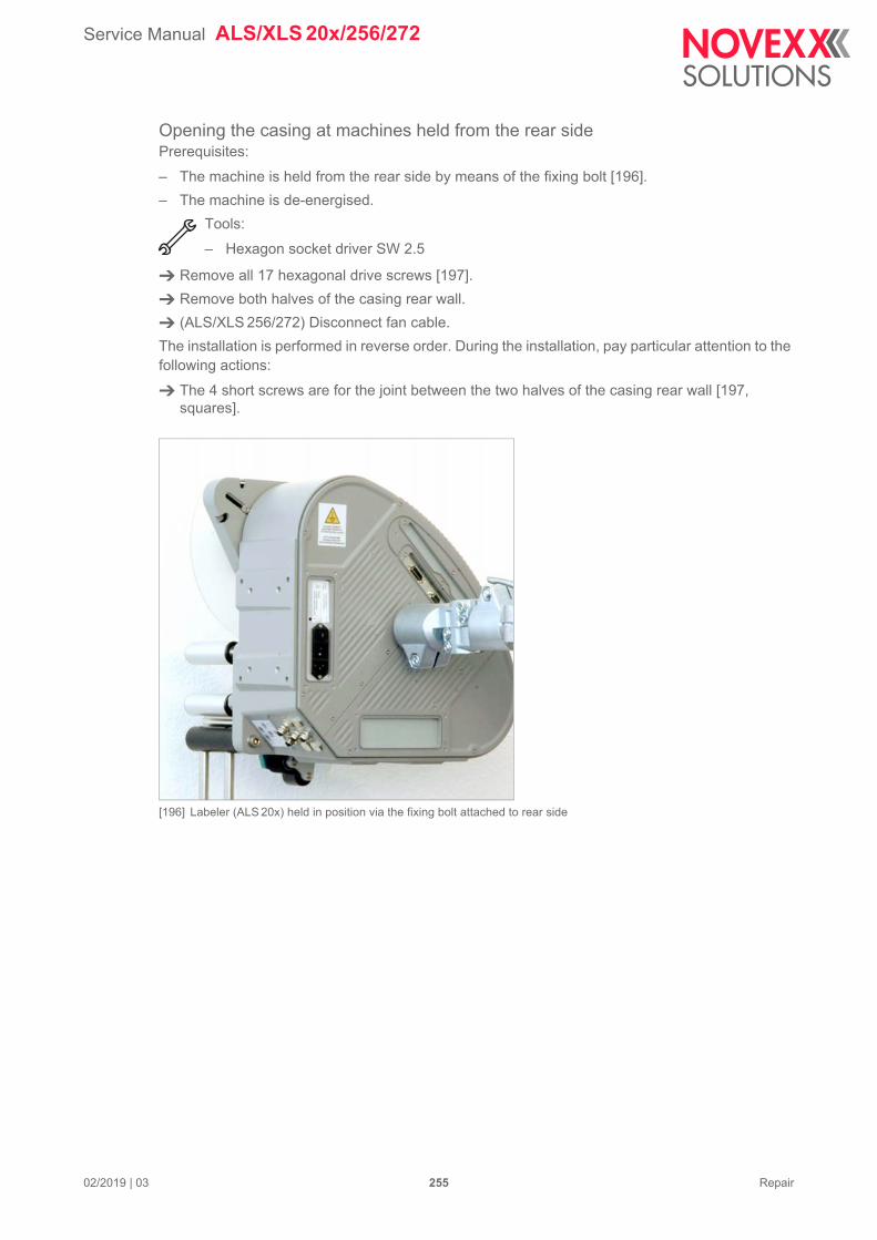
Service Manual ALS/XLS 20x/256/272
02/2019 | 03 255 Repair
Opening the casing at machines held from the rear sidePrerequisites:
– The machine is held from the rear side by means of the fixing bolt [196].
– The machine is de-energised.
Tools:
– Hexagon socket driver SW 2.5
Remove all 17 hexagonal drive screws [197].
Remove both halves of the casing rear wall.
(ALS/XLS 256/272) Disconnect fan cable.
The installation is performed in reverse order. During the installation, pay particular attention to the following actions:
The 4 short screws are for the joint between the two halves of the casing rear wall [197, squares].
[196] Labeler (ALS 20x) held in position via the fixing bolt attached to rear side
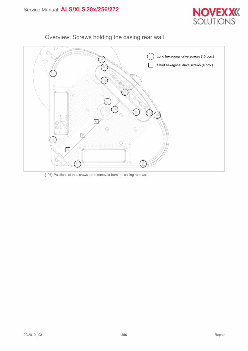
Service Manual ALS/XLS 20x/256/272
02/2019 | 03 256 Repair
Overview: Screws holding the casing rear wall
[197] Positions of the screws to be removed from the casing rear wall
Long hexagonal drive screws (13 pcs.)
Short hexagonal drive screws (4 pcs.)
Service Manual ALS/XLS 20x/256/272
02/2019 | 03 257 Repair
(ALS/XLS 256/272) Exchanging the fanTools:
– Hexagon socket driver size 2.5– Cross-head screwdriver size 2
Remove the half of the rear casing that carries the fan. To do this, remove 11 screws [198, ar-rows].
[198] Position of the screws to be removed.
Remove the rear wall carefully and disconnect the cable of the fan from the extension cable [199D].
Turn out 4 screws [199A] at the fan. Remove fan [199C] and fan guard [199D].
The installation is performed in reverse order. During the installation, pay particular attention to the following:
Install the fan so that it blows outwards (arrow = flow direction).
The spare fan is delivered with extension cable.
Put the delivered extension cable aside, if the installed extension cable is supposed to be used.
If an applicator interface (AI) is installed, the fan must be connected to the free branch of the Y-cable that supplies the AI board. The Y-cable comes with the AI board.
For details refer to the connection diagram in chapter ALS 256/272 with Applicator Interface on page 161.
Service Manual ALS/XLS 20x/256/272
02/2019 | 03 258 Repair
[199] Removing the fan (C).
A
B
C
D
Service Manual ALS/XLS 20x/256/272
02/2019 | 03 259 Repair
UNWIND UNIT
Expanding mandrelTools:
– Hexagon socket driver SW 2.5, 3– Size 2 Phillips screwdriver– Circlip pliers internal for diameter 15
Auxiliary materials:
– Multi-purpose grease– Loctite 648 adhesive
Replacing expansion bars
Remove core adapters [200A].
Remove three screws [201B] on the front side of the sleeve [201A].
Fully unscrew knob [201C] complete with sleeve by turning it to the right (left-hand thread).
Remove front O-ring [202B].
Remove expansion bars [202A].
Remove rear O-ring.
The installation is performed in reverse order. During the installation, pay particular attention to the following actions:
Grease the sliding surfaces of the expansion bars before installing.
Removing unwinding spool
Remove core adapters [200A].
Remove three screws [201B] on the front side of the sleeve [201A].
Fully unscrew knob [201C] complete with sleeve by turning it to the right (left-hand thread).
Remove front O-ring [202B].
Remove aluminium ring [202C].
Remove the circlip [203A] and shim.
Release brake and remove unwinding spool [204].
[204] Removing unwinding spool with brake released
[200] Removing core adapters
[201] Removing knob and front-end screws
[202] Removing front O-ring, expansion bars and aluminium ring
[203] Remove the circlip
A
C
B
A
C
A B
A
Service Manual ALS/XLS 20x/256/272
02/2019 | 03 260 Repair
Replacing ball bearings in expanding mandrel
– Prerequisite: expansion bars and unwinding spool are removed.
Remove 3 screws [205B], remove the support disc [205A].
Soften up the adhesive bond on both ball bearings [206A, B] using a hot air blower.
Remove the ball bearings.
Remove adhesive residues from the bearing seats.
Fixing the ball bearings with adhesive:
Glue the ball bearings into the bearing seats with Loctite 648.
Follow the adhesive manufacturer's instruc-tions for use.
Glue the ball bearings into the expanding mandrel [206]. Allow the adhesive bond to set.
Installing the unwinding spool.
Install unwinding spool with brake loosened.
Install shim [207B] and retaining ring. Ensure that the circlip fully engages with the groove in the shaft.
Measure the axial play of the unwinding spool on the shaft.
– Desired nominal play: c. 0.2 mm
If necessary, remove circlip and readjust axial play using a suitable shim.
Install O-ring and aluminium ring.
Install knob complete with sleeve, paying attention to the situation of the front-facing thread [207A] in the expanding mandrel.
Install core adapters.
[205] Removing the support disc (fig.: ALS 20x)
[206] Installation position of ball bearings in expanding mandrel
[207] Adjusting axial play with shim
B
A
A B
B
A
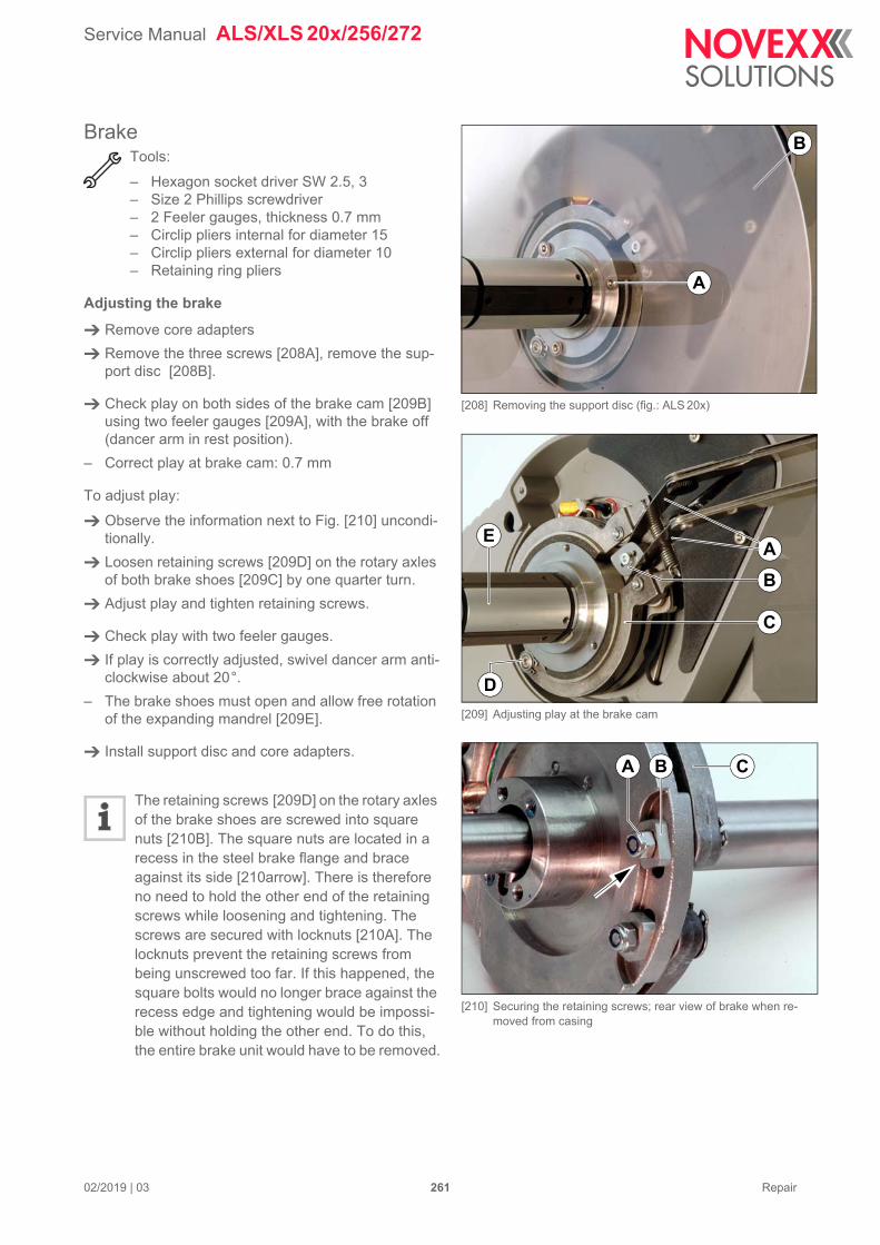
Service Manual ALS/XLS 20x/256/272
02/2019 | 03 261 Repair
BrakeTools:
– Hexagon socket driver SW 2.5, 3– Size 2 Phillips screwdriver– 2 Feeler gauges, thickness 0.7 mm– Circlip pliers internal for diameter 15– Circlip pliers external for diameter 10– Retaining ring pliers
Adjusting the brake
Remove core adapters
Remove the three screws [208A], remove the sup-port disc [208B].
Check play on both sides of the brake cam [209B] using two feeler gauges [209A], with the brake off (dancer arm in rest position).
– Correct play at brake cam: 0.7 mm
To adjust play:
Observe the information next to Fig. [210] uncondi-tionally.
Loosen retaining screws [209D] on the rotary axles of both brake shoes [209C] by one quarter turn.
Adjust play and tighten retaining screws.
Check play with two feeler gauges.
If play is correctly adjusted, swivel dancer arm anti-clockwise about 20°.
– The brake shoes must open and allow free rotation of the expanding mandrel [209E].
Install support disc and core adapters.
The retaining screws [209D] on the rotary axles of the brake shoes are screwed into square nuts [210B]. The square nuts are located in a recess in the steel brake flange and brace against its side [210arrow]. There is therefore no need to hold the other end of the retaining screws while loosening and tightening. The screws are secured with locknuts [210A]. The locknuts prevent the retaining screws from being unscrewed too far. If this happened, the square bolts would no longer brace against the recess edge and tightening would be impossi-ble without holding the other end. To do this, the entire brake unit would have to be removed.
[208] Removing the support disc (fig.: ALS 20x)
[209] Adjusting play at the brake cam
[210] Securing the retaining screws; rear view of brake when re-moved from casing
A
B
A
B
D
C
E
B CA
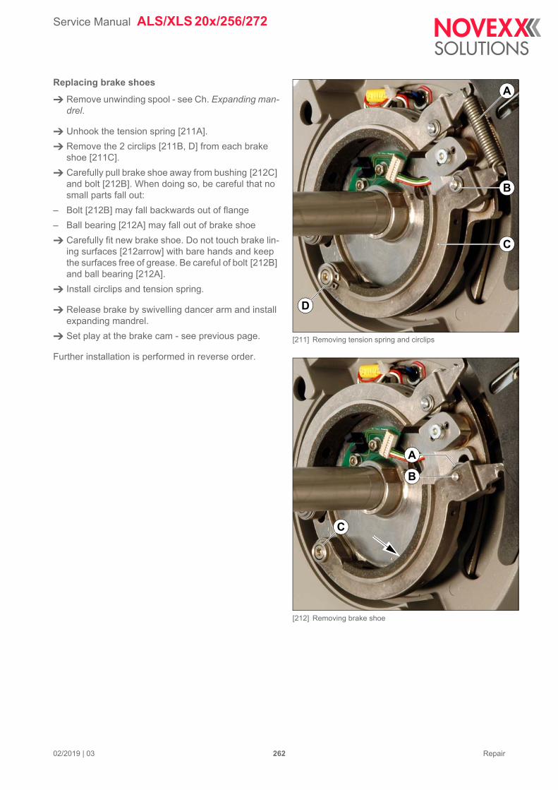
Service Manual ALS/XLS 20x/256/272
02/2019 | 03 262 Repair
Replacing brake shoes
Remove unwinding spool - see Ch. Expanding man-drel.
Unhook the tension spring [211A].
Remove the 2 circlips [211B, D] from each brake shoe [211C].
Carefully pull brake shoe away from bushing [212C] and bolt [212B]. When doing so, be careful that no small parts fall out:
– Bolt [212B] may fall backwards out of flange
– Ball bearing [212A] may fall out of brake shoe
Carefully fit new brake shoe. Do not touch brake lin-ing surfaces [212arrow] with bare hands and keep the surfaces free of grease. Be careful of bolt [212B] and ball bearing [212A].
Install circlips and tension spring.
Release brake by swivelling dancer arm and install expanding mandrel.
Set play at the brake cam - see previous page.
Further installation is performed in reverse order.
[211] Removing tension spring and circlips
[212] Removing brake shoe
B
A
D
C
B
A
C
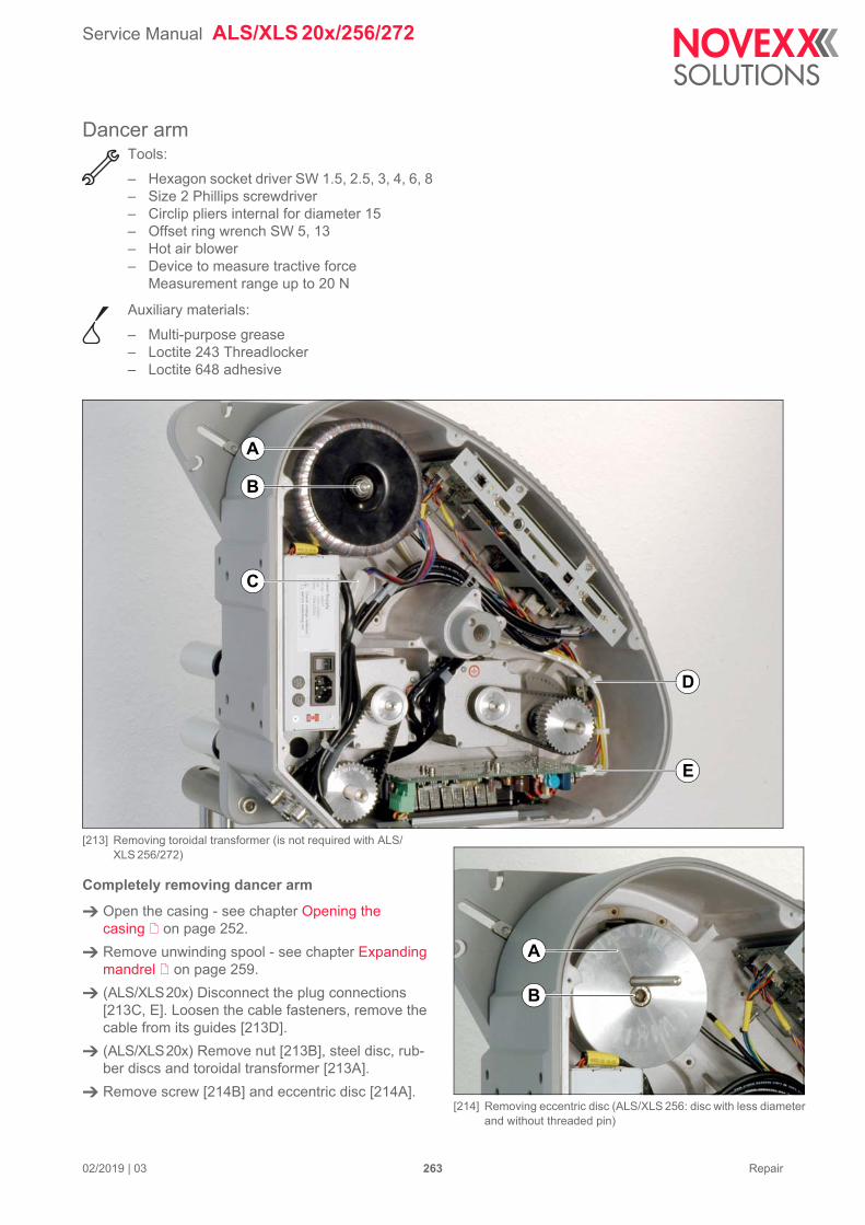
Service Manual ALS/XLS 20x/256/272
02/2019 | 03 263 Repair
Dancer armTools:
– Hexagon socket driver SW 1.5, 2.5, 3, 4, 6, 8– Size 2 Phillips screwdriver– Circlip pliers internal for diameter 15– Offset ring wrench SW 5, 13– Hot air blower– Device to measure tractive force
Measurement range up to 20 N
Auxiliary materials:
– Multi-purpose grease– Loctite 243 Threadlocker– Loctite 648 adhesive
[213] Removing toroidal transformer (is not required with ALS/XLS 256/272)
Completely removing dancer arm
Open the casing - see chapter Opening the casing on page 252.
Remove unwinding spool - see chapter Expanding mandrel on page 259.
(ALS/XLS20x) Disconnect the plug connections [213C, E]. Loosen the cable fasteners, remove the cable from its guides [213D].
(ALS/XLS20x) Remove nut [213B], steel disc, rub-ber discs and toroidal transformer [213A].
Remove screw [214B] and eccentric disc [214A].
C
E
D
B
A
[214] Removing eccentric disc (ALS/XLS 256: disc with less diameter and without threaded pin)
A
B
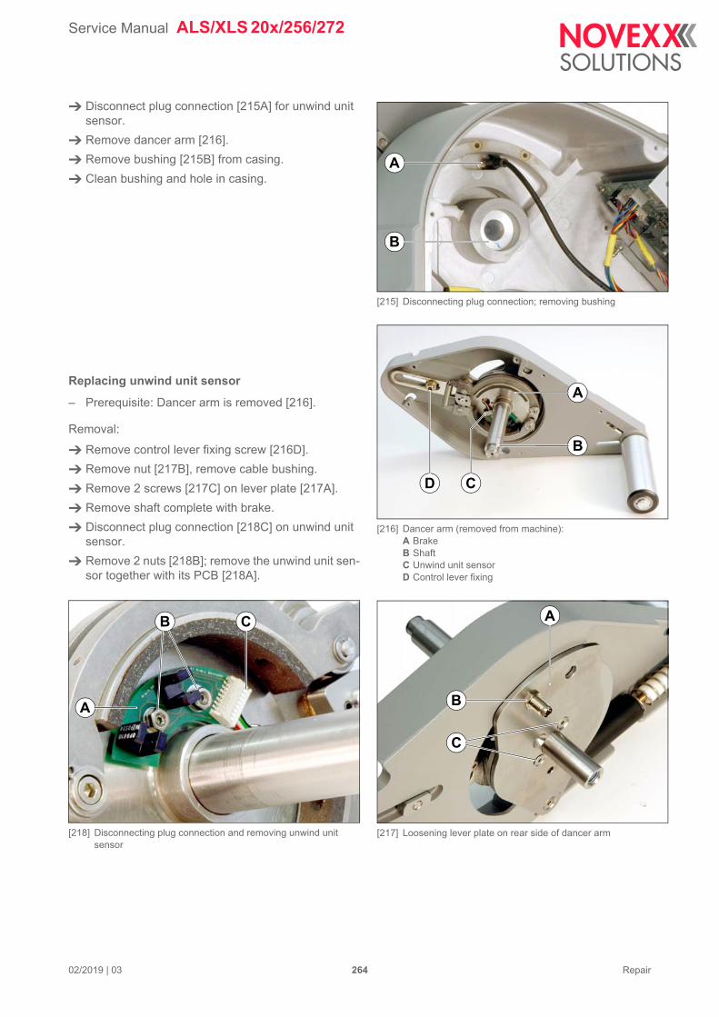
Service Manual ALS/XLS 20x/256/272
02/2019 | 03 264 Repair
Disconnect plug connection [215A] for unwind unit sensor.
Remove dancer arm [216].
Remove bushing [215B] from casing.
Clean bushing and hole in casing.
Replacing unwind unit sensor
– Prerequisite: Dancer arm is removed [216].
Removal:
Remove control lever fixing screw [216D].
Remove nut [217B], remove cable bushing.
Remove 2 screws [217C] on lever plate [217A].
Remove shaft complete with brake.
Disconnect plug connection [218C] on unwind unit sensor.
Remove 2 nuts [218B]; remove the unwind unit sen-sor together with its PCB [218A].
[218] Disconnecting plug connection and removing unwind unit sensor
[215] Disconnecting plug connection; removing bushing
[216] Dancer arm (removed from machine):A BrakeB ShaftC Unwind unit sensorD Control lever fixing
[217] Loosening lever plate on rear side of dancer arm
A
B
C
A
B
D
A
C
B
CB
A
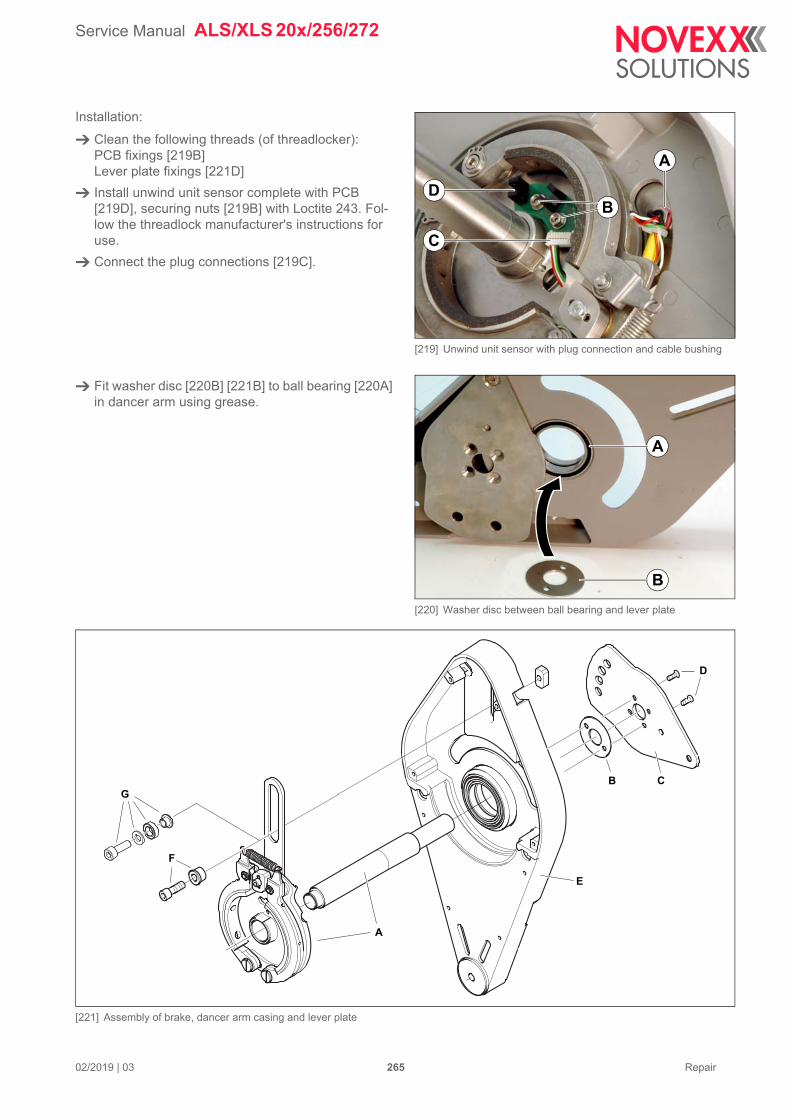
Service Manual ALS/XLS 20x/256/272
02/2019 | 03 265 Repair
Installation:
Clean the following threads (of threadlocker):PCB fixings [219B]Lever plate fixings [221D]
Install unwind unit sensor complete with PCB [219D], securing nuts [219B] with Loctite 243. Fol-low the threadlock manufacturer's instructions for use.
Connect the plug connections [219C].
Fit washer disc [220B] [221B] to ball bearing [220A] in dancer arm using grease.
[221] Assembly of brake, dancer arm casing and lever plate
[219] Unwind unit sensor with plug connection and cable bushing
[220] Washer disc between ball bearing and lever plate
D
C
B
A
A
B
A
B C
D
E
F
G
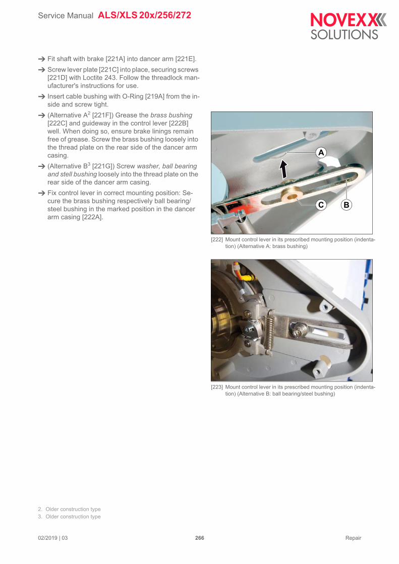
Service Manual ALS/XLS 20x/256/272
02/2019 | 03 266 Repair
Fit shaft with brake [221A] into dancer arm [221E].
Screw lever plate [221C] into place, securing screws [221D] with Loctite 243. Follow the threadlock man-ufacturer's instructions for use.
Insert cable bushing with O-Ring [219A] from the in-side and screw tight.
(Alternative A2 [221F]) Grease the brass bushing [222C] and guideway in the control lever [222B] well. When doing so, ensure brake linings remain free of grease. Screw the brass bushing loosely into the thread plate on the rear side of the dancer arm casing.
(Alternative B3 [221G]) Screw washer, ball bearing and stell bushing loosely into the thread plate on the rear side of the dancer arm casing.
Fix control lever in correct mounting position: Se-cure the brass bushing respectively ball bearing/steel bushing in the marked position in the dancer arm casing [222A].
2. Older construction type3. Older construction type
[222] Mount control lever in its prescribed mounting position (indenta-tion) (Alternative A: brass bushing)
[223] Mount control lever in its prescribed mounting position (indenta-tion) (Alternative B: ball bearing/steel bushing)
A
BC
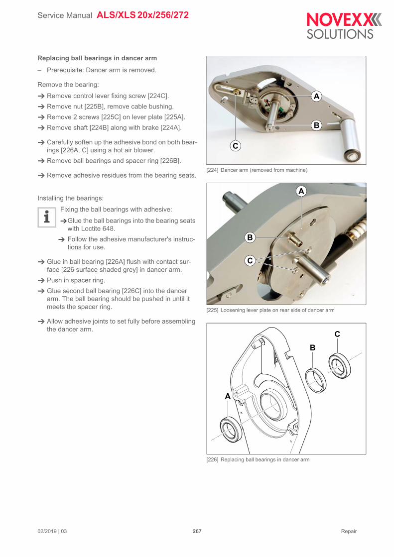
Service Manual ALS/XLS 20x/256/272
02/2019 | 03 267 Repair
Replacing ball bearings in dancer arm
– Prerequisite: Dancer arm is removed.
Remove the bearing:
Remove control lever fixing screw [224C].
Remove nut [225B], remove cable bushing.
Remove 2 screws [225C] on lever plate [225A].
Remove shaft [224B] along with brake [224A].
Carefully soften up the adhesive bond on both bear-ings [226A, C] using a hot air blower.
Remove ball bearings and spacer ring [226B].
Remove adhesive residues from the bearing seats.
Installing the bearings:
Fixing the ball bearings with adhesive:
Glue the ball bearings into the bearing seats with Loctite 648.
Follow the adhesive manufacturer's instruc-tions for use.
Glue in ball bearing [226A] flush with contact sur-face [226 surface shaded grey] in dancer arm.
Push in spacer ring.
Glue second ball bearing [226C] into the dancer arm. The ball bearing should be pushed in until it meets the spacer ring.
Allow adhesive joints to set fully before assembling the dancer arm.
[224] Dancer arm (removed from machine)
[225] Loosening lever plate on rear side of dancer arm
[226] Replacing ball bearings in dancer arm
A
B
C
A
C
B
A
B
C
Service Manual ALS/XLS 20x/256/272
02/2019 | 03 268 Repair
Assembling dancer arm:
Clean the threads of the fastening screws [227D] for the lever plate.
Fit washer disc [229B] [230B] to ball bearing [229A] in dancer arm using grease.
Fit shaft with brake [227A] into dancer arm [227E].
Screw lever plate [227C] into place, securing screws [227D] with Loctite 243. Follow the threadlock man-ufacturer's instructions for use.
Insert cable bushing with O-Ring [228A] from the in-side of the dancer arm and screw tight.
Grease the brass bushing [230C] and guideway in the control lever [230B] well. When doing so, ensure brake linings remain free of grease.
Fix control lever in correct mounting position: Se-cure the brass bushing in the marked position in the dancer arm casing [230A].
[230] Mount control lever in its prescribed mounting position
[227] Assembly of brake, dancer arm casing and lever plate
[228] Unwind unit sensor with plug connection and cable bushing
[229] Washer disc between ball bearing and lever plate
B C
A
D
E
A
A
B
A
BC
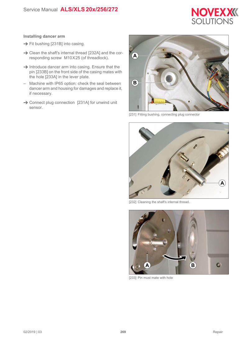
Service Manual ALS/XLS 20x/256/272
02/2019 | 03 269 Repair
Installing dancer arm
Fit bushing [231B] into casing.
Clean the shaft's internal thread [232A] and the cor-responding screw M10X25 (of threadlock).
Introduce dancer arm into casing. Ensure that the pin [233B] on the front side of the casing mates with the hole [233A] in the lever plate.
– Machine with IP65 option: check the seal between dancer arm and housing for damages and replace it, if necessary.
Connect plug connection [231A] for unwind unit sensor.
[231] Fitting bushing, connecting plug connector
[232] Cleaning the shaft's internal thread.
[233] Pin must mate with hole
A
B
A
A B
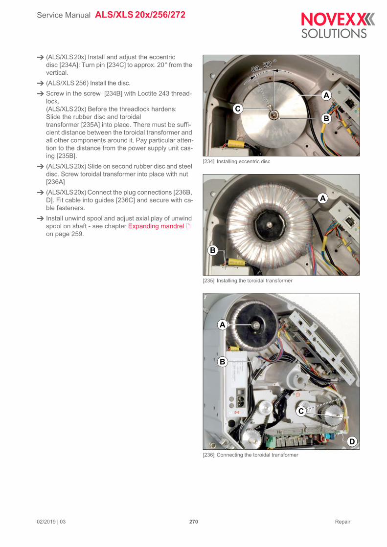
Service Manual ALS/XLS 20x/256/272
02/2019 | 03 270 Repair
(ALS/XLS20x) Install and adjust the eccentric disc [234A]: Turn pin [234C] to approx. 20° from the vertical.
(ALS/XLS 256) Install the disc.
Screw in the screw [234B] with Loctite 243 thread-lock. (ALS/XLS20x) Before the threadlock hardens:Slide the rubber disc and toroidal transformer [235A] into place. There must be suffi-cient distance between the toroidal transformer and all other components around it. Pay particular atten-tion to the distance from the power supply unit cas-ing [235B].
(ALS/XLS20x) Slide on second rubber disc and steel disc. Screw toroidal transformer into place with nut [236A]
(ALS/XLS20x) Connect the plug connections [236B, D]. Fit cable into guides [236C] and secure with ca-ble fasteners.
Install unwind spool and adjust axial play of unwind spool on shaft - see chapter Expanding mandrel on page 259.
[234] Installing eccentric disc
[235] Installing the toroidal transformer
[236] Connecting the toroidal transformer
ca. 20 °ca. 20 °
B
A
C
A
B
A
D
C
B
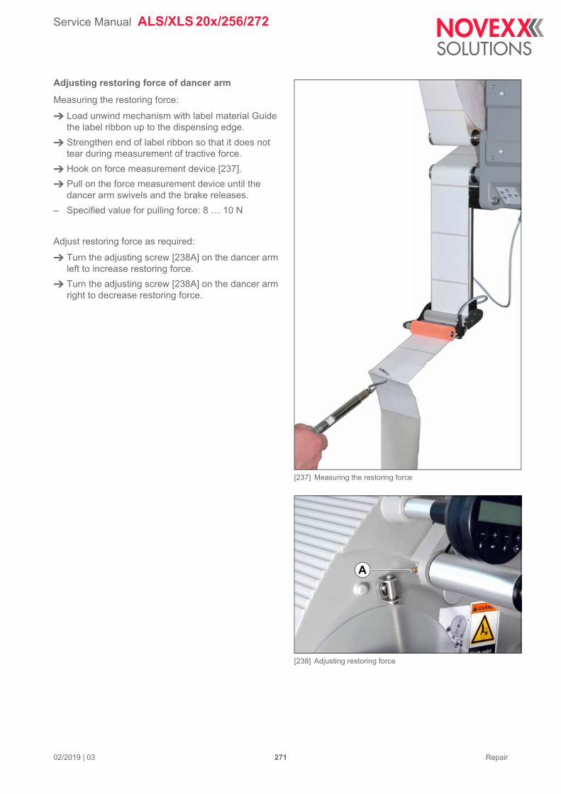
Service Manual ALS/XLS 20x/256/272
02/2019 | 03 271 Repair
Adjusting restoring force of dancer arm
Measuring the restoring force:
Load unwind mechanism with label material Guide the label ribbon up to the dispensing edge.
Strengthen end of label ribbon so that it does not tear during measurement of tractive force.
Hook on force measurement device [237].
Pull on the force measurement device until the dancer arm swivels and the brake releases.
– Specified value for pulling force: 8 ... 10 N
Adjust restoring force as required:
Turn the adjusting screw [238A] on the dancer arm left to increase restoring force.
Turn the adjusting screw [238A] on the dancer arm right to decrease restoring force.
[237] Measuring the restoring force
[238] Adjusting restoring force
A
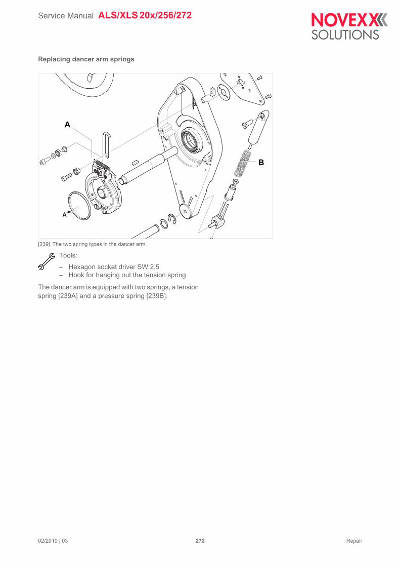
Service Manual ALS/XLS 20x/256/272
02/2019 | 03 272 Repair
Replacing dancer arm springs
[239] The two spring types in the dancer arm.
Tools:
– Hexagon socket driver SW 2.5– Hook for hanging out the tension spring
The dancer arm is equipped with two springs, a tension spring [239A] and a pressure spring [239B].
A
A
B
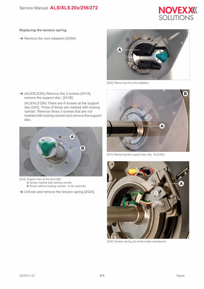
Service Manual ALS/XLS 20x/256/272
02/2019 | 03 273 Repair
Replacing the tension spring
Remove the core adapters [240A].
(ALS/XLS20x) Remove the 3 screws [241A], remove the support disc [241B].
(ALS/XLS 256) There are 6 screws at the support disc [243]. Three of those are marked with locking varnish. Remove those 3 screws that are not marked with locking varnish and remove the support disc.
[243] Support disc at the ALS 256.A Screw marked with locking varnishB Screw without locking varnish - to be removed
Unhook and remove the tension spring [242A].
[240] Removing the core adapters
[241] Removing the support disc (fig.: ALS 20x)
[242] Tension spring (A) at the brake mechanism.
A
A
B
A
A
B
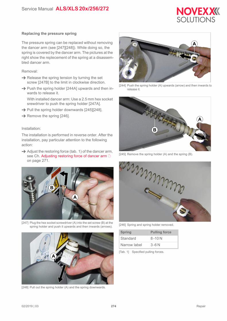
Service Manual ALS/XLS 20x/256/272
02/2019 | 03 274 Repair
Replacing the pressure spring
The pressure spring can be replaced without removing the dancer arm (see [247][248]). While doing so, the spring is covered by the dancer arm. The pictures at the right show the replecement of the spring at a disassem-bled dancer arm.
Removal:
Release the spring tension by turning the set screw [247B] to the limit in clockwise direction.
Push the spring holder [244A] upwards and then in-wards to release it.
With installed dancer arm: Use a 2.5 mm hex socket srewdriver to push the spring holder [247A].
Pull the spring holder downwards [245][248].
Remove the spring [246].
Installation:
The installation is performed in reverse order. After the installation, pay particular attention to the following action:
Adjust the restoring force (tab. 1) of the dancer arm, see Ch. Adjusting restoring force of dancer arm on page 271.
[247] Plug the hex socket screwdriver (A) into the set screw (B) at the spring holder and push it upwards and then inwards (arrows).
[248] Pull out the spring holder (A) and the spring downwards.
[244] Push the spring holder (A) upwards (arrow) and then inwards to release it.
[245] Remove the spring holder (A) and the spring (B).
[246] Spring and spring holder removed.
Spring Pulling force
Standard 8 -10 N
Narrow label 3 -6 N
[Tab. 1] Specified pulling forces.
A
A
B
B
A
A
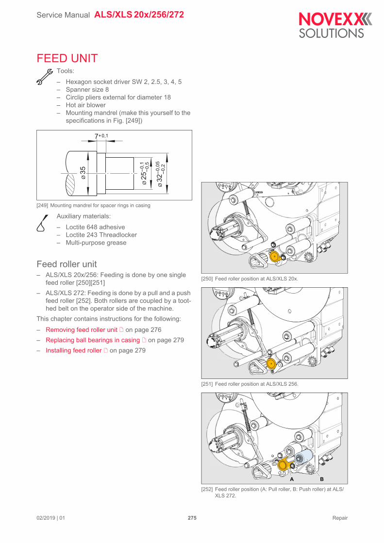
Service Manual ALS/XLS 20x/256/272
02/2019 | 01 275 Repair
FEED UNITTools:
– Hexagon socket driver SW 2, 2.5, 3, 4, 5– Spanner size 8– Circlip pliers external for diameter 18– Hot air blower– Mounting mandrel (make this yourself to the
specifications in Fig. [249])
[249] Mounting mandrel for spacer rings in casing
Auxiliary materials:
– Loctite 648 adhesive– Loctite 243 Threadlocker– Multi-purpose grease
Feed roller unit– ALS/XLS 20x/256: Feeding is done by one single
feed roller [250][251]
– ALS/XLS 272: Feeding is done by a pull and a push feed roller [252]. Both rollers are coupled by a toot-hed belt on the operator side of the machine.
This chapter contains instructions for the following:
– Removing feed roller unit on page 276
– Replacing ball bearings in casing on page 279
– Installing feed roller on page 279
7+0,1
Ø 3
2-
0,0
5
Ø 3
5
Ø 2
5-
0,1
-0
,5
-0
,2
[250] Feed roller position at ALS/XLS 20x.
[251] Feed roller position at ALS/XLS 256.
[252] Feed roller position (A: Pull roller, B: Push roller) at ALS/XLS 272.
A B
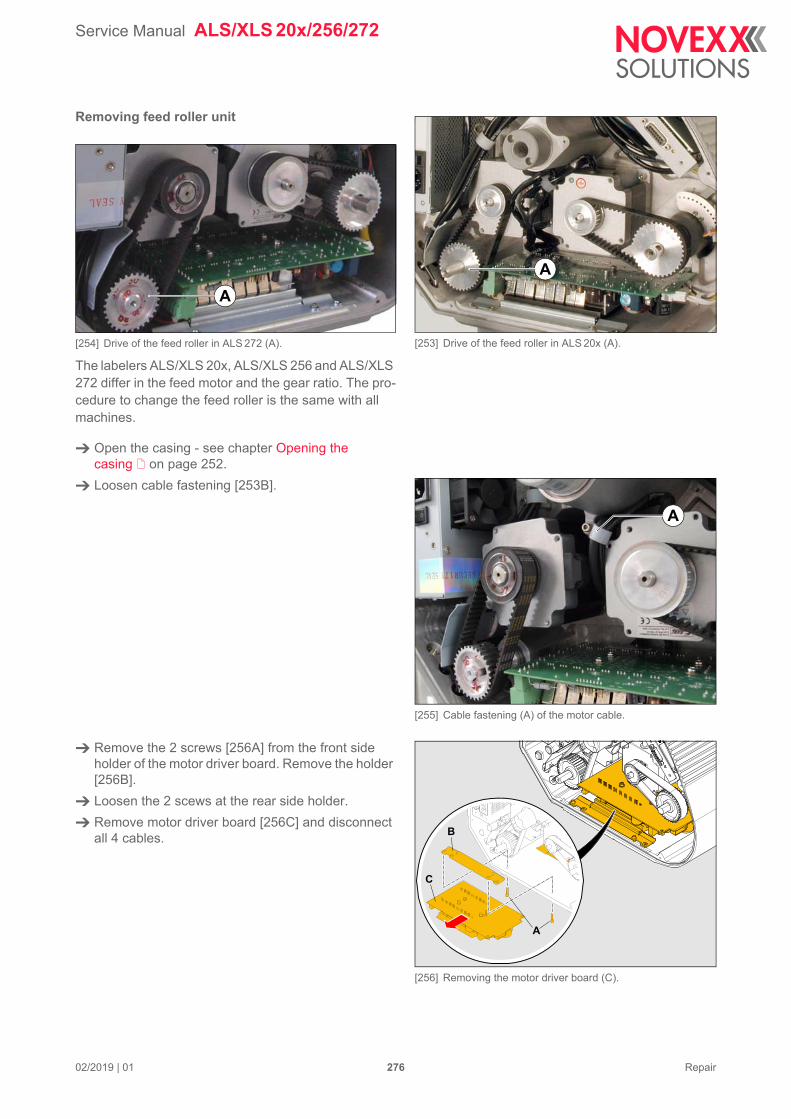
Service Manual ALS/XLS 20x/256/272
02/2019 | 01 276 Repair
Removing feed roller unit
[254] Drive of the feed roller in ALS 272 (A).
The labelers ALS/XLS 20x, ALS/XLS 256 and ALS/XLS 272 differ in the feed motor and the gear ratio. The pro-cedure to change the feed roller is the same with all machines.
Open the casing - see chapter Opening the casing on page 252.
Loosen cable fastening [253B].
Remove the 2 screws [256A] from the front side holder of the motor driver board. Remove the holder [256B].
Loosen the 2 scews at the rear side holder.
Remove motor driver board [256C] and disconnect all 4 cables.
[253] Drive of the feed roller in ALS 20x (A).
A
A
[255] Cable fastening (A) of the motor cable.
[256] Removing the motor driver board (C).
A
A
B
C
Service Manual ALS/XLS 20x/256/272
02/2019 | 01 277 Repair
Loosen the 3 screws on the motor [257A] to slacken the toothed belt [257B].
Loosen 2 setscrews on the large pulley [258A].
Remove pulley [259A] and toothed belt [259B].
Remove circlip [259C] and shim [259D].
On the opposite side of the machine, fold the pres-sure roller out of its working position [260].
Continued overleaf.
[257] Screws (A) holding the feed motor in place.
[258] Set screws (A) at the pulley (picture showing ALS 272).
[259] Removing the feed roller (E).
[260] (Folding the pressure roller downwards.
A
B
A
A
B
CD
E
Service Manual ALS/XLS 20x/256/272
02/2019 | 01 278 Repair
(ALS/XLS 272) Before pulling out the fee roller, the toothed belt [261B] on the operator side of the machine has to be slackened.
(ALS/XLS 272) At the front feed roller [261C], loo-sen the screw [262B] at the inner end of the excen-ter-axle. Turn the excenter-axis by applying a spanner at the outside end [262A] of the axle, until the toothed belt is slack
Pull the feed roller and shaft [263] out of the casing.
[261] (ALS/XLS 272) Toothed belt (B) between the feed rollers (A) and (C).
[262] (ALS/XLS 272) Excenter-axis at the front feed roller (cross-section).
[263] Removed feed roller (ALS 20x)
A
B
C
A
B
C
Service Manual ALS/XLS 20x/256/272
02/2019 | 01 279 Repair
Replacing ball bearings in casing
– Prerequisite: Feed roller is removed.
Carefully soften up the adhesive bond on both bear-ings [264A] using a hot air blower.
Remove the bearings.
Remove spacer rings [264B].
Remove adhesive residues from the bearing seats.
Fixing the ball bearings with adhesive:
Glue the ball bearings into the bearing seats with Loctite 648.
Follow the adhesive manufacturer's instruc-tions for use.
Press the spacer rings into the casing to a depth of 7 mm, using the mounting mandrel [265].
Glue the ball bearings into the casing. The ball bear-ings should be pushed in until they meet the spacer rings.
Allow adhesive joint to set fully before installing the feed roller.
Installing feed roller
Smooth dents in the shaft [266arrow] with an oil-stone as necessary.
Lightly grease the part of the feed roller shaft that has contact with the bearings [267B] but keep the feed roller itself [267A] free from grease.
Introduce the feed roller and shaft into the bearing.
– (ALS/XLS 272) Be careful that the toothed belt on the operator side is fitted to the toothed belt pulley.
Install circlip [266B] and shim [266C].
[267] Removed feed roller
[264] Ball bearing in casing
[265] Installation position of spacer rings and ball bearings in casing
[266] Installing shim and circlip
A
B
7+0,17+0,1
B C
A
A B
Service Manual ALS/XLS 20x/256/272
02/2019 | 01 280 Repair
Unscrew setscrews [268B] from the belt pulley [268A]. Clean threads and screw setscrews back in with Loctite 243 Threadlock.
Place the toothed belt [268D] over the motor pinion [268C].
Slide belt pulley into place and pull belt onto belt pul-ley.
Turn the belt pulley in order to align one of the two setscrews [268B] with the bevel in the shaft [268arrow].
Aligning belt pulley and toothed belt with motor pin-ion: The toothed belt must run in the centre of the belt pulley and motor pinion.
– (ALS/XLS 256/272) The belt pulley is positioned fur-ther outside on the shaft (approx. 1.5 mm behind the shaft end).
Tighten setscrew [268B] to bevel, then tighten sec-ond setscrew.
Slide the motor [270A] until the toothed belt is taut. Tighten 3 screws on the motor mount.
Connect and install the motor driver board [270D].
– Connection diagram, see chapter Wiring Diagrams on page 156 ff.
Fasten motor lead to housing with cable fastening [270E].
(ALS/XLS 272) Tighten the toothed belt [271C] bet-ween the two feed rollers. To do so, turn the excen-ter-axis [271A] at the front feed roller carefully, until the toothed belt is tightened. Thighten the screw [271B].
Install casing rear wall.
[271] (ALS/XLS 272) Excenter-axis at the front feed roller (cross-sec-tion).
[268] Screw in one of the setscrews so that it engages with the bevel at the end of the shaft (position of the belt pulley in ALSs 20x)
[269] Position of the belt pulley in ALS 256
[270] Adjust belt tension; connect and fit PCB
A
B D
C
A
approx. 1.5 mm
D
A
C
B
A
B
C
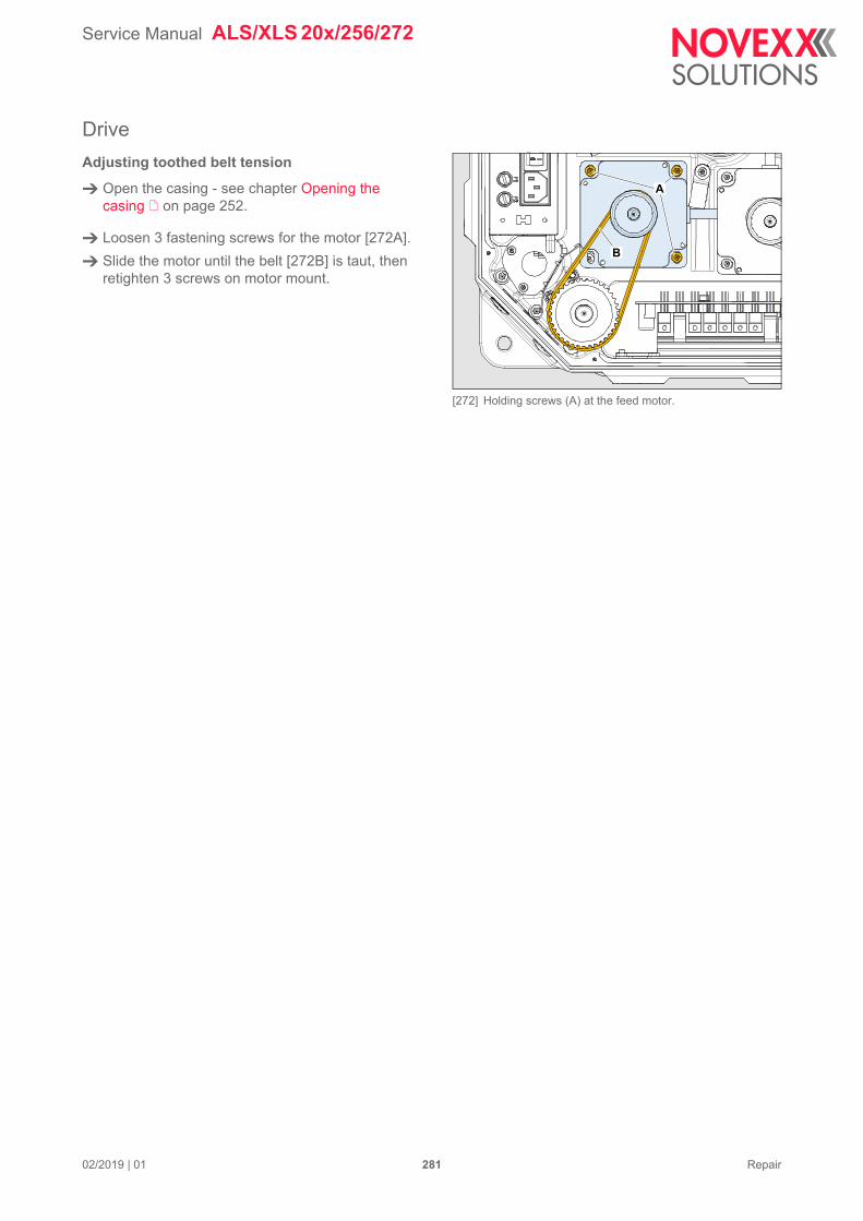
Service Manual ALS/XLS 20x/256/272
02/2019 | 01 281 Repair
Drive
Adjusting toothed belt tension
Open the casing - see chapter Opening the casing on page 252.
Loosen 3 fastening screws for the motor [272A].
Slide the motor until the belt [272B] is taut, then retighten 3 screws on motor mount.
[272] Holding screws (A) at the feed motor.
A
B
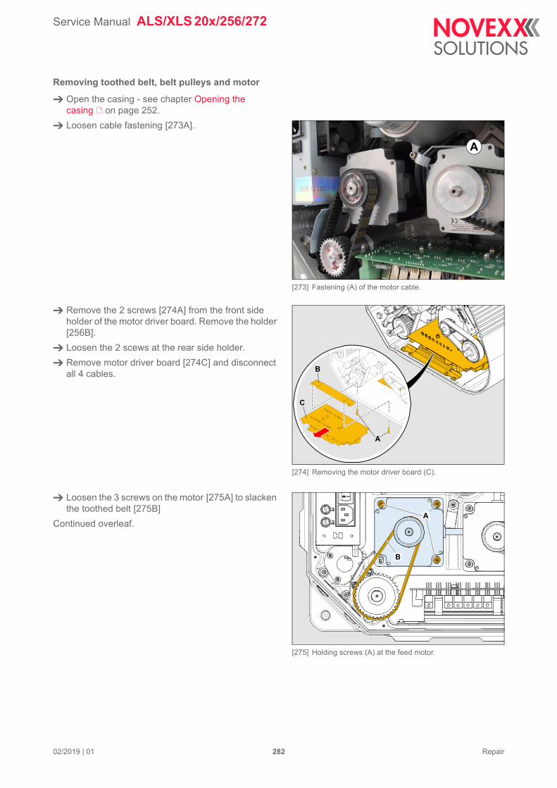
Service Manual ALS/XLS 20x/256/272
02/2019 | 01 282 Repair
Removing toothed belt, belt pulleys and motor
Open the casing - see chapter Opening the casing on page 252.
Loosen cable fastening [273A].
Remove the 2 screws [274A] from the front side holder of the motor driver board. Remove the holder [256B].
Loosen the 2 scews at the rear side holder.
Remove motor driver board [274C] and disconnect all 4 cables.
Loosen the 3 screws on the motor [275A] to slacken the toothed belt [275B]
Continued overleaf.
[273] Fastening (A) of the motor cable.
[274] Removing the motor driver board (C).
A
A
B
C
[275] Holding screws (A) at the feed motor.
A
B
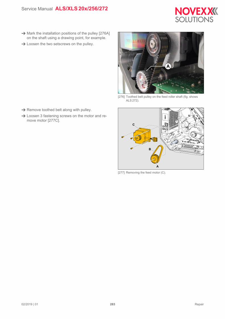
Service Manual ALS/XLS 20x/256/272
02/2019 | 01 283 Repair
Mark the installation positions of the pulley [276A] on the shaft using a drawing point, for example.
Loosen the two setscrews on the pulley.
Remove toothed belt along with pulley.
Loosen 3 fastening screws on the motor and re-move motor [277C].
[276] Toothed belt pulley on the feed roller shaft (fig. shows ALS 272).
[277] Removing the feed motor (C).
A
A
B
C
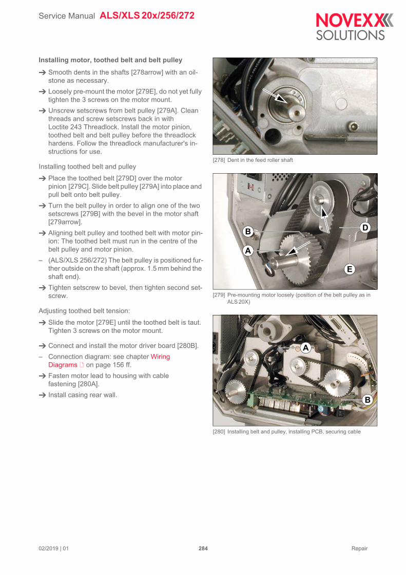
Service Manual ALS/XLS 20x/256/272
02/2019 | 01 284 Repair
Installing motor, toothed belt and belt pulley
Smooth dents in the shafts [278arrow] with an oil-stone as necessary.
Loosely pre-mount the motor [279E], do not yet fully tighten the 3 screws on the motor mount.
Unscrew setscrews from belt pulley [279A]. Clean threads and screw setscrews back in with Loctite 243 Threadlock. Install the motor pinion, toothed belt and belt pulley before the threadlock hardens. Follow the threadlock manufacturer's in-structions for use.
Installing toothed belt and pulley
Place the toothed belt [279D] over the motor pinion [279C]. Slide belt pulley [279A] into place and pull belt onto belt pulley.
Turn the belt pulley in order to align one of the two setscrews [279B] with the bevel in the motor shaft [279arrow].
Aligning belt pulley and toothed belt with motor pin-ion: The toothed belt must run in the centre of the belt pulley and motor pinion.
– (ALS/XLS 256/272) The belt pulley is positioned fur-ther outside on the shaft (approx. 1.5 mm behind the shaft end).
Tighten setscrew to bevel, then tighten second set-screw.
Adjusting toothed belt tension:
Slide the motor [279E] until the toothed belt is taut. Tighten 3 screws on the motor mount.
Connect and install the motor driver board [280B].
– Connection diagram: see chapter Wiring Diagrams on page 156 ff.
Fasten motor lead to housing with cable fastening [280A].
Install casing rear wall.
[278] Dent in the feed roller shaft
[279] Pre-mounting motor loosely (position of the belt pulley as in ALS 20X)
[280] Installing belt and pulley, installing PCB, securing cable
A
B D
E
B
A
Service Manual ALS/XLS 20x/256/272
02/2019 | 01 285 Repair
Pressure roller„Pressure roller“ names in the following the parts pictu-red on the right.
The pressure roller at the ALS/XLS 272 [281A] differs in the following points from the roller at ALS/XLS 20x and ALS/XLS 256 [281B] labellers:
– narrower rollers
– only 1 ball bearing in the roller equipped with ball be-aring(s)
Tools:
– Hexagon socket driver SW 2.5, 3, 5– Hot air blower
Auxiliary materials:
– Loctite 648 adhesive– Loctite 243 Threadlocker– Multi-purpose grease
[281] Pressure rollers (both RH) for ALS/XLS 20x/256 (B) and for ALS/XLS 272 (A).
Service Manual ALS/XLS 20x/256/272
02/2019 | 01 286 Repair
Replacing ball bearings
Fold pressure roller out of working position [282A].
Screw the knurled thumbscrew [282B] nearly all of the way out and remove the pressure roller along with clamping ring [282C].
Remove setscrews [283G], springs [283F] and pressure pins [283E].
Pull out the axle [283D], remove steel roller [283C] and washer discs [283A].
Soften up the adhesive bond on both ball bearings [283B] using a hot air blower.
Remove the ball bearings.
Remove adhesive residues from the bearing seats.
Fixing the ball bearings with adhesive:
Glue the ball bearings into the bearing seats with Loctite 648.
Follow the adhesive manufacturer's instruc-tions for use.
Glue the ball bearings flush with the end surfaces of the steel roller.
Allow the adhesive bond to harden fully.
Place steel roller with washer discs in pressure roller assembly and slide in the axle [283D], with the con-tact surfaces [283arrows] for the pressure pins fac-ing backwards.
Grease pressure pins, springs and setscrews and install them in the pressure roller. Ensure that the pressure pins mate with the contact surfaces on the axle [284arrow].
Screw the setscrews inside the pressure roller to a depth as described in the next chapter [284A]
Adjusting the pressure force
To set the standard initial tension of the springs, turn in both setscrews [284A] on the rear side of the pressure roller:
Clockwise to the same degree, to increase pressure force.
Anticlockwise to the same degree, to decrease pressure force.
Machine Screw-in depth setscrews
ALS/XLS 20x 2 mm
ALS/XLS 256 4 mm
[282] Removing pressure roller
[283] Disassembling pressure roller
[284] Adjusting the pressure force
AB
C
E
AB
C
D
FG
A
Service Manual ALS/XLS 20x/256/272
02/2019 | 01 287 Repair
Support axle
To ensure the pressure roller functions correctly, the support axle [285A] must be in a defined position:
– Groove [285arrow] in the support axle points ap-prox. 45° downwards.
To set the position of the support axle:
Open the casing - see chapter Opening the casing on page 252.
Loosen cable fastening [286A] for motor leads.
Remove 4 screws [285B] that secure motor driver board in place.
Remove motor driver board [286B] and disconnect all 4 plug connections [286C].
Remove screw [287A].
Clean thread. Screw in the screw, using Loctite 243 Threadlock. Follow the threadlock manufacturer's instructions for use.
Before threadlock hardens, rotate the support axle to the correct position and tighten the screw.
Connect and install the motor driver board.
Fasten motor leads to housing with cable fastening.
Install casing rear wall.
[285] The groove in the support axle for the pressure roller points downwards at 45°.
[286] Removing the motor driver board
[287] Retaining screw for support axle
A
B
B
C
A
A
Service Manual ALS/XLS 20x/256/272
04/2019 | 00 288 Repair
REWIND UNIT
Expanding mandrel (ALS 2xx)Tools:
– Hexagon socket driver SW 2, 2.5, 3– Size 2 Phillips screwdriver– Adjust gauge (make this yourself to the di-
mensions shown in Fig. [288])
[288] Adjust gauge for cones in expanding mandrelALS 204: Measurement A = 110 mmALS 206: Measurement A = 160 mm
Auxiliary materials:
– Loctite 480 adhesive– Loctite 243 Threadlocker– Multi-purpose grease
Removing the spool hub
Remove the countersunk screws [289B] on front ends of the cone follower inserts [289A].
Remove the cone follower inserts.
Remove one of the synthetic binders [290].
Remove the spool hub segments [291].
A
t = 4
20
8
30
20
[289] Removing cone follower inserts
[290] Remove synthetic binder
[291] Removing the spool hub segments
B
A
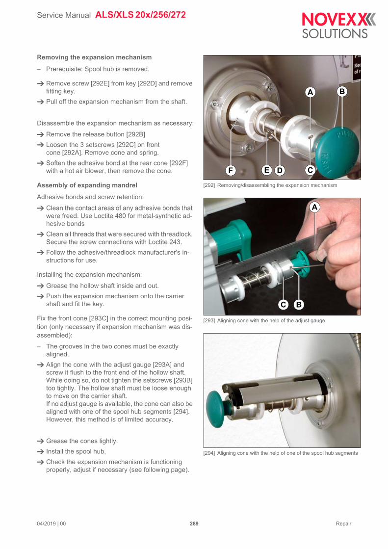
Service Manual ALS/XLS 20x/256/272
04/2019 | 00 289 Repair
Removing the expansion mechanism
– Prerequisite: Spool hub is removed.
Remove screw [292E] from key [292D] and remove fitting key.
Pull off the expansion mechanism from the shaft.
Disassemble the expansion mechanism as necessary:
Remove the release button [292B]
Loosen the 3 setscrews [292C] on front cone [292A]. Remove cone and spring.
Soften the adhesive bond at the rear cone [292F] with a hot air blower, then remove the cone.
Assembly of expanding mandrel
Adhesive bonds and screw retention:
Clean the contact areas of any adhesive bonds that were freed. Use Loctite 480 for metal-synthetic ad-hesive bonds
Clean all threads that were secured with threadlock. Secure the screw connections with Loctite 243.
Follow the adhesive/threadlock manufacturer's in-structions for use.
Installing the expansion mechanism:
Grease the hollow shaft inside and out.
Push the expansion mechanism onto the carrier shaft and fit the key.
Fix the front cone [293C] in the correct mounting posi-tion (only necessary if expansion mechanism was dis-assembled):
– The grooves in the two cones must be exactly aligned.
Align the cone with the adjust gauge [293A] and screw it flush to the front end of the hollow shaft. While doing so, do not tighten the setscrews [293B] too tightly. The hollow shaft must be loose enough to move on the carrier shaft.If no adjust gauge is available, the cone can also be aligned with one of the spool hub segments [294]. However, this method is of limited accuracy.
Grease the cones lightly.
Install the spool hub.
Check the expansion mechanism is functioning properly, adjust if necessary (see following page).
[292] Removing/disassembling the expansion mechanism
[293] Aligning cone with the help of the adjust gauge
[294] Aligning cone with the help of one of the spool hub segments
A
DE C
B
F
A
C B

Service Manual ALS/XLS 20x/256/272
04/2019 | 00 290 Repair
Adjusting the expansion mechanism
If the expanding mandrel cannot be compressed when the release button is pushed in:
Loosen the 3 setscrews [305B] on front cone [305A].
Slide the cone fractionally towards the machine cas-ing and tighten the setscrews. Take care not to over-tighten the setscrews.
Check the expansion mechanism is functioning properly. Repeat adjustment procedure as neces-sary.
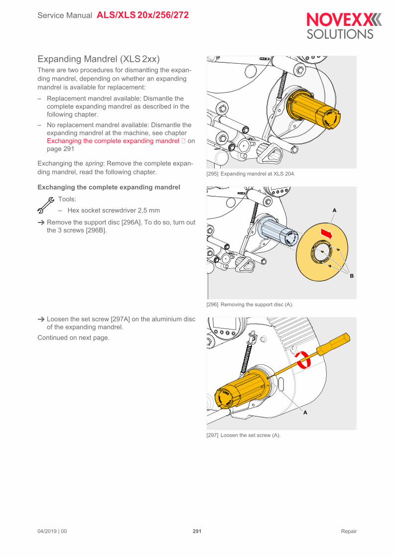
Service Manual ALS/XLS 20x/256/272
04/2019 | 00 291 Repair
Expanding Mandrel (XLS 2xx)There are two procedures for dismantling the expan-ding mandrel, depending on whether an expanding mandrel is available for replacement:
– Replacement mandrel available: Dismantle the complete expanding mandrel as described in the following chapter.
– No replacement mandrel available: Dismantle the expanding mandrel at the machine, see chapter Exchanging the complete expanding mandrel on page 291
Exchanging the spring: Remove the complete expan-ding mandrel, read the following chapter.
Exchanging the complete expanding mandrel
Tools:
– Hex socket screwdriver 2,5 mm
Remove the support disc [296A]. To do so, turn out the 3 screws [296B].
Loosen the set screw [297A] on the aluminium disc of the expanding mandrel.
Continued on next page.
[295] Expanding mandrel at XLS 204.
[296] Removing the support disc (A).
[297] Loosen the set screw (A).
B
A
A
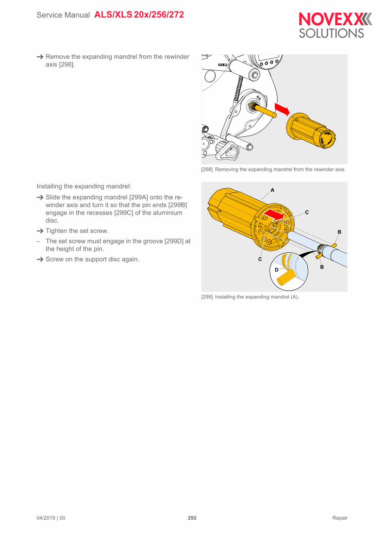
Service Manual ALS/XLS 20x/256/272
04/2019 | 00 292 Repair
Remove the expanding mandrel from the rewinder axis [298].
Installing the expanding mandrel:
Slide the expanding mandrel [299A] onto the re-winder axis and turn it so that the pin ends [299B] engage in the recesses [299C] of the aluminium disc.
Tighten the set screw.
– The set screw must engage in the groove [299D] at the height of the pin.
Screw on the support disc again.
[298] Removing the expanding mandrel from the rewinder axis.
[299] Installing the expanding mandrel (A).
A
B
CB
C
D
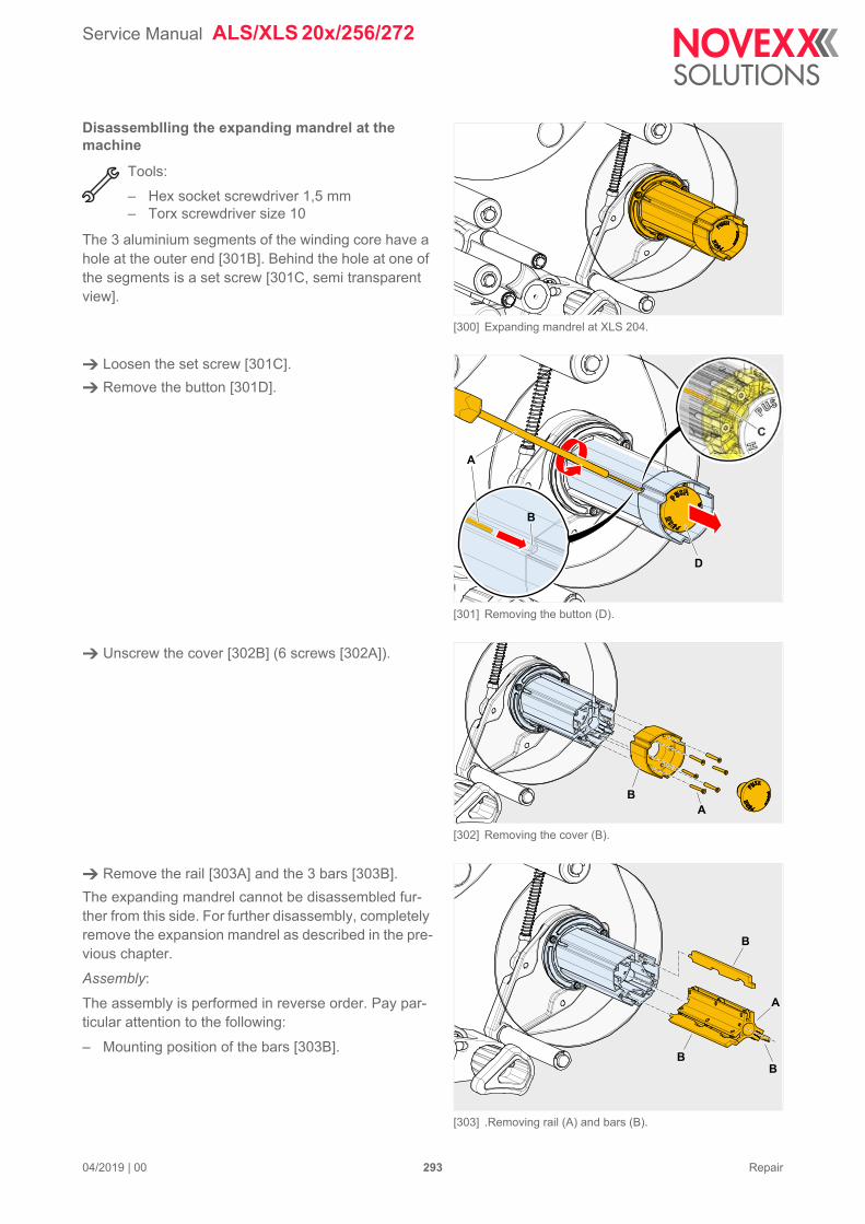
Service Manual ALS/XLS 20x/256/272
04/2019 | 00 293 Repair
Disassemblling the expanding mandrel at the machine
Tools:
– Hex socket screwdriver 1,5 mm– Torx screwdriver size 10
The 3 aluminium segments of the winding core have a hole at the outer end [301B]. Behind the hole at one of the segments is a set screw [301C, semi transparent view].
Loosen the set screw [301C].
Remove the button [301D].
Unscrew the cover [302B] (6 screws [302A]).
Remove the rail [303A] and the 3 bars [303B].
The expanding mandrel cannot be disassembled fur-ther from this side. For further disassembly, completely remove the expansion mandrel as described in the pre-vious chapter.
Assembly:
The assembly is performed in reverse order. Pay par-ticular attention to the following:
– Mounting position of the bars [303B].
[300] Expanding mandrel at XLS 204.
[301] Removing the button (D).
[302] Removing the cover (B).
[303] .Removing rail (A) and bars (B).
A
B
C
D
AB
A
B
BB
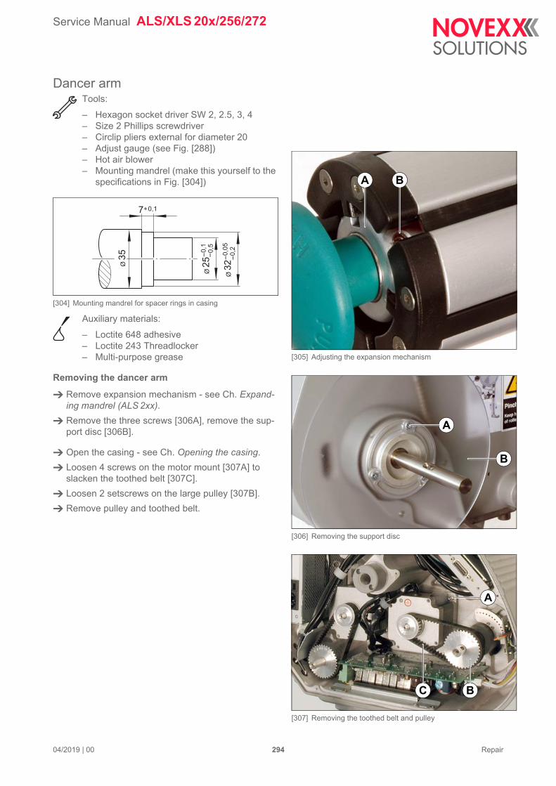
Service Manual ALS/XLS 20x/256/272
04/2019 | 00 294 Repair
Dancer armTools:
– Hexagon socket driver SW 2, 2.5, 3, 4– Size 2 Phillips screwdriver– Circlip pliers external for diameter 20– Adjust gauge (see Fig. [288])– Hot air blower– Mounting mandrel (make this yourself to the
specifications in Fig. [304])
[304] Mounting mandrel for spacer rings in casing
Auxiliary materials:
– Loctite 648 adhesive– Loctite 243 Threadlocker– Multi-purpose grease
Removing the dancer arm
Remove expansion mechanism - see Ch. Expand-ing mandrel (ALS 2xx).
Remove the three screws [306A], remove the sup-port disc [306B].
Open the casing - see Ch. Opening the casing.
Loosen 4 screws on the motor mount [307A] to slacken the toothed belt [307C].
Loosen 2 setscrews on the large pulley [307B].
Remove pulley and toothed belt.
7+0,1
Ø 3
2-
0,0
5
Ø 3
5
Ø 2
5-
0,1
-0
,5
-0
,2
[305] Adjusting the expansion mechanism
[306] Removing the support disc
[307] Removing the toothed belt and pulley
A B
A
B
A
C B
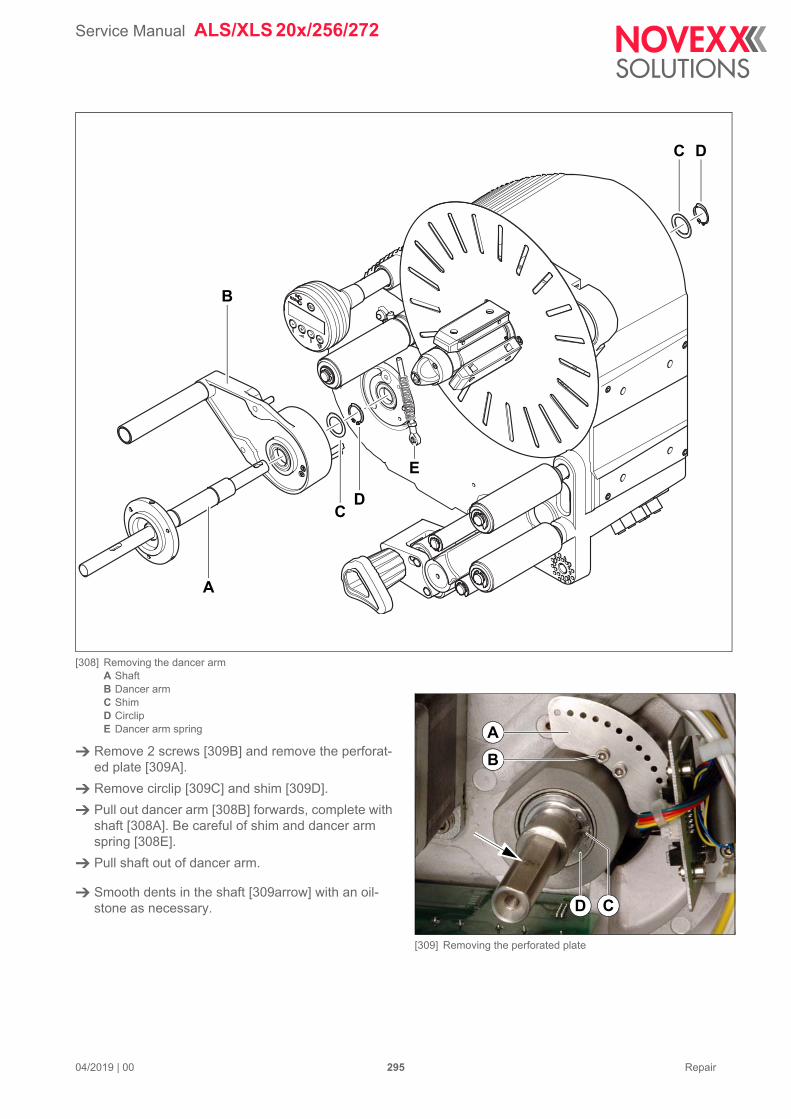
Service Manual ALS/XLS 20x/256/272
04/2019 | 00 295 Repair
[308] Removing the dancer armA ShaftB Dancer armC ShimD CirclipE Dancer arm spring
Remove 2 screws [309B] and remove the perforat-ed plate [309A].
Remove circlip [309C] and shim [309D].
Pull out dancer arm [308B] forwards, complete with shaft [308A]. Be careful of shim and dancer arm spring [308E].
Pull shaft out of dancer arm.
Smooth dents in the shaft [309arrow] with an oil-stone as necessary.
B
A
DC
CD
E
[309] Removing the perforated plate
D
A
B
C
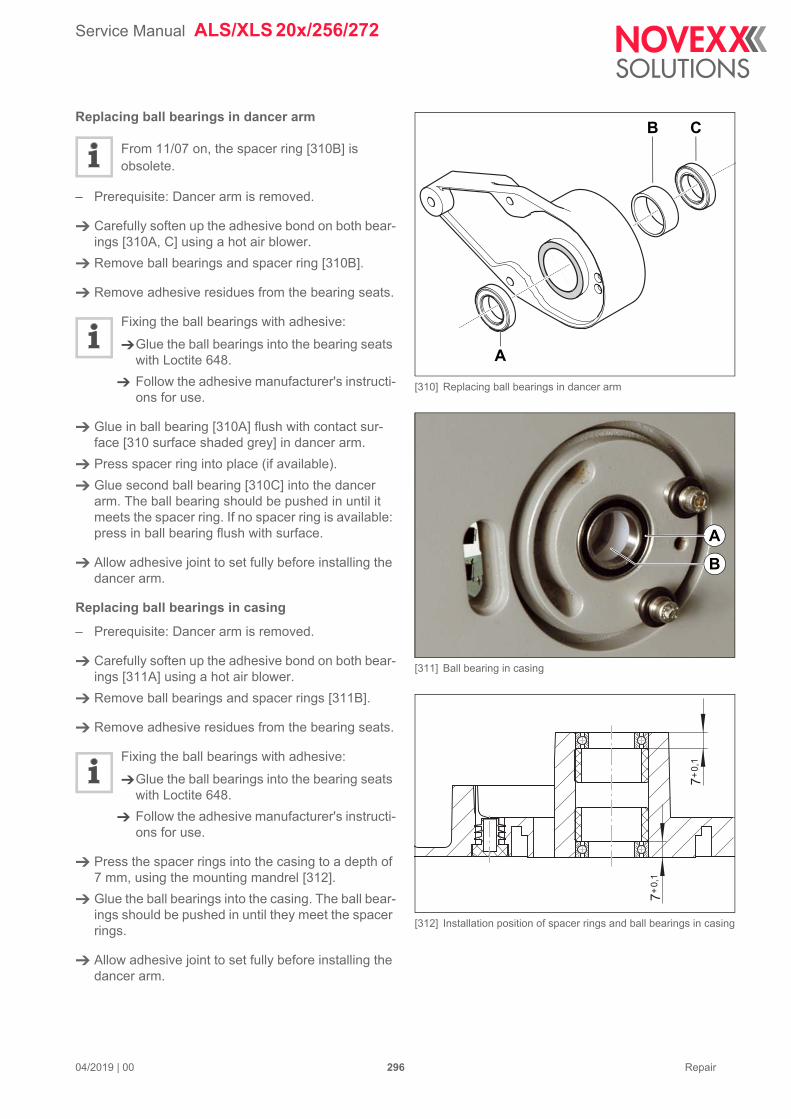
Service Manual ALS/XLS 20x/256/272
04/2019 | 00 296 Repair
Replacing ball bearings in dancer arm
From 11/07 on, the spacer ring [310B] is obsolete.
– Prerequisite: Dancer arm is removed.
Carefully soften up the adhesive bond on both bear-ings [310A, C] using a hot air blower.
Remove ball bearings and spacer ring [310B].
Remove adhesive residues from the bearing seats.
Fixing the ball bearings with adhesive:
Glue the ball bearings into the bearing seats with Loctite 648.
Follow the adhesive manufacturer's instructi-ons for use.
Glue in ball bearing [310A] flush with contact sur-face [310 surface shaded grey] in dancer arm.
Press spacer ring into place (if available).
Glue second ball bearing [310C] into the dancer arm. The ball bearing should be pushed in until it meets the spacer ring. If no spacer ring is available: press in ball bearing flush with surface.
Allow adhesive joint to set fully before installing the dancer arm.
Replacing ball bearings in casing
– Prerequisite: Dancer arm is removed.
Carefully soften up the adhesive bond on both bear-ings [311A] using a hot air blower.
Remove ball bearings and spacer rings [311B].
Remove adhesive residues from the bearing seats.
Fixing the ball bearings with adhesive:
Glue the ball bearings into the bearing seats with Loctite 648.
Follow the adhesive manufacturer's instructi-ons for use.
Press the spacer rings into the casing to a depth of 7 mm, using the mounting mandrel [312].
Glue the ball bearings into the casing. The ball bear-ings should be pushed in until they meet the spacer rings.
Allow adhesive joint to set fully before installing the dancer arm.
[310] Replacing ball bearings in dancer arm
[311] Ball bearing in casing
[312] Installation position of spacer rings and ball bearings in casing
A
B C
A
B
7+
0,1
7+
0,1
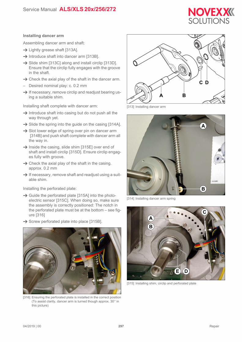
Service Manual ALS/XLS 20x/256/272
04/2019 | 00 297 Repair
Installing dancer arm
Assembling dancer arm and shaft:
Lightly grease shaft [313A].
Introduce shaft into dancer arm [313B].
Slide shim [313C] along and install circlip [313D]. Ensure that the circlip fully engages with the groove in the shaft.
Check the axial play of the shaft in the dancer arm.
– Desired nominal play: c. 0.2 mm
If necessary, remove circlip and readjust bearing us-ing a suitable shim.
Installing shaft complete with dancer arm:
Introduce shaft into casing but do not push all the way through yet.
Slide the spring into the guide on the casing [314A].
Slot lower edge of spring over pin on dancer arm [314B] and push shaft complete with dancer arm all
the way in.
Inside the casing, slide shim [315E] over end of shaft and install circlip [315D]. Ensure circlip engag-es fully with groove.
Check the axial play of the shaft in the casing. approx. 0.2 mm
If necessary, remove shaft and readjust using a suit-able shim.
Installing the perforated plate:
Guide the perforated plate [315A] into the photo-electric sensor [315C]. When doing so, make sure the assembly is correctly positioned: The notch in the perforated plate must be at the bottom – see fig-ure [316]
Screw perforated plate into place [315B].
[316] Ensuring the perforated plate is installed in the correct position(To assist clarity, dancer arm is turned though approx. 30° in this picture)
[313] Installing dancer arm
[314] Installing dancer arm spring
[315] Installing shim, circlip and perforated plate
A
C D
B
B
A
E
A
B
D
C
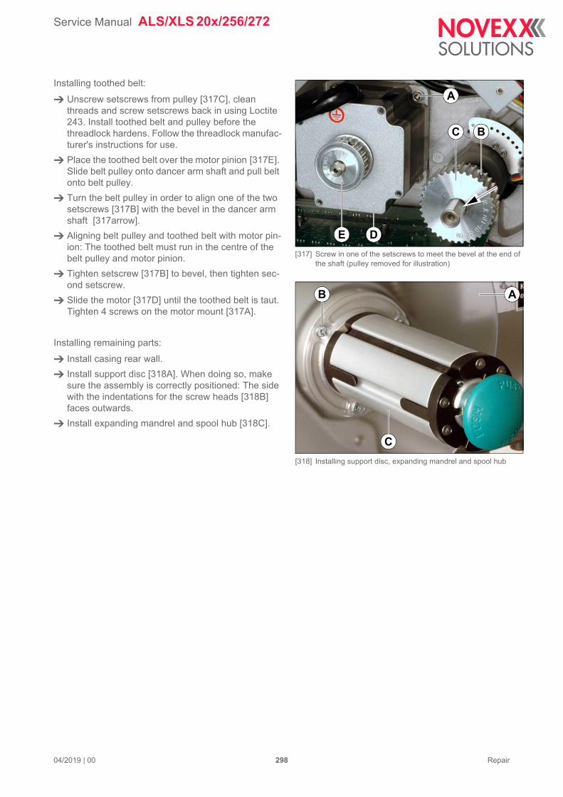
Service Manual ALS/XLS 20x/256/272
04/2019 | 00 298 Repair
Installing toothed belt:
Unscrew setscrews from pulley [317C], clean threads and screw setscrews back in using Loctite 243. Install toothed belt and pulley before the threadlock hardens. Follow the threadlock manufac-turer's instructions for use.
Place the toothed belt over the motor pinion [317E]. Slide belt pulley onto dancer arm shaft and pull belt onto belt pulley.
Turn the belt pulley in order to align one of the two setscrews [317B] with the bevel in the dancer arm shaft [317arrow].
Aligning belt pulley and toothed belt with motor pin-ion: The toothed belt must run in the centre of the belt pulley and motor pinion.
Tighten setscrew [317B] to bevel, then tighten sec-ond setscrew.
Slide the motor [317D] until the toothed belt is taut. Tighten 4 screws on the motor mount [317A].
Installing remaining parts:
Install casing rear wall.
Install support disc [318A]. When doing so, make sure the assembly is correctly positioned: The side with the indentations for the screw heads [318B] faces outwards.
Install expanding mandrel and spool hub [318C].
[317] Screw in one of the setscrews to meet the bevel at the end of the shaft (pulley removed for illustration)
[318] Installing support disc, expanding mandrel and spool hub
E D
A
BC
AB
C
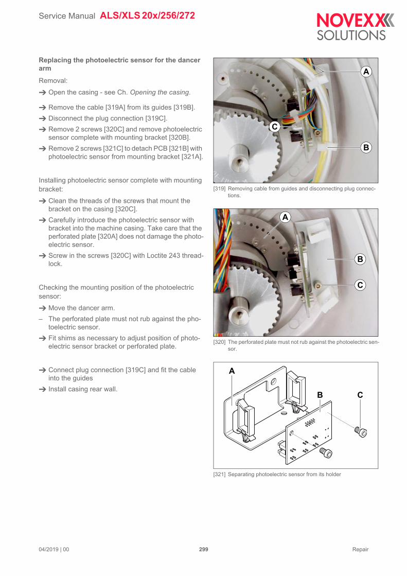
Service Manual ALS/XLS 20x/256/272
04/2019 | 00 299 Repair
Replacing the photoelectric sensor for the dancer arm
Removal:
Open the casing - see Ch. Opening the casing.
Remove the cable [319A] from its guides [319B].
Disconnect the plug connection [319C].
Remove 2 screws [320C] and remove photoelectric sensor complete with mounting bracket [320B].
Remove 2 screws [321C] to detach PCB [321B] with photoelectric sensor from mounting bracket [321A].
Installing photoelectric sensor complete with mounting bracket:
Clean the threads of the screws that mount the bracket on the casing [320C].
Carefully introduce the photoelectric sensor with bracket into the machine casing. Take care that the perforated plate [320A] does not damage the photo-electric sensor.
Screw in the screws [320C] with Loctite 243 thread-lock.
Checking the mounting position of the photoelectric sensor:
Move the dancer arm.
– The perforated plate must not rub against the pho-toelectric sensor.
Fit shims as necessary to adjust position of photo-electric sensor bracket or perforated plate.
Connect plug connection [319C] and fit the cable into the guides
Install casing rear wall.
[319] Removing cable from guides and disconnecting plug connec-tions.
[320] The perforated plate must not rub against the photoelectric sen-sor.
[321] Separating photoelectric sensor from its holder
B
C
A
C
B
A
A
CB
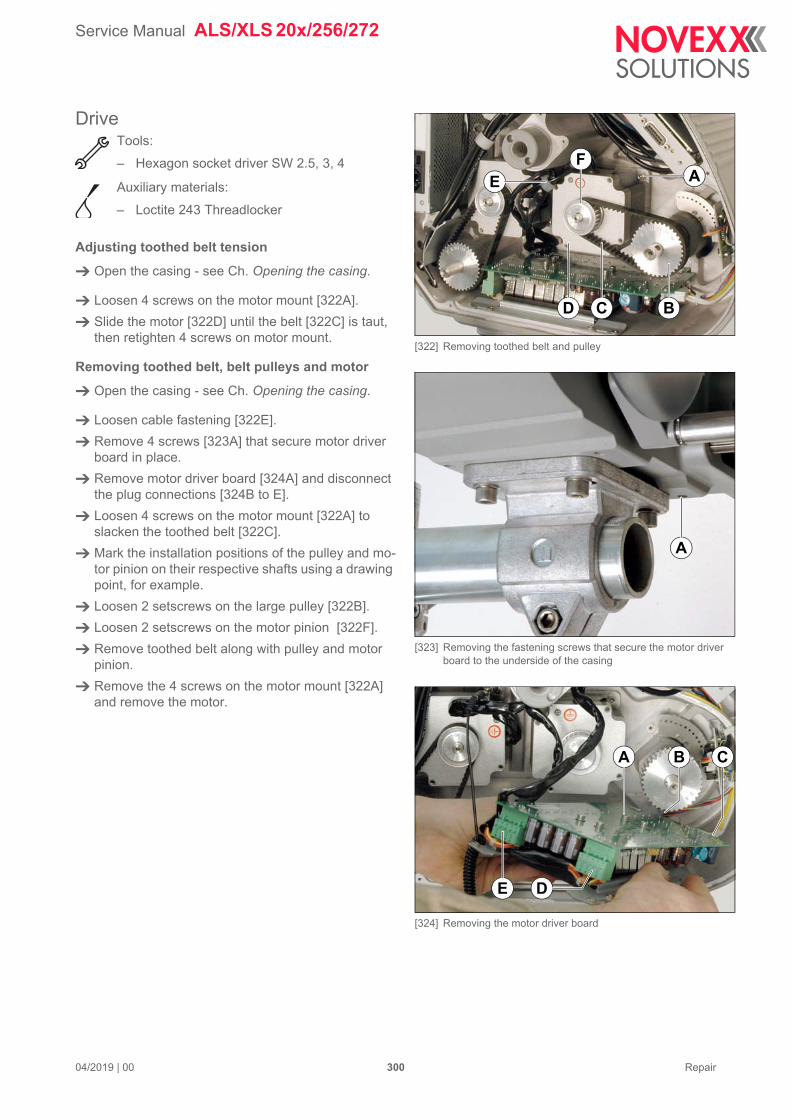
Service Manual ALS/XLS 20x/256/272
04/2019 | 00 300 Repair
DriveTools:
– Hexagon socket driver SW 2.5, 3, 4
Auxiliary materials:
– Loctite 243 Threadlocker
Adjusting toothed belt tension
Open the casing - see Ch. Opening the casing.
Loosen 4 screws on the motor mount [322A].
Slide the motor [322D] until the belt [322C] is taut, then retighten 4 screws on motor mount.
Removing toothed belt, belt pulleys and motor
Open the casing - see Ch. Opening the casing.
Loosen cable fastening [322E].
Remove 4 screws [323A] that secure motor driver board in place.
Remove motor driver board [324A] and disconnect the plug connections [324B to E].
Loosen 4 screws on the motor mount [322A] to slacken the toothed belt [322C].
Mark the installation positions of the pulley and mo-tor pinion on their respective shafts using a drawing point, for example.
Loosen 2 setscrews on the large pulley [322B].
Loosen 2 setscrews on the motor pinion [322F].
Remove toothed belt along with pulley and motor pinion.
Remove the 4 screws on the motor mount [322A] and remove the motor.
[322] Removing toothed belt and pulley
[323] Removing the fastening screws that secure the motor driver board to the underside of the casing
[324] Removing the motor driver board
A
C BD
E
F
A
E D
CBA
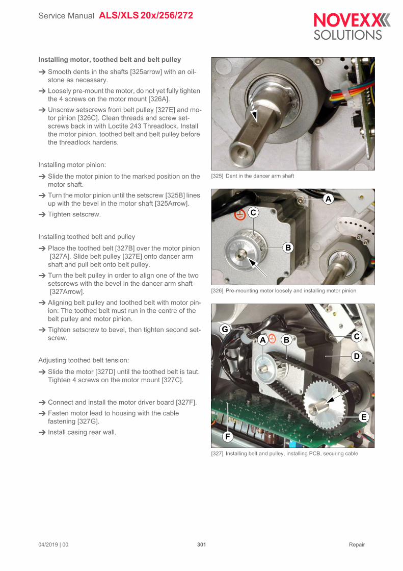
Service Manual ALS/XLS 20x/256/272
04/2019 | 00 301 Repair
Installing motor, toothed belt and belt pulley
Smooth dents in the shafts [325arrow] with an oil-stone as necessary.
Loosely pre-mount the motor, do not yet fully tighten the 4 screws on the motor mount [326A].
Unscrew setscrews from belt pulley [327E] and mo-tor pinion [326C]. Clean threads and screw set-screws back in with Loctite 243 Threadlock. Install the motor pinion, toothed belt and belt pulley before the threadlock hardens.
Installing motor pinion:
Slide the motor pinion to the marked position on the motor shaft.
Turn the motor pinion until the setscrew [325B] lines up with the bevel in the motor shaft [325Arrow].
Tighten setscrew.
Installing toothed belt and pulley
Place the toothed belt [327B] over the motor pinion [327A]. Slide belt pulley [327E] onto dancer arm
shaft and pull belt onto belt pulley.
Turn the belt pulley in order to align one of the two setscrews with the bevel in the dancer arm shaft [327Arrow].
Aligning belt pulley and toothed belt with motor pin-ion: The toothed belt must run in the centre of the belt pulley and motor pinion.
Tighten setscrew to bevel, then tighten second set-screw.
Adjusting toothed belt tension:
Slide the motor [327D] until the toothed belt is taut. Tighten 4 screws on the motor mount [327C].
Connect and install the motor driver board [327F].
Fasten motor lead to housing with the cable fastening [327G].
Install casing rear wall.
[325] Dent in the dancer arm shaft
[326] Pre-mounting motor loosely and installing motor pinion
[327] Installing belt and pulley, installing PCB, securing cable
B
A
C
E
F
GA C
D
B
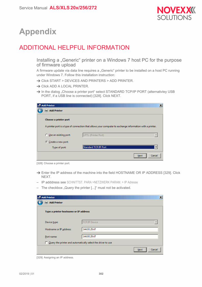
Service Manual ALS/XLS 20x/256/272
Appendix
ADDITIONAL HELPFUL INFORMATION
Installing a „Generic“ printer on a Windows 7 host PC for the purpose of firmware uploadA firmware update via data line requires a „Generic“ printer to be installed on a host PC running under Windows 7. Follow this installation instruction:
Click START > DEVICES AND PRINTERS > ADD PRINTER.
Click ADD A LOCAL PRINTER.
In the dialog „Choose a printer port“ select STANDARD TCP/IP PORT (alternativley USB PORT, if a USB line is connected) [328]. Click NEXT.
[328] Choose a printer port.
Enter the IP address of the machine into the field HOSTNAME OR IP ADDRESS [329]. Click NEXT.
– IP adddress see SCHNITTST. PARA >NETZWERK PARAM. > IP Adresse
– The checkbox „Query the printer [...]“ must not be activated.
[329] Assigning an IP address.
02/2019 | 01 302
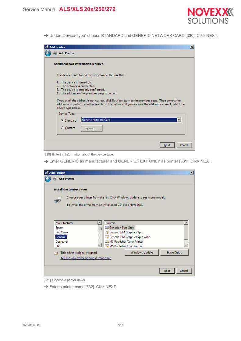
Service Manual ALS/XLS 20x/256/272
Under „Device Type“ choose STANDARD and GENERIC NETWORK CARD [330]. Click NEXT.
[330] Entering information about the device type.
Enter GENERIC as manufacturer and GENERIC/TEXT ONLY as printer [331]. Click NEXT.
[331] Choose a printer driver.
Enter a printer name [332]. Click NEXT.
02/2019 | 01 303
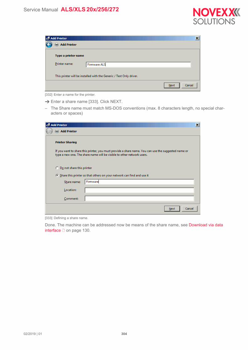
Service Manual ALS/XLS 20x/256/272
[332] Enter a name for the printer.
Enter a share name [333]. Click NEXT.
– The Share name must match MS-DOS conventions (max. 8 characters length, no special char-acters or spaces)
[333] Defining a share name.
Done. The machine can be addressed now be means of the share name, see Download via data interface on page 130.
02/2019 | 01 304
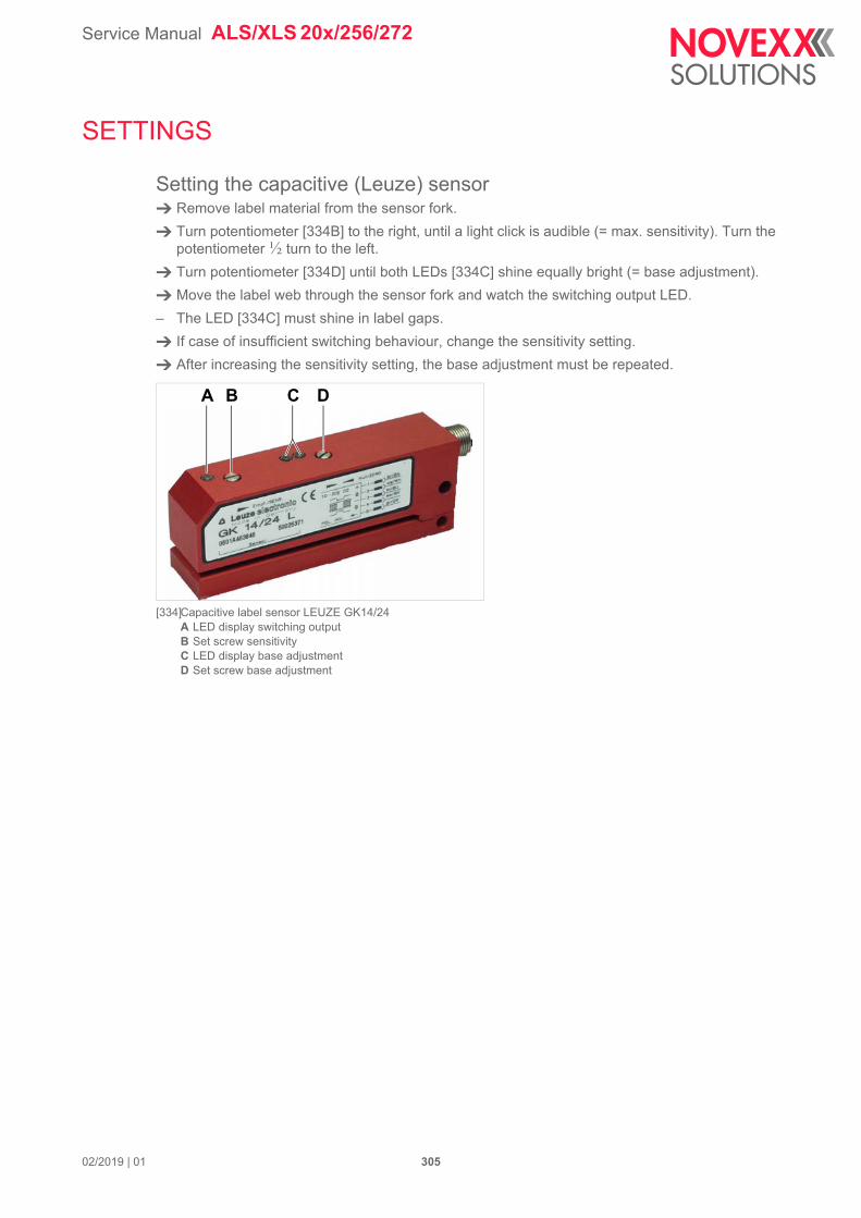
Service Manual ALS/XLS 20x/256/272
SETTINGS
Setting the capacitive (Leuze) sensor Remove label material from the sensor fork.
Turn potentiometer [334B] to the right, until a light click is audible (= max. sensitivity). Turn the potentiometer ½ turn to the left.
Turn potentiometer [334D] until both LEDs [334C] shine equally bright (= base adjustment).
Move the label web through the sensor fork and watch the switching output LED.
– The LED [334C] must shine in label gaps.
If case of insufficient switching behaviour, change the sensitivity setting.
After increasing the sensitivity setting, the base adjustment must be repeated.
[334]Capacitive label sensor LEUZE GK14/24A LED display switching outputB Set screw sensitivityC LED display base adjustmentD Set screw base adjustment
BA C D
02/2019 | 01 305
Service Manual ALS/XLS 20x/256/272
CALCULATION SHEET FOR PERFORMANCE DIAGRAMS
[335] Example calculation with the calculation sheete for performance diagrams.A InputsB Calculated ValuesC Tabs for graphics
The integration of an ALS 20x labeler in a production line is made easier or even possible with the knowledge of certain performance data. Such performance data can be calculated and visualized be means of the Excel file „ALS20x_Ramping.xls“. The file is stored in the „\Labeller_and_Pan-dA\Utilities“ folder on the documentation CD (Service).
Using the calculation sheet Open the file „ALS20x_Ramping.xls“ [335].
– Requires Microsoft Excel or a compatible spread sheet program.
Enter the the values for „max. speed“ and „label pitch (including gap)“ into the input fields [335A].
Read the calculation results [335B].
Inputsmax speed
– Maximum dispensing speed (aimed at).
– Must equal the conveyor speed of the production line.
label pitch (including gap)
– Length of one label plus one gap (measure from one label start to another)
A
B
C
02/2019 | 01 306
Service Manual ALS/XLS 20x/256/272
Outputstime for acceleration
Elapsed time after a start signal until the max. dispensing speed is reached.
run length for acc.
– Run length during the acceleration phase (label length which is already dispensed until the max. dispensing speed is reached).
– The distance between dispensing edge and pressure roller (with direct dispensing) measures 15 mm. Within those 15 mm, the acceleration must be finished.
run length at max. speed
– Run length minus the acceleration and braking phases.
– If the label is shorter than both run lengths for acceleration and braking together, the max. dis-pensing speed is not reached at all. In this case the note „max speed not reached“ appears in the results field.
total time for dispensing
– Required time for dispensing one label.
theoretical max. performance
– Theoretical max. label rate.
– This value can also be determined graphically, see chapter Label rate on page 28.
Diagrams of performance dataOut of the input values, the calculation sheet calculates and draws diagrams for the functions v(t) [336], v(x) and x(t).
The diagrams show some basic relations, which cannot be read as clearly from the calculation results.
Example [336]: With a label length of 26 mm, the required max. dispensing speed of 40 m/min is not reached (red circle). The motor is already braked, before the max. speed is reached (see also Dispensing speed over duration v(t) on page 30).
02/2019 | 01 307
Service Manual ALS/XLS 20x/256/272
[336] Graph of the dispensing speed over the dispensing duration after the following inputs: label length (including gap) = 26 mm; max. dispensing speed = 40 m/min.
02/2019 | 01 308


Novexx Solutions GmbHOhmstraße 385386 EchingGermany +49-8165-925-0www.novexx.com


