Embed Size (px)
Citation preview

Shape optimization with F-functionbalancing for reducing the sonic boom
initial shock pressure rise
Charbel Farhat†, Brian Argrow, Melike Nikbay and Kurt MauteDepartment of Aerospace Engineering Sciences
University of Colorado, Campus Box 429Boulder, CO 80309-0429
ABSTRACTA shape optimization methodology for reducing the initial shock pressure rise (ISPR) on theground of a supersonic aircraft is presented. This methodology combines elements from thelinearized aerodynamic theory such as Whitham’s F-function with elements from the nonlinearaerodynamic theory such as the prediction of lift distribution by an Euler or a Navier-Stokes flowsolver. It also features a concept of F-function lobe balancing that locates suitable positive andnegative lobe pairs of the F-function, and modifies the shape of the aircraft to balance the areasof these lobes. The latter feature accelerates the convergence of the optimization procedure andforces it to generate an aircraft shape with a multi-shock ground signature, which reduces furtherthe ISPR. This shaping technology is illustrated with an application to the Point of Departureaircraft developed by Lockheed-Martin for Phase I of DARPA’s Quiet Supersonic Platformprogram. At M∞ = 1.5, a twenty-fold reduction of the ISPR on the ground, from 1.616 psfto 0.083 psf, is demonstrated while maintaining constant length, lift (weight), and inviscid drag.At M∞ = 2.0, a six-fold reduction of the ISPR on the ground, from 1.866 psf to 0.324 psf, is alsodemonstrated while maintaining constant length, lift (weight), and inviscid drag.
1. NOMENCLATUREThroughout this paper, the abbreviations expanded in Table 1 are used.
2. INTRODUCTIONThe topic of sonic boom flourished in the sixties with the advent of the SupersonicTransport project which was canceled in 1971, then from the mid-eighties to the mid-nineties with the subsequent High Speed Civil Transport (HSCT) program, andwas recently resurrected by DARPA’s Quiet Supersonic Platform (QSP) project.However, whereas the practical specifications for the Boeing HSCT called for a 292-seatsupersonic aircraft with a gross take-off weight of 900,000 pounds and assumed subsonic
aeroacoustics volume 3· number 4 · 2005 – pages 361 – 377 361
Paper 3(4)-01-Farhat.Qxd 24-2-05 3:44 pm Page 361

overland flight until further validation of the low-boom design process [3], DARPA’snew QSP project [4] focused in Phase I on a smaller aircraft with a gross take-off weightof 100,000 pounds, but with improved capabilities that include flight over land withoutadverse sonic boom consequences. For this reason, the QSP project called for a designprocedure that minimizes in general the sonic boom effects, and limits in particular the initial shock pressure rise (ISPR) on the ground. During Phase I, this limit was setto 0.3 psf.
Sonic boom minimization began with Busemann [1] who explained in 1935 how toeliminate the wave drag and sonic boom due to an aircraft’s volume, then noted in 1955that the lift contribution to both issues is inescapable [2]. The first minimum for a fullsignature was given in the form of a lower bound by Petty [5] who determined theminimum shock strength under the provision that the absolute value of the overpressurebe everywhere less than or equal to the front shock pressure rise. Hayes and Weiskopf [6]and George and Seebass [7] established the conditions under which both front and rearshock waves could be eliminated, then Seebass and George [8] gave general results forthe possible minima of the three parameters of the full ground signature: the impulse,the ISPR, and the ISPR followed in a finite rise time by a maximum pressure (Fig. 1).These and most if not all of the other linearized sonic boom theories and studies haveposed the appropriate sonic boom minimization question in terms of the aircraft’sequivalent body of revolution, and attempted to solve the problem of how to shape theequivalent body of revolution in the vertical plane below the aircraft rather than how toshape the true geometry of the aircraft to minimize one of the three ground signatureparameters mentioned above [9]. For this reason, and to the best of the authors’knowledge, all previously conceived low-boom design methods centered arounddetermining first the optimal equivalent body of revolution, then evaluating itsWhitham’s F-function [10], then manually iterating on an initial aircraft design to forceits Whitham’s F-function to match as closely as possible that of the optimal equivalentbody of revolution. This approach, even when benefiting from existing charts such asthose provided by Darden [11] for documenting which sonic boom levels could beachieved for a transport aircraft operating at Mach numbers of 2.5 and 3.2, remainscumbersome and inefficient.
362 Shape optimization with F-function balancing for reducing the sonic boom initial shock
Table 1. Expanded abbreviations
ARAP Aeronautical Research Associates of PrincetonCFD Computational Fluid DynamicsDARPA Defense Advanced Research Projects AgencyHSCT High Speed Civil TransportISPR Initial Shock Pressure RiseLM Lockheed-MartinPOD Point of DepartureQSP Quiet Sonic Program
Paper 3(4)-01-Farhat.Qxd 24-2-05 3:44 pm Page 362

aeroacoustics volume 3 · number 4 · 2005 363
Recently, Yamaguchi and Nakamura [12] have revisited the sonic boom minimizationproblem and reported on the application of a genetic algorithm to the optimization of theshape of a supersonic transport in order to minimize its boom overpressure on the ground.While their approach is also based on the linearized sonic boom and aerodynamictheories and relies on Whitham’s F-function, it operates however on the true geometryof the aircraft. In their previous work [13], the authors of this paper presented a shapeoptimization methodology for minimizing the ISPR that also operates directly on thetrue geometry of an aircraft rather than on the equivalent body of revolution, but differshowever from the approach proposed in [12] in at least three aspects: (a) the optimizationmethodology presented in [13] combines elements from both the linearized and nonlinearaerodynamic theories, (b) it exploits the latest advances in computational fluid dynamics(CFD) for predicting the lift distribution and performing its sensitivity analysis, and (c) itrelies on a gradient-based three-model oriented optimization procedure with a proventrack-record [14]. In this paper, the original shape optimization methodology forminimizing the ISPR described in [13] is improved by the incorporation of a concept of F-function lobe balancing. This algorithmic addition is shown to accelerate theconvergence rate of the optimization procedure, and force it to generate a shape that ischaracterized by a multi-shock ground signature and therefore an even lower ISPR.
∆p
∆pmax
∆p
t
t
∆p
t
τ
Figure 1. Overpressure signatures: (1) minimum impulse with an ISPR of ∆p,(2) minimum ISPR ∆p, (3) minimum overpressure with ISPR ∆p,followed in a finite rise time τ by a maximum pressure ∆pmax.
Paper 3(4)-01-Farhat.Qxd 24-2-05 3:44 pm Page 363

Next, the improved, computational-based, low-boom shaping methodology forsupersonic aircraft is described in some details, and illustrated with the application tothe Point of Departure (POD) candidate QSP recently developed by Lockheed-Martin(LM). At M∞ = 1.5, a twenty-fold reduction of the ISPR on the ground, from 1.616 psfto 0.083 psf, is demonstrated while maintaining constant length, lift (weight), andcombined lift-induced and wave drag. At M∞ = 2.0, a six-fold reduction, from 1.866 psfto 0.324 psf, is also demonstrated while maintaining constant length, lift (weight), andcombined lift-induced and wave drag.
3. FORMULATION OF A SONIC BOOM MINIMIZATION PROBLEMHere, Whitham’s linearized theory for predicting the mid- and far-field pressure signaturesat supersonic speeds is adopted because of its acceptance by the sonic boom community aswell as its appealing computational simplicity. For this purpose, the abscissa along an axiswhose origin is located at or near the nose of the aircraft is denoted by x. This axis runsparallel to the fuselage (Fig. 2). A ′ superscript is used to designate the derivative withrespect to x. On the other hand, the nonlinear aerodynamic theory is adopted for evaluatingthe pressure distribution in the near-field in order to properly capture shocks.
3.1. Mid-Field Signature In the mid-field region — that is, the region centered about Mach waves in which thedistance away from the Mach waves is small compared to the distance away from theaircraft — the linearized aerodynamic theory predicts the ISPR by the followingformula [10]
(1)∆ =+
−( ) ( )∞ ∫p
p zM F y dy
r
y2
11
54
34
18
0
2
0
γγ
364 Shape optimization with F-function balancing for reducing the sonic boom initial shock
α
θ = µ − α x1
xi
xN
x
xi + 1
Svi + 1
Ai + 1
U∞
µ
Figure 2. x-axis, Mach angle µ, angle of attack α, angle θ, and cross-sectional areas Ai and .SVi
Paper 3(4)-01-Farhat.Qxd 24-2-05 3:44 pm Page 364

which incorporates the reflection coefficient with a value of 2, and where ∆p is thepressure rise, pr is a reference pressure, z is the flight altitude, γ is the ratio of specificheats, M∞ is the Mach number in the free stream, F is Whitham’s F-function, and y0 isits balance point [10]
F(y0) = 0. (2)
Let µ denote the Mach angle defined by
(3)
and α denote the angle of attack. Under the assumption that the cross-sectional areaA(x) generated by the intersection of the aircraft and the planes forming a constant angle θ with the x-axis (see Fig. 2) is a C2 function (a function with continuous first andsecond derivatives), and that A′(x) and A′′(x) have bounded variations, F(y) has thefollowing form
(4)
where SV denotes the cross-sectional area due to volume of the equivalent body ofrevolution and is given by
SV(x) = A(x) sinθ, (5)
and SL denotes the cross-sectional area due to lift of the equivalent body of revolutionand is given by
.(6)
In Eq. (3) and Eq. (4) above, is the Prandtl-Glauert factor, arethe free-stream density and speed, respectively, and l denotes the lift distribution alongthe x axis.
In this work, the lift distribution is predicted by CFD. More specifically, given thatsupersonic crusing is usually performed at low angles of attack where most relevantviscous effects are negligible, the supersonic flow is modeled here by the Euler ratherthan Navier-Stokes equations. These equations are solved to obtain the pressuredistribution on the surface of the aircraft.
Let L denote the length of the aircraft. In order to account for multiple shocks in themid-field, the balance point y0 is computed as the root yj of F in [0, L] that maximizesthe value of [15].∫0
y j F y dy( )
ρ∞ ∞and Uβ = −∞M2 1
S xU
l dL
x( ) = ( )
∞ ∞∫β
ρξ ξ2
0.
F yS x S x
y xdxV L
y( ) = ′′ + ′′∫1
2 0π( ) ( )
–
µ = −
∞sin ,1 1
M
aeroacoustics volume 3 · number 4 · 2005 365
Paper 3(4)-01-Farhat.Qxd 24-2-05 3:44 pm Page 365

3.2. Ground SignatureIf one assumes that multiple shocks present in the near- or mid-field coalesce beforereaching the ground, one can determine the sonic boom induced ISPR on the groundfrom Eq. (1), after defining an appropriate reference pressure pr that accounts for thevariation of atmospheric pressure and temperature between the flight altitude and theground. This assumption is made here for the purpose of shape optimization only andis justified in Section 3.3. Furthermore, following Jone’s recommendation [15], pr isdefined as the geometric mean of the pressure at the flight altitude pa and the pressureon the ground pg — that is,
(7)
and therefore the ISPR on the ground is “estimated” by
(8)
3.3. Constrained Functional MinimizationWhen multiple shocks present at flight altitude coalesce into a bow shock and a tailshock before reaching the ground, the pressure signature they generate on the ground isan N-wave with an ISPR higher than when these shocks do not coalesce but rathergenerate a multiple-shock ground signature. Hence, predicting the ISPR for the purposeof shape optimization by Eq. (8), which assumes an N-wave ground signature, isjustified by the fact that assuming a two-shock system on the ground is equivalent toassuming the worst case scenario for sonic boom.
From Eq. (8), it follows that the shape optimization problem for minimizing theISPR can be formulated as follows:
Find an aircraft shape Γ that minimizes
(9)
under a set of NC constraints
Cj (Γ) ≥ 0 j = 1, …, NC. (10)
Eq. (9) above recognizes the dependency of F on Γ via the dependency of SV and SL onΓ (see Eq. (4)), and the dependency of y0 on Γ via its dependency on the length of theaircraft and on F (see Eq. (2)). Typical constraints are performance constraints such asthe lift, drag, and lift-to-drag ratio.
However, after optimization, the ARAP propagation code [16,17] rather than Eq. (8)is used in this work to evaluate the ISPR of the final aircraft configuration, because thiscode is capable of predicting correctly the desirable multiple-shock ground signatures.
G F S S y dyV L
y S SV L
Γ Γ ΓΓ Γ Γ
( ) = ( ) ( )( )( ) ( )( )
∫ , ,, ,
0
0
∆ =+
−( ) ( )∞ ∫pz
M p p F y dya g
y2
11
54
34
18
0
2γγ
.0
p p pr a g= ,
366 Shape optimization with F-function balancing for reducing the sonic boom initial shock
Paper 3(4)-01-Farhat.Qxd 24-2-05 3:44 pm Page 366

3.4. Shape ParametrizationBecause the design of a supersonic aircraft must address many issues besides sonicboom, the objective of an aircraft shaping technology for sonic boom minimization ismore often to tune or optimize an initial aerodynamic shape to minimize sonic boomeffects, rather than to design from scratch such a shape. For this reason, it is assumedhere that an initial shape Γ0 of the aircraft is available. Furthermore, Γ is parametrizedand written as follows
Γ = Γ(p) (11)
where
(12)
Np denotes the total number of shape parameters pj, and the superscript T designates thetranspose operation. Then, the constrained minimization problem (9,10) is projectedonto a finite-dimensional subspace and transformed into the parameter finding problem:
Find that minimizes
(13)
under a set of NC constraints
Cj(p) ≥ 0 j = 1, …, NC. (14)
3.5. F-Function Lobe BalancingIt is well-known that a multi-shock ground signature has a series of pressure rises thatare individually smaller than if the shocks coalesce into bow and tail waves andgenerate an N-wave ground signature. Hence, if the initial aerodynamic shape of an aircraftproduces an N-wave ground signature, one desires that the optimized shape of this aircraftgenerates a multi-shock ground signature. However, whichever optimization algorithm ischosen for solving the constrained minimization problem (13,14), this algorithm cannot beexpected to produce at each iteration a candidate shape that generates a multi-shock groundsignature; it can be expected to do so only at convergence, if at all. Furthermore, G(p) (13)is not in general a convex function, and therefore the chosen optimization algorithm islikely to find only a local minimum.
It follows that given an optimization algorithm for solving the constrainedminimization problem (13,14), the convergence of this algorithm can be accelerated andthe quality of the solution it delivers can be improved if this constrained minimizationproblem is reformulated so that the optimization algorithm produces in principle, and ateach iteration, a shape that generates a multi-shock ground signature. Here, one approachfor achieving this objective is presented.
G F S S y dyV L
y S SV L
p p pp p p
( ) = ( ) ( )( )( ) ( )( )∫ , ,
, ,
0
0
p ∈�Np
p p pN
T N
p
p= [ ] ∈1 K � .
aeroacoustics volume 3 · number 4 · 2005 367
Paper 3(4)-01-Farhat.Qxd 24-2-05 3:44 pm Page 367

First, it is noted that in [18], Koegler pointed out that the shock that forms betweena balanced pair of negative and positive lobes of the F-function –– in this order, fromleft to right (Fig. 3) –– is straight and may propagate to the ground without coalescinginto the bow or tail shock. Hence, such balancing of the F-function provides a mean forfinding a shape that generates a multi-shock ground signature and meeting the objectivedefined above.
Then, it is recalled that when multiple shocks are present at the flight altitude, the F-function has more than one interior root yi(p, SV (p), SL(p)), and y0(p, SV(p),
SL(p)) is given by that root of F that maximizes It follows that balancing pairs of lobes of the F-function is equivalent to minimizing y0 (p, SV(p), SL(p)) (note in Fig. 3 the translation to the left of the balance point from y00
before balancing the lobes to y0 after balancing them) –– which also contributes tominimizing the objective function G(p) (see Eq. (13)).
From the above remarks, it follows that the original constrained minimizationproblem (13,14) can be reformulated as:
Find that minimizes
(15)
under a set of NC constraints
Cj(p) ≥ 0 j = 1, …, NC , (16)
and where F(yi) = F(yi+1) = F(yi+2) = 0, F(y) ≤ 0 ∀y ∈ [yi, yi+1], F(y) ≥ 0 ∀y ∈ [yi+1, yi+2],and each ωi,i+2 is a specified weight for the pair of lobes of the F-function lying in [yi, yi+1] ∪ [yi+1, yi+2].
The above formulation offers the advantage that while G(p) is minimized, lobebalancing is automatically performed, a multi-shock ground signature is favored, andthe ISPR is minimized.
G G F S S y dyi i
i
V Ly
y
iSV SL
iSV SL
p p p pp p p
p p p( ) = ( ) + ( ) ( )( )+∑ ∫ ( ) ( )( )+
( ) ( )( )ω , , ,
, ,
, ,
22
p ∈�Np
∫0y S S
V Li V L F S S y dy( , ( ), ( ))
( ( ), ( ), ) .p p p
p p
368 Shape optimization with F-function balancing for reducing the sonic boom initial shock
original
balanced+
+ +− −
−
F(y)
y00
y0 y
Figure 3. Balancing of a pair of lobes of an F-function.
Paper 3(4)-01-Farhat.Qxd 24-2-05 3:44 pm Page 368

4. COMPUTATIONAL FRAMEWORKIn this work, both constrained minimization problems (13,14) and (15,16) arediscretized by the finite element method, the cross-sectional area of the equivalent bodyof revolution at a point xi is evaluated by the automatic slicer described in [13], and thepressure distribution in the near-field is predicted by CFD. Then, the resulting discreteminimization problem is solved by a Lagrange multiplier method –– that is, thisminimization problem is transformed into finding the saddle-point of the Lagrangian
(17)
where λ is a vector of Lagrange multipliers. The Kuhn-Tucker equations associatedwith the above Lagrangian and all underlying discrete gradients are evaluatedanalytically, and these equations are solved by an SQP algorithm [19].
5. APPLICATION TO LM’S POD AIRCRAFTThe shaping methodology described in the previous sections of this paper is illustratedhere with the optimization of LM’s POD supersonic platform (Fig. 7(a)) in view ofimproving its sonic boom performance. This aircraft has a length L = 128.57 ft and aweight assumed here to be equal to 98,000 lbs. Because of symmetry, only half of thiscandidate QSP (Fig. 4) is modeled. However, all signatures are computed for the fullaircraft. To represent the shape of this vehicle, a surface mesh with 97,537 triangles and49,306 grid points is generated using ICEM CFD. This software is also used todiscretize the computational domain of the flow around the half-model by a volumemesh with 1,224,583 tetrahedra and 234,405 grid points.
Two different sets of level flight conditions are considered. The first set is definedby M∞ = 1.5, z = 45,000 ft, and the trim angle of attack α = 0.7°. The second set of flightconditions is associated with the same altitude z = 45,000 ft, but a higher Mach numberM∞ = 2.0 and its corresponding trim angle of attack α = 0.02°.
For the flight conditions associated with the lower Mach number M∞ = 1.5, the ISPRpredicted by ARAP –– that is, the “true” ISPR –– for the POD’s initial design is equalto 1.616 psf. Hence, this ISPR is 5.4 times higher than the limit of 0.3 psf set by DARPAfor Phase I of the QSP project. At M∞ = 2.0, the ISPR predicted by ARAP for the POD’sinitial design becomes equal to 1.866 psf — that is, 6.2 times higher than the limit of 0.3 psf.
L p p C p, λ λ( ) = ( ) + ( )G T
aeroacoustics volume 3 · number 4 · 2005 369
Figure 4. Half-model of LM’s POD aircraft.
Paper 3(4)-01-Farhat.Qxd 24-2-05 3:44 pm Page 369

To reduce the above values of the ISPR, the shape optimization methodologydescribed in this paper is applied, with and without F-function lobe balancing, to thePOD’s initial design using the following eight shape parameters: • Two parameters that describe the inclination of the nose of the target aircraft and
its curvature at the intersection with the fuselage. The intersection between thefuselage and the nose is constrained to remain C1 continuous.
• Six parameters for controlling the dihedral, sweep, and twist angles of the canardand the wing. More specifically, one vertical and one horizontal translationaldegrees of freedom (dofs) are introduced at each of the leading and trailing tips ofthe canard and the wing. The vertical dofs are allowed to move independently, butthe horizontal dofs of the canard are constrained to have the same motion, and thehorizontal dofs of the wing are also constrained to have the same motion.
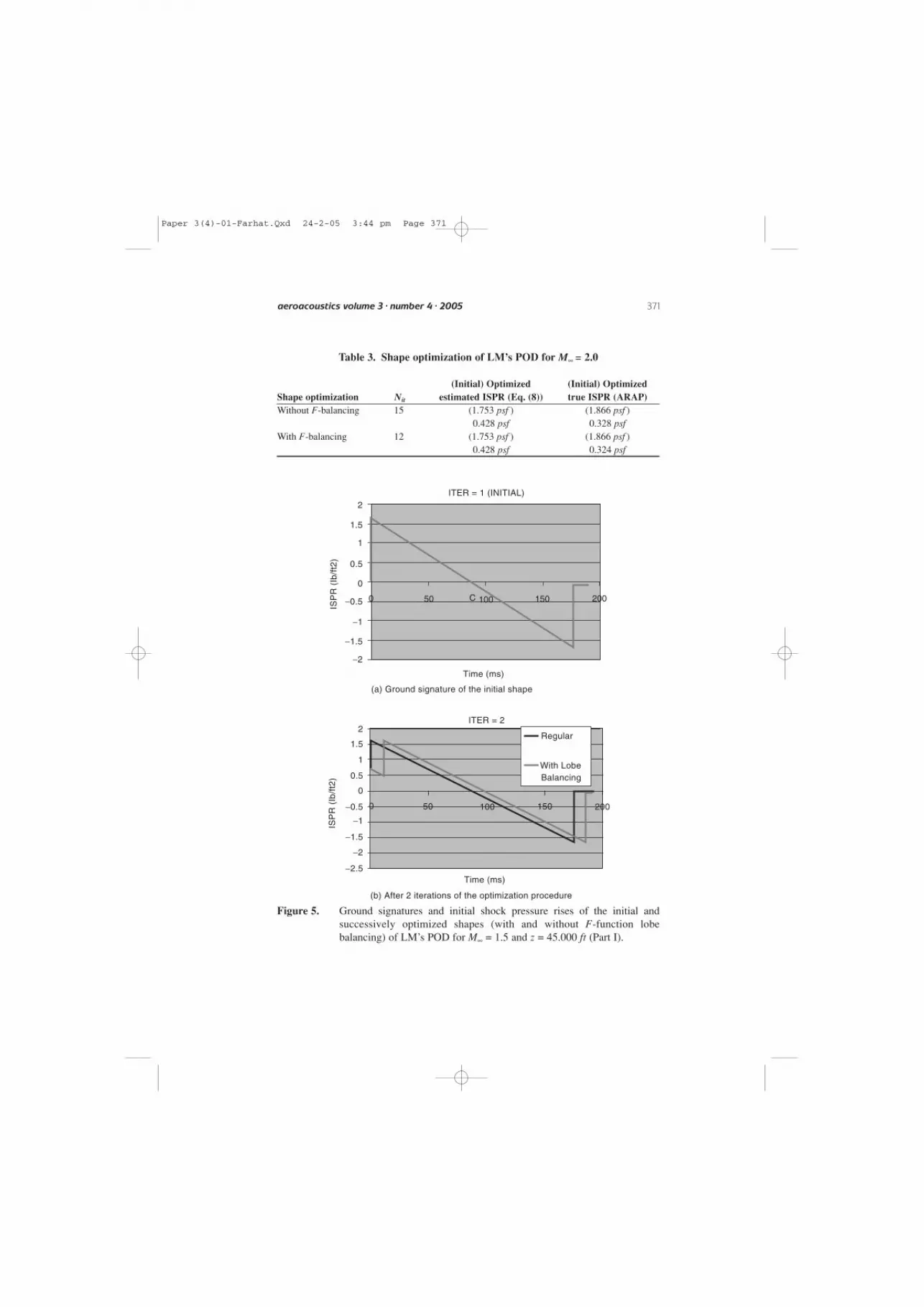
In each case, the length, lift, and inviscid (combined lift-induced and wave) drag areconstrained to remain constant. The performance results obtained for the optimizationswith and without F-function lobe balancing are summarized in Table 2 for M∞ = 1.5,and Table 3 for M∞ = 2.0. These include the number of iterations for convergence of theoptimization algorithm, Nit, and the various optimized values of the ISPR. The ISPR ispredicted using both Eq. (8) and the ARAP code. The reader is reminded that Eq. (8)assumes the worst case scenario of a two-shock (N-wave) ground signature, while theARAP code addresses multi-shock ground signatures. The ground signatures predicted byARAP during the shape optimization of LM’s POD for M∞ = 1.5 are reported in Fig. 5and Fig. 6. These ground signatures are contrasted with the ground signature predictedby the same code for the given initial shape of this candidate QSP and the same Machnumber. The optimized shapes, with and without F-function lobe balancing, are displayedin Fig. 7 for M∞ = 1.5 and Fig. 8 for M∞ = 2.0. Finally, the ground signatures predictedby ARAP for the initial shape and the shapes optimized with F-function lobe balancingfor Μ∞ = 1.5 and M∞ = 2.0 are displayed in Fig. 9.
The results reported in Table 1 and Table 2 show that• Eq. (8) and the ARAP code predict essentially the same ISPR values for the initial
shape of LM’s POD. This is because, as shown in Fig. 5(a), the initial shape ofthis aircraft has an N-wave signature on the ground. However, for each optimizedshape, ARAP predicts a significantly lower ISPR value than Eq. (8). This is because,as shown for example in Fig. (9), the ground signatures of the optimized shapesof LM’s POD are characterized by three shocks and therefore cannot be correctlypredicted by Eq. (8) which assumes a two-shock N-wave signature on the ground.
370 Shape optimization with F-function balancing for reducing the sonic boom initial shock
Table 2. Shape optimization of LM’s POD for M∞ = 1.5
(Initial) Optimized (Initial) OptimizedShape optimization Nit estimated ISPR (Eq. (8)) true ISPR (ARAP)Without F-balancing 13 (1.623 psf ) (1.616 psf )
0.594 psf 0.152 psfWith F-balancing 9 (1.623 psf ) (1.616 psf )
0.717 psf 0.083 psf
Paper 3(4)-01-Farhat.Qxd 24-2-05 3:44 pm Page 370
aeroacoustics volume 3 · number 4 · 2005 371
Table 3. Shape optimization of LM’s POD for M∞ = 2.0
(Initial) Optimized (Initial) OptimizedShape optimization Nit estimated ISPR (Eq. (8)) true ISPR (ARAP)Without F-balancing 15 (1.753 psf ) (1.866 psf )
0.428 psf 0.328 psfWith F-balancing 12 (1.753 psf ) (1.866 psf )
0.428 psf 0.324 psf
0
2
1.5
1
Time (ms)
ITER = 1 (INITIAL)
ISP
R (
Ib/f
t2)
0.5
0
−0.5
−1
−1.5
−2
2
1.5
1
Time (ms)
ITER = 2
ISP
R (
Ib/f
t2) 0.5
0
0 50 100 150 200−0.5
−1
−1.5
−2
−2.5
50 C 100 150 200
Regular
With LobeBalancing
(b) After 2 iterations of the optimization procedure
(a) Ground signature of the initial shape
Figure 5. Ground signatures and initial shock pressure rises of the initial andsuccessively optimized shapes (with and without F-function lobebalancing) of LM’s POD for M∞ = 1.5 and z = 45.000 ft (Part I).
Paper 3(4)-01-Farhat.Qxd 24-2-05 3:44 pm Page 371

Nevertheless, the results summarized in Table 1 and Table 2 confirm the suitabilityof Eq. (8) for the purpose of optimization because they highlight the ability of theoptimization methodology described in this paper, for all considered cases, to startfrom an initial shape that generates an N-wave signature on the ground, and convergeto an aerodynamic shape that generates a multi-shock signature on the ground.
372 Shape optimization with F-function balancing for reducing the sonic boom initial shock
2
1.5
1
0.5
0
0 50 150 200−0.5
−1
−1.5
−2
−2.5
ITER = 6
ITER = 9
Time (ms)
(a) After 6 iterations of the optimization procedure
ISP
R (
Ib/f
t2)
0 50 100 150 200
Time (ms)
(b) After 9 iterations of the optimization procedure
2
1.5
1
0.5
0
−0.5
−1
−1.5
−2
−2.5
ISP
R (
Ib/f
t2)
Regular
With LobeBalancing
Regular
With LobeBalancing
100
Figure 6. Ground signatures and initial shock pressure rises of the initial andsuccessively optimized shapes (with and without F-function lobebalancing) of LM’s POD for M∞ = 1.5 and z = 45.000 ft (Part II).
Paper 3(4)-01-Farhat.Qxd 24-2-05 3:44 pm Page 372

aeroacoustics volume 3 · number 4 · 2005 373
(a) Initial shape (with pressure contours)
(b) Optimized shape without F -functionlobe balancing (with pressure contours)
(c) Optimized shape with F -function lobebalancing (with pressure contours)
Figure 7. Initial and optimized shapes for minimum ISPR at M∞ = 1.5 and z = 45.000 ft of LM’s POD.
Paper 3(4)-01-Farhat.Qxd 24-2-05 3:44 pm Page 373

374 Shape optimization with F-function balancing for reducing the sonic boom initial shock
(a) Optimized shape without F -function lobe balancing(with pressure contours)
(b) Optimized shape with F -function lobe balancing(with pressure contours)
Figure 8. Initial and optimized shapes for minimum ISPR at M∞ = 2.0 and z = 45.000 ft of LM’s POD.
Paper 3(4)-01-Farhat.Qxd 24-2-05 3:44 pm Page 374

• As expected, balancing the appropriate lobes of the F-function accelerates theconvergence of the proposed optimization procedure. For M∞ = 1.5, it also leadsto an ISPR value on the ground which is twice as small as otherwise.
The mechanism responsible for this acceleration of convergence is captured in Fig. 5and Fig. 6. Indeed, the results summarized in this figure show that the shape producedby one iteration of the basic optimization method has an N-wave ground signature, butthat produced by the optimization method equipped with F-function lobe balancing hasa three-shock ground signature and therefore a lower ISPR. In the absence of F-functionlobe balancing, it takes seven iterations before a shape with a three-shock groundsignature is generated.
It is interesting to note that for M∞ = 2.0, the optimization method produces the sameshape whether F-function lobe balancing is performed or not (Fig. 8), but for M∞ = 1.5,it produces two different shapes (Fig. 7). For M∞ = 1.5, the shape of LM’s PODgenerated by the optimization method without F-function lobe balancing has the nosetilted down by an additional 1.8°, the canard surfaces swept forward by 24.9º withrespect to the initial design, twisted positively by an additional 0.7° and tilted downwith respect to the fuselage by another 0.3°, the wings swept forward by 2.2° withrespect to the initial design, twisted positively by an additional 0.2°, and tilted downwith respect to the fuselage by another 3.8°. On the other hand, the shape of this aircraftgenerated by the optimization method for M∞ = 1.5 and equipped with F-function lobe
aeroacoustics volume 3 · number 4 · 2005 375
Initial M = 1.5
Opt. M = 1.5
Initial M = 2.0
Opt. M = 2.0
2
2.5
1.5
1
0.5
0
−0.5
−1
−1.5
−2
−2.5
−3
ISP
R (
lb/f
t2)
Time (ms)
0 50 100 150 200
Figure 9. Ground signatures and initial shock pressure rises of the initial shape, andthe shapes optimized with F-function lobe balancing for M∞ = 1.5 and M∞ = 2.0 of LM’s POD.
Paper 3(4)-01-Farhat.Qxd 24-2-05 3:44 pm Page 375

balancing has the nose tilted up by an additional 0.9°, the canard surfaces swept forwardby only 19.5° with respect to the initial design, twisted positively by an additional full1.0° and tilted down with respect to the fuselage by as much as 8.5°, the wings sweptbackward by 1.8° with respect to the initial design, twisted positively by an additional2.9°, and tilted down with respect to the fuselage by another 5.2°.
Most importantly, Table 1 and Table 2 as well as Fig. 9 highlight the fact that withand without F-function lobe balancing, at M∞ = 1.5, the optimized shape of LM’s PODmeets DARPA’s goal in Phase I of a minimum ISPR below 0.3 psf, and at M∞ = 2.0, italmost meets this goal. However, Fig. 9 also suggests that it remains to reduce thestrengths of the second and aft shocks.
6. CONCLUSIONSThe computational technology has sufficiently matured in the last two decades to justifyrevisiting and automating the sonic boom minimization problem. Such an effort wasperformed at the University of Colorado, and focused on the constrained shapeoptimization of a supersonic aircraft for minimizing the initial shock pressure rise(ISPR). For this purpose, elements from the linearized sonic boom theory werecombined with elements from the nonlinear aerodynamic theory, and a computational-based low-boom shaping methodology was developed. Even though it is based onWhitham’s F-function, this methodology operates directly on the geometry of theaircraft, and addresses separately and at each iteration of the optimization process thecontributions of volume and lift. Each of its underlying design, analysis, andoptimization models is equipped to address radical changes, rather than small amplitudeperturbations, in both the geometry and topology of the initial shape of an aircraft inorder to reduce the ISPR. Wings can be twisted, swept forward or backward, cranked,or even translated along the fuselage during the optimization process without requiringany intervention from the analyst or necessitating a remeshing of the geometry. Theconcept of F-function lobe balancing was also incorporated in this shape optimizationmethodology and shown to accelerate convergence towards a shape with a multi-shockground signature. The resulting computational technology was successfully applied tothe shape optimization of a Lockheed-Martin Point of Departure aircraft. Neglecting the effect of the propulsion system, a twenty-fold reduction in the ISPR on the groundat M∞ = 1.5, from 1.616 psf to 0.083 psf, and a six-fold reduction at M∞ = 2.0, from1.866 psf to 0.324 psf, were demonstrated for this supersonic design while maintainingconstant length, lift, and combined lift-induced and wave drag.
7. ACKNOWLEDGEMENTSThe authors acknowledge the support by DARPA under the Contract DARPAMDA972-01-2-0002 (Cooperative Agreement “QSP”). They also thank ICEM CFDEngineering Inc. for providing their ICEM CFD mesh generation software.
REFERENCES[1] A. Busemann, Aerodynamischer Auftreib bei Ueberschallgeswindigkeit, Proc.
Volta Congress, 1935, 315–317.
376 Shape optimization with F-function balancing for reducing the sonic boom initial shock
Paper 3(4)-01-Farhat.Qxd 24-2-05 3:44 pm Page 376

[2] A. Busemann, The relation between minimizing drag and noise at supersonicspeeds, Proc. High Speed Aerodynamics, Polytechnic Institute of Brooklyn, 1955,133–144.
[3] High Speed Civil Transport, Program review, the Boeing Commercial AirplaneGroup, P.O. Box 3707, Seattle, WA 98124-2207.
[4] Quiet Sonic Platform (QSP), http://www.darpa.mil/tto/programs/qsp.html.
[5] J. S. Petty, Lower bounds for sonic boom considering the negative overpressureregion, J. Aircraft, 1970, 7:375–377.
[6] W. D. Hayes and F. B. Weiskopf, Optimum configurations for bangless sonicbooms, Quarterly of Applied Mathematics, 1972, 30:311–328.
[7] A. R. George and R. Seebass, Sonic boom minimization including both front andrear shock waves, AIAA J., 1969, 10:2091–2093.
[8] R. Seebass and A. R. George, Design and operation of aircraft to minimize theirsonic boom, J. Aircraft, 1974, 11:509–517.
[9] R. Seebass and B. Argrow, Sonic boom minimization revisited, AIAAPaper No. 98-2956, 29th AIAA Fluid Dynamics Conference, June 15–18, 1998,Albuquerque, New Mexico.
[10] G. B. Whitham, The flow pattern of a supersonic projectile, Commun. Pure Appl.Math., 1952, 5:301–348.
[11] C. M. Darden, Charts for determining potential minimum sonic boomoverpressures for supersonic cruise aircraft, NASA TN 1820, 1981.
[12] H. Yamaguchi and Y. Nakamura, Optimization of low boom configuration of SSTby genetic algorithm, AIAA Paper No. 98-2899, 29th AIAA Fluid DynamicsConference, June 15–18, 1998, Albuquerque, New Mexico.
[13] C. Farhat, K. Maute, B. Argrow and M. Nikbay, A shape optimization methodologyfor reducing the sonic boom initial pressure rise, AIAA Paper 2002-0145,40th Aerospace Sciences Meeting and Exhibit, January 14 –17, 2002, Reno, Nevada.
[14] K. Maute, M. Nikbay and C. Farhat, Coupled analytical sensitivity analysis andoptimization of three-dimensional nonlinear aeroelastic systems, AIAA J., 2001,39:2051–2061.
[15] L. B. Jones, Lower bounds for sonic bangs, J. Royal Aero. Soc., 1961, 433– 436.
[16] W. D. Hayes and R. C. Haefeli, The ARAP sonic boom program, Sonic BoomWorkshop, Ed. I. A. Schwartz, NASA SP-180, 1968, 151–158.
[17] P. G. Coen, Development of a computer technique for the prediction of transportaircraft flight profile sonic boom signature, M.S. Thesis, George WashingtonUniversity, 1991.
[18] R. K. Koegler, Possible means of reducing sonic booms and effects through shockdecay phenomena and some comments on aural response, Sonic Boom Research,A. R. Seebass, Ed., NASA SP-147, Washington, D.C., 1967, 95–102.
[19] K. Schittkowski, NLPQL: A FORTRAN subroutine for solving constrainednonlinear programming problems, Ana. Oper. Res., 1985, 5:485–500.
aeroacoustics volume 3 · number 4 · 2005 377
Paper 3(4)-01-Farhat.Qxd 24-2-05 3:44 pm Page 377

Paper 3(4)-01-Farhat.Qxd 24-2-05 3:44 pm Page 378


![Ultra Sonic Sensors [Persian]](https://img.pdfslide.net/doc/110x75/631cf6f01c5736defb026123/ultra-sonic-sensors-persian.jpg)