Embed Size (px)
Citation preview
International Conference on Computer Applications in Shipbuilding 2015, Bremen, Germany
© 2015: The Royal Institution of Naval Architects
SHIP WORK BREAKDOWN STRUCTURES THROUGH DIFFERENT SHIP LIFECYCLE
STAGES
Malay Pal, Siemens Industry Software, India
SUMMARY
Definition of complete and accurate work breakdown structures of a ship is an important and critical activity in every
shipbuilding project. This is required in every stage of a ship project, right from the inquiry and concept design stage, to
basic, detail and production design, and continues through definition of as-built structure, maintenance work breakdown
structure, etc., right up to defining work breakdown structures for decommissioning (for ship and offshore structures).
While the need is well understood, many shipyards and ship design organizations find it challenging to define these
work breakdown structures across all stages of a project, and to understand the linkages between these work breakdown
structures through the various phases of a design and build project. Things become more difficult when the ship or
offshore structure enters its service life, when the maintenance (and later the decommissioning) organizations are
different.
One key challenge in the definition of ship work breakdown structures is how to represent the same entity in different
structures as it moves through its lifecycle, e.g., from concept design to basic design to detail design to production
design. A new component based approach based on 4th generation of design (4GD) technology built into a PLM system
to manage ship data allows for the definition of different but linked work breakdown structures of a ship through its
different lifecycle stages.
This paper explains in detail the different work breakdown structures in shipbuilding and how 4GD technology can be
used to define and manage the same.
NOMENCLATURE
4GD 4th
Generation Design
AWBS Area Work Breakdown Structure
BOP Bill of Process
BOR Bill of Resources
CWBS Contract Work Breakdown Structure
ESWBS Expanded Ship Work Breakdown
Structure
HBCM Hull Block Construction Method
LRW Liquid Radioactive Waste
MRV Multi Role Vessel
O&M Operation and Maintenance
PLM Product Lifecycle Management
PWBS Product Work Breakdown Structure
RFP Request for Proposal
SFI Senter for Forskningsdrevet Innovasjon
SNF Spent Nuclear Fuel
SOW Statement of Work
SRW Solid Radioactive Waste
SWBS Ship or System Work Breakdown
Structure
WBS Work Breakdown Structure
ZOFM Zone Outfitting Method
ZPTM Zone Painting Method
ZWBS Zone Work Breakdown Structure
1. INTRODUCTION
A complex project like shipbuilding is made manageable
by breaking it down into individual components in a
hierarchical structure, known as the work breakdown
structure, or the WBS. Such a structure defines tasks that
can be completed independently of other tasks,
facilitating resource allocation, assignment of
responsibilities, and measurement and control of the
project. An effective WBS plays a key role in the
implementation of a shipbuilding project.
Definition of complete and accurate work breakdown
structures is required in every stage of a ship project
through its acquisition, deployment, and
decommissioning and disposal phases. While the need is
well understood, many shipyards and ship design
organizations find it challenging to define these work
breakdown structures across all stages of a project, and to
understand the linkages between them.
This paper explains the different work breakdown
structures in shipbuilding and how a new component
based approach based on 4th generation of design (4GD)
technology built into a PLM system can be used to define
and manage the same.
This paper discusses the topic using examples of naval
and other government ships, but the principles are
equally applicable to commercial ships, offshore
platforms and luxury yachts.
2. WORK BREAKDOWN STRUCTURE
A Work Breakdown Structure (WBS) breaks down the
work of a project into a hierarchical structure of
elements, in order to manage and control the scope. This
allows good definition of the work, and allows discrete,
coherent packages of work to be estimated and then

International Conference on Computer Applications in Shipbuilding 2015, Bremen, Germany
© 2015: The Royal Institution of Naval Architects
delegated. A typical example can be Figure 1, which
shows a basic WBS for the construction of a nuclear
submarine. Generically, a work breakdown structure is
defining the solution to a problem in terms of a product.
A work breakdown structure serves as a coordinating
medium. For each work breakdown structure element,
Fig. 1 : A Work Breakdown Structure for Construction of a Nuclear Submarine
the detailed technical objectives are defined and specified
work tasks are assigned to each contractor’s organization
elements, and assigned for the resources, materials, and
processes required to attain the objectives. The linkage
between the specification requirements, the work
breakdown structure, the statement of work, and the
master and detailed schedules provides specific insights
into the relationship between cost, schedule, and
performance. This relationship allows all items to be
tracked to the same work breakdown structure element.
Work breakdown structures commonly used in
shipbuilding are either systems- or product-oriented.
3. PROGRAM WORK BREAKDOWN
STRUCTURE
The Program Work Breakdown Structure provides a
framework for specifying the objectives of the program.
It defines the program in terms of hierarchically related
product-oriented elements. Each element provides logical
summary points for assessing technical accomplishments
and for measuring cost and schedule performance.
The Program WBS is developed early in the conceptual
stages of a program through systems engineering and
management planning processes. It evolves through
iterative analysis of the program objective, functional
design criteria, program scope, technical performance
requirements, acquisition strategy, and other technical
documentation.
Early in the concept exploration phase, the systems
engineering efforts are aimed at trying to establish the
user’s need. Prior to system design and development,
system requirements must be established. For naval
ships, these requirements flow down from high-level
program documents, class and other regulations, and
establish allocated mission functions assigned to specific
ships.
In Requirements Analysis, the systems engineer
identifies and documents the customer’s requirements
and translates them into a set of technical requirements
for the system. The requirements analysis should cover
the whole scope of the project, i.e., ship performance,
software, logistics, project management, safety,
environment, human resources, test and acceptance, etc.
It is essential to have a management system for user
requirements and the linkages to system requirements,
and then through to the eventual design specifications
through to the formal acceptance activities. The user (or
customer) requirements form the basis of the contract
and its acceptance, and they can then be used to manage
support of the ships through life.

International Conference on Computer Applications in Shipbuilding 2015, Bremen, Germany
© 2015: The Royal Institution of Naval Architects
Functional Analysis begins with separating an entity
(e.g., ship, system) into high-level functional categories.
During Functional Analysis/Allocation, the systems
engineer translates the requirements identified in
Requirements Analysis into a functional decomposition
that describes the product in terms of an assembly of
configuration items where each configuration item is
defined by what it must do, its required performance, and
its interfaces. Configuration items can be hardware,
software, or manpower. Functional allocation is the
process that assigns systems, subsystems, and
components to perform each function.
Functional Analysis translates the ship’s missions,
performance, goals, and other requirements into discrete
and well-defined functions. The aim of functional
analysis is to identify all of the activities that the system
is required to perform, and each of these functions should
represent what must be done, not how to do it. Functions
are broken down to the appropriate level, often to sub-
functions and functional elements, depending on the
range of functions addressed by the entity (refer
Requirements and Functional Breakdown Structures in
Figure 3). Functional elements contain detailed
descriptions of a system's functions at a level which
allows the allocation of system components (i.e.,
equipment) to these individual elements. The Program
WBS is developed at this point and precedes issue of a
formal request for proposal (RFP).
The Program WBS is included as part of the solicitation
(RFP) and used by the successful contractor to develop a
more detailed Contract Work Breakdown Structure
(CWBS) which includes all product elements (hardware,
software, data, or services) for which the contractor is
responsible.
4. CONTRACT WORK BREAKDOWN
STRUCTURE (CWBS)
The Contract Work Breakdown Structure (CWBS) is the
complete WBS for a specific contract. It is developed by
the contractor in accordance with the contract statement
of work (SOW). It includes the Program WBS elements
for the products (hardware, software, data, or services)
which are to be furnished by the contractor. Contractors
extend the Contract WBS included in the RFP and
submit the complete Contract WBS with their proposal.
A CWBS provides a consistent and visible framework
that facilitates uniform planning, assignment of
responsibilities, and status reporting.
5. SHIP WORK BREAKDOWN STRUCTURE
(SWBS)
The U. S. Navy currently uses a systems-oriented
breakdown called the Expanded Ship Work Breakdown
Structure (ESWBS). It is used throughout the entire ship
life cycle to organize and correlate elements for cost,
weight, specifications, system function and effectiveness,
design, production, and maintenance studies. Numbering
systems for ship’s drawings and related documents,
general and contract specifications, ship’s weight groups,
technical manuals, etc. are based on the ESWBS.
The US Navy's Systems Work Breakdown Structure was
originally issued in March 1973 as a structured system
(3-digit numbers providing 5 levels of breakdown) which
was intended for use in specification preparation, cost
estimating, cost progressing, management, weight
control, drawing numbering, shipyard job order coding,
and similar purposes. ESWBS provides two additional
levels of breakdown of functional systems so that
ESWBS can be used for logistic support, maintenance,
and life cycle support purposes. So ESWBS is a five digit
functional classification system, with the fourth and fifth
single digit classification levels used to incorporate the
functions that support maintenance and repair needs. For
example, for weight reporting purposes, only the first
three digits of this system apply.
SWBS groups are defined by basic function. The
functional segments of a ship, as represented by a ship’s
structure, systems, machinery, armament, outfitting, etc.,
are classified by a system of 3-digit numeric groups. The
major functional groups are :
ESWBS Group Description
000 General Guidance and
Administration
100 Hull Structure
200 Propulsion Plant
300 Electric Plant
400 Command and Surveillance
500 Auxiliary Systems
600 Outfit and Furnishings
700 Armament
800 Integration/Engineering
900 Ship Assembly and Support
Services
Table 1 : ESWBS Groups (first three digits)
ESWBS Groups 800 and 900 (refer Table 1) although a
part of the of the work breakdown structure, deal with
engineering and design support. Therefore, these items
are not required to physically describe the technical
aspects of the ship.
The ESWBS classification system allows the ship to be
specified at any of three levels : one-, two-, and three
digits. Each higher level indicates a higher degree of
technical definition, as can be seen from the examples in
Table 2 below.

International Conference on Computer Applications in Shipbuilding 2015, Bremen, Germany
© 2015: The Royal Institution of Naval Architects
(Group) 100 - Hull Structure
(Element) 101 - General Arrangement-
Structural Drawings
(Subgroup) 110 - Shell and Supporting
Structure
(Element) 111 - Shell Plating, Surface
Ship and Submarine
Pressure Hull
(Element) 112 - Shell Plating,
Submarine Nonpressure
Hull
(Subgroup) 120 - Hull Structural Bulkheads
(Element) 121 - Longitudinal Structural
Bulkheads
(Element) 122 - Transverse Structural
Bulkheads
Table 2 : An Example of the ESWBS Organisation
6. SFI GROUP SYSTEM
The SFI group system was developed at the Norwegian
Ship Research Institute (Senter for Forskningsdrevet
Innovasjon - SFI), now known as MARINTEK. The SFI
group system is an international standard which is used
for a functional breakdown of technical and economic
information of ships and offshore structures. It structures
and systemizes all the ship’s different systems and
components through a 3-digit coding structure. Through
the ships’ lifetime, the SFI coding system is used for
different purposes, like control of shipping, offshore or
shipbuilding operations. In cost management, this
structure works as a cost work breakdown structure.
The ship is divided into 10 main groups from 0 to 9, but
often only main group 1-8 are used (refer Table 3). Main
group 0 and 9 are extra posts where the user can address
costs related to the ship that does not fit into the other
main groups. The main groups are divided into 2-digit
groups which are again divided into 3-digit subgroups.
SFI Group Description
0 (reserved)
1 Ship General
2 Hull
3 Equipment for Cargo
4 Ship Equipment
5 Equipment for Crew and
Passengers
6 Machinery Main Components
7 Systems for Machinery Main
Components
8 Ship Common Systems
9 (reserved)
Table 3 : SFI Groups
7. PRODUCT WORK BREAKDOWN
STRUCTURE (PWBS)
Product Work Breakdown Structure (PWBS) was
developed to support group technology shipbuilding.
PWBS subdivides work in accordance with an interim
product view. Parts and sub-assemblies are grouped by
common permanent characteristics, and classified by
both design and manufacturing attributes. The
classification system typically specifies parameters, such
as form, dimensions, tolerances, material, and types and
complexity of production machinery operations.
Classification by product aspects relates a part or sub-
assembly to a zone of a ship and also to work processes
by problem area and by work stage.
A shipbuilder's PWBS is hardware or product oriented,
and is consistent with the methods of planning,
scheduling, and construction actually being used by the
shipbuilder. The PWBS used on a particular shipbuilding
program is based on the products produced and on the
coding system used by the shipbuilder. PWBS provides a
natural breakdown for schedule reporting and for
collection of financial data.
First, PWBS divides the shipbuilding process into three
basic types of work : hull construction, outfitting, and
painting, because each imposes its own unique set of
manufacturing problems. These types of work are further
subdivided into fabrication and assembly classifications.
Within the painting classification, fabrication applies to
the manufacture of paint, and assembly refers to its
application. The assembly subdivisions are naturally
linked to zones (see next section “Zone Work
Breakdown Structure” and Figure 3).
Second, PWBS classifies interim products in accordance
with their resource needs :
Material : e.g., steel plate, machinery, cable, etc.
Manpower : e.g., welder, fitter, rigger,
transporter, etc.
Facilities : e.g., buildings, docks, machinery,
tools, etc.
Expenses : e.g., designing, transportation, sea
trials, etc.
Third, PWBS classifies interim products by the four
product aspects needed for control of production
processes. Two of these, system and zone, are related to
the ship design function while the other two, area and
stage, are related to the production function. These four
terms many be defined as follows :
System - A structural or an operational
characteristic of a product, e.g., longitudinal or
transverse bulkhead, fuel-oil service system,
deck lighting system, etc.

International Conference on Computer Applications in Shipbuilding 2015, Bremen, Germany
© 2015: The Royal Institution of Naval Architects
Zone - An objective of production which is any
geographical division of a product, e.g., engine
room, cargo hold, operations room, etc., and
their sub-divisions, or combinations (e.g., a
structural block or outfit unit, a subassembly of
either and ultimately, a part or component).
Area - A division of the production process into
similar types of work problems which can be
- by feature (e.g., curved vs. flat panel, small
diameter vs. large diameter pipe, etc.)
- by quantity (e.g., job-by-job vs. flow lane,
etc.)
- by quality (e.g., grade of workers or
facilities required, etc.)
- by work type (e.g., marking, cutting,
bending, welding, painting, testing, etc.),
and
- by anything else that creates a manifestly
different work problem.
Stage – Various sequences in the production
cycle, e.g., preparation, fabrication, assembly,
etc.
8. ZONE WORK BREAKDOWN
STRUCTURE (ZWBS)
A zone is defined as a volume of the seaframe that
provides space, structural support, and services required
to perform a function, or a group of similar
interchangeable functions located therein. Zones share
the following :
Similar Environment
Similar Functions
Bundled Services
Examples of zones defined in ships to address particular
functions or services are Fire zone, Collision zone,
Electronics zone, Weapons zone, Underwater Sensor
zone, etc. Each zone has unique features and
characteristics that help define and distinguish it from
other types of zones.
A ship is also divided into design zones for easier
management of the ship’s design and construction, and to
aid design review. This is a spatial or geographical
division of the ship. Each zone is designed with all
piping, wiring, outfitting, machinery, and furniture to be
contained within that zone. During design review, the
reviewers can “see” all of the ship, including its interior
structure and all items to be included in the finished ship
for the zones being reviewed.
Zone Work Breakdown Structure (ZWBS) can also be
defined based on a spatial breakdown of the ship (more
from the way a ship is constructed), and is sometimes
used interchangeably with Area Work Breakdown
Structure (AWBS) - both show spatial breakdown of the
ship. In some shipyards, the AWBS is defined for Design
Zones, which are again spatial.
AWBS is also defined for a shipyard (not ship) based on
segregation of work (e.g., by feature, by work type, etc.)
as explained in the previous section.
Zone logic significantly enhances the efficiency and
productivity of design and production work by taking
advantage of the underlying similarities in the products
or subassemblies, those common characteristics
classified by both design and production attributes.
Zone logic technology concepts dictate that work be
planned and executed under a priority scheme :
1. Divide work into geographical zones carefully
considering the nature of the problems that are
involved,
2. Develop a zone oriented product and interim
product work breakdown structure,
3. Properly sequence the work to be accomplished by
stage and area,
4. Plan final systems tests as necessary.
Shipbuilding methods have consistently become more
productive during the last few decades mainly because of
the change from traditional system-oriented processes to
the following zone-oriented processes :
Hull Block Construction Method (HBCM),
Zone Outfitting Method (ZOFM), and
Zone Painting Method (ZPTM).
HBCM planners define interim products starting with a
hull as a zone, thence subdividing it into block zones
which in turn are divided into sub-block zones and so on.
The process is completed when zones are defined that
cannot be further subdivided, i.e., zones which
correspond to parts. The nature of any of these zones
associates it with a specific manufacturing level. This
regimentation is natural for hull construction but not so
for outfitting.
The Zone Outfitting Method (ZOFM) is a natural
consequence of HBCM because both employ the same
logic. Shipyards which employ ZOFM assemble most
outfit components independent of or on hull blocks.
The Zone Painting Method (ZPTM) is a natural
extension of the logic employed in both HBCM and
ZOFM. It transfers much painting work, traditionally
performed in a building dock or at an outfit pier, to
preceding manufacturing levels (on-block) by integrating
painting with hull construction and outfitting processes.
In ZPTM, a zone is not only defined by compartments
such as decks, cargo holds, engine room, etc., but also by
hull blocks, sub-blocks and components. The defined
hull blocks of ZPTM are identical to the hull blocks
defined for HBCM and ZOFM.

International Conference on Computer Applications in Shipbuilding 2015, Bremen, Germany
© 2015: The Royal Institution of Naval Architects
9. LIFECYCLE PHASES AFTER SHIP
DELIVERY
Before analysing information requirements of ship
product structure in the lifecycle phases after ship
delivery, it is worth comparing abstraction level of
product structure data used in the design/manufacturing
phases with that of product structure data in the
operations and maintenance (O&M) phases. Objects
represented in product structure in the design phase are
classes, abstract objects which do not exist in the real
world. They specify shape, physical characteristics, and
functional characteristics that members (or individuals)
of a class must have, e.g., centrifugal pump type A. On
the other hand, individuals which exist at specific time-
space in the real world should be managed in product
structure in the O&M phase in addition to classes. For
example, it is required to monitor and trace installation
time, repair history, and current status of a real pump
with tag number 0000001.
In the O&M phase, after O&M master plan is first
established from design and manufacturing data of a
product, O&M works are performed according to this
master plan, of which history is also managed. The O&M
master plan links to class-level product structure while
the O&M history connects to individual-level product
structure. Therefore, information model of ship product
structure should support both class- and individual- level
product structures and couple them together.
Information model for supporting ship product structures
is discussed in section 11.
10. DECOMMISSIONING
Decommissioning and disposal activities present their
own unique set of challenges, and the legal obligations
required of operators and those contracted with the work
are demanding and detailed. Maintaining complete
compliance and operational best practices is fundamental
to the success of the entire decommissioning process,
which means operators and the contractors assigned need
to carefully plan, execute and follow-up the
decommissioning work.
Decommissioning is also very important in offshore and
for nuclear powered ships/submarines. To keep the
length of this paper within reasonable limits, this topic is
not discussed further. Only an example of the work
breakdown structure for dismantling of a nuclear
submarine is given below (Figure 2) :
Fig. 2 : A Work Breakdown Structure for Dismantling of a Nuclear Submarine (LRW : Liquid Radioactive Waste,
SRW : Solid Radioactive Waste)
11. INFORMATION REQUIREMENTS OF
SHIP PRODUCT STRUCTURES
Definition of complete and accurate work breakdown
structures of a ship is an important and critical activity in
every shipbuilding project. This is required in every stage

International Conference on Computer Applications in Shipbuilding 2015, Bremen, Germany
© 2015: The Royal Institution of Naval Architects
of a ship project, right from the inquiry and concept
design stage, to basic, detail and production design, and
continues through definition of as-built structure,
maintenance work breakdown structure, etc., right up to
defining work breakdown structures for
decommissioning.
Views on the same product are different from each other
depending on lifecycle phases or application purposes,
which lead to different product structures for the same
product. Ship product structure evolves from a rough
structure to more detailed structures during the course of
a project – from system-oriented product views in the
conceptual and basic design phases to block-oriented
product views in the detailed design phase, to zone-
oriented product views in the manufacturing design
phase. Later, near the end of the contract, the
transformation back to a system orientation occurs to
permit overall ship evaluation, in terms of both systems
performance and cost performance. The information
model of ship product structures should be able to
support these multiple product views.
In pre-design (initial/contract) design, basic design and
detail design phase, the product tree for outfitting is
defined based upon the SWBS (System Work
Breakdown Structure) which is composed of the
functional unit of the outfitting equipment. The early
stage of ship design is the basis for developing the
product structure and SWBS since the ship consists only
of systems. A hull block tree, outfitting equipment,
building specification, and schematic P&ID, for example,
are linked to the product structure represented by SWBS.
During production design phase, the product is designed
based on the hull block structure on which units or parts
of outfitting equipment are installed, which depends on
block division planning. During this phase, production
information such as process (stage), workplace and
production schedule is determined. This stage of design
is used to define the actual geometry of interim products
that capture the joining of blocks, the mounting of outfit
and equipment items, the process plan, and production
schedule.
The design phase which expresses the system structure to
the block and zone of the hull structure in the 3D
geometry is also called transition design phase.
Transition design starts part way through functional
design (under initial and basic design phases) and is
characterized by the layout of major distributive systems
into 3D and the arrangement of key compartments or
areas , e.g., the machinery spaces.
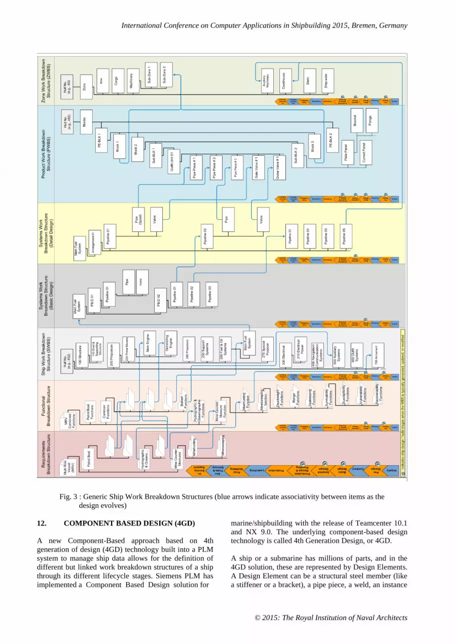
In systems trees (like Ship or Systems Work Breakdown
Structures in Figure 3), each parent product or
component part is associated with its system. In block
tree (Product Work Breakdown Structure in Figure 3),
each parent product or component part is associated with
its block. For outfitting work, each outfitting parent
product or component part is associated with a virtual
Zone Work Breakdown Structure which is a zone tree
(refer Figure 3).
In outfitting work, usually different types of equipment,
i.e., a mechanical part, electrical part and piping part, are
assigned to the same zone since all the
installation/assembly operations are associated with the
same zone. When the work breakdown structure of a hull
block and zone is generated in process planning, the
outfitting system is divided into manufacturing parts and
installation parts that are connected to the block and zone
structures.
In addition to supporting multiple product views, the
information model for defining ship work breakdown
structures should associate the product structure with the
product data. The product data includes not only
information of Product, Process, Resource, and
Production schedule but also 2D drawing, document,
production method and the attributes of each component.
Specifying the sequence of processes required to obtain
the product as well as the materials and resources (work
centers) required for each process would lead to the
development of Bill of Process (BOP) and Bill of
Resources (BOR). So the generic work breakdown
structure diagram shown in Figure 3 can be expanded
further (to the right) to add trees for Bill of Process and
Bill of Resources. However, this is not elaborated further
in this paper because of the limitations in showing a very
big diagram. The information model should allow
components of each product structure to be linked
together as the ship project progresses so that their
evolution can be traced (the blue arrows in Figure 3 show
this link or associativity), and should allow full
traceability at any point in time.
International Conference on Computer Applications in Shipbuilding 2015, Bremen, Germany
© 2015: The Royal Institution of Naval Architects
Fig. 3 : Generic Ship Work Breakdown Structures (blue arrows indicate associativity between items as the
design evolves)
12. COMPONENT BASED DESIGN (4GD)
A new Component-Based approach based on 4th
generation of design (4GD) technology built into a PLM
system to manage ship data allows for the definition of
different but linked work breakdown structures of a ship
through its different lifecycle stages. Siemens PLM has
implemented a Component Based Design solution for
marine/shipbuilding with the release of Teamcenter 10.1
and NX 9.0. The underlying component-based design
technology is called 4th Generation Design, or 4GD.
A ship or a submarine has millions of parts, and in the
4GD solution, these are represented by Design Elements.
A Design Element can be a structural steel member (like
a stiffener or a bracket), a pipe piece, a weld, an instance

International Conference on Computer Applications in Shipbuilding 2015, Bremen, Germany
© 2015: The Royal Institution of Naval Architects
of a standard part (e.g., flange), an individual length of
HVAC duct, or a specific cable hanger.
A Collaborative Design is an overall collection of Design
Elements. It is a single container for all the design data
that comprises a ship or a class of ships. A Design
Element is an independently managed occurrence of
design data within a Collaborative Design. The design
data is authored and modified by a multi-disciplinary
team of contributors, and is available for downstream
use, e.g., manufacturing.
Each Design Element has a specific business purpose and
is managed independently in the following ways :
Has its own access privileges (i.e., read/write)
Has its own maturity status (i.e., in work, being
checked, released)
Has its own position in ship coordinates
Has its own set of attributes (e.g., pump
operating pressure for each pump instance)
Has its own revision history
Has its own unit effectivity
Has its own locking status (checked out /
checked in)
In Component-Based Design, there is no product-level
assembly structure. A Design Element is a declared
member of a Collaborative Design – it is not a child of a
Collaborative Design. So the millions of Design
Elements that comprise the members of a Collaborative
Design are essentially a large flat collection of design
data.
Partitions provide a way for a user to organize product
data (Design Elements) in a traditional hierarchical
manner as per the requirement. As explained earlier, in
shipbuilding different product views are required as ship
design proceeds, so there are multiple work breakdown
structures like ESWBS, PWBS, AWBS, ZWBS, etc. So
each of these different product views or work breakdown
structures are defined as different Partition Schemes.
Partition Scheme hierarchies provide a logical way to
organize the millions of Design Elements in multiple
ways. A Collaborative Design can have one or more
Partition Schemes for organizing data. This is explained
in Figure 4 below. There is no limit to the number of
Partition Schemes which can be defined for a
Collaborative Design, which means any number of work
breakdown structures or views of a ship can be
generated. Figures 5 to 7 show different Partition
Schemes representing ESWBS, AWBS and PWBS for a
Multi Role Vessel (MRV).
Fig. 4 : Collaborative Design, Partitions and Partition Schemes

International Conference on Computer Applications in Shipbuilding 2015, Bremen, Germany
© 2015: The Royal Institution of Naval Architects
Fig. 5 : System Partition Scheme (ESWBS) for a Multi Role Vessel (MRV)
A Design Element may be a member of multiple partition
hierarchies, and may also appear in more than one
partition node within a single partition hierarchy. For
example, in a system-based partition hierarchy (like
ESWBS), a generator is part of an electrical power
system, generator cooling system, and the fuel system.
The same generator is also in the engine compartment
zone in a zone-based partition hierarchy (like ZWBS).
The design data does not change while creating and
modifying the partition hierarchies. Partitions are used
only to organize the Design Elements into multiple
views. In addition, Partitions can be populated manually
(i.e., user assigns a Design Element as a member of a
specific Partition), or Partitions can be populated
dynamically (i.e., a Partition declares a Design Element
to be its member because the Design Element lies within
a specified volume area, or the Design Element has a
certain attribute value defined).
Partitions hierarchies are navigated as an indented tree,
which provides a convenient and natural way to browse
and navigate product data.
The Design Element is also a versatile object where the
business decides the level of detail needed for each type
of design data in the overall ship design. For example,
each pump assembly unit placed on different ship decks
can be its own Design Element, all steel plates
throughout the entire ship can each be a Design Element,
each Weld can be a Design Element, and even the hull
surface definition can be managed as a Design Element.
The shipbuilder has the option to decide the level of
granularity for independently managed critical design
data, and defines these as the Design Elements in the ship
Collaborative Design.

International Conference on Computer Applications in Shipbuilding 2015, Bremen, Germany
© 2015: The Royal Institution of Naval Architects
Fig. 6 : Area Partition Scheme (AWBS) for the MRV (Green lines show Area Boundaries in Drawing)
Fig. 7 : Product Partition Scheme (PWBS) for the MRV (Red dotted lines show Block Boundaries in
Drawing)

International Conference on Computer Applications in Shipbuilding 2015, Bremen, Germany
© 2015: The Royal Institution of Naval Architects
Taking the example of the Product Partition Scheme
(PWBS) of the Multi Role Vessel shown in Fig. 7 above
further, we can expand the PWBS to lower levels for
definition of the interim products right up to the
individual part level. The individual part is a Design
Element as explained at the beginning of this section.
This is shown in Figures 8 to 11 below.
Fig. 8 : PWBS for the MRV showing one Grand Block
Fig. 9 : PWBS for the MRV showing Blocks

International Conference on Computer Applications in Shipbuilding 2015, Bremen, Germany
© 2015: The Royal Institution of Naval Architects
Fig. 10 : PWBS for the MRV showing Sub-Block
Fig. 11: PWBS for the MRV showing Assembly, Sub-Assemblies, and Fabricated Parts (up to the Design
Element level)
A careful observation of the Partition Schemes shown in
Figures 4 and 7 will show that they represent two
different Product Work Breakdown Structure (PWBS)
for the same ship (MRV). This in effect means the two
PWBSs are for two different build strategies. So it is very
easy to define and assess alternate build strategies in
4GD using Partition Schemes.
It is not necessary to define partition hierarchies prior to
the start of a project or program. While some partition
hierarchies may be fully understood at the start of a

International Conference on Computer Applications in Shipbuilding 2015, Bremen, Germany
© 2015: The Royal Institution of Naval Architects
program, there is no penalty or design impact for
defining a new partition while a program is already in
progress, and no impact for extending and/or altering an
existing partition hierarchy. Moreover, since Partitions
are completely separate from the design data of the
Design Elements, the partition assignment of Design
Elements can be easily changed.
13. 4GD AND PLM
The Siemens PLM 4GD component-based design
solution is fully immersed in the Teamcenter PLM
backbone. This effectively integrates shipbuilding-
capable design tools within a rich PLM backbone, and
provides the ability to effectively manage not only the
design information for a given ship, but the whole
product development process, including the design itself
and all related information across the lifecycle for
families of ships as they evolve.
Apart from the ability to define different product views
(or WBS) of a ship, submarine or offshore structure as it
evolves through its lifecycle, there are several other
advantages of the Siemens PLM 4GD component-based
design solution as below :
Management of End-to-End Product Data across
the Product Lifecycle
Workflow automation and Change Management
Versioning and Controlled Evolution of Product
Data
Ship / Hull effectivity / Carry over within ship
class or from sister ships
Enable multiple users collaborating or working
in parallel on alternative designs without
duplication
Capture of stable product baselines for
certification of contract milestones and support
for historical configuration
Support for Multi-CAD design content and
flexible round-trip supplier data exchange
14. CONCLUSION
Recent trends in the engineering information
management technology of the shipbuilding industry are
characterized by the spread of the product lifecycle
management (PLM) concept and an increased demand on
better use of ship engineering data after ship delivery.
Product structure data, explicit hierarchical assembly
structures representing assemblies and the constituents of
those assemblies, form the backbone of all engineering
data managed by PLM systems. Since core information
managed by PLM systems is product structure, a suitable
information model which can efficiently define and
manage the various ship work breakdown structures
through different ship life cycle stages is required. The
new Component Based Design solution for
marine/shipbuilding based on 4th generation of design
(4GD) technology with Teamcenter PLM backbone
addresses these requirements.
15. REFERENCES
1. BMT Defence Services, ‘White Paper : The
Procurement of Naval and Government Ships’,
http://www.bmtdsl.co.uk/media/1058725/BMTD
SL-Naval-Ship-Procurement-Whitepaper.pdf
2. MARCANTONIO, Raymond T., SANFORD, E.
Gregory, TILLMAN, David S., LEVINE,
Andrew J., ‘Addressing the Design Challenges
of Open System Architecture Systems on U.S.
Navy Ships – Building Out of the Box’,
http://media.bmt.org/bmt_media/resources/39/m
astpapervariablegeomfinalv8.pdf
3. DOERRY, Capt. Norbert H., ‘Systems
Engineering and Zonal Ship Design’,
http://www.doerry.org/norbert/papers/060501Sy
stemsEngineeringZonalShipDesign.pdf
4. LEE, Jang Hyun, KIM, Seung Hyun, LEE,
Kyungho, ‘Integration of evolutional BOMs for
design of ship outfitting equipment’, Computer-
Aided Design 44 (2012) 253-273
5. MUN, Duhwan, DO Namchul, CHOI
Wooyoung, ‘Information model of ship product
structure supporting operation and maintenance
after ship delivery’, PLM11 8th International
Conference on Product Lifecycle Management,
2011.
6. ‘Chapter 7 – Earned Value Management’,
http://www.navsea.navy.mil/Portals/103/Docum
ents/SUPSHIP/SOM/Ch%20%207%20-
%20Earned%20Value%20Management.pdf,
2011.
7. MORRIS, Brett, ‘A Process to Establish the
Common Functions Performed by a Multi-Role
Vessel’, Maritime Platforms Division, DSTO,
Australia, 2010.
8. DALPIAZ, Theresa M., MILLER, Gerald,
McQUILLAN, Darren, EMMRICH, Martin,
‘Conducting A Human Factors Engineering 3-D
Computer Modeling Ship Design Review’,
http://media.bmt.org/bmt_media/resources/39/C
onductingaHFE3-
DCopmuterModelingShipDesignReview.pdf
9. BRESLER, Stewart, STRUCKO, Amy,
SICKING, Paul, ‘Next-Generation Design
Paradigm for Shipbuilders’, SIEMENS White
Paper, 2013
10. SAWE, ‘Weight Estimating and Margin Manual

International Conference on Computer Applications in Shipbuilding 2015, Bremen, Germany
© 2015: The Royal Institution of Naval Architects
For Marine Vehicles’, International Society of
Allied Weight Engineers, Inc., U.S., 2001
11. SCOTT, Jaime A., ‘A Strategy for Modelling
the Design-Development Phase of a Product’
(Thesis), University of Newcastle, 1999.
12. U.S. DoD, ‘Department of Defense Handbook –
Work Breakdown Structure’, MIL-HDBK-881,
1998.
13. NASA, ‘Work Breakdown Structure
Reference Guide’, National Aeronautics and
Space Administration, U.S., 1994.
14. NSRP, ‘Strategizing and Executing the
Implementation and Utilization of Zone
Technology at Philadelphia Naval Shipyard’,
Naval Surface Warfare Center, U.S., 1989.
15. HEFFRON , John S., ‘The Impact of Group
Technology-based Shipbuilding Methods on
Naval Ship Design and Acquisition Practices’
(Thesis), Massachusetts Institute of Technology,
1988.
16. BRADLEY, Cecil D., ‘A Statistical Analysis of
Surface Escort Cost Estimation’ (Thesis), Naval
Postgraduate School, U.S., 1988
17. NSRP, ‘Painting On-block – The Zone Painting
Method Advantage’, Naval Surface Warfare
Center, U.S., 1986
18. U.S. Department of Commerce – Maritime
Administration & Todd Pacific Shipyards
Corporation, ‘Product Work Breakdown
Structure’, Naval Surface Warfare Center, U.S.,
1980.
16. AUTHORS BIOGRAPHY
Malay Pal currently holds the position of Director –
Shipbuilding in the Industries group of Siemens Industry
Software. He is responsible for solution consulting
activities for the shipbuilding, marine and offshore
industry, and is a member of the dedicated global team in
Siemens Industry Software for the marine industry.
Malay’s previous experience includes 12 years working
with IBM in a variety of roles including leading IBM’s
activities in the shipbuilding and marine industry in India
and the Asia Pacific. He has over 25 years’ experience in
working with the shipbuilding industry, both naval
(warships, submarines) and commercial, in the areas of
design, construction and data management.


