Embed Size (px)
Citation preview

XII International Conference on Computational Plasticity. Fundamentals and ApplicationsCOMPLAS XII
E. Onate, D.R.J. Owen, D. Peric and B. Suarez (Eds)
SIMULATION OF MATERIAL CONSEQUENCES INDUCEDBY FSW FOR A TRIGONAL PIN
J.C. ROUX, E. FEULVARCH AND J.M. BERGHEAU
Universite de Lyon, ENISE, LTDS, UMR 5513 CNRS58 rue Jean Parot, 42023 Saint-Etienne cedex 2, France
e-mail: [email protected], [email protected], [email protected]
Key words: Friction Stir Welding, Finite Element, Meshing technique, Advection Equa-tion
Abstract. The numerical simulation of Friction Stir Welding processes involves thecoupling of a solid mechanics approach under large strains and large strain rates and heattransfer. The eulerian formalism leads to specially e!cient finite element simulations ofthe matter flow under steady conditions. But with such a formulation, the calculation ofthe consequences induced by the stirring on the material (stirred state, microstructure,etc.) requires the coupling of advection equations for integrating the associated statevariables. In this paper, a moving mesh strategy is proposed for the numerical simulationof Friction Stir Welding and material consequences, for complex pin’s geometries. Thenumerical processing is detailed and the e!ciency of the proposed method is discussed ona Friction Stir Welding simulation of 7075 series aluminum alloy.
1 Introduction
Numerical simulation of friction stir welding process is of growing interest in industrydue to its ability to give an assembling solution in situations where all others conventionalwelding processes fail. This simulation needs to couple a solid mechanics approach underlarge strains and large strain rates with heat transfer so as to account for the temperatureraise coming from the dissipated viscoplastic power and the friction between the pin andthe matter. Several finite element formulations have been proposed to simulate the matterflow during the process. With a lagrangian formalism, an explicit step by step analysis isperformed to follow the rotation of the pin. If such simulations give useful informationsfor the stage corresponding to the penetration of the pin into the material, it leads to verytime consuming simulations to get the material flow under steady conditions. In addition,as the mesh follows the matter flow, the large distortions of the latter leads to unacceptableelement distortions and the local modeling of thermal and mechanical e"ects requires veryfine meshes in the vicinity of the stirring zone leading to significant size problems. This can
Simulation of material consequences induced by FSW for a trigonal pin
1274

J.C. ROUX, E. FEULVARCH AND J.M. BERGHEAU
be avoided by means of a re-meshing procedure refining discretization only in the vicinityof the welding zone but this again increases the computing time. The Arbitrary LagrangianEulerian approach (ALE) can be used to obtain realistic computation times [1, 2, 3]. Thisconsists in introducing a relative velocity between the mesh and the base material inorder to decrease the distortions of the mesh. An alternative approach consists in usingmeshless techniques such as the Smoothed-Particle Hydrodynamics (SPH) [4, 5] or theMoving Particle Semi-implicit (MPS) method [6]. Anyway, as transient simulations mustbe performed, these approaches are complicated to implement and very time consuming[1, 7].
As most of welding processes, the Friction Stir Welding process involves a small sizewelding zone compared to that of the studied structure. It is very often assumed that asteady state is reached when the welded structure displays a translational geometry ona long distance. Therefore, the thermo-mechanical fields during the steady phase of theprocess can be calculated using a steady analysis with a reference frame linked to thewelding velocity in an Eulerian formalism [8, 9, 10, 11], thus significantly reducing thecomputational e!orts by avoiding the transient analysis. But it is obvious that such asteady state can only exist with axisymmetric tools.
For non-axisymmetric tools, a periodic state can be assumed, whose period dependson the tool’s geometry. In this case, the finite element simulation of the periodic phase ofthe process can be achieved within an Eulerian formalism coupled with a simple movingmesh technique as suggested by Feulvarch et al. [12]. The mesh is composed of 2 parts :a first one which is fixed around the stirring zone and a second one which includes thebase material near the tool and moves with a rotational solid motion corresponding tothe tool’s rotational velocity. Therefore, there are no mesh distortions. Moreover, theEulerian formalism leads to satisfactory computing times which constitute a real numericalchallenge [13].
The main di"culty induced by the Eulerian formalism is that the history of the materialis not known a priori. Indeed, the mesh does not follow the material. Thus, the history ofthe material must be integrated for knowing the state of the base material at any pointof the workpiece in terms of level of stirred state or other physical quantities such asthose linked to the microstructure. These quantities are not just interesting in the post-processing of a thermomechanical computation but also during the thermomechanicalsimulation itself because the material behavior may depend on them. To overcome thisdi"culty, we propose in this paper, to couple the thermomechanical problem with anadvection equation. Unfortunately, it will be shown that the moving mesh techniqueinitially proposed by Feulvarch et al. does not properly handle the advection equation fornumerical considerations. A variant of this approach is thus proposed so as to treat theadvection problem. At last, the capacity of the method proposed is discussed in the caseof the friction stir welding simulation of 7075 series aluminum alloy.
1275

J.C. ROUX, E. FEULVARCH AND J.M. BERGHEAU
2 Physical model
2.1 Material flow
The material flow is governed by the momentum balance equation where inertial e!ectsare neglected. For the momentum equation, it is possible to adopt Stokes assumptionby considering that viscous stresses are predominant [14]. Within this framework, themomentum equation is given by :
div(!) = 0 (1)
where ! is the Cauchy stress tensor.The mechanical behavior law must be able to represent both the pasty behavior in the
vicinity of the tool and the plastic behavior with infinitesimal distortions on the edges ofthe iron sheets. Within the Eulerian formalism, the material is modeled as a temperaturedependent non Newtonian fluid through the following relation :
S = 2µD (2)
where S is the deviatoric stress tensor, µ is the dynamic viscosity and D is the strain ratetensor.
Viscosity can be defined in di!erent ways. The simplest approach consists in assu-ming that stresses only depend on the strain rate, and not on the strain itself, throughthe Norton-Ho! law. It involves the consistency K of the base material as well as thesensitivity m to the strain rate, both parameters being temperature dependent :
µ = K (!3Deq)
m!1 (3)
where Deq =!
2/3D : D represents the equivalent strain rate.Modeling the tool-material mechanical contact is certainly one of the most complex
aspects. The thickness of the boundary layer is estimated to be 1mm maximum around thetool. Various models can be used to treat this boundary layer trough a friction coe"cient,such as Norton’s model, for instance, which is very similar to Norton-Ho! behavior law[1] :
" = #K"vtool # v"q!1 (vtool # v) (4)
where # is a coe"cient related to the nature of the interface and q is the sensitivity ofthe tangent stress " at the sliding velocity vtool # v. vtool and v correspond respectivelyto the local velocity of the tool and the material outside the boundary layer.
2.2 Heat transfer
Friction Stir Welding involves no external heat source. Dissipation due to stirring ofthe material and its friction on the tool are su"cient to cause temperature rise in themacroscopic scaling thus allowing welding in the solid state. Heat transfer is governed bythe heat equation :
Q+ div($ gradT ) = %C&T
&t+ %C vcv gradT (5)
3
1276

J.C. ROUX, E. FEULVARCH AND J.M. BERGHEAU
where Q denotes the volumetric source term ; ! denotes the thermal conductivity ; " isthe volumetric density ; C is the specific heat ; T is the temperature ; vcv is the convectivevelocity corresponding to the Eulerian formalism.
The partial derivative problem governing thermomechanical coupling consists in jux-taposing the partial derivative problem related to heat di!usion with the problem relatedto mechanical phenomena. Both problems are coupled by :
– the mechanical power dissipated, involved as an internal source term in the heatequation,
– the influence of the material flow velocity on the thermal convection term,– the temperature dependence of the mechanical behavior.
The volumetric source term Q involved in the heat equation corresponds to the mechanicalpower dissipated per unit volume. It can be expressed from the stress and the strain rateas follows :
Q = #S : D (6)
where # is the Taylor-Quinney coe"cient ranging from 0.9 to 1 corresponding to the partof the mechanical power dissipated as heat.
With regard to heat transfer, the heat flux received by the welded sheets from theambient air is modeled from a heat exchange coe"cient Hext. Likewise, modelling thethermal contact between the sheets and the welding support is performed by means of anexchange coe"cient Hcontact. With regard to the tool-material interface, the heat dissipa-ted resulting from the friction of the matter on the tool is given by :
qinterface = # $ (vtool ! v) (7)
# has been defined in (6) and is also taken into account in this expression as the mechanicalpower does not entirely dissipate as heat in the boundary layer. A part #material of theheat dissipated is received by the base material and the other part is absorbed by thetool. As the thermo-mechanical coupling involved by Friction Stir Welding is very strong,the thermal and mechanical analyses must be performed simultaneously.
2.3 Integration of the material’s history
The simulation of the mechanical properties after welding requires to know the historyof the material. Di!erent approaches can be used to integrate the history of the mate-rial in an Eulerian formalism. The first one consists in integrating the physical quantitiesalong the trajectories corresponding to the stream lines in a stationnary configuration[10, 15]. This is not easy to do in 3D. An alternative approach consists in using an advec-tion equation. This technique does not require any integration of the physical quantitiesalong the trajectories passing through each integration point of the elements of the finiteelement mesh. Let’s assume that the physical quantity observed is governed by a di!eren-tial equation of the following type (phase proportions, fraction of hardened precipitates,
4
1277

J.C. ROUX, E. FEULVARCH AND J.M. BERGHEAU
equivalent strain,...) :du
dt= F
!
u, T,dT
dt,D, . . .
"
(8)
In the context of the Eulerian formalism, this leads to
!u
!t+ vcv grad u = F
!
u, T,dT
dt,D, ...
"
(9)
This expression constitutes the advection equation. The solution of this equation gives thedistribution of u in space at each time step without needing to compute the trajectoriesof the material during the welding step and the rotation of the tool. In this paper, wepropose to apply this formulation to compute the equivalent strain "eq. The interest ofintegrating the equivalent strain is that it can allow access to the stirred state of thematerial after welding and therefore the state of restoration for hardened alloys.
3 Finite element modeling
3.1 Discretization
To model the incompressible non Newtonian flow, finite element modeling faces a nu-merical di!culty. The discretization used must be chosen in a sensible way to avoid lockingphenomena leading to an unrealistic solution. From a mathematical point of view, thiscan be explained by the fact that the velocity field must be su!ciently rich to satisfyboth strain balance and incompressibility. In this work, the set of equations is solvedusing a tetrahedral element P1+/P1 detailed in [16], with which it is very easy to create amesh for tools with complex geometries. This element is known to be very e!cient in thecontext of large strain and strain rates. For this tetrahedral element, the discrete fields ofpressure, temperature and equivalent strain are linear and continuous :
ph(x) =N#
i=1
phi Ni(x) ; T h(x) =N#
i=1
T hi Ni(x) ; "heq(x) =
N#
i=1
"heqi Ni(x) (10)
In these expressions, N denotes the number of nodes ; phi , Thi and "heqi the values of the
functions ph, T h and "heq at node i and Ni(x) the shape function associated to this node.The approximation of the velocity is as follows :
vH(x) =N#
i=1
vhi Ni(x) +
M#
j=1
vbj N
bj (x) (11)
whereM is the number of elements, vhi the value of the velocity at node i. vb
j is the velocityvalue at each added internal node and N b
j (x) denotes the associated shape function whichequal to zero on the element boundaries. An implicit (backward) Euler algorithm tole-rating relatively large time steps is adopted for time integration of the temperature andthe equivalent strain [17] : This discretization has the advantage of being unconditionallystable.
5
1278

J.C. ROUX, E. FEULVARCH AND J.M. BERGHEAU
3.2 Weak formulation
To apply the finite element method, the weak integral formulation of the coupledproblem is written in the discrete form as follows :
Find functions T h, vH , ph, !heq such as for all functions "h, wH , qh, #h
!""""""""""""""""""#
""""""""""""""""""$
%
!
$C%T
%t
h
"h dV +
%
!
$C vcv .gradT h ("h + &h) dV
+
%
!
'gradT h .grad"h dV !%
!
Q"h dV !%
!!q
q "h dS = 0
%
!
2µD(vH) : D(wH) dV !%
!
ph div(wH) dV !%
!!!
wH ( dS = 0
%
!
qh div(vH) dV = 0
%
!
%!eq%t
h
#h dV +
%
!
&vcv .grad !heq
'(#h + )h) dV !
%
!
Deq #h dV = 0
(12)
where "h, wH , qh and #h are discrete test fields builded respectively in the same way asT h, vH , ph and !heq. To deal with the advection term, &h and )h are discrete test fieldsdefined from the SU method (Streamline-Upwind).
3.3 Moving mesh strategy
As explained in the previous sections, the thermo-mechanical phenomena are stronglycoupled. In order to solve this problem, a staggered approach could be used where thethermal problem and the mechanical problem are treated independently. But the impor-tance of the couplings incites to prefer an approach where both problems are treatedsimultaneously to obtain the spatial distributions of temperature and velocity. Then, theequivalent strain can be computed using the advection equation. If the material beha-vior depends on the equivalent strain, a fully coupled approach could be used but thisis not the case for the example proposed in the last part of this paper. Therefore, thethermomechanical problem does not depend on the results of the advection problem. So,the calculation of the equivalent strain is performed in a second step using the equivalentstrain rate resulting from the thermomechanical computation.
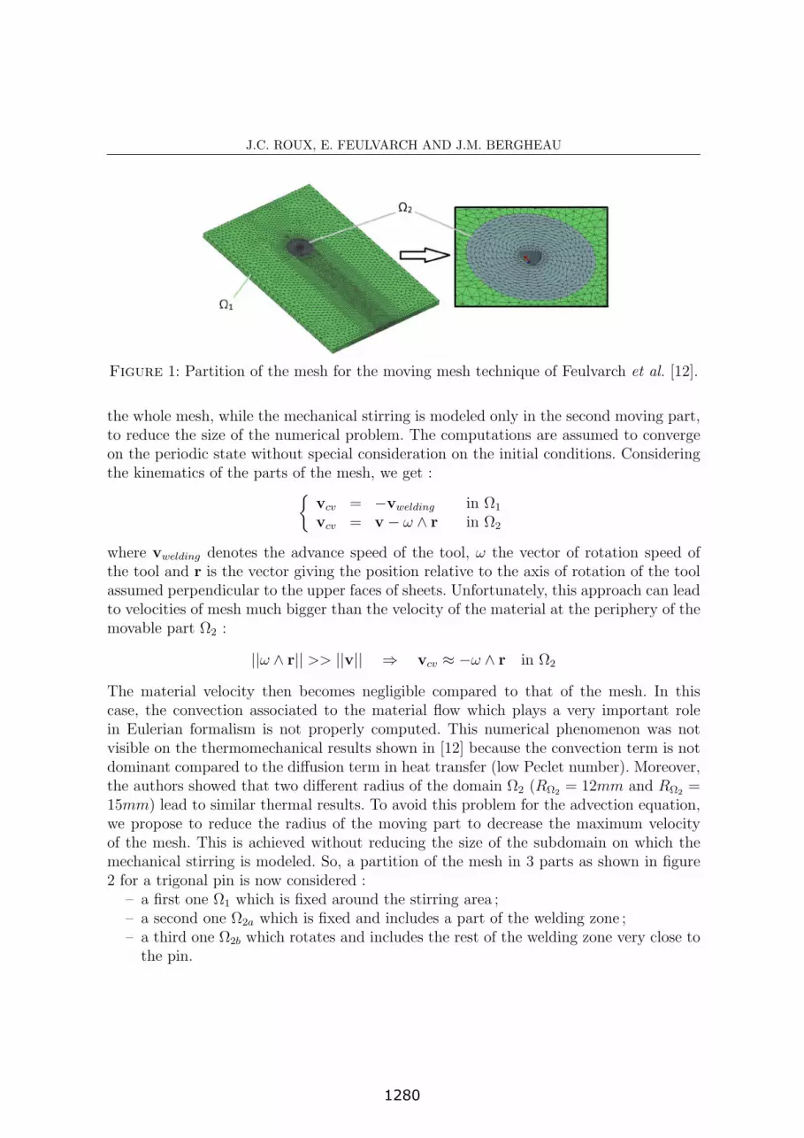
For complex tool geometries, the computation can be carried out using the movingmesh strategy proposed by Feulvarch et al. [12]. This approach is based on a partition ofthe mesh in 2 parts as shown in figure 1 : a first one called !1 which is fixed around thestirring zone and a second one called !2 which includes the base material in contact withthe tool. The second part !2 is circular with a radius R!2 and moves with a rotational solidmotion at a rotational velocity equal to the one of the tool. Heat transfer is computed on
6
1279
J.C. ROUX, E. FEULVARCH AND J.M. BERGHEAU
Figure 1: Partition of the mesh for the moving mesh technique of Feulvarch et al. [12].
the whole mesh, while the mechanical stirring is modeled only in the second moving part,to reduce the size of the numerical problem. The computations are assumed to convergeon the periodic state without special consideration on the initial conditions. Consideringthe kinematics of the parts of the mesh, we get :
!vcv = !vwelding in !1
vcv = v ! ! " r in !2
where vwelding denotes the advance speed of the tool, ! the vector of rotation speed ofthe tool and r is the vector giving the position relative to the axis of rotation of the toolassumed perpendicular to the upper faces of sheets. Unfortunately, this approach can leadto velocities of mesh much bigger than the velocity of the material at the periphery of themovable part !2 :
||! " r|| >> ||v|| # vcv $ !! " r in !2
The material velocity then becomes negligible compared to that of the mesh. In thiscase, the convection associated to the material flow which plays a very important rolein Eulerian formalism is not properly computed. This numerical phenomenon was notvisible on the thermomechanical results shown in [12] because the convection term is notdominant compared to the di"usion term in heat transfer (low Peclet number). Moreover,the authors showed that two di"erent radius of the domain !2 (R!2 = 12mm and R!2 =15mm) lead to similar thermal results. To avoid this problem for the advection equation,we propose to reduce the radius of the moving part to decrease the maximum velocityof the mesh. This is achieved without reducing the size of the subdomain on which themechanical stirring is modeled. So, a partition of the mesh in 3 parts as shown in figure2 for a trigonal pin is now considered :
– a first one !1 which is fixed around the stirring area ;– a second one !2a which is fixed and includes a part of the welding zone ;– a third one !2b which rotates and includes the rest of the welding zone very close tothe pin.
7
1280

J.C. ROUX, E. FEULVARCH AND J.M. BERGHEAU
Figure 2: New partition of the mesh.
The part !2b shown in figure 2 is circular with a radius as small as possible whichcorresponds to the envelop of the pin. With this new partition, we get :
!
"
#
vcv = !vwelding in !1
vcv = v in !2a
vcv = v ! ! " r in !2b
From the discretization point of view, the global mesh is built in such a way that itstays consistent at each angular position of !2b during its rotation. Connections betweenparts in terms of temperature, velocity, pressure and equivalent strain are carried out witha penalty technique. With this approach, ||!" r|| stays comparable to ||v|| everywhere in!2b. Therefore, the convection due to material flow is correctly taken into account in thesimulation compared to the convection due to the kinematic of the mesh.
4 Application to FSW of alloy 7075 with a trigonal pin
The new moving mesh technique is applied to the simulation of FSW of 7075 aluminumsheets. This application is similar to the one proposed in [12]. The tool has a trigonal pinand a flat shoulder with a radius equal to 10mm. The tool axis is perpendicular to theupper faces of the sheets to be welded. In this example, the mesh is composed of 41 648nodes and 231 206 elements, and it has been shown in [12] that an external radius of12mm for !2a is su"cient to accurately compute thermomechanical results. All physicaldata are given in appendix.
Figure 3 shows the temperature distribution on the welding plane with a weldingvelocity of 5 mm.s!1 and a rotation speed equal to 500 rpm. All results are similar to theones already obtained by Feulvarch et al. [12] and the periodic state is also reached after10 rotations of the pin which corresponds to a computation time lower than 7 hours on astandard Intel(R) Core(TM)2 duo 2.53GHz PC with 4Go memory. For the proposed newapproach, the maximum velocity of the mesh is located at the maximum radius of !2b
which is equal to 3mm. This leads to a maximum value of about ||! " r|| # 157mm.s!1
comparable to the maximum computed material velocity of about ||v|| # 50mm.s!1. Forthe moving mesh technique firstly proposed in [12], the maximum velocity of the mesh forR!2 = 12mm was about ||! " r|| # 628mm.s!1. This value is bigger by several orders of
8
1281

J.C. ROUX, E. FEULVARCH AND J.M. BERGHEAU
Figure 3: Temperature distributions (!C) in the welding plane in the tool, the aluminumsheets and the backing plate.
magnitude than the material velocity equal to 5mm.s"1. The convection in the orthoradialdirection linked to the motion of the mesh is then predominant compared to convection dueto the material flow. This leads to an unrealistic and oscillating distribution of equivalentstrains as shown in figure 4(a) obtained by solving the advection problem. Indeed, for thisresult obtained at time 0.23s, the equivalent strain varies between !8000% and 15000%while the equivalent strain must be positive. Whatever the simulation time, the equivalentstrain is concentrated around the pin while the material convection is supposed to leadto a comet-shaped distribution. It is obvious that the distribution plotted in figure 4(a)does not correspond to physical reality. With the method developped, the comet-shapeddistribution of the equivalent strain clearly appears in figure 4(b). One can note that theequivalent strain is of the same order than the one obtained by Assidi et al. [1].
5 Conclusion
In this article, a coupling between thermomechanical calculation and an advectionequation has been proposed, for integrating the material history in an Eulerian formalism.It is shown that the moving mesh strategy initially proposed by Feulvarch et al. [12] mustbe adapted so as to accurately integrate the advection equation associated to the physicalquantities of interest. It is suggested to decompose now the mesh in 3 parts : a part verynear to the pin which rotates with the pin, a second part around the first one neededfor the mechanical computation and a third part including the rest of the aluminumsheets needed to model heat transfer. The e!ciency of the proposed approach is shownin an application of Friction Stir Welding of 7075 aluminum sheets with a trigonal pin,for calculating the equivalent strain in the whole structure giving useful information onthe stirred state of the material. The same approach can now be used to calculate otheruseful physical quantities such as those associated with microstructure through adequatekinetics equations.
9
1282

J.C. ROUX, E. FEULVARCH AND J.M. BERGHEAU
Figure 4: (a) Equivalent strain distribution in !2 obtained with the moving mesh tech-nique proposed in [12] - (b) Equivalent strain distribution in !2a and !2b obtained withthe new technique.
REFERENCES
[1] M. Assidi, L. Fourment, S. Guerdoux, T. Nelson, Friction model for friction stir wel-ding process simulation : Calibrations from welding experiments, International Journalof Machine Tools & Manufacture, vol. 50, 143-155, 2010.
[2] A. Timesli, B. Braikat, H. Zahrouni, A. Moufki, H. Lahmam, Toward friction stirwelding simulation using moving least square technique, Proc of the 2nd InternationalConference on Friction Stir Welding and Processing FSWP’2012, ISBN 978-2911256-72-1, 119-121, 2012.
[3] T. Heuze, J.B. Leblond, J.M. Bergheau, E. Feulvarch, A finite element for laminar flowof incompressible fluids with inertia e!ects and thermomechanical coupling, EuropeanJournal of Computational Mechanics, vol. 19, 293-304, 2010.
[4] A. M Tartakovsky, G. Grant, X. Sun and M. Khaleel, Modeling of Friction Stir Wel-ding (FSW) Process with Smooth Particle Hydrodynamics (SPH), SAE 2006 WorldCongress, Detroit, USA, 2006.
[5] O. Lorrain, J. Serri, V. Favier, H. Zahrouni, M. El Hadrouz, A contribution to acritical review of FSW numerical simulation, Journal of Mechanics of Materials andStructures, vol. 4, 351-369, 2009.
[6] G. Yoshikawa, F. Miyasaka, Y. Hirata, Y. Katayama, T. Fuse, Development of nume-rical simulation model for FSW employing particle method, Science and Technology ofWelding and Joining, 17(4), 255-263, 2012.
[7] H. Schmidt, J. Hattel., A local model for the thermomechanical conditions in frictionstir welding, Modell. Simul. Mater. Sci. Eng., vol. 13, 77-93, 2005.
10
1283

J.C. ROUX, E. FEULVARCH AND J.M. BERGHEAU
[8] P. A. Colegrove, H. R. Shercli!, Development of Trivex friction stir welding tool - Part1 and 2, Science and Technology of Welding and Joining, 9(4), 345-361, 2004.
[9] D. Jacquin, B. de Meester, A. Simar, D. Deloison, F. Montheillet, C. Desrayaud, Asimple Eulerian thermomechanical modeling of friction stir welding, Journal of Mate-rials Processing Technology, vol. 211, 57-65, 2011.
[10] A. Bastier, M.H. Maitournam, F. Roger, K. Dang Van,Modelling of the residual stateof friction stir welded plates, Journal Material Processing Technology, vol. 200, 25-37,2008.
[11] E. Feulvarch, V. Robin, F. Boitout, J.M. Bergheau, A 3D finite element modelling forthermofluid flow in friction stir welding, Mathematical modelling of weld phenomena8, edited by H. Cerjack, H.K.D.H. Bhadeshia, E. Kozeshnik, ISBN 978-3-902465-69-6,711-724, 2007.
[12] E. Feulvarch, J.-C. Roux, J.-M. Bergheau, A simple and robust moving mesh tech-nique for the finite element simulation of Friction Stir Welding, Journal of Computa-tional and Applied Mathematics, vol. 246, 269-277, 2013.
[13] C. Tutum, J. H. Hattel, Numerical optimisation of friction stir welding : review offuture challenges, Science and Technology of Welding and Joining, 16(4), 318-324,2011.
[14] H. R. Shercli!, P. A. Colegrove, Modelling of Friction Stir Welding, Mathematicalmodelling of weld phenomena, vol. 6, 927-974, 2002.
[15] J.-M. Bergheau, G. Mangialenti, F. Boitout, Contribution of numerical simulation tothe analysis of heat treatment and surface hardening processes, Proc. of Heat Treat’98,18th ASM Heat Treating Society Conference and Exposition, ASM International, 681-690, 1998.
[16] E. Feulvarch, N. Moulin, P. Saillard, T. Lornage, J.-M. Bergheau, 3D simulation ofglass forming process, Journal of Materials Processing Technology, vol. 164165, 1197-1203, 2005.
[17] E. Feulvarch, J.M. Bergheau, An implicit-fixed grid method for the finite elementanalysis of heat transfer involving phase changes, Numerical Heat Transfer - Part B :Fundamentals, 51(6), 585-610, 2007.
[18] Jin Z., Cassada W. A., Cady C. M., Gray G. T.,Mechanical Response of AA7075 Alu-minium Alloy over aWide Range of Temperatures and Strain Rates, Material ScienceForum, vol. 331-337, 527-532, 2000.
Appendix – Material data
In the literature, it is di"cult to find data related to consistency K and sensitivitym (see section 2.1) to the strain rate occurring in Norton-Ho! law expression on thetemperature range of FSW. For alloy 7075, Jin et al. measure the flow stress variation
11
1284

J.C. ROUX, E. FEULVARCH AND J.M. BERGHEAU
by means of compression tests at strain rates ranging from 0.001 s!1 to 2100 s!1 andtemperatures ranging from 23" C to 470" C [18]. In the example of section 4, consistencyand sensitivity have been determined from these evolutions and are given in table 1. The
T ("C) 20 200 300 400 470K (MPam) 630 440 145 83 30m 0 225.10!4 708.10!4 127.10!3 146.10!3
Table 1: Values of the material consistencyK and its strain rate sensitivitym as functionsof temperature for the Norton-Ho! model.
thermal characteristics are given in tables 2 and 3. The emissivity of the tool and backingplate is equal to 0.05 and the one of the aluminum alloy is 0.88. In equation (4), !K and qare taken equal respectively to 5 MPaq and 0.25 for the modeling of the mechanical contactbetween the tool and the sheets. Considering the e!usivity of the materials in contact,the sheets are assumed to receive about 60% of the power dissipated by friction at theinterface. For heat exchanges with the welding support, the value of Hcontact depends ontemperature, contact pressure, and on the nature of the materials in contact and manyother parameters such as surface states. That is why literature reveals a very wide rangeof values. In this application, Hcontact is considered equal to 1000 Wm!2K!1.
T ("C) 20 120 220 320 420 470" (kg/m3) 2750 2730 2710 2690 2660 2650C (J/kg/K) 850 910 960 980 1040 1100# (W/m/K) 130 139 146 155 163 170
Table 2: Thermal properties of 7075 aluminum alloy.
T ("C)" (kg/m3)C (J/kg/K)# (W/m/K)
20 200 400 5007850 7800 7730 7690450 550 610 65068 59 47 41.5
Table 3: Thermal properties of tool and backing plate.
12
1285


