Embed Size (px)
Citation preview
Simulation of PTFE sintering: thermal stresses and deformation behavior
LUCA ANDENA* and MARTA RINK
Dipartimento di Chimica, Materiali e Ingegneria chimica “G. Natta” Politecnico di Milano
Piazza L. da Vinci 32, 20133 Milano, Italy
FABIO POLASTRI Algoflon Research & Development Laboratory
CRS Ausimont Viale Lombardia 20, 20021 Bollate (MI), Italy
ABSTRACT A finite element model has been used to study the sintering process of Polytetrafluoroethylene (PTFE) cylinders in order to predict residual thermal stresses; both solid (rods) and hollow (billets) blocks were studied. The simulation of the process has been performed considering three separate stages: thermal, deformation and stress analysis. For each stage relevant material properties have been determined experimentally. In particular, the deformation behavior of PTFE has been thoroughly investigated by means of thermo-mechanical analysis (TMA). It has been shown that experimental results can be explained considering deformation recovery and orientation effects. Predictions of the model have been compared with experimental measurements performed on real PTFE sintered cylinders. Temperature and deformation distributions determined with the model agree well with experimental data. Fair agreement between predicted and experimentally measured residual stresses is obtained and the influence of cylinder size and applied cooling rate on residual stresses is correctly predicted.
KEYWORDS
Sintering, Polytetrafluoroethylene, thermal stresses, residual stresses, deformation recovery, orientation
*TO WHOM CORRESPONDENCE SHOULD BE ADDRESSED. E-MAIL:
2
INTRODUCTION
Polytetrafluoroethylene (PTFE) is a polymer with outstanding features, mainly due to its characteristic chemical structure: it shows excellent thermal and chemical resistance, and also very good anti-friction and dielectric properties. PTFE has an unusually high melt viscosity, which prevents use of common processing technologies, such as extrusion and injection molding. The extremely high molecular weight is responsible for the rubberlike behavior of PTFE melts. For this reason, alternative processing technologies like sintering have been developed. In this process, PTFE fine powder is compressed inside a steel mold; a block is obtained, which is then heated above melting temperature for a time sufficient to allow for the particles to coalesce. During heating the material is neither confined nor subjected to any applied load. A typical application of PTFE is as thin film, skived from sintered cylindrical blocks. The very low thermal conductivity of the material is responsible for high temperature gradients during sintering, which in turn originate thermal stresses. As a consequence out of plane deformations are observed in the skived film. Thermal stresses may even induce fracture during sintering but this is an uncommon event. To reduce them heating and cooling rates must be very slow, and in industrial practice a few intermediate isothermal steps are applied to reach thermal equilibrium; industrial sintering cycles may last as long as one week. A simulation of the sintering process may lead to an optimization of processing conditions. In fact, knowledge of the effective thermal history at every site of the block may ensure overall good sintering, selecting the best compromise between cycle duration and residual stresses. Jog, et al. (1) proposed a computer simulation of temperature profiles during the sintering cycle of PTFE billets using heat transfer equations. An extensive literature deals with theoretical predictions of residual stresses. The existing theories are based on constitutive equations of linear elasticity (2) and linear viscoelasticity (3). The first mathematical analyses of thermal-stress development during cooling based on linear elasticity were reported a long time ago (4,5). Transient thermal stresses were predicted in both thin plates and cylinders. Later, various authors (6,7) calculated the transient thermal stresses along the longitudinal, radial, and angular directions from the temperature field in a cylinder. According to linear elasticity, transient thermal stresses become equal to zero as soon as the temperature in the sample becomes uniform. In reality, however, there are residual thermal stresses frozen in the sample at this point. To avoid this deficiency the theories based on linear elasticity have incorporated the thermoelastic response of the medium together with some assumption on the material behavior above and below glass-transition temperature(8-11). Some authors (9,10) propose that Tg separates the fluid and elastic behavior of the medium: above Tg the medium is plastic and strains may develop instantaneously with no internal stresses, while below the medium is elastic, thermal strains are residual and internal stresses are unrelaxed. The theories based on linear elasticity cannot predict the transient thermal stresses. Thus, during the 1960s, the theories of thermal stresses based on linear viscoelasticity evolved (12-15). Nonisothermal viscoelasticity with time- and temperature-dependent relaxation modulus were employed. In the present study a finite element model has been used to predict temperature, deformations and stresses during sintering of cylindrical PTFE blocks. The parameters necessary to describe the material behavior were determined experimentally. Their determination has proved to be quite complex and unveiled interesting phenomena, related to orientation and memory effects in PTFE. These effects have been reported by several authors, notably by Yamaguchi, et al. (16). Finally, different experimental techniques were used to verify data obtained from simulation. In particular, residual stresses measurements were performed using a layer-removal technique (17), a variant of a method which has been applied to plastic tubes (18,19).
3
THE SINTERING PROCESS
The PTFE blocks considered in this work were obtained from Algoflon ® F7 granular fine powders, kindly supplied by Ausimont S.p.A. DSC data at 1 °C/min show that this powder grade has melting and crystallization temperature of 336 °C and 317 °C respectively. Upon melting, the polymer crystalline structure is permanently altered and subsequent cooling yields a degree of crystallinity which is considerably lower than the characteristic value (about 90%) of the “virgin” polymer. Subsequent re-melting occurs at a slightly lower temperature (about 325 °C). The PTFE powder was compressed at room temperature inside cylindrical molds, to obtain solid (rods) and hollow (billets) blocks of varying size, as shown in Table 1. During molding a pressure of 30 MPa is applied for several minutes.
Type Geometry External diameter (mm) Internal diameter (mm) Height (mm) Cycle* R (°C/h)
B1 Billet 100 43 100 C12 165
B2 Billet 100 43 112 C12 165
B3 Billet 100 43 220 C12 165
B4 Billet 180 43 113 C36 55
B5 Billet 180 43 173 C36 55
R1 Rod 100 - 179 C24 82
R2 Rod 100 - 105 C24 82
R3 Rod 60 - 119 C8 247
* - The cycle label represents its duration expressed in hours.
Table 1. Rods and billets considered in this study.
Sintering was then performed inside ovens heated by blowing hot air from below; the blocks were placed on a perforated plate. The overall duration of the sintering process increases as the size of the block increases, as shown in Table 1. All the sintering cycles considered consist of the following steps:
1. heating from room temperature to 300 °C at a rate R 2. stay at 300 °C for a time t 3. heating from 300 to 370 °C at 0.42 R 4. stay at the sintering temperature (370 °C) for 1.5 t 5. cooling from 370 to 330 °C at -0.15 R 6. cooling from 330 to 300 °C at -0.18 R 7. cooling from 300 °C to room temperature at - R
The durations of the single steps vary proportionally with total cycle time: the rate R ranges from 250 to 55 °C/h (see Table 1), while the time t ranges from 65 to 300 minutes. As sintering ovens
4
are not usually equipped with a cooling system, the effective rate of cooling during the last step decreases as the oven temperature approaches room temperature.
FORMULATION OF THE MODEL
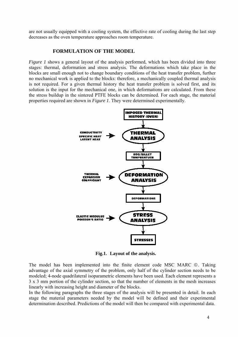
Figure 1 shows a general layout of the analysis performed, which has been divided into three stages: thermal, deformation and stress analysis. The deformations which take place in the blocks are small enough not to change boundary conditions of the heat transfer problem, further no mechanical work is applied to the blocks: therefore, a mechanically coupled thermal analysis is not required. For a given thermal history the heat transfer problem is solved first, and its solution is the input for the mechanical one, in which deformations are calculated. From these the stress buildup in the sintered PTFE blocks can be determined. For each stage, the material properties required are shown in Figure 1. They were determined experimentally.
Fig.1. Layout of the analysis. The model has been implemented into the finite element code MSC MARC . Taking advantage of the axial symmetry of the problem, only half of the cylinder section needs to be modeled; 4-node quadrilateral isoparametric elements have been used. Each element represents a 3 x 3 mm portion of the cylinder section, so that the number of elements in the mesh increases linearly with increasing height and diameter of the blocks. In the following paragraphs the three stages of the analysis will be presented in detail. In each stage the material parameters needed by the model will be defined and their experimental determination described. Predictions of the model will then be compared with experimental data.
5
THERMAL ANALYSIS
The heat transfer problem is solved using the well-known Fourier heat flux model, under the assumption of a macroscopic continuum formulation. This leads to the general heat conduction equation given as:
qTkt
TρC
(1)
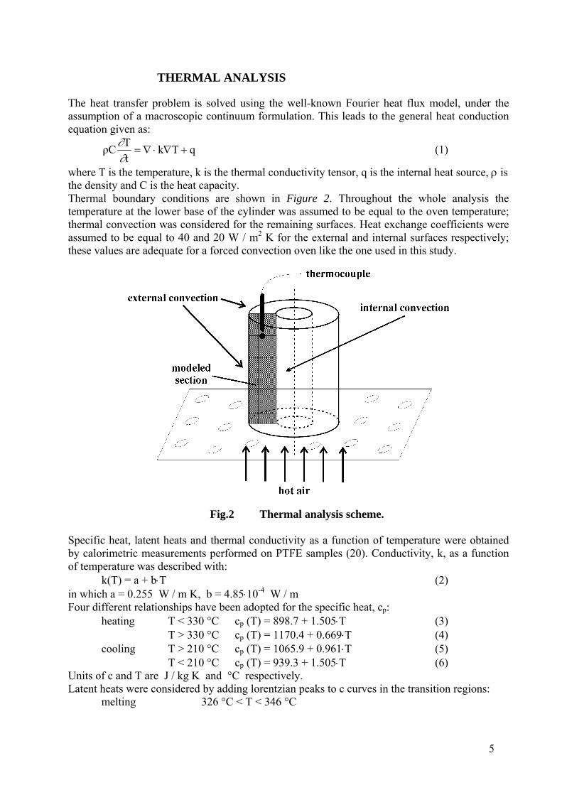
where T is the temperature, k is the thermal conductivity tensor, q is the internal heat source, is the density and C is the heat capacity. Thermal boundary conditions are shown in Figure 2. Throughout the whole analysis the temperature at the lower base of the cylinder was assumed to be equal to the oven temperature; thermal convection was considered for the remaining surfaces. Heat exchange coefficients were assumed to be equal to 40 and 20 W / m2 K for the external and internal surfaces respectively; these values are adequate for a forced convection oven like the one used in this study.
Fig.2 Thermal analysis scheme. Specific heat, latent heats and thermal conductivity as a function of temperature were obtained by calorimetric measurements performed on PTFE samples (20). Conductivity, k, as a function of temperature was described with:
k(T) = a + bT (2) in which a = 0.255 W / m K, b = 4.8510-4 W / m Four different relationships have been adopted for the specific heat, cp: heating T < 330 °C cp (T) = 898.7 + 1.505T (3) T > 330 °C cp (T) = 1170.4 + 0.669T (4) cooling T > 210 °C cp (T) = 1065.9 + 0.961T (5) T < 210 °C cp (T) = 939.3 + 1.505T (6) Units of c and T are J / kg K and °C respectively. Latent heats were considered by adding lorentzian peaks to c curves in the transition regions: melting 326 °C < T < 346 °C
6
cp*(T) = cp (T) + 22 73364
7174000
T - 864 (7)
crystallization 307 °C < T < 327 °C
cp*(T) = cp (T) + 22 2.43364
2.449200
T - 157.5 (8)
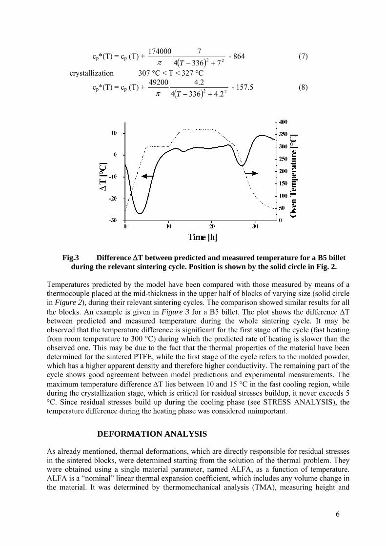
Fig.3 Difference T between predicted and measured temperature for a B5 billet
during the relevant sintering cycle. Position is shown by the solid circle in Fig. 2. Temperatures predicted by the model have been compared with those measured by means of a thermocouple placed at the mid-thickness in the upper half of blocks of varying size (solid circle in Figure 2), during their relevant sintering cycles. The comparison showed similar results for all the blocks. An example is given in Figure 3 for a B5 billet. The plot shows the difference T between predicted and measured temperature during the whole sintering cycle. It may be observed that the temperature difference is significant for the first stage of the cycle (fast heating from room temperature to 300 °C) during which the predicted rate of heating is slower than the observed one. This may be due to the fact that the thermal properties of the material have been determined for the sintered PTFE, while the first stage of the cycle refers to the molded powder, which has a higher apparent density and therefore higher conductivity. The remaining part of the cycle shows good agreement between model predictions and experimental measurements. The maximum temperature difference T lies between 10 and 15 °C in the fast cooling region, while during the crystallization stage, which is critical for residual stresses buildup, it never exceeds 5 °C. Since residual stresses build up during the cooling phase (see STRESS ANALYSIS), the temperature difference during the heating phase was considered unimportant.
DEFORMATION ANALYSIS
As already mentioned, thermal deformations, which are directly responsible for residual stresses in the sintered blocks, were determined starting from the solution of the thermal problem. They were obtained using a single material parameter, named ALFA, as a function of temperature. ALFA is a “nominal” linear thermal expansion coefficient, which includes any volume change in the material. It was determined by thermomechanical analysis (TMA), measuring height and
7
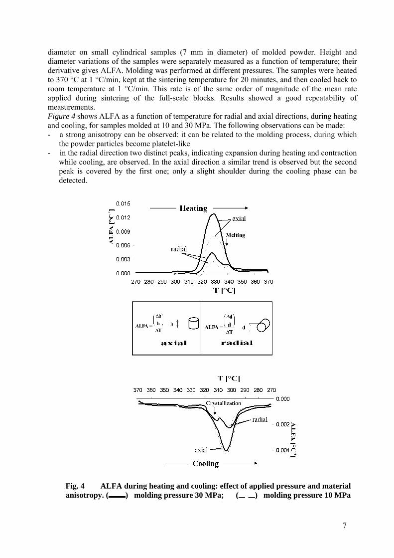
diameter on small cylindrical samples (7 mm in diameter) of molded powder. Height and diameter variations of the samples were separately measured as a function of temperature; their derivative gives ALFA. Molding was performed at different pressures. The samples were heated to 370 °C at 1 °C/min, kept at the sintering temperature for 20 minutes, and then cooled back to room temperature at 1 °C/min. This rate is of the same order of magnitude of the mean rate applied during sintering of the full-scale blocks. Results showed a good repeatability of measurements. Figure 4 shows ALFA as a function of temperature for radial and axial directions, during heating and cooling, for samples molded at 10 and 30 MPa. The following observations can be made: - a strong anisotropy can be observed: it can be related to the molding process, during which
the powder particles become platelet-like - in the radial direction two distinct peaks, indicating expansion during heating and contraction
while cooling, are observed. In the axial direction a similar trend is observed but the second peak is covered by the first one; only a slight shoulder during the cooling phase can be detected.
Fig. 4 ALFA during heating and cooling: effect of applied pressure and material anisotropy. ( ) molding pressure 30 MPa; ( ) molding pressure 10 MPa
8
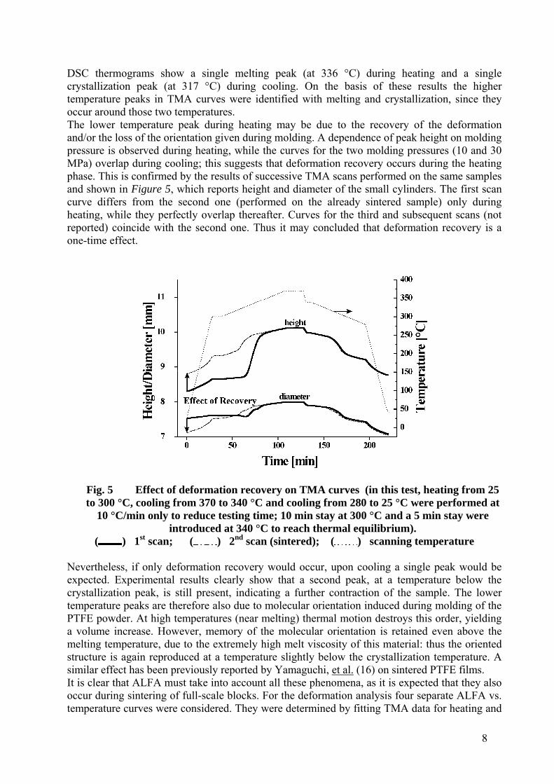
DSC thermograms show a single melting peak (at 336 °C) during heating and a single crystallization peak (at 317 °C) during cooling. On the basis of these results the higher temperature peaks in TMA curves were identified with melting and crystallization, since they occur around those two temperatures. The lower temperature peak during heating may be due to the recovery of the deformation and/or the loss of the orientation given during molding. A dependence of peak height on molding pressure is observed during heating, while the curves for the two molding pressures (10 and 30 MPa) overlap during cooling; this suggests that deformation recovery occurs during the heating phase. This is confirmed by the results of successive TMA scans performed on the same samples and shown in Figure 5, which reports height and diameter of the small cylinders. The first scan curve differs from the second one (performed on the already sintered sample) only during heating, while they perfectly overlap thereafter. Curves for the third and subsequent scans (not reported) coincide with the second one. Thus it may concluded that deformation recovery is a one-time effect.
Fig. 5 Effect of deformation recovery on TMA curves (in this test, heating from 25 to 300 °C, cooling from 370 to 340 °C and cooling from 280 to 25 °C were performed at
10 °C/min only to reduce testing time; 10 min stay at 300 °C and a 5 min stay were introduced at 340 °C to reach thermal equilibrium).
( ) 1st scan; ( ) 2nd scan (sintered); ( ) scanning temperature Nevertheless, if only deformation recovery would occur, upon cooling a single peak would be expected. Experimental results clearly show that a second peak, at a temperature below the crystallization peak, is still present, indicating a further contraction of the sample. The lower temperature peaks are therefore also due to molecular orientation induced during molding of the PTFE powder. At high temperatures (near melting) thermal motion destroys this order, yielding a volume increase. However, memory of the molecular orientation is retained even above the melting temperature, due to the extremely high melt viscosity of this material: thus the oriented structure is again reproduced at a temperature slightly below the crystallization temperature. A similar effect has been previously reported by Yamaguchi, et al. (16) on sintered PTFE films. It is clear that ALFA must take into account all these phenomena, as it is expected that they also occur during sintering of full-scale blocks. For the deformation analysis four separate ALFA vs. temperature curves were considered. They were determined by fitting TMA data for heating and
9
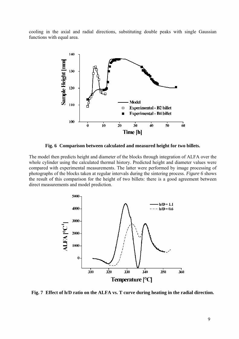
cooling in the axial and radial directions, substituting double peaks with single Gaussian functions with equal area.
Fig. 6 Comparison between calculated and measured height for two billets.
The model then predicts height and diameter of the blocks through integration of ALFA over the whole cylinder using the calculated thermal history. Predicted height and diameter values were compared with experimental measurements. The latter were performed by image processing of photographs of the blocks taken at regular intervals during the sintering process. Figure 6 shows the result of this comparison for the height of two billets: there is a good agreement between direct measurements and model prediction.
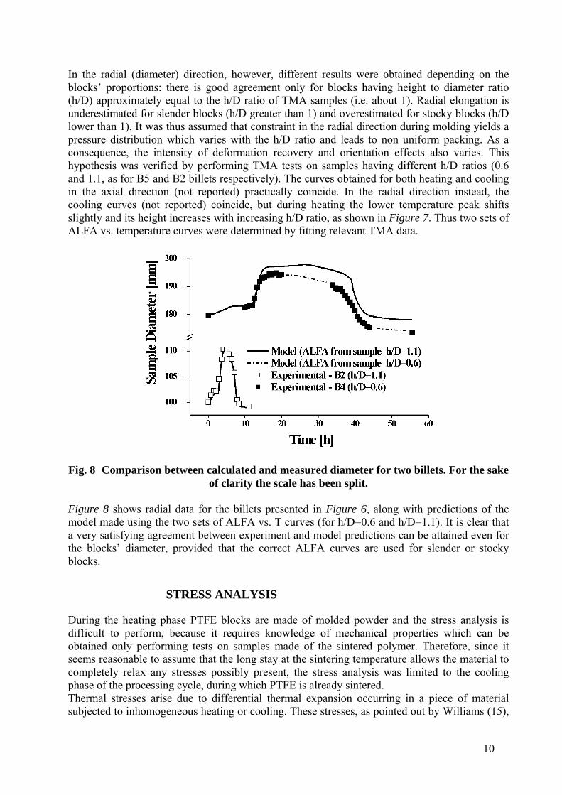
Fig. 7 Effect of h/D ratio on the ALFA vs. T curve during heating in the radial direction.
10
In the radial (diameter) direction, however, different results were obtained depending on the blocks’ proportions: there is good agreement only for blocks having height to diameter ratio (h/D) approximately equal to the h/D ratio of TMA samples (i.e. about 1). Radial elongation is underestimated for slender blocks (h/D greater than 1) and overestimated for stocky blocks (h/D lower than 1). It was thus assumed that constraint in the radial direction during molding yields a pressure distribution which varies with the h/D ratio and leads to non uniform packing. As a consequence, the intensity of deformation recovery and orientation effects also varies. This hypothesis was verified by performing TMA tests on samples having different h/D ratios (0.6 and 1.1, as for B5 and B2 billets respectively). The curves obtained for both heating and cooling in the axial direction (not reported) practically coincide. In the radial direction instead, the cooling curves (not reported) coincide, but during heating the lower temperature peak shifts slightly and its height increases with increasing h/D ratio, as shown in Figure 7. Thus two sets of ALFA vs. temperature curves were determined by fitting relevant TMA data.
Fig. 8 Comparison between calculated and measured diameter for two billets. For the sake
of clarity the scale has been split.
Figure 8 shows radial data for the billets presented in Figure 6, along with predictions of the model made using the two sets of ALFA vs. T curves (for h/D=0.6 and h/D=1.1). It is clear that a very satisfying agreement between experiment and model predictions can be attained even for the blocks’ diameter, provided that the correct ALFA curves are used for slender or stocky blocks.
STRESS ANALYSIS
During the heating phase PTFE blocks are made of molded powder and the stress analysis is difficult to perform, because it requires knowledge of mechanical properties which can be obtained only performing tests on samples made of the sintered polymer. Therefore, since it seems reasonable to assume that the long stay at the sintering temperature allows the material to completely relax any stresses possibly present, the stress analysis was limited to the cooling phase of the processing cycle, during which PTFE is already sintered. Thermal stresses arise due to differential thermal expansion occurring in a piece of material subjected to inhomogeneous heating or cooling. These stresses, as pointed out by Williams (15),
11
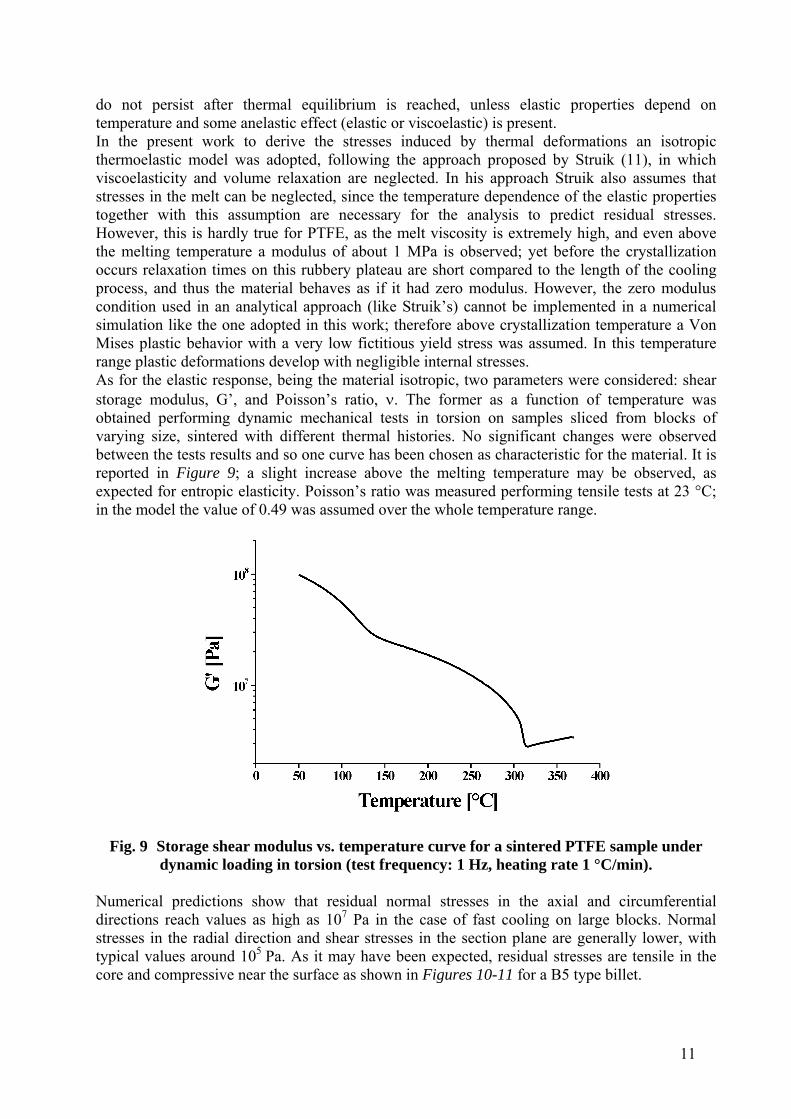
do not persist after thermal equilibrium is reached, unless elastic properties depend on temperature and some anelastic effect (elastic or viscoelastic) is present. In the present work to derive the stresses induced by thermal deformations an isotropic thermoelastic model was adopted, following the approach proposed by Struik (11), in which viscoelasticity and volume relaxation are neglected. In his approach Struik also assumes that stresses in the melt can be neglected, since the temperature dependence of the elastic properties together with this assumption are necessary for the analysis to predict residual stresses. However, this is hardly true for PTFE, as the melt viscosity is extremely high, and even above the melting temperature a modulus of about 1 MPa is observed; yet before the crystallization occurs relaxation times on this rubbery plateau are short compared to the length of the cooling process, and thus the material behaves as if it had zero modulus. However, the zero modulus condition used in an analytical approach (like Struik’s) cannot be implemented in a numerical simulation like the one adopted in this work; therefore above crystallization temperature a Von Mises plastic behavior with a very low fictitious yield stress was assumed. In this temperature range plastic deformations develop with negligible internal stresses. As for the elastic response, being the material isotropic, two parameters were considered: shear storage modulus, G’, and Poisson’s ratio, . The former as a function of temperature was obtained performing dynamic mechanical tests in torsion on samples sliced from blocks of varying size, sintered with different thermal histories. No significant changes were observed between the tests results and so one curve has been chosen as characteristic for the material. It is reported in Figure 9; a slight increase above the melting temperature may be observed, as expected for entropic elasticity. Poisson’s ratio was measured performing tensile tests at 23 °C; in the model the value of 0.49 was assumed over the whole temperature range.
Fig. 9 Storage shear modulus vs. temperature curve for a sintered PTFE sample under
dynamic loading in torsion (test frequency: 1 Hz, heating rate 1 °C/min).
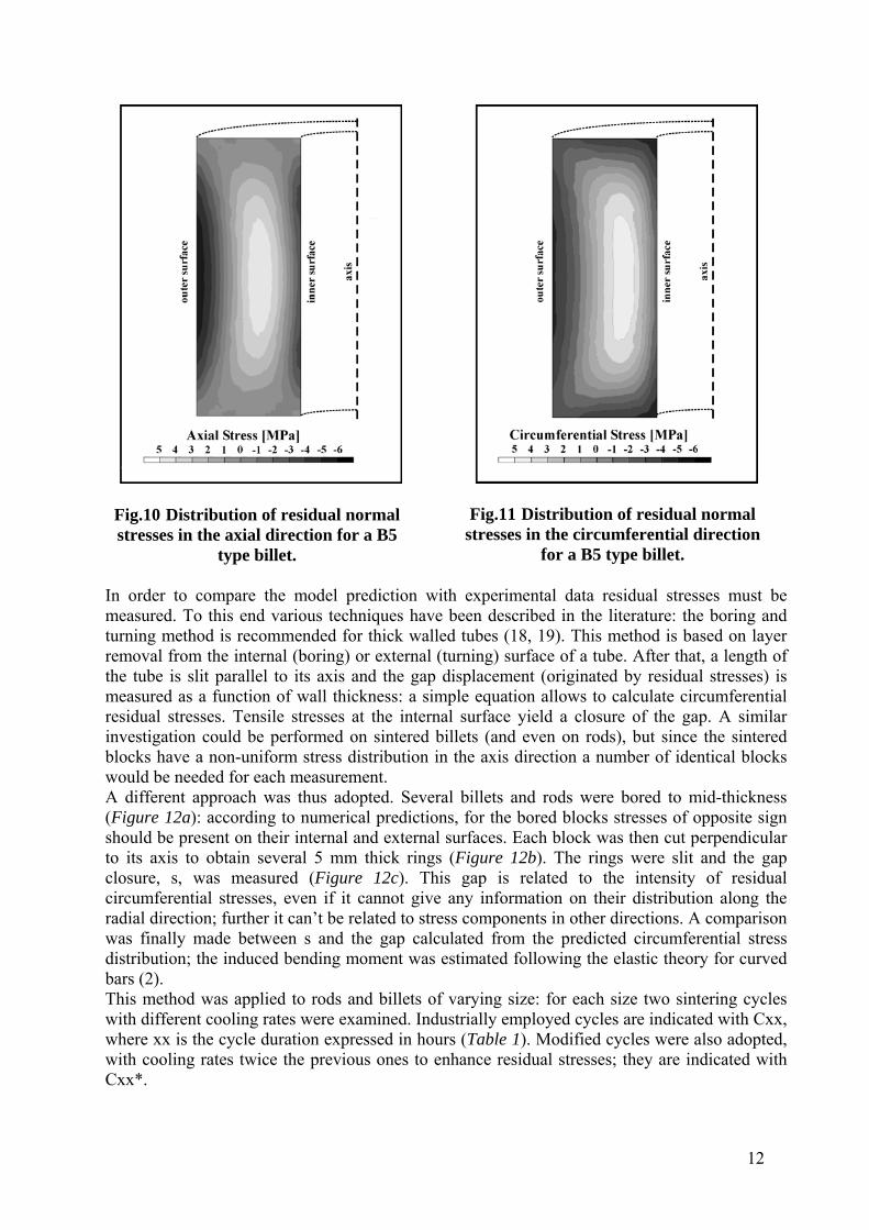
Numerical predictions show that residual normal stresses in the axial and circumferential directions reach values as high as 107 Pa in the case of fast cooling on large blocks. Normal stresses in the radial direction and shear stresses in the section plane are generally lower, with typical values around 105 Pa. As it may have been expected, residual stresses are tensile in the core and compressive near the surface as shown in Figures 10-11 for a B5 type billet.
12
Fig.10 Distribution of residual normal stresses in the axial direction for a B5
type billet.
Fig.11 Distribution of residual normal stresses in the circumferential direction
for a B5 type billet.
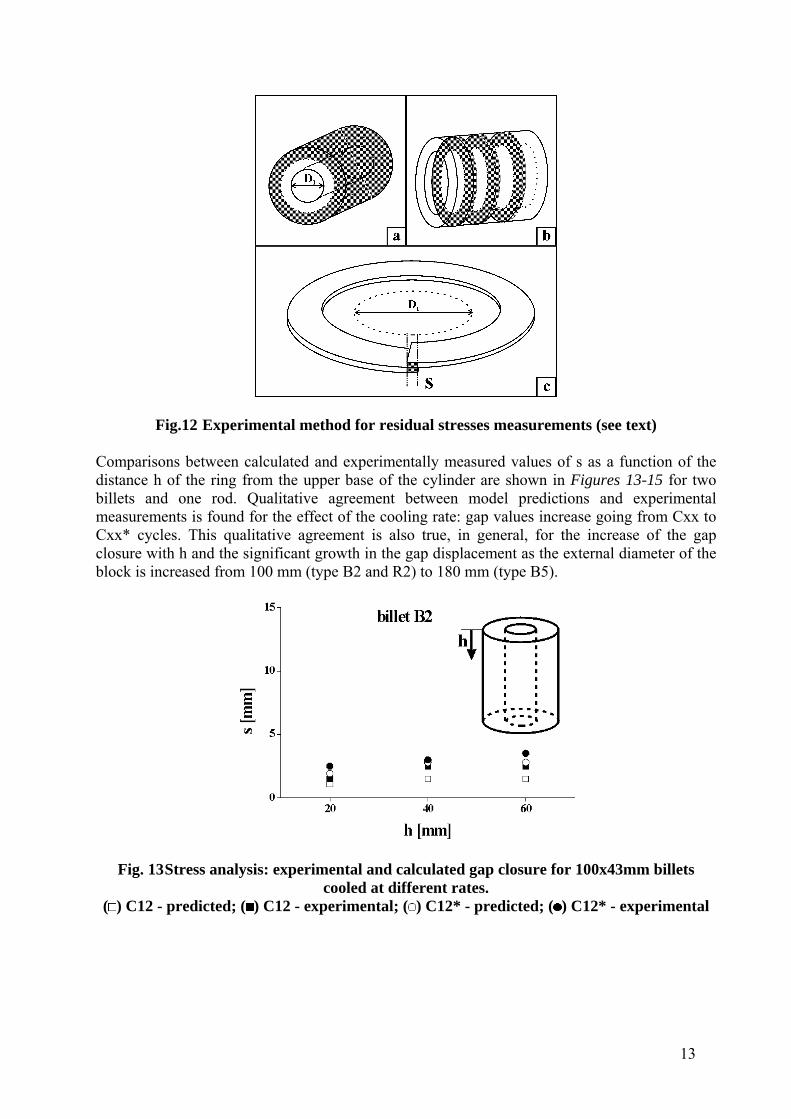
In order to compare the model prediction with experimental data residual stresses must be measured. To this end various techniques have been described in the literature: the boring and turning method is recommended for thick walled tubes (18, 19). This method is based on layer removal from the internal (boring) or external (turning) surface of a tube. After that, a length of the tube is slit parallel to its axis and the gap displacement (originated by residual stresses) is measured as a function of wall thickness: a simple equation allows to calculate circumferential residual stresses. Tensile stresses at the internal surface yield a closure of the gap. A similar investigation could be performed on sintered billets (and even on rods), but since the sintered blocks have a non-uniform stress distribution in the axis direction a number of identical blocks would be needed for each measurement. A different approach was thus adopted. Several billets and rods were bored to mid-thickness (Figure 12a): according to numerical predictions, for the bored blocks stresses of opposite sign should be present on their internal and external surfaces. Each block was then cut perpendicular to its axis to obtain several 5 mm thick rings (Figure 12b). The rings were slit and the gap closure, s, was measured (Figure 12c). This gap is related to the intensity of residual circumferential stresses, even if it cannot give any information on their distribution along the radial direction; further it can’t be related to stress components in other directions. A comparison was finally made between s and the gap calculated from the predicted circumferential stress distribution; the induced bending moment was estimated following the elastic theory for curved bars (2). This method was applied to rods and billets of varying size: for each size two sintering cycles with different cooling rates were examined. Industrially employed cycles are indicated with Cxx, where xx is the cycle duration expressed in hours (Table 1). Modified cycles were also adopted, with cooling rates twice the previous ones to enhance residual stresses; they are indicated with Cxx*.
13
Fig.12 Experimental method for residual stresses measurements (see text)
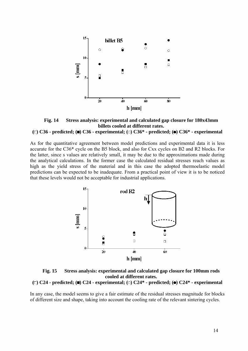
Comparisons between calculated and experimentally measured values of s as a function of the distance h of the ring from the upper base of the cylinder are shown in Figures 13-15 for two billets and one rod. Qualitative agreement between model predictions and experimental measurements is found for the effect of the cooling rate: gap values increase going from Cxx to Cxx* cycles. This qualitative agreement is also true, in general, for the increase of the gap closure with h and the significant growth in the gap displacement as the external diameter of the block is increased from 100 mm (type B2 and R2) to 180 mm (type B5).
Fig. 13 Stress analysis: experimental and calculated gap closure for 100x43mm billets
cooled at different rates. ( ) C12 - predicted; ( ) C12 - experimental; ( ) C12* - predicted; ( ) C12* - experimental
14
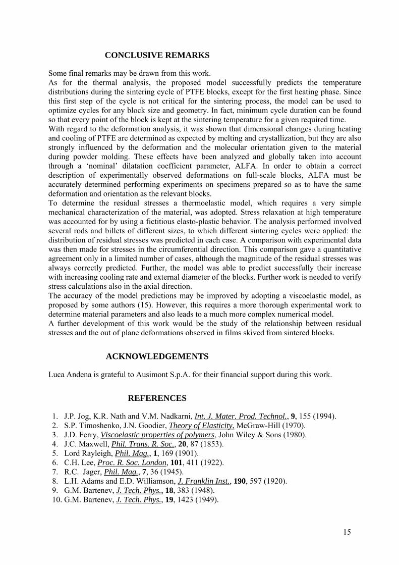
Fig. 14 Stress analysis: experimental and calculated gap closure for 180x43mm
billets cooled at different rates. ( ) C36 - predicted; ( ) C36 - experimental; ( ) C36* - predicted; ( ) C36* - experimental
As for the quantitative agreement between model predictions and experimental data it is less accurate for the C36* cycle on the B5 block, and also for Cxx cycles on B2 and R2 blocks. For the latter, since s values are relatively small, it may be due to the approximations made during the analytical calculations. In the former case the calculated residual stresses reach values as high as the yield stress of the material and in this case the adopted thermoelastic model predictions can be expected to be inadequate. From a practical point of view it is to be noticed that these levels would not be acceptable for industrial applications.
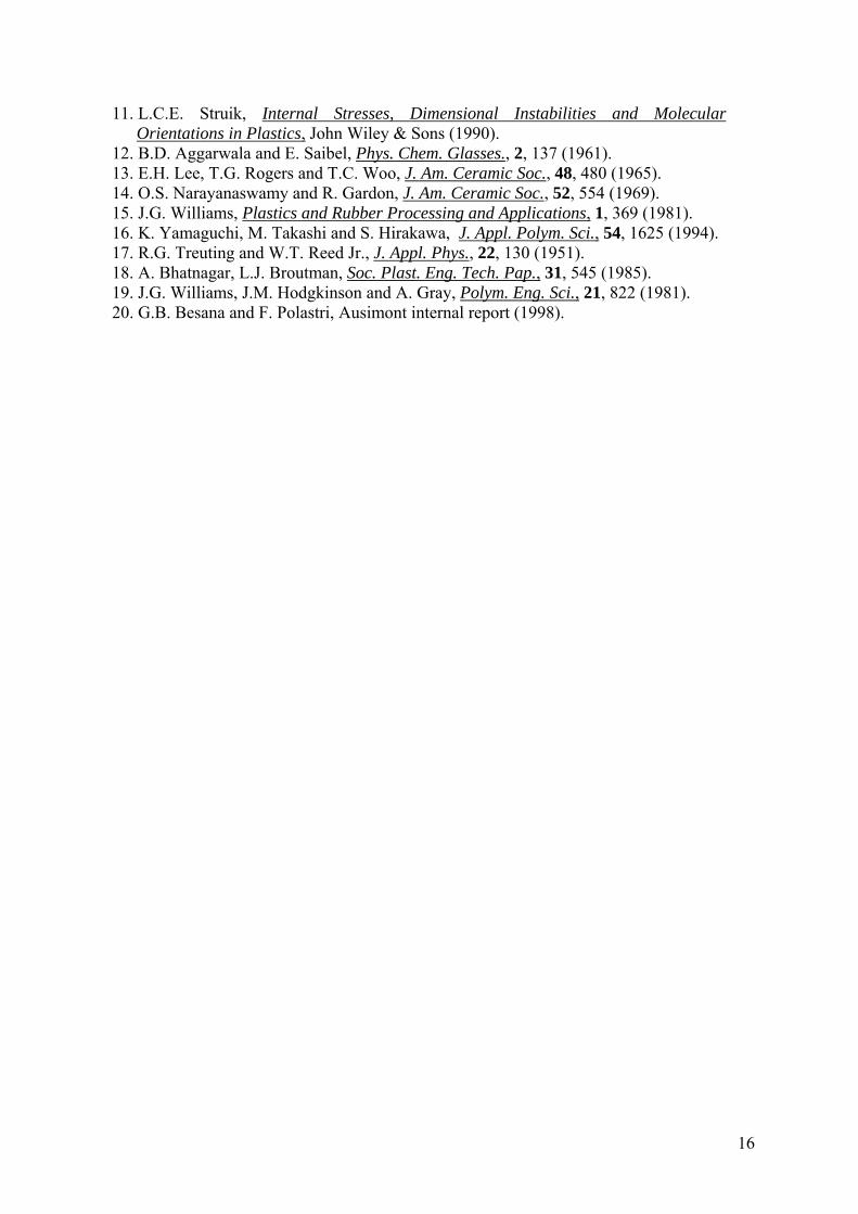
Fig. 15 Stress analysis: experimental and calculated gap closure for 100mm rods
cooled at different rates. ( ) C24 - predicted; ( ) C24 - experimental; ( ) C24* - predicted; ( ) C24* - experimental
In any case, the model seems to give a fair estimate of the residual stresses magnitude for blocks of different size and shape, taking into account the cooling rate of the relevant sintering cycles.
15
CONCLUSIVE REMARKS
Some final remarks may be drawn from this work. As for the thermal analysis, the proposed model successfully predicts the temperature distributions during the sintering cycle of PTFE blocks, except for the first heating phase. Since this first step of the cycle is not critical for the sintering process, the model can be used to optimize cycles for any block size and geometry. In fact, minimum cycle duration can be found so that every point of the block is kept at the sintering temperature for a given required time. With regard to the deformation analysis, it was shown that dimensional changes during heating and cooling of PTFE are determined as expected by melting and crystallization, but they are also strongly influenced by the deformation and the molecular orientation given to the material during powder molding. These effects have been analyzed and globally taken into account through a ‘nominal’ dilatation coefficient parameter, ALFA. In order to obtain a correct description of experimentally observed deformations on full-scale blocks, ALFA must be accurately determined performing experiments on specimens prepared so as to have the same deformation and orientation as the relevant blocks. To determine the residual stresses a thermoelastic model, which requires a very simple mechanical characterization of the material, was adopted. Stress relaxation at high temperature was accounted for by using a fictitious elasto-plastic behavior. The analysis performed involved several rods and billets of different sizes, to which different sintering cycles were applied: the distribution of residual stresses was predicted in each case. A comparison with experimental data was then made for stresses in the circumferential direction. This comparison gave a quantitative agreement only in a limited number of cases, although the magnitude of the residual stresses was always correctly predicted. Further, the model was able to predict successfully their increase with increasing cooling rate and external diameter of the blocks. Further work is needed to verify stress calculations also in the axial direction. The accuracy of the model predictions may be improved by adopting a viscoelastic model, as proposed by some authors (15). However, this requires a more thorough experimental work to determine material parameters and also leads to a much more complex numerical model. A further development of this work would be the study of the relationship between residual stresses and the out of plane deformations observed in films skived from sintered blocks.
ACKNOWLEDGEMENTS
Luca Andena is grateful to Ausimont S.p.A. for their financial support during this work.
REFERENCES
1. J.P. Jog, K.R. Nath and V.M. Nadkarni, Int. J. Mater. Prod. Technol., 9, 155 (1994). 2. S.P. Timoshenko, J.N. Goodier, Theory of Elasticity, McGraw-Hill (1970). 3. J.D. Ferry, Viscoelastic properties of polymers, John Wiley & Sons (1980). 4. J.C. Maxwell, Phil. Trans. R. Soc., 20, 87 (1853). 5. Lord Rayleigh, Phil. Mag., 1, 169 (1901). 6. C.H. Lee, Proc. R. Soc. London, 101, 411 (1922). 7. R.C. Jager, Phil. Mag., 7, 36 (1945). 8. L.H. Adams and E.D. Williamson, J. Franklin Inst., 190, 597 (1920). 9. G.M. Bartenev, J. Tech. Phys., 18, 383 (1948). 10. G.M. Bartenev, J. Tech. Phys., 19, 1423 (1949).
16
11. L.C.E. Struik, Internal Stresses, Dimensional Instabilities and Molecular Orientations in Plastics, John Wiley & Sons (1990).
12. B.D. Aggarwala and E. Saibel, Phys. Chem. Glasses., 2, 137 (1961). 13. E.H. Lee, T.G. Rogers and T.C. Woo, J. Am. Ceramic Soc., 48, 480 (1965). 14. O.S. Narayanaswamy and R. Gardon, J. Am. Ceramic Soc., 52, 554 (1969). 15. J.G. Williams, Plastics and Rubber Processing and Applications, 1, 369 (1981). 16. K. Yamaguchi, M. Takashi and S. Hirakawa, J. Appl. Polym. Sci., 54, 1625 (1994). 17. R.G. Treuting and W.T. Reed Jr., J. Appl. Phys., 22, 130 (1951). 18. A. Bhatnagar, L.J. Broutman, Soc. Plast. Eng. Tech. Pap., 31, 545 (1985). 19. J.G. Williams, J.M. Hodgkinson and A. Gray, Polym. Eng. Sci., 21, 822 (1981). 20. G.B. Besana and F. Polastri, Ausimont internal report (1998).


