Embed Size (px)
Citation preview

Simultaneous extraction of geometry and surfaceproperties of targets using simple infraredsensors
Tayfun Aytac¸Billur BarshanBilkent UniversityDepartment of Electrical EngineeringTR-06800 Bilkent, Ankara, TurkeyE-mail: [email protected]
Abstract. We investigate the use of low-cost infrared (IR) sensors forthe simultaneous extraction of geometry and surface properties of com-monly encountered features or targets in indoor environments, such asplanes, corners, and edges. The intensity measurements obtained fromsuch sensors are highly dependent on the location, geometry, and sur-face properties of the reflecting target in a way that cannot be repre-sented by a simple analytical relationship, therefore complicating the lo-calization and recognition process. We propose the use of angularintensity scans and present an algorithm to process them to determinethe geometry and the surface type of the target and estimate its position.The method is verified experimentally with planes, 90-deg corners, and90-deg edges covered with aluminum, white cloth, and Styrofoam pack-aging material. An average correct classification rate of 80% of bothgeometry and surface over all target types is achieved and targets arelocalized within absolute range and azimuth errors of 1.5 cm and 1.1deg, respectively. Taken separately, the geometry and surface type oftargets can be correctly classified with rates of 99 and 81%, respectively,which shows that the geometrical properties of the targets are moredistinctive than their surface properties, and surface determination is thelimiting factor. The method demonstrated shows that simple IR sensors,when coupled with appropriate processing, can be used to extract sub-stantially more information than that for which such devices are com-monly employed. © 2004 Society of Photo-Optical Instrumentation Engineers.[DOI: 10.1117/1.1789136]
Subject terms: pattern recognition; feature extraction; target differentiation; targetlocalization; surface differentiation; surface localization; infrared sensors; positionestimation; optical sensing.
Paper 030547 received Oct. 31, 2003; revised manuscript received Mar. 11,2004; accepted for publication Mar. 28, 2004.
in-en-on.stedIRctosele.n-
notth
ndectbe
itse alta-f ththe
enseum-nals.nedt a
-
lsn-ry
k-
sti-p-
tsonsor.age
1 Introduction
Target differentiation and localization is of considerableterest for intelligent systems where it is necessary to idtify targets and their positions for autonomous operatiDifferentiation is also important in industrial applicationwhere different materials must be identified and separaIn this paper, we consider the use of a very simplesensing system consisting of one emitter and one detefor the purpose of differentiation and localization. Thedevices are inexpensive, practical, and widely availabThe emitted light is reflected from the target and its intesity is measured at the detector. However, it is oftenpossible to make reliable distance estimates based onvalue of a single intensity return because the return depeon both the geometry and surface properties of the refling target. Likewise, the properties of the target cannotdeduced from simple intensity returns without knowingdistance and angular location. In this paper, we proposscanning technique and an algorithm that can simuneously determine the geometry and the surface type otarget, in a manner that is invariant to its location. Oncetarget type is determined, its position (r ,u) can also be
Opt. Eng. 43(10) 2437–2447 (October 2004) 0091-3286/2004/$15.00
.
r
es-
e
estimated. The method we propose is scalable in the sthat the accuracy can be increased by increasing the nber of reference scans without increasing the computatiocomplexity of the differentiation and localization procesOur results show that by properly processing data obtaifrom such simple IR sensors, it is possible to extracsignificantly greater amount of information than is commonly expected from such sensors.
Most work on pattern recognition involving IR deawith recognition or detection of features or targets in coventional 2-D images. Examples of work in this categoinclude face identification,1 automatic target recognition,2
target tracking,3 automatic vehicle detection,4 remotesensing,5 detection and identification of targets in bacground clutter,6,7 and automated terrain analysis.8 Note thatthe position-invariant pattern recognition and position emation achieved in this paper are different from such oerations performed on conventional images9 in that here wework not on direct ‘‘photographic’’ images of the targeobtained by some kind of imaging system, but ratherangular intensity scans obtained by rotating a point senThe targets we differentiate are not patterns in a 2-D im
2437© 2004 Society of Photo-Optical Instrumentation Engineers

s intheionthari-al
cesms
and
nd
ap-/rnarthe
heng
sor
terdorray
senn artin
ties
ngesed. Int ofrecuththee-
and
utl toctocted,es-tedys
degcmdange
theFig
tedeir
bithip
ner,ceity
theothed
Aytac and Barshan: Simultaneous extraction of geometry . . .
whose coordinates we try to determine, but rather objectspace, exhibiting depth, whose position with respect tosensing system we must estimate. As such, positinvariant differentiation and localization is achieved wian approach quite different than those employed in invant pattern recognition and localization in conventionimages.10–16
IR sensors are used in robotics and automation, procontrol, remote sensing, and safety and security systeMore specifically, they have been used in simple objectproximity detection,17 counting,18 distance and depthmonitoring,19 floor sensing, position measurement, acontrol,20,21 obstacle/collision avoidance,22,23 and mapbuilding.24 IR sensors are used in door detection and mping of openings in walls,25 as well as monitoring doorswindows of buildings and vehicles, and ‘‘light curtains’’ foprotecting an area. In Ref. 26, the properties of a plasurface at a known distance were determined usingPhong illumination model, and using this information, tIR sensor employed was modeled as an accurate rafinder for surfaces at short ranges. In Ref. 27, an IR-senbased system that can measure distances up to 1 m is de-scribed. References 28, 29, and 30 deal with optical demination of depth information. In Ref. 31, simulation anevaluation of the recognition abilities of active IR sensarrays are considered for autonomous systems using atracing approach. Reference 32 describes a passive IRing system that identifies the locations of the people iroom. IR sensors have also been used for automated soof waste objects made of different materials.33 In Ref. 34,we considered targets with different geometrical properbut made of the same surface material~wood!. A correctclassification rate of 97% was achieved with absolute raand azimuth errors of 0.8 cm and 1.6 deg. A rule-baapproach to the same problem can be found in Ref. 35Ref. 36, targets made of different surface materials buthe same planar geometry were differentiated with a cordifferentiation rate of 87% and absolute range and azimerrors of 1.2 cm and 1.0 deg. In this paper, we deal withproblem of differentiating and localizing targets whose gometry and surface properties both vary, generalizingunifying the results of Refs. 34 and 36.
2 Target Differentiation and Localization
The IR sensor37 used in this study@see Fig. 1~a!# consists ofan emitter and detector, works with 20 to 28-V dc inpvoltage, and provides analog output voltage proportionathe measured intensity reflected off the target. The detewindow is covered with an IR filter to minimize the effeof ambient light on the intensity measurements. Indewhen the emitter is turned off, the detector reading issentially zero. The sensitivity of the device can be adjuswith a potentiometer to set the operating range of the stem.
The targets employed in this study are a plane, a 90-corner, and a 90-deg edge, each with a height of 120~Fig. 2!. They are covered with aluminum, white cloth, anStyrofoam packaging material. Our method is based ongularly scanning each target over a certain angular ranThe IR sensor is mounted on a 12-in. rotary table38 to ob-tain angular scans from these targets. A photograph ofexperimental setup and its schematics can be seen in
2438 Optical Engineering, Vol. 43 No. 10, October 2004
-
s.
e-
-
-s-
g
t
r
-
-.
s.
1~b! and 3, respectively. Reference data sets are collecfor each target with 2.5-cm distance increments from thnearest to their maximum observable ranges atu50 deg.The output signal is processed using an 8-microprocessor-compatible analog-to-digital converter chaving a conversion time of 100ms.
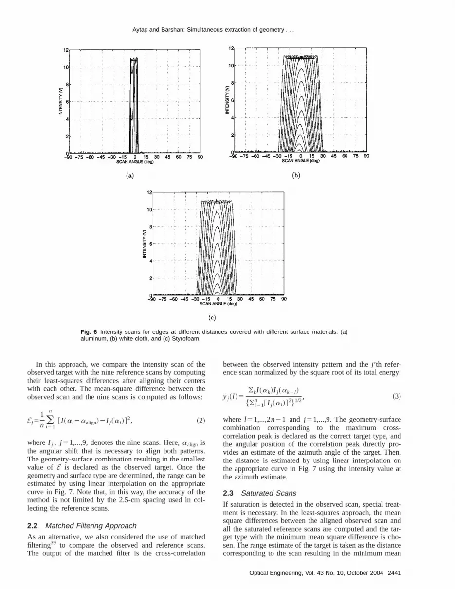
The resulting reference scans for the plane, the corand the edge covered with materials of different surfaproperties are shown in Figs. 4, 5, and 6. The intensscans areu invariant but notr invariant; changes inr resultin variations in both the magnitude and the basewidth ofintensity scans. Scans of corners covered with white cland Styrofoam packaging material have a triple-hump
Fig. 1 (a) IR sensor used in this study and (b) experimental setup.
Fig. 2 Target primitives used in this study.

eci-
ceor
ncaning
r inatednotfor
ly,gs.nceis-re-igs.her-erals ofalsom.t aith
an.ke
ans
Aytac and Barshan: Simultaneous extraction of geometry . . .
pattern~with a much smaller middle hump! correspondingto the two orthogonal constituent planes and their interstion. The intensity scans for corners covered with alumnum @Fig. 5~a!# have three distinct saturated humps. Notithat the return signal intensities saturate at an intensity cresponding to about 11 V output voltage.
We now describe the differentiation and localizatioprocess of an arbitrarily located target whose intensity swas observed. First, we check for saturation by examin
Fig. 3 Top view of the experimental setup used in target differentia-tion and localization. The emitter and detector windows are circularwith an 8-mm diameter and a center-to-center separation 12 mm.(The emitter is above the detector.) Both the scan angle a and thetarget azimuth u are measured counterclockwise from the horizontalaxis.
-
-
the central intensity value of the observed scanI (a). Thissituation is treated separately, as will be explained lateSec. 2.3. Note that a corner scan is considered saturwhen its central intensity enters the saturation region,the humps, since it is the former value that is relevantour method.
We start by determining the target type. Unfortunatedirect comparison with the corresponding curves in Fi4–6 is not possible since we do not yet know the distato the target, and comparing with all the curves at all dtances would be computationally very expensive. Thefore, we exploit the fact that the successive curves in F4–6 exhibit a monotonic dependence on distance. Furtmore, when an observed scan is compared to the sevsuccessive curves in any of Figs. 4–6, the two measuredifference between them described in Secs. 2.1 and 2.2exhibit a monotonic fall and rise around a single minimuTherefore, we are ensured that we will not be settling asuboptimal point if we compare the observed scan not wall scans at all distances, but only with the nine scans~onefor each particular geometry and surface type! whose cen-tral intensities are closest to that of the observed scTherefore, for unsaturated scans, it is sufficient to manine comparisons instead of comparisons with all the sc
Fig. 4 Intensity scans for planes at different distances covered with different surface materials: (a)aluminum, (b) white cloth, and (c) Styrofoam.
2439Optical Engineering, Vol. 43 No. 10, October 2004

Aytac and Barshan: Simultaneous extraction of geometry . . .
2440 Opti
Fig. 5 Intensity scans for corners at different distances covered with different surface materials: (a)aluminum, (b) white cloth, and (c) Styrofoam.
cmad
ase
ereitieandomoreec
hear
o th
k-an
inging
fol-ted
isby
s ofndhistheo-ity
bee
ourthe
incanurefor
in Figs. 4–6. This remains the case even if the 2.5-increments are reduced to smaller values. This has thevantage that the accuracy of the system can be increwithout increasing the cost of computation~although agreater number of scans must be stored!. As a test, we alsoran a version of the method where 18 comparisons wmade using the scans with the nearest central intensboth above and below the observed central intensity,also using all of the scans shown in Figs. 4–6. These cputationally more expensive approaches, exceedingly mso in the latter case, did not improve the results with respto a comparison with only nine scans. In fact, in tmatched filtering case discussed in Sec. 2.2, the resultseven somewhat better when nine scans are used, due tfact that this systematic elimination ofa priori suboptimalscans eliminates the small possibility that they will mistaenly be chosen as the best matching scan due to noiseother errors.
Two alternative approaches are employed in performthe nine comparisons. These are discussed in the followtwo subsections.
2.1 Least-Squares Approach
First, we estimate the angular position of the target aslows. Assuming the observed scan pattern is not satura
cal Engineering, Vol. 43 No. 10, October 2004
-d
s
-
t
ee
d
,
we check whether or not it has two major humps. If so, ita corner and we find the angular location of the cornertaking the average of the angular locations of the peakthe two major humps of the intensity scan. If not, we fithe angular location of the peak of the single hump. Tangular value can be directly taken as an estimate ofangular position of the target. Alternatively, the angular psition can be estimated by finding the center of grav~COG! of the scan as follows:
uCOG5( i 51
n a i I ~a i !
( i 51n I ~a i !
. ~1!
Ideally, these two angular position estimates wouldequal, but in practice they differ by a small amount. Wconsider the use of both alternatives when tabulatingresults. From now on, we refer to either estimate as‘‘center angle’’ of the scan.
Plots of the intensity at the center angle of each scanFigs. 4–6 as a function of the distance at which that swas obtained, play an important role in our method. Fig7 shows these plots for the intensity value at the COGplanes, corners, and edges.
Aytac and Barshan: Simultaneous extraction of geometry . . .
Fig. 6 Intensity scans for edges at different distances covered with different surface materials: (a)aluminum, (b) white cloth, and (c) Styrofoam.
thetintersth
ws
rnslesthen bateheol-
hedns
ion
rgy:
es-ando-en,onat
eat-eanandtar-
ho-ancean
In this approach, we compare the intensity scan ofobserved target with the nine reference scans by computheir least-squares differences after aligning their cenwith each other. The mean-square difference betweenobserved scan and the nine scans is computed as follo
Ej51
n (i 51
n
@ I ~a i2aalign!2I j~a i !#2, ~2!
whereI j , j 51,...,9, denotes the nine scans. Here,aalign isthe angular shift that is necessary to align both patteThe geometry-surface combination resulting in the smalvalue of E is declared as the observed target. Oncegeometry and surface type are determined, the range caestimated by using linear interpolation on the appropricurve in Fig. 7. Note that, in this way, the accuracy of tmethod is not limited by the 2.5-cm spacing used in clecting the reference scans.
2.2 Matched Filtering Approach
As an alternative, we also considered the use of matcfiltering39 to compare the observed and reference scaThe output of the matched filter is the cross-correlat
g
e:
.t
e
.
between the observed intensity pattern and thej’th refer-ence scan normalized by the square root of its total ene
yj~ l !5(kI ~ak!I j~ak2 l !
$( i 51n @ I j~a i !#
2%1/2, ~3!
where l 51,...,2n21 and j 51,...,9. The geometry-surfaccombination corresponding to the maximum croscorrelation peak is declared as the correct target type,the angular position of the correlation peak directly prvides an estimate of the azimuth angle of the target. Ththe distance is estimated by using linear interpolationthe appropriate curve in Fig. 7 using the intensity valuethe azimuth estimate.
2.3 Saturated Scans
If saturation is detected in the observed scan, special trment is necessary. In the least-squares approach, the msquare differences between the aligned observed scanall the saturated reference scans are computed and theget type with the minimum mean square difference is csen. The range estimate of the target is taken as the distcorresponding to the scan resulting in the minimum me
2441Optical Engineering, Vol. 43 No. 10, October 2004

Aytac and Barshan: Simultaneous extraction of geometry . . .
2442 Opt
Fig. 7 Central intensity (COG) versus distance curves for different targets: (a) plane, (b) corner, and(c) edge.
la-rateg iat
ccucetheingnotase
edestgleir
tionionaxir
theccu-theionstisof
inallith
ctlync-tiesen-orof
st-d inchrecthech.
square difference. Similarly, for the matched filter, corretion between the observed scan and all the stored satureference scans is computed and the target type resultinthe highest correlation peak is selected. The range estimis again taken as that of the best matching scan.
Note that, in the saturated case, range estimation aracy is limited by the 2.5-cm interval at which the referenscans were taken since interpolation is not possible. Ifaccuracy is not satisfactory, it can be improved by reducthe 2.5-cm intervals. Note that the 2.5-cm interval doeslimit the range estimation accuracy in the unsaturated cwhere interpolation is possible from Fig. 7.
3 Experimental Verification and Discussion
In this section, we experimentally verify the proposmethod by situating targets at randomly selected distancrand azimuth anglesu and collecting a total of 194 tesscans. The targets are randomly located at azimuth anvarying from 245 to 45 deg from their nearest to themaximum observable ranges in Figs. 4, 5, and 6.
The results of least-squares-based target differentiaare displayed in Tables 1 and 2 in the form of confusmatrices. Table 1 gives the results obtained using the mmum intensity~or the middle-of-two-maxima intensity fo
ical Engineering, Vol. 43 No. 10, October 2004
dne
-
,
s
-
corner! values, and Table 2 gives those obtained usingintensity value at the COG of the scans. The average aracy over all target types can be found by summingcorrect decisions given along the diagonal of the confusmatrix and dividing this sum by the total number of tetrials ~194!. The same average correct classification rateachieved by using the maximum and the COG variationsthe least-squares approach, which is 77%.
Matched filter differentiation results are presentedTable 3. The average accuracy of differentiation overtarget types is 80%, which is better than that obtained wthe least-squares approach.
Planes and corners covered with aluminum are correclassified with all approaches employed due to their distitive features. Planar targets of different surface properare better classified than the others, with a correct differtiation rate of 91% for the matched filtering approach. Fcorner targets, the highest correct differentiation rate83% is achieved with the COG variation of the leasquares approach. The greatest difficulty is encounterethe differentiation of edges of different surfaces, whihave the most similar intensity patterns. The highest cordifferentiation rate of 60% for edges is achieved with tmaximum intensity variation of the least-squares approa

getre-of
ties
erle 4xi-
, the ere-h isontareareted
, anst-vellutest-1.
estedde
d toe syarferw tanck,ar
d ast-he0%arm
imeandIn
cor-ans.face
andore
reets,dataarere
recton-entsets.od.t is
Aytac and Barshan: Simultaneous extraction of geometry . . .
Taken separately, the geometry and surface type of tarcan be correctly classified with rates of 99 and 81%,spectively, which shows that the geometrical propertiesthe targets are more distinctive than their surface properand surface determination is the limiting factor.
The average absolute range and azimuth estimationrors for the different approaches are presented in Tabfor all test targets. As we see in the table, using the mamum and COG variations of the least-squares approachtarget ranges are estimated with average absolute rangrors of 1.8 and 1.7 cm, respectively. Matched filteringsults in an average absolute range error of 1.5 cm, whicbetter than the least-squares approach. The greatest cbution to the range errors comes from targets whichincorrectly differentiated and/or whose intensity scanssaturated. If we average over only correctly differentiatargets~regardless of whether they lead to saturation!, theaverage absolute range errors are reduced to 1.2, 1.00.7 cm for the maximum and COG variations of the leasquares and the matched filtering approaches, respectiAs for azimuth estimation, the respective average absoerrors for the maximum and COG variations of leasquares and the matched filtering approaches are 1.6,and 1.1 deg, with matched filtering resulting in the smallerror. When we average over only correctly differentiattargets, these errors are reduced to 1.5, 1.2, and 0.9respectively.
To explore the boundaries of system performance anassess the robustness of the system, we also tested thtem with targets of either unfamiliar geometry, unfamilisurface, or both, whose scans are not included in the reence data sets. Therefore, these targets are totally nethe system. First, tests were done for planes, corners,edges covered with five new surfaces: brown, violet, blaand white paper, and wood. The results of these testspresented in Tables 5, 6, and 7. Planes are classifieplanes100% of the time using both variations of the leasquares method and 99.3% of the time using the matcfiltering approach. Corners are classified as corners 10of the time using any of the three approaches. Edgescorrectly classified 89.1% of the time using the maximu
Table 1 Confusion matrix: least-squares-based classification (maxi-mum variation).
Actual
Detected
P C E
AL WC ST AL WC ST AL WC ST
AL 24 — — — — — — — —
P WC — 25 4 — — — — — —
ST — 9 20 — — — — — —
AL — — — 22 — — — — —
C WC — — — — 10 12 — — —
ST — — — — — 20 — — —
AL — — — — — — 9 — 1
E WC — — — — — — — 11 9
ST — — 1 — — — — 8 9
AL, aluminum; WC, white cloth; ST, Styrofoam; WO, wood; BR,brown paper; VI, violet paper; BL, black paper; WH, white paper; P,plane; C, corner; E, edge; CY, cylinder.
s
,
-
er-
ri-
d
y.
5,
g,
s-
-od
es
d
e
variation of the least-squares approach, 88.2% of the tusing the COG variation of the least-squares approach,87.3% of the time using the matched filtering approach.these tests, no target type is mistakenly classified as aner due to the unique characteristics of the corner scFor the same reason, corners of the preceding five surtypes are never classified as planes or edges. The rangeazimuth errors are comparable or slightly larger than bef~not shown!.
We also tested the system with cylinders, which wenot among the three geometries in the original data swith the same surface types as used in the referencesets: aluminum, white cloth, and Styrofoam. The resultsgiven in Table 8 and indicate that cylindrical targets amost likely to be classified as edges. In this case, corsurface classification rate drops to 35%. We have also csidered cylinders whose surface properties are differthan the surface types considered in the reference dataThese are brown, violet, black, and white paper and woThat is, both the geometry and surface type of this targe
Table 2 Confusion matrix: least-squares based classification (COGvariation).
Actual
Detected
P C E
AL WC ST AL WC ST AL WC ST
AL 24 — — — — — — — —
P WC — 25 4 — — — — — —
ST — 9 20 — — — — — —
AL — — — 22 — — — — —
C WC — — — — 13 9 — — —
ST — — — — 2 18 — — —
AL — — 1 — — — 7 — 2
E WC — — — — — — — 14 6
ST — 1 1 — — — — 10 6
AL, aluminum; WC, white cloth; ST, Styrofoam; WO, wood; BR,brown paper; VI, violet paper; BL, black paper; WH, white paper; P,plane; C, corner; E, edge; CY, cylinder.
Table 3 Confusion matrix: matched filter based classification.
Actual
Detected
P C E
AL WC ST AL WC ST AL WC ST
AL 24 — — — — — — — —
P WC — 27 2 — — — — — —
ST — 5 24 — — — — — —
AL — — — 22 — — — — —
C WC — — — — 14 8 — — —
ST — — — — 4 16 — — —
AL — — — — — — 9 1 —
E WC — — — — — — — 11 9
ST — — 2 — — — — 8 8
AL, aluminum; WC, white cloth; ST, Styrofoam; WO, wood; BR,brown paper; VI, violet paper; BL, black paper; WH, white paper; P,plane; C, corner; E, edge; CY, cylinder.
2443Optical Engineering, Vol. 43 No. 10, October 2004

Aytac and Barshan: Simultaneous extraction of geometry . . .
2444 Optical Engi
Table 4 Absolute range and azimuth estimation errors over all test targets.
Method
P C E
Average ErrorAL WC ST AL WC ST AL WC ST
LS-max r (cm) 2.2 2.3 1.0 2.1 0.8 0.5 2.4 1.9 2.7 1.8
u (deg) 0.9 2.3 0.8 2.4 1.7 1.3 1.1 2.0 1.7 1.6
LS-COG r (cm) 2.2 0.6 1.0 2.1 0.6 0.6 3.8 1.4 3.2 1.7
u (deg) 0.9 1.0 0.8 2.4 1.4 1.1 1.2 2.2 2.3 1.5
MF r (cm) 1.7 0.5 0.7 1.5 0.6 0.6 2.2 1.7 4.2 1.5
u (deg) 0.8 0.9 0.7 1.0 1.1 1.0 1.1 2.6 0.9 1.1
LS: least-squares, MF: matched filter.
stypetionr isazi
theheithe, thghesi-
ofvia
t ofon
omori-e abe
ue,of
ingtiond infor.he
notes
gest isith
cangeton.
totally unfamiliar to the system. Again, cylinders are molikely to be classified as edges with Styrofoam surface t~see Table 9!. In these two cases, average range estimaerror increases to about 9 to 11 cm, but the azimuth erroof the same order of magnitude as before, since ourmuth estimation method is independent of target type.
These results indicate that geometrical properties oftargets are more dominant and distinctive compared to tsurface properties. When the geometry is familiar butsurface type is not, as in the cases in Tables 5, 6, and 7correct classification rate of the geometry is very hi~about 96% on the average!. However, when the surfactype is familiar but the geometry is not, the correct clasfication rate of the surface type is lower~35%!, as inTable 8.
Among the three approaches, the maximum variationthe least-squares approach is slightly more robust to detions from targets included in the reference sets.
In the remainder of this section, we discuss the effecvarying the orientation of the targets from their head-
Table 5 Confusion matrix for planar targets with unfamiliar surface.
Actual
Detected
P C E
AL WC ST AL WC ST AL WC ST
WO — 16 14 — — — — — —
BR — 20 10 — — — — — —
P VI — 22 8 — — — — — —
(LS-max) BL — 24 6 — — — — — —
WH — 18 11 — — — — — —
WO — 15 15 — — — — — —
BR — 20 10 — — — — — —
P VI — 22 8 — — — — — —
(LS-COG) BL — 24 6 — — — — — —
WH — 16 13 — — — — — —
WO — 19 11 — — — — — —
BR — 22 8 — — — — — —
P VI — 23 6 — — — — — 1
(MF) BL 1 25 4 — — — — — —
WH — 18 11 — — — — — —
AL, aluminum; WC, white cloth; ST, Styrofoam; WO, wood; BR,brown paper; VI, violet paper; BL, black paper; WH, white paper; P,plane; C, corner; E, edge; CY, cylinder.
neering, Vol. 43 No. 10, October 2004
-
r
e
-
positions. This constitutes a separate degree of freedthan the range and azimuth of the targets. Varying theentation for planes does not make any difference sinccomplete scan is acquired. The acquired scan will stillthat of a plane, with its peak shifted to the azimuthal valwhich corresponds to the direction where the sensor linesight is perpendicular to the plane. In other words, varythe orientation of planes does not lead to any deteriorain performance since such planes are already includethe reference set. Variation of orientation is not an issuecylinders to begin with, since they are rotation invariant
Change of orientation will make a difference when ttarget geometry is a corner or an edge, leading to scansexisting in the reference set. Unlike with the case of planand cylinders, varying the orientation of corners and edleads to asymmetric scans. If the scan is symmetric, ieither a plane or a cylinder, or a corner or an edge wnearly 0 deg orientation, and the described algorithmhandle it. If the scan is asymmetric, we know that the taris either a corner or an edge with nonzero orientati
Table 6 Confusion matrix for corner targets with unfamiliar surface.
Actual
Detected
P C E
AL WC ST AL WC ST AL WC ST
WO — — — — 9 13 — — —
BR — — — 1 3 17 — — —
C VI — — — 1 20 — — — —
(LS-max) BL — — — — 12 10 — — —
WH — — — — 12 9 — — —
WO — — — — 10 12 — — —
BR — — — 1 3 17 — — —
C VI — — — 1 2 18 — — —
(LS-COG) BL — — — — 13 9 — — —
WH — — — — 13 8 — — —
WO — — — — 14 8 — — —
BR — — — 1 4 16 — — —
C VI — — — 1 3 17 — — —
(MF) BL — — — — 13 9 — — —
WH — — — — 13 8 — — —
AL, aluminum; WC, white cloth; ST, Styrofoam; WO, wood; BR,brown paper; VI, violet paper; BL, black paper; WH, white paper; P,plane; C, corner; E, edge; CY, cylinder.

hethech
tedcanno
ns,wect
tyam
en-et.mi-nd
canori-les
on-ofe-re--ntable-
ri-ed ats. Aon-fer-1.47
orre-ncencetss.testhedr-
rors
Aytac and Barshan: Simultaneous extraction of geometry . . .
While it is possible to deal with this case by extending treference set to include targets with nonzero orientation,introduction of a simple rule enables us to handle sucases with only minor modification of the already presenalgorithm. We can determine whether the asymmetric scomes from a corner or an edge by checking whether orit has two humps. Thus, even with arbitrary orientatiothe target geometry can be determined. Furthermore,observe that variations in orientation have very little effeon the central intensity of the asymmetric scans~see Fig. 8for some examples!. This means that the central intensivalue can be used to determine the distance in the s
Table 7 Confusion matrix for edge targets with unfamiliar surface.
Actual
Detected
P C E
AL WC ST AL WC ST AL WC ST
WO — 1 5 — — — — 9 7
BR — — 2 — — — — 12 8
E VI — — 2 — — — — 10 8
(LS-max) BL — — — — — — — 14 9
WH — — 2 — — — — 12 9
WO — 2 4 — — — 1 11 4
BR — — — — — — 1 15 6
E VI — 1 3 — — — — 15 1
(LS-COG) BL — 1 — — — — — 16 6
WH — 2 — — — — — 13 8
WO — — 6 — — — — 12 4
BR — — 3 — — — — 10 9
E VI — — 1 — — — — 17 2
(MF) BL — — 2 — — — — 15 6
WH — — 2 — — — — 12 9
AL, aluminum; WC, white cloth; ST, Styrofoam; WO, wood; BR,brown paper; VI, violet paper; BL, black paper; WH, white paper; P,plane; C, corner; E, edge; CY, cylinder.
Table 8 Confusion matrix for cylindrical targets with familiar sur-face.
Actual
Detected
P C E
AL WC ST AL WC ST AL WC ST
AL — — — — — — 1 — 12
CY WC 7 — 1 — — — — 5 12
(LS-max) ST 4 — — — — — 1 4 16
AL — — — — — — — — 13
CY WC 7 1 — — — — — 4 13
(LS-COG) ST 4 1 1 — — — — 5 14
AL — — — — — — 1 — 12
CY WC 8 — 2 — — — — 2 13
(MF) ST 5 — 1 — — — — 5 14
AL, aluminum; WC, white cloth; ST, Styrofoam; WO, wood; BR,brown paper; VI, violet paper; BL, black paper; WH, white paper; P,plane; C, corner; E, edge; CY, cylinder.
t
e
manner as before by using linear interpolation on the ctral intensity versus distance curves for a particular targ
To summarize, with the preceding observations andnor modifications to the algorithm, the same geometry asurface recognition and position estimation objectivesbe achieved even when the targets do not have 0-degentations. Note, however, that while this approach enabus to accomplish the desired objectives in an orientatiinvariant manner, it does not determine the orientationthe target. If determination of target orientation is also dsired, this can be accomplished either by storing corsponding scans in the reference set~increasing storage requirements!, or more efficiently by constructing orientatioangle versus measure-of-asymmetry plots based on suimeasures of asymmetry~for instance, ratios of characteristics of the left- and right-hand sides of the scans!.
To demonstrate this, we performed additional expements with corners and edges. These targets were placrandom orientation angles at randomly selected distancetotal of 100 test scans were collected. Using the orientatiinvariant approach already described, 100% correct difentiation and absolute mean range errors of 1.02 andcm for corners and edges respectively, were achieved.
We also tested the case where reference scans csponding to different orientations are acquired. Referedata sets were collected for both targets with 5-cm distaincrements atu50 deg, where the orientation of the targeare varied between235 to 35 deg with 2.5-deg incrementA total of 489 reference scans were collected. For eachscan, the best-fitting reference scan was found by matcfiltering. This method also resulted in 100% correct diffeentiation rate. Absolute mean range and orientation er
Table 9 Confusion matrix for cylindrical targets with unfamiliar sur-face.
Actual
Detected
P C E
AL WC ST AL WC ST AL WC ST
WO 8 — — — — — — 4 13
BR 7 — — — — — — 5 13
CY VI 7 1 1 — — — — 5 12
(LS-max) BL 5 — — — — — — 3 16
WH 8 — — — — — — 5 13
WO 8 — — — — — — 3 14
BR 7 — 1 — — — — 4 13
CY VI 7 2 1 — — — — 5 11
(LS-COG) BL 5 — — — — — 1 7 11
WH 8 1 — — — — — 3 14
WO 8 — — — — — — 5 12
BR 7 — 2 — — — — 4 12
CY VI 8 — 3 — — — — 3 12
(MF) BL 7 — 2 — — — — 3 12
WH 8 — — — — — — 5 13
AL, aluminum; WC, white cloth; ST, Styrofoam; WO, wood; BR,brown paper; VI, violet paper; BL, black paper; WH, white paper; P,plane; C, corner; E, edge; CY, cylinder.
2445Optical Engineering, Vol. 43 No. 10, October 2004

Aytac and Barshan: Simultaneous extraction of geometry . . .
2446 Opti
Fig. 8 Intensity scans for a wooden (a) corner at 65 cm and (b) edge at 35 cm for orientationsbetween 0 and 35 deg with 2.5-deg increments. The curves with the dotted lines indicate 0-degorientation.
an
lyco
sinp-
renacyre
st-sysarthe
temghrgebyif-ofere
1.5e isd bas
preat
lyusu
areacem-riescte-ed
saidm-
cesral,um-ries
henractm--w-cally,ly
ion,po-eal-g-
g,no-re-
tingeed-
ldn-anyp-be
ap-temgid-
y
lsosen-sity
for corners and edges were 1.13 and 1.26 cm and 4.485.53 deg, respectively.
4 Discussion and Conclusion
In this study, differentiation and localization of commonencountered indoor features or targets such as planes,ners, and edges with different surfaces was achieved uan inexpensive IR emitter and detector pair. Different aproaches were compared in terms of correct target diffetiation rate, and range and azimuth estimation accurThe matched filtering approach in general gave bettersults for both differentiation and localization. The robuness of the methods was investigated by presenting thetem with targets of either unfamiliar geometry, unfamilisurface type, or both. These targets were not included inreference sets so they were completely new to the sys
The accomplishment of this study is that even thouthe intensity scan patterns are highly dependent on talocation, and this dependence cannot be representedsimple relationship, we realize position-invariant target dferentiation. An average correct target differentiation rate80% over all target types was achieved and targets wlocalized within absolute range and azimuth errors ofcm and 1.1 deg, respectively. The method we proposscalable in the sense that the accuracy can be increaseincreasing the number of reference scans without increing the computational cost. The results reported here resent the outcome of our efforts to explore the limits of whis achievable in terms of identifying information with ona simple emitter-detector pair. Such simple sensors areally put to much lower information-extracting uses.
We saw that the geometrical properties of the targetsmore distinctive than their surface properties, and surfdetermination is the limiting factor. In this paper, we deonstrated target differentiation for three target geometand three different surfaces. Based on the data we colleand on our previous works,34–36 it seems possible to increase the vocabulary of different geometries, providthey are not too similar. However, the same cannot befor the number of different surfaces. For a given total nu
cal Engineering, Vol. 43 No. 10, October 2004
d
r-g
-.-
-
.
ta
y--
-
d
ber of distinct targets, increasing the number of surfaand decreasing the number of geometries will, in geneworsen the results. On the other hand, decreasing the nber of surfaces and increasing the number of geometwill, in general, improve the results.
This paper demonstrated that simple IR sensors, wcoupled with appropriate processing, can be used to extsubstantially more information than such devices are comonly employed for. We expect this flexibility to significantly extend the range of applications in which such locost single-sensor-based systems can be used. Specifiwe expect that it will be possible to go beyond relativesimple tasks such as simple object and proximity detectcounting, distance and depth monitoring, floor sensing,sition measurement, obstacle/collision avoidance, and ding with tasks such as differentiation, classification, reconition, clustering, position estimation, map buildinperception of the environment and surroundings, automous navigation, and target tracking. The approach psented here would be more useful where a self-correcoperation is possible due to repeated observations and fback.
A typical application of the demonstrated system woube in mobile robotics in surveying an unknown enviroment composed of elementary features or targets. Martificial environments fall into this category. Industrial aplications where different targets and/or materials mustidentified and separated may also benefit from thisproach. We plan to test and evaluate the developed syson a small mobile robot in our laboratory for map buildinin a test room composed of the primitive features consered in this study.
Current work involves identifying more generallshaped targets~such as a vase or a bottle! by using severalscans from each target obtained at different heights. Abeing considered is the parametric modeling and repretation of intensity scans rather than the use of the intenscan vectors themselves.

e-x-
,’’
or
pid
ou-m
ing
edtec-
lti-
nal
sing
l
n-
onor-
ant
lo-
lar
u-
dd ar
forinms
or
in
o-bile
talrs,’’
ot
the
ov-
ofphic
argetg,’’
r-
s-
ts
si-
d
n,
L:
,
Aytac and Barshan: Simultaneous extraction of geometry . . .
Acknowledgments
This research was supported by TU¨ BITAK under BDP and197E051 grants. The authors would like to thank the Dpartment of Engineering Science of the University of Oford for donating the IR sensors.
References1. P. J. Phillips, ‘‘Matching pursuit filters applied to face identification
IEEE Trans. Image Process.7, 1150–1164~Aug. 1998!.2. H. Kwon, S. Z. Der, and N. M. Nasrabadi, ‘‘Adaptive multisens
target detection using feature-based fusion,’’Opt. Eng. 41, 69–80~Jan. 2002!.
3. T. Tsao and Z. Q. Wen, ‘‘Image-based target tracking through rasensor orientation change,’’Opt. Eng.41, 697–703~Mar. 2002!.
4. I. Pavlidis, P. Symosek, B. Fritz, M. Bazakos, and N. Papanikoloplos, ‘‘Automatic detection of vehicle occupants: the imaging probleand its solution,’’Mach. Vision Appl.11, 313–320~Apr. 2000!.
5. P. M. Tag, R. L. Bankert, and L. R. Brody, ‘‘An AVHRR multiplecloud-type classification package,’’J. Appl. Meterol.39, 125–134~Feb. 2000!.
6. A. K. Jain, N. K. Ratha, and S. Lakshmanan, ‘‘Object detection usGabor filters,’’Pattern Recogn.30, 295–309~Feb. 1997!.
7. Z. Zalevsky, D. Mendlovic, E. Rivlin, and S. Rotman, ‘‘Contraststatistical processing algorithm for obtaining improved target detion performances in infrared cluttered environment,’’Opt. Eng.39,2609–2617~Oct. 2000!.
8. B. Bhanu, P. Symosek, and S. Das, ‘‘Analysis of terrain using muspectral images,’’Pattern Recogn.30, 197–215~Feb. 1997!.
9. F. T. S. Yu and S. Yin, Eds.,Selected Papers on Optical PatterRecognition, Vol. MS 156 of SPIE Milestone Series, SPIE OpticEngineering Press, Bellingham, WA~1999!.
10. D. Casasent and D. Psaltis, ‘‘Scale invariant optical correlation uMellin transforms,’’Opt. Commun.17, 59–63~Apr. 1976!.
11. M. McDonnell, ‘‘Clarification on use of Mellin transform in opticapattern recognition,’’Opt. Commun.25~3!, 320–322~1978!.
12. H. H. Arsenault, Y. N. Hsu, and K. Chalasinska-Macukow, ‘‘Rotatioinvariant pattern recognition,’’Opt. Eng. 23, 705–709 ~Nov./Dec.1984!.
13. F. T. S. Yu, X. Li, E. Tam, S. Jutamulia, and D. A. Gregory, ‘‘Rotatiinvariant pattern recognition with a programmable joint transform crelator,’’ Appl. Opt.28, 4725–4727~Nov. 1989!.
14. G. Gheen, ‘‘Design considerations for low-clutter, distortion invaricorrelation filters,’’Opt. Eng.29, 1029–1032~Sep. 1990!.
15. C. Gu, J. Hong, and S. Campbell, ‘‘2-D shift invariant volume hographic correlator,’’Opt. Commun.88, 309–314~Apr. 1992!.
16. P. Refregier, ‘‘Optical pattern recognition—optimal trade-off circuharmonic filters,’’Opt. Commun.86, 113–118~Nov. 1991!.
17. E. Cheung and V. J. Lumelsky, ‘‘Proximity sensing in robot maniplator motion planning: system and implementation issues,’’IEEETrans. Rob. Autom.5, 740–751~Dec. 1989!.
18. A. J. Hand, ‘‘Infrared sensor counts insects,’’Photonics Spectra32,30–31~Nov. 1998!.
19. H. C. Wikle, S. Kottilingam, R. H. Zee, and B. A. Chin, ‘‘Infraresensing techniques for penetration depth control of the submergewelding process,’’J. Mater. Process. Technol.113, 228–233~June2001!.
20. Y. Arai and M. Sekiai, ‘‘Absolute position measurement systemmobile robot based on incident angle detection of infrared light,’’Proc. of the IEEE/RSJ Int. Conf. on Intelligent Robots and Syste,pp. 986–991, Las Vegas, NV~2003!.
21. B. Butkiewicz, ‘‘Position control system with fuzzy microprocessAL220,’’ Lect. Notes Comput. Sci.1226, 74–81~1997!.
22. V. J. Lumelsky and E. Cheung, ‘‘Real-time collision avoidanceteleoperated whole-sensitive robot arm manipulators,’’IEEE Trans.Syst. Man. Cybern.23, 194–203~Jan./Feb. 1993!.
23. T.-H. S. Li, S.-J. Chang, and Y.-X. Chen, ‘‘Implementation of autonmous fuzzy garage-parking control by an FPGA-based car-like morobot using infrared sensors,’’ inProc. IEEE Int. Conf. on Roboticsand Automation, pp. 3776–3781, Taipei, Taiwan~2003!.
24. H.-H. Kim, Y.-S. Ha, and G.-G. Jin, ‘‘A study on the environmenmap building for a mobile robot using infrared range-finder sensoin Proc. IEEE/RSJ Int. Conf. on Intelligent Robots and Systems, pp.711–716, Las Vegas, NV~2003!.
25. A. M. Flynn, ‘‘Combining sonar and infrared sensors for mobile robnavigation,’’ Int. J. Robot. Res.7, 5–14~Dec. 1988!.
26. P. M. Novotny and N. J. Ferrier, ‘‘Using infrared sensors and
c
Phong illumination model to measure distances,’’ inProc. IEEE Int.Conf. on Robotics and Automation, pp. 1644–1649, Detroit, MI~1999!.
27. G. Benet, F. Blanes, J. E. Simo´, and P. Pe´rez, ‘‘Using infrared sensorsfor distance measurement in mobile robots,’’Robt. Auton. Syst.40,255–266~2002!.
28. F. J. Cuevas, M. Servin, and R. Rodriguez-Vera, ‘‘Depth object recery using radial basis functions,’’Opt. Commun.163, 270–277~May1999!.
29. P. Klysubun, G. Indebetouw, T. Kim, and T. C. Poon, ‘‘Accuracythree-dimensional remote target location using scanning hologracorrelation,’’Opt. Commun.184, 357–366~Oct. 2000!.
30. J. J. Esteve-Taboada, P. Refregier, J. Garcia, and C. Ferreira, ‘‘Tlocalization in the three-dimensional space by wavelength mixinOpt. Commun.202, 69–79~Feb. 2002!.
31. B. Iske, B. Ja¨ger, and U. Ru¨ckert, ‘‘A ray-tracing approach for simu-lating recognition abilities of active infrared sensor arrays,’’ inProc.1st IEEE Int. Conf. on Sensors, Vol. 2, pp. 1227–1232, Orlando, FL~2002!.
32. K. Hashimoto, T. Tsuruta, K. Morinaka, and N. Yoshiike, ‘‘High peformance human information sensor,’’Sens. Actuators, A79, 46–52~Jan. 2000!.
33. D. M. Scott, ‘‘A 2-color near-infrared sensor for sorting recycled platic waste,’’Meas. Sci. Technol.6, 156–159~Feb. 1995!.
34. T. Aytacand B. Barshan, ‘‘Differentiation and localization of targeusing infrared sensors,’’Opt. Commun.210, 25–35~Sep. 2002!.
35. T. Aytacand B. Barshan, ‘‘Rule-based target differentiation and potion estimation based on infrared intensity measurements,’’Opt. Eng.42, 1766–1771~June 2003!.
36. B. Barshan and T. Aytac¸, ‘‘Position-invariant surface recognition anlocalization using infrared sensors,’’Opt. Eng.42, 3589–3594~Dec.2003!.
37. Matrix Elektronik, AG, Kirchweg 24 CH-5422 OberehrendingeSwitzerland,IRS-U-4A Proximity Switch Datasheet~1995!.
38. Arrick Robotics, P.O. Box 1574, Hurst, Texas, 76053 URwww.robotics.com/rt12.html,RT-12 Rotary Positioning Table~2002!.
39. J. W. Goodman,Introduction to Fourier Optics, 2nd ed., pp. 246–249McGraw-Hill, New York ~1996!.
Tayfun Aytac¸ received his BS degree inelectrical engineering in 2000 from GaziUniversity, Ankara, Turkey, and his MS de-gree in electrical engineering in 2002 fromBilkent University, Ankara, Turkey, wherehe is currently working toward his PhD de-gree. His current research interests includeintelligent sensing, optical sensing, patternrecognition, sensor data fusion, target dif-ferentiation, and sensor-based robotics.
Billur Barshan received her BS degrees inboth electrical engineering and physicsfrom Bogazici University, Istanbul, Turkey,and her MS and PhD degrees in electricalengineering from Yale University, New Ha-ven, Connecticut, in 1986, 1988, and 1991,respectively. Dr. Barshan was a researchassistant at Yale University from 1987 to1991, and a postdoctoral researcher withthe Robotics Research Group at Universityof Oxford, United Kingdom, from 1991 to
1993. In 1993, she joined Bilkent University, Ankara, where she iscurrently a professor in the Department of Electrical Engineeringand where she is the founder of the Robotics and Sensing Labora-tory. She is the recipient of the 1994 Nakamura Prize awarded to themost outstanding paper at the 1993 IEEE/RSJ Intelligent Robotsand Systems International Conference, the 1998 TUBITAK YoungInvestigator Award, and the 1999 Mustafa N. Parlar Foundation Re-search Award. Dr. Barshan’s current research interests include in-telligent sensors, sonar and inertial navigation systems, sensor-based robotics, and multisensor data fusion.
2447Optical Engineering, Vol. 43 No. 10, October 2004


