Embed Size (px)
Citation preview

THE MAGAZINE OF THE INSTITUTION OF ENGINEERS, SINGAPORE
SINGAPORE THE ENGINEERJuly 2021 | MCI (P) 020/03/2021
www.ies.org.sg
CIVIL & STRUCTURAL ENGINEERING: A specialist in pile extraction as well as pre-loading and pilingDESIGN INNOVATION: The new State Courts TowersPROJECT APPLICATION: The Ferenc Puskás Stadium in Budapest
PLUS
COVER STORY:
Singapore’s next-generation port
CIVIL & STRUCTURAL ENGINEERING
24 THE SINGAPORE ENGINEERJuly 2021
FOR SINGAPORE INFRASTRUCTURE PROJECTS
REBARCOUPLERSYSTEMS
byRichardGoodman,TechnicalManager,Dextra,UK
Their advantages are explained.
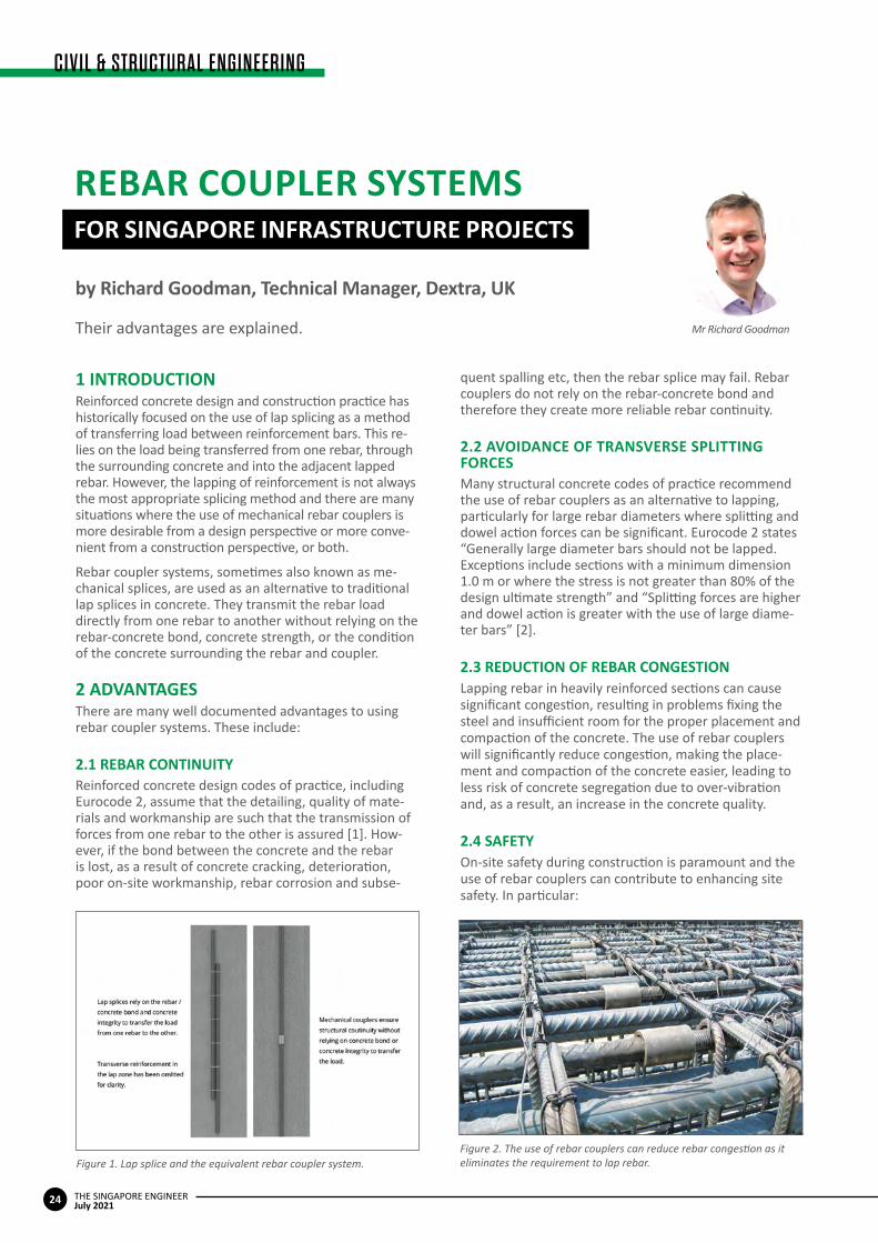
1 INTRODUCTIONReinforced concrete design and construction practice has historically focused on the use of lap splicing as a method of transferring load between reinforcement bars. This re-lies on the load being transferred from one rebar, through the surrounding concrete and into the adjacent lapped rebar. However, the lapping of reinforcement is not always the most appropriate splicing method and there are many situations where the use of mechanical rebar couplers is more desirable from a design perspective or more conve-nient from a construction perspective, or both.
Rebar coupler systems, sometimes also known as me-chanical splices, are used as an alternative to traditional lap splices in concrete. They transmit the rebar load directly from one rebar to another without relying on the rebar-concrete bond, concrete strength, or the condition of the concrete surrounding the rebar and coupler.
2 ADVANTAGESThere are many well documented advantages to using rebar coupler systems. These include:
2.1REBARCONTINUITYReinforced concrete design codes of practice, including Eurocode 2, assume that the detailing, quality of mate-rials and workmanship are such that the transmission of forces from one rebar to the other is assured [1]. How-ever, if the bond between the concrete and the rebar is lost, as a result of concrete cracking, deterioration, poor on-site workmanship, rebar corrosion and subse-
quent spalling etc, then the rebar splice may fail. Rebar couplers do not rely on the rebar-concrete bond and therefore they create more reliable rebar continuity.
2.2AVOIDANCEOFTRANSVERSESPLITTINGFORCESMany structural concrete codes of practice recommend the use of rebar couplers as an alternative to lapping, particularly for large rebar diameters where splitting and dowel action forces can be significant. Eurocode 2 states “Generally large diameter bars should not be lapped. Exceptions include sections with a minimum dimension 1.0 m or where the stress is not greater than 80% of the design ultimate strength” and “Splitting forces are higher and dowel action is greater with the use of large diame-ter bars” [2].
2.3REDUCTIONOFREBARCONGESTIONLapping rebar in heavily reinforced sections can cause significant congestion, resulting in problems fixing the steel and insufficient room for the proper placement and compaction of the concrete. The use of rebar couplers will significantly reduce congestion, making the place-ment and compaction of the concrete easier, leading to less risk of concrete segregation due to over-vibration and, as a result, an increase in the concrete quality.
2.4SAFETYOn-site safety during construction is paramount and the use of rebar couplers can contribute to enhancing site safety. In particular:
Figure 1. Lap splice and the equivalent rebar coupler system.Figure 2. The use of rebar couplers can reduce rebar congestion as it eliminates the requirement to lap rebar.
Mr Richard Goodman
25
CIVIL & STRUCTURAL ENGINEERING
THE SINGAPORE ENGINEERJuly 2021
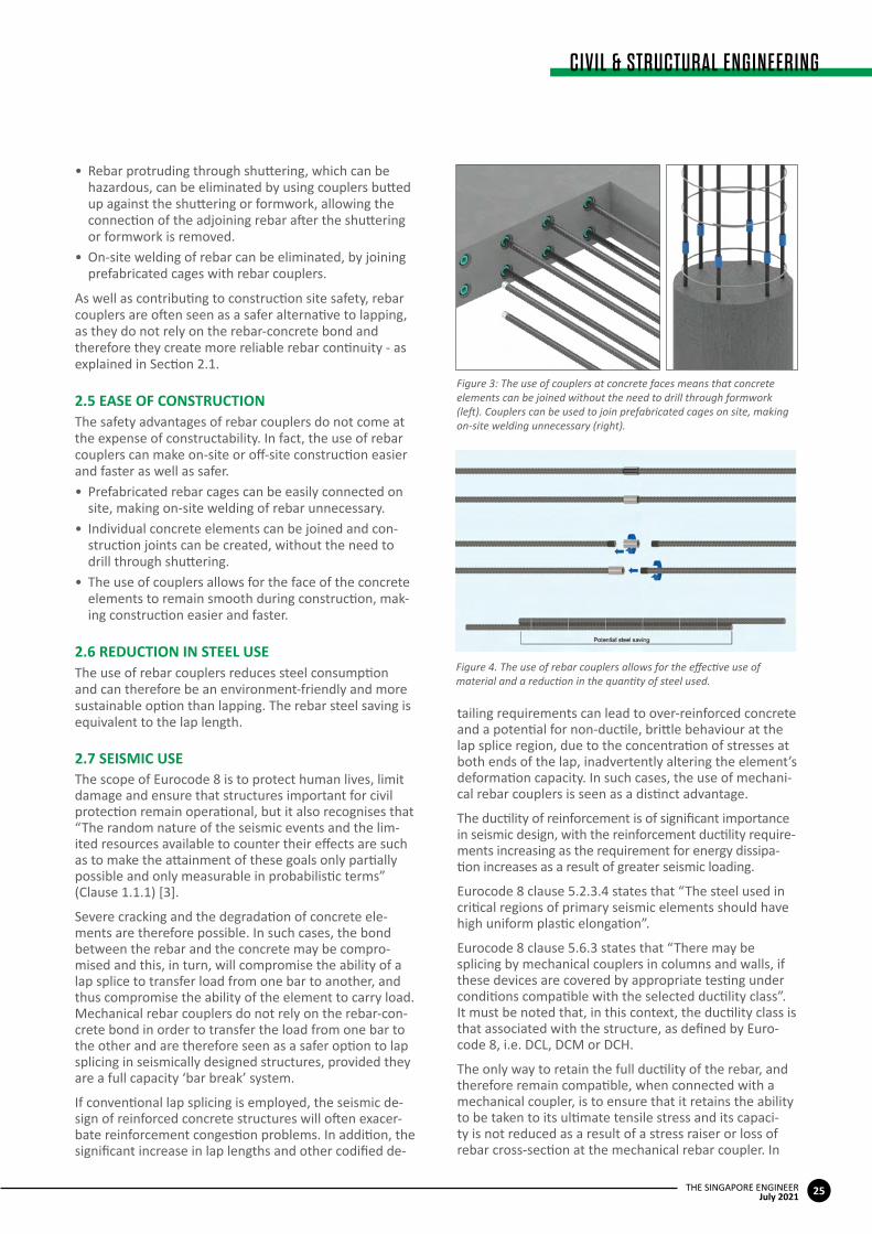
• Rebar protruding through shuttering, which can be hazardous, can be eliminated by using couplers butted up against the shuttering or formwork, allowing the connection of the adjoining rebar after the shuttering or formwork is removed.
• On-site welding of rebar can be eliminated, by joining prefabricated cages with rebar couplers.
As well as contributing to construction site safety, rebar couplers are often seen as a safer alternative to lapping, as they do not rely on the rebar-concrete bond and therefore they create more reliable rebar continuity - as explained in Section 2.1.
2.5EASEOFCONSTRUCTIONThe safety advantages of rebar couplers do not come at the expense of constructability. In fact, the use of rebar couplers can make on-site or off-site construction easier and faster as well as safer.• Prefabricated rebar cages can be easily connected on
site, making on-site welding of rebar unnecessary.• Individual concrete elements can be joined and con-
struction joints can be created, without the need to drill through shuttering.
• The use of couplers allows for the face of the concrete elements to remain smooth during construction, mak-ing construction easier and faster.
2.6REDUCTIONINSTEELUSEThe use of rebar couplers reduces steel consumption and can therefore be an environment-friendly and more sustainable option than lapping. The rebar steel saving is equivalent to the lap length.
2.7SEISMICUSEThe scope of Eurocode 8 is to protect human lives, limit damage and ensure that structures important for civil protection remain operational, but it also recognises that “The random nature of the seismic events and the lim-ited resources available to counter their effects are such as to make the attainment of these goals only partially possible and only measurable in probabilistic terms” (Clause 1.1.1) [3].
Severe cracking and the degradation of concrete ele-ments are therefore possible. In such cases, the bond between the rebar and the concrete may be compro-mised and this, in turn, will compromise the ability of a lap splice to transfer load from one bar to another, and thus compromise the ability of the element to carry load. Mechanical rebar couplers do not rely on the rebar-con-crete bond in order to transfer the load from one bar to the other and are therefore seen as a safer option to lap splicing in seismically designed structures, provided they are a full capacity ‘bar break’ system.
If conventional lap splicing is employed, the seismic de-sign of reinforced concrete structures will often exacer-bate reinforcement congestion problems. In addition, the significant increase in lap lengths and other codified de-
tailing requirements can lead to over-reinforced concrete and a potential for non-ductile, brittle behaviour at the lap splice region, due to the concentration of stresses at both ends of the lap, inadvertently altering the element’s deformation capacity. In such cases, the use of mechani-cal rebar couplers is seen as a distinct advantage.
The ductility of reinforcement is of significant importance in seismic design, with the reinforcement ductility require-ments increasing as the requirement for energy dissipa-tion increases as a result of greater seismic loading.
Eurocode 8 clause 5.2.3.4 states that “The steel used in critical regions of primary seismic elements should have high uniform plastic elongation”.
Eurocode 8 clause 5.6.3 states that “There may be splicing by mechanical couplers in columns and walls, if these devices are covered by appropriate testing under conditions compatible with the selected ductility class”. It must be noted that, in this context, the ductility class is that associated with the structure, as defined by Euro-code 8, i.e. DCL, DCM or DCH.
The only way to retain the full ductility of the rebar, and therefore remain compatible, when connected with a mechanical coupler, is to ensure that it retains the ability to be taken to its ultimate tensile stress and its capaci-ty is not reduced as a result of a stress raiser or loss of rebar cross-section at the mechanical rebar coupler. In
Figure 4. The use of rebar couplers allows for the effective use of material and a reduction in the quantity of steel used.
Figure 3: The use of couplers at concrete faces means that concrete elements can be joined without the need to drill through formwork (left). Couplers can be used to join prefabricated cages on site, making on-site welding unnecessary (right).
CIVIL & STRUCTURAL ENGINEERING
26 THE SINGAPORE ENGINEERJuly 2021
other words, the coupler needs to be what is commonly known as a bar break system, that is, a system which exceeds the ultimate tensile strength of the actual rebar it is connected to, ultimately forcing a tensile failure to occur in the rebar away from the influence of the coupler splice.
Thus, only full capacity, bar break systems should be used in seismically designed reinforced concrete struc-tures, as these are the only types of systems where the ductility of the connecting rebar is not compromised.
2.8SUMMARYOFADVANTAGESMechanical rebar couplers create a continuity of rein-forcement, which is not reliant on the quality or integrity of the concrete. Their use creates less rebar congestion, and more convenient and often safer site practice, as well as reduces the amount of steel used. Their use is not just allowed by Eurocodes but is also recommended under certain circumstances. While different performance levels exist for rebar couplers, the use of a guaranteed bar break coupler means there will ultimately be no brittle failure in a ‘beyond design’ event and the full ductility of the rebar will be maintained - a feature which is recommended in safety-critical applications or if the structure could be subject to impact damage or a seismic event.
3 TYPES OF COUPLER SYSTEMSClause 8.7.1 of Eurocode 2 allows the forces to be transmitted from one rebar to another by the lapping or welding of rebar as well as the use of “mechanical de-vices assuring load transfer in tension-compression or in compression only”. However, compression only couplers are not used or certified for use in Singapore.
Tension-compression couplers can broadly be catego-rised as follows:
(a) Couplers requiring rebar end preparation such as threading or the extrusion of sleeves onto the ends of the rebar.
(b) Repair couplers requiring no rebar end preparation.
(c) Grouted couplers, requiring one or both adjoining rebars to be grouted into the coupler.
In addition, some coupler systems have in-built quality control features whereby each and every connection is automatically and systematically proof loaded by the processing machinery as part of a quality control proce-dure.
Different types of rebar coupler systems are shown in Figure 3-1 of the Singapore Building and Construction Authority (BCA) design guide for the use of Grade B600 rebar [4]. However, the Singapore Land Transport Au-thority’s (LTA) materials and workmanship specification states that “Only straight metric threaded and swaged couplers shall be used. The couplers shall be a type which are simple to install and can be verified to be in-stalled correctly by visual inspection” (Clause 11.18.4.1) [5]. Both of these types of rebar coupler systems fit into category (a) above, are discussed further in Section 3.1,
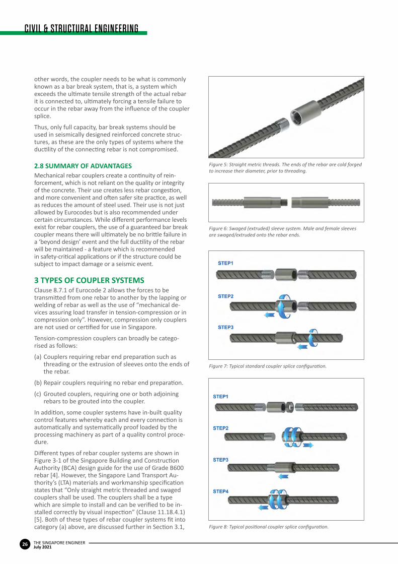
Figure 5: Straight metric threads. The ends of the rebar are cold forged to increase their diameter, prior to threading.
Figure 7: Typical standard coupler splice configuration.
Figure 8: Typical positional coupler splice configuration.
Figure 6: Swaged (extruded) sleeve system. Male and female sleeves are swaged/extruded onto the rebar ends.
27
CIVIL & STRUCTURAL ENGINEERING
THE SINGAPORE ENGINEERJuly 2021
and are illustrated in Figure 5 and Figure 6.
It should be noted that the couplers shown in Figure 5 and Figure 6 are both simple to install and their correct installation can be verified by visual inspection, as the achievement of the appropriate level of male-to-female thread engagement can be clearly seen. When using oth-er types of couplers, it is more difficult, and often impos-sible, to visually verify that they are installed correctly.
Some types of coupler systems require to be torqued to a specific minimum value, in order to achieve the correct level of performance. It is advisable that these types of couplers are marked in some way after the torquing op-eration has been completed, in order to give a visual in-dication that the correct procedures have been followed.
3.1COUPLERSREQUIRINGREBAREND PREPARATIONCoupler systems requiring rebar end preparation are usually the most cost-effective, but their use needs to be pre-planned, as the bar end processing usually occurs at the rebar cut-and-bend depot and the appro-
priate rebar is supplied to the site. These cut-and-bend fabricators would usually hold a stock of couplers and have the machinery to process the rebar ends to suit the coupler system.
Each system is typically available in a number of different configurations. These are:• Standard: Standard couplers require the adjoining
rebar to be rotated to form the connection.• Positional: Positional coupler systems do not require
the rotation of the adjoining rebar.• Bridging: Bridging coupler systems will allow the ad-
joining rebar to be connected without rotation while also bridging a gap.
• Transition: Transition couplers allow connection be-tween rebars of different diameters.
3.1.1StandardcouplersA standard coupler configuration requires the rotation of the adjoining rebar to make the connection.
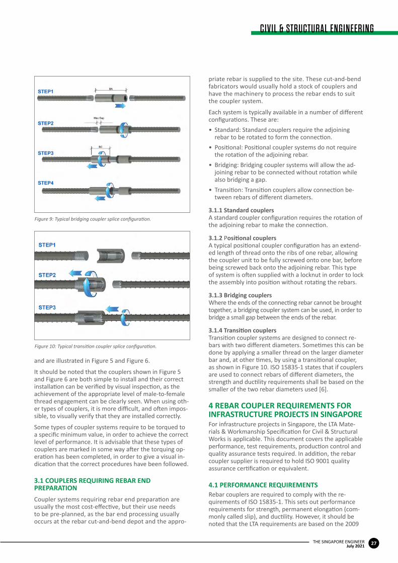
3.1.2 PositionalcouplersA typical positional coupler configuration has an extend-ed length of thread onto the ribs of one rebar, allowing the coupler unit to be fully screwed onto one bar, before being screwed back onto the adjoining rebar. This type of system is often supplied with a locknut in order to lock the assembly into position without rotating the rebars.
3.1.3BridgingcouplersWhere the ends of the connecting rebar cannot be brought together, a bridging coupler system can be used, in order to bridge a small gap between the ends of the rebar.
3.1.4TransitioncouplersTransition coupler systems are designed to connect re-bars with two different diameters. Sometimes this can be done by applying a smaller thread on the larger diameter bar and, at other times, by using a transitional coupler, as shown in Figure 10. ISO 15835-1 states that if couplers are used to connect rebars of different diameters, the strength and ductility requirements shall be based on the smaller of the two rebar diameters used [6].
4REBARCOUPLERREQUIREMENTSFOR INFRASTRUCTURE PROJECTS IN SINGAPOREFor infrastructure projects in Singapore, the LTA Mate-rials & Workmanship Specification for Civil & Structural Works is applicable. This document covers the applicable performance, test requirements, production control and quality assurance tests required. In addition, the rebar coupler supplier is required to hold ISO 9001 quality assurance certification or equivalent.
4.1PERFORMANCEREQUIREMENTSRebar couplers are required to comply with the re-quirements of ISO 15835-1. This sets out performance requirements for strength, permanent elongation (com-monly called slip), and ductility. However, it should be noted that the LTA requirements are based on the 2009
Figure 10: Typical transition coupler splice configuration.
Figure 9: Typical bridging coupler splice configuration.
CIVIL & STRUCTURAL ENGINEERING
28 THE SINGAPORE ENGINEERJuly 2021
version of ISO 15835, rather than the more up-to-date 2018 version.
The LTA specification document also requires all thread-ed rebar coupler systems to undergo systematic proof loading, prior to being released from the cut-and-bend fabricators, with a requirement to mark the rebar to indicate that this has been done. The proof load should be between 75% and 100% of the characteristic yield strength of the rebar.
4.1.1TensilestrengthThe LTA rebar coupler specification document requires that the strength of the assembly be equal to or greater than the required SS 560: 2016 characteristic tensile strength of the rebar used as part of the assembly [7]. For example, when a coupler system is used with grade 500B rebar, the minimum assembly breaking load should equate to a load which produces a stress in the adjoining rebar equal to or greater than 500 x 1.08 = 540 Mpa. 1.08 is the applicable minimum tensile strength/yield strength ratio specified in SS 560.
The standard goes on to say that “failure of the cou-pled bar assembly shall occur in the bar outside the coupler or testing machine grips”. It should be noted that this is different to failure outside of the mechanical splice length, i.e. outside the influence of the coupler, connection or processed bar material, as defined in ISO 15835-1: 2018. For additional safety, and to ensure the adjoining rebar is capable of achieving its full Agt duc-tility (percentage total elongation at maximum force), as described in Section 4.4, it is recommended that the rebar coupler system is capable of achieving a full bar break level of performance, i.e. a failure location outside the length of mechanical splice, as defined in ISO 15835-1: 2018.
4.1.2Permanentelongation/slipThe LTA requirement for permanent elongation, com-monly known as slip, after unloading from 60% of the
characteristic yield strength, is for the value to be not greater than 0.1 mm. The testing procedure for this is the ISO 15835-1: 2018 Option 2 test.
4.1.3DuctilityDuctility is measured in terms of Agt for the adjoining re-bar. The LTA requirement is in line with ISO 15835-1: 2018, with the requirement for recorded values to be greater than 70% of the value for the parent (reference) bar.
4.2TESTINGANDQUALITYCONTROL REQUIREMENTSPrior to acceptance of use, the contractor is required to prepare samples for initial qualification testing. Testing is also required during production, for the project in ques-tion. One assembly is tested during the production of the first 10 sets of couplers, and one assembly is tested per 200 units produced thereafter. One control bar is also required with each coupler assembly. These samples are taken during the processing stage (bar end forging, threading, swaging etc), which would normally take place at the rebar cut-and-bend factory.
Finally, the contractor is required to submit a method statement for assembly, installation and post-installation inspection.
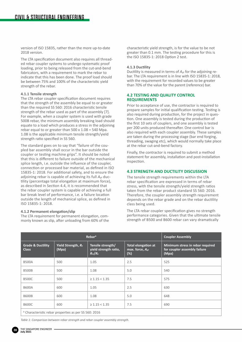
4.3STRENGTHANDDUCTILITYDISCUSSIONThe tensile strength requirements within the LTA rebar specification are expressed in terms of rebar stress, with the tensile strength/yield strength ratios taken from the rebar product standard SS 560: 2016. Therefore, the coupler assembly strength requirement depends on the rebar grade and on the rebar ductility class being used.
The LTA rebar coupler specification gives no strength performance categories. Given that the ultimate tensile strength of B500 and B600 rebar can vary dramatically
Rebara Coupler Assembly
Grade&DuctilityClass
YieldStrength,Re
(Mpa)Tensilestrength/yieldstrengthratio,Rm/Re
Totalelongationatmax.force,Agt
(%)
Minimumstressinrebarrequiredfor coupler assembly failure(Mpa)
B500A 500 1.05 2.5 525
B500B 500 1.08 5.0 540
B500C 500 ≥ 1.15 < 1.35 7.5 575
B600A 600 1.05 2.5 630
B600B 600 1.08 5.0 648
B600C 600 ≥ 1.15 < 1.35 7.5 690
a Characteristic rebar properties as per SS 560: 2016
Table 1: Comparison between rebar strength and rebar coupler assembly strength.

29
CIVIL & STRUCTURAL ENGINEERING
THE SINGAPORE ENGINEERJuly 2021
(for example, SS 560 allows for the ultimate tensile strength of B500C rebar to vary between 575 Mpa and 897 Mpa), this means that there can be a variety of tensile strength performance characteristics of rebar couplers approved for use with the B500 or B600 rebar. If a higher tensile performance level/greater factor of safety is required, then a bar break coupler system should be specified, which requires a tensile failure to occur in the rebar away from the influence of the connection or bar-end processing. This failure mode is defined in ISO 15835-1: 2018 and the failure mode is recorded on laboratory test certificates, as defined in ISO 15835-2: 2018.
The percentage elongation at maximum force (Agt) is the principal measure of SS 560 rebar ductility, and it should be noted that if the rebar coupler system fails before the rebar, the rebar will not reach its maximum force and will therefore exhibit a reduction in Agt ductility. The only way to maintain the full Agt of the rebar system is to have a bar break rebar coupler system.
5REFERENCES[1] EN 1992-1-1 Eurocode 2: Design of concrete structures. Part 1-1: General rules and rules for buildings.[2] EN 1992-1-1 defines large diameter rebar as that having a diameter greater than 32 mm. National Annexes may differ.[3] EN 1998-1 Eurocode 8: Design of structures for earthquake resistance. Part 1: General rules, seismic actions and rules for buildings.[4] BC 5: 2019 Design Guide for the Use of Grade B600 High Strength Reinforcement in Reinforced Concrete Structures. Building and Construction Authority.[5] Materials & Workmanship Specification for Civil & Structural Works. Land Transport Authority Engineering Group Document. E/GD/09/104/A2(a).[6] ISO 15835-1: 2018 Steels for the reinforcement of concrete - Reinforcement couplers for mechanical splices of bars - Part 1: Requirements. International Organization for Standardization.[7] SS 560: 2016 Singapore Standard, Specification of steel for the reinforcement of concrete - Weldable reinforcement steel - Bar, coil and decoiled product.
The Cebu-Cordova Link Expressway (CCLEX) is one of the biggest infrastructure projects being undertaken in the Philippines. The project features a combination of a causeway, a gigantic cable-stayed bridge that will cross the navigable zone of the Cebu Strait, two viaducts and four low height bridges, as well as roadways and pedestrian walkways.
CCLEX is a project undertaken by Cebu Cordova Link Expressway Corporation (CCLEC), in partnership with the local government units of Cebu City and the Municipality of Cordova. CCLEC is a wholly owned subsidiary of MPTC, the toll road arm of Metro Pacific Investments Corporation (MPIC), a publicly listed infrastructure holding company and a member of the MVP Group of Companies.
The CCLEX project aims to provide better transport facilities, while reducing traffic congestion in the region, as well as improving connectivity within Cebu City. It will also support Cordova’s economic growth, as the expressway will position the city as the gateway for island tourism.
After its completion, CCLEX will link Cebu mainland and Mactan Island through Cordova town. The 8.5 km-long toll bridge will feature two lanes that will serve up to 40,000 vehicles a day.
The main bridge will be built with a 400 m cable-stayed main span, with a 60 m navigation clearance, allowing ships to easily navigate through the expressway. The main bridge of the expressway
will connect Guadalupe River to the Shell Island in Cordova, while its colossal viaducts will link it to the causeway and road networks to Mactan.
The design and the construction of this megaproject is undertaken by the Cebu Link Joint Venture (CLJV). The CLJV is a joint-venture partnership between Spain-based Acciona Construccion S A and the Philippines-based First Balfour Inc and D M Consunji Inc.
For the reinforcement of the colossal expressway’s foundations, the contractor chose Dextra’s rebar splicing solutions, including Standard, Bridging as well as Transition splices.
The official ground-breaking of the toll bridge was performed in 2017. It is targeted to be substantially completed by the end of 2021 and open to motorists in the first quarter of 2022.
ColossalbridgeinthePhilippinesnearscompletion
The Cebu-Cordova Link Expressway is expected to be open to motorists in the first quarter of 2022. Image: Cebu Cordova Link Expressway Corporation.


