Embed Size (px)
Citation preview
1094 KSME International Journal, VoL 18 No. 7, pp. 1094~1106, 2004
Sliding Mode Control of Two-Wheeled Welding Mobile Robot for Tracking Smooth Curved Welding Path
Tan Lain Chung, Trong Hieu Bui Department of Mechanical Eng., College of Eng., Pukyong National University,
San 100, Yongdang-Dong, Nam-Gu, Pusan 608-739, Korea
Tan Tien Nguyen Department of Mechanical Eng., Hochiminh City University of Technology,
268 Ly Thuong Kiet, Dist. 10, Hochiminh City, Vietnam
Sang Bong Kim* Department of Mechanical Eng., College of Eng., Pukyong National University,
San 100, Yongdang-Dong, Nam-Gu, Pusan 608-739, Korea
In this paper, a nonlinear controller based on sliding mode control is applied to a two
-wheeled Welding Mobile Robot (WMR) to track a smooth curved welding path at a constant
velocity of the welding point. The mobile robot is considered in terms of dynamics model in
Cartesian coordinates under the presence of external disturbance, and its parameters are exactly
known. It is assumed that the disturbance satisfies the matching condition with a known
boundary. To obtain the controller, the tracking errors are defined, and the two sliding surfaces
are chosen to guarantee that the errors converge to zero asymptotically. Two cases are to be
considered : fixed torch and controllable torch. In addition, a simple way of measuring the errors
is introduced using two potentiometers. The simulation and experiment on a two-wheeled
welding mobile robot are provided to show the effectiveness of the proposed controller.
Key Words : Welding Mobile Robot (WMR), Nonholonomic, Sliding Mode Control
Nomenclature (x, y) : Coordinates of the WMR's center [m]
¢ : Heading angle of the WMR Irad~
: Linear velocity of the WMR's center
[m/s3 OA : Angular velocity of the WMR's center
[rad/s]
co,-~, wtw: Angular velocities of the right and the
left wheels [rad/s~
(xw, yw) : Coordinates of the welding point [m]
Cw :Heading angle of the welding point
[rad]
* Corresponding Author, E-mail : memcl @ pknu.ac.kr TEL : -1-t-82-51-620-1606; FAX : -t-82-51-621-1411 Department of Mechanical Eng., College of Eng., Pukyong National University, San 100, Yongdang- Dong, Nam-Gu, Pusan 608-739, Korea. (Manuscript Received August 26, 2003; Revised April 2, 2004)
uw : Linear velocity of the welding point
[m/sl cow : Angular velocity of the welding point
[rad/s]
xr, yr : Coordinates of the reference point [m]
Cr : Angle between F and x axis [rad]
Ur : Welding velocity [m/s]
OAr : Angular velocity of the reference point
(the rate of change of ~r) [rad/s]
b :Distance between driving wheel and
the symmetric axis ~ml
r : Radius of driving wheel [m]
d : Distance between geometric center and
mass center of the WMR [m]
l : Torch length [m~ M(q) : Symmetric, positive definite inertia ma-
trix
V(q, c)) : Centripetal and coriolis matrix
B (q) : Input transformation matrix
Sliding Mode Control o f Two- Wheeled Welding Mobile Robot for Tracking Smooth Curved Welding ... 1095
A ( q ) : Matrix related with the nonholonomic
constraints r : Control input vector [kgm]
rr~, r~w : Torques of the motors which act on the
right and the left wheels [kgm~
/l : Constraint force vector
u : C o n t r o l law which determines error
dynamics
mc : Mass of the body without the driving
wheels [kg]
mw : M a s s of each driving wheel with its
motor [kg]
Iw : Moment of inertia of each wheel with
its motor about the wheel axis [kgm 2]
Im : Moment of inertia of each wheel with
its motor about the wheel diameter [kgm 2]
Ic : Moment of inertia of the body about
the vertical axis through the mass cen-
ter of the WMR [kgm z]
1. Introduction
Welding automation has been widely used in
all types of manufacturing, and one of the most complex applications is welding systems based on
autonomous robots. Some special welding robots
can provide several benefits in certain welding
applications. Among them, welding mobile robot
used in line welding application can generates the
perfect movements at a certain travel speed, which
makes it possible to produce a consistent weld
penetration and weld strength.
In practice, some various robotic welding sys-
tems have been developed recently. Kim, Ko,
Cho and Kim (2000) developed a three dimen-
sional laser vision system for intelligent shipyard
welding robot to detect the welding position and
to recognize the 3D shape of the welding envi-
ronments. Jeon, Park and Kim (2002) presented
the seam tracking and motion control of two-
wheeled welding mobile robot for lattice type
welding; the control is separated into three dri-
ving motions: straight locomotion, turning loco-
motion, and torch slider control. Kam, Jeon and
Kim (2001) proposed a control algorithm based on "trial and error" method for straight welding
using body positioning sensors and seam tracking
sensor. Both of controllers proposed by Jeon and
Kam have been successfully applied to the prac-
ticed field. Bui, Nguyen, Chung and Kim (2003)
proposed a simple nonlinear controller for the
two-wheeled welding mobile robot tracking a
smooth-curved welding path using Lyapunov
function candidate.
On the other hand, there are several works on
adaptive and sliding mode control theory for
tracking control of mobile robots in literatures,
especially, the mobile robots are considered under
the model uncertainties and disturbances. Fierro
and Lewis (1995) developed a combined kinema-
tics and torque control law using backstepping
approach and asymptotic stability is guaranteed
by Lyapunov theory which can be applied to the
three basic nonholonomic navigat ion: tracking
a reference trajectory, path following and stabili-
zation about a desired posture. Yang and Kim
(1999) proposed a new sliding mode control law
which is robust against initial condition errors,
measurement disturbances and noises in the sen-
sor data to asymptotically stabilize to a desired
trajectory by means of the computed-torque
method. Fukao, Nakagawa and Adachi (2000)
proposed the integration of a kinematic control-
ler and a torque controller for the dynamic
model of a nonholonomic mobile robot. In the
design, a kinematics adaptive tracking controller
is proposed. Then a torque adaptive controller
with unknown parameters is derived using the
kinematic controller. Chwa, Seo, Kim and Choi
(2002) proposed a new sliding mode control
method for trajectory tracking of nonholonomic
wheeled mobile robots presented in two-dimen-
sional polar coordinates in the presence of the
external disturbances; additionally, the control-
ler showed the better effectiveness in the com-
parison with the above in terms of the sensiti-
vity to the parameters of sliding surface. Bui,
Chung, Nguyen and Kim (2003) proposed adap-
tive tracking control of two-wheeled welding
mobile robot with unknown parameters of mo-
ments of inertia in dynamic model.
In this paper, a nonlinear controller using sliding mode control is applied to two-wheeled
1096 Tan Lain Chung, Trong Hieu Bui, Tan Tien Nguyen and Sang Bong Kim
welding mobile robot to track a smooth-curved
welding path. To design the tracking controller,
the errors are defined between the welding point
on the torch and the reference point moving at a
specified constant welding speed on the welding
path. There are two cases of controller: fixed
torch controller and controllable torch control-
ler. The two sliding surfaces are chosen to make
the errors to approach zeros as reasonable as
desired for practical application. The control law
is extracted from the stable conditions respective-
ly. The controllable torch controller gives much
more performance in comparison with the other.
In addition, a simple way for sensing the errors
using potentiometers is introduced to realize the
above controller. The simulation and experi-
mental studies have been conducted to show the
effectiveness of the proposed controller.
2. Dynamic Model of the Welding Mobile Robot
In this section, the dynamic model of a two-
wheeled WMR is considered with nonholonomic
constraints in relation with its coordinates and
the reference welding path.
The WMR is modeled under the following
assumptions :
(I) The radius of welding curve is sufficiently
larger than turning radius of the WMR.
(2) The robot has two driving wheels for body
motion, and those are positioned on an axis
passed through the robot geometric center.
(3) Two passive wheels are installed in front
and rear of the body at the bottom for balance of
mobile platform, and their motion can be ignored
in the dynamics.
(4) The velocity at the point contacted with the
ground in the plane of the wheel is zero.
(5) The center of mass and the center of rota-
tion of the mobile robot are coincided.
(6) A torch slider is located to coincide the axis
through the center of two driving wheels.
(7) A magnet is set up at the bottom of the
robot's center to avoid slipping.
The WMR used in this paper is of a two-
welding torch ~ wheel- driving motors
@ sensor @ proximitysensor
@ torchslide," ~'_) lowerlimitswitch
@ torch-slider-driving motor @ driving wheels
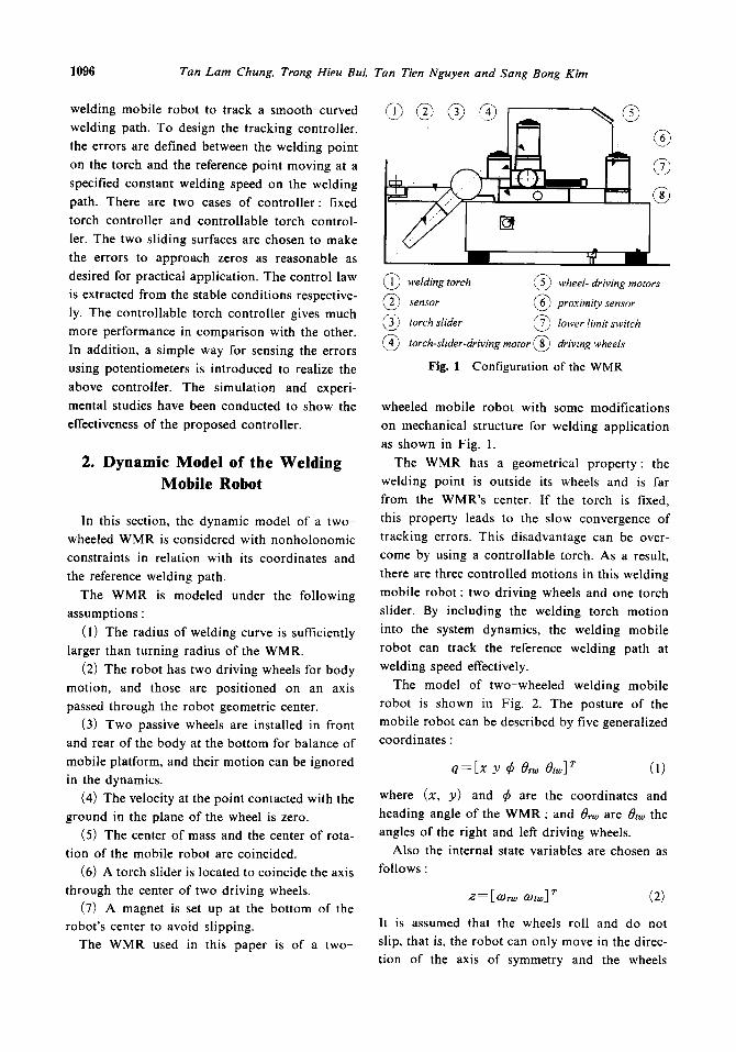
Fig. 1 Configuration of the WMR
wheeled mobile robot with some modifications
on mechanical structure for welding application
as shown in Fig. 1.
The WMR has a geometrical property: the
welding point is outside its wheels and is far
from the WMR's center. If the torch is fixed,
this property leads to the slow convergence of
tracking errors. This disadvantage can be over-
come by using a controllable torch. As a result,
there are three controlled motions in this welding
mobile robot : two driving wheels and one torch
slider. By including the welding torch motion
into the system dynamics, the welding mobile
robot can track the reference welding path at
welding speed effectively.
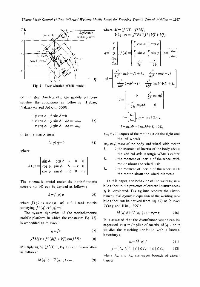
The model of two-wheeled welding mobile
robot is shown in Fig. 2. The posture of the
mobile robot can be described by five generalized
coordinates :
q=Ex Y ¢ Or~ O,w] ~ (1)
where (x, y) and ff are the coordinates and
heading angle of the WMR ; and tg,-a, are ~,w the
angles of the right and left driving wheels.
Also the internal state variables are chosen as
follows :
z = [co~ ~o,~] ~ (2)
It is assumed that the wheels roll and do not
slip, that is, the robot can only move in the direc-
tion of the axis of symmetry and the wheels
Sliding Mode Control of Two- Wheeled Welding Mobile Robot for Tracking Smooth Curved Welding ... 1097
Y - ' e 3
, . , ' ~ Reference t X r , Y r "qJr } " ' ~ " ~ "
Y~ . . . . . . . . . . . . . . . . . . . . . . . . ~!t_\¢_, . . . . . . . . ,,eldi:lf__r_ng path
>'~ . . . . . . . . . . . :---: . . . . . . . ."t," "'- ~ . .
x u x r x 'w.x
Fig. 2 Two-wheeled WMR model
do not slip. Analytically, the mobile platform satisfies the conditions as following (Fukao, Nakagawa and Adachi, 2000):
3) cos ¢- :~ sin ¢ = 0 .~ cos ¢ + P sin ¢+b¢=rwno (3) 2 cos ¢+.9 sin ¢-bd)=roJt~
or in the matrix form
A(q) q=O (4)
where
. [ s i n ¢ - c o s ¢ 0 0 0 ]
A(q)=lCos¢ s i n e b - r 0 [ c o s ¢ s i n e - b 0 - r
The kinematic model under the nonholonomic constraints (4) can be derived as follows:
( 1 = J ( q ) z (5)
where J(q) is n × ( n - m ) a full rank matrix satisfying j r (q) A r (q) =0.
The system dynamics of the nonholonomic mobile platform in which the constraint Eq. (5) is embedded as follows :
(1 =]z (7)
JrMJ2.+JT(M]+ VJ)z=JZBr (8)
Multiplying by (JrB)-l, Eq. (8) can be rewritten as follows :
A~(q) 2 + V(q, (1 )z=r (9)
where/]a¢= (JTB)-1JrM], V(q, z) = (JrB)-~Jr(Mj + VJ)
[o, wJ t_ f g ~ ]
_ [4b ~ ( tub'+i ) +Iw r~ ~ 2 (rnb2_i) 1 M = 2 2
I T 2
0 medq3
r 2
[ - T b mecl(S o
r - - [ rn°] m---mc+2mw, --k z'no j '
I= mcd2 + 2m~bZ + L + 2I,~
rno, Vtw : torques of the motor act on the right and the left wheels
me, row: mass of the body and wheel with motor Ie : the moment of inertia of the body about
the vertical axis through WMR's center Iw : the moment of inertia of the wheel with
motor about the wheel axis I,~ : the moment of inertia of the wheel with
the motor about the wheel diameter
In this paper, the behavior of the welding mo- bile robot in the presence of external disturbances ra is considered. Taking into account the distur- bances, real dynamic equation of the welding mo- bile robot can be derived from Eq. (9) as follows (Yang and Kim, 1999):
l~(q)2+l/(q, 0) z + rd= z" (10)
It is assumed that the disturbance vector can be expressed as a multiplier of matrix A4(q), or it satisfies the matching condition with a known boundary :
r a = M ( q ) f (11)
f = [ f l , f2] r, I f , I<fm,, If2l<<_fm, (12)
where f,~, and fm~ are upper bounds of distur- bances.
1098 Tan Lam Chung, Trong Hieu Bu~ Tan Tien Nguyen and Sang Bong Kim
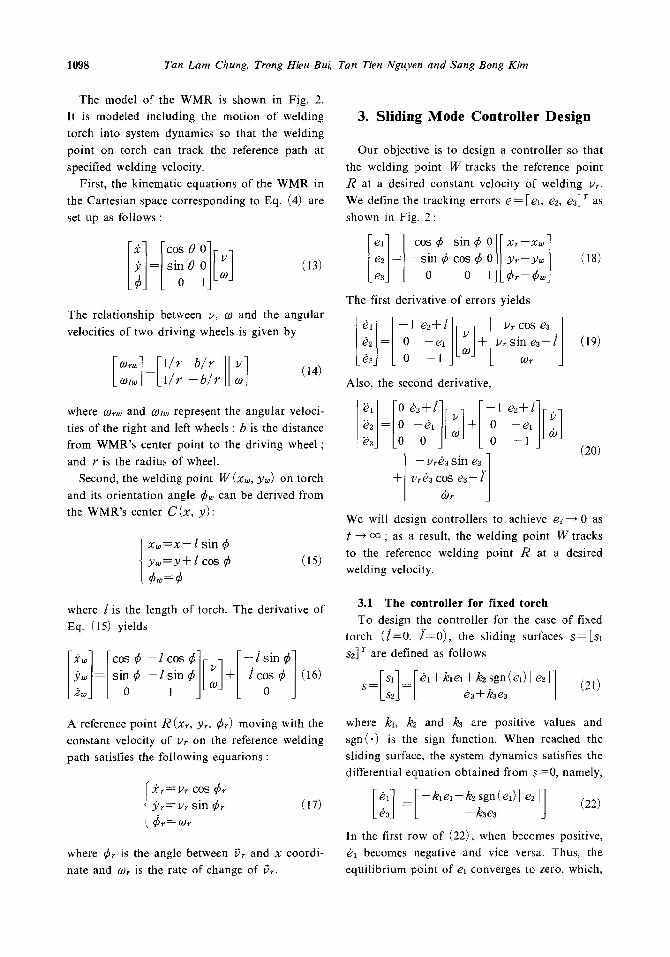
The model of the WMR is shown in Fig. 2.
It is modeled including the motion of welding
torch into system dynamics so that the welding
point on torch can track the reference path at
specified welding velocity.
First, the kinematic equations of the WMR in
the Cartesian space corresponding to Eq. (4) are
set up as follows :
[,1 L 0 0 l] L °j
(13)
The relationship between ~, co and the angular
velocities of two driving wheels is given by
[co~]:[1/r b / r 1[~1 ~,~ L l / r -b/rJL~J
(14)
where COrw and cozw represent the angular veloci-
ties of the right and left wheels ; b is the distance
from WMR's center point to the driving wheel;
and r is the radius of wheel.
Second, the welding point W(xw, y~) on torch
and its orientation angle ¢~, can be derived from
the WMR's center C(x , y) :
x w = x - l sin ¢ y w = y + l cos ¢
¢w=¢ (is)
where l is the length of torch. The derivative of
Eq. (15) yields
lxw cos _,cos lr 1 l-,sin l Ywl=/sin¢%J L 0 - l s i n ¢ l co -4-1c7 ¢ (16)
3. Sliding Mode Control ler Des ign
Our objective is to design a controller so that
the welding point W tracks the reference point
/~ at a desired constant velocity of welding yr.
We define the tracking errors e = [el, e2, es] r as
shown in Fig. 2:
eli [ COS ~ s in ¢ O][Xr--Xw] e z l = l - - s i n q~ cos qS O|| yr--y~ [ (18)
e3J [ 0 0 l J L C r - ¢ w j
The first derivative of errors yields
= +[u~ sin e3- / (19) ~a
Also, the second derivative,
~d [o (2o)
Jr- Yre3 COS e3- i'/ / &, J
We will design controllers to achieve ei--~ 0 as
t --~ co ; as a result, the welding point W tracks
to the reference welding point R at a desired
welding velocity.
3.1 The controller for fixed torch
To design the controller for the case of fixed torch ( ] = 0 , l '=0) , the sliding surfaces s = [ s l
Sz] r are defined as follows
[s l ] [~ ,+k, el+kZ sgn(el)[ ez 1] S= ] [ #s+kse, (21)
A reference point R ( x r , y~, ~r) moving with the
constant velocity of Vr on the reference welding path satisfies the following equations :
{ Xr~-i2r COS ¢r Y.r= Vr sin e r (17)
where Cr is the angle between ~r and x coordi-
nate and (.Or is the rate of change of ~r.
where kl, k2 and k3 are positive values and
sgn(.) is the sign function. When reached the sliding surface, the system dynamics satisfies the
differential equation obtained from s=0 , namely,
In the first row of (22), when becomes positive,
~1 becomes negative and vice versa. Thus, the
equilibrium point of el converges to zero, which,
Sliding Mode Control of Two- Wheeled Welding Mobile Robot for Tracking Smooth Curved Welding ... 1099
in turn, leads to the asymptotic convergence of [ ezl to zero. Similarly, the second row, es also converges to zero.
As a feedback linearization of the system, the control input is defined by computed-torque method as follows (Yang and Kim, 1999)
M ( q ) 2 r + V(q, q ) z + M ( q ) u = r (23)
where u = [ul u2] r is a control law which deter- mines error dynamics.
Substitution of the control law (23) into Eq. (10) yields
2 + / = 2 ~ + u (24)
~ ~ - 2 ~ = u - f
The following procedure is to design the con- trol law u which stabilizes the sliding surface vector s. From Eqs. (20) and (21) with / = 0 and l'=O, we have
E::]F
In this application, the speed of the welding point is constant ( I ) r=0) , Eq. (25) can be rewritten as follows
(26) + [ ~2oJ+ (e2+1)0(o-~,~3 sin e3]
For the simplicity, Eq. (26) is modified as below
[ ~ , + k ~ + k , sgn(e~)] e2]] ~3+k3~3
[ ( ~ - ~ ) 1 r820J+ (e2+l) cb-Vr83sin e31 ---[/~-~,/J+[ 0 (27)
+ [kt 8t + k2 sgn (et) l 8z I] L k~8~ ]
Substituting Eqs. (21) and (24) into Eq. (27), it reduces to
"1 r,,,l+ rs, l+ v:<,,+ (,:+,/<~,-,,~, ~m ',] D2J---Lu~J LAJ L o
+[k,8, +k~ sgn(el) [ 821] (28)
L k383
Let the control law u = [ul u2] r be
0] Lsgn (s~) / LaJ Lo
+[k,8,+~ sgn(e,/1 82 q L k28~ J
where q; and Pi, ( i = ! , 2) are positive constant values, then Eq. (28) becomes
$ = -- Q s - P sgn (s) + f (30)
Define the Lyapunov function as
1 r V = ~ s s (31)
Its derivative yields
= s r ( - Q s - P s g n ( s ) + f ) (32)
=-s'Os - (PI s I-fs) where,
s _- ,rs'l; o_-[;, oo] If we choose qi~O, P i~ / , , , ( i = 1 , 2) then 1)" turns to be negative semi-definite, and the control law u stabilizes sliding surfaces (21).
3.2 The control ler for control lable torch
To design the controller, the sliding surfaces S = [Sl S2] r are defined as
[s , ] [01+kxe, ] S ~ Lsd to~+k, ed (33)
Similarly, following the above steps with the new sliding surfaces of Eq. (33), the control law u can be derived as
[uq I" °V]+Ib' 0][ ,,o/s,/1 u2J=L0 q2J[s~] L0/~Jk sgn(s2)J
+Ikd LgesJ
We have to design one more controller for torch as follows :
1100 Tan Lain Chung, Trong Hieu Bui, Tan Tien Nguyen and Sang Bong Kim
Let the Lyapunov function candidate be
l V---~- e~ (35)
17=e2d~=e2( -exoJ+ ur sin e 3 - i ) (36)
To achieve 17<0, we choose control law for the torch as follows:
l = ur sin e3+ k22e2- glO) (37)
3.3 Chattering phenomena elimination
In general, chattering must be eliminated for the controller to perform properly. This can be achieved by smoothing out the control discon- tinuity in a thin boundary layer neighboring the switching surface (Jean-Jacques E. Slotine and Weiping Li, 1991.)
In this case, the welding velocity is rather slow, 7.5 mm/s ; consequently, the chattering pheno- mena makes the motor alternatively change di- rection, forward and backward by sampling time, to make it impossible to implement the controller. Therefore, a smooth controller is used with a thin boundary layer 0=0.1 instead of the switching
controller from Eq. (34) by substituting sign(.) function with sat(.) function, that is,
[ 0
+[klel] [k~e~J
where the saturation function is defined as
sat (y) = y if I Y I ~ ' (39)
sat (y) =sgn (y) otherwise
With smoothing approach, the controller (38) can be implemented to the practical welding mo- bile robot totally. The effectiveness of the con- troller can be seen through the simulation and the
experiment.
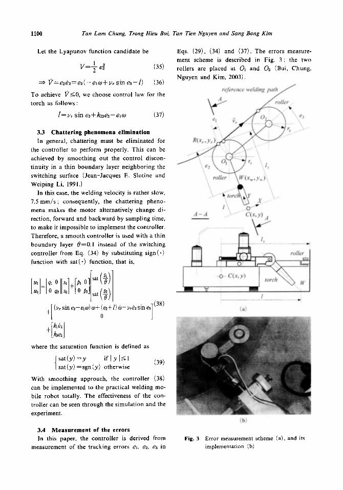
Eqs. (29), (34) and (37). The errors measure- ment scheme is described in Fig. 3: the two rollers are placed at Oa and 02 (Bui, Chung, Nguyen and Kim, 2003).
reference wehting p a t h / /
A - A .... ~-" C(x,Y) d
l :
(a)
3.4 Measurement of the errors In this paper, the controller is derived from
measurement of the tracking errors ex, e2, e3 in Fig. 3
(b)
Error measurement scheme (a), and its implementation (b)
Sliding Mode Control o f Two- Wheeled Welding Mobile Robot for Tracking Smooth Curved Welding ... 1101
The roller at 01 is used to specify the two errors
el, e2 and the other, error e3. The distance be-
tween the two rollers O102 is chosen according
to the curve radius of the reference welding path
at the contact R ( X r , Yr) such as ~ r / / O ~ . The
rollers' diameters are chosen small enough to
overcome the friction force.
From Fig. 3(a), we have the relationships
ea = -- rs s in e3
e2 = ( l , - - l ) -- r s (1 - -cos e3) (40)
e 3 : / (OIC, O102) - - a ' / 2
where rs is the radius of roller, and ls is the
length of sensor. And the two potentiometers are
used for measuring the errors : one linear poten-
tiometer for measuring ( l s - - l ) and one rotating
potentiometer, the angular between X coordinate
of WMR and ~r.
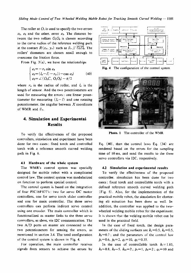
Fig. 4 The configuration of the control system
4. Simulation and Experimental Results
To verify the effectiveness of the proposed
controllers, simulation and experiment have been
done for two cases: fixed torch and controlled
torch with a reference smooth curved welding
path in Fig. 6.
4.1 Hardware of the whole system
The WMR's control system was specially
designed for mobile robot with a complicated
control law. The control system was modularized
on function to perform special control.
The control system is based on the integration
of four PICI6F877's : two for servo DC motor
controllers, one for servo torch slider controller
and one for main controller. The three servo
controllers can perform indirect servo control
using one encoder. The main controller which is
functionalized as master links to the three servo
controllers, as slave, via I2C communication. The
two A / D ports on master are connected to the
two potentiometers for sensing the errors, as
mentioned in section 3.4. The total configuration
of the control system is shown in Fig. 4.
For operation, the main controller receives
signals from sensors to achieve the errors by
Photo. 1 The controller of the WMR
Eq. (40), then the control laws Eq. (34) are
rendered based on the errors for the sampling
time of l0 ms, and send the results to the three
servo controllers via I2C, respectively.
4.2 Simulation and experimental results
To verify the effectiveness of the proposed
controller, simulation has been done for two
cases: fixed torch and controllable torch with a
defined reference smooth curved welding path
(Fig. 5). Also, for the implementation of the
practical mobile robot, the simulation for chatter-
ing eli mination has been done as well. In
addition, the controller was applied to the two-
wheeled welding mobile robot for the experiment.
It is shown that the welding mobile robot can be
used in the practical field.
In the case of fixed torch, the design para-
meters of the sliding surfaces are k1=0.5, k2=0.5,
ka=0.7; and the parameters of the control law
i01=0.6, P2=2, q l=10, q2----0.35.
In the case of controllable torch kl----1.85,
k2=0.8, ka=5, kz2=2 ; p l = l , ,02=2; q l = 1 0 and
1102 Tan Lain Chung, Trong Hieu BuL Tan Tien Nguyen and Sang Bong K im
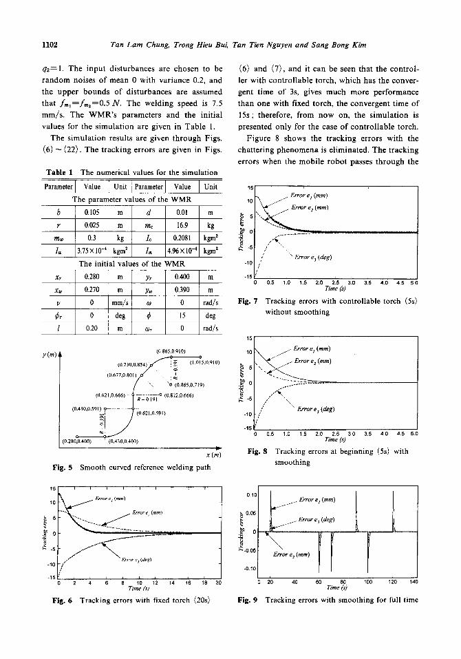
q2 = 1 . The input disturbances are chosen to be
random noises of mean 0 with variance 0.2, and
the upper bounds o f disturbances are assumed
that f m , = f m ~ : 0 . 5 N . The welding speed is 7.5
mm/s . The W M R ' s parameters and the init ial
values for the s imulat ion are given in Table 1.
The s imulat ion results are given through Figs.
(6) ~ (22). The t racking errors are given in Figs.
Table 1 The numerical values for the simulation
Param0t0rl Valae I uni' I Parameter I Val.e I unit The parameter values of the WMR
b 0.105 m d 0.01 m
r 0.025 m mc 16.9 kg
m~ 0.3 kg lc 0.2081 kgm z
Iv 375x10 -4 kgm z I . 496Xl0 -4 kgm 2
The initial values of the WMR
Xr 0.280 m Yr 0.400 m
xw 0.270 m y~ 0.390 m
v 0 mm/s o) 0 rad/s
~r 0 deg ~ 15 deg
l 0.20 m c0~ 0 rad/s
y (m) (0.865,0.q I O)
(0.730,0.854) . f ~ ~. (I.0~5J).910)
( 0 . 6 7 7 , 0 . 8 0 H / ~ " \ - - x~O (0.865,0.719)
(0.621,0.666) ~ -RLO~-I~ io (0.812,0.666) /
(o.,,o.o.,o,, ............... ]
° : 10.280,0.400) (0.430,0.400)
I= x (m)
Fig. 5 Smooth curved reference welding path
(6) and (7), and it can be seen that the control-
ler with control lable torch, which has the conver-
gent t ime of 3s, gives much more performance
than one with fixed torch, the convergent time of
15s; therefore, from now on, the s imulat ion is
presented only for the case of cont ro l lable torch.
Figure 8 shows the tracking errors with the
chattering phenomena is eliminated. The t racking
errors when the mobi le robot passes through the
15
10
[5
t& -5
-10
-15
Fig. 7
//Error e I (ram) ~ e (ram) '%, 2
/ " Error e z (deg)
d.5 1'.o 1.s 2.0 Z5 3.o ~15 4.0 4.s s.o Time (s)
Tracking errors with controllable torch (5s)
without smoothing
10 / Error e t (ram)
t, "~ / Error e 2 (ram)
b. -s [ , / '.. -lO[/" \ Err°re3(deg)
-15 ~' 0 0.5 1.0 1.5 2.0 2.5 3.0 3.5 4.0 4.5 5.0
Time (s)
Fig. 8 Tracking errors at beginning (5s) with
smoothing
15 , i , i i i i
10 ~ Err°ret(mm)
°:'\ .......... ...... ,.,
~ -5 ~ Error e, (deg) -10 " / ' f l " ~ -15
0 2 i ; 8 1'0 1'2 1'4 1'6 1'8 Time (st
Fig. 6 Tracking errors with fixed torch (20s)
' 0.1011 I L [ ~ j e r ~ o r e , ( m m ) I
b o.os I I g
t a I[ l~..O.OS e 2 (ram)
L I I
2o o 20 40 80 80 loo 12o 14o Time (s)
Fig. 9 Tracking errors with smoothing for full time
Sliding Mode Control of Two- Wheeled WeMing Mobile Robot for Tracking Smooth Curved Welding ... 1103
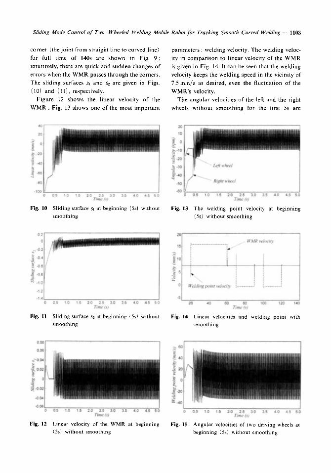
corner (the joint from straight line to curved line)
for full time of 140s are shown in Fig. 9;
intuitively, there are quick and sudden changes of
errors when the WMR passes through the corners.
The sliding surfaces s~ and s2 are given in Figs.
(10) and (11), respectively.
Figure 12 shows the linear velocity of the
WMR ; Fig. 13 shows one of the most important
parameters : welding velocity. The welding veloc-
ity in comparison to linear velocity of the WMR
is given in Fig. 14. It can be seen that the welding
velocity keeps the welding speed in the vicinity of
7.5 mm/s as desired, even the fluctuation of the
WMR's velocity.
The angular velocities of the left and the right
wheels without smoothing lbr the first 5s are
0.0
0.0
,..:~ 0.0
0.0
-0.0
-0 0
-00, 0
Fig. 10
0.5 1.0 15 2.0 2.5 3.0 3.5 4.0 4.5 5 0 Time (s)
Sliding surface s, at beginning (5s) without smoothing
6O
40 -~.
20
.~ o
~z .~ -20
~: -40
0
Fig. 13
0.5 1 0 1.5 2.0 2.5 3.0 3 5 4 0 4.5 5.0 Time (s)
The welding point velocity at beginning (5s) without smoothing
0 2
0
., -02
"~ -04
~. -06
-08
'~ -~ 0
-1.2
- 1 . 4
Fig. 11
0.5 '1 0 1 5 2.0 2 5 3.0 35 4.0 4 5 5 Time (s)
Sliding surface s2 at beginning (5s) without smoothing
Fig.
. . . . . . . . . . . . . . . . . . . . ]
_ , i I
W M R veloci ty
[ i : i q
, 1 W e l d i n g po in t velocio , : . . . . . . . . . . " ; . . . . . . . . . '-'
20 40 60 80 lO0 12o 140 Time (st
14 Linear velocities and welding point with smoothing
4O
2O
o
.~, -20
4 o
-60
-80
-lOO
Fig. 12
0.5 10 15 2 0 2 5 3 0 35 4 0 4 5 5 0 mim~.* ix1
Linear velocity of the WMR at beginning (5s) without smoothing
20
10
5 0
,~, -10 k~
" ~ - 2 0
.~ -30
,~- -40
-50
-60 0
Fig. 15
0.5 1 0 1.5 2.0 2.5 3.0 3.5 4.0 4 5 5.0 Time (s)
Angular velocities of two driving wheels at beginning (5s) without smoothing
1 1 0 4 Tan Lain Chung, Trong Hieu BuL Tan Tien Nguyen and Sang Bong Kim
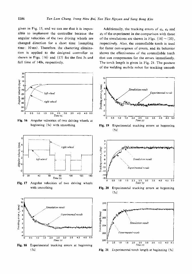
given in Fig. 15, and we can see that it is impos-
sible to implement the controller because the
angular velocities of the two driving wheels are
changed direction for a short time (sampling
time: 10 ms). Therefore, the chattering elimina-
tion is applied to the designed controller as
shown in Figs. (16) and (17) for the first 5s and
full time of 140s, respectively.
3O
20
10 go ~ -10
-20
-30
-40
-50
-6£
Fig. 16
:; left wheel
J ~ " " ~ right wheel
,/ 0.5 1.0 1.5 2.0 2.5 3.0 3.5 4.0 4.5 5.0
Time (s)
A n g u l a r velocities of two driving wheels at beginning (5s) with smoothing
Additionally, the tracking errors of e~, ez and
e3 of the experiment in the comparison with those
of the simulations are shown in Figs. (18) ~ (20),
respectively. Also, the controllable torch is used
for faster convergence of errors, and its behavior
shows the effectiveness of the controllable torch
that can compensates for the errors immediately.
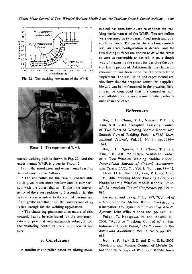
The torch length is given in Fig. 21. The posture
of the welding mobile robot for tracking smooth
10
8
4
.~ 2
~ o -2
-4
Simulation result Experimental result
"W'C r . , w~ t'Y141 . . . .
Fig.
0 0.5 1.0 1.5 2.0 2.5 30 3.5 4 0 4.5 5.0 Time (s)
19 Experimental tracking errors at beginning (Ss)
8
~. 2
-2
. . . . . . . . . . . . . . . . . . . . ]
"~efi wheel , _ _
', . . . . . . . . . _, ,, . . . . . . . . . . .
20 40 60 80 1 O0 120 140
Fig. 17
Time (s) I 0 0.5 1.0 15 2.0 2.5 3.0 3.5 4.0 4.5 5.0
A n g u l a r velocities of two driving wheels Time(s)
with smoothing Fig. 20 Experimental tracking errors at beginning
(Ss)
14
12
g - 8
~ s ~ 4
~ 2 0
-2
-4
Fig. 18
~ / " Simulation result
~ / / j//Experimental result
05 1.0 1.5 2,0 2.5 3.0 3.5 4.0 4 5 5 0 T ime ( s )
Experimental tracking errors at beginning (Ss)
4 2
/ ~ 4 -6 "\.,,, Simulation result -8 \ \
~ -10 XExperimental result ~ -12
-14 -16
210 [
208
~ 206
• ~ 204
:202
200
\
\\
tion result
Experimental result
05 1.0 1.5 2"0 2.5 3 0 3.5 4.0 4.5 50 Time (s)
Fig. 21 Experimental torch length at beginning ( 5 s )
Sliding Mode Control of Two-Wheeled Welding Mobile Robot for Tracking Smooth Curved Welding ... 1105
1.0
0.9
0.8
~ 0.6
~ 0.5
o4~-
0.2 i
0.1 : 0.2
Fig. 22
i i r I I " ~ . . . . ]
(x ey)-Reykrence
welding path ~ " ~ c l ~ (x ~, y~) - Welding point i
, i i I i i . . . . J .
0.3 0A 0.5 0.6 0.7 0 8 0.9 1.0 11 1.2
x - c o o r d i n a t e ( m )
The tracking movement of the WMR
control has been introduced to enhance the trac-
I king performances of the WMR. The controllers
were designed in two cases : fixed torch and con-
trollable torch. To design the tracking control-
lers, an error configuration is defined and the
two sliding surfaces are chosen to drive the errors
to zero as reasonable as desired. Also, a simple
way of measuring the errors for deriving the con-
trol law is proposed. Additionally, the chattering
elimination has been done for the controller to
implement. The simulation and experimental res-
ults show that the proposed controller is applica-
ble and can be implemented in the practical field.
It can be concluded that the controller with
controllable torch gives the much better perform-
ance than the other.
References
Photo. 2 The experimental WMR
curved welding path is shown in Fig. 22. And the
experimental WMR is given in Photo. 2.
From the simulation and experimental results,
we can conclude as follows
• The controller for the case of controllable
torch gives much more performance in compari-
son with the other, that is, (i) the time conver-
gence of the errors reduces to 3 seconds ; (ii) the
system is less sensitive to the control parameters,
if not gentle and flat ; (iii) the convergence of e2
is fast enough for the welding application.
• The chattering phenomena, as nature of this
control, has to be eliminated for the implemen-
tation of practical welding mobile robot ; if not,
the chattering controller fails to implement for
sure.
5. Conclusions
A nonlinear controller based on sliding mode
Bui, T.H., Chung, T.L. , Nguyen, T.T. and
Kim, S.B., 2003, "Adaptive Tracking Control
of Two-Wheeled Welding Mobile Robot with
Smooth Curved Welding Path," KSME Inter- national Journal, Vol. 17, No. 11, pp. 1684~
1694.
Bui, T.H. , Nguyen, T.T. , Chung, T.L. and
Kim, S. B., 2003, "A Simple Nonlinear Control
of a Two-Wheeled Welding Mobile Robot,"
International Journal of Control, Automation, and System (IJCAS), Vol. 1, No. I, pp. 35--42.
Chwa, D. K., Seo J. H., Kim, P.J. and Choi,
J. Y., 2002, "Sliding Mode Tracking Control of
Nonholonomic Wheeled Mobile Robots," Proc. of the American Control Conference, pp. 3991-
996.
Fierro, R. and Lewis, F. L., 1997, "Control of
a Nonholonomic Mobile Robot: Backstepping
Kinematics into Dynamics," Journal of Robotic Systems, John Wiley & Sons, Inc., pp. 149~ 163.
Fukao, T., Nakagawa, H. and Adachi, N.,
2000, "Adaptive Tracking Control of a Non-
holonomic Mobile Robot," IEEE Trans. on Ro- botics and Automation, Vol. 16, No. 5, pp. 609--
615.
Jeon, Y.B., Park, S.S. and Kim, S. B., 2002,
"Modeling and Motion Control of Mobile Ro-
bot for Lattice Type of Welding," KSME Inter-
1106 Tan Lain Chung, Trong Hieu Bui, Tan Tien Nguyen and Sang Bong Kim
national Journal, Vol. 16, No. 1, pp. 83--93. Jean-Jacques E. Slotine and Weiping Li, 1991,
Applied Nonlinear Control, Prentice-Hall Inter- national, Inc., pp. 122--125.
Kam, B.O., Jeon, Y.B. and Kim, S. B., 2001, "Motion Control of Two-Wheeled Welding Mo- bile Robot with Seam Tracking Sensor," Proc.
IEEE Industrial Electronics, Vol. 2, pp. 851 ~ 856. Kanayama, Y., Kimura, Y., Miyazaki, F. and
Noguchi, T., 1991, "A Stable Tracking Control Method for a Nonholonomic Mobile Robot," Proc. IEEE Intelligent Robots and Systems Work-
shop, Japan, Vol. 3, pp. 1236- 1241. Kim, M. Y., Ko, K. W., Cho, H. S. and Kim, J.
H., 2000, "Visual Sensing and Recognition of Welding Environment for Intelligent Shipyard
Welding Robots," Proc. IEEE Intelligent Robots and Systems, Vol. 3, pp. 2159--2165.
Lee, T.C., Lee, C. H. and Teng, C.C., 1999, "Adaptive Tracking Control of Nonholonomic Mobile Robot by Computed Torque," Proc. IEEE Decision and Control, pp. 1254--1259.
Yang, J.M. and Kim, J.H., 1999, "Sliding Mode Control for Trajectory Tracking of Non- holonomic Wheeled Mobile Robots," IEEE
Trans. Robotics and Automation, Vol. 15, No. 3, pp. 578~587.
Yun, X. and Yamamoto, Y., 1993, "Internal Dynamics of a Wheeled Mobile Robot," Proc.
IEEE Intelligent Robots and Systems, pp. 1288~ 1294.


