Embed Size (px)
Citation preview
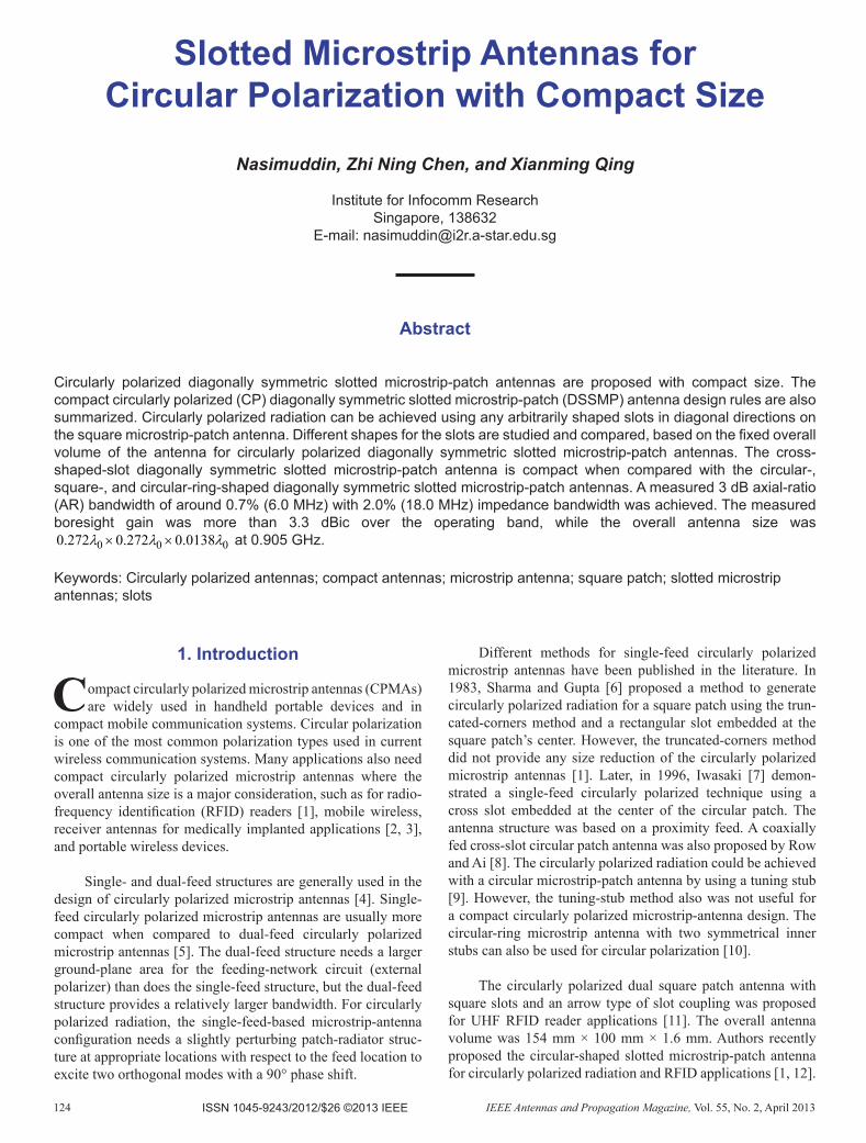
124 IEEE Antennas and Propagation Magazine, Vol. 55, No. 2, April 2013
Slotted Microstrip Antennas for CircularPolarizationwithCompactSize
Nasimuddin, Zhi Ning Chen, and Xianming Qing
Institute for Infocomm ResearchSingapore, 138632
E-mail: [email protected]
Abstract
Circularly polarized diagonally symmetric slotted microstrip-patch antennas are proposed with compact size. The compact circularly polarized (CP) diagonally symmetric slotted microstrip-patch (DSSMP) antenna design rules are also summarized. Circularly polarized radiation can be achieved using any arbitrarily shaped slots in diagonal directions on the square microstrip-patch antenna. Different shapes for the slots are studied and compared, based on the fi xed overall volume of the antenna for circularly polarized diagonally symmetric slotted microstrip-patch antennas. The cross-shaped-slot diagonally symmetric slotted microstrip-patch antenna is compact when compared with the circular-, square-, and circular-ring-shaped diagonally symmetric slotted microstrip-patch antennas. A measured 3 dB axial-ratio (AR) bandwidth of around 0.7% (6.0 MHz) with 2.0% (18.0 MHz) impedance bandwidth was achieved. The measured boresight gain was more than 3.3 dBic over the operating band, while the overall antenna size was
0 0 00.272 0.272 0.0138λ λ λ× × at 0.905 GHz. Keywords: Circularly polarized antennas; compact antennas; microstrip antenna; square patch; slotted microstrip antennas; slots
1.Introduction
Compact circularly polarized microstrip antennas (CPMAs) are widely used in handheld portable devices and in
compact mobile communication systems. Circular polarization is one of the most common polarization types used in current wireless communication systems. Many appli cations also need compact circularly polarized microstrip antennas where the overall antenna size is a major considera tion, such as for radio-frequency identifi cation (RFID) readers [1], mobile wireless, receiver antennas for medically implanted applications [2, 3], and portable wireless devices.
Single- and dual-feed structures are generally used in the design of circularly polarized microstrip antennas [4]. Single-feed circularly polarized microstrip antennas are usually more compact when compared to dual-feed circularly polarized microstrip antennas [5]. The dual-feed structure needs a larger ground-plane area for the feeding-network circuit (external polarizer) than does the single-feed structure, but the dual-feed structure provides a relatively larger bandwidth. For circularly polarized radiation, the single-feed-based microstrip-antenna confi guration needs a slightly perturbing patch-radiator struc-ture at appropriate locations with respect to the feed location to excite two orthogonal modes with a 90° phase shift.
Different methods for single-feed circularly polarized microstrip antennas have been published in the literature. In 1983, Sharma and Gupta [6] proposed a method to generate circularly polarized radiation for a square patch using the trun-cated-corners method and a rectangular slot embedded at the square patch’s center. However, the truncated-corners method did not provide any size reduction of the circularly polarized microstrip antennas [1]. Later, in 1996, Iwasaki [7] demon-strated a single-feed circularly polarized technique using a cross slot embedded at the center of the circular patch. The antenna structure was based on a proximity feed. A coaxially fed cross-slot circular patch antenna was also proposed by Row and Ai [8]. The circularly polarized radiation could be achieved with a circular microstrip-patch antenna by using a tuning stub [9]. However, the tuning-stub method also was not useful for a compact circularly polarized microstrip-antenna design. The circular-ring microstrip antenna with two symmet rical inner stubs can also be used for circular polarization [10].
The circularly polarized dual square patch antenna with square slots and an arrow type of slot coupling was proposed for UHF RFID reader applications [11]. The overall antenna volume was 154 mm × 100 mm × 1.6 mm. Authors recently proposed the circular-shaped slotted microstrip-patch antenna for circularly polarized radiation and RFID applications [1, 12].
ISSN 1045-9243/2012/$26 ©2013 IEEE
For size reduction of the antenna, four symmetrical slits along the orthogonal directions of the circular-shaped slotted patch radiator were used. The compact circularly polarized microstrip antenna was proposed for handheld RFID reader requirements.
In this paper, a method is proposed to generate circularly polarized radiation with compact size of the square microstrip antenna using a diagonally symmetric slotted microstrip-patch structure. The proposed method is based on symmetrically embedded slots along the diagonal directions on the microstrip square-patch radiator. Circularly polarized diagonally sym-metric slotted microstrip-patch antennas are proposed and studied based on circular-, square-, circular-ring-, and cross-shaped slots. A larger slot perimeter type of slot based on a diagonally symmetric slotted microstrip-patch antenna is more compact when compared with the circular-, square-, and cir-cular-ring-shaped-slot diagonally symmetric slotted micro-strip-patch antennas. By slightly varying the perimeter of the slots in the diagonal directions of the square patch, circularly polarized radiation can be obtained. In addition, the proposed technique can be also used for size reduction of the circularly polarized microstrip antennas. Some design guidelines for the proposed compact circularly polarized diagonally symmetric slotted microstrip-patch antenna are also discussed. The meas-ured results are compared with simulated results obtained from the IE3D commercial simulator [13].
2.AntennaStructureandDesign
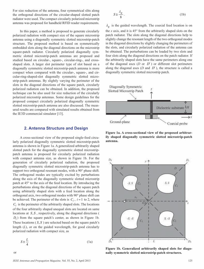
A cross-sectional view of the proposed single-feed circu-larly polarized diagonally symmetric slotted microstrip-patch antenna is shown in Figure 1a. A generalized arbitrarily shaped slotted patch for the diagonally symmetric slotted microstrip-patch antenna is proposed for circularly polarized radiation with compact antenna size, as shown in Figure 1b. For the generation of circularly polarized radiation, the pro posed diagonally symmetric slotted microstrip-patch antenna has to support two orthogonal resonant modes, with a 90° phase shift. The orthogonal modes are typically excited by perturbations along the axis of the diagonally symmetric slot ted microstrip patch at 45° to the axis of the feed location. By introducing the perturbations along the diagonal directions of the square patch using arbitrarily shaped slots with a feed location along the orthogonal axis, two orthogonal modes with 90° phase shift can be achieved. The perimeter of the slots is iC , 1i = to 2, where
iC is the perimeter of the arbitrarily shaped slots. The locations of the four arbitrarily shaped unequal slots are located on same locations at ,S S , respec tively, along the diagonal directions (
iD ) from the square patch’s center, as shown in Figure 1b. These locations ( ,S S ) are selected based on the square patch’s length (L), or on the guided wavelength, for good circularly polarized radiation with compact size, as
4LS ≅ (1a)
or
8gS
λ≅ . (1b)
gλ is the guided wavelength. The coaxial feed location is on the x axis, and it is 45° from the arbitrarily shaped slots on the patch radiator. The slots along the diagonal directions help to slightly change the resonant length of the two orthogonal modes in the diagonal directions by slightly changing the perimeters of the slots, and circularly polarized radiation of the antenna can be obtained. The perturbations can be loaded by two slots and four slots along the diagonal directions on the patch radiator. If the arbitrarily shaped slots have the same perimeters along one of the diagonal axes (D or D′ ) or differ ent slot perimeters along the diagonal axes (D and D′ ), the structure is called a diagonally symmetric slotted microstrip patch.
Figure 1b. Generalized arbitrarily shaped slots for diago-nally symmetric slotted microstrip-patch structures.
Figure 1a. A cross-sectional view of the proposed arbitrar-ily shaped diagonally symmetric slotted microstrip-patch antenna.
AP_Mag_Apr_2013_Final.indd 124 5/18/2013 8:57:25 PM
IEEE Antennas and Propagation Magazine, Vol. 55, No. 2, April 2013 125
Slotted Microstrip Antennas for CircularPolarizationwithCompactSize
Nasimuddin, Zhi Ning Chen, and Xianming Qing
Institute for Infocomm ResearchSingapore, 138632
E-mail: [email protected]
Abstract
Circularly polarized diagonally symmetric slotted microstrip-patch antennas are proposed with compact size. The compact circularly polarized (CP) diagonally symmetric slotted microstrip-patch (DSSMP) antenna design rules are also summarized. Circularly polarized radiation can be achieved using any arbitrarily shaped slots in diagonal directions on the square microstrip-patch antenna. Different shapes for the slots are studied and compared, based on the fi xed overall volume of the antenna for circularly polarized diagonally symmetric slotted microstrip-patch antennas. The cross-shaped-slot diagonally symmetric slotted microstrip-patch antenna is compact when compared with the circular-, square-, and circular-ring-shaped diagonally symmetric slotted microstrip-patch antennas. A measured 3 dB axial-ratio (AR) bandwidth of around 0.7% (6.0 MHz) with 2.0% (18.0 MHz) impedance bandwidth was achieved. The measured boresight gain was more than 3.3 dBic over the operating band, while the overall antenna size was
0 0 00.272 0.272 0.0138λ λ λ× × at 0.905 GHz. Keywords: Circularly polarized antennas; compact antennas; microstrip antenna; square patch; slotted microstrip antennas; slots
1.Introduction
Compact circularly polarized microstrip antennas (CPMAs) are widely used in handheld portable devices and in
compact mobile communication systems. Circular polarization is one of the most common polarization types used in current wireless communication systems. Many appli cations also need compact circularly polarized microstrip antennas where the overall antenna size is a major considera tion, such as for radio-frequency identifi cation (RFID) readers [1], mobile wireless, receiver antennas for medically implanted applications [2, 3], and portable wireless devices.
Single- and dual-feed structures are generally used in the design of circularly polarized microstrip antennas [4]. Single-feed circularly polarized microstrip antennas are usually more compact when compared to dual-feed circularly polarized microstrip antennas [5]. The dual-feed structure needs a larger ground-plane area for the feeding-network circuit (external polarizer) than does the single-feed structure, but the dual-feed structure provides a relatively larger bandwidth. For circularly polarized radiation, the single-feed-based microstrip-antenna confi guration needs a slightly perturbing patch-radiator struc-ture at appropriate locations with respect to the feed location to excite two orthogonal modes with a 90° phase shift.
Different methods for single-feed circularly polarized microstrip antennas have been published in the literature. In 1983, Sharma and Gupta [6] proposed a method to generate circularly polarized radiation for a square patch using the trun-cated-corners method and a rectangular slot embedded at the square patch’s center. However, the truncated-corners method did not provide any size reduction of the circularly polarized microstrip antennas [1]. Later, in 1996, Iwasaki [7] demon-strated a single-feed circularly polarized technique using a cross slot embedded at the center of the circular patch. The antenna structure was based on a proximity feed. A coaxially fed cross-slot circular patch antenna was also proposed by Row and Ai [8]. The circularly polarized radiation could be achieved with a circular microstrip-patch antenna by using a tuning stub [9]. However, the tuning-stub method also was not useful for a compact circularly polarized microstrip-antenna design. The circular-ring microstrip antenna with two symmet rical inner stubs can also be used for circular polarization [10].
The circularly polarized dual square patch antenna with square slots and an arrow type of slot coupling was proposed for UHF RFID reader applications [11]. The overall antenna volume was 154 mm × 100 mm × 1.6 mm. Authors recently proposed the circular-shaped slotted microstrip-patch antenna for circularly polarized radiation and RFID applications [1, 12].
For size reduction of the antenna, four symmetrical slits along the orthogonal directions of the circular-shaped slotted patch radiator were used. The compact circularly polarized microstrip antenna was proposed for handheld RFID reader requirements.
In this paper, a method is proposed to generate circularly polarized radiation with compact size of the square microstrip antenna using a diagonally symmetric slotted microstrip-patch structure. The proposed method is based on symmetrically embedded slots along the diagonal directions on the microstrip square-patch radiator. Circularly polarized diagonally sym-metric slotted microstrip-patch antennas are proposed and studied based on circular-, square-, circular-ring-, and cross-shaped slots. A larger slot perimeter type of slot based on a diagonally symmetric slotted microstrip-patch antenna is more compact when compared with the circular-, square-, and cir-cular-ring-shaped-slot diagonally symmetric slotted micro-strip-patch antennas. By slightly varying the perimeter of the slots in the diagonal directions of the square patch, circularly polarized radiation can be obtained. In addition, the proposed technique can be also used for size reduction of the circularly polarized microstrip antennas. Some design guidelines for the proposed compact circularly polarized diagonally symmetric slotted microstrip-patch antenna are also discussed. The meas-ured results are compared with simulated results obtained from the IE3D commercial simulator [13].
2.AntennaStructureandDesign
A cross-sectional view of the proposed single-feed circu-larly polarized diagonally symmetric slotted microstrip-patch antenna is shown in Figure 1a. A generalized arbitrarily shaped slotted patch for the diagonally symmetric slotted microstrip-patch antenna is proposed for circularly polarized radiation with compact antenna size, as shown in Figure 1b. For the generation of circularly polarized radiation, the pro posed diagonally symmetric slotted microstrip-patch antenna has to support two orthogonal resonant modes, with a 90° phase shift. The orthogonal modes are typically excited by perturbations along the axis of the diagonally symmetric slot ted microstrip patch at 45° to the axis of the feed location. By introducing the perturbations along the diagonal directions of the square patch using arbitrarily shaped slots with a feed location along the orthogonal axis, two orthogonal modes with 90° phase shift can be achieved. The perimeter of the slots is iC , 1i = to 2, where
iC is the perimeter of the arbitrarily shaped slots. The locations of the four arbitrarily shaped unequal slots are located on same locations at ,S S , respec tively, along the diagonal directions (
iD ) from the square patch’s center, as shown in Figure 1b. These locations ( ,S S ) are selected based on the square patch’s length (L), or on the guided wavelength, for good circularly polarized radiation with compact size, as
4LS ≅ (1a)
or
8gS
λ≅ . (1b)
gλ is the guided wavelength. The coaxial feed location is on the x axis, and it is 45° from the arbitrarily shaped slots on the patch radiator. The slots along the diagonal directions help to slightly change the resonant length of the two orthogonal modes in the diagonal directions by slightly changing the perimeters of the slots, and circularly polarized radiation of the antenna can be obtained. The perturbations can be loaded by two slots and four slots along the diagonal directions on the patch radiator. If the arbitrarily shaped slots have the same perimeters along one of the diagonal axes (D or D′ ) or differ ent slot perimeters along the diagonal axes (D and D′ ), the structure is called a diagonally symmetric slotted microstrip patch.
Figure 1b. Generalized arbitrarily shaped slots for diago-nally symmetric slotted microstrip-patch structures.
Figure 1a. A cross-sectional view of the proposed arbitrar-ily shaped diagonally symmetric slotted microstrip-patch antenna.
AP_Mag_Apr_2013_Final.indd 125 5/18/2013 8:57:26 PM
126 IEEE Antennas and Propagation Magazine, Vol. 55, No. 2, April 2013
The conditions for circularly polarized radiation based on the slot perimeters are as follows:
• For a two-slot-based diagonally symmetric slotted microstrip-patch antenna: 1 0C > and 2 0C = , or
2 0C > and 1 0C = .
• For a four-slot-based diagonally symmetric slotted microstrip-patch antenna: When 1C is different from 2C , then either 2 1C C> or 1 2C C> should be satisfi ed.
The design guidelines for the circularly polarized diago-nally symmetric slotted microstrip-patch antenna are summa-rized, based on simulation, as follows:
1. Determine the initial dimensions of the square patch according to the operating frequency with around 10% higher than that of the desired operat ing frequency and the antenna size constraint;
2. Optimize the coaxial feed location to achieve good impedance matching;
3. Insert the arbitrarily shaped slots along the diagonal directions with locations of ,S S as given in Equa-tion (1);
4. Optimize the arbitrarily shaped slot sizes for the best circularly polarized radiation at the desired operating frequency, based on the relationship for the slot perimeters given above. The operating fre-quency can be adjusted by changing the number of slots, the slots’ shape, and the slots’ size;
If the desired performance over the required frequency-band is not achieved at the end of Step 4, the initial parameters in Step 1 should be changed and the steps iterated. The right-hand and left-hand circularly polarized radiation can be changed based on the ratio of the slot perimeters or on the feed location’s axis.
The square patch was proposed for study of the diago nally symmetric slotted microstrip-patch antennas in this paper. The antennas were designed at around 900 MHz. A square patch length (L) of 78.0 mm ( 00.23λ ) and a ground-plane area of 90.0 mm × 90.0 mm ( 00.27λ × 00.27λ ) were selected. The proposed diagonally symmetric slotted micro strip-patch antennas were designed on an RO3004C substrate (with a thickness of 4.572H = mm ( 00.0137λ ), a dielectric constant of 3.38, and a loss tangent of 0.0027). The coaxial feed location ( 0x ) was on the x axis. The overall antenna vol ume was designed based on the suitability for hand held/portable RFID reader applications. The input and radia tion performance of the antennas was studied based on the fi xed overall antenna volume and the area of the square patch radiator. The conventional truncated-corners square patch and rectangular slotted square patch techniques [6] were also com pared with the proposed
technique to obtain the circularly polarized radiation of the single-feed microstrip antennas.
3.ExamplesofDSSMPantenna
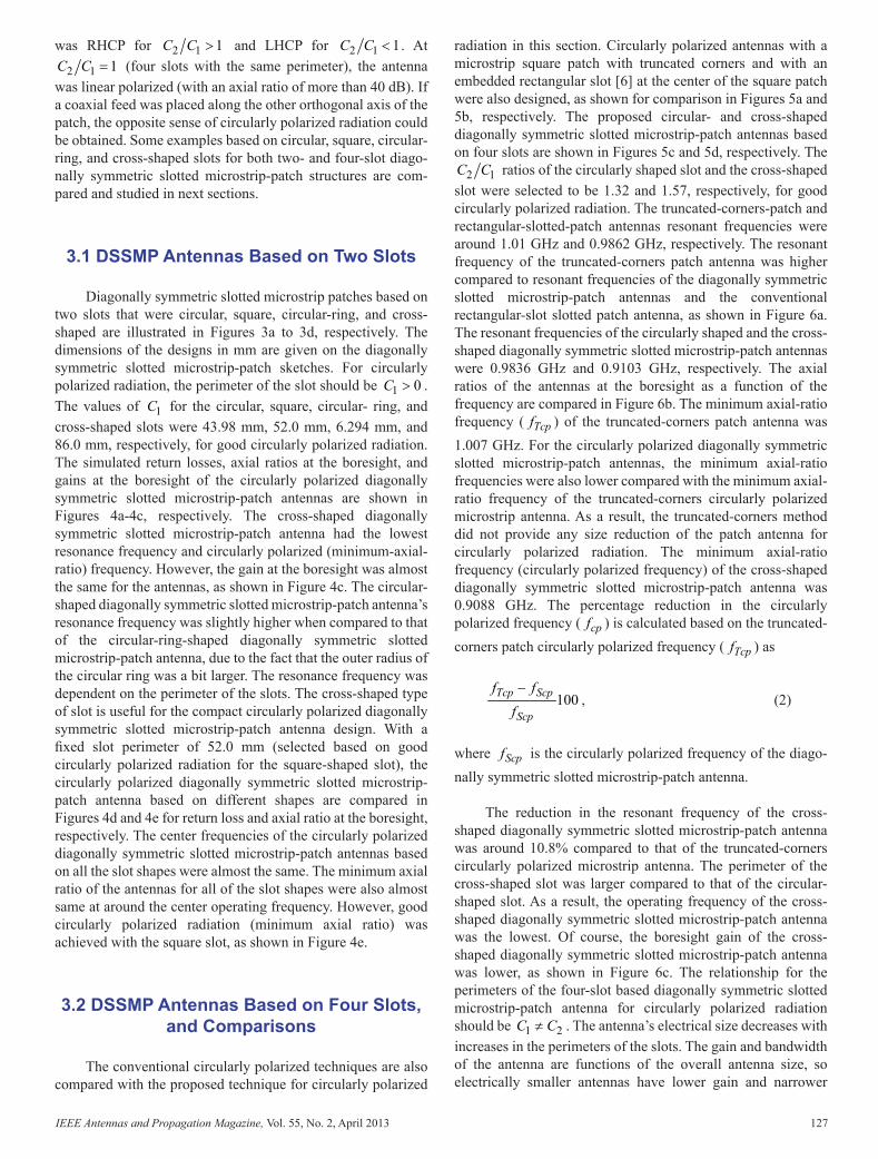
In this section, examples of the circularly polarized diago-nally symmetric slotted microstrip-patch antennas were studied based on two and four circular-shaped slots. Figure 2 shows the simulated axial ratio at the boresight as a function of the variation of 2 1C C (the ratio of perimeters of the slots). 1C was fi xed (44 mm) and 2C was varied. The dotted horizon tal line shows the 3 dB axial-ratio (AR) range. For 2 1 0C C = to 0.4, left-handed circularly polarized (LHCP) radiation was achieved as shown in the region colored yellow in Figure 2. When 2 1 0C C = , 2 0C = and 1 0C > , the struc ture was a circularly polarized diagonally symmetric slotted microstrip-patch antenna based on two slots. The 2 1C C range for right-handed circularly polarized (RHCP) was approximately from 1.24 to 1.41, as shown in the fi gure by the region colored gray. The best circularly polarized radiation was achieved at around
2 1 1.32C C = . This was the case of a circularly polarized diagonally symmetric slotted microstrip-patch antenna based on four slots. The operating frequency (minimum axial ratio) is also plotted in the fi gure, and it decreased with an increase in the 2 1C C ratio ( 2C increased with fi xed 1C ). The slotted perimeter on the patch increased with an increase in the 2 1C C ratio, so that the surface-cur rent path on the patch radiator was increased and the operating frequency was shifted down. The diagonally symmetric slotted microstrip-patch antenna based on four slots was more com pact compared to the diagonally symmetric slotted microstrip-patch antenna based on two slots. This is a very important design consideration for compact circularly polarized micro strip antennas. The proposed antenna
Figure 2. The variations of the axial ratio at the boresight and of the operating frequency with the perimeters of the slots.
was RHCP for 2 1 1C C > and LHCP for 2 1 1C C < . At
2 1 1C C = (four slots with the same perimeter), the antenna was linear polar ized (with an axial ratio of more than 40 dB). If a coaxial feed was placed along the other orthogonal axis of the patch, the opposite sense of circularly polarized radiation could be obtained. Some examples based on circular, square, circular-ring, and cross-shaped slots for both two- and four-slot diago-nally symmetric slotted microstrip-patch structures are com-pared and studied in next sections.
3.1DSSMPAntennasBasedonTwoSlots
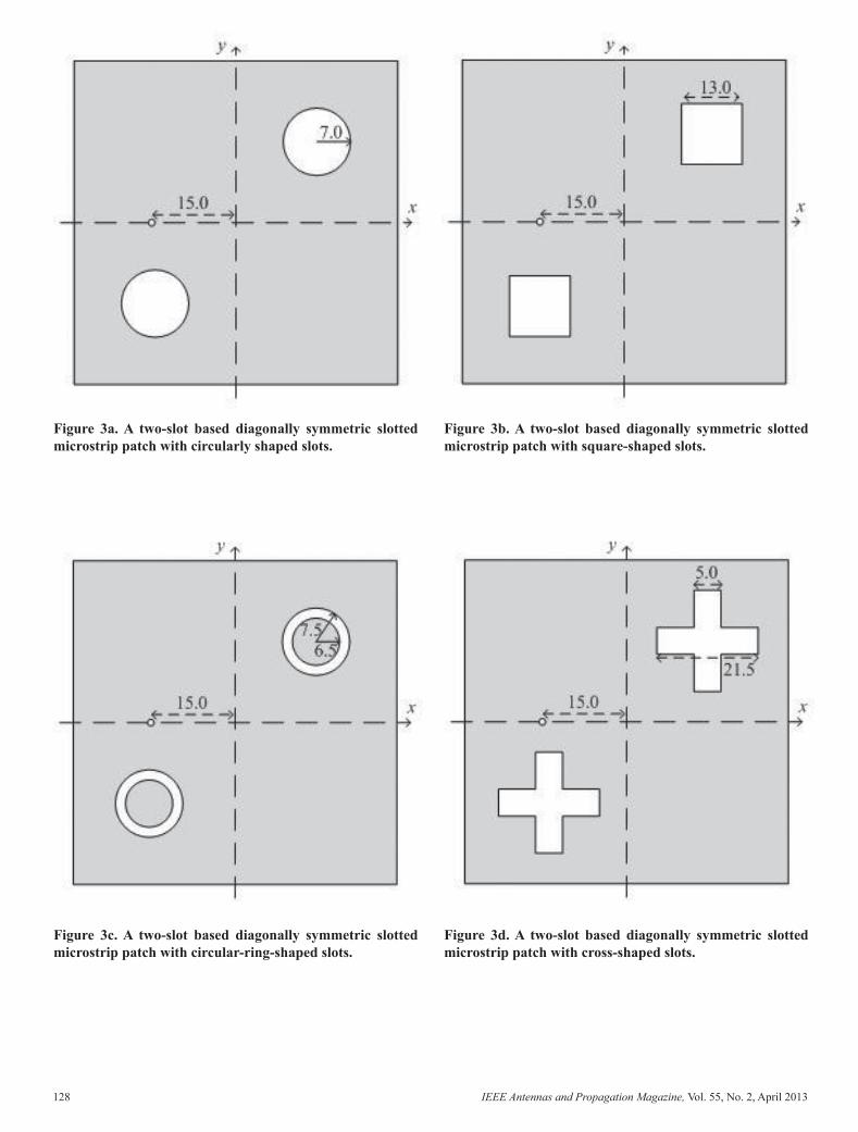
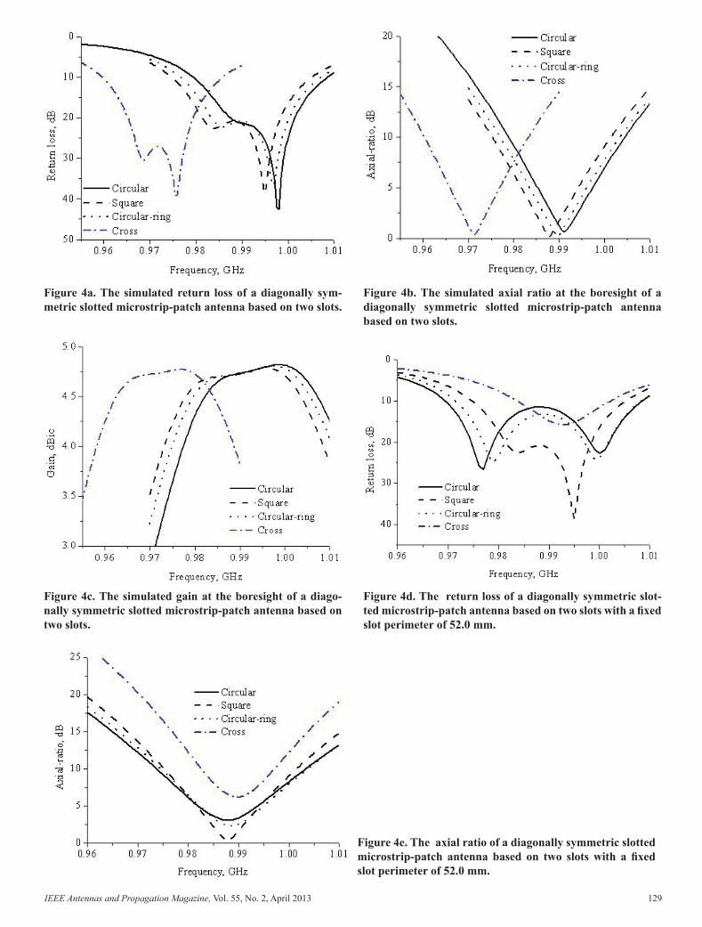
Diagonally symmetric slotted microstrip patches based on two slots that were circular, square, circular-ring, and cross-shaped are illustrated in Figures 3a to 3d, respectively. The dimensions of the designs in mm are given on the diago nally symmetric slotted microstrip-patch sketches. For circu larly polarized radiation, the perimeter of the slot should be 1 0C > . The values of 1C for the circular, square, circular- ring, and cross-shaped slots were 43.98 mm, 52.0 mm, 6.294 mm, and 86.0 mm, respectively, for good circularly polarized radiation. The simulated return losses, axial ratios at the boresight, and gains at the boresight of the circularly polarized diagonally symmetric slotted microstrip-patch antennas are shown in Figures 4a-4c, respectively. The cross-shaped diagonally symmetric slotted microstrip-patch antenna had the lowest resonance frequency and circularly polarized (minimum-axial-ratio) frequency. However, the gain at the boresight was almost the same for the antennas, as shown in Figure 4c. The circular-shaped diagonally symmetric slotted microstrip-patch antenna’s resonance frequency was slightly higher when compared to that of the circular-ring-shaped diagonally symmetric slotted microstrip-patch antenna, due to the fact that the outer radius of the circular ring was a bit lar ger. The resonance frequency was dependent on the perimeter of the slots. The cross-shaped type of slot is useful for the compact circularly polarized diagonally symmetric slotted microstrip-patch antenna design. With a fi xed slot perimeter of 52.0 mm (selected based on good circularly polarized radia tion for the square-shaped slot), the circularly polarized diago nally symmetric slotted microstrip-patch antenna based on different shapes are compared in Figures 4d and 4e for return loss and axial ratio at the boresight, respectively. The center frequencies of the circularly polarized diagonally symmetric slotted microstrip-patch antennas based on all the slot shapes were almost the same. The minimum axial ratio of the anten nas for all of the slot shapes were also almost same at around the center operating frequency. However, good circularly polarized radiation (minimum axial ratio) was achieved with the square slot, as shown in Figure 4e.
3.2DSSMPAntennasBasedonFourSlots,and Comparisons
The conventional circularly polarized techniques are also compared with the proposed technique for circularly polarized
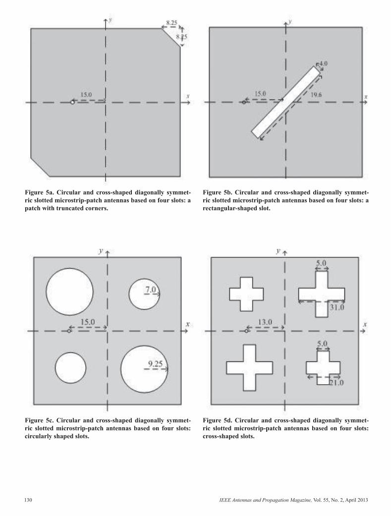
radiation in this section. Circularly polarized antennas with a microstrip square patch with truncated corners and with an embedded rectangular slot [6] at the center of the square patch were also designed, as shown for comparison in Figures 5a and 5b, respectively. The proposed circular- and cross-shaped diagonally symmetric slotted microstrip-patch antennas based on four slots are shown in Figures 5c and 5d, respectively. The
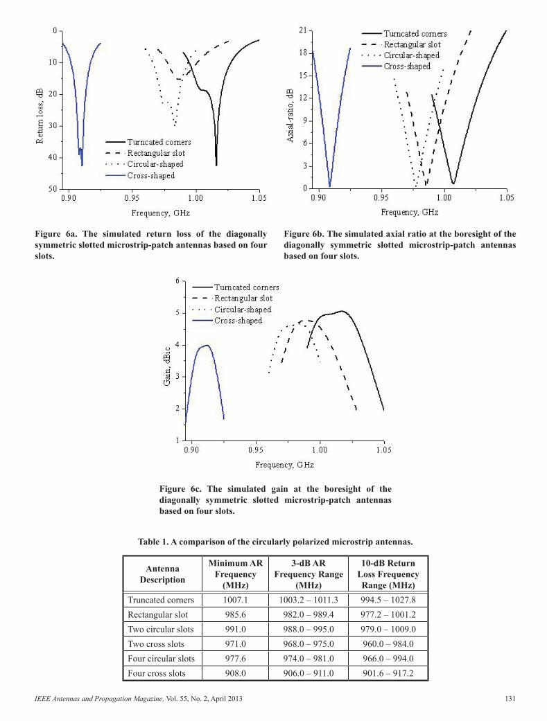
2 1C C ratios of the circularly shaped slot and the cross-shaped slot were selected to be 1.32 and 1.57, respectively, for good circularly polarized radiation. The truncated-corners-patch and rectangular-slotted-patch antennas resonant fre quencies were around 1.01 GHz and 0.9862 GHz, respec tively. The resonant frequency of the truncated-corners patch antenna was higher compared to resonant frequencies of the diagonally symmetric slotted microstrip-patch antennas and the conventional rectangular-slot slotted patch antenna, as shown in Figure 6a. The resonant frequencies of the circularly shaped and the cross-shaped diagonally symmetric slotted microstrip-patch antennas were 0.9836 GHz and 0.9103 GHz, respectively. The axial ratios of the antennas at the boresight as a function of the frequency are compared in Figure 6b. The minimum axial-ratio frequency ( Tcpf ) of the truncated-cor ners patch antenna was 1.007 GHz. For the circularly polar ized diagonally symmetric slotted microstrip-patch antennas, the minimum axial-ratio frequencies were also lower com pared with the minimum axial-ratio frequency of the trun cated-corners circularly polarized microstrip antenna. As a result, the truncated-corners method did not provide any size reduction of the patch antenna for circularly polarized radia tion. The minimum axial-ratio frequency (circularly polarized frequency) of the cross-shaped diagonally symmetric slotted microstrip-patch antenna was 0.9088 GHz. The percentage reduction in the circularly polarized frequency ( cpf ) is calcu lated based on the truncated-corners patch circularly polarized frequency ( Tcpf ) as
100Tcp Scp
Scp
f ff−
, (2)
where Scpf is the circularly polarized frequency of the diago-nally symmetric slotted microstrip-patch antenna.
The reduction in the resonant frequency of the cross-shaped diagonally symmetric slotted microstrip-patch antenna was around 10.8% compared to that of the truncated-corners circularly polarized microstrip antenna. The perimeter of the cross-shaped slot was larger compared to that of the circular-shaped slot. As a result, the operating frequency of the cross-shaped diagonally symmetric slotted microstrip-patch antenna was the lowest. Of course, the boresight gain of the cross-shaped diagonally symmetric slotted microstrip-patch antenna was lower, as shown in Figure 6c. The relationship for the perimeters of the four-slot based diagonally symmetric slotted microstrip-patch antenna for circularly polarized radiation should be 1 2C C≠ . The antenna’s electrical size decreases with increases in the perimeters of the slots. The gain and bandwidth of the antenna are functions of the overall antenna size, so electrically smaller antennas have lower gain and nar rower
AP_Mag_Apr_2013_Final.indd 126 5/18/2013 8:57:26 PM
IEEE Antennas and Propagation Magazine, Vol. 55, No. 2, April 2013 127
The conditions for circularly polarized radiation based on the slot perimeters are as follows:
• For a two-slot-based diagonally symmetric slotted microstrip-patch antenna: 1 0C > and 2 0C = , or
2 0C > and 1 0C = .
• For a four-slot-based diagonally symmetric slotted microstrip-patch antenna: When 1C is different from 2C , then either 2 1C C> or 1 2C C> should be satisfi ed.
The design guidelines for the circularly polarized diago-nally symmetric slotted microstrip-patch antenna are summa-rized, based on simulation, as follows:
1. Determine the initial dimensions of the square patch according to the operating frequency with around 10% higher than that of the desired operat ing frequency and the antenna size constraint;
2. Optimize the coaxial feed location to achieve good impedance matching;
3. Insert the arbitrarily shaped slots along the diagonal directions with locations of ,S S as given in Equa-tion (1);
4. Optimize the arbitrarily shaped slot sizes for the best circularly polarized radiation at the desired operating frequency, based on the relationship for the slot perimeters given above. The operating fre-quency can be adjusted by changing the number of slots, the slots’ shape, and the slots’ size;
If the desired performance over the required frequency-band is not achieved at the end of Step 4, the initial parameters in Step 1 should be changed and the steps iterated. The right-hand and left-hand circularly polarized radiation can be changed based on the ratio of the slot perimeters or on the feed location’s axis.
The square patch was proposed for study of the diago nally symmetric slotted microstrip-patch antennas in this paper. The antennas were designed at around 900 MHz. A square patch length (L) of 78.0 mm ( 00.23λ ) and a ground-plane area of 90.0 mm × 90.0 mm ( 00.27λ × 00.27λ ) were selected. The proposed diagonally symmetric slotted micro strip-patch antennas were designed on an RO3004C substrate (with a thickness of 4.572H = mm ( 00.0137λ ), a dielectric constant of 3.38, and a loss tangent of 0.0027). The coaxial feed location ( 0x ) was on the x axis. The overall antenna vol ume was designed based on the suitability for hand held/portable RFID reader applications. The input and radia tion performance of the antennas was studied based on the fi xed overall antenna volume and the area of the square patch radiator. The conventional truncated-corners square patch and rectangular slotted square patch techniques [6] were also com pared with the proposed
technique to obtain the circularly polarized radiation of the single-feed microstrip antennas.
3.ExamplesofDSSMPantenna
In this section, examples of the circularly polarized diago-nally symmetric slotted microstrip-patch antennas were studied based on two and four circular-shaped slots. Figure 2 shows the simulated axial ratio at the boresight as a function of the variation of 2 1C C (the ratio of perimeters of the slots). 1C was fi xed (44 mm) and 2C was varied. The dotted horizon tal line shows the 3 dB axial-ratio (AR) range. For 2 1 0C C = to 0.4, left-handed circularly polarized (LHCP) radiation was achieved as shown in the region colored yellow in Figure 2. When 2 1 0C C = , 2 0C = and 1 0C > , the struc ture was a circularly polarized diagonally symmetric slotted microstrip-patch antenna based on two slots. The 2 1C C range for right-handed circularly polarized (RHCP) was approximately from 1.24 to 1.41, as shown in the fi gure by the region colored gray. The best circularly polarized radiation was achieved at around
2 1 1.32C C = . This was the case of a circularly polarized diagonally symmetric slotted microstrip-patch antenna based on four slots. The operating frequency (minimum axial ratio) is also plotted in the fi gure, and it decreased with an increase in the 2 1C C ratio ( 2C increased with fi xed 1C ). The slotted perimeter on the patch increased with an increase in the 2 1C C ratio, so that the surface-cur rent path on the patch radiator was increased and the operating frequency was shifted down. The diagonally symmetric slotted microstrip-patch antenna based on four slots was more com pact compared to the diagonally symmetric slotted microstrip-patch antenna based on two slots. This is a very important design consideration for compact circularly polarized micro strip antennas. The proposed antenna
Figure 2. The variations of the axial ratio at the boresight and of the operating frequency with the perimeters of the slots.
was RHCP for 2 1 1C C > and LHCP for 2 1 1C C < . At
2 1 1C C = (four slots with the same perimeter), the antenna was linear polar ized (with an axial ratio of more than 40 dB). If a coaxial feed was placed along the other orthogonal axis of the patch, the opposite sense of circularly polarized radiation could be obtained. Some examples based on circular, square, circular-ring, and cross-shaped slots for both two- and four-slot diago-nally symmetric slotted microstrip-patch structures are com-pared and studied in next sections.
3.1DSSMPAntennasBasedonTwoSlots
Diagonally symmetric slotted microstrip patches based on two slots that were circular, square, circular-ring, and cross-shaped are illustrated in Figures 3a to 3d, respectively. The dimensions of the designs in mm are given on the diago nally symmetric slotted microstrip-patch sketches. For circu larly polarized radiation, the perimeter of the slot should be 1 0C > . The values of 1C for the circular, square, circular- ring, and cross-shaped slots were 43.98 mm, 52.0 mm, 6.294 mm, and 86.0 mm, respectively, for good circularly polarized radiation. The simulated return losses, axial ratios at the boresight, and gains at the boresight of the circularly polarized diagonally symmetric slotted microstrip-patch antennas are shown in Figures 4a-4c, respectively. The cross-shaped diagonally symmetric slotted microstrip-patch antenna had the lowest resonance frequency and circularly polarized (minimum-axial-ratio) frequency. However, the gain at the boresight was almost the same for the antennas, as shown in Figure 4c. The circular-shaped diagonally symmetric slotted microstrip-patch antenna’s resonance frequency was slightly higher when compared to that of the circular-ring-shaped diagonally symmetric slotted microstrip-patch antenna, due to the fact that the outer radius of the circular ring was a bit lar ger. The resonance frequency was dependent on the perimeter of the slots. The cross-shaped type of slot is useful for the compact circularly polarized diagonally symmetric slotted microstrip-patch antenna design. With a fi xed slot perimeter of 52.0 mm (selected based on good circularly polarized radia tion for the square-shaped slot), the circularly polarized diago nally symmetric slotted microstrip-patch antenna based on different shapes are compared in Figures 4d and 4e for return loss and axial ratio at the boresight, respectively. The center frequencies of the circularly polarized diagonally symmetric slotted microstrip-patch antennas based on all the slot shapes were almost the same. The minimum axial ratio of the anten nas for all of the slot shapes were also almost same at around the center operating frequency. However, good circularly polarized radiation (minimum axial ratio) was achieved with the square slot, as shown in Figure 4e.
3.2DSSMPAntennasBasedonFourSlots,and Comparisons
The conventional circularly polarized techniques are also compared with the proposed technique for circularly polarized
radiation in this section. Circularly polarized antennas with a microstrip square patch with truncated corners and with an embedded rectangular slot [6] at the center of the square patch were also designed, as shown for comparison in Figures 5a and 5b, respectively. The proposed circular- and cross-shaped diagonally symmetric slotted microstrip-patch antennas based on four slots are shown in Figures 5c and 5d, respectively. The
2 1C C ratios of the circularly shaped slot and the cross-shaped slot were selected to be 1.32 and 1.57, respectively, for good circularly polarized radiation. The truncated-corners-patch and rectangular-slotted-patch antennas resonant fre quencies were around 1.01 GHz and 0.9862 GHz, respec tively. The resonant frequency of the truncated-corners patch antenna was higher compared to resonant frequencies of the diagonally symmetric slotted microstrip-patch antennas and the conventional rectangular-slot slotted patch antenna, as shown in Figure 6a. The resonant frequencies of the circularly shaped and the cross-shaped diagonally symmetric slotted microstrip-patch antennas were 0.9836 GHz and 0.9103 GHz, respectively. The axial ratios of the antennas at the boresight as a function of the frequency are compared in Figure 6b. The minimum axial-ratio frequency ( Tcpf ) of the truncated-cor ners patch antenna was 1.007 GHz. For the circularly polar ized diagonally symmetric slotted microstrip-patch antennas, the minimum axial-ratio frequencies were also lower com pared with the minimum axial-ratio frequency of the trun cated-corners circularly polarized microstrip antenna. As a result, the truncated-corners method did not provide any size reduction of the patch antenna for circularly polarized radia tion. The minimum axial-ratio frequency (circularly polarized frequency) of the cross-shaped diagonally symmetric slotted microstrip-patch antenna was 0.9088 GHz. The percentage reduction in the circularly polarized frequency ( cpf ) is calcu lated based on the truncated-corners patch circularly polarized frequency ( Tcpf ) as
100Tcp Scp
Scp
f ff−
, (2)
where Scpf is the circularly polarized frequency of the diago-nally symmetric slotted microstrip-patch antenna.
The reduction in the resonant frequency of the cross-shaped diagonally symmetric slotted microstrip-patch antenna was around 10.8% compared to that of the truncated-corners circularly polarized microstrip antenna. The perimeter of the cross-shaped slot was larger compared to that of the circular-shaped slot. As a result, the operating frequency of the cross-shaped diagonally symmetric slotted microstrip-patch antenna was the lowest. Of course, the boresight gain of the cross-shaped diagonally symmetric slotted microstrip-patch antenna was lower, as shown in Figure 6c. The relationship for the perimeters of the four-slot based diagonally symmetric slotted microstrip-patch antenna for circularly polarized radiation should be 1 2C C≠ . The antenna’s electrical size decreases with increases in the perimeters of the slots. The gain and bandwidth of the antenna are functions of the overall antenna size, so electrically smaller antennas have lower gain and nar rower
AP_Mag_Apr_2013_Final.indd 127 5/18/2013 8:57:26 PM
128 IEEE Antennas and Propagation Magazine, Vol. 55, No. 2, April 2013
Figure 3a. A two-slot based diagonally symmetric slotted microstrip patch with circularly shaped slots.
Figure 3b. A two-slot based diagonally symmetric slotted microstrip patch with square-shaped slots.
Figure 3c. A two-slot based diagonally symmetric slotted microstrip patch with circular-ring-shaped slots.
Figure 3d. A two-slot based diagonally symmetric slotted microstrip patch with cross-shaped slots.
Figure 4a. The simulated return loss of a diagonally sym-metric slotted microstrip-patch antenna based on two slots.
Figure 4b. The simulated axial ratio at the boresight of a diagonally symmetric slotted microstrip-patch antenna based on two slots.
Figure 4c. The simulated gain at the boresight of a diago-nally symmetric slotted microstrip-patch antenna based on two slots.
Figure 4e. The axial ratio of a diagonally symmetric slot ted microstrip-patch antenna based on two slots with a fi xed slot perimeter of 52.0 mm.
Figure 4d. The return loss of a diagonally symmetric slot-ted microstrip-patch antenna based on two slots with a fi xed slot perimeter of 52.0 mm.
AP_Mag_Apr_2013_Final.indd 128 5/18/2013 8:57:26 PM
IEEE Antennas and Propagation Magazine, Vol. 55, No. 2, April 2013 129
Figure 3a. A two-slot based diagonally symmetric slotted microstrip patch with circularly shaped slots.
Figure 3b. A two-slot based diagonally symmetric slotted microstrip patch with square-shaped slots.
Figure 3c. A two-slot based diagonally symmetric slotted microstrip patch with circular-ring-shaped slots.
Figure 3d. A two-slot based diagonally symmetric slotted microstrip patch with cross-shaped slots.
Figure 4a. The simulated return loss of a diagonally sym-metric slotted microstrip-patch antenna based on two slots.
Figure 4b. The simulated axial ratio at the boresight of a diagonally symmetric slotted microstrip-patch antenna based on two slots.
Figure 4c. The simulated gain at the boresight of a diago-nally symmetric slotted microstrip-patch antenna based on two slots.
Figure 4e. The axial ratio of a diagonally symmetric slot ted microstrip-patch antenna based on two slots with a fi xed slot perimeter of 52.0 mm.
Figure 4d. The return loss of a diagonally symmetric slot-ted microstrip-patch antenna based on two slots with a fi xed slot perimeter of 52.0 mm.
AP_Mag_Apr_2013_Final.indd 129 5/18/2013 8:57:26 PM
130 IEEE Antennas and Propagation Magazine, Vol. 55, No. 2, April 2013
Figure 5a. Circular and cross-shaped diagonally symmet-ric slotted microstrip-patch antennas based on four slots: a patch with truncated corners.
Figure 5b. Circular and cross-shaped diagonally symmet-ric slotted microstrip-patch antennas based on four slots: a rectangular-shaped slot.
Figure 5c. Circular and cross-shaped diagonally symmet-ric slotted microstrip-patch antennas based on four slots: circularly shaped slots.
Figure 5d. Circular and cross-shaped diagonally symmet-ric slotted microstrip-patch antennas based on four slots: cross-shaped slots.
Figure 6c. The simulated gain at the boresight of the diagonally symmetric slotted microstrip-patch antennas based on four slots.
Figure 6a. The simulated return loss of the diagonally symmetric slotted microstrip-patch antennas based on four slots.
Figure 6b. The simulated axial ratio at the boresight of the diagonally symmetric slotted microstrip-patch antennas based on four slots.
Table 1. A comparison of the circularly polarized microstrip antennas.
Antenna Description
Minimum AR Frequency
(MHz)
3-dB AR Frequency Range
(MHz)
10-dB Return Loss Frequency Range (MHz)
Truncated corners 1007.1 1003.2 – 1011.3 994.5 – 1027.8Rectangular slot 985.6 982.0 – 989.4 977.2 – 1001.2Two circular slots 991.0 988.0 – 995.0 979.0 – 1009.0Two cross slots 971.0 968.0 – 975.0 960.0 – 984.0Four circular slots 977.6 974.0 – 981.0 966.0 – 994.0Four cross slots 908.0 906.0 – 911.0 901.6 – 917.2
AP_Mag_Apr_2013_Final.indd 130 5/18/2013 8:57:26 PM
IEEE Antennas and Propagation Magazine, Vol. 55, No. 2, April 2013 131
Figure 5a. Circular and cross-shaped diagonally symmet-ric slotted microstrip-patch antennas based on four slots: a patch with truncated corners.
Figure 5b. Circular and cross-shaped diagonally symmet-ric slotted microstrip-patch antennas based on four slots: a rectangular-shaped slot.
Figure 5c. Circular and cross-shaped diagonally symmet-ric slotted microstrip-patch antennas based on four slots: circularly shaped slots.
Figure 5d. Circular and cross-shaped diagonally symmet-ric slotted microstrip-patch antennas based on four slots: cross-shaped slots.
Figure 6c. The simulated gain at the boresight of the diagonally symmetric slotted microstrip-patch antennas based on four slots.
Figure 6a. The simulated return loss of the diagonally symmetric slotted microstrip-patch antennas based on four slots.
Figure 6b. The simulated axial ratio at the boresight of the diagonally symmetric slotted microstrip-patch antennas based on four slots.
Table 1. A comparison of the circularly polarized microstrip antennas.
Antenna Description
Minimum AR Frequency
(MHz)
3-dB AR Frequency Range
(MHz)
10-dB Return Loss Frequency Range (MHz)
Truncated corners 1007.1 1003.2 – 1011.3 994.5 – 1027.8Rectangular slot 985.6 982.0 – 989.4 977.2 – 1001.2Two circular slots 991.0 988.0 – 995.0 979.0 – 1009.0Two cross slots 971.0 968.0 – 975.0 960.0 – 984.0Four circular slots 977.6 974.0 – 981.0 966.0 – 994.0Four cross slots 908.0 906.0 – 911.0 901.6 – 917.2
AP_Mag_Apr_2013_Final.indd 131 5/18/2013 8:57:26 PM
132 IEEE Antennas and Propagation Magazine, Vol. 55, No. 2, April 2013
bandwidth. The simulated performance of the circularly polarized microstrip antennas based on four slots, two slots, truncated corners, and a rectangular slot are also summarized in Table 1. The cross-shaped slotted diagonally symmetric slotted microstrip-patch antenna based on four slots had the lowest operating frequency (minimum axial ratio) compared to the other slotted circularly polarized microstrip antennas.
3.3TuningoftheOperatingFrequencybyRelativeChangesinSlotSizes
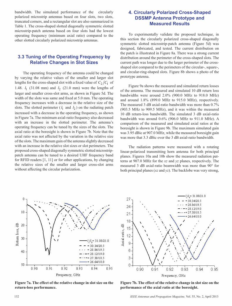
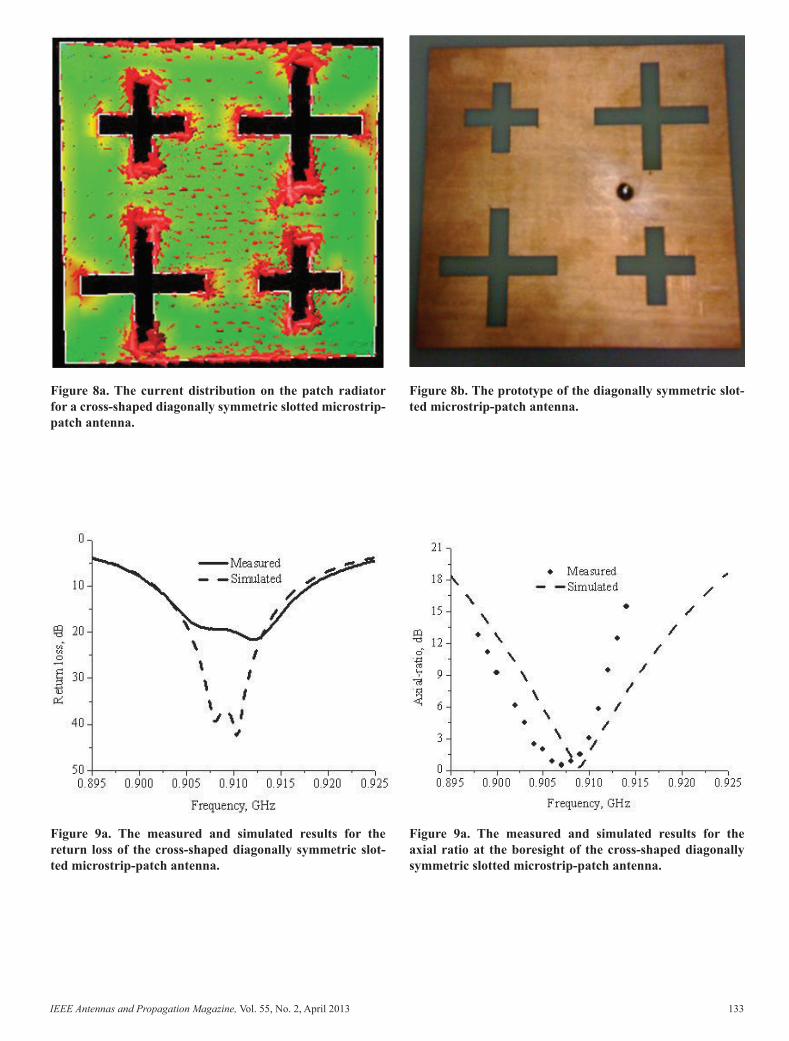
The operating frequency of the antenna could be changed by varying the relative values of the smaller and larger slot lengths for the cross-shaped slot with a fi xed value of 2 1C C of 1.48. 1l (31.08 mm) and 2l (21.0 mm) were the lengths of larger and smaller cross-slot arms, as shown in Figure 5d. The width of the slots was same and fi xed at 5.0 mm. The operat ing frequency increases with a decrease in the relative size of the slots. The slotted perimeter ( 1l and 2l ) on the radiating patch increased with a decrease in the operating frequency, as shown in Figure 7a. The minimum axial-ratio frequency also decreased with an increase in the slotted perimeter. The antenna’s operating frequency can be tuned by the sizes of the slots. The axial ratio at the boresight is shown in Figure 7b. Note that the axial ratio was not affected by the variation in the relative size of the slots. The maximum gain of the antenna slightly decreased with an increase in the relative slot sizes or slot perimeters. The proposed cross-shaped diagonally sym metric slotted microstrip-patch antenna can be tuned to a desired UHF frequency band for RFID readers [1, 11] or for other applications, by changing the relative sizes of the smaller and larger cross-slot arms without affecting the circu lar polarization.
4.CircularlyPolarizedCross-ShapedDSSMPAntennaPrototypeand
Measured Results
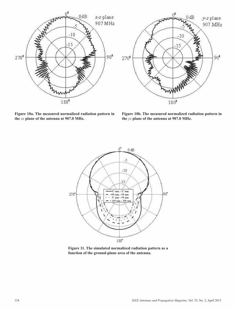
To experimentally validate the proposed technique, in this section the circularly polarized cross-shaped diagonally symmetric slotted microstrip-patch antenna (Figure 5d) was designed, fabricated, and tested. The current distribution on the patch is illustrated in Figure 8a. There was a strong current distribution around the perimeter of the cross-shaped slots. The current path was longer due to the larger perimeter of the cross-shaped slot compared to the perimeters of the circular-, square-, and circular-ring-shaped slots. Figure 8b shows a photo of the prototype antenna.
Figure 9a shows the measured and simulated return losses of the antenna. The measured and simulated 10 dB return loss bandwidths were around 2.0% (900.0 MHz to 918.0 MHz) and around 1.8% (899.0 MHz to 915.0 MHz), respectively. The measured 3 dB axial-ratio bandwidth was more than 0.7% (903.5 MHz to 909.5 MHz), and it was within the measured 10 dB return-loss bandwidth. The simulated 3 dB axial-ratio bandwidth was around 0.6% (906.0 MHz to 911.0 MHz). A comparison of the measured and simulated axial ratios at the boresight is shown in Figure 9b. The maxi mum simulated gain was 3.95 dBic at 907.0 MHz, while the measured boresight gain was more that 3.3 dBic over the 3 dB axial-ratio bandwidth.
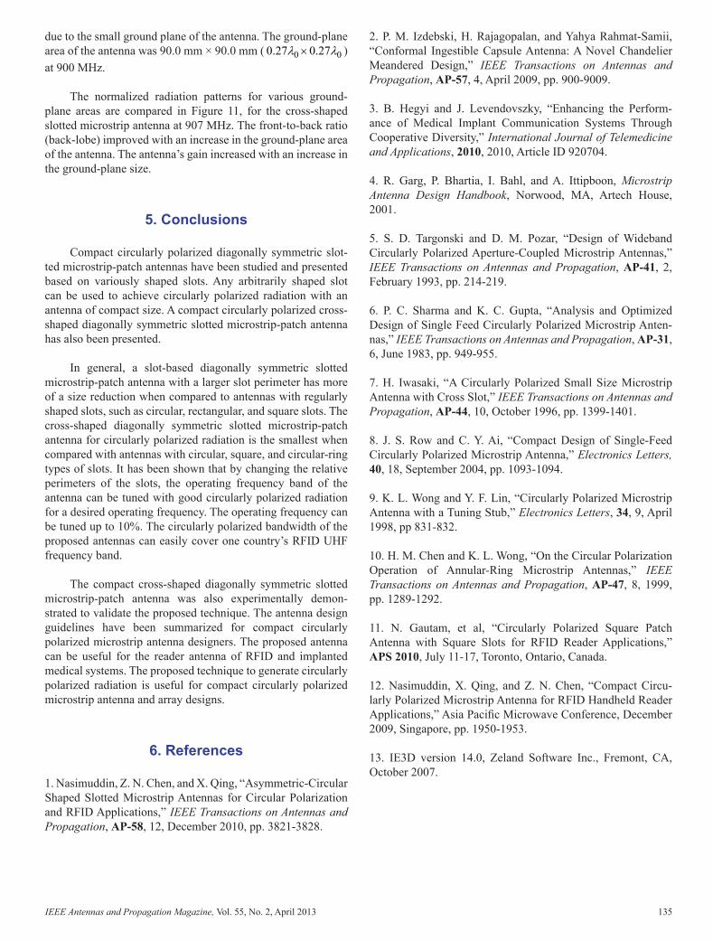
The radiation patterns were measured with a rotating linear-polarized transmitting horn antenna for both principal planes. Figures 10a and 10b show the measured radiation pat-terns at 907.0 MHz for the xz and yz planes, respectively. The measured 3 dB axial-ratio beamwidth was more than 90° for both principal planes (xz and yz). The backlobe was very strong,
Figure 7a. The effect of the relative change in slot size on the return-loss performance.
Figure 7b. The effect of the relative change in slot size on the performance of the axial ratio at the boresight.
Figure 8a. The current distribution on the patch radiator for a cross-shaped diagonally symmetric slotted micro strip-patch antenna.
Figure 8b. The prototype of the diagonally symmetric slot-ted microstrip-patch antenna.
Figure 9a. The measured and simulated results for the return loss of the cross-shaped diagonally symmetric slot-ted microstrip-patch antenna.
Figure 9a. The measured and simulated results for the axial ratio at the boresight of the cross-shaped diagonally symmetric slotted microstrip-patch antenna.
AP_Mag_Apr_2013_Final.indd 132 5/18/2013 8:57:27 PM
IEEE Antennas and Propagation Magazine, Vol. 55, No. 2, April 2013 133
bandwidth. The simulated performance of the circularly polarized microstrip antennas based on four slots, two slots, truncated corners, and a rectangular slot are also summarized in Table 1. The cross-shaped slotted diagonally symmetric slotted microstrip-patch antenna based on four slots had the lowest operating frequency (minimum axial ratio) compared to the other slotted circularly polarized microstrip antennas.
3.3TuningoftheOperatingFrequencybyRelativeChangesinSlotSizes
The operating frequency of the antenna could be changed by varying the relative values of the smaller and larger slot lengths for the cross-shaped slot with a fi xed value of 2 1C C of 1.48. 1l (31.08 mm) and 2l (21.0 mm) were the lengths of larger and smaller cross-slot arms, as shown in Figure 5d. The width of the slots was same and fi xed at 5.0 mm. The operat ing frequency increases with a decrease in the relative size of the slots. The slotted perimeter ( 1l and 2l ) on the radiating patch increased with a decrease in the operating frequency, as shown in Figure 7a. The minimum axial-ratio frequency also decreased with an increase in the slotted perimeter. The antenna’s operating frequency can be tuned by the sizes of the slots. The axial ratio at the boresight is shown in Figure 7b. Note that the axial ratio was not affected by the variation in the relative size of the slots. The maximum gain of the antenna slightly decreased with an increase in the relative slot sizes or slot perimeters. The proposed cross-shaped diagonally sym metric slotted microstrip-patch antenna can be tuned to a desired UHF frequency band for RFID readers [1, 11] or for other applications, by changing the relative sizes of the smaller and larger cross-slot arms without affecting the circu lar polarization.
4.CircularlyPolarizedCross-ShapedDSSMPAntennaPrototypeand
Measured Results
To experimentally validate the proposed technique, in this section the circularly polarized cross-shaped diagonally symmetric slotted microstrip-patch antenna (Figure 5d) was designed, fabricated, and tested. The current distribution on the patch is illustrated in Figure 8a. There was a strong current distribution around the perimeter of the cross-shaped slots. The current path was longer due to the larger perimeter of the cross-shaped slot compared to the perimeters of the circular-, square-, and circular-ring-shaped slots. Figure 8b shows a photo of the prototype antenna.
Figure 9a shows the measured and simulated return losses of the antenna. The measured and simulated 10 dB return loss bandwidths were around 2.0% (900.0 MHz to 918.0 MHz) and around 1.8% (899.0 MHz to 915.0 MHz), respectively. The measured 3 dB axial-ratio bandwidth was more than 0.7% (903.5 MHz to 909.5 MHz), and it was within the measured 10 dB return-loss bandwidth. The simulated 3 dB axial-ratio bandwidth was around 0.6% (906.0 MHz to 911.0 MHz). A comparison of the measured and simulated axial ratios at the boresight is shown in Figure 9b. The maxi mum simulated gain was 3.95 dBic at 907.0 MHz, while the measured boresight gain was more that 3.3 dBic over the 3 dB axial-ratio bandwidth.
The radiation patterns were measured with a rotating linear-polarized transmitting horn antenna for both principal planes. Figures 10a and 10b show the measured radiation pat-terns at 907.0 MHz for the xz and yz planes, respectively. The measured 3 dB axial-ratio beamwidth was more than 90° for both principal planes (xz and yz). The backlobe was very strong,
Figure 7a. The effect of the relative change in slot size on the return-loss performance.
Figure 7b. The effect of the relative change in slot size on the performance of the axial ratio at the boresight.
Figure 8a. The current distribution on the patch radiator for a cross-shaped diagonally symmetric slotted micro strip-patch antenna.
Figure 8b. The prototype of the diagonally symmetric slot-ted microstrip-patch antenna.
Figure 9a. The measured and simulated results for the return loss of the cross-shaped diagonally symmetric slot-ted microstrip-patch antenna.
Figure 9a. The measured and simulated results for the axial ratio at the boresight of the cross-shaped diagonally symmetric slotted microstrip-patch antenna.
AP_Mag_Apr_2013_Final.indd 133 5/18/2013 8:57:27 PM
134 IEEE Antennas and Propagation Magazine, Vol. 55, No. 2, April 2013
Figure 10a. The measured normalized radiation pattern in the xz plane of the antenna at 907.0 MHz.
Figure 10b. The measured normalized radiation pattern in the yz plane of the antenna at 907.0 MHz.
Figure 11. The simulated normalized radiation pattern as a function of the ground-plane area of the antenna.
due to the small ground plane of the antenna. The ground-plane area of the antenna was 90.0 mm × 90.0 mm ( 0 00.27 0.27λ λ× ) at 900 MHz.
The normalized radiation patterns for various ground-plane areas are compared in Figure 11, for the cross-shaped slotted microstrip antenna at 907 MHz. The front-to-back ratio (back-lobe) improved with an increase in the ground-plane area of the antenna. The antenna’s gain increased with an increase in the ground-plane size.
5.Conclusions
Compact circularly polarized diagonally symmetric slot-ted microstrip-patch antennas have been studied and presented based on variously shaped slots. Any arbitrarily shaped slot can be used to achieve circularly polarized radiation with an antenna of compact size. A compact circularly polarized cross-shaped diagonally symmetric slotted microstrip-patch antenna has also been presented.
In general, a slot-based diagonally symmetric slotted microstrip-patch antenna with a larger slot perimeter has more of a size reduction when compared to antennas with regularly shaped slots, such as circular, rectangular, and square slots. The cross-shaped diagonally symmetric slotted microstrip-patch antenna for circularly polarized radiation is the smallest when compared with antennas with circular, square, and cir cular-ring types of slots. It has been shown that by changing the relative perimeters of the slots, the operating frequency band of the antenna can be tuned with good circularly polar ized radiation for a desired operating frequency. The operating frequency can be tuned up to 10%. The circularly polarized bandwidth of the proposed antennas can easily cover one country’s RFID UHF frequency band.
The compact cross-shaped diagonally symmetric slotted microstrip-patch antenna was also experimentally demon-strated to validate the proposed technique. The antenna design guidelines have been summarized for compact circularly polarized microstrip antenna designers. The proposed antenna can be useful for the reader antenna of RFID and implanted medical systems. The proposed technique to generate circu larly polarized radiation is useful for compact circularly polarized microstrip antenna and array designs.
6.References
1. Nasimuddin, Z. N. Chen, and X. Qing, “Asymmetric-Cir cular Shaped Slotted Microstrip Antennas for Circular Polari zation and RFID Applications,” IEEE Transactions on Anten nas and Propagation, AP-58, 12, December 2010, pp. 3821-3828.
2. P. M. Izdebski, H. Rajagopalan, and Yahya Rahmat-Samii, “Conformal Ingestible Capsule Antenna: A Novel Chandelier Meandered Design,” IEEE Transactions on Antennas and Propagation, AP-57, 4, April 2009, pp. 900-9009.
3. B. Hegyi and J. Levendovszky, “Enhancing the Perform-ance of Medical Implant Communication Systems Through Cooperative Diversity,” International Journal of Telemedicine and Applications, 2010, 2010, Article ID 920704.
4. R. Garg, P. Bhartia, I. Bahl, and A. Ittipboon, Microstrip Antenna Design Handbook, Norwood, MA, Artech House, 2001.
5. S. D. Targonski and D. M. Pozar, “Design of Wideband Circularly Polarized Aperture-Coupled Microstrip Antennas,” IEEE Transactions on Antennas and Propagation, AP-41, 2, February 1993, pp. 214-219.
6. P. C. Sharma and K. C. Gupta, “Analysis and Optimized Design of Single Feed Circularly Polarized Microstrip Anten-nas,” IEEE Transactions on Antennas and Propagation, AP-31, 6, June 1983, pp. 949-955.
7. H. Iwasaki, “A Circularly Polarized Small Size Microstrip Antenna with Cross Slot,” IEEE Transactions on Antennas and Propagation, AP-44, 10, October 1996, pp. 1399-1401.
8. J. S. Row and C. Y. Ai, “Compact Design of Single-Feed Circularly Polarized Microstrip Antenna,” Electronics Letters, 40, 18, September 2004, pp. 1093-1094.
9. K. L. Wong and Y. F. Lin, “Circularly Polarized Microstrip Antenna with a Tuning Stub,” Electronics Letters, 34, 9, April 1998, pp 831-832.
10. H. M. Chen and K. L. Wong, “On the Circular Polarization Operation of Annular-Ring Microstrip Antennas,” IEEE Transactions on Antennas and Propagation, AP-47, 8, 1999, pp. 1289-1292.
11. N. Gautam, et al, “Circularly Polarized Square Patch Antenna with Square Slots for RFID Reader Applications,” APS 2010, July 11-17, Toronto, Ontario, Canada.
12. Nasimuddin, X. Qing, and Z. N. Chen, “Compact Circu-larly Polarized Microstrip Antenna for RFID Handheld Reader Applications,” Asia Pacifi c Microwave Conference, December 2009, Singapore, pp. 1950-1953.
13. IE3D version 14.0, Zeland Software Inc., Fremont, CA, October 2007.
AP_Mag_Apr_2013_Final.indd 134 5/18/2013 8:57:27 PM
IEEE Antennas and Propagation Magazine, Vol. 55, No. 2, April 2013 135
Figure 10a. The measured normalized radiation pattern in the xz plane of the antenna at 907.0 MHz.
Figure 10b. The measured normalized radiation pattern in the yz plane of the antenna at 907.0 MHz.
Figure 11. The simulated normalized radiation pattern as a function of the ground-plane area of the antenna.
due to the small ground plane of the antenna. The ground-plane area of the antenna was 90.0 mm × 90.0 mm ( 0 00.27 0.27λ λ× ) at 900 MHz.
The normalized radiation patterns for various ground-plane areas are compared in Figure 11, for the cross-shaped slotted microstrip antenna at 907 MHz. The front-to-back ratio (back-lobe) improved with an increase in the ground-plane area of the antenna. The antenna’s gain increased with an increase in the ground-plane size.
5.Conclusions
Compact circularly polarized diagonally symmetric slot-ted microstrip-patch antennas have been studied and presented based on variously shaped slots. Any arbitrarily shaped slot can be used to achieve circularly polarized radiation with an antenna of compact size. A compact circularly polarized cross-shaped diagonally symmetric slotted microstrip-patch antenna has also been presented.
In general, a slot-based diagonally symmetric slotted microstrip-patch antenna with a larger slot perimeter has more of a size reduction when compared to antennas with regularly shaped slots, such as circular, rectangular, and square slots. The cross-shaped diagonally symmetric slotted microstrip-patch antenna for circularly polarized radiation is the smallest when compared with antennas with circular, square, and cir cular-ring types of slots. It has been shown that by changing the relative perimeters of the slots, the operating frequency band of the antenna can be tuned with good circularly polar ized radiation for a desired operating frequency. The operating frequency can be tuned up to 10%. The circularly polarized bandwidth of the proposed antennas can easily cover one country’s RFID UHF frequency band.
The compact cross-shaped diagonally symmetric slotted microstrip-patch antenna was also experimentally demon-strated to validate the proposed technique. The antenna design guidelines have been summarized for compact circularly polarized microstrip antenna designers. The proposed antenna can be useful for the reader antenna of RFID and implanted medical systems. The proposed technique to generate circu larly polarized radiation is useful for compact circularly polarized microstrip antenna and array designs.
6.References
1. Nasimuddin, Z. N. Chen, and X. Qing, “Asymmetric-Cir cular Shaped Slotted Microstrip Antennas for Circular Polari zation and RFID Applications,” IEEE Transactions on Anten nas and Propagation, AP-58, 12, December 2010, pp. 3821-3828.
2. P. M. Izdebski, H. Rajagopalan, and Yahya Rahmat-Samii, “Conformal Ingestible Capsule Antenna: A Novel Chandelier Meandered Design,” IEEE Transactions on Antennas and Propagation, AP-57, 4, April 2009, pp. 900-9009.
3. B. Hegyi and J. Levendovszky, “Enhancing the Perform-ance of Medical Implant Communication Systems Through Cooperative Diversity,” International Journal of Telemedicine and Applications, 2010, 2010, Article ID 920704.
4. R. Garg, P. Bhartia, I. Bahl, and A. Ittipboon, Microstrip Antenna Design Handbook, Norwood, MA, Artech House, 2001.
5. S. D. Targonski and D. M. Pozar, “Design of Wideband Circularly Polarized Aperture-Coupled Microstrip Antennas,” IEEE Transactions on Antennas and Propagation, AP-41, 2, February 1993, pp. 214-219.
6. P. C. Sharma and K. C. Gupta, “Analysis and Optimized Design of Single Feed Circularly Polarized Microstrip Anten-nas,” IEEE Transactions on Antennas and Propagation, AP-31, 6, June 1983, pp. 949-955.
7. H. Iwasaki, “A Circularly Polarized Small Size Microstrip Antenna with Cross Slot,” IEEE Transactions on Antennas and Propagation, AP-44, 10, October 1996, pp. 1399-1401.
8. J. S. Row and C. Y. Ai, “Compact Design of Single-Feed Circularly Polarized Microstrip Antenna,” Electronics Letters, 40, 18, September 2004, pp. 1093-1094.
9. K. L. Wong and Y. F. Lin, “Circularly Polarized Microstrip Antenna with a Tuning Stub,” Electronics Letters, 34, 9, April 1998, pp 831-832.
10. H. M. Chen and K. L. Wong, “On the Circular Polarization Operation of Annular-Ring Microstrip Antennas,” IEEE Transactions on Antennas and Propagation, AP-47, 8, 1999, pp. 1289-1292.
11. N. Gautam, et al, “Circularly Polarized Square Patch Antenna with Square Slots for RFID Reader Applications,” APS 2010, July 11-17, Toronto, Ontario, Canada.
12. Nasimuddin, X. Qing, and Z. N. Chen, “Compact Circu-larly Polarized Microstrip Antenna for RFID Handheld Reader Applications,” Asia Pacifi c Microwave Conference, December 2009, Singapore, pp. 1950-1953.
13. IE3D version 14.0, Zeland Software Inc., Fremont, CA, October 2007.
AP_Mag_Apr_2013_Final.indd 135 5/18/2013 8:57:27 PM

136 IEEE Antennas and Propagation Magazine, Vol. 55, No. 2, April 2013
Introducing the Feature Article Authors
Nasimuddin was born February 1975 in Bulandshahar, UP, India. He received the MSc in Electronics from the Jamia Millia Islamia, New Delhi, India, in 1996; the MTech in Microwave Electronics from the University of Delhi, India, in 1998; and the PhD from the University of Delhi, Delhi, India, in 2004 for theoretical work in the fi eld of multilayer slow-wave microstrip structures and microstrip-patch antennas.
Dr. Nasimuddin was awarded a Senior Research Fellow-ship from CSIR Government of India in Engineering Science (2001-2003). From 2004 to 2006, he was an Australian Post-doctoral Fellow (the fellowship was awarded from the Austra-lian Research Council, Australian government) with Macquarie University, Sydney, Australia. Currently, he is working as a scientist in the Department of RF and Optical, Institute for Infocomm Research, Singapore. He received a Young Scientist Award (2005) from the International Union of Radio Science (URSI) in 2005. He has published over 50 refe reed journal articles. His research interests include the areas of multilayered microstrip-based structures, millimeter-wave antennas, RFID reader antennas, UWB antennas, and circu larly polarized microstrip antennas. Dr. Nasimuddin is a Sen ior Member of the IEEE and a member of the IEEE Antennas and Propagation Society.
Zhi Ning Chen received his BEng, MEng, PhD, and DoE from the Institute of Communications Engineering, China, and the University of Tsukuba, Japan, all in Electrical Engineering. During 1988-1997, he worked at the Institute of Communications Engineering, Southeast University, and the City University of Hong Kong, China, with teaching and research appointments. In 1997, he was awarded a JSPS Fel lowship to join the University of Tsukuba, Japan. In 2001 and 2004, he visited the University of Tsukuba under the JSPS Fellowship Program (senior level). In 2004, he worked at the IBM T. J. Watson Research Center, USA, as an Academic Visitor. Since 1999, he has worked with
the Institute for Info comm Research. His current appointments are Principal Sci entist and Department Head for RF & Optical. He is concur rently holding Adjunct/Guest professorships at Southeast Uni versity, Nanjing University, Shanghai Jiao Tong University, Tongji University, and the National University of Singapore.
He has been the key organizer of many international tech-nical events. He was the founder of the International Workshop on Antenna Technology (iWAT). He has published 280 journal and conference papers, as well as authored and edited the books Broadband Planar Antennas, UWB Wireless Communication, Antennas for Portable Devices, and Antennas for Base Station in Wireless Communications. He also con tributed to the books UWB Antennas and Propagation for Communications, Radar, and Imaging and the Antenna Engi neering Handbook. He holds 28 granted and fi led patents, with 17 licensed deals with industry. He was the recipient of the CST University Publication Award 2008, an Honorable Men tion in the IEEE AP-S Student Paper Contest 2008, the IES Prestigious Engineering Achievement Award 2006, the 2I R Quarterly Best Paper Award 2004, and the IEEE iWAT 2005 Best Poster Award. His current research interests include applied electromagnetics, and antennas for applications of microwave, mm-wave, sub-mm-wave, and THz in imaging systems. He is a Fellow of the IEEE, and was an IEEE AP-S Distinguished Lecturer (2008-2010).
Xianming Qing was born in May 1965, in the People’s Republic of China. He received the BEng from the University of Electronic Science and Technology of China (UESTC), China, in 1985, and the DrEng from Chiba University, Japan, in 2010.
During 1987-1996, Dr. Qing was with UESTC for teach-ing and research. He was appointed a Lecturer in 1990 and an Associate Professor in 1995. He joined the National Univer-sity of Singapore (NUS) in 1997 as a research scientist, where he focused on the study of high-temperature superconductor (HTS) microwave devices. Since 1998, he has been with the Institute for Infocomm Research (I2R, formerly known as CWC and ICR), Singapore. He currently holds the position of research scientist and is the leader of the antenna group under the RF and Optical Department. His main research interests are antenna design and characterization for wireless applica tions. In particular, his current R&D focuses on small and broadband antennas/arrays for wireless systems, such as ultra-wideband (UWB) systems, radio-frequency identifi cation (RFID)
systems, and medical imaging systems, and micro wave, mm-wave, sub-mm-wave, and THz imaging systems.
Dr. Qing has authored and coauthored over 70 technical papers published in international journals or presented at international conferences, and fi ve book chapters. He has received six awards for advancement of science and technol-ogy in the People’s Republic of China. He was also the recipi-ent of the IES Prestigious Engineering Achievement Award 2006, Singapore. He holds eight granted and fi led patents. Dr. Qing has been a member of the IEEE Antennas and Propaga-tion Society since 1990. He severed as the organizer and chair for special sessions on RFID antennas at the IEEE Interna-tional Symposium on Antennas and Propagation in 2007 and 2008. He also served a the guest editor of the special issue on “Antennas for Emerging Radio Frequency Identifi cation (RFID) Applications” for the International Journal on Wire less & Optical Communications. He has served as a TPC member and session chair for a number of conferences, and as the reviewer for many prestigious journals.
AP_Mag_Apr_2013_Final.indd 136 5/18/2013 8:57:27 PM
IEEE Antennas and Propagation Magazine, Vol. 55, No. 2, April 2013 137
Introducing the Feature Article Authors
Nasimuddin was born February 1975 in Bulandshahar, UP, India. He received the MSc in Electronics from the Jamia Millia Islamia, New Delhi, India, in 1996; the MTech in Microwave Electronics from the University of Delhi, India, in 1998; and the PhD from the University of Delhi, Delhi, India, in 2004 for theoretical work in the fi eld of multilayer slow-wave microstrip structures and microstrip-patch antennas.
Dr. Nasimuddin was awarded a Senior Research Fellow-ship from CSIR Government of India in Engineering Science (2001-2003). From 2004 to 2006, he was an Australian Post-doctoral Fellow (the fellowship was awarded from the Austra-lian Research Council, Australian government) with Macquarie University, Sydney, Australia. Currently, he is working as a scientist in the Department of RF and Optical, Institute for Infocomm Research, Singapore. He received a Young Scientist Award (2005) from the International Union of Radio Science (URSI) in 2005. He has published over 50 refe reed journal articles. His research interests include the areas of multilayered microstrip-based structures, millimeter-wave antennas, RFID reader antennas, UWB antennas, and circu larly polarized microstrip antennas. Dr. Nasimuddin is a Sen ior Member of the IEEE and a member of the IEEE Antennas and Propagation Society.
Zhi Ning Chen received his BEng, MEng, PhD, and DoE from the Institute of Communications Engineering, China, and the University of Tsukuba, Japan, all in Electrical Engineering. During 1988-1997, he worked at the Institute of Communications Engineering, Southeast University, and the City University of Hong Kong, China, with teaching and research appointments. In 1997, he was awarded a JSPS Fel lowship to join the University of Tsukuba, Japan. In 2001 and 2004, he visited the University of Tsukuba under the JSPS Fellowship Program (senior level). In 2004, he worked at the IBM T. J. Watson Research Center, USA, as an Academic Visitor. Since 1999, he has worked with
the Institute for Info comm Research. His current appointments are Principal Sci entist and Department Head for RF & Optical. He is concur rently holding Adjunct/Guest professorships at Southeast Uni versity, Nanjing University, Shanghai Jiao Tong University, Tongji University, and the National University of Singapore.
He has been the key organizer of many international tech-nical events. He was the founder of the International Workshop on Antenna Technology (iWAT). He has published 280 journal and conference papers, as well as authored and edited the books Broadband Planar Antennas, UWB Wireless Communication, Antennas for Portable Devices, and Antennas for Base Station in Wireless Communications. He also con tributed to the books UWB Antennas and Propagation for Communications, Radar, and Imaging and the Antenna Engi neering Handbook. He holds 28 granted and fi led patents, with 17 licensed deals with industry. He was the recipient of the CST University Publication Award 2008, an Honorable Men tion in the IEEE AP-S Student Paper Contest 2008, the IES Prestigious Engineering Achievement Award 2006, the 2I R Quarterly Best Paper Award 2004, and the IEEE iWAT 2005 Best Poster Award. His current research interests include applied electromagnetics, and antennas for applications of microwave, mm-wave, sub-mm-wave, and THz in imaging systems. He is a Fellow of the IEEE, and was an IEEE AP-S Distinguished Lecturer (2008-2010).
Xianming Qing was born in May 1965, in the People’s Republic of China. He received the BEng from the University of Electronic Science and Technology of China (UESTC), China, in 1985, and the DrEng from Chiba University, Japan, in 2010.
During 1987-1996, Dr. Qing was with UESTC for teach-ing and research. He was appointed a Lecturer in 1990 and an Associate Professor in 1995. He joined the National Univer-sity of Singapore (NUS) in 1997 as a research scientist, where he focused on the study of high-temperature superconductor (HTS) microwave devices. Since 1998, he has been with the Institute for Infocomm Research (I2R, formerly known as CWC and ICR), Singapore. He currently holds the position of research scientist and is the leader of the antenna group under the RF and Optical Department. His main research interests are antenna design and characterization for wireless applica tions. In particular, his current R&D focuses on small and broadband antennas/arrays for wireless systems, such as ultra-wideband (UWB) systems, radio-frequency identifi cation (RFID)
systems, and medical imaging systems, and micro wave, mm-wave, sub-mm-wave, and THz imaging systems.
Dr. Qing has authored and coauthored over 70 technical papers published in international journals or presented at international conferences, and fi ve book chapters. He has received six awards for advancement of science and technol-ogy in the People’s Republic of China. He was also the recipi-ent of the IES Prestigious Engineering Achievement Award 2006, Singapore. He holds eight granted and fi led patents. Dr. Qing has been a member of the IEEE Antennas and Propaga-tion Society since 1990. He severed as the organizer and chair for special sessions on RFID antennas at the IEEE Interna-tional Symposium on Antennas and Propagation in 2007 and 2008. He also served a the guest editor of the special issue on “Antennas for Emerging Radio Frequency Identifi cation (RFID) Applications” for the International Journal on Wire less & Optical Communications. He has served as a TPC member and session chair for a number of conferences, and as the reviewer for many prestigious journals.
AP_Mag_Apr_2013_Final.indd 137 5/18/2013 8:57:27 PM


