Embed Size (px)
Citation preview
HF AntennasRevised: 5-March-2007
Note: Figures are clickable for pop-up enlargement.
Now that you've got a feel for the basic principles of what RF waves are, and how they propagate, let's reviewa few things about antennas - the part of the station that actually puts the signal into - and pulls it out of -the air! This short discussion of antenna science is to highlight some of the factors that are important toDXers and very briefly review a few of the more commonly used antennas types. Since an understanding ofHF propagation and antenna principles are THE most important "tools" that a DXer can have, it follows thatone should develop a sense for "continuing education" on these subjects. Not only will it be helpful inimproving your ability to work DX, it may also save you some money. How? Well, before mortgaging thehouse to buy a new DX4000ProIX transceiver so that you can "work more DX", be advised that the mosteffective investment that you can make is in the antenna that you use, and often this can be done at afraction of the cost of even a modestly priced transceiver.
So, after P.E.P.S.I., the next three most important things for DXing are (i) the antenna, (ii) the antenna, and
(iii) the antenna. Its easy to see why this is so - on receive, if the antenna cannot produce enough signalstrength (vs. noise), then the most sophisticated and expensive receiver can do little more than light up andlook pretty; while on transmit, a KW amplifier will do little good if all of the radiated power is going straightup to warm the clouds or straight down to warm the worms. Once you reach the point at which you're readyto improve your station, then it's time to learn more - and as much as you can - about the fascinating field ofantenna theory, design, and practice. As in almost all of the other subjects having to do with amateur radio,antennas can be as complex as one has time to invest in learning about them, or as simple as takingsomeone else's advice and hoping that they're right. What follows is a highly over-simplified attempt to distilland summarize some of the common questions and points of interest to DXers. It is meant only as a briefintroduction which may help to spur further interest in learning more. There is an abundance of informationavailable on antenna theory, design, and performance in the printed literature as well as on the Web (Note:Probably one of the most extensive online antenna resources for hams can be found at www.cebik.com). Look
for it and make use of it! Provided in the References are other sources of expertise, detail, and ideas.
First, what is an Antenna?
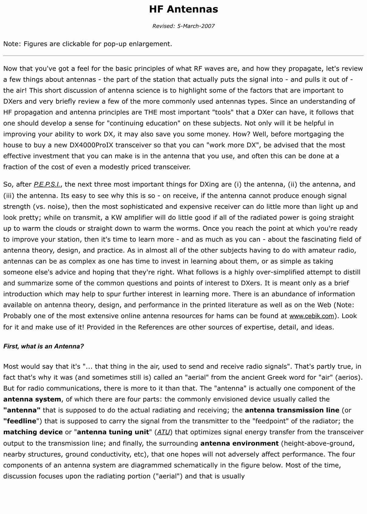
Most would say that it's "... that thing in the air, used to send and receive radio signals". That's partly true, infact that's why it was (and sometimes still is) called an "aerial" from the ancient Greek word for "air" (aerios).But for radio communications, there is more to it than that. The "antenna" is actually one component of theantenna system, of which there are four parts: the commonly envisioned device usually called the"antenna" that is supposed to do the actual radiating and receiving; the antenna transmission line (or"feedline") that is supposed to carry the signal from the transmitter to the "feedpoint" of the radiator; thematching device or "antenna tuning unit" (ATU) that optimizes signal energy transfer from the transceiver
output to the transmission line; and finally, the surrounding antenna environment (height-above-ground,nearby structures, ground conductivity, etc), that one hopes will not adversely affect performance. The fourcomponents of an antenna system are diagrammed schematically in the figure below. Most of the time,discussion focuses upon the radiating portion ("aerial") and that is usually
what we think of when we speak of an "antenna". However, it would be a mistake to ignore the othercomponents because a poor or improperly matched feedline, or a failure to address detrimentalenvironmental conditions can easily reduce the performance of the best of the radiators. Below, we'll coversome of the key points about the four components, including the types of antenna radiators that arecommonly used for DX. Readers are strongly urged to do additional research on all components of the systemwhen considering an antenna.
Measuring Antenna Performance: The Reference Antenna and Free Space models
When comparing different antennas, it would be useful to be able to describe each of them in terms of howwell each performs. But how do you describe the capability of one type of antenna as compared to another?Well, we can do so in a manner similar to that we use to compare the size and weight of different objects -we describe them in terms of a defined standard unit of length (meter, cm, foot, inch) and a standard unit ofmass (kilogram, gram, pound, ounce). To do this for antennas, we choose one type, along with a definedenvironment, as a reference standard for performance measurement. The ideal reference antenna would beone that radiates energy equally in all 3 dimensions, called an isotropic radiator. To visualize anapproximation of the concept of an isotropic radiator, think of it as similar to a very small light bulb that isemitting light in all directions of the surrounding space. While it is possible to approximate an isotropicradiator, in fact it does not (cannot) exist, but is just a convenient theoretical tool that is used for describingthe properties of real antennas.
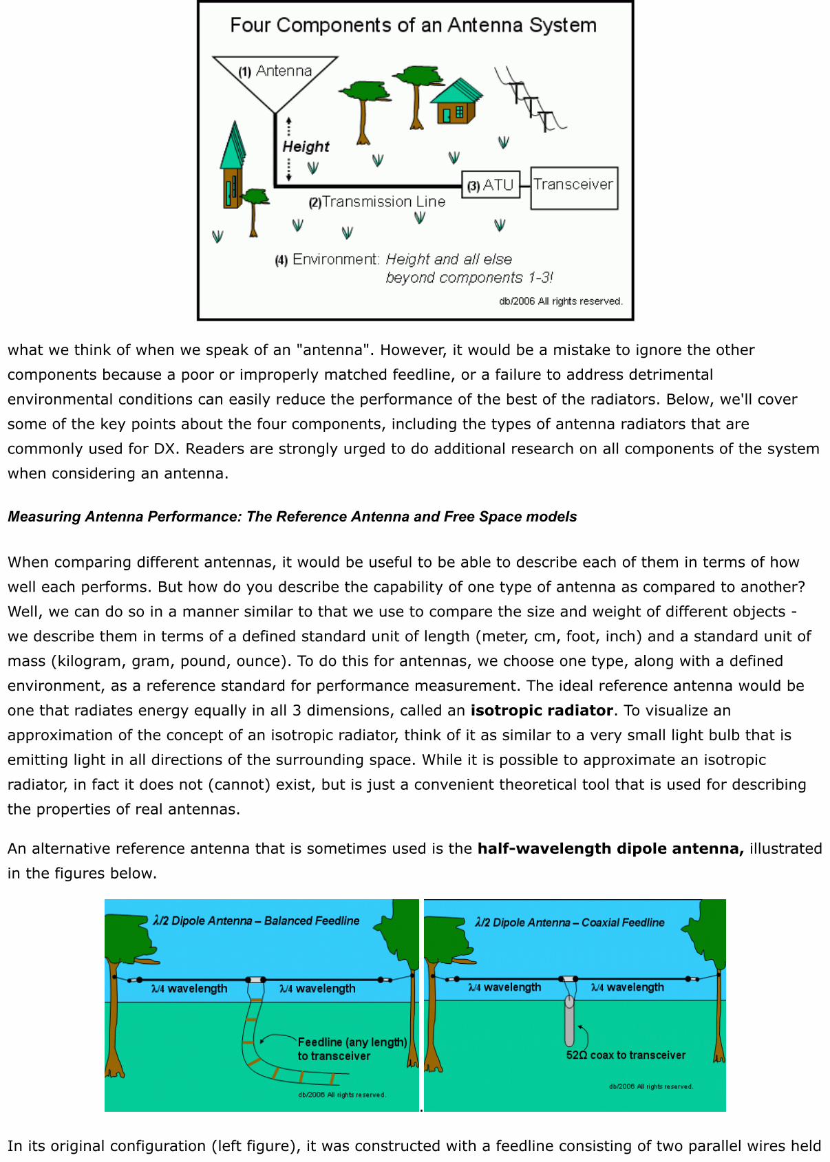
An alternative reference antenna that is sometimes used is the half-wavelength dipole antenna, illustratedin the figures below.
.
In its original configuration (left figure), it was constructed with a feedline consisting of two parallel wires held
apart (e.g., from 2-12 inches) by insulated spacers; today, coaxial cable (right figure) is more commonly usedfor dipole antenna feedlines. What defines a dipole antenna is the balanced symmetry of the radiatingelements about the center: both sides of the feed-point are identical. As shown in the left illustration, dipoleantennas were originally fed with "twin-lead" and, because of the double-sided symmetry, were often called"doublets", a term which one still occasionally hears. A dipole fed with twin-lead and matched to thetransmitter with an "antenna tuning unit" can serve as an inexpensive multi-band antenna (e.g., see "All-band doublet " at www.cebik.com/edu/edu6.html). While the dipole can be a useful reference that is easy to
understand, it isn't as convenient as the theoretical isotropic radiator because, as we shall soon see, thedipole has directional (non-isotropic) properties.
Of course, we must also define the standard reference environment. In reality, it is impossible to have anenvironment at one geographical location that is truly identical to others elsewhere. Fortunately, science andcomputers come to the rescue! There are theoretical mathematical antenna modeling programs that canprovide very good estimates of the way different antennas radiate, and with readily available computers,anyone can experiment with antenna designs and evaluations. Mathematical models, based upon the physicsof EM wave production, define two regions of space for antenna analyses: the near-field region within a large
number of wavelengths surrounding the antenna, and the far-field region beyond. The near-field is where the
radiation pattern is formed as a result of interactions among the antenna variables, including the radiatingelements and the environment (notably the ground surface). The far-field is the region sufficiently distant(many wavelengths) from the antenna so that in the portion of space in which we detect the radiation, itappears to be a "flat" or "plane" wave without any noticeable sphericity.
To avoid problems with environmental variables, the most effective way to compare different antenna designsis to imagine them to be placed in outer-space away from everything, and let the software simulate theirradiation patterns for analysis. This is referred to as the "free-space environment". With these data, onecan then compare apples-to-apples, the premise being that if antenna "A" exhibits characteristics in free-space that are more favorable for the intended application than does antenna "B", although it may notperform as ideally in the real-world, it may still be expected to exhibit a similar performance edge when bothA and B would encounter the same environmental variables. How well do these models work? Field tests onEarth-bound antennas have verified the reliability of the theoretical model comparisons in providing very goodestimates of the results to be expected in actual applications. Further, today's antenna modeling software cannow also do a pretty good job of including estimates of some of the real-world environmental variables(nearby structures, height-above-ground, ground conditions, etc.) in the evaluation of antenna characteristicsin situ (i.e., in your backyard!).
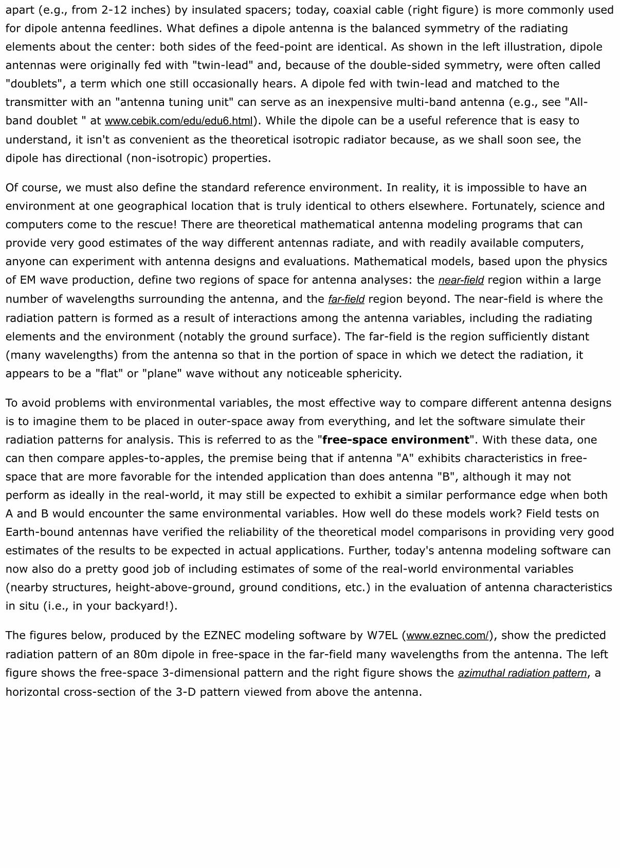
The figures below, produced by the EZNEC modeling software by W7EL (www.eznec.com/), show the predicted
radiation pattern of an 80m dipole in free-space in the far-field many wavelengths from the antenna. The leftfigure shows the free-space 3-dimensional pattern and the right figure shows the azimuthal radiation pattern, a
horizontal cross-section of the 3-D pattern viewed from above the antenna.
In the 3-D view, we see that the antenna produces a doughnut-shaped toroidal pattern, with no radiation in
the direction of the ends. The adjacent azimuthal slice at 0o in the horizontal plane shows that the dipoleradiation favors the directions broad-side to the antenna in a "figure-8" pattern. Using antenna modelingsoftware, radiation patterns like these can be generated for other types of antennas, allowing you to comparethem without concern for the environmental differences that likely exist between your backyard and that ofsomeone else's next door or around the globe. Of course, as we shall see below, once you decide which isbest for you, the actual pattern of the HF antenna that you do install in your back yard will be quite differentthan it appears in free space! However, as mentioned, you can also incorporate an estimated description ofyour own Earth-bound environment in order to get a pretty good idea of what your expected on-site resultswill be. A brief example of how to interpret the pattern graphs can be found in the "Miscellaneous Notes"Appendix under "Antenna Notes".
Impedance, Standing Wave Ratio, and Balance
Remember the 3rd component of the antenna system, the matching device or "antenna tuning unit (atu)"?What exactly does that do for us? Let's review some basic electronics theory. When dealing with alternatingcurrents (such as RF), everything (including air and outer-space) that the currents flow through will havesome effect upon the flow. The effects are a result of the fact that, in addition to resistance (R), everymaterial has the intrinsic ability to exhibit capacitive (C) and/or inductive (L) properties to some extent. Weare familiar with the effect of resistance (current reduction and heat-loss due to electron collisions withstationary atoms & molecules), but what about that of L and C? Simply stated, both L and C can each reduceAC flow due to electromagnetic force interactions, but they do so in off-setting ways, because each may havea different effect upon the phase of the alternating current and so, for certain combinations of L,C values,
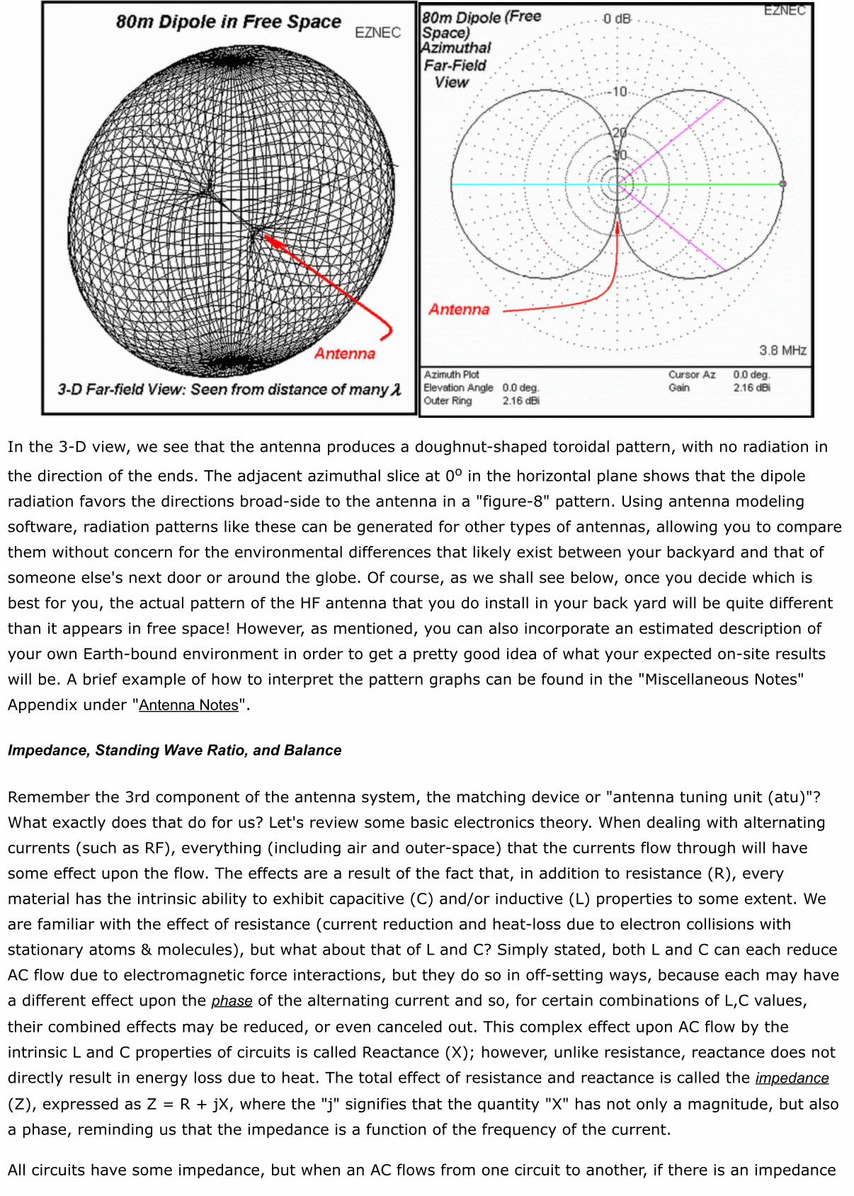
their combined effects may be reduced, or even canceled out. This complex effect upon AC flow by theintrinsic L and C properties of circuits is called Reactance (X); however, unlike resistance, reactance does notdirectly result in energy loss due to heat. The total effect of resistance and reactance is called the impedance
(Z), expressed as Z = R + jX, where the "j" signifies that the quantity "X" has not only a magnitude, but alsoa phase, reminding us that the impedance is a function of the frequency of the current.
All circuits have some impedance, but when an AC flows from one circuit to another, if there is an impedance
difference between the circuits, part of the current will "flow forward" into the second circuit while an amountin proportion to the impedance difference will be "reflected back" into the first circuit. The circuits of interestto us at this point are the transmitter output circuit, the transmission line, and the antenna radiator.Impedance mismatches anywhere between the transmitter and the radiator may result in part of the RFpower from the transmitter being reflected back by the mismatch. Mismatches may occur between thetransmitter and the transmission line and/or between the transmission line and the radiator. The "forward"and "reflected" waves on the transmission line can constructively/destructively interfere with each other byperiodically adding and subtracting each cycle, establishing a periodic wave pattern on the line that, if it couldbe envisioned, would appear to be an undulating wave that seems to "stand in place" in terms of the locationsof the crests and troughs. For this reason, it is called a Standing Wave (e.g.,
www.glenbrook.k12.il.us/gbssci/Phys/mmedia/waves/swf.html). For a given operating frequency, the extent of any
impedance mismatch between the antenna and the transmitter can be described in terms of the ratio of thevoltage maxima to the voltage minima on the transmission line: the higher the ratio, the worse is theimpedance mismatch and the more power is being reflected. This is called the Standing Wave Ratio (SWR). If
there is no impedance mismatch between the antenna and the feedline at a given frequency, then all of thepower going to the antenna is radiated and there is none reflected to interfere (add/subtract), therefore thevoltage remains the same at all points between the transmitter and radiator, providing a SWR of 1:1.
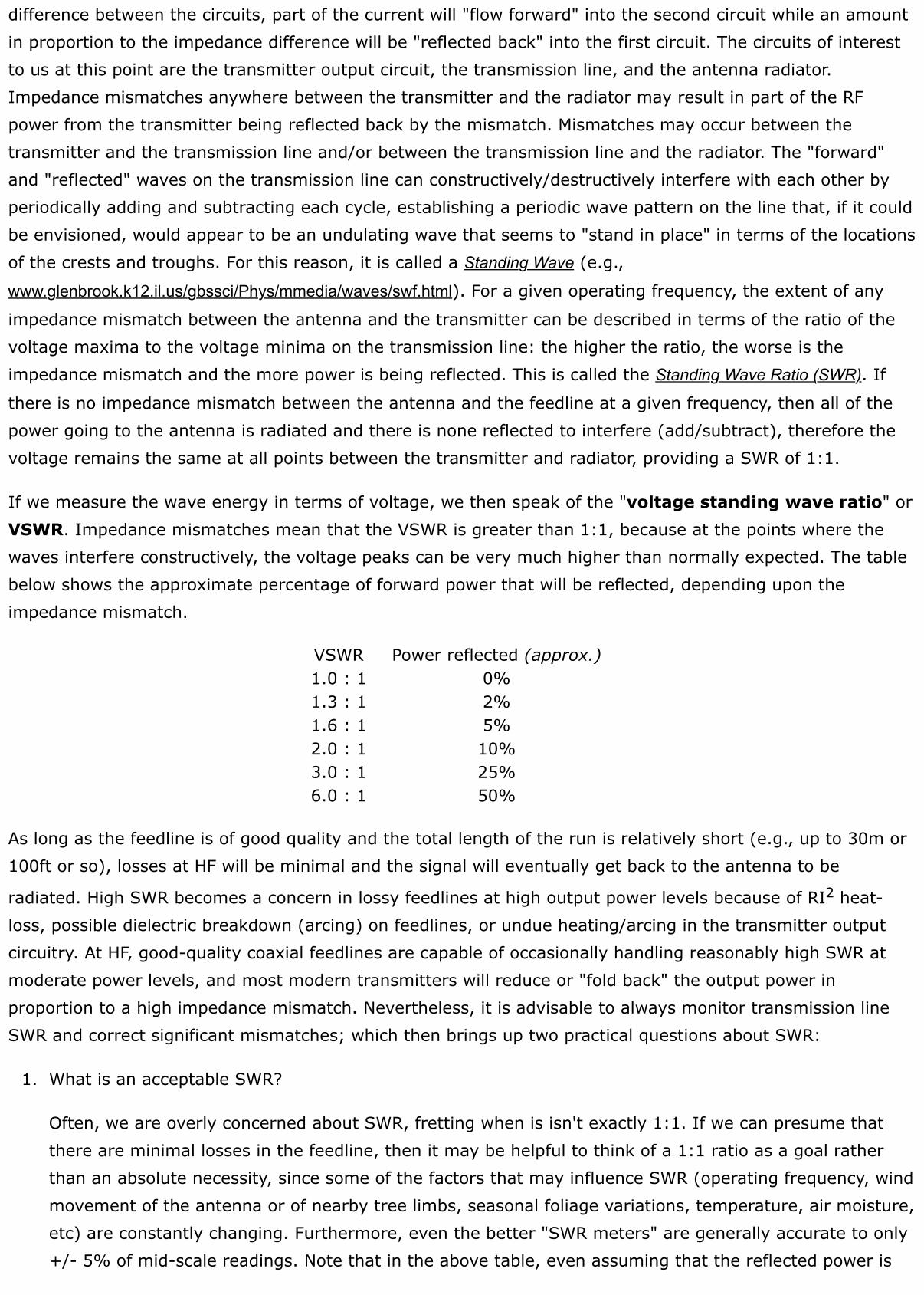
If we measure the wave energy in terms of voltage, we then speak of the "voltage standing wave ratio" orVSWR. Impedance mismatches mean that the VSWR is greater than 1:1, because at the points where thewaves interfere constructively, the voltage peaks can be very much higher than normally expected. The tablebelow shows the approximate percentage of forward power that will be reflected, depending upon theimpedance mismatch.
VSWR Power reflected (approx.)1.0 : 1 0%1.3 : 1 2%1.6 : 1 5%2.0 : 1 10%3.0 : 1 25%6.0 : 1 50%
As long as the feedline is of good quality and the total length of the run is relatively short (e.g., up to 30m or100ft or so), losses at HF will be minimal and the signal will eventually get back to the antenna to be
radiated. High SWR becomes a concern in lossy feedlines at high output power levels because of RI2 heat-loss, possible dielectric breakdown (arcing) on feedlines, or undue heating/arcing in the transmitter outputcircuitry. At HF, good-quality coaxial feedlines are capable of occasionally handling reasonably high SWR atmoderate power levels, and most modern transmitters will reduce or "fold back" the output power inproportion to a high impedance mismatch. Nevertheless, it is advisable to always monitor transmission lineSWR and correct significant mismatches; which then brings up two practical questions about SWR:
1. What is an acceptable SWR?
Often, we are overly concerned about SWR, fretting when is isn't exactly 1:1. If we can presume thatthere are minimal losses in the feedline, then it may be helpful to think of a 1:1 ratio as a goal ratherthan an absolute necessity, since some of the factors that may influence SWR (operating frequency, windmovement of the antenna or of nearby tree limbs, seasonal foliage variations, temperature, air moisture,etc) are constantly changing. Furthermore, even the better "SWR meters" are generally accurate to only+/- 5% of mid-scale readings. Note that in the above table, even assuming that the reflected power is
lost (which it usually isn't), it would really not be of a concern below 2:1. Of course, one should alwaysstrive to improve the antenna system as much as possible, but for HF operation at amateur power levels,little or no practical difference in communications ability will be noticed between a SWR meter reading of2:1 and one of 1:1. At high SWR (usually 2:1 or greater), modern transmitters will "fold back" theoutput power in proportion to the mismatch; however, when necessary, reasonable operation can usuallybe enjoyed with a reading as high as 2:1 despite the reduction in output power.
2. What happens to the reflected power when the SWR is not 1:1?
Again, assuming that there are minimal losses in the transmission line, since it is an AC, upon cyclereversal the reflected component along with the forward component will flow back to the antennaimpedance mismatch and part will be radiated while part will be reflected, and so on, until thetransmission is ended. This is analogous to the action of sea waves encountering a river inlet (another"circuit" with an "impedance difference"): part of the water flows into the river and a portion is"reflected" back into the sea. Is the reflected water "lost"? No, it is just incorporated into the next wavecycle, flowing back to the river mouth. So it is with AC in loss-less circuits with differing impedances -the reflected energy just returns as part of the next cycle.
Of course, it follows that if there is no impedance mismatch between circuits, then there is no current flowdifference in them. Maximum power transfer per cycle between circuits occurs when they have closelymatched impedances. Since we are interested in transferring RF power from the transceiver to/from theradiating element of the antenna system, we must be concerned with matching the impedances all along theroute. Ideally, this means that we would like the same impedance to exist from the transceiver outputterminal to the antenna radiator. Fortunately, transceivers are designed to have a standard output impedanceof 50 , so all one need do is "match" the rest of the antenna system to this value. For the time being, sufficeto say that this can usually be accomplished by using a transmission line and a radiator of similar impedance,or by using some form of "antenna tuning unit (ATU)", that can make the antenna system impedance appearto be the same as that of the transceiver output. A word of caution: since there are ATUs that can matchalmost anything to a transmitter output, it should be evident that an SWR of 1:1 is not a guarantee of theeffectiveness of the antenna, but only the ATU. Indeed, a 50 resistor connected across the transmitteroutput will provide a nice 1:1 SWR, but not much power will be radiated. So, when monitoring your antennaSWR, you should also be aware of how your antenna is supposed to perform and keep a close eye on anyperformance changes - if you notice anything, then maintenance may be required! A very good practicaldiscussion of SWR appeared in the November, 2006 issue of QST (p.37): "Understanding SWR by Example"'by Darrin, K5DVW.
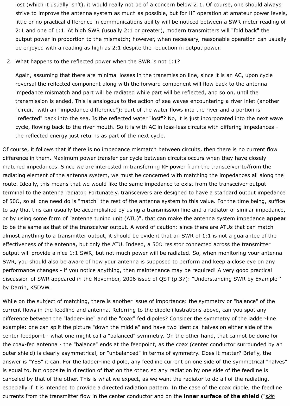
While on the subject of matching, there is another issue of importance: the symmetry or "balance" of thecurrent flows in the feedline and antenna. Referring to the dipole illustrations above, can you spot anydifference between the "ladder-line" and the "coax" fed dipoles? Consider the symmetry of the ladder-lineexample: one can split the picture "down the middle" and have two identical halves on either side of thecenter feedpoint - what one might call a "balanced" symmetry. On the other hand, that cannot be done forthe coax-fed antenna - the "balance" ends at the feedpoint, as the coax (center conductor surrounded by anouter shield) is clearly asymmetrical, or "unbalanced" in terms of symmetry. Does it matter? Briefly, theanswer is "YES" it can. For the ladder-line dipole, any feedline current on one side of the symmetrical "halves"is equal to, but opposite in direction of that on the other, so any radiation by one side of the feedline iscanceled by that of the other. This is what we expect, as we want the radiator to do all of the radiating,especially if it is intended to provide a directed radiation pattern. In the case of the coax dipole, the feedlinecurrents from the transmitter flow in the center conductor and on the inner surface of the shield ("skin
effect"), completely contained within the cable and therefore also not radiating, as illustrated in the figure
below for one-half of the cycle. So far, so good.
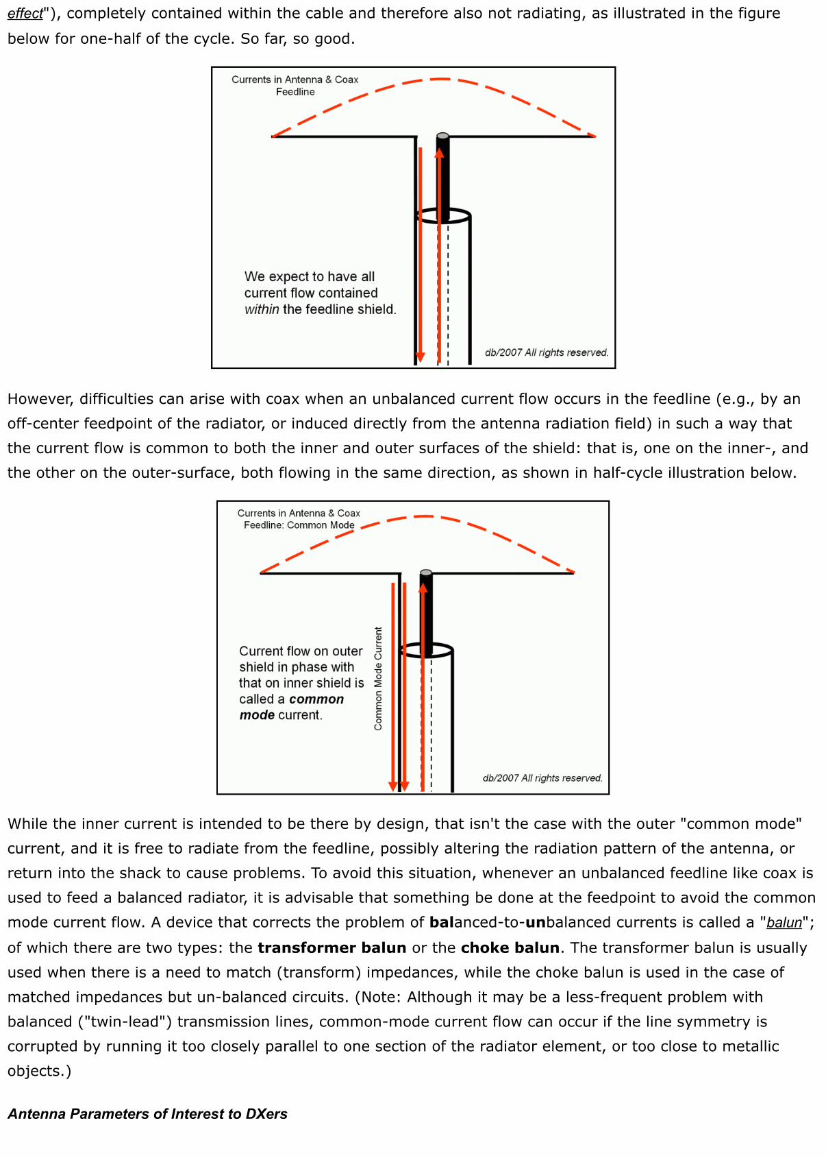
However, difficulties can arise with coax when an unbalanced current flow occurs in the feedline (e.g., by anoff-center feedpoint of the radiator, or induced directly from the antenna radiation field) in such a way thatthe current flow is common to both the inner and outer surfaces of the shield: that is, one on the inner-, andthe other on the outer-surface, both flowing in the same direction, as shown in half-cycle illustration below.
While the inner current is intended to be there by design, that isn't the case with the outer "common mode"current, and it is free to radiate from the feedline, possibly altering the radiation pattern of the antenna, orreturn into the shack to cause problems. To avoid this situation, whenever an unbalanced feedline like coax isused to feed a balanced radiator, it is advisable that something be done at the feedpoint to avoid the commonmode current flow. A device that corrects the problem of balanced-to-unbalanced currents is called a "balun";
of which there are two types: the transformer balun or the choke balun. The transformer balun is usuallyused when there is a need to match (transform) impedances, while the choke balun is used in the case ofmatched impedances but un-balanced circuits. (Note: Although it may be a less-frequent problem withbalanced ("twin-lead") transmission lines, common-mode current flow can occur if the line symmetry iscorrupted by running it too closely parallel to one section of the radiator element, or too close to metallicobjects.)
Antenna Parameters of Interest to DXers
Now that we have a "yardstick" for comparing antenna types, what exactly do we measure and compare? Anyconductor connected to the output of a transmitter will radiate some RF energy, so what we must beconcerned with is the efficiency of the radiator for its intended purpose and environment. Basically, there arefive attributes of an antenna that are of concern for DXing:
angle of radiation - the angle from horizontal (sometimes measured from vertical) at which a majorportion of the radiated power leaves the antenna.gain - how much radiated power will be effectively focused in a specific direction compared to areference antenna.front-to-back ratio - difference in directional gain between the forward and reverse direction; ameasure of the attenuation provided at the "back" of a directional antenna.bandwidth - the band of frequencies over which the antenna will perform as well as intended.noise susceptibility - to what extent it may be vulnerable to reception of manmade (environmental)noise or interferences.
The first four attributes apply to antennas on both transmit and receive - a transmitted signal gain in onedirection means a received signal gain as well. Although the value of directional antennas with gain isobvious, the idea of a "negative gain" (signal attenuation) described by the front-to-back ratio may initiallyseem odd to some. However, it provides a well-known edge for DXers: when you're in a pileup, not only is itnice to be able to direct more of your signal energy towards the desired station, but it is also nice tosimultaneously reduce the interference caused by the clamor of stations calling from the opposite direction!The last factor, noise susceptibility, is of importance for weak signal reception where antennas that providehigh signal-to-noise ratio are desirable. These factors are not necessarily independent of one-another andtrade-offs among them are usually required. We'll look briefly into the meaning of each, but readers areadvised to consult antenna reference books and web-sources, some of which are listed under Referencesbelow.
Here is a brief discussion of each:
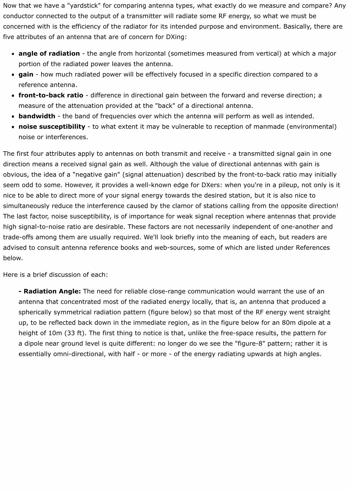
- Radiation Angle: The need for reliable close-range communication would warrant the use of anantenna that concentrated most of the radiated energy locally, that is, an antenna that produced aspherically symmetrical radiation pattern (figure below) so that most of the RF energy went straightup, to be reflected back down in the immediate region, as in the figure below for an 80m dipole at aheight of 10m (33 ft). The first thing to notice is that, unlike the free-space results, the pattern fora dipole near ground level is quite different: no longer do we see the "figure-8" pattern; rather it isessentially omni-directional, with half - or more - of the energy radiating upwards at high angles.
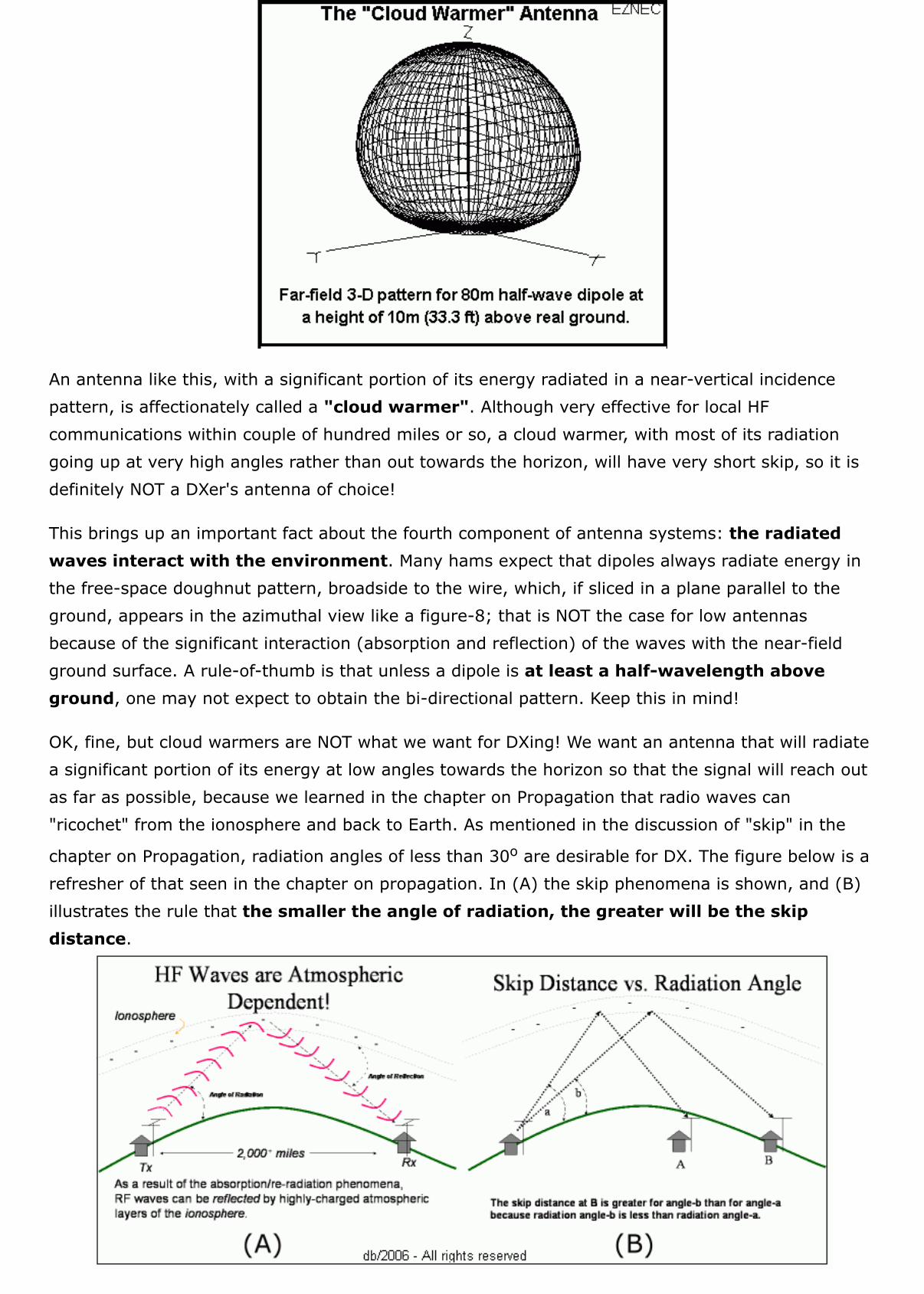
An antenna like this, with a significant portion of its energy radiated in a near-vertical incidencepattern, is affectionately called a "cloud warmer". Although very effective for local HFcommunications within couple of hundred miles or so, a cloud warmer, with most of its radiationgoing up at very high angles rather than out towards the horizon, will have very short skip, so it isdefinitely NOT a DXer's antenna of choice!
This brings up an important fact about the fourth component of antenna systems: the radiatedwaves interact with the environment. Many hams expect that dipoles always radiate energy inthe free-space doughnut pattern, broadside to the wire, which, if sliced in a plane parallel to theground, appears in the azimuthal view like a figure-8; that is NOT the case for low antennasbecause of the significant interaction (absorption and reflection) of the waves with the near-fieldground surface. A rule-of-thumb is that unless a dipole is at least a half-wavelength aboveground, one may not expect to obtain the bi-directional pattern. Keep this in mind!
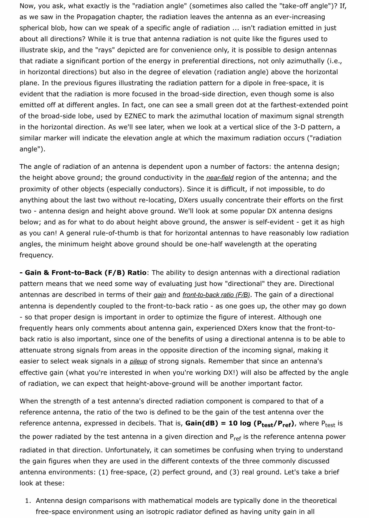
OK, fine, but cloud warmers are NOT what we want for DXing! We want an antenna that will radiatea significant portion of its energy at low angles towards the horizon so that the signal will reach outas far as possible, because we learned in the chapter on Propagation that radio waves can"ricochet" from the ionosphere and back to Earth. As mentioned in the discussion of "skip" in the
chapter on Propagation, radiation angles of less than 30o are desirable for DX. The figure below is arefresher of that seen in the chapter on propagation. In (A) the skip phenomena is shown, and (B)illustrates the rule that the smaller the angle of radiation, the greater will be the skipdistance.
Now, you ask, what exactly is the "radiation angle" (sometimes also called the "take-off angle")? If,as we saw in the Propagation chapter, the radiation leaves the antenna as an ever-increasingspherical blob, how can we speak of a specific angle of radiation ... isn't radiation emitted in justabout all directions? While it is true that antenna radiation is not quite like the figures used toillustrate skip, and the "rays" depicted are for convenience only, it is possible to design antennasthat radiate a significant portion of the energy in preferential directions, not only azimuthally (i.e.,in horizontal directions) but also in the degree of elevation (radiation angle) above the horizontalplane. In the previous figures illustrating the radiation pattern for a dipole in free-space, it isevident that the radiation is more focused in the broad-side direction, even though some is alsoemitted off at different angles. In fact, one can see a small green dot at the farthest-extended pointof the broad-side lobe, used by EZNEC to mark the azimuthal location of maximum signal strengthin the horizontal direction. As we'll see later, when we look at a vertical slice of the 3-D pattern, asimilar marker will indicate the elevation angle at which the maximum radiation occurs ("radiationangle").
The angle of radiation of an antenna is dependent upon a number of factors: the antenna design;the height above ground; the ground conductivity in the near-field region of the antenna; and the
proximity of other objects (especially conductors). Since it is difficult, if not impossible, to doanything about the last two without re-locating, DXers usually concentrate their efforts on the firsttwo - antenna design and height above ground. We'll look at some popular DX antenna designsbelow; and as for what to do about height above ground, the answer is self-evident - get it as highas you can! A general rule-of-thumb is that for horizontal antennas to have reasonably low radiationangles, the minimum height above ground should be one-half wavelength at the operatingfrequency.
- Gain & Front-to-Back (F/B) Ratio: The ability to design antennas with a directional radiationpattern means that we need some way of evaluating just how "directional" they are. Directionalantennas are described in terms of their gain and front-to-back ratio (F/B). The gain of a directional
antenna is dependently coupled to the front-to-back ratio - as one goes up, the other may go down- so that proper design is important in order to optimize the figure of interest. Although onefrequently hears only comments about antenna gain, experienced DXers know that the front-to-back ratio is also important, since one of the benefits of using a directional antenna is to be able toattenuate strong signals from areas in the opposite direction of the incoming signal, making iteasier to select weak signals in a pileup of strong signals. Remember that since an antenna's
effective gain (what you're interested in when you're working DX!) will also be affected by the angleof radiation, we can expect that height-above-ground will be another important factor.
When the strength of a test antenna's directed radiation component is compared to that of areference antenna, the ratio of the two is defined to be the gain of the test antenna over thereference antenna, expressed in decibels. That is, Gain(dB) = 10 log (Ptest/Pref), where Ptest is
the power radiated by the test antenna in a given direction and Pref is the reference antenna power
radiated in that direction. Unfortunately, it can sometimes be confusing when trying to understandthe gain figures when they are used in the different contexts of the three commonly discussedantenna environments: (1) free-space, (2) perfect ground, and (3) real ground. Let's take a brieflook at these:
1. Antenna design comparisons with mathematical models are typically done in the theoreticalfree-space environment using an isotropic radiator defined as having unity gain in all
directions. The resulting measure for the test antenna is said to be the "gain over the isotropicantenna", or "dBi gain" for short, where the "i" indicates that the comparison was with anisotropic radiator. Alternatively, comparisons may be made with a standard half-wave dipole, inwhich case the gain is expressed as "dB gain over a dipole", or "dBd gain" for short. There isa difference between the two measures that arises from the fact that, as we saw in the free-space pattern for the dipole, it does favor a broadside direction, so a dipole has an intrinsicgain over an isotropic radiator of about 2.1 dB in the directions broadside to the dipole; moreappropriately, we should say that the free-space dipole has a gain of 2.1 dBi. What this meansis that free-space dBi and dBd gain figures are related as follows: dBd = dBi - 2.1.
2. The theoretical modeling can also be done in an environment that resembles actual use, but isstill idealized to reduce unknowns. This is the "perfect ground" environment in which theantenna is imagined to be on a perfectly conducting, flat plane surface in the near-field. In thiscase, the free-space 3-D pattern is cut in half, and the "bottom-half" energy is reflected upinto the "top-half", doubling the radiated power forming the pattern. As we might expect, theresult is that the gain figures for directional antennas would increase over that of free-space.For example, the gain of a dipole over perfect ground would be 8.4 dBi (6.3 dBd) at an
elevation angle of 30o.3. Modeling programs such as EZNEC can simulate "real" ground conditions that more nearly
approximate the conditions in your backyard. The effect of real ground on the antenna patternis also to reflect the near-field energy upwards to contribute to the radiated pattern, but to lessextent than the perfect ground, as there now will be some loss. In the case of the dipole, gain
would be 7.6 dBi (5.5 dBd) at an elevation angle of 30o.
It is easy to feel that this is all more confusing than helpful, but the important thing to remember isthat in looking at the specifications of different directional antennas, you should always be certainthat comparisons are made using the same units of gain. If the units are of the same measure, thenyou will have a fair comparison. A final note about antenna "gain": while it may seem that the useof the term implies an amplification of the radiated energy, that isn't the case. What a directionalantenna does is the same as what is done with a "spotlight" - rather than allowing the energy toradiate in all directions, it is simply focused into a desired direction; so a more appropriate term is"directional gain". For this reason, directional antennas are referred to as "beam antennas" or just
"beams".
One last comment about antenna gain: occasionally one encounters the term Effective Radiated Power
(ERP) of an antenna, such as in radiation safety considerations. As the name implies, it is a measure
of the effective (as opposed to actual) power radiated in the direction of interest, such as towardsthe neighbors' houses. ERP is the product of power supplied to an antenna and the antenna gain ina given direction, as compared to a reference antenna. For example, an output of 100w-PEP into a3-el Yagi with 6 dBd gain (x4 power gain over a dipole) would provide an ERP of 400w PEP in theforward direction of the beam as compared to a dipole.
- Bandwidth: The bandwidth of an antenna describes the frequency range over which it willfunction as expected. In the simplest case, this is the frequency range over which the impedancematch to the transmitter output is within satisfactory limits, usually specified as an SWR of 2:1 orless. However, in the case of the directional antennas discussed below, bandwidth is a criticalmeasure of the frequency range over which the antenna gain and F/B ratio hold up.
- Noise Susceptibility: RF waves, as discussed in that chapter, have electric and magnetic field
components that "leap-frog" through space once the wave is radiated from its source and, byconvention, the orientation or "polarization" of the wave is described in terms of the orientation of
the electric field component. That is the reason we say that horizontal antennas, such as a dipole,will produce "horizontally polarized" radio waves (see illustrations in "RF Waves"), while verticalantennas will produce "vertically polarized" waves. It follows that if the antenna orientation is thesame as that of an incoming wave polarization, then it will be somewhat more sensitive to signalinduction by the wave. However, wave polarization may be altered by several factors, the mostcommon being reflection at conductive surfaces. Radio waves from distant stations, havingundergone ionospheric refraction and ground reflection, may have a variety of polarization angles.Therefore, differences in the polarization of the antennas at each end of a long communicationspath are not of great significance in regard to communications signals. On the other hand, receive-antenna polarization is of importance when there is a significant amount of locally generated noise(as in suburban and urban areas), since this type of noise happens to be predominantly verticallypolarized. This means that a vertical antenna will be more sensitive to locally generated noise. Forthis reason, vertically oriented antennas, while they can be very effective transmit antennas, have areputation for being "noisy" receiving antennas.
To help understand the first three parameters above, as well as the data available in the radiation patterngraphs that one frequently sees (some previously, with more below), an illustrated example is explained in"Antenna Notes" in the "Miscellaneous Notes" Appendix. Antenna design, modification, and optimization would
be a tedious process if one had to continually resort to field testing for new ideas or changes to see if theyperformed as expected. Since it is difficult (more to the point: IMPOSSIBLE!) to control the environmentaround antennas when making comparisons, software modeling and the theoretical construct of the freespace environment are very useful. Yet, it can often be confusing to the uninitiated, making it a goodmarketing tool! Caveat emptor ... .
Antennas for DXers
There are as many different antenna designs as there are ways to draw lines on paper, but here are a veryfew of the more popular ones used by DXers. These are presented in approximate order of increasing over-all(transmit and receive) effectiveness for DXing. The antenna that you use, or select to install, will probablydepend upon the usual variables that affect most of our choices: available space, money, antenna supportstructures, and any neighborhood restrictions. No matter what your circumstances, there is a solution towhatever problems that you happen to face and, while it may not be the "pileup buster" of your dreams(don't we all dream ...?) it should allow you to get into the chase. As an example, years ago from my single-story apartment building, I was able to work more than 100 different DXCC entities with a 50-watttransmitter and a 15m vertical mounted at the roof edge, using the roof flashing as a "ground" (a smallschool banner on the antenna was my "disguise").
- Random-wire or "Long-wire" antennas: Consisting of as long a piece of wire as can beinstalled at as great a height as possible, these are by far the simplest of all antennas. As illustratedin the figure below, a typical installation consists
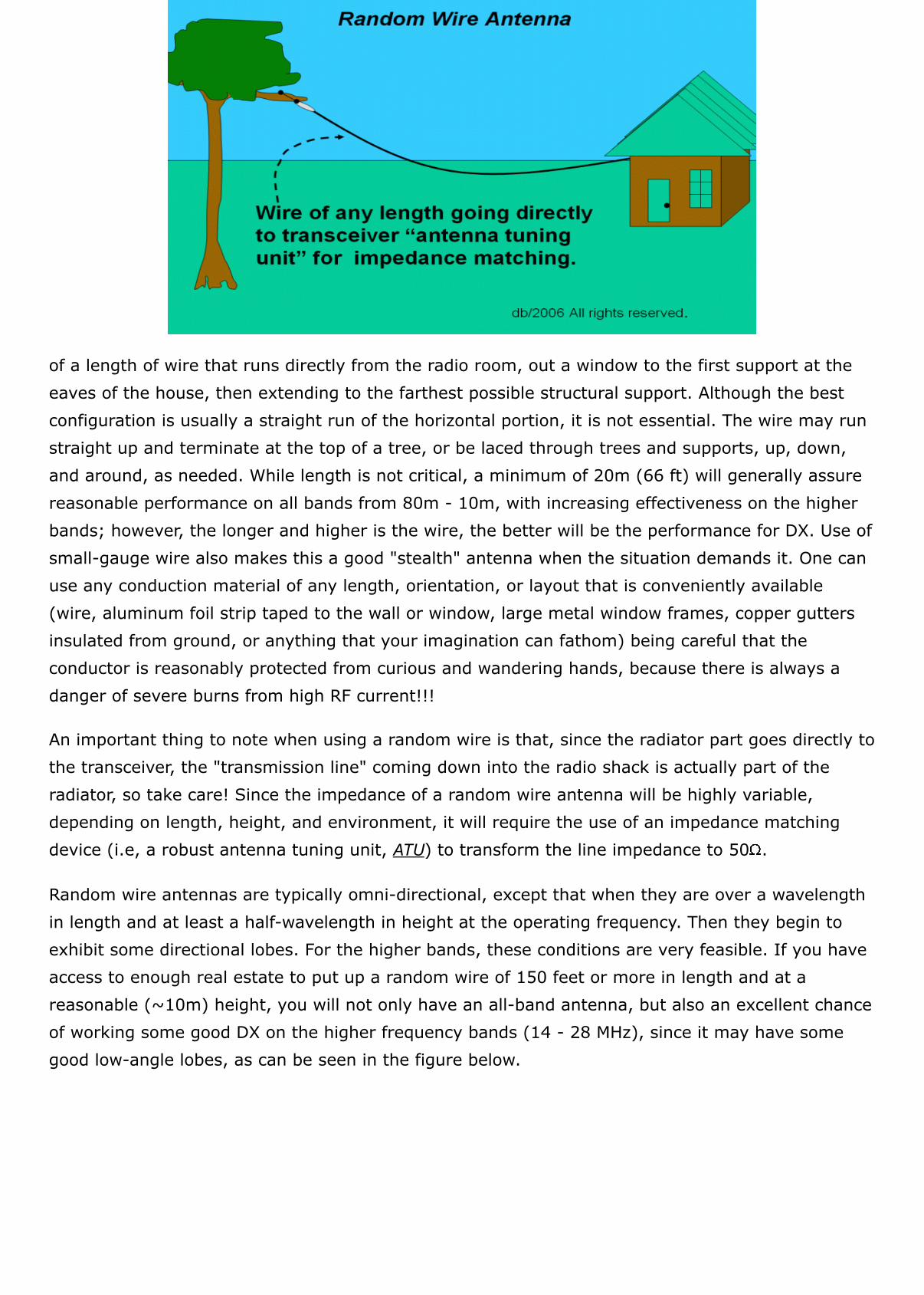
of a length of wire that runs directly from the radio room, out a window to the first support at theeaves of the house, then extending to the farthest possible structural support. Although the bestconfiguration is usually a straight run of the horizontal portion, it is not essential. The wire may runstraight up and terminate at the top of a tree, or be laced through trees and supports, up, down,and around, as needed. While length is not critical, a minimum of 20m (66 ft) will generally assurereasonable performance on all bands from 80m - 10m, with increasing effectiveness on the higherbands; however, the longer and higher is the wire, the better will be the performance for DX. Use ofsmall-gauge wire also makes this a good "stealth" antenna when the situation demands it. One canuse any conduction material of any length, orientation, or layout that is conveniently available(wire, aluminum foil strip taped to the wall or window, large metal window frames, copper guttersinsulated from ground, or anything that your imagination can fathom) being careful that theconductor is reasonably protected from curious and wandering hands, because there is always adanger of severe burns from high RF current!!!
An important thing to note when using a random wire is that, since the radiator part goes directly tothe transceiver, the "transmission line" coming down into the radio shack is actually part of theradiator, so take care! Since the impedance of a random wire antenna will be highly variable,depending on length, height, and environment, it will require the use of an impedance matchingdevice (i.e, a robust antenna tuning unit, ATU) to transform the line impedance to 50 .
Random wire antennas are typically omni-directional, except that when they are over a wavelengthin length and at least a half-wavelength in height at the operating frequency. Then they begin toexhibit some directional lobes. For the higher bands, these conditions are very feasible. If you haveaccess to enough real estate to put up a random wire of 150 feet or more in length and at areasonable (~10m) height, you will not only have an all-band antenna, but also an excellent chanceof working some good DX on the higher frequency bands (14 - 28 MHz), since it may have somegood low-angle lobes, as can be seen in the figure below.
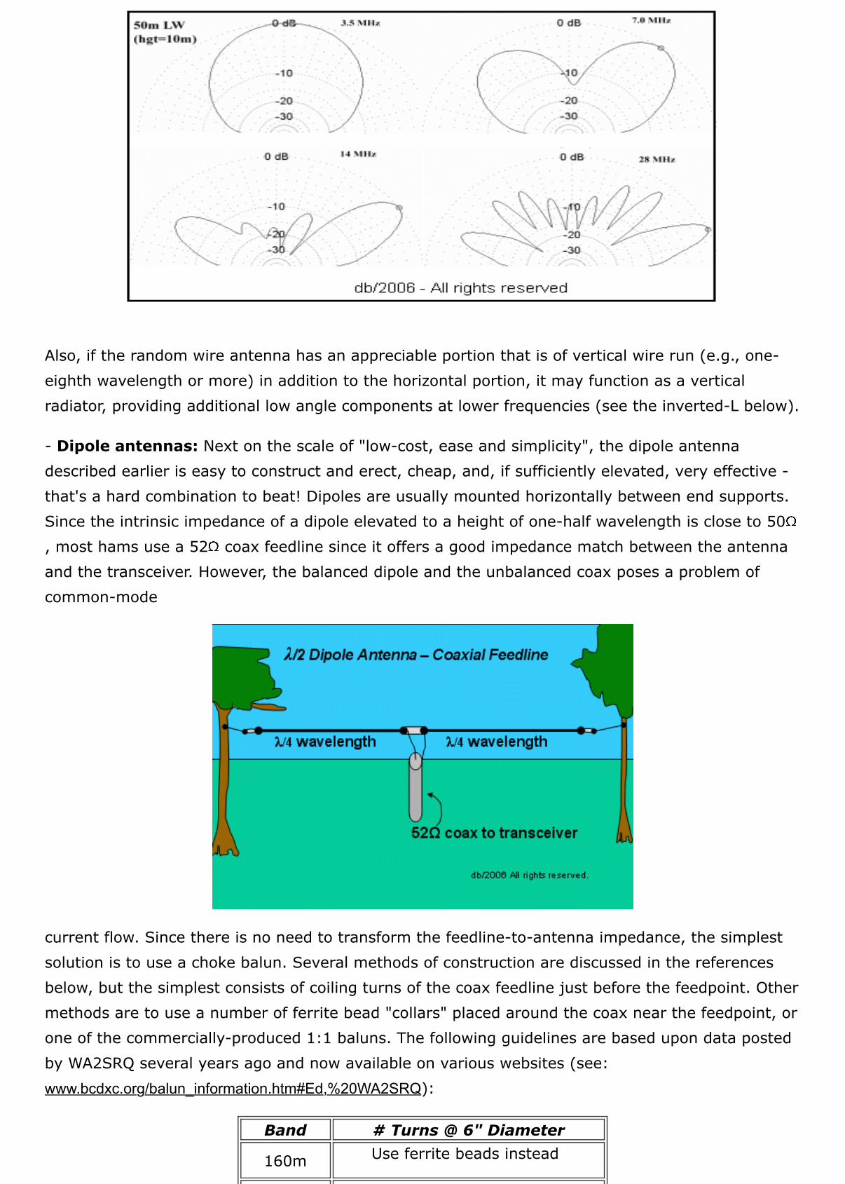
Also, if the random wire antenna has an appreciable portion that is of vertical wire run (e.g., one-eighth wavelength or more) in addition to the horizontal portion, it may function as a verticalradiator, providing additional low angle components at lower frequencies (see the inverted-L below).
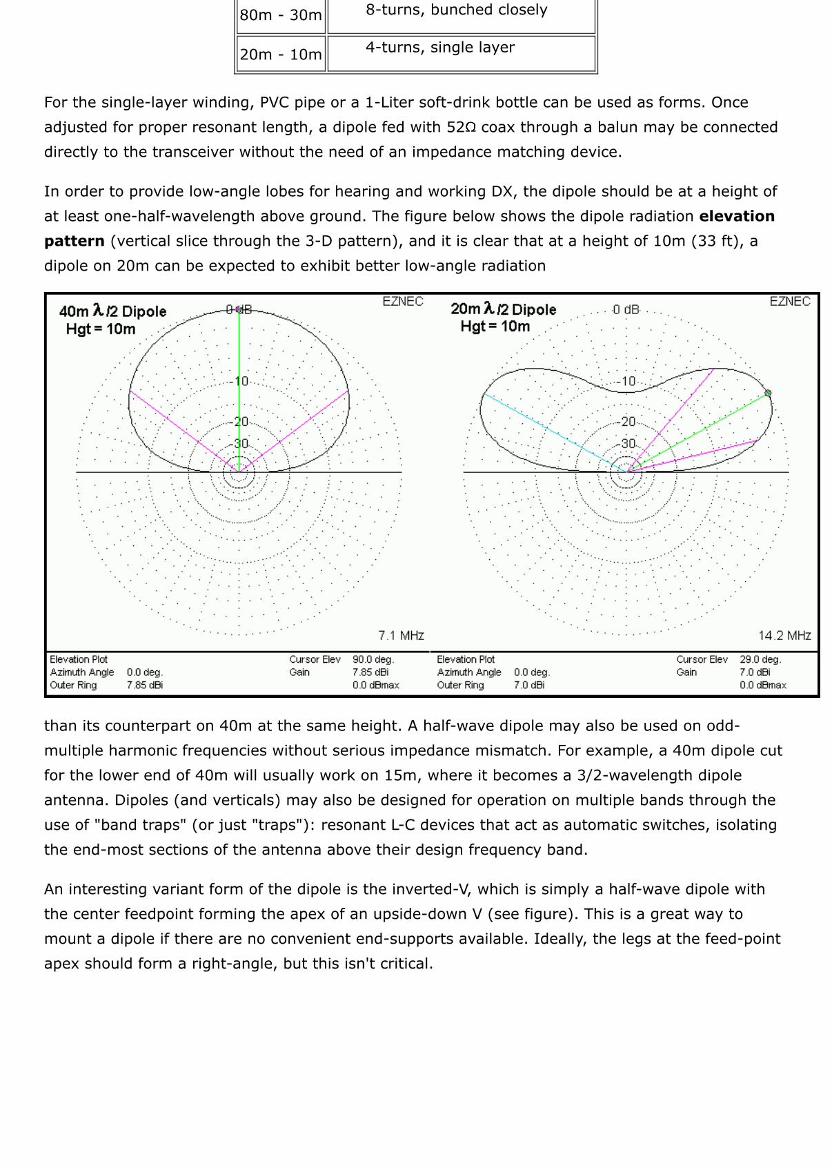
- Dipole antennas: Next on the scale of "low-cost, ease and simplicity", the dipole antennadescribed earlier is easy to construct and erect, cheap, and, if sufficiently elevated, very effective -that's a hard combination to beat! Dipoles are usually mounted horizontally between end supports.Since the intrinsic impedance of a dipole elevated to a height of one-half wavelength is close to 50, most hams use a 52 coax feedline since it offers a good impedance match between the antennaand the transceiver. However, the balanced dipole and the unbalanced coax poses a problem ofcommon-mode
current flow. Since there is no need to transform the feedline-to-antenna impedance, the simplestsolution is to use a choke balun. Several methods of construction are discussed in the referencesbelow, but the simplest consists of coiling turns of the coax feedline just before the feedpoint. Othermethods are to use a number of ferrite bead "collars" placed around the coax near the feedpoint, orone of the commercially-produced 1:1 baluns. The following guidelines are based upon data postedby WA2SRQ several years ago and now available on various websites (see:www.bcdxc.org/balun_information.htm#Ed,%20WA2SRQ):
Band # Turns @ 6" Diameter
160m Use ferrite beads instead
80m - 30m 8-turns, bunched closely
20m - 10m 4-turns, single layer
For the single-layer winding, PVC pipe or a 1-Liter soft-drink bottle can be used as forms. Onceadjusted for proper resonant length, a dipole fed with 52 coax through a balun may be connecteddirectly to the transceiver without the need of an impedance matching device.
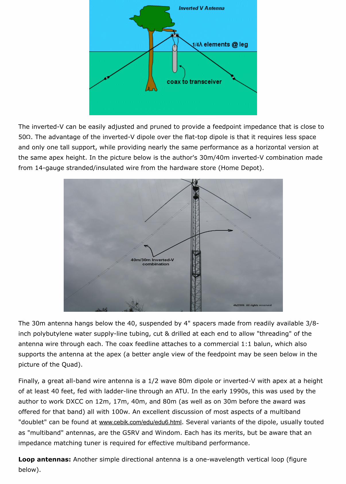
In order to provide low-angle lobes for hearing and working DX, the dipole should be at a height ofat least one-half-wavelength above ground. The figure below shows the dipole radiation elevationpattern (vertical slice through the 3-D pattern), and it is clear that at a height of 10m (33 ft), adipole on 20m can be expected to exhibit better low-angle radiation
than its counterpart on 40m at the same height. A half-wave dipole may also be used on odd-multiple harmonic frequencies without serious impedance mismatch. For example, a 40m dipole cutfor the lower end of 40m will usually work on 15m, where it becomes a 3/2-wavelength dipoleantenna. Dipoles (and verticals) may also be designed for operation on multiple bands through theuse of "band traps" (or just "traps"): resonant L-C devices that act as automatic switches, isolatingthe end-most sections of the antenna above their design frequency band.
An interesting variant form of the dipole is the inverted-V, which is simply a half-wave dipole withthe center feedpoint forming the apex of an upside-down V (see figure). This is a great way tomount a dipole if there are no convenient end-supports available. Ideally, the legs at the feed-pointapex should form a right-angle, but this isn't critical.
The inverted-V can be easily adjusted and pruned to provide a feedpoint impedance that is close to50 . The advantage of the inverted-V dipole over the flat-top dipole is that it requires less spaceand only one tall support, while providing nearly the same performance as a horizontal version atthe same apex height. In the picture below is the author's 30m/40m inverted-V combination madefrom 14-gauge stranded/insulated wire from the hardware store (Home Depot).
The 30m antenna hangs below the 40, suspended by 4" spacers made from readily available 3/8-inch polybutylene water supply-line tubing, cut & drilled at each end to allow "threading" of theantenna wire through each. The coax feedline attaches to a commercial 1:1 balun, which alsosupports the antenna at the apex (a better angle view of the feedpoint may be seen below in thepicture of the Quad).
Finally, a great all-band wire antenna is a 1/2 wave 80m dipole or inverted-V with apex at a heightof at least 40 feet, fed with ladder-line through an ATU. In the early 1990s, this was used by theauthor to work DXCC on 12m, 17m, 40m, and 80m (as well as on 30m before the award wasoffered for that band) all with 100w. An excellent discussion of most aspects of a multiband"doublet" can be found at www.cebik.com/edu/edu6.html. Several variants of the dipole, usually touted
as "multiband" antennas, are the G5RV and Windom. Each has its merits, but be aware that animpedance matching tuner is required for effective multiband performance.
Loop antennas: Another simple directional antenna is a one-wavelength vertical loop (figurebelow).
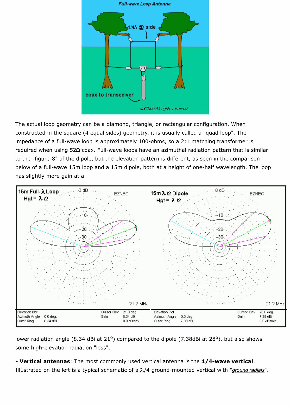
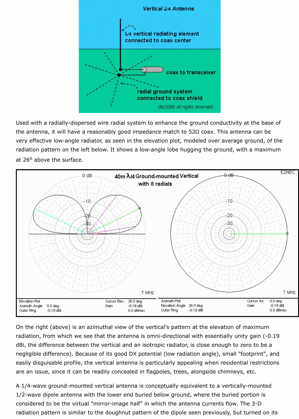
The actual loop geometry can be a diamond, triangle, or rectangular configuration. Whenconstructed in the square (4 equal sides) geometry, it is usually called a "quad loop". Theimpedance of a full-wave loop is approximately 100-ohms, so a 2:1 matching transformer isrequired when using 52 coax. Full-wave loops have an azimuthal radiation pattern that is similarto the "figure-8" of the dipole, but the elevation pattern is different, as seen in the comparisonbelow of a full-wave 15m loop and a 15m dipole, both at a height of one-half wavelength. The loophas slightly more gain at a
lower radiation angle (8.34 dBi at 21o) compared to the dipole (7.38dBi at 28o), but also showssome high-elevation radiation "loss".
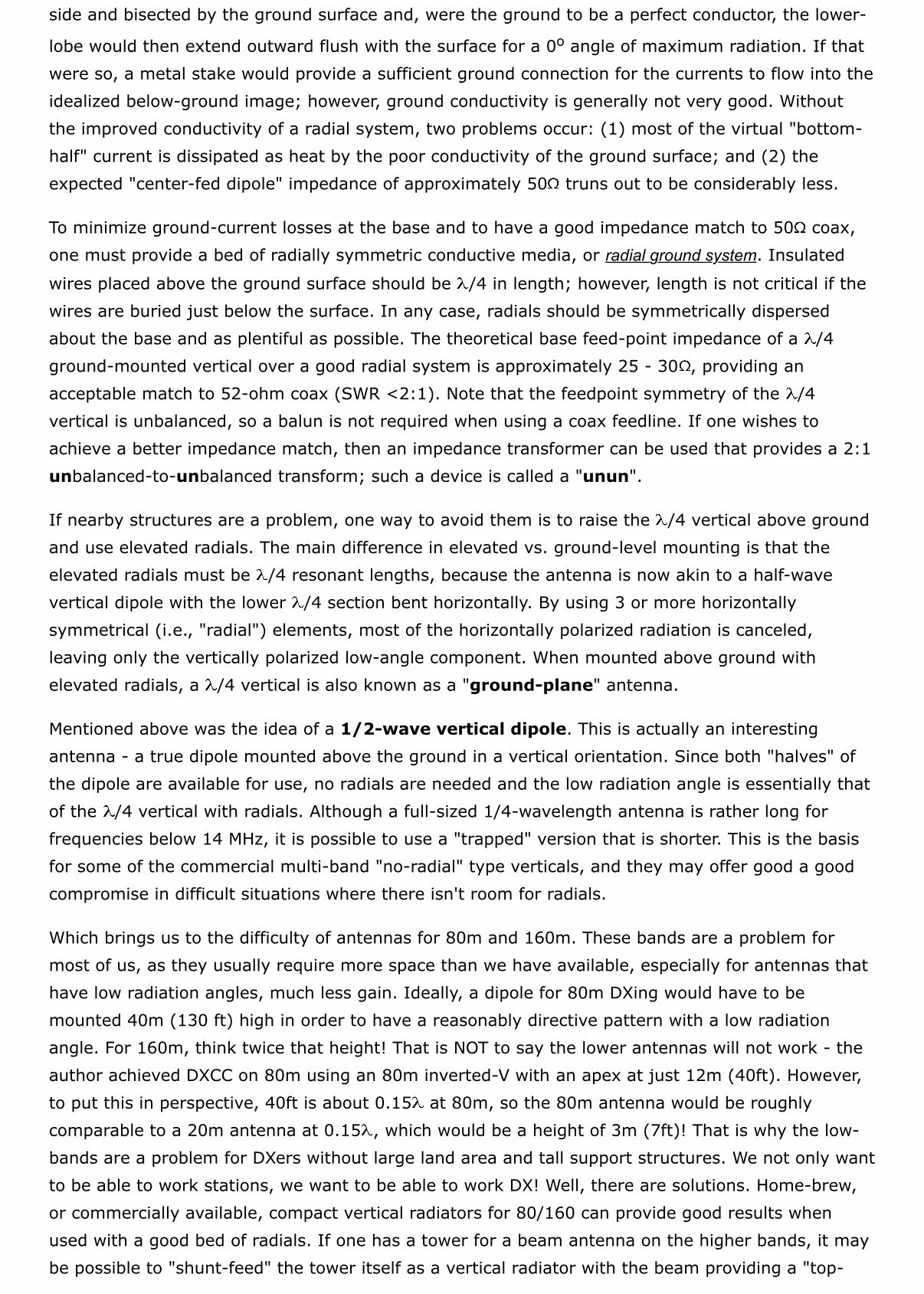
- Vertical antennas: The most commonly used vertical antenna is the 1/4-wave vertical.Illustrated on the left is a typical schematic of a /4 ground-mounted vertical with "ground radials".
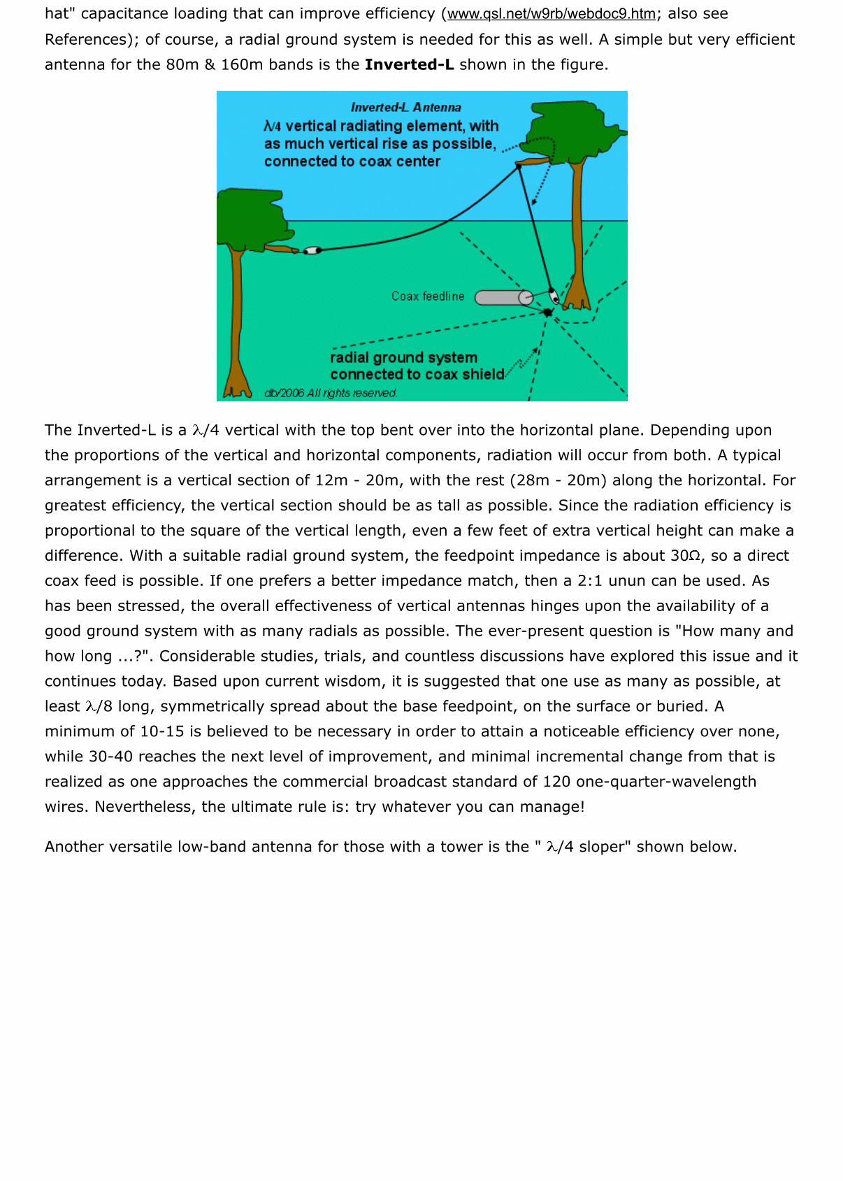
Used with a radially-dispersed wire radial system to enhance the ground conductivity at the base ofthe antenna, it will have a reasonably good impedance match to 52 coax. This antenna can bevery effective low-angle radiator, as seen in the elevation plot, modeled over average ground, of theradiation pattern on the left below. It shows a low-angle lobe hugging the ground, with a maximum
at 26o above the surface.
On the right (above) is an azimuthal view of the vertical's pattern at the elevation of maximumradiation, from which we see that the antenna is omni-directional with essentially unity gain (-0.19dBi, the difference between the vertical and an isotropic radiator, is close enough to zero to be anegligible difference). Because of its good DX potential (low radiation angle), small "footprint", andeasily disguisable profile, the vertical antenna is particularly appealing when residential restrictionsare an issue, since it can be readily concealed in flagpoles, trees, alongside chimneys, etc.
A 1/4-wave ground-mounted vertical antenna is conceptually equivalent to a vertically-mounted1/2-wave dipole antenna with the lower end buried below ground, where the buried portion isconsidered to be the virtual "mirror-image half" in which the antenna currents flow. The 3-Dradiation pattern is similar to the doughnut pattern of the dipole seen previously, but turned on its
side and bisected by the ground surface and, were the ground to be a perfect conductor, the lower-
lobe would then extend outward flush with the surface for a 0o angle of maximum radiation. If thatwere so, a metal stake would provide a sufficient ground connection for the currents to flow into theidealized below-ground image; however, ground conductivity is generally not very good. Withoutthe improved conductivity of a radial system, two problems occur: (1) most of the virtual "bottom-half" current is dissipated as heat by the poor conductivity of the ground surface; and (2) theexpected "center-fed dipole" impedance of approximately 50 truns out to be considerably less.
To minimize ground-current losses at the base and to have a good impedance match to 50 coax,one must provide a bed of radially symmetric conductive media, or radial ground system. Insulated
wires placed above the ground surface should be /4 in length; however, length is not critical if thewires are buried just below the surface. In any case, radials should be symmetrically dispersedabout the base and as plentiful as possible. The theoretical base feed-point impedance of a /4ground-mounted vertical over a good radial system is approximately 25 - 30 , providing anacceptable match to 52-ohm coax (SWR <2:1). Note that the feedpoint symmetry of the /4vertical is unbalanced, so a balun is not required when using a coax feedline. If one wishes toachieve a better impedance match, then an impedance transformer can be used that provides a 2:1unbalanced-to-unbalanced transform; such a device is called a "unun".
If nearby structures are a problem, one way to avoid them is to raise the /4 vertical above groundand use elevated radials. The main difference in elevated vs. ground-level mounting is that theelevated radials must be /4 resonant lengths, because the antenna is now akin to a half-wavevertical dipole with the lower /4 section bent horizontally. By using 3 or more horizontallysymmetrical (i.e., "radial") elements, most of the horizontally polarized radiation is canceled,leaving only the vertically polarized low-angle component. When mounted above ground withelevated radials, a /4 vertical is also known as a "ground-plane" antenna.
Mentioned above was the idea of a 1/2-wave vertical dipole. This is actually an interestingantenna - a true dipole mounted above the ground in a vertical orientation. Since both "halves" ofthe dipole are available for use, no radials are needed and the low radiation angle is essentially thatof the /4 vertical with radials. Although a full-sized 1/4-wavelength antenna is rather long forfrequencies below 14 MHz, it is possible to use a "trapped" version that is shorter. This is the basisfor some of the commercial multi-band "no-radial" type verticals, and they may offer good a goodcompromise in difficult situations where there isn't room for radials.
Which brings us to the difficulty of antennas for 80m and 160m. These bands are a problem formost of us, as they usually require more space than we have available, especially for antennas thathave low radiation angles, much less gain. Ideally, a dipole for 80m DXing would have to bemounted 40m (130 ft) high in order to have a reasonably directive pattern with a low radiationangle. For 160m, think twice that height! That is NOT to say the lower antennas will not work - theauthor achieved DXCC on 80m using an 80m inverted-V with an apex at just 12m (40ft). However,to put this in perspective, 40ft is about 0.15 at 80m, so the 80m antenna would be roughlycomparable to a 20m antenna at 0.15 , which would be a height of 3m (7ft)! That is why the low-bands are a problem for DXers without large land area and tall support structures. We not only wantto be able to work stations, we want to be able to work DX! Well, there are solutions. Home-brew,or commercially available, compact vertical radiators for 80/160 can provide good results whenused with a good bed of radials. If one has a tower for a beam antenna on the higher bands, it maybe possible to "shunt-feed" the tower itself as a vertical radiator with the beam providing a "top-
hat" capacitance loading that can improve efficiency (www.qsl.net/w9rb/webdoc9.htm; also see
References); of course, a radial ground system is needed for this as well. A simple but very efficientantenna for the 80m & 160m bands is the Inverted-L shown in the figure.
The Inverted-L is a /4 vertical with the top bent over into the horizontal plane. Depending uponthe proportions of the vertical and horizontal components, radiation will occur from both. A typicalarrangement is a vertical section of 12m - 20m, with the rest (28m - 20m) along the horizontal. Forgreatest efficiency, the vertical section should be as tall as possible. Since the radiation efficiency isproportional to the square of the vertical length, even a few feet of extra vertical height can make adifference. With a suitable radial ground system, the feedpoint impedance is about 30 , so a directcoax feed is possible. If one prefers a better impedance match, then a 2:1 unun can be used. Ashas been stressed, the overall effectiveness of vertical antennas hinges upon the availability of agood ground system with as many radials as possible. The ever-present question is "How many andhow long ...?". Considerable studies, trials, and countless discussions have explored this issue and itcontinues today. Based upon current wisdom, it is suggested that one use as many as possible, atleast /8 long, symmetrically spread about the base feedpoint, on the surface or buried. Aminimum of 10-15 is believed to be necessary in order to attain a noticeable efficiency over none,while 30-40 reaches the next level of improvement, and minimal incremental change from that isrealized as one approaches the commercial broadcast standard of 120 one-quarter-wavelengthwires. Nevertheless, the ultimate rule is: try whatever you can manage!
Another versatile low-band antenna for those with a tower is the " /4 sloper" shown below.
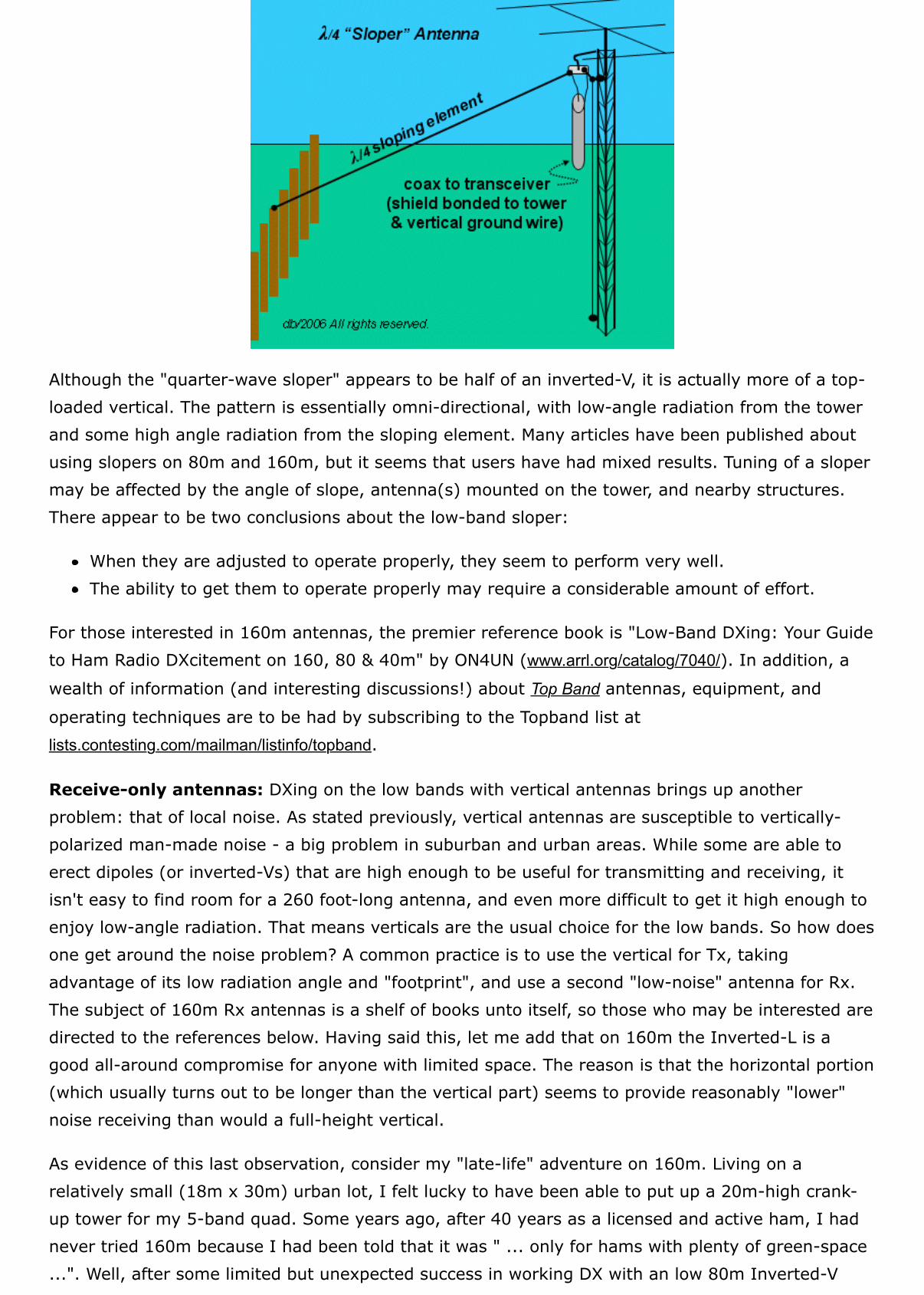
Although the "quarter-wave sloper" appears to be half of an inverted-V, it is actually more of a top-loaded vertical. The pattern is essentially omni-directional, with low-angle radiation from the towerand some high angle radiation from the sloping element. Many articles have been published aboutusing slopers on 80m and 160m, but it seems that users have had mixed results. Tuning of a slopermay be affected by the angle of slope, antenna(s) mounted on the tower, and nearby structures.There appear to be two conclusions about the low-band sloper:
When they are adjusted to operate properly, they seem to perform very well.The ability to get them to operate properly may require a considerable amount of effort.
For those interested in 160m antennas, the premier reference book is "Low-Band DXing: Your Guideto Ham Radio DXcitement on 160, 80 & 40m" by ON4UN (www.arrl.org/catalog/7040/). In addition, a
wealth of information (and interesting discussions!) about Top Band antennas, equipment, and
operating techniques are to be had by subscribing to the Topband list atlists.contesting.com/mailman/listinfo/topband.
Receive-only antennas: DXing on the low bands with vertical antennas brings up anotherproblem: that of local noise. As stated previously, vertical antennas are susceptible to vertically-polarized man-made noise - a big problem in suburban and urban areas. While some are able toerect dipoles (or inverted-Vs) that are high enough to be useful for transmitting and receiving, itisn't easy to find room for a 260 foot-long antenna, and even more difficult to get it high enough toenjoy low-angle radiation. That means verticals are the usual choice for the low bands. So how doesone get around the noise problem? A common practice is to use the vertical for Tx, takingadvantage of its low radiation angle and "footprint", and use a second "low-noise" antenna for Rx.The subject of 160m Rx antennas is a shelf of books unto itself, so those who may be interested aredirected to the references below. Having said this, let me add that on 160m the Inverted-L is agood all-around compromise for anyone with limited space. The reason is that the horizontal portion(which usually turns out to be longer than the vertical part) seems to provide reasonably "lower"noise receiving than would a full-height vertical.
As evidence of this last observation, consider my "late-life" adventure on 160m. Living on arelatively small (18m x 30m) urban lot, I felt lucky to have been able to put up a 20m-high crank-up tower for my 5-band quad. Some years ago, after 40 years as a licensed and active ham, I hadnever tried 160m because I had been told that it was " ... only for hams with plenty of green-space...". Well, after some limited but unexpected success in working DX with an low 80m Inverted-V
hung from the tower, I decided that it was definitely possible for even a city-slicker to enjoy 160m. Iput up an Inverted-L for 160m: 40m of 12AWG stranded/insulated copper wire runningapproximately 12m vertically up a small oak tree in the rear, and going out horizontally for 28m toa pine tree in the front yard. Initially, I buried 10 radials varying in length (20m - 40m), andeventually squeezed in another 6, weaving around structures and plants in the yard and, withpermission, sneaking a few out on the property behind and adjacent to mine. Did it work? Well,after some 5 years, I had over 100 DXCC entities confirmed, while having as much fun as I didwhen I first began to work DX in the middle 1950s! Of course, it was not easy and required a lot oflate night/early morning listening through a LOT of noise, along with developing a newunderstanding of propagation, receiver sensitivity/selectivity, improving signal-to-noise ratio, andplenty of P.E.P.S.I.!!. But I will tell you that it was, for me, an achievement of immense satisfaction
that I never imagined possible! Topband - try it, you'll like it!
For those who prefer multiband antennas, the inverted-L could be used as an all-band antenna withthe placement of an ATU at the base. There are also commercially-available multiband verticals.Multi-band wire antennas can be constructed using resonant inductor-capacitor circuits to electrical"cut" the length of a long conductor at a desired operating frequency, thereby "trapping" thecurrents within that length, hence the popular name: "traps". Just remember that, regardless ofany marketing claims to the contrary, low angle radiation from a short vertical antenna is contingentupon an effective ground system.
Directional antennas: Described in terms of their gain and front-to-back ratio (F/B), these are the
ultimate antennas for DXing because they offer not only directivity, but also front-to-back rejectionthat is invaluable in DX pileups. Directional antennas are constructed by combining two or moreantenna elements in an array that makes use of the "interference" property of waves in whichphase similarities and differences can produce reinforcement or suppression of the mixed wave. Wehave already encountered and discussed the simplest of the directional antennas - the dipole andthe full-wave loop. By proper design and layout of an array of dipole, loop, or vertical elements, onecan focus radiation (constructive interference) in one direction while minimizing (destructive interference)
it in other directions. Remember that since an antenna's directional gain will also be affected by theangle of radiation, we can expect that height-above-ground can be another important factor. Also,the F/B ratio will decrease (or may even reverse!) as one exceeds the design bandwidth of theantenna (typically 100 - 200 KHz or so).
There are three methods for designing directional antennas, depending upon how the elements aremade to radiate:
parasitic arrays - power is fed to one element ("active" or "driven element"), and the other("parasitic") elements absorb and re-radiate at different relative phases depending uponplacement.phased arrays - power of is fed to all elements, using a method for varying the relative phaseof the signal going to each active element.combination of both - more than one active element, along with one or more parasiticelements.
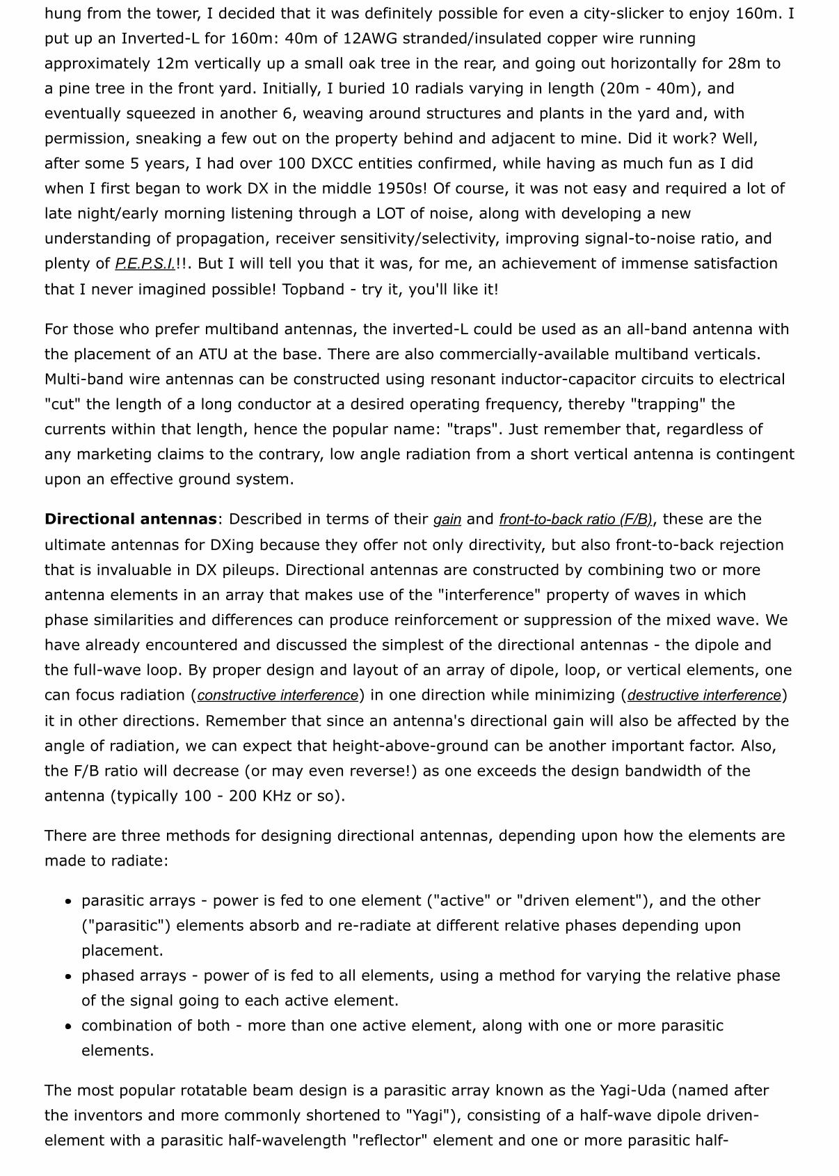
The most popular rotatable beam design is a parasitic array known as the Yagi-Uda (named afterthe inventors and more commonly shortened to "Yagi"), consisting of a half-wave dipole driven-element with a parasitic half-wavelength "reflector" element and one or more parasitic half-
wavelength "director" elements mounted in parallel on a boom, each spaced approximately 0.15 -0.25 wavelengths apart, as seen in the left illustration below. The free-space azimuthal radiationpattern of a 20m version is shown on the right. Yagi parasitic elements are tuned to slightlydifferent resonant frequencies than the operating frequency for the driven element: the reflector isabout 5% longer, while the director is about 5% shorter.
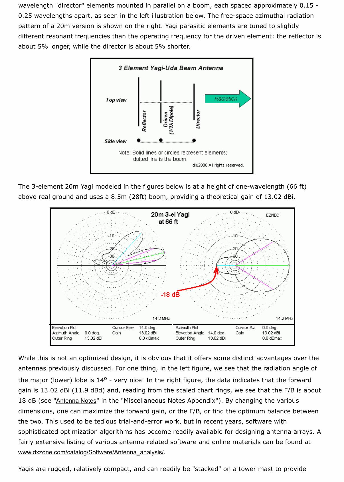
The 3-element 20m Yagi modeled in the figures below is at a height of one-wavelength (66 ft)above real ground and uses a 8.5m (28ft) boom, providing a theoretical gain of 13.02 dBi.
While this is not an optimized design, it is obvious that it offers some distinct advantages over theantennas previously discussed. For one thing, in the left figure, we see that the radiation angle of
the major (lower) lobe is 14o - very nice! In the right figure, the data indicates that the forwardgain is 13.02 dBi (11.9 dBd) and, reading from the scaled chart rings, we see that the F/B is about18 dB (see "Antenna Notes" in the "Miscellaneous Notes Appendix"). By changing the various
dimensions, one can maximize the forward gain, or the F/B, or find the optimum balance betweenthe two. This used to be tedious trial-and-error work, but in recent years, software withsophisticated optimization algorithms has become readily available for designing antenna arrays. Afairly extensive listing of various antenna-related software and online materials can be found atwww.dxzone.com/catalog/Software/Antenna_analysis/.
Yagis are rugged, relatively compact, and can readily be "stacked" on a tower mast to provide
multi-band coverage with a single tower. The picture below shows a 3-el 15/10m Yagi "stacked"above a 5-el 20m "monoband" Yagi (courtesy KB5GL).
Multi-band Yagis, like verticals, can be constructed using either resonant inductor-capacitor "traps"to electrically "cut" long elements at a desired operating frequency, or by essentially mountingmultiple Yagis strategically spaced on the same boom, with a common-feed for the driven elements.Looking closely at the upper Yagi in the picture above, you can see the "traps" that "cut" theelements for 10m, and are ignored by the 15m currents so that they use the entire length. Inrecent years, a new method of providing Yagi (and vertical) multi-band capability was developedand is now marketed as the StepIR, in which the element lengths are dynamically altered remotelyin order to change the operating frequency (www.steppir.com/design.htm).
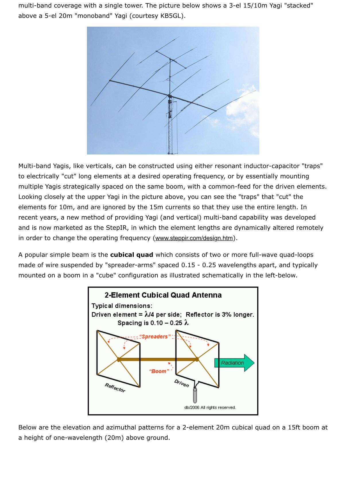
A popular simple beam is the cubical quad which consists of two or more full-wave quad-loopsmade of wire suspended by "spreader-arms" spaced 0.15 - 0.25 wavelengths apart, and typicallymounted on a boom in a "cube" configuration as illustrated schematically in the left-below.
Below are the elevation and azimuthal patterns for a 2-element 20m cubical quad on a 15ft boom ata height of one-wavelength (20m) above ground.
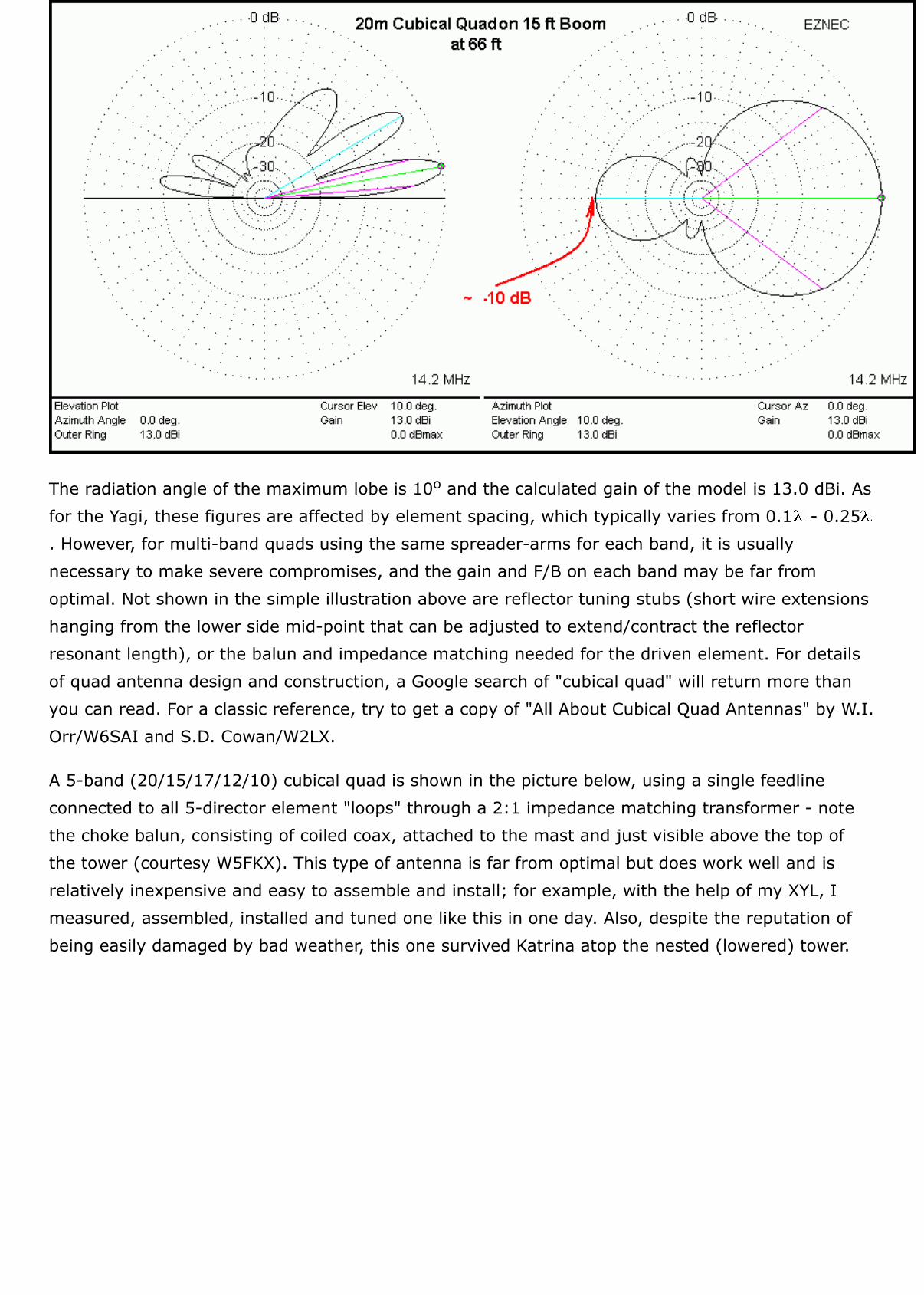
The radiation angle of the maximum lobe is 10o and the calculated gain of the model is 13.0 dBi. Asfor the Yagi, these figures are affected by element spacing, which typically varies from 0.1 - 0.25. However, for multi-band quads using the same spreader-arms for each band, it is usuallynecessary to make severe compromises, and the gain and F/B on each band may be far fromoptimal. Not shown in the simple illustration above are reflector tuning stubs (short wire extensionshanging from the lower side mid-point that can be adjusted to extend/contract the reflectorresonant length), or the balun and impedance matching needed for the driven element. For detailsof quad antenna design and construction, a Google search of "cubical quad" will return more thanyou can read. For a classic reference, try to get a copy of "All About Cubical Quad Antennas" by W.I.Orr/W6SAI and S.D. Cowan/W2LX.
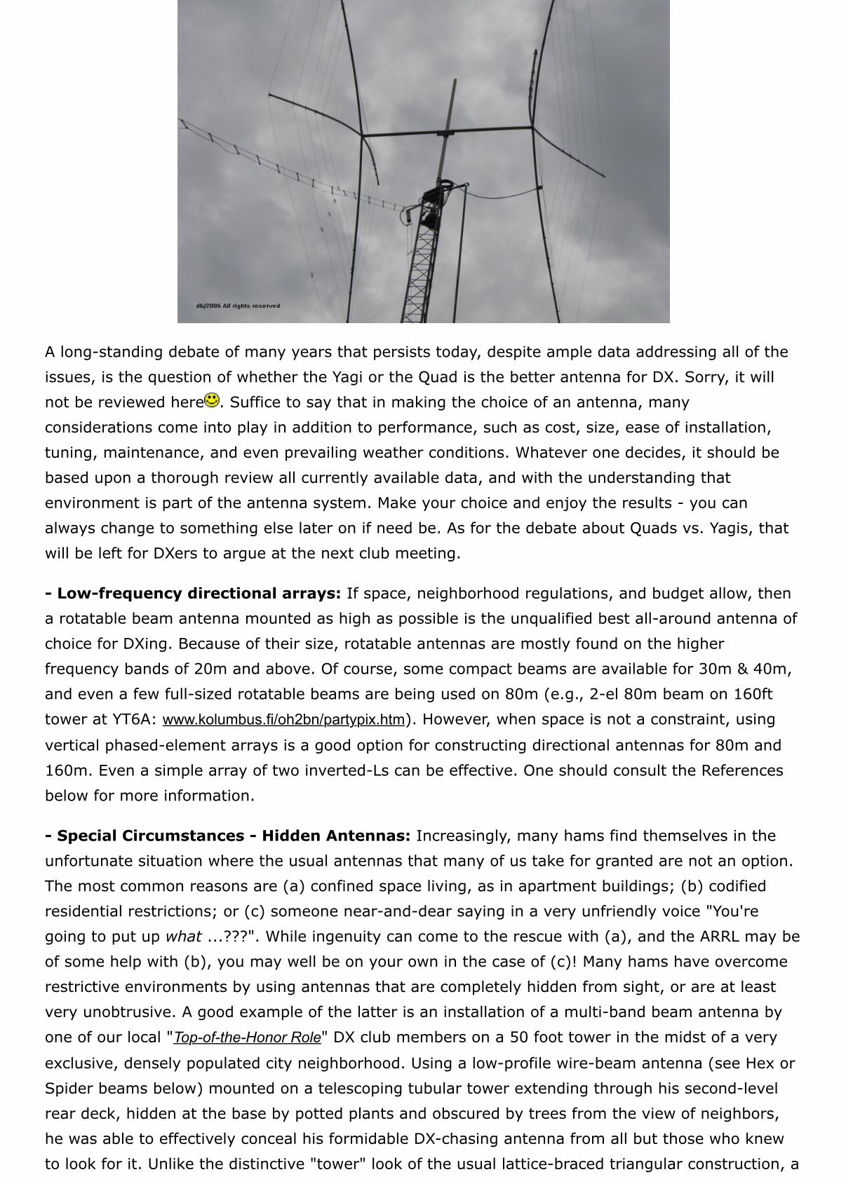
A 5-band (20/15/17/12/10) cubical quad is shown in the picture below, using a single feedlineconnected to all 5-director element "loops" through a 2:1 impedance matching transformer - notethe choke balun, consisting of coiled coax, attached to the mast and just visible above the top ofthe tower (courtesy W5FKX). This type of antenna is far from optimal but does work well and isrelatively inexpensive and easy to assemble and install; for example, with the help of my XYL, Imeasured, assembled, installed and tuned one like this in one day. Also, despite the reputation ofbeing easily damaged by bad weather, this one survived Katrina atop the nested (lowered) tower.
A long-standing debate of many years that persists today, despite ample data addressing all of theissues, is the question of whether the Yagi or the Quad is the better antenna for DX. Sorry, it willnot be reviewed here . Suffice to say that in making the choice of an antenna, manyconsiderations come into play in addition to performance, such as cost, size, ease of installation,tuning, maintenance, and even prevailing weather conditions. Whatever one decides, it should bebased upon a thorough review all currently available data, and with the understanding thatenvironment is part of the antenna system. Make your choice and enjoy the results - you canalways change to something else later on if need be. As for the debate about Quads vs. Yagis, thatwill be left for DXers to argue at the next club meeting.
- Low-frequency directional arrays: If space, neighborhood regulations, and budget allow, thena rotatable beam antenna mounted as high as possible is the unqualified best all-around antenna ofchoice for DXing. Because of their size, rotatable antennas are mostly found on the higherfrequency bands of 20m and above. Of course, some compact beams are available for 30m & 40m,and even a few full-sized rotatable beams are being used on 80m (e.g., 2-el 80m beam on 160fttower at YT6A: www.kolumbus.fi/oh2bn/partypix.htm). However, when space is not a constraint, using
vertical phased-element arrays is a good option for constructing directional antennas for 80m and160m. Even a simple array of two inverted-Ls can be effective. One should consult the Referencesbelow for more information.
- Special Circumstances - Hidden Antennas: Increasingly, many hams find themselves in theunfortunate situation where the usual antennas that many of us take for granted are not an option.The most common reasons are (a) confined space living, as in apartment buildings; (b) codifiedresidential restrictions; or (c) someone near-and-dear saying in a very unfriendly voice "You'regoing to put up what ...???". While ingenuity can come to the rescue with (a), and the ARRL may beof some help with (b), you may well be on your own in the case of (c)! Many hams have overcomerestrictive environments by using antennas that are completely hidden from sight, or are at leastvery unobtrusive. A good example of the latter is an installation of a multi-band beam antenna byone of our local "Top-of-the-Honor Role" DX club members on a 50 foot tower in the midst of a very
exclusive, densely populated city neighborhood. Using a low-profile wire-beam antenna (see Hex orSpider beams below) mounted on a telescoping tubular tower extending through his second-levelrear deck, hidden at the base by potted plants and obscured by trees from the view of neighbors,he was able to effectively conceal his formidable DX-chasing antenna from all but those who knewto look for it. Unlike the distinctive "tower" look of the usual lattice-braced triangular construction, a
tubular tower is not too different than flag poles or the aluminum street-light standards seen inmany neighborhoods, and the compact Hex or Spider beam configurations seem to be lessnoticeable than large Yagis or quads. Of course, adjacent foliage and the discrete placement ofdecorative plants do help!
A good "stealth" antenna for DXers is commonly known as the "flag-pole" vertical, consisting of avertical radiator disguised as a flagpole. Variations on this include: an actual flagpole mounted onan insulating base, or a multiband vertical mounted inside of heavy-walled PVC conduit that servesas the flagpole. Another "vertical" option is the use of a light-weight tilt-over installation that can beerected at night and then concealed during the day.
Attic-mounted dipoles, verticals, or even small compact beams, can often work just as well asoutdoor antennas, especially in multi-level residences where attic-level antennas may be as high (orhigher!) as their outdoor counterparts. Just be very careful not to use excessive power that maycause harmful RF exposure to occupants. Usually, for bands below 10m, output levels of 100w oreven more may be within safety limits as long as there is no prolonged exposure at close proximity.My son lives in a covenant-restricted subdivision near Chicago, so he mounted a pair of dipoles for20m and a 17m in his attic, about 30ft above ground. He does not use an amplifier, and our regularweek-end schedule has been working well for over 7-years with this simple arrangement. Duringvisits, I have used his station to make some very nice DX contacts.
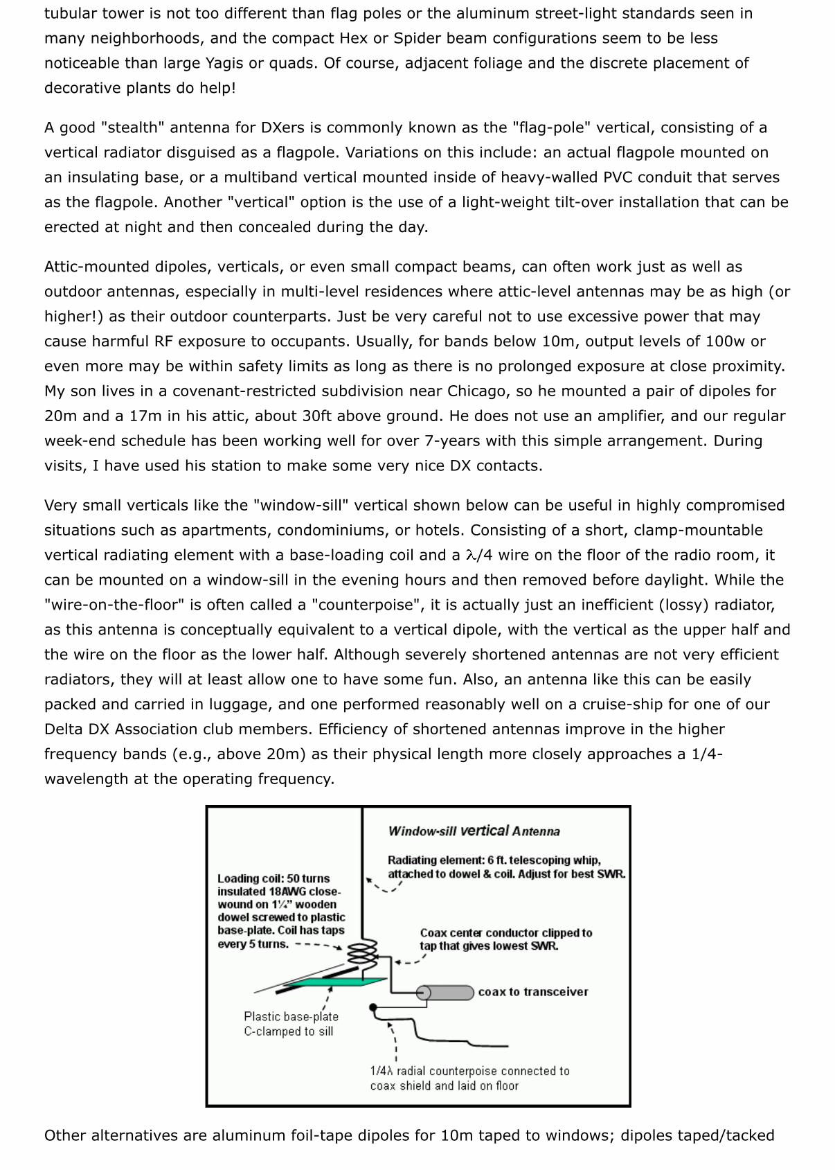
Very small verticals like the "window-sill" vertical shown below can be useful in highly compromisedsituations such as apartments, condominiums, or hotels. Consisting of a short, clamp-mountablevertical radiating element with a base-loading coil and a /4 wire on the floor of the radio room, itcan be mounted on a window-sill in the evening hours and then removed before daylight. While the"wire-on-the-floor" is often called a "counterpoise", it is actually just an inefficient (lossy) radiator,as this antenna is conceptually equivalent to a vertical dipole, with the vertical as the upper half andthe wire on the floor as the lower half. Although severely shortened antennas are not very efficientradiators, they will at least allow one to have some fun. Also, an antenna like this can be easilypacked and carried in luggage, and one performed reasonably well on a cruise-ship for one of ourDelta DX Association club members. Efficiency of shortened antennas improve in the higherfrequency bands (e.g., above 20m) as their physical length more closely approaches a 1/4-wavelength at the operating frequency.
Other alternatives are aluminum foil-tape dipoles for 10m taped to windows; dipoles taped/tacked
to an apartment wall or ceiling; very thin wire (eg, enameled 28 AWG ) run from a window to a tree
or other convenient support; all of which can be practically invisible, yet will allow you to enjoysome level of activity despite restrictions.
Summary
So what is important to know about antennas and what kind should you put up? There is really no "one fitsall" answer. It depends upon many factors, but undoubtedly the most important are cost, available space, andlocal community regulations. From the brief discussion above, you should be able to begin looking into thebest choice for your circumstances, using these very general observations:
random wire, dipole, and vertical antennas are usually the cheapest and easiest to erect and can be veryeffective.for horizontal antennas, height is important; for vertical antennas, ground system is important.variable-direction antennas (Yagi, cubical quad, or vertical arrays) are generally more effective than non-directional or fixed-direction antennas.for a directional array, front-to-back ratio may often be as important as gain.impedance matching is important, but SWR should not be an obsession: below 2:1 is usable; below1.5:1 is acceptable.low SWR doesn't guarantee that all is working as expected - know your antenna.
The important thing that must be stressed is that virtually any conductor will receive and radiate signals tosome extent, so begin with whatever you have and work to improve it. Just because others may have a grandsetup and you cannot is no reason for you to give up on DXing. Many DXers, at one time or another - myselfincluded - have been faced with antenna restrictions, but that is just one of life's many challenges. You canstill manage to have some fun, even with a "stealth" antenna. Indeed, DXCC has been achieved withamazingly simple stations running QRP and using hidden random wires or attic dipoles. Whatever antenna
you put up, use it to develop your DXing skills: tuning, learning about propagation, understanding thecharacteristics of the various bands, and above all else, practice P.E.P.S.I.! A last word of caution: the question
of "what is the best antenna" is probably the most controversial in ham radio and usually the quickest way tostart a friendly argument, so be advised! ;-)
I would like to thank L.B. Cebik, W4RNL, for his help with valuable comments and suggestions inthe editing of this chapter. LB was recently elected to Honorary Life Membership in the EastTennessee DX Association (www.etdxa.org/).
What about Operating Modes - which is best for DX?
Reference Websites
Antennas by T. Rauch, W8JI (http://www.w8ji.com/antennas.htm)
Antennas from the Ground Up - L.B. Cebik, W4RNL (http://www.cebik.com/gup/groundup.html)
Antenna reference sites by XE1BEF (http://members.fortunecity.com/xe1bef/80meters-antenna.htm)
ARRL Antenna Book (http://www.arrl.org/catalog/)
ARRL Technical Information Services (http://www2.arrl.org/tis/info/antheory.html)
ARRL Wire Antenna Classics (http://www.arrl.org/catalog/7075/)

Balun Info by BC DX Club (http://www.bcdxc.org/balun_information.htm)
Balun - The Ugly Balun (http://www.hamuniverse.com/balun.html)
Balun-What is it? ... L.B. Cebik, W4RNL (http://www.cebik.com/a10/ant47.html)
Basic Antenna Concepts (http://www.wirelessisland.net/basic%20antenna%20concepts.htm)
Basic Yagi Antenna Design for the Experimenter (http://www.hamuniverse.com/yagibasics.html)
Cubical Quad Antenna Design - Dr. Carl O. Jelinek, N6VNG (http://www.cvarc.org/QUAD/CubQuad.html)
Cushcraft MA5V vertical - "no radial" design (http://www.cushcraft.com/amateur/support/pdf/MA5V.pdf)
EZNEC Antenna Software by W7EL (http://www.eznec.com/)
Hex Beams (http://www.hexbeam.com/)
Low-Band DXing: Your Guide to Ham Radio DXcitement on 160, 80 & 40m. ON4UN. ARRL, Newington,CT. 2005.Plain Facts about Multiband Vertical - Lew McCoy, W1ICP (http://www2.arrl.org/tis/info/multibandvert.html)
Radial Tech-Notes by Butternut (http://www.bencher.com/pdfs/00361ZZV.pdf)
Short, Vertical, Top-Capacitance-Loaded Antennas - R.J. Edwards G4FGQ(http://www.smeter.net/antennas/tophat2.php)
Skin Effect - Wikipedia (http://en.wikipedia.org/wiki/Skin_effect)
Spider beams (http://www.spiderbeam.net/)
Standing Waves - (http://www.glenbrook.k12.il.us/GBSSCI/PHYS/mmedia/waves/harm4.html)
Stealth Antennas - The DX Zone (http://www.dxzone.com/catalog/Technical_Reference/Antennas/Stealth/)
StepIR Antennas (http://www.steppir.com)
Topband? No way! (but Never say Never) by W5FKX - QST, pp 52-55, Feb, 2007W0CH's Travel Antenna - windowsill vertical for 40/20m (http://www.w0ch.com/travel_antenna/details.htm)
Wire Antennas page @ hardcoredx.com (http://www.hard-core-dx.com/nordicdx/antenna/wire/)
Yagi Antenna design for experimenters - Ham University (www.hamuniverse.com/yagibasics.html)


