Embed Size (px)
Citation preview
E X PE R I M E NT M A N UA L
GENERAL ADVICE AND WARNINGS
1. Please read these instructions, follow the safety rules,
and keep them for reference. We recommend you build the
models in the order given. You will then be able to under-
stand the way the parts connect together, and go on to cre-
ate many more different models.
2. This kit has been designed for children over 8 years of age.
It aims to help children discover solar power and how it
works while creating a variety of models.
3. Discuss the safety warnings and possible risks involved
with the children before allowing them to build these
models.
4. In order to prevent a short circuit and damage to the solar
motor unit, do not expose the solar panel to a high tempera-
ture light bulb for a long period of time.
5. While activating the solar powered models with a light
bulb, please keep your hands away from the light bulb and
fixture to avoid burning yourself.
6. Please experiment with at least a 60 watt light bulb or out-
door sunshine. A normal electric flashlight is too weak to ac-
tivate the solar vehicles.
SAFETY ADVICE
IMPORTANT INFORMATION
WARNING! Not appropriate for use by
children under 3 years of age. There is a
danger of suffocation due to the possibili-
ty of swallowing or inhaling small parts.
The kit contains some small parts, such as
anchor pins, gears, and axles, so it is abso-
lutely essential that you keep it out of the
reach of young children.
Save the packaging and instructions, as
they contain important information.
Dear Parents,
Solar power is an exciting, cutting-edge
technology, and it isn’t really all that
hard to understand. This kit makes the
science of solar power — generating
electricity from light — tangible and
fun for young scientists.
This experiment kit is designed to help
bring the fascinating world of mechan-
ics and solar power a little bit closer to
your child. With its multipurpose mate-
rials and easy-to-grasp examples, it will
provide a first look into the world of
physical measurements and laws —
and thus also contribute to a better un-
derstanding of what your child will be
learning in school.
The individual experimental setups are
assembled step by step out of pieces
with variably interconnecting parts.
The assembly will take a little patience
and practice at first. It will be ideal if
you can help your child until he or she is
familiar with all the connection
methods.
We wish your child a lot of fun discover-
ing and learning!
1
EQUIPMENT
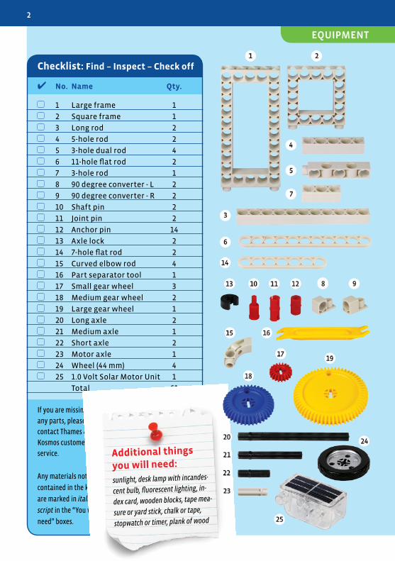
✔ No. Name Qty.
1 Large frame 1
2 Square frame 1
3 Long rod 2
4 5-hole rod 2
5 3-hole dual rod 4
6 11-hole flat rod 2
7 3-hole rod 1
8 90 degree converter - L 2
9 90 degree converter - R 2
10 Shaft pin 2
11 Joint pin 2
12 Anchor pin 14
13 Axle lock 2
14 7-hole flat rod 2
15 Curved elbow rod 4
16 Part separator tool 1
17 Small gear wheel 3
18 Medium gear wheel 2
19 Large gear wheel 1
20 Long axle 2
21 Medium axle 1
22 Short axle 2
23 Motor axle 1
24 Wheel (44 mm) 4
25 1.0 Volt Solar Motor Unit 1
Total 61
If you are missing
any parts, please
contact Thames &
Kosmos customer
service.
Any materials not
contained in the kit
are marked in italic
script in the “You will
need” boxes.
Checklist: Find – Inspect – Check off
Additional things
you will need:
sunlight, desk lamp with incandes-
cent bulb, fluorescent lighting, in-
dex card, wooden blocks, tape mea-
sure or yard stick, chalk or tape,
stopwatch or timer, plank of wood
2
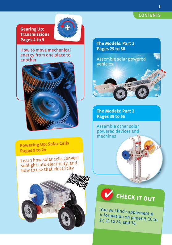
Powering Up: Solar Cells
Pages 9 to 24
Learn how solar cells convert
sunlight into electricity, and
how to use that electricity
✔
You will find supplemental information on pages 9, 16 to 17, 21 to 24, and 38.
CHECK IT OUT
Gearing Up:TransmissionsPages 4 to 9
How to move mechanical energy from one place to another
The Models: Part 1Pages 25 to 38
Assemble solar powered vehicles
The Models: Part 2Pages 39 to 56
Assemble other solar powered devices and machines
3
CONTENTS
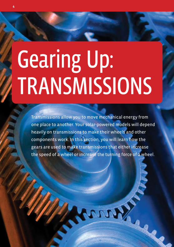
Transmissions allow you to move mechanical energy from
one place to another. Your solar-powered models will depend
heavily on transmissions to make their wheels and other
components work. In this section, you will learn how the
gears are used to make transmissions that either increase
the speed of a wheel or increase the turning force of a wheel.
Gearing Up:TRANSMISSIONS
4
HERE’S HOW
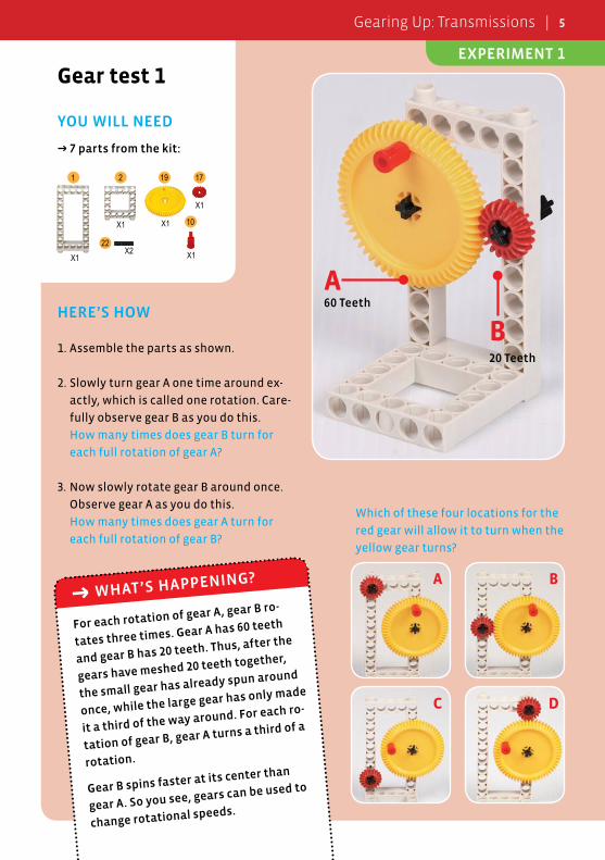
1. Assemble the parts as shown.
2. Slowly turn gear A one time around ex-
actly, which is called one rotation. Care-
fully observe gear B as you do this.
How many times does gear B turn for
each full rotation of gear A?
3. Now slowly rotate gear B around once.
Observe gear A as you do this.
How many times does gear A turn for
each full rotation of gear B?
Gear test 1
YOU WILL NEED
→ 7 parts from the kit:
For each rotation of gear A, gear B ro-
tates three times. Gear A has 60 teeth
and gear B has 20 teeth. Thus, after the
gears have meshed 20 teeth together,
the small gear has already spun around
once, while the large gear has only made
it a third of the way around. For each ro-
tation of gear B, gear A turns a third of a
rotation.
Gear B spins faster at its center than
gear A. So you see, gears can be used to
change rotational speeds.
→ WHAT’S HAPPENING?
B
A60 Teeth
20 Teeth
21
X1
X1 10
X1
19 17
X1
X1
22X2
Which of these four locations for the
red gear will allow it to turn when the
yellow gear turns?
A B
C D
EXPERIMENT 1
Gearing Up: Transmissions | 5
HERE’S HOW
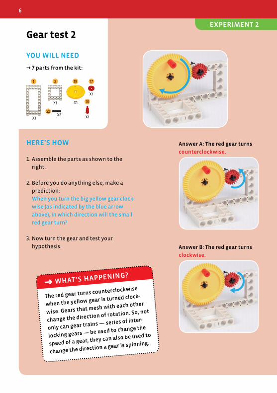
1. Assemble the parts as shown to the
right.
2. Before you do anything else, make a
prediction:
When you turn the big yellow gear clock-
wise (as indicated by the blue arrow
above), in which direction will the small
red gear turn?
3. Now turn the gear and test your
hypothesis.
Gear test 2
YOU WILL NEED
→ 7 parts from the kit:
A B
A B
問題:
問題:A B
A B
問題:
問題:A B
A B
問題:
問題:
21
X1
X1 10
X1
19 17
X1
X1
22X2
The red gear turns counterclockwise
when the yellow gear is turned clock-
wise. Gears that mesh with each other
change the direction of rotation. So, not
only can gear trains — series of inter-
locking gears — be used to change the
speed of a gear, they can also be used to
change the direction a gear is spinning.
→ WHAT’S HAPPENING?
Answer B: The red gear turns
clockwise.
Answer A: The red gear turns
counterclockwise.
6
EXPERIMENT 2
HERE’S HOW
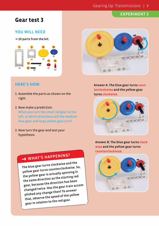
1. Assemble the parts as shown on the
right.
2. Now make a prediction.
When you turn the small red gear to the
left, in which directions will the medium
blue gear and large yellow gear turn?
3. Now turn the gear and test your
hypothesis.
Gear test 3
YOU WILL NEED
→ 10 parts from the kit:
A B
A B
問題:
問題:
A B
A B
問題:
問題:A B
A B
問題:
問題:
The blue gear turns clockwise and the
yellow gear turns counterclockwise. So,
the yellow gear is actually spinning in
the same direction as the starting red
gear, because the direction has been
changed twice. Has the gear train accom-
plished any change then? To answer
that, observe the speed of the yellow
gear in relation to the red gear.
→ WHAT’S HAPPENING?
Answer B: The blue gear turns clock-
wise and the yellow gear turns
counterclockwise.
Answer A: The blue gear turns coun-
terclockwise and the yellow gear
turns clockwise.
21
X1
X1 10
X2
19
17
X1
X1
22X2
21
18
X1
X1
Gearing Up: Transmissions | 7
EXPERIMENT 3
HERE’S HOW
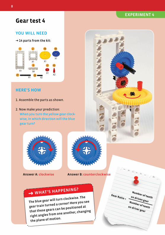
1. Assemble the parts as shown.
2. Now make your prediction:
When you turn the yellow gear clock-
wise, in which direction will the blue
gear turn?
Gear test 4
YOU WILL NEED
→ 14 parts from the kit:
The blue gear will turn clockwise. The
gear train turned a corner! Here you see
that these gears can be positioned at
right angles from one another, changing
the plane of motion.
→ WHAT’S HAPPENING?
21
X1
X110
X2
19
17
X1
X1
22X2
21
18
X1
X1
5
X4
Answer B: counterclockwiseAnswer A: clockwise
Gear Ratio =
Number of teeth on driven gearNumber of teeth on driver gear
8
EXPERIMENT 4
MACHINES
For something to be called a machine, it has to have
a source of power and a way to transmit power from
one place to another — a transmission. Power can
come from many sources, like heat or electricity.
Power can be transmitted in many ways. Gear trains
like the ones you have just experimented with in Ex-
periments 1–4 are good examples.
This kit contains a special machine called the solar
motor unit. It is a single-piece device that takes light
and converts it into motion. The light source can be
sunlight or even light from a powerful lamp. The mo-
tion is the spinning of an axle that sticks out from ei-
ther side of the unit.
But how exactly does the solar motor unit convert
light into motion? The solar panel on the top — a se-
ries of photovoltaic panels — generates electric cur-
rent when exposed to enough light. That electric cur-
rent in turn goes to powering an electric motor,
which results in the spinning of the motor’s shaft.
From there, a transmission consisting of four gears
carries the motion all the way to the axles on the
sides of the unit, which can be used to activate your
models!
The solar panel and the electric motor will be ex-
plained in the next section. First, let’s look at how
the transmission in the solar motor unit works.
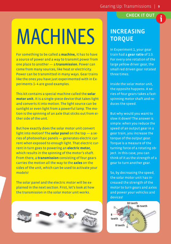
INCREASING TORQUE
In Experiment 1, your gear
train had a gear ratio of 1:3.
For every one rotation of the
large yellow driver gear, the
small red driven gear rotated
three times.
Inside the solar motor unit,
the opposite happens. A se-
ries of four gears takes a fast-
spinning motor shaft and re-
duces the speed.
But why would you want to
slow it down? The answer is
simple: when you reduce the
speed of an output gear in a
gear train, you increase the
torque of the output gear.
Torque is a measure of the
turning force of a rotating ob-
ject. In this case, you can
think of it as the strength of a
gear to turn another gear.
So, by decreasing the speed,
the solar motor unit has in-
creased the strength of the
motor to turn gears and axles
and power your vehicles and
devices!
8
teeth
8 teeth
30 teeth36 teeth
Gear Ratio =
Number of teeth on driven gearNumber of teeth on driver gear
CHECK IT OUT
Gearing Up: Transmissions | 9
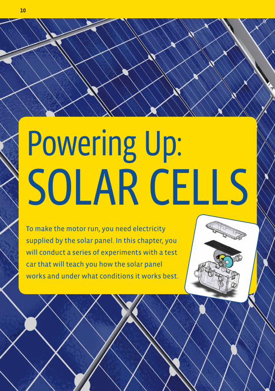
To make the motor run, you need electricity
supplied by the solar panel. In this chapter, you
will conduct a series of experiments with a test
car that will teach you how the solar panel
works and under what conditions it works best.
Powering Up:
SOLAR CELLS
10
HERE’S HOW
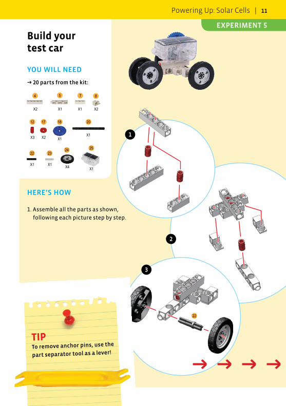
1. Assemble all the parts as shown,
following each picture step by step.
Build your test car
YOU WILL NEED
→ 20 parts from the kit:
22
25242322
20181712
8754
X2 X1 X1 X2
X3 X2 X1X1
X1 X1 X4 X1
TIP To remove anchor pins, use the
part separator tool as a lever!
1
2
3
→ → → → →
Powering Up: Solar Cells | 11
EXPERIMENT 5
23
20
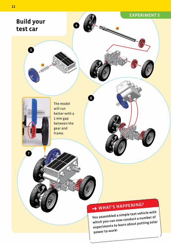
Build your test car
The model
will run
better with a
1 mm gap
between the
gear and
frame.
4
5
6
7
You assembled a simple test vehicle with
which you can now conduct a number of
experiments to learn about putting solar
power to work!
→ WHAT’S HAPPENING?
12
EXPERIMENT 5
HERE’S HOW
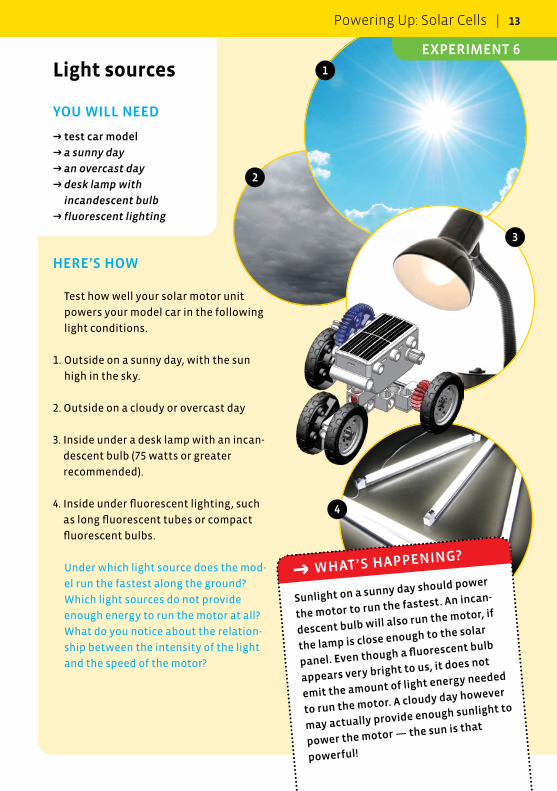
Test how well your solar motor unit
powers your model car in the following
light conditions.
1. Outside on a sunny day, with the sun
high in the sky.
2. Outside on a cloudy or overcast day
3. Inside under a desk lamp with an incan-
descent bulb (75 watts or greater
recommended).
4. Inside under fluorescent lighting, such
as long fluorescent tubes or compact
fluorescent bulbs.
Under which light source does the mod-
el run the fastest along the ground?
Which light sources do not provide
enough energy to run the motor at all?
What do you notice about the relation-
ship between the intensity of the light
and the speed of the motor?
Light sources
YOU WILL NEED
→ test car model
→ a sunny day
→ an overcast day
→ desk lamp with
incandescent bulb
→ fluorescent lighting
1
2
3
4
Sunlight on a sunny day should power
the motor to run the fastest. An incan-
descent bulb will also run the motor, if
the lamp is close enough to the solar
panel. Even though a fluorescent bulb
appears very bright to us, it does not
emit the amount of light energy needed
to run the motor. A cloudy day however
may actually provide enough sunlight to
power the motor — the sun is that
powerful!
→ WHAT’S HAPPENING?
Powering Up: Solar Cells | 13
EXPERIMENT 6
HERE’S HOW
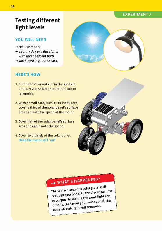
1. Put the test car outside in the sunlight
or under a desk lamp so that the motor
is running.
2. With a small card, such as an index card,
cover a third of the solar panel’s surface
area and note the speed of the motor.
3. Cover half of the solar panel’s surface
area and again note the speed.
4. Cover two-thirds of the solar panel.
Does the motor still run?
Testing different light levels
YOU WILL NEED
→ test car model
→ a sunny day or a desk lamp
with incandescent bulb
→ small card (e.g. index card)
The surface area of a solar panel is di-
rectly proportional to the electrical pow-
er output. Assuming the same light con-
ditions, the larger your solar panel, the
more electricity it will generate.
→ WHAT’S HAPPENING?
14
EXPERIMENT 7
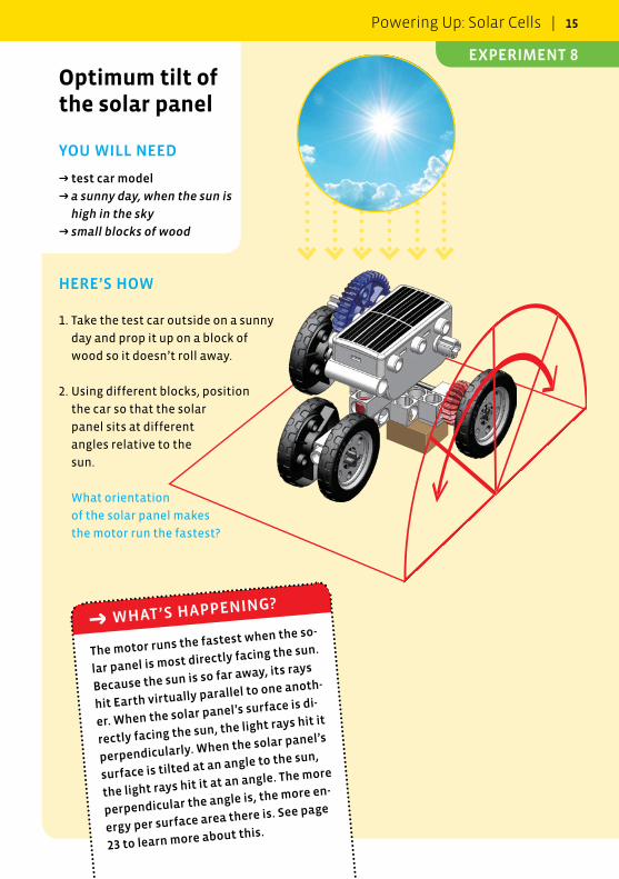
HERE’S HOW
1. Take the test car outside on a sunny
day and prop it up on a block of
wood so it doesn’t roll away.
2. Using different blocks, position
the car so that the solar
panel sits at different
angles relative to the
sun.
What orientation
of the solar panel makes
the motor run the fastest?
Optimum tilt of the solar panel
YOU WILL NEED
→ test car model
→ a sunny day, when the sun is
high in the sky
→ small blocks of wood
The motor runs the fastest when the so-
lar panel is most directly facing the sun.
Because the sun is so far away, its rays
hit Earth virtually parallel to one anoth-
er. When the solar panel’s surface is di-
rectly facing the sun, the light rays hit it
perpendicularly. When the solar panel’s
surface is tilted at an angle to the sun,
the light rays hit it at an angle. The more
perpendicular the angle is, the more en-
ergy per surface area there is. See page
23 to learn more about this.
→ WHAT’S HAPPENING?
Powering Up: Solar Cells | 15
EXPERIMENT 8
A solar cell is a flat device that uses an elec-
tronic material called a semiconductor to
convert photons, or particles of light ener-
gy, into electrical energy. The semiconduc-
tor creates a voltage, or difference in elec-
trical potential energy, between two
surfaces when it is exposed to light. You can
think of it like a battery, which also has a
voltage between to points. This technology
is called photovoltaics.
The phenomenon of electricity is nothing
more than the movement of negatively
charged particles, called electrons, through
a material, called a conductor. Electricity
flows easily through some materials, like
metal, and poorly or not at all through other
materials, like plastic. We have discovered
materials, like silicon, which are naturally
poor conductors in pure form, but can be
treated to become better conductors under
special conditions. These are called
semiconductors.
load(motor)
electron flow
p-n junction
n-t
ype
laye
rp
-typ
e la
yer
n-t
ype
laye
rp
-typ
e la
yer
n-t
ype
laye
rp
-typ
e la
yer
photons (sunlight)
contact layer
contact layer
load(motor)
electron flow
n-t
ype
laye
rp
-typ
e la
yer
sun
electron electronhole
freeelectron
sun
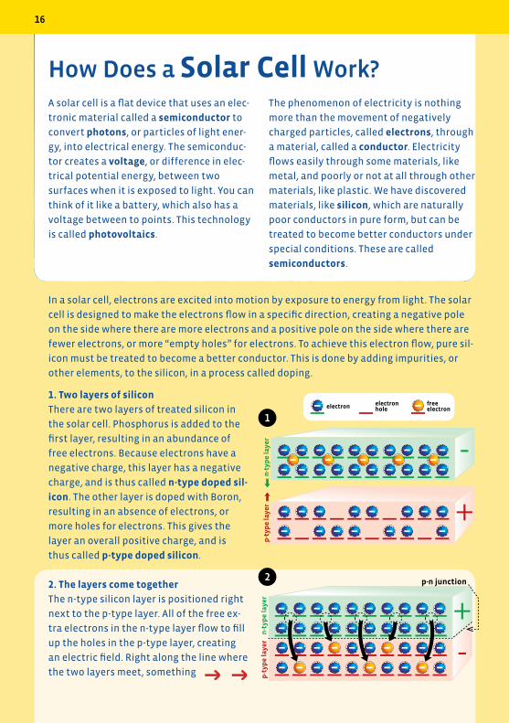
1. Two layers of silicon
There are two layers of treated silicon in
the solar cell. Phosphorus is added to the
first layer, resulting in an abundance of
free electrons. Because electrons have a
negative charge, this layer has a negative
charge, and is thus called n-type doped sil-
icon. The other layer is doped with Boron,
resulting in an absence of electrons, or
more holes for electrons. This gives the
layer an overall positive charge, and is
thus called p-type doped silicon.
2. The layers come together
The n-type silicon layer is positioned right
next to the p-type layer. All of the free ex-
tra electrons in the n-type layer flow to fill
up the holes in the p-type layer, creating
an electric field. Right along the line where
the two layers meet, something
load(motor)
electron flow
p-n junction
n-t
ype
laye
rp
-typ
e la
yer
n-t
ype
laye
rp
-typ
e la
yer
n-t
ype
laye
rp
-typ
e la
yer
photons (sunlight)
contact layer
contact layer
load(motor)
electron flow
n-t
ype
laye
rp
-typ
e la
yer
sun
electron electronhole
freeelectron
sun
How Does a Solar Cell Work?
In a solar cell, electrons are excited into motion by exposure to energy from light. The solar
cell is designed to make the electrons flow in a specific direction, creating a negative pole
on the side where there are more electrons and a positive pole on the side where there are
fewer electrons, or more “empty holes” for electrons. To achieve this electron flow, pure sil-
icon must be treated to become a better conductor. This is done by adding impurities, or
other elements, to the silicon, in a process called doping.
1
2
→ →
16
load(motor)
electron flow
p-n junction
n-t
ype
laye
rp
-typ
e la
yer
n-t
ype
laye
rp
-typ
e la
yer
n-t
ype
laye
rp
-typ
e la
yer
photons (sunlight)
contact layer
contact layer
load(motor)
electron flow
n-t
ype
laye
rp
-typ
e la
yer
sun
electron electronhole
freeelectron
sun
load(motor)
electron flow
p-n junction
n-t
ype
laye
rp
-typ
e la
yer
n-t
ype
laye
rp
-typ
e la
yer
n-t
ype
laye
rp
-typ
e la
yer
photons (sunlight)
contact layer
contact layer
load(motor)
electron flow
n-t
ype
laye
rp
-typ
e la
yer
sun
electron electronhole
freeelectron
sun
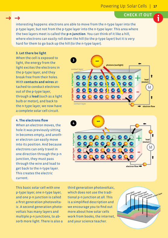
interesting happens: electrons are able to move from the n-type layer into the
p-type layer, but not from the p-type layer into the n-type layer. This area where
the two layers meet is called the p-n junction. You can think of it like a hill,
where electrons can easily roll down the hill (to the p-type layer) but it is very
hard for them to go back up the hill (to the n-type layer).
cover glass
antiglare layer
top contact layer
n-type silicon
p-type silicon
bottom contact layer
3
4
→ →
third generation photovoltaic,
which does not use the tradi-
tional p-n junction at all. This
is a simplified description and
we encourage you to find out
more about how solar cells
work from books, the internet,
and your science teacher.
3. Let there be light
When the cell is exposed to
light, the energy from the
light excites the electrons in
the p-type layer, and they
break free from their holes.
With contacts and wires at-
tached to conduct electrons
out of the p-type layer,
through a load (such as a light
bulb or motor), and back to
the n-type layer, we now have
a complete solar cell circuit.
4. The electrons flow
When an electron moves, the
hole it was previously sitting
in becomes empty, and anoth-
er electron can easily move
into its position. And because
electrons can only travel in
one direction through the p-n
junction, they must pass
through the wire and load to
get back to the n-type layer.
This creates the electric
current.
This basic solar cell with one
p-type layer, one n-type layer,
and one p-n junction is called
a first generation photovolta-
ic. A second generation photo-
voltaic has many layers and
multiple p-n junctions, to ab-
sorb more light. There is also a
CHECK IT OUT
Powering Up: Solar Cells | 17
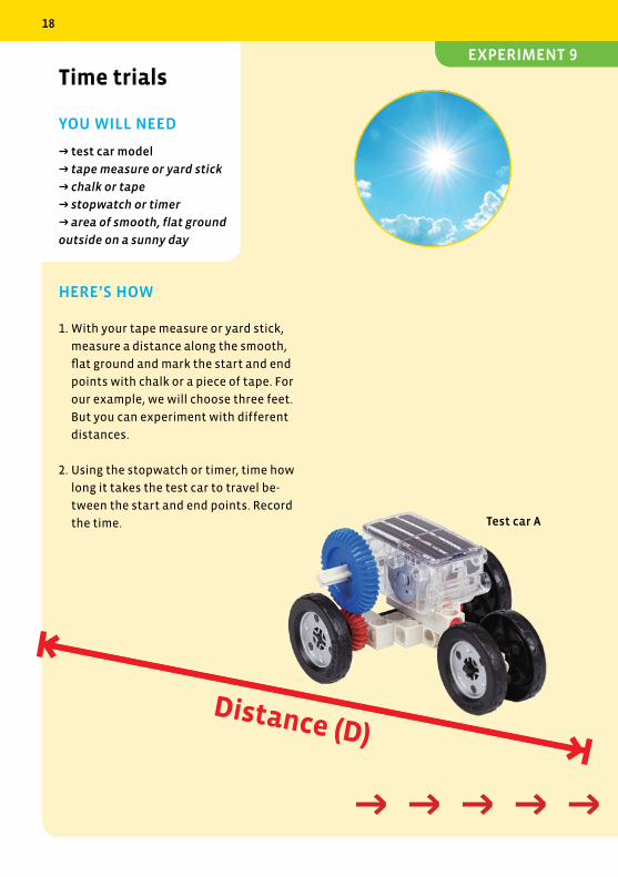
HERE’S HOW
1. With your tape measure or yard stick,
measure a distance along the smooth,
flat ground and mark the start and end
points with chalk or a piece of tape. For
our example, we will choose three feet.
But you can experiment with different
distances.
2. Using the stopwatch or timer, time how
long it takes the test car to travel be-
tween the start and end points. Record
the time.
Time trials
YOU WILL NEED
→ test car model
→ tape measure or yard stick
→ chalk or tape
→ stopwatch or timer
→ area of smooth, flat ground
outside on a sunny day
Distance (D)
Test car A
→ → → → →
18
EXPERIMENT 9
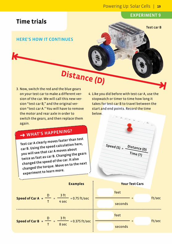
HERE’S HOW IT CONTINUES
Time trials
Test car A clearly moves faster than test
car B. Using the speed calculation here,
you will see that car A moves about
twice as fast as car B. Changing the gears
changed the speed of the car. It also
changed the torque. Move on to the next
experiment to learn more.
→ WHAT’S HAPPENING?
Distance (D)
Test car A
Test car B
Speed (S) =Distance (D)
Time (T)
Examples Your Test Cars
Speed of Car A =D
=3 ft
= 0.75 ft/sec feet
=
ft/secT 4 sec
seconds
Speed of Car B =D
=3 ft
= 0.375 ft/sec feet
=
ft/secT 8 sec
seconds
3. Now, switch the red and the blue gears
on your test car to make a different ver-
sion of the car. We will call this new ver-
sion “test car B,” and the original ver-
sion “test car A.” You will have to remove
the motor and rear axle in order to
switch the gears, and then replace them
again.
4. Like you did before with test car A, use the
stopwatch or timer to time how long it
takes for test car B to travel between the
start and end points. Record the time
below.
→ → → → →
Powering Up: Solar Cells | 19
EXPERIMENT 9
HERE’S HOW
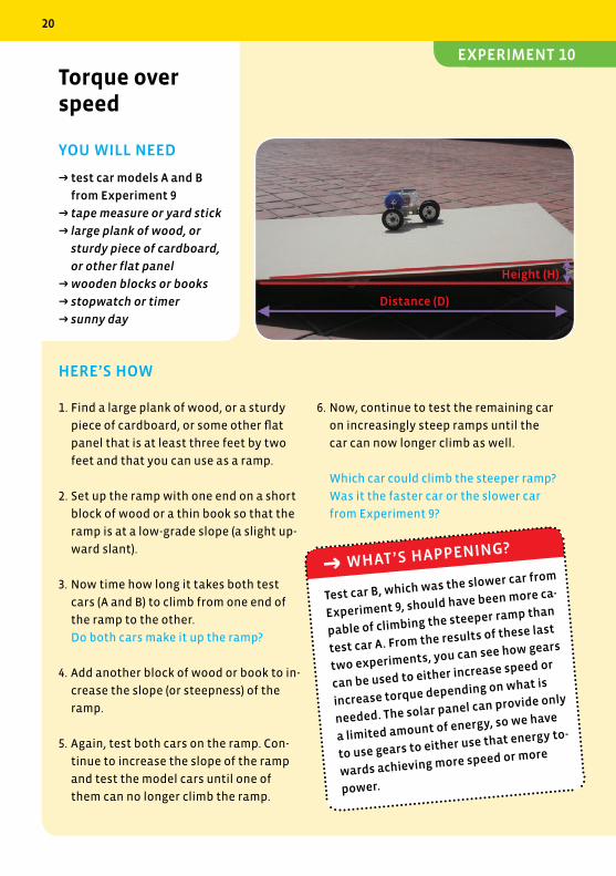
1. Find a large plank of wood, or a sturdy
piece of cardboard, or some other flat
panel that is at least three feet by two
feet and that you can use as a ramp.
2. Set up the ramp with one end on a short
block of wood or a thin book so that the
ramp is at a low-grade slope (a slight up-
ward slant).
3. Now time how long it takes both test
cars (A and B) to climb from one end of
the ramp to the other.
Do both cars make it up the ramp?
4. Add another block of wood or book to in-
crease the slope (or steepness) of the
ramp.
5. Again, test both cars on the ramp. Con-
tinue to increase the slope of the ramp
and test the model cars until one of
them can no longer climb the ramp.
6. Now, continue to test the remaining car
on increasingly steep ramps until the
car can now longer climb as well.
Which car could climb the steeper ramp?
Was it the faster car or the slower car
from Experiment 9?
Torque over speed
YOU WILL NEED
→ test car models A and B
from Experiment 9
→ tape measure or yard stick
→ large plank of wood, or
sturdy piece of cardboard,
or other flat panel
→ wooden blocks or books
→ stopwatch or timer
→ sunny day
Test car B, which was the slower car from
Experiment 9, should have been more ca-
pable of climbing the steeper ramp than
test car A. From the results of these last
two experiments, you can see how gears
can be used to either increase speed or
increase torque depending on what is
needed. The solar panel can provide only
a limited amount of energy, so we have
to use gears to either use that energy to-
wards achieving more speed or more
power.
→ WHAT’S HAPPENING?
Distance (D)
Height (H)
20
EXPERIMENT 10
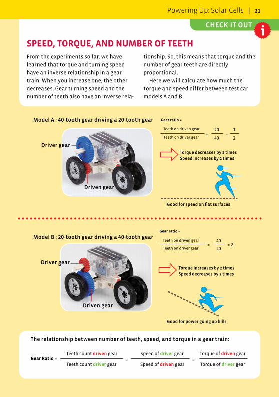
From the experiments so far, we have
learned that torque and turning speed
have an inverse relationship in a gear
train. When you increase one, the other
decreases. Gear turning speed and the
number of teeth also have an inverse rela-
The relationship between number of teeth, speed, and torque in a gear train:
Gear Ratio = = =Teeth count driven gear Speed of driver gear Torque of driven gear
Teeth count driver gear Speed of driven gear Torque of driver gear
Model A : 40-tooth gear driving a 20-tooth gear Gear ratio =
Teeth on driven gear
Teeth on driver gear= =
20 1
40 2
Torque decreases by 2 timesSpeed increases by 2 times
Driven gear
Driver gear
Model B : 20-tooth gear driving a 40-tooth gear Gear ratio =
= = 2Teeth on driven gear 40
Teeth on driver gear 20
Torque increases by 2 times Speed decreases by 2 times
Driven gear
Driver gear
SPEED, TORQUE, AND NUMBER OF TEETH
Good for speed on flat surfaces
Good for power going up hills
tionship. So, this means that torque and the
number of gear teeth are directly
proportional.
Here we will calculate how much the
torque and speed differ between test car
models A and B.
CHECK IT OUT
Powering Up: Solar Cells | 21
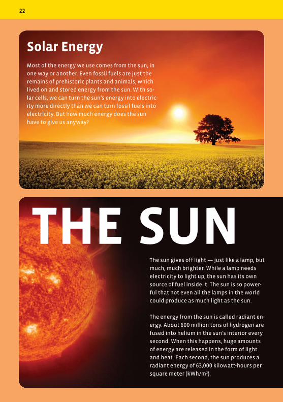
The sun gives off light — just like a lamp, but
much, much brighter. While a lamp needs
electricity to light up, the sun has its own
source of fuel inside it. The sun is so power-
ful that not even all the lamps in the world
could produce as much light as the sun.
The energy from the sun is called radiant en-
ergy. About 600 million tons of hydrogen are
fused into helium in the sun’s interior every
second. When this happens, huge amounts
of energy are released in the form of light
and heat. Each second, the sun produces a
radiant energy of 63,000 kilowatt-hours per
square meter (kWh/m2).
Solar EnergyMost of the energy we use comes from the sun, in
one way or another. Even fossil fuels are just the
remains of prehistoric plants and animals, which
lived on and stored energy from the sun. With so-
lar cells, we can turn the sun’s energy into electric-
ity more directly than we can turn fossil fuels into
electricity. But how much energy does the sun
have to give us anyway?
THE SUN
22
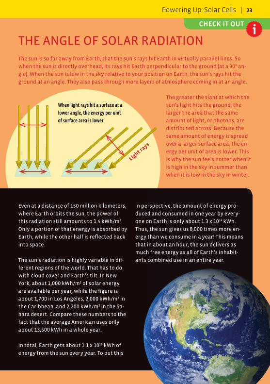
THE ANGLE OF SOLAR RADIATIONThe sun is so far away from Earth, that the sun’s rays hit Earth in virtually parallel lines. So
when the sun is directly overhead, its rays hit Earth perpendicular to the ground (at a 90° an-
gle). When the sun is low in the sky relative to your position on Earth, the sun’s rays hit the
ground at an angle. They also pass through more layers of atmosphere coming in at an angle.
The greater the slant at which the
sun’s light hits the ground, the
larger the area that the same
amount of light, or photons, are
distributed across. Because the
same amount of energy is spread
over a larger surface area, the en-
ergy per unit of area is lower. This
is why the sun feels hotter when it
is high in the sky in summer than
when it is low in the sky in winter.
Even at a distance of 150 million kilometers,
where Earth orbits the sun, the power of
this radiation still amounts to 1.4 kWh/m2.
Only a portion of that energy is absorbed by
Earth, while the other half is reflected back
into space.
The sun’s radiation is highly variable in dif-
ferent regions of the world. That has to do
with cloud cover and Earth’s tilt. In New
York, about 1,000 kWh/m2 of solar energy
are available per year, while the figure is
about 1,700 in Los Angeles, 2,000 kWh/m2 in
the Caribbean, and 2,200 kWh/m2 in the Sa-
hara desert. Compare these numbers to the
fact that the average American uses only
about 13,500 kWh in a whole year.
In total, Earth gets about 1.1 x 10¹⁸ kWh of
energy from the sun every year. To put this
in perspective, the amount of energy pro-
duced and consumed in one year by every-
one on Earth is only about 1.3 x 10¹⁴ kWh.
Thus, the sun gives us 8,000 times more en-
ergy than we consume in a year! This means
that in about an hour, the sun delivers as
much free energy as all of Earth’s inhabit-
ants combined use in an entire year.
When light rays hit a surface at a
lower angle, the energy per unit
of surface area is lower.
Light rays
CHECK IT OUT
Powering Up: Solar Cells | 23
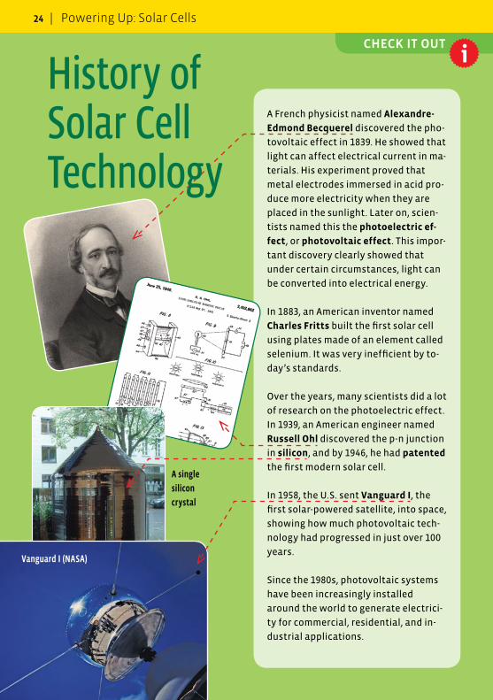
A French physicist named Alexandre-
Edmond Becquerel discovered the pho-
tovoltaic effect in 1839. He showed that
light can affect electrical current in ma-
terials. His experiment proved that
metal electrodes immersed in acid pro-
duce more electricity when they are
placed in the sunlight. Later on, scien-
tists named this the photoelectric ef-
fect, or photovoltaic effect. This impor-
tant discovery clearly showed that
under certain circumstances, light can
be converted into electrical energy.
In 1883, an American inventor named
Charles Fritts built the first solar cell
using plates made of an element called
selenium. It was very inefficient by to-
day’s standards.
Over the years, many scientists did a lot
of research on the photoelectric effect.
In 1939, an American engineer named
Russell Ohl discovered the p-n junction
in silicon, and by 1946, he had patented
the first modern solar cell.
In 1958, the U.S. sent Vanguard I, the
first solar-powered satellite, into space,
showing how much photovoltaic tech-
nology had progressed in just over 100
years.
Since the 1980s, photovoltaic systems
have been increasingly installed
around the world to generate electrici-
ty for commercial, residential, and in-
dustrial applications.
History of Solar Cell Technology
A single
silicon
crystal
Vanguard I (NASA)
CHECK IT OUT
24 | Powering Up: Solar Cells
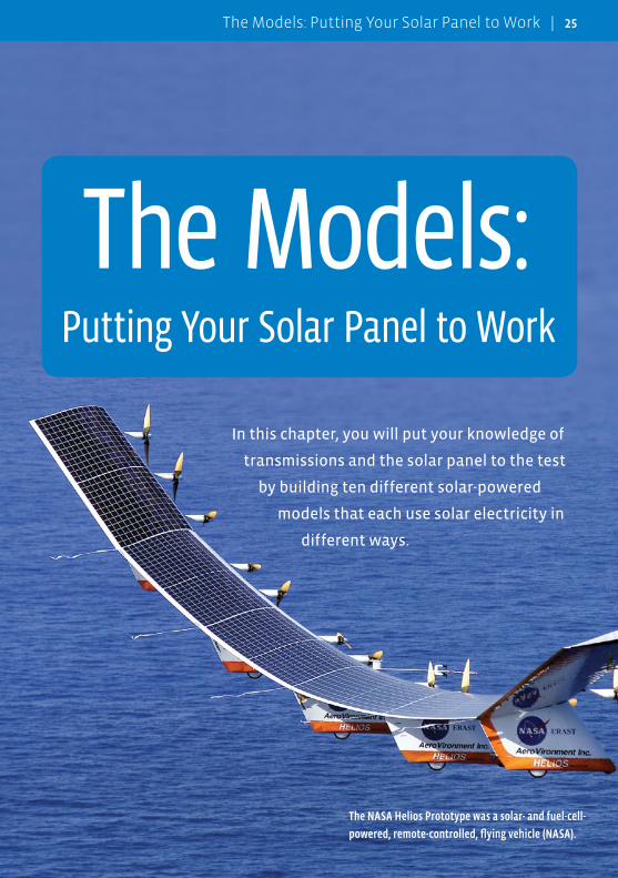
In this chapter, you will put your knowledge of
transmissions and the solar panel to the test
by building ten different solar-powered
models that each use solar electricity in
different ways.
The Models: Putting Your Solar Panel to Work
The NASA Helios Prototype was a solar- and fuel-cell-
powered, remote-controlled, flying vehicle (NASA).
The Models: Putting Your Solar Panel to Work | 25
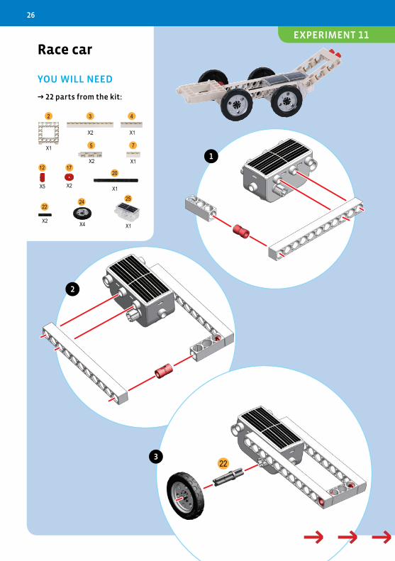
Race car
YOU WILL NEED
→ 22 parts from the kit:
252422
201712
75
432
X1
X2 X1
X2 X1
X5 X2 X1
X2 X4 X1
22
1
2
3
→ → → → →
26
EXPERIMENT 11
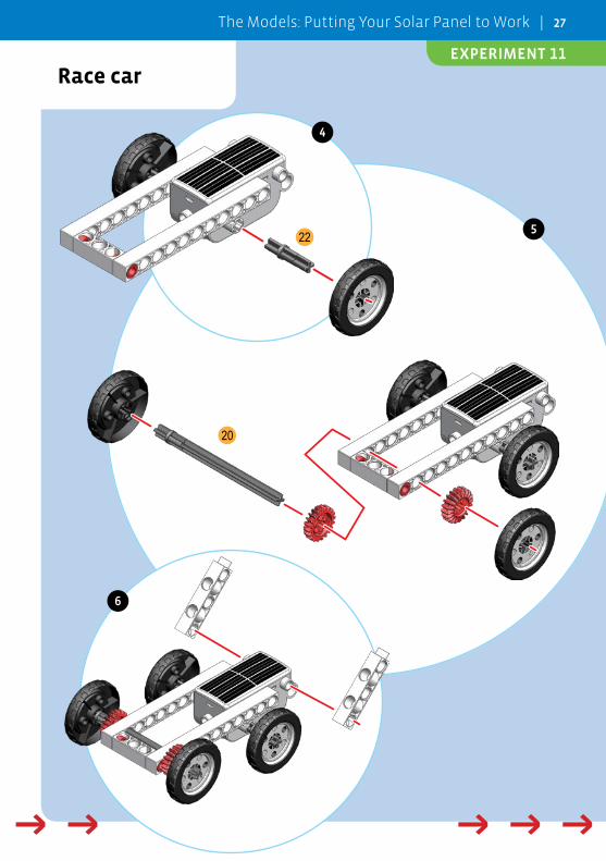
Race car
20
22
4
5
6
→ → → → → → → → → →
The Models: Putting Your Solar Panel to Work | 27
EXPERIMENT 11
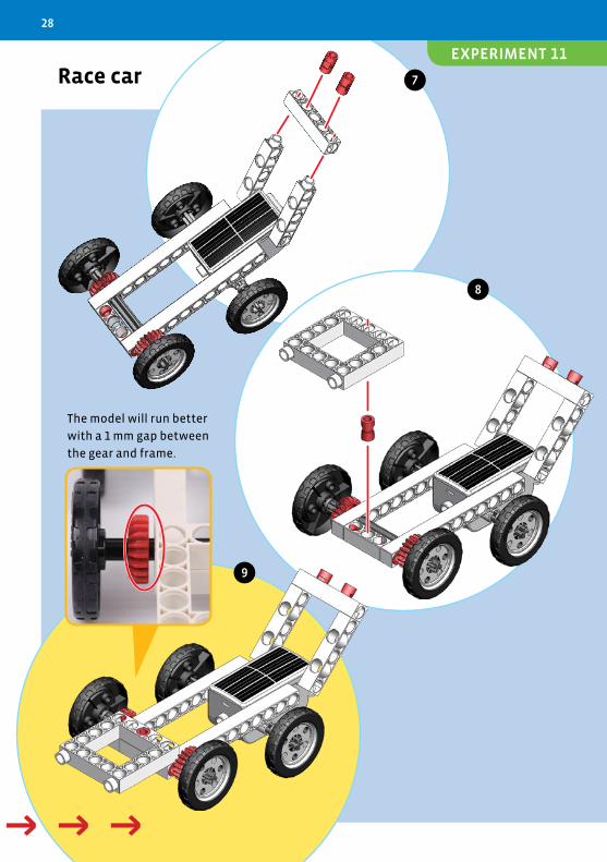
Race car 7
8
9
The model will run better
with a 1 mm gap between
the gear and frame.
→ → → → →
28
EXPERIMENT 11
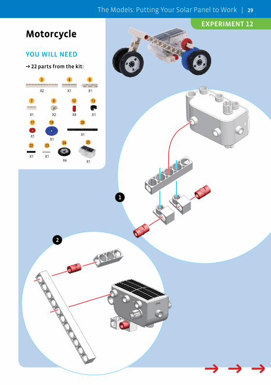
Motorcycle
YOU WILL NEED
→ 22 parts from the kit:
25242322
201817
131287
543
X2 X1 X1
X1 X2 X4 X1
X1X1
X1
X1 X1X4 X1
1
2
→ → → → →
The Models: Putting Your Solar Panel to Work | 29
EXPERIMENT 12
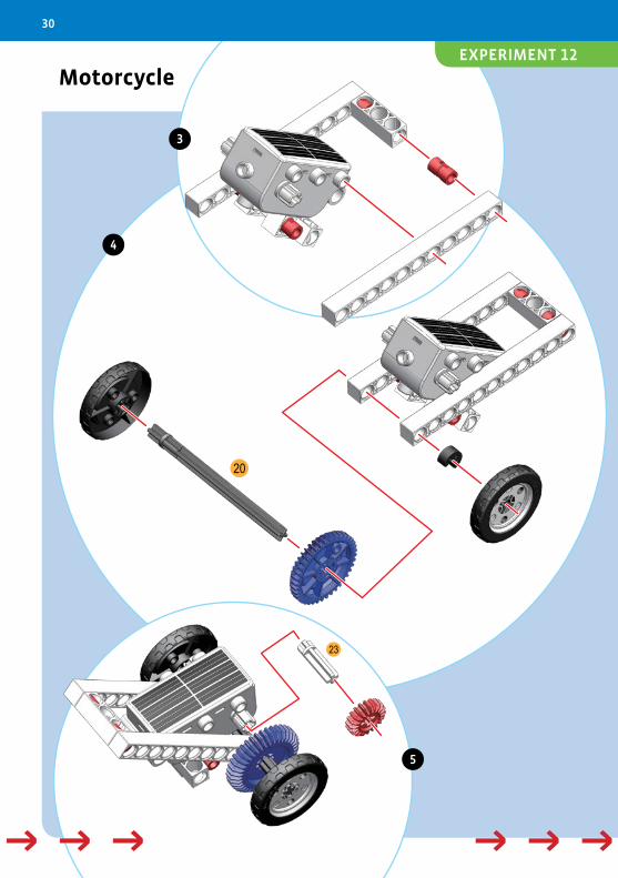
Motorcycle
23
20
3
4
5
→ → → → →→ → → → →
30
EXPERIMENT 12
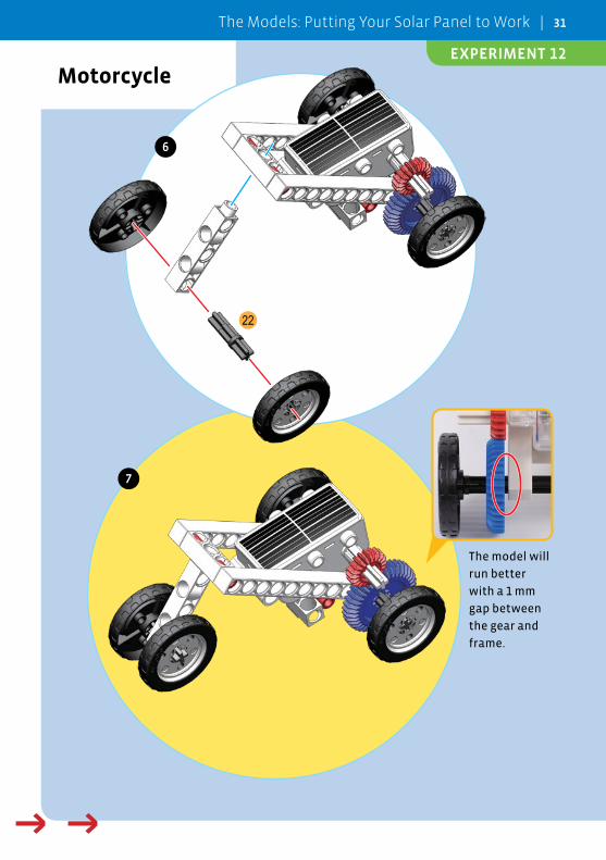
Motorcycle
22
6
7
The model will
run better
with a 1 mm
gap between
the gear and
frame.
→ → → → →
The Models: Putting Your Solar Panel to Work | 31
EXPERIMENT 12
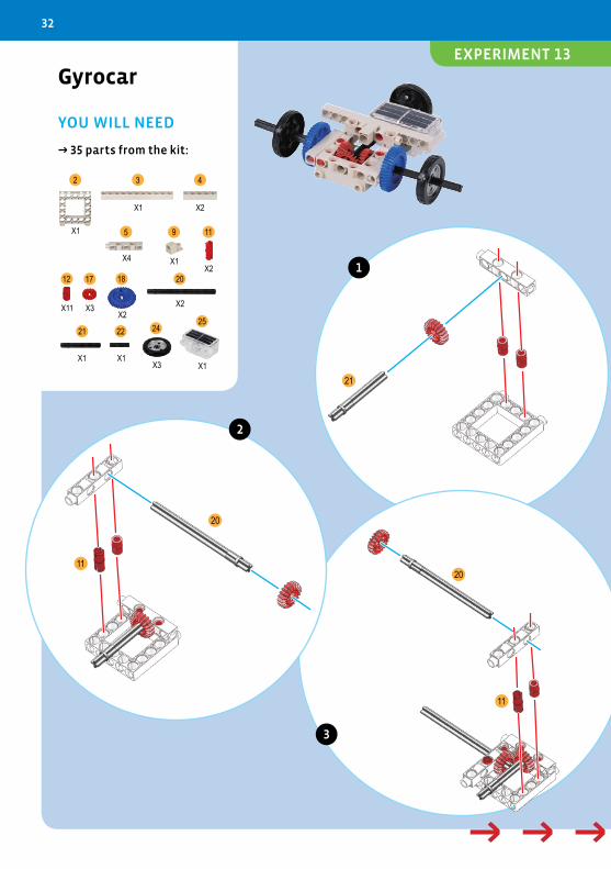
Gyrocar
YOU WILL NEED
→ 35 parts from the kit:
21
20
1120
11
25242221
20181712
1195
432
X1
X1 X2
X4 X1X2
X11 X3X2
X2
X1 X1X3 X1
1
2
3
→ → → → →
32
EXPERIMENT 13
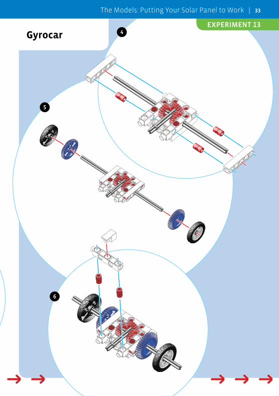
Gyrocar 4
5
6
→ → → → → → → → → →
The Models: Putting Your Solar Panel to Work | 33
EXPERIMENT 13
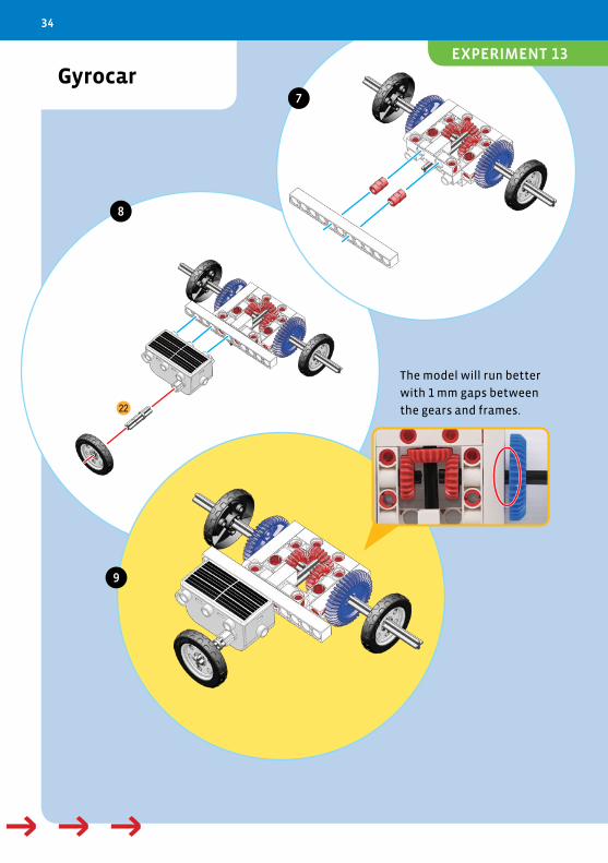
Gyrocar
22
8
7
9
The model will run better
with 1 mm gaps between
the gears and frames.
→ → → → →
34
EXPERIMENT 13
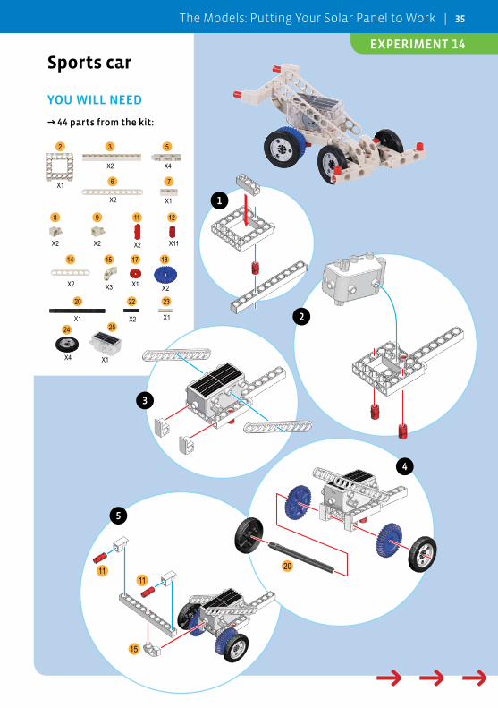
Sports car
YOU WILL NEED
→ 44 parts from the kit:
20
15
1111
2524
232220
18171514
121198
76
532
X1
X2 X4
X2 X1
X2 X2 X2 X11
X2 X3 X1 X2
X1 X2 X1
X4 X1
1
2
3
4
5
→ → → → →
The Models: Putting Your Solar Panel to Work | 35
EXPERIMENT 14
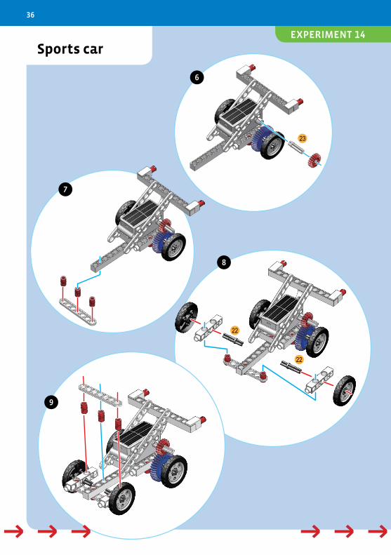
Sports car
22
22
23
6
7
8
9
→ → → → →→ → → → →
36
EXPERIMENT 14
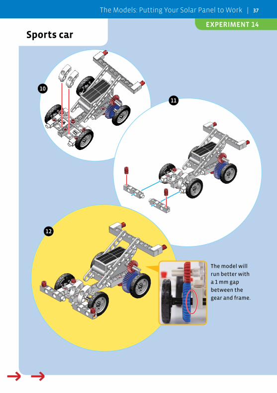
Sports car
The model will
run better with
a 1 mm gap
between the
gear and frame.
11
12
10
→ → → → →
The Models: Putting Your Solar Panel to Work | 37
EXPERIMENT 14
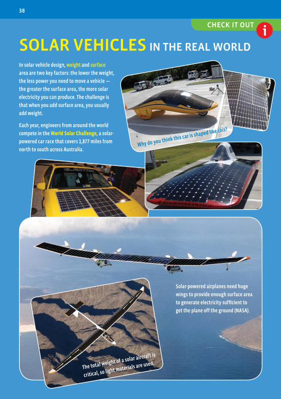
SOLAR VEHICLES IN THE REAL WORLD
Solar-powered airplanes need huge
wings to provide enough surface area
to generate electricity sufficient to
get the plane off the ground (NASA).
Why do you think this car is shaped like this?
The total weight of a solar aircraft is
critical, so light materials are used.
In solar vehicle design, weight and surface
area are two key factors: the lower the weight,
the less power you need to move a vehicle —
the greater the surface area, the more solar
electricity you can produce. The challenge is
that when you add surface area, you usually
add weight.
Each year, engineers from around the world
compete in the World Solar Challenge, a solar-
powered car race that covers 1,877 miles from
north to south across Australia.
CHECK IT OUT
38
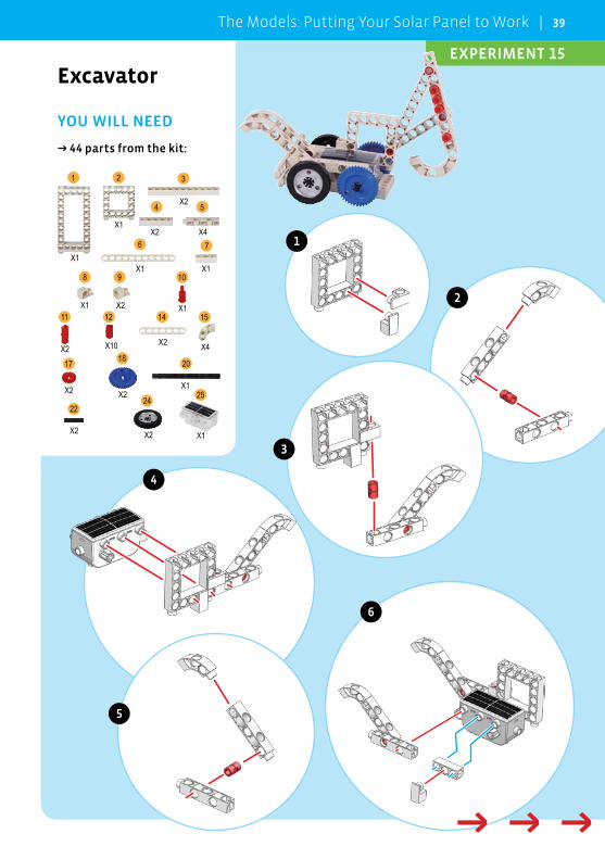
Excavator
YOU WILL NEED
→ 44 parts from the kit:
252422
201817
15141211
1098
76
54
321
X1
X1
X2
X2 X4
X1 X1
X1 X2 X1
X2 X10 X2 X4
X2 X2X1
X2 X2 X1
1
6
2
3
4
5
→ → → → →
The Models: Putting Your Solar Panel to Work | 39
EXPERIMENT 15
Excavator
20
22
11
7
12
8
9
10
→ → → → →→ → → → →
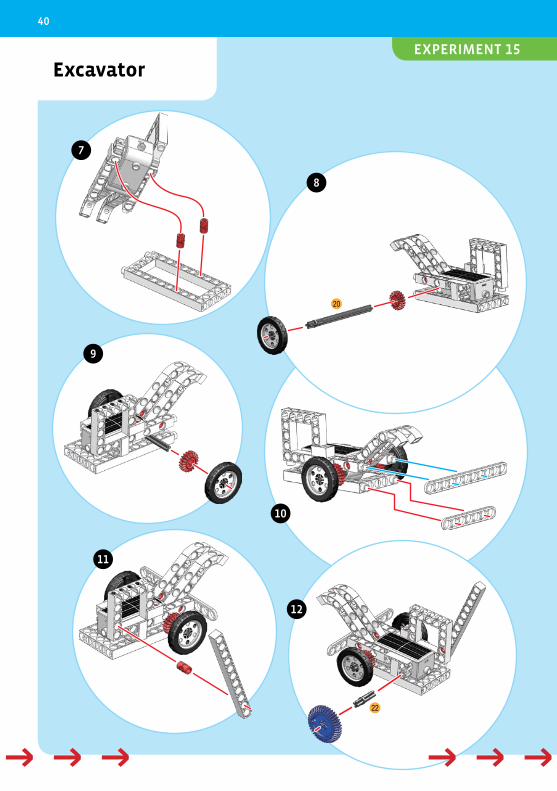
40
EXPERIMENT 15
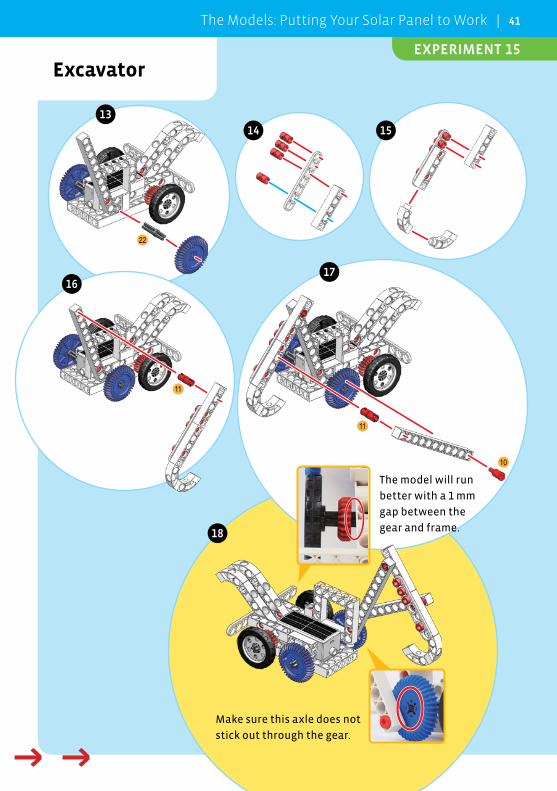
Excavator
22
11
11
10
The model will run
better with a 1 mm
gap between the
gear and frame.
Make sure this axle does not
stick out through the gear.
13
14 15
1617
18
→ → → → →
The Models: Putting Your Solar Panel to Work | 41
EXPERIMENT 15
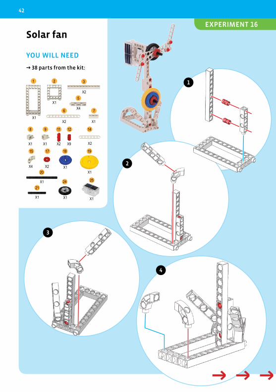
Solar fan
YOU WILL NEED
→ 38 parts from the kit:
252421
20
19181715
14121198
76
5
321
X1
X1
X2
X4
X2 X1
X1 X1 X2 X9 X2
X4 X2 X1X1
X1
X1 X1 X1
1
2
3
4
→ → → → →
42
EXPERIMENT 16
Solar fan
21
20
11
11
6
7
8
5
→ → → → → → → → → →
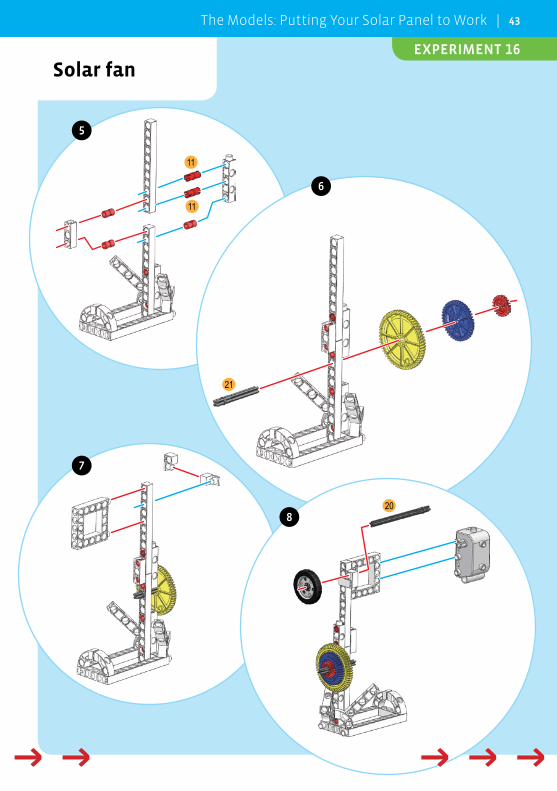
The Models: Putting Your Solar Panel to Work | 43
EXPERIMENT 16
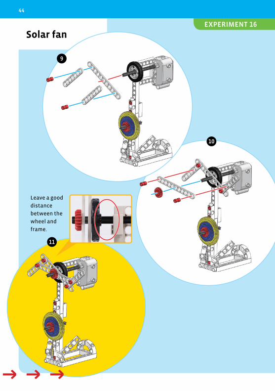
Solar fan
Leave a good
distance
between the
wheel and
frame.
11
9
10
→ → → → →
44
EXPERIMENT 16
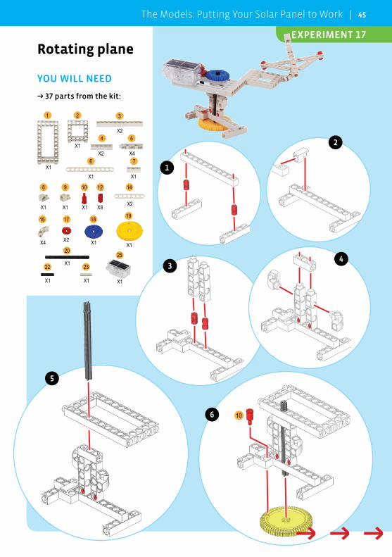
Rotating plane
YOU WILL NEED
→ 37 parts from the kit:
25
2322
20
19181715
14121098
76
54
321
X1
X1
X2
X2 X4
X1 X1
X1 X1 X1 X8 X2
X4 X2 X1 X1
X1
X1 X1 X1
10
1
6
2
34
5
→ → → → →
The Models: Putting Your Solar Panel to Work | 45
EXPERIMENT 17
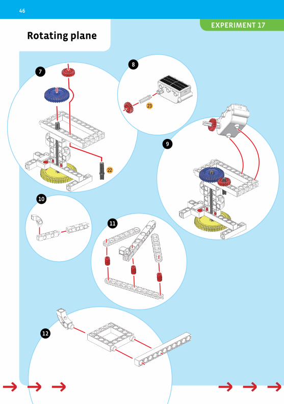
Rotating plane
23
22
11
7
12
8
9
10
→ → → → →→ → → → →
46
EXPERIMENT 17
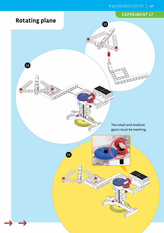
Rotating plane
The small and medium
gears must be meshing.
13
14
15
→ → → → →
Kapitelüberschrift | 47
EXPERIMENT 17
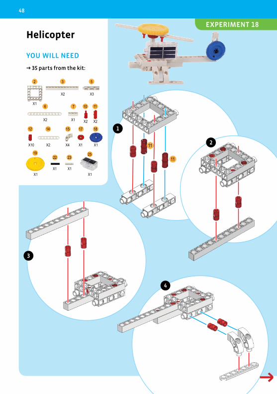
Helicopter
YOU WILL NEED
→ 35 parts from the kit:
252322
19
1817151412
111076
532
X1
X2 X3
X2 X1 X2 X2
X10 X2 X4 X1 X1
X1X1 X1
X1
11
11
1
2
3
4
→ → → → →
48
EXPERIMENT 18
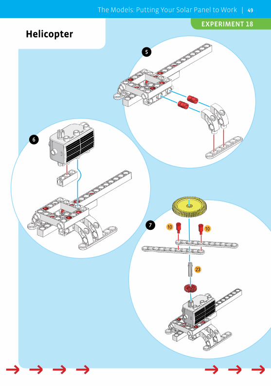
Helicopter
23
10 10
6
7
5
→ → → → → → → → → →
The Models: Putting Your Solar Panel to Work | 49
EXPERIMENT 18
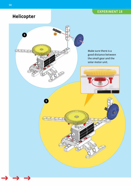
Helicopter
228
9
Make sure there is a
good distance between
the small gear and the
solar motor unit.
→ → → → →
50
EXPERIMENT 18
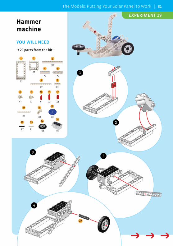
Hammer machine
YOU WILL NEED
→ 29 parts from the kit:
25242322
181514
12111098
76
54
321
X1
X1
X1
X2 X2
X2 X1
X1 X1 X1 X1 X6
X1 X1 X1
X2 X1X2 X1
22
1
2
35
4
→ → → → →
The Models: Putting Your Solar Panel to Work | 51
EXPERIMENT 19
Hammer machine
22
23
10
6
7
8
9
→ → → → → → → → → →
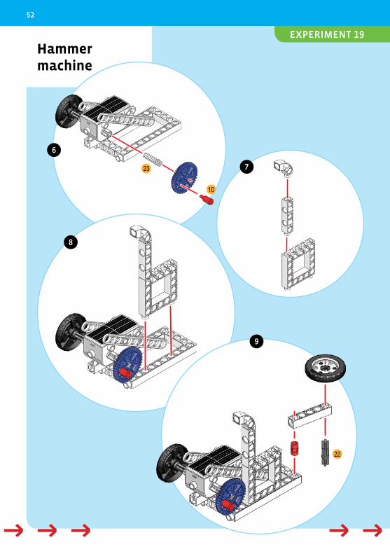
52
EXPERIMENT 19
Hammer machine
11
11
12
13
14
10
→ → → → →
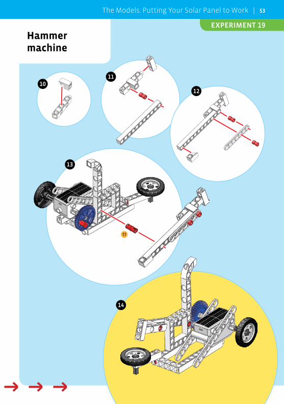
The Models: Putting Your Solar Panel to Work | 53
EXPERIMENT 19
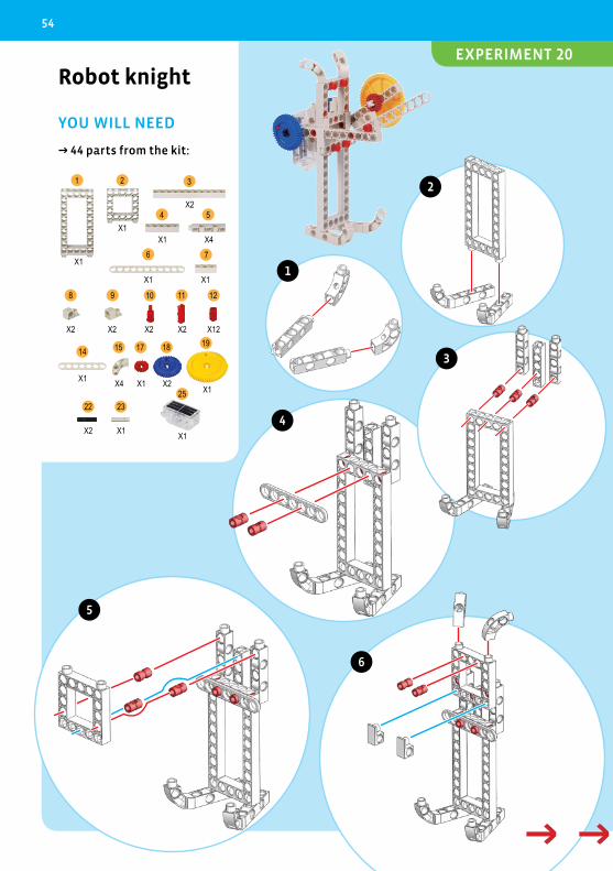
Robot knight
YOU WILL NEED
→ 44 parts from the kit:
252322
1918171514
12111098
76
54
321
X1
X1
X2
X1 X4
X1 X1
X2 X2 X2 X2 X12
X1 X4 X1 X2 X1
X2 X1 X1
1
6
3
4
2
5
→ → → → →
54
EXPERIMENT 20
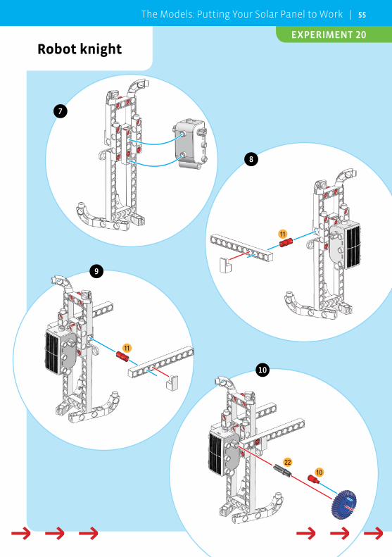
Robot knight
11
11
2210
7
8
9
10
→ → → → → → → → → →
The Models: Putting Your Solar Panel to Work | 55
EXPERIMENT 20
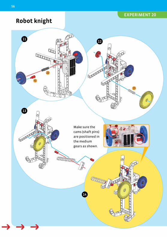
Robot knight
23
22
10
1112
13
14
Make sure the
cams (shaft pins)
are positioned in
the medium
gears as shown.
→ → → → →
56
EXPERIMENT 20

1st English Edition © 2012 Thames & Kosmos, LLC, Providence, RI, USA® Thames & Kosmos is a registered trademark of Thames & Kosmos, LLC.Original Concept and Development: Genius Toy Taiwan Co., Ltd., Taichung, Taiwan, R.O.C.Text: Ted McGuire; Additional Graphics and Layout: Dan FreitasDistributed in North America by Thames & Kosmos, LLC. Providence, RI 02903Phone: 800-587-2872; Email: [email protected]
This work, including all its parts, is copyright protected. Any use outside the specific limits of the copyright law is prohibited and punishable by law without the consent of the publisher. This applies specifically to reproductions, translations, microfilming, and storage and processing in electronic systems and networks. We do not guarantee that all material in this work is free from copy-right or other protection.
Photos: p. 3 top left and top right, p. 4, 10, 13 (1 and 3), 14 top, 15 top, 16 top, 17 top, 22 top, (all previous istock.com);p. 13 (2) second mouse (CC BY 2.0), p. 13 (4) Marshal Astor (CC BY SA 2.0), p. 24 2nd from bottom Dave Messina (CC BY 2.0), p. 38 top Ben-ton Greenen (CC BY 2.0), p. 24 2nd from top Siemens (CC BY ND 2.0), p. 24 3rd from top Steven Rainwater (CC BY 2.0), p. 24 4th from top Daniel Borman (CC BY 2.0), p. 24 bottom Ccoonnrraadd (CC BY SA 3.0) (all previous flicker.com);p. 24 top, 2nd from top (all previous public domain)p. 22 bottom, 23 bottom, 24 bottom, 25, 38 (2nd from bottom) (all previous courtesy of NASA);All Illustrations and All Other Photos: Genius Toy Taiwan Co., Ltd., Taichung, Taiwan, R.O.C., and Thames & Kosmos.
Package design and layout: Atelier Bea Klenk, Klenk/Riedinger Orlando Florin Rosu, pdtnc, cycreation, Mark Herreid, LoopAll, Secret Side, Elvira Schäfer (all previous www.fotolia.com); Oliver Klasen, Stuttgart; Claus Rayhle, Rayhle Designstudio, Bietigheim; Friedrich Werth, werthdesign, Horb-Betra
The publisher has made every effort to identify the owners of the rights to all photos used. If there is any instance in which the owners of the rights to any pictures have not been acknowledged, they are asked to inform the publisher about their copyright ownership so that they may receive the customary image fee.
Printed in Taiwan / Imprimé en Taiwan
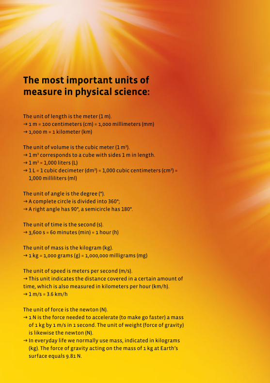
The most important units of measure in physical science:
The unit of length is the meter (1 m).
→ 1 m = 100 centimeters (cm) = 1,000 millimeters (mm)
→ 1,000 m = 1 kilometer (km)
The unit of volume is the cubic meter (1 m3).
→ 1 m3 corresponds to a cube with sides 1 m in length.
→ 1 m3 = 1,000 liters (L)
→ 1 L = 1 cubic decimeter (dm3) = 1,000 cubic centimeters (cm3) =
1,000 milliliters (ml)
The unit of angle is the degree (°).
→ A complete circle is divided into 360°;
→ A right angle has 90°, a semicircle has 180°.
The unit of time is the second (s).
→ 3,600 s = 60 minutes (min) = 1 hour (h)
The unit of mass is the kilogram (kg).
→ 1 kg = 1,000 grams (g) = 1,000,000 milligrams (mg)
The unit of speed is meters per second (m/s).
→ This unit indicates the distance covered in a certain amount of
time, which is also measured in kilometers per hour (km/h).
→ 1 m/s = 3.6 km/h
The unit of force is the newton (N).
→ 1 N is the force needed to accelerate (to make go faster) a mass
of 1 kg by 1 m/s in 1 second. The unit of weight (force of gravity)
is likewise the newton (N).
→ In everyday life we normally use mass, indicated in kilograms
(kg). The force of gravity acting on the mass of 1 kg at Earth’s
surface equals 9.81 N.


