Embed Size (px)
Citation preview
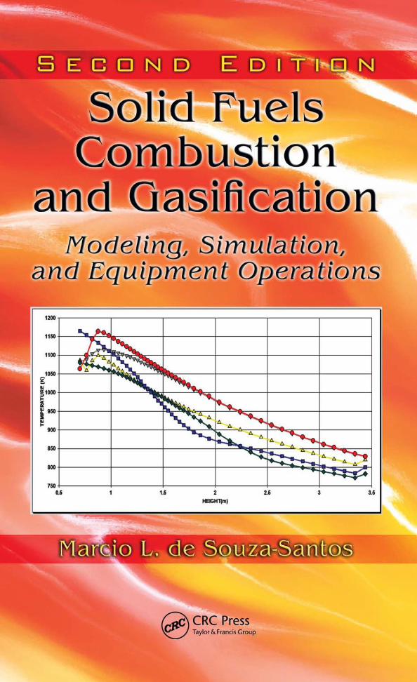
Solid FuelsCombustion
and GasificationModeling, Simulation,
and Equipment Operations
Second Edit ion
TAF-47493_SANTOS-09-0805-C000.indd 1 2/11/10 10:34:16 AM

TAF-47493_SANTOS-09-0805-C000.indd 2 2/11/10 10:34:16 AM
Solid FuelsCombustion
and GasificationModeling, Simulation,
and Equipment Operations
Second Edit ion
Marcio L. de Souza-Santos
CRC Press is an imprint of theTaylor & Francis Group, an informa business
Boca Raton London New York
TAF-47493_SANTOS-09-0805-C000.indd 3 2/11/10 10:34:16 AM
CRC PressTaylor & Francis Group6000 Broken Sound Parkway NW, Suite 300Boca Raton, FL 33487-2742
© 2010 by Taylor & Francis Group, LLCCRC Press is an imprint of Taylor & Francis Group, an Informa business
No claim to original U.S. Government worksVersion Date: 20140512
International Standard Book Number-13: 978-1-4200-4750-9 (eBook - PDF)
This book contains information obtained from authentic and highly regarded sources. Reasonable efforts have been made to publish reliable data and information, but the author and publisher cannot assume responsibility for the validity of all materials or the consequences of their use. The authors and publishers have attempted to trace the copyright holders of all material reproduced in this publication and apologize to copyright holders if permission to publish in this form has not been obtained. If any copyright material has not been acknowledged please write and let us know so we may rectify in any future reprint.
Except as permitted under U.S. Copyright Law, no part of this book may be reprinted, reproduced, transmit-ted, or utilized in any form by any electronic, mechanical, or other means, now known or hereafter invented, including photocopying, microfilming, and recording, or in any information storage or retrieval system, without written permission from the publishers.
For permission to photocopy or use material electronically from this work, please access www.copyright.com (http://www.copyright.com/) or contact the Copyright Clearance Center, Inc. (CCC), 222 Rosewood Drive, Danvers, MA 01923, 978-750-8400. CCC is a not-for-profit organization that provides licenses and registration for a variety of users. For organizations that have been granted a photocopy license by the CCC, a separate system of payment has been arranged.
Trademark Notice: Product or corporate names may be trademarks or registered trademarks, and are used only for identification and explanation without intent to infringe.
Visit the Taylor & Francis Web site athttp://www.taylorandfrancis.com
and the CRC Press Web site athttp://www.crcpress.com
Dedication
To the 200 years of Charles Darwin, one among the greatest liberators of humanity.
The history of science—by far the most successful claim to knowledge accessible to humans—teaches that the most we can hope for is successive improvement in our understanding, learning from our mistakes, an asymp-totic approach to the Universe, but with the proviso that absolute certainty will always elude us.
Carl Sagan(The Demon-Haunted World: Science as a Candle in the Dark)
TAF-47493_SANTOS-09-0805-C000e.indd 5 2/11/10 10:34:44 AM

TAF-47493_SANTOS-09-0805-C000e.indd 6 2/11/10 10:34:44 AM
vii
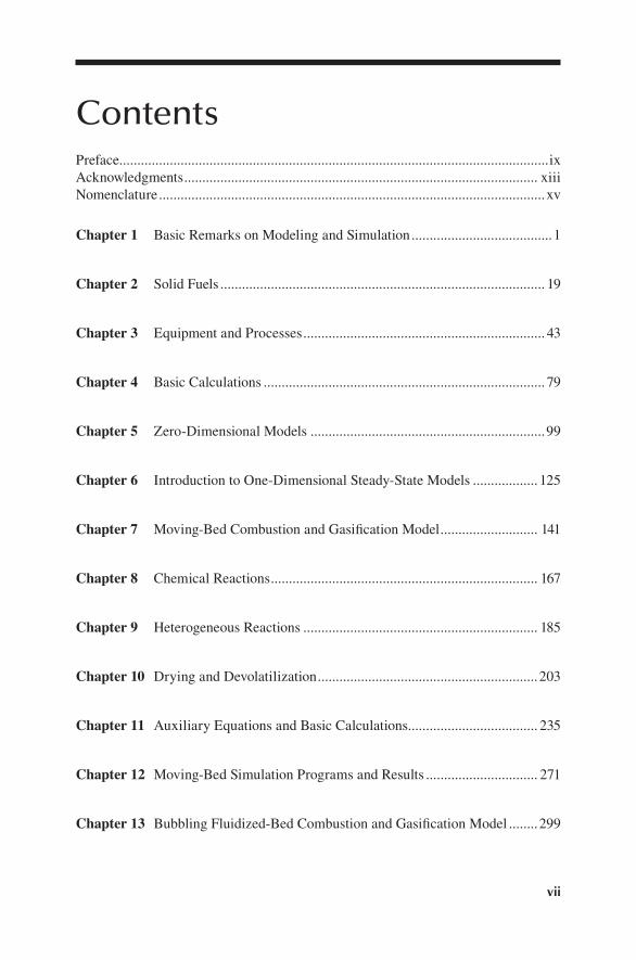
ContentsPreface.......................................................................................................................ixAcknowledgments .................................................................................................. xiiiNomenclature ...........................................................................................................xv
1.Chapter Basic Remarks on Modeling and Simulation .......................................1
2.Chapter Solid Fuels .......................................................................................... 19
3.Chapter Equipment and Processes ................................................................... 43
4.Chapter Basic Calculations .............................................................................. 79
5.Chapter Zero-Dimensional Models .................................................................99
6.Chapter Introduction to One-Dimensional Steady-State Models .................. 125
7.Chapter Moving-Bed Combustion and Gasification Model ........................... 141
8.Chapter Chemical Reactions .......................................................................... 167
9.Chapter Heterogeneous Reactions ................................................................. 185
1.0.Chapter Drying and Devolatilization .............................................................203
1.1.Chapter Auxiliary Equations and Basic Calculations.................................... 235
1.2.Chapter Moving-Bed Simulation Programs and Results ............................... 271
1.3.Chapter Bubbling Fluidized-Bed Combustion and Gasification Model ........299
TAF-47493_SANTOS-09-0805-C000toc.indd 7 2/11/10 10:36:40 AM
viii Contents
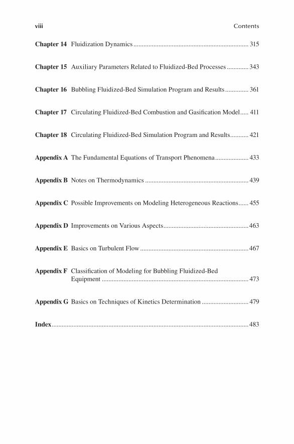
1.4.Chapter Fluidization Dynamics ..................................................................... 315
1.5.Chapter Auxiliary Parameters Related to Fluidized-Bed Processes ............. 343
1.6.Chapter Bubbling Fluidized-Bed Simulation Program and Results .............. 361
1.7.Chapter Circulating Fluidized-Bed Combustion and Gasification Model ..... 411
1.8.Chapter Circulating Fluidized-Bed Simulation Program and Results ........... 421
Appendix A The Fundamental Equations of Transport Phenomena .................... 433
Appendix B Notes on Thermodynamics .............................................................. 439
Appendix C Possible Improvements on Modeling Heterogeneous Reactions ...... 455
Appendix D Improvements on Various Aspects ...................................................463
Appendix E Basics on Turbulent Flow ................................................................. 467
Appendix F Classification of Modeling for Bubbling Fluidized-Bed Equipment ........................................................................................ 473
Appendix G Basics on Techniques of Kinetics Determination ............................ 479
Index ...................................................................................................................... 483
TAF-47493_SANTOS-09-0805-C000toc.indd 8 2/11/10 10:36:40 AM
ix
PrefaceThe general perception is to equate solid fuels with pollution. That is understandable, but not necessarily correct or inevitable. There is no doubt that the burning of coal in thermoelectric stations raises justified concerns regarding the emission of pollut-ants. The abundance of coal, lack of alternative resources, and economic pressures have led many countries to continue and even increase the application of this fuel for power generation. Evidently, that picture is not unchangeable, first because spe-cial attention has been given to biomasses because of their renewability and overall zero carbon dioxide generation aspects, and second because of the development of new techniques. These new techniques have allowed much lower emissions of sul-fur and nitrogen oxides into the atmosphere, while raising efficiency. A good part of that success is due to process optimization through mathematical modeling and simulation.
Therefore, it is not surprising that the number of professionals and graduate students entering fields related to combustion and gasification of solid fuels is increasing. However, unlike focused researchers, many of these new professionals are not interested in deep consideration based on exhaustive literature review of spe-cialized texts on the subject. These publications are important, but most assume an audience of accomplished mathematical modelers and are not preoccupied with presenting the details of how it is possible to start from fundamental and general equations and arrive at a final model for an equipment or process. Those just start-ing out in the field are also generally not interested in the other extreme, i.e., simple and mechanistic description of equipment design procedures or instruction manuals for application of commercial simulation packages. They tend to have a few main preoccupations:
Being acquainted enough with the fundamental phenomena taking place in •the equipment or processesGaining knowledge of basic procedures of modeling and simulation of •equipment and systemsDeveloping mathematical models and simulation programs to predict the •behavior of this equipment or these processes, mainly for cases when no commercial simulators are availableApplying the available tools when simulators are commercially avail-•able, depending on the conditions of time and resources (in this case, one should be able to properly set the conditions asked as input by the simulator, evaluate the applicability of possible solutions, and choose among various alternatives)Using simulation programs to improve operations of existing equipment or •for optimized design of new equipmentBuilding confidence for decision making regarding process improvements •and investments
TAF-47493_SANTOS-09-0805-C000f.indd 9 2/11/10 10:35:08 AM
x Preface
Experience shows that a good route to acquiring real and testable understanding of a subject in the area of processing is to develop models and computer simula-tors. Developing a successful simulator is an accomplishment in which a student can justly take pride, since it represents the accumulated knowledge of the subject.
It is important to emphasize the need for simple models. Of course, there are several levels at which models can be built. Nonetheless, one should be careful with too simple or too complex ones. The low extreme usually provides only super-ficial information, while the other usually takes years to develop and involves considerable computational difficulties because of convergence problems and incoherencies.
In the present text, model complexity is extended only as far as needed to achieve a reasonable representation of that equipment. For instance, the examples are lim-ited to two dimensions, and most of the models are based on a one-dimensional approach. This may sound simplistic; however—as demonstrated in the text—the level of detail and usefulness of results from such simulations are not negligible. In addition, this book can also be used as an introduction for more complex models.
The text is designed to be useful to graduate students, engineers, and profession-als with degrees in any exact science and has been applied as such for many years in courses at all levels.
Although the main concern of this book is with modeling combustion and gas-ification processes, it is also an introduction to mathematical modeling and simula-tion. The basic methods illustrated here can be used for modeling a wide range of processes and equipment commonly found in industry.
Operations of boilers, furnaces, incinerators, gasifiers, or any other equipment dealing with combustion or gasification phenomena involve a multitude of simul-taneous processes, such as heat, mass, and momentum transfers; chemical kinetics of several reactions; drying; pyrolysis, etc. Those should be coherently combined to allow reasonable simulation of industrial units or equipment. To help accomplish that, the text describes combustion and gasification processes in some detail.
Although the basic concepts of thermodynamics and transport phenomena can be found in several texts, the respective fundamental equations are included. Thus, the need to consult other texts has been minimized. Most of the time, the concepts usually learned in engineering courses are sufficient.
In view of the practical approach, several correlations and equations are taken from the literature without a preoccupation with mathematical demonstrations. References are provided and should be consulted by those interested in further details.
The main strategy of the book is to teach by example. Besides the significant frac-tion of industrial equipment operating with suspensions of pulverized solid fuels, the specific cases of moving and fluidized beds have been selected because they have several qualities:
They cover a good fraction of processes found in industry involving com-•bustion or gasification of solid fuels. In the particular case of fluidized beds, the fraction of equipment using that technique has continuously increased. Actually, conventional boilers and furnaces operating with suspensions have been retrofitted to fluidized beds.
TAF-47493_SANTOS-09-0805-C000f.indd 10 2/11/10 10:35:08 AM
Preface xi
They allow easy-to-follow examples on how simplifying assumptions regar-•ding the operation of real industrial equipment can be set.They permit relatively quick introduction of fundamental equations without •the need for too complex treatments.They provide simple examples of modeling and show how those examples •can be put together in order to write a simulation program.
To summarize, the book intends to accomplish the following objectives:
Show several constructive and operational features of equipment dealing •with combustion and gasification of solid fuels, such as coal, biomass, solid residues, etc. Present basic aspects of solid and gas combustion phenomena•Introduce the fundamental methodology to formulate a mathematical model •of the above equipmentDemonstrate possible routes from model to workable computer simulation •programShow comparisons between simulations and real operations•Illustrate interpretations of simulation results that may be applied as tools •for improving the performance of existing industrial equipment or for opti-mized design of new equipment
It is organized as follows:
Chapter 1 presents a few generally applicable notions concerning modeling and simulation.
Chapter 2 shows the main characteristics of solid fuels, such as coals and biomasses.
Chapter 3 introduces basic concepts of solid-gas systems and the main charac-teristics of combustion and gasification equipment.
Chapter 4 provides formulas and methods to allow initial calculations regard-ing solid fuel processing.
Chapter 5 describes the fundamental equations of zero-dimensional models with the objective of allowing verification of overall relations between inputs and outputs of any general process, including combustors and gasifiers.
Chapter 6 introduces a very basic and simple first-dimension model of a gas reactor. Of course, it is not the intention to present any model for flames. That is beyond the scope of this introductory book. However, it is useful to introduce standard considerations regarding mathematical modeling and the application of mass, energy, and momentum transfer equations.
Chapter 7 describes the first example of a model for solid fuel combustion and gasification equipment. The case of a moving-bed combustor or gasifier is used for this model.
Chapters 8 and 9 introduce the methods to compute gas–gas and gas–solid reaction rates.
Chapter 10 introduces the modeling of drying and pyrolysis of solid fuels.
TAF-47493_SANTOS-09-0805-C000f.indd 11 2/11/10 10:35:08 AM
xii Preface
Chapter 11 presents auxiliary and constitutive equations and methods that may be used to build a computer program to simulate the model described in the previous chapter.
Chapter 12 shows how to put together all the information previously described in order to build a workable simulation program. The chapter also pres-ents comparisons between simulations and real operations of a moving-bed gasifier.
Chapter 13 repeats the approach used in Chapter 7, but now having in mind bubbling fluidized-bed combustors and gasifiers.
Chapters 14 and 15 provide correlations and constitutive equations needed to complete the simulation of bubbling fluidized bed combustors and gasifiers.
Chapter 16 shows the strategy of assembling a simulation program based on the model presented for bubbling fluidized beds, as well as comparisons between simulations and real operations of boilers and gasifiers.
Chapter 17 repeats the approach used in Chapter 13 for the case of circulating fluidized-bed combustors and gasifiers.
Chapter 18 is similar to Chapter 16, but now using examples related to circulat-ing fluidized bed equipment.
Almost all chapters include exercises. They are intended to stimulate the imagi-nation and build confidence in solving problems related to modeling and simulation. The relative degree of difficulty or volume of work involved on solutions is indicated by the increasing number of asterisks. Problems with four asterisks usually require good training in solving differential equations or demand considerable work.
TAF-47493_SANTOS-09-0805-C000f.indd 12 2/11/10 10:35:08 AM

xiii
Acknowledgments I had the pleasure of working with several colleagues who helped in this endeavor. In particular, I am grateful to Alan B. Hedley (University of Sheffield, United Kingdom), Francisco D. Alves de Souza (Institute for Technological Research, São Paulo, Brazil), and former colleagues at the Institute of Gas Technology (Chicago). I am also grateful to my family for their support and motivation, Dr. Alex Moutsoglou (South Dakota State University) and CRC Press personnel for pointing out correc-tions and making suggestions, the University of Campinas for its support, and Prof. John Grace and Dr. Xuantian Li (University of British Columbia) for valuable infor-mation regarding the operations of a circulating fluidized-bed gasifier.
TAF-47493_SANTOS-09-0805-C000g.indd 13 2/11/10 10:35:38 AM

TAF-47493_SANTOS-09-0805-C000g.indd 14 2/11/10 10:35:38 AM
xv
Nomenclaturea general parameter or coefficient (dimensions depend on the applica-
tion), ratio between the radius of the nucleus and the original particle, or Helmoltz energy (J kg–1)
A area (m2) or ash (in chemical reactions)ai parameters or constants (dimensionless)â activity coefficient (dimensionless)ae air excess (dimensionless)b exergy (J kg–1)B coefficient, constant, or parameter (dimensions depend on the application)c specific heat at constant pressure (J kg–1 K–1)C constant or parameter to be defined in each situationCOC1(j) coefficient of component j in the representative formula of char (after
drying and devolatilization of original fuel) (dimensionless)COC2(j) coefficient of component j in the representative formula of coke (due to
tar coking) (dimensionless)COF(j) coefficient of component j in the representative formula of original solid
fuel (dimensionless)COT(j) coefficient of component j in the representative formula of tar
(dimensionless)COV(j) coefficient of component j in the representative formula of volatile
fraction of the original solid fuel (dimensionless)d diameter (m)Dj diffusivity of component j in the phase or media indicated afterwards
(m2 s–1)dP particle diameter (m)Ei activation energy of reaction i (J kmol–1)f factor or fraction (dimensionless)F mass flow (kg s–1)f514 total mass fractional conversion of carbonfair air excess (dimensionless)fbexp expansion factor of the bed or ratio between its actual volume and
volume at minimum fluidization condition (dimensionless)ffc mass fraction conversion of fixed carbonffr fuel ratio factor used in reactivity calculations (dimensionless)fm mass fraction of particles of kind m among all particles present in the
process (dimensionless)fmoist mass fractional conversion of moisture (or fractional degree of drying)ftur factor related to turbulent fluidization regime (dimensionless)fV mass fractional conversion of volatiles (or degree of devolatilization)g acceleration of gravity (m s–2) or specific Gibbs function (J/kg)G mass flux (kg m–2 s–1)
TAF-47493_SANTOS-09-0805-C000h.indd 15 2/11/10 10:36:08 AM
xvi Nomenclature
h enthalpy (J kg–1)H height (m)HHV high heat value (J kg–1)i inclination relative to the horizontal position (rad)I variable to indicate the direction of mass flow concerning a control
volume (+1 entering the control volume; –1 leaving the control volume)jj mass flux of component j due to diffusion process (kg m–2 s–1)k0i preexponential coefficient of reaction i (s–1; otherwise, unit depends on
the reaction)K0i preexponential equilibrium coefficient for reaction i (unit depends on the
reaction and notation)ki kinetic coefficient of reaction i (s–1; otherwise, unit depends on the
reaction)Ki equilibrium coefficient for reaction i (unit depends on the reaction and
notation)kt specific turbulent kinetic energy (m2 s–2)l mixing length (m)L coefficient used in devolatilization computations (dimensionless)Lgrate length of grate (m)LHV low heat value (J kg–1)LT length of tube (m)M mass (kg) Mj molecular mass of component j (kmol/kg)n number of molesNAr Archimedes number (dimensionless)NBi Biot number (dimensionless)nCP number of chemical species or componentsnCV number of control volumesnG number of chemical species or components in the gas phaseNj mass flux of component j referred to a fixed frame of coordinates
(kg m–2 s–1)NNu Nusselt number (dimensionless)NPe Peclet number (dimensionless)NPr Prandtl number (dimensionless)NRe Reynolds number (dimensionless)nS number of chemical species or components in the solid phaseNSc Schmidt number (dimensionless)NSh Sherwood number (dimensionless)nSR number of streamsp index for the particle geometry (0 = planar, 1 = cylindrical, 2 = sphere)pj partial pressure of component j (Pa)P pressure (Pa)q energy flux (W m–2)Q rate of energy generation (+) or consumption (–) of an equipment
or system (W)r radial coordinate (m)
TAF-47493_SANTOS-09-0805-C000h.indd 16 2/11/10 10:36:09 AM
Nomenclature xvii
R equipment radius (m)R universal gas constant (8314.2 J kmol–1 K–1)RC rate of energy transfer to (if positive) or from (if negative) the indicated
phase due to convection (W m–3 [of reactor volume or volume of the indicated phase])
Rcond rate of energy transfer to (if positive) or from (if negative) the indicated phase due to conduction (W m–3 [of reactor volume or volume of the indicated phase])
Rh rate of energy transfer to (if positive) or from (if negative) the indicated phase due to mass transfer between phases (W m–3 [of reactor volume or volume of the indicated phase])
Rheat heating rate imposed to a process (K/s)ri rate of reaction i (for homogeneous reactions: kg m–3 s–1; for heteroge-
neous reactions: kg m–2 s–1)Rj rate of component j generation (if positive) or consumption (if negative)
by chemical reactions (kg m–3 s–1; in molar basis [~], the units are kmol m–3 s–1)
Rkind,j rate of component j generation (if positive) or consumption (if negative) by chemical reactions (units vary according to the kind of reaction: if the subscript indicates homogeneous reactions, the units are kg m–3 [of gas phase] s–1; if heterogeneous reactions, kg m–2 [of external are of reacting particles] s–1)
RM,G,j total rate of production (or consumption if negative) of gas component j (kg m–3 [of gas phase] s–1)
RM,S,j total rate of production (or consumption if negative) of solid-phase com-ponent j (kg m–3 [of reacting particles] s–1)
RQ rate of energy generation (if positive) or consumption (if negative) due to chemical reactions (W m–3 [of reactor volume or volume of the indicated phase])
RR rate of energy transfer to (if positive) or from (if negative) the indicated phase due to radiation (W m–3 [of reactor volume or volume of the indi-cated phase])
s entropy (J kg–1 K–1)S cross-sectional area (m2) or, if no index, cross-sectional area of reactor
(m2)t time (s)T temperature (K)T* reference temperature (298 K)Te ratio between activation energy and gas constant
ER( ) (K)
u velocity (m s–1)U gas superficial velocity (m s–1) or resistance to mass transfer (s m–2)ureduc reduced gas velocity (dimensionless)v specific volume (m3 kg–1)V volume (m3)x coordinate or distance (m)X elutriation parameter (kg/s)
TAF-47493_SANTOS-09-0805-C000h.indd 17 2/11/10 10:36:10 AM
xviii Nomenclature
xj mole fraction of component j (dimensionless)y coordinate (m) or dimensionless variableY rate of irreversibility generation at a control volume (W)W rate of work generation (+) or consumption (–) by an equipment or
system (W)wj mass fraction of component j (dimensionless)z vertical coordinate (m)Z compressibility factor (dimensionless)
Greek Letters
α coefficient of heat transfer by convection (W m–2 K–1)αm relaxation coefficient related to momentum transfer involving solid phase
(m s–1)β coefficient (dimensionless) or mass transfer coefficient (m s–1) γ area of particles per volume of reactor or volume of indicated phase as
index (m2/m3)γB area of bubbles per volume of reactor (m2/m3)Γ rate of fines production due to particle attrition (kg s–1)δ unit vector (m)∆ G i0, variation of Gibbs function related to reaction i (J kmol–1)ε void fraction (dimensionless)ε’ emissivity (dimensionless)εt dissipation rate of specific turbulent kinetic energy (m2 s–3)ζ particle porosity (m3 of pores/m3 of particle)η efficiency or effectiveness coefficientθ angular coordinateΘ solid particle friability (m–1)ι efficiency coefficientλ thermal conductivity (W m–1 K–1)Λ parameter related to mass and energy transferφ particle sphericityµ viscosity (kg m–1 s–1) or chemical potential (J kg–1)νij stoichiometry coefficient of component j in reaction iΞ chemical component formula ρ density (unit depends on the reaction and notation)ρp apparent density of particle (kg m–3)ρj mass basis concentration of component j (kg m–3) (in some situations,
component j can be indicated by its formula) σ Stefan-Boltzmann constant (W m–2 K–4)σv standard deviation for distributed energy devolatilization modelτ shear stress tensor (Pa)υ tortuosity factorΦ Thiele modulusχ number of atoms of an element (first index) in a molecule of a chemical component (second index)
TAF-47493_SANTOS-09-0805-C000h.indd 18 2/11/10 10:36:11 AM
Nomenclature xix
ψ mass transfer coefficient (s–1 if between two gas phases; kmol m–2 s–1 if between gas and solid)
ω Pitzer’s acentric factor (dimensionless)ϖ Air ratio (dimensionless)Ω parameter of the Redlich-Kwong equation of state (dimensionless) or
(only in Appendix E) a parameter related to mass and energy transfers
Other
∇ gradient operator∇2 Laplacian operator
superscripts
→ vector or tensor_ time averaged∪ fluctuation or perturbation~ in molar basis^ relative concentration (dimensionless)′ number fraction″ area fraction′″ volume fractions for particles smaller than the particles whose kind and the level are indi-
cated in the subscript
subscripts
Numbers as subscripts may represent sequence of variables, chemical species, or reactions. In the particular case of chemical species, the number would be equal to or greater than 19. In the case of reactions, it will be clear when the number indicates reaction number. The numbering for components and reactions is shown in Tables 7.1 through 7.5.
0 at reference or ideal conditiona at the nucleus–outer shell interfaceA shell or residual layerair airapp apparent (sometimes, this index does not appear and should be under-
stood, as for instance ρp = ρp,app)aro aromaticash ashav average valueb based on exergyB bubblebexp related to the expansion of the bedbri bridges
TAF-47493_SANTOS-09-0805-C000h.indd 19 2/11/10 10:36:12 AM
xx Nomenclature
bulk bulkc critical valueC convection contribution or, in some obvious situations, carboncar carbonaceous solidchar charCIP coated inert particleCOF, COT, COV see above (under “Nomenclature”)cond conduction contributionCP chemical componentCSP coke shell particleCV control volume or equipmentcy cycloned drying or dry basisD beddaf dry and ash-free basisdif diffusion contributiondist distributorE emulsionental relative to enthalpyentro relative to entropyeq equilibrium conditionexer relative to exergyf formation at 298 K and 1 atmF freeboardfc fixed carbonfl fluidfuel related to fuelG gas phaseh transfer of energy due to mass transferH related to the circulation of particles in a fluidized bed or, in
some obvious situations, hydrogenhet related to heterogeneous (or gas–solid) reactionshom related to homogeneous (or gas–gas) reactionsi reaction i (numbers are described in Chapter 7)I as at the feeding pointiCO component numberiCV control volume (or equipment) numberiSR stream numberj chemical component (numbers are described in Chapter 7)J related to the internal surface or internal dimensionK related to the recycling of particles, collected in the cyclone, to
the bedl chemical elementL at the leaving point or conditionlam laminar condition
TAF-47493_SANTOS-09-0805-C000h.indd 20 2/11/10 10:36:12 AM
Nomenclature xxi
m physical phase (carbonaceous solid, m = 1; limestone or dolomite, m = 2; inert solid, m = 3; gas, m = 4)
M mass generation or transfermax maximum conditionmb minimum bubbling conditionmf minimum fluidization conditionmin minimum conditionmoist moisture or watermon monomersmtp metaplastN nucleus, core, or, in some obvious situations, nitrogenO at the external or outside surface, or, in some obvious situa-
tions, oxygenorif orifices in the distributor platep particle (if no other indication, property of particle is related to
apparent value; see Equation 3.12)P at constant pressureper peripheral groupsplenum average conditions in the plenum below the distributor plate or
devicepores related to particle poresQ chemical reactionr at reduced conditionR related to radiative heat transferreal related to real or skeletal density of solid particlesS solid phase, particles, or, if indicated for a property (such as
density), apparent particle densitysat at saturation conditionsit immobile recombination sitesSR streamT terminal value or tubestar tarto mixing-takeover valuetr transition to fast fluidizationtur turbulent conditionU unreacted-core modelv related to devolatilizationV volatileW wallX exposed-core model or related to elutriation of particlesY related to entrainment of particles∞ at the gas phase far from the particle surface
TAF-47493_SANTOS-09-0805-C000h.indd 21 2/11/10 10:36:12 AM

TAF-47493_SANTOS-09-0805-C000h.indd 22 2/11/10 10:36:12 AM
1
1 Basic Remarks on Modeling and Simulation
1.1 EXPERIMENT AND SIMULATION
Over the years, I have heard questions such as “If the equipment is working, why all the effort to simulate it?” and “Can’t we just find the optimum operational point by experimentation?”
The basic answer to the first question is this: We simulate equipment because it is always possible to improve and, given an objective, to optimize an existing operation. Optimization not only increases competitiveness of a company but may also deter-mine its chances of survival. For the second question the answer is that yes, we could find the optimal point by experimentation; however, experimentation is much more expensive than computation, not to mention carrying the risk of disaster and loss of life due to trial-and-error tests aimed at making improvements. In addition, if any variable of the original process changes, the optimum that was determined through
CONTENTS
1.1 Experiment and Simulation ..............................................................................11.1.1 The Experimental Method ....................................................................2
1.1.1.1 Example 1.1 ............................................................................21.1.1.2 Example 1.2............................................................................31.1.1.3 Example 1.3............................................................................41.1.1.4 Example 1.4 ............................................................................61.1.1.5 Example 1.5 ...........................................................................7
1.1.2 The Theoretical Method .......................................................................81.2 A Classification for Mathematical Models ..................................................... 10
1.2.1 Phenomenological versus Analogical Models .................................... 101.2.2 Steady-State Models ........................................................................... 11
1.2.2.1 0D-S Models ........................................................................ 121.2.2.2 One-Dimensional Steady Models ........................................ 131.2.2.3 Two-Dimensional Steady Models ........................................ 131.2.2.4 Three-Dimensional Steady Models ..................................... 14
1.2.3 Dynamic or nD-D Models .................................................................. 161.2.4 Which Level to Attack? ...................................................................... 16
1.3 Exercises ......................................................................................................... 171.3.1 Problem 1.1 ......................................................................................... 171.3.2 Problem 1.2 ......................................................................................... 17
References ................................................................................................................ 17
TAF-47493_SANTOS-09-0805-C001.indd 1 2/11/10 10:37:34 AM
2 Solid Fuels Combustion and Gasification
costly experimentation is no longer valid. For example, if a thermoelectric power unit starts receiving coal with different properties than that previously used, the optimum operational point would not be the same. It is also important to remember that the experimentally found optimum at a given scale is not applicable to other scales, even if several conditions remain the same. In fact, no company today can afford not to use computer simulation to seek optimized design or operation of its industrial processes.
One may think that these remarks could hide some sort of prejudice against the experimental method. Nothing could be further from the truth. There is no valid theory without experimentation. A model or theory is not applicable unless it is experimen-tally verifiable, and this is a fundamental aspect of science. In other words, no matter how sophisticated a mathematical model and consequent simulation are, they would be useless if they cannot reproduce the values of variables measured during real opera-tions within an acceptable degree of deviation. If the simulation does not observe those basic characteristics, it would not be able to predict the behavior of future equipment with some degree of confidence and would therefore be useless as a designing tool.
Before going any further, let us make a few comments on experimental and theo-retical procedures.
1.1.1 The experimenTal meThod
One may ask about the conditions required for the application of the experimental method in order to obtain or infer valid information concerning the behavior of a process. For this, the following definitions are useful:
Controlled variables• are those whose values can, within a certain range, be imposed freely. An example is the temperature of a bath heated by electri-cal resistances.Observed variables• are those whose values can be measured, directly or indirectly. An example is the thermal conductivity of the fluid in the bath where the temperature has been controlled.
Experiments are a valid source of information if, during the course of tests, the observed variables are solely affected by the controlled variables. Any other vari-able should be maintained at a constant value.
1.1.1.1 Example 1.1Let us imagine one is interested in determining the dependence on temperature of the thermal conductivity of a liquid with a given composition and under a given pressure. Therefore, the observed variable would be the thermal conductivity of the liquid and the controlled variable would be its average temperature. For that, the thermal conductivity would be measured at various levels of temperature, and during the following must be guaranteed:
The temperature of the liquid bath should be kept as uniform as possible. •A small agitation would suffice.Its chemical composition and pressure must be maintained at constant levels. •
TAF-47493_SANTOS-09-0805-C001.indd 2 2/11/10 10:37:34 AM
Basic Remarks on Modeling and Simulation 3
In doing so, it will be possible to correlate cause and effect: i.e., the values of observed and controlled variables. These correlations may take the form of graphs or math-ematical expressions.
1.1.1.2 Example 1.2The SO2 absorption by limestone can be represented by the following reaction:
CaO SO O CaSO+ + ↔2 2 4
12
.
The experiments to determine the kinetics of that reaction should be conducted under carefully chosen conditions, and one ought to do the following:
Provide a proper barge to hold a small sample of limestone, which would •be maintained in a container that could allow continuous injections and withdrawals of gases.Provide a system to continuously weight the barge with required precision.•See that various mixtures of SO• 2 and O2, with precisely determined compo-sitions, are injected into the container and pass around the barge. (The con-centrations of reactants [SO2 and O2] in the involving atmosphere should be controlled or kept as constant as possible; therefore, a fresh supply of the reacting mixture should be guaranteed.)Maintain a constant pressure in the capsule containing the barge.•Be sure that the limestone sample has its maximum particle size reduced to •a point such that no interference of particle size on the reaction rate can be noticed. (That interference is caused by the resistance to mass transfer of gas components through the porous structure of the particle.)Maintain the temperature in the container as constant as possible during •each value experimental test. (This can be achieved by heating or cool-ing devices around the barge. Temperature differences between the various regions of the sample should be reduced or kept to a minimum. This can be accomplished by using thin layers of sample and through high heat trans-fer coefficients between gas and solid sample. One method is to increase the Reynolds number or the relative velocity between gas and particles. Of course, this has limitations because the gas stream should carry no solid.)Organize the tests with different periods. (At the end of each test, samples •of the CaO and CaSO4 mixture would be analyzed. An alternative is to apply algorithms that allow the determination of composition based on the sample weight. If this is accomplished, the weight of the barge could be measured during longer tests.)
Following the above guidelines, during the experiments the number of controlled variables could be reduced to the temperature and the concentrations of SO2 and O2 in the incoming gas stream. The degree of conversion of CaO into CaSO4 would be the observed variable against time.
In addition, a large number of experimental tests should be carried out to elimi-nate bias. This is possible to verify by quantitative means.
TAF-47493_SANTOS-09-0805-C001.indd 3 2/11/10 10:37:35 AM
4 Solid Fuels Combustion and Gasification
Even after all these precautions, the determined kinetics is valid only at the range of temperature and concentration of the experiments. In addition, it is applicable only to the particular kind of limestone tested because other chemical components, different from those involved in the reaction and present in the original limestone, may have catalyst or poisoning activity.
The above examples show the correct scientific experimental procedure. This procedure allows observations that may be applied to understand the phenomenon. Within an established range of conditions, the conclusions do not depend on a partic-ular situation. Therefore, they can be generalized and used in mathematical models combining several other phenomena.
It is also important to be aware that experimental optimization of a process pres-ents stringent limitations due to two factors:
1. The number of variables interfering in a given process is usually much big-ger than the number of controllable variables. Variation imposed on a single input may represent variations on several process conditions and conse-quently on several observed variables.
2. Scale effects must be considered. Physical-chemical properties of sub-stances handled by the process do not obey a linear dependence with the geometry of the equipment, such as length, area, and volume. For instance, one may double the volume of a chemical reactor, but densities or viscosi-ties of streams entering or leaving the reactor are not doubled.
In some cases, scaling up does not even allow geometric similarity with the experimental or pilot unit. The following example illustrates the false inference from experimental procedures.
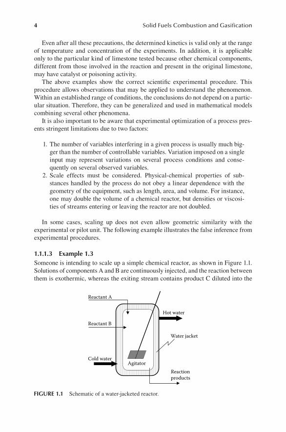
1.1.1.3 Example 1.3Someone is intending to scale up a simple chemical reactor, as shown in Figure 1.1. Solutions of components A and B are continuously injected, and the reaction between them is exothermic, whereas the exiting stream contains product C diluted into the
Reactant A
Reactant B
AgitatorCold water
Hot water
Reaction products
Water jacket
FIGURE 1.1 Schematic of a water-jacketed reactor.
TAF-47493_SANTOS-09-0805-C001.indd 4 2/11/10 10:37:36 AM
Basic Remarks on Modeling and Simulation 5
reacting mixture. The process follows a steady-state regime, and water is used as cooling fluid that runs inside a jacket surrounding the reactor. A stirring device maintains the reacting media as homogeneous as possible.
An engineer knows the optimum temperature to be maintained in the vessel in order to achieve the maximum output of species C. He or she would try to find the correct flow of cold water through the jacket in order to maintain the optimum temperature. To achieve this, a pilot was built, and through experiments, the best operational condition was set. Now, the engineer intends to build an industrial-scale reactor that delivers ten times the rate of C obtained in the pilot.
Someone suggests that the same geometric shape of the pilot be kept, that is, H/D = 2 (where H = level filled with fluid and D = diameter). However, to obtain the same concentration of C in the exiting stream, the residence time of reactants in the volume should be maintained. Residence time τ is usually defined by the following equation:
τ ρ= V
F (1.1)
where V is the volume of the reactor (filled with reacting mixture), ρ is the aver-age density of the fluid, and F is the mass flow of injected fluids into the reactor. Assuming a cylindrical reactor, the volume is given by the following equation:
V
D H= π 2
4.
(1.2)
The following relation should be set in order to maintain the same residence time:
V V= 10 0. (1.3)
Here, index 0 indicates the pilot dimensions. To keep the H/D ratio equal to 2, the new diameter would be
D D= 101 30
/ . (1.4)
The area for heat transfer (neglecting the bottom) is given by
A HD= π . (1.5)
Therefore, the area ratio would be
AA
HDH D
DD0 0 0
2
02= = .
(1.6)
Using 1.4, one gets
A A= 102 30
/ . (1.7)
TAF-47493_SANTOS-09-0805-C001.indd 5 2/11/10 10:37:39 AM
6 Solid Fuels Combustion and Gasification
According to this option, the heat exchanging area of the industrial-scale reactor would be only 4.64 times the respective heat exchanging area of the pilot unit. Thus, cooling would not be as efficient as before. Conversely, if one tries to multiply the reactor wall area by 10, the volume would be much larger than 10 times the volume of the pilot. Actually, this would increase the residence time of the reactants by more than 31 times, which is not desirable because (a) the investment in the new reactor would be much larger than intended, and (b) the reactants would sit idle in the reactor because the residence time of reactants would be much larger than the value found through optimization tests.
The only possibility is to modify the H/D ratio in order to maintain the same area/volume relationship as found in the pilot. For instance, if one proposes to keep the same diameter as the pilot, the industrial reactor would be 10 times as tall as the experimental unit. Having in mind limitations determined by the factory layout, this solution may not be convenient or practical. This demonstrates that not even similar geometric shape can be kept in a scaling up procedure.
The alternative to multiplying the volume by 10 while maintaining the same shape of the pilot would be to install a refrigerating coil inside the reactor. After a proper design, that would provide the required heat transferring rates.
1.1.1.4 Example 1.4Another example is given for the case of a boiler. Someone wants to optimize the boiler design through experimental tests using a relatively small pilot unit. The unit is composed of a furnace with a tube bank that can be partially retreated from the furnace in order to vary the heat exchange area. Coal is continuously fed into it while water runs into the tube bank.
After a few tests in which the fuel feeding rate is kept constant, the engineer finds the fraction of exposed tube area, which provides the maximum rate of steam gen-eration. This can be explained by the following:
1. If the tube area is increased, the heat transfer between the furnace and the tubes is augmented, leading to increases in steam production. However, fur-ther increases in the tube area also lead to decreases in the average tempera-ture in the furnace. This reduces the carbon conversion or fuel utilization and therefore diminishes the rate of energy transferred to tubes for steam generation.
2. If the area of the tubes is decreased, the average temperature in the furnace increases and the carbon conversion is enhanced. Therefore, more coal is converted to provide energy, possibly leading to augmentations in the steam generation. However, after a certain point, the lack of sufficient tube area for heat transfer would just raise the temperature of the gases leaving the chimney, resulting in a reduction in boiler efficiency.
As we have seen, the optimum heat exchanging area to achieve the maximum boiler efficiency should be an intermediate point. However, it is not easy to find such a solution because of the great number of processes or phenomena influencing the process. Among them are all sorts of heat transfers among the particles, gases, and
TAF-47493_SANTOS-09-0805-C001.indd 6 2/11/10 10:37:39 AM
Basic Remarks on Modeling and Simulation 7
tubes; mass transfers among gases and particles; momentum transfers among those phases; and several chemical reactions. To achieve a good solution through experi-mentations would be a nightmare, if not a virtual impossibility.
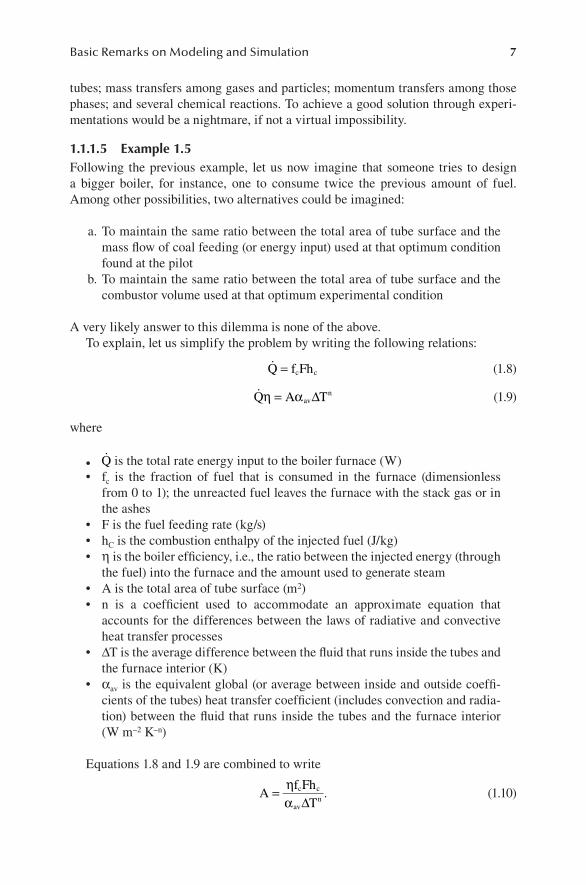
1.1.1.5 Example 1.5Following the previous example, let us now imagine that someone tries to design a bigger boiler, for instance, one to consume twice the previous amount of fuel. Among other possibilities, two alternatives could be imagined:
a. To maintain the same ratio between the total area of tube surface and the mass flow of coal feeding (or energy input) used at that optimum condition found at the pilot
b. To maintain the same ratio between the total area of tube surface and the combustor volume used at that optimum experimental condition
A very likely answer to this dilemma is none of the above. To explain, let us simplify the problem by writing the following relations:
Q f Fhc c= (1.8)
Q A Tav
nη α= ∆ (1.9)
where
Q• is the total rate energy input to the boiler furnace (W)f• c is the fraction of fuel that is consumed in the furnace (dimensionless from 0 to 1); the unreacted fuel leaves the furnace with the stack gas or in the ashesF is the fuel feeding rate (kg/s)•h• C is the combustion enthalpy of the injected fuel (J/kg)η• is the boiler efficiency, i.e., the ratio between the injected energy (through the fuel) into the furnace and the amount used to generate steamA is the total area of tube surface (m• 2)n is a coefficient used to accommodate an approximate equation that •accounts for the differences between the laws of radiative and convective heat transfer processesΔ• T is the average difference between the fluid that runs inside the tubes and the furnace interior (K)α• av is the equivalent global (or average between inside and outside coeffi-cients of the tubes) heat transfer coefficient (includes convection and radia-tion) between the fluid that runs inside the tubes and the furnace interior (W m–2 K–n)
Equations 1.8 and 1.9 are combined to write
A
f FhT
c c
avn= η
α ∆.
(1.10)
TAF-47493_SANTOS-09-0805-C001.indd 7 2/11/10 10:37:41 AM
8 Solid Fuels Combustion and Gasification
Let us examine alternative a. According to Equation 1.10, the area of tubes seems to be proportional to the fuel-feeding rate. However, assuming the same tube bank configuration as in the pilot, its area would not be linearly proportional to the fur-nace volume. Therefore, the average velocity of gases crossing the tube bank will be different from the values found in the pilot. The heat transfer coefficient will change as well, because it is a strong function of that velocity. Looking at Equation 1.10, it is easy to conclude that alternative a will not work.
Now, if one tries alternative b and increases the furnace volume, according to Equation 1.1, the residence time of fuel particles in the furnace will increase as well. That will greatly differ from the optimum found during pilot tests. Therefore, the fuel conversion and the boiler efficiency will not be the same as the pilot, and the second alternative would not work either.
As seen, even that simplified analysis is able to demonstrate the complexity of the question. Hence, one would ask how this type of problem should be faced. Answering that question, among others, will be one of the main goals of this book.
1.1.2 The TheoreTical meThod
It is too difficult for the human mind to interpret any single or combination of phe-nomena in which more than three variables are involved. It is not a coincidence that the graphical representation of influences is also limited to that number of variables. Some researchers make invalid extrapolations of the experimental method and apply the results to multidimensional problems. For instance, consider the case explained above: trying to infer the kinetics of SO2 absorption using a boiler combustor to which coal and limestone are added. As temperature and concentration (among sev-eral other variables) change from point to point in the combustion chamber, no real control over the influencing variables is possible. The best that can be accomplished is the verification of some interdependence. The results of such a study might be use-ful for optimizing a particular application without the pretension of generalizing the results and applying them to other situations, despite any eventual similarities.
On the other hand, the theoretical method is universal. If it is based on fundamen-tal equations (mass, momentum, and energy conservations) and correlations obtained from well-conducted experimental procedures, the theoretical approach does not suffer from limitations due to the number of variables involved. Therefore, math-ematical modeling is not a matter of sophistication, but the only possible method by which to understand complex processes. In addition, the simple fact that a simulation program is capable of being processed to generate information that describes, within a reasonable degree of deviations, the behavior of a real operation is in itself a strong indication of the coherence of the mathematical structure.
The most important properties of mathematical modeling, along with its respec-tive simulation program, can be summarized as follows:
Mathematical modeling requires much less in the way of financial resources •than experimental investigation.It can be applied to studying conditions in areas that are difficult or impos-•sible to access or where uncertainties in measurements are implicit. Such
TAF-47493_SANTOS-09-0805-C001.indd 8 2/11/10 10:37:41 AM
Basic Remarks on Modeling and Simulation 9
conditions may include very high temperatures, as are usually found in combustion and gasification processes. In addition, these processes nor-mally involve various phases with moving boundaries, turbulence, etc.It can be extended to infer the behavior of a process far from the tested •experimental range.It allows a much better understanding of the experimental data and results •and therefore can be used to complement the knowledge acquired from experimental tests.It can be used to optimize the experimental procedure and to avoid tests at •uninteresting or even dangerous ranges of operations.It can be used during the scaling-up phase in order to achieve an optimized •design of the equipment or process unit. This brings substantial savings of time and money because it eliminates or drastically reduces the need for intermediate pilot scales.The model and its respective program are not static. In other words, they •can be improved at any time to expand the range of application, increase reliability, or decrease the time necessary for the computations.The model and the program can also be improved as more and better infor-•mation become available from experimental investigations. Results pub-lished in the literature concerning the basic phenomena involved in the simulated process or system represent a constant source of information. Therefore, the program can be seen as a reservoir of knowledge.
Mathematical modeling is not a task but a process. The development of a math-ematical model and its respective computer simulation program is not a linear sequence in which each step follows the former one until the end. The process is composed of a series of forward and backward movements, where each block or task is repeatedly revisited.
One should be suspicious of simple answers. Nature is complex, and the process of modeling it is an effort to represent it as closely as possible. The best that can be done is to improve the approximations in order to decrease deviation from reality. A good simulation program should be capable of reproducing measured operational data within an acceptable level of deviation. In most cases, even these deviations have a limit that cannot be surpassed, which is established by several constraints, including the following:
Intrinsic errors—due to limitations in measurement precision—in correla-•tion obtained through experimental proceduresAvailable knowledge from literature or personal experience•The basic level of modeling adopted (zero, one, or more dimensions)•
These factors, as well others, are discussed further in Chapter 12.Therefore, only approximations—sometimes crude ones—of the reality are possi-
ble. However, despite its simplicity, any model should be mathematically consistent.It is advisable to go from simple to complex, not the other way around. Modeling
is an evolutionary movement. Usually, there is a long path from the very first model
TAF-47493_SANTOS-09-0805-C001.indd 9 2/11/10 10:37:41 AM
10 Solid Fuels Combustion and Gasification
to a more elaborate version. It is important to include very few effects in the first trial. Several hypotheses and simplifications should be assumed; otherwise, the risk of not achieving a working model would increase. In addition, evolution requires compari-sons between simulation results and reality. If one starts from the very simple, results might be obtained from computations. Then, comparisons against experimental or equipment operational data may provide clues for improvements.
During industrial operations, measurements of variables can seldom be made with deviations smaller than 5%. For instance, the average temperature of a stack gas released from an industrial boiler can easily fluctuate 30 K around an average of 600 K. Therefore, if the respective model has already produced deviations against measured or published values below that range, one might consider stopping.
Improvements in a model should be accomplished mainly by eliminating one (and only one) simplifying assumption at a time, followed by verification if the new ver-sion leads to representations closer to reality by comparison against experimentation. If not, one may eliminate another assumption, and so on. On the other hand, if one starts from complex models, not even computational results may be obtainable. Even if computation results are achieved, there would be little chance of identifying where improvements should be made. If one needs to travel, it is better to have a small and inexpensive car that runs than a luxury sedan without any wheels.
1.2 A CLASSIFICATION FOR MATHEMATICAL MODELS
1.2.1 phenomenological versus analogical models
Industrial equipment or processes operate by receiving physical inputs, processing them, and delivering physical outputs. Among the usual physical inputs and outputs of streams are flow rates, compositions, temperatures, and pressures.
In addition to those variables, heat and work may be exchanged through the con-trol surface.
Phenomenological models intend to reproduce the processes taking place in the equipment as closely as possible. Those models are based on two types of equations:
Fundamental equations,• * such as the laws of thermodynamics and mass, energy, and momentum conservationAuxiliary equations, usually based on empirical or semiempirical correlations •
The combination of fundamental equations and auxiliary correlations may lead to models that would be valid within the same range as the correlations used. Such a procedure brings some assurance that phenomenological models are reflecting reality within that range.
* The fundamental laws of thermodynamics can be found in any textbook. The main relations are repeated in Chapter 5 and Appendix B. Those related to conservation can be found in any text of trans-port phenomena [1–4]. In addition, Appendix A summarizes those that are the most important for the purposes of this book.
TAF-47493_SANTOS-09-0805-C001.indd 10 2/11/10 10:37:41 AM
Basic Remarks on Modeling and Simulation 11
Analogy models, although useful for relatively simple systems or processes, sim-ply mimic the behavior of a process and therefore do not reflect reality. Examples of analogy models are those based on mass-and-spring systems or on electric circuits.
Since phenomenological models are built on fundamental equations and tested correlations, the respective simulation programs are not just more realistic and reliable than analogy models but also provide much more information than simple descriptions of the properties and characteristics of the output streams. As men-tioned before, is extremely important to properly understand the role of variables that are not accessible for direct or even indirect measurements. For instance, such information might be useful in designing new optimized units, as well as visualizing operational controlling methods for the simulated process or operation. In addition, developing a phenomenological model requires setting relationships linking vari-ous variables. Consequently, the combination of experimental observations with the theoretical interpretation usually leads to a better understanding of processes taking place in the equipment or industrial process.
The phenomenological models can be classified according to several criteria. The first branching is set according to the number of space dimensions considered in the model. Therefore, three levels are possible. A second branching considers the inclusion of time as a variable. If time is not included, the model is called steady state; otherwise, it is a dynamic model. Moreover, several other characteristics can be added to model classifications, such as whether laminar or turbulent flow condi-tions are assumed and whether dissipative effects (such as those provided by terms containing viscosity, thermal conductivity, and diffusivity) are included or not. The list could go on. However, in this introductory text, only spatial dimensions and time are considered. During the present text, mathematical models are classified as follows:
1. Zero-dimensional steady (0D-S): This is the simplest level of modeling and includes no dimension or time as a variable.
2. Three-dimensional-dynamic (3D-D): This includes three space dimensions and time as variables.
1.2.2 sTeady-sTaTe models
Despite being widely used, the term steady-state regime leads to mistakes if not clearly understood.
In relation to a given set of space coordinates, a steady-state regime for a control volume* will be established if:
1. The control surface does not deform or move. 2. The mass flows and average properties of each input and output stream
remain constant.
* See Appendix B, section B.1, “Heat and Work.”
TAF-47493_SANTOS-09-0805-C001.indd 11 2/11/10 10:37:42 AM
12 Solid Fuels Combustion and Gasification
3. The rates of heat and work exchanges between the control volume and surrounds are constant.
4. Despite differences in conditions from point to point inside the control vol-ume, they remain constant at each position.
Most industrial equipments work at or near steady-state conditions, at least during the largest portion of their operational life. On the other hand, there is no such a thing as a perfect steady-state regime. Even for supposedly steady operations, some degree of fluctuations against time is observed regarding variables such as temperatures, concentrations, pressures, etc. Nevertheless, most of the time, those variables remain within relative narrow ranges during operations of several industrial processes and can thus be treated as constants.
1.2.2.1 0D-S ModelsZero-dimensional (0D) models set relations between input and output variables of a control volume without considering the details of the phenomena occurring inside that volume. Therefore, no description or evaluation of temperature, velocity, or concentra-tion profiles inside the equipment being studied is possible. 0D-S models keep those values constant regarding time. In spite that, 0D-S models are very useful, mainly if an overall analysis of an equipment, or system composed of several equipments, is intended. Depending on the complexity of internal phenomena and the information available about a process, this may be the only achievable level of modeling. However, that should not be taken for granted because it may involve serious difficulties, mainly when many subsystems (or equipment) are considered in an industrial unit process.
Since 0D models do not consider descriptions regarding internal points inside the equipment, they require assumptions such as chemical and thermodynamic equilib-rium conditions at the output streams. Such hypotheses may constitute oversimplifi-cations, leading to false conclusions because of the following points:
a) Rigorously, equilibrium at exiting streams would require infinite residence time of the chemical components or substances inside the equipment. The typical residence time of several classes of reactors, combustors, and gas-ifiers is seconds to minutes. Therefore, outputs with conditions far from equilibrium might occur. For instance (and as will be demonstrated later in the text), gasifiers are among those types of equipment that do not deliver streams at chemical equilibrium.
b) Even when equilibrium is assumed, determination of exiting stream compo-sitions requires the value of their temperatures. However, to estimate those, one needs to perform energy balance or balances, which require the compo-sitions and temperatures of the streams to allow computation of enthalpies or internal energies of the exiting streams. Reiterative procedures based on equilibrium assumptions may work if exiting streams are composed of just one or two components. However, reiterative processes with several nested convergence problems might bring awkward computational problems. Most of these situations take significant effort and computational time to achieve a solution. Failure to arrive at a solution is not uncommon.
TAF-47493_SANTOS-09-0805-C001.indd 12 2/11/10 10:37:42 AM
Basic Remarks on Modeling and Simulation 13
c) If the process includes gas–solid reactions—as in combustors or gasifiers— the level of solid fuel (such as coal or biomass) conversion varies signifi -cantly. This happens even for single pieces of equipment operating at different conditions. Zero-dimensional models should assume the level of fuel conversion because they cannot address values of residence times of different phases inside a real reactor. In addition, they are not able to evalu-ate internal process, such as heat and mass transfers between gases and solid particles. Moreover, the bulk of solid reacting conversions occur at points of high temperature inside the equipment. That temperature is usu-ally much higher than the temperatures of exiting streams (gas or solid particles). Consequently, to perform the energy balance for the control vol-ume, one needs to guess some sort of average representative temperature at which the reactions and equilibrium should be computed. Apart from being artificial from the point of view of phenomenology, such guessed values are completely arbitrary.
Therefore, 0D (which includes 0D-S and zero-dimensional dynamic [0D-D]) models are very limited and might even lead to wrong conclusions. Besides, they are not capable of predicting a series of possible operational problems common in com-bustors and gasifiers, such as critical temperatures that might surpass the limits of integrity of wall materials, explosion limits, values that start runaway processes, etc.
Apart from all that, 0D models are also extremely deficient in cases of combus-tion and gasification of solids because pyrolysis or devolatilization is present. That very complex process introduces gases and complex mixtures of organic and inor-ganic substances at particular regions of the equipment. The compositions of those streams have a strong influence on the composition and temperature of the exiting gas, even if equilibrium is assumed.
1.2.2.2 One-Dimensional Steady ModelsThe second level of modeling is to assume that all properties or conditions inside the equipment vary only at one space coordinate. They constitute a considerable improvement in quantity and quality of information provided by the 0D models. Equilibrium hypotheses are no longer necessary, and profiles of the variables, such as temperature, pressures, and compositions, throughout the equipment can be deter-mined. Of course, they might not be enough to properly represent processes where severe variations of temperature, concentration, and other parameters occur in more than one dimension.
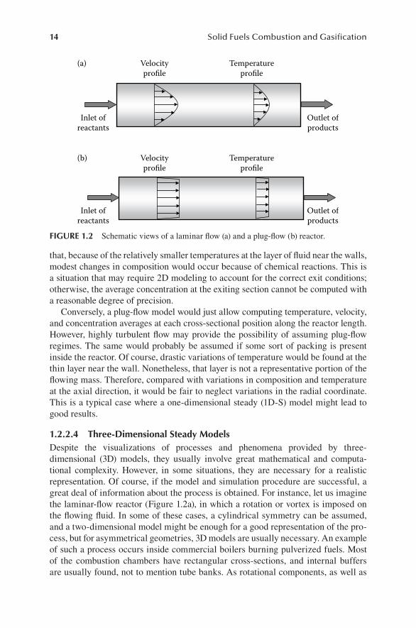
1.2.2.3 Two-Dimensional Steady ModelsTwo-dimensional (2D) models may be necessary in cases where the variations in a second dimension can no longer be neglected. For example, let us imagine the dif-ference between a laminar-flow reactor and a plug-flow reactor. Figure 1.2 illustrates a reactor in which exothermic reactions take place and heat can be exchanged with the environment through the external wall.
In Figure 1.2a, the variations of temperature and composition in the axial direction are added to the variations in the radial direction. It is easy to imagine
TAF-47493_SANTOS-09-0805-C001.indd 13 2/11/10 10:37:42 AM
14 Solid Fuels Combustion and Gasification
that, because of the relatively smaller temperatures at the layer of fluid near the walls, modest changes in composition would occur because of chemical reactions. This is a situation that may require 2D modeling to account for the correct exit conditions; otherwise, the average concentration at the exiting section cannot be computed with a reasonable degree of precision.
Conversely, a plug-flow model would just allow computing temperature, velocity, and concentration averages at each cross-sectional position along the reactor length. However, highly turbulent flow may provide the possibility of assuming plug-flow regimes. The same would probably be assumed if some sort of packing is present inside the reactor. Of course, drastic variations of temperature would be found at the thin layer near the wall. Nonetheless, that layer is not a representative portion of the flowing mass. Therefore, compared with variations in composition and temperature at the axial direction, it would be fair to neglect variations in the radial coordinate. This is a typical case where a one-dimensional steady (1D-S) model might lead to good results.
1.2.2.4 Three-Dimensional Steady ModelsDespite the visualizations of processes and phenomena provided by three- dimensional (3D) models, they usually involve great mathematical and computa-tional complexity. However, in some situations, they are necessary for a realistic representation. Of course, if the model and simulation procedure are successful, a great deal of information about the process is obtained. For instance, let us imagine the laminar-flow reactor (Figure 1.2a), in which a rotation or vortex is imposed on the flowing fluid. In some of these cases, a cylindrical symmetry can be assumed, and a two-dimensional model might be enough for a good representation of the pro-cess, but for asymmetrical geometries, 3D models are usually necessary. An example of such a process occurs inside commercial boilers burning pulverized fuels. Most of the combustion chambers have rectangular cross-sections, and internal buffers are usually found, not to mention tube banks. As rotational components, as well as
Velocityprofile
Temperatureprofile
Velocityprofile
Temperatureprofile
(a)
Outlet ofproducts
Inlet ofreactants
Outlet ofproducts
Inlet ofreactants
(b)
FIGURE 1.2 Schematic views of a laminar flow (a) and a plug-flow (b) reactor.
TAF-47493_SANTOS-09-0805-C001.indd 14 2/11/10 10:37:43 AM
Basic Remarks on Modeling and Simulation 15
strong reversing flows, are present (see Figure 2.10), no symmetry assumption is pos-sible or reasonable. On the other hand, as with everything in life, there is a price to be paid. Let us imagine what would be necessary to set up a complete model. First, the solution of the complete Navier-Stokes or momentum conservation equations should be found. That solution ought to be combined with the equations of energy and mass conservation applied for all chemical species. All these equations must be written for three directions and solved throughout the reactor. Such a system of equa-tions would also require a large number of boundary conditions. Frequently, these conditions involve not just given or known values at interfaces, but also derivatives. Moreover, boundary conditions might require complex geometric descriptions. For example, the injections of reactant streams at the feeding section may be made by such a complex distributing system that even setting the boundary condition would be a very difficult problem. When auxiliary correlations and equations for computa-tions of all parameters are included, the final set of mathematical equations would be significantly large. However, commercially available computational fluid dynam-ics programs have been developed and, in many cases, are capable of solving such problems. Very good results are obtainable, particularly for single-phase systems (gas–gas, for instance). Nonetheless, combustion and gasification of solid fuels still present considerable difficulties, due to large amounts of chemical reactions and pro-cesses combined with directional radiative heat exchanging with interfering media. In most situations, those problems are overwhelming, especially in cases of combus-tion and gasification of pulverized fuel suspensions.
On the other hand, one must ask whether all that information would really neces-sary for good design or optimization of a boiler. Is it essential to predict the details of the velocities, concentration, and temperature profiles in all directions inside the equipment? What is the cost-benefit situation in this case? Departing from a previous one- or two-dimensional model, would this three-dimensional model be capable of decreasing the deviations between simulation and real operation to a point where the time and money invested in it would be justifiable? Is it useful to have a model that generates deviations below the measurement errors? Finally, what would be neces-sary to measure in order to validate such a model against real operations? Along this line, let us ask what sorts of variables are usually possible to measure and what is the degree of precision or certainty of such measurements.
Anyone who has worked at an industrial processing plant knows that is not always easy to measure temperature profiles inside equipment. For instance, if combustion of solid fuel is taking place, the composition, temperature, and velocity profiles of gas streams, as well as those of solids, are extremely difficult to determine with a reasonable degree of confidence and reproducibility. On the other hand, average values of temperatures, pressures, mass flows, and compositions of the entering and leaving streams can be measured. Sometimes, average values of variables at a few points inside the equipment are obtainable. This illustrates how important it is for those involved in the mathematical modeling of a particular type of equipment or process to be very well acquainted with its real operation. That provides valu-able training that could be very useful when one decides to develop a model and its respective simulation program. If this is not possible, it is advisable to keep in contact with the personnel involved in those operations, as well as reading as many
TAF-47493_SANTOS-09-0805-C001.indd 15 2/11/10 10:37:43 AM
16 Solid Fuels Combustion and Gasification
papers or reports as possible related to operations of the industrial or pilot units in question. This will be extremely rewarding when simplification assumptions of a model need to be made.
1.2.3 dynamic or nd-d models
In addition to the above considerations, models might include time as a variable, and they are therefore called dynamic models.
Some processes are designed to impose variations of input values of tempera-ture, concentration, velocity, pressure, etc. Others cannot escape from such situa-tions, such as batch operations of reactors and internal combustion engines. In those instances, dynamic models are required. Those approaches are also useful or neces-sary when control strategies are to be set or for cases where start-up and/or stopping procedures should be monitored or controlled. Safety or economics may demand these approaches.
Most of the considerations described above for steady-state models, regarding the necessity of including more dimensions, are also valid for dynamic models.
1.2.4 Which level To aTTack?
The choice among the various levels of modeling should be based on necessity. Sophistication is not a guarantee of quality. The same is true of extreme simplicity, which could lead to false or naive assumptions about complex phenomena.
The following suggestions may serve as a guide:
1. In case of steady-state or near-steady-state processes, it is advisable to start from a 0D-S model (or from 0D-D model if dynamic). Even if this is not the desired level, it is useful just to verify whether one’s understanding of the overall operation of the equipment or process is coherent or not. Overall mass and energy conservation should always hold.
2. Comparisons between simulation results and the measured values should be made. As we have seen, measurements in industrial operations always present relatively high deviations. Unless more details within the equipment are necessary, the present level might be satisfactory if it has already pro-duced relatively low deviations between simulation and measured values.
3. If simulation results and the measured values do not compare well, at least within a reasonable degree of approximation, the model equations must be revisited. The hypothesis and simplifications should also be reevaluated. Then, the process should start again from Step 2. It is also possible that for reasons already explained, the elected level of attack cannot properly simu-late the process. The reasons for that have been noted above. In addition, there may be deviations produced by the previous level or the need for more detailed information. In any of those circumstances, it might be necessary to add a dimension and time as a variable.
4. Before starting a higher and more sophisticated level of modeling, it is advisable to verify what can be measured in the equipment pilot or the
TAF-47493_SANTOS-09-0805-C001.indd 16 2/11/10 10:37:43 AM
Basic Remarks on Modeling and Simulation 17
industrial unit to be simulated. In addition, one should verify whether the measurements and available information would be enough for the compari-sons against results from that next simulation level. If they are not sufficient, the merit of stepping up the model should receive serious consideration.
1.3 EXERCISES
1.3.1 problem 1.1*
Discuss others possibilities for the design of the reactor and solving the scaling-up contradictions, as described in Example 1.3.
1.3.2 problem 1.2**
Based on the considerations raised in Example 1.4, develop some suggestions for a feasible scaling up of the boiler.
REFERENCES
1. Bird, R.B., Stewart, W.E., and Lightfoot, E.N., Transport Phenomena, John Wiley, New York, 1960.
2. Slattery, J.C., Momentum, Energy, and Mass Transfer in Continua, Robert E. Kriefer, Huntington, NY, 1978.
3. Brodkey, R.S., The Phenomena of Fluid Motions, Dover, New York, 1967. 4. Gidaspow, D., Multiphase Flow and Fluidization, Academic Press, San Diego, CA,
1994.
TAF-47493_SANTOS-09-0805-C001.indd 17 2/11/10 10:37:43 AM

TAF-47493_SANTOS-09-0805-C001.indd 18 2/11/10 10:37:43 AM
References
1 Chapter 1: Basic Remarks onModeling andSimulation
1. Bird, R.B., Stewart, W.E., and Lightfoot, E.N.,Transport Phenomena, John Wiley, New York, 1960.
2. Slattery, J.C., Momentum, Energy, and Mass Transfer inContinua, Robert E. Kriefer, Huntington, NY, 1978.
3. Brodkey, R.S., The Phenomena of Fluid Motions, Dover,New York, 1967.
4. Gidaspow, D., Multiphase Flow and Fluidization, AcademicPress, San Diego, CA, 1994.
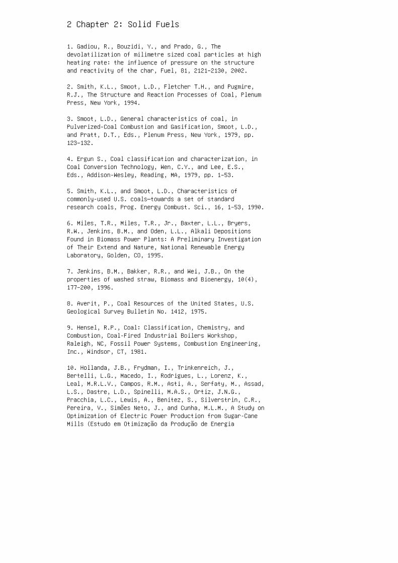
2 Chapter 2: Solid Fuels
1. Gadiou, R., Bouzidi, Y., and Prado, G., Thedevolatilization of milimetre sized coal particles at highheating rate: the influence of pressure on the structureand reactivity of the char, Fuel, 81, 2121–2130, 2002.
2. Smith, K.L., Smoot, L.D., Fletcher T.H., and Pugmire,R.J., The Structure and Reaction Processes of Coal, PlenumPress, New York, 1994.
3. Smoot, L.D., General characteristics of coal, inPulverized-Coal Combustion and Gasification, Smoot, L.D.,and Pratt, D.T., Eds., Plenum Press, New York, 1979, pp.123–132.
4. Ergun S., Coal classification and characterization, inCoal Conversion Technology, Wen, C.Y., and Lee, E.S.,Eds., Addison-Wesley, Reading, MA, 1979, pp. 1–53.
5. Smith, K.L., and Smoot, L.D., Characteristics ofcommonly-used U.S. coals—towards a set of standardresearch coals, Prog. Energy Combust. Sci., 16, 1–53, 1990.
6. Miles, T.R., Miles, T.R., Jr., Baxter, L.L., Bryers,R.W., Jenkins, B.M., and Oden, L.L., Alkali DepositionsFound in Biomass Power Plants: A Preliminary Investigationof Their Extend and Nature, National Renewable EnergyLaboratory, Golden, CO, 1995.
7. Jenkins, B.M., Bakker, R.R., and Wei, J.B., On theproperties of washed straw, Biomass and Bioenergy, 10(4),177–200, 1996.
8. Averit, P., Coal Resources of the United States, U.S.Geological Survey Bulletin No. 1412, 1975.
9. Hensel, R.P., Coal: Classification, Chemistry, andCombustion, Coal-Fired Industrial Boilers Workshop,Raleigh, NC, Fossil Power Systems, Combustion Engineering,Inc., Windsor, CT, 1981.
10. Hollanda, J.B., Frydman, I., Trinkenreich, J.,Bertelli, L.G., Macedo, I., Rodrigues, L., Lorenz, K.,Leal, M.R.L.V., Campos, R.M., Asti, A., Serfaty, M., Assad,L.S., Dastre, L.D., Spinelli, M.A.S., Ortiz, J.N.G.,Pracchia, L.C., Lewis, A., Benitez, S., Silverstrin, C.R.,Pereira, V., Simões Neto, J., and Cunha, M.L.M., A Study onOptimization of Electric Power Production from Sugar-CaneMills (Estudo em Otimização da Produção de Energia
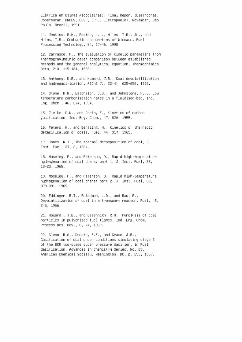
Elétrica em Usinas Alcooleiras), Final Report (Eletrobras,Copersucar, BNDES, CESP, CPFL, Eletropaulo), November, SaoPaulo, Brazil, 1991.
11. Jenkins, B.M., Baxter, L.L., Miles, T.R., Jr., andMiles, T.R., Combustion properties of biomass, FuelProcessing Technology, 54, 17–46, 1998.
12. Carrasco, F., The evaluation of kinetic parameters fromthermogravimetric data: comparison between establishedmethods and the general analytical equation, ThermochimicaActa, 213, 115–134, 1993.
13. Anthony, D.B., and Howard, J.B., Coal devolatilizationand hydrogasification, AIChE J., 22(4), 625–656, 1976.
14. Stone, H.N., Batchelor, J.D., and Johnstone, H.F., Lowtemperature carbonisation rates in a fluidised-bed, Ind.Eng. Chem., 46, 274, 1954.
15. Zielke, C.W., and Gorin, E., Kinetics of carbongasification, Ind. Eng. Chem., 47, 820, 1955.
16. Peters, W., and Bertling, H., Kinetics of the rapiddegasification of coals, Fuel, 44, 317, 1965.
17. Jones, W.I., The thermal decomposition of coal, J.Inst. Fuel, 37, 3, 1964.
18. Moseley, F., and Paterson, D., Rapid high-temperaturehydrogenation of coal chars: part 1, J. Inst. Fuel, 38,13–23, 1965.
19. Moseley, F., and Paterson, D., Rapid high-temperaturehydrogenation of coal chars: part 2, J. Inst. Fuel, 38,378–391, 1965.
20. Eddinger, R.T., Friedman, L.D., and Rau, E.,Devolatilization of coal in a transport reactor, Fuel, 45,245, 1966.
21. Howard., J.B., and Essenhigh, R.H., Pyrolysis of coalparticles in pulverized fuel flames, Ind. Eng. Chem.Process Des. Dev., 6, 74, 1967.
22. Glenn, R.A., Donath, E.E., and Grace, J.R.,Gasification of coal under conditions simulating stage 2of the BCR two-stage super pressure gasifier, in FuelGasification, Advances in Chemistry Series, No. 69,American Chemical Society, Washington, DC, p. 253, 1967.
23. Kimber, G.M., and Gray, M.D., Rapid devolatilization ofsmall coal particles, Combustion and Flame, 11, 360, 1967.
24. Kimber, G.M., and Gray, M.D., Measurements of ThermalDecomposition of Low and High Rank Non-Swelling Coals atM.H.D. Temperatures, British Coal Utilization ResearchAssociation, Document No. MHD 32, 1967.
25. Badzioch, S., and Hawksley, P.G.W., Kinetics of thermaldecomposition of pulverized coal particles, Ind. Eng.Chem. Process Des. Dev., 9, 521, 1970.
26. Belt, R.J., Wilson, J.S., and Sebastian, J.J.S.,Continuous rapid carbonisation of powdered coal byentrainment and response surface analysis of data, Fuel,50, 381, 1971.
27. Belt, R.J., and Roder, M.M., Low-sulfur fuel bypressurized entrainment carbonisation of coal, AmericanChemical Society, Div. of Fuel Chem. Preprints, 17(2), 82,1972.
28. Coates, R.L., Chen, C.L., and Pope, B.J., Coaldevolatilization in a low pressure, low residence timeentrained flow reactor, in Coal Gasification, Advances inChemistry Series, No. 131, American Chemical Society,Washington, DC, 1974, p. 92.
29. Johnson, J.L., Gasification of Montana lignite inhydrogen and in helium during initial reaction stages,American Chemical Society, Div. of Fuel Chem. Preprints,20(3), 61, 1975.
30. Shapatina, E.A., Kalyuzhnyi, V.A., and Chukhanov, Z.F.,Technological utilization of fuel for energy, 1: Thermaltreatments of fuels, 1960. (Paper reviewed by Badzoich, S.,British Coal Utilization Research Association MonthlyBulletin, 25, 285, 1961.)
31. Moseley, F., and Paterson, D., Rapid high-temperaturehydrogenation of bituminous coal, J. Inst. Fuel, 40, 523,1967.
32. Feldmann, H.F., Simons, W.H., Mimn, J.A., and Hitshue,R.W., Reaction model of bituminous coal hydrogasificationin a dilute phase, American Chemical Society, Div. of FuelChem. Preprints, 14(4), 1, 1970.
33. Yu, Q., Brage, C., Chen, G., and Sjöström, K.,
Temperature impact on the formation of tar from biomasspyrolysis in a free-fall reactor, J. Analytical and AppliedPyrolysis, 40–41, 481–489, 1997.
34. Tsuge, S., Analytical pyrolysis—past, present andfuture, J. Analytical and Applied Pyrolysis, 32, 1–6,1995.
35. Bridgwater, A.V., and Peacocke, G.V.C., Fast pyrolysisprocesses for biomass, Renewable and Sustainable EnergyReviews, 4, 1–73, 2000.
36. Moran, M.J., and Shapiro, H.N., Fundamentals ofThermodynamics, 3rd Ed., John Wiley, New York, 1996.
37. van Wylen, G.J., and Sonntag R.E., Fundamentals ofClassical Thermodynamics, John Wiley, New York, 1973.
38. Kestin J., A Course in Thermodynamics, Vols. I and II,Hemisphere, New York, 1979.
39. van Krevelen, D.W., and Schuyer, J., Coal Sciences,Elsevier, Amsterdam, 1957.
40. Badzioch, S., Rapid and controlled decomposition ofcoal, British Coal Utilization Research AssociationMonthly Bulletin, 25(8), 285, 1961.
41. Pitt, G.J., The kinetics of the evolution of volatileproducts from coal, Fuel, 41, 267, 1962.
42. Loison, R., and Chauvin, R., Pyrolyse rapide ducharbon, Chimie et Industrie, 91, 3, 269–274, 1964.
43. Gregory, D.R., and Littlejohn, R.F., Survey ofnumerical data on the thermal decomposition of coal, CoalUtilization Res. Assoc. Monthly Bull., 29(6), 173, 1965.
44. Eddinger, R.T., Friedman, L.D., and Rau E.,Devolatilization of coal in a transport reactor, Fuel, 45,245, 1966.
45. Wiser, W.H., Hill G.R., and Kertamus, N.J., Kineticstudy of the pyrolysis of a highvolatile bituminous coal,Ind. Eng. Chem. Process Des. Dev., 6, 133, 1967.
46. Roberts, A.F., A review of kinetics data for thepyrolysis of wood and related substances, Combustion andFlame, 14, 261–272, 1970.
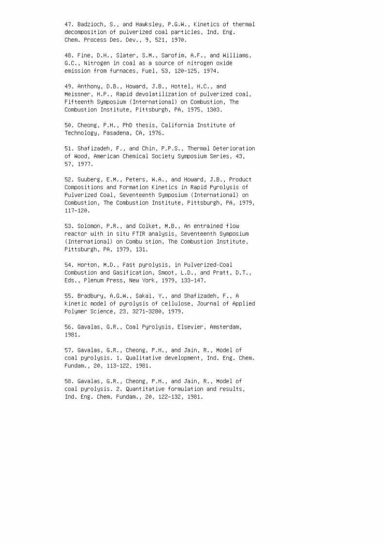
47. Badzioch, S., and Hawksley, P.G.W., Kinetics of thermaldecomposition of pulverized coal particles, Ind. Eng.Chem. Process Des. Dev., 9, 521, 1970.
48. Fine, D.H., Slater, S.M., Sarofim, A.F., and Williams,G.C., Nitrogen in coal as a source of nitrogen oxideemission from furnaces, Fuel, 53, 120–125, 1974.
49. Anthony, D.B., Howard, J.B., Hottel, H.C., andMeissner, H.P., Rapid devolatilization of pulverized coal,Fifteenth Symposium (International) on Combustion, TheCombustion Institute, Pittsburgh, PA, 1975, 1303.
50. Cheong, P.H., PhD thesis, California Institute ofTechnology, Pasadena, CA, 1976.
51. Shafizadeh, F., and Chin, P.P.S., Thermal Deteriorationof Wood, American Chemical Society Symposium Series, 43,57, 1977.
52. Suuberg, E.M., Peters, W.A., and Howard, J.B., ProductCompositions and Formation Kinetics in Rapid Pyrolysis ofPulverized Coal, Seventeenth Symposium (International) onCombustion, The Combustion Institute, Pittsburgh, PA, 1979,117–120.
53. Solomon, P.R., and Colket, M.B., An entrained flowreactor with in situ FTIR analysis, Seventeenth Symposium(International) on Combu stion, The Combustion Institute,Pittsburgh, PA, 1979, 131.
54. Horton, M.D., Fast pyrolysis, in Pulverized-CoalCombustion and Gasification, Smoot, L.D., and Pratt, D.T.,Eds., Plenum Press, New York, 1979, 133–147.
55. Bradbury, A.G.W., Sakai, Y., and Shafizadeh, F., Akinetic model of pyrolysis of cellulose, Journal of AppliedPolymer Science, 23, 3271–3280, 1979.
56. Gavalas, G.R., Coal Pyrolysis, Elsevier, Amsterdam,1981.
57. Gavalas, G.R., Cheong, P.H., and Jain, R., Model ofcoal pyrolysis. 1. Qualitative development, Ind. Eng. Chem.Fundam., 20, 113–122, 1981.
58. Gavalas, G.R., Cheong, P.H., and Jain, R., Model ofcoal pyrolysis. 2. Quantitative formulation and results,Ind. Eng. Chem. Fundam., 20, 122–132, 1981.
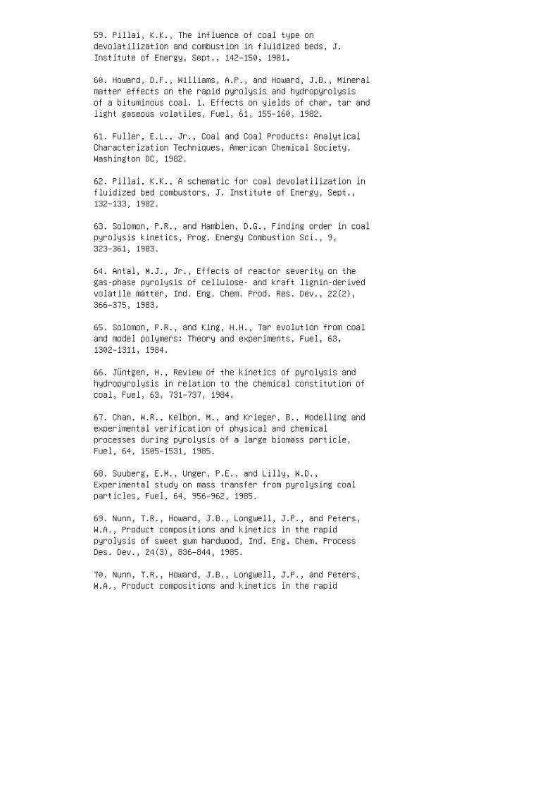
59. Pillai, K.K., The influence of coal type ondevolatilization and combustion in fluidized beds, J.Institute of Energy, Sept., 142–150, 1981.
60. Howard, D.F., Williams, A.P., and Howard, J.B., Mineralmatter effects on the rapid pyrolysis and hydropyrolysisof a bituminous coal. 1. Effects on yields of char, tar andlight gaseous volatiles, Fuel, 61, 155–160, 1982.
61. Fuller, E.L., Jr., Coal and Coal Products: AnalyticalCharacterization Techniques, American Chemical Society,Washington DC, 1982.
62. Pillai, K.K., A schematic for coal devolatilization influidized bed combustors, J. Institute of Energy, Sept.,132–133, 1982.
63. Solomon, P.R., and Hamblen, D.G., Finding order in coalpyrolysis kinetics, Prog. Energy Combustion Sci., 9,323–361, 1983.
64. Antal, M.J., Jr., Effects of reactor severity on thegas-phase pyrolysis of cellulose- and kraft lignin-derivedvolatile matter, Ind. Eng. Chem. Prod. Res. Dev., 22(2),366–375, 1983.
65. Solomon, P.R., and King, H.H., Tar evolution from coaland model polymers: Theory and experiments, Fuel, 63,1302–1311, 1984.
66. Jüntgen, H., Review of the kinetics of pyrolysis andhydropyrolysis in relation to the chemical constitution ofcoal, Fuel, 63, 731–737, 1984.
67. Chan, W.R., Kelbon, M., and Krieger, B., Modelling andexperimental verification of physical and chemicalprocesses during pyrolysis of a large biomass particle,Fuel, 64, 1505–1531, 1985.
68. Suuberg, E.M., Unger, P.E., and Lilly, W.D.,Experimental study on mass transfer from pyrolysing coalparticles, Fuel, 64, 956–962, 1985.
69. Nunn, T.R., Howard, J.B., Longwell, J.P., and Peters,W.A., Product compositions and kinetics in the rapidpyrolysis of sweet gum hardwood, Ind. Eng. Chem. ProcessDes. Dev., 24(3), 836–844, 1985.
70. Nunn, T.R., Howard, J.B., Longwell, J.P., and Peters,W.A., Product compositions and kinetics in the rapid
pyrolysis of milled wood lignin, Ind. Eng. Chem. ProcessDes. Dev., 24(3), 844–852, 1985.
71. Suuberg, E.M., Lee, D., and Larsen, J.W., Temperaturedependence of crosslinking processes in pyrolysis of coal,Fuel, 64, 1668–1671, 1985.
72. Simmons, G.M., and Gentry, M., Kinetic formation of CO,CO 2 , H 2 , and light hydrocarbon gases from cellulosepyrolysis, J. Analytical and Applied Pyrolysis, 10,129–138, 1986.
73. Squir, K.R., Solomon, P.R., Carangelo, R.M., andDiTaranto, M.B., Tar evolution from coal and modelpolymers: 2. The effects of aromatic ring sizes anddonatable hydrogens, Fuel, 65, 833–843, 1986.
74. Solomon, P.R., Serio, M.A., Carangelo, R.M., andMarkham, J.R., Very rapid coal pyrolysis, Fuel, 65,182–193, 1986.
75. Fong, W.S., Peters, W.A., and Howard, J.B., Kinetics ofgeneration and destruction of pyridine extractables in arapidly pyrolysing bituminous coal, Fuel, 65, 251–254,1986.
76. Solomon, P.R., Beér, J.M., and Longwell, J.P.,Fundamentals of coal conversion and relation to coalpyrolysis, Energy, 12(8–9), 837–862, 1987.
77. Serio, M.A., Hamblen, D.G., Markham, J.R., and Solomon,P.R., Kinetics of volatile evolution in coal pyrolysis:experiment and theory, Energy & Fuels, 1, 138–152, 1987.
78. Xu, W.C., and Tomita, A., Effect of coal type on theflash pyrolysis of various coals, Fuel, 66, 627–631, 1987.
79. Niksa, S., and Kerstein, A.R., On the role ofmacromolecular configuration in rapid coaldevolatilization, Fuel, 66, 1389–1399, 1987.
80. Niksa, S., Rapid coal devolatilization as anequilibrium flash distillation, AIChE J., 34, 790–802,1988.
81. Solomon, P.R., Hamblen, D.G., Carangelo, R.M., Serio,M.A., and Deshpande, G.V., General model of coaldevolatilization, Energy & Fuels, 2, 405–422, 1988.
82. Solomon, P.R., Hamblen, D.G., Carangelo, R.M., Serio,
M.A., and Deshpande, G.V., Models of tar formation duringcoal devolatilization, Combustion and Flame, 71, 137– 146,1988.
83. Alves, S.S., and Figueiredo, J.L., Pyrolysis kineticsof lignocellulosic materials by multistage isothermalthermogravimetry, J. Analytical and Applied Pyrolysis, 13,123–134, 1988.
84. Bruinsma, O.S.L., Geerstsma, R.S., Bank, P., andMoulijin, J.A., Gas phase pyrolysis of coal-relatedaromatic compounds in a coiled tube flow reactor: 1.Benzene and derivatives, Fuel, 67, 327–333, 1988.
85. Uden, A.G., Berruti, F., and Scott, D.S., A kineticmodel for the production of liquids from the flashpyrolysis of biomass, Chem. Eng. Comm., 65, 207–221, 1988.
86. Boroson, M.L., Howard, J.B., Longwell, J.P., andPeters, W.A., Product yields and kinetics from the vaporphase cracking of wood pyrolysis tars, AIChE J., 35(1),120–128, 1989.
87. Yun, Y., Maswadeh, W., Meuzellaar, H.L.C., Simmleit,N., and Schulten, H.R., Estimation of coaldevolatilization modelling parameters fromthermogravimetric and time-resolved soft ionisation massspectrometric data, American Chemical Society, Div. FuelChem., 34(4), 1308–1316, 1989.
88. Solomon, P.R., Best, P.E., Yu, Z.Z., and Deshpande,G.V., A macromolecular network model for coal fluidity,Preprint, American Chemical Society, Div. Fuel Chem.,34(3), 895–906, 1989.
89. Grant, D.M., Pugmire, R.J., Fletcher, T.H., andKerstein, A.R., Chemical model of coal devolatilizationusing percolation lattice statistics, Energy & Fuels, 3,175–186, 1989.
90. Solomon, P.R., Hamblen, D.G., Yu, Z.Z., and Serio,M.A., Network models of coal thermal decomposition, Fuel,69, 754–763, 1990.
91. Solomon, P.R., Hamblen, D.G., Serio, M.A., Smoot, L.D.,and Brewster, B.S., Measurement and Modeling of AdvancedCoal Conversion Process, Fourteenth Quaterly Report forU.S. Department of Energy, Contract No. DE-AC21-86MC23075,Morgantown Energy Technology Center, Morgantown, WV,Advanced Fuel Research, Inc., East Hartford, CT, Brigham
Young University, Provo, UT, 1990.
92. Fletcher, T.H., Kerstein, A.R., Pugmire, R.J., andGrant, D.M., Chemical percolation model fordevolatilization. II: Temperature and heating rate effectson product yields, Energy & Fuels, 3, 54–60, 1990.
93. Niksa, S., Flashchain theory for rapid coaldevolatilization kinetics. 1: Formulation, Energy & Fuels,5, 647–665, 1991.
94. Niksa, S., Flashchain theory for rapid coaldevolatilization kinetics. 2: Impact of operating behaviorof various coals; 3: Modeling the behavior of variouscoals, Energy & Fuels, 5, 665–683, 1991.
95. Fletcher, T.H., Kerstein, A.R., Pugmire, R.J., andGrant, D.M., A chemical percolation model fordevolatilization. III: Direct use of 13 C NMR data topredict effects of coal type, Energy & Fuels, 6, 414–431,1992.
96. EPRI, Chemical and Physical Characteristics of TarSamples from Selected Manufactured Gas Plant Sites. ProjectNo. 2879-12. Final report. Atlantic Environmental ServicesInc., Colchester, CT, 1993.
97. Garcia, A.N., Estudio Termoquimico y Cinetico de laPirolisis de Residuos Solidos Urbanos, PhD thesis,University of Alicante, Alicante, Spain, 1993.
98. Solomon, P.R., Fletcher, T.H., and Pugmire, R.J.,Progress in coal pyrolysis, Fuel, 72, 587–597, 1993.
99. Font, R., Marcilla, A., Devesa, J., and Verdu, E.,Kinetic study of the flash pyrolysis of almond shells in afluidized bed reactor at high temperatures, J. Analyticaland Applied Pyrolysis, 27(2), 245–273, 1993.
100. Kocaefe, D., Charette, A., and Catonguay, L., Greencoke pyrolysis; investigation of simultaneous changes ingas and solid phases, Fuel, 74(6), 791–799, 1995.
101. Font, R., and Williams, P.T., Pyrolysis of biomasswith constant heating rate: influence of the operatingconditions, Thermochimica Acta, 205, 109–123, 1995.
102. Brage, C., Yu, Q., and Sjöström, K., Characteristicsof evolution of tar from wood pyrolysis in a fixed-bedreactor, Fuel, 75(2), 213–219, 1996.
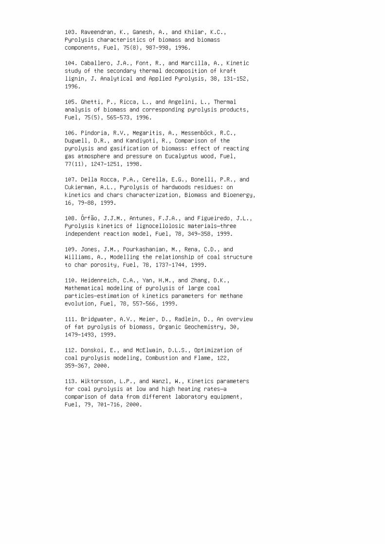
103. Raveendran, K., Ganesh, A., and Khilar, K.C.,Pyrolysis characteristics of biomass and biomasscomponents, Fuel, 75(8), 987–998, 1996.
104. Caballero, J.A., Font, R., and Marcilla, A., Kineticstudy of the secondary thermal decomposition of kraftlignin, J. Analytical and Applied Pyrolysis, 38, 131–152,1996.
105. Ghetti, P., Ricca, L., and Angelini, L., Thermalanalysis of biomass and corresponding pyrolysis products,Fuel, 75(5), 565–573, 1996.
106. Pindoria, R.V., Megaritis, A., Messenböck, R.C.,Dugwell, D.R., and Kandiyoti, R., Comparison of thepyrolysis and gasification of biomass: effect of reactinggas atmosphere and pressure on Eucalyptus wood, Fuel,77(11), 1247–1251, 1998.
107. Della Rocca, P.A., Cerella, E.G., Bonelli, P.R., andCukierman, A.L., Pyrolysis of hardwoods residues: onkinetics and chars characterization, Biomass and Bioenergy,16, 79–88, 1999.
108. Órfão, J.J.M., Antunes, F.J.A., and Figueiredo, J.L.,Pyrolysis kinetics of lignocellolosic materials—threeindependent reaction model, Fuel, 78, 349–358, 1999.
109. Jones, J.M., Pourkashanian, M., Rena, C.D., andWilliams, A., Modelling the relationship of coal structureto char porosity, Fuel, 78, 1737–1744, 1999.
110. Heidenreich, C.A., Yan, H.M., and Zhang, D.K.,Mathematical modeling of pyrolysis of large coalparticles—estimation of kinetics parameters for methaneevolution, Fuel, 78, 557–566, 1999.
111. Bridgwater, A.V., Meier, D., Radlein, D., An overviewof fat pyrolysis of biomass, Organic Geochemistry, 30,1479–1493, 1999.
112. Donskoi, E., and McElwain, D.L.S., Optimization ofcoal pyrolysis modeling, Combustion and Flame, 122,359–367, 2000.
113. Wiktorsson, L.P., and Wanzl, W., Kinetics parametersfor coal pyrolysis at low and high heating rates—acomparison of data from different laboratory equipment,Fuel, 79, 701–716, 2000.
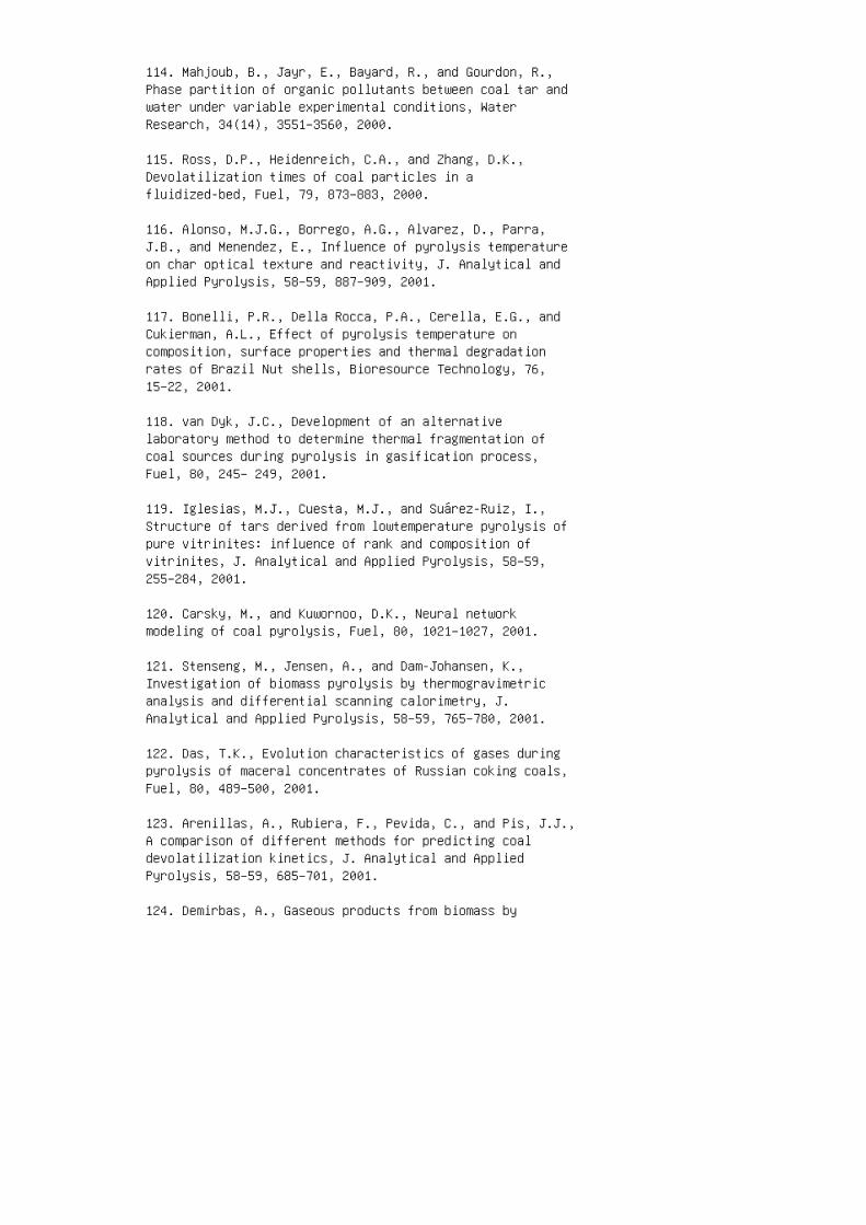
114. Mahjoub, B., Jayr, E., Bayard, R., and Gourdon, R.,Phase partition of organic pollutants between coal tar andwater under variable experimental conditions, WaterResearch, 34(14), 3551–3560, 2000.
115. Ross, D.P., Heidenreich, C.A., and Zhang, D.K.,Devolatilization times of coal particles in afluidized-bed, Fuel, 79, 873–883, 2000.
116. Alonso, M.J.G., Borrego, A.G., Alvarez, D., Parra,J.B., and Menendez, E., Influence of pyrolysis temperatureon char optical texture and reactivity, J. Analytical andApplied Pyrolysis, 58–59, 887–909, 2001.
117. Bonelli, P.R., Della Rocca, P.A., Cerella, E.G., andCukierman, A.L., Effect of pyrolysis temperature oncomposition, surface properties and thermal degradationrates of Brazil Nut shells, Bioresource Technology, 76,15–22, 2001.
118. van Dyk, J.C., Development of an alternativelaboratory method to determine thermal fragmentation ofcoal sources during pyrolysis in gasification process,Fuel, 80, 245– 249, 2001.
119. Iglesias, M.J., Cuesta, M.J., and Suárez-Ruiz, I.,Structure of tars derived from lowtemperature pyrolysis ofpure vitrinites: influence of rank and composition ofvitrinites, J. Analytical and Applied Pyrolysis, 58–59,255–284, 2001.
120. Carsky, M., and Kuwornoo, D.K., Neural networkmodeling of coal pyrolysis, Fuel, 80, 1021–1027, 2001.
121. Stenseng, M., Jensen, A., and Dam-Johansen, K.,Investigation of biomass pyrolysis by thermogravimetricanalysis and differential scanning calorimetry, J.Analytical and Applied Pyrolysis, 58–59, 765–780, 2001.
122. Das, T.K., Evolution characteristics of gases duringpyrolysis of maceral concentrates of Russian coking coals,Fuel, 80, 489–500, 2001.
123. Arenillas, A., Rubiera, F., Pevida, C., and Pis, J.J.,A comparison of different methods for predicting coaldevolatilization kinetics, J. Analytical and AppliedPyrolysis, 58–59, 685–701, 2001.
124. Demirbas, A., Gaseous products from biomass by

pyrolysis and gasification: effects of catalyst onhydrogen yield, Energy Conservation and Management, 43,897–909, 2002.
125. Jüntgen, H., Coal characterization in relation to coalcombustion, in Fundamentals of the Physical-Chemistry ofPulverized Coal Combustion, Lahaye, J., and Prado, G.,Eds., Martinus Nijhoff, Dordrecht, Netherlands, 1987, pp.4–59.
126. Dryden, I.G.C., Chemistry of coal and its relation tocoal carbonization, J. Inst. Fuel, 30, 193, 1957.
126. Jones, W.I., The thermal decomposition of coal, J.Inst. Fuel, 37, 3, 1964.
128. Peters, W., and Bertling, H., Kinetics of the rapiddegasification of coals, Fuel, 44, 317, 1965.
3 Chapter 3: Equipment and Processes
1. Wen, C.Y., and Lee, E.S., Coal Conversion Technology,Addison-Wesley, Reading, MA, 1979.
2. Perry, J.H., Green, D.W., and Maloney, J.O., in Perry’sChemical Engineers Handbook, 7th ed., McGraw-Hill, NewYork, 1997.
3. Smoot, L.D., and Pratt, D.T., Pulverized-Coal Combustionand Gasification, Plenum Press, New York, 1979.
4. Smoot, L.D., and Smith, P.J., Coal Combustion andGasification, Plenum Press, New York, 1985.
5. Williams, A., Backreedy, R., Habib, R., Jones, J.M., andPourkashanian, M., Modelling coal combustion: the currentposition, Fuel, 81, 605–618, 2002.
6. Kunii, D., and Levenspiel, O., Fluidization Engineering,2nd Ed., John Wiley, New York, 1991.
7. Geldart, D., Gas Fluidization Technology, John Wiley,Chichester, United Kingdom, 1986.
8. Ergun, S., Fluid ow through packed columns, ChemicalEngineering Progress, 48, 91–94, 1952.
9. Allen, T., Particle Size Measurement, 3rd ed., Chapmanand Hall, London, 1981.
10. Davidson, J.F., and Harrison, D., Fluidized Particles,Cambridge University Press, Cambridge, United Kingdom,1963.
11. Yang, W.C., Fluidization Solids Handling andProcessing, Noyes, Westwood, NJ, 1999.
12. Hobbs, M.L., Radulovic, P.T., and Smoot, L.D.,Combustion and gasication of coals in xed-beds, Prog.Energy Combust. Sci., 19, 505–556, 1993.
13. de Souza-Santos, M.L., Modelling and Simulation ofFluidized-Bed Boilers and Gasifiers for CarbonaceousSolids, Ph.D. thesis, University of Shefeld, UnitedKingdom, 1987.
14. de Souza-Santos, M.L., Comprehensive modelling andsimulation of uidized-bed boilers and gasiers, Fuel, 68,1507–1521, 1989.
15. de Souza-Santos, M.L., Application of comprehensivesimulation to pressurized bed hydroretorting of shale,Fuel, 73, 1459–1465, 1994.
16. de Souza-Santos, M.L., A new version of CSFB,comprehensive simulator for uidized bed equipment, Fuel,86, 12–13, 1684–1709, 2007.
17. de Souza-Santos, M.L., Solid Fuels Combustion andGasification: Modeling, Simulation, and EquipmentOperation, Marcel Dekker (CRC Press), New York, 2004.
18. Salo, K., Jartunen, M., and Asplund, D., Production ofFuel with Gasication of Peat in Fixed Bed, Peat as anEnergy Alternative, Arlington, Virginia, December 1–3,1980.
19. Ergun, S., Coal Classication and Characterization, inCoal Conversion Technology, Wen, C.Y., and Lee, E.S.,Eds., Addison-Wesley, Reading, MA, 1979, pp. 1–53.
20. Wen, C.Y., and Chen, L.H., Fluidized bed freeboardphenomena: entrainment and elutriation, AIChE J., 28, 117,1982.
21. de Souza-Santos, M.L., A study on pressurizeduidized-bed gasication of biomass through the use ofcomprehensive simulation. Proc. Fourth InternationalConference on Technologies and Combustion for a CleanEnvironment, Lisbon, Portugal, 7–10 July, 1997, paper25.2, Vol. II, 7–13.
22. de Souza-Santos, M.L., CSFB applied to uidized-bedgasication of special fuels, Fuel, 88, 826–833, 2009.
23. de Souza-Santos, M.L., Application of comprehensivesimulation of uidized-bed reactors to the pressurizedgasication of biomass, Journal of the Brazilian Society ofMechanical Sciences, XVI(4), 376–383, 1994.
24. de Souza-Santos, M.L., Search for favorable conditionsof atmospheric uidized-bed gasication of sugar-canebagasse through comprehensive simulation, Proc. 14thBrazilian Congress of Mechanical Engineering , Bauru, SãoPaulo, Brazil, December 8–12, 1997.
25. de Souza-Santos, M.L., Search for favorable conditionsof pressurized uidized-bed gasication of sugar-canebagasse through comprehensive simulation, Proc. 14th
Brazilian Congress of Mechanical Engineering , Bauru, SãoPaulo, Brazil, December 8–12, 1997.
26. Grace, J.R., Gas Fluidization Course, Center forProfessional Advancement, East Brunswick, New Jersey,1984.
27. Knowlton, T.M., and Hirsan, I., L-valves characterizedfor solids ow, Hydrocarbon Processing, 57, 149–156, 1978.
28. Knowlton, T.M., Hirsan, I., and Leung, L.S., The effectof aeration tap location on the performance of a J-valve,in Fluidization, Davidson, J.F., and Keairns, D.L., Eds.,Cambridge University Press, Cambridge, United Kingdom,1978.
29. Smith, D., Anderson, J.S., Atkin, J.A.R., Bekofske,K.L., Brown, R.A., Cavanna, J., Christianson, S., Failing,K.-H., Friedman, A.M., Glenn, J.C., Hebden, D.J.,Mainhardt, P.J., Schuetz, M., Wheeldon, J.M., and Carls,E.L., IEA Grimethorpe 2m × 2m pressurized uidized bedcombustion project—experimental performance results andfuture plans, in Open Literature Publications: GrimethorpePressurized Fluidized Bed Combustion Project, NCB (IEAGrimethorpe), Grimethorpe, Barnsley, United Kingdom, 1985.
30. McKendrick, D., IEA Grimethorpe 2m x 2m pressuriseduidised bed combustor— review of performance, results andengineering developments, in Open Literature Publications;Grimethorpe Pressurized Fluidized Bed Combustion Project,NCB (IEA Grimethorpe), Grimethorpe, Barnsley, UnitedKingdom, 1985.
31. Hollanda, J.B., Frydman, I., Trinkenreich, J.,Bertelli, L.G., Macedo, I., Rodrigues, L., Lorenz, K.,Leal, M.R.L.V., Campos, R.M., Asti, A., Serfaty, M., Assad,L.S., Dastre, L.D., Spinelli, M.A.S., Ortiz, J.N.G.,Pracchia, L.C., Lewis, A., Benitez, S., Silverstrin, C.R.,Pereira, V., Simões Neto, J., and Cunha, M.L.M., A study onoptimization of electric power production from sugar-canemills (Estudo em otimização da produção de energiaelétrica em usinas alcooleiras), Final Report, Eletrobras,Copersucar, BNDES, CESP, CPFL, Eletropaulo, Sao Paulo,Brazil, 1991.
32. de Souza-Santos, M.L., A study on pressurizeduidized-bed gasication of biomass through the use ofcomprehensive simulation, in Combustion Technologies for aClean Environment, Gordon and Breach, Amsterdam,Netherlands, 1998.
33. Larson, E.D., and Williams, R.H., Biomass-redsteam-injected gas turbine cogeneration, Proc. of the ASMECogen-Turbo Symposium , Montreux, Switzerland, August 30 toSeptember 1, 1988.
34. Williams, R.H., Biomass gasier/gas turbine power andgreenhouse warming, IEA/ OECD Expert Seminar on EnergyTechnologies for Reducing Emissions of Greenhouse Gases,OECD Headquarters, Paris, April 12–14, 1989.
35. Ogden, J., Williams, R.H., and Fulmer, M.E.,Cogeneration applications of biomass gasier/gas turbinetechnologies in the cane sugar and alcohol industries,Proc. Conference on Energy and Environment in the 21stCentury, Massachusetts Institute of Technology, Cambridge,MA, March 26–28, 1990.
36. Consonni, S., and Larson, E.D.,Biomass-gasier/aeroderivative gas turbine combinedcycles; Part A: Technologies and performance modelingcogen, Proc. Turbo Power’94, The American Society ofMechanical Engineers’ 8th Congress & Exposition on GasTurbines in Cogeneration and Utility, Industrial andIndependent Power Generation, Portland, OR, October 25–27,1994.
37. Consonni, S., and Larson, E.D.,Biomass-gasier/aeroderivative gas turbine combinedcycles; Part B: Performance calculations and economicassessment cogen, Proc. Turbo Power’94, The AmericanSociety of Mechanical Engineers’ 8th Congress & Expositionon Gas Turbines in Cogeneration and Utility, Industrial andIndependent Power Generation, Portland, OR, October 25–27,1994.
38. Larson, E.D., and Hughes, W.M., Performance modeling ofaeroderivative steam-injected gas turbine and combinedcycles fueled from xed or uid-bed biomass gasiers,Proc. Turbo Expo ’96, 41st ASME Gas Turbine and AeroengineCongress, Birmingham, United Kingdom, June 10–13, 1996.
39. Larson, E.D., and Marrison, C.I., Economic scales forrst-generation biomass-gasiers turbine combined cyclesfueled from energy plantations, Proc. Turbo Expo ’96, The41st ASME Gas Turbine and Aeroengine Congress, Birmingham,United Kingdom, June10–13, 1996.
40. de Souza-Santos, M.L., A feasibility study of analternative power generation system based on biomass
gasication/gas turbine concept, Fuel, 78, 529–538, 1999.
41. Brown, M.G., Baker, E.G., and Mudge, L.K., Evaluationof process for removal of particulates, tars, and oils frombiomass gasier product gases, in Energy from Biomass andWastes , Klass, D.L., Ed., Elsevier Applied Science,London, 1987, pp. 655–77.
42. Cohn, A., Direct coal red gas turbines, WorkshopProceedings of Electric Power Research Institute , ReportAP3939 SR, Palo Alto, CA, 1985.
43. Meadowcroft, D.B., and Stringer, J., Corrosion incoal-red gas turbines, Materials Science and Technology,3, 562–570, 1987.
44. Horner, M.W., Simplied IGCC with hot fuel gascombustion (85-JPGC-GT-13), ASME/ IEEE Power GenerationConference, Milwaukee, WI, 1985.
45. Scandrett, L.A., and Clift, R., The thermodynamics ofalkali removal from coal-derived gases, Journal of theInstitute of Energy, 57, 391–97, December, 1984.
46. Spacil, H.S., and Luthura, K.L., Journal of theElectrochemical Society, 129(9), 2119– 2126, 1982.
47. Lehtovaara, A., and Mojtahedi, W., Ceramic-lterbehavior in gasication, Bioresource Technology, 46,113–118, 1993.
48. Pedersen, K., Malmgreem-Hansen, B., and Petersen, P.,Catalytic cleaning of hot gas ltration. biomass forenergy and the environment, Proc. 9th European BioenergyConference , Chartier, P., Ferrero, G.L., Henius, U.M.,Hultberg, S., Sachau, J., and Wiinbland, M., Eds.,Pergamon Press, 1996, pp. 1312–1317.
49. Barisic V., and Zbetta, ED, Combustion of differenttypes of biomass in CFB boilers, Proc. 16th EuropeanBiomass Conference, Valencia, Spain, June 2–6, 2008.
50. Larson, E.D., Biomass-gasier/gas-turbine cogenerationin the pulp and paper industry, Proc. 36th ASMEInternational Gas Turbine and Aeroengine Congress andExhibition, Orlando, FL, June 3–6, 1991.
4 Chapter 4: Basic Calculations
1. Kunii, D., and Levenspiel, O., Fluidization Engineering,2nd Ed., John Wiley, New York, 1991.
2. Wypych, P.W., Design considerations of long-distancepneumatic transport and pipe branching, in FluidizationSolids Handling and Processing, Yang, W.-C., Ed., Noyes,Westwood, NJ, 1999, pp. 712–772.
3. Allen, T., Particle Size Measurement, 2nd Ed., Chapmanand Hall, London, 1975.
4. Geldart, D., and Abrahamsen, A.R., Fluidization of fineporous powders, recent advances in fluidization andfluid-particle systems, AIChE Symp. Series, 77(205),160–165, 1981.
5. Perry, J.H., Green, D.W., and Maloney, J.O., in Perry’sChemical Engineers Handbook, 7th Ed., McGraw-Hill, NewYork, 1997.
6. Grace, J.R., in Handbook of Multiphase Systems,Hetsroni, G., Ed., Hemisphere, Washington, DC, 1982.
7. Babu, S.P., Shah, B., and Talwalkar, A., Fluidizationcorrelations for coal gasification materials—minimumfluidization velocity and fluidization bed expansion ratio,AIChE Symp. Series, 176(74), 176–186, 1978.
8. Ergun, S., Fluid flow through packed columns, ChemicalEngineering Progress, 48, 91–94, 1952.
9. Wen, C.Y., and Yu., Y.H., A generalized method forpredicting the minimum fluidization velocity, AIChE J.,12, 610–612, 1966.
10. Kestin J., A Course in Thermodynamics, Vols. I and II,Hemisphere, New York, 1979.
11. Poling, B.E., Prausnitz, J.M., and O’Connell, J.P., TheProperties of Gases and Liquids, 5th Ed., McGraw-Hill, NewYork, 2000.
12. Reid, C.R., Prausnitz, J.M., and Poling, B.E., TheProperties of Gases and Liquids, 4th Ed., McGraw-Hill, NewYork, 1987.
13. Perales, J.F., Coll, T., Llop, M.F., Puigjaner, L.,Arnaldos, J., and Casal, J., On the transition from
bubbling to fast fluidization regimes, in CirculatingFluidized Bed Technology III, Basu, P., and Horio, M.,Eds., Pergamon Press, Oxford, United Kingdom, 73–78, 1991.
14. Geldart, D., Gas Fluidization Technology, John Wiley,Chichester, United Kingdom, 1986.
15. Geldart, D., Behavior of gas-fluidised beds, PowderTechnology, 6, 201–215, 1973.
16. Kwauk, M., and Li, J., Fluidization regimes, PowderTechnology, 87, 193–202, 1996.
17. Reh, L., Verbrennung in der. wirbelschicht,Chem-Ing-Techn., 40, 509–514, 1968.
18. Grace, J.R., Gas Fluidization course, Center forProfessional Advancement, East Brunswick, NJ, 1984.
19. Basu, P., Combustion and Gasification in FluidizedBeds, CRC Press, New York, 2006.
20. Horio, M., and Morishita, K., Flow regimes of highvelocity fluidization, Jpn. J. Multiphase Flow, 2(2),117–136, 1988.
21. Lanneau, K.P., Gas–solid contacting in fluidized beds,Trans. Inst. Chem. Eng., 38, 125, 1960.
22. Kehoe, P.W.K., and Davidson, J.F., Inst. Chem. Eng.(London) Symp. Series, 33, 97, 1971.
23. Massimila, L., AIChE Symp. Series, 69(128), 11, 1973.
5 Chapter 5: Zero-Dimensional Models
1. Moran, M.J., and Shapiro, H.N., Fundamentals ofThermodynamics, 3rd Ed., John Wiley, New York, 1996.
2. van Wylen, G.J., and Sonntag R.E., Fundamentals ofClassical Thermodynamics, John Wiley, New York, 1973.
3. Kestin J., A Course in Thermodynamics, Vols. I and II,Hemisphere, New York, 1979.
4. de Souza-Santos, M.L., A study on thermo-chemicallyrecuperated power generation systems using natural gas,Fuel, 76(7), 593–601, 1997.
5. Perry, J.H., Green, D.W., and Maloney, J.O., in Perry’sChemical Engineers Handbook, 7th Ed., McGraw-Hill, NewYork, 1997.
6. Carnahan, B., Lutter, H.A., and Wilkes, J.O., AppliedNumerical Methods, John Wiley, New York, 1969.
7. Bakhvalov, N.S., Numerical Methods, Mir, Moscow, 1977.
8. Kopachenova, N.V., and Maron, I.A., ComputationalMathematics, Mir, Moscow, 1975.
9. Lapidus, L., Digital Computation for Chemical Engineers,McGraw-Hill, New York, 1962.
10. Reid, C.R., Prausnitz, J.M., and Poling, B.E., TheProperties of Gases and Liquids, 4th Ed., McGraw-Hill, NewYork, 1987.
11. Poling, B.E., Prausnitz, J.M., and O’Connell, J.P., TheProperties of Gases and Liquids, 5th Ed., McGraw-Hill, NewYork, 2000.
6 Chapter 6: Introduction toOne-Dimensional Steady-State Models
1. Smoot, L.D., and Pratt, D.T., Pulverized-Coal Combustionand Gasification, Plenum Press, New York, 1979.
2. Smoot, L.D., and Smith, P.J., Coal Combustion andGasification, Plenum Press, New York, 1985.
3. Perry, J.H., Green, D.W., and Maloney, J.O., in Perry’sChemical Engineers Handbook, 7th Ed., McGraw-Hill, NewYork, 1997.
4. Poling, B.E., Prausnitz, J.M., and O’Connell, J.P., TheProperties of Gases and Liquids, 5th Ed., McGraw-Hill, NewYork, 2000.
5. Reid, C.R., Prausnitz, J.M., and Poling, B.E., TheProperties of Gases and Liquids, 4th Ed., McGraw-Hill, NewYork, 1987.
6. Beaton, C.F., and Hewitt, G.F., Physical Property Datafor the Design Engineer, Hemisphere, New York, 1989.
7. Glassman, I., Combustion, 3rd Ed., Academic Press, SanDiego, CA, 1996.
8. Warnatz, J., Maas, U., and Dibble, R.W., Combustion,Springer, Berlin, Germany, 1999.
9. Kuo, K.K., Principles of Combustion, John Wiley, NewYork, 1986.
10. Bird, R.B., Stewart, W.E., and Lightfoot, E.N.,Transport Phenomena, John Wiley, New York, 1960.
11. Viskanta, R., Radiation transfer and interaction ofconvection with radiation heat transfer, in Advances inHeat Transfer, Vol. 3, Academic Press, New York, 1966,175–251.
12. Gibson, M.M., and Monahan, J.A., A simple model ofradiation heat transfer from a cloud of burning particlesin a confined gas stream, Int. J. Heat Mass Transfer, 14,141–147, 1971.
13. Siddal, R.G., Flux methods for the analysis of radiantheat transfer, in Proc. 4th Symposium on Flame ResearchCommittee and Inst. of Fuel, 1972, pp. 169–177.
14. Shah, N.G., An improved flux model for the calculationof radiation heat transfer in combustion chambers, inProc. 16th National Heat Transf. Conf., St. Louis, MO,August 1976.
15. Lockwood, F.C., and Shah, N.G., Evaluation of anefficient radiation flux model for furnace predictionprocedures, in Proc. 16th International Heat TransferConference, Toronto, Ontario, Canada, August 1978.
16. Siddal, R.G., and Seçuk, R., Evaluation of a newsix-flux model for radiative transfer in retangularenclosures, Trans. IchemE, 57, 163–169, 1979.
17. Brewster, M.Q., Effective absorption and emissivity ofparticulate media with application to a fluidized bed,Transactions of the ASME, 108, 710–713, 1986.
18. Brewster, M.Q., Thermal Radiative Transfer andProperties, John Wiley, New York, 1992.
19. Tien, C.L., Thermal radiation in packed and fluidizedbeds, Transaction of the ASME, 110, 1230–1242, 1988.
20. Rabi, J.A., and de Souza-Santos, M.L., Incorporation ofa 2-flux model for radiative heat transfer in acomprehensive fluidized bed simulator. Part I: Preliminarymodel equations, in Proc. ENCIT-2002, 9th BrazilianCongress on Engineering and Thermal Sciences, Caxambu,Minas Gerais, Brazil, October 15–18, 2002.
21. Rabi, J.A., and de Souza-Santos, M.L., Incorporation ofa 2-flux model for radiative heat transfer in acomprehensive fluidized bed simulator. Part II: Numericalresults and assessment, ENCIT-2002, 9th Brazilian Congresson Engineering and Thermal Sciences, Caxambu, MinasGerais, Brazil, October 15–18, 2002.
22. Rabi, J.A., Usage of Flux Method to Improve RadiativeHeat Transfer Modelling inside Bubbling Fluidized BedBoilers and Gasifiers, PhD thesis, Faculty of MechanicalEngineering, State University of Campinas, Campinas, SãoPaulo, Brazil, 2002.
23. Bakhvalov, N.S., Numerical Methods, Mir, Moscow, 1977.
24. Kopachenova, N.V., and Maron, I.A., ComputationalMathematics, Mir, Moscow, 1975.
25. Lapidus, L., Digital Computation for Chemical

Engineers, McGraw-Hill, New York, 1962.
7 Chapter 7: Moving-Bed Combustion andGasification Model
1. Smoot, L.D., and Smith, P.J., Coal Combustion andGasification, Plenum Press, New York, 1985.
2. de Souza-Santos, M.L., Modelling and Simulation ofFluidized‑Bed Boilers and Gasifiers for CarbonaceousSolids, PhD thesis, University of Sheffield, Sheffield,United Kingdom, 1987.
3. de Souza-Santos, M.L., Development of a Simulation Modeland Optimization of Gasifiers for Various Fuels(Desenvolvimento de Modelo de Simulação e Otimização deGaseificadores com Diversos Tipos de Combustíveis),IPT-Inst. Pesq. Tec. Est. São Paulo, SCTDE-SP, Report No.20.689, DEM/AET, São Paulo, Brazil, 1985.
4. de Souza-Santos, M.L., and Jen, L.C., Study of EnergyAlternative Sources; Use of Biomass and Crop Residues asEnergy Source: Part B: Development of a MathematicalModels and Simulation Programs for Up‑Stream andDown‑Stream Moving Bed Gasifiers. (Estudo de FontesAlternativa de Energia, Parte B), IPT—Institute forTechnological Research of São Paulo, Report No.16.223-B/DEM/AET, São Paulo, Brazil, 1982.
5. Jen, L.C., and de Souza-Santos, M.L., Modeling andsimulation of fixed-bed gasifiers for charcoal, BrazilianJournal of Chemical Engineering (Modelagem e simulação degaseificador de leito fixo para carvão, Revista Brasileirade Engenharia Química), 7(3–4), 18–23, 1984.
6. DeSai, P.R., and Wen, C.Y., Computer Modeling of theMERC Fixed Bed Gasifier, U.S. Department of Energy Report,MERC/CR-78/3, Morgantown, WV, 1978.
7. Yoon, H., Wei, J., and Denn, M.M., A model formoving-bed coal gasification reactors, AIChE J., 24(5),885–903, 1978.
8. Hobbs, M.L., Radulovic, P.T., and Smoot, L.D.,Combustion and gasification of coals in fixed-beds, Prog.Energy Combust. Sci., 19, 505–556, 1993.
9. Schmidt, F.W., Henderson, R.E., and Wolgemuth, C.H.,Introduction to Thermal Sciences, 2nd Ed., John Wiley, NewYork, 1984.
10. Bird, R.B., Stewart, W.E., and Lightfoot, E.N.,
Transport Phenomena, John Wiley, New York, 1960.
11. de Souza-Santos, M.L., Comprehensive modelling andsimulation of fluidized-bed boilers and gasifiers, Fuel,68, 1507–1521, 1989.
12. de Souza-Santos, M.L., Application of comprehensivesimulation to pressurized bed hydroretorting of shale,Fuel, 73, 1459–1465, 1994.
13. de Souza-Santos, M.L., A study on pressurizedfluidized-bed gasification of biomass through the use ofcomprehensive simulation, in Proc. Fourth InternationalConference on Technologies and Combustion for a CleanEnvironment, Lisbon, Portugal, July 7–10, 1997, paper25.2, vol. II, pp. 7–13.
14. de Souza-Santos, M.L., A study on pressurizedfluidized-bed gasification of biomass through the use ofcomprehensive simulation, in Combustion Technologies for aClean Environment, Gordon and Breach, Amsterdam,Netherlands, 1998.
15. de Souza-Santos, M.L., Application of comprehensivesimulation of fluidized-bed reactors to the pressurizedgasification of biomass, Journal of the Brazilian Societyof Mechanical Sciences, 16(4), 376–383, 1994.
16. de Souza-Santos, M.L., Search for favorable conditionsof atmospheric fluidized-bed gasification of sugar-canebagasse through comprehensive simulation, in Proc. 14thBrazilian Congress of Mechanical Engineering, Bauru, SãoPaulo, Brazil, December 8–12, 1997.
17. de Souza-Santos, M.L., Search for favorable conditionsof pressurized fluidized-bed gasification of sugar-canebagasse through comprehensive simulation, in Proc. 14thBrazilian Congress of Mechanical Engineering, Bauru, SãoPaulo, Brazil, December 8–12, 1997.
18. de Souza-Santos, M.L., A feasibility study of analternative power generation system based on biomassgasification/gas turbine concept, Fuel, 78, 529–538, 1999.
19. Rabi, J.A., and de Souza-Santos, M.L., Incorporation ofa 2-flux model for radiative heat transfer in acomprehensive fluidized bed simulator. Part I: Preliminarymodel equations, in Proc. ENCIT‑2002, 9th BrazilianCongress on Engineering and Thermal Sciences, Caxambu,Minas Gerais, Brazil, October 15–18, 2002.
20. Rabi, J.A., and de Souza-Santos, M.L., Incorporation ofa 2-flux model for radiative heat transfer in acomprehensive fluidized bed simulator. Part II: Numericalresults and assessment, in ENCIT‑2002, 9th BrazilianCongress on Engineering and Thermal Sciences, Caxambu,Minas Gerais, Brazil, October 15–18, 2002.
21. Rabi, J.A., Usage of Flux Method to Improve RadiativeHeat Transfer Modelling inside Bubbling Fluidized BedBoilers and Gasifiers, PhD thesis, Faculty of MechanicalEngineering, State University of Campinas, Campinas, SãoPaulo, Brazil, 2002.
22. Costa, M.A.S., and de Souza-Santos, M.L., Studies onthe mathematical modeling of circulation rates ofparticles in bubbling fluidized beds, Power Technology,103, 110– 116, 1999.
23. Rabi, J.A., and de Souza-Santos, M.L., Incorporation ofa two-flux model for radiative heat transfer in acomprehensive fluidized bed simulator. Part I: Preliminarytheoretical investigations, Thermal Engineering, 3, 64–70,2003.
8 Chapter 8: Chemical Reactions
1. de Souza-Santos, M.L., Modelling and Simulation ofFluidized‑Bed Boilers and Gasifiers for CarbonaceousSolids, PhD thesis, University of Sheffield, Sheffield,United Kingdom, 1987.
2. de Souza-Santos, M.L., Comprehensive modelling andsimulation of fluidized-bed boilers and gasifiers, Fuel,68, 1507–1521, 1989.
3. de Souza-Santos, M.L., Application of comprehensivesimulation to pressurized bed hydroretorting of shale,Fuel, 73, 1459–1465, 1994.
4. de Souza-Santos, M.L., A study on pressurizedfluidized-bed gasification of biomass through the use ofcomprehensive simulation, in Proc. Fourth InternationalConference on Technologies and Combustion for a CleanEnvironment, Lisbon, Portugal, July 7–10, 1997, paper25.2, Vol. II, pp. 7–13.
5. de Souza-Santos, M.L., A study on pressurizedfluidized-bed gasification of biomass through the use ofcomprehensive simulation, in Combustion Technologies for aClean Environment, Gordon and Breach, Amsterdam,Netherlands, 1998.
6. de Souza-Santos, M.L., Application of comprehensivesimulation of fluidized-bed reactors to the pressurizedgasification of biomass, Journal of the Brazilian Societyof Mechanical Sciences, 16(4), 376–383, 1994.
7. de Souza-Santos, M.L., Search for favorable conditionsof atmospheric fluidized-bed gasification of sugar-canebagasse through comprehensive simulation, in Proc. 14thBrazilian Congress of Mechanical Engineering, Bauru, SãoPaulo, Brazil, December 8–12, 1997.
8. de Souza-Santos, M.L., Search for favorable conditionsof pressurized fluidized-bed gasification of sugar-canebagasse through comprehensive simulation, in Proc. 14thBrazilian Congress of Mechanical Engineering, Bauru, SãoPaulo, Brazil, December 8–12, 1997.
9. de Souza-Santos, M.L., Development of a Simulation Modeland Optimization of Gasifiers for Various Fuels(Desenvolvimento de Modelo de Simulação e Otimização deGaseificadores com Diversos Tipos de Combustíveis),IPT-Inst. Pesq. Tec. Est. São Paulo, SCTDE-SP, Report No.
20.689, DEM/AET, São Paulo, SP, Brazil, 1985.
10. de Souza-Santos, M.L., and Jen, L.C., Study of EnergyAlternative Sources; Use of Biomass and Crop Residues asEnergy Source: Part B: Development of a MathematicalModels and Simulation Programs for Up‑Stream andDown‑Stream Moving Bed Gasifiers. (Estudo de FontesAlternativa de Energia, Parte B). IPT-Institute forTechnological Research of São Paulo, Report No.16.223-B/DEM/AET, São Paulo, Brazil, 1982.
11. Jen, L.C., and de Souza-Santos, M.L., Modeling andsimulation of fixed-bed gasifiers for charcoal (Modelageme simulação de gaseificador de leito fixo para carvão),Brazilian Journal of Chemical Engineering (RevistaBrasileira de Engenharia Química), 7(3–4), 18–23, 1984.
12. Rabi, J.A., and de Souza-Santos, M.L., Incorporation ofa 2-flux model for radiative heat transfer in acomprehensive fluidized bed simulator. Part I: Preliminarymodel equations, in Proc. ENCIT‑2002, 9th BrazilianCongress on Engineering and Thermal Sciences, Caxambu,Minas Gerais, Brazil, October 15–18, 2002.
13. Rabi, J.A., and de Souza-Santos, M.L., Incorporation ofa 2-flux model for radiative heat transfer in acomprehensive fluidized bed simulator. Part II: Numericalresults and assessment, ENCIT‑2002, 9th BrazilianCongress on Engineering and Thermal Sciences, Caxambu,Minas Gerais, Brazil, October 15–18, 2002.
14. Rabi, J.A., Usage of Flux Method to Improve RadiativeHeat Transfer Modelling inside Bubbling Fluidized BedBoilers and Gasifiers, PhD thesis, Faculty of MechanicalEngineering, State University of Campinas, Campinas, SaoPaulo, Brazil, 2002.
15. Chen, Z., Lin, M., Ignowski, J., Kelly, B., Linjewile,T.M., and Agarwal, P.K., Mathematical modeling offluidized bed combustion; 4: N 2 O and NO x emissions fromthe combustion of char, Fuel, 80, 1259–1272, 2001.
16. Desroches-Ducarne, E., Dolignier, J.C., Marty, E.,Martin, G., and Delfosse, L., Modelling of gaseouspollutants emissions in circulating fluidized bedcombustion of municipal refuse, Fuel, 77(13), 1399–1410,1998.
17. Babcock and Wilcox, SO2 Absorption in Fluidized BedCombustor of Coal—Effect of Limestone Particle Size.
Report EPRI FP-667, Project 719-1, 1978.
18. NCB (IEA Grimethorpe) Ltd., Fluidized Bed CombustionProject, Grimethorpe Experimental Facility, ReportGEF/84/12, Test Series 2.2, Vol. 1, Main Report, 1985.
19. NCB (IEA Grimethorpe) Ltd., Fluidized Bed CombustionProject, Grimethorpe Experimental Facility, ReportGEF/84/12, Test Series 2.2, Vol. 2, Appendices, 1985.
20. Glassman, I., Combustion, 3rd Ed., Academic Press, SanDiego, CA, 1996.
21. Warnatz, J., Maas, U., and Dibble, R.W., Combustion,Springer, Berlin, Germany, 1999.
22. Kuo, K.K., Principles of Combustion, John Wiley, NewYork, 1986.
23. Fenimore, C.P., Formation of nitric oxide in premixedhydrocarbon flames, in Proc. of International Symposium onCombustion, 13, 1970, Utah, Combustion Institute,Pittsburgh, PA, 1971, pp. 373–380.
24. Glarborg, P., Miller, J.A., and Kee, R.J., Kineticmodeling and sensitivity analysis of nitrogen oxideformation in well-stirred reactors, Combustion and Flame,65, 177–202, 1986.
25. Miller, J.A., and Bowman, C.T., Mechanism and modelingof nitrogen chemistry in combustion, Progress in Energyand Combustion Science, 15(4), 287–338, 1989.
26. Meunier, P., Costa, M., and Carvalho, M.G., Theformation and destruction of NO in turbulent propanediffusion flames, Fuel, 77(15), 1705–1714, 1998.
27. Westenberg, A.A., Kinetics of NO and CO in lean,premixed hydrocarbon-air flames, Combustion Science andTechnology, 4(2), 59–64, 1971.
28. Wood, S.C., Select the right NO x control technology,Chemical Engineering Progress, 90(1), 32–38, 1994.
29. Desroches-Ducarne, E., Dolignier, J.C., Marty, E.,Martin, G., and Delfosse, L., Modelling of gaseouspollutants emissions in circulating fluidized bedcombustion of municipal refuse, Fuel, 77(13), 1399–1410,1998.
30. Liu, H., and Gibbs, B.M., Modelling of NO and N 2 Oemissions from biomass-fired circulating fluidized bedcombustors, Fuel, 81, 271–280, 2002.
31. Pachenkov, G.M., and Lebedev, V.P., Chemical Kineticsand Catalysis, Mir, Moscow, 1976.
32. Vilienskii, T.V., and Hezmalian, D.M., Dynamics of thecombustion of pulverized fuel, Energia (Moscow), 11,246–251, 1978.
33. Hottel, H.C., and Howard, J.B., New Energy Technology,MIT Press, Cambridge, MA, 1971.
34. Parent, J.D., and Katz, S., Equilibrium Compositionsand Enthalpy Changes for the Reaction of Carbon, Oxygen,and Steam, IGT-Inst. Gas Tech. Research Bulletin 2, 1948.
35. Kanury, A.M., Introduction to Combustion Phenomena,Gordon and Breach Science, London, 1975.
36. Arthur, J.A., Reaction between carbon and oxygen,Trans. Faraday Soc., 47, 164–178, 1951.
37. Rossberg, M., Experimentelle Ergebnisse über diePrimärreaktionen bei der Kohlenstoffverbrennung Z.Elektrochem., 60, 952–956, 1956.
38. Dryer, F.L., and Glassman, I., High-temperatureoxidation of CO and CH 4 , in Proc. 14th Symposium(International) on Combustion, Combustion Institute, 1973,pp. 978–1003.
39. Howard, J.B., Williams, G.C., and Fine, D.H., Kineticsof Carbon Monoxide Oxidation in Post Flame Gases, Proc.14th Symposium (International) on Combustion, CombustionInstitute, 1973, pp. 975–986.
40. Hottel, H.C., Williams, G.C., Nerheim, N.M., andSchneider, G.R., Burning Rate of Carbon Monoxide, Proc.10th Symposium (International) on Combustion, CombustionInstitute, 1965, pp. 111–121.
41. Yetter, R.A., Dryer, F.L., and Rabitz, H.,Complications of one-step kinetics for moist CO oxidation,Proc. 21st Symposium (International) on Combustion,Combustion Institute, 1986, pp. 749–760.
42. Sergeant, G.D., and Smith, I.W., Combustion rate ofbituminous coal char in the temperature range 800 to 1700
K, Fuel , 52, 52-77, 1973.
43. Gibson, M.A., and Euker, C.A., Mathematical Modellingof Fluidized Bed Coal Gasification, presented at the AIChEmeeting, Los Angeles, CA, 1975.
44. Adánez, J., Miranda, J.L., and Gavilán, J.M., Kineticsof a lignite-char gasification by CO 2 , Fuel, 64,801–804, 1985.
45. Fredersdorff, C.G., and Elliott, M.A., Coalgasification, in Chemistry of Coal Utilization,Supplementary Volume, Lowry, H.H., Ed., John Wiley, NewYork, 1963.
46. Johnson, J.L., Kinetics of Coal Gasification, JohnWiley, New York, 1979.
47. Oguma, A., Yamada, N., Furusawa, T., and Kunii, D.,Preprint for the 11th Fall Meeting of the Soc. of Chem.Eng. Japan, 1977, p. 121.
48. Solomon, P.R., Hamblen, D.G., Carangelo, R.M., Serio,M.A., and Deshpande, G.V., General model of coaldevolatilization, Energy and Fuels, 2, 405–422, 1988.
49. Asaki, Z. Fukunaka, Y., Nagase, T., and Kondo, Y.,Thermal decomposition of limestone in a fluidized bed,Metallurgical Transactions, 5, 381–390, 1974.
50. Borgwardt, R.H., Calcination kinetics and surface areaof dispersed limestone particles, AIChE J., 31 (1),103–111, 1985.
51. Rajan, R.R., and Wen, C.Y., A comprehensive model forfluidized bed coal combustors, AIChE J., 26(4), 642-655,1980.
52. Efthimiadis, E.A., and Sotirchos, S.V., Sulfidation oflimestone-derived calcines, Ind. Chem. Eng. Res., 31(10),10, 2311–2321, 1992.
53. Antal, M.J., Jr., Effects of reactor severity on thegas-phase pyrolysis of celulose and kraft lignin-derivedvolatile matter, Ind. Eng. Chem. Prod. Res. Dev., 22(2),366–375, 1983.
54. Liden, A.G., Berruti, F., and Scott, D.S., A kineticmodel for the production of liquids from the flashpyrolysis of biomass, Chem. Eng. Commun., 65, 207–221,
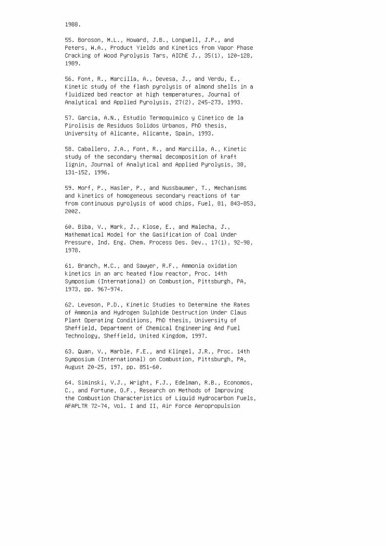
1988.
55. Boroson, M.L., Howard, J.B., Longwell, J.P., andPeters, W.A., Product Yields and Kinetics from Vapor PhaseCracking of Wood Pyrolysis Tars, AIChE J., 35(1), 120–128,1989.
56. Font, R., Marcilla, A., Devesa, J., and Verdu, E.,Kinetic study of the flash pyrolysis of almond shells in afluidized bed reactor at high temperatures, Journal ofAnalytical and Applied Pyrolysis, 27(2), 245–273, 1993.
57. Garcia, A.N., Estudio Termoquimico y Cinetico de laPirolisis de Residuos Solidos Urbanos, PhD thesis,University of Alicante, Alicante, Spain, 1993.
58. Caballero, J.A., Font, R., and Marcilla, A., Kineticstudy of the secondary thermal decomposition of kraftlignin, Journal of Analytical and Applied Pyrolysis, 38,131–152, 1996.
59. Morf, P., Hasler, P., and Nussbaumer, T., Mechanismsand kinetics of homogeneous secondary reactions of tarfrom continuous pyrolysis of wood chips, Fuel, 81, 843–853,2002.
60. Biba, V., Mark, J., Klose, E., and Malecha, J.,Mathematical Model for the Gasification of Coal UnderPressure, Ind. Eng. Chem. Process Des. Dev., 17(1), 92–98,1978.
61. Branch, M.C., and Sawyer, R.F., Ammonia oxidationkinetics in an arc heated flow reactor, Proc. 14thSymposium (International) on Combustion, Pittsburgh, PA,1973, pp. 967–974.
62. Leveson, P.D., Kinetic Studies to Determine the Ratesof Ammonia and Hydrogen Sulphide Destruction Under ClausPlant Operating Conditions, PhD thesis, University ofSheffield, Department of Chemical Engineering And FuelTechnology, Sheffield, United Kingdom, 1997.
63. Quan, V., Marble, F.E., and Klingel, J.R., Proc. 14thSymposium (International) on Combustion, Pittsburgh, PA,August 20–25, 197, pp. 851–60.
64. Siminski, V.J., Wright, F.J., Edelman, R.B., Economos,C., and Fortune, O.F., Research on Methods of Improvingthe Combustion Characteristics of Liquid Hydrocarbon Fuels,AFAPLTR 72–74, Vol. I and II, Air Force Aeropropulsion

Laboratory, Wright-Patterson Air Force Base, OH, 1972.
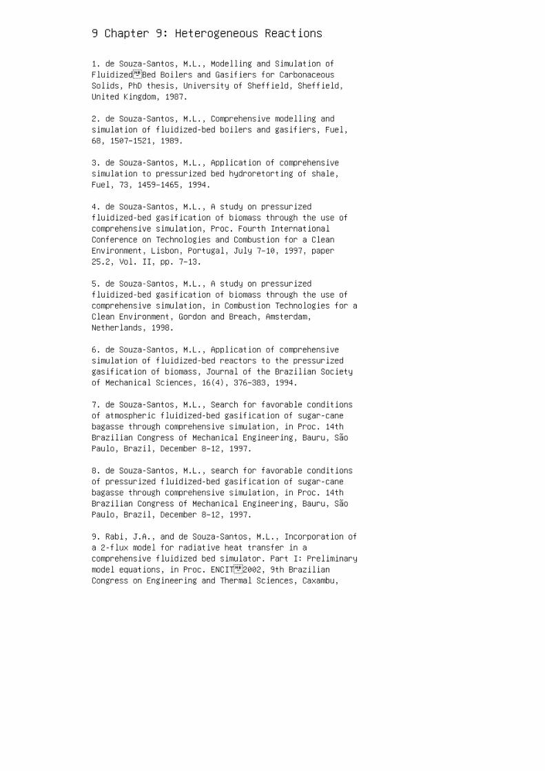
9 Chapter 9: Heterogeneous Reactions
1. de Souza-Santos, M.L., Modelling and Simulation ofFluidized‑Bed Boilers and Gasifiers for CarbonaceousSolids, PhD thesis, University of Sheffield, Sheffield,United Kingdom, 1987.
2. de Souza-Santos, M.L., Comprehensive modelling andsimulation of fluidized-bed boilers and gasifiers, Fuel,68, 1507–1521, 1989.
3. de Souza-Santos, M.L., Application of comprehensivesimulation to pressurized bed hydroretorting of shale,Fuel, 73, 1459–1465, 1994.
4. de Souza-Santos, M.L., A study on pressurizedfluidized-bed gasification of biomass through the use ofcomprehensive simulation, Proc. Fourth InternationalConference on Technologies and Combustion for a CleanEnvironment, Lisbon, Portugal, July 7–10, 1997, paper25.2, Vol. II, pp. 7–13.
5. de Souza-Santos, M.L., A study on pressurizedfluidized-bed gasification of biomass through the use ofcomprehensive simulation, in Combustion Technologies for aClean Environment, Gordon and Breach, Amsterdam,Netherlands, 1998.
6. de Souza-Santos, M.L., Application of comprehensivesimulation of fluidized-bed reactors to the pressurizedgasification of biomass, Journal of the Brazilian Societyof Mechanical Sciences, 16(4), 376–383, 1994.
7. de Souza-Santos, M.L., Search for favorable conditionsof atmospheric fluidized-bed gasification of sugar-canebagasse through comprehensive simulation, in Proc. 14thBrazilian Congress of Mechanical Engineering, Bauru, SãoPaulo, Brazil, December 8–12, 1997.
8. de Souza-Santos, M.L., search for favorable conditionsof pressurized fluidized-bed gasification of sugar-canebagasse through comprehensive simulation, in Proc. 14thBrazilian Congress of Mechanical Engineering, Bauru, SãoPaulo, Brazil, December 8–12, 1997.
9. Rabi, J.A., and de Souza-Santos, M.L., Incorporation ofa 2-flux model for radiative heat transfer in acomprehensive fluidized bed simulator. Part I: Preliminarymodel equations, in Proc. ENCIT‑2002, 9th BrazilianCongress on Engineering and Thermal Sciences, Caxambu,
Minas Gerais, Brazil, October 15–18, 2002.
10. Rabi, J.A., and de Souza-Santos, M.L., Incorporation ofa 2-flux model for radiative heat transfer in acomprehensive fluidized bed simulator. Part II: Numericalresults and assessment, in Proc. ENCIT‑2002, 9thBrazilian Congress on Engineering and Thermal Sciences,Caxambu, Minas Gerais, Brazil, October 15–18, 2002.
11. Rabi, J.A., Usage of Flux Method to Improve RadiativeHeat Transfer Modelling inside Bubbling Fluidized BedBoilers and Gasifiers, PhD thesis, Faculty of MechanicalEngineering, State University of Campinas, Campinas, SãoPaulo, Brazil, 2002.
12. de Souza-Santos, M.L., Development of a SimulationModel and Optimization of Gasifiers for Various Fuels(Desenvolvimento de Modelo de Simulação e Otimização deGaseificadores com Diversos Tipos de Combustíveis),IPT-Inst. Pesq. Tec. Est. São Paulo, SCTDE-SP, Report No.20.689, DEM/AET, São Paulo, Brazil, 1985.
13. de Souza-Santos, M.L., and Jen, L.C., Study of EnergyAlternative Sources; Use of Biomass and Crop Residues asEnergy Source: Part B: Development of a MathematicalModels and Simulation Programs for Up‑Stream andDown‑Stream Moving Bed Gasifiers. (Estudo de FontesAlternativa de Energia. Parte B), IPT-Institute forTechnological Research of São Paulo, Report No.16.223-B/DEM/AET, São Paulo, Brazil, 1982.
14. Jen, L.C., and de Souza-Santos, M.L., Modeling andsimulation of fixed-bed gasifiers for charcoal (Modelageme simulação de gaseificador de leito fixo para carvão),Brazilian Journal of Chemical Engineering (RevistaBrasileira de Engenharia Química), 7(3–4), 18–23, 1984.
15. Smoot, L.D., and Smith, P.J., Coal Combustion andGasification, Plenum Press, New York, 1985.
10 Chapter 10: Drying and Devolatilization
1. Milne, T.A., Abatzglou, N., and Evans, R.J., BiomassGasifier Tars: Their Nature, Formation and Conversion, USDepartment of Energy, 1998.
2. Badzioch, S., and Hawksley, P.G.W., Kinetics of thermaldecomposition of pulverised coal particles, Ind. Eng.Chem. Process Des. Dev., 9, 5.21–5.30, 1970.
3. Arenillas, A., Rubiera, F., Pevida, C., and Pis, J.J., Acomparison of different methods for predicting coaldevolatilization kinetics, Journal of Analytical andApplied Pyrolysis, 5.8–5.9, 685.–701, 2001.
4.. Nunn, T.R., Howard, J.B., Longwell, J.P., and Peters,W.A., Product compositions and kinetics in the rapidpyrolysis of sweet gum hardwood, Ind. Eng. Chem. ProcessDes. Dev. , 24.(3), 836–84.4., 1985..
5.. Nunn, T.R., Howard, J.B., Longwell, J.P., and Peters,W.A., Product compositions and kinetics in the rapidpyrolysis of milled wood lignin, Ind. Eng. Chem. ProcessDes. Dev., 24.(3), 84.4.–85.2, 1985..
6. Loison, R., and Chauvin, R., Pyrolyse rapide du charbon,Chimie et Industrie, 91, 3, 269–274., 1964.. TABLE 10.4Boundary Conditions to be Used in an Exercise Gas Species(j) Reaction Number (j) w I,i,j (Mass Fraction) a H 2 (19)1 0.0139 H 2 O (20) 1 0.0129 2 0.0129 NH 3 (22) 1 0.0000CO (4.4.) 1 0.05.36 2 0.0225. 3 0.0215. CO 2 (4.6) 10.0000 2 0.0075. 3 0.005.4. HCN (5.1) 1 0.0097 2 0.024.7 CH4. (61) 1 0.0000 2 0.0214. 3 0.0161 C 2 H 4. (88) b 10.2220 Tar (398) 1 0.4.4.39 a These are not actual valuesderived from coal analysis. Actual values can be found inSolomon et al. [10]. b Representing all aliphaticcomponents other than methane.
7. Fuller, E.L., Jr., Coal and Coal Products: AnalyticalCharacterization Techniques, American Chemical Society,Washington, DC, 1982.
8. Solomon, P.R., and Hamblen, D.G., Finding order in coalpyrolysis kinetics, Prog. Energy Combustion Sci, 9,323–361, 1983.
9. Das, T.K., Evolution characteristics of gases duringpyrolysis of maceral concentrates of Russian coking coals,Fuel, 80, 4.89–5.00, 2001.
10. Solomon, P.R., Hamblen, D.G., Carangelo, R.M., Serio,M.A., and Deshpande, G.V., General model of coaldevolatilization, Energy & Fuels, 2, 4.05.–4.22, 1988.
11. Simmons, G.M., and Gentry, M., Kinetic formation of CO,CO 2 , H 2 , and light hydrocarbon gases from cellulosepyrolysis, Journal of Analytical and Applied Pyrolysis, 10,129–138, 1986.
12. Morf, P., Hasler, P., and Nussbaumer, T., Mechanismsand kinetics of homogeneous secondary reactions of tarfrom continuous pyrolysis of wood chips, Fuel, 81,84.3–85.3, 2002.
13. Shafizadeh, F., and Chin, P.P.S., Thermal deteriorationof wood, American Chemical Society Symp. Ser. , 4.3, 5.7,1977.
14.. Chan, W.R., Kelbon, M., and Krieger, B., Effect ofpressure on the pyrolysis of newsprint, Fuel , 64.,15.05.–15.13, 1985..
15.. Órfão, J.J.M., Antunes, F.J.A., and Figueiredo, J.L.,Pyrolysis kinetics of lignocellolosic materials—threeindependent reaction model, Fuel, 78, 34.9–35.8, 1999.
16. Bradbury, A.G.W., Sakai, Y., and Shafizadeh, F., Akinetic model of pyrolysis of cellulose, Journal of AppliedPolymer Science, 23, 3271–3280, 1979.
17. Thurner, F., and Mann, U., Kinetic investigation ofwood pyrolysis, Ind. Eng. Chem. Progress Des. Dev. , 20,4.82–4.4.8, 1981.
18. Solomon, P.R., Beér, J.M., and Longwell, J.P.,Fundamentals of coal conversion and relation to coalpyrolysis, Energy, 12(8–9), 837–862, 1987.
19. Fine, D.H., Slater, S.M., Sarofim, A.F., and Williams,G.C., Nitrogen in coal as a source of nitrogen oxideemission from furnaces, Fuel, 5.3, 120–125., 1974..
20. de Souza-Santos, M.L., Modelling and Simulation ofFluidized‑Bed Boilers and Gasifiers for CarbonaceousSolids, PhD thesis, University of Sheffield, Sheffield,United Kingdom, 1987.
21. de Souza-Santos, M.L., Comprehensive modelling andsimulation of fluidized-bed boilers and gasifiers, Fuel ,68, 15.07–15.21, 1989.
22. de Souza-Santos, M.L., Application of comprehensivesimulation of fluidized-bed reactors to the pressurizedgasification of biomass, Journal of the Brazilian Societyof Mechanical Sciences , 16(4.), 376–383,1994..
23. de Souza-Santos, M.L., Development of a SimulationModel and Optimization of Gasifiers for Various Fuels(Desenvolvimento de Modelo de Simulação e Otimização deGaseificadores com Diversos Tipos de Combustíveis),IPT-Inst. Pesq. Tec. Est. São Paulo, SCTDE-SP, Report No.20.689, DEM/AET, São Paulo, Brazil, 1985..
24.. de Souza-Santos, M.L., and Jen, L.C., Study of EnergyAlternative Sources; Use of Biomass and Crop Residues asEnergy Source: Part B: Development of a MathematicalModels and Simulation Programs for Up‑Stream andDown‑Stream Moving Bed Gasifiers. (Estudo de FontesAlternativa de Energia, Parte B), IPT-Institute forTechnological Research of São Paulo, Report No.16.223-B/DEM/AET, São Paulo, Brazil, 1982.
25.. Jen, L.C., and de Souza-Santos, M.L., Modeling andsimulation of fixed-bed gasifiers for charcoal (Modelageme simulação de gaseificador de leito fixo para carvão),Brazilian Journal of Chemical Engineering (RevistaBrasileira de Engenharia Química ), 7(3–4.), 18–23, 1984..
26. Rajan, R.R., and Wen, C.Y., A comprehensive model forfluidized bed coal combustors, AIChE J., 26(4.),64.2–65.5., 1980.
27. Howard, D.F., Williams, A.P., and Howard, J.B., Mineralmatter effects on the rapid pyrolysis and hydropyrolysisof a bituminous coal. 1. Effects on yields of char, tar andlight gaseous volatiles, Fuel , 61, 15.5.–160, 1982.
28. Brage, C., Yu, Q., and Sjöström, K., Characteristics ofevolution of tar from wood pyrolysis in a fixed-bedreactor, Fuel , 75.(2), 213–219, 1996.
29. Bruinsma, O.S.L., Geerstsma, R.S., Bank, P., andMoulijin, J.A., Fuel, 67, 327, 1988.
30. Pitt, G.J., The kinetics of the evolution of volatileproducts from coal, Fuel, 4.1, 267, 1962.
31. Anthony, D.B., and Howard, J.B., Coal devolatilizationand hydrogasification, AIChE J., 22(4.), 625.–65.6, 1976.
32. Anthony, D.B., Howard, J.B., Hottel, H.C., andMeissner, H.P., Rapid devolatilization of pulverized coal,Fifteenth Symposium (International) on Combustion,Combustion Institute, Pittsburgh, PA, 1975., p. 1303.
33. Cheong, P.H., PhD thesis, California Institute ofTechnology, Pasadena, CA, 1976.
34.. Gavalas, G.R., Coal Pyrolysis, Elsevier, Amsterdam,Netherlands, 1981.
35.. Gavalas, G.R., Cheong, P.H., and Jain, R., Model ofcoal pyrolysis. 1. Qualitative development, Ind. Eng. Chem.Fundam., 20, 113–122, 1981.
36. Gavalas, G.R., Cheong, P.H., and Jain, R., Model ofcoal pyrolysis. 2. Quantitative formulation and results,Ind. Eng. Chem. Fundam., 20, 122–132, 1981.
37. Niksa, S., Kerstein, A.R., On the role ofmacromolecular configuration in rapid coaldevolatilization, Fuel, 66, 1389–1399, 1987.
38. Niksa, S., Rapid coal devolatilization as anequilibrium flash distillation, AIChE J., 34., 790–802,1988.
39. Solomon, P.R., and Colket, M.B., Seventeenth Symposium(International) on Combustion, Combustion Institute,Pittsburgh, PA, 1979, p. 131–14.3.
4.0. Serio, M.A., Hamblen, D.G., Markham, J.R., andSolomon, P.R., Kinetics of volatile evolution in coalpyrolysis: experiment and theory, Energy & Fuels, 1,138–15.2, 1987.
4.1. Solomon, P.R., Serio, M.A., Carangelo, R.M., andMarkham, J.R., Very rapid coal pyrolysis, Fuel, 65.,182–193, 1986.
4.2. Solomon, P.R., and King, H.H., Tar evolution from coaland model polymers: Theory and experiments, Fuel, 63,1302–1311, 1984..
4.3. Squire, K.R., Solomon, P.R., Carangelo, R.M., andDiTaranto, M.B., Tar evolution from coal and modelpolymers: 2. The effects of aromatic ring sizes anddonatable hydrogens, Fuel , 65., 833–84.3, 1986.
4.4.. Grant, D.M., Pugmire, R.J., Fletcher, T.H., and
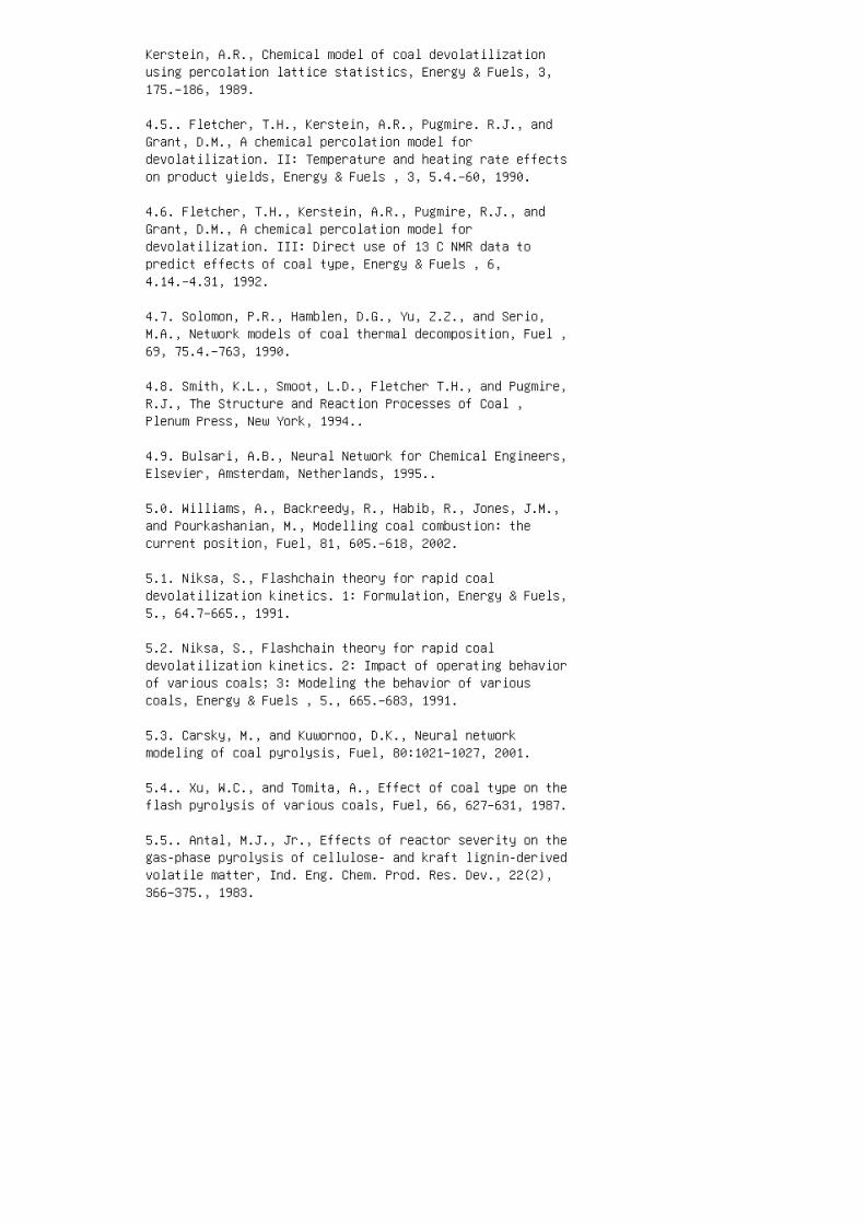
Kerstein, A.R., Chemical model of coal devolatilizationusing percolation lattice statistics, Energy & Fuels, 3,175.–186, 1989.
4.5.. Fletcher, T.H., Kerstein, A.R., Pugmire. R.J., andGrant, D.M., A chemical percolation model fordevolatilization. II: Temperature and heating rate effectson product yields, Energy & Fuels , 3, 5.4.–60, 1990.
4.6. Fletcher, T.H., Kerstein, A.R., Pugmire, R.J., andGrant, D.M., A chemical percolation model fordevolatilization. III: Direct use of 13 C NMR data topredict effects of coal type, Energy & Fuels , 6,4.14.–4.31, 1992.
4.7. Solomon, P.R., Hamblen, D.G., Yu, Z.Z., and Serio,M.A., Network models of coal thermal decomposition, Fuel ,69, 75.4.–763, 1990.
4.8. Smith, K.L., Smoot, L.D., Fletcher T.H., and Pugmire,R.J., The Structure and Reaction Processes of Coal ,Plenum Press, New York, 1994..
4.9. Bulsari, A.B., Neural Network for Chemical Engineers,Elsevier, Amsterdam, Netherlands, 1995..
5.0. Williams, A., Backreedy, R., Habib, R., Jones, J.M.,and Pourkashanian, M., Modelling coal combustion: thecurrent position, Fuel, 81, 605.–618, 2002.
5.1. Niksa, S., Flashchain theory for rapid coaldevolatilization kinetics. 1: Formulation, Energy & Fuels,5., 64.7–665., 1991.
5.2. Niksa, S., Flashchain theory for rapid coaldevolatilization kinetics. 2: Impact of operating behaviorof various coals; 3: Modeling the behavior of variouscoals, Energy & Fuels , 5., 665.–683, 1991.
5.3. Carsky, M., and Kuwornoo, D.K., Neural networkmodeling of coal pyrolysis, Fuel, 80:1021–1027, 2001.
5.4.. Xu, W.C., and Tomita, A., Effect of coal type on theflash pyrolysis of various coals, Fuel, 66, 627–631, 1987.
5.5.. Antal, M.J., Jr., Effects of reactor severity on thegas-phase pyrolysis of cellulose- and kraft lignin-derivedvolatile matter, Ind. Eng. Chem. Prod. Res. Dev., 22(2),366–375., 1983.
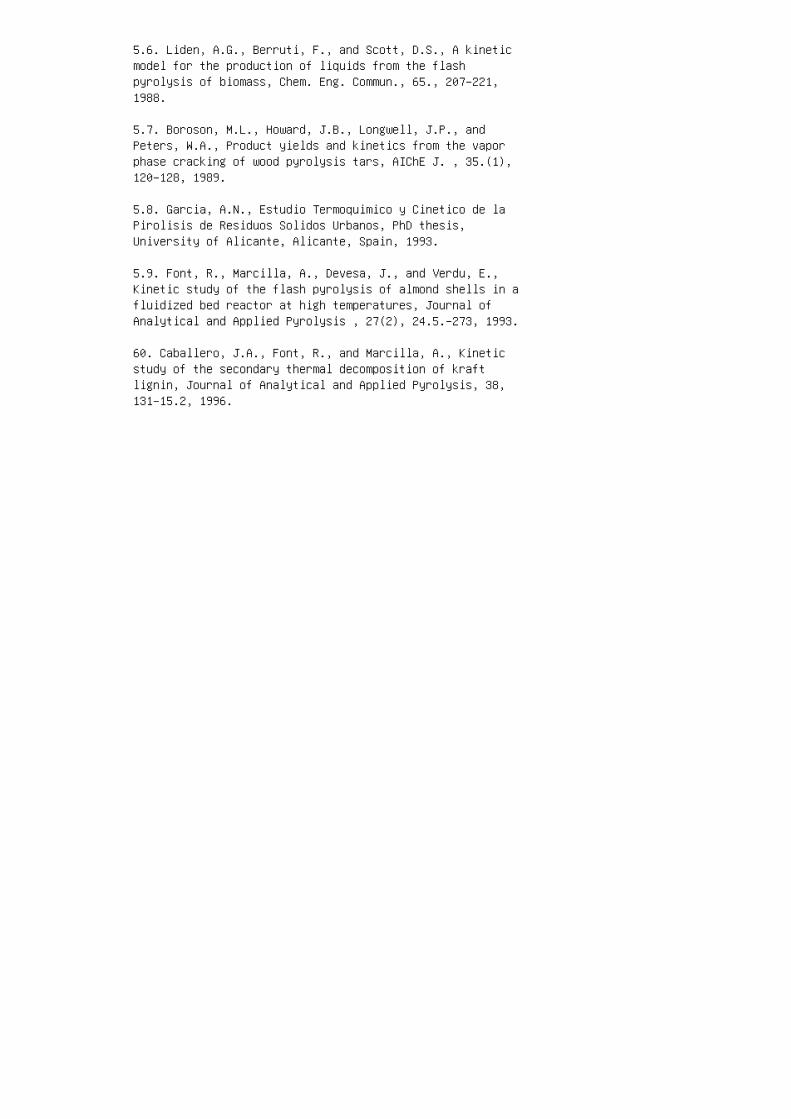
5.6. Liden, A.G., Berruti, F., and Scott, D.S., A kineticmodel for the production of liquids from the flashpyrolysis of biomass, Chem. Eng. Commun., 65., 207–221,1988.
5.7. Boroson, M.L., Howard, J.B., Longwell, J.P., andPeters, W.A., Product yields and kinetics from the vaporphase cracking of wood pyrolysis tars, AIChE J. , 35.(1),120–128, 1989.
5.8. Garcia, A.N., Estudio Termoquimico y Cinetico de laPirolisis de Residuos Solidos Urbanos, PhD thesis,University of Alicante, Alicante, Spain, 1993.
5.9. Font, R., Marcilla, A., Devesa, J., and Verdu, E.,Kinetic study of the flash pyrolysis of almond shells in afluidized bed reactor at high temperatures, Journal ofAnalytical and Applied Pyrolysis , 27(2), 24.5.–273, 1993.
60. Caballero, J.A., Font, R., and Marcilla, A., Kineticstudy of the secondary thermal decomposition of kraftlignin, Journal of Analytical and Applied Pyrolysis, 38,131–15.2, 1996.
11 Chapter 11: Auxiliary Equations andBasic Calculations
1. de Souza-Santos, M.L., Development of a Simulation Modeland Optimization of Gasifiers for Various Fuels(Desenvolvimento de Modelo de Simulação e Otimização deGaseificadores com Diversos Tipos de Combustíveis),IPT-Inst. Pesq. Tec. Est. São Paulo, SCTDE-SP, Report No.20.689, DEM/AET, São Paulo, Brazil, 1985.
2. de Souza-Santos, M.L., and Jen, L.C., Study of EnergyAlternative Sources; Use of Biomass and Crop Residues asEnergy Source: Part B: Development of a MathematicalModels and Simulation Programs for Up-Stream andDown-Stream Moving Bed Gasifiers. (Estudo de FontesAlternativa de Energia. Parte B), IPT-Institute forTechnological Research of São Paulo, Report No.16.223-B/DEM/AET, São Paulo, Brazil, 1982.
3. Jen, L.C., and de Souza-Santos, M.L., Modeling andsimulation of fixed-bed gasifiers for charcoal (Modelageme simulação de gaseificador de leito fixo para carvão),Brazilian Journal of Chemical Engineering (RevistaBrasileira de Engenharia Química), 7(3–4), 18–23, 1984.
4. Yu, Q., Brage, C., Chen, G., Sjöström, K., Temperatureimpact on the formation of tar from biomass pyrolysis in afree-fall reactor, J. Analytical and Applied Pyrolysis,40–41, 481–489, 1997.
5. Brage, C., Yu, Q., and Sjöström, K., Characteristics ofevolution of tar from wood pyrolysis in a fixed-bedreactor, Fuel, 75(2), 213–219, 1996.
6. Field, M.A., Gill, D.W., Morgan, B.B., and Hawksley,P.G.W., Combustion of pulverized coal, Brit. Coal Utiliz.Res. Assoc. Mon. Bull., 31(6),285–345, 1967.
7. Poling, B.E., Prausnitz, J.M., and O’Connell, J.P., TheProperties of Gases and Liquids, 5th Ed., McGraw-Hill, NewYork, 2000.
8. Reid, C.R., Prausnitz, J.M., and Poling, B.E., TheProperties of Gases and Liquids, 4th Ed., McGraw-Hill, NewYork, 1987.
9. Walker, P.L., Jr., Rusinko, F., Jr., and Austin, L.G.,Gas reactions of carbon, in Advances in Catalysis, Vol.XI, Academic Press, New York, 1959, 133–221.
10. de Souza-Santos, M.L., Modelling and Simulation ofFluidized-Bed Boilers and Gasifiers for CarbonaceousSolids, PhD thesis, University of Sheffield, Sheffield,United Kingdom, 1987.
11. de Souza-Santos, M.L., Comprehensive modelling andsimulation of fluidized-bed boilers and gasifiers, Fuel,68, 1507–1521, 1989.
12. de Souza-Santos, M.L., Application of comprehensivesimulation to pressurized bed hydroretorting of shale,Fuel, 73, 1459–1465, 1994.
13. de Souza-Santos, M.L., Application of comprehensivesimulation of fluidized-bed reactors to the pressurizedgasification of biomass, Journal of the Brazilian Societyof Mechanical Sciences, 16(4), 376–383, 1994.
14. DeSai, P.R., and Wen, C.Y., Computer Modeling of theMERC Fixed Bed Gasifier, U.S. Department of Energy Report,MERC/CR-78/3, Morgantown, WV, March 1978.
15. Yoon, H., Wei, J., and Denn, M.M., A model formoving-bed coal gasification reactors, AIChE J., 24(5),885–903, 1978.
16. Davini, P., DeMichele, G., and Bertacchi, S., Reactionbetween calcium-based sorbents and sulphur dioxide: athermogravimetric investigation, Fuel, 70, 201–204, 1991.
17. Elias-Kohav, T., Sheintuch, M., and Avnir, D.,Steady-state diffusion and reactions in catalytic fractalporous media, Chem. Eng. Sci., 46(11), 2787–2798, 1991.
18. Kasaoka, S., Sakata, Y., and Tong, C., Kineticsevaluation of reactivity of various coal char forgasification with carbon dioxide in comparison with steam,Intern. Chem. Eng., 25(1), 160–175, 1985.
19. Bird, R.B., Stewart, W.E., and Lightfoot, E.N.,Transport Phenomena, John Wiley, New York, 1960.
20. Slattery, J.C., Momentum, Energy, and Mass Transfer inContinua, Robert E. Krieger, New York, 1978.
21. Incropera, F.P., and DeWitt, D.P., Fundamentals of Heatand Mass Transfer, 4th Ed., John Wiley, New York, 1996.
22. Luikov, A.V., Heat and Mass Transfer, Mir, Moscow, 1980.
23. Treybal, R.E., Mass Transfer Operations, 2nd Ed.,McGraw-Hill, New York, 1968.
24. Gupta, A.S., and Thodos, G., Direct analogy betweenmass and heat transfer to beds of spheres, AIChE J., 9(6),751–754, 1963.
25. Steinberger, R.L., and Treybal, R.E., Mass transferfrom a solid soluble sphere to a flowing liquid system,AIChE J., 6, 227, 1960.
26. Kothari, A.K., MSc thesis, Illinois Institute ofTechnology, Chicago, 1967.
27. Perry, J.H., Green, D.W., and Maloney, J.O., in J.H.Perry, ed., Perry’s Chemical Engineers Handbook, 7th Ed.,McGraw-Hill, New York, 1997, 12-1–12-90.
28. Alemasov, V.E., Dregalin, A.F., Tishin, A.P., andKhudyakov, V.A., Computation methods, in Thermodynamic andThermophysical Properties of Combustion Products, Glushko,V.P., Ed., Vol. I, Viniti, Moscow, 1971.
29. Yaws, C.L., Hood, L.D., Gorin, C., Thakore, S., andMiller, J.W., Jr., Correlation constants for chemicalcompounds, Chemical Engineering, 16, 79–87, 1976.
30. Yaws, C.L., Schorr, G.R., Shah, P.N., and Miller, J.W.,Jr. Correlation constants for chemical compounds, ChemicalEngineering, 22, 153–161, 1976.
31. Yaws, C.L., Schorr, G.R., Shah, P.N., McGinley, J.J.,and Miller, J.W., Jr., Correlation constants for liquids,Chemical Engineering, 25, 127–135, 1976.
32. Smoot, L.D., and Pratt, D.T., Pulverized-CoalCombustion and Gasification, Plenum Press, New York, 1979.
33. Kunii, D., and Levenspiel, O., FluidizationEngineering, 2nd Ed., John Wiley, New York, 1991.
34. Geldart, D., Gas Fluidization Technology, John Wiley,Chichester, United Kingdom, 1986.
35. Ergun, S., Fluid flow through packed columns, ChemicalEngineering Progress, 48, 91–94, 1952.
36. Idel’cik, I.E., Memento de Pertes de Charge, Eyrolles,Paris, 1960.

37. Niksa, S., Rapid coal devolatilization as anequilibrium flash distillation, AIChE J., 34, 790–802,1988.
38. Adánez, J., Miranda, J.L., and Gavilán, J.M., Kineticsof a lignite-char gasification by CO 2 , Fuel, 64,801–804, 1985.
12 Chapter 12: Moving-Bed SimulationPrograms and Results
1. Gibbs, W.W., Software’s chronic crisis, ScientificAmerican, 86–95, September 1994.
2. de Souza-Santos, M.L., Development of a Simulation Modeland Optimization of Gasifiers for Various Fuels(Desenvolvimento de Modelo de Simulação e Otimização deGaseificadores com Diversos Tipos de Combustíveis),IPT-Inst. Pesq. Tec. Est. São Paulo, SCTDE-SP, Report No.20.689, DEM/AET, São Paulo, Brazil, 1985.
3. de Souza-Santos, M.L., and Jen, L.C., Study of EnergyAlternative Sources; Use of Biomass and Crop Residues asEnergy Source: Part B: Development of a MathematicalModels and Simulation Programs for Up-Stream andDown-Stream Moving Bed Gasifiers. (Estudo de FontesAlternativa de Energia. Parte B), IPT-Institute forTechnological Research of São Paulo, Report No.16.223-B/DEM/AET, São Paulo, Brazil, 1982.
4. Jen, L.C., and de Souza-Santos, M.L., Modeling andsimulation of fixed-bed gasifiers for charcoal (Modelageme simulação de gaseificador de leito fixo para carvão),Brazilian Journal of Chemical Engineering (RevistaBrasileira de Engenharia Química), 7(3–4), 18–23, 1984.
5. Hobbs, M.L., Radulovic, P.T., and Smoot, L.D.,Combustion and gasification of coals in fixed-beds, Prog.Energy Combust. Sci., 19, 505–556, 1993.
6. DeSai, P.R., and Wen, C.Y., Computer Modeling of theMERC Fixed Bed Gasifier, U.S. Department of Energy ReportMERC/CR-78/3, Morgantown, WV, March 1978.
7. Yoon, H., Wei, J., and Denn, M.M., A model formoving-bed coal gasification reactors, AIChE J., 24(5),885–903, 1978.
8. Stillman, R., Simulation of a moving bed gasifier of awestern coal, IBM J. Res. Dev., 23, 240–252, 1979.
9. Hobbs, M.L., Radulovic, P.T., and Smoot, L.D., Modelingfixed-bed coal gasifiers, AIChE J., 38, 681–702, 1992.
10. Radulovic, P.T., Ghani, M.U., and Smoot, L.D., Animproved model for fixed-bed combustion and gasification,Fuel, 74(4), 582–594, 1995.
11. Ghani, M.U., Radulovic, P.T., and Smoot, L.D., Animproved model for fixed-bed combustion and gasification:sensitivity analysis and applications, Fuel, 75(10),1213–1226, 1996.
12. Cooper, J., and Hallett, W.L.H., A numerical model forpacked-bed combustion of char particles, ChemicalEngineering Science, 55, 4451–4460, 2000.
13. Perry, J.H., Green, D.W., and Maloney, J.O., in Perry’sChemical Engineers Handbook, 7th Ed., McGraw-Hill, NewYork, 1997, 12-1–12-90.
14. Poling, B.E., Prausnitz, J.M., and O’Connell, J.P., TheProperties of Gases and Liquids, 5th Ed., McGraw-Hill, NewYork, 2000.
15. Reid, C.R., Prausnitz, J.M., and Poling, B.E., TheProperties of Gases and Liquids, 4th Ed., McGraw-Hill, NewYork, 1987.
16. Alemasov, V.E., Dregalin, A.F., Tishin, A.P., andKhudyakov, V.A., Computation methods, in Thermodynamic andThermophysical Properties of Combustion Products, Vol. I,Glushko, V.P., Ed., Viniti, Moscow, 1971.
17. Carnahan, B., Lutter, H.A., and Wilkes, J.O., AppliedNumerical Methods, John Wiley, New York, 1969.
18. Bakhvalov, N.S., Numerical Methods, Mir, Moscow, 1977.
19. Kopachenova, N.V., and Maron, I.A., ComputationalMathematics, Mir, Moscow, 1975.
20. Lapidus, L., Digital Computation for ChemicalEngineers, McGraw-Hill, New York, 1962.
13 Chapter 13: Bubbling Fluidized-BedCombustion and Gasification Model
1. Kunii, D., and Levenspiel, O., Fluidization Engineering,2nd Ed., John Wiley, New York, 1991.
2. Davidson, J.F., and Harrison, D., Fluidized Particles,Cambridge University Press, Cambridge, United Kingdom,1963.
3. de Souza-Santos, M.L., Modelling and Simulation ofFluidized‑Bed Boilers and Gasifiers for CarbonaceousSolids, PhD thesis, University of Sheffield, Sheffield,United Kingdom, 1987.
4. de Souza-Santos, M.L., Comprehensive modelling andsimulation of fluidized-bed boilers and gasifiers, Fuel,68, 1507–1521, 1989.
5. Zhang, G.T., and Ouyang, F., Heat transfer between thefluidized bed and the distributor plate, Ind. Eng. Chem.Process Des. Dev., 24(2), 430–433, 1985.
14 Chapter 14: Fluidization Dynamics
1. Davidson, J.F., and Harrison, D., Fluidization, AcademicPress, New York, 1985.
2. Toomey, R.D., and Johnstone, H.F., Gaseous fluidizationof solid particles, Chem. Eng. Progress, 48(5), 220–226,1952.
3. Kunii, D., and Levenspiel, O., Fluidization Engineering,2nd Ed., John Wiley, New York, 1991.
4. Davidson, J.F., and Harrison, D., Fluidized Particles,Cambridge University Press, Cambridge, United Kingdom,1963.
5. de Souza-Santos, M.L., Modelling and Simulation ofFluidized‑Bed Boilers and Gasifiers for CarbonaceousSolids, PhD thesis, University of Sheffield, Sheffield,United Kingdom, 1987.
6. de Souza-Santos, M.L., Comprehensive modelling andsimulation of fluidized-bed boilers and gasifiers, Fuel,68, 1507–1521, 1989.
7. de Souza-Santos, M.L., Application of comprehensivesimulation of fluidized-bed reactors to the pressurizedgasification of biomass, Journal of the Brazilian Societyof Mechanical Sciences, 16(4), 376–383, 1994.
8. Babu, S.P., Shah, B., and Talwalkar, A., Fluidizationcorrelations for coal gasification materials—minimumfluidization velocity and fluidization bed expansion ratio,AIChE Symp. Ser., 176(74), 176–186, 1978.
9. Wen, C.Y., and Yu., Y.H., A generalized method forpredicting the minimum fluidization velocity, AIChE J.,12, 610–612, 1966.
10. Delvosalle, C., and Vanderschuren, J., Gas-to-particlesand particle-to-particle heat transfer in fluidized bedsof large particles, Chem. Eng. Sci., 40(5), 769–779, 1985.
11. Mori, S., and Wen, C.Y., Estimation of bubble diameterin gaseous fluidized beds, AIChE J., 21, 109, 1975.
12. Stubington, J.F., Barret, D., and Lowry, G., Bubblesize measurements and correlation in a fluidized bed athigh temperature, Chem. Eng. Res. Des., 62, 173–178, 1984.
13. Horio, H., and Nonaka, A., A generalized bubblediameter correlation for gas–solid fluidized beds, AIChEJ., 33(11), 1865–1872, 1987.
14. Bouillard, J.X., Lyczkowski, R.W., Folga, S., Gidaspow,D., and Berry, G.F., Hydrodynamics of erosion of heatexchanger tubes in fluidized bed combustors, CanadianJournal of Chemical Engineering, 67, 218–229, 1989.
15. Bouillard, J.X., and Lyczkowski, R.M., On the erosionof heat exchanger tube banks in fluidized-bed combustors,Powder Technology, 68, 37–51, 1991.
16. Talmor, E., and Benenati, D., Solids mixing andcirculation in gas fluidized beds, AIChE J., 9, 536–540,1963.
17. Geldart, D., Gas Fluidization Technology, John Wiley,Chichester, United Kingdom, 1986.
18. Gidaspow, D., Multiphase Flow and Fluidization,Academic Press, San Diego, CA, 1994.
19. Liu, Y., and Gidaspow, D., Solids mixing in fluidizedbeds—a hydrodynamic approach, Chem. Eng. Sci., 36,539–547, 1981.
20. Gidaspow, D., and Ettehadleh, B., Fluidization intwo-dimensional beds with a jet. 2. Hydrodynamic modeling,Ind. Eng. Chem. Fundam., 22(2), 193–201, 1983.
21. Gidaspow, D., Hydrodynamics of fluidization and heattransfer: supercomputed modeling, Appl. Mech. Rev., 39(1),1–23, 1986.
22. Gidaspow, D., Lin, C., Seo, Y.C., Fluidization intwo-dimensional beds with a jet. 1. Experimental porositydistributions, Ind. Eng. Chem. Fundam., 22(2), 187–193,1983.
23. Gidaspow, D., Tsuo, Y.P., and Ding, J., Hydrodynamicsof circulating and bubbling fluidized beds, in Proc. ofthe Materials Issues in Circulating Fluidized‑bedCombustors, Argonne National Laboratory, June 19–23, 1989.
24. Soo. S.L., Note on motions of phases in a fluidizedbed, Powder Technology, 45, 169– 172, 1986.
25. Soo, S.L., Average circulatory motion of particles influidized beds, Powder Technology, 57, 107–117, 1989.
26. Soo, S.L., Particulates and Continuum, Multiphase FluidDynamics, Hemisphere, New York, 1989.
27. Lin, J.S., Chen, M.M., and Chao, B.T., A novelradioactive particle tracking facility for measurement ofsolid motion in gas fluidized beds, AIChE J., 31(3),465–473, 1985.
28. Costa, M.A.S., and de Souza-Santos, M.L., Studies onthe mathematical modeling of circulation rates ofparticles in bubbling fluidized beds, Power Technology,103, 110– 116, 1999.
29. Costa, A.M.S., Improvements on the MathematicalModeling and Simulation of Circulation Rates of SolidParticles in Bubbling Fluidized Beds (in Portuguese), MScthesis, Faculty of Mechanical Engineering, University ofCampinas, São Paulo, Brazil, 1998.
30. Ergun, S., Fluid flow through packed columns, ChemicalEngineering Progress, 48, 91–94, 1952.
31. Saxton, J.A., Fitton, J.B., and Vermeulen, T., Cellmodel theory of homogeneous fluidization: density andviscosity behavior, AIChE J, 16(1), 120–130, 1970.
32. Wen, C.Y., and Chen, L.H., Fluidized bed freeboardphenomena: entrainment and elutriation, AIChE J., 28, 117,1982.
33. Lewis, W.K., Gilliland, E.R., and Lang, P.M.,Entrainment from fluidized beds, Chem. Eng. Prog. Symp.Ser., 58(38), 65–78, 1962.
34. Walsh, P.M., Mayo, J.E., and Beer, J.M., Refluxingparticles in the freeboard of a fluidized bed, AIChE Symp.Ser., 80(234), 119–128, 1984.
35. Merrick, D., and Highley, J., Particle size reductionand elutriation in a fluidized bed process, AIChE Symp.Ser., 70(137), 366–378, 1974.
36. Chirone, R., D’Amore, M., and Massimila, L., Carbonattrition in fluidized combustion of petroleum coke, Proc.20th Symp. (Int.) on Combustion, Combustion Institute, AnnArbor, MI, 1984.
37. Salatino, P., and Massimila, L., A descriptive model ofcarbon attrition in the fluidized combustion of coal char,
Chem. Eng. Sci., 40(10), 1905–1916, 1985.
38. Vaux, W.G., and Schruben, J.S., Kinetics of attritionin the bubbling zone of a fluidized bed, AIChE Symp. Ser.,79(222), 97–102, 1983.
39. Leith, D., and Mehta, D., Cyclone performance anddesign, Atmospheric Environment, 7, 527–549, 1973.
40. Nienow, A.W., Rowe, P.N., and Cheung, L.Y.L., Themixing/segregation behaviour of a dense powder with twosizes of a lighter one in a gas fluidised bed, inFluidization, Davidson, J.F., and Keairns, D.L., Eds.,Cambridge University Press, Cambridge, United Kingdom,1978, p. 146.
41. Yang, W.C., Fluidization Solids Handling andProcessing, Noyes, Westwood, NJ, 1999.
42. Lim, K.S., Zhu, J.X., and Grace, J.R., Hydrodynamics ofgas–solid fluidization, Int. J. Multiphase Flow, 21,141–193, 1995.
43. Davidson, J.F., and Keairns, D.L., Fluidization,Cambridge University Press, Cambridge, United Kingdom,1978.
44. Kwauk, M., and Li, J., Fluidization regimes, PowderTechnology, 87, 193–202, 1996.
15 Chapter 15: Auxiliary ParametersRelated to Fluidized-Bed Processes
1. Kobayashi, H., and Arai, F., Determination of a gascross-flow coefficient between the bubble and emulsionphases by measuring the residence time distribution of afluid in a fluidized bed, Kagaku Kogaku, 31, 239, 1967.
2. Rajan, R.R., and Wen, C.Y., A comprehensive model forfluidized bed coal combustors, AIChE J., 26(4), 642–655,1980.
3. Raman, P., Walawender, W.P., Fan, L.T., and Chang, C.C.,Mathematical model for the fluid-bed gasification ofbiomass materials: application to feedlot manure, Ind. Eng.Chem. Process Des. Dev., 20(4), 686–692, 1981.
4. Chang, C.C., Fan, L.T., and Walawender, W.P., Dynamicmodeling of biomass gasification in a fluidized bed, AIChESymposium Series, 80(234), 80–90, 1984.
5. Kunii, D., and Levenspiel, O., Fluidization Engineering,2nd Ed., John Wiley, New York, 1991.
6. Tojo, K., Chang, C.C., and Fan, L.T., Modeling ofdynamic and steady-state shallow fluidized bed coalcombustors. effects of feeder distribution, Ind. Eng. Chem.Process Des. Dev., 20(3), 411–416, 1981.
7. Weimer, A.W., and Clough, D.E., Modeling a low pressuresteam-oxygen fluidized bed coal gasification reactor,Chem. Eng. Sci., 36, 549–567, 1981.
8. Overturf, B.W., and Reklaitis, G.V., Fluidized-bedreactor model with generalized particle balances. Part I:Formulation and solution, AIChE J., 29(5), 813–820, 1983.
9. Overturf, B.W., and Reklaitis, G.V., Fluidized-bedreactor model with generalized particle balances. Part II:Coal combustion application, AIChE J., 29(5):820–829, 1983.
10. Sit, S.P., and Grace, J.R., Effect of bubbleinteraction on the interphase mass transfer in gasfluidized beds, Chem. Eng. Sci., 36, 327–335, 1981.
11. Behie, L.A., and Kohoe, P., The grid region in afluidized bed reactor, AIChE J., 19, 1070, 1973.
12. La Nause, R.D., Jung, K., and Kastl, J., Mass transferto large particles in fluidized beds of small particles,
Chem. Eng. Sci., 39, 1623–1633, 1984.
13. Kothari, A.K., MSc thesis, Illinois Institute ofTechnology, Chicago, 1967.
14. Gelperin, N.I., Einstein, V.G., and Kwasha, V.B.,Fluidization Technique Fundamentals, Izd. Khimia, Moscow,1967.
15. Gibson, M.M., and Monahan, J.A., A simple model ofradiation heat transfer from a cloud of burning particlesin a confined gas stream, Int. J. Heat Mass Transfer, 14,141–147, 1971.
16. Siddal, R.G., Flux methods for the analysis of radiantheat transfer, in Proc. 4th Symposium on Flame ResearchCommittee and Inst. of Fuel, 1972, pp. 169–177.
17. Shah, N.G., New Method for the Computation of RadiationHeat Transfer in Combustion Chambers, PhD thesis, ImperialCollege of Science and Technology, London, 1979.
18. Lockwood, F.C., and Shah, N.G., Evaluation of anefficient radiation flux model for furnace predictionprocedures, in Proc. 16th International Heat TransferConference, Toronto, Ontario, Canada, August 1978.
19. Siddal, R.G., and Seçuk, R., Evaluation of a newsix-flux model for radiative transfer in retangularenclosures, Trans. IchemE, 57, 163–169, 1979.
20. Brewster, M.Q., Effective absorption and emissivity ofparticulate media with application to a fluidized bed,Trans. ASME, 108, 710–713, 1986.
21. Brewster, M.Q., Thermal Radiative Transfer andProperties, John Wiley, New York, 1992.
22. Tien, C.L., Thermal radiation in packed and fluidizedbeds, Trans. ASME, 110, 1230– 1242, 1988.
23. Ozisik, M.N., Radiative Transfer and Interactions withConduction and Convection, John Wiley, New York, 1973.
24. Buckius, R.O., and Hwang, D.C., Radiation propertiesfor polydispersions: application to coal, Trans. ASME J.Heat Transfer, 102, 99–103, 1980.
25. Brewster, M.Q., and Tien, C.L., Radiative transfer inpacked fluidized beds: dependent versus independent
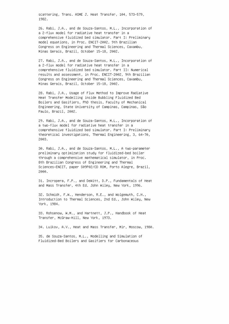
scattering, Trans. ASME J. Heat Transfer, 104, 573–579,1982.
26. Rabi, J.A., and de Souza-Santos, M.L., Incorporation ofa 2-flux model for radiative heat transfer in acomprehensive fluidized bed simulator. Part I: Preliminarymodel equations, in Proc. ENCIT-2002, 9th BrazilianCongress on Engineering and Thermal Sciences, Caxambu,Minas Gerais, Brazil, October 15–18, 2002.
27. Rabi, J.A., and de Souza-Santos, M.L., Incorporation ofa 2-flux model for radiative heat transfer in acomprehensive fluidized bed simulator. Part II: Numericalresults and assessment, in Proc. ENCIT-2002, 9th BrazilianCongress on Engineering and Thermal Sciences, Caxambu,Minas Gerais, Brazil, October 15–18, 2002.
28. Rabi, J.A., Usage of Flux Method to Improve RadiativeHeat Transfer Modelling inside Bubbling Fluidized BedBoilers and Gasifiers, PhD thesis, Faculty of MechanicalEngineering, State University of Campinas, Campinas, SãoPaulo, Brazil, 2002.
29. Rabi, J.A., and de Souza-Santos, M.L., Incorporation ofa two-flux model for radiative heat transfer in acomprehensive fluidized bed simulator. Part I: Preliminarytheoretical investigations, Thermal Engineering, 3, 64–70,2003.
30. Rabi, J.A., and de Souza-Santos, M.L., A two-parameterpreliminary optimization study for fluidized-bed boilerthrough a comprehensive mathematical simulator, in Proc.8th Brazilian Congress of Engineering and ThermalSciences–ENCIT, paper S09P02/CD ROM, Porto Alegre, Brazil,2000.
31. Incropera, F.P., and DeWitt, D.P., Fundamentals of Heatand Mass Transfer, 4th Ed. John Wiley, New York, 1996.
32. Schmidt, F.W., Henderson, R.E., and Wolgemuth, C.H.,Introduction to Thermal Sciences, 2nd Ed., John Wiley, NewYork, 1984.
33. Rohsenow, W.M., and Hartnett, J.P., Handbook of HeatTransfer, McGraw-Hill, New York, 1973.
34. Luikov, A.V., Heat and Mass Transfer, Mir, Moscow, 1980.
35. de Souza-Santos, M.L., Modelling and Simulation ofFluidized-Bed Boilers and Gasifiers for Carbonaceous
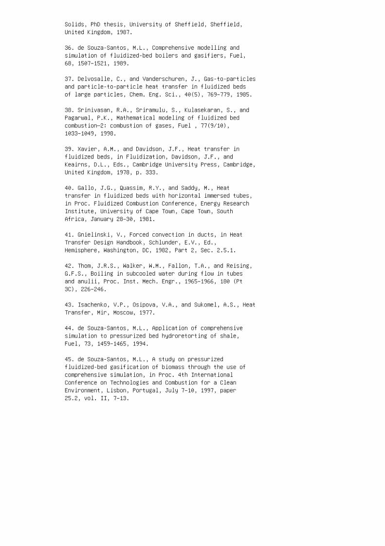
Solids, PhD thesis, University of Sheffield, Sheffield,United Kingdom, 1987.
36. de Souza-Santos, M.L., Comprehensive modelling andsimulation of fluidized-bed boilers and gasifiers, Fuel,68, 1507–1521, 1989.
37. Delvosalle, C., and Vanderschuren, J., Gas-to-particlesand particle-to-particle heat transfer in fluidized bedsof large particles, Chem. Eng. Sci., 40(5), 769–779, 1985.
38. Srinivasan, R.A., Sriramulu, S., Kulasekaran, S., andPagarwal, P.K., Mathematical modeling of fluidized bedcombustion—2: combustion of gases, Fuel , 77(9/10),1033–1049, 1998.
39. Xavier, A.M., and Davidson, J.F., Heat transfer influidized beds, in Fluidization, Davidson, J.F., andKeairns, D.L., Eds., Cambridge University Press, Cambridge,United Kingdom, 1978, p. 333.
40. Gallo, J.G., Quassim, R.Y., and Saddy, M., Heattransfer in fluidized beds with horizontal immersed tubes,in Proc. Fluidized Combustion Conference, Energy ResearchInstitute, University of Cape Town, Cape Town, SouthAfrica, January 28–30, 1981.
41. Gnielinski, V., Forced convection in ducts, in HeatTransfer Design Handbook, Schlunder, E.V., Ed.,Hemisphere, Washington, DC, 1982, Part 2, Sec. 2.5.1.
42. Thom, J.R.S., Walker, W.M., Fallon, T.A., and Reising,G.F.S., Boiling in subcooled water during flow in tubesand anulii, Proc. Inst. Mech. Engr., 1965–1966, 180 (Pt3C), 226–246.
43. Isachenko, V.P., Osipova, V.A., and Sukomel, A.S., HeatTransfer, Mir, Moscow, 1977.
44. de Souza-Santos, M.L., Application of comprehensivesimulation to pressurized bed hydroretorting of shale,Fuel, 73, 1459–1465, 1994.
45. de Souza-Santos, M.L., A study on pressurizedfluidized-bed gasification of biomass through the use ofcomprehensive simulation, in Proc. 4th InternationalConference on Technologies and Combustion for a CleanEnvironment, Lisbon, Portugal, July 7–10, 1997, paper25.2, vol. II, 7–13.
46. de Souza-Santos, M.L., A study on pressurizedfluidized-bed gasification of biomass through the use ofcomprehensive simulation, in Combustion Technologies for aClean Environment, Gordon and Breach, Amsterdam,Netherlands, 1998.
47. de Souza-Santos, M.L., Application of comprehensivesimulation of fluidized-bed reactors to the pressurizedgasification of biomass, Journal of the Brazilian Societyof Mechanical Sciences, 16(4), 376–383, 1994.
48. de Souza-Santos, M.L., Search for favorable conditionsof pressurized fluidized-bed gasification of sugar-canebagasse through comprehensive simulation, in Proc. 14thBrazilian Congress of Mechanical Engineering, Bauru, SãoPaulo, Brazil, December 8–12, 1997.
49. de Souza-Santos, M.L., A study on thermo-chemicallyrecuperated power generation systems using natural gas,Fuel, 76(7), 593–601, 1997.
50. Costa, M.A.S., and de Souza-Santos, M.L., Studies onthe mathematical modeling of circulation rates of particlesin bubbling fluidized beds, Power Technology , 103,110–116, 1999.
51. Zhang, G.T., and Ouyang, F., Heat transfer between thefluidized bed and the distributor plate, Ind. Eng. Chem.Process Des. Dev., 24(2), 430–433, 1985.
16 Chapter 16: Bubbling Fluidized-BedSimulation Program and Results
1. de Souza-Santos, M.L., Modelling and Simulation ofFluidized‑Bed Boilers and Gasifiers for CarbonaceousSolids, PhD thesis, University of Sheffield, Sheffield,United Kingdom, 1987.
2. de Souza-Santos, M.L., Comprehensive modelling andsimulation of fluidized-bed boilers and gasifiers, Fuel,68, 1507–1521, 1989.
3. de Souza-Santos, M.L., Solid Fuels Combustion andGasification: Modeling, Simulation, and EquipmentOperation, Marcel Dekker (CRC Press), New York, 2004.
4. de Souza-Santos, M.L., Comprehensive simulator (CSFMB)applied to circulating fluidized bed boilers and gasifiers,The Open Chemical Engineering Journal, 2, 106–118, 2008.
5. de Souza-Santos, M. L., CSFB applied to fluidized-bedgasification of special fuels, Fuel, 88(5), 826–833, 2009.
6. Rabi, J.A., and de Souza-Santos, M.L., Comparison of twomodel approaches implemented in a comprehensivefluidized-bed simulator to predict radiative heat transfer:results for a coal-fed boiler, International Journal onComputer and Experimental Simulations in Engineering andScience, 3, 87–105, 2008.
7. Babcock and Wilcox Co., SO 2 Absorption in FluidizedBed Combustor of Coal—Effect of Limestone Particle Size,Report EPRI FP-667, Project 719-1, 1978.
8. Babcock and Wilcox Co., Summary Evaluation ofAtmospheric Pressure Fluidized Bed Combustion Applied toElectric Utility Large Steam Generators, Report EPRIFP-308, Vol. II: Appendices, 1976.
9. Overturf, B.W., and Reklaitis, G.V., Fluidized-bedreactor model with generalized particle balances. Part I:Formulation and solution, AIChE J., 29(5), 813–820, 1983.
10. Overturf, B.W., and Reklaitis, G.V., Fluidized-bedreactor model with generalized particle balances. Part II:Coal combustion application, AIChE J., 29(5), 820–829,1983.
11. Ergun S., Coal classification and characterization, inCoal Conversion Technology, Wen, C.Y., and Lee. E.S.,

Eds., Addison-Wesley, Reading, MA, 1979, pp. 1–53.
12. Evans, R.J., Knight, R.A., Onischak, M., and Babu,S.P., Process and environmental assessment of the RENUASprocess, presented at Symposium on Energy from Biomass andWastes, sponsored by the Institute of Gas Technology,Washington, DC, April 6–10, 1986.
13. Perry, J.H., Green, D.W., and Maloney, J.O., in Perry’sChemical Engineers Handbook, 7th Ed., Perry, J.H., Ed.McGraw-Hill, New York, 1997, pp. 12-1–12-90.
14. Incropera, F.P., and DeWitt, D.P., Fundamentals of Heatand Mass Transfer, 4th Ed., John Wiley, New York, 1996.
15. Rohsenow, W.M., and Hartnett, J.P., Handbook of HeatTransfer, McGraw-Hill, New York, 1973.
17 Chapter 17: Circulating Fluidized-BedCombustion and Gasification Model
1. de Souza-Santos, M.L., Solid Fuels Combustion andGasification: Modeling, Simulation, and EquipmentOperation, Marcel Dekker, New York, 2004.
2. Geldart, D., Gas Fluidization Technology, John Wiley,Chichester, U.K., 1986.
3. de Souza-Santos, M.L., A new version of CSFB,Comprehensive Simulator for Fluidized Bed Equipment, Fuel,86, 1684–1709, 2007.
4. de Souza-Santos, M.L., Modelling and Simulation ofFluidized-Bed Boilers and Gasifiers for CarbonaceousSolids, PhD thesis, University of Sheffield, Sheffield,United Kingdom, 1987.
5. de Souza-Santos, M.L., Comprehensive modeling andsimulation of fluidized-bed boilers and gasifiers, Fuel,68, 1507–1521, 1989.
6. de Souza-Santos, M.L., Cincoto M.A., Pikman B., Ushima,A.H., and de Souza, M.E., Fluidized-bed combustion of ricehusks; experimental tests, in Proc. IV Brazilian Congresson Energy, Rio de Janeiro, Brazil, November 5–9, 1990.
7. Ushima, A.H., Guardani, R., and de Souza-Santos, M.L.,Determination of operational conditions for the reductionof CaSO 4 to CaS in a fluidized bed, presented at the 9thBrazilian Congress on Chemical Engineering, Salvador,Bahia, Brazil, 1992.
8. de Souza-Santos, M.L., Comprehensive Modeling andSimulation of Fluidized-Bed Reactors Used in EnergyGeneration Processes, presented at the Meeting on EnergyModeling: Optimizing Information and Resources, Instituteof Gas Technology, Chicago, 1993.
9. de Souza-Santos, M.L., Application of comprehensivesimulation to pressurized fluidized bed hydroretorting ofshale, Fuel, 73, 1459–1465, 1994.
10. de Souza-Santos, M.L., Application of comprehensivesimulation of fluidized-bed reactors to the pressurizedgasification of biomass, Journal of the Brazilian Societyof Mechanical Sciences, 16(4), 376–383, 1994.
11. de Souza-Santos, M.L., A study on pressurized
fluidized-bed gasification of biomass through the use ofcomprehensive simulation, in Proc. Fourth InternationalConference on Technologies and Combustion for a CleanEnvironment, Lisbon, Portugal, paper 25.2, vol. II, 1997.
12. de Souza-Santos, M.L., Search for favorable conditionsof atmospheric fluidized-bed gasification of sugar-canebagasse through comprehensive simulation, presented at the14th Brazilian Congress of Mechanical Engineering, Bauru,São Paulo, Brazil, 1997.
13. de Souza-Santos, M.L., Search for favorable conditionsof pressurized fluidized-bed gasification of sugar-canebagasse through comprehensive simulation, presented at the14th Brazilian Congress of Mechanical Engineering, Bauru,São Paulo, Brazil, 1997.
14. de Souza-Santos, M.L., A study on pressurizedfluidized-bed gasification of biomass through the use ofcomprehensive simulation, in Proc. Combustion Technologiesfor a Clean Environment, Vol. 4, Carvalho, M.G., Fiveland,W.A., Lockwood, F.C. and Papadopoulos, C., Eds. Gordon andBreach, Amsterdam, Holland, 1998, Chapter 4.
15. de Souza-Santos, M.L., A feasibility study on analternative power generation system based on biomassgasification/gas turbine concept, Fuel, 78, 529–538, 1999.
16. Costa, A.M.S., and de Souza-Santos, M.L., Studies onthe mathematical modeling of circulation rate of particlesin bubbling fluidized beds, Powder Technology, 103, 110–116, 1999.
17. Leveson, P.D., and de Souza-Santos, M.L., Improvementson the modeling of sulphur dioxide emissions fromfluidized bed combustors and gasifiers, presented at ENCIT2000—8th Brazilian Congress of Thermal Engineering andSciences, Porto Alegre, Brazil, 2000.
18. Rabi, J.A., and de Souza-Santos, M.L., A two-parameterpreliminary optimization study for a fluidized-bed boilerthrough a comprehensive mathematical simulator, presentedat ENCIT 2000—8th Brazilian Congress of Thermal Engineeringand Sciences, Porto Alegre, Brazil, 2000.
19. de Souza-Santos, M.L., Two trial models for the rate ofcombustion and gasification of liquid fuels sprayed oninert fluidized particles, presented at the SixthInternational Conference on Technologies and Combustionfor a Clean Environment, Porto, Portugal, 2001.
20. de Souza-Santos, M.L., Two trial models for the rate ofcombustion and gasification of slurries or liquid biomasssprayed on inert fluidized particles, presented at theFifth Biomass Conference of the Americas, Orlando, FL,2001.
21. Rabi, J.A., and de Souza-Santos, M.L., Preliminaryimprovements in the radiative heat transfer modeling forfluidized bed biomass gasification: bed section, presentedat the Fifth Biomass Conference of the Americas, Orlando,FL, 2001.
22. Rabi, J.A., and de Souza-Santos, M.L., Incorporation ofa 2-flux model for radiative heat transfer in acomprehensive fluidized bed simulator. Part I: Preliminarymodel equations, presented at the 9th Brazilian Congress onEngineering and Thermal Sciences, Caxambu, Brazil, 2002.
23. Rabi, J.A., and de Souza-Santos, M.L., Incorporation ofa 2-flux model for radiative heat transfer in acomprehensive fluidized bed simulator. Part II: Numericalresults and assessment, presented at the 9th BrazilianCongress on Engineering and Thermal Sciences, Caxambu,Brazil, 2002.
24. Rabi, J.A., and de Souza-Santos, M.L., Incorporation ofa two-flux model for radiative heat transfer in acomprehensive fluidized bed simulator. Part I: Preliminarytheoretical investigations, Thermal Engineering, 3, 64–70,2003.
25. Rabi, J.A., and de Souza-Santos, M.L., Incorporation ofa two-flux model for radiative heat transfer in acomprehensive fluidized bed simulator. Part II: Numericalresults and assessment, Thermal Engineering, 4, 49–54,2004.
26. van den Enden, P.J., and Lora, E.S., Design approachfor a biomass fed fluidized bed gasifier using thesimulation software CSFB, Biomass and Bioenergy, 26,281–287, 2004.
27. Pécora, A.A.B., Study of the Fluid Dynamics ofCirculating Fluidized Beds with Secondary Air Injection,PhD thesis, University of Campinas, Campinas, Brazil, 1995.
28. Pécora, A.A.B., and Goldstein, L., Jr., A fluiddynamics study of circulating fluidized beds withsecondary air injection, ASME Heat Transfer Division, 334,
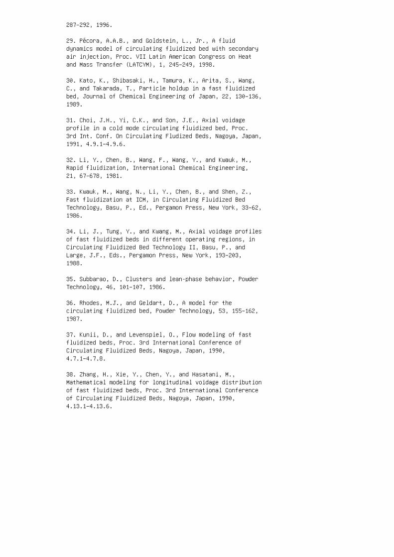
287–292, 1996.
29. Pécora, A.A.B., and Goldstein, L., Jr., A fluiddynamics model of circulating fluidized bed with secondaryair injection, Proc. VII Latin American Congress on Heatand Mass Transfer (LATCYM), 1, 245–249, 1998.
30. Kato, K., Shibasaki, H., Tamura, K., Arita, S., Wang,C., and Takarada, T., Particle holdup in a fast fluidizedbed, Journal of Chemical Engineering of Japan, 22, 130–136,1989.
31. Choi, J.H., Yi, C.K., and Son, J.E., Axial voidageprofile in a cold mode circulating fluidized bed, Proc.3rd Int. Conf. On Circulating Fludized Beds, Nagoya, Japan,1991, 4.9.1–4.9.6.
32. Li, Y., Chen, B., Wang, F., Wang, Y., and Kwauk, M.,Rapid fluidization, International Chemical Engineering,21, 67–678, 1981.
33. Kwauk, M., Wang, N., Li, Y., Chen, B., and Shen, Z.,Fast fluidization at ICM, in Circulating Fluidized BedTechnology, Basu, P., Ed., Pergamon Press, New York, 33–62,1986.
34. Li, J., Tung, Y., and Kwang, M., Axial voidage profilesof fast fluidized beds in different operating regions, inCirculating Fluidized Bed Technology II, Basu, P., andLarge, J.F., Eds., Pergamon Press, New York, 193–203,1988.
35. Subbarao, D., Clusters and lean-phase behavior, PowderTechnology, 46, 101–107, 1986.
36. Rhodes, M.J., and Geldart, D., A model for thecirculating fluidized bed, Powder Technology, 53, 155–162,1987.
37. Kunii, D., and Levenspiel, O., Flow modeling of fastfluidized beds, Proc. 3rd International Conference ofCirculating Fluidized Beds, Nagoya, Japan, 1990,4.7.1–4.7.8.
38. Zhang, H., Xie, Y., Chen, Y., and Hasatani, M.,Mathematical modeling for longitudinal voidage distributionof fast fluidized beds, Proc. 3rd International Conferenceof Circulating Fluidized Beds, Nagoya, Japan, 1990,4.13.1–4.13.6.
39. Rhodes, M.J., Modeling the flow structure ofupward-flowing gas–solid suspensions, Powder Technology,60, 27–38, 1990.
40. Yang, W.C., A model for the dynamics of circulatingfluidized bed loop, in Circulating Fluidized BedTechnology II, Large, J.F., and Basu P., Eds., PergamonPress, New York, 1988, pp. 181–191.
41. Kefa, C., Jianren, F., Zhongyang, L., Jianhua, Y., andMingjiang, N., The prediction and measurement of particlebehavior in circulating fluidized beds, in CirculatingFluidized Bed Technology II, Large, J.F., and Basu, P.,Eds. Pergamon Press, New York, 1988, pp. 27–131.
42. Berruti, F., and Kalogerakis, N., Modeling the internalflow structure of circulating fluidized beds, The CanadianJournal of Chemical Engineering, 67, 1010–1014, 1989.
43. Guardani, R., Characterization of Fluid Dynamics andMathematical Modeling of Circulating Fluidized BedReactor, PhD thesis, Department of Chemical Engineering,Polytechnic School, University of Sao Paulo, Sao Paulo,Brazil, 1989.
44. Wen, C.Y., and Chen, L.H., Fluidized bed freeboardphenomena: entrainment and elutriation, AIChE J., 28, 117,1982.
45. Rohsenow, W.M., and Hartnett, J.P., Handbook of HeatTransfer, McGraw-Hill, New York, 1973.
46. Luikov, A.V., Heat and Mass Transfer, Mir, Moscow, 1980.
47. Isachenko, V.P., Osipova, V.A., and Sukomel, A.S., HeatTransfer, Mir, Moscow, 1977.
48. Incropera, F.P., and DeWitt, D.P., Fundamentals of Heatand Mass Transfer, 4th Ed. John Wiley, New York, 1996.
49. Schmidt, F.W., Henderson, R.E., and Wolgemuth, C.H.,Introduction to Thermal Sciences, 2nd Ed., John Wiley, NewYork, 1984.
50. Toomey, R.D., Johnstone, H.F., Gaseous fluidization ofsolid particles, Chem. Eng. Progress, 48(5), 220–226,1952.
51. de Souza-Santos, M.L., Comprehensive simulator (CSFMB)applied to circulating fludized-bed boilers and gasifiers,

The Open Chemical Engineering Journal, 2, 106– 118, 2008.
18 Chapter 18: Circulating Fluidized-BedSimulation Program and Results
1. Li, X.T., Grace, J.R., Lim, C.J., Watkinson, A.P., Chen,H.P., and Kim, J.R., Biomass gasification in a circulatingbed, Biomass and Bioenergy, 26, 171–193, 2004.
2. Grace, J.R., Brereton, C.M.H., Lim, C.J., Legros, R.,Shao, J., Senior, R.C., Wu, R.L., Muir, J.R., and Engman,R., Circulating Fluidized Bed Combustion of WesternCanadian Fuels, Final Report prepared for the Energy Minesand Resources of Canada under contract 52ss.23440-7-9136,1989.
3. Pécora, A.A.B., Study of the fluid dynamics ofcirculating fluidized beds with secondary air injection,PhD thesis, University of Campinas, Campinas, SP, Brazil,1995.
4. Pécora, A.A.B., Goldstein Jr., L., A fluid dynamicsstudy of circulating fluidized beds with secondary airinjection, ASME Heat Transfer Division, 334, 287–292, 1996.Height (m) 0.E1 1.E-2 2.E-2 3.E-2 4.E-2 5.E-2 6.E-2 0 0.5 11.5 2 2.5 3 3.5 4 F l o w ( k g / s ) Carbonac. AbsorbentInert
FIGURE 18.12 Upward flow of solid particles throughout thelean region during cold oper
ation (test carried out at Unicamp).
A: The Fundamental Equations of TransportPhenomena
1. Bird, R.B., Stewart, W.E., and Lightfoot, E.N.,Transport Phenomena, John Wiley, New York, 1960.
2. Slattery, J.C., Momentum, Energy, and Mass Transfer inContinua, Robert E. Krieger, New York, 1978.
3. Brodkey, R.S., The Phenomena of Fluid Motions, Dover,New York, 1967.
4. Luikov, A.V., Heat and Mass Transfer, Mir, Moscow, 1980.
5. Poling, B.E., Prausnitz, J.M., and O’Connell, J.P., TheProperties of Gases and Liquids, 5th Ed., McGraw-Hill, NewYork, 2000.
6. Reid, C.R., Prausnitz, J.M., and Poling, B.E., TheProperties of Gases and Liquids, 4th Ed., McGraw-Hill, NewYork, 1987.
B: Notes on Thermodynamics
1. Moran, M.J., and Shapiro, H.N., Fundamentals ofThermodynamics, 3rd Ed., John Wiley, New York, 1996.
2. van Wylen, G.J., and Sonntag R.E., Fundamentals ofClassical Thermodynamics, John Wiley, New York, 1973.
3. Kestin J., A Course in Thermodynamics, Vols. I and II,Hemisphere, New York, 1979.
4. Perry, J.H., Green, D.W., and Maloney, J.O., in Perry’sChemical Engineers Handbook, 7th Ed., Perry, J.H., Ed.,McGraw-Hill, New York, 1997, 12–1 to 12–90.
5. Szargut, J., Morris, D.R., Steward, F.R., ExergyAnalysis of Thermal, Chemical and Metallurgical Processes,Hemisphere, New York, 1988.
6. Beaton, C.F., and Hewitt, G.F., Physical Property Datafor the Design Engineer, Hemisphere, New York, 1989.
7. Alemasov, V.E., Dregalin, A.F., Tishin, A.P., andKhudyakov, V.A., Computation methods, in Thermodynamic andThermophysical Properties of Combustion Products, Glushko,V.P., Ed., Vol. I, Viniti, Moscow, 1971.
8. Yaws, C.L., Hood, L.D., Gorin, C., Thakore, S., andMiller, J.W., Jr., Correlation constants for chemicalcompounds, Chemical Engineering, 16, 79–87, 1976.
9. Yaws, C.L., Schorr, G.R., Shah, P.N., and Miller, J.W.,Jr., Correlation constants for chemical compounds,Chemical Engineering, 22, 153–161, 1976.
10. Poling, B.E., Prausnitz, J.M., and O’Connell, J.P., TheProperties of Gases and Liquids, 5th Ed., McGraw-Hill, NewYork, 2000.
11. Reid, C.R., Prausnitz, J.M., and Poling, B.E., TheProperties of Gases and Liquids, 4th Ed., McGraw-Hill, NewYork, 1987.
12. Ergun S., Coal classification and characterization, inCoal Conversion Technology, Wen, C.Y., and Lee. E.S.,Eds., Addison-Wesley, Reading, MA, 1979, pp. 1–53.
D: Improvements on Various Aspects
1. Soo. S.L., Note on motions of phases in a fluidized bed,Powder Technology, 45, 169– 172, 1986.
2. Soo, S.L., Average circulatory motion of particles influidized beds, Powder Technology, 57, 107–117, 1989.
3. Soo, S.L., Particulates and Continuum, Multiphase FluidDynamics, Hemisphere, New York, 1989.
4. Finlayson, B.A., The Method of Weighted Residuals andVariational Principles, Academic Press, New York, 1972.
5. Villadsen, J., and Michelsen, M.L., Solution ofDifferential Equation Models by Polynomial Approximations,Prentice-Hall, New Jersey, 1978.
6. de Souza-Santos, M. L., Analytical and ApproximateMethods Applied to Transport Phenomena, CRC Press, NewYork, 2007.
7. de Souza-Santos, M.L., Modelling and Simulation ofFluidized‑Bed Boilers and Gasifiers for CarbonaceousSolids, PhD thesis, University of Sheffield, Sheffield,United Kingdom, 1987.
8. de Souza-Santos, M.L., Comprehensive modelling andsimulation of fluidized-bed boilers and gasifiers, Fuel,68, 1507–1521, 1989.
9. de Souza-Santos, M.L., A new version of CSFB,Comprehensive Simulator for Fluidized Bed Equipment, Fuel,86(12–13), 1684–1709, 2007.
10. de Souza-Santos, M.L., Comprehensive simulator (CSFMB)applied to circulating fluidized bed boilers and gasifiers,The Open Chemical Engineering Journal, 2, 106–118, 2008.
11. de Souza-Santos, M.L., CSFB applied to fluidized-bedgasification of special fuels, Fuel, 88, 5, 826–833, 2009.
E: Basics on Turbulent Flow
1. Bird, R.B., Stewart, W.E., and Lightfoot, E.N.,Transport Phenomena, John Wiley, New York, 1960.
2. Slattery, J.C., Momentum, Energy, and Mass Transfer inContinua, Robert E. Krieger, New York, 1978.
3. Brodkey, R.S., The Phenomena of Fluid Motions, Dover,New York, 1967.
4. Smoot, L.D., and Smith, P.J., Coal Combustion andGasification, Plenum Press, New York, 1985.
5. Luikov, A.V., Heat and Mass Transfer, Mir, Moscow, 1980.
6. Incropera, F.P., and DeWitt, D.P., Fundamentals of Heatand Mass Transfer, 4th Ed. John Wiley, New York, 1996.
7. Schmidt, F.W., Henderson, R.E., and Wolgemuth, C.H.,Introduction to Thermal Sciences, 2nd Ed., John Wiley, NewYork, 1984.
8. Rohsenow, W.M., and Hartnett, J.P., Handbook of HeatTransfer, McGraw-Hill, New York, 1973.
9. Libby, P.A., and Williams, F.A., Turbulent ReactingFlows, Academic Press, New York, 1994.
10. Smoot, L.D., and Pratt, D.T., Pulverized-CoalCombustion and Gasification, Plenum Press, New York, 1979.
11. Glassman, I., Combustion, 3rd ed., Academic Press, SanDiego, CA, 1996.
12. Warnatz, J., Maas, U., and Dibble, R.W., Combustion,Springer, Berlin, Germany, 1999.
13. Kuo, K.K., Principles of Combustion, John Wiley, NewYork, 1986.
F: Classification of Modeling forBubbling Fluidized-Bed Equipment
1. de Souza-Santos, M.L., Modelling and Simulation ofFluidized‑Bed Boilers and Gasifiers for CarbonaceousSolids, PhD thesis, University of Sheffield, Sheffield,United Kingdom, 1987.
* After that, several other models appeared in theliterature, as well as improvements on former ones.
bed. A few of those can be found in the reference list ofChapter 17.
2. de Souza-Santos, M.L., Comprehensive modelling andsimulation of fluidized-bed boilers and gasifiers, Fuel,68, 1507–1521, 1989.
3. de Souza-Santos, M.L., A study on pressurizedfluidized-bed gasification of biomass through the use ofcomprehensive simulation, in Proc. Fourth InternationalConference on Technologies and Combustion for a CleanEnvironment, Lisbon, Portugal, July 7–10, 1997, paper25.2, Vol. II, pp. 7–13.
4. de Souza-Santos, M.L., A study on pressurizedfluidized-bed gasification of biomass through the use ofcomprehensive simulation, in Combustion Technologies for aClean Environment, Gordon and Breach, Amsterdam,Netherlands, 1998.
5. de Souza-Santos, M.L., Application of comprehensivesimulation of fluidized-bed reactors to the pressurizedgasification of biomass, Journal of the Brazilian Societyof Mechanical Sciences, 16(4), 376–383, 1994.
6. de Souza-Santos, M.L., Search for favorable conditionsof atmospheric fluidized-bed gasification of sugar-canebagasse through comprehensive simulation, in Proc. 14thBrazilian Congress of Mechanical Engineering, Bauru, SãoPaulo, Brazil, December 8–12, 1997.
7. de Souza-Santos, M.L., Search for favorable conditionsof pressurized fluidized-bed gasification of sugar-canebagasse through comprehensive simulation, in Proc. 14thBrazilian Congress of Mechanical Engineering, Bauru, SãoPaulo, Brazil, December 8–12, 1997.
8. de Souza-Santos, M.L., A study on thermo-chemicallyrecuperated power generation systems using natural gas,
Fuel, 76(7), 593–601, 1997.
9. Rabi, J.A., and de Souza-Santos, M.L., Incorporation ofa 2-flux model for radiative heat transfer in acomprehensive fluidized bed simulator. Part I: Preliminarymodel equations, in Proc. ENCIT‑2002, 9th BrazilianCongress on Engineering and Thermal Sciences, Caxambu,Brazil, October 15–18, 2002.
10. Rabi, J.A., and de Souza-Santos, M.L., Incorporation ofa 2-flux model for radiative heat transfer in acomprehensive fluidized bed simulator. Part II: Numericalresults and assessment, ENCIT‑2002, 9th BrazilianCongress on Engineering and Thermal Sciences, Caxambu,Brazil, October 15–18, 2002.
11. Rabi, J.A., Usage of Flux Method to Improve RadiativeHeat Transfer Modelling inside Bubbling Fluidized BedBoilers and Gasifiers, PhD thesis, Faculty of MechanicalEngineering, State University of Campinas, Campinas, SãoPaulo, Brazil, 2002.
12. Rajan, R.R., and Wen, C.Y., A comprehensive model forfluidized bed coal combustors, AIChE J., 26(4), 642–655,1980.
13. Costa, M.A.S., and de Souza-Santos, M.L., Studies onthe mathematical modeling of circulation rates ofparticles in bubbling fluidized beds, Power Technology,103, 110– 116, 1999.
14. Rabi, J.A., and de Souza-Santos, M.L., Incorporation ofa two-flux model for radiative heat transfer in acomprehensive fluidized bed simulator. Part I: Preliminarytheoretical investigations, Thermal Engineering, 3, 64–70,2003.
15. Raman, P., Walawender, W.P., Fan, L.T., and Chang,C.C., Mathematical model for the fluid-bed gasification ofbiomass materials. application to feedlot manure, Ind. Eng.Chem. Process Des. Dev., 20(4), 686–692, 1981.
16. Chang, C.C., Fan, L.T., and Walawender, W.P., Dynamicmodeling of biomass gasification in a fluidized bed, AIChESymp. Series, 80(234), 80–90, 1984.
17. Tojo, K., Chang, C.C., and Fan, L.T., Modeling ofdynamic and steady-state shallow fluidized bed coalcombustors. effects of feeder distribution, Ind. Eng. Chem.Process Des. Dev., 20(3), 411–416, 1981.
18. Weimer, A.W., and Clough, D.E., Modeling a low pressuresteam-oxygen fluidized bed coal gasification reactor,Chem. Eng. Sci., 36, 549–567, 1981.
19. Overturf, B.W., and Reklaitis, G.V., Fluidized-bedreactor model with generalized particle balances. Part I:Formulation and solution, AIChE J., 29(5), 813–820, 1983.
20. Overturf, B.W., and Reklaitis, G.V., Fluidized-bedreactor model with generalized particle balances. Part II:Coal combustion application, AIChE J., 29(5), 820–829,1983.
21. Campbell, E.K., and Davidson, J.F., The combustion ofcoal in fluidized beds, Inst. Fuel Symp. Series,1:A2.1–A2.9, 1975.
22. Gibbs, B.M., A mathematical model for predicting theperformance of a fluidized combustion, Institute of FuelSymposium Series, 1(1), A5.1–5.10, 1975.
23. Gordon, A.L., and Amudson, N.R., Modelling of fluidizedbed reactors-IV: Combustion of carbon particles, Chem.Eng. Sci., 31(12), 1163–1178, 1976.
24. Chen, T.P., and Saxena, S.C., Mathematical modeling ofcoal combustion in fluidized beds with sulphur emissioncontrol by limestone or dolomite, Fuel, 56, 501–413, 1977.
25. Horio, M., and Wen, C.Y., An assessment offluidized-bed modeling, AIChE Symp. Series, 73(161), 9–21,1977.
26. Horio, M., Rengarajan, P., Krishnan, R., and Wen, C.Y.,Fluidized Bed Combustor Modeling, West VirginiaUniversity, Morgantown, WV, NASA Report No. NAS3-19725,1977.
27. Gordon, A.L., Caram, H.S., and Amudson, N.R., Modellingof fluidized bed reactors—V; Combustion of coal particles:an extension, Chem. Eng. Sci., 33, 713–722, 1978.
28. Horio, M., Mori, S., and Muchi, I., A model study fordevelopment of low NO x fluidized-bed coal combustion, inProc. 5th International Conference of Fluidized BedCombustion, Washington DC, Conf-771272-p2, II, 605–624,1978.
29. Chen, T.P., Saxena, S.C., A mechanistic model
applicable to coal combustion in fluidized beds, AIChESymp. Series, 74(176), 149–161, 1978.
30. MIT Energy Laboratory, Modelling of Fluidized BedCombustion of Coal. Final Report: “A First Order” SystemModel of Fluidized Bed Combustor, Vol. I, MassachusettsInstitute of Technology, Report to U.S. Department ofEnergy, Contract No. E(49-18)2295, 1978.
31. Saxena, S.C., Grewal, N.S., and Venhatoramana, M.,Modeling of a Fluidized Bed Combustor with Immersed Tubes,University of Illinois at Chicago Circle, Report to U.S.Department of Energy, No. EE-1787-10, 1978.
32. Horio, M., and Wen, C.Y., Simulation of fluidized bedcombustors, Part I. Combustion efficiency and temperatureprofile, AIChE Symp. Series, 74(176), 101–109, 1978.
33. Fan, L.T., Tojo, K., and Chang, C.C., Modeling ofshallow fluidized bed combustion of coal particles, Ind.Eng. Chem. Process Des. Dev., 18(2), 333–337, 1979.
34. Kayihan, F., and Reklaitis, G.V., Modeling of stagedfluidized bed coal pyrolysis reactors, Ind. Eng. Chem.Process Des. Dev., 19, 15–23, 1980.
35. Park, D., Levenspiel, O., and Fitzgerald, T.J., A modelfor scale atmospheric fluidized bed combustors, AIChESymp. Series, 77(277), 116–126, 1981.
36. Congalidis, J.P., and Georgakis, C., Multiplicitypatterns in atmospheric fluidized bed coal combustors,Chem. Eng. Sci., 36, 1529, 1981.
37. Glicksman, L., Lord, W., Valenzuela, J., Bar-Cohen, A.,and Hughes, R., A model of fluid mechanics in fluidizedbed combustors, AIChE Symp. Series, 77(205), 139–147, 1981.
38. Fee, D.C., Myles, K.M., Marroquin, G., and Fan, L.S.,An analytical model for freeboard and in-bed limestonesulfation in fluidized-bed coal combustors, Chem. Eng.Sci., 39, 731–737, 1984.
39. Chandran, R.R., and Sutherland, D.D., Performancesimulation of fluidized-bed coal combustors, Preprint Am.Chem. Soc., Div. Fuel Chem., 33(2), 145, 1988.
40. Azevedo, J.L.T., Carvalho, M.G., and Durão, D.F.G.,Mathematical modeling of coalfired fluidized bedcombustors, Combustion and Flame, 77, 91–100, 1989.
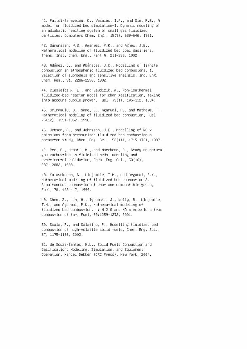
41. Faltsi-Saravelou, O., Vasalos, I.A., and Sim, F.B., Amodel for fluidized bed simulation—I. Dynamic modeling ofan adiabatic reacting system of small gas fluidizedparticles, Computers Chem. Eng., 15(9), 639–646, 1991.
42. Gururajan, V.S., Agarwal, P.K., and Agnew, J.B.,Mathematical modeling of fluidized bed coal gasifiers,Trans. Inst. Chem. Eng., Part A, 211–238, 1992.
43. Adánez, J., and Abánades, J.C., Modelling of lignitecombustion in atmospheric fluidized bed combustors. 1.Selection of submodels and sensitive analysis, Ind. Eng.Chem. Res., 31, 2286–2296, 1992.
44. Ciesielczyk, E., and Gawdizik, A., Non-isothermalfluidized-bed reactor model for char gasification, takinginto account bubble growth, Fuel, 73(1), 105–112, 1994.
45. Sriramulu, S., Sane, S., Agarwal, P., and Mathews, T.,Mathematical modeling of fluidized bed combustion, Fuel,75(12), 1351–1362, 1996.
46. Jensen, A., and Johnsson, J.E., Modelling of NO xemissions from pressurized fluidized bed combustion—aparameter study, Chem. Eng. Sci., 52(11), 1715–1731, 1997.
47. Pre, P., Hemati, M., and Marchand, B., Study on naturalgas combustion in fluidized beds: modeling andexperimental validation, Chem. Eng. Sci., 53(16),2871–2883, 1998.
48. Kulasekaran, S., Linjewile, T.M., and Argawal, P.K.,Mathematical modeling of fluidized bed combustion 3.Simultaneous combustion of char and combustible gases,Fuel, 78, 403–417, 1999.
49. Chen, Z., Lin, M., Ignowski, J., Kelly, B., Linjewile,T.M., and Agarwal, P.K., Mathematical modeling offluidized bed combustion. 4: N 2 O and NO x emissions fromcombustion of tar, Fuel, 80:1259–1272, 2001.
50. Scala, F., and Salatino, P., Modelling fluidized bedcombustion of high-volatile solid fuels, Chem. Eng. Sci.,57, 1175–1196, 2002.
51. de Souza-Santos, M.L., Solid Fuels Combustion andGasification: Modeling, Simulation, and EquipmentOperation, Marcel Dekker (CRC Press), New York, 2004.

52. de Souza-Santos, M.L., A New Version of CSFB,Comprehensive Simulator for Fluidized Bed Equipment, Fuel,86, 12–13, 1684–1709, 2007.
53. de Souza-Santos, M.L., CSFB applied to fluidized-bedgasification of special fuels, Fuel, 88(5), 826–833, 2009.
54. Rabi, J.A., and de Souza-Santos, M.L., Comparison oftwo model approaches implemented in a comprehensivefluidized-bed simulator to predict radiative heat transfer:results for a coal-fed boiler, International Journal onComputer and Experimental Simulations in Engineering andScience, 3, 87–105, 2008.
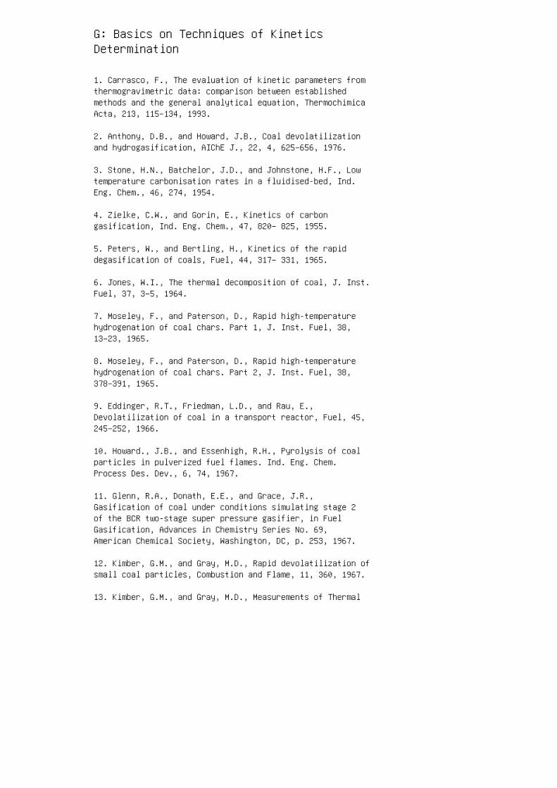
G: Basics on Techniques of KineticsDetermination
1. Carrasco, F., The evaluation of kinetic parameters fromthermogravimetric data: comparison between establishedmethods and the general analytical equation, ThermochimicaActa, 213, 115–134, 1993.
2. Anthony, D.B., and Howard, J.B., Coal devolatilizationand hydrogasification, AIChE J., 22, 4, 625–656, 1976.
3. Stone, H.N., Batchelor, J.D., and Johnstone, H.F., Lowtemperature carbonisation rates in a fluidised-bed, Ind.Eng. Chem., 46, 274, 1954.
4. Zielke, C.W., and Gorin, E., Kinetics of carbongasification, Ind. Eng. Chem., 47, 820– 825, 1955.
5. Peters, W., and Bertling, H., Kinetics of the rapiddegasification of coals, Fuel, 44, 317– 331, 1965.
6. Jones, W.I., The thermal decomposition of coal, J. Inst.Fuel, 37, 3–5, 1964.
7. Moseley, F., and Paterson, D., Rapid high-temperaturehydrogenation of coal chars. Part 1, J. Inst. Fuel, 38,13–23, 1965.
8. Moseley, F., and Paterson, D., Rapid high-temperaturehydrogenation of coal chars. Part 2, J. Inst. Fuel, 38,378–391, 1965.
9. Eddinger, R.T., Friedman, L.D., and Rau, E.,Devolatilization of coal in a transport reactor, Fuel, 45,245–252, 1966.
10. Howard., J.B., and Essenhigh, R.H., Pyrolysis of coalparticles in pulverized fuel flames. Ind. Eng. Chem.Process Des. Dev., 6, 74, 1967.
11. Glenn, R.A., Donath, E.E., and Grace, J.R.,Gasification of coal under conditions simulating stage 2of the BCR two-stage super pressure gasifier, in FuelGasification, Advances in Chemistry Series No. 69,American Chemical Society, Washington, DC, p. 253, 1967.
12. Kimber, G.M., and Gray, M.D., Rapid devolatilization ofsmall coal particles, Combustion and Flame, 11, 360, 1967.
13. Kimber, G.M., and Gray, M.D., Measurements of Thermal
Decomposition of Low and High Rank Non-Swelling Coals atM.H.D Temperatures, British Coal Utilization ResearchAssociation, Document No. MHD 32, 1967.
14. Badzioch, S., Hawksley, P.G.W., Kinetics of thermaldecomposition of pulverized coal particles, Ind. Eng.Chem. Process Des. Dev., 9, 521, 1970.
15. Belt, R.J., Wilson, J.S., and Sebastian, J.J.S.,Continuous rapid carbonisation of powdered coal byentrainment and response surface analysis of data, Fuel,50, 381, 1971.
16. Belt, R.J., and Roder, M.M., Low-sulfur fuel bypressurized entrainment carbonisation of coal, Am. Chem.Soc., Div. of Fuel Chem. Preprints, 17(2), 82, 1972.
17. Coates, R.L., Chen, C.L., and Pope, B.J., Coaldevolatilization in a low pressure, low residence timeentrained flow reactor, in Coal Gasification, Advances inChemistry Series, No. 131, American Chemical Society,Washington, DC, 1974, p. 92.
18. Johnson, J.L., Gasification of Montana lignite inhydrogen and in helium during initial reaction stages, Am.Chem. Soc., Div. of Fuel Chem. Preprints, 20(3), 61, 1975.
19. Shapatina, E.A., Kalyuzhnyi, V.A., and Chukhanov, Z.F.,Technological utilization of fuel for energy, 1. Thermaltreatments of fuels, 1960 (Paper reviewed by S. Badzoich,British Coal Utilization Research Association MonthlyBulletin, 25, 285, 1961.)
20. Moseley, F., and Paterson, D., Rapid high-temperaturehydrogenation of bituminous coal, J. Inst. Fuel, 40, 523,1967.
21. Feldmann, H.F., Simons, W.H., Mimn, J.A., and Hitshue,R.W., Reaction model of bituminous coal hydrogasificationin a dilute phase, Am. Chem. Soc., Div. of Fuel Chem.Preprints, 14(4), 1, 1970.
22. Yu, Q., Brage, C., Chen, G., Sjöström, K., Temperatureimpact on the formation of tar from biomass pyrolysis in afree-fall reactor, Journal of Analytical and AppliedPyrolysis, 40–41, 481–489, 1997.
23. Tsuge, S., Analytical pyrolysis—past, present andfuture, Journal of Analytical and Applied Pyrolysis, 32,1–6, 1995.

24. Bridgwater, A.V., and Peacocke, G.V.C., Fast pyrolysisprocesses for biomass, Renewable and Sustainable EnergyReviews, 4, 1–73, 2000.


