Embed Size (px)
Citation preview
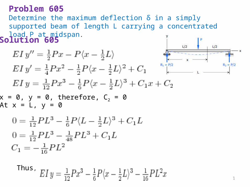
Problem 605Determine the maximum deflection δ in a simply supported beam of length L carrying a concentrated load P at midspan.Solution 605
At x = 0, y = 0, therefore, C2 = 0At x = L, y = 0
Thus,1
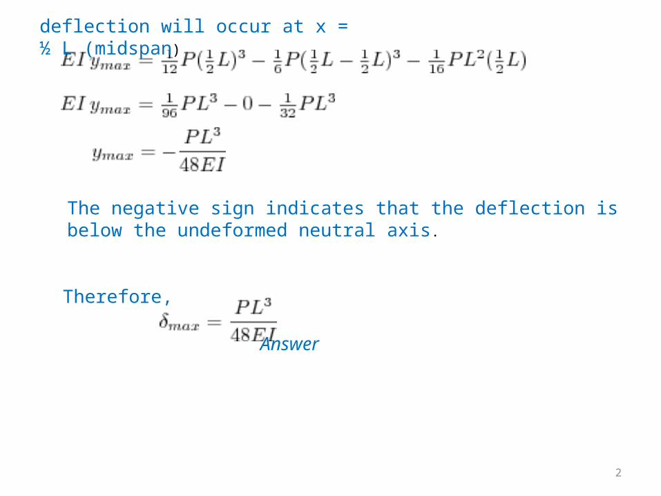
deflection will occur at x = ½ L (midspan)
The negative sign indicates that the deflection is below the undeformed neutral axis.
Therefore, Answer
2
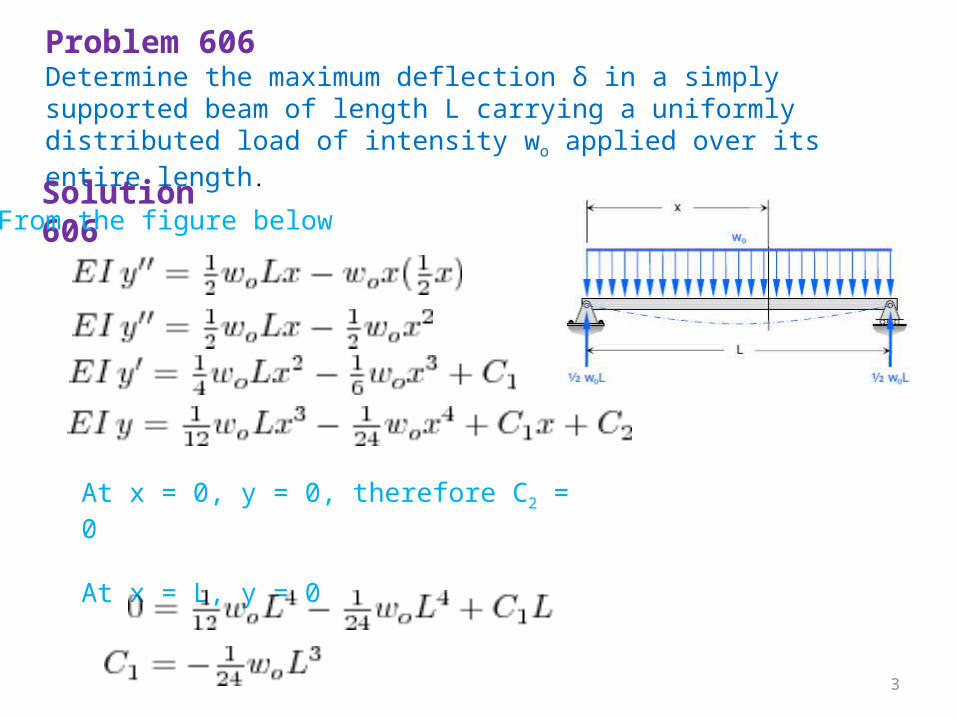
Problem 606Determine the maximum deflection δ in a simply supported beam of length L carrying a uniformly distributed load of intensity wo applied over its entire length.Solution 606 From the figure below
At x = 0, y = 0, therefore C2 = 0 At x = L, y = 0
3
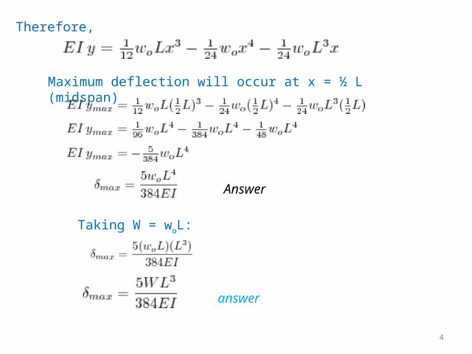
Therefore,
Maximum deflection will occur at x = ½ L (midspan)
Answer
Taking W = woL:
answer
4
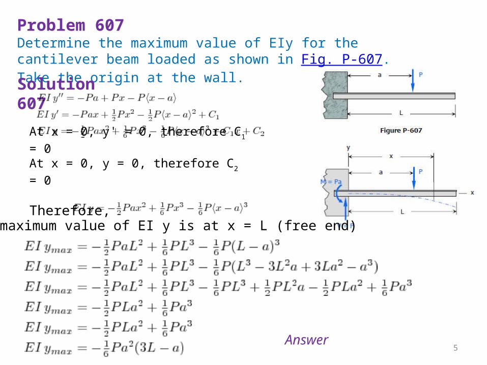
Problem 607Determine the maximum value of EIy for the cantilever beam loaded as shown in Fig. P-607. Take the origin at the wall.Solution 607
At x = 0, y' = 0, therefore C1 = 0At x = 0, y = 0, therefore C2 = 0 Therefore,
The maximum value of EI y is at x = L (free end)
Answer 5
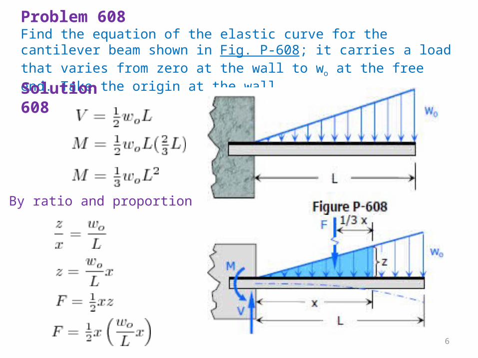
Problem 608Find the equation of the elastic curve for the cantilever beam shown in Fig. P-608; it carries a load that varies from zero at the wall to wo at the free end. Take the origin at the wall.Solution 608
By ratio and proportion
6
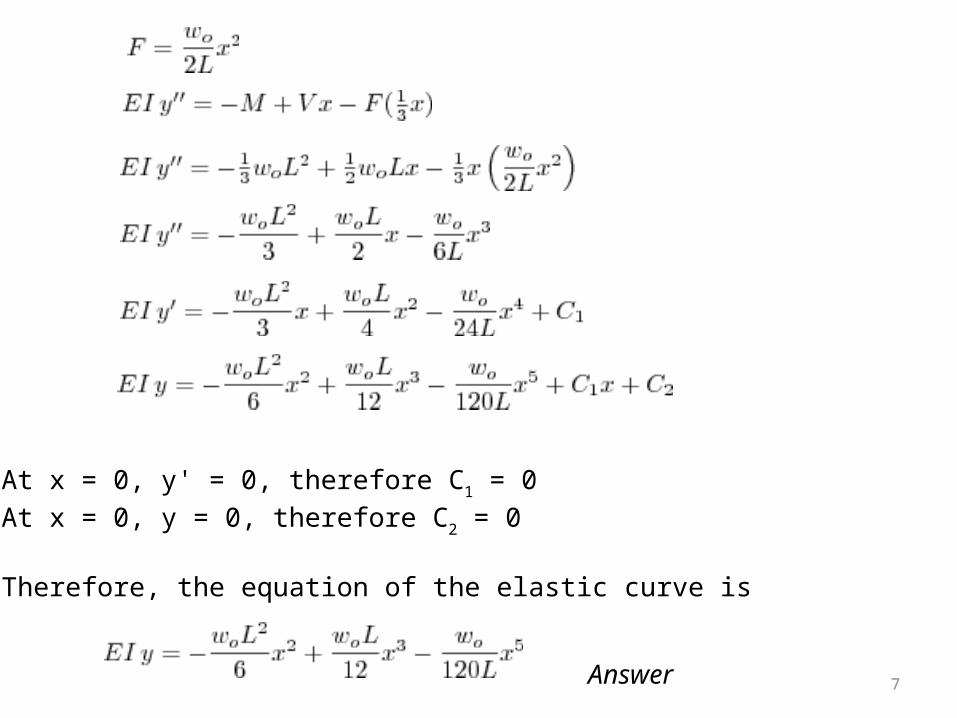
At x = 0, y' = 0, therefore C1 = 0At x = 0, y = 0, therefore C2 = 0 Therefore, the equation of the elastic curve is
Answer
7
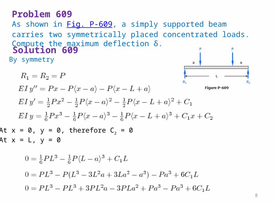
Problem 609As shown in Fig. P-609, a simply supported beam carries two symmetrically placed concentrated loads. Compute the maximum deflection δ.Solution 609 By symmetry
At x = 0, y = 0, therefore C2 = 0At x = L, y = 0
8
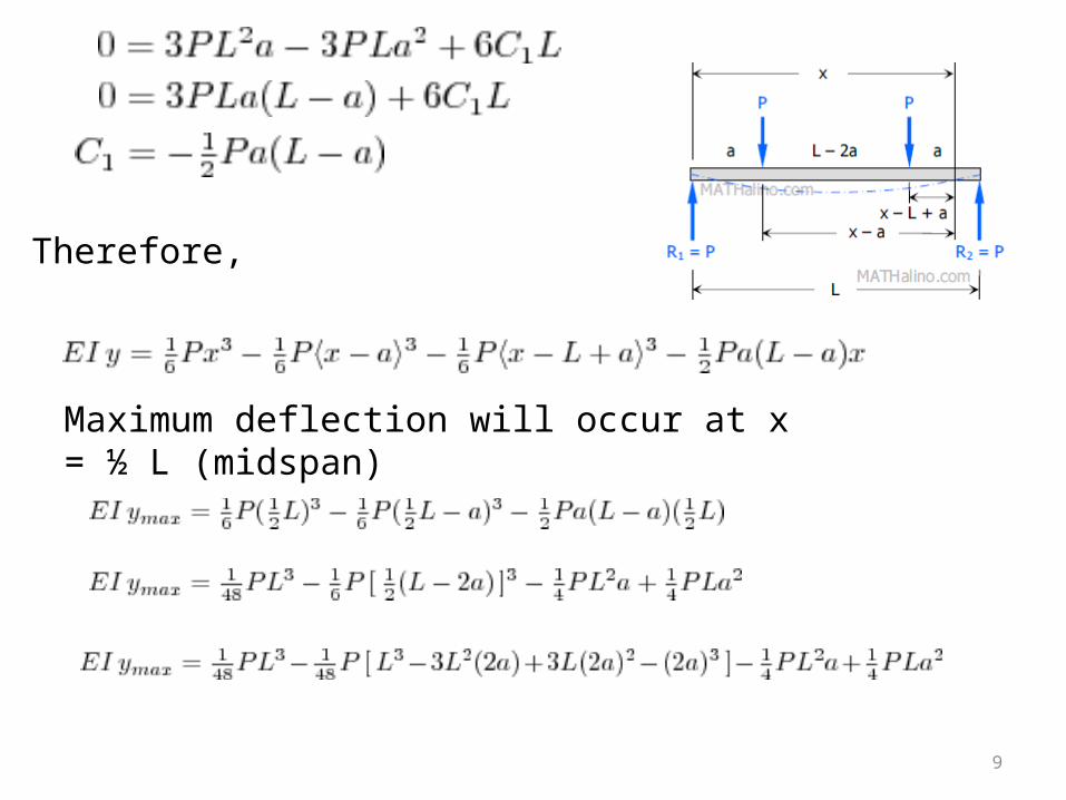
Therefore,
Maximum deflection will occur at x = ½ L (midspan)
9
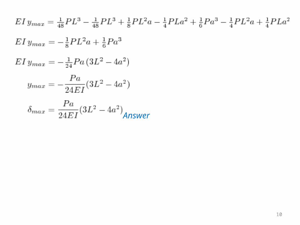
Answer
10
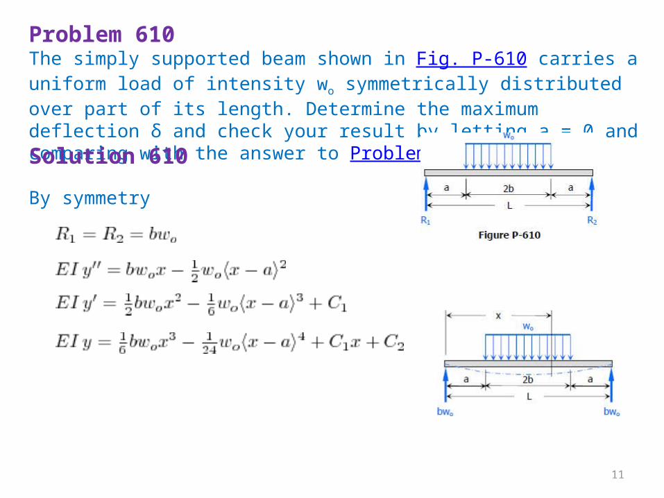
Problem 610The simply supported beam shown in Fig. P-610 carries a uniform load of intensity wo symmetrically distributed over part of its length. Determine the maximum deflection δ and check your result by letting a = 0 and comparing with the answer to Problem 606.Solution 610 By symmetry
11
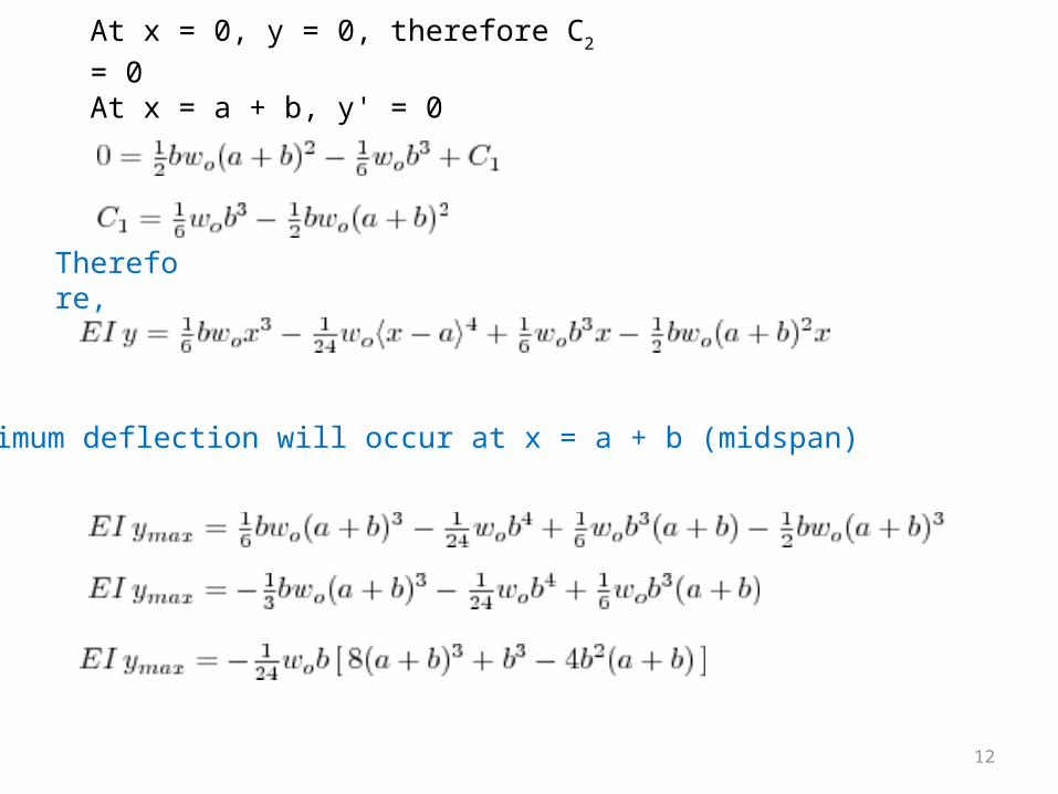
At x = 0, y = 0, therefore C2 = 0At x = a + b, y' = 0
Therefore,
Maximum deflection will occur at x = a + b (midspan)
12
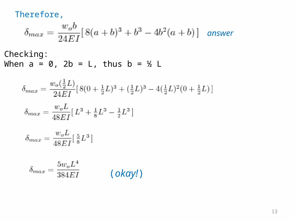
Therefore,
answer
Checking:When a = 0, 2b = L, thus b = ½ L
(okay!)
13
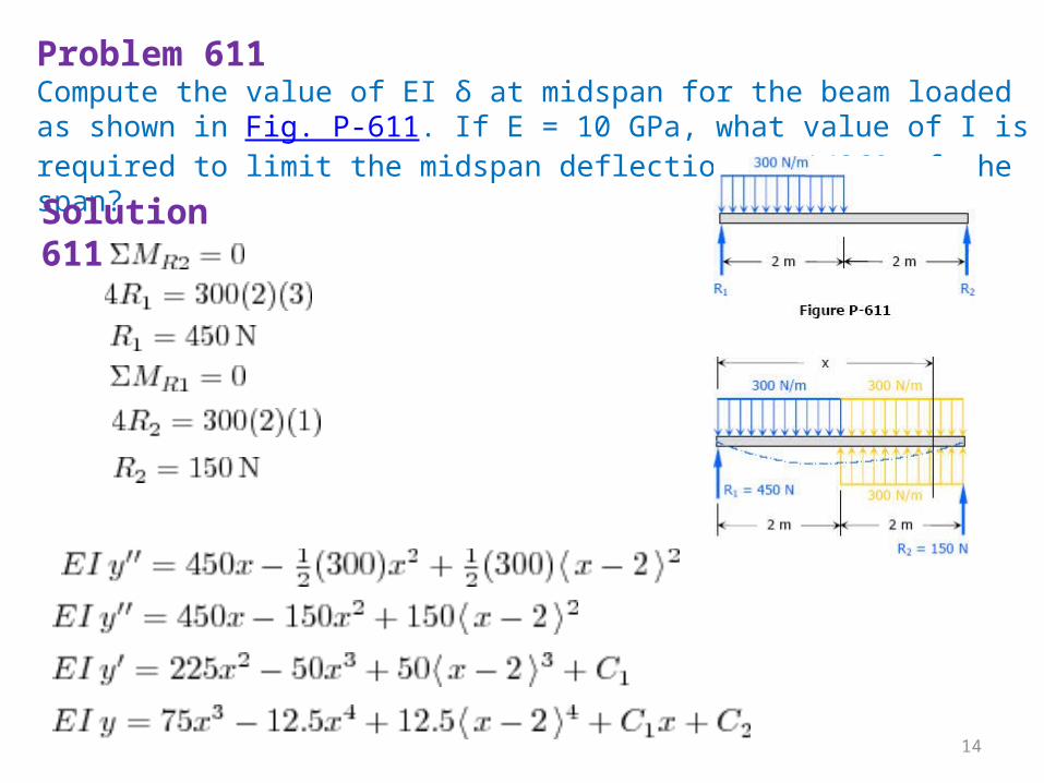
Problem 611Compute the value of EI δ at midspan for the beam loaded as shown in Fig. P-611. If E = 10 GPa, what value of I is required to limit the midspan deflection to 1/360 of the span?Solution 611
14
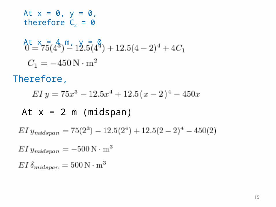
At x = 0, y = 0, therefore C2 = 0 At x = 4 m, y = 0
Therefore,
At x = 2 m (midspan)
15
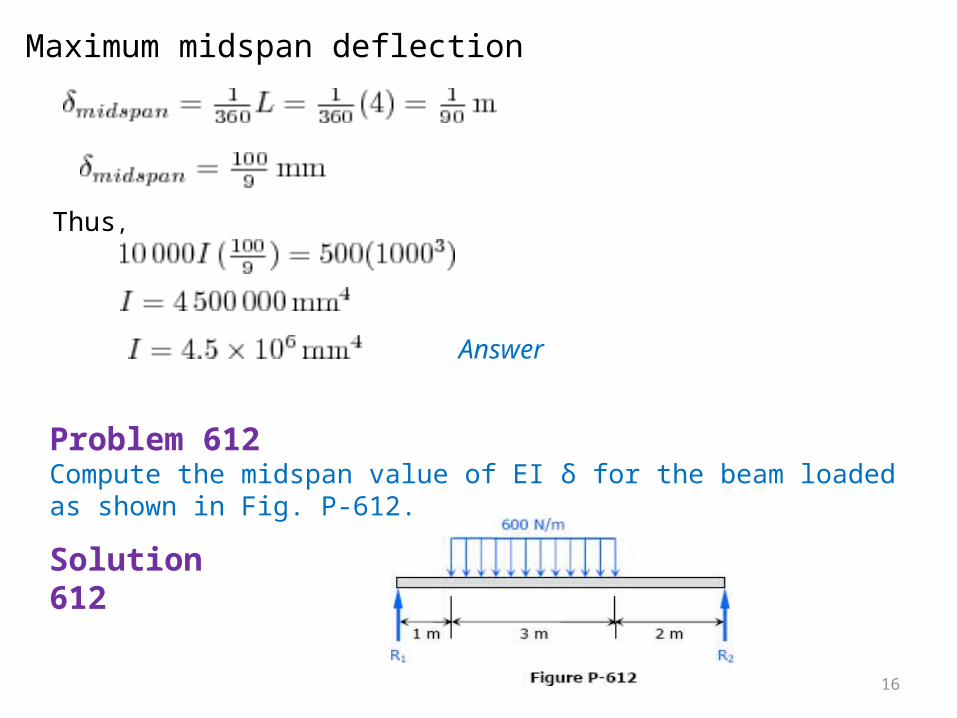
Maximum midspan deflection
Thus,
Answer
Problem 612Compute the midspan value of EI δ for the beam loaded as shown in Fig. P-612.
Solution 612
16
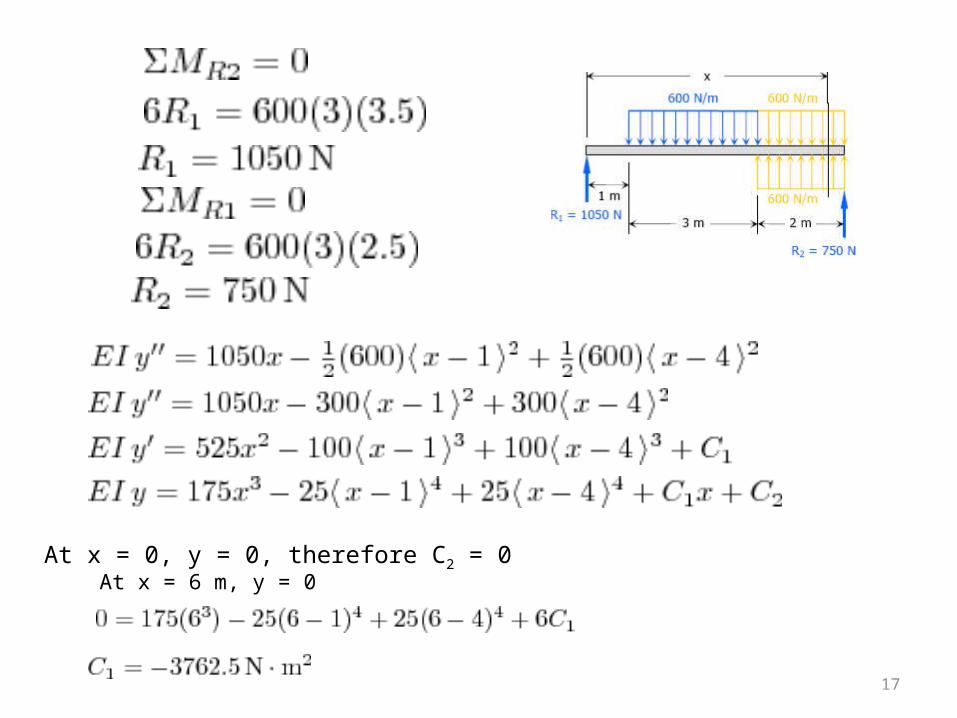
At x = 0, y = 0, therefore C2 = 0At x = 6 m, y = 0
17
Therefore,
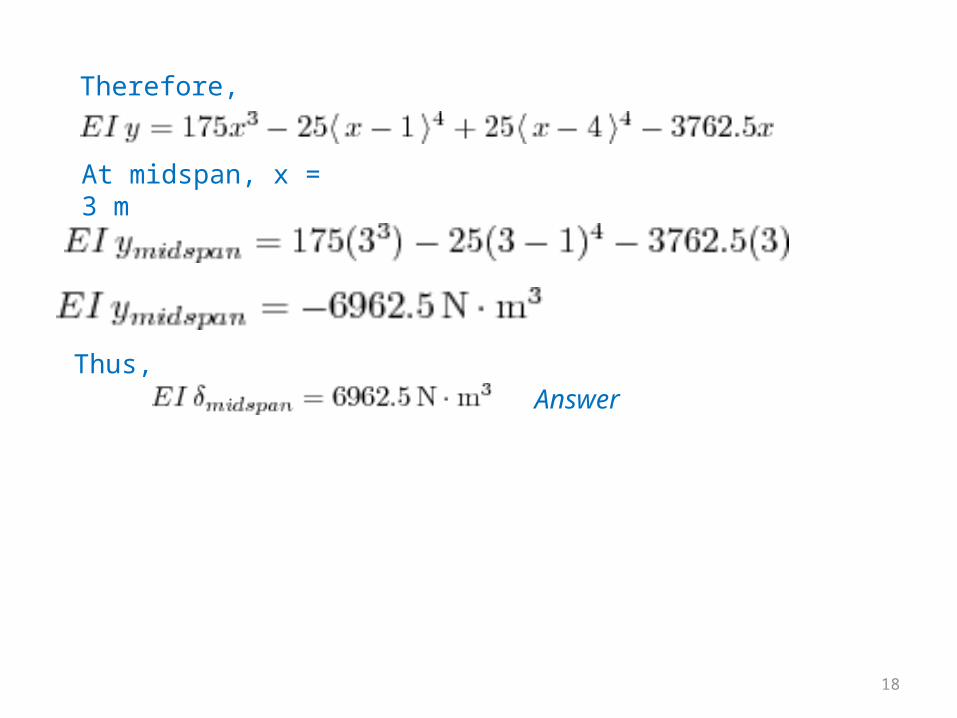
At midspan, x = 3 m
Thus,
Answer
18
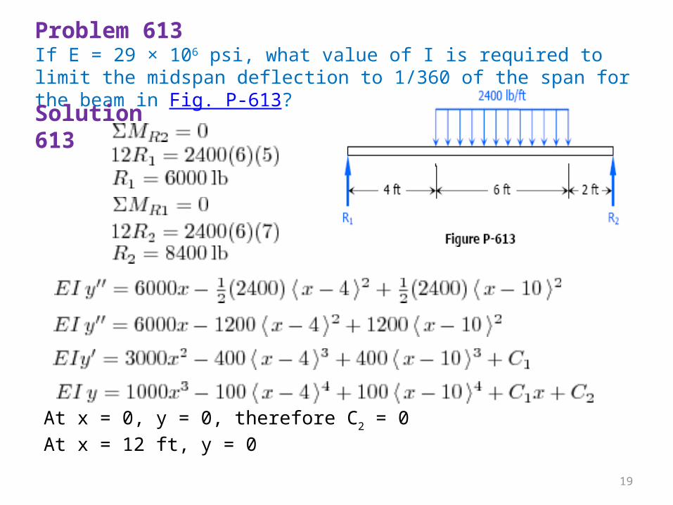
Problem 613If E = 29 × 106 psi, what value of I is required to limit the midspan deflection to 1/360 of the span for the beam in Fig. P-613?Solution 613
At x = 0, y = 0, therefore C2 = 0At x = 12 ft, y = 0
19
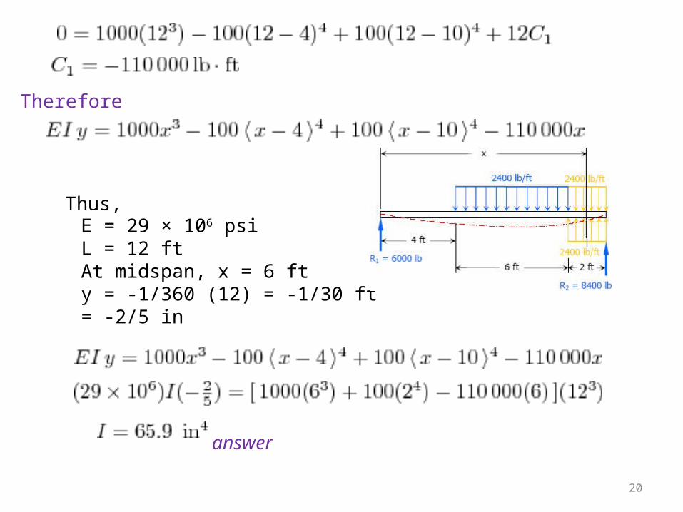
Therefore
E = 29 × 106 psiL = 12 ftAt midspan, x = 6 fty = -1/360 (12) = -1/30 ft = -2/5 in
Thus,
answer
20
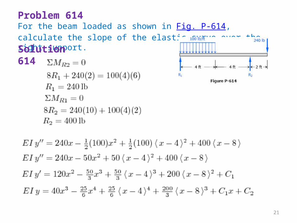
Problem 614For the beam loaded as shown in Fig. P-614, calculate the slope of the elastic curve over the right support. Solution 614
21
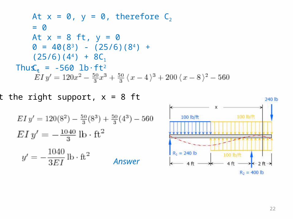
At x = 0, y = 0, therefore C2 = 0At x = 8 ft, y = 00 = 40(83) - (25/6)(84) + (25/6)(44) + 8C1C1 = -560 lb·ft2Thus,
At the right support, x = 8 ft
Answer
22
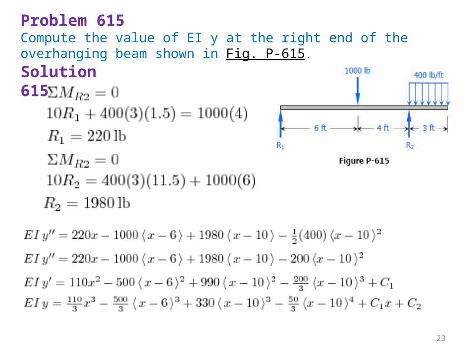
Problem 615Compute the value of EI y at the right end of the overhanging beam shown in Fig. P-615.Solution 615
23
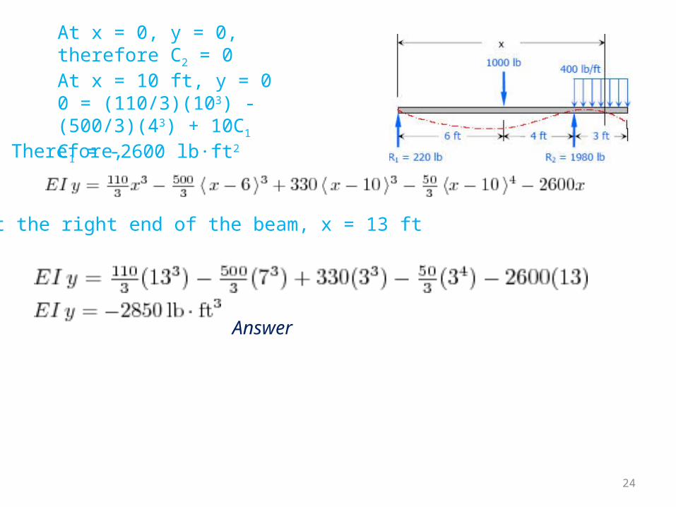
At x = 0, y = 0, therefore C2 = 0At x = 10 ft, y = 00 = (110/3)(103) - (500/3)(43) + 10C1C1 = -2600 lb·ft2
Therefore,
At the right end of the beam, x = 13 ft
Answer
24
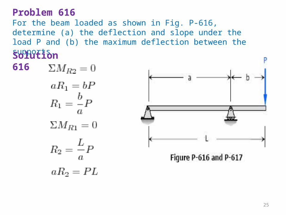
Problem 616For the beam loaded as shown in Fig. P-616, determine (a) the deflection and slope under the load P and (b) the maximum deflection between the supports.Solution 616
25
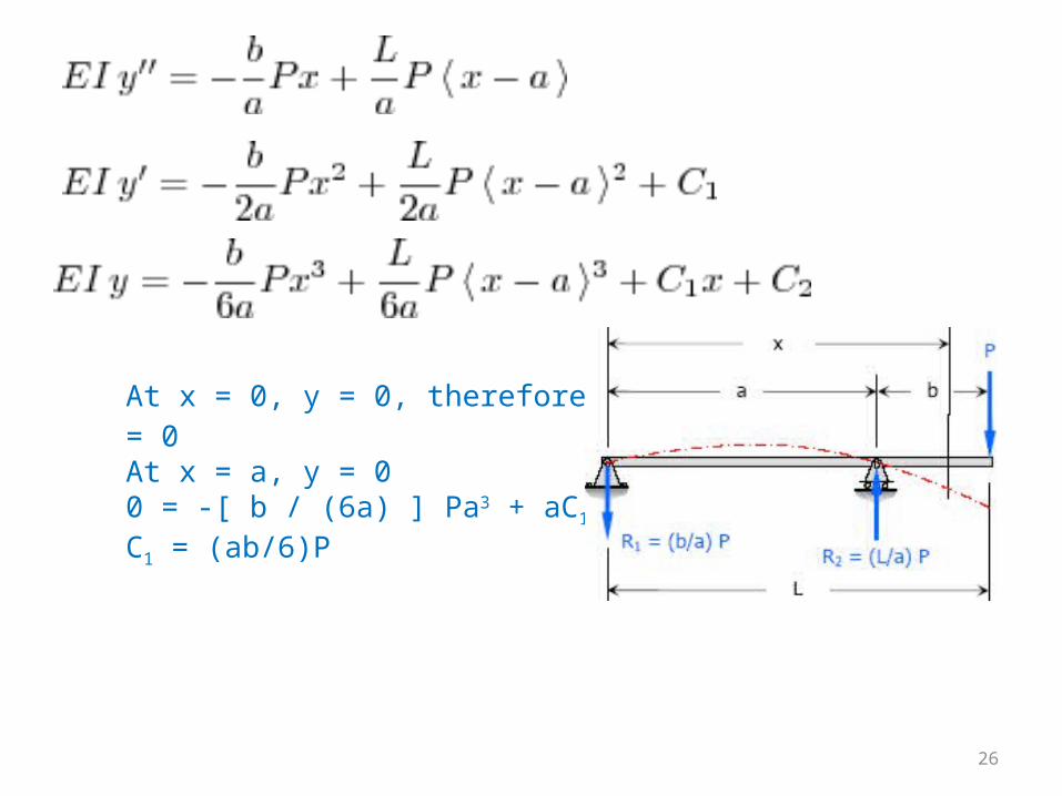
At x = 0, y = 0, therefore C2 = 0At x = a, y = 00 = -[ b / (6a) ] Pa3 + aC1C1 = (ab/6)P
26
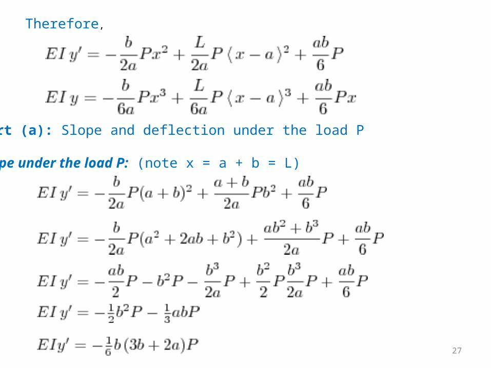
Therefore,
Part (a): Slope and deflection under the load P Slope under the load P: (note x = a + b = L)
27
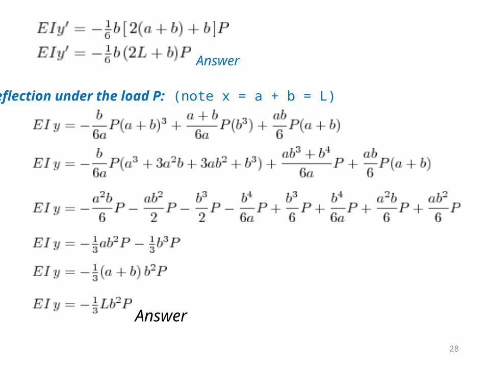
Deflection under the load P: (note x = a + b = L)
Answer
Answer
28
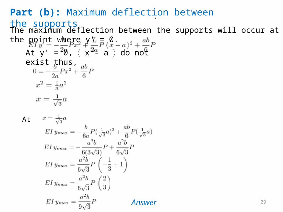
Part (b): Maximum deflection between the supportsThe maximum deflection between the supports will occur at the point where y' = 0.
At y' = 0, ⟨ x - a ⟩ do not exist thus,
,
At
Answer 29
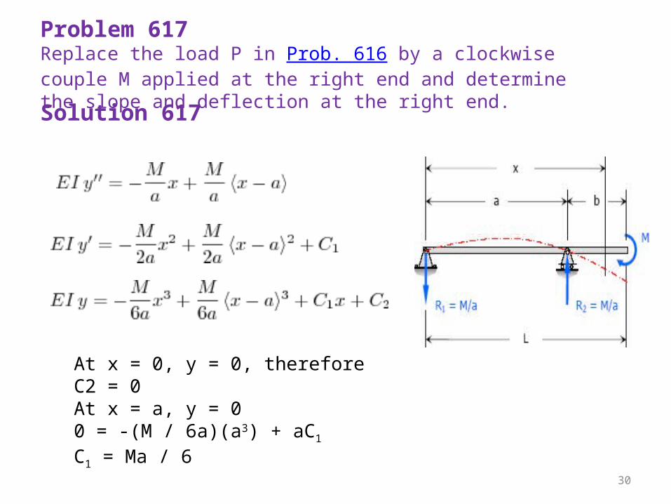
Problem 617Replace the load P in Prob. 616 by a clockwise couple M applied at the right end and determine the slope and deflection at the right end.Solution 617
At x = 0, y = 0, therefore C2 = 0At x = a, y = 00 = -(M / 6a)(a3) + aC1C1 = Ma / 6
30
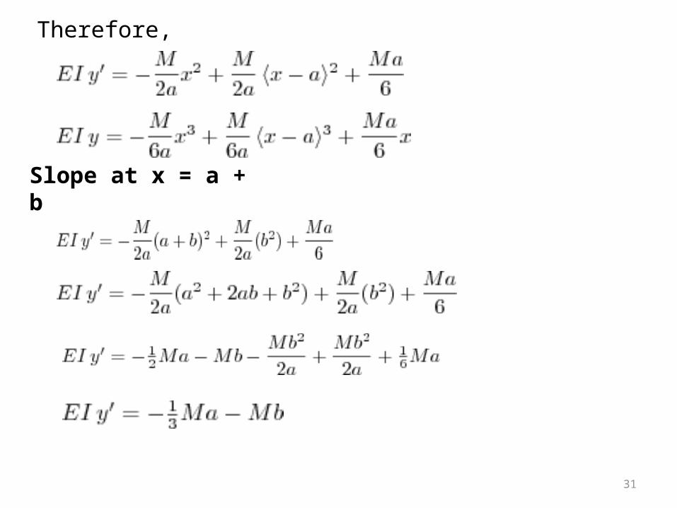
Therefore,
Slope at x = a + b
31
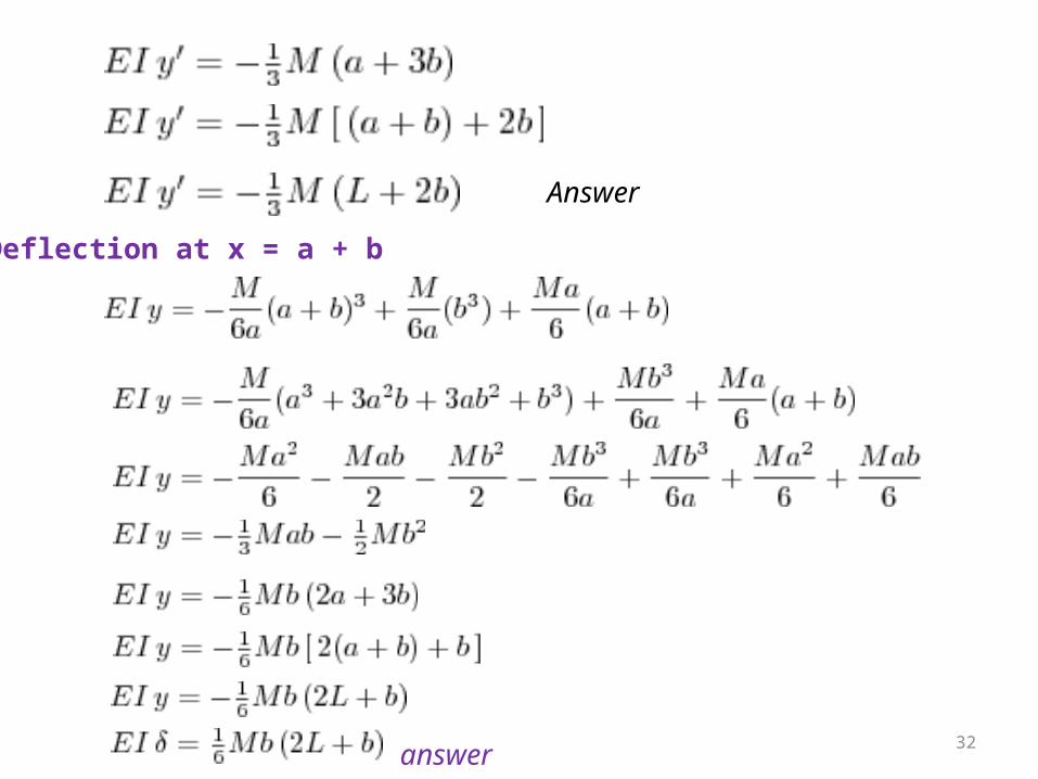
Answer
Deflection at x = a + b
answer 32
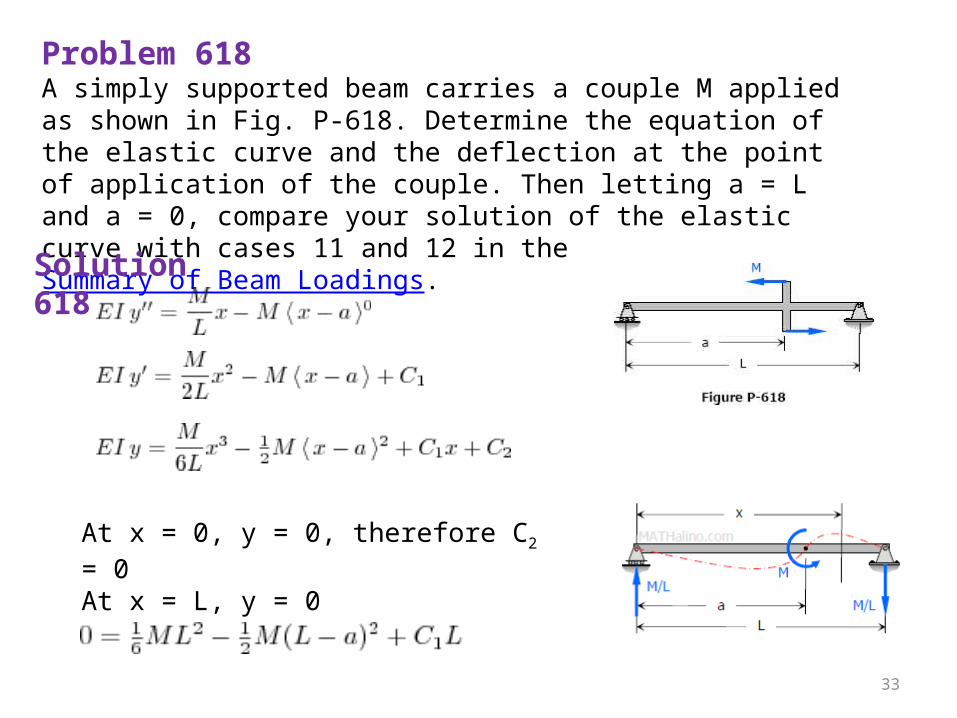
Problem 618A simply supported beam carries a couple M applied as shown in Fig. P-618. Determine the equation of the elastic curve and the deflection at the point of application of the couple. Then letting a = L and a = 0, compare your solution of the elastic curve with cases 11 and 12 in the Summary of Beam Loadings.Solution 618
At x = 0, y = 0, therefore C2 = 0At x = L, y = 0
33
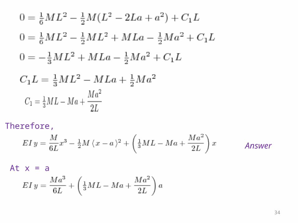
Therefore,
Answer
At x = a
34
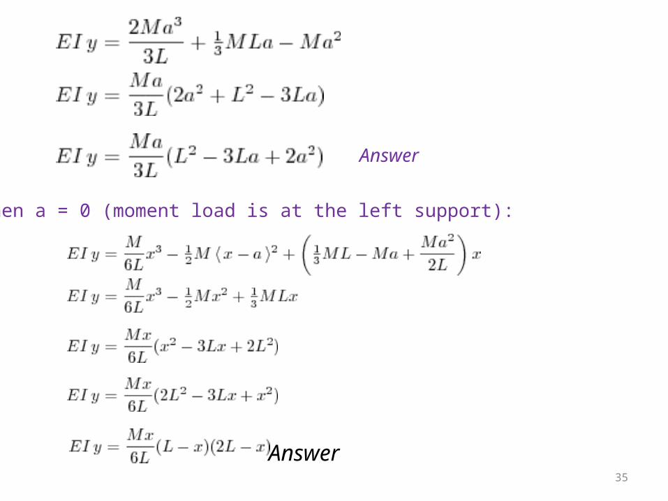
Answer
When a = 0 (moment load is at the left support):
Answer35
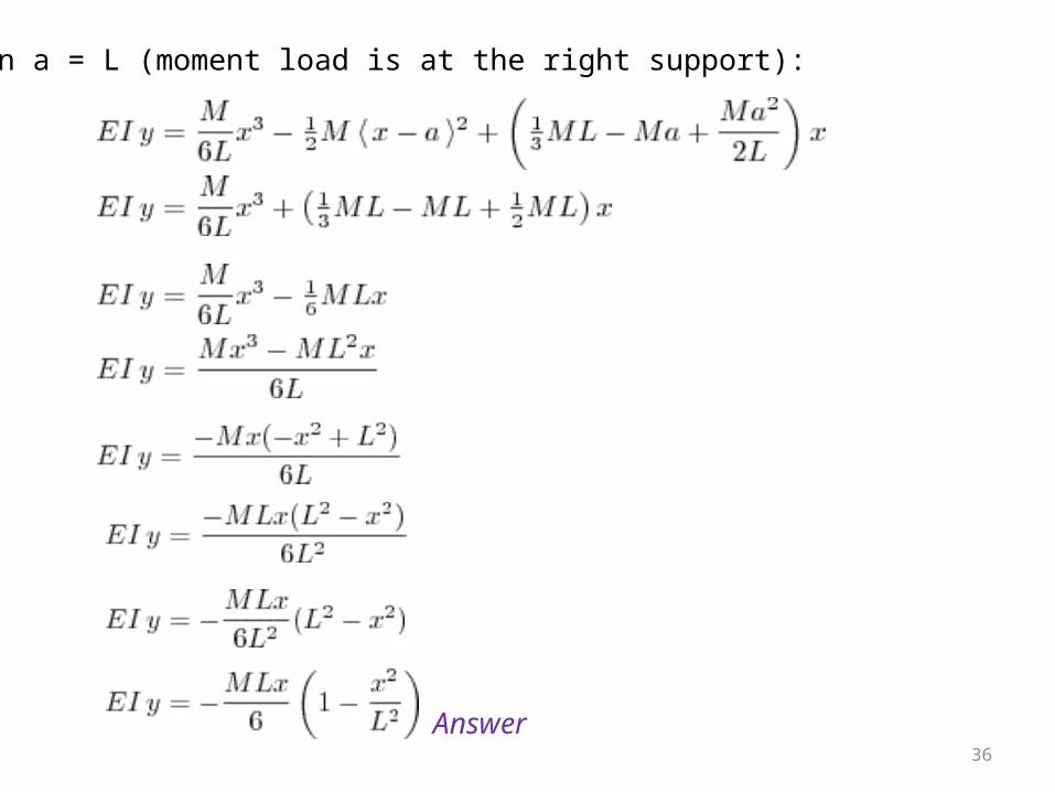
When a = L (moment load is at the right support):
Answer
36
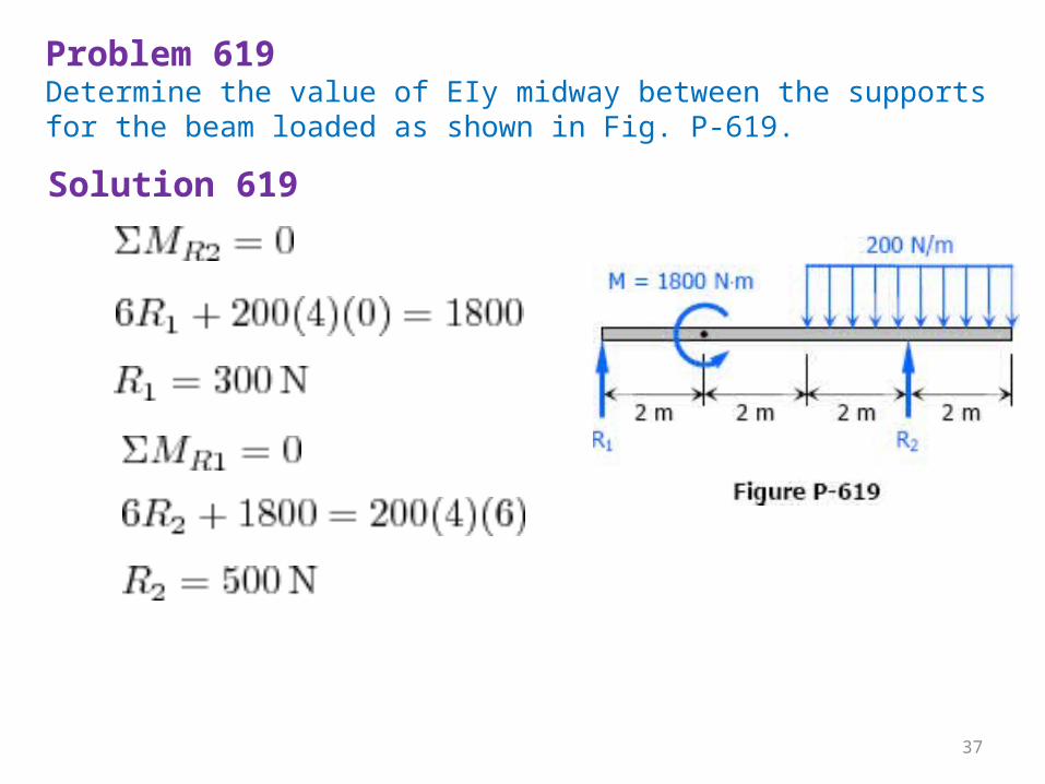
Problem 619Determine the value of EIy midway between the supports for the beam loaded as shown in Fig. P-619.
Solution 619
37
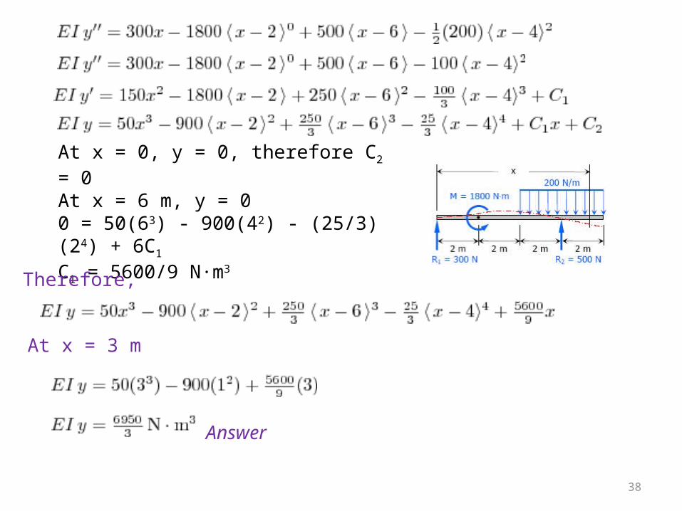
At x = 0, y = 0, therefore C2 = 0At x = 6 m, y = 00 = 50(63) - 900(42) - (25/3)(24) + 6C1C1 = 5600/9 N·m3
Therefore,
At x = 3 m
Answer
38
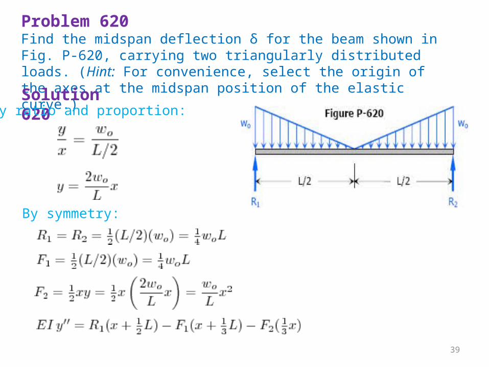
Problem 620Find the midspan deflection δ for the beam shown in Fig. P-620, carrying two triangularly distributed loads. (Hint: For convenience, select the origin of the axes at the midspan position of the elastic curve.)Solution 620 By ratio and proportion:
By symmetry:
39
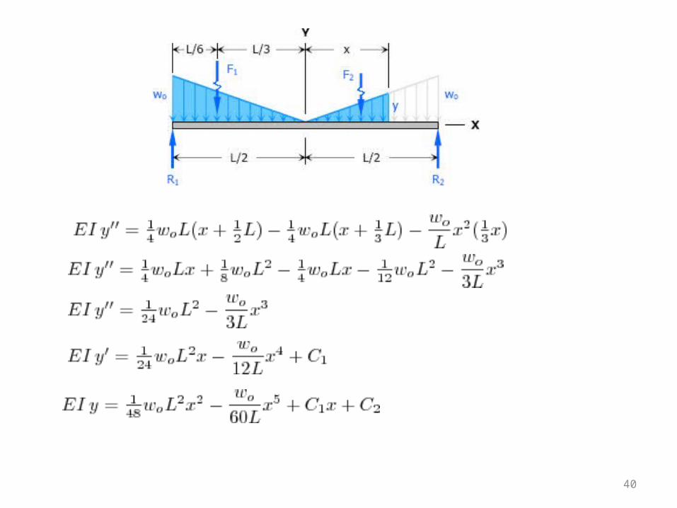
40
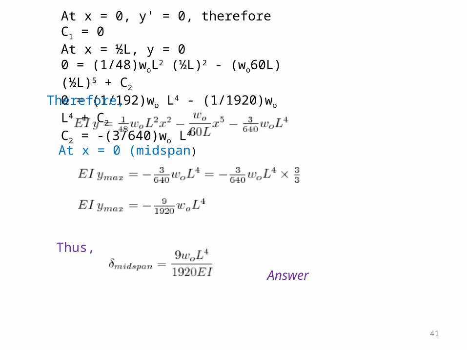
At x = 0, y' = 0, therefore C1 = 0At x = ½L, y = 00 = (1/48)woL2 (½L)2 - (wo60L)(½L)5 + C20 = (1/192)wo L4 - (1/1920)wo L4 + C2C2 = -(3/640)wo L4
Therefore,
At x = 0 (midspan)
Thus,
Answer
41
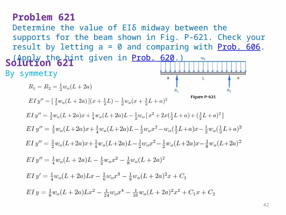
Solution 621 By symmetry
Problem 621Determine the value of EIδ midway between the supports for the beam shown in Fig. P-621. Check your result by letting a = 0 and comparing with Prob. 606. (Apply the hint given in Prob. 620.)
42
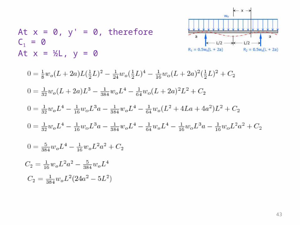
At x = 0, y' = 0, therefore C1 = 0At x = ½L, y = 0
43
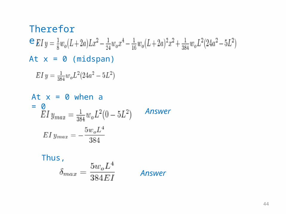
At x = 0 (midspan)
AnswerAt x = 0 when a = 0
Thus, Answer
Therefore,
44
Slope,
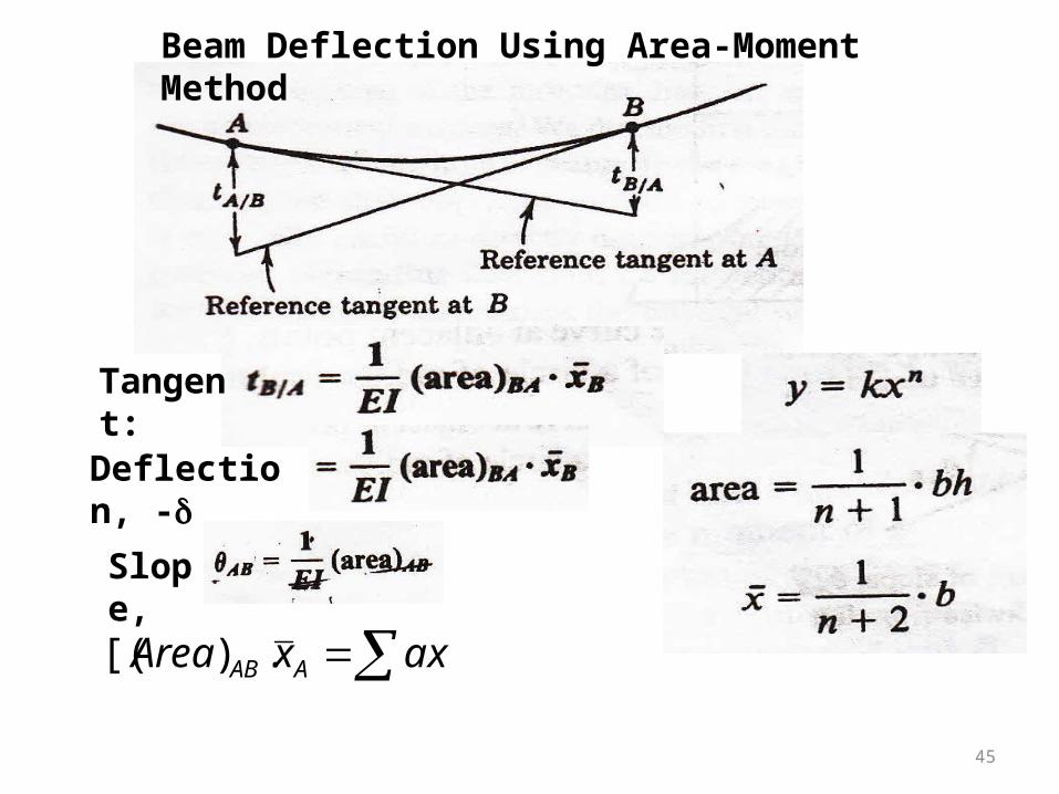
Tangent:Deflection, -d
axxArea AAB.)[(
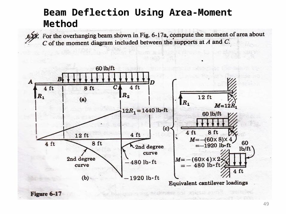
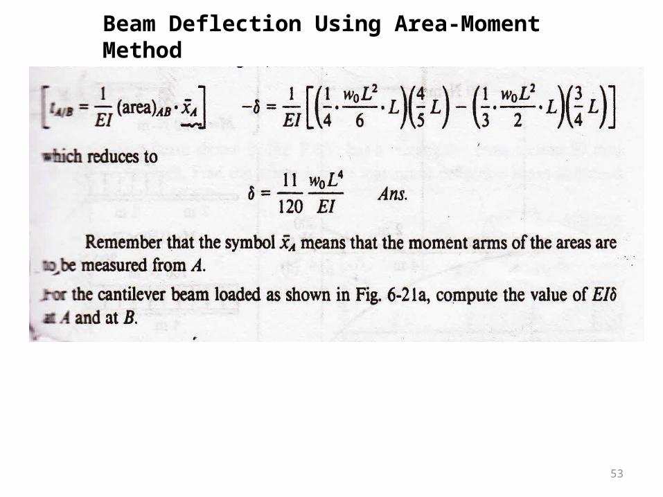
Beam Deflection Using Area-Moment Method
45
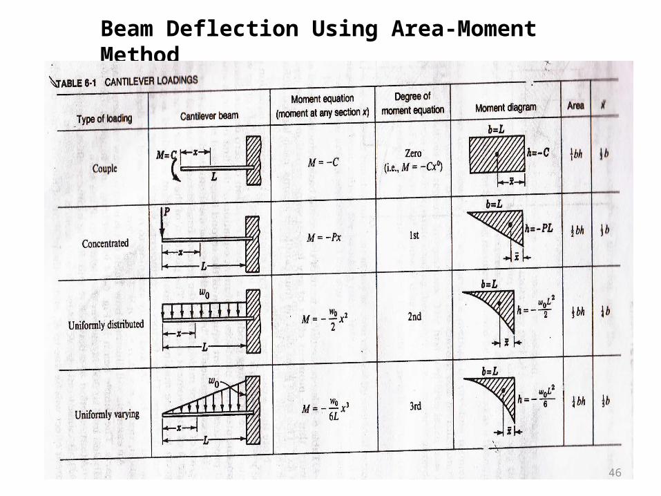
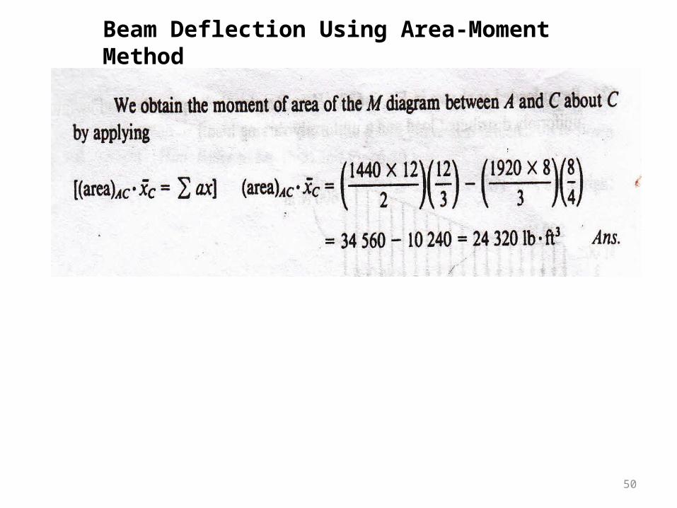
Beam Deflection Using Area-Moment Method
46
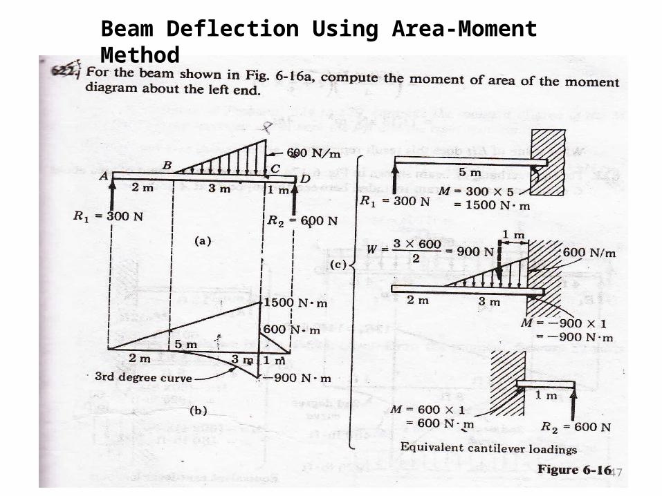
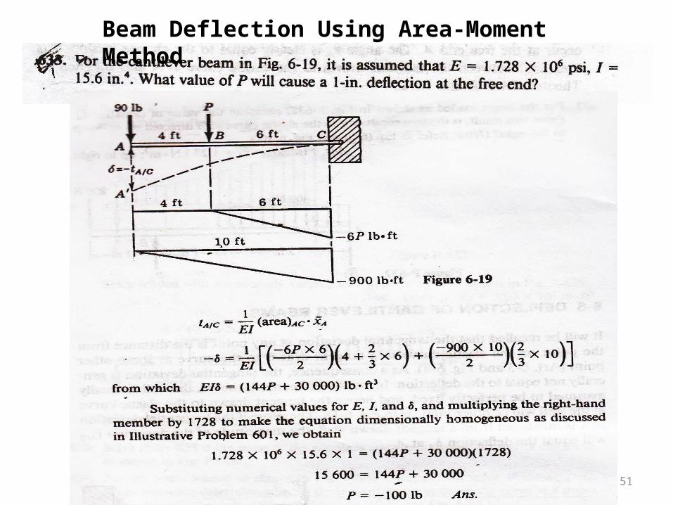
Beam Deflection Using Area-Moment Method
47
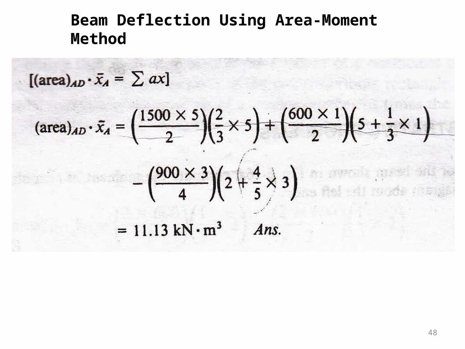
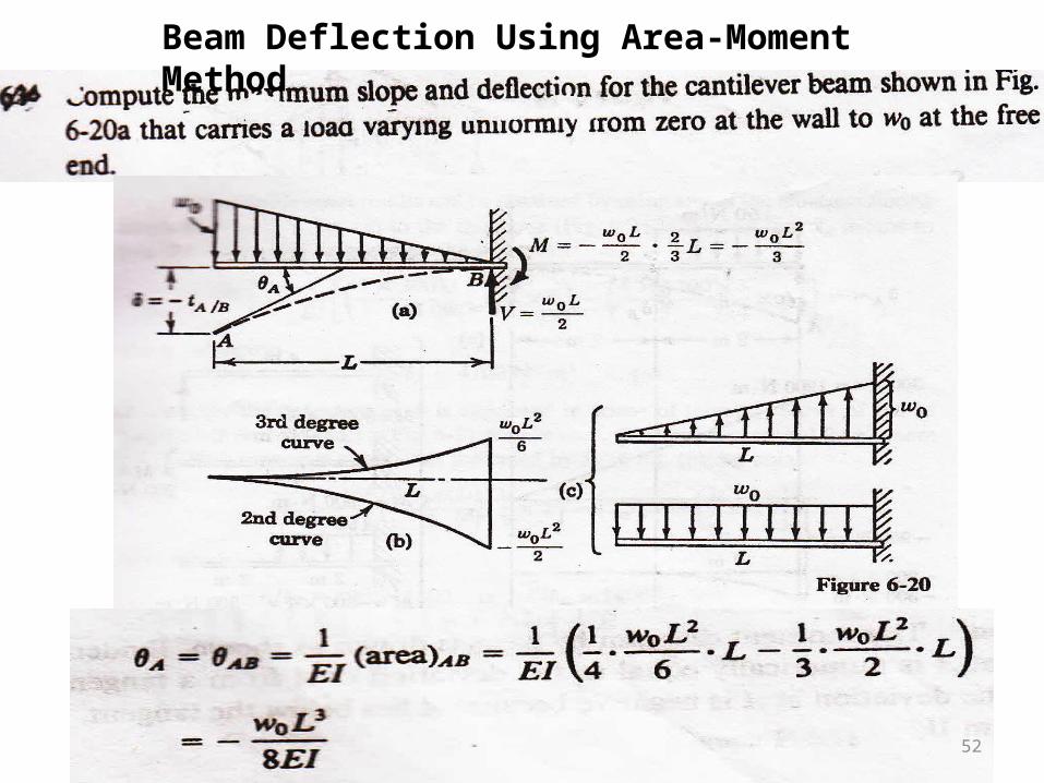
Beam Deflection Using Area-Moment Method
48
Beam Deflection Using Area-Moment Method
49
Beam Deflection Using Area-Moment Method
50
Beam Deflection Using Area-Moment Method
51
Beam Deflection Using Area-Moment Method
52
Beam Deflection Using Area-Moment Method
53
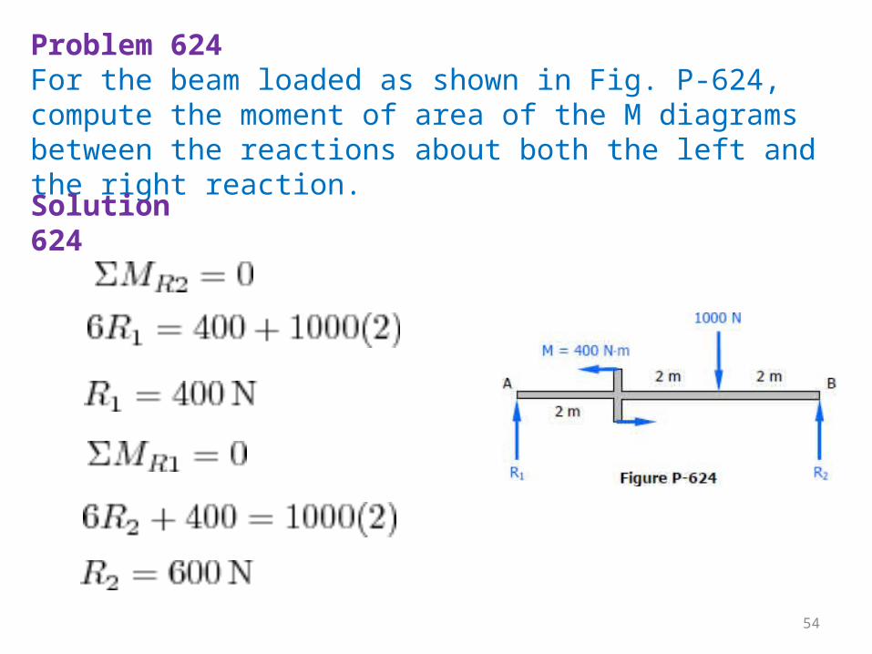
Problem 624For the beam loaded as shown in Fig. P-624, compute the moment of area of the M diagrams between the reactions about both the left and the right reaction.
Solution 624
54
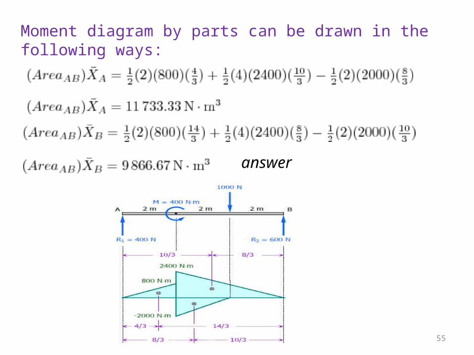
Moment diagram by parts can be drawn in the following ways:
answer
55
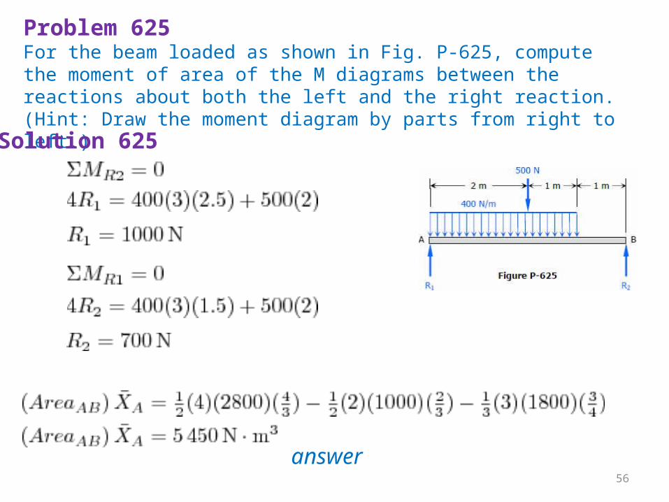
Problem 625For the beam loaded as shown in Fig. P-625, compute the moment of area of the M diagrams between the reactions about both the left and the right reaction. (Hint: Draw the moment diagram by parts from right to left.)Solution 625
answer
56
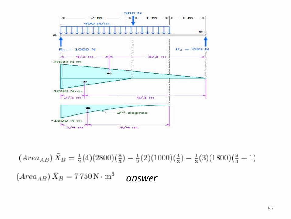
answer
57
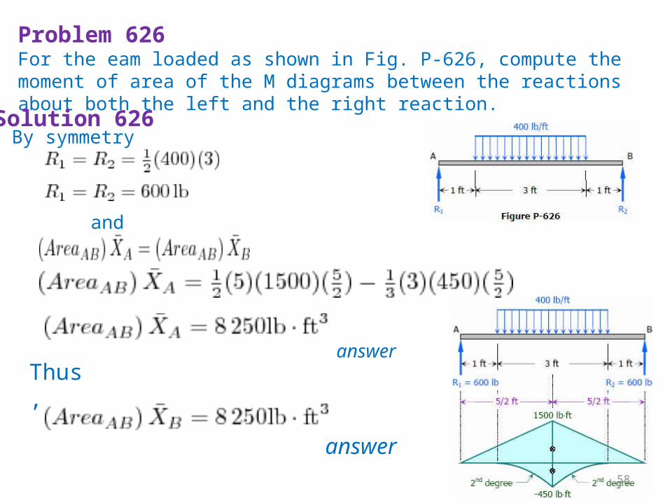
Problem 626For the eam loaded as shown in Fig. P-626, compute the moment of area of the M diagrams between the reactions about both the left and the right reaction.Solution 626 By symmetry
and
answer
Thus,
answer
58
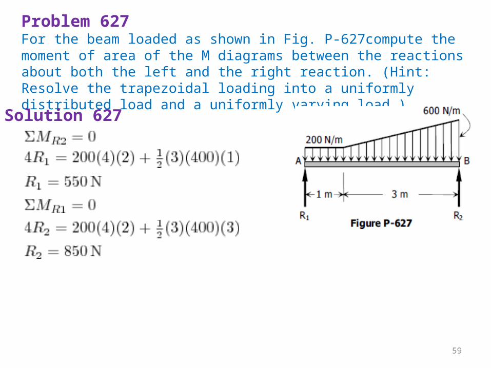
Problem 627For the beam loaded as shown in Fig. P-627compute the moment of area of the M diagrams between the reactions about both the left and the right reaction. (Hint: Resolve the trapezoidal loading into a uniformly distributed load and a uniformly varying load.)Solution 627
59
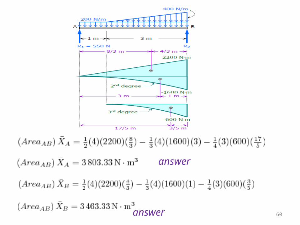
answer
answer 60
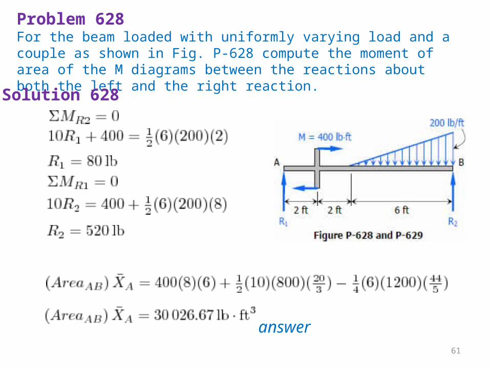
Problem 628For the beam loaded with uniformly varying load and a couple as shown in Fig. P-628 compute the moment of area of the M diagrams between the reactions about both the left and the right reaction. Solution 628
answer 61
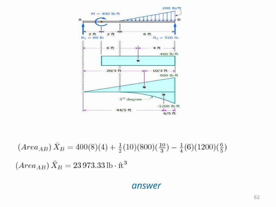
answer
62
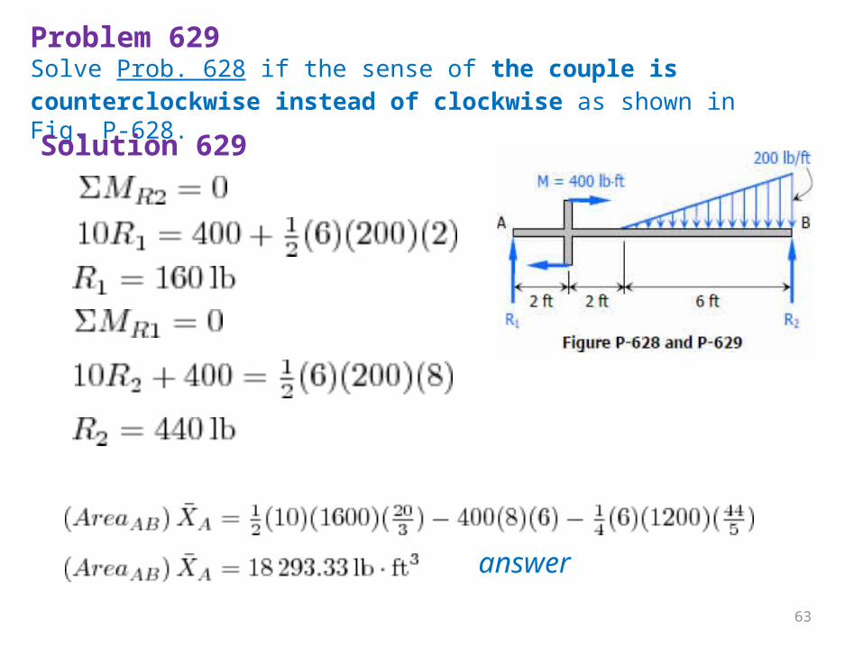
Problem 629Solve Prob. 628 if the sense of the couple is counterclockwise instead of clockwise as shown in Fig. P-628.Solution 629
answer
63
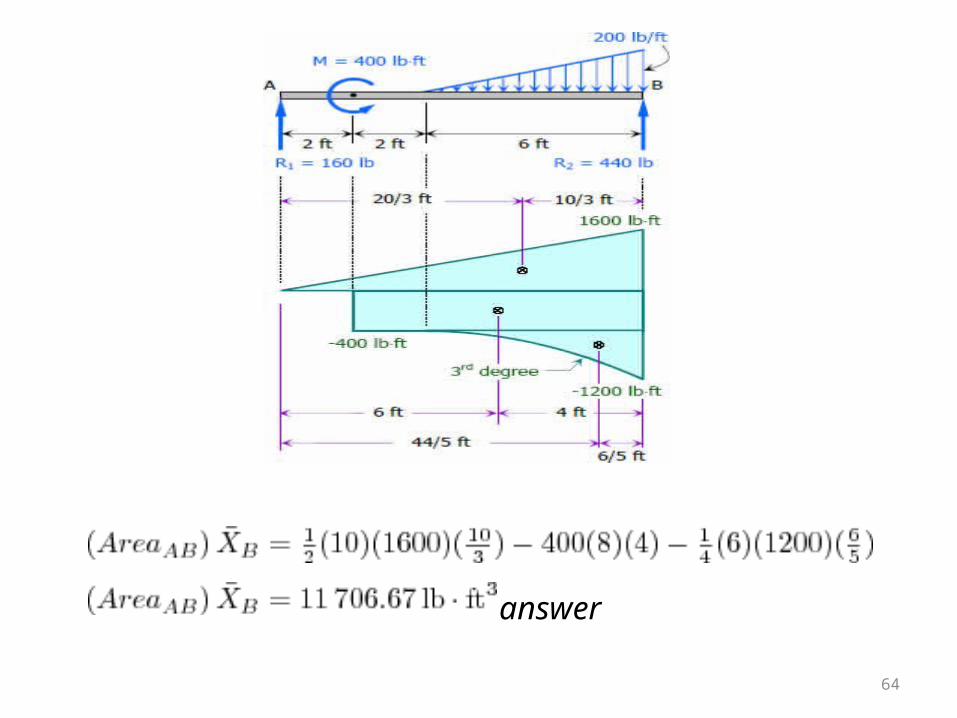
answer
64
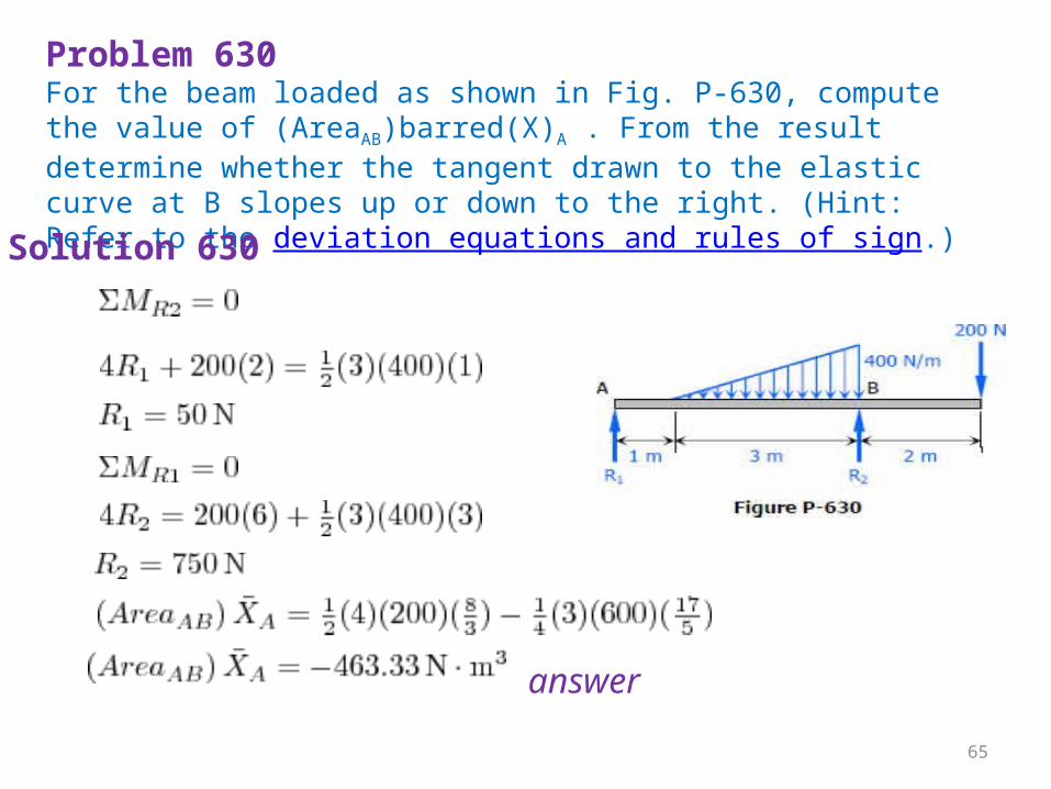
Problem 630For the beam loaded as shown in Fig. P-630, compute the value of (AreaAB)barred(X)A . From the result determine whether the tangent drawn to the elastic curve at B slopes up or down to the right. (Hint: Refer to the deviation equations and rules of sign.)Solution 630
answer
65
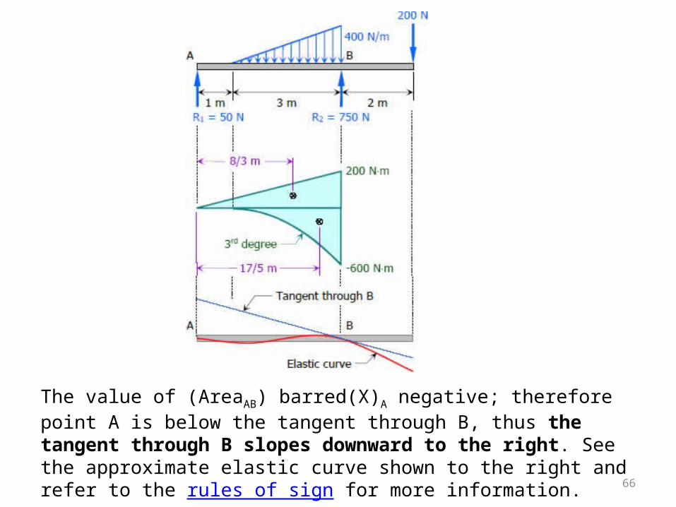
The value of (AreaAB) barred(X)A negative; therefore point A is below the tangent through B, thus the tangent through B slopes downward to the right. See the approximate elastic curve shown to the right and refer to the rules of sign for more information. 66
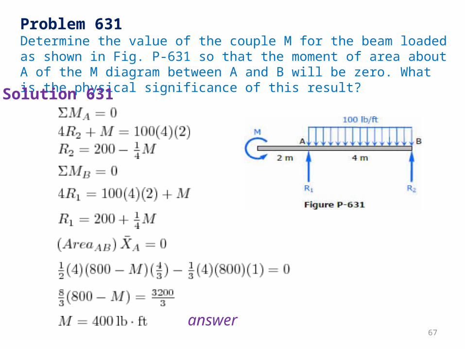
Problem 631Determine the value of the couple M for the beam loaded as shown in Fig. P-631 so that the moment of area about A of the M diagram between A and B will be zero. What is the physical significance of this result?Solution 631
answer67
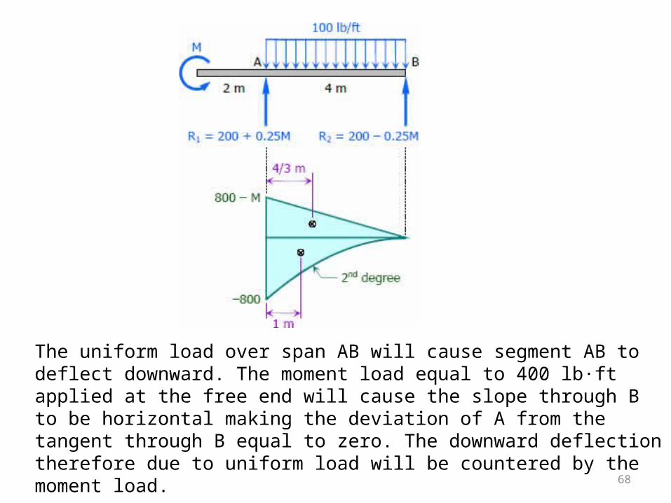
The uniform load over span AB will cause segment AB to deflect downward. The moment load equal to 400 lb·ft applied at the free end will cause the slope through B to be horizontal making the deviation of A from the tangent through B equal to zero. The downward deflection therefore due to uniform load will be countered by the moment load. 68
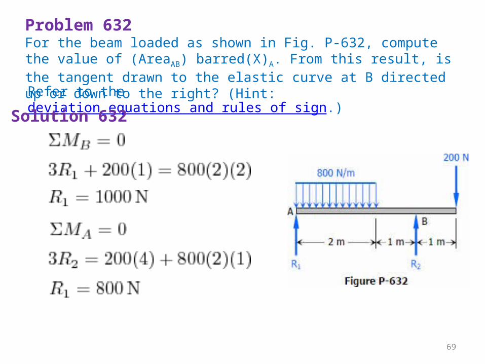
Problem 632For the beam loaded as shown in Fig. P-632, compute the value of (AreaAB) barred(X)A. From this result, is the tangent drawn to the elastic curve at B directed up or down to the right? (Hint: Refer to the deviation equations and rules of sign.)Solution 632
69
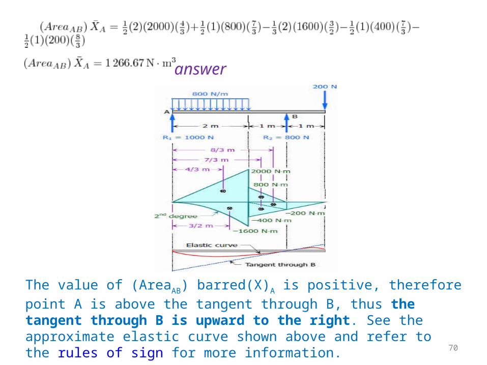
answer
The value of (AreaAB) barred(X)A is positive, therefore point A is above the tangent through B, thus the tangent through B is upward to the right. See the approximate elastic curve shown above and refer to the rules of sign for more information. 70
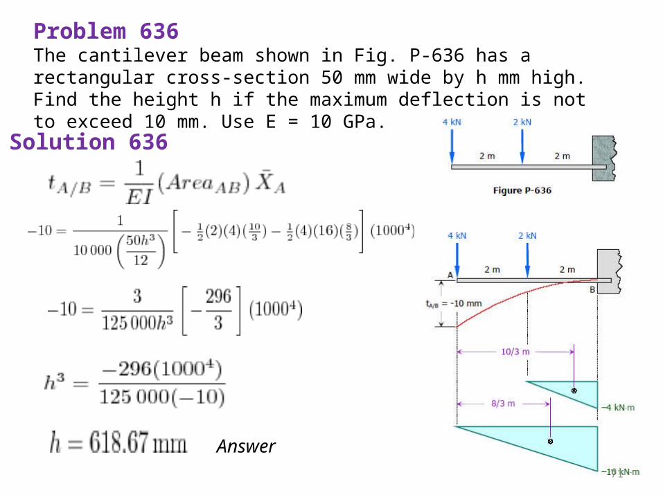
Problem 636The cantilever beam shown in Fig. P-636 has a rectangular cross-section 50 mm wide by h mm high. Find the height h if the maximum deflection is not to exceed 10 mm. Use E = 10 GPa.
Solution 636
Answer71
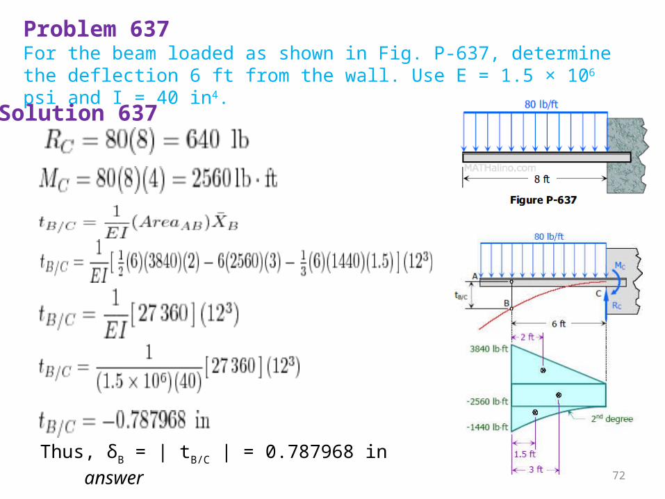
Problem 637For the beam loaded as shown in Fig. P-637, determine the deflection 6 ft from the wall. Use E = 1.5 × 10⁶ psi and I = 40 in4.Solution 637
Thus, δB = | tB/C | = 0.787968 in answer 72
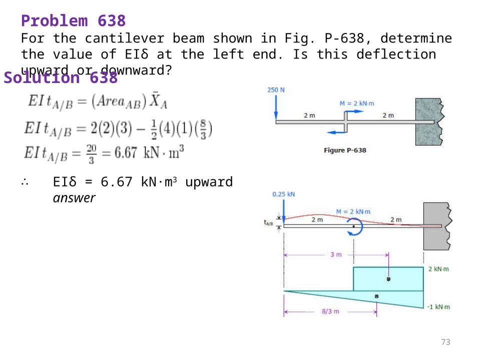
Problem 638For the cantilever beam shown in Fig. P-638, determine the value of EIδ at the left end. Is this deflection upward or downward?Solution 638
∴ EIδ = 6.67 kN·m3 upward answer
73
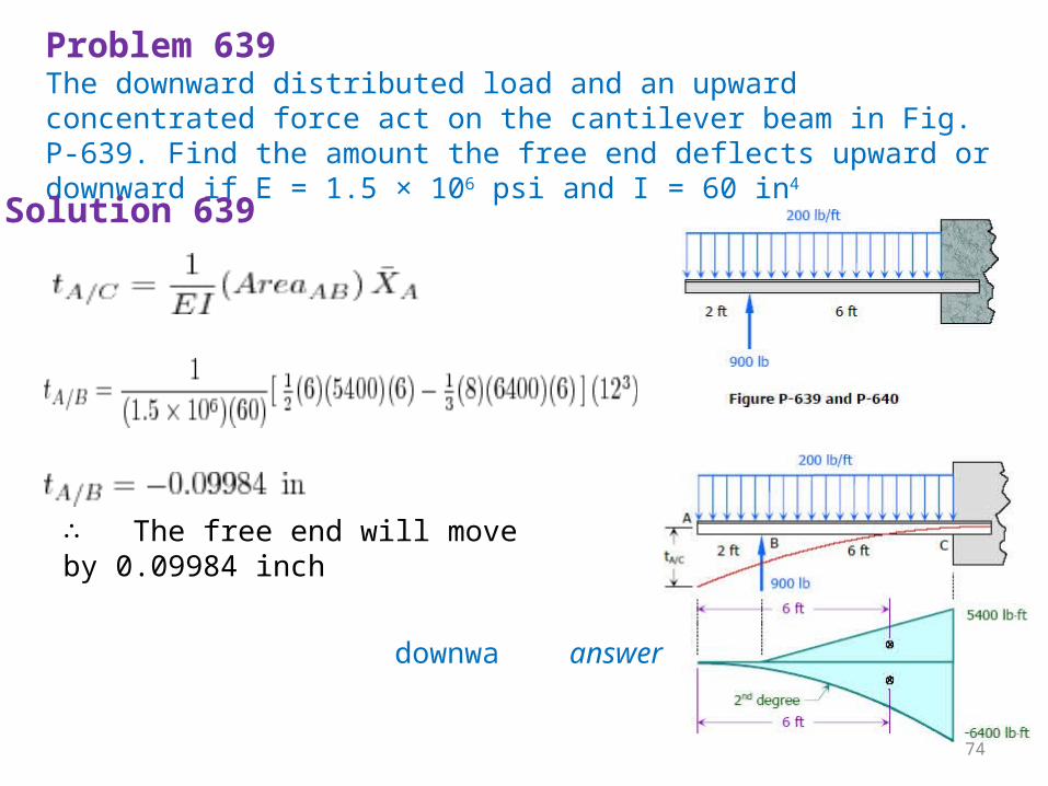
Problem 639The downward distributed load and an upward concentrated force act on the cantilever beam in Fig. P-639. Find the amount the free end deflects upward or downward if E = 1.5 × 10⁶ psi and I = 60 in4
Solution 639
∴ The free end will move by 0.09984 inch downwa answer
74
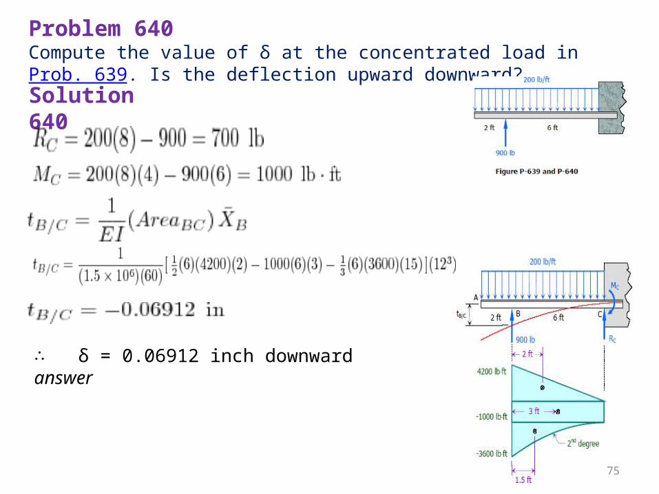
Problem 640Compute the value of δ at the concentrated load in Prob. 639. Is the deflection upward downward?Solution 640
∴ δ = 0.06912 inch downward answer
75
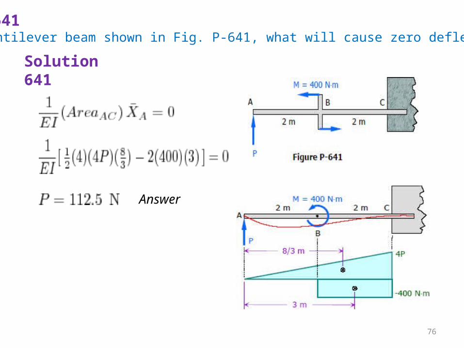
Problem 641For the cantilever beam shown in Fig. P-641, what will cause zero deflection at A?
Solution 641
Answer
76
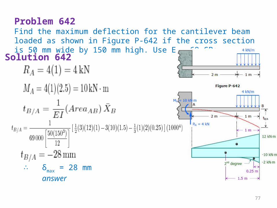
Problem 642Find the maximum deflection for the cantilever beam loaded as shown in Figure P-642 if the cross section is 50 mm wide by 150 mm high. Use E = 69 GPa.
Solution 642
∴ δmax = 28 mm answer
77
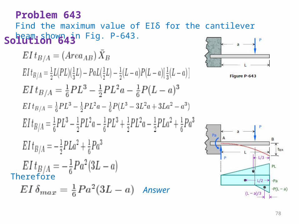
Problem 643Find the maximum value of EIδ for the cantilever beam shown in Fig. P-643.Solution 643
Therefore
Answer
78
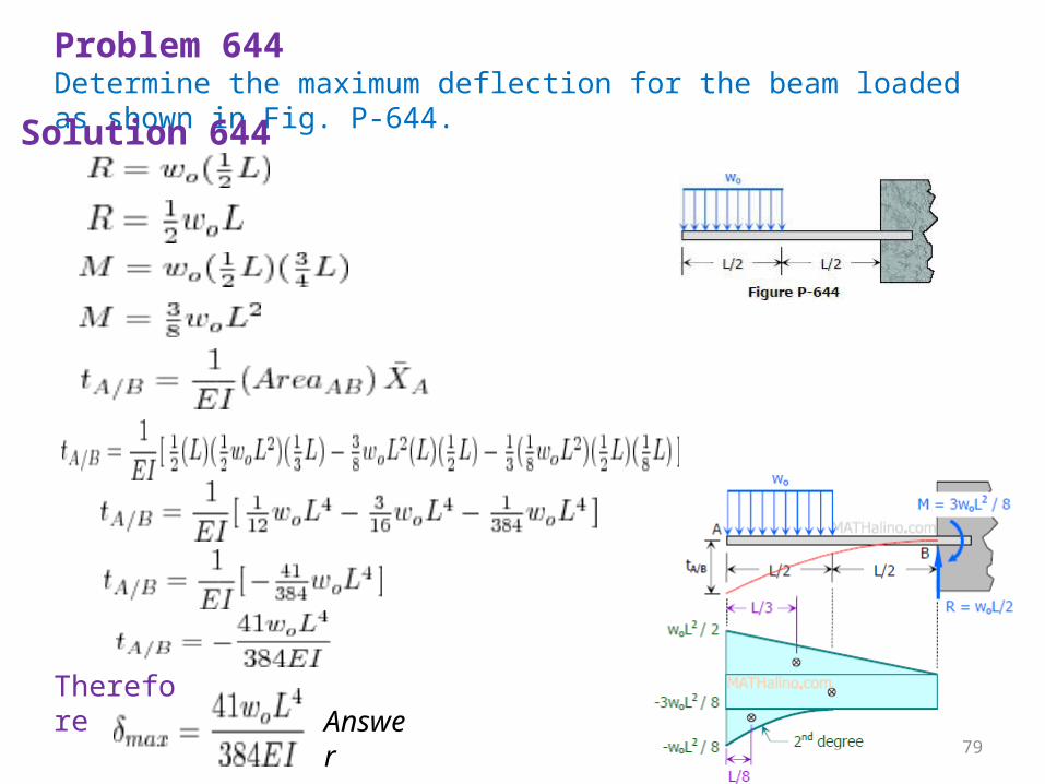
Problem 644Determine the maximum deflection for the beam loaded as shown in Fig. P-644.Solution 644
Therefore Answe
r 79
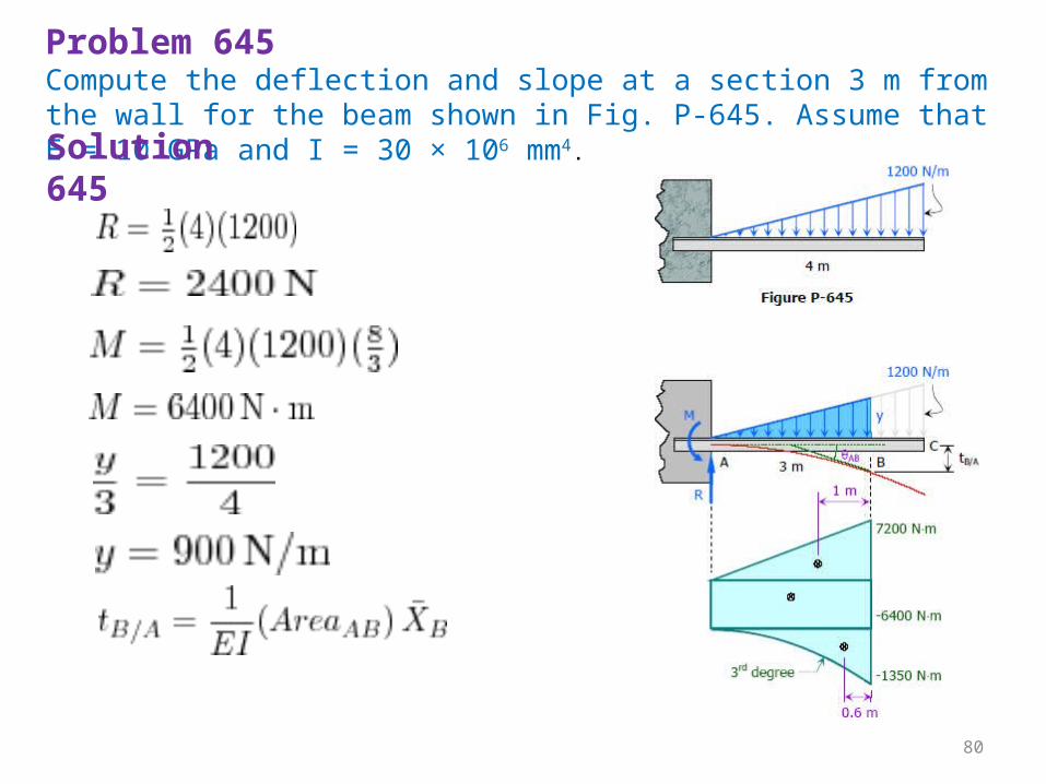
Problem 645Compute the deflection and slope at a section 3 m from the wall for the beam shown in Fig. P-645. Assume that E = 10 GPa and I = 30 × 106 mm4.Solution 645
80
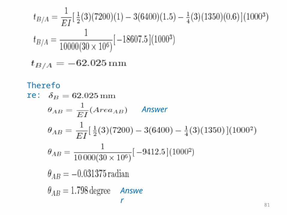
Therefore:
Answer
Answer 81
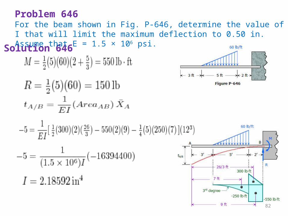
Solution 646
Problem 646For the beam shown in Fig. P-646, determine the value of I that will limit the maximum deflection to 0.50 in. Assume that E = 1.5 × 10⁶ psi.
82
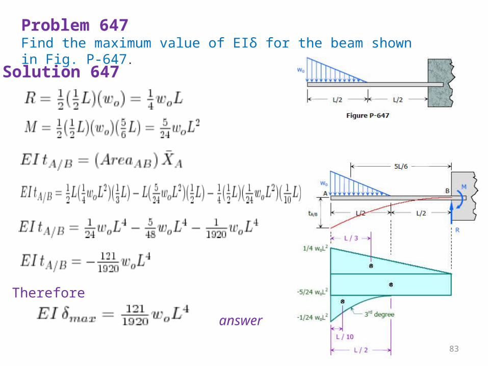
Problem 647Find the maximum value of EIδ for the beam shown in Fig. P-647.
Solution 647
Therefore
answer
83
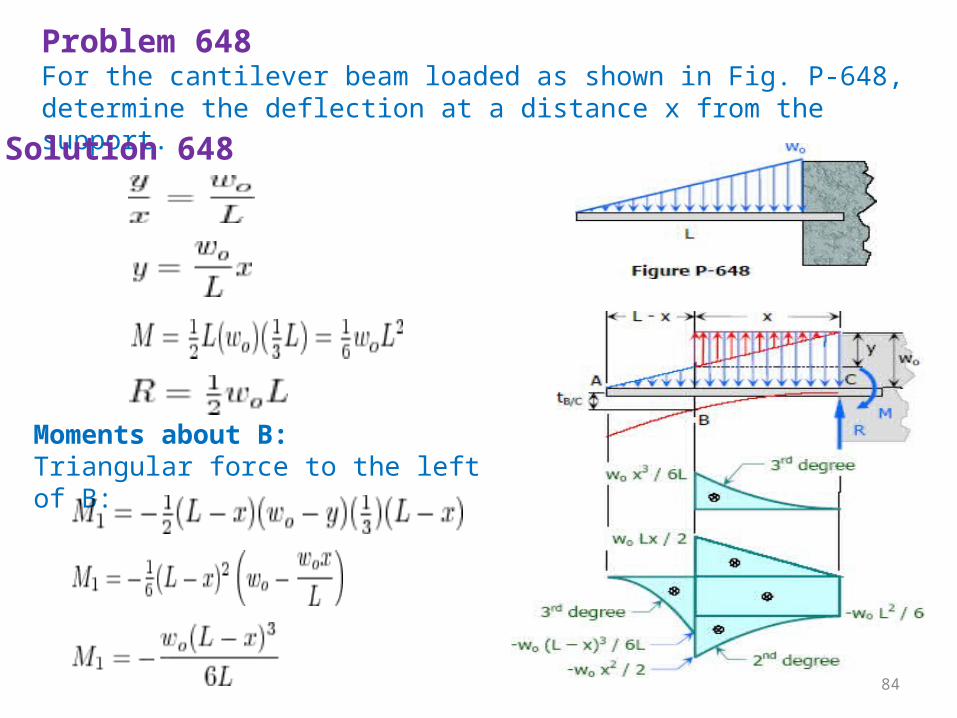
Problem 648For the cantilever beam loaded as shown in Fig. P-648, determine the deflection at a distance x from the support.
Solution 648
Moments about B:Triangular force to the left of B:
84
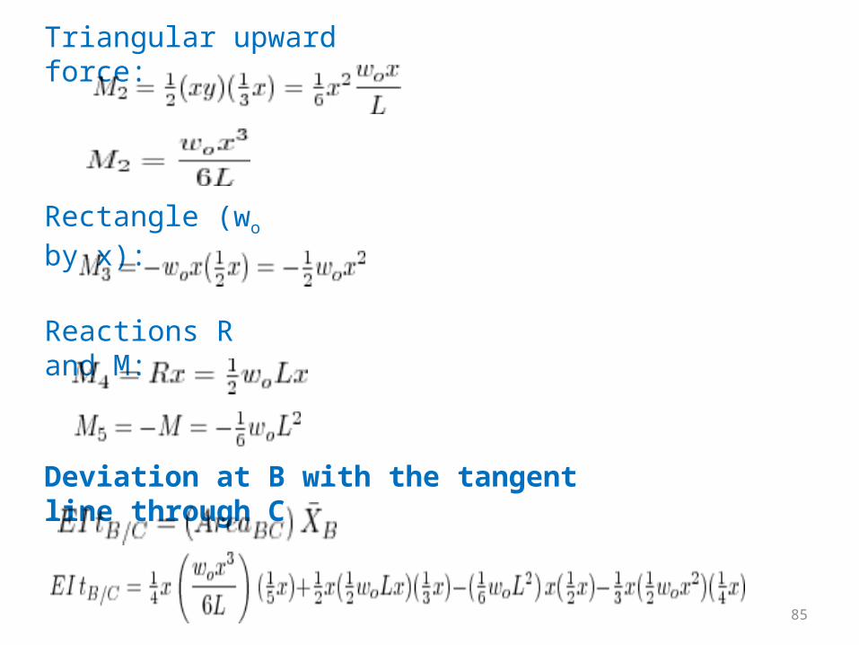
Triangular upward force:
Rectangle (wo by x):
Reactions R and M:
Deviation at B with the tangent line through C
85
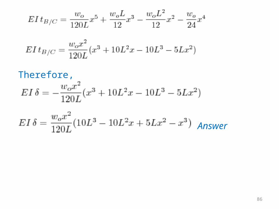
Therefore,
Answer
86


