Embed Size (px)
Citation preview
Special-Purpose Nickel Alloys
NICKEL-BASE ALLOYS have a number ofunique properties, or combinations of proper-ties, that allow them to be used in a variety ofspecialized applications. For example, the highresistivity (resistance to flow of electricity) andheat resistance of nickel-chromium alloys leadto their use as electric resistance heating ele-ments. The soft magnetic properties ofnickel-iron alloys are employed in electronicdevices and for electromagnetic shielding ofcomputers and communication equipment. Iron-nickel alloys have low expansion characteris-tics as a result of a balance between thermal ex-pansion and magnetostrictive changes withtemperature. Originally used as clock pendu-lums, these alloys are now widely employed aslead frames in packaging electronic chips andas the shadow-masks in color television tubes.On a larger scale, they provide one solution tocoping with the thermal expansion require-ments of storage and transportation tanks forthe growing liquid natural gas industry.
Other properties of interest that expand themarkets and applications of nickel and nickelalloys include those to follow:
• Shape memory characteristics of equiatomicnickel-titanium alloys that allow them to beused as actuators, hydraulic connectors, andeyeglass frames
• The high strength at elevated temperatureand resistance to stress relaxation that allowwrought nickel-beryllium-titanium to beused for demanding electrical/electronic ap-plications, for example, springs subjected toelevated temperatures (up to 370 °C, or 700°F) for short times
• The combination of heat removal (high ther-mal conductivity) and wear resistance thatallows cast nickel-beryllium-carbon alloysto be used for tooling for glass forming oper-ations
These and other special-purpose alloys and ap-plications are described subsequently.
Commercially Pure Nickelfor Electronic Applications
Commercially pure nickel is available in sev-eral grades, slightly different in composition, to
meet special needs. The grades considered inthis section include the following:
• Nickel 200 (99.6% Ni, 0.04% C)• Nickel 201 (99.6% Ni, 0.02% C maximum)• Nickel 205 (99.6% Ni, 0.04% C, 0.04% Mg)• Nickel 233 (see composition in table that fol-
lows)• Nickel 270 (99.97% Ni)
Composition limits and property data on sev-eral of these grades can be found in the article“Wrought Corrosion-Resistant Nickels andNickel Alloys” in this Handbook.
Nickel 200 and 201. Wrought Nickel 200(UNS N02200), the general purpose grade, isused for leads and terminals where goodstrength and toughness at elevated temperatureand subzero temperatures are necessary; fortransducers (it being one of three metals dem-onstrating magnetostrictive properties); and forfuel cell and battery plates.
A low-carbon variant, Nickel 201 (UNSN02201), is ideal for deep drawing, etching,spinning, and coining; its rate of work harden-ing is also low.
Nickel 205. The selected chemistry ofNickel 205 (UNS N02205) results in a highmagnetostrictive coefficient and Curie temper-ature. Its uses have included grid side rods,base pins, anodes, getter tabs, and cathodeshields.
Nickel 233 (UNS N02233) is specially pro-duced to the following closely controlled, low-
residual-element levels:This grade is especially suitable for active cath-odes, vacuum tube anodes, and structural partsof tubes.
Nickel 270 (UNS N02270), a high-purity,powder-produced nickel, is 99.97% nickel witha 0.001% maximum limit on cobalt, magne-sium, chromium, titanium, sulfur, silicon, man-
ganese, and copper, a 0.005% limit on iron, anda 0.02% limit on carbon. This high purity re-sults in lower coefficient of expansion, electri-cal resistivity, Curie temperature, and greaterductility than those of other grades of nickeland makes Nickel 270 especially useful forsome electronics applications such as compo-nents of hydrogen thyratrons and as a substratefor precious metal cladding.
Resistance Heating Alloys
Resistance heating alloys are used in manyvaried applications—from small household ap-pliances to large industrial process heating sys-tems and furnaces. In appliances or industrialprocess heating, the heating elements are usu-ally either open helical coils of resistance wiremounted with ceramic bushings in a suitablemetal frame, or enclosed metal-sheathed ele-ments consisting of a smaller-diameter helicalcoil of resistance wire electrically insulatedfrom the metal sheath by compacted refractoryinsulation. In industrial furnaces, elements of-ten must operate continuously at temperaturesas high as 1300 °C (2350 °F) for furnaces usedin metal-treating industries, 1700 °C (3100 °F)for kilns used for firing ceramics, and occasion-ally 2000 °C (3600 °F) or higher for special ap-plications.
Material Requirements. Materials for elec-tric heating depend on an inherent resistance tothe flow of electricity to generate heat. Copperwire does not get appreciably hot when carry-ing electricity because it has good electricalconductivity. Thus for an alloy—as wire, rib-bon, or strip—to perform as an electric heatingelement, it must resist the flow of electricity.
Most of the common steels and alloys suchas stainless steels do resist the flow of electric-ity. The measure of this characteristic is re-ferred to as “electrical resistivity.” It is ex-pressed as either ohm millimeter square permeter (Ω ⋅ mm2/m) in metric units or ohmtimes circular mils per foot (Ω ⋅ circular mil/ft)in English units.
If resistivity alone was the prime factor foran electric heating element, the choice could befrom many alloy candidates in a broad spec-trum of cost. However, there are a number ofrequirements a material must meet in order toavoid failure and provide an extended service
Element Percentage
Carbon 0.15 maxCopper 0.10 maxIron 0.10 maxMagnesium 0.01–0.10Manganese 0.30 maxSulfur 0.008 maxSilicon 0.10 maxTitanium 0.005 maxNickel 99.00 min
© 2000 ASM International. All Rights Reserved.ASM Specialty Handbook: Nickel, Cobalt, and Their Alloys (#06178G)
www.asminternational.org
life. The primary requirements of materialsused for heating elements are high meltingpoint, high electrical resistivity, reproducibletemperature coefficient of resistance, good oxi-dation resistance, absence of volatile compo-nents, and resistance to contamination. Otherdesirable properties are good elevated-tempera-ture creep strength, high emissivity, low ther-mal expansion, and low modulus (both ofwhich help minimize thermal fatigue), good re-sistance to thermal shock, and good strengthand ductility at fabrication temperatures.
Property Data. Four groups of materials arecommonly used for high-temperature resistanceheating elements: (1) nickel-chromium (Ni-Cr)and nickel-chromium-iron (Ni-Cr-Fe) alloys,(2) iron-chromium-aluminum alloys, (3) refrac-tory metals, and (4) nonmetallic (ceramic) ma-terials. Of these four groups, the Ni-Cr andNi-Cr-Fe alloys serve by far the greatest num-ber of applications. Table 1 compares the phys-ical and mechanical properties of the fourgroups. Maximum operating temperatures forresistance heating materials for furnace appli-cations are given in Table 2. Additional prop-erty data on some of the Ni-Cr and Ni-Cr-Fe al-loys listed in Tables 1 and 2 can be found indata sheets published in the section Propertiesof Electrical Resistance Alloys in the article“Electrical Resistance Alloys” in Propertiesand Selection: Nonferrous Alloys and Special-Purpose Materials, Volume 2 of the ASMHandbook.
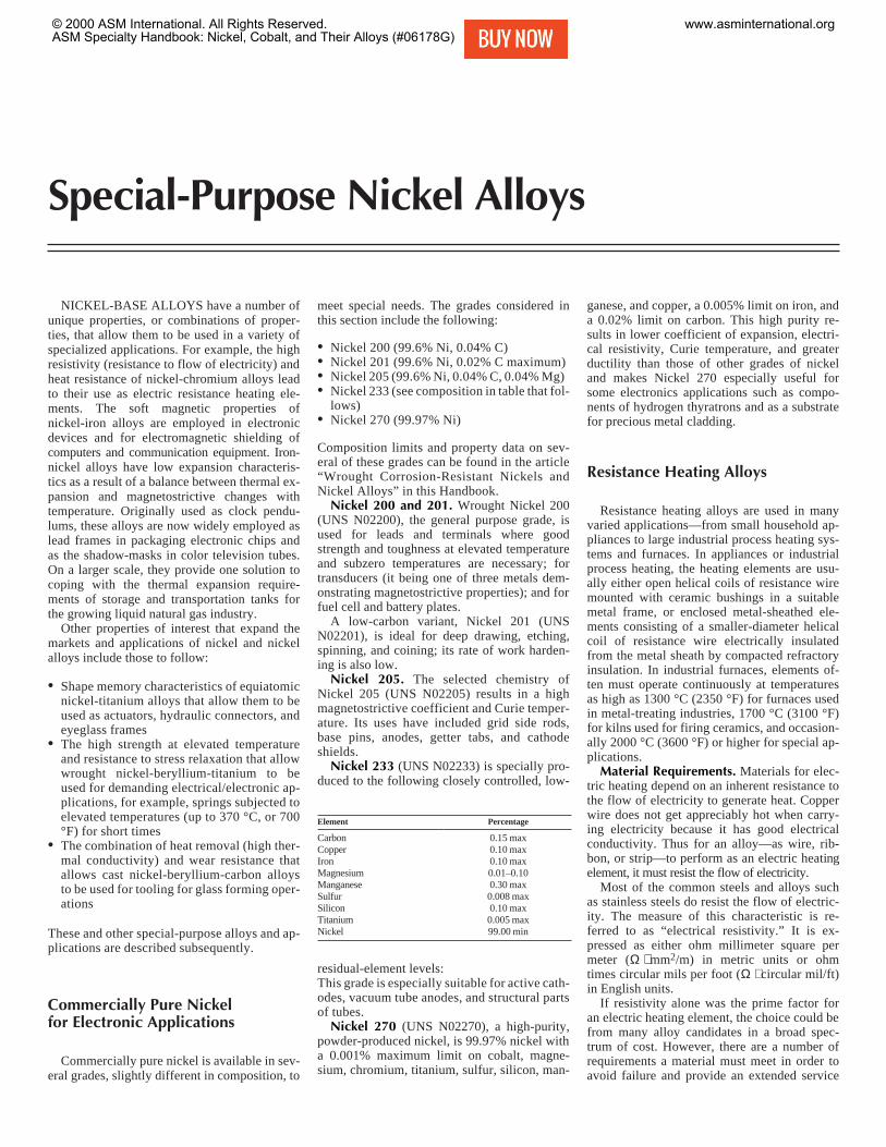
The resistivities of Ni-Cr and Ni-Cr-Fe al-loys are high, ranging from 1000 to 1187nΩ ⋅ m (600 to 714 Ω ⋅ circular mil/ft) at 25 °C.Figure 1 shows that the resistance changesmore rapidly with temperature for 35Ni-20Cr-
Special-Purpose Nickel Alloys / 93
Table 1 Typical properties of resistance heating materials
Average change in Thermal expansion,
Resistivity(a), resistance(c), %, from 20 °C to: µm · °C, from 20 °C to: Tensile strength Density
Basic composition Ω · mm 2 /m(b) 260 °C 540 °C 815 °C 1095 °C 100 °C 540 °C 815 °C MPa ksi g/cm3 lb/in.3
Nickel-chromium and nickel-chromium-iron alloys78.5Ni-20Cr-1.5Si (80–20) 1.080 4.5 7.0 6.3 7.6 13.5 15.1 17.6 655–1380 95–200 8.41 0.3077.5Ni-20Cr-1.5Si-1Nb 1.080 4.6 7.0 6.4 7.8 13.5 15.1 17.6 655–1380 95–200 8.41 0.3068.5Ni-30Cr-1.5Si (70–30) 1.180 2.1 4.8 7.6 9.8 12.2 … … 825–1380 120–200 8.12 0.2968Ni-20Cr-8.5Fe-2Si 1.165 3.9 6.7 6.0 7.1 … 12.6 … 895–1240 130–180 8.33 0.3060Ni-16Cr-22Fe-1.5Si 1.120 3.6 6.5 7.6 10.2 13.5 15.1 17.6 655–1205 95–175 8.25 0.3037Ni-21Cr-40Fe-2Si 1.08 7.0 15.0 20.0 23.0 14.4 16.5 18.6 585–1135 85–165 7.96 0.28835Ni-20Cr-43Fe-1.5Si 1.00 8.0 15.4 20.6 23.5 15.7 15.7 … 550–1205 80–175 7.95 0.28735Ni-20Cr-42.5Fe-1.5Si-1Nb 1.00 8.0 15.4 20.6 23.5 15.7 15.7 … 550–1205 80–175 7.95 0.287
Iron-chromium-aluminum alloys83.5Fe-13Cr-3.25Al 1.120 7.0 15.5 … … 10.6 … … 620–1035 90–150 7.30 0.2681Fe-14.5Cr-4.25Al 1.25 3.0 9.7 16.5 … 10.8 11.5 12.2 620–1170 90–170 7.28 0.2673.5Fe-22Cr-4.5Al 1.35 0.3 2.9 4.3 4.9 10.8 12.6 13.1 620–1035 90–150 7.15 0.2672.5Fe-22Cr-5.5Al 1.45 0.2 1.0 2.8 4.0 11.3 12.8 14.0 620–1035 90–150 7.10 0.26
Pure metalsMolybdenum 0.052 110 238 366 508 4.8 5.8 … 690–2160 100–313 10.2 0.369Platinum 0.105 85 175 257 305 9.0 9.7 10.1 345 50 21.5 0.775Tantalum 0.125 82 169 243 317 6.5 6.6 … 345–1240 50–180 16.6 0.600Tungsten 0.055 91 244 396 550 4.3 4.6 4.6 3380–6480 490–940 19.3 0.697
Nonmetallic heating-element materialsSilicon carbide 0.995–1.995 –33 –33 –28 –13 4.7 … … 28 4 3.2 0.114Molybdenum disilicide 0.370 105 222 375 523 9.2 … … 185 27 6.24 0.225MoSi2 + 10% ceramic additives 0.270 167 370 597 853 13.1 14.2 14.8 … … 5.6 0.202Graphite 9.100 –16 –18 –13 –8 1.3 … … 1.8 0.26 1.6 0.057
(a) At 20 °C (68 °F). (b) To convert to Ω·circular mil/ft, multiply by 601.53. (c) Changes in resistance may vary somewhat, depending on cooling rate.
Table 2 Recommended maximum furnace operating temperatures for resistance heatingmaterials
Approximate Maximum furnacemelting point operating temperature in air
Basic composition, % °C °F °C °F
Nickel-chromium and nickel-chromium-iron alloys78.5Ni-20Cr-1.5Si (80–20) 1400 2550 1150 210077.5Ni-20Cr-1.5Si-1Nb 1390 254068.5Ni-30Cr-1.5Si (70–30) 1380 2520 1200 220068Ni-20Cr-8.5Fe-2Si 1390 2540 1150 210060Ni-16Cr-22Fe-1.5Si 1350 2460 1000 185035Ni-30Cr-33.5Fe-1.5Si 1400 255035Ni-20Cr-43Fe-1.5Si 1380 2515 925 170035Ni-20Cr-42.5Fe-1.5Si-1Nb 1380 2515
Iron-chromium-aluminum alloys83.5Fe-13Cr-3.25Al 1510 2750 1050 192081Fe-14.5Cr-4.25Al 1510 275079.5Fe-15Cr-5.2Al 1510 2750 1260 230073.5Fe-22Cr-4.5Al 1510 2750 1280 233572.5Fe-22Cr-5.5Al 1510 2750 1375 2505
Pure metalsMolybdenum 2610 4730 400(a) 750(a)Platinum 1770 3216 1500 2750Tantalum 3000 5400 500(a) 930(a)Tungsten 3400 6150 300(a) 570(a)
Nonmetallic heating-element materialsSilicon carbide 2410 4370 1600 2900Molybdenum disilicide (b) (b) 1700–1800 3100–3270MoSi2 + 10% ceramic additives (b) (b) 1900 3450Graphite 3650–3700(b) 6610–6690(c) 400(d) 750(d)
Recommended temperatures
Element Vacuum Pure H2 City gas
Mo 1650 °C (3000 °F) 1760 °C (3200 °F) 1700 °C (3100 °F)Ta 2480 °C (4500 °F) Not recommended Not recommendedW 1650 °C (3000 °F) 2480 °C (4500 °F) 1700 °C (3100 °F)
(a) Recommended atmospheres for these metals are a vacuum of 10–4 to 10–5 mm Hg, pure hydrogen, and partly combusted city gas dried to a dewpoint of 4 °C (40 °F). In these atmospheres, the recommended temperatures, would be as shown above. (b) Decomposes before melting at approxi-mately 1740 °C (3165 °F) for MoSi2, and 1825 °C (3315 °F) for MoSi2 + 10% ceramic additives. (c) Graphite volatilizes without melting at 3650 to3700 °C (6610 to 6690 °F). (d) At approximately 400 °C (750 °F) (threshold oxidation temperature), graphite undergoes a weight loss of 1% in 24 hin air. Graphite elements can be operated at surface temperatures up to 2205 °C (4000 °F) in inert atmospheres.
© 2000 ASM International. All Rights Reserved.ASM Specialty Handbook: Nickel, Cobalt, and Their Alloys (#06178G)
www.asminternational.org
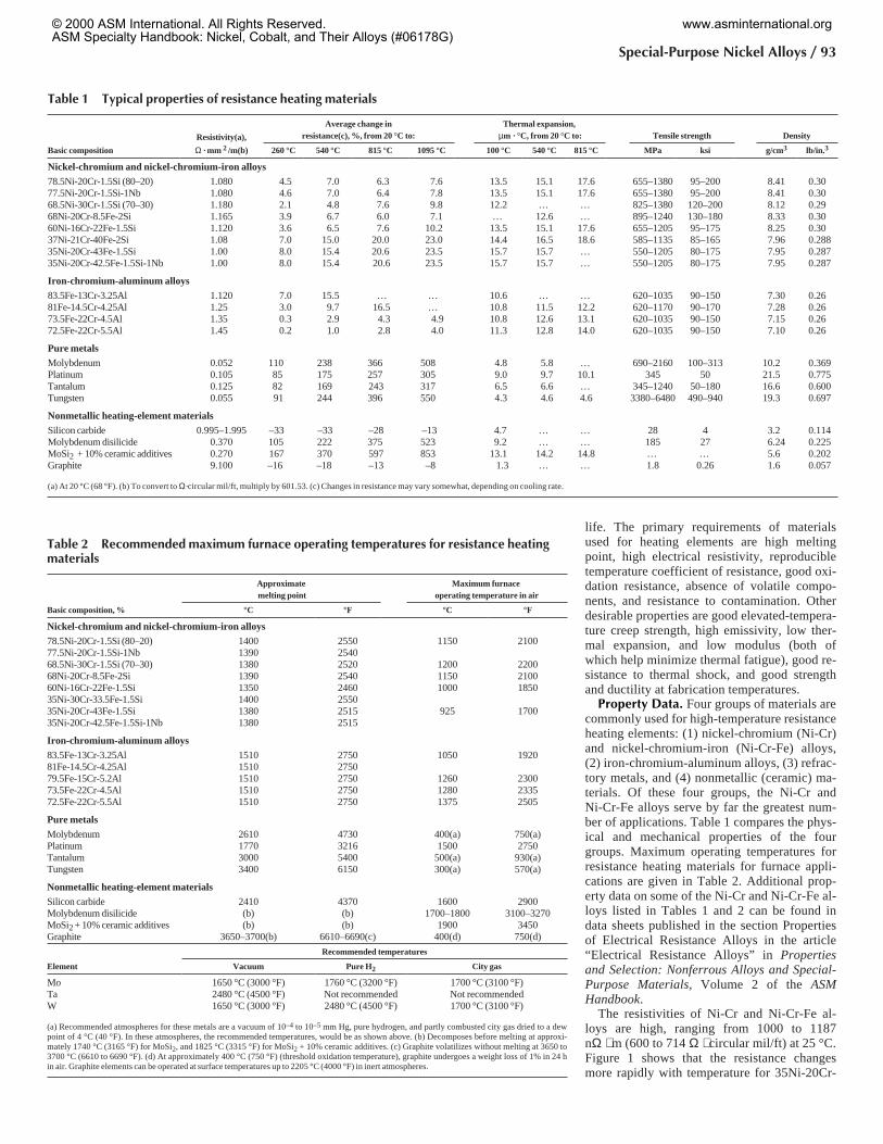
45Fe than for any other alloy in this group. Thecurve for 35Ni-30Cr-35Fe (which is no longerproduced) is similar but slightly lower. Theother four curves, which are for alloys withsubstantially higher nickel contents, reflect rel-atively low changes in resistance with tempera-ture. For these alloys, rate of change reaches apeak near 540 °C (1000 °F), goes through aminimum at about 760 to 870 °C (1400 to1600 °F), and then increases again. For Ni-Cralloys, the change in resistance with tempera-ture depends on section size and cooling rate.Figure 2 presents values for a typical80Ni-20Cr alloy. The maximum change (curveA) occurs with small sections, which cool rap-idly from the last production heat treatment.The smallest change occurs for heavy sections,which cool slowly. The average curve (curveB) is characteristic of medium-size sections.
Nickel Alloys for Resistors and Thermo-stats. In addition to their use as heating ele-ments in furnaces and appliances, nickel elec-trical resistance alloys are also used ininstruments and control equipment to measureand regulate electrical characteristics, for ex-ample, resistors, and in applications whereheat generated in a metal resistor is convertedto mechanical energy, for example, thermostatmetals. Resistor alloys include Ni-Cr andNi-Cr-Fe alloys similar to those used for heat-ing elements and 75Ni-20Cr-3Al alloys con-taining small amounts of other metals—usu-ally either copper, manganese, or iron. Athermostat metal is a composite material (usu-ally in the form of sheet or strip) that consistsof two or more materials bonded together, ofwhich one may be a nonmetal. Nickel-iron,nickel-chromium-iron, and nickel-copper al-loys are commonly used. Additional informa-tion on resistor and thermostat alloys can befound in the article “Electrical Resistance Al-loys” in Properties and Selection: NonferrousAlloys and Special-Purpose Materials, Vol-ume 2 of the ASM Handbook.
Thermocouple Alloys
The thermocouple thermometer is one of themost widely used devices for measurement oftemperature in the metals industry. Essentially,a thermocouple thermometer is a system con-sisting of a temperature-sensing element calleda thermocouple, which produces an electromo-tive force (emf) that varies with temperature, adevice for sensing emf, which may include aprinted scale for converting emf to equivalenttemperature units, and an electrical conductor(extension wires) for connecting the thermo-couple to the sensing device. Although anycombination of two dissimilar metals and/oralloys will generate a thermal emf, only eightthermocouples are in common industrial usetoday. These eight have been chosen on the basisof such factors as mechanical and chemicalproperties, stability of emf, reproducibility, andcost.
Table 3 presents base compositions, meltingpoints, and electrical resistivities of the eightstandard thermocouples. As indicated in the ta-ble, nickel-copper, nickel-chromium, nickel-silicon, and nickel alloys containing variouscombinations of aluminum, manganese, iron,silicon, and cobalt are used as either the positive(P) or negative (N) thermoelement. The maxi-mum operating temperatures and limiting envi-ronmental factors for these alloys are also listedin Table 3. A nonstandard nickel-base thermo-couple element consisting of 82Ni-18Mo alloy asthe positive themoelement and 99Ni-1Co alloyas the negative thermoelement is also used inhydrogen or reducing atmospheres. More de-tailed information on thermocouple devices andmaterials can be found in the article “Thermo-couple Materials” in Properties and Selection:Nonferrous Alloys and Special-Purpose Mate-rials, Volume 2 of the ASM Handbook and in“Thermocouple Materials” in the Metals Hand-book Desk Edition, Second Edition.
Nickel-Iron Soft Magnetic Alloys
Soft magnetic nickel-iron alloys containingfrom about 30 to 80% Ni are used extensivelyin applications requiring the following charac-teristics:
• High permeability• High saturation magnetostriction• Low hysteresis-energy loss• Low eddy-current loss in alternating flux• Low Curie temperature• Constant permeability with changing tem-
perature
As shown in Table 4, these include electromag-netic and radio frequency shields, transform-ers, amplifiers, tape recording head laminations,ground fault interrupter cores, antishoplifting de-vices, torque motors, and so on.
The nickel-iron alloys are generally manu-factured as strip or sheet product; however, bil-let, bar, and wire can be produced as needed.Strip products are usually supplied in a
94 / Introduction to Nickel and Nickel Alloys
Fig. 1 Variation of resistance with temperature for sixNi-Cr and Ni-Cr-Fe alloys. To calculate resis-
tance at temperature, multiply resistance at room tempera-ture by the temperature factor.
Fig. 2 Variation of resistance with temperature for80Ni-20Cr heating alloy. Curve A is for a speci-
men cooled rapidly after the last production heat treat-ment. Curve C is for a specimen cooled slowly after thelast production heat treatment. Curve B represents the av-erage value for material as delivered by the producer. Tocalculate resistance at temperature, multiply the resistanceat room temperature by the temperature factor.
Table 3 Properties of standard thermocouples
Base Melting point, Resistivity, Recommended Max temperature
Type Thermoelements composition °C nΩ · m service °C °F
J JP Fe 1450 100 Oxidizing or reducing 760 1400JN 44Ni-55Cu 1210 500
K KP 90Ni-9Cr 1350 700 Oxidizing 1260 2300KN 94Ni-Al, Mn, Fe, Si, Co 1400 320
N NP 84Ni-14Cr-1.4Si 1410 930 Oxidizing 1260 2300NN 95Ni-4.4Si-0.15 Mg 1400 370
T TP OFHC Cu 1083 17 Oxidizing or reducing 370 700TN 44Ni-55Cu 1210 500
E EP 90Ni-9Cr 1350 700 Oxidizing 870 1600EN 44Ni-55Cu 1210 500
R RP 87Pt-13Rh 1860 196 Oxidizing or inert 1480 2700RN Pt 1769 104
S SP 90Pt-10Rh 1850 189 Oxidizing or inert 1480 2700SN Pt 1769 104
B BP 70Pt-30Rh 1927 190 Oxidizing, vacuum or inert 1700 3100BN 94Pt-6Rh 1826 175
© 2000 ASM International. All Rights Reserved.ASM Specialty Handbook: Nickel, Cobalt, and Their Alloys (#06178G)
www.asminternational.org
cold-rolled condition for stamping laminationsor as thin foil for winding of tape toroidalcores. Strip and sheet products may also besupplied in a low-temperature, mill-annealed,fine-grain condition suitable for forming anddeep drawing.
Classes of Commercial Alloys
Two broad classes of commercial alloyshave been developed in the nickel-iron system.Based on nickel content, these include high-nickel alloys (about 79% Ni) and low-nickel al-loys (about 45 to 50% Ni). Some alloys con-taining even lower nickel contents (~29 to36%) can be used for measuring instruments re-quiring magnetic temperature compensation(see Table 4).
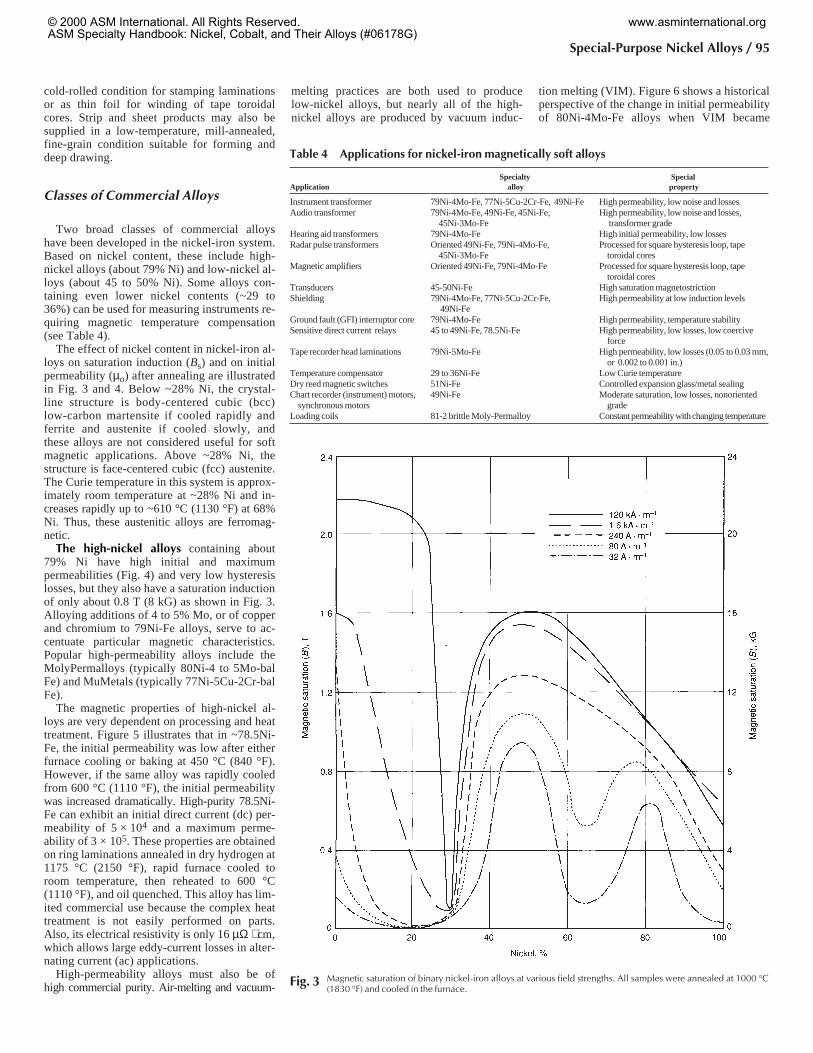
The effect of nickel content in nickel-iron al-loys on saturation induction (Bs) and on initialpermeability (µo) after annealing are illustratedin Fig. 3 and 4. Below ~28% Ni, the crystal-line structure is body-centered cubic (bcc)low-carbon martensite if cooled rapidly andferrite and austenite if cooled slowly, andthese alloys are not considered useful for softmagnetic applications. Above ~28% Ni, thestructure is face-centered cubic (fcc) austenite.The Curie temperature in this system is approx-imately room temperature at ~28% Ni and in-creases rapidly up to ~610 °C (1130 °F) at 68%Ni. Thus, these austenitic alloys are ferromag-netic.
The high-nickel alloys containing about79% Ni have high initial and maximumpermeabilities (Fig. 4) and very low hysteresislosses, but they also have a saturation inductionof only about 0.8 T (8 kG) as shown in Fig. 3.Alloying additions of 4 to 5% Mo, or of copperand chromium to 79Ni-Fe alloys, serve to ac-centuate particular magnetic characteristics.Popular high-permeability alloys include theMolyPermalloys (typically 80Ni-4 to 5Mo-balFe) and MuMetals (typically 77Ni-5Cu-2Cr-balFe).
The magnetic properties of high-nickel al-loys are very dependent on processing and heattreatment. Figure 5 illustrates that in ~78.5Ni-Fe, the initial permeability was low after eitherfurnace cooling or baking at 450 °C (840 °F).However, if the same alloy was rapidly cooledfrom 600 °C (1110 °F), the initial permeabilitywas increased dramatically. High-purity 78.5Ni-Fe can exhibit an initial direct current (dc) per-meability of 5 × 10⁴ and a maximum perme-ability of 3 × 10⁵. These properties are obtainedon ring laminations annealed in dry hydrogen at1175 °C (2150 °F), rapid furnace cooled toroom temperature, then reheated to 600 °C(1110 °F), and oil quenched. This alloy has lim-ited commercial use because the complex heattreatment is not easily performed on parts.Also, its electrical resistivity is only 16 µΩ ⋅ cm,which allows large eddy-current losses in alter-nating current (ac) applications.
High-permeability alloys must also be ofhigh commercial purity. Air-melting and vacuum-
melting practices are both used to producelow-nickel alloys, but nearly all of the high-nickel alloys are produced by vacuum induc-
tion melting (VIM). Figure 6 shows a historicalperspective of the change in initial permeabilityof 80Ni-4Mo-Fe alloys when VIM became
Special-Purpose Nickel Alloys / 95
Fig. 3 Magnetic saturation of binary nickel-iron alloys at various field strengths. All samples were annealed at 1000 °C(1830 °F) and cooled in the furnace.
Table 4 Applications for nickel-iron magnetically soft alloys
Specialty SpecialApplication alloy property
Instrument transformer 79Ni-4Mo-Fe, 77Ni-5Cu-2Cr-Fe, 49Ni-Fe High permeability, low noise and lossesAudio transformer 79Ni-4Mo-Fe, 49Ni-Fe, 45Ni-Fe,
45Ni-3Mo-FeHigh permeability, low noise and losses,
transformer gradeHearing aid transformers 79Ni-4Mo-Fe High initial permeability, low lossesRadar pulse transformers Oriented 49Ni-Fe, 79Ni-4Mo-Fe,
45Ni-3Mo-FeProcessed for square hysteresis loop, tape
toroidal coresMagnetic amplifiers Oriented 49Ni-Fe, 79Ni-4Mo-Fe Processed for square hysteresis loop, tape
toroidal coresTransducers 45-50Ni-Fe High saturation magnetostrictionShielding 79Ni-4Mo-Fe, 77Ni-5Cu-2Cr-Fe,
49Ni-FeHigh permeability at low induction levels
Ground fault (GFI) interruptor core 79Ni-4Mo-Fe High permeability, temperature stabilitySensitive direct current relays 45 to 49Ni-Fe, 78.5Ni-Fe High permeability, low losses, low coercive
forceTape recorder head laminations 79Ni-5Mo-Fe High permeability, low losses (0.05 to 0.03 mm,
or 0.002 to 0.001 in.)Temperature compensator 29 to 36Ni-Fe Low Curie temperatureDry reed magnetic switches 51Ni-Fe Controlled expansion glass/metal sealingChart recorder (instrument) motors,
synchronous motors49Ni-Fe Moderate saturation, low losses, nonoriented
gradeLoading coils 81-2 brittle Moly-Permalloy Constantpermeabilitywithchanging temperature
© 2000 ASM International. All Rights Reserved.ASM Specialty Handbook: Nickel, Cobalt, and Their Alloys (#06178G)
www.asminternational.org
widely used around 1960. Interstitial impuritiessuch as carbon, sulfur, oxygen, and nitrogenmust be minimized by special melting proce-dures and by careful final annealing of lamina-tions and other core configurations. Sulfur con-tents higher than several ppm and carbon in ex-cess of 20 ppm are detrimental to final-annealedmagnetic properties in high-nickel alloys.
Laminations or parts made from these high-nickel alloys are usually commercially an-nealed in pure dry hydrogen (dew point lessthan –50 °C, or –58 °F, at ~1000 to 1205 °C, or1830 to 2200 °F) for several hours to eliminatestresses, to increase grain size, and to providefor alloy purification. They are cooled at anypractical rate down to the critical ordering
temperature range. The rate of cooling throughthe ordering range is typically 55 to 350 °C/h(100 to 630 °F/h), depending on the alloy beingheat treated. Although the cooling rate belowthe ordering range is not critical, stresses due torapid quenching must be avoided.
Vacuum furnaces may be used to annealsome high-nickel soft magnetic alloys if the ap-plication does not demand the optimum mag-netic properties. However, dry hydrogen isstrongly recommended for annealing nickel-iron alloys. Parts must always be thoroughlydegreased to remove oils (particularly sul-fur-bearing oils) prior to annealing.
The low-nickel alloys containing approxi-mately 45 to 50% Ni are lower in initial and
maximum permeability than the 79% Ni alloys(Fig. 4), but the low-nickel alloys have a highersaturation induction (about 1.5 T, or 15 kG, asshown in Fig. 3). Values of initial permeability(at a magnetic induction, B, or 4 mT, or 40 G)above 1.2 × 10⁴ are typically obtained in low-nickel alloys, and values above 6 × 10⁴ aretypically obtained for 79Ni-4Mo-Fe alloys at60 Hz using 0.36 mm (0.014 in.) thick lamina-tions.
In alloys containing approximately 45 to50% Ni, the effect of cooling rate on initial per-meability is not great, as evidenced in Fig. 5.The typical annealing cycle to develop highpermeability for these low-nickel alloys is simi-lar to the high-nickel cycle, except that anycooling rate between ~55 °C/h (100 °F/h) and~140 °C/h (252 °F/h) is usually suggested. Adry hydrogen atmosphere is also recommendedfor annealing low-nickel alloys.
Property Data. The magnetic properties ofthe nickel-iron soft magnetic alloys are a func-tion of strip thickness, melting procedure,chemical analysis, and freedom from contami-nants such as carbon, sulfur, and oxygen thatcan be picked up during melting, machining, orannealing. As described earlier, these alloysmust be annealed in an inert dry hydrogen at-mosphere to reduce carbon, to prevent surfaceoxidation during the annealing cycle, and topromote optimum magnetic properties. Tables5 and 6 provide typical dc and ac magneticcharacteristics of nickel-iron alloys. Table 7lists recommended heat treatments and the re-sulting mechanical properties.
Low-Expansion Alloys
The room-temperature coefficients of ther-mal expansion for most metals and alloys range
96 / Introduction to Nickel and Nickel Alloys
Fig. 4 Effect of nickel content on initial permeability, Curie temperature, and transformation in nickel-iron alloys
Fig. 5 Relative initial permeability at 2 mT (20 G) forNi-Fe alloys given various heat treatments. Treat-
ments were as follows: furnace cooled—1 h at 900 to 950°C (1650 to 1740 °F), cooled at 100 °C/h (180 °F/h);baked—furnace cooled plus 20 h at 450 °C (840 °F); dou-ble treatment—furnace cooled plus 1 h at 600 °C (1110 °F)and cooled at 1500 °C/min (2700 °F/min).
© 2000 ASM International. All Rights Reserved.ASM Specialty Handbook: Nickel, Cobalt, and Their Alloys (#06178G)
www.asminternational.org
from about 5 to 25 µm/m ⋅ K. For some appli-cations, however, alloys must be selected thatexhibit a very low thermal expansion (0 to 2µm/m ⋅ K) or display uniform and predictableexpansion over certain temperature ranges.This has resulted in a family of iron-nickel,iron-nickel-chromium, and iron-nickel-cobaltlow-expansion alloys used in applications suchas the following:
• Rods and tapes for geodetic surveying• Compensating pendulums and balance wheels
for clocks and watches• Moving parts that require control of expan-
sion, such as pistons for some internal-combustion engines
• Bimetal strip• Glass-to-metal seals• Thermostatic strip• Vessels and piping for storage and transpor-
tation of liquefied natural gas• Superconducting systems in power transmis-
sions• Integrated-circuit lead frames
• Components for radios and other electronicdevices
• Structural components in optical and lasermeasuring systems
Low-expansion alloys are also used with high-expansion alloys (65%Fe-27%Ni-5%Mo,or 53%Fe-42%Ni-5%Mo) to produce move-ments in thermoswitches and other temperature-regulating devices.
Effect of Nickel on theThermal Expansion of Iron
Nickel has a profound effect on the thermalexpansion of iron. Depending on the nickelcontent, alloys of iron and nickel have coeffi-cients of linear expansion ranging from a smallnegative value (–0.5 µm/m ⋅ K) to a large posi-tive value (20 µm/m ⋅ K). Figure 7 shows theeffect of nickel content on the linear expansionof iron-nickel alloys at room temperature. Inthe range of 30 to 60% Ni, alloys with appropri-
ate expansion characteristics can be selected.The alloy containing 36% nickel (with smallquantities of manganese, silicon, and carbonamounting to a total of less than 1%) has a co-efficient of expansion so low that its length isalmost invariable for ordinary changes in tem-perature. This alloy is known as Invar, meaninginvariable.
After the discovery of Invar, an intensivestudy was made of the thermal and elastic prop-erties of several similar alloys. Iron-nickel al-loys that have nickel contents higher than thatof Invar retain to some extent the expansioncharacteristics of Invar. Alloys that contain lessthan 36% nickel have much higher coefficientsof expansion than alloys containing 36% ormore nickel.
Invar (Fe-36%Ni Alloy)
Invar (UNS number K93601) and related bi-nary iron-nickel alloys have low coefficients ofexpansion over only a rather narrow range oftemperature (see Fig. 8). At low temperaturesin the region from A to B, the coefficient of ex-pansion is high. In the interval between B andC, the coefficient decreases, reaching a mini-mum in the region from C to D. With increas-ing temperature, the coefficient begins again toincrease from D to E, and thereafter (from E toF), the expansion curve follows a trend similarto that of the nickel or iron of which the alloy iscomposed. The minimum expansivity prevailsonly in the range from C to D.
In the region between D and E in Fig. 8, thecoefficient is changing rapidly to a higher value.The temperature limits for a well-annealed 36%Ni iron are 162 and 271 °C (324 and 520 °F).These temperatures correspond to the initialand final losses of magnetism in the material(that is, the Curie temperature). The slope ofthe curve between C and D is, then, a measureof the coefficient of expansion over a limitedrange of temperature.
Table 8 gives coefficients of linear expan-sion of iron-nickel alloys between 0 and 38 °C(32 and 100 °F). The expansion behavior of
Special-Purpose Nickel Alloys / 97
Fig. 6 Progress in initial permeability values of commercial-grade nickel-iron alloys since early 1940s. Frequency, f, is60 Hz. Thickness of annealed laminations was 0.36 mm (0.014 in.).
Table 5 Typical direct current magnetic properties of annealed high-permeability nickel-iron alloysData for 0.30 to 1.52 mm (0.012 to 0.060 in.) thickness strip; ring laminations annealed in dry hydrogen at 1175 °C (2150 °F) (unless otherwise noted), 2 to 4 h at temperature. ASTM A596
Permeability Approximate induction at Saturation,
Maximum, maximum permeability, µm Residual induction Br Coercive force, Hc induction, (Bs) Resistivity,
Alloy Initial × 103 µm × 103 T kG T kG A · m–1 Oe T kG µΩ · cm
Low nickel45Ni-Fe 7(a) 90 0.6 6 0.68 6.8 4 0.05 1.58 15.8 5049Ni-Fe(b) 6.1(a) 64 0.8 8 0.96 9.6 8 0.10 1.55 15.5 4749Ni-Fe(c) 14(a) 140 0.78 7.8 0.97 9.7 4 0.05 1.55 15.5 4749Ni-Fe 17(a) 180 0.75 7.5 0.90 9.0 2.4 0.03 1.55 15.5 4745Ni-3Mo-Fe 6(a) 60 0.62 6.2 0.89 8.9 4.8 0.06 1.45 14.5 65
High nickel78.5Ni-Fe 50(d) 300 0.35 3.5 0.50 5.0 1.0 0.013 1.05 10.5 1679Ni-4Mo-Fe 90(d) 400 0.28 2.8 0.35 3.5 0.3 0.004 0.79 7.9 5975Ni-5Cu-2Cr-Fe 85(d) 375 0.25 2.5 0.34 3.4 0.4 0.005 0.77 7.7 56
(a) Measured at B = 10 mT (100 G). (b) Annealed at 955 °C (1750 °F). (c) Annealed at 1065 °C (1950 °F). (d) Measured at B = 4 mT (40 G)
© 2000 ASM International. All Rights Reserved.ASM Specialty Handbook: Nickel, Cobalt, and Their Alloys (#06178G)
www.asminternational.org
several iron-nickel alloys over wider ranges oftemperature is represented by curves 1 to 5 inFig. 9. For comparison, Fig. 9 also includes thesimilar expansion obtained for ordinary steel.
Effects of Composition on Expansion Co-efficient. Figure 7 shows the effect of variationin nickel content on linear expansivity. Mini-mum expansivity occurs at approximately 36%Ni, and small additions of other metals have
considerable influences on the position of thisminimum. Because further additions of nickelraise the temperature at which the inherentmagnetism of the alloy disappears, the inflec-tion temperature in the expansion curve (Fig. 8)also rises with increasing nickel content.
The addition of third and fourth elements toiron-nickel provides useful changes of desiredproperties (mechanical and physical) but signif-
icantly changes thermal expansion characteris-tics. Minimum expansivity shifts toward highernickel contents when manganese or chromiumis added and toward lower nickel contentswhen copper, cobalt, or carbon is added. Ex-cept for the ternary alloys with Ni-Fe-Co com-positions, the value of the minimum expan-sivity for any of these ternary alloys is, ingeneral, greater than that of a typical Invar al-loy.
Figure 10 shows the effects of additions ofmanganese, chromium, copper, and carbon.Additions of silicon, tungsten, and molybde-num produce effects similar to those caused byadditions of manganese and chromium; thecomposition of minimum expansivity shifts to-ward higher contents of nickel. Addition of car-bon is said to produce instability in Invar,which is attributed to the changing solubility ofcarbon in the austenitic matrix during heattreatment.
Effects of Processing. Heat treatment andcold work change the expansivity of Invar al-loys considerably. Table 9 shows the effect ofheat treatment for a 36% Ni Invar alloy. Theexpansivity is greatest in well-annealed mate-rial and least in quenched material.
Annealing is done at 750 to 850 °C (1380 to1560 °F). When the alloy is quenched in waterfrom these temperatures, expansivity is de-creased, but instability is induced both in actuallength and in coefficient of expansion. To over-come these deficiencies and to stabilize the ma-terial, it is common practice to stress relieve atapproximately 315 to 425 °C (600 to 800 °F)and to age at a low temperature 90 °C (200 °F)for 24 to 48 hours.
Cold drawing also decreases the thermal ex-pansion coefficient of Invar alloys. The valuesfor the coefficients in the following table arefrom experiments on two heats of Invar:
By cold working after quenching, it is possi-ble to produce material with a zero, or even anegative, coefficient of expansion. A negativecoefficient can be increased to zero by carefulannealing at a low temperature.
Magnetic Properties. Invar and all similariron-nickel alloys are ferromagnetic at roomtemperature and become paramagnetic athigher temperatures. Because additions innickel content raise the temperature at whichthe inherent magnetism of the alloy disappears,the inflection temperature in the expansioncurve rises with increasing nickel content. Theloss of magnetism in a well-annealed sample ofa true Invar begins at 162 °C (324 °F) and endsat 271 °C (520 ° F). In a quenched sample, theloss begins at 205 °C (400 °F) and ends at271 °C (520 °F).
98 / Introduction to Nickel and Nickel Alloys
Table 6 Typical alternating current magnetic properties of annealed high-permeabilitynickel-iron alloys
Nominal Thickness, Cyclic Impedance permeability, µz × 103, at indicated induction, B(a)
composition mm (in.) frequency, Hz B = 4 mT (40 G) B = 20 mT (200 G) B = 0.2 T (2 kG) B = 0.4 T (4 kG) B = 0.8 T (8 kG)
49Ni-Fe(b) 0.51 (0.020) 60 10.2 16.5 31.3 40.1 ...0.36 (0.014) 60 12 19.4 37.3 48.2 54.70.25 (0.010) 60 12 20.5 42.5 54.9 68.90.15 (0.006) 60 12 21 47 63.5 85.30.51 (0.020) 400 4.7 5.9 11.7 11.3 ...0.36 (0.014) 400 6.1 7.9 14.4 17.7 13.30.15 (0.006) 400 8.8 12.6 21.8 28.6 35
79Ni-4Mo-Fe 0.36 (0.014) 60 68 77 100 ... ...79Ni-5Mo-Fe 0.15 (0.006) 60 90 110 170 ... ...
0.10 (0.004) 60 110 135 230 ... ...0.03 (0.001) 60 100 120 180 ... ...0.36 (0.014) 400 23.2 25.4 30.5 ... ...0.15 (0.006) 400 49.7 52.4 64.5 ... ...0.03 (0.001) 400 89.6 105.2 180.4 ... ...
49Ni-Fe(c) 0.36 (0.014) 60 ... ... ... ... ...0.15 (0.006) 60 ... ... ... ... ...0.36 (0.014) 400 ... ... ... ... ...0.15 (0.006) 400 ... ... ... ... ...
Inductance permeability, µL × 103, DU laminations(d)
Nominal composition B = 4 mT( 40 G) B = 20 mT (200 G) B = 0.2 T (2 kG) B = 0.4 T (4 kG) B = 0.8 T (8 kG)
49Ni-Fe(b) ... ... ... ... ...... ... ... ... ...... ... ... ... ...... ... ... ... ...... ... ... ... ...... ... ... ... ...
79Ni-4Mo-Fe ... ... ... ... ...79Ni-5Mo-Fe ... ... ... ... ...
... ... ... ... ...
... ... ... ... ...
... ... ... ... ...
... ... ... ... ...
... ... ... ... ...
... ... ... ... ...49Ni-Fe(c) 18.6 35.8 78 110 135
19.6 39.2 98.5 142 21511.8 17.6 36.4 55 3012.2 18.5 48.3 95 164
Core loss in mW/kg (mW/lb) at indicated induction B
Nominal composition B = 4 mT (40 G) B = 20 mT (200 G) B = 0.2 T (2 kG) B = 0.4 T (4 kG) B = 0.8 T (8 kG)
49Ni-Fe(b) ... ... ... ... ...0.011 (0.005) 0.21 (0.097) 15 (6.7) 48 (21.7) 160 (73)
... ... ... ... ...0.009 (0.004) 0.21 (0.094) 13 (5.8) 44 (19.9) 135 (62)
... ... ... ... ...0.21 (0.094) 4.34 (1.97) 282 (128) 905 (410) 3880 (1760)0.15 (0.069) 3.20 (1.45) 238 (108) 705 (320) 2310 (1050)
79Ni-4Mo-Fe ... 0.099 (0.045) 6.50 (2.95) ... ...79Ni-5Mo-Fe ... 0.051 (0.023) 3.00 (1.36) ... ...
... 0.024 (0.011) 1.60 (0.73) ...
... ... ... ... ...0.11 (0.050) 2.20 (1.00) 160 (72.5) ... ...0.044 (0.020) 0.99 (0.45) 65.9 (29.9) ... ...
... ... ... ... ...49Ni-Fe(c) 0.011 (0.005) 0.22 (0.10) 15 (6.6) 51 (23) 185 (83)
0.007 (0.003) 0.13 (0.06) 8.6 (3.9) 31 (14) 105 (47)0.20 (0.091) 4.4 (2.00) 306 (139) 1010 (460) 4800 (2200)0.11 (0.052) 2.38 (1.08) 172 (78.0) 550 (250) 1700 (790)
(a) Tested per ASTM A 772 method: thicknesses >0.13 mm (0.005 in.) tested using ring specimens; <0.13 mm (0.005 in.) tested via tape toroid speci-mens. (b) Nonoriented rotor or motor grade. (c) Transformer semioriented grade. (d) Per ASTM A 346 method; DU, interleaved U-shape transformer
Material condition Expansivity, ppm/°C
Direct from hot mill 1.4 (heat 1)1.4 (heat 2)
Annealed and quenched 0.5 (heat 1)0.8 (heat 2)
Quenched and cold drawn (>70% 0.14 (heat 1)reduction with a diameter of 3.2 to6.4 mm, or 0.125 to 0.250 in.)
0.3 (heat 2)
© 2000 ASM International. All Rights Reserved.ASM Specialty Handbook: Nickel, Cobalt, and Their Alloys (#06178G)
www.asminternational.org
Special-Purpose Nickel Alloys / 99
Table 7 Typical heat treatments and physical properties of nickel-iron alloys
Ultimate
Alloy nominal ASTM Annealing Yield Strength tensile strength Elongation, Specific
composition standard treatment(a) Hardness MPa ksi MPa ksi % gravity
45Ni-Fe A 753 Type 1 Dry hydrogen, 1120 to1175 °C (2050 to 2150 °F),2 to 4 h, cool at nominally85 °C/h (150 °F/h)
48 HRB 165 24 441 64 35 8.17
49Ni-Fe A 753 type 2 Same as 45Ni-Fe 48 HRB 165 24 441 64 35 8.2545Ni-3Mo-Fe ... Same as 45Ni-Fe ... ... ... ... ... ... 8.2778.5Ni-Fe ... Dry hydrogen, 1175 °C
(2150 °F), 4 h rapid cool toRT(b), reheat to 600 °C(1110 °F), 1 h, oil quenchto RT
50 HRB 159 23 455 66 35 8.60
80Ni-4Mo-Fe A 753 type 4 Dry hydrogen, 1120 to 1175°C (2050 to 2150 °F), 2 to 4h cool through criticalordering temperaturerange, ~760 to400 °C(1400 to 750 °F) at a ratespecified for the particularalloy, typically 55 °C/h(100 °F/ h) up to ~390 °C/h(700 °F/h)
58 HRB 172 25 545 79 37 8.74
80Ni-5Mo-Fe A 753 type 4 Same as 80Ni-4Mo-Fe 58 HRB 172 25 545 79 37 8.7577Ni-5Cu-2Cr-Fe A 753 type 3 Same as 80Ni-4Mo-Fe 50 HRB 125 18 441 64 27 8.50
(a) All nickel-iron soft magnetic alloys should be annealed in a dry (–50 °C, or –58 °F) hydrogen atmosphere, typically for 2 to 4 h; cool as recom-mended by producer. Vacuum annealing generally provides lower properties, which may be acceptable depending upon specific application. (b) RT,room temperature
Fig. 7 Coefficient of linear expansion at 20 °C versus Nicontent for Fe-Ni alloys containing 0.4% Mn and
0.1% C
Fig. 8 Change in length of a typical Invar alloy over dif-ferent ranges of temperature
Fig. 9 Thermal expansion of iron-nickel alloys. Curve1, 64Fe-31Ni-5Co; curve 2, 64Fe-36Ni (Invar);
curve 3, 58Fe-42Ni; curve 4, 53Fe-47Ni; curve 5,48Fe-52Ni; curve 6, carbon steel (0.25% C)
Table 8 Thermal expansion of iron-nickelalloys between 0 and 38 °C
Ni, % Mean coefficient, µm/m · K
31.4 3.395 + 0.00885 t34.6 1.373 + 0.00237 t35.6 0.877 + 0.00127 t37.3 3.457 – 0.00647 t39.4 5.357 – 0.00448 t43.6 7.992 – 0.00273 t44.4 8.508 – 0.00251 t48.7 9.901 – 0.00067 t50.7 9.984 + 0.00243 t53.2 10.045 + 0.00031 t
6
4
2
0
–2
–4
Cha
nge
in %
Ni
8
6
4
2
0Incr
ease
in c
oeffi
cien
t ×10
6
0 1 2 3 4 5 6 7 8 9 10
Alloying element, %
Mn
Cr
CCu
Mn
Cr
CuC
(a)
(b)
Fig. 10 Effect of alloying elements on expansion characteristics of iron-nickel alloys. (a) Displacement of nickel con-tent caused by additions of manganese, chromium, copper, and carbon to alloy of minimum expansivity. (b)
Change in value of minimum coefficient of expansion caused by additions of manganese, chromium, copper, and carbon
Table 9 Effect of heat treatment oncoefficient of thermal expansion of Invar
Condition Mean coefficient, µm/m · K
As forged
At 17–100 °C (63–212 °F) 1.66At 17–250 °C (63–480 °F) 3.11
Quenched from 830 °C (1530 °F)
At 18–100 °C (65–212 °F) 0.64At 18–250 °C (65–480 °F) 2.53
Quenched from 830 °C and tempered
At 16–100 °C (60–212 °F) 1.02At 16–250 °C (60–480 °F) 2.43
Quenched from 830 °C to room temperature in 19 h
At 16–100 °C (60–212 °F) 2.01At 16–250 °C (60–480 °F) 2.89
© 2000 ASM International. All Rights Reserved.ASM Specialty Handbook: Nickel, Cobalt, and Their Alloys (#06178G)
www.asminternational.org
Electrical Properties. The electrical resis-tance of 36Ni-Fe Invar is between 750 and 850nΩ ⋅ m at ordinary temperatures. The tempera-ture coefficient of electrical resistivity is about1.2 mΩ/Ω · K over the range of low expansivity.As nickel content increases above 36%, the elec-trical resistivity decreases to approximately 165nΩ ⋅ m at approximately 80% NiFe.
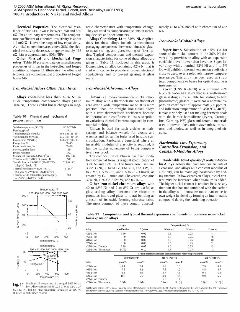
Other Physical and Mechanical Prop-erties. Table 10 presents data on miscellaneousproperties of Invar in the hot-rolled and forgedconditions. Figure 11 illustrates the effects oftemperature on mechanical properties of forged66Fe-34Ni.
Iron-Nickel Alloys Other Than Invar
Alloys containing less than 36% Ni in-clude temperature compensator alloys (30 to34% Ni). These exhibit linear changes in mag-
netic characteristics with temperature change.They are used as compensating shunts in meter-ing devices and speedometers.
Alloys Containing 42 to 50% Ni. Applica-tions for these alloys include semiconductorpackaging components, thermostat bimetals, glass-to-metal sealing, and glass sealing of fiber op-tics. Typical compositions and thermal expan-sion characteristics for some of these alloys aregiven in Table 11. Included in this group isDumet wire, an alloy containing 42% Ni that isclad with copper to provide improved electricalconductivity and to prevent gassing at glassseals.
Iron-Nickel-Chromium Alloys
Elinvar is a low-expansion iron-nickel-chro-mium alloy with a thermoelastic coefficient ofzero over a wide temperature range. It is morepractical than the straight iron-nickel alloyswith a zero thermoelastic coefficient becauseits thermoelastic coefficient is less susceptibleto variations in nickel content expected in com-mercial melting.
Elinvar is used for such articles as hair-springs and balance wheels for clocks andwatches and for tuning forks used in radio syn-chronization. Particularly beneficial where aninvariable modulus of elasticity is required, ithas the further advantage of being compara-tively rustproof.
The composition of Elinvar has been modi-fied somewhat from its original specification of36% Ni and 12% Cr. The limits now used are33 to 35 Ni, 53 to 61 Fe, 4 to 5 Cr, 1 to 3 W, 0.5to 2 Mn, 0.5 to 2 Si, and 0.5 to 2 C. Elinvar, ascreated by Guillaume and Chevenard, contains32% Ni, 10% Cr, 3.5% W, and 0.7% C.
Other iron-nickel-chromium alloys with40 to 48% Ni and 2 to 8% Cr are useful asglass-sealing alloys because the chromiumpromotes improved glass-to-metal bonding asa result of its oxide-forming characteristics.The most common of these contain approxi-
mately 42 to 48% nickel with chromium of 4 to6%.
Iron-Nickel-Cobalt Alloys
Super-Invar. Substitution of ~5% Co forsome of the nickel content in the 36% Ni (In-var) alloy provides an alloy with an expansioncoefficient even lower than Invar. A Super-In-var alloy with a nominal 32% Ni and 4 to 5%Co will exhibit a thermal expansion coefficientclose to zero, over a relatively narrow tempera-ture range. This alloy has been used as struc-tural components or bases for optical and laserinstruments.
Kovar (UNS K94610) is a nominal 29%Ni-17%Co-54%Fe alloy that is a well-knownglass-sealing alloy suitable for sealing to hard(borosilicate) glasses. Kovar has a nominal ex-pansion coefficient of approximately 5 ppm/°Cand inflection temperature of ~450 °C (840 °F).Kovar is widely used for making hermetic sealswith the harder borosilicate (Pyrex, Corning,Inc., Corning, NY) glass and ceramic materialsused in power tubes, microwave tubes, transis-tors, and diodes, as well as in integrated cir-cuits.
Hardenable Low-Expansion,Controlled-Expansion, andConstant-Modulus Alloys
Hardenable Low-Expansion/Constant-Modu-lus Alloys. Alloys that have low coefficients ofexpansion, and alloys with constant modulus ofelasticity, can be made age hardenable by add-ing titanium. In low-expansion alloys, nickel con-tent must be increased when titanium is added.The higher nickel content is required because anytitanium that has not combined with the carbonin the alloy will neutralize more than twice itsown weight in nickel by forming an intermetalliccompound during the hardening operation.
100 / Introduction to Nickel and Nickel Alloys
800
600
400
200
0
Tens
ile s
tren
gth,
MP
a
80
40
0
Duc
tility
, %
Temperature, ˚F200 400 600 800 1000 1200 1400
0 200 400 600 800
100
60
20
Tens
ile s
treng
th, k
si
Temperature, ˚C
Temperature, ˚F200 400 600 800 1000 1200 1400
0 200 400 600 800Temperature, ˚C
Reductionin area
Elongation
Fig. 11 Mechanical properties of a forged 34% Ni al-loy. Alloy composition: 0.25 C, 0.55 Mn, 0.27
Si, 33.9 Ni, bal Fe. Heat treatment: annealed at 800 °C(1475 °F) and furnace cooled
Table 11 Composition and typical thermal expansion coefficients for common iron-nickellow-expansion alloys
ASTM Composition(a), %
Alloy specification C (max) Mn (max) Si (max) Ni (nom)
42 Ni-Iron F 30 0.02 0.5 0.25 4146 Ni-Iron F 30 0.02 0.5 0.25 4648 Ni-Iron F 30 0.02 0.5 0.25 4852 Ni-Iron F 30 0.02 0.5 0.25 5142 Ni-Iron (Dumet) F 29 0.05 1.0 0.25 4242 Ni-Iron (Thermostat) B 753 0.10 0.4 0.25 42
Typical thermal expansion coefficients from room temperature to:
300 °C (570 °F) 400 °C (750 °F) 500 °C (930 °F)
Alloy ppm/°C ppm/°F ppm/°C ppm/°F ppm/°C ppm/°F
42 Ni-Iron 4.4 2.4 6.0 3.3 7.9 4.446 Ni-Iron 7.5 4.2 7.5 4.2 8.5 4.748 Ni-Iron 8.8 4.9 8.7 4.8 9.4 5.252 Ni-Iron 10.1 5.6 9.9 5.5 9.9 5.542 Ni-Iron (Dumet) ... ... 6.6 3.7 ... …42 Ni-Iron (Thermostat) 5.8(b) 3.2(b) 5.6(c) 3.1(c) 5.7(d) 3.15(d)
(a) Balance of iron with residual impurity limits of 0.25% max Si, 0.015% max P, 0.01% max S, 0.25% max Cr, and 0.5% max Co. (b) From roomtemperature to 90 °C (200 °F). (c) From room temperature to 150 °C (300 °F). (d) From room temperature to 370 °C (700 °F)
Table 10 Physical and mechanicalproperties of Invar
Solidus temperature, °C (°F) 1425 (2600)Density, g/cm3 8.1Tensile strength, MPa (ksi) 450–585 (65–85)Yield strength, MPa (ksi) 275–415 (40–60)Elastic limit, MPa (ksi) 140–205 (20–30)Elongation, % 30–45Reduction in area, % 55–70Scleroscope hardness 19Brinell hardness 160Modulus of elasticity, GPa (106 psi) 150 (21.4)Thermoelastic coefficient, µm/m · K 500Specific heat, at 25–100 °C (78–212 °F),
J/kg · °C (Btu/lb · °F)515 (0.123)
Thermal conductivity, at 20–100 °C(68–212 °F), W/m · K (Btu/ft · h · °F)
11 (6.4)
Thermoelectric potential (against copper),at –96 °C (–140 °F), µV/K
9.8
© 2000 ASM International. All Rights Reserved.ASM Specialty Handbook: Nickel, Cobalt, and Their Alloys (#06178G)
www.asminternational.org
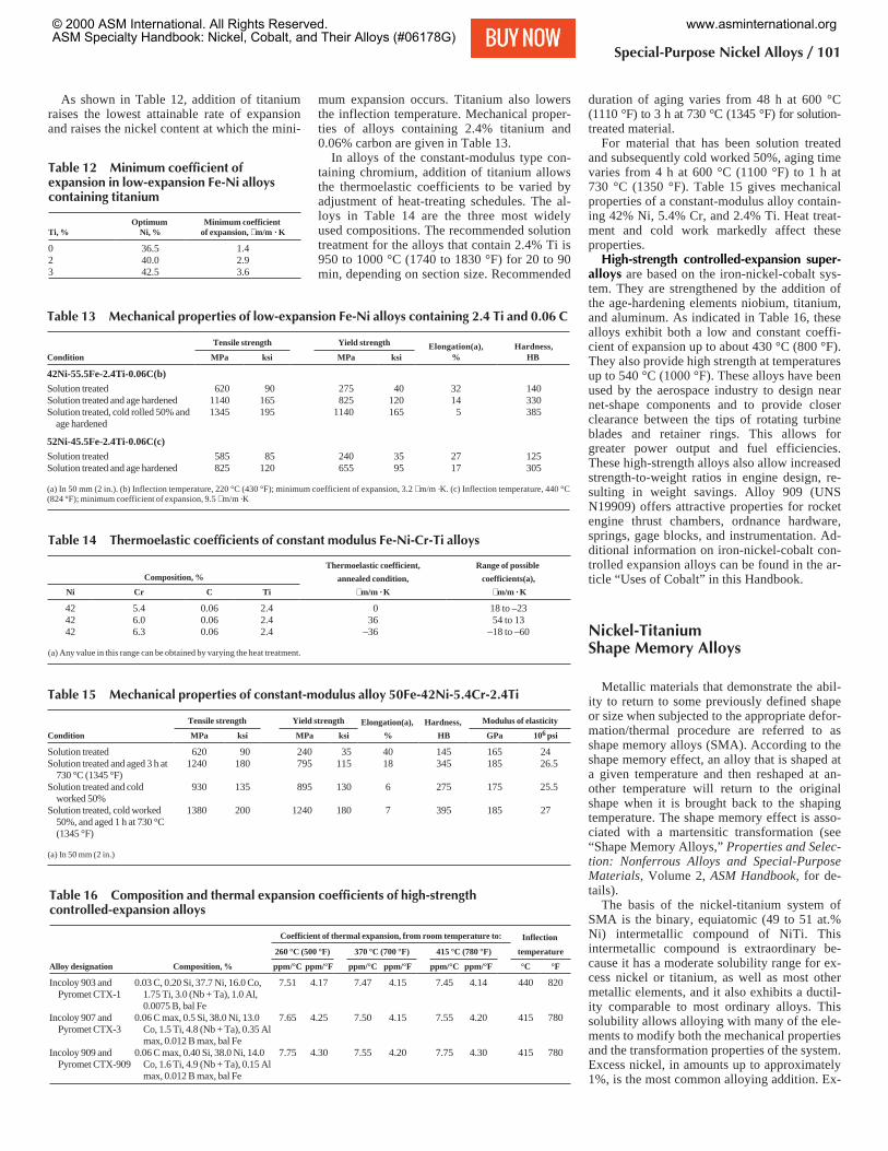
As shown in Table 12, addition of titaniumraises the lowest attainable rate of expansionand raises the nickel content at which the mini-
mum expansion occurs. Titanium also lowersthe inflection temperature. Mechanical proper-ties of alloys containing 2.4% titanium and0.06% carbon are given in Table 13.
In alloys of the constant-modulus type con-taining chromium, addition of titanium allowsthe thermoelastic coefficients to be varied byadjustment of heat-treating schedules. The al-loys in Table 14 are the three most widelyused compositions. The recommended solutiontreatment for the alloys that contain 2.4% Ti is950 to 1000 °C (1740 to 1830 °F) for 20 to 90min, depending on section size. Recommended
duration of aging varies from 48 h at 600 °C(1110 °F) to 3 h at 730 °C (1345 °F) for solution-treated material.
For material that has been solution treatedand subsequently cold worked 50%, aging timevaries from 4 h at 600 °C (1100 °F) to 1 h at730 °C (1350 °F). Table 15 gives mechanicalproperties of a constant-modulus alloy contain-ing 42% Ni, 5.4% Cr, and 2.4% Ti. Heat treat-ment and cold work markedly affect theseproperties.
High-strength controlled-expansion super-alloys are based on the iron-nickel-cobalt sys-tem. They are strengthened by the addition ofthe age-hardening elements niobium, titanium,and aluminum. As indicated in Table 16, thesealloys exhibit both a low and constant coeffi-cient of expansion up to about 430 °C (800 °F).They also provide high strength at temperaturesup to 540 °C (1000 °F). These alloys have beenused by the aerospace industry to design nearnet-shape components and to provide closerclearance between the tips of rotating turbineblades and retainer rings. This allows forgreater power output and fuel efficiencies.These high-strength alloys also allow increasedstrength-to-weight ratios in engine design, re-sulting in weight savings. Alloy 909 (UNSN19909) offers attractive properties for rocketengine thrust chambers, ordnance hardware,springs, gage blocks, and instrumentation. Ad-ditional information on iron-nickel-cobalt con-trolled expansion alloys can be found in the ar-ticle “Uses of Cobalt” in this Handbook.
Nickel-TitaniumShape Memory Alloys
Metallic materials that demonstrate the abil-ity to return to some previously defined shapeor size when subjected to the appropriate defor-mation/thermal procedure are referred to asshape memory alloys (SMA). According to theshape memory effect, an alloy that is shaped ata given temperature and then reshaped at an-other temperature will return to the originalshape when it is brought back to the shapingtemperature. The shape memory effect is asso-ciated with a martensitic transformation (see“Shape Memory Alloys,” Properties and Selec-tion: Nonferrous Alloys and Special-PurposeMaterials, Volume 2, ASM Handbook, for de-tails).
The basis of the nickel-titanium system ofSMA is the binary, equiatomic (49 to 51 at.%Ni) intermetallic compound of NiTi. Thisintermetallic compound is extraordinary be-cause it has a moderate solubility range for ex-cess nickel or titanium, as well as most othermetallic elements, and it also exhibits a ductil-ity comparable to most ordinary alloys. Thissolubility allows alloying with many of the ele-ments to modify both the mechanical propertiesand the transformation properties of the system.Excess nickel, in amounts up to approximately1%, is the most common alloying addition. Ex-
Special-Purpose Nickel Alloys / 101
Table 13 Mechanical properties of low-expansion Fe-Ni alloys containing 2.4 Ti and 0.06 C
Tensile strength Yield strength Elongation(a), Hardness,Condition MPa ksi MPa ksi % HB
42Ni-55.5Fe-2.4Ti-0.06C(b)Solution treated 620 90 275 40 32 140Solution treated and age hardened 1140 165 825 120 14 330Solution treated, cold rolled 50% and
age hardened1345 195 1140 165 5 385
52Ni-45.5Fe-2.4Ti-0.06C(c)Solution treated 585 85 240 35 27 125Solution treated and age hardened 825 120 655 95 17 305
(a) In 50 mm (2 in.). (b) Inflection temperature, 220 °C (430 °F); minimum coefficient of expansion, 3.2 m/m ·K. (c) Inflection temperature, 440 °C(824 °F); minimum coefficient of expansion, 9.5 m/m ·K
Table 14 Thermoelastic coefficients of constant modulus Fe-Ni-Cr-Ti alloys
Thermoelastic coefficient, Range of possibleComposition, % annealed condition, coefficients(a),
Ni Cr C Ti m/m · K m/m · K
42 5.4 0.06 2.4 0 18 to –2342 6.0 0.06 2.4 36 54 to 1342 6.3 0.06 2.4 –36 –18 to –60
(a) Any value in this range can be obtained by varying the heat treatment.
Table 15 Mechanical properties of constant-modulus alloy 50Fe-42Ni-5.4Cr-2.4Ti
Tensile strength Yield strength Elongation(a), Hardness, Modulus of elasticity
Condition MPa ksi MPa ksi % HB GPa 106 psi
Solution treated 620 90 240 35 40 145 165 24Solution treated and aged 3 h at
730 °C (1345 °F)1240 180 795 115 18 345 185 26.5
Solution treated and coldworked 50%
930 135 895 130 6 275 175 25.5
Solution treated, cold worked50%, and aged 1 h at 730 °C(1345 °F)
1380 200 1240 180 7 395 185 27
(a) In 50 mm (2 in.)
Table 16 Composition and thermal expansion coefficients of high-strengthcontrolled-expansion alloys
Coefficient of thermal expansion, from room temperature to: Inflection
260 °C (500 °F) 370 °C (700 °F) 415 °C (780 °F) temperature
Alloy designation Composition, % ppm/°C ppm/°F ppm/°C ppm/°F ppm/°C ppm/°F °C °F
Incoloy 903 andPyromet CTX-1
0.03 C, 0.20 Si, 37.7 Ni, 16.0 Co,1.75 Ti, 3.0 (Nb + Ta), 1.0 Al,0.0075 B, bal Fe
7.51 4.17 7.47 4.15 7.45 4.14 440 820
Incoloy 907 andPyromet CTX-3
0.06 C max, 0.5 Si, 38.0 Ni, 13.0Co, 1.5 Ti, 4.8 (Nb + Ta), 0.35 Almax, 0.012 B max, bal Fe
7.65 4.25 7.50 4.15 7.55 4.20 415 780
Incoloy 909 andPyromet CTX-909
0.06 C max, 0.40 Si, 38.0 Ni, 14.0Co, 1.6 Ti, 4.9 (Nb + Ta), 0.15 Almax, 0.012 B max, bal Fe
7.75 4.30 7.55 4.20 7.75 4.30 415 780
Table 12 Minimum coefficient ofexpansion in low-expansion Fe-Ni alloyscontaining titanium
Ti, %Optimum
Ni, %Minimum coefficient
of expansion, m/m · K
0 36.5 1.42 40.0 2.93 42.5 3.6
© 2000 ASM International. All Rights Reserved.ASM Specialty Handbook: Nickel, Cobalt, and Their Alloys (#06178G)
www.asminternational.org


