Embed Size (px)
Citation preview
30 l INDIAN ENGINEERING EXPORTS l DECEMBER 2019
TECH FRONTIERS
Light-weight designs are central to improving efficiency and optimising energy consumption. In this quest for weight reduction and improved fuel economy cast iron has been and is still being replaced by aluminium in automotive application. Solution strengthened ferritic ductile iron (SSFDI) presents an interesting potential for reducing weight through its combination of higher strength and elongation. While being developed to provide better machinability properties of solution strengthened ferritic ductile iron, the material is now being recognised as having interesting potential to reduce weight. This potential is not only being recognised by the automotive but also the wind energy industry
SSFDI – A potential alternative for lightweight design
Introduction to SSFIn 2011, the second group of spheroidal graphite cast irons were included in the Eu-ropean standard EN-1563; solid solution strengthened ferritic ductile (SSF) iron. These grades were initially studied by Vol-vo in the early 1980s with the purpose of providing a material that provides similar mechanical properties as ferritic-pearlitic ductile iron grade EN-GJS-500-7 but was easier to machine. This work was presented at the World Foundry Congress in 2000 by LE Bjørkegren and K Hamberg and demon-strated that alloying with silicon provided a material with similar strength combined with higher elongation and lower and more uniform hardness to EN-GJS-500-7.
The incorporation of these grades in the European standard evoked renewed interest in SSF. In particular, German researcher H Löblich saw a need for investing in learning more about this material. He studied how to
C Hartung, A Plowman, R Logan are with the Elkem Group
C HARTUNG, A PLOWMAN, R LOGAN
DECEMBER 2019 l INDIAN ENGINEERING EXPORTS l 31
produce this material, the effect of carbide promoting elements as well as effect of sili-con on static and cyclic mechanical proper-ties at different temperatures. SSF exhibits a single matrix and a more uniform hardness independent of section size. This provides a solution to the known challenge of the ferritic-pearlitic grades and provides high-er strength and elongation. This combina-tion of property improvements creates new possibilities for other applications. Ductile iron grades have standardised names that indicate the tensile strength and elongation (in MPa and percentage, respectively) of a tensile test specimen, e.g. EN-GJS-600-10. It should be noted that these values are given for separately cast samples with relatively thin-wall (thickness below 30 mm). The requirements decrease as the wall thickness increases and these requirements for SSF grades of ductile iron from EN standard 1563 are shown in Table1. Requirements for mechanical properties also change if the tensile specimen is taken from the actual casting and these mechanical requirements are shown in Table2. For example, a ten-sile test bar taken from a casting with rel-evant wall thickness of 50 mm made from EN-GJS-600-10 only needs to have tensile strength of 560 MPa and elongation of 6% to meet the standard.
Compared to the ferritic-pearlitic grades the SSF grades provide higher elonga-tion and yield strength at the same tensile strength as can be seen in Table3.
This combination of higher yield strength with higher elongation allows for lighter de-signs as the casting section thickness can be reduced. Expensive alloying elements also offer a more cost-efficient alternative.
This potential for light weight designs of-fers an interesting potential within the engi-neering segment. In addition, this material promotes maintaining cast iron and con-verting steel components within the wind energy segment.
Market review for SSFConsidering the growing interest in SSF, it is worthwhile to evaluate the market
Table1: Mechanical properties of SSF ductile irons according to EN 1563. Separately cast samplesMaterial Relevant wall
thickness t mm0.2% proof strength Rp0.2 MPa
Tensile strength Rm MPa
Elongation A %
EN-GJS-450-18 t≤30 350 450 18
30≤t≤60 340 430 14
t> To be agreed upon between manufacturer and purchaser
EN-GJS-500-14 t≤30 400 500 14
30≤t≤60 390 480 12
t>
EN- GJS-600-10 t≤30 470 600 10
30≤t≤60 450 580 8
t> To be agreed upon between manufacturer and purchaser
Source: ISO EN 1563 (2018), Founding – Spheroidal Graphite Cast Irons
Table2: Mechanical properties of SSF ductile irons from EN 1563. Samples cut from castingsMaterial Relevant wall
thickness t mm0.2% proof strength Rp0.2 MPa
Tensile strength Rm MPa
Elongation A %
EN-GJS-450-18 t≤30 350 440 16
30≤t≤60 340 420 12
t> Guidance value to be provided by manufacturer
EN-GJS-500-14 t≤30 400 480 12
30≤t≤60 390 460 10
t> Guidance value to be provided by manufacturer
EN-GJS-600-10 t≤30 450 580 8
30≤t≤60 430 560 6
t> Guidance value to be provided by manufacturer
Source: ISO EN 1563 (2018), Founding – Spheroidal Graphite Cast Irons
Table3: Mechanical properties of SSF grades compared to ferritic-pearlitic in 30 mm tensile bar
SSF DI SSF DI SSF DI
Material Grade EN-GJS 450-18 500-7 500-14 700-2 600-10 800-2
0.2% proof strength MPa 350 320 400 420 470 480
Tensile strength MPa 450 500 500 700 600 800
Elongation A % 18 7 14 2 10 2
Hardness HB 170-200 170-230 185-215 225-305 200-230 245-335
Fracture toughness, KIC MPa√m
30* 22-25* 28 23* 15* 14*
Density kg/dm3 7.1 7.1 7.0 7.2 7.0 7.2
Note: *K Vollrath, Neue, hochinteressante Kugelgraphit-Gusswerkstoffe, Giesserei, 09-2013
32 l INDIAN ENGINEERING EXPORTS l DECEMBER 2019
TECH FRONTIERS
potential for this material. Modern Cast-ings 51st Census of World Casting Pro-duction indicated the total annual pro-duction of ductile iron to be 25,467,378 tonnes in 2016. The potential for SSF is connected to converting ferritic-pearlitic castings, replacing ferritic castings within the wind energy segment and replacing steel castings and weldments.
When it comes to the wind energy segment, this is based on installed ca-pacity estimated to be around 3 million tonnes of ductile iron per year. It should be possible to convert 30% or 900,000 tonnes; of this, however, around 90,000 tonnes are currently produced in SSF. This puts the total current production of SSF to 340,000 tonnes and which is about 1.4% of the total ductile iron production worldwide. However, this volume is in-creasing as more wind generator manu-facturers see the benefit of using a high-er strength ductile iron allowing for a weight reduction of approximately 30%.
With regard to the automotive sector, the OEMs are now starting to take notice of the new SSF grades and several found-ries in India and China are now starting to run trials with the new grades. It is likely that within the next few years the market for these SSF grades will increase by around 20% of the current ductile iron automotive market.
Design of experiments With incorporation of SSF in the Euro-pean standard and increasing industry and academia interest in SSF, Elkem rec-ognised the strategic importance of this material. Research on understanding how the treatment process and choices related to the treatment process affected the mi-crostructure and properties was justified.
It was observed that significant region-al differences existed for the preferred combination of MgFeSi and inoculation related to SSF. To understand better what combinations are favourable and wheth-er some combinations are better than others it was decided to run a series of
trials. (Table4)The goal of each trial was to make
EN-GJS-600-10 and achieve above min-imum requirements for elongation, yield strength and ultimate tensile strength combined with a nodule density of more than 100 N/mm2 and more than 80% nodularity. This grade is the most chal-lenging SSF grade to achieve.
The four 1500-kg melts were prepared in a coreless-induction furnace from steel scrap. The actual final iron composition is shown in Table5.
The treatment was carried out in a tundish ladle with a pocket design that allowed a 20-mm cover layer to be placed on top of the MgFeSi. Addition rate of MgFeSi varied between 1.05 and 1.37% by weight of Mg to achieve the same tar-get residual Mg content in the treatment
ladle after deslagging. The treated iron was then divided into five 32-kg capaci-ty pouring ladles at 30-second intervals where the inoculant had been added to the bottom. The inoculated iron was held for 1 minute prior to casting into a sand mould. The same inoculant was used in the first and last pouring ladle.
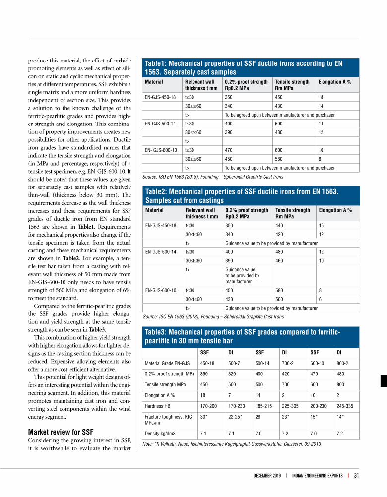
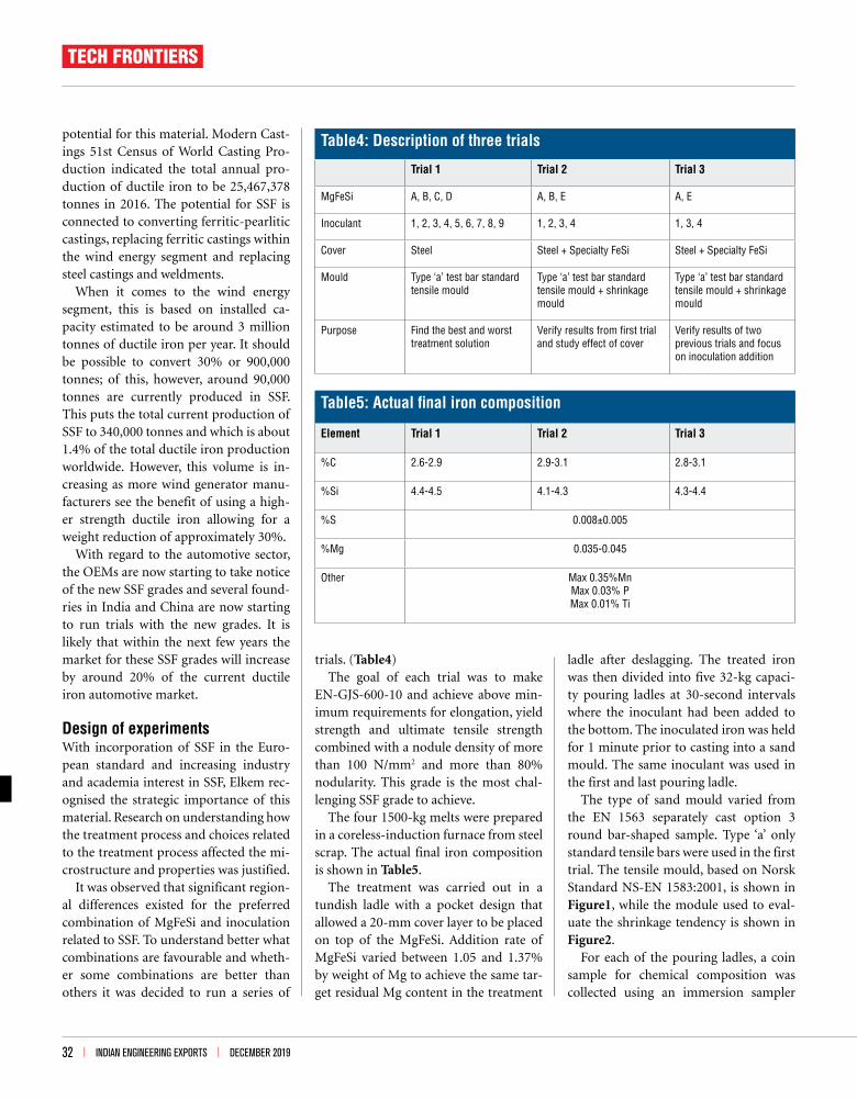
The type of sand mould varied from the EN 1563 separately cast option 3 round bar-shaped sample. Type ‘a’ only standard tensile bars were used in the first trial. The tensile mould, based on Norsk Standard NS-EN 1583:2001, is shown in Figure1, while the module used to eval-uate the shrinkage tendency is shown in Figure2.
For each of the pouring ladles, a coin sample for chemical composition was collected using an immersion sampler
Table4: Description of three trials
Trial 1 Trial 2 Trial 3
MgFeSi A, B, C, D A, B, E A, E
Inoculant 1, 2, 3, 4, 5, 6, 7, 8, 9 1, 2, 3, 4 1, 3, 4
Cover Steel Steel + Specialty FeSi Steel + Specialty FeSi
Mould Type ‘a’ test bar standard tensile mould
Type ‘a’ test bar standard tensile mould + shrinkage mould
Type ‘a’ test bar standard tensile mould + shrinkage mould
Purpose Find the best and worst treatment solution
Verify results from first trial and study effect of cover
Verify results of two previous trials and focus on inoculation addition
Table5: Actual final iron composition
Element Trial 1 Trial 2 Trial 3
%C 2.6-2.9 2.9-3.1 2.8-3.1
%Si 4.4-4.5 4.1-4.3 4.3-4.4
%S 0.008±0.005
%Mg 0.035-0.045
Other Max 0.35%Mn Max 0.03% P Max 0.01% Ti
DECEMBER 2019 l INDIAN ENGINEERING EXPORTS l 33
and four thermal-analysis-cups were poured. The chemical composition was determined as follows: C and S using a combustion technique, Si using wet chemical determination and all other el-ements using an Optical Emission Spec-trometer.
The following parameters were used to evaluate the trials: chemical composition of the base iron, treated and inoculated iron, thermal analysis data of base iron, microstructure and mechanical proper-ties of the final iron. A section taken was used for microstructure characterisation and both tensile bars were pulled to ob-tain tensile strength (Rm), yield strength (Rp0.2) and elongation (A5).
Microstructure and the characterisa-tion quantification were carried out with a Zeiss optical microscope equipped us-ing an Axioplan 2 automatic stage con-troller at a magnification of 100X. The digital camera provided an image reso-lution of 0.68 µm/pixel (1.47 pixel/µm), and an image size of 1280x960 pixels. For samples having chunky graphite the structure was only documented with a single photo at 100X.
ResultsFrom the obtained results the following observation could be made:
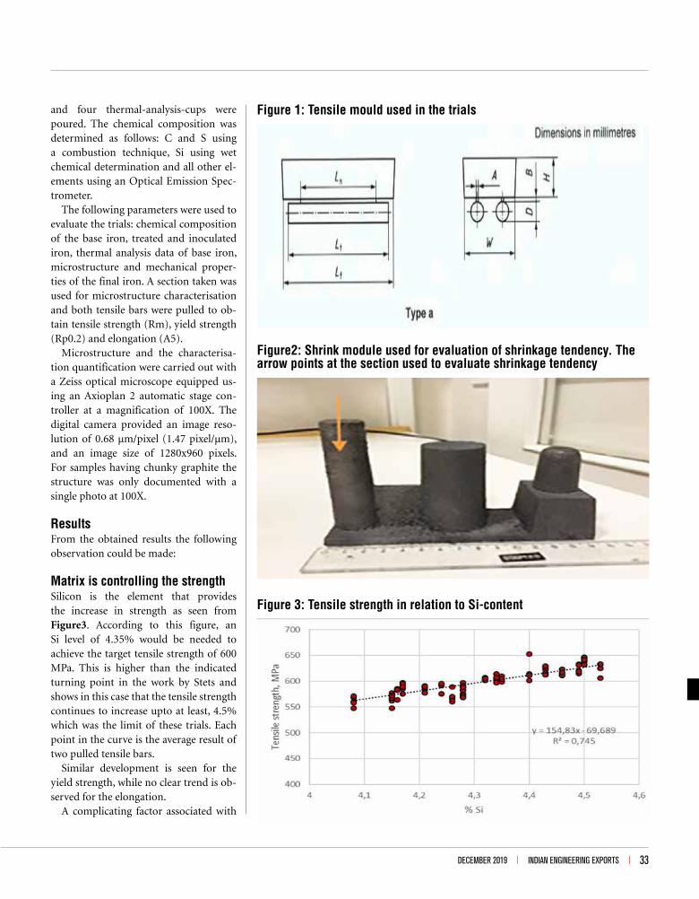
Matrix is controlling the strengthSilicon is the element that provides the increase in strength as seen from Figure3. According to this figure, an Si level of 4.35% would be needed to achieve the target tensile strength of 600 MPa. This is higher than the indicated turning point in the work by Stets and shows in this case that the tensile strength continues to increase upto at least, 4.5% which was the limit of these trials. Each point in the curve is the average result of two pulled tensile bars.
Similar development is seen for the yield strength, while no clear trend is ob-served for the elongation.
A complicating factor associated with
Figure 1: Tensile mould used in the trials
Figure 3: Tensile strength in relation to Si-content
Figure2: Shrink module used for evaluation of shrinkage tendency. The arrow points at the section used to evaluate shrinkage tendency
34 l INDIAN ENGINEERING EXPORTS l DECEMBER 2019
Si and the fact that the strength is so strongly connected to the Si-level is the increasing analytical error with increas-ing Si and lack of available certified refer-ence material (CRM) and reference ma-terial calibration standards for SSF iron. It is therefore important to work with alloys with defined and consistent chem-istry and sizing.
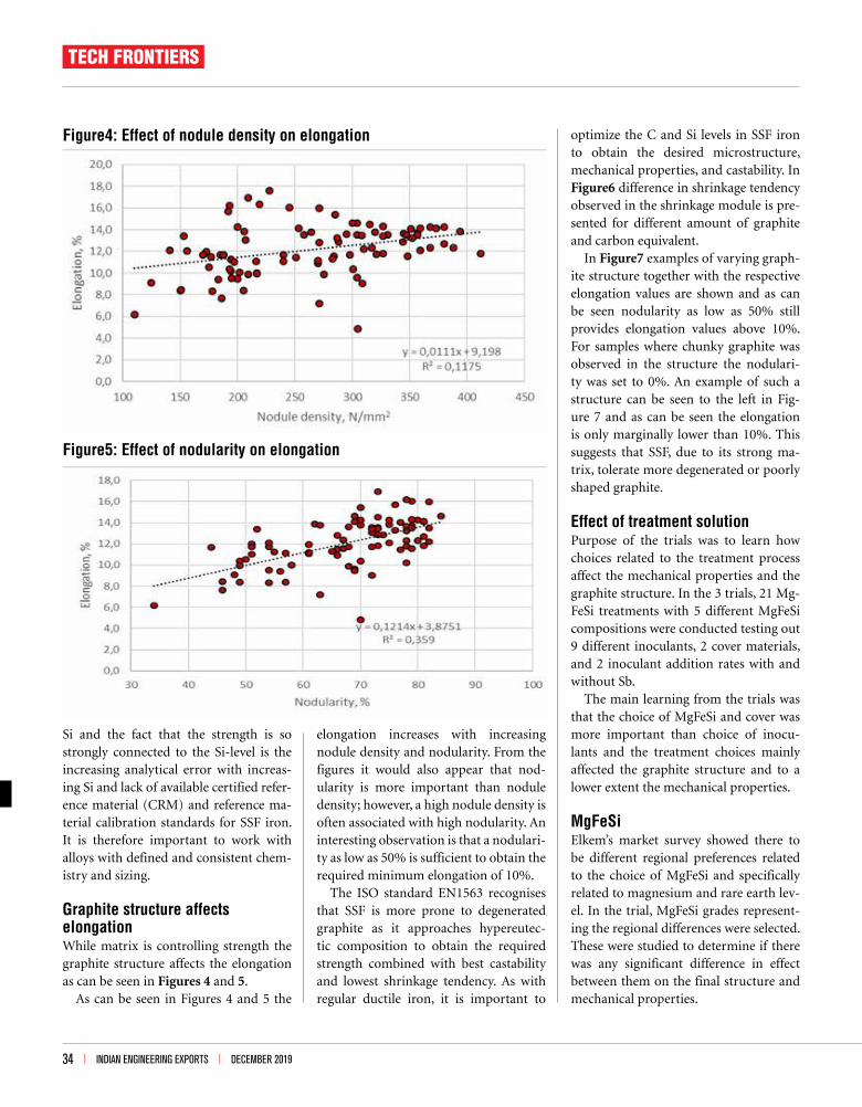
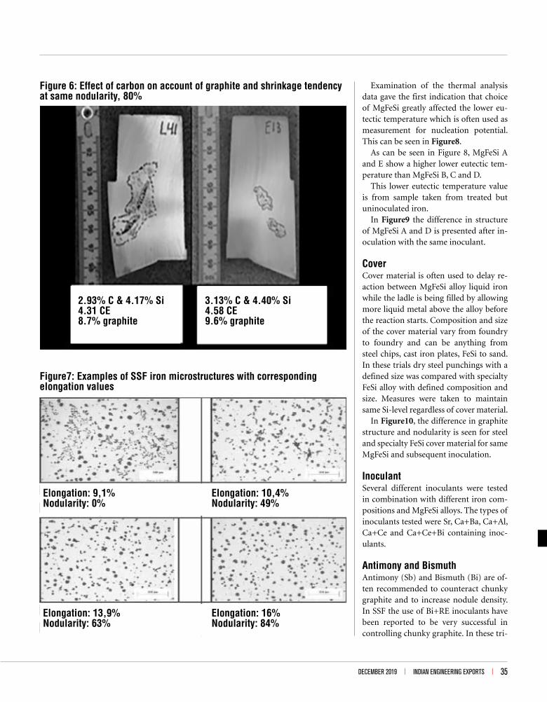
Graphite structure affects elongationWhile matrix is controlling strength the graphite structure affects the elongation as can be seen in Figures 4 and 5.
As can be seen in Figures 4 and 5 the
elongation increases with increasing nodule density and nodularity. From the figures it would also appear that nod-ularity is more important than nodule density; however, a high nodule density is often associated with high nodularity. An interesting observation is that a nodulari-ty as low as 50% is sufficient to obtain the required minimum elongation of 10%.
The ISO standard EN1563 recognises that SSF is more prone to degenerated graphite as it approaches hypereutec-tic composition to obtain the required strength combined with best castability and lowest shrinkage tendency. As with regular ductile iron, it is important to
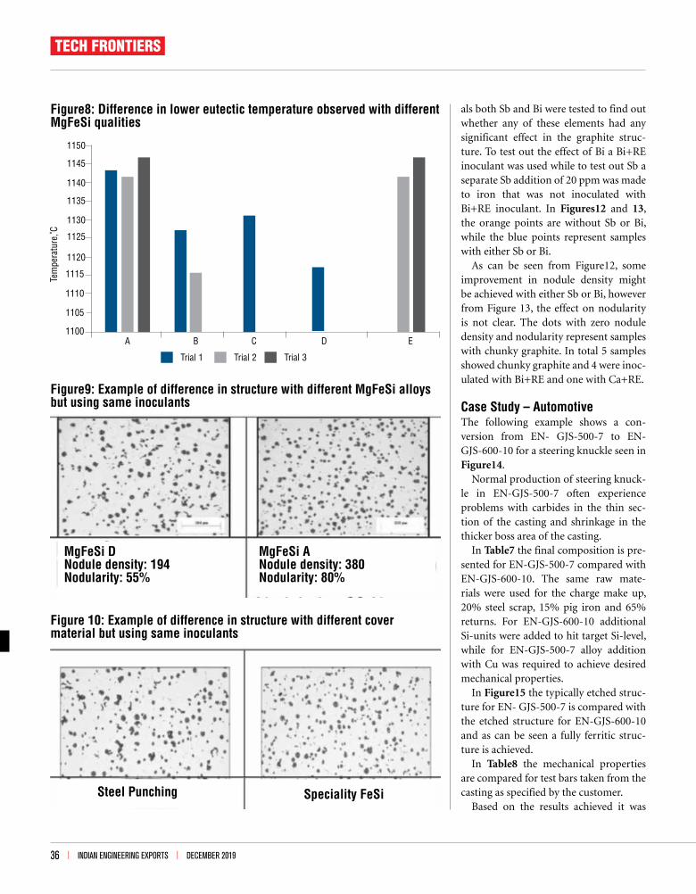
optimize the C and Si levels in SSF iron to obtain the desired microstructure, mechanical properties, and castability. In Figure6 difference in shrinkage tendency observed in the shrinkage module is pre-sented for different amount of graphite and carbon equivalent.
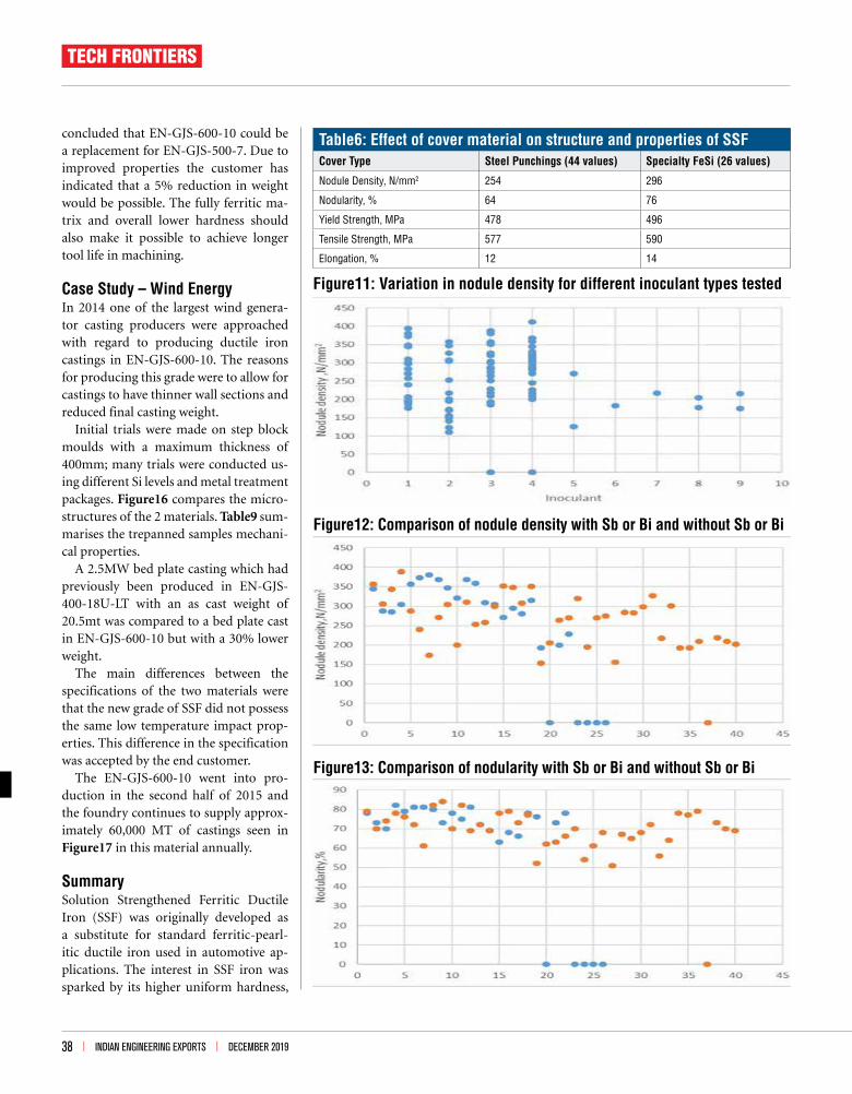
In Figure7 examples of varying graph-ite structure together with the respective elongation values are shown and as can be seen nodularity as low as 50% still provides elongation values above 10%. For samples where chunky graphite was observed in the structure the nodulari-ty was set to 0%. An example of such a structure can be seen to the left in Fig-ure 7 and as can be seen the elongation is only marginally lower than 10%. This suggests that SSF, due to its strong ma-trix, tolerate more degenerated or poorly shaped graphite.
Effect of treatment solutionPurpose of the trials was to learn how choices related to the treatment process affect the mechanical properties and the graphite structure. In the 3 trials, 21 Mg-FeSi treatments with 5 different MgFeSi compositions were conducted testing out 9 different inoculants, 2 cover materials, and 2 inoculant addition rates with and without Sb.
The main learning from the trials was that the choice of MgFeSi and cover was more important than choice of inocu-lants and the treatment choices mainly affected the graphite structure and to a lower extent the mechanical properties.
MgFeSi Elkem’s market survey showed there to be different regional preferences related to the choice of MgFeSi and specifically related to magnesium and rare earth lev-el. In the trial, MgFeSi grades represent-ing the regional differences were selected. These were studied to determine if there was any significant difference in effect between them on the final structure and mechanical properties.
Figure5: Effect of nodularity on elongation
Figure4: Effect of nodule density on elongation
TECH FRONTIERS
DECEMBER 2019 l INDIAN ENGINEERING EXPORTS l 35
Examination of the thermal analysis data gave the first indication that choice of MgFeSi greatly affected the lower eu-tectic temperature which is often used as measurement for nucleation potential. This can be seen in Figure8.
As can be seen in Figure 8, MgFeSi A and E show a higher lower eutectic tem-perature than MgFeSi B, C and D.
This lower eutectic temperature value is from sample taken from treated but uninoculated iron.
In Figure9 the difference in structure of MgFeSi A and D is presented after in-oculation with the same inoculant.
CoverCover material is often used to delay re-action between MgFeSi alloy liquid iron while the ladle is being filled by allowing more liquid metal above the alloy before the reaction starts. Composition and size of the cover material vary from foundry to foundry and can be anything from steel chips, cast iron plates, FeSi to sand. In these trials dry steel punchings with a defined size was compared with specialty FeSi alloy with defined composition and size. Measures were taken to maintain same Si-level regardless of cover material.
In Figure10, the difference in graphite structure and nodularity is seen for steel and specialty FeSi cover material for same MgFeSi and subsequent inoculation.
InoculantSeveral different inoculants were tested in combination with different iron com-positions and MgFeSi alloys. The types of inoculants tested were Sr, Ca+Ba, Ca+Al, Ca+Ce and Ca+Ce+Bi containing inoc-ulants.
Antimony and BismuthAntimony (Sb) and Bismuth (Bi) are of-ten recommended to counteract chunky graphite and to increase nodule density. In SSF the use of Bi+RE inoculants have been reported to be very successful in controlling chunky graphite. In these tri-
Figure7: Examples of SSF iron microstructures with corresponding elongation values
Elongation: 9,1%Nodularity: 0%
Elongation: 13,9%Nodularity: 63%
Elongation: 16%Nodularity: 84%
Elongation: 10,4%Nodularity: 49%
Figure 6: Effect of carbon on account of graphite and shrinkage tendency at same nodularity, 80%
2.93% C & 4.17% Si4.31 CE8.7% graphite
3.13% C & 4.40% Si4.58 CE9.6% graphite
36 l INDIAN ENGINEERING EXPORTS l DECEMBER 2019
als both Sb and Bi were tested to find out whether any of these elements had any significant effect in the graphite struc-ture. To test out the effect of Bi a Bi+RE inoculant was used while to test out Sb a separate Sb addition of 20 ppm was made to iron that was not inoculated with Bi+RE inoculant. In Figures12 and 13, the orange points are without Sb or Bi, while the blue points represent samples with either Sb or Bi.
As can be seen from Figure12, some improvement in nodule density might be achieved with either Sb or Bi, however from Figure 13, the effect on nodularity is not clear. The dots with zero nodule density and nodularity represent samples with chunky graphite. In total 5 samples showed chunky graphite and 4 were inoc-ulated with Bi+RE and one with Ca+RE.
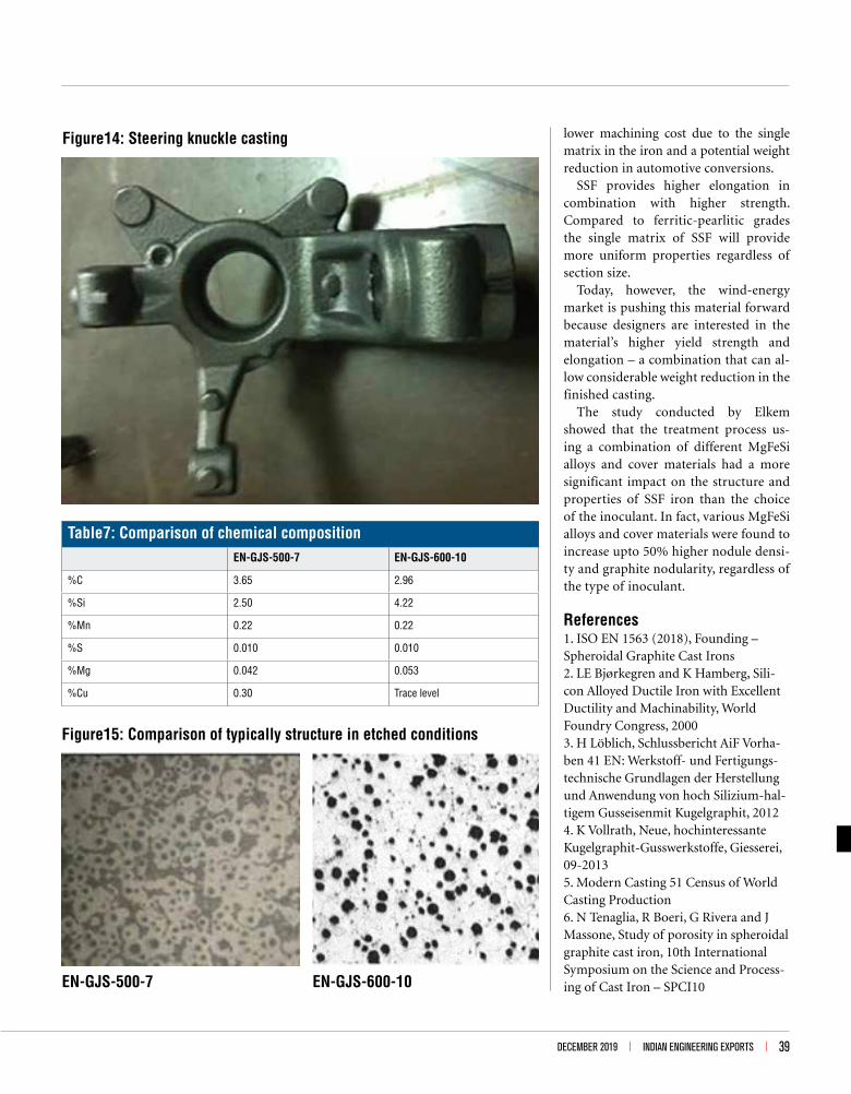
Case Study – Automotive The following example shows a con-version from EN- GJS-500-7 to EN-GJS-600-10 for a steering knuckle seen in Figure14.
Normal production of steering knuck-le in EN-GJS-500-7 often experience problems with carbides in the thin sec-tion of the casting and shrinkage in the thicker boss area of the casting.
In Table7 the final composition is pre-sented for EN-GJS-500-7 compared with EN-GJS-600-10. The same raw mate-rials were used for the charge make up, 20% steel scrap, 15% pig iron and 65% returns. For EN-GJS-600-10 additional Si-units were added to hit target Si-level, while for EN-GJS-500-7 alloy addition with Cu was required to achieve desired mechanical properties.
In Figure15 the typically etched struc-ture for EN- GJS-500-7 is compared with the etched structure for EN-GJS-600-10 and as can be seen a fully ferritic struc-ture is achieved.
In Table8 the mechanical properties are compared for test bars taken from the casting as specified by the customer.
Based on the results achieved it was
1150
1145
1140
1135
1130
1125
1120
1115
1110
1105
1100
Tem
pera
ture
,˚C
Trial 1
A B C D E
Trial 2 Trial 3
Figure8: Difference in lower eutectic temperature observed with different MgFeSi qualities
Figure9: Example of difference in structure with different MgFeSi alloys but using same inoculants
MgFeSi DNodule density: 194Nodularity: 55%
MgFeSi ANodule density: 380Nodularity: 80%
Figure 10: Example of difference in structure with different cover material but using same inoculants
Steel Punching Speciality FeSi
TECH FRONTIERS

38 l INDIAN ENGINEERING EXPORTS l DECEMBER 2019
concluded that EN-GJS-600-10 could be a replacement for EN-GJS-500-7. Due to improved properties the customer has indicated that a 5% reduction in weight would be possible. The fully ferritic ma-trix and overall lower hardness should also make it possible to achieve longer tool life in machining.
Case Study – Wind EnergyIn 2014 one of the largest wind genera-tor casting producers were approached with regard to producing ductile iron castings in EN-GJS-600-10. The reasons for producing this grade were to allow for castings to have thinner wall sections and reduced final casting weight.
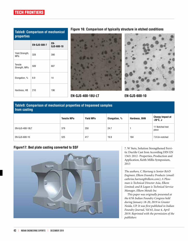
Initial trials were made on step block moulds with a maximum thickness of 400mm; many trials were conducted us-ing different Si levels and metal treatment packages. Figure16 compares the micro-structures of the 2 materials. Table9 sum-marises the trepanned samples mechani-cal properties.
A 2.5MW bed plate casting which had previously been produced in EN-GJS-400-18U-LT with an as cast weight of 20.5mt was compared to a bed plate cast in EN-GJS-600-10 but with a 30% lower weight.
The main differences between the specifications of the two materials were that the new grade of SSF did not possess the same low temperature impact prop-erties. This difference in the specification was accepted by the end customer.
The EN-GJS-600-10 went into pro-duction in the second half of 2015 and the foundry continues to supply approx-imately 60,000 MT of castings seen in Figure17 in this material annually.
SummarySolution Strengthened Ferritic Ductile Iron (SSF) was originally developed as a substitute for standard ferritic-pearl-itic ductile iron used in automotive ap-plications. The interest in SSF iron was sparked by its higher uniform hardness,
Table6: Effect of cover material on structure and properties of SSFCover Type Steel Punchings (44 values) Specialty FeSi (26 values)
Nodule Density, N/mm2 254 296
Nodularity, % 64 76
Yield Strength, MPa 478 496
Tensile Strength, MPa 577 590
Elongation, % 12 14
Figure12: Comparison of nodule density with Sb or Bi and without Sb or Bi
Figure13: Comparison of nodularity with Sb or Bi and without Sb or Bi
Figure11: Variation in nodule density for different inoculant types tested
TECH FRONTIERS
DECEMBER 2019 l INDIAN ENGINEERING EXPORTS l 39
lower machining cost due to the single matrix in the iron and a potential weight reduction in automotive conversions.
SSF provides higher elongation in combination with higher strength. Compared to ferritic-pearlitic grades the single matrix of SSF will provide more uniform properties regardless of section size.
Today, however, the wind-energy market is pushing this material forward because designers are interested in the material’s higher yield strength and elongation – a combination that can al-low considerable weight reduction in the finished casting.
The study conducted by Elkem showed that the treatment process us-ing a combination of different MgFeSi alloys and cover materials had a more significant impact on the structure and properties of SSF iron than the choice of the inoculant. In fact, various MgFeSi alloys and cover materials were found to increase upto 50% higher nodule densi-ty and graphite nodularity, regardless of the type of inoculant.
References1. ISO EN 1563 (2018), Founding – Spheroidal Graphite Cast Irons2. LE Bjørkegren and K Hamberg, Sili-con Alloyed Ductile Iron with Excellent Ductility and Machinability, World Foundry Congress, 20003. H Löblich, Schlussbericht AiF Vorha-ben 41 EN: Werkstoff- und Fertigungs-technische Grundlagen der Herstellung und Anwendung von hoch Silizium-hal-tigem Gusseisenmit Kugelgraphit, 20124. K Vollrath, Neue, hochinteressante Kugelgraphit-Gusswerkstoffe, Giesserei, 09-20135. Modern Casting 51 Census of World Casting Production6. N Tenaglia, R Boeri, G Rivera and J Massone, Study of porosity in spheroidal graphite cast iron, 10th International Symposium on the Science and Process-ing of Cast Iron – SPCI10
Figure14: Steering knuckle casting
Table7: Comparison of chemical compositionEN-GJS-500-7 EN-GJS-600-10
%C 3.65 2.96
%Si 2.50 4.22
%Mn 0.22 0.22
%S 0.010 0.010
%Mg 0.042 0.053
%Cu 0.30 Trace level
Figure15: Comparison of typically structure in etched conditions
EN-GJS-500-7 EN-GJS-600-10
40 l INDIAN ENGINEERING EXPORTS l DECEMBER 2019
Table8: Comparison of mechanical properties
EN-GJS-500-7 EN-GJS-600-10
Yield Strength, MPa 328 390
Tensile Strength, MPa 509 607
Elongation, % 8.9 14
Hardness, HB 210 196
7. W Stets, Solution Strengthened Ferri-tic Ductile Cast Iron According DIN EN 1563: 2012- Properties, Production and Application, Keith Millis Symposium, 2013
The authors, C Hartung is Senior R&D Engineer, Elkem Foundry Products (email: [email protected]); A Plow-man is Technical Director Asia, Elkem Limited; and R Logan is Technical Service Manager, Elkem Metals Inc
This paper was originally presented at the 67th Indian Foundry Congress held during January 18-20, 2019 in Greater Noida, UP. It was first published in Indian Foundry Journal, Vol 65, Issue 4, April 2019. Reprinted with the permission of the publishers
Table9: Comparison of mechanical properties of trepanned samples from casting
Tensile MPa Yield MPa Elongation, % Hardness, BHN Charpy Impact at -20°C, J
EN-GJS-400-18LT 379 250 24.7 1 11 Notched test piece
EN-GJS-600-10 525 417 19.9 184 7.8 Un-notched
Figure17: Bed plate casting converted to SSF
Figure 16: Comparison of typically structure in etched conditions
EN-GJS-400-18U-LT EN-GJS-600-10
TECH FRONTIERS


