Embed Size (px)
Citation preview

6B
Steering Wheel and Column ConstructionThis double tube type steering column has the following three important features in addition to the steering function:• The column is energy absorbing, designed to compress in a front-end collision.• The ignition switch and lock are mounted conveniently on this column.• With the column mounted lock, the ignition and steering operations can be locked to inhibit
theft of the vehicle.To insure the energy absorbing action, it is important that only the specified screws, bolts and nuts be used as designated, and that they are tightened to the specified torque. When the column assembly is removed from the vehicle, special care must be taken in handling it. Use of a steering wheel puller or a sharp blow on the end of the steering shaft, leaning on the assembly, or dropping the assembly could shear the plastic shear pins which maintain column length and position.The driver air bag (inflator) module is one of the supplemental restraint (air bag) system components and is mounted to the center of the steering wheel. During certain frontal crashes, the air bag system supplements the restraint of the driver’s and passenger’s seat belts by deploying the air bags. The air bag (inflator) module should be handled with care to prevent accidental deployment. When servicing, be sure to observe Precautions on Service and Diagnosis of Air Bag System:Except advanced Air Bag or Precautions on Service and Diagnosis of Air Bag System:Advanced Air Bag.
Page 1 of 1AEN8RW016201001
3/27/2015https://suzukipitstopplus.com/Media/Manuals/SX4/2008/Service_Manual/99500-80J10-33...
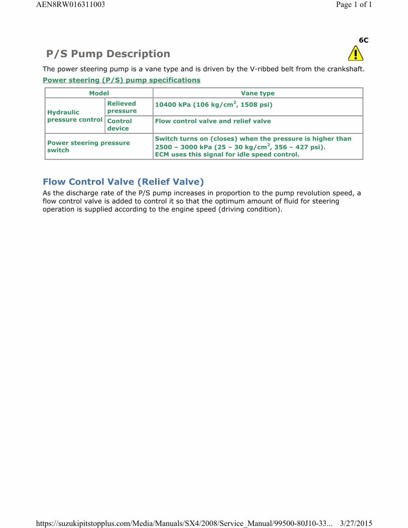
6C
P/S Pump DescriptionThe power steering pump is a vane type and is driven by the V-ribbed belt from the crankshaft.Power steering (P/S) pump specifications
Model Vane type
Hydraulic pressure control
Relieved pressure
10400 kPa (106 kg/cm2, 1508 psi)
Control device
Flow control valve and relief valve
Power steering pressure switch
Switch turns on (closes) when the pressure is higher than 2500 – 3000 kPa (25 – 30 kg/cm2, 356 – 427 psi).ECM uses this signal for idle speed control.
Flow Control Valve (Relief Valve)As the discharge rate of the P/S pump increases in proportion to the pump revolution speed, a flow control valve is added to control it so that the optimum amount of fluid for steering operation is supplied according to the engine speed (driving condition).
Page 1 of 1AEN8RW016311003
3/27/2015https://suzukipitstopplus.com/Media/Manuals/SX4/2008/Service_Manual/99500-80J10-33...

6C
P/S System DescriptionThe power steering (P/S) system in this vehicle reduces the driver’s effort needed in turning the steering wheel (3) by utilizing the hydraulic pressure generated by the power steering (P/S) pump (2) which is driven by the engine.It is an integral type with the rack and pinion gears and the control valve unit, hydraulic pressure cylinder unit all built in the steering gear case (1).
4. P/S fluid reservoir
5. P/S pump drive belt
Page 1 of 1AEN8RW016311001
3/27/2015https://suzukipitstopplus.com/Media/Manuals/SX4/2008/Service_Manual/99500-80J10-33...

6C
Steering Gear Case DescriptionThe steering gear case consists of two sections: one including a cylinder and the other a valve. Main components of the cylinder section are a gear case (7), a rack (8) and a tube and those of the valve section are a valve case (10), a sleeve (4) and a stub shaft (2). The sleeve is linked with the pinion (6) through a pin (1) and the valve and stub shaft are integrated into one unit. Then the pinion and the stub shaft are linked to each other by means of the torsion bar (3).Thus, when the stub shaft moves, the valve changes its position, thereby switching the hydraulic passage from the pump to the cylinder to help steering operation.When turning the steering wheel feels heavy due to P/S fluid leakage or for some other reason (i.e., when in the manual steering mode), the stub shaft and pinion are in direct linkage and the force is output directly through the pinion and rack.
5. Bearing 9. Ferrule
Page 1 of 1AEN8RW016311002
3/27/2015https://suzukipitstopplus.com/Media/Manuals/SX4/2008/Service_Manual/99500-80J10-33...

6C
P/S Fluid Change
CAUTION: Do not use any fluid other than the specified P/S fluid. Use of any fluid other than the specified P/S fluid may cause juddering or some other faulty condition to occur.
1) Lift up vehicle.2) Remove front under cover.3) When engine is cool, remove P/S gear low pressure hose (1) from pipe and drain P/S fluid
from low pressure hose.
4) Install low pressure hose to pipe.5) Fill specified P/S fluid and bleed air referring to P/S System Air Bleeding
Procedure:Hydraulic Type.6) Repeat Step 3) to 5) for 2 or 3 times if necessary.
P/S fluid specificationEquivalent to ATF DEXRON®-II (ESSO JWS2326) or ATF DEXRON®-III
P/S fluid capacity reference valueAbout 0.85 liters (1.8/1.5 US/Imp.pt)
Page 1 of 1AEN8RW016316001
3/27/2015https://suzukipitstopplus.com/Media/Manuals/SX4/2008/Service_Manual/99500-80J10-33...

6C
P/S Fluid Leakage CheckStart engine and turn steering wheel fully to the right and left so that maximum hydraulic pressure is provided. Then visually check gear case, P/S pump and P/S fluid reservoir themselves and each joint of their connecting pipes for leakage.
CAUTION: Never keep steering wheel turned fully for longer than 10 seconds.
Page 1 of 1AEN8RW016316003
3/27/2015https://suzukipitstopplus.com/Media/Manuals/SX4/2008/Service_Manual/99500-80J10-33...

6C
P/S Hose / Pipe Components
1. P/S pump assembly 7. P/S fluid reservoir bracket 13. To P/S gear case assembly
2. Bracket 8. Cooling pipe : 25 N·m (2.5 kgf-m, 18.0 lbf-ft)
3. P/S fluid reservoir 9. P/S pump union bolt : 55 N·m (5.5 kgf-m, 40.0 lbf-ft)
4. High pressure hose and pipe 10. P/S pump mounting bolt : 35 N·m (3.5 kgf-m, 25.5 lbf-ft)
5. Suction hose 11. P/S gear case low pressure return pipe : Do not reuse.
6. Low pressure return hose 12. Washer
Page 1 of 1AEN8RW016316015
3/27/2015https://suzukipitstopplus.com/Media/Manuals/SX4/2008/Service_Manual/99500-80J10-33...

6C
P/S Pump Components
1. Suction connector : 3.7 N·m (0.37 kgf-m, 2.7 lbf-ft)
2. O-ring : 20 N·m (2.0 kgf-m, 14.5 lbf-ft)
3. Pressure switch : Do not reuse.
4. Suction connector bolt
Page 1 of 1AEN8RW016316017
3/27/2015https://suzukipitstopplus.com/Media/Manuals/SX4/2008/Service_Manual/99500-80J10-33...

6C
P/S System Air Bleeding Procedure1) Jack up the front end of vehicle and apply safety stands.2) Fill P/S fluid reservoir with fluid up to specified level.
NOTE: Before starting engine, place transmission gear shift lever in “Neutral” (shift selector lever to “P” range for A/T model), and set parking brake.
3) After running engine at idling speed for 3 to 5 seconds, stop it and add fluid to satisfy specification.
4) With engine stopped, turn steering wheel to the right and left as far as it stops, repeat it a few times and fill fluid to specified level.
5) With engine running at idling speed, repeat stop-to-stop turn of steering wheel till all foams in P/S fluid reservoir are gone.
NOTE: Make sure to bleed air completely. If air remains in fluid, P/S pump may make humming noise or steering wheel may feel heavy.
6) Finally check to make sure that fluid is filled to specified level.
Page 1 of 1AEN8RW016316004
3/27/2015https://suzukipitstopplus.com/Media/Manuals/SX4/2008/Service_Manual/99500-80J10-33...

6C
P/S Pump Removal and InstallationReference: P/S Pump Components:Hydraulic Type
RemovalCAUTION: Never disassemble P/S pump. Disassembly will spoil its original performance. If faulty condition is found, replace it with new one.
NOTE: Be sure to clean each joint of suction and discharge sides thoroughly before removal.
1) Disconnect negative (–) cable at battery.2) Take out P/S fluid in reservoir with syringe or such.3) Remove IMT valve actuator referring to IMT Valve Actuator Removal and Installation.4) Disconnect high pressure pipe (1) and suction hose (2) from power steering pump (3).
NOTE: As fluid flows out of disconnected joints, put a receptacle under joints or a plug to pipe.
5) Disconnect pressure switch lead wire at switch terminal.6) Remove water pump and generator drive belt referring to Water Pump and Generator Drive
Belt Removal and Installation.7) Remove P/S pump mounting bolts (1) and then remove P/S pump.
Page 1 of 2AEN8RW016316016
3/27/2015https://suzukipitstopplus.com/Media/Manuals/SX4/2008/Service_Manual/99500-80J10-33...

NOTE: Plug each port of removed pump to prevent dust or any other foreign matter from entering.
InstallationReverse removal procedure, and then nothing the following instructions.
NOTE: Fill specified power steering fluid after installation and bleed air without failure referring to P/S System Air Bleeding Procedure:Hydraulic Type.
Tightening torqueP/S pump mounting bolt: 25 N·m (2.5 kgf-m, 18.0 lbf-ft)High pressure pipe union bolt: 55 N·m (5.5 kgf-m, 40.0 lbf-ft)
Page 2 of 2AEN8RW016316016
3/27/2015https://suzukipitstopplus.com/Media/Manuals/SX4/2008/Service_Manual/99500-80J10-33...

6C
Steering Gear Case Assembly Components
1. Steering gear case
10. Boot 19. Cotter pin
Page 1 of 2AEN8RW016316012
3/27/2015https://suzukipitstopplus.com/Media/Manuals/SX4/2008/Service_Manual/99500-80J10-33...

2. Member bracket
11. Clip : 13 N·m (1.3 kgf-m, 9.5 lbf-ft)
3. Tie-rod 12. Steering gear case mounting bolt: Refer toSteering Gear Case Assembly Removal and Installation:Hydraulic Type
: 35 N·m (3.5 kgf-m, 25.5 lbf-ft)
4. Band 13. Steering gear case grommet : 45 N·m (4.5 kgf-m, 32.5 lbf-ft): Refer to Tie-Rod End Removal and Installation:Hydraulic Type
5. Rack boot 14. High pressure pipe : 70 N·m (7.0 kgf-m, 51.0 lbf-ft)
6. Rack boot clip
15. Low pressure return hose : 88 N·m (8.8 kgf-m, 64.0 lbf-ft)
7. Tie-rod end lock nut
16. Low pressure return pipe : 45 N·m (4.5 kgf-m, 32.5 lbf-ft)
8. Tie-rod end 17. Cylinder pipe “A” : Do not reuse.
9. Tie-rod end nut
18. Cylinder pipe “B”
NOTE: Component enclosed in broken line cannot be disassembled and adjusted.
Page 2 of 2AEN8RW016316012
3/27/2015https://suzukipitstopplus.com/Media/Manuals/SX4/2008/Service_Manual/99500-80J10-33...

6C
Steering Gear Case Assembly Removal and Installation
Reference: Steering Gear Case Assembly Components:Hydraulic Type
RemovalCAUTION: Be sure to set front wheels (tires) in straight direction and remove ignition key from key cylinder before the following steps, otherwise contact coil of air bag system may get damaged.
1) Take out fluid in P/S fluid reservoir with syringe or such.2) Remove steering joint cover.3) Make alignment marks (1) on pinion shaft (2) and joint of steering lower shaft (3) for a
guide during reinstallation.4) Loosen joint bolt (steering column side) (4) and remove joint bolt (pinion shaft side) (5),
and then disconnect steering lower shaft (3) from pinion shaft (2).
5) Disconnect high pressure pipe (1) and return hose (2).
6) Remove front suspension frame with steering gear case from vehicle referring to Front Suspension Frame, Stabilizer Bar and/or Bush Removal and Installation (2WD Model) or
Page 1 of 4AEN8RW016316013
3/27/2015https://suzukipitstopplus.com/Media/Manuals/SX4/2008/Service_Manual/99500-80J10-33...

Front Suspension Frame, Stabilizer Bar and/or Bush Removal and Installation (4WD Model), and then remove steering gear case from front suspension frame.
7) Remove cylinder pipes (3) and (4) from steering gear case, using flare nut wrench.
NOTE: As fluid flows out of disconnected joints, put a receptacle under joints or a plug to pipe.
8) Disconnect high pressure pipe (1) and low pressure return hose (2) from steering gear case, using flare nut wrench.
NOTE: As fluid flows out of disconnected joints, have a container under joints or a plug to pipe.
Installation1) Install cylinder pipes (4) and (5) to steering gear case using flare nut wrench.
Tightening torqueCylinder pipe A (a): 13 N·m (1.3 kgf-m, 9.5 lbf-ft)Cylinder pipe B (a): 13 N·m (1.3 kgf-m, 9.5 lbf-ft)
2) Install high pressure pipe (1) and low pressure return pipe (2) to steering gear case and then connect low pressure return hose (3) to low pressure return pipe (2). Tightening torqueHigh pressure pipe (b): 35 N·m (3.5 kgf-m, 25.5 lbf-ft)Low pressure return pipe (b): 35 N·m (3.5 kgf-m, 25.5 lbf-ft)
3) Install grommet (1) as shown in figure.
Page 2 of 4AEN8RW016316013
3/27/2015https://suzukipitstopplus.com/Media/Manuals/SX4/2008/Service_Manual/99500-80J10-33...

2. Protrusion
4) Install steering gear case to suspension frame (3) as follows. a) Set member bracket (2) to steering gear case (1).b) Install all steering gear case mounting bolts by hand.c) Tighten steering mounting bolts in numerical order and specified torque.
Tightening torqueSteering gear case mounting bolt (a): 70 N·m (7.0 kgf-m, 51.0 lbf-ft)
4. Mounting rubber protrusion
5) Install front suspension frame with steering gear case to vehicle referring to Steps 4) – 22) of Front Suspension Frame, Stabilizer Bar and/or Bush Removal and Installation (2WD
Page 3 of 4AEN8RW016316013
3/27/2015https://suzukipitstopplus.com/Media/Manuals/SX4/2008/Service_Manual/99500-80J10-33...

Model) or Front Suspension Frame, Stabilizer Bar and/or Bush Removal and Installation (4WD Model).
6) Connect high pressure pipe (1) and return hose (2) to specified torque. Tightening torqueHigh pressure pipe union bolt (a): 55 N·m (5.5 kgf-m, 40.0 lbf-ft)
7) Be sure that steering wheel and brake discs (right & left) are all straight-ahead position and then insert steering lower shaft (1) into steering pinion shaft (2) with matching marks (3).
8) Tighten steering shaft joint lower bolt (4) and upper bolt (5) to specified torque (tighten lower side first and then tighten upper side). Tightening torqueSteering lower shaft assembly upper joint bolt (a): 25 N·m (2.5 kgf-m, 18.5 lbf-ft)Steering lower shaft assembly lower joint bolt (b): 25 N·m (2.5 kgf-m, 18.5 lbf-ft)
9) Install steering joint cover.10) After installation, be sure to fill specified power steering fluid and bleed air. Refer to P/S
System Air Bleeding Procedure:Hydraulic Type.11) Check toe setting. Adjust as required. Refer to Front Wheel Alignment Inspection and
Adjustment.
Page 4 of 4AEN8RW016316013
3/27/2015https://suzukipitstopplus.com/Media/Manuals/SX4/2008/Service_Manual/99500-80J10-33...

6C
Steering Rack Boot Check• Check boot for crack and damage which, if any, means possibility of rusty gear, entry of dust
or lack of grease. Also, check if any of such faulty conditions exists.• Check steering rack boot for dent or breakage.
If there is a dent, keep boot in most compressed state for some seconds to connect dent.
Page 1 of 1AEN8RW016316007
3/27/2015https://suzukipitstopplus.com/Media/Manuals/SX4/2008/Service_Manual/99500-80J10-33...

6C
Tie-Rod / Rack Boot Removal and InstallationReference: Steering Rack Boot Check:Hydraulic TypeReference: Steering Gear Case Assembly Components:Hydraulic Type
Removal1) Remove steering gear case from vehicle referring to Steering Gear Case Assembly Removal
and Installation:Hydraulic Type.2) For ease of adjustment after installation, make marking (4) of tie-rod end lock nut position
of tie-rod thread.3) Loosen tie-rod end lock nut (2) and remove tie-rod end.4) Remove boot band and clip.5) Remove boot (3) from tie-rod (1).
6) Remove tie-rod (2) from rack (3).
1. Vise
4. Aluminum plate
Installation
Page 1 of 4AEN8RW016316014
3/27/2015https://suzukipitstopplus.com/Media/Manuals/SX4/2008/Service_Manual/99500-80J10-33...

1) Install tie-rod (1) to rack (2).
2) Tighten tie-rod ball nut (1) to specified torque. Tightening torqueTie-rod ball nut (a): 88 N·m (8.8 kgf-m, 64.0 lbf-ft)
2. Rack
3) Apply grease “A” to boot inside as shown in figure. Position boot properly in grooves of gear case (2) (or rack side mount) and tie-rod (1). After this, check to ensure that boot is free from twist and dent. “A”: Grease 99000–25050 (SUZUKI Super Grease E)
4) Clamp boot with clip (1) and fasten band (2) securely using special tool.
NOTE: After clamping, make sure that the boot installation part is fixed.If the boot turns easily by hand, tighten with higher torque to fix it firmly.
Special Tool
Page 2 of 4AEN8RW016316014
3/27/2015https://suzukipitstopplus.com/Media/Manuals/SX4/2008/Service_Manual/99500-80J10-33...

(A): 09943–57010
a: Max 3 mm
5) Install tie-rod end lock nut and tie-rod end to tie-rod. Position lock nut to marking (1) made in removal.
NOTE: When tie-rod was replaced, measure length “A” on removed tie-rod and use it on new replacement tie-rod so as to position lock nut properly.
6) Tighten tie-rod end lock nut to specified torque. Tightening torque
Page 3 of 4AEN8RW016316014
3/27/2015https://suzukipitstopplus.com/Media/Manuals/SX4/2008/Service_Manual/99500-80J10-33...

Tie-rod end lock nut (a): 45 N·m (4.5 kgf-m, 32.5 lbf-ft)
7) Install steering gear case to vehicle referring to Steering Gear Case Assembly Removal and Installation:Hydraulic Type.
Page 4 of 4AEN8RW016316014
3/27/2015https://suzukipitstopplus.com/Media/Manuals/SX4/2008/Service_Manual/99500-80J10-33...

6C
Tie-Rod End Ball Joint InspectionReference: Tie-Rod End Removal and Installation:Hydraulic Type• Inspect for play in ball joint.• inspect for play in rack end ball joint.
In either case, if found defective, replace.
Page 1 of 1AEN8RW016316011
3/27/2015https://suzukipitstopplus.com/Media/Manuals/SX4/2008/Service_Manual/99500-80J10-33...

6C
Tie-Rod End Initial Position SettingSet tie-rods to following specified length “A”.Initial position of tie-rod end “A”: Approx. 201 mm (7.91 in.)
Page 1 of 1AEN8RW016316020
3/27/2015https://suzukipitstopplus.com/Media/Manuals/SX4/2008/Service_Manual/99500-80J10-33...

6C
Tie-Rod End Removal and InstallationReference: Tie-Rod End Boot Check:Hydraulic Type
Removal1) Hoist vehicle and then remove wheel referring to Wheel (with Tire) Removal and
Installation.2) Remove cotter pin (2) and tie-rod end nut (1) from steering knuckle.
3) Disconnect tie-rod end (1) from knuckle (2) using puller (3).
4) For ease of adjustment after installation, make marking (1) of tie-rod end lock nut (2) position on tie-rod end thread. Then, Loosen lock nut and remove tie-rod end (3) from tie-rod (4).
Page 1 of 3AEN8RW016316010
3/27/2015https://suzukipitstopplus.com/Media/Manuals/SX4/2008/Service_Manual/99500-80J10-33...

InstallationReference: Tie-Rod End Ball Joint Inspection:Hydraulic Type1) Install tie-rod end lock nut (1) and tie-rod end (2) to tie-rod (3). Align lock nut with mark
(4) on tie-rod thread.
2) Connect tie-rod end to knuckle. Tighten tie-rod end nut (1) to specified torque.3) Bend new cotter pin (2).
NOTE: After tightening tie-rod end nut to specified torque, match next first slot of nut with hole of tie-rod end for insertion of cotter pin (rotation angle 60° max).
Tightening torqueTie-rod end nut (a): 45 N·m (4.5 kgf-m, 32.5 lbf-ft)
Page 2 of 3AEN8RW016316010
3/27/2015https://suzukipitstopplus.com/Media/Manuals/SX4/2008/Service_Manual/99500-80J10-33...

4) Set tie-rod end initial position referring to Tie-Rod End Initial Position Setting:Hydraulic Type.
5) Inspect for proper toe referring to Front Wheel Alignment Inspection and Adjustment.6) After confirming proper toe, tighten tie-rod end lock nut to specified torque.
Tightening torqueTie-rod end lock nut (a): 45 N·m (4.5 kgf-m, 32.5 lbf-ft)
7) Tighten wheel nuts to specified torque and lower hoist. Tightening torqueWheel nut: 85 N·m (8.5 kgf-m, 61.5 lbf-ft)
Page 3 of 3AEN8RW016316010
3/27/2015https://suzukipitstopplus.com/Media/Manuals/SX4/2008/Service_Manual/99500-80J10-33...

6C
P/S System Specification and Service Data
Item Specification
Hydraulic pressure Control Relieved pressure 10400 kPa (106 kg/cm2
or 1508 psi)
Control device Flow control valve
Relief valve
Power steering pressure switch Switch turns on (closes) when the pressure is higher than 2,400 – 3,100 kPa (24 – 31 kg/cm2, 341 – 441 psi). ECM uses this signal for idle speed control.
Specified fluid Equivalent to ATF DEXRON®-II, (ESSO JWS 2326) or ATF DEXRON®-III
Fluid capacity of system about 0.85 L (1.8/1.5 US/Imp pt.)
CAUTION: The value is rough amount of fluid in entire system. Fluid level should be within “LOWER” and “UPPER” level marks on fluid reservoir, which means that appropriate amount of fluid is in it. (For details, refer to P/S Fluid Level Check:Hydraulic Type.)
Steering Wheel Play 0 – 30 mm (0 – 1.2 in.)
Steering force Less than 40 N (4.0 kg, 8.8 lb) (Refer to Steering Force Check:Hydraulic Type for procedure of force check.)
P/S belt tension Refer to Water Pump and Generator Drive Belt On-Vehicle Inspection.
Page 1 of 1AEN8RW016317001
3/27/2015https://suzukipitstopplus.com/Media/Manuals/SX4/2008/Service_Manual/99500-80J10-33...

6C
Tightening Torque Specifications
CAUTION: For fastener with * (asterisk) below, be sure to tighten it according to specified procedure in “Repair Instructions”.
Fastening partTightening torque
NoteN·m kgf-m lbf-ft
Tie-rod end nut 45 4.5 32.5
Tie-rod end lock nut 45 4.5 32.5
Wheel nut 85 8.5 61.5
Cylinder pipe A 13 1.3 9.5
Cylinder pipe B 13 1.3 9.5
High pressure pipe 35 3.5 25.5
Low pressure return pipe 35 3.5 25.5
Steering gear case mounting bolt 70 7.0 51.0
High pressure pipe union bolt 55 5.5 40.0
Steering lower shaft assembly upper joint bolt 25 2.5 18.5
Steering lower shaft assembly lower joint bolt 25 2.5 18.5
Tie-rod ball nut 88 8.8 64.0
P/S pump mounting bolt 25 2.5 18.0
NOTE: The specified tightening torque is also described in the following.Steering Gear Case Assembly Components:Hydraulic TypeP/S Hose / Pipe Components:Hydraulic TypeP/S Pump Components:Hydraulic Type
Reference:For the tightening torque of fastener not specified in this section, refer to Fasteners Information.
Page 1 of 1AEN8RW016317002
3/27/2015https://suzukipitstopplus.com/Media/Manuals/SX4/2008/Service_Manual/99500-80J10-33...

6A
Steering Symptom Diagnosis
Condition Possible Cause Action
Hard steering Tire not adequately inflated Inflate tires to proper pressure.Malfunction of power steering system
Check and correct. Refer to P/S System Symptom Diagnosis:Hydraulic Type or P/S System Symptom Diagnosis:Electric Type.
Bind in tie-rod end ball studs or lower ball joints
Replace tie-rod end or front suspension control arm.
Disturbed front wheel alignment Check and adjust front wheel alignment.
Bind in steering column Repair or replace steering column assembly.
Rack and pinion adjustment (for electric model)
Check and adjustment rack and pinion torque.
Too much play in steering
Wheel bearings worn Replace wheel bearing.Loose steering gear case bolts Tighten gear case bolts.Faulty steering gear case assembly
Replace steering gear case assembly.
Worn steering shaft joints Replace steering lower shaft assembly.
Worn tie-rod ends or tie-rod inside ball joints
Replace tie-rod end or tie-rod.
Worn lower ball joints Replace front suspension control arm.
Rack and pinion adjustment (for electric model)
Check and adjustment rack and pinion torque.
Poor return ability Bind in tie-rod end ball studs Replace tie-rod end.Bind in ball joints Replace front suspension control
arm.Bind in steering column Replace steering column
assembly.Disturbed front end alignment Check and adjust front end
alignment.Faulty steering gear case assembly
Replace steering gear case assembly.
Tires not adequately inflated Adjust tire pressure.Rack and pinion adjustment (for electric model)
Check and adjustment rack and pinion torque.
Rack and pinion noise (Rattle or chuckle)
Loose steering gear case bolts Tighten steering gear case bolts.Rack and pinion adjustment (for electric model)
Check and adjustment rack and pinion torque.
Page 1 of 2AEN8RW016104001
3/27/2015https://suzukipitstopplus.com/Media/Manuals/SX4/2008/Service_Manual/99500-80J10-33...
Faulty steering gear case assembly
Replace steering gear case assembly.
Broken or otherwise damaged wheel bearing(s)
Replace wheel bearing(s).
Wander or poor steering stability
Mismatched or uneven tires Replace or inflate tires to proper pressure.
Loosen ball joints and tie-rod ends
Replace suspension control arm or tie-rod end.
Faulty struts or mountings Replace strut or repair mounting.
Loose stabilizer bar Tighten or replace stabilizer bar or bush.
Broken or sagging coil springs Replace coil spring.Rack and pinion adjustment (for electric model)
Check and adjustment rack and pinion torque.
Disturbed front wheel alignment Check and adjust front wheel alignment.
Faulty steering gear case assembly
Replace steering gear case assembly.
Erratic steering when braking
Worn wheel bearings Replace wheel bearing.Broken or sagging coil springs Replace coil spring.Wheel tires are inflated unequally
Inflate tires to proper pressure.
Disturbed front wheel alignment Check and adjust front wheel alignment.
Brakes not working in unison Check and repair brake system.Leaking wheel cylinder or caliper Repair or replace wheel cylinder
or caliper.Warped discs Replace brake disc.Badly worn brake linings Replace brake shoe lining.Drum is out of round in some brakes
Replace brake drum.
Defective wheel cylinders Replace or repair wheel cylinder.
Page 2 of 2AEN8RW016104001
3/27/2015https://suzukipitstopplus.com/Media/Manuals/SX4/2008/Service_Manual/99500-80J10-33...


